Calhoun: The NPS Institutional Archive Theses and Dissertations Thesis Collection 2003-12 FORCEnet engagement packs : "operationalizing" FORCEnet to deliver tomorrow's Naval network-centric combat reach capabilities . . . today Rieken, Danny Michael Monterey, California. Naval Postgraduate School http://hdl.handle.net/10945/6192

Welcome message from author
This document is posted to help you gain knowledge. Please leave a comment to let me know what you think about it! Share it to your friends and learn new things together.
Transcript
Calhoun: The NPS Institutional Archive
Theses and Dissertations Thesis Collection
2003-12
FORCEnet engagement packs : "operationalizing"
FORCEnet to deliver tomorrow's Naval
network-centric combat reach capabilities . . . today
Rieken, Danny Michael
Monterey, California. Naval Postgraduate School
http://hdl.handle.net/10945/6192
NAVAL
POSTGRADUATE SCHOOL
THESIS
Approved for public release; distribution is unlimited
FORCEnet ENGAGEMENT PACKS: “OPERATIONALIZING” FORCEnet TO DELIVER
TOMORROW’S NAVAL NETWORK-CENTRIC COMBAT REACH CAPABILITIES . . . TODAY
by
Robert Woodrow Hesser Danny Michael Rieken
December 2003
Thesis Co-Advisors: Alex Bordetsky Rex Buddenberg

THIS PAGE INTENTIONALLY LEFT BLANK
i
REPORT DOCUMENTATION PAGE Form Approved OMB No. 0704-0188 Public reporting burden for this collection of information is estimated to average 1 hour per response, including the time for reviewing instruction, searching existing data sources, gathering and maintaining the data needed, and completing and reviewing the collection of information. Send comments regarding this burden estimate or any other aspect of this collection of information, including suggestions for reducing this burden, to Washington headquarters Services, Directorate for Information Operations and Reports, 1215 Jefferson Davis Highway, Suite 1204, Arlington, VA 22202-4302, and to the Office of Management and Budget, Paperwork Reduction Project (0704-0188) Washington DC 20503. 1. AGENCY USE ONLY (Leave blank)
2. REPORT DATE December 2003
3. REPORT TYPE AND DATES COVERED Master’s Thesis
4. TITLE AND SUBTITLE: FORCEnet Engagement Packs: “Operationalizing” FORCEnet to Deliver Tomorrow’s Naval Network-Centric Combat Reach Capabilities . . . Today 6. AUTHOR(S) Robert Woodrow Hesser and Danny Michael Rieken
5. FUNDING NUMBERS
7. PERFORMING ORGANIZATION NAME(S) AND ADDRESS(ES) Naval Postgraduate School Monterey, CA 93943-5000
8. PERFORMING ORGANIZATION REPORT NUMBER
9. SPONSORING /MONITORING AGENCY NAME(S) AND ADDRESS(ES)
10. SPONSORING/MONITORING AGENCY REPORT NUMBER
11. SUPPLEMENTARY NOTES The views expressed in this thesis are those of the author and do not reflect the official policy or position of the Department of Defense or the U.S. Government. 12a. DISTRIBUTION / AVAILABILITY STATEMENT Approved for public release; distribution is unlimited
12b. DISTRIBUTION CODE
13. ABSTRACT (maximum 200 words) In response to the CNO’s tasking to examine Sea Supremacy within the context of SEA POWER 21, SSG XXII
proposed the concept of FORCEnet Engagement Packs (FnEPs). The FnEPs concept represents the operational construct for FORCEnet and demonstrates the power of FORCEnet by integrating a specific set of joint sensors, platforms, weapons, warriors, networks and command and control systems, for the purpose of performing mission-specific engagements. Initial pack asset allocation and constitution will be based on a specific threat or mission; however, the capability to dynamically re-configure and re-allocate assets “on the fly,” to reconstitute a new pack will enable cross-mission engagement capabilities. Integrating the six FORCEnet factors must focus on five critical functions we term “Combat Reach Capabilities (CRCs)”. These include: Integrated Fire Control (IFC), Automated Battle Management Aids (ABMAs), Composite Tracking (CT), Composite Combat Identification (CCID), and Common/Single Integrated Pictures (CP). FnEPs achieves fully integrated joint capabilities focused on the engagement chain, and represents a revolutionary transformation in Naval operations complimentary to FORCEnet, SEA POWER 21, and Sea Supremacy.
This thesis has two goals. First, we will conduct analysis to better understand the FnEPs Concept including the myriad of technical, organizational, and programmatic requirements for its implementation. Second, we will propose a roadmap for the continued development and ‘institutionalization’ of the FnEPs Concept.
15. NUMBER OF PAGES
435
14. SUBJECT TERMS C2, C4ISR, Command and Control, Engagement Chain, FnEPs, FORCEnet, FORCEnet Engagement Packs, NCW, Network-Centric Warfare, SEA POWER 21, Sea Supremacy, SSG, SSG XXI, SSG XXII, Strategic Studies Group 16. PRICE CODE
17. SECURITY CLASSIFICATION OF REPORT
Unclassified
18. SECURITY CLASSIFICATION OF THIS PAGE
Unclassified
19. SECURITY CLASSIFICATION OF ABSTRACT
Unclassified
20. LIMITATION OF ABSTRACT
UL NSN 7540-01-280-5500 Standard Form 298 (Rev. 2-89) Prescribed by ANSI Std. 239-18

ii
THIS PAGE INTENTIONALLY LEFT BLANK
iii
Approved for public release; distribution is unlimited
FORCEnet ENGAGEMENT PACKS: “OPERATIONALIZING” FORCEnet TO DELIVER TOMORROW’S NAVAL NETWORK-CENTRIC COMBAT REACH
CAPABILITIES . . . TODAY
Robert Woodrow Hesser Major, United State Marine Corps
B.S., Georgia Tech University, 1991 MBA, Averett University, 1999
from the
NAVAL POSTGRADUATE SCHOOL
December 2003
Danny Michael Rieken Lieutenant Commander, United States Navy
B.A.E.M., University of Minnesota, 1991
from the
NAVAL POSTGRADUATE SCHOOL March 2004
Submitted in partial fulfillment of the
requirements for the degree of
MASTER OF SCIENCE IN INFORMATION TECHNOLOGY MANAGEMENT
Authors: Robert Woodrow Hesser Danny Michael Rieken
Approved by: Alex Bordetsky
Thesis Co-Advisor Rex Buddenberg
Thesis Co-Advisor Dan C. Boger Chairman, Department of Information Sciences

iv
THIS PAGE INTENTIONALLY LEFT BLANK
v
ABSTRACT
In response to the CNO’s tasking to examine Sea Supremacy within the context of
SEA POWER 21, SSG XXII proposed the concept of FORCEnet Engagement Packs
(FnEPs). The FnEPs concept represents the operational construct for FORCEnet and
demonstrates the power of FORCEnet by integrating a specific set of joint sensors,
platforms, weapons, warriors, networks and command and control systems, for the
purpose of performing mission-specific engagements. Initial pack asset allocation and
constitution will be based on a specific threat or mission; however, the capability to
dynamically re-configure and re-allocate assets “on the fly,” to reconstitute a new pack
will enable cross-mission engagement capabilities. Integrating the six FORCEnet factors
must focus on five critical functions we term “Combat Reach Capabilities (CRCs)”.
These include: Integrated Fire Control (IFC), Automated Battle Management Aids
(ABMAs), Composite Tracking (CT), Composite Combat Identification (CCID), and
Common/Single Integrated Pictures (CP). FnEPs achieves fully integrated joint
capabilities focused on the engagement chain, and represents a revolutionary
transformation in Naval operations complimentary to FORCEnet, SEA POWER 21, and
Sea Supremacy.
This thesis has two goals. First, we will conduct analysis to better understand the
FnEPs Concept including the myriad of technical, organizationa l, and programmatic
requirements for its implementation. Second, we will propose a roadmap for the
continued development and ‘institutionalization’ of the FnEPs Concept.

vi
THIS PAGE INTENTIONALLY LEFT BLANK
vii
TABLE OF CONTENTS
I. INTRODUCTION .......................................................................................................1 A. PURPOSE OF RESEARCH...........................................................................3 B. NAVAL C4ISR ARCHITECTURE INTEROPERABILITY
CHALLENGES................................................................................................4 1. Architecture versus Infrastructure – A Misguided Focus ...............7 2. Sub-Optimized Resources for the Joint Task Force
Commander........................................................................................16 3. Insufficient Focus on Engagement Chain........................................18
C. A DIFFERENT APPROACH TO INTEROPERABILITY ......................21 1. Integration of Legacy, Advanced and Joint Systems .....................26 2. Capabilities-Based and Focused on MCPs ......................................28 3. Focus on Engagement Chain ............................................................30
D. RESEARCH METHODOLOGY.................................................................31 E. SCOPE OF THESIS ......................................................................................31 F. DEFINITIONS...............................................................................................32 G. ASSUMPTIONS ............................................................................................37
II. FORCENET ENGAGEMENT PACK BACKGROUND ......................................43 A. FORCENET ROOTS – NETWORK CENTRIC WARFARE..................43
1. Today’s Vision for FORCEnet . . . A Fully-Netted Force ..............45 2. “Operationalizing” FORCEnet in the Near Term .........................53
B. FORCENET ENGAGEMENT PACKS (FNEPS) ......................................54 1. FnEP Concept Vision and Definition...............................................54
a. What is a “Pack”.....................................................................55 2. Combat Reach Capabilities ..............................................................58
a. Automated Battle Management Aids (ABMAs).....................61 b. ABMAs Characteristics and Requirements...........................62 c. ABMAs Performance Metrics (Notional)..............................65 d. Integrated Fire Control (IFC)................................................65 e. IFC Characteristics and Requirements .................................67 f. IFC Performance Metrics (Notional)....................................68 g. Composite Combat Identification (CCID).............................69 h. CCID Characteristics and Requirements...............................70 i. CCID Performance Metrics (Notional) .................................71 j. Composite Tracking (CT).......................................................71 k. CT Characteristics and Requirements...................................72 l. CT Performance Metrics (Notional)......................................73 m. Single/Common Pictures (CP) ...............................................73 n. CP Characteristics and Requirements...................................73 o. CP Performance Metrics ........................................................73
3. FnEPs . . . Beginnings of a Real World Example ...........................75
viii
C. CONCLUSION ..............................................................................................78
III. FORCENET ENGAGEMENT PACKS (FNEPS) ANALYSIS.............................81 A. THE GEMINII METHODOLOGY.............................................................81
1. Static Analysis of FnEPs ...................................................................87 2. Dynamic Analysis of FnEPs ..............................................................87 3. TVDB ..................................................................................................91 4. NTIRA ................................................................................................91 5. DSM ....................................................................................................93 6. Summary ............................................................................................96
B. CURRENT ANALYSIS OF FNEPS ............................................................96 C. NOTIONAL OPERATIONAL PACK SCENARIO ................................101 D. ANALYSIS ROAD AHEAD .......................................................................215 E. CONCLUSION ............................................................................................217
IV. FROM ARPANET TO THE FUTURE . . . BUILDING A WARFIGHTING INTERNET TO SUPPORT FORCENET AND FNEPS .....................................219 A. INTRODUCTION .......................................................................................219 B. CRITICAL FACTORS ...............................................................................220
1. Protocols ...........................................................................................221 2. IPv6 ...................................................................................................222
a. Scalability..............................................................................222 b. Autoconfiguration.................................................................222 c. Security..................................................................................224 d. Performance and QoS ..........................................................224 e. Challenges to IPv6................................................................225 f. Other Protocol -Related Challenges......................................225
3. Mobile Routing and Networking ....................................................229 4. Satellite Communications ...............................................................233 5. Wireless Communications ...............................................................241 6. RF Communications and Antennas ...............................................245 7. Antennas ...........................................................................................247 8. Bandwidth ........................................................................................250 9. Networked Virtual Environments (net-VEs) ................................254
C. FORCENET FNEPS AND THE NEED FOR A “WARFIGHTING INTERNET” ................................................................................................257 1. Ashore ...............................................................................................259 2. Afloat – On Board............................................................................262 3. Afloat – Off Board ...........................................................................263 4. Joint...................................................................................................263 5. Sea Bed to Space Scope ...................................................................264 6. Internet Protocols ............................................................................264 7. High Capacity...................................................................................264 8. Efficiency ..........................................................................................264 9. System-to-Warfighter Interfaces....................................................265 10. Dynamic & Mobile...........................................................................265 11. Scalable .............................................................................................266
ix
12. Robust ...............................................................................................266 13. Tiered Architecture .........................................................................267 14. Logical Architecture ........................................................................269 15. Systems Architecture .......................................................................271 16. Data Links ........................................................................................272 17. A FORCEnet Scenario ....................................................................275
a. Act 1: Composing the Force and Building a Shared Understanding.......................................................................276
b. Act 2: Creating Shared Situational Awareness ..................277 c. Act 3: Self-Synchronization.................................................278 d. Act 4: Intra Theater Missile Defense...................................279
18. TCA and GIG 2.0.............................................................................280 19. Composeable Services .....................................................................282 20. Joint Fires Network (JFN) and the Distributed Common
Ground Station (DCGS) ..................................................................291 D. CONCLUSIONS..........................................................................................294
V. AREAS FOR FURTHER FNEP RESEARCH .....................................................295 A. MISSION AREA ANALYSIS ....................................................................296 B. FURTHER FNEP DEVELOPMENT EXPANSION AND
INTEGRATION ..........................................................................................298 1. Joint Services....................................................................................299 2. NATO, Allied and Coalition Partners ...........................................300 3. Homeland Security/Homeland Defense .........................................302
C. EXPANSION OF FORCENET ENGAGEMENT PACK INTEGRATION ..........................................................................................305 1. Logistics Systems .............................................................................307 2. Modeling and Simulation Impacts on/by FnEPs ..........................308 3. Training Systems .............................................................................310
D. DOCTRINE ORGANIZATION TRAINING MATERIAL LEADERSHIP PERSONNEL AND FACILITY (DOTMLPF)..............311
E. OTHER FNEP INFLUENCING FACTORS............................................317 1. Joint Planning and Execution System (JOPES) ...........................318 2. Joint Strategic Planning System (JSPS) ........................................319 3. Acquisition Business Processes.......................................................320
a. Requirements Generation and Validation...........................321 b. Testing...................................................................................322 c. Logistics.................................................................................322 d. Contract Management ..........................................................322 e. Program Management Incentivization................................322
4. Life-Cycle Support ...........................................................................323 5. Technology Drivers ..........................................................................323 6. Programmatic Phasing ....................................................................323 7. Technical Impacts of FnEPs on Current Programs of Record ...323 8. PPBS Funding, Funding Alignments and POM/PR Cycles.........324
x
F. KNOWLEDGE MANAGEMENT AND KNOWLEDGE VALUE ADDED .........................................................................................................328
VI. RESULTS, RECOMMENDATIONS AND CONCLUSIONS ............................329 A. RESULTS .....................................................................................................329 B. RECOMMENDATIONS FOR ‘INSTITUTIONALIZING’ FNEPS......334 C. CONCLUSIONS..........................................................................................346
VII. EPILOGUE ..............................................................................................................349
APPENDIX A.......................................................................................................................351 A. COMMON SYSTEM FUNCTION LIST (CSFL) TO FNEP CRC
MAPPING ....................................................................................................351
APPENDIX B. NETWORKING BASICS........................................................................385 A. SONET..........................................................................................................385 B. DENSE WAVE DIVISION MULTIPLEXING (DWDM).......................387 C. ASYNCHRONOUS TRANSFER MODE (ATM) ....................................387 D. TODAY’S NETWORKS .............................................................................388 E. INTERNET PROTOCOL (IP)...................................................................390 F. QUALITY OF SERVICE ...........................................................................392 G. SECURITY...................................................................................................394 H. IP MULTICAST AND BROADCAST ......................................................396 I. ADDRESSING AND ROUTING ...............................................................397 J. MILITARY NETWORKING CONSIDERATIONS, “A
WARFIGHTING INTERNET” .................................................................399 K. SUMMARY..................................................................................................400
BIBLIOGRAPHY................................................................................................................401
INITIAL DISTRIBUTION LIST.......................................................................................409
xi
LIST OF FIGURES Figure 1. Network Centric Operations…The Way Ahead. ...............................................5 Figure 2. USS Carl Vinson (CVN-70) Tactical Flag Command Center. ..........................9 Figure 3. Vertically Oriented Functional Data Interchange Areas. ................................11 Figure 4. Today’s Complexity and Integration Status. ...................................................12 Figure 5. Engagement Zones...........................................................................................16 Figure 6. Refocusing on Engagement Chain vs. Planning and Collaboration. ...............19 Figure 7. Mission Capability Package (MCP). ...............................................................29 Figure 8. Concurrent Strike and TAMD TACSITs.........................................................40 Figure 9. The Military as a Network-Centric Enterprise ................................................45 Figure 10. Evolution to FORCEnet...................................................................................46 Figure 11. Operational Overview (OV-1). ........................................................................47 Figure 12. Combat Reach Function. .................................................................................48 Figure 13. Using Architecture Products in Systems Engineering and Acquisition. .........50 Figure 14. The Vision: Composeable Mission Capability. ..............................................51 Figure 15. Evolution to FORCEnet...................................................................................53 Figure 16. Increasing Reliance of Businesses on Information Technology. .....................60 Figure 17. Key Combat Reach Capabilities. .....................................................................61 Figure 18. The Process of Establishing CCID. .................................................................69 Figure 19. Potential Sensors and Other Sources of Data to Determine CCID. .................70 Figure 20. Composite Tracking and Identification. ..........................................................72 Figure 21. FORCEnet Engagement Pack Relationships. ..................................................75 Figure 22. FnEPs Operational Vignette Part I. .................................................................76 Figure 23. FnEPs Operational Vignette Part II. ................................................................77 Figure 24. Architecture Assessment Process and Toolset. ...............................................82 Figure 25. GEMINII Architecture Assessment Process and Toolset................................83 Figure 26. Baseline TAMD TACSIT. ...............................................................................84 Figure 27. Baseline Strike TACSIT. .................................................................................85 Figure 28. “As-Is” –vs- “To-Be” Architectures. ...............................................................86 Figure 29. TAMD and Strike Pack Architecture Interoperability Use Cases. ..................88 Figure 30. Architecture Interoperability Process Perspective. ..........................................89 Figure 31. Framework Organization. ................................................................................90 Figure 32. Authoritative Data Sources Feeding NTIRA. ..................................................92 Figure 33. Static DSM.......................................................................................................94 Figure 34. FORCEnet Reference Implementation and Architecture. .............................100 Figure 35. Strike to SuW Pack Example.........................................................................103 Figure 36. Surface Warfare to Missile Defense Pack Scenario. .....................................104 Figure 37. Potential TAMD Pack Systems. ....................................................................106 Figure 38. Point-to-Point Integration. .............................................................................107 Figure 39. Capabilities Based Approach. ........................................................................108 Figure 40. Distributed Services. ......................................................................................109 Figure 41. Distributed Services. ......................................................................................111
xii
Figure 42. How Do We Move to Distributed Services? .................................................112 Figure 43. Distributed Services Provides Composeable Capabilities. ............................114 Figure 44. Establishing Distributed Services, Overland Cruise Missile Defense
(Example). .....................................................................................................115 Figure 45. Service Delivery, Overland Cruise Missile Defense (Example). ..................116 Figure 46. FnEP Strategy to Align Systems with Warfighting Capabilities. ..................118 Figure 47. Scenario-WESTPAC TACSIT-4 (F-S), F/A-18E/F with JSOW...................121 Figure 48. Generate Interoperability Requirement. ........................................................122 Figure 49. Strike Interoperability Requirements.............................................................124 Figure 50. Assessment Team Methodology Final Checklist. .........................................125 Figure 51. PID Reference Platform Models....................................................................126 Figure 52. SID Reference System Models. .....................................................................126 Figure 53. Visio ES Tool. ...............................................................................................128 Figure 54. Battle Force (BF) Electromagnetic Interference (EMI) Impact Assessment
Tool (IAT). ....................................................................................................129 Figure 55. BF EMI IAT. .................................................................................................130 Figure 56. Static Assessment, BGSIT Database. ............................................................131 Figure 57. NTIRA FORCEnet Execution Plan. ..............................................................132 Figure 58. Force Composition Realignments..................................................................133 Figure 59. NTIRA Install Counts. ...................................................................................134 Figure 60. WESTPAC TACSIT. .....................................................................................135 Figure 61. MCP TVDB Assessment Reports..................................................................136 Figure 62. MCP TVDB Assessment Reports, by System. ..............................................137 Figure 63. MCP TVDB Assessment Reports, by Activity. .............................................138 Figure 64. Technical View Generator, Gap/Overlap Analysis. ......................................139 Figure 65. Analyze Capability Gaps and Duplications. ..................................................140 Figure 66. Selected Systems, Activities in TACSIT. ......................................................141 Figure 67. System Support to Selected Activities...........................................................142 Figure 68. Editing System Function Matrix....................................................................143 Figure 69. Modified SV-6 TACSIT. ...............................................................................144 Figure 70. GAPS/DUPS Report. .....................................................................................145 Figure 71. Applied Changes to All Strike TACSITs. .....................................................146 Figure 72. Impacts on Other Strike TACSITs. ...............................................................147 Figure 73. Number of Systems by Activity. ...................................................................148 Figure 74. Portfolio Discovery Discussion. ....................................................................149 Figure 75. NTIRA Analysis. ...........................................................................................150 Figure 76. Cost Rollup and Analysis. .............................................................................151 Figure 77. Rapid Cost Shifting. .......................................................................................152 Figure 78. FORCEnet Distributed Services. ...................................................................153 Figure 79. FORCEnet Distributed Interoperability Requirements. ................................154 Figure 80. FORCEnet Strategic/Operational/Tactical Hierarchy. ..................................155 Figure 81. FORCEnet Strategic/Operational/Tactical Hierarchy (Joint Strike
Example). .......................................................................................................156 Figure 82. Service Mapping to FORCEnet Hierarchy. ...................................................157 Figure 83. Current Service Mappings to FORCEnet Hierarchy. ....................................158
xiii
Figure 84. Data Format Details. ......................................................................................159 Figure 85. Composable Mission Services. ......................................................................160 Figure 86. Composable Mission Capability. ...................................................................161 Figure 87. Technical View Database – Working Scenario Builder. ...............................162 Figure 88. Activity Timing, Choosing TACSITS to Use................................................163 Figure 89. Activity Timing, Choosing Dependencies.....................................................164 Figure 90. Activity Timing, Defining Dependencies. .....................................................165 Figure 91. Activity Timing, Defining Dependencies. .....................................................166 Figure 92. DSM Output...................................................................................................167 Figure 93. TVDB Screen Shot. .......................................................................................168 Figure 94. Analysis of Integration Inter-Relationships. ..................................................169 Figure 95. GEMINII Integration of Inter-Relationships. ................................................170 Figure 96. Discover FnEP Services: Service to Function Mapping. ..............................171 Figure 97. Portfolio Development & Metcalf’s Law. .....................................................172 Figure 98. Rank Functions by Service: Producer...........................................................173 Figure 99. Rank Functions by Service: Consumer.........................................................175 Figure 100. FnEPs Services. .............................................................................................177 Figure 101. Static Assessment – SSG Scenario (To-Be Phase 1). ....................................178 Figure 102. Example Partitions. ........................................................................................179 Figure 103. ‘As- is’ Platform Centric Architecture. ..........................................................181 Figure 104. Integration Pattern Emergence. .....................................................................182 Figure 105. Architecture (‘To-Be’ (Phase 1)). ..................................................................184 Figure 106. Discovered Partitions (“To-Be” Phase 1). .....................................................185 Figure 107. Static Assessment – SSG Scenario (“To-Be” Phase 1). ................................186 Figure 108. Integration Pattern Emergence. .....................................................................188 Figure 109. Architecture (“To-Be” Phase 2).....................................................................189 Figure 110. Discovered Partitions (To-Be Phase 2)..........................................................190 Figure 111. Alternative Engagement Pack (“To-Be” Phase 2). ........................................191 Figure 112. Integration Pattern Emergence. .....................................................................192 Figure 113. Integration Pattern Emergence Summary. .....................................................193 Figure 114. “As- is” Strike-TAMD Multi-Mission Scenario Translated into JWARS. ....194 Figure 115. Services Portfolio Discovery (Notional Values). ..........................................196 Figure 116. Defining a FORCEnet Spiral Engagement Pack: Illustrative Example........197 Figure 117. % End to End Coverage by TACSIT for Target Bundle. ..............................198 Figure 118. Defining a Fn Spiral Engagement Pack Illustrative Example. ......................199 Figure 119. Spiral FORCEnet Development (Supporting Infrastructure). .......................200 Figure 120. Investment Analysis.......................................................................................201 Figure 121. POM-06 Phase B System Interoperability Assessment Criteria....................203 Figure 122. POM-06 Phase B System Interoperability Assessment Criteria....................204 Figure 123. Viability versus Fit Calculations. ..................................................................205 Figure 124. Viability versus Fit (for All Systems, All Mission Areas). ...........................206 Figure 125. Viability versus Fit (for All Systems, All Mission Areas), Increase
Viability. ........................................................................................................207 Figure 126. Viability versus Fit (for All Systems, All Mission Areas), Increase Fit........208 Figure 127. Viability versus Fit (COP/CTP).....................................................................209
xiv
Figure 128. Bundle Systems by Engagement Chain Phase and Redundancy. ..................210 Figure 129. FORCEnet Migration Illustrative Approach. ................................................212 Figure 130. OPNAV Capability Evolution Description: Program Alignment to
Mission Capabilities. .....................................................................................214 Figure 131. FnEPs Overlay onto NIFC-CA Engage on Remote (EOR) Scenario. ...........216 Figure 132. IPv6 Supporting a Notional Mobile Network................................................223 Figure 133. Bang Networks Real-Time Network Data Center. ........................................228 Figure 134. Growth of Mobile Networking. .....................................................................230 Figure 135. Cisco Mobile Router Technology. .................................................................231 Figure 136. Notional Scenario Utilizing Mobile Router Technology. ..............................232 Figure 137. Neah Bay Mobile Router Experiment. ..........................................................233 Figure 138. Growth Trends for SATCOM BW Usage. ....................................................235 Figure 139. Satellite Data Network Types. .......................................................................236 Figure 140. Relationship of Warfighting Internet to Tiered Architecture. .......................238 Figure 141. File Transfer Performance of SCPS vs. IP. ...................................................240 Figure 142. SkyX Gateway Architecture. .........................................................................241 Figure 143. ONR's AMFR-C Concept. .............................................................................250 Figure 144. Growth of Bandwidth Requirements. ............................................................251 Figure 145. Bandwidth Comparison of Past and Present Conflicts. .................................252 Figure 146. Growth of Bandwidth to Residential End-Users. ..........................................252 Figure 147. Composite Agent Model. ...............................................................................256 Figure 148. FnEPs Functional Architecture, Notional Strike “Pack”. ..............................259 Figure 149. Naval Ashore Network Infrastructure. ..........................................................260 Figure 150. Naval Network Infrastructure with Supporting Infrastructure Services. .......261 Figure 151. Interface Between Combat Systems and FORCEnet Afloat Network. .........263 Figure 152. Tiered Architecture. .......................................................................................267 Figure 153. FORCEnet Implementation Architecture. .....................................................270 Figure 154. Red Side IP Enclave Routing. .......................................................................272 Figure 155. High Level Data Link Vision. .......................................................................273 Figure 156. FORCEnet and Transformational Communications......................................281 Figure 157. The Vision: Composeable Mission Capability. ............................................283 Figure 158. How Do We Move to Distributed Services?. ................................................284 Figure 159. Distributed Services Provides Composeable Capabilities. ............................285 Figure 160. Establishing Distributed Services, Overland Cruise Missile Defense
(Example). .....................................................................................................286 Figure 161. Service Delivery, Overland Cruise Missile Defense (Example). ..................287 Figure 162. FnEP Strategy to Align Systems with Warfighting Capabilities. ..................289 Figure 163. Additional FnEP Pack Mission Areas. ..........................................................297 Figure 164. Expansion of FnEP Integration......................................................................306 Figure 165. The Role of Modeling & Simulation. ............................................................310 Figure 166. The Law of Disruption. ..................................................................................314 Figure 167. Defense Planning Systems - Interrelationships. ............................................318 Figure 168. SPAWAR 00--View from the Bridge. ...........................................................325 Figure 169. “As-Is” Organization, Money Flows and Results..........................................327 Figure 170. Small Asymmetric Threats versus Massed Threats. ......................................329
xv
Figure 171. Identification of Redundant Strike System Functionality. ............................331 Figure 172. Planned Funding to Install through 07 (NTIRA)...........................................333 Figure 173. Potential Savings on Redundant System Functions.......................................334 Figure 174. Roadmap to Achieve FnEPss Block I............................................................335 Figure 175. MCP Development Process. ..........................................................................337 Figure 176. An Example of a SONET Network Connecting Four Remote Sites. ............386 Figure 177. Four Layer Model Network. ..........................................................................388 Figure 178. A More Ideal Network Model. ......................................................................390 Figure 179. Five Step Model for Network Security. .........................................................395

xvi
THIS PAGE INTENTIONALLY LEFT BLANK

xvii
LIST OF TABLES Table 1. Common System Function List (CSFL) to FnEP CRC Mapping. .................352

xviii
THIS PAGE INTENTIONALLY LEFT BLANK
xix
ACKNOWLEDGMENTS
The authors would like to acknowledge and express their gratitude to a number of
individuals who played an important role in the development of the FORCEnet
Engagement Packs (FnEPs) Concept. First, we would like to thank our colleagues at the
CNO’s Strategic Studies Group (XXII) who initially came up with the concept and who
helped us to develop the concept more fully and for ADM (Ret.) Jim Hogg’s unrelenting
support of our continued efforts. To the other members of Concept Generation Team
Forward, especially CAPT Joe Giaquinto who was particularly instrumental in helping to
shape our ideas by sharing his own expertise, a great deal of sage advice, as well as a
little bit of mentoring thrown in. For the superb cooperation of Phil Charles, LCDR Phil
Turner, Gary Durante, Rebecca Reed, Victor Campbell, Matt Largent and all those at
SPAWAR Systems Center Charleston for working with us on FnEPs, we can’t thank you
enough. All these people helped “peel the onion, scratch the itch, and put meat on the
bone.” “Truth be told,” without such efforts, FnEPs would just be another great idea.
The authors would also like to express their gratitude to Dr. Alex Bordetsky and
Rex Buddenberg for their sponsorship, assistance, prudent direction, sincere dedication,
many long office discussions, and good humor throughout all our work on this thesis.
More than anything, they gave two young officers who took on too much to chew the
latitude we needed to pursue a pretty wild idea.
For everyone’s help we thank you very, very much.
DEDICATION For once in my life, I will try and limit saying too much and acknowledge there
are simply far too many people who have helped me become the man and Marine I am
and accomplish all that I have. Even more than all those people; however, I would like to
dedicate my efforts to those who will continue to push FORCEnet and FnEPs forward, in
order that we eventually realize the vision of what ADM Hogg calls, “The Fully-Netted
Force.” Dan and I began with so many questions, and while we think we found a few
answers, there are many more to be found. When we started, we didn’t know where all
this would lead, but we think we found the right direction to continue, and to all who

xx
would continue our work, I challenge you, as I always have myself, to give your very
best effort. – Woody
I wholeheartedly echo Woody’s sentiments and would like to take this
opportunity to express my sincerest and deepest thanks to some additional people who
have encouraged me throughout this FnEPs project.
To my parents, Oscar and Dorothy Rieken, regardless of the challenges that I
have faced in life, I have always received your love, encouragement and support. I am
eternally grateful for placing me on the right path and giving me the life foundation you
did, for without you, I would not have achieved much at all.
To Carol and Raymon Henry for recognizing potential and taking the time to
show me the world of possibilities. Your mentoring, teaching, and continuous gentle
prodding, caused me to expand my horizons and stretch for my dreams. For this you will
always have a special place in my heart.
To LuDean and Fern Bruer - Your persevering support, love and encouragement
during the course of my pursuits have been nothing short of phenomenal. You both are
such veritable role models, often emulated but never equaled, that your sage advice and
wisdom makes everything seem possible.
Most importantly, love and heartfelt thanks are such inadequate words for my
wonderful wife and best friend, Lisa K. Bruer. You have always supported me and this
endeavor has been no exception. You have allowed me to take occasional “leaves of
absence” from family life in order that I may work towards the completion of this thesis
and pursue my Navy career. For your patience, support and encouragement I am
eternally grateful. To my beautiful and talented daughter, Calista Rose, you are the
center of our universe. You light up our lives like nothing else can and are such a
blessing in all aspects of the word.
To all of you deserve the praise for allowing me to pursue this work. Thank you
for your unwavering support, love, encouragement and understanding. I love you all. –
Dan
xxi
EXECUTIVE SUMMARY
The theme of our thesis, FnEPs . . .
Think Different . . . Fight Different1 has its
background in the work recently completed as Associate Fellows as a part of the Chief of
Naval Operations (CNO) Strategic Studies Group
(SSG) XXII. The CNO tasked SSG XXII to examine
Sea Supremacy in the context of Sea Power 21. In
response to the tasking, SSG XXII proposed the
overarching theme of achieving Sea Supremacy
through the “Coherent Adaptive Force” (CAF). This
theme was based upon five concepts: Coherent
Adaptive Command (CAC), Operational Human
Systems Integration (OpHSI), FORCEnet
Engagement Packs (FnEPs), Global Maritime
Awareness (GMA), and Deep Red. CAC seeks to
align planning, command and execution to provide a
process that can match the timescales of combat.
OpHSI seeks to develop and support the commanders
for the operational level of war. FnEPs represents the
opportunity to accelerate the development and
“operationalization” of FORCEnet focused on engagement capabilities. GMA seeks to
deploy systems that will provide a surface picture around the world in support of Sea
Supremacy and defense of U.S. shores. Insights into an uncertain world (Deep Red)
seeks to institutionalize a robust, innovative, effective Navy-wide approach to red
teaming, providing reachback for the operational commander, and exploiting massive
multi-user persistent environments.
1 Apple “Think Different,” Apple Online [Home Page On-Line]; Available at
[http://www.apple.com/thinkdifferent]; Accessed 1 October 2003.
Here’s to the crazy ones.
The misfits.
The rebels.
The troublemakers.
The round pegs in the square holes.
The ones who see things differently.
They’re not fond of rules.
And they have no respect for the status quo.
You can praise them, disagree with them, quote them,
disbelieve them, glorify or vilify them.
About the only thing you can’t do is ignorethem.
Because they change things.
They invent. They imagine. They heal.They explore. They create. They inspire.
They push the human race forward.
Maybe they have to be crazy.
How else can you stare at an empty canvas and see awork of art?
Or sit in silence and hear a song that’s never been written?Or gaze at a red planet and see a laboratory on wheels?
We make tools for these kinds of people .
While some see them as the crazy ones,we see genius.
Because the people who are crazy enough to thinkthey can change the world, are the ones who do.
FnEPs . . . Think Different . . . Fight DifferentFnEPs . . . Think Different . . . Fight Different
xxii
The FnEPs Concept represents the operational construct for FORCEnet and
demonstrates the power of FORCEnet by integrating a specific set of joint sensors,
platforms, weapons, warriors, networks and command & control systems, for the purpose
of performing mission-specific engagements. Initial pack asset allocation and
configuration to constitute a pack will be based on a specific threat or mission; however,
the capability to dynamically re-configure and re-allocate assets “on the fly,” to
reconstitute a new pack will enable cross-mission engagement capabilities. Integrating
the six FORCEnet factors must focus on enabling five critical functions called the
“Combat Reach Capabilities (CRCs)”. These CRCs are: Integrated Fire Control (IFC),
Automated Battle Management Aids (ABMAs), Composite Tracking (CT), Composite
Combat Identification (CCID), and Common/Single Integrated Pictures (CP).
Ultimately, FnEPs will help “operationalize” FORCEnet by demonstrating a network-
centric operational construct that supports an increase in combat reach and provides an
order of magnitude increase in combat power by creating more effective engagements,
better sensor-shooter-weapon assignments and improved utilization of assets. FnEPs
achieves fully integrated joint capabilities focused on the engagement chain, and
represents a revolutionary transformation in Naval operations complimentary to
FORCEnet, SEA POWER 21, and Sea Supremacy.
It is important to note that while FnEPs is in large measure complimentary to the
FORCEnet concept, four key aspects differentiate FnEPs from current FORCEnet
initiatives:
Joint – “Packs” will be developed as Joint systems-of-systems distinguishing
FORCEnet from the Army Future Combat System (FCS) and Air Force C2 Constellation.
Adaptive – “Packs” will provide robust sensor-shooter-weapon linkages allowing
components to cross-connect “on-the-fly” supporting mission area-to-mission area
engagements.
Engagement Oriented – “Packs” will demonstrate application of combat power
by:
xxiii
• Self-synchronization through the use of ABMAs
• Supporting cross-platform and cross-service IFC
• Developing theater-wide shared battle space awareness through CT, CCID, and CP.
Field near-term net-centric capabilities – Technology enabling FnEPs is available
today, including the intra- and inter-service system engineering know how required to
integrate individual systems into the “packs”. Initial Operating Capability of the first
Engagement Pack is achievable in five years from program initiation. 2
This thesis has two goals. First, we will conduct analysis to better understand the
FnEPs Concept including the myriad of technical, organizational, and programmatic
requirements for its implementation. Second, we will propose a roadmap for the
continued development and ‘institutionalization’ of the FnEPs Concept that is in
accordance with both Commander, NAVNETWARCOM, VADM Mayo’s tasker to
develop an FnEPs prototype for trial in FY04, and the original timeline provided to the
CNO (Block I, FnEPs IOC in 2009). In order to accomplish these two objectives, 1) we
have engaged a wide variety of experts from DoD, government, academia and the
commercial sectors, in order to better understand the challenges highlighted above and
possible solutions, 2) we have engaged a variety of DoN organizations to begin
development of an FnEPs prototype and a roadmap for its development, 3) we engaged
SPAWAR Systems Center Charleston and the FORCEnet Architecture Chief Engineer’s
office to conduct objective analysis supporting the continued development of FnEPs.
2 SSG XXII Readahead to CNO (August, 2003), 1.

xxiv
THIS PAGE INTENTIONALLY LEFT BLANK
1
I. INTRODUCTION
The following thesis introduces
the concept of FORCEnet Engagement
Packs (FnEPs). The FnEPs Concept
represents the operational construct for
FORCEnet and demonstrates the power
of FORCEnet by integrating a specific
set of joint sensors, platforms, weapons,
warriors, networks and command &
control systems, for the purpose of
performing mission-specific
engagements. Initial pack asset
allocation and configuration to constitute
a pack will be based on a specific threat
or mission; however, the capability to dynamically re-configure and re-allocate assets “on
the fly,” to reconstitute a new pack will enable cross-mission engagement capabilities.
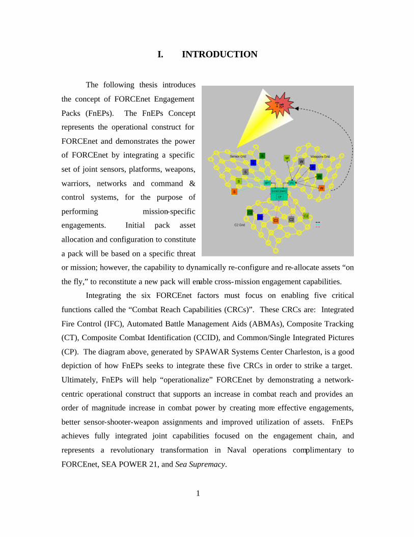
Integrating the six FORCEnet factors must focus on enabling five critical
functions called the “Combat Reach Capabilities (CRCs)”. These CRCs are: Integrated
Fire Control (IFC), Automated Battle Management Aids (ABMAs), Composite Tracking
(CT), Composite Combat Identification (CCID), and Common/Single Integrated Pictures
(CP). The diagram above, generated by SPAWAR Systems Center Charleston, is a good
depiction of how FnEPs seeks to integrate these five CRCs in order to strike a target.
Ultimately, FnEPs will help “operationalize” FORCEnet by demonstrating a network-
centric operational construct that supports an increase in combat reach and provides an
order of magnitude increase in combat power by creating more effective engagements,
better sensor-shooter-weapon assignments and improved utilization of assets. FnEPs
achieves fully integrated joint capabilities focused on the engagement chain, and
represents a revolutionary transformation in Naval operations complimentary to
FORCEnet, SEA POWER 21, and Sea Supremacy.
2
To date the vast majority of “publicity” related to FnEPs has been via literally
dozens of PowerPoint-based briefings. Such briefings have resulted in strong and near
universal endorsement from the CNO and many other members of Naval leadership,
Government, academia, and the commercial sector. While the thesis that follows is,
admittedly, long and perhaps overly wide in scope and level of detail for a Masters- level
research effort, we believe such a presentation is necessary to chronicle the diverse
efforts of those people who forged the concept and have assisted its analysis and
continued development. Moreover, such depth and detail is important to ensure 1) An
understanding of the challenges the Navy and DoD currently face in terms of C4ISR
system interoperability. 2) How we will address these challenges in order to better
design, and implement the large information systems the Navy will require in the future.
3) Sound technical, organizational, programmatic and acquisition-related
recommendations which will combine to ensure our future C4ISR systems and
architecture(s) will provide the functionality required by NCW, FORCEnet, and FnEPs.
Only by understanding all three of these aspects of the cha llenge can we provide the basis
upon which to remain on the proper road ahead for the continued development FnEPs and
the “operationalization” of FORCEnet.
Accordingly, our thesis is organized into five chapters.
Chapter I lays the foundation for understanding the challenges Navy and DoD
currently face as the services attempt to maximize combat efficiency and effectiveness in
the 21st Century through the principles of NCW. From a naval perspective, these goals
are captured in the Concept of SEA POWER 21, which critically depends on FORCEnet
as the “glue” which binds together and enables Sea Strike, Sea Shield, and Sea Basing.
As will be discussed in greater detail, while FORCEnet does not consist solely of a
network or networks, it critically depends upon the interoperability of C4ISR systems and
an integrated C4ISR network architecture.
Chapter II introduces the FnEPs concept and develops it within the larger context
of FORCEnet. Most importantly this chapter will illustrate how the FnEPs concept will
enable the “operationalization” of FORCEnet through the integration of the six
FORCEnet Factors around five key “Combat Reach Capabilites.”

3
Chapter III will present the analysis we, in conjunction with others, have
conducted. This analysis will not only objectively demonstrate the tremendous
improvements in efficiency, effectiveness, and increased “Combat Reach” FnEPs
enables, but will help to provide greater development and deeper understanding of
FORCEnet and the FnEPs concept.
Chapter IV presents both a general discussion of some of the critical technical
factors impacting the future of the networking and military applications, as well as a
more specific examination of the “Warfighting Internet” required to support FORCEnet
and FnEPs.
Finally, Chapter V will present 1) Our significant results and findings as a result
of our analysis, 2) Our general conclusions drawn from these results, and 3) Most
importantly, a series of recommendations that seek to provide a roadmap for the
continued development and “Institutionalization” of FnEPs.
Chapter I represents an introduction to our thesis. Sections A provides the
purpose of our research. Sections B & C provides a background discussion of the current
Navy C4ISR architecture and a general discussion of what we believe is a solution to
these challenges as they relate to FORCEnet and a new concept we have developed called
FORCEnet Engagement Packs (FnEPs). Sections D-G presents our research
methodology, the scope of our thesis, our assumptions, and some basic definitions.
A. PURPOSE OF RESEARCH
The purpose of our thesis is the introduction, continued development, and further
refinement of a new concept called FORCEnet Engagment Packs (FnEPs).
Fundamentally, the FnEPs concept is the operational construct for FORCEnet and
represents the opportunity to “operationalize” FORCEnet. In doing so, FnEPs
demonstrates the power of FORCEnet to improve the combat reach and effectiveness for
the JTF Commander. More specifically, our research will address two major areas. First
we will identify the technical and non-technical challenges facing the FnEPs concept and
the “operationalization” of FORCEnet, including networking and related requirements,
organizational and process related challenges, and programmatic and acquisition related
issues. Second, we will continue the analysis of the FnEPs concept by focusing on a
deeper understanding of the five specific FnEPs functional requirements we have
4
identified as “Combat Reach Capabilities” (CRCs) and how the CRCs map to the
ASN(RDA) Common System Functions List (CSFL). Finally, in completing this thesis
we will provide recommendations for continued development and implementation of
FnEPs which 1) Respond to the tasker given by VADM Mayo, (Commander,
NETWARCOM) to develop a prototype FnEP “Pack” for review and potential fleet trial
in TRIDENT WARRIORFY04 and, 2) Are in accordance with the recommendations
made to the CNO by SSG XXII (FnEPs Block I (IOC), 2009).
We need to take a systems approach and coevolve capabilities that will support missions throughout the detect, decide, attack, and assess sequence. Experimentation will help us correct for fire. As we optimize information flow through current systems, network limitations will highlight areas for future investment based on mission versus platform needs. The key is to reorganize now and start the process. NCW has a long way to go.3
Ultimately, the FnEPs concept seeks to achieve fully integrated joint capabilities focused
on the engagement chain, thereby achieving a revolutionary transformation in Naval
operations complimentary to the concepts of FORCEnet, SEA POWER 21, and Sea
Supremacy.
B. NAVAL C4ISR ARCHITECTURE INTEROPERABILITY CHALLENGES
Before embarking on a discussion of the challenges facing today’s C4ISR
infrastructure, it is important to understand two key concepts upon which solutions to
these challenges must be based – Network Centric Warfare (NCW) and FORCEnet.
NCW has its roots in the Revolution in Military Affairs (RMA) which resulted
from changes in American society that were dominated by the co-evolution of
economics, information technology, and business processes and organizations. These are
linked by three themes:
• The shift in focus from centralized (i.e., platform-centric) resources to distributed (i.e., network-centric) resources.
• The shift from viewing actors as independent to viewing them as part of a continuously adapting ecosystem.
3 Hardesty, 71.
5
• The importance of making strategic choices to adapt or even survive in such changing ecosystems.4
In their book Network Centric Warfare, Alberts, Garstka, and Stein define
Network Centric Warfare (NCW) as follows:
An information superiority-enabled concept of operations that generates increased combat power by networking sensors, decision makers, and shooters to achieve shared awareness, increased speed of command, higher tempo of operations, greater lethality, increased survivability, and a degree of self-synchronization. 5
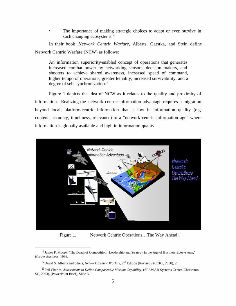
Figure 1 depicts the idea of NCW as it relates to the quality and proximity of
information. Realizing the network-centric information advantage requires a migration
beyond local, platform-centric information that is low in information quality (e.g.
content, accuracy, timeliness, relevance) to a “network-centric information age” where
information is globally available and high in information quality.
Figure 1. Network Centric Operations…The Way Ahead6.
4 James F. Moore, “The Death of Competition: Leadership and Strategy in the Age of Business Ecosystems,” Harper Business, 1996.
5 David S. Alberts and others, Network Centric Warfare, 2nd Edition (Revised), (CCRP, 2000), 2.
6 Phil Charles, Assessments to Define Composeable Mission Capability, (SPAWAR Systems Center, Charleston, SC, 2003), (PowerPoint Brief), Slide 3.
6
A related concept, FORCEnet, seeks to implement the theory of NCW.7 The
Chief of Naval Operations’ Strategic Studies Group XXI defined FORCEnet as:
The operational construct and architectural framework for naval warfare in the information age that integrates warriors, sensors, networks, command and control, platforms, and weapons into a networked, distributed combat force that is scalable across all levels of conflict from seabed to space and sea to land.8
FORCEnet is critical to the Navy’s most recent concept for future naval
operations, SEA POWER 21, which “envisions transformed operational capabilities that
will allow sea-based forces to execute the full range of joint operations from the maritime
domain . . .”9 While SEA POWER 21 will be made possible by Sea Strike, Sea Shield,
and Sea Basing, the key or “glue” which ties these concepts together is FORCEnet.
The Navy’s C4ISR architecture has evolved over a long period of time and has
witnessed tremendous advancements in technology and capabilities. Unfortunately, for a
number of various reasons, evolution of the Navy’s C4ISR architecture has not fully taken
advantage of such advances and capabilities. These reasons are widely varied, and
extend beyond technical hurdles to include fiscal, programmatic, and acquisition-related
challenges. Ultimately, organizational and cultural resistance has played a significant
role as well. As a result of these challenges, our current C4ISR architecture is ill-suited to
support the achievement of the vision for concepts such as NCW and SEA POWER 21.
The remainder of Section A will discuss these challenges more specifically as follows:
• Architecture versus infrastructure
• Sub-optimized resources for the JTF Commander
• Insufficient focus on engagement chain
7 Richard W. Mayo, Vice Admiral, U.S. Navy, John Nathman, Vice Admiral, U.S. Navy, “FORCEnet: Turning Information into Power,” Proceedings, February 2003, x.
8 SSG XXI Report to CNO (August, 2002), 1. 9 Ibid.
7
1. Architecture versus Infrastructure – A Misguided Focus
Fundamentally, the challenge currently
facing NCW and FORCEnet can be derived from
their very names! Both concepts rely critically on
“networking” of many things (e.g., computers,
humans, organizations, ideas, systems, platforms,
weapons, information, etc.) and imply the need for
system integration, interoperability, and ultimately,
a supporting C4ISR network. Unfortunately, many of the current C4ISR systems and
weapon system to weapon system interfaces have been developed in a stove-piped
manner, generally without consideration of the need for integration and interoperability
with other C4ISR or weapon systems outside a narrowly defined scope. As a result, some
redundant systems and capabilities exist, while in other cases critical capabilities and
system interoperability are absent. Even considering a specific functional area focus on
integration in regards to ISR, C2, or FC systems does not improve the challenge, because
from the perspective of NCW and FORCEnet, the list of systems requiring integration
and interoperability is not only extremely large, but indeterminate. Further, NCW and
FORCEnet currently lack a sufficiently focused and well defined set of requirements or
capabilities which are necessary to determine the systems integration and interoperability
requirements. This process must begin with integration and fleet-validated
interoperability requirements derived from desired warfighting capabilities. This will
lead to systems with the appropriately aligned system functionality in response to those
capabilities.
While current C4ISR systems and components are collectively referred to as an
architecture of systems, this label is woefully misleading. The problem stems from a
general misunderstanding of the definitions of architecture and infrastructure which lead
to poor and over generalized use of the terms throughout the Navy and DoD in general.
Terms like architecture and infrastructure have come to mean so many things to so many
people that their actual meanings have been lost. Documents like the Joint Technical
Architecture (JTA) are really not architecture documents, but more appropriately
described as a collection of standards to be applied to almost anything. The JTA does not
“…the ability to collect, communicate, process, and protect information is the most important factor defining military power.” - Bruce Berkowitz The New Face of War
8
provide an overall framework for how systems should be architected or planned for in
response to a specific (or set of specific) business or warfighting requirements. The
Information Technology Standards Guidance (ITSG) was one example of a document
which set out to propose standards and guidance for their use, but never seemed to catch
on. Examples of subtle, but important distinctions between several terms, including
architecture and infrastructure should be clarified:
• Infrastructure (e.g. “system of public works”; the communication pipes themselves)
• Architecture in the plural (usually descriptions of infrastructures, how they should act and in response to a specific requirement)
• Provisioning (e.g. allowance parts list, range and quantity of items, or configuration; making a service available for use)
• Systems engineering (getting the right boxes connected appropriately)
• Machine language dictionaries such as the “instruction set architecture”' for Intel Architecture chips or MilStd 1750 processors10
Overall, the problem emerges from the lack of an architectural “standard” and
common understanding of requirements to which system engineers and program
managers must adhere.
Thus far, the discussion highlights the critical need for system integration. From
our current perspective there are four major challenges facing system integration:
• Platform-centric integration
• Inadequate information exchange requirements
• Vertical versus horizontal integration
• Domain-focused integration
• Stove-piped, tightly coupled, and brittle integration.
Each of these areas is addressed below.
Platform-centric integration – In considering platform-centric integration, the
following quote by RDML Sharp, is helpful in characterizing past and current efforts
aimed at integration. FORCEnet, RDML Sharp said, “is about interoperability – it’s
about boxes and wires and ones and zeros, protocols, frequencies, bandwidth, and linking
10 Rex Buddenberg. “What’s Wrong with DoD’s So-Called Information Architectures and What We Ought to be
Doing About It,” Naval Postgraduate School, March 2000, 3.
9
things together.”11 RDML Sharp cited the evolution of capabilities since the 1983
invasion of Grenada, when an air controller called in air support using a pay phone.
During Operation Desert Storm in 1991, the public could see video of weapons homing
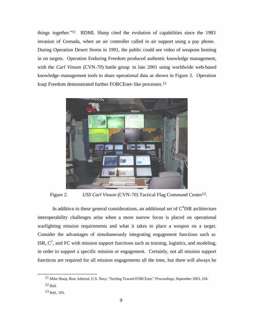
in on targets. Operation Enduring Freedom produced authentic knowledge management,
with the Carl Vinson (CVN-70) battle group in late 2001 using worldwide web-based
knowledge-management tools to share operational data as shown in Figure 2. Operation
Iraqi Freedom demonstrated further FORCEnet- like processes.12
Figure 2. USS Carl Vinson (CVN-70) Tactical Flag Command Center13.
In addition to these general considerations, an additional set of C4ISR architecture
interoperability challenges arise when a more narrow focus is placed on operational
warfighting mission requirements and what it takes to place a weapon on a target.
Consider the advantages of simultaneously integrating engagement functions such as
ISR, C2, and FC with mission support functions such as training, logistics, and modeling,
in order to support a specific mission or engagement. Certainly, not all mission support
functions are required for all mission engagements all the time, but there will always be
11 Mike Sharp, Rear Admiral, U.S. Navy. “Inching Toward FORCEnet,” Proceedings, September 2003, 104.
12 Ibid. 13 Ibid., 105.
10
“threads” of systems from each of the three functional domains (ISR, C2, and FC) which
must be integrated to ensure the successful engagement or mission accomplishment. For
a variety of reasons, these mission engagement “threads” (or parts of them) have
historically been bolted to an individual platform such as the F/A-18, a destroyer or other
physical platform. These interoperability challenges include programmatic funding
limitations or operational requirements for unit independence (historically, there was
minimal need to interoperate beyond the boundaries of a ship, plane, submarine, etc.
because that was how they were designed to be employed). Due to this “platform-
specific” design methodology, the mission integration within these platforms and specific
functional areas on those platforms (e.g., destroyer and its FC systems) has typically been
very tight. As an example, a sensor or fire control radar on a ship is typically designed to
only work with the weapon launcher and weapons organic to that specific ship. Today,
these systems are “composed” of stove-piped, non- interoperable, message-oriented
systems burdened with costly and lengthy integration and maintenance support cycles. A
better solution are “composeable” services where components are “Plug-and-Fight,” and
able to assemble capabilities on-the-fly, discovery (publish and subscribe) based, and
tailorable to the mission or user. Such capabilities require integration across and between
a variety of sensors, shooters, and weapons, but these requirements have never been
articulated or developed into modern systems.
Inadequate information exchange requirements – Another perspective requiring
consideration is that of information exchange requirements (IERs) between the systems
discussed above. Historically speaking, IERs have been defined, designed, tested,
programmed, funded, and operated from a platform-centric perspective between specific
pairs of systems. More recently a vertical, “functional” perspective (e.g., within C2 or
ISR, etc.) has been adopted, but inadequate standards, especially interface standards,
continues to pose challenges to system interoperability. This challenge is growing even
more critical as we continue to shift towards a horizontal “mission” or “engagement-
chain” perspective. Collectively, the effects of these architectural challenges are
reflected in the following quote by Captain David C. Hardesty in his recent Proceedings
article, “Fix Net Centric for the Operators.”
11
With all the clamor about network-centric warfare (NCW) and the U.S. Navy’s evolving FORCEnet, one would think the Navy is moving rapidly toward a well thought out, connected force with seamless data paths that reach from sensors, through appropriate command and control, to our wide array of available weapons. At least in the near term, this is not the case.14
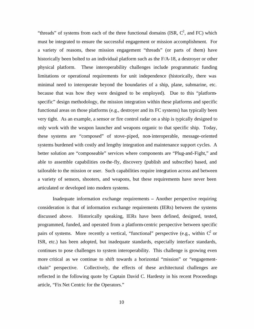
Vertical versus horizontal integration – The above discussion also highlights the
reason today’s systems are large ly integrated in a vertical manner, and along functional
“lanes,” including ISR for operational support; C2 for organizational command and
control; and FC for weapons delivery. Figure 3 depicts such vertical integration.
11
FnEPs Functional Information Exchange Areas
ISR
Functional Information Exchange Requirements
FC
M &
S
C2
Tra
inin
g
Lo
gis
tics Voice Coms,
GPS-aided INS
Low BW, Low Latency Networks
Link 16, CDL, other
Medium BW and Latency Networks
Satellites comms, UCAV(L) downlink
High BW, High Latency Networks
Figure 3. Vertically Oriented Functional Data Interchange Areas15.
14 David C. Hardesty, Captain, U.S. Navy. “Fix Net Centric for the Operators,” Proceedings, September 2003, 68.
15 Robert W. Hesser and Danny M. Rieken. FORCEnet Engagment Packs (FnEPs), (Naval Postgraduate School, December 2003), (PowerPoint Brief), Slide 11.
12
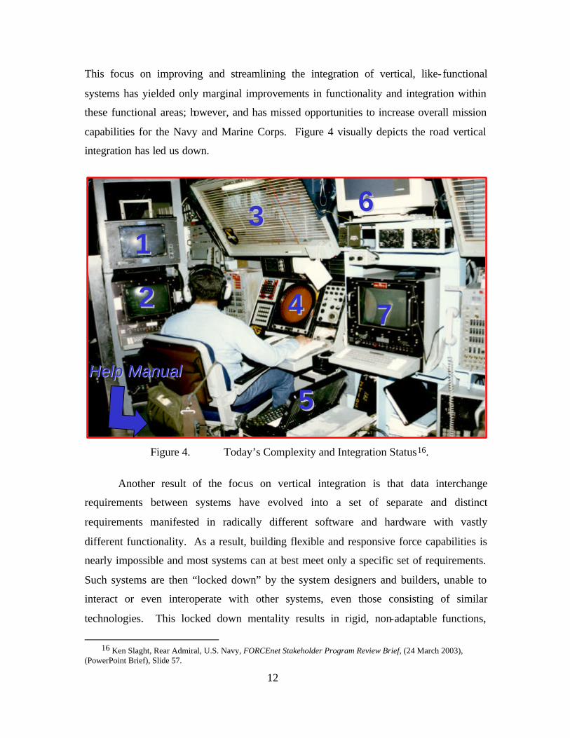
This focus on improving and streamlining the integration of vertical, like-functional
systems has yielded only marginal improvements in functionality and integration within
these functional areas; however, and has missed opportunities to increase overall mission
capabilities for the Navy and Marine Corps. Figure 4 visually depicts the road vertical
integration has led us down.
Help ManualHelp Manual
1133
22 44
55
66
77
Help ManualHelp Manual
1133
22 44
55
66
77
Figure 4. Today’s Complexity and Integration Status16.
Another result of the focus on vertical integration is that data interchange
requirements between systems have evolved into a set of separate and distinct
requirements manifested in radically different software and hardware with vastly
different functionality. As a result, building flexible and responsive force capabilities is
nearly impossible and most systems can at best meet only a specific set of requirements.
Such systems are then “locked down” by the system designers and builders, unable to
interact or even interoperate with other systems, even those consisting of similar
technologies. This locked down mentality results in rigid, non-adaptable functions,
16 Ken Slaght, Rear Admiral, U.S. Navy, FORCEnet Stakeholder Program Review Brief, (24 March 2003),
(PowerPoint Brief), Slide 57.
13
efficient for their particular function but limited in flexibility and agility of the overall
systems to perform in a total force construct such as FORCEnet. This prevents rapidly
changing requirements for new or different sets of functions or adapting as the
operational situation changes. The solution of such interoperability problems is at the top
of the priority requirements from the Fleet and Field Commanders17 and while progress
has been made, integration between systems across functional areas has lagged. CAPT
Hardesty continues,
Implementation of network-centric warfare at the tactical level has been flawed. Typifying incompatibilities is the software in the Navy’s F-14D . . . in support of Operation Iraqi Freedom—which was unable to synch with Air Force electronic reconnaissance aircraft over targets in Iraq. A systems approach and coevolution of capabilities are needed now. 18
The way information is actually managed and provided to the warfighter is the
transformational part of FORCEnet which FnEPs seeks to refine from a combat
engagement chain perspective. Today, requests for information and provision of that
information are processed through dedicated systems. These processes also lack a means
to turn this information into actionable knowledge and directly influence the ability to
carry out engagements via the engagement chain. Again, CAPT Hardesty captures the
impact of these shortcomings,
The Navy has failed to make significant progress in applying network-centric warfare concepts to tactical weapons and sensors that are deployed or under development. This is particularly true in naval aviation, where we continue systems acquisition and development in the same platform-centric manner. To implement network-centric warfare effectively and connect our tactical forces intelligently, we must reorganize. Each mission-area kill-chain sequence—detect, decide, attack, assess—must be examined to determine information exchange requirements among all platforms contributing to that mission area. Only then can we implement the co-evolution of systems, organization, and doctrine that will allow us to reap the benefits of network-centric warfare.19
17 SPAWAR Code 05, Office of the Chief Engineer. FORCEnet Government Reference Architecture (GRA)
Vision, (Version 1.0, 08 April 2003), 4-5.
18 Hardesty, 68. 19 Ibid.
14
While falling far short of what FnEPs requires in terms of integration and
interoperability, systems like CEC and the Aegis Weapon System (AWS), represent
examples of, at least, minimal cross-functional integration and hint at the potential for
full horizontal, mission area integration. An even better example is that of Joint Fires
Network (JFN); however, as the following quote indicates, JFN does not go far enough to
accomplish full horizontal integration across the engagement chain.
JFN is another major NCW effort designed to address critical operational deficiencies in time-sensitive targeting/time-critical strike against rapidly relocatable targets. Although JFN has demonstrated significant improvements in intelligence, surveillance, and reconnaissance management and integration with targeting, command, and control functions aboard ship, it has limited ability to provide engagement information to the weapon systems that can engage relocatable targets rapidly.20
At the heart of such systems’ potential is the integration of appropriate systems from the
ISR, C2, and FC functional domains which contribute to engagement effectiveness by
using cooperative and networked resources from similarly equipped platforms. Again
citing the examples of CEC and AWS, horizontal integration across functional domains is
accomplished through a very deliberate and conscious effort to control all aspects of this
mission within all functional domains. “The [fleet battle] experiments (FBE) have
improved our understanding of how to accelerate time-sensitive targeting/time-critical
strike, but they have been weak on integrating with actual weapon systems.”21
Domain-focused integration – Another perspective requiring consideration is that
of domain focused integration across ashore, afloat, and space domains. While the
previous section highlighted the problems associated with solely focusing on vertical
integration, domain-focused integration further exacerbates the challenges. Domain
focused integration proposes there are separate and unique integration requirements
among the afloat, ashore, and space domains. Specifically, systems employed afloat on
ships will have different interoperability requirements than those systems terrestrially
employed to support expeditionary requirements for the Marine Corps or other space-
20 Ibid., 69. 21 Ibid.
15
based information systems. Domain-focus integration challenges have critical
implications for the engagement chain because the (optimal) integration of systems must
cross domains. Such integration implies a dynamic aspect as well, due to the mobile and
ad hoc nature of Navy and Marine Corps deployments, Joint Task Force composition,
and allied and coalition operations.
Stove-piped and tightly coupled integration – Solutions to date have been the
result of stove-piped and tightly coupled integration leading to “brittle” systems
incapable of functional flexibility. Returning to the example of CEC and AWS,
proponents of the integration displayed in current Navy systems often cite these systems
as examples for the future. It should be noted that “integrated” is a relative term;
however, and CEC and AWS do not demonstrate the degree of integration necessary to
realize the capabilities envisioned by NCW, FORCEnet, and FnEPs. Worse still, these
systems are tightly coupled. Such tight coupling of the architecture is neither sufficiently
flexible nor adaptive with respect to time-critical targets or dynamic to emergent
operational requirements and can often lead to cascading effects throughout other parts of
the architecture. Conversely, our current capability to respond to changing mission
reorientations, operational configurations, or in response to equipment failures usually
require manual, time-consuming, and labor- intensive efforts—if possible at all! Even
CEC is highly mutually-dependent and based on a non-modular design. As such, CEC is
a relatively “brittle” system where even relatively minor configuration changes result in
wide-reaching ripple effects. Granted, CEC and AWS are extremely important and
capable systems, critical to today’s mission success, but these systems still leave room for
improvement!
Finally, security remains a major concern within the functional ISR, C2, and FC
system domains. Historically, security has been bolted on as an afterthought rather than
being designed from the beginning as an integral part of an overall system. As systems
become integrated and more interoperable, this challenge will become even more
prominent. Our ability to transition technology to operational use critically depends on
how well it can be secured and upon its reliability. Security must be built into the C4ISR
infrastructure structure such that our systems are secure while being integrated and
networked robustly, seamlessly, and coherently.
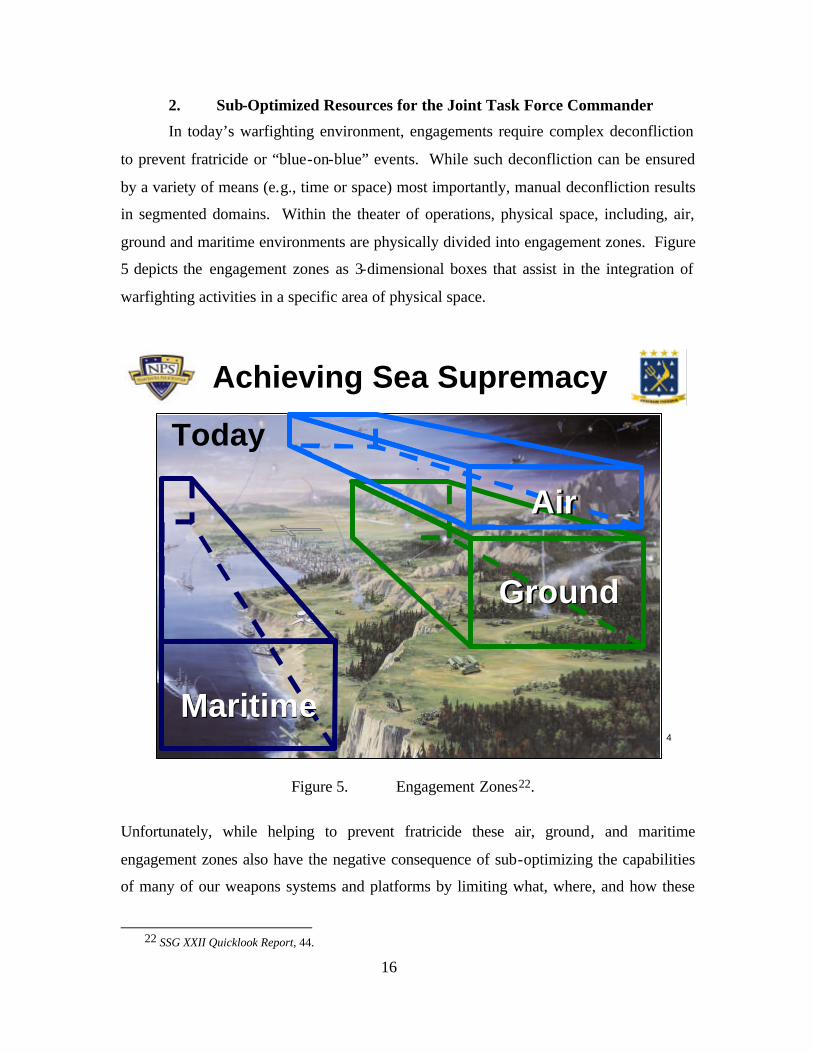
16
2. Sub-Optimized Resources for the Joint Task Force Commander
In today’s warfighting environment, engagements require complex deconfliction
to prevent fratricide or “blue-on-blue” events. While such deconfliction can be ensured
by a variety of means (e.g., time or space) most importantly, manual deconfliction results
in segmented domains. Within the theater of operations, physical space, including, air,
ground and maritime environments are physically divided into engagement zones. Figure
5 depicts the engagement zones as 3-dimensional boxes that assist in the integration of
warfighting activities in a specific area of physical space.
4
Today
Achieving Sea Supremacy
GroundGround
AirAir
MaritimeMaritime
Figure 5. Engagement Zones22.
Unfortunately, while helping to prevent fratricide these air, ground, and maritime
engagement zones also have the negative consequence of sub-optimizing the capabilities
of many of our weapons systems and platforms by limiting what, where, and how these
22 SSG XXII Quicklook Report, 44.
17
assets are employed. As an example, many modern systems are limited to the use of
organic track data from a sensor to a weapon. This may lead to situations where weapons
are limited to specific engagement ranges and against specific targets and conditions.
This challenge is discussed in greater detail in the scenarios presented below.
Geographic deconfliction by engagement zones also potentially limits the full use of
sensors, especially those “outside” a given engagement zone. While this simplifies the
integration challenge by limiting the responsibility for a given set of targets to those
sensors and targets within the specified engagement zone, it also limits the ability of
sensors to provide data on all targets they may have within their field of view. As sensors
become more powerful (and expensive), this sub-optimization can become critical.
As discussed above, engagement zones chiefly focus on the prevention of blue-
on-blue incidents. This is accomplished by physically limiting or prescribing the location
of friendly forces to predetermined areas. Not only is this method inefficient, especially
given the increasingly fluid and dynamic nature of today’s battlespace, but there are
many tragic examples accidents despite such boundaries. As a result, even given
engagement zones, visual identification (VID) is required before engaging a target.
While VID is certainly beneficial, it is not always practical and may preclude the
engagement of targets under conditions unsuited to VID. VID results in a number of
challenges. 1) One of the largest negative impacts of the requirement for VID is the
allocation of critical assets to perform this function when they might otherwise be able to
conduct other missions. 2) The requirement for VID typically lengthens the time
required to complete the engagement of targets. 3) Interoperability challenges and the
inability to pass identification information between engagement zones and the assets
within these zones must be considered.
Suboptimal allocation of resources is also a result of many of the interoperability
challenges highlighted above. While most of these challenges were presented from the
perspective of Navy systems, the problem is even greater when the focus is expanded to
include joint, allied, and coalition systems. Another of CAPT Hardesty’s quotes captures
this problem:
18
DoD and the Navy are committed to network-centric warfare as a foundation of transformation. Unfortunately, NCW implementation at the tactical level has been lackluster. There is no overarching NCW vision or plan at the tactical level. Platform-centric decisions have driven the problem and left us with incompatible implementations. Contractors, who have little incentive to make the systems we already have work together, offer new capabilities that would take years to field and still not provide the joint and multinational interoperability we need.23
The implication is clear, one of the most critical overarching challenges facing the
Navy’s C4ISR architecture, is also its lack of “Jointness” and its lack of joint, allied and
coalition systems integration.
3. Insufficient Focus on Engagement Chain
On of the most critical shortcomings of the the current C4ISR architecture, and
perhaps most overlooked, is an insufficient focus on the “Engagement Chain.”
To date, collaboration and planning activities have received a great deal of focus,
and tremendous progress has been made. Activities like Intelligence Preparation of the
Battlepsace (IPB), joint sensor and weapon system planning, mission planning, and
communication services planning historically been the focus of a great deal of research
and development. In contrast, unfortunately, less effort has been focused on the actual
engagement of targets. Figure 6 introduces the engagement chain process and shows how
this focus is different than that of planning and collaboration.
23 Hardesty, 71.
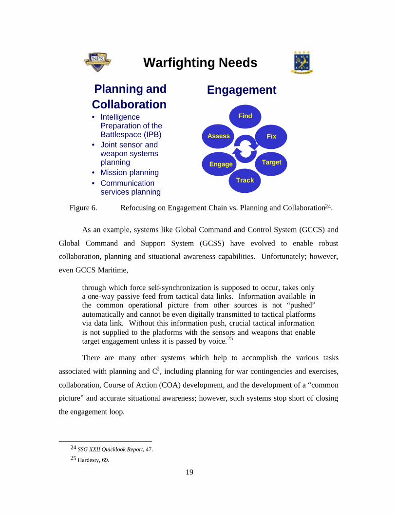
19
Warfighting Needs
Planning andCollaboration• Intelligence
Preparation of the Battlespace (IPB)
• Joint sensor and weapon systems planning
• Mission planning• Communication
services planning
Engagement
Find
Fix
Target
Track
Engage
Assess
Figure 6. Refocusing on Engagement Chain vs. Planning and Collaboration24.
As an example, systems like Global Command and Control System (GCCS) and
Global Command and Support System (GCSS) have evolved to enable robust
collaboration, planning and situational awareness capabilities. Unfortunately; however,
even GCCS Maritime,
through which force self-synchronization is supposed to occur, takes only a one-way passive feed from tactical data links. Information available in the common operational picture from other sources is not “pushed” automatically and cannot be even digitally transmitted to tactical platforms via data link. Without this information push, crucial tactical information is not supplied to the platforms with the sensors and weapons that enable target engagement unless it is passed by voice.25
There are many other systems which help to accomplish the various tasks
associated with planning and C2, including planning for war contingencies and exercises,
collaboration, Course of Action (COA) development, and the development of a “common
picture” and accurate situational awareness; however, such systems stop short of closing
the engagement loop.
24 SSG XXII Quicklook Report, 47. 25 Hardesty, 69.
20
As previously discussed, physically segmented, separately managed, and non-
integrated engagement zones also produce sub-optimal use of weapons’ kinematic
(range) capabilities. If a weapon has a kinematic capability greater than that of the sensor
or fire control system of the firing platform, the weapon will never be used to its full
combat reach capability unless “handed off.” to another sensor. Another example of sub-
optimization that results from weapons being limited to the inputs of their organic firing
platform is that of target-weapon-shooter “mismatches”. Such mismatches occur, for
example, when target-weapon pairings are made based on physical proximity rather than
on an optimum solution based on all available sensors, weapons, or shooters. Greater
integration among available assets would improve these suboptimal assignments by
allowing optimal target-weapon pairings, regardless of geographical location or other
limitation. It should be noted, however, that assigning optimal target-weapon-shooter
pairings is a far more difficult challenge than simply integrating all sensors, weapons, and
shooters. While a given solution to a particular threat may be optimal at the local or
tactical level, the solution may not be optimal when considered from an operational or
strategic perspective.
A final, general observation is that fundamentally speaking, the Navy’s current
C4ISR architecture is, at best, simply a set of pipes which facilitates data transfer and the
support of various end-user systems. The network must improve in order to facilitate the
full utilization of available warfighting applications and the use of such applications as
“distributed services” among all assets. Put another way – the network needs to be more
than just a set of pipes and infrastructure – the network should be an integral part of the
warfighting solution by supporting all network-aware applications for all network
“nodes”, whatever they may be or how they may be manifested, to collaborate, self-
synchronize, sense, and react to environmental stimulus. In this way, the C4ISR
architecture can evolve beyond simply a group of networks—and truly support DoD as a
warfighting tool.
21
C. A DIFFERENT APPROACH TO INTEROPERABILITY
The lack of interoperability of our current
system is in large part due to lack of a fundamentally
sound C4ISR “architecture”. The way systems are
interconnected today is process and platform
dependent. Their ability to interact and collaborate
is limited and their behavior is primarily platform or
system centric. This severely limits adaptability and
modularity. 26 As discussed previously, there are a number of reasons and factors
contributing to this problem; According to Rex Buddenberg, Senior Lecturer of
Information Science at the Naval Postgraduate School, the technical aspects of the
solution depend upon three requirements:
• The need for a definition of architecture as a means to achieve interoperability.
• Ensure the modularization of systems matches the Sense, Decide, and Act taxonomic functions.
• The need to define a set of interface standards.
Each of these requirements is generally discussed below
The need for a definition of “Architecture” – According to Buddenberg, a major
part of the problems surrounding interoperability and our current C4ISR architecture is an
“undisciplined definition.”27 Buddenberg further contends, “The best and most
applicable definition for architecture is “Design. The way things fit together….such a
prescriptional, design-focused definition, as a means to interoperability is the proper area
of concern to the architect (CIO)”. 28 In this definition, “things” refers to information
systems (both large and small), all of which can be decomposed into sense, decide, and
act functions, connected by communications.29 By “large” information systems, we are
referring to those which cross platform, program, service and allied boundaries. Chapter
26 Charles, GEMINII Overview, Global Engineering Methods: Initiative for Integration and Interoperability,
Slide 8.
27 Buddenberg, 2.
28 Ibid. 29 Ibid., 4.
“Progress is impossible without change, and those who cannot change their minds cannot change anything.” - George Bernard Shaw Playwright
22
II will introduce and fully discuss a new concept called FORCEnet Engagement Packs
(FnEPs), but is is important to note here the information systems necessary to support
FnEPs will all be considered large information systems. This perspective also aligns well
with the FnEPs concept because by being focused on optimizing combat engagements
across all functions of the engagement chain, FnEPs will require systems which cross
platform, program, service and allied boundaries.
The Navy knows how to build small information systems – those where it is
possible to get boundaries drawn around the entire system and placed under a single
program manager. An example highlighted by Buddenberg is that of the California Class
CGN, a ship program that demonstrated as soon as a program expands to a multiple
program manager information system problem, the level of complexity jumps30. In this
case, there were multiple program managers but only a single platform. From the
California Class CGNs Aegis was born, and with it the “mega program manger” (PMS-
400) with enough responsibility and authority to force end-to-end integration along a
single mission area which crossed many functional area (C2, ISR, FC, etc.) boundaries.
Unfortunately, this massive, multi-billion dollar program lacked the ability to scale up to
that of cross-platform integration and interoperability – which remains the critical next
step and a valuable lesson learned from CEC.
Buddenberg also highlights the fact that as we evolve in the “Information Age”
we must better understand the value of information and that there are significant potential
benefits and improvements if we can design, develop, and implement systems properly.
Buddenberg observes a number of “painful lessons” learned by the military and private
industry about how to approach large, complex information systems and identifies a
number of characteristics the architecture should exhibit. According to Buddenberg, in
general the architecture should be:
• Simple
• Minimal and extensible
• Scaleable
30 The California Class CGNs were the last pre-Aegis cruisers and are widely understood today to have had
inoperable combat systems when they were commissioned.
23
• Real (meaning it requires no “uninvented” technology to implement)
• Platform and function independent31
These characteristics are all fundamental to FnEPs as well. The challenges
highlighted above are also similar. As Buddenberg points out, “large information
systems today are like large software systems a quarter of a century ago. We understand
the problem poorly and we haven’t settled on a real discipline, or even a good
methodology, yet.”32 A large part of the problem FnEPs tries to address is the
interoperability and integration requirements problem when you look at information
systems from the engagement chain perspective. Unfortunately, DoD is constrained
beyond technical solutions. As a prime example, the Defense Reorganization Act
(Goldwater-Nichols) puts into place a requirements system designed for the procurement
and engineering of stove-piped platforms, not large integrated and network-centric
information systems.
Implement a standard set of Interfaces – A key to the solution lies in the
implementation of a standard set of interfaces for whatever nodes or end systems are to
connect to the network. If we achieve this, then these end systems, including the sensors,
weapons, and other components of a given FnEPs “Pack” can interconnect in a “Plug and
Fight” manner – a key requirement to the dynamic allocation and reallocation of assets to
packs and mission areas.
Buddenberg contends a coherent architecture must use a common network
structure.33 In the case of virtually all current and future programs related to C4ISR
networks, the focus is on the implementation of internet technology. Further,
Buddenberg identifies several key assumptions about the network any architecture must
support. These include:
• Within the network cloud we have e-mail Message Transfer Agents.
• A network monitoring capability that uses SNMP.
31 Ibid.
32 Ibid. 33 Ibid., 5.
24
• We need a Public Key Infrastructure (PKI).34
• The network must support QoS services.35
The first architectural rule is that all end systems attach to the network; never
directly to each other. Providing these systems qualify as “Good Network Citizens,”36
they can be easily attached to an Internet. Good Network Citizens should have the
following characteristics:
• A LAN interface
• An “enveloping” interface.
• A management interface.
• A PKI-base capability to authenticate itself.
• An ability to request QoS services if best-effort delivery is not adequate.37
Buddenberg acknowledges that while this description is not explicit, these
specifications are sufficient and allow for modifications without wholesale changes to the
end system38.
It is important to note there has been much discussion regarding what the most
appropriate technologies are to support the architectural characteristics and network
required by the Navy and DoD. Most of this discussion, especially related to QOS,
centers on the suitability of Internet technology and of the IP and IPv6 protocols in
particular. In the context of FnEPs, such considerations become even more critical as
they impact functions associated with the engagement chain. The characteristics
discussed above will be discussed in greater detail in Chapter IV, along with a discussion
of the current and emerging technologies most likely to impact the performance of this
recommended architecture.
34 According to Buddenberg, PKI, in turn, implies a directory structure. This directory may do many things, but
the architectural requirement is that it authentically serve public keys. Resistance to denial of service attacks, link crypto, low probability of intercept and detection are all issues that belong inside the network cloud; they are not of architectural concern to end systems attached to the network.
35 Buddenberg, 5.
36 For a more in-depth discussion, refer to Buddenberg’s “What’s Wrong with DoD’s So-Called Information Architectures and What We Ought to be Doing About It,” Naval Postgraduate School, March 2000. WWW Link: [http://web1.nps.navy.mil/~budden/lecture.notes/good_net_citizen.html], Accessed October 2003.
37 Buddenberg, 5. 38 Ibid.
25
Modularization of Systems – The purpose of the interface definition discussion
above is fundamentally related to answering the challenge of connecting end systems to
the network itself. The remaining challenge is ensuring the interface of end systems
amongst each other. For this reason the core of the architecture must display a
modularization methodology. Buddenberg observes that interoperability problems with
the current “architecture” can generally be viewed as deficiencies related to mis-
modularization of the systems or where the complexity of the systems and processes do
not cleanly nest.39 These issues can be solved by addressing the following rules:
• Make the functions of sense, decide and act match the module boundaries. Avoid, in particular, placing single sensor integration functions in the decision module. Modularize the end systems consistent ly to increase the probability that a sensor originally part of one program can provide data effectively to a decision support module that was part of another.
• Nest cleanly. The best illustration is in structured software langages that make it very difficult for a subroutine to return to any place other than where it was called from. Clean nesting allows reuse of modules and building of arbitrarily complex information systems.
• Chain properly. Ensure that the act function (not the decide) of one system represents the sense function of the next system. Recognize sense-decide-decide-act chains not as chaining at all, but as poor (but often necessary) halfway steps that should only be indulged in to accommodate legacy.40
A FORCEnet Architecture – Fortunately, given the current state of commercial
and Department of Defense technology, improvements are possible beginning today and
could be implemented using a spiral development approach. Such an approach would
also allow leveraging legacy systems and emerging technology in ways that are fiscally
and programmatically viable. Contrary to the picture of today’s C4ISR architecture, we
feel an improved C4ISR architecture should:
39 Ibid. 40 Ibid., 6.
26
• More closely integrate all components, including legacy systems, advanced technology, and joint assets
• Be more capabilities-based and focused on a refined set of Mission Capabilities Packages (MCPs).
• More focused on the engagement chain
The remainder of this section seeks to address each of these.
1. Integration of Legacy, Advanced and Joint Systems
From a technical (not to mention fiscal and organizational) standpoint,
improvements to today’s C4ISR architecture require an evolutionary process which builds
on already existing capabilities. While we lack some of the technical answers and cannot
afford to recapitalize the entire fleet’s capabilities all at once, many of our current
systems have demonstrated a high level of performance and proven capability to
“accomplish the mission.” Captain Robert Whitkop, former director of the Navy
Network Warfare Command’s FORCEnet division, said, “FORCEnet Block 0 already
exists in the fielded Navy networks operated by [Navy Network Warfare Command] that
serve some 7,000 personnel.”41 Accordingly, we should leverage existing capabilities
and systems where possible and seek the integration of new and advanced technology
through a spiral development process. Using a spiral development process will
accomplish integration in an incremental manner and enable the sound management of
cost and risk. This methodology is also better for risk management and mitigation over
the long term because as related integration and supporting development takes place,
better short term corrections can be made with a lower cost threshold and minimal impact
to overall development.
Beyond simply integrating legacy and advanced systems however; joint, including
allied and coalition integration will also be critical. There are two chief reasons for this.
1) Only by including joint systems and capabilities can we realize the full synergies
possible with an integrated C4ISR infrastructure. 2) Each of the services and our allies
and coalition partners possesses core competencies. As a result of the services becoming
more specialized with respect to these core competencies—and optimized towards
specific statutorily mandated roles and missions, individual services cannot function and
41 Sharp, 104.
27
“fight” independently. Today’s combat operations are chiefly focused around the
establishment and effective operation of JTFs. These JTFs would benefit greatly from
the synergistic effects and capabilities that an integrated C4ISR infrastructure would
enable. As a specific example, consider the recent example of Operation Enduring
Freedom (OEF) in Afghanistan. Throughout OEF, the Navy was required (and able!) to
support forces ashore across a distance in excess of 600 miles. Such support was not
seamless; however, especially from the perspective of fire support, and tragic blue-on-
blue accidents resulted.
The following excerpt from CAPT Hardesty’s article characterizes such a “joint”
C4ISR architecture,
While initial focus of the tactical NCW organization will be on rapid correction of current interoperability shortfalls, its mission-area-based analysis will result in development of a long-range NCW plan that is synchronized with the other services. Marine Corps operators must be included . . . to provide the interface to all relevant Marine Corps systems. The plan must include a means to pass relevant digital data from the Army’s Tactical Internet to supporting naval tactical units. A coherent plan integrating and deconflicting naval aviation with Army artillery and naval fire control systems is required. Multiplatform sensor-integration efforts . . . must be coordinated to ensure both Navy and Air Force platforms can participate. Information from assets in space should be integrated directly into tactical kill chains.42
While joint integration is difficult, as discussed above, a spiral development and
implementation methodology would help to realize more robust capabilities over time,
without unrealistically high hurdles enroute. RDML Sharp, Captain Whitkop, and others
have stressed that,
FORCEnet requires a joint-service architecture achieved through the use of common standards and protocols. All the services want to be linked. They have to push the joint arena. Everyone is doing C4I [command, control, communications, computers, intelligence]. They need a Joint Forces Command 43 to force them to work towards a common architecture.44
42 Hardesty, 71.
43 Note: The Joint Ballistic Missile Command and Control (JBMC2) Agency currently has this responsibility. 44 Sharp, 104.

28
Finally, joint integration has the potential to reduce redundancies and increase
efficiencies within the Navy and across the other services—an important quality in the
current fiscal and budgetary environment. It should be noted that certain standards
currently exist as validated requirements, including MIL STD 6016 (TADIL-J), the future
standard for all joint tactical data communications. Unfortunately, such standards are
neither being uniformly adhered to or enforced on a joint basis.
While it is understood that a fully- integrated joint C4ISR infrastructure is likely
many years from full realization, there also remains a critical need for near-term
solutions. Not only does our current C4ISR architecture and infrastructure lack the
flexibility and adaptability to effectively counter the ever-changing threat environment
posed by new, emerging asymmetric threats, but our traditional adversaries and threat
remain viable and demand attention. Ultimately, the current and future threat landscape
will be increasingly characterized by non- linear behavior and asymmetric threats. Such a
landscape demands a C4ISR infrastructure that is “time-critically agile” in order to
respond to this multi-dimensional enmeshment of new and traditional threats on a global
scale.
2. Capabilities-Based and Focused on MCPs 45
As highlighted in Section A, the current C4ISR infrastructure suffers from highly
stove-piped systems and integration that is at best vertically focused along the functional
lines of ISR, C2, and FC. Conversely, what is needed is greater horizontal integration
focused on warfighting capabilities. The Navy’s Mission Capability Packages (MCPs)
provide an excellent framework for several reasons. 1) MCPs are capability-based.
Currently, examples of MCPs include Missile Defense (MD), Strike, Undersea Warfare
(USW or ASW), Anti-surface Warfare (ASuW), among others. Such names highlight the
highly focused nature of MCPs on specific capabilities rather than functional areas. 2)
MCPs are joint by definition. As discussed above, joint integration is critical to the
success of a future C4ISR infrastructure. 3) From a Naval perspective, MCPs support the
establishment and sustainment of Sea Supremacy. This is important because SEA
POWER 21 relies critically upon Sea Supremacy. Citing the CNO's words, Sea
45 Naval Capability Pillars (NCPs) are the 4 SEA POWER 21 Pillars of Sea Strike, Sea Shield, Sea Basing and
FORCEnet. MCPs being distinct from and a subset of NCPs, include such specific mission areas as Strike and TAMD.
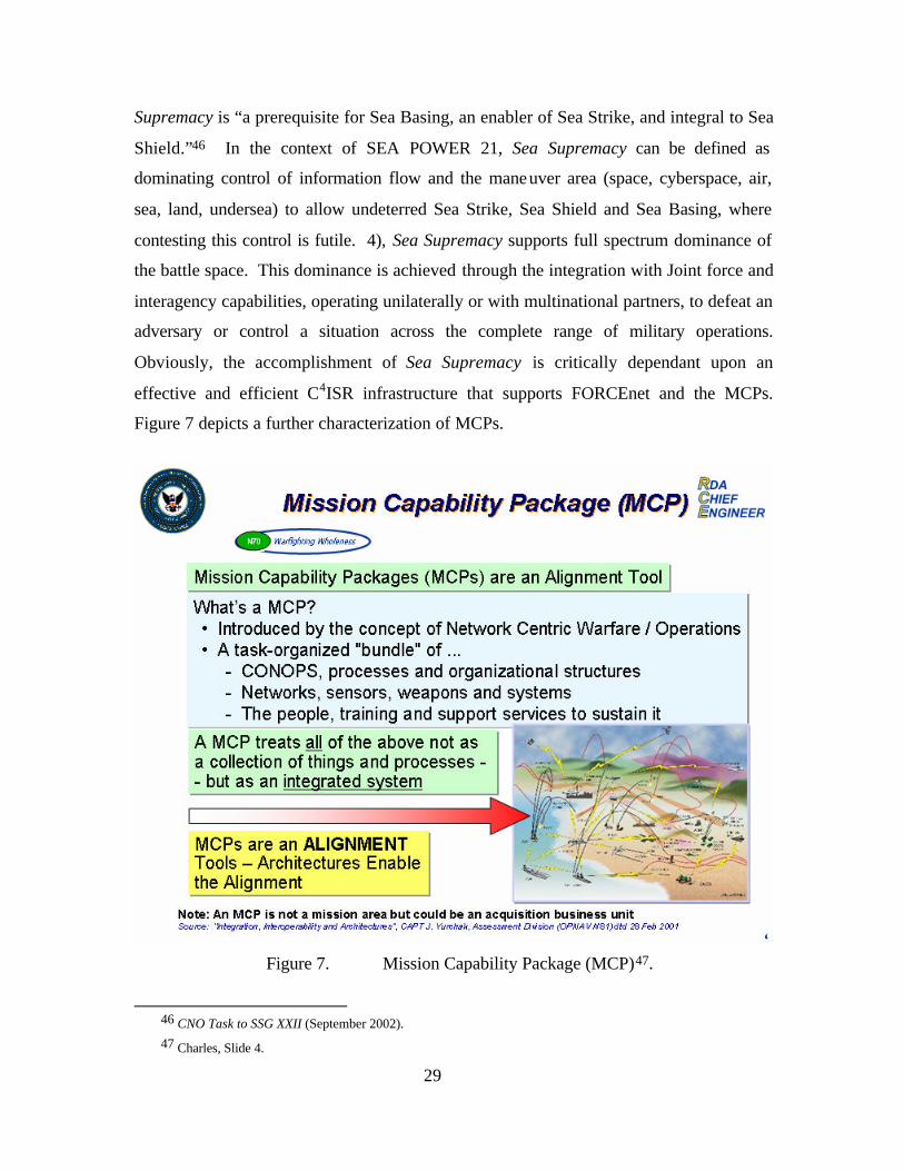
29
Supremacy is “a prerequisite for Sea Basing, an enabler of Sea Strike, and integral to Sea
Shield.”46 In the context of SEA POWER 21, Sea Supremacy can be defined as
dominating control of information flow and the maneuver area (space, cyberspace, air,
sea, land, undersea) to allow undeterred Sea Strike, Sea Shield and Sea Basing, where
contesting this control is futile. 4), Sea Supremacy supports full spectrum dominance of
the battle space. This dominance is achieved through the integration with Joint force and
interagency capabilities, operating unilaterally or with multinational partners, to defeat an
adversary or control a situation across the complete range of military operations.
Obviously, the accomplishment of Sea Supremacy is critically dependant upon an
effective and efficient C4ISR infrastructure that supports FORCEnet and the MCPs.
Figure 7 depicts a further characterization of MCPs.
Figure 7. Mission Capability Package (MCP)47.
46 CNO Task to SSG XXII (September 2002). 47 Charles, Slide 4.
30
3. Focus on Engagement Chain
As will be discussed in greater detail in Chapter II, there has been a tremendous
amount of progress made in the areas of C2, planning, collaborative technologies, and
other related areas that significantly and positively impact the challenges facing the
current C4ISR architecture and its support of the operations of the Navy. System
integration and interoperability, while still far from a desired end-state, are certainly
headed in a positive direction. Further, there is a great deal of advanced research and
development ongoing in critical aspects of C2 as it relates to human systems integration
and decision support. Collectively, these advancements are all steps in the right
direction, but they do not go far enough to solve one of the most fundamental and critical
shortcomings of the current C4ISR architecture. Highlighted above, this challenge is a
lack of focus on the engagement chain. Previous sections have also highlighted many of
the challenges facing the integration and interoperability of sensors, weapons, and other
related combat systems, amongst themselves; however, a greater challenges surfaces
when it is realized that today there are extremely few examples of weapons and related
“combat” systems that are horizontally integrated with the advanced C2 capabilities and
functionality we currently have. To express the point from the perspective of the
warfighter, all the command and control, communications, situational awareness, and
other information available across the battlefield does not do a bit of good if the
warfighter can’t ultimately engage the enemy! What is needed is a C4ISR architecture
that supports not only the full spectrum of C2 and related functionality, but the ability to
ultimately bring decision making to bear in the form of engagements against our
adversaries.
Thus far, Section B has presented a general characterization of the future C4ISR
infrastructure—namely that of the need for greater integration that is more joint, more
focused on the engagement chain, and achieves greater warfighting capabilities in the
near-term. A recent concept developed by the CNO’s Strategic Studies Group, called
FORCEnet Engagment Packs (FnEPs) seeks to achieve these goals and is the focus of the
remainder of this thesis. The following sections will outline the purpose, methodology,
and scope of our research, as well as present a set of assumptions and basic definitions.
31
D. RESEARCH METHODOLOGY
Our methodology consists of three key aspects. First, we intend to engage a wide
variety of experts from DoD, government, academia and the commercial sectors in order
to better understand the broad array of challenges facing the current C4ISR architecture
and the implications these challenges have for FORCEnet and FnEPs. Second, we will
engage SPAWAR Systems Center Charleston and the FORCEnet Architecture Chief
Engineer’s office to conduct objective analysis in support of the continued development
of the FnEPs concept. In conducting this analysis, we will use SPAWAR’s Gobal
Engineering Methods: Initiative for Naval Integration and Interoperability, (GEMINII)
and tool set, which provides the capability to conduct both static and dynamic
interoperability analysis through first order system architecture decomposition and gap
analysis. Using GEMINI we will 1) Perform scenario-based analysis of TAMD and
Strike FnEPs “Packs”, and 2) Define and assess the specific functionality of FnEPs
CRCs and how they map to the ASN (RD&A) Common System Functions List (CSFL).
Ultimately we will seek the discovery of requirements for near-term systems integration
and those systems necessary to support the development of near-term FORCEnet and
FnEP functionality. Finally, we will coordinate with a variety of DoN organizations to
begin development of an FnEPs prototype and a roadmap for its development.
Specifically related to this final requirement, we will provide recommendations for
continued development and implementation of FnEPs which 1) Respond to the tasker
given by VADM Mayo, (Commander, NAVNETWARCOM) to develop a prototype
FnEPs “Pack” for review and potential fleet trial in TRIDENT WARRIORFY04 and, 2)
Are in accordance with the recommendations made to the CNO by SSG XXII (FnEPs
Block I (IOC), 2009).
E. SCOPE OF THESIS
In accordance with the goals of our research, the scope of this thesis will focus on
the development and refinement of the FnEPs concept and its relationship and
implications for NCW, FORCEnet and SEA POWER 21. As part of this refinement, we
will also provide a series of recommendations and “Roadmap” focused on the continued
32
development of FnEPs and the “institutionalization” of the FORCEnet and FnEPs in the
near term, in accordance with VADM Mayo’s tasker and the recommendations provided
to the CNO.
It is important to note that while we will broadly identify and address the array of
challenges facing the implementation of FORCEnet and FnEPs, including 1) technical
and non-technical challenges, 2) organizational and process related challenges, and 3)
programmatic and acquisition related issues, the specific “answers” to such challenges lie
well beyond the scope of this thesis and our research. We have chosen to focus primarily
on the technical and network-related challenges facing FORCEnet and FnEPs, while
providing limited recommendations with respect to the other challenges. Chapter V will
address further areas for future development.
F. DEFINITIONS
This section seeks to define some basic terms that will be used throughout this
thesis.
Architecture – The design or way systems and/or other components of a network
fit together such that modularity is achieved, enabling architecture scaleability. Key
assumptions in this definition include the implementation of a standard set of interfaces
for whatever nodes are to connect to the network and a common network structure.
Bundle – System function/information exchange mapping to service area (e.g.,
sense, decide, or act)
Capabilities – Warfighter, outcome-based effects based on two types of variables,
conditions (i.e., things we ‘set’) and metrics (i.e., things we ‘measure’) like weather,
AOR geometry, threat, lethality, coverage (sensor, engagement) survivability, timeliness,
or time, space and force factors.
Combat Reach Capabilities (CRCs) – Fundamentally, CRCs are further
refinements of Garstka’s Network-Centric Warfare principles. Beyond these general
principles; however, the CRCs seek to define specific warfighting functionality necessary
to improve combat power. There are five specific CRCs include Integrated Fire Control
(IFC), Automated Battle Management Aids (ABMA), Composite Tracking (CT),
33
Composite Combat Identification (CCID), and Common/Single Integrated Pictures (CP).
These CRCs are the product of specific FORCEnet factor integration focused and must
be engineered to achieve critical, end-to-end combat functions.
Derived Capabilities – Derived capabilities are parameters of services (e.g.,
security, connectivity, availability, maintainability, bandwidth efficiency,
interoperability, latency, delay, jitter, etc.). These derived capabilities may be articulated
in the form of requirements, quality of service (QoS) or in service level agreements
(SLAs).
Engagement Chain – The process by which missions are conducted for the
purposes of prosecuting targets. This process includes the following steps: Find, Fix,
Target, Track, Engage, and Assess.
Engagement Pack – a specific set of joint sensors, platforms, weapons, warriors,
networks and command & control systems, for the purpose of performing mission-
specific engagements. Initial pack asset allocation and configuration to constitute a pack
will be based on a specific threat or mission; however, the capability to dynamically re-
configure and re-allocate assets “on-the-fly,” to reconstitute a new pack will enable cross-
mission engagement capabilities. Integrating the six FORCEnet factors must focus on
enabling five critical functions called the “Combat Reach Capabilities (CRCs)”. These
CRCs are: Integrated Fire Control (IFC), Automated Battle Management Aids
(ABMAs), Composite Tracking (CT), Composite Combat Identification (CCID), and
Common/Single Integrated Pictures (CP). Ultimately, FnEPs will help “operationalize”
FORCEnet by demonstrating a network-centric operational construct that supports an
increase in combat reach and provides an order of magnitude increase in combat power
by creating more effective engagements, better sensor-shooter-weapon assignments and
improved utilization of assets. FnEPs achieves fully integrated joint capabilities focused
on the engagement chain, and represents a revolutionary transformation in Naval
operations complimentary to FORCEnet, SEA POWER 21, and Sea Supremacy.
Each “pack” contains a mix of legacy and advanced Joint capabilities which
leverages available assets to provide fire power on demand and adaptive to support any
type of conflict or combat any type of threat the JTF Commander might require. Spiral
development of FnEPs supports a process that leads incrementally to a fully integrated
34
Joint Force, providing a near-term set of FORCEnet engagement functions to the JTF
Commander. Information is passed by way of common protocols and standards,
supported by unique bandwidth allocations depending on the requirements of the
individual mission areas through all phases of the kill chain; find, fix, target, track,
engage and assess. Perhaps most significantly, the FnEPs concept will provide mission-
specific capabilities that are scalable, adaptable, and dynamically reconfigurable as a
single warfighting system of systems. “Packs” have specific functionality acting
collectively to support common objectives both within a pack and as a collection of
packs. This is unlike ‘swarm’ that implies a mass of common functions, supporting a
common objective. A pack consists of a mix of manned and unmanned systems. The
pack is a system of engagement subsystems adaptable for a particular mission area, and
in many cases, multi- functional, so that a pack can support another mission area on
demand48.
FORCEnet – “The operational construct and architectural framework for naval
warfare in the information age that integrates warriors, sensors, networks, command and
control, platforms, and weapons into a networked, distributed combat force that is
scalable across all levels of conflict from seabed to space and sea to land.”49
FORCEnet Engagement Packs (FnEPs) – The concept that defines the
operational construct for the realization of FORCEnet as it relates to the engagement
chain.
Infrastructure – The physical instantiation of an architecture, especially is it
relates to the actual networks which support the exchange of all types of C4ISR related
information.
Integration – The bringing of different systems together into a coherent
architecture such that unrestricted and equal association between those systems is
possible. These systems could be different from a functional, technical or design-based
48 Joseph Giaquinto, Captain, U.S. Navy. FORCEnet Engagement Packs (FnEPs), (SSG XXII, June 2003),
(PowerPoint Brief), Slide 13. 49 SSG XXI.
35
perspective; however, this coherent architecture allows these systems or functional
capabilities to work seamlessly towards a common goal. Integration seeks to achieve
interoperability.
Interoperability – From a networking perspective, this implies the ability of
software and hardware on multiple machines from multiple vendors to communicate. In
a more general DoD sense, interoperability is the ability of systems, units, or forces to
provide services to and accept services from other systems, units, or forces and to use the
services so exchanged to enable them to operate effectively together.
Network – Unless otherwise specified, our use of this term refers to the
interconnectivity of information systems that either generate or consume data and are
largely comprised of communications resources and C4ISR related networks, including
both IP and non-IP (e.g., Link-16, CEC) systems.
Network-Centric Warfare (NCW) - “An information superiority-enabled concept
of operations that generates increased combat power by networking sensors, decision
makers, and shooters to achieve shared awareness, increased speed of command, higher
tempo of operations, greater lethality, increased survivability, and a degree of self-
synchronization.”50
Open Architecture (OA) – A standards-based approach to creating modular,
interoperable, and scaleable systems. Further OA allows for the use of future technology
and insertion of components from one generation to the next based on hardware and
software products that conform to open standards, thereby resulting in significant savings
and improving interoperability. From a Navy perspective, the Open Architecture
Computing Environment (OACE) seeks to implement an OA approach, inc luding
specifications for interfaces, services, and supporting formats. OA will enable properly
engineered components to be utilized across a wide range of systems with minimal
change requirements necessary to interoperate with components on local and remote
systems.
50 Alberts, 2.
36
“Operationalize” – Transforming a theoretical concept into practical terms. In the
context of FORCEnet, “operationalize” is about realizing the vision of FORCEnet in a
warfighting context focused on the engagement chain in order to achieve the potential of
Network-Centric Warfare.
Pack – Minimum end-to-end sequence of service areas mapped to integrated
components (systems), (e.g., specific “Pack”)
Portfolio – Program mapping to multiple end-to-end packs aligned to mission area
capabilities
Strike – As defined in Joint Publication, JP 1-02, an attack that is intended to
inflict damage on, seize or destroy an objective. The Strike MCP will evaluate mission
capability to inflict damage on or destroy an objective.
Tactical Situations (TACSITs) – TACSITs are graphical representations of MCP
mission areas and depict what activities occur along the Engagement Chain. Further,
TACSITs refine the Operational Situations (OPSITs) based on a specific Design
Reference Mission (DRM). Finally, TACSITs depict how the engagement chain
activities are linked as an end-to-end set of processes. These characteristics allow
TACSITs to be used as baseline reference documentation in a variety of settings,
including the modeling and validation of OPNAV budget submissions.
Theater Air and Missile Defense (TAMD) – Mission area created within the
JTAMD process that states activities within the mission area seek to: Prevent, defeat, and
minimize the consequences of adversary employment of ballistic, cruise, and air-to-
surface missiles and aircraft, especially those equipped with weapons of mass
destruction. Preventing entails destroying launchers, missiles, aircraft, and their
sustaining and enabling infrastructure on the ground, or otherwise suppressing missile
launchers and aircraft sorties. Defeating involves intercepting missiles and aircraft in
flight to destroy their payloads. Minimizing consequences deals with warning specific
personnel and areas at risk of missile and aircraft attack in time to enhance their
protective posture.51 As defined in Joint Publication, JP 3-01, all defensive measures
51 Herbert C. Kaler, Robert Riche, and Timothy B. Hassell, “A Vision for Joint Theater Air and Missile Defense,”
Joint Forces Quarterly, Autumn/Winter 1999-2000, 68.
37
designed to destroy attacking enemy aircraft or missiles in the earth's envelope or
atmosphere, or to nullify or reduce the effectiveness of such attack. Destroy enemy
theater missiles in flight or prior to launch or to otherwise disrupt enemy's theater missile
operations through an appropriate mix of mutually supportive passive missile defense;
active missile defense; attack operations; and supporting command, control,
communications, computers, and intelligence measures. More generally, TAMD ensures
all around air defense of the battlespace from attack by enemy aircraft, anti-surface
missiles, surface to surface missiles, and theater ballistic missiles. TAMD MCP will
evaluate naval capabilities to provide critical point defense, area air and missile defense,
and contribute to theater air and missile defense.
G. ASSUMPTIONS
This thesis makes the following assumptions with respect to the FnEPs concept
and its “operationalizing” FORCEnet.
FORCEnet Engagement Packs (FnEPs) – In its most technical sense, FORCEnet
is about the integration and networking of systems together, a process which currently
faces tremendous cultural, process-related, and, to a lesser degree, technical issues. As a
result, fully achieving the ultimate objective of FORCEnet-- a “fully- integrated” family
of systems—is not realistically achievable in the near-term time frame with which SSG
XXII was chartered by the CNO. Cultural and process-related challenges
notwithstanding, there has been a great deal of technological progress made, leaving us
poised to make significant strides towards the realization of FORCEnet in the near-term.
SSG XXII envisioned the evolution of a set of mission-oriented joint capabilities
developed as warfighting “packs.” The collection of mission packs can be linked
together to provide the JTF Commander a single system-of-systems construct, which we
have labeled FORCEnet Engagement Packs (FnEPs). In short, FnEPs represents an
operational construct for the realization, or “operationalization,” of FORCEnet in the near
term (FnEPs Block I IOC 2009).
Even an initial “Pack” must integrate joint assets simply because the Navy and
Marine Corps do not have all the assets required to perform certain critical missions such
as TAMD. Due to the first responder presence the Navy and Marine Corps in-theater,
38
initial pack constitution may be limited and primarily Naval in nature. As other service
assets become available, “packs” will be augmented with those joint assets in order to
fully develop the warfighting capability required.
Human C2 versus Automated Systems and Processes – Although FORCEnet and
FnEPs will leverage the power of networks and IT technology and utilized increased
levels of automation to achieve increased combat effectiveness and efficiency, these
concepts will never eliminate the warfighter as a critical part of such concepts. Recall the
definition of FORCEnet that lists integration of the warfigther as the first of six critical
FORCEnet factors. Similarly, while the current hierarchical C2 structure is at times
inefficient, span of operational control is still going to be an important operational
requirement for the management of complex, large-scale combat operations, and we do
not foresee the possibility for a single C2 “layer” which controls all networked activities
within the “packs.”
“Pooled Resources Paradigm” – While increases in the numbers and varieties of
integrated and “networked” systems will enable FnEPs to provide orders of magnitude
increase in combat power, challenges associated with increased networking will likely
emerge. We assume a paradigm shift will be required, whereby an individual will be
required to release ownership of dedicated, direct control authority for assets in order to
create “pools” of warfighting assets in realizing distributed warfighting services. This
“pooled asset paradigm” would make assets dynamically available for assignment to
engagements optimized across the entire force. This paradigm has two key aspects.
First, pooled assets do not change the presumption that these warfighting assets would
still be available to their organic “owners” for such requirements as self-defense.
Secondly, this paradigm will require a cultural shift towards trusting the use of weapons
and sensors beyond the control of single firing platform. A possible example of the
benefits of this is an Aegis cruiser that has been designated to engage a land-based target,
such as a Silkworm missile, beyond the range of its own organic radar. In order to utilize
the full kinematic range of the Standard missile, control must be handed off to another
entity for control, in this case perhaps an Army Patriot battery. In this scenario, we
assume the Patriot battery cannot engage the target due to the lower range capabilities of
the Patriot missile; however the Patriot fire control radar is capable of controlling the
39
Standard missile fired by the Aegis ship out to the range required in this scenario. This
scenario could be extended to reflect a second missile threat—in this case, a second
Silkworm missile is fired at the Aegis ship. Although the ship is aware of possible danger
to itself, rather than defaulting to a self-defense posture, the pooled resource paradigm
enables a more optimal solution by allowing the Aegis to continue its original
engagement in conjunction with the Patriot battery while a second Aegis ship or second
Patriot battery (possibly even working together!) perform the defensive engagement for
the first Aegis ship! This scenario demonstrates that from an engagement perspective,
the integration of systems results in capabilities not possible among individual systems,
Another related assumption to network-pooled resources is that “more” is always
“better.” In this case increasing the connection nodes in a network among previously
segmented systems might create the effect of reducing independent capability. Greater
levels of communication and data exchange may in fact create more noise and become
counterproductive in certain circumstances, adding to the “fog of war.” In this way, the
value of such exchanges could substantially degrade across the network. FnEPs seeks to
reduce this problem by optimizing connectivity such that only the required systems are
connected and only when necessary.
Trust – Trust in networked assets and their capabilities is inherent. The scenario
discussed above depicts the critical nature of trust, and by implication, the security,
reliability, and availability requirements for network resources and warfighting assets.
Trust is closely interrelated with authenticity of data and information. Such
characteristics must be engineered into the systems upon which FORCEnet and FnEPs
will function.
TACSITs – The Strike and TAMD Tactical Situations (TACSITs) used for this
thesis were defined using a single F/A-18 doing TAMD and Strike missions equipped
with Joint Stand-Off Weapon (JSOW). TACSITs are occurring simultaneously, with
aircraft shifting between missions based on the operational scenario. This means that
related information elements are available to both missions simultaneously and that there
are information exchange correlation efforts ongoing (full, partial or minimal) according
to Figure 8.
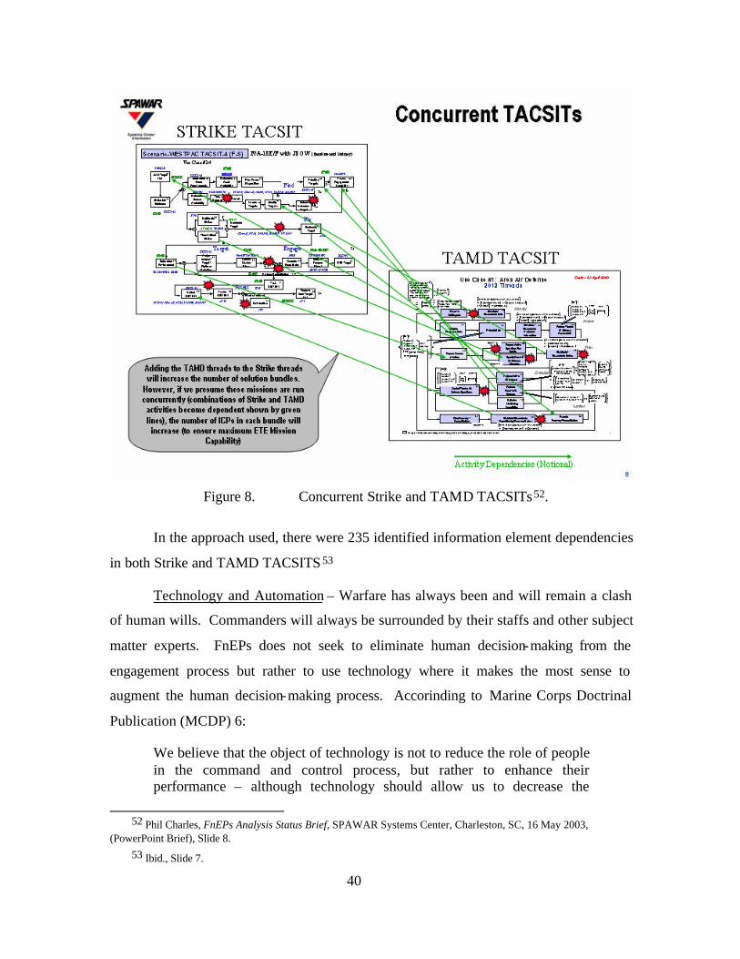
40
Figure 8. Concurrent Strike and TAMD TACSITs 52.
In the approach used, there were 235 identified information element dependencies
in both Strike and TAMD TACSITS 53
Technology and Automation – Warfare has always been and will remain a clash
of human wills. Commanders will always be surrounded by their staffs and other subject
matter experts. FnEPs does not seek to eliminate human decision-making from the
engagement process but rather to use technology where it makes the most sense to
augment the human decision-making process. Accorinding to Marine Corps Doctrinal
Publication (MCDP) 6:
We believe that the object of technology is not to reduce the role of people in the command and control process, but rather to enhance their performance – although technology should allow us to decrease the
52 Phil Charles, FnEPs Analysis Status Brief, SPAWAR Systems Center, Charleston, SC, 16 May 2003,
(PowerPoint Brief), Slide 8. 53 Ibid., Slide 7.

41
number of people involved in the process . . . Technology should seek to automate routine functions which machines can accomplish more efficiently than people in order to free people to focus on the aspects of command and control which require judgment and intuition.54
FnEPs will likely never replace judgment and intuition; however, ABMA functionality
will enhance the decision-making process for the commander and their staff.
54 U.S. Marine Corps, MCDP-6 Command and Control, (Washington, DC, 4 October 1996), 136.

42
THIS PAGE INTENTIONALLY LEFT BLANK
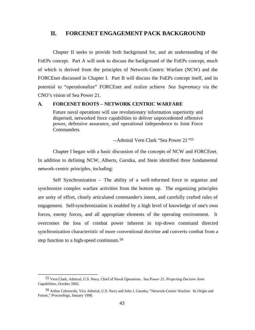
43
II. FORCENET ENGAGEMENT PACK BACKGROUND
Chapter II seeks to provide both background for, and an understanding of the
FnEPs concept. Part A will seek to discuss the background of the FnEPs concept, much
of which is derived from the principles of Network-Centric Warfare (NCW) and the
FORCEnet discussed in Chapter I. Part B will discuss the FnEPs concept itself, and its
potential to “operationalize” FORCEnet and realize achieve Sea Supremacy via the
CNO’s vision of Sea Power 21.
A. FORCENET ROOTS – NETWORK CENTRIC WARFARE
Future naval operations will use revolutionary information superiority and dispersed, networked force capabilities to deliver unprecedented offensive power, defensive assurance, and operational independence to Joint Force Commanders.
--Admiral Vern Clark “Sea Power 21”55
Chapter I began with a basic discussion of the concepts of NCW and FORCEnet.
In addition to defining NCW, Alberts, Garstka, and Stein identified three fundamental
network-centric principles, including:
Self Synchronization – The ability of a well- informed force to organize and
synchronize complex warfare activities from the bottom up. The organizing principles
are unity of effort, clearly articulated commander's intent, and carefully crafted rules of
engagement. Self-synchronization is enabled by a high level of knowledge of one's own
forces, enemy forces, and all appropriate elements of the operating environment. It
overcomes the loss of combat power inherent in top-down command directed
synchronization characteristic of more conventional doctrine and converts combat from a
step function to a high-speed continuum.56
55 Vern Clark, Admiral, U.S. Navy, Chief of Naval Operations. Sea Power 21: Projecting Decisive Joint
Capabilities, October 2002.
56 Arthur Cebrowski, Vice Admiral, U.S. Navy and John J. Garstka, “Network-Centric Warfare: Its Origin and Future,” Proceedings, January 1998.
44
Remote Sensor Engagements – Historically, DoD has focused on platform-centric
operations, whereby combat power is often sub-optimized due to the fact platforms are
unable to generate engagement quality information at ranges greater than or equal to the
maximum engagement range of the platform’s organic weapons. As an example, recall
the discussion of AEGIS and CEC in Chapter I. In contrast, network-centric operations
focus on engagements facilitated via robust networks and digital data links that will allow
the optimized use of weapons and sensors independent of platform restrictions.
Shared Battlespace Awareness - This concept is often mistakenly considered as a
single picture or a perspective that must be common amongst all users or participants.
Actually, NCW holds that battlespace awareness really exists in a distributed form. From
the user’s perspective, only a slice of “operational picture” is available at any given time.
This view can take the form of either a particular detail or a more general, overall
perspective. The ability to move up and down these levels of abstraction without
introducing distortions is a critical aspect of such an operational picture.
The following figure illustrates the military as a Network-Centric Enterprise and
relates these network-centric principles via a model that graphically depicts the definition
of NCW and the network-centric principles discussed above.
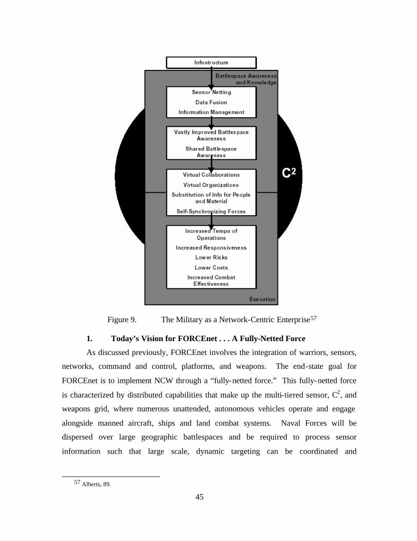
45
Figure 9. The Military as a Network-Centric Enterprise57
1. Today’s Vision for FORCEnet . . . A Fully-Netted Force
As discussed previously, FORCEnet involves the integration of warriors, sensors,
networks, command and control, platforms, and weapons. The end-state goal for
FORCEnet is to implement NCW through a “fully-netted force.” This fully-netted force
is characterized by distributed capabilities that make up the multi-tiered sensor, C2, and
weapons grid, where numerous unattended, autonomous vehicles operate and engage
alongside manned aircraft, ships and land combat systems. Naval Forces will be
dispersed over large geographic battlespaces and be required to process sensor
information such that large scale, dynamic targeting can be coordinated and
57 Alberts, 89.
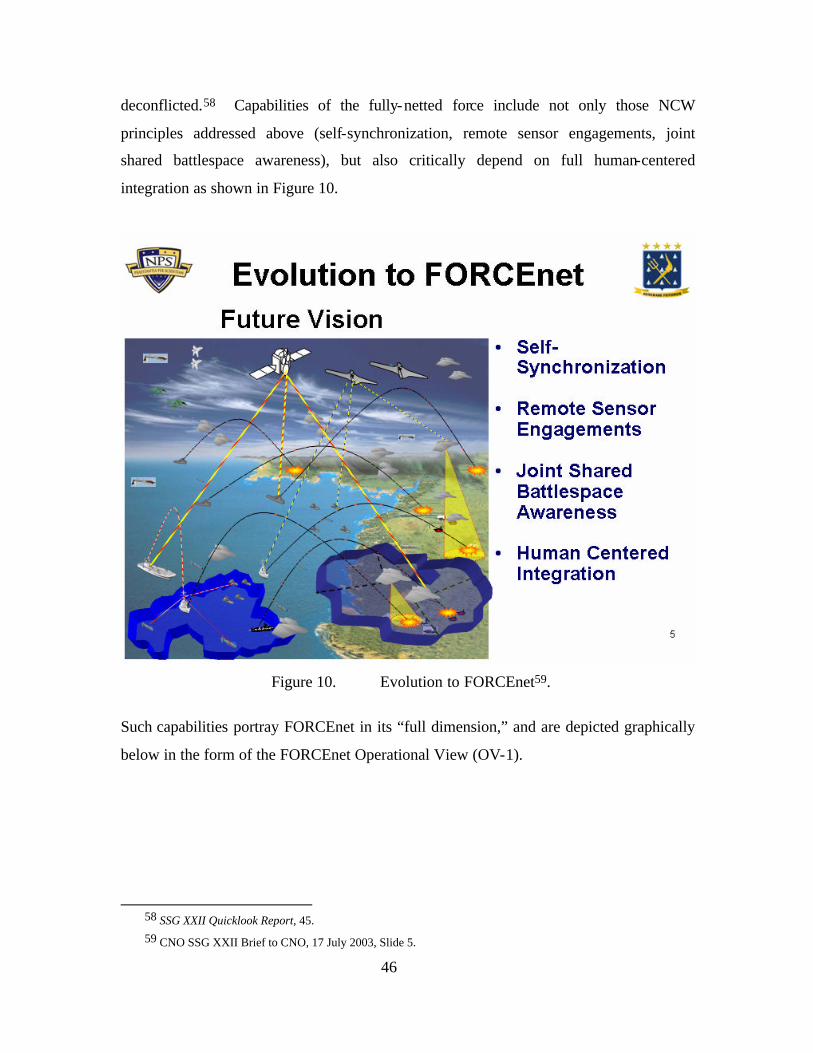
46
deconflicted.58 Capabilities of the fully-netted force include not only those NCW
principles addressed above (self-synchronization, remote sensor engagements, joint
shared battlespace awareness), but also critically depend on full human-centered
integration as shown in Figure 10.
Figure 10. Evolution to FORCEnet59.
Such capabilities portray FORCEnet in its “full dimension,” and are depicted graphically
below in the form of the FORCEnet Operational View (OV-1).
58 SSG XXII Quicklook Report, 45. 59 CNO SSG XXII Brief to CNO, 17 July 2003, Slide 5.
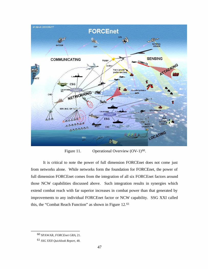
47
Figure 11. Operational Overview (OV-1)60.
It is critical to note the power of full dimension FORCEnet does not come just
from networks alone. While networks form the foundation for FORCEnet, the power of
full dimension FORCEnet comes from the integration of all six FORCEnet factors around
those NCW capabilities discussed above. Such integration results in synergies which
extend combat reach with far superior increases in combat power than that generated by
improvements to any individual FORCEnet factor or NCW capability. SSG XXI called
this, the “Combat Reach Function” as shown in Figure 12.61
60 SPAWAR, FORCEnet GRA, 21. 61 SSG XXII Quicklook Report, 48.
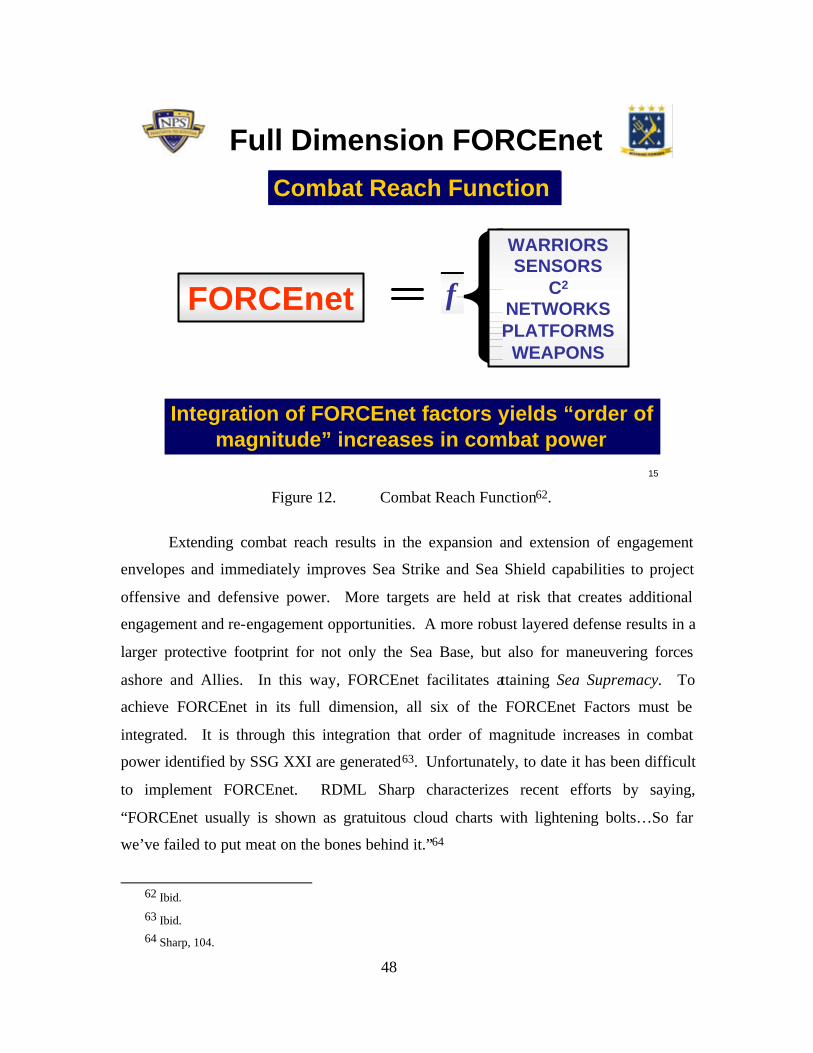
48
15
Full Dimension FORCEnet
FORCEnet f
WARRIORSSENSORS
C2
NETWORKSPLATFORMSWEAPONS
Integration of FORCEnet factors yields “order of magnitude” increases in combat power
Extended Combat ReachCombat Reach Function
Figure 12. Combat Reach Function62.
Extending combat reach results in the expansion and extension of engagement
envelopes and immediately improves Sea Strike and Sea Shield capabilities to project
offensive and defensive power. More targets are held at risk that creates additional
engagement and re-engagement opportunities. A more robust layered defense results in a
larger protective footprint for not only the Sea Base, but also for maneuvering forces
ashore and Allies. In this way, FORCEnet facilitates attaining Sea Supremacy. To
achieve FORCEnet in its full dimension, all six of the FORCEnet Factors must be
integrated. It is through this integration that order of magnitude increases in combat
power identified by SSG XXI are generated63. Unfortunately, to date it has been difficult
to implement FORCEnet. RDML Sharp characterizes recent efforts by saying,
“FORCEnet usually is shown as gratuitous cloud charts with lightening bolts…So far
we’ve failed to put meat on the bones behind it.”64
62 Ibid.
63 Ibid. 64 Sharp, 104.
49
As discussed in Chapter IV, successful network design requires 1) The definition
of the capabilities desired for the network, and 2) A functional decomposition of these
capabilities in order to determine the requirements for the network. Similarly, NCW and
NCO must be functionally decomposed in order to determine the requirements necessary
to build FORCEnet. In technical networking terms, these requirements will translate into
the technology, topologies, protocols, and standards necessary to “build” FORCEnet.
Although this decomposition remains relatively vague and indeterminate in terms of the
development of specific requirements for FORCEnet, Naval Network Warfare Command
(NAVNETWARCOM) published the “FORCEnet Initial Capabilities Document (ICD)
(Coordination Draft) on 5 February 2003. The FORCEnet ICD contains a preliminary
compilation of FORCEnet functional requirements. Subsequently on 8 April 2003,
SPAWAR, the chief engineers for FORCEnet, released a FORCEnet Government
Reference Architecture (GRA) designed to “describe a vision for the Naval FORCEnet
initiative”. 65 The GRA was later updated and released as the FORCEnet Architecture
Vision on 18 July 2003. Finally, the FORCEnet Architecture and Standards Document
(Vols. I and II) were released on 3 Nov 2003. Figure 13 depicts the various levels of
system engineering architectural views presented in these documents.
65 FORCEnet GRA.
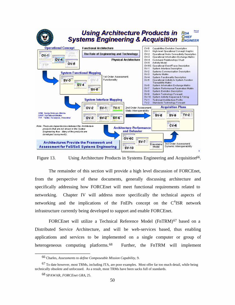
50
Figure 13. Using Architecture Products in Systems Engineering and Acquisition66.
The remainder of this section will provide a high level discussion of FORCEnet,
from the perspective of these documents, generally discussing architecture and
specifically addressing how FORCEnet will meet functional requirements related to
networking. Chapter IV will address more specifically the technical aspects of
networking and the implications of the FnEPs concept on the C4ISR network
infrastructure currently being developed to support and enable FORCEnet.
FORCEnet will utilize a Technical Reference Model (FnTRM)67 based on a
Distributed Service Architecture, and will be web-services based, thus enabling
applications and services to be implemented on a single computer or group of
heterogeneous computing platforms.68 Further, the FnTRM will implement
66 Charles, Assessments to define Composeable Mission Capability, 9.
67 To date however, most TRMs, including JTA, are poor examples. Most offer far too much detail, while being technically obsolete and unfocused. As a result, most TRMs have been sacks full of standards.
68 SPAWAR, FORCEnet GRA, 25.
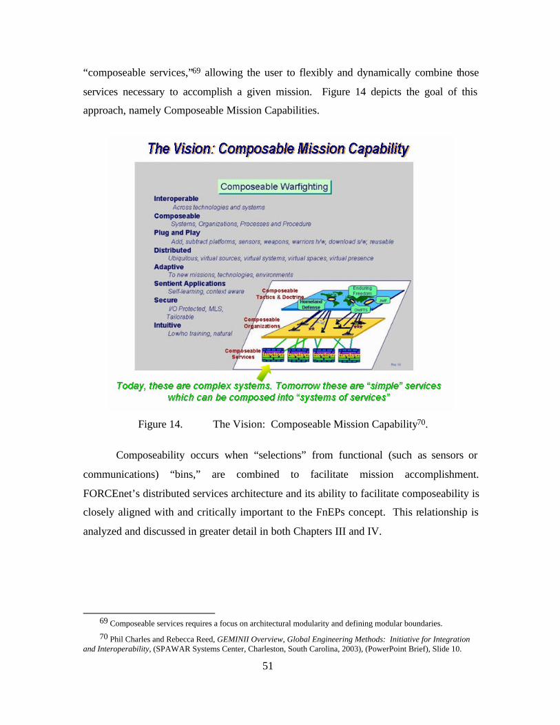
51
“composeable services,”69 allowing the user to flexibly and dynamically combine those
services necessary to accomplish a given mission. Figure 14 depicts the goal of this
approach, namely Composeable Mission Capabilities.
Figure 14. The Vision: Composeable Mission Capability70.
Composeability occurs when “selections” from functional (such as sensors or
communications) “bins,” are combined to facilitate mission accomplishment.
FORCEnet’s distributed services architecture and its ability to facilitate composeability is
closely aligned with and critically important to the FnEPs concept. This relationship is
analyzed and discussed in greater detail in both Chapters III and IV.
69 Composeable services requires a focus on architectural modularity and defining modular boundaries.
70 Phil Charles and Rebecca Reed, GEMINII Overview, Global Engineering Methods: Initiative for Integration and Interoperability, (SPAWAR Systems Center, Charleston, South Carolina, 2003), (PowerPoint Brief), Slide 10.
52
FnTRM will also ensure the network infrastructure is highly available, reliable,
scalable, and will ensure robust security functionality. In order to accomplish all this, the
FnTRM will be based on a four- layer architecture (not to be confused with the traditional
four-layer architecture discussed in Chapter IV that parallels modern commercial
Enterprise Architectures,) and includes the following functionality:71
• Client Side Presentation Layer
• Client Side Business Logic
• Server Side Presentation Layer
• Server Side Business Logic
• Enterprise Information Systems Layer (Infrastructure)
Finally, the FnTRM will make maximum use of commercial standards. This will
ensure increased interoperability and the ability to leverage, rather that duplicate,
supporting infrastructure and services. Some of the key existing and emerging industry
and DoD standards the FnTRM intends to be implemented include:72
• Joint Technical Architecture
• IEEE 802 (wireless) profiled for FORCEnet
• IPv6
As discussed previously, NAVNETWARCOM published the FORCEnet ICD,
which contained a preliminary compilation of FORCEnet functional requirements.
Subsequently, the FORCEnet GRA and Architecture Vision documents described “a
vision for the Naval FORCEnet initiative”. 73 As set forth in these documents, FORCEnet
functional requirements include:74
• Provide dynamic, multi-path and survivable networks
• Conduct distributed, collaborative command and control
• Provide expeditionary, multi-tiered sensor and weapon information
71 SPAWAR, FORCEnet GRA, 25. 72 SPAWAR, FORCEnet GRA, 27.
73 Ibid.
74 SPAWAR, Code 05, Office of the Chief Engineer.,FORCEnet Initial Capabilities Document (ICD), (Coordination Draft, 5 February 2003), 22.
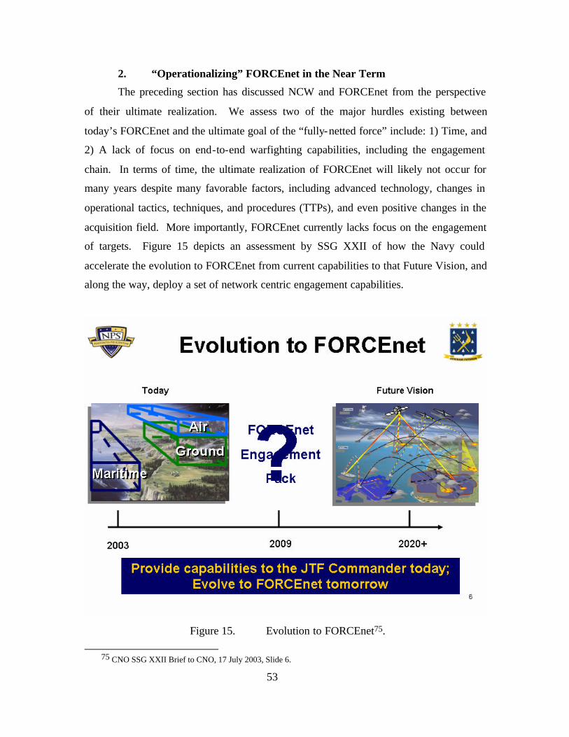
53
2. “Operationalizing” FORCEnet in the Near Term
The preceding section has discussed NCW and FORCEnet from the perspective
of their ultimate realization. We assess two of the major hurdles existing between
today’s FORCEnet and the ultimate goal of the “fully-netted force” include: 1) Time, and
2) A lack of focus on end-to-end warfighting capabilities, including the engagement
chain. In terms of time, the ultimate realization of FORCEnet will likely not occur for
many years despite many favorable factors, including advanced technology, changes in
operational tactics, techniques, and procedures (TTPs), and even positive changes in the
acquisition field. More importantly, FORCEnet currently lacks focus on the engagement
of targets. Figure 15 depicts an assessment by SSG XXII of how the Navy could
accelerate the evolution to FORCEnet from current capabilities to that Future Vision, and
along the way, deploy a set of network centric engagement capabilities.
Figure 15. Evolution to FORCEnet75.
75 CNO SSG XXII Brief to CNO, 17 July 2003, Slide 6.
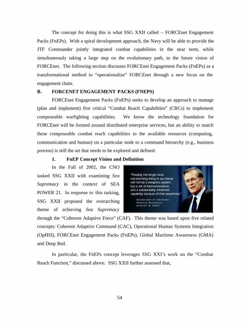
54
The concept for doing this is what SSG XXII called – FORCEnet Engagement
Packs (FnEPs). With a spiral development approach, the Navy will be able to provide the
JTF Commander jointly integrated combat capabilities in the near term, while
simultaneously taking a large step on the evolutionary path, to the future vision of
FORCEnet. The following section discusses FORCEnet Engagement Packs (FnEPs) as a
transformational method to “operationalize” FORCEnet through a new focus on the
engagement chain.
B. FORCENET ENGAGEMENT PACKS (FNEPS)
FORCEnet Engagement Packs (FnEPs) seeks to develop an approach to manage
(plan and implement) five critical “Combat Reach Capabilities” (CRCs) to implement
composeable warfighting capabilities. We know the technology foundation for
FORCEnet will be formed around distributed enterprise services, but an ability to match
these composeable combat reach capabilities to the available resources (computing,
communication and human) on a particular node to a command hierarchy (e.g., business
process) is still the art that needs to be explored and defined.
1. FnEP Concept Vision and Definition
In the Fall of 2002, the CNO
tasked SSG XXII with examining Sea
Supremacy in the context of SEA
POWER 21. In response to this tasking,
SSG XXII proposed the overarching
theme of achieving Sea Supremacy
through the “Coherent Adaptive Force” (CAF). This theme was based upon five related
concepts: Coherent Adaptive Command (CAC), Operational Human Systems Integration
(OpHSI), FORCEnet Engagement Packs (FnEPs), Global Maritime Awareness (GMA)
and Deep Red.
In particular, the FnEPs concept leverages SSG XXI’s work on the “Combat
Reach Function,” discussed above. SSG XXII further assessed that,
55
By implementing the Combat Reach Function, FnEPs will provide net-centric engagement capabilities to the Joint war fighter in the near term (Block I, 2009). These “Packs” will support a spiral development effort that leads incrementally to a fully integrated Joint Force. A capabilities-based approach will support “Pack” development providing mission-to-mission distributed services.76
a. What is a “Pack”
As discussed previously in the definition section, each FnEPs “Pack” will
be an ensemble of FORCEnet factors (i.e. warriors, sensors, C2 systems, networks,
platforms, and weapons) that are generally integrated around and across particular
Mission Capability Packages (MCPs) such as Strike or Theater Area Missile Defense
(TAMD). “Packs” are finite collections of small pieces of warfighting functionality
loosely joined to address a threat. Most importantly, “packs” will bind not just technical,
system functionality, but humans and business processes in new collaborative ways. The
FnEPs Concept represents the operational construct for FORCEnet and demonstrates the
power of FORCEnet by integrating a specific set of joint sensors, platforms, weapons,
warriors, networks and command & control systems, for the purpose of performing
mission-specific engagements. Initial pack asset allocation and configuration to
constitute a pack will be based on a specific threat or mission; however, the capability to
dynamically re-configure and re-allocate assets “on the fly,” to reconstitute a new pack
will enable cross-mission engagement capabilities. Integrating the six FORCEnet factors
must focus on enabling five critical functions called the “Combat Reach Capabilities
(CRCs)”. These CRCs are: Integrated Fire Control (IFC), Automated Battle
Management Aids (ABMAs), Composite Tracking (CT), Composite Combat
Identification (CCID), and Common/Single Integrated Pictures (CP). Ultimately, FnEPs
will help “operationalize” FORCEnet by demonstrating a network-centric operational
construct that supports an increase in combat reach and provides an order of magnitude
increase in combat power by creating more effective engagements, better sensor-shooter-
weapon assignments and improved utilization of assets. FnEPs achieves fully integrated
joint capabilities focused on the engagement chain, and represents a revolutionary
transformation in Naval operations complimentary to FORCEnet, SEA POWER 21, and
76 SSG XXII Readahead to CNO, 1.
56
Sea Supremacy. Packs provide tightly integrated end-to-end engagement capabilities
through three distinct information flow domains of Intelligence, Surveillance and
Reconnaissance (ISR), Command and Control (C2) and Fire Control (FC). Such
integration will remain loosely coupled; however, ensuring FnEPs will be inherently
flexible, scalable, and focused on supporting the full spectrum of threat engagement,
including detection, tracking, identification, sensor and weapon management, fire control
solution generation, battle damage assessment, and re-engagement actions. Finally,
FnEPs will be the result of a spiral development process, which leads incrementally to a
fully integrated joint force.
While such descriptions generally highlight the importance of integration
and interoperability of systems to both the FORCEnet and FnEPs concepts, several key
aspects differentiate FnEPs from current FORCEnet initiatives.77 FnEPs:
• Leverage joint assets
• Demonstrate adaptability across multiple mission areas
• Focus on the Engagement Chain
• Can be fielded in the near-term
The following section briefly discusses each of these
Joint – “Packs” will be developed as Joint systems-of-systems
distinguishing FORCEnet from the Army Future Combat System (FCS) and Air Force C2
Constellation. Ultimately, this jointness would extend to include full- interoperability
across coalition and allied forces as well.
Adaptive – “Packs” will provide robust sensor-shooter-weapon linkages
allowing components to cross-connect “on-the-fly” supporting mission area-to-mission
area engagements. Unlike the case with current weapons systems; “pack” assets are not
permanently or specifically tasked to support specific MCPs or “bolted together” into
tightly coupled, stove-piped, or proprietary systems. Instead, “packs” form, engage, and
disperse in response to specific tasks or missions, with pack assets assigned dynamically
on an as-needed basis. This concept was introduced and discussed in Chapter I as the
77 Ibid.
57
“Pooled Assets Paradigm.” In this way, individual “packs” are capable of dynamically
adapting, not only to various targets or missions within a given MCP, but between
different MCPs altogether, “on the fly,” and in response to changing threat scenarios.
The adaptability of the “packs” is best exhibited by the ability of the same
set of Fn “Factors” to engage threats from one mission area to another “on-the-fly”. For
example, a Missile Defense (MD) “pack” involved in integrated air defense operations,
can use sensing information generated by national assets and airborne surveillance
platforms to find, fix, target, track and assess moving and mobile ground targets, passing
that information to multi-mission “shooters” and their weapons (e.g. DDGs, Fighters,
UAVs, others). The same set of assets can provide optimized sensor-shooter-weapon to
target assignments to neutralize ground targets (or maritime surface contacts) “in-stride”
of the MD operations. These attack operations adaptively support MD, Strike, SuW, and
other mission areas.
It is critical to note that while FnEPs adaptability is specifically enabled by
the CRCs identified previously, more generally, Pack assets or “FORCEnet Factors”
must be system engineered to support the five CRCs through a high level of integration
and interoperability. Adaptability will require common interface protocols, and
reasoning algorithms. Further, human machine integration (HMI) must be built into the
FORCEnet “Factors” to support the sharing, evaluation, and passing (to weapons in-
flight) of composite tracking and identification information. Automated Battle
Management Aids (ABMAs) aid both the tactical and operational commander by
supporting composite common threat evaluations, dynamically-bidded preferred shot
recommendations, and dynamic- interactive sensor coordination. This kind of
adaptability supports distributed combat operations and enables the JTF commander to
extend his combat reach while efficiently managing his/her resources. As an analogy,
consider the human body and its immune system that uses antigens to discriminate
between, and in some cases attack certain protein chains. Similarly, FnEPs when
threatened, produce defenses in the form of “Packs” which are volumetric,
discriminative, and adaptive based on the threat situation.
58
Engagement Oriented – “Packs” will demonstrate application of combat
power by: self-synchronization through the use of ABMAs; supporting cross-platform
and cross-service IFC; and developing theater-wide shared battle space awareness
through CT, CCID, and CP. Ultimately, FnEPs seeks to utilize distributed forces to
achieve massed effects against the complete spectrum of missions, targets, and
adversaries.
Field Near-Term Net-Centric Capabilities – Technology supporting the
five CRCs is available today, along with intra- and inter-service system engineering
know how. Initial Operating Capability of the first Engagement Pack is achievable in
five years from program initiation (Block I IOC in FY09).
The remainder of Chapter II will highlight how a specific set of five
Combat Reach Capabilities (CRCs) will make the FnEPs concept possible.
2. Combat Reach Capabilities
To show how significant improvements in
combat reach can be accomplished by
“operationalizing” FORCEnet via the FnEPs
concept, it is useful to consider the following
analog. Today the Internet and other commercial
network infrastructures are continuing to evolve beyond the mere passing of information,
to the point these networks support and facilitate the ‘work’ of the business world
transactions (e.g., e-business, e-commerce, e-trade, etc.). Today and in the future,
military networks should be similarly evolving to a level where they support the
warfighting ‘work’ of conducting engagements. In this way, FORCEnet can be
“operationalized” for use in a military setting in much the same way the Internet has been
“operationalized” for use in a business enterprise setting. Fundamentally, FnEPs
provides the overarching framework and capabilities necessary to drive integration and
interoperability requirements. This can be accomplished across existing systems,
programs, and other related initiatives, thereby reducing the risk level associated with
new sytems and technology.
“Change your thoughts and you change your world.” - The Rev. Dr. Norman Vincent Peale
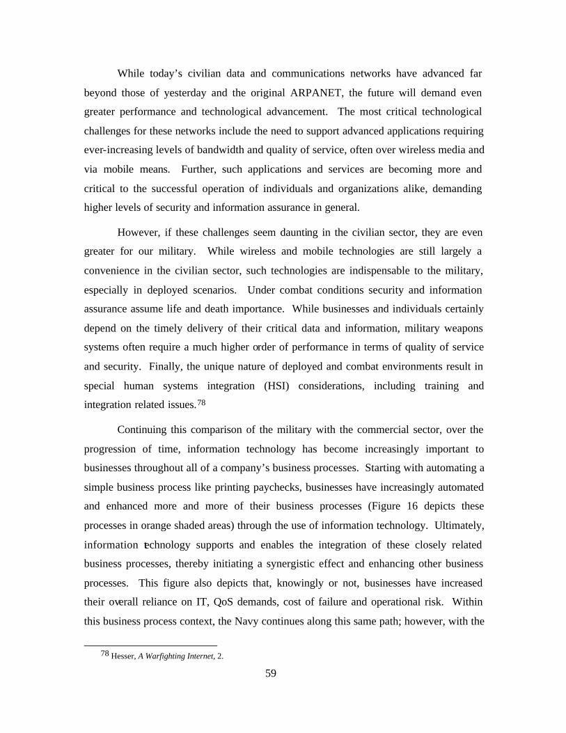
59
While today’s civilian data and communications networks have advanced far
beyond those of yesterday and the original ARPANET, the future will demand even
greater performance and technological advancement. The most critical technological
challenges for these networks include the need to support advanced applications requiring
ever-increasing levels of bandwidth and quality of service, often over wireless media and
via mobile means. Further, such applications and services are becoming more and
critical to the successful operation of individuals and organizations alike, demanding
higher levels of security and information assurance in general.
However, if these challenges seem daunting in the civilian sector, they are even
greater for our military. While wireless and mobile technologies are still largely a
convenience in the civilian sector, such technologies are indispensable to the military,
especially in deployed scenarios. Under combat conditions security and information
assurance assume life and death importance. While businesses and individuals certainly
depend on the timely delivery of their critical data and information, military weapons
systems often require a much higher order of performance in terms of quality of service
and security. Finally, the unique nature of deployed and combat environments result in
special human systems integration (HSI) considerations, including training and
integration related issues.78
Continuing this comparison of the military with the commercial sector, over the
progression of time, information technology has become increasingly important to
businesses throughout all of a company’s business processes. Starting with automating a
simple business process like printing paychecks, businesses have increasingly automated
and enhanced more and more of their business processes (Figure 16 depicts these
processes in orange shaded areas) through the use of information technology. Ultimately,
information technology supports and enables the integration of these closely related
business processes, thereby initiating a synergistic effect and enhancing other business
processes. This figure also depicts that, knowingly or not, businesses have increased
their overall reliance on IT, QoS demands, cost of failure and operational risk. Within
this business process context, the Navy continues along this same path; however, with the
78 Hesser, A Warfighting Internet, 2.
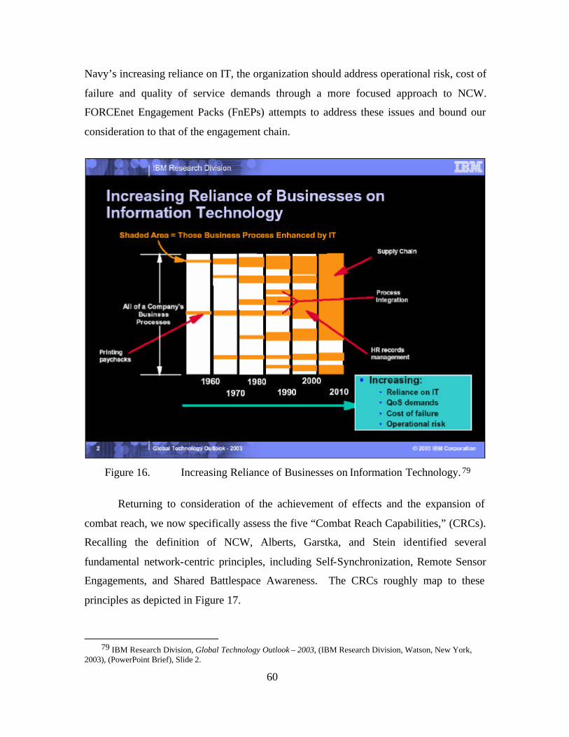
60
Navy’s increasing reliance on IT, the organization should address operational risk, cost of
failure and quality of service demands through a more focused approach to NCW.
FORCEnet Engagement Packs (FnEPs) attempts to address these issues and bound our
consideration to that of the engagement chain.
Figure 16. Increasing Reliance of Businesses on Information Technology. 79
Returning to consideration of the achievement of effects and the expansion of
combat reach, we now specifically assess the five “Combat Reach Capabilities,” (CRCs).
Recalling the definition of NCW, Alberts, Garstka, and Stein identified several
fundamental network-centric principles, including Self-Synchronization, Remote Sensor
Engagements, and Shared Battlespace Awareness. The CRCs roughly map to these
principles as depicted in Figure 17.
79 IBM Research Division, Global Technology Outlook – 2003, (IBM Research Division, Watson, New York,
2003), (PowerPoint Brief), Slide 2.
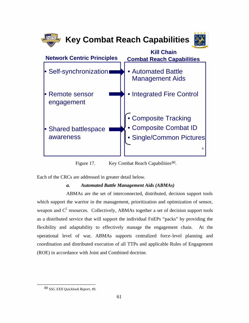
61
9
Key Combat Reach Capabilities
• Self-synchronization
• Remote sensor engagement
• Shared battlespace awareness
Network Centric PrinciplesKill Chain
Combat Reach Capabilities
• Automated Battle Management Aids
• Integrated Fire Control
• Composite Tracking• Composite Combat ID• Single/Common Pictures
Figure 17. Key Combat Reach Capabilities80.
Each of the CRCs are addressed in greater detail below.
a. Automated Battle Management Aids (ABMAs)
ABMAs are the set of interconnected, distributed, decision support tools
which support the warrior in the management, prioritization and optimization of sensor,
weapon and C2 resources. Collectively, ABMAs together a set of decision support tools
as a distributed service that will support the individual FnEPs “packs” by providing the
flexibility and adaptability to effectively manage the engagement chain. At the
operational level of war, ABMAs supports centralized force- level planning and
coordination and distributed execution of all TTPs and applicable Rules of Engagement
(ROE) in accordance with Joint and Combined doctrine.
80 SSG XXII Quicklook Report, 49.
62
b. ABMAs Characteristics and Requirements
• Distributed and networked
• A set of interconnected decision support tools
• A set of action and reaction agents that monitor the collective, but distributed, ‘state-space’ of the nodal characteristics of the pack assets within this networked, virtua l environment
• Requires common algorithms and inputs, detailed information about system members, and a means to codify options to ensure consistency and quality of decision support information. Such tools will reduce complexity to manage available mission area resources.
• Ability to address the challenges posed by the management of widely dispersed, highly technical assets over extended geographical areas. In the context of the TAMD mission area, expanded air and missile defense resources throughout the joint battlespace require selecting a proper mix of assets quickly and accurately, and exercising effective control in a dynamic environment. ABMAs represent the set of tools Commanders need to take advantage of the extended battlespace made available by the CRCs and the distributed services supported by FORCEnet in order to efficiently and effectively engage the enemy.
• Ability support a common threat evaluation (CTE), assessment, and prioritization
• Ability to make dynamic-bidded shot opportunities and preferred shooter recommendations.
• Ability to facilitate distributed engagement resource allocation and coordination
• Ability to conduct distributed sensor coordination (DSC)
• Ability to generate, and when approved by humans to do so, implement warfighting options executable in (near) real- time.
• Ability to constitute a mission ‘pack’ on request by pulling from the pool of networked assets in response to specific tasks, mission requirements or threat, assigned dynamically and only on an as-needed basis. ABMA manages the adaptive, reconfigurable, flexible, and time-sensitive nature of the pack. ABMAs’ ability to manage those pack assets may be enabled using a common or unique set of MIBs (like SNMP) designed to manage ALL pack network nodes. ABMAs are able to disperse a “pack” (or release “pack” assets back to the networked environment or to another “pack”) once the threat has disappeared or been neutralized.
• Ability to act in a ‘passive’ mode by listening to network assets and distributed services (i.e., ‘sensing’ agents in a networked-virtual environments model.)
63
• Ability to act in an ‘active’ mode by actively commanding and adapting to the threat environment by tasking assets as part of given FnEP “packs” (e.g. ‘reacting’ agents in the networked-virtual environment s model.) Such command functions might also include monitoring and directing resources to reposition themselves for optimum sensor coverage.
• Ability to help minimize the occurrence of combat weapon system mismatches where engagements would be a sub-optimal use of weapon kinematic (range) capabilities. As an example, if a weapon has a kinematic capability greater than that of the organic sensor or fire control system of the firing platform, unless “handed off”, or “forward-passed” to another sensor.
• Ability to pass relevant data (e.g., radar tracks and associated measurement data) amongst all joint ‘pack’ components and provide deconfliction options between pack components.
• Ability to assist in multiplatform sensor integration or reconfiguration, such that dynamic sensor assignments or retaskings can be made in order to generate requisite fidelity of data to make appropriate sensor-weapon pairings.
• Ability to configure situationally-dependant network architectures providing dynamic bandwidth allocation and alternate path redundancy to aid in survivability and redundancy.
• Manage a set of composeable warfighting pack assets through distributed enterprise services and be able to optimize these composeable combat reach capabilities according to available resources (computing, communication and human) on a particular node to a command hierarchy (e.g., business process).
• Ability to support common composite threat assessment, positive hostile ID (95% common among participating units), and prioritization through multi-source automated fusion. Subsequently, calculate weapon to target error baskets and assign/prioritize sensor-shooter-weapon linkages. These linkages should be made by dynamic-bidded shot opportunities and creating preferred shooter recommendations based on all sensors and weapons delivery platforms/resources available and engagement geometries encountered.
• Assist in the “self-synchronization” of pack assets, which is the ability of a well- informed force to organize and synchronize complex warfare activities from the bottom up. The organizing principles are unity of effort, clearly articulated commander's intent, and carefully crafted rules of engagement. Self-synchronization is enabled by a high level of knowledge of one's own forces, enemy forces, and all appropriate elements of the operating environment. It overcomes the loss of combat
64
power inherent in top-down command directed synchronization characteristic of more conventional doctrine and converts combat from a step function to a high-speed continuum.
• Minimize unengaged threats (free riders) while also minimizing unintentional redundant engagements (over engagements)
• Logistics system information, when integrated into a “pack,” will be able to provide just-in-time logistic supplies, maintenance requirements and anticipatory warfighting needs. These logistics systems are integral FnEP pack factors and will be able to demonstrate the application of combat effectiveness of “user interface agents” Included in this functionality is the ability to automatically notify crews and schedule required corrective maintenance actions when ammunition or other warfighting supplies need replenishment. Such notification will be based on in- line condition or utilization of monitoring data, and will serve to update commanders and other decision makers regarding the status of their forces. Other related capabilities include the ability to compute mileage a vehicle can travel based on fuel capacity and proposed mission parameters.
• Modeling and simulation systems integrated into a “pack” could possibly capture and store, for later use and analysis, real-world warfighting activities to be used in doctrine refinement or new tactical procedures. The use of modeling and simulation systems as “quiet observers” of “pack” activity could help answer many questions such as; when and where should packs form, how “packs” should form, what resources should “packs” use, when should those resources be used and from whom, threat engagement, better sensor-weapon-shooter linkages, etc. Modeling and simulation should have the ability to conduct real-time or off- line operational option analysis and course of action analysis which could either help with time-critical decisions in real-word operations or be used to build up the repository of ABMAs options and baseline analysis for use in a set of circumstances at a later time. Integrated modeling and simulation assets into a “pack” would be able to conduct COA analysis in (near) real time.
• The manner in which TPFDDs are produced and carried out could foreseeably be changed significantly given the ABMAs function within an FnEP. TPFDDs could be automated by the ABMAs such that plans for scheduling and movement of forces, loading of transportation (e.g., size, weight, deck space, etc.) and dispersion of routing deploying units to the AOR would be optimally planned and automatically produced. The deliberate and crisis action planning processes would take advantage of all five of the FnEP CRCs to make the strategic planning, movement and execution more automated, efficient and optimized. The automated generation and processing of TPFDD, Warning, Planning, Alert, Execute, Deployment and Fragmentary (FRAGO’s) Orders by the ABMAs and supported by integrated logistics systems using humans as decision
65
makers would make the planning products fully integrated, logistically supportable, politically acceptable, and executable within an optimized set of criteria.
c. ABMAs Performance Metrics (Notional)
• # of leakers
• # of free riders
• # of fratricide
• % total attrition
• # kills within keep-out threshold of defended assets
• Missile utilization efficiency
• # of possible Beyond Line of Sight (BLOS) engagements
• Expanded area defended per force structure
• Decision range
• # Engagement opportunities per target
• # Blue defended assets lost
• # Red not launched due to Blue engagements
• # Engagement options per target
• # Rounds used per theater
• # Rounds used per kill
• Range (negated) from defended point
• Range (engagement) per weapons range
• Distance target penetrated Blue air space
• Success of attack offensive counter air target
• 98% Threat killed in Common Reference Scenario(s)
• 1% Leakers in Common Reference Scenario(s)
• 1% Free Riders/unengaged Common Reference Scenario(s)
d. Integrated Fire Control (IFC)
This is the capability to perform beyond line-of-sight engagements using
remote sensors to support precision tracking updates to in-flight weapons. IFC is
generally responsible for the management of weapons and weapons fly-out. The
66
definition of IFC implies that this CRC be required to support real time and/or near real
time data received/transmit capability and be capable of receiving and processing real
time sensor data between IFC systems. Particular functionality of IFC also includes:
• Engage-on-remote (remote sensor provides track shooter provides uplink)
• Forward Pass (remote sensor controls weapon)
• In-Flight Target Updates (IFTU) (data updates to change the guidance of ordnance during flight)
The following sequence reflects the requirements to conduct the EOR using the Aegis
Weapon System (AWS)81
1. Sensor Detects Target 2. Target is tracked, 3. Sensor data passed to CEC sensor network 4. CEC passes sensor data to ship 5. Shipboard CEC filters sensor data, 6. AWS receives CEC Track and evaluates threat 7. AWS request additiona l Off-board sensor data via CEC 8. CEC request additional data from Sensor platform 9. Sensor platform passes additional sensor data to CEC 10. CEC sends additional Sensor data to ship 11. AWS receives CEC Track from CEC 12. AWS conducts pre-engagement calculations 13. AWS requests additional off-board sensor, via CEC 14. AWS erects missile (provides missile initial launch conditions (pitch roll,
location), fly out parameters and initial course directions 15. Off board sensor affirmatively responds to engagement requests via CEC,
schedules dedicated support 16. AWS launches weapon and establishes S band uplink 17. Off-board sensor increase reporting rate via CEC 18. AWS uplinks Off-board Sensor data till OTH 19. AWS enables inertial mid-course guidance 20. Missile receives S-band up link data (E-2C data and WCS mid-course
corrections) 21. Missile calculates own mid course corrections and compares with uplink,
fly’s independent when OTH 22. Missile seeker turns on, searches hand over basket, maneuvers, detects and
engages threat. 23. Off-board sensor provides Data on engaged track for Kill Assessment 24. AWS Performs Kill Assessment
81 Swift, Lloyd. Naval Integrated Fire Control—Counter Air, (RDA CHENG Off-Site, 10-11 September 2003),
(PowerPoint Brief), Slides 29-30.
67
e. IFC Characteristics and Requirements
• Ability to maximize the effective use of limited airborne sensor resources to support over the horizon engagements of enemy raids to defend assets ashore and afloat.
• Ability to coordinate surveillance, acquisition, and tracking coverage throughout the battle space to simultaneously support defense of theater assets ashore, area defense and self defense.
• Ability to have graceful degradation such that degraded capability is no worse than current capability and such that communications breakdowns do not result in over-engagement
• Ability to be responsive in simultaneous, multi-mission scenarios to new or maneuvering threats.
• Ability to be adaptive to control by direction, negation, etc.
• Ability to synchronize engagement coordination within fire control loops
• Ability to Forward Pass control of weapons in flight by remote tracking and control of weapon in flight to error basket.
• Ability to be consistent such that there is not ambiguity in threat prioritization
• Ability to keep message latency requirements very small for dynamic processing
• Ability to conduct In Flight Target Updates (IFTUs) to weapons in flight
• Ability to control weapons in flight from off-board sensors and sensors other than those organic sensors located on the platforms which launched the weapons.
• Ability to exploit the full kinematic range of any joint weapon system.
• Ability to launch and control weapons from any weapons delivery vehicle, manned or unmanned.
• Ability to engage on remote (EOR) where remote tracking to shooter continues to provide target uplinks to a weapon in flight.
• Ability to create increased offensive and defensive power projection.
• Ability to change focus from platform self-defense to integrated force defense and thus, create higher volume of sortie and strike rates due to effective combined arms engagement of targets.
• Ability to create target engagement solutions sooner, creating more reaction time, and multiple re-engagement opportunities should the initial engagements fail.
• Ability to handle small, time-sensitive strike threats with appropriate weapons.
68
• Ability to have weapon/sensor independent functionality, thereby reducing life cycle costs through the minimization of modifications when systems are added or deleted.
f. IFC Performance Metrics (Notional)
• RMS accuracy of track handover ID to a participant
• RMS accuracy of cue to a Fire Control Radar
• RMS accuracy of vector cue for a fighter to a target
• RMS accuracy of remote IFTU to interceptor
• % of time cue enabled fighter to acquired target at a tactically significant range (beyond enemy targeting range)
• % of time enabled fighter to engage target and get one or more shots before the merge
• Number of fighters required for DCA
• Range of intercept
• # kills within keep-out threshold of defended assets
• % of effective BLOS engagements
• Range (negated) from defended point
• Range (engagement) per weapons range
• Distance target penetrated Blue air space
• Range (negated) from defended point
• Range (engagement) per weapons range
• Distance target penetrated Blue air space
• Minimize number of free riders
• % of increase in ability to handle larger raids
• Minimize unintentional over-engagements
• % increase in engagement sustainability
• % increase in engagement effectiveness (engagement with higher probability of success is selected)
• Decreased confusion and clarified conflicting data
• % increase in depth of fire
• % increase in sortie generation
• % increase in engagement rate
• % increase in engagement volume (area coverage)
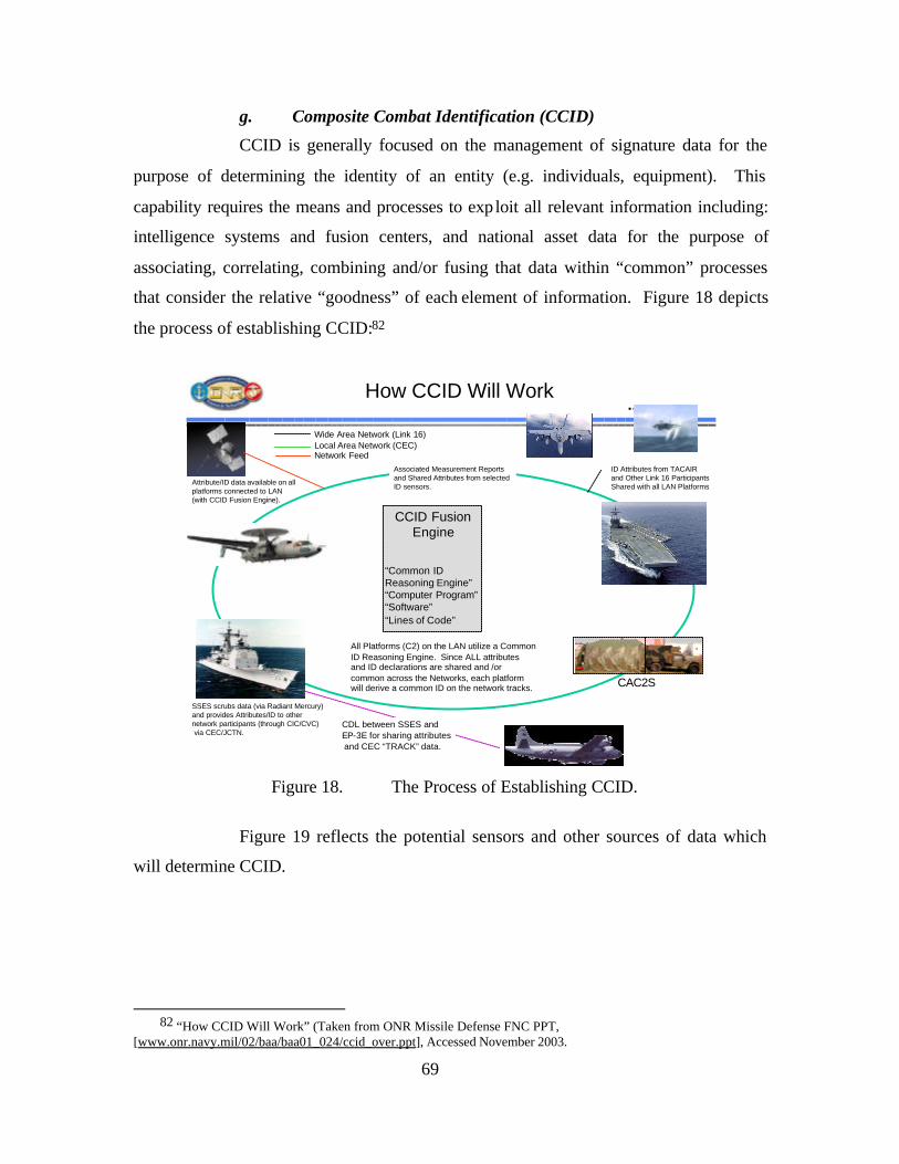
69
g. Composite Combat Identification (CCID)
CCID is generally focused on the management of signature data for the
purpose of determining the identity of an entity (e.g. individuals, equipment). This
capability requires the means and processes to exp loit all relevant information including:
intelligence systems and fusion centers, and national asset data for the purpose of
associating, correlating, combining and/or fusing that data within “common” processes
that consider the relative “goodness” of each element of information. Figure 18 depicts
the process of establishing CCID:82
How CCID Will Work
Attribute/ID data available on allplatforms connected to LAN(with CCID Fusion Engine).
All Platforms (C2) on the LAN utilize a Common ID Reasoning Engine. Since ALL attributes and ID declarations are shared and /or common across the Networks, each platformwill derive a common ID on the network tracks.
Wide Area Network (Link 16)Local Area Network (CEC)Network Feed
CDL between SSES and EP-3E for sharing attributesand CEC “TRACK” data.
Associated Measurement Reports and Shared Attributes from selectedID sensors.
ID Attributes from TACAIR and Other Link 16 ParticipantsShared with all LAN Platforms
SSES scrubs data (via Radiant Mercury) and provides Attributes/ID to other network participants (through CIC/CVC)via CEC/JCTN.
CCID Fusion Engine
“Common ID Reasoning Engine”“Computer Program”“Software”“Lines of Code”
CAC2S
Figure 18. The Process of Establishing CCID.
Figure 19 reflects the potential sensors and other sources of data which
will determine CCID.
82 “How CCID Will Work” (Taken from ONR Missile Defense FNC PPT,
[www.onr.navy.mil/02/baa/baa01_024/ccid_over.ppt], Accessed November 2003.
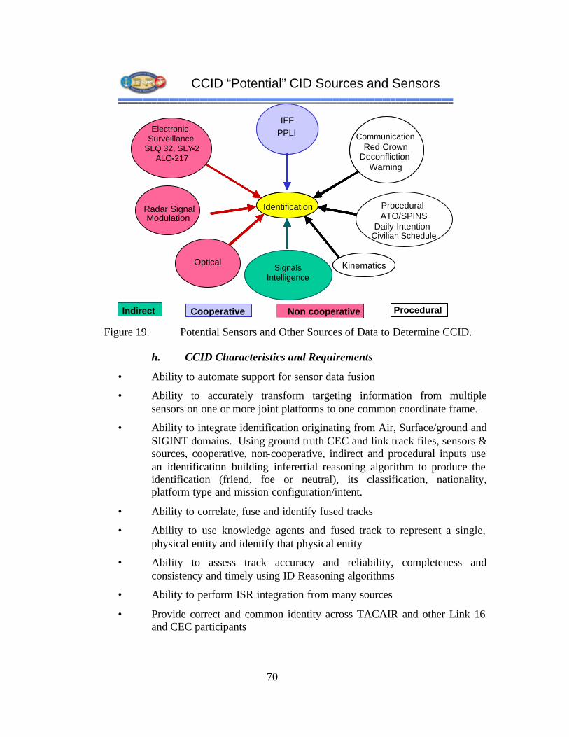
70
CCID “Potential” CID Sources and Sensors
Identification
IntelligenceSIGINT
OutboardTIBS/TDDS
Electronic Surveillance
SLQ 32, SLY-2ALQ-217
Radar SignalModulation
IFFPPLI
EPLRS
ProceduralATO/SPINS
Daily Intention
CommunicationRed Crown
DeconflictionWarning
Kinematics
Indirect
Identification
SignalsIntelligence
IFFPPLI
Civilian Schedule
CommunicationRed Crown
DeconflictionWarning
Optical Kinematics
Indirect Cooperative Non cooperative Procedural Figure 19. Potential Sensors and Other Sources of Data to Determine CCID.
h. CCID Characteristics and Requirements
• Ability to automate support for sensor data fusion
• Ability to accurately transform targeting information from multiple sensors on one or more joint platforms to one common coordinate frame.
• Ability to integrate identification originating from Air, Surface/ground and SIGINT domains. Using ground truth CEC and link track files, sensors & sources, cooperative, non-cooperative, indirect and procedural inputs use an identification building inferential reasoning algorithm to produce the identification (friend, foe or neutral), its classification, nationality, platform type and mission configuration/intent.
• Ability to correlate, fuse and identify fused tracks
• Ability to use knowledge agents and fused track to represent a single, physical entity and identify that physical entity
• Ability to assess track accuracy and reliability, completeness and consistency and timely using ID Reasoning algorithms
• Ability to perform ISR integration from many sources
• Provide correct and common identity across TACAIR and other Link 16 and CEC participants
71
• Ability to automatically take regional commercial air corridors, combine with point of origin, air tasking order and battle group protection to prepare tracks.
• Ability to fuse sensor tracks and resolve conflicts using CEC and Link 16 or other independent CID source.
• Ability to process land fixed targets and identify redundant reports on the same emitter, fuse data and convolve ellipses.
• Ability to combine emitters into sites and link sites into networks.
• Analogous to Multi-Source Integration
i. CCID Performance Metrics (Notional)
• % participants with common, clear, and accurate ID
• % of tracks with CID prior to entering AOI
• Probability a detected object is correctly classified
• Probability a detected object is correctly identified
• False ID rate
• % of airborne objects identified correctly
• % of airborne objects classified correctly
• Range at with ID or classification was made
• Time to correct ID from initial detection
• # of times a ID changes on a target
• % of ID improvement due to ID fusion
• % of time ID fusion is achieved
• % of threat objects held “in-track” upon entering AOI
• Number of Blue losses due to Air Picture
• Probability to develop/designate High Payoff Target
j. Composite Tracking (CT)
Create and maintain a network-wide track state based on all measurements
of the target made by all sensors in the network. CT is generally analogous to Sensor
Fused Tracking (SFT) and is responsible for the management of measurement level
sensor data. The following diagram graphically depicts CT.
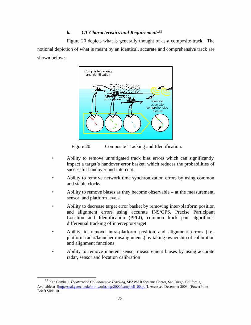
72
k. CT Characteristics and Requirements83
Figure 20 depicts what is generally thought of as a composite track. The
notional depiction of what is meant by an identical, accurate and comprehensive track are
shown below:
Figure 20. Composite Tracking and Identification.
• Ability to remove unmitigated track bias errors which can significantly
impact a target’s handover error basket, which reduces the probabilities of successful handover and intercept.
• Ability to remove network time synchronization errors by using common and stable clocks.
• Ability to remove biases as they become observable – at the measurement, sensor, and platform levels.
• Ability to decrease target error basket by removing inter-platform position and alignment errors using accurate INS/GPS, Precise Participant Location and Identification (PPLI), common track pair algorithms, differential tracking of interceptor/target
• Ability to remove intra-platform position and alignment errors (i.e., platform radar/launcher misalignments) by taking ownership of calibration and alignment functions
• Ability to remove inherent sensor measurement biases by using accurate radar, sensor and location calibration
83 Ken Cambell, Theaterwide Collaborative Tracking, SPAWAR Systems Center, San Diego, California, Available at [http://seal.gatech.edu/onr_workshop/2000/campbell_00.pdf], Accessed December 2003. (PowerPoint Brief) Slide 10.
73
l. CT Performance Metrics (Notional)
• Number of Blue losses due to Air Picture error
• Probability to develop/designate High Payoff Target
• Success of attack offensive counter air target
• Percent of detecting and tracking of all air vehicles
• Quality of tracks formed when non-composite sources are combined with composite tracks
• QoS of Composite Tracking networks as determined by latency and error rates
m. Single/Common Pictures (CP)
CP is the integrated capability to receive, correlate, and display a Common
Tactical Picture (CTP), including planning applications and theater-generated
overlays/projections (i.E., Meteorological and Oceangraphic (METOC), battleplans, force
position projections). Overlays and projections may include location of friendly, hostile,
and neutral units, assets, and reference points. The CP may include information relevant
to the tactical and strategic level of command. This includes, but is not limited to, any
geographically oriented data, planning data from Joint Operation Planning and Execution
System (JOPES), readiness data from Status of Resources and Training System
(SORTS), intelligence (including imagery overlays), reconnaissance data from the Global
Reconnaissance Information System (GRIS), weather from METOC, predictions of
nuclear, biological, and chemical (NBC) fallout, and Air Tasking Order (ATO) data.84
n. CP Characteristics and Requirements
• Common grid-reference frames
• Common correlation schemes
• Common tracking methodologies
• Time synchronization
• Common Communication protocols
o. CP Performance Metrics
• Completeness: The picture is complete when all objects are detected, tracked and reported.
84 Chairman of the Joint Chiefs of Staff Instruction (CJCSI) 3151.01. Global Command and Control System
Common Operational Picture Reporting Requirements , 10 June 1997.
74
• Clarity: The picture is clear when it does not include ambiguous or spurious tracks, there is no dualing present and tracks are not dropped.
• Continuity: The picture is continuous when the tracks are long lived and stable.
• Kinematic Accuracy: The picture is kinematically accurate when the position and velocity of a track agrees with the position and velocity of the associated object.
• ID Completeness: The ID is complete when all tracked objects are labeled in a state other than unknown.
• ID Accuracy: The ID is accurate when all tracked objects are labeled correctly.
• ID Clarity: The ID is ambiguous when a tracked object has two or more conflicting ID states.
• Commonality: The picture is common when the tracks held by each participant have the same track number, position, and ID.
As Figure 21 depicts, the integration of the six FORCEnet Factors form
the foundation upon which the five CRCs are built. However, it is the specifically
focused integration of the six FORCEnet Factors to achieve the five CRCs which will
provide increased combat power and increased combat reach.
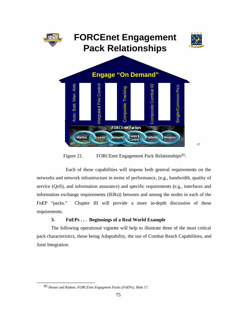
75
17
FORCEnet EngagementPack Relationships
Aut
o. B
att.
Man
. Aid
s
Inte
grat
ed F
ire C
ontro
l
Com
posi
te T
rack
ing
Com
posi
te C
omba
t ID
Sin
gle/
Com
mon
Pic
s
FORCEnet Engagement “Pack”Engage “On Demand”Engage “On Demand”
WarriorsWarriors SensorsSensors NetworksNetworks Comm &Control
Comm &Control PlatformsPlatforms WeaponsWeapons
FORCEnet FactorsFORCEnet Factors
Figure 21. FORCEnet Engagement Pack Relationships85.
Each of these capabilities will impose both general requirements on the
networks and network infrastructure in terms of performance, (e.g., bandwidth, quality of
service (QoS), and information assurance) and specific requirements (e.g., interfaces and
information exchange requirements (IERs)) between and among the nodes in each of the
FnEP “packs.” Chapter III will provide a more in-depth discussion of these
requirements.
3. FnEPs . . . Beginnings of a Real World Example
The following operational vignette will help to illustrate three of the most critical
pack characteristics, those being Adaptability, the use of Combat Reach Capabilities, and
Joint Integration.
85 Hesser and Rieken. FORCEnet Engagment Packs (FnEPs), Slide 17.
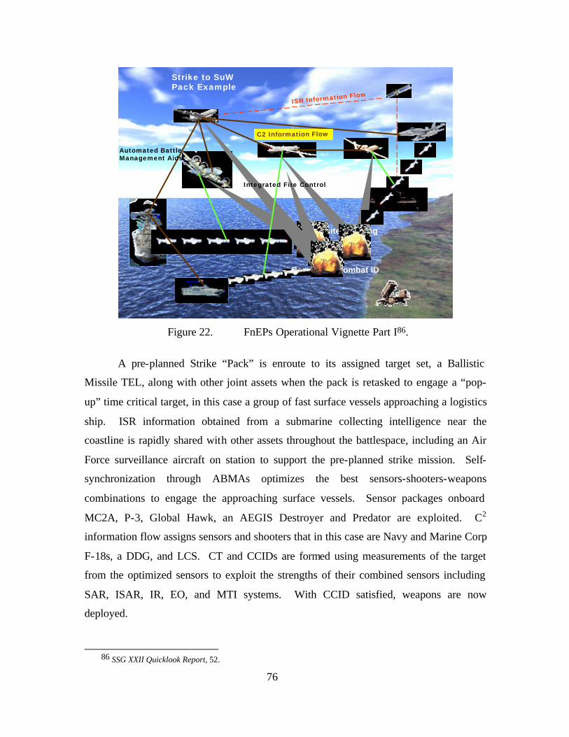
76
14
Strike to SuWPack Example
ISR Information Flow
Composite Combat ID
Composite Tracking
Integrated Fire Control
C2 Information Flow
Automated BattleManagement Aids
Figure 22. FnEPs Operational Vignette Part I86.
A pre-planned Strike “Pack” is enroute to its assigned target set, a Ballistic
Missile TEL, along with other joint assets when the pack is retasked to engage a “pop-
up” time critical target, in this case a group of fast surface vessels approaching a logistics
ship. ISR information obtained from a submarine collecting intelligence near the
coastline is rapidly shared with other assets throughout the battlespace, including an Air
Force surveillance aircraft on station to support the pre-planned strike mission. Self-
synchronization through ABMAs optimizes the best sensors-shooters-weapons
combinations to engage the approaching surface vessels. Sensor packages onboard
MC2A, P-3, Global Hawk, an AEGIS Destroyer and Predator are exploited. C2
information flow assigns sensors and shooters that in this case are Navy and Marine Corp
F-18s, a DDG, and LCS. CT and CCIDs are formed using measurements of the target
from the optimized sensors to exploit the strengths of their combined sensors including
SAR, ISAR, IR, EO, and MTI systems. With CCID satisfied, weapons are now
deployed.
86 SSG XXII Quicklook Report, 52.
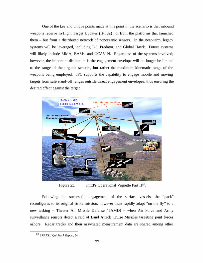
77
One of the key and unique points made at this point in the scenario is that inbound
weapons receive In-flight Target Updates (IFTUs) not from the platforms that launched
them – but from a distributed network of nonorganic sensors. In the near-term, legacy
systems will be leveraged, including P-3, Predator, and Global Hawk. Future systems
will likely include MMA, BAMs, and UCAV-N. Regardless of the systems involved;
however, the important distinction is the engagement envelope will no longer be limited
to the range of the organic sensors, but rather the maximum kinematic range of the
weapons being employed. IFC supports the capability to engage mobile and moving
targets from safe stand-off ranges outside threat engagement envelopes, thus ensuring the
desired effect against the target.
15
SuW to MD Pack Example
Automated BattleManagement Aids
ISR Information Flow
Composite Tracking
Composite Combat ID
C2Information Flow
Figure 23. FnEPs Operational Vignette Part II87.
Following the successful engagement of the surface vessels, the “pack”
reconfigures to its original strike mission; however must rapidly adapt “on the fly” to a
new tasking – Theater Air Missile Defense (TAMD) – when Air Force and Army
surveillance sensors detect a raid of Land Attack Cruise Missiles targeting joint forces
ashore. Radar tracks and their associated measurement data are shared among other
87 SSG XXII Quicklook Report, 54.
78
airborne and surface sensors. ABMAs assign sensors and prioritize shooters based on
resources available and engagement geometries. In this case, JLENS, MC2A, F-18, P-3,
DDG, LCS, and Patriot are the “pack” components that will rapidly integrate and exploit
the strengths of each system to successfully engage the inbound cruise missiles. The C2
information flow supports the creation of a CP in the form of a Single Integrated Air
Picture (SIAP). CTs are formed and shared among surveillance and fire control sensors,
while a common threat evaluation and positive hostile ID is provided by multi-source
automatic fusion assisted by the ABMAs. Weapon to target error baskets are calculated
and are used to assign sensor-shooter-weapon linkages. Finally, weapons are released
and supported by in-flight target updates as needed by assigned offboard fire control
sensors. Highlighted in this scenario is the potential role a P-3 plays in missile defense,
demonstrating the power of all five CRCs. In spite of the lack of an organic missile
defense fire control system, the P-3 could be used solely as a launch platform with
offboard weapons control. With successful engagement of the Cruise Missiles, the
“pack” returns to, and reconfigures for, its original strike mission, and successfully
destroys a moving ballistic missile TEL from a safe stand-off range. This scenario
further demonstrates the adaptability, agility, and combat reach capabilities of the
FnEPs.
C. CONCLUSION
In its most general sense, FnEPs strives to achieve fully integrated joint
capabilities focused on the engagement chain, thereby achieving economies of scale and
economies of scope. As a result, FnEPs promises a revolutionary transformation in naval
operations complimentary to the concepts of FORCEnet, SEA POWER 21, and Sea
Supremacy.
Implicit to realizing FnEPs are a host of C4ISR and networking-related
requirements which must be defined, understood, supported technologically and
operationally implemented from the engagement chain perspective. As outlined in
Chapter I, currently, the Department of Navy’s C4ISR network infrastructure is a
collection of many vertically-oriented, stove-piped and legacy systems built around
common data interchange requirements which have difficulty communicating effectively
or efficiently in a sufficiently timely manner. Most of these vertically-oriented, stove-
79
piped legacy systems historically have not been designed with a horizontal mission
capability focus. As a result, interoperability and integration challenges result in a sub-
optimization of overall warfighting mission capabilities. More critically, such sub-
optimization is a result of many things, both technically and programmatically related.
From a technical standpoint the DoD C4ISR architecture is a complex
environment with many different sensors, communication systems, weapon systems, and
platforms performing many different functions. The architecture demonstrates a number
of characteristics incompatible with FORCEnet, the SEA POWER 21 vision and FnEPs,
including:
• A point-to-point framework with system interoperability challenges
• Is circuit and/or platform centric
• Offers only fixed services with pre-allocated resources
• Is inefficient in its usage of available spectrum and bandwidth
Overall, today’s C4ISR architecture is unable to dynamically respond to different
mixes and matches of force elements and as a result faces difficulties in terms of the
integration of new/different platforms, adaptation of communication systems to
unanticipated missions, and challenges associated with the seamless integration of new
C4ISR systems. These poor interoperability characteristics also result in systems that are
difficult to maintain from a life-cycle perspective due to component obsolescence and
mission or threat changes.
From a programmatic standpoint, the DoN continues to procure communication
and weapon systems in a fragmented, uncoordinated and financially disjointed manner
with no real end-to-end strategic plan. As a result of all these challenges, operations are
often relegated to the lowest common denominator, which include, for example, satellite
communications or weapon engagement ranges. Unfortunately, even projected systems
do not present an answer to many of the challenges that exceed current system
capabilities.
The successful development and fleet implementation of FnEPs and the
“operationization” of FORCEnet will require addressing these technical and
programmatic challenges. Perhaps an even greater challenge facing the success of these

80
concepts is the need for organizational and process-related changes that are necessary if
DoD is to realize the tremendous potential improvements in operational effectiveness
FnEPs and FORCEnet have to offer.
81
III. FORCENET ENGAGEMENT PACKS (FNEPS) ANALYSIS
As discussed
previously, we
assess the ultimate
vision of
FORCEnet characterized by ADM Jim Hogg (Ret.), director of the SSG, as “The fully
netted force” which faces a number of technical, programmatic, and organization
challenges. From a technical perspective alone, the complexity generated by the potential
explosion of system interactions is huge, unaffordable, and unrealizable in the near term.
FnEPs seeks the integration of specific “packs” of FORCEnet factors, including legacy
systems and advanced technology, in order to achieve or “operationalize” FORCEnet in
the near-term. The discovery of requirements for such near-term integration and the
systems necessary to support the development of near-term FORCEnet and FnEPs
functionality requires a robust and unique analysis effort. Chapter IV is devoted to a
discussion of the analytic methodology and results we obtained from this methodology
and will be broken into three parts. Part I will discuss the research methodology itself
and describe the analysis process. Part II will discuss the actual analysis conducted in
support of the FnEPs concept and the development of a prototype pack. Part III will
discuss analysis not yet completed, but that remains critical to the development and
fielding of FnEPs in accordance with the timeline briefed to the CNO.
A. THE GEMINII METHODOLOGY
As part of the development of the FnEPs concept, SSG XXII sought analysis to
support the benefits we believed FORCEnet and FnEPs could bring directly to the
warfigthers and operating forces. More specifically, our analysis seeks to more fully
understand the system decomposition into FnEPs factor components as the first step in
the Combat Reach integration process. When recomposing factor components into
“packs,” the five Combat Reach Capabilities (CRCs) become critical enablers to pack
composition (horizontal ‘lanes’). Additionally, understanding how these CRCs provide
warfighting distributed services are key to understanding how distributed services support
pack adaptability across both Strike and TAMD. We discovered an evolving toolset and
““WWee ccaannnnoott ssoollvvee oouurr pprroobblleemmss wwiitthh tthhee ssaammee tthhiinnkkiinngg wwee uusseedd wwhheenn wwee ccrreeaatteedd tthh eemm”” ---- AAllbbeerrtt EEiinnsstteeiinn
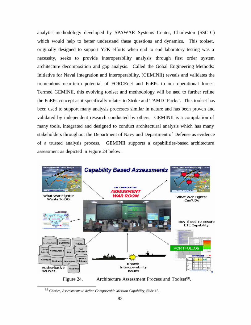
82
analytic methodology developed by SPAWAR Systems Center, Charleston (SSC-C)
which would help to better understand these questions and dynamics. This toolset,
originally designed to support Y2K efforts when end to end laboratory testing was a
necessity, seeks to provide interoperability analysis through first order system
architecture decomposition and gap analysis. Called the Gobal Engineering Methods:
Initiative for Naval Integration and Interoperability, (GEMINII) reveals and validates the
tremendous near-term potential of FORCEnet and FnEPs to our operational forces.
Termed GEMINII, this evolving toolset and methodology will be used to further refine
the FnEPs concept as it specifically relates to Strike and TAMD ‘Packs’. This toolset has
been used to support many analysis processes similar in nature and has been proven and
validated by independent research conducted by others. GEMINII is a compilation of
many tools, integrated and designed to conduct architectural analysis which has many
stakeholders throughout the Department of Navy and Department of Defense as evidence
of a trusted analysis process. GEMINII supports a capabilities-based architecture
assessment as depicted in Figure 24 below.
Figure 24. Architecture Assessment Process and Toolset88.
88 Charles, Assessments to define Composeable Mission Capability, Slide 15.
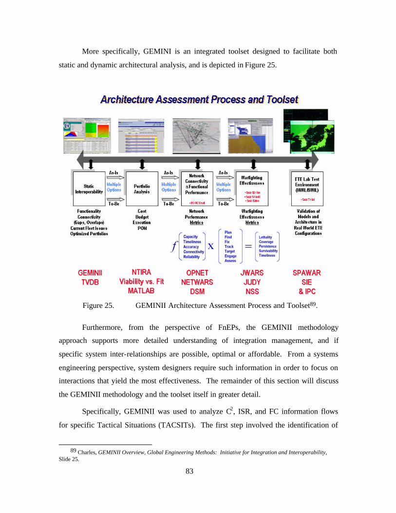
83
More specifically, GEMINI is an integrated toolset designed to facilitate both
static and dynamic architectural analysis, and is depicted in Figure 25.
Figure 25. GEMINII Architecture Assessment Process and Toolset89.
Furthermore, from the perspective of FnEPs, the GEMINII methodology
approach supports more detailed understanding of integration management, and if
specific system inter-relationships are possible, optimal or affordable. From a systems
engineering perspective, system designers require such information in order to focus on
interactions that yield the most effectiveness. The remainder of this section will discuss
the GEMINII methodology and the toolset itself in greater detail.
Specifically, GEMINII was used to analyze C2, ISR, and FC information flows
for specific Tactical Situations (TACSITs). The first step involved the identification of
89 Charles, GEMINII Overview, Global Engineering Methods: Initiative for Integration and Interoperability,
Slide 25.
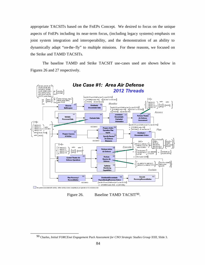
84
appropriate TACSITs based on the FnEPs Concept. We desired to focus on the unique
aspects of FnEPs including its near-term focus, (including legacy systems) emphasis on
joint system integration and interoperability, and the demonstration of an ability to
dynamically adapt “on-the-fly” to multiple missions. For these reasons, we focused on
the Strike and TAMD TACSITs.
The baseline TAMD and Strike TACSIT use-cases used are shown below in
Figures 26 and 27 respectively.
Figure 26. Baseline TAMD TACSIT90.
90 Charles, Initial FORCEnet Engagement Pack Assessment for CNO Strategic Studies Group XXII, Slide 3.
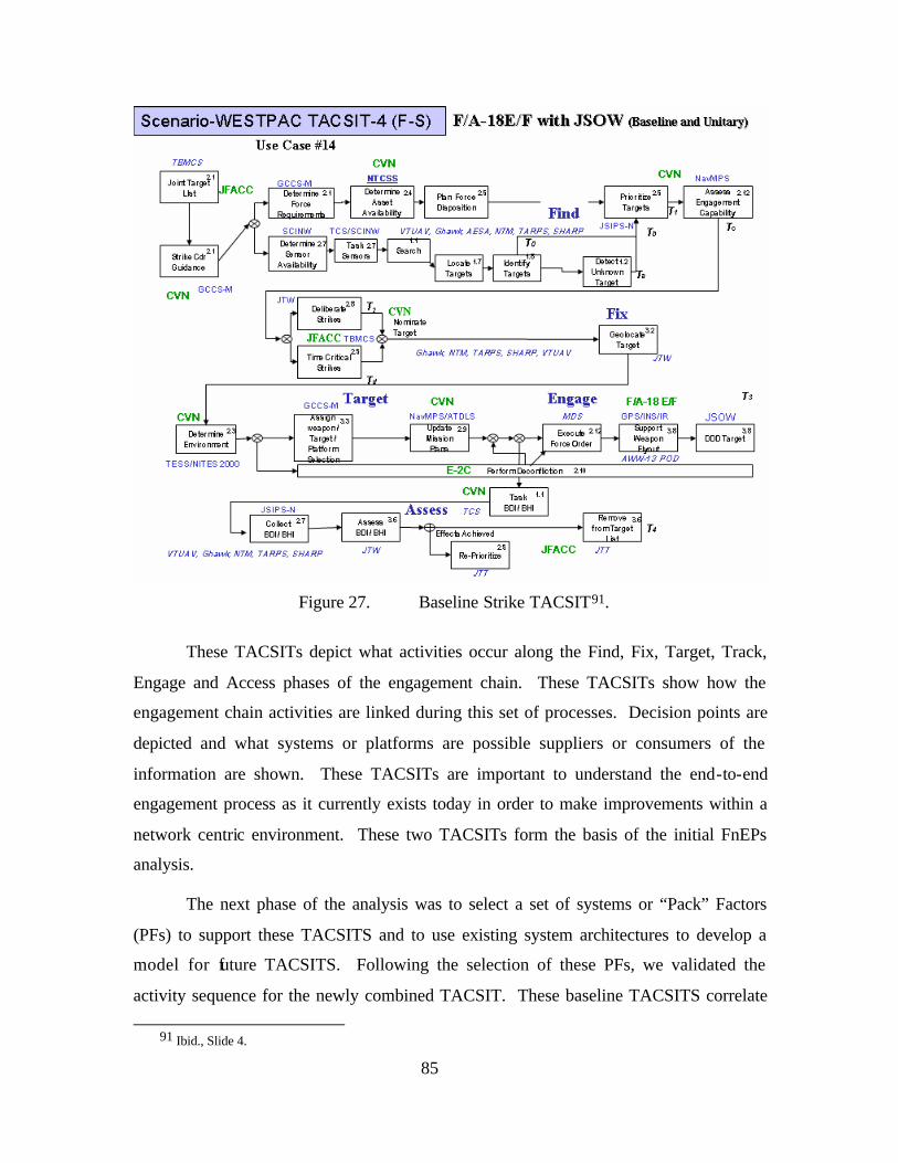
85
Figure 27. Baseline Strike TACSIT91.
These TACSITs depict what activities occur along the Find, Fix, Target, Track,
Engage and Access phases of the engagement chain. These TACSITs show how the
engagement chain activities are linked during this set of processes. Decision points are
depicted and what systems or platforms are possible suppliers or consumers of the
information are shown. These TACSITs are important to understand the end-to-end
engagement process as it currently exists today in order to make improvements within a
network centric environment. These two TACSITs form the basis of the initial FnEPs
analysis.
The next phase of the analysis was to select a set of systems or “Pack” Factors
(PFs) to support these TACSITS and to use existing system architectures to develop a
model for future TACSITS. Following the selection of these PFs, we validated the
activity sequence for the newly combined TACSIT. These baseline TACSITS correlate
91 Ibid., Slide 4.
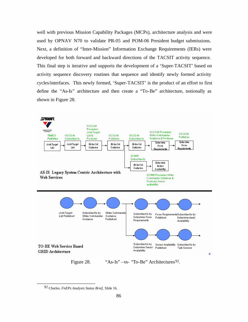
86
well with previous Mission Capability Packages (MCPs), architecture analysis and were
used by OPNAV N70 to validate PR-05 and POM-06 President budget submissions.
Next, a definition of “Inter-Mission” Information Exchange Requirements (IERs) were
developed for both forward and backward directions of the TACSIT activity sequence.
This final step is iterative and supports the development of a ‘Super-TACSIT’ based on
activity sequence discovery routines that sequence and identify newly formed activity
cycles/interfaces. This newly formed, ‘Super-TACSIT’ is the product of an effort to first
define the “As-Is” architecture and then create a “To-Be” architecture, notionally as
shown in Figure 28.
Figure 28. “As-Is” –vs- “To-Be” Architectures92.
92 Charles. FnEPs Analysis Status Brief, Slide 16.
87
The diagram above illustrates how related system interface (SV-6) lines are
sequenced and correlated in terms of Information Exchanges (IEs) and function (‘Super
SV-6) interface lines from the perspective of a possible “As-Is” architecture. The
ultimate objective of this process is the creation of a new ‘Super-System’ architectural
view. Such an architecture can be further ana lyzed using a “Service Discovery Routine”
which results in fused, integrated, distributed and composite services.
In completing the above analysis, GEMINII facilitated both a static “As-Is” and
dynamic “To-Be” architecture interoperability analysis to discover engineering level
trade off situations and discovers new “To-Be” packages of capabilities. The following
sections discussed these individually.
1. Static Analysis of FnEPs
The first part of the GEMINII methodology involved a static, or “As-Is”,
architecture assessment that allowed for the synthesis and assessment of system
integration requirements from the perspective of FORCEnet and FnEPs amongst many
different systems. In this case, we sought to assess potential integration requirements for
“packs” capable of Strike and TAMD missions. Additionally, we sought to identify
“capability gaps” in terms of the ability to achieve the five CRCs and answer the
question, “can we do this today?” To accomplish this static assessment GEMINII was
integrated with TVDB and the DSM. Together these tools help to better align resources
for multiple mission area assessments, management of FORCEnet factor integration
complexity, and the identification of requirements for future architectures, including
interface and functional requirements to achieve the five CRCs independent of
technology. Importantly, this static assessment also identified optimized portfolios of
service bundles necessary to support FORCEnet and FnEPs based on gaps or overlaps in
system functionality, and current fleet issues. DSM uses this information to evaluate
system function and activity interactions to help understand the clustering and
partitioning of system functionality.
2. Dynamic Analysis of FnEPs
A useful framework to consider this part of the analysis is that of the “To-Be”
perspective in terms of legacy and future systems and the degree of integration and
interoperability required for them to support FORCEnet and FnEPs. More specifically,
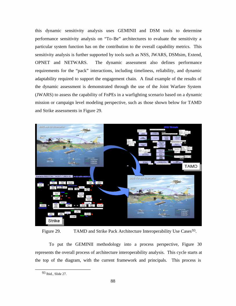
88
this dynamic sensitivity analysis uses GEMINII and DSM tools to determine
performance sensitivity analysis on “To-Be” architectures to evaluate the sensitivity a
particular system function has on the contribution to the overall capability metrics. This
sensitivity analysis is further supported by tools such as NSS, JWARS, DSMsim, Extend,
OPNET and NETWARS. The dynamic assessment also defines performance
requirements for the “pack” interactions, including timeliness, reliability, and dynamic
adaptability required to support the engagement chain. A final example of the results of
the dynamic assessment is demonstrated through the use of the Joint Warfare System
(JWARS) to assess the capability of FnPEs in a warfighting scenario based on a dynamic
mission or campaign level modeling perspective, such as those shown below for TAMD
and Strike assessments in Figure 29.
Figure 29. TAMD and Strike Pack Architecture Interoperability Use Cases93.
To put the GEMINII methodology into a process perspective, Figure 30
represents the overall process of architecture interoperability analysis. This cycle starts at
the top of the diagram, with the current framework and principals. This process is
93 Ibid., Slide 27.
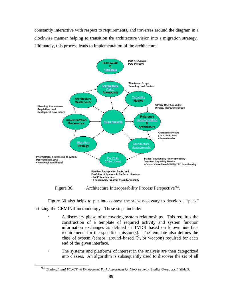
89
constantly interactive with respect to requirements, and traverses around the diagram in a
clockwise manner helping to transition the architecture vision into a migration strategy.
Ultimately, this process leads to implementation of the architecture.
Figure 30. Architecture Interoperability Process Perspective 94.
Figure 30 also helps to put into context the steps necessary to develop a “pack”
utilizing the GEMINII methodology. These steps include:
• A discovery phase of uncovering system relationships. This requires the construction of a template of required activity and system function information exchanges as defined in TVDB based on known interface requirements for the specified mission(s). The template also defines the class of system (sensor, ground-based C2, or weapon) required for each end of the given interface.
• The systems and platforms of interest in the analysis are then categorized into classes. An algorithm is subsequently used to discover the set of all
94 Charles, Initial FORCEnet Engagement Pack Assessment for CNO Strategic Studies Group XXII, Slide 5.
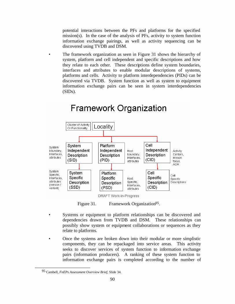
90
potential interactions between the PFs and platforms for the specified mission(s). In the case of the analysis of PFs, activity to system function information exchange pairings, as well as activity sequencing can be discovered using TVDB and DSM.
• The framework organization as seen in Figure 31 shows the hierarchy of system, platform and cell independent and specific descriptions and how they relate to each other. These descriptions define system boundaries, interfaces and attributes to enable modular descriptions of systems, platforms and cells. Activity to platform interdependencies (PIDs) can be discovered via TVDB. System function as well as system to equipment information exchange pairs can be seen in system interdependencies (SIDs).
Figure 31. Framework Organization95.
• Systems or equipment to platform relationships can be discovered and
dependencies drawn from TVDB and DSM. These relationships can possibly show system or equipment collaborations or sequences as they relate to platforms.
• Once the systems are broken down into their modular or more simplistic components, they can be repackaged into service areas. This activity seeks to discover services of system function to information exchange pairs (information producers). A ranking of these system function to information exchange pairs is completed according to the number of
95 Cambell, FnEPs Assessment Overview Brief, Slide 34.
91
consumers of this data across all services. A second ranking of system function to information exchange pairs is completed according to uniqueness, Integration & Interoperability (I & I), performance, vision or other criteria.
Services are prioritized by program where the system function/information
exchange pairs are compared with redundancy and programmatic issues (maturity,
funding, volatility, risk, cost, FORCnet impact) or by optimizing opportunities for legacy
to distributed services solutions.
Having generally discussed the GEMINI methodology, it is useful to understand
the individual tools GEMINII includes.
3. TVDB
The Technical View Database (TVDB) is an analysis tool that translates the
TACSIT architectures into system function/information exchange pairs useful for
analyzing the current engagement chain processes. TVDB will also allow new TACSIT
interfaces and activities to be created or connected in new ways to analyze their effects
on the rest of the TACSIT. TVDB uses Casualty Reports (CASREPS) for systems on the
NWAS-Corona Troubled Systems Process list and Battlegroup Situation (BGSIT) Report
data to capture current system functional and technical shortfalls.
4. NTIRA
The Naval Tool for Interoperability Risk Assessment (NTIRA) is also part of the
GEMINII advanced engineering assessment process which uses authoritative inputs to
FORCEnet and Naval Capability Pillar (NCP) analysis, using valid current and planned
configuration data, validated requirements and warfighting capabilities to assess system
viability vs. fit. NTIRA is a web-based tool to analyze major IT investments and
requirements in terms of the proposed investment’s contribution to the Navy’s
warfighting mission. NTIRA provides unique, capabilities-based view of maritime strike
groups and their supporting systems. NTIRA displays the effect of proposed investments
on Joint and Navy capabilities using the Fleet-validated Joint/Navy Mission Essential
Task Lists (J/NMETL), a detailed analysis of each C4I system, and the training
requirements resident in the Training Information Management System (NTIMS).
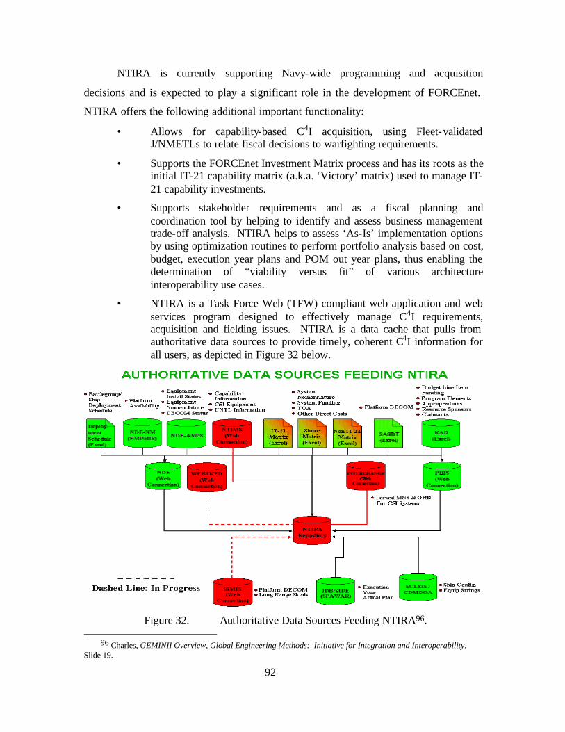
92
NTIRA is currently supporting Navy-wide programming and acquisition
decisions and is expected to play a significant role in the development of FORCEnet.
NTIRA offers the following additional important functionality:
• Allows for capability-based C4I acquisition, using Fleet-validated J/NMETLs to relate fiscal decisions to warfighting requirements.
• Supports the FORCEnet Investment Matrix process and has its roots as the initial IT-21 capability matrix (a.k.a. ‘Victory’ matrix) used to manage IT-21 capability investments.
• Supports stakeholder requirements and as a fiscal planning and coordination tool by helping to identify and assess business management trade-off analysis. NTIRA helps to assess ‘As-Is’ implementation options by using optimization routines to perform portfolio analysis based on cost, budget, execution year plans and POM out year plans, thus enabling the determination of “viability versus fit” of various architecture interoperability use cases.
• NTIRA is a Task Force Web (TFW) compliant web application and web services program designed to effectively manage C4I requirements, acquisition and fielding issues. NTIRA is a data cache that pulls from authoritative data sources to provide timely, coherent C4I information for all users, as depicted in Figure 32 below.
Figure 32. Authoritative Data Sources Feeding NTIRA96.
96 Charles, GEMINII Overview, Global Engineering Methods: Initiative for Integration and Interoperability,
Slide 19.
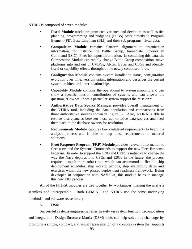
93
NTIRA is composed of seven modules:
• Fiscal Module tracks program cost variance and deviation as well as ties planning, programming and budgeting (PPBS) costs directly to Program Element (PE), Base Line Item (BLI) and their sub programs’ fiscal data.
• Composition Module contains platform alignment to organization information, for instance the Battle Group, Immediate Superior In Command (ISIC), Fleet homeport information. In containing this data, the Composition Module can rapidly change Battle Group composition, move platforms into and out of CVBGs, ARGs, ESGs and CSGs and identify fiscal or capability effects throughout the newly composed force.
• Configuration Module contains system installation status, configuration evolution over time, version/variant information and describes the current system architectural inter-relationships.
• Capability Module contains the operational to system mapping and can show a specific mission contribution of systems and can answer the question, ‘How well does a particular system support the mission?’
• Authoritative Data Source Manager provides overall management of the NTIRA tool, including the data population and comparisons from those authoritative sources shown in Figure 32. Also, NTIRA is able to resolve discrepancies between those authoritative data sources and feed them back to the database owners for resolution.
• Requirements Module captures fleet-validated requirements to begin the analysis process and is able to map those requirements to material solutions.
• Fleet Response Program (FRP) Module provides relevant information to fleet users and the Systems Commands to support the new Fleet Response Program. In order to support the CNO and CFFC’s initiative to change the way the Navy deploys into CSGs and ESGs in the future, the process requires a much more robust tool which can accommodate flexible ship deployment schedules, ship workup periods, ship availability dates and exercises within the new phased deployment readiness framework. Being developed in conjunction with NAVSEA, this module helps to manage this new FRP process
All of the NTIRA modules are tied together by workspaces, making the analysis
seamless and interoperable. Both GEMINII and NTIRA use the same underlying
‘methods’ and software reuse library.
5. DSM
Successful systems engineering relies heavily on system function decomposition
and integration. Design Structure Matrix (DSM) tools can help solve this challenge by
providing a simple, compact, and visual representation of a complex system that supports
94
innovative solutions to decomposition and integration problems. The DSM is a matrix
identifying interactions between stages of development, delivery or operation of a
system. This matrix complements the IDEF models of the past. DSM provides a tool to
simplify, focus and align sub-processes of system development and provides a framework
to assess rework, risk, key performance parameters and system interactions through the
use of metrics. DSMs have been used extens ively in the past97, and their use increased
greatly in the 1990s throughout a number of industries including semiconductor design,
automotive, and aerospace.98 DSMs can be broken into both static and expanded
parametric based types. The GEMINII methodology currently uses a static DSM which
is basically a square matrix representing architectural components and interfaces.
Figure 33. Static DSM.
In the example DSM in Figure 33, elements are represented by the shaded
elements along the diagonal. An off-diagonal mark signifies the dependency of one
element on another. Reading down a column reveals input sources, while reading across
a row indicates output destinations. Thus, in Figure 33, element B provides input to
elements A, C, D, F, H, and I, and it depends on input from elements C, D, F, and H. 99.
97 Browning, p. 293.
98 Ibid. 99 Browning, p. 292.
95
The point of the matrix is to illuminate the interdependency structure and aid in
the design and optimization of products, processes, and organizations. Several types of
static DSMs exist; however, the type used as part of the Gemini/NTIRA toolset in
support of the analysis of the FnEPs concept is specifically a “Component-Based” or
“Architecture” DSM. Such DSMs are generally used to:
• Model system architectures based on components and/or subsystems and their relationships.
• Understand and document the interactions between the elements (e.g. their integration).
• Analyze potential reintegration of the elements via clustering (e.g. integration analysis).100
One of the most important and useful aspects of DSM used for the analysis of
FnEPs is its utility in analyzing components of the architecture. Product architecture is
the arrangement of functional elements into physical partitions that become the building
blocks for a product or family of products.101 Partitions should implement one or a few
functions entirely, and interactions between partitions should be well defined. This
supports the creation of modular, reconfigurable, and scaleable system architectures
which have advantages in simplicity and reusability for a produc t family or
platform. 102,103 Further, a lesson can be learned from the research showing that
innovative product architectures can be a source of competitive advantage for product
development firms104. This applies to FnEPs in that the “packs” are analogous to these
innovative product architectures. The analogy can be extended by considering the
relationships among elements are what give systems their added value, and, furthermore,
that the greatest leverage in systems architecting is at the interfaces105. The “innovation”
100 T. U. Pimmler and S. D. Eppinger, “Integration Analysis of Product Decompositions,” (Proc. ASME 6th Int.
Conf. on Design Theory and Methodology), Minneapolis, Minnesota, 1994.
101 K. T. Ulrich and S. D. Eppinger, Product Design and Development, 2nd,, New York: McGraw-Hill, 2000.
102 C. Y. Baldwin and K. B. Clark, Design Rules: The Power of Modularity. Cambridge, Massachusetts: MIT Press, 2000, Vol. 1.
103 R. Sanchez and J. T. Mahoney, “Modularity, Flexibility, and Knowledge Management in Product and Organization Design,” IEEE Eng. Manage.Rev ., pp. 50–61, 1997.
104 R. M. Henderson and K. B. Clark, “Architectural Innovation: The Reconfiguration of Existing Product Technologies and the Failure of Established Firms,” Administ. Sci. Quart., Vol. 35, pp. 9–30, 1990.
105 E. Rechtin, Systems Architecting: Creating & Building Complex Systems, Englewood Cliffs, New Jersey: Prentice-Hall, 1991.
96
referred to above is predicated on an understanding of the interfaces or interactions
between system elements. Developers can innovate on top of the standard and provide
unique advantages without breaking the interaction or interface requirements. This is the
primary function of a static DSM such as that being used to analyze FnEPs! The use of
GEMINII and DSM together discovers previously unknown integration patterns and
reveals key information flows for the five CRCs that enable a “pack.”
6. Summary
In summary, the GEMINII methodology assists in the development of an end-to-
end, integrated, out-come based capability, enterprise architecture and provides a
foundation for balancing future requirements versus resources to improve war fighter
capability. This GEMINII methodology and sensitivity analysis of the five CRCs
measures operational benefit by answering questions and providing metrics for questions
such as the following:
• Has the engagement envelope been extended?
• Has C2 decision time decreased?
• Has the engagement time decreased?
• Has defense in depth been increased or strengthened?
• Has there been an improvement in performance in terms of such metrics as lethality, survivability, coverage, persistence, or timeliness?
From the perspective of FnEPs, this methodology seeks to produce and evaluate
an architecture capable of supporting dynamically re-configurable mission capabilities,
enabled by the CRC’s including Composite Tracking (CT), Composite Combat
Identification (CCID), Common/Single Pictures (CP), Automated Battle Management
Aids (ABMAs) and Integrated Fire Control (IFC). By using the modular, reconfigurable,
integrated architecture framework envisioned by FORCEnet combined with the
GEMINII methodology and modeling tools, we were able to manage the complexity of
NCW, obtain greater understanding of the FnEPs’ concept and evaluate FnEPs’ potential
for increase end-to-end warfighting effectiveness in general.
B. CURRENT ANALYSIS OF FNEPS
Beyond its initial development for use in Y2K, GEMINII was more recently
adapted for use in support of the OPNAV N6 POM06 assessment process. This
assessment sought to provide analysis in support of the identification of systems and
97
programs that would (or would not) support the general integration and interoperability
requirements of FORCEnet. While considering the POM06 assessment for FORCEnet
programs as part of our development of the FnEPs concept, SSG XXII assessed the same
toolset and analytic methodology could be applied to FnEPs. SSC-C agreed, and together
we undertook the evaluation of a set of joint assets or “Pack Factors” (PFs) as potential
FnEPs “pack” candidates. These PFs included a representative set of weapons, sensors,
platforms, and other FORCEnet factors and generally focused on the Strike and Theater
Area Missile Defense (TAMD) Naval Mission Capability Packages (MCPs).
Specifically, the GEMINII toolset
• Supported first order assessment of the PF decomposition process and the recomposition of “packs” necessary to support the Strike and TAMD MCPs.
• Generated system inter-relationships with respect to the five Combat Reach Capabilities (CRCs), including Automated Battle Management Aids, (ABMAs) Integrated Fire Control, (IFC) Composite Tracking, (CT) Composite Combat ID, (CCID) and Single and Common Pictures (CP).
More generally, our initial analysis enabled us to evaluate activity sequences,
required system interactions, potential integration shortfalls, and the adaptability of
‘packs’ across mission areas. Overall, we identified over 85,000 potential integration
inter-relationships tied to the five CRCs listed above. Further, the process allowed for a
sensitivity analysis of these inter-relationships that supported optimized system to system
integration. Overall, our analysis provided important insights from this process
including:
• System decomposition into factor components is just the first step in the integration process.
• When recomposing PFs into “packs,” the five CRCs become the critical enablers to “pack” functionality.
• Not all system inter-relationships are possible, optimal or affordable. System designers will need to focus on interactions that yield the most effectiveness.
• The five CRCs support the FORCEnet Chief Engineer’s Architecture Vision by providing distributed combat services, dynamically composed and adaptable across both Strike and TAMD MCPs.
• Most importantly--our sensitivity analysis demonstrated that while incremental improvements could be realized through each of the CRCs, a
98
dramatic increase in system inter-relationships and engagement performance occurred when ALL five CRCs were implemented together. We reaffirmed the true benefits of FORCEnet can only be achieved by engineering complete packages of CRC functionality into our systems.
In addition to the ana lysis conducted with SSC-C, we conducted several other first order
analysis efforts. While our thesis does not specifically review such analysis, in general,
all analytical work demonstrated that Strike and TAMD “Packs” improve combat reach
and overall warfighting effectiveness. Selected results demonstrated:
• A 40% better utilization of Blue assets in ASW and Offensive Counter Air operations.
• A 40% improvement in TAMD kills against cruise missile raids.
• A 50% reduction in the number of leakers against massive raids of ballistic missiles.
• A 100% increase in engagement envelope as measured by engagement range.
• An up to ten-fold increase in overland-protected footprint highlighting Sea Shield’s potential contribution to littoral TAMD.
This chapter will summarize analysis that has been done to date. As Plato would
have said, “The beginning is the most important part of the work”, so with this in mind
the beginning part of the analysis is a critical first step. The first step is to set up goals
and scenarios illustrating issues and viewpoints wanting to be examined. Utilizing the
“SMART” Business Scenario, we aim to be Specific by defining what needs to be done
in the FnEPs “business.” In this case, the specific focus is going to be on CONOPS and
Tactical Situation (TACSIT) activities and not merely system boxes. This analysis aims
to be Measurable through clear metrics, linked to outcome based effects. This analysis
seeks to be Actionable, by clearly segmenting the problem and providing the basis for
determining elements and plans for the solution (guidance and priorities). This analysis
seeks to be Realistic, in that the problem can be solved within the bounds of physical
reality. Tactics, Techniques, Procedures (TTPs), time and cost are all some of the
realistic constraints which will help bound the problem. Lastly, this work should be
Time-sensitive such that there is a clear statement of when the solution opportunity
expires therefore implying a deadline and sense of urgency for implementation.
99
With this in mind, our analysis faces two key challenges. 1) Identify and validate
the warfighting architecture improvements required to significantly enhance naval
warfighting effectiveness in 2009 within the context of FnEPs, and 2) Demonstrate the
concept of distributed services as a tool for analyzing and optimizing warfighting
architectures will be utilized. In order to get from the “As-Is” to the “To-Be”
architecture, several key aspects must be understood,
• Understand what the warfighting requirement is and what capabilities it will take to win in a network-centric warfare environment.
• Understand the “As-Is” architecture from a weapons coordination standpoint and its attendant problems of manually configured systems, with multiple, non- integrated stove piped functionality and rigid command and control.
• Understand the “To-Be” architecture from the FnEP perspective taking into account the five Combat Reach Capabilities. Understanding these CRCs implies a high level of autonomous action and awareness of other engagement units, both friendly and unfriendly.
• Understand what metrics will validate these improvements.
Questions like, “will the coherence and reliability of a tactical picture or a
shortened kill chain reduce blue on blue and blue on white engagements” will be looked
at. This work will analyze “pack” deployment that can provide the five CRCs with a
target timeframe of 2009. This analysis work will be completed by examining
capabilities from a warfighter outcome-based perspective. These capabilities are based
on two types of variables, 1) Conditions (i.e., things we ‘set’) and 2) Metrics (i.e., things
we ‘measure’) like weather, AOR-Geometry, threat, lethality, coverage (sensor,
engagement) survivability, timeliness, OR time, space, force factors. These warfighting,
effects-based capability variables produce derived capabilities that must exist to support
the overarching objectives. These derived capabilities are parameters of services (e.g.,
security, connectivity, availability, maintainability, bandwidth efficiency,
interoperability, latency, delay, jitter, etc.) and may be articulated in the form of
requirements or in service level agreements (SLAs). Figure 34 depicts the reference
implementation and architecture that will frame all follow on discussions. In an
operational sense, there are warfighting activities, nodal functions, information, and
systems used in achieving a mission. Mission requirements require collaboration and
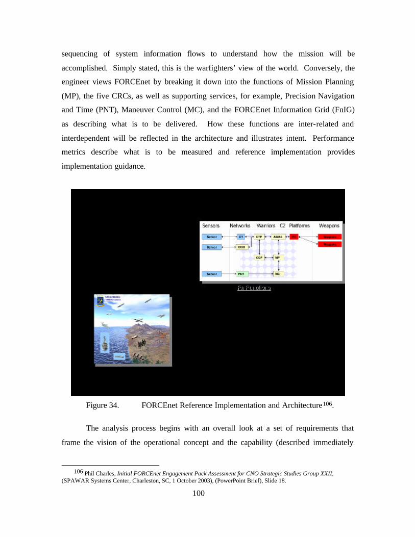
100
sequencing of system information flows to understand how the mission will be
accomplished. Simply stated, this is the warfighters’ view of the world. Conversely, the
engineer views FORCEnet by breaking it down into the functions of Mission Planning
(MP), the five CRCs, as well as supporting services, for example, Precision Navigation
and Time (PNT), Maneuver Control (MC), and the FORCEnet Information Grid (FnIG)
as describing what is to be delivered. How these functions are inter-related and
interdependent will be reflected in the architecture and illustrates intent. Performance
metrics describe what is to be measured and reference implementation provides
implementation guidance.
Figure 34. FORCEnet Reference Implementation and Architecture106.
The analysis process begins with an overall look at a set of requirements that
frame the vision of the operational concept and the capability (described immediately
106 Phil Charles, Initial FORCEnet Engagement Pack Assessment for CNO Strategic Studies Group XXII,
(SPAWAR Systems Center, Charleston, SC, 1 October 2003), (PowerPoint Brief), Slide 18.
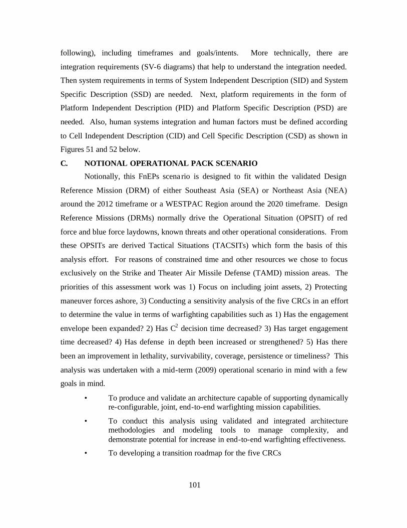
101
following), including timeframes and goals/intents. More technically, there are
integration requirements (SV-6 diagrams) that help to understand the integration needed.
Then system requirements in terms of System Independent Description (SID) and System
Specific Description (SSD) are needed. Next, platform requirements in the form of
Platform Independent Description (PID) and Platform Specific Description (PSD) are
needed. Also, human systems integration and human factors must be defined according
to Cell Independent Description (CID) and Cell Specific Description (CSD) as shown in
Figures 51 and 52 below.
C. NOTIONAL OPERATIONAL PACK SCENARIO
Notionally, this FnEPs scena rio is designed to fit within the validated Design
Reference Mission (DRM) of either Southeast Asia (SEA) or Northeast Asia (NEA)
around the 2012 timeframe or a WESTPAC Region around the 2020 timeframe. Design
Reference Missions (DRMs) normally drive the Operational Situation (OPSIT) of red
force and blue force laydowns, known threats and other operational considerations. From
these OPSITs are derived Tactical Situations (TACSITs) which form the basis of this
analysis effort. For reasons of constrained time and other resources we chose to focus
exclusively on the Strike and Theater Air Missile Defense (TAMD) mission areas. The
priorities of this assessment work was 1) Focus on including joint assets, 2) Protecting
maneuver forces ashore, 3) Conducting a sensitivity analysis of the five CRCs in an effort
to determine the value in terms of warfighting capabilities such as 1) Has the engagement
envelope been expanded? 2) Has C2 decision time decreased? 3) Has target engagement
time decreased? 4) Has defense in depth been increased or strengthened? 5) Has there
been an improvement in lethality, survivability, coverage, persistence or timeliness? This
analysis was undertaken with a mid-term (2009) operational scenario in mind with a few
goals in mind.
• To produce and validate an architecture capable of supporting dynamically re-configurable, joint, end-to-end warfighting mission capabilities.
• To conduct this analysis using validated and integrated architecture methodologies and modeling tools to manage complexity, and demonstrate potential for increase in end-to-end warfighting effectiveness.
• To developing a transition roadmap for the five CRCs
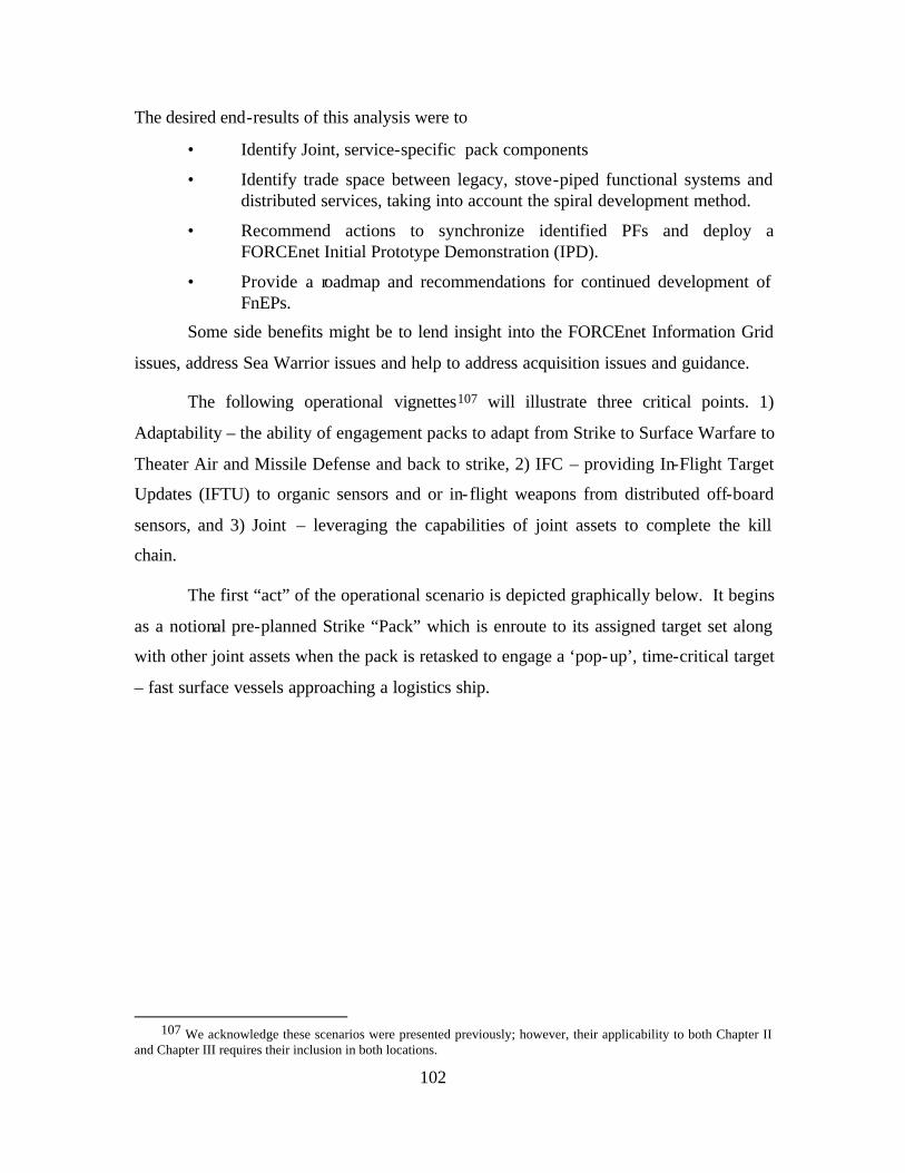
102
The desired end-results of this analysis were to
• Identify Joint, service-specific pack components
• Identify trade space between legacy, stove-piped functional systems and distributed services, taking into account the spiral development method.
• Recommend actions to synchronize identified PFs and deploy a FORCEnet Initial Prototype Demonstration (IPD).
• Provide a roadmap and recommendations for continued development of FnEPs.
Some side benefits might be to lend insight into the FORCEnet Information Grid
issues, address Sea Warrior issues and help to address acquisition issues and guidance.
The following operational vignettes107 will illustrate three critical points. 1)
Adaptability – the ability of engagement packs to adapt from Strike to Surface Warfare to
Theater Air and Missile Defense and back to strike, 2) IFC – providing In-Flight Target
Updates (IFTU) to organic sensors and or in-flight weapons from distributed off-board
sensors, and 3) Joint – leveraging the capabilities of joint assets to complete the kill
chain.
The first “act” of the operational scenario is depicted graphically below. It begins
as a notional pre-planned Strike “Pack” which is enroute to its assigned target set along
with other joint assets when the pack is retasked to engage a ‘pop-up’, time-critical target
– fast surface vessels approaching a logistics ship.
107 We acknowledge these scenarios were presented previously; however, their applicability to both Chapter II
and Chapter III requires their inclusion in both locations.
103
Figure 35. Strike to SuW Pack Example108.
ISR information obtained from a submarine collecting intelligence near the
coastline is rapidly shared with other assets throughout the battlespace including an Air
Force surveillance aircraft on station to support the pre-planned strike mission. Self-
synchronization through ABMAs optimizes the best sensors-shooters-weapons
combinations to engage the approaching surface vessels. Sensor packages onboard an
MC2A, P-3, Global Hawk, an AEGIS Destroyer and Predator are exploited. C2
information flow assigns sensors and shooters. Navy and Marine Corp F-18s, a DDG,
and LCS are the optimized shooters. CTs and CCIDs are formed using measurements of
the target from the optimized sensors allowing Global Hawk and Predator UAVs, in this
example, to exploit the strengths of their combined ISAR, IR, Elint, and MTI radar
sensors. With CCID satisfied, weapons are now deployed. The key point here is that
inbound weapons are receiving In-flight Target Updates (IFTUs) not from the platforms
108 SSG XXII Quicklook Report, 52.
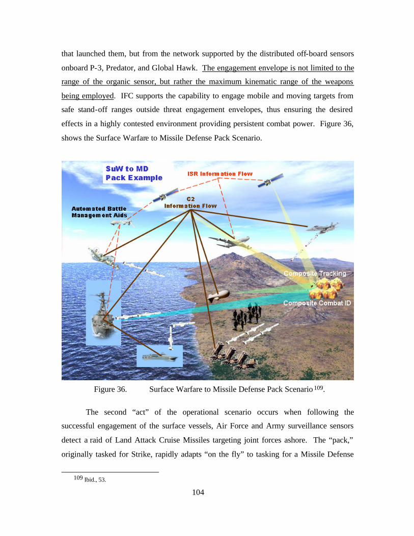
104
that launched them, but from the network supported by the distributed off-board sensors
onboard P-3, Predator, and Global Hawk. The engagement envelope is not limited to the
range of the organic sensor, but rather the maximum kinematic range of the weapons
being employed. IFC supports the capability to engage mobile and moving targets from
safe stand-off ranges outside threat engagement envelopes, thus ensuring the desired
effects in a highly contested environment providing persistent combat power. Figure 36,
shows the Surface Warfare to Missile Defense Pack Scenario.
Figure 36. Surface Warfare to Missile Defense Pack Scenario 109.
The second “act” of the operational scenario occurs when following the
successful engagement of the surface vessels, Air Force and Army surveillance sensors
detect a raid of Land Attack Cruise Missiles targeting joint forces ashore. The “pack,”
originally tasked for Strike, rapidly adapts “on the fly” to tasking for a Missile Defense
109 Ibid., 53.
105
mission. Radar tracks and their associated measurement data are shared among other
airborne and surface sensors. ABMAs assign sensors and prioritize shooters based on
resources available and engagement geometries. In this case, JLENS, MC2A, F-18, P-3,
DDG, LCS, and Patriot are the “pack” components that will rapidly integrate and explo it
the strengths of each system to successfully engage the inbound cruise missiles. The C2
information flow supports the creation of a CP in the form of a Single Integrated Air
Picture (SIAP). CTs are formed and shared among surveillance and fire control sensors.
A common threat evaluation and positive hostile ID are assisted by ABMAs. Weapon to
target error baskets are calculated and are used to assign sensor-shooter-weapon linkages.
Weapons are released and are uplinked in-flight target updates as needed by assigned
offboard fire control sensors. The potential role P-3 plays in missile defense highlighted
in this vignette shows the power of all five CRCs. In spite of the lack of an organic
missile defense fire control system, the P-3 could be used solely as a launch platform
with off-board weapons control. With successful engagement of the Cruise Missiles, the
“pack” returns to, and reconfigures for its original strike mission, further demonstrating
the adaptability, agility, and combat reach capabilities of FnEPs.
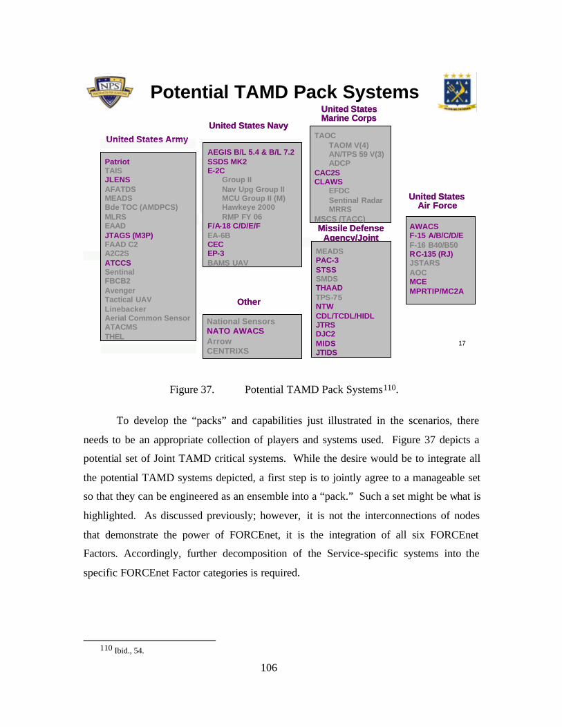
106
17
AWACSF-15 A/B/C/D/EF-16 B40/B50 RC-135 (RJ)JSTARSAOCMCEMPRTIP/MC2A
Other
United States Navy
United States Air Force
PatriotTAISJLENSAFATDSMEADSBde TOC (AMDPCS)MLRSEAADJTAGS (M3P)FAAD C2A2C2SATCCSSentinalFBCB2AvengerTactical UAVLinebackerAerial Common SensorATACMSTHEL
United States Army TAOCTAOM V(4)AN/TPS 59 V(3)ADCP
CAC2SCLAWS
EFDCSentinal RadarMRRS
MSCS (TACC)
United StatesMarine Corps
Missile Defense Agency/Joint
MEADSPAC-3STSSSMDSTHAADTPS-75NTWCDL/TCDL/HIDLJTRSDJC2MIDSJTIDS
AEGIS B/L 5.4 & B/L 7.2SSDS MK2E-2C
Group IINav Upg Group II MCU Group II (M)Hawkeye 2000RMP FY 06
F/A-18 C/D/E/FEA-6BCEC EP-3BAMS UAV
National SensorsNATO AWACSArrowCENTRIXS
AWACSF-15 A/B/C/D/EF-16 B40/B50RC-135 (RJ)JSTARSAOCMCEMPRTIP/MC2A
Other
United States Navy
United States Air Force
PatriotTAISJLENSAFATDSMEADSBde TOC (AMDPCS)MLRSEAADJTAGS (M3P)FAAD C2A2C2SATCCSSentinalFBCB2AvengerTactical UAVLinebackerAerial Common SensorATACMSTHEL
United States Army TAOCTAOM V(4)AN/TPS 59 V(3)ADCP
CAC2SCLAWS
EFDCSentinal RadarMRRS
MSCS (TACC)
United StatesMarine Corps
Missile Defense Agency/Joint
MEADSPAC-3STSSSMDSTHAADTPS-75NTWCDL/TCDL/HIDLJTRSDJC2MIDSJTIDS
AEGIS B/L 5.4 & B/L 7.2SSDS MK2E-2C
Group IINav Upg Group II MCU Group II (M)Hawkeye 2000RMP FY 06
F/A-18 C/D/E/FEA-6BCEC EP-3BAMS UAV
National SensorsNATO AWACSArrowCENTRIXS
Potential TAMD Pack Systems
Figure 37. Potential TAMD Pack Systems110.
To develop the “packs” and capabilities just illustrated in the scenarios, there
needs to be an appropriate collection of players and systems used. Figure 37 depicts a
potential set of Joint TAMD critical systems. While the desire would be to integrate all
the potential TAMD systems depicted, a first step is to jointly agree to a manageable set
so that they can be engineered as an ensemble into a “pack.” Such a set might be what is
highlighted. As discussed previously; however, it is not the interconnections of nodes
that demonstrate the power of FORCEnet, it is the integration of all six FORCEnet
Factors. Accordingly, further decomposition of the Service-specific systems into the
specific FORCEnet Factor categories is required.
110 Ibid., 54.
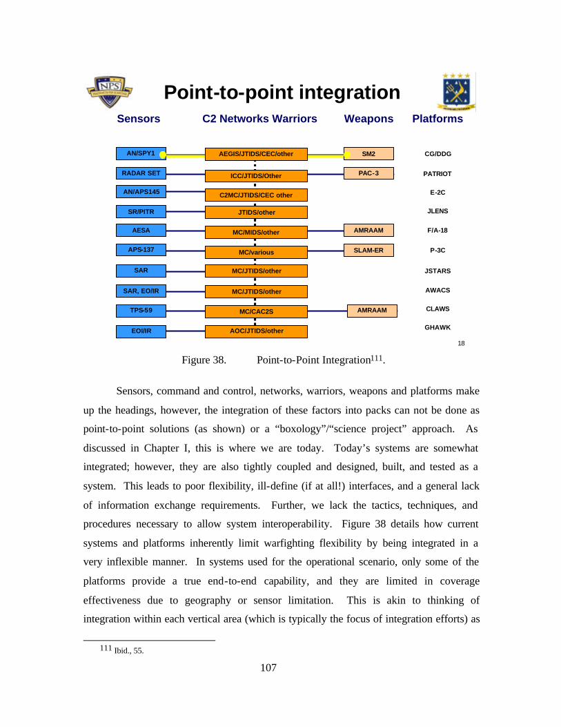
107
18
TPS-59
Sensors
AN/SPY1
RADAR SET
AESA
APS-137
AN/APS145
SAR
SAR, EO/IR
SR/PITR
EOI/IR
Fn Factors DecompositionWeapons
SM2
PAC-3
AMRAAM
SLAM-ER
AMRAAM
Platforms
CG/DDG
PATRIOT
F/A-18
P-3C
E-2C
JSTARS
CLAWS
GHAWK
AWACS
JLENS
Point-to-point integrationC2 Networks Warriors
AEGIS/JTIDS/CEC/other
ICC/JTIDS/Other
C2MC/JTIDS/CEC other
JTIDS/other
MC/MIDS/other
MC/various
MC/JTIDS/other
MC/JTIDS/other
MC/CAC2S
AOC/JTIDS/other
Figure 38. Point-to-Point Integration111.
Sensors, command and control, networks, warriors, weapons and platforms make
up the headings, however, the integration of these factors into packs can not be done as
point-to-point solutions (as shown) or a “boxology”/“science project” approach. As
discussed in Chapter I, this is where we are today. Today’s systems are somewhat
integrated; however, they are also tightly coupled and designed, built, and tested as a
system. This leads to poor flexibility, ill-define (if at all!) interfaces, and a general lack
of information exchange requirements. Further, we lack the tactics, techniques, and
procedures necessary to allow system interoperability. Figure 38 details how current
systems and platforms inherently limit warfighting flexibility by being integrated in a
very inflexible manner. In systems used for the operational scenario, only some of the
platforms provide a true end-to-end capability, and they are limited in coverage
effectiveness due to geography or sensor limitation. This is akin to thinking of
integration within each vertical area (which is typically the focus of integration efforts) as
111 Ibid., 55.
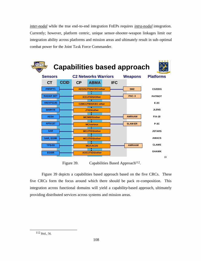
108
inter-nodal while the true end-to-end integration FnEPs requires intra-nodal integration.
Currently; however, platform centric, unique sensor-shooter-weapon linkages limit our
integration ability across platforms and mission areas and ultimately result in sub-optimal
combat power for the Joint Task Force Commander.
19
ABMAABMACTCT IFCIFCCPCPCCIDCCID
TPS-59
Sensors
AN/SPY1
RADAR SET
AESA
APS-137
AN/APS145
SAR
SAR, EO/IR
SR/PITR
EOI/IR
Weapons
SM2
PAC-3
AMRAAM
SLAM-ER
AMRAAM
Platforms
CG/DDG
PATRIOT
F/A-18
P-3C
E-2C
JSTARS
CLAWS
GHAWK
AWACS
JLENS
C2 Networks Warriors
AEGIS/JTIDS/CEC/other
ICC/JTIDS/Other
C2MC/JTIDS/CEC other
JTIDS/other
MC/MIDS/other
MC/various
MC/JTIDS/other
MC/JTIDS/other
MC/CAC2S
AOC/JTIDS/other
Combat Reach CapabilitiesCapabilities based approach
Figure 39. Capabilities Based Approach112.
Figure 39 depicts a capabilities based approach based on the five CRCs. These
five CRCs form the focus around which there should be pack re-composition. This
integration across functional domains will yield a capability-based approach, ultimately
providing distributed services across systems and mission areas.
112 Ibid., 56.
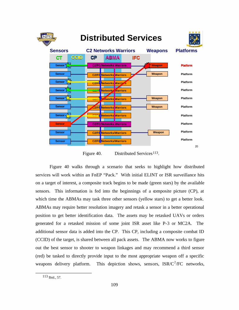
109
20
Capabilities based approachDistributed Services
CTCT CCIDCCID CPCP ABMAABMA IFCIFC
Weapons
Weapon
Weapon
Weapon
Weapon
Weapon
Sensor
C2 Networks Warriors Platforms
Platform
Platform
Platform
Platform
Platform
Platform
Platform
Platform
Platform
Platform
Sensor
Sensors
Sensor
Sensor
Sensor
Sensor
Sensor
Sensor
Sensor
Sensor
Sensor
C2/FC/Networks/Warriors
C2/FC/Networks/Warriors
C2/FC/Networks/Warriors
C2/FC/Networks/Warriors
C2/FC/Networks/Warriors
C2/FC/Networks/Warriors
C2/FC/Networks/Warriors
C2/FC/Networks/Warriors
C2/FC/Networks/Warriors
C2/FC/Networks/Warriors
CCIDCCIDCTCT CPCP
PlatformWeapon
ABMAABMA
Sensor C2/FC/Networks/Warriors
C2/FC/Networks/Warriors
IFCIFC
Sensor
Weapon Platform
Figure 40. Distributed Services113.
Figure 40 walks through a scenario that seeks to highlight how distributed
services will work within an FnEP “Pack.” With initial ELINT or ISR surveillance hits
on a target of interest, a composite track begins to be made (green stars) by the available
sensors. This information is fed into the beginnings of a composite picture (CP), at
which time the ABMAs may task three other sensors (yellow stars) to get a better look.
ABMAs may require better resolution imagery and retask a sensor in a better operational
position to get better identification data. The assets may be retasked UAVs or orders
generated for a retasked mission of some joint ISR asset like P-3 or MC2A. The
additional sensor data is added into the CP. This CP, including a composite combat ID
(CCID) of the target, is shared between all pack assets. The ABMA now works to figure
out the best sensor to shooter to weapon linkages and may recommend a third sensor
(red) be tasked to directly provide input to the most appropriate weapon off a specific
weapons delivery platform. This depiction shows, sensors, ISR/C2/FC networks,
113 Ibid., 57.
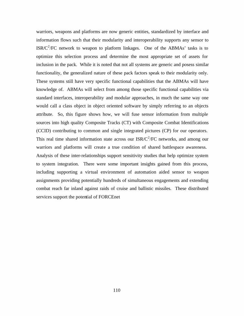
110
warriors, weapons and platforms are now generic entities, standardized by interface and
information flows such that their modularity and interoperability supports any sensor to
ISR/C2/FC network to weapon to platform linkages. One of the ABMAs’ tasks is to
optimize this selection process and determine the most appropriate set of assets for
inclusion in the pack. While it is noted that not all systems are generic and posess similar
functionality, the generalized nature of these pack factors speak to their modularity only.
These systems still have very specific functional capabilities that the ABMAs will have
knowledge of. ABMAs will select from among those specific functional capabilities via
standard interfaces, interoperability and modular approaches, in much the same way one
would call a class object in object oriented software by simply referring to an objects
attribute. So, this figure shows how, we will fuse sensor information from multiple
sources into high quality Composite Tracks (CT) with Composite Combat Identifications
(CCID) contributing to common and single integrated pictures (CP) for our operators.
This real time shared information state across our ISR/C2/FC networks, and among our
warriors and platforms will create a true condition of shared battlespace awareness.
Analysis of these inter-relationships support sensitivity studies that help optimize system
to system integration. There were some important insights gained from this process,
including supporting a virtual environment of automation aided sensor to weapon
assignments providing potentially hundreds of simultaneous engagements and extending
combat reach far inland against raids of cruise and ballistic missiles. These distributed
services support the potential of FORCEnet
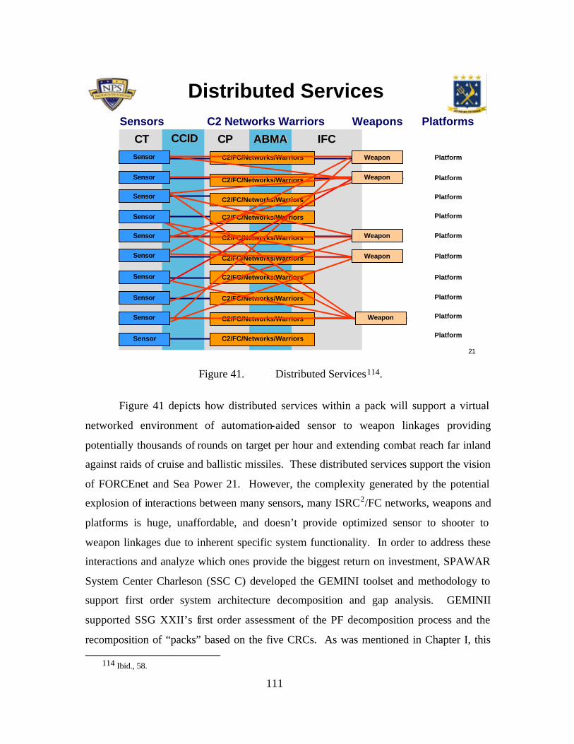
111
21
Capability-based approachDistributed Services
CTCT CCIDCCID CPCP ABMAABMA IFCIFC
Sensor
C2 Networks Warriors Platforms
Platform
Platform
Platform
Platform
Platform
Platform
Platform
Platform
Platform
Platform
C2/FC/Networks/Warriors
C2/FC/Networks/Warriors
C2/FC/Networks/Warriors
C2/FC/Networks/Warriors
C2/FC/Networks/Warriors
C2/FC/Networks/Warriors
C2/FC/Networks/Warriors
C2/FC/Networks/Warriors
C2/FC/Networks/Warriors
C2/FC/Networks/Warriors
Sensor
Sensors
Sensor
Sensor
Sensor
Sensor
Sensor
Sensor
Sensor
Sensor
Sensor
Weapons
Weapon
Weapon
Weapon
Weapon
Weapon
Figure 41. Distributed Services114.
Figure 41 depicts how distributed services within a pack will support a virtual
networked environment of automation-aided sensor to weapon linkages providing
potentially thousands of rounds on target per hour and extending combat reach far inland
against raids of cruise and ballistic missiles. These distributed services support the vision
of FORCEnet and Sea Power 21. However, the complexity generated by the potential
explosion of interactions between many sensors, many ISRC2/FC networks, weapons and
platforms is huge, unaffordable, and doesn’t provide optimized sensor to shooter to
weapon linkages due to inherent specific system functionality. In order to address these
interactions and analyze which ones provide the biggest return on investment, SPAWAR
System Center Charleson (SSC C) developed the GEMINI toolset and methodology to
support first order system architecture decomposition and gap analysis. GEMINII
supported SSG XXII’s first order assessment of the PF decomposition process and the
recomposition of “packs” based on the five CRCs. As was mentioned in Chapter I, this
114 Ibid., 58.
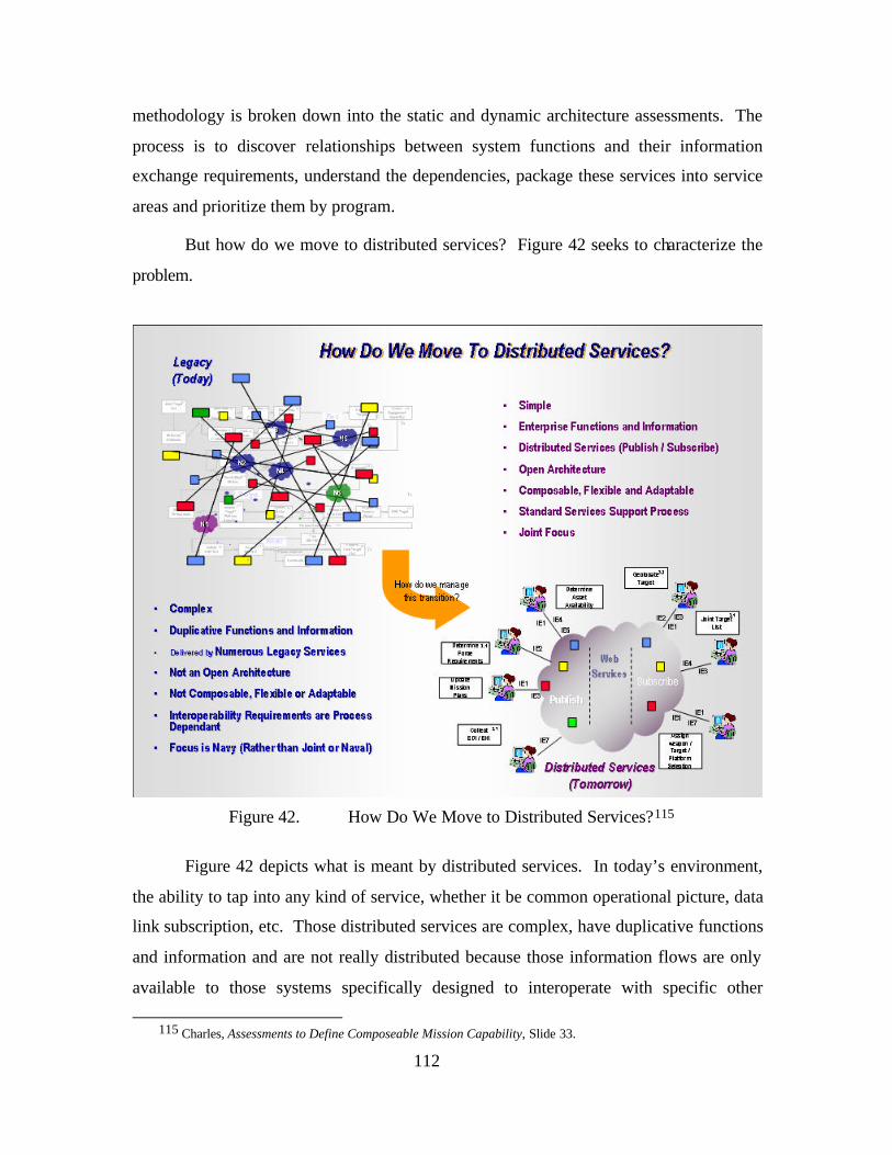
112
methodology is broken down into the static and dynamic architecture assessments. The
process is to discover relationships between system functions and their information
exchange requirements, understand the dependencies, package these services into service
areas and prioritize them by program.
But how do we move to distributed services? Figure 42 seeks to characterize the
problem.
Figure 42. How Do We Move to Distributed Services?115
Figure 42 depicts what is meant by distributed services. In today’s environment,
the ability to tap into any kind of service, whether it be common operational picture, data
link subscription, etc. Those distributed services are complex, have duplicative functions
and information and are not really distributed because those information flows are only
available to those systems specifically designed to interoperate with specific other
115 Charles, Assessments to Define Composeable Mission Capability, Slide 33.
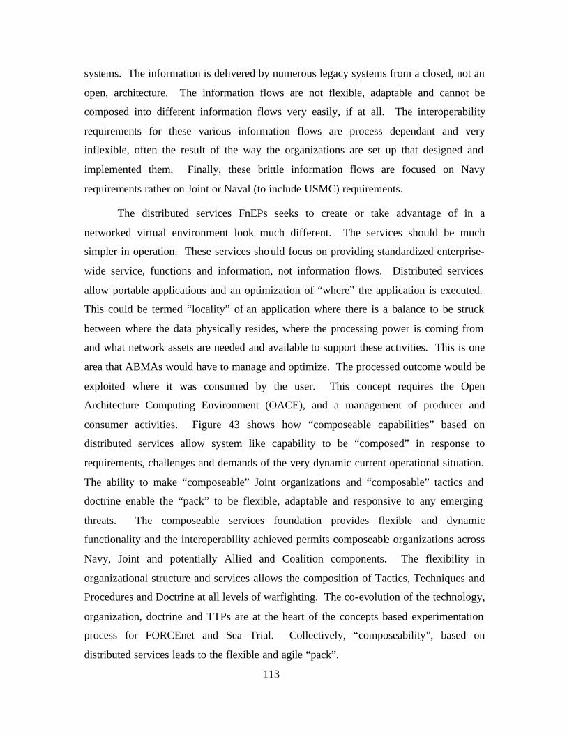
113
systems. The information is delivered by numerous legacy systems from a closed, not an
open, architecture. The information flows are not flexible, adaptable and cannot be
composed into different information flows very easily, if at all. The interoperability
requirements for these various information flows are process dependant and very
inflexible, often the result of the way the organizations are set up that designed and
implemented them. Finally, these brittle information flows are focused on Navy
requirements rather on Joint or Naval (to include USMC) requirements.
The distributed services FnEPs seeks to create or take advantage of in a
networked virtual environment look much different. The services should be much
simpler in operation. These services should focus on providing standardized enterprise-
wide service, functions and information, not information flows. Distributed services
allow portable applications and an optimization of “where” the application is executed.
This could be termed “locality” of an application where there is a balance to be struck
between where the data physically resides, where the processing power is coming from
and what network assets are needed and available to support these activities. This is one
area that ABMAs would have to manage and optimize. The processed outcome would be
exploited where it was consumed by the user. This concept requires the Open
Architecture Computing Environment (OACE), and a management of producer and
consumer activities. Figure 43 shows how “composeable capabilities” based on
distributed services allow system like capability to be “composed” in response to
requirements, challenges and demands of the very dynamic current operational situation.
The ability to make “composeable” Joint organizations and “composable” tactics and
doctrine enable the “pack” to be flexible, adaptable and responsive to any emerging
threats. The composeable services foundation provides flexible and dynamic
functionality and the interoperability achieved permits composeable organizations across
Navy, Joint and potentially Allied and Coalition components. The flexibility in
organizational structure and services allows the composition of Tactics, Techniques and
Procedures and Doctrine at all levels of warfighting. The co-evolution of the technology,
organization, doctrine and TTPs are at the heart of the concepts based experimentation
process for FORCEnet and Sea Trial. Collectively, “composeability”, based on
distributed services leads to the flexible and agile “pack”.
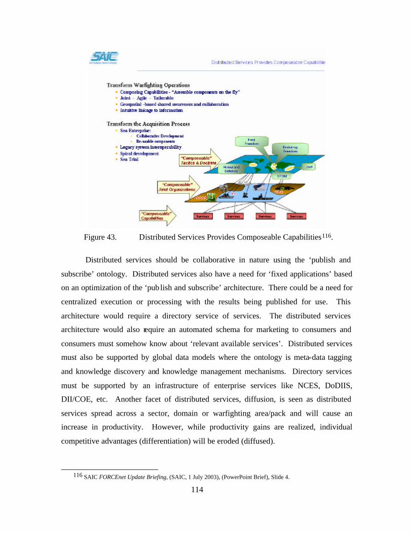
114
Figure 43. Distributed Services Provides Composeable Capabilities116.
Distributed services should be collaborative in nature using the ‘publish and
subscribe’ ontology. Distributed services also have a need for ‘fixed applications’ based
on an optimization of the ‘pub lish and subscribe’ architecture. There could be a need for
centralized execution or processing with the results being published for use. This
architecture would require a directory service of services. The distributed services
architecture would also require an automated schema for marketing to consumers and
consumers must somehow know about ‘relevant available services’. Distributed services
must also be supported by global data models where the ontology is meta-data tagging
and knowledge discovery and knowledge management mechanisms. Directory services
must be supported by an infrastructure of enterprise services like NCES, DoDIIS,
DII/COE, etc. Another facet of distributed services, diffusion, is seen as distributed
services spread across a sector, domain or warfighting area/pack and will cause an
increase in productivity. However, while productivity gains are realized, individual
competitive advantages (differentiation) will be eroded (diffused).
116 SAIC FORCEnet Update Briefing, (SAIC, 1 July 2003), (PowerPoint Brief), Slide 4.
115
Distributed services are envisioned to work in a ‘publish and subscribe’ manner
such as depicted in Figure 44.
Figure 44. Establishing Distributed Services, Overland Cruise Missile Defense
(Example)117.
As depicted in this figure, a given combat node or element will logon and
authenticate (register) themselves to “publish and subscribe” to services. This example
depicts an AEGIS cruiser that is assigned the mission to project overland cruise missile
defense to defend a ground force. Additionally, a joint theater Global Hawk asset has
been assigned to support the mission. This example has each of the nodes advertising
and registering services that it has available to support the mission, additionally, each of
the nodes request to subscribe to services that are needed for the node to execute its
mission. This figure demonstrates when a new member wishes to join a distributed
service, once authenticated, the user publishes to the rest of the distributed services
subscribers what kinds of information, what data formats, system functionalities are
117 Ibid., Slide 6.
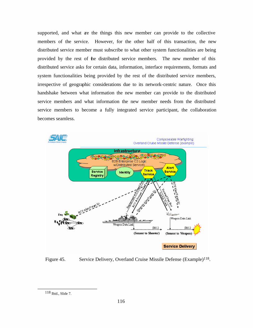
116
supported, and what are the things this new member can provide to the collective
members of the service. However, for the other half of this transaction, the new
distributed service member must subscribe to what other system functionalities are being
provided by the rest of the distributed service members. The new member of this
distributed service asks for certain data, information, interface requirements, formats and
system functionalities being provided by the rest of the distributed service members,
irrespective of geographic considerations due to its network-centric nature. Once this
handshake between what information the new member can provide to the distributed
service members and what information the new member needs from the distributed
service members to become a fully integrated service participant, the collaboration
becomes seamless.
Figure 45. Service Delivery, Overland Cruise Missile Defense (Example)118.
118 Ibid., Slide 7.
117
Once the ABMAs have composed the operational approach that will be used to
execute the overland cruise missile capability, the FORCEnet infrastructure is quickly
configured to support the publish and subscribe services (capabilities) needed. In this
example, the network establishes two consumer-to-consumer (C2C) services that allow
the three nodes to exchange information. One is a basic track services and the other
missile alert service. In this case, the AEGIS cruiser has subscribed to receive AMTI
sensor feeds from the Global Hawk’s MP-RTIP radar. The AEGIS cruiser’s on-board
distributed sensor processor has the ability to mix the Global Hawk’s remote sensor with
its local sensors to detect and ID a cruise missile threat, and to immediately report this
data to prepare for an attack (employ chemical and biological defense mechanisms). In
addition, it provides the same information back to the Global Hawk so that the MP-RTIP
radar can execute a High Resolution Radar (HRR) continuous track update information to
the AEGIS cruiser. This information is sufficient to provide the AEGIS with a fire
quality solution that can be used to engage the cruise missile remotely.
Further, the AEGIS has been made aware of the Global Hawk’s ability to not only
support a remote engagement (sensor-to-shooter paradigm) for remote engagement, but
also has the ability to support forward pass (sensor-to-weapon paradigm). This allows the
Global Hawk to take control of the SM-2 and provide mid-course and terminal guidance
support directly to the SM-2 in flight. This enables the AEGIS to engage the cruise
missile at a greater range, and potentially support a shoot- look-shoot to engage the threat.
As the scenario plays-out, the AEGIS indicates that it will engage the target, and
request forward pass support from the Global Hawk. The Global Hawk indicates it will
comply with the engagement request – the AEGIS launches the SM-2, controls initial
weapon fly-out, then turns final engagement over to the Global Hawk. We assume a
successful engagement and this example ends.
Distributed services must be built on a common, open architecture that allows the
ability to interoperate and collaborate without consideration to all the possible
combinations or permutations of possible systems both already in operational use or those
being designed. Open architectures built on secure, common standards will allow nesting
and chaining the most simple, well defined and completely defined interface of any

118
number of architecture pieces into the most complex service. This approach allows
distributed services to be composed of modular system functionality as the need or
situation dictates and allows for the architecture and ‘infostructure’ to be as flexible and
adaptable as needed. These composeability, flexibility, and adaptability characteristics
produce the needed ‘small pieces, loosely coupled’ architecture so critically important to
FnEPs. These enterprise-wide, standard services will be able to support business
processes as they evolve and change based on the response needed to environmental or
threat inputs. As with all initiatives, including FnEPs, this notion of distributed services
must be joint and incorporate service participants from all services because the FnEPs
concept cannot be achieved with only single service inputs. The question remains, how
do distributed services become a reality? Figure 46 seeks to show a process to be used
that would accomplish the goal of realizing distributed services.
Figure 46. FnEP Strategy to Align Systems with Warfighting Capabilities119.
119 Hesser and Rieken, FORCEnet Engagment Packs (FnEPs), Slide 10.
119
Figure 46 is an FnEPs strategy to align systems and programs. Our thesis seeks to
more fully understand the system decomposition into FnEP factor components (depicted
in Figure 46) as the first step in the Combat Reach integration process. When
recomposing factor components into “packs,” the five CRCs and a few critical services
(horizontal ‘lanes’) become critical enablers to pack composition. The GEMINII
approach supports more detailed understanding of integration management to understand
if all system interrelationships are possible, optimal, desired or affordable. There would
be a need for sys tem designers to use this information to focus on interactions that yield
the most effectiveness. Understanding how combat reach capabilities provide
warfighting distributed services are key to understanding how distributed services support
“pack” adaptability across both Strike and TAMD mission areas.
The first step in the process is to establish the FORCEnet architecture with respect
to services required. As stated before, FnEPs requires specific integration of all six
FORCEnet factors (warriors, sensors, platforms, networks, command and control and
weapons) focused on the five CRCs. The five CRCs and services depicted in Figure 46
are: sensors, common tracks, composite combat identification, common tactical pictures,
automated battle management aids, integrated fire control, weapons, common/single
operational picture, mission planning, precision navigation and timing, and FORCnet
information grid. In Figure 46, the FORCEnet services along the left are a combination
of both FORCEnet Factors and CRCs. The five primary FnEP CRCs are supported by
other services such as Precision Navigation and Timing (PNT), Mission Planning (MP)
and FORCEnet Information Grid (Fn IG)) while Single/Common Pictures is further
broken down into the Common Tactical Picture (CTP). In the next step, “As-Is”
operational systems/programs are overlaid onto a map that shows how these individual
Stove-piped systems’ deliver the required FnEP capabilities. The next step is to
decompose these “As-Is” operational systems into their system functions and/or
information categories and map them to the respective CRCs and services. This is where
the transformation process begins by decomposing systems into small pieces (system
functions/information pairs) which will align functionality to distributed services. The
SSC-C GEMINII methodology (NTIRA, TVDB and associated tools) will be the toolset
by which this decomposition takes place. The next step is to analyze the gaps and
120
overlaps of system functionality as provided by current systems in support of the defined
FORCEnet services. The GEMINII methodology supports the gap and overlap analysis
process but also provides tools to do dynamic modeling of new integrated, distributed
architectures. This realigned system functionality, combined with defined architectural
interfaces at the CRC and service level and organized around and end-to-end perspective
of the engagement chain will make FnEP analysis possible. The objective at this juncture
is to perform architectural analysis from a CRC and distributed service perspective of
“like” systems and maintain capability context within a particular engagement chain,
called TACSITs in this situation. The final and critical step is to align and integrate those
new CRCs (system functions) and distributed services along the TACSIT-defined
engagement chain and propose new funding and integration alignment changes which
will allow for an end-to-end engagement chain integration based service. This process
will allow prioritization and synchronization of program funding and capability
increments across naval and joint programs. This strategy also begins to support
composeable warfighting analysis because the analysis is general and abstract enough
such that it is not strictly limited to an individual TACSIT, but can define a whole new
TACSIT based on whatever operational threat or situation is presented. This strategy and
analysis process can support operational architectures of FORCEnet factors based on new
tactics, techniques and procedures as they evolve. The composeability aspect of
FORCEnet factor integration and analysis is interesting because it provides benefits on
both the operational (common interfaces, a ‘toolset’ that gives you the flexibility to
define what you want and need) and acquisition (only build/pay for a function once)
levels.
Factor Integration Analysis – To begin the FORCEnet factor integration
analysis, SSC Charleston began by supporting the SSG to conduct a pack factor (system
functional) decomposition, focusing only in the Strike and TAMD mission areas. Using
the same potential Navy and Joint Systems in both mission areas, the SSG and SSC-C
decomposed these factors into appropriate sensors, networks, command and control
nodes, weapons and evaluated the 85,000 information exchange requirements supporting
the five CRCs. This analysis yielded sequences of activities and Factor interactions
required to fulfill Strike and TAMD mission areas and adapt between these missions.
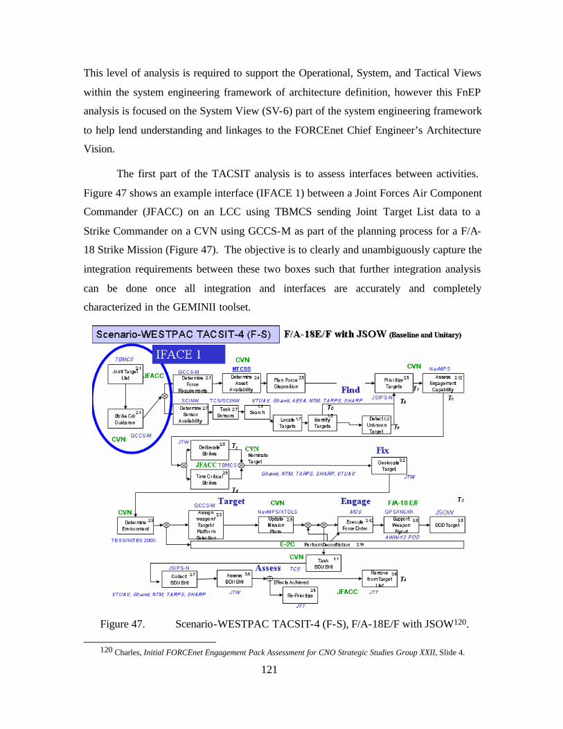
121
This level of analysis is required to support the Operational, System, and Tactical Views
within the system engineering framework of architecture definition, however this FnEP
analysis is focused on the System View (SV-6) part of the system engineering framework
to help lend understanding and linkages to the FORCEnet Chief Engineer’s Architecture
Vision.
The first part of the TACSIT analysis is to assess interfaces between activities.
Figure 47 shows an example interface (IFACE 1) between a Joint Forces Air Component
Commander (JFACC) on an LCC using TBMCS sending Joint Target List data to a
Strike Commander on a CVN using GCCS-M as part of the planning process for a F/A-
18 Strike Mission (Figure 47). The objective is to clearly and unambiguously capture the
integration requirements between these two boxes such that further integration analysis
can be done once all integration and interfaces are accurately and completely
characterized in the GEMINII toolset.
Figure 47. Scenario-WESTPAC TACSIT-4 (F-S), F/A-18E/F with JSOW120.
120 Charles, Initial FORCEnet Engagement Pack Assessment for CNO Strategic Studies Group XXII, Slide 4.
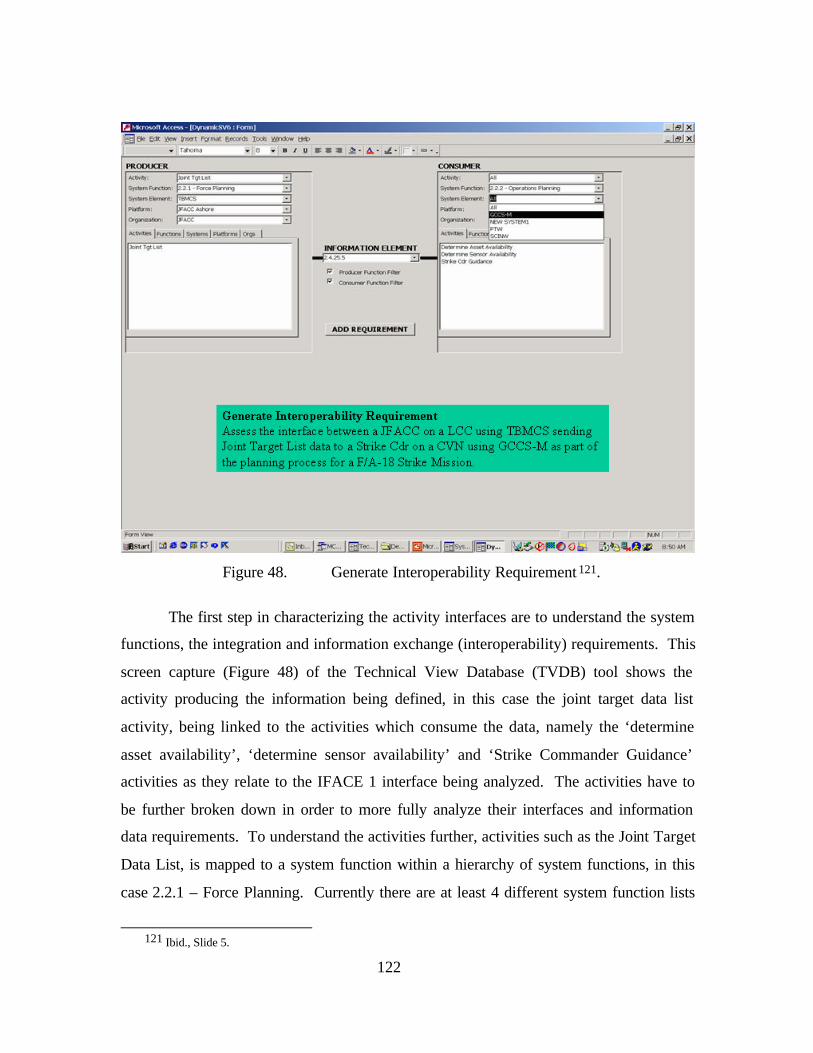
122
Figure 48. Generate Interoperability Requirement 121.
The first step in characterizing the activity interfaces are to understand the system
functions, the integration and information exchange (interoperability) requirements. This
screen capture (Figure 48) of the Technical View Database (TVDB) tool shows the
activity producing the information being defined, in this case the joint target data list
activity, being linked to the activities which consume the data, namely the ‘determine
asset availability’, ‘determine sensor availability’ and ‘Strike Commander Guidance’
activities as they relate to the IFACE 1 interface being analyzed. The activities have to
be further broken down in order to more fully analyze their interfaces and information
data requirements. To understand the activities further, activities such as the Joint Target
Data List, is mapped to a system function within a hierarchy of system functions, in this
case 2.2.1 – Force Planning. Currently there are at least 4 different system function lists
121 Ibid., Slide 5.
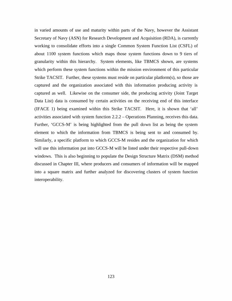
123
in varied amounts of use and maturity within parts of the Navy, however the Assistant
Secretary of Navy (ASN) for Research Development and Acquisition (RDA), is currently
working to consolidate efforts into a single Common System Function List (CSFL) of
about 1100 system functions which maps those system functions down to 9 tiers of
granularity within this hierarchy. System elements, like TBMCS shown, are systems
which perform these system functions within the mission environment of this particular
Strike TACSIT. Further, these systems must reside on particular platform(s), so those are
captured and the organization associated with this information producing activity is
captured as well. Likewise on the consumer side, the producing activity (Joint Target
Data List) data is consumed by certain activities on the receiving end of this interface
(IFACE 1) being examined within this Strike TACSIT. Here, it is shown that ‘all’
activities associated with system function 2.2.2 – Operations Planning, receives this data.
Further, ‘GCCS-M’ is being highlighted from the pull down list as being the system
element to which the information from TBMCS is being sent to and consumed by.
Similarly, a specific platform to which GCCS-M resides and the organization for which
will use this information put into GCCS-M will be listed under their respective pull-down
windows. This is also beginning to populate the Design Structure Matrix (DSM) method
discussed in Chapter III, where producers and consumers of information will be mapped
into a square matrix and further analyzed for discovering clusters of system function
interoperability.
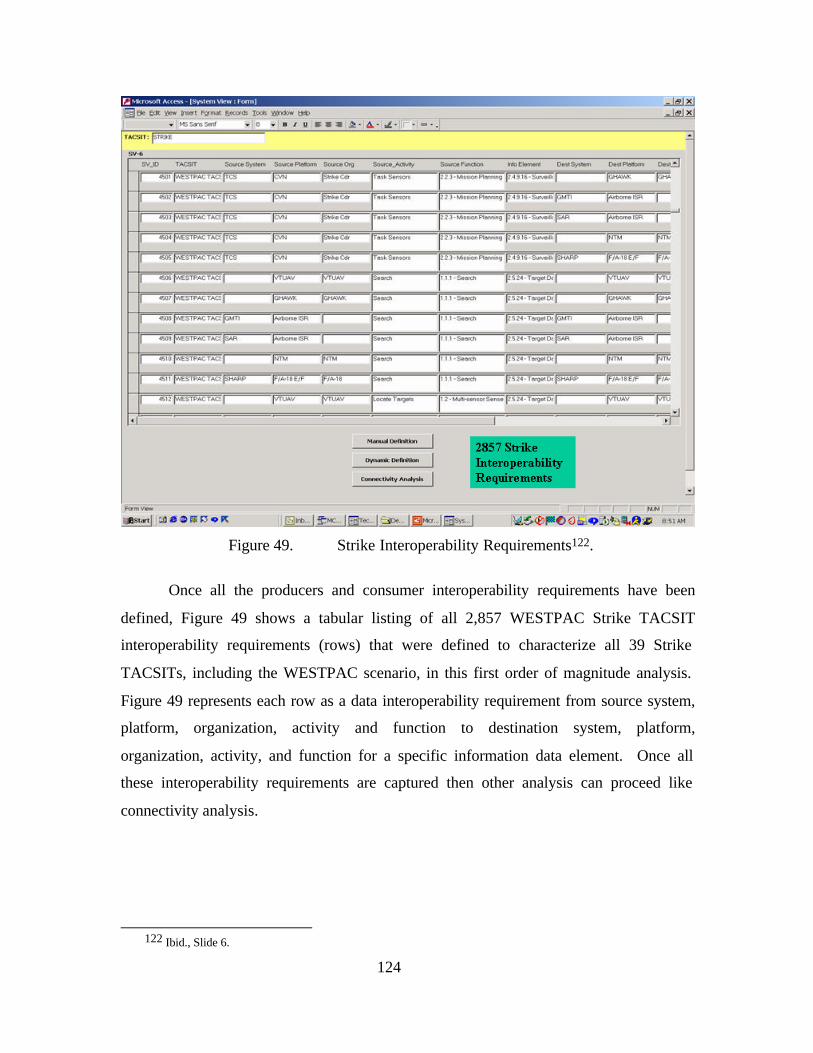
124
Figure 49. Strike Interoperability Requirements122.
Once all the producers and consumer interoperability requirements have been
defined, Figure 49 shows a tabular listing of all 2,857 WESTPAC Strike TACSIT
interoperability requirements (rows) that were defined to characterize all 39 Strike
TACSITs, including the WESTPAC scenario, in this first order of magnitude analysis.
Figure 49 represents each row as a data interoperability requirement from source system,
platform, organization, activity and function to destination system, platform,
organization, activity, and function for a specific information data element. Once all
these interoperability requirements are captured then other analysis can proceed like
connectivity analysis.
122 Ibid., Slide 6.
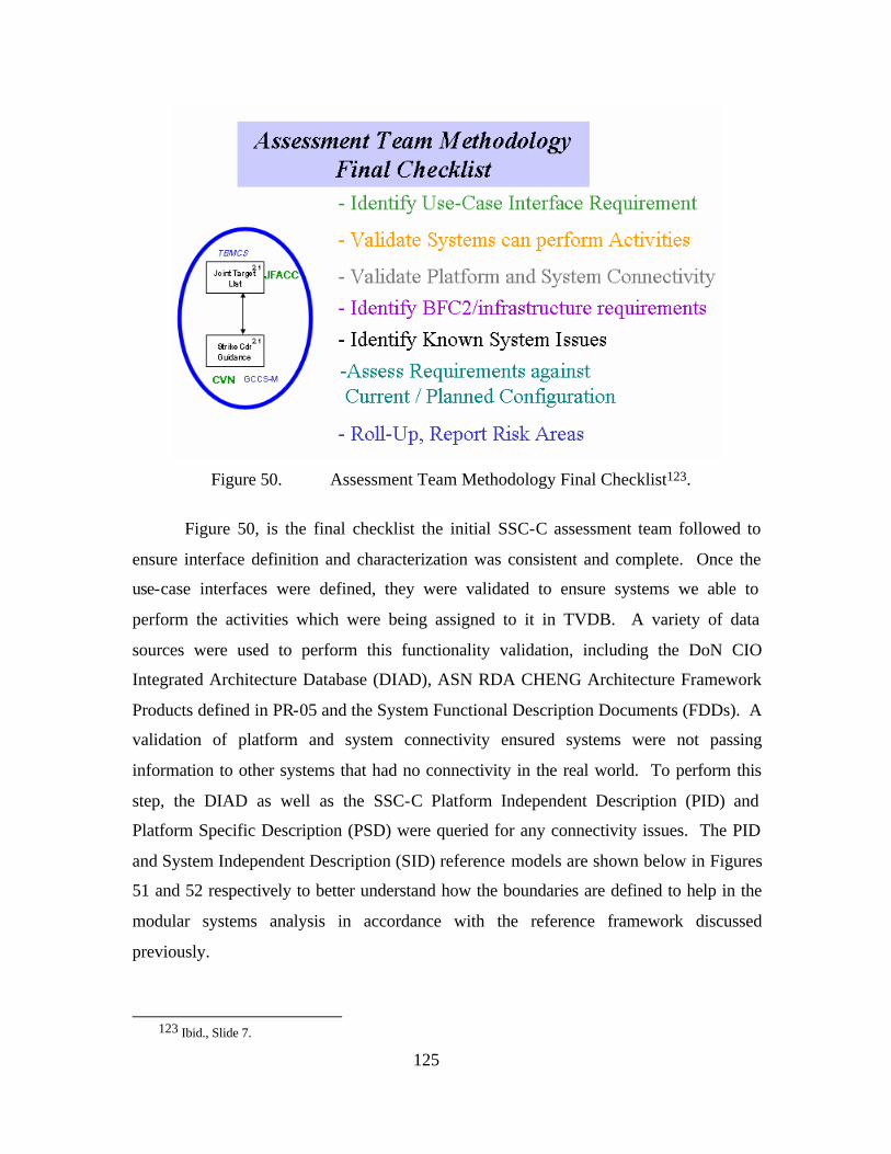
125
Figure 50. Assessment Team Methodology Final Checklist123.
Figure 50, is the final checklist the initial SSC-C assessment team followed to
ensure interface definition and characterization was consistent and complete. Once the
use-case interfaces were defined, they were validated to ensure systems we able to
perform the activities which were being assigned to it in TVDB. A variety of data
sources were used to perform this functionality validation, including the DoN CIO
Integrated Architecture Database (DIAD), ASN RDA CHENG Architecture Framework
Products defined in PR-05 and the System Functional Description Documents (FDDs). A
validation of platform and system connectivity ensured systems were not passing
information to other systems that had no connectivity in the real world. To perform this
step, the DIAD as well as the SSC-C Platform Independent Description (PID) and
Platform Specific Description (PSD) were queried for any connectivity issues. The PID
and System Independent Description (SID) reference models are shown below in Figures
51 and 52 respectively to better understand how the boundaries are defined to help in the
modular systems analysis in accordance with the reference framework discussed
previously.
123 Ibid., Slide 7.
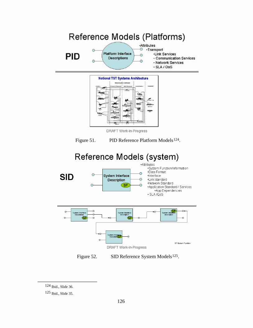
126
Figure 51. PID Reference Platform Models124.
Figure 52. SID Reference System Models125.
124 Ibid., Slide 36. 125 Ibid., Slide 35.
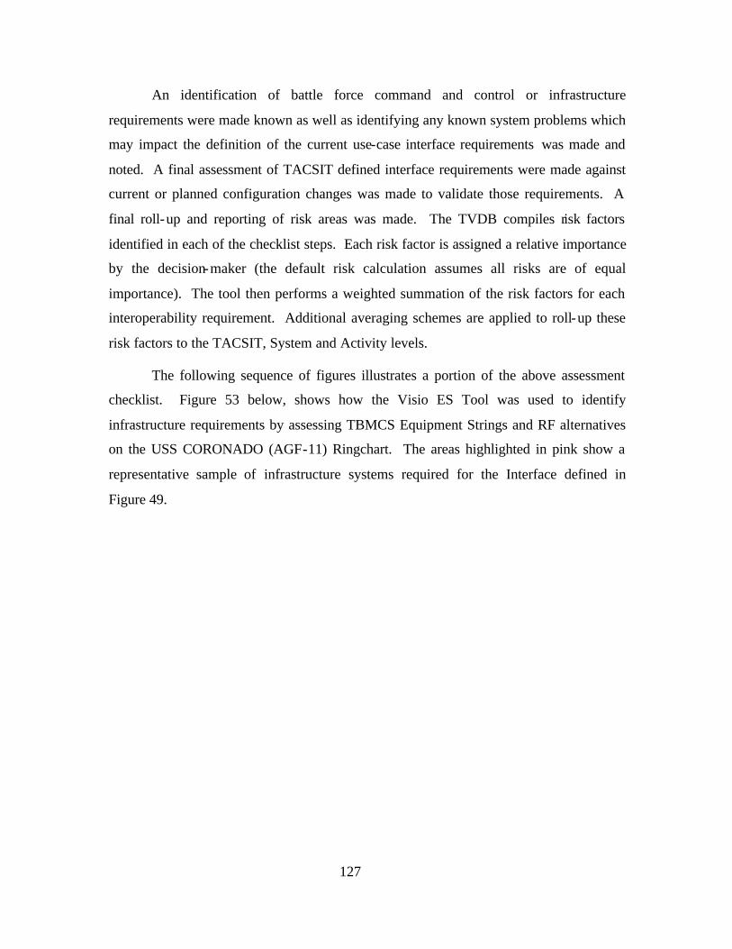
127
An identification of battle force command and control or infrastructure
requirements were made known as well as identifying any known system problems which
may impact the definition of the current use-case interface requirements was made and
noted. A final assessment of TACSIT defined interface requirements were made against
current or planned configuration changes was made to validate those requirements. A
final roll-up and reporting of risk areas was made. The TVDB compiles risk factors
identified in each of the checklist steps. Each risk factor is assigned a relative importance
by the decision-maker (the default risk calculation assumes all risks are of equal
importance). The tool then performs a weighted summation of the risk factors for each
interoperability requirement. Additional averaging schemes are applied to roll-up these
risk factors to the TACSIT, System and Activity levels.
The following sequence of figures illustrates a portion of the above assessment
checklist. Figure 53 below, shows how the Visio ES Tool was used to identify
infrastructure requirements by assessing TBMCS Equipment Strings and RF alternatives
on the USS CORONADO (AGF-11) Ringchart. The areas highlighted in pink show a
representative sample of infrastructure systems required for the Interface defined in
Figure 49.
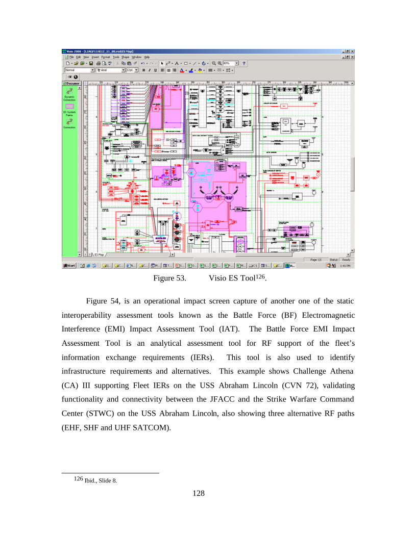
128
Figure 53. Visio ES Tool126.
Figure 54, is an operational impact screen capture of another one of the static
interoperability assessment tools known as the Battle Force (BF) Electromagnetic
Interference (EMI) Impact Assessment Tool (IAT). The Battle Force EMI Impact
Assessment Tool is an analytical assessment tool for RF support of the fleet’s
information exchange requirements (IERs). This tool is also used to identify
infrastructure requirements and alternatives. This example shows Challenge Athena
(CA) III supporting Fleet IERs on the USS Abraham Lincoln (CVN 72), validating
functionality and connectivity between the JFACC and the Strike Warfare Command
Center (STWC) on the USS Abraham Lincoln, also showing three alternative RF paths
(EHF, SHF and UHF SATCOM).
126 Ibid., Slide 8.
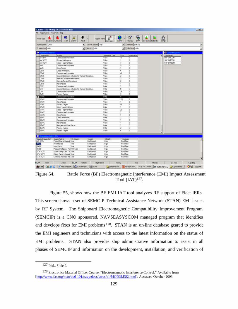
129
Figure 54. Battle Force (BF) Electromagnetic Interference (EMI) Impact Assessment
Tool (IAT)127.
Figure 55, shows how the BF EMI IAT tool analyzes RF support of Fleet IERs.
This screen shows a set of SEMCIP Technical Assistance Network (STAN) EMI issues
by RF System. The Shipboard Electromagnetic Compatibility Improvement Program
(SEMCIP) is a CNO sponsored, NAVSEASYSCOM managed program that identifies
and develops fixes for EMI problems 128. STAN is an on-line database geared to provide
the EMI engineers and technicians with access to the latest information on the status of
EMI problems. STAN also provides ship administrative information to assist in all
phases of SEMCIP and information on the development, installation, and verification of
127 Ibid., Slide 9.
128 Electronics Material Officer Course, “Electromagnetic Interference Control,” Available from [http://www.fas.org/man/dod-101/navy/docs/swos/e1/MOD3LES2.html]; Accessed October 2003.
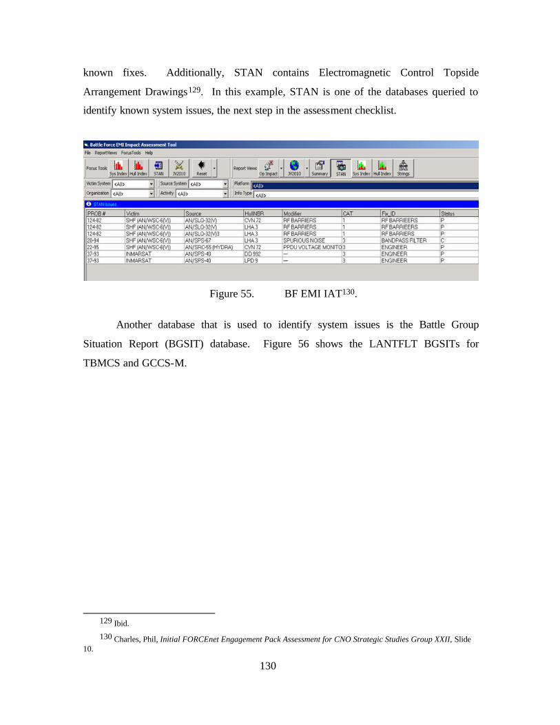
130
known fixes. Additionally, STAN contains Electromagnetic Control Topside
Arrangement Drawings129. In this example, STAN is one of the databases queried to
identify known system issues, the next step in the assessment checklist.
Figure 55. BF EMI IAT130.
Another database that is used to identify system issues is the Battle Group
Situation Report (BGSIT) database. Figure 56 shows the LANTFLT BGSITs for
TBMCS and GCCS-M.
129 Ibid.
130 Charles, Phil, Initial FORCEnet Engagement Pack Assessment for CNO Strategic Studies Group XXII, Slide 10.
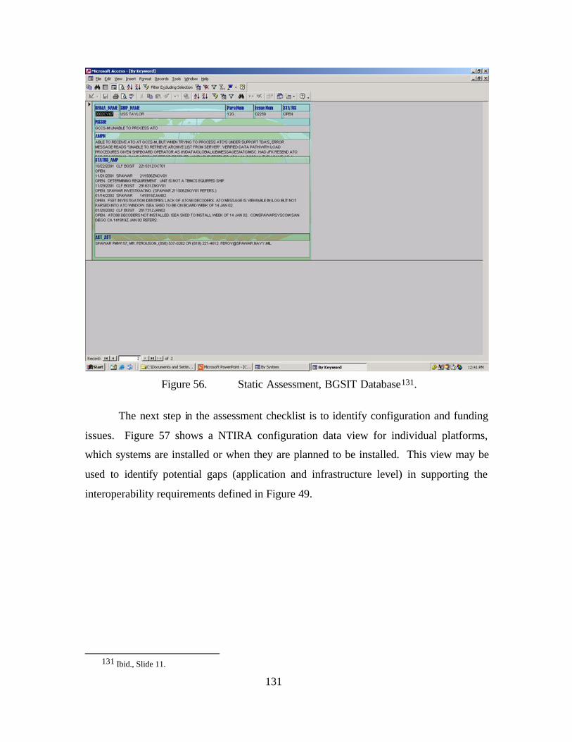
131
Figure 56. Static Assessment, BGSIT Database131.
The next step in the assessment checklist is to identify configuration and funding
issues. Figure 57 shows a NTIRA configuration data view for individual platforms,
which systems are installed or when they are planned to be installed. This view may be
used to identify potential gaps (application and infrastructure level) in supporting the
interoperability requirements defined in Figure 49.
131 Ibid., Slide 11.
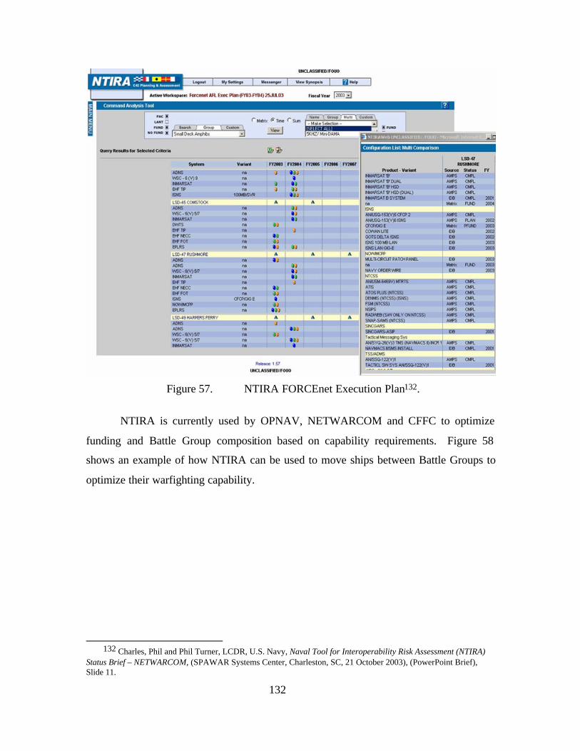
132
Figure 57. NTIRA FORCEnet Execution Plan132.
NTIRA is currently used by OPNAV, NETWARCOM and CFFC to optimize
funding and Battle Group composition based on capability requirements. Figure 58
shows an example of how NTIRA can be used to move ships between Battle Groups to
optimize their warfighting capability.
132 Charles, Phil and Phil Turner, LCDR, U.S. Navy, Naval Tool for Interoperability Risk Assessment (NTIRA)
Status Brief – NETWARCOM, (SPAWAR Systems Center, Charleston, SC, 21 October 2003), (PowerPoint Brief), Slide 11.
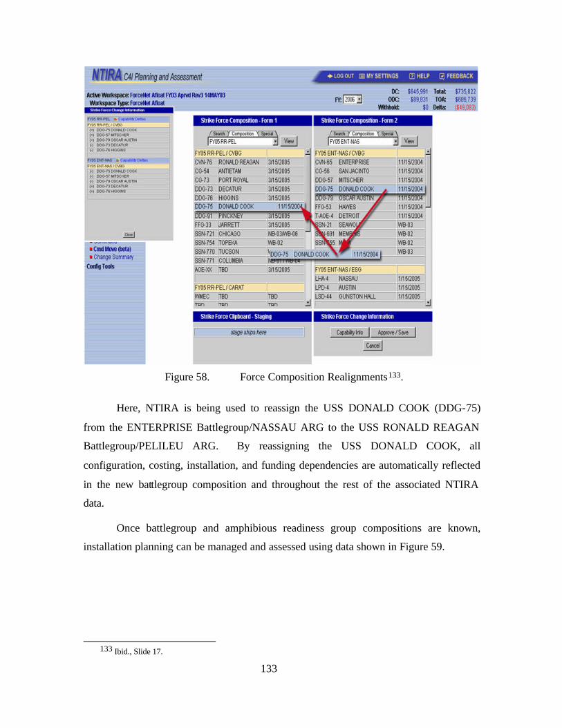
133
Figure 58. Force Composition Realignments133.
Here, NTIRA is being used to reassign the USS DONALD COOK (DDG-75)
from the ENTERPRISE Battlegroup/NASSAU ARG to the USS RONALD REAGAN
Battlegroup/PELILEU ARG. By reassigning the USS DONALD COOK, all
configuration, costing, installation, and funding dependencies are automatically reflected
in the new battlegroup composition and throughout the rest of the associated NTIRA
data.
Once battlegroup and amphibious readiness group compositions are known,
installation planning can be managed and assessed using data shown in Figure 59.
133 Ibid., Slide 17.
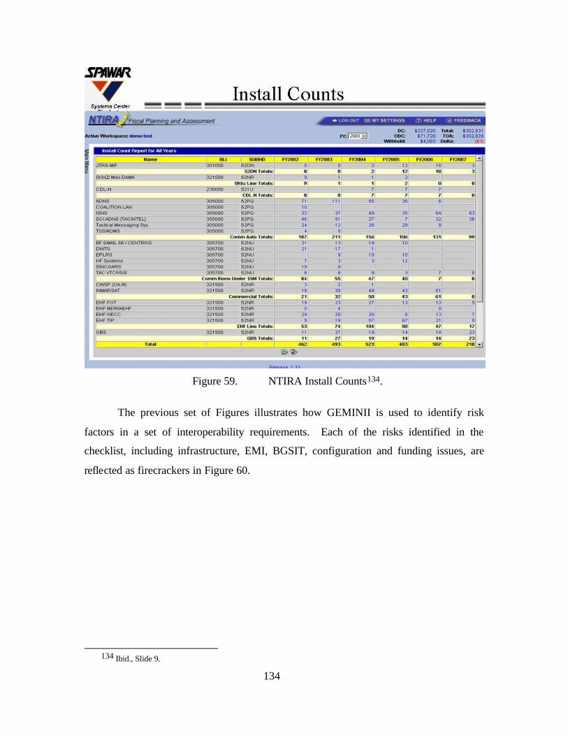
134
Figure 59. NTIRA Install Counts134.
The previous set of Figures illustrates how GEMINII is used to identify risk
factors in a set of interoperability requirements. Each of the risks identified in the
checklist, including infrastructure, EMI, BGSIT, configuration and funding issues, are
reflected as firecrackers in Figure 60.
134 Ibid., Slide 9.
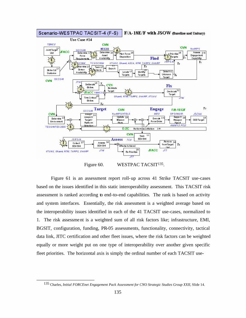
135
Figure 60. WESTPAC TACSIT135.
Figure 61 is an assessment report roll-up across 41 Strike TACSIT use-cases
based on the issues identified in this static interoperability assessment. This TACSIT risk
assessment is ranked according to end-to-end capabilities. The rank is based on activity
and system interfaces. Essentially, the risk assessment is a weighted average based on
the interoperability issues identified in each of the 41 TACSIT use-cases, normalized to
1. The risk assessment is a weighted sum of all risk factors like; infrastructure, EMI,
BGSIT, configuration, funding, PR-05 assessments, functionality, connectivity, tactical
data link, JITC certification and other fleet issues, where the risk factors can be weighted
equally or more weight put on one type of interoperability over another given specific
fleet priorities. The horizontal axis is simply the ordinal number of each TACSIT use-
135 Charles, Initial FORCEnet Engagement Pack Assessment for CNO Strategic Studies Group XXII, Slide 14.
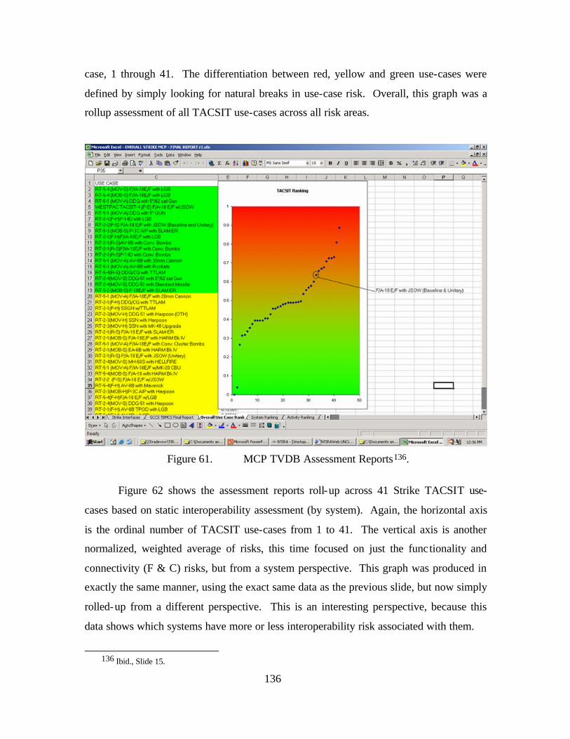
136
case, 1 through 41. The differentiation between red, yellow and green use-cases were
defined by simply looking for natural breaks in use-case risk. Overall, this graph was a
rollup assessment of all TACSIT use-cases across all risk areas.
Figure 61. MCP TVDB Assessment Reports136.
Figure 62 shows the assessment reports roll-up across 41 Strike TACSIT use-
cases based on static interoperability assessment (by system). Again, the horizontal axis
is the ordinal number of TACSIT use-cases from 1 to 41. The vertical axis is another
normalized, weighted average of risks, this time focused on just the func tionality and
connectivity (F & C) risks, but from a system perspective. This graph was produced in
exactly the same manner, using the exact same data as the previous slide, but now simply
rolled-up from a different perspective. This is an interesting perspective, because this
data shows which systems have more or less interoperability risk associated with them.
136 Ibid., Slide 15.
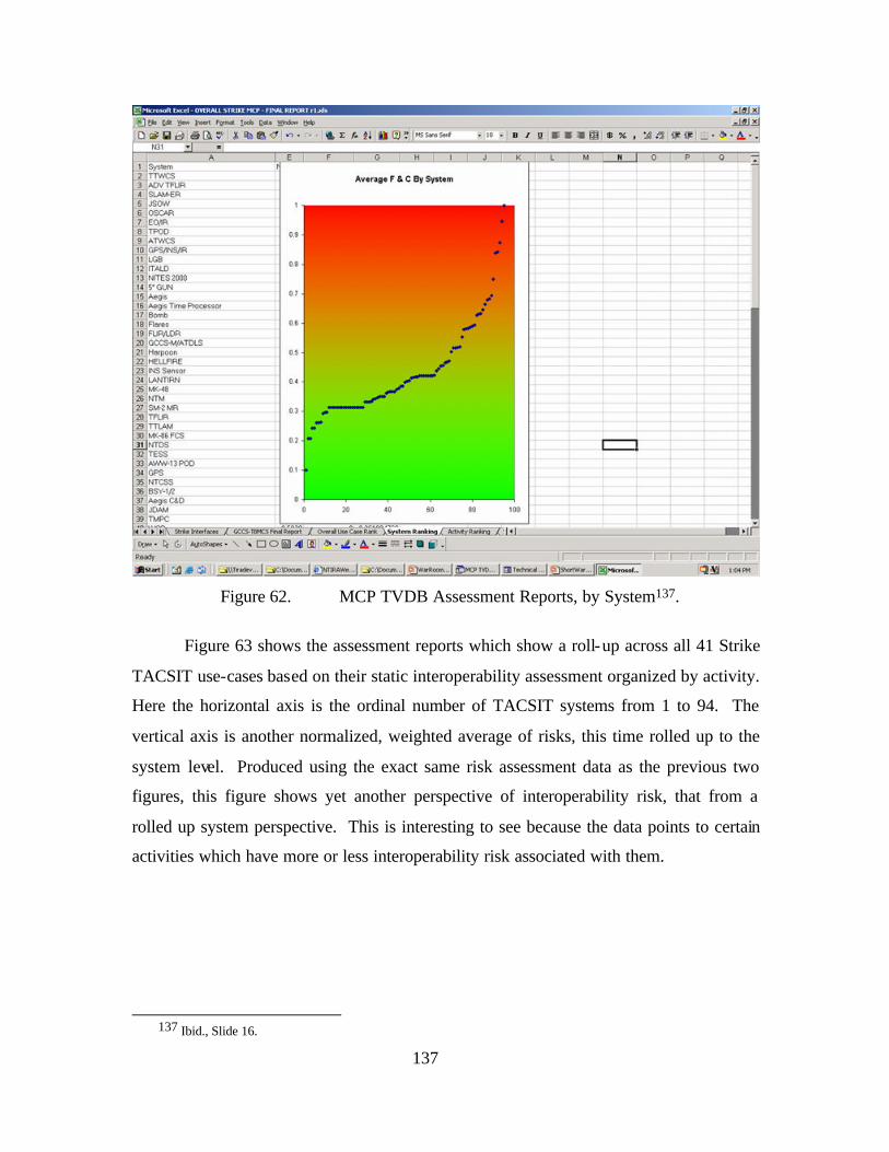
137
Figure 62. MCP TVDB Assessment Reports, by System137.
Figure 63 shows the assessment reports which show a roll-up across all 41 Strike
TACSIT use-cases based on their static interoperability assessment organized by activity.
Here the horizontal axis is the ordinal number of TACSIT systems from 1 to 94. The
vertical axis is another normalized, weighted average of risks, this time rolled up to the
system level. Produced using the exact same risk assessment data as the previous two
figures, this figure shows yet another perspective of interoperability risk, that from a
rolled up system perspective. This is interesting to see because the data points to certain
activities which have more or less interoperability risk associated with them.
137 Ibid., Slide 16.
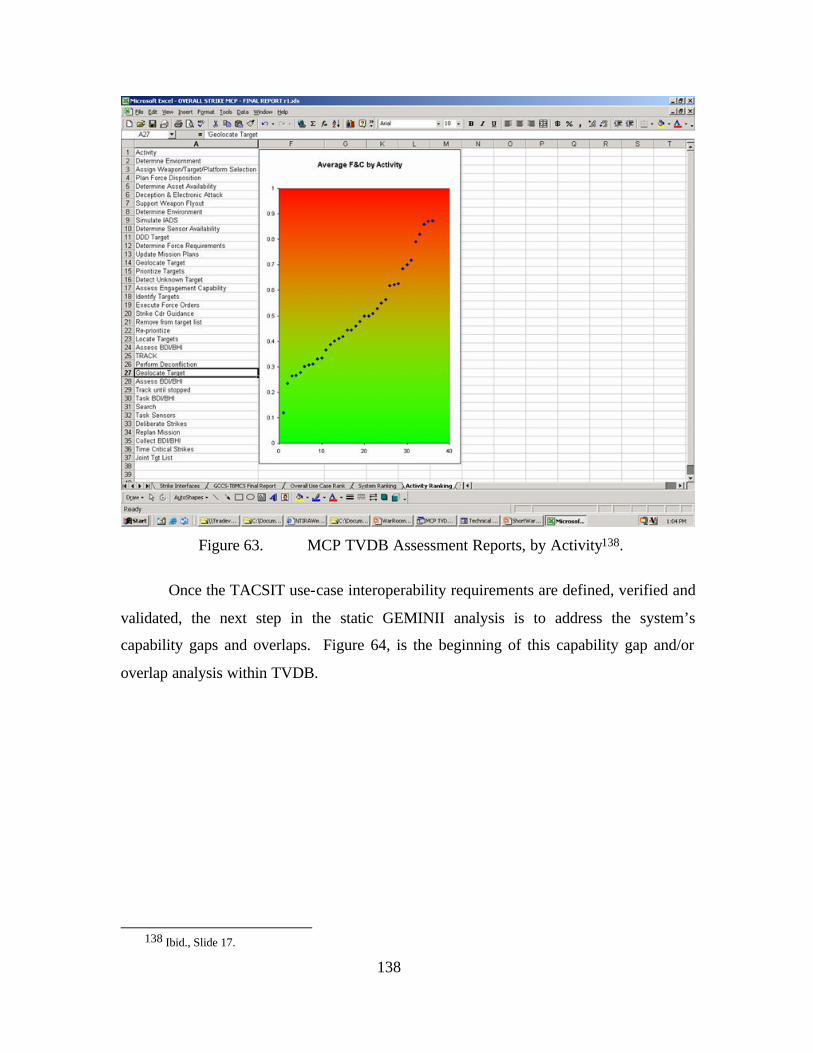
138
Figure 63. MCP TVDB Assessment Reports, by Activity138.
Once the TACSIT use-case interoperability requirements are defined, verified and
validated, the next step in the static GEMINII analysis is to address the system’s
capability gaps and overlaps. Figure 64, is the beginning of this capability gap and/or
overlap analysis within TVDB.
138 Ibid., Slide 17.
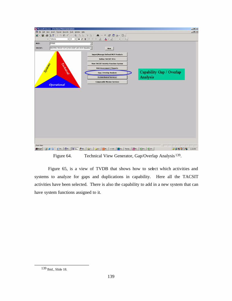
139
Figure 64. Technical View Generator, Gap/Overlap Analysis 139.
Figure 65, is a view of TVDB that shows how to select which activities and
systems to analyze for gaps and duplications in capability. Here all the TACSIT
activities have been selected. There is also the capability to add in a new system that can
have system functions assigned to it.
139 Ibid., Slide 18.
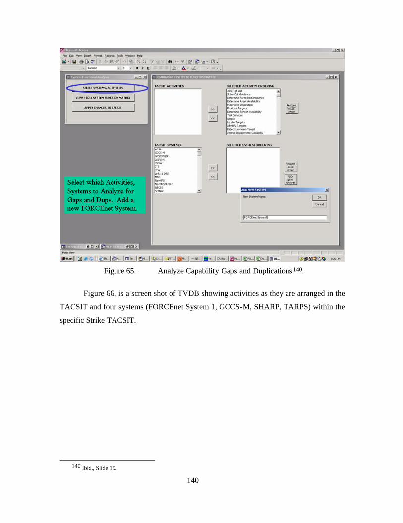
140
Figure 65. Analyze Capability Gaps and Duplications 140.
Figure 66, is a screen shot of TVDB showing activities as they are arranged in the
TACSIT and four systems (FORCEnet System 1, GCCS-M, SHARP, TARPS) within the
specific Strike TACSIT.
140 Ibid., Slide 19.
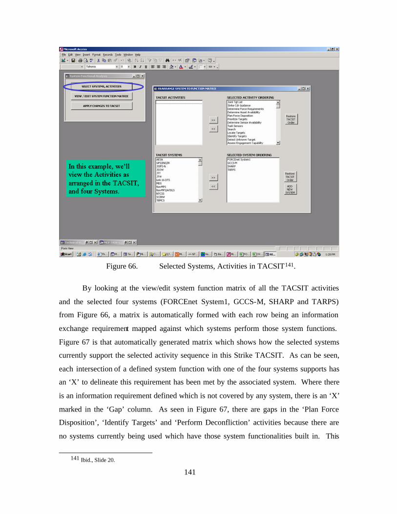
141
Figure 66. Selected Systems, Activities in TACSIT141.
By looking at the view/edit system function matrix of all the TACSIT activities
and the selected four systems (FORCEnet System1, GCCS-M, SHARP and TARPS)
from Figure 66, a matrix is automatically formed with each row being an information
exchange requirement mapped against which systems perform those system functions.
Figure 67 is that automatically generated matrix which shows how the selected systems
currently support the selected activity sequence in this Strike TACSIT. As can be seen,
each intersection of a defined system function with one of the four systems supports has
an ‘X’ to delineate this requirement has been met by the associated system. Where there
is an information requirement defined which is not covered by any system, there is an ‘X’
marked in the ‘Gap’ column. As seen in Figure 67, there are gaps in the ‘Plan Force
Disposition’, ‘Identify Targets’ and ‘Perform Deconfliction’ activities because there are
no systems currently being used which have those system functionalities built in. This
141 Ibid., Slide 20.
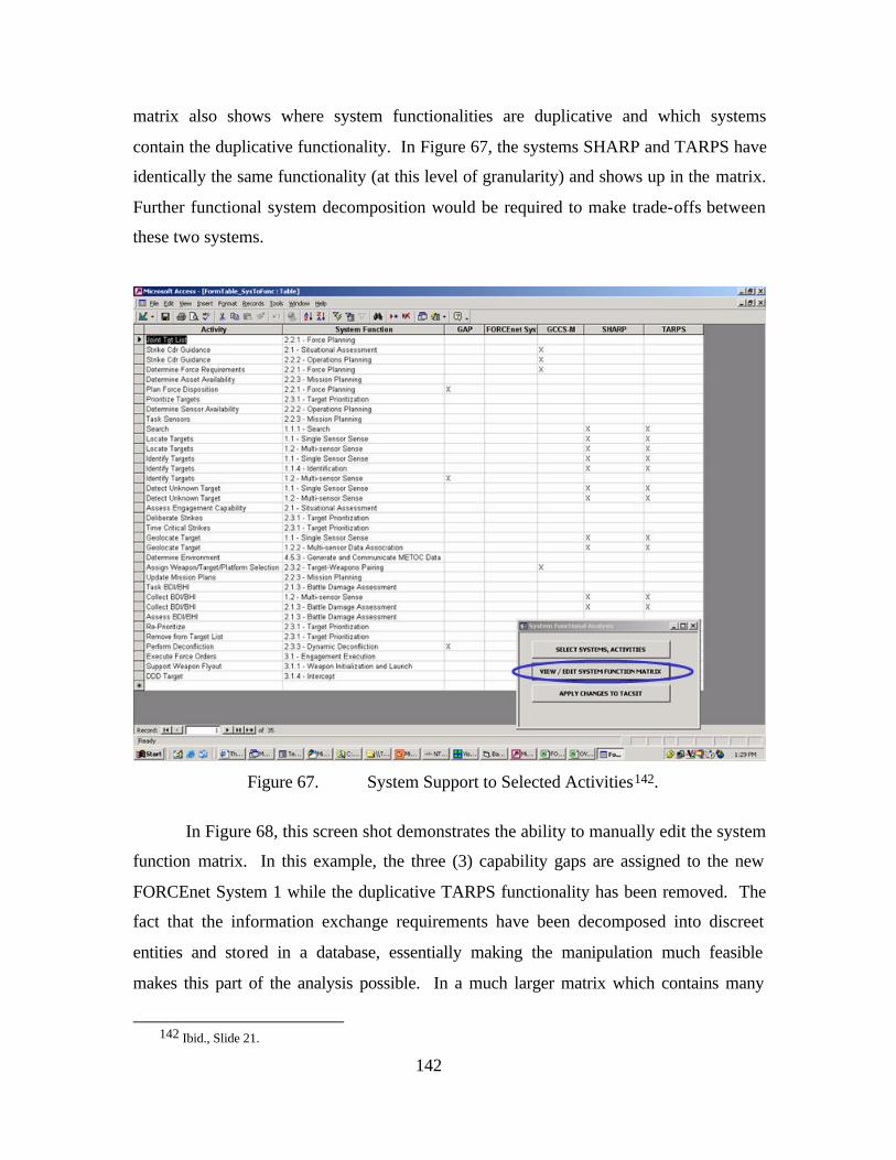
142
matrix also shows where system functionalities are duplicative and which systems
contain the duplicative functionality. In Figure 67, the systems SHARP and TARPS have
identically the same functionality (at this level of granularity) and shows up in the matrix.
Further functional system decomposition would be required to make trade-offs between
these two systems.
Figure 67. System Support to Selected Activities142.
In Figure 68, this screen shot demonstrates the ability to manually edit the system
function matrix. In this example, the three (3) capability gaps are assigned to the new
FORCEnet System 1 while the duplicative TARPS functionality has been removed. The
fact that the information exchange requirements have been decomposed into discreet
entities and stored in a database, essentially making the manipulation much feasible
makes this part of the analysis possible. In a much larger matrix which contains many
142 Ibid., Slide 21.
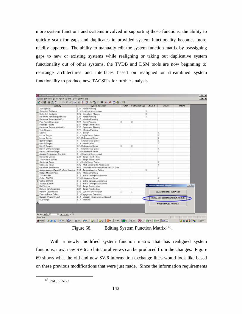
143
more system functions and systems involved in supporting those functions, the ability to
quickly scan for gaps and duplicates in provided system functionality becomes more
readily apparent. The ability to manually edit the system function matrix by reassigning
gaps to new or existing systems while realigning or taking out duplicative system
functionality out of other systems, the TVDB and DSM tools are now beginning to
rearrange architectures and interfaces based on realigned or streamlined system
functionality to produce new TACSITs for further analysis.
Figure 68. Editing System Function Matrix143.
With a newly modified system function matrix that has realigned system
functions, now, new SV-6 architectural views can be produced from the changes. Figure
69 shows what the old and new SV-6 information exchange lines would look like based
on these previous modifications that were just made. Since the information requirements
143 Ibid., Slide 22.
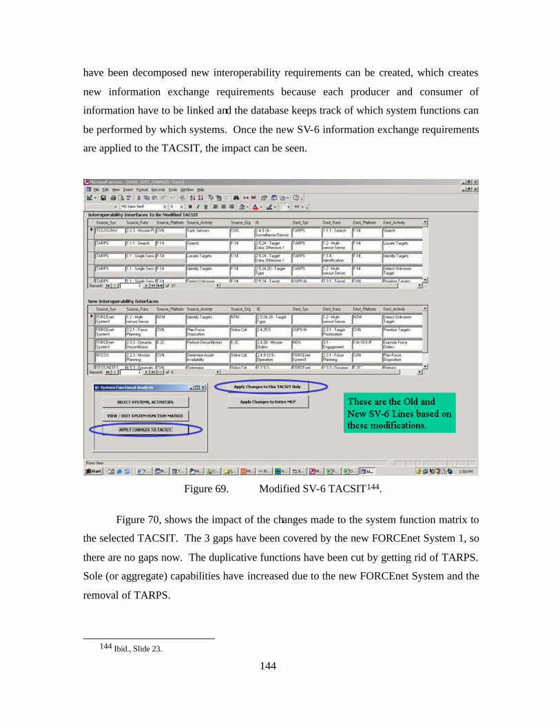
144
have been decomposed new interoperability requirements can be created, which creates
new information exchange requirements because each producer and consumer of
information have to be linked and the database keeps track of which system functions can
be performed by which systems. Once the new SV-6 information exchange requirements
are applied to the TACSIT, the impact can be seen.
Figure 69. Modified SV-6 TACSIT144.
Figure 70, shows the impact of the changes made to the system function matrix to
the selected TACSIT. The 3 gaps have been covered by the new FORCEnet System 1, so
there are no gaps now. The duplicative functions have been cut by getting rid of TARPS.
Sole (or aggregate) capabilities have increased due to the new FORCEnet System and the
removal of TARPS.
144 Ibid., Slide 23.
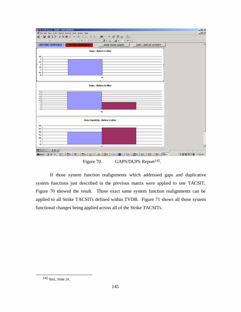
145
Figure 70. GAPS/DUPS Report145.
If those system function realignments which addressed gaps and duplicative
system functions just described in the previous matrix were applied to one TACSIT,
Figure 70 showed the result. Those exact same system function realignments can be
applied to all Strike TACSITs defined within TVDB. Figure 71 shows all those system
functional changes being applied across all of the Strike TACSITs.
145 Ibid., Slide 24.
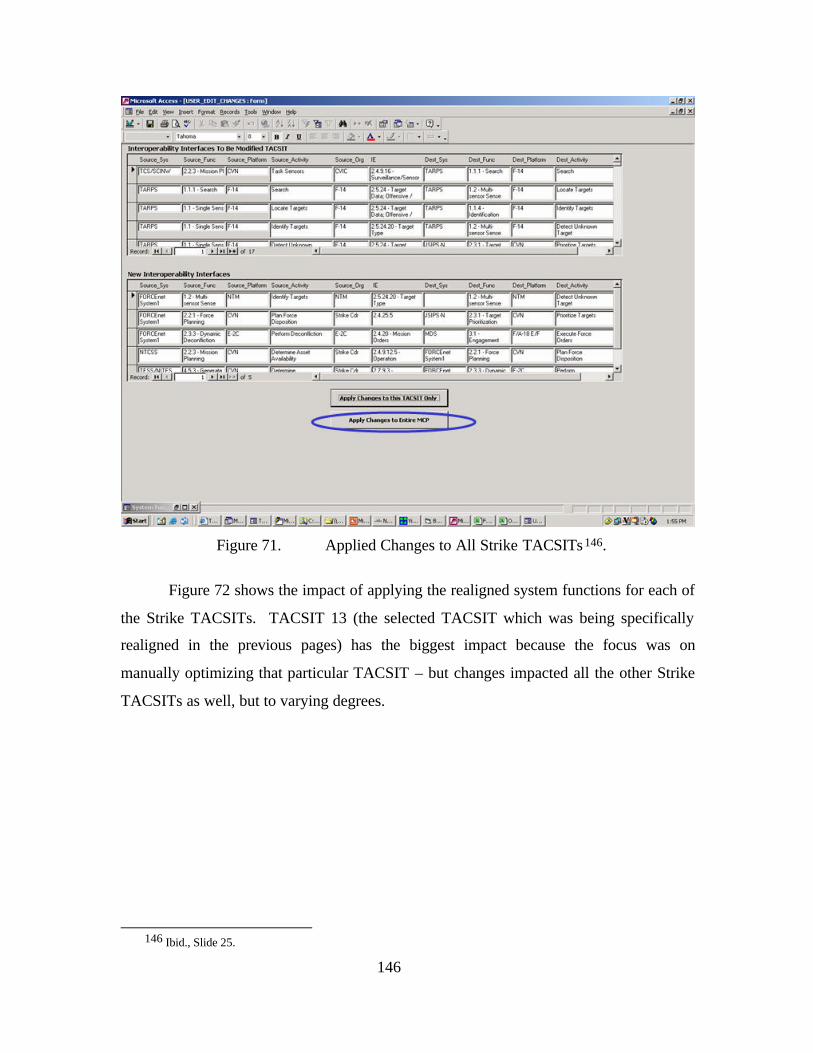
146
Figure 71. Applied Changes to All Strike TACSITs146.
Figure 72 shows the impact of applying the realigned system functions for each of
the Strike TACSITs. TACSIT 13 (the selected TACSIT which was being specifically
realigned in the previous pages) has the biggest impact because the focus was on
manually optimizing that particular TACSIT – but changes impacted all the other Strike
TACSITs as well, but to varying degrees.
146 Ibid., Slide 25.
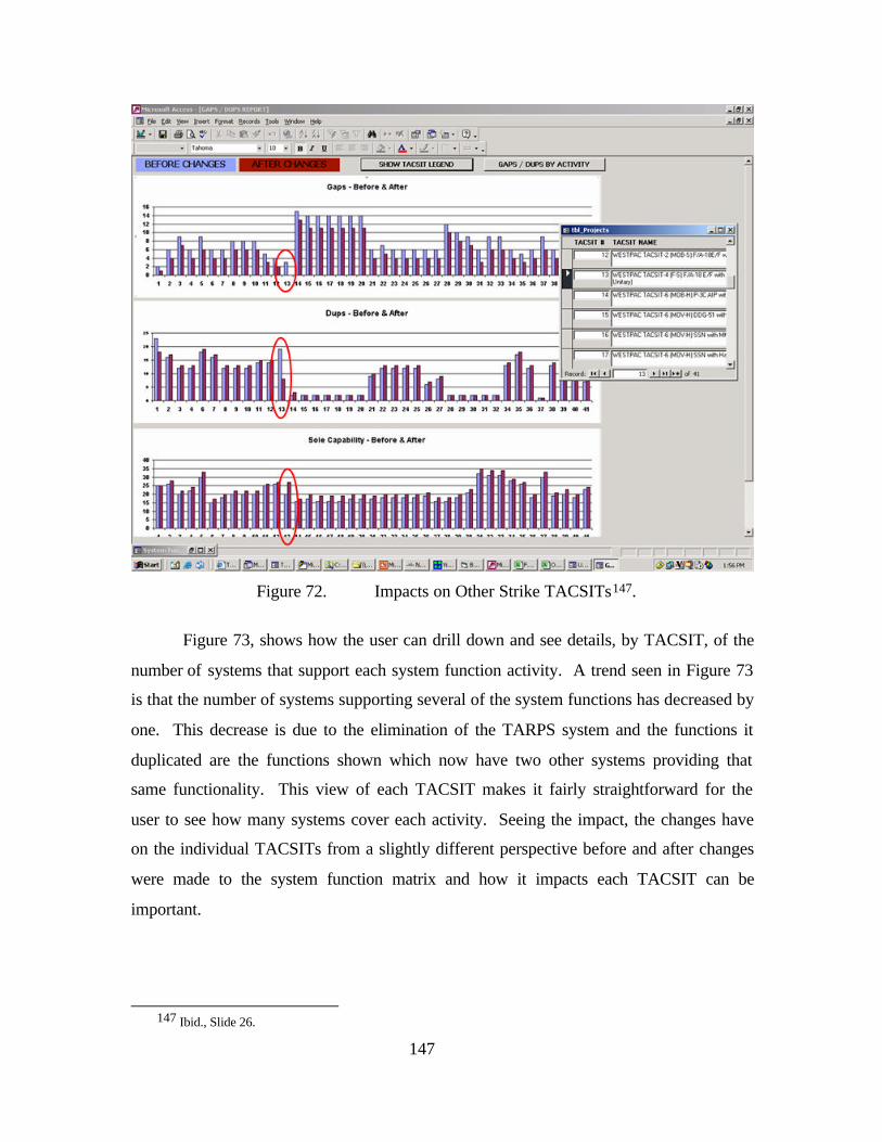
147
Figure 72. Impacts on Other Strike TACSITs147.
Figure 73, shows how the user can drill down and see details, by TACSIT, of the
number of systems that support each system function activity. A trend seen in Figure 73
is that the number of systems supporting several of the system functions has decreased by
one. This decrease is due to the elimination of the TARPS system and the functions it
duplicated are the functions shown which now have two other systems providing that
same functionality. This view of each TACSIT makes it fairly straightforward for the
user to see how many systems cover each activity. Seeing the impact, the changes have
on the individual TACSITs from a slightly different perspective before and after changes
were made to the system function matrix and how it impacts each TACSIT can be
important.
147 Ibid., Slide 26.
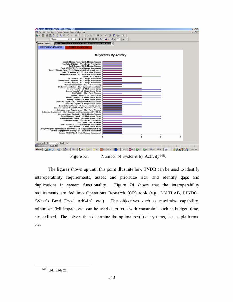
148
Figure 73. Number of Systems by Activity148.
The figures shown up until this point illustrate how TVDB can be used to identify
interoperability requirements, assess and prioritize risk, and identify gaps and
duplications in system functionality. Figure 74 shows that the interoperability
requirements are fed into Operations Research (OR) tools (e.g., MATLAB, LINDO,
‘What’s Best! Excel Add-In’, etc.). The objectives such as maximize capability,
minimize EMI impact, etc. can be used as criteria with constraints such as budget, time,
etc. defined. The solvers then determine the optimal set(s) of systems, issues, platforms,
etc.
148 Ibid., Slide 27.
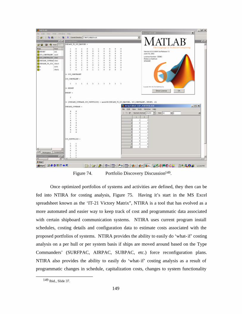
149
Figure 74. Portfolio Discovery Discussion149.
Once optimized portfolios of systems and activities are defined, they then can be
fed into NTIRA for costing analysis, Figure 75. Having it’s start in the MS Excel
spreadsheet known as the ‘IT-21 Victory Matrix”, NTIRA is a tool that has evolved as a
more automated and easier way to keep track of cost and programmatic data associated
with certain shipboard communication systems. NTIRA uses current program install
schedules, costing details and configuration data to estimate costs associated with the
proposed portfolios of systems. NTIRA provides the ability to easily do ‘what- if’ costing
analysis on a per hull or per system basis if ships are moved around based on the Type
Commanders’ (SURFPAC, AIRPAC, SUBPAC, etc.) force reconfiguration plans.
NTIRA also provides the ability to easily do ‘what- if’ costing analysis as a result of
programmatic changes in schedule, capitalization costs, changes to system functionality
149 Ibid., Slide 37.
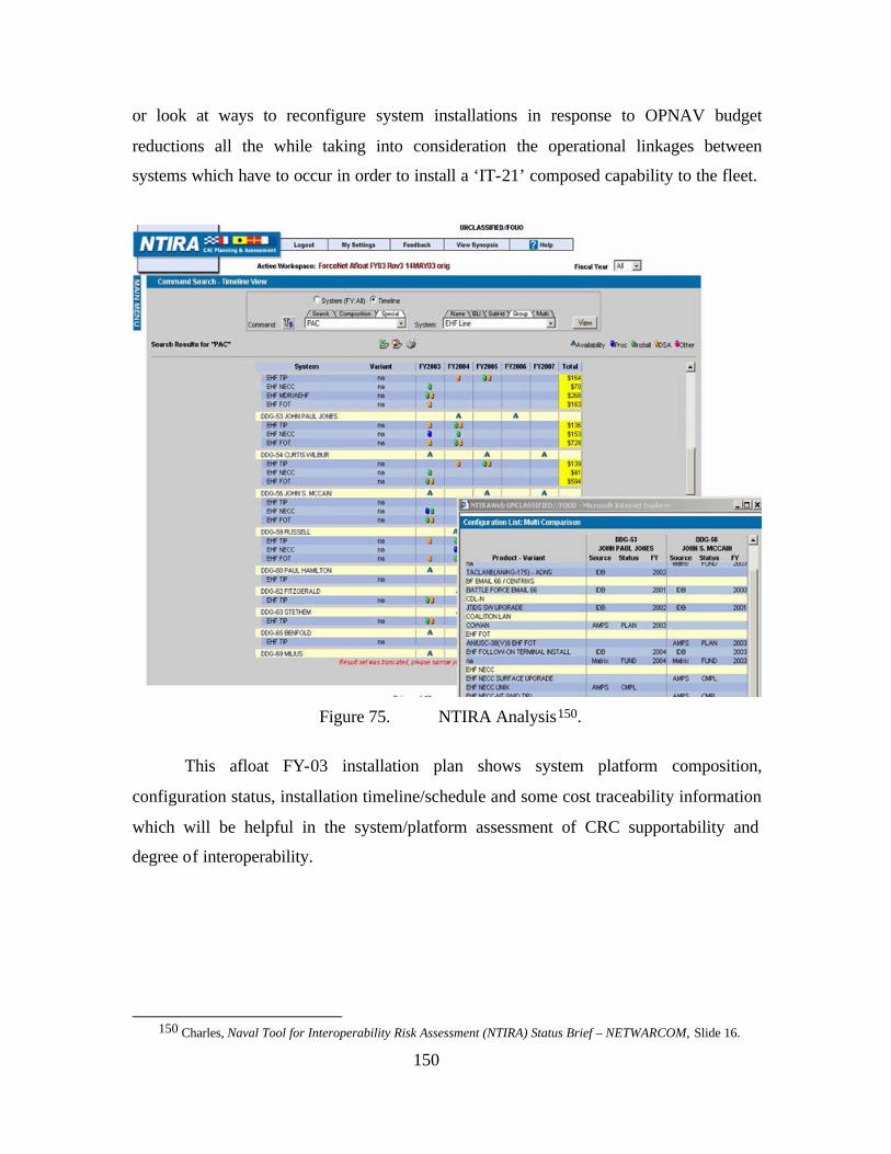
150
or look at ways to reconfigure system installations in response to OPNAV budget
reductions all the while taking into consideration the operational linkages between
systems which have to occur in order to install a ‘IT-21’ composed capability to the fleet.
Figure 75. NTIRA Analysis150.
This afloat FY-03 installation plan shows system platform composition,
configuration status, installation timeline/schedule and some cost traceability information
which will be helpful in the system/platform assessment of CRC supportability and
degree of interoperability.
150 Charles, Naval Tool for Interoperability Risk Assessment (NTIRA) Status Brief – NETWARCOM, Slide 16.
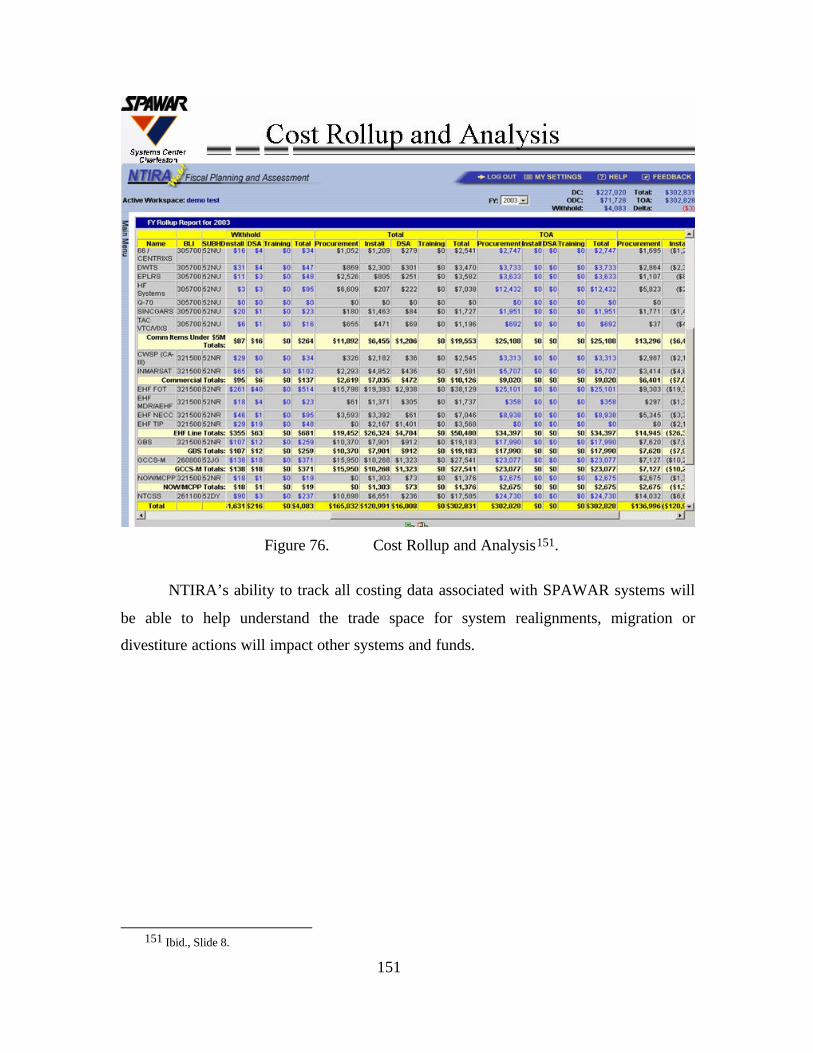
151
Figure 76. Cost Rollup and Analysis151.
NTIRA’s ability to track all costing data associated with SPAWAR systems will
be able to help understand the trade space for system realignments, migration or
divestiture actions will impact other systems and funds.
151 Ibid., Slide 8.
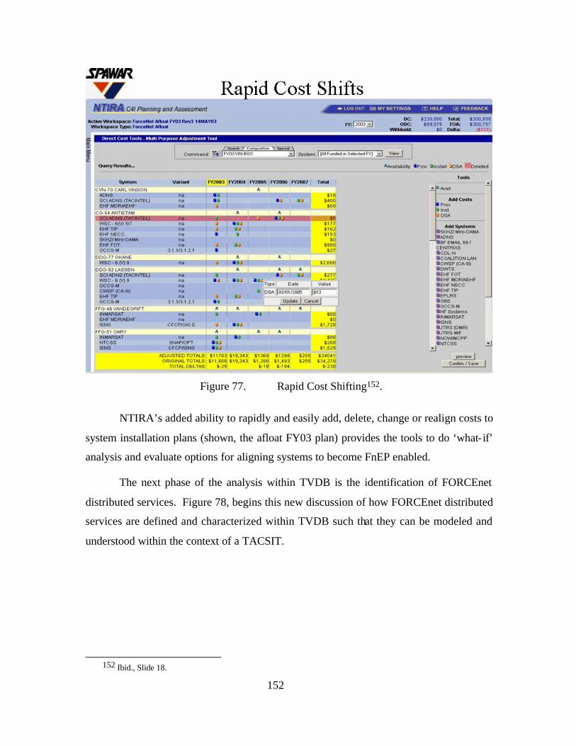
152
Figure 77. Rapid Cost Shifting152.
NTIRA’s added ability to rapidly and easily add, delete, change or realign costs to
system installation plans (shown, the afloat FY03 plan) provides the tools to do ‘what- if’
analysis and evaluate options for aligning systems to become FnEP enabled.
The next phase of the analysis within TVDB is the identification of FORCEnet
distributed services. Figure 78, begins this new discussion of how FORCEnet distributed
services are defined and characterized within TVDB such that they can be modeled and
understood within the context of a TACSIT.
152 Ibid., Slide 18.
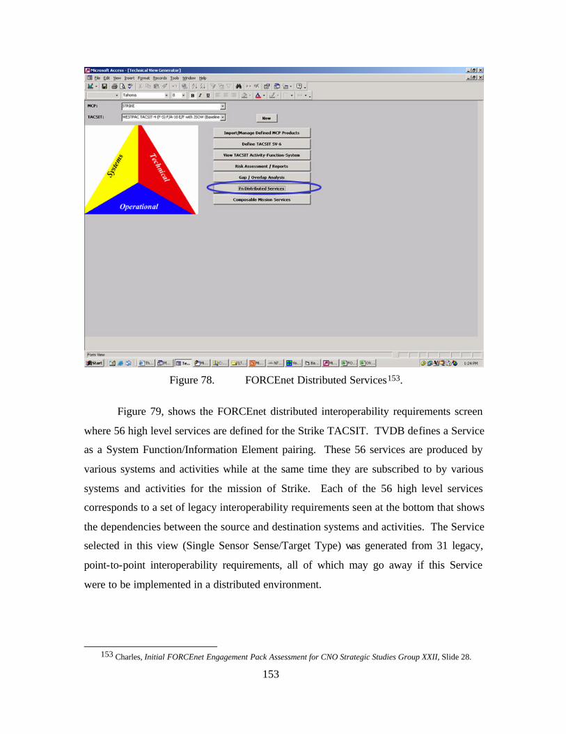
153
Figure 78. FORCEnet Distributed Services153.
Figure 79, shows the FORCEnet distributed interoperability requirements screen
where 56 high level services are defined for the Strike TACSIT. TVDB defines a Service
as a System Function/Information Element pairing. These 56 services are produced by
various systems and activities while at the same time they are subscribed to by various
systems and activities for the mission of Strike. Each of the 56 high level services
corresponds to a set of legacy interoperability requirements seen at the bottom that shows
the dependencies between the source and destination systems and activities. The Service
selected in this view (Single Sensor Sense/Target Type) was generated from 31 legacy,
point-to-point interoperability requirements, all of which may go away if this Service
were to be implemented in a distributed environment.
153 Charles, Initial FORCEnet Engagement Pack Assessment for CNO Strategic Studies Group XXII, Slide 28.
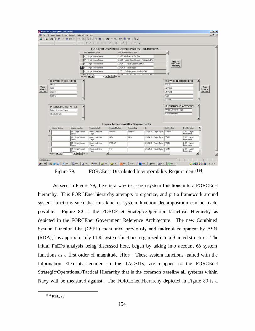
154
Figure 79. FORCEnet Distributed Interoperability Requirements154.
As seen in Figure 79, there is a way to assign system functions into a FORCEnet
hierarchy. This FORCEnet hierarchy attempts to organize, and put a framework around
system functions such that this kind of system function decomposition can be made
possible. Figure 80 is the FORCEnet Strategic/Operational/Tactical Hierarchy as
depicted in the FORCEnet Government Reference Architecture. The new Combined
System Function List (CSFL) mentioned previously and under development by ASN
(RDA), has approximately 1100 system functions organized into a 9 tiered structure. The
initial FnEPs analysis being discussed here, began by taking into account 68 system
functions as a first order of magnitude effort. These system functions, paired with the
Information Elements required in the TACSITs, are mapped to the FORCEnet
Strategic/Operational/Tactical Hierarchy that is the common baseline all systems within
Navy will be measured against. The FORCEnet Hierarchy depicted in Figure 80 is a
154 Ibid., 29.
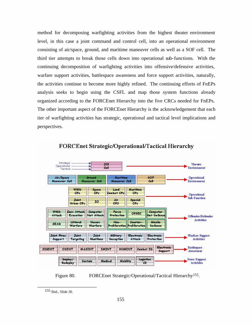
155
method for decomposing warfighting activities from the highest theater environment
level, in this case a joint command and control cell, into an operational environment
consisting of air/space, ground, and maritime maneuver cells as well as a SOF cell. The
third tier attempts to break those cells down into operational sub-functions. With the
continuing decomposition of warfighting activities into offensive/defensive activities,
warfare support activities, battlespace awareness and force support activities, naturally,
the activities continue to become more highly refined. The continuing efforts of FnEPs
analysis seeks to begin using the CSFL and map those system functions already
organized according to the FORCEnet Hierarchy into the five CRCs needed for FnEPs.
The other important aspect of the FORCEnet Hierarchy is the acknowledgement that each
tier of warfighting activities has strategic, operational and tactical level implications and
perspectives.
Figure 80. FORCEnet Strategic/Operational/Tactical Hierarchy155.
155 Ibid., Slide 30.
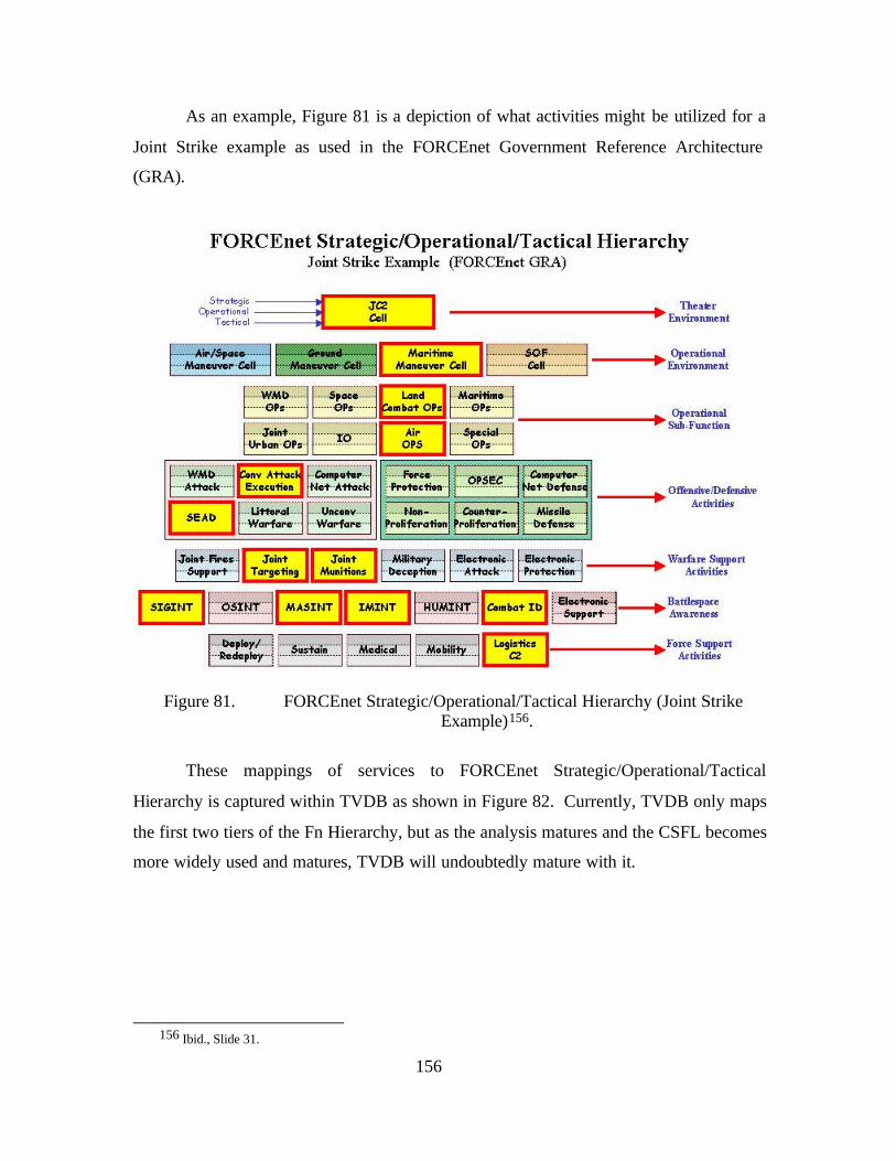
156
As an example, Figure 81 is a depiction of what activities might be utilized for a
Joint Strike example as used in the FORCEnet Government Reference Architecture
(GRA).
Figure 81. FORCEnet Strategic/Operational/Tactical Hierarchy (Joint Strike
Example)156.
These mappings of services to FORCEnet Strategic/Operational/Tactical
Hierarchy is captured within TVDB as shown in Figure 82. Currently, TVDB only maps
the first two tiers of the Fn Hierarchy, but as the analysis matures and the CSFL becomes
more widely used and matures, TVDB will undoubtedly mature with it.
156 Ibid., Slide 31.
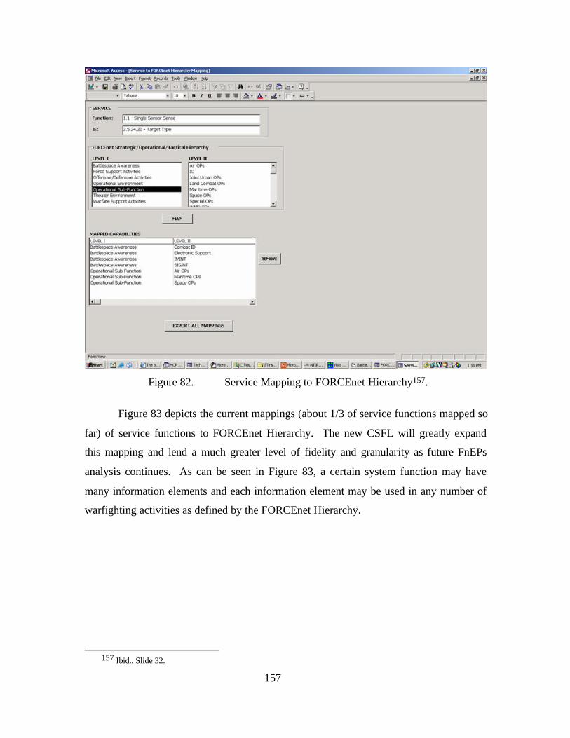
157
Figure 82. Service Mapping to FORCEnet Hierarchy157.
Figure 83 depicts the current mappings (about 1/3 of service functions mapped so
far) of service functions to FORCEnet Hierarchy. The new CSFL will greatly expand
this mapping and lend a much greater level of fidelity and granularity as future FnEPs
analysis continues. As can be seen in Figure 83, a certain system function may have
many information elements and each information element may be used in any number of
warfighting activities as defined by the FORCEnet Hierarchy.
157 Ibid., Slide 32.
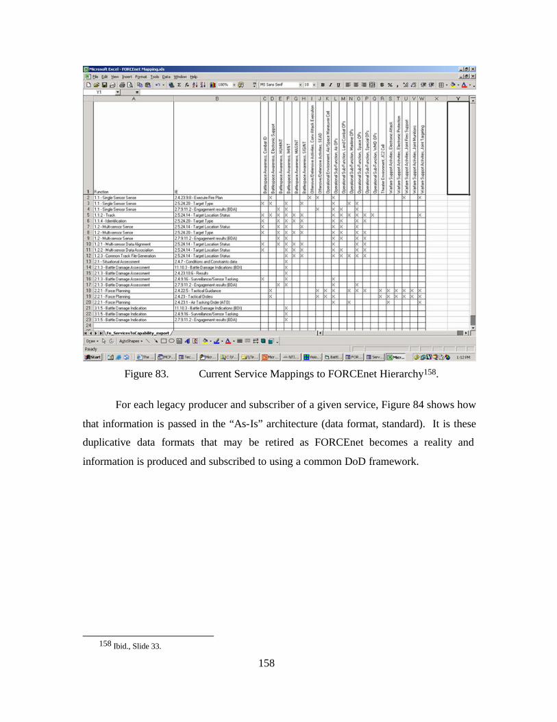
158
Figure 83. Current Service Mappings to FORCEnet Hierarchy158.
For each legacy producer and subscriber of a given service, Figure 84 shows how
that information is passed in the “As-Is” architecture (data format, standard). It is these
duplicative data formats that may be retired as FORCEnet becomes a reality and
information is produced and subscribed to using a common DoD framework.
158 Ibid., Slide 33.
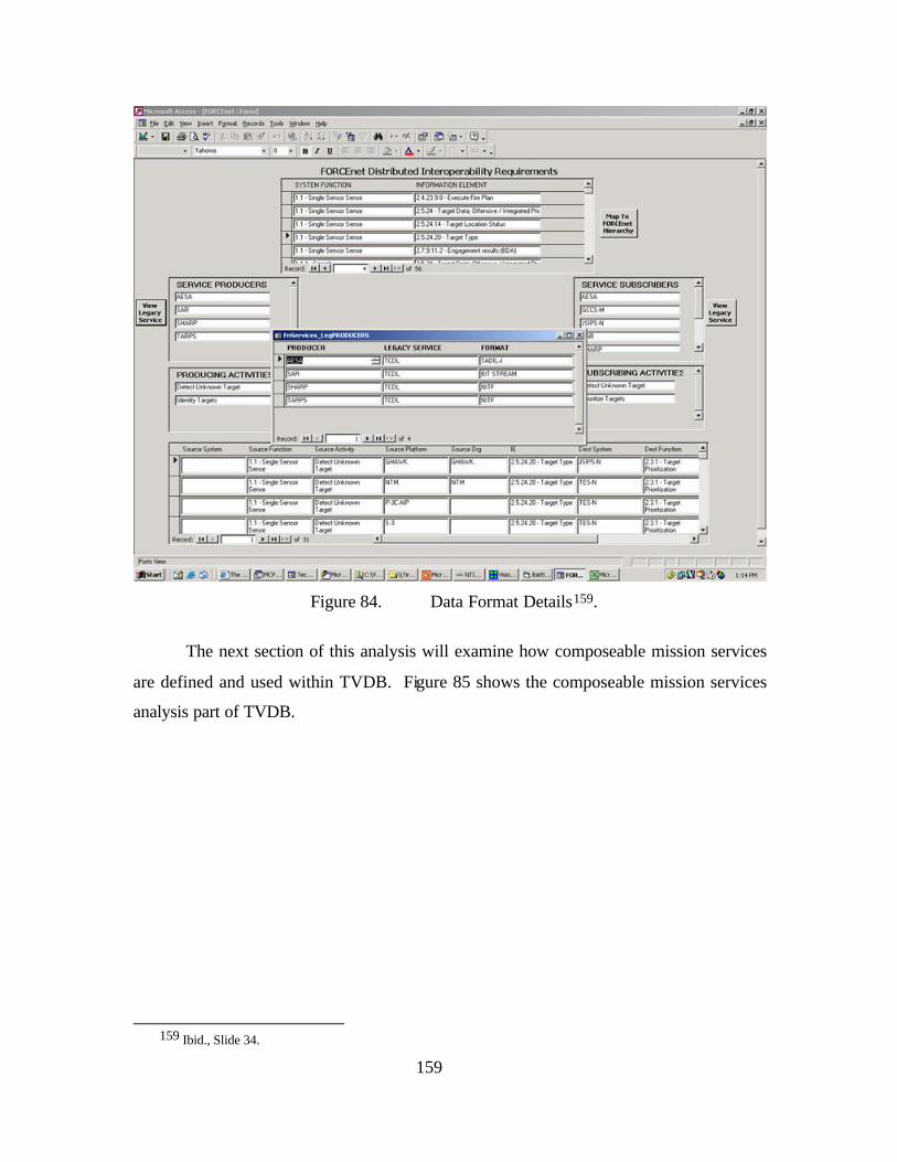
159
Figure 84. Data Format Details159.
The next section of this analysis will examine how composeable mission services
are defined and used within TVDB. Figure 85 shows the composeable mission services
analysis part of TVDB.
159 Ibid., Slide 34.
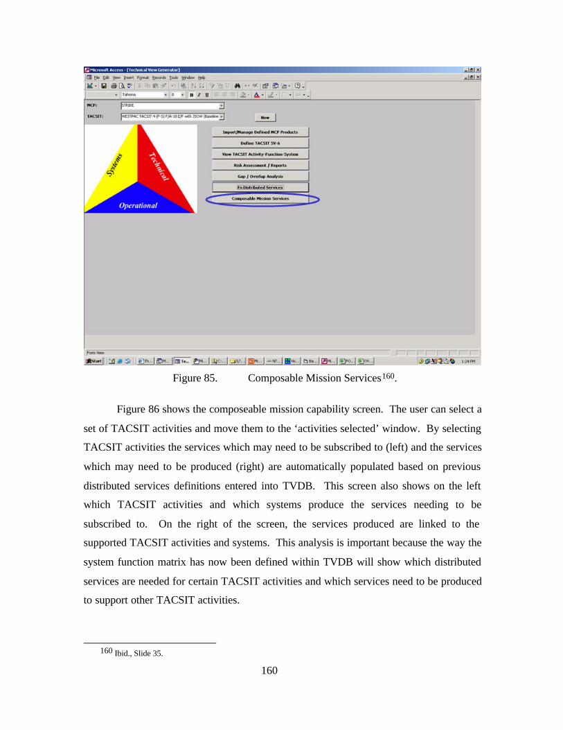
160
Figure 85. Composable Mission Services160.
Figure 86 shows the composeable mission capability screen. The user can select a
set of TACSIT activities and move them to the ‘activities selected’ window. By selecting
TACSIT activities the services which may need to be subscribed to (left) and the services
which may need to be produced (right) are automatically populated based on previous
distributed services definitions entered into TVDB. This screen also shows on the left
which TACSIT activities and which systems produce the services needing to be
subscribed to. On the right of the screen, the services produced are linked to the
supported TACSIT activities and systems. This analysis is important because the way the
system function matrix has now been defined within TVDB will show which distributed
services are needed for certain TACSIT activities and which services need to be produced
to support other TACSIT activities.
160 Ibid., Slide 35.
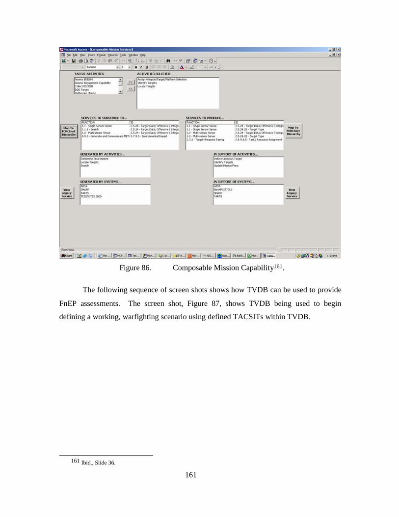
161
Figure 86. Composable Mission Capability161.
The following sequence of screen shots shows how TVDB can be used to provide
FnEP assessments. The screen shot, Figure 87, shows TVDB being used to begin
defining a working, warfighting scenario using defined TACSITs within TVDB.
161 Ibid., Slide 36.
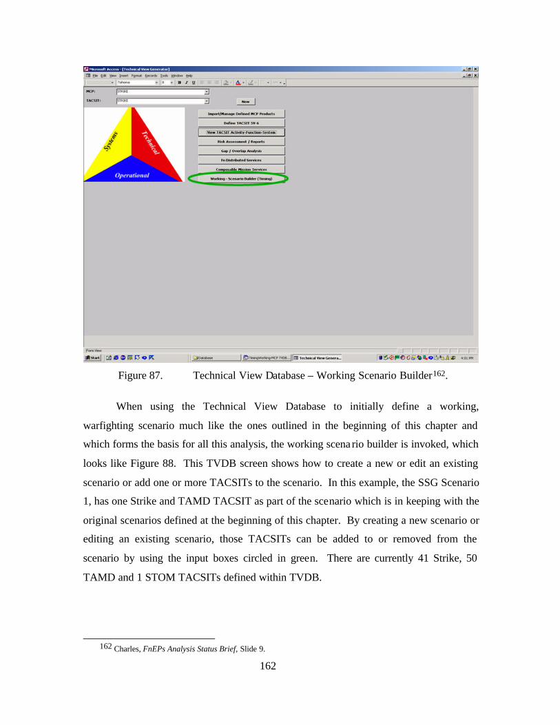
162
Figure 87. Technical View Database – Working Scenario Builder162.
When using the Technical View Database to initially define a working,
warfighting scenario much like the ones outlined in the beginning of this chapter and
which forms the basis for all this analysis, the working scena rio builder is invoked, which
looks like Figure 88. This TVDB screen shows how to create a new or edit an existing
scenario or add one or more TACSITs to the scenario. In this example, the SSG Scenario
1, has one Strike and TAMD TACSIT as part of the scenario which is in keeping with the
original scenarios defined at the beginning of this chapter. By creating a new scenario or
editing an existing scenario, those TACSITs can be added to or removed from the
scenario by using the input boxes circled in green. There are currently 41 Strike, 50
TAMD and 1 STOM TACSITs defined within TVDB.
162 Charles, FnEPs Analysis Status Brief, Slide 9.
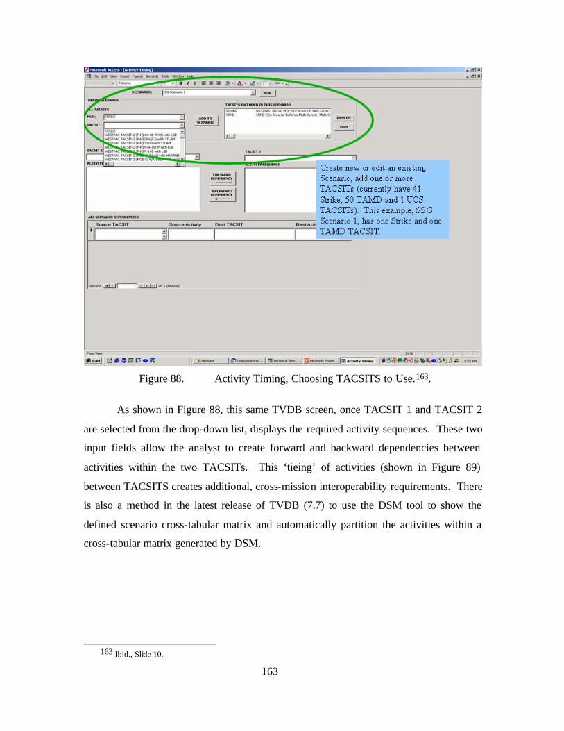
163
Figure 88. Activity Timing, Choosing TACSITS to Use.163.
As shown in Figure 88, this same TVDB screen, once TACSIT 1 and TACSIT 2
are selected from the drop-down list, displays the required activity sequences. These two
input fields allow the analyst to create forward and backward dependencies between
activities within the two TACSITs. This ‘tieing’ of activities (shown in Figure 89)
between TACSITS creates additional, cross-mission interoperability requirements. There
is also a method in the latest release of TVDB (7.7) to use the DSM tool to show the
defined scenario cross-tabular matrix and automatically partition the activities within a
cross-tabular matrix generated by DSM.
163 Ibid., Slide 10.
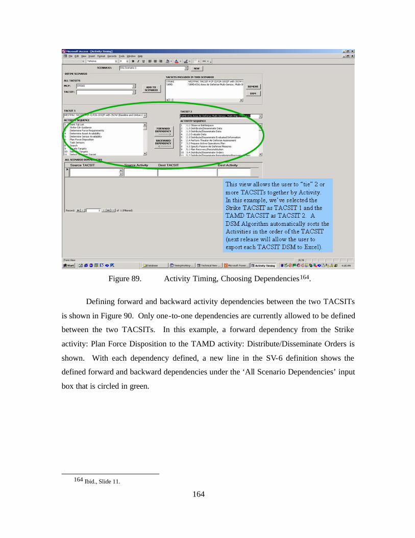
164
Figure 89. Activity Timing, Choosing Dependencies164.
Defining forward and backward activity dependencies between the two TACSITs
is shown in Figure 90. Only one-to-one dependencies are currently allowed to be defined
between the two TACSITs. In this example, a forward dependency from the Strike
activity: Plan Force Disposition to the TAMD activity: Distribute/Disseminate Orders is
shown. With each dependency defined, a new line in the SV-6 definition shows the
defined forward and backward dependencies under the ‘All Scenario Dependencies’ input
box that is circled in green.
164 Ibid., Slide 11.
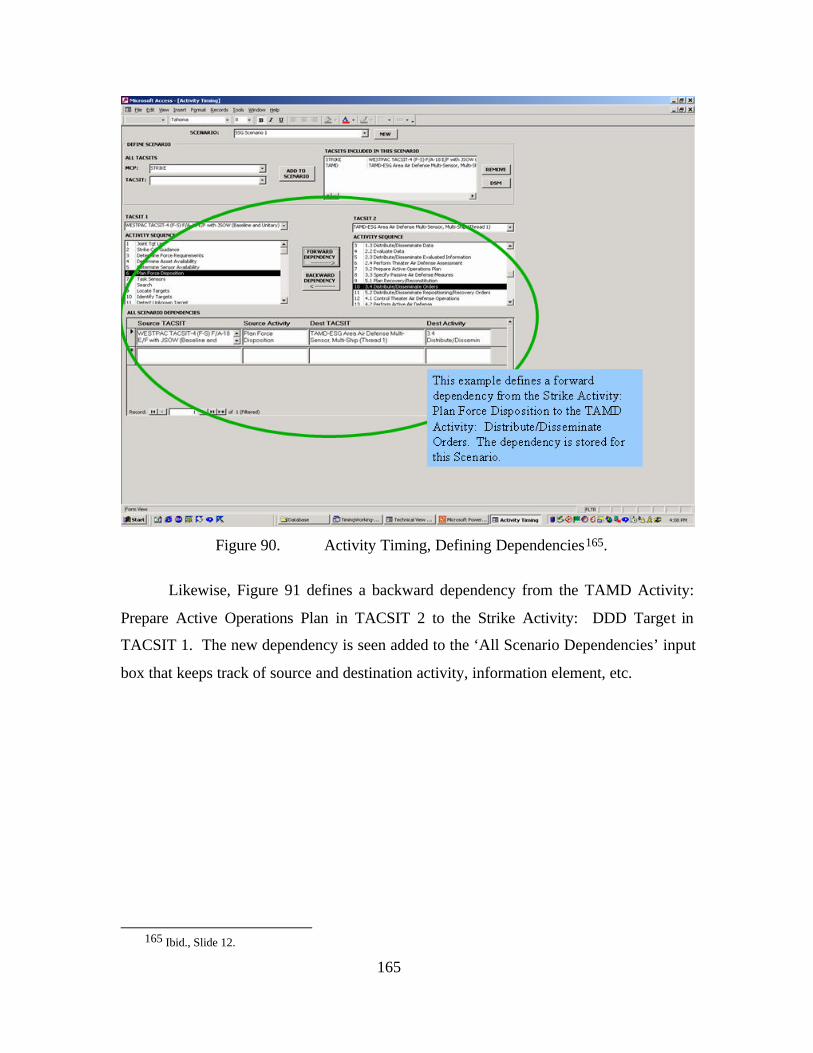
165
Figure 90. Activity Timing, Defining Dependencies165.
Likewise, Figure 91 defines a backward dependency from the TAMD Activity:
Prepare Active Operations Plan in TACSIT 2 to the Strike Activity: DDD Target in
TACSIT 1. The new dependency is seen added to the ‘All Scenario Dependencies’ input
box that keeps track of source and destination activity, information element, etc.
165 Ibid., Slide 12.
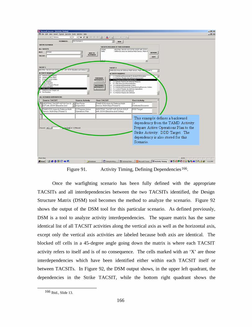
166
Figure 91. Activity Timing, Defining Dependencies166.
Once the warfighting scenario has been fully defined with the appropriate
TACSITs and all interdependencies between the two TACSITs identified, the Design
Structure Matrix (DSM) tool becomes the method to analyze the scenario. Figure 92
shows the output of the DSM tool for this particular scenario. As defined previously,
DSM is a tool to analyze activity interdependencies. The square matrix has the same
identical list of all TACSIT activities along the vertical axis as well as the horizontal axis,
except only the vertical axis activities are labeled because both axis are identical. The
blocked off cells in a 45-degree angle going down the matrix is where each TACSIT
activity refers to itself and is of no consequence. The cells marked with an ‘X’ are those
interdependencies which have been identified either within each TACSIT itself or
between TACSITs. In Figure 92, the DSM output shows, in the upper left quadrant, the
dependencies in the Strike TACSIT, while the bottom right quadrant shows the
166 Ibid., Slide 13.
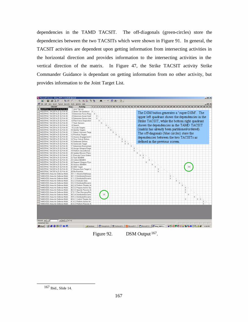
167
dependencies in the TAMD TACSIT. The off-diagonals (green-circles) store the
dependencies between the two TACSITs which were shown in Figure 91. In general, the
TACSIT activities are dependent upon getting information from intersecting activities in
the horizontal direction and provides information to the intersecting activities in the
vertical direction of the matrix. In Figure 47, the Strike TACSIT activity Strike
Commander Guidance is dependant on getting information from no other activity, but
provides information to the Joint Target List.
Figure 92. DSM Output 167.
167 Ibid., Slide 14.
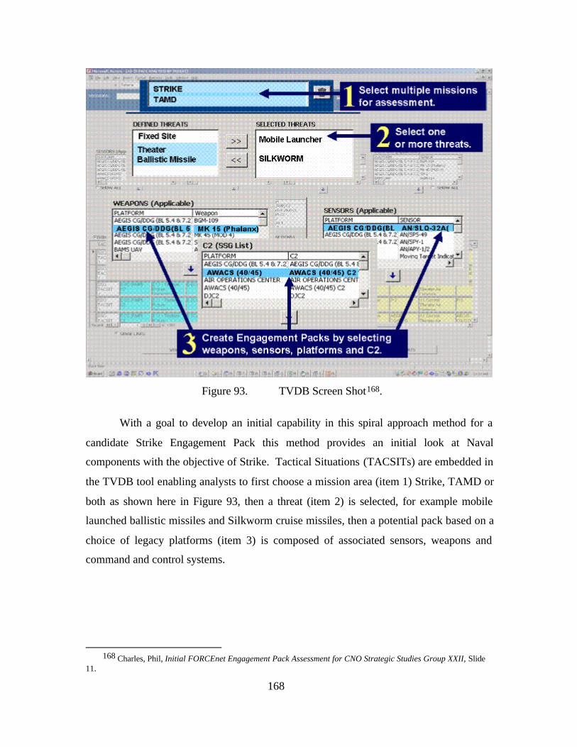
168
Figure 93. TVDB Screen Shot168.
With a goal to develop an initial capability in this spiral approach method for a
candidate Strike Engagement Pack this method provides an initial look at Naval
components with the objective of Strike. Tactical Situations (TACSITs) are embedded in
the TVDB tool enabling analysts to first choose a mission area (item 1) Strike, TAMD or
both as shown here in Figure 93, then a threat (item 2) is selected, for example mobile
launched ballistic missiles and Silkworm cruise missiles, then a potential pack based on a
choice of legacy platforms (item 3) is composed of associated sensors, weapons and
command and control systems.
168 Charles, Phil, Initial FORCEnet Engagement Pack Assessment for CNO Strategic Studies Group XXII, Slide
11.
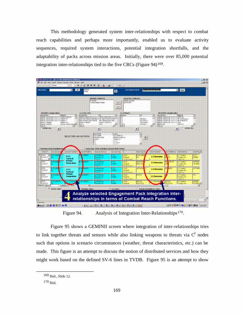
169
This methodology generated system inter-relationships with respect to combat
reach capabilities and perhaps more importantly, enabled us to evaluate activity
sequences, required system interactions, potential integration shortfalls, and the
adaptability of packs across mission areas. Initially, there were over 85,000 potential
integration inter-relationships tied to the five CRCs (Figure 94)169.
Figure 94. Analysis of Integration Inter-Relationships170.
Figure 95 shows a GEMINII screen where integration of inter-relationships tries
to link together threats and sensors while also linking weapons to threats via C2 nodes
such that options in scenario circumstances (weather, threat characteristics, etc.) can be
made. This figure is an attempt to discuss the notion of distributed services and how they
might work based on the defined SV-6 lines in TVDB. Figure 95 is an attempt to show
169 Ibid., Slide 12. 170 Ibid.
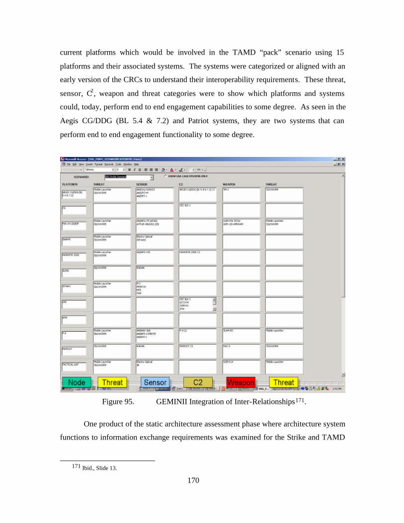
170
current platforms which would be involved in the TAMD “pack” scenario using 15
platforms and their associated systems. The systems were categorized or aligned with an
early version of the CRCs to understand their interoperability requirements. These threat,
sensor, C2, weapon and threat categories were to show which platforms and systems
could, today, perform end to end engagement capabilities to some degree. As seen in the
Aegis CG/DDG (BL 5.4 & 7.2) and Patriot systems, they are two systems that can
perform end to end engagement functionality to some degree.
Figure 95. GEMINII Integration of Inter-Relationships171.
One product of the static architecture assessment phase where architecture system
functions to information exchange requirements was examined for the Strike and TAMD
171 Ibid., Slide 13.
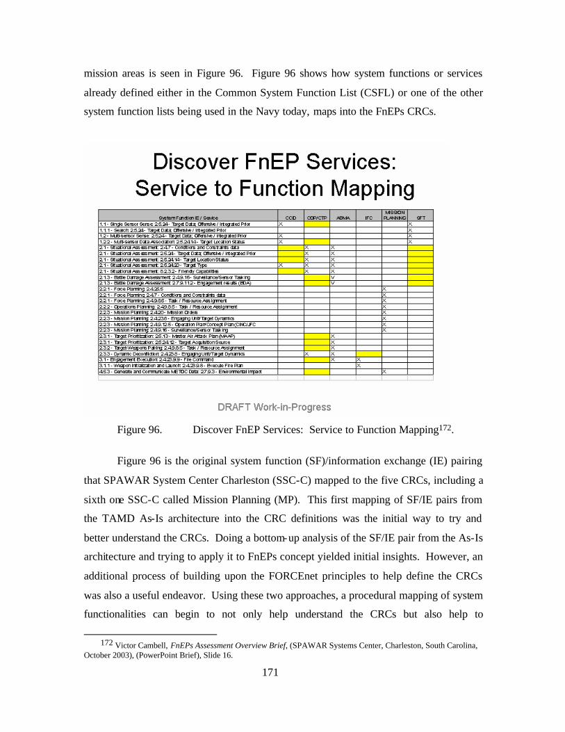
171
mission areas is seen in Figure 96. Figure 96 shows how system functions or services
already defined either in the Common System Function List (CSFL) or one of the other
system function lists being used in the Navy today, maps into the FnEPs CRCs.
Figure 96. Discover FnEP Services: Service to Function Mapping172.
Figure 96 is the original system function (SF)/information exchange (IE) pairing
that SPAWAR System Center Charleston (SSC-C) mapped to the five CRCs, including a
sixth one SSC-C called Mission Planning (MP). This first mapping of SF/IE pairs from
the TAMD As-Is architecture into the CRC definitions was the initial way to try and
better understand the CRCs. Doing a bottom-up analysis of the SF/IE pair from the As-Is
architecture and trying to apply it to FnEPs concept yielded initial insights. However, an
additional process of building upon the FORCEnet principles to help define the CRCs
was also a useful endeavor. Using these two approaches, a procedural mapping of system
functionalities can begin to not only help understand the CRCs but also help to
172 Victor Cambell, FnEPs Assessment Overview Brief, (SPAWAR Systems Center, Charleston, South Carolina,
October 2003), (PowerPoint Brief), Slide 16.
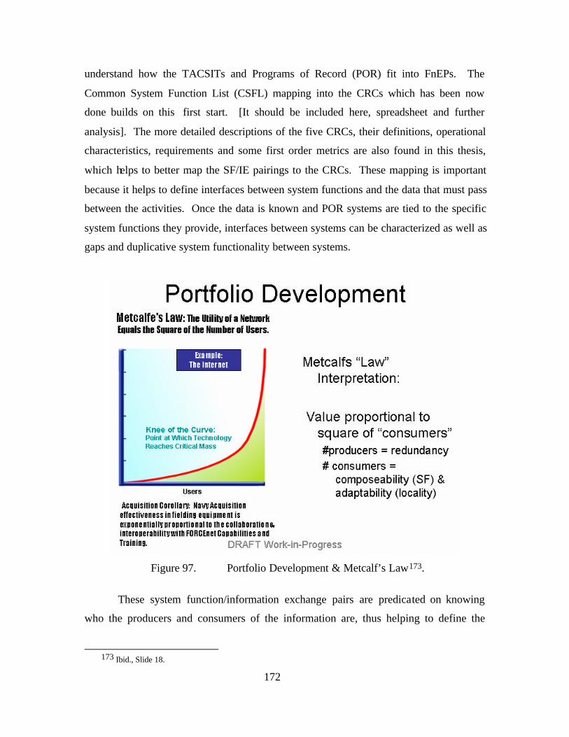
172
understand how the TACSITs and Programs of Record (POR) fit into FnEPs. The
Common System Function List (CSFL) mapping into the CRCs which has been now
done builds on this first start. [It should be included here, spreadsheet and further
analysis]. The more detailed descriptions of the five CRCs, their definitions, operational
characteristics, requirements and some first order metrics are also found in this thesis,
which helps to better map the SF/IE pairings to the CRCs. These mapping is important
because it helps to define interfaces between system functions and the data that must pass
between the activities. Once the data is known and POR systems are tied to the specific
system functions they provide, interfaces between systems can be characterized as well as
gaps and duplicative system functionality between systems.
Figure 97. Portfolio Development & Metcalf’s Law173.
These system function/information exchange pairs are predicated on knowing
who the producers and consumers of the information are, thus helping to define the
173 Ibid., Slide 18.
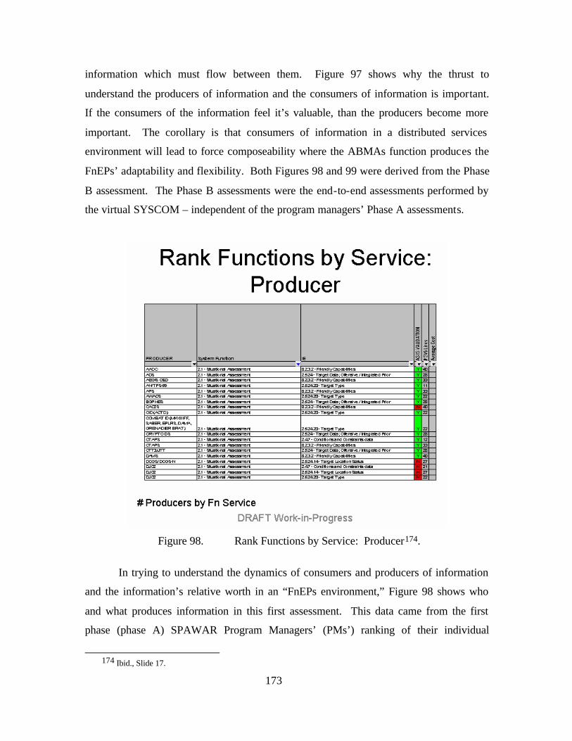
173
information which must flow between them. Figure 97 shows why the thrust to
understand the producers of information and the consumers of information is important.
If the consumers of the information feel it’s valuable, than the producers become more
important. The corollary is that consumers of information in a distributed services
environment will lead to force composeability where the ABMAs function produces the
FnEPs’ adaptability and flexibility. Both Figures 98 and 99 were derived from the Phase
B assessment. The Phase B assessments were the end-to-end assessments performed by
the virtual SYSCOM – independent of the program managers’ Phase A assessments.
Figure 98. Rank Functions by Service: Producer174.
In trying to understand the dynamics of consumers and producers of information
and the information’s relative worth in an “FnEPs environment,” Figure 98 shows who
and what produces information in this first assessment. This data came from the first
phase (phase A) SPAWAR Program Managers’ (PMs’) ranking of their individual
174 Ibid., Slide 17.
174
systems’ POM-06 assessments conducted in June/July 2002 timeframe. SSC-C simply
re-analyzed the data given to them with the specific criteria and FnEPs focus as listed in
the spreadsheet. The producer of the information is a specific system, associated with a
particular system function/information exchange pair. Each individual row are SV-6
interface lines, which shows a producer/service pairing, as generated from the individual
TACSIT interoperability requirements. The “As-Is Validation” column (missing is an
identical column, “To-Be Validation”) is an acknowledgement that in the current “As-Is”
architecture there currently is a validated interface between the producer and system
function/information exchange pair. The SV-6 lines column is the number of SV-6
interfaces this producer is supporting. This number is a simple measure of the
information’s value and interface complexity. Both interface inputs and outputs are
counted in this column. The Average Cost column is a place for sparsely received
costing data is to be plugged in. In Figure 98, there just happened to be no costing
figures provided. The most important aspect about Figure 98, is that this lays the
foundation for further analysis by being the first half (producers) of the definition for the
interaction matrix used by the DSM tool to further analyze system interactions. This
information will be used in DSM as the columns (producers) in the DSM interaction
matrix. The second half of the analysis is an understanding of system
function/information exchange pairs from the consumer of information’s perspective.
Figure 99 shows a ranked order function list by service to consumer.
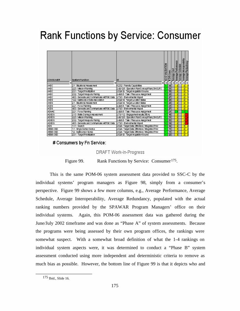
175
Figure 99. Rank Functions by Service: Consumer175.
This is the same POM-06 system assessment data provided to SSC-C by the
individual systems’ program managers as Figure 98, simply from a consumer’s
perspective. Figure 99 shows a few more columns, e.g., Average Performance, Average
Schedule, Average Interoperability, Average Redundancy, populated with the actual
ranking numbers provided by the SPAWAR Program Managers’ office on their
individual systems. Again, this POM-06 assessment data was gathered during the
June/July 2002 timeframe and was done as “Phase A” of system assessments. Because
the programs were being assessed by their own program offices, the rankings were
somewhat suspect. With a somewhat broad definition of what the 1-4 rankings on
individual system aspects were, it was determined to conduct a “Phase B” system
assessment conducted using more independent and deterministic criteria to remove as
much bias as possible. However, the bottom line of Figure 99 is that it depicts who and
175 Ibid., Slide 16.
176
what systems consume what information. More importantly, this information provides
the second half of the DSM interaction matrix data (rows) of consumer interactions
allowing for further analytical work to be done.
Figure 100, is an attempt to take the five CRCs and one additional supporting
distributed service (Mission Planning) and understand how they might be assembled from
the system function/information exchange pairs. These services are depicted as a
sequence of system functions that support or help to define the capabilities needed within
each of the six FnEP services. These system functions are rank ordered (from more to
less) by the number of SV-6 lines that support each CRC. This depiction of fishboned
system function/information exchange pairs imply they drive and produce the CRC
capabilities based on what system function/information exchange pairs are supporting a
particular CRC or distributed service. This may not be entirely accurate or provide the
entire picture. The other part of this analysis may be the opposite, where each CRC or
distributed service drives and defines the requirements for what should be in each system
function/information exchange pair. This way the CRC is not the product of existing
individual system function/information exchange pairs functionality, but the CRC
functionality drives the requirements for what each system function/information
exchange pair does. Two different ways of looking at CRC functionality with, quite
possibly, two totally different outcomes.
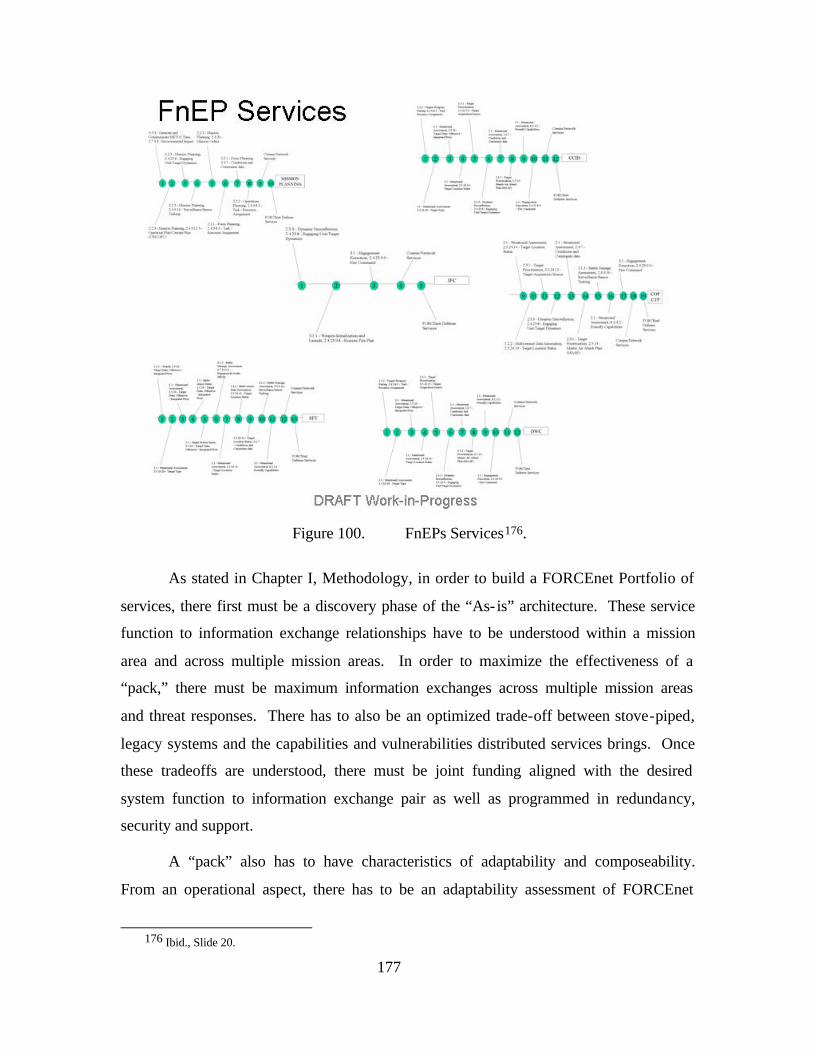
177
Figure 100. FnEPs Services176.
As stated in Chapter I, Methodology, in order to build a FORCEnet Portfolio of
services, there first must be a discovery phase of the “As- is” architecture. These service
function to information exchange relationships have to be understood within a mission
area and across multiple mission areas. In order to maximize the effectiveness of a
“pack,” there must be maximum information exchanges across multiple mission areas
and threat responses. There has to also be an optimized trade-off between stove-piped,
legacy systems and the capabilities and vulnerabilities distributed services brings. Once
these tradeoffs are understood, there must be joint funding aligned with the desired
system function to information exchange pair as well as programmed in redundancy,
security and support.
A “pack” also has to have characteristics of adaptability and composeability.
From an operational aspect, there has to be an adaptability assessment of FORCEnet
176 Ibid., Slide 20.
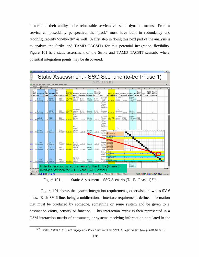
178
factors and their ability to be relocatable services via some dynamic means. From a
service composeability perspective, the “pack” must have built in redundancy and
reconfigurability ‘on-the-fly’ as well. A first step in doing this next part of the analysis is
to analyze the Strike and TAMD TACSITs for this potential integration flexibility.
Figure 101 is a static assessment of the Strike and TAMD TACSIT scenario where
potential integration points may be discovered.
Figure 101. Static Assessment – SSG Scenario (To-Be Phase 1)177.
Figure 101 shows the system integration requirements, otherwise known as SV-6
lines. Each SV-6 line, being a unidirectional interface requirement, defines information
that must be produced by someone, something or some system and be given to a
destination entity, activity or function. This interaction matrix is then represented in a
DSM interaction matrix of consumers, or systems receiving information populated in the
177 Charles, Initial FORCEnet Engagement Pack Assessment for CNO Strategic Studies Group XXII, Slide 16.
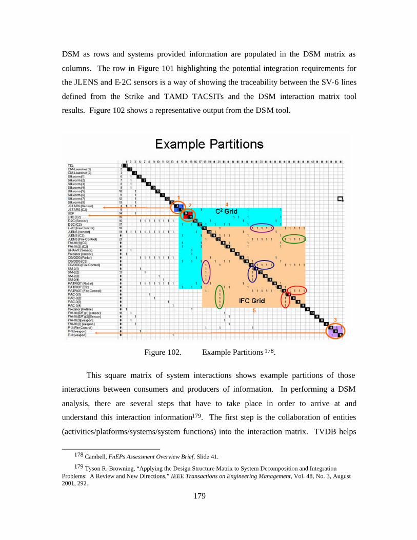
179
DSM as rows and systems provided information are populated in the DSM matrix as
columns. The row in Figure 101 highlighting the potential integration requirements for
the JLENS and E-2C sensors is a way of showing the traceability between the SV-6 lines
defined from the Strike and TAMD TACSITs and the DSM interaction matrix tool
results. Figure 102 shows a representative output from the DSM tool.
Figure 102. Example Partitions 178.
This square matrix of system interactions shows example partitions of those
interactions between consumers and producers of information. In performing a DSM
analysis, there are several steps that have to take place in order to arrive at and
understand this interaction information179. The first step is the collaboration of entities
(activities/platforms/systems/system functions) into the interaction matrix. TVDB helps
178 Cambell, FnEPs Assessment Overview Brief, Slide 41.
179 Tyson R. Browning, “Applying the Design Structure Matrix to System Decomposition and Integration Problems: A Review and New Directions,” IEEE Transactions on Engineering Management, Vol. 48, No. 3, August 2001, 292.
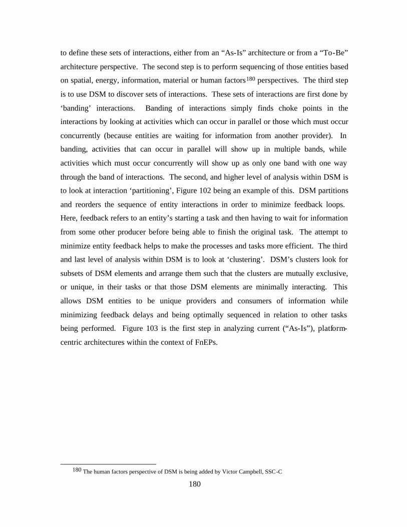
180
to define these sets of interactions, either from an “As-Is” architecture or from a “To-Be”
architecture perspective. The second step is to perform sequencing of those entities based
on spatial, energy, information, material or human factors180 perspectives. The third step
is to use DSM to discover sets of interactions. These sets of interactions are first done by
‘banding’ interactions. Banding of interactions simply finds choke points in the
interactions by looking at activities which can occur in parallel or those which must occur
concurrently (because entities are waiting for information from another provider). In
banding, activities that can occur in parallel will show up in multiple bands, while
activities which must occur concurrently will show up as only one band with one way
through the band of interactions. The second, and higher level of analysis within DSM is
to look at interaction ‘partitioning’, Figure 102 being an example of this. DSM partitions
and reorders the sequence of entity interactions in order to minimize feedback loops.
Here, feedback refers to an entity’s starting a task and then having to wait for information
from some other producer before being able to finish the original task. The attempt to
minimize entity feedback helps to make the processes and tasks more efficient. The third
and last level of analysis within DSM is to look at ‘clustering’. DSM’s clusters look for
subsets of DSM elements and arrange them such that the clusters are mutually exclusive,
or unique, in their tasks or that those DSM elements are minimally interacting. This
allows DSM entities to be unique providers and consumers of information while
minimizing feedback delays and being optimally sequenced in relation to other tasks
being performed. Figure 103 is the first step in analyzing current (“As-Is”), platform-
centric architectures within the context of FnEPs.
180 The human factors perspective of DSM is being added by Victor Campbell, SSC-C
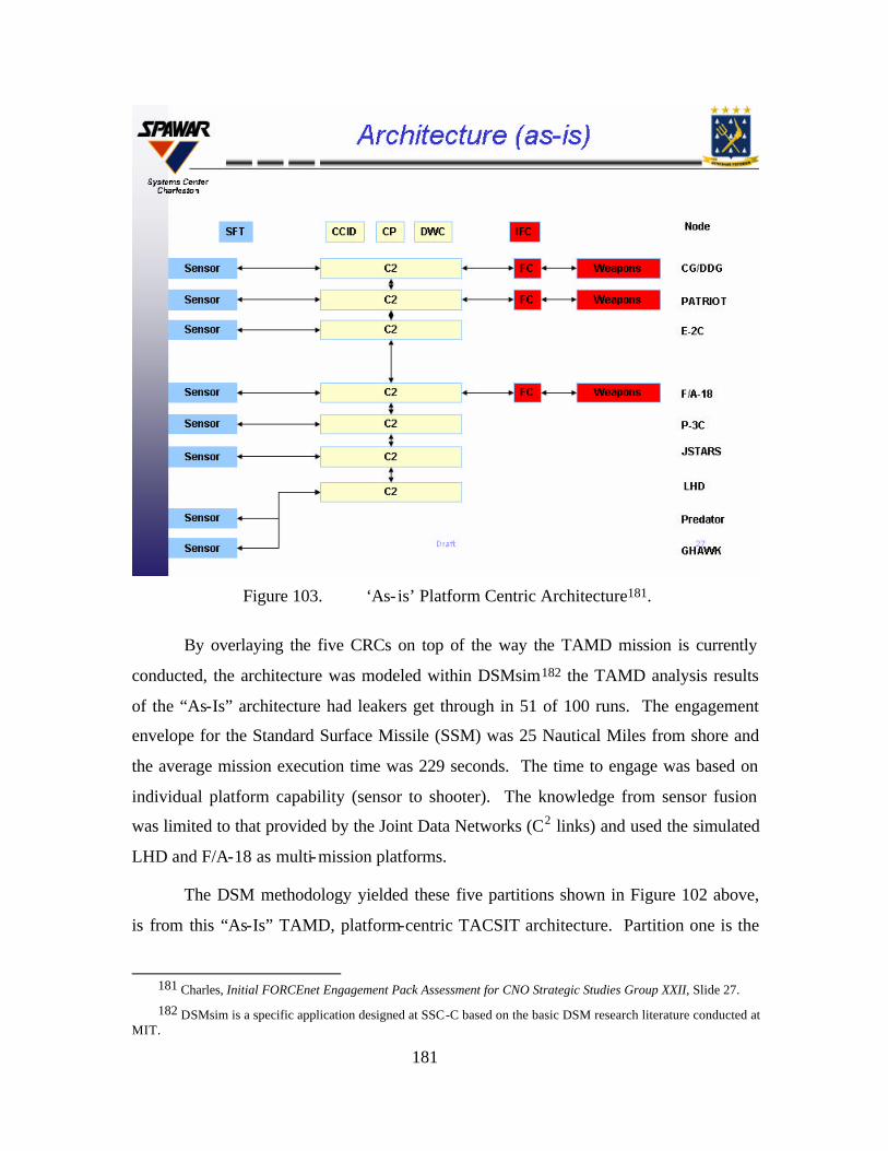
181
Figure 103. ‘As- is’ Platform Centric Architecture181.
By overlaying the five CRCs on top of the way the TAMD mission is currently
conducted, the architecture was modeled within DSMsim182 the TAMD analysis results
of the “As-Is” architecture had leakers get through in 51 of 100 runs. The engagement
envelope for the Standard Surface Missile (SSM) was 25 Nautical Miles from shore and
the average mission execution time was 229 seconds. The time to engage was based on
individual platform capability (sensor to shooter). The knowledge from sensor fusion
was limited to that provided by the Joint Data Networks (C2 links) and used the simulated
LHD and F/A-18 as multi-mission platforms.
The DSM methodology yielded these five partitions shown in Figure 102 above,
is from this “As-Is” TAMD, platform-centric TACSIT architecture. Partition one is the
181 Charles, Initial FORCEnet Engagement Pack Assessment for CNO Strategic Studies Group XXII, Slide 27.
182 DSMsim is a specific application designed at SSC-C based on the basic DSM research literature conducted at MIT.
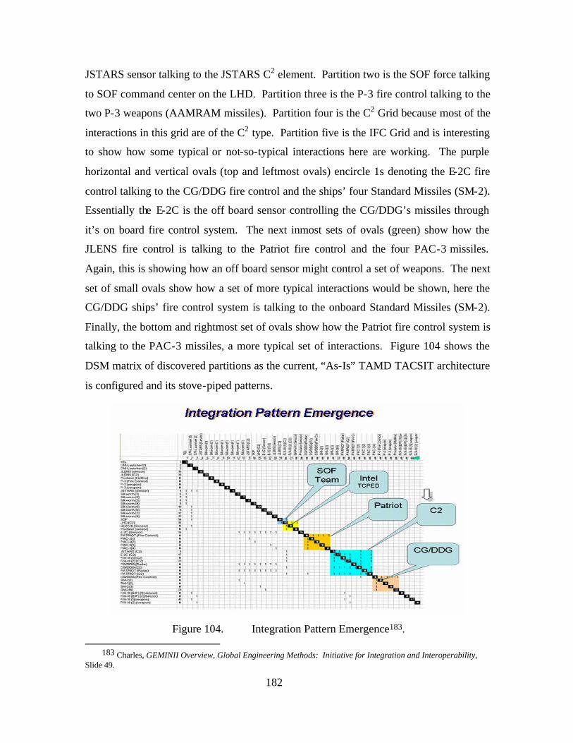
182
JSTARS sensor talking to the JSTARS C2 element. Partition two is the SOF force talking
to SOF command center on the LHD. Partition three is the P-3 fire control talking to the
two P-3 weapons (AAMRAM missiles). Partition four is the C2 Grid because most of the
interactions in this grid are of the C2 type. Partition five is the IFC Grid and is interesting
to show how some typical or not-so-typical interactions here are working. The purple
horizontal and vertical ovals (top and leftmost ovals) encircle 1s denoting the E-2C fire
control talking to the CG/DDG fire control and the ships’ four Standard Missiles (SM-2).
Essentially the E-2C is the off board sensor controlling the CG/DDG’s missiles through
it’s on board fire control system. The next inmost sets of ovals (green) show how the
JLENS fire control is talking to the Patriot fire control and the four PAC-3 missiles.
Again, this is showing how an off board sensor might control a set of weapons. The next
set of small ovals show how a set of more typical interactions would be shown, here the
CG/DDG ships’ fire control system is talking to the onboard Standard Missiles (SM-2).
Finally, the bottom and rightmost set of ovals show how the Patriot fire control system is
talking to the PAC-3 missiles, a more typical set of interactions. Figure 104 shows the
DSM matrix of discovered partitions as the current, “As-Is” TAMD TACSIT architecture
is configured and its stove-piped patterns.
Figure 104. Integration Pattern Emergence183.
183 Charles, GEMINII Overview, Global Engineering Methods: Initiative for Integration and Interoperability,
Slide 49.
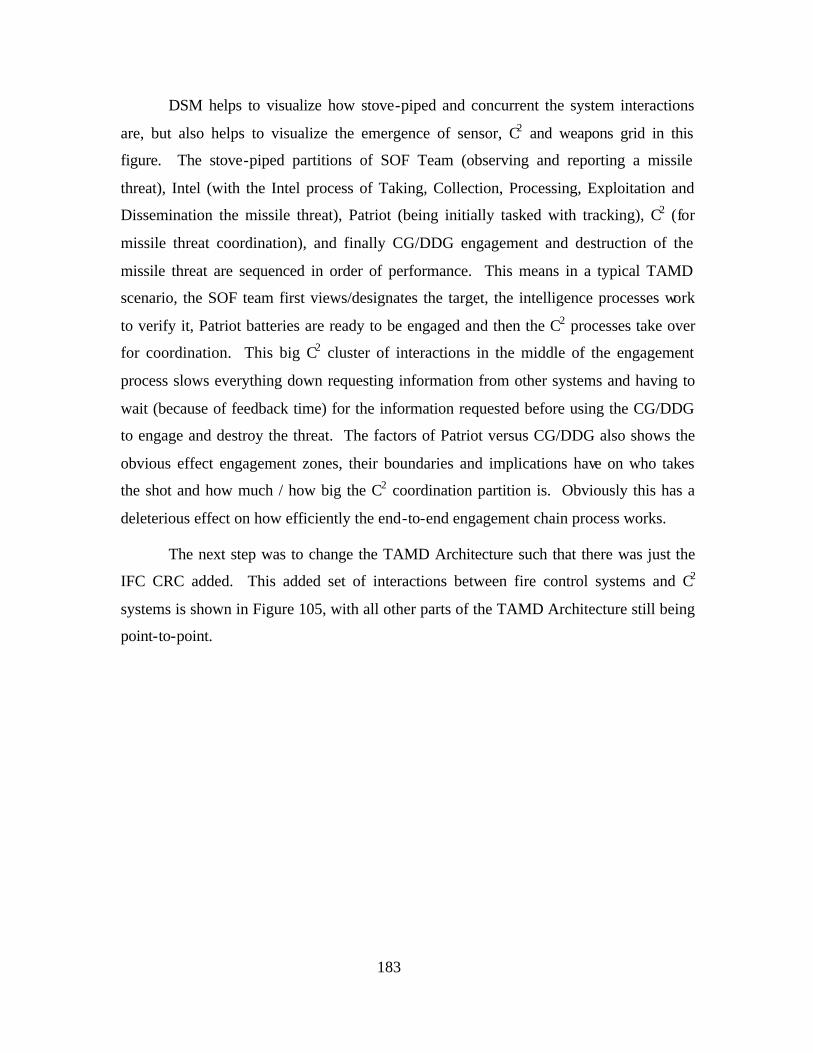
183
DSM helps to visualize how stove-piped and concurrent the system interactions
are, but also helps to visualize the emergence of sensor, C2 and weapons grid in this
figure. The stove-piped partitions of SOF Team (observing and reporting a missile
threat), Intel (with the Intel process of Taking, Collection, Processing, Exploitation and
Dissemination the missile threat), Patriot (being initially tasked with tracking), C2 (for
missile threat coordination), and finally CG/DDG engagement and destruction of the
missile threat are sequenced in order of performance. This means in a typical TAMD
scenario, the SOF team first views/designates the target, the intelligence processes work
to verify it, Patriot batteries are ready to be engaged and then the C2 processes take over
for coordination. This big C2 cluster of interactions in the middle of the engagement
process slows everything down requesting information from other systems and having to
wait (because of feedback time) for the information requested before using the CG/DDG
to engage and destroy the threat. The factors of Patriot versus CG/DDG also shows the
obvious effect engagement zones, their boundaries and implications have on who takes
the shot and how much / how big the C2 coordination partition is. Obviously this has a
deleterious effect on how efficiently the end-to-end engagement chain process works.
The next step was to change the TAMD Architecture such that there was just the
IFC CRC added. This added set of interactions between fire control systems and C2
systems is shown in Figure 105, with all other parts of the TAMD Architecture still being
point-to-point.
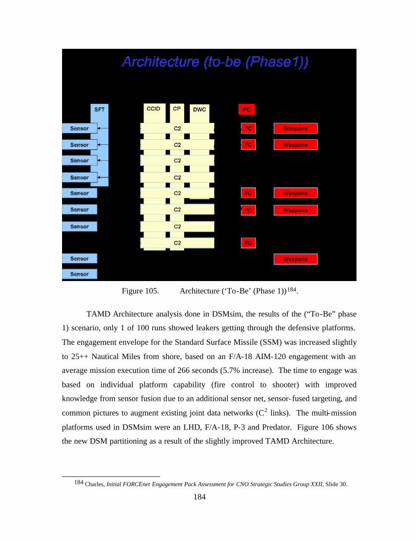
184
Figure 105. Architecture (‘To-Be’ (Phase 1))184.
TAMD Architecture analysis done in DSMsim, the results of the (“To-Be” phase
1) scenario, only 1 of 100 runs showed leakers getting through the defensive platforms.
The engagement envelope for the Standard Surface Missile (SSM) was increased slightly
to 25++ Nautical Miles from shore, based on an F/A-18 AIM-120 engagement with an
average mission execution time of 266 seconds (5.7% increase). The time to engage was
based on individual platform capability (fire control to shooter) with improved
knowledge from sensor fusion due to an additional sensor net, sensor-fused targeting, and
common pictures to augment existing joint data networks (C2 links). The multi-mission
platforms used in DSMsim were an LHD, F/A-18, P-3 and Predator. Figure 106 shows
the new DSM partitioning as a result of the slightly improved TAMD Architecture.
184 Charles, Initial FORCEnet Engagement Pack Assessment for CNO Strategic Studies Group XXII, Slide 30.
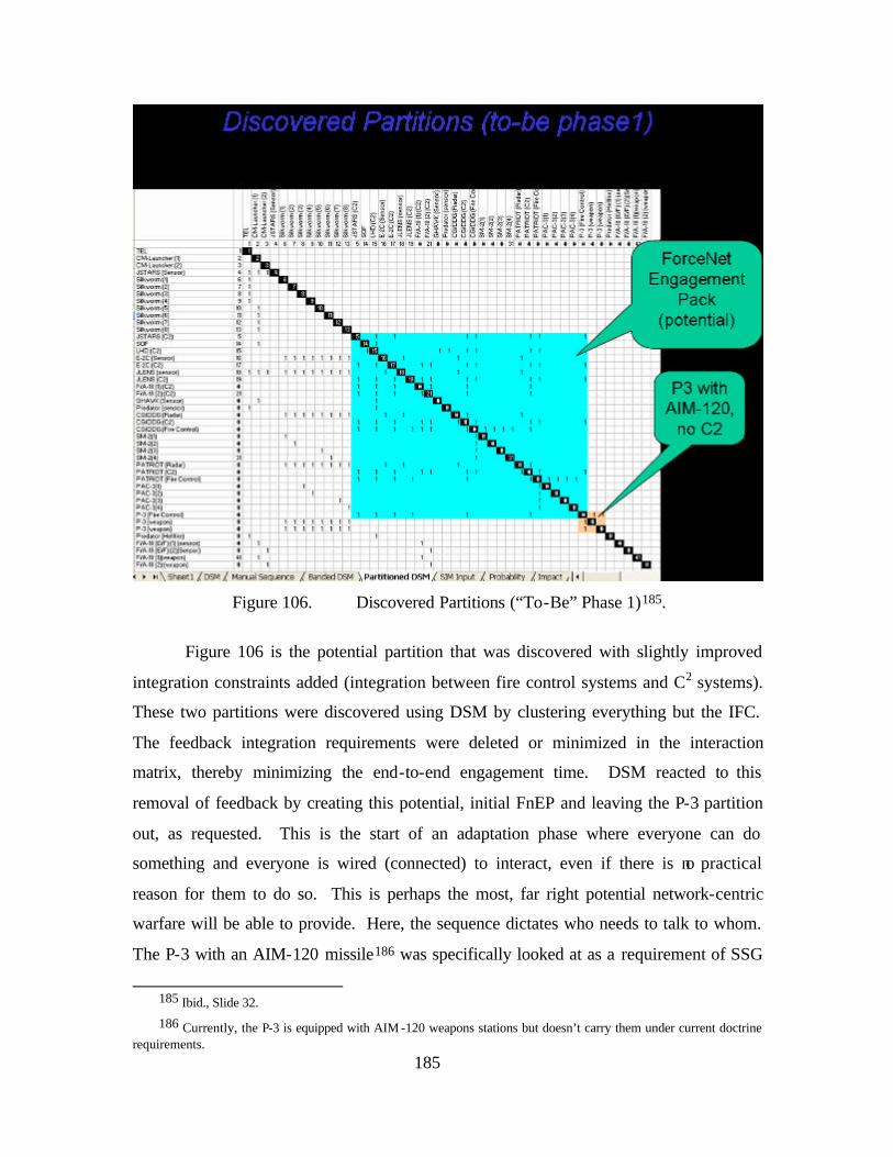
185
Figure 106. Discovered Partitions (“To-Be” Phase 1)185.
Figure 106 is the potential partition that was discovered with slightly improved
integration constraints added (integration between fire control systems and C2 systems).
These two partitions were discovered using DSM by clustering everything but the IFC.
The feedback integration requirements were deleted or minimized in the interaction
matrix, thereby minimizing the end-to-end engagement time. DSM reacted to this
removal of feedback by creating this potential, initial FnEP and leaving the P-3 partition
out, as requested. This is the start of an adaptation phase where everyone can do
something and everyone is wired (connected) to interact, even if there is no practical
reason for them to do so. This is perhaps the most, far right potential network-centric
warfare will be able to provide. Here, the sequence dictates who needs to talk to whom.
The P-3 with an AIM-120 missile186 was specifically looked at as a requirement of SSG
185 Ibid., Slide 32.
186 Currently, the P-3 is equipped with AIM -120 weapons stations but doesn’t carry them under current doctrine requirements.
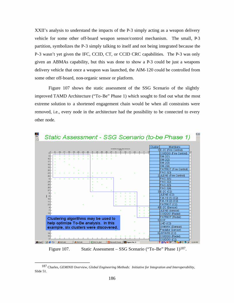
186
XXII’s analysis to understand the impacts of the P-3 simply acting as a weapon delivery
vehicle for some other off-board weapon sensor/control mechanism. The small, P-3
partition, symbolizes the P-3 simply talking to itself and not being integrated because the
P-3 wasn’t yet given the IFC, CCID, CT, or CCID CRC capabilities. The P-3 was only
given an ABMAs capability, but this was done to show a P-3 could be just a weapons
delivery vehicle that once a weapon was launched, the AIM-120 could be controlled from
some other off-board, non-organic sensor or platform.
Figure 107 shows the static assessment of the SSG Scenario of the slightly
improved TAMD Architecture (“To-Be” Phase 1) which sought to find out what the most
extreme solution to a shortened engagement chain would be when all constraints were
removed, i.e., every node in the architecture had the possibility to be connected to every
other node.
Figure 107. Static Assessment – SSG Scenario (“To-Be” Phase 1)187.
187 Charles, GEMINII Overview, Global Engineering Methods: Initiative for Integration and Interoperability,
Slide 51.
187
With all interoperability constraints removed, several interesting observations can
be made. The DSM clustering algorithms came up with six clusters, identified in the blue
sidebar of Figure 107. Starting from the top left hand corner, the clusters start out with
the largest one first, i.e., the cluster that takes the most time in the engagement chain, and
orders the clusters according to amounts of interactions and time. The big clusters have
more interactions and take longer time to complete. From there, sequentially smaller,
faster, more independent clusters of activities show up. Therefore, the absolutely shortest
time an engagement can take is the physical fly-out of the weapon, which is why in
Figure 107, the largest and first cluster is made up of the E2-C and CG/DDG fire control
systems launching the SM-2 missiles. This shows that the shortest engagement chain
process in this IDEALIZED (shortest engagement), once a target is identified, is to
launch the weapons (here SM-2s off a CG/DDG) and then control them by other assets
once they are in flight. With the other clusters following immediately thereafter, target
identification, sensor refinement/CCID and finally in-flight target updates would happen
as the weapon is in its fly-out phase to the target. Obviously, this is in a very idealized
world where CCID target verification would take place before weapons are released, this
illustration is simply a way of validating the DSM results make analytical sense. With
runs done in DSMsim using this idealized, constraint-free environment, engagement
chain completion times were down around 25-90 seconds, the time needed for the
Standard Surface Missile to fly out to its maximum kinematic range.
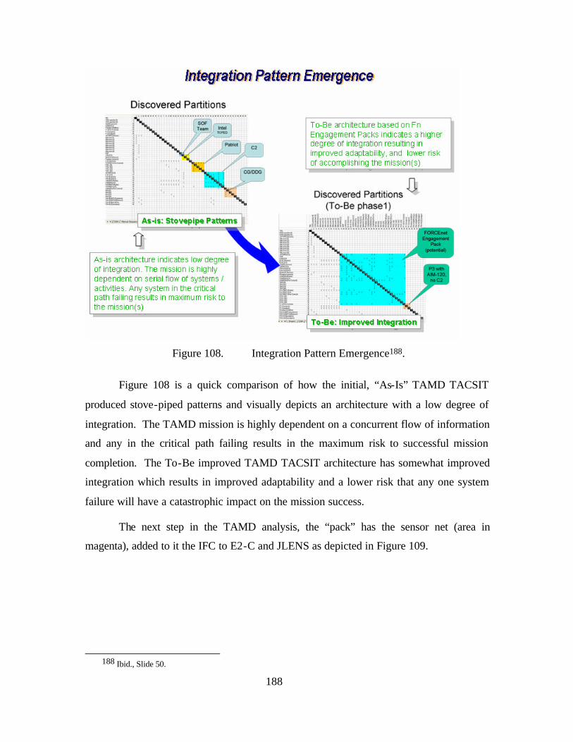
188
Figure 108. Integration Pattern Emergence188.
Figure 108 is a quick comparison of how the initial, “As-Is” TAMD TACSIT
produced stove-piped patterns and visually depicts an architecture with a low degree of
integration. The TAMD mission is highly dependent on a concurrent flow of information
and any in the critical path failing results in the maximum risk to successful mission
completion. The To-Be improved TAMD TACSIT architecture has somewhat improved
integration which results in improved adaptability and a lower risk that any one system
failure will have a catastrophic impact on the mission success.
The next step in the TAMD analysis, the “pack” has the sensor net (area in
magenta), added to it the IFC to E2-C and JLENS as depicted in Figure 109.
188 Ibid., Slide 50.
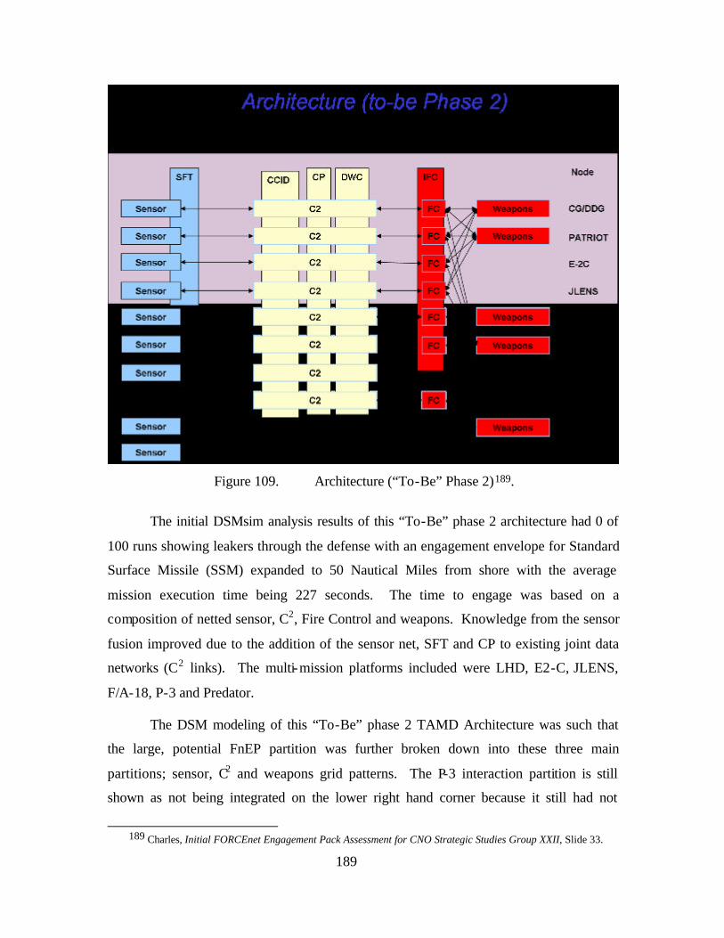
189
Figure 109. Architecture (“To-Be” Phase 2)189.
The initial DSMsim analysis results of this “To-Be” phase 2 architecture had 0 of
100 runs showing leakers through the defense with an engagement envelope for Standard
Surface Missile (SSM) expanded to 50 Nautical Miles from shore with the average
mission execution time being 227 seconds. The time to engage was based on a
composition of netted sensor, C2, Fire Control and weapons. Knowledge from the sensor
fusion improved due to the addition of the sensor net, SFT and CP to existing joint data
networks (C2 links). The multi-mission platforms included were LHD, E2-C, JLENS,
F/A-18, P-3 and Predator.
The DSM modeling of this “To-Be” phase 2 TAMD Architecture was such that
the large, potential FnEP partition was further broken down into these three main
partitions; sensor, C2 and weapons grid patterns. The P-3 interaction partition is still
shown as not being integrated on the lower right hand corner because it still had not
189 Charles, Initial FORCEnet Engagement Pack Assessment for CNO Strategic Studies Group XXII, Slide 33.
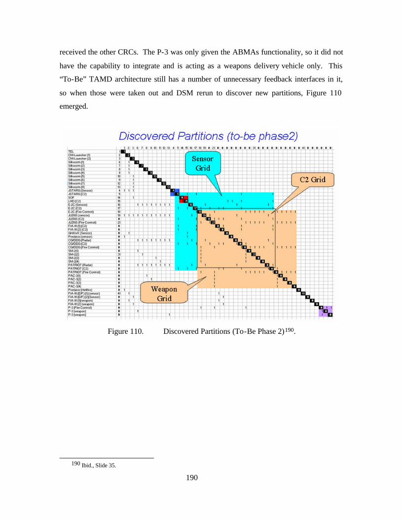
190
received the other CRCs. The P-3 was only given the ABMAs functionality, so it did not
have the capability to integrate and is acting as a weapons delivery vehicle only. This
“To-Be” TAMD architecture still has a number of unnecessary feedback interfaces in it,
so when those were taken out and DSM rerun to discover new partitions, Figure 110
emerged.
Figure 110. Discovered Partitions (To-Be Phase 2)190.
190 Ibid., Slide 35.
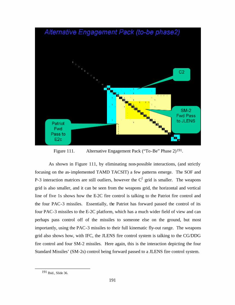
191
Figure 111. Alternative Engagement Pack (“To-Be” Phase 2)191.
As shown in Figure 111, by eliminating non-possible interactions, (and strictly
focusing on the as- implemented TAMD TACSIT) a few patterns emerge. The SOF and
P-3 interaction matrices are still outliers, however the C2 grid is smaller. The weapons
grid is also smaller, and it can be seen from the weapons grid, the horizontal and vertical
line of five 1s shows how the E-2C fire control is talking to the Patriot fire control and
the four PAC-3 missiles. Essentially, the Patriot has forward passed the control of its
four PAC-3 missiles to the E-2C platform, which has a much wider field of view and can
perhaps pass control off of the missiles to someone else on the ground, but most
importantly, using the PAC-3 missiles to their full kinematic fly-out range. The weapons
grid also shows how, with IFC, the JLENS fire control system is talking to the CG/DDG
fire control and four SM-2 missiles. Here again, this is the interaction depicting the four
Standard Missiles’ (SM-2s) control being forward passed to a JLENS fire control system.
191 Ibid., Slide 36.
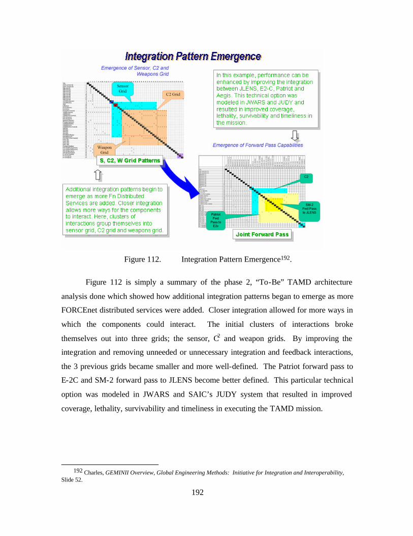
192
Figure 112. Integration Pattern Emergence192.
Figure 112 is simply a summary of the phase 2, “To-Be” TAMD architecture
analysis done which showed how additional integration patterns began to emerge as more
FORCEnet distributed services were added. Closer integration allowed for more ways in
which the components could interact. The initial clusters of interactions broke
themselves out into three grids; the sensor, C2 and weapon grids. By improving the
integration and removing unneeded or unnecessary integration and feedback interactions,
the 3 previous grids became smaller and more well-defined. The Patriot forward pass to
E-2C and SM-2 forward pass to JLENS become better defined. This particular technical
option was modeled in JWARS and SAIC’s JUDY system that resulted in improved
coverage, lethality, survivability and timeliness in executing the TAMD mission.
192 Charles, GEMINII Overview, Global Engineering Methods: Initiative for Integration and Interoperability,
Slide 52.
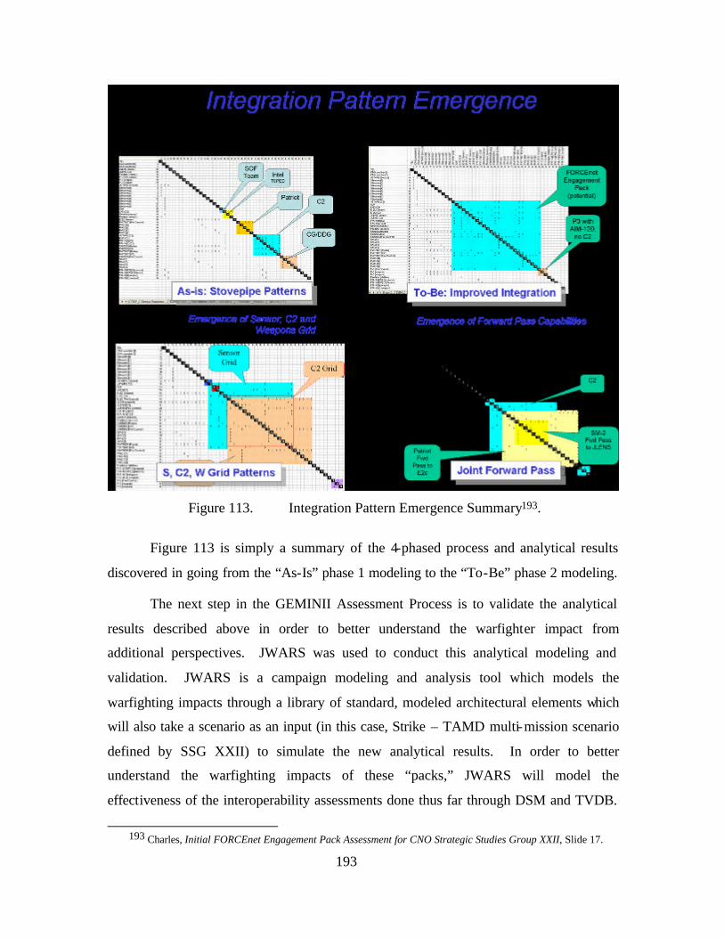
193
Figure 113. Integration Pattern Emergence Summary193.
Figure 113 is simply a summary of the 4-phased process and analytical results
discovered in going from the “As-Is” phase 1 modeling to the “To-Be” phase 2 modeling.
The next step in the GEMINII Assessment Process is to validate the analytical
results described above in order to better understand the warfighter impact from
additional perspectives. JWARS was used to conduct this analytical modeling and
validation. JWARS is a campaign modeling and analysis tool which models the
warfighting impacts through a library of standard, modeled architectural elements which
will also take a scenario as an input (in this case, Strike – TAMD multi-mission scenario
defined by SSG XXII) to simulate the new analytical results. In order to better
understand the warfighting impacts of these “packs,” JWARS will model the
effectiveness of the interoperability assessments done thus far through DSM and TVDB.
193 Charles, Initial FORCEnet Engagement Pack Assessment for CNO Strategic Studies Group XXII, Slide 17.
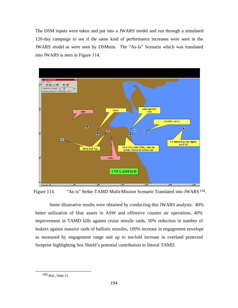
194
The DSM inputs were taken and put into a JWARS model and run through a simulated
120-day campaign to see if the same kind of performance increases were seen in the
JWARS model as were seen by DSMsim. The “As-Is” Scenario which was translated
into JWARS is seen in Figure 114.
Figure 114. “As- is” Strike-TAMD Multi-Mission Scenario Translated into JWARS 194.
Some illustrative results were obtained by conducting this JWARS analysis: 40%
better utilization of blue assets in ASW and offensive counter air operations, 40%
improvement in TAMD kills against cruise missile raids, 50% reduction in number of
leakers against massive raids of ballistic missiles, 100% increase in engagement envelope
as measured by engagement range and up to ten-fold increase in overland protected
footprint highlighting Sea Shield’s potential contribution to littoral TAMD.
194 Ibid., Slide 21.
195
In some of the initial sensitivity analysis findings, the engagement envelope
expansion and the ability to engage the threat was dependant on ALL five combat reach
functions working together and the managed pairing of sensor, weapon and threat was
imperative. C2 decision time was dependant on CT, CCID and CP were the significant
contributors towards required C2 decision time. This requirement has impacts on systems
and training. The engagement time was dependent of CT, CCID and CP were the
significant contributors towards required engagement time (ability to fire sooner).
Defense in depth was dependent on multiplicity of CT, CCID, CP, ABMAs and IFC
which would allow defense in depth. The addition of these combat reach functions
provided more options to engage.
Some observations about the results were the capability of the FnEP “pack”
increases as combat reach functions are enabled. A number of integration requirements
increases as FORCEnet combat reach functions are enabled. The number of logical
interfaces explodes meaning there are now redundant ways to accomplish the mission
which gives it the ability to adapt. FORCEnet introduces increased complexity which
requires disciplined engineering and tools to manage this complexity. The integration
patterns discovered helps to define capability and allow management of the ensuing
complexity.
The next part of the GEMINII analysis methodology is to analyze just how these
To-Be architectures can be implemented using a spiral developmental strategy and
starting with the legacy systems the Navy has today. The first part in doing this analysis
is to further study the area of distributed services in an effort to make the interactions
modeled above possible. In analyzing this notion of distributed services, it is necessary
to go back to the baseline Strike and TAMD TACSITs. Figure 115 describes the process
for how distributed services were put together and analyzed with the goal to setup the
inputs for an optimization tool like MATLAB to come up with an optimal way to put the
needed distributed services together.
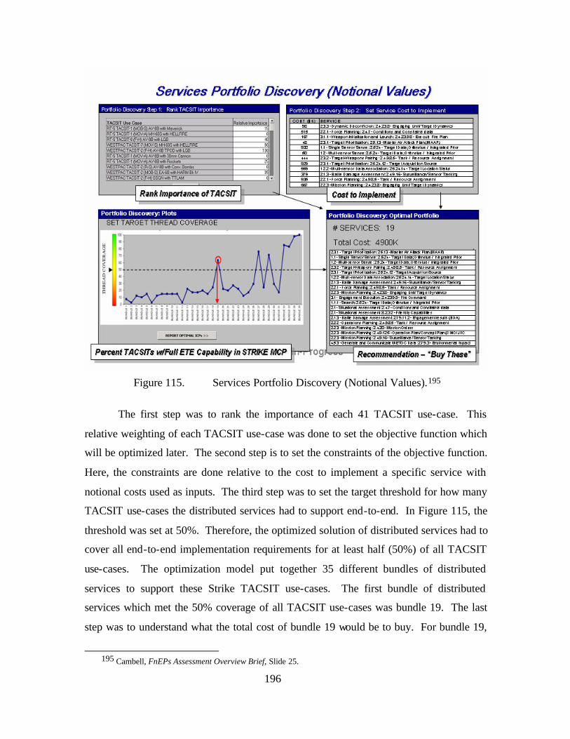
196
Figure 115. Services Portfolio Discovery (Notional Values).195
The first step was to rank the importance of each 41 TACSIT use-case. This
relative weighting of each TACSIT use-case was done to set the objective function which
will be optimized later. The second step is to set the constraints of the objective function.
Here, the constraints are done relative to the cost to implement a specific service with
notional costs used as inputs. The third step was to set the target threshold for how many
TACSIT use-cases the distributed services had to support end-to-end. In Figure 115, the
threshold was set at 50%. Therefore, the optimized solution of distributed services had to
cover all end-to-end implementation requirements for at least half (50%) of all TACSIT
use-cases. The optimization model put together 35 different bundles of distributed
services to support these Strike TACSIT use-cases. The first bundle of distributed
services which met the 50% coverage of all TACSIT use-cases was bundle 19. The last
step was to understand what the total cost of bundle 19 would be to buy. For bundle 19,
195 Cambell, FnEPs Assessment Overview Brief, Slide 25.
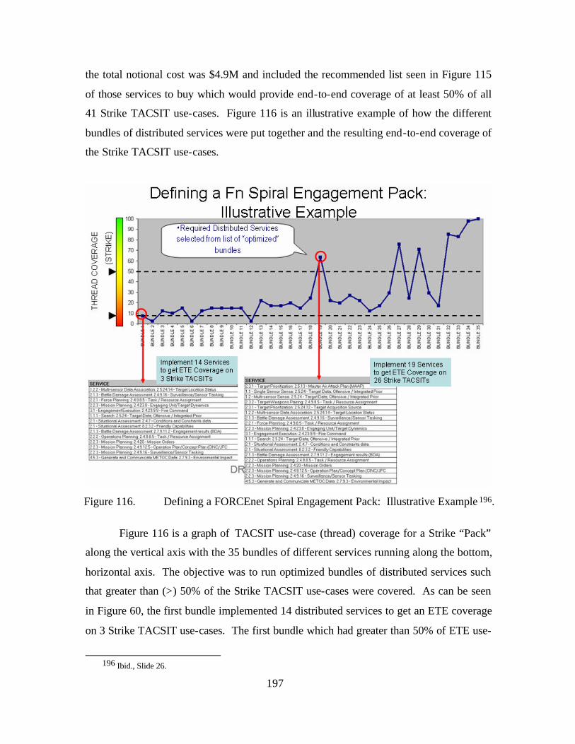
197
the total notional cost was $4.9M and included the recommended list seen in Figure 115
of those services to buy which would provide end-to-end coverage of at least 50% of all
41 Strike TACSIT use-cases. Figure 116 is an illustrative example of how the different
bundles of distributed services were put together and the resulting end-to-end coverage of
the Strike TACSIT use-cases.
Figure 116. Defining a FORCEnet Spiral Engagement Pack: Illustrative Example 196.
Figure 116 is a graph of TACSIT use-case (thread) coverage for a Strike “Pack”
along the vertical axis with the 35 bundles of different services running along the bottom,
horizontal axis. The objective was to run optimized bundles of distributed services such
that greater than (>) 50% of the Strike TACSIT use-cases were covered. As can be seen
in Figure 60, the first bundle implemented 14 distributed services to get an ETE coverage
on 3 Strike TACSIT use-cases. The first bundle which had greater than 50% of ETE use-
196 Ibid., Slide 26.
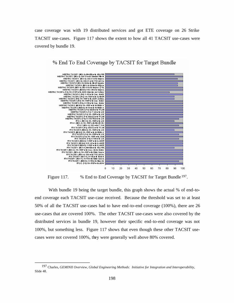
198
case coverage was with 19 distributed services and got ETE coverage on 26 Strike
TACSIT use-cases. Figure 117 shows the extent to how all 41 TACSIT use-cases were
covered by bundle 19.
Figure 117. % End to End Coverage by TACSIT for Target Bundle 197.
With bundle 19 being the target bundle, this graph shows the actual % of end-to-
end coverage each TACSIT use-case received. Because the threshold was set to at least
50% of all the TACSIT use-cases had to have end-to-end coverage (100%), there are 26
use-cases that are covered 100%. The other TACSIT use-cases were also covered by the
distributed services in bundle 19, however their specific end-to-end coverage was not
100%, but something less. Figure 117 shows that even though these other TACSIT use-
cases were not covered 100%, they were generally well above 80% covered.
197 Charles, GEMINII Overview, Global Engineering Methods: Initiative for Integration and Interoperability,
Slide 48.
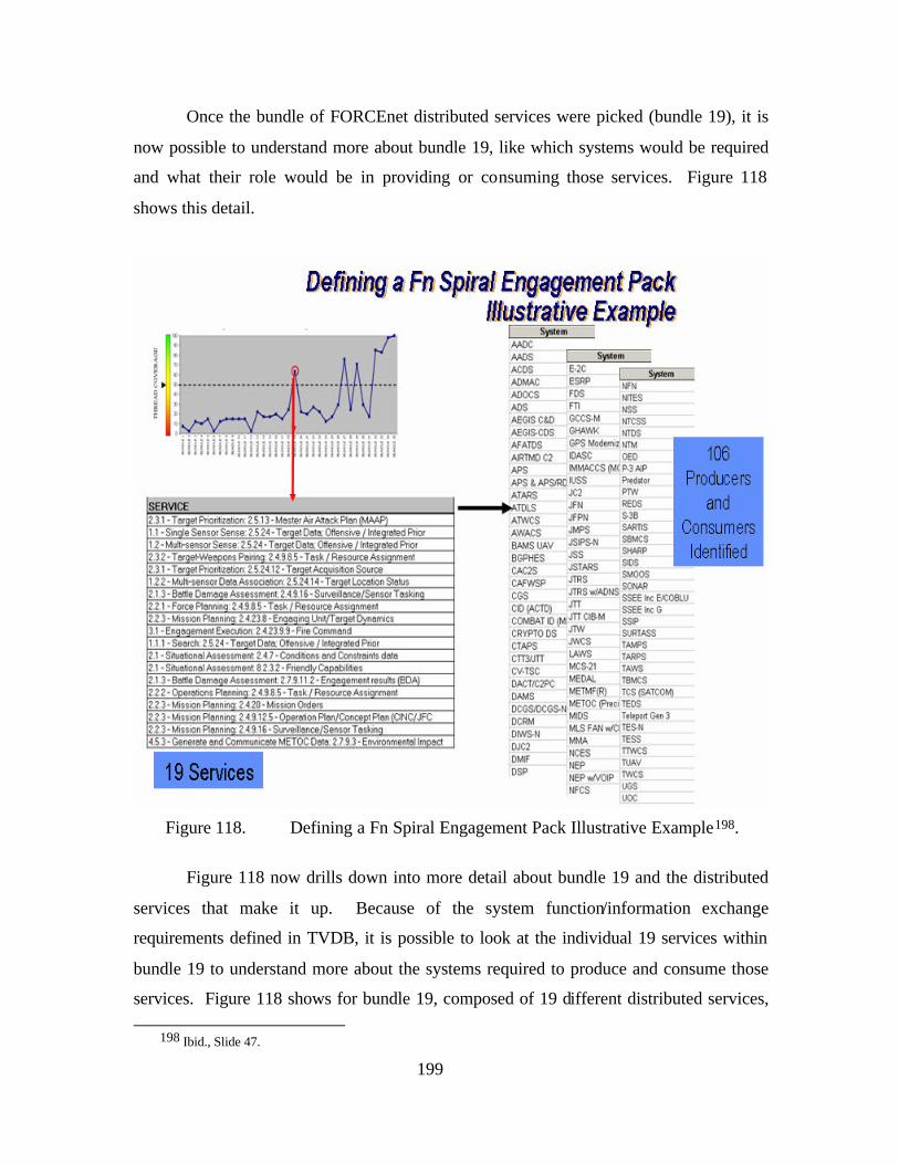
199
Once the bundle of FORCEnet distributed services were picked (bundle 19), it is
now possible to understand more about bundle 19, like which systems would be required
and what their role would be in providing or consuming those services. Figure 118
shows this detail.
Figure 118. Defining a Fn Spiral Engagement Pack Illustrative Example198.
Figure 118 now drills down into more detail about bundle 19 and the distributed
services that make it up. Because of the system function/information exchange
requirements defined in TVDB, it is possible to look at the individual 19 services within
bundle 19 to understand more about the systems required to produce and consume those
services. Figure 118 shows for bundle 19, composed of 19 different distributed services,
198 Ibid., Slide 47.
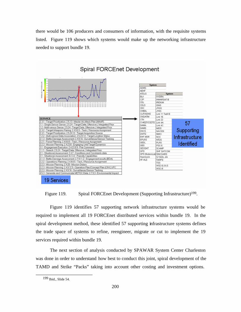
200
there would be 106 producers and consumers of information, with the requisite systems
listed. Figure 119 shows which systems would make up the networking infrastructure
needed to support bundle 19.
Figure 119. Spiral FORCEnet Development (Supporting Infrastructure)199.
Figure 119 identifies 57 supporting network infrastructure systems would be
required to implement all 19 FORCEnet distributed services within bundle 19. In the
spiral development method, these identified 57 supporting infrastructure systems defines
the trade space of systems to refine, reengineer, migrate or cut to implement the 19
services required within bundle 19.
The next section of analysis conducted by SPAWAR System Center Charleston
was done in order to understand how best to conduct this joint, spiral development of the
TAMD and Strike “Packs” taking into account other costing and investment options.
199 Ibid., Slide 54.
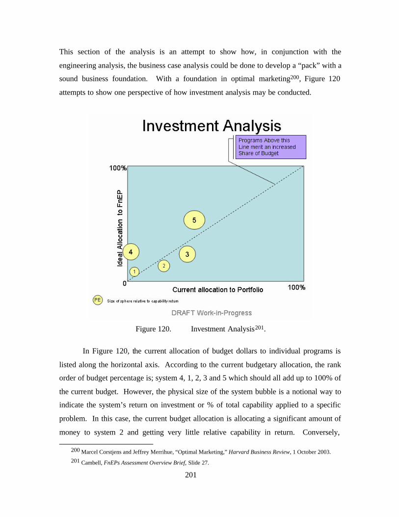
201
This section of the analysis is an attempt to show how, in conjunction with the
engineering analysis, the business case analysis could be done to develop a “pack” with a
sound business foundation. With a foundation in optimal marketing200, Figure 120
attempts to show one perspective of how investment analysis may be conducted.
Figure 120. Investment Analysis201.
In Figure 120, the current allocation of budget dollars to individual programs is
listed along the horizontal axis. According to the current budgetary allocation, the rank
order of budget percentage is; system 4, 1, 2, 3 and 5 which should all add up to 100% of
the current budget. However, the physical size of the system bubble is a notional way to
indicate the system’s return on investment or % of total capability applied to a specific
problem. In this case, the current budget allocation is allocating a significant amount of
money to system 2 and getting very little relative capability in return. Conversely,
200 Marcel Corstjens and Jeffrey Merrihue, “Optimal Marketing,” Harvard Business Review, 1 October 2003. 201 Cambell, FnEPs Assessment Overview Brief, Slide 27.
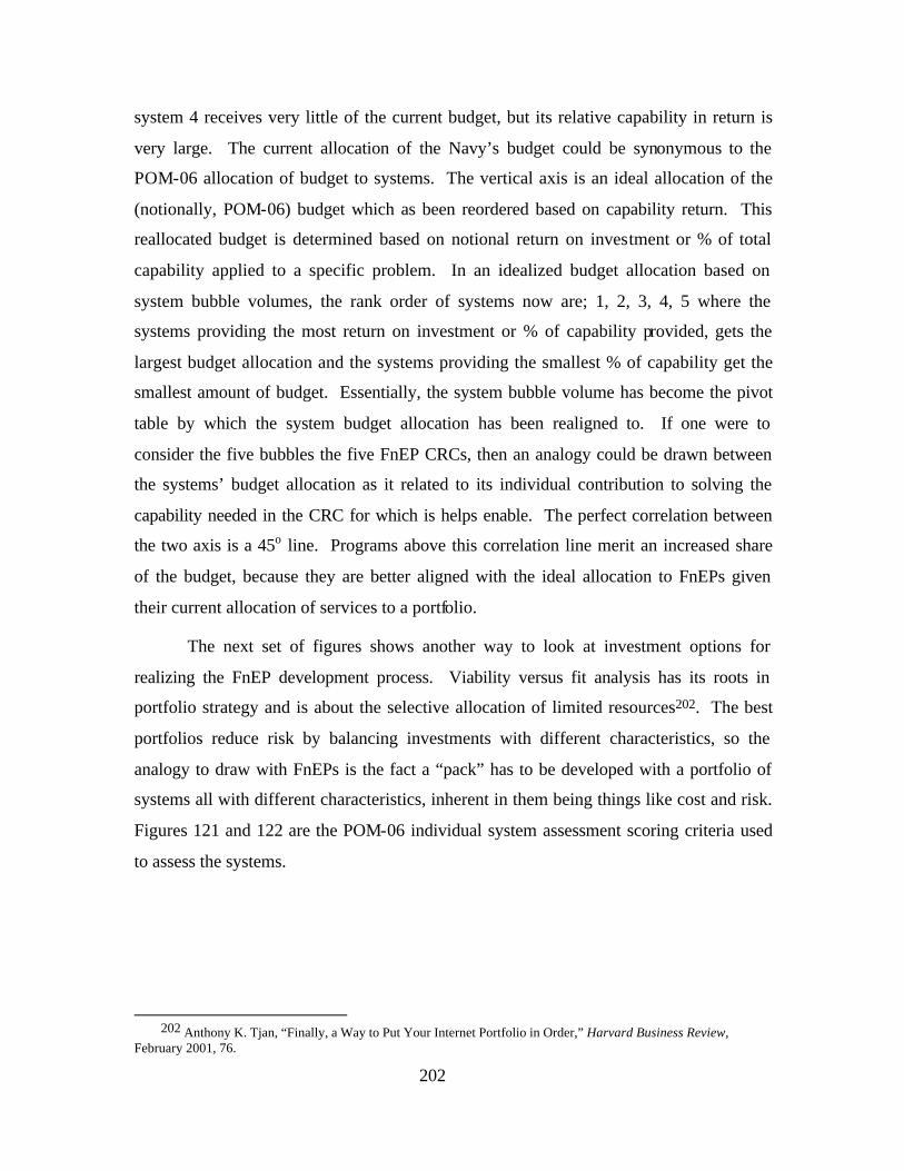
202
system 4 receives very little of the current budget, but its relative capability in return is
very large. The current allocation of the Navy’s budget could be synonymous to the
POM-06 allocation of budget to systems. The vertical axis is an ideal allocation of the
(notionally, POM-06) budget which as been reordered based on capability return. This
reallocated budget is determined based on notional return on investment or % of total
capability applied to a specific problem. In an idealized budget allocation based on
system bubble volumes, the rank order of systems now are; 1, 2, 3, 4, 5 where the
systems providing the most return on investment or % of capability provided, gets the
largest budget allocation and the systems providing the smallest % of capability get the
smallest amount of budget. Essentially, the system bubble volume has become the pivot
table by which the system budget allocation has been realigned to. If one were to
consider the five bubbles the five FnEP CRCs, then an analogy could be drawn between
the systems’ budget allocation as it related to its individual contribution to solving the
capability needed in the CRC for which is helps enable. The perfect correlation between
the two axis is a 45o line. Programs above this correlation line merit an increased share
of the budget, because they are better aligned with the ideal allocation to FnEPs given
their current allocation of services to a portfolio.
The next set of figures shows another way to look at investment options for
realizing the FnEP development process. Viability versus fit analysis has its roots in
portfolio strategy and is about the selective allocation of limited resources202. The best
portfolios reduce risk by balancing investments with different characteristics, so the
analogy to draw with FnEPs is the fact a “pack” has to be developed with a portfolio of
systems all with different characteristics, inherent in them being things like cost and risk.
Figures 121 and 122 are the POM-06 individual system assessment scoring criteria used
to assess the systems.
202 Anthony K. Tjan, “Finally, a Way to Put Your Internet Portfolio in Order,” Harvard Business Review,
February 2001, 76.
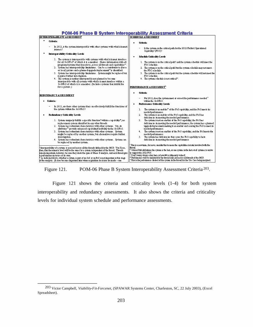
203
Figure 121. POM-06 Phase B System Interoperability Assessment Criteria 203.
Figure 121 shows the criteria and criticality levels (1-4) for both system
interoperability and redundancy assessments. It also shows the criteria and criticality
levels for individual system schedule and performance assessments.
203 Victor Campbell, Viability-Fit-Forcenet, (SPAWAR Systems Center, Charleston, SC, 22 July 2003), (Excel
Spreadsheet).
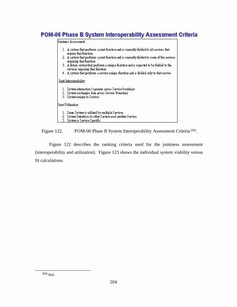
204
Figure 122. POM-06 Phase B System Interoperability Assessment Criteria 204.
Figure 122 describes the ranking criteria used for the jointness assessment
(interoperability and utilization). Figure 123 shows the individual system viability versus
fit calculations.
204 Ibid.
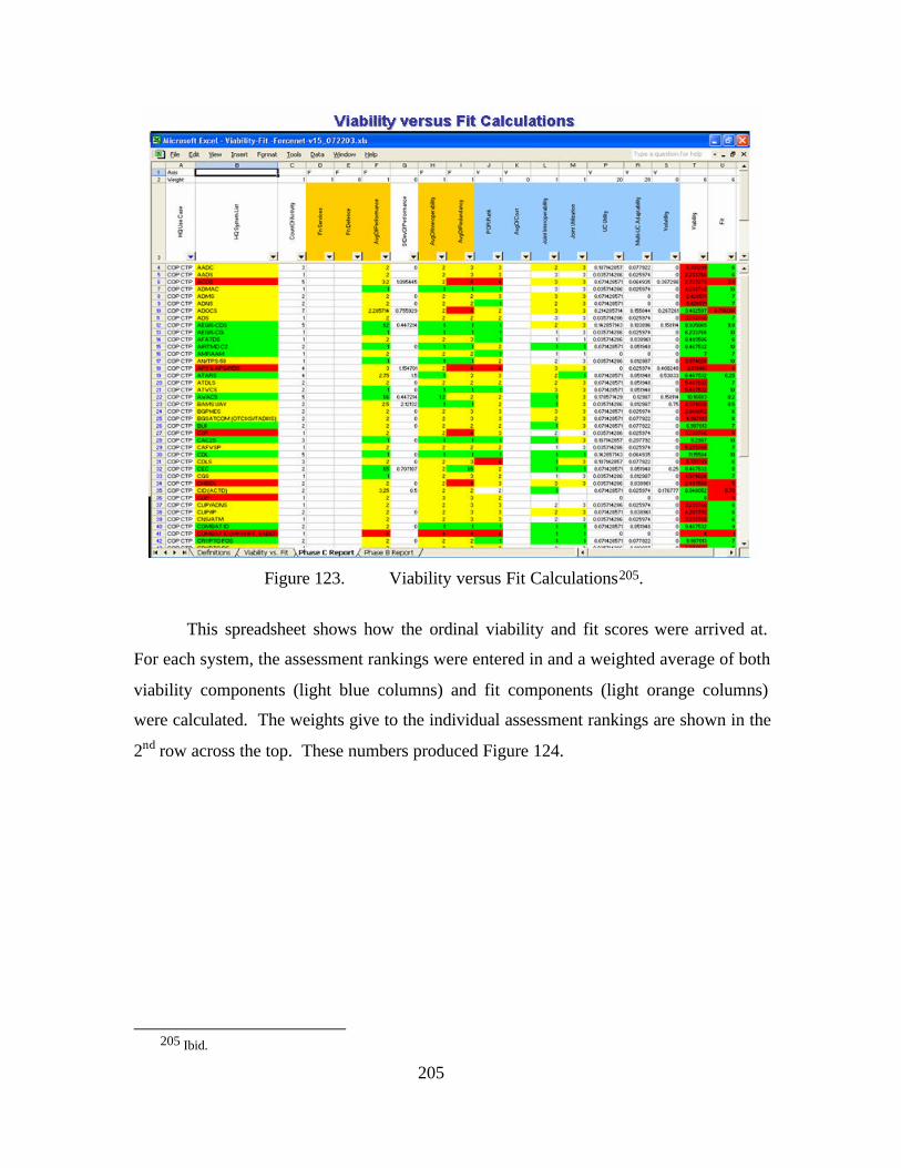
205
Figure 123. Viability versus Fit Calculations205.
This spreadsheet shows how the ordinal viability and fit scores were arrived at.
For each system, the assessment rankings were entered in and a weighted average of both
viability components (light blue columns) and fit components (light orange columns)
were calculated. The weights give to the individual assessment rankings are shown in the
2nd row across the top. These numbers produced Figure 124.
205 Ibid.
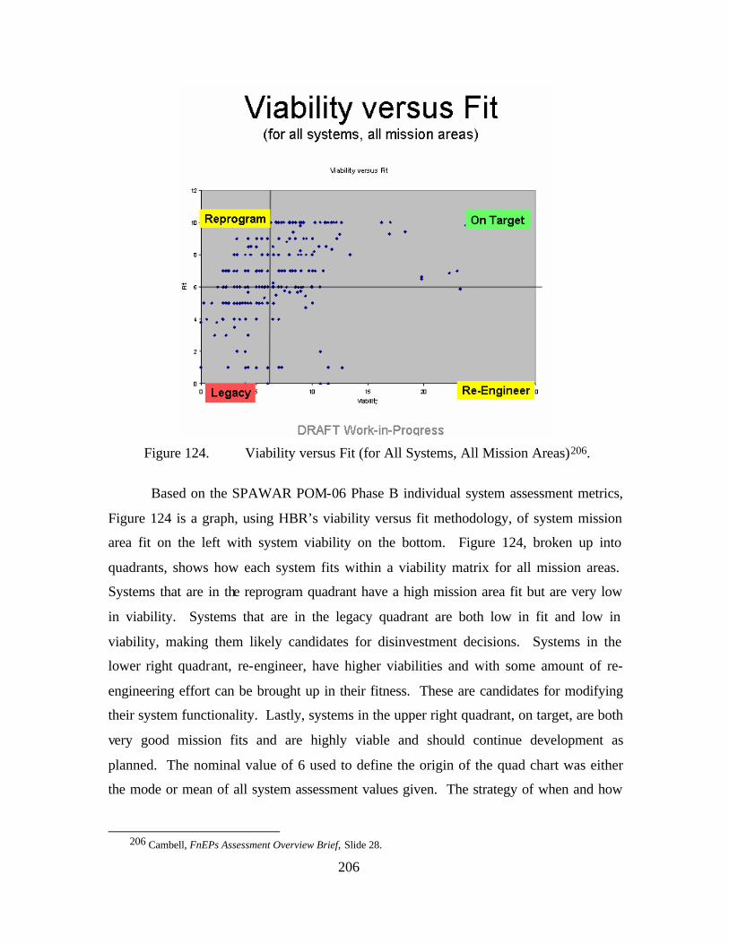
206
Figure 124. Viability versus Fit (for All Systems, All Mission Areas)206.
Based on the SPAWAR POM-06 Phase B individual system assessment metrics,
Figure 124 is a graph, using HBR’s viability versus fit methodology, of system mission
area fit on the left with system viability on the bottom. Figure 124, broken up into
quadrants, shows how each system fits within a viability matrix for all mission areas.
Systems that are in the reprogram quadrant have a high mission area fit but are very low
in viability. Systems that are in the legacy quadrant are both low in fit and low in
viability, making them likely candidates for disinvestment decisions. Systems in the
lower right quadrant, re-engineer, have higher viabilities and with some amount of re-
engineering effort can be brought up in their fitness. These are candidates for modifying
their system functionality. Lastly, systems in the upper right quadrant, on target, are both
very good mission fits and are highly viable and should continue development as
planned. The nominal value of 6 used to define the origin of the quad chart was either
the mode or mean of all system assessment values given. The strategy of when and how
206 Cambell, FnEPs Assessment Overview Brief, Slide 28.
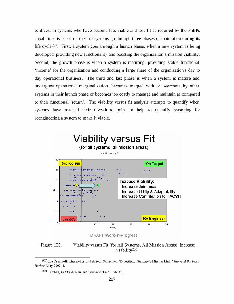
207
to divest in systems who have become less viable and less fit as required by the FnEPs
capabilities is based on the fact systems go through three phases of maturation during its
life cycle 207. First, a system goes through a launch phase, when a new system is being
developed, providing new functionality and boosting the organization’s mission viability.
Second, the growth phase is when a system is maturing, providing stable functional
‘income’ for the organization and conducting a large share of the organization’s day to
day operational business. The third and last phase is when a system is mature and
undergoes operational marginalization, becomes merged with or overcome by other
systems in their launch phase or becomes too costly to manage and maintain as compared
to their functional ‘return’. The viability versus fit analysis attempts to quantify when
systems have reached their divestiture point or help to quantify reasoning for
reengineering a system to make it viable.
Figure 125. Viability versus Fit (for All Systems, All Mission Areas), Increase
Viability208.
207 Lee Dranikoff, Tim Koller, and Antoon Schneider, “Divestiture: Strategy’s Missing Link,” Harvard Business Review, May 2002, 1.
208 Cambell, FnEPs Assessment Overview Brief, Slide 37.
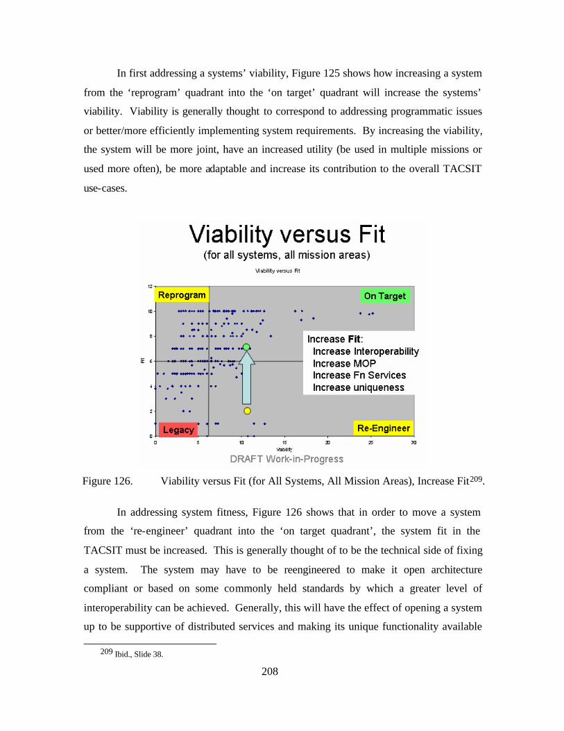
208
In first addressing a systems’ viability, Figure 125 shows how increasing a system
from the ‘reprogram’ quadrant into the ‘on target’ quadrant will increase the systems’
viability. Viability is generally thought to correspond to addressing programmatic issues
or better/more efficiently implementing system requirements. By increasing the viability,
the system will be more joint, have an increased utility (be used in multiple missions or
used more often), be more adaptable and increase its contribution to the overall TACSIT
use-cases.
Figure 126. Viability versus Fit (for All Systems, All Mission Areas), Increase Fit209.
In addressing system fitness, Figure 126 shows that in order to move a system
from the ‘re-engineer’ quadrant into the ‘on target quadrant’, the system fit in the
TACSIT must be increased. This is generally thought of to be the technical side of fixing
a system. The system may have to be reengineered to make it open architecture
compliant or based on some commonly held standards by which a greater level of
interoperability can be achieved. Generally, this will have the effect of opening a system
up to be supportive of distributed services and making its unique functionality available
209 Ibid., Slide 38.
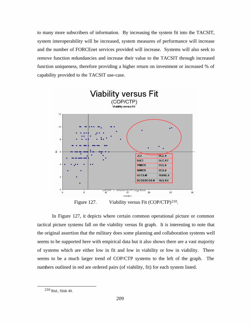
209
to many more subscribers of information. By increasing the system fit into the TACSIT,
system interoperability will be increased, system measures of performance will increase
and the number of FORCEnet services provided will increase. Systems will also seek to
remove function redundancies and increase their value to the TACSIT through increased
function uniqueness, therefore providing a higher return on investment or increased % of
capability provided to the TACSIT use-case.
Figure 127. Viability versus Fit (COP/CTP)210.
In Figure 127, it depicts where certain common operational picture or common
tactical picture systems fall on the viability versus fit graph. It is interesting to note that
the original assertion that the military does some planning and collaboration systems well
seems to be supported here with empirical data but it also shows there are a vast majority
of systems which are either low in fit and low in viability or low in viability. There
seems to be a much larger trend of COP/CTP systems to the left of the graph. The
numbers outlined in red are ordered pairs (of viability, fit) for each system listed.
210 Ibid., Slide 40.
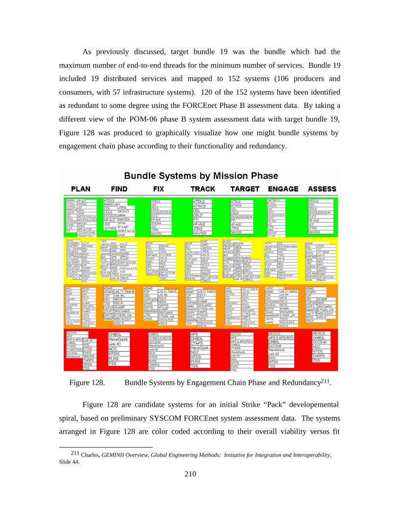
210
As previously discussed, target bundle 19 was the bundle which had the
maximum number of end-to-end threads for the minimum number of services. Bundle 19
included 19 distributed services and mapped to 152 systems (106 producers and
consumers, with 57 infrastructure systems). 120 of the 152 systems have been identified
as redundant to some degree using the FORCEnet Phase B assessment data. By taking a
different view of the POM-06 phase B system assessment data with target bundle 19,
Figure 128 was produced to graphically visualize how one might bundle systems by
engagement chain phase according to their functionality and redundancy.
Figure 128. Bundle Systems by Engagement Chain Phase and Redundancy211.
Figure 128 are candidate systems for an initial Strike “Pack” developemental
spiral, based on preliminary SYSCOM FORCEnet system assessment data. The systems
arranged in Figure 128 are color coded according to their overall viability versus fit
211 Charles, GEMINII Overview, Global Engineering Methods: Initiative for Integration and Interoperability,
Slide 44.
211
assessment and categorized according to where they fit into the engagement chain
process. The systems in the green band are essentially the systems on the FORCEnet
vision systems list that should migrate to support “packs.” The green-banded systems
have minimal system functional redundancy and are high in both viability and fit
assessments. Again, the functional redundancy definition and assessment criteria are
found in Figure 121. The unique system functions contained within the green band are
systems which have fulfilled valid warfighting requirements and continue to be value-
added to the engagement chain. At the other end of the spectrum, the red band are the
systems which have the highest system function redundancy and are low in both viability
and fit assessments. These systems should not migrate to support “packs” and would be
ideal systems to cut and use the freed-up fiscal resources to address either re-engineering
or re-programming efforts for the systems in the yellow and orange bands. The systems
within the yellow and orange bands are those that should be further investigated for
migration into this particular “pack” development spiral.
With the TAMD and Strike TACSIT use-case architectures and their attendant
systems now analyzed according to both various technical and programmatic criteria, the
part of the discussion will briefly focus on bringing it all together in a notional FnEPs
migration approach. Figure 129 is a visualization of this approach.
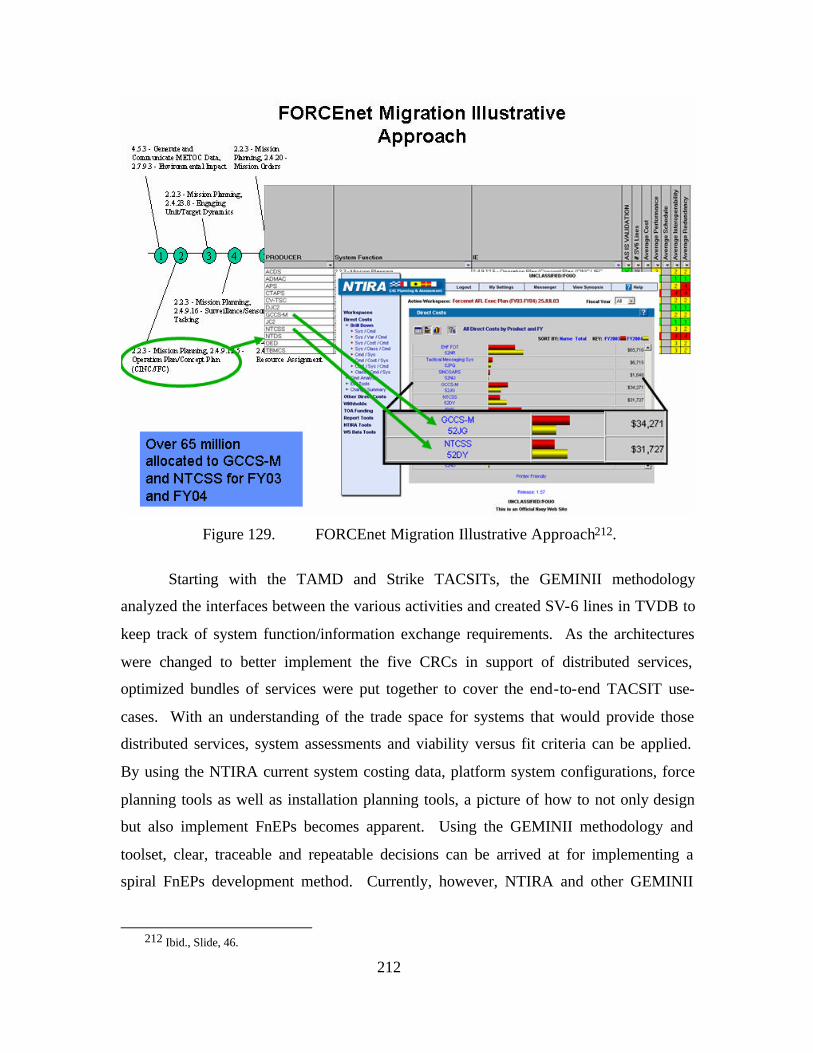
212
Figure 129. FORCEnet Migration Illustrative Approach212.
Starting with the TAMD and Strike TACSITs, the GEMINII methodology
analyzed the interfaces between the various activities and created SV-6 lines in TVDB to
keep track of system function/information exchange requirements. As the architectures
were changed to better implement the five CRCs in support of distributed services,
optimized bundles of services were put together to cover the end-to-end TACSIT use-
cases. With an understanding of the trade space for systems that would provide those
distributed services, system assessments and viability versus fit criteria can be applied.
By using the NTIRA current system costing data, platform system configurations, force
planning tools as well as installation planning tools, a picture of how to not only design
but also implement FnEPs becomes apparent. Using the GEMINII methodology and
toolset, clear, traceable and repeatable decisions can be arrived at for implementing a
spiral FnEPs development method. Currently, however, NTIRA and other GEMINII
212 Ibid., Slide, 46.
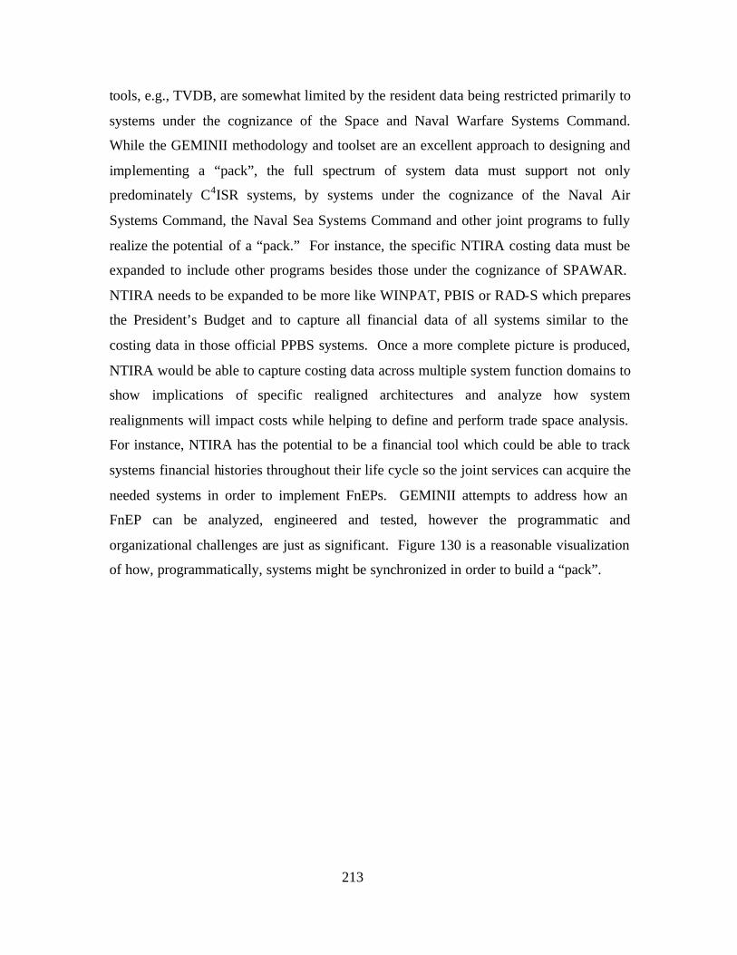
213
tools, e.g., TVDB, are somewhat limited by the resident data being restricted primarily to
systems under the cognizance of the Space and Naval Warfare Systems Command.
While the GEMINII methodology and toolset are an excellent approach to designing and
implementing a “pack”, the full spectrum of system data must support not only
predominately C4ISR systems, by systems under the cognizance of the Naval Air
Systems Command, the Naval Sea Systems Command and other joint programs to fully
realize the potential of a “pack.” For instance, the specific NTIRA costing data must be
expanded to include other programs besides those under the cognizance of SPAWAR.
NTIRA needs to be expanded to be more like WINPAT, PBIS or RAD-S which prepares
the President’s Budget and to capture all financial data of all systems similar to the
costing data in those official PPBS systems. Once a more complete picture is produced,
NTIRA would be able to capture costing data across multiple system function domains to
show implications of specific realigned architectures and analyze how system
realignments will impact costs while helping to define and perform trade space analysis.
For instance, NTIRA has the potential to be a financial tool which could be able to track
systems financial histories throughout their life cycle so the joint services can acquire the
needed systems in order to implement FnEPs. GEMINII attempts to address how an
FnEP can be analyzed, engineered and tested, however the programmatic and
organizational challenges are just as significant. Figure 130 is a reasonable visualization
of how, programmatically, systems might be synchronized in order to build a “pack”.
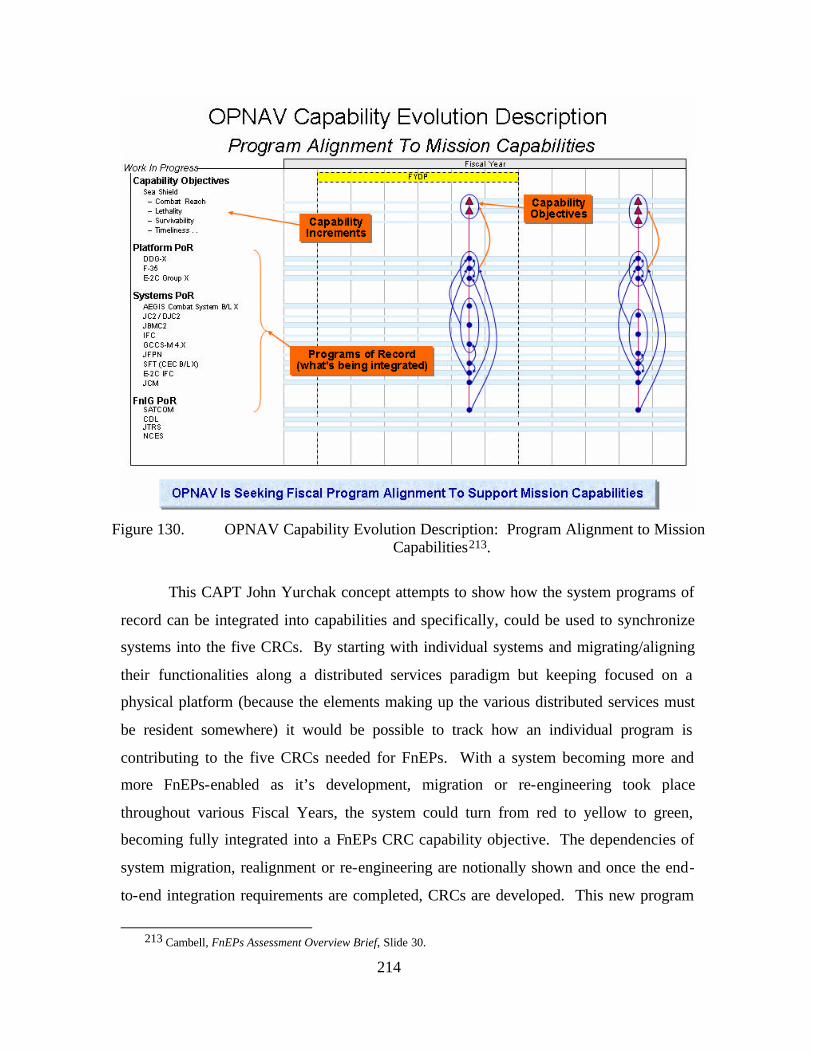
214
Figure 130. OPNAV Capability Evolution Description: Program Alignment to Mission
Capabilities213.
This CAPT John Yurchak concept attempts to show how the system programs of
record can be integrated into capabilities and specifically, could be used to synchronize
systems into the five CRCs. By starting with individual systems and migrating/aligning
their functionalities along a distributed services paradigm but keeping focused on a
physical platform (because the elements making up the various distributed services must
be resident somewhere) it would be possible to track how an individual program is
contributing to the five CRCs needed for FnEPs. With a system becoming more and
more FnEPs-enabled as it’s development, migration or re-engineering took place
throughout various Fiscal Years, the system could turn from red to yellow to green,
becoming fully integrated into a FnEPs CRC capability objective. The dependencies of
system migration, realignment or re-engineering are notionally shown and once the end-
to-end integration requirements are completed, CRCs are developed. This new program
213 Cambell, FnEPs Assessment Overview Brief, Slide 30.
215
planning exhibit called the Capability Evolution Description or process to align programs
to mission capabilities being proposed by the OPNAV N81 IWARS office could be
expanded upon to help realize FnEPs in the near term.
D. ANALYSIS ROAD AHEAD
As discussed in the prior sections, this thesis focused the contextual aspects of
FnEPs and high- level, first order assessments. Future assessment efforts will require
more detailed design and implementation requirements analysis. In order to continue to
refine the FnEPs concept, requirements and analysis will need to expand into greater
detail of information exchanges, computational elements (system functions), and Intra-
and Inter-nodal networking considerations. As an example, we (to include SSC-C)
experimented with such an assessment utilizing the Navy Integrated Fire Control –
Counter Air (NIFC-CA) concept assessed an example of technology/processes which
support the IFC CRC.
From a GEMINII perspective, we developed the Use-Case based on the Engage
on Remote (EOR) sequence provided as part of a NIFC-CA briefing. Our goal was to
take the FnEPs concept and overlay it on top of the NIFC-CA EOR sequence to get a
better understanding of how the five CRCs would interact. The next issue was to refine
the computational architecture and provide greater detail to the Combat Reach
Functionality. To accomplish this, we chose the ASN (RD&A) Chief Engineer’s
(CHENG) developing Common System Function List (CSFL). Figure 131 shows our
first attempt at how the EOR sequence of events, augmented with some detail from the
CSFL would be overlayed on top of all five CRCs.
216
Figure 131. FnEPs Overlay onto NIFC-CA Engage on Remote (EOR) Scenario.
The arrows imply system function interactions and dependencies. Note that there
are sets of system functions that would behave in a looping fashion, which are not
displayed here. What is depicted is a threat being detected in the upper left-hand corner,
and subsequently this setting off the system functions shown. As a result of this exercise,
there were new system function interactions added due to the adaptability, and flexibility
precepts which were not present in the current EOR sequence followed. Furthermore, the
exercise demonstrates where the required functionality should be partitioned into the five
CRCs.
This overlay is a critical first step in developing the CRC threads for the
FORCEnet Integrated Architecture. The interrelationships shown here begins to get at
the: “what information to what warfighter at what time for what specfic purpose” issue.
This type of information will be useful in developing IERs that will eventually define
network requirements. Future steps to complete this Strike and TAMD analysis would be
to take other existing concepts and programs like NIFC-CA and overlay them onto the
217
FnEPs concept to understand the interactions between the five CRCs. This process
allows the discovery of new functionality and the framework by which to assess
duplicated functionality that should be consolidated with a CRC. Once a more complete
and detailed understanding as well as mapping of legacy program functionality is
overlayed on top of the five CRCs, the interaction arrows can be turned into interfaces.
With a parameterized DSM model of these interactions, clusters of interactions can be
analyzed. We propose that these clusters of interactions could identify system
function/information exchange pairs and QoS metrics that are required to be present to
implement the clusters of interactions. We propose using TVDB to assess and redesign
new TACSITs based on those discovered and optimized interactions, TVDB will also
incorporate the new or altered SV-6 lines to show those system function/information
exchange pair requirements. Once new TACSITs are designed, which reflect the
understanding of the warfighter process and activities, the functions constituted within
the CRCs and interactions required between the CRCs could be assessed against actual
legacy system functionality and how well it supports that specific interface in the new
TACSITs. By doing system analysis on their functionalities and looking for gaps and
duplication in system functions, newly realigned systems would emerge to support those
TACSITs. NTIRA could possibly be used to analyze the cost, schedule and performance
impacts of realigning those system functions within legacy systems given an expanded
view of all Navy system financial data. Perhaps more importantly, the GEMINII process
would be able to cluster identified and needed, but as of yet not available, system
functionality which would be properly clustered into new systems or families of new
systems (based on their required interactions) to properly fill the operational gaps, system
functional gaps and produce the end-to-end CRCs. Analysis up to this point and trends
point to the largest gaps in CRCs as being within the sets of decision support tools needed
to implement the required functionality of the ABMAs.
E. CONCLUSION
The section has discussed the evolving GEMINII toolset and chronicaled a year-
long cooperative analysis effort aimed at further refinement of the FnEPs concept as it
specifically relates to the Strike and TAMD “Packs.” Overall, GEMINII revealed and
validated the tremendous near-term potential of FORCEnet and FnEPs to our operational
218
forces. At its roots; however, FnEPs remains a dynamic concept applicable across many
mission areas. “Packs” will exist and function throughout a networked virtual
environement with virtual borders between packs and amongst pack members. “Packs”
must be capable of dynamically adapting within this environment of ever-changing and
asymmetric threats. Accordingly, future analysis will require a commitment to challenge,
refine, and challenge again working engagement chain models, where the steps are
complex and have ambiguous boundaries. Only through such analysis can we ensure this
transformational concept fully develops FORCEnet and NCW across all mission areas.
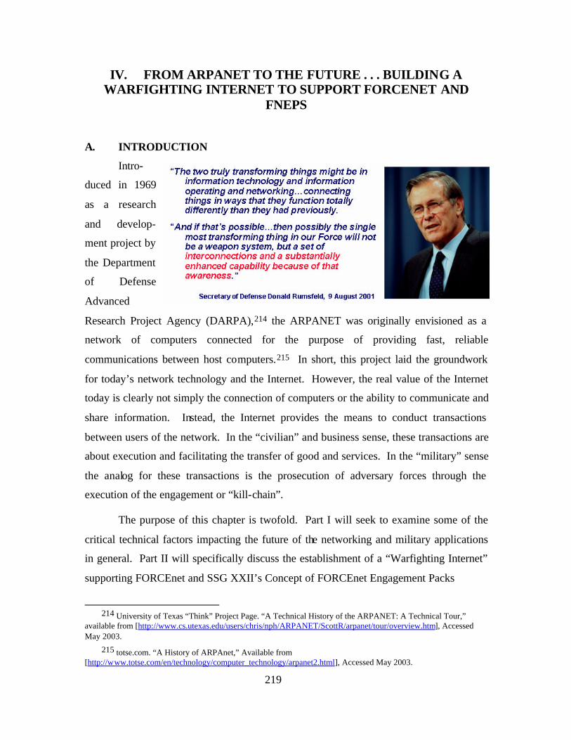
219
IV. FROM ARPANET TO THE FUTURE . . . BUILDING A WARFIGHTING INTERNET TO SUPPORT FORCENET AND
FNEPS
A. INTRODUCTION
Intro-
duced in 1969
as a research
and develop-
ment project by
the Department
of Defense
Advanced
Research Project Agency (DARPA),214 the ARPANET was originally envisioned as a
network of computers connected for the purpose of providing fast, reliable
communications between host computers.215 In short, this project laid the groundwork
for today’s network technology and the Internet. However, the real value of the Internet
today is clearly not simply the connection of computers or the ability to communicate and
share information. Instead, the Internet provides the means to conduct transactions
between users of the network. In the “civilian” and business sense, these transactions are
about execution and facilitating the transfer of good and services. In the “military” sense
the analog for these transactions is the prosecution of adversary forces through the
execution of the engagement or “kill-chain”.
The purpose of this chapter is twofold. Part I will seek to examine some of the
critical technical factors impacting the future of the networking and military applications
in general. Part II will specifically discuss the establishment of a “Warfighting Internet”
supporting FORCEnet and SSG XXII’s Concept of FORCEnet Engagement Packs
214 University of Texas “Think” Project Page. “A Technical History of the ARPANET: A Technical Tour,”
available from [http://www.cs.utexas.edu/users/chris/nph/ARPANET/ScottR/arpanet/tour/overview.htm], Accessed May 2003.
215 totse.com. “A History of ARPAnet,” Available from [http://www.totse.com/en/technology/computer_technology/arpanet2.html], Accessed May 2003.
220
(FnEPs). To assist the less knowledgeable reader, Appendix B “Networking Basics”
provides additional background and basic information regarding networking and network
technology.
B. CRITICAL FACTORS
For years and years enthusiasts have been saying that the Internet will happen “tomorrow.” You're going to keep reading prognostications that the big change will happen in the next twelve months. This is just baloney. The social adaptations that have to occur take years and the infrastructure has to be built out. But when the social and technical changes reach critical mass, the change will be quick and irreversible.
---Bill Gates “The Road Ahead”
While today’s commercial data and communications networks have advanced far
beyond those of yesterday and the original ARPANET, the future will demand even
greater performance and technological advancement. The most critical technological
challenges for these networks include the need to support advanced applications requiring
ever-increasing levels of bandwidth and Quality of Service (QoS), often over wireless
media and in support of mobile applications and functionality. Further, such applications
and services are becoming more and critical to the successful operation of individuals and
organizations alike, demanding higher levels of security and information assurance in
general.
But if these challenges seem daunting in the commercial sector, they are even
more so for our military. While wireless and mobile technology is still largely a
convenience for civilians and in the commercial sector, such technologies are critical and
indispensable to the military, especially in deployed scenarios. Under combat conditions
security and information assurance assume life and death importance. While businesses
and individuals certainly depend on the timely delivery of the ir critical data and
information, military weapons systems often require a much higher order of performance
from a QoS perspective. Finally, the unique nature of deployed and combat
environments result in special human systems integration (HSI) considerations, including
training and integration related issues.
221
As a result of these challenges, military “networks” will require unique
performance functionality when compared to commercial networks and the “Internet”
with which most of us are so familiar. The remainder of this section seeks to address
some of this unique functionality, including the following:
• Protocols
• Mobile Routing and Networking
• Satellite Communications
• Wireless Communications
• RF Communications and Antennas
• Bandwidth
1. Protocols
As reviewed in Appendix B “Networking
Basics” network protocols are critically important to
the functioning of computer networks. Originally,
the Internet Protocol (IP) was designed to be highly
scalable in terms of application support and the
number of devices and/or users on a network. Further, IP’s scalability would enable the
creation and interoperability of “networks of networks”, such as the Internet. Since the
introduction of IP; however, the exponential growth of information technology in general
and networking more specifically have combined to result in greater and greater demands
being placed on IP to provide “plug and play” network interoperability. More
specifically, three major challenges to IP currently exist. 1) The rise in popularity and
demand for streaming audio and video and other demanding multimedia applications has
greatly increased the requirement for provisioning some sort of Quality of Service (QoS)
mechanism, especially in bandwidth limited situations such as a radio-wide area network
(WAN). 2) A rise in the criticality of the data, applications, and other services being
provided across the Internet and the resultant requirements to provide security. 3) The
exponential growth in the popularity of the Internet itself, and the number of wireless and
mobile users and devices being connected to the Internet has created address space
shortages and routing challenges. Individually and collectively these three challenges
were unforeseen by the developers of the current version of the IP protocol, called IPv4.
“32 bits should be enough address space for the Internet.” - Dr. Vint Cerf, 1977 Founder of the IP Protocol
222
Fortunately; however, these challenges have not surfaced overnight and efforts have been
ongoing to not only solve these problems but also foresee and forestall others. Chief
among these efforts have been the development and implementation of IPv6 – a new and
improved version of the original IPv4.
2. IPv6
Fundamentally, IPv6 offers advantages over IPv4 in four areas:
• Scalability
• Autoconfiguration
• Security
• Performance and QoS
a. Scalability
As discussed previously, IPv4 is sorely in need of an increase in its
address space. The most obvious reason is to provide for a unique IP address for every
device currently connected or envisioned as connecting to a network in the future.
Currently, IPv4’s address space is only 32 bits, which only allows four billion addresses.
By comparison, the world’s population currently exceeds six billion, limiting addresses,
and therefore individually networked devices to less than one device per person (Network
Address Translation (NAT) notwithstanding). Conversely, IPv6 uses a 128-bit address
space, theoretically enough for 340 trillion trillion trillion addresses.216 Again, put into
perspective, this number is estimated to provide enough IP addresses for every grain of
sand on Earth. 217 An added benefit of so many available addresses is the ability to
improve the prefix aggregation problem discussed previously, thus reducing external
routing tables to roughly 8000 items from over 100,000 currently seen in some routers.
This will obviously increase the speed and efficiency of routing decisions.
b. Autoconfiguration
One of the most significant improvements offered by IPv6 is its address
autoconfiguration features. More and more, networking is evolving beyond the wired
216 There will actually be somewhat fewer available addresses in practice, due to the way addresses are
structured, but even a conservative estimate will still allow about 35 trillion sites, each with an 80-bit local address space.
217 Technology & Business, “IPv6: Time to Change?,” 5 November 2002, Available at [http://www.zdnet.com.au/printfriendly?AT=2000034884-20269647], Accessed May 2003.
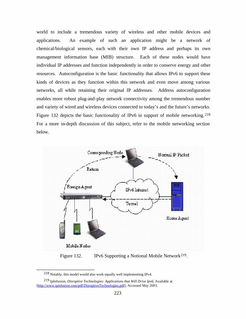
223
world to include a tremendous variety of wireless and other mobile devices and
applications. An example of such an application might be a network of
chemical/biological sensors, each with their own IP address and perhaps its own
management information base (MIB) structure. Each of these nodes would have
individual IP addresses and function independently in order to conserve energy and other
resources. Autoconfiguration is the basic functionality that allows IPv6 to support these
kinds of devices as they function within this network and even move among various
networks, all while retaining their original IP addresses. Address autoconfiguration
enables more robust plug-and-play network connectivity among the tremendous number
and variety of wired and wireless devices connected to today’s and the future’s networks.
Figure 132 depicts the basic functionality of IPv6 in support of mobile networking. 218
For a more in-depth discussion of this subject, refer to the mobile networking section
below.
Figure 132. IPv6 Supporting a Notional Mobile Network219.
218 Notably, this model would also work equally well implementing IPv4.
219 IpInfusion, Disruptive Technologies: Applications that Will Drive Ipv6, Available at [http://www.ipinfusion.com/pdf/DisruptiveTechnologies.pdf], Accessed May 2003.
224
c. Security
The IPv6 specification includes security features in the form of packet
encryption (Encapsulated Security Payload, or ESP) and source authentication
(Authentication Header, or AH). Both these features are optional parts of the IPv4
specification, but it is mandatory that they are included in every IPv6 implementation. In
the context of the security discussion below, this functionality helps to ensure
confidentiality, authenticity, and non-repudiation. AH also provides assurance that the
packet has not been altered in transit. That said, it is not mandatory that either ESP or
AH are actually used. This IPv6 support of security is more elegant than that of IPv4 and
is one of the more compelling reasons to migrate to IPv6. More specifically, IPv6
implements IPsec such that only the payload and extension header require encryption
while the primary header remains untouched.
d. Performance and QoS
IPv6 packets include a Flow Label field, allowing routers to establish
virtual circuit-style connections. The Flow Label field identifies a set of packets that
belong to the same flow—much like the IPv4 Service Type (Diffserv or DS) field. The
Flow Label field for a particular flow is a pseudo-random number. No other flow from
the same source is assigned the same Flow Label. The Flow Label and the source
address are therefore the only information needed for a router to classify a packet for the
purpose of determining its priority, and they are stored in the packet header. This is a
much more simple method than with IPv4, whose process typically requires examination
of the source address, source port, destination address, and destination port. This
simplification in terms of the fixed size and reduced number of fields in the IPv6 header
also allows for simplified processing by routers. Further advantages include improved
performance by preventing packet fragmentation. This functionality is accomplished via
an algorithm designed to discover the transmission path and the smallest MTU
(maximum transmission unit) along it, and then restricting packet sizes to that minimum.
Collectively, these advantages help routers and other network devices provide QoS and
traffic management. Furthermore, routers will be able to use the information they collect
to analyse traffic patterns and use the results to improve overall network performance.
225
e. Challenges to IPv6
One of the most critical challenges facing IPv6 is the transition from IPv4.
Despite so many applications and equipment already supporting IPv6, we have
remarkably little knowledge or experience about IPv6 or its practical implementation.
Unlike other Asian countries who face far more immediate challenges with continued use
of IPv4, such as critical shortages of available IP addresses, in North America, the
conduct of necessary research and development to ensure a smooth transition from IPv4
to IPv6 has been lackluster. Beyond the implementation of IPv6; there remain
unanswered questions related to the security and mobility support enhancements being
touted as advantages to IPv6 as well. In order to rectify this shortcoming, the North
American IPv6 Task Force (NAv6TF), in collaboration with the University of New
Hampshire Interoperability Lab (UNH-IOL), the Joint Interoperability Test Command
(JITC), and the Department of Defense (DoD), developed the Moonv6 project. The
Moonv6 project is combination of a muti-site, IPv6 based network and series of of
interoperability events designed to test the functionality and interoperability of equipment
and operating systems that will support IPv6. Fundamentally; however, IPv6 goes
beyond simply addressing the shortcomings and other challenges facing IPv4 and/or
adding improvements to the IP protocol. IPv6 is about developing a global technology
that will truly enable the ubiquitous potential of current and future networking, including
true IP mobility and ease of use for the end user.220 Ultimately, while IPv6 will help to
enable FORCEnet and FnEPs, of far larger importance is the transition of other, currently
non-routable networks (e.g., Link 11, Link 16, etc.)!
f. Other Protocol -Related Challenges
As discussed previously, due to the unique nature of military networking
in deployed and combat scenarios, requirements exist beyond those of commercial
networks and the Internet, especially related to security, QoS, and performance in general
(e.g., performance requirements associated with ISR, C2, and FC/weapons applications
across wireless and RF networks). The remainder of this section seeks to discuss
examples of current network protocol research and development related to these
challenges.
220 IBM Research Division, IP Over Everyhting,2.
226
These requirements are fundamentally related to providing the high levels
of availability and reliability (the network must stay up), scalability (the network must
support higher and higher numbers of users and devices or “end systems”221), and
connectivity (nodes must stay connected, even as they transit between network domains).
Examples of highly developed software that supports such functionality requirements is
Cisco’s Internet Operating System (IOS). Just like any other operating system, IOS is a
package of network systems software, and specialized delivery and discovery protocols
that provides a common IP fabric, functionality, and command-line interface across a
(mobile) network.222
In terms of support for latency requirements, military networking
requirements result in one of the most difficult overall challenges to IP-based networking.
This challenge is twofold and results from the fundamental “connectionless” nature of IP-
based networking and the fact that all packets have the same priority. While this problem
can be mitigated through the use of the IPv6 protocol, which will provide packet
prioritization through QoS functionality, a second issue involves the laws of physics.
The nature of a “Warfighting Internet” is such that routing will in some cases involve
multiple wireless and/or satellite link “hops”. Such routing will introduce both increased
latency times and “faults” related to increased Bit Error Rates (BER). Notably, IP in and
of itself, does not increase latency, nor does it add to BER. IP does permit the
multiplexing of multiple datastreams together, thereby greatly increasing bandwidth
efficiency. Unfortunately, one result of such efficiency is an increase in the “bursty”
behavior which can effect latency. A tradeoff exists between reducing such latency while
maintaining bandwidth efficiency. Overall, both problems of latency and BER can
combine to result in increased dropped connections. Further, in the case of real- and
near-real time latency demands of weapons and other fire-control related requirements,
network faults and latency can become unacceptable. One of the greatest “criticisms” of
IP-based networking is the latency intolerant nature of IP itself. Ironically, this
221 “End systems” include such nodes as bridge routers or actual edge devices which serve some sense, decide or
act function.
222 Sharon Berry, “Mobile Routing Creates Seamless Links, Increases Situational Awareness,” (Signal Magazine), (October 2002), Available at [http://www.us.net/signal/Archive/Oct02/in-oct.html], Accessed May 2003.
227
intolerance is actually a function of the Transmission Control Protocol (TCP). One of
TCP’s strongest fault correction features is that long delays (such as those encountered in
satellite link and multi-hop situations) are interpreted as faults or worse, as dropped
connections. As a result, packets are resent. At a minimum, this has the effect of
inefficient resource usage, and at worse, leads to an infinite loop of undeliverable packets
and possible network instability.
This reference to TCP highlights, while the existing IP protocol is
sufficient in most circumstances, there are other challenges related to the Transport Layer
of the ISO 7-Layer Model such as the growing requirement for Portable, Real-Time
Protocols (PRTP). As a result, significant research and progress is being made in the
areas of fault-tolerant and real- time protocols, suitable for the environment of a
Warfighting Internet. Examples include basic protocol standards and research such as the
Real-Time Protocol (RTP), an IETF standard that provides end-to-end delivery services
for data with real-time characteristics, such as interactive audio and video. Another such
standard is the Real-Time Control Protocol (RTCP), an IETF standard that provides
feedback on the transmission and reception quality of data carried by the RTP.223 At the
opposite end of the spectrum is research on the technology utilizing the aforementioned
standards to provision real-time applications and services over IP-based networks.
Generally speaking, any future transport layer protocol should exhibit the following four
characteristics:
• Support for reliable multicast.
• Inherent security, particularly in the area of resistance to syn-flood denial of service attacks.
• “Early open” – This would allow real data to be passed on the 3-way handshake datagrams thereby reducing latency during the connection opening process.
• Support for QoS sensitivity must be improved, eliminating the current assumption a lost datagram is automatically the result of congestion.
223 Ibid.
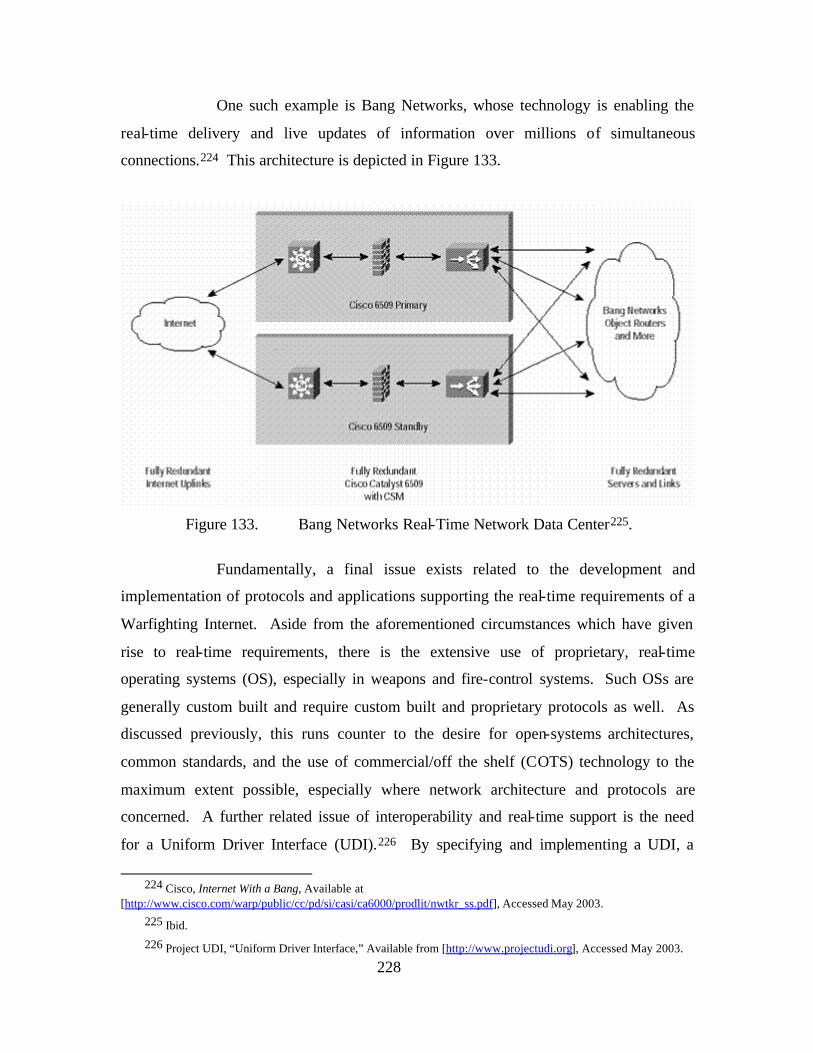
228
One such example is Bang Networks, whose technology is enabling the
real-time delivery and live updates of information over millions of simultaneous
connections.224 This architecture is depicted in Figure 133.
Figure 133. Bang Networks Real-Time Network Data Center225.
Fundamentally, a final issue exists related to the development and
implementation of protocols and applications supporting the real-time requirements of a
Warfighting Internet. Aside from the aforementioned circumstances which have given
rise to real-time requirements, there is the extensive use of proprietary, real-time
operating systems (OS), especially in weapons and fire-control systems. Such OSs are
generally custom built and require custom built and proprietary protocols as well. As
discussed previously, this runs counter to the desire for open-systems architectures,
common standards, and the use of commercial/off the shelf (COTS) technology to the
maximum extent possible, especially where network architecture and protocols are
concerned. A further related issue of interoperability and real-time support is the need
for a Uniform Driver Interface (UDI).226 By specifying and implementing a UDI, a
224 Cisco, Internet With a Bang, Available at
[http://www.cisco.com/warp/public/cc/pd/si/casi/ca6000/prodlit/nwtkr_ss.pdf], Accessed May 2003. 225 Ibid.
226 Project UDI, “Uniform Driver Interface,” Available from [http://www.projectudi.org], Accessed May 2003.
229
single device driver could support an I/O card across multiple platforms and operating
systems as appropriate for a given task. When such COTs OSs and UDIs are combined
with improved protocols, the overall performance of a Warfighting Internet will be vastly
improved, especially in terms of reduced network latency. One example of one such
standardization is that of the POSIX interface standards. These are well developed,
mature, and would greatly enhance support for real-time performance if implemented and
adhered to.
While the protocol related issues discussed above are perhaps the most
critical for a Warfighting Internet, other critical considerations and challenges remain.
The following sections address these issues individually.
3. Mobile Routing and Networking
For more than a decade, data roaming
services using private and proprietary wireless
technologies have enabled delivery trucks, police,
fire, and other emergency vehicles to communicate
with networks.227 With the growing popularity of
an assortment of personal wireless devices such as cell phones, PDAs, and others
designed to access the Internet and other business and personal networks, the requirement
for mobile support and networking technologies is growing at an exponential rate.
Moreover, ‘mobility’ implies a variety of applications and circumstances:
• Mobile IP requires end system mobility.
• MANETs require mobility in the form of rapidly changing network topologies.
• Satellite Communications and WLAN applications require mobility in the form of “radio reach.”
• Radio Frequency communications require mobility in the form of small and non-steerable antennas, especially for disadvantaged users.
• Submerged submarines require mobility in the form of Low Frequency (LF) or lower communications.
Figure 134 depicts this exponential growth curve into the near future.
227 Cisco, Mobile IP & Mobile Networks Promise New Era of Satellite and Wireless Communications, Available
from [http://www.cisco.com/warp/public/732/Tech/mobile/ip/docs/nasa_glenn_0129.pdf], Accessed May 2003.
“640K ought to be enough for anybody, and by the way, what’s a network?” - Bill Gates, 1984
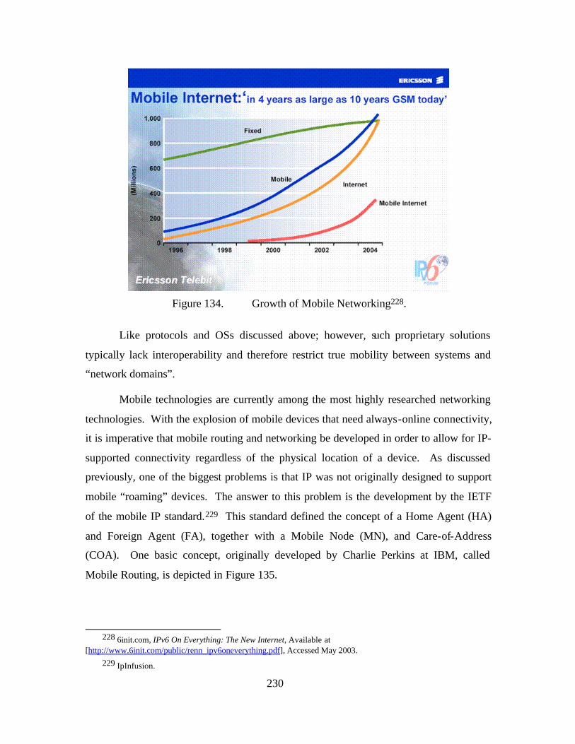
230
Figure 134. Growth of Mobile Networking228.
Like protocols and OSs discussed above; however, such proprietary solutions
typically lack interoperability and therefore restrict true mobility between systems and
“network domains”.
Mobile technologies are currently among the most highly researched networking
technologies. With the explosion of mobile devices that need always-online connectivity,
it is imperative that mobile routing and networking be developed in order to allow for IP-
supported connectivity regardless of the physical location of a device. As discussed
previously, one of the biggest problems is that IP was not originally designed to support
mobile “roaming” devices. The answer to this problem is the development by the IETF
of the mobile IP standard.229 This standard defined the concept of a Home Agent (HA)
and Foreign Agent (FA), together with a Mobile Node (MN), and Care-of-Address
(COA). One basic concept, originally developed by Charlie Perkins at IBM, called
Mobile Routing, is depicted in Figure 135.
228 6init.com, IPv6 On Everything: The New Internet, Available at
[http://www.6init.com/public/renn_ipv6oneverything.pdf], Accessed May 2003. 229 IpInfusion.
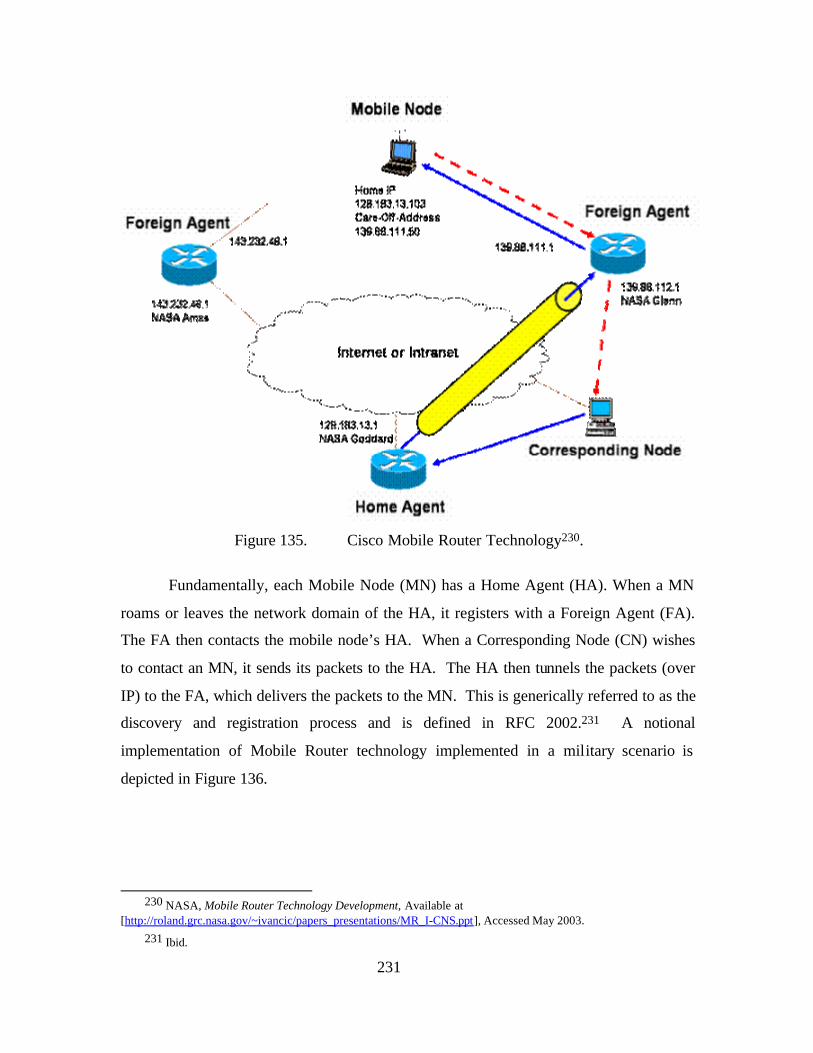
231
Figure 135. Cisco Mobile Router Technology230.
Fundamentally, each Mobile Node (MN) has a Home Agent (HA). When a MN
roams or leaves the network domain of the HA, it registers with a Foreign Agent (FA).
The FA then contacts the mobile node’s HA. When a Corresponding Node (CN) wishes
to contact an MN, it sends its packets to the HA. The HA then tunnels the packets (over
IP) to the FA, which delivers the packets to the MN. This is generically referred to as the
discovery and registration process and is defined in RFC 2002.231 A notional
implementation of Mobile Router technology implemented in a military scenario is
depicted in Figure 136.
230 NASA, Mobile Router Technology Development, Available at
[http://roland.grc.nasa.gov/~ivancic/papers_presentations/MR_I-CNS.ppt], Accessed May 2003. 231 Ibid.
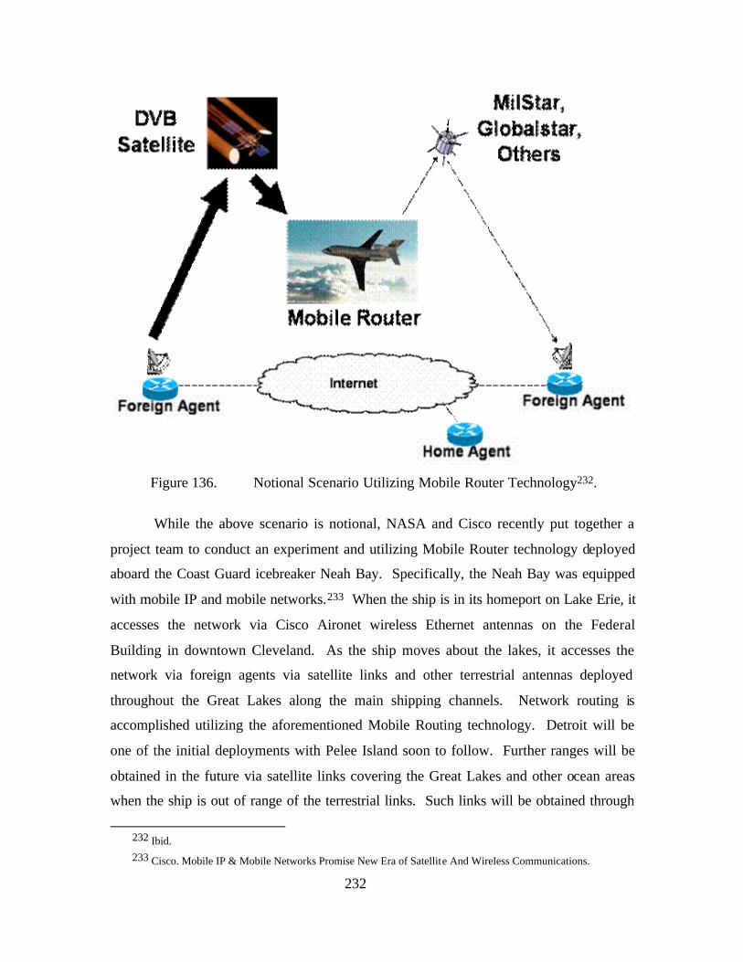
232
Figure 136. Notional Scenario Utilizing Mobile Router Technology232.
While the above scenario is notional, NASA and Cisco recently put together a
project team to conduct an experiment and utilizing Mobile Router technology deployed
aboard the Coast Guard icebreaker Neah Bay. Specifically, the Neah Bay was equipped
with mobile IP and mobile networks.233 When the ship is in its homeport on Lake Erie, it
accesses the network via Cisco Aironet wireless Ethernet antennas on the Federal
Building in downtown Cleveland. As the ship moves about the lakes, it accesses the
network via foreign agents via satellite links and other terrestrial antennas deployed
throughout the Great Lakes along the main shipping channels. Network routing is
accomplished utilizing the aforementioned Mobile Routing technology. Detroit will be
one of the initial deployments with Pelee Island soon to follow. Further ranges will be
obtained in the future via satellite links covering the Great Lakes and other ocean areas
when the ship is out of range of the terrestrial links. Such links will be obtained through
232 Ibid. 233 Cisco. Mobile IP & Mobile Networks Promise New Era of Satellite And Wireless Communications.
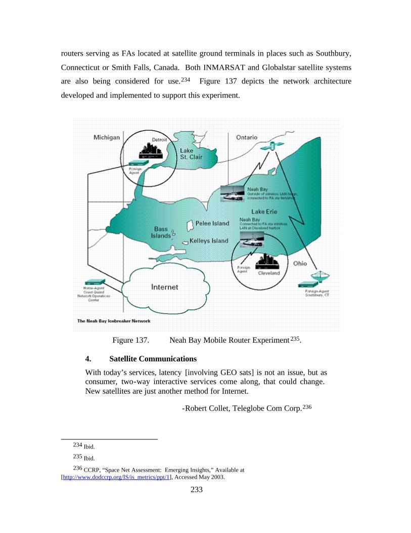
233
routers serving as FAs located at satellite ground terminals in places such as Southbury,
Connecticut or Smith Falls, Canada. Both INMARSAT and Globalstar satellite systems
are also being considered for use.234 Figure 137 depicts the network architecture
developed and implemented to support this experiment.
Figure 137. Neah Bay Mobile Router Experiment 235.
4. Satellite Communications
With today’s services, latency [involving GEO sats] is not an issue, but as consumer, two-way interactive services come along, that could change. New satellites are just another method for Internet.
-Robert Collet, Teleglobe Com Corp.236
234 Ibid.
235 Ibid.
236 CCRP, “Space Net Assessment: Emerging Insights,” Available at [http://www.dodccrp.org/IS/is_metrics/ppt/1], Accessed May 2003.
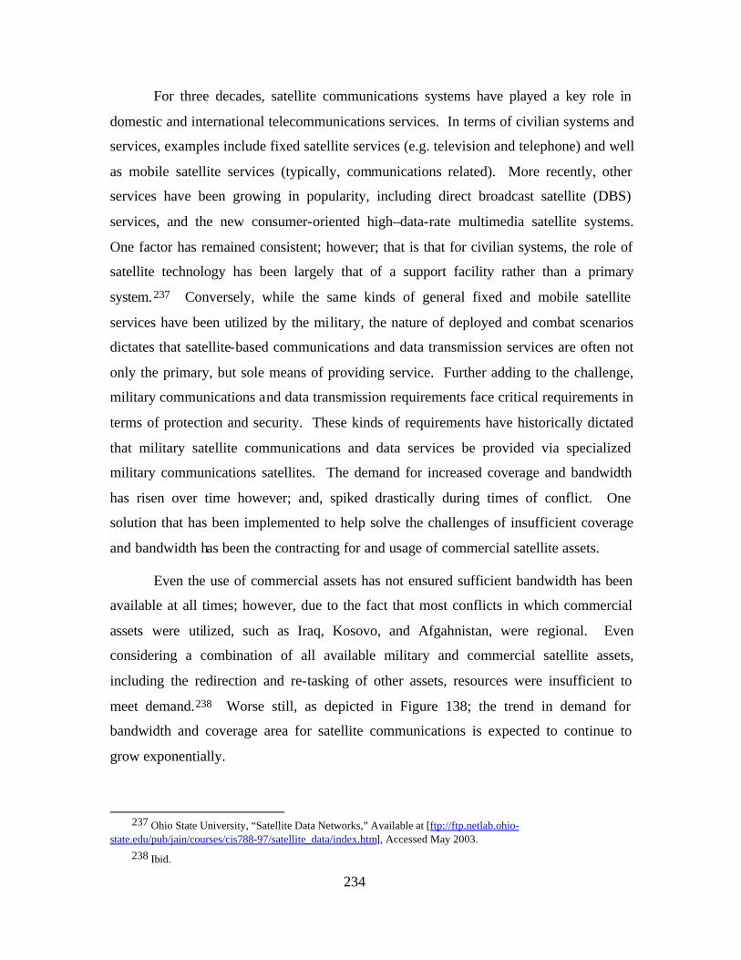
234
For three decades, satellite communications systems have played a key role in
domestic and international telecommunications services. In terms of civilian systems and
services, examples include fixed satellite services (e.g. television and telephone) and well
as mobile satellite services (typically, communications related). More recently, other
services have been growing in popularity, including direct broadcast satellite (DBS)
services, and the new consumer-oriented high–data-rate multimedia satellite systems.
One factor has remained consistent; however; that is that for civilian systems, the role of
satellite technology has been largely that of a support facility rather than a primary
system.237 Conversely, while the same kinds of general fixed and mobile satellite
services have been utilized by the military, the nature of deployed and combat scenarios
dictates that satellite-based communications and data transmission services are often not
only the primary, but sole means of providing service. Further adding to the challenge,
military communications and data transmission requirements face critical requirements in
terms of protection and security. These kinds of requirements have historically dictated
that military satellite communications and data services be provided via specialized
military communications satellites. The demand for increased coverage and bandwidth
has risen over time however; and, spiked drastically during times of conflict. One
solution that has been implemented to help solve the challenges of insufficient coverage
and bandwidth has been the contracting for and usage of commercial satellite assets.
Even the use of commercial assets has not ensured sufficient bandwidth has been
available at all times; however, due to the fact that most conflicts in which commercial
assets were utilized, such as Iraq, Kosovo, and Afgahnistan, were regional. Even
considering a combination of all available military and commercial satellite assets,
including the redirection and re-tasking of other assets, resources were insufficient to
meet demand.238 Worse still, as depicted in Figure 138; the trend in demand for
bandwidth and coverage area for satellite communications is expected to continue to
grow exponentially.
237 Ohio State University, “Satellite Data Networks,” Available at [ftp://ftp.netlab.ohio-
state.edu/pub/jain/courses/cis788-97/satellite_data/index.htm], Accessed May 2003. 238 Ibid.
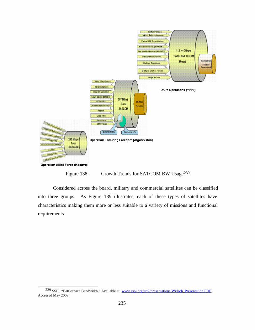
235
Figure 138. Growth Trends for SATCOM BW Usage239.
Considered across the board, military and commercial satellites can be classified
into three groups. As Figure 139 illustrates, each of these types of satellites have
characteristics making them more or less suitable to a variety of missions and functional
requirements.
239 SSPI, “Battlespace Bandwidth,” Available at [www.sspi.org/art2/presentations/Welsch_Presentation.PDF],
Accessed May 2003.
236
Figure 139. Satellite Data Network Types240.
Having discussed some of the specific challenges related to the shortage of
resources in terms of coverage and bandwidth, it would seem that a Warfighting Internet
faces predominantly technical challenges. Regardless of such challenges, or resource
availability in terms of the type or number of military and/or commercial satellites;
however, technological issues are not the only challenges related to satellite
communications. As highlighted by a number of studies and reports, including the
Global Information Grid Support to CINC Requirements Study (Apr 2001) however,
other significant challenges exist. Chief among these are the following:241
• DoD Communications requirements and acquisition requirements are disjointed, inflexible, and inconsistent with the GIG vision
• Current SATCOM requirements process cannot produce reliable capacity estimates
• Capability shortfalls are not always bandwidth related
While the need for overhaul of the requirements generation process is widely
acknowledged, the second two bullets are somewhat counterintuitive. As the study
reveals, while bandwidth is widely cited as the prevailing shortfall, problems associated
with separate funding and management of assets reduces the number of joint solutions
240 Ibid.
241 OSD, “GIG Support to CINC Requirements,” Available at [http://www.dsc.osd.mil/studies/docs/GIG_Appendix_A_JRP_Draft_Final.pdf], Accessed May 2003.
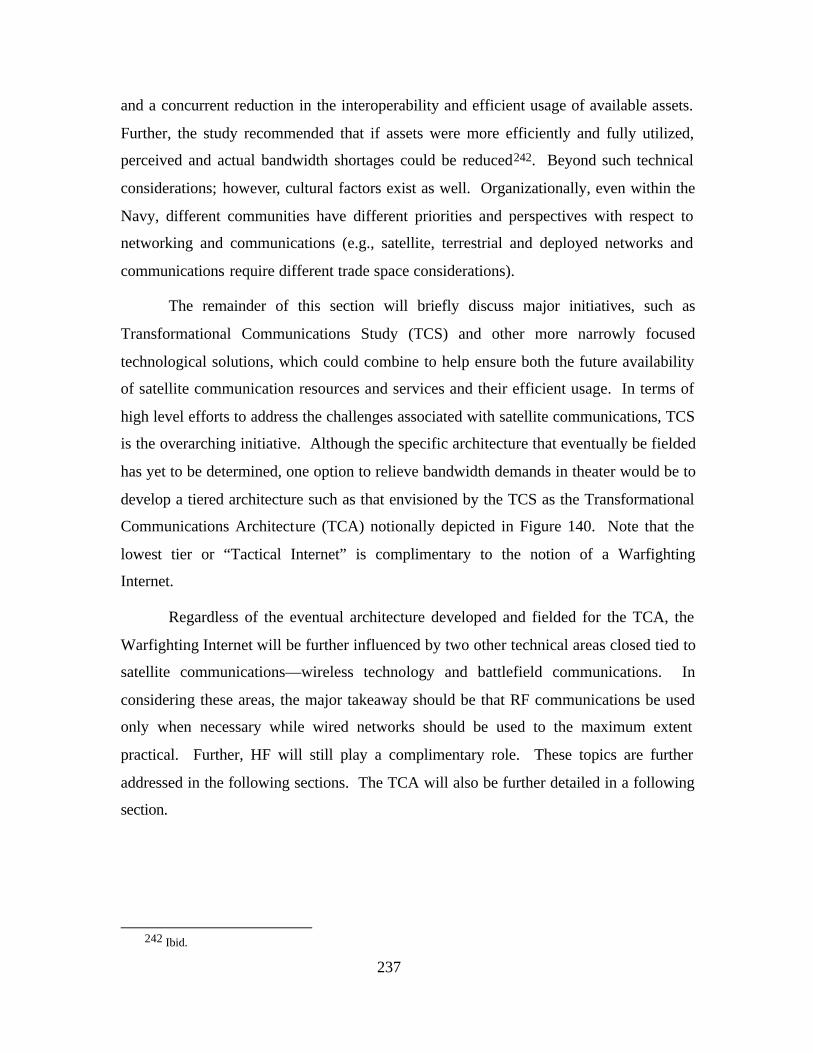
237
and a concurrent reduction in the interoperability and efficient usage of available assets.
Further, the study recommended that if assets were more efficiently and fully utilized,
perceived and actual bandwidth shortages could be reduced242. Beyond such technical
considerations; however, cultural factors exist as well. Organizationally, even within the
Navy, different communities have different priorities and perspectives with respect to
networking and communications (e.g., satellite, terrestrial and deployed networks and
communications require different trade space considerations).
The remainder of this section will briefly discuss major initiatives, such as
Transformational Communications Study (TCS) and other more narrowly focused
technological solutions, which could combine to help ensure both the future availability
of satellite communication resources and services and their efficient usage. In terms of
high level efforts to address the challenges associated with satellite communications, TCS
is the overarching initiative. Although the specific architecture that eventually be fielded
has yet to be determined, one option to relieve bandwidth demands in theater would be to
develop a tiered architecture such as that envisioned by the TCS as the Transformational
Communications Architecture (TCA) notionally depicted in Figure 140. Note that the
lowest tier or “Tactical Internet” is complimentary to the notion of a Warfighting
Internet.
Regardless of the eventual architecture developed and fielded for the TCA, the
Warfighting Internet will be further influenced by two other technical areas closed tied to
satellite communications—wireless technology and battlefield communications. In
considering these areas, the major takeaway should be that RF communications be used
only when necessary while wired networks should be used to the maximum extent
practical. Further, HF will still play a complimentary role. These topics are further
addressed in the following sections. The TCA will also be further detailed in a following
section.
242 Ibid.
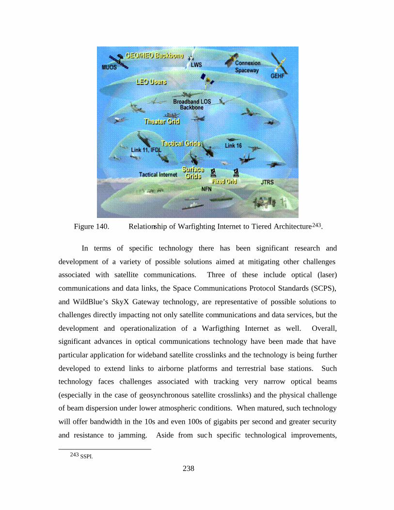
238
Figure 140. Relationship of Warfighting Internet to Tiered Architecture243.
In terms of specific technology there has been significant research and
development of a variety of possible solutions aimed at mitigating other challenges
associated with satellite communications. Three of these include optical (laser)
communications and data links, the Space Communications Protocol Standards (SCPS),
and WildBlue’s SkyX Gateway technology, are representative of possible solutions to
challenges directly impacting not only satellite communications and data services, but the
development and operationalization of a Warfigthing Internet as well. Overall,
significant advances in optical communications technology have been made that have
particular application for wideband satellite crosslinks and the technology is being further
developed to extend links to airborne platforms and terrestrial base stations. Such
technology faces challenges associated with tracking very narrow optical beams
(especially in the case of geosynchronous satellite crosslinks) and the physical challenge
of beam dispersion under lower atmospheric conditions. When matured, such technology
will offer bandwidth in the 10s and even 100s of gigabits per second and greater security
and resistance to jamming. Aside from such specific technological improvements,
243 SSPI.
239
optical connectivity will enable greater economics associated with lower satellite
crosslink costs through the elimination of multiple intermediate ground relay stations.244
As will be discussed in a section specifically dedicated to bandwidth below, this paper
does not purpose bandwidth as the simple solution to the challenges of modern and future
networking, but optical communications are one of the technologies under development
that will enable the levels of bandwidth required by a Warfigthing Internet.
Another of the most significant challenges facing a Warfighting Internet is its
requirement to utilize IP-based networks (including IPv6) over satellite links. This
challenge results directly from the inefficiency of TCP due to latency created by long
transmission path lengths and the noise associated with wireless links. As discussed
above, the need exists for improvements to transport layer protocols. While many
examples currently exist (e.g., XTP, XCP, etc.), we will only discuss SCPS. Formally
accepted in 1999, the SCPS suite of protocols was developed cooperatively by the
Department of Defense and NASA, for use primarily in handling Internet packet traffic
over wireless channels, including those with very long transmission delays, such as
geosynchronous satellite-earth links and satellite crosslinks.245 Importantly; however,
from the user's perspective, this technology uses the same IP and performs equally well
over the existing terrestrial Internet. This is accomplished because instead of being an
entirely new set of standards, the SCPS suite is essentially a new version of the existing
standards, (including both TCP/IP and File Transfer Protocol (FTP)) optimized to operate
over networks containing one or more wireless paths such as a ground to geosynchronous
satellite link or a wireless terrestrial link. If desired, an optional Security Protocol
(SCPS-SP) can also be utilized in order to provide a variety of security functionality. 246
In general, SCPS helps to mitigate problems associated with a variety of other specific
challenges related to long-distance satellite links and wireless communications in general.
These include the following transport layer related issues:
• Error rates caused by channel noise (not simply network congestion)
244 IEEE, “Optical Space Communications,” Available at [http://www.ieee.org/organizations/tab/newtech/workshops/ntdc_2001_08.pdf], Accessed May 2003.
245 Air Force Research Lab “Advanced Internet Protocols For Communications Over Satellite,” Available At [http://Www.Afrlhorizons.Com/Briefs/0006/If9907.Html], Accessed May 2003.
246 Ibid.
240
• Link asymmetry (different bandwidths in opposing directions)
• Long propagation delays
• Interrupted connectivity
Figure 141 depicts the increase in performance of SCPS over IP and was
measured as a function of varying channel bandwidth, bit error rate and link asymmetry.
Parallel tests were conducted using both SCPS and IP so that a direct comparison could
be made between them under identical conditions.
Figure 141. File Transfer Performance of SCPS vs. IP247.
Another example of a technology developed to help provide IP-based networking
over satellite links, while simultaneously mitigating the challenges associated with such
situation’s is generically called Performance Enhancing Proxy (PEP). One specific of
such is Wild Blue’s SkyX Gateway technology. By transparently replacing TCP with a
highly efficient protocol especially designed for the long latency, asymmetric bandwidth,
and high loss conditions typical of satellite networks, the SkyX Gateway will enable
high-performance connectivity over satellite links by reducing latency through cuts in
connection set-up times248. As an example of this technology’s performance, is its
capability of delivering 3 mb/sec download speed across a commercially available Ka-
band spot beam. The architecture for this technology is depicted in Figure 142.
247 Ibid.
248 The tradeoff is that you don’t have end-to-end transport layer connectivity., you have 3 store-and-forward network segments.
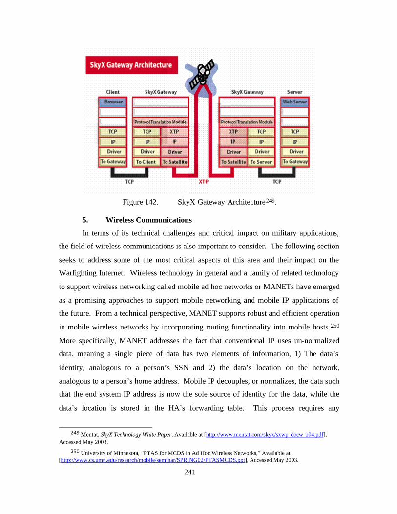
241
Figure 142. SkyX Gateway Architecture249.
5. Wireless Communications
In terms of its technical challenges and critical impact on military applications,
the field of wireless communications is also important to consider. The following section
seeks to address some of the most critical aspects of this area and their impact on the
Warfighting Internet. Wireless technology in general and a family of related technology
to support wireless networking called mobile ad hoc networks or MANETs have emerged
as a promising approaches to support mobile networking and mobile IP applications of
the future. From a technical perspective, MANET supports robust and efficient operation
in mobile wireless networks by incorporating routing functionality into mobile hosts.250
More specifically, MANET addresses the fact that conventional IP uses un-normalized
data, meaning a single piece of data has two elements of information, 1) The data’s
identity, analogous to a person’s SSN and 2) the data’s location on the network,
analogous to a person’s home address. Mobile IP decouples, or normalizes, the data such
that the end system IP address is now the sole source of identity for the data, while the
data’s location is stored in the HA’s forwarding table. This process requires any
249 Mentat, SkyX Technology White Paper, Available at [http://www.mentat.com/skyx/sxwp-docw-104.pdf],
Accessed May 2003.
250 University of Minnesota, “PTAS for MCDS in Ad Hoc Wireless Networks,” Available at [http://www.cs.umn.edu/research/mobile/seminar/SPRING02/PTASMCDS.ppt], Accessed May 2003.
242
MANET converging protocol to post the details of a piece of data’s “mobility” in the
form of net conversion to the HA such that the data’s identity and location can again be
paired. As with other technologies, applications, and capabilities discussed throughout
this paper, wireless and MANET technology have gained in popularity through civilian
application, and their use in military applications should follow as well. While wireless
technologies answer many of the requirements and related demands in deployed and
combat scenarios, MANETs add the following advantages:
• No need for fixed infrastructure
• Each node equipped with one or more radios
• Radios can be heterogeneous
• Each node free to move about while communicating
• Paths between nodes can be multi-hop251
In general, wireless and mobile computing are combined and collectively exhibit the
following general limitations:
Wireless Network
• Packet loss due to transmission errors
• Variable capacity links
• Frequent disconnections/partitions
• Limited communication bandwidth
• Broadcast nature of the communications
• Security and Information Assurance-related considerations
Mobility
• Dynamically changing topologies/routes
• Lack of mobility awareness by system/applications
Mobile Computer
• Short battery lifetime
• Limited capacities252
251 Vanessa Clark, Mobile Computing in Ad hoc Wireless Networks, Available at
[http://students.cec.wustl.edu/~cs333/calendar/Mobile_Computing_in_Ad_hoc_Wireless_Networks.ppt], Accessed May 2003, (PowerPoint Brief).
252 Carlos Cordeiro and Agrawal, Dharma, Mobile Ad Hoc Networking, Available at [http://www.ececs.uc.edu/~cordeicm/course/Slides_ad_hoc.pdf], Accessed May 2003.
243
At the root of some of these challenges lie protocol issues, many of which were
addressed above. In the context of wireless networking; however, it is appropriate to
highlight some additional difficulties. It is especially important for these hurdles to be
overcome if the Warfighting Internet is to be possible. In the case of all general Internet
implementations, including both wired (terrestrial) and wireless, IP is typically paired
with its sister protocol, the Transport Control Protocol (TCP). IP is fundamentally
responsible for moving packets of data from node to node via the IP or “Internet
Address”. Conversely, TCP is responsible for verifying the correct delivery of data end-
to-end across any number of nodes or “hops” between the sender and receiver of the data.
As pointed out above, wireless networks are especially vulnerable to data loss. There are
many reasons for this, but what is critical is that TCP is responsible for data delivery
verification. 253 As discussed in the Satellite Communications section above, there has
been significant research and development into new and improved protocols and protocol
extensions to ensure the successful operations of wireless networks.
Another significant challenge fo r wireless applications and services is that of
security. Apart from user passwords and physical network security and hardware devices
such as firewalls and intrusion detection systems and mechanisms, the most fundamental
means of security remains encryption. Packet-based traffic can be encrypted at any point
in the network, and remains so until de-crypted, regardless or wired or wireless
connections. A further layer of security can be added for military application, and that
has been used successfully in radio frequency communications for some time. This
method, called Direct Sequence Spread Spectrum (DSSS) spreads the data
communication over the full transmission frequency spectrum and sends a specific
sequence of pieces of 32 bits of data called data “chips”. Safety and reliability is achieve
by sending many copies of the data “sliced up” across the link, and only one copy of the
data needs to be received to have complete transmission of the data or information. The
primary reason DSSS is used by the military goes beyond simply making it more difficult
253 Ruy de Oliveira and Braun, Torsten, TCP in Wireless Mobile Ad Hoc Networks, Available at
[http://www.iam.unibe.ch/~rvs/publications/TR-IAM -02-003.pdf], Accessed May 2003.
244
to read the data, but also makes the transmission difficult to “jam.”254 Another of the
challenges faced by wireless networking technology is a relative lack of bandwidth.
While wireless technology will likely continue to lag wired solutions in this area, a
number of advanced technologies are currently available and will enable a Warfigthing
Internet to meet current and future bandwidth requirements. The first of these is the
IEEE 802.11 standard, which governs wireless networking. The 802.11 standard is
further broken down into other “sub” areas. The first of these standards, 802.11b utilizes
a carrier frequency of 2.4 GHz to achieve bandwidths of up to 11 mb/sec. Due to the
variety of limitations associated with the wireless environment; however, actual
throughput is typically less. A second standard, 802.11a utilizes a higher 5.2 GHz
frequency and is therefore able to achieve higher bandwidth which under ideal
circumstances approached 50mb/sec. While the question of which standard to utilize
may seem trivial especially in terms of bandwidth, a number of considerations must be
taken into account. These considerations include the propagation characteristics of
higher wavelengths, which severely limits the ranges over which 802.11a devices can
successfully achieve consistent network links.255 Generally speaking, the 802.11
standard faces the following shortcomings:
• Because layer 1 only has one pseudo-noise (PN) code, there is no low probability of interception (LPI)/low probability of detection (LPD) functionality
• Because layer 2 does not support MAC address encryption, it is vulnerable to traffic analysis.
• Because the layer 2 carrier sense MAC algorithm is adapted from the wired Ethernet standards, it is unstable if faced with too many users sharing a common channel.
Both layer 2 shortcomings are fixed in 802.11b; however, the first could be solved
through the adoption of COTS technology. A final potential drawback of the 802.11
standard is that it utilizes unlicensed RF spectrum. As a result, it must “compete” with
other unlicensed industrial, scientific, and medical (ISM) users. As with all tradeoffs;
254 Break Free Wireless, High-Speed Wireless Internet and Data Link Overview, Available at
[http://www.breakfreewireless.com/techoverview.html], Accessed May 2003.
255 3com, Comparing Performance of 802.11b and 802.11a Wireless Technologies, Available at [http://www.3com.com/other/pdfs/products/en_US/104027_tb.pdf], Accessed May 2003.
245
however, solutions exist to help mitigate or even eliminate a variety of challenges. The
following section addresses these issues in the context of communications in general and
antennas more specifically,
6. RF Communications and Antennas
While this paper introduces the term “Warfigthing Internet”, the concept of a
deployed “Internet” is not new. DoD has worked to digitize units and forces from the
highest echelons down to individual platforms and even individual warriors for years.
Whether via wired or wireless means, digital communications form the basis for any such
Internet. Presently, the ability exists to provision a rudimentary tactical Internet via
existing radio systems, including a combination of the single channel ground and
airborne radio system (SINCGARS) and a vehicle-mounted wideband radio, the
enhanced position location reporting system (EPLRS). At higher echelons, other
equipment is available, such as that found in the Army’s tactical operations center, where
commanders rely on the mobile subscriber equipment’s tactical packet network, and the
near-term data radio (NTDR).256 NTDR extends its capabilities beyond those of other
digital radios like SINCGARS and EPLRS by implementing routing functionality. This
allows disparate communications systems to connect via Internet routers using IP.
As discussed throughout the preceding sections; however, a Warfigthing Internet
will need to support a number of advanced services, all of which combine to far exceed
the current capabilities of deployed, tactical implementations of an internet. At least for
the foreseeable future, at the individua l and small unit level, the backbone of the
Warfigthing Internet will continue to be provided via digital means across RF devices.
The remainder of this section will seek to discuss RF comms options, including the
AN/PRC-138B HF radio, the AN/PRC-117F UHF/VHF radio, and the Joint Tactical
Radio System (JTRS), and the implications for their use as part of the Warfighting
Internet. At present, the the AN/PRC-138B is used to augment the SINCGARS and
EPLRS radios for over the horizon communications at ranges in the hundreds of miles,
albeit at a modest 2.4 kb/sec data rate. The second example, the AN/PRC-117F is an
example of today’s more modern software programmable radios, and as currently fielded
256 Sandra I. Erwin, “Data-Centric’ Army Wants Next -Generation Tactical Net,” (National Defense), (October,
2000), Available at [http://www.nationaldefensemagazine.org/article.cfm?Id=304]; Accessed May 2003.
246
is capable of UHF and VHF operations, as well as SATCOM capable up to 64 kb/sec.
The most advanced option, is that of JTRS, which will utilize software control of various
modulation techniques, wide- or narrow-band operations, communications security
(COMSEC) functionality, and waveform requirements.257 JTRS will be by far the most
versatile of tactical radios ever fielded, virtually eliminating the need for multiple radios
and other communications devices, especially at the tactical levels. As with the various
802.11 standards discussed above, no single radio type currently available combines the
best advantages of all frequencies and modulations, but JTRS will come close.
JTRS is envisioned as the tactical- level backbone of the Warfighting Internet for
another critical reason. Not only will JTRS be able to replicate the existing SINCGARS
and EPRLS waveforms, thus eliminating the need for these radios, but JTRS will provide
a wideband network waveform, needed to move large amounts of data, video and voice
services, at high data rates.258 JTRS will also offer a common operating system and
common architecture for all foreseeable radio applications. This open architecture is
what will separate JTRS from the AN/PRC-117F and other such digital multi-mission,
multi-band radios, software programmable radios. This open-architecture
implementation is similar to that of the commercial PC industry whereby companies are
becoming increasing required to build hardware to support open-standards architectures.
This has become a prime driver of the popularity of the Internet, and will likewise drive
the Warfigthing Intrernet. JTRS will take many years to fully develop and ensure Joint
integration; however, and until this occurs, today’s crop of software-based radios such as
the AN/PRC 117F will continue to help provision tactical internets via their embedded IP
interface, which eliminates the need for Internet controller cards, or other external
hardware. There is danger in an over-reliance on such systems; however, as these have
demonstrated the following shortcomings:
257 WirelessWeb, SDR Faces Hardware Challenges, Available at [http://wireless.iop.org/articles/feature/4/5/2/1],
Accessed May 2003. 258 Erwin.
247
• Lack the necessary integration with other services’ communication equipment
• Lack the necessary bandwidth capacity to support future requirements
• Lack the adaptability to support tactical internetting and data-transmission
7. Antennas
Another related technical aspect of communications and wireless networking in
general and which will significantly impact the Warfighting Internet is that of antennas.
The following section will review these issues and some of the technologies currently
available or under development to help solve such challenges.
Antennas play a critical role in the provisioning of modern communications
services and networks, including the Internet. While traditional phone lines and
terrestrial fiber networks continue to carry the bulk of all communications and network
traffic throughout the United States, such infrastructure is extremely expensive and time-
consuming to emplace. In fact, in certain more remote areas within the U.S. and
throughout the rest of the world, wireless networks, such cellular phone networks are a
more economical and prevalent solution. As has been pointed out in the context of
virtually every aspect of networking throughout this paper, while the applications such as
communications and data transfer required under both civilian and military applications
are in large measure similar, again, the circumstances under which these services are
provided are often far more challenging for the military, especially under deployed and
combat conditions. Antenna requirements are one of the most extreme examples of such.
Antennas of all varieties support such networks by providing the connectivity across open
air links. While this concept and especially the antennas themselves seem simple, in fact,
modern antennas are carefully designed and engineered to meet a demanding set of
performance characteristics, and are often optimized for a single particular application.
Cell-phone towers are an example. A final critical consideration is that of placement of
the antenna, and again, this is typically driven by the desire to optimize performance for a
given applications. Again, cellular network antenna placement is offered as an example.
The example of civilian cellular networks is chosen for its demonstration of flexibility
enjoyed by civilian applications, especially in terms of the number, size, and geographic
location of the antenna(s) themselves. Conversely, many military antenna applications
248
are subject to restrictions in terms of geographic location. (especially aboard platforms
such as ships, submarines, and aircraft.) Herein lies some of the greatest challenges
related to “radiation” in the sense the close proximity of multiple antennas leads to issues
of interference, and potential weapons restrictions. Military applications often face
greater challenges in terms of available output power and security issues associated with
both radar cross section and being located or “DF-ed” (direction found) by potential
adversaries. While typically not a concern for ships or aircraft, ashore forces, especially
those in urban areas with buildings and other vertical structures in close proximity, face
reception challenges due to reflected signals. This phenomenon is called multipath
distortion. 259
As with other technological hurdles, ongoing research and development has led to
a number of possible solutions to such challenges. The remainder of this section will
discuss two potential solutions to the problems discussed above. The first of these
solutions is related to what are generally referred to as “smart antennas”. A smart
antenna system combines multiple antenna elements with a signal-processing capability
to optimize its radiation and/or reception pattern automatically in response to the signal
environment.260 Such antennas are used extensively in civilian applications, including
cellular network antennas, and have great promise for military applications as well. The
benefits of such antennas include the efficiency and security of steered beams, and the
ability to “target” desired receivers (in the case of networks, other “nodes”) without
interfering with others, in crowded or otherwise “dirty” or interference prone
environments, such as urban areas. Smart antennas offer the following specific benefits:
• Better range/coverage – Focusing the energy sent out into the cell increases base station range and coverage. Lower power requirements also enable a greater battery life and smaller/lighter handset size.
• Increased capacity – Precise control of signal nulls quality and mitigation of interference combine to frequency reuse reduce distance (or cluster size), improving capacity. Certain adaptive technologies (such as space
259 Kenneth C. Crandall, “OFDM Kills Multipath Distortion,” (EE Times), (April 15, 2002), Available at
[http://www.eetimes.com/in_focus/communications/OEG20020412S0072], Accessed May 2003.
260 International Engineering Consortium, Smart Antenna Systems, Available at [http://www.iec.org/online/tutorials/smart_ant/], Accessed May 2003.
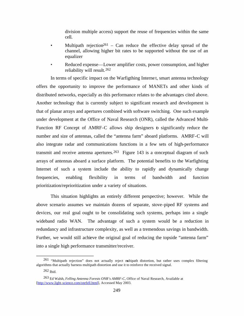
249
division multiple access) support the reuse of frequencies within the same cell.
• Multipath rejection261 – Can reduce the effective delay spread of the channel, allowing higher bit rates to be supported without the use of an equalizer
• Reduced expense—Lower amplifier costs, power consumption, and higher reliability will result.262
In terms of specific impact on the Warfigthing Interne t, smart antenna technology
offers the opportunity to improve the performance of MANETs and other kinds of
distributed networks, especially as this performance relates to the advantages cited above.
Another technology that is currently subject to significant research and development is
that of planar arrays and apertures combined with software switching. One such example
under development at the Office of Naval Research (ONR), called the Advanced Multi-
Function RF Concept of AMRF-C allows ship designers to significantly reduce the
number and size of antennas, called the “antenna farm” aboard platforms. AMRF-C will
also integrate radar and communications functions in a few sets of high-performance
transmit and receive antenna apertures.263 Figure 143 is a conceptual diagram of such
arrays of antennas aboard a surface platform. The potential benefits to the Warfighting
Internet of such a system include the ability to rapidly and dynamically change
frequencies, enabling flexibility in terms of bandwidth and function
prioritization/reprioritization under a variety of situations.
This situation highlights an entirely different perspective; however. While the
above scenario assumes we maintain dozens of separate, stove-piped RF systems and
devices, our real goal ought to be consolidating such systems, perhaps into a single
wideband radio WAN. The advantage of such a system would be a reduction in
redundancy and infrastructure complexity, as well as a tremendous savings in bandwidth.
Further, we would still achieve the original goal of reducing the topside “antenna farm”
into a single high performance transmitter/receiver.
261 “Multipath rejection” does not actually reject multipath distortion, but rather uses complex filtering
algorithms that actually harness multipath distortion and use it to reinforce the received signal.
262 Ibid.
263 Ed Walsh, Felling Antenna Forests ONR’s AMRF-C, Office of Naval Research, Available at [http://www.light-science.com/onrfell.html], Accessed May 2003.
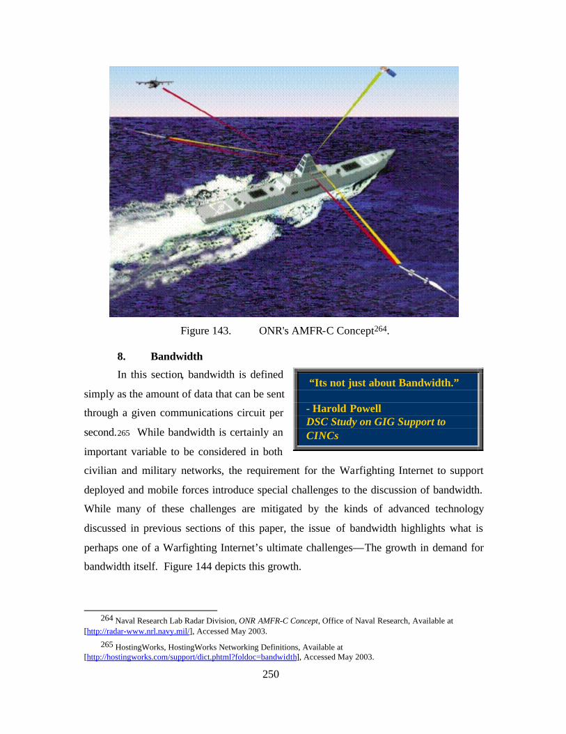
250
Figure 143. ONR's AMFR-C Concept264.
8. Bandwidth
In this section, bandwidth is defined
simply as the amount of data that can be sent
through a given communications circuit per
second.265 While bandwidth is certainly an
important variable to be considered in both
civilian and military networks, the requirement for the Warfighting Internet to support
deployed and mobile forces introduce special challenges to the discussion of bandwidth.
While many of these challenges are mitigated by the kinds of advanced technology
discussed in previous sections of this paper, the issue of bandwidth highlights what is
perhaps one of a Warfighting Internet’s ultimate challenges—The growth in demand for
bandwidth itself. Figure 144 depicts this growth.
264 Naval Research Lab Radar Division, ONR AMFR-C Concept, Office of Naval Research, Available at
[http://radar-www.nrl.navy.mil/], Accessed May 2003.
265 HostingWorks, HostingWorks Networking Definitions, Available at [http://hostingworks.com/support/dict.phtml?foldoc=bandwidth], Accessed May 2003.
“Its not just about Bandwidth.” - Harold Powell DSC Study on GIG Support to CINCs
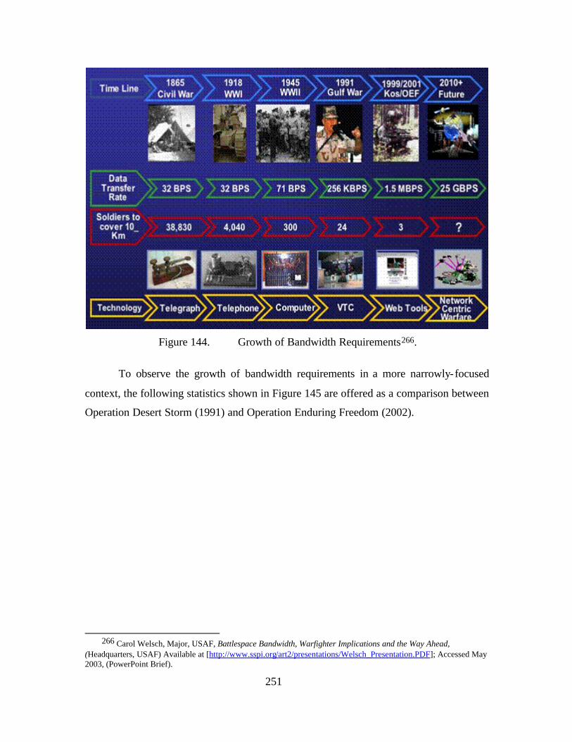
251
Figure 144. Growth of Bandwidth Requirements266.
To observe the growth of bandwidth requirements in a more narrowly-focused
context, the following statistics shown in Figure 145 are offered as a comparison between
Operation Desert Storm (1991) and Operation Enduring Freedom (2002).
266 Carol Welsch, Major, USAF, Battlespace Bandwidth, Warfighter Implications and the Way Ahead,
(Headquarters, USAF) Available at [http://www.sspi.org/art2/presentations/Welsch_Presentation.PDF]; Accessed May 2003, (PowerPoint Brief).
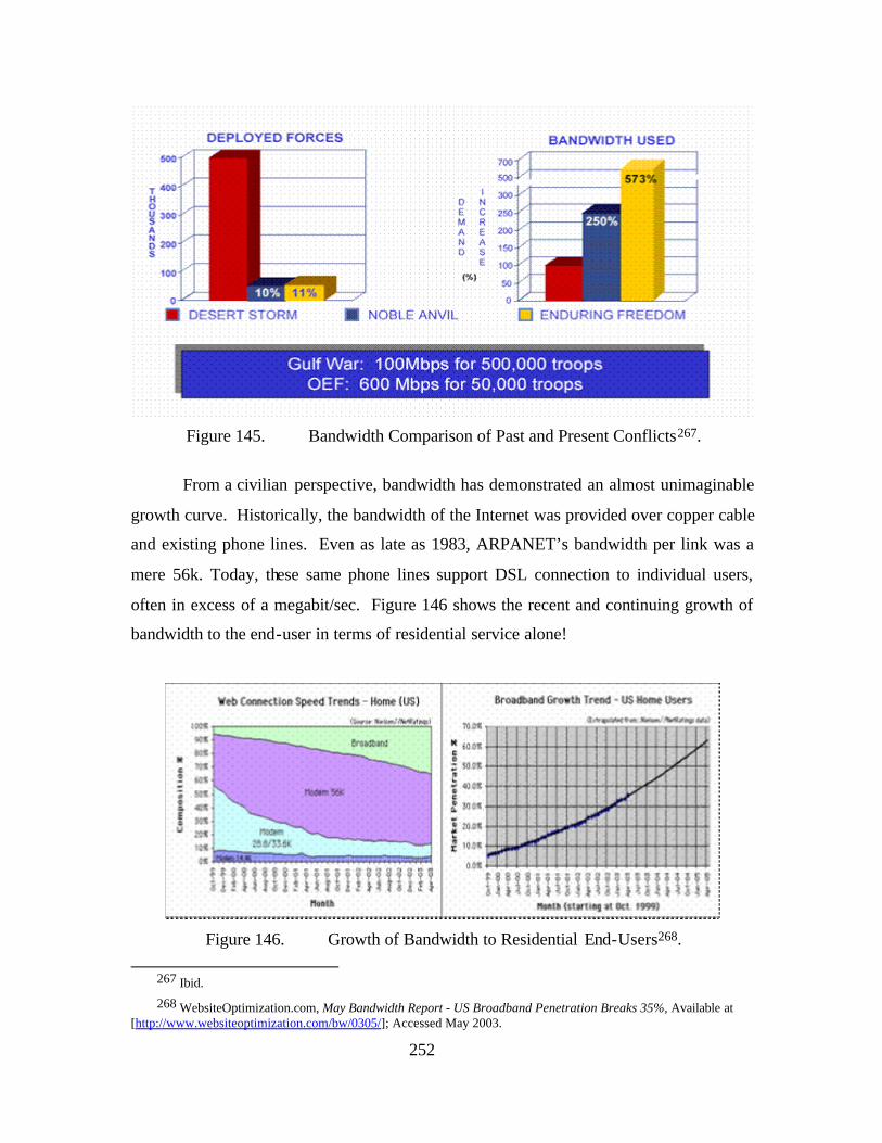
252
Figure 145. Bandwidth Comparison of Past and Present Conflicts267.
From a civilian perspective, bandwidth has demonstrated an almost unimaginable
growth curve. Historically, the bandwidth of the Internet was provided over copper cable
and existing phone lines. Even as late as 1983, ARPANET’s bandwidth per link was a
mere 56k. Today, these same phone lines support DSL connection to individual users,
often in excess of a megabit/sec. Figure 146 shows the recent and continuing growth of
bandwidth to the end-user in terms of residential service alone!
Figure 146. Growth of Bandwidth to Residential End-Users268.
267 Ibid.
268 WebsiteOptimization.com, May Bandwidth Report - US Broadband Penetration Breaks 35%, Available at [http://www.websiteoptimization.com/bw/0305/]; Accessed May 2003.
253
Interestingly, experiments and efforts at “bandwidth world records” are common,
and as recently as 2001 Alcatel and NEC in separately demonstrated bandwidth in excess
of 10 terabits/sec across over 100 km of fiber-optic cable.269 By December 2002, a
company called Yotta Yotta was able to utilize similar technology to demonstrate a file
transfer of 5 terabytes of data between Chicago, Illinois to Vancouver, British Columbia
and Ottawa, Ontario, at a sustained average throughput of 11.1 gigabits/sec. “This is
equivalent to transferring all printed collections from the Library of Congress within two
hours time,” said Wayne Karpoff, vice president and CTO for Yotta Yotta.270 While
such technology is certainly not ready for deployment, today’s Internet is largely
supported by a fiber-optic backbone with cables commonly supporting bandwidth from
hundreds of megabits/sec (OC-12) to over 10 gigabits/sec (OC-192). It should be noted;
however, from a commercial perspective the Internet remains highly overprovisioned,
and that most backbone links are utilized at no greater than 10% of overall capacity271.
The real problem remains provisioning such bandwidth across “the last mile” to the end-
user remains a significant challenge, at least economically.
What is the impact of such technology? In terms of pure throughput, sufficient
bandwidth is available via terrestrial fiber, especially in and between major metropolitan
areas, to support any current and foreseeable network applications. In terrestrial
networks, more bandwidth simply costs money. Conversely, the RF spectrum is limited
so more money can only buy more bandwidth up to a certain spectral constraint, limited
by the laws of physics. The preceding discussion has highlighted one of the key
differences between civilian and military networking and its critical impact on bandwidth
availability – that of stationary nodes (e.g. buildings) versus mobile nodes (e.g. ships).
While much of the provisioning of the Warfighting Internet could be accomplished across
terrestrial fiber networks in exactly the same manner as its civilian counterpart deployed
scenarios introduce “air gaps” which no amount of fiber can bridge. This introduces two
critical challenges which must be overcome. First, is a problem related to the laws of
269 Light Reading, “Alcatel Holds World Record for a Day,” (Light Reading), (22 March 2001), Available at [http://www.lightreading.com/document.asp?doc_id=4380], Accessed May 2003.
270 Yottayotta, “New World Record Set for Tcp Disk-to-Disk Bulk Transfer,” Press Release, Available at [http://Www.Yottayotta.Com/Pages/News/Press_04.Htm], Accessed May 2003.
271 Rex Buddenberg, Senior Lecturer of Information Systems, Naval Postgraduate School.
254
physics governing many of the deployed environments, including at-sea, undersea, air,
and space, as well as the long distances involved. Second is the problem of what are
called “disadvantaged users”. Such users, such as submarines, are not only challenged by
the physics of the environments in which they operate, but the restriction(s) they are
faced with in terms of power and antenna aperture size.
While technological solutions such as those discussed throughout this section will
likely continue to help answer the bandwidth challenge—and may perhaps even someday
render the bandwidth variable irrelevant, part of the near-term solution lies in more
efficient use of available bandwidth. One example of technology designed to help
accomplish this is DARPA’s Adaptive Spectrum Utilization. 272 This is actually a
concept which includes a number of related technologies designed to facilitate adaptive
spectrum sharing by employing unused spectrum, including frequency, time, and power,
when and where available using special waveforms, protocols, and etiquette to overlay
and underlay frequencies without interference.
While possibilities for increased efficiency lie in technological solutions, perhaps
the greatest opportunity for bandwidth savings and efficiency lies in how we utilize a
Warfighting Internet. More specifically, opportunities exist in terms of C3 processes and
tactics, techniques, and procedures (TTPs) that would reduce the demands placed on the
network(s) on the first place.
9. Networked Virtual Environments (net-VEs)
Another promising area for networking technology related to FnEPs can be found
in the field of networked virtual environments (net-VEs). Fundamentally, net-VEs is a
construct in which multiple users interact with each other in real time, even though those
users may be geographically dispersed, perhaps even around the world. This definition
aligns well with the concept of an FnEPs “pack”, whose assets will also likely be
geographically dispersed yet still need to interact. Another generalized challenge net-
VEs have sought to address is that of resource management. In order for net-VEs to
work effectively the following resource management trade spaces must be considered:
272 Paul Kolodzy, A DARPA Perspective on Broadband Wireless Systems, (DARPA), (6 September 2000),
Available at [http://www.its.bldrdoc.gov/meetings/art/art00/Slides00/kol/kol_s.pdf], Accessed December 2003.
255
• Communications protocol optimization, including bandwidth and processing requirements
• Data flow restriction, including compression, packet aggregation, area of interest filters, multicasting, and caching
• Leveraging of limited user perception
• System architecture modification, including peer-to-peer, client-server, or hybrid architectures
Many of these same resource trade spaces will exist for FORCEnet and FnEPs as well.
Interestingly, multiple net-VEs may be required to operate simultaneously over the same
network (The may be an example of an application of a Common Operational Picture
(COP) whereby different net-VEs could service the needs for multiple levels of command
(e.g. platoon, company, battalion)).
Overall, current and future net-VEs are facing the situation where today’s network
infrastructures and ever-increasing numbers of users are demanding that these systems
scale to sizes that make traditional methods for resource optimization unsuitable. These
same network infrastructures will introduce some of the same problems to the
development and implementation of FORCEnet and FnEPs namely that:
• While the computers that support the requirements for information processing will become more powerful, such capacity will remain limited. This is likely to remain especially true in applications where space and power are limited.
• Networks will continue to face limited capacity in terms of latency and bandwidth—factors which are the two most significant resource constraints for many aspects of FORCEnet and FnEPs.
Fortunately, as this section has discussed, great progress has been made towards
addressing these challenges in many areas of network technology and development,
especially in the field of net-VEs. We anticipate many of the same techniques developed
or under development will have similar application to the development and
implementation of the network infrastructure necessary to support FORCEnet and FnEPs.
One example of a particular concept developed to support net-VEs that has
applicability to FnEPs is that of the Composite Agent Model, developed by Commander
Brian Osborn, a principal investigator at the Naval Postgraduate School shown in Figure
147.
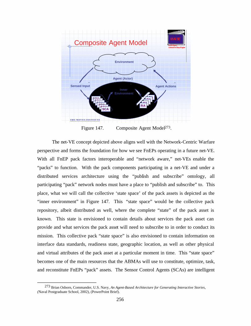
256
MAISE
Multi-AgentInteractive Story Engine
Composite Agent Model
Agent (Actor)
SCASCA
SCASCASCA
SCA
Inner Environment
RARA
RARARA
Environment
Agent ActionsSensed Input
Figure 147. Composite Agent Model273.
The net-VE concept depicted above aligns well with the Network-Centric Warfare
perspective and forms the foundation for how we see FnEPs operating in a future net-VE.
With all FnEP pack factors interoperable and “network aware,” net-VEs enable the
“packs” to function. With the pack components participating in a net-VE and under a
distributed services architecture using the “publish and subscribe” ontology, all
participating “pack” network nodes must have a place to “publish and subscribe” to. This
place, what we will call the collective ‘state space’ of the pack assets is depicted as the
“inner environment” in Figure 147. This “state space” would be the collective pack
repository, albeit distributed as well, where the complete “state” of the pack asset is
known. This state is envisioned to contain details about services the pack asset can
provide and what services the pack asset will need to subscribe to in order to conduct its
mission. This collective pack “state space” is also envisioned to contain information on
interface data standards, readiness state, geographic location, as well as other physical
and virtual attributes of the pack asset at a particular moment in time. This “state space”
becomes one of the main resources that the ABMAs will use to constitute, optimize, task,
and reconstitute FnEPs “pack” assets. The Sensor Control Agents (SCAs) are intelligent
273 Brian Osborn, Commander, U.S. Navy, An Agent-Based Architecture for Generating Interactive Stories,
(Naval Postgraduate School, 2002), (PowerPoint Brief).
257
agents which monitor the net-VE and feed “pack” asset state attribute changes back into
the collective “state space.” These SCAs, would be present in all networked pack assets
to monitor the net-VE. Once a changed attribute “state” (e.g., low UAV fuel, new pack
asset, new threat, changed course/speed/heading of an in-flight weapon, etc.) is published
to the “state space,” Reactive Agents (RAs) will have updated the “state space” attribute
and will alert the ABMAs to take appropriate action to change the activity within the net-
VE. This step will continue as a feedback loop until the desired attribute value is shown
in the “state space.” This monitoring, processing, action and appropriate feedback is a
continuous loop, managed primarily by ABMAs.
C. FORCENET FNEPS AND THE NEED FOR A “WARFIGHTING INTERNET”
Having outlined some of the technical
considerations for military networking in Part I,
the following section will discuss the concept of a
“Warfighting Internet” as it relates to the concept
of FORCEnet Engagement Packs (FnEPs).
As presented in Chapter I FnEPs is defined
as:
The FnEPs Concept represents the operational construct for FORCEnet and demonstrates the power of FORCEnet by integrating a specific set of joint sensors, platforms, weapons, warriors, networks and command & control systems, for the purpose of performing mission-specific engagements. Initial pack asset allocation and configuration to constitute a pack will be based on a specific threat or mission; however, the capability to dynamically re-configure and re-allocate assets “on the fly,” to reconstitute a new pack will enable cross-mission engagement capabilities. Integrating the six FORCEnet factors must focus on enabling five critical functions called the “Combat Reach Capabilities (CRCs)”. These CRCs are: Integrated Fire Control (IFC), Automated Battle Management Aids (ABMAs), Composite Tracking (CT), Composite Combat Identification (CCID), and Common/Single Integrated Pictures (CP). Ultimately, FnEPs will help “operationalize” FORCEnet by demonstrating a network-centric operational construct that supports an increase in combat reach and provides an order of magnitude increase in combat power by creating more effective engagements, better sensor-shooter-weapon assignments and improved utilization of assets. FnEPs
“Good ideas are not adopted automatically, they must be driven into practice with courageous impatience.” - ADM Hyman G. Rickover
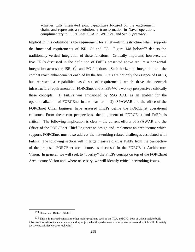
258
achieves fully integrated joint capabilities focused on the engagement chain, and represents a revolutionary transformation in Naval operations complimentary to FORCEnet, SEA POWER 21, and Sea Supremacy.
Implicit in this definition is the requirement for a network infrastructure which supports
the functional requirements of ISR, C2 and FC. Figure 148 below274 depicts the
traditionally vertical integration of these functions. Critically important; however, the
five CRCs discussed in the definition of FnEPs presented above require a horizontal
integration across the ISR, C2, and FC functions. Such horizontal integration and the
combat reach enhancements enabled by the five CRCs are not only the essence of FnEPs,
but represent a capabilities-based set of requirements which drive the network
infrastructure requirements for FORCEnet and FnEPs275. Two key perspectives critically
these concepts. 1) FnEPs was envisioned by SSG XXII as an enabler for the
operationalization of FORCEnet in the near-term. 2) SPAWAR and the office of the
FORCEnet Chief Engineer have assessed FnEPs define the FORCEnet operational
construct. From these two perspectives, the alignment of FORCEnet and FnEPs is
critical. The following implication is clear – the current efforts of SPAWAR and the
Office of the FORCEnet Chief Engineer to design and implement an architecture which
supports FORCEnet must also address the networking-related challenges associated with
FnEPs. The following section will in large measure discuss FnEPs from the perspective
of the proposed FORCEnet architecture, as discussed in the FORCEnet Architecture
Vision. In general, we will seek to “overlay” the FnEPs concept on top of the FORCEnet
Architecture Vision and, where necessary, we will identify critical networking issues.
274 Hesser and Rieken., Slide 9.
275 This is in marked contrast to other major programs such as the TCA and GIG, both of which seek to build infrastructure without such an understanding of just what the performance requirements are—and which will ultimately dictate capabilities we are stuck with!
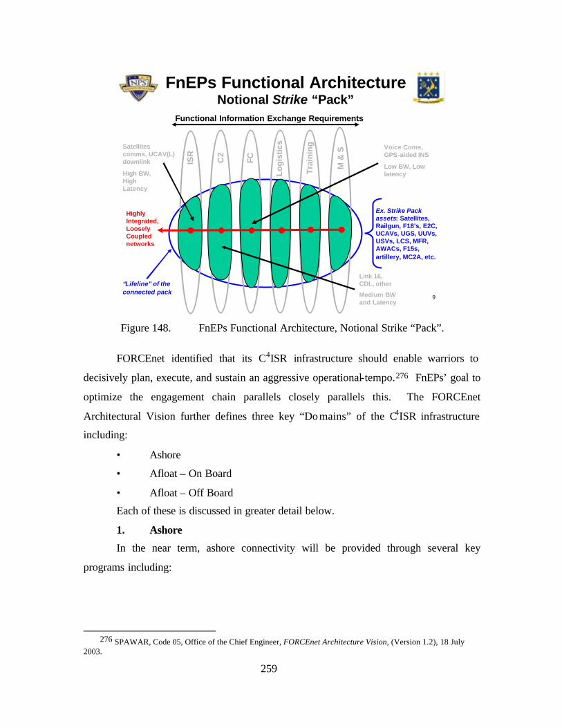
259
9
“Lifeline” of the connected pack
FnEPs Functional ArchitectureNotional Strike “Pack”
ISR
Functional Information Exchange Requirements
Ex. Strike Pack assets: Satellites, Railgun, F18’s, E2C, UCAVs, UGS, UUVs, USVs, LCS, MFR, AWACs, F15s, artillery, MC2A, etc.
FC
M &
S
C2
Tra
inin
g
Lo
gis
tics
Voice Coms, GPS-aided INS
Low BW, Low latency
Link 16, CDL, other
Medium BW and Latency
Highly Integrated, Loosely Coupled networks
Satellites comms, UCAV(L) downlink
High BW, High Latency
Figure 148. FnEPs Functional Architecture, Notional Strike “Pack”.
FORCEnet identified that its C4ISR infrastructure should enable warriors to
decisively plan, execute, and sustain an aggressive operational-tempo.276 FnEPs’ goal to
optimize the engagement chain parallels closely parallels this. The FORCEnet
Architectural Vision further defines three key “Domains” of the C4ISR infrastructure
including:
• Ashore
• Afloat – On Board
• Afloat – Off Board
Each of these is discussed in greater detail below.
1. Ashore
In the near term, ashore connectivity will be provided through several key
programs including:
276 SPAWAR, Code 05, Office of the Chief Engineer, FORCEnet Architecture Vision, (Version 1.2), 18 July 2003.
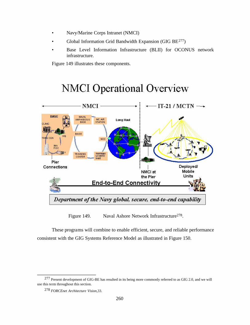
260
• Navy/Marine Corps Intranet (NMCI)
• Global Information Grid Bandwidth Expansion (GIG BE277)
• Base Level Information Infrastructure (BLII) for OCONUS network infrastructure.
Figure 149 illustrates these components.
Figure 149. Naval Ashore Network Infrastructure278.
These programs will combine to enable efficient, secure, and reliable performance
consistent with the GIG Systems Reference Model as illustrated in Figure 150.
277 Present development of GIG-BE has resulted in its being more commonly referred to as GIG 2.0, and we will
use this term throughout this section. 278 FORCEnet Architecture Vision,33.
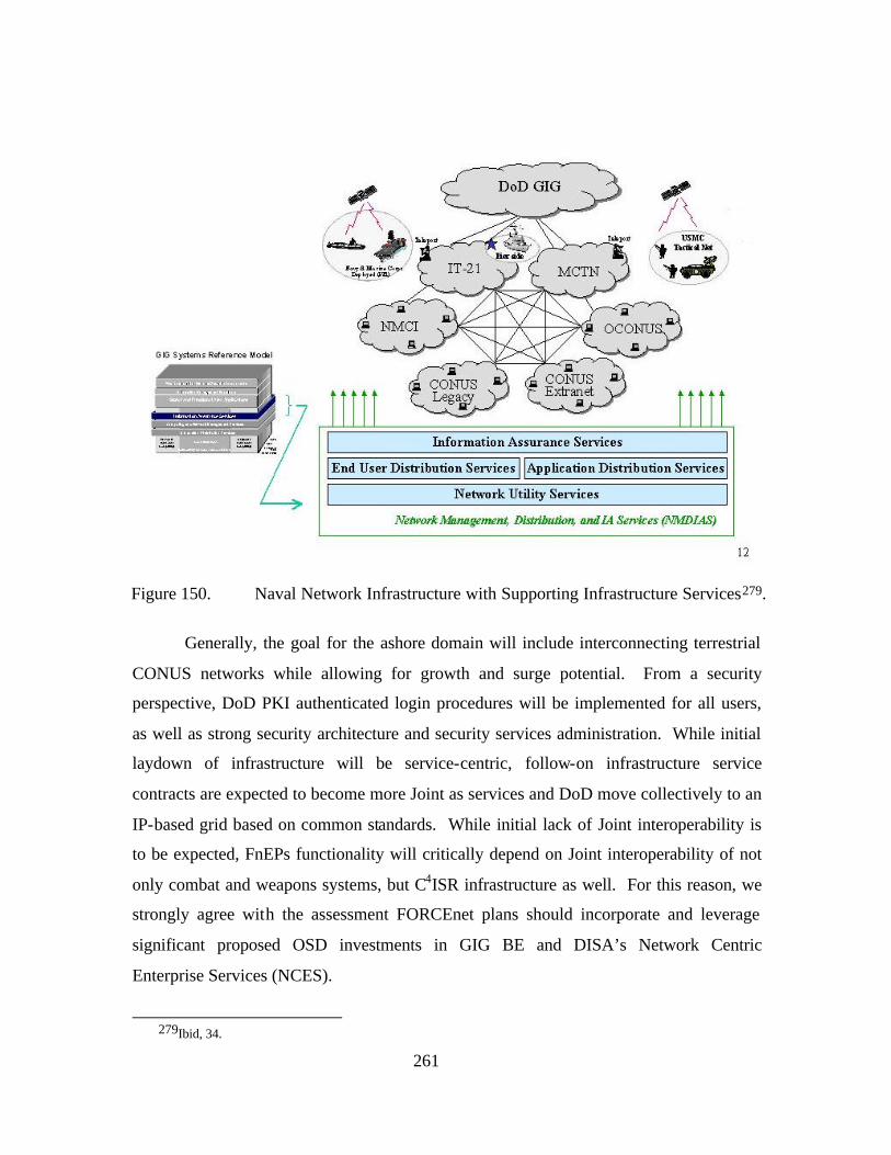
261
Figure 150. Naval Network Infrastructure with Supporting Infrastructure Services279.
Generally, the goal for the ashore domain will include interconnecting terrestrial
CONUS networks while allowing for growth and surge potential. From a security
perspective, DoD PKI authenticated login procedures will be implemented for all users,
as well as strong security architecture and security services administration. While initial
laydown of infrastructure will be service-centric, follow-on infrastructure service
contracts are expected to become more Joint as services and DoD move collectively to an
IP-based grid based on common standards. While initial lack of Joint interoperability is
to be expected, FnEPs functionality will critically depend on Joint interoperability of not
only combat and weapons systems, but C4ISR infrastructure as well. For this reason, we
strongly agree with the assessment FORCEnet plans should incorporate and leverage
significant proposed OSD investments in GIG BE and DISA’s Network Centric
Enterprise Services (NCES).
279Ibid, 34.
262
2. Afloat – On Board
Afloat systems associated with the C4ISR infrastructure supporting FORCEnet
seeks the establishment of a common, standardized networking infrastructure and a set of
common core services that:
• Support the transfer and distribution of information via multiple medium and data types on ships and at shore Network Operations Centers (NOCs) for both tactical and non-tactical mobile forces of the Navy, Marine Corps, joint, and allied operational elements;
• Deliver online, anytime, anywhere connectivity supporting ship operations that is responsive, seamless, and secure across multiple classification levels that meet the QoS requirements of the user or application.
• Support hosted systems, applications and the Family of Systems (FoS) concept without degradation or resource diversion to mission focus; and promote and facilitate technology refreshment and capability growth throughout a ship's life cycle 280.
Generally, most C4I, Hull, Mechanical and Electrical (HM&E) and Combat
Systems (CS) fall within scope of the FORCEnet Afloat – on board Network (FAN).
While the ultimate goal is a single network infrastructure, based on the unique
availability and data latency requirements required by these systems will require that
separate physical networks be maintained in the near-term. Figure 151 depicts the initial
interface between Combat Systems Open Architecture and the current FORCEnet
shipboard network; however, the requirements for such architectures will have to be more
fully developed in the future under the FnEPs concept. For example, under the future
FORCEnet vision for Distributed Services such interfaces may change significantly.
280 Ibid., 36.
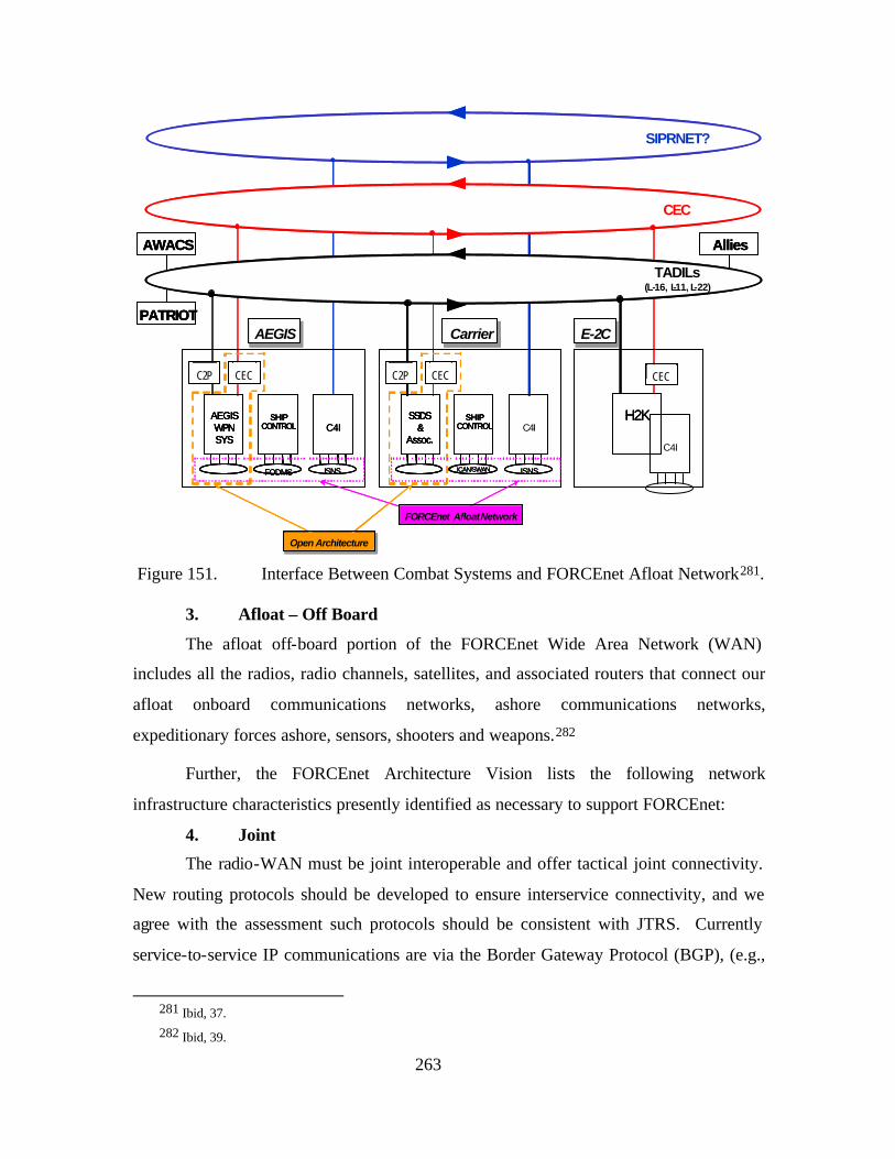
263
C2P CEC
AEGIS WPN SYS
SHIP CONTROL
FODMS
C4I
ISNS
CEC
H2K
SIPRNET?
CEC
TADILs (L - 16, L - 11, L - 22)
Allies AWACS
PATRIOT
C2P CEC
SSDS &
Assoc. SHIP
CONTROL
ICAN/SWAN
C4I
ISNS
FORCNnet Afloat Network Open Architecture Open Architecture
AEGIS AEGIS Carrier Carrier E - 2C E - 2C
C2P CEC
AEGIS WPN SYS
SHIP CONTROL
FODMS C4I
ISNS
C2P C2P CEC CEC
AEGIS WPN SYS
AEGIS WPN SYS
AEGIS WPN SYS
SHIP CONTROL SHIP CONTROL SHIP CONTROL
FODMS
C4I C4I
ISNS
CEC CEC
H2K H2K
SIPRNET?
CEC
TADILs (L - 16, L - 11, L - 22)
Allies Allies AWACS AWACS
PATRIOT PATRIOT
C2P CEC
SSDS &
Assoc. SHIP
CONTROL
ICAN/SWAN ISNS
C2P C2P CEC CEC
SSDS &
Assoc. SSDS
& Assoc. SSDS
& Assoc.
SHIP CONTROL SHIP CONTROL SHIP CONTROL
ICAN/SWAN ISNS
FORCEnet Afloat Network Open Architecture Open Architecture
AEGIS AEGIS Carrier Carrier E - 2C E - 2C
Figure 151. Interface Between Combat Systems and FORCEnet Afloat Network281.
3. Afloat – Off Board
The afloat off-board portion of the FORCEnet Wide Area Network (WAN)
includes all the radios, radio channels, satellites, and associated routers that connect our
afloat onboard communications networks, ashore communications networks,
expeditionary forces ashore, sensors, shooters and weapons.282
Further, the FORCEnet Architecture Vision lists the following network
infrastructure characteristics presently identified as necessary to support FORCEnet:
4. Joint
The radio-WAN must be joint interoperable and offer tactical joint connectivity.
New routing protocols should be developed to ensure interservice connectivity, and we
agree with the assessment such protocols should be consistent with JTRS. Currently
service-to-service IP communications are via the Border Gateway Protocol (BGP), (e.g.,
281 Ibid, 37. 282 Ibid, 39.
264
the interface between the Automated Digital Network System (ADNS) and MAGTF
routers). This characteristic will be especially critical for enabling full FnEPs
functionality.
5. Sea Bed to Space Scope
Sea Power 21 implies the requirement for communications between a full range
of assets operating across a continuum of sea bed, surface (and land-based), and space
6. Internet Protocols
As discussed previously, using IP-based networking and communications will
provide a number of benefits. While technical challenges remain, migration to IPv6 from
IPv4 or other circuit-switched, currently non-routable networks promises improved
features and performance necessary to FORCEnet and FnEPs and we agree should form
the basis of the network layer throughout the network. A variety of network performance
characteristics (e.g., ISR –vs- Fire Control) will always exist. At least in the near term
and due to constraints associated with legacy systems, proprietary systems, and
specialized networks will remain. The challenge lies in ensuring the interoperability and
integration of these systems in order to achieve and end-to-end, engagement chain
focused network architecture.
7. High Capacity
The network must support the rapid growth of information exchange
requirements, especially from the perspective of bandwidth and required QOS. The
following factors will help to ensure the necessary capacity is available in the future:
• From a “space” perspective, Advanced Wideband System (AWS), Advanced Extremely High Frequency (AEHF), Mobile User Objective System (MUOS), next generation SHF, and TCS.
• JTRS and Tactical Targeting Networking Technology (TTNT) will provide the future growth in LoS networking.
• Microwave trunks such as Multipoint Common Data Link (MPCDL), and Tactical Common Data Link (TCDL) will provide high data rate point to point connectivity.
8. Efficiency
Congestion is a chronic problem in Navy RF communications today. This is in
large measure due to static communications and bandwidth allocations. What is required
is the ability to dynamically allocate resources on an as-required basis, while ensuring
265
required QOS. Other efficiency tasks relate to ensuring the router to router interconnects
are in place, and that the network pipes are consolidated. Dynamic bandwidth allocation
can be implemented by utilizing modern communications protocols such as IPv6, while
also and utilizing the lowest tier consistent with communications needs. A critical aspect
of QOS is the need Joint standards and enforceability. These are especially important
because FnEPs will require networks support the real-time performance requirements of
weapons and other combat systems. In general, further efficiency gains can be gained via
advances in compression and caching, reducing the redundancy in transmissions. Flow
control, traffic monitoring, bandwidth management, network management, and user
discipline are mechanisms that enable the
warfighter and network managers to manipulate the network for efficiency and to control
communications flows, thereby allowing the most important communications to receive
priority, giving speed to critical information.
9. System-to-Warfighter Interfaces
FORCEnet and FnEPs critically depend on the integration of the warfigther.
Accordingly, we strongly agree with the assessment of the need to offer common
interfaces to our warfighters. This implies the requirement for providing “the right
information to the right place at the right time, in the right context”. As specific
examples from the perspective of FnEPs, these interfaces will need to include mission
and system status, especially as provided by ABMAs.
10. Dynamic & Mobile
The deployed and expeditionary nature of today’s forces and operations makes
this particular characteristic of C4ISR infrastructure particularly important. More
specifically, both FORCEnet and FnEPs will take advantage of the opportunities from
massing capabilities without massing forces. Examples of the implications for such
mobility of forces and assets and the corresponding requirement for dynamic networking
and routing include next generation software defined radios, such as JTRS, and
accompanying routers. Such systems need to be able to auto-discover the channels and
routes with least cost and minimal latency in coordination with localized and global
network managers and their accommodating service level agreements283. Such
283 Ibid., 41.
266
capabilities will eliminate the current satellite channel and (manual) routing
reconfiguration difficulties experienced as assets change operational commands (i.e.
inchop during transit from one AoR to another) as well as the difficulties experienced
when a platform joins or leaves the Joint Task Force.284 A notable aspect to improving
this challenge is to take advantage of existing opportunities to reduce redundant resource
usage by forces when they are not mobile (deployed). An example is that while ships are
pierside, they should maximize their use of all terrestrial-based networks, thereby making
available SATCOM resources for those who are deployed. Currently, the Base-Level
Information Infrastructure (BLII) pierside connectivity does not provide ALL in-port
shipboard communication services. This results in the requirement to maintain CA-III
SHF connectivity while also in port. We need to fix this problem!
11. Scalable
This characteristic is closely related to the requirement for C4ISR infrastructure to
support dynamic and mobile routing. From a FORCEnet perspective, scalability must
support force- level changes, as battle groups join or split, and in littoral areas where joint
forces and coalition forces could be operating together within close proximity. FnEPs’
cross-mission functionality is especially dependant on the ability of individual assets or
“nodes” to join and/or leave the network “on-the-fly”. We agree with the assessment
current tactical data links should be enhanced in their flexibility to add or delete users
from the network automatically and adaptively reallocate bandwidth resources. As
communications loads and channel availability change, routers must balance the
communications load across the available channels, thereby allowing the network to scale
up or down while mitigating congestion. 285
12. Robust
While FORCEnet implies a high reliance on network robustness, FnEPs’
introduction of weapons and other combat systems into consideration will make this
characteristic even more critical. Similar to today’s Internet, availability will be
improved via route diversity and mesh density. More, specifically, FORCEnet envisions
a transition from hub and spoke architecture toward a “Tiered Architecture” (discussed
284 Ibid. 285 Ibid.
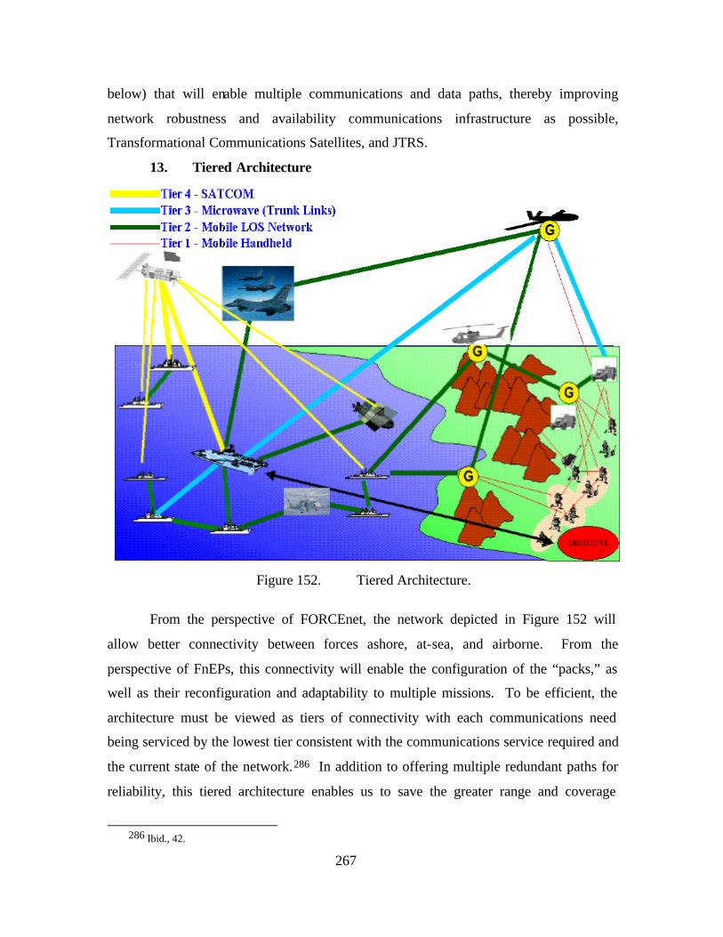
267
below) that will enable multiple communications and data paths, thereby improving
network robustness and availability communications infrastructure as possible,
Transformational Communications Satellites, and JTRS.
13. Tiered Architecture
Figure 152. Tiered Architecture.
From the perspective of FORCEnet, the network depicted in Figure 152 will
allow better connectivity between forces ashore, at-sea, and airborne. From the
perspective of FnEPs, this connectivity will enable the configuration of the “packs,” as
well as their reconfiguration and adaptability to multiple missions. To be efficient, the
architecture must be viewed as tiers of connectivity with each communications need
being serviced by the lowest tier consistent with the communications service required and
the current state of the network.286 In addition to offering multiple redundant paths for
reliability, this tiered architecture enables us to save the greater range and coverage
286 Ibid., 42.
268
satellite connectivity for the communications that require it, thereby mitigating
congestion in the space segment and ensuring warfighter access to critical operational
information and systems. The dense connectivity offered by these multiple paths
converts our ships from end hosts in the network to fully enabled network nodes capable
of sending, receiving, and relaying information.
As discussed in the FORCEnet Architectural Vision, the four tiers are:
• Tier 1: Within platforms and radio handhelds. This tier would include shipboard LANs (wired and wireless [e.g. 802.11]) and radios such as SINCGARS.
• Tier 2: Networked LoS and BLoS among platforms and expeditionary forces ashore. This tier includes most JTRS components, Intra-BattleGroup Wireless Networking, Tactical Digital Information Links (TADILs), Tactical Targeting Network Technology (TTNT), and HF Alternate Low Energy (ALE)287. Each platform at this tier should, in general, be able to serve as an end or a relay in the communications path, thereby giving platforms access to each other’s communications assets consistent with operational priorities and the state of the network. Participation of airborne assets in Tier 2 is very important due to the LoS limitation and the distances associated with surface ships and submarines. JTRS cluster 4 provides the standards and interfaces for airborne networks and how airborne communicators connect to land, sea, and space communications assets. Most antenna patterns for Tier 2 will be omni directional, thereby facilitating each node’s ability to know the state of its neighbors and to route packets to its reachable neighbors. Dynamic routing and dynamic physical layers will be the chief technical challenges at this tier. There must be a single joint mobile ad hoc network layer that can be applied globally across any data link layer. This layer needs to be consistent with plans for the JTRS WNW and facilitate incorporation of coalition units. Possible Mobile IP enhancements include dynamic low overhead routing protocols such as the Ad-hoc On-demand Distance Vector (AODV) routing protocol.
• Tier 3: Trunked LoS and BLoS. This tier includes TCDL, Digital Wideband Transmission System (DWTS), and HF ALE. Trunked LoS is high capacity, high range connectivity typically via an airborne communications node. This provides wideband connectivity between littoral ships and land forces on the beach or between clusters of ships spaced too far apart for tier 2 connectivity. Tiers 1, 2, and 3 will typically be organic.
287 According to Buddenberg, ALE’s benefits are limited to HF transmissions and BLOS skywave
communications. HF communications best fit is for ELOS, while leaving BLOS to SATCOM. This leaves little value added for ALE.
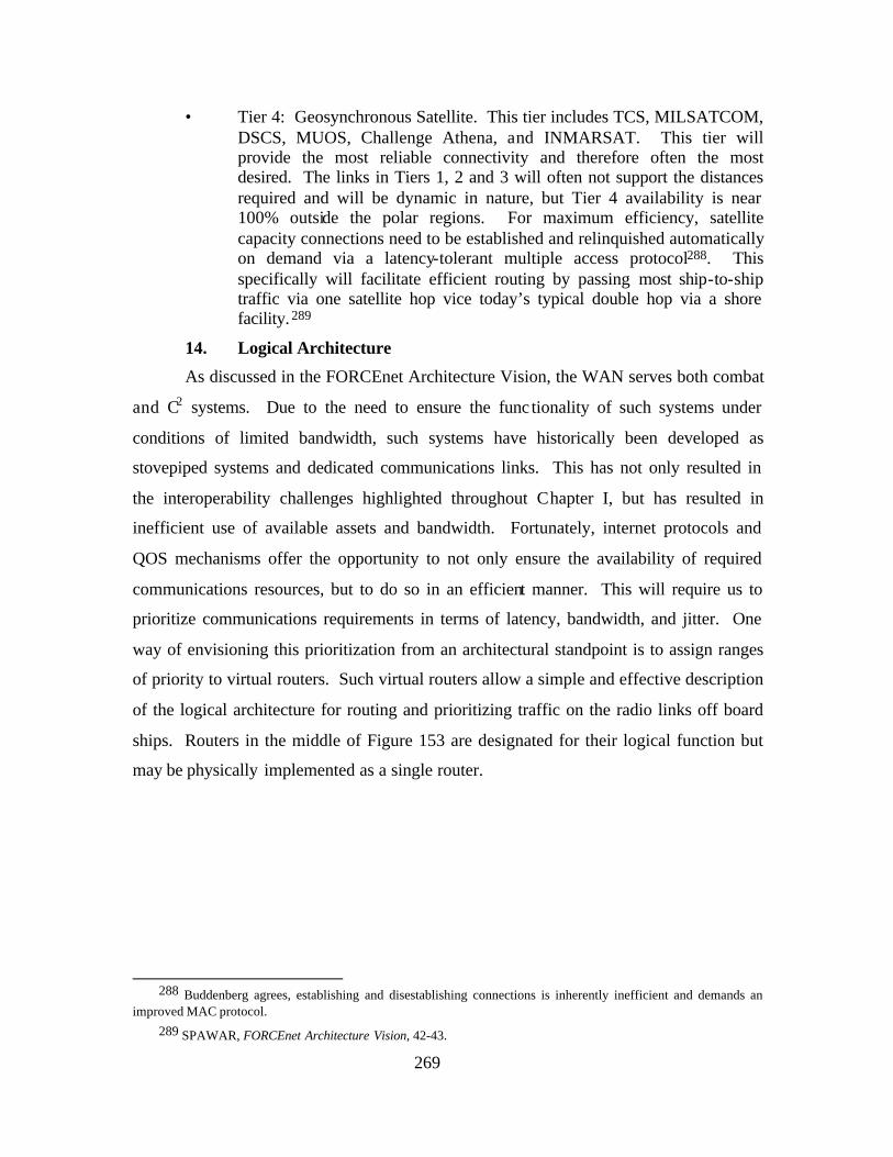
269
• Tier 4: Geosynchronous Satellite. This tier includes TCS, MILSATCOM, DSCS, MUOS, Challenge Athena, and INMARSAT. This tier will provide the most reliable connectivity and therefore often the most desired. The links in Tiers 1, 2 and 3 will often not support the distances required and will be dynamic in nature, but Tier 4 availability is near 100% outside the polar regions. For maximum efficiency, satellite capacity connections need to be established and relinquished automatically on demand via a latency-tolerant multiple access protocol288. This specifically will facilitate efficient routing by passing most ship-to-ship traffic via one satellite hop vice today’s typical double hop via a shore facility.289
14. Logical Architecture
As discussed in the FORCEnet Architecture Vision, the WAN serves both combat
and C2 systems. Due to the need to ensure the func tionality of such systems under
conditions of limited bandwidth, such systems have historically been developed as
stovepiped systems and dedicated communications links. This has not only resulted in
the interoperability challenges highlighted throughout Chapter I, but has resulted in
inefficient use of available assets and bandwidth. Fortunately, internet protocols and
QOS mechanisms offer the opportunity to not only ensure the availability of required
communications resources, but to do so in an efficient manner. This will require us to
prioritize communications requirements in terms of latency, bandwidth, and jitter. One
way of envisioning this prioritization from an architectural standpoint is to assign ranges
of priority to virtual routers. Such virtual routers allow a simple and effective description
of the logical architecture for routing and prioritizing traffic on the radio links off board
ships. Routers in the middle of Figure 153 are designated for their logical function but
may be physically implemented as a single router.
288 Buddenberg agrees, establishing and disestablishing connections is inherently inefficient and demands an
improved MAC protocol. 289 SPAWAR, FORCEnet Architecture Vision, 42-43.
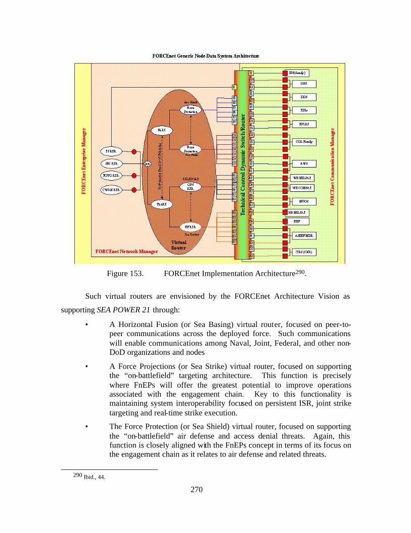
270
Figure 153. FORCEnet Implementation Architecture290.
Such virtual routers are envisioned by the FORCEnet Architecture Vision as
supporting SEA POWER 21 through:
• A Horizontal Fusion (or Sea Basing) virtual router, focused on peer-to-peer communications across the deployed force. Such communications will enable communications among Naval, Joint, Federal, and other non-DoD organizations and nodes
• A Force Projections (or Sea Strike) virtual router, focused on supporting the “on-battlefield” targeting architecture. This function is precisely where FnEPs will offer the greatest potential to improve operations associated with the engagement chain. Key to this functionality is maintaining system interoperability focused on persistent ISR, joint strike targeting and real-time strike execution.
• The Force Protection (or Sea Shield) virtual router, focused on supporting the “on-battlefield” air defense and access denial threats. Again, this function is closely aligned with the FnEPs concept in terms of its focus on the engagement chain as it relates to air defense and related threats.
290 Ibid., 44.
271
It is important to emphasize that the goal of FORCEnet to implement a
centralized network management solution and that no specific RF communication
solution will be dedicated to support any one of the FORCEnet component networks
discussed above. Further, FORCEnet will rely on a network implementing a dynamic
access scheme to ensure that any radio resource can be allocated to any mission based on
Joint BMC2ISR needs.291 Again, such goals are in direct alignment with the
requirements of FnEPs.
15. Systems Architecture
As outlined in the FORCEnet Architecture Vision, a critical consideration is that
of the interface between the on-board communications (internal) and the RF channels
allowing for the passing of data and communications to and from a given platform
(external). The functionality such an interface must enable includes:
• Automatic routing
• QoS enforcement
• Encryption
• Autodiscovery of radio channels, and the radios themselves.
The black IP router depicted in diagram xx below controls IP traffic among and
between any of the other security enclave routers, combat systems, or “packs”. In
addition to route determination, this router will provide QoS enforcement.
291 Ibid., 45.
272
Terminal 1 ...
INFOSEC until MLS
LAN Switches
LAN
Switches
LAN
Switches
Router
Router
Router
FFE
FFE
FFE
SCI
GENSER
UNCLAS
Q2
Q1
QN
Q out
Q out
Q out
Q2
Q1
QN
Q2
Q1
QN
SH
F 1
CD
L
SH
F 2
WN
W
TC AE
HF
Subnet Convergence Layer
MI Layer
DL
TRANSEC
SIS
Area 0 Area 0
CO
MS
EC
(H
AIP
E)
Mobile Qos
INFOSEC until MLS
LAN Switches
LAN
Switches
LAN
Switches
Router
Router
Router
FFE
FFE
FFE
SCI
GENSER
UNCLAS
Q2
Q1
QN
Q out
Q out
Q out
Q2
Q1
QN
Q2
Q1
QN
Combat System IP (BLK)
TADILS IP? (BLK)
Combat System IP (BLK)
TADILS IP? (BLK)
SH
F 1
Link
16
CD
L
SH
F 2
WN
W
TC AE
HF
Subnet Convergence Layer
MI Layer
DL
TRANSEC
SIS
Area 0 Area 0
CO
MS
EC
(H
AIP
E)
Mobile Qos
Red Side IP Enclave Routing
Black IP Router
EP
LRS
HF
Terminal 2 Terminal 1 ...
INFOSEC until MLS
LAN Switches
LAN
Switches
LAN
Switches
Router
Router
Router
FFE
FFE
FFE
SCI
GENSER
UNCLAS
Q2
Q1
QN
Q out
Q out
Q out
Q2
Q1
QN
Q2
Q1
QN
SH
F 1
CD
L
SH
F 2
WN
W
TC AE
HF
Subnet Convergence Layer
MI Layer
DL
TRANSEC
SIS
Area 0 Area 0
CO
MS
EC
(H
AIP
E)
Mobile Qos
INFOSEC until MLS
LAN Switches
LAN
Switches
LAN
Switches
Router
Router
Router
FFE
FFE
FFE
SCI
GENSER
UNCLAS
Q2
Q1
QN
Q out
Q out
Q out
Q2
Q1
QN
Q2
Q1
QN
Combat System IP (BLK)
TADILS IP? (BLK)
Combat System IP (BLK)
TADILS IP? (BLK)
SH
F 1
Link
16
CD
L
SH
F 2
WN
W
TC AE
HF
Subnet Convergence Layer
MI Layer
DL
TRANSEC
SIS
Area 0 Area 0
CO
MS
EC
(H
AIP
E)
Mobile Qos
Red Side IP Enclave Routing
Black IP Router
EP
LRS
HF
Terminal 2
Figure 154. Red Side IP Enclave Routing.
The other routers depicted in Figure 154 will prioritize packets according to
differentiated service code points (DSCP) in the IP header. The label will indicate the
operational priority and tolerance for [round-trip] latency, jitter, and the deterministic
requirements (bounded delay delivery) of the packet. Such labels are critical to allowing
for end-to-end QoS. Together, the security enclave routers and the black router will share
QoS enforcement roles. As depicted in diagram 154, each of these LANs is connected to
the RF devices off the ship via its enclave router, a COMSEC device, and the black
router. While we agree this is a viable near term solution, in the long run, providing data
security (layer 7) is a better way to go.
16. Data Links
It is important to note that even considering relatively less demanding networking
functionality, current and near term C4ISR infrastructure implementation may not fully
support performance requirements. From the perspective of FnEPs and the latency, QOS,
and security requirements of combat systems, these requirements will be even more
critical. It will take time for the open architecture and open standards approach that the
FORCEnet Architectiure Vision proposes to be fully implemented. In the meantime
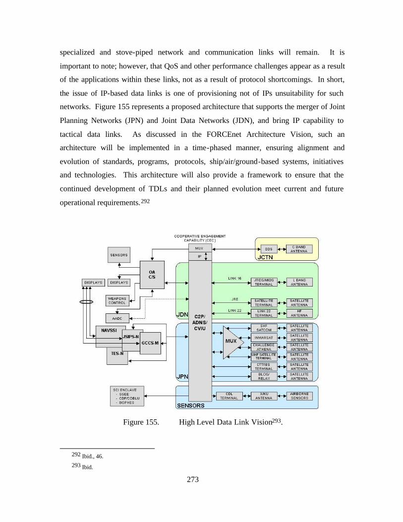
273
specialized and stove-piped network and communication links will remain. It is
important to note; however, that QoS and other performance challenges appear as a result
of the applications within these links, not as a result of protocol shortcomings. In short,
the issue of IP-based data links is one of provisioning not of IPs unsuitability for such
networks. Figure 155 represents a proposed architecture that supports the merger of Joint
Planning Networks (JPN) and Joint Data Networks (JDN), and bring IP capability to
tactical data links. As discussed in the FORCEnet Architecture Vision, such an
architecture will be implemented in a time-phased manner, ensuring alignment and
evolution of standards, programs, protocols, ship/air/ground-based systems, initiatives
and technologies. This architecture will also provide a framework to ensure that the
continued development of TDLs and their planned evolution meet current and future
operational requirements.292
Figure 155. High Level Data Link Vision293.
292 Ibid., 46. 293 Ibid.
274
Unfortunately, current TDL operations, including Link 11 and Link 16 do not
provide the throughput, bandwidth, QoS control, and flexibility necessary to meet the
information exchange requirements envisioned by FORCEnet.294 Such requirements will
change, and likely increase in terms performance, when the CRC functionality of FnEPs
is considered. As a result, we agree with the assessment acceleration of engagement time
lines and seamless data exchange from sensor-shooter-weapon necessitates enhancements
to current Link-16 capabilities. One such solution to this challenge is the Next
Generation Command and Control Processor (NGC2P) Program, which will allow the
Navy to incorporate Link 22 and Joint Range Extension (JRE) capability in conjunction
with a preplanned upgrade to the existing C2P and Combat Data Link Management
System (CDLMS). Together with other integration efforts including the airborne Low
Cost Integration (LCI), this effort is being accomplished as a joint US Navy and USAF
effort under the name of Common Link Integration Processing (CLIP). This effort
represents potential development of a joint service, cross-platform, TDL message
processing and integration application which will provide the interface to various tactical
data communication systems including current terminals and radios and those under
development such as MIDS SCA and JTRS. Additional advantages of CLIP include its
ability to interface with any host (i.e. combat) system, and its utilization of primarily
open systems software that can reside on any operating system or hardware.295
Overall, the following are goals of the FORCEnet Data Link architecture outlined
in the FORCEnet Architecture Vision:
• Migrate all network systems to include IP capability
• Convergence to three Tactical Data Links
• Low-end BLoS link for use with coalition partners (Link-22)
• Hi-end BLoS link for high bandwidth (JRE)
• LoS link (Link-16) for bandwidth and ATC functions
• Use of JTRS for radio functions for all links
294 Ibid., 47. 295 Ibid., 47.
275
• Invest in a single network and communication processing capability for use across all ship and aircraft systems to include dynamic networking and network management functionality;
• Link-16 uses IP, JRE uses JREAP, CEC moves to IP as part of Open Architecture (OA)
• CDL and TCDL need to be converged through a common, light-weight processor and migrated to IP.
While we generally agree with these goals, we caution that careful modularization
of the network architecture and its member systems should be the overarching goal.
Further, as COTS technology improves and as other solutions become available we
should not “blindly pursue” the specific systems identified above. Proper modularization
will help to ensure that we are not constrained to a particular system or “boxological”
approach.
17. A FORCEnet Scenario
As discussed in the FORCEnet Architecture Vision, the requisite network
infrastructure characteristics and “capabilities” can best be identified and portrayed
within the context of a war-fighting scenario. The following discussion relates such a
scenario, presented in the FORCEnet Architecture Vision (Version 1.2 dtd 18 July 2003),
and set against the stage of the Philippine Islands. While this scenario was originally
designed to demonstrate how FORCEnet will change the way Navy conducts warfare and
generates force as a component of a Joint, Allied and/or Coalition Force, we will overlay
the FnEPs concept onto this scenario, and specifically inject networking-related
considerations, especially as they relate to the five CRCs. As noted in the FORCEnet
Architecture Vision, from which the following scenario was taken, this scenario can serve
as the basis for a demonstration framework, which can evolve in a laboratory and
development environment to showcase applications, composeable functionality, network
tools, interoperability mechanisms, and other components that are key parts of making
FORCEnet and FnEPs a reality296.
296 Ibid., 13.
276
a. Act 1: Composing the Force and Building a Shared Understanding297
The Joint Task Force (JTF), an ad hoc force formulated more on the basis
of proximity than capability, arrives on the scene. This ad hoc nature does not concern
the Commander Joint Task Force (CJTF), since each element’s J3 and J6s are well versed
in the art of composing command and control interoperability and supporting technical
infrastructure. Under direction of the CJTF J6, distributed, converged IP-based networks
are established. Bandwidth management and control tools allow all the J6’s to build their
information exchange and management plans, based on the CJTF’s preliminary guidance.
Agents will monitor traffic in real time and recommend adjustments to maximize
connectivity and throughput.
Since distributed services were instituted across DoD, operators have
grown accustomed to gathering needed information and display the same coherently.
This capability will allow the virtual JTF intelligence organization to rapidly assemble an
accurate, timely Intelligence Preparation of the Battlefield (IPB). Employing information
derived from national and theater Intelligence, Surveillance and Reconnaissance (ISR)
assets, the IPB is updated and currency is maintained as the crisis evolves. In addition to
an IPB, both sensor-derived data and seamless support from the theater JIC acquired by a
network agent is integrated into the Predictive Battlespace (in this case, perhaps,
operational space) Awareness (PBA) process allowing for the assembled forces to be
fully aware of the situation, recent events, and potential hazards of their mission, to
include potential adversary courses of action.
From an FnEPs perspective, in this scenario, no “packs” are yet formed,
rather the CP is being developed and the ABMA system is “ready” in terms of its
awareness of available pack assets and their status. From a networking perspective ISR
and C2 functionality are being utilized, however bandwidth, Availability/Survivability,
and QOS demands are relatively low, due to the “pre-conflict” status of the situation.
Conversely, available bandwidth may be relatively low, due to the fact relatively few
assets may be available or dedicated for use in theater.
297 Ibid., 15.
277
As highlighted in the FORCEnet Architecture Vision, at this point the
network infrastructure closely resembles current technology, with various LoS or BloS
links. However, through dynamic network configuration and bandwidth allocation, now
the transmission path is transparent to the force, and redundant, fault-tolerant links are
provisioned. Additionally, sophisticated, defense in depth information assurance
protocols guard against constant net intrusion, yet still enable needed coalition (and
allied) information sharing at several levels of security. 298
b. Act 2: Creating Shared Situational Awareness
Based on the information centric computing environment alert agents
determine an inconsistency in data is likely based on Global Positioning System (GPS)
jamming, and send an alert to all GPS subscribers. Cross cueing and fusion of
Unmanned Ground Sensors (UGS), JSTARS, and ESM receivers quickly leads to
detection, identification and a track of the GPS jammer. From an FnEPs perspective, this
is analogous to the initiation of the engagement chain, more specifically sensor assets
have been cued in order to “find” and “fix” possible targets. Within minutes, the CJTF
initiates an on-demand high resolution Video Teleconference (VTC) with their
components, where collaboratively they determine the operational impact of the jammer,
conclude action is required, and generate courses of action. Graphical depictions of plans
reduce misunderstanding and the high resolution VTC allows the various commanders to
learn from body language, tone of voice, and words, each other’s true perceptions.
Satisfied they are on the same page, the CJTF moves on to the next challenge. From the
perspective of FnEPs, this human decision-making intensive process can be made more
efficient through the use of of ABMAs which can help optimize the decision-making
process of determining optimum sensor-shooter-weapons linkages. Rather than removing
the warfighter from the decision-making process; however, ABMAs enable the use of
advanced decision support tools and allow Commanders and their staffs to focus on other
tasks. In terms of networking technology, ABMAs have the advantage of being
dynamically “adjusted” or “tuned” depending on any number of situational factors. Two
key factors are 1) Time and 2) Available processing power and other network resources.
First, from the perspective of time, the given scenario is transitioning from pre-conflict to
298 Ibid.
278
conflict. Accordingly, there would likely still be time and other necessary resources to
leave the decision-making process largely to the CJTF and his staff. Given an increase in
optempo; however, ABMAs could be allowed to operate in an increasingly automated
manner, thus assisting the warfighter with decision-making in the face of increasingly
chaotic situations and the “fog of war.” Interestingly, by significantly decreasing
engagement timelines, FnEPs will likely similarly compress the time available for
optimal decision-making as well. This further highlights the importance and value of
robust ABMAs functionality. The second perspective, that of available processing power
and other network resources, also highlights the need for the dynamic functionality of of
ABMAs. For example, especially during pre-conflict or other less operationally intensive
phases of conflict, computing power and other network resources to process complex
algorithms and challenging optimization problems would likely be available. As
optempo increased, these resources
could be dynamically reconfigured and optimized to support decision-making under a
variety of conditions. The remaining two “acts” of the FORCEnet operational scenario
have been overlayed with the CRC functionality inherent to the FnEPs concept.
c. Act 3: Self-Synchronization
At this point, the CJTF directs his staff to execute the mission. Due to the
facilitation of common awareness (through CP functionality), subordinate commanders
understood the intent and plan as well as the commander. In this case, four V-22s ingress
the rebel-controlled area, while their current tactical picture highlights Special Forces on
the ground positioned to neutralize the one nearby surface to air missile site.
Preprogrammed Unmanned Aerial Vehicles (UAVs) circled in stealth mode, listening for
any signals from the Miscellaneous Command Ship (AGF). Unexpectedly a brief hint of
a previously unidentified AGF unit is detected by one of the UAVs.
UGS detected an unidentified hovercraft approaching the LZ. In-country
special forces launch a rapid reaction mini-UAV, confirming with the sensor coordinator.
Identified as hostile (through CCID functionality), the forces are now in a quandary; the
key LZ for the V-22’s is at risk, jeopardizing the operation. The fires coordinator, alerted
by a change in plan cue (and assisted by ABMA functionality), rapidly analyzes the
situation. The V-22 has Hellfire laser designated missiles onboard but an F-35 is
279
available and also capable of providing mensurated targeting data in the form of in-flight
target updates to Extended Range Guided Munitions (ERGM) fired from surface ships
located over the horizon and out of harms reach.
An infiltration team notes that the area to the east is devoid of AGF and
recommends that the V-22s change flight path easterly and save Hellfire for other
emerging threats. (Because CT have been passed throughout the JTF) The fires
coordinator recognizes the F-35 is capable of rapidly engaging the hovercraft with
JSOW-ER. Without requiring orders, the Special Operations Forces (SOF) reports that
the mini UAV could lase the hostile hovercraft immediately following notification
(through IFC functionality). In less than five minutes from detection, a single Joint
Stand-Off Weapon (JSOW) destroys the hovercraft from a 60-mile range. The V-22s are
then redirected to the LZ where the Special Forces deploy from them and eliminate the
GPS jammer. Through operational synchronization, an element of Sea Strike had been
masterfully executed in support of Joint Forces.
d. Act 4: Intra Theater Missile Defense
Through netted National Intelligence sources, (CP functionality) the CJTF
learns of an Army Ground Force (AGF) request to affiliated Al Qaeda terrorist cells
operating within nearby Brunei for assistance in a retribution attack for the loss of their
GPS jammer asset. The CJTF directs that the AGF commander’s third generation
cellular technology IP enabled PDA become a target for exploitation and offensive
Information Operations. This exploitation indicates an imminent cruise missile attack.
Using Predictive Battlespace Awareness applications, possible enemy Courses of Action
are posted to the Knowledge Web (KWEB) where Joint Forces Air Component
Commander (JFACC) begins dynamic replanning of Airspace Controls (Airspace Control
Order - ACO) to counter the threat against critical Government of Philippines
infrastructure targets on the Defended Assets List (ABMAs functionality). This includes
designation of Overland Cruise Missile Defense kill boxes for extended range SAM
engagements using airborne Fire Control (FC) radar. The change to the ACO is posted to
KWEB for situational awareness and automatically forwarded to the operational forces
via the network for real-time deconfliction of airborne fixed and rotary wing assets
(ABMAs functionality). Airborne Early Warning aircraft detect the low observable
280
cruise missile by building a composite track (CT functionality) through networked
sensors and preplanned responses published on the KWEB allow immediate engagement
of the threat (CCID functionality) by a surface ship operating off the coast. An active
seeker SAM completes a successful engagement, destroying the cruise missile, by using
the network to subscribe to the fire control solution for the target published by several
ground and airborne FC radars (IFC functionality).
It is critical to note that while the preceding scenario demonstrated the
integration of the existing combat systems and processes into FORCEnet, the vast
majority of these systems are Naval systems and TTPs such as those required to support
IFC are assumed to have been transitioned to. FnEPs will absolutely require integration
of joint assets and new TTPs in order to maximize the five CRCs identified in Chapter 2!
Through machine to machine collaboration using an Open-Architecture Computing and
Networking Environment, sensors, Combat Systems, C2 nodes and weapons become the
peripherals and applications that ride the network to enable FORCEnet to satisfy required
operational capabilities as the “new” construct of a composeable combat system.
18. TCA and GIG 2.0
The C4ISR infrastructure proposed by the FORCEnet Architecture Vision is only
one part of a “triad” of network infrastructure programs that also includes the
Transformational Communications Architecture (TCA) and the Global Information Grid
2.0 terrestrial infrastructure upgrade (GIG 2.0), which together will provide a standard
means to interconnect all deployed and fixed users and facilities in a global network,
while improving our architecture’s bandwidth, survivability, and in-theater reach
capabilities. This relationship is depicted in Figure 156.299
In conjunction with NSA and GIG 2.0, the TCA will provide wide-band, black
network layer IP-based communications. Tremendous increases in available bandwidth
will be made possible by the NRO Optical Relay satellite (ORCA)300, MILSATCOM
Transformational Satellite (TSAT), and advanced Polar Satellite (APS) interoperating
with each other using wideband cross links. Further, space based IP routers and/or circuit
299 Ibid., 23. 300 Ibid.
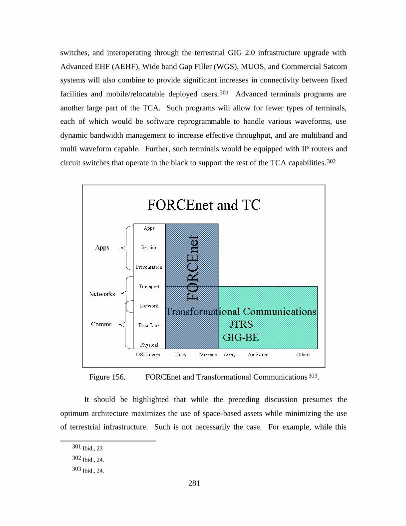
281
switches, and interoperating through the terrestrial GIG 2.0 infrastructure upgrade with
Advanced EHF (AEHF), Wide band Gap Filler (WGS), MUOS, and Commercial Satcom
systems will also combine to provide significant increases in connectivity between fixed
facilities and mobile/relocatable deployed users.301 Advanced terminals programs are
another large part of the TCA. Such programs will allow for fewer types of terminals,
each of which would be software reprogrammable to handle various waveforms, use
dynamic bandwidth management to increase effective throughput, and are multiband and
multi waveform capable. Further, such terminals would be equipped with IP routers and
circuit switches that operate in the black to support the rest of the TCA capabilities.302
Figure 156. FORCEnet and Transformational Communications 303.
It should be highlighted that while the preceding discussion presumes the
optimum architecture maximizes the use of space-based assets while minimizing the use
of terrestrial infrastructure. Such is not necessarily the case. For example, while this
301 Ibid., 23
302 Ibid., 24. 303 Ibid., 24.
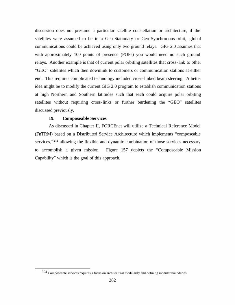
282
discussion does not presume a particular satellite constellation or architecture, if the
satellites were assumed to be in a Geo-Stationary or Geo-Synchronous orbit, global
communications could be achieved using only two ground relays. GIG 2.0 assumes that
with approximately 100 points of presence (POPs) you would need no such ground
relays. Another example is that of current polar orbiting satellites that cross- link to other
“GEO” satellites which then downlink to customers or communication stations at either
end. This requires complicated technology included cross- linked beam steering. A better
idea might be to modify the current GIG 2.0 program to establish communication stations
at high Northern and Southern latitudes such that each could acquire polar orbiting
satellites without requiring cross- links or further burdening the “GEO” satellites
discussed previously.
19. Composeable Services
As discussed in Chapter II, FORCEnet will utilize a Technical Reference Model
(FnTRM) based on a Distributed Service Architecture which implements “composeable
services,”304 allowing the flexible and dynamic combination of those services necessary
to accomplish a given mission. Figure 157 depicts the “Composeable Mission
Capability” which is the goal of this approach.
304 Composeable services requires a focus on architectural modularity and defining modular boundaries.
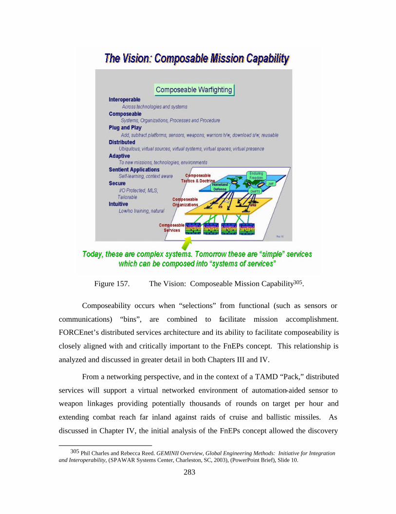
283
Figure 157. The Vision: Composeable Mission Capability305.
Composeability occurs when “selections” from functional (such as sensors or
communications) “bins”, are combined to facilitate mission accomplishment.
FORCEnet’s distributed services architecture and its ability to facilitate composeability is
closely aligned with and critically important to the FnEPs concept. This relationship is
analyzed and discussed in greater detail in both Chapters III and IV.
From a networking perspective, and in the context of a TAMD “Pack,” distributed
services will support a virtual networked environment of automation-aided sensor to
weapon linkages providing potentially thousands of rounds on target per hour and
extending combat reach far inland against raids of cruise and ballistic missiles. As
discussed in Chapter IV, the initial analysis of the FnEPs concept allowed the discovery
305 Phil Charles and Rebecca Reed. GEMINII Overview, Global Engineering Methods: Initiative for Integration
and Interoperability, (SPAWAR Systems Center, Charleston, SC, 2003), (PowerPoint Brief), Slide 10.
284
of relationships between combat system functions and their information exchange
requirements, and the packaging of service areas, prioritized to support a variety of
missions.
As discussed in Chapter IV; however, achieving distributed services presents a
number of technical challenges. Figure 158 seeks to characterize the problem.
Figure 158. How Do We Move to Distributed Services?306.
Distributed services require the ability to access “services”, such as the common
operational picture (COP), data link subscription, or other information. Presently, these
services are complex, face interoperability problems, and are generally via a closed,
rather than open architecture. Ultimately, this prevents the composeability of the
information into different information flows. The distributed services FnEPs seeks to
create or take advantage of in a networked virtual environment look much different. The
306 Charles, Assessments to Define Composeable Mission Capability, Slide 33.
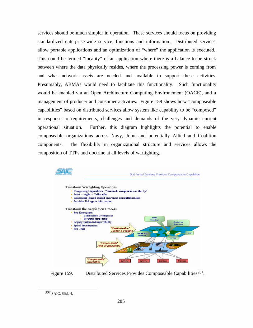
285
services should be much simpler in operation. These services should focus on providing
standardized enterprise-wide service, functions and information. Distributed services
allow portable applications and an optimization of “where” the application is executed.
This could be termed “locality” of an application where there is a balance to be struck
between where the data physically resides, where the processing power is coming from
and what network assets are needed and available to support these activities.
Presumably, ABMAs would need to facilitate this functionality. Such functionality
would be enabled via an Open Architecture Computing Environement (OACE), and a
management of producer and consumer activities. Figure 159 shows how “composeable
capabilities” based on distributed services allow system like capability to be “composed”
in response to requirements, challenges and demands of the very dynamic current
operational situation. Further, this diagram highlights the potential to enable
composeable organizations across Navy, Joint and potentially Allied and Coalition
components. The flexibility in organizational structure and services allows the
composition of TTPs and doctrine at all levels of warfighting.
Figure 159. Distributed Services Provides Composeable Capabilities307.
307 SAIC. Slide 4.
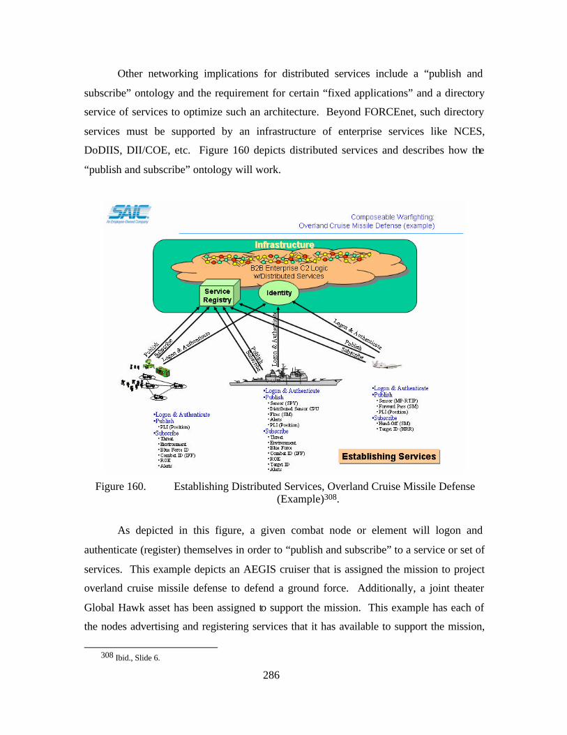
286
Other networking implications for distributed services include a “publish and
subscribe” ontology and the requirement for certain “fixed applications” and a directory
service of services to optimize such an architecture. Beyond FORCEnet, such directory
services must be supported by an infrastructure of enterprise services like NCES,
DoDIIS, DII/COE, etc. Figure 160 depicts distributed services and describes how the
“publish and subscribe” ontology will work.
Figure 160. Establishing Distributed Services, Overland Cruise Missile Defense
(Example)308.
As depicted in this figure, a given combat node or element will logon and
authenticate (register) themselves in order to “publish and subscribe” to a service or set of
services. This example depicts an AEGIS cruiser that is assigned the mission to project
overland cruise missile defense to defend a ground force. Additionally, a joint theater
Global Hawk asset has been assigned to support the mission. This example has each of
the nodes advertising and registering services that it has available to support the mission,
308 Ibid., Slide 6.
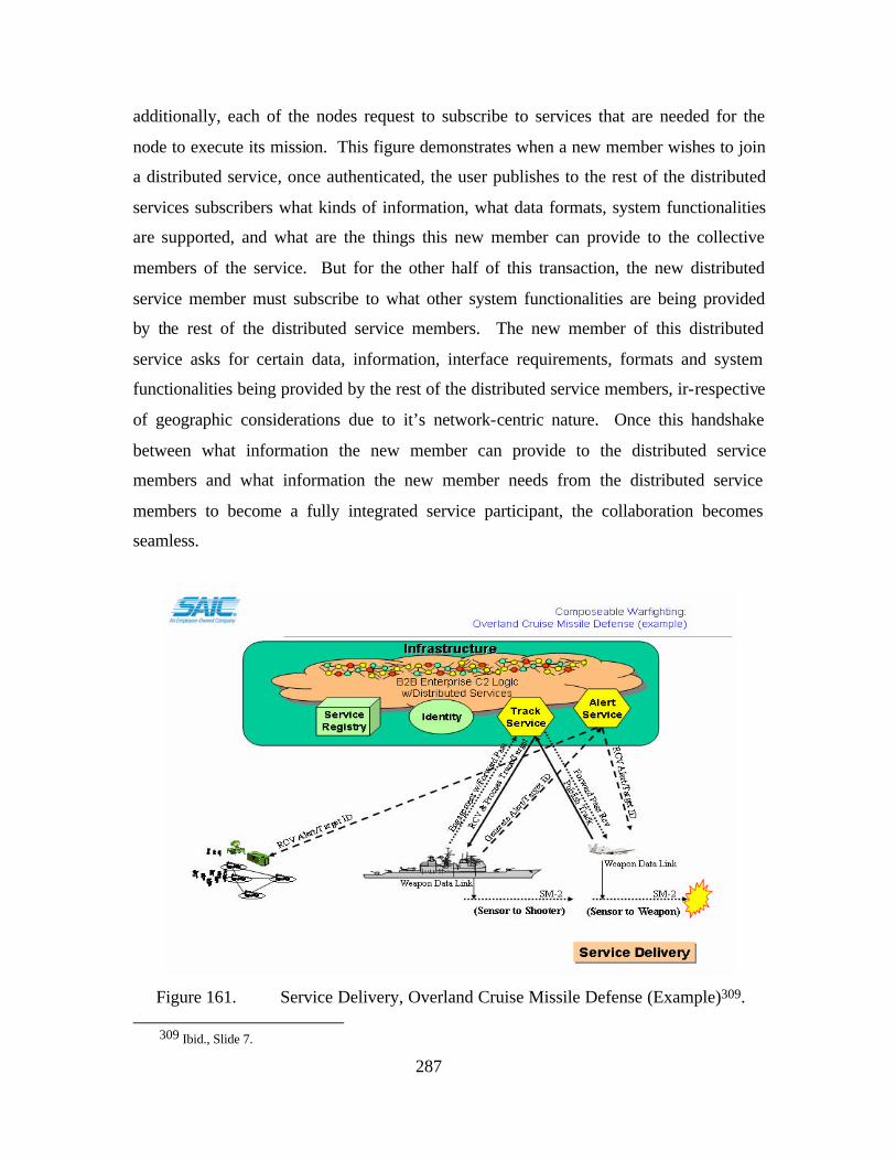
287
additionally, each of the nodes request to subscribe to services that are needed for the
node to execute its mission. This figure demonstrates when a new member wishes to join
a distributed service, once authenticated, the user publishes to the rest of the distributed
services subscribers what kinds of information, what data formats, system functionalities
are supported, and what are the things this new member can provide to the collective
members of the service. But for the other half of this transaction, the new distributed
service member must subscribe to what other system functionalities are being provided
by the rest of the distributed service members. The new member of this distributed
service asks for certain data, information, interface requirements, formats and system
functionalities being provided by the rest of the distributed service members, ir-respective
of geographic considerations due to it’s network-centric nature. Once this handshake
between what information the new member can provide to the distributed service
members and what information the new member needs from the distributed service
members to become a fully integrated service participant, the collaboration becomes
seamless.
Figure 161. Service Delivery, Overland Cruise Missile Defense (Example)309.
309 Ibid., Slide 7.
288
Once ABMAs have composed the operational approach that will be used to
execute the overland cruise missile capability, the FORCEnet infrastructure is quickly
configured to support the publish and subscribe service capabilities needed. In this
example, the network establishes two consumer-to-consumer (C2C) services that allow
the three nodes to exchange information. One is a basic track services and the other
missile alert service. In this case, the AEGIS cruiser has subscribed to receive AMTI
sensor feeds from the Global Hawk’s MP-RTIP radar. The AEGIS cruiser’s on-board
distributed sensor processor has the ability to mix the Global Hawk’s remote sensor with
its local sensors to detect and ID a cruise missile threat, and to immediately report this
data to prepare for an attack (employ chemical and biological defense mechanisms). In
addition, it provides the same information back to the Global Hawk so that the MP-RTIP
radar can execute a High Resolution Radar (HRR) continuous track update information to
the AEGIS cruiser. This information is sufficient to provide the AEGIS with a fire
quality solution that can be used to engage the cruise missile remotely.
Further, the AEGIS has been made aware of the Global Hawk’s ability to not only
support a remote engagement (sensor-to-shooter paradigm) for remote engagement, but
also has the ability to support forward pass (sensor-to-weapon paradigm). This allows the
Global Hawk to take control of the SM-2 and provide mid-course and terminal guidance
support directly to the SM-2 in flight. This enables the AEGIS to engage the cruise
missile at a greater range, and potent ially support a shoot- look-shoot to engage the threat.
As the scenario plays-out, the AEGIS indicates that it will engage the target, and
request forward pass support from the Global Hawk. The Global Hawk indicates it will
comply with the engagement request – the AEGIS launches the SM-2, controls initial
weapon fly-out, then turns final engagement over to the Global Hawk. We assume a
successful engagement and this example ends.
As discussed previously, distributed services must be built on a common, open
architecture that allows the ability to interoperate and collaborate without consideration
to all the possible combinations or permutations of possible systems both already in
operational use or those being designed. Open architectures built on secure, common
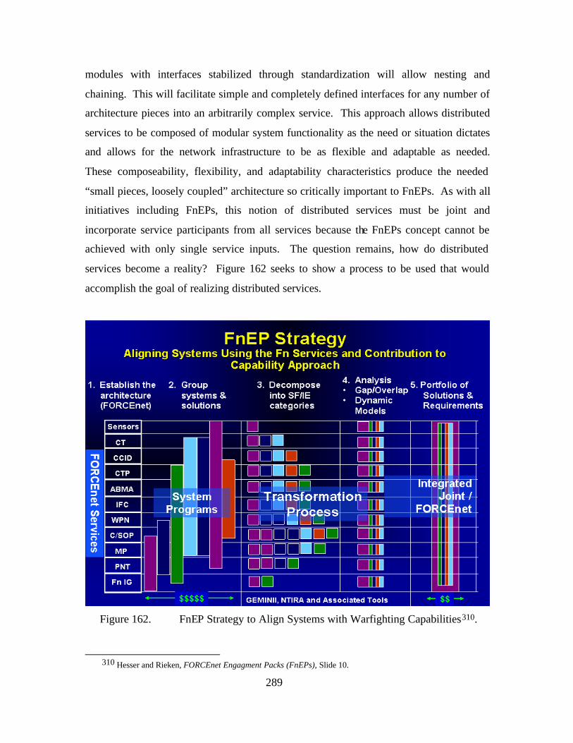
289
modules with interfaces stabilized through standardization will allow nesting and
chaining. This will facilitate simple and completely defined interfaces for any number of
architecture pieces into an arbitrarily complex service. This approach allows distributed
services to be composed of modular system functionality as the need or situation dictates
and allows for the network infrastructure to be as flexible and adaptable as needed.
These composeability, flexibility, and adaptability characteristics produce the needed
“small pieces, loosely coupled” architecture so critically important to FnEPs. As with all
initiatives including FnEPs, this notion of distributed services must be joint and
incorporate service participants from all services because the FnEPs concept cannot be
achieved with only single service inputs. The question remains, how do distributed
services become a reality? Figure 162 seeks to show a process to be used that would
accomplish the goal of realizing distributed services.
Figure 162. FnEP Strategy to Align Systems with Warfighting Capabilities310.
310 Hesser and Rieken, FORCEnet Engagment Packs (FnEPs), Slide 10.
290
Figure 162 depicts a strategy to align systems and programs using the FnEPs
concept. This strategy critically hinges on the understanding of system decomposition
into FnEPs Pack Factor (PF) components as the first step. When recomposing PF
components into “packs,” combat reach capabilities and a few critical services (horizontal
“lanes”) become critical enablers to pack composition. The GEMINII approach used
throughout our analysis of FnEPs supports more detailed understanding of integration
management to understand if all system interrelationships are possible, optimal, desired
or affordable. There would be a need for system designers to use this information to
focus on interactions that yield the most effectiveness. Understanding how combat reach
capabilities provide warfighting distributed services are key to understanding how
distributed services support pack adaptability across both Strike and TAMD mission
areas.
As highlighted in Chapter III, the first step in the process is to establish the
FORCEnet architecture with respect to services required. FnEPs depends on both the
integration of all six FORCEnet factors (warriors, sensors, platforms, networks,
command and control and weapons) and the functionality provided by the five Combat
Reach Capabilities (CRCs). The figure above lists these as FORCEnet “services” along
the left, but also depicts other services such as Precision Navigation and Timing (PNT),
Mission Planning (MP) and FORCEnet Information Grid (Fn IG)) (Single/Common
Pictures (synonomous with the CP CRC) referred to as the Common Tactical Picture
(CTP)). Step two involves overlaying “As-Is” operational systems/programs onto a map
which shows how these individual Stove-piped systems’ deliver the required FnEP
capabilities. Step three decomposes these “As-Is” operational systems into their system
functions and/or information categories and map them to the respective CRCs and
services. This is where the transformation process begins by decomposing systems into
small pieces (system functions/information pairs) that will align functionality to
distributed services. The SSC-C GEMINII methodology (NTIRA, TVDB and associated
tools) was critical in facilitating this decomposition. Step four focuses on the analysis of
the gaps and overlaps of system functionality as provided by current systems in support
of the defined FORCEnet services. The GEMINII methodology supports the gap and
overlap analysis process but also provides tools to do dynamic modeling of new
291
integrated, distributed architectures. This realigned system functionality, combined with
defined architectural interfaces at the CRC and service level and organized around and
end-to-end perspective of the engagement chain will make FnEPs analysis possible. At
this critical point analysis could be conducted to determine FORCEnet network
infrastructure requirements from a CRC and distributed service perspective using “like”
systems while maintaining capability context within a particular engagement chain,
called TACSITs in this situation. The final and critical step is to align and integrate those
new CRCs (system functions) and distributed services along the TACSIT-defined
engagement chain and propose new funding and integration alignment changes which
will allow for an end-to-end engagement chain integration based service.
Overall, in addition to providing the basis for network infrastructure requirements,
this process will allow for prioritization and synchronization of program funding and
capability increments across naval and joint programs. This strategy also begins to
support composeable warfighting analysis because the analysis is general and abstract
enough such that it is not strictly limited to an individual TACSIT, but permits the
definition of new TACSITs based on whatever operational threat or situation is
presented. This strategy and analysis process can support operational architectures of Fn
factors based on new tactics, techniques and procedures as they evolve.
20. Joint Fires Network (JFN) and the Distributed Common Ground Station (DCGS)
Two examples of current programs that approach the kinds of functionality FnEPs
require are the Joint Fires Network (JFN) and DGCS. JFN consists of three major
components:
• JSIPS – A shipboard system that can receive, process, exploit, store and disseminate digital imagery fed from national (spy satellites) and tactical sensors aboard aircraft, for example.
• GCCS – A multi-service network mandated by the Defense Department which seeks to provide information in support of the development of situation awareness and a “common operational picture (COP).
• TES – A ground station that receives, processes and disseminates intelligence, surveillance and reconnaissance information.
• JFN started out as a Navy-only effort to address the demanding functionality necessary to support time-critical strike by compressing the target engagement cycle, from hours to minutes, necessary to support
292
time-critical strike. It has grown to a joint program which functions by expediting the gathering, processing and fusing of imagery and other intelligence from national and tactical sensors, enabling operators aboard ships and aircraft to develop targeting data usable by a “shooter” all within a 10-minute cycle. Ultimately the goal of JFN is to support the Marine Corps requirement to meet a 2.5-minute response for call for fire. Interesting, by focusing on the engagement chain, JFN demands much of the same kinds of requirements and functionality as FnEPs. This section will briefly discuss these similarities while outlining in broad terms the increased demands of FnEPs. This comparision will prove useful in subsequent discussions of networking and integration requirements of FnEPs.
First and foremost, similar to the vision of FnEPs, JFN is a joint program which
requires a high degree of interoperability between a variety of otherwise service-specific
platforms and systems. Although it is important to note JFN currently faces a number of
technical hurdles, such as bandwidth, the most difficult challenges JFN faces are those
associated with the integration of these platforms and systems. Until these are overcome
JFN only approximates the answers to the demands of FnEPs. Interestingly, it is the
requirements of the Marine Corps to meet a 2.5-minute response for a call of fire that
may become a forcing function driving JFN towards the levels of performance FnEPs
will require. Such levels of performance will absolutely demand the Navy and the other
services come up with common standards for JFN, as opposed to its current makeup of
disparate technologies that have been forced to talk to each other via “middleware,” or
software interfaces.311
This demand for common standards is the second major similarity between JFN
and FnEPs. As a result of the demand for common standards, “the most desirable course
in JFN is to develop an entirely new architecture, one that is designed specifically to be
interoperable among the services and to meet the stringent requirements for fire support
of land forces on the ground.”312 Problems related to the establishment of standards
include
311 Navy, Air Force Team Up in “Joint Fires Network”, Sandra I. Erwin, March 2003, 312 Capt. James Phillips, head of the Navy’s surface warfare division warfare systems branch.
293
• Until the Navy and the other services can come up with common standards for JFN, the system will remain a mix of disparate technologies that have been forced to talk to each other via “middleware,” or software interfaces.
• The definitive standards for Joint JFN implementation have not been determined.
A third similarity is that JFN will follow the “spiral development” approach,
similar to that envisioned for FnEPs. Spiral development makes sense in this program,
because the technology changes rapidly and the integration is so complex. 313
Despite the improvements to the engagement chain timelines JFN represents, JFN
currently faces the following challenges:
• JFN does not address the actual engagement of targets or the “pulling of the trigger”.
• JFN is not fast enough for Marines, who want to reduce the current engagement timeline to 2.5 minutes due to close proximity to targets on the ground. (The problem is that national- level intelligence takes too long to arrive. Only tactical on-board sensors can provide the intelligence fast enough).
• JFN is expensive, requires trained analysts, and is bandwidth and processing intensive. As a result, it is currently only planned for deployment aboard aircraft carriers.
Overall, while JFN is promising from a system integration and interoperability
perspective, the only way to have “true” interoperability is to have common hardware and
standards for displaying information across the services, Deutsch said. “The
interoperability problem is largely solved when you have the same equipment, same
architecture.” The Distributed Common Ground Station (DCGS) program seeks to
develop such common standards for intelligence processing and an acceptable format for
the display of information that all the services can agree to. Much broader than JFN,
DCGS is a combination of hardware, software transmit/receive devices and data links.
At present the Navy and Air Force have largely adopted DCGS, but while the
Army and Marines have similar, they lack the same architecture. RADM(sel) Deutsch
explains a number of the advantages of DCGS, especially if it becomes fully adopted by
all services, “If we go in that direction, we can save money with a larger buy, and we
would have more commonality, guaranteed interoperability by the fact that you are
313 Robert W. Hesser, JFN and FnEPs, SSG XXII, June 2003.
294
purchasing the same systems.” One of the reasons services have been reluctant to fully
accept a single standard such as that of DCGS is the requirement to address service-
unique applications. DCGS and JFN; however; seek to allow for such, but under a
common “core” system.
Beyond the opportunities that programs such as JFN, and DCGS offer to
FORCnet and FnEPs; however, we must again highlight that such programs seek
standards and commonality while missing the point of the need for modularity.
Standards yield commonality, yet appropriate modularization is required for
interoperability. Each is distinct from the other, yet both are required. In order to
achieve interoperability among systems, we must 1) begin with standards, 2) decompose
system functionality based on system function interaction patterns, 3) rebuild the
appropriate system modules based on optimized system function interaction patterns as
end-to-end systems using standardized interfaces.
D. CONCLUSIONS
As this chapter has highlighted, determining the network infrastructure
requirements for a “Warfighting Internet” enabling FORCEnet and FnEPs is decidedly a
non-trival task. While we have highlighted many high level and more specific
consideration, we assess the requirement for detailed analysis in two additional areas. 1)
The specific requirements associated with integration and interoperability of legacy and
future systems within each “Pack” mission area, (e.g., Strike, TAMD, ASW, ASuW, etc.)
and 2) Identification of specific C4ISR network infrastructure performance requirements
(e.g., bandwidth, QoS, security). While time prevented us from completing this analysis,
fortunately, there are a number of ongoing programs related research and development
efforts (e.g. JFN, NIFC-CA, DCGS) which will help to determine system requirements
and network performance parameters associated with such functionality the CRCs will
require. Most importantly, as highlighted in Chapter II, SPAWAR and the Office of the
FORCEnet Chief Engineer have matured the vision for a C4ISR architecture that is
closely aligned with, and will likely address many of the technical networking-related
challenges associated FORCEnet and FnEPs.
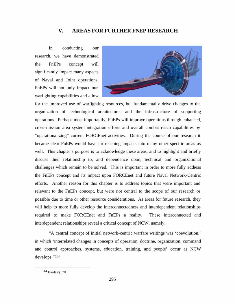
295
V. AREAS FOR FURTHER FNEP RESEARCH
In conducting our
research, we have demonstrated
the FnEPs concept will
significantly impact many aspects
of Naval and Joint operations.
FnEPs will not only impact our
warfighting capabilities and allow
for the improved use of warfighting resources, but fundamentally drive changes to the
organization of technological architectures and the infrastructure of supporting
operations. Perhaps most importantly, FnEPs will improve operations through enhanced,
cross-mission area system integration efforts and overall combat reach capabilities by
“operationalizing” current FORCEnet activities. During the course of our research it
became clear FnEPs would have far reaching impacts into many other specific areas as
well. This chapter’s purpose is to acknowledge these areas, and to highlight and briefly
discuss their relationship to, and dependence upon, technical and organizational
challenges which remain to be solved. This is important in order to more fully address
the FnEPs concept and its impact upon FORCEnet and future Naval Network-Centric
efforts. Another reason for this chapter is to address topics that were important and
relevant to the FnEPs concept, but were not central to the scope of our research or
possible due to time or other resource considerations. As areas for future research, they
will help to more fully develop the interconnectedness and interdependent relationships
required to make FORCEnet and FnEPs a reality. These interconnected and
interdependent relationships reveal a critical concept of NCW, namely,
“A central concept of initial network-centric warfare writings was ‘coevolution,’
in which ‘interrelated changes in concepts of operation, doctrine, organization, command
and control approaches, systems, education, training, and people’ occur as NCW
develops.”314
314 Hardesty, 70.
296
Understanding and managing these complex dynamics from more than just the
technical, engineering perspective is important to realizing the full potential of NCW and
FnEPs.
A. MISSION AREA ANALYSIS
Within the Strike and TAMD mission areas, significant work remains to be done
in order to fully understand the five CRCs within the context of the FnEPs concept.
Major challenges remain to more fully understand FnEPs as they apply to Strike and
TAMD with the inclusion of more systems and pack factors (PFs) into these mission
areas. Specifically, this research includes the integration of legacy systems to include
system function realignment, the retiring of older systems, and the development of new
systems and technology. The spiral development of FnEPs will continue to require
refinements to the analysis and answering questions related to the definition and
understanding of CRCs. The “meta-questions” include:
• What are the CRCs?
• How do these support other mission areas?
• Are there other CRCs?
• Beyond the tactical level, how will FnEPs impact the strategic, operational, and strategic levels of warfare.
More specifically, other questions remain, examples include:
• How will the CRCs be integrated, modeled, tested and measured against performance metrics in their design.
• What CRC capabilities are realizable given current technology and fiscal resources,
• What are the required information flows within and between CRCs,
• What are the security implications of standardization and OACE.
• What are the implications for warfighting effectiveness, given major network or other combat system failure. What are the TTPs in the event of such failures (e.g., are there platform-centric options available within FnEPs).
While this thesis focused on the Strike and TAMD mission areas, this scope was
chosen simply due to practical time and resource constraints. There are a number of
other mission areas which need to be examined using the same methodology and rigor to
understand those areas with the same level of fidelity as Strike and TAMD. Examples
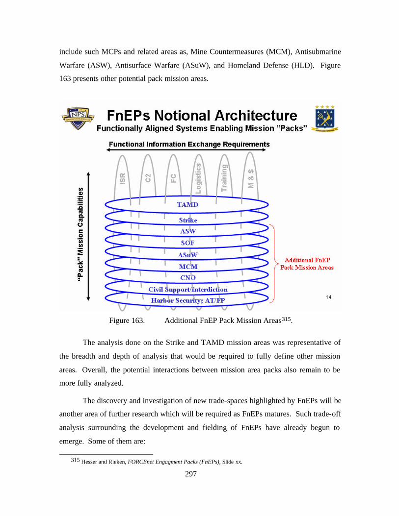
297
include such MCPs and related areas as, Mine Countermeasures (MCM), Antisubmarine
Warfare (ASW), Antisurface Warfare (ASuW), and Homeland Defense (HLD). Figure
163 presents other potential pack mission areas.
Figure 163. Additional FnEP Pack Mission Areas315.
The analysis done on the Strike and TAMD mission areas was representative of
the breadth and depth of analysis that would be required to fully define other mission
areas. Overall, the potential interactions between mission area packs also remain to be
more fully analyzed.
The discovery and investigation of new trade-spaces highlighted by FnEPs will be
another area of further research which will be required as FnEPs matures. Such trade-off
analysis surrounding the development and fielding of FnEPs have already begun to
emerge. Some of them are:
315 Hesser and Rieken, FORCEnet Engagment Packs (FnEPs), Slide xx.
298
• Cost-benefit tradeoffs between more robust networks and smarter weapons
• Roles and missions between manned and unmanned vehicles
• Centralized vs decentralized C2, especially with respect to situational considerations. For example, on the eve of war, C2 is typically centralized to prevent precipitation of unwanted events. As soon as the shooting starts, however, C2 rapidly decentralizes as events unfold.
• Platform-centric vs distributed activities/services
It is reasonable to expect others will come to the forefront as deeper and more thorough
analysis continues within and between various mission areas.
Several new trade-space areas where there will have to be further research
include:
• Determining the balance between management schemas and technology. Just how, when and to what extent is a management schema adequate and optimized for use within the FnEP concept balance with the technology and it’s limitations (whatever those are) on computing, communications, option generation and use of pooled, networked assets.
• Determining the balance between a FnEP capable of guiding a “dumb” weapon all the way through the terminal phase of flight to target impact with that of the capability to put a “smarter” weapon with some low-cost terminal seeker and left to engage the appropriate target given the weapon is within the target error basket. Further, the question of Battle Damage Assessment (BDA) in either of these scenarios is appropriate
• Economic trade-off analysis of network options of tangible and intangible benefits and/or factors as well as the evaluation of risks.
B. FURTHER FNEP DEVELOPMENT EXPANSION AND INTEGRATION
The next area of important consideration for further analysis is the need for
immediate and continual integration beyond Naval assets as the FnEPs (spiral)
development progresses. Critical to realizing the ultimate vision of FORCEnet and
“operationalizing” this concept, FnEPs was established on the premise of joint
interoperability. The primary reason for this is that individually, the services possess
neither the platforms nor capabilities necessary to achieve the five CRCs. While it is
acknowledged joint integration is critical to FnEPs from the beginning and continuous
throughout the entire pack development processes, it is also pragmatic to realize joint
299
integration is a long, tedious process impacted by many things in addition to simply
technical considerations, so integration beyond Naval assets is critical to the FnEPs
concept. Admiral Clark comments,
FORCEnet is an initiative to tie together naval, joint, and national information grids to achieve unprecedented situational awareness and knowledge management . . . FORCEnet will be central to commanding joint operations from the sea.316
A fundamental FnEP objective is the further development of Naval combat reach
capabilities with full interoperability among service components, joint task force
elements and allied/coalition partners. This goal should be supported by high- level
architecture tenets and standards, supported by a strong cross-functional systems
engineering effort across C2, FC and ISR systems. These efforts should result in FnEPs
development coordinated, supported and integrated with both legacy system and
transformational initiative development including the Navy, Army, Air Force, and Coast
Guard.
1. Joint Services
First of all, Joint integration of other U.S. services’ assets as they relate to and can
participate in their appropriate FnEPs development process has to be aggressively
pursued. This is an area that will continue to be a centerpiece of FnEPs and as such, will
require large, ongoing efforts across all services and across a wide variety of systems.
Specific areas or tasks for follow-on research will have to address joint requirements
definition, validation and apportionment of system functionality and funds to specific
services’ systems. Systems engineering processes that address joint, warfighting
integration from pack and combat reach perspectives instead of the traditional stove-
piped system perspective. While there may be initial quick-wins such as the ability to
integrate several existing joint systems into a prototype “pack,” the ultimate vision for
FnEPs is that of fully intergrating joint assets. Particularly important is the identification
and inventory of functionality provided by all systems such that gaps and overlaps can be
identified allowing for mission-specific functionality to be appropriately managed and
migrated into core pack functionality. Initiatives such as the Transformational
316 Admiral Vern Clark, Admiral, U.S. Navy, Chief of Naval Operations. Lecture at Naval War College, Newport, Rhode Island, 12 June 2002.
300
Communications Architecture (TCA), Future Combat System (FCS), Command and
Control Constellation (C2C), Global Information Grid – 2.0 (GIG-2.0), Teleports and
others will have to take into account the requirements generated by the end-to-end
engagement chain focus of FnEPs and could result in new or modified requirements.
2. NATO, Allied and Coalition Partners
Another important area for further FnEPs integration analysis will be system
development, engineering, testing and support such that integration between U.S. military
systems and those of our NATO, Allied and Coalition partners are possible because most
future conflicts will involve U.S. forces operating with forces from many different
countries. The following quotes highlight the importance of this,
The significant involvement of coalition forces in Operation Enduring Freedom –including over 100 ships deployed in Central Asia for an extended period – has re-emphasized the requirement for improved IP data systems interoperability with allied and coalition forces.317
Developing a networked capability will be fundamental to joint and coalition warfighting in the Information Age.318
In addition to the military perspective, Allied and Coalition partner integration is
becoming increasingly important socially, politically, and diplomatically. Within the
FnEPs concept, “packs” will not realize their full warfighting potential until all
participants are fully integrated and contribute their systems and capabilities to “pack”
funictionality. There are foreseeable situations where Allied or Coalition partners are the
only ones with the requisite assets, response times or expertise in order to accomplish a
specific mission. FnEPs must be flexible, adaptable and responsive enough to address
the full spectrum of warfare from peacekeeping to Military Operations Other Than War
(MOOTW) to full force-on-force engagements in response to a wide variety of
asymmetric or conventional threats. In order to accomplish this, FnEPs should be able to
utilize the Allied and Coalition partner capabilities and coevolve complementary, non-
redundant programs and weapons systems. An understanding of ours and their
317 Robert J. Natter, Admiral, U.S. Navy, Commander U.S. Fleet Forces Command, “The Future of Fleet
Information Warfare,” CHIPS, Summer 2002.
318 Mr. Geoff Hoon, Secretary of State for Defense, United Kingdom, Aviation Week and Space Technology, 23 December 2002.
301
capabilities to ident ify overlaps and gaps in system capabilities as well as how these
capabilities fit into the 1-4-2-1 threat scenario would be a logical starting point. One
possible example of Allied interoperability would be the Netherlands’ use of Aegis fitting
into a TAMD “Pack” with U.S. forces. In a new, more dangerous and far-reaching
asymmetric threat environment, FnEPs should be able to conduct major conventional
warfare, but simultaneously have an increasing ability to address unconventional threats
via unconventional methods or conventional methods applied in new ways. These
MOOTW, peace-keeping/peace-enforcement, GWOT, humanitarian missions are and
will continue to require more flexible, adaptable, responsive and scaleable capabilities
reliant on NATO, Allied and Coalition assets.
There will continue to be challenges related to technological advancements,
doctrine, cultural, language, physical resources, trust, security and releasability between
the U.S. and other partners, therefore FnEPs development will have to take these
considerations into account as well. There could also be several challenges related to
simply integrating coalition systems into a “pack” using the same distributed services and
composeable force structures this concept envisions simply because of the wide variation
of systems wanting to be integrated. Research in this area should focus on addressing
these and other challenges related to identifying NATO, Allied and Coalition integration
into FnEPs development.
There may be value added in continued evolution of CENTRIXS across all AORs
helping to provide a common coalition baseline that allows for coordination,
collaboration and a common operational picture in the near term. A longer term prospect
might be to develop a coalition baseline in parallel with a “pack.” There may also have
to be an increased integration and training efforts of coalition partners in FnEPs
development efforts. There also may have to be a redefinition of information
classification and standardization across many functional system domains to match the
principles of NCW.
In focusing on NATO, Allied and Coalition partners, it will be important to
involve as many partners as possible, as early as possible in the FnEP concept
302
development, requirements and warfighting procedures processes such that partner
integration can be a part of the spiral development effort rather than being a bolted-on,
underutilized, marginalized asset.
3. Homeland Security/Homeland Defense
The events of September 11th, 2001
crystallized the American need to secure our
homeland against all kinds of conventional
and unconventional terrorist threats. This has
precipitated the realization that although the
Navy can and will continue to protect
America's security through overseas engagements, the Navy now also must act to take
decisive and deliberate steps to protect our domestic maritime domain and be prepared to
engage threats there as well. In collaboration with Coast Guard the U.S. Navy must be
able to conduct synchronized maritime operations to deter, prevent, and defeat threats and
aggression aimed at our homeland.
FnEPs should be prepared to execute uniquely homeland security or homeland
defense missions while at the same time using proven warfighting capabilities. FnEPs
will have to work with and integrate the U.S. Coast Guard’s important capabilities and
resources available to the Captains of the Ports (COTPs), Groups, Districts and Areas and
keep pace with their fleet modernization initiative, Deepwater. While Deepwater
represents significant integration opportunities by “getting in on the ground floor” of the
development, it should be noted; however, Deepwater is almost totally a fleet
modernization program focused on platform replacement and has much less to do with
modernization of their information systems and architectures. This introduces challenges
due to the broad scope and breadth of homeland security and homeland defense missions
because USCG assets must also be integrated into “packs.” Further FnEPs relies on
system interoperability within a larger coalition of Department of Homeland Security,
Border Patrol, Immigration and Naturalization Service, Drug Enforcement Agency, law
enforcement, FBI, CIA, Canadian and Mexican governments, to name a few. Another
good example of a program which could integrate with FnEPs is the U.S. Customs
303
Agency’s Container Security Initiative. This program could provide information and
decision support, for example, into a homeland defense “pack” improving the defensive
posture of “pack” participants.
In general, the integration of organizations responsible for homeland
security/homeland defense will be an important enabler to FnEPs flexibility, agility and
responsiveness to time-critical threats against the U.S. homeland from many different
domains (e.g., maritime environment, air or land-based). Even other organization such as
the FAA could be important contributors to FnEP functionality. As an example, the FAA
is responsible for the domestic air picture and would be needed to form a complete air
picture for a given “pack.”
FnEPs will have to be designed and “operationalized” to implement Global
Maritime Awareness (GMA) as a key enabler of realizing how the FnEPs concept will
lend operational and organizational structure to providing for homeland
security/homeland defense. The Navy has traditionally focused on providing homeland
security and homeland defense by addressing threats in the forward theater. However, as
threats seek to encroach upon the continental U.S., FnEPs will be the warfighting concept
flexible, agile and responsive enough to act upon that threat irrespective of its theater or
origin. FnEPs will enable the Navy, NORAD and the FAA to monitor air traffic over
home waters. Where the Navy operates in the forward theater, air contacts are tracked as
well as warships. However, the vast majority of vessels in the world are not tracked.
Any one of those vessels could be a threat, so this is the Global Maritime Awareness
(GMA) foundation FnEPs will be able to implement. GMA is a comprehensive
understanding of who or what is in the global maritime setting and who may pose a threat
to the U.S. or its allies319. In pursuing GMA, there currently is no single solution to
gaining effective knowledge of who and what poses a threat to the U.S.’s Sea
Supremacy. 320 FnEPs will address this by bringing together a collection of activities,
systems and pack factors such that the network-centric capabilities afforded to any other
319 Dennis Stokowski, Captain, U.S. Navy and Odom, Curt, Captain, USCG, “Implementing the Concept of
Global Maritime Awareness,” SSG XXII, 30 July 2003, 1.
320 GMA is distinct from the USCG’s Maritime Domain Awareness (MDA) concept in that GMA focuses on global knowledge and tracking of vessels and contracts of interest from their port of origin, while MDA focuses more specifically on protecting U.S. Coastal waters out to the Economic Exclusion Zone (EEZ) only.
304
mission area are applied to defending the U.S. maritime environment as well. A key
element of GMA, FnEPs will have to integrate vessel tracking technologies supported by
new processes and organizational alignments. FnEPs will have to provide a network-
centric ability to carry out GMA’s enmeshment strategy of locating, identifying and
continuously tracking a maritime threat on a global scale. There are areas for future
research on how FnEPs will be able to integrate with other domestic and international
agencies to develop the ability to track INMARSAT-C polling on vessel traffic in
conjunction with efforts already on-going at COMLANTFLT’s Naval Control and
Coordination of Shipping (NCAPS) Organization. The use of the International Maritime
Organization’s (IMO’s) Automatic Identification System (AIS) on military aircraft and
ships is an area that FnEPs would have to utilize in keeping a persistent track of threats
for possible future engagement. Research into how FnEPs would be able to work within
the new Fleet Response Plan and with the USCG to contribute significantly to Homeland
Defense through these integration efforts would be another important mission area.
FnEPs should be able to seamlessly integrate Coast Guard Deepwater and legacy assets
into the homeland defense “pack” such that missions like Maritime Interception
Operations (MIO) or surging a CSG or ESG during the sustain-readiness phase of the
IDTC to conduct Homeland Defense operations on short notice is possible. The mission
area of mine countermeasures also seems to be particularly important to FnEPs because
the Navy is the only service capable of this mission area, yet many other service and
government agency assets would be involved if there were a mine threat in the U.S.
maritime environment. The National Maritime Intelligence Center (NMIC) would be a
key part of future FnEP research to implement GMA because NMIC does a good job in
tracking a small number of vessels of interest and mining information out of various
databases. However, NMIC is advantageously positioned to establish a critical, central
fusion point for GMA information which should evolve into a comprehensive joint and
interagency operation, a key part of the end to end engagement focused activities of
FnEPs321. There will have to be substantial research efforts between the Department of
Homeland Security, USCG, Customs and other agencies to understand and help integrate
military unique defensive capabilities into the entire civil defense and civil support
321 Ibid., 2.
305
picture of homeland defense from the maritime environment when called upon to do so.
Homeland defense from an air and ground picture would involve NORTHCOM, NORAD
and others being involved with FnEPs development, testing and implementation to assure
those FnEPs defensive (and as needed offensive) capabilities would be integrated into the
entire homeland defense picture. Within the domestic maritime environment, FnEPs will
need to be integrated with the Joint Harbor Operations Centers (JHOCs) to expand the
awareness and control of vessel movements in harbor areas. Organizational research
with COMLANTFLT, COMPACFLT, Commander Navy Installations, NORTHCOM,
COMTHIRDFLT, COMSECONDFLT, PACOM, ALCOM, USCG PAC and LANT
Area Commanders, USCG District Commanders and Captains of the Ports (COTPs) will
ensure FnEP development takes into account the Navy and Coast Guard’s systems, TTPs,
and mission area responsibilities such that the five CRCs are available to defend the U.S.
maritime area as well as any forward theater. FnEPs will help to “operationalize”
FORCEnet within the domestic maritime environment as a more definitive approach to
GMA emerges. With an expanded JIATF organization that not only focuses on drug
operations in SOUTHCOM’s AOR but leads GMA efforts off the entire coastal area of
the U.S., FnEPs will drive system integration with USCG, Customs, INS, Border Patrol
and other agencies’ system capabilities to provide a complete and through defensive
posture which becomes increasingly harder to penetrate as a threat encroaches the U.S.
maritime environment from international waters.
In conclusion, the abilities of FnEPs-employed homeland defense resources will
enable the Navy to be proactive and “manage” the threat, rather than remain reactive and
remain defensive. Here, “managing” implies a certain control over the threat whether it
be by controlling information, its means of transportation, it's ability to deliver a weapon,
or whatever effect-based operation is deemed necessary.
C. EXPANSION OF FORCENET ENGAGEMENT PACK INTEGRATION
There are also several categories of functional data interchange systems that will
support and enable FnEPs. In addition to the core functional data interchange systems
addressed in this thesis (Command and Control (C2), Fire Control (FC) and Intelligence,
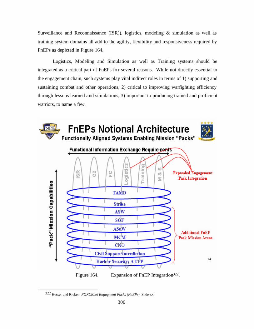
306
Surveillance and Reconnaissance (ISR)), logistics, modeling & simulation as well as
training system domains all add to the agility, flexibility and responsiveness required by
FnEPs as depicted in Figure 164.
Logistics, Modeling and Simulation as well as Training systems should be
integrated as a critical part of FnEPs fo r several reasons. While not directly essential to
the engagement chain, such systems play vital indirect roles in terms of 1) supporting and
sustaining combat and other operations, 2) critical to improving warfighting efficiency
through lessons learned and simulations, 3) important to producing trained and proficient
warriors, to name a few.
Figure 164. Expansion of FnEP Integration322.
322 Hesser and Rieken, FORCEnet Engagment Packs (FnEPs), Slide xx.
307
1. Logistics Systems
Logistics system information, when integrated into a “pack,” will be able to
provide just- in-time logistic supplies, maintenance requirements and anticipatory
warfighting needs, all critical to keeping the engagement chain working. These logistics
systems, as integral PFs, will be able to demonstrate the application of combat
effectiveness of ‘user interface agents’ working with the ABMAs that automatically
notify crews and schedule required corrective maintenance actions when ammunition or
other warfighting supplies need replenishment. Such notification will be based on in- line
condition or utilization of monitoring data, and will serve to update commanders and
other decisison makers regarding the status of their forces. Other related capabilities
include the ability to compute mileage a vehicle can travel based on fuel capacity and
proposed mission parameters. It is important to note DoD’s Office of Force
Transformation’s Sense and Respond Logistics (S&RL) Concept of Operations shares
many parallel characteristics with that of FnEPs. The Office of Force Transformation’s
draft SLRC Functional Concept323 document describes S&RL as “an adaptive method for
maintaining operational availability of units by managing their end-to-end support
network.” The document goes on to describe its prominent characteristics, which include
the following:
• It is a functionally-organized network of units (as opposed to a hierarchical organization)
• All units within that network are potential consumers and providers of supply to and from all other units in the network
• Units dynamically synchronize to satisfy demand in respond to changes in the environment.
Further, OSD Office of Force Transformation identified the following key ideas of the
S&RL Concept:324
• Assume demand is ultimately unpredictable, so success depends on speed of pattern recognition and speed of response
• The best supply chain is no longer one that is highly optimized, but one that is highly flexible
323 OSD Office of Force Transformation, SRLC Functional Concept, (Draft Version), (20 June 2003).
324 Linda Lewandowski, S&R Project: Co-Evolution of an Adaptive Logistics Capability, OSD Office of Force Transformation, 30 May 2003.
308
• Organizes business units and subunits into “modular capabilities” that negotiate with one another over commitments
• Networks “self-synchronize” via a common environment and set of shared objectives; typically business financial and customer satisfaction measures
• Depends on sophisticated IT support to enable data sharing, “knowing earlier,” commitment tracking, and role reconfiguration
In short, S&RL aligns closely with FnEPs in that it is based upon highly adaptive,
self-synchronizing, dynamically reconfigurable demand and supply networks that
anticipate and stimulate actions to enhance capability or mitigate support shortfalls. Like
FnEPs, S&RL will change the way we interact with producers and consumers of
information, as well as fundamental interactions between Service entities that will no
longer have stovepiped logistics systems that cannot communicate. As outlined in the
S&RL Conops, support bases and end-to-end pipelines will be devoid of color and the
supply network will be dynamically reconfigurable utilizing all of the DoD and its
partners resources to meet customer demands directly in a timely manner. In addition,
because of the new capabilities, the S&RL system will provide enhanced options for
operational activities that were previously nonexistent.325
2. Modeling and Simulation Impacts on/by FnEPs
Integrated into FnEPs, modeling and simulation systems could possibly capture
and store, for later use and analysis, real-world warfighting activities to be used in
doctrine refinement or new tactical procedures. The use of modeling and simulation
systems as ‘quiet observers’ of pack activity could help answer many questions like;
when and where should “packs” form, how “packs” should form, what resources should
“packs” use, when should those resources be used and from whom, threat engagement,
better sensor-weapon-shooter linkages, etc. Modeling and simulation systems as pack
components could also be important for real-world, deployment training and work up
exercises, helping to make the Fleet Response Plan an exercise in honing warfighting
skills using real-world, relevant and current environments yet in a simulated and
protected environment for exercise. The area of modeling and simulation as it impacts
the development of FnEPS and conversely how FnEPs could influence the use,
325 OSD Office of Force Transformation, Sense and Respond Logistics Concept of Operations (SRLC), (Draft
Version 1.0), (4 August 2003), 5.
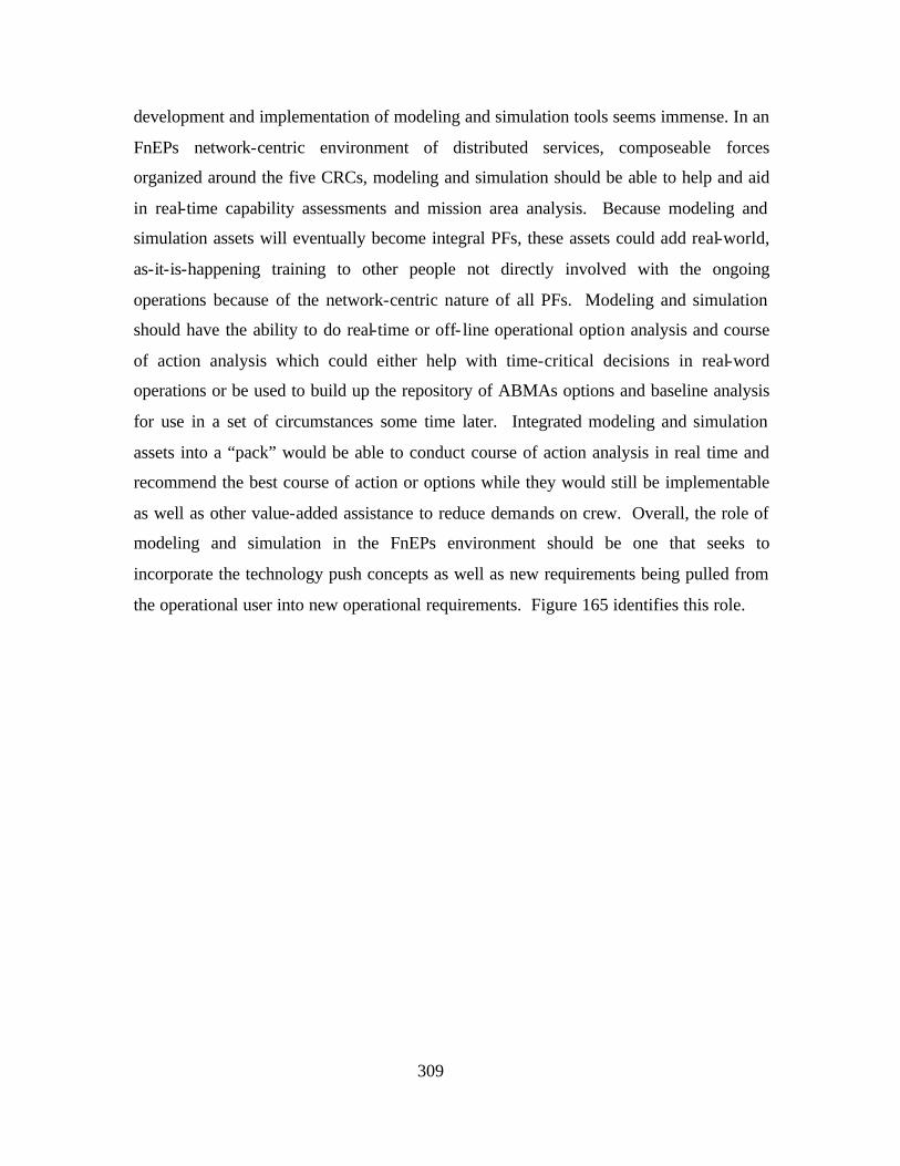
309
development and implementation of modeling and simulation tools seems immense. In an
FnEPs network-centric environment of distributed services, composeable forces
organized around the five CRCs, modeling and simulation should be able to help and aid
in real-time capability assessments and mission area analysis. Because modeling and
simulation assets will eventually become integral PFs, these assets could add real-world,
as-it-is-happening training to other people not directly involved with the ongoing
operations because of the network-centric nature of all PFs. Modeling and simulation
should have the ability to do real-time or off- line operational option analysis and course
of action analysis which could either help with time-critical decisions in real-word
operations or be used to build up the repository of ABMAs options and baseline analysis
for use in a set of circumstances some time later. Integrated modeling and simulation
assets into a “pack” would be able to conduct course of action analysis in real time and
recommend the best course of action or options while they would still be implementable
as well as other value-added assistance to reduce demands on crew. Overall, the role of
modeling and simulation in the FnEPs environment should be one that seeks to
incorporate the technology push concepts as well as new requirements being pulled from
the operational user into new operational requirements. Figure 165 identifies this role.
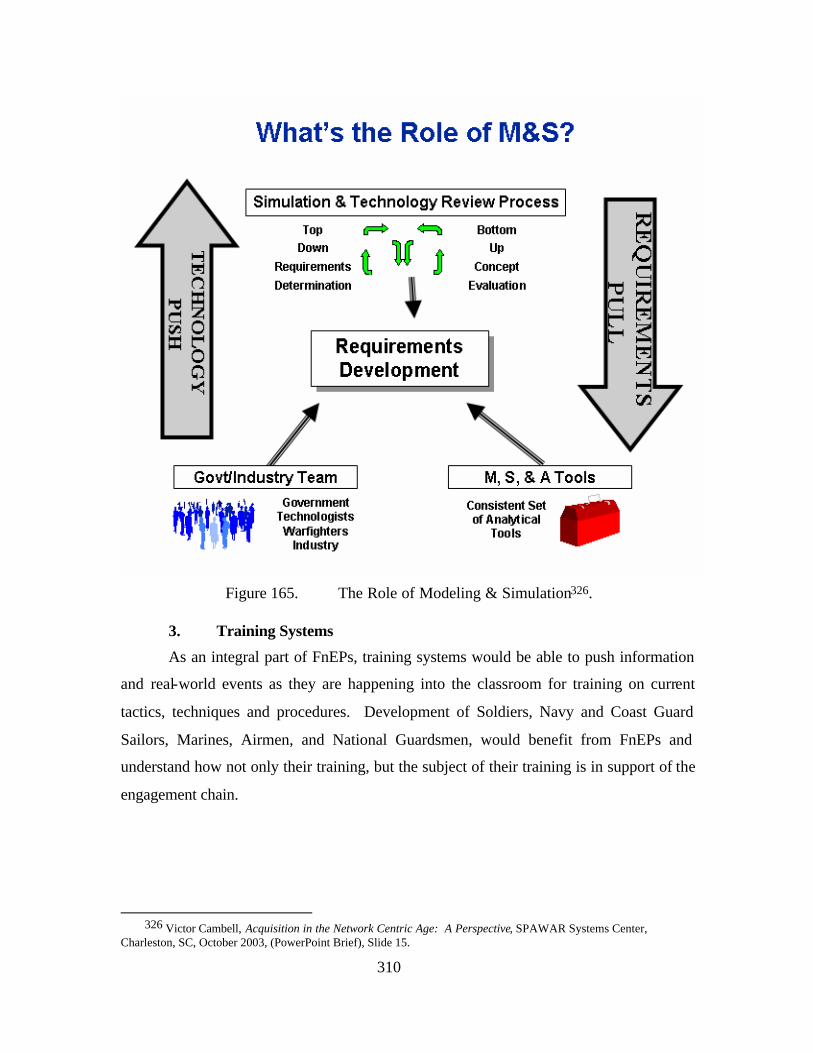
310
Figure 165. The Role of Modeling & Simulation326.
3. Training Systems
As an integral part of FnEPs, training systems would be able to push information
and real-world events as they are happening into the classroom for training on current
tactics, techniques and procedures. Development of Soldiers, Navy and Coast Guard
Sailors, Marines, Airmen, and National Guardsmen, would benefit from FnEPs and
understand how not only their training, but the subject of their training is in support of the
engagement chain.
326 Victor Cambell, Acquisition in the Network Centric Age: A Perspective, SPAWAR Systems Center,
Charleston, SC, October 2003, (PowerPoint Brief), Slide 15.
311
D. DOCTRINE ORGANIZATION TRAINING MATERIAL LEADERSHIP PERSONNEL AND FACILITY (DOTMLPF)
The area of DOTMLPF is an
overarching area of activities which will also be
impacted by and on the FnEPs concept to
varying degrees. This section’s purpose is to
simply highlight some of these perceived
possible impacts and briefly explore why future research in these areas will be needed.
Doctrine – The new edition of Naval Doctrine Publication (NDP) 1: Naval
Warfare, scheduled for completion in 2003 by the Naval Warfare Development
Command (NWDC) will be the Navy’s first servicewide doctrinal document in 50
years327. The new NDP-1 will be written from the operational art perspective and will
focus on the employment of U.S. numbered and theater forces at the operational level of
war328. The concept of FnEPs will have eventual impacts on NDP-1 because FnEPs will
impact the Navy’s view on the employment of its forces in joint and combined major
operations and campaigns. Critical to FnEPs is communication and integration among
services and with allies and coalition partners which will have to be addressed in NDP-1.
With FnEPs being a flexible, adaptable and self-synchronizing way of conducting NCW,
NDP-1 will have to be an equally broad, flexible framework for the employment of naval
forces in peacetime and wartime and throughout the entire spectrum of conflict. FnEPs
creates an environment for Naval forces to be employed in many new ways, given their
reliance on composeable forces and distributed services. The network-centric manner in
which the five CRCs will be implemented and fought within FnEPs will drive changes to
planning, preparation, execution and sustainment of major naval operations as well as
asymmetric threats as a part of joint or combined operations. NDP-1 should be based on
the idea of achieving Sea Supremacy within the context of SEA POWER 21 and how this
strategic vision will be possible within the FnEPs concept. Warfighting operations have
traditionally been conducted in a ‘waterfall’ or sequential approach, under FnEPs,
operations will become more spiral, parallel and multi-threaded instead of a deliberately
327 Milan Vego, “New Doctrine Must Be Flexible & Dynamic,” Proceedings, May 2003, 75. 328 Ibid.
312
phased approach. This mode of operations could quite possibly become more
experimentally dependent, hence the increased and vital role of the modeling and
simulation pack assets. Even though NCW is focused on the tactical level of war at sea,
FnEPs has operational and strategic implications to how warfare will be conducted in the
future, which brings to bear the full potential of NCW. NDP-1 will have to examine how
doctrinal changes related to the FnEPs concept will impact the tactical, operational and
strategic levels of warfare. Improvements as a result of FnEPs will also impact the
Navy’s capabilities, including how the Navy is employed, coordinated and integrated
with the other services’ doctrines. In an FnEPs focus on distributed services and
composeable forces, the idea of operational art will evolve due to the fundamental
decisions about when, where and how to fight and then, to what severity combat
operations will be involved. The identification of a center of gravity or a concentration of
combat power is now totally transformed within the FnEPs concept. With distributed
forces and services integrated along the engagement chain, the center of gravity may also
be much more distributed and certainly, the combat capabilities are, making them harder
to counter.
In conclusion, FnEPs will also change the Navy’s culture as highlighted by the
following quote:
commonly held, concisely stated, and authoritatively expressed beliefs, fundamental principles, organizational tenets, and methods of combat force employment intended to guide the planning, preparation, and combat employment of one’s forces to accomplish given military objectives.329
Dudley Knox, writing for Proceedings in 1915 on the role of doctrine in naval
warfare, noted that no matter how well ships perform individually, “they must be welded
into a body” that “can act collectively” before they are ready for action. 330 FnEPs is the
tactical level instantiation of this collective action.
329 Ibid., 77. 330 Ibid.
313
Organization and Process – Due to the horizontal, engagement chain focus of
integration with the emphasis on the five CRCs, organizations and their boundaries will
become increasingly blurred. The organizational effects of FnEPs may be many within
and between organizations now forced to integrate in this new defined manner. With
FnEPs forcing organizations to migrate from being focused on individual weapon
systems and platforms to Joint Mission Area Acquisition Programs and supporting
research, development, and engineering across
mission areas in support of the engagement
chain, there quite possibly will be many
implications on how organizations will address
this challenge. A diffusion of system functions
will cause system and program dependencies to
drive portfolios of system functions (i.e., capabilities) rather than individual system/s
cost/benefit analysis driving the capabilities fielded. Currently existing ‘rice bowls’ and
‘stove-piped’ system boundaries could possibly become so blurred, organizational
boundaries will exist only to serve administrative personnel needs vice facilitating
execution of specific missions. Organizational mission work could quite possibly move
in the same ‘pack’ direction to support and be aligned with mission areas rather than
specific systems. Currently, our society is undergoing a transition from the Industrial
Age to the Information Age. New technology has been a tremendous driver in this
transition, but as Figure 166 depicts, while technological change has been exponential,
social, business, and political changes have lagged.
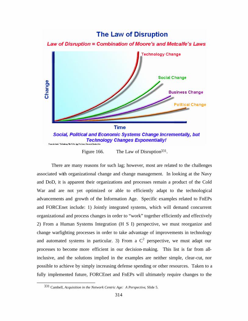
314
Figure 166. The Law of Disruption331.
There are many reasons for such lag; however, most are related to the challenges
associated with organizational change and change management. In looking at the Navy
and DoD, it is apparent their organizations and processes remain a product of the Cold
War and are not yet optimized or able to efficiently adapt to the technological
advancements and growth of the Information Age. Specific examples related to FnEPs
and FORCEnet include: 1) Jointly integrated systems, which will demand concurrent
organizational and process changes in order to “work” together efficiently and effectively
2) From a Human Systems Integration (H S I) perspective, we must reorganize and
change warfighting processes in order to take advantage of improvements in technology
and automated systems in particular. 3) From a C2 perspective, we must adapt our
processes to become more efficient in our decision-making. This list is far from all-
inclusive, and the solutions implied in the examples are neither simple, clear-cut, nor
possible to achieve by simply increasing defense spending or other resources. Taken to a
fully implemented future, FORCEnet and FnEPs will ultimately require changes to the
331 Cambell, Acquisition in the Network Centric Age: A Perspective, Slide 5.
315
very cultures of DoD and the individual services, a change which can only occur
incrementally over time, through a combination of education and commitment across all
levels of organization.
Training, Tactics and Procedures (TTPs) within an FnEPs environment – Tactics,
Techniques and Procedures (TTPs) to operate in an FnEPs environment will be one of the
transformational aspects of FnEPs. Everyone from E-1 to O-10 will have to understand
how operating in an FnEPs environment increases their warfighting capabilities and how
best to take full operational advantage of the tools FnEPs brings to warfighting. The
operational implementation training on how, when, with whom and under what
circumstances an FnEPs “pack” can be utilized and fought will have to be examined.
Training in distributed, collaborative, flexible and adaptable joint environments with
composeable warfighting services and a number of different PFs will require new
warfighting management, C2 and system understanding in a FnEPs environment. The
implications and processes of how decisions will have to be made, how to evaluate
options, understand new consequences and still operated effectively against a wide range
of time-sensitive and asymmetric threats in a FnEPs environment will also be needed.
The overall role of the training community will be to provide an early and continuous
training context within the FnEPs environment and to assess the impacts of or
implications to TTP and Doctrine on/as a result of design concepts like FnEPs. Training
activities should be able to provide a trained crew simultaneously with the first fleet
deployment, which means crew training must be done simultaneously as the FnEPs
prototype “pack” and other related development efforts mature. Training must be an
integral part of FnEPs as software and simulation are reused to support embedded and
distributed training, operational planning, course of action analysis and becomes an
indistinguishable part of a deployed capability. FnEPs tries to elicit a warfighting
organization which can evolve to cover multi-missions and have a cross-trained, adaptive
force.
Material – Material considerations in light of FnEPs will have impacts based on
the new horizontal integration efforts between functional system areas. Systems will
have to be redesigned and reengineered over the course of time as a result of system
functionality gaps, overlaps and realignments take place to implement the five CRCs.
316
Over the course of time, this will cause systems to be retired, legacy system functionality
realigned or new systems developed to cover gaps in functionality needed to realize the
CRCs. Because of this end-to-end engagement chain integration focus of systems around
mission areas, there will also be new requirements for support equipment and material
not previously needed in the current stove-piped environment.
Leadership-Impacts of FnEPs onto the Information Professional (IP) Officer and
IT Rating Communities – Another area for further research is envisioned to be how the
Information Professional (IP) officer community and the Information Technology (IT)
rating community (among others) would be involved in the engagement chain processes
as envisioned or as impacted by FnEPs. This could very well be the key to the future
viability of the IP community. Specifically, IPs and ITs could have vastly different roles
in the warfighting community than they currently do. In a truly network-centric
environment where the pack has the capabilities envisioned, the IP and IT communities
are going to be critical to helping to establish and maintain the collaborative efforts
amongst all warfighting assets throughout the entire engagement chain. This research
area would help to lend an understanding to the various facets of how the IP and IT
communities would enable FnEPs. The IP and IT communities will be in a new role
where visibility and active participation in the entire engagement chain coupled with an
understanding of network and communication systems/technologies will help fuel smart
disinvestment decisions on where C4ISR systems can and should be realigned to
recapitalize money for new investments. Research activities in this area can help
understand how the IP and IT communities can support the war fighter through out the
engagement chain, much like the Intelligence community does today, but with a
deliberate focus. Research in this area would help to understand how the IP can become
a fully integrated member of the warfighting team, with both supported and supporting
roles across all warfare areas. In the supported role, IP’s are a member of the team that
executes the engagement chain. In the supporting role, IP skills enable the Commander’s
decision making and execution at every step. FnEPs will enable the IP and IT
communities to assume both roles and perhaps define new ones, within the engagement
chain. Future research in this area will help to show how these communities will help
enable and advance warfighting capabilities and the Naval Combat Reach through their
317
unique set of combat skills. Possible questions for this research to answer could be, what
will be the impact of FnEPs to Operations Relevance, the Information Warrior, and/or
Operational and Technical expertise? How can IPs and ITs further the understanding of
the doctrinal role of the IP in the naval command structure and the role of the IP in the
enterprise as it is focused on the engagement chain. Within the context of FnEPs, how
can the Navy utilize IP and IT experience and expertise to reduce overall “Total Cost of
Ownership (TCO)” of information/C4I systems, services and/or products as they relate to
the engagement chain? This research can hopefully generate a clear definition of IP and
IT community roles which will enable more efficient assignment of personnel and more
efficient use of training resources as they are related to warfighting capabilities and the
engagement chain.
Personnel – In the area of personnel, FnEPs could possibly have impacts on such
things as how human resources are tracked, assigned, employed and managed. Having
human resources assigned to pack assets, if a “pack” asset needs certain human resources
because of a specific set of circumstances, or during the normal course of duty rotations,
there could feasibly be an avenue for the “packs” to interface with other systems to
address this need.
Facility – Lastly, in the area of facilities, the FnEPs concept might have primary
or secondary impacts on facilities used to house, develop, test, implement or operate
these CRCs. Platforms may be impacted by form, fit and function of systems used to
implement the CRCs. There may need to be modified or new facilities built to facilitate
interoperability between the sea, air and land domains as well as interoperability between
NATO, allied and coalition partner support facilities. Facility impacts within mission
areas, especially one like homeland defense, may be realized when military and
homeland defense-oriented government agencies are required to interoperate and work
together.
E. OTHER FNEP INFLUENCING FACTORS
There will also need to be an understanding of how FnEPs will both influence and
be influenced by other challenges internal and external to DoD within the Defense
Planning Systems shown in Figure 167.
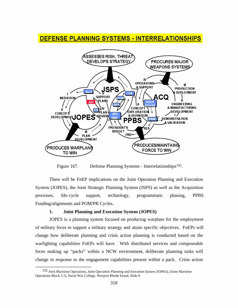
318
Figure 167. Defense Planning Systems - Interrelationships332.
There will be FnEP implications on the Joint Operation Planning and Execution
System (JOPES), the Joint Strategic Planning System (JSPS) as well as the Acquisition
processes, life-cycle support, technology, programmatic phasing, PPBS
Funding/alignments and POM/PR Cycles.
1. Joint Planning and Execution System (JOPES)
JOPES is a planning system focused on producing warplans for the employment
of military foces to support a military strategy and attain specific objectives. FnEPs will
change how deliberate planning and crisis action planning is conducted based on the
warfighting capabilities FnEPs will have. With distributed services and composeable
foces making up “packs” within a NCW environment, deliberate planning tasks will
change in response to the engagement capabilities present within a pack. Crisis action
332 Joint Maritime Operations, Joint Operation Planning and Execution System (JOPES), (Joint Maritime Operations Block 5.1), Naval War College, Newport Rhode Island, Slide 9.
319
planning will also be changed because FnEPs are specifically designed to be flexible,
adaptable across all mission areas and focused on the end-to-end engagement chain
process. There will be impacts into how OPLANs, CONPLANs and Functional Plans are
produced and documented in light of how “packs” are envisioned to operate. The manner
in which TPFDDs are produced and carried out could foreseeably be changed
significantly given the ABMAs function within FnEPs. TPFDDs could be automated by
the ABMAs such that plans for scheduling and movement of foces, loading of
transportation (e.g., size, weight, deck space, etc.) and dispersion of routing deploying
units to the AOR would be automatically produced. The deliberate and crisis action
planning processes would take advantage of the five CRCs to make the strategic
planning, movement and execution more automated, efficient and optimized in response
to GWOT, terrorism or asymmetric threats so that the combat response is more flexible,
adaptable and takes advantage of distributed services to put composeable forces in place
to neutralize the threat in a much more timely manner. The automated generation and
processing of TPFDD, Warning, Planning, Alert, Execute, Deployment Fragmentary
(FRAGO’s) Orders by ABMAs and supported by integrated logistics systems using
humans as decision makers would make the planning products fully integrated,
transportionally feasible, logistically adequate, politically acceptable and executable
within an optimized set of criteria. The implications for the importance of integrating
training, modeling & simulation as well as logistics systems into a “pack” are
unmistakable within this context. Those systems must be integral to FnEPs to support all
the Defense Planning Systems.
2. Joint Strategic Planning System (JSPS)
The Joint Strategic Planning System is responsible for producing strategic
planning documents like the Defense Planning Guidance (DPG) which articulate the roles
and objectives of the military within the National strategic objectives. While the direct
impact FnEPs might have in the production and planning aspects of these documents may
be small, FnEPs will have significant indirect impacts. With the combat capabilities
FnEPs will possess, the options for strategic planning and what the nation will be capable
of doing militarily will definitely impact the contents of these planning documents. With
flexible, adaptable capabilities integrated across multiple mission areas and focused on
320
the engagement chain there will be many more options available to be employed within
the wide spectrum of conflict. These new combat options will present the planners
within the JSPS system more flexibility when developing these plans.
3. Acquisition Business Processes
The acquisition business processes are ones which will have an influence on and
be influenced by FnEPs. The way PFs are acquired will also be influenced by FnEPs.
The current method of platform-centric acquisition will not support a FnEPs concept
because it has no other choice but to continue creating stove-piped and independent
systems which are not necessarily supportive of an engagement-oriented concept like
FnEPs. Senior Lecturer Rex Buddenberg makes some excellent observations regarding
the unsuitability of the current “program manager methodology”:
But as we consider how to build large1 information systems, we find that the conventional program manager methodology does not work - at least not without some modification. Information systems cut across multiple platforms. Indeed, interoperability impacts an indefinitely large number of diverse platforms when we consider multiple services and allies as within the scope of 'enterprise wide'. It is not conceivable that we would give any program manager that much authority. Further, if we tried, the mega-program would be so large that it would collapse of its own weight. Indeed, the landscape is littered with far less sizable information system programs that have failed.”333
Rex Buddenberg continues by assessing the need for multiple program managers
to have the central authority and “teeth” to force such a plurality of managers to “play
nicely together in the sandbox.” Rex Buddenberg recommends tackling the problem of
building our architectures in two stages:
• First, require all information systems to be cross-program interoperable. How to achieve this is the subject of the referenced paper.
• Second, include the interoperability requirements in each program manager’s charter.
One observation on the impact of architecture design by “committees”:
All of the existing `architecture' documents are a product of committees7. Enter the natural bureaucratic, committee tendencies: reach a common denominator that all on the committee can agree upon. Motivation was less to do something good; more not to do something bad. As a result, we
333 Buddenberg, 1.
321
got deforestation without compensation8. Some of the standards are mutually contradictory and unnecessarily complicated, but that's secondary: none of these committees produced anything so risky as a real architecture. Ironically, we seem to have produced the inverse of the crypto system that is described by Lt Keefer to Ens Willie Kieth in The Caine Mutiny: “The Navy is a master plan designed by geniuses for execution by idiots9.” We can all agree that standards are a necessary part of architecture. But the various Joint Technical Architectures are mere collections of standards - not architecture10. The committees tended to work on the things they knew how to work on - compendia of standards - rather than the things that needed to be worked on. This well-meaning work has diverted us from the main objective of an architecture.334
Also, Moore’s Law precludes successful acquisition in traditional 10-20 year time
frames, especially within an FnEPs environment. Collaboration between users, builders
(industry and program managers) and trainers will occur concurrently through integrated
digital environments in which data is transferred seamlessly across COTS and non-COTS
tools and applications.
a. Requirements Generation and Validation
Requirements generation and validation will have to be relooked at now
that an end-to-end, engagement chain, perspective is being used and the five CRCs are
the focus. Requirements generation and validation processes will also have to be
relooked at because of the integration requirements of cross-functional domain
requirements. C2, FC and ISR systems still need to be integrated with other C2, FC and
ISR systems, but they now also must interoperate with each other horizontally across C2,
FC and ISR domains as well. This could possibly have far-reaching impacts into system
modularization, decisions of which system maintains which functionality, commonality,
standardization and interoperability amongst all service initiatives instead of stove-piped
interests and specific warfighting domain requirements. This will foster and demand a
much more wide ranging understanding of requirements traceability and cross
functionality. The role of the requirements community will be to provide continuous user
operational context of the requirements from an overall end-to-end engagement
perspective, that is, provide an understanding of the operational environment, viewpoint
and surrounding set of circumstances which will help the acquisition community make
334 Ibid. 3.
322
cost/performance and other tradeoff analysis meaningful in an FnEPs environment. The
requirements generation and validation community will have to identify, early-on, the
unrealistic requirements and certain enabling technologies which may help FnEPs grow
and mature. This will require a much more integrated understanding of cause and effect
analysis amongst and between links in the systems which make up the “packs.” The
requirements community will also have to help address life cycle cost concerns earlier
than anyone else in the acquisition community due to this pack asset integration
perspective.
b. Testing
Testing requirements, scenarios and other testing procedures will have to
be done within a “pack” and consequently, focused on the engagement chain, rather than
on just specific individual system testable criteria which may or may not be related to the
overall CRC functionality or furthering the maturation of the CRCs.
c. Logistics
Logistics will now have to understand linkages from warfighting activities
to logistics-based requirements of warfighting sustainment in a time-critical,
collaborative environment.
d. Contract Management
All aspects of contract management will now be focused on integration
and interoperability of pack components, because if a new PF does not integrate with a
pack, it doesn’t get to the fight. RFIs, proposals, FARs, contract evaluation,
administration, even incentive fees and how the contracts are structured will have to be
synchronized within the “pack” and it’s requirements for warfighting, mission
requirements and engagement chain implications.
e. Program Management Incentivization
Program managers will have to be incentivized to deliver integrated and
non-duplicitive systems that fill a critical niche to the pack, but do not utilize fiscal
resources to implement functionality better suited for another system, either within or
external to the PM’s service. By reducing duplicative functionality, resources will be
saved thereby incentivizing PMs who will be permitted to keep such savings in order to
further develop other requirements.
323
4. Life-Cycle Support
Life-cycle support and maintenance must be planned, resource and implemented
on the timeframe compatible with all PFs if the “packs” are to be viable warfighting
assets. There must be a way for life-cycle support to be conducted without adversely
impacting the “packs” flexibility, responsiveness, agility or warfighting capabilities.
Life-cycle support will have to be delivered in new ways, perhaps more in-situ than
before.
5. Technology Drivers
Moore’s Law also indicates that technologies will require a more iterative and
experimental approach to drive the cost down. Technology drivers will need to be
planned for, their integration managed and easily supported or readily identified by PFs.
Evolutionary technology insertion as it relates to implementation analysis and trade-offs.
Technology drivers will help to push pack capabilities to new levels of maturation and
capability, while they will also have secondary effects on many other areas such as
support, training, etc.
6. Programmatic Phasing
The FnEPs concept will require programmatic phasing to be addressed in such a
manner that will allow multiple individual programs, and systems and other PFs, to be
separately funded, developed and supported while maintaining a consistent pack
integration schedule to deliver a capability at some predetermined point in time. For
example, terminals can not be years ahead or behind of their supported satellite or
weapon system launchers can not be still in development while the missile is
independently designed, tested and fielded (by another service). If programs become out
of schedule alignment, there will have to be a way to ensure the “pack” capability is
developed together, so funding and/or time would have to be reallocated across programs
and across services to maintain the integrity of the overall capability’s development.
7. Technical Impacts of FnEPs on Current Programs of Record
In addition to the program management aspects of current programs, there are
engineering aspects to current programs of record which will be impacted by FnEPs. As
a result of the FnEPs concept and its attendant requirements for flexibility, agility, and
cross-mission area integration on-the-fly, these new requirements should cause a re-
324
examination of programs already under development to assess if the currnet programs
will support these future warfighting requirements. Numerous ongoing programs of
record and other initiatives should be assessed to determine their ability to support FnEPs
through their current forms. These include:
• Programs such as; NIFC-CA, DCGS, JFN
• Iniatives such as FORCEnet distributed services/composeable forces and horizontal fusion
• Research and development projects such as ONR’s DWC and other Future Naval Capabilities (FNCs)
Some initial insight came into this from a detailed look at the Engage-On-Remote
(EOR) sequence being used in the NIFC-CA program. While the currnet sequence was
certainly able to be overlayed into the FnEPs concept, there were additional engineering
issues of interfaces and data sharing which were brought out by the capabilities needed to
make a ‘Pack’ operate. Also as an example, in conducting our research, we learned
programs such as the Transformational Communication Architecture (TCA) and Mobile
User Objective System (MUOS) Satellite Programs will probably not be able to support
the FnEPs concept for an integrated, networked warfighting environment under their
current system engineering plans. The ability to support highly mobile, sometime
autonomous, networked, PFs in a highly flexible, adaptable and composeable force based
on networked, distributed services in a time-critical environment should be critcally
looked at. The ability to meet simple challenges with geosychronous time delays,
multiple decryption and reencryption times, information processing times and the ability
to route data to the end user within very time-critical threshholds seems doubtful at best.
With TCA achieving IOC shortly after IOC for FnEPs Block I, TCA must support FnEP
CRC requirements at IOC, therefore planning and system engineering efforts must begin
now in earnest. This kind of detailed analysis of how the current programs of record fit
underneath and hang together under this new FnEP integration concept will also be a
critical, continuous process.
8. PPBS Funding, Funding Alignments and POM/PR Cycles
Funding considerations, POM and PR cycles which attempt to find money, pay
unexpected DoD fiscal bills or the general management of fiscal funds within DoD will
have to understand how impacting a programs funds (i.e., taken away) will impact not
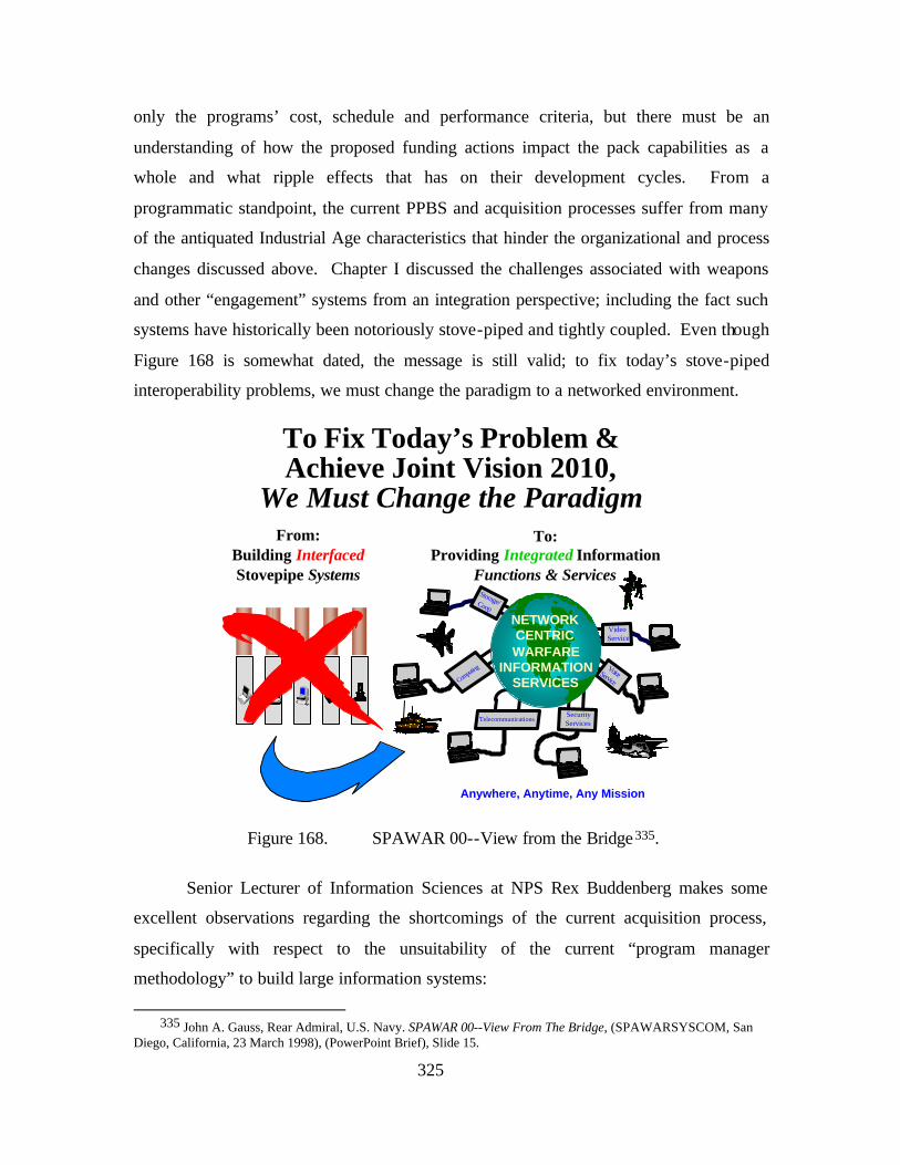
325
only the programs’ cost, schedule and performance criteria, but there must be an
understanding of how the proposed funding actions impact the pack capabilities as a
whole and what ripple effects that has on their development cycles. From a
programmatic standpoint, the current PPBS and acquisition processes suffer from many
of the antiquated Industrial Age characteristics that hinder the organizational and process
changes discussed above. Chapter I discussed the challenges associated with weapons
and other “engagement” systems from an integration perspective; including the fact such
systems have historically been notoriously stove-piped and tightly coupled. Even though
Figure 168 is somewhat dated, the message is still valid; to fix today’s stove-piped
interoperability problems, we must change the paradigm to a networked environment.
To Fix Today’s Problem &Achieve Joint Vision 2010,
We Must Change the ParadigmFrom:
Building InterfacedStovepipe Systems
To:Providing Integrated Information
Functions & Services
Computi
ng
Storage/Coop
TelecommunicationsSecurity Services
VoiceService
VideoService
NETWORKCENTRICWARFARE
INFORMATIONSERVICES
Anywhere, Anytime, Any Mission
Figure 168. SPAWAR 00--View from the Bridge335.
Senior Lecturer of Information Sciences at NPS Rex Buddenberg makes some
excellent observations regarding the shortcomings of the current acquisition process,
specifically with respect to the unsuitability of the current “program manager
methodology” to build large information systems:
335 John A. Gauss, Rear Admiral, U.S. Navy. SPAWAR 00--View From The Bridge, (SPAWARSYSCOM, San
Diego, California, 23 March 1998), (PowerPoint Brief), Slide 15.
326
Information sys tems cut across multiple platforms. Indeed, interoperability impacts an indefinitely large number of diverse platforms when we consider multiple services and allies as within the scope of 'enterprise wide'. It is not conceivable that we would give any program manager that much authority. Further, if we tried, the mega-program would be so large that it would collapse of its own weight. Indeed, the landscape is littered with far less sizable information system programs that have failed.336
We agree with Buddenberg’s assessment, however, we believe there also needs to
be a central authority with the “teeth” to force these PM’s to work together. Buddenberg
suggests the following steps to address the challenges presented above
• First, require all information systems to be cross-program interoperable.
• Second, include the interoperability requirements in each program manager's charter.
We would add to these recommendations the need to “modernize” the acquisition
process in order to better incentivize PM’s to achieve these interoperability requirements.
Unfortunately, without changes in programmatic and acquisition processes, such
challenges are likely to remain. More specifically, and as highlighted previously, one of
the most glaring deficiencies is the near total lack of incentives for program managers to
integrate their systems or to work towards the level of (joint) interoperability FnEPs and
FORCEnet will require. Further, the kinds of programs necessary to support the
development of the integrated architectures required by FORCEnet and FnEPs introduce
new challenges to the current acquisition process. Finally, the acquisition process
mandates a set of statutory requirements and limitations that mandate the allocation of
fiscal resources. The result of these constraints, as depicted in Figure 169, is that stove-
piped systems are a result of the organization and fiscal partitioning which resources and
supports their development.
336 Buddenberg, 3.
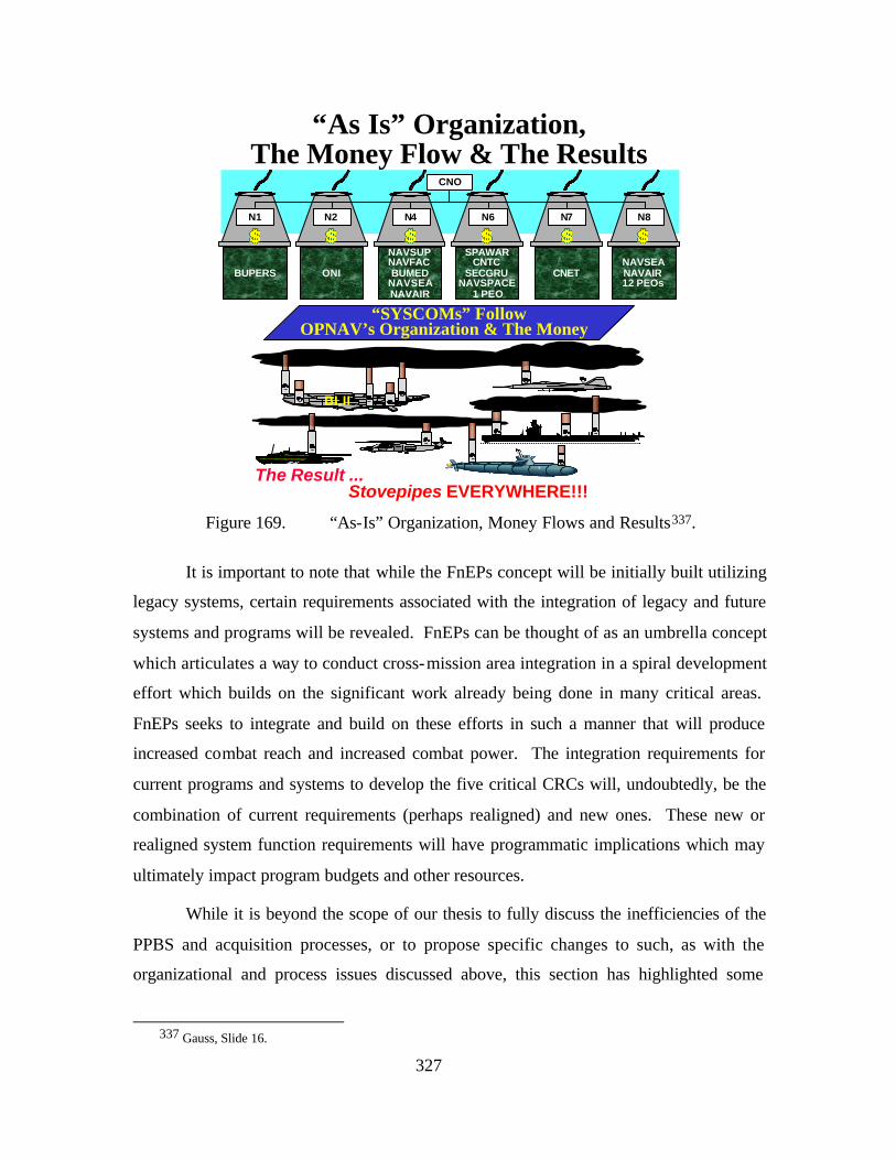
327
“As Is” Organization,The Money Flow & The Results
“SYSCOMs” FollowOPNAV’s Organization & The Money
CNETNAVSEANAVAIR12 PEOs
NAVSUPNAVFACBUMED
NAVSEANAVAIR
ONIBUPERS
CNO
N1 N4 N6N2
SPAWARCNTC
SECGRUNAVSPACE
1 PEO
N7 N8
BLII
The Result .............
..........
..........
..........
..........
..........
..........
....................
..........
..........
..........
....................
Stovepipes EVERYWHERE!!! Figure 169. “As-Is” Organization, Money Flows and Results337.
It is important to note that while the FnEPs concept will be initially built utilizing
legacy systems, certain requirements associated with the integration of legacy and future
systems and programs will be revealed. FnEPs can be thought of as an umbrella concept
which articulates a way to conduct cross-mission area integration in a spiral development
effort which builds on the significant work already being done in many critical areas.
FnEPs seeks to integrate and build on these efforts in such a manner that will produce
increased combat reach and increased combat power. The integration requirements for
current programs and systems to develop the five critical CRCs will, undoubtedly, be the
combination of current requirements (perhaps realigned) and new ones. These new or
realigned system function requirements will have programmatic implications which may
ultimately impact program budgets and other resources.
While it is beyond the scope of our thesis to fully discuss the inefficiencies of the
PPBS and acquisition processes, or to propose specific changes to such, as with the
organizational and process issues discussed above, this section has highlighted some
337 Gauss, Slide 16.
328
general opportunities for improvement, while acknowledging the tremendous challenges
associated with programmatic and acquisition related changes. Such changes can only
occur if supported across the leadership of DoD. Notably, this support must include
program managers and other acquisition decision authorities.
F. KNOWLEDGE MANAGEMENT AND KNOWLEDGE VALUE ADDED
In the digital information age, there is a shift from knowledge management to
“getting the warfighter connected.” There should be an in depth look at collaboration and
how best to utilize it in an FnEPs environment. Perhaps the publishing model for
information sharing should be examined with an eye towards a collaborative management
based scheme built on some kind of ‘Brokering’ model. Current knowledge management
models assume people know how, when and where to get available information. The
challenge within the knowledge management domain given the current data explosion
trends are to find the right, appropriate information in a vast sea of data based on specific
user needs in a timely manner. Using knowledge management in this manner would
bring people together in an innovative, collaborative environment to create value added
to FnEPs. This would be an area to study and understand how knowledge management
and knowledge value added concepts could both help to mature FnEPs or conversely, to
help understand how FnEPs he lps the military better perform knowledge management
and better understand what parts or aspects of packs are, or are not, knowledge value
added. These two concepts of knowledge management and knowledge value added
might better provide for increased insight into existing warfighting capabilities, their
realized or potential capabilities and potential for further refinement or streamlining.
329
VI. RESULTS, RECOMMENDATIONS AND CONCLUSIONS
A. RESULTS
NCW, FORCEnet, and FnEPs will generally require the Navy to change its
culture and move away from platform-centric systems, and their related TTPs.
Fortunately, this change is already beginning. The Navy has already started to transform
its operations in ways that are aligned with these concepts. Examples include
collaborative planning, chat, etc. where operations, rules and interactions are based on
web interactions. By becoming more “loosely coupled,” the Navy will be better able to
respond to emerging and future threats such as terrorists and asymmetric threats because
operations and our engagement chains can respond and adjust to much more compressed
timelines, and time critical threats. A large challenge remains; however, in terms of
unbinding our combat systems to fully integrate them in this loosely joined, adaptive and
responsive world, in order to effectively and efficiently address asymmetric as well as
conventional threats. Figure 170 visually depicts this notional difference in threats.
Figure 170. Small Asymmetric Threats versus Massed Threats338.
338 David Weinberger, Small Pieces Loosely Joined {a unified theory of the web}, (Cambridge, Massaschusetts;
Perseus Publishing, 2002), Cover.
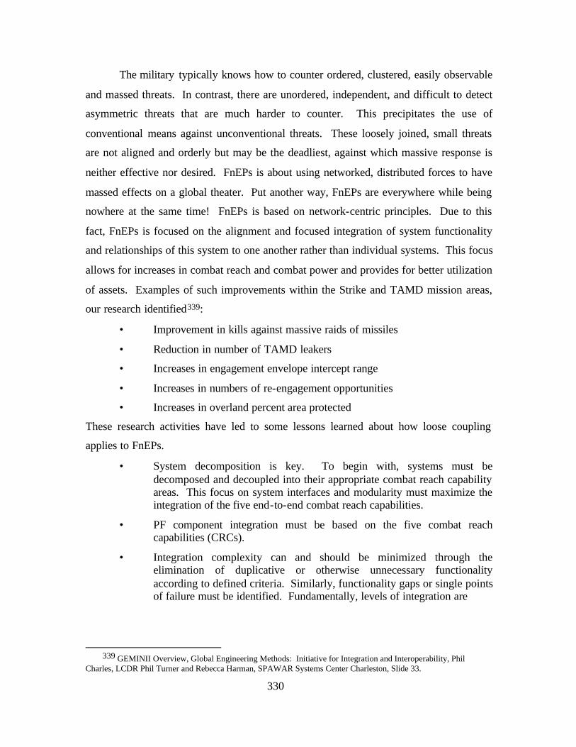
330
The military typically knows how to counter ordered, clustered, easily observable
and massed threats. In contrast, there are unordered, independent, and difficult to detect
asymmetric threats that are much harder to counter. This precipitates the use of
conventional means against unconventional threats. These loosely joined, small threats
are not aligned and orderly but may be the deadliest, against which massive response is
neither effective nor desired. FnEPs is about using networked, distributed forces to have
massed effects on a global theater. Put another way, FnEPs are everywhere while being
nowhere at the same time! FnEPs is based on network-centric principles. Due to this
fact, FnEPs is focused on the alignment and focused integration of system functionality
and relationships of this system to one another rather than individual systems. This focus
allows for increases in combat reach and combat power and provides for better utilization
of assets. Examples of such improvements within the Strike and TAMD mission areas,
our research identified339:
• Improvement in kills against massive raids of missiles
• Reduction in number of TAMD leakers
• Increases in engagement envelope intercept range
• Increases in numbers of re-engagement opportunities
• Increases in overland percent area protected
These research activities have led to some lessons learned about how loose coupling
applies to FnEPs.
• System decomposition is key. To begin with, systems must be decomposed and decoupled into their appropriate combat reach capability areas. This focus on system interfaces and modularity must maximize the integration of the five end-to-end combat reach capabilities.
• PF component integration must be based on the five combat reach capabilities (CRCs).
• Integration complexity can and should be minimized through the elimination of duplicative or otherwise unnecessary functionality according to defined criteria. Similarly, functionality gaps or single points of failure must be identified. Fundamentally, levels of integration are
339 GEMINII Overview, Global Engineering Methods: Initiative for Integration and Interoperability, Phil
Charles, LCDR Phil Turner and Rebecca Harman, SPAWAR Systems Center Charleston, Slide 33.
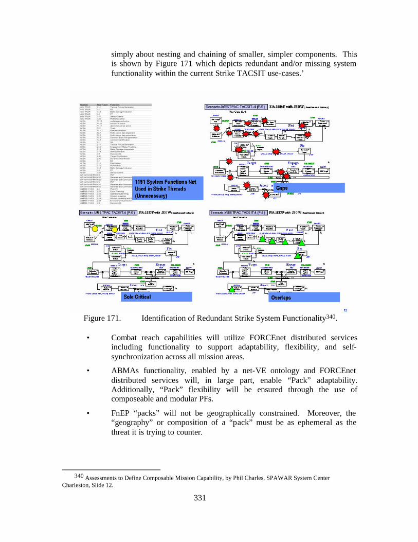
331
simply about nesting and chaining of smaller, simpler components. This is shown by Figure 171 which depicts redundant and/or missing system functionality within the current Strike TACSIT use-cases.’
Figure 171. Identification of Redundant Strike System Functionality340.
• Combat reach capabilities will utilize FORCEnet distributed services
including functionality to support adaptability, flexibility, and self-synchronization across all mission areas.
• ABMAs functionality, enabled by a net-VE ontology and FORCEnet distributed services will, in large part, enable “Pack” adaptability. Additionally, “Pack” flexibility will be ensured through the use of composeable and modular PFs.
• FnEP “packs” will not be geographically constrained. Moreover, the “geography” or composition of a “pack” must be as ephemeral as the threat it is trying to counter.
340 Assessments to Define Composable Mission Capability, by Phil Charles, SPAWAR System Center
Charleston, Slide 12.
332
• FnEPs enables responding to pressures from asymmetric terrorist threats, time-critical targets, and other “fleeting” threats. FnEPs is a like response to a like threat.
• FnEPs must be decentralized and distributed while remaining secure, survivable, and reliable under the most austere conditions. Much like decentralized network routers “Packs” must make decentralized decisions. This is similar to the routing of packets in a highly dynamic internet highway system, where the stop and ask technique for finding the path to a destination turns out not only to the more robust but also the more efficient.341
• Just as collaborators are the heart of the web, groups of networked assets and other PFs are the heart of FnEPs.
Another benefit of the analysis methodology chosen was to identify disinvestment
opportunities by which capital to realign system functionality can be saved and/or
reinvested. Figure 172 shows some early results of the power to link redundant system
function data in TVDB to real live programmatic data in NTIRA. From the assessments
that were conducted and the viability –vs- fit graphs shown in Chapter III, the following
systems were categorized according to their alignment (level of risk) with FORCEnet.
Additionally, the dollar figures in blue depict potential reinvestment opportunities if these
systems were realigned. In total, $740,756,000 was identified and allocated to 15 of 152
systems. This number is conservative because SSC-C lacked data for the remaining
systems.
341 Weinberger, 80.
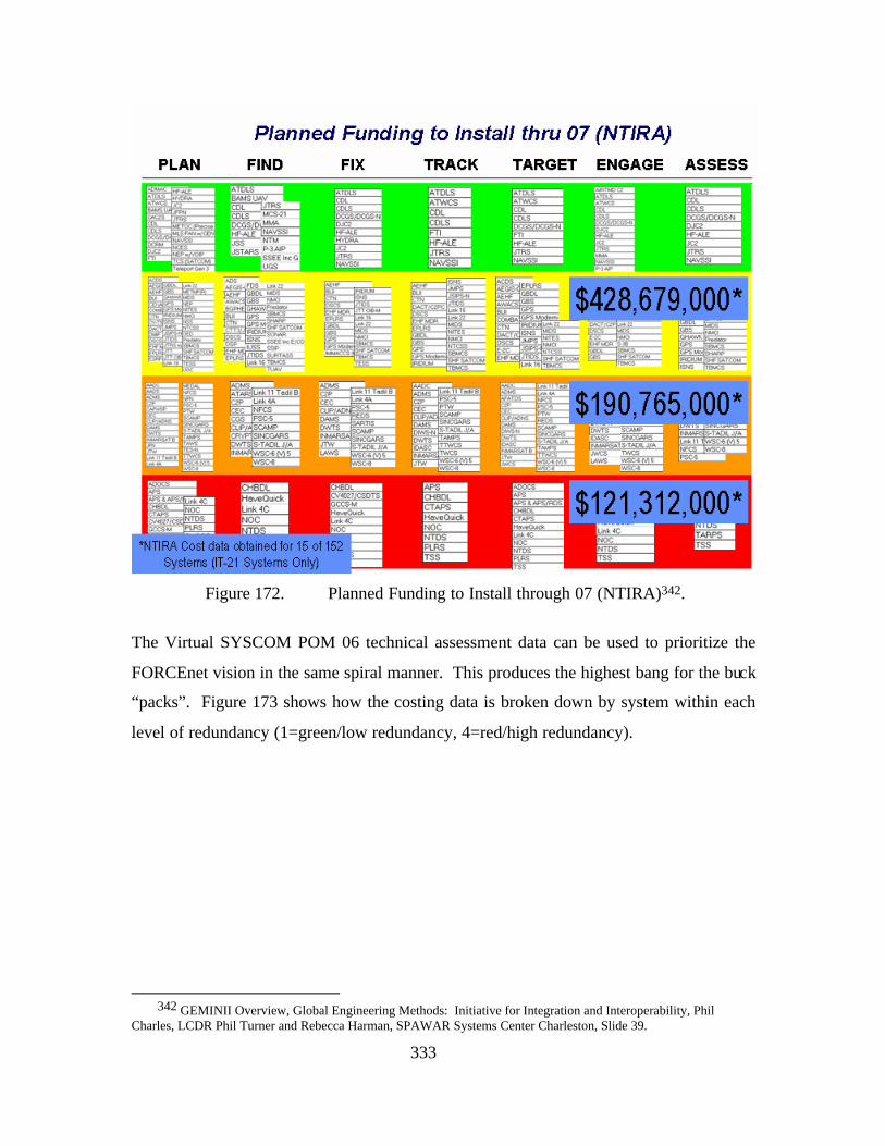
333
Figure 172. Planned Funding to Install through 07 (NTIRA)342.
The Virtual SYSCOM POM 06 technical assessment data can be used to prioritize the
FORCEnet vision in the same spiral manner. This produces the highest bang for the buck
“packs”. Figure 173 shows how the costing data is broken down by system within each
level of redundancy (1=green/low redundancy, 4=red/high redundancy).
342 GEMINII Overview, Global Engineering Methods: Initiative for Integration and Interoperability, Phil
Charles, LCDR Phil Turner and Rebecca Harman, SPAWAR Systems Center Charleston, Slide 39.
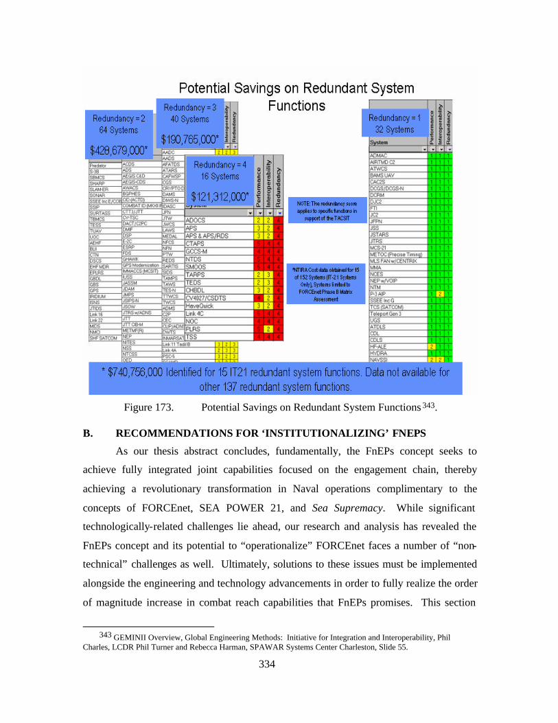
334
Figure 173. Potential Savings on Redundant System Functions 343.
B. RECOMMENDATIONS FOR ‘INSTITUTIONALIZING’ FNEPS
As our thesis abstract concludes, fundamentally, the FnEPs concept seeks to
achieve fully integrated joint capabilities focused on the engagement chain, thereby
achieving a revolutionary transformation in Naval operations complimentary to the
concepts of FORCEnet, SEA POWER 21, and Sea Supremacy. While significant
technologically-related challenges lie ahead, our research and analysis has revealed the
FnEPs concept and its potential to “operationalize” FORCEnet faces a number of “non-
technical” challenges as well. Ultimately, solutions to these issues must be implemented
alongside the engineering and technology advancements in order to fully realize the order
of magnitude increase in combat reach capabilities that FnEPs promises. This section
343 GEMINII Overview, Global Engineering Methods: Initiative for Integration and Interoperability, Phil
Charles, LCDR Phil Turner and Rebecca Harman, SPAWAR Systems Center Charleston, Slide 55.
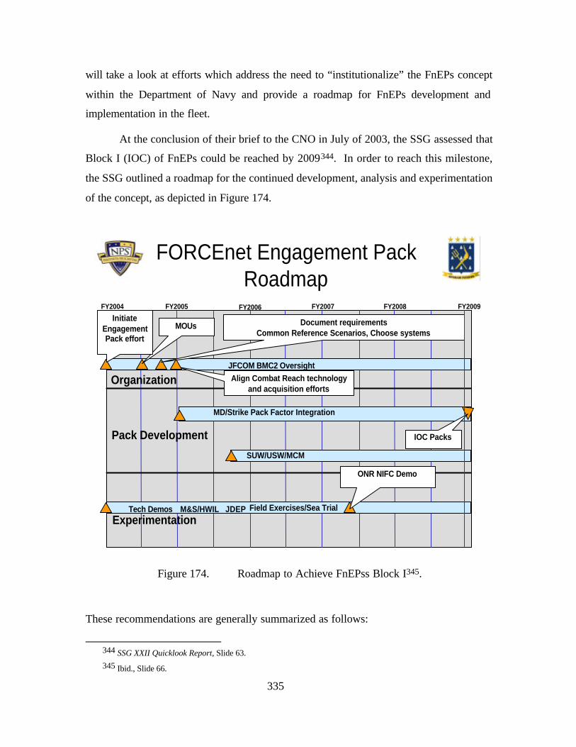
335
will take a look at efforts which address the need to “institutionalize” the FnEPs concept
within the Department of Navy and provide a roadmap for FnEPs development and
implementation in the fleet.
At the conclusion of their brief to the CNO in July of 2003, the SSG assessed that
Block I (IOC) of FnEPs could be reached by 2009344. In order to reach this milestone,
the SSG outlined a roadmap for the continued development, analysis and experimentation
of the concept, as depicted in Figure 174.
34
FORCEnet Engagement Pack Roadmap
FY2006 FY2007 FY2008FY2004
Organization
FY2005 FY2009
Pack Development
Experimentation
Document requirementsCommon Reference Scenarios, Choose systems
Align Combat Reach technology and acquisition efforts
MOUsInitiate
Engagement Pack effort
MD/Strike Pack Factor Integration
IOC Packs
SUW/USW/MCM
M&S/HWIL JDEP Field Exercises/Sea TrialTech Demos
JFCOM BMC2 Oversight
ONR NIFC Demo
Figure 174. Roadmap to Achieve FnEPss Block I345.
These recommendations are generally summarized as follows:
344 SSG XXII Quicklook Report, Slide 63. 345 Ibid., Slide 66.
336
• Document specific “pack” warfighting, capability, 346 and system performance requirements, starting with already documented joint capstone requirements. It was recommended to begin with the TAMD and Strike mission areas, because of current related activities and high, near-term potential.
• Consistent with recommendations made by SSG XXI, the Navy must accelerate the development of an integrated, cross service modeling and simulation and hardware- in-the- loop, assessment environment. The DISA-led Joint Distributed Engineering Plant (JDEP) is such an example.
• Align ongoing Navy- led efforts, including the Navy Integrated Fire Control, Counter Air Initiative (NIFC-CA), Joint Fires Network (JFN), and the Deployable Joint Command and Control (DJCS) Program. 347
• The Navy should closely tie FnEPs development to the Sea Trial process. Further, FnEPs development should leverage already planned exercises and demonstrations, including ONR’s Navy Integrated Fire Control event scheduled for 2007.348
Broad-based support for the FnEPs concept has been given by senior Naval
leadership as well as Joint Forces Command. Subsequent to SSG XXII completing their
work in August 2003, and building on that basis of support, our thesis has continued the
development of, and pursued a more in depth understanding of the FnEPs concept leading
to some analysis and options for FnEPs’ implementation. Out of this work came ideas
for refining the roadmap for the future and institutionalizing FnEPs within the
Department of Navy. As our research has continued, three significant events have most
significantly impacted refinements to this roadmap, 1) The Naval Studies Board (NSB),
who were chartered to examine “FORCEnet Implementation Strategy”, 2) The NPS
Cebrowski Institute’s research effort focused on the development of a reference
architecture for battlespace communications and related FORCEnet research, and 3)
Commander, NAVNETWARCOM (at the time VADM Mayo) tasker to
SPAWAR/OPNAV N61 to develop a prototype “pack” for review and potential fleet trial
in FY04. Each of these is addressed below.
346 Currently, such capabilities are collectively referred to as the five CRCs.
347 This list is not all-inclusive. 348 Ibid.
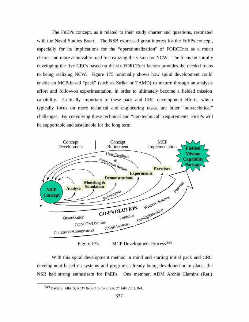
337
The FnEPs concept, as it related to their study charter and questions, resonated
with the Naval Studies Board. The NSB expressed great interest for the FnEPs concept,
especially for its implications for the “operationalization” of FORCEnet as a much
clearer and more achievable road for realizing the vision for NCW. The focus on spirally
developing the five CRCs based on the six FORCEnet factors provides the needed focus
to being realizing NCW. Figure 175 notionally shows how spiral development could
enable an MCP-based “pack” (such as Strike or TAMD) to mature through an analysis
effort and follow-on experimentation, in order to ultimately become a fielded mission
capability. Critically important to these pack and CRC development efforts, which
typically focus on more technical and engineering tasks, are other “non-technical”
challenges. By coevolving these technical and “non-technical” requirements, FnEPs will
be supportable and sustainable for the long term.
MCPConcept
ConceptDevelopment
ConceptRefinement
MCPImplementation
AnalysisModeling &Simulation
DemonstrationsExperiments
Exercises
FieldedMission
CapabilityPackage
CO-EVOLUTION
Organization
Command ArrangementsCONOPS/Doctrine
C4ISR SystemsTraining/Educatio
n
Person
nel
Weapons Systems
Logistics
Refinements
User Feedback&Assessment Results
Figure 175. MCP Development Process349.
With this spiral development method in mind and starting initial pack and CRC
development based on systems and programs already being developed or in place, the
NSB had strong enthusiasm for FnEPs. One member, ADM Archie Clemins (Ret.)
349 David S. Alberts, NCW Report to Congress, 27 July 2001, 8-4.
338
reportedly mentioned; the Navy should not wait to implement FnEPs, but should begin
immediately. As a result, there are a wide range of potential impacts the NSB may have
on institutionalizing FnEPs as a result of their report.
The NPS Cebrowski Institute (CI) is charted to explore information innovations
that support battlespace superiority. The CI sponsors a theme of research that will draw
multiple disciplines and teams of faculty, students and industry to contribute to new
knowledge. In October 2003, the Chairman of the Computer Science Department at NPS
and the Director of the CI proposed the development of a reference model for battlespace
communications as CI’s theme for 2004. Upon learning of the FnEPs concept and
ongoing research efforts, the director of the CI also voiced strong support and interest in
continuing with FnEPs involvement. The first step will be institutionalizing ongoing
research and development activities already in progress with members of the CI over the
course of the next few months.
As a result of the CNO’s support of the FnEPs concept and in conjunction with
ongoing activities at NAVNETWARCOM related to continued development of
FORCEnet, VADM Mayo tasked SPAWAR/N61 to develop a prototype “pack” for
review and potential fleet trial in FY04. Several meetings and efforts have resulted in a
response to this tasking, and include participants representing a variety of stakeholders
and organizations. Overall, consensus was reached that FnEPs is the operational
construct for FORCEnet and a mechanism to rapidly achieve the full engagement
capability of FORCEnet in the near term. FnEPs was seen as giving a focus to the
current FORCEnet way ahead by facilitating SEA POWER 21 warfighting capability. As
a result of the groups’ effort, the following high- level recommendations were made:
• Formalize FnEPs as fundamental to Sea Power 21 implementation and operations
• Define technical, operational, and fiscal requirements, including those from the joint/coalition perspective
• Develop first FnEPs “Pack” candidates
As a result of these recommendations, initial discussions were begun in October
2003 to assess the feasibility of beginning FnEPs experimentation in Trident Warrior
2004. Although the focus for FnEPs Spiral I is the demonstration of sensor-to-weapon
339
connectivity and basic combat reach capabilities, additional recommendations were also
provided. These were generally focused from a longer term perspective, and are
discussed in Chapter VII, future areas for research. In addition to the near and longer
term recommendations outlined above, a number of organizational roles and
responsibilities were proposed. These organiza tional roles and responsibilities have
become better refined during the course of our research and through follow-on
discussions with leadership throughout the Navy. Below are our recommendations for
“institutionalizing” FnEPs based on those conversations, research and past professional
experience.
There are at least two distinct areas in which FnEPs has to be “institutionalized”
in order for the concept to mature and become the truly revolutionary operational
construct it was designed/envisioned to be. These areas include 1) “institutionalizing”
FnEP research and development efforts within the S&T community, and 2)
“institutionalizing” FnEPs capability within the acquisition and PPBS communities of
work through validated (via Sea Trial), fleet-driven requirements.
First, the “institutionalization” of FnEPs within the research and development
(both raw and applied) community will have to be done using efforts at within
organizations like NPS, DARPA, ONR, and others, however there has to be pervasive
and robust partnerships with private industry to infuse ideas, business processes and
technology from respective leaders in their competitive market domains. In addition,
these combined military and private industry efforts will need to leverage the enormous
amount of work already done and in progress with programs already underway that are
working in areas which are directly related to FnEPs. Programs like the Joint Fires
Network (JFN), Naval Integrated Fire Control – Counter Air (NIFC-CA), and the
Distributed Common Ground Station (DCGS) are not only established but are relatively
mature from a technology standpoint. These programs will support the initial spiral
development of FnEPs and provide an overarching vision for achieving Network-Centric
Warfare. Integrating the landscape of many good, albeit fragmented programmatic
efforts, into alignment with one overarching concept, FnEPs, will produce the
consolidated and synergistic efforts required to realize the operational concept of FnEPs.
340
In accomplishing these S&T tasks, there appears to be some short, mid and long term
efforts that can begin now. Some initial thoughts are outlined below.
• NWDC
• Act as conduit to acquisition and PPBS communities to access impact to and provide input to FnEPs research and development efforts.
• Coordinate with DISA Joint Distributed Engineering Plant (JDEP) initiative to forward the development of a system-of-system land-based hardware- in-the- loop and modeling and simulation assessment environment and integrate that environment with the Sea Trial experimentation process
• NNWC/NWDC/SPAWAR (FORCEnet CHENG) – Evaluate and integrate appropriate ongoing ONR/DARPA initiatives with FBE plan, e.g., ONR 2007 Integrated Fire Control event. Ensure FBEs build and test CRC capabilities to achieve FnEP performance requirements.
• NPS – Align FnEPs research efforts throughout NPS including: the Cebrowski Institute, Meyer Institute and other appropriate Information Systems (IS), Computer Science (CS), Modeling, Virtual Environements, and Simulation (MOVES) Institute, Busines and Public Policy, Operation Research (OR) or other departments/institues to:
• Initiate discussions with DARPA regarding possible DARPA FnEP technology program to look at technology implications and technological challenges (e.g., system function decoupling into functional modules, horizontal mission area integration, system function alignment into capabilities-based areas, etc.) which would help in development of CRCs
• Apply, develop or otherwise focus many other appropriate departments/institutes’ FnEPs relevant research and student activity
• Use IP Community Center of Excellence (IP COE) to help position the IP Community to institutionalize FnEPs in the Fleet and conduct professional training on FnEPs. Use the IP COE as the venue by which the IP Community uses FnEPs to define their future role in the warfighting community.
• Take full advantage of proximity to cutting edge commercial technology and organizations in Silicon Valley which represents opportunities for continued FnEP coordination and development
• Use Cooperative Research and Development Agreements (CRADAs) as a method to initiate this work with industry
341
• ONR/NRL – Realign current S&T roadmap to reflect FnEP operational concept
• Coordinate with private industry to address maturing CRCs and looking for technology hurdles to a warfighting networked virtual environment.
• ONR/NRL/DARPA/NPS conduct an annual FnEPs research and development symposium to focus on R&D efforts and forward tasks.
The second community of efforts which need to be aligned with FnEPs in order to
“institutionalize” and mature FnEPs into the revolutionary operational construct it is, will
have to be done through the acquisition and PPBS communities, using fleet-validated
requirements to drive the entire set of processes. These efforts at “institutionalizing”
FnEPs from the operational perspective must start with Joint Forces Command (JFCOM)
working in concert with the Combined Fleet Forces Command (CFFC). With JFCOM
being the Navy’s transformational component commander there should be ample
opportunity for departments, including the Experimentation Department (J9), to
understand the truly transformational aspects of FnEPs. JFCOM should spearhead the
operational development and experimentation efforts. Additionally, CFFC, in their role
as consolidated fleet requirements sponsors, should develop and document a set of
validated operational needs. These must be validated thorough the numbered fleets, Type
Commanders, Fleet Headquarters and eventually through the component commanders on
their way to the Joint Requirements Oversight Council (JROC). Using Joint, fleet
validated requirements to support FnEPs, POM and PR inputs into the PPBS processes
will align funding such that ongoing program efforts can continue. This alignment must
also include the FnEPs operational construct such that system functionality includes the
five CRCs. In accomplishing these tasks, there are short, mid and long term efforts that
can begin now. Some initial thoughts are outlined below.
• CFFC - Endorse FnEPs as an integral component of Sea Trial & Trident Warrior. Act as consolidated operational fleet-validated requirements sponsor to the joint community and JFCOM.
• Identify corresponding FnEP Fleet requirements via Fn Requirements OAG
• JFCOM – Endorse FnEPs as a joint operational construct which will not mature with only Naval involvement. Bring joint community requirements into alignment with developing CRCs. Take the FnEPs
342
concept to the joint community for further alignment of efforts. Sponsor an annual, joint FnEPs development conference to share ideas between private industry and the military on achievements, progress and future aspirations.
• Coordinate Joint involvement and establish appropriate cross-service and interagency MOUs.
• OPNAV N7/N8 – Align program resources with system functionality in order to develop all five critical Combat Reach Capabilities (CRCs). Remove gaps and duplicates in specific programs’ system functionality as they become aligned with the CRCs. Align program resources in concert with JFCOM and CFFC sponsored requirements to develop CRCs. Start realigning POM and PR budget inputs to fund initial pack prototype assets
• ASN(RD&A)
• Convene a Naval Board of Directors (BOD) to oversee FnEP CRC development and program cost, schedule and performance alignments to continue maturing CRC development and warfighting capability assessments
• Establish FnEPs Direct Reporting Program Manger (DRPM) Office to lead the Joint FnEPs effort. An alternative course of action would be to coordinate with JFCOM BMC2 Agency (JSSEO) and NETWARCOM the solicitation for a FnEPs Program Manager and Deputy Program Manager to lead the Joint FnEP effort.
• Initiate cross-service and interagency MOU development. • Document Joint Combat Reach Capability performance
requirements in: • Initial Capabilities Documents • FBE success criteria (based on metrics) • Initiate POM funding and work to get FnEPs realigned
FYDP budget to cover needed CRC development, integration, training, testing, M&S, experimentation, etc., costs not already covered or available by realignment within currently existing programs. May have to start up programs that will contain system functionality gaps currently not being developed in any program, e.g., ABMA functionalities.
• Define and coordinate technical, operational and fiscal requirements within cost, schedule and performance criteria
• Define FnEP plan of action and milestones. • SYSCOMS - Support FnEPs in respective Sea Power 21 pillars. Work
with resource sponsors to align program system functionality to develop CRCs.
343
• Convene an FnEPs Oversight Board (FOB) to oversee CRC integration development. Will align individual program cost, schedule and performance criteria to further CRC development. Decide on how best to Sea Trial FnEPs combat capabilities and oversee planning.
• Decide on how best to manage CRC development work as it relates to ongoing programmatic efforts, funding and requirements alignments.
• Nomination of FnEPs Sea Trial event candidate systems
• Technical assessments
• Develop a transition roadmap to the network-centric Combat Reach Capabilities and collectively decide on coordination of work
• SPAWAR
• Produce and validate an architecture capable of supporting dynamically reconfigurable mission capabilities beginning with TAMD and Strike Packs.
• Use integrated architecture methodologies and modeling tools to demonstrate an increase end to end warfighting effectiveness and management of complexity
• Technical lead as FORCEnet CHENG
• Continue pack prototype development
• Coordinate inclusion of FnEPs concept and vernacular in appropriate FORCEnet documentation. Modification of Fn documentation (e.g., Campaign Plan, Architecture and Standards, Government Reference Vision, etc.) such that they can be built upon and expanded to reflect FnEP requirements will help communicate FnEP to all concerned. There is a significant amount of Fn work that is directly related to FnEPs by design.
• NWDC
• Rewrite existing Tactics, Techniques and Procedures to reflect FnEPs operational construct
• Develop FnEPs operational CONOPs
• Develop or coordinate changes to DOTMLPF areas of impact
• Work with CFFC and JFCOM to ensure coordination with Sea Trial process
• Act as conduit to S&T community to access impact to and provide input to FnEPs research and development efforts.
344
• Modify FORCEnet Limited Objective Experiments (LOEs) to accommodate FnEPs objectives.
• Modify Hairy Buffalo and Giant Shadow exercises to include FnEPs requirements.
• Plan for FnEPs requirements in Fleet Battle Experiments (FBEs)
• NETWARCOM
• Officia lly initiate and take ownership of and be Naval operational authority for FnEPs
• In coordination with FnEPs program office, SYSCOMs, JFCOM and CFFC, lead the development of FnEPs 5-year Execution Plan. Plan should include:
• Performance requirements and metrics (see CRC definitions, capabilities and metrics in Chapter III)
• Organizational responsibilities and cross-service coordination
• Program capability milestones (of which initial 1-year pack prototype effort is one).
• Experimentation schedule • Funding requirements • Develop a Joint Services Inclusion Plan (example: JRAE)
• Advise CFFC with respect to requirements and implementation of FnEPs. Coordinate issues such as modernization needs, training initiatives and operational concept development coordination with CFFC and NWDC.
• Coordinate alignment of the following efforts and organizations to support FnEP execution plan
• NWDC for Naval component of joint doctrinal development and network infrastructure concept development
• Joint Fires Network (JFN) • Deployable Joint Command and Control System (DJC2S) • SPAWWAR 05 FORCEnet Architecture Vision • Naval Integrated Fire Control – Counter Air (NIFC-CA) • NAVSEA 06/PEO(IWS) • NAVAIR Director NCW • PEO (IT), (C4I) & NRO
• Evaluate Transformational Communication Architecture (TCA) to support FnEPs operational construct and technical implications for mobile, adaptive Naval platforms
• Evaluate MILSATCOM and Commercial SATCOM programs for FnEP requirement supportability (e.g., MUOS, etc.)
345
• MCCDC • ONR Missile Defense Future Naval Capabilities transition
strategy, e.g., • Distributed Weapons Coordination (DWC)
• Composite Combat Identification (CCID)
• Multi-Source Integration
• Advanced Sensor Netting Technology
• FnEPs development with JFCOM and other services, interagencies (JTAMDO, MDA, etc.)
• Coordinate inclusion of FnEPs concept and vernacular in appropriate FORCEnet documentation
• Coordinate with CNO N6/N7/N8 to identify and support funding and requirements for FnEP development.
• Continue to evaluate POM-06 and PR-07 for funding alignments.
• Use FnEPs as the overarching concept for POM-08 inputs. • Coordinate with CNO N7 to define operational scenarios to
support FnEP development
• Naval Capabilities Development Process • New/revised OPSITs and TACSITs
These are significant recommendations. However, we strongly feel if FORCEnet
and NCW are to be realized, FnEPs will be the operational construct which will provide
the focus and purpose for their achievement. We believe the alignments between
NAVSEA, NAVAIR, SPAWAR and PEOs should take on a much more proactive,
integral role in FORCEnet development, and is absolutely key critical to implementation
of FnEPs. Without NAVSEA and NAVAIR’s involvement, FnEPs will not happen,
because the whole premise of FnEPs is engagement focused. The alignment of efforts
between SPAWAR, NAVSEA, NAVAIR and MARCORSYSCOM have to be all
focused on the engagement chain for the purposes of increased combat reach and
increased combat power through cross-warfighting functional system integration. These
aligned efforts must be supported by alignments in funding and funding support as well
as resource sponsorship. FnEPs development, prototyping, testing, experimentation,
deployment and operational use have to be supported fiscally as well as via capstone
346
requirements documents, most of which already exist, in order to sustainable at any level
or pack size. Our recommendations form the framework and provide the support for the
significant technical integration and engineering analysis which must also be conducted.
We believe these “formal” activities are necessary but insufficient -
transformational change requires “institutionalize” change and concepts such FORCEnet
and FnEPs are no exception. FnEPs has already gone through several iterations of
concept development from its initial construct as the Adaptive Engagement System
(AES) to the Joint Adaptive Engagement System (JAES) to the current FORCEnet
Engagement Packs (FnEPs) concept. FnEPs will doubtless continue to evolve on many
different levels and from many different perspectives on its way to “operationalizing’
FORCEnet.
C. CONCLUSIONS
Today, the Navy and our
Nation face new challenges that
demand we transform the Navy. In
addition to its role in forward
power projection, the Navy now
faces a new role in homeland
defense. These changes require
that the Navy be able to go places
and fight in ways it has never done
before. In doing so, we are taking the Navy to a place where no one else can follow
through big, fundamental, high-technology, collaborative warfighting capabilities which
will ensure the Navy’s overwhelming strength and ability to deter, defend and obviate
global threats including those to our homeland. The Navy's overarching strategy to
accomplish this should be to:
“There are 2 types of people; Requirements people and “Big Idea” people. Requirements people like to deal in deliberate detail, while “Big Idea” people start with a general vision and create from there . . . the Army’s “Own the Night” initiative is a Big Idea”
Bran Ferren, Executive VP for Creative Technology Walt Disney Imagineering

347
Achieve and maintain global Sea Supremacy by using its unique capabilities in an unprecedented collaborative effort with joint, interagency, and coalition partners to defend against threats from the maritime environment. This collaborative effort will assure a focused response, permitting the "right" partner with the "right" asset to engage the "right" threat at the "right" time350.
We believe this overarching strategy, squarely supports the Navy’s Vision of SEA
POWER 21 and “operationalizing” FORCEnet is critically important to getting there.
In its truest, fully developed form, FnEPs represents the operational construct for
FORCEnet and will enable FORCEnet to become an integral and undistinguishable part
of Sea Strike, Sea Shield and Sea Basing. Beyond simply the ‘glue’ that holds SEA
POWER 21 together, FnEPs will allow FORCEnet to disappear into Sea Strike, Sea
Shield and Sea Basing and making distributed, composeable warfighting services
ubiquitous, yet focused, throughout the battlespace. Ultimately, FnEPs will help
FORCEnet achieve more aligned warfighting capabilities that can address both force-on-
force as well as asymmetric threats.
FnEPs is the ‘Big Idea’ Concept for 21st Century warfighting which will enable
big, fundamental, high- technology, collaborative capabilities. FnEPs will do nothing
short of truly transform how the Navy, at least, and quite possibly DoD, conducts warfare
in the future by delivering tomorrow’s Network-Centric combat reach capabilities . . .
today.
350 SSG XXII, May 2003.

348
THIS PAGE INTENTIONALLY LEFT BLANK
349
VII. EPILOGUE
As discussed in the introduction, the current development of FnEPs is a result of
initial efforts by SSG XXII, (including the analysis efforts of other organizations) and
follow-on work as a part of this thesis at NPS. While to date, these efforts have reflected
countless briefings, this thesis represents the most complete discussion of FnEPs and its
relationship to FORCEnet to date. A significant part of this thesis is its recommendations
with respect to the roadmap for future development and “institutionalization” of FnEPs.
Even as this thesis is being written, some of the recommendations are being
implemented.
• Prior to his retirement, VADM Mayo tasked SPAWAR with the development of a plan for an initial prototype “pack” and its implementation within the next year. Efforts as a result of this tasker have lead to NAVNETWARCOM’s planning the first FnEPs conference to be held in January 2004 to further refine the FnEPs road ahead.
• Another critical aspect of the development of FnEPs is its continued research and development. As a result, several organizations within NPS have stepped forward and agreed to align their efforts with the FnEPs concept.
• Beyond the initial enthusiasm and support of the Department of Navy senior leadership, significant interest within the acquisition community continues to grow as FnEPs has been identified as the operational construct for FORCEnet. Such groups as the Virtual SYSCOM and others have engaged to explore this opportunity.
• From its inception, FnEPs was developed to be integral to FORCEnet. Thoughout its initial developement by the CNO’s SSG XXII, and our continued efforts at NPS, SSC Charleston and the office of the FORCEnet Architect Chief Engineer have been instrumental in FnEPs evolution. As a result, significant and continuing efforts are being made to ensure the alignment of FnEPs and FORCEnet. These include a number of ongoing architecture assessments and other critical FORCEnet related initiatives.

350
THIS PAGE INTENTIONALLY LEFT BLANK
351
APPENDIX A
A. COMMON SYSTEM FUNCTION LIST (CSFL) TO FNEP CRC MAPPING
Table 1 is part of the draft Common System Function List (CSFL) in development
by the Assistant Secretary of the Navy for Research Development and Acquisition (ASN,
RD&A). The CSFL has over 1100 functions organized into a 9-tier (as defined by the
FORCEnet Operational, Strategic and Tactical Hierachy in the Government Reference
Architecture, version 1.0, dated 08 April 2003) system function hierarchy. The CSFL is a
combined list of several system function lists already in use by various organizations for
such activities as the PR-05 Strike assessment, POM-06 assessment, and original FnEPs
analysis conducted by SPAWAR Systems Center Charleston for SSG XXII. These
system functions are descriptions of common system functions which are implemented in
Navy systems and would form the basis by which systems are described, understood and
mapped to. This list in Table 1 is not all inclusive of the 1100+ system functions due to
the fact they are not all directly related to the level of FnEPs analysis at this point. The
attempt to better understand the system functionality required of the five CRCs dictated
that we only analyze the area ‘1.0 Combat’ of the CSFL. There were over 430 system
functions which were mapped to the CRCs. The CRC legend was:
1 – Composite Tracking (CT) functions 2 – Composite Combat Identification (CCID) functions 3 – Integrated Fire Control (IFC) functions 4 – Common/Single Pictures (CP) functions 5 – Automated Battle Management Aids (ABMA) functions
This CSFL to CRC mapping exercise led to a more refined understanding of what
each CRC should be able to do and helped further refine the NIFC-CA Engage on
Remote to CRC mapping analysis.
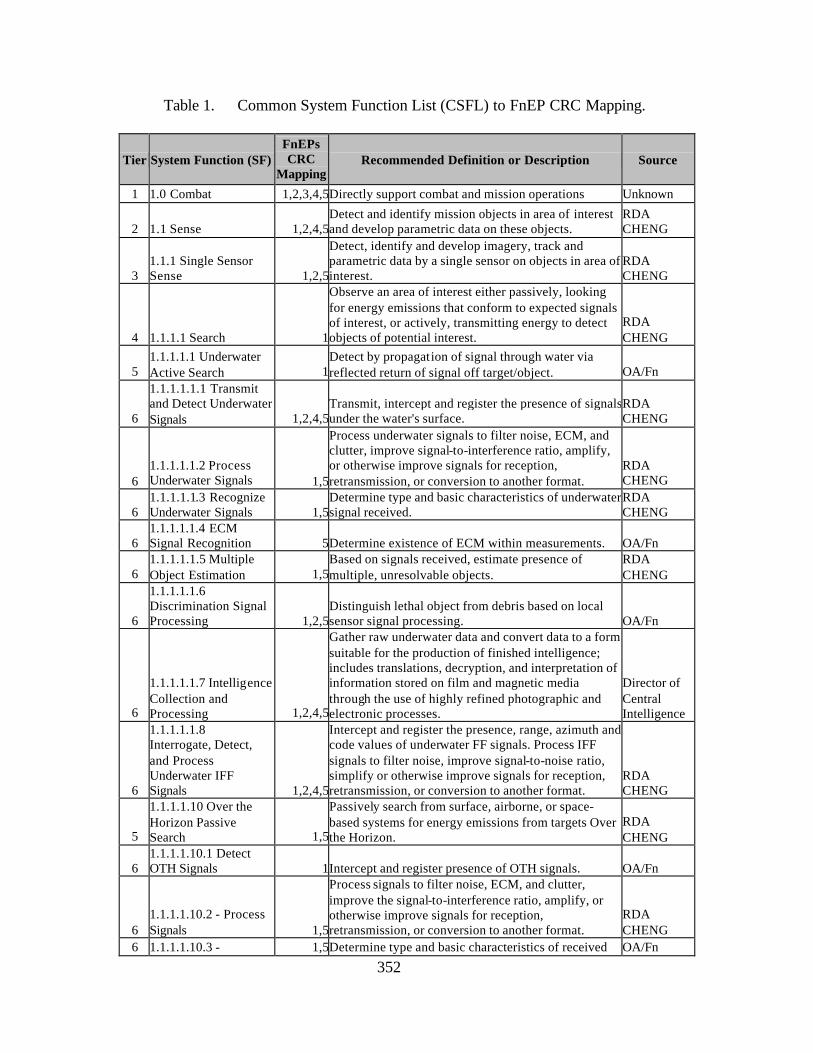
352
Table 1. Common System Function List (CSFL) to FnEP CRC Mapping.
Tier System Function (SF) FnEPs CRC
Mapping Recommended Definition or Description Source
1 1.0 Combat 1,2,3,4,5Directly support combat and mission operations Unknown
2 1.1 Sense 1,2,4,5Detect and identify mission objects in area of interest and develop parametric data on these objects.
RDA CHENG
3 1.1.1 Single Sensor Sense 1,2,5
Detect, identify and develop imagery, track and parametric data by a single sensor on objects in area of interest.
RDA CHENG
4 1.1.1.1 Search 1
Observe an area of interest either passively, looking for energy emissions that conform to expected signals of interest, or actively, transmitting energy to detect objects of potential interest.
RDA CHENG
5 1.1.1.1.1 Underwater Active Search 1
Detect by propagation of signal through water via reflected return of signal off target/object. OA/Fn
6
1.1.1.1.1.1 Transmit and Detect Underwater Signals 1,2,4,5
Transmit, intercept and register the presence of signals under the water's surface.
RDA CHENG
6 1.1.1.1.1.2 Process Underwater Signals 1,5
Process underwater signals to filter noise, ECM, and clutter, improve signal-to-interference ratio, amplify, or otherwise improve signals for reception, retransmission, or conversion to another format.
RDA CHENG
6 1.1.1.1.1.3 Recognize Underwater Signals 1,5
Determine type and basic characteristics of underwater signal received.
RDA CHENG
6 1.1.1.1.1.4 ECM Signal Recognition 5Determine existence of ECM within measurements. OA/Fn
6 1.1.1.1.1.5 Multiple Object Estimation 1,5
Based on signals received, estimate presence of multiple, unresolvable objects.
RDA CHENG
6
1.1.1.1.1.6 Discrimination Signal Processing 1,2,5
Distinguish lethal object from debris based on local sensor signal processing. OA/Fn
6
1.1.1.1.1.7 Intelligence Collection and Processing 1,2,4,5
Gather raw underwater data and convert data to a form suitable for the production of finished intelligence; includes translations, decryption, and interpretation of information stored on film and magnetic media through the use of highly refined photographic and electronic processes.
Director of Central Intelligence
6
1.1.1.1.1.8 Interrogate, Detect, and Process Underwater IFF Signals 1,2,4,5
Intercept and register the presence, range, azimuth and code values of underwater FF signals. Process IFF signals to filter noise, improve signal-to-noise ratio, simplify or otherwise improve signals for reception, retransmission, or conversion to another format.
RDA CHENG
5
1.1.1.1.10 Over the Horizon Passive Search 1,5
Passively search from surface, airborne, or space-based systems for energy emissions from targets Over the Horizon.
RDA CHENG
6 1.1.1.1.10.1 Detect OTH Signals 1Intercept and register presence of OTH signals. OA/Fn
6 1.1.1.1.10.2 - Process Signals 1,5
Process signals to filter noise, ECM, and clutter, improve the signal-to-interference ratio, amplify, or otherwise improve signals for reception, retransmission, or conversion to another format.
RDA CHENG
6 1.1.1.1.10.3 - 1,5Determine type and basic characteristics of received OA/Fn
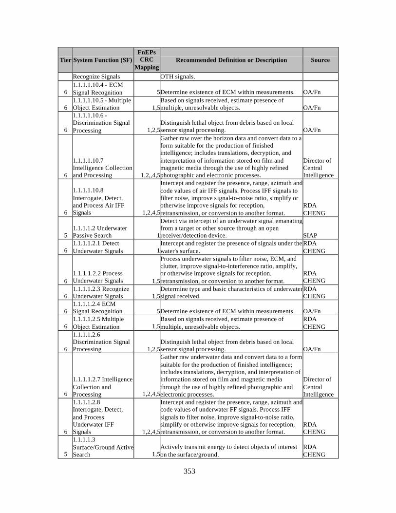
353
Tier System Function (SF) FnEPs CRC
Mapping Recommended Definition or Description Source
Recognize Signals OTH signals.
6 1.1.1.1.10.4 - ECM Signal Recognition 5Determine existence of ECM within measurements. OA/Fn
6 1.1.1.1.10.5 - Multiple Object Estimation 1,5
Based on signals received, estimate presence of multiple, unresolvable objects. OA/Fn
6
1.1.1.1.10.6 - Discrimination Signal Processing 1,2,5
Distinguish lethal object from debris based on local sensor signal processing. OA/Fn
6
1.1.1.1.10.7 Intelligence Collection and Processing 1,2,,4,5
Gather raw over the horizon data and convert data to a form suitable for the production of finished intelligence; includes translations, decryption, and interpretation of information stored on film and magnetic media through the use of highly refined photographic and electronic processes.
Director of Central Intelligence
6
1.1.1.1.10.8 Interrogate, Detect, and Process Air IFF Signals 1,2,4,5
Intercept and register the presence, range, azimuth and code values of air IFF signals. Process IFF signals to filter noise, improve signal-to-noise ratio, simplify or otherwise improve signals for reception, retransmission, or conversion to another format.
RDA CHENG
5 1.1.1.1.2 Underwater Passive Search 1
Detect via intercept of an underwater signal emanating from a target or other source through an open receiver/detection device. SIAP
6 1.1.1.1.2.1 Detect Underwater Signals 1
Intercept and register the presence of signals under the water's surface.
RDA CHENG
6 1.1.1.1.2.2 Process Underwater Signals 1,5
Process underwater signals to filter noise, ECM, and clutter, improve signal-to-interference ratio, amplify, or otherwise improve signals for reception, retransmission, or conversion to another format.
RDA CHENG
6 1.1.1.1.2.3 Recognize Underwater Signals 1,5
Determine type and basic characteristics of underwater signal received.
RDA CHENG
6 1.1.1.1.2.4 ECM Signal Recognition 5Determine existence of ECM within measurements. OA/Fn
6 1.1.1.1.2.5 Multiple Object Estimation 1,5
Based on signals received, estimate presence of multiple, unresolvable objects.
RDA CHENG
6
1.1.1.1.2.6 Discrimination Signal Processing 1,2,5
Distinguish lethal object from debris based on local sensor signal processing. OA/Fn
6
1.1.1.1.2.7 Intelligence Collection and Processing 1,2,4,5
Gather raw underwater data and convert data to a form suitable for the production of finished intelligence; includes translations, decryption, and interpretation of information stored on film and magnetic media through the use of highly refined photographic and electronic processes.
Director of Central Intelligence
6
1.1.1.1.2.8 Interrogate, Detect, and Process Underwater IFF Signals 1,2,4,5
Intercept and register the presence, range, azimuth and code values of underwater FF signals. Process IFF signals to filter noise, improve signal-to-noise ratio, simplify or otherwise improve signals for reception, retransmission, or conversion to another format.
RDA CHENG
5
1.1.1.1.3 Surface/Ground Active Search 1,5
Actively transmit energy to detect objects of interest on the surface/ground.
RDA CHENG
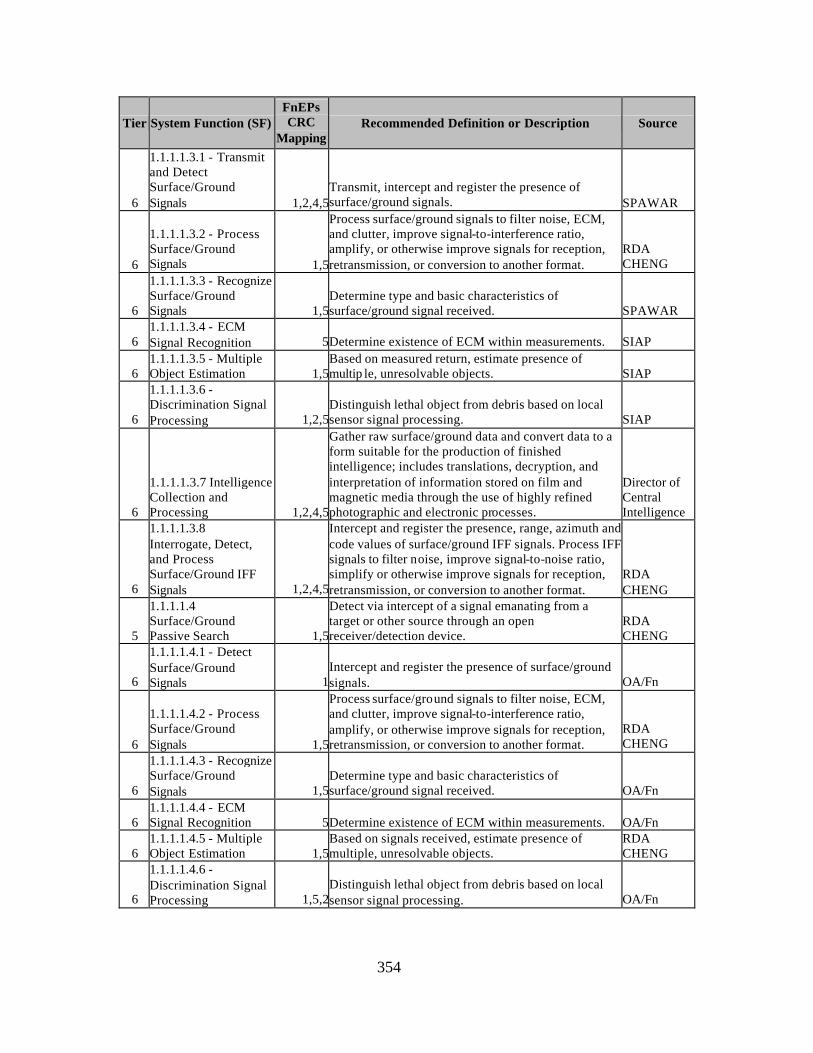
354
Tier System Function (SF) FnEPs CRC
Mapping Recommended Definition or Description Source
6
1.1.1.1.3.1 - Transmit and Detect Surface/Ground Signals 1,2,4,5
Transmit, intercept and register the presence of surface/ground signals. SPAWAR
6
1.1.1.1.3.2 - Process Surface/Ground Signals 1,5
Process surface/ground signals to filter noise, ECM, and clutter, improve signal-to-interference ratio, amplify, or otherwise improve signals for reception, retransmission, or conversion to another format.
RDA CHENG
6
1.1.1.1.3.3 - Recognize Surface/Ground Signals 1,5
Determine type and basic characteristics of surface/ground signal received. SPAWAR
6 1.1.1.1.3.4 - ECM Signal Recognition 5Determine existence of ECM within measurements. SIAP
6 1.1.1.1.3.5 - Multiple Object Estimation 1,5
Based on measured return, estimate presence of multip le, unresolvable objects. SIAP
6
1.1.1.1.3.6 - Discrimination Signal Processing 1,2,5
Distinguish lethal object from debris based on local sensor signal processing. SIAP
6
1.1.1.1.3.7 Intelligence Collection and Processing 1,2,4,5
Gather raw surface/ground data and convert data to a form suitable for the production of finished intelligence; includes translations, decryption, and interpretation of information stored on film and magnetic media through the use of highly refined photographic and electronic processes.
Director of Central Intelligence
6
1.1.1.1.3.8 Interrogate, Detect, and Process Surface/Ground IFF Signals 1,2,4,5
Intercept and register the presence, range, azimuth and code values of surface/ground IFF signals. Process IFF signals to filter noise, improve signal-to-noise ratio, simplify or otherwise improve signals for reception, retransmission, or conversion to another format.
RDA CHENG
5
1.1.1.1.4 Surface/Ground Passive Search 1,5
Detect via intercept of a signal emanating from a target or other source through an open receiver/detection device.
RDA CHENG
6
1.1.1.1.4.1 - Detect Surface/Ground Signals 1
Intercept and register the presence of surface/ground signals. OA/Fn
6
1.1.1.1.4.2 - Process Surface/Ground Signals 1,5
Process surface/ground signals to filter noise, ECM, and clutter, improve signal-to-interference ratio, amplify, or otherwise improve signals for reception, retransmission, or conversion to another format.
RDA CHENG
6
1.1.1.1.4.3 - Recognize Surface/Ground Signals 1,5
Determine type and basic characteristics of surface/ground signal received. OA/Fn
6 1.1.1.1.4.4 - ECM Signal Recognition 5Determine existence of ECM within measurements. OA/Fn
6 1.1.1.1.4.5 - Multiple Object Estimation 1,5
Based on signals received, estimate presence of multiple, unresolvable objects.
RDA CHENG
6
1.1.1.1.4.6 - Discrimination Signal Processing 1,5,2
Distinguish lethal object from debris based on local sensor signal processing. OA/Fn
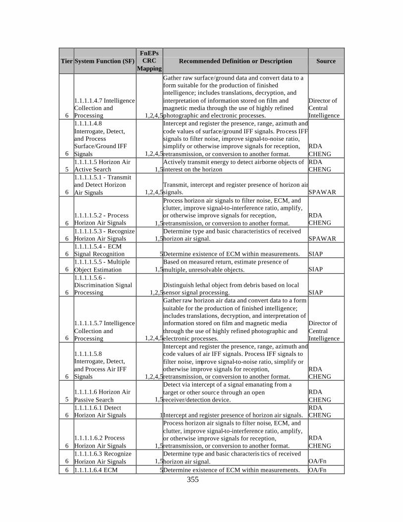
355
Tier System Function (SF) FnEPs CRC
Mapping Recommended Definition or Description Source
6
1.1.1.1.4.7 Intelligence Collection and Processing 1,2,4,5
Gather raw surface/ground data and convert data to a form suitable for the production of finished intelligence; includes translations, decryption, and interpretation of information stored on film and magnetic media through the use of highly refined photographic and electronic processes.
Director of Central Intelligence
6
1.1.1.1.4.8 Interrogate, Detect, and Process Surface/Ground IFF Signals 1,2,4,5
Intercept and register the presence, range, azimuth and code values of surface/ground IFF signals. Process IFF signals to filter noise, improve signal-to-noise ratio, simplify or otherwise improve signals for reception, retransmission, or conversion to another format.
RDA CHENG
5 1.1.1.1.5 Horizon Air Active Search 1,5
Actively transmit energy to detect airborne objects of interest on the horizon
RDA CHENG
6
1.1.1.1.5.1 - Transmit and Detect Horizon Air Signals 1,2,4,5
Transmit, intercept and register presence of horizon air signals. SPAWAR
6 1.1.1.1.5.2 - Process Horizon Air Signals 1,5
Process horizon air signals to filter noise, ECM, and clutter, improve signal-to-interference ratio, amplify, or otherwise improve signals for reception, retransmission, or conversion to another format.
RDA CHENG
6 1.1.1.1.5.3 - Recognize Horizon Air Signals 1,5
Determine type and basic characteristics of received horizon air signal. SPAWAR
6 1.1.1.1.5.4 - ECM Signal Recognition 5Determine existence of ECM within measurements. SIAP
6 1.1.1.1.5.5 - Multiple Object Estimation 1,5
Based on measured return, estimate presence of multiple, unresolvable objects. SIAP
6
1.1.1.1.5.6 - Discrimination Signal Processing 1,2,5
Distinguish lethal object from debris based on local sensor signal processing. SIAP
6
1.1.1.1.5.7 Intelligence Collection and Processing 1,2,4,5
Gather raw horizon air data and convert data to a form suitable for the production of finished intelligence; includes translations, decryption, and interpretation of information stored on film and magnetic media through the use of highly refined photographic and electronic processes.
Director of Central Intelligence
6
1.1.1.1.5.8 Interrogate, Detect, and Process Air IFF Signals 1,2,4,5
Intercept and register the presence, range, azimuth and code values of air IFF signals. Process IFF signals to filter noise, improve signal-to-noise ratio, simplify or otherwise improve signals for reception, retransmission, or conversion to another format.
RDA CHENG
5 1.1.1.1.6 Horizon Air Passive Search 1,5
Detect via intercept of a signal emanating from a target or other source through an open receiver/detection device.
RDA CHENG
6 1.1.1.1.6.1 Detect Horizon Air Signals 1Intercept and register presence of horizon air signals.
RDA CHENG
6 1.1.1.1.6.2 Process Horizon Air Signals 1,5
Process horizon air signals to filter noise, ECM, and clutter, improve signal-to-interference ratio, amplify, or otherwise improve signals for reception, retransmission, or conversion to another format.
RDA CHENG
6 1.1.1.1.6.3 Recognize Horizon Air Signals 1,5
Determine type and basic characteris tics of received horizon air signal. OA/Fn
6 1.1.1.1.6.4 ECM 5Determine existence of ECM within measurements. OA/Fn
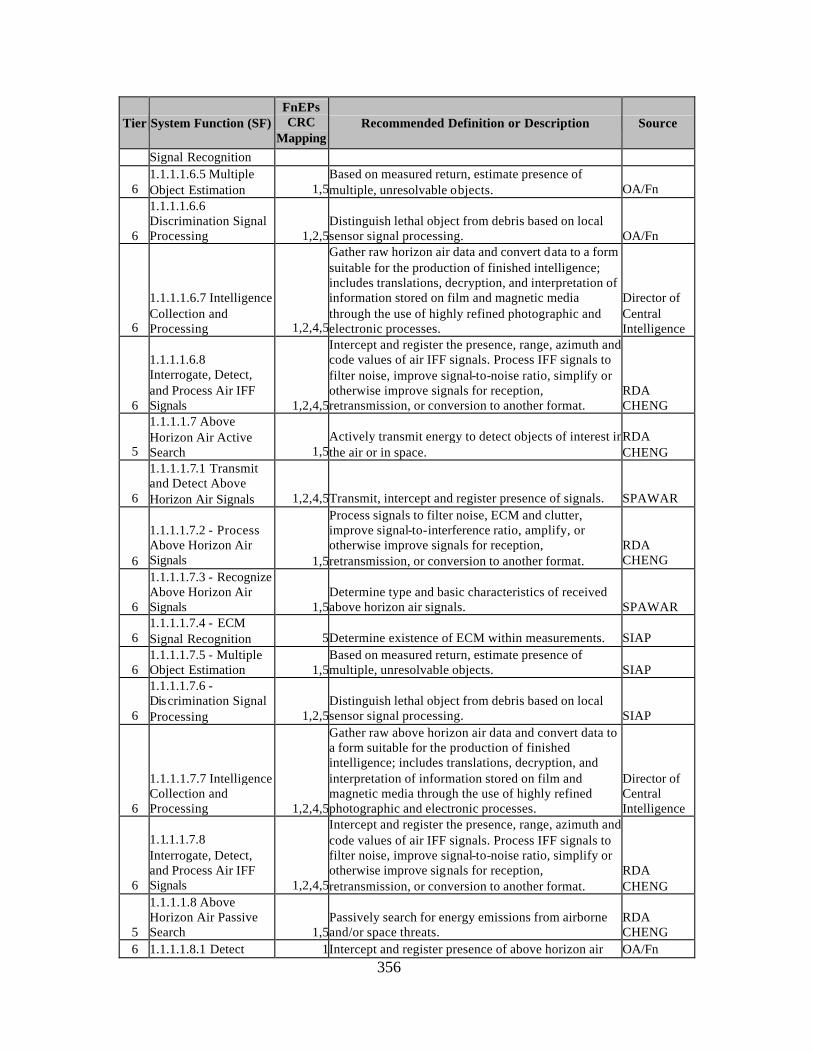
356
Tier System Function (SF) FnEPs CRC
Mapping Recommended Definition or Description Source
Signal Recognition
6 1.1.1.1.6.5 Multiple Object Estimation 1,5
Based on measured return, estimate presence of multiple, unresolvable objects. OA/Fn
6
1.1.1.1.6.6 Discrimination Signal Processing 1,2,5
Distinguish lethal object from debris based on local sensor signal processing. OA/Fn
6
1.1.1.1.6.7 Intelligence Collection and Processing 1,2,4,5
Gather raw horizon air data and convert data to a form suitable for the production of finished intelligence; includes translations, decryption, and interpretation of information stored on film and magnetic media through the use of highly refined photographic and electronic processes.
Director of Central Intelligence
6
1.1.1.1.6.8 Interrogate, Detect, and Process Air IFF Signals 1,2,4,5
Intercept and register the presence, range, azimuth and code values of air IFF signals. Process IFF signals to filter noise, improve signal-to-noise ratio, simplify or otherwise improve signals for reception, retransmission, or conversion to another format.
RDA CHENG
5
1.1.1.1.7 Above Horizon Air Active Search 1,5
Actively transmit energy to detect objects of interest in the air or in space.
RDA CHENG
6
1.1.1.1.7.1 Transmit and Detect Above Horizon Air Signals 1,2,4,5Transmit, intercept and register presence of signals. SPAWAR
6
1.1.1.1.7.2 - Process Above Horizon Air Signals 1,5
Process signals to filter noise, ECM and clutter, improve signal-to-interference ratio, amplify, or otherwise improve signals for reception, retransmission, or conversion to another format.
RDA CHENG
6
1.1.1.1.7.3 - Recognize Above Horizon Air Signals 1,5
Determine type and basic characteristics of received above horizon air signals. SPAWAR
6 1.1.1.1.7.4 - ECM Signal Recognition 5Determine existence of ECM within measurements. SIAP
6 1.1.1.1.7.5 - Multiple Object Estimation 1,5
Based on measured return, estimate presence of multiple, unresolvable objects. SIAP
6
1.1.1.1.7.6 - Discrimination Signal Processing 1,2,5
Distinguish lethal object from debris based on local sensor signal processing. SIAP
6
1.1.1.1.7.7 Intelligence Collection and Processing 1,2,4,5
Gather raw above horizon air data and convert data to a form suitable for the production of finished intelligence; includes translations, decryption, and interpretation of information stored on film and magnetic media through the use of highly refined photographic and electronic processes.
Director of Central Intelligence
6
1.1.1.1.7.8 Interrogate, Detect, and Process Air IFF Signals 1,2,4,5
Intercept and register the presence, range, azimuth and code values of air IFF signals. Process IFF signals to filter noise, improve signal-to-noise ratio, simplify or otherwise improve signals for reception, retransmission, or conversion to another format.
RDA CHENG
5
1.1.1.1.8 Above Horizon Air Passive Search 1,5
Passively search for energy emissions from airborne and/or space threats.
RDA CHENG
6 1.1.1.1.8.1 Detect 1Intercept and register presence of above horizon air OA/Fn
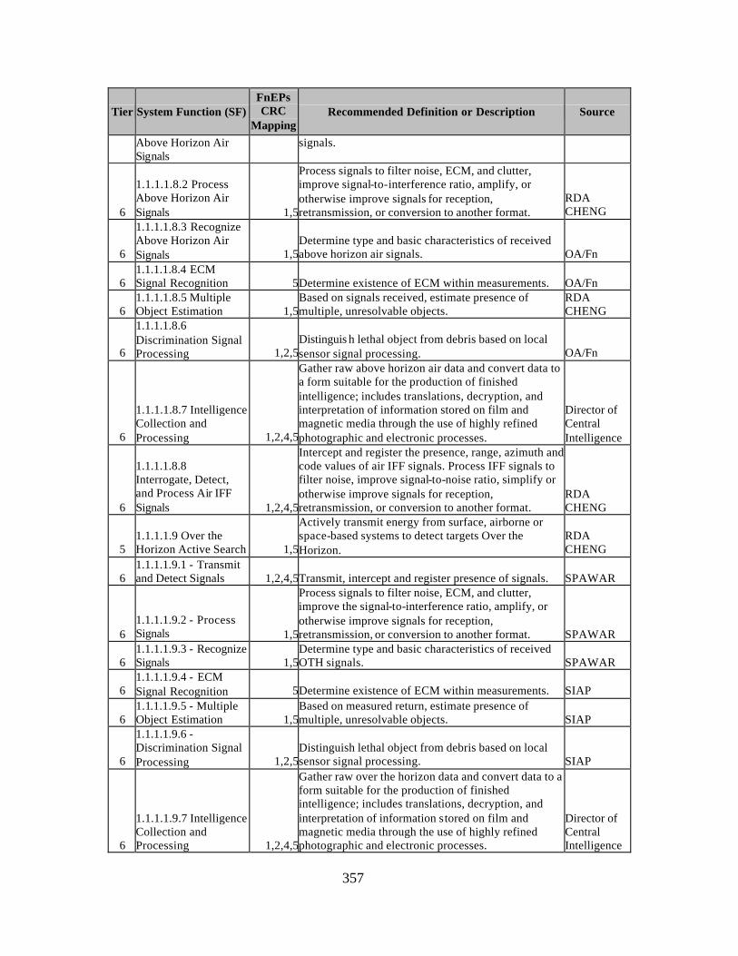
357
Tier System Function (SF) FnEPs CRC
Mapping Recommended Definition or Description Source
Above Horizon Air Signals
signals.
6
1.1.1.1.8.2 Process Above Horizon Air Signals 1,5
Process signals to filter noise, ECM, and clutter, improve signal-to-interference ratio, amplify, or otherwise improve signals for reception, retransmission, or conversion to another format.
RDA CHENG
6
1.1.1.1.8.3 Recognize Above Horizon Air Signals 1,5
Determine type and basic characteristics of received above horizon air signals. OA/Fn
6 1.1.1.1.8.4 ECM Signal Recognition 5Determine existence of ECM within measurements. OA/Fn
6 1.1.1.1.8.5 Multiple Object Estimation 1,5
Based on signals received, estimate presence of multiple, unresolvable objects.
RDA CHENG
6
1.1.1.1.8.6 Discrimination Signal Processing 1,2,5
Distinguis h lethal object from debris based on local sensor signal processing. OA/Fn
6
1.1.1.1.8.7 Intelligence Collection and Processing 1,2,4,5
Gather raw above horizon air data and convert data to a form suitable for the production of finished intelligence; includes translations, decryption, and interpretation of information stored on film and magnetic media through the use of highly refined photographic and electronic processes.
Director of Central Intelligence
6
1.1.1.1.8.8 Interrogate, Detect, and Process Air IFF Signals 1,2,4,5
Intercept and register the presence, range, azimuth and code values of air IFF signals. Process IFF signals to filter noise, improve signal-to-noise ratio, simplify or otherwise improve signals for reception, retransmission, or conversion to another format.
RDA CHENG
5 1.1.1.1.9 Over the Horizon Active Search 1,5
Actively transmit energy from surface, airborne or space-based systems to detect targets Over the Horizon.
RDA CHENG
6 1.1.1.1.9.1 - Transmit and Detect Signals 1,2,4,5Transmit, intercept and register presence of signals. SPAWAR
6 1.1.1.1.9.2 - Process Signals 1,5
Process signals to filter noise, ECM, and clutter, improve the signal-to-interference ratio, amplify, or otherwise improve signals for reception, retransmission, or conversion to another format. SPAWAR
6 1.1.1.1.9.3 - Recognize Signals 1,5
Determine type and basic characteristics of received OTH signals. SPAWAR
6 1.1.1.1.9.4 - ECM Signal Recognition 5Determine existence of ECM within measurements. SIAP
6 1.1.1.1.9.5 - Multiple Object Estimation 1,5
Based on measured return, estimate presence of multiple, unresolvable objects. SIAP
6
1.1.1.1.9.6 - Discrimination Signal Processing 1,2,5
Distinguish lethal object from debris based on local sensor signal processing. SIAP
6
1.1.1.1.9.7 Intelligence Collection and Processing 1,2,4,5
Gather raw over the horizon data and convert data to a form suitable for the production of finished intelligence; includes translations, decryption, and interpretation of information stored on film and magnetic media through the use of highly refined photographic and electronic processes.
Director of Central Intelligence
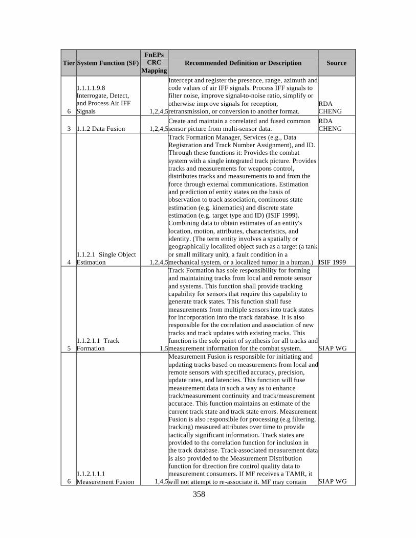
358
Tier System Function (SF) FnEPs CRC
Mapping Recommended Definition or Description Source
6
1.1.1.1.9.8 Interrogate, Detect, and Process Air IFF Signals 1,2,4,5
Intercept and register the presence, range, azimuth and code values of air IFF signals. Process IFF signals to filter noise, improve signal-to-noise ratio, simplify or otherwise improve signals for reception, retransmission, or conversion to another format.
RDA CHENG
3 1.1.2 Data Fusion 1,2,4,5Create and maintain a correlated and fused common sensor picture from multi-sensor data.
RDA CHENG
4 1.1.2.1 Single Object Estimation 1,2,4,5
Track Formation Manager, Services (e.g., Data Registration and Track Number Assignment), and ID. Through these functions it: Provides the combat system with a single integrated track picture. Provides tracks and measurements for weapons control, distributes tracks and measurements to and from the force through external communications. Estimation and prediction of entity states on the basis of observation to track association, continuous state estimation (e.g. kinematics) and discrete state estimation (e.g. target type and ID) (ISIF 1999). Combining data to obtain estimates of an entity's location, motion, attributes, characteristics, and identity. (The term entity involves a spatially or geographically localized object such as a target (a tank or small military unit), a fault condition in a mechanical system, or a localized tumor in a human.) ISIF 1999
5 1.1.2.1.1 Track Formation 1,5
Track Formation has sole responsibility for forming and maintaining tracks from local and remote sensor and systems. This function shall provide tracking capability for sensors that require this capability to generate track states. This function shall fuse measurements from multiple sensors into track states for incorporation into the track database. It is also responsible for the correlation and association of new tracks and track updates with existing tracks. This function is the sole point of synthesis for all tracks and measurement information for the combat system. SIAP WG
6 1.1.2.1.1.1 Measurement Fusion 1,4,5
Measurement Fusion is responsible for initiating and updating tracks based on measurements from local and remote sensors with specified accuracy, precision, update rates, and latencies. This function will fuse measurement data in such a way as to enhance track/measurement continuity and track/measurement accurace. This function maintains an estimate of the current track state and track state errors. Measurement Fusion is also responsible for processing (e.g filtering, tracking) measured attributes over time to provide tactically significant information. Track states are provided to the correlation function for inclusion in the track database. Track-associated measurement data is also provided to the Measurement Distribution function for direction fire control quality data to measurement consumers. If MF receives a TAMR, it will not attempt to re-associate it. MF may contain SIAP WG
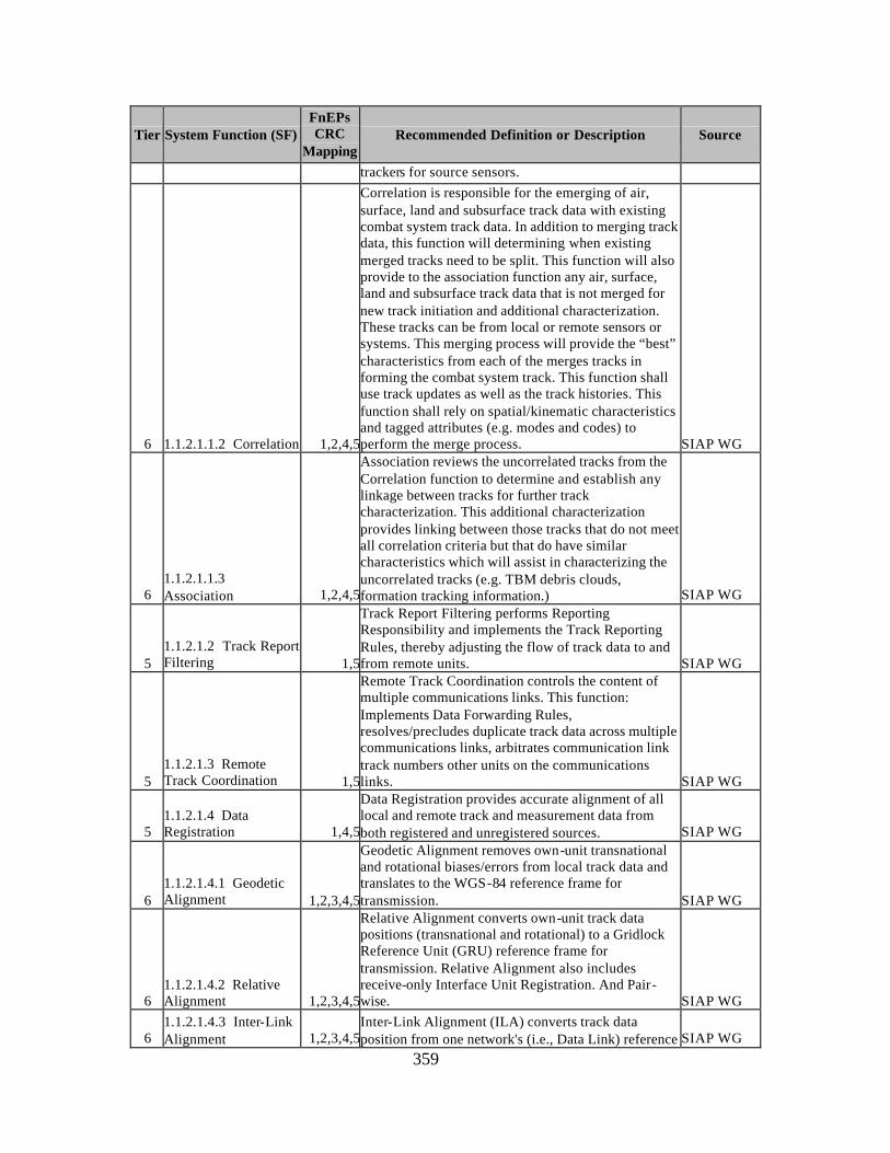
359
Tier System Function (SF) FnEPs CRC
Mapping Recommended Definition or Description Source
trackers for source sensors.
6 1.1.2.1.1.2 Correlation 1,2,4,5
Correlation is responsible for the emerging of air, surface, land and subsurface track data with existing combat system track data. In addition to merging track data, this function will determining when existing merged tracks need to be split. This function will also provide to the association function any air, surface, land and subsurface track data that is not merged for new track initiation and additional characterization. These tracks can be from local or remote sensors or systems. This merging process will provide the “best” characteristics from each of the merges tracks in forming the combat system track. This function shall use track updates as well as the track histories. This function shall rely on spatial/kinematic characteristics and tagged attributes (e.g. modes and codes) to perform the merge process. SIAP WG
6 1.1.2.1.1.3 Association 1,2,4,5
Association reviews the uncorrelated tracks from the Correlation function to determine and establish any linkage between tracks for further track characterization. This additional characterization provides linking between those tracks that do not meet all correlation criteria but that do have similar characteristics which will assist in characterizing the uncorrelated tracks (e.g. TBM debris clouds, formation tracking information.) SIAP WG
5 1.1.2.1.2 Track Report Filtering 1,5
Track Report Filtering performs Reporting Responsibility and implements the Track Reporting Rules, thereby adjusting the flow of track data to and from remote units. SIAP WG
5 1.1.2.1.3 Remote Track Coordination 1,5
Remote Track Coordination controls the content of multiple communications links. This function: Implements Data Forwarding Rules, resolves/precludes duplicate track data across multiple communications links, arbitrates communication link track numbers other units on the communications links. SIAP WG
5 1.1.2.1.4 Data Registration 1,4,5
Data Registration provides accurate alignment of all local and remote track and measurement data from both registered and unregistered sources. SIAP WG
6 1.1.2.1.4.1 Geodetic Alignment 1,2,3,4,5
Geodetic Alignment removes own-unit transnational and rotational biases/errors from local track data and translates to the WGS-84 reference frame for transmission. SIAP WG
6 1.1.2.1.4.2 Relative Alignment 1,2,3,4,5
Relative Alignment converts own-unit track data positions (transnational and rotational) to a Gridlock Reference Unit (GRU) reference frame for transmission. Relative Alignment also includes receive-only Interface Unit Registration. And Pair-wise. SIAP WG
6 1.1.2.1.4.3 Inter-Link Alignment 1,2,3,4,5
Inter-Link Alignment (ILA) converts track data position from one network's (i.e., Data Link) reference SIAP WG
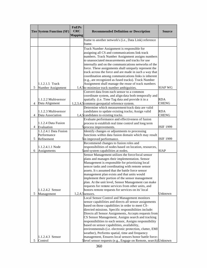
360
Tier System Function (SF) FnEPs CRC
Mapping Recommended Definition or Description Source
frame to another network's (i.e., Data Link) reference frame.
5 1.1.2.1.5 Track Number Assignment 1,4,5
Track Number Assignment is responsible for assigning all CS and communications link track numbers. Track Number Assignment assigns numbers to unassociated measurements and tracks for use internally and on the communications networks of the force. These assignments shall uniquely represent the track across the force and are made in such a way that coordination among communications links is inherent (e.g., are recognized as fused tracks). Track Number Assignment shall manage the reuse of track numbers to minimize track number ambiguities. SIAP WG
4 1.1.2.2 Multi-sensor Data Alignment 1,2,3,4,5
Convert data from each sensor to a common coordinate system, and align data both temporally and spatially. (i.e. Time Tag data and provide it in a common geospatial reference system.
RDA CHENG
4 1.1.2.3 Multi-sensor Data Association 1,4,5
Determine which measurement/track data are valid candidates to update existing tracks; Assign valid candidates to existing tracks.
RDA CHENG
4 1.1.2.4 Data Fusion Evaluation 5
Evaluate performance and effectiveness of fusion process to establish real time control and long term process improvements. ISIF 1999
5
1.1.2.4.1 Data Fusion Performance Refinement 5
Identify changes or adjustments to processing functions within data fusion domain which may result in improved performance. ISIF 1999
6 1.1.2.4.1.1 Node Assignments 5
Recommend changes to fusion roles and responsibilities of nodes based on location, resources, and system capabilities at nodes. SIAP
5 1.1.2.4.2 Sensor Management 1,2,4,5
Sensor Management utilizes the force/local sensor plans and manages their implementation. Sensor Management is responsible for prioritizing local sensor tasks and coordinating with remote sensor assets. It s assumed that the battle force sensor management plan exists and that units would implement their portion of the sensor management plan. At the unit level, Sensor Management can make requests for remote services from other units, and honors remote requests for services on its' local sensors. Unknown
5 1.1.2.4.3 Sensor Control 5
Local Sensor Control and Management monitors sensor capabilities and directs all sensor assignments based on those capabilities in order to meet CS-directed missions. Specific responsibilities include: Directs all Sensor Assignments, Accepts requests from CS Sensor Management, Assigns search and tracking responsibilities to each sensor, Assigns responsibility based on sensor capabilities, availability, environmentals (i.e. electronic protection, clutter, EMI weather), Performs spatial, time and frequency management, Ensures local sensors honor battle force-level sensor requests (e.g., Engage on Remote, search) Unknown
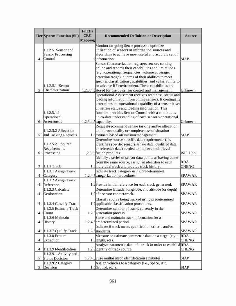
361
Tier System Function (SF) FnEPs CRC
Mapping Recommended Definition or Description Source
4
1.1.2.5 Sensor and Sensor Processing Control 5
Monitor on-going Sense process to optimize utilization of sensors or information sources and algorithms to achieve most useful and accurate set of information. SIAP
5 1.1.2.5.1 Sensor Characterization 1,2,3,4,5
Sensor Characterization registers sensors coming online and records their capabilities and limitations (e.g., operational frequencies, volume coverage, detection range) in terms of their abilities to meet specific classification capabilities, and vulnerability to an adverse RF environment. These capabilities are stored for use by sensor control and management. Unknown
6
1.1.2.5.1.1 Operational Assessment 1,2,3,4,5
Operational Assessment receives readiness, status and loading information from online sensors. It continually determines the operational capability of a sensor based on sensor status and loading information. This function provides Sensor Control with a continuous up-to-date understanding of each sensor's operational capability. Unknown
5 1.1.2.5.2 Allocation and Tasking Requests 1,5
Request/recommend sensor tasking and/or allocation to improve quality or completeness of situation estimate based on mission management. SIAP
6
1.1.2.5.2.1 Source Requirements Processing 1,2,3,5,
Determine source specific data requirements (i.e. identifies specific sensors/sensor data, qualified data, or reference data) needed to improve multi-level fusion products. ISIF 1999
3 1.1.3 Track 1,5
Identify a series of sensor data points as having come from the same source, assign an identifier to each individual track and provide track history.
RDA CHENG
4 1.1.3.1 Assign Track Category 1,2,4,5
Indicate track category using predetermined categorization procedures. SPAWAR
4 1.1.3.2 Assign Track Reference 1,2Provide initial reference for each track generated. SPAWAR
4 1.1.3.3 Calculate Geolocation 1,2
Determine latitude, longitude, and altitude (or depth) of a sensor contact/track. SPAWAR
4 1.1.3.4 Classify Track 1,2Classify source being tracked using predetermined applicable classification procedures. SPAWAR
4 1.1.3.5 Estimate Track Count 1,2,5
Determine number of tracks currently in the generation process. SPAWAR
4 1.1.3.6 Maintain History 1,2,4,5
Store and maintain track information for a predetermined period. SPAWAR
4 1.1.3.7 Qualify Track 1,2,5Indicate if track meets qualification criteria and/or standards. SPAWAR
4 1.1.3.8 Feature Extraction 1,5
Measure or estimate parametric data on a target (e.g., length, rcs).
RDA CHENG
4 1.1.3.9 Identification 1,2,5Analyze parametric data of a track in order to establish identity of track source.
RDA CHENG
5 1.1.3.9.1 Activity and Status Decision 1,2,4,5Fuse multi-sensor identification attributes. SIAP
5 1.1.3.9.2 Category Decision 1,5
Assign vehicles to a category (i.e., Space, Air, Ground, etc.). SIAP
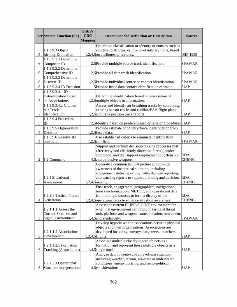
362
Tier System Function (SF) FnEPs CRC
Mapping Recommended Definition or Description Source
5 1.1.3.9.3 Object Identity Estimation 1,2,4,5
Determine classification or identity of entities such as emitters, platforms, or low-level military units, based on attributes or features. ISIF 1999
6 1.1.3.9.3.1 Determine Composite ID 2,5Provide multiple source track identification. SPAWAR
6 1.1.3.9.3.2 Determine Comprehensive ID 2,5Provide all data track identification. SPAWAR
6 1.1.3.9.3.3 Determine Discrete ID 1,2,5Provide individual source or contact identification. SPAWAR
6 1.1.3.9.3.4 ID Decision 5Provide fused data contact identification estimate. SIAP
7
1.1.3.9.3.4.1 ID Determination Based on Associations 1,2,5
Determine identification based on association of multiple objects in a formation. SIAP
7
1.1.3.9.3.4.2 Civilian Air Track Identification 1,2,5
Assess and identify air breathing tracks by combining existing sensor tracks and civilian/FAA flight plans and track position track reports. SIAP
5 1.1.3.9.4 Procedural ID 2,5Identify based on predetermined criteria or procedures.SIAP
5 1.1.3.9.5 Organization Decision 1,2,5
Provide estimate of country/force identification from fused data. SIAP
5 1.1.3.9.6 Resolve ID conflicts1 1,2,5
Use established criteria to eliminate identification conflicts. SPAWAR
2 1.2 Command 4,5
Support and perform decision-making processes that effectively and efficiently direct the force(s) under command, and that support employment of offensive and defensive weapons.
RDA CHENG
3 1.2.1 Situational Assessment 1,2,4,5
Generate a common tactical picture and provide awareness of the tactical situation, including engagement status reporting, battle damage reporting, and warning reports to support planning and decision-making.
RDA CHENG
4 1.2.1.1 Tactical Picture Generation 1,2,4,5
Fuse track, engagement, geographical, navigational, time synchronization, METOC, and operational data from multiple sources to form a display of the operational area to enhance situation awareness.
RDA CHENG
5
1.2.1.1.1 Assess the Current Situation and Signal Environment 1,4,5
Assess the current ELINT/SIGINT environment for what that environment can imply in terms of threat unit, platform and weapon, status, location, movement, and availability. SPAWAR
5 1.2.1.1.2 Associations Development 1,2,4,5
Develop hypotheses for associations between physical objects and their organizations. Associations are developed including convoys, targeteers, launchers, flights. SIAP
6 1.2.1.1.2.1 Formation Tracking (Association) 1,4,5
Associate multiple closely spaced objects as a formation and represent those multiple objects as a single track. SIAP
5 1.2.1.1.3 Operational Situation Interpretation 4,5
Analyze data in context of an evolving situation including weather, terrain, sea-state or underwater conditions, enemy doctrine, and socio-political considerations. SIAP
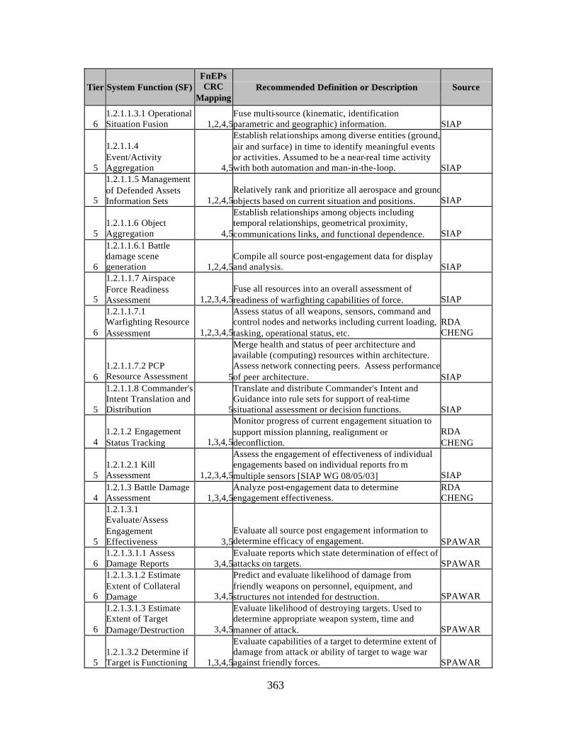
363
Tier System Function (SF) FnEPs CRC
Mapping Recommended Definition or Description Source
6 1.2.1.1.3.1 Operational Situation Fusion 1,2,4,5
Fuse multi-source (kinematic, identification parametric and geographic) information. SIAP
5
1.2.1.1.4 Event/Activity Aggregation 4,5
Establish relationships among diverse entities (ground, air and surface) in time to identify meaningful events or activities. Assumed to be a near-real time activity with both automation and man-in-the-loop. SIAP
5
1.2.1.1.5 Management of Defended Assets Information Sets 1,2,4,5
Relatively rank and prioritize all aerospace and ground objects based on current situation and positions. SIAP
5 1.2.1.1.6 Object Aggregation 4,5
Establish relationships among objects including temporal relationships, geometrical proximity, communications links, and functional dependence. SIAP
6
1.2.1.1.6.1 Battle damage scene generation 1,2,4,5
Compile all source post-engagement data for display and analysis. SIAP
5
1.2.1.1.7 Airspace Force Readiness Assessment 1,2,3,4,5
Fuse all resources into an overall assessment of readiness of warfighting capabilities of force. SIAP
6
1.2.1.1.7.1 Warfighting Resource Assessment 1,2,3,4,5
Assess status of all weapons, sensors, command and control nodes and networks including current loading, tasking, operational status, etc.
RDA CHENG
6 1.2.1.1.7.2 PCP Resource Assessment 5
Merge health and status of peer architecture and available (computing) resources within architecture. Assess network connecting peers. Assess performance of peer architecture. SIAP
5
1.2.1.1.8 Commander's Intent Translation and Distribution 5
Translate and distribute Commander's Intent and Guidance into rule sets for support of real-time situational assessment or decision functions. SIAP
4 1.2.1.2 Engagement Status Tracking 1,3,4,5
Monitor progress of current engagement situation to support mission planning, realignment or deconfliction.
RDA CHENG
5 1.2.1.2.1 Kill Assessment 1,2,3,4,5
Assess the engagement of effectiveness of individual engagements based on individual reports fro m multiple sensors [SIAP WG 08/05/03] SIAP
4 1.2.1.3 Battle Damage Assessment 1,3,4,5
Analyze post-engagement data to determine engagement effectiveness.
RDA CHENG
5
1.2.1.3.1 Evaluate/Assess Engagement Effectiveness 3,5
Evaluate all source post engagement information to determine efficacy of engagement. SPAWAR
6 1.2.1.3.1.1 Assess Damage Reports 3,4,5
Evaluate reports which state determination of effect of attacks on targets. SPAWAR
6
1.2.1.3.1.2 Estimate Extent of Collateral Damage 3,4,5
Predict and evaluate likelihood of damage from friendly weapons on personnel, equipment, and structures not intended for destruction. SPAWAR
6
1.2.1.3.1.3 Estimate Extent of Target Damage/Destruction 3,4,5
Evaluate likelihood of destroying targets. Used to determine appropriate weapon system, time and manner of attack. SPAWAR
5 1.2.1.3.2 Determine if Target is Functioning 1,3,4,5
Evaluate capabilities of a target to determine extent of damage from attack or ability of target to wage war against friendly forces. SPAWAR
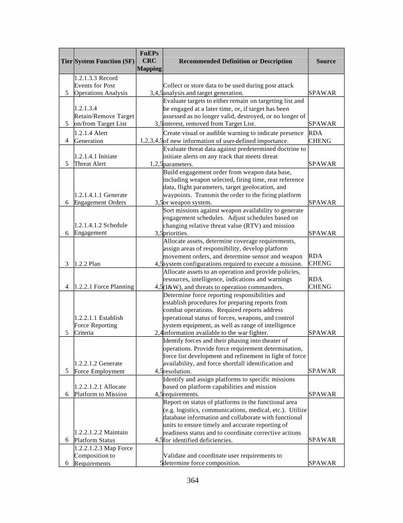
364
Tier System Function (SF) FnEPs CRC
Mapping Recommended Definition or Description Source
5
1.2.1.3.3 Record Events for Post Operations Analysis 3,4,5
Collect or store data to be used during post attack analysis and target generation. SPAWAR
5
1.2.1.3.4 Retain/Remove Target on/from Target List 3,5
Evaluate targets to either remain on targeting list and be engaged at a later time, or, if target has been assessed as no longer valid, destroyed, or no longer of interest, removed from Target List. SPAWAR
4 1.2.1.4 Alert Generation 1,2,3,4,5
Create visual or audible warning to indicate presence of new information of user-defined importance.
RDA CHENG
5 1.2.1.4.1 Initiate Threat Alert 1,2,5
Evaluate threat data against predetermined doctrine to initiate alerts on any track that meets threat parameters. SPAWAR
6 1.2.1.4.1.1 Generate Engagement Orders 3,5
Build engagement order from weapon data base, including weapon selected, firing time, rear reference data, flight parameters, target geolocation, and waypoints. Transmit the order to the firing platform or weapon system. SPAWAR
6 1.2.1.4.1.2 Schedule Engagement 3,5
Sort missions against weapon availability to generate engagement schedules. Adjust schedules based on changing relative threat value (RTV) and mission priorities. SPAWAR
3 1.2.2 Plan 4,5
Allocate assets, determine coverage requirements, assign areas of responsibility, develop platform movement orders, and determine sensor and weapon system configurations required to execute a mission.
RDA CHENG
4 1.2.2.1 Force Planning 4,5
Allocate assets to an operation and provide policies, resources, intelligence, indications and warnings (I&W), and threats to operation commanders.
RDA CHENG
5
1.2.2.1.1 Establish Force Reporting Criteria 2,4
Determine force reporting responsibilities and establish procedures for preparing reports from combat operations. Required reports address operational status of forces, weapons, and control system equipment, as well as range of intelligence information available to the war fighter. SPAWAR
5 1.2.2.1.2 Generate Force Employment 4,5
Identify forces and their phasing into theater of operations. Provide force requirement determination, force list development and refinement in light of force availability, and force shortfall identification and resolution. SPAWAR
6 1.2.2.1.2.1 Allocate Platform to Mission 4,5
Identify and assign platforms to specific missions based on platform capabilities and mission requirements. SPAWAR
6 1.2.2.1.2.2 Maintain Platform Status 4,5
Report on status of platforms in the functional area (e.g. logistics, communications, medical, etc.). Utilize database information and collaborate with functional units to ensure timely and accurate reporting of readiness status and to coordinate corrective actions for identified deficiencies. SPAWAR
6
1.2.2.1.2.3 Map Force Composition to Requirements 5
Validate and coordinate user requirements to determine force composition. SPAWAR
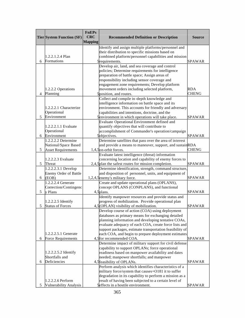
365
Tier System Function (SF) FnEPs CRC
Mapping Recommended Definition or Description Source
6 1.2.2.1.2.4 Plan Formations 5
Identify and assign multiple platforms/personnel and their distribution to specific missions based on combined platform/personnel capabilities and mission requirements. SPAWAR
4 1.2.2.2 Operations Planning 5
Develop air, land, and sea coverage and control policies; Determine requirements for intelligence preparation of battle space; Assign areas of responsibility including sensor coverage and engagement zone requirements; Develop platform movement orders including selected platform, position, and routes.
RDA CHENG
5
1.2.2.2.1 Characterize Operational Environment 5
Collect and compile in -depth knowledge and intelligence information on battle space and its environment. This accounts for friendly and adversary capabilities and intentions, doctrine, and the environment in which operations will take place. SPAWAR
6
1.2.2.2.1.1 Evaluate Operational Environment 5
Evaluate Operational Environment defined and quantify objectives that will contribute to accomplishment of Commander's operation/campaign objectives. SPAWAR
5
1.2.2.2.2 Determine National/Space Based Asset Requirements 1,4,5
Determine satellites that pass over the area of interest and provide a means to maneuver, support, and sustain on-orbit forces.
RDA CHENG
5 1.2.2.2.3 Evaluate Threat 2,4,5
Evaluate latest intelligence (threat) information concerning location and capability of enemy forces to plan the safest routes for mission completion. SPAWAR
6
1.2.2.2.3.1 Develop Enemy Order of Battle (EOB) 1,2,4,5
Determine identification, strength, command structure, and disposition of personnel, units, and equipment of enemy's military force. SPAWAR
5
1.2.2.2.4 Generate Correction/Contingency Plans 4,5
Create and update operational plans (OPLANS), concept OPLANS (CONPLANS), and functional plans. SPAWAR
5 1.2.2.2.5 Identify Status of Forces 4,5
Identify manpower resources and provide status and progress of mobilization. Provide operational plan (OPLAN) visibility of mobilization. SPAWAR
6 1.2.2.2.5.1 Generate Force Requirements 4,5
Develop course of action (COA) using deployment databases as primary means for exchanging detailed planning information and developing tentative COAs, evaluate adequacy of each COA, create force lists and support packages, estimate transportation feasibility of each COA, and begin to prepare deployment estimates for recommended COA. SPAWAR
6
1.2.2.2.5.2 Identify Shortfalls and Deficiencies 4,5
Determine impact of military support for civil defense; capability to support OPLANs; force operational readiness based on manpower availability and dates needed; manpower shortfalls; and manpower feasibility of OPLANs. SPAWAR
5 1.2.2.2.6 Perform Vulnerability Analysis 5
Perform analysis which identifies characteristics of a military force/system that causes+O181 it to suffer degradation in its capability to perform a mission as a result of having been subjected to a certain level of effects in a hostile environment. SPAWAR
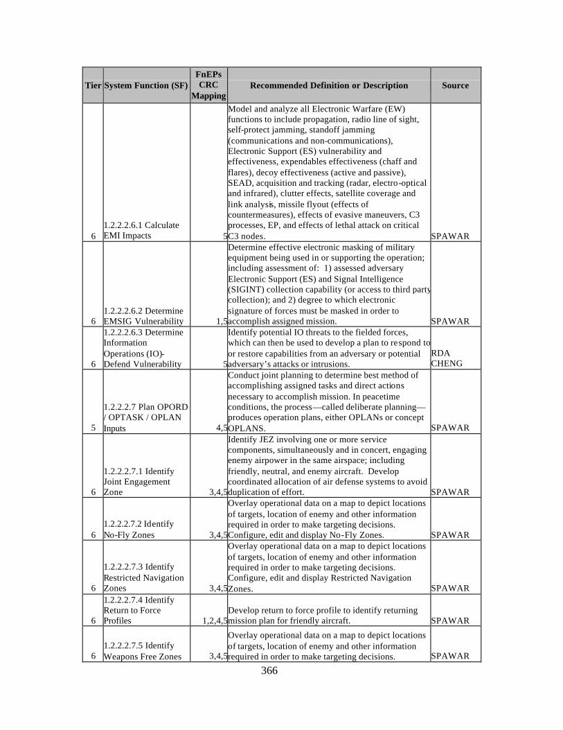
366
Tier System Function (SF) FnEPs CRC
Mapping Recommended Definition or Description Source
6 1.2.2.2.6.1 Calculate EMI Impacts 5
Model and analyze all Electronic Warfare (EW) functions to include propagation, radio line of sight, self-protect jamming, standoff jamming (communications and non-communications), Electronic Support (ES) vulnerability and effectiveness, expendables effectiveness (chaff and flares), decoy effectiveness (active and passive), SEAD, acquisition and tracking (radar, electro-optical and infrared), clutter effects, satellite coverage and link analysis, missile flyout (effects of countermeasures), effects of evasive maneuvers, C3 processes, EP, and effects of lethal attack on critical C3 nodes. SPAWAR
6 1.2.2.2.6.2 Determine EMSIG Vulnerability 1,5
Determine effective electronic masking of military equipment being used in or supporting the operation; including assessment of: 1) assessed adversary Electronic Support (ES) and Signal Intelligence (SIGINT) collection capability (or access to third party collection); and 2) degree to which electronic signature of forces must be masked in order to accomplish assigned mission. SPAWAR
6
1.2.2.2.6.3 Determine Information Operations (IO)-Defend Vulnerability 5
Identify potential IO threats to the fielded forces, which can then be used to develop a plan to respond to or restore capabilities from an adversary or potential adversary’s attacks or intrusions.
RDA CHENG
5
1.2.2.2.7 Plan OPORD / OPTASK / OPLAN Inputs 4,5
Conduct joint planning to determine best method of accomplishing assigned tasks and direct actions necessary to accomplish mission. In peacetime conditions, the process—called deliberate planning—produces operation plans, either OPLANs or concept OPLANS. SPAWAR
6
1.2.2.2.7.1 Identify Joint Engagement Zone 3,4,5
Identify JEZ involving one or more service components, simultaneously and in concert, engaging enemy airpower in the same airspace; including friendly, neutral, and enemy aircraft. Develop coordinated allocation of air defense systems to avoid duplication of effort. SPAWAR
6 1.2.2.2.7.2 Identify No-Fly Zones 3,4,5
Overlay operational data on a map to depict locations of targets, location of enemy and other information required in order to make targeting decisions. Configure, edit and display No-Fly Zones. SPAWAR
6
1.2.2.2.7.3 Identify Restricted Navigation Zones 3,4,5
Overlay operational data on a map to depict locations of targets, location of enemy and other information required in order to make targeting decisions. Configure, edit and display Restricted Navigation Zones. SPAWAR
6
1.2.2.2.7.4 Identify Return to Force Profiles 1,2,4,5
Develop return to force profile to identify returning mission plan for friendly aircraft. SPAWAR
6 1.2.2.2.7.5 Identify Weapons Free Zones 3,4,5
Overlay operational data on a map to depict locations of targets, location of enemy and other information required in order to make targeting decisions. SPAWAR
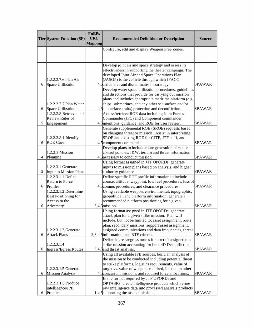
367
Tier System Function (SF) FnEPs CRC
Mapping Recommended Definition or Description Source
Configure, edit and display Weapon Free Zones.
6 1.2.2.2.7.6 Plan Air Space Utilization 4,5
Develop joint air and space strategy and assess its effectiveness in supporting the theater campaign. The developed Joint Air and Space Operations Plan (JASOP) is the vehicle through which JFACC articulates and disseminates its strategy. SPAWAR
6 1.2.2.2.7.7 Plan Water Space Utilization 4,5
Develop water space utilization procedures, guidelines and directions that provide for carrying out mission plans and includes appropriate maritime platform (e.g. ships, submarines, and any other sea surface and/or subsurface crafts) protection and deconfliction. SPAWAR
5
1.2.2.2.8 Retrieve and Review Rules of Engagement 4,5
Access/retrieve ROE data including Joint Forces Commander (JFC) and Component commander intentions, guidance, and ROE for user review. SPAWAR
6 1.2.2.2.8.1 Identify ROE Cues 4,5
Generate supplemental ROE (SROE) requests based on changing threat or mission. Assist in interpreting SROE and existing ROE for CJTF, JTF staff, and component commands. SPAWAR
4 1.2.2.3 Mission Planning 4,5
Develop plans to include route generation, airspace control policies, I&W, terrain and threat information necessary to conduct mission. SPAWAR
5 1.2.2.3.1 Generate Input to Mission Plans 5
Using format assigned in JTF OPORDs, generate inputs to mission plans based on analysis, and higher authority guidance. SPAWAR
6
1.2.2.3.1.1 Define Return to Force Profiles 4,5
Define specific RTF profile information to include course, altitude, waypoint, low fuel procedures, loss of comms procedures, and clearance procedures. SPAWAR
6
1.2.2.3.1.2 Determine Best Positioning for Access to the Adversary 3,4,5
Using available weapon, environmental, topographic, geopolitical, and platform information, generate a recommended platform positioning for a given mission. SPAWAR
6 1.2.2.3.1.3 Generate Attack Plans 2,3,4,5
Using format assigned in JTF OPORDs, generate attack plan for a given strike mission. Plan will include, but not be limited to, asset assignment, route plan, secondary missions, support asset assignment, assigned communications and data frequencies, threat information, and RTF criteria. SPAWAR
6 1.2.2.3.1.4 Ingress/Egress Routes 3,4,5
Define ingress/egress routes for aircraft assigned to a strike mission accounting for both 4D Deconfliction and threat analysis. SPAWAR
6 1.2.2.3.1.5 Generate Mission Analysis 4,5
Using all available IPB sources, build an analysis of the mission to be conducted including potential threat to strike platforms, logistics requirements, value of target vs. value of weapons required, impact on other concurrent missions, and required force allocations. SPAWAR
6
1.2.2.3.1.6 Produce intelligence/IPB Products 1,4,5
In the format required by JTF OPORDs and OPTASKs, create intelligence products which refine raw intelligence data into processed analysis products supporting the tasked mission. SPAWAR
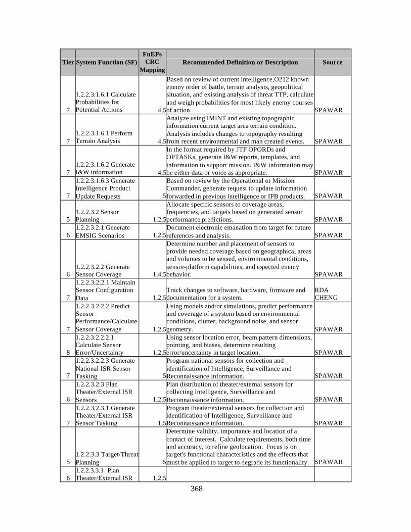
368
Tier System Function (SF) FnEPs CRC
Mapping Recommended Definition or Description Source
7
1.2.2.3.1.6.1 Calculate Probabilities for Potential Actions 4,5
Based on review of current intelligence,O212 known enemy order of battle, terrain analysis, geopolitical situation, and existing analysis of threat TTP, calculate and weigh probabilities for most likely enemy courses of action. SPAWAR
7 1.2.2.3.1.6.1 Perform Terrain Analysis 4,5
Analyze using IMINT and existing topographic information current target area terrain condition. Analysis includes changes to topography resulting from recent environmental and man created events. SPAWAR
7 1.2.2.3.1.6.2 Generate I&W information 4,5
In the format required by JTF OPORDs and OPTASKs, generate I&W reports, templates, and information to support mission. I&W information may be either data or voice as appropriate. SPAWAR
7
1.2.2.3.1.6.3 Generate Intelligence Product Update Requests 5
Based on review by the Operational or Mission Commander, generate request to update information forwarded in previous intelligence or IPB products. SPAWAR
5 1.2.2.3.2 Sensor Planning 1,2,5
Allocate specific sensors to coverage areas, frequencies, and targets based on generated sensor performance predictions. SPAWAR
6 1.2.2.3.2.1 Generate EMSIG Scenarios 1,2,5
Document electronic emanation from target for future references and analysis. SPAWAR
6 1.2.2.3.2.2 Generate Sensor Coverage 1,4,5
Determine number and placement of sensors to provide needed coverage based on geographical areas and volumes to be sensed, environmental conditions, sensor-platform capabilities, and expected enemy behavior. SPAWAR
7
1.2.2.3.2.2.1 Maintain Sensor Configuration Data 1,2,5
Track changes to software, hardware, firmware and documentation for a system.
RDA CHENG
7
1.2.2.3.2.2.2 Predict Sensor Performance/Calculate Sensor Coverage 1,2,5
Using models and/or simulations, predict performance and coverage of a system based on environmental conditions, clutter, background noise, and sensor geometry. SPAWAR
8
1.2.2.3.2.2.2.1 Calculate Sensor Error/Uncertainty 1,2,5
Using sensor location error, beam pattern dimensions, pointing, and biases, determine resulting error/uncertainty in target location. SPAWAR
7
1.2.2.3.2.2.3 Generate National ISR Sensor Tasking 5
Program national sensors for collection and identification of Intelligence, Surveillance and Reconnaissance information. SPAWAR
6
1.2.2.3.2.3 Plan Theater/External ISR Sensors 1,2,5
Plan distribution of theater/external sensors for collecting Intelligence, Surveillance and Reconnaissance information. SPAWAR
7
1.2.2.3.2.3.1 Generate Theater/External ISR Sensor Tasking 1,5
Program theater/external sensors for collection and identification of Intelligence, Surveillance and Reconnaissance information. SPAWAR
5 1.2.2.3.3 Target/Threat Planning 5
Determine validity, importance and location of a contact of interest. Calculate requirements, both time and accuracy, to refine geolocation. Focus is on target's functional characteristics and the effects that must be applied to target to degrade its functionality. SPAWAR
6 1.2.2.3.3.1 Plan Theater/External ISR 1,2,5
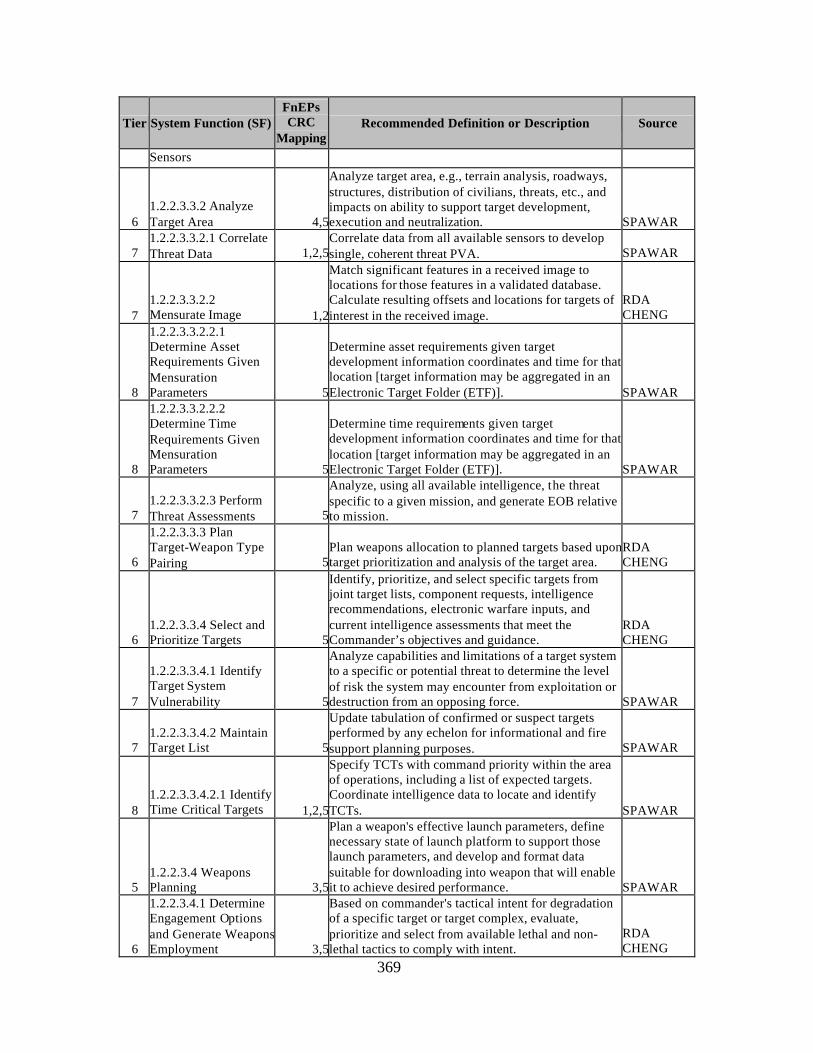
369
Tier System Function (SF) FnEPs CRC
Mapping Recommended Definition or Description Source
Sensors
6 1.2.2.3.3.2 Analyze Target Area 4,5
Analyze target area, e.g., terrain analysis, roadways, structures, distribution of civilians, threats, etc., and impacts on ability to support target development, execution and neutralization. SPAWAR
7 1.2.2.3.3.2.1 Correlate Threat Data 1,2,5
Correlate data from all available sensors to develop single, coherent threat PVA. SPAWAR
7 1.2.2.3.3.2.2 Mensurate Image 1,2
Match significant features in a received image to locations for those features in a validated database. Calculate resulting offsets and locations for targets of interest in the received image.
RDA CHENG
8
1.2.2.3.3.2.2.1 Determine Asset Requirements Given Mensuration Parameters 5
Determine asset requirements given target development information coordinates and time for that location [target information may be aggregated in an Electronic Target Folder (ETF)]. SPAWAR
8
1.2.2.3.3.2.2.2 Determine Time Requirements Given Mensuration Parameters 5
Determine time requirements given target development information coordinates and time for that location [target information may be aggregated in an Electronic Target Folder (ETF)]. SPAWAR
7 1.2.2.3.3.2.3 Perform Threat Assessments 5
Analyze, using all available intelligence, the threat specific to a given mission, and generate EOB relative to mission.
6
1.2.2.3.3.3 Plan Target-Weapon Type Pairing 5
Plan weapons allocation to planned targets based upon target prioritization and analysis of the target area.
RDA CHENG
6 1.2.2.3.3.4 Select and Prioritize Targets 5
Identify, prioritize, and select specific targets from joint target lists, component requests, intelligence recommendations, electronic warfare inputs, and current intelligence assessments that meet the Commander’s objectives and guidance.
RDA CHENG
7
1.2.2.3.3.4.1 Identify Target System Vulnerability 5
Analyze capabilities and limitations of a target system to a specific or potential threat to determine the level of risk the system may encounter from exploitation or destruction from an opposing force. SPAWAR
7 1.2.2.3.3.4.2 Maintain Target List 5
Update tabulation of confirmed or suspect targets performed by any echelon for informational and fire support planning purposes. SPAWAR
8 1.2.2.3.3.4.2.1 Identify Time Critical Targets 1,2,5
Specify TCTs with command priority within the area of operations, including a list of expected targets. Coordinate intelligence data to locate and identify TCTs. SPAWAR
5 1.2.2.3.4 Weapons Planning 3,5
Plan a weapon's effective launch parameters, define necessary state of launch platform to support those launch parameters, and develop and format data suitable for downloading into weapon that will enable it to achieve desired performance. SPAWAR
6
1.2.2.3.4.1 Determine Engagement Options and Generate Weapons Employment 3,5
Based on commander's tactical intent for degradation of a specific target or target complex, evaluate, prioritize and select from available lethal and non-lethal tactics to comply with intent.
RDA CHENG
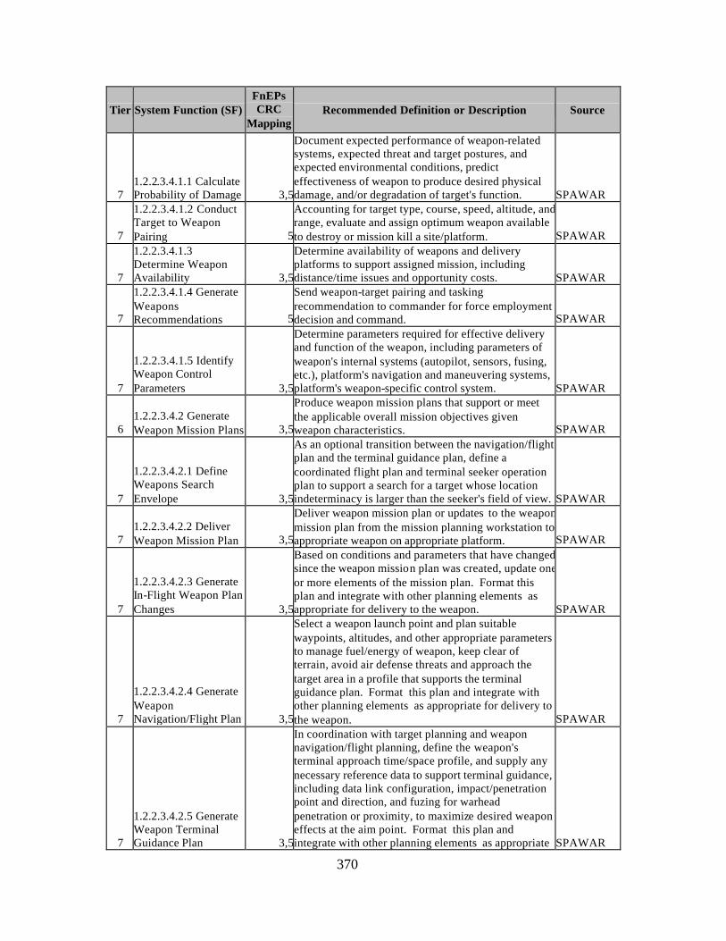
370
Tier System Function (SF) FnEPs CRC
Mapping Recommended Definition or Description Source
7 1.2.2.3.4.1.1 Calculate Probability of Damage 3,5
Document expected performance of weapon-related systems, expected threat and target postures, and expected environmental conditions, predict effectiveness of weapon to produce desired physical damage, and/or degradation of target's function. SPAWAR
7
1.2.2.3.4.1.2 Conduct Target to Weapon Pairing 5
Accounting for target type, course, speed, altitude, and range, evaluate and assign optimum weapon available to destroy or mission kill a site/platform. SPAWAR
7
1.2.2.3.4.1.3 Determine Weapon Availability 3,5
Determine availability of weapons and delivery platforms to support assigned mission, including distance/time issues and opportunity costs. SPAWAR
7
1.2.2.3.4.1.4 Generate Weapons Recommendations 5
Send weapon-target pairing and tasking recommendation to commander for force employment decision and command. SPAWAR
7
1.2.2.3.4.1.5 Identify Weapon Control Parameters 3,5
Determine parameters required for effective delivery and function of the weapon, including parameters of weapon's internal systems (autopilot, sensors, fusing, etc.), platform's navigation and maneuvering systems, platform's weapon-specific control system. SPAWAR
6 1.2.2.3.4.2 Generate Weapon Mission Plans 3,5
Produce weapon mission plans that support or meet the applicable overall mission objectives given weapon characteristics. SPAWAR
7
1.2.2.3.4.2.1 Define Weapons Search Envelope 3,5
As an optional transition between the navigation/flight plan and the terminal guidance plan, define a coordinated flight plan and terminal seeker operation plan to support a search for a target whose location indeterminacy is larger than the seeker's field of view. SPAWAR
7 1.2.2.3.4.2.2 Deliver Weapon Mission Plan 3,5
Deliver weapon mission plan or updates to the weapon mission plan from the mission planning workstation to appropriate weapon on appropriate platform. SPAWAR
7
1.2.2.3.4.2.3 Generate In-Flight Weapon Plan Changes 3,5
Based on conditions and parameters that have changed since the weapon mission plan was created, update one or more elements of the mission plan. Format this plan and integrate with other planning elements as appropriate for delivery to the weapon. SPAWAR
7
1.2.2.3.4.2.4 Generate Weapon Navigation/Flight Plan 3,5
Select a weapon launch point and plan suitable waypoints, altitudes, and other appropriate parameters to manage fuel/energy of weapon, keep clear of terrain, avoid air defense threats and approach the target area in a profile that supports the terminal guidance plan. Format this plan and integrate with other planning elements as appropriate for delivery to the weapon. SPAWAR
7
1.2.2.3.4.2.5 Generate Weapon Terminal Guidance Plan 3,5
In coordination with target planning and weapon navigation/flight planning, define the weapon's terminal approach time/space profile, and supply any necessary reference data to support terminal guidance, including data link configuration, impact/penetration point and direction, and fuzing for warhead penetration or proximity, to maximize desired weapon effects at the aim point. Format this plan and integrate with other planning elements as appropriate SPAWAR
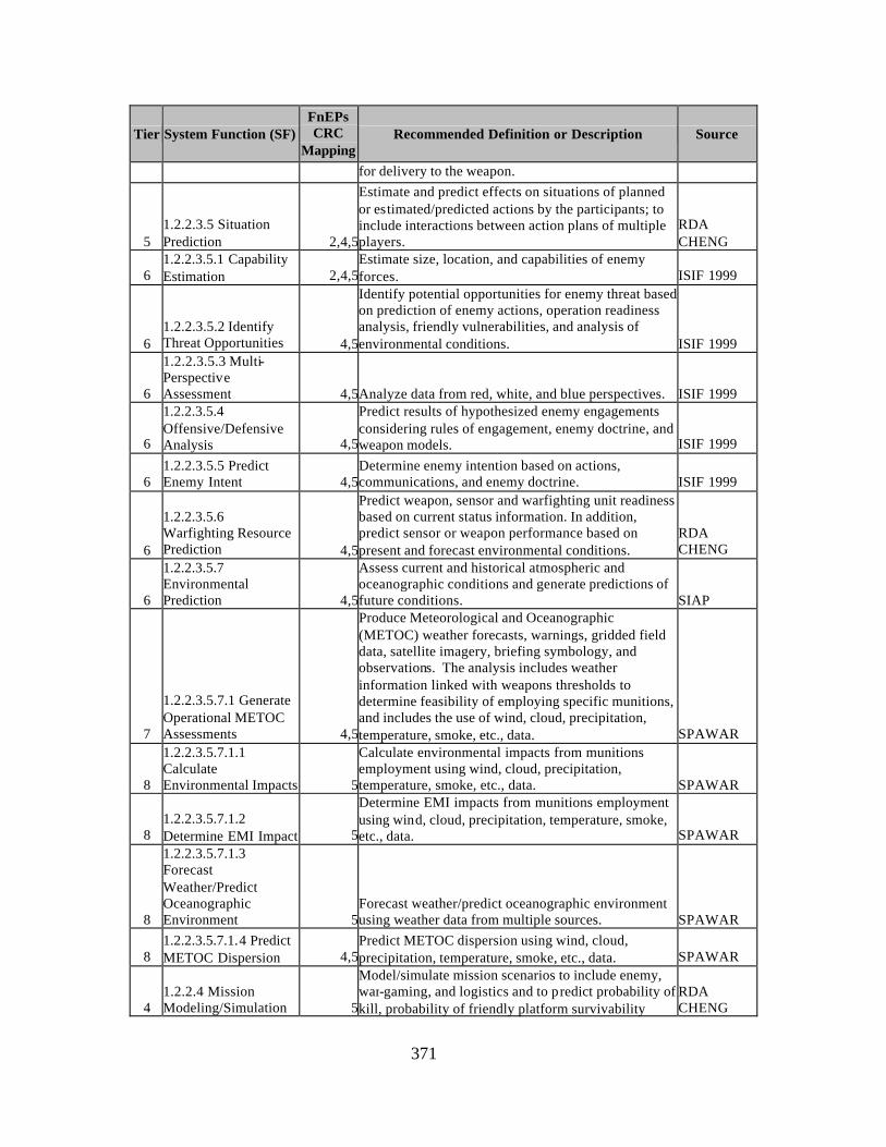
371
Tier System Function (SF) FnEPs CRC
Mapping Recommended Definition or Description Source
for delivery to the weapon.
5 1.2.2.3.5 Situation Prediction 2,4,5
Estimate and predict effects on situations of planned or estimated/predicted actions by the participants; to include interactions between action plans of multiple players.
RDA CHENG
6 1.2.2.3.5.1 Capability Estimation 2,4,5
Estimate size, location, and capabilities of enemy forces. ISIF 1999
6 1.2.2.3.5.2 Identify Threat Opportunities 4,5
Identify potential opportunities for enemy threat based on prediction of enemy actions, operation readiness analysis, friendly vulnerabilities, and analysis of environmental conditions. ISIF 1999
6
1.2.2.3.5.3 Multi-Perspective Assessment 4,5Analyze data from red, white, and blue perspectives. ISIF 1999
6
1.2.2.3.5.4 Offensive/Defensive Analysis 4,5
Predict results of hypothesized enemy engagements considering rules of engagement, enemy doctrine, and weapon models. ISIF 1999
6 1.2.2.3.5.5 Predict Enemy Intent 4,5
Determine enemy intention based on actions, communications, and enemy doctrine. ISIF 1999
6
1.2.2.3.5.6 Warfighting Resource Prediction 4,5
Predict weapon, sensor and warfighting unit readiness based on current status information. In addition, predict sensor or weapon performance based on present and forecast environmental conditions.
RDA CHENG
6
1.2.2.3.5.7 Environmental Prediction 4,5
Assess current and historical atmospheric and oceanographic conditions and generate predictions of future conditions. SIAP
7
1.2.2.3.5.7.1 Generate Operational METOC Assessments 4,5
Produce Meteorological and Oceanographic (METOC) weather forecasts, warnings, gridded field data, satellite imagery, briefing symbology, and observations. The analysis includes weather information linked with weapons thresholds to determine feasibility of employing specific munitions, and includes the use of wind, cloud, precipitation, temperature, smoke, etc., data. SPAWAR
8
1.2.2.3.5.7.1.1 Calculate Environmental Impacts 5
Calculate environmental impacts from munitions employment using wind, cloud, precipitation, temperature, smoke, etc., data. SPAWAR
8 1.2.2.3.5.7.1.2 Determine EMI Impact 5
Determine EMI impacts from munitions employment using wind, cloud, precipitation, temperature, smoke, etc., data. SPAWAR
8
1.2.2.3.5.7.1.3 Forecast Weather/Predict Oceanographic Environment 5
Forecast weather/predict oceanographic environment using weather data from multiple sources. SPAWAR
8 1.2.2.3.5.7.1.4 Predict METOC Dispersion 4,5
Predict METOC dispersion using wind, cloud, precipitation, temperature, smoke, etc., data. SPAWAR
4 1.2.2.4 Mission Modeling/Simulation 5
Model/simulate mission scenarios to include enemy, war-gaming, and logistics and to predict probability of kill, probability of friendly platform survivability
RDA CHENG
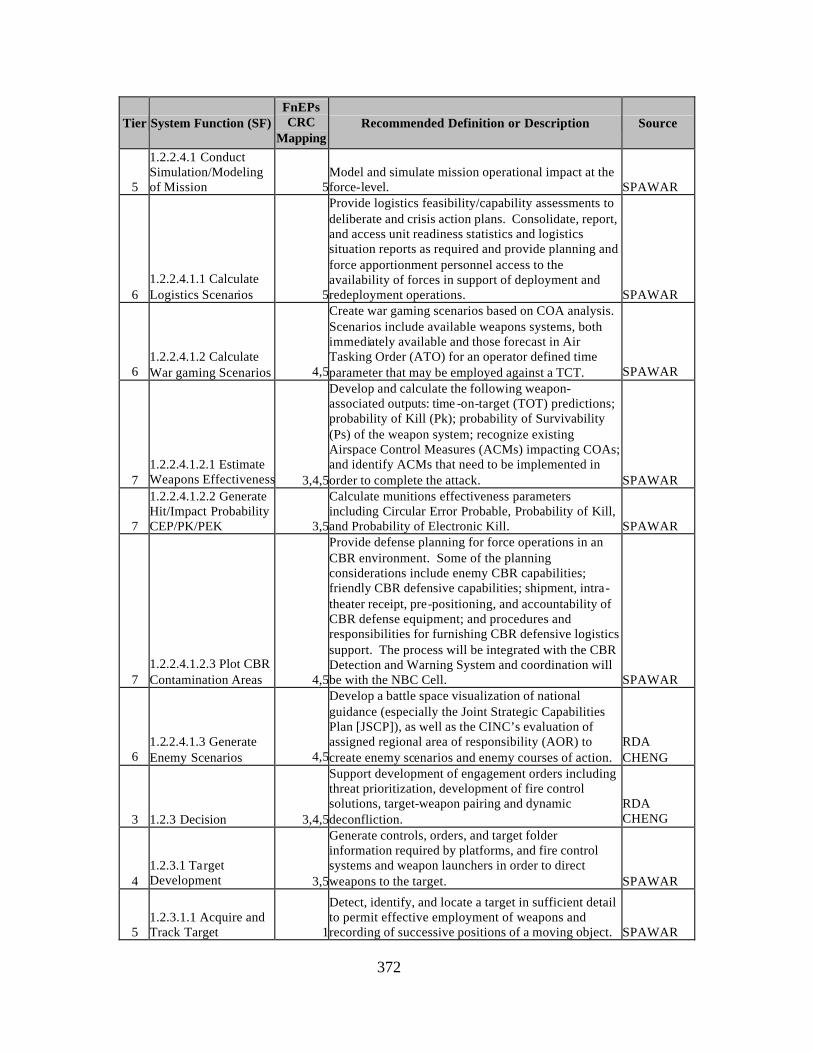
372
Tier System Function (SF) FnEPs CRC
Mapping Recommended Definition or Description Source
5
1.2.2.4.1 Conduct Simulation/Modeling of Mission 5
Model and simulate mission operational impact at the force-level. SPAWAR
6 1.2.2.4.1.1 Calculate Logistics Scenarios 5
Provide logistics feasibility/capability assessments to deliberate and crisis action plans. Consolidate, report, and access unit readiness statistics and logistics situation reports as required and provide planning and force apportionment personnel access to the availability of forces in support of deployment and redeployment operations. SPAWAR
6 1.2.2.4.1.2 Calculate War gaming Scenarios 4,5
Create war gaming scenarios based on COA analysis. Scenarios include available weapons systems, both immediately available and those forecast in Air Tasking Order (ATO) for an operator defined time parameter that may be employed against a TCT. SPAWAR
7 1.2.2.4.1.2.1 Estimate Weapons Effectiveness 3,4,5
Develop and calculate the following weapon-associated outputs: time -on-target (TOT) predictions; probability of Kill (Pk); probability of Survivability (Ps) of the weapon system; recognize existing Airspace Control Measures (ACMs) impacting COAs; and identify ACMs that need to be implemented in order to complete the attack. SPAWAR
7
1.2.2.4.1.2.2 Generate Hit/Impact Probability CEP/PK/PEK 3,5
Calculate munitions effectiveness parameters including Circular Error Probable, Probability of Kill, and Probability of Electronic Kill. SPAWAR
7 1.2.2.4.1.2.3 Plot CBR Contamination Areas 4,5
Provide defense planning for force operations in an CBR environment. Some of the planning considerations include enemy CBR capabilities; friendly CBR defensive capabilities; shipment, intra-theater receipt, pre-positioning, and accountability of CBR defense equipment; and procedures and responsibilities for furnishing CBR defensive logistics support. The process will be integrated with the CBR Detection and Warning System and coordination will be with the NBC Cell. SPAWAR
6 1.2.2.4.1.3 Generate Enemy Scenarios 4,5
Develop a battle space visualization of national guidance (especially the Joint Strategic Capabilities Plan [JSCP]), as well as the CINC’s evaluation of assigned regional area of responsibility (AOR) to create enemy scenarios and enemy courses of action.
RDA CHENG
3 1.2.3 Decision 3,4,5
Support development of engagement orders including threat prioritization, development of fire control solutions, target-weapon pairing and dynamic deconfliction.
RDA CHENG
4 1.2.3.1 Target Development 3,5
Generate controls, orders, and target folder information required by platforms, and fire control systems and weapon launchers in order to direct weapons to the target. SPAWAR
5 1.2.3.1.1 Acquire and Track Target 1
Detect, identify, and locate a target in sufficient detail to permit effective employment of weapons and recording of successive positions of a moving object. SPAWAR
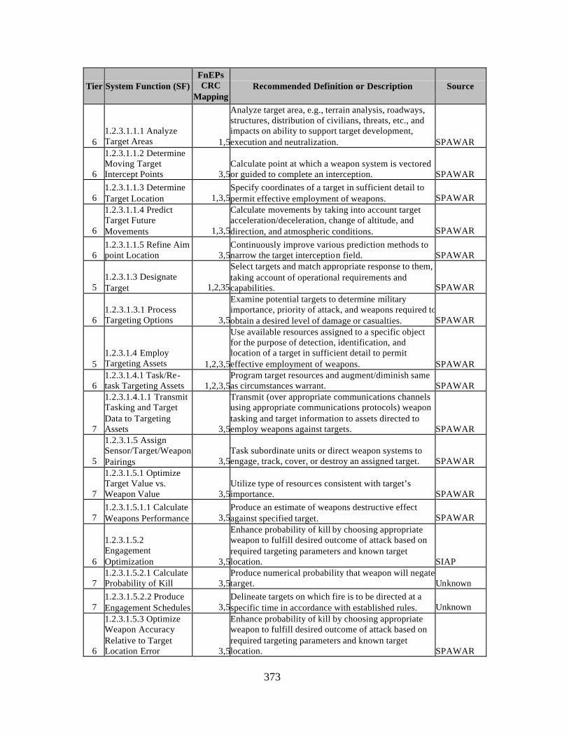
373
Tier System Function (SF) FnEPs CRC
Mapping Recommended Definition or Description Source
6 1.2.3.1.1.1 Analyze Target Areas 1,5
Analyze target area, e.g., terrain analysis, roadways, structures, distribution of civilians, threats, etc., and impacts on ability to support target development, execution and neutralization. SPAWAR
6
1.2.3.1.1.2 Determine Moving Target Intercept Points 3,5
Calculate point at which a weapon system is vectored or guided to complete an interception. SPAWAR
6 1.2.3.1.1.3 Determine Target Location 1,3,5
Specify coordinates of a target in sufficient detail to permit effective employment of weapons. SPAWAR
6
1.2.3.1.1.4 Predict Target Future Movements 1,3,5
Calculate movements by taking into account target acceleration/deceleration, change of altitude, and direction, and atmospheric conditions. SPAWAR
6 1.2.3.1.1.5 Refine Aim point Location 3,5
Continuously improve various prediction methods to narrow the target interception field. SPAWAR
5 1.2.3.1.3 Designate Target 1,2,35
Select targets and match appropriate response to them, taking account of operational requirements and capabilities. SPAWAR
6 1.2.3.1.3.1 Process Targeting Options 3,5
Examine potential targets to determine military importance, priority of attack, and weapons required to obtain a desired level of damage or casualties. SPAWAR
5 1.2.3.1.4 Employ Targeting Assets 1,2,3,5
Use available resources assigned to a specific object for the purpose of detection, identification, and location of a target in sufficient detail to permit effective employment of weapons. SPAWAR
6 1.2.3.1.4.1 Task/Re-task Targeting Assets 1,2,3,5
Program target resources and augment/diminish same as circumstances warrant. SPAWAR
7
1.2.3.1.4.1.1 Transmit Tasking and Target Data to Targeting Assets 3,5
Transmit (over appropriate communications channels using appropriate communications protocols) weapon tasking and target information to assets directed to employ weapons against targets. SPAWAR
5
1.2.3.1.5 Assign Sensor/Target/Weapon Pairings 3,5
Task subordinate units or direct weapon systems to engage, track, cover, or destroy an assigned target. SPAWAR
7
1.2.3.1.5.1 Optimize Target Value vs. Weapon Value 3,5
Utilize type of resources consistent with target’s importance. SPAWAR
7 1.2.3.1.5.1.1 Calculate Weapons Performance 3,5
Produce an estimate of weapons destructive effect against specified target. SPAWAR
6
1.2.3.1.5.2 Engagement Optimization 3,5
Enhance probability of kill by choosing appropriate weapon to fulfill desired outcome of attack based on required targeting parameters and known target location. SIAP
7 1.2.3.1.5.2.1 Calculate Probability of Kill 3,5
Produce numerical probability that weapon will negate target. Unknown
7 1.2.3.1.5.2.2 Produce Engagement Schedules 3,5
Delineate targets on which fire is to be directed at a specific time in accordance with established rules. Unknown
6
1.2.3.1.5.3 Optimize Weapon Accuracy Relative to Target Location Error 3,5
Enhance probability of kill by choosing appropriate weapon to fulfill desired outcome of attack based on required targeting parameters and known target location. SPAWAR
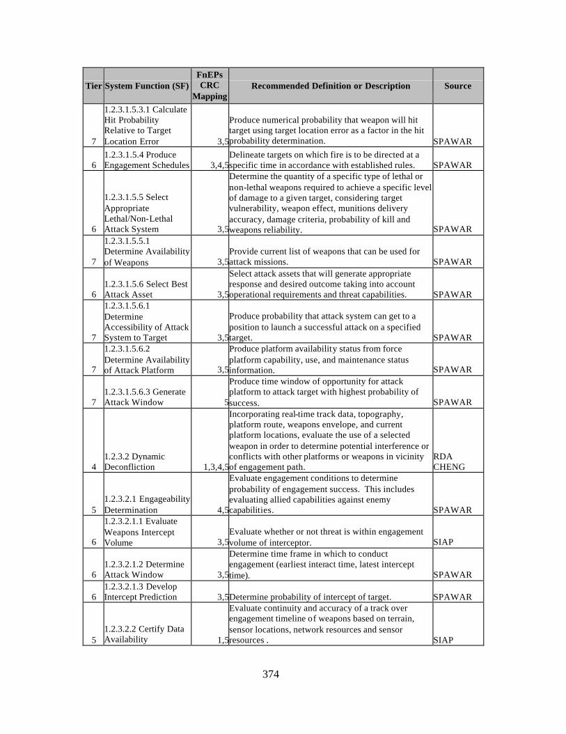
374
Tier System Function (SF) FnEPs CRC
Mapping Recommended Definition or Description Source
7
1.2.3.1.5.3.1 Calculate Hit Probability Relative to Target Location Error 3,5
Produce numerical probability that weapon will hit target using target location error as a factor in the hit probability determination. SPAWAR
6 1.2.3.1.5.4 Produce Engagement Schedules 3,4,5
Delineate targets on which fire is to be directed at a specific time in accordance with established rules. SPAWAR
6
1.2.3.1.5.5 Select Appropriate Lethal/Non-Lethal Attack System 3,5
Determine the quantity of a specific type of lethal or non-lethal weapons required to achieve a specific level of damage to a given target, considering target vulnerability, weapon effect, munitions delivery accuracy, damage criteria, probability of kill and weapons reliability. SPAWAR
7
1.2.3.1.5.5.1 Determine Availability of Weapons 3,5
Provide current list of weapons that can be used for attack missions. SPAWAR
6 1.2.3.1.5.6 Select Best Attack Asset 3,5
Select attack assets that will generate appropriate response and desired outcome taking into account operational requirements and threat capabilities. SPAWAR
7
1.2.3.1.5.6.1 Determine Accessibility of Attack System to Target 3,5
Produce probability that attack system can get to a position to launch a successful attack on a specified target. SPAWAR
7
1.2.3.1.5.6.2 Determine Availability of Attack Platform 3,5
Produce platform availability status from force platform capability, use, and maintenance status information. SPAWAR
7 1.2.3.1.5.6.3 Generate Attack Window 5
Produce time window of opportunity for attack platform to attack target with highest probability of success. SPAWAR
4 1.2.3.2 Dynamic Deconfliction 1,3,4,5
Incorporating real-time track data, topography, platform route, weapons envelope, and current platform locations, evaluate the use of a selected weapon in order to determine potential interference or conflicts with other platforms or weapons in vicinity of engagement path.
RDA CHENG
5 1.2.3.2.1 Engageability Determination 4,5
Evaluate engagement conditions to determine probability of engagement success. This includes evaluating allied capabilities against enemy capabilities. SPAWAR
6
1.2.3.2.1.1 Evaluate Weapons Intercept Volume 3,5
Evaluate whether or not threat is within engagement volume of interceptor. SIAP
6 1.2.3.2.1.2 Determine Attack Window 3,5
Determine time frame in which to conduct engagement (earliest interact time, latest intercept time). SPAWAR
6 1.2.3.2.1.3 Develop Intercept Prediction 3,5Determine probability of intercept of target. SPAWAR
5 1.2.3.2.2 Certify Data Availability 1,5
Evaluate continuity and accuracy of a track over engagement timeline of weapons based on terrain, sensor locations, network resources and sensor resources . SIAP
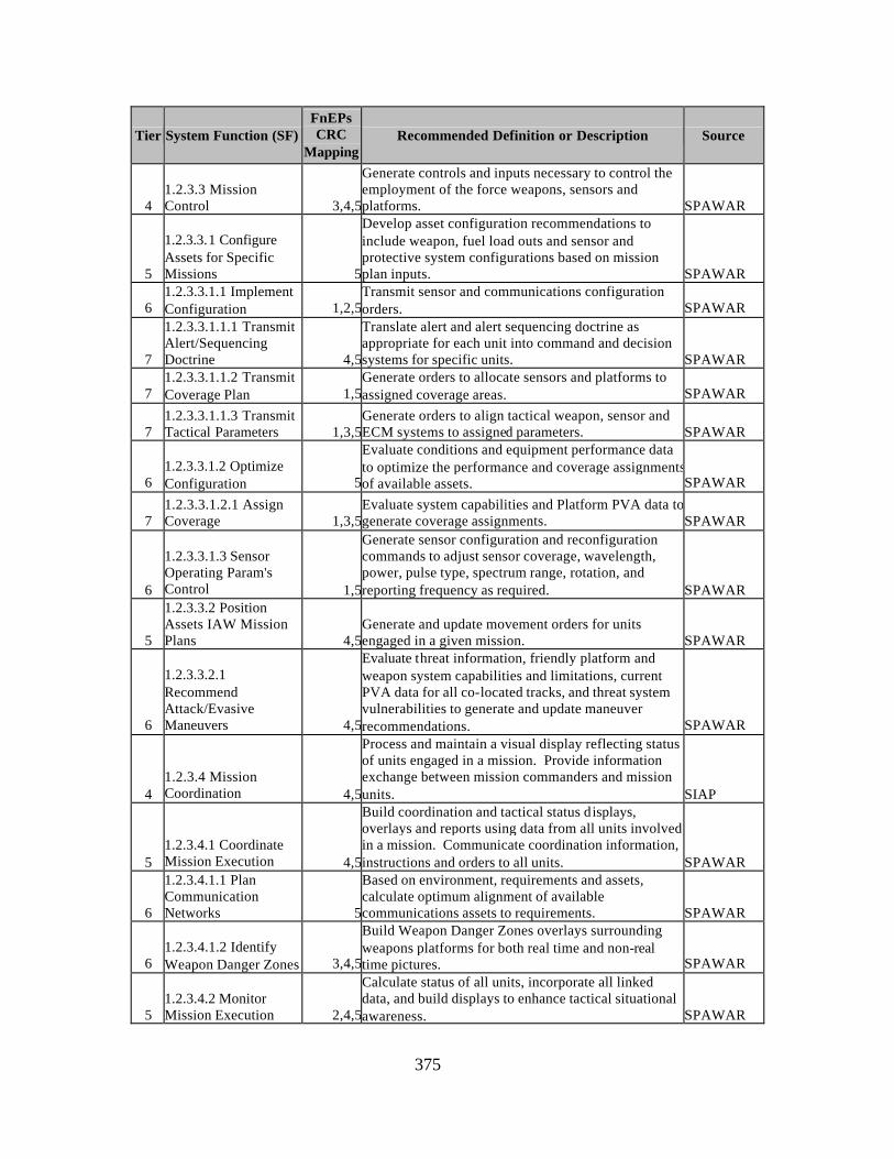
375
Tier System Function (SF) FnEPs CRC
Mapping Recommended Definition or Description Source
4 1.2.3.3 Mission Control 3,4,5
Generate controls and inputs necessary to control the employment of the force weapons, sensors and platforms. SPAWAR
5
1.2.3.3.1 Configure Assets for Specific Missions 5
Develop asset configuration recommendations to include weapon, fuel load outs and sensor and protective system configurations based on mission plan inputs. SPAWAR
6 1.2.3.3.1.1 Implement Configuration 1,2,5
Transmit sensor and communications configuration orders. SPAWAR
7
1.2.3.3.1.1.1 Transmit Alert/Sequencing Doctrine 4,5
Translate alert and alert sequencing doctrine as appropriate for each unit into command and decision systems for specific units. SPAWAR
7 1.2.3.3.1.1.2 Transmit Coverage Plan 1,5
Generate orders to allocate sensors and platforms to assigned coverage areas. SPAWAR
7 1.2.3.3.1.1.3 Transmit Tactical Parameters 1,3,5
Generate orders to align tactical weapon, sensor and ECM systems to assigned parameters. SPAWAR
6 1.2.3.3.1.2 Optimize Configuration 5
Evaluate conditions and equipment performance data to optimize the performance and coverage assignments of available assets. SPAWAR
7 1.2.3.3.1.2.1 Assign Coverage 1,3,5
Evaluate system capabilities and Platform PVA data to generate coverage assignments. SPAWAR
6
1.2.3.3.1.3 Sensor Operating Param's Control 1,5
Generate sensor configuration and reconfiguration commands to adjust sensor coverage, wavelength, power, pulse type, spectrum range, rotation, and reporting frequency as required. SPAWAR
5
1.2.3.3.2 Position Assets IAW Mission Plans 4,5
Generate and update movement orders for units engaged in a given mission. SPAWAR
6
1.2.3.3.2.1 Recommend Attack/Evasive Maneuvers 4,5
Evaluate threat information, friendly platform and weapon system capabilities and limitations, current PVA data for all co-located tracks, and threat system vulnerabilities to generate and update maneuver recommendations. SPAWAR
4 1.2.3.4 Mission Coordination 4,5
Process and maintain a visual display reflecting status of units engaged in a mission. Provide information exchange between mission commanders and mission units. SIAP
5 1.2.3.4.1 Coordinate Mission Execution 4,5
Build coordination and tactical status displays, overlays and reports using data from all units involved in a mission. Communicate coordination information, instructions and orders to all units. SPAWAR
6
1.2.3.4.1.1 Plan Communication Networks 5
Based on environment, requirements and assets, calculate optimum alignment of available communications assets to requirements. SPAWAR
6 1.2.3.4.1.2 Identify Weapon Danger Zones 3,4,5
Build Weapon Danger Zones overlays surrounding weapons platforms for both real time and non-real time pictures. SPAWAR
5 1.2.3.4.2 Monitor Mission Execution 2,4,5
Calculate status of all units, incorporate all linked data, and build displays to enhance tactical situational awareness. SPAWAR
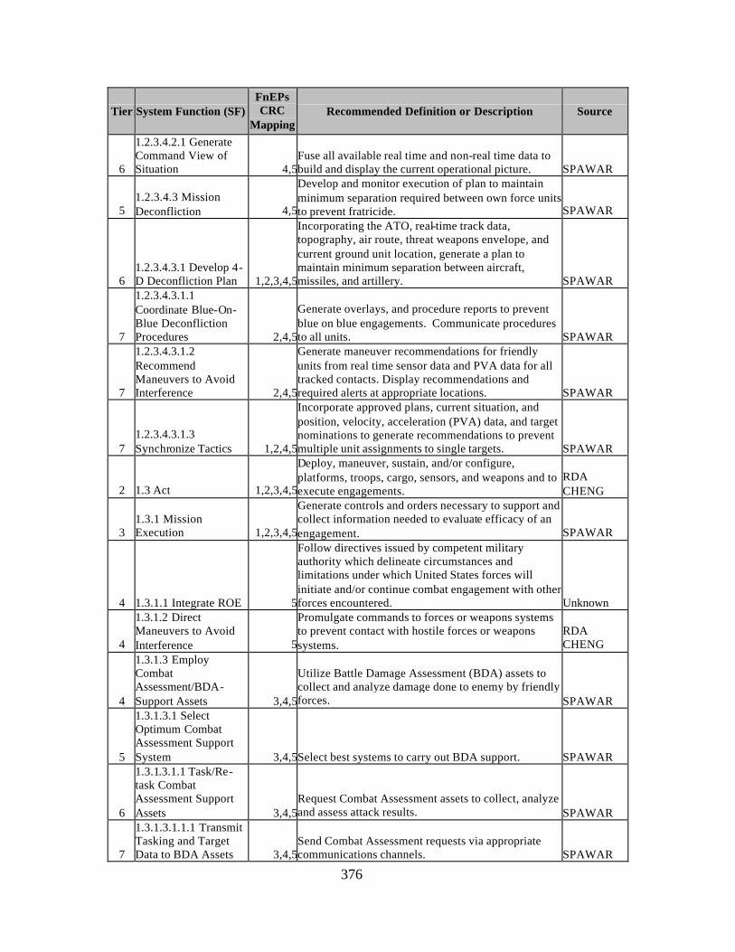
376
Tier System Function (SF) FnEPs CRC
Mapping Recommended Definition or Description Source
6
1.2.3.4.2.1 Generate Command View of Situation 4,5
Fuse all available real time and non-real time data to build and display the current operational picture. SPAWAR
5 1.2.3.4.3 Mission Deconfliction 4,5
Develop and monitor execution of plan to maintain minimum separation required between own force units to prevent fratricide. SPAWAR
6 1.2.3.4.3.1 Develop 4-D Deconfliction Plan 1,2,3,4,5
Incorporating the ATO, real-time track data, topography, air route, threat weapons envelope, and current ground unit location, generate a plan to maintain minimum separation between aircraft, missiles, and artillery. SPAWAR
7
1.2.3.4.3.1.1 Coordinate Blue-On-Blue Deconfliction Procedures 2,4,5
Generate overlays, and procedure reports to prevent blue on blue engagements. Communicate procedures to all units. SPAWAR
7
1.2.3.4.3.1.2 Recommend Maneuvers to Avoid Interference 2,4,5
Generate maneuver recommendations for friendly units from real time sensor data and PVA data for all tracked contacts. Display recommendations and required alerts at appropriate locations. SPAWAR
7 1.2.3.4.3.1.3 Synchronize Tactics 1,2,4,5
Incorporate approved plans, current situation, and position, velocity, acceleration (PVA) data, and target nominations to generate recommendations to prevent multiple unit assignments to single targets. SPAWAR
2 1.3 Act 1,2,3,4,5
Deploy, maneuver, sustain, and/or configure, platforms, troops, cargo, sensors, and weapons and to execute engagements.
RDA CHENG
3 1.3.1 Mission Execution 1,2,3,4,5
Generate controls and orders necessary to support and collect information needed to evaluate efficacy of an engagement. SPAWAR
4 1.3.1.1 Integrate ROE 5
Follow directives issued by competent military authority which delineate circumstances and limitations under which United States forces will initiate and/or continue combat engagement with other forces encountered. Unknown
4
1.3.1.2 Direct Maneuvers to Avoid Interference 5
Promulgate commands to forces or weapons systems to prevent contact with hostile forces or weapons systems.
RDA CHENG
4
1.3.1.3 Employ Combat Assessment/BDA-Support Assets 3,4,5
Utilize Battle Damage Assessment (BDA) assets to collect and analyze damage done to enemy by friendly forces. SPAWAR
5
1.3.1.3.1 Select Optimum Combat Assessment Support System 3,4,5Select best systems to carry out BDA support. SPAWAR
6
1.3.1.3.1.1 Task/Re-task Combat Assessment Support Assets 3,4,5
Request Combat Assessment assets to collect, analyze and assess attack results. SPAWAR
7
1.3.1.3.1.1.1 Transmit Tasking and Target Data to BDA Assets 3,4,5
Send Combat Assessment requests via appropriate communications channels. SPAWAR
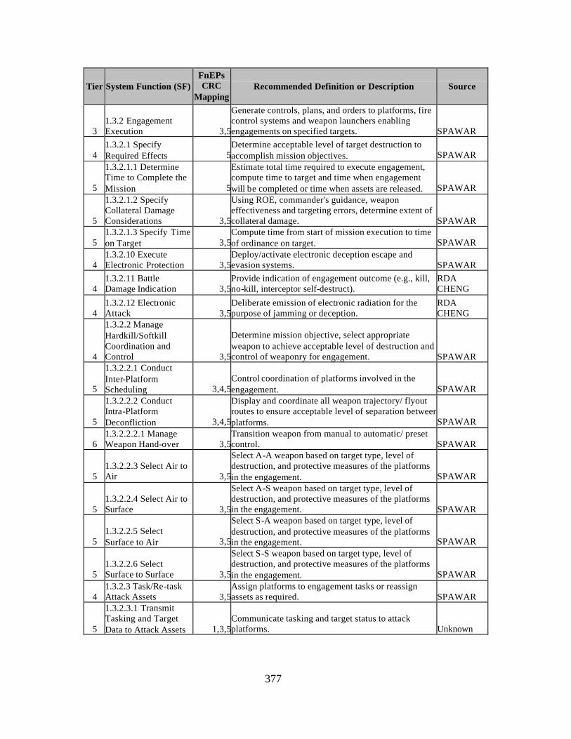
377
Tier System Function (SF) FnEPs CRC
Mapping Recommended Definition or Description Source
3 1.3.2 Engagement Execution 3,5
Generate controls, plans, and orders to platforms, fire control systems and weapon launchers enabling engagements on specified targets. SPAWAR
4 1.3.2.1 Specify Required Effects 5
Determine acceptable level of target destruction to accomplish mission objectives. SPAWAR
5
1.3.2.1.1 Determine Time to Complete the Mission 5
Estimate total time required to execute engagement, compute time to target and time when engagement will be completed or time when assets are released. SPAWAR
5
1.3.2.1.2 Specify Collateral Damage Considerations 3,5
Using ROE, commander's guidance, weapon effectiveness and targeting errors, determine extent of collateral damage. SPAWAR
5 1.3.2.1.3 Specify Time on Target 3,5
Compute time from start of mission execution to time of ordinance on target. SPAWAR
4 1.3.2.10 Execute Electronic Protection 3,5
Deploy/activate electronic deception escape and evasion systems. SPAWAR
4 1.3.2.11 Battle Damage Indication 3,5
Provide indication of engagement outcome (e.g., kill, no-kill, interceptor self-destruct).
RDA CHENG
4 1.3.2.12 Electronic Attack 3,5
Deliberate emission of electronic radiation for the purpose of jamming or deception.
RDA CHENG
4
1.3.2.2 Manage Hardkill/Softkill Coordination and Control 3,5
Determine mission objective, select appropriate weapon to achieve acceptable level of destruction and control of weaponry for engagement. SPAWAR
5
1.3.2.2.1 Conduct Inter-Platform Scheduling 3,4,5
Control coordination of platforms involved in the engagement. SPAWAR
5
1.3.2.2.2 Conduct Intra-Platform Deconfliction 3,4,5
Display and coordinate all weapon trajectory/ flyout routes to ensure acceptable level of separation between platforms. SPAWAR
6 1.3.2.2.2.1 Manage Weapon Hand-over 3,5
Transition weapon from manual to automatic/ preset control. SPAWAR
5 1.3.2.2.3 Select Air to Air 3,5
Select A-A weapon based on target type, level of destruction, and protective measures of the platforms in the engagement. SPAWAR
5 1.3.2.2.4 Select Air to Surface 3,5
Select A-S weapon based on target type, level of destruction, and protective measures of the platforms in the engagement. SPAWAR
5 1.3.2.2.5 Select Surface to Air 3,5
Select S-A weapon based on target type, level of destruction, and protective measures of the platforms in the engagement. SPAWAR
5 1.3.2.2.6 Select Surface to Surface 3,5
Select S-S weapon based on target type, level of destruction, and protective measures of the platforms in the engagement. SPAWAR
4 1.3.2.3 Task/Re-task Attack Assets 3,5
Assign platforms to engagement tasks or reassign assets as required. SPAWAR
5
1.3.2.3.1 Transmit Tasking and Target Data to Attack Assets 1,3,5
Communicate tasking and target status to attack platforms. Unknown
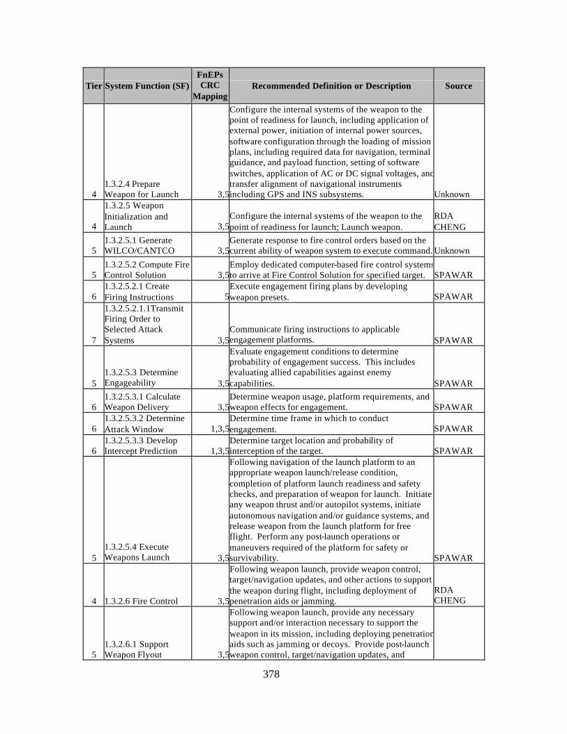
378
Tier System Function (SF) FnEPs CRC
Mapping Recommended Definition or Description Source
4 1.3.2.4 Prepare Weapon for Launch 3,5
Configure the internal systems of the weapon to the point of readiness for launch, including application of external power, initiation of internal power sources, software configuration through the loading of mission plans, including required data for navigation, terminal guidance, and payload function, setting of software switches, application of AC or DC signal voltages, and transfer alignment of navigational instruments including GPS and INS subsystems. Unknown
4
1.3.2.5 Weapon Initialization and Launch 3,5
Configure the internal systems of the weapon to the point of readiness for launch; Launch weapon.
RDA CHENG
5 1.3.2.5.1 Generate WILCO/CANTCO 3,5
Generate response to fire control orders based on the current ability of weapon system to execute command. Unknown
5 1.3.2.5.2 Compute Fire Control Solution 3,5
Employ dedicated computer-based fire control systems to arrive at Fire Control Solution for specified target. SPAWAR
6 1.3.2.5.2.1 Create Firing Instructions 5
Execute engagement firing plans by developing weapon presets. SPAWAR
7
1.3.2.5.2.1.1Transmit Firing Order to Selected Attack Systems 3,5
Communicate firing instructions to applicable engagement platforms. SPAWAR
5 1.3.2.5.3 Determine Engageability 3,5
Evaluate engagement conditions to determine probability of engagement success. This includes evaluating allied capabilities against enemy capabilities. SPAWAR
6 1.3.2.5.3.1 Calculate Weapon Delivery 3,5
Determine weapon usage, platform requirements, and weapon effects for engagement. SPAWAR
6 1.3.2.5.3.2 Determine Attack Window 1,3,5
Determine time frame in which to conduct engagement. SPAWAR
6 1.3.2.5.3.3 Develop Intercept Prediction 1,3,5
Determine target location and probability of interception of the target. SPAWAR
5 1.3.2.5.4 Execute Weapons Launch 3,5
Following navigation of the launch platform to an appropriate weapon launch/release condition, completion of platform launch readiness and safety checks, and preparation of weapon for launch. Initiate any weapon thrust and/or autopilot systems, initiate autonomous navigation and/or guidance systems, and release weapon from the launch platform for free flight. Perform any post-launch operations or maneuvers required of the platform for safety or survivability. SPAWAR
4 1.3.2.6 Fire Control 3,5
Following weapon launch, provide weapon control, target/navigation updates, and other actions to support the weapon during flight, including deployment of penetration aids or jamming.
RDA CHENG
5 1.3.2.6.1 Support Weapon Flyout 3,5
Following weapon launch, provide any necessary support and/or interaction necessary to support the weapon in its mission, including deploying penetration aids such as jamming or decoys. Provide post-launch weapon control, target/navigation updates, and
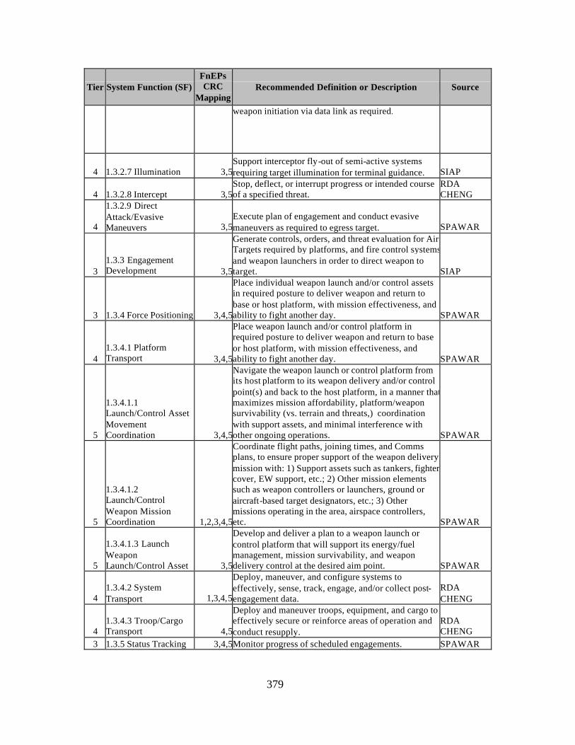
379
Tier System Function (SF) FnEPs CRC
Mapping Recommended Definition or Description Source
weapon initiation via data link as required.
4 1.3.2.7 Illumination 3,5Support interceptor fly-out of semi-active systems requiring target illumination for terminal guidance. SIAP
4 1.3.2.8 Intercept 3,5Stop, deflect, or interrupt progress or intended course of a specified threat.
RDA CHENG
4
1.3.2.9 Direct Attack/Evasive Maneuvers 3,5
Execute plan of engagement and conduct evasive maneuvers as required to egress target. SPAWAR
3 1.3.3 Engagement Development 3,5
Generate controls, orders, and threat evaluation for Air Targets required by platforms, and fire control systems and weapon launchers in order to direct weapon to target. SIAP
3 1.3.4 Force Positioning 3,4,5
Place individual weapon launch and/or control assets in required posture to deliver weapon and return to base or host platform, with mission effectiveness, and ability to fight another day. SPAWAR
4 1.3.4.1 Platform Transport 3,4,5
Place weapon launch and/or control platform in required posture to deliver weapon and return to base or host platform, with mission effectiveness, and ability to fight another day. SPAWAR
5
1.3.4.1.1 Launch/Control Asset Movement Coordination 3,4,5
Navigate the weapon launch or control platform from its host platform to its weapon delivery and/or control point(s) and back to the host platform, in a manner that maximizes mission affordability, platform/weapon survivability (vs. terrain and threats,) coordination with support assets, and minimal interference with other ongoing operations. SPAWAR
5
1.3.4.1.2 Launch/Control Weapon Mission Coordination 1,2,3,4,5
Coordinate flight paths, joining times, and Comms plans, to ensure proper support of the weapon delivery mission with: 1) Support assets such as tankers, fighter cover, EW support, etc.; 2) Other mission elements such as weapon controllers or launchers, ground or aircraft-based target designators, etc.; 3) Other missions operating in the area, airspace controllers, etc. SPAWAR
5
1.3.4.1.3 Launch Weapon Launch/Control Asset 3,5
Develop and deliver a plan to a weapon launch or control platform that will support its energy/fuel management, mission survivability, and weapon delivery control at the desired aim point. SPAWAR
4 1.3.4.2 System Transport 1,3,4,5
Deploy, maneuver, and configure systems to effectively, sense, track, engage, and/or collect post-engagement data.
RDA CHENG
4 1.3.4.3 Troop/Cargo Transport 4,5
Deploy and maneuver troops, equipment, and cargo to effectively secure or reinforce areas of operation and conduct resupply.
RDA CHENG
3 1.3.5 Status Tracking 3,4,5Monitor progress of scheduled engagements. SPAWAR
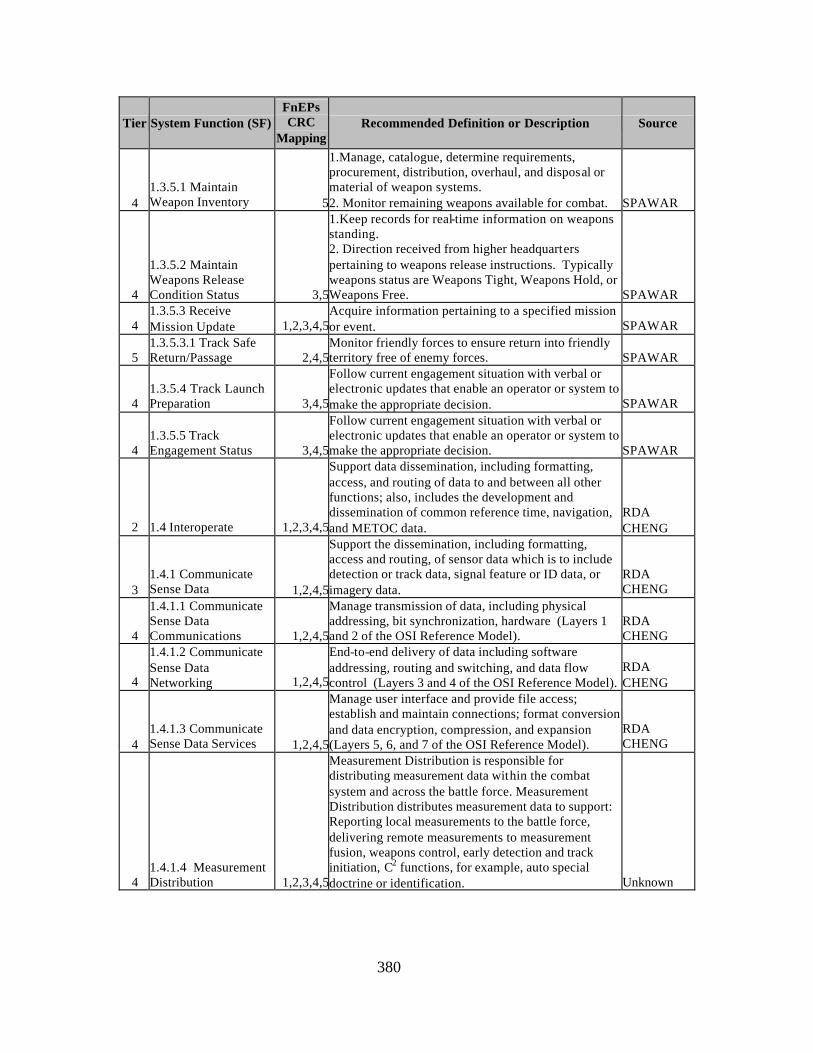
380
Tier System Function (SF) FnEPs CRC
Mapping Recommended Definition or Description Source
4 1.3.5.1 Maintain Weapon Inventory 5
1.Manage, catalogue, determine requirements, procurement, distribution, overhaul, and disposal or material of weapon systems. 2. Monitor remaining weapons available for combat. SPAWAR
4
1.3.5.2 Maintain Weapons Release Condition Status 3,5
1.Keep records for real-time information on weapons standing. 2. Direction received from higher headquarters pertaining to weapons release instructions. Typically weapons status are Weapons Tight, Weapons Hold, or Weapons Free. SPAWAR
4 1.3.5.3 Receive Mission Update 1,2,3,4,5
Acquire information pertaining to a specified mission or event. SPAWAR
5 1.3.5.3.1 Track Safe Return/Passage 2,4,5
Monitor friendly forces to ensure return into friendly territory free of enemy forces. SPAWAR
4 1.3.5.4 Track Launch Preparation 3,4,5
Follow current engagement situation with verbal or electronic updates that enable an operator or system to make the appropriate decision. SPAWAR
4 1.3.5.5 Track Engagement Status 3,4,5
Follow current engagement situation with verbal or electronic updates that enable an operator or system to make the appropriate decision. SPAWAR
2 1.4 Interoperate 1,2,3,4,5
Support data dissemination, including formatting, access, and routing of data to and between all other functions; also, includes the development and dissemination of common reference time, navigation, and METOC data.
RDA CHENG
3 1.4.1 Communicate Sense Data 1,2,4,5
Support the dissemination, including formatting, access and routing, of sensor data which is to include detection or track data, signal feature or ID data, or imagery data.
RDA CHENG
4
1.4.1.1 Communicate Sense Data Communications 1,2,4,5
Manage transmission of data, including physical addressing, bit synchronization, hardware (Layers 1 and 2 of the OSI Reference Model).
RDA CHENG
4
1.4.1.2 Communicate Sense Data Networking 1,2,4,5
End-to-end delivery of data including software addressing, routing and switching, and data flow control (Layers 3 and 4 of the OSI Reference Model).
RDA CHENG
4 1.4.1.3 Communicate Sense Data Services 1,2,4,5
Manage user interface and provide file access; establish and maintain connections; format conversion and data encryption, compression, and expansion (Layers 5, 6, and 7 of the OSI Reference Model).
RDA CHENG
4 1.4.1.4 Measurement Distribution 1,2,3,4,5
Measurement Distribution is responsible for distributing measurement data within the combat system and across the battle force. Measurement Distribution distributes measurement data to support: Reporting local measurements to the battle force, delivering remote measurements to measurement fusion, weapons control, early detection and track initiation, C2 functions, for example, auto special doctrine or identification. Unknown
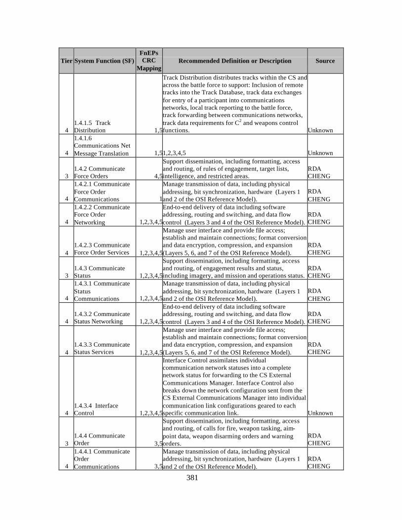
381
Tier System Function (SF) FnEPs CRC
Mapping Recommended Definition or Description Source
4 1.4.1.5 Track Distribution 1,5
Track Distribution distributes tracks within the CS and across the battle force to support: Inclusion of remote tracks into the Track Database, track data exchanges for entry of a participant into communications networks, local track reporting to the battle force, track forwarding between communications networks, track data requirements for C2 and weapons control functions. Unknown
4
1.4.1.6 Communications Net Message Translation 1,51,2,3,4,5 Unknown
3 1.4.2 Communicate Force Orders 4,5
Support dissemination, including formatting, access and routing, of rules of engagement, target lists, intelligence, and restricted areas.
RDA CHENG
4
1.4.2.1 Communicate Force Order Communications 1
Manage transmission of data, including physical addressing, bit synchronization, hardware (Layers 1 and 2 of the OSI Reference Model).
RDA CHENG
4
1.4.2.2 Communicate Force Order Networking 1,2,3,4,5
End-to-end delivery of data including software addressing, routing and switching, and data flow control (Layers 3 and 4 of the OSI Reference Model).
RDA CHENG
4 1.4.2.3 Communicate Force Order Services 1,2,3,4,5
Manage user interface and provide file access; establish and maintain connections; format conversion and data encryption, compression, and expansion (Layers 5, 6, and 7 of the OSI Reference Model).
RDA CHENG
3 1.4.3 Communicate Status 1,2,3,4,5
Support dissemination, including formatting, access and routing, of engagement results and status, including imagery, and mission and operations status.
RDA CHENG
4
1.4.3.1 Communicate Status Communications 1,2,3,4,5
Manage transmission of data, including physical addressing, bit synchronization, hardware (Layers 1 and 2 of the OSI Reference Model).
RDA CHENG
4 1.4.3.2 Communicate Status Networking 1,2,3,4,5
End-to-end delivery of data including software addressing, routing and switching, and data flow control (Layers 3 and 4 of the OSI Reference Model).
RDA CHENG
4 1.4.3.3 Communicate Status Services 1,2,3,4,5
Manage user interface and provide file access; establish and maintain connections; format conversion and data encryption, compression, and expansion (Layers 5, 6, and 7 of the OSI Reference Model).
RDA CHENG
4 1.4.3.4 Interface Control 1,2,3,4,5
Interface Control assimilates individual communication network statuses into a complete network status for forwarding to the CS External Communications Manager. Interface Control also breaks down the network configuration sent from the CS External Communications Manager into individual communication link configurations geared to each specific communication link. Unknown
3 1.4.4 Communicate Order 3,5
Support dissemination, including formatting, access and routing, of calls for fire, weapon tasking, aim-point data, weapon disarming orders and warning orders.
RDA CHENG
4
1.4.4.1 Communicate Order Communications 3,5
Manage transmission of data, including physical addressing, bit synchronization, hardware (Layers 1 and 2 of the OSI Reference Model).
RDA CHENG
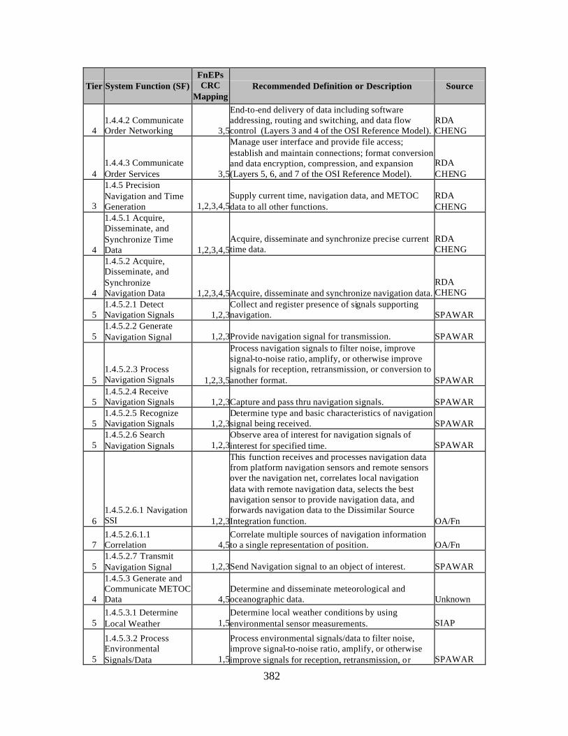
382
Tier System Function (SF) FnEPs CRC
Mapping Recommended Definition or Description Source
4 1.4.4.2 Communicate Order Networking 3,5
End-to-end delivery of data including software addressing, routing and switching, and data flow control (Layers 3 and 4 of the OSI Reference Model).
RDA CHENG
4 1.4.4.3 Communicate Order Services 3,5
Manage user interface and provide file access; establish and maintain connections; format conversion and data encryption, compression, and expansion (Layers 5, 6, and 7 of the OSI Reference Model).
RDA CHENG
3
1.4.5 Precision Navigation and Time Generation 1,2,3,4,5
Supply current time, navigation data, and METOC data to all other functions.
RDA CHENG
4
1.4.5.1 Acquire, Disseminate, and Synchronize Time Data 1,2,3,4,5
Acquire, disseminate and synchronize precise current time data.
RDA CHENG
4
1.4.5.2 Acquire, Disseminate, and Synchronize Navigation Data 1,2,3,4,5Acquire, disseminate and synchronize navigation data.
RDA CHENG
5 1.4.5.2.1 Detect Navigation Signals 1,2,3
Collect and register presence of signals supporting navigation. SPAWAR
5 1.4.5.2.2 Generate Navigation Signal 1,2,3Provide navigation signal for transmission. SPAWAR
5 1.4.5.2.3 Process Navigation Signals 1,2,3,5
Process navigation signals to filter noise, improve signal-to-noise ratio, amplify, or otherwise improve signals for reception, retransmission, or conversion to another format. SPAWAR
5 1.4.5.2.4 Receive Navigation Signals 1,2,3Capture and pass thru navigation signals. SPAWAR
5 1.4.5.2.5 Recognize Navigation Signals 1,2,3
Determine type and basic characteristics of navigation signal being received. SPAWAR
5 1.4.5.2.6 Search Navigation Signals 1,2,3
Observe area of interest for navigation signals of interest for specified time. SPAWAR
6 1.4.5.2.6.1 Navigation SSI 1,2,3
This function receives and processes navigation data from platform navigation sensors and remote sensors over the navigation net, correlates local navigation data with remote navigation data, selects the best navigation sensor to provide navigation data, and forwards navigation data to the Dissimilar Source Integration function. OA/Fn
7 1.4.5.2.6.1.1 Correlation 4,5
Correlate multiple sources of navigation information to a single representation of position. OA/Fn
5 1.4.5.2.7 Transmit Navigation Signal 1,2,3Send Navigation signal to an object of interest. SPAWAR
4
1.4.5.3 Generate and Communicate METOC Data 4,5
Determine and disseminate meteorological and oceanographic data. Unknown
5 1.4.5.3.1 Determine Local Weather 1,5
Determine local weather conditions by using environmental sensor measurements. SIAP
5
1.4.5.3.2 Process Environmental Signals/Data 1,5
Process environmental signals/data to filter noise, improve signal-to-noise ratio, amplify, or otherwise improve signals for reception, retransmission, or SPAWAR
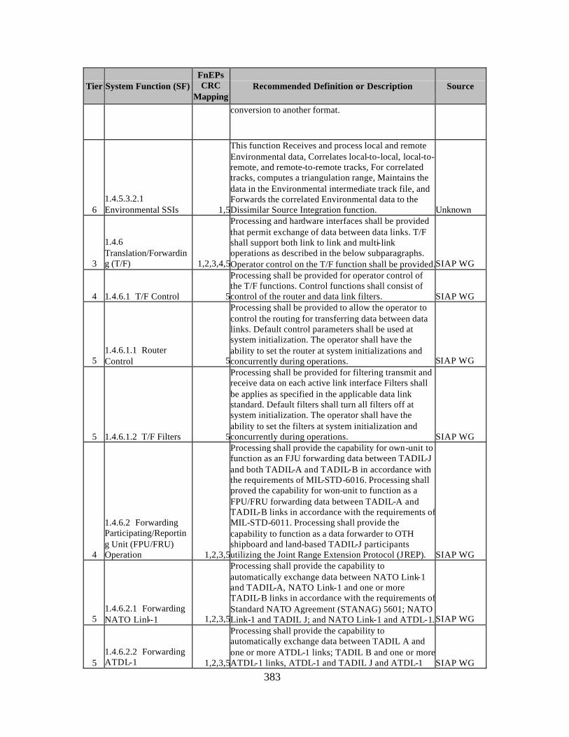
383
Tier System Function (SF) FnEPs CRC
Mapping Recommended Definition or Description Source
conversion to another format.
6 1.4.5.3.2.1 Environmental SSIs 1,5
This function Receives and process local and remote Environmental data, Correlates local-to-local, local-to-remote, and remote-to-remote tracks, For correlated tracks, computes a triangulation range, Maintains the data in the Environmental intermediate track file, and Forwards the correlated Environmental data to the Dissimilar Source Integration function. Unknown
3
1.4.6 Translation/Forwarding (T/F) 1,2,3,4,5
Processing and hardware interfaces shall be provided that permit exchange of data between data links. T/F shall support both link to link and multi-link operations as described in the below subparagraphs. Operator control on the T/F function shall be provided.SIAP WG
4 1.4.6.1 T/F Control 5
Processing shall be provided for operator control of the T/F functions. Control functions shall consist of control of the router and data link filters. SIAP WG
5 1.4.6.1.1 Router Control 5
Processing shall be provided to allow the operator to control the routing for transferring data between data links. Default control parameters shall be used at system initialization. The operator shall have the ability to set the router at system initializations and concurrently during operations. SIAP WG
5 1.4.6.1.2 T/F Filters 5
Processing shall be provided for filtering transmit and receive data on each active link interface Filters shall be applies as specified in the applicable data link standard. Default filters shall turn all filters off at system initialization. The operator shall have the ability to set the filters at system initialization and concurrently during operations. SIAP WG
4
1.4.6.2 Forwarding Participating/Reporting Unit (FPU/FRU) Operation 1,2,3,5
Processing shall provide the capability for own-unit to function as an FJU forwarding data between TADIL-J and both TADIL-A and TADIL-B in accordance with the requirements of MIL-STD-6016. Processing shall proved the capability for won-unit to function as a FPU/FRU forwarding data between TADIL-A and TADIL-B links in accordance with the requirements of MIL-STD-6011. Processing shall provide the capability to function as a data forwarder to OTH shipboard and land-based TADIL-J participants utilizing the Joint Range Extension Protocol (JREP). SIAP WG
5 1.4.6.2.1 Forwarding NATO Link-1 1,2,3,5
Processing shall provide the capability to automatically exchange data between NATO Link-1 and TADIL-A, NATO Link-1 and one or more TADIL-B links in accordance with the requirements of Standard NATO Agreement (STANAG) 5601; NATO Link-1 and TADIL J; and NATO Link-1 and ATDL-1. SIAP WG
5 1.4.6.2.2 Forwarding ATDL-1 1,2,3,5
Processing shall provide the capability to automatically exchange data between TADIL A and one or more ATDL-1 links; TADIL B and one or more ATDL-1 links, ATDL-1 and TADIL J and ATDL-1 SIAP WG
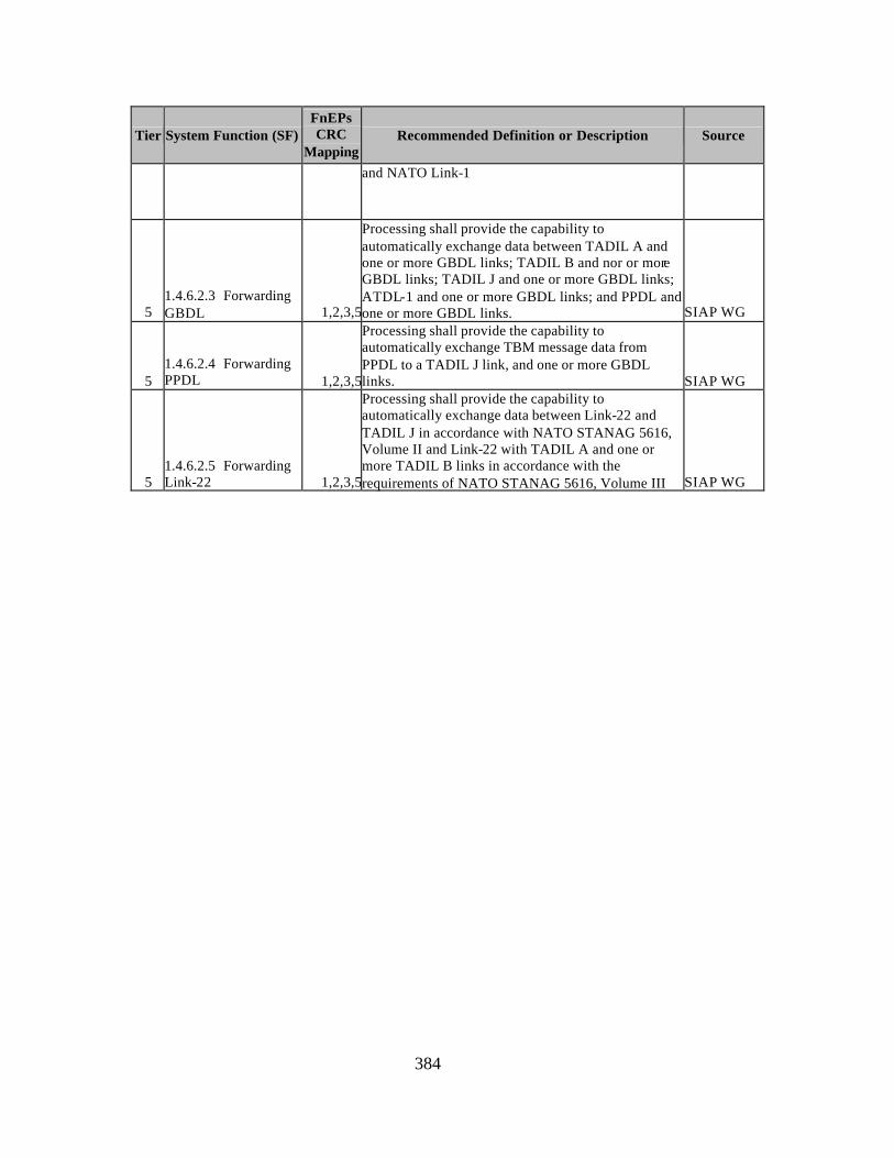
384
Tier System Function (SF) FnEPs CRC
Mapping Recommended Definition or Description Source
and NATO Link-1
5 1.4.6.2.3 Forwarding GBDL 1,2,3,5
Processing shall provide the capability to automatically exchange data between TADIL A and one or more GBDL links; TADIL B and nor or more GBDL links; TADIL J and one or more GBDL links; ATDL-1 and one or more GBDL links; and PPDL and one or more GBDL links. SIAP WG
5 1.4.6.2.4 Forwarding PPDL 1,2,3,5
Processing shall provide the capability to automatically exchange TBM message data from PPDL to a TADIL J link, and one or more GBDL links. SIAP WG
5 1.4.6.2.5 Forwarding Link-22 1,2,3,5
Processing shall provide the capability to automatically exchange data between Link-22 and TADIL J in accordance with NATO STANAG 5616, Volume II and Link-22 with TADIL A and one or more TADIL B links in accordance with the requirements of NATO STANAG 5616, Volume III SIAP WG
385
APPENDIX B. NETWORKING BASICS
In general, “computer” networks consist of three major parts: technology,
topology, and protocols. Technology can be thought of as the equipment used to build
the network, such as hubs, routers, and switches, as well as the means to connect this
equipment, such as fiber-optic cable, satellite links, or some other form of wireless
communications. The topology of a network can be thought of as its architecture and
determines how the various components of the network are connected. Finally, protocols
can be thought of as the “laws” of the network, which collectively ensure the information
is transmitted across the network and understood by the receiver(s) and sender(s). The
following sections will discuss three alternative technologies currently used in core
networking:
• SONET
• Dense Wave Division Multiplexing (DWDM)
• Asynchronous Transfer Mode (ATM)
Note: Due to the relative complexity of each of these, they will each be addressed in
individual sections below.
A. SONET
SONET351 is a standard method to interconnect fiber optic systems. Its
bandwidth ranges from over 50 Mbps at the OC-1 level to nearly 10 Gbps at the OC-192
level. SONET uses TDM (Time-Division Multiplexing) to multiplex multiple channels.
To have two distinct paths between any two systems, and therefore withstand accidental
fiber cuts or electronic equipment failures, SONET systems are built around rings, with
fast protection-switching schemes. Rings can be interconnected with cross-connects
using optical-to-optical electronic
Conversion (O-E-O) to perform switching. High speed O-E-O cross-connects are
not yet widely deployed, and therefore automatic end-to-end provisioning of services is
not possible. Carriers typically offer SONET to interconnect corporate sites at very high
speeds, either within one SONET ring, i.e. the MAN (Metropolitan Area Network) or
351 J. Manchester, et al., “IP over SONET”, IEEE Communications Magazine, Vol. 36, No. 5, May 1998, 136-142.
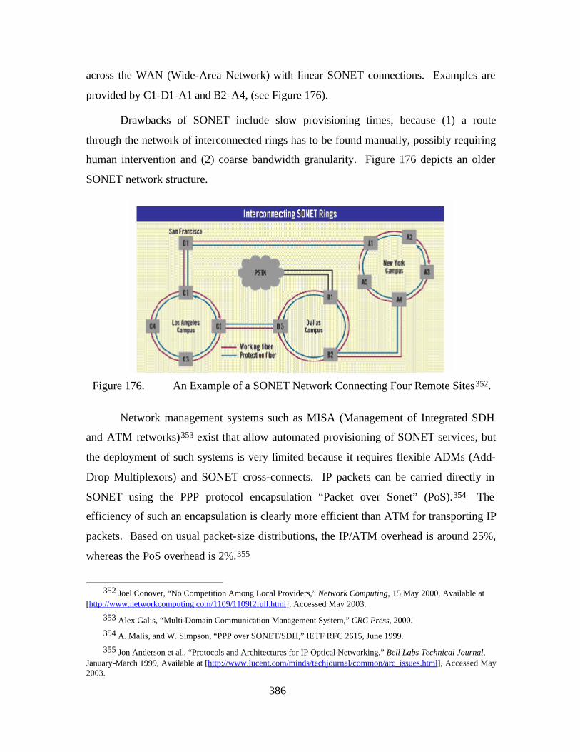
386
across the WAN (Wide-Area Network) with linear SONET connections. Examples are
provided by C1-D1-A1 and B2-A4, (see Figure 176).
Drawbacks of SONET include slow provisioning times, because (1) a route
through the network of interconnected rings has to be found manually, possibly requiring
human intervention and (2) coarse bandwidth granularity. Figure 176 depicts an older
SONET network structure.
Figure 176. An Example of a SONET Network Connecting Four Remote Sites352.
Network management systems such as MISA (Management of Integrated SDH
and ATM networks)353 exist that allow automated provisioning of SONET services, but
the deployment of such systems is very limited because it requires flexible ADMs (Add-
Drop Multiplexors) and SONET cross-connects. IP packets can be carried directly in
SONET using the PPP protocol encapsulation “Packet over Sonet” (PoS).354 The
efficiency of such an encapsulation is clearly more efficient than ATM for transporting IP
packets. Based on usual packet-size distributions, the IP/ATM overhead is around 25%,
whereas the PoS overhead is 2%.355
352 Joel Conover, “No Competition Among Local Providers,” Network Computing, 15 May 2000, Available at
[http://www.networkcomputing.com/1109/1109f2full.html], Accessed May 2003.
353 Alex Galis, “Multi-Domain Communication Management System,” CRC Press, 2000. 354 A. Malis, and W. Simpson, “PPP over SONET/SDH,” IETF RFC 2615, June 1999.
355 Jon Anderson et al., “Protocols and Architectures for IP Optical Networking,” Bell Labs Technical Journal, January-March 1999, Available at [http://www.lucent.com/minds/techjournal/common/arc_issues.html], Accessed May 2003.
387
B. DENSE WAVE DIVISION MULTIPLEXING (DWDM)
DWDM356 is a newer technology that allows multiplexing over different
wavelengths, thereby virtually multiplying the available capacity per individual optical
fiber. Cost savings on equipment are huge when compared with the alternative of laying
additional fiber, especially in the case of long haul transmission where amplifiers are
required on each fiber. For a carrier that needs to upgrade its SONET network, adding
DWDM makes it possible to keep the existing SONET investment, and scale up the
remainder of network based on the newly available wavelengths. The major difference
with DWDM systems is that traffic is handled purely optically, and only converted
electronically where necessary. Optical cross-connects are also available that switch
entire wavelengths optically. By reducing optical to electronic conversion bit error rates
approach zero, thus eliminating the need to detect such errors (as in SONET networks).
All-optical DWDM networks are also have the advantage of being compatible with
existing fiber networks and well as CWDM (Coarse WDM). This compatibility allows
for LAN architectures and LAN economics (e.g. low price per port, simplicity of
management). Further, infrastructure upgrade costs are much lower because fiber
represents a 20 year investment, as opposed to SONET equipment which quickly
becomes obsolete.357
C. ASYNCHRONOUS TRANSFER MODE (ATM)
Similarly to SONET, ATM358 is circuit-based, with the main difference being that
ATM circuits are virtual. Instead of performing TDM, each fixed-size cell carries the ID
of the virtual connection to which it belongs in its header. This allows one to benefit
from statistical multiplexing gain on the link, and therefore make better use of existing
resources. ATM is still the only transport technology capable of guaranteeing Quality of
Service (QoS)359, and therefore offers “integrated services”. ATM circuits are sometimes
referred to as “software” circuits, and can therefore be dynamically established and
356 N. Ghani, S. Dixit, and T.S. Wang, “On IP over-WDM Integration,” IEEE Communications Magazine, Vol.
38, No. 3, March 2000, 74. 357 IBM Research Division, IP over Everything.
358 Ibid.
359 AT&T believes otherwise, and are currently provisioning their communications backbones with MPLS CIP traffic shaping technology in place of SONET.ATM.
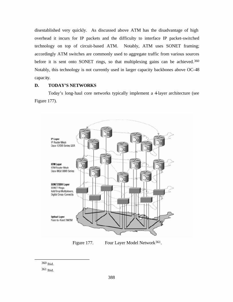
388
disestablished very quickly. As discussed above ATM has the disadvantage of high
overhead it incurs for IP packets and the difficulty to interface IP packet-switched
technology on top of circuit-based ATM. Notably, ATM uses SONET framing;
accordingly ATM switches are commonly used to aggregate traffic from various sources
before it is sent onto SONET rings, so that multiplexing gains can be achieved.360
Notably, this technology is not currently used in larger capacity backbones above OC-48
capacity.
D. TODAY’S NETWORKS
Today’s long-haul core networks typically implement a 4-layer architecture (see
Figure 177).
Figure 177. Four Layer Model Network361.
360 Ibid. 361 Ibid.
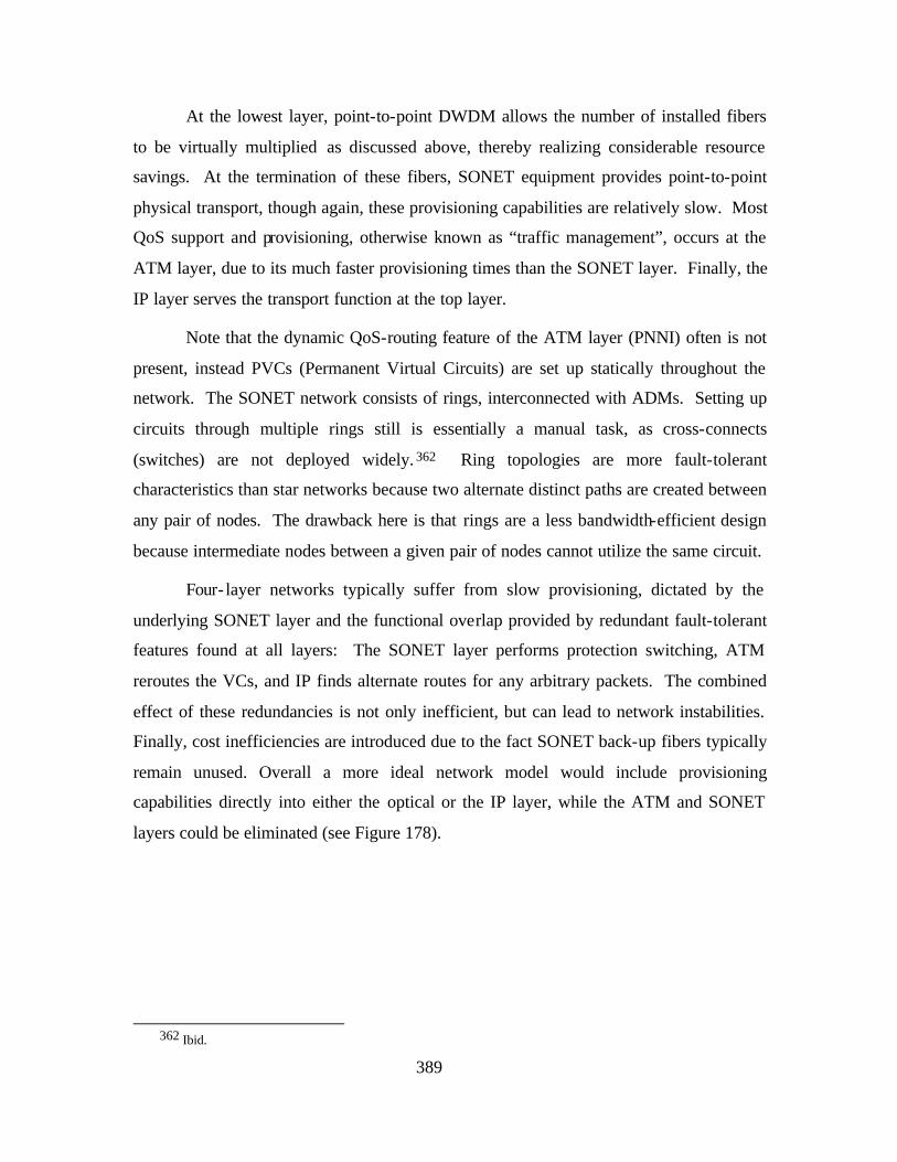
389
At the lowest layer, point-to-point DWDM allows the number of installed fibers
to be virtually multiplied as discussed above, thereby realizing considerable resource
savings. At the termination of these fibers, SONET equipment provides point-to-point
physical transport, though again, these provisioning capabilities are relatively slow. Most
QoS support and provisioning, otherwise known as “traffic management”, occurs at the
ATM layer, due to its much faster provisioning times than the SONET layer. Finally, the
IP layer serves the transport function at the top layer.
Note that the dynamic QoS-routing feature of the ATM layer (PNNI) often is not
present, instead PVCs (Permanent Virtual Circuits) are set up statically throughout the
network. The SONET network consists of rings, interconnected with ADMs. Setting up
circuits through multiple rings still is essentially a manual task, as cross-connects
(switches) are not deployed widely. 362 Ring topologies are more fault-tolerant
characteristics than star networks because two alternate distinct paths are created between
any pair of nodes. The drawback here is that rings are a less bandwidth-efficient design
because intermediate nodes between a given pair of nodes cannot utilize the same circuit.
Four- layer networks typically suffer from slow provisioning, dictated by the
underlying SONET layer and the functional overlap provided by redundant fault-tolerant
features found at all layers: The SONET layer performs protection switching, ATM
reroutes the VCs, and IP finds alternate routes for any arbitrary packets. The combined
effect of these redundancies is not only inefficient, but can lead to network instabilities.
Finally, cost inefficiencies are introduced due to the fact SONET back-up fibers typically
remain unused. Overall a more ideal network model would include provisioning
capabilities directly into either the optical or the IP layer, while the ATM and SONET
layers could be eliminated (see Figure 178).
362 Ibid.
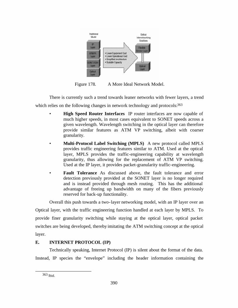
390
Figure 178. A More Ideal Network Model.
There is currently such a trend towards leaner networks with fewer layers, a trend
which relies on the following changes in network technology and protocols:363
• High Speed Router Interfaces IP router interfaces are now capable of much higher speeds, in most cases equivalent to SONET speeds across a given wavelength. Wavelength switching in the optical layer can therefore provide similar features as ATM VP switching, albeit with coarser granularity.
• Multi-Protocol Label Switching (MPLS) A new protocol called MPLS provides traffic engineering features similar to ATM. Used at the optical layer, MPLS provides the traffic-engineering capability at wavelength granularity, thus allowing for the replacement of ATM VP switching. Used at the IP layer, it provides packet-granularity traffic-engineering.
• Fault Tolerance As discussed above, the fault tolerance and error detection previously provided at the SONET layer is no longer required and is instead provided through mesh routing. This has the additional advantage of freeing up bandwidth on many of the fibers previously reserved for back-up functionality.
Overall this push towards a two-layer networking model, with an IP layer over an
Optical layer, with the traffic engineering function handled at each layer by MPLS. To
provide finer granularity switching while staying at the optical layer, optical packet
switches are being developed, thereby imitating the ATM switching concept at the optical
layer.
E. INTERNET PROTOCOL (IP)
Technically speaking, Internet Protocol (IP) is silent about the format of the data.
Instead, IP species the “envelope” including the header information containing the
363 Ibid.
391
addressing scheme by which this information is sent between a source and its destination.
Information to be sent across the network is aggregated into “packets” each of which
begins with a header containing, among other information the “addresses” of the sender
and receiver. A simple analogy is that of a letter (the packet), which contains the
information being sent, and an envelope (the header), which contains the addresses of the
sender and receiver.
From its origins, the Internet Protocol (IP) was designed to be highly scalable in
terms of application support and the number of devices and/or users on a network.
Further, IP’s scalability would enable the creation and interoperability of “networks of
networks”, such as the Internet. As a result, IP has come to dominate the networking
market for several reasons:
• Open Source IP is open and available to everyone, encouraging rapid innovation.
• Application Independent IP is application- independent, requiring no proprietary application- layer gateways.
• Service Location Services are placed at the edges of the network rather than integrated into the network itself; this allows services to evolve without impacting the network and keeps complexity out of the network core.
• Global Address Scheme The ability of packets to carry globally meaningful addresses enables network nodes to make autonomous decisions in processing each packet. This allows the distribution of work throughout the nodes, providing redundancy as well as improving scalability.364
Further, and perhaps most importantly, the complexity of the network itself, as
well as application definition occurs at the edge of the network, not the core. This is a
critical distinction in that you can completely define the application in terms of Sense,
Decide, and Act functionality at the end systems or “nodes” that are attached. Since the
introduction of IP; however, the exponential growth of technology in general and
networking more specifically have combined to result in greater and greater demands
364 Ibid.
392
being placed on IP to provide “plug and play” network interoperability. If IP is to
become the convergence layer for seamless networking and interoperability, the
following challenges will have to be met:
• Quality of Service (QoS)
• Security
• IP Multicast and Broadcast
• Addressing and Routing
Note: Due to the relative complexity of each of these, they will each be addressed in
individual sections below.
F. QUALITY OF SERVICE
Historically, most network traffic has been bursty, rather than continuous,
therefore, IP was originally designed not make hard allocations of bandwidth or circuit
resources. This “burstiness” is also a side-effect of the muxing together of multiple data
streams in order to increase bandwidth efficiency. Instead of providing dedicated
circuits; however, IP provides what is called a “best-effort” service which routes packets
according to the most efficient path from the sender, through a network, before rebuilding
the “message” on the receiving end of the network. While this is appropriate for less
time critical traffic and data that is not sequence dependant, and has the advantage of
being highly bandwidth efficient, it is not suitable for streaming network flows such as
voice and video. Such traffic demands the data be transmitted from the sender in such a
way that it arrives “on time” and in the “proper order”. Typically this has required
circuit-switched technology such as ATM in order to guarantee the network resources
would remain available throughout time the critical traffic was being routed. As
discussed in the previous section, such technology, while effective, is bandwidth
inefficient.
QoS refers to the capability of a network to provide better service to selected
network traffic. The primary goal of QoS is to provide priority for critical traffic,
controlled jitter and latency (required by some real-time and interactive traffic such as
streaming audio and video), and improved loss characteristics.365 Also important is
365 CISCO. Quality of Service Networking. Available at
[http://www.cisco.com/univercd/cc/td/doc/cisintwk/ito_doc/qos.htm#wp1024961], Accessed May 2003.
393
making sure that while some applications require some level of determinism (or bounded
delay delivery,) such does not result in other applications or network traffic fail. One of
the primary shortcomings cited of IP, (more accurately IPv4) is that it does not enforce
QoS demands.366 This is an inaccurate assumption! Today Internet Services Porviders
(ISPs) do not “look at” the DS byte contained in every IP packet and whose function is to
dictate priority. There are reasons for this, including reducing the possibly for Denial of
Service attacks; however is not a reflection of the inability of IP to enforce QoS. Because
IP is capable of supporting end-to-end communications across networks, it will need to
be able to provide QoS across links of varying bandwidths and link layers where
bottlenecks might occur. Although not introduced yet in this discussion, wireless
networks will remain bandwidth disadvantaged for the foreseeable future, and are thus
even more dependent on QoS provisioning.
There are currently two techniques for achieving QoS provisioning in IP
networks.367 368 The first of these, Int-Serv is a more deterministic method, and requires
routers to keep state throughout the transmission in order to maintain the connection
resources required. This approach obviously runs counter to the notion of the
connectionless design of internets and therefore does not scale well. The second method
is Diff-Serv, a more qualitative approach whereby each packet signals to the router what
priority it has. Unlike like the previous technique; however, no resources are actually
dedicated to actual traffic. Given unlimited bandwidth, QoS would of course not be an
issue. Until improvements can be made in the area of bandwidth current techniques to
avoid QoS problems remain rudimentary. Two examples are: (1) caching packets and (2)
utilizing more or less dedicated links for high demand traffic such as
videoteleconferencing.
366 IBM Research Divison. IP Over Everything.
367 R. Braden, et al., “Resource ReSerVation Protocol (RSVP) Version 1 Functional Specification,” IETF RFC 2205, September 1997.
368 J. Wroclawski, “The Use of RSVP with IETF Integrated Services,” IETF RFC 2210, September 1997.
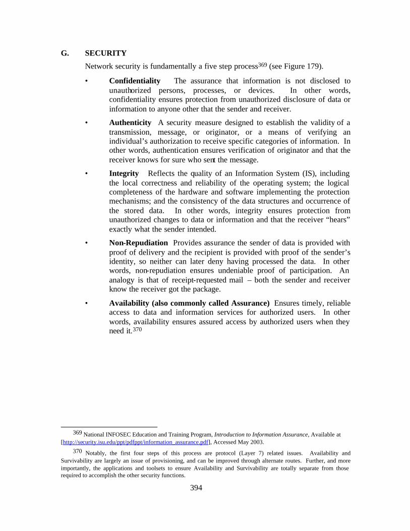
394
G. SECURITY
Network security is fundamentally a five step process369 (see Figure 179).
• Confidentiality The assurance that information is not disclosed to unauthorized persons, processes, or devices. In other words, confidentiality ensures protection from unauthorized disclosure of data or information to anyone other that the sender and receiver.
• Authenticity A security measure designed to establish the validity of a transmission, message, or originator, or a means of verifying an individual’s authorization to receive specific categories of information. In other words, authentication ensures verification of originator and that the receiver knows for sure who sent the message.
• Integrity Reflects the quality of an Information System (IS), including the local correctness and reliability of the operating system; the logical completeness of the hardware and software implementing the protection mechanisms; and the consistency of the data structures and occurrence of the stored data. In other words, integrity ensures protection from unauthorized changes to data or information and that the receiver “hears” exactly what the sender intended.
• Non-Repudiation Provides assurance the sender of data is provided with proof of delivery and the recipient is provided with proof of the sender’s identity, so neither can later deny having processed the data. In other words, non-repudiation ensures undeniable proof of participation. An analogy is that of receipt-requested mail – both the sender and receiver know the receiver got the package.
• Availability (also commonly called Assurance) Ensures timely, reliable access to data and information services for authorized users. In other words, availability ensures assured access by authorized users when they need it.370
369 National INFOSEC Education and Training Program, Introduction to Information Assurance, Available at
[http://security.isu.edu/ppt/pdfppt/information_assurance.pdf], Accessed May 2003. 370 Notably, the first four steps of this process are protocol (Layer 7) related issues. Availability and
Survivability are largely an issue of provisioning, and can be improved through alternate routes. Further, and more importantly, the applications and toolsets to ensure Availability and Survivability are totally separate from those required to accomplish the other security functions.
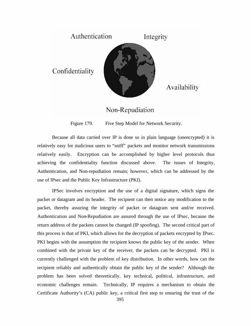
395
Figure 179. Five Step Model for Network Security.
Because all data carried over IP is done so in plain language (unencrypted) it is
relatively easy for malicious users to “sniff” packets and monitor network transmissions
relatively easily. Encryption can be accomplished by higher level protocols thus
achieving the confidentiality function discussed above. The issues of Integrity,
Authentication, and Non-repudiation remain; however, which can be addressed by the
use of IPsec and the Public Key Infrastructure (PKI).
IPSec involves encryption and the use of a digital signature, which signs the
packet or datagram and its header. The recipient can then notice any modification to the
packet, thereby assuring the integrity of packet or datagram sent and/or received.
Authentication and Non-Repudiation are assured through the use of IPsec, because the
return address of the packets cannot be changed (IP spoofing). The second critical part of
this process is that of PKI, which allows for the decryption of packets encrypted by IPsec.
PKI begins with the assumption the recipient knows the public key of the sender. When
combined with the private key of the receiver, the packets can be decrypted. PKI is
currently challenged with the problem of key distribution. In other words, how can the
recipient reliably and authentically obtain the public key of the sender? Although the
problem has been solved theoretically, key technical, political, infrastructure, and
economic challenges remain. Technically, IP requires a mechanism to obtain the
Certificate Authority’s (CA) public key, a critical first step to ensuring the trust of the
396
entire PKI infrastructure. On the political and economic sides, there is the need for a
global public key infrastructure. Even if such an “GKI” infrastructure existed; however,
questions would remain such as “How easy is it to deny access to certain countries?” or
“Is it desirable to have the functionality to exclude anybody? Finally, there is the issue of
revocation of certificates. This is analogous to merchants keeping lists of bad credit
cards, albeit a more fundamentally difficult problem to solve.
Security support in IP is a key element for the growth of IP-based networks for a
very simple reason. Current solutions are largely implemented through the use of private
leased networks. Not only is this expensive, but defeats the fundamental advantages of
leveraging the near-ubiquity of the Internet. Although ATM VCs offer the functionality
of such dedicated and relatively secure connections, the move towards IP-based
networking will make such an option unavailable. One answer answer currently lies in
the use of Virtual Private Networks (VPNs). VPNs are IP-based, and are thus
connectionless, yet still maintain the relative security advantages of dedicated circuits.
Overall, it is important to note that IPsec is not a security “cure-all.” IPsec does not
prevent problems from DOS attacks and “Syn-Floods,” nor does it address security
challenges at layers 1 & 2.
H. IP MULTICAST AND BROADCAST
As discussed in the QoS section above, older network traffic demands focused on
data transfer and applications were typically shared between single or small groups of
users located on the same LAN or subnet. As technology and the use of networks have
grown, new applications have emerged such as LAN TV, desktop conferencing,
corporate broadcasts, and collaborative computing. A critical difference such
applications have over more traditional network applications is the requirement for
simultaneous communication between groups of computers. This process is known
generically as multipoint communications, and can be extremely bandwidth intensive in
either IP-based or circuit-switched networks. The reason for this is that if user requests
information from a sender, this information is sent as any other traffic in a point-to-point
manner. Depending on the type of traffic (e.g. audio and video applications), even such
communications between single users can be both bandwidth and QOS intensive. Now
scale the example to one requiring collaboration between multiple users. In this case, the
397
same network traffic has to be sent as many times as there are users who request the
traffic. In such an example, it is easy to understand the bandwidth inefficiencies that
quickly emerge. Three existing solutions for ensuring bandwidth efficiency in multipoint
communications are presented below. 371
• Unicast With a unicast design, applications can send one copy of each packet to each member of the multicast group. While technically simple to implement, this technique has significant scaling restrictions if the group is large. In addition, it requires extra bandwidth, because the same information has to be carried multiple times, even across shared links.
• Broadcast In a broadcast design, applications can send one copy of each packet and address it to a broadcast address. This technique is even simpler than unicast for the application to implement. However, the problem of “broadcast storms” exists, whereby unless the broadcast transmission is stopped at a given LAN boundary, the transmission is sent everywhere. Sending the broadcast everywhere is a significant usage of network resources if only a small group of users required the information in the first place.
• Multicast With a multicast design, applications can send one copy of each packet and address it to the group of computers that want to receive it. Another way of describing this is the network layer delivery of information to to multiple end systems for the “price” of a single transit through each router.372 This technique addresses packets to a group of receivers rather than to a single receiver, and it depends on the network to forward the packets to only the networks that need to receive them.
Importantly, the above solutions require protocol extensions to IP in order to provide
proper functionality. It is beyond this scope of this paper to discuss the details of these
extensions; however, a reference is provided below. 373
I. ADDRESSING AND ROUTING
This area is one of the greatest challenges to the implementation of IP and, more
specifically, its scalability. There are two major reasons for this challenge. First and
foremost is the shrink ing availability of IPv4 addresses. Originally, the 32 bit address
space available under IPv4 was deemed sufficient for any foreseeable grown. The
371 CISCO, Multicast Routing. Available at [http://www.cisco.com/warp/public/614/17.html], Accessed May
2003. 372 This definition is closely aligned with the opportunities of developing a radio-WAN, which will also allow for
the delivery of of information to multiple end systems for the price of a sincle transit through each network segment. In the case of a radio-WAN this will occur at layer 2, not possible for point-to-point physical networks.
373 Ibid.
398
exponential growth of the Internet and the demand for IP addresses down to the
individual level has resulted in smaller and smaller blocks and numbers of addresses
available. One result of this is that many organizations now have to use discontinuous
blocks of IP addresses that do not necessarily aggregate with the IP address of their ISP.
This leads to the second threat to IP and its scalability, the growing size of routing tables
in major exchange points. Routing tables with more than 100 k entries are commonplace,
due to the numbers of exceptions in the aggregation of prefixes previously discussed.
Although fast IP routers can cope with current table sizes and MPLS allows of short-
circuit address lookup in the core networks, IP routing tables will continue to grow in
size, endangering scalability of IP routing protocols and forwarding schemes.374
A short term solution to the shrinking number of available IP addresses is
Network Address Translation (NAT).375 Basically, through manipulation of port
numbers, NAT allows a large number of hosts to share a single unique IPv4 address. As
an example of the scale of the use of this workaround, consider 70% of Fortune 1000
companies have been forced to deploy NATs.376 While NAT has been successful in
slowing the problem of IP address depletion, it was never intended as a long-term
solution, and presents a numbers of cha llenges to today’s and the future’s network
environment. These problems include the following examples:
• Lack of peer-to-peer Functionality NAT destroys a key benefit of the Internet as a network of ‘always-on, equally-connected, easily-reachable’ peers. Peer-to-peer capability provides a powerful tool, empowering users to become “contributors” rather than simply “consumers” of data, information, and, ultimately, knowledge. Peer-to-peer systems rely on the critical assumption a user can find and connect to another user. If “hidden” behind NAT; however, this assumption is not valid. To circumvent such a problem, peer-to-peer systems utilize an extra level of complexity, which leads to greater network efficiencies than should exist.
• Security Challenges NAT presents a variety of challenges to security protocols such as IPSec. While these are outside the scope of this paper, as discussed previously, and in particular for peer-to-peer computing, strong security is essential.
374 IBM Research Division, IP Over Everything.
375 Ibid.
376 Access Networks, Last Mile: Die Ankoppelung an den Information-Highway, 1999, Available at [http://www.accessnetworks.ch/home.thtml/access/dsl], Accessed May 2003.
399
• Lack of QoS Functionality NAT is one of the single largest technical hurdles for applications requiring Quality of Service (QoS) such as Voice over IP (VoIP) and real-time video.
The preceding section has discussed both the reasons why IP has grown to
dominate the networking market and the challenges IP will have to face if it is to become
the convergence layer for seamless networking and interoperability in the future. In
short, IPv4 has grown somewhat long in the tooth, and is poised for an upgrade to move
into the future. IPv6 represents that upgrade and is discussed in greater detail in Chapter
IV.
J. MILITARY NETWORKING CONSIDERATIONS, “A WARFIGHTING INTERNET”
Fundamentally, networks that support military needs require that all of the above
considerations be addressed. Two basic issues are fundamentally critical; however—
available communications capacity and protection of the network(s) from congestion. 377
While communications capacity is typically equated with bandwidth, the term “available”
implies the need for a network(s) that have a high degree of reliability and security as
well. The reason that availability and freedom from congestion are so critical is
intuitively obvious. The nature of “military” networking demands the network support
operations across the continuum of operations from peace to war. Obviously, such a
continuum also demands a range of functionality from in terms of latency and bandwidth
demands (e.g. real-time weapons control vs, high resolution satellite imagery). As a
result of these considerations, many military systems and their supporting networks are
designed, developed, and procured in a stove-piped fashion. While this can lead to
sufficient levels of security and performance interoperability with other systems is often
sub-optimized. This sub-optimization runs counter to the inherent and intuitive benefits
of networking systems together, namely a synergistic effect that results from the
integration of previously disparate systems. Beyond such technical considerations;
however, ultimately lives depend upon such networks, a fact which drives even higher
levels of network availability, security, and overall functionality.
377 SPAWAR, FORCEnet Government Reference Architecture (GRA) Vision, 39.
400
K. SUMMARY
As with the design of any system, the process of network design involves a
process of design tradeoffs with the goal of optimizing the performance of the network.
While it is relatively straightforward to design and optimize a single purpose-built
network, such as a fire control system, current and future networks are growing
increasingly heterogeneous, and are relied on to connect more and different users and
information. Many of these networks, such as the Internet, are more accurately
characterized as “networks of networks”. Today and into the future, these networks of
networks must integrate the designs and functions of individual networks that may or
may not have been originally intended or designed to work together. Regardless,
ultimately, networks exist to achieve some process, function, capability, or group thereof.
The definition of FORCEnet implies the ultimate example, demanding the networking of
BOTH physical and largely deterministic “nodes” and processes (e.g. weapons and
sensors), WITH warriors and C2 functions which are fundamentally subjective. Chapter
IV is focused on 1) A discussion of the critical technical factors impacting the future of
the networking and military applications in general, and 2) Within the context of the
current FORCEnet Architecture Vision, develop a “Warfighting Internet” supporting
SSG XXII’s Concept of FORCEnet Engagement Packs (FnEPs).
401
BIBLIOGRAPHY
3com, Comparing Performance of 802.11b and 802.11a Wireless Technologies, Available at [http://www.3com.com/other/pdfs/products/en_US/104027_tb.pdf]; Accessed May 2003.
6init.com. IPv6 On Everything: The New Internet, Available at [http://www.6init.com/public/renn_ipv6oneverything.pdf]; Accessed May 2003.
Access Networks. Last Mile: Die Ankoppelung an den Information-Highway. 1999.
Air Force Research Lab. “Advanced Internet Protocols for Communications Over Satellite,” Available at [http://www.afrlhorizons.com/Briefs/0006/IF9907.html]; Accessed May 2003.
Alberts, David S., Garstka, John J. and Stein, Frederick P., Network Centric Warfare, (2nd Edition (Revised)), CCRP, 2000.
Alberts, David S., NCW Report to Congress, 27 July 2001.
Anderson, Jon. et al. “Protocols and Architectures for IP Optical Networking.“ Bell Labs Technical Journal. January-March 1999. Available at [http://www.lucent.com/minds/techjournal/common/arc_issues.html], Accessed May 2003.
Apple “Think Different,” Apple Online. Home Page On-Line. Available at [http://www.apple.com/thinkdifferent]; Internet; Accessed 1 October 2003.
Berry, Sharon, “Mobile Routing Creates Seamless Links, Increases Situational Awareness,” (Signal Magazine), (October 2002), Available at http://www.us.net/signal/Archive/Oct02/in-oct.html; Accessed May 2003.
Braden, R. et. al, “Resource ReSerVation Protocol (RSVP) Version 1 Functional Specification.” IETF RFC 2205. September 1997.
Break Free Wireless, High-Speed Wireless Internet and Data Link Overview, Available at [http://www.breakfreewireless.com/techoverview.html]; Accessed May 2003.
Browning, Tyson R., “Applying the Design Structure Matrix to System Decomposition and Integration Problems: A Review and New Directions,” IEEE Transactions on Engineering Management, Vol. 48, No. 3, August 2001.
Buddenberg, Rex, “What’s Wrong with DoD’s So-Called Information Architectures and What We Ought to be Doing About It.” Naval Postgraduate School, March 2000, 1-12.
402
Cambell, Ken, Theaterwide Collaborative Tracking. SPAWAR Systems Center, San Diego, CA. Available at [http://seal.gatech.edu/onr_workshop/2000/campbell_00.pdf], Accessed December 2003. (PowerPoint Brief) slide 10.
Cambell, Victor, Acquisition in the Network Centric Age: A Perspective, SPAWAR Systems Center, Charleston, South Carolina, October 2003, (PowerPoint Brief).
Cambell, Victor, FnEPs Assessment Overview Brief. SPAWAR Systems Center, Charleston, South Carolina, October 2003, (PowerPoint Brief).
Campbell, Victor, Viability-Fit-Forcenet, SPAWAR Systems Center, Charleston, South Carolina, 22 July 2003, (Excel Spreadsheet).
CCRP, “Space Net Assessment: Emerging Insights,” Available at [http://www.dodccrp.org/IS/is_metrics/ppt/1]; Accessed May 2003.
Cebrowski, Arthur, Vice Admiral, U.S. Navy and Garstka, John J., “Network-Centric Warfare: Its Origin and Future,” Proceedings, January 1998.
Chairman of the Joint Chiefs of Staff Instruction (CJCSI) 3151.01, Global Command and Control System Common Operational Picture Reporting Requirements, 10 June 1997.
Charles, Phil and Turner, Phil, LCDR, U.S. Navy, Naval Tool for Interoperability Risk Assessment (NTIRA) Status Brief – NETWARCOM, SPAWAR Systems Center, Charleston, South Carolina, 21 October 2003, (PowerPoint Brief).
Charles, Phil, Assessments to Define Composeable Mission Capability, SPAWAR Systems Center, Charleston, South Carolina, 2003, (PowerPoint Brief).
Charles, Phil, FnEPs Analysis Status Brief, SPAWAR Systems Center, Charleston, South Carolina, 16 May 2003, (PowerPoint Brief).
Charles, Phil, Initial FORCEnet Engagement Pack Assessment for CNO Strategic Studies Group XXII, SPAWAR Systems Center, Charleston, South Carolina, 1 October 2003, (PowerPoint Brief).
Charles, Phil. and Reed, Rebecca, GEMINII Overview, Global Engineering Methods: Initiative for Integration and Interoperability, SPAWAR Systems Center, Charleston, South Carolina, 2003, (PowerPoint Brief).
Cisco, Internet With a Bang. Available at [http://www.cisco.com/warp/public/cc/pd/si/casi/ca6000/prodlit/nwtkr_ss.pdf]; Accessed May 2003.
Cisco, Mobile IP & Mobile Networks Promise New Era of Satellite and Wireless Communications. Available at [http://www.cisco.com/warp/public/732/Tech/mobile/ip/docs/nasa_glenn_0129.pdf]; Accessed May 2003.
403
Cisco. Multicast Routing. Available at [http://www.cisco.com/warp/public/614/17.html], Accessed May 2003.
Cisco. Quality of Service Networking. Available at [http://www.cisco.com/univercd/cc/td/doc/cisintwk/ito_doc/qos.htm#wp1024961], Accessed May 2003.
Clark, Vanessa, Mobile Computing in Ad Hoc Wireless Networks, Available at [http://students.cec.wustl.edu/~cs333/calendar/Mobile_Computing_in_Ad_hoc_Wireless_Networks.ppt]; Accessed May 2003. (PowerPoint Brief).
Clark, Vern, Admiral, U.S. Navy, Chie f of Naval Operations, Lecture at Naval War College, Newport, Rhode Island, 12 June 2002.
Clark, Vern, Admiral, U.S. Navy, Chief of Naval Operations, Sea Power 21: Projecting Decisive Joint Capabilities, October 2002.
CNO Task to SSG XXII (September 2002).
Conover, Joel, “No Competition Among Local Providers.” Network Computing. 15 May 2000. Available at [http://www.networkcomputing.com/1109/1109f2full.html], Accessed May 2003.
Cordeiro, Carlos and Agrawal, Dharma, Mobile Ad Hoc Networking, Available at [http://www.ececs.uc.edu/~cordeicm/course/slides_ad_hoc.pdf]; Accessed May 2003.
Corstjens, Marcel and Merrihue, Jeffrey, “Optimal Marketing,” Harvard Business Review, 1 October 2003.
Crandall, Kenneth C., “OFDM Kills Multipath Distortion.” (EE Times), (15 April 2002), Available at [http://www.eetimes.com/in_focus/communications/OEG20020412S0072]; Accessed May 2003.
Dranikoff, Lee, Koller, Tim, and Schneider, Antoon, “Divestiture: Strategy’s Missing Link,” Harvard Business Review, May 2002, 1-12.
Electronics Material Officer Course, “Electromagnetic Interference Control.” Available at [http://www.fas.org/man/dod-101/navy/docs/swos/e1/MOD3LES2.html]; Accessed October 2003.
Erwin, Sandra I., “Data-Centric’ Army Wants Next-Generation Tactical Net.” (National Defense), (October, 2000), Available at [http://www.nationaldefensemagazine.org/article.cfm?Id=304]; Accessed May 2003.
Galis, Alex, “Multi-Domain Communication Management System.” CRC Press, 2000.
Gauss, John A., Rear Admiral, U.S. Navy. SPAWAR 00--View From The Bridge. SPAWAR Systems Center, San Diego, Califronia, 23 March 1998, (PowerPoint Brief).
404
Ghani, N., S. Dixit, and T.S. Wang, “On IP over-WDM Integration.” IEEE Communications Magazine, Vol. 38, No. 3, March 2000. 72-84.
Giaquinto, Joseph N., Captain, U.S. Navy, “Getting on with a “Warfighting Internet,” 3 March 03, (E-Mail).
Giaquinto, Joseph N., Captain, U.S. Navy, FORCEnet Engagement Packs (FnEPs). SSG XXII, June 2003, (PowerPoint Brief).
Hardesty, David C., Captain, U.S. Navy, “Fix Net Centric for the Operators,” Proceedings, September 2003.
Hesser, Robert W. and Rieken, Danny M., FORCEnet Engagement Packs (FnEPs). Naval Postgraduate School, December 2003, (PowerPoint Brief).
Hesser, Robert W., A Warfigthing Internet, SSG XXII, June 2003.
Hesser, Robert W., JFN and FnEPs. SSG XXII, June 2003.
Hoon, Mr. Geoff, Secretary of State for Defense, United Kingdom, Aviation Week and Space Technology, 23 December 2002.
HostingWorks, HostingWorks Networking Definitions. Available at [http://hostingworks.com/support/dict.phtml?foldoc=bandwidth]; Accessed May 2003.
IBM Research Division, IP Over Everything. (IBM Research Division), Watson, New York, 2003.
IBM Research Division. Global Technology Outlook – 2003, (IBM Research Division), Watson, New York, 2003, (PowerPoint Brief).
IEEE, “Optical Space Communications,” Available at [http://www.ieee.org/organizations/tab/newtech/workshops/ntdc_2001_08.pdf]; Accessed May 2003.
International Engineering Consortium, Smart Antenna Systems, Available at [http://www.iec.org/online/tutorials/smart_ant/]; Accessed May 2003.
IpInfusion.com, Disruptive Technologies: Applications that Will Drive IPv6, Available at [http://www.ipinfusion.com/pdf/DisruptiveTechnologies.pdf]; Accessed May 2003.
Joint Maritime Operations, Joint Operation Planning and Execution System (JOPES), (Joint Maritime Operations Block 5.1), Naval War College, Newport Rhode Island.
Kaler, Herbert C., Riche, Robert, and Hassell, Timothy B.. “A Vision for Joint Theater Air and Missile Defense,” Joint Forces Quarterly, Autumn/Winter 1999-2000, x-xx.
405
Kolodzy, Paul, A DARPA Perspective on Broadband Wireless Systems, DARPA, 6 September 2000), Available at [http://www.its.bldrdoc.gov/meetings/art/art00/slides00/kol/kol_s.pdf], Accessed December 2003.
Lewandowski, Linda, S&R Project: Co-evolution of an Adaptive Logistics Capability, OSD Office of Force Transformation. 30 May 2003.
Light Reading, “Alcatel Holds World Record for a Day.” Light Reading, 22 March 2001, Available at [http://www.lightreading.com/document.asp?doc_id=4380]; Accessed May 2003.
Malis, A. and W. Simpson, “PPP over SONET/SDH.” IETF RFC 2615. June 1999.
Mayo, Richard W., Vice Admiral, and Nathman, John, Vice Admiral, U.S. Navy, “FORCEnet: Turning Information into Power,” Proceedings, February 2003, x-xx.
Meeks, Wayne A., “Getting on with a “Warfighting Network.” NAVSEA 06, IWS Division, 21 March 2003, (E-Mail).
Mentat, SkyX Technology White Paper, Available at [http://www.mentat.com/skyx/sxwp-docw-104.pdf]; Accessed May 2003.
Moore, James F., “The Death of Competition: Leadership and Strategy in the Age of Business Ecosystems,” Harper Business, 1996.
NASA, Mobile Router Technology Development. Available at [http://roland.grc.nasa.gov/~ivancic/papers_presentations/MR_I-CNS.ppt]; Accessed May 2003.
National INFOSEC Education and Training Program. Introduction to Information Assurance. Available at [http://security.isu.edu/ppt/pdfppt/information_assurance.pdf], Accessed May 2003.
Natter, Robert J., Admiral, U.S. Navy, Commander U.S. Fleet Forces Command. “The Future of Fleet Information Warfare,” CHIPS, Summer 2002.
Naval Research Lab Radar Division, ONR AMFR-C Concep., Office of Naval Research, Available at [http://radar-www.nrl.navy.mil/]; Accessed May 2003.
Ohio State University, “Satellite Data Networks.” Available at [ftp://ftp.netlab.ohio-state.edu/pub/jain/courses/cis788-97/satellite_data/index.htm]; Accessed May 2003.
Oliveira, Ruy de and Braun, Torsten. TCP in Wireless Mobile Ad Hoc Network. Available at [http://www.iam.unibe.ch/~rvs/publications/TR-IAM-02-003.pdf]; Accessed May 2003.
406
Osborn, Brian, Commander, U.S. Navy, An Agent-Based Architecture for Generating Interactive Stories, Naval Postgraduate School, 2002, (PowerPoint Brief).
OSD Office of Force Transformation, Sense and Respond Logistics Concept of Operations (SRLC), Draft Version, 20 June 2003.
OSD Office of Force Transformation, Sense and Respod Logistics Concept of Operations (SRLC), Draft Version 1.0, 4 August 2003.
OSD, “GIG Support to CINC Requirements,” Available at [http://www.dsc.osd.mil/studies/docs/GIG_Appendix_A_JRP_Draft_Final.pdf]; Accessed May 2003.
Project UDI, “Uniform Driver Interface,” Available from [http://www.projectudi.org]; Accessed May 2003.
SAIC, FORCEnet Update Briefing, SAIC, 1 July 2003, (PowerPoint Brief).
Sharpe, Mike, Rear Admiral, U.S. Navy, “Inching Toward FORCEnet,” Proceedings, September 2003.
Slaght, Ken, Rear Admiral, U.S. Navy, FORCEnet Stakeholder Program Review Brief, 24 March 2003, (PowerPoint Brief).
SPAWAR, Code 05, Office of the Chief Engineer, FORCEnet Architecture Vision. (Version 1.2), 18 July 2003.
SPAWAR, Code 05, Office of the Chief Engineer, FORCEnet Government Reference Architecture (GRA) Vision. (Version 1.0), 8 April 2003.
SPAWAR, Code 05, Office of the Chief Engineer, FORCEnet Initial Capabilities Document (ICD), (Coordination Draft), 5 February 2003.
SSG XXI Report to CNO, (August 2002).
SSG XXII Quicklook Report, (August 2003).
SSG XXII Readahead to CNO, (August 2003).
SSPI, “Battlespace Bandwidth,” Available at [www.sspi.org/art2/presentations/Welsch_Presentation.PDF]; Accessed May 2003.
Stokowski, Dennis, Captain, U.S. Navy and Odom, Curt, Captain, USCG, “Implementing the Concept of Global Maritime Awareness,” SSG XXII, 30 July 2003.
Swift, Lloyd, Naval Integrated Fire Control—Counter Air, (RDA CHENG Off-Site, 10-11 September 2003), (PowerPoint Brief).
407
Technology & Business, “IPv6: Time to Change?.” 5 November 2002, Available at [http://www.zdnet.com.au/printfriendly?AT=2000034884-20269647]; Accessed May 2003.
Tjan, Anthony K., “Finally, A Way to Put Your Internet Portfolio in Order,” Harvard Business Review, February 2001, 76-86.
totse.com. “A History of ARPAnet,” Available at [http://www.totse.com/en/technology/computer_technology/arpanet2.html]; Accessed June 2003.
U.S. Marine Corps, MCDP-6 Command and Control. (Washington, DC, 4 October1996).
University of Minnesota, “PTAS for MCDS in Ad Hoc Wireless Networks,” Available at [http://www.cs.umn.edu/research/mobile/seminar/SPRING02/PTASMCDS.ppt]; Accessed May 2003.
University of Texas, “Think” Project Page. “A Technical History of the ARPANET: A Technical Tour,” Available at [http://www.cs.utexas.edu/users/chris/nph/ARPANET/ScottR/arpanet/tour/overview.htm]; Accessed June 2003.
Vego, Milan, “New Doctrine Must Be Flexible & Dynamic,” Proceedings, May 2003.
Walsh, Ed, Felling Antenna Forests ONR’s AMRF-C, Office of Naval Research, Available at [http://www.light-science.com/onrfell.html]; Accessed May 2003.
WebsiteOptimization.com. May Bandwidth Report - US Broadband Penetration Breaks 35%, Available at [http://www.websiteoptimization.com/bw/0305/]; Accessed May 2003.
Weinberger, David, Small Pieces Loosely Joined {A Unified Theory of the Web}, Cambridge, Massachusetts; Perseus Publishing, 2002.
Welsch, Carol. Major, USAF, Battlespace Bandwidth, Warfighter Implications and the Way Ahead, Headquarters, USAF. Available at [http://www.sspi.org/art2/presentations/Welsch_Presentation.PDF]; Accessed May 2003, (PowerPoint Brief).
Wilson, Jeff W., CAPT, U.S. Navy. “Getting on with a “Warfighting Internet,” 28 February 03, (E-Mail).
WirelessWeb, SDR Faces Hardware Challenges, Available at [http://wireless.iop.org/articles/feature/4/5/2/1]; Accessed May 2003.
Wroclawski, J. “The Use of RSVP with IETF Integrated Services.” IETF RFC 2210. September 1997.

408
YottaYotta, “New World Record Set for TCP Disk-to-Disk Bulk Transfer,” Press Release, Available at [http://www.yottayotta.com/pages/news/press_04.htm]; Accessed May 2003.
409
INITIAL DISTRIBUTION LIST
1. Defense Technical Information Center Ft. Belvoir, Virginia
2. Dudley Knox Library
Naval Postgraduate School Monterey, California
3. Marine Corps Representative
Naval Postgraduate School Monterey, California
4. Director, Training and Education, MCCDC, Code C46
Quantico, Virginia 5. Director, Marine Corps Research Center, MCCDC, Code C40RC
Quantico, Virginia 6. Marine Corps Tactical Systems Support Activity (Attn: Operations Officer)
Camp Pendleton, California 7. Mr. James Kadane
Space and Naval Warfare Systems Command (SPAWAR 05) San Diego, California
8. Admiral James Hogg (Ret.)
Chief of Naval Operations Strategic Studies Group (CNO SSG) Newport, Rhode Island
9. CAPT Joe Giaquinto
Commanding Officer, Naval Surface Warfare Center (NSWC) Indian Head Indian Head, Maryland
10. Mr. Phil Charles
Technical Director, SPAWAR System Center Charleston (SSC-CHAS) Charleston, South Carolina
11. CAPT Donald Kerrigan
Naval Network Warfare Command (NAVNETWARCOM) NAB Little Creek, Norfolk, Virginia
Related Documents