Int. J. Computer Applications in Technology, Vol. 39, Nos. 1/2/3, 2010 137 Copyright © 2010 Inderscience Enterprises Ltd. Force pattern characterisation of Caenorhabditis elegans in motion Ali Ghanbari Department of Mechanical Engineering, University of Canterbury, Christchurch 8140, New Zealand Email: [email protected] Volker Nock and Richard Blaikie MacDiarmid Institute, Department of Electrical and Computer Engineering, University of Canterbury, Christchurch 8140, New Zealand Email: [email protected] Email: [email protected] J. Geoffrey Chase, XiaoQi Chen, Christopher E. Hann and Wenhui Wang* Department of Mechanical Engineering, University of Canterbury, Christchurch 8140, New Zealand Email: [email protected] Email: [email protected] Email: [email protected] Email: [email protected] *Corresponding author Abstract: Caenorhabditis elegans is a worm that could be mutated to have different muscle arms, which may generate distinct force patterns when the worm moves. In this paper, an integrated system employing both a novel PDMS device and a visual feedback from the device is reported. The silicone elastomer-based PDMS device consists of arrays of pillars, which form open channels for the worm to move in and bend the pillars in contact. Enabled by a single vision sensor (CCD/CMOS) camera, the computer vision system is able to transform the forces generated by C. elegans, through detecting the deflection of the pillars with sub-pixel accuracy. The experimental results demonstrate that the current vision-based force sensing system is capable of performing robust force measurements at a full 30 Hz with a 1.52 μN resolution. The framework has the potential to significantly facilitate the study on the relationship between muscle arms and force patterns of C. elegans in motion, and thus gives a better understanding of muscle arms development and modelling. Keywords: micro-device; force sensor; biomechanics; C. elegans; MEMS; lab on chip; computer vision; muscle arm; automation. Reference to this paper should be made as follows: Ghanbari, A., Nock, V., Blaikie, R., Chase, J.G., Chen, X-Q., Hann, C.E. and Wang, W.H. (2010) ‘Force pattern characterisation of Caenorhabditis elegans in motion’, Int. J. Computer Applications in Technology, Vol. 39, Nos. 1/2/3, pp.137–144. Biographical notes: Ali Ghanbari is pursuing his PhD in Mechatronics at the University of Canterbury, Christchurch, New Zealand. He received the BSc in Electrical Engineering from the University of Tehran in 1998 and the MSc in Electrical Engineering Control from Iran University of Science and Technology in 2000. Then he joined the industry and worked in R&D and engineering divisions of companies such as Power Research Centre (MATN) and Schneider Electric. His research interests include robotic bio-manipulation, bio-MEMS and control systems. Volker Nock is a graduate of the Institute of Microsystem Technology (IMTEK) at Freiburg University in Germany. As part of his degree he spent a year studying nanotechnology at Flinders University in Adelaide, Australia. In 2004 he wrote his Diploma Thesis on ‘Single-use valves and

Welcome message from author
This document is posted to help you gain knowledge. Please leave a comment to let me know what you think about it! Share it to your friends and learn new things together.
Transcript

Int. J. Computer Applications in Technology, Vol. 39, Nos. 1/2/3, 2010 137
Copyright © 2010 Inderscience Enterprises Ltd.
Force pattern characterisation of Caenorhabditis elegans in motion
Ali Ghanbari Department of Mechanical Engineering, University of Canterbury, Christchurch 8140, New Zealand Email: [email protected]
Volker Nock and Richard Blaikie MacDiarmid Institute, Department of Electrical and Computer Engineering, University of Canterbury, Christchurch 8140, New Zealand Email: [email protected] Email: [email protected]
J. Geoffrey Chase, XiaoQi Chen, Christopher E. Hann and Wenhui Wang* Department of Mechanical Engineering, University of Canterbury, Christchurch 8140, New Zealand Email: [email protected] Email: [email protected] Email: [email protected] Email: [email protected] *Corresponding author
Abstract: Caenorhabditis elegans is a worm that could be mutated to have different muscle arms, which may generate distinct force patterns when the worm moves. In this paper, an integrated system employing both a novel PDMS device and a visual feedback from the device is reported. The silicone elastomer-based PDMS device consists of arrays of pillars, which form open channels for the worm to move in and bend the pillars in contact. Enabled by a single vision sensor (CCD/CMOS) camera, the computer vision system is able to transform the forces generated by C. elegans, through detecting the deflection of the pillars with sub-pixel accuracy. The experimental results demonstrate that the current vision-based force sensing system is capable of performing robust force measurements at a full 30 Hz with a 1.52 μN resolution. The framework has the potential to significantly facilitate the study on the relationship between muscle arms and force patterns of C. elegans in motion, and thus gives a better understanding of muscle arms development and modelling.
Keywords: micro-device; force sensor; biomechanics; C. elegans; MEMS; lab on chip; computer vision; muscle arm; automation.
Reference to this paper should be made as follows: Ghanbari, A., Nock, V., Blaikie, R., Chase, J.G., Chen, X-Q., Hann, C.E. and Wang, W.H. (2010) ‘Force pattern characterisation of Caenorhabditis elegans in motion’, Int. J. Computer Applications in Technology, Vol. 39, Nos. 1/2/3, pp.137–144.
Biographical notes: Ali Ghanbari is pursuing his PhD in Mechatronics at the University of Canterbury, Christchurch, New Zealand. He received the BSc in Electrical Engineering from the University of Tehran in 1998 and the MSc in Electrical Engineering Control from Iran University of Science and Technology in 2000. Then he joined the industry and worked in R&D and engineering divisions of companies such as Power Research Centre (MATN) and Schneider Electric. His research interests include robotic bio-manipulation, bio-MEMS and control systems.
Volker Nock is a graduate of the Institute of Microsystem Technology (IMTEK) at Freiburg University in Germany. As part of his degree he spent a year studying nanotechnology at Flinders University in Adelaide, Australia. In 2004 he wrote his Diploma Thesis on ‘Single-use valves and
138 A. Ghanbari et al.
pumps for minimally invasive drug delivery’ at the Royal Institute of Technology’s Microsystem Laboratory in Stockholm. After graduation he continued to work at IMTEK on wireless data and power transmission to implants. He joined the MacDiarmid Institute in New Zealand in 2005 as a PhD student, where he is working on microfluidics for bioartificial livers.
Richard Blaikie is Professor in the Department of Electrical and Computer Engineering at the University of Canterbury. He received his BSc from the University of Otago, New Zealand, in 1988 and his PhD from the University of Cambridge in 1992. For one year he was a visiting scientist at the Hitachi Cambridge Laboratory, investigating single-electron effects in semiconductor nanostructures. He is a founding member of the University’s Nanostructure Engineering, Science and Technology group, and is currently the Director of the MacDiarmid Institute for Advanced Materials and Nanotechnology.
J. Geoffrey Chase received his BS from Case Western Reserve University in 1986 in Mechanical Engineering. His MS and PhD were obtained at Stanford University in 1991 and 1996. He spent six years working for General Motors and a further five years consulting in Silicon Valley, including positions at Xerox PARC, GN ReSound, Hughes Space and Communications and Infineon Technologies AG, before coming to the University of Canterbury in 2000. His fundamental research interests include automatic control, physiological systems dynamics, structural dynamics and vibrations, dynamic and systems modeling. He has published over 470 international, refereed journal and conference papers in these areas over the last nine years, and is an inventor on over 11 US and European patents.
XiaoQi Chen is Professor and Director for Mechatronics Engineering at the University of Canterbury. He was Senior Research Assistant at the University of Durham (1989–1990), Research Fellow at Brunel University (1990–1992) and Senior Scientist in Singapore Institute of Manufacturing Technology (1992–2006). He obtained his BE from South China University of Technology in 1984, MSc from Brunel University, UK, in 1986, and PhD from the University of Liverpool, UK, in 1989. He received Singapore National Technology Award in 1999. He also received the China–UK Technical Co-Operation Award.
Christopher E. Hann received his BSc (Hons) degree with first class honours and PhD in mathematics from the University of Canterbury in 1996 and 2001. He worked as a mathematics teaching fellow until 2003, joined the Department of Mechanical Engineering in 2004 as a postdoctorate, and from 2007 onwards he is a Sir Charles Hercus Health Research Fellow. His research includes Biomedical systems and parameter identification, control systems and computer vision. He has published over 200 refereed journal and conference papers, is an inventor on several patents and is on the editorial board for a bioengineering journal.
Wenhui Wang is a Lecturer in the Mechanical Engineering Department. He received his BS and MS from Beijing Institute of Technology, China in 1998 and 2001, respectively, and PhD from the National University of Singapore in 2005. His research areas include microfluidic devices, MEMS, micro-manipulation, bio-devices and instrumentations, computer vision and manufacturing process monitoring. He has published over 35 peer-reviewed conference and journal papers, holds three US patents, and is on the editorial board of four journals in Mechatronics. He won the Best Conference Paper Award on IEEE CASE 2007 and Best Student Conference Paper Award on IEEE/ASME MESA 2008.
1 Introduction
Caenorhabditis elegans is a multicellular eukaryotic nematode living in temperate soil environments. Due to its relative simplicity in anatomy, C. elegans has been used extensively as a model organism for studies on cellular differentiation, neural networking and genetic modification in eukaryotes (Brenner, 1974). It was the first multicellular organism to have its genome completely sequenced (The Caenorhabditis elegans Sequence Consortium, 1998).
Commonly in biological study, the worm C. elegans can be genetically modified to obtain mutants with different number of muscle arms, which in turn affects the motion patterns of the nematode. It is of biologists’ particular interest to study the correlation between muscle arms and motion
patterns. For example, to determine if there is a positive relationship such that a mutant with more muscle arms generates greater motion forces. As the worm is tiny (~1 mm in length and <100 μm in width, invisible to the naked eye), the typical dynamic sensors used in millimetre and larger scales cannot be used to measure the force existing.
Most existing force measurement techniques are designed for using with biological cells. At the micro-nanoscale, measurements are often conducted using MEMS (Micro-Electro-Mechanical Systems) transducers, such as capacitive force sensors (Sun and Nelson, 2002; Sun et al., 2003; Sun et al., 2005) and piezoresistive cantilevers (Fauver et al., 1998; Lin et al., 2001). Compared to other cellular force measurement techniques, such as optical tweezers (Conia et al., 1997), Atomic Force Microscopy (AFM) (Charras et al., 2001),

Force pattern characterisation of C. elegans in motion 139
magnetic bead measurement (Fass and Odde, 2003) and micropipette aspiration (Hochmuth, 2000), MEMS force sensors are more cost-effective and provide flexibility for system integration. However, the construction of MEMS force transducers typically depends on silicon micromachining which requires sophisticated equipment sets and an increase in processing effort. Significant care must also be taken in properly designing and shielding electronic detection circuits in order to obtain a satisfactory force measurement resolution. Furthermore, issues such as biocompatibility and operating in an aqueous environment for C. elegans to survive often pose stringent challenges and intricacies in MEMS design, material selection and microfabrication.
Two decades ago, the flexible substrate method was introduced for characterising mechanical interactions between biological cells and their surrounding environment (Harris et al., 1980). More recently, an innovative approach employing microfabricated PDMS (polydimethylsiloxane) post/pillar structures as force transducers was reported to visually measure traction forces generated by adherent cells [smooth muscle cells (Tan et al., 2003), epithelial cells (Roure et al., 2005) and cardiac myocytes (Zhao and Zhang, 2006)]. Unlike flexible thin substrates, the post/pillar structures do not require heavily complex computations for calculating traction forces. Compared to silicon-based MEMS devices, PDMS-based devices are biocompatible and can be readily constructed using the soft lithography technique (Kim et al., 1995; Xia et al., 1996)
without requiring intensive microfabrication efforts or sophisticated equipment sets.
Inspired by the previous work (Liu et al., 2007), this paper reports a PDMS device and the image processing method capable of characterising the force pattern of C. elegans in motion. To measure the force, the worm is put inside the open channel formed by parallel arrays of pillars on the PDMS device. When moving in a sinusoidal manner, the worm bends the pillars, whose deflection can be sensed by a camera. Figure 1 shows the schematic of C. elegans movement in the PDMS device and the corresponding bending the pillars. Using a well-established force-deflection model of the pillars, the force of C. elegans in motion can be resolved from the deflection obtained via image processing.
Figure 1 Schematic of the C. elegans movement in the PDMS device (see online version for colours)
2 Device fabrication and experimental data collection
2.1 Device fabrication
For this research, force measurement devices were fabricated by replica-moulding of a photoresist master in polydimethylsiloxane (PDMS, Sylgard 184, Dow Corning) silicone polymer (Xia and Whitesides, 1998). Figure 2 shows a schematic of the device fabrication process. First, a master mould was formed in SU-8 negative photoresist (MicroChem) on a 4" silicon wafer as substrate. In brief, an initial layer of SU-8 2025 was spin-coated to a thickness of 15 μm, softbaked according to the resist datasheet and exposed in a Suess MA6 mask aligner using a high-resolution chrome mask to form the channel outline (MicroChem, 2008). After postbake, a second, 100 μm thick, layer of SU-8 2100 was coated on top of the first layer. The wafer was softbaked again and exposed through a second mask containing both the channel outline and pillar array. Finally, the resist pattern was developed in (1-methoxy-2-propyl) acetate in an ultrasonic bath, rinsed with IPA and hardbaked for 20 min at 150°C.
Figure 2 Schematic of the device fabrication (see online version for colours)
For replica-moulding, PDMS pre-polymer was prepared by mixing Sylgard 184 base:curing agent in a 10:1 (w/w) ratio. The pre-polymer was thoroughly mixed and degassed to remove any air bubbles. Meanwhile, the surface of the SU-8 mould was treated by exposure to trimethylchlorsilane (TMCS, Sigma Aldrich) vapour for 10 min to facilitate de-moulding. Following this step, the mixture was poured onto the mould and degassed again to allow for bubble-free filling of the pillar holes. The mould was then placed on a
140 A. Ghanbari et al.
hotplate and cured for 1 h at 80°C. After cooling to room temperature, the replica was carefully peeled off and cured for a further 3 h at 150°C. Individual devices were cut out using a scalpel and placed on microscope slides for handling.
2.2 C. elegans culture
Nematodes were cultured as described by Brenner (1974). 60 mm Nematode Growth Medium (NGM) petri dishes are prepared for holding the worm. 600 μl of saturated LB culture of bacteria E. coli strain OP50 was spread onto the fresh NGM agar plate for feeding the worm. The dishes were allowed to dry for 1 h before use.
2.3 Device loading
Prior to introduction of C. elegans, the surface of the PDMS device was rendered hydrophilic by use of a laboratory corona treater (Electro-Technic Products). The top of the device was then covered with a 22 × 22 mm glass coverslip (ESCO) to enclose the pillar-containing part of the channel. Following this, de-ionised water (DI) was dispensed onto the uncovered inlet by pipette and the channel structure was filled via capillary action. Individual C. elegans were transferred from the culture dish by use of an inoculating needle and carefully placed in the water-filled channel inlet. A thin water layer was thus formed on the device surface to provide a moisturised environment that is required for the worm to move normally.
2.4 Data collection
Worm movement was imaged using a Nikon Eclipse 80i fluorescence microscope in bright field mode. A digital camera (DS-5Mc, Nikon) was used to record still images and movies for analysis on a PC. Images were post-processed to determine pillar deflection vectors and then infer the forces.
3 Vision-based force measurement
3.1 Force calculation
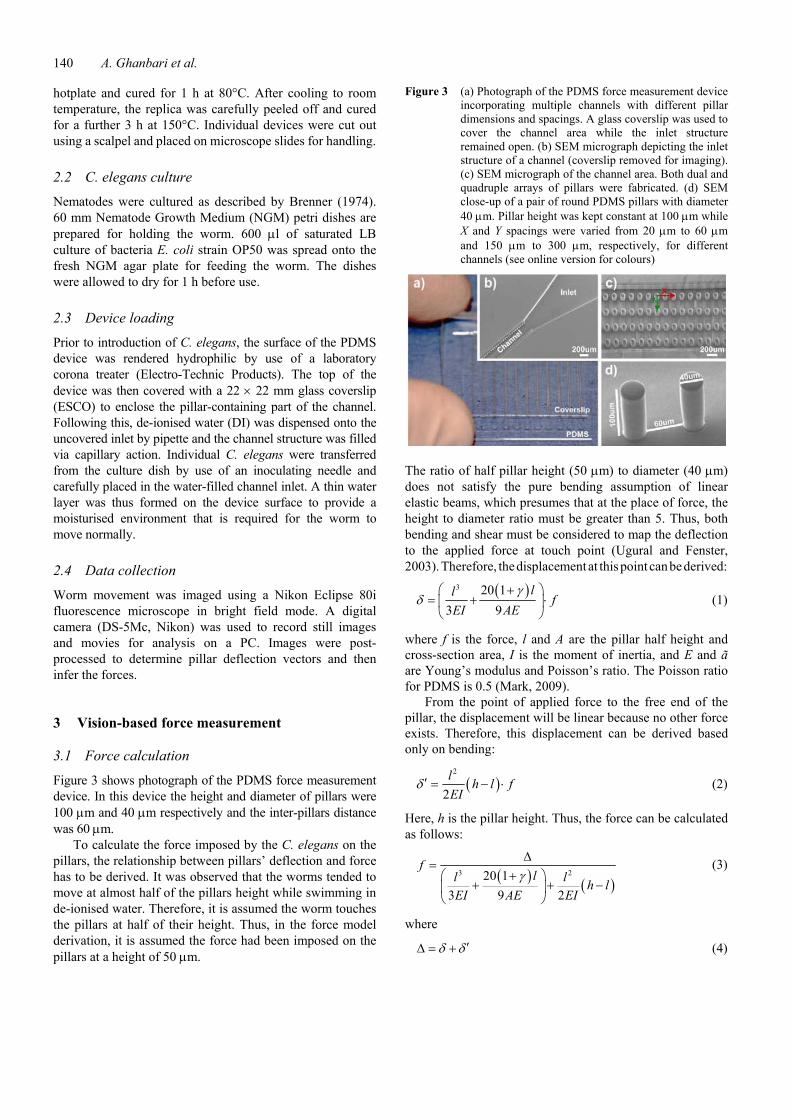
Figure 3 shows photograph of the PDMS force measurement device. In this device the height and diameter of pillars were 100 μm and 40 μm respectively and the inter-pillars distance was 60 μm.
To calculate the force imposed by the C. elegans on the pillars, the relationship between pillars’ deflection and force has to be derived. It was observed that the worms tended to move at almost half of the pillars height while swimming in de-ionised water. Therefore, it is assumed the worm touches the pillars at half of their height. Thus, in the force model derivation, it is assumed the force had been imposed on the pillars at a height of 50 μm.
Figure 3 (a) Photograph of the PDMS force measurement device incorporating multiple channels with different pillar dimensions and spacings. A glass coverslip was used to cover the channel area while the inlet structure remained open. (b) SEM micrograph depicting the inlet structure of a channel (coverslip removed for imaging). (c) SEM micrograph of the channel area. Both dual and quadruple arrays of pillars were fabricated. (d) SEM close-up of a pair of round PDMS pillars with diameter 40 μm. Pillar height was kept constant at 100 μm while X and Y spacings were varied from 20 μm to 60 μm and 150 μm to 300 μm, respectively, for different channels (see online version for colours)
The ratio of half pillar height (50 μm) to diameter (40 μm) does not satisfy the pure bending assumption of linear elastic beams, which presumes that at the place of force, the height to diameter ratio must be greater than 5. Thus, both bending and shear must be considered to map the deflection to the applied force at touch point (Ugural and Fenster, 2003). Therefore, the displacement at this point can be derived:
( )3 20 13 9
ll fEI AE
γδ
+⎛ ⎞= + ⋅⎜ ⎟⎝ ⎠
(1)
where f is the force, l and A are the pillar half height and cross-section area, I is the moment of inertia, and E and ã are Young’s modulus and Poisson’s ratio. The Poisson ratio for PDMS is 0.5 (Mark, 2009).
From the point of applied force to the free end of the pillar, the displacement will be linear because no other force exists. Therefore, this displacement can be derived based only on bending:
( )2
2l h l fEI
δ ′ = − ⋅ (2)
Here, h is the pillar height. Thus, the force can be calculated as follows:
( ) ( )3 220 1
3 9 2
fll l h l
EI AE EI
Δ=
+⎛ ⎞+ + −⎜ ⎟
⎝ ⎠
γ (3)
where
δ δ ′Δ = + (4)

Force pattern characterisation of C. elegans in motion 141
Pillar diameters are considered uniform along the height (Figure 3d). Therefore, the moment of inertia of each pillar is defined:
4
64DI π
= (5)
Note that drag forces on the pillars by the fluidic environment are safely ignored (Hughes and Brighton, 1999).
In equation (3) the only unknown parameters are Young’s modulus E, and pillar deflection ∆. Based on the PDMS device fabrication specifications, E is equal to 1.6 MPa (Schneider et al., 2008). Hence, the force imposed by C. elegans can be obtained by measuring the pillars deflection Δ, which is detectable via image processing discussed in the following section.
3.2 Image processing and deflection measurement An image processing algorithm was developed and adapted to track pillar deflection accurately. A total of 35 consecutive frames were selected for processing. Without loss of generality, three specific pillars (Figure 4) were selected for showing the deflection measurement.
Figure 4 Top view of targeted pillars for deflection measurement and C. elegans movement direction (see online version for colours)
First, frames were converted to black and white to have binary images for subsequent extraction of the edge coordinates, as shown in Figure 5(a). Second, three zones were defined to extract each pillar image in an assigned square window. Then, the following algorithm was applied to trace the outline of the outer circle of the deflected pillar:
• Scanning the square window from bottom left until a nonzero pixel belonging to the outer circle of the pillar from the top view is found. Pixel P0 is a starting pixel of the circle tracing.
• Defining the tracing direction.
• Searching the 3 × 3 neighbourhood of the current pixel in an anti-clockwise direction, beginning the neighbourhood search in the pixel positioned in the defined tracing direction. The first nonzero pixel found is the second circle point P1.
• The circle point tracing is repeated up to detecting nth pixel Pn.
Figure 5b shows a traced outline of the outer circle of the three targeted pillars for n = 65 points.
A least-square fitting algorithm was employed to fit a circle to the traced points. The algorithm minimises the following equation, which is the sum of squares of algebraic distance of the n detected points from the circle centre:
( ) ( ) ( )22 2 2
1, , n
c c i c i ciG x y r x x y y r
=⎡ ⎤= − + − −⎣ ⎦∑ (6)
Figure 5 (a) Converted binary image. (b) Traced outlines of the outer circles (see online version for colours)
Here, xc and yc are the coordinates of the circle centre and r is the circle radius. First, define:
2 cA x= − (7) 2 cB y= − (8) 2 2 2c cC x y r= + − (9)
Equation (6) can thus be rewritten:
( ) ( )22 21
, , ni i i ii
G A B C x y Ax By C=
= + + + +∑ (10)
The result is a differentiating equation with respect to A, B and C that creates a linear equation set. By solving this equation set, centre coordinates and a radius are calculated. Figure 6 shows the fitted circles for three targeted pillars. Figure 7 shows processed square windows of three pillars and fitted circles in six different frames. In all 35 processed frames the fitted circles accurately locate the top view of deflected pillars including their centres for tracking.
142 A. Ghanbari et al.
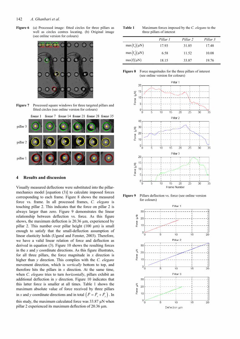
Figure 6 (a) Processed image: fitted circles for three pillars as well as circles centres locating. (b) Original image (see online version for colours)
Figure 7 Processed square windows for three targeted pillars and fitted circles (see online version for colours)
4 Results and discussion
Visually measured deflections were substituted into the pillar-mechanics model [equation (3)] to calculate imposed forces corresponding to each frame. Figure 8 shows the measured force vs. frame. In all processed frames, C. elegans is touching pillar 2. This indicates that the force on pillar 2 is always larger than zero. Figure 9 demonstrates the linear relationship between deflection vs. force. As this figure shows, the maximum deflection is 20.36 µm, experienced by pillar 2. This number over pillar height (100 µm) is small enough to satisfy that the small-deflection assumption of linear elasticity holds (Ugural and Fenster, 2003). Therefore, we have a valid linear relation of force and deflection as derived in equation (3). Figure 10 shows the resulting forces in the x and y coordinate directions. As this figure illustrates, for all three pillars, the force magnitude in x direction is higher than y direction. This complies with the C. elegans movement direction, which is vertically bottom to top, and therefore hits the pillars in x direction. At the same time, when C. elegans tries to turn horizontally, pillars exhibit an additional deflection in y direction. Figure 10 indicates that this latter force is smaller at all times. Table 1 shows the maximum absolute value of force received by three pillars in x and y coordinate directions and in total ( )x yF F F= + . In
this study, the maximum calculated force was 33.87 µN when pillar 2 experienced its maximum deflection of 20.36 µm.
Table 1 Maximum forces imposed by the C. elegans to the three pillars of interest
Pillar 1 Pillar 2 Pillar 3
( )xmax f μN 17.93 31.85 17.48
( )ymax f μN 6.58 11.52 10.08
( )max f μN 18.15 33.87 19.76
Figure 8 Force magnitudes for the three pillars of interest (see online version for colours)
Figure 9 Pillars deflection vs. force (see online version for colours)
Force pattern characterisation of C. elegans in motion 143
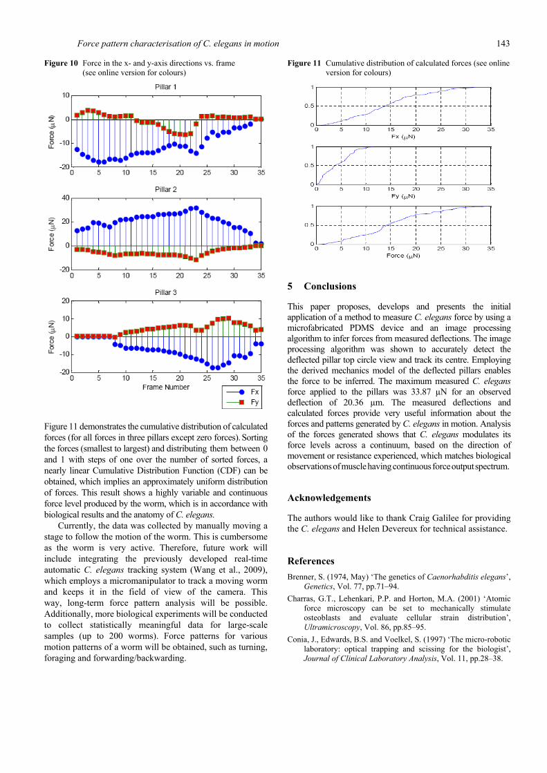
Figure 10 Force in the x- and y-axis directions vs. frame (see online version for colours)
Figure 11 demonstrates the cumulative distribution of calculated forces (for all forces in three pillars except zero forces). Sorting
the forces (smallest to largest) and distributing them between 0 and 1 with steps of one over the number of sorted forces, a nearly linear Cumulative Distribution Function (CDF) can be obtained, which implies an approximately uniform distribution of forces. This result shows a highly variable and continuous force level produced by the worm, which is in accordance with biological results and the anatomy of C. elegans.
Currently, the data was collected by manually moving a stage to follow the motion of the worm. This is cumbersome as the worm is very active. Therefore, future work will include integrating the previously developed real-time automatic C. elegans tracking system (Wang et al., 2009), which employs a micromanipulator to track a moving worm and keeps it in the field of view of the camera. This way, long-term force pattern analysis will be possible. Additionally, more biological experiments will be conducted to collect statistically meaningful data for large-scale samples (up to 200 worms). Force patterns for various motion patterns of a worm will be obtained, such as turning, foraging and forwarding/backwarding.
Figure 11 Cumulative distribution of calculated forces (see online version for colours)
5 Conclusions
This paper proposes, develops and presents the initial application of a method to measure C. elegans force by using a microfabricated PDMS device and an image processing algorithm to infer forces from measured deflections. The image processing algorithm was shown to accurately detect the deflected pillar top circle view and track its centre. Employing the derived mechanics model of the deflected pillars enables the force to be inferred. The maximum measured C. elegans force applied to the pillars was 33.87 µN for an observed deflection of 20.36 µm. The measured deflections and calculated forces provide very useful information about the forces and patterns generated by C. elegans in motion. Analysis of the forces generated shows that C. elegans modulates its force levels across a continuum, based on the direction of movement or resistance experienced, which matches biological observations of muscle having continuous force output spectrum.
Acknowledgements
The authors would like to thank Craig Galilee for providing the C. elegans and Helen Devereux for technical assistance.
References Brenner, S. (1974, May) ‘The genetics of Caenorhabditis elegans’,
Genetics, Vol. 77, pp.71–94. Charras, G.T., Lehenkari, P.P. and Horton, M.A. (2001) ‘Atomic
force microscopy can be set to mechanically stimulate osteoblasts and evaluate cellular strain distribution’, Ultramicroscopy, Vol. 86, pp.85–95.
Conia, J., Edwards, B.S. and Voelkel, S. (1997) ‘The micro-robotic laboratory: optical trapping and scissing for the biologist’, Journal of Clinical Laboratory Analysis, Vol. 11, pp.28–38.

144 A. Ghanbari et al.
Fass, J.N. and Odde, D.J. (2003) ‘Tensile force dependent neurite elicitation via Anti-â1 integrin antibody-coated magnetic beads’, Biophysics Journal, Vol. 85, pp.623–636.
Fauver, M.E., Dunaway, D.L., Lillenfeld, D.H., Craighead, H.G. and Pollack, G.H. (1998) ‘Microfabricated cantilevers for measurement of subcellular and molecular forces’, IEEE Transactions on Biomedical Engineering, Vol. 45, pp.891–898.
Harris, A.K., Wild, P. and Stopak, D. (1980) ‘Silicone rubber substrata: a new wrinkle in the study of cell locomotion’, Science, Vol. 208, pp.177–179.
Hochmuth, R.M. (2000) ‘Micropipette aspiration of living cells’, Journal of Biomechanics, Vol. 33, pp.15–22.
Hughes, W.F. and Brighton, J.A. (1999) Schaums’s Outline of Theory and Problems of Fluid Dynamics, McGraw-Hill, NY.
Kim, E., Xia, Y. and Whitesides, G.M. (1995) ‘Polymer microstructures formed by moulding in capillaries’, Nature, Vol. 376, pp.581–584.
Lin, G., Palmer, G., Pister, K.S.J. and Roos, K.P. (2001) ‘Miniature heart cell force transducer system implemented in MEMS technology’, IEEE Transactions on Biomedical Engineering, Vol. 9, pp.996–1006.
Liu, X.Y., Sun, Y., Wang, W.H. and Lansdorp, B.M. (2007) ‘Vision-based cellular force measurement using an elastic microfabricated device’, Journal of Micromechanics and Microengineering, Vol. 17, No. 7, pp.1281–1288.
Mark, J.E. (2009) Polymer Data Handbook, Oxford University Press, Oxford.
MicroChem (2008) SU-8 2000 Datasheet. Roure, O.D., Saez, A., Buguin, A., Austin, R.H., Chavrier, P,
Siberzan, P. and Ladoux, B. (2005) ‘Force mapping in epithelial cell migration’, Proceedings of National Academy of Sciences USA, Vol. 102, pp.2390–2395.
Schneider, F., Fellner, T., Wilde, J. and Wallrabe, U. (2008) ‘Mechanical properties of silicones for MEMS’, Journal of Micromechanics and Microengineering, Vol. 18, pp.1–9.
Sun, Y. and Nelson, B.J. (2002) ‘Biological cell injection using an autonomous microrobotic system’, International Journal of Robotics Research, Vol. 21, Nos. 10–11.
Sun, Y., Fry, S.N., Potassek, D.P., Bell, D.J. and Nelson, B.J. (2005) ‘Characterizing fruit fly flight behaviour using a microforce sensor with a new comb drive configuration’, Journal of Microelectromechanical System, Vol. 14, pp.4–11.
Sun, Y., Wan, K.T., Nelson, B.J., Bischof, J. and Roberts, K. (2003) ‘Mechanical property characterization of the mouse zona pellucida’, IEEE Transactions on Nanobioscience, Vol. 2, pp.279–286.
Tan, J.L., Tien, J., Pirone, D.M., Gary, D.S., Bhadriraju, K. and Chen, C.S. (2003) ‘Cells lying on a bed of microneedles: an approach to isolate mechanical force’, Proceedings of National Academy of Sciences USA, Vol. 100, pp.1484–1489.
The Caenorhabditis elegans Sequence Consortium (1998, December) ‘Genome sequence of the nematode C. elegans: a platform for investigating biology’, Science, Vol. 282, pp.2012–2018.
Ugural, A.C. and Fenster, S.K. (2003) Advanced Strength and Applied Elasticity, McGraw-Hill, NY.
Wang, W.H., Sun, Y., Dixon, S.J., Alexander, M. and Roy, P.J. (2009) ‘An automated micropositioning system for investigating C. elegans locomotive behaviour’, Journal for the Association for Laboratory Automation, Vol. 14, No. 5, pp.269–276.
Xia, Y.N. and Whitesides, G.M. (1998, March) ‘Soft lithography’, Angewandte Chemie-International Edition, Vol. 37, pp.551–575.
Xia, Y., Kim, E., Zhao, X.M., Rogers, J.A., Prentiss, M. and Whitesides, G.M. (1996) ‘Complex optical surfaces formed by replica molding against elastomeric masters’, Science, Vol. 273, pp.347–349.
Zhao, Y. and Zhang, X. (2006) ‘Cellular mechanics study in cardiac myocytes using PDMS pillars array’, Sensors Actuators, Vol. 125, pp.398–404.
Related Documents