REPAIR INSTRUCTION For vehicles with Caterpillar/ZF Astronic drive train only Read the repair instruction in Section 6 before installing the transmission to the engine.

Welcome message from author
This document is posted to help you gain knowledge. Please leave a comment to let me know what you think about it! Share it to your friends and learn new things together.
Transcript

RE
PA
IR IN
ST
RU
CT
ION
RE
PA
IR IN
ST
RU
CT
ION
For vehicles with Caterpillar/ZF Astronicdrive train only
Read the repair instruction in Section 6 beforeinstalling the transmission to the engine.
For vehicles with Caterpillar/ZF Astronicdrive train only
Read the repair instruction in Section 6 beforeinstalling the transmission to the engine.

RE
PA
IR IN
ST
RU
CT
ION
RE
PA
IR IN
ST
RU
CT
ION

OG
BF
RO
FO
GB
FR
OF
DATE 11/99
DATE 11/99
C2045
C2045
Congratulations. You are operating one of the world's best linehaul coaches. As you learn more about thefeatures of this fine coach, you will agree that VAN HOOL has Qualities That Make The Difference.
You will find that some of these differences will require familiarization. So please spend some timereviewing this Guidebook to acquaint yourself with the operation of your VAN HOOL coach. It willbe time well spent, for you and your passengers.
WELCOME TO THE VAN HOOLCOMMUTER COACH
T05118
OG
BF
RO
FO
GB
FR
OF
C2045DATE 11/99
DATE 11/99C2045
FEDERAL AND STATE LAWS GOVERNING TRAFFIC SPEED LIMITS MUST BE OBEYED AT ALLTIMES. HOWEVER, FOR SAFETY REASONS, THE MAXIMUM INDICATED SPEED LIMIT OF THE
VAN HOOL COACHES IS RATED AT 72 MPH (120 KM/H).
FEDERAL AND STATE LAWS GOVERNING TRAFFIC SPEED LIMITS MUST BE OBEYED AT ALLTIMES. HOWEVER, FOR SAFETY REASONS, THE MAXIMUM INDICATED SPEED LIMIT OF THE
VAN HOOL COACHES IS RATED AT 72 MPH (120 KM/H).

TA
BL
E O
F C
ON
TE
NT
ST
AB
LE
OF
CO
NT
EN
TS
OG
BT
OC
FO
GB
TO
CF
C2045
C2045
TABLE OF CONTENTS
SECTION
GENERAL INFORMATION (safety instructions, identification,assistance, dimensions and data, exterior compartments) ................................ 1
OPERATING INSTRUCTIONS (driver's compartment and controls,driving instructions, emergency conditions) ....................................................... 2
ACCESSORIES (climate control, combustion heater, lavatory,wheelchair lift) ......................................................................................................... 3
MAINTENANCE ................................................................................................. 4
APPENDICES (lubricants and fluids, conversion factors,electrical system) .................................................................................................... 5
UPDATES AND ADDITIONS ......................................................................... 6
INDEX .................................................................................................................. 7

TA
BL
E O
F C
ON
TE
NT
ST
AB
LE
OF
CO
NT
EN
TS
OG
BT
OC
FO
GB
TO
CF
C2045
C2045

GE
NE
RA
L I
NF
OR
MA
TIO
NG
EN
ER
AL
IN
FO
RM
AT
ION
Upd
ate
B_O
GB
01A
GU
pdat
e B
_OG
B01
AG
SECTION 1 PAGE 1DATE 10/2004
SECTION 1 PAGE 1DATE 10/2004
C2045
C2045
GENERAL INFORMATION
SAFETY INSTRUCTIONS
Recommendations to avoid injury or damage to health ........................................................ page 3Recommendations to avoid damage to the vehicle .............................................................. page 5Recommendations for the protection of the environment ..................................................... page 6
IDENTIFICATION
Vehicle identification plate .................................................................................................... page 7Vehicle identification number ................................................................................................ page 8Engine identification plate ..................................................................................................... page 8Wheel warning plate .............................................................................................................. page 9
CAUTIONS, NOTES AND COMMENTS ................................................................................. page 10
ASSISTANCE .......................................................................................................................... page 11
DIMENSIONS AND DATA ........................................................................................................ page 12
EXTERIOR COMPARTMENTS ................................................................................................ page 15
GENERAL INFORMATION
SAFETY INSTRUCTIONS
Recommendations to avoid injury or damage to health .......................................................... page 3Recommendations to avoid damage to the vehicle ................................................................ page 5Recommendations for the protection of the environment ........................................................ page 6
IDENTIFICATION
Vehicle identification plate ..................................................................................................... page 7Vehicle identification number ................................................................................................. page 8Engine identification plate ..................................................................................................... page 8Wheel warning plate .............................................................................................................. page 9
CAUTIONS, NOTES AND COMMENTS ................................................................................. page 10
ASSISTANCE .......................................................................................................................... page 11
DIMENSIONS AND DATA ........................................................................................................ page 12
EXTERIOR COMPARTMENTS ................................................................................................ page 15

GE
NE
RA
L IN
FO
RM
AT
ION
Update B
_OG
B01A
GU
pdate B_O
GB
01AG
GE
NE
RA
L IN
FO
RM
AT
ION
PAGE 2 DATE 10/2004 SECTION 1
DATE 10/2004PAGE 2 SECTION 1
C2045
C2045

GE
NE
RA
L I
NF
OR
MA
TIO
NG
EN
ER
AL
IN
FO
RM
AT
ION
Upd
ate
B_O
GB
01A
GU
pdat
e B
_OG
B01
AG
SECTION 1 PAGE 3DATE 10/2004
SECTION 1 PAGE 3DATE 10/2004
C2045
C2045
SAFETY INSTRUCTIONS
In order to avoid damage to equipment andprevent personal injury, it is very important toensure that the operator of the vehicle is fullytrained and that he/she understands clearly everyvehicle operation outlined in this manual.
In order to assist you to avoid accidents anddamage, we have gathered a series of generalinstructions below, applicable to the operation ofcommercial vehicles. In addition, you will find inthe various sections of the manual, specificprecautions related to the operations described.Read them carefully both in the interest of yourown safety and that of the vehicle.
The VAN HOOL Company cannot be heldresponsible for conforming with these safetyinstructions within your company. It can forecastneither ANY situation nor ANY error liable tocause accidents, damage or health problems.
RECOMMENDATIONS TO AVOIDINJURY OR DAMAGE TO HEALTH
• Familiarize yourself with the location and theaction of each of the controls before drivingthe coach for the first time.
• Before operating the coach be sure you knowwhere to find the fire extinguishers and how touse them.
• Before starting the engine, always ensure thatthe parking brake is properly set and that thetransmission is in neutral.
• DO NOT allow either the engine or thecombustion heater to operate in a confinedarea without exhaust gas extractionequipment.
• In order to reduce risk of fire, stop the engineand cut off the heating (combustion heater)before filling with diesel fuel.

GE
NE
RA
L IN
FO
RM
AT
ION
Update B
_OG
B01A
GU
pdate B_O
GB
01AG
GE
NE
RA
L IN
FO
RM
AT
ION
PAGE 4 DATE 10/2004 SECTION 1
DATE 10/2004PAGE 4 SECTION 1
C2045
C2045
• Before commencing any operation, be sure tohave read and fully understood the relevantinstructions.
• Before doing any work in the enginecompartment, set the start override switch inthe engine compartment to the cut-off positionin order to prevent the engine from beingstarted from the driver's position. Put a "DONOT START" placard on the steering wheel.
• Basically, all servicing operations should becarried out with the engine stopped. If,however, it becomes necessary to carry outcertain engine checks with the engine running,keep well away from any rotating parts.
!!! CAUTION !!!
THE FLICKERING LIGHT OF FLUORESCENTTUBES SOMETIMES CREATES AN OPTICAL
ILLUSION THAT A ROTATING FAN MAYAPPEAR STATIONARY.
• To avoid burns, DO NOT touch a hot engine,transmission or retarder with bare hands.
• Never open the cooling or heating systemswhile the coolant is still hot. If, however, thesituation forces you to do so anyway, firstallow the pressure to be relieved from thesurge tank as explained in the Sections"Driving Instructions" and "MaintenanceProcedures".
• Neither tighten nor loosen fuel, coolant, air oroil line couplings while under pressure. DONOT check a pressurized system for leakswith your hands. Before disconnecting oropening any component that is part of asystem utilizing pressure, bleed the pressurecarefully from the system after having takenevery necessary precaution.
• Keep in mind that vehicle body groundclearance can suddenly decrease by over 3inches when the suspension air bellows aredepressurized (whether intentionally orinadvertently).
• To reduce the risk of incendive short circuits,when disconnecting batteries alwaysdisconnect the ground cable first. Whenreconnecting the batteries, first connect thepositive cable.

GE
NE
RA
L I
NF
OR
MA
TIO
NG
EN
ER
AL
IN
FO
RM
AT
ION
Upd
ate
B_O
GB
01A
GU
pdat
e B
_OG
B01
AG
SECTION 1 PAGE 5DATE 10/2004
SECTION 1 PAGE 5DATE 10/2004
C2045
C2045
• The batteries contain a corrosive solution ofsulfuric acid. The gases given off by a batteryare highly explosive.
• Use only tools maintained in good condition.Worn-out wrenches, for example, mayinadvertently slip off and provoke injury.
• Before lifting the vehicle with a jack, apply theparking brake and chock the wheelsremaining on the ground.
• Only use jacks in good condition, of adequatelifting capacity and of the appropriate type.
• Never get beneath a vehicle supported only byjacks or hoists; always fit additional supportingblocks or stands first.
• The gas struts on the lift-up type coach bodydoors contain gas under high pressure. Neverpierce or attempt to open these units. Do notheat.
• Children younger than 10 years should alwaystake place on a seat with a seatback in frontof it.
RECOMMENDATIONS TO AVOIDDAMAGE TO THE VEHICLE
• Take care that each problem be remedied assoon as possible in order to avoid anyaggravation.
• Adhere to the tightening torquesrecommended in the "MaintenanceProcedures" Section of this manual.
• Always turn off the battery master switchbefore undertaking any work on the vehicle'selectrical system.
• Never disconnect any electronic control orregulation modules (engine control box,transmission control box, speed limiter, etc.) ifthe battery master switch is "on".
• Where a vehicle has an encapsulated engine:after each maintenance or repair operation,check for the presence of any flammableliquids or materials at the base of the engineencapsulation (Diesel fuel spilled whenbleeding the fuel system, for example).

GE
NE
RA
L IN
FO
RM
AT
ION
Update B
_OG
B01A
GU
pdate B_O
GB
01AG
GE
NE
RA
L IN
FO
RM
AT
ION
PAGE 6 DATE 10/2004 SECTION 1
DATE 10/2004PAGE 6 SECTION 1
C2045
C2045
• When necessary to raise the vehicle chassisby means of jacks, these should be locatedsolely under the chassis lifting points indicatedunder the heading "Emergency Conditions" inthe "Operating Instructions" Section
• Never add cold coolant to an overheatedengine.
• The use of portable phones and transmittingequipment inside the vehicle could disruptnormal operation of the electronical equipmentand thus jeopardize the vehicle's reliability. Inorder not to endanger your vehicle's reliability,only use portable phones and transmittingequipment inside the vehicle if they areconnected to an exterior antenna.
RECOMMENDATIONS FOR THEPROTECTION OF THE ENVIRONMENT
Avoid contaminating the natural environment withtoxic or polluting substances. Lube oil, anti-freeze, hydraulic fluids, refrigerants, batteryelectrolyte, used oil and fuel filter elements, lead-acid batteries as well as asbestos containingwaste must be disposed of according to local,State and Federal guidelines. Information on therules currently in force should be obtained fromthe appropriate environmental authorities(E.P.A.).
DO NOT let the coach engine idle forunnecessarily long periods. During idling, exhaustemission levels are much higher.

GE
NE
RA
L I
NF
OR
MA
TIO
NG
EN
ER
AL
IN
FO
RM
AT
ION
Upd
ate
B_O
GB
01A
GU
pdat
e B
_OG
B01
AG
SECTION 1 PAGE 7DATE 10/2004
SECTION 1 PAGE 7DATE 10/2004
C2045
C2045
F04710
T03731
IDENTIFICATION
VEHICLE IDENTIFICATION PLATE
The vehicle identification plate is located in thestepwell of the entrance door.
The plate contains the following information:
A: Front axleB: Drive axleC: Tag axleD: Gross vehicle weight ratingE: Month/year of constructionF: Gross axle weight ratingG: Tire sizeH: Rim sizeI: Cold inflation pressureJ: Production numberK: Vehicle identification number
T03731
F04710

GE
NE
RA
L IN
FO
RM
AT
ION
Update B
_OG
B01A
GU
pdate B_O
GB
01AG
GE
NE
RA
L IN
FO
RM
AT
ION
PAGE 8 DATE 10/2004 SECTION 1
DATE 10/2004PAGE 8 SECTION 1
C2045
C2045
T05185
T03328
VEHICLE IDENTIFICATION NUMBER
The vehicle identification number is stamped onthe right-hand chassis side member, behind theR.H front wheel.
ENGINE IDENTIFICATION
Detroit Diesel
The engine serial number and model number arelaser etched on the fuel filter side of the cylinderblock just below the intake manifold and above thecast-in Detroit Diesel logo.
Cummins
The engine dataplate is located on the fuel filterside of the engine, on the rocker housing.
XXXXXXXXXXX
DETROIT DIESEL
T03002
CUMMINS
VEHICLE IDENTIFICATION NUMBER
The vehicle identification number is stamped onthe right-hand chassis side member, behind theR.H front wheel.
ENGINE IDENTIFICATION
Detroit Diesel
The engine serial number and model number arelaser etched on the fuel filter side of the cylinderblock just below the intake manifold and above thecast-in Detroit Diesel logo.
Cummins
The engine dataplate is located on the fuel filterside of the engine, on the rocker housing.
T05185
T03328
XXXXXXXXXXX
DETROIT DIESEL
T03002
CUMMINS

GE
NE
RA
L I
NF
OR
MA
TIO
NG
EN
ER
AL
IN
FO
RM
AT
ION
Upd
ate
B_O
GB
01A
GU
pdat
e B
_OG
B01
AG
SECTION 1 PAGE 9DATE 10/2004
SECTION 1 PAGE 9DATE 10/2004
C2045
C2045
Caterpillar
The serial number plate is located at the fuel filterside of the cylinder block near the rear of theengine.
Caterpillar
The serial number plate is located at the fuel filterside of the cylinder block near the rear of theengine.
WHEEL WARNING PLATE
Current vehicles are fitted with 22.5" x 9.00"wheels instead of 22.5" x 8.25" wheels. Vehicleswith 9.00" wheels have a "9 inch wheels"warning plate next to the vehicle identificationplate. .
!!! CAUTION !!!
NEVER FIT 8.25" WHEELS ON VEHICLESORIGINALLY FITTED WITH 9.00" WHEELS
OR 9.00" WHEELS ON VEHICLESORIGINALLY FITTED WITH 8.25" WHEELS.
CATERPILLAR
CATERPILLAR

GE
NE
RA
L IN
FO
RM
AT
ION
Update B
_OG
B01A
GU
pdate B_O
GB
01AG
GE
NE
RA
L IN
FO
RM
AT
ION
PAGE 10 DATE 10/2004 SECTION 1
DATE 10/2004PAGE 10 SECTION 1
C2045
C2045
CAUTIONS, NOTES AND COMMENTS
Three types of headings are used in this manual to attract your attention. It is the driver's responsibilityto become familiar with the cautions and notes in the guide.
!!! CAUTION !!!
CONCERNS MATTERS THAT MAY ENDANGER LIVES OR DAMAGE PROPERTY.
NOTE
Indicates useful tips or other advice that should be remembered.
Comments are printed in italics to draw attention to important data or information.

GE
NE
RA
L I
NF
OR
MA
TIO
NG
EN
ER
AL
IN
FO
RM
AT
ION
Upd
ate
B_O
GB
01A
GU
pdat
e B
_OG
B01
AG
SECTION 1 PAGE 11DATE 10/2004
SECTION 1 PAGE 11DATE 10/2004
C2045
C2045
IF YOU NEED ASSISTANCE, CALL YOUR NEARESTAUTHORIZED VAN HOOL SERVICE CENTER
CALIFORNIA
FLORIDA
MINNESOTA
NEW JERSEY
TEXAS
13261 Garden Grove Blvd., (800) 322-2877 (714) 663-9826Garden Grove, CA 92843 (714) 740-8888
17469 West Colonial Drive, (800) 222-2871 (407) 905-7010Building A, (407) 656-7977Winter Garden, FL 34787
1506 30th Street NW, (800) 222-2875 (507) 334-8311Faribault, MN 55021 (507) 334-1871
1494 Federal Street, (800) 222-2873 (609) 966-0055Camden, NJ 08105 (609) 966-1500
1702 S. Great Southwest Pkwy, (972) 206-1110 (972) 602-7333Grand Prairie, TX 75051
Phone no. Fax no.LOCATION
REGIONAL SERVICE CENTERS

GE
NE
RA
L IN
FO
RM
AT
ION
Update B
_OG
B01A
GU
pdate B_O
GB
01AG
GE
NE
RA
L IN
FO
RM
AT
ION
PAGE 12 DATE 10/2004 SECTION 1
DATE 10/2004PAGE 12 SECTION 1
C2045
C2045
DIMENSIONS AND DATA
DIMENSIONS
VEHICLE LENGTH ........................................................................................................................... 45'
VEHICLE WIDTH .......................................................................................................................... 102"
VEHICLE HEIGHT ......................................................................................................................... 138"
WHEELBASE ..............................................................................................................................25' 4"
INTERIOR HEIGHT .......................................................................................................................... 75"
FRONT OVERHANG ....................................................................................................................... 77"
REAR OVERHANG ....................................................................................................................... 115"
STEP HEIGHT ................................................................................................................................ 49"

GE
NE
RA
L I
NF
OR
MA
TIO
NG
EN
ER
AL
IN
FO
RM
AT
ION
Upd
ate
B_O
GB
01A
GU
pdat
e B
_OG
B01
AG
SECTION 1 PAGE 13DATE 10/2004
SECTION 1 PAGE 13DATE 10/2004
C2045
C2045
DATA
ENGINE ........................................................................................... Detroit Diesel Series 60 DDEC IVDetroit Diesel Series 60 DDEC V
Cummins ISM 01Cummins ISM 02
Caterpillar C13
TRANSMISSION ........................................................................................................ Allison WT B500ZF Astronic
AXLES
Front and tag axle ............................................................................................................. Van HoolDrive axle ................................................................................................................................ Dana
BRAKES
Front and tag axle ...................................................................................... ArvinMeritor disc brakesDrive axle .......................................................................... Dana S-cam or ArvinMeritor disc brakes
POWER STEERING ........................................................................................................................ ZF
ELECTRICAL SYSTEM: 24-volt negative ground electrical system (except head lamps, clearance lamps,identification lamps and side marker lamps which are 12-volt)
GE
NE
RA
L IN
FO
RM
AT
ION
Update B
_OG
B01A
GU
pdate B_O
GB
01AG
GE
NE
RA
L IN
FO
RM
AT
ION
PAGE 14 DATE 10/2004 SECTION 1
DATE 10/2004PAGE 14 SECTION 1
C2045
C2045
T05120
T05120

GE
NE
RA
L I
NF
OR
MA
TIO
NG
EN
ER
AL
IN
FO
RM
AT
ION
Upd
ate
B_O
GB
01A
GU
pdat
e B
_OG
B01
AG
SECTION 1 PAGE 15DATE 10/2004
SECTION 1 PAGE 15DATE 10/2004
C2045
C2045
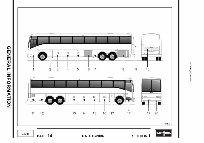
EXTERIOR COMPARTMENTS
1. Access to windshield washer tank anddriver's compartment HVAC unit
2. Left-hand fuel filler lid
3. Luggage compartment (access to mainjunction box)
4. Luggage compartment
5. Luggage compartment
6. AC condenser compartment
7. Combustion heater compartment
8. Access to cooling radiator, charge-aircooler, air cleaner, batteries, batteryjunction box and mechanical batteryisolating switch (current vehicles only)
9. Coolant filler lid
10. Engine compartment rear door
11. Access to power steering reservoir andwaste holding tank
12. Luggage compartment
13. Luggage compartment (access to HVACjunction box, ISM/DDEC/CAT junction boxand pressure switch box)
14. Luggage compartment
15. Luggage compartment
16. Luggage compartment (access to mainjunction box)
17. Right-hand fuel filler lid
18. Entrance door
19. Spare wheel and tire compartment
20. Air system emergency fill
GE
NE
RA
L IN
FO
RM
AT
ION
Update B
_OG
B01A
GU
pdate B_O
GB
01AG
GE
NE
RA
L IN
FO
RM
AT
ION
PAGE 16 DATE 10/2004 SECTION 1
DATE 10/2004PAGE 16 SECTION 1
C2045
C2045

OP
ER
AT
ING
IN
ST
RU
CT
ION
SO
PE
RA
TIN
G I
NS
TR
UC
TIO
NS
Upd
ate
B_O
GB
02A
PU
pdat
e B
_OG
B02
AP
SECTION 2 PAGE 2A-1DATE 10/2004
SECTION 2 PAGE 2A-1DATE 10/2004C2045
C2045
OPERATING INSTRUCTIONS
DRIVER'S COMPARTMENT AND CONTROLS
DRIVER'S SEAT .................................................................................................................. page 2A-9
To adjust driver's seat ....................................................................................................... page 2A-9
SEAT BELTS ...................................................................................................................... page 2A-11
EXTERIOR REAR-VIEW MIRRORS .................................................................................... page 2A-11
STEERING COLUMN .......................................................................................................... page 2A-12
STEERING COLUMN COMBINATION SWITCH ................................................................. page 2A-13
INSTRUMENT PANEL (NON-MULTIPLEXED VEHICLES; MODEL YEARS 2000, 2001, 2002) ............... page 2A-15
INSTRUMENT PANEL (NON-MULTIPLEXED VEHICLES; MODEL YEAR 2003) ................................. page 2A-17
INSTRUMENT PANEL (MULTIPLEXED VEHICLES) ................................................................... page 2A-19
INSTRUMENT PANEL SWITCHES ...................................................................................... page 2A-20

Update B
_OG
B02A
PU
pdate B_O
GB
02AP
OP
ER
AT
ING
INS
TR
UC
TIO
NS
OP
ER
AT
ING
INS
TR
UC
TIO
NS
PAGE 2A-2 DATE 10/2004 SECTION 2
DATE 10/2004PAGE 2A-2 SECTION 2
C2045
C2045
WARNING AND INDICATOR LIGHTS (NON-MULTIPLEXED VEHICLES) ........................... page 2A-26
WARNING AND INDICATOR LIGHTS (MULTIPLEXED VEHICLES) ................................... page 2A-34
MESSAGES ON MULTIFUNCTION DISPLAY (MULTIPLEXED VEHICLES ONLY) ............. page 2A-35
INSTRUMENTS (NON-MULTIPLEXED VEHICLES)
Speedometer ................................................................................................................... page 2A-40Tachometer ..................................................................................................................... page 2A-40Engine coolant temperature gauge .................................................................................. page 2A-41Engine oil pressure gauge ............................................................................................... page 2A-41Front axle brakes air-pressure gauge .............................................................................. page 2A-42Drive axle service brakes air-pressure gauge ................................................................... page 2A-42Tag axle brakes air-pressure gauge ................................................................................. page 2A-42Turbo boost gauge .......................................................................................................... page 2A-42Fuel level gauge .............................................................................................................. page 2A-43
INSTRUMENTS (MULTIPLEXED VEHICLES)
Speedometer/odometer ................................................................................................... page 2A-44Tachometer ..................................................................................................................... page 2A-44Engine coolant temperature gauge .................................................................................. page 2A-44Fuel level gauge .............................................................................................................. page 2A-44Information screens on multifunction display ................................................................... page 2A-44

OP
ER
AT
ING
IN
ST
RU
CT
ION
SO
PE
RA
TIN
G I
NS
TR
UC
TIO
NS
Upd
ate
B_O
GB
02A
PU
pdat
e B
_OG
B02
AP
SECTION 2 PAGE 2A-3DATE 10/2004
SECTION 2 PAGE 2A-3DATE 10/2004C2045
C2045
DRIVING INSTRUCTIONS
ENGINE
To stop the engine ........................................................................................................... page 2B-1Pre-starting checks ......................................................................................................... page 2B-2To start the engine .......................................................................................................... page 2B-2To drive off ....................................................................................................................... page 2B-4To warm-up the engine .................................................................................................... page 2B-5
WT B500 AUTOMATIC TRANSMISSION ............................................................................ page 2B-6
Shift selector................................................................................................................... page 2B-6Range selection .............................................................................................................. page 2B-7"Do not shift" light ........................................................................................................... page 2B-9Diagnostic codes ............................................................................................................ page 2B-10Throttle control ............................................................................................................... page 2B-10Downshift or reverse inhibitor feature ............................................................................. page 2B-11Using the engine to slow the vehicle ............................................................................... page 2B-11Range preselection ......................................................................................................... page 2B-12Cold weather starts ......................................................................................................... page 2B-12Driving on snow or ice ..................................................................................................... page 2B-13Rocking out ..................................................................................................................... page 2B-13High transmission fluid temperature ................................................................................ page 2B-14Kick-down ....................................................................................................................... page 2B-15
DRIVING INSTRUCTIONS
ENGINE
To stop the engine ........................................................................................................... page 2B-1Pre-starting checks ......................................................................................................... page 2B-2To start the engine .......................................................................................................... page 2B-2To drive off ....................................................................................................................... page 2B-4To warm-up the engine .................................................................................................... page 2B-5
WT B500 AUTOMATIC TRANSMISSION ............................................................................ page 2B-6
Shift selector ................................................................................................................... page 2B-6Range selection .............................................................................................................. page 2B-7"Do not shift" light ........................................................................................................... page 2B-9Diagnostic codes ............................................................................................................ page 2B-10Throttle control ................................................................................................................ page 2B-10Downshift or reverse inhibitor feature ............................................................................... page 2B-11Using the engine to slow the vehicle ................................................................................ page 2B-11Range preselection ......................................................................................................... page 2B-12Cold weather starts ......................................................................................................... page 2B-12Driving on snow or ice ..................................................................................................... page 2B-13Rocking out ..................................................................................................................... page 2B-13High transmission fluid temperature ................................................................................ page 2B-14Kick-down ....................................................................................................................... page 2B-15
Update B
_OG
B02A
PU
pdate B_O
GB
02AP
OP
ER
AT
ING
INS
TR
UC
TIO
NS
OP
ER
AT
ING
INS
TR
UC
TIO
NS
PAGE 2A-4 DATE 10/2004 SECTION 2
DATE 10/2004PAGE 2A-4 SECTION 2
C2045
C2045
ZF ASTRONIC-TRANSMISSION .................................................................................... page 2B-15
CRUISE CONTROL/FAST IDLE .................................................................................... page 2B-16
Cruise control .................................................................................................................. page 2B-16Fast idle .......................................................................................................................... page 2B-17
POWER STEERING ......................................................................................................... page 2B-19
BRAKES
Jake brake ...................................................................................................................... page 2B-19ZF Astronic ..................................................................................................................... page 2B-20Service brake (foot brake) ................................................................................................ page 2B-20Parking brake .................................................................................................................. page 2B-21Anti-lock braking system (ABS) ...................................................................................... page 2B-22
AUTOMATIC TRACTION CONTROL (ASR) ........................................................................ page 2B-22
RAISE/LOWER SYSTEM (optional) ................................................................................... page 2B-23
FRONT LOWER SYSTEM ................................................................................................. page 2B-24
REAR RAISE SYSTEM ....................................................................................................... page 2B-24
TAG AXLE UNLOADING (optional) ................................................................................... page 2B-25
ENTRANCE DOOR
Door control with dashboard switch ................................................................................ page 2B-26Door control from the outside .......................................................................................... page 2B-26

OP
ER
AT
ING
IN
ST
RU
CT
ION
SO
PE
RA
TIN
G I
NS
TR
UC
TIO
NS
Upd
ate
B_O
GB
02A
PU
pdat
e B
_OG
B02
AP
SECTION 2 PAGE 2A-5DATE 10/2004
SECTION 2 PAGE 2A-5DATE 10/2004C2045
C2045
To lock door from the inside ............................................................................................ page 2B-26To lock/unlock door from the outside ............................................................................... page 2B-26Automatic reopening ....................................................................................................... page 2B-27
LUGGAGE COMPARTMENT DOORS CENTRAL LOCKING SYSTEM ............................... page 2B-28
EMERGENCY CONDITIONSPARKING BRAKE EMERGENCY RELEASE
Air pressure release ....................................................................................................... page 2C-1Mechanical release ........................................................................................................ page 2C-1
HAZARD WARNING FLASHER ........................................................................................ page 2C-2
ENTRANCE DOOR EMERGENCY OPERATION .............................................................. page 2C-3
EMERGENCY OPERATION OF RAISE, LOWER AND REAR RISE SYSTEM ................. page 2C-4
COOLING FAN MECHANICAL LOCKING DEVICE ............................................................. page 2C-5
EMERGENCY EXITS
Side window emergency escape ..................................................................................... page 2C-6Roof emergency escape.................................................................................................. page 2C-7
LEAK IN HEATING SYSTEM .............................................................................................. page 2C-7
To lock door from the inside ............................................................................................ page 2B-26To lock/unlock door from the outside ............................................................................... page 2B-26Automatic reopening ....................................................................................................... page 2B-27
LUGGAGE COMPARTMENT DOORS CENTRAL LOCKING SYSTEM ............................... page 2B-28
EMERGENCY CONDITIONSPARKING BRAKE EMERGENCY RELEASE
Air pressure release ....................................................................................................... page 2C-1Mechanical release......................................................................................................... page 2C-1
HAZARD WARNING FLASHER ........................................................................................ page 2C-2
ENTRANCE DOOR EMERGENCY OPERATION .................................................................. page 2C-3
EMERGENCY OPERATION OF RAISE, LOWER AND REAR RISE SYSTEM ..................... page 2C-4
COOLING FAN MECHANICAL LOCKING DEVICE ............................................................. page 2C-5
EMERGENCY EXITS
Side window emergency escape ..................................................................................... page 2C-6Roof emergency escape.................................................................................................. page 2C-7
LEAK IN HEATING SYSTEM .............................................................................................. page 2C-7

Update B
_OG
B02A
PU
pdate B_O
GB
02AP
OP
ER
AT
ING
INS
TR
UC
TIO
NS
OP
ER
AT
ING
INS
TR
UC
TIO
NS
PAGE 2A-6 DATE 10/2004 SECTION 2
DATE 10/2004PAGE 2A-6 SECTION 2
C2045
C2045
AN ENGINE WARNING LIGHT IS ILLUMINATED ............................................................... page 2C-8
Cummins ISM engine ..................................................................................................... page 2C-8Detroit Diesel engine ....................................................................................................... page 2C-10Caterpillar engine ............................................................................................................ page 2C-11
WT B500-TRANSMISSION "DO NOT SHIFT" LIGHT IS ILLUMINATED ............................ page 2C-12
Diagnostic codes ............................................................................................................ page 2C-12Diagnostic code display procedure .................................................................................. page 2C-13
ABS WARNING LIGHT IS ILLUMINATED .......................................................................... page 2C-14
AIR SYSTEM EMERGENCY FILL ....................................................................................... page 2C-14
PUSH-STARTING ............................................................................................................... page 2C-14
LIFTING AND TOWING THE COACH WITH A TOW TRUCK ............................................. page 2C-15
TIRE INFLATION ................................................................................................................ page 2C-16
SPARE WHEEL & TIRE ...................................................................................................... page 2C-16
TO CHANGE A ROAD WHEEL ........................................................................................... page 2C-17
To remove the wheel ........................................................................................................ page 2C-18To fit the spare wheel ...................................................................................................... page 2C-22
AN ENGINE WARNING LIGHT IS ILLUMINATED ............................................................... page 2C-8
Cummins ISM engine ...................................................................................................... page 2C-8Detroit Diesel engine ....................................................................................................... page 2C-10Caterpillar engine ............................................................................................................ page 2C-11
WT B500-TRANSMISSION "DO NOT SHIFT" LIGHT IS ILLUMINATED ............................ page 2C-12
Diagnostic codes ............................................................................................................ page 2C-12Diagnostic code display procedure .................................................................................. page 2C-13
ABS WARNING LIGHT IS ILLUMINATED .......................................................................... page 2C-14
AIR SYSTEM EMERGENCY FILL ....................................................................................... page 2C-14
PUSH-STARTING ............................................................................................................... page 2C-14
LIFTING AND TOWING THE COACH WITH A TOW TRUCK ............................................. page 2C-15
TIRE INFLATION ................................................................................................................ page 2C-16
SPARE WHEEL & TIRE ...................................................................................................... page 2C-16
TO CHANGE A ROAD WHEEL ........................................................................................... page 2C-17
To remove the wheel ........................................................................................................ page 2C-18To fit the spare wheel ...................................................................................................... page 2C-22
OP
ER
AT
ING
IN
ST
RU
CT
ION
SO
PE
RA
TIN
G I
NS
TR
UC
TIO
NS
Upd
ate
B_O
GB
02A
PU
pdat
e B
_OG
B02
AP
SECTION 2 PAGE 2A-7DATE 10/2004
SECTION 2 PAGE 2A-7DATE 10/2004C2045
C2045
CHASSIS FRAME JACKING POINTS ................................................................................ page 2C-22
CLIMATE CONTROL OVERRIDE ........................................................................................ page 2C-24
JUMP STARTING ............................................................................................................. page 2C-24
To connect booster battery cables................................................................................... page 2C-25To disconnect booster battery cables .............................................................................. page 2C-26
MANUAL WHEELCHAIR LIFT OPERATION ................................................................... page 2C-27

Update B
_OG
B02A
PU
pdate B_O
GB
02AP
OP
ER
AT
ING
INS
TR
UC
TIO
NS
OP
ER
AT
ING
INS
TR
UC
TIO
NS
PAGE 2A-8 DATE 10/2004 SECTION 2
DATE 10/2004PAGE 2A-8 SECTION 2
C2045
C2045

OP
ER
AT
ING
IN
ST
RU
CT
ION
SO
PE
RA
TIN
G I
NS
TR
UC
TIO
NS
Upd
ate
B_O
GB
02A
PU
pdat
e B
_OG
B02
AP
SECTION 2 PAGE 2A-9DATE 10/2004
SECTION 2 PAGE 2A-9DATE 10/2004C2045
C2045
DRIVER'S COMPARTMENT AND CONTROLSDRIVER'S SEAT
!!! CAUTION !!!
ALWAYS WEAR SAFETY BELT. MAKESURE THE SEAT IS ADJUSTED ANDSAFETY BELT FASTENED BEFORE
DRIVING.
NEVER ADJUST THE SEAT WHILE THECOACH IS IN MOTION.
TO ADJUST DRIVER'S SEAT
1. BackrestLift lever then adjust backrest to desiredangle.
2. Tilt(rear)To lower or raise the seat's rear section, pullhandle up, and push or pull the seat cushion.
3. Tilt(front)To lower or raise the seat's front section, pullhandle up, and push or pull the seat cushion.
T05111
DRIVER'S COMPARTMENT AND CONTROLS
DRIVER'S SEAT
!!! CAUTION !!!
ALWAYS WEAR SAFETY BELT. MAKESURE THE SEAT IS ADJUSTED ANDSAFETY BELT FASTENED BEFORE
DRIVING.
NEVER ADJUST THE SEAT WHILE THECOACH IS IN MOTION.
TO ADJUST DRIVER'S SEAT
1. BackrestLift lever then adjust backrest to desiredangle.
2. Tilt(rear)To lower or raise the seat's rear section, pullhandle up, and push or pull the seat cushion.
3. Tilt(front)To lower or raise the seat's front section, pullhandle up, and push or pull the seat cushion.
T05111
Update B
_OG
B02A
PU
pdate B_O
GB
02AP
OP
ER
AT
ING
INS
TR
UC
TIO
NS
OP
ER
AT
ING
INS
TR
UC
TIO
NS
PAGE 2A-10 DATE 10/2004 SECTION 2
DATE 10/2004PAGE 2A-10 SECTION 2
C2045
C2045
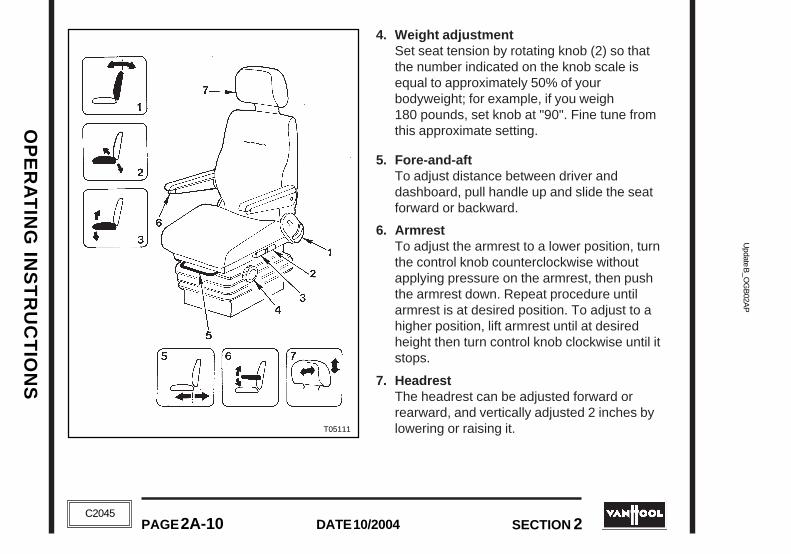
4. Weight adjustmentSet seat tension by rotating knob (2) so thatthe number indicated on the knob scale isequal to approximately 50% of yourbodyweight; for example, if you weigh180 pounds, set knob at "90". Fine tune fromthis approximate setting.
5. Fore-and-aftTo adjust distance between driver anddashboard, pull handle up and slide the seatforward or backward.
6. ArmrestTo adjust the armrest to a lower position, turnthe control knob counterclockwise withoutapplying pressure on the armrest, then pushthe armrest down. Repeat procedure untilarmrest is at desired position. To adjust to ahigher position, lift armrest until at desiredheight then turn control knob clockwise until itstops.
7. HeadrestThe headrest can be adjusted forward orrearward, and vertically adjusted 2 inches bylowering or raising it.T05111
OP
ER
AT
ING
IN
ST
RU
CT
ION
SO
PE
RA
TIN
G I
NS
TR
UC
TIO
NS
Upd
ate
B_O
GB
02A
PU
pdat
e B
_OG
B02
AP
SECTION 2 PAGE 2A-11DATE 10/2004
SECTION 2 PAGE 2A-11DATE 10/2004C2045
C2045
!!! CAUTION !!!
FOR THE BEST PROTECTION, POSITIONTHE HEADREST BEHIND YOUR HEAD AND
NOT BEHIND YOUR NECK.
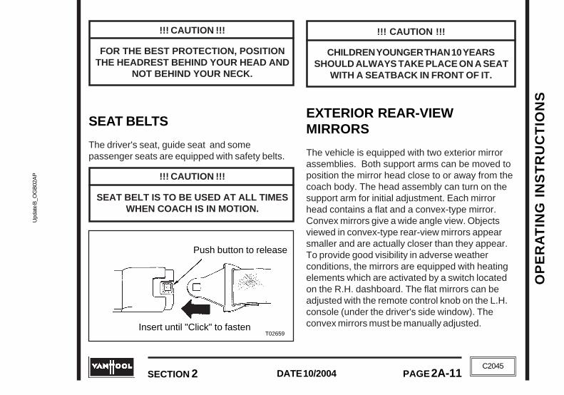
SEAT BELTS
The driver's seat, guide seat and somepassenger seats are equipped with safety belts.
!!! CAUTION !!!
SEAT BELT IS TO BE USED AT ALL TIMESWHEN COACH IS IN MOTION.
T02659
Push button to release
Insert until "Click" to fasten
!!! CAUTION !!!
CHILDREN YOUNGER THAN 10 YEARSSHOULD ALWAYS TAKE PLACE ON A SEAT
WITH A SEATBACK IN FRONT OF IT.
EXTERIOR REAR-VIEWMIRRORS
The vehicle is equipped with two exterior mirrorassemblies. Both support arms can be moved toposition the mirror head close to or away from thecoach body. The head assembly can turn on thesupport arm for initial adjustment. Each mirrorhead contains a flat and a convex-type mirror.Convex mirrors give a wide angle view. Objectsviewed in convex-type rear-view mirrors appearsmaller and are actually closer than they appear.To provide good visibility in adverse weatherconditions, the mirrors are equipped with heatingelements which are activated by a switch locatedon the R.H. dashboard. The flat mirrors can beadjusted with the remote control knob on the L.H.console (under the driver's side window). Theconvex mirrors must be manually adjusted.
!!! CAUTION !!!
FOR THE BEST PROTECTION, POSITIONTHE HEADREST BEHIND YOUR HEAD AND
NOT BEHIND YOUR NECK.
SEAT BELTS
The driver's seat, guide seat and somepassenger seats are equipped with safety belts.
!!! CAUTION !!!
SEAT BELT IS TO BE USED AT ALL TIMESWHEN COACH IS IN MOTION.
!!! CAUTION !!!
CHILDREN YOUNGER THAN 10 YEARSSHOULD ALWAYS TAKE PLACE ON A SEAT
WITH A SEATBACK IN FRONT OF IT.
EXTERIOR REAR-VIEWMIRRORS
The vehicle is equipped with two exterior mirrorassemblies. Both support arms can be moved toposition the mirror head close to or away from thecoach body. The head assembly can turn on thesupport arm for initial adjustment. Each mirrorhead contains a flat and a convex-type mirror.Convex mirrors give a wide angle view. Objectsviewed in convex-type rear-view mirrors appearsmaller and are actually closer than they appear.To provide good visibility in adverse weatherconditions, the mirrors are equipped with heatingelements which are activated by a switch locatedon the R.H. dashboard. The flat mirrors can beadjusted with the remote control knob on the L.H.console (under the driver's side window). Theconvex mirrors must be manually adjusted.
T02659
Push button to release
Insert until "Click" to fasten

Update B
_OG
B02A
PU
pdate B_O
GB
02AP
OP
ER
AT
ING
INS
TR
UC
TIO
NS
OP
ER
AT
ING
INS
TR
UC
TIO
NS
PAGE 2A-12 DATE 10/2004 SECTION 2
DATE 10/2004PAGE 2A-12 SECTION 2
C2045
C2045
To adjust the flat-type mirrors
Adjust the flat-type mirrors until the roadis in full view.
1. Select mirror to be adjusted by rotating thecontrol knob so as to have the index (5)pointing towards:
• left upper corner of dial for left side mirror• right upper corner of dial for right side mirror.
2. To adjust mirror up ordown, press on edges(2) or (4) of controlknob.
3. To adjust mirrorsideways, press onedges (1) or (3) ofcontrol knob.
You can adjust the flat-type mirrors when thebattery master switch is closed and the ignition ison.
NOTE
Manual adjustment of the flat-typemirror is not possible.
To adjust the convex-type mirrors
Adjust the convex-type mirrors manually until theside of the coach is visible.
STEERING COLUMN
The articulated steering column can be adjustedfor rake and height.
While keeping the air valvebutton (located on thefootwell, in front of your seat)depressed with your foot,push and pull steering wheeluntil desired height and rakeare obtained. Then releasebutton to relock steeringcolumn.
NOTE
The pneumatic lock-release will onlyoperate when there is sufficient
pressure in the auxiliaries air tank.
A build-in safety device ensures that the steeringcolumn can only be adjusted with the vehiclestationary.
T00084
F03737

OP
ER
AT
ING
IN
ST
RU
CT
ION
SO
PE
RA
TIN
G I
NS
TR
UC
TIO
NS
Upd
ate
B_O
GB
02A
PU
pdat
e B
_OG
B02
AP
SECTION 2 PAGE 2A-13DATE 10/2004
SECTION 2 PAGE 2A-13DATE 10/2004C2045
C2045
STEERING COLUMNCOMBINATION SWITCH
1. Horn
2. Windshield washer
3. High beam flashing (handle springs backwhen released)
4. High/low headlight beam selector.Headlights beam changes each time thehandle is pulled upwards against springpressure
5. Turn signals
6. Wipers
0 : offJ : intermittent wipingI : slow wipingII : fast wiping
T03314
Update B
_OG
B02A
PU
pdate B_O
GB
02AP
OP
ER
AT
ING
INS
TR
UC
TIO
NS
OP
ER
AT
ING
INS
TR
UC
TIO
NS
PAGE 2A-14 DATE 10/2004 SECTION 2
DATE 10/2004PAGE 2A-14 SECTION 2
C2045
C2045
T05631
T05631

OP
ER
AT
ING
IN
ST
RU
CT
ION
SO
PE
RA
TIN
G I
NS
TR
UC
TIO
NS
Upd
ate
B_O
GB
02A
PU
pdat
e B
_OG
B02
AP
SECTION 2 PAGE 2A-15DATE 10/2004
SECTION 2 PAGE 2A-15DATE 10/2004C2045
C2045
INSTRUMENT PANEL(NON-MULTIPLEXED VEHICLES; MODEL YEARS 2000, 2001, 2002)
1. Parking brakeemergency release push-pull valve
2. Exterior rear-view mirrorcontrol
3. Passengerscompartment climatecontrol
4. Cruise control/fast idleswitches
5. Transmission push-button selector
6. Steering columncombination switch
7. Jake Brake control(lever or rocker switch)
8. Fuel level gauge
9. Air outlet
10. Engine coolanttemperature gauge
11. Tachometer
12. Engine oil pressure gauge
13. Turbo boost gauge
14. Upper indicator light panel
15. Lower indicator light panel
16. Speedometer
17. Drive axle service brakesair-pressure gauge
18. Front axle brakes air-pressure gauge
19. Air outlet
20. Dashboard gaugesillumination rheostat
21. Master/ignition switch
22. Starter switch
23. Dashboard switchesillumination rheostat
24. Hazard warning flasherswitch
25. Entrance door control
26. Video control panel
27. Radio
28. Driver's compartmentclimate control
29. Combustion heatertimer
30. Diagnostic box
31. Luggage compartmentdoors central lockingsystem push-pull valve
32. Parking brake push-pull valve
33. Steering columnposition unlock button
34. Tag axle brakes air-pressure gauge
35. Loudspeaker
36. +12V socket
37. Combustion heateron/off switch
38. Microphone socket

Update B
_OG
B02A
PU
pdate B_O
GB
02AP
OP
ER
AT
ING
INS
TR
UC
TIO
NS
OP
ER
AT
ING
INS
TR
UC
TIO
NS
PAGE 2A-16 DATE 10/2004 SECTION 2
DATE 10/2004PAGE 2A-16 SECTION 2
C2045
C2045
T06261
T06261

OP
ER
AT
ING
IN
ST
RU
CT
ION
SO
PE
RA
TIN
G I
NS
TR
UC
TIO
NS
Upd
ate
B_O
GB
02A
PU
pdat
e B
_OG
B02
AP
SECTION 2 PAGE 2A-17DATE 10/2004
SECTION 2 PAGE 2A-17DATE 10/2004C2045
C2045
INSTRUMENT PANEL(NON-MULTIPLEXED VEHICLES, MODEL YEAR 2003)
1. Parking brakeemergency release push-pull valve
2. Cup holders
3. Passengerscompartment climatecontrol
4. Exterior rear-view mirrorcontrol
5. Transmission push-button selector
6. Steering columncombination switch
7. Fuel level gauge
8. Air outlet
9. Engine coolanttemperature gauge
10. Tachometer
11. Engine oil pressuregauge
12. Turbo boost gauge
13. Upper indicator light panel
14. Lower indicator light panel
15. Speedometer
16. Drive axle service brakesair-pressure gauge
17. Front axle brakes air-pressure gauge
18. Air outlet
19. Dashboard gaugesillumination rheostat
20. Master/ignition switch
21. Starter switch
22. Dashboard switchesillumination rheostat
23. Hazard warning flasherswitch
24. Entrance door control
25. Video control panel
26. Radio
27. Driver's compartmentclimate control
28. Diagnostic box
29. Luggage compartmentdoors central lockingsystem push-pull valve
30. Parking brake push-pull valve
31. Steering columnposition unlock button
32. Tag axle brakes air-pressure gauge
33. Loudspeaker
34. +12V socket
35. Cruise control/fast idleswitches
36. Microphone socket
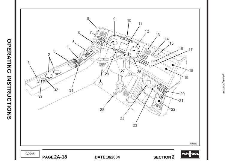
Update B
_OG
B02A
PU
pdate B_O
GB
02AP
OP
ER
AT
ING
INS
TR
UC
TIO
NS
OP
ER
AT
ING
INS
TR
UC
TIO
NS
PAGE 2A-18 DATE 10/2004 SECTION 2
DATE 10/2004PAGE 2A-18 SECTION 2
C2045
C2045
T06262
T06262

OP
ER
AT
ING
IN
ST
RU
CT
ION
SO
PE
RA
TIN
G I
NS
TR
UC
TIO
NS
Upd
ate
B_O
GB
02A
PU
pdat
e B
_OG
B02
AP
SECTION 2 PAGE 2A-19DATE 10/2004
SECTION 2 PAGE 2A-19DATE 10/2004C2045
C2045
INSTRUMENT PANEL (MULTIPLEXED VEHICLES)
1. Parking brakeemergency release push-pull valve
2. Cup holders
3. Passengerscompartment climatecontrol
4. Exterior rear-view mirrorcontrol
5. Transmission push-button selector
6. Steering columncombination switch
7. Fuel level gauge
8. Air outlet
9. Speedometer
10. Indicator light panel
11. Multifunction display
12. Tachometer
13. Air outlet
14. Master/ignition switch
15. Starter switch
16. Hazard warning flasherswitch
17. Entrance door control
18. Video control panel
19. Radio
20. Driver's compartmentclimate control
21. Emergency switch
22. Diagnostic box
23. Luggage compartmentdoors central lockingsystem push-pull valve
24. Parking brake push-pullvalve
25. ZF Intarder handle
26. Engine coolanttemperature gauge
27. Multifunction displaybrightness rheostat
28. Steering columnposition unlock button
29. Multifunction displayselection button
30. Loudspeaker
31. Cruise control/fast idleswitches
32. Microphone socket
33. +12V socket

Update B
_OG
B02A
PU
pdate B_O
GB
02AP
OP
ER
AT
ING
INS
TR
UC
TIO
NS
OP
ER
AT
ING
INS
TR
UC
TIO
NS
PAGE 2A-20 DATE 10/2004 SECTION 2
DATE 10/2004PAGE 2A-20 SECTION 2
C2045
C2045
INSTRUMENT PANEL SWITCHES
Master/ignition switch
Off: batteries disconnectedFirst position: batteriesconnectedSecond position: ignition on
Drivers compartment lightingswitch
Depressing this rocker switch to thefirst position will turn on the ceilinglights above the driver's seat andstepwell. Depressing this switch to thesecond position will turn on both theceiling lights above the driver's seatand stepwell and the frontmost aislefluorescent lamp.
Interior lighting switch
Depressing this rocker switch to thefirst position will turn on the aisle nightlights and the parcel racks night lightsand power the passenger's readinglight circuit to enable passengers tooperate their personal reading lamps.Depressing this switch to the secondposition will turn on the aislefluorescent lights (except the frontmostone) and the reading lights.
Exterior lighting switch
Depressing this rocker switch to thefirst position will turn on the clearance,identification and marker lights.Depressing the switch to the secondposition will turn on the clearance,identification and marker lights and theheadlights (switching the headlightsfrom low beam to high beam is with thecombination switch on the steeringcolumn)
MASTER SWITCH
OFF
IGNITION
MASTER
MASTER SWITCH
OFF
IGNITION
MASTER
Exterior lighting switch
Depressing this rocker switch to thefirst position will turn on the clearance,identification and marker lights.Depressing the switch to the secondposition will turn on the clearance,identification and marker lights and theheadlights (switching the headlightsfrom low beam to high beam is with thecombination switch on the steeringcolumn)

OP
ER
AT
ING
IN
ST
RU
CT
ION
SO
PE
RA
TIN
G I
NS
TR
UC
TIO
NS
Upd
ate
B_O
GB
02A
PU
pdat
e B
_OG
B02
AP
SECTION 2 PAGE 2A-21DATE 10/2004
SECTION 2 PAGE 2A-21DATE 10/2004C2045
C2045
Luggage compartment lights
Depressing this rocker switch will turnon the luggage compartment lights.
Coach front kneeling system
Depressing this rocker switch willactivate the front kneeling system.Refer to "Front kneeling system" inSection 2B.
Coach rear raise system
The rear raise system is activated aslong as this spring-loaded switch isdepressed. Refer to "Rear raisesystem" in Section 2B.
Coach raise/lower system (optional)
Depressing the lower part of the rockerswitch will activate the suspensionlowering system. Depressing the upperpart of the rocker switch will activatethe suspension raising system. Referto "Raise/lower system" in Section 2B.
Tag axle unloading (optional)
Depressing this rocker switch (spring-loaded switch on multiplexed vehicles)will activate the tag axle unloadingsystem. Refer to "Tag axle unloading"in Section 2B.
Climate control "on/off"
Refer to "Climate control" in Section 3.
FRESH AIROPEN
CLOSEDRECIRC. AIR
Passengers' compartmentrecirculated air intake (on the L.H.console, under the driver's window)
Refer to "Climate control" in Section 3.
Luggage compartment lights
Depressing this rocker switch will turnon the luggage compartment lights.
Coach front kneeling system
Depressing this rocker switch willactivate the front kneeling system.Refer to "Front kneeling system" inSection 2B.
Coach rear raise system
The rear raise system is activated aslong as this spring-loaded switch isdepressed. Refer to "Rear raisesystem" in Section 2B.
Coach raise/lower system (optional)
Depressing the lower part of the rockerswitch will activate the suspensionlowering system. Depressing the upperpart of the rocker switch will activatethe suspension raising system. Referto "Raise/lower system" in Section 2B.
Tag axle unloading (optional)
Depressing this rocker switch (spring-loaded switch on multiplexed vehicles)will activate the tag axle unloadingsystem. Refer to "Tag axle unloading"in Section 2B.
Climate control "on/off"
Refer to "Climate control" in Section 3.
Passengers' compartmentrecirculated air intake (on the L.H.console, under the driver's window)
Refer to "Climate control" in Section 3.
FRESH AIROPEN
CLOSEDRECIRC. AIR

Update B
_OG
B02A
PU
pdate B_O
GB
02AP
OP
ER
AT
ING
INS
TR
UC
TIO
NS
OP
ER
AT
ING
INS
TR
UC
TIO
NS
PAGE 2A-22 DATE 10/2004 SECTION 2
DATE 10/2004PAGE 2A-22 SECTION 2
C2045
C2045
FRESH AIROPEN
CLOSEDRECIRC. AIR
Combustion heater "on/off" switch
Refer to "Climate control" in Section 3.
L.H.-switch: first blower of driver'scompartment HVAC unit
This switch controls the velocity of theair that is sent to the air outlets in thedashboard and to the driver's footwell.This is a three position switch: off, half,full.
R.H.-switch: second blower ofdriver's compartment HVAC unit
This switch controls the velocity of theair that is sent to the windshield. Thisis a three position switch: off, half, full.
Driver's compartment HVAC unitrecirculated air intake(on R.H. console)
Front fog lights
Depress this rocker switch to turn onthe fog lights.
Combustion heater "on/off" switch
Refer to "Climate control" in Section 3.
L.H.-switch: first blower of driver'scompartment HVAC unit
This switch controls the velocity of theair that is sent to the air outlets in thedashboard and to the driver's footwell.This is a three position switch: off, half,full.
R.H.-switch: second blower ofdriver's compartment HVAC unit
This switch controls the velocity of theair that is sent to the windshield. Thisis a three position switch: off, half, full.
Driver's compartment HVAC unitrecirculated air intake(on R.H. console)
FRESH AIROPEN
CLOSEDRECIRC. AIR
Front fog lights
Depress this rocker switch to turn onthe fog lights.

OP
ER
AT
ING
IN
ST
RU
CT
ION
SO
PE
RA
TIN
G I
NS
TR
UC
TIO
NS
Upd
ate
B_O
GB
02A
PU
pdat
e B
_OG
B02
AP
SECTION 2 PAGE 2A-23DATE 10/2004
SECTION 2 PAGE 2A-23DATE 10/2004C2045
C2045
OVERRIDE
PROTECTION
DIA
Docking lights
The coach is equipped with fourdocking lights (two at the front and twoat the rear). Depress this rocker switchto power the docking lights system.The front docking lights illuminatetogether with the signal flashers toincrease lateral visibility while turning.The rear lights illuminate automaticallywhen the reverse (R) range is selectedto increase visibility while backing-upor docking the coach. The system isswitched off automatically when thevehicle speed reaches or exceeds10 mph.
Side mirror heating
Refer to "Exterior rear-view mirrors"earlier in this Section.
Deep snow and mud switch
Refer to "Automatic Traction Control(ASR)" in Section 2B.
Cummins and Caterpillar engines:diagnostic switch (with lockingdevice)
Refer to "An Engine Warning Light isilluminated" in Section 2C.
Cummins engine: stop engineoverride
Refer to "Warning and IndicatorLights" further in this Section.
OVERRIDE
PROTECTION
DIA

Update B
_OG
B02A
PU
pdate B_O
GB
02AP
OP
ER
AT
ING
INS
TR
UC
TIO
NS
OP
ER
AT
ING
INS
TR
UC
TIO
NS
PAGE 2A-24 DATE 10/2004 SECTION 2
DATE 10/2004PAGE 2A-24 SECTION 2
C2045
C2045
Detroit Diesel engine:stop engine override anddiagnostic switch (with lockingdevice)
For stop engine override: refer to"Warning and Indicator Lights"further in this Section.
For diagnostic switch: refer to "AnEngine Warning Light isilluminated" in Section 2C.
OVERRIDE
PROTECTION
DIA
OFF RES/ACCEL
ON SET/COASTCRUISE CONTROL
LIFT POWER
Cruise control/fast idle
Refer to "Cruise control/fastidle" in Section 2B.
Warning light test button (only onnon-multiplexed vehicles)
Jake brake
Refer to "Jake Brake" in Section 2B.
ZF intarder: foot controldisconnect switch
Refer to "ZF Intarder" in Section 6.
Wheelchair lift release
With the parking brake applied,depressing this rocker switch willenergize the wheelchair lift controlpanel behind the lift door.Simultaneously the door brake isactivated.
Entrance door control
Refer to "Entrance door" inSection 2B.
Detroit Diesel engine:stop engine override anddiagnostic switch (with lockingdevice)
For stop engine override: refer to"Warning and Indicator Lights"further in this Section.
For diagnostic switch: refer to "AnEngine Warning Light is illuminated"in Section 2C.
Cruise control/fast idle
Refer to "Cruise control/fastidle" in Section 2B.
Warning light test button (only onnon-multiplexed vehicles)
Jake brake
Refer to "Jake Brake" in Section 2B.
ZF intarder: foot controldisconnect switch
Refer to "ZF Intarder" in Section 6.
Wheelchair lift release
With the parking brake applied,depressing this rocker switch willenergize the wheelchair lift controlpanel behind the lift door.Simultaneously the door brake isactivated.
Entrance door control
Refer to "Entrance door" inSection 2B.
OVERRIDE
PROTECTION
DIA
OFF RES/ACCEL
ON SET/COAST
CRUISE CONTROL
LIFT POWER

OP
ER
AT
ING
IN
ST
RU
CT
ION
SO
PE
RA
TIN
G I
NS
TR
UC
TIO
NS
Upd
ate
B_O
GB
02A
PU
pdat
e B
_OG
B02
AP
SECTION 2 PAGE 2A-25DATE 10/2004
SECTION 2 PAGE 2A-25DATE 10/2004C2045
C2045
START
Hazard warning flasher
Starter switch
The engine start switch is amomentary-on type switch and mustbe held in the depressed position toengage the starter. When released,switch will return to normal position.
Emergency switch (only onmultiplexed vehicles)
Use this switch in case of danger (firehazard). This switch instantly cuts offthe engine and the batteries at thesame time. The switch is provided witha safety cover (sealed).
Hazard warning flasher
START
Starter switch
The engine start switch is amomentary-on type switch and mustbe held in the depressed position toengage the starter. When released,switch will return to normal position.
Emergency switch (only onmultiplexed vehicles)
Use this switch in case of danger (firehazard). This switch instantly cuts offthe engine and the batteries at thesame time. The switch is providedwith a safety cover (sealed).
Passengers emergency buttonsdisconnect switch
Pressing down this rocker switch willdisconnect the electrical circuit of thepassengers emergency buttons.
Passengers emergency buttonsdisconnect switch
Pressing down this rocker switch willdisconnect the electrical circuit of thepassengers emergency buttons.

Update B
_OG
B02A
PU
pdate B_O
GB
02AP
OP
ER
AT
ING
INS
TR
UC
TIO
NS
OP
ER
AT
ING
INS
TR
UC
TIO
NS
PAGE 2A-26 DATE 10/2004 SECTION 2
DATE 10/2004PAGE 2A-26 SECTION 2
C2045
C2045
WARNING AND INDICATOR LIGHTS(NON-MULTIPLEXED VEHICLES)
Turn signal indicator light (green)
Flashes when the turn signals areactivated.
Air pressure (red)
Lights when pressure in any of the airtanks is below safety level. A warningbuzzer will sound.
!!! CAUTION !!!
DO NOT DRIVE WITH THE "AIRPRESSURE" LIGHT ON.
Air pressure in front wheel brakestank (red)
Lights when pressure in front wheelbrakes tank is below safety level.
Air pressure in drive wheel brakestank (red)
Lights when pressure in drive wheelbrakes tank is below safety level.
Air pressure in tag wheel brakestank (red)
Lights when pressure in tag wheelbrakes tank is below safety level.
High beam indicator light (blue)
Lights when the high beams areselected. High beams are selected withthe steering column combination switch.
Stop button (red)
Lights when passenger presses stopbutton.

OP
ER
AT
ING
IN
ST
RU
CT
ION
SO
PE
RA
TIN
G I
NS
TR
UC
TIO
NS
Upd
ate
B_O
GB
02A
PU
pdat
e B
_OG
B02
AP
SECTION 2 PAGE 2A-27DATE 10/2004
SECTION 2 PAGE 2A-27DATE 10/2004C2045
C2045
Parking brake (red)
Comes on when the parking brake isapplied regardless of the position of theparking brake control valve.
Suspension raise and rear raisesystem (yellow)
Lights when the suspension raise or rearraise system is energized.
Transmission fluid temperature (red)
Lights when the transmission fluidtemperature rises to danger level.
Entrance door (red)
Lights when the entrance door is open.
Alternator No. 1 (red)
If this message comes on during normaldriving, a fault has occurred in battery
charging system of alternator No. 1. Use of thestarter, HVAC system or lights in thesecircumstances will rapidly discharge the batteries.Also comes on when the battery equalizer is notworking properly.
Suspension lower and front kneelingsystem (yellow)
Lights when the suspension lower orfront kneeling system is energized.

Update B
_OG
B02A
PU
pdate B_O
GB
02AP
OP
ER
AT
ING
INS
TR
UC
TIO
NS
OP
ER
AT
ING
INS
TR
UC
TIO
NS
PAGE 2A-28 DATE 10/2004 SECTION 2
DATE 10/2004PAGE 2A-28 SECTION 2
C2045
C2045
Fire (red)
Comes on when there is a fire or anunusually high heat condition in theengine or combustion heatercompartment.
!!! CAUTION !!!
IF LIGHT COMES ON, STOP COACH ASQUICKLY AS POSSIBLE AND DIRECTPASSENGERS TO LEAVE THE COACH
AND MOVE TO A POINT OF SAFETY AWAYFROM THE COACH. DO NOT OPERATE
THE COACH UNTIL YOU ARE SURE THEREIS NO FIRE AND/OR THE CAUSE FORWARNING HAS BEEN DETERMINED
AND CORRECTED.
Alternator No.2 (red)
Lights when the second alternator is notcharging the batteries.
AC failure (yellow)
Lights to indicate a problem in the ACsystem.
WTB500- transmission (yellow)
This should light with ignition on andengine not running. If it does not comeon,request service immediately.
Illumination of this light, accompanied by eightseconds of short beeps from the push-buttonselector, indicates that shifts are being restricted.Operation can continue in order to reach serviceassistance. Shift selector requests may notrespond, since the transmission is subject tooperating limitations, i.e. upshifts and downshiftsmay be restricted. Direction changes will notoccur.
Waste water level (green)
Lights when the waste water tank isnearly full.
Combustion heater (green)
Lights when the combustion heater isstandby.
ACFAILURE
DONOT
SHIFT
Fire (red)
Comes on when there is a fire or anunusually high heat condition in theengine or combustion heatercompartment.
!!! CAUTION !!!
IF LIGHT COMES ON, STOP COACH ASQUICKLY AS POSSIBLE AND DIRECTPASSENGERS TO LEAVE THE COACH
AND MOVE TO A POINT OF SAFETY AWAYFROM THE COACH. DO NOT OPERATE
THE COACH UNTIL YOU ARE SURE THEREIS NO FIRE AND/OR THE CAUSE FORWARNING HAS BEEN DETERMINED
AND CORRECTED.
Alternator No.2 (red)
Lights when the second alternator is notcharging the batteries.
AC failure (yellow)
Lights to indicate a problem in the ACsystem.
WTB500-transmission (yellow)
This should light with ignition on andengine not running. If it does not comeon,request service immediately.
Illumination of this light, accompanied by eightseconds of short beeps from the push-buttonselector, indicates that shifts are being restricted.Operation can continue in order to reach serviceassistance. Shift selector requests may notrespond, since the transmission is subject tooperating limitations, i.e. upshifts and downshiftsmay be restricted. Direction changes will notoccur.
Waste water level (green)
Lights when the waste water tank isnearly full.
Combustion heater (green)
Lights when the combustion heater isstandby.
ACFAILURE
DONOT
SHIFT

OP
ER
AT
ING
IN
ST
RU
CT
ION
SO
PE
RA
TIN
G I
NS
TR
UC
TIO
NS
Upd
ate
B_O
GB
02A
PU
pdat
e B
_OG
B02
AP
SECTION 2 PAGE 2A-29DATE 10/2004
SECTION 2 PAGE 2A-29DATE 10/2004C2045
C2045
Anti-lock braking system (yellow)
This light works as follows with ignitionon:
• Light comes on momentarily, then goes out.ABS SYSTEM IS O.K.
• Light does not disappear at ignition:
- When coach is driven at speeds above4 mph, message will disappear.ABS SYSTEM IS O.K.
- If light does not disappear at speeds above 4mph, the Electronic Control Unit of the systemsenses a fault in the ABS system.
If the Electronic Control Unit senses a fault duringnormal coach operation, the ABS light will comeon and stay on.
Automatic traction control (yellow)
Lights when the drive wheels spin duringacceleration, indicating ASR is active.
The light will go out when the drive wheels stopspinning.
Brake lining wear (yellow)
Lights when brake pads are worn to thelimit. Should this happen, there are only
a few hundred miles of lining left and animmediate brake pad change should be made.
Master switch (green)
Lights when the battery master switch ison, but it will only do so when the engineis not running.
Jake brake/hydraulic retarder(green)
Comes on when the Jake brake/hydraulic retarder is on.
Tag axle unloading (green)
Comes on when the tag axle isunloaded.
Wheelchair lift release
Comes on when the wheelchair liftsystem is released.
ASR
Anti-lock braking system (yellow)
This light works as follows with ignitionon:
• Light comes on momentarily, then goes out.ABS SYSTEM IS O.K.
• Light does not disappear at ignition:
- When coach is driven at speeds above4 mph, message will disappear.ABS SYSTEM IS O.K.
- If light does not disappear at speeds above 4mph, the Electronic Control Unit of the systemsenses a fault in the ABS system.
If the Electronic Control Unit senses a fault duringnormal coach operation, the ABS light will comeon and stay on.
Automatic traction control (yellow)
Lights when the drive wheels spinduring acceleration, indicating ASR is
active. The light will go out when the drive wheelsstop spinning.
Brake lining wear (yellow)
Lights when brake pads are worn to thelimit. Should this happen, there are only
a few hundred miles of lining left and animmediate brake pad change should be made.
Master switch (green)
Lights when the battery master switch ison, but it will only do so when the engineis not running.
Jake brake/hydraulic retarder(green)
Comes on when the Jake brake/hydraulic retarder is on.
Tag axle unloading (green)
Comes on when the tag axle isunloaded.
Wheelchair lift release
Comes on when the wheelchair liftsystem is released.
ASR

Update B
_OG
B02A
PU
pdate B_O
GB
02AP
OP
ER
AT
ING
INS
TR
UC
TIO
NS
OP
ER
AT
ING
INS
TR
UC
TIO
NS
PAGE 2A-30 DATE 10/2004 SECTION 2
DATE 10/2004PAGE 2A-30 SECTION 2
C2045
C2045
ENGINE WARNING LIGHTS
Cummins ISM01 engine
These three lights should illuminate with theignition on. They should stop illuminating after afew seconds. The light will remain off until a faultcode is registered. If one of the lights remains on,an active fault code exists.
Comes on at the occurrence of any ofthe following out-of-limit conditions:
• coolant temperature• coolant level• oil temperature• oil pressure• air intake manifold temperature
If this light illuminates while driving, thevehicle can be safely driven but the faultmust be corrected as soon as possible.
This light indicates a major systemproblem and the vehicle should bestopped as soon as safely possible.This should be considered an
emergency. The vehicle must remain parked aslong as the fault exists.
The engine protection system logs separate faultcodes for out-of-range conditions associated withany of the following sensors:
• coolant temperature• coolant level• oil temperature• oil pressure• air intake manifold temperature
This system will activate an engine warning lightwhen an out-of-range condition occurs. The lampwill remain on as long as the fault exists, andengine power and speed will gradually be reduced.If the out-of-range conditions continue, the lightwill start to flash or blink. A 30 second shutdown(= stepped, powerdown sequence until it shutsdown completely) sequence will begin.Momentarily depress the "Protection-override"dashswitch to override the emergency shutdownduring a 30 second period. To obtain asubsequent override of 30 seconds, the switchmust be recycled.
!!! CAUTION !!!
THE STOP ENGINE OVERRIDE MUST BEUSED ONLY IN EMERGENCY, SUCH AS
STOPENGINE
ENGINEWARNING
ENGINEMAINT

OP
ER
AT
ING
IN
ST
RU
CT
ION
SO
PE
RA
TIN
G I
NS
TR
UC
TIO
NS
Upd
ate
B_O
GB
02A
PU
pdat
e B
_OG
B02
AP
SECTION 2 PAGE 2A-31DATE 10/2004
SECTION 2 PAGE 2A-31DATE 10/2004C2045
C2045
MOVING THE VEHICLE OUT OF TRAFFIC.EXCESSIVE USE COULD CAUSE SEVERE
ENGINE DAMAGE.
Cummins ISM02 engine
Both lights should illuminate with the ignition on.They should stop illuminating after a few seconds.The light will remain off until a fault code isregistered. If one of the lights remains on, anactive fault code exists.
Should this light come on for anyreason, the coach can still be operatedand you can proceed to yourdestination. This condition should bereported at the first available opportunity.
This light indicates a major systemproblem and the vehicle should bestopped as soon as safely possible.This should be considered an
emergency. The vehicle must remain parked aslong as the fault exists.
The engine is equipped with an engine protectionsystem. This system monitors critical engine
temperatures and pressures, and it will logdiagnostic faults if an over or under normaloperation condition occurs. If an out-of-rangecondition exists, and an engine derate action isinitiated, the operator will be alerted by an enginewarning lamp. If the out-of-range conditionscontinue, the light will start to flash or blink. A 30second shutdown (= stepped, powerdownsequence until it shuts down completely)sequence will begin. Momentarily depress the"Protection-override" dashswitch to override theemergency shutdown during a 30 second period.To obtain a subsequent override of 30 seconds,the switch must be recycled.
!!! CAUTION !!!
THE STOP ENGINE OVERRIDE MUST BEUSED ONLY IN EMERGENCY, SUCH AS
MOVING THE VEHICLE OUT OF TRAFFIC.EXCESSIVE USE COULD CAUSE SEVERE
ENGINE DAMAGE.
ENGINEWARNING
STOPENGINE
MOVING THE VEHICLE OUT OF TRAFFIC.EXCESSIVE USE COULD CAUSE SEVERE
ENGINE DAMAGE.
Cummins ISM02 engine
Both lights should illuminate with the ignition on.They should stop illuminating after a few seconds.The light will remain off until a fault code isregistered. If one of the lights remains on, anactive fault code exists.
Should this light come on for anyreason, the coach can still be operatedand you can proceed to yourdestination. This condition should bereported at the first available opportunity.
This light indicates a major systemproblem and the vehicle should bestopped as soon as safely possible.This should be considered an
emergency. The vehicle must remain parked aslong as the fault exists.
The engine is equipped with an engine protectionsystem. This system monitors critical engine
temperatures and pressures, and it will logdiagnostic faults if an over or under normaloperation condition occurs. If an out-of-rangecondition exists, and an engine derate action isinitiated, the operator will be alerted by an enginewarning lamp. If the out-of-range conditionscontinue, the light will start to flash or blink. A 30second shutdown (= stepped, powerdownsequence until it shuts down completely)sequence will begin. Momentarily depress the"Protection-override" dashswitch to override theemergency shutdown during a 30 second period.To obtain a subsequent override of 30 seconds,the switch must be recycled.
!!! CAUTION !!!
THE STOP ENGINE OVERRIDE MUST BEUSED ONLY IN EMERGENCY, SUCH AS
MOVING THE VEHICLE OUT OF TRAFFIC.EXCESSIVE USE COULD CAUSE SEVERE
ENGINE DAMAGE.
ENGINEWARNING
STOPENGINE

Update B
_OG
B02A
PU
pdate B_O
GB
02AP
OP
ER
AT
ING
INS
TR
UC
TIO
NS
OP
ER
AT
ING
INS
TR
UC
TIO
NS
PAGE 2A-32 DATE 10/2004 SECTION 2
DATE 10/2004PAGE 2A-32 SECTION 2
C2045
C2045
Detroit Diesel engine
Both lights will come on if ignition is switched on.This is the result of the DDEC computerdiagnosing the system to ensure everything isfunctional, including the light bulbs of both warninglights. If everything is O.K., both lights will go outin approx. 5 seconds.
NOTE
IF THE WARNING LIGHTS STAY ON,CONSULT A DDEC TECHNICIAN. OPERATING
THE ENGINE UNDER THESECIRCUMSTANCES MAY RESULT
IN ENGINE DAMAGE.
Should this light come on for anyreason, the coach can still beoperated and you can proceed to yourdestination. This condition should be
reported to a DDEC technician as soon aspossible.
When this light comes on, the DDECcomputer has detected a majormalfunction in the engine that requiresimmediate attention. It is your
responsibility to shut down the engine to avoidserious damage. The conditions that will causethe "Stop Engine" light to come on are:
• high coolant temperature• low coolant level• high oil temperature• low oil pressure
If the "Stop Engine" light illuminates, a 30 secondshutdown (= stepped, powerdown sequence untilit shuts down completely) sequence will begin.
Momentarily depress the "DIA" dashboard switchto override the emergency shutdown during a 30second period. To obtain a subsequent override,the switch must be recycled after 15 to 20seconds.
NOTE
HOLDING DOWN THE STOP ENGINEOVERRIDE SWITCH WILL NOT PREVENT
THE ENGINE SHUTDOWN SEQUENCE. YOUMUST CONTINUE TO RESET THE
AUTOMATIC SHUTDOWN SYSTEM BYPRESSING THE STOP ENGINE OVERRIDE
SWITCH AT INTERVALS OF APPROX. 15 TO20 SECONDS.
STOPENGINE
CHECKENGINE

OP
ER
AT
ING
IN
ST
RU
CT
ION
SO
PE
RA
TIN
G I
NS
TR
UC
TIO
NS
Upd
ate
B_O
GB
02A
PU
pdat
e B
_OG
B02
AP
SECTION 2 PAGE 2A-33DATE 10/2004
SECTION 2 PAGE 2A-33DATE 10/2004C2045
C2045
The ECM will record the number of times theoverride is activated after a fault has occurred.
!!! CAUTION !!!
THE STOP ENGINE OVERRIDE MUST BEUSED ONLY IN EMERGENCY, SUCH ASMOVING THE COACH OUT OF TRAFFIC.
EXCESSIVE USE COULD CAUSESEVERE ENGINE DAMAGE.
Caterpillar
The "ENGINE WARNING" light will come on for 5seconds if ignition is switched on. If the lamp failsto illuminate, notify your authorized Caterpillardealer. If the lamp continues to stay on, the ECMhas detected a problem in the system.
This lamp indicates an activediagnostic code. The coach can stillbe operated and you can proceed toyour destination. This conditionshould be reported at the firstopportunity.
When this light comes on, the ECMhas detected a major malfunction inthe engine that requires immediateattention. It is your responsibility to
shut down the engine to avoid serious damage.The conditions that will cause the "Stop Engine"light to come on are:
• high coolant temperature• low coolant level• high inlet air temperature• low oil pressure.
In some cases the engine protection system willlimit vehicle speed, engine power and engine speed.This is indicating by the flashing of the "STOP
ENGINE" light.
When the engine is fully derated, the engine poweris limited to 160 hp. During a low oil pressurecondition, the engine can be limited to 1350 rpm.
STOPENGINE
ENGINEWARNING
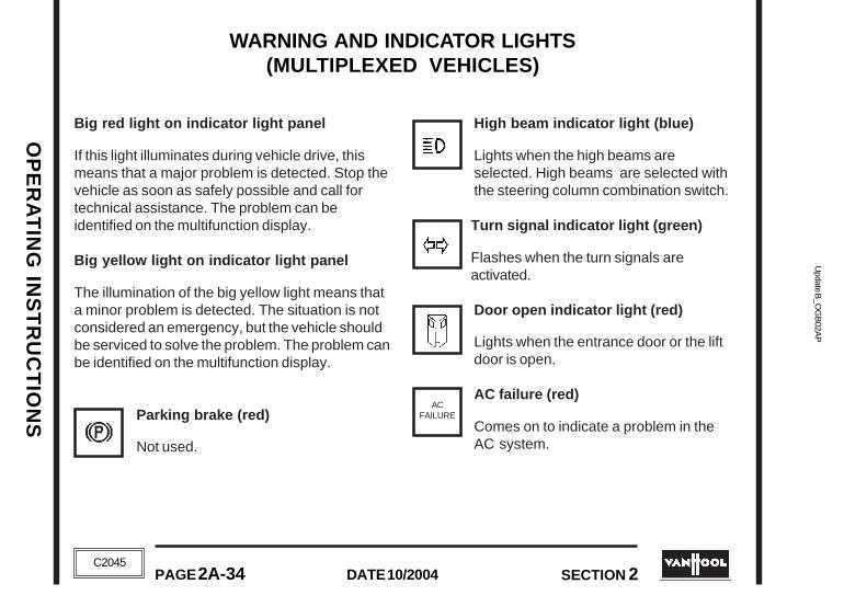
Update B
_OG
B02A
PU
pdate B_O
GB
02AP
OP
ER
AT
ING
INS
TR
UC
TIO
NS
OP
ER
AT
ING
INS
TR
UC
TIO
NS
PAGE 2A-34 DATE 10/2004 SECTION 2
DATE 10/2004PAGE 2A-34 SECTION 2
C2045
C2045
WARNING AND INDICATOR LIGHTS(MULTIPLEXED VEHICLES)
Big red light on indicator light panel
If this light illuminates during vehicle drive, thismeans that a major problem is detected. Stop thevehicle as soon as safely possible and call fortechnical assistance. The problem can beidentified on the multifunction display.
Big yellow light on indicator light panel
The illumination of the big yellow light means thata minor problem is detected. The situation is notconsidered an emergency, but the vehicle shouldbe serviced to solve the problem. The problem canbe identified on the multifunction display.
Parking brake (red)
Not used.
High beam indicator light (blue)
Lights when the high beams areselected. High beams are selected withthe steering column combination switch.
Turn signal indicator light (green)
Flashes when the turn signals areactivated.
Door open indicator light (red)
Lights when the entrance door or the liftdoor is open.
AC failure (red)
Comes on to indicate a problem in theAC system.
WARNING AND INDICATOR LIGHTS(MULTIPLEXED VEHICLES)
Big red light on indicator light panel
If this light illuminates during vehicle drive, thismeans that a major problem is detected. Stop thevehicle as soon as safely possible and call fortechnical assistance. The problem can beidentified on the multifunction display.
Big yellow light on indicator light panel
The illumination of the big yellow light means thata minor problem is detected. The situation is notconsidered an emergency, but the vehicle shouldbe serviced to solve the problem. The problem canbe identified on the multifunction display.
Parking brake (red)
Not used.
ACFAILURE
High beam indicator light (blue)
Lights when the high beams areselected. High beams are selected withthe steering column combination switch.
Turn signal indicator light (green)
Flashes when the turn signals areactivated.
Door open indicator light (red)
Lights when the entrance door or the liftdoor is open.
AC failure (red)
Comes on to indicate a problem in theAC system.
ACFAILURE

OP
ER
AT
ING
IN
ST
RU
CT
ION
SO
PE
RA
TIN
G I
NS
TR
UC
TIO
NS
Upd
ate
B_O
GB
02A
PU
pdat
e B
_OG
B02
AP
SECTION 2 PAGE 2A-35DATE 10/2004
SECTION 2 PAGE 2A-35DATE 10/2004C2045
C2045
MESSAGES ON MULTIFUNCTION DISPLAY(MULTIPLEXED VEHICLES ONLY)
Fuel level low
Jake brake
Comes on when the Jake brake or ZFIntarder is on.
Combustion heater standby
Comes on when the combustion heateris standby.
Combustion heater burneroperative
Comes on when the burner of thecombustion heater is operative.
Wheelchair lift released
Lights when the wheelchair lift system isreleased.
Parking brake
Comes on when the parking brake isapplied regardless of the position of theparking brake control valve.
Multiplex system failure
Comes on when a node output isinterrupted or shorted
Tag axle unloading
Comes on when the tag axle isunloaded.
Battery voltage low
Comes on when the battery voltage islow with engine running.
Multiplex communication failure
Comes on when there is a multiplexcommunication failure.
Starter motor
Starter selection switch in enginecompartment in the REAR STARTposition.

Update B
_OG
B02A
PU
pdate B_O
GB
02AP
OP
ER
AT
ING
INS
TR
UC
TIO
NS
OP
ER
AT
ING
INS
TR
UC
TIO
NS
PAGE 2A-36 DATE 10/2004 SECTION 2
DATE 10/2004PAGE 2A-36 SECTION 2
C2045
C2045
Suspension front kneeling system
Comes on when the front kneelingsystem is energized.
Suspension rear raise system
Comes on when the suspension rearraise system is energized.
Suspension raise system
Comes on when the suspension raisesystem is energized.
Suspension lower system
Comes on when the suspension lowersystem is energized.
Anti-lock braking system
This message works as follows withignition on:
• Message comes on momentarily, then goesout. ABS SYSTEM IS OK.
• Message does not disappear at ignition:
- When vehicle is driven at speeds above 4mph, message will disappear. ABS SYSTEMIS OK.
- If message does not disappear at speedsabove 4 mph, the Electronic Control Unit ofthe system senses a fault in the ABSsystem.
If the Electronic ControlUnit senses a fault duringnormal vehicle operation, the ABS message willcome on and stay on.
Automatic traction control
Comes on when the drive wheels spinduring acceleration, indicating ASR isactive. The message will disappearwhen the drive wheels stop spinning.
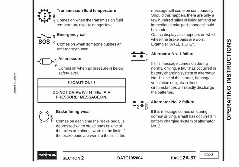
OP
ER
AT
ING
IN
ST
RU
CT
ION
SO
PE
RA
TIN
G I
NS
TR
UC
TIO
NS
Upd
ate
B_O
GB
02A
PU
pdat
e B
_OG
B02
AP
SECTION 2 PAGE 2A-37DATE 10/2004
SECTION 2 PAGE 2A-37DATE 10/2004C2045
C2045
Transmission fluid temperature
Comes on when the transmission fluidtemperature rises to danger level.
Emergency call
Comes on when someone pushes anemergency button.
Air pressure
Comes on when air pressure is belowsafety level.
!!! CAUTION !!!
DO NOT DRIVE WITH THE "AIRPRESSURE" MESSAGE ON.
Brake lining wear
Comes on each time the brake pedal isdepressed when brake pads on one ofthe axles are almost worn to the limit. Ifthe brake pads are worn to the limit, the
message will come on continuously.Should this happen, there are only afew hundred miles of lining left and animmediate brake pad change shouldbe made.On the display also appears on whichwheel the brake pads are worn.Example: "AXLE 1 LHS".
Alternator No. 1 failure
If this message comes on duringnormal driving, a fault has occurred inbattery charging system of alternatorNo. 1. Use of the starter, heating/ventilation or lights in thesecircumstances will rapidly dischargethe batteries.
Alternator No. 2 failure
If this message comes on duringnormal driving, a fault has occurred inbattery charging system of alternatorNo. 2.

Update B
_OG
B02A
PU
pdate B_O
GB
02AP
OP
ER
AT
ING
INS
TR
UC
TIO
NS
OP
ER
AT
ING
INS
TR
UC
TIO
NS
PAGE 2A-38 DATE 10/2004 SECTION 2
DATE 10/2004PAGE 2A-38 SECTION 2
C2045
C2045
Engine warning message(Cummins)
Refer to "Warning and indicatorlights (non-multiplexed vehicles)"for more information.
Engine warning message(Detroit Diesel DDEC IV only)
Refer to "Warning and indicatorlights (non-multiplexed vehicles)"for more information.
Engine warning message(Detroit Diesel DDEC V)
Refer to "CHECK ENGINE" warninglight under "Warning and indicatorlights (non-multiplexed vehicles)"for more information.
Engine warning message(Caterpillar)
This message flashes at fivesecond intervals whenever theelectronics detect an active fault of
ENGINEWARNING
STOP ENGINE
CHECKENGINE
ENGINEWARNING
ENGINEWARNING
condition. If the message appears and if themessage stays on after initial start-up, theelectronics have detected a system problem
Engine warning message(Cummins and Detroit Diesel)
Refer to "Warning and indicatorlights (non-multiplexed vehicles)"for more information.
Engine warning message(Caterpillar)
Warns you of engine problems.
STOP ENGINE

OP
ER
AT
ING
IN
ST
RU
CT
ION
SO
PE
RA
TIN
G I
NS
TR
UC
TIO
NS
Upd
ate
B_O
GB
02A
PU
pdat
e B
_OG
B02
AP
SECTION 2 PAGE 2A-39DATE 10/2004
SECTION 2 PAGE 2A-39DATE 10/2004C2045
C2045
DO NOT SHIFT
BATTERYUNBALANCE
WTB500-transmission
Refer to "Warning and indicatorlights (non-multiplexed vehicles)"for more information.
Battery equalizer
Comes on when battery equalizeris not working properly.
Fire
Refer to "Warning and indicator lights(non-multiplexed vehicles)" for moreinformation.
ZF Astronic-transmission
Refer to "ZF Astronic" in Section 6.
DO NOT SHIFT
BATTERYUNBALANCE
WTB500-transmission
Refer to "Warning and indicatorlights (non-multiplexed vehicles)"for more information.
Battery equalizer
Comes on when battery equalizeris not working properly.
Fire
Refer to "Warning and indicator lights(non-multiplexed vehicles)" for moreinformation.
ZF Astronic-transmission
Refer "ZF Astronic" in Section 6.

Update B
_OG
B02A
PU
pdate B_O
GB
02AP
OP
ER
AT
ING
INS
TR
UC
TIO
NS
OP
ER
AT
ING
INS
TR
UC
TIO
NS
PAGE 2A-40 DATE 10/2004 SECTION 2
DATE 10/2004PAGE 2A-40 SECTION 2
C2045
C2045
INSTRUMENTS(NON-MULTIPLEXED VEHICLES)
SPEEDOMETER
Indicates forward speedof the coach in miles-per-hour and kilometers-per-hour. The odometerregisters the accumulatedmiles the coach hasbeen driven.
TACHOMETER
Indicates the enginespeed in hundreds ofrevolutions per minute.Onflat road stretches andwhen going uphill theengine ECU limits enginespeed at approx. 2,100rpm.
!!! CAUTION !!!
THE ELECTRONIC FUEL SYSTEMS HAVENO CONTROL OVER THE ENGINE, WHENIT IS BEING DRIVEN BY THE WHEELS OFTHE VEHICLE GOING DOWNHILL. UNDER
THESE CIRCUMSTANCES, IT IS UP YOU TOKEEP ENGINE REVS UNDER CONTROL BY
REDUCING VEHICLE SPEED.WHEN THE TACHOMETER NEEDLE
EXCEEDS "21" ON THE DIAL, THE ENGINEOVERSPEEDS. THIS MAY LEAD TO
SERIOUS DAMAGE.T03682
T03683
INSTRUMENTS(NON-MULTIPLEXED VEHICLES)
SPEEDOMETER
Indicates forward speedof the coach in miles-per-hour and kilometers-per-hour. The odometerregisters the accumulatedmiles the coach hasbeen driven.
TACHOMETER
Indicates the enginespeed in hundreds ofrevolutions per minute.Onflat road stretches andwhen going uphill theengine ECU limits enginespeed at approx. 2,100rpm.
!!! CAUTION !!!
THE ELECTRONIC FUEL SYSTEMS HAVENO CONTROL OVER THE ENGINE, WHENIT IS BEING DRIVEN BY THE WHEELS OFTHE VEHICLE GOING DOWNHILL. UNDER
THESE CIRCUMSTANCES, IT IS UP TO YOU TO KEEP ENGINE REVS UNDER CONTROL
BY REDUCING VEHICLE SPEED.WHEN THE TACHOMETER NEEDLE
EXCEEDS "21" ON THE DIAL, THE ENGINEOVERSPEEDS. THIS MAY LEAD TO
SERIOUS DAMAGE.T03682
T03683

OP
ER
AT
ING
IN
ST
RU
CT
ION
SO
PE
RA
TIN
G I
NS
TR
UC
TIO
NS
Upd
ate
B_O
GB
02A
PU
pdat
e B
_OG
B02
AP
SECTION 2 PAGE 2A-41DATE 10/2004
SECTION 2 PAGE 2A-41DATE 10/2004C2045
C2045
T03684
T03685
ENGINE COOLANT TEMPERATUREGAUGE
The temperature of thecoolant must never moveinto the red area(approx. 210°F). If theengine overheats innormal drivingconditions, first checktransmission oil level,coolant level and fanoperation.
!!! CAUTION !!!
CHECK COOLANT LEVEL ONLY WHENENGINE HAS BEEN STOPPED. WAIT UNTILCOOLANT TEMPERATURE IS BELOW 120°F
BEFORE REMOVING SURGE TANK CAP.FAILURE TO DO SO MAY CAUSE
PERSONAL INJURY FROM HOT COOLANTSPRAY.
NEVER ADD COLD COOLANT TO ANOVERHEATED ENGINE: CRACKS IN
CYLINDER BLOCK MAY RESULT.ALLOW ENGINE TO COOL TO BELOW
120°F BEFORE ADDING COOLANT.
ENGINE OIL PRESSURE GAUGE
ENGINE COOLANT TEMPERATUREGAUGE
The temperature of thecoolant must never moveinto the red area (approx.210°F). If the engineoverheats in normaldriving conditions, firstcheck transmission oillevel, coolant level andfan operation.
!!! CAUTION !!!
CHECK COOLANT LEVEL ONLY WHENENGINE HAS BEEN STOPPED. WAIT UNTILCOOLANT TEMPERATURE IS BELOW 120°F
BEFORE REMOVING SURGE TANK CAP.FAILURE TO DO SO MAY CAUSE
PERSONAL INJURY FROM HOT COOLANTSPRAY.
NEVER ADD COLD COOLANT TO ANOVERHEATED ENGINE: CRACKS IN
CYLINDER BLOCK MAY RESULT.ALLOW ENGINE TO COOL TO BELOW
120°F BEFORE ADDING COOLANT.
T03684
• 30 psi at 1,200 rpm• 10 psi at idle speed
• 50 psi at 2,100 rpm• 12 psi at idle speed
Minimum oil pressure (warm engine)
Cummins
Detroit Diesel
T03685
ENGINE OIL PRESSURE GAUGE
• 30 psi at 1,200 rpm• 10 psi at idle speed
• 50 psi at 2,100 rpm• 12 psi at idle speed
Minimum oil pressure (warm engine)
Cummins
Detroit Diesel

Update B
_OG
B02A
PU
pdate B_O
GB
02AP
OP
ER
AT
ING
INS
TR
UC
TIO
NS
OP
ER
AT
ING
INS
TR
UC
TIO
NS
PAGE 2A-42 DATE 10/2004 SECTION 2
DATE 10/2004PAGE 2A-42 SECTION 2
C2045
C2045
T03689
T03690
T03686
FRONT AXLE BRAKESAIR-PRESSURE GAUGE
This gauge, calibrated inpsi, indicates pressure infront axle brakes tank.
Normal working pressureranges from 105 to 135psi.
DRIVE AXLE SERVICE BRAKESAIR-PRESSURE GAUGE
This gauge, calibrated inpsi indicates pressure indrive axle service brakestank.
Normal working pressureranges from 105 to 135psi.
TAG AXLE BRAKES AIR-PRESSUREGAUGE
This gauge, calibrated inpsi indicates pressure intag axle brakes tank.
Normal working pressureranges from 105 to 135psi.
TURBO BOOST GAUGE
This gauge indicates theboost pressure in theengine air intakemanifold.
T03688
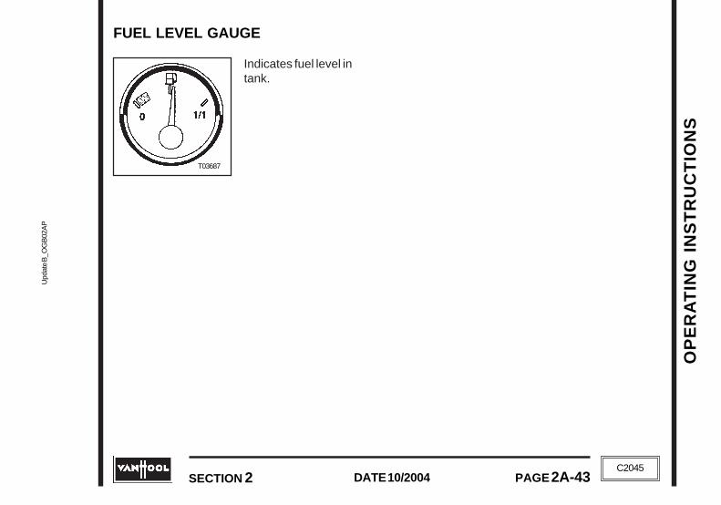
OP
ER
AT
ING
IN
ST
RU
CT
ION
SO
PE
RA
TIN
G I
NS
TR
UC
TIO
NS
Upd
ate
B_O
GB
02A
PU
pdat
e B
_OG
B02
AP
SECTION 2 PAGE 2A-43DATE 10/2004
SECTION 2 PAGE 2A-43DATE 10/2004C2045
C2045
T03687
FUEL LEVEL GAUGE
Indicates fuel level intank.
T03687
FUEL LEVEL GAUGE
Indicates fuel level intank.

Update B
_OG
B02A
PU
pdate B_O
GB
02AP
OP
ER
AT
ING
INS
TR
UC
TIO
NS
OP
ER
AT
ING
INS
TR
UC
TIO
NS
PAGE 2A-44 DATE 10/2004 SECTION 2
DATE 10/2004PAGE 2A-44 SECTION 2
C2045
C2045
INSTRUMENTS(MULTIPLEXED VEHICLES)
SPEEDOMETER/ODOMETER
Indicates forward speed of the coach in miles-per-hour. The odometer registers the accumulatedmiles the coach has been driven.
TACHOMETER
Refer to "Instruments (non-multiplexed vehicles)"for more information.
ENGINE COOLANT TEMPERATUREGAUGE
Refer to "Instruments (non-multiplexed vehicles)"for more information.
FUEL LEVEL GAUGE
Indicates fuel level in tank.
INFORMATION SCREENS ONMULTIFUNCTION DISPLAY
Air pressure, engine oil pressure, turbo boost andtransmission fluid temperature can be visualized
1. Speedometer/odometer
2. Multifunction display
3. Tachometer
4. Engine coolant temperature gauge
5. Multifunction display brightness rheostat
6. Multifunction display selection button
7. Fuel level gauge

OP
ER
AT
ING
IN
ST
RU
CT
ION
SO
PE
RA
TIN
G I
NS
TR
UC
TIO
NS
Upd
ate
B_O
GB
02A
PU
pdat
e B
_OG
B02
AP
SECTION 2 PAGE 2A-45DATE 10/2004
SECTION 2 PAGE 2A-45DATE 10/2004C2045
C2045
by pressing the multifuction display selectionbutton.
Air pressure information screen
Press the multifunction display selection buttononce. Status is shown as a bar graph whichdisappears automatically after 10 seconds.
Bar graph showing 125 psi in the front axlebrakes tank ("I"), 135 psi in the drive axleservice ("II") and 115 psi on the tag axle ("I"beneath pressure numbers)
Engine oil pressure informationscreen
Press the multifunction display selection buttonfour times to obtain the actual operating pressure.Pressure in psi.
Turbo boost information screen
Press the multifunction display selection buttonthree times to obtain the boost pressure in theengine air intake manifold. Pressure in psi.
Transmission fluid temperatureinformation screen
Press the multifunction display selection buttontwice to obtain the actual transmission fluidtemperature. Temperature in Fahrenheit.

Update B
_OG
B02A
PU
pdate B_O
GB
02AP
OP
ER
AT
ING
INS
TR
UC
TIO
NS
OP
ER
AT
ING
INS
TR
UC
TIO
NS
PAGE 2A-46 DATE 10/2004 SECTION 2
DATE 10/2004PAGE 2A-46 SECTION 2
C2045
C2045

OP
ER
AT
ING
IN
ST
RU
CT
ION
SO
PE
RA
TIN
G I
NS
TR
UC
TIO
NS
Upd
ate
B_O
GB
02A
QU
pdat
e B
_OG
B02
AQ
SECTION 2 PAGE 2B-1DATE 10/2004
SECTION 2 PAGE 2B-1DATE 10/2004
C2045
C2045
DRIVING INSTRUCTIONSENGINE
TO STOP THE ENGINE
By switching off the ignition, the fuel supply to thecylinders will be cut off and the engine will stop.
!!! CAUTION !!!
ALLOW THE ENGINE TO IDLE 3 TO 5MINUTES AFTER A FULL LOAD
OPERATION BEFORE SHUTTING THEENGINE OFF. THIS ALLOWS THE ENGINE TO COOL GRADUALLY AND UNIFORMLY.
BY NO MEANS MUST THE ENGINE BERACED JUST BEFORE STOPPING IT.
TO DO SO MAY CAUSE SEVEREDAMAGE TO THE TURBOCHARGER.
For vehicles with a raise/lower system only:
If you leave the coach unattended for a longerperiod of time, operate the coach lower system toprevent the coach from leaning to one side andpossibly causing damage to adjacent vehicles orobjects. This precaution will counter the unequalloss of pressure(which occurs after a longerperiod of time) in the air suspension system.
Procedure:
1. Park the coach.
!!! CAUTION !!!
THE NEXT STEP WILL CAUSE THE COACHSUPERSTRUCTURE TO FALL OVER2 INCHES BELOW NORMAL RIDING
HEIGHT. TAKE CARE THAT NO PERSONSOR OBJECTS GET CAUGHT
UNDERNEATH THE COACH SKIRT.
2. Momentarily push the lower part of the"Raise/lower"switch on the instrument
panel.The coach will lower about 2inches.
DRIVING INSTRUCTIONS
ENGINE
TO STOP THE ENGINE
By turning the ignition switch key to the "off"position, the fuel supply to the cylinders will be cutoff and the engine will stop.
!!! CAUTION !!!
ALLOW THE ENGINE TO IDLE 3 TO 5MINUTES AFTER A FULL LOAD
OPERATION BEFORE SHUTTING THEENGINE OFF. THIS ALLOWS THE ENGINE TO COOL GRADUALLY AND UNIFORMLY.
BY NO MEANS MUST THE ENGINE BERACED JUST BEFORE STOPPING IT.
TO DO SO MAY CAUSE SEVEREDAMAGE TO THE TURBOCHARGER.
For vehicles with a raise/lower system only:
If you leave the coach unattended for a longerperiod of time, operate the coach lower system toprevent the coach from leaning to one side andpossibly causing damage to adjacent vehicles orobjects. This precaution will counter the unequalloss of pressure(which occurs after a longerperiod of time) in the air suspension system.
Procedure:
1. Park the coach.
!!! CAUTION !!!
THE NEXT STEP WILL CAUSE THE COACHSUPERSTRUCTURE TO FALL OVER2 INCHES BELOW NORMAL RIDING
HEIGHT. TAKE CARE THAT NO PERSONSOR OBJECTS GET CAUGHT
UNDERNEATH THE COACH SKIRT.
2. Momentarily push the lower part of the"Raise/lower"switch on the instrument
panel.The coach will lower about 2inches.

Update B
_OG
B02A
QU
pdate B_O
GB
02AQ
OP
ER
AT
ING
INS
TR
UC
TIO
NS
OP
ER
AT
ING
INS
TR
UC
TIO
NS
PAGE 2B-2 DATE 10/2004 SECTION 2
DATE 10/2004PAGE 2B-2 SECTION 2
C2045
C2045
3. Turn the ignition switch key to the "off" position.
4. Switch off master switch on instrument panel.
Follow procedure from high to low before driving off.
PRE-STARTING CHECKS
The following checks should be made beforetaking the coach on service:
• Engine oil level• Coolant level• Transmission fluid level• Power steering fluid level• Check that the outside of the coach is clear
and clean• Wheel nuts for tightness• Tire inflation and condition• Air-cleaner restriction indicator• Emergency windows securely latched.
From inside the vehicle, firmly push outward onboth lower corners of the emergency window.No movement is allowed.From outside the vehicle, check the alignmentof the emergency side windows. Lower edge ofan emergency window that is not properlylatched will visibly stick out.
• Wheel rims for cracks and deformation• Check for fluid leaks in engine compartment, at
wheel hubs, etc.• Drive belt condition and tension
TO START THE ENGINE
!!! CAUTION !!!
TO PREVENT DAMAGE TO THE STARTINGMOTOR, DO NOT ENGAGE STARTING
MOTOR FOR MORE THAN 15 SECONDS.WAIT 2 MINUTES BETWEEN EACH
ATTEMPT TO START.
TO PREVENT SERIOUS STARTING MOTORDAMAGE, DO NOT PRESS THE STARTERSWITCH AGAIN AFTER THE ENGINE HAS
STARTED.
PROTECT THE TURBOCHARGER DURINGTHE STARTUP BY NOT ACCELERATINGTO ANY SPEED ABOVE IDLE FOR TWO
MINUTES TO ALLOW OIL TO REACH THETURBOCHARGER.

OP
ER
AT
ING
IN
ST
RU
CT
ION
SO
PE
RA
TIN
G I
NS
TR
UC
TIO
NS
Upd
ate
B_O
GB
02A
QU
pdat
e B
_OG
B02
AQ
SECTION 2 PAGE 2B-3DATE 10/2004
SECTION 2 PAGE 2B-3DATE 10/2004
C2045
C2045
1. Make sure the parking brake is on.
2. Switch ignition "on".
Non-multiplexed vehicle: the following warninglights should come on:
• "DO NOT SHIFT" (only in case of WT-transmission)
• Parking brake• Alternator No.1• Alternator No.2• Low engine oil pressure• "ABS" (for a few seconds)• "ASR" (for a few seconds)• In case of Cummins ISM engine: The
engine diagnostic lights "ENGINE MAINT","STOP ENGINE" and "ENGINE WARNING" come onfor approximately 3 seconds. These lampswill not come on if you turn off the ignitionand than back on within 30 seconds.
• In case of Detroit Diesel engine: The enginediagnostic lights "STOP ENGINE" and "CHECKENGINE" come on for approximately 5seconds.
If air pressure is low, the air pressure warninglight will also illuminate and a buzzer willsound.
Multiplexed vehicle: the following warningmessages should come on:
• Parking brake• Alternator No.1• Alternator No.2• "ABS" (for a few seconds)• "ASR" (for a few seconds)• In case of Cummins ISM engine: The engine
warning messages "ENGINE MAINTENANCE"(ISM01 only), "ENGINE WARNING" and "STOPENGINE" come on successively. Afterapproximately 3 seconds the "STOP ENGINE"message is changed by the "DO NOT SHIFT"message (only in case of WT-transmission).The engine warning messages will not comeon if you turn off the ignition and than backon within 30 seconds.
• In case of Detroit Diesel engine: The enginewarning message "STOP ENGINE" comes onfor approx. 5 seconds. For WT-transmissiononly: after approximately 5 seconds the"STOP ENGINE" message is changed by the"DO NOT SHIFT" message.
• In case of Caterpillar engine: The enginewarning message "ENGINE WARNING" comeson for approx. 5 seconds. For WT-transmission only: after approximately 5seconds the "ENGINE WARNING" messageis changed by the "DO NOT SHIFT" message
If air pressure is low, the air pressure warninglight will also illuminate and a buzzer willsound.
1. Make sure the parking brake is on.
2. Switch ignition "on".
Non-multiplexed vehicle: the following warninglights should come on:
• "DO NOT SHIFT" (only in case of WT-transmission)
• Parking brake• Alternator No.1• Alternator No.2• Low engine oil pressure• "ABS" (for a few seconds)• "ASR" (for a few seconds)• In case of Cummins ISM engine: The
engine diagnostic lights "ENGINE MAINT","STOP ENGINE" and "ENGINEWARNING" come on for approximately3 seconds. These lamps will not come on ifyou turn off the ignition and than back onwithin 30 seconds.
• In case of Detroit Diesel engine: Theengine diagnostic lights "STOP ENGINE"and "CHECK ENGINE" come on forapproximately 5 seconds.
If air pressure is low, the air pressure warninglight will also illuminate and a buzzer willsound.
Multiplexed vehicle: the following warningmessages should come on:
• Parking brake• Alternator No.1• Alternator No.2• "ABS" (for a few seconds)• "ASR" (for a few seconds)• In case of Cummins ISM engine: The engine
warning messages "ENGINE MAINTENANCE"(ISM01 only), "ENGINE WARNING" and "STOPENGINE" come on successively. Afterapproximately 3 seconds the "STOP ENGINE"message is changed by the "DO NOT SHIFT"message (only in case of WT-transmission).The engine warning messages will not comeon if you turn off the ignition and than backon within 30 seconds.
• In case of Detroit Diesel engine: The enginewarning message "STOP ENGINE" comes onfor approx. 5 seconds. For WT-transmissiononly: after approximately 5 seconds the"STOP ENGINE" message is changed by the"DO NOT SHIFT" message.
• In case of Caterpillar engine: The enginewarning message "ENGINE WARNING" comeson for approx. 5 seconds. For WT-transmission only: after approximately 5seconds the "ENGINE WARNING" messageis changed by the "DO NOT SHIFT" message
If air pressure is low, the air pressure warninglight will also illuminate and a buzzer willsound.

Update B
_OG
B02A
QU
pdate B_O
GB
02AQ
OP
ER
AT
ING
INS
TR
UC
TIO
NS
OP
ER
AT
ING
INS
TR
UC
TIO
NS
PAGE 2B-4 DATE 10/2004 SECTION 2
DATE 10/2004PAGE 2B-4 SECTION 2
C2045
C2045
Control box in engine compartment
1. Socket for 24V lamp2. Engine compartment
light switch2. Engine stop button3. Starter override switch4. Engine start button
NOTE
The Electronic Control Unit of thetransmission automatically selects
neutral at startup.
4. Be sure the override switch in the enginecompartment is in the "run" position.Otherwise the starting motor will not engage.
5. Press the starter switch firmly. As soon asengine fires, release switch.
NOTE
For Cummins and Caterpillar engines:in park the engine speed is limited to
1,600 rpm.
TO DRIVE OFF
1. Build up normal working pressure in thecompressed air tanks.
In any case, before taking the coach onservice, run the engine at part throttle for about5 minutes before operating with load.
NOTE
The Electronic Control Unit of thetransmission automatically selects
neutral at startup.
4. Be sure the override switch in the enginecompartment is in the "run" position.Otherwise the starting motor will not engage.
5. Press the starter switch firmly. As soon asengine fires, release switch.
NOTE
For Cummins and Caterpillar engines:in park the engine speed is limited to
1,600 rpm.
TO DRIVE OFF
1. Build up normal working pressure in thecompressed air tanks.
In any case, before taking the coach onservice, run the engine at part throttle forabout 5 minutes before operating with load.
Control box in engine compartment
1. Socket for 24V lamp2. Engine compartment
light switch2. Engine stop button3. Starter override switch4. Engine start button
3. Make sure transmission is in Neutral(the display of the transmission push-buttonselector will display N).
3. Make sure transmission is in Neutral(the display of the transmission push-buttonselector will display N).

OP
ER
AT
ING
IN
ST
RU
CT
ION
SO
PE
RA
TIN
G I
NS
TR
UC
TIO
NS
Upd
ate
B_O
GB
02A
QU
pdat
e B
_OG
B02
AQ
SECTION 2 PAGE 2B-5DATE 10/2004
SECTION 2 PAGE 2B-5DATE 10/2004
C2045
C2045
2. With the engine idling, depress and hold thefoot brake pedal: then depress the appropriategear selector button.
NOTE
The transmission will not go into gearunless the foot brake is depressed.
3. Release parking brake.The parking brakelight on the instrument panel should go out,when the parking brake push-pull valve isplaced in the OFF position. If it does not doso, this means circuit air-pressure is still low.
!!! CAUTION !!!
DO NOT ATTEMPT TO DRIVE OFFBEFORE THE PARKING BRAKE
INDICATOR LIGHT HAS GONE OUT.
4. Release foot brake pedal and accelerate.The vehicle now moves off and driving canfurther be regulated by mere use of throttlepedal and foot brake.
TO WARM-UP THE ENGINE
Avoid full throttle operation with a cold engine.Drive at moderate speeds until coolanttemperature gauge indicates 140 °F. Only thenmay the engine be required to develop its fulloutput.

Update B
_OG
B02A
QU
pdate B_O
GB
02AQ
OP
ER
AT
ING
INS
TR
UC
TIO
NS
OP
ER
AT
ING
INS
TR
UC
TIO
NS
PAGE 2B-6 DATE 10/2004 SECTION 2
DATE 10/2004PAGE 2B-6 SECTION 2
C2045
C2045
T05126
PUSH-BUTTONSHIFT SELECTOR
WT B500 AUTOMATICTRANSMISSION
The B500 automatic is available in two versions,with either 5 or 6 forward speeds and onereverse. The transmission operation is controlledby an Electronic Control Unit (ECU). In addition,the ECU monitors the system for conditions thatcould result in damage to the transmission orimproper vehicle operation.
SHIFT SELECTOR
The pushbutton shiftselector has R, N, D, ↓↓↓↓↓ ,↑↑↑↑↑ , a mode button and adigital display. Duringnormal operation, whenthe D (Drive) button ispressed, the digitaldisplay shows the highestforward range attainablefor the shift schedule inuse. Abnormal operationis also indicated by the
digital display. When all segments of the digitaldisplay are illuminated for more than 12 seconds,the ECU did not complete initialization.When thedigital display is blank, there is no power to theselector. When the display shows a " " (cateye),a selector-related fault code has been logged.Conditions which illuminate the "DO NOT SHIFT"light will disable the shift selector and the digitaldisplay will show the range actually attained. Thetransmission will not shift into range if a "DO NOTSHIFT" code is active. When the display showseither R or D has been requested and the displayis flashing, the requesed range has not beenachieved due to an inhibit function. Check foractive codes when D (Drive) is not attained. OnceD (Drive) is attained, the transmission will shiftinto the lowest range programmed for the D (Drive)position, usually first. Manual selection of rangeswithin the D (Drive) selection is done by pressingthe ↑↑↑↑↑ (UP) or ↓↓↓↓↓ (DOWN) arrow buttons until thedesired range is shown in the display window.
The pushbutton selector incorporates a MODEbutton which allows the driver to enable asecondary shift schedule.
T05126
PUSH-BUTTONSHIFT SELECTOR

OP
ER
AT
ING
IN
ST
RU
CT
ION
SO
PE
RA
TIN
G I
NS
TR
UC
TIO
NS
Upd
ate
B_O
GB
02A
QU
pdat
e B
_OG
B02
AQ
SECTION 2 PAGE 2B-7DATE 10/2004
SECTION 2 PAGE 2B-7DATE 10/2004
C2045
C2045
It is not necessary to select the right moment toupshift or downshift during changing road andtraffic conditions. The transmission does it for you.However, knowledge of the gear ranges and whento select them will make vehicle control and yourjob even easier.
RANGE SELECTION
!!! CAUTION !!!
IN THE EVENT YOU LEAVE THE COACH,EVEN MOMENTARILY, WHILE THE ENGINE
IS RUNNING, BE SURE THAT THETRANSMISSION IS IN N (NEUTRAL),
PARKING BRAKE IS SET AND PROPERLYENGAGED. UNEXPECTED AND POSSIBLE
SUDDEN VEHICLE MOVEMENT MAYOCCUR IF THESE PRECAUTIONS
ARE NOT TAKEN.
Completely stop the vehicle beforeshifting from a forward range to Reverseor from Reverse to a forward range. Thedisplay will show R when Reverse isattained.
Use Neutral when you start the engine,to check vehicle accessories, and forextended periods of engine idleoperation. Neutral and economy modeare automatically set during startup. Ifthe vehicle starts in any range otherthan neutral, seek serviceimmediately.The display will show Nwhen Neutral is selected. Alwaysselect N (Neutral) before turning off thevehicle engine.
!!! CAUTION !!!
IF YOU LET THE VEHICLE COASTIN NEUTRAL, THERE IS NO ENGINEBRAKING AND YOU COULD LOSECONTROL. COASTING CAN ALSOCAUSE SEVERE TRANSMISSION
DAMAGE. TO HELP AVOID INJURYAND PROPERTY DAMAGE, DO NOTALLOW THE VEHICLE TO COAST
IN NEUTRAL.R
N
It is not necessary to select the right moment toupshift or downshift during changing road andtraffic conditions. The transmission does it for you.However, knowledge of the gear ranges and whento select them will make vehicle control and yourjob even easier.
RANGE SELECTION
!!! CAUTION !!!
IN THE EVENT YOU LEAVE THE COACH,EVEN MOMENTARILY, WHILE THE ENGINE
IS RUNNING, BE SURE THAT THETRANSMISSION IS IN N (NEUTRAL), PARKING
BRAKE IS SET AND PROPERLY ENGAGED.UNEXPECTED AND POSSIBLE SUDDEN
VEHICLE MOVEMENT MAYOCCUR IF THESE PRECAUTIONS
ARE NOT TAKEN.
Completely stop the vehicle beforeshifting from a forward range to Reverseor from Reverse to a forward range. Thedisplay will show R when Reverse isattained.
Use Neutral when you start the engine,to check vehicle accessories, and forextended periods of engine idleoperation. Neutral and economy modeare automatically set during startup. Ifthe vehicle starts in any range otherthan neutral, seek serviceimmediately.The display will show Nwhen Neutral is selected. Alwaysselect N (Neutral) before turning off thevehicle engine.
!!! CAUTION !!!
IF YOU LET THE VEHICLE COASTIN NEUTRAL, THERE IS NO ENGINEBRAKING AND YOU COULD LOSECONTROL. COASTING CAN ALSOCAUSE SEVERE TRANSMISSION
DAMAGE. TO HELP AVOID INJURYAND PROPERTY DAMAGE, DO NOTALLOW THE VEHICLE TO COAST
IN NEUTRAL.R
N

Update B
_OG
B02A
QU
pdate B_O
GB
02AQ
OP
ER
AT
ING
INS
TR
UC
TIO
NS
OP
ER
AT
ING
INS
TR
UC
TIO
NS
PAGE 2B-8 DATE 10/2004 SECTION 2
DATE 10/2004PAGE 2B-8 SECTION 2
C2045
C2045
5432
The transmission will initially attain firstrange when D (Drive) is selected(except for those units programmed tostart in second range). As vehiclespeed increases, the transmission willupshift automatically through eachrange. As the vehicle slows, thetransmission will downshiftautomatically. The display will show thecurrent operating range.
!!! CAUTION !!!
IF YOU JUST DOWNSHIFT OR JUST USESERVICE BRAKES WHEN GOING DOWNHILL,
YOU CAN LOSE CONTROL AND CAUSEINJURY AND PROPERTY DAMAGE. TO HELP
AVOID LOSS OF CONTROL, USE ACOMBINATION OF DOWNSHIFTING, BRAKING,
AND OTHER RETARDING DEVICES.DOWNSHIFTING TO A LOWER TRANSMISSION
RANGE INCREASES ENGINE BRAKING ANDHELPS YOU TO MAINTAIN CONTROL.
THE TRANSMISSION HAS A FEATURE TO
PREVENT AUTOMATIC UPSHIFTING ABOVE
THE LOWER RANGE SELECTED. HOWEVER,
DURING DOWNHILL OPERATION, IF ENGINE
GOVERNED SPEED IS EXCEEDED IN THE
LOWER RANGE, THE TRANSMISSION MAY
UPSHIFT TO THE NEXT HIGHER RANGE. THIS
WILL REDUCE BRAKING AND COULD CAUSE
A LOSS OF CONTROL. APPLY THE VEHICLE
BRAKES OR OTHER RETARDING DEVICE TO
PREVENT EXCEEDING ENGINE GOVERNED
SPEED IN THE LOWER RANGE SELECTED.
.
Occasionally, road conditions, load, ortraffic conditions will make it desirableto restrict automatic shifting to a lowerrange. Lower ranges provide greaterengine braking for going down grades(the lower the range, the greater thebraking effect).
With the arrow buttons you can selectindividual forward ranges. Push the ↑↑↑↑↑(UP) or ↓↓↓↓↓ (DOWN) arrow to the desiredrange. The display will show yourchoice of range. Even though a lower
D
The transmission will initially attain firstrange when D (Drive) is selected(except for those units programmed tostart in second range). As vehiclespeed increases, the transmission willupshift automatically through eachrange. As the vehicle slows, thetransmission will downshiftautomatically. The display will show thecurrent operating range.
!!! CAUTION !!!
IF YOU JUST DOWNSHIFT OR JUST USESERVICE BRAKES WHEN GOING DOWNHILL,
YOU CAN LOSE CONTROL AND CAUSEINJURY AND PROPERTY DAMAGE. TO HELP
AVOID LOSS OF CONTROL, USE ACOMBINATION OF DOWNSHIFTING, BRAKING,
AND OTHER RETARDING DEVICES.DOWNSHIFTING TO A LOWER TRANSMISSION
RANGE INCREASES ENGINE BRAKING ANDHELPS YOU TO MAINTAIN CONTROL.
THE TRANSMISSION HAS A FEATURE TO
PREVENT AUTOMATIC UPSHIFTING ABOVE
THE LOWER RANGE SELECTED. HOWEVER,
DURING DOWNHILL OPERATION, IF ENGINE
GOVERNED SPEED IS EXCEEDED IN THE
LOWER RANGE, THE TRANSMISSION MAY
UPSHIFT TO THE NEXT HIGHER RANGE. THIS
WILL REDUCE BRAKING AND COULD CAUSE
A LOSS OF CONTROL. APPLY THE VEHICLE
BRAKES OR OTHER RETARDING DEVICE TO
PREVENT EXCEEDING ENGINE GOVERNED
SPEED IN THE LOWER RANGE SELECTED.
.
Occasionally, road conditions, load, ortraffic conditions will make it desirableto restrict automatic shifting to a lowerrange. Lower ranges provide greaterengine braking for going down grades(the lower the range, the greater thebraking effect).
With the arrow buttons you can selectindividual forward ranges. Push the ↑↑↑↑↑(UP) or ↓↓↓↓↓ (DOWN) arrow to thedesired range. The display will showyour choice of range. Even though a
D
5432

OP
ER
AT
ING
IN
ST
RU
CT
ION
SO
PE
RA
TIN
G I
NS
TR
UC
TIO
NS
Upd
ate
B_O
GB
02A
QU
pdat
e B
_OG
B02
AQ
SECTION 2 PAGE 2B-9DATE 10/2004
SECTION 2 PAGE 2B-9DATE 10/2004
C2045
C2045
1
DO NOTSHIFT
range was selected, the transmissionmay not downshift until vehicle speedis reduced.
Use this range when pulling throughmud and deep snow, whenmaneuvering in tight spaces, or whiledriving up or down grades. First rangeprovides the vehicle with its maximumdriving power and maximum enginebraking power. Push the ↓↓↓↓↓ (DOWN)arrow until first range appears on thedisplay.
"DO NOT SHIFT" LIGHT
The electronic control system isprogrammed to inform you of a problemwith the transmission system andautomatically take action to protect the
operator, vehicle, and transmission. When theElectronic Control Unit (ECU) detects a DO NOTSHIFT condition, the ECU restricts shifting, turnson the DO NOT SHIFT light on the instrumentpanel, and registers a diagnostic code.
NOTE
For some problems, diagnostic codesmay be registered without the ECUactivating the DO NOT SHIFT light.
Each time the engine is started, the DO NOTSHIFT light will illuminate, then turn off after a fewseconds. This momentary lighting is to show thatthe status light circuits are working properly. If theDO NOT SHIFT light does not illuminate duringignition, or if the light remains on after ignition, thesystem should be checked immediately
Continued illumination of the DO NOT SHIFT lightduring vehicle operation (other than start-up)indicates that the ECU has signaled a diagnosticcode. Illumination of the DO NOT SHIFT light isaccompanied by a flashing display from the shiftselector. The shift selector display will show theactual range attained and the transmission will notrespond to shift selector requests.
The indications from the shift selector are providedto inform the operator that the transmission is notperforming as designed and is operating withreduced capabilities. Before turning the ignition off,
lower range was selected, thetransmission may not downshift untilvehicle speed is reduced.
Use this range when pulling throughmud and deep snow, whenmaneuvering in tight spaces, or whiledriving up or down grades. First rangeprovides the vehicle with its maximumdriving power and maximum enginebraking power. Push the ↓↓↓↓↓ (DOWN)arrow until first range appears on thedisplay.
"DO NOT SHIFT" LIGHT
The electronic control system isprogrammed to inform you of a problemwith the transmission system andautomatically take action to protect the
operator, vehicle, and transmission. When theElectronic Control Unit (ECU) detects a DO NOTSHIFT condition, the ECU restricts shifting, turnson the DO NOT SHIFT light on the instrumentpanel, and registers a diagnostic code.
NOTE
For some problems, diagnostic codesmay be registered without the ECUactivating the DO NOT SHIFT light.
Each time the engine is started, the DO NOTSHIFT light will illuminate, then turn off after a fewseconds. This momentary lighting is to show thatthe status light circuits are working properly. If theDO NOT SHIFT light does not illuminate duringignition, or if the light remains on after ignition, thesystem should be checked immediately
Continued illumination of the DO NOT SHIFT lightduring vehicle operation (other than start-up)indicates that the ECU has signaled a diagnosticcode. Illumination of the DO NOT SHIFT light isaccompanied by a flashing display from the shiftselector. The shift selector display will show theactual range attained and the transmission willnot respond to shift selector requests.
The indications from the shift selector areprovided to inform the operator that thetransmission is not performing as designed and isoperating with reduced capabilities. Before turning
1
DO NOTSHIFT

Update B
_OG
B02A
QU
pdate B_O
GB
02AQ
OP
ER
AT
ING
INS
TR
UC
TIO
NS
OP
ER
AT
ING
INS
TR
UC
TIO
NS
PAGE 2B-10 DATE 10/2004 SECTION 2
DATE 10/2004PAGE 2B-10 SECTION 2
C2045
C2045
the transmission may be operated for a short timein the selected range in order to "limp home" forservice assistance. Service should be performedimmediately in order to minimize the potential fordamage to the transmission.
When the DO NOT SHIFT light comes on and theignition switch is turned off, the transmission willremain in N (Neutral) until the condition causingthe DO NOT SHIFT light is corrected
Generally, while the DO NOT SHIFT light is on,upshifts and downshifts will be restricted anddirection changes will not occur. The pushbuttonshift selector does not respond to any operatorshift requests while the DO NOT SHIFT light isilluminated. The lockup clutch is disengaged whentransmission shifting is restricted or during anycritical transmission malfunction
DIAGNOSTIC CODES
Refer to "Transmission diagnostic codes" inSection 2C.
THROTTLE CONTROL
!!! CAUTION !!!
TO HELP AVOID INJURY OR PROPERTYDAMAGE CAUSED BY SUDDEN MOVEMENTOF THE VEHICLE, DO NOT MAKE SHIFTSFROM N (NEUTRAL) TO D (DRIVE) OR R
(REVERSE) WHEN THE THROTTLE IS OPEN.IF YOU SHIFT WHILE THE THROTTLE ISOPEN TOO MUCH, THE TRANSMISSION
WILL ONLY ENGAGE IF THE THROTTLE ISCLOSED IN THE NEXT THREE SECONDS.
THAT CAN CAUSE A SUDDEN MOVEMENT OFTHE VEHICLE. LEAVING THE THROTTLEOPEN LONGER THAN THREE SECONDS
CAUSES THE TRANSMISSION TO REMAININ N (NEUTRAL). AVOID THIS CONDITIONBY MAKING SHIFTS FROM N (NEUTRAL)
TO D (DRIVE) OR R (REVERSE) ONLYWHEN THE THROTTLE IS CLOSED.
The position of the throttle pedal influences thetiming at which automatic shifting occurs. When
the ignition off, the transmission may be operatedfor a short time in the selected range in order to"limp home" for service assistance. Service shouldbe performed immediately in order to minimize thepotential for damage to the transmission.
When the DO NOT SHIFT light comes on and theignition switch is turned off, the transmission willremain in N (Neutral) until the condition causingthe DO NOT SHIFT light is corrected
Generally, while the DO NOT SHIFT light is on,upshifts and downshifts will be restricted anddirection changes will not occur. The pushbuttonshift selector does not respond to any operatorshift requests while the DO NOT SHIFT light isilluminated. The lockup clutch is disengagedwhen transmission shifting is restricted or duringany critical transmission malfunction
DIAGNOSTIC CODES
Refer to "Transmission diagnostic codes" inSection 2C.
THROTTLE CONTROL
!!! CAUTION !!!
TO HELP AVOID INJURY OR PROPERTYDAMAGE CAUSED BY SUDDEN MOVEMENTOF THE VEHICLE, DO NOT MAKE SHIFTSFROM N (NEUTRAL) TO D (DRIVE) OR R
(REVERSE) WHEN THE THROTTLE IS OPEN.IF YOU SHIFT WHILE THE THROTTLE ISOPEN TOO MUCH, THE TRANSMISSION
WILL ONLY ENGAGE IF THE THROTTLE ISCLOSED IN THE NEXT THREE SECONDS.THAT CAN CAUSE A SUDDEN MOVEMENT
OF THE VEHICLE. LEAVING THE THROTTLEOPEN LONGER THAN THREE SECONDS
CAUSES THE TRANSMISSION TO REMAININ N (NEUTRAL). AVOID THIS CONDITIONBY MAKING SHIFTS FROM N (NEUTRAL)
TO D (DRIVE) OR R (REVERSE) ONLYWHEN THE THROTTLE IS CLOSED.
The position of the throttle pedal influences thetiming at which automatic shifting occurs. When

OP
ER
AT
ING
IN
ST
RU
CT
ION
SO
PE
RA
TIN
G I
NS
TR
UC
TIO
NS
Upd
ate
B_O
GB
02A
QU
pdat
e B
_OG
B02
AQ
SECTION 2 PAGE 2B-11DATE 10/2004
SECTION 2 PAGE 2B-11DATE 10/2004
C2045
C2045
the pedal is fully depressed, upshifts will occurautomatically at high engine speeds. A partiallydepressed position of the pedal will cause theupshifts to occur at lower engine speeds. Anelectronic throttle position signal tells the ECUhow much the operator has depressed the pedal.Excessive throttle position affects directionalchange shifts (shifts from N (Neutral) to D (Drive)or R (Reverse)).
DOWNSHIFT OR REVERSEINHIBITOR FEATURE
NOTE
The shift from N (Neutral) to D (Drive)or R (Reverse) is inhibited when enginespeed is above idle. N (Neutral) must
be reselected and the idle speedreduced before the shift will occur.
When shifts to D (Drive) or R (Reverse)are inhibited, the digit on the shift
selector display will flash.
Although there is no speed limitation onupshifting, there is on downshifting and shifts fromN (Neutral) into D (Drive) or R (Reverse). If adownshift or Neutral-to-Range shift is selectedwhen the engine speed is too high, the ECU willprevent the shift from occurring until N (Neutral) isreselected and/or the shift is made at a lowerspeed.
USING THE ENGINE TO SLOW THEVEHICLE
!!! CAUTION !!!
IF YOU JUST DOWNSHIFT OR JUST USESERVICE BRAKES WHEN GOING
DOWNHILL, YOU CAN LOSE CONTROLAND CAUSE INJURY AND PROPERTYDAMAGE. TO HELP AVOID LOSS OFCONTROL, USE A COMBINATION OF
DOWNSHIFTING, BRAKING, AND OTHERRETARDING DEVICES. DOWNSHIFTING TO
A LOWER TRANSMISSION RANGEINCREASES ENGINE BRAKING AND HELPS
Update B
_OG
B02A
QU
pdate B_O
GB
02AQ
OP
ER
AT
ING
INS
TR
UC
TIO
NS
OP
ER
AT
ING
INS
TR
UC
TIO
NS
PAGE 2B-12 DATE 10/2004 SECTION 2
DATE 10/2004PAGE 2B-12 SECTION 2
C2045
C2045
YOU TO MAINTAIN CONTROL. THETRANSMISSION HAS A FEATURE TO
PREVENT AUTOMATIC UPSHIFTING ABOVETHE LOWER RANGE SELECTED.
HOWEVER, DURING DOWNHILL
OPERATION, IF ENGINE GOVERNED SPEED
IS EXCEEDED IN THE LOWER RANGE, THE
TRANSMISSION MAY UPSHIFT TO THE
NEXT HIGHER RANGE. THIS WILL REDUCE
BRAKING AND COULD CAUSE A LOSS OF
CONTROL. APPLY THE VEHICLE BRAKES
OR OTHER RETARDING DEVICE TO
PREVENT EXCEEDING ENGINE GOVERNED
SPEED IN THE LOWER RANGE SELECTED.
To use the engine as a braking force, select thenext lower range. If the vehicle is exceeding themaximum speed for this range, use the retarderand/or the service brakes to slow the coach.When a lower speed is reached, the ECU willautomatically downshift the transmission. Enginebraking provides good speed control for goingdown grades. When the vehicle is heavily loaded,
or the grade is steep, it may be desirable topreselect a lower range before reaching the grade.If engine-governed speed is exceeded, thetransmission will upshift automatically to the nextrange.
RANGE PRESELECTION
Range preselection means selecting a lowerrange to match driving conditions you encounteror expect to encounter. Learning to takeadvantage of preselected shifts will give youbetter control on slick or icy roads and ondowngrades. Downshifting to a lower rangeincreases engine braking. The selection of alower range often prevents cycling between thatrange and the next higher range on a series ofshort up-and-down hills.
COLD WEATHER STARTS
The transmission is programmed to restrict fulloperation until specific temperatures are reached.Refer to the following chart for temperature restric-tions.
YOU TO MAINTAIN CONTROL. THETRANSMISSION HAS A FEATURE TO
PREVENT AUTOMATIC UPSHIFTING ABOVETHE LOWER RANGE SELECTED.
HOWEVER, DURING DOWNHILL
OPERATION, IF ENGINE GOVERNED SPEED
IS EXCEEDED IN THE LOWER RANGE, THE
TRANSMISSION MAY UPSHIFT TO THE
NEXT HIGHER RANGE. THIS WILL REDUCE
BRAKING AND COULD CAUSE A LOSS OF
CONTROL. APPLY THE VEHICLE BRAKES
OR OTHER RETARDING DEVICE TO PREVENT
EXCEEDING ENGINE GOVERNED SPEED IN
THE LOWER RANGE SELECTED.
To use the engine as a braking force, select thenext lower range. If the vehicle is exceeding themaximum speed for this range, use the retarderand/or the service brakes to slow the coach.When a lower speed is reached, the ECU willautomatically downshift the transmission. Enginebraking provides good speed control for goingdown grades. When the vehicle is heavily loaded,
or the grade is steep, it may be desirable topreselect a lower range before reaching the grade.If engine-governed speed is exceeded, thetransmission will upshift automatically to the nextrange.
RANGE PRESELECTION
Range preselection means selecting a lowerrange to match driving conditions you encounteror expect to encounter. Learning to takeadvantage of preselected shifts will give you bettercontrol on slick or icy roads and on downgrades.Downshifting to a lower range increases enginebraking. The selection of a lower range oftenprevents cycling between that range and the nexthigher range on a series of short up-and-downhills.
COLD WEATHER STARTS
The transmission is programmed to restrict fulloperation until specific temperatures are reached.Refer to the following chart for temperature restric-tions.

OP
ER
AT
ING
IN
ST
RU
CT
ION
SO
PE
RA
TIN
G I
NS
TR
UC
TIO
NS
Upd
ate
B_O
GB
02A
QU
pdat
e B
_OG
B02
AQ
SECTION 2 PAGE 2B-13DATE 10/2004
SECTION 2 PAGE 2B-13DATE 10/2004
C2045
C2045
DO NOT SHIFTLight
OFF
OFF
OFF
Operation
Neutral, Second,or Reverse
Neutral, Second,or Reverse
Full operation inall ranges
Sump OilTemperature
-25 °F and below
-24 °Fto 19 °F
20 °F andabove
DRIVING ON SNOW OR ICE
Here is where all of your ability as a professionaldriver comes into focus regardless of whattransmission you have. If possible, reduce yourspeed and select a lower range before you losetraction. Select the range that will not exceed thespeed you expect to maintain. Accelerate ordecelerate very gradually to prevent losingtraction. It is very important to slow gradually,when a lower range is selected. It is important thatyou reach the lower range selected beforeattempting to accelerate. This will avoid anunexpected downshift during acceleration.
ROCKING OUT
!!! CAUTION !!!
TO HELP AVOID INJURY OR PROPERTYDAMAGE CAUSED BY SUDDEN MOVEMENTOF THE VEHICLE, DO NOT MAKE SHIFTSFROM N (NEUTRAL) TO D (DRIVE) OR R
(REVERSE) WHEN THE THROTTLE IS OPEN.IF YOU SHIFT WHILE THE THROTTLE ISOPEN TOO MUCH, THE TRANSMISSION
WILL ONLY ENGAGE IF THE THROTTLE ISCLOSED IN THE NEXT THREE SECONDS.
THAT CAN CAUSE A SUDDEN MOVEMENT OFTHE VEHICLE. LEAVING THE THROTTLEOPEN LONGER THAN THREE SECONDS
CAUSES THE TRANSMISSION TO REMAININ N (NEUTRAL). AVOID THIS CONDITIONBY MAKING SHIFTS FROM N (NEUTRAL)
TO D (DRIVE) OR R (REVERSE) ONLYWHEN THE THROTTLE IS CLOSED.
DO NOT MAKE N (NEUTRAL)-TO-D(DRIVE)OR DIRECTIONAL SHIFT CHANGES WHEN
DRIVING ON SNOW OR ICE
Here is where all of your ability as a professionaldriver comes into focus regardless of whattransmission you have. If possible, reduce yourspeed and select a lower range before you losetraction. Select the range that will not exceed thespeed you expect to maintain. Accelerate ordecelerate very gradually to prevent losingtraction. It is very important to slow gradually,when a lower range is selected. It is important thatyou reach the lower range selected beforeattempting to accelerate. This will avoid anunexpected downshift during acceleration.
ROCKING OUT
!!! CAUTION !!!
TO HELP AVOID INJURY OR PROPERTYDAMAGE CAUSED BY SUDDEN MOVEMENTOF THE VEHICLE, DO NOT MAKE SHIFTSFROM N (NEUTRAL) TO D (DRIVE) OR R
(REVERSE) WHEN THE THROTTLE IS OPEN.IF YOU SHIFT WHILE THE THROTTLE ISOPEN TOO MUCH, THE TRANSMISSION
WILL ONLY ENGAGE IF THE THROTTLE ISCLOSED IN THE NEXT THREE SECONDS.THAT CAN CAUSE A SUDDEN MOVEMENT
OF THE VEHICLE. LEAVING THE THROTTLEOPEN LONGER THAN THREE SECONDS
CAUSES THE TRANSMISSION TO REMAININ N (NEUTRAL). AVOID THIS CONDITIONBY MAKING SHIFTS FROM N (NEUTRAL)
TO D (DRIVE) OR R (REVERSE) ONLYWHEN THE THROTTLE IS CLOSED.
DO NOT MAKE N (NEUTRAL)-TO-D(DRIVE)OR DIRECTIONAL SHIFT CHANGES WHEN
DO NOT SHIFTLight
OFF
OFF
OFF
Operation
Neutral, Second,or Reverse
Neutral, Second,or Reverse
Full operation inall ranges
Sump OilTemperature
-25 °F and below
-24 °Fto 19 °F
20 °F andabove

Update B
_OG
B02A
QU
pdate B_O
GB
02AQ
OP
ER
AT
ING
INS
TR
UC
TIO
NS
OP
ER
AT
ING
INS
TR
UC
TIO
NS
PAGE 2B-14 DATE 10/2004 SECTION 2
DATE 10/2004PAGE 2B-14 SECTION 2
C2045
C2045
THE ENGINE RPM IS ABOVE IDLE. IF THEWHEELS ARE STUCK AND NOT TURNING,DO NOT APPLY FULL POWER FOR MORETHAN 30 SECONDS. FULL POWER FOR
MORE THAN 30 SECONDS UNDER THESECONDITIONS WILL CAUSE THE
TRANSMISSION TO OVERHEAT. IF THETRANSMISSION OVERHEATS, SHIFT TON (NEUTRAL) AND OPERATE THE ENGINE
AT 1,200 - 1,500 RPM UNTIL ITCOOLS (2-3 MINUTES).
If the vehicle is stuck in deep sand, snow, ormud, it may be possible to rock it out. Shift to D(Drive) and apply steady, light throttle (never fullthrottle). When the vehicle has rocked forward asfar as it will go, apply and hold the coach servicebrakes. Allow the engine to return to idle; thenselect R (Reverse). Release the brakes and applya steady, light throttle and allow the vehicle torock in R (Reverse) as far as it will go. Again,apply and hold the service brakes and allow theengine to return to idle. This procedure may berepeated in D (Drive) and R (Reverse) if eachdirectional shift continues to move the bus a
greater distance. Never make N (Neutral)-to-D(Drive) or directional shift changes when theengine rpm is above idle.
HIGH TRANSMISSION FLUIDTEMPERATURE
If the transmission overheats, the ECU will inhibitoperation in the higher ranges.
If the transmission overheats during normaloperations, check the fluid level in thetransmission. (Refer to the Fluid CheckProcedures as described in the "Maintenance"section.)
If the engine coolant temperature gauge indicatesa high temperature, the transmission is probablyoverheated. Stop the vehicle and check thecooling system. If it appears to be functioningproperly, run the engine at 1,200 - 1,500 rpm withthe transmission in N (Neutral). This shouldreduce the transmission and engine temperaturesto normal operating levels in 2 or 3 minutes. Iftemperature does not decrease, reduce the enginerpm.

OP
ER
AT
ING
IN
ST
RU
CT
ION
SO
PE
RA
TIN
G I
NS
TR
UC
TIO
NS
Upd
ate
B_O
GB
02A
QU
pdat
e B
_OG
B02
AQ
SECTION 2 PAGE 2B-15DATE 10/2004
SECTION 2 PAGE 2B-15DATE 10/2004
C2045
C2045
!!! CAUTION !!!
THE ENGINE SHOULD NEVER BEOPERATED FOR MORE THAN 30
SECONDS AT FULL THROTTLE WITHTHE TRANSMISSION IN RANGE AND THE
OUTPUT STALLED. PROLONGEDOPERATION OF THIS TYPE WILL CAUSE
THE TRANSMISSION FLUID TEMPERATURETO BECOME EXCESSIVELY HIGH ANDWILL RESULT IN SEVERE OVERHEAT
DAMAGE TO THE TRANSMISSION.
If the engine coolant temperature gauge indicates ahigh temperature, an engine problem is indicated. Ifhigh temperature in either the engine or transmis-sion persists, stop the engine and have the over-heating condition investigated by a technician.
KICK-DOWN
When you need maximum effort fast (e.g. forovertaking or hill-climbing), depress the throttlepedal through the detent marking the full throttleposition.
This action causes earlier-than-normal downshiftsand delays upshifts until maximum engine speedis reached.
ZF ASTRONICTRANSMISSION
Refer to "ZF Astronic transmission" in Section 6.
!!! CAUTION !!!
THE ENGINE SHOULD NEVER BEOPERATED FOR MORE THAN 30
SECONDS AT FULL THROTTLE WITHTHE TRANSMISSION IN RANGE AND THE
OUTPUT STALLED. PROLONGEDOPERATION OF THIS TYPE WILL CAUSE
THE TRANSMISSION FLUID TEMPERATURETO BECOME EXCESSIVELY HIGH ANDWILL RESULT IN SEVERE OVERHEAT
DAMAGE TO THE TRANSMISSION.
If the engine coolant temperature gauge indicates ahigh temperature, an engine problem is indicated. Ifhigh temperature in either the engine or transmis-sion persists, stop the engine and have the over-heating condition investigated by a technician.
KICK-DOWN
When you need maximum effort fast (e.g. forovertaking or hill-climbing), depress the throttlepedal through the detent marking the full throttleposition.
This action causes earlier-than-normal downshiftsand delays upshifts until maximum engine speedis reached.
ZF ASTRONICTRANSMISSION
Refer to ZF Astronic transmission" in Section 6.

Update B
_OG
B02A
QU
pdate B_O
GB
02AQ
OP
ER
AT
ING
INS
TR
UC
TIO
NS
OP
ER
AT
ING
INS
TR
UC
TIO
NS
PAGE 2B-16 DATE 10/2004 SECTION 2
DATE 10/2004PAGE 2B-16 SECTION 2
C2045
C2045
CRUISE CONTROL/FAST IDLE
These switches have a dual purpose depending onvehicle speed:
• parked vehicle: fast idle• vehicle speed higher than 30 mph (20 mph for a
Detroit Diesel engine): cruise control
CRUISE CONTROL
!!! CAUTION !!!
DO NOT USE CRUISE CONTROL WHENTHE ROAD IS SLIPPERY, IN HEAVY
TRAFFIC, OR WHEN THE WEATHER ISINCLEMENT. LOSS OF VEHICLE
CONTROL CAN RESULT.
The cruise control has three modes: off, standbyand active.
Cruise control off
Place switch (1) in the "OFF" position.
Cruise control standby
Occurs, when switch (1) is put in the "ON"position.
Cruise control active
With switch (1) in the "ON" position, push andrelease switch (2) into the "SET/COAST" position.Release throttle pedal.
Momentarily pushing switch (2) into the "SET/COAST" position will establish a set speed at thespeedometer reading at the time of pushing.
T01226
Cruise control/fast idle switches
CRUISE CONTROL/FAST IDLE
These switches have a dual purpose depending onvehicle speed:
• parked vehicle: fast idle• vehicle speed higher than 30 mph (20 mph for a
Detroit Diesel engine): cruise control
CRUISE CONTROL
!!! CAUTION !!!
DO NOT USE CRUISE CONTROL WHENTHE ROAD IS SLIPPERY, IN HEAVY
TRAFFIC, OR WHEN THE WEATHER ISINCLEMENT. LOSS OF VEHICLE
CONTROL CAN RESULT.
The cruise control has three modes: off, standbyand active.
Cruise control off
Place switch (1) in the "OFF" position.
Cruise control standby
Occurs, when switch (1) is put in the "ON"position.
Cruise control active
With switch (1) in the "ON" position, push andrelease switch (2) into the "SET/COAST"position. Release throttle pedal.
Momentarily pushing switch (2) into the "SET/COAST" position will establish a set speed at thespeedometer reading at the time of pushing.
T01226
Cruise control/fast idle switches

OP
ER
AT
ING
IN
ST
RU
CT
ION
SO
PE
RA
TIN
G I
NS
TR
UC
TIO
NS
Upd
ate
B_O
GB
02A
QU
pdat
e B
_OG
B02
AQ
SECTION 2 PAGE 2B-17DATE 10/2004
SECTION 2 PAGE 2B-17DATE 10/2004
C2045
C2045
Momentarily pushing switch (2) into the"RESUME/ACCEL." position will return cruisecontrol to the previously established cruise speed.
Once the cruise control is in the active mode, thethrottle pedal can be used to increase the vehiclespeed beyond the cruise control set speed. Whenthe pedal is released, cruise control is reactivatedwhen vehicle speed reaches the previously setspeed.
Cruise control is deactivated and returns to thestandby mode in several ways: the brake pedal ispressed, Jake Brake or ZF Intarder is switched on,the engine speed (rpm) drops below 1,000 rpm(1,100 rpm for Detroit Diesel engine), the vehiclespeed (mph) drops below 30 mph (20 mph forDetroit Diesel engine).
To return to active mode if cruise control hasbeen disengaged, the operator must push andrelease switch (2) either into "SET/COAST"position or into "RESUME/ACCEL." position.
The vehicle speed can be increased withoutdepressing throttle pedal, by holding switch (2) inthe "RESUME/ACCEL." position; the speed atrelease becomes the new cruise control setspeed.
By holding switch (2) in the "SET/COAST"position, the vehicle speed decreases until switchis released; the speed at release becomes thenew cruise control set speed.
FAST IDLE
The switches are used for fast idle adjustment, if:• throttle pedal is released• brake pedal is released• parking brake is applied• transmission is in "Neutral"
Fast idle is needed to maintain sufficient electricalpower and HVAC compressor rpm's to run theHVAC system while parked.
Cummins engine
With switch (1) in the "ON" position, push andrelease switch (2) into the:
• "RESUME/ACCEL." position to cause theengine to idle at a speed of 1,200 rpm;
• "SET/COAST" position to cause the engine toidle at a speed of 900 rpm.

Update B
_OG
B02A
QU
pdate B_O
GB
02AQ
OP
ER
AT
ING
INS
TR
UC
TIO
NS
OP
ER
AT
ING
INS
TR
UC
TIO
NS
PAGE 2B-18 DATE 10/2004 SECTION 2
DATE 10/2004PAGE 2B-18 SECTION 2
C2045
C2045
Then push and release switch(2) in the:
• "RESUME/ACCEL." position to increase theengine fast idle speed with 25 rpm. Thishappens every time the switch is momentarilypushed in the "RESUME/ACCEL" position. Themaximum fast idle speed is full rpm.
• "SET/COAST" position to decrease the enginefast idle speed with 25 rpm. This happens everytime the switch is momentarily pushed in the"SET/COAST" position. The minimum fast idlespeed is 600 rpm.
Fast idle is deactivated in several ways: the brakepedal or throttle pedal is pressed, switch (1) isplaced in the "OFF" position or Jake Brake controllever is moved.
Caterpillar engine
With switch (1) in the "ON" position, push andrelease switch (2) into the "SET/COAST" positionto cause the engine to idle at a speed of 900 rpm.To cause the engine to idle at a speed of 1,200rpm, push and release switch (2) into the "SET/COAST" position twice.
To go back from 1,200 to 900 rpm, push andrelease switch (2) into the "RESUME/ACCEL"position.
By holding switch (2) in the "RESUME/ACCEL."position, the fast idle speed will increase until theswitch is released. The maximum idle speed is1,600 rpm.By holding switch (2) in the "SET/COAST" position,the fast idle speed will decrease until the switch isreleased. The minimum fast idle speed is 850 rpm.
Fast idle is deactivated in several ways: the brakepedal or throttle pedal is pressed, switch (1) isplaced in the "OFF" position, Jake Brake controllever is moved or transmission is set into gear.
Detroit Diesel engine
With switch (1) in the "ON" position, push andrelease switch (2) in the "RESUME/ACCEL"position to bring the fast idle to 1,000 rpm.
T01226
Cruise control/fast idle switches
By holding switch (2) in the "RESUME/ACCEL."position, the fast idle speed will increase until theswitch is released. The maximum idle speed is1,600 rpm.By holding switch (2) in the "SET/COAST" position,the fast idle speed will decrease until the switch isreleased. The minimum fast idle speed is 850 rpm.
Fast idle is deactivated in several ways: the brakepedal or throttle pedal is pressed, switch (1) isplaced in the "OFF" position, Jake Brake controllever is moved or transmission is set into gear.
Detroit Diesel engine
With switch (1) in the "ON" position, push andrelease switch (2) in the "RESUME/ACCEL"position to bring the fast idle to 1,000 rpm.
Then push and release switch(2) in the:
• "RESUME/ACCEL." position to increase theengine fast idle speed with 25 rpm. Thishappens every time the switch is momentarilypushed in the "RESUME/ACCEL" position. Themaximum fast idle speed is full rpm.
• "SET/COAST" position to decrease the enginefast idle speed with 25 rpm. This happens everytime the switch is momentarily pushed in the"SET/COAST" position. The minimum fast idlespeed is 600 rpm.
Fast idle is deactivated in several ways: the brakepedal or throttle pedal is pressed, switch (1) isplaced in the "OFF" position or Jake Brake controllever is moved.
Caterpillar engine
With switch (1) in the "ON" position, push andrelease switch (2) into the "SET/COAST" positionto cause the engine to idle at a speed of 900 rpm.To cause the engine to idle at a speed of 1,200rpm, push and release switch (2) into the "SET/COAST" position twice.
To go back from 1,200 to 900 rpm, push andrelease switch (2) into the "RESUME/ACCEL"position.
T01226
Cruise control/fast idle switches

OP
ER
AT
ING
IN
ST
RU
CT
ION
SO
PE
RA
TIN
G I
NS
TR
UC
TIO
NS
Upd
ate
B_O
GB
02A
QU
pdat
e B
_OG
B02
AQ
SECTION 2 PAGE 2B-19DATE 10/2004
SECTION 2 PAGE 2B-19DATE 10/2004
C2045
C2045
POWER STEERING
Should hydraulic assistance fail while driving,steering is still possible but requires extra manualeffort. Since steering movements andmaneuvering will be slower and more difficult toperform, adopt a correspondingly reduced speedand take the coach to the workshop as soon aspossible.
!!! CAUTION !!!
REMEMBER THAT A LOSS OF STEERINGPOWER ASSISTANCE WILL NEVER LEAVEYOU WITH AN UNSTEERABLE VEHICLE;
THE RESISTANCE AT THE STEERINGWHEEL WILL INCREASE CONSIDERABLY.AS THIS TYPE OF BREAKDOWN IS RAREAND THEREFORE WILL HAPPEN RATHER
UNEXPECTEDLY, YOUR FIRSTIMPRESSION MIGHT BE THAT THE
STEERING SYSTEM IS LOCKED.
BRAKES
JAKE BRAKE
The Jake Brake is an engine retarder that usesthe engine itself to add in slowing and controllingthe vehicle. When actuated, the Jake Brakealters the operation of the engine's exhaust valves,so that the engine works as a power absorbing aircompressor. This provides a retarding action tothe wheels.
The Jake Brake is controlled by a three-positionswitch (lever on earlier vehicles) on the instrumentpanel. The switch offers two stages of increasedpower from the Jake Brake:
Former switch
First position: 50% engine braking
Second position: 100% engine braking
Third position: 0% engine braking
Current switch
First position: 0% engine braking
Second position: 50% engine braking
Third position: 100% engine braking
POWER STEERING
Should hydraulic assistance fail while driving,steering is still possible but requires extra manualeffort. Since steering movements andmaneuvering will be slower and more difficult toperform, adopt a correspondingly reduced speedand take the coach to the workshop as soon aspossible.
!!! CAUTION !!!
REMEMBER THAT A LOSS OF STEERINGPOWER ASSISTANCE WILL NEVER LEAVE
YOU WITH AN UNSTEERABLE VEHICLE;THE RESISTANCE AT THE STEERING
WHEEL WILL INCREASE CONSIDERABLY.AS THIS TYPE OF BREAKDOWN IS RAREAND THEREFORE WILL HAPPEN RATHER
UNEXPECTEDLY, YOUR FIRSTIMPRESSION MIGHT BE THAT THE
STEERING SYSTEM IS LOCKED.
BRAKES
JAKE BRAKE
The Jake Brake is an engine retarder that usesthe engine itself to add in slowing and controllingthe vehicle. When actuated, the Jake Brakealters the operation of the engine's exhaust valves,so that the engine works as a power absorbing aircompressor. This provides a retarding action tothe wheels.
The Jake Brake is controlled by a three-positionswitch (lever on earlier vehicles) on the instrumentpanel. The switch offers two stages of increasedpower from the Jake Brake:
Former switch
First position: 50% engine braking
Second position: 100% engine braking
Third position: 0% engine braking
Current switch
First position: 0% engine braking
Second position: 50% engine braking
Third position: 100% engine braking
0%
50%
100%
100%
0%
50%
0%
50%
100%
100%
0%
50%

Update B
_OG
B02A
QU
pdate B_O
GB
02AQ
OP
ER
AT
ING
INS
TR
UC
TIO
NS
OP
ER
AT
ING
INS
TR
UC
TIO
NS
PAGE 2B-20 DATE 10/2004 SECTION 2
DATE 10/2004PAGE 2B-20 SECTION 2
C2045
C2045
SERVICE BRAKE (FOOT BRAKE)
The brake pedal acts on all wheels of the coachthrough a triple-circuit compressed air system.
!!! CAUTION !!!
FULL BRAKING POWER MAY NOT BE
AVAILABLE, WHEN BRAKES ARE WET.
IF THE VEHICLE HAS BEEN DRIVENTHROUGH WATER, OR AFTER WASHING
IT, DRY THE BRAKES BY LIGHTLYAPPLYING THE SERVICE BRAKE SEVERALTIMES WHEN THE COACH IS IN MOTION.
Keep an eye on the dashboard air-pressuregauges. In normal service conditions, pointers ofthese instruments should register between 105and 135 psi.
When an air-pressure warning light comes onwhile driving, stop the coach aside the road andcall for technical assistance.
This light on the instrument panelshows when the Jake Brake is "on".
!!! CAUTION !!!
THE JAKE BRAKE CANNOT HOLD THECOACH STATIONARY. DO NOT USE IT
AS A PARKING BRAKE.
NOTE
When the Jake Brake is switched on ,you only have to lift your foot from thethrottle pedal and you start braking.
ZF INTARDER
Refer to "ZF Intarder" in Section 6.
SERVICE BRAKE (FOOT BRAKE)
The brake pedal acts on all wheels of the coachthrough a triple-circuit compressed air system.
!!! CAUTION !!!
FULL BRAKING POWER MAY NOT BE
AVAILABLE, WHEN BRAKES ARE WET.IF THE VEHICLE HAS BEEN DRIVEN
THROUGH WATER, OR AFTER WASHING IT, DRY THE BRAKES BY LIGHTLY
APPLYING THE SERVICE BRAKE SEVERALTIMES WHEN THE COACH IS IN MOTION.
Keep an eye on the dashboard air-pressuregauges. In normal service conditions, pointers ofthese instruments should register between 105and 135 psi.
When an air-pressure warning light comes onwhile driving, stop the coach aside the road andcall for technical assistance.

OP
ER
AT
ING
IN
ST
RU
CT
ION
SO
PE
RA
TIN
G I
NS
TR
UC
TIO
NS
Upd
ate
B_O
GB
02A
QU
pdat
e B
_OG
B02
AQ
SECTION 2 PAGE 2B-21DATE 10/2004
SECTION 2 PAGE 2B-21DATE 10/2004
C2045
C2045
PARKING BRAKE
!!! CAUTION !!!
THE PARKING BRAKE SHOULD BEAPPLIED BEFORE LEAVING THE DRIVER'SSEAT. THIS WILL HELP KEEP THE COACHFROM MOVING UNEXPECTEDLY, WHICHCOULD RESULT IN PERSONAL INJURY
AND/OR PROPERTY DAMAGE.
The parking brake operates on the drive wheels.Air is used in this system to keep the brakesOFF. A failure in the air supply will bring thebrakes into operation automatically.
The parking brakecontrol valve islocated on the R.H.lower console.
• To apply the parking brake: pull control valveknob up.
• To release the parking brake, push the controlvalve knob down.
This light on the instrument panel willcome on, when the parking brake is on.
T03734

Update B
_OG
B02A
QU
pdate B_O
GB
02AQ
OP
ER
AT
ING
INS
TR
UC
TIO
NS
OP
ER
AT
ING
INS
TR
UC
TIO
NS
PAGE 2B-22 DATE 10/2004 SECTION 2
DATE 10/2004PAGE 2B-22 SECTION 2
C2045
C2045
ANTI-LOCK BRAKING SYSTEM (ABS)The purpose of ABS is to maintain vehicle stabilityand control during braking, and to minimize thestopping distance regardless of road conditions.
NOTE
Having ABS on your vehicle should nottempt you to reckless driving. Even theshortest possible braking distance maybe too long. Also bear in mind that the
vehicles behind you may not beequipped with ABS and may not be
able to stop as fast as you can.
In order to benefit from the ABS equipment, youshould not operate the brake pedal in a pumpingmanner as you would in case of a brake systemwithout ABS on slippery roads. Hold the brakepedal once it is pressed down. ABS automaticallyapplies the brakes up to five times per second,obviously much faster than you could do pumpingthe brake pedal.
If this light comes on during normalcoach operation, the whole or a part ofthe system is defective. Since thebraking power is not affected, you may
drive on. Still you should reckon with a higherskidding risk. Report the fault to the workshoppersonnel as soon as you return.
AUTOMATIC TRACTIONCONTROL (ASR)
ASR helps improve traction when coach is onslippery surfaces by reducing drive wheeloverspin.ASR works automatically in two differentways:
1. If a drive wheel starts to spin, ASR applies airpressure to brake the wheel. This transfersengine torque to the wheels with bettertraction.
2. If all drive wheels spin, ASR reduces enginetorque to provide improved traction.
ASR turns itself on and off, you do not have to selectthis feature.

OP
ER
AT
ING
IN
ST
RU
CT
ION
SO
PE
RA
TIN
G I
NS
TR
UC
TIO
NS
Upd
ate
B_O
GB
02A
QU
pdat
e B
_OG
B02
AQ
SECTION 2 PAGE 2B-23DATE 10/2004
SECTION 2 PAGE 2B-23DATE 10/2004
C2045
C2045
This light comes on when the drive wheelsspin during acceleration, indicating ASR isactive. It will extinguish when the drivewheels stop spinning.
Deep snow and mud switchThis funcion increases available traction on extra softsurfaces like slush or mud, or on snow-coveredupgrades, by slightly increasing the permissiblewheel spin.
When this feature is selected, the ASRlight blinks continuously.
To deactivate this feature press switchagain or turn off ignition.
RAISE/LOWER SYSTEM(OPTIONAL)
By actuating the "Raise/Lower" switchon the instrument panel, the height ofthe suspension air bellows can eitherbe increased or decreased by about 2inches in relation to the normal
operating height. This allows the vehicle to passmore easily under overhead spans or on steep oruneven ground.
!!! CAUTION !!!
THE RAISE / LOWER SYSTEM ISTO BE OPERATED ONLY AT SLOW
MANOEUVERING SPEED, OR DAMAGETO THE VEHICLE COULD RESULT.
A buzzer will sound as long as the raise/lowersystem is activated.
To activate the
• lower system: momentarily push on lower partof switch.
• raise system: momentarily push on upper partof switch.
To deactivate the
• lower system: momentarily push on lower partof switch again.
• raise system: momentarily push on upper partof switch again.
ASR
This light comes on when the drive wheelsspin during acceleration, indicating ASR isactive. It will extinguish when the drivewheels stop spinning.
Deep snow and mud switch
This funcion increases available traction on extra softsurfaces like slush or mud, or on snow-coveredupgrades, by slightly increasing the permissiblewheel spin.
When this feature is selected, the ASRlight blinks continuously.
To deactivate this feature press switchagain or turn off ignition.
RAISE/LOWER SYSTEM(OPTIONAL)
By actuating the "Raise/Lower" switchon the instrument panel, the height ofthe suspension air bellows can eitherbe increased or decreased by about 2inches in relation to the normal
operating height. This allows the vehicle to passmore easily under overhead spans or on steep oruneven ground.
!!! CAUTION !!!
THE RAISE / LOWER SYSTEM ISTO BE OPERATED ONLY AT SLOW
MANOEUVERING SPEED, OR DAMAGETO THE VEHICLE COULD RESULT.
A buzzer will sound as long as the raise/lowersystem is activated.
To activate the
• lower system: momentarily push on lower partof switch.
• raise system: momentarily push on upper partof switch.
To deactivate the
• lower system: momentarily push on lower partof switch again.
• raise system: momentarily push on upper partof switch again.
ASR

Update B
_OG
B02A
QU
pdate B_O
GB
02AQ
OP
ER
AT
ING
INS
TR
UC
TIO
NS
OP
ER
AT
ING
INS
TR
UC
TIO
NS
PAGE 2B-24 DATE 10/2004 SECTION 2
DATE 10/2004PAGE 2B-24 SECTION 2
C2045
C2045
FRONT LOWER SYSTEM
This system is designed to lower thefront of the coach to provide a lowerpassenger door step height.
!!! CAUTION !!!
BEFORE LOWERING THEFRONT OF THE COACH, TAKE CARE
THAT PEOPLE OUTSIDE OF THE COACHSTAND CLEAR OF THE ENTRANCE
DOOR AND WELL BACK OF THE CURB TO HELP AVOID PERSONAL INJURY.
The front lower system operates only when theparking brake is applied and the entrance dooris closed.
1. Push rocker switch to lower the front end ofthe coach.This will automatically apply the door brakeand disconnect the throttle pedal. A buzzerwill sound as long as the coach is lowering.
3. Wait until the buzzer stops to sound andopen the entrance door.If you open the entrance door when thebuzzer sounds, the coach will be brought tonormal ride height immediately.
REAR RAISE SYSTEM
This feature is installed to prevent rearbumper scuffing in off-highwaysituations. This feature will raise therear of the vehicle to allow additionalrear body clearance.To activate the rear raise system:momentarily push lower part ofswitch.
To deactivate the rear raise system: momentarilypush lower part of switch again.
!!! CAUTION !!!
THIS SYSTEM IS TO BE OPERATED ONLYAT LOW MANOEUVERING SPEED.

OP
ER
AT
ING
IN
ST
RU
CT
ION
SO
PE
RA
TIN
G I
NS
TR
UC
TIO
NS
Upd
ate
B_O
GB
02A
QU
pdat
e B
_OG
B02
AQ
SECTION 2 PAGE 2B-25DATE 10/2004
SECTION 2 PAGE 2B-25DATE 10/2004
C2045
C2045
TAG AXLE UNLOADING(OPTIONAL)
!!! CAUTION !!!
THE TAG AXLE UNLOADING SYSTEM MUSTBE USED ONLY IN EMERGENCY, SUCH AS TO
DRIVE OFF ON A SLIPPERY ROAD ORTO MANOEUVRE THE VEHICLE. TAG AXLE
UNLOADING WILL RESULT IN ANOVERWEIGHT SITUATION ON THE
DRIVE AXLE .
This system is used to improve the traction whenthe road surface is slippery.
Rocker switch
The tag axle air bellows are unloadedas this rocker switch is depressed.The system will be switched offautomatically when the vehicle speedreaches or exceeds 10 mph.Consequently, the system will be
switched on again when the vehicle speed fallsbelow 10 mph with the switch depressed.
Spring-loaded type switch
The tag axle air bellows are unloadedas the lower part of this switch ismomentarily depressed. The systemwill be switched off automaticallywhen the vehicle speed reaches orexceeds 10 mph, or after 1 minute.

Update B
_OG
B02A
QU
pdate B_O
GB
02AQ
OP
ER
AT
ING
INS
TR
UC
TIO
NS
OP
ER
AT
ING
INS
TR
UC
TIO
NS
PAGE 2B-26 DATE 10/2004 SECTION 2
DATE 10/2004PAGE 2B-26 SECTION 2
C2045
C2045
ENTRANCE DOOR
DOOR CONTROL WITH DASHBOARDSWITCH
To open the doorMomentarily depress the switch.
To close the doorMomentarily depress the same switchagain.
DOOR CONTROL FROM THEOUTSIDEThe entrance door can be opened/closed bymeans of push button(1) recessed into the doorleaf.
To open the doorMomentarily depresspush button(1).
To close the doorMomentarily depressthe same push buttonagain.
TO LOCK DOOR FROM THE INSIDEThe door can be lockedfrom the inside by turning theknob to the left. Unlock byturning the knob to the right.
TO LOCK/UNLOCK DOOR FROM THEOUTSIDE
The entrance doorcan also be lockedfrom the outside.First insert the keyinto lock (1) andturn the key aquarter turn to theright (in this positionyou cannot remove
the key). Then, turn black handle (2) a quarter turnto the left to lock the door. Return the key aquarter turn to the left and remove the key. Nowthe door is locked.
T03664
T04280
T03663

OP
ER
AT
ING
IN
ST
RU
CT
ION
SO
PE
RA
TIN
G I
NS
TR
UC
TIO
NS
Upd
ate
B_O
GB
02A
QU
pdat
e B
_OG
B02
AQ
SECTION 2 PAGE 2B-27DATE 10/2004
SECTION 2 PAGE 2B-27DATE 10/2004
C2045
C2045
To unlock: insert key into lock and turn key aquarter turn to the right. Turn black handle aquarter turn to the right. Turn key a quarter turn tothe left and remove the key. The door is unlockedagain.
!!! CAUTION !!!
THE DOOR MUST BE UNLOCKED BEFORECLOSING. FAILURE TO DO SO CAN
DAMAGE THE MECHANISM.
AUTOMATIC REOPENINGIf the door is blocked during the closing oropening cycle, the door movement will be reversedautomatically. It will remain in that position untilyou push again a control switch.

Update B
_OG
B02A
QU
pdate B_O
GB
02AQ
OP
ER
AT
ING
INS
TR
UC
TIO
NS
OP
ER
AT
ING
INS
TR
UC
TIO
NS
PAGE 2B-28 DATE 10/2004 SECTION 2
DATE 10/2004PAGE 2B-28 SECTION 2
C2045
C2045
LUGGAGE COMPARTMENTDOORS CENTRAL LOCKING
SYSTEM
The luggage compartment doors are locked byspring pressure of the single acting air cylindermounted in each door handle, and require airpressure to be released. They will be lockedautomatically when the parking brake is released.To unlock the doors, first apply the parking brake.Actuation of the control button, mounted on theR.H.lower console, will lock or unlock.
To unlock the doors:
1. Apply parking brake.
2. Push the control button to unlock the doors.
To lock the doors:
Pull the control button to lock the doors. Notethat the doors will be locked automaticallywhen you release the parking brake,regardless of the position of the control button.

OP
ER
AT
ING
IN
ST
RU
CT
ION
SO
PE
RA
TIN
G I
NS
TR
UC
TIO
NS
Upd
ate
B_O
GB
02A
RU
pdat
e B
_OG
B02
AR
SECTION 2 PAGE 2C-1DATE 10/2004
SECTION 2 PAGE 2C-1DATE 10/2004
C2045
C2045
T03735
EMERGENCY CONDITIONSPARKING BRAKE
EMERGENCY RELEASE
AIR PRESSURE RELEASE
If the coach is forced to a sudden stop due to lackof air pressure in the service brake tanks(causing instant automatic application of thespring brakes), you can use the parking brakeemergency release to move the coach to a pointof safety.
Hold down the "EMERGENCY PARKING BRAKE
RELEASE" knob, which is mounted on thetray below the driver'swindow. As long asthe knob is pushed in,the spring brakeactuators on the driveaxle are supplied withcompressed air fromthe parking brakeemergency releasetank. This will releasethe parking brake.
NOTE
THIS PROCEDURE CAN ONLY BE DONE AFEW TIMES, UNTIL THE EMERGENCY TANKAIR PRESSURE HAS FALLEN TOO LOW TO
RELEASE THE BRAKES.
MECHANICAL RELEASE
!!! CAUTION !!!
ALWAYS CHOCK ROAD WHEELSPRIOR TO MECHANICALLY RELEASING
THE PARKING BRAKE.
TO REDUCE THE RISK OF PERSONALINJURY, INSERT SAFETY PROPS
BETWEEN THE COACH BODY EDGESAND THE GROUND BEFORE GETTING
BENEATH THE COACH.
To tow the coach in the event of the spring brakeactuator connecting lines being defective, eachdrive axle brake cylinder has a mechanicalrelease.

Update B
_OG
B02A
RU
pdate B_O
GB
02AR
OP
ER
AT
ING
INS
TR
UC
TIO
NS
OP
ER
AT
ING
INS
TR
UC
TIO
NS
PAGE 2C-2 DATE 10/2004 SECTION 2
DATE 10/2004PAGE 2C-2 SECTION 2
C2045
C2045
T03775
Parking brake release bolt on drive axle brakecylinder
The release bolt is located under the dust cap onthe front of each cylinder.
Chock wheels to prevent the coach from rollingaway. To mechanically release the spring brakeactuator, remove the dust cap (if installed) andturn the release bolt counterclockwise as far as itwill go. Do this for both brake cylinders of theaxle. The coach can now be towed. Refer to"LIFTING AND TOWING THE COACH WITH ATOW TRUCK" later in this Section.
As soon as the air supply has been restored,rescrew the bolt in to a torque of 35 to 38 ft.lbf.Reinstall the dust cap.
HAZARD WARNINGFLASHER
The hazard warningflasher has beendesigned to have allturn signal lights flashsimultaneously, whenthe "hazard" switch onthe R.H. dashboard ispushed. You canenergize the systemat any time. Use the
hazard warning flasher to warn other driverswhenever your coach becomes a traffic hazard.
T03017
DUST CAP

OP
ER
AT
ING
IN
ST
RU
CT
ION
SO
PE
RA
TIN
G I
NS
TR
UC
TIO
NS
Upd
ate
B_O
GB
02A
RU
pdat
e B
_OG
B02
AR
SECTION 2 PAGE 2C-3DATE 10/2004
SECTION 2 PAGE 2C-3DATE 10/2004
C2045
C2045
F04257
T02708
ENTRANCE DOOREMERGENCY OPERATION
The pneumatic dooractuation cylinder can bedepressurized by usingthe emergency releasehandles on the insideand outside (at the rightunder the front bumper)of the coach, which allowthe door leaf to be
pushed or pulled open manually. Turn the handlein the direction of the arrow to release thepressure. The handle must be returned to its initialposition before the door will operate automaticallyagain.
With the push-button mounted under the rubberboot (see photo) you can open/close the doorfrom inside should the electrical control circuit failwith the compressed air system still intact.
!!! CAUTION !!!
WHEN OPERATING THE DOOR VALVEMANUALLY, THE SAFETY RE-OPEN
SYSTEM WILL BE INOPERATIVE.
Location of emergency push-button to open/close the door in case of an electrical controlcircuit fail with compressed-air system stillintact (at the right of the stairway whenentering the vehicle)
F04257
T02708
ENTRANCE DOOREMERGENCY OPERATION
The pneumatic dooractuation cylinder canbe depressurized byusing the emergencyrelease handles on theinside and outside (at theright under the frontbumper) of the coach,which allow the door leaf
to be pushed or pulled open manually. Turn thehandle in the direction of the arrow to release thepressure. The handle must be returned to its initialposition before the door will operate automaticallyagain.
With the push-button mounted under the rubberboot (see photo) you can open/close the doorfrom inside should the electrical control circuit failwith the compressed air system still intact.
!!! CAUTION !!!
WHEN OPERATING THE DOOR VALVEMANUALLY, THE SAFETY RE-OPEN
SYSTEM WILL BE INOPERATIVE.
Location of emergency push-button to open/close the door in case of an electrical controlcircuit fail with compressed-air system stillintact (at the right of the stairway whenentering the vehicle)
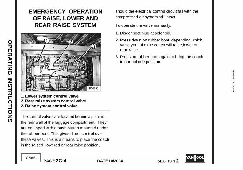
Update B
_OG
B02A
RU
pdate B_O
GB
02AR
OP
ER
AT
ING
INS
TR
UC
TIO
NS
OP
ER
AT
ING
INS
TR
UC
TIO
NS
PAGE 2C-4 DATE 10/2004 SECTION 2
DATE 10/2004PAGE 2C-4 SECTION 2
C2045
C2045
F04390
EMERGENCY OPERATIONOF RAISE, LOWER ANDREAR RAISE SYSTEM
1. Lower system control valve2. Rear raise system control valve2. Raise system control valve
The control valves are located behind a plate inthe rear wall of the luggage compartment. Theyare equipped with a push button mounted underthe rubber boot. This gives direct control overthese valves. This is a means to place the coachin the raised, lowered or rear raise position,
should the electrical control circuit fail with thecompressed-air system still intact.
To operate the valve manually:
1. Disconnect plug at solenoid.
2. Press down on rubber boot, depending whichvalve you take the coach will raise,lower orrear raise.
3. Press on rubber boot again to bring the coachin normal ride position.

OP
ER
AT
ING
IN
ST
RU
CT
ION
SO
PE
RA
TIN
G I
NS
TR
UC
TIO
NS
Upd
ate
B_O
GB
02A
RU
pdat
e B
_OG
B02
AR
SECTION 2 PAGE 2C-5DATE 10/2004
SECTION 2 PAGE 2C-5DATE 10/2004
C2045
C2045
F04686
Location of screws to mechanically lock the fanclutch
COOLING FAN MECHANICALLOCKING DEVICE
In case of an electrical power or fan clutch failure,the fan clutch can be mechanically locked asfollows:
!!! CAUTION !!!
SET THE OVERRIDE SWITCH IN THEENGINE COMPARTMENT TO THE "OFF"POSITION TO PREVENT ACCIDENTAL
STARTING OF THE ENGINE
1. Set the starter override switch in the enginecompartment to the "off" position to preventaccidental starting of the engine.
2. Loosen the locking nuts of the two screws(wrench size: 13 mm) located at the front ofthe fan clutch (see photo).
3. Tighten both screws until the fan can not beturned by hand anymore (tightening torquescrews: 18 ft.lbf)
4. Tighten the locking nuts again.
!!! CAUTION !!!
THIS IS ONLY A TEMPORARY REPAIR.ALWAYS TIGHTEN BOTH
LOCKING SCREWS.

Update B
_OG
B02A
RU
pdate B_O
GB
02AR
OP
ER
AT
ING
INS
TR
UC
TIO
NS
OP
ER
AT
ING
INS
TR
UC
TIO
NS
PAGE 2C-6 DATE 10/2004 SECTION 2
DATE 10/2004PAGE 2C-6 SECTION 2
C2045
C2045
T02688
PULLDOWN
PUSH
EMERGENCY EXITS
SIDE WINDOW EMERGENCY ESCAPESome side windows can be used as anemergency escape. They are hinged at the topand equipped with a handle to open from theinside, only in case of emergency. When a handleis not located within an occupant space of anadjacent seat, a label indicates the location of thenearest release mechanism.
To open:
1. Pull the window latch handle down.
2. Push the window out from the bottom.
To close:
1. From inside the vehicle, open the window atleast 45°.
2. Release the window so that it falls to close.
3. Check that emergency window is securelylatched.From inside the vehicle, firmly push outward onboth lower corners. No movement is allowed.From outside the vehicle, check the alignmentof the emergency side window. Lower edge ofan emergency window that is not properlylatched wil visibly stick out.

OP
ER
AT
ING
IN
ST
RU
CT
ION
SO
PE
RA
TIN
G I
NS
TR
UC
TIO
NS
Upd
ate
B_O
GB
02A
RU
pdat
e B
_OG
B02
AR
SECTION 2 PAGE 2C-7DATE 10/2004
SECTION 2 PAGE 2C-7DATE 10/2004
C2045
C2045
F02302
ROOF EMERGENCY ESCAPE
The roof ventilators located in the front and rearsections of the coach can be opened from theinside to serve as escape hatches.
To open the escape hatch:
1. Push out the ventilaton hatch completely.
2. Push black tab (1) in the direction shown bythe arrow on release handle (2).
3. Push release handle (2) out.
LEAK IN HEATING SYSTEM
If engine coolant should be lost through a massiveleak in the vehicle heating system lines, switch offthe climate control switch and isolate the enginecooling system from the heating system byclosing the main isolating valves in the heatingsystem supply and return lines.
The isolating valves are located in the combustionheater compartment.

Update B
_OG
B02A
RU
pdate B_O
GB
02AR
OP
ER
AT
ING
INS
TR
UC
TIO
NS
OP
ER
AT
ING
INS
TR
UC
TIO
NS
PAGE 2C-8 DATE 10/2004 SECTION 2
DATE 10/2004PAGE 2C-8 SECTION 2
C2045
C2045
the lights will not flash but will be illuminated.The fault code will flash in the followingsequence:
First, the "ENGINE WARNING" light will flash.There will be a short pause, lasting for one totwo seconds. After that the flashing of the"STOP ENGINE" light will indicate the number ofthe recorded fault. There will be an one- or two-second pause between two consecutivenumbers. Then the "ENGINE WARNING" light willcome on, signaling that the end of the faultcode number has been reached. The three-digit
AN ENGINE WARNING LIGHTIS ILLUMINATED
For vehicle operation when an engine warninglight on the instrument panel illuminates, seeunder "WARNING AND INDICATOR LIGHTS".Read fault codes before calling for assistance.
NOTE
ON MULTIPLEXED VEHICLES ONLY: THEENGINE DIAGNOSTIC LIGHTS ARE LOCATEDIN THE DIAGNOSTIC BOX. THE DIAGNOSTIC
BOX IS MOUNTED BEHIND AN ACCESSDOOR IN THE R.H. CONSOLE.
CUMMINS ISM ENGINE
Proceed as follows.
1. Unlock switch "A" and push lower part.
2. Switch ignition "on".
3. If any fault codes were active during systempower down, the "ENGINE WARNING" and "STOP
ENGINE" lights will begin to flash the code of therecorded faults. If no fault codes are recorded,
T03033
ISM Engine diagnostic switch on L.H. dashboard
DIA
ISM DIAGNOSE
the lights will not flash but will be illuminated.The fault code will flash in the followingsequence:
First, the "ENGINE WARNING" light will flash.There will be a short pause, lasting for one totwo seconds. After that the flashing of the"STOP ENGINE" light will indicate the number ofthe recorded fault. There will be an one- or two-second pause between two consecutivenumbers. Then the "ENGINE WARNING" light willcome on, signaling that the end of the faultcode number has been reached. The three-digit
AN ENGINE WARNING LIGHTIS ILLUMINATED
For vehicle operation when an engine warninglight on the instrument panel illuminates, seeunder "WARNING AND INDICATOR LIGHTS".Read fault codes before calling for assistance.
NOTE
ON MULTIPLEXED VEHICLES ONLY: THEENGINE DIAGNOSTIC LIGHTS ARE LOCATEDIN THE DIAGNOSTIC BOX. THE DIAGNOSTIC
BOX IS MOUNTED BEHIND AN ACCESS DOORIN THE R.H. CONSOLE.
CUMMINS ISM ENGINE
Proceed as follows.
1. Unlock switch "A" and push lower part.
2. Switch ignition "on".
3. If any fault codes were active during systempower down, the "ENGINE WARNING" and "STOP
ENGINE" lights will begin to flash the code of therecorded faults. If no fault codes are recorded,
T03033
ISM Engine diagnostic switch on L.H. dashboard
DIA
ISM DIAGNOSE

OP
ER
AT
ING
IN
ST
RU
CT
ION
SO
PE
RA
TIN
G I
NS
TR
UC
TIO
NS
Upd
ate
B_O
GB
02A
RU
pdat
e B
_OG
B02
AR
SECTION 2 PAGE 2C-9DATE 10/2004
SECTION 2 PAGE 2C-9DATE 10/2004
C2045
C2045
code number will continue repeating itself untilthe system is instructed otherwise.
To go to the next fault code, momentarily pushswitch (2) of the "Cruise control/Fast idle"system into the "RESUME/ACCEL" position. Thistakes you to the fault code recorded next. Youcan return to the previous fault code bymomentarily pushing this switch into the "SET/
COAST" position. If only one fault code hasbeen recorded, the ISM system will
T01226
Cruise control/fast idle switches
continuously display the same fault code,when lower or upper part of this switch ismomentarily pushed.
!!! CAUTION !!!
DO NOT FORGET TO SWITCH OFF(UPPER PART PUSHED) SWITCH "A"WHEN NOT USING THE DIAGNOSTIC
SYSTEM.
Active fault codes can also be displayed bythe Road Relay (option). If the fault codebecomes inactive during the trip, it will not bedisplayed by the Road Relay. When a fault isidentified, the Road Relay will display a fault/alarm message. Active fault codes can beviewed by pressing and holding down thediagnostic (wrench) key. If more than one faulthas been found, the fault codes will scrollevery three to five seconds.

Update B
_OG
B02A
RU
pdate B_O
GB
02AR
OP
ER
AT
ING
INS
TR
UC
TIO
NS
OP
ER
AT
ING
INS
TR
UC
TIO
NS
PAGE 2C-10 DATE 10/2004 SECTION 2
DATE 10/2004PAGE 2C-10 SECTION 2
C2045
C2045
DETROIT DIESEL ENGINE
It is important to point out that whenever the"CHECK ENGINE" light (CEL) ("ENGINE WARNING" lighton multiplexed vehicles) ,or the "STOP ENGINE" light(SEL) comes on, the DDEC computer will deter-mine where the problem is, and will then store thisinformation in its memory.
If the malfunction is intermittent, the lights willcome on and go off as the computer senses thechanging engine condition.
Read fault codes before calling for assistance.
With the engine shut off and the ignitionon, depress and hold the "DIA" switchin the diagnostic box:
Active codes will be flashed on the "STOP ENGINE"light (SEL) first, followed by inactive codesbeing flashed on the "CHECK ENGINE" light (CEL).They will for example flashtwice...pause....flash once...pause, thus in thiscase flash code number 21. Code 21 indicatesthe throttle position sensor input voltage ishigh. Code 25 indicates that all systems areworking satisfactorily.
When all the inactive codes have been flashed,the process of flashing all the active codes fol-lowed by all the inactive codes will repeat until the"DIA" switch is released.
SEL / CEL EXAMPLES
SEL Active Codes
1 Flash 3 Flashes
Long pauseShortpause
Code 13 Code 21
Shortpause
T03675
CEL Inactive Codes
2 Flashes 1 Flash
DIA
DETROIT DIESEL ENGINE
IIt is important to point out that whenever the "CHECK
ENGINE" light (CEL) ("ENGINE WARNING" light onmultiplexed vehicles) ,or the "STOP ENGINE" light(SEL) comes on, the DDEC computer will determinewhere the problem is, and will then store this informa-tion in its memory.
If the malfunction is intermittent, the lights willcome on and go off as the computer senses thechanging engine condition.
Read fault codes before calling for assistance.
With the engine shut off and the ignitionon, depress and hold the "DIA" switchin the diagnostic box:
Active codes will be flashed on the "STOP ENGINE"light (SEL) first, followed by inactive codes beingflashed on the "CHECK ENGINE" light (CEL). They willfor example flash twice...pause....flashonce...pause, thus in this case flash code number21. Code 21 indicates the throttle position sensorinput voltage is high. Code 25 indicates that allsystems are working satisfactorily.
When all the inactive codes have been flashed,the process of flashing all the active codes fol-lowed by all the inactive codes will repeat until the"DIA" switch is released.
SEL / CEL EXAMPLES
SEL Active Codes
1 Flash 3 Flashes
Long pauseShortpause
Code 13 Code 21
Shortpause
T03675
CEL Inactive Codes
2 Flashes 1 Flash
DIA

OP
ER
AT
ING
IN
ST
RU
CT
ION
SO
PE
RA
TIN
G I
NS
TR
UC
TIO
NS
Upd
ate
B_O
GB
02A
RU
pdat
e B
_OG
B02
AR
SECTION 2 PAGE 2C-11DATE 10/2004
SECTION 2 PAGE 2C-11DATE 10/2004
C2045
C2045
CATERPILLAR ENGINE
First method
1. Place the "CRUISE CONTROL ON/OFF" switch inthe "OFF" position.
2. Push the "SET/RESUME" switch to eitherposition. Hold that position until the "ENGINE
WARNING" lamp begins to flash.
Second method
Push and hold the "DIA" switch in thediagnostic box until the "ENGINE
WARNING" lamp begins to flash.
The "ENGINE WARNING" lamp will flash inorder to indicate a two digit flash code.
The sequence of flashing represents the systemdiagnostic message. Count the first sequence offlashes in order to determine the first digit of thediagnostic code. After a two second pause, thesecond sequence of flashes will identify thesecond digit of the diagnostic code.
DIA
Any additional diagnostic codes will follow after apause. The additional diagnostic codes will bedisplayed in the same manner. Flash code 55signals that "No Detected Faults" have occurredsince the ignition key switch has been turned tothe ON position. Troubleshooting is not requiredfor codes "35", "41", "47" and "55".

Update B
_OG
B02A
RU
pdate B_O
GB
02AR
OP
ER
AT
ING
INS
TR
UC
TIO
NS
OP
ER
AT
ING
INS
TR
UC
TIO
NS
PAGE 2C-12 DATE 10/2004 SECTION 2
DATE 10/2004PAGE 2C-12 SECTION 2
C2045
C2045
WTB500 AUTOMATICTRANSMISSION "DO NOT
SHIFT" LIGHT IS ILLUMINATED
For vehicle operation when the "DO NOT SHIFT"warning light illuminates, see under"WT B500 Automatic Transmission" and"Warning and indicator lights" earlier in thisSection. Read diagnostic codes before calling forassistance.
DIAGNOSTIC CODES
Diagnostics codes are numerical indicationsrelating to a malfunction in transmission operation.Each code consists of a two-digit main code anda two-digit subcode. These codes are logged in alist in the ECU memory with the most severe orotherwise most recent code listed first. Amaximum of five codes (numbered d1-d5) may belisted in memory at one time. As codes areadded, the oldest nonactive code is dropped fromthe list. If all codes are active, the code with thelowest priority that is not included on the severitylist is dropped from the list. Access to thediagnostic codes and code information is throughthe pushbutton shift selector or the diagnosticdata reader.
The ECU separately stores the active andhistorical (nonactive) codes. An active code is anycode that is current in the ECU decision-makingprocess. Historical codes are codes that areretained in the ECU's memory and will notnecessarily affect the ECU decision-makingprocess. Historical codes are useful indetermining if a problem is isolated, isintermittent, or results from a previousmalfunction.
When the diagnostic mode is entered, the firstcode (position d1) is displayed as follows (eachdisplay item lasts for about one second): d, 1,main code (two digits displayed one-at-a-time),subcode (two digits displayed one-at-a-time),sequence repeats. Press the MODE buttonmomentarily to display codes for positions d2-d5in the same manner. After a fixed number ofignition cycles, a code may be deleted frommemory if it has not recurred. The shift selectordiagnostic mode will end automatically after twominutes without operator input.
WTB500 AUTOMATICTRANSMISSION "DO NOT
SHIFT" LIGHT IS ILLUMINATED
For vehicle operation when the "DO NOT SHIFT"warning light illuminates, see under"WT B500 Automatic Transmission" and"Warning and indicator lights" earlier in thisSection. Read diagnostic codes before calling forassistance.
DIAGNOSTIC CODES
Diagnostics codes are numerical indicationsrelating to a malfunction in transmission operation.Each code consists of a two-digit main code anda two-digit subcode. These codes are logged in alist in the ECU memory with the most severe orotherwise most recent code listed first. Amaximum of five codes (numbered d1-d5) may belisted in memory at one time. As codes areadded, the oldest nonactive code is dropped fromthe list. If all codes are active, the code with thelowest priority that is not included on the severitylist is dropped from the list. Access to thediagnostic codes and code information is throughthe pushbutton shift selector or the diagnosticdata reader.
The ECU separately stores the active andhistorical (nonactive) codes. An active code isany code that is current in the ECU decision-making process. Historical codes are codes thatare retained in the ECU's memory and will notnecessarily affect the ECU decision-makingprocess. Historical codes are useful indetermining if a problem is isolated, isintermittent, or results from a previousmalfunction.
When the diagnostic mode is entered, the firstcode (position d1) is displayed as follows (eachdisplay item lasts for about one second): d, 1,main code (two digits displayed one-at-a-time),subcode (two digits displayed one-at-a-time),sequence repeats. Press the MODE buttonmomentarily to display codes for positions d2-d5in the same manner. After a fixed number ofignition cycles, a code may be deleted frommemory if it has not recurred. The shift selectordiagnostic mode will end automatically after twominutes without operator input.

OP
ER
AT
ING
IN
ST
RU
CT
ION
SO
PE
RA
TIN
G I
NS
TR
UC
TIO
NS
Upd
ate
B_O
GB
02A
RU
pdat
e B
_OG
B02
AR
SECTION 2 PAGE 2C-13DATE 10/2004
SECTION 2 PAGE 2C-13DATE 10/2004
C2045
C2045
DIAGNOSTIC CODE DISPLAY PROCEDURE
Diagnostic codes can be read and cleared by twomethods:• With the Pro-Link® 9000 Diagnostic Data Reader.The use of the Pro-Link® 9000 diagnostic tool isdescribed in the instruction manual furnished witheach tool.
• With the pushbutton shift selector.
To display stored codes
Proceed as follows to read the diagnostic codeswith the pushbutton shift selector:
1. Bring the vehicle to a stop at a safe location.Apply the parking brake.
2. Simultaneously press the "up" and "down"arrow buttons twice to access the diagnosticdisplay mode.
3. Observe the digital display for codes (codeswill appear one digit at a time).
3. Press the MODE button to see the next code -repeat for subsequent codes.
To clear active indicators and resume vehicleoperation
Proceed as follows to clear active indicators:
Press and hold the MODE button forapproximately three seconds until the modeindicator (LED) flashes. Release the MODE buttonand active indicators such as the "DO NOTSHIFT" light will not be illuminated. Some codesare self-clearing and others require ignition cyclesto clear.
NOTE
If the condition that caused the code isstill present, the code will again become
active.
DIAGNOSTIC CODE DISPLAY PROCEDURE
Diagnostic codes can be read and cleared by twomethods:• With the Pro-Link® 9000 Diagnostic Data Reader.The use of the Pro-Link® 9000 diagnostic tool isdescribed in the instruction manual furnished witheach tool.
• With the pushbutton shift selector.
To display stored codes
Proceed as follows to read the diagnostic codeswith the pushbutton shift selector:
1. Bring the vehicle to a stop at a safe location.Apply the parking brake.
2. Simultaneously press the "up" and "down"arrow buttons twice to access the diagnosticdisplay mode.
3. Observe the digital display for codes (codeswill appear one digit at a time).
3. Press the MODE button to see the next code -repeat for subsequent codes.
To clear active indicators and resume vehicleoperation
Proceed as follows to clear active indicators:
Press and hold the MODE button forapproximately three seconds until the modeindicator (LED) flashes. Release the MODEbutton and active indicators such as the "DONOT SHIFT" light will not be illuminated. Somecodes are self-clearing and others require ignitioncycles to clear.
NOTE
If the condition that caused the code isstill present, the code will again become
active.

Update B
_OG
B02A
RU
pdate B_O
GB
02AR
OP
ER
AT
ING
INS
TR
UC
TIO
NS
OP
ER
AT
ING
INS
TR
UC
TIO
NS
PAGE 2C-14 DATE 10/2004 SECTION 2
DATE 10/2004PAGE 2C-14 SECTION 2
C2045
C2045
F04694
ABS WARNING LIGHT ISILLUMINATED
Read trouble codes before calling for assistance.Proceed as follows:
1. Turn ignition key on.
2. Press and hold the diagnostic switch for onesecond. The diagnostic switch is located in thediagnostic box in R.H. console of dashboard.
3. Count the flashes of the "ABS" warning lamp inthe diagnostic box to determine the blink code.
The fault code will be displayed as two sets offlashes with each set separated by a 1 secondpause.
Active fault: 1-8 flashes, 1second pause, 1-6flashes, 4 second pause. Code will be repeateduntil ignition is switched off.
Stored fault: 1-8 flashes, 1second pause, 1-6flashes, 4 second pause. Displays all stored faultsonce then stops blinking.
AIR SYSTEM EMERGENCYFILL
!!! CAUTION !!!
THE AIR SUPPLIED MUST BE CLEANAND DRY. THE PRESSURE SHOULD
NOT EXCEED 135 PSI.
If the coach airpressure is lowand the enginecannot beoperated, the airsystem may befilled from anexternal sourceby attaching an
air hose to the nipple behind the front bumper. Toopen the front bumper, see "Spare Wheel & Tire".
PUSH-STARTING
Note that the engine can NOT be started by pushingor towing the coach.
ABS WARNING LIGHT ISILLUMINATED
Read trouble codes before calling for assistance.Proceed as follows:
1. Turn ignition key on.
2. Press and hold the diagnostic switch for onesecond. The diagnostic switch is located in thediagnostic box in R.H. console of dashboard.
3. Count the flashes of the "ABS" warning lamp inthe diagnostic box to determine the blink code.
The fault code will be displayed as two sets offlashes with each set separated by a 1 secondpause.
Active fault: 1-8 flashes, 1second pause, 1-6flashes, 4 second pause. Code will be repeateduntil ignition is switched off.
Stored fault: 1-8 flashes, 1second pause, 1-6flashes, 4 second pause. Displays all stored faultsonce then stops blinking.
AIR SYSTEM EMERGENCYFILL
!!! CAUTION !!!
THE AIR SUPPLIED MUST BE CLEANAND DRY. THE PRESSURE SHOULD
NOT EXCEED 135 PSI.
If the coach airpressure is lowand the enginecannot beoperated, the airsystem may befilled from anexternal source
by attaching an air hose to the nipple behind thefront bumper. To open the front bumper, see"Spare Wheel & Tire".
PUSH-STARTING
Note that the engine can NOT be started by pushingor towing the coach.
F04694

OP
ER
AT
ING
IN
ST
RU
CT
ION
SO
PE
RA
TIN
G I
NS
TR
UC
TIO
NS
Upd
ate
B_O
GB
02A
RU
pdat
e B
_OG
B02
AR
SECTION 2 PAGE 2C-15DATE 10/2004
SECTION 2 PAGE 2C-15DATE 10/2004
C2045
C2045
F03645
F02558
Reinforced cross-member to lift up frontof coach
LIFTING AND TOWING THECOACH WITH A TOW TRUCK
Before towing a disabled vehicle, both drive axlehalf shafts should be withdrawn or the propellershaft removed.
!!! CAUTION !!!
FAILURE TO WITHDRAW THE DRIVEAXLE HALF SHAFTS OR REMOVE
THE PROPELLER SHAFT MAY CAUSESEVERE TRANSMISSION DAMAGE.
If drive axle half shafts have been removed,suitably seal off the wheel hub openings to preventloss of lubricant and entry of dirt. Refer to "ParkingBrake Emergency Release" earlier in this sectionto mechanically release parking brake.
The coach can be lifted and towed by a tow truckequipped with a lifting beam.
Place the forks of the lifting system only:
• under the reinforced cross-member when liftingthe front of the coach or...
• under the anchor points when lifting the rear.
Lifting and towing can now commence. Anchor points to lift up rear of coach

Update B
_OG
B02A
RU
pdate B_O
GB
02AR
OP
ER
AT
ING
INS
TR
UC
TIO
NS
OP
ER
AT
ING
INS
TR
UC
TIO
NS
PAGE 2C-16 DATE 10/2004 SECTION 2
DATE 10/2004PAGE 2C-16 SECTION 2
C2045
C2045
Front bumper release lever
!!! CAUTION !!!
NO TOWING OPERATION, WHICH INANY WAY IS NOT SAFE FOR THE
TOWING VEHICLE, OPERATOR, POSSIBLEBYSTANDERS OR OTHER MOTORISTS,
SHOULD BE ATTEMPTED.
FOLLOW ALL FEDERAL AND STATE LAWSAPPLICABLE TO VEHICLES IN TOW.
TIRE INFLATION
The air system emergency fill nipple can also beused to inflate the tires:
1. Clamp the tire inflation hose connector to thetire valve.
2. Press the other end of the hose to the "airsystem emergency fill" nipple behind the frontbumper.
3. If necessary, start the engine so that thecompressor can charge the air system. Themaximum tire pressure that can be obtained inthis way is the air system operating pressure.
SPARE WHEEL & TIRE
!!! CAUTION !!!
NEVER STORE OTHER OBJECTS THANTHE SPARE WHEEL IN THE SPARE WHEEL
COMPARTMENT SINCE THEY CANINTERFERE WITH THE STEERING LINKAGE
MECHANISM.
The spare wheel is carried behind the frontbumper.
To take out the spare wheel:
1. Turn bumper release lever located in thecompartment in front of L.H. front wheel.
F04697

OP
ER
AT
ING
IN
ST
RU
CT
ION
SO
PE
RA
TIN
G I
NS
TR
UC
TIO
NS
Upd
ate
B_O
GB
02A
RU
pdat
e B
_OG
B02
AR
SECTION 2 PAGE 2C-17DATE 10/2004
SECTION 2 PAGE 2C-17DATE 10/2004
C2045
C2045
F04860
2. From outside of coach, release safety latch (seephoto above).
3. Push bumper fully down.
4. Loosen spare wheel securing belt and pull outspare wheel on its rollers.
5. Change wheel - see next heading forinstructions - and stow defective road wheelinside spare wheel compartment.
6. To close spare wheel compartment, swingbumper upwards and press firmly to ensureproper double locking.
After having mounted the spare wheel, tire inflationpressure must be checked and, if necessary,corrected as soon as possible.The inflation pressures are mentioned on thevehicle identification plate in the stepwell of theentrance door.
TO CHANGE A ROAD WHEEL
Before attempting to jack the coach:
• Direct all passengers to disembark;
• Apply the parking brake;• Securely chock those road wheels that will
remain on the ground.
Only use the hydraulic jack (VH No.10583382)supplied with your coach.
Location of front bumper safety latch

Update B
_OG
B02A
RU
pdate B_O
GB
02AR
OP
ER
AT
ING
INS
TR
UC
TIO
NS
OP
ER
AT
ING
INS
TR
UC
TIO
NS
PAGE 2C-18 DATE 10/2004 SECTION 2
DATE 10/2004PAGE 2C-18 SECTION 2
C2045
C2045
Necessary equipment for lifting front or tagwheel
1 .Lifting bracket2.Set of wooden blocks
A: Jack supporting blockB: Axle supporting block
3.Hydraulic jack(VH No. 10583382)
T03584
!!! CAUTION !!!
DO NOT GET UNDER THE COACH WHENIT IS SUPPORTED ONLY BY A JACK.
ENSURE THAT THE JACK BASE ISFIRMLY SEATED ON LEVEL GROUND.
TO REMOVE THE WHEEL
If installed, remove the "RADOLID" wheel nut
caps with a socket wrench by turning them to the
left until they can be removed. Clean the exposed
portion of each wheel bolt with a stiff brush, then
loosen all wheel nuts approx. half a turn.
NOTE
All road wheels on this coach haveright-hand threads.
To remove a front or tag wheel
A special wheel lifting bracket (Van Hool PartNo.619900160 for steel wheels; No. 10627455 for
Alcoa forged aluminum wheels) is supplied in thecoach tool kit. This bracket mounts on the wheelnut bolts and the front of the bracket then servesas a support for the jack.The method of using wheel lifting bracket inconjunction with wooden blocks and hydraulicjack is obvious from the diagram on next page.

OP
ER
AT
ING
IN
ST
RU
CT
ION
SO
PE
RA
TIN
G I
NS
TR
UC
TIO
NS
Upd
ate
B_O
GB
02A
RU
pdat
e B
_OG
B02
AR
SECTION 2 PAGE 2C-19DATE 10/2004
SECTION 2 PAGE 2C-19DATE 10/2004
C2045
C2045
T03579
Operating sequence to change a front or tag wheel
T03579
Operating sequence to change a front or tag wheel

Update B
_OG
B02A
RU
pdate B_O
GB
02AR
OP
ER
AT
ING
INS
TR
UC
TIO
NS
OP
ER
AT
ING
INS
TR
UC
TIO
NS
PAGE 2C-20 DATE 10/2004 SECTION 2
DATE 10/2004PAGE 2C-20 SECTION 2
C2045
C2045
1. Remove the two top and bottom wheel nuts.
2. Install lifting bracket on to the free wheel bolts.
!!! CAUTION !!!
THE LIFTING BRACKET MUST BE NUTTED UP AGAINST THE WHEEL USING:
••••• FOUR ORDINARY M22X1.5 NUTS IN CASEOF A STEEL WHEEL; NOT THE FLANGED
WHEEL NUTS WHICH PROVIDEINSUFFICIENT SCREW THREADENGAGEMENT ON THE STUDS.
••••• FOUR MODIFIED WHEEL NUTS(VH NO. 10627683) IN CASE OF AN ALCOA
ALUMINUM WHEEL.
3. If necessary, move the coach until the liftingbracket is vertical.
!!! CAUTION !!!
ONLY A SLIGHT DEVIATION FROMVERTICAL CAN BE OVERCOME WHEN
JACKING UP THE BRACKET. A LARGER
AMOUNT OF MISALIGNMENT MAY CAUSETHE JACK TO SLIP AWAY DURING THE
LIFTING PROCESS.
4. Apply the parking brake and chock the wheelswhich will remain on the ground in order toprevent the coach from moving.
5. Place the jack on wooden block A as indicatedin the figure and raise wheel until woodenblock B can be introduced under the steeringknuckle carrier (hub carrier on tag axle).Besure there is a space of approx. 2 inchesbetween tire flank and block. Otherwise, thespare wheel cannot be installed properly.The side of block B with the metal tag "THIS
SIDE UP FOR FRONT AXLE" must be up whenchanging a front wheel.The side of block B with the metal tag "THIS
SIDE UP FOR TAG AXLE" must be up whenchanging a tag wheel.
6. Lower steering knuckle carrier(hub carrier ontag axle) onto block B.
7. Remove jack and change wheel.

OP
ER
AT
ING
IN
ST
RU
CT
ION
SO
PE
RA
TIN
G I
NS
TR
UC
TIO
NS
Upd
ate
B_O
GB
02A
RU
pdat
e B
_OG
B02
AR
SECTION 2 PAGE 2C-21DATE 10/2004
SECTION 2 PAGE 2C-21DATE 10/2004
C2045
C2045
Detail of jacking point on drive axle suspensionbeam
T03581
Jacking points on drive axle suspension beams
T03582
To remove a drive wheel in case ofone flat tirePosition the jacks under the suspension beamjacking points forward and rearward of the wheel.Then raise jacks until tires are clear off theground. Install a safety supporting block under theaxle. Remove wheelnuts and wheel.

Update B
_OG
B02A
RU
pdate B_O
GB
02AR
OP
ER
AT
ING
INS
TR
UC
TIO
NS
OP
ER
AT
ING
INS
TR
UC
TIO
NS
PAGE 2C-22 DATE 10/2004 SECTION 2
DATE 10/2004PAGE 2C-22 SECTION 2
C2045
C2045
T00042
TO FIT THE SPARE WHEEL1. Clean hub pilot and wheel disc center hole.
Smear pilot lightly with "Never-Seez".
2. Clean wheel bolts with a steel brush and applya drop of oil to bolt-end threads. Also apply asingle drop of oil between wheel nut and itscaptive washer.
3. Locate spare wheel on hub and fit, but do notyet tighten the wheel nuts.
4. Raise jack(s) so that block B can be removed.
5. For front wheel: repeat the whole "To removea front wheel" process but this time "from highto low".For drive wheel: lower wheel to ground.
6. Tighten wheelnuts evenly inseveral steps,going round inthe sequenceshown in figureuntil a finaltorque of 427 to456 ft.lbf isreached.
7. If fitted, install the "RADOLID" wheel nut caps asfollows:
a. Place wheel nut cap loosely over wheel nut.
!!! CAUTION !!!
USE ONLY A SOCKET WRENCH INNEXT STEP. NO OTHER TYPES OF
WRENCHES ARE ALLOWED.
b. Using a socket wrench, turn wheel nut cap to theright until a light snap-effect is felt.
CHASSIS FRAME JACKINGPOINTS
When it is necessary to raise the coach by usingjacks under the chassis frame, locate the jack(s)solely under the points marked with arrows in theillustrations on the following page; otherwisedistortion or other damage to chassis sections mayresult.
!!! CAUTION !!!
NEVER RELY ON THE JACK(S) ALONETO SUPPORT THE VEHICLE. IF NEEDED
TO GET UNDER THE RAISED COACH,ALWAYS FIT ADDITIONAL SUPPORTING
STANDS OR TIMBER PACKING TO REDUCETHE RISK OF PERSONAL INJURY.

OP
ER
AT
ING
IN
ST
RU
CT
ION
SO
PE
RA
TIN
G I
NS
TR
UC
TIO
NS
Upd
ate
B_O
GB
02A
RU
pdat
e B
_OG
B02
AR
SECTION 2 PAGE 2C-23DATE 10/2004
SECTION 2 PAGE 2C-23DATE 10/2004
C2045
C2045
F03645F02558F02559
Chassis frame jacking points
T03399
F03645F02558F02559
Chassis frame jacking points
T03399

Update B
_OG
B02A
RU
pdate B_O
GB
02AR
OP
ER
AT
ING
INS
TR
UC
TIO
NS
OP
ER
AT
ING
INS
TR
UC
TIO
NS
PAGE 2C-24 DATE 10/2004 SECTION 2
DATE 10/2004PAGE 2C-24 SECTION 2
C2045
C2045
mal
T03790
Climate control override switch (in HVACjunction box)
CLIMATE CONTROL OVERRIDE
In the event the climate control system electronicsfail, an override switch may be used to obtainmanual control over the coach interior heating/cooling. The switch is located in the HVACjunction box. The override switch has threepositions: "Normal", "Override Heating" and"Override Cooling".
Placing the switch in the "Override heating"position will provide continuous heating as long as
the climate control on/off switch on the R.H. lowerconsole is "on". Placing the switch in the"Override Cooling" position will provide continuouscooling as long as the climate control on/offswitch on the R.H. lower console is "on". Airtemperature control is now achieved by switchingon and off the climate control on/off switch.
Overriding the automatic control is merely atemporary solution. Have the system checked assoon as possible.
JUMP STARTING
The instructions below must be followed,otherwise personal injury or property damage mayresult.
!!! CAUTION !!!
DO NOT SMOKE NEAR BATTERIES.BATTERIES GIVE OFF A GAS, WHICH IS
FLAMMABLE AND EXPLOSIVE.
Overrideheating
Overridecooling
Climaoperation Service

OP
ER
AT
ING
IN
ST
RU
CT
ION
SO
PE
RA
TIN
G I
NS
TR
UC
TIO
NS
Upd
ate
B_O
GB
02A
RU
pdat
e B
_OG
B02
AR
SECTION 2 PAGE 2C-25DATE 10/2004
SECTION 2 PAGE 2C-25DATE 10/2004
C2045
C2045
TO LESSEN THE RISK OF INJURY IN CASEAN EXPLOSION DOES OCCUR, WEAR EYE
PROTECTION OR SHIELD YOUR EYES,WHEN WORKING NEAR ANY BATTERY.DO NOT LEAN OVER THE BATTERIES.
THIS COACH HAS TWO 12-VOLTBATTERIES CONNECTED IN SERIES TOPROVIDE POWER TO THE NEGATIVE
GROUND ELECTRICAL SYSTEM. MAKESURE THE OTHER VEHICLE ALSO HAS A
NEGATIVE GROUND ELECTRICAL SYSTEMOF SUFFICIENT CAPACITY TO START
THE VEHICLE. IF UNSURE OF THE OTHERVEHICLE'S VOLTAGE (OR IF THE
VOLTAGE AND/OR GROUND ON THEOTHER VEHICLE ARE DIFFERENT FROMYOUR COACH), DO NOT TRY TO JUMP
START AS PERSONAL INJURY ORSEVERE DAMAGE TO ELECTRIC ANDELECTRONIC PARTS MAY RESULT.
CHECK BATTERY FLUID LEVEL.(DO NOT CHECK WITH AN OPEN FLAMEAND DO NOT SMOKE.) ADD CLEAN OR
DISTILLED WATER BEFORE JUMPSTARTING. DO NOT ALLOW BATTERY
FLUID TO CONTACT EYES, SKIN, FABRIC,OR PAINTED SURFACES BECAUSE
BATTERY FLUID IS A CORROSIVE ACID.FLUSH ANY CONTACTED AREA WITH
WATER IMMEDIATELY ANDTHOROUGHLY. ALSO GET MEDICAL
HELP, IF EYES ARE AFFECTED.
JUMPER CABLE SIZE: MINIMUM 3/0 AWG.
TO CONNECT BOOSTER BATTERYCABLES
1. First:
• apply the parking brake;• place the transmission in neutral;• turn off the engine;• turn off the ignition;• switch off the master switch;• turn off all electrical accessories.
Make sure that these conditions are met onboth vehicles when you jump start with anothervehicle.

Update B
_OG
B02A
RU
pdate B_O
GB
02AR
OP
ER
AT
ING
INS
TR
UC
TIO
NS
OP
ER
AT
ING
INS
TR
UC
TIO
NS
PAGE 2C-26 DATE 10/2004 SECTION 2
DATE 10/2004PAGE 2C-26 SECTION 2
C2045
C2045
F04693
Terminals for jump starting in enginecompartment
1. Positive terminal2. Ground stud
2. Disconnect the wires from the GND (ground)terminal of the battery equalizer. Do not allowthis cable to touch any other connection onthe equalizer because the other terminals areconnected to the batteries.
3. Connect the first jumper cable from thepositive terminal on the charged battery(identified by a red collar, "+" or "P" on thepost or clamp) to terminal (1). To connect the
cable to terminal (1), first pull the spring-loadedprotective cover back.
4. Connect one end of the second cable to thegrounded negative ("-", black, blue or "N")terminal of the charged battery. Connect theother end to the ground stud (2) for jumpstarting on the vehicle being started.DO NOT connect directly to the negative postof the discharged battery. Do not connect itwith or attach it near pulleys, fans, or otherparts that will move when the engine is started.
5. Start the engine of the vehicle with thedischarged batteries.
6. Let the engine idle for a few minutes so thatthe voltage of the batteries can equal. This willreduce the formation of sparks whendisconnecting the jumper cables.
TO DISCONNECT BOOSTERBATTERY CABLES
1. Take care that the clamps from one jumpercable do not inadvertently touch the clampson the other jumper cable, disconnect thejumper lead from the ground stud (2) on thevehicle being started.

OP
ER
AT
ING
IN
ST
RU
CT
ION
SO
PE
RA
TIN
G I
NS
TR
UC
TIO
NS
Upd
ate
B_O
GB
02A
RU
pdat
e B
_OG
B02
AR
SECTION 2 PAGE 2C-27DATE 10/2004
SECTION 2 PAGE 2C-27DATE 10/2004
C2045
C2045
2. Remove the remaining end of the negativejumper cable from the booster battery.
3. Remove one end of the remaining jumpercable from the positive (red) terminal (1) onthe vehicle being started, then remove theother end of the same cable from the positiveterminal of the booster battery.
4. Reconnect wires onto the GND (ground)terminal of the battery equalizer.
NOTE
Always check the battery equalizercircuit breaker after jump starting
the vehicle.
MANUAL WHEELCHAIR LIFTOPERATION
Refer to the wheelchair lift manufacturer's bookletsupplied with your coach.

Update B
_OG
B02A
RU
pdate B_O
GB
02AR
OP
ER
AT
ING
INS
TR
UC
TIO
NS
OP
ER
AT
ING
INS
TR
UC
TIO
NS
PAGE 2C-28 DATE 10/2004 SECTION 2
DATE 10/2004PAGE 2C-28 SECTION 2
C2045
C2045
Upd
ate
1_O
GB
03A
FU
pdat
e 1_
OG
B03
AF
AC
CE
SS
OR
IES
AC
CE
SS
OR
IES
SECTION 3 PAGE 1DATE 09/2003
SECTION 3 PAGE 1DATE 09/2003
C2045
C2045
ACCESSORIES
CLIMATE CONTROL
Driver's compartment ............................................................................................................ page 3Passenger compartment heating/ventilation and air conditioning .......................................... page 4
COMBUSTION HEATER ..................................................................................................... page 5
Operation with digital timer ................................................................................................... page 7
LAVATORY ......................................................................................................................... page 8
WHEELCHAIR LIFT (OPTIONAL)
To deploy the wheelchair lift system ..................................................................................... page 10
To shut off the wheelchair lift system .................................................................................... page 10
Emergency procedure .......................................................................................................... page 11

AC
CE
SS
OR
IES
Update 1_O
GB
03AF
Update 1_O
GB
03AF
DATE 09/2003
PAGE 2
PAGE 2
AC
CE
SS
OR
IES
SECTION 3DATE 09/2003
SECTION 3
C2045
C2045
WHEELCHAIR RESTRAINT SYSTEM
Pre-boarding recommendations ............................................................................................ page 12
Securing the chair ................................................................................................................ page 13
Securing the passenger ....................................................................................................... page 16
Warnings ............................................................................................................................. page 19

Upd
ate
1_O
GB
03A
FU
pdat
e 1_
OG
B03
AF
AC
CE
SS
OR
IES
AC
CE
SS
OR
IES
SECTION 3 PAGE 3DATE 09/2003
SECTION 3 PAGE 3DATE 09/2003
C2045
C2045
CLIMATE CONTROL
DRIVER'S COMPARTMENT
DRIVER'S DEFROSTER/HEATERThe front-end defroster/heater operatesindependently of the passenger compartmenttemperature control system. It is used to heat thedriver's compartment and to demist or defrost thewindshield. Warm air is ducted to slots at thebase of the windshield, and to adjustable outletson the dashboard and in the footwell.
Air flap control switch:
• fresh air: depress upper part ofswitch
• recirculated air: depress lower partof switch
To operate the defroster/heater:
1. If accelerated warm-up or windshield defrostingis required, depress lower part of air flap controlswitch to obtain inside air recirculation.
2. Set rotary knob to adjust heat of airoutput. Turn clockwise to raise,counterclockwise to lower thetemperature.
3. Set blower switches for bloweroperation. The defroster/heatercontains two blowers which areactivated each with a separateswitch. Each of the two switcheshas three positions: off/low speed/high speed. With one switch youcan control the air flow to thewindshield, with the other the airflow to the footwell and the dashoutlets.
4. Adjust air outlets as required.

AC
CE
SS
OR
IES
Update 1_O
GB
03AF
Update 1_O
GB
03AF
DATE 09/2003
PAGE 4
PAGE 4
AC
CE
SS
OR
IES
SECTION 3DATE 09/2003
SECTION 3
C2045
C2045
DRIVER'S AIR CONDITIONINGThe driver's A/C will be automatically activatedwhen the passenger's climate control switch is onand the A/C system is in operation.To control the temperature in the driver's area, turnthe rotary knob:
• clockwise to raise thetemperature
• counterclockwise to lower thetemperature
PASSENGER COMPARTMENTHEATING, VENTILATION ANDAIR-CONDITIONINGThe heating, ventilation and air conditioningsystem (HVAC) of the passengers compartmentis a fully automatic system with the exception ofthe fresh air flaps.
You can set the interiortemperature with rotary knob if:
• engine is running
• climate control on/off switchis in the "ON" position
Once the temperature has been selected, thesystem automatically selects one of the fiveoperating modes:
• Cooling high: Blowers at high speed, full airconditioning
• Cooling low: Blowers at low speed, reducedair conditioning
• Reheat: Blowers at low speed, reduced airconditioning, hot water circulates through theroof heaters only
• Ventilation: Blowers at low speed, air condition-ing off, hot water off.
• Heating: Blowers at low speed, air conditoningoff, hot water circulates through roof and floorheaters. The floor heating elements are of theradiant type.
The blowers in the roof will force the air throughthe adjustable air outlets above the passengerseats and the side windows, through the holes in
DRIVER'S AIR CONDITIONINGThe driver's A/C will be automatically activatedwhen the passenger's climate control switch is onand the A/C system is in operation.To control the temperature in the driver's area, turnthe rotary knob:
• clockwise to raise thetemperature
• counterclockwise to lower thetemperature
PASSENGER COMPARTMENTHEATING, VENTILATION ANDAIR-CONDITIONINGThe heating, ventilation and air conditioningsystem (HVAC) of the passengers compartment isa fully automatic system with the exception of thefresh air flaps.
You can set the interiortemperature with rotary knob if:
• engine is running
• climate control on/off switchis in the "ON" position
Once the temperature has been selected, thesystem automatically selects one of the fiveoperating modes:
• Cooling high: Blowers at high speed, full airconditioning
• Cooling low: Blowers at low speed, reducedair conditioning
• Reheat: Blowers at low speed, reduced airconditioning, hot water circulates through theroof heaters only
• Ventilation: Blowers at low speed, air condition-ing off, hot water off.
• Heating: Blowers at low speed, air conditoningoff, hot water circulates through roof and floorheaters. The floor heating elements are of theradiant type.
The blowers in the roof will force the air throughthe adjustable air outlets above the passengerseats and the side windows, through the holes in

Upd
ate
1_O
GB
03A
FU
pdat
e 1_
OG
B03
AF
AC
CE
SS
OR
IES
AC
CE
SS
OR
IES
SECTION 3 PAGE 5DATE 09/2003
SECTION 3 PAGE 5DATE 09/2003
C2045
C2045
F04685
Air outlets above passenger seats
the lower edge (aisle side) of the roof duct andthrough several other air outlets in the passengerscompartment.
Air flap control switch:
• fresh air: depress upper part ofswitch.
• recirculated air: depress lower partof switch.
With the system operating while the vehicle isparked, the engine must run on fast idle in order toprovide efficient power to the batteries and therefrigeration system.
NOTE
It is recommended to leave the freshair flaps in the open position at all
times except when the systemefficiency is affected by extreme
outside temperatures. It is also helpfulto temporarily close the fresh air flaps
for rapid cooling and heating.
the lower edge (aisle side) of the roof duct andthrough several other air outlets in the passengerscompartment.
Air flap control switch
• fresh air: depress upper part ofswitch.
• recirculated air: depress lower partof switch.
With the system operating while the vehicle isparked, the engine must run on fast idle in order toprovide efficient power to the batteries and therefrigeration system.
NOTE
It is recommended to leave the freshair flaps in the open position at all
times except when the systemefficiency is affected by extreme
outside temperatures. It is also helpfulto temporarily close the fresh air flaps
for rapid cooling and heating.t
F04685
Air outlets above passenger seats

AC
CE
SS
OR
IES
Update 1_O
GB
03AF
Update 1_O
GB
03AF
DATE 09/2003
PAGE 6
PAGE 6
AC
CE
SS
OR
IES
SECTION 3DATE 09/2003
SECTION 3
C2045
C2045
Climate control panel (optional)
1. Temperature increase button: After pushingthe button, the interior temperature setpoint isincreased with one °F. Standard setpoint is65°F. When the button is pushed for aprolonged time, the setpoint will increaseevery 1/2 second.
2. Temperature indication: The red display willindicate setpoint(standard), interiortemperature or outside temperature.
3. Outside temperature button: After pushingthe button, the outside temperature isdisplayed for 10 seconds, afterwards thesetpoint is indicated.
4. Interior temperature button: After pushingthe button, the interior temperature isdisplayed for 10 seconds, afterwards thesetpoint is indicated.
5. A/C on/fail indicator: The upper led willilluminate when the A/C system is on.The lower led will illuminate whenever there isa problem with the air conditioning system. Inthis event, the system must be checked assoon as possible.
6. Temperature decrease button: After pushingthe button, the interior temperature setpoint isdecreased with one °F. Standard setpoint is65°F. When the button is pushed for aprolonged time, the setpoint will decreaseevery 1/2 second.
T03814
1. Temperature increase button2. Temperature indication3. Outside temperature button4. Interior temperature button5. AC on/fail indicator6. Temperature decrease button
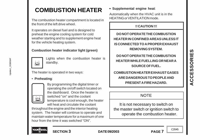
Upd
ate
1_O
GB
03A
FU
pdat
e 1_
OG
B03
AF
AC
CE
SS
OR
IES
AC
CE
SS
OR
IES
SECTION 3 PAGE 7DATE 09/2003
SECTION 3 PAGE 7DATE 09/2003
C2045
C2045
COMBUSTION HEATER
The combustion heater compartment is located inthe front of the left drive wheel.
It operates on diesel fuel and is designed topreheat the engine cooling system for coldweather starting and to supplement engine heatfor the vehicle heating system.
Combustion heater indicator light (green)
Lights when the combustion heater isstandby.
The heater is operated in two ways:
• Preheating:
By programming the digital timer oroperating the on/off switch located onthe dashboard. Once the heater isswitched "on" and the coolanttemperature is cool enough, the heaterwill heat and circulate the coolant
throughout the engine and the interior heatingsystem. The heater will continue to operate andmaintain water temperature for a maximum of onehour from the time it was switched "ON".
••••• Supplemental engine heat:
Automatically when the HVAC unit is in theHEATING or VENTILATION mode.
!! CAUTION !!!
DO NOT OPERATE THE COMBUSTION
HEATER IN CONFINED AREAS UNLESS IT
IS CONNECTED TO A PROPER EXHAUST
REMOVING SYSTEM.
DO NOT OPERATE THE COMBUSTION
HEATER WHILE FUELLING OR NEAR A
SOURCE OF FUEL.
COMBUSTION HEATER EXHAUST GASES
ARE DANGEROUS TO PEOPLE AND
PRESENT A FIRE HAZARD.
NOTE
It is not necessary to switch onthe master switch or ignition switch to
operate the combustion heater.

AC
CE
SS
OR
IES
Update 1_O
GB
03AF
Update 1_O
GB
03AF
DATE 09/2003
PAGE 8
PAGE 8
AC
CE
SS
OR
IES
SECTION 3DATE 09/2003
SECTION 3
C2045
C2045
OPERATION WITH DIGITALTIMER(OPTIONAL)
OPERATION WITH DIGITALTIMER(OPTIONAL)

Upd
ate
1_O
GB
03A
FU
pdat
e 1_
OG
B03
AF
AC
CE
SS
OR
IES
AC
CE
SS
OR
IES
SECTION 3 PAGE 9DATE 09/2003
SECTION 3 PAGE 9DATE 09/2003
C2045
C2045
LAVATORY
F04141
The lavatory compartment is located at the rightrear of the coach. It is standard equipped with achemical toilet, wet napkin dispenser, wastepaper container and mirror.
The compartment flood light will illuminate withthe master/ignition switch in the second position.With the engine running the ventilation fan willstart to run at low speed. Locking the door frominside will turn the ventilation fan to high speed,illuminate the compartment roof lights andilluminate the occupied light.
This light will come on, when thewaste holding tank is nearly full.

AC
CE
SS
OR
IES
Update 1_O
GB
03AF
Update 1_O
GB
03AF
DATE 09/2003
PAGE 10
PAGE 10
AC
CE
SS
OR
IES
SECTION 3DATE 09/2003
SECTION 3
C2045
C2045
WHEELCHAIR LIFT(OPTIONAL)
TO DEPLOY THE WHEELCHAIRLIFT SYSTEM
1. Park the coach on a level surface with thetransmission in neutral, apply the parkingbrake and leave the engine running (shut downthe engine if required by local law).
2. Make sure both of the lift doors are properlyclosed.
3. Press the "LIFT POWER" switch once..
• The system is now switched on.• The indicator lights next to the "LIFT
POWER" switch come on.• The drive and tag axle service brakes areactivated (interlock).• The wheelchair lift system is enabled;• The lift can be deployed.
4. Deploy the lift according to the OEM operatinginstructions supplied with the coach (see liftmanual in lift door pocket).
TO SHUT OFF THEWHEELCHAIR LIFT SYSTEM
1. Stow the lift carefully according to the OEMoperating instructions supplied with the coach(see lift manual in lift door pocket).
2. Close the lift doors.
F05963
"Lift Power" switch
WHEELCHAIR LIFT(OPTIONAL)
TO DEPLOY THE WHEELCHAIRLIFT SYSTEM
1. Park the coach on a level surface with thetransmission in neutral, apply the parkingbrake and leave the engine running (shut downthe engine if required by local law).
2. Make sure both of the lift doors are properlyclosed.
3. Press the "LIFT POWER" switch once..
• The system is now switched on.• The indicator lights next to the "LIFT
POWER" switch come on.• The drive and tag axle service brakes areactivated (interlock).• The wheelchair lift system is enabled;• The lift can be deployed.
4. Deploy the lift according to the OEM operatinginstructions supplied with the coach (see liftmanual in lift door pocket).
TO SHUT OFF THE WHEEL-CHAIR LIFT SYSTEM
1. Stow the lift carefully according to the OEMoperating instructions supplied with the coach(see lift manual in lift door pocket).
2. Close the lift doors.
F05963
"Lift Power" switch

Upd
ate
1_O
GB
03A
FU
pdat
e 1_
OG
B03
AF
AC
CE
SS
OR
IES
AC
CE
SS
OR
IES
SECTION 3 PAGE 11DATE 09/2003
SECTION 3 PAGE 11DATE 09/2003
C2045
C2045
3. With the parking brake still applied, press the"LIFT POWER" switch on the instrument panelonce.• The system is now switched off.• The indicator lights next to the switch go out.• The interlock is released.• The wheelchair lift system is disabled.• The lift cannot be deployed anymore.
4. It is now safe to drive the coach.
EMERGENCY PROCEDURE
!!! CAUTION !!!
PARKING BRAKE MUST BE APPLIED ANDTRANSMISSION IN NEUTRAL.
When the lift system fails to become activatedbecause of a malfunctioning "LIFT POWER" switch orlift door microswitch, throwing the RL53 switch inthe main junction box (see figure) may put it inoperation.
NOTE:
THE "LIFT POWER" SWITCH CANNOT BESWITCHED ON OR OFF IF:
• THE PARKING BRAKE IS RELEASED.• THE LIFT IS NOT PROPERLY STOWED.
• THE LIFT DOORS ARE OPEN.
F05964
Lift interlock system override switch on relayRL53

AC
CE
SS
OR
IES
Update 1_O
GB
03AF
Update 1_O
GB
03AF
DATE 09/2003
PAGE 12
PAGE 12
AC
CE
SS
OR
IES
SECTION 3DATE 09/2003
SECTION 3
C2045
C2045
NOTE:
THE COACH CANNOT BE MOVED IF:
• THE "LIFT POWER" SWITCH IS INTHE "ON" POSITION.
• THE LIFT IS NOT PROPERLY STOWED.
WHEELCHAIRRESTRAINT
SYSTEM
PRE-BOARDINGRECOMMENDATIONS
• Inspect and prepare all your restraint systembelts.
• Be sensitive to your passenger• Be careful in handling the wheelchair• Explain to your passenger what you are doing
to make them feel comfortable with theprocess.
• List of belts for each passenger and chairlocation:-two front wheelchair tiedowns-two rear wheelchair tiedowns-one upper torso belt occupant tiedown-one pelvic belt occupant tiedown
NOTE:
DO NOT ALTER ANY OF THE RESTRAINTSYSTEM BELTS OR COMPONENTS.
DO NOT INTERCHANGE BELTS FROM ONEWHEELCHAIR POSITION TO ANOTHER.ALWAYS KEEP BELTS TOGETHER AS A
COMPLETE KIT.
NOTE:
THE COACH CANNOT BE MOVED IF:
• THE "LIFT POWER" SWITCH IS INTHE "ON" POSITION.
• THE LIFT IS NOT PROPERLY STOWED.
WHEELCHAIRRESTRAINT
SYSTEM
PRE-BOARDINGRECOMMENDATIONS
• Inspect and prepare all your restraint systembelts.
• Be sensitive to your passenger• Be careful in handling the wheelchair• Explain to your passenger what you are doing
to make them feel comfortable with theprocess.
• List of belts for each passenger and chairlocation:-two front wheelchair tiedowns-two rear wheelchair tiedowns-one upper torso belt occupant tiedown-one pelvic belt occupant tiedown
NOTE:
DO NOT ALTER ANY OF THE RESTRAINTSYSTEM BELTS OR COMPONENTS.
DO NOT INTERCHANGE BELTS FROM ONEWHEELCHAIR POSITION TO ANOTHER.ALWAYS KEEP BELTS TOGETHER AS A
COMPLETE KIT.

Upd
ate
1_O
GB
03A
FU
pdat
e 1_
OG
B03
AF
AC
CE
SS
OR
IES
AC
CE
SS
OR
IES
SECTION 3 PAGE 13DATE 09/2003
SECTION 3 PAGE 13DATE 09/2003
C2045
C2045
SECURING THE CHAIR
1. Position wheelchair
Wheel the chair into a forward facing positioncentering the chair squarely on all four corners ofthe tiedown anchorage points. The front and rearbelts, when fastened, should create anglesapproximately as shown in figure 1.
Turn off power on electric chairs and release chairbrakes.
NOTE:
THE "X" IN EACH OF THE FIGURESINDICATES A TIEDOWN ANCHORAGE POINT.
Figure 1: Preferred angles and locations oftiedown straps from wheelchair securementpoints to vehicle anchor points. Fronttiedowns should be angled out for lateralstability when possible. D= 12"

AC
CE
SS
OR
IES
Update 1_O
GB
03AF
Update 1_O
GB
03AF
DATE 09/2003
PAGE 14
PAGE 14
AC
CE
SS
OR
IES
SECTION 3DATE 09/2003
SECTION 3
C2045
C2045
2. Secure the two front belts
Attach the front belts by connecting the chairhook to a solid frame member of the chair asshown in figure 2. Connect the opposite end to theappropriate tiedown anchorage point. Belt anglesfor the front belts should be maintained as shownin figure 1.
T06081
T06082
Figure 2
Figure 3
If necessary, pull the loose end of the belt untilsnug and connect velcro tabs (if applicable) tokeep excess belting off the floor as shown infigure 3.

Upd
ate
1_O
GB
03A
FU
pdat
e 1_
OG
B03
AF
AC
CE
SS
OR
IES
AC
CE
SS
OR
IES
SECTION 3 PAGE 15DATE 09/2003
SECTION 3 PAGE 15DATE 09/2003
C2045
C2045
3. Secure the two rear belts
Attach rear belts by connecting the chair hook toa solid frame member close to the point where thechair back and cushion meet as shown in figure 4.
Attach the opposite end to the appropriate tiedownanchorage point. Belt angles for the rear beltsshould be maintained as shown in figure 1.
T06083
T06084
Figure 4
Figure 5
If necessary, with the buckle open, pull the looseend of the belt until snug. While holding the looseend with one hand, close the lever of the clampdown until it locks and connect velcro (ifappicable) to keep excess belting off the floor asshown in figure 5. Check that the belts are tightand the chair is secure enough so that it does nothave any movement back and forth... now applythe chair brake.
NOTE:
FRONT AND REAR BELT TENSION ISESSENTIAL TO FIRM SECUREMENT OFCHAIR. FINAL TENSIONING IN CHAIR
SECUREMENT SYSTEM IS PROVIDED BYREAR BUCKLES.
3. Secure the two rear belts
Attach rear belts by connecting the chair hook toa solid frame member close to the point where thechair back and cushion meet as shown in figure 4.
Attach the opposite end to the appropriate tiedownanchorage point. Belt angles for the rear beltsshould be maintained as shown in figure 1.
T06083
T06084
Figure 4
Figure 5
If necessary, with the buckle open, pull the looseend of the belt until snug. While holding the looseend with one hand, close the lever of the clampdown until it locks and connect velcro (ifappicable) to keep excess belting off the floor asshown in figure 5. Check that the belts are tightand the chair is secure enough so that it does nothave any movement back and forth... now applythe chair brake.
NOTE:
FRONT AND REAR BELT TENSION ISESSENTIAL TO FIRM SECUREMENT OF
CHAIR. FINAL TENSIONING IN CHAIRSECUREMENT SYSTEM IS PROVIDED BY
REAR BUCKLES.

AC
CE
SS
OR
IES
Update 1_O
GB
03AF
Update 1_O
GB
03AF
DATE 09/2003
PAGE 16
PAGE 16
AC
CE
SS
OR
IES
SECTION 3DATE 09/2003
SECTION 3
C2045
C2045
SECURING THE PASSENGER
4. Attach the occupant tiedowns
Pass the loose ends of the pelvic belt around theoccupant and downward toward the rearwheelchair tiedowns. Connect the loose ends ofthe pelvic belt to the appropriate connectors onthe rear wheelchair tiedowns as shown in figure 6.
NOTE:
PELVIC BELT SHOULD PASS BETWEEN THEGAP IN THE SIDE PANELS AND THE SEAT,OR BETWEEN THE GAP IN THE SEAT AND
THE BACK REST.MAKE SURE BOTH SIDES OF THE PELVIC
BELT ARE SECURELY FASTENED.
T06083 Figure 6
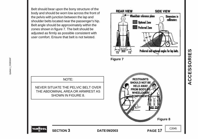
Upd
ate
1_O
GB
03A
FU
pdat
e 1_
OG
B03
AF
AC
CE
SS
OR
IES
AC
CE
SS
OR
IES
SECTION 3 PAGE 17DATE 09/2003
SECTION 3 PAGE 17DATE 09/2003
C2045
C2045
Belt should bear upon the bony structure of thebody and should be worn low across the front ofthe pelvis with junction between the lap andshoulder belts located near the passenger's hip.Belt angle should be approximately within thezones shown in figure 7. The belt should beadjusted as firmly as possible consistent withuser comfort. Ensure that belt is not twisted.
NOTE:
NEVER SITUATE THE PELVIC BELT OVERTHE ABDOMINAL AREA OR ARMREST AS
SHOWN IN FIGURE 8.
Figure 7
Figure 8

AC
CE
SS
OR
IES
Update 1_O
GB
03AF
Update 1_O
GB
03AF
DATE 09/2003
PAGE 18
PAGE 18
AC
CE
SS
OR
IES
SECTION 3DATE 09/2003
SECTION 3
C2045
C2045
5. Attach the upper torso belt
If necessary, connect the upper torso belt to eitherthe left or right pin of the pelvic belt (this dependson which side of the vehicle the chair is located -i.e. right hand pin if the chair is on the left sideand left hand pin if the chair is on the right side)as shown in the figure 9.
T06083 Figure 9
T06083 Figure 10
Pull adjustment snugly (see figure 10). Uppertorso belt should be adjusted as firmly as possibleconsistent with upper comfort. Ensure that belt isnot twisted.
NOTE:
UPPER TORSO SHOULD LIE ACROSS THEMID POINT OF THE SHOULDER AND TRAVEL
UPWARD AND REARWARD FROM THATPOINT TO ENSURE THAT DOWNWARDFORCES ON THE SPINE ARE AVOIDED.

Upd
ate
1_O
GB
03A
FU
pdat
e 1_
OG
B03
AF
AC
CE
SS
OR
IES
AC
CE
SS
OR
IES
SECTION 3 PAGE 19DATE 09/2003
SECTION 3 PAGE 19DATE 09/2003
C2045
C2045
WARNINGS
• Occupant restraints should not be held awayfrom the body by wheelchair components or partssuch as the wheelchair armrests or wheels (seefigure 8).
• Never rely on the chair's own lap belt unless it isQ'Straint approved or strength is confirmed.
• Make sure belts are kept clean and off the floorand stored in Wall Pouch.
• Make sure you use your own driver's seat belt.
• The "Restraint" system should be used inaccordance with these instructions.
· The "Restraint" system has been dynamicallytested with an ATD restrained by both pelvic (lap)and upper torso (shoulder) belts. Use of only apelvic belt may comprise the safety of thepassenger.

AC
CE
SS
OR
IES
Update 1_O
GB
03AF
Update 1_O
GB
03AF
DATE 09/2003
PAGE 20
PAGE 20
AC
CE
SS
OR
IES
SECTION 3DATE 09/2003
SECTION 3
C2045
C2045

MA
INT
EN
AN
CE
MA
INT
EN
AN
CE
Upd
ate_
A_O
GB
04A
GU
pdat
e_A
_OG
B04
AG
PAGE 1DATE 10/2004
SECTION 4 PAGE 1DATE 10/2004
SECTION 4
C2045
C2045
!!! CAUTION !!!
THIS SECTION COVERS COMMON MAINTENANCE THAT MAY NEED TO BE DONE WHILE
THE COACH IS AWAY FROM AN AUTHORIZED SERVICE CENTER OR THE OPERATOR'S
LOCATION. THESE PROCEDURES ARE PROVIDED AS BASIC GUIDELINES ONLY, AND DO
NOT TAKE THE PLACE OF MAINTENANCE PROCEDURES AS DESCRIBED WITHIN THE
APPROPRIATE MAINTENANCE MANUALS FOR THE COACH OR COMPONENTS.
WHEN WORKING WITH OILS, COOLANTS OR OTHER LIQUIDS, BE ESPECIALLY
WATCHFUL FOR BURN DANGERS. IF POSSIBLE, ALLOW THE COACH TO COOL OFF
FOR SEVERAL HOURS BEFORE CONDUCTING MAINTENANCE PROCEDURES.

MA
INT
EN
AN
CE
MA
INT
EN
AN
CE
Update_A
_OG
B04A
GU
pdate_A_O
GB
04AG
DATE 10/2004PAGE 2 SECTION 4
DATE 10/2004PAGE 2 SECTION 4C2045
C2045
MAINTENANCE
ENGINE
To check engine oil level ............................................................................................... page 5To check coolant level ................................................................................................... page 8To drain (primary) fuel filter (Cummins and Caterpillar engines) ...................................... page 10To inspect drive belts ..................................................................................................... page 10To inspect crankcase breather tube (Cummins engine only) .......................................... page 11
AIR CLEANER
To check condition ........................................................................................................ page 12Dump valve .................................................................................................................... page 12To change air-cleaner element ....................................................................................... page 12
WT B500 AUTOMATIC TRANSMISSION
To check fluid level with dipstick .................................................................................... page 15To check fluid level with push-button selector ................................................................ page 17
POWER STEERING SYSTEM
To check fluid level ........................................................................................................ page 20
MA
INT
EN
AN
CE
MA
INT
EN
AN
CE
Upd
ate_
A_O
GB
04A
GU
pdat
e_A
_OG
B04
AG
PAGE 3DATE 10/2004
SECTION 4 PAGE 3DATE 10/2004
SECTION 4
C2045
C2045
TIRES ............................................................................................................................... page 21
To check tire inflation pressure ...................................................................................... page 21
To inspect tires.............................................................................................................. page 22
ROAD WHEELS
To check wheel nut tightening torque............................................................................. page 22
SUSPENSION
To check normal body ground clearance ....................................................................... page 23
To check shock absorbers ............................................................................................ page 23
BATTERIES
To check battery fluid level ............................................................................................ page 24
To check battery cables ................................................................................................ page 24
WINDSHIELD WASHER
To check fluid level ........................................................................................................ page 25

MA
INT
EN
AN
CE
MA
INT
EN
AN
CE
Update_A
_OG
B04A
GU
pdate_A_O
GB
04AG
DATE 10/2004PAGE 4 SECTION 4
DATE 10/2004PAGE 4 SECTION 4C2045
C2045
TOILET
To drain the toilet ........................................................................................................... page 26To fill the toilet ............................................................................................................... page 26To flush ......................................................................................................................... page 27To operate the toilet in cold weather .............................................................................. page 27To clean the interior of the lavatory compartment ........................................................... page 29
WASTE HOLDING TANK .................................................................................................. page 29
APPEARANCE CARE
Coach exterior ............................................................................................................... page 23Coach interior ................................................................................................................ page 33

MA
INT
EN
AN
CE
MA
INT
EN
AN
CE
Upd
ate_
A_O
GB
04A
GU
pdat
e_A
_OG
B04
AG
PAGE 5DATE 10/2004
SECTION 4 PAGE 5DATE 10/2004
SECTION 4
C2045
C2045
F04393
T03003
ENGINE
TO CHECK ENGINE OIL LEVEL
Cummins engine
Check the oil level daily.
The coach must be on level ground during the oillevel checking. Otherwise the measurement maybe inaccurate.
Wait at least five minutes after shutting off theengine before checking the oil. This gives the oilthe time to drain to the oil pan.
Never operate the engine with the oil level belowthe "L" (low) mark or above the "H" (high) markon the dipstick.
If necessary, add oil until it reaches the "H" (high)mark on the dipstick. The difference between the"L" (low) mark and the "H" (high) mark on thedipstick amounts to 2 U.S. gallons. For oilrecommendations, see "Lubricants and Fluids"Section.
ENGINE
TO CHECK ENGINE OIL LEVEL
Cummins engine
Check the oil level daily.
The coach must be on level ground during the oillevel checking. Otherwise the measurement maybe inaccurate.
Wait at least five minutes after shutting off theengine before checking the oil. This gives the oilthe time to drain to the oil pan.
T03003
Never operate the engine with the oil level belowthe "L" (low) mark or above the "H" (high) mark onthe dipstick.
If necessary, add oil until it reaches the "H" (high)mark on the dipstick. The difference between the"L" (low) mark and the "H" (high) mark on thedipstick amounts to 2 U.S. gallons. For oilrecommendations, see "Lubricants and Fluids"Section.
Dipstick
Engine oilfiller tube
F04393
Dipstick
Engine oilfiller tube

MA
INT
EN
AN
CE
MA
INT
EN
AN
CE
Update_A
_OG
B04A
GU
pdate_A_O
GB
04AG
DATE 10/2004PAGE 6 SECTION 4
DATE 10/2004PAGE 6 SECTION 4C2045
C2045
F02925
Detroit Diesel engine
Check the oil level daily.
The coach must be on level ground during the oillevel checking. Otherwise the measurement maybe inaccurate.
Wait at least twenty minutes after shutting off thewarm engine before checking the oil. This givesthe oil the time to drain to the oil pan.
Never operate the engine with the oil level belowthe "L" (low) mark or above the "F" (full) mark onthe dipstick.
If necessary, add oil until it reaches the "F" (full)mark on the dipstick. The difference between the"L" (low) mark and the "F" (full) mark on thedipstick amounts to 6 U.S. Qts. For oilrecommendations, see "Lubricants and Fluids"Section.
DDEC IV
Dipstick
Engine oilfiller tube
DDEC IV with EGR and DDEC V
Dipstick
Engine oilfiller tube
F02925DDEC IV
Dipstick
Engine oilfiller tube
DDEC IV with EGR and DDEC V
Dipstick
Engine oilfiller tube

MA
INT
EN
AN
CE
MA
INT
EN
AN
CE
Upd
ate_
A_O
GB
04A
GU
pdat
e_A
_OG
B04
AG
PAGE 7DATE 10/2004
SECTION 4 PAGE 7DATE 10/2004
SECTION 4
C2045
C2045
Caterpillar engine
Check the oil level daily.
Perform this check with the engine stopped.
1. Maintain the oil level between the "ADD" markand "FULL" mark on the dipstick. Do not fill thecrankcase above "FULL" mark.
!!! CAUTION !!!
ENGINE DAMAGE CAN OCCUR IF THECRANKCASE IS FILLED ABOVE THE "FULL"
MARK ON THE DIPSTICK.
IF THE OIL LEVEL IS ABOVE THE "FULL"MARK ON THE DIPSTICK, DRAIN SOME OF
THE OIL IMMEDIATELY.
2. Remove the oil filler cap and add oil, ifnecessary.For oil recommendations, see"Lubricants and Fluids" Section. Do not fill thecrankcase above the "FULL" mark on thedipstick. Clean the oil filler cap. Install the oilfiller cap.
1. Dipstick2. Engine oil filler tube

MA
INT
EN
AN
CE
MA
INT
EN
AN
CE
Update_A
_OG
B04A
GU
pdate_A_O
GB
04AG
DATE 10/2004PAGE 8 SECTION 4
DATE 10/2004PAGE 8 SECTION 4C2045
C2045
T03340
TEMP.
TO CHECK COOLANT LEVEL
!!! CAUTION !!!
NEVER REMOVE THE SURGE TANK FILLER
CAP, IF THE COOLANT TEMPERATURE
IS ABOVE 120°F. COOLANT AND
STEAM MAY BE BLOWN OUT,
POSSIBLY CAUSING PERSONAL INJURY.
IF THE FILLER CAP MUST BE OPENED
WHILE THE ENGINE IS HOT, TURN IT
CAREFULLY TO THE LEFT UNTIL THE
FIRST STOP AND LET THE PRESSURE
ESCAPE. THEN TURN TO THE SECOND
STOP AND REMOVE THE CAP.
DO NOT ADD COLD COOLANT WHEN
THE ENGINE IS HOT. ENGINE CASTINGS
MAY BE DAMAGED. ALLOW THE ENGINE
TO COOL TO BELOW 120°F BEFORE
ADDING COOLANT.
T03340
TEMP.

MA
INT
EN
AN
CE
MA
INT
EN
AN
CE
Upd
ate_
A_O
GB
04A
GU
pdat
e_A
_OG
B04
AG
PAGE 9DATE 10/2004
SECTION 4 PAGE 9DATE 10/2004
SECTION 4
C2045
C2045
T05203
The coolant level must be checked daily.
With the engine cold, check whether the coolantlevel is between the "MIN" and "MAX" indicatorson the surge tank. If coolant level drops below the"MIN" indicator, "Engine Protection System" willderate the engine power.
As necessary, fill the system until the coolantlevel is to the "MAX" indicator using:
• for Cummins engine: ethelyne form of"Fleetguard Compleat";
• for Detroit Diesel engine: water mixed with"Power Cool" (= fully formulated, inhibitedethylene glycol-base anti-freeze).
• for Caterpillar: water mixed with CaterpillarDEAC (= fully formulated, inhibited ethyleneglycol-base anti-freeze).
Do not add plain water. Otherwise theanti-freeze/SCA (supplemental coolant additives)solution in the cooling system will beprogressively diluted, causing a reduction of frostand corrosion prevention properties.1. Filler cap
2. Surge tank3. Low coolant level sensor
T04157
MIN
MAX
4. Pressure relief cap5. Gauge glass
The coolant level must be checked daily.
With the engine cold, check whether the coolantlevel is between the "MIN" and "MAX" indicatorson the surge tank. If coolant level drops below the"MIN" indicator, "Engine Protection System" willderate the engine power.
T05203
1. Filler cap2. Surge tank3. Low coolant level sensor
4. Pressure relief cap5. Gauge glass
As necessary, fill the system until the coolantlevel is to the "MAX" indicator using:
• for Cummins engine: ethelyne form of"Fleetguard Compleat";
• for Detroit Diesel engine: water mixed with"Power Cool" (= fully formulated, inhibitedethylene glycol-base anti-freeze).
• for Caterpillar: water mixed with CaterpillarDEAC (= fully formulated, inhibited ethyleneglycol-base anti-freeze).
Do not add plain water. Otherwise theanti-freeze/SCA (supplemental coolant additives)solution in the cooling system will beprogressively diluted, causing a reduction of frostand corrosion prevention properties.
T04157
MIN
MAX

MA
INT
EN
AN
CE
MA
INT
EN
AN
CE
Update_A
_OG
B04A
GU
pdate_A_O
GB
04AG
DATE 10/2004PAGE 10 SECTION 4
DATE 10/2004PAGE 10 SECTION 4C2045
C2045
T02644
T00222
TO DRAIN (PRIMARY) FUEL FILTER(Cummins and Caterpillar engines)Drain the fuel filter daily. Shut off the engine. Useyour hand to open the drain valve. Turn the valvecounterclockwise approx. 1 ½ to 2 turns untildraining occurs. Drain the filter until clear fuelemerges from it.
When closing the valve, do not overtighten it.Overtightening may damage the threads. Turn thevalve clockwise to close. Dispose of the drainedwater in accordance with local environmentalregulations.
TO INSPECT DRIVE BELTS
Visually inspect the belts every day for cracks andexcessive wear.
V-belts
Change the V-belts, if they look frayed (worn) or ifyou notice one of the following defects (see figureopposite):
1. Cracks in sides or bottom.2. Soft, sticky sides, sometimes flaking.Swollen
profile (rubber affected by grease or oil).3. Glazed (burned) sides.4. Cuts or tears.
TO DRAIN (PRIMARY) FUEL FILTER(Cummins and Caterpillar engines)Drain the fuel filter daily. Shut off the engine. Useyour hand to open the drain valve. Turn the valvecounterclockwise approx. 1 ½ to 2 turns untildraining occurs. Drain the filter until clear fuelemerges from it.
When closing the valve, do not overtighten it.Overtightening may damage the threads. Turnthe valve clockwise to close. Dispose of thedrained water in accordance with localenvironmental regulations.
TO INSPECT DRIVE BELTSVisually inspect the belts every day for cracks andexcessive wear.
V-belts
Change the V-belts, if they look frayed (worn) or ifyou notice one of the following defects (see figureopposite):
1. Cracks in sides or bottom.2. Soft, sticky sides, sometimes flaking.Swollen
profile (rubber affected by grease or oil).3. Glazed (burned) sides.4. Cuts or tears.
T02644
T00222

MA
INT
EN
AN
CE
MA
INT
EN
AN
CE
Upd
ate_
A_O
GB
04A
GU
pdat
e_A
_OG
B04
AG
PAGE 11DATE 10/2004
SECTION 4 PAGE 11DATE 10/2004
SECTION 4
C2045
C2045
T02643
T03004
V-ribbed belt
Check V-ribbed belt for intersecting cracks.Transverse (across the belt width) cracks areacceptable. Longitudinal (direction of belt length)cracks intersecting with transverse cracks are notacceptable. Replace the belt, if it is frayed or haspieces of material missing.
TO INSPECT CRANKCASEBREATHER TUBE(Cummins engine only)
Check the crankcase breather tube daily duringcold weather operations for ice buildup, whichcould obstruct the tube.
If an ice buildup is present, remove the breathertube and clear the obstruction.
T02643
T03004

MA
INT
EN
AN
CE
MA
INT
EN
AN
CE
Update_A
_OG
B04A
GU
pdate_A_O
GB
04AG
DATE 10/2004PAGE 12 SECTION 4
DATE 10/2004PAGE 12 SECTION 4C2045
C2045
T02406
Air-cleaner restriction indicator
1. Reset button2. Window
AIR CLEANERTO CHECK CONDITION
Check the condition of the air cleaner elementdaily by observing the restriction indicator. If ared plunger appears in window (2) with the engineoff, the air cleaner element should be replaced assoon as possible. After the element has beenreplaced, push the reset button (1) to release thered plunger.
DUMP VALVE
The cleaner is equipped with a rubber dumpvalve. While the engine is running, this valveautomatically expels dirt collected in the aircleaner dust pan. From time to time, squeeze thevalve body by hand in order to prevent the valveslit from sticking shut due to the presence ofmoisture in the air.
TO CHANGE AIR-CLEANERELEMENT
Change the air-cleaner element when therestriction indicator shows red plunger afterengine shutdown. Regardless of restrictionindication, the element should be discarded afterone year.
To change the element:
1. Stop the engine. Release toggle clips (4) andremove dust pan (3).
2. Gently pull element (2) off the outlet tube andout of housing (1). Avoid knocking theelement against the housing. The element fitstightly over the outlet tube, creating the critical
AIR CLEANERTO CHECK CONDITION
Check the condition of the air cleaner elementdaily by observing the restriction indicator. If ared plunger appears in window (2) with the engineoff, the air cleaner element should be replaced assoon as possible. After the element has beenreplaced, push the reset button (1) to release thered plunger.
DUMP VALVE
The cleaner is equipped with a rubber dumpvalve. While the engine is running, this valveautomatically expels dirt collected in the aircleaner dust pan. From time to time, squeeze thevalve body by hand in order to prevent the valve slitfrom sticking shut due to the presence of moisturein the air.
TO CHANGE AIR-CLEANERELEMENT
Change the air-cleaner element when therestriction indicator shows red plunger after engineshutdown. Regardless of restriction indication, theelement should be discarded after one year.
To change the element:
1. Stop the engine. Release toggle clips (4) andremove dust pan (3).
2. Gently pull element (2) off the outlet tube andout of housing (1). Avoid knocking theelement against the housing. The element fitstightly over the outlet tube, creating the criticalseal on the inside diameter of the air cleaner
T02406
Air-cleaner restriction indicator
1. Reset button2. Window

MA
INT
EN
AN
CE
MA
INT
EN
AN
CE
Upd
ate_
A_O
GB
04A
GU
pdat
e_A
_OG
B04
AG
PAGE 13DATE 10/2004
SECTION 4 PAGE 13DATE 10/2004
SECTION 4
C2045
C2045
T03580
seal on the inside diameter of the air cleanerend cap. The element should be removedgently to reduce the amount of dust dislodged.There will be some initial resistance, similar tobreaking the seal on a jar. Gently twist theelement clockwise and counterclockwise todisengage the seal.
3. Check the old element. This could help youdetect foreign material on the sealing surfacethat is causing leakage. A streak of dust on theclean air side of the element is the tell-tale sign.If it exists, be sure the cause is removed beforeinstalling a new element.
4. Always clean the inside of the air cleanerhousing and outlet tube with a clean, damp cloth.Dirt accidentally transferred to the inside of theoutlet tube will reach the engine and cause wear.Be careful not to damage the element sealingarea on the tube.
5. Inspect the new element for damage. Alwayslook for possible shipping or handling damage.Pay particular attention to the inside of theopen end (the sealing area). Check for cuts,etc. Do not install a damaged element.
end cap. The element should be removedgently to reduce the amount of dust dislodged.There will be some initial resistance, similar tobreaking the seal on a jar. Gently twist theelement clockwise and counterclockwise todisengage the seal.
3. Check the old element. This could help youdetect foreign material on the sealing surfacethat is causing leakage. A streak of dust on theclean air side of the element is the tell-tale sign.If it exists, be sure the cause is removed beforeinstalling a new element.
4. Always clean the inside of the air cleanerhousing and outlet tube with a clean, damp cloth.Dirt accidentally transferred to the inside of theoutlet tube will reach the engine and cause wear.Be careful not to damage the element sealingarea on the tube.
5. Inspect the new element for damage. Alwayslook for possible shipping or handling damage.Pay particular attention to the inside of theopen end (the sealing area). Check for cuts,etc. Do not install a damaged element.
T03580

MA
INT
EN
AN
CE
MA
INT
EN
AN
CE
Update_A
_OG
B04A
GU
pdate_A_O
GB
04AG
DATE 10/2004PAGE 14 SECTION 4
DATE 10/2004PAGE 14 SECTION 4C2045
C2045
6. Install new element. The radial seal area is onthe inside of the open end of the element. Thiscritical sealing area will stretch slightly, adjustitself and distribute the sealing pressure evenlyonto the outlet tube as the element is installed.To complete a tight seal, apply firm pressure atthe outer rim of the element, not the flexiblecenter. Due to its unique design, coverpressure is not necessary to compress theelement seal.
7. Install dust cover so that dump valve (5) isdownward and close toggle clips (4).

MA
INT
EN
AN
CE
MA
INT
EN
AN
CE
Upd
ate_
A_O
GB
04A
GU
pdat
e_A
_OG
B04
AG
PAGE 15DATE 10/2004
SECTION 4 PAGE 15DATE 10/2004
SECTION 4
C2045
C2045
F04684
F04684
F04392
Location of transmission fill tube (1)and dipstick (2) on a coach withCummins engine
WT B500 AUTOMATICTRANSMISSION
TO CHECK FLUID LEVEL WITHDIPSTICK
!!! CAUTION !!!
WHEN CHECKING THE FLUID LEVEL,MAKE SURE THAT THE TRANSMISSION ISIN NEUTRAL, THAT THE PARKING BRAKE
HAS BEEN PROPERLY ENGAGED ANDTHAT THE WHEELS HAVE BEEN CHOCKED.
IGNORING THESE PRECAUTIONS MAYLEAD TO UNEXPECTED SUDDEN COACH
MOVEMENT.
Clean the area around the end of the fill tube andthe dipstick tube before removing the cap and thedipstick. This will help prevent dirt or foreignmatter from entering the fluid system, which maycause damage to the transmision.
Location of transmission fill tube (1)and dipstick (2) on a coach with DetroitDiesel engine
WT B500 AUTOMATICTRANSMISSION
TO CHECK FLUID LEVEL WITHDIPSTICK
!!! CAUTION !!!
WHEN CHECKING THE FLUID LEVEL,MAKE SURE THAT THE TRANSMISSION ISIN NEUTRAL, THAT THE PARKING BRAKE
HAS BEEN PROPERLY ENGAGED ANDTHAT THE WHEELS HAVE BEEN CHOCKED.
IGNORING THESE PRECAUTIONS MAYLEAD TO UNEXPECTED SUDDEN COACH
MOVEMENT.
Clean the area around the end of the fill tube andthe dipstick tube before removing the cap and thedipstick. This will help prevent dirt or foreignmatter from entering the fluid system, which maycause damage to the transmision.
Location of transmission fill tube (1)and dipstick (2) on a coach withCummins engine
Location of transmission fill tube (1)and dipstick (2) on a coach with DetroitDiesel engine
F04392

MA
INT
EN
AN
CE
MA
INT
EN
AN
CE
Update_A
_OG
B04A
GU
pdate_A_O
GB
04AG
DATE 10/2004PAGE 16 SECTION 4
DATE 10/2004PAGE 16 SECTION 4C2045
C2045
T02645
Cold fluid level check
Cold check
The purpose of the Cold Check is to determinewhether the transmission contains enough fluid tobe operated safely until a Hot Check can becarried out.
1. If the engine has been shut down for anextended time, park the coach on a levelsurface and apply the parking brake.
2. Run the engine for at least 1 minute. Shift toDrive and operate the engine for 30 secondsat 1,000 - 1,500 rpm; then shift to Reverse toclear the hydraulic system of air. Then shift toNeutral and allow the engine to idle.
3. Having wiped the dipstick clean, check thefluid level. If the fluid on the dipstick isbetween the COLD ADD and the COLD FULLmarker, the level is satisfactory. If the fluidlevel is not within this area, add or drain fluiduntil the correct level is reached.
4. Perform a Hot Check at the first opportunityafter normal operating temperature (160°F-200°F) has been reached.
!!! CAUTION !!!
FLUID LEVEL CHECK CANNOT BEACCURATE UNLESS THE ENGINE IS IDLINGIN NEUTRAL, THE TRANSMISSION FLUID ISAT THE PROPER TEMPERATURE AND THE
COACH IS ON A LEVEL SURFACE.
T02645
Cold fluid level check

MA
INT
EN
AN
CE
MA
INT
EN
AN
CE
Upd
ate_
A_O
GB
04A
GU
pdat
e_A
_OG
B04
AG
PAGE 17DATE 10/2004
SECTION 4 PAGE 17DATE 10/2004
SECTION 4
C2045
C2045
T02646
Hot fluid level check
Hot check
As temperature increase causes the fluid level torise, the fluid must be hot to ensure accuratechecking.
1. Drive coach until engine is at operatingtemperature.
2. Park the coach on a level surface and shift toNeutral. Apply the parking brake and allow theengine to run at low idle.
3. Having wiped the dipstick clean, check thefluid level. The safe operating level isanywhere within the area ranging from theHOT ADD to the HOT FULL marker on the
dipstick.
4. If the level is not within this area, add or drainfluid as necessary until the level is within the
right area. DO NOT OVERFILL!
TO CHECK FLUID LEVEL WITHPUSH-BUTTON SELECTOR
The transmission has an oil level sensor, whichprovides you with an indication of the fluid levelthrough the shift selector.
NOTE
The pushbutton selector can displayone character at a time.
T02646
Hot fluid level check

MA
INT
EN
AN
CE
MA
INT
EN
AN
CE
Update_A
_OG
B04A
GU
pdate_A_O
GB
04AG
DATE 10/2004PAGE 18 SECTION 4
DATE 10/2004PAGE 18 SECTION 4C2045
C2045
T05126
Push-button selector
1. Park the coach on a level surface, shift toN (Neutral) and apply the parking brake.
2. Press the up and down arrow buttons oncesimultaneously.
3. The fluid level check may be delayed until thefollowing conditions are met:
• fluid temperature above 140°F and below 220°F;
• transmission in neutral;
• coach stationary for approx. two minutes to allow the fluid to settle;
• engine at idle;
• transmission output shaft is stopped.
The indication of a delayed fluid level check isa "-" in the display window followed by anumerical display.
Correct Fluid Level: "o,L" is displayed ("o,L"represents "Fluid (Oil) Level Check Mode"),followed by "o,K". The "o,K" display indicatesthe fluid is within the correct fluid level zone.The sensor display and the transmissiondipstick may not agree exactly because the oillevel sensor compensates for fluidtemperature.
Low Fluid Level: "o,L" is displayed ("o,L"represents "Fluid (Oil) Level Check Mode"),followed by "Lo" ("Lo" represents "Low OilLevel") and the number of quarts thetransmission fluid is low. Example: "2"indicates two additional quarts of fluid will bringthe fluid level within the middle of the "oK"zone.
High Fluid Level: "o,L" is displayed ("o,L"represents "Fluid (Oil) Level Check Mode"),followed by "HI" ("HI" represents "High Oil
1. Park the coach on a level surface, shift toN (Neutral) and apply the parking brake.
2. Press the up and down arrow buttons oncesimultaneously.
3. The fluid level check may be delayed until thefollowing conditions are met:
• fluid temperature above 140°F and below 220°F;
• transmission in neutral;
• coach stationary for approx. two minutes to allow the fluid to settle;
• engine at idle;
• transmission output shaft is stopped.
The indication of a delayed fluid level check isa "-" in the display window followed by anumerical display.
Correct Fluid Level: "o,L" is displayed ("o,L"represents "Fluid (Oil) Level Check Mode"),followed by "o,K". The "o,K" display indicatesthe fluid is within the correct fluid level zone.The sensor display and the transmissiondipstick may not agree exactly because the oillevel sensor compensates for fluidtemperature.
Low Fluid Level: "o,L" is displayed ("o,L"represents "Fluid (Oil) Level Check Mode"),followed by "Lo" ("Lo" represents "Low OilLevel") and the number of quarts thetransmission fluid is low. Example: "2"indicates two additional quarts of fluid willbring the fluid level within the middle of the"oK" zone.
High Fluid Level: "o,L" is displayed ("o,L"represents "Fluid (Oil) Level Check Mode"),followed by "HI" ("HI" represents "High Oil
T05126
Push-button selector

MA
INT
EN
AN
CE
MA
INT
EN
AN
CE
Upd
ate_
A_O
GB
04A
GU
pdat
e_A
_OG
B04
AG
PAGE 19DATE 10/2004
SECTION 4 PAGE 19DATE 10/2004
SECTION 4
C2045
C2045
Level") and the number of quarts thetransmission fluid is overfilled. Example: "1"indicates one quart of fluid above the fulltransmission level.
Invalid for display: "o,L" is displayed ("o,L"represents "Fluid (Oil) Level Check Mode"),followed by "-" and a numerical display. Thenumerical display is a fault code and indicatesconditions are not proper to receive the fluidlevel information, or that there is a systemmalfunction. The fault codes that may beencountered are shown in the table below.
!!! CAUTION !!!
LOW OR HIGH FLUID LEVEL CAN CAUSEOVERHEATING AND IRREGULAR SHIFTPATTERNS. THESE CONDITIONS CANDAMAGE THE TRANSMISSION IF NOT
CORRECTED.
NOTE
Sensor failure display should bereported to a Van Hool or Allison
service center in your area.
5. To exit the fluid level display mode, press anyrange button on the pushbutton shift selector.
DISPLAY
o,L,-,0,X
o,L,-,5,0
o,L,-,5,9
o,L,-,6,5
o,L,-,7,0
o,L,-,7,9
o,L,-,8,9
o,L,-,9,5
CAUSE OF CODE
Settling time too short
Engine speed (rpm) too low
Engine speed (rpm) too high
Neutral must be selected
Sump fluid temperature too low
Sump fluid temperature too high
Output shaft rotation
Sensor failure
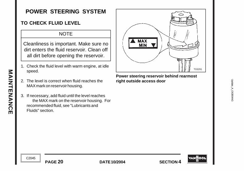
MA
INT
EN
AN
CE
MA
INT
EN
AN
CE
Update_A
_OG
B04A
GU
pdate_A_O
GB
04AG
DATE 10/2004PAGE 20 SECTION 4
DATE 10/2004PAGE 20 SECTION 4C2045
C2045
POWER STEERING SYSTEM
TO CHECK FLUID LEVEL
NOTE
Cleanliness is important. Make sure nodirt enters the fluid reservoir. Clean off
all dirt before opening the reservoir.
1. Check the fluid level with warm engine, at idlespeed.
2. The level is correct when fluid reaches theMAX mark on reservoir housing.
3. If necessary, add fluid until the level reachesthe MAX mark on the reservoir housing. For
recommended fluid, see "Lubricants andFluids" section.
Power steering reservoir behind rearmostright outside access door
T03291
POWER STEERING SYSTEM
TO CHECK FLUID LEVEL
NOTE
Cleanliness is important. Make sure nodirt enters the fluid reservoir. Clean off
all dirt before opening the reservoir.
1. Check the fluid level with warm engine, at idlespeed.
2. The level is correct when fluid reaches theMAX mark on reservoir housing.
3. If necessary, add fluid until the level reachesthe MAX mark on the reservoir housing. Forrecommended fluid, see "Lubricants andFluids" section.
Power steering reservoir behind rearmostright outside access door
T03291

MA
INT
EN
AN
CE
MA
INT
EN
AN
CE
Upd
ate_
A_O
GB
04A
GU
pdat
e_A
_OG
B04
AG
PAGE 21DATE 10/2004
SECTION 4 PAGE 21DATE 10/2004
SECTION 4
C2045
C2045
T00242
TIRES
!!! CAUTION !!!
NO TIRES OF SIZES OR CONSTRUCTIONTYPES OTHER THAN THE ORIGINAL ONES
ARE TO BE FITTED WITHOUT PRIORCONSENT BY VAN HOOL. NEVER FIT TIRESWITH LOWER LOAD OR SPEED RATINGS.
TO CHECK TIRE INFLATIONPRESSURE
Check the inflation pressure of each tire every dayand adjust, if necessary. Correct pressure willprolong tire durability. Underinflation, however,will cause increased fuel consumption and tireoverheating. If tire pressure is too high, the rideand road holding qualities of the vehicle will beimpaired.Use an accurate pressure gauge. The inflationpressures for the standard tires (Goodyear315/80 R22.5 and Firestone 315/80 R22.5) are
mentioned on the vehicle identification plate in thestepwell of the entrance door. Pressure valuesapply to cold tires, i.e. after at least 1 hour ofstandstill. If pressure has dropped more than itnormally does, remove and inspect the tire todetermine the cause.
If your coach is equipped with other tires than thestandard ones, follow the instructions of the tiremanufacturer in relation to the maximum speed,maximum load and inflation pressures.
T00242

MA
INT
EN
AN
CE
MA
INT
EN
AN
CE
Update_A
_OG
B04A
GU
pdate_A_O
GB
04AG
DATE 10/2004PAGE 22 SECTION 4
DATE 10/2004PAGE 22 SECTION 4C2045
C2045
T00237
430 to 450 ft.lbf
TO INSPECT TIRESRemove sharp stones and other foreign bodiesfrom the tire tread. They may cause damage inthe long run.
Replace the tire, if you encounter one of thefollowing signs of damage:
• Bumps, bulges or knots;• Tread cuts, snags or side wall cracks deep
enough to expose cords;• Visible body cords.
Also pay attention to the tread wear patterns.
T00244
ROAD WHEELS
TO CHECK WHEEL NUT TORQUE
Visually check for loose wheel nuts daily.Properwheel nut tightening torque is 430 to 450 ft.lbf.
NOTE
All wheels of the coach have right-handthreads. Whenever a wheel has beenremoved, the wheel nuts should be
checked after 25 miles and after the next50 miles. Tighten the nuts on a daily
basis until the wheel is properly seated.
TO INSPECT TIRESRemove sharp stones and other foreign bodiesfrom the tire tread. They may cause damage inthe long run.
Replace the tire, if you encounter one of thefollowing signs of damage:
• Bumps, bulges or knots;• Tread cuts, snags or side wall cracks deep
enough to expose cords;• Visible body cords.
Also pay attention to the tread wear patterns.
ROAD WHEELS
TO CHECK WHEEL NUT TORQUE
Visually check for loose wheel nuts daily.Properwheel nut tightening torque is 430 to 450 ft.lbf.
NOTE
All wheels of the coach have right-handthreads. Whenever a wheel has beenremoved, the wheel nuts should be
checked after 25 miles and after the next50 miles. Tighten the nuts on a daily
basis until the wheel is properly seated.
T00244
T00237
430 to 450 ft.lbf

MA
INT
EN
AN
CE
MA
INT
EN
AN
CE
Upd
ate_
A_O
GB
04A
GU
pdat
e_A
_OG
B04
AG
PAGE 23DATE 10/2004
SECTION 4 PAGE 23DATE 10/2004
SECTION 4
C2045
C2045
T00251
SUSPENSION
TO CHECK NORMAL BODY GROUNDCLEARANCE
Before commencing daily service, with the vehiclestationary and normal air pressure in the system,visually check that normal body ground clearanceis maintained at both sides of the coach.
TO CHECK SHOCK ABSORBERS
Every week, check front and rear suspensionshock absorbers for:• cracked or pulverised rubber washers of top and
bottom mountings;• dents in the shock body;• signs of oil leaks.
SUSPENSION
TO CHECK NORMAL BODY GROUNDCLEARANCE
Before commencing daily service, with the vehiclestationary and normal air pressure in the system,visually check that normal body ground clearanceis maintained at both sides of the coach.
T00251
TO CHECK SHOCK ABSORBERS
Every week, check front and rear suspensionshock absorbers for:• cracked or pulverised rubber washers of top and
bottom mountings;• dents in the shock body;• signs of oil leaks.

MA
INT
EN
AN
CE
MA
INT
EN
AN
CE
Update_A
_OG
B04A
GU
pdate_A_O
GB
04AG
DATE 10/2004PAGE 24 SECTION 4
DATE 10/2004PAGE 24 SECTION 4C2045
C2045
F04258
BATTERIES
T00268
TO CHECK BATTERY FLUID LEVEL
!!! CAUTION !!!
BATTERIES CONTAIN SULFURIC ACID,WHICH IS HIGHLY CORROSIVE ANDMAY CAUSE BODILY INJURY AND
EQUIPMENT DAMAGE.
The level should reach the bottom of the vent capopening. Use clean or distilled water.
TO CHECK BATTERY CABLES
!!! CAUTION !!!
WHEN REMOVING OR INSTALLINGBATTERY CABLES, ALWAYS REMOVE
GROUND CABLE FIRST AND RECONNECTGROUND CABLE LAST TO AVOIDDANGEROUS SHORT CIRCUITS.
The batteries are located in the compartmentbehind the L.H. tag wheel
BATTERIES
TO CHECK BATTERY FLUID LEVEL
!!! CAUTION !!!
BATTERIES CONTAIN SULFURIC ACID,WHICH IS HIGHLY CORROSIVE AND
MAY CAUSE BODILY INJURY ANDEQUIPMENT DAMAGE.
The level should reach the bottom of the vent capopening. Use clean or distilled water.
TO CHECK BATTERY CABLES
!!! CAUTION !!!
WHEN REMOVING OR INSTALLINGBATTERY CABLES, ALWAYS REMOVE
GROUND CABLE FIRST AND RECONNECTGROUND CABLE LAST TO AVOIDDANGEROUS SHORT CIRCUITS.
F04258
The batteries are located in the compartmentbehind the L.H. tag wheel
T00268

MA
INT
EN
AN
CE
MA
INT
EN
AN
CE
Upd
ate_
A_O
GB
04A
GU
pdat
e_A
_OG
B04
AG
PAGE 25DATE 10/2004
SECTION 4 PAGE 25DATE 10/2004
SECTION 4
C2045
C2045
Check to make sure cable connections are ingood condition, tight and free of corrosion.
T03796
Windshield washer tank
T00266
WINDSHIELD WASHER
TO CHECK FLUID LEVEL
The windshield washer tank is located in the com-partment in front of the L.H. front wheel..
Fill the tank with a proper mixture of clean water andfreeze protection liquid.
Check to make sure cable connections are ingood condition, tight and free of corrosion.
WINDSHIELD WASHER
TO CHECK FLUID LEVEL
The windshield washer tank is located in the com-partment in front of the L.H. front wheel..
Fill the tank with a proper mixture of clean water andfreeze protection liquid.
T00266
T03796
Windshield washer tank

MA
INT
EN
AN
CE
MA
INT
EN
AN
CE
Update_A
_OG
B04A
GU
pdate_A_O
GB
04AG
DATE 10/2004PAGE 26 SECTION 4
DATE 10/2004PAGE 26 SECTION 4C2045
C2045
TOILET
TO DRAIN THE TOILETThe toilet must be drained when the liquid levelreaches the "DUMP LEVEL" on gauge glass (3).
A manually operated slide dump valve is providedat the bottom of the toilet to drain the toilet. Thedump valve is accessible through the enginecompartment.
To drain the toilet:
1. Unlock dump valve handle (4).
2. Pull dump valve handle(4). This dumpscontents of toilet in waste holding tank.
3. To rinse toilet tank: connect a external watersource to coupling (2) and open "TOILETTANK RINSING + FILLING" cock (1). Closecock (1) when toilet tank is rinsed.
4. Close the dump valve, by pushing its handlecompletely, if toilet is empty. Relock valve (4).
TO FILL THE TOILET
1. Connect a external water source to coupling(2).
2. Open " TOILET TANK RINSING + FILLING "cock (1) until water reaches the "FILL LEVEL"on gauge glass (3).
T05572
Lavatory service compartment located at theright in the engine compartment
1. "TOILET TANK RINSING + FILLING" cock2. Exterior water source coupling3. Gauge glass4. Toilet dump valve handle
DUMP LEVEL
FILL LEVEL
T05572
Lavatory service compartment located at theright in the engine compartment
1. "TOILET TANK RINSING + FILLING" cock2. Exterior water source coupling3. Gauge glass4. Toilet dump valve handle
DUMP LEVEL
FILL LEVEL

MA
INT
EN
AN
CE
MA
INT
EN
AN
CE
Upd
ate_
A_O
GB
04A
GU
pdat
e_A
_OG
B04
AG
PAGE 27DATE 10/2004
SECTION 4 PAGE 27DATE 10/2004
SECTION 4
C2045
C2045
F04772
3. Press the flush button and add the properamount of toilet chemical through the bowl.
TO FLUSH
Depress flush button located above the toilet.
TO OPERATE THE TOILET IN COLDWEATHER
In cold weather protect the toilet from freezing so asto avoid damage to certain toilet parts.
Table 1
Tankvolume
gallons
346810121620
Weight (in lbs) of CaCl2 required in
tank to protect to temperature of
10°F
45.38
10.513162127
30°F
0.60.81.31.82.22.53.54.2
20°F
2.83.55.57.59111518
0°F
56.510
13.517202733
Table 2
25%
+10°F
33%
0°F
40%
-12°F
50%
-34°F
% of antifreezerequired in tank
Protects to
3. Press the flush button and add the properamount of toilet chemical through the bowl.
TO FLUSH
Depress flush button located above the toilet.
TO OPERATE THE TOILET IN COLDWEATHER
In cold weather protect the toilet from freezing so asto avoid damage to certain toilet parts.
Tankvolume
gallons
346810121620
Weight (in lbs) of CaCl2 required in
tank to protect to temperature of
10°F
45.38
10.513162127
30°F
0.60.81.31.82.22.53.54.2
20°F
2.83.55.57.59111518
0°F
56.510
13.517202733
Table 2
25%
+10°F
33%
0°F
40%
-12°F
50%
-34°F
% of antifreezerequired in tank
Protects to
Flush button
F04772
Flush button
Table 1

MA
INT
EN
AN
CE
MA
INT
EN
AN
CE
Update_A
_OG
B04A
GU
pdate_A_O
GB
04AG
DATE 10/2004PAGE 28 SECTION 4
DATE 10/2004PAGE 28 SECTION 4C2045
C2045
The toilet chemical will freeze below 30°F.
The first way to protect the toilet assembly in coldweather is to use an anti-freeze solution such asCalcium Chloride (CaCl
2) in the toilet tank.
Depending upon the expected average lowtemperature and the expected accumulation ofwaste in the toilet tank between draining, chargethe toilet according to table 1. The quantity ofCalcium Chloride should never exceed 20 percentby weight. Therefore, the tank contents cannot bekept from freezing below 0°F. Further, theCalcium Chloride must be added in amountsproportional to the amount of waste in the tank toavoid exceeding a 20 percent concentration in thelower temperature protection range.Another way to protect the toilet assembly, shouldit be exposed to extremely cold temperatures; is touse Ethylene Glycol as an anti-freeze solution inthe toilet tank.
Based on the expected average low temperatureand the quantity of waste in the toilet tank, chargethe toilet assembly according to table 2.
!!! CAUTION !!!
ETHYLENE AND PROPYLENE GLYCOL ARETOXIC SUBSTANCES. DO NOT SWALLOW
OR INHALE. THEY CAN IRRITATE THEEYES. IF THE SUBSTANCE HAS BEEN
SWALLOWED, HAVE A FIRST-AIDASSISTANT MAKE THE
VICTIM VOMIT (PROVIDED HE/SHE ISCONSCIOUS). IN CASE OF INHALATION,BRING THE VICTIM INTO THE OPEN AIR.
CALL A DOCTOR IN BOTH CASES. IF EYESHAVE BEEN AFFECTED, RINSE THEM
THOROUGHLY WITH PLENTY OF WATER. CON-SULT A PHYSICIAN IN CASE OF
EYE IRRITATION.
The toilet chemical will freeze below 30°F.
The first way to protect the toilet assembly in coldweather is to use an anti-freeze solution such asCalcium Chloride (CaCl
2) in the toilet tank.
Depending upon the expected average low tempera-ture and the expected accumulation of waste in thetoilet tank between draining, charge the toilet ac-cording to table 1. The quantity of Calcium Chlorideshould never exceed 20 percent by weight. There-fore, the tank contents cannot be kept from freezingbelow 0°F. Further, the Calcium Chloride must beadded in amounts proportional to the amount ofwaste in the tank to avoid exceeding a 20 percentconcentration in the lower temperature protectionrange.Another way to protect the toilet assembly, should itbe exposed to extremely cold temperatures; is to useEthylene Glycol as an anti-freeze solution in the toilettank.
Based on the expected average low temperatureand the quantity of waste in the toilet tank, charge thetoilet assembly according to table 2.
!!! CAUTION !!!
ETHYLENE AND PROPYLENE GLYCOL ARETOXIC SUBSTANCES. DO NOT SWALLOW
OR INHALE. THEY CAN IRRITATE THEEYES. IF THE SUBSTANCE HAS BEEN
SWALLOWED, HAVE A FIRST-AIDASSISTANT MAKE THE
VICTIM VOMIT (PROVIDED HE/SHE ISCONSCIOUS). IN CASE OF INHALATION,BRING THE VICTIM INTO THE OPEN AIR.
CALL A DOCTOR IN BOTH CASES. IF EYESHAVE BEEN AFFECTED, RINSE THEM
THOROUGHLY WITH PLENTY OF WATER. CON-SULT A PHYSICIAN IN CASE OF
EYE IRRITATION.

MA
INT
EN
AN
CE
MA
INT
EN
AN
CE
Upd
ate_
A_O
GB
04A
GU
pdat
e_A
_OG
B04
AG
PAGE 29DATE 10/2004
SECTION 4 PAGE 29DATE 10/2004
SECTION 4
C2045
C2045
F04775
TO CLEAN THE INTERIOR OF THELAVATORY COMPARTMENT
To avoid unintentionally drainage of waste waterwhen cleaning the lavatory compartment withwater, a shut-off valve with a red handle is installedin the lavatory floor drain hose. The valve isaccessible through the luggage compartment doorbehind the right tag wheel and is labeled"RESTROOM FLOOR DRAIN".
Restroom floor drain shut-off valve
WASTE HOLDING TANKThe waste holding tank is located behind theengine compartment side-door, at the right of thecoach.
A manually operated slide dump valve is providedat the bottom of the tank to drain the tank.
To drain the tank:
1. Position the coach so that the waste holdingtank outlet is over a receptable or sewer inletor other facilities to comply with local healthregulations.
2. Unlock dump valve handle.
3. Pull dump valve handle.
4. Return the handle to its original position whenthe waste holding tank is empty. relock dumpvalve.
TO CLEAN THE INTERIOR OF THELAVATORY COMPARTMENT
To avoid unintentionally drainage of waste waterwhen cleaning the lavatory compartment withwater, a shut-off valve with a red handle is installedin the lavatory floor drain hose. The valve isaccessible through the luggage compartment doorbehind the right tag wheel and is labeled"RESTROOM FLOOR DRAIN".
WASTE HOLDING TANKThe waste holding tank is located behind theengine compartment side-door, at the right of thecoach.
A manually operated slide dump valve is providedat the bottom of the tank to drain the tank.
To drain the tank:
1. Position the coach so that the waste holdingtank outlet is over a receptable or sewer inletor other facilities to comply with local healthregulations.
2. Unlock dump valve handle.
3. Pull dump valve handle.
4. Return the handle to its original position whenthe waste holding tank is empty. relock dumpvalve.
F04775
Restroom floor drain shut-off valve

MA
INT
EN
AN
CE
MA
INT
EN
AN
CE
Update_A
_OG
B04A
GU
pdate_A_O
GB
04AG
DATE 10/2004PAGE 30 SECTION 4
DATE 10/2004PAGE 30 SECTION 4C2045
C2045
APPEARANCE CARE
!!! CAUTION !!!
WHEN USING CLEANING AGENTS OROTHER CHEMICALS, FOLLOW THE
MANUFACTURER'S ADVICE.
COACH EXTERIOR
Paint
General instructions for washing
• Wash the body thoroughly with plenty ofpreferably soft water.
• Only use non-abrasive, non-corrosive fluidcleaning agents. Always use the quantitiesindicated by the manufacturer of the cleaningagent.
• Always pre-wash the coach with clean water toremove any sand that might damage the finishduring the complete wash. Use a soft brushwithout applying any pressure.
• To actually wash the vehicle, use a sponge or asoft car brush with a rubber or soft syntheticbody.
• Soak dried insects with a special agentavailable in retail before removing them.
• Rinse the body thoroughly with soft water.Soap residue may damage the paint finish overtime.
• After rinsing, the body can be dried with achamois.
To wash with an automatic washing facility
NOTE
Before having the coach cleaned in anautomatic washing facility, remove theside mirrors, close the ventilation flaps
and switch off the HVAC system.
APPEARANCE CARE
!!! CAUTION !!!
WHEN USING CLEANING AGENTS OROTHER CHEMICALS, FOLLOW THE
MANUFACTURER'S ADVICE.
COACH EXTERIOR
Paint
General instructions for washing
• Wash the body thoroughly with plenty ofpreferably soft water.
• Only use non-abrasive, non-corrosive fluidcleaning agents. Always use the quantitiesindicated by the manufacturer of the cleaningagent.
• Always pre-wash the coach with clean water toremove any sand that might damage the finishduring the complete wash. Use a soft brushwithout applying any pressure.
• To actually wash the vehicle, use a sponge or asoft car brush with a rubber or soft synthetic body.
• Soak dried insects with a special agentavailable in retail before removing them.
• Rinse the body thoroughly with soft water.Soap residue may damage the paint finish overtime.
• After rinsing, the body can be dried with achamois.
To wash with an automatic washing facility
NOTE
Before having the coach cleaned in anautomatic washing facility, remove theside mirrors, close the ventilation flaps
and switch off the HVAC system.

MA
INT
EN
AN
CE
MA
INT
EN
AN
CE
Upd
ate_
A_O
GB
04A
GU
pdat
e_A
_OG
B04
AG
PAGE 31DATE 10/2004
SECTION 4 PAGE 31DATE 10/2004
SECTION 4
C2045
C2045
To remove the side mirror:
1. Disconnect power plug.
2. Pull up and remove mirror and arm.
To wash with high-pressure cleaners
• High-pressure cleaners remove dirt, but not thegreasy film on the vehicle body. To remove thisfilm, a brush or a sponge are still necessary.
• Keep the hand wand nozzle at least one footaway from the paint and do not aim the wand at aparticular spot for too long. Otherwise, if thewater is warm, you risk driving the dirt into thepaint.
!!! CAUTION !!!
WHEN USING A HIGH-PRESSURECLEANING FACILITY, KEEP THE
TEMPERATURE BELOW 150°F ANDWATER PRESSURE BELOW 700 PSI.
To remove tar
• Remove tar spots with a special agent or withdenatured alcohol. Apply the cleaning agent witha soft cloth and rub the affected spots lightly. Donot press too hard to prevent scratching the finishwith particles of sand that may be stuck in the tar.
• After having removed the tar, wash and rinsethe treated spots.
To wax-coat the paint
• It is a good idea to wax-coat your vehicle afterwinter with a liquid, non-corrosive polish.Previously wash and dry the vehicle bodythoroughly.
• In order to restore the original gloss of worn orspotted paint, a light rubber compound or polishmay be used. Rub evenly and not too long on aparticular spot to prevent the paint from becomingtoo thin. Apply a layer of fixing wax immediatelyafter treatment with cleaner.

MA
INT
EN
AN
CE
MA
INT
EN
AN
CE
Update_A
_OG
B04A
GU
pdate_A_O
GB
04AG
DATE 10/2004PAGE 32 SECTION 4
DATE 10/2004PAGE 32 SECTION 4C2045
C2045
!!! CAUTION !!!
DO NOT TREAT METALLIC PAINT WITH ANORDINARY CLEANER, AS THE PAINT
MAY DULL AS A RESULT OF THIS.
Coach understructure
• Once a year, after winter, the vehicleunderstructure has to be cleaned and inspected.
• First wash the understructure with a handwand to remove all the mud and salt. The watershould not contain any detergents or oilderivatives as these attack the rust-preventivelayer. The hand wand pressure should notexceed 700 psi.
• When the understructure is clean, check formissing areas of undercoating protection. Oncethe under-structure is completely dry, spray theaffected areas with a high-quality rust-preventiveagent such as KATCHUTEX WAX (from ADSChemicals) and DINITROL METALLIC.
NOTE
If you have to spray rust-preventiveliquid near compressed-air apparatus,
first seal all openings or dampers.
Measures against corrosion
• Make sure the vehicle is always parked underthe best possible conditions.
• Pay strict attention to the understructuremaintenance instructions mentioned above.
• After each wash, check the body paint forcracks and damage due to road chippings.Cover interrupted areas as quickly as possiblewith paint to prevent corrosion from spreadingunder the paint.
• Have any accident damage repaired as quicklyas possible to prevent corrosion.
• As soon as corroded areas are spotted, takeevery precaution to prevent the corrosion from
!!! CAUTION !!!
DO NOT TREAT METALLIC PAINT WITH ANORDINARY CLEANER, AS THE PAINTMAY DULL AS A RESULT OF THIS.
Coach understructure
• Once a year, after winter, the vehicleunderstructure has to be cleaned and inspected.
• First wash the understructure with a hand wandto remove all the mud and salt. The water shouldnot contain any detergents or oil derivatives asthese attack the rust-preventive layer. The handwand pressure should not exceed 700 psi.
• When the understructure is clean, check formissing areas of undercoating protection. Oncethe under-structure is completely dry, spray theaffected areas with a high-quality rust-preventiveagent such as KATCHUTEX WAX (from ADSChemicals) and DINITROL METALLIC.
NOTE
If you have to spray rust-preventiveliquid near compressed-air apparatus,
first seal all openings or dampers.
Measures against corrosion
• Make sure the vehicle is always parked underthe best possible conditions.
• Pay strict attention to the understructuremaintenance instructions mentioned above.
• After each wash, check the body paint forcracks and damage due to road chippings.Cover interrupted areas as quickly as possiblewith paint to prevent corrosion from spreadingunder the paint.
• Have any accident damage repaired as quicklyas possible to prevent corrosion.
• As soon as corroded areas are spotted, takeevery precaution to prevent the corrosion from

MA
INT
EN
AN
CE
MA
INT
EN
AN
CE
Upd
ate_
A_O
GB
04A
GU
pdat
e_A
_OG
B04
AG
PAGE 33DATE 10/2004
SECTION 4 PAGE 33DATE 10/2004
SECTION 4
C2045
C2045
spreading. Do not put off repair for more than3 months, otherwise the affected component willbe completely beyond saving.
• Every 2 years, the frame tubes located entirelyor partly under floor level should be injected witha high-quality rust-preventive liquid for hollowspaces such as TECTYL or DINITROLPENETRANT. The body posts are open at thebottom; holes have been drilled in the horizontaltubes that have to be treated.
To clean anodized aluminium
• Clean anodized aluminium parts with neutral,non-abrasive synthetic agents (certainly not withchrome polish or products containing sodium,ammonia, chlorohydric acid or phosphoric acid).
• Never treat stubborn stains with steel wool.The extremely thin protective layer will bescrubbed off and the aluminium will oxidize. Ifnecessary, use a non-abrasive polyamide woolenscrub pad (e.g. 3M Scotch Brite dish scourer).
• Rinse the aluminium abundantly to remove allcleaning agent.
To clean chromed parts
• Wash chromed parts with soapy water andrinse abundantly.
• Polish chromed parts in poor state.
• Protect chromed parts during the cold seasonby treating them with a special protective waxavailable in retail.
COACH INTERIOR
To clean leatherette
• Clean the leatherette from time to time withlukewarm soapy water and rinse with a mixture ofwater and a bit of vinegar.
• Stubborn spots can be removed with denaturedalcohol. Before treating large areas, always test asmall area for discoloration.
• To keep the leatherette supple, sponge it witha mixture of 3 U.S. Qts of water, 1 pint of milkand a handful of kitchen salt. Do not rinse. Drywith a chamois. Wring the chamois regularly.
spreading. Do not put off repair for more than3 months, otherwise the affected component willbe completely beyond saving.
• Every 2 years, the frame tubes located entirelyor partly under floor level should be injected witha high-quality rust-preventive liquid for hollowspaces such as TECTYL or DINITROLPENETRANT. The body posts are open at thebottom; holes have been drilled in the horizontaltubes that have to be treated.
To clean anodized aluminium
• Clean anodized aluminium parts with neutral,non-abrasive synthetic agents (certainly not withchrome polish or products containing sodium,ammonia, chlorohydric acid or phosphoric acid).
• Never treat stubborn stains with steel wool.The extremely thin protective layer will bescrubbed off and the aluminium will oxidize. Ifnecessary, use a non-abrasive polyamide woolenscrub pad (e.g. 3M Scotch Brite dish scourer).
• Rinse the aluminium abundantly to remove allcleaning agent.
To clean chromed parts
• Wash chromed parts with soapy water andrinse abundantly.
• Polish chromed parts in poor state.
• Protect chromed parts during the cold seasonby treating them with a special protective waxavailable in retail.
COACH INTERIOR
To clean leatherette
• Clean the leatherette from time to time withlukewarm soapy water and rinse with a mixture ofwater and a bit of vinegar.
• Stubborn spots can be removed withdenatured alcohol. Before treating large areas,always test a small area for discoloration.
• To keep the leatherette supple, sponge it witha mixture of 3 U.S. Qts of water, 1 pint of milkand a handful of kitchen salt. Do not rinse. Drywith a chamois. Wring the chamois regularly.
MA
INT
EN
AN
CE
MA
INT
EN
AN
CE
Update_A
_OG
B04A
GU
pdate_A_O
GB
04AG
DATE 10/2004PAGE 34 SECTION 4
DATE 10/2004PAGE 34 SECTION 4C2045
C2045
To clean moquette upholstery
• Clean the seat upholstery weekly with avacuum cleaner.
• If necessary, moquette can be cleaned with asolution of mild soap in cold water. This soapsolution must be applied in small doses with asponge or a soft brush. Rub with the grain of thefabric. Remove the soap solution with a damp,clean cloth or sponge. Then rub the treated areaseveral times with a dry cloth. Subsequently rubthe still moist moquette with a fairly hard brush.Finally, when the upholstery is dry, rub it onceagain with the grain of the fabric.
• The look of the moquette seats can berevitalized by steaming. Put a damp cloth over theseat upholstery and press it with a hot iron. Thesteam will penetrate the fabric fibers and makethem stand upright again.
To remove stains from fabric upholstery
• Deal with stains as quickly as possible. Oncethey dry or oxidize, they will be much harder toremove.
• Use a reputable cleaning agent available inretail, appropriate for the nature of the stain and
harmless to the fabric (check on packaging). Alsoregular household agents may be used. Consult afabric stain reference list to find out what agent ismost appropriate.
• If the nature of the stain is unknown, first treatit with a solution of water and detergent. If thestain persists, use a dry cleaning agent once thefabric has completely dried again.
• Use only white cloths or paper kitchen towels toapply the cleaning agent.
• Fresh coffee or cocoa stains are not hard toremove. Just rub them with a solution ofdetergent and lukewarm water. When the stainshave dried, however, it is practically impossible toremove them.
• Felt-tip marker stains can only be removedwith alcohol, felt pen stains with trichlorethylene,and nail polish with acetone.
• Remove chewing gum by freezing it with aspray, smashing it and scraping it off.
• Always test chemical cleaning agents on asmall non-obtrusive area to check fordiscoloration or damage.
To clean moquette upholstery
• Clean the seat upholstery weekly with avacuum cleaner.
• If necessary, moquette can be cleaned with asolution of mild soap in cold water. This soapsolution must be applied in small doses with asponge or a soft brush. Rub with the grain of thefabric. Remove the soap solution with a damp,clean cloth or sponge. Then rub the treated areaseveral times with a dry cloth. Subsequently rubthe still moist moquette with a fairly hard brush.Finally, when the upholstery is dry, rub it onceagain with the grain of the fabric.
• The look of the moquette seats can berevitalized by steaming. Put a damp cloth over theseat upholstery and press it with a hot iron. Thesteam will penetrate the fabric fibers and makethem stand upright again.
To remove stains from fabric upholstery
• Deal with stains as quickly as possible. Oncethey dry or oxidize, they will be much harder toremove.
• Use a reputable cleaning agent available inretail, appropriate for the nature of the stain and
harmless to the fabric (check on packaging). Alsoregular household agents may be used. Consult afabric stain reference list to find out what agent ismost appropriate.
• If the nature of the stain is unknown, first treatit with a solution of water and detergent. If thestain persists, use a dry cleaning agent once thefabric has completely dried again.
• Use only white cloths or paper kitchen towelsto apply the cleaning agent.
• Fresh coffee or cocoa stains are not hard toremove. Just rub them with a solution of detergentand lukewarm water. When the stains have dried,however, it is practically impossible to removethem.
• Felt-tip marker stains can only be removedwith alcohol, felt pen stains with trichlorethylene,and nail polish with acetone.
• Remove chewing gum by freezing it with aspray, smashing it and scraping it off.
• Always test chemical cleaning agents on asmall non-obtrusive area to check fordiscoloration or damage.

MA
INT
EN
AN
CE
MA
INT
EN
AN
CE
Upd
ate_
A_O
GB
04A
GU
pdat
e_A
_OG
B04
AG
PAGE 35DATE 10/2004
SECTION 4 PAGE 35DATE 10/2004
SECTION 4
C2045
C2045
• Ventilate the vehicle interior well while usingchemical agents.
To wash crepe headrest covers
• Do not use softener as this will deteriorate thecovers.
• Use a mild washing powder in warm water(approx. 86°F). Rinse well in clean water anddrip dry (do not wring). Do not use bleach.
To clean ABS plastic parts
!!! CAUTION !!!
SOLVENTS LIKE TERPENTINE, PAINTTHINNER, TRICHLORETHYLENE OR
DRY-CLEANING NAPHTA CAN DAMAGEABS PLASTIC.
• Sponge ABS plastic with a solution of warmwater and soap. Use a soft brush and apply onlylittle pressure to remove stubborn stains.
• Restore the original lustre of ABS parts using aspecial product available in retail.
!!! CAUTION !!!
DO NOT APPLY POLISH ON THESTEERING WHEEL OR ON ABS SEATS ASTHEY WOULD BECOME TOO SLIPPERY.
To clean perspex plastic panels
!!! CAUTION !!!
SOLVENTS LIKE TERPENTINE, PAINTTHINNER, TRICHLORETHYLENE ORDRY-CLEANING NAPHTA ATTACK
PERSPEX PLASTIC.
• Never rub perspex plastic, when it is dry.
• Wash the panel thoroughly, then dry it with aperfectly clean chamois. After washing, apply anantistatic polish.
• Minor scratches can be removed with a specialpolish available in retail.

MA
INT
EN
AN
CE
MA
INT
EN
AN
CE
Update_A
_OG
B04A
GU
pdate_A_O
GB
04AG
DATE 10/2004PAGE 36 SECTION 4
DATE 10/2004PAGE 36 SECTION 4C2045
C2045
To check/clean safety belts
• Replace the belt, in case of mechanism failureor, if the fabric is torn or frayed.
• If necessary, hand-wash the seat belt in asolution of warm water and neutral soap. Do notwash the buckles! Rinse thoroughly and let dry(out of the sun).
• Do not strain the belt while it is wet. This couldbe detrimental to the fabric strength. For thesame reason, never bleach or dye the seat beltfabric.

AP
PE
ND
ICE
SA
PP
EN
DIC
ES
Upd
ate
B_O
GB
05A
FU
pdat
e B
_OG
B05
AF
SECTION 5 PAGE 1DATE 10/2004
SECTION 5 PAGE 1DATE 10/2004
C2045
C2045
APPENDICESLUBRICANTS AND FLUIDS
ENGINE LUBRICATING OIL RECOMMENDATIONS
Cummins engine ............................................................................................................. page 4Detroit Diesel engine ....................................................................................................... page 5Caterpillar engine ............................................................................................................ page 5
FUEL RECOMMENDATIONS
Cummins engine ............................................................................................................. page 7Detroit Diesel engine ....................................................................................................... page 7Caterpillar engine ............................................................................................................ page 8
COOLANT RECOMMENDATIONS
Cummins engine ............................................................................................................. page 9Detroit Diesel engine ....................................................................................................... page 10Caterpillar engine ............................................................................................................ page 11
AUTOMATIC TRANSMISSION FLUID RECOMMENDATIONS
Allison WTB500(R) .......................................................................................................... page 12ZF Astronic ..................................................................................................................... page 12
DRIVE AXLE OIL RECOMMENDATIONS ........................................................................... page 13
Oil viscosity recommendations ........................................................................................ page 13

AP
PE
ND
ICE
S
Update B
_OG
B05A
FU
pdate B_O
GB
05AF
AP
PE
ND
ICE
S
PAGE 2 DATE 10/2004 SECTION 5
DATE 10/2004PAGE 2 SECTION 5C2045
C2045
POWER STEERING FLUID RECOMMENDATIONS ............................................................ page 13
CONVERSION FACTORS ............................................................................... page 14
ELECTRICAL SYSTEM (non-mùltiplexed vehicles)
FUSES
Mega® fuses .................................................................................................................... page 16Maxifuses ....................................................................................................................... page 16Autofuses ........................................................................................................................ page 17
CIRCUIT BREAKERS .......................................................................................................... page 17
In main junction box ........................................................................................................ page 17In ISM/DDEC junction box ............................................................................................... page 20
ELECTRICAL SYSTEM (multiplexed vehicles)
FUSES
Mega® fuses .................................................................................................................... page 22Maxifuses ....................................................................................................................... page 22Autofuses ........................................................................................................................ page 23
AP
PE
ND
ICE
SA
PP
EN
DIC
ES
Upd
ate
B_O
GB
05A
FU
pdat
e B
_OG
B05
AF
SECTION 5 PAGE 3DATE 10/2004
SECTION 5 PAGE 3DATE 10/2004
C2045
C2045
CIRCUIT BREAKERS .......................................................................................................... page 24
In main junction box ........................................................................................................ page 24In toilet compartment junction box ................................................................................... page 26In front junction box ......................................................................................................... page 26

AP
PE
ND
ICE
S
Update B
_OG
B05A
FU
pdate B_O
GB
05AF
AP
PE
ND
ICE
S
PAGE 4 DATE 10/2004 SECTION 5
DATE 10/2004PAGE 4 SECTION 5C2045
C2045
LUBRICANTS AND FLUIDS
ENGINE LUBRICATING OILRECOMMENDATIONS
Cummins engine
Engine sump capacity (without oil filter:
Max. level ................... 9 U.S. gallonsMin. level .................... 7 U.S. gallons
The use of high-quality engine lubricating oils andappropriate oil drain and filter change intervals arecritical factors in maintaining engine performanceand durability.
ISM01-engine: Cummins Inc. recommends theuse of a high-quality 15W-40 multiviscosity heavy-duty engine oil that meets the requirements ofCummins Engineering Specification CES 20071 orCES 20076. American Petroleum Institute (API)specification CH-4 can be used as an alternativeto CES 20071.
ISM02-engine: Cummins Inc. recommends theuse of a high-quality 15W-40 multiviscosity heavy-duty engine oil that meets the requirements of
Cummins Engineering Specifications CES 20078or CES 20076. The oil grades CC, CD, CE, CF, orCG have been obsoleted by API and must not beused.
Synthetic engine oils, API category III, arerecommended for use in Cummins enginesoperating in ambient temperature conditionsconsistently below -13°F. Above this temperature,petroleum-based multigrade lubricants arerecommended. Synthetic 0W-30 oils that meetAPI category III can be used in operations wherethe ambient temperature never exceeds 32°F.Multiviscosity oils rated 0W-30 do not offer thesame level of protection against fuel dilution as dohigher multigrade oils. Higher cylinder wear can beexperienced when using 0W-30 oils in high-loadsituations.
For further details and an explanation of enginelubricating oils for Cummins engines, refer toCummins Engine Oil Recommendations, BulletinNo.3810340.
Oil viscosity should be chosen according to thetypical climate conditions experienced by theuser. Use of 15W-40 is recommended for the best
LUBRICANTS AND FLUIDS
ENGINE LUBRICATING OILRECOMMENDATIONS
Cummins engine
Engine sump capacity (without oil filter):
Max. level ................... 9 U.S. gallonsMin. level .................... 7 U.S. gallons
The use of high-quality engine lubricating oils andappropriate oil drain and filter change intervals arecritical factors in maintaining engine performanceand durability.
ISM01-engine: Cummins Inc. recommends theuse of a high-quality 15W-40 multiviscosity heavy-duty engine oil that meets the requirements ofCummins Engineering Specification CES 20071 orCES 20076. American Petroleum Institute (API)specification CH-4 can be used as an alternativeto CES 20071.
ISM02-engine: Cummins Inc. recommends theuse of a high-quality 15W-40 multiviscosity heavy-duty engine oil that meets the requirements of
Cummins Engineering Specifications CES 20078or CES 20076. The oil grades CC, CD, CE, CF, orCG have been obsoleted by API and must not beused.
Synthetic engine oils, API category III, arerecommended for use in Cummins enginesoperating in ambient temperature conditionsconsistently below -13°F. Above this temperature,petroleum-based multigrade lubricants arerecommended. Synthetic 0W-30 oils that meetAPI category III can be used in operations wherethe ambient temperature never exceeds 32°F.Multiviscosity oils rated 0W-30 do not offer thesame level of protection against fuel dilution as dohigher multigrade oils. Higher cylinder wear can beexperienced when using 0W-30 oils in high-loadsituations.
For further details and an explanation of enginelubricating oils for Cummins engines, refer toCummins Engine Oil Recommendations, BulletinNo.3810340.
Oil viscosity should be chosen according to thetypical climate conditions experienced by theuser. Use of 15W-40 is recommended for the best

AP
PE
ND
ICE
SA
PP
EN
DIC
ES
Upd
ate
B_O
GB
05A
FU
pdat
e B
_OG
B05
AF
SECTION 5 PAGE 5DATE 10/2004
SECTION 5 PAGE 5DATE 10/2004
C2045
C2045
engine durability at higher ambient temperature.For temperature or cold conditions, 10W-30 or5W-30 viscosity can be used for easier starting,improved oil flow, and improved fuel economy.
!!! CAUTION !!!
THE USE OF A SYNTHETIC BASE OIL DOESNOT JUSTIFY EXTENDED OIL CHANGEINTERVALS. EXTENDED OIL CHANGE
INTERVALS CAN DECREASE ENGINE LIFEDUE TO FACTORS SUCH AS CORROSION,
DEPOSITS AND WEAR.
Detroit Diesel engine
Engine oil pan capacity (without oil filters):
• Full mark ...........................32 U.S. Qts• Low mark ..........................26 U.S. Qts
Total oil capacity of the engine: 40 U.S. Qts to thefull mark (with oil filters installed and filters and oilgalleries charged).
Detroit Diesel recommend the use of a highquality SAE 15W-40 oil meeting API performanceclassification:
• CH-4 or equivalent for engines without ExhaustGas Recirculation
• CI-4 or equivalent for engines with Exhaust GasRecirculation (Engine models: 6067MK2E,6067MV2E)
T02716

AP
PE
ND
ICE
S
Update B
_OG
B05A
FU
pdate B_O
GB
05AF
AP
PE
ND
ICE
S
PAGE 6 DATE 10/2004 SECTION 5
DATE 10/2004PAGE 6 SECTION 5C2045
C2045
Caterpillar engine
Engine oil pan capacity (without oil filter):
• Full mark .............................................• Low mark ............................................
Caterpillar recommend the use of API CI-4 oil thatmeets the Caterpillar requirements.
The proper viscosity grade of oil is determined bythe minimum ambient temperature during coldengine start-up, and the maximum ambienttemperature during engine operation (refer to table).
SAE 0W-20SAE 0W-30SAE 0W-40SAE 5W-30SAE 5W-40SAE 10W-30SAE 10W-40SAE 15W-40
-40°F-40°F-40°F-22°F-22°F0°F0°F15°F
50°F86°F104°F86°F122°F104°F122°F122°F
Viscosity GradeMinimum
temperatureMaximum
temperature

AP
PE
ND
ICE
SA
PP
EN
DIC
ES
Upd
ate
B_O
GB
05A
FU
pdat
e B
_OG
B05
AF
SECTION 5 PAGE 7DATE 10/2004
SECTION 5 PAGE 7DATE 10/2004
C2045
C2045
FUEL RECOMMENDATIONS
Fuel tank capacity: 120 or 245 U.S. gallons.
Cummins engine
!!! CAUTION !!!
DO NOT MIX GASOLINE, ALCOHOL, ORGASOHOL WITH DIESEL FUEL. THIS
MIXTURE CAN CAUSE AN EXPLOSION.
DUE TO THE PRECISE TOLERANCES OFDIESEL INJECTION SYSTEMS, IT IS
EXTREMELY IMPORTANT THAT THE FUELBE KEPT CLEAN AND FREE OF DIRT OR
WATER. DIRT OR WATER IN THE SYSTEMMAY CAUSE SEVERE DAMAGE TO BOTH
THE FUEL INJECTION PUMP AND THEFUEL INJECTORS.
Cummins Engine Company, Inc., recommend theuse of ASTM No. 2D diesel fuel. The use of No.2D diesel fuel will result in optimum engineperformance. At operating temperatures below32°F, acceptable performance can be obtained byusing blends of No. 2D diesel and No. 1D diesel.
NOTE
LIGHTER FUELS CAN REDUCE FUELECONOMY.
The viscocity of the fuel must be kept above1.3 cST at 104°F to provide adequate fuel systemlubrication.
Detroit Diesel engine
!!! CAUTION !!!
THE FUEL USED MUST BE CLEAN,COMPLETELY DISTILLED, STABLE, AND
NON-CORROSIVE.
Fuel must meet the properties of ASTMdesignation D 975 (grades 1-D and 2-D).
NOTE
DO NOT USE FUEL WITH SULFUR CONTENTABOVE 0.05 MASS PERCENT FOR DETROIT
DIESEL EGR ENGINES.

AP
PE
ND
ICE
S
Update B
_OG
B05A
FU
pdate B_O
GB
05AF
AP
PE
ND
ICE
S
PAGE 8 DATE 10/2004 SECTION 5
DATE 10/2004PAGE 8 SECTION 5C2045
C2045
Caterpillar engine
Caterpillar recommend that all distillate diesel fuel,including ULSD fuel (ie fuel containing 15 ppm orless sulfur using ASTM D2622 or DIN 51400) meetthe requirements of the Caterpillar Specificationsfor Distillate Diesel Fuel.In North America, diesel fuel that is identified asNo.1-D or No. 2-D in "ASTM D975" generally meetthe specifications.
NOTE
OPERATING WITH FUELS THAT DO NOTMEET CATERPILLAR'S RECOMMENDATIONS
CAN CAUSE THE FOLLOWING EFFECTS:STARTING DIFFICULTY, POOR COMBUSTION,
DEPOSITS IN THE FUEL INJECTORS,REDUCED SERVICE LIFE OF THE FUEL
SYSTEM, DEPOSITS IN THE COMBUSTIONCHAMBER, AND REDUCED SERVICE LIFE OF
THE ENGINE.
NOTE
REFER TO SPECIAL PUBLICATION,SEBU6385, "CATERPILLAR ON-HIGHWAY
DIESEL TRUCK ENGINE FLUIDSRECOMMENDATIONS" FOR THE
CATERPILLAR SPECIFICATIONS FORDISTILLATE FUEL AND FOR ADDITIONALINFORMATION THAT RELATES TO FUEL
FOR YOUR ENGINE.
Caterpillar engine
Caterpillar recommend that all distillate diesel fuel,including ULSD fuel (ie fuel containing 15 ppm orless sulfur using ASTM D2622 or DIN 51400) meetthe requirements of the Caterpillar Specificationsfor Distillate Diesel Fuel.In North America, diesel fuel that is identified asNo.1-D or No. 2-D in "ASTM D975" generally meetthe specifications.
NOTE
OPERATING WITH FUELS THAT DO NOTMEET CATERPILLAR'S RECOMMENDATIONS
CAN CAUSE THE FOLLOWING EFFECTS:STARTING DIFFICULTY, POOR COMBUSTION,
DEPOSITS IN THE FUEL INJECTORS,REDUCED SERVICE LIFE OF THE FUEL
SYSTEM, DEPOSITS IN THE COMBUSTIONCHAMBER, AND REDUCED SERVICE LIFE
OF THE ENGINE.
NOTE
REFER TO SPECIAL PUBLICATION,SEBU6385, "CATERPILLAR ON-HIGHWAY
DIESEL TRUCK ENGINE FLUIDSRECOMMENDATIONS" FOR THE
CATERPILLAR SPECIFICATIONS FORDISTILLATE FUEL AND FOR ADDITIONALINFORMATION THAT RELATES TO FUEL
FOR YOUR ENGINE.
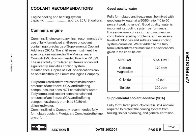
AP
PE
ND
ICE
SA
PP
EN
DIC
ES
Upd
ate
B_O
GB
05A
FU
pdat
e B
_OG
B05
AF
SECTION 5 PAGE 9DATE 10/2004
SECTION 5 PAGE 9DATE 10/2004
C2045
C2045
COOLANT RECOMMENDATIONS
Engine cooling and heating systemcapacity: ........................ approx. 26 U.S. gallons.
Cummins engine
Cummins Engine company, Inc., recommends theuse of fully formulated antifreeze or coolantcontaining a precharge of Supplemental CoolantAdditives (SCA). The antifreeze must meet thespecifications outlined in The MaintenanceCouncil (TMC) Recommended Practice RP 329.The use of fully formulated antifreeze or coolantsignificantly simplifies cooling systemmaintenance. Copies of TMC specifications canbe obtained through Cummins Engine Company.
Fully formulated antifreeze contains balancedamounts of antifreeze, SCA, and bufferingcompounds, but does NOT contain 50% water.Fully formulated coolant contains balancedamounts of antifreeze, SCA, and bufferingcompounds already premixed 50/50 withdeionized water.Cummins Engine Company recommended fullyformulated coolant: Fleetguard Compleat (ethelyneglycol form).
Good quality water
Fully formulated antifreeze must be mixed withgood quality water at a 50/50 ratio (40 to 60percent working range). Good quality water isimportant for cooling system performance.Excessive levels of calcium and magnesiumcontribute to scaling problems, and excessivelevels of chlorides and sulfates cause coolingsystem corrosion. Water added to the fullyformulated antifreeze must meet specificationsgiven in the chart below.
MAX. LIMIT
170 ppm
40 ppm
100 ppm
MINERAL
CalciumMagnesium
Chloride
Sulfate
Supplemental coolant additive (SCA)
Fully formulated products contain SCA and arerequired to protect the cooling system fromfouling, solder blooming, and general corrosion.

AP
PE
ND
ICE
S
Update B
_OG
B05A
FU
pdate B_O
GB
05AF
AP
PE
ND
ICE
S
PAGE 10 DATE 10/2004 SECTION 5
DATE 10/2004PAGE 10 SECTION 5C2045
C2045
The recommended concentration level of DCA 4 is1.5 units per U.S. gallon. The DCA 4 concentra-tion must never exceed 3.0 units per U.S. gallonnor fall below 1.2 units per U.S. gallon.
Detroit Diesel engine
!!! CAUTION !!!
LONG LIFE COOLANT WITH NITRITE ISNOT SUITABLE FOR USE INDETROIT DIESEL ENGINES.
Water requirements
Distilled or de-ionized water which eliminates theadverse effects of minerals in tap water ispreferred. High levels of dissolved chlorides,sulfates, magnesium, and calcium in some tapwater causes scale deposits, sludge depositsand/or corrosion. These deposits have beenshown to result in water pump failures and poorheat transfer, resulting in over-heating. If tap wateris used, the mineral content in the water must bebelow the maximum allowable limits shown in thetable.
Antifreeze
Use genuine Detroit Diesel "Power Cool". DetroitDiesel part number 23512138.
Antifreeze must be used in any climate for bothfreeze and boiling point protection. Detroit Dieselrecommend a 50 % "Power Cool" antifreeze /water solution in most climates. Concentrationsover 67 % are not recommended because of thepoor heat transfer, reduced freeze protection andpossible silicate dropout. An antifreezeconcentration below 33 % offers too little freezeand/or corrosion protection and is notrecommended.
Maximum allowable limits for mineralsin water
Parts permillion
40100340
170
Grains pergallon
2.55.820
10
•••••Chlorides•••••Sulfates•••••Total dissolved solids•••••Total hardness
magnesium &calcium
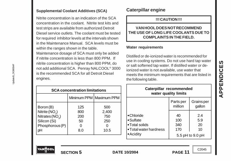
AP
PE
ND
ICE
SA
PP
EN
DIC
ES
Upd
ate
B_O
GB
05A
FU
pdat
e B
_OG
B05
AF
SECTION 5 PAGE 11DATE 10/2004
SECTION 5 PAGE 11DATE 10/2004
C2045
C2045
Supplemental Coolant Additives (SCA)
Nitrite concentration is an indication of the SCAconcentration in the coolant. Nitrite test kits andtest strips are available from authorized DetroitDiesel service outlets. The coolant must be testedfor required inhibitor levels at the intervals shownin the Maintenance Manual. SCA levels must bewithin the ranges shown in the table.Maintenance dosage of SCA must only be addedif nitrite concentration is less than 800 PPM. Ifnitrite concentration is higher than 800 PPM, donot add additional SCA. Penray NALCOOL® 3000is the recommended SCA for all Detroit Dieselengines.
SCA concentration limitations
Minimum PPM
125800200500
8.0
Maximum PPM
5002,4007502500
10.5
Boron (B)Nitrite (NO
2)
Nitrates (NO3)
Silicon (Si)Phosphorous (P)pH
Caterpillar engine
!!! CAUTION !!!
VAN HOOL DOES NOT RECOMMENDTHE USE OF LONG LIFE COOLANTS DUE TO
COMPLAINTS IN THE FIELD.
Water requirements
Distilled or de-ionized water is recommended foruse in cooling systems. Do not use hard tap wateror salt softened tap water. If distilled water or de-ionized water is not available, use water thatmeets the minimum requirements that are listed inthe following table.
Caterpillar recommendedwater quality limits
Parts permillion
40100340170
Grains pergallon
2.45.92010
•••••Chloride•••••Sulfate•••••Total solids•••••Total water hardness•••••Acidity 5.5 pH to 9.0 pH

AP
PE
ND
ICE
S
Update B
_OG
B05A
FU
pdate B_O
GB
05AF
AP
PE
ND
ICE
S
PAGE 12 DATE 10/2004 SECTION 5
DATE 10/2004PAGE 12 SECTION 5C2045
C2045
Antifreeze
Acceptable antifreeze/coolant: Caterpillar DieselEngine Antifreeze/Coolant (DEAC) or acommercial heavy-duty coolant/antifreeze thatmeets "ASTM D4985", or "ASTM D6210"specifications.
Antifreeze must be used in any climate for bothfreeze and boiling point protection. Caterpillarrecommend a 50 % antifreeze / water solution inmost climates.
Supplemental Coolant Additives (SCA)
Supplemental Coolant Additives (SCA) help toprotect the metal surfaces of the cooling system.Many additives are depleted during engineoperation. These additives must be replacedperiodically. This can be done by adding liquidSCA.
Caterpillar DEAC does not require a treatmentwith Caterpillar SCA at the initial fill. When acommercial heavy-duty coolant/antifreeze is used,the system must be treated with Caterpillar SCAto a concentration level that is between 3 percentand 6 percent by volume of the system.
AUTOMATIC TRANSMISSION FLUIDRECOMMENDATIONS
Allison WTB500(R)
Capacity:
• Initial fill ......................... approx. 47 U.S. Qts• Refill after oil change ...... approx. 37 U.S. Qts
DEXRON-III and C-4 fluids are recommended.
NOTE
FROM JANUARY 2002 ONWARDS, THETRANSMISSION IS FACTORY FILLED WITH
"TRANSYND TM SYNTHETIC AUTOMATICTRANSMISSION FLUID". THESE
TRANSMISSIONS HAVE A SMALL PLASTICTAG TO THE FILL TUBE OR DIPSTICK.
ZF Astronic
Capacity: approx. 11 U.S. Qts.
Fluid to ZF lubricant list TE-ML 02. This list can befound on the internet at "www.zf.com".

AP
PE
ND
ICE
SA
PP
EN
DIC
ES
Upd
ate
B_O
GB
05A
FU
pdat
e B
_OG
B05
AF
SECTION 5 PAGE 13DATE 10/2004
SECTION 5 PAGE 13DATE 10/2004
C2045
C2045
SAE 85W-140
SAE 80W-140
SAE 80W-90
SAE 75W
1008668503210-4-15-40°F
DRIVE AXLE OIL RECOMMENDATIONS
Capacity: approx. 20 U.S. Qts.
Multigrade gear lubricants meeting therequirements of military specificationMIL-L-2105D are recommended.
Oil viscosity recommendations
Oil viscosity should be selected on the basis ofthe ambient temperature range the vehiclenormally operates in. See table, for right oilviscosity.
POWER STEERING FLUIDRECOMMENDATIONS
Capacity: approx. 9.3 U.S. Qts.
DEXRON-IID, -IIE, -III fluids are recommended.
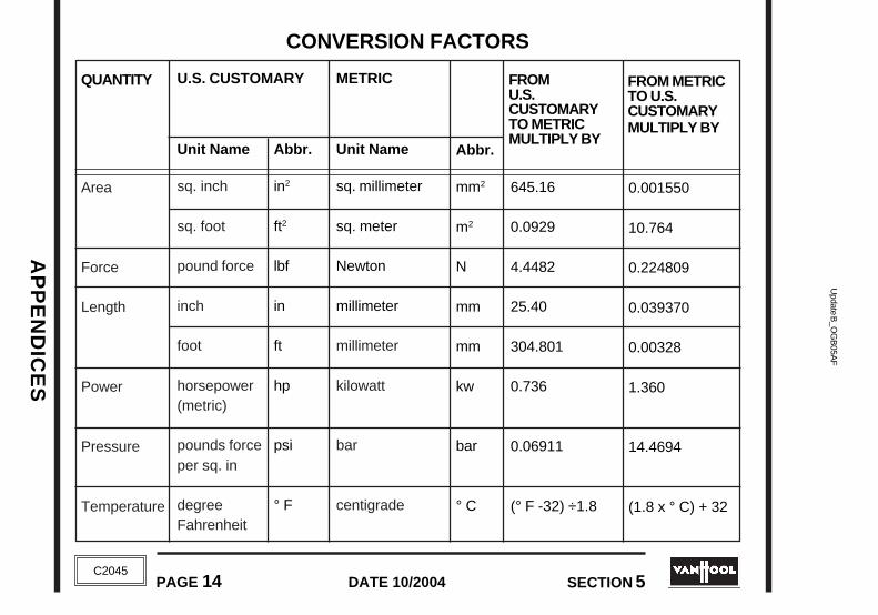
AP
PE
ND
ICE
S
Update B
_OG
B05A
FU
pdate B_O
GB
05AF
AP
PE
ND
ICE
S
PAGE 14 DATE 10/2004 SECTION 5
DATE 10/2004PAGE 14 SECTION 5C2045
C2045
CONVERSION FACTORS
QUANTITY
Area
Force
Length
Power
Pressure
Temperature
FROMU.S.CUSTOMARYTO METRICMULTIPLY BY
FROM METRICTO U.S.CUSTOMARYMULTIPLY BY
U.S. CUSTOMARY
Unit Name
sq. inch
sq. foot
pound force
inch
foot
horsepower(metric)
pounds forceper sq. in
degreeFahrenheit
Abbr.
in2
ft2
lbf
in
ft
hp
psi
° F
METRIC
Unit Name
sq. millimeter
sq. meter
Newton
millimeter
millimeter
kilowatt
bar
centigrade
Abbr.
mm2
m2
N
mm
mm
kw
bar
° C
645.16
0.0929
4.4482
25.40
304.801
0.736
0.06911
(° F -32) ÷1.8
0.001550
10.764
0.224809
0.039370
0.00328
1.360
14.4694
(1.8 x ° C) + 32

AP
PE
ND
ICE
SA
PP
EN
DIC
ES
Upd
ate
B_O
GB
05A
FU
pdat
e B
_OG
B05
AF
SECTION 5 PAGE 15DATE 10/2004
SECTION 5 PAGE 15DATE 10/2004
C2045
C2045
CONVERSION FACTORS (continued)
Newton-meter
Newton-meter
kilometers/hour
liter
liter
cubic centimeter
kilogram
0.737562
8.850756
0.6214
0.264179
61.02545
0.06102
2.204623
1.35582
0.113
1.6093
3.7853
0.01639
16.387
0.4536
Nm
Nm
kph
l
l
cm3
kg
METRIC
Unit Name
QUANTITY U.S. CUSTOMARY
Unit Name Abbr. Abbr.
FROMU.S.CUSTOMARYTO METRICMULTIPLY BY
FROM METRICTO U.S.CUSTOMARYMULTIPLY BY
pound forceper foot
pound forceper inch
miles/hour
gallon (U.S.)
cubic inch
cubic inch
pound(avoir.)
ft.lbf
in.lbf
mph
gal
in3
in3
lb
Torque
Velocity
Volume:liquiddisplace-ment
Weight(mass)

AP
PE
ND
ICE
S
Update B
_OG
B05A
FU
pdate B_O
GB
05AF
AP
PE
ND
ICE
S
PAGE 16 DATE 10/2004 SECTION 5
DATE 10/2004PAGE 16 SECTION 5C2045
C2045
No.
0206
AMP
125 A125 A
DESCRIPTION
Main fuse "HVAC"Main fuse "Main junction box"
FUSES
Mega® fuses
The main circuits areprotected by Mega® fuseslocated in the batteryjunction box.T03785
T03786
ELECTRICAL SYSTEM(NON-MULTIPLEXED VEHICLES)
MAINJUNCTION
BOX
HVACJUNCTION
BOX
T05409
BATTERYJUNCTION BOX
Location of junction boxes
ISM/DDECJUNCTION BOX
MaxifusesThese are located in the mainjunction box and the batteryjunction box.
In main junction box
No.
010151
AMP
30 A30 A
DESCRIPTION
StarterMain fuse "+12 VDC"
C2045
No.
0206
AMP
125 A125 A
DESCRIPTION
Main fuse "HVAC"Main fuse "Main junction box"
FUSES
Mega® fuses
The main circuits areprotected by Mega® fuseslocated in the batteryjunction box.T03785
T03786
MaxifusesThese are located in the mainjunction box and the batteryjunction box.
In main junction box
No.
010151
AMP
30 A30 A
DESCRIPTION
StarterMain fuse "+12 VDC"
JUNCTION BOXOF RHS ROOF
BLOWERS
JUNCTION BOXOF LHS ROOF
BLOWERS
MAINJUNCTION
BOX
HVACJUNCTION
BOX
T05409
BATTERYJUNCTION BOX
Location of junction boxes
ISM/DDECJUNCTION BOX
C2045
JUNCTION BOXOF RHS ROOF
BLOWERS
JUNCTION BOXOF LHS ROOF
BLOWERS
ELECTRICAL SYSTEM(NON-MULTIPLEXED VEHICLES)

AP
PE
ND
ICE
SA
PP
EN
DIC
ES
Upd
ate
B_O
GB
05A
FU
pdat
e B
_OG
B05
AF
SECTION 5 PAGE 17DATE 10/2004
SECTION 5 PAGE 17DATE 10/2004
C2045
C2045
T03788
CIRCUIT BREAKERSMost subcircuits areprotected by circuitbreakers. They are ofthe manual resettype. When a circuitbreaker is overloaded,the reset button popsout, thus opening thecircuit. To reset thecircuit breaker, push
the reset button. If the circuit breaker pops outagain, have the electrical circuit checked.
In main junction box
In battery junction box
No.
1588
89.189.2150201
AMP
30 A30 A30 A30 A50 A50 A
DESCRIPTION
Main fuse "audio/video"Main fuse "B+"
Main fuse "engine supply"Main fuse "transmission supply"
Main fuse "+12 VDC"110V system
AUTOFUSES
These are located in the mainjunction box.
T03786
No.
43154155
156
AMP
3 A10 A10 A
3 A
DESCRIPTION
• DDEC ProDriver• audio/video• Flasher and buzzer at
entrance door indicating thecoach is lowering/raising,audio/video +12VDC
• Amplifier antenna
PROTECTED CIRCUITS
• switched D+signal
• Defroster fan
• Defroster fan
• stop lights
• socket for +24VDC portablelamp, starter switch in enginecompartment
AMP
8 A
15 A
15 A
8 A
8 A
No.
20
22.1
23
23.1
25
RESET BUTTON
MANUAL RELEASE
T03788
CIRCUIT BREAKERSMost subcircuits areprotected by circuitbreakers. They are ofthe manual resettype. When a circuitbreaker is overloaded,the reset button popsout, thus opening thecircuit. To reset thecircuit breaker, push
the reset button. If the circuit breaker pops outagain, have the electrical circuit checked.
In main junction box
In battery junction box
No.
1588
89.189.2150201
AMP
30 A30 A30 A30 A50 A50 A
DESCRIPTION
Main fuse "audio/video"Main fuse "B+"
Main fuse "engine supply"Main fuse "transmission supply"
Main fuse "+12 VDC"110V system
AUTOFUSES
These are located in the mainjunction box.
T03786
No.
43154155
156
AMP
3 A10 A10 A
3 A
DESCRIPTION
• DDEC ProDriver• audio/video• Flasher and buzzer at
entrance door indicating thecoach is lowering/raising,audio/video +12VDC
• Amplifier antenna
PROTECTED CIRCUITS
• switched D+signal
• Defroster fan
• Defroster fan
• stop lights
• socket for +24VDC portablelamp,starter switch in enginecompartment
AMP
8 A
15 A
15 A
8 A
8 A
No.
20
22.1
23
23.1
25
RESET BUTTON
MANUAL RELEASE

AP
PE
ND
ICE
S
Update B
_OG
B05A
FU
pdate B_O
GB
05AF
AP
PE
ND
ICE
S
PAGE 18 DATE 10/2004 SECTION 5
DATE 10/2004PAGE 18 SECTION 5C2045
C2045
AMP
15 A
15 A
15 A
8 A
8 A
8 A
8 A
8 A
8 A
8 A
8 A
PROTECTED CIRCUITS
• aisle light (white)
• reading lights
• reading lights
• luggage compartment lightscontrol
• Road Relay (Cummins)
• toilet
• +12 VDC main relay control
• ISM diagnostics (Cummins)
• digital clock• speed switch
• exitation alternator D+• engine stop• brake light switches
• tag axle unloading• Flasher and buzzer at entrance
door indicating the coach islowering/raising
• suspension raise/lowersystem
No.
26
28
29
29.2
30
31
32
33
34
35
36.1
PROTECTED CIRCUITS
• luggage compartment lights,cigarette lighter
• entrance light• "Watch your step" light• interior light control
• spotlights wheelchair lift
• amplifier speakers
• marker lights relay• neutral/parking brake relay• ignition switch• DDEC/ISM security
• windshield wipers
• ABS
• ABS
• aisle night lights• hatrack night lights
• map light• driver's light• First aisle light• guide/video light
• aisle light (white)
AMP
8 A
8 A
8 A
8 A
8 A
15 A
10 A
10 A
15 A
8 A
15 A
No.
36.2
37.1
37.2
39
42
46.1
47
49
50
51
52
AMP
15 A
15 A
15 A
8 A
8 A
8 A
8 A
8 A
8 A
8 A
8 A
PROTECTED CIRCUITS
• aisle light (white)
• reading lights
• reading lights
• luggage compartment lightscontrol
• Road Relay (Cummins)
• toilet
• +12 VDC main relay control
• ISM diagnostics (Cummins)
• digital clock• speed switch
• exitation alternator D+• engine stop• brake light switches
• tag axle unloading• Flasher and buzzer at entrance
door indicating the coach islowering/raising
• suspension raise/lowersystem
No.
26
28
29
29.2
30
31
32
33
34
35
36.1
PROTECTED CIRCUITS
• luggage compartment lights,cigarette lighter
• entrance light• "Watch your step" light• interior light control
• spotlights wheelchair lift
• amplifier speakers
• marker lights relay• neutral/parking brake relay• ignition switch• DDEC/ISM security
• windshield wipers
• ABS
• ABS
• aisle night lights• hatrack night lights
• map light• driver's light• First aisle light• guide/video light
• aisle light (white)
AMP
8 A
8 A
8 A
8 A
8 A
15 A
10 A
10 A
15 A
8 A
15 A
No.
36.2
37.1
37.2
39
42
46.1
47
49
50
51
52

AP
PE
ND
ICE
SA
PP
EN
DIC
ES
Upd
ate
B_O
GB
05A
FU
pdat
e B
_OG
B05
AF
SECTION 5 PAGE 19DATE 10/2004
SECTION 5 PAGE 19DATE 10/2004
C2045
C2045
No.
80
81.1
82
83.1
83.2
93
94.1
94.2
95
96
97
98
131
152
153
PROTECTED CIRCUITS
• master switch supply
• turn signals• Road Relay (Cummins)
• digital clock• combustion heater timer
• combustion heater
• combustion heater
• marker lights(RHS)
• transmission selector light• dashboard lights
• marker lights(LHS)• lights in switches
• headlights, low beam
• headlights, low beam
• headlights, high beam
• headlights, high beam
• Defroster
• + 12 VDC CB socket
• + 12 VDC audio/video,marker lights
AMP
8 A
10 A
8 A
15 A
15 A
8 A
8 A
8 A
8 A
8 A
8 A
8 A
8 A
8 A
15 A
No.
53
54
55
56
57
58
59
60
61
62
65
66
AMP
8 A
8 A
8 A
8 A
8 A
8 A
8 A
8 A
8 A
8 A
8 A
6 A
PROTECTED CIRCUITS
• windshield wipers/washers• side mirror adjustment• horn
• exterior lights control
• turn signals
• starter override switch in en-gine compartment
• driver's side window
• battery equalizer +15• dashboard supply• Jake Brake
• stepwell lights
• backup lights• Road Relay control (Cummins)
• cooling fan clutch
• air dryer
• Destination sign unit
• Fresh air flap interior
• ABS
No.
80
81.1
82
83.1
83.2
93
94.1
94.2
95
96
97
98
131
152
153
PROTECTED CIRCUITS
• master switch supply
• turn signals• Road Relay (Cummins)
• digital clock• combustion heater timer
• combustion heater
• combustion heater
• marker lights(RHS)
• transmission selector light• dashboard lights
• marker lights(LHS)• lights in switches
• headlights, low beam
• headlights, low beam
• headlights, high beam
• headlights, high beam
• Defroster
• + 12 VDC CB socket
• + 12 VDC audio/video,marker lights
AMP
8 A
10 A
8 A
15 A
15 A
8 A
8 A
8 A
8 A
8 A
8 A
8 A
8 A
8 A
15 A
No.
53
54
55
56
57
58
59
60
61
62
65
66
AMP
8 A
8 A
8 A
8 A
8 A
8 A
8 A
8 A
8 A
8 A
8 A
6 A
PROTECTED CIRCUITS
• windshield wipers/washers• side mirror adjustment• horn
• exterior lights control
• turn signals
• starter override switch in en-gine compartment
• driver's side window
• battery equalizer +15• dashboard supply• Jake Brake
• stepwell lights
• backup lights• Road Relay control (Cummins)
• cooling fan clutch
• air dryer
• Destination sign unit
• Fresh air flap interior
• ABS

AP
PE
ND
ICE
S
Update B
_OG
B05A
FU
pdate B_O
GB
05AF
AP
PE
ND
ICE
S
PAGE 20 DATE 10/2004 SECTION 5
DATE 10/2004PAGE 20 SECTION 5C2045
C2045
No.
185
PROTECTED CIRCUITS
• Entrance door
AMP
8 A
PROTECTED CIRCUITS
• DDEC ignition supply(Detroit Diesel)
• DDEC supply (Detroit Diesel)
• DDEC supply (Detroit Diesel)
• D+ alternator 2
• D+ alternator 1
• "W" terminal of alternator
In ISM/DDEC junction box
No.
F1
F4
F5
70
71
79
AMP
6 A
15 A
15 A
8 A
8 A
6 A
No.
185
PROTECTED CIRCUITS
• Entrance door
AMP
8 A
PROTECTED CIRCUITS
• DDEC ignition supply(Detroit Diesel)
• DDEC supply (Detroit Diesel)
• DDEC supply (Detroit Diesel)
• D+ alternator 2
• D+ alternator 1
• "W" terminal of alternator
In ISM/DDEC junction box
No.
F1
F4
F5
70
71
79
AMP
6 A
15 A
15 A
8 A
8 A
6 A
AP
PE
ND
ICE
SA
PP
EN
DIC
ES
Upd
ate
B_O
GB
05A
FU
pdat
e B
_OG
B05
AF
SECTION 5 PAGE 21DATE 10/2004
SECTION 5 PAGE 21DATE 10/2004
C2045
C2045

AP
PE
ND
ICE
S
Update B
_OG
B05A
FU
pdate B_O
GB
05AF
AP
PE
ND
ICE
S
PAGE 22 DATE 10/2004 SECTION 5
DATE 10/2004PAGE 22 SECTION 5C2045
C2045
No.
02
05
06
AMP
125 A
100 A
125 A
DESCRIPTION
Main fuse "HVAC"
Wheelchair lift
Main fuse "Main junction box"
FUSES
Mega® fuses
The main circuits are protectedby Mega® fuses located in thebattery junction box and in thetoiletcompartment junction box.
T03785
T03786
ELECTRICAL SYSTEM(MULTIPLEXED VEHICLES)
MaxifusesThese are located in the mainjunction box and the battery junctionbox.
In main junction box
No.
130151
AMP
50 A30 A
DESCRIPTION
Node 1Main fuse "+12 VDC"
ELECTRICAL SYSTEM(MULTIPLEXED VEHICLES)
No.
02
05
06
AMP
125 A
100 A
125 A
DESCRIPTION
Main fuse "HVAC"
Wheelchair lift
Main fuse "Main junction box"
FUSES
Mega® fuses
The main circuits are protectedby Mega® fuses located in thebattery junction box and in thetoiletcompartment junction box.
T03785
T03786
MaxifusesThese are located in the mainjunction box and the battery junctionbox.
In main junction box
No.
130151
AMP
50 A30 A
DESCRIPTION
Node 1Main fuse "+12 VDC"
MAINJUNCTION
BOX
HVACJUNCTION BOX
T06265
BATTERYJUNCTION BOX
Location of junction boxes
ISM/DDECJUNCTION BOX
C2045
JUNCTION BOXOF RHS ROOF
BLOWERS
JUNCTION BOXOF LHS ROOF
BLOWERS
FRONTJUNCTION BOX
JUNCTION BOXIN TOILET
COMPARTMENT
MAINJUNCTION
BOX
HVACJUNCTION BOX
T06265
BATTERYJUNCTION BOX
Location of junction boxes
ISM/DDECJUNCTION BOX
C2045
JUNCTION BOXOF RHS ROOF
BLOWERS
JUNCTION BOXOF LHS ROOF
BLOWERS
FRONTJUNCTION BOX
JUNCTION BOXIN TOILET
COMPARTMENT

AP
PE
ND
ICE
SA
PP
EN
DIC
ES
Upd
ate
B_O
GB
05A
FU
pdat
e B
_OG
B05
AF
SECTION 5 PAGE 23DATE 10/2004
SECTION 5 PAGE 23DATE 10/2004
C2045
C2045
In battery junction box
No.
1015848588
89.189.2150
AMP
30 A30 A80 A40 A30 A30 A30 A50 A
DESCRIPTION
Starter motorMain fuse "audio/video"
Battery equalizerBattery equalizerMain fuse "B+"
Main fuse "engine supply"Main fuse "transmission supply"
Main fuse "+12 VDC"
AUTOFUSES
These are located in the mainjunction box.
T03786
No.
43154
AMP
3 A10 A
DESCRIPTION
• DDEC ProDriver• audio/video
No.
155
156158
AMP
10 A
3 A15 A
DESCRIPTION
• Flasher and buzzer atentrance door indicating thecoach is lowering/raising,audio/video +12VDC
• Amplifier antenna• Front fog lights
In main junction box
Midi® fusesThese are located in thetoilet compartment junctionbox.
No.
F1MF2M
AMP
50 A50 A
DESCRIPTION
• HVAC system• HVAC system
T03785

AP
PE
ND
ICE
S
Update B
_OG
B05A
FU
pdate B_O
GB
05AF
AP
PE
ND
ICE
S
PAGE 24 DATE 10/2004 SECTION 5
DATE 10/2004PAGE 24 SECTION 5C2045
C2045
In main junction box
PROTECTED CIRCUITS
• wheelchair lift
• defroster fan
• defroster fan
• socket for +24VDC portablelamp, starter switch in enginecompartment
• luggage compartment lights
• amplifier speakers
• ABS
• ABS
• guide/video light
• side mirror adjustment
• voltage reference, cigarettelighter
• Road Relay (Cummins)• starter• DDEC/ISM security• Jake Brake
AMP
10 A
15 A
15 A
8 A
15 A
8 A
10 A
10 A
8 A
8 A
8 A
8 A
No.
16
22.1
23
25
26
29.2
32
33
35
36
39
42
T03788
CIRCUIT BREAKERS
RESET BUTTON
MANUAL RELEASE
Most subcircuits are protected by circuit breakers.They are of the manual reset type. When a circuitbreaker is overloaded, the reset button pops out,thus opening the circuit. To reset the circuitbreaker, push the reset button. If the circuitbreaker pops out again, have the electrical circuitchecked.
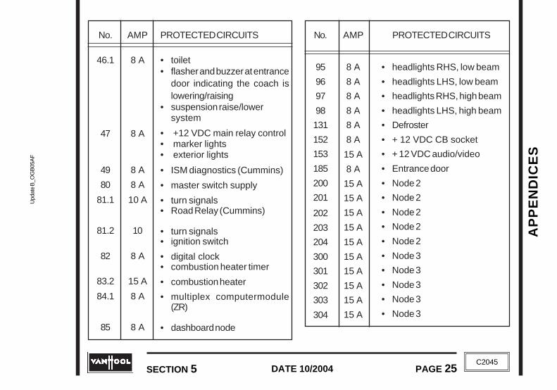
AP
PE
ND
ICE
SA
PP
EN
DIC
ES
Upd
ate
B_O
GB
05A
FU
pdat
e B
_OG
B05
AF
SECTION 5 PAGE 25DATE 10/2004
SECTION 5 PAGE 25DATE 10/2004
C2045
C2045
No.
95
96
97
98
131
152
153
185
200
201
202
203
204
300
301
302
303
304
PROTECTED CIRCUITS
• headlights RHS, low beam
• headlights LHS, low beam
• headlights RHS, high beam
• headlights LHS, high beam
• Defroster
• + 12 VDC CB socket
• + 12 VDC audio/video
• Entrance door
• Node 2
• Node 2
• Node 2
• Node 2
• Node 2
• Node 3
• Node 3
• Node 3
• Node 3
• Node 3
AMP
8 A
8 A
8 A
8 A
8 A
8 A
15 A
8 A
15 A
15 A
15 A
15 A
15 A
15 A
15 A
15 A
15 A
15 A
AMP
8 A
8 A
8 A
8 A
10 A
10
8 A
15 A
8 A
8 A
PROTECTED CIRCUITS
• toilet• flasher and buzzer at entrance
door indicating the coach islowering/raising
• suspension raise/lowersystem
• +12 VDC main relay control• marker lights• exterior lights
• ISM diagnostics (Cummins)
• master switch supply
• turn signals• Road Relay (Cummins)
• turn signals• ignition switch
• digital clock• combustion heater timer
• combustion heater
• multiplex computermodule(ZR)
• dashboard node
No.
46.1
47
49
80
81.1
81.2
82
83.2
84.1
85
No.
95
96
97
98
131
152
153
185
200
201
202
203
204
300
301
302
303
304
PROTECTED CIRCUITS
• headlights RHS, low beam
• headlights LHS, low beam
• headlights RHS, high beam
• headlights LHS, high beam
• Defroster
• + 12 VDC CB socket
• + 12 VDC audio/video
• Entrance door
• Node 2
• Node 2
• Node 2
• Node 2
• Node 2
• Node 3
• Node 3
• Node 3
• Node 3
• Node 3
AMP
8 A
8 A
8 A
8 A
8 A
8 A
15 A
8 A
15 A
15 A
15 A
15 A
15 A
15 A
15 A
15 A
15 A
15 A
AMP
8 A
8 A
8 A
8 A
10 A
10
8 A
15 A
8 A
8 A
PROTECTED CIRCUITS
• toilet• flasher and buzzer at entrance
door indicating the coach islowering/raising
• suspension raise/lowersystem
• +12 VDC main relay control• marker lights• exterior lights
• ISM diagnostics (Cummins)
• master switch supply
• turn signals• Road Relay (Cummins)
• turn signals• ignition switch
• digital clock• combustion heater timer
• combustion heater
• multiplex computermodule(ZR)
• dashboard node
No.
46.1
47
49
80
81.1
81.2
82
83.2
84.1
85

AP
PE
ND
ICE
S
Update B
_OG
B05A
FU
pdate B_O
GB
05AF
AP
PE
ND
ICE
S
PAGE 26 DATE 10/2004 SECTION 5
DATE 10/2004PAGE 26 SECTION 5C2045
C2045
In front junction box
PROTECTED CIRCUITS
• Windshield wipers
• Node 1
• Node 1
• Node 1
• Node 1
• Node 1
• Diagnostics
AMP
15 A
15 A
15 A
15 A
15 A
15 A
8 A
No.
31
100
101
102
103
104
105
In toilet compartment junction box
PROTECTED CIRCUITS
• Node 4
• Node 4
• Node 4
• Node 4
• Node 4
• Node 5
• Node 5
• Node 5
• Node 5
• Node 5
• Node 6
• Node 6
• Node 6
• Node 6
• Node 6
AMP
15 A
15 A
15 A
15 A
15 A
15 A
15 A
15 A
15 A
15 A
15 A
15 A
15 A
15 A
15 A
No.
400
401
402
403
404
500
501
502
503
504
600
601
602
603
604

UP
DA
TE
S A
ND
AD
DIT
ION
SU
PD
AT
ES
AN
D A
DD
ITIO
NS
OG
B06
AF
OG
B06
AF
SECTION 6 PAGE 1DATE 10/2004
SECTION 6 PAGE 1DATE 10/2004
C2045
C2045
UPDATES AND ADDITIONS
ZF ASTRONIC TRANSMISSION
Introduction ........................................................................................................................... page 3Push-button shift selector ..................................................................................................... page 3Automatic mode .................................................................................................................... page 5Manual mode ........................................................................................................................ page 5To operate ............................................................................................................................. page 5
ZF INTARDER
Introduction ......................................................................................................................... page 14Message on multifunction display ....................................................................................... page 14To operate ........................................................................................................................... page 14
MECHANICAL BATTERY ISOLATING SWITCH ....................................................................... page 15

UP
DA
TE
S A
ND
AD
DIT
ION
S
OG
B06A
FO
GB
06AF
UP
DA
TE
S A
ND
AD
DIT
ION
S
C2045PAGE 2 DATE 10/2004 SECTION 6
PAGE 2 SECTION 6DATE 10/2004C2045

UP
DA
TE
S A
ND
AD
DIT
ION
SU
PD
AT
ES
AN
D A
DD
ITIO
NS
OG
B06
AF
OG
B06
AF
SECTION 6 PAGE 3DATE 10/2004
SECTION 6 PAGE 3DATE 10/2004
C2045
C2045
ZF ASTRONIC TRANSMISSION
INTRODUCTION
The ZF ASTRONIC is a 12-speed auto-shiftingelectronically controlled mechanical typetransmission. Because the clutch operation isalso controlled by the gear shift system, there isno need for a clutch pedal.
PUSH-BUTTON SHIFT SELECTOR
The push-button shift selector has six push-buttons and a digital display. The six push-buttonsare identified as "R", "N", "D", "↑" (up arrow), "↓"(down arrow) and "Fn".
• "R": reverse• "N": neutral (no gears selected
in transmission)• "D": forward• "↑": Upshift• "↓": downshift• "Fn": to change between
automatic and manual mode.
The buttons "R", "N" and "D" contain a led. Theled:• flashes when a range change is requested;• illuminates when the range change iscompleted.
The "R", "N" and "D" buttons respond oncereleased. If the buttons are held down for morethan 5 seconds, the shift is ignored.
The ↑ ", "↓" and "Fn" buttons respond immediately.

UP
DA
TE
S A
ND
AD
DIT
ION
S
OG
B06A
FO
GB
06AF
UP
DA
TE
S A
ND
AD
DIT
ION
S
C2045PAGE 4 DATE 10/2004 SECTION 6
PAGE 4 SECTION 6DATE 10/2004C2045
Messages on display
Gear shift system self-check.Comes on when you switch on thevehicle ignition.
Transmission in neutral.
Transmission in reverse.
Gear shift system in automaticmode (indicated by two bars andtwo arrows). In this example: 4thgear selected.
Gear shift system in manualmode (no bars or arrowsdisplayed). In this example: 4thgear selected.
Insufficient compressed-airsupply. Alternates with the normaldisplay.
Throttle pedal error.Remedy: Release the throttlepedal. If the message does notdisappear, there is a systemerror. Vehicle can not be drivenany further.
Clutch overloaded.This message alternates with thenormal display.Remedy: refer to instructionsunder "Clutch protection". furtheron.
Clutch wear.Remedy: visit nearest specializedworkshop to replace the clutch.
Serious failure in gear shiftsystem.Stop vehicle. The vehicle must notbe driven further. Call for technicalassistance.

UP
DA
TE
S A
ND
AD
DIT
ION
SU
PD
AT
ES
AN
D A
DD
ITIO
NS
OG
B06
AF
OG
B06
AF
SECTION 6 PAGE 5DATE 10/2004
SECTION 6 PAGE 5DATE 10/2004
C2045
C2045
AUTOMATIC MODE
"D" button pushed. The gear shift system selectsthe proper gear. If the throttle pedal is depressed,the clutch will be engaged automatically and thevehicle will be put in motion. Upshifting anddownshifting will be performed automatically bythe gear shift system.
Gear shifts resulting in engine over-revving orstalling are ignored in the automatic mode.
You can always intervene manually by pushingthe "↑" or "↓ " button (back-off of throttle pedal notnecessary).
MANUAL MODE
The manual mode is selected with the "Fn"button.
If the throttle pedal is depressed, the clutch will beengaged automatically and the vehicle will be putin motion. Upshifting and downshifting is done withthe "↑" and "↓" buttons.
Avoid gear shifts resulting in engine over-revving.
Engine may stall if the throttle pedal is depressedwith the transmission in a too high gear.
TO OPERATE
!!! CAUTION!!!
DO NOT LEAVE YOUR SEAT WITH THEENGINE RUNNING AND TRANSMISSIONIN GEAR. THE ZF ASTRONIC DOES NOT
HAVE A PARK POSITION.
To start engine
1. Apply the parking brake.
2. Switch on ignition. On the display appears themessage "CH".
3. Start the engine. The message "CH" changesinto "N" to indicate that the self test is com-pleted and the transmission is in neutral. TheLED of the "N" button illuminates as soon asthe gear shift system has detected neutral.If the air pressure is low, wait until the "AL"message that alternates with the "N" messagedisappears.
NOTE:
GEAR SHIFTS ARE ONLY POSSIBLEWHEN THE ENGINE IS RUNNING.

UP
DA
TE
S A
ND
AD
DIT
ION
S
OG
B06A
FO
GB
06AF
UP
DA
TE
S A
ND
AD
DIT
ION
S
C2045PAGE 6 DATE 10/2004 SECTION 6
PAGE 6 SECTION 6DATE 10/2004C2045
To drive off, forward travel
1. Start the engine (refer to "To start the engine")earlier in this chapter.
2. Depress the brake pedal and push the "D"button. The automatic mode is selected.
On the display appears the driving-off gearselected by the gear shift system. The led ofthe "D" button illuminates (clutch still remainsdisengaged at this stage).
3. Release the parking brake.
!!! CAUTION !!!
THE VEHICLE MAY ROLL AWAY EVEN IF THETHROTTLE PEDAL IS NOT DEPRESSED.
4. Release the brake pedal and depress thethrottle pedal.
The clutch will be engaged automatically andthe vehicle starts to move.
"Easy start" system. This system keeps airpressure in the drive axle service brake cham-bers for about 2 seconds after releasing thebrake pedal. This prevents the coach fromrolling away between releasing the brake pedal
and activating the throttle pedal. The systemworks only when vehicle is stopped. Note thatthe pressure in the drive axle service airchambers depends on the position of the brakepedal at release.
To change driving-off gear
To change the driving-off gear: push the "↑" or "↓"button. The display shows the selected driving-offgear.
To manoeuvre
1st gear, 2nd gear, and reverse have been set upas manoeuvring gears for extremely slow travel.Manoeuvring mode is not available in the othergears.The gear shift system detects manoeuvringcondition by the position of the throttle pedal andthe low vehicle speed. In manoeuvring modeengine responds to throttle pedal movement andclutch control differs from the normal driving mode.
!!! CAUTION !!!
CHANGING FROM MANOEUVRING MODE TONORMAL DRIVING MODE IS PERFORMED
To drive off, forward travel
1. Start the engine (refer to "To start the engine")earlier in this chapter.
2. Depress the brake pedal and push the "D"button. The automatic mode is selected.
On the display appears the driving-off gearselected by the gear shift system. The led ofthe "D" button illuminates (clutch still remainsdisengaged at this stage).
3. Release the parking brake.
!!! CAUTION !!!
THE VEHICLE MAY ROLL AWAY EVEN IF THETHROTTLE PEDAL IS NOT DEPRESSED.
4. Release the brake pedal and depress thethrottle pedal.
The clutch will be engaged automatically andthe vehicle starts to move.
"Easy start" system. This system keeps airpressure in the drive axle service brake cham-bers for about 2 seconds after releasing thebrake pedal. This prevents the coach fromrolling away between releasing the brake pedal
and activating the throttle pedal. The systemworks only when the vehicle is stopped. Notethat the pressure in the drive axle service airchambers depends on the position of the brakepedal at release.
To change driving-off gear
To change the driving-off gear: push the "↑" or "↓"button. The display shows the selected driving-offgear.
To manoeuvre
1st gear, 2nd gear, and reverse have been set upas manoeuvring gears for extremely slow travel.Manoeuvring mode is not available in the othergears.The gear shift system detects manoeuvringcondition by the position of the throttle pedal andthe low vehicle speed. In manoeuvring modeengine responds to throttle pedal movement andclutch control differs from the normal driving mode.
!!! CAUTION !!!
CHANGING FROM MANOEUVRING MODE TONORMAL DRIVING MODE IS PERFORMED

UP
DA
TE
S A
ND
AD
DIT
ION
SU
PD
AT
ES
AN
D A
DD
ITIO
NS
OG
B06
AF
OG
B06
AF
SECTION 6 PAGE 7DATE 10/2004
SECTION 6 PAGE 7DATE 10/2004
C2045
C2045
AUTOMATICALLY AND DEPENDS ONTHROTTLE PEDAL POSITION AND VEHICLE
SPEED. DURING THIS CHANGE THE VEHICLEMAY ACCELERATE SUDDENLY. ACCIDENT
HAZARD.
To roll from up or down grades
Precondition: engine running
!!! CAUTION!!!
DO NOT ALLOW THE VEHICLE TO ROLL INTHE OPPOSITE DIRECTION OF TRAVEL TO
THAT OF THE GEAR SELECTED.
If the vehicle rolls forward and you shift from "N" to"D", the gear shift system selects a gear suitablefor the vehicle speed. Driveline is fully engaged.
To change between operating modes
It is always possible to change from manual toautomatic mode or vice versa, even while thevehicle is in motion.
To change from manual to automatic mode
Press "Fn" button.
To change from automatic to manual mode
Press "Fn" button.
To shift gear
In automatic mode
All upshifts and downshifts are performed auto-matically. Shifting depends on throttle pedalposition, loading, vehicle speed, engine speed.
In manual mode
Push the "↑" or "↓" button once. The gear shiftsystem temporarily exits the automatic mode. Ifno other manual intervension is made within 10 to20 seconds, the gear shift system will return toautomatic mode again.
To jump one gear: push the "↑" or "↓" buttontwice.
To jump two gears: push the "↑" or "↓" buttonthree times.

UP
DA
TE
S A
ND
AD
DIT
ION
S
OG
B06A
FO
GB
06AF
UP
DA
TE
S A
ND
AD
DIT
ION
S
C2045PAGE 8 DATE 10/2004 SECTION 6
PAGE 8 SECTION 6DATE 10/2004C2045
NOTE:
YOU CAN SHIFT TO NEUTRAL FROM ANYGEAR AND AT ANY TIME.
THERE IS NO NEED TO BACK-OFF ORDEPRESS THE THROTTLE PEDAL
DURING THE SHIFT PROCESS. THETHROTTLE IS AUTOMATICALLYCONTROLLED FOR THE SHIFT.
!!! CAUTION!!!
IF YOU SHIFT TO NEUTRAL WHILE VEHICLEIS IN MOTION, ENGINE BRAKE IS NO
LONGER EFFECTIVE.
To reverse
Completely stop the vehicle before shifting toreverse.
1. Depress the brake pedal and push the "R"button.On the display appears "R" and the led in the"R" button illuminates (clutch still remainsdisengaged at this stage).
2. Depress the throttle pedal and, at the sametime, release the brake pedal (clutch will beengaged automatically).The vehicle moves backwards.
!!! CAUTION!!!
THE TRANSMISSION WILL NOT SHIFT TOREVERSE WHILE THE VEHICLE IS IN
MOTION. COMPLETELY STOP THE VEHICLE.
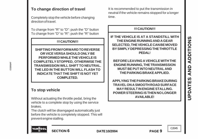
UP
DA
TE
S A
ND
AD
DIT
ION
SU
PD
AT
ES
AN
D A
DD
ITIO
NS
OG
B06
AF
OG
B06
AF
SECTION 6 PAGE 9DATE 10/2004
SECTION 6 PAGE 9DATE 10/2004
C2045
C2045
To change direction of travel
Completely stop the vehicle before changingdirection of travel.
To change from "R" to "D": push the "D" buttonTo change from "D" to "R": push the "R" button
!!! CAUTION!!!
SHIFTING FROM FORWARD TO REVERSEOR VICE VERSA SHOULD ONLY BE
PERFORMED WHILE THE VEHICLE ISCOMPLETELY STOPPED, OTHERWISE THETRANSMISSION WILL SHIFT TO NEUTRAL.THE LED IN THE BUTTON WILL FLASH TO
INDICATE THAT THE SHIFT IS NOT YETCOMPLETED.
To stop vehicle
Without actuating the throttle pedal, bring thevehicle to a complete stop by using the servicebrakes.The clutch will be disengaged automatically justbefore the vehicle is completely stopped. This willprevent engine stalling.
It is recommended to put the transmission inneutral if the vehicle remains stopped for a longertime.
!!! CAUTION!!!
IF THE VEHICLE IS AT A STANDSTILL WITHTHE ENGINE RUNNING AND A GEAR
SELECTED, THE VEHICLE CAN BE MOVEDBY SIMPLY DEPRESSING THE THROTTLE
PEDAL!
BEFORE LEAVING A VEHICLE WITH THEENGINE RUNNING, THE TRANSMISSION
MUST BE PUT INTO NEUTRAL ANDTHE PARKING BRAKE APPLIED.
APPLYING THE PARKING BRAKE DURINGTRAVEL ON A SMOOTH ROAD SURFACE
MAY RESULT IN ENGINE STALLING.POWER STEERING IS THEN NO LONGER
AVAILABLE!

UP
DA
TE
S A
ND
AD
DIT
ION
S
OG
B06A
FO
GB
06AF
UP
DA
TE
S A
ND
AD
DIT
ION
S
C2045PAGE 10 DATE 10/2004 SECTION 6
PAGE 10 SECTION 6DATE 10/2004C2045
To switch off engine and park thevehicle
1. Bring vehicle to a complete stop.
2. Apply parking brake
3. Push "N" button. On the display appears "N"and the led of the "N" button illuminates.
4. Switch off ignition to stop the engine.
NOTE:
THE GEAR SHIFT SYSTEM WILLAUTOMATICALLY PUT THE TRANSMISSION
IN NEUTRAL WHEN THE IGNITION ISSWITCHED OFF WITH THE TRANSMISSION
NOT IN NEUTRAL .
!!! CAUTION!!!
BECAUSE THE TRANSMISSIONAUTOMATICALLY SHIFTS
TO NEUTRAL WHEN THE IGNITION ISSWITCHED OFF, THE VEHICLE MAY ROLL
AWAY IF PARKING BRAKE IS NOTAPPLIED.
Clutch protection
"CL" is displayed if there is a risk that the clutchwill be overloaded as a result of several startingattempts in a short time or creeping in a too highdriving-off gear.
Remedy:
1. Depress the throttle pedal to engage theclutch.
2. Stop the vehicle.
3. Quickly shift to a lower gear.
To protect the mechanical components of theclutch release device, shift the transmission toneutral if the vehicle remains stopped for a longertime (for more than approx. 1 to 2 minutes, forexample, in traffic jams, at railway crossings etc).This will engage the clutch and relieves the clutchrelease device.
Although the clutch operation is automaticallycontrolled, you still have considerable influence onclutch service life. So it is recommended to putthe vehicle in motion in the lowest possible gear toincrease the clutch service life.

UP
DA
TE
S A
ND
AD
DIT
ION
SU
PD
AT
ES
AN
D A
DD
ITIO
NS
OG
B06
AF
OG
B06
AF
SECTION 6 PAGE 11DATE 10/2004
SECTION 6 PAGE 11DATE 10/2004
C2045
C2045
Engine overspeed protection
The electronics protect the engine againstoverspeed and stalling.
Manual mode
An automatic upshift is not made if the vehicle isgoing downhill. Under these circumstances, it isup to you to keep engine revs under control byreducing vehicle speed.
!!! CAUTION!!!
ENGINE OVERSPEED MAY LEAD TOSERIOUS ENGINE DAMAGE.
Automatic mode
!!! CAUTION!!!
TO PROTECT THE ENGINE AGAINSTOVERSPEED, THE GEAR SHIFT SYSTEM
WILL UPSHIFT AUTOMATICALLY WHEN THEVEHICLE SPEED INCREASES.
Vehicle on roller dynamometer
1. Drive the vehicle on the roller dynamometer.
2. Push the "N" button. The transmission is inneutral.
If the dynamometer is started, the gear shiftsystem detects the "driving vehicle" status. If youpush the "D" button with the dynamometer acti-vated, the gear shift system will select a gear thatis appropriate for the speed and close the clutch.Automatic shifts are not undertaken because thefront wheels are not rotating.
Reverse can not be selected when thedynamometer is activated.
!!! CAUTION!!!
VEHICLE MAY DRIVE OFF THEDYNAMOMETER, EVEN IF THE THROTTLE
PEDAL IS NOT DEPRESSED.

UP
DA
TE
S A
ND
AD
DIT
ION
S
OG
B06A
FO
GB
06AF
UP
DA
TE
S A
ND
AD
DIT
ION
S
C2045PAGE 12 DATE 10/2004 SECTION 6
PAGE 12 SECTION 6DATE 10/2004C2045
Error messages
This warning message appears on themultifunction display and a buzzersounds if a system fault is present.
This means:
• increased vigilance• restricted drive comfort, e.g. when driving-off
and shifting or automatic mode is no longeravailable
• the vehicle can not be driven any further• take vehicle to a specialized workshop as soon
as possible
A serious system fault is present ifthis warning message appears on themultifunction display together with themessage "SM" on the push-buttonshift selector display and a buzzersounds.
This means:
• the vehicle must not be driven any further• stop vehicle
How should you respond to a system fault?
With the vehicle stationary, proceed as follows:
1. Switch off the ignition and wait until the displayextinguishes.
If the display does not extinguish, switch offmaster switch.
2. Switch ignition back on.
If the fault message is still present, you have tobring the vehicle to a specialized workshop.Read fault codes before calling for assistance.
To display active fault code
1. Switch on the ignition.
2. Start to push the "N" button.
3. Hold down the "↑" button.
The fault code appears on the display.

UP
DA
TE
S A
ND
AD
DIT
ION
SU
PD
AT
ES
AN
D A
DD
ITIO
NS
OG
B06
AF
OG
B06
AF
SECTION 6 PAGE 13DATE 10/2004
SECTION 6 PAGE 13DATE 10/2004
C2045
C2045
To display fault codes from the fault memory
1. Switch on the ignition.
2. Start to push the "N" button and, at the sametime, depress the brake pedal.
3. While holding down the brake pedal, push andhold down the "↑" button.
The faults saved appear on the display, oneafter another.
Fault code reproduction
Fault codes 1 to 99 (example: faultcode 19)
Fault codes 100 to 199 (example:fault code 122)
Fault codes 200 to 299 (exam-ple: fault code 227)
To start the vehicle at low ambienttemperatures
Ambient temperature between -4 and -22 °F
With the vehicle at a standstill, operate the enginefor at least 10 minutes until the transmission oilhas warmed up.
Ambient temperature below -22 °F
Use warm air to bring the transmission tempera-ture above -22 °F before starting the engine.

UP
DA
TE
S A
ND
AD
DIT
ION
S
OG
B06A
FO
GB
06AF
UP
DA
TE
S A
ND
AD
DIT
ION
S
C2045PAGE 14 DATE 10/2004 SECTION 6
PAGE 14 SECTION 6DATE 10/2004C2045
ZF INTARDER
INTRODUCTION
The ZF Intarder is a hydraulic retarder integrated inthe ZF Astronic.
MESSAGE ON MULTIFUNCTIONDISPLAY
This message appears when the retarderis in operation. The message alsoappears for 3 seconds, when the ignition
is switched on. The message flashes in case ofan electric failure. Drive to the nearest specializedrepair shop.
TO OPERATE
The ZF Intarder is operated with the service brakepedal or with a hand lever at the steering column.It contains also an automatic braking feature (seefurther on).
Foot operation
The ZF Intarder will become operative as soon asyou depress the brake pedal.
To disconnect foot operation
The purpose of this dashswitch is todisconnect the ZF Intarder from thebrake pedal.Leaf this switch in the non-pushedposition except when the use of theIntarder could create a safety hazard,such as on slippery roads or when thecoach is empty.
Hand operation
The hand lever has fivestages: 0,1,2,3,4.
• The hand lever allows retardation in fourstages.
T03801
ZF INTARDER
INTRODUCTION
The ZF Intarder is a hydraulic retarder integrated inthe ZF Astronic.
MESSAGE ON MULTIFUNCTIONDISPLAY
This message appears when the retarderis in operation. The message alsoappears for 3 seconds, when the ignition
is switched on. The message flashes in case ofan electric failure. Drive to the nearest specializedrepair shop.
TO OPERATE
The ZF Intarder is operated with the service brakepedal or with a hand lever at the steering column.It contains also an automatic braking feature (seefurther on).
Foot operation
The ZF Intarder will become operative as soon asyou depress the brake pedal.
To disconnect foot operation
The purpose of this dashswitch is todisconnect the ZF Intarder from thebrake pedal.Leaf this switch in the "ON" positionexcept when the use of the Intardercould create a safety hazard, such ason slippery roads or when the coach isempty.
Hand operation
The hand lever has fivestages: 0,1,2,3,4.
• The hand lever allows retardation in fourstages.
T03801

UP
DA
TE
S A
ND
AD
DIT
ION
SU
PD
AT
ES
AN
D A
DD
ITIO
NS
OG
B06
AF
OG
B06
AF
SECTION 6 PAGE 15DATE 10/2004
SECTION 6 PAGE 15DATE 10/2004
C2045
C2045
• Never pull hand lever backwards in onemovement, but leave it in each position for amoment.
• When returning to the "0" position, however,you can move the handle in one movement
!!! CAUTION!!!
THE INTARDER CANNOT HOLD THE VEHICLESTATIONARY. DO NOT USE IT AS A
PARKING BRAKE.
Automatic braking
The automatic braking feature holds the vehicle atthe same speed throughout a changing downhillgradient.
It operates only when the hand lever is in the "0"position and the vehicle speed is above 15 mph.The system will be engaged automatically assoon as you:
• release the throttle pedal;• release the brake pedal;• switch off the cruise control;• bring back the hand lever to the "0" position.
MECHANICAL BATTERYISOLATING SWITCH
Current vehicles are equipped with a mechanicalbattery isolating switch in the batteriescompartment.
!!! CAUTION!!!
NEVER DISCONNECT THE BATTERIES WHENTHE ENGINE IS RUNNING UNLESS IN
EMERGENCY SITUATIONS SUCH AS FIRE.BATTERY DISCONNECT SHOULD NOT BE
PERFORMED PRIOR TO 30 SECONDSFOLLOWING IGNITION OFF; OTHERWISE
THE ECM OF THE ENGINE WILL NOT STORETHE ENGINE INFORMATION AND WILL
RESULT IN CORRUPTED AND INCOMPLETEDATA BEING STORED.
The purpose of the switch is to allow servicetechnicians to shutt off the entire electricalsystem with the exception of the batteryequalizer. It also prevents battery drainage whenthe vehicle is parked for an extented period oftime. Be aware that some electronic equipment(such as combution heater timer, digital clock,radio,...) must be set again.

UP
DA
TE
S A
ND
AD
DIT
ION
S
OG
B06A
FO
GB
06AF
UP
DA
TE
S A
ND
AD
DIT
ION
S
C2045PAGE 16 DATE 10/2004 SECTION 6
PAGE 16 SECTION 6DATE 10/2004C2045
1. Batteries disconnected2. Batteries connected
• To disconnect the batteries: turn the switchlever to the left. There is no need to remove thelever from the switch.
• To connect the batteries: turn the switch leverto the right.
1. Batteries disconnected2. Batteries connected
• To disconnect the batteries: turn the switchlever to the left. There is no need to remove thelever from the switch.
• To connect the batteries: turn the switch leverto the right.

UP
DA
TE
S A
ND
AD
DIT
ION
SU
PD
AT
ES
AN
D A
DD
ITIO
NS
OG
B06
AF
OG
B06
AF
SECTION 6 PAGE 17DATE 10/2004
SECTION 6 PAGE 17DATE 10/2004
C2045
C2045
!!! REPAIR INSTRUCTION !!!
Only for vehicles with Caterpillar/ZF Astronic drive train.
Before installing the transmission to the engine, measure the transmission input shaft to enginecrankshaft clearance.
Procedure:
1. Position a straight-edge against the head of thetransmission input shaft (as shown). Makesure that the straight-edge keeps in positionduring measurement! Let an assistant measurethe distance between the engine-to-transmission mounting surface and thestraight-edge by using the caliper tail formeasuring depths. Record this distance.
2. With the straight-edge still against the head ofthe transmission input shaft, let an assistantmeasure at the other side of the transmission.
3. Repeat measurements of step 1 and 2.
4. Calculate average (X) of the fourmeasurements.

UP
DA
TE
S A
ND
AD
DIT
ION
S
OG
B06A
FO
GB
06AF
UP
DA
TE
S A
ND
AD
DIT
ION
S
C2045PAGE 18 DATE 10/2004 SECTION 6
PAGE 18 SECTION 6DATE 10/2004C2045
5. Place the straight-edge on the engine-to-transmission mounting surface of the engine.Place the caliper on the straight-edge, in linewith the crankshaft, and measure the distance(Y) to the crankshaft face.
Calculate clearance (Y-X).
If clearance is less than 0.02 inch, you have tocut back the transmission input shaft bygrinding.

IND
EX
IND
EX
Upd
ate
B_O
GB
07A
FU
pdat
e B
_OG
B07
AF
SECTION 7 PAGE 1DATE 10/2004
SECTION 7 PAGE 1DATE 10/2004C2045
C2045
Section/page
A
Air cleaner...................................................................................................................................... 4/12Air system emergency fill .......................................................................................................... 2/2C-14Anti-lock braking system (ABS) ................................................................................................ 2/2B-22
Trouble code reading .......................................................................................................... 2/2C-14Assistance ..................................................................................................................................... 1/10Astronic (ZF) .................................................................................................................................... 6/3Automatic traction control (ASR) ............................................................................................... 2/2B-22
B
Batteries ........................................................................................................................................ 4/24Body ground clearance................................................................................................................... 4/23Brakes
Anti-lock braking system ................................................................................................... 2/2B-22Jake brake ......................................................................................................................... 2/2B-19Parking brake ..................................................................................................................... 2/2B-21Parking brake emergency release ........................................................................................ 2/2C-1Service brake ..................................................................................................................... 2/2B-20ZF Intarder .............................................................................................................................. 6/14
INDEX

Update B
_OG
B07A
FU
pdate B_O
GB
07AF
IND
EX
DATE 10/2004PAGE 2 SECTION 7
PAGE 2 DATE 10/2004 SECTION 7
IND
EX
C2045
C2045
Section/page
C
Chassis frame jacking points .................................................................................................... 2/2C-22Circuit breakers ......................................................................................................................5/17, 5/24Climate control
Driver's compartment ................................................................................................................. 3/3Override ............................................................................................................................. 2/2C-24Passengers' compartment ......................................................................................................... 3/4
Combustion heater ........................................................................................................................... 3/7Compartments
Driver's compartment and controls ........................................................................................ 2/2A-9Exterior compartments ............................................................................................................ 1/15
CoolantLevel ......................................................................................................................................... 4/8Recommendations .................................................................................................................... 5/9
Cooling fanMechanical locking device .................................................................................................... 2/2C-5
Cruise control/fast idleCruise control ..................................................................................................................... 2/2B-16Fast idle ............................................................................................................................. 2/2B-17
D
Dimensions and data ..................................................................................................................... 1/12Drive belts ...................................................................................................................................... 4/10Driver's seat ................................................................................................................................ 2/2A-9

IND
EX
IND
EX
Upd
ate
B_O
GB
07A
FU
pdat
e B
_OG
B07
AF
SECTION 7 PAGE 3DATE 10/2004
SECTION 7 PAGE 3DATE 10/2004C2045
C2045
Section/page
E
Electrical system ...................................................................................................................5/16, 5/22Emergency exits ......................................................................................................................... 2/2C-6Engine
Trouble code reading ............................................................................................................ 2/2C-8Oil level ..................................................................................................................................... 4/5To drive off ............................................................................................................................ 2/2B-4To start ................................................................................................................................. 2/2B-2To stop ................................................................................................................................. 2/2B-1To warm-up .......................................................................................................................... 2/2B-5
Entrance doorControl ............................................................................................................................... 2/2B-26Emergency operation ........................................................................................................... 2/2C-3
F
Fast idle .................................................................................................................................... 2/2B-17Front lower system ................................................................................................................... 2/2B-24Fuel recommendations ..................................................................................................................... 5/7Fuses ....................................................................................................................................5/16, 5/22
HHazard warning flasher ................................................................................................................ 2/2C-2

Update B
_OG
B07A
FU
pdate B_O
GB
07AF
IND
EX
DATE 10/2004PAGE 4 SECTION 7
PAGE 4 DATE 10/2004 SECTION 7
IND
EX
C2045
C2045
IIdentification
Engine identification .................................................................................................................. 1/8Vehicle identification number ..................................................................................................... 1/8Vehicle identification plate ......................................................................................................... 1/7
Ignition switch ........................................................................................................................... 2/2A-13Instrument panel ........................................................................................... 2/2A-15, 2/2A-17, 2/2A-19
Instrument panel switches .................................................................................................. 2/2A-20
JJump starting ............................................................................................................................ 2/2C-24
LLavatory ......................................................................................................................................... 3/14Lifting and towing ...................................................................................................................... 2/2C-15Lights
Warning and indicator lights ................................................................................. 2/2A-26, 2/2A-34
MMaster switch ........................................................................................................................... 2/2A-13Mechanical battery isolating switch ................................................................................................ 6/15
PPower steering system
Failure ................................................................................................................................ 2/2B-19Fluid level ................................................................................................................................ 4/20Fluid recommendations ........................................................................................................... 5/13
Section/page

IND
EX
IND
EX
Upd
ate
B_O
GB
07A
FU
pdat
e B
_OG
B07
AF
SECTION 7 PAGE 5DATE 10/2004
SECTION 7 PAGE 5DATE 10/2004C2045
C2045
RRaise/lower system................................................................................................................... 2/2B-23Rear rise system ....................................................................................................................... 2/2B-24Rear view mirrors ....................................................................................................................... 2/2A-11
SSafety instructions ........................................................................................................................... 1/3Seat belt ................................................................................................................................... 2/2A-11Shock absorbers ............................................................................................................................ 4/23Spare wheel & tire ..................................................................................................................... 2/2C-16Speedometer ............................................................................................................... 2/2A-40, 2/2A-44Steering column ........................................................................................................................ 2/2A-12Steering column combination switch ......................................................................................... 2/2A-13
TTachometer ................................................................................................................. 2/2A-40, 2/2A-44Tag axle unloading .................................................................................................................... 2/2B-25Tires ............................................................................................................................................... 4/22
Emergency tire inflation ...................................................................................................... 2/2C-16To check tire inflation pressure ................................................................................................ 4/21To inspect tires ....................................................................................................................... 4/22
Toilet .............................................................................................................................................. 4/26Transmission
To check fluid level (Allison WTB500) ...................................................................................... 4/15Trouble code reading (Allison WTB500) .............................................................................. 2/2C-12Fluid recommendations (Allison WTB500 and ZF Astronic) ..................................................... 5/12
Turbo boost gauge .................................................................................................................... 2/2A-42
Section/page

Update B
_OG
B07A
FU
pdate B_O
GB
07AF
IND
EX
DATE 10/2004PAGE 6 SECTION 7
PAGE 6 DATE 10/2004 SECTION 7
IND
EX
C2045
C2045
WWheelchair
Lift .......................................................................................................................................... 3/10Restraint system..................................................................................................................... 3/12
WheelsSpare wheel & tire .............................................................................................................. 2/2C-16To change a road wheel ...................................................................................................... 2/2C-17To check wheel nuts torque ..................................................................................................... 4/22
Windshield washer tank ................................................................................................................. 4/25Windshield wipers/washer ......................................................................................................... 2/2A-13
ZZF Astronic ...................................................................................................................................... 6/3ZF Intarder...................................................................................................................................... 6/14
Section/page
Related Documents