Research Report KTC-91-2 DEVELOPMENT OF TURNING TEMPLATES FOR V ARlO US DESIGN VEHICLES by Kenneth R. Agent Research Engineer and Jerry G. Pigman Research Engineer Kentucky Transportation Center College of Engineering Universi of Kentuc Lexington, Kentucky in cooperation with Kentucky Transportation Cabinet Commonwealth of Kentuc and Federal Highway Administration US Department of Transportation The contents of this report reflt the views of the authors, who are responsible for the facts and aura of the data presented herein. The contents do not necearily reflect the official views or policies of the University of Kentuc, the Kentuc Transportation Cabinet, or the Federal Highway Administration. This report does not constitute a standard, specification, or regulation. The inclusion of manufacturer names and trade names are for identification purposes and are not to be considered endorsements. April1991

Welcome message from author
This document is posted to help you gain knowledge. Please leave a comment to let me know what you think about it! Share it to your friends and learn new things together.
Transcript

Research Report KTC-91-2
DEVELOPMENT OF TURNING TEMPLATES FOR V ARlO US DESIGN VEHICLES
by
Kenneth R. Agent Research Engineer
and
Jerry G. Pigman Research Engineer
Kentucky Transportation Center College of Engineering University of Kentucky
Lexington, Kentucky
in cooperation with
Kentucky Transportation Cabinet Commonwealth of Kentucky
and
Federal Highway Administration US Department of Transportation
The contents of this report reflect the views of the authors, who are responsible for the facts and accuracy of the data presented herein. The contents do not necessarily reflect the official views or
policies of the University of Kentucky, the Kentucky Transportation Cabinet, or the Federal Highway Administration. This report does not constitute a standard, specification, or regulation. The inclusion of manufacturer names and trade names are for identification purposes and are not
to be considered endorsements.
April1991

Technical Report Documentation Page
1. Report No. 2. Government Accession No. 3. Recipient's Catalog No.
KTC-91-2
4. Title and Subtitle 5. Report Date
April1991 Development of Turning Templates for Various Design Vehicles 6. Performing Organization Code
7. Author(s) 8. Performing Organization Report No.
K. R. Agent and J. G. Pigman KTC-91-2
9. Performing Organization Name and Address 10. Work Uno No. (TRAIS)
Kentucky Transportation Center College of Engineering 11. Contract or Grant No.
University of Kentucky KYHPR-90-130
Lexington, KY 40506-0043 13. Type of Report and Period Covered
Interim 12. Sponsoring Agency Name and Address
Kentucky Transportation Cabinet State Office Building 14. Sponsoring Agency Code
Frankfort, KY 40622
15. Supplementary Notes
Study Title: Evaluation of Highway Geometries Related to Large Trucks Prepared in cooperation with US Department of Transportation; Federal Highway Administration
16. Abstract
The objective of this study was to develop the data necessary to produce the turning tern plates that would represent the minimum turning paths for critical design vehicles. This would include information concerning truck turning radii and offiracking for larger trucks with varying wheelbases operating in Kentucky. In order for the turning templates used for the various design vehicles to be based on the same procedure, data were produced tor design vehicles ranging from a passenger car to a combination truck with a 53·foot trailer. The simulation model used was the Truck Offtracking Model (TOM) and was developed by the California Department of Transportation.
The data obtained from the truck offiracking simulation program show that it can be used to develop turning templates that agree with those developed by MSHTO. The plotting information generated from this study can be used to prepare turning templates that can be used in the design process.
17. Key Words 18. Distribution Statement
Design Vehicle Offtracking Unlimited with Transportation Swept Path Cabinet Approval Turning Template
19. Security Classif. (of this report) 20. Security Classif. (of this page) 21. No. of Pages 22. Price
Unclassified Unclassified 27
Form DOT 1700.7 (8·72) Reproduction of completed page authorized
TABLE OF CONTENTS
INTRODUCTION . . . . . . . . . . . . . . . . . . . . . . . . . . . . . . . . . . . . . . . . . . . . 1
PROCEDURE . . . . . . . . . . . . . . . . . . . . . . . . . . . . . . . . . . . . . . . . . . . . . . . 2
RESULTS . . . . . . . . . . . . . . . . . . . . . . . . . . . . . . . . . . . . . . . . . . . . . . . . . . 4
CONCLUSION . . . . . . . . . . . . . . . . . . . . . . . . . . . . . . . . . . . . . . . . . . . . . . 6
TABLES . . . . . . . . . . . . . . . . . . . . . . . . . . . . . . . . . . . . . . . . . . . . . . . . . . . 7
FIGURES . . . . . . . . . . . . . . . . . . . . . . . . . . . . . . . . . . . . . . . . . . . . . . . . . 15

INTRODUCTION
The Surface Transportation Assistance Act of 1982 (STAA) increased the allowable dimensions of trucks to a length of 48 feet for semitrailers of combination vehicles and an overall width of 102 inches. The increased dimensions were permitted on the Interstate System and on the qualifying Federal-aid Primary System. In addition, the Kentucky Transportation Cabinet has established length limitations of 53 feet for semitrailers for combination vehicles operating on highways designated as the Increased Dimension-Twin Trailer System (IDTT). For the vehicles with increased dimensions, regulations were adopted to designate highways on which they could operate in Kentucky. Included were the Interstate System and much of the Federal-aid Primary System. The regulations also included a provision for a limit of five miles travel distance off the designated network for the purpose of attaining reasonable access to terminals and other necessary facilities.
One result of allowing increased lengths of combination vehicles is that it results in increased offtracking of larger trucks. The physical characteristics of vehicles are used in geometric design. Specifically, the turning paths of various design vehicles are necessary for the design of intersections and ramps. If the offtracking distance is increased, this will have an effect on the design of intersectins and ramps.
Design guidelines and turning radius templates have been prepared and used by the Kentucky Transportation Cabinet for the 48-foot semitrailer; however, templates have not been prepared for the 53-foot semitrailer that is currently operating in Kentucky. These truck turning templates are necessary for engineers to design intersections and ramps to accommodate large trucks. In addition, templates are used for locating curbs, island noses, retaining walls, signal poles, and other roadway hardware so that they are clear of a vehicle turning at an intersection.
The objective of this study was to develop the data necessary to produce the turning templates that would represent the minimum turning paths for critical design vehicles. This would include information concerning truck turning radii and offtracking for larger trucks with varying wheelbases operating in Kentucky. In order for the turning templates used for the various design vehicles to be based on the same methodology, data were produced for design vehicles ranging from a passenger car to a combination truck with a 53-foot trailer.
1

PROCEDURE
In order to prepare a series of turning templates, it was necessary to use a computer program to simulate the turning movement of various design vehicles. The literature was reviewed to determine the alternative simulation procedures that were available. Two computer models were tested in detail. One turning or offtracking model could produce simulations within the constraints and capabilities of a personal computer (1), while another required mainframe capabilities (2).
Several plots were generated using both procedures and compared to the templates currently in use. Based on the types and format of output generated and comparisions between simulation data and currently used data, the decision was made to use the mainframe version of the turning or offtracking model (2). The model was developed by the California Department of Transportation and was named the Truck Offtracking Model (TOM).
In the model, a turn to the right was input at various angles. Plotting data were output to represent the movement of various positions on the vehicle as it made the turn. These points included the left and right front tires, the left and right rear tires, and the left front corner of the vehicle. The maximum offtracking distance and swept path as well as this location in the turn were part of the output. The offtracking distance was defined as the distance the right rear tire tracked inside the right front tire as the vehicle made the righthand turn. The swept path output from the computer program was the distance the right rear tire tracked inside the left front tire. The trajectory of the left front corner of the vehicle was also plotted and could be used instead of the left front tire to determine the swept path.
The input into the program included the path geometry, vehicle configuration, simulation parameters, and plotting data. The degree of turn and radius of the turn were input as part of the path geometry. The number of units in the vehicle, vehicle width, wheelbase of the various units, and, if applicable, the location of the fifth wheel or hitch were input as part of the vehicle configuration. The plotting data input defined the location of the various points on the vehicle for which a plot of the path through the turn was obtained.
Several series of computer runs were performed based on the following criteria:
1. scale, 2. turning angle, 3. vehicle designation, and 4. turning radius.
2

Three scales were used. The scales used were 1 inch equals 20, 40, and 50 feet. The turning angles used were 30, 60, 90, 120, 150, and 180 degrees. The design vehicles used were based on the vehicles described in "A Policy on Geometric Design of Highways and Streets" published by the American Association of State Highway and Transportation Officials (AASHTO) (3). Nine vehicle designations were specified. These included five combination trucks (WB-40, WB-50, WB-60, WB-62, and WB-67), two buses, a single unit truck, and a passenger car. The dimensions given in this publication were used in the computer simulation runs. A summary of the dimensions used in the simulations is given in Table 1. For the five combination trucks, three turning radii were used (45, 60, and 75 feet). For the single unit bus and truck, turning radii of 42 and 60 feet were used. For the articulated bus, turning radii of 38 and 55 feet were used. For the passenger car, a turning radius of 24 feet was used.
The passenger car was defined as a single unit vehicle with a width of 7 feet. Its wheelbase was 11 feet with a front overhang of 3 feet. This meant that, for the plotting data, the front overhang was 14 feet in front of the rear wheels. The single unit truck was defined as single unit vehicle with a width of 8.5 feet. Its wheelbase was 20 feet with a front overhang of 4 feet. The bus was defined as a single unit vehicle with a width of 8.5 feet. Its wheelbase was 25 feet with a front overhang of 7 feet. The articulated bus was defined as having two units with a width of 8.5 feet. The wheelbases of the two units were 18 feet and 24 feet with the hitch point 4 feet behind the rear axle of the front unit. The front overhang was 8.5 feet. The WB-40 truck was defined as having two units with a width of 8.5 feet. The wheelbases of the two units were 13 feet and 27 feet. The filth wheel location was assumed to be over the rear axle of the first unit for all the combination trucks. The front overhang was 4 feet. The WB-50 truck was defined as having two units with a width of 8.5 feet. The wheelbases of the two units (to the rear axle) were 20 and 30 feet with a front overhang of 3 feet. The WB-60 truck was defined as having four units with a width of 8.5 feet. The units were the tractor, semitrailer, towbar, and trailer. The wheelbases used for the four units were 9.7 feet, 20 feet, 9.4 feet, and 20.9 feet, respectively. The front overhang was 2 feet. The WB-62 truck was defined as having two units with a width of 8.5 feet. The wheelbases of the two units were 20 feet and 41 feet with a front overhang of 3 feet. The WB-67 truck was defined as having two units with a width of 8.5 feet. The wheelbases of the two units were 20 feet and 46 feet with a front overhang of 3 feet.
A summary of the vehicle designations and turning radii used for each vehicle type is given in Table 2. For a given vehicle designation and turning radius, simulation runs were made for the three scales and six turning angles. Considering the various combinations of scale, turning angle, vehicle type, and turning radius resulted in the necessity of 396 simulation runs.
3

Five combination truck categories were specified to account for the variance in combination truck sizes and turning characteristics. The WB-40 is representative of medium tractor-semitrailer combinations. The WB-50 is representative of larger tractor-semitrailer combinations commonly in use. The WB-60 is representative of a larger tractor-semitrailer full trailer commonly in use. The WB-62 is representative of a larger tractor-semitrailer combination allowed on selected highways by the STAA. The WB-62 has been referred to as the design vehicle with a 48-foot trailer. The WB-67 is representative of a larger tractor-semitrailer grandfathered on selected highways by the STAA. The WB-67 has been referred to as the design vehicle with a 53-foot trailer.
Vehicle classification data are taken routinely on various classes of highways. Axle spacings data are collected as part of this data collection. These data were summarized to compare axle spacings recorded as part of the data collection process with the design vehicles used to prepare the turning templates.
RESULTS
Data were input into the Truck Offtracking Model (TOM) as described in the procedure. For each set of input data, summary information was obtained as
well as a plot file. An example of the type of summary information for one simulation run is shown in Figure 1. The plot file information was loaded onto 3.5-inch disks for use in the preparation of a series of turning templates.
The information obtained will allow 66 turning templates to be prepared. This results from the combination of the turning radii specified for the nine vehicle designations in combination with the three scales. Six turning angles are given on each template. Examples of the types of templates which can be prepared from the plot file information are shown in Figures 2 through 10. These figures show turning movements for each of the nine vehicle designations. The turning templates show the turning paths of the left front corner and right rear tire of the vehicles. A total of 33 disks were used to store the data necessary to plot the 66 turning templates.
The maximum offtracking and swept path as well as the location where this occurred were obtained for each simulation. This information is summarized in Table 3 as a function of vehicle designation, turning radius, and turning angle. The offtracking distance is the difference in the travel path of the right front and right rear tires through the righthand turn. The swept path distance given in Table 3 is the differnce in the travel path of the left front and right rear tires. The program used the left front tire rather than the left front corner to determine swept path. The path of the left front corner was included in the plot file. Offtracking distances ranged from 1.6 feet for a passenger car turning with a 30 degree angle at a 24-foot turning radius to 36.0 feet for a WB-67 truck turning
4
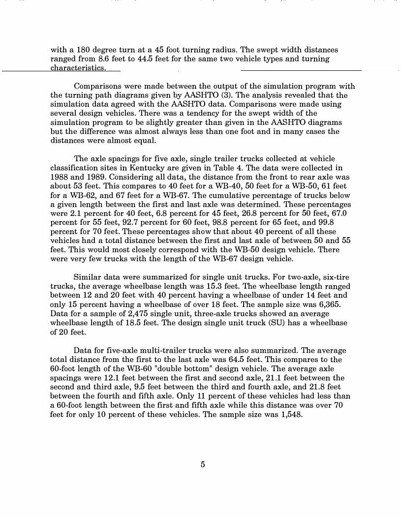
with a 180 degree turn at a 45 foot turning radius. The swept width distances ranged from 8.6 feet to 44.5 feet for the same two vehicle types and turning characteristics.
Comparisons were made between the output of the simulation program with the turning path diagrams given by AASHTO (3). The analysis revealed that the simulation data agreed with the AASHTO data. Comparisons were made using several design vehicles. There was a tendency for the swept width of the simulation program to be slightly greater than given in the AASHTO diagrams but the difference was almost always less than one foot and in many cases the distances were almost equal.
The axle spacings for five axle, single trailer trucks collected at vehicle classification sites in Kentucky are given in Table 4. The data were collected in 1988 and 1989. Considering all data, the distance from the front to rear axle was about 53 feet. This compares to 40 feet for a WB-40, 50 feet for a WB-50, 61 feet for a WB-62, and 67 feet for a WB-67. The cumulative percentage of trucks below a given length between the first and last axle was determined. These percentages were 2. 1 percent for 40 feet, 6.8 percent for 45 feet, 26.8 percent for 50 feet, 67.0 percent for 55 feet, 92.7 percent for 60 feet, 98.8 percent for 65 feet, and 99.8 percent for 70 feet. These percentages show that about 40 percent of all these vehicles had a total distance between the first and last axle of between 50 and 55 feet. This would most closely correspond with the WB-50 design vehicle. There were very few trucks with the length of the WB-67 design vehicle.
Similar data were summarized for single unit trucks. For two-axle, six-tire trucks, the average wheelbase length was 15.3 feet. The wheelbase length ranged between 12 and 20 feet with 40 percent having a wheelbase of under 14 feet and only 15 percent having a wheelbase of over 18 feet. The sample size was 6,365. Data for a sample of 2,475 single unit, three-axle trucks showed an average wheelbase length of 18.5 feet. The design single unit truck (SU) has a wheelbase of 20 feet.
Data for five-axle multi-trailer trucks were also summarized. The average total distance from the first to the last axle was 64.5 feet. This compares to the 60-foot length of the WB-60 "double bottom" design vehicle. The average axle spacings were 12.1 feet between the first and second axle, 21.1 feet between the second and third axle, 9.5 feet between the third and fourth axle, and 21.8 feet between the fourth and fifth axle. Only 11 percent of these vehicles had less than a 60-foot length between the first and fifth axle while this distance was over 70 feet for only 10 percent of these vehicles. The sample size was 1,548.
5

CONCLUSION
The data obtained from the truck offtracking simulation program show that it can be used to develop turning templates that agree with those developed by AASHTO (3). The plotting information generated from this study can be used to prepare turning templates that can be used in the design process. The turning templates include nine design vehicles including the 48-foot and 53-foot semitrailer.
REFERENCES
1. "Program Documentation and User's Guide," FHWA Vehicle Offtracking Model, IBM PC Version 1.0, Analysis Group, Incorporated, July 20, 1986.
2. "Truck Offtracking Model (TOM), Program Documentation and User's Guide," California Department of Transportation, January 1985.
3. "A Policy on Geometric Design of Highways and Streets," American Association of State Highway and Transportation Officials, 1990.
6

T
Dimension (Feet)
Overall Overhang
Design Vehicle Type Symbol Width Length Front Rear WB1 WB2 s T WB3
Passenger Car p 7 19 3 5 11
Single-Unit Truck su 8.5 30 4 6 20
Single-Unit Bus BUS 8.5 40 7 8 25
Articulated Bus A-BUS 8.5 60 8.5 9.5 18 4 20
Combination Trucks
Intermediate
Semitrailer WB-40 8.5 50 4 6 13 27
Large Semitrailer WB-50 8.5 55 3 2 20 30
"" Double Bottom
Semitrailer-full trailer WB-60 8.5 65 2 3 9.7 20 4 5.4 20.9
Interstate . Semitrailer WB-62 8.5 69 3 3 20 41
Interstate Semitrailer WB-67 8.5 74 3 3 20 46

TABLE2. VEIDCLE TURNING SIMULATIONS*
Vehicle Type Vehicle Designations Turning Radius (Feet)
Combination Trucks WB-40 45,60,75
WB-50 45,60,75
WB-60 45,60,75
WB-62 45,60,75
WB-67 45,60,75
Buses BUS 42,60
A-BUS 38,55
Single Unit Truck su 42,60
Passenger Car p 24
* Scales of P=20'; 1"=40"; and 1" =50'. Turning angles (degrees) of 30, 60, 90, 120, 150, and 180.
8

TABLE3. MAXIMUM OFfTRACKING AND SWEPT WIDTH
TURNING TURNING MAXIMUM MAXIMUM VEIUCLE RADIUS ANGLE OFFIRACKING SWEPT WIDTII LOCATION
DESIGNATION (FEET) (DEGREES) (FEET)* (FEET)** (DEGREES)
p 24 30 1.6 8.6 19
60 2.4 9.4 44
90 2.8 9.8 69
120 3.0 10.0 93
150 3.1 10.1 121
180 3.2 10.2 149
su 42 30 2.9 11.4 21
60 4.3 12.8 43
90 5.1 13.6 69
120 5.4 13.9 94
150 5.6 14.1 123
180 5.7 14.2 150
60 30 2.5 11.0 21
60 3.3 11.8 46
90 3.6 12.1 73
120 3.7 12.2 100
150 3.7 12.2 130
180 3.7 12.2 159
BUS 42 30 3.8 12.3 21
60 6.1 14.6 43
90 7.5 16.0 66
120 8.3 16.8 91
150 8.8 17.3 118
180 9.1 17.6 146
60 30 3.4 11.9 20
60 4.9 13.4 45
90 5.5 14.0 70
120 5.8 14.3 98
150 5.9 14.4 126
180 5.9 14.4 154
9

TABLE 3. MAXIMUM OFFTRACKING AND SWEPT WIDTII (continued)
1URNING 1URNING MAXIMUM MAXIMUM VEHICLE RADIUS ANGLE OFFIRACKING SWEPTWID1H LOCATION
(<tltHJ (<lltll)" tltll
A-BUS 38 30 5.0 13.5 20
60 8.5 17.0 38
90 11.1 19.6 59
120 13.0 21.4 83
150 14.3 22.8 106
180 15.3 23.8 130
55 30 4.5 13.0 19
60 7.1 15.6 40
90 8.4 16.9 63
120 9.1 17.6 88
150 9.4 17.9 113
180 9.5 18.0 141
WB-40 45 30 4.8 13.3 19
60 7.8 16.3 40
90 9.8 18.3 61
120 11.1 19.6 86
150 11.9 20.4 110
180 12.4 20.9 137
60 30 4.4 12.9 19
60 6.7 15.2 41
90 7.8 16.3 64
120 8.3 16.8 90
150 8.6 17.1 116
180 8.7 17.2 144
75 30 4.0 12.5 20
60 5.7 14.2 42
90 6.3 14.8 67
120 6.6 15.1 94
150 6.6 15.1 121
180 6.7 15.2 150
10

TABLE 3. MAXIMUM OFFTRACKING AND SWEPT WIDTH (continued)
TURNING TURNING MAXIMUM MAXIMUM VEIDCLE RADIUS ANGLE OFFIRACKING SWEPT WIDTH LOCATION
·'
WB-50 45 30 6.0 14.5 19
60 10.3 18.8 38
90 13.4 21.9 60
120 15.7 24.2 81
150 17.3 25.8 105
180 18.5 27.0 130
60 30 5.6 14.1 19
60 9.0 17.5 39
90 11.0 19.4 62
120 12.0 20.5 86
150 12.6 21.1 111
180 12.9 21.4 138
75 30 5.3 13.8 19
60 7.8 16.3 40
90 9.0 17.5 64
120 9.6 18.1 89
150 9.8 18.3 115
180 9.8 18.3 144
WB-60 45 30 5.3 13.8 17
60 8.8 17.3 36
90 11.2 19.7 57
120 12.8 21.3 79
150 13.8 22.3 101
180 14.4 22.9 125
60 30 4.9 13.4 18
60 7.6 16.1 39
90 8.9 17.4 59
120 9.6 18.1 82
150 9.9 18.4 107
180 10.0 18.5 132
11

TABLE 3. MAXIMUM OFFfRACKING AND SWEPT WIDTH (continued)
TURNING TURNING MAXIMUM MAXIMUM vrr ""Dr> HLHll
DESIGNATION (FEE1) (DEGREES) (FEET)* (FEE1)** (DEGREES)
WB-60 75 30 4.5 13.0 18
60 7.0 15.0 39
90 7.3 15.8 62
120 7.5 16.0 86
150 7.6 16.1 111
180 7.6 16.1 138
WB-62 45 30 7.9 16.4 19
60 14.0 22.5 39
90 19.0 27.5 59
120 23.1 31.6 81
150 26.7 35.2 104
180 29.9 38.4 126
60 30 7.4 15.9 19
60 12.5 21.0 39
90 16.0 24.5 61
120 18.4 26.9 84
150 20.1 28.6 109
180 21.2 29.7 134
75 30 7.0 15.5 19
60 11.2 19.7 40
90 13.6 22.1 63
120 15.0 23.5 88
150 15.8 24.3 113
180 16.2 24.7 140
12
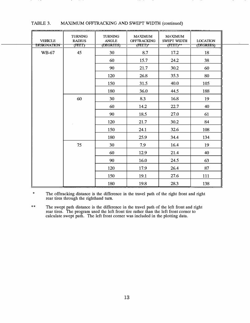
TABLE 3. MAXIMUM OFFrRACKING AND SWEPT WIDTH (continued)
�
*
**
TURNING TURNING MAXIMUM MAXIMUM VEHICLE RADIUS ANGLE OFFIRACKING SWEPTWID1H LOCATION
'rHlU" lrlmlJ l' "'" lrDDl. lUilC
WB-67 45 30 8.7 17.2 18
60 15.7 24.2 38
90 21.7 30.2 60
120 26.8 35.3 80
150 31.5 40.0 105
180 36.0 44.5 188
60 30 8.3 16.8 19
60 14.2 22.7 40
90 18.5 27.0 61
120 21.7 30.2 84
150 24.1 32.6 108
180 25.9 34.4 134
75 30 7.9 16.4 19
60 12.9 21.4 40
90 16.0 24.5 63
120 17.9 26.4 87
150 19.1 27.6 111
180 19.8 28.3 138
The offtracking distance is the difference in the travel path of the right front and right rear tires through the righthand tum.
The swept path distance is the difference in the travel path of the left front and right rear tires. The program used the left front tire rather than the left front corner to calculate swept path. The left front corner was included in the plotting data.
13

TABLE 4. AXLE SPACINGS FOR FIVE AXLE, SINGLE TRAILER TRUCKS
*
Axle Rural Numbers Interstate
1-2 13.4
2-3 4.4
3-4 31.2
4-5 4.2
Sample sizes were:
rural interstate -rural arterial -rural collector -urban interstate -urban arterial -all systems -
Rural Arterial
13.1
4.4
29.4
4.1
15,901 1,424
285 6,136 1,855
25,606
A ,J, <:, m, t\*
Highway System
Rural Urban Urban Collector Interstate Arterial
13.2 13.4 12.9
4.4 4.5 4.4
27.0 31.5 28.3
4.2 4.2 4.2
14
All
13.3
4.4
30.9
4.2

Figure 1. Summary Information from Simulation Run
90 DEGREE TURN - 45 FOOT RADIUS - WB;oo - 1'�20'
PATH INPUT DATA:
DEGREE OF CURVE � 90.00
RADIUS OF CURVE • 45.00
DISTANCE TRAVELED AFTER REACHING END OF CURVE • 100.00
VEHICLE INPUT DATA:
NUMBER OF UNITS IN VEHICLE CONFIGURATION • 2
VEHICLE
UNIT# 1
2
WHEELBASE
LENGTH
20.00
30.00
DISTANCE THAT 5TH WHEEL (OR HITCH)
LIES IN FRONT OF THE REAR AXLE
0.00
0.00
NOTE: A CONSTANT WIDTH OF 8.50' IS TO BE ADDED TO THE AMOUNT OF
OFFTRACKING FOR THE PURPOSE OF CALCULATING THE SWEPT WIDTH.
90 DEGREE TURN - 45 FOOT RADIUS - WB-50 - 1'=20'
OFFTRACKING S�Y
LOCATION AMOUNT OF SWEPT
(DEGREE) OFFTRACKING WIDTH
0.00 5.71 14.21 ( B C )
59.68 13.40 21.90 (MAX)
90.00 10.85 19.35 ( E C)
15
L A B E L
TRACTOR
TRAILER

Figure 2. Minimum turning path for P design vehicle
( 24 foot turning radius ) ( Scale : 1" = 20' )
16

Figure 3. Minimum turning path for SU design vehicle
( 42 foot turning radius ) ( Scale : 1" = 20' )
17

Figure 4. Minimum turning path for A-BUS design vehicle
( 38 foot turning radius ) ( Scale : I" = 20' )
18
180"
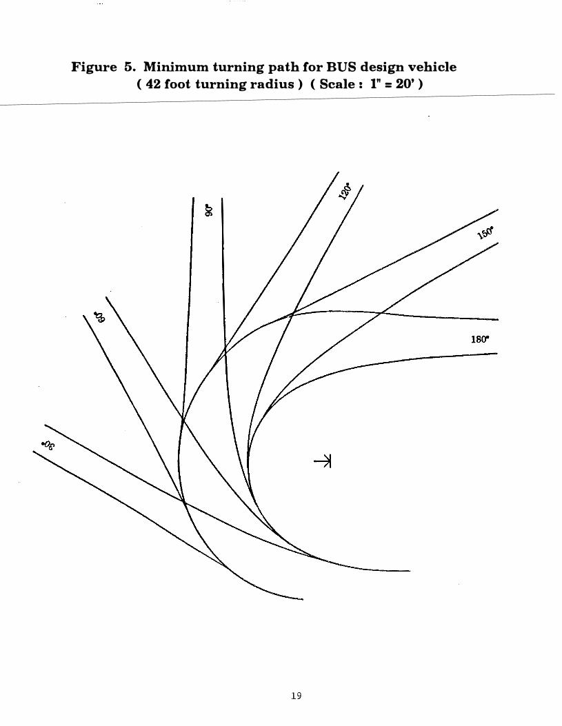
Figure 5. Minimum turning path for BUS design vehicle
( 42 foot turning radius ) ( Scale : 1" = 20' )
19

Figure 6. Minimum turning path for WB-40 design vehicle
( 45 foot turning radius ) ( Scale : 1" = 20' )
20
180"

Figure 7. Minimum turning path for WB-50 design vehicle
( 45 foot turning radius ) ( Scale : 1" = 20' )
21
180"

Figure 8. Minimum turning path for WB-60 design vehicle
( 45 foot turning radius ) ( Scale : 1" = 20' )
22
180"

Figure 9. Minimum turning path for WB-62 design vehicle ( 45 foot turning radius ) ( Scale : I" = 20' )
23

Figure 10. Minimum turning path for WB-67 design vehicle
( 45 foot turning radius ) ( Scale : 1" = 20' )
24
Related Documents


