Technical Characteristics Connector Size 6B 10B 16B Inserts Number of Poles 6+PE 24+PE 10+PE 42+PE 6+PE 16+PE 40+PE 72+PE UL/CSA Rated Voltage* 600V Maximum Rated Current 16A 10A 16A 10A 35A 16A 10A EN 61984 (2001- 11) Pollution Degree 3 Rated Voltage AC/DC 500V 250V 500V 250V 830V 500V 250V Impulse Withstand Voltage 6kV 4kV 6kV 4kV 6kV 4kV EN 61984 (2001- 11) Pollution Degree 2 Rated Voltage 400/690V 230/400V 400/690V 230/400V 1000V 400/690V 230/400V Impulse Withstand Voltage 6kV 4kV 6kV 4kV 8kV 6kV 4kV Continuous Current Carrying Capacity Refer to Electrical Engineering section charts Insulation Resistance 10 10 h Material Polycarbonate Temperature Range -40°C to 125°C (-40°F to 257°F) Flammability UL 94 V-0 GWT 960° Degree Protection With Housing IP66, NEMA/UL (Type 1, 4, 4x, 12) Without Housing IP20 Mechanical Working Life 500 Cycles Conductor Termi- nation Screw Terminals 4 N/A 4 N/A 4 4 N/A N/A Crimp Contacts 4 4 4 4 N/A 4 4 4 Contacts Material Hard-silver plated (2µm Au) or gold plated copper alloy Minimum Recommended Load (voltage & current) 5V/5mA AC/DC (silver plated) Contact Resistance m 1 mh m 3 mh m 1 mh m 3 mh m 0.5 mh m 1 mh m 3 mh Screw Terminal Wire Size mm ² 0.5-2.5mm² N/A 0.5-2.5mm² N/A 1.5-6 mm² 0.5-2.5 mm² N/A AWG 20-14 AWG N/A 20-14 AWG N/A 16-10 AWG 20-14 AWG N/A Screw Terminal Tightening Test Torque 0.5 Nm N/A 0.5 Nm N/A 1.2 Nm 0.5 Nm N/A Screw Terminal Stripping Length 7.0 mm N/A 7.0 mm N/A 10.5 mm 7.0 mm N/A Crimp Terminal Wire Size mm ² 0.14-4 mm² 0.14-2.5 mm² 0.14-4 mm² 0.14-2.5 mm² N/A 0.14-4 mm² 0.14-2.5 mm² AWG 26-12 AWG 26-14 AWG 26-12 AWG 26-14 AWG N/A 26-12 AWG 26-14 AWG Crimp Terminal Stripping Length 7.5 mm 8 mm 7.5 mm 8 mm N/A 7.5 mm 8 mm Aluminum Hoods/Bases/ Couplers/ Covers Material Die cast aluminum alloy, Polyester powder coated Locking Element Stainless steel lever and peg Housings Seal NBR (Nitrile) Degree of Protection Acc. to EN 60529 (coupled) NEMA 250, UL50, 50E IP66, NEMA/UL (Type 1, 4, 4X, 12) Temperature Range -40°C to 125°C (-40°F to 257°F) Thread Metric EN50262 Pg DIN 40430 * Connectors should not be coupled and decoupled under electrical load. STD Series Multi-Wire Connectors Specifications 1-800-633-0405 Multi-Wire Connectors tMWC-8 For the latest prices, please check AutomationDirect.com.

Welcome message from author
This document is posted to help you gain knowledge. Please leave a comment to let me know what you think about it! Share it to your friends and learn new things together.
Transcript

Technical CharacteristicsConnector Size 6B 10B 16B
Inserts
Number of Poles 6+PE 24+PE 10+PE 42+PE 6+PE 16+PE 40+PE 72+PE
UL/CSA Rated Voltage* 600V
Maximum Rated Current 16A 10A 16A 10A 35A 16A 10A
EN 61984 (2001-11) Pollution Degree 3
Rated Voltage AC/DC 500V 250V 500V 250V 830V 500V 250V
Impulse Withstand Voltage 6kV 4kV 6kV 4kV 6kV 4kV
EN 61984 (2001-11) Pollution Degree 2
Rated Voltage 400/690V 230/400V 400/690V 230/400V 1000V 400/690V 230/400V
Impulse Withstand Voltage 6kV 4kV 6kV 4kV 8kV 6kV 4kV
Continuous Current Carrying Capacity Refer to Electrical Engineering section charts
Insulation Resistance 1010 h
Material Polycarbonate
Temperature Range -40°C to 125°C (-40°F to 257°F)
Flammability UL 94 V-0 GWT 960°
Degree ProtectionWith Housing IP66, NEMA/UL (Type 1, 4, 4x, 12)
Without Housing IP20
Mechanical Working Life 500 Cycles
Conductor Termi-nation
Screw Terminals 4 N/A 4 N/A 4 4 N/A N/A
Crimp Contacts 4 4 4 4 N/A 4 4 4
Contacts
Material Hard-silver plated (2µm Au) or gold plated copper alloyMinimum Recommended Load (voltage & current) 5V/5mA AC/DC (silver plated)
Contact Resistance m 1 mh m 3 mh m 1 mh m 3 mh m 0.5 mh m 1 mh m 3 mh
Screw Terminal Wire Size
mm ² 0.5-2.5mm² N/A 0.5-2.5mm² N/A 1.5-6 mm² 0.5-2.5 mm² N/A
AWG 20-14 AWG N/A 20-14 AWG N/A 16-10 AWG 20-14 AWG N/A
Screw Terminal Tightening Test Torque 0.5 Nm N/A 0.5 Nm N/A 1.2 Nm 0.5 Nm N/A
Screw Terminal Stripping Length 7.0 mm N/A 7.0 mm N/A 10.5 mm 7.0 mm N/A
Crimp Terminal Wire Size
mm ² 0.14-4 mm² 0.14-2.5 mm² 0.14-4 mm² 0.14-2.5 mm² N/A 0.14-4 mm² 0.14-2.5 mm²
AWG 26-12 AWG 26-14 AWG 26-12 AWG 26-14 AWG N/A 26-12 AWG 26-14 AWG
Crimp Terminal Stripping Length 7.5 mm 8 mm 7.5 mm 8 mm N/A 7.5 mm 8 mm
Aluminum Hoods/Bases/ Couplers/ Covers
Material Die cast aluminum alloy, Polyester powder coated
Locking Element Stainless steel lever and peg
Housings Seal NBR (Nitrile)
Degree of Protection Acc. to EN 60529 (coupled) NEMA 250, UL50, 50E IP66, NEMA/UL (Type 1, 4, 4X, 12)
Temperature Range -40°C to 125°C (-40°F to 257°F)
Thread Metric EN50262 Pg DIN 40430
* Connectors should not be coupled and decoupled under electrical load.
STD Series Multi-Wire Connectors Specifications
1 - 80 0 - 633 - 0405Multi-Wire ConnectorstMWC-8
For the latest prices, please check AutomationDirect.com.

Conductor TerminationOverviewTwo types of conductor termination are available for ZIPport inserts:
• Screw terminations• Crimp terminations
Screw TerminationsScrew terminations consist of contacts made of silver-plated copper alloy and are incorporated with a wire clamp (with the exception of the size 3A inserts and size 24B with 80A con-tacts) for firmly securing the conductors. The screw terminals use stainless steel captive screws and meet VDE 0609 / EN 60999 standards.
Proper conductor installation requires no special preparation when using inserts with the wire clamp terminals (no wire fer-rules). The table below lists the current rating, maximum wire gauge and stripping lengths.
The value of tensile strength of conductors in accordance with the dimensions of the screws and the wires are shown in the following table:
Increasing the tightening torque does not necessarily improve the contact resistance. The screw torques are selected accord-ing to standard EN 60999-1, to provide excellent mechanical, thermal and electrical behaviour. The conductor or terminal may be damaged if the recommended values are significantly exceeded.
*Note: Size 32B requires 2 size 16B inserts
Crimp TerminationsCrimp terminations consist of contacts made of silver or gold-plated copper alloy. Crimp terminations are accomplished by applying a crimp contact to the conductor by means of a crimping tool. Crimp contacts are available in several sizes:
10 amp, 26-14 AWG
16 amp, 26 -12 AWG
A perfect crimp connection is gastight, corrosion free and is equal to a cold weld of the parts being connected. Wires to be connected must be carefully matched with the correct wire size of crimp contacts.
The requirements for crimp connectors are depicted in IEC 60352, part 2.
Note: Low currents and voltages:
ZIPport standard contacts (screw and crimp) have a silver plated surface. This metal has excellent conductive proper-ties. During the contacts’s lifetime, the silver surface gener-ates a black oxide layer due to its affinity to sulphur (always present in the atmosphere). This layer is conductive smooth and very thin and is partly interrupted when the contacts are mated and unmated, thus guaranteeing very low contact resistances. In the case of very low current or voltage, small changes to the transmitted signal may be encountered.
In applications where voltage and current are lower than 5V and 5mA, and in extremely aggressive environments, ZIPport gold plated contacts are recommended. See ZIPport spare parts and accessories pages.
Current RatingMax Wire Gauge Stripping Length
mm (in)(mm ²) AWG10A 2.5 14 4.5 (0.18)
16A 2.5 14 7 (0.28)
35A 6.0 10 11.5 (0.45)
16/80A 25/16 14/5 7 (0.28)/14 (0.55)
Wire Clamp
Screw Terminals with Wire Clamps
Wire Gauge mm² (AWG)
1.5 (16)
2.5 (14)
4 (12)
6 (10)
10 (8)
16 (6)
Size of Screw M3 M3 M3.5 M4 M4 M6
Tensile Strength of Stranded Wire (N) 40 50 60 80 90 100
Wire ferrules not necessary. Wire ferrules can be used.
STD Series Multi-Wire ConnectorsInsert Screw Specifications
Insert Size Screw Type
Scre
w S
ize
Tigh
teni
ng T
orqu
e (N
m)
Tigh
teni
ng T
orqu
e (in
-lbs)
Reco
mm
ende
d Sc
rew
driv
er S
ize
Reco
mm
ende
d Sc
rew
driv
er P
art
3A10 Amp Terminal
M30.25 2.2 0.4 x 2.5 DN-SS3Installation
Ground M3.5
10A, 16A
16 Amp TerminalM3
0.50 4.4 0.5 x 3.0 TW-SD-SL-1InstallationGround M4
6B, 10B
16 Amp TerminalM3 0.50 4.4 Ph 0-0.8 x 4 DN-SS4
InstallationGround M4 1.2 10.6 Ph 2 1.0 x 5.5 DN-SS5
16B
35 Amp Terminal M4 1.2 10.6 Ph 1 - 0.8 x 4DN-SS416 Amp Terminal
M3 0.50 4.4 Ph 0-0.8 x 4Installation
Ground M4 1.2 10.6 Ph 2 1.0 x 5.5DN-SS5
24B
80 Amp Terminal M6 2.5 22.1 1.0 x 5.516 Amp Terminal
M3 0.50 4.4 Ph 0-0.8 x 4 DN-SS4Installation
Ground M4 1.2 10.6 Ph 2 1.0 x 5.5 DN-SS5
32B*16 Amp Terminal
M3 0.50 4.4 Ph 0-0.8 x 4DN-SS4Installation
Ground M4 1.2 10.6 Ph 2 1.0 x 5.5
tMWC-3Multi-Wire Connectorsw w w. a u to m at i o n d i re c t . c o m / w i r i n g- s o l u t i o n s
For the latest prices, please check AutomationDirect.com.

Crimp Contact to Insert InstallationProper installation of the crimp contacts is important for a good electrical and mechanical connection. The following steps will ensure correct installation.
Step 1: Select the Crimp Contacts Select a crimp contact based on the rating of the Insert you are using - 10 or 16 amps; the gender - male or female; and gauge of wire being used.
Step 2:
Step 3: Install the Insert into the Housing.Now that the crimp contacts are installed, the insert can be placed into the housing by aligning the corner installation screws of the insert with the screw holes located in the corners of the housing. Tighten the screws according to the tightening torques listed in the Insert Screw Specifications table in this document.
Wire Entry ConnectionZIPports offer four types of connection for wire entry into the housings. Two entries accommodate flex conduit and two accept cable.
CLICK!CLICK!
Install the Crimp Contacts Into the InsertInstall the Crimp Contacts Into the InsertInstall the Crimp Contacts Into the InsertA Insert stripped
wire end into contact.
B Use Crimping Tool to secure connection.
C Thread wire and crimped contact through appropriate hood, base, or coupler.
D Slide crimped contact into insert until “click” indicates that contact is secure.
Metric/PgConnection
This is standard on all hous-ings that offer a threaded wire entry. Sizes range from Pg 11 to Pg 36. This is for using fittings with a male Pg thread connection.
Adapter toNPT Pipe Fitting
This adapter converts the Pg thread to an NPT thread. Sizes range from 3/8” to 1-1/4” in relation to the Pg threaded opening in the housing.
IP68Cable Gland
For securing a cable to the housing. This is an all inclu-sive fitting that can be tight-ened without using separate washers.
IP66 Cable Glandwith washer
For securing a cable to the housing. This gland is avail-able in plastic or metal in relation to housing material. Includes two washers and four gaskets to accomodate a wide range of cable diam-eters.
STD Series Multi-Wire Connectors
1 - 80 0 - 633 - 0405Multi-Wire ConnectorstMWC-4
For the latest prices, please check AutomationDirect.com.
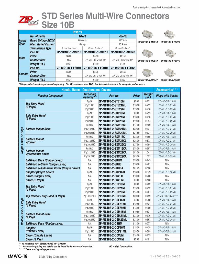
Inserts
Insert Type
No. of Poles 10+PE 42+PERated Voltage AC/DC 600 Volts 600 Volts
Max. Rated Current 16 Amps 10 Amps
Termination Type Screw Terminals Crimp Contacts* Crimp Contacts*
Male
Part No. ZP-MC10B-1-MS010 ZP-MC10B-1-MC010 ZP-MC10B-1-MC042Price $6.00 $5.50 $13.50
Contact Size N/A ZP-MC-CC-M16A-XX* ZP-MC-CC-M10A-XX*
Weight (lb.) 0.134 0.099 0.099
Female
Part No. ZP-MC10B-1-FS010 ZP-MC10B-1-FC010 ZP-MC10B-1-FC042Price $6.00 $5.25 $13.50
Contact Size N/A ZP-MC-CC-M16A-XX* ZP-MC-CC-M10A-XX*
Weight (lb.) 0.134 0.099 0.103
Hoods, Bases, Couplers and Covers Accessories***
Housing Component Threading Opening** Part No. Price Weight
(lb.) Plugs with Gasket
Sing
le L
ever
/ 2
Pegs
Top Entry Hood (2 Pegs)
Pg 16 ZP-MC10B-2-STE16M $8.00 0.271 ZP-MC-PLG-16M8Pg 21 HC ZP-MC10B-2-STE21ML $18.00 0.432 ZP-ML-PLG-21M8Pg 29 HC ZP-MC10B-2-STE29ML $19.00 0.410 ZP-ML-PLG-29M8
Side Entry Hood (2 Pegs)
Pg 16 ZP-MC10B-2-SSE16M $9.00 0.255 ZP-MC-PLG-16M8Pg 21 HC ZP-MC10B-2-SSE21ML $18.00 0.416 ZP-ML-PLG-21M8Pg 29 HC ZP-MC10B-2-SSE29ML $19.00 0.394 ZP-ML-PLG-29M8
Surface Mount BasePg 16x2 ZP-MC10B-2-SSM16M $17.00 0.509 ZP-MC-PLG-16M8
Pg 21x2 HC ZP-MC10B-2-SSM21ML $22.00 0.637 ZP-ML-PLG-21M8Pg 29x2 HC ZP-MC10B-2-SSM29ML $21.50 0.637 ZP-ML-PLG-29M8
Surface Mount w/Cover
Pg 16x2 ZP-MC10B-2-SSM16C $23.00 0.655 ZP-MC-PLG-16M8Pg 21x2 HC ZP-MC10B-2-SSM21CL $28.00 0.873 ZP-ML-PLG-21M8Pg 29x2 HC ZP-MC10B-2-SSM29CL $27.50 0.794 ZP-ML-PLG-29M8
Surface Mount w/Automatic Cover
Pg 16x2 ZP-MC10B-2-SSM16CA $78.00 0.697 ZP-MC-PLG-16M8Pg 21x2 HC ZP-MC10B-2-SSM21CA $83.00 1.041 ZP-ML-PLG-21M8Pg 29x2 HC ZP-MC10B-2-SSM29CA $83.00 1.027 ZP-ML-PLG-29M8
Bulkhead Base (Single Lever) N/A ZP-MC10B-2-SBHM $29.00 0.245 N/A
Bulkhead w/Cover (Single Lever) N/A ZP-MC10B-2-SBHC $16.00 0.401 N/A
Bulkhead w/Automatic Cover (Single Cover) N/A ZP-MC10B-2-SBHCA $61.75 0.520 N/A
Coupler (Single Lever) Pg 16 ZP-MC10B-2-SCP16M $18.00 0.379 ZP-ML-PLG-16M8
Cover (Single Lever) N/A ZP-MC10B-2-SCVLM $10.00 0.200 N/A
Cover (2 Pegs) N/A ZP-MC10B-2-SCVPM $6.00 0.108 N/A
Doub
le L
ever
/ 4
Pegs
Top Entry Hood (4 Pegs)
Pg 16 ZP-MC10B-2-DTE16M $7.00 0.262 ZP-MC-PLG-16M8
Pg 21 HC ZP-MC10B-2-DTE21ML $13.00 0.432 ZP-ML-PLG-21M8Pg 29 HC ZP-MC10B-2-DTE29ML $14.00 0.407 ZP-ML-PLG-29M8
Top Double Entry Hood (4 Pegs) Pg 13.5x2 HC ZP-MC10B-2-DTE13M2 $20.00 0.459 ZP-MC-PLG-13M8****
Side Entry Hood (4 Pegs)
Pg 16 ZP-MC10B-2-DSE16M $6.00 0.260 ZP-MC-PLG-16M8Pg 21 HC ZP-MC10B-2-DSE21ML $12.50 0.421 ZP-ML-PLG-21M8Pg 29 HC ZP-MC10B-2-DSE29ML $13.50 0.399 ZP-ML-PLG-29M8
Surface Mount Base (4 Peg)
Pg 16x2 ZP-MC10B-2-DSM16M $19.50 0.537 ZP-MC-PLG-16M8Pg 21x2 HC ZP-MC10B-2-DSM21ML $23.00 0.676 ZP-ML-PLG-21M8Pg 29x2 HC ZP-MC10B-2-DSM29ML $23.00 0.663 ZP-ML-PLG-29M8
Bulkhead Base (Double Lever) N/A ZP-MC10B-2-DBHM $13.00 0.277 N/A
Coupler (Double Lever)
Pg 16 ZP-MC10B-2-DCP16M $18.00 0.429 ZP-MC-PLG-16M8Pg 21 HC ZP-MC10B-2-DCP21ML $28.50 0.599 ZP-MC-PLG-21M8
Cover (Double Lever) N/A ZP-MC10B-2-DCVLM $14.00 0.235 N/A
Cover (4 Peg) N/A ZP-MC10B-2-DCVPM $6.50 0.101 N/A
*Crimp contacts must be purchased separately. The XX represents wire AWG. See Accessories section for complete part numbers.
ZP-MC10B-1-MS010
ZP-MC10B-1-MC010 ZP-MC10B-1-FC010
ZP-MC10B-1-MC042 ZP-MC10B-1-FC042
ZP-MC10B-1-FS010
** To convert to NPT, select a Pg to NPT adapter. *** Accessories pricing and details can be found in the Accessories section. HC = High Construction ***** There are 2 openings per hood.
STD Series Multi-Wire Connectors Size 10B
1 - 80 0 - 633 - 0405Multi-Wire ConnectorstMWC-18
For the latest prices, please check AutomationDirect.com.

Accessories*** Continued
Housing Component IP66 Cable Glands
IP68 Cable Glands
Pg to NPT AdapterPg13.5/Pg16 to ½” Pg 21 to ¾” Pg 29 to 1” Pg 29 to 1¼”
Sing
le L
ever
/ 2
Pegs
Top Entry Hood (2 Pegs)
ZP-MC-CG-16M5 ZP-MC-CG-16M8 ZP-MC-A-16012 N/A N/A N/AN/A ZP-MC-CG-21M8 N/A ZP-MC-A-21034 N/A N/AN/A ZP-MC-CG-29M8 N/A N/A ZP-MC-A-29100 ZP-MC-A-29114
Side Entry Hood (2 Pegs)
ZP-MC-CG-16M5 ZP-MC-CG-16M8 ZP-MC-A-16012 N/A N/A N/AN/A ZP-MC-CG-21M8 N/A ZP-MC-A-21034 N/A N/AN/A ZP-MC-CG-29M8 N/A N/A ZP-MC-A-29100 ZP-MC-A-29114
Surface Mount BaseZP-MC-CG-16M5 ZP-MC-CG-16M8 ZP-MC-A-16012 N/A N/A N/AZP-MC-CG-21M5 ZP-MC-CG-21M8 N/A ZP-MC-A-21034 N/A N/AZP-MC-CG-29M5 ZP-MC-CG-29M8 N/A N/A ZP-MC-A-29100 ZP-MC-A-29114
Surface Mount w/Cover
ZP-MC-CG-16M5 ZP-MC-CG-16M8 ZP-MC-A-16012 N/A N/A N/AZP-MC-CG-21M5 ZP-MC-CG-21M8 N/A ZP-MC-A-21034 N/A N/AZP-MC-CG-29M5 ZP-MC-CG-29M8 N/A N/A ZP-MC-A-29100 ZP-MC-A-29114
Surface Mount w/Automatic Cover
ZP-MC-CG-16M5 ZP-MC-CG-16M8 ZP-MC-A-16012 N/A N/A N/AZP-MC-CG-21M5 ZP-MC-CG-21M8 N/A ZP-MC-A-21034 N/A N/AZP-MC-CG-29M5 ZP-MC-CG-29M8 N/A N/A ZP-MC-A-29100 ZP-MC-A-29114
Bulkhead Base (Single Lever) N/A N/A N/A N/A N/A N/A
Bulkhead w/Cover (Single Lever) N/A N/A N/A N/A N/A N/A
Bulkhead w/Automatic Cover (Single Lever) N/A N/A N/A N/A N/A N/A
Coupler (Single Lever) ZP-MC-CG-16M5 ZP-MC-CG-16M8 ZP-MC-A-16012 N/A N/A N/A
Cover (Single Lever) N/A N/A N/A N/A N/A N/A
Cover (2 Pegs) N/A N/A N/A N/A N/A N/A
Doub
le L
ever
/ 4
Pegs
Top Entry Hood (4 Pegs)
ZP-MC-CG-16M5 ZP-MC-CG-16M8 ZP-MC-A-16012 N/A N/A N/AN/A ZP-MC-CG-21M8 N/A ZP-MC-A-21034 N/A N/AN/A ZP-MC-CG-29M8 N/A N/A ZP-MC-A-29100 ZP-MC-A-29114
Top Double Entry Hood (4 Pegs) N/A ZP-MC-CG-13M8 ZP-MC-A-13012**** N/A N/A N/A
Side Entry Hood (4 Pegs)
ZP-MC-CG-16M5 ZP-MC-CG-16M8 ZP-MC-A-16012 N/A N/A N/AN/A ZP-MC-CG-21M8 N/A ZP-MC-A-21034 N/A N/AN/A ZP-MC-CG-29M8 N/A N/A ZP-MC-A-29100 ZP-MC-A-29114
Surface Mount Base (4 Pegs)ZP-MC-CG-16M5 ZP-MC-CG-16M8 ZP-MC-A-16012 N/A N/A N/A
N/A ZP-MC-CG-21M8 N/A ZP-MC-A-21034 N/A N/AN/A ZP-MC-CG-29M8 N/A N/A ZP-MC-A-29100 ZP-MC-A-29114
Bulkhead Base (Double Lever) N/A N/A N/A N/A N/A N/A
Coupler (Double Lever)
ZP-MC-CG-16M5 ZP-MC-CG-16M8 ZP-MC-A-16012 N/A N/A N/AN/A ZP-MC-CG-21M8 N/A ZP-MC-A-21034 N/A N/A
Cover (Double Lever) N/A N/A N/A N/A N/A N/A
Cover (4 Pegs) N/A N/A N/A N/A N/A N/A
** To convert to NPT, select a Pg to NPT adapter. *** Accessories pricing and details can be found in the Accessories section. **** There are 2 openings per hood.
Single Lever Surface Mount
Base
Single Lever Bulkhead Base
Single Lever Coupler
Single Lever Cover
Double Lever Top Entry Hood
Double Lever Side Entry Hood
Double Lever Surface Mount
Base
Single Lever Top Entry Hood
Single Lever Side Entry Hood
Single Lever Top Entry Hood High
Capacity
Single Lever Side Entry Hood High
Capacity
Single Lever Surface Mount Base
High Capacity
Double Lever Top Entry Hood High Capacity
Double Lever Side Entry Hood High Capacity
Note: See end of section for accessory photos
Surface Mount w/Cover
Double Entry Hood
STD Series Multi-Wire Connectors Size 10B
tMWC-19Multi-Wire Connectorsw w w. a u to m at i o n d i re c t . c o m / w i r i n g- s o l u t i o n s
For the latest prices, please check AutomationDirect.com.

Electrical Engineering Data - Load Diagrams
32
28
1.524
20
1.0
16
12
8
Ambient temperature (C°)
20 30 40 50 60 70 80 90 100 110 120 130
4
0.5
2.5
4.0
Size 6B 6P +16
14
1.5
12
10
1.0
8
6
4
Ambient temperature (C°)
20 30 40 50 60 70 80 90 100 110 120 130
2
0.5
2.5
Size 6B 24P +
32
28
1.5
24
20
1.016
12
8
Ambient temperature (C°)
20 30 40 50 60 70 80 90 100 110 120 130
4
2.5
0.5
4.0
Size 10B 10P +16
14
1.512
10
1.0
8
6
4
Ambient temperature (C°)
20 30 40 50 60 70 80 90 100 110 120 130
2
2.5
0.5
4.0
Size 10B 42P +
STD Series Multi-Wire Connectors
tMWC-29Multi-Wire Connectorsw w w. a u to m at i o n d i re c t . c o m / w i r i n g- s o l u t i o n s
For the latest prices, please check AutomationDirect.com.

Size 10B Inserts
Male Female
Male Female
Male Female
ZP-MC10B-1-MS010 ZP-MC10B-1-FS010
ZP-MC10B-1-MC010 ZP-MC10B-1-FC010
ZP-MC10B-1-MC042 ZP-MC10B-1-FC042
Dimensions mm [in]
10 + – Screw Terminals
10 + – Crimp Contacts
42 + – Crimp Contacts
STD Series Multi-Wire Dimensions
tMWC-49Multi-Wire Connectorsw w w. a u to m at i o n d i re c t . c o m / w i r i n g- s o l u t i o n s
For the latest prices, please check AutomationDirect.com.

Size 6B, 10B, 16B, 24B, 32B Hoods
Single Lever Top Entry Hood
Part Number Size Thread A B C D E
ZP-MC06B-2-STE16M 6B Pg 16 60.0 [2.36]
43.5 [1.71]
53.0 [2.09]
27.0 [1.06]
44.0 [1.73]
ZP-MC10B-2-STE16M 10B Pg 16 73.5 [2.89]
43.5 [1.71]
58.0 [2.28]
27.0 [1.06]
57.0 [2.24]
ZP-MC16B-2-STE21M 16B Pg 21 94 [3.70]
43.5 [1.71]
58.0 [2.28]
27.0 [1.06]
77.5 [3.05]
ZP-MC24B-2-STE21M 24B Pg 21 120.5 [4.74]
43.5 [1.71]
68.0 [2.68]
27.0 [1.06]
104.0 [4.09]
Single Lever Side Entry Hood
Single Lever Side Entry High Construction Hood
Dimensions mm [in]
Note: Size 32B hoods require 2 of the 16B inserts.
Part Number Size Thread A B C D E F G
ZP-MC06B-2-SSE16M 6B Pg 16 60.0 [2.36]
43.5 [1.71]
47.0 [1.85]
27.0 [1.06]
44.0 [1.73]
54.0 [2.13]
78.5 [3.09]
ZP-MC10B-2-SSE16M 10B Pg 16 73.5 [2.89]
43.5 [1.71]
52.0 [2.05]
27.0 [1.06]
57.0 [2.24]
55.6 [2.19]
90.9 [3.58]
ZP-MC16B-2-SSE21M 16B Pg 21 94.0 [3.70]
43.5 [1.71]
63.0 [2.48]
27.0 [1.06]
77.5 [3.05]
66.2 [2.61]
109.7 [4.32]
ZP-MC24B-2-SSE21M 24B Pg 21 120.5 [4.74]
43.5 [1.71]
63.0 [2.48]
27.0 [1.06]
104.0 [4.09]
65.4 [2.58]
136.4 [5.37]
Part Number Size Thread A B CZP-MC06B-2-SSE21ML
6BPg 21 60.0
[2.36]43.5
[1.71]80.0
[3.15]ZP-MC06B-2-SSE29ML Pg 29
ZP-MC10B-2-SSE21ML10B
Pg 21 73.5 [2.90]
43.5 [1.71]
80.0 [3.15]ZP-MC10B-2-SSE29ML Pg 29
ZP-MC16B-2-SSE21ML16B
Pg 21 94.0 [3.70]
43.5 [1.71]
80.0 [3.15]ZP-MC16B-2-SSE29ML Pg 29
ZP-MC24B-2-SSE21ML24B
Pg 21 120.5 [4.74]
43.5 [1.71]
80.0 [3.15]ZP-MC24B-2-SSE29ML Pg 29
ZP-MC32B-2-SSE36M 32B Pg 36 94.0 [3.70]
83.0 [3.27]
94.0 [3.70]
Single Lever Top Entry High Construction Hood
Part Number Size Thread A B CZP-MC06B-2-STE21ML
6BPg 21 60.0
[2.36]43.5
[1.71]75.0
[2.95]ZP-MC06B-2-STE29ML Pg 29ZP-MC10B-2-STE21ML
10BPg 21 73.5
[2.89]43.5
[1.71]75.5
[2.97]ZP-MC10B-2-STE29ML Pg 29ZP-MC16B-2-STE21ML
16BPg 21 94.0
[3.70]43.5
[1.71]75.5
[2.97]ZP-MC16B-2-STE29ML Pg 29ZP-MC24B-2-STE21ML
24BPg 21 120.5
[4.74]43.5
[1.71]75.5
[2.97]ZP-MC24B-2-STE29ML Pg 29
ZP-MC32B-2-STE36M 32B Pg 36 94.0 [3.70]
83.0 [3.27]
89.0 [3.50]
STD Series Multi-Wire Dimensions
tMWC-55Multi-Wire Connectorsw w w. a u to m at i o n d i re c t . c o m / w i r i n g- s o l u t i o n s
For the latest prices, please check AutomationDirect.com.

Double Lever Top Entry Hood
Double Lever Top Entry High Construction Hood
Part Number Size Thread A B CZP-MC10B-2-DTE21ML
10BPg 21 73.5
[2.89]43.5
[1.71]75.5
[2.97]ZP-MC10B-2-DTE29ML Pg 29ZP-MC16B-2-DTE21ML
16BPg 21
94.0 [3.70]
43.5 [1.71]
75.5 [2.97]ZP-MC16B-2-DTE29ML Pg 29
ZP-MC24B-2-DTE21ML24B
Pg 21 120.5 [4.74]
43.5 [1.71]
75.5 [2.97]ZP-MC24B-2-DTE29ML Pg 29
ZP-MC32B-2-DTE36M 32B* Pg 36 94.0 [3.70]
83.0 [3.27]
89.0 [3.50]
Dimensions mm [in]
Double Lever Side Entry Hood
*Note: Size 32B hoods require 2 of the 16B inserts.
Size 10B, 16B, 24B, 32B Hoods
Part Number Size Thread A B C D E
ZP-MC10B-2-DTE16M 10B Pg 16 73.5 [2.89]
43.5 [1.71]
58.0 [2.28]
27.0 [1.06]
57.0 [2.24]
ZP-MC16B-2-DTE21M 16B Pg 21 94.0 [3.70]
43.5 [1.71]
58.0 [2.28]
27.0 [1.06]
77.5 [3.05]
ZP-MC24B-2-DTE21M24B
Pg 21 120.5 [4.74]
43.5 [1.71]
68.0 [2.68]
27.0 [1.06]
104.0 [4.09]ZP-MC24B-2-DTE29M Pg 29
Part Number Size Thread A B C D E F G
ZP-MC10B-2-DSE16M 10B Pg 16 73.5 [2.89]
43.5 [1.71]
52.0 [2.05]
27.5 [1.08]
57.5 [2.26]
57.5 [2.26]
83.9 [3.30]
ZP-MC16B-2-DSE21M 16B Pg 21 94.0 [3.70]
43.5 [1.71]
63.0 [2.48]
27.5 [1.08]
77.5 [3.05]
58.0 [2.28]
102.7 [4.04]
ZP-MC24B-2-DSE21M24B
Pg 21 120.5 [4.74]
43.5 [1.71]
63.0 [2.48]
27.5 [1.08]
104.0 [4.09]
57.0 [2.24]
129.3 [5.09]ZP-MC24B-2-DSE29M Pg 29
STD Series Multi-Wire Dimensions
1 - 80 0 - 633 - 0405Multi-Wire ConnectorstMWC-56
For the latest prices, please check AutomationDirect.com.

Size 10B, 16B, 24B, 32B HoodsDimensions mm [in]
Double Lever Double Top Entry Hood High Construction
*Note: Size 32B hoods require 2 of the 16B inserts.
Double Lever Side Entry High Construction Hood
Part Number Size Thread A B CZP-MC10B-2-DSE21ML
10BPg 21 73.5
[2.89]43.5
[1.71]80.0
[3.15]ZP-MC10B-2-DSE29ML Pg 29
ZP-MC16B-2-DSE21ML16B
Pg 2194.0
[3.70]43.5
[1.71]80.0
[3.15]ZP-MC16B-2-DSE29ML Pg 29
ZP-MC24B-2-DSE21ML24B
Pg 21 120.5 [4.74]
43.5 [1.71]
80.0 [3.15]ZP-MC24B-2-DSE29ML Pg 29
ZP-MC32B-2-DSE36M 32B* Pg 36 94.0 [3.70]
83.0 [3.27]
94.0 [3.70]
Part Number Size Thread A B C D
ZP-MC10B-2-DTE13M2 10B Pg 13.5x2 73.5 [2.89]
43.5 [1.71]
81.0 [3.19]
24.0 [0.94]
ZP-MC16B-2-DTE16M216B
Pg 16x2 94.0 [3.70]
43.5 [1.71]
81.0 [3.19]
38.0 [1.50]
ZP-MC16B-2-DTE21M2 Pg 21x2
ZP-MC24B-2-DTE21M224B
Pg 21x2 120.5 [4.74]
43.5 [1.71]
81.0 [3.19]
53.0 [2.09]ZP-MC24B-2-DTE29M2 Pg 29x2
STD Series Multi-Wire Dimensions
tMWC-57Multi-Wire Connectorsw w w. a u to m at i o n d i re c t . c o m / w i r i n g- s o l u t i o n s
For the latest prices, please check AutomationDirect.com.

Single Lever Surface Mount Base
Single Lever High Construction Surface Mount Base
Part Number Size Thread A B C D E FZP-MC06B-2-SSM21ML
6BPg 21x2 83.5
[3.29]57.0
[2.24]72.0
[2.84]70.0
[2.76]40.0
[1.57]79.5
[3.13]ZP-MC06B-2-SSM29ML Pg 29x2ZP-MC10B-2-SSM21ML
10BPg 21x2 97.0
[3.82]57.0
[2.24]73.0
[2.88]82.0
[3.23]40.0
[1.57]79.5
[3.13]ZP-MC10B-2-SSM29ML Pg 29x2ZP-MC16B-2-SSM21ML
16BPg 21x2 117.0
[4.61]57.0
[2.24]77.0
[3.03]105.0 [4.13]
45.0 [1.77]
79.5 [3.13]ZP-MC16B-2-SSM29ML Pg 29x2
ZP-MC24B-2-SSM21ML24B
Pg 21x2 143.5 [5.65]
57.0 [2.24]
80.0 [3.15]
132.0 [5.20]
45.0 [1.77]
79.5 [3.13]ZP-MC24B-2-SSM29ML Pg 29x2
Size 6B, 10B, 16B, 24B, 32B BasesDimensions mm [in]
Part Number Size Thread A B C D E F
ZP-MC06B-2-SSM16M 6B Pg 16x2 83.5 [3.29]
57.0 [2.24]
53.0 [2.09]
70.0 [2.76]
40.0 [1.57]
79.5 [3.13]
ZP-MC10B-2-SSM16M 10B Pg 16x2 97.0 [3.82]
57.0 [2.24]
57.0 [2.24]
82.0 [3.23]
40.0 [1.57]
79.5 [3.13]
ZP-MC16B-2-SSM21M 16B Pg 21x2 117.0 [4.61]
57.0 [2.24]
63.0 [2.48]
105.0 [4.13]
45.0 [1.77]
79.5 [3.13]
ZP-MC24B-2-SSM21M 24B Pg 21x2 143.5 [5.65]
57.0 [2.24]
63.0 [2.48]
132 [5.20]
45.0 [1.77]
79.5 [3.13]
ZP-MC32B-2-SSM36M 32B Pg 36x2 125.0 [4.92]
84.5 [3.33]
87.5 [3.44]
112.0 [4.41]
67.0 [2.64]
115.5 [4.55]
Single Lever Surface Mount Base With Cover
Part Number Size Thread A B C D E F G H
ZP-MC06B-2-SSM16C 6B Pg 16x2 83.5 [3.29]
57.0 [2.24]
53.0 [2.09]
70.0 [2.76]
40.0 [1.57]
101.0 [3.98]
115.3 [4.54]
150.7 [5.93]
ZP-MC10B-2-SSM16C 10B Pg 16x2 97.0 [3.82]
57.0 [2.24]
57.0 [2.24]
82.0 [3.23]
40.0 [1.57]
101.0 [3.98]
115.3 [4.54]
145.5 [5.73]
ZP-MC16B-2-SSM21C 16B Pg 21x2 117.0 [4.61]
57.0 [2.24]
63.0 [2.48]
105.0 [4.13]
45.0 [1.77]
101.0 [3.98]
124.5 [4.90]
145.5 [5.73]
ZP-MC24B-2-SSM21C 24B Pg 21x2 143.5 [5.65]
57.0 [2.24]
63.0 [2.48]
132.0 [5.20]
45.0 [1.77]
101.0 [3.98]
124.5 [4.90]
145.5 [5.73]
ZP-MC32B-2-SSM36C 32B Pg 36x2 125.0 [4.92]
84.5 [3.33]
87.5 [3.44]
112.0 [4.41]
67.0 [2.64]
146.0 [5.75]
187.0 [7.36]
228.9 [9.01]
STD Series Multi-Wire Dimensions
1 - 80 0 - 633 - 0405Multi-Wire ConnectorstMWC-58
For the latest prices, please check AutomationDirect.com.

Size 6B, 10B, 16B, 24B, 32B Bases
Single Lever Surface Mount Base With Automatic Cover
Single Lever High Construction Surface Mount Base With Automatic Cover
Part Number Size Thread A B C D E F G HZP-MC06B-2-SSM21CL
6BPg 21x2 83.5
[3.29]57.0
[2.24]73.0
[2.87]70.0
[2.76]45.0
[1.77]101.0 [3.98]
132.1 [5.20]
146.8 [5.78]ZP-MC06B-2-SSM29CL Pg 29x2
ZP-MC10B-2-SSM21CL10B
Pg 21x2 97.0 [3.82]
57.0 [2.24]
73.0 [2.87]
82.0 [3.23]
45.0 [1.77]
101.0 [3.98]
133.3 [5.25]
148.0 [5.83]ZP-MC10B-2-SSM29CL Pg 29x2
ZP-MC16B-2-SSM21CL16B
Pg 21x2 117.0 [4.61]
57.0 [2.24]
77.0 [3.03]
105.0 [4.13]
45.0 [1.77]
101.0 [3.98]
137.5 [5.41]
150.0 [5.91]ZP-MC16B-2-SSM29CL Pg 29x2
ZP-MC24B-2-SSM21CL24B
Pg 21x2 143.5 [5.65]
57.0 [2.24]
80.0 [3.15]
132.0 [5.20]
45.0 [1.77]
101.0 [3.98]
140.5 [5.53]
154.4 [6.08]ZP-MC24B-2-SSM29CL Pg 29x2
Part Number Size Thread A B C D E F G
ZP-MC06B-2-SSM21CA6B
Pg 21x2 83.5 [3.29]
57.0 [2.24]
73.0 [2.87]
70.0 [2.76]
45.0 [1.77]
101.0 [3.98]
137.3 [5.41]
ZP-MC06B-2-SSM29CA Pg 29x2ZP-MC10B-2-SSM21CA
10BPg 21x2 97.0
[3.82]57.0
[2.24]73.0
[2.87]82.0
[3.23]45.0
[1.77]101.0 [3.98]
137.3 [5.41]ZP-MC10B-2-SSM29CA Pg 29x2
ZP-MC16B-2-SM21CAL16B
Pg 21x2 117.0 [4.61]
57.0 [2.24]
77.0 [3.03]
105.0 [4.13]
45.0 [1.77]
101.0 [3.98]
141.7 [5.58]ZP-MC16B-2-SM29CAL Pg 29x2
ZP-MC24B-2-SM21CAL24B
Pg 21x2 143.5 [5.65]
57.0 [2.24]
80.0 [3.15]
132.0 [5.20]
45.0 [1.77]
101.0 [3.98]
144.8 [5.70]ZP-MC24B-2-SM29CAL Pg 29x2
Part Number Size Thread A B C D E F G
ZP-MC06B-2-SSM16CA 6B Pg 16x2 83.5 [3.29]
57.0 [2.24]
53.0 [2.09]
70.0 [2.76]
40.0 [1.57]
101.0 [3.98]
117.8 [4.64]
ZP-MC10B-2-SSM16CA 10B Pg 16x2 97.0 [3.82]
57.0 [2.24]
57.0 [2.24]
82.0 [3.23]
40.0 [1.57]
101.0 [3.98]
121.0 [4.76]
ZP-MC16B-2-SSM21CA 16B Pg 21x2 117.0 [4.61]
57.0 [2.24]
63.0 [2.48]
105.0 [4.13]
45.0 [1.77]
101.0 [3.98]
127.5 [5.02]
ZP-MC24B-2-SSM21CA 24B Pg 21x2 143.5 [5.65]
57.0 [2.24]
63.0 [2.48]
132.0 [5.20]
45.0 [1.77]
101.0 [3.98]
127.8 [5.03]
Single Lever High Construction Surface Mount Base With Cover
Dimensions mm [in]
STD Series Multi-Wire Dimensions
tMWC-59Multi-Wire Connectorsw w w. a u to m at i o n d i re c t . c o m / w i r i n g- s o l u t i o n s
For the latest prices, please check AutomationDirect.com.

Size 6B, 10B, 16B, 24B, 32B BasesDimensions mm [in]
Single Lever Bulkhead Base
Single Lever Bulkhead Base w/Cover
Part Number Size A B C D E F G H J
ZP-MC06B-2-SBHC 6B 82.0 [3.23]
44.0 [1.73]
29.5 [1.16]
70.0 [2.75]
32.0 [1.26]
101.0 [3.98]
53.0 [2.09]
36.0 [1.42]
88.5 [3.48]
ZP-MC10B-2-SBHC 10B 95.5 [3.76]
44.0 [1.73]
29.5 [1.16]
83.0 [3.27]
32.0 [1.26]
101.0 [3.98]
66.5 [2.62]
36.0 [1.42]
88.5 [3.48]
ZP-MC16B-2-SBHC 16B 115.5 [4.55]
44.0 [1.73]
29.5 [1.16]
103.0 [4.06]
32.0 [1.26]
101.0 [3.98]
86.5 [3.41]
36.0 [1.42]
88.5 [3.48]
ZP-MC24B-2-SBHC 24B 142.5 [5.61]
44.0 [1.73]
29.5 [1.16]
130.0 [5.12]
32.0 [1.26]
101.0 [3.98]
113.0 [4.45]
36.0 [1.42]
88.5 [3.48]
ZP-MC32B-2-SBHC 32B 124.5 [4.90]
84.5 [3.33]
35.5 [1.40]
110.0 [4.33]
65.0 [2.56]
146.0 [5.75]
87.5 [3.44]
76.5 [3.01]
134.5 [5.30]
Single Lever Bulkhead Base w/Automatic Cover
Part Number Size A B C D E F G* H* J
ZP-MC06B-2-SBHCA 6B 82.0 [3.23]
44.0 [1.73]
29.5 [1.16]
70.0 [2.75]
32.0 [1.26]
101.0 [3.98]
53.0 [2.09]
36.0 [1.42]
97.8 [3.85]
ZP-MC10B-2-SBHCA 10B 95.5 [3.76]
44.0 [1.73]
29.5 [1.16]
83.0 [3.27]
32.0 [1.26]
101.0 [3.98]
66.5 [2.62]
36.0 [1.42]
97.8 [3.85]
ZP-MC16B-2-SBHCA 16B 115.5 [4.55]
44.0 [1.73]
29.5 [1.16]
103.0 [4.06]
32.0 [1.26]
101.0 [3.98]
86.5 [3.41]
36.0 [1.42]
97.8 [3.85]
ZP-MC24B-2-SBHCA 24B 142.5 [5.61]
44.0 [1.73]
29.5 [1.16]
130.0 [5.12]
32.0 [1.26]
101.0 [3.98]
113.0 [4.45]
36.0 [1.42]
97.8 [3.85]
Part Number Size A B C D E F G* H*
ZP-MC06B-2-SBHM 6B 82.0 [3.23]
44.0 [1.73]
29.5 [1.16]
70.0 [2.75]
32.0 [1.26]
73.0 [2.88]
53.0 [2.09]
36.0 [1.42]
ZP-MC10B-2-SBHM 10B 95.5 [3.76]
44.0 [1.73]
29.5 [1.16]
83.0 [3.27]
32.0 [1.26]
73.0 [2.88]
66.5 [2.62]
36.0 [1.42]
ZP-MC16B-2-SBHM 16B 115.5 [4.55]
44.0 [1.73]
29.5 [1.16]
103.0 [4.06]
32.0 [1.26]
73.0 [2.88]
86.5 [3.41]
36.0 [1.42]
ZP-MC24B-2-SBHM 24B 142.5 [5.61]
44.0 [1.73]
29.5 [1.16]
130.0 [5.12]
32.0 [1.26]
73.0 [2.88]
113.0 [4.45]
36.0 [1.42]
ZP-MC32B-2-SBHM 32B 124.5 [4.90]
84.5 [3.33]
35.5 [1.40]
110.0 [4.33]
65.0 [2.56]
116.0 [4.57]
87.5 [3.44]
76.5 [3.01]
*Dimensions G and H refer to cutout size
*Dimensions G and H refer to cutout size
STD Series Multi-Wire Dimensions
1 - 80 0 - 633 - 0405Multi-Wire ConnectorstMWC-60
For the latest prices, please check AutomationDirect.com.
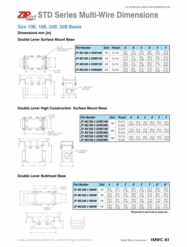
Double Lever Bulkhead Base
Double Lever Surface Mount Base
Size 10B, 16B, 24B, 32B Bases
Double Lever High Construction Surface Mount Base
Dimensions mm [in]
Part Number Size Thread A B C D E F
ZP-MC10B-2-DSM16M 10B Pg 16x2 97.0 [3.82]
57.0 [2.24]
57.0 [2.24]
82.0 [3.23]
40.0 [1.57]
127.0 [5.00]
ZP-MC16B-2-DSM21M 16B Pg 21x2 117.0 [4.61]
57.0 [2.24]
63.0 [2.48]
105.0 [4.13]
45.0 [1.77]
147.0 [5.79]
ZP-MC24B-2-DSM21M 24B Pg 21x2 143.5 [5.65]
57.0 [2.24]
63.0 [2.48]
132.0 [5.20]
45.0 [1.77]
174.0 [6.85]
ZP-MC32B-2-DSM36M 32B Pg 36x2 125.0 [4.92]
84.5 [3.33]
87.5 [3.44]
112.0 [4.41]
67.0 [2.64]
147.0 [5.79]
Part Number Size Thread A B C D E FZP-MC10B-2-DSM21ML
10BPg 21x2 97.0
[3.82]57.0
[2.24]73.0
[2.87]82.0
[3.23]45.0
[1.77]127.0 [5.00]ZP-MC10B-2-DSM29ML Pg 29x2
ZP-MC16B-2-DSM21ML16B
Pg 21x2 117.0 [4.61]
57.0 [2.24]
77.0 [3.03]
105.0 [4.13]
45.0 [1.77]
147.0 [5.79]ZP-MC16B-2-DSM29ML Pg 29x2
ZP-MC24B-2-DSM21ML24B
Pg 21x2 143.5 [5.65]
57.0 [2.24]
80.0 [3.15]
132.0 [5.20]
45.0 [1.77]
174.0 [6.85]ZP-MC24B-2-DSM29ML Pg 29x2
Part Number Size A B C D E F G* H*
ZP-MC10B-2-DBHM 10B 95.5 [3.76]
53.5 [2.11]
29.5 [1.16]
83.0 [3.27]
32.0 [1.26]
127.0 [5.00]
66.5 [2.62]
36.0 [1.42]
ZP-MC16B-2-DBHM 16B 115.5 [4.55]
53.5 [2.11]
29.5 [1.16]
103.0 [4.05]
32.0 [1.26]
147.0 [5.79]
86.5 [3.41]
36.0 [1.42]
ZP-MC24B-2-DBHM 24B 142.5 [5.61]
53.5 [2.11]
29.5 [1.16]
130.0 [5.19]
32.0 [1.26]
174.0 [6.85]
113.0 [4.45]
36.0 [1.42]
ZP-MC32B-2-DBHM 32B 124.5 [4.90]
84.5 [3.33]
35.5 [1.40]
110.0 [4.33]
65.0 [2.56]
147.0 [5.79]
87.5 [3.44]
76.5 [3.01]
*Dimensions G and H refer to cutout size
STD Series Multi-Wire Dimensions
tMWC-61Multi-Wire Connectorsw w w. a u to m at i o n d i re c t . c o m / w i r i n g- s o l u t i o n s
For the latest prices, please check AutomationDirect.com.
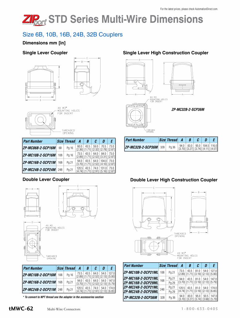
* To convert to NPT thread see the adapter in the accessories section
Single Lever Coupler
Double Lever Coupler
Part Number Size Thread A B C D E
ZP-MC06B-2-SCP16M 6B Pg 16 60.0 [2.36]
43.5 [1.71]
59.0 [2.32]
70.5 [2.78]
73.0 [2.87]
ZP-MC10B-2-SCP16M 10B Pg 16 73.5 [2.89]
43.5 [1.71]
64.0 [2.52]
84.0 [3.31]
73.0 [2.87]
ZP-MC16B-2-SCP21M 16B Pg 21 94.0 [3.70]
43.5 [1.71]
64.0 [2.52]
104.0 [4.10]
73.0 [2.87]
ZP-MC24B-2-SCP24M 24B Pg 21 120.5 [4.74]
43.5 [1.71]
74.0 [2.91]
131.0 [5.16]
73.0 [2.87]
Part Number Size Thread A B C D E
ZP-MC10B-2-DCP16M 10B Pg 16 73.5 [2.89]
43.5 [1.71]
64.0 [2.52]
54.0 [2.13]
127.0 [5.00]
ZP-MC16B-2-DCP21M 16B Pg 21 94.0 [3.70]
43.5 [1.71]
64.0 [2.52]
54.0 [2.13]
147.0 [5.79]
ZP-MC24B-2-DCP21M 24B Pg 21 120.5 [4.74]
43.5 [1.71]
74.0 [2.91]
54.0 [2.13]
174.0 [6.85]
Double Lever High Construction Coupler
Part Number Size Thread A B C D E
ZP-MC10B-2-DCP21ML 10B Pg 21 73.5 [2.89]
43.5 [1.71]
81.0 [3.19]
54.0 [2.13]
127.0 [5.00]
ZP-MC16B-2-DCP21ML16B
Pg 21 94.0 [3.70]
43.5 [1.71]
81.0 [3.19]
54.0 [2.13]
147.0 [5.79]ZP-MC16B-2-DCP29ML Pg 29
ZP-MC24B-2-DCP21ML24B
Pg 21 120.5 [4.74]
43.5 [1.71]
81.0 [3.19]
54.0 [2.13]
174.0 [6.85]ZP-MC24B-2-DCP29ML Pg 29
ZP-MC32B-2-DCP36M 32B Pg 36 94.0 [3.70]
83.0 [3.27]
95.0 [3.74]
93.5 [3.68]
147.0 [5.79]
Size 6B, 10B, 16B, 24B, 32B CouplersDimensions mm [in]
Part Number Size Thread A B C D E
ZP-MC32B-2-SCP36M 32B Pg 36 94.0 [3.70]
83.0 [3.27]
95.0 [3.74]
104.5 [4.11]
116.0 [4.57]
Single Lever High Construction Coupler
ZP-MC32B-2-SCP36M
STD Series Multi-Wire Dimensions
1 - 80 0 - 633 - 0405Multi-Wire ConnectorstMWC-62
For the latest prices, please check AutomationDirect.com.
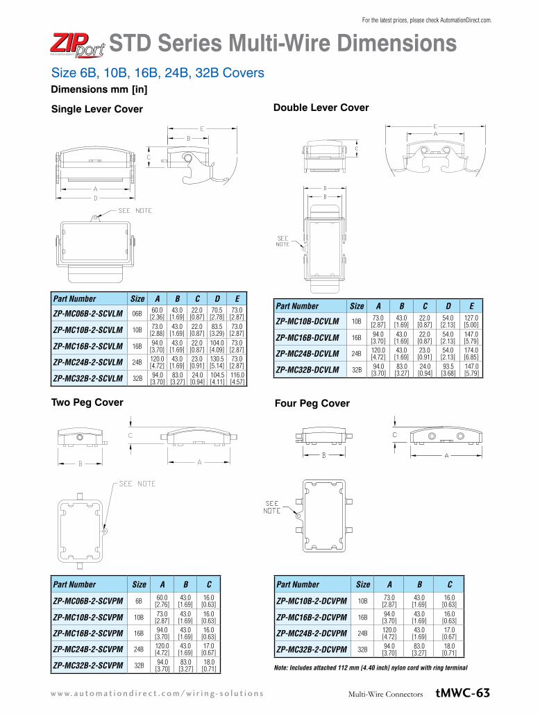
Single Lever Cover Double Lever Cover
Part Number Size A B C D E
ZP-MC06B-2-SCVLM 06B 60.0 [2.36]
43.0 [1.69]
22.0 [0.87]
70.5 [2.78]
73.0 [2.87]
ZP-MC10B-2-SCVLM 10B 73.0 [2.88]
43.0 [1.69]
22.0 [0.87]
83.5 [3.29)
73.0 [2.87]
ZP-MC16B-2-SCVLM 16B 94.0 [3.70]
43.0 [1.69]
22.0 [0.87]
104.0 [4.09]
73.0 [2.87]
ZP-MC24B-2-SCVLM 24B 120.0 [4.72]
43.0 [1.69]
23.0 [0.91]
130.5 [5.14]
73.0 [2.87]
ZP-MC32B-2-SCVLM 32B 94.0 [3.70]
83.0 [3.27]
24.0 [0.94]
104.5 [4.11]
116.0 [4.57]
Part Number Size A B C D E
ZP-MC10B-DCVLM 10B 73.0 [2.87]
43.0 [1.69]
22.0 [0.87]
54.0 [2.13]
127.0 [5.00]
ZP-MC16B-DCVLM 16B 94.0 [3.70]
43.0 [1.69]
22.0 [0.87]
54.0 [2.13]
147.0 [5.79]
ZP-MC24B-DCVLM 24B 120.0 [4.72]
43.0 [1.69]
23.0 [0.91]
54.0 [2.13]
174.0 [6.85]
ZP-MC32B-DCVLM 32B 94.0 [3.70]
83.0 [3.27]
24.0 [0.94]
93.5 [3.68]
147.0 [5.79]
Four Peg Cover
Part Number Size A B C
ZP-MC10B-2-DCVPM 10B 73.0 [2.87]
43.0 [1.69]
16.0 [0.63]
ZP-MC16B-2-DCVPM 16B 94.0 [3.70]
43.0 [1.69]
16.0 [0.63]
ZP-MC24B-2-DCVPM 24B 120.0 [4.72]
43.0 [1.69]
17.0 [0.67]
ZP-MC32B-2-DCVPM 32B 94.0 [3.70]
83.0 [3.27]
18.0 [0.71]
Note: Includes attached 112 mm [4.40 inch] nylon cord with ring terminal
Dimensions mm [in]Size 6B, 10B, 16B, 24B, 32B Covers
Two Peg Cover
Part Number Size A B C
ZP-MC06B-2-SCVPM 6B 60.0 [2.76]
43.0 [1.69]
16.0 [0.63]
ZP-MC10B-2-SCVPM 10B 73.0 [2.87]
43.0 [1.69]
16.0 [0.63]
ZP-MC16B-2-SCVPM 16B 94.0 [3.70]
43.0 [1.69]
16.0 [0.63]
ZP-MC24B-2-SCVPM 24B 120.0 [4.72]
43.0 [1.69]
17.0 [0.67]
ZP-MC32B-2-SCVPM 32B 94.0 [3.70]
83.0 [3.27]
18.0 [0.71]
STD Series Multi-Wire Dimensions
tMWC-63Multi-Wire Connectorsw w w. a u to m at i o n d i re c t . c o m / w i r i n g- s o l u t i o n s
For the latest prices, please check AutomationDirect.com.

StandardsThe inserts are designed and manufactured to conform with EN 61984, (IEC 61984), VDE 0627 and UL 1977/CSA C22.2 182.3 standards. They are certified and labeled with the cULus and CE marks. The connectors are therefore in conformance with both European/International and American systems. This permits them to be used in a wider range of applications worldwide.
• EN 61984 Connectors safety requirements and tests
• VDE 0627 Connectors (DIN VDE 0627)• EN 60664-1 Insulation coordination for
equipment within low-voltage systems
• EN 175 301-801 High density rectangular connectors, round removable crimp contacts
• EN 60947-7-1 part 7-1 Low-voltage switchgear and control gear, Ancillary equipment - Terminal blocks for copper conductors
• VDE 0110 Table 4 concerning clearance and creepage distances
• EN 60512 Connectors for electronic equipment, tests and measurements
• UL 1977 Component connectors for use in data, signal, control and power applications
• CSA.C22.2 No. 182.3 Special use attachment, plugs, receptacles and connectors
• EN 60529 Degree of protection provided by enclosures (IP degree)
• EN 50262 Metric cable glands for electrical installation
• EN 60423 Conduits for electrical purposes. Outside diameters of conduits for electrical installations and thread for conduits and fittings
• ISO 23570-2 Industrial automation system and integration. Distributed installation in industrial applications. Part 2: Hybrid communication bus.
• ISO 23570-3 Industrial automation system and integration. Distributed installation in industrial applications Part 3: Power distribution bus.
DESINA® specifications Specification to standardize electrical, hydraulic and pneumatic components and their interconnection on a common platform for CNC controlled machine tools and manufacturing lines.
Directives and DeclarationsNEMA-250 Declaration of Conformity
Metal and plastic enclosures for Multipole Industrial Connec-tors (Heavy Duty Connectors). Series STD, STD-HV, HE, HE-HV all sizes. Are designed and manufactured in conformity with NEMA 250-1991 Standard and meet the requirements of NEMA Type 4, 4x and 12.
2006/95/EC: LVD Directive
Directive 2006/95/EC of the European Parliament and of the council of 12 December 2006 on the harmonisation of the laws of Members States relating to electrical equipment de-signed for use within certain voltage limits.
2002/95/EC: RoHS Directive
Directive 2002/95/EC of the European Parliament and of the Council of 27 January 2003 on the restriction of the use of certain hazardous substances in electrical and electronic equipment.
2008/35/EC: RoHS Directive amendment
Directive 2008/35/EC of the European Parliament and of the Council of 11 March 2008 amending Directive 2002/95/EC of the use of certain hazardous substances in electrical and electronic equipments (RoHS) as regards the implementing powers conferred on the Commission.
2004/108/EC EMC Directive
EMC, Electromagnetic Compatibility Directive.
In accordance with the European Directive that regulates the emission and the immunity of the equipment, for the products designed for EMC industrial applications.
Regulation (EC) No 1907/2006 of the European Parliament and of the Council of 18 December 2006 concerning the Reg-istration Evaluation, Authorization and Restriction of Chemi-cals (REACH), establishing a European Chemicals Agency, amending Directive 1999/45/EC and repealing Council Reg-ulation (EEC) No 793/93 and Commission Regulation (EC) No 1488/94 as well as Council Directive 76/769/EEC and Commission Directives 91/155/EEC, 93/67/EEC, 93/105/EEC and 2000/21/EC.
Warning - According to EN 61984, connectors should not be coupled and decoupled under electical load.
Type 1/4/4x/12
STD Series Multi-Wire Connectors
(Distributed and Standardized Installation Technology), Studied by German Manufacturers of Machine Tool Association.
tMWC-5Multi-Wire Connectorsw w w. a u to m at i o n d i re c t . c o m / w i r i n g- s o l u t i o n s
For the latest prices, please check AutomationDirect.com.

Crimp Contact Basic Assembly Screw Terminal Basic Assembly
Strain Relief (Cable Gland)
Housing (Size 3A Coupler or Base)
Crimp Contacts (Female Contact)
Female Insert (Crimp Type)
Male Insert (Crimp Type)
Crimp Contacts (Male Contact)
Housing (Size 3A Hood)
Strain Relief (Cable Gland)
Strain Relief (Cable Gland)
Housing (Size 10B Hood)
Female Insert (Screw Type)
Male Insert (Screw Type)
Housing (Size 10B Surface Mount)
Strain Relief (Cable Gland)
Plug and Gasket
Pg to NPT Adapter or
Housing and Inserts (Size 32B)
STD Series Multi-Wire Connectors
1 - 80 0 - 633 - 0405Multi-Wire ConnectorstMWC-6
For the latest prices, please check AutomationDirect.com.

Male Crimp Contact
ZP-MC-RT1 ZP-MC-RT2
ZP-MC-CT1ZP-MC-CT2
Note: The crimp contact ampacities listed above are the Maximum current ratings for the crimp contacts only. The current rating DOES NOT reflect the wire gauge current rating.
10 Amp Crimp Contacts - 100/Pack
Male Price Weight (lb.) Female Price Weight
(lb.)Wire Gauge mm² [AWG]
Stripping Length
Silv
er-P
late
d ZP-MC-CC-M10A-22 $36.00 0.150 ZP-MC-CC-F10A-22 $38.00 0.150 0.14-0.37 [26-22]
8 mm[0.32 in]
ZP-MC-CC-M10A-20 $36.00 0.150 ZP-MC-CC-F10A-20 $39.00 0.140 0.5 [20]
ZP-MC-CC-M10A-18 $36.00 0.150 ZP-MC-CC-F10A-18 $39.00 0.150 0.75 [18]
ZP-MC-CC-M10A-16 $36.00 0.150 ZP-MC-CC-F10A-16 $39.00 0.140 1.5 [16]
ZP-MC-CC-M10A-14 $36.00 0.140 ZP-MC-CC-F10A-14 $39.00 0.150 2.5 [14]
Gold
-Pla
ted ZP-MC-CC-M10A-22G $74.75 0.157 ZP-MC-CC-F10A-22G $82.00 0.159 0.14-0.37 [26-22]
ZP-MC-CC-M10A-20G $74.75 0.150 ZP-MC-CC-F10A-20G $82.00 0.157 0.5 [20]
ZP-MC-CC-M10A-18G $74.75 0.146 ZP-MC-CC-F10A-18G $94.50 0.150 0.75 [18]
ZP-MC-CC-M10A-16G $74.75 0.146 ZP-MC-CC-F10A-16G $82.00 0.150 1.5 [16]
ZP-MC-CC-M10A-14G $74.75 0.146 ZP-MC-CC-F10A-14G $82.00 0.152 2.5 [14]Female Crimp
Contact
Male Crimp Contact
Female Crimp Contact
16 Amp Crimp Contacts - 100/Pack
Male Price Weight (lb.) Female Price Weight
(lb.)Wire Gauge mm² [AWG]
Stripping Length
Silv
er-P
late
d
ZP-MC-CC-M16A-22 $25.00 0.280 ZP-MC-CC-F16A-22 $29.00 0.280 0.14-0.37 [26-22]
7.5 mm[0.29 in]
ZP-MC-CC-M16A-20 $26.00 0.360 ZP-MC-CC-F16A-20 $29.00 0.350 0.5 [20]
ZP-MC-CC-M16A-18 $25.00 0.270 ZP-MC-CC-F16A-18 $23.50 0.290 0.75 [18]
ZP-MC-CC-M16A-16 $25.00 0.350 ZP-MC-CC-F16A-16 $29.00 0.350 1.5 [16]
ZP-MC-CC-M16A-14 $25.00 0.270 ZP-MC-CC-F16A-14 $29.00 0.280 2.5 [14]
ZP-MC-CC-M16A-12 $25.00 0.350 ZP-MC-CC-F16A-12 $29.00 0.350 4.0 [12]
Gold
-Pla
ted
ZP-MC-CC-M16A-22G $114.50 0.280 ZP-MC-CC-F16A-22G $172.75 0.322 0.14-0.37 [26-22]
ZP-MC-CC-M16A-20G $114.50 0.276 ZP-MC-CC-F16A-20G $172.75 0.318 0.5 [20]
ZP-MC-CC-M16A-18G $114.50 0.273 ZP-MC-CC-F16A-18G $172.75 0.315 0.75 [18]
ZP-MC-CC-M16A-16G $114.50 0.273 ZP-MC-CC-F16A-16G $172.75 0.320 1.5 [16]
ZP-MC-CC-M16A-14G $118.25 0.276 ZP-MC-CC-F16A-14G $172.75 0.320 2.5 [14]
ZP-MC-CC-M16A-12G $114.50 0.273 ZP-MC-CC-F16A-12G $172.75 0.329 4.0 [12]
Crimp Contact ToolsPart
Number Qty. Description Price Weight (lb.)
ZP-MC-CT1
1
Crimping tool w/dieset and locator $589.00 1.593
ZP-MC-CT2 Crimping tool w/dieset only, no locator $85.00 0.814
ZP-MC-RT1 Removal tool for 10A contacts $89.00 0.081
ZP-MC-RT2 Removal tool for 16A contacts $79.00 0.086
Crimp Contacts - 10 and 16 AmpCrimp contacts are made of hard silver-plated or gold-plated copper alloy. Wires to be connected must be care-fully matched with the correct wire size of crimp contacts. Crimp contacts should be installed using a crimping tool. For applications with voltages and currents lower than 5V and 5mA gold plated contacts are recommended.
STD Series Multi-Wire Connectors Spare Parts and Accessories
tMWC-33Multi-Wire Connectorsw w w. a u to m at i o n d i re c t . c o m / w i r i n g- s o l u t i o n s
For the latest prices, please check AutomationDirect.com.
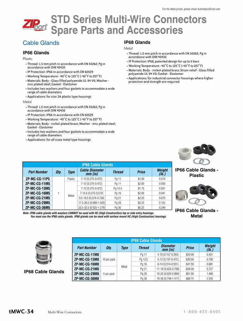
Cable GlandsIP66 GlandsPlastic
• Thread: 1.5 mm pitch in accordance with EN 50262, Pg in accordance with DIN 40430
• IP Protection: IP66 in accordance with EN 60529• Working Temperature: -40°C to 125°C (-40°F to 257°F)• Materials: Body - Glass filled polyamide UL 94 V0; Washer -
zinc plated steel; Gasket - Elastomer• Includes two washers and four gaskets to accommodate a wide
range of cable diameters• Applications: for size 3A plastic type housings
Metal• Thread: 1.5 mm pitch in accordance with EN 50262, Pg in
accordance with DIN 40430• IP Protection: IP66 in accordance with EN 60529• Working Temperature: -40°C to 125°C (-40°F to 257°F)• Materials: Body - nickel-plated brass; Washer - zinc plated steel;
Gasket - Elastomer• Includes two washers and four gaskets to accommodate a wide
range of cable diameters• Applications: for all sizes metal type housings
IP68 GlandsMetal
• Thread: 1.5 mm pitch in accordance with EN 50262, Pg in accordance with DIN 40430
• IP Protection: IP68, patented design for up to 5 bars• Working Temperature: -40°C to 125°C (-40°F to 257°F)• Materials: Body - nickel-plated brass; Strain relief - Glass filled
polyamide UL 94 V0; Gasket - Elastomer• Applications: for industrial connector housings where higher
protection and strength are required
IP66 Cable Glands
Part Number Qty. Type Cable Diameter mm [in] Thread Price Weight
(lb.)ZP-MC-CG-11P5
1
Plastic 7-12 [0.275-0.472] Pg 11 $1.00 0.019
ZP-MC-CG-11M5
Metal
7-12 [0.275-0.472] Pg 11 $2.00 0.030
ZP-MC-CG-13M5 7-12 [0.275-0.472] Pg 13.5 $1.75 0.031
ZP-MC-CG-16M5 7-14.5 [0.275-0.570] Pg 16 $2.00 0.041
ZP-MC-CG-21M5 9.5-18.5 [0.374-0.728] Pg 21 $2.25 0.070
ZP-MC-CG-29M5 17.5-26.5 [0.688-1.043] Pg 29 $3.25 0.125
ZP-MC-CG-36M5 23.5-32.5 [0.925-1.279] Pg 36 $6.25 0.249
IP68 Cable Glands
Part Number Qty. Type Thread Diameter mm [in] Price Weight
(lb.)ZP-MC-CG-11M8
10 per pack
Metal
Pg 11 4-10 [0.157-0.393] $29.00 0.451
ZP-MC-CG-13M8 Pg 13.5 5-12 [0.197-0.472] $30.00 0.780
ZP-MC-CG-16M8 Pg 16 8-14 [0.314-0.551] $41.50 0.881
ZP-MC-CG-21M85 per pack
Pg 21 11-18 [0.433-0.708] $34.00 0.727
ZP-MC-CG-29M8 Pg 29 16-25 [0.629-0.984] $61.00 1.466
ZP-MC-CG-36M8 Pg 36 19-36 [0.748-1.417] $88.75 2.205
IP66 Cable Glands - Plastic
IP66 Cable Glands - Metal
IP68 Cable Glands
Note: IP66 cable glands with washers CANNOT be used with HC (High Construction) top or side entry housings. You must use the IP68 cable glands. IP66 glands can be used with surface mount HC (High Construction) housings.
STD Series Multi-Wire Connectors Spare Parts and Accessories
1 - 80 0 - 633 - 0405Multi-Wire ConnectorstMWC-34
For the latest prices, please check AutomationDirect.com.

Blanking Plugs with Gasket
• Thread: 1.5 mm pitch in accordance with EN 50262, Pg in accordance with DIN 40430• IP Protection: IP68 in accordance with EN 60529• Working Temperature: -40°C to 125°C (-40°F to 257°F)• Materials: Body - nickel-plated brass; Gasket - Elastomer• Applications: for blanking threaded holes on housings or other enclosures
Blanking Plugs W/GasketPart Number Qty. Type Thread Price Weight (lb.)
ZP-MC-PLG-11M8
10 per pack
Metal
Pg 11 $14.00 0.169
ZP-MC-PLG-13M8 Pg 13.5 $14.00 0.192
ZP-MC-PLG-16M8 Pg 16 $20.00 0.253
ZP-MC-PLG-21M8 Pg 21 $31.00 0.478
ZP-MC-PLG-29M85 per pack
Pg 29 $32.00 0.218
ZP-MC-PLG-36M8 Pg 36 $49.00 0.706
Pg to NPT AdaptersPart Number Qty. Type Pg Thread NPT Thread Price Weight (lb.)
ZP-MC-A-11038
1 Metal
Pg 11 3/8” $5.00 0.044
ZP-MC-A-11012 Pg 11 1/2” $4.50 0.072
ZP-MC-A-13012 Pg 13.5 1/2” $4.50 0.106
ZP-MC-A-16012 Pg 16 1/2” $7.00 0.070
ZP-MC-A-21034 Pg 21 3/4” $8.00 0.101
ZP-MC-A-29100 Pg 29 1” $13.00 0.194
ZP-MC-A-29114 Pg 29 1 1/4” $14.00 0.238
ZP-MC-A-36114 Pg 36 1 1/4” $15.25 0.201
Pg to NPT Adapters
• Thread: Metric 1.5 mm pitch Pg in accordance with DIN 40430, NPT in accordance with USAS B2-1• IP Protection: dependant on coupling and other components• Working Temperature: -60°C to 200°C (-76°F to 392°F)• Materials: nickel-plated brass• Applications: for converting a Pg thread to an NPT thread
Blanking Plugs W/Gasket
Pg to NPT Adapters
Replacement GasketsPart Number Qty. Size Type Material Price Weight (lb.)
ZP-MC03A-GSK
10 per pack
3A
For bulkhead housings
Nitrile Botadiene Rubber (NBR)
$6.00 0.085
ZP-MC10A-GSK 10A $5.00 0.082
ZP-MC16A-GSK 16A $5.00 0.079
ZP-MC06B-GSK 6B $6.00 0.097
ZP-MC10B-GSK 10B $6.00 0.105
ZP-MC16B-GSK 16B $7.00 0.127
ZP-MC24B-GSK 24B $8.00 0.141
ZP-MC32B-GSK 32B $14.00 0.229
Replacement Gaskets
Replacement Gaskets
STD Series Multi-Wire Connectors Spare Parts and Accessories
tMWC-35Multi-Wire Connectorsw w w. a u to m at i o n d i re c t . c o m / w i r i n g- s o l u t i o n s
For the latest prices, please check AutomationDirect.com.

Insert Plates with Cutouts
Part Number Qty. Description Price Weight (lb.)
ZP-MC6B-2-1XDB9
1
6B housing insert plate with 1 DB9 cutout $1.50 0.0176
ZP-MC6B-2-2XDB9 6B housing insert plate with 2 DB9 cutouts $1.25 0.0154
ZP-MC6B-2-1XDB15 6B housing insert plate with 1 DB15 cutout $1.50 0.0176
ZP-MC6B-2-2XDB15 6B housing insert plate with 2 DB15 cutouts $1.25 0.0154
Insert Plates with Cutouts
Insert Plates with Cutouts
Insert Plates Reducers
Insert Plates - Reducers
Part Number Qty. Description Price Weight (lb.)
ZP-MC24B-2-RD6B1
Insert plate allows any 6B insert plate to be used in any size 24B housing $5.00 0.0838
ZP-MC24B-2-RD10B Insert plate allows any 10B insert plate to be used in any size 24B housing $5.00 0.0816
ZP-MC24B-2-RD16B Insert plate allows any 16B insert plate to be used in any size 24B housing $5.00 0.0772
Insert Plates - Blank
Part Number Qty. Description Price Weight (lb.)
ZP-MC6B-2-BLANK
1
Blank insert plate for any size 6B housing $4.00 0.4343
ZP-MC10B-2-BLANK Blank insert plate for any size 10B housing $4.00 0.0463
ZP-MC16B-2-BLANK Blank insert plate for any size 16B housing $4.00 0.0529
ZP-MC24B-2-BLANK Blank insert plate for any size 24B housing $5.00 0.0573Insert Plates
Blank
Note: machine screw M3-0.5x16 hardware not included
STD Series Multi-Wire Connectors Spare Parts and Accessories
1 - 80 0 - 633 - 0405Multi-Wire ConnectorstMWC-36
For the latest prices, please check AutomationDirect.com.

DIN Rail Mounting KitsPart Number Qty. Description Price Weight (lb.)
ZP-MC06B-DKIT
1
For size 6B inserts $20.00 0.374
ZP-MC10B-DKIT For size 10B inserts $20.00 0.377
ZP-MC16B-DKIT For size 16B inserts $24.00 0.385
ZP-MC24B-DKIT For size 24B inserts $24.00 0.392
ZP-MC-RT3 Insert removal tool $110.00 0.052
Replacement Screws / Polarization KeyPart Number Qty. Description Price Weight (lb.)
ZP-MC-SCRWKIT 2 pieces of each part
M3.5 - PE screw for size 3A inserts
$5.50 0.048
M4 - PE screw for size 6B insert, size 10B insert, size 16B insert (16+PE) and size 24B insert (24+PE)
M4 - PE screw for size 16B insert (6+PE) and size 24B insert (8+4+PE)
M3 - Installation screw for 3A inserts only
M3 - Installation screw for all inserts except 3A
ZP-MC-POLKEY-1 12 Polarization key for size 3A 12-pin inserts. Two keys are required per coupled connec-tion. $4.75 0.011
DIN Rail Mounting Kits
DIN Rail Mounting Kits
Replacement Screws/Polarization Key
ZP-MC-RT3
• For mounting inserts inside an enclosure• Fits 35 mm DIN rail
Polarization Key
Sixteen PossibleCombinations
Using the Polarization Key
STD Series Multi-Wire Connectors Spare Parts and Accessories
tMWC-37Multi-Wire Connectorsw w w. a u to m at i o n d i re c t . c o m / w i r i n g- s o l u t i o n s
For the latest prices, please check AutomationDirect.com.
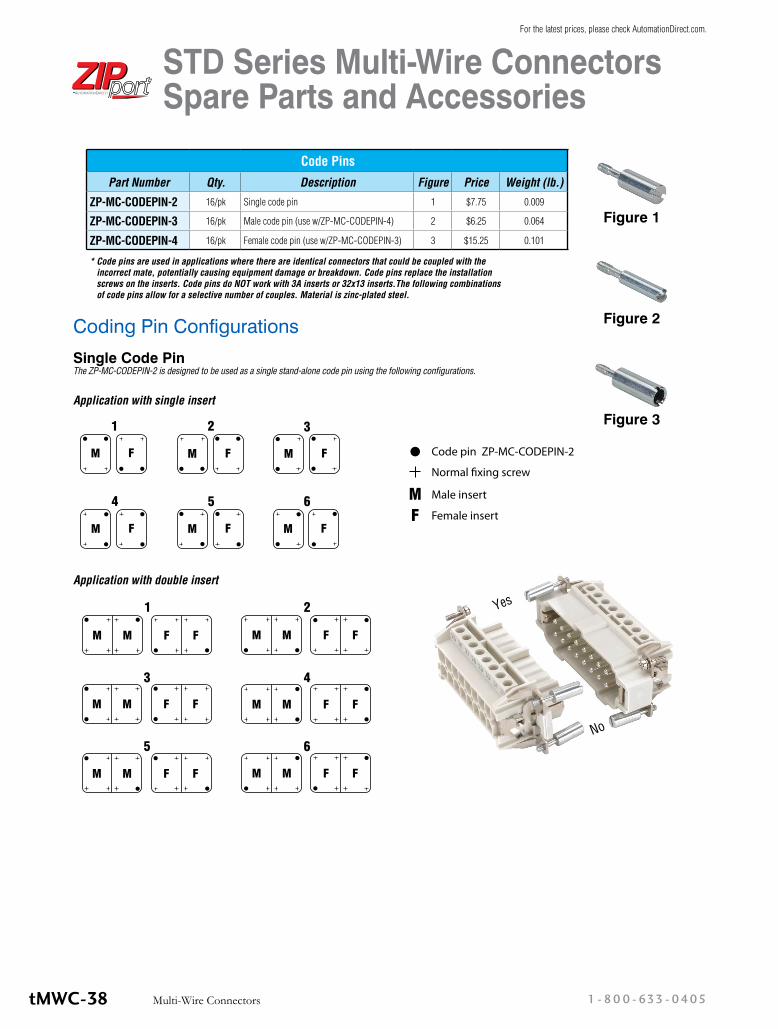
Coding Pin ConfigurationsSingle Code Pin The ZP-MC-CODEPIN-2 is designed to be used as a single stand-alone code pin using the following configurations.
* Code pins are used in applications where there are identical connectors that could be coupled with the incorrect mate, potentially causing equipment damage or breakdown. Code pins replace the installation screws on the inserts. Code pins do NOT work with 3A inserts or 32x13 inserts.The following combinations of code pins allow for a selective number of couples. Material is zinc-plated steel.
Code Pins
Part Number Qty. Description Figure Price Weight (lb.)
ZP-MC-CODEPIN-2 16/pk Single code pin 1 $7.75 0.009
ZP-MC-CODEPIN-3 16/pk Male code pin (use w/ZP-MC-CODEPIN-4) 2 $6.25 0.064
ZP-MC-CODEPIN-4 16/pk Female code pin (use w/ZP-MC-CODEPIN-3) 3 $15.25 0.101
Figure 1
Figure 2
Figure 3
Application with double insert
Application with single insert
Yes
No
STD Series Multi-Wire Connectors Spare Parts and Accessories
1 - 80 0 - 633 - 0405Multi-Wire ConnectorstMWC-38
For the latest prices, please check AutomationDirect.com.

Coding Pin ConfigurationsMale / Female Code Pins The ZP-MC-CODEPIN-3 and the ZIP-MC-CODEPIN-4 are designed to be used together using the following configurations.
Male code pin ZP-MC-CODEPIN-3
Female code pin ZP-MC-CODEPIN-4
Application with double insertApplication with single insert
STD Series Multi-Wire Connectors Spare Parts and Accessories
tMWC-39Multi-Wire Connectorsw w w. a u to m at i o n d i re c t . c o m / w i r i n g- s o l u t i o n s
For the latest prices, please check AutomationDirect.com.
Related Documents