RUSSIAN MARITIME REGISTER OF SHIPPING RULES FOR THE CARGO HANDLING GEAR OF SEA-GOING SHIPS ND No. 2-020101-145-E Saint-Petersburg Edition 2021

Welcome message from author
This document is posted to help you gain knowledge. Please leave a comment to let me know what you think about it! Share it to your friends and learn new things together.
Transcript

RUSSIAN MARITIME REGISTER OF SHIPPING
RULESFOR THE CARGO HANDLING GEAR
OF SEA-GOING SHIPS
ND No. 2-020101-145-E
Saint-PetersburgEdition 2021
Rules for the Cargo Handling Gear of Sea-Going Ships of Russian Maritime Register of Shipping havebeen approved in accordance with the established approval procedure and come into force on 1 January 2021.
The international requirements related to the cargo handling gear of sea-going ships have been takeninto consideration.
The Rules are published in electronic format in Russian and English.
# Russian Maritime Register of Shipping, 2021

Amendedparas/chapters/sections
Informationon amendments
Number and dateof the Circular Letter
Entry-into-forcedate
REVISION HISTORY
(purely editorial amendments are not included in the Revision History)For this version, there are no amendments to be included in the Revision History.

1 GENERAL
1.1 APPLICATION
1.1.1 The requirements of these Rules apply to cargo handling gear to be installed on sea-going ships,fixed offshore platforms, as well as on mobile offshore drilling units and intended for loading, unloadingand moving of loads carried and for conveyance of persons, and other cargo handling gear listed in 1.3.1.
The requirements of these Rules apply also to loose gear suspended to cargo gripping devices which
are an integral part of the ship, such as slings, lifting beams, frames and container spreaders, etc.
1.1.2 The requirements of these Rules are not applicable to the suspended drilling equipment and cargohandling gear used for production processes in MODU, drilling and geological exploration ships, pipelayers, etc. as well as to grabs and cargo lifting electromagnets.
1.1.3 These Rules apply in full measure to cargo handling gear, technical documentation for which wassubmitted to the Register for review after coming into force of these Rules.
The existing cargo handling gear are covered by the requirements of the rules, according to which theyhave been manufactured, as well as the requirements of Sections 10 – 12. Application of the present Rulesin repair and rerigging of the existing cargo handling gear and in replacement of their interchangeablecomponents and loose gear shall be determined depending on the works performed, critical interchange-able/repaired components or parts and the scope of rerigging.
1.1.4 Compliance with the requirements of these Rules is mandatory for obtaining or maintainingRegister documents on cargo handling gear. Such documents are not part of the classification documents.
1.1.5 The Register may impose additional requirements not incorporated in these Rules provided theyare necessary to ensure safe operation of the equipment.
1.1.6 Provisions of the International Convention on Occupational Safety and Health (Deck Work),1979 (ILO-152) and the ILO Code of Practice on Safety and Health in Ports, 2005 have been taken intoaccount in the relevant Sections of the Rules.
Rules for the Cargo Handling Gear of Sea-Going Ships4
1.2 DEFINITIONS AND EXPLANATIONS
1.2.1 For the purpose of these Rules the following definitions and explanations have been adopted.A n n u a l i n s p e c t i o n is conducted to verify the compliance of the cargo handling gear with
documents issued. The scope of the annual survey is specified by the Surveyor depending on the technicalcondition of the cargo handling gear.
A p l a t f o r m o f a s h i p ' s e l e v a t i n g p l a t f o r m is a load-carrying structure of the ship'selevating platform with or without side guards, which runs between the guides with the help of ropes, aleverpulling system, hydraulic drives, gear rack or spindle. Where structurally required, a platform canform a deckedin area of the ship and be fixed with locking devices in the working positions during cargohandling operations and in the "stowed for sea" position. The ship's elevating platform may have one ortwo platforms to carry out simultaneous cargo handling operations on different decks.
A p p l i a n c e t o c o n v e y t h e p e r s o n n e l ( t h e a p p l i a n c e f o r t h e p e r s o n n e l c o n v e y )_ nets, baskets, cradles or other products specially designed and certified for this purpose.
A u t o m a t i c o v e r l o a d c u t - o u t is a device automatically limiting a load on the crane or partthereof by disconnecting the machinery drive when the load exceeds safe working load.
B u f f e r o f s h i p ' s e l e v a t i n g p l a t f o r m is a damping stop which provides substantial energyabsorption of movable mass of the ship's elevating platform.
C a r g o d e r r i c k r e e l s mean machinery used for moving derrick booms without a load or holdingthem securely when the boom is loaded, and driven either by winches or independently.
C a r g o h a n d l i n g g e a r i s a combination of appliances installed on board ship (floating facility)and intended for loading, unloading and moving of loads from one position to another and for conveyanceof persons (ship's derricks, ship's cranes, hoists, ship's lifts, ship's elevating platforms and upper structuresof floating cranes and crane ships).
C a r g o h o i s t a r r a n g e m e n t s are the part of the cargo handling gear which may include metalstructures, ropes and interchangeable components. Cargo hoist arrangements unlike loose gear arepermanently attached to the cargo handling gear and cannot be used separately from it.
C o m p e t e n t b o d y means ministry, governmental institution or some other administrationauthorized to issue rules, decrees or other instructions having the force of the law.
C o m p e t e n t p e r s o n means a Surveyor to the Register or a responsible person authorized orrecognized by the Register.
A responsible person authorized or recognized by the Register may be:a responsible representative of the manufacturer recognized by the Register as a competent person
regarding testing of loose gear and interchangeable components with a proof load, testing of wire and naturalfibre ropes and chains as well as heat treatment of components in case where is no Surveyor to the Register orwhere the manufacturer has a permit for carrying out such tests and works without survey by the Register;
a non-exclusive Surveyor to the Register authorized to carry out survey according to the Agreementbetween the Register and the non-exclusive Surveyor.
C o n t a i n e r s p r e a d e r is a cargo-gripping device in the form of a frame or a beam with fittings forgripping containers, which comply with international standards and which are mechanically or manuallyconnected to the upper corner fittings of the container.
D e r r i c k c r a n e is a cargo handling gear having a boom which can be raised, lowered and slewedwith the help of winches which are an integral part of the cargo handling gear.
D r i v i n g u n i t is hydraulic pump units and winches.E f f e c t i v e j i b r a d i u s o f b o o m is the maximum distance from the centre of gravity of the
cargo hoisted to the side or transom of pontoon when it is upright.F i x e d g e a r includes items permanently attached to the structural elements of the cargo handling
gear or to the ship hull, such as derrick eye plates or guy ropes on booms, span eye plates and heelgoosenecks with their bearings, derrick heel fork lugs, mast and derrick bands, deck eye plates, built-insheaves, etc.
Rules for the Cargo Handling Gear of Sea-Going Ships5

F l o a t i n g f a c i l i t y is a structure, such as a pontoon, floating dock, repair ship, mobile offshoredrilling unit or a similar floating structure.
G e a r includes items of cargo handling appliance used for transmission of forces and effecting ofkinematic connection, other than machinery parts.
G u i d e s o f s h i p ' s e l e v a t i n g p l a t f o r m are part of the ship's elevating platform designed toensure the required direction of the platform movement and to hold the platform in the position whengripping devices are tripped.
H e a v y - l i f t d e r r i c k is a ship's derrick with a safe working load of 10 t and more per single-slewed derrick.
H o i s t is a stationary power-driven or hand-operated lifting appliance of a simplified design of catdavit, telpher, pulley block or whip type.
I n t e r c h a n g e a b l e c o m p o n e n t s are such items as chains, rings, hooks, shackles, blocks,turnbuckles, etc. which are parts of a cargo handling gear or loose gear attached to the elements of thecargo handling gear or loose gear by detachable connections.
J i b r a d i u s o f b o o m is the maximum distance between the centre of gravity of the cargo hoistedand the vertical axis of derrick heel swivel rotation.
L i f t g r i p p i n g d e v i c e s are automatically operated devices for braking the lift car or acounterweight with a certain deceleration and holding them in the guides in case a preset speed is exceededwhen moving downwards or in case of a break in the rope.
L i f t o v e r s p e e d g o v e r n o r is a device by which gripping devices are tripped when the presetspeed is exceeded.
L i f t t r u n k is a totally enclosed ship space where the lift car and counterweight are positioned.The terms used in these Rules are shown in Figs. 1 to 5.L i f t i n g c a p a c i t y is the maximum weight of a safely lifted load including that of auxiliaries used
for securing the load, such as slings, lifting beams, platforms, nets, etc., as well as the weight of grabs,cargo lifting electromagnets, boxes and buckets.
L i f t i n g c a p a c i t y i n d i c a t o r is a device automatically showing (no matter whether the load issuspended or not) the maximum allowable design load for the particular crane at different jib radii.
L i g h t - l i f t d e r r i c k is a ship's derrick with a safe working load of less than 10 t per single-slewed derrick.
L i m i t s w i t c h is a device automatically limiting movement of a cargo handling gear or part thereofby disconnecting the machinery drive in the extreme positions.
L o o s e g e a r includes slings, lifting beams, frames and container spreaders, etc., by means of whicha load can be secured to the cargo handling gear but which do not form an integral part of the cargohandling gear or load.
M a c h i n e r y include cargo winches, cargo derrick reels, machinery used for topping, slewing andhoisting crane booms and travel of cranes and hoists.
M e t a l s t r u c t u r e s ( l o a d - b e a r i n g s t r u c t u r e s ) include derricks, masts, posts, bridges,gantries, etc. which take up loads acting on the cargo handling gear.
P r i n c i p l e o f a c c e p t a b l e n u m b e r o f p a s s e n g e r s is determination of the safe workingload based on permissible number of passengers which depends on the usable area of the car floor.
P r o o f l o a d is a load whose weight is certified with an accuracy of +2 per cent for carrying outproof load tests.
S a f e w o r k i n g l o a d ( S W L ) is the maximum allowable static load applied to each individualcomponent of the cargo handling gear.
Safe working load (SWL) for multiple-sheaved blocks is the working load limit on the eye.Safe working load (SWL) for single-sheaved blocks with or without a becket is the maximum
allowable rope pull. For single-sheaved blocks without a becket the allowable rope pull is equal to half theworking load limit on the block eye. For single-sheaved blocks with a becket the allowable rope pull isequal to one-third of the working load limit on the block eye.
Rules for the Cargo Handling Gear of Sea-Going Ships6

S a f e w o r k i n g l o a d o f s h i p ' s l i f t is the maximum permissible weight of persons or loads,for lifting or lowering of which the lift is designed, including the weight of auxiliary loose geartemporarily used for securing the loads.
S a f e t y f a c t o r is the ratio of the minimum breaking load to the safe working load.S h i p ' s c a r g o l i f t is a ship's lift intended for lifting and lowering loads not accompanied by people.S h i p ' s c r a n e is a cargo handling gear (stationary or mobile) capable of transporting loads without
any blocks or ropes suspended outside its structure.S h i p ' s d e r r i c k is a cargo handling gear designed for holding and moving loads by the system of
blocks and ropes suspended to the derrick structure and beyond it (to masts, posts, decks and winches).S h i p ' s e l e v a t i n g p l a t f o r m is a cargo handling gear with one or more platforms for vertical
transportation of loads between cargo decks of ro-ro ships, operated by hydraulically or electric andmechanical drives.
S h i p ' s l i f t is a cargo handling gear intended for lifting and lowering persons or loads in a carrunning between the guides positioned vertically in the trunk relative to the position of the ship on an evenkeel, and provided with lockable doors on all passenger or cargo decks.
S h i p ' s l i f t c a r is a load-carrying part of the ship's lift enclosed over its entire height and providedwith a floor and ceiling.
S h i p ' s p a s s e n g e r l i f t is a ship's lift intended for lifting and lowering persons or loadsaccompanied by people.
S h o e s o f t h e s h i p ' s e l e v a t i n g p l a t f o r m are elements of movable parts of the ship'selevating platform which ensure a certain position of the platform in relation to the guides.
S t o p o f s h i p ' s e l e v a t i n g p l a t f o r m is a device which limits platform movement inemergency or in extreme working positions.
T h o r o u g h e x a m i n a t i o n means external inspection supplemented, where necessary, by othermethods of survey, such as hammering, measuring, flaw detection, functional tests and disassembling ofthe examined structures, machinery and parts of the cargo handling gear to check their condition and toverify their safe operation.
U p p e r s t r u c t u r e o f f l o a t i n g c r a n e , c r a n e s h i p , e t c . is a cargo handling erectioninstalled on the open deck which is designed to support a cargo handling gear and loads.
W i n c h w i t h a d r u m is a winch having a drum to coil a rope thereupon.W i n c h w i t h a t r a c t i o n s h e a v e is a winch provided with a sheave which produces a pull in
the rope by means of its traction in the groove of special design.W i n c h e s are machines for hoisting, lowering and movement of cargo or booms.
Rules for the Cargo Handling Gear of Sea-Going Ships7
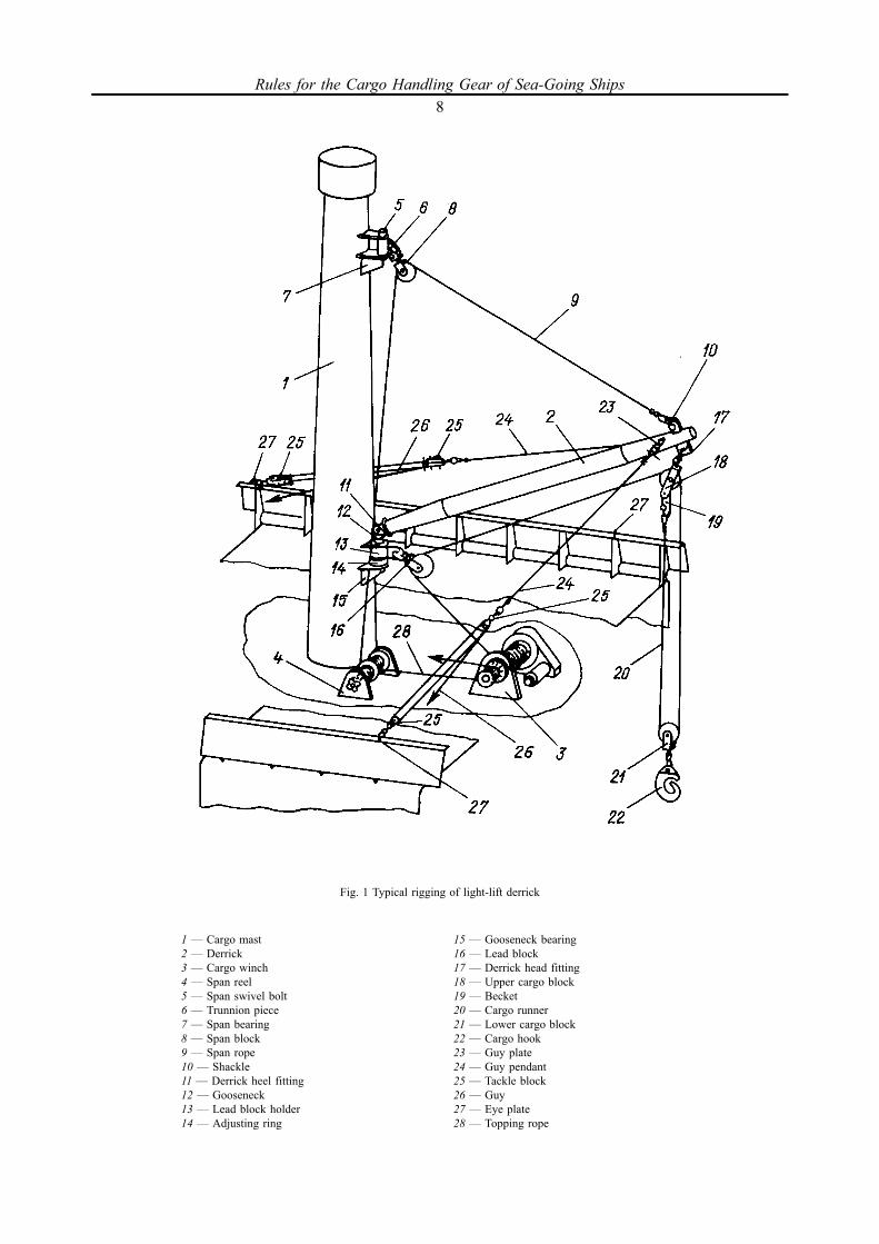
Fig. 1 Typical rigging of light-lift derrick
1 _ Cargo mast2 _ Derrick3 _ Cargo winch4 _ Span reel5 _ Span swivel bolt6 _ Trunnion piece7 _ Span bearing8 _ Span block9 _ Span rope10 _ Shackle11 _ Derrick heel fitting12 _ Gooseneck13 _ Lead block holder14 _ Adjusting ring
15 _ Gooseneck bearing16 _ Lead block17 _ Derrick head fitting18 _ Upper cargo block19 _ Becket20 _ Cargo runner21 _ Lower cargo block22 _ Cargo hook23 _ Guy plate24 _ Guy pendant25 _ Tackle block26 _ Guy27 _ Eye plate28 _ Topping rope
Rules for the Cargo Handling Gear of Sea-Going Ships8
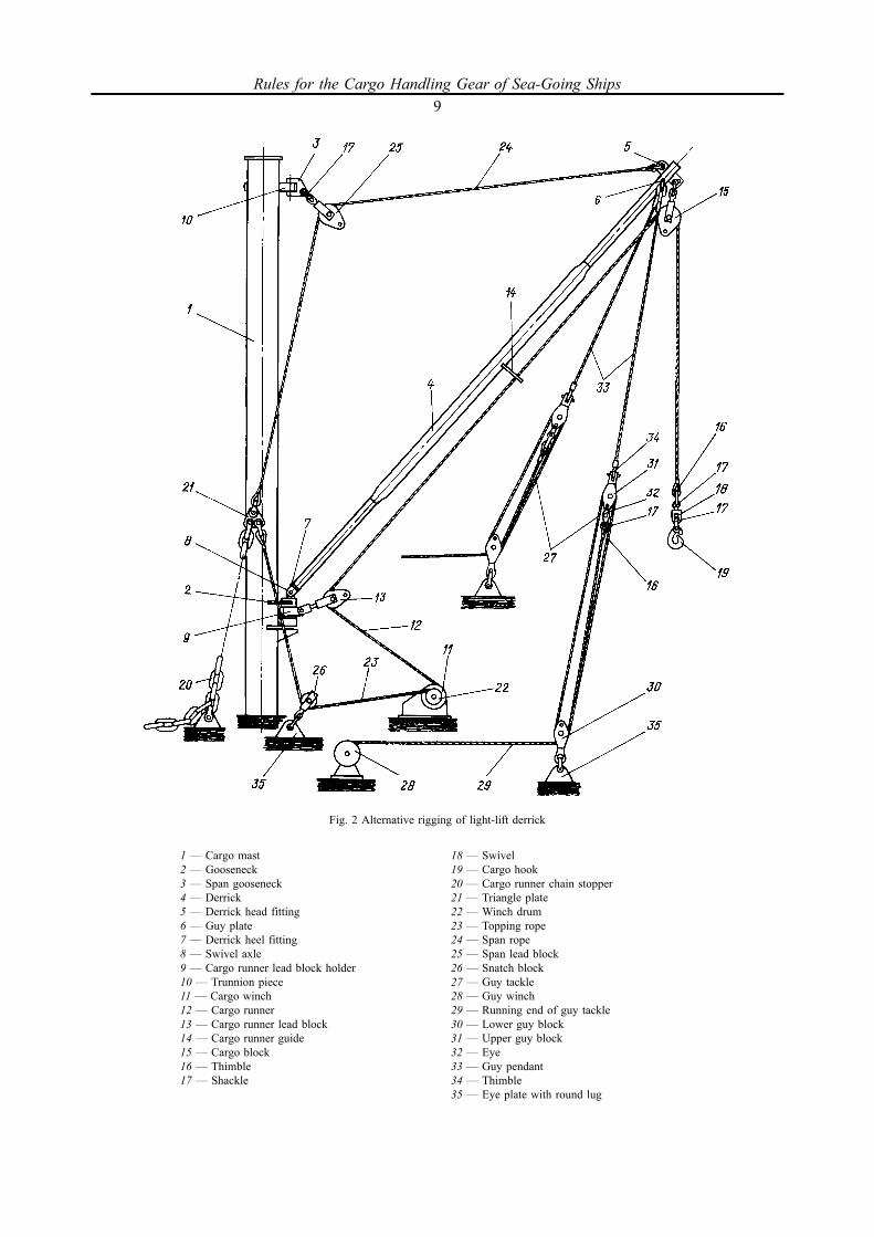
Fig. 2 Alternative rigging of light-lift derrick
1 _ Cargo mast2 _ Gooseneck3 _ Span gooseneck4 _ Derrick5 _ Derrick head fitting6 _ Guy plate7 _ Derrick heel fitting8 _ Swivel axle9 _ Cargo runner lead block holder10 _ Trunnion piece11 _ Cargo winch12 _ Cargo runner13 _ Cargo runner lead block14 _ Cargo runner guide15 _ Cargo block16 _ Thimble17 _ Shackle
18 _ Swivel19 _ Cargo hook20 _ Cargo runner chain stopper21 _ Triangle plate22 _ Winch drum23 _ Topping rope24 _ Span rope25 _ Span lead block26 _ Snatch block27 _ Guy tackle28 _ Guy winch29 _ Running end of guy tackle30 _ Lower guy block31 _ Upper guy block32 _ Eye33 _ Guy pendant34 _ Thimble35 _ Eye plate with round lug
Rules for the Cargo Handling Gear of Sea-Going Ships9
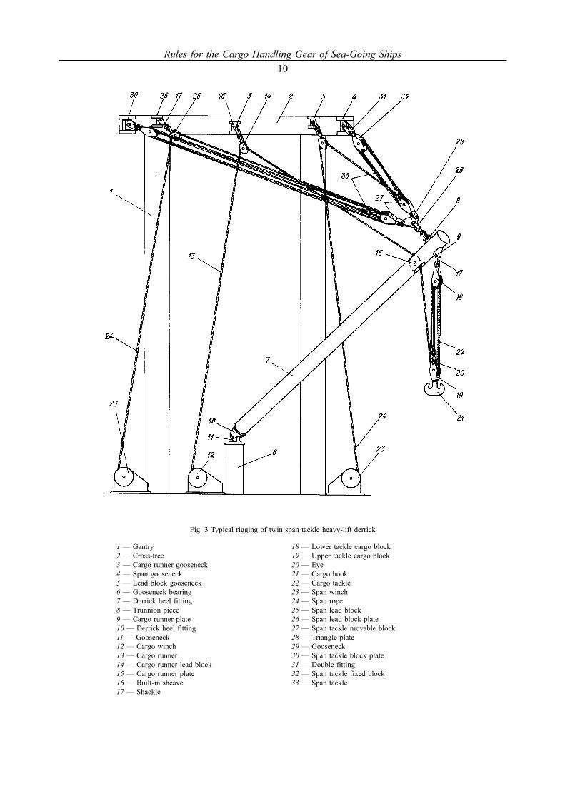
Fig. 3 Typical rigging of twin span tackle heavy-lift derrick
1 _ Gantry2 _ Cross-tree3 _ Cargo runner gooseneck4 _ Span gooseneck5 _ Lead block gooseneck6 _ Gooseneck bearing7 _ Derrick heel fitting8 _ Trunnion piece9 _ Cargo runner plate10 _ Derrick heel fitting11 _ Gooseneck12 _ Cargo winch13 _ Cargo runner14 _ Cargo runner lead block15 _ Cargo runner plate16 _ Built-in sheave17 _ Shackle
18 _ Lower tackle cargo block19 _ Upper tackle cargo block20 _ Eye21 _ Cargo hook22 _ Cargo tackle23 _ Span winch24 _ Span rope25 _ Span lead block26 _ Span lead block plate27 _ Span tackle movable block28 _ Triangle plate29 _ Gooseneck30 _ Span tackle block plate31 _ Double fitting32 _ Span tackle fixed block33 _ Span tackle
Rules for the Cargo Handling Gear of Sea-Going Ships10
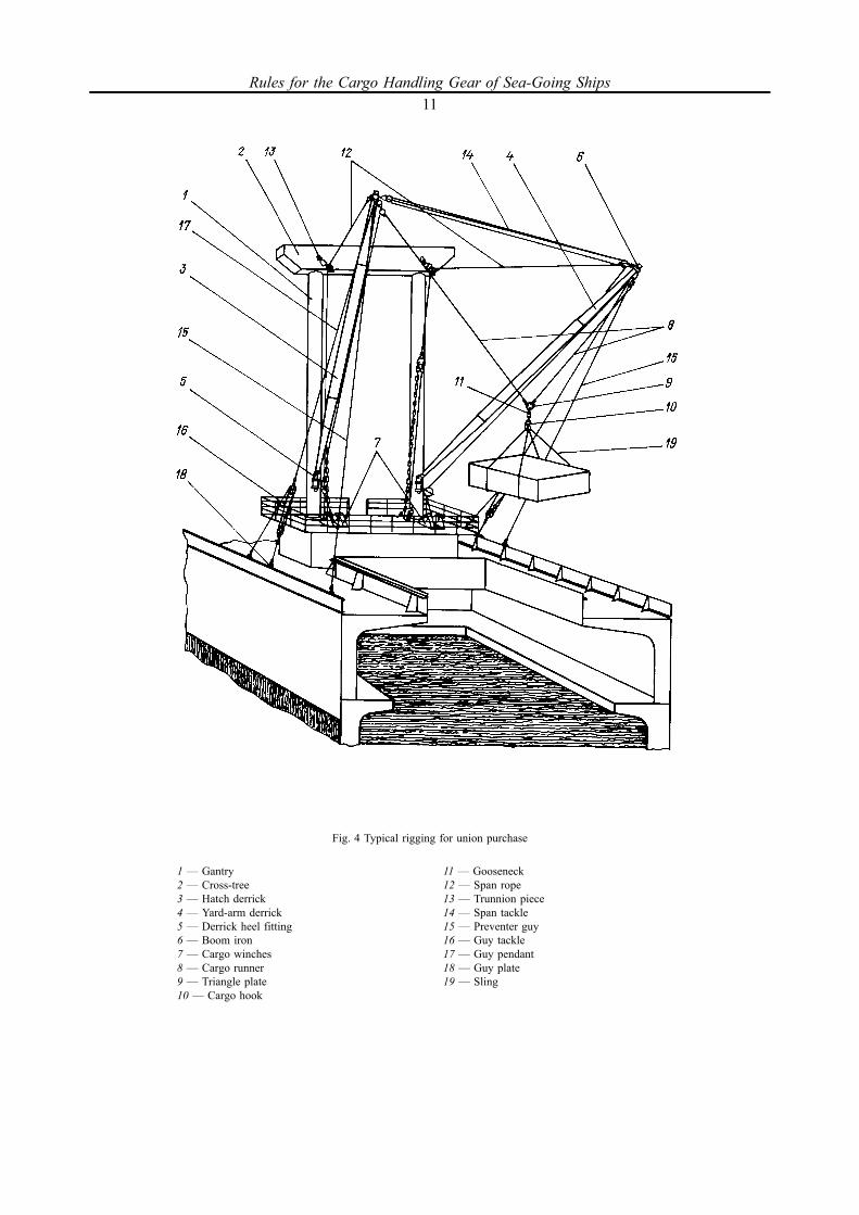
Fig. 4 Typical rigging for union purchase
1 _ Gantry2 _ Cross-tree3 _ Hatch derrick4 _ Yard-arm derrick5 _ Derrick heel fitting6 _ Boom iron7 _ Cargo winches8 _ Cargo runner9 _ Triangle plate10 _ Cargo hook
11 _ Gooseneck12 _ Span rope13 _ Trunnion piece14 _ Span tackle15 _ Preventer guy16 _ Guy tackle17 _ Guy pendant18 _ Guy plate19 _ Sling
Rules for the Cargo Handling Gear of Sea-Going Ships11

Fig. 5 Deck full-swing crane
1 _ Crane post2 _ Supporting and turning circle3 _ Crane turning part4 _ Luffing hydraulic cylinder5 _ Crane machinery space6 _ Operator's cabin7 _ Derrick heel bearing8 _ Derrick9 _ Marking10 _ Guard plate11 _ Stopper plate12 _ Rope guard against slipping off sheave
13 _ Hydraulic motor14 _ Topping winch15 _ Cargo runner16 _ Rope sockets17 _ Thimble18 _ Connecting shackle19 _ Counterweight20 _ Swivel21 _ Connecting link22 _ Chain23 _ Cargo hook
Rules for the Cargo Handling Gear of Sea-Going Ships12
1.3 SCOPE OF SURVEY
1.3.1 Subject to survey by the Register are the following cargo handling gear:.1 ship's derricks, ship's cranes and hoists (pulley blocks, telphers, etc.) having lifting capacity 1 t and
more;.2 upper structures of floating cranes and crane ships;.3 cranes on floating docks and cranes mounted on mobile offshore drilling units and fixed offshore
platforms intended for loading and unloading of supply vessels with safe working load 1 t and more;.4 ship's cranes having lifting capacity 1 t and more for personnel convey;.5 ship's cargo lifts with safe working load 250 kg and more and electrically driven passenger lifts
intended for lifting and lowering of persons and/or loads in the car moved by the ropes with a speed not inexcess of 1,0 m/s;.6 ship's elevating platforms with a lifting capacity 1 t and more;.7 fixed gear and interchangeable components of cargo handling gear;.8 ropes of cargo handling gear;.9 loose gear (slings, spreaders, lifting beams and frames, etc.) being part of the ship;.10 appliances, being part of the ship, designed to convey the personnel.Survey of cargo handling gear of other types and purposes shall be specially considered by the Register
in each particular case.1.3.2 Register survey of cargo handling gear of other types covers:.1 review and approval of technical documentation;.2 survey of manufacture, installation on board ship (floating facility) and repairs of cargo handling
gear;.3 tests;.4 issue of Register documents.1.3.3 The following items are subject to survey by the Register:.1 ship's derricks:metal structures;winches and reels;components and ropes;.2 cranes and hoists:metal structures;machinery;components and ropes;safety devices;.3 lifts:metal structures;lift equipment;lift winches;safety devices;ropes and parts for rope system;.4 ship's elevating platforms:platforms;platform equipment;load-bearing components;safety devices;.5 machinery drives;.6 electrical equipment of cargo handling gear;.7 boilers and pressure vessels used in cargo handling gear;.8 pumping and piping of cargo handling gear;
Rules for the Cargo Handling Gear of Sea-Going Ships13
.9 appliances to convey the personnel (nets, baskets, cradles or other products specially designed forthis purpose).
The nomenclature of essential structures, machinery and components of cargo handling gear subject tothe Register survey is given in the Appendix.
1.3.4 Survey during manufacture, installation on board ship and repairs of cargo handling gear, theirmachinery, metal structures, components and safety devices is conducted in compliance with GeneralRegulations for the Classification and Other Activity.
1.3.5 Survey of machinery, hydraulic and steam drives of machinery, pumping and piping, electricalequipment, components and materials as well as boilers and pressure vessels which are not covered by thespecific requirements of these Rules shall be based on the applicable requirements of the relevant parts ofRules for the Classification and Construction of Sea-Going Ships.
Where, however, the requirements contained in these Rules are equivalent to, or different from those ofthe relevant parts of Rules for the Classification and Construction of Sea-Going Ships, preference shall begiven to these Rules.
1.3.6 Survey of ship's derricks, cranes and hoists of fishing vessels used with fishing gear as well ofship's stationary derricks intended for operation in union purchase rig with derricks of another ship iscarried out in the same way as in case of ordinary cargo handling gear for lifting loads of a specifiedweight, i.e. the Register does not participate in determination of the lifting capacity required for operationwith the fishing gear, relating this to the competence of the shipowner.
1.3.7 Survey of derrick cranes, hoists of cat davit and telpher types is carried out as that of ship'scranes, and survey of hoists of pulley block or whip types is similar to that of the appropriate componentsof ship's derricks.
Rules for the Cargo Handling Gear of Sea-Going Ships14
1.4 TECHNICAL DOCUMENTATION
1.4.1 Technical documentation submitted to the Register for review shall include:.1 Specification (Explanatory Note);.2 general arrangement plans of the cargo handling gear with indication of principal characteristics
(safe working load, operation areas, outreach, cargo lifting and lowering speed, maximum and minimumoutreach, slewing speed, etc.);
.3 general arrangement plans of cargo masts with derricks, ship's cranes, hoists, lifts and ship'selevating platforms, their attachments to ship structures and hull strengthening in way of their installation;
.4 drawing (scheme) of derrick and crane rigging;
.5 documentation on welded joints of metal structures;
.6 drawings of metal structures (cargo masts, derricks, bridges, gantries, mounts (pedestals) andcolumns, supporting and slewing gear of cranes, trunks, cars and ship's lift guides, platforms and guides ofship's elevating platforms, etc.) with strength and stability calculations;
.7 technical documentation on machinery and drives:assembly drawings with sections;drawings of cargo shafts, gear wheels and pinions of reduction gear units as well as couplings (may be
submitted together with assembly drawings);basic diagrams of hydraulic units;drawings of bed frames and housings together with particulars on welding (may be submitted together
with assembly drawings);strength calculations or calculation results of essential stress-bearing items;explanatory note or description with indication of principal technical characteristics;testing programmes for the prototype and a serial specimen of the machinery;.8 technical documentation on electrical equipment:description of the operation principle and main performance specifications;specification including the list of associated items, devices and materials;structural assembly drawings;circuit diagram of the electric drive;testing programme;.9 drawings of components of the cargo handling gear together with strength calculations or with
particulars proving their strength as equivalent to that of the standard components approved by theRegister;
.10 drawings of safety devices (together with strength calculations where necessary);
.11 drawings of securing of the cargo handling gear in the stowed for sea position;
.12 diagrams of forces acting on stressed items of the cargo handling gear;
.13 strength calculations or results of calculations for load-bearing structures as well as stabilitycalculations of jib cranes and rope-suspended jib booms;
.14 instructions for derricks operating in union purchase rig with indication of the working range, safeworking load, types, sizes and scheme of rigging;
.15 testing programme of the cargo handling gear in assembly at the manufacturer;
.16 documentation on marking of the cargo-handling gear and components subject to the RS survey.1.4.2 Technical documentation on cranes, winches, metal structures, gear and safety devices of cargo
handling gear may be submitted separately (independent of the ship technical documentation), the typesand purposes of the ships and floating facilities for which they are designed shall be, however, indicated.
1.4.3 Use of metal structures, gear, machinery and devices manufactured according to the standardsand specifications agreed upon with, or approved by, the Register does need special approval. No approvalis specially needed either for use of the processes, heat treatment and calculations which comply with thestandards and specifications approved by the Register.
Rules for the Cargo Handling Gear of Sea-Going Ships15
1.4.4 Where needed, the Register may request submission of strength calculations for ship structuresand hull strengthening in places where masts, posts, winches, cranes, hoists, eye plates are fitted and wherederricks and cranes are stowed for sea.
1.4.5 Where the cargo handling gear has been altered due to modernization or repairs, the scope of thedocuments submitted shall be consistent with alterations made, having regard to their effect on thecompliance with the requirements of these Rules.
1.4.6 Where a cargo handling appliance which has been manufactured according to the design notapproved by the Register is submitted to the initial survey, the scope of the required technicaldocumentation, including check calculations, shall be based on the list referred to in 1.4.1.
In certain cases, the technical documentation required may be reduced, taking into account thedocuments issued by the firms (manufacturers) and other classification societies (refer also to 11.1.4).
Rules for the Cargo Handling Gear of Sea-Going Ships16
1.5 GENERAL TECHNICAL REQUIREMENTS
1.5.1 All cargo handling gear, their metal structures, machinery, gear and devices shall be designed andconstructed in compliance with these Rules and standards in force, agreed upon with the Register. Safeoperation of the cargo handling gear shall be ensured with the specified heel and trim of the ship at themaximum jib radius and within the specified range of the ambient temperatures.
1.5.2 Machinery (drives) and brakes.
1.5.2.1 Mechanical, hydraulic and steam drives, pumping and piping, electrical equipment where notcovered by the specific requirements of these Rules shall comply with applicable requirements ofPart VIII "Systems and Piping", Sections 6 and 7, Part IX "Machinery" and Part XI "Electrical Equipment"of the Rules for the Classification and Construction of Sea-Going Ships.
The power of winches shall be limited to a value corresponding to the safe working load of thederricks. This is likely to range from 18,6 to 37 kW (25 to 50 hp) for hoisting speeds of 0,4 m/s for 8 tloads and 0,6 m/s for 3 t loads.
1.5.2.2 The cargo handling gear machinery with a coupling between the machinery and the drive aswell as the machinery used for changing speed of transportation shall be so designed as to prevent fallingof the load or uncontrolled movement of the boom or crane when the drive is disconnected or when thespeed is changed.
The hydraulically-driven machinery shall be provided with devices to prevent falling of the load oruncontrolled movement of the boom or crane in case of a pressure drop in the hydraulic system.
1.5.2.3 The hoisting and luffing machinery shall be so constructed that load or boom could be loweredonly by using a drive.
Provision shall be made for means enabling to safely stop and lower the load in case of emergency.1.5.2.4 All the machinery of the cargo handling gear other than screw-driven machinery with self-
braking or machinery driven from hydraulic cylinders provided with pilot controlled check valves shall beprovided with automatically applied brake or brakes capable to ensure braking with a safety factorspecified in the relevant Chapters of these Rules.
The safety factor of braking action is the ratio of the torque exerted by the brakes to the static torquecreated on the braking shaft by the maximum design tension in the rope (for machinery used for topping,luffing and slewing operations with the help of the ropes) and by the design value of the inertia forces (formachinery with rigid kinematic coupling, such as machinery used for turning and movement of cranes andfor luffing crane jibs).
The design of electrically operated brakes shall be such that the operating solenoid could not be excitedby the return electromotive force from an engine, by parasitic or stray currents or by a puncture ofinsulation. Provision shall be made for manual release of brakes in emergency when power supply toelectric drives of the hoisting machinery fails.
1.5.2.5 The brakes shall normally be applied automatically when:the motion control lever is returned to its neutral position;any emergency stop is operated;there is any power supply failure;in the case of electrically operated brakes, there is a failure of one phase or a significant drop in voltage
or frequency of the power supply.1.5.2.6 Band brakes shall only be used for emergency braking. The brake lining or pads shall remain
adequately secured during their working life. Unless the brake is self-adjusting, appropriate means shall beprovided to permit brake adjustment to be readily carried out in safety. Brakes shall be of a closed-bandtype, unless otherwise specified in the relevant Chapters of these Rules and they shall be applied smoothly,without any throws; they have to have simple and readily accessible means of adjustment and enable easyreplacement of the friction parts.
1.5.2.7 Machinery and their bed plates shall be capable of withstanding the forces set up duringbraking.
Rules for the Cargo Handling Gear of Sea-Going Ships17

1.5.2.8 The forces for operation of adjustible brakes shall not exceed 160 N on a handle or lever and310 N on a foot pedal. For brakes regularly used under normal operating conditions the forces shall be atleast halved. The brake pedals shall have a non-skid surface.
1.5.2.9 The hoisting and luffing machinery of the cargo handling gear specially intended for loading,unloading and transportation of dangerous cargoes shall be provided with two automatic independentclosed-band brakes capable of holding the load (jib) with one brake in case of power failure. The brakesmay be actuated consecutively.
Where there is a coupling between the engine and the reduction gear, one brake shall be fitted on thehalf-coupling on the side of the reduction gear or on the shaft of the reduction gear. The other brake maybe positioned on the engine shaft or at any point of the driving mechanism. The brakes shall be so arrangedthat in order to check the reliable operation of one of the brakes, the action of the other brake is easilyprevented.
The hoisting and luffing machinery driven from hydraulic cylinders the second device equivalent to abrake may be omitted.
1.5.2.10 Manually-driven hoisting machinery shall be provided with a self-locking gear or a "safetyhandle" which is a handle and a ratchet built into a brake. Other devices (a hydraulic drive with a handpump) which prevent the load from spontaneous lowering may be used.
1.5.2.11 Manually-driven cargo handling gear shall be so designed that a force to be applied by eachoperator is not in excess of 160 N. Manually operated pull chains shall be protected against falling off thechain wheel.
1.5.2.12 Means shall be provided to secure adjustable disconnected brakes in the closed position. Thebraking force may not be created by brake loads. Brake springs used for this purpose shall be of a pushtype and have guides in the form of liners or holders.
1.5.2.13 A brake placed between the engine and the transmission shall be positioned on thetransmission shaft.
1.5.2.14Where several items of machinery are served by one drive, brakes shall be fitted on each item.1.5.2.15 The brake drum shall be protected against rain, sea water, snow, ice, oils or fats unless the
brake is designed for operation without such protection.1.5.2.16 Any (hand, foot or automatic) brake shall develop a braking torque which is by 25 per cent
more than the torque required under most unfavourable conditions of operation with maximum-weightload, irrespective of the losses in the transmissions.1.5.2.17 A slewing brake shall be capable of holding the jib stationary with the maximum safe working
load suspended at its maximum radius when the maximum in-service wind acts on the crane in the mostadverse direction. Sudden application of the brake shall not damage the jib.
1.5.3 Electrical drives.
1.5.3.1 Electrical drives of the cargo handling gear provided with mechanical ventilation shall have aninterlocking gear to prevent starting or further operation of the drive with ventilation cut off.
1.5.3.2 The movable part of the deck crane shall be earthed with a special cable connected to theturning part or to a rotating drum by a current collector having at least two brushes.
Movable parts of cargo handling gear may be earthed through rollers or tracks, provided a good contactis ensured.1.5.3.3 Self-reeling flexible cables shall not allow long lengths of cable to drag on the deck where they
can be exposed to damage.Outlets shall generally be not more than 50 m apart.The use of motorized reels is preferable to springs or counterweights. Reels shall be placed on the
waterside, preferably on the outside of the gantry legs.1.5.3.4 Trolley systems of hoists shall be fed by overhead conductors or conductors in channels.Overhead conductors shall be sufficiently high to prevent contact by load.Channels for conductors shall be properly drained and designed to prevent entry of any objects likely
to cause danger.
Rules for the Cargo Handling Gear of Sea-Going Ships18

1.5.4 Hydraulic systems.
1.5.4.1 The dimensions and design of hydraulic systems shall meet the established technical standardson the hydraulic systems. Safe operation of the hydraulic systems under all envisaged service conditionsshall be ensured by suitable measures, such as selection of filters, coolers, control devices, primary-circuitpressure control, selection of a suitable hydraulic oil, etc.
1.5.4.2 The hydraulic system shall be so constructed that an pressure rise above the permissible valueis prevented. The limits of the piston extreme positions in servomotors shall be specified.
1.5.4.3 Pipe connections shall be made by high pressure hoses. The hoses shall be suitable for theparticular working fluids, pressures, temperatures, environmental conditions and shall meet therequirements of the recognized standards.
The breaking pressure of a hose shall be at least equal to four times the allowable working pressure.Threaded sleeves with locking pins and a seam may be used in case the substantiation is provided and
the equivalent strength is proved.1.5.4.4 The piping system may be connected to another hydraulic system, for which such connection is
allowed. In this case, a second pump unit and the provision of suitable shut-off valves are recommended.1.5.4.5 The hydraulic pipes between servomotors or hydraulic motors shall be made with a higher
degree of safety. This also relates to all the devices connected thereto.Flanged bolted connections shall be tested for tightness by a pressure equal to 1,5 times the design
pressure or 1,5 times the maximum working pressure.1.5.4.6 Hydraulic servomotors shall be provided with devices fitted directly on the cylinder and
operating in case a crack in the system to prevent fast falling of the load, jib or spontaneous turning of thecargo handling gear.
1.5.4.7 Hydraulic servomotors shall be installed and connected to load-bearing metal structures so thatno external forces affect the piston rod.
1.5.5 Winch drums.
1.5.5.1 The length of the winch drums shall be such that the rope can be wound onto the drum in onelayer as far as possible; in any case, the number of rope layers shall not be more than three. The exceptionmay be made for heavy-lift cargo handling gear or twin span tackle derricks, provided there is a rope-coiling trolley or rope pressing roller. Use of drums with coiling a rope in more than three layers shall besubstantiated in each case. Drum design drawings and strength analysis for the drum with the coiled ropeshall be submitted to the Register for review. The rope transfer to the upper layer shall be provided withoutits pinching between the last coil of the lower layer and the flange.
1.5.5.2 A diameter of the drum shall be not less than 18 rope diameters.1.5.5.3 A rope drum intended for multi-layer coiling of the rope shall be fitted with flanges on both
ends, which shall extend above the top layer of the rope by at least 2,5 times the rope diameter.Grooved drums intended for one-layer reeling of two rope runs may not be fitted with flanges,
provided the runs are coiled from the edges of the drum to its centre. Where one rope run is coiled on thegrooved drum the flange may be omitted on the side where the rope is fastened to the drum.
1.5.5.4 Drums of motor-driven winches where the rope is coiled onto the drum in a single layer shallhave a shell with a helical groove made so that:
.1 a groove bottom radius exceeds in the cross-section the rope radius by at least 10 per cent;
.2 an arc length of the radius-bent groove bottom corresponds to a sector with an angle equal to at least1208;
.3 a gap between to adjacent coils shall be sufficient for a rope uncoiled from the drum not to touch theother coil;
.4 the groove width in the cross-section increases in the direction from the bottom outside, wherenecessary.
1.5.5.5 Span rope and cargo drums of winches operating with ship's cranes, derricks or derrick cranesshall be suitable for coiling the working length of the rope necessary to lift the load from the floor of theship hold with the derrick being in its extreme working position as well as from the hold floor of the bargemoored alongside the ship with the maximum outreach of the boom and at the least draught of the ship.
Rules for the Cargo Handling Gear of Sea-Going Ships19

1.5.5.6 The number of the full coils which remain on the drum when the entire length of the is unreeledshall be at least:
three for flat drums (with no grooves) andtwo for grooved drums, provided:one coil shall remain on the winch drum of the derrick or crane lowered on the supports in the stowed
for sea position;two coils on the winch drum of the derrick with the boom in its lowest stowed for sea position;three coils in case of a travelling crane with the boom lowered in its horizontal position for removal or
addition of a jib section;three coils for a derrick crane on rigid supports with the boom in its lowest stowed for sea
position.1.5.5.7 The drum shall be so positioned that proper coiling of the rope thereon shall be ensured. The
deflection of the rope in relation to the plane normal to the axis of the drum shall not exceed 48.It is recommended that all drums which cannot be seen by the operator in the course of operation be
fitted with a guide-on system for satisfactory running of the rope on to the drum.1.5.6 Securing of gear and ropes.
1.5.6.1 Fixed axles with support gear rotating thereon (drums, sheaves, wheels, rollers, etc.) shall beefficiently secured to prevent their turning and their axial displacement.
1.5.6.2 All bolted, keyed and wedged connections in cargo handling gear shall be protected frominadvertent loosening and release.
1.5.6.3 Interchangeable components shall be so secured that their bending or twisting is prevented, forwhich purpose use may be made of swivels. Where twisting of the cargo runner may occur, provision shall bemade for a swivel in the suspension system of the cargo-gripping device. Use may be made of swivels with balland roller bearings, their regular lubrication shall be provided. Swivels shall freely turn under the load.
1.5.6.4 The ends of the ropes attached to metal structures and gear shall be fitted with thimbles or bebuilt in rope sockets or clips of the design approved by the Register. The ends of the ropes attached to thewinch drums may have no thimbles or sockets. In this case, a reliable attachment of the rope to the drumshall be ensured. There shall be at least two pressing devices using the force of friction.
1.5.6.5 The running ends of heavy-lift derrick guy tackle shall be securely attached to the guy winchdrums.
Where reels are used for fastening preventer guys with derricks in union purchase rig, provision shallbe made for reliable attachment of the ropes to the drums.
1.5.6.6 Rope sheaves, blocks and rope ends attached to metal structures shall be so positioned as toprevent the ropes from slipping off the drums and block sheaves and also to prevent their rubbing inrelation to one another or a metal structure. Attachment of ropes shall be designed for the greatest staticforce produced by a test load.
1.5.6.7 Derricks and hoists intended for handling fishing gear may be used together with deck machineryother than cargo winches, with winding of the cargo rope, in the course of operations with fishing gear, onto thewarping drums of the deck machinery and the free end of the cargo rope held by hands.
In such a case, for testing the cargo handling gear the rope shall be reliably secured onto the warping.In all other respects, relevant requirements of these Rules shall be applied to the deck machinery used forthe above purposes.
1.5.7 Controls and power supply.
1.5.7.1 Machinery controls of cargo handling gear shall be so made and fitted that the direction ofmovement of handles, levers or wheels corresponds to that of the load movement, namely: rotation of thewheel clockwise shall correspond to load lifting, boom topping and slewing to the right; pulling of thevertical lever or lifting of the slanted lever shall correspond to load lifting or boom topping; movement ofthe lever to the right to slewing to the right.
1.5.7.2 Handles, levers and wheels shall be fixed in zero and working positions (with step control) andbe marked. By "fixing" is meant keeping a control in the zero and working positions when a force requiredto shift it from the position is greater than that for moving the control between the fixed positions.
Rules for the Cargo Handling Gear of Sea-Going Ships20
Moreover, provision shall be made for interlocking the handles, levers and wheels in the zero position.The handles, levers and wheels shall be so arranged that their easy use is provided.1.5.7.3 Controls of cargo handling gear shall prevent simultaneous operation of more than two items of
machinery. This requirement shall not be applied to the cargo handling gear, in the construction of whichprovision is made for combination of several movements.
1.5.7.4 The force to be applied to hand-operated controls shall not exceed 120 N for hand- and 300 Nfor foot-operated drive. The force required for control of frequently operated handles, wheels, pedals andother controls shall not exceed 40 N. For seldom operated controls a force not exceeding 160 N may bepermitted.
The travel of the control lever shall not exceed:60 cm in case of manual operation;25 cm in case of foot operation.1.5.7.5 In case of push-button controls, a separate button shall be used for each direction of movement.Push-buttons shall be provided with spring-loaded or another device for self-return to the "stop"
position when the operator removes his hand or relaxes its force. The device shall not require an effortwhich causes operator's tiredness.
1.5.7.6 Controls and instruments shall be arranged at the control panel so that they can be seen by theoperator. The directions of movements and functions they are intended for shall be clearly and indeliblyindicated thereon.
The starting levers shall have a symbol and an inscription showing the direction of their movement tostart the particular device.
The inscriptions shall be made in Russian and in English.1.5.7.7 Controls of the cargo handling gear (controllers, knife-switches, push-buttons, etc.) designed
for transportation of dangerous goods or occasional conveyance of people in lashing cages and boatswain’schairs as well as controls used in the portable remote control panels shall be provided with a device forself-return to the zero position.
Where, in case of remote control, the operator cannot see the winch drum, proper winding of the rope ontothe drum shall be ensured (refer also to 1.5.5.7).
1.5.7.8 The valves connecting the deck steam line to the lifting machinery shall be positioned in thevicinity of the machinery, be accessible at any time and easy in maintenance.
1.5.7.9 The wheels intended for placing into operation shall be provided with symbols and inscriptionsshowing the direction of their rotation for opening of the devices and placing them into operation.
1.5.7.10 Where a cargo winch is fitted with a variable-speed transmission and where speed levers inthe neutral position enable the drum to rotate freely, a stand-by brake shall be provided on the drum sideaccording to 1.5.2.10. The speed lever of the transmission shall have an interlocking device to preventdisconnection of the transmission during lifting or lowering of the load.
1.5.7.11 Power supply to the coil of the magnetic brake shall prevent accidental power supply in thegeneration mode of the motor operation due to stray currents or as a result of an insulation puncture.
1.5.7.12 In electrically-driven cargo handling gear power supply to motors shall not be possible untilthe appropriate handles, wheels and levers at the control stations are set in the zero position.
It is recommended that provision be made for signalling of the voltage availability in the mains as wellas for on/off visual indication of the electric drive.
1.5.7.13 Short-circuits and other failures in the control circuits of the electric drives shall not result intheir starting or further operation, release of brakes or keeping them released.
Where no power is supplied in the control circuits, all operating machinery shall automatically stopalso in case when controls are not in the zero position.
1.5.7.14 The control circuits with independent electric drives of span and preventer guy reels shallprevent the drives from starting or further operation with a load on the hook.
Instead of interlocking, provision may be made for starting the above drives only by authorizedpersons of the ship personnel.
Rules for the Cargo Handling Gear of Sea-Going Ships21
1.5.7.15 A button or a safety switch for disconnection of the main circuit of the electric drive shall beprovided within the reach of the operator's hand directly at the control station of the cargo handling gear.They shall be painted red and bear an inscription "STOP".
No switch is required for hydraulic drives with a mechanism for control lever self-return to the zeroposition.
1.5.7.16 A switch accessible only for authorised persons of the ship crew shall be provided in the maincircuit of the cargo handling gear or provision shall be made for locking the switch in the position.
1.5.7.17 Use of bare trolley wires for power supply of travelling cargo handling gear is not allowed.1.5.7.18 Any possibility of spontaneous switching on of the electric drive shall be prevented.The motor of the hoisting machinery shall start only after the control handle moves from the neutral
position.1.5.8 Safe working load.1.5.8.1 Cargo handling gear where the safe working load varies with the radius of operation shall
display a chart, showing the radius and corresponding safe working load, in the cab or at the controls.The chart shall also state the maximum and minimum operating radius for the cargo handling gear and
from where the radius is measured.Such cargo handling gear shall also be fitted with a radius indicator and, where practicable, a safe
working load indicator corresponding to the specified operating radius.The chart and indicators shall be located in a position where the operator at the controls can clearly see
them.1.5.8.2 The maximum load that may be lifted when items of loose gear (slings, lifting beam and frame,
spreader, etc.) that have a significant weight are attached to cargo handling gear shall be unambiguous.There shall be no confusion between the safe working load:below the header block/hook of the cargo handling gear;of the loose gear;below the loose gear.1.5.8.3 Cranes used for lifting containers shall be fitted with load-indicating devices that show mass of
the load being lifted.1.5.9 Controls.1.5.9.1 Controls of cargo handling gear shall ensure that the operator has ample room for operation
when at the controls.1.5.9.2 Controls shall be:so positioned that the operator has an unrestricted view of the operation or any person authorized to
give signals to the operator;marked with their purpose and method of operation.1.5.9.3 Whenever driving considerations permit, controls shall return to the neutral position when
released.1.5.9.4 Consideration shall be given to fitting "dead man’s" controls to prevent inadvertent movement.1.5.9.5 The control system shall be such that no motion can start when the power supply is connected
or the engine started. Movements shall only be possible after a positive action.1.5.10 Lubrication.1.5.10.1 All moving or rotating parts of cargo handling gear shall be provided with greasing and
lubrication points.1.5.10.2 Every greasing and lubrication point shall be located where lubrication can be carried out
safely. Remote lubrication points shall be provided where necessary.
Rules for the Cargo Handling Gear of Sea-Going Ships22

1.6 SPECIAL REQUIREMENTS
1.6.1 In order to prevent spark formation during cargo handling operations on board oil tankers, oilrecovery vessels, gas carriers, chemical tankers and other similar ships, such gear as cargo hooks, shackles,swivels, chains, etc. shall be of an intrinsically safe type to comply with the recognized standards.
Rules for the Cargo Handling Gear of Sea-Going Ships23
2 CALCULATIONS
2.1 GENERAL
2.1.1 Methods for calculation of forces and stresses in structural elements of cargo handling gear arenot governed by these Rules but the Register may require in separate cases that the calculation methodsapproved by the Society are applied.
2.1.2 For derrick cranes, hoists of cat davit and telpher types the appropriate methods of calculatingship's cranes shall be applied; for hoists of pulley block and whip types, calculation methods used forship's derricks shall be applied.
The latter methods, having regard to the provision of 2.2.2 and 2.3.16, shall be also applied to loosegear.
For cranes used on mobile offshore drilling units, calculation methods of ship's cranes shall be appliedwith due regard for specifics of their operation.
Rules for the Cargo Handling Gear of Sea-Going Ships24
2.2 DESIGN LOADS AND STRESSES
2.2.1 Design loads for ship's derricks, ship's cranes and hoists, upper structures of floating docks andcrane ships, ship's lifts and ship's elevating platforms are given in the relevant sections of these Rules.
2.2.2 Used as a design load for loose gear is the weight of a safely lifted load and a dead load.For spreaders it shall be assumed that the centre of gravity of a container may deviate from the
geometrical centre by up to 1/10 of the container length and breadth.A special case of loading shall be also applied to spreaders where the pay load is taken only by three
rotary gripping heads.For loose gear suspended at four hoisting ropes without making the rope lengths equal, strength shall
be proved for the case when the pay load is unfavourably applied to three ropes only.2.2.3 The following shall be taken into account in calculations of machinery of cargo handling gear:.1 design loads of the machinery shall be determined with regard to the loads of the cargo handling
gear and conditions for determination of forces in structural elements;.2 safety factors of machinery items shall be not less than those of metal structures of cargo handling
gear;.3 gear wheels shall meet the requirements of 4.2, Part IX "Machinery" of the Rules for the
Classification and Construction of Sea-Going Ships.2.2.4 Friction losses in block sheaves and in rope bending on the sheaves shall be taken equal to 5 per
cent for each sheave with a sliding bearing and 2 per cent for sheaves with anti-friction bearings.Variation of forces in the structural components of the cargo handling gear when the ropes are pulled
through the blocks shall be considered for the motion or motions that are the most unfavourable for thegear (hoisting and lowering a load or a topping a boom).
2.2.5 When compressed beams and compressed beams with an applied bending moment shall becalculated, account shall be taken with adequate accuracy of the effect of the longitudinal forces on thestress value, having regard to the eccentricity of their application, structural camber and initial curvaturedue to dead load (refer also to 2.3.12).
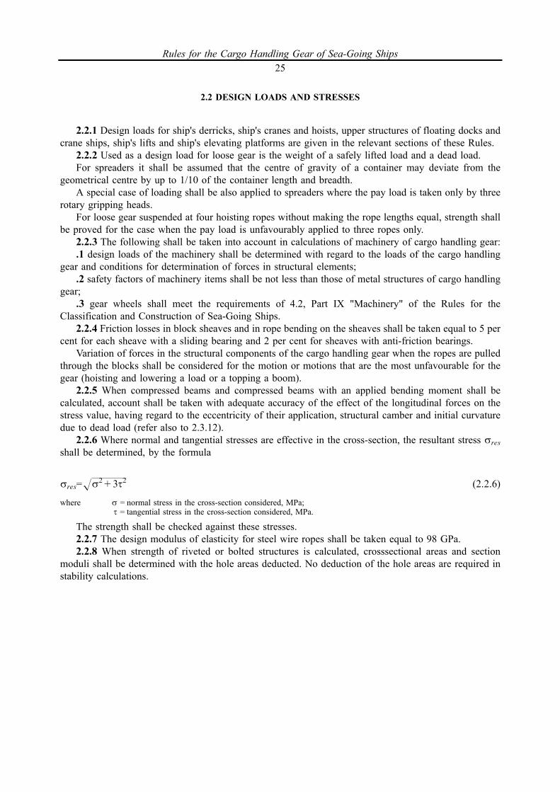
2.2.6 Where normal and tangential stresses are effective in the cross-section, the resultant stress sres
shall be determined, by the formula
sres=Hs2+3t2 (2.2.6)
where s = normal stress in the cross-section considered, MPa;t = tangential stress in the cross-section considered, MPa.
The strength shall be checked against these stresses.2.2.7 The design modulus of elasticity for steel wire ropes shall be taken equal to 98 GPa.2.2.8 When strength of riveted or bolted structures is calculated, crosssectional areas and section
moduli shall be determined with the hole areas deducted. No deduction of the hole areas are required instability calculations.
Rules for the Cargo Handling Gear of Sea-Going Ships25
2.3 ALLOWABLE STRESSES, SAFETY FACTORS AND STABILITY MARGIN
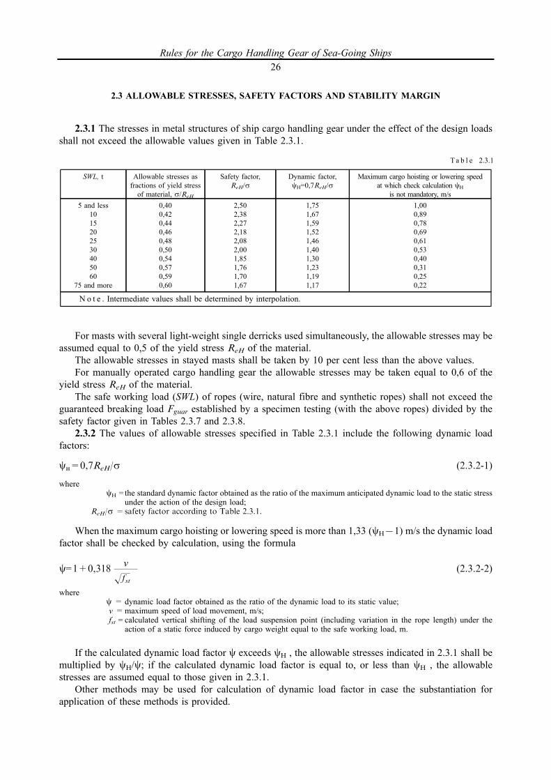
2.3.1 The stresses in metal structures of ship cargo handling gear under the effect of the design loadsshall not exceed the allowable values given in Table 2.3.1.
For masts with several light-weight single derricks used simultaneously, the allowable stresses may beassumed equal to 0,5 of the yield stress ReH of the material.
The allowable stresses in stayed masts shall be taken by 10 per cent less than the above values.For manually operated cargo handling gear the allowable stresses may be taken equal to 0,6 of the
yield stress ReH of the material.The safe working load (SWL) of ropes (wire, natural fibre and synthetic ropes) shall not exceed the
guaranteed breaking load Fguar established by a specimen testing (with the above ropes) divided by thesafety factor given in Tables 2.3.7 and 2.3.8.
2.3.2 The values of allowable stresses specified in Table 2.3.1 include the following dynamic loadfactors:
cN=0,7ReH/s (2.3.2-1)
wherecH = the standard dynamic factor obtained as the ratio of the maximum anticipated dynamic load to the static stress
under the action of the design load;ReH/s =safety factor according to Table 2.3.1.
When the maximum cargo hoisting or lowering speed is more than 1,33 (cH71) m/s the dynamic loadfactor shall be checked by calculation, using the formula
c=1+0,318v
(2.3.2-2)Hfst
wherec = dynamic load factor obtained as the ratio of the dynamic load to its static value;v =maximum speed of load movement, m/s;fst =calculated vertical shifting of the load suspension point (including variation in the rope length) under the
action of a static force induced by cargo weight equal to the safe working load, m.
If the calculated dynamic load factor c exceeds cH , the allowable stresses indicated in 2.3.1 shall bemultiplied by cH/c; if the calculated dynamic load factor is equal to, or less than cH , the allowablestresses are assumed equal to those given in 2.3.1.
Other methods may be used for calculation of dynamic load factor in case the substantiation forapplication of these methods is provided.
SWL, t Allowable stresses asfractions of yield stressof material, s/ReH
Safety factor,ReH/s
Dynamic factor,cH=0,7ReH/s
Maximum cargo hoisting or lowering speedat which check calculation cH
is not mandatory, m/s5 and less
1015202530405060
75 and more
0,400,420,440,460,480,500,540,570,590,60
2,502,382,272,182,082,001,851,761,701,67
1,751,671,591,521,461,401,301,231,191,17
1,000,890,780,690,610,530,400,310,250,22
N o t e . Intermediate values shall be determined by interpolation.
T a b l e 2.3.1
Rules for the Cargo Handling Gear of Sea-Going Ships26

2.3.3 In calculation of the allowable stresses in metal structures, the yield stress guaranteed by thestandard or specifications shall be taken as the basis for calculations; in all cases, however, it shall notexceed 0,70 of the minimum tensile strength guaranteed by the standard or specifications.
2.3.4 The allowable stresses indicated in 2.3.1 relate to tensile, compression and bending deformationsand reduced stresses.
2.3.5 The design and dimensions of interchangeable components and rope sockets shall be such as toprevent permanent deformations when tested with a proof load as specified in 10.2.1 and breaking whentested with an ultimate load according to 10.2.9. Items of interchangeable components which aremanufactured in accordance with the standards and normative documents approved by the Register areconsidered as meeting the requirement.
The allowable stresses in non-standard fixed gear shall not exceed those assumed for metal structures(refer to 2.3.1 to 2.3.4).
2.3.6 The safety factor of span chains, chains of cargo runners, preventer guys and loose gear, ropesockets and pressed clamps (bushes) of the ropes in relation to the breaking load shall not be less than 4.
For calibrated chains used with sprockets in manually operated hoists the safety factor shall be not lessthan 3,2.
2.3.7 The safety factor of the steel wire ropes in relation to the breaking load of the rope as a wholeshall not be less than the values given in Table 2.3.7.
2.3.8 The safety factor of natural fibre ropes, rigging and slings in relation to the breaking load of therope as a whole shall not be less than the values given in Table 2.3.8 and the safety factor of syntheticropes shall be a minimum of 5.
2.3.9 The stability margin shall be not less than the safety factor (in relation to the yield point) for thecompression of the same element.
2.3.10 Compressed beams shall be checked for overall stability and their thin-walled parts, for localstability. If they comply with the requirements of 4.3.3, tubular members need not be checked for localstability.
Beams subject to transverse bending shall be checked for overall stability and their vertical walls andcompressed flanges, for local stability.
2.3.11 The critical load of axially compressed beams shall be determined with due regard for initialeccentricity of the longitudinal forces and the initial bend; the total value of both shall not be lessthan 0,001 of the beam length.
Wire ropes Safety factor with SWL, t
Cargo runners, span ropes, guy tackles, cargo and spanropes of cranes, ropes of loose gear, slings
10 and less 11 _ 160 161 and more
5 1048,85/SWL+1910 3
Shrouds, stays, guy pendants and preventer guys 10 and less 30 50 and more
4 3,5 3
Ta b l e 2.3.7
Nominal diameter of natural fibre ropes, mm Safety factor
1214 _ 17
18 _ 23
24 _ 39
40 and more
12
10876
Ta b l e 2.3.8
Rules for the Cargo Handling Gear of Sea-Going Ships27
2.3.12 Ship steel derricks may be calculated, using the assumed stability margin determined with dueregard for variation of the cross-section along the length of the derrick but with no account of the initialeccentricity and bend. This value shall not be less than 4,5.
2.3.13 Flexibility of each portion of the axially compressed beams with varying cross-section as takenbetween the connecting members (plates or lattices) shall be not less than 40.
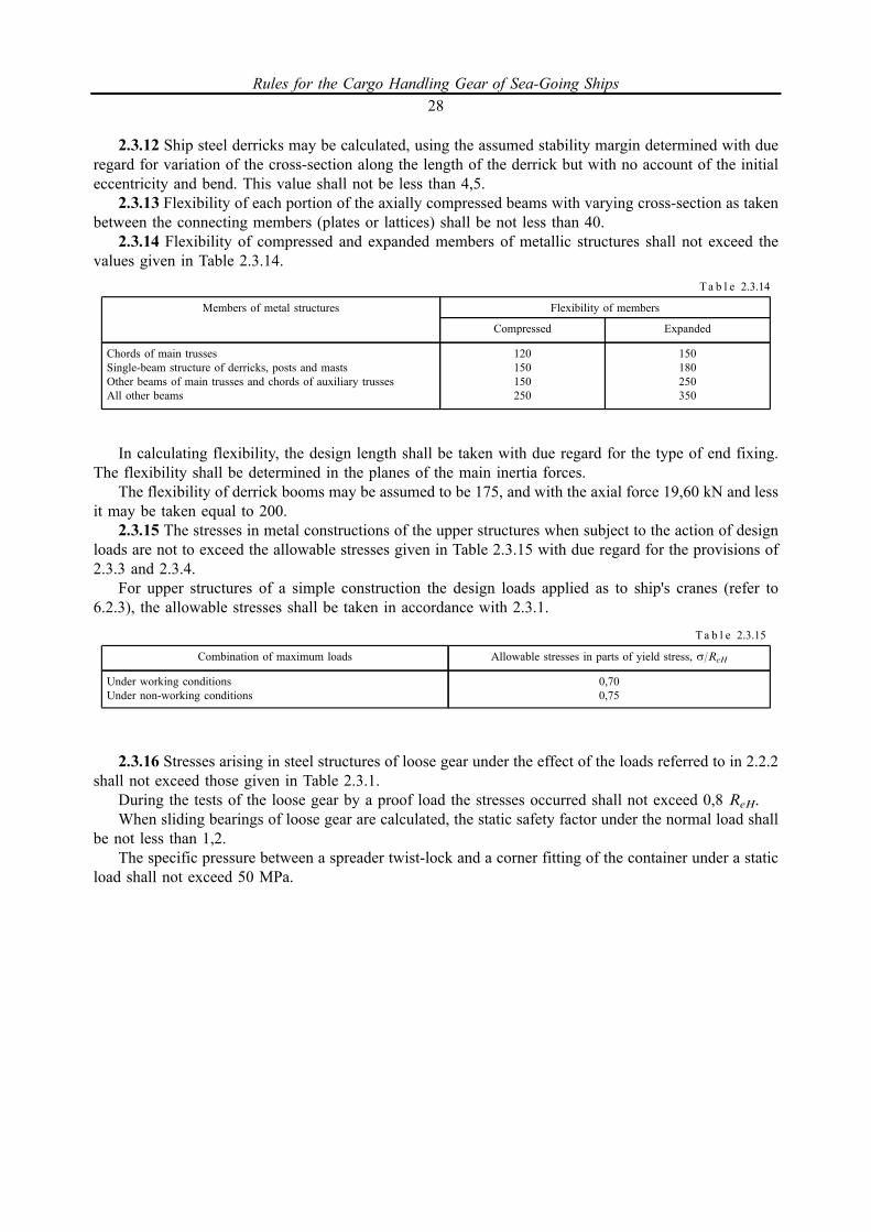
2.3.14 Flexibility of compressed and expanded members of metallic structures shall not exceed thevalues given in Table 2.3.14.
In calculating flexibility, the design length shall be taken with due regard for the type of end fixing.The flexibility shall be determined in the planes of the main inertia forces.
The flexibility of derrick booms may be assumed to be 175, and with the axial force 19,60 kN and lessit may be taken equal to 200.
2.3.15 The stresses in metal constructions of the upper structures when subject to the action of designloads are not to exceed the allowable stresses given in Table 2.3.15 with due regard for the provisions of2.3.3 and 2.3.4.
For upper structures of a simple construction the design loads applied as to ship's cranes (refer to6.2.3), the allowable stresses shall be taken in accordance with 2.3.1.
2.3.16 Stresses arising in steel structures of loose gear under the effect of the loads referred to in 2.2.2shall not exceed those given in Table 2.3.1.
During the tests of the loose gear by a proof load the stresses occurred shall not exceed 0,8 ReH.When sliding bearings of loose gear are calculated, the static safety factor under the normal load shall
be not less than 1,2.The specific pressure between a spreader twist-lock and a corner fitting of the container under a static
load shall not exceed 50 MPa.
Members of metal structures Flexibility of members
Compressed Expanded
Chords of main trussesSingle-beam structure of derricks, posts and mastsOther beams of main trusses and chords of auxiliary trussesAll other beams
120150150250
150180250350
Ta b l e 2.3.14
Combination of maximum loads Allowable stresses in parts of yield stress, s/ReH
Under working conditionsUnder non-working conditions
0,700,75
Ta b l e 2.3.15
Rules for the Cargo Handling Gear of Sea-Going Ships28
3 MATERIALS AND WELDING
3.1 MATERIALS
3.1.1 The materials used in the manufacture of stress-bearing metal structures, machinery and gear ofcargo handling gear, as well as heat treatment of forged and cast items, where not covered by the specificrequirements of these Rules, shall comply with the appropriate requirements of Part XIII "Materials" of theRules for the Classification and Construction of Sea-Going Ships.
The materials used in the manufacture of stress-bearing structures of cargo handling gear installed onfixed offshore platforms, mobile offshore drilling units as well as on the ships operated under lowtemperatures shall be covered by the additional requirements of Part XII "Materials" of the Rules for theClassification, Construction and Equipment of Mobile Offshore Drilling Units and Fixed OffshorePlatforms.
It is allowed to use the steel manufactured in compliance with the international or national standardsrecognized by the Register, if it is proven to comply with the requirements set forth in the present Section.
3.1.2 All stress-bearing parts and fittings of metal structures, machinery and gear other than thosereferred to 3.1.3 and 3.1.4 shall be made of steel; use of other materials shall be in each case confirmed bythe substantiation agreed with the Register. The substantiation shall contain the evidence that themechanical properties of the material selected corres-pond the design values and are not lower than thevalues required by these Rules, and that the material may be used under the specified external conditions.
3.1.3 The first grade timber may be used for side plates of blocks for natural fibre or synthetic ropes.3.1.4 Cast iron may be used for manufacture of the following items:.1 gear, worm and travelling wheels of hand-operated cargo handling gear;.2 worm wheels with a bronze rim;.3 drums and whipping drums of winches, gear boxes and sheaves of blocks;.4 brake shoes, drum brackets and bearing bodies;.5 casings and units of hydraulic equipment, hydraulic engines, pumps.3.1.5 Mechanical properties and chemical composition of the rolled steel used for stress-bearing
elements of metal structures of cargo handling gear and cargo-gripping devices shall comply with therespective requirements of 3.2, 3.5, 3.13, Part XIII "Materials" of the Rules for the Classification andConstruction of Sea-Going Ships.
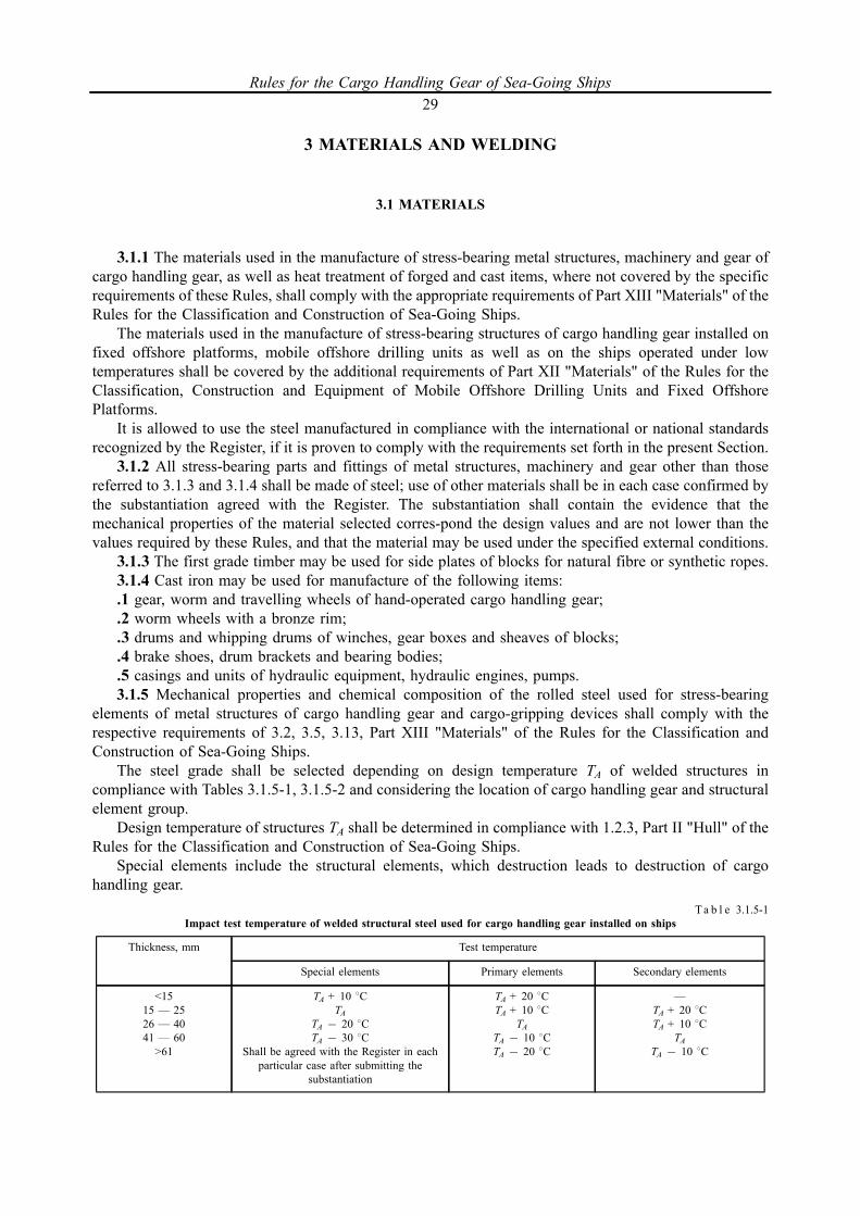
The steel grade shall be selected depending on design temperature ТА of welded structures incompliance with Tables 3.1.5-1, 3.1.5-2 and considering the location of cargo handling gear and structuralelement group.
Design temperature of structures ТА shall be determined in compliance with 1.2.3, Part II "Hull" of theRules for the Classification and Construction of Sea-Going Ships.
Special elements include the structural elements, which destruction leads to destruction of cargohandling gear.
Thickness, mm Test temperature
Special elements Primary elements Secondary elements
<1515 _ 2526 _ 4041 _ 60
>61
TA + 10 8CTA
TA 7 20 8CTA 7 30 8C
Shall be agreed with the Register in eachparticular case after submitting the
substantiation
TA + 20 8CTA + 10 8C
TATA 7 10 8CTA 7 20 8C
_
TA + 20 8CTA + 10 8C
TATA 7 10 8C
Ta b l e 3.1.5-1Impact test temperature of welded structural steel used for cargo handling gear installed on ships
Rules for the Cargo Handling Gear of Sea-Going Ships29

Primary elements include the structural elements subjected to high stresses.The rest elements are the secondary elements.For the structural elements loaded in Z-direction provision shall be made for the application of
Z-steels.3.1.6 Steel used for forgings and castings of cargo handling gear welded elements shall comply with
the requirements to impact test results of rolled steel performed at the temperature complying with thatspecified in Tables 3.1.5-1 and 3.1.5-2.
Steel used for forgings and castings of not welded elements, as well as for not welded elements madeof rolled steel, including bolts, hooks, shackles, swivels etc. shall comply with the international andnational standards recognized by the Register or other contract requirements to impact test results but notless than 27 J at the design temperature ТA.
Forgings and castings intended for components operating at temperatures below zero shall complywith the requirements of 3.5.4 and 3.5.5, Part XIII "Materials" of the Rules for the Classification andConstruction of Sea-Going Ships, respectively.
Steel used for manufacture of chains for cargo handling gear intended for operation at temperaturesbelow 720 8C shall meet the requirements for chain steel of grade 2 or 3 according to 3.6, Part XIII"Materials" of the Rules for the Classification and Construction of Sea-Going Ships.
Chains for which no heat treatment is required for improvement of quality or strength shall benormalized after manufacture.
.1.7 All steel castings and forgings used in cargo handling gear, as well as welded items with stressedclosely spaced or intersecting welded joints shall be heat-treated for stress relieving (castings from alloyedsteels shall be quenched and tempered, castings and forgings from carbon steels shall be quenched andtempered or normalized, and electrically welded items shall be annealed).
Heat treatment of items shall be carried out in muffle furnaces under efficient control of thetemperature. Heat treatment conditions shall be specified depending on the steel grade, use and size of theitems and shall be agreed upon with the Register.
Heat treatment shall be confirmed by the document drawn up by the manufacturer according to thestandards of the firm. The particulars of heat treatment of interchangeable components shall be entered in theCertificate of Test and Thorough Examination of Interchangeable Components and Loose Gear (Form 5.1.4).
If heat treatment of the interchangeable components was supervised by a competent person, a relevantentry shall be made in Part II of the Register of Ship's Cargo Handling Gear Lifting Appliances and by theRS surveyor, based on the Certificate of Test and Thorough Examination of Interchangeable Componentsand Loose Gear signed by the competent person.
3.1.8 Use of higher strength materials for manufacture of structures and components of cargo handlinggear may be permitted, provided the Rules requirements for the steels are met.
Thickness, mm Test temperature
Special elements Primary elements Secondary elements
<1515 _ 2526 _ 4041 _ 60
>61
TATA 7 10 8CTA 7 20 8CTA 7 30 8C1
Shall be agreed with the Register in eachparticular case after submitting the
substantiation
TA + 10 8CTA
TA 7 10 8CTA 7 20 8CTA 7 30 8C
TA + 20 8CTA + 10 8C
TATA 7 10 8CTA 7 20 8C
1 In order to confirm the use, the crack resistance parameter values shall be determined for the base metal and welded joint metal (CTOD)at the temperature ТА.
T a b l e 3.1.5-2Impact test temperature of welded structural steel used for cargo handling gear installed on MODU/FOP
Rules for the Cargo Handling Gear of Sea-Going Ships30

3.2 WELDING
3.2.1 Use of welding in metal structures, components and machinery of cargo handling gear, qualitycontrol of welded joints and their heat treatment, where not covered by the specific requirements of theseRules, shall comply with the appropriate requirements of Part XIV "Welding" of the Rules for theClassification and Construction of Sea-Going Ships.
Welding consumables and welding procedures shall be selected according to 2.2, Part XIV "Welding"of the Rules for the Classification and Construction of Sea-Going Ships and 2.5, Part XIII "Welding" of theRules for the Classification, Construction and Equipment of Mobile Offshore Drilling Units and FixedOffshore Platforms. The welding procedure applied shall be approved by the Register.
3.2.2 The dimensions of fillet welds shall be assigned as small as possible based on the strengthcalculation and with regard to the manufacturing conditions. The leg length of a fillet weld shall not be lessthan 4 mm but it shall not exceed 1,2 of the least thickness of the welded items. The length of the filletweld shall be not less than 50 mm.
Where short fillet welds are used for tee-joints of such essential components as slewing guy plates(refer to 9.2.3), lead block fastening nose (refer to 9.2.6), span eye plate (refer to 9.2.8), eye plates on shiphull and metal structures (refer to 9.2.9), special attention shall be given to the quality of welding andtesting of welds. In particular, the welds shall be examined along their entire length by a method approvedby the Register.
3.2.3 Round and ring-shaped items of small diameters (chains, rod shrouds) shall be joined byresistance welding.
3.2.4 Butt welded joints of the load-transferring structural elements, which are oriented transverse tothe loading direction, shall be primarily made by root-penetration double-sided or one-sided welding.Acceptability of one-sided welding using a backing strap shall be analyzed at the design stage taking intoconsideration the structure cycling loads. For the purpose of increasing the fatigue strength, if necessary,the welds shall be additionally treated by means of TIG flashing, surface and plastic deformation or finishgrinding.
3.2.5 In structures of enclosed circuit where there is no access from inside, use of plug welds ispermitted for attachment of the closing plate on the inside framing (diaphragms). For the requirements forplug welds, refer to 1.7.5.13, Part II "Hull" of the Rules for the Classification and Construction of Sea-Going Ships.
3.2.6 Weld quality of stress-bearing members of metal structures shall be examined by theradiographic or some method of non-destructive control approved by the Register. Not less than 10 percent of the length of the welded joint tested shall be tested. Welded joint intersections shall be mandatorilyexamined. Circular continuous butt welds of masts, columns, derricks and other stress-bearing metalstructures shall be examined over the entire length. Welds of masts (columns) intended for installation ofbooms with a safe working load of more than 25 t are subject to 100 per cent radiography up to a height3,5 m above the deck of their attachment.
Rules for the Cargo Handling Gear of Sea-Going Ships31
4 SHIP'S DERRICKS
4.1 GENERAL
4.1.1 The requirements of this Section apply to ship cargo derricks of an ordinary design, whichoperate under the following conditions:
single derricks with one span;twin span tackle derricks;derrick cranes;union purchase rig.Derricks with special design are subject to special consideration by the Register.4.1.2 Typical rigging schemes for ship's derrick are given in Section 1.4.1.3 Each derrick shall be provided with a power- operated topping winch or a span winch meeting
the requirements of 4.5.2.Where provision of a span winch is not reasonably practicable, a span chain joined to the span rope by
means of a monkey or a delta plate shall be employed.4.1.4 The span chain of derricks shall be secured to an eye plate on the deck or mast.Fastening of span ropes, guys and preventer guys at the expense of friction forces (rope stops, bollards,
cleats) is not allowed.4.1.5 The lengths of a span rope and a cargo runner shall be chosen so that the minimum number of
turns on the appropriate drum is not less than that required by 1.5.5.6 under all possible combinations oflocation and movements of booms during operation.
4.1.6 Use of snatch hooks for leading cargo runners and span ropes is not allowed.4.1.7 Where a derrick winch is fitted with a common motor for raising or lowering either the jib or the
load and the jib is held by a pawl engaging in the derricking drum when the motor is being used to raise orlower a load, an effective interlock shall be fitted to the pawl engagement gear so that the pawl cannot bedisengaged from the drum until the motor has been positively connected to the derricking drum drive.
4.1.8 When the cargo runner becomes slack downward movement of the block under the effect of itsown weight shall be restricted. For this purpose provision shall be made in the assembly design of theblock fitted to the heel of the derrick for a limiting stop or the lead block shall be provided with a duct bill.
4.1.9 Provision shall be made to ensure efficient securing of derricks when they are stowed for sea.Where the derrick is stowed vertically along the mast during the voyage but where it cannot be adjusted inthis position with the help of a span, a special arrangement shall be provided to keep it in the position.
4.1.10 Slewing guys of derricks shall be designed so that operation of the derrick at the maximum jibradius is ensured with the ship or mobile offshore drilling unit having a list 58 and a trim 28.
4.1.11 The derrick heel bearing shall be fitted above the deck where winches are installed at a heightnot to hinder the attending personnel and proper winding of the cargo runner on to the drum.
4.1.12 The gooseneck of the derrick with one span and span eye plate shall be generally positioned atone vertical line. Displacement of span fitting in relation to the derrick heel shall be in each casesubstantiated, verified by the calculations and agreed with the Register
4.1.13 Seatings of heavy-lift derrick goosenecks shall be adequately strong and rigid. The deck shall bestrengthened in the area of the gooseneck. The heel socket of the gooseneck shall be provided with a holefor water drainage.
4.1.14 Twin span tackle derricks shall be designed and installed in such a way as to preclude jack-knifing when in the extreme positions. Where necessary, structural measures shall be taken to limit slewingangles of the spans or derricks.
4.1.15 Derrick cranes shall be provided with limit switches that automatically come into action in theoutreach and slewing extreme positions of the derrick cranes and, when proved necessary, with othersafety devices in accordance with the requirements of 5.5.
Rules for the Cargo Handling Gear of Sea-Going Ships32

4.1.16 The design and arrangement of union purchase rigs shall provide a possibility to operate thebooms in the mode of single booms.
4.1.17 When derricks shall be operated in union purchase rig, their outfit shall include:.1 adequately strong preventer guys and fittings for their attachment to the deck and derrick head;.2 devices for bridling cargo runners (including a check chain between the cargo runners);.3 arrangements enabling to control extreme positions of the derricks and preventer guys during
operation as provided in the calculations and also the angle between the cargo runners, whicharrangements shall be contained in the Instructions for Derricks Used in Union Purchase.
Visual control of the working position of the derricks or the limiting height of lifting a load may beused if, under actual conditions of operation, such control proved sufficiently reliable (e.g. if the limits ofallowable service area or fixed positions of the derricks are governed by such ship structures as hatchcomings, superstructures, deckhouses, etc.)
It is recommended that permanent indicators be used to control boom positions relative to the horizonand centreline of the ship.
Where visual control of boom positions and the included angle between cargo runners is notconsidered to be reliable, provision shall be made for such structural arrangements as marking of spanropes, preventer guys and preventer guy eye plates or other acceptable arrangements.
Places where preventer guys are attached and the length of the preventer guys shall be fixedstructurally but not controlled visually;
.4 boom head guys or inner guys to preclude slewing of the boom towards the preventer guy.4.1.18 The derricks used in union purchase shall be so positioned that a load is easily carried over the
top of the bulwark or hatch coaming, with a limited angle between the cargo runners not exceeding 1208.4.1.19 The hauling ends of guy tackle ropes of heavy-lift derricks shall be securely attached to winch drums.Efficient attachment of ropes to the drums shall be also ensured where winches are used for securing
preventer guys in union purchase rig.4.1.20 Loose, interchangeable and fixed gear of ship's derricks shall comply with the requirements of
Section 9.
Rules for the Cargo Handling Gear of Sea-Going Ships33

4.2 CALCULATION
4.2.1 In determining the loads on the components of single derricks the following angles between aboom and a horizontal shall be used: 158 for light-lift derricks; 258 for heavy-lift derricks.
If the minimum angle under actual operating conditions exceeds the above values, the minimum anglemay be used in calculations.
For a built-in sheave of a cargo runner and cargo blocks with a cargo runner which is parallel to thederrick boom, the resultant load shall be calculated using the largest possible angle of boom inclination tothe horizontal but not less than 608.
4.2.2 The maximum angle of boom inclination to the horizontal shall not exceed 708.4.2.3 The maximum angle of boom slewing relative to the centre line of the ship when the boom is
swung outboard shall not exceed 758.4.2.4 Where the derrick heel is structurally shifted in relation to the vertical passing through the span
eye plate at a value exceeding 0,025 of the eye plate height above the derrick heel, the stresses in thederrick, span and slewing guy units shall be specially calculated, having regard to limitations for theadjustment of guys and the extreme positions of the booms.
4.2.5 For twin span tackle derricks the requirements of 4.2.1 may be applied, the only difference,however, being that the span tension shall be determined for the maximum slewing of the derrick boom tothe side opposite to the span under consideration.
Where the heel of the derrick fitted with twin span tackles is structurally shifted in relation to thevertical plane passing through the span eye fittings, the requirements of 4.2.4 may be applied.
4.2.6 Provision shall be made to obviate the risk of horizontal jack-knifing of the twin span tacklederrick when the boom is at the maximum slewing distance from the middle position. For heavy-liftderricks account shall be taken of heel and trim angles referred to in 4.2.9. The jack-knifing is unlikely tooccur if there exists a horizontal component of the span tension, which is normal to the direction of theboom in the projected plan and equal to not less than 0,1 of the derrick safe working load.
4.2.7 When derricks are operated in union purchase rig, the stresses in the derrick gear shall bedetermined for the worst possible position (for the gear concerned) of the maximum safety lifted load onthe trajectory defined by the limited angle between the cargo runners (refer to 4.1.18).
If, under actual operating conditions, derricks may be rigged in several different ways, to be includedin the calculation is the one under which the greatest stresses occur; this applies also to determination ofthe design position of the derricks and preventer guy units when specifying the working areas to be servedby the derricks in union purchase.
When derricks are operated in union purchase, the stresses in booms, cargo runners and span ropesshall generally not exceed the stresses originated in the single derrick rig. Where the stresses in the unionpurchase components (for example, the axial thrust down the boom) exceed those met in case of singlederrick rig, the scantlings of the components in question shall be based on the stresses originated inderricks rigged in union purchase.
4.2.8 When derricks shall be operated in union purchase rig, the derricks and preventer guy units shallbe so fitted as to obviate the risk of vertical jack-knifing of derricks (tipping over) under all possible waysof rigging and positions of the load.
To preclude the risk of jack-knifing, additional inner guys may be used. Slewing guys may be used forthis purpose.
The jack-knifing is not likely to occur if there is a positive tension in the span when the derrick is underload, having no regard to the own weight of the derrick and its gear.
4.2.9 The design stress in the slewing guy units shall be not less than 25 per cent of the cargo gravityforce equal to the derrick safe working load.
For heavy-lift derricks the above value shall be verified at a heel of 58 and trim 28 when the derrick isswung fully outboard. If heel and trim are greater in operation than the above values, the actual values ofheel and trim shall be used in calculations.
Rules for the Cargo Handling Gear of Sea-Going Ships34
Where special arrangements, such as ballasting, are made to reduce the heel when working with aheavy-lift derrick, these arrangements may be taken into account in calculating the force in the guy.
The design stress in boom head guys or in union purchase tackles shall not be less than 10 per cent ofthe gravity force of the load corresponding to the safe working load for the single slewing derrick.
4.2.10 Where two or more light derricks are used simultaneously on one mast, the relative position ofthe booms shall be assumed such where maximum stresses in the mast cross-section are produced, and ifthe mast is provided with standing rigging, the maximum tension which arose in the standing rigging.
Where no special proof is available, the initial tension of the standing rigging shall be taken equal to 1/12 ofthe breaking load of the rope as a whole.
4.2.11 When several positions of a boom are possible, calculations shall be made for each positionseparately. Allowable angles of inclination shall be indicated in the Certificate of Test and ThoroughExamination of Lifting Appliances (Form 5.1.2).
4.2.12 For derricks the parts of which are secured on the cross-trees account shall be taken of abending moment and a torque which may arise under conditions of uneven distribution of forces in thetackle-blocks.
4.2.13 The safe working load shall be taken as a design load for derricks.The derrick own weight shall be considered (except for operation in union purchase) if the derrick
mass amounts to 20 per cent of the safe working load and more.For derricks of a special (non-tubular) design wind pressure shall be taken into consideration as
specified for ship's cranes.In determining tension in slewing guys of heavy-lift derricks, heel and trim shall be considered as
specified in 4.2.9.
Rules for the Cargo Handling Gear of Sea-Going Ships35
4.3 CARGO MASTS
4.3.1 Cargo masts shall have at least two props.The deck of a sufficiently strong deckhouse or superstructure may serve as the upper prop.The places in way of fixing the masts shall be adequately stiffened.4.3.2 The wall thickness of cargo masts shall not be less than 5 mm if they are arranged within
enclosed spaces; it shall be not less than 6,5 mm if they stand outdoors or have no access inside and at least5 mm for those having access inside. Cargo masts used for ventilation purposes shall have wall thicknessnot less than 6,5 mm.
4.3.3 The outside diameter of a cargo mast D, in mm, depending on the wall thickness t, in mm, shallnot exceed the following relationships:
D=1000t/(257t) with t415 mm,
D=100t with t>15 mm.
The diameter of the mast may be increased if the actual stresses in the mast are below the allowablestresses, which shall be in each case verified by the calculation agreed with the Register (refer alsoto 2.3.1).
4.3.4 The construction of cargo masts and their parts shall prevent water accumulation in inaccessibleplaces. All parts other than enclosed structures shall be accessible for inspection, cleaning and painting.
4.3.5 The design forces in cargo masts shall be determined for such position of a boom or combinationof booms which cause the largest forces.
4.3.6 Shrouds shall be so fitted as not to interfere with operation of booms or running rigging. It is notrecommended that shrouds be attached to the ends of the cross-trees (cross-piece) of the mast.
4.3.7 The ropes of the standing rigging shall be provided with rigging screws; the shroud and stayplates shall be securely attached to the ship hull; the direction of the plates shall be as indicated in 9.2.9.Use of only one item (e.g., shackle) for fastening two ropes is not allowed.
Rules for the Cargo Handling Gear of Sea-Going Ships36
4.4 DERRICK BOOMS
4.4.1 The wall thickness of steel derrick booms shall not be less than 4 mm.The outside diameter of derrick booms shall not exceed the values specified in 4.3.3.The diameters of the boom sections in the area of the boom head and heel shall be not less than 0,65 of
the boom diameter in its middle part.Transverse butt welds are not allowed in the middle part of derrick booms. The arrangement of these
welds shall be in accordance with the standards recognized by the Register.The maximum structural camber of the steel boom shall not exceed 1/1500 of its length, either in the
plane of the suspension or in the plane normal thereto.4.4.2 Eye plates for fastening guys shall be fitted as close as possible to the eye plates for fastening the
cargo block in compliance with 9.2.9.4.4.3 Where a built-in sheave is fitted the boom shall be additionally strengthened to make a section
modulus in way of the sheave not less than that of the boom without a sheave.4.4.4 After fitting of eye plates and a built-in sheave and upon completion of all welding operations,
each boom shall be tested for tightness by air with a pressure 0,03 MPa.4.4.5 Quality control of welded joints is carried out by means of external examination, measurements
and radiography in accordance with 3.2.7.
Rules for the Cargo Handling Gear of Sea-Going Ships37
4.5 CARGO WINCHES AND REELS
4.5.1 Cargo winches, span winches and slewing guy winches used for changing the position of derricksunder load shall comply with the requirements of 1.5. Their drive shall have a braking moment which is1,5 times the required nominal moment.
4.5.2 Span ropes reels and preventer guy reels shall be provided with ratches which automaticallycome into action when the winch drives are disconnected or fail, or when the current is switched off orpower supply to the motor of independent reel drive is interrupted.
Where reels are driven by the rope from the load drum or whippng drum of the cargo winch, automaticoperation may not be needed if the pawl does not rise above the ratchet by more than 15 mm.
4.5.3 The reels driven independently shall also comply with the requirements for cargo winches (see4.5.1), except for the requirements for the brakes of the cargo handling gear with electric drives.
4.5.4 Where reels are driven by a rope the winch drive shall be efficiently divided by a substantialflange into two sections: for the working rope and for the driving rope. The driving rope shall be securelyfastened to the drum of the topping or similar winch, and to the load drum or to the whipping drum of thecargo winch.
4.5.5 Winches and reels shall be installed so that the fleet angle of a rope reeled onto the drum shall beno more 48 about the plane vertical to the longitudinal axis of the drum, and adequate tension is ensured sothat the rope will properly reel onto the drum, whatever the position of the derrick may be. A coiler or apressure roller shall be provided if necessary (refer also to 1.5.5.7).
4.5.6 It is recommended that arrangements are made to prevent inadmissible stresses in the boom andspan due to the tension in the guy winches for single span heavy-lift derricks.
4.5.7 The ratchet-and-pawl mechanisms shall withstand the torque which is at least 1,5 times themaximum torque induced by the force in the derrick boom under the maximum load conditions.
4.5.8 A span reel driven by another winch through the driving rope shall not be used with a derrickboom the safe working load of which exceeds 3 tons.
4.5.9 The rope intended for driving the span reel:shall not be used on a drum which may damage the rope owing to its condition and design;shall not have more turns on the drum than that specified. Extra turns may be laid onto the drum
provided with appropriate flanges;shall not be paid out through the drum, in particular, if the rope is made of a synthetic fibre.Performance of the chosen rope shall ensure its adequate strength and reliability in operation.
Rules for the Cargo Handling Gear of Sea-Going Ships38

4.6 SAFETY DEVICES
4.6.1 The requirements of 5.5.1, 5.5.2, 5.5.3 and 5.5.5 specified for ship’s cranes and hoists apply alsoto derrick cranes.4.6.2 At the installation of safety devices for derrick cranes, type of work shall be considered for
derrick cranes used in union purchase.
Rules for the Cargo Handling Gear of Sea-Going Ships39

5 SHIP'S CRANES AND HOISTS
5.1 GENERAL
5.1.1 The requirements of this Section apply to cranes and hoists with allowance for their specificoperating conditions and structural features.
5.1.2 Jib cranes shall be designed and installed in such a way as to obviate a risk of jack-knifing (referalso to 5.7.1).
5.1.3 Cranes with derricks on rope suspension shall be designed in such a way as to obviate a risk ofjack-knifing of the derrick to the side opposite to the outreach; due account shall be taken of heel and trimwhich are likely to be encountered in service; limiting stops may be used when required (refer alsoto 5.2.4).
5.1.4 The design of ship’s cranes and hoists shall enable them to be securely attached to the hull of theship, fixed offshore platform and mobile offshore drilling unit. The hull structure of a ship, fixed offshoreplatform and mobile offshore drilling unit shall be adequately stiffened in the place where a crane or hoistwill be installed..
5.1.5 Provision shall be made to ensure efficient fastening of cranes, their derricks and hoists whenstowed for sea.
Rules for the Cargo Handling Gear of Sea-Going Ships40
5.2 CALCULATION
5.2.1 The total design load of the ship's cranes will include:.1 safe working load;.2 crane own weight;.3 wind pressure of 400 Pa acting on the deck crane and load surfaces in the longitudinal and transverse
directions.In stress calculations of crane elements angles of inclination shall be taken into consideration in
accordance with 5.2.3.For cranes intended for operation at rolling the de-sign loads shall meet the requirements of 6.2.1 and
6.2.2.5.2.2 In calculating the wind load, the windward side of the crane shall be assumed as follows: for
continuous-sided constructions it is the area outlined by the contour of the construction, and for latticedconstructions it is the area outlined by the contour of the construction with the area of gaps between thebeams deducted.
For cranes with equally high beams running at different levels (continuous-sided or latticed) onebehind another, and with the distance between the beams less than the beam height, the windward sideshall be assumed as the total area of the front beam; if the distance between the beams is equal to or morethan the height of the beam, but less than its double height, the windward side shall be the total area of thefront beam plus 50 per cent of the area of each subsequent beam; if the distance between the beams isequal to the double height of the beam or more, the windward side shall be the total area of all the beams.Portions of rear beams not covered by the front beam shall be fully allowed for in the calculations.
For tubular constructions the design windward side may be reduced by multiplying it by the correctionfactor 0,75.
The design windward area of the load is the actual area outlined by the contour of the load to be liftedby the crane.
For cranes with the safe working loads up to 10 t inclusive, where appropriate data are not available,the load area may be assumed equal to 2 m2 per 1 t for loads up to 2 t inclusive, and 1 m2 per 1 t for loadsof 10 t. The intermediate values of load area may be determined by interpolation.
5.2.3 Stress calculations for structural members of the ship’s cranes installed on ships and mobileoffshore drilling units shall be made for a heel 58 and a trim 28. If the heel and trim in service are greaterthan those indicated above, actual values shall be used in the calculations.
5.2.4 For derrick crane booms on rope suspension it shall be proved by calculations or a functional testthat there is no risk of boom jack-knifing to the side opposite to boom outreach.
The jack-knifing is unlikely to occur if there is a positive tension in the boom ropes when the outreachof the boom is minimum and the inclination of the boom is the least that could occur in service (but notless than the heel of 58 and trim 28), the wind pressure from the side of the outreach being as specified in5.2.1.3.
Rules for the Cargo Handling Gear of Sea-Going Ships41
5.3 METAL STRUCTURES
5.3.1 The wall thickness of stress-bearing elements of crane or hoist metal structures which are readilyaccessible for inspection and maintenance as well as of the elements arranged in enclosed spaces shall notbe less than 4 mm; the wall thickness of box-type or tubular metal structures inaccessible for inspectionand maintenance from the inside shall not be less than 6 mm.
The maximum structural camber of the crane boom shall not exceed 1/1500 of its length, both in theplane of suspension and in the plane normal thereto.
5.3.2 The outside diameter of tubular elements of metal structures shall not exceed the value indicatedin 4.3.3.
5.3.3 The construction liable to loads (especially to vibration loads) dangerous for breaking away rivetheads shall be avoided. In exceptional cases only, may such a construction be permitted. Tensile stresses inrivets with countersink or half-countersink heads are not allowed.
The holes for rivets and finished bolts shall be drilled in the joined items at one go or separatelythrough jib plates.
The diameter of rivets and bolts used in the stress-bearing items shall not be less than 12 mm.The maximum thickness of riveted items shall not exceed five diameters of the rivet.The least number of rivets securing an item in the assembly or used on either side of the joint shall be
not less than two.
Rules for the Cargo Handling Gear of Sea-Going Ships42
5.4 MACHINERY
5.4.1 The machinery of the cranes and hoists shall comply with the general technical requirements asspecified in 1.5.
5.4.2 The safety factor of braking for the hoisting machinery shall not be less than 1,5. For topping(luffing) machinery the safety factor of braking shall not be less than 2; the static moment on the brakingshaft due to the weight of the load, weight of the jib and the counterbalance, shall be determined for such aposition of the jib in which the moment is maximum.
In case the drive is fitted with two or more brakes, the safety factor of braking shall be specified,assuming that the entire load is held by one brake.
The safety factor of braking of each of the brakes shall not be less than 1,25 at simultaneous operationof all brakes. If operation of brakes is not simultaneous, the safety factors for individual brakes shall beused.
5.4.3 Slewing and travelling motion brakes shall be of such design that they will either actautomatically or be controlled; use of "normally on" brakes shall be subject to special consideration by theRegister in each case.
The safety factor of braking shall not be less than 1,0.The safety factor of braking for the upper structures of floating cranes (crane ships) and for the cranes
intended for operation at rolling shall be not less than 1,5.Hand-braked slewing and travelling motion machinery shall be provided with stops against
uncontrolled slewing or movement of the cranes.
Rules for the Cargo Handling Gear of Sea-Going Ships43
5.5 SAFETY DEVICES
5.5.1 Ship’s and deck cranes, as well as power-operated hoists for stopping machinery in extremepositions shall be fitted with the following limiters (switches that automatically come into action):
hoisting limiter preventing the load-lifting attachment (hook, lifting frame or beam, spreader, etc.)being raised to the position where it strikes the structure of other crane or hoist;
lowering limiter ensuring that the minimum number of turns is always left on the winch drum;derricking-in limiter ensuring that the crane jib cannot be derricked back beyond the minimum radius
position:derricking-out limiter ensuring that the jib cannot be derricked out beyond the maximum radius
position;telpher or trolley limiter ensuring that the trolley or crab is stopped before it reaches the track end stops;slewing limiter on cranes with a limited arc of slew;long travel limiter on rail-mounted cranes preventing them from approaching the track end stops;grab interlocking limiter.Provision shall be made for reverse movement of the above items of machinery after the limiters (limit
switches) have been actuated.Where closing switches are provided for shunting the limit switches (e.g. for lowering a jib below the
maximum radius position when the crane is being stowed for sea), they shall be accessible only forauthorized crew personnel.5.5.2 Where one motion of a crane or derrick crane can cause a second motion to approach a limiter (e.
g. a derricking-out motion that can cause a hoist motion to reach its limit), the limiter shall stop bothmotions.
Where the jib, when being lowered, is superimposed on the cargo-gripping device, the lowering limiterand derricking-out limiter shall be actuated simultaneously.
5.5.3 The cranes, stability of which depends upon the load position on the hook shall be provided withsafe working load limiters (SWL limiters) automatically disconnecting the crane machinery when anattempt is made to lift the load exceeding the safe working load of the crane for a given radius.
The SWL limiter shall operate when the load being raised or lowered exceeds the safe working load bya predetermined amount, generally within the range of 3 to 10 per cent above the safe working load. Thelimiter shall only prevent motions that would increase the overload. After operation the SWL limiter shallnot prevent the load from being lowered.
The following requirements shall be met for the SWL limiters:sensors with electric output signal to measure mechanical forces in the jib and the jib radius shall be
fitted;output circuits shall be interrupted when the actuation limit is exceeded, the limiter is faulty or power
supply is discontinued.It is recommended that SWL limiters be fitted on cranes of other types and on hoists.In order to enhance safe operation of the ship and deck cranes, it is recommended to provide them with
recorders of the following parameters:calendar date and time;current value of cargo weight;current value of jib radii;operation of a SWL limiter.5.5.4 Cranes with varying jib radii and constant safe working load over the whole radius shall be
provided with SWL limiters of hoisting machinery.5.5.5 Cargo handling gear with the stationary control station or radio and telecontrol shall be provided
with an audible warning alarm which can be put into operation by the driver at any time. The audiblewarning alarm shall be clearly heard and be distinctive among other audible signals and operation noises.
Rules for the Cargo Handling Gear of Sea-Going Ships44

5.5.6 Cranes operating in tandem and mounted on a common supporting and slewing bearing as wellas those which operate in tandem, but are mounted separately, shall be fitted with automatic limitingswitches to stop them in case of any mismatch in their operation or at least audible alarms shall beprovided to warn the crane operator accordingly.
Such cranes shall be equipped with a control system enabling to control both cranes from any of themat the discretion of the operator.
When operating in tandem, both cranes shall be switched off upon operation of any of the limitingswitches.
Rules for the Cargo Handling Gear of Sea-Going Ships45
5.6 COUNTERBALANCES
5.6.1 The design of the crane counterbalance shall ensure that the weight will remain stable while thecrane is in use. Fastening of separate cargoes in the counterbalance shall prevent their displacement.
5.6.2 The adjustable counterbalances shall either move automatically when the jib radii are beingchanged or be provided with a means for clear indication of the position of the counterbalance for differentjib radii. In case of movement of the adjustable counterbalance, any possibility of its jamming shall beprevented.
Rules for the Cargo Handling Gear of Sea-Going Ships46

5.7 MOBILE CRANES AND HOISTS
5.7.1 Stability of the mobile cranes shall be ensured under all conditions, whether in service or not.Stability shall be checked in accordance with procedures and standards approved by the Register.
5.7.2 Mobile cranes shall be provided with devices for anchoring the crane to its rails or with reverserollers.5.7.3 Mobile cranes and hoists installed on the open decks shall be provided with interlocking devices
that prevent inadvertent movement along the track when in non-working condition (stowed for sea).Cranes and hoists may not be provided with interlocking devices when in non-working condition and
under the wind load at the maximum allowable wind speed, the safety factor of braking for the travelingmotion machinery referred to in 5.4.3 is not less than 1,2.5.7.4 When devices for anchoring the crane to its rails are used as interlocking devices, their design
shall ensure securing of the crane and hoists during their movement along the entire length of the track.Power-driven interlocking devices shall be provided with means for manual operation.5.7.5 Wheels of mobile cranes, trolleys and hoists shall be so designed or fitted that their derailment is
prevented.5.7.6 Frames of mobile cranes and trolleys shall be provided with bearing struts arranged at a distance
of not more than 20 mm from the rails and may be used as supports in case a wheel or an axle is broken.The struts shall be calculated for the maximum permissible load.
5.7.7 Mobile cranes, trolleys and power-driven hoists shall be provided with buffers to prevent theircontact with stops. The buffers may be fitted on stops.
5.7.8 Efficient stops shall be provided at both ends of the track, the design of which shall be such as towithstand the contact with the crane, trolley or hoist moving with the maximum working load at thenominal speed.
5.7.9 If several cranes or trolleys travel at one railway, they shall be provided with the stops to preventtheir collision.
Rules for the Cargo Handling Gear of Sea-Going Ships47

5.8 CRANES USED TO CONVEY PERSONNEL
5.8.1 The requirements of this Chapter apply to the ship's cranes and cranes installed on MODU/FOPand used to convey the personnel. The term "personnel convey" includes the application of cranes togetherwith appliances for the personnel convey used to move the personnel between ships and/or MODU/FOPand to lift the personnel by crane within the ship and/or MODU/FOP.5.8.2 The personnel shall be conveyed by a net, basket, cradle or other product specially designed and
certified for this purpose. These products shall not be used for other purposes than the personnel convey.5.8.3 A crane operator shall observe the appliance for the personnel convey with people during
transportation as well as its lifting and lowering areas and have a direct continuous radio or telephonecommunication with the personnel conveyed.5.8.4 Speed of the vertical movement of the appliance for the personnel convey shall not exceed 20 m/
min.5.8.5 Accidental movement of the appliance for the personnel convey shall be prevented by stay ropes
or other means of stabilization.5.8.6 When the appliance for the personnel convey is gripped by a spreader, every fitting shall be
provided with the clamps for blocking the spreader locks, and safety chains of the appliance for thepersonnel convey shall be hooked to the spreader shackles.5.8.7 During convey of the personnel, the following conditions shall be met:.1 wave height shall not exceed 2 m;.2 wind speed shall not exceed 10 m/s;.3 personnel shall not be conveyed in low-visibility conditions (heavy rain, snow, fog), icing and in any
other conditions that may endanger the personnel safety;.4 lifting and lowering areas of the appliance for the personnel convey shall be free from any foreign
objects.5.8.8 The load diagram and curve built for the personnel lifting shall be submitted for review as part of
the crane technical documentation.5.8.9 SWL of the appliance for the personnel convey shall not exceed 50 per cent of SWL of the cargo
handling gear at the specified luffing during the personnel convey.5.8.10 During design and analysis of the cargo handling gear used to convey the personnel, double
personnel weight shall be applied as design load. The appliance for the personnel convey shall be regardedas part of load.5.8.11 During analysis of the cargo handling gear and building of a load diagram, a jib radius of boom
and wave height shall be considered.5.8.12 The safety factor of ropes for the load corresponding to the full loading condition during the
personnel convey shall be at least 10.5.8.13 Non rotating, corrosion-resistant steel wire ropes shall be used for personnel convey. The scope
of the wire rope shall be confirmed by the manufacturer.5.8.14 The rope, which breaking load shall not be less than four times more than the design load under
the most unfavourable conditions of the personnel convey, shall be secured between the appliance for thepersonnel convey and hook in such a way as to avoid injury of the personnel by a hook.5.8.15 The winches of hoisting and luffing machinery of the cranes used to convey the personnel shall
be subject for survey for the personnel convey.5.8.16 The winches of hoisting and luffing machinery shall be provided with two closed-band brakes.
In case of an emergency shutdown or a power failure, the brakes shall be activated automatically. It shallbe possible to test each brake separately.5.8.17 Measures shall be provided to restart lifting and lowering of the personnel to be conveyed in a
safe position from any position in case of a power failure.5.8.18When hydraulic cylinders are used for luffing, retraction and extension of the derrick, they shall
be provided with non-return valves at both inlet and outlet manifolds to provide the cylinders unchanged
Rules for the Cargo Handling Gear of Sea-Going Ships48

position in case of the hydraulic system failure. The required non-return valves shall be installed directlyadjacent to the cylinders.5.8.19 At least three coils shall remain on the winch drum.5.8.20 The hooks used to lift the personnel shall be provided with safety latches with efficient securing
to avoid any inadvertent opening of a safety latch. A blocking and/or a spring retention device cannot beconsidered the efficient securing.5.8.21 During convey of the personnel, the cargo handling gear shall be operated from one control
panel complying with the requirements in 5.8.3.5.8.22 The crane control panel shall be equipped with a special manual switch to actuate the personnel
covey/load lifting mode blocked in both positions with a key and with a continuous light indicator warningof the personnel convey mode activation. The automatic or manual overload protection systems, if any,shall be automatically switched off when the personnel convey mode is activated.5.8.23 In the personnel convey mode the following functions shall be provided:.1 all brakes are automatically actuated when the controls are in neutral position and in case of an
emergency shutdown;.2 automatic overload protection system, if any, is interlocked;.3 manual overload protection system is interlocked;.4 motion compensators, rope tensioning systems, swell compensators, if any, are interlocked, except for
those specially designed for the personnel convey;.5 emergency disconnect systems, if any, are interlocked, i.e. they shall not be actuated, irrespective of
the switch or emergency release position.5.8.24 The characteristics of the appliance for the personnel convey shall comply with the following:.1 rated load of the appliance shall be calculated as follows:165 kg for the first person,100 kg for every subsequent person;.2 design of the appliance shall be such that personnel may hold on the appliance standing close to its
side;.3 dimensions of the appliance shall be such as to provide the appliance stability when lowered onto
the deck.5.8.25 The appliance for the personnel convey shall have solid, non-skid bottom/floor surface to
withstand a load at least twice exceeding the rated lifting capacity of the appliance and rigid guard rails atleast 1100 mm high along the entire bottom/floor capable of withstanding a horizontal load equal to not lessthan half rated lifting capacity. The structure between the guard rails and the bottom/floor shall prevent thepersonnel accidental slipping-out in case of the appliance swinging during convey. Provision shall be madefor the personnel efficient securing to the appliance with safety devices during convey. Safety harnesses ofthe personnel in the appliance shall be tightly secured to the appropriate anchor points. Length of the safetydevice lanyard shall be such that a person shall remain within the appliance in any case.5.8.26 The appliance for the personnel convey shall be hung up on a hook of a cargo handling gear by
a special ring non-detachable in operating conditions. The appliance may be moved by container craneswith the fixed spreaders.5.8.27 Any possibility of tipping over of the appliance for the personnel convey shall be excluded in
case when the personnel to be conveyed is standing at one side of the appliance creating the maximumoverturning moment.5.8.28 To provide safety, the slings used to hung up the appliance for the personnel convey shall not be
used for other purposes and shall have the following values of the safety factor:for chain slings _ at least 8;for rope slings _ at least 10;for thimbles (shackles, rings) used to hang up the appliance for the personnel convey _ at least 10.5.8.29 The rope ends shall be fastened with braided thimbles or thimbles with clamps, ferrules shall
not be used. Length of the slings used to lift the appliance for the personnel convey shall be set inaccordance with the developed slinging diagrams.
Rules for the Cargo Handling Gear of Sea-Going Ships49
5.8.30 Only automatic spreaders with triple (electrical and mechanical) interlocking of twistlockrelease may be used to lift and move the appliance for the personnel convey. Mechanical spreaders andframes with manual lock release are not permitted.5.8.31 The tests include lifting and holding for 10 min a load located at the bottom/on the floor of the
appliance for the personnel convey, which mass is twice greater than the lilting capacity of the appliance.
Rules for the Cargo Handling Gear of Sea-Going Ships50

6 UPPER STRUCTURES OF FLOATING CRANES AND CRANE SHIPS. CRANES ONFLOATING DOCKS
6.1 GENERAL
6.1.1 The upper structures of the floating cranes, crane ships and cranes installed on floating docks aresubject to all the requirements of the present Rules applied to the ship's cranes with due regard foradditions and amendments specified in this Section.
6.1.2 In case of inclinations permissible for the floating crane and crane ship in use, a counterbalanceshall not extend outboard.
6.1.3 The upper structures shall be provided with SWL limiters which comply with the requirements of5.5.3.
Rules for the Cargo Handling Gear of Sea-Going Ships51
6.2 CALCULATION
6.2.1 The design loads for the upper structures shall be taken as follows:.1 load weight;.2 own weight of structures and equipment arranged thereupon;.3 wind load (wind pressure on the load and metal structures shall be taken not less than 400 Pa for
maximum loads in the working condition, not less than 125 Pa for load drop and not less than 2000 Pa forthe maximum load in the non-working condition. The design wind pressure in the non-working conditionmay be reduced if well-grounded reasons are given, allowing for actual conditions of service of the upperstructures in the water area, but in all cases, however, it shall be assumed not less than 1000 Pa);
.4 loads due to heel and trim of the ship (stress calculation for structural members of the upperstructures intended for operation in still water shall be made on the basis of static list 58, with the slewingupper structure jib positioned transversely and on the basis of static trim, equal to 28, with the jib alongsidethe ship; if the heel and trim are greater in service than those stated above, the actual values shall be takenfor calculation; inertia forces acting on the upper structures as a result of rolling;
.5 inertia forces resulting from hoisting (lowering) the load with the hoisting machinery, whenoperating in the acceleration (deceleration) mode (dynamic load factor shall be calculated by a methodapproved by the Register; in this case, its value for the upper structures intended for operation in still watershall be not less than 1,15, and not less than 1,4 for the upper structures intended for operation at rolling);
.6 inertia forces arising from deceleration (acceleration) of jib luffing, slewing or travel machinery andloads resulting from rolling (calculated using angles of load deviation determined by a method approvedby the Register; in all cases, the angles shall be assumed not less than 38 far and wide the derrick at a time).The angles shall be counted off from the vertical with maximum dynamic heel of the upper structure;
.7 centrifugal inertia forces resulting from the upper structure turn;
.8 vertical inertia forces acting on the load in case of rolling (considered by means of a dynamic loadfactor determined by a method approved by the Register; in all cases the value of the dynamic load factorshall not be less than 1,25).
6.2.2 The following combinations of the design loads for the upper structures shall be considered:.1 normal loads in the working condition.The loads to be included in the calculations are: the safe working load, own weight of constructions,
inertia forces in case of smooth starting and braking, the average wind pressure. They are considered incalculation of endurance (fatigue strength) of the upper structure made by a method approved by theRegister. Thus obtained, the value of safety factor shall be not less than that determined by the calculationgiven in 6.2.2.2;
.2 maximum loads in the working condition.Case 1. The upper structure is motionless (the hoisting machinery alone is working); hoisting (tearing
off) of a load from the ground (deck) or braking in lowering the load, drop of load occur.The loads to be included in the calculations are: the safe working load allowing for the maximum dynamic
load factor, own weight of construction components and wind pressure on the crane structure and the load inthe working condition, inertia loads resulted from the drop of the load and ship's motions in rolling.
The dynamic load factor shall be calculated with due regard for the maximum speed of load handling,rigidity of the structure (ropes included), and the structure and load masses both for hoisting (tearing off)and braking (when lowering) the load.
Case 2. The upper structure with the load is in motion (travelling, luffing or slewing), one of the itemsof machinery is in acceleration or deceleration mode.
The loads to be included in the calculations are: the safe working load and own weight of constructioncomponents with due allowance for the shock factor while moving along the track, maximum horizontalinertia forces of masses of the upper structure and the load, allowing for skidding of wheels, disconnectionof limiting moment couplings or other design features, wind pressure on the upper structure and the load inthe working condition and inertia forces resulting from rolling.
Rules for the Cargo Handling Gear of Sea-Going Ships52

The shock factor is determined depending on the travelling speed and rail joints;.3 maximum load under non-working condition. The loads to be included in the calculations are: own
weight of construction components and wind pressure on the construction in the non-working condition.In well-grounded cases, owing to specific features of service or the upper structure, use of the design
loads different from the above may be required.6.2.3 For the upper structures of simple construction such as mast or mast-jib type, the design loads
referred to in 5.2.1 may be used.
Rules for the Cargo Handling Gear of Sea-Going Ships53
6.3 METAL STRUCTURES, DRUMS, BLOCKS
6.3.1 The wall thickness of stress-bearing elements of metal structures shall be not less than:5,0 mm for profiles painted from the inside and outside;6,0 mm for closed box sections;5,0 mm for hot-rolled or extruded tubes with hermetically closed ends.6.3.2 The thickness of the profile plate in welded structures shall be not less than 30 mm and not less
than 50 mm in riveted and bolted structures.6.3.3 The ratio of the drum (block) and rope diameters shall be not less than:16 for the drum;18 for the working block;14 for the balance block.6.3.4 The metal structures shall be so designed as to provide an access for their inspection from the
inside. If such access cannot be provided, the requirements of 10.4.4 shall be met.6.3.5 Welded structures and joints of metal structure elements shall meet the requirements of 1.7, Part II
"Hull", and Part XIV "Welding" of the Rules for the Classification and Construction of Sea-Going Ships.
Rules for the Cargo Handling Gear of Sea-Going Ships54

6.4 TESTS
6.4.1 The upper structure of the prototype floating crane (crane ship) intended for the operation atrolling shall be subject to full-scale tests in the scope specified in 10.3.4, with maximum values of rollingand wind pressure.
6.4.2 In addition to the tests to be carried out in accordance with 10.3.5, the upper structure of series-built floating cranes (crane ships) intended for operation at rolling shall be tested:
.1 with a proof load equal to 1,4 of the safe working load with maximum radius of the jib along theship. The proof load shall be applied statically. The time of keeping the upper structure under the load is atleast 5 min;
.2 with a proof load equal to 1,25 of the safe working load in the scope specified in 10.3.4.
Rules for the Cargo Handling Gear of Sea-Going Ships55

7 SHIP'S LIFTS
7.1 GENERAL
7.1.1 The requirements of this Section do not apply to the lifts with the safe working load less than 250kg and to the lifts of special construction such as outboard lifts, as well as to the auxiliaries used forsecuring cargo (e.g. rigging screws, hooks, shoes on the rails, lighting gates, etc.) which are not an integralpart of the lift.
7.1.2 The lifts and their components shall be so designed, constructed and installed on board ships asto ensure their safe and efficient operation in full compliance with these Rules, recognized standards andspecifications based on the above documents and approved in accordance with the established procedure.
7.1.3 The ratio of drum, sheave or block diameter measured in the groove bottom to the rope diametershall not be less than the values given in Table 7.1.3.
7.1.4 The lifts shall be provided with completely enclosed machinery spaces constructed to giveweather protection and fitted with lockable doors.
The size of the machinery space shall ensure:.1 convenient access to the winch and motor from at least two sides with the width of a passageway not
less than 500 mm;.2 the width of a passageway (in clear) from the front side of the control panels not less than 750 mm.Where access is required from the rear of the panel for maintenance, the clearance between the panel
and the wall shall be not less than 750 mm;.3 the free area of at least 100061000 mm at the entrance of the machinery space.The height of the machinery space shall enable the mounting and dismantling of the equipment.7.1.5 Equipment which does not relate to the lifts may not be installed in the trunks and machinery
spaces.7.1.6 The slots for passage of the cable made in the floor of the machinery and block spaces shall be of
such size that the clearance between the cable and the slot edge will not be less than 25 mm. The slots shallbe surrounded by kerbs at least 50 mm high.
7.1.7 Each opening in a deck provided for a cargo lift platform shall be protected by barriers of aheight of not less than 1 m above the deck level on each side of the opening that is not in use for vehicleaccess and egress.
The machinery of the cargo lift shall be interlocked unless the barriers are all closed.7.1.8 A suitable trip device shall be fitted beneath each side and end of the platform and beneath each
side and end of each deck opening provided for the lift. Where locking latches are fitted at any deck toenable the platform to be stowed during cargo handling operations, they shall be interlocked in such amanner with the lift controls that the power cannot be applied to the platform until all the latches arewithdrawn.
Typeof lift
Drum or tractionsheave
Angleblocks
Blocks of overspeed governors,gripping device operation, etc.
Passenger
Cargo
40
30
30
25
25
25
Ta b l e 7.1.3
Rules for the Cargo Handling Gear of Sea-Going Ships56
7.2 CALCULATION
7.2.1 General.
Methods of calculation of forces and stresses in the lift components are not regulated by the Rules but inseparate cases the Register may require that calculation methods approved by the Register are used.
7.2.2 Design loads.
7.2.2.1 In calculating the strength and stability of metal structures and loose gear, as well as the itemsof safety devices and guides the following shall be taken into account:
.1 for the operating condition:safe working load;own mass of the equipment;weight components for a ship having a heel of 158;weight components for a ship having a trim of 38;inertia forces due to ship's motion;inertia forces exerted when the car (counterweight) is setting down on gripping devices and buffers;.2 for stowed condition:own mass of equipment;weight components for a ship having a heel of 308;weight components for a ship having a trim of 68;inertia forces due to ship's motions.The design loads shall be considered for the most unfavourable operating condition of the structural
member concerned.
7.2.2.2 The useful car area for the passenger lifts is determined according to Table 7.2.2.2.The maximum available car area, in m2, may be increased as follows:1,17 for 5 persons;1,66 for 8 persons;2,35 for 12 persons;3,56 for 20 persons.In calculating the safe working load of the lift the mass of one passenger is assumed to be 80 kg.A decrease in useful car area may be taken into consideration as follows:where the handrails are installed, in proportion to the distance between the handrails and the car walls;where hinged doors are used, by the amount of the space occupied by one panel when it is open.In calculating the loads it is assumed that the centre of gravity position of passengers and cargo in the
car is as follows:for passenger lifts, at 1/6 of the width and 1/6 of the depth from the centre of the car floor;for cargo lifts, at 1/2 of the width and 1/2 of the depth.
Maximum number of passengers Maximum car area, in m2,not more than
Maximum number of passengers Maximum car area, in m2,not more than
34567891011
0,700,901,101,301,451,601,751,902,05
121314151617181920
2,202,352,502,652,802,953,103,253,40
N o t e . The requirements of the Table do not apply to the lifts designed before 1982.
Ta b l e 7.2.2.2
Rules for the Cargo Handling Gear of Sea-Going Ships57

The vertical centre of gravity position of cargo or passengers is assumed to be 1/2 of the car heightcounting from the floor.
Where the cargo is transported on trucks, the actual position of cargo in the lift car shall be taken intoaccount.
7.2.2.3 Inertia forces due to ship's motions taken into account in the calculation shall be not less thanthose determined by the following formulae:
rolling
Py=aQ(0,061ymaxz +sin ymax); (7.2.2.3-1)T21
P ’z=kaQ(0,061ymaxy +cos ymax). (7.2.2.3-2)T21
pitching
Px=aQ(0,061cmaxz +sincmax); (7.2.2.3-3)T22
P ’’z=kaQ(0,061cmaxx +coscmax), (7.2.2.3-4)T22
where Px = component of the inertia forces, parallel to the longitudinal axis of the ship, kN;Py = component of the inertia forces, parallel to the transverse axis of the ship, kN;Pz = component of the inertia forces, parallel to the vertical axis of the ship, kN;P ’z =vertical component of the inertia forces due to rolling, kN;P ’’z =vertical component of the inertia forces due to pitching, kN;
a = 11,38, factor determined by multiplication of constant factor 1,16 by g = 9,81 where g is the gravitationalacceleration, m/s2;
Q =mass of structural member of lift and/or the allowable safe working load, t;ymax, cmax = amplitudes of rolling and pitching, respectively, deg. The amplitudes for the operating condition of the lift
shall be taken as maximum values at which the operation of the lift is still permitted and for stowed conditionthey shall be not less than 308 and 68 with a period of rolling and pitching 12 s and 7 s, respectively;
x, y, z = centre of gravity coordinates of lift structural members about the axes, with the ship centre of gravity being theorigin of the coordinates, m;
t1, t2 = periods of rolling and pitching, respectively, s;k =dynamic load factor calculated with due regard for lift movement. The minimum values of factor k for main
operating modes are given in Table 7.2.2.3-1.
The values of Table 7.2.2.3-2 for load components may be used having regard to a considerable effectof the lift position on the resultant components of load.
7.2.2.4 Strength calculations of winches and their foundations are based on the values of rope pullaccording to 7.2.3.2, taking into account losses due to friction forces, as well as the heel and trim of the ship.Dynamic load factor is determined by calculations or experimentally, but in no case shall it be less than 1,4.
7.2.2.5 The design deceleration of an empty car or counterweight run, when setting down on buffers inan emergency at the rated speed, shall not exceed 25 m/s2. This value may be exceeded, if the decelerationtime is not more than 0,04 s. The car buffers shall be so designed as to take up the kinetic energy of the carwith the test load exceeding the safe working load of the lift by 10 per cent.
No. Operating mode of the lift Dynamic load factor, k
12345
Starting and stoppingSetting down on bufferSetting down on abrupt braking gripping deviceSetting down on smooth braking gripping deviceRolling of a truck in the car
1,23,53,53,01,5
Ta b l e 7.2.2.3-1
Rules for the Cargo Handling Gear of Sea-Going Ships58

7.2.3 Strength requirements.
7.2.3.1 The comparable stresses in structural members when subjected to the loads specified in 7.2.2.1with regard to 7.2.2.3 shall not exceed the following allowable stresses given in Table 7.2.3.1 (refer also to2.3.3 and 2.3.4):
For winches and their foundations the allowable stresses shall be assumed equal to 0,6 ReH.In strength calculation of the parts made of cast iron, the safety factor shall be doubled relative to the
allowable stresses.7.2.3.2 The safety factor of the suspension ropes with respect to their breaking load on the whole shall
be not less than specified in Table 7.2.3.2.
The safety factors of the suspension ropes specified in Table 7.2.3.2 are adopted as applied to thesingle rope run. The load S, in kN, imposed to one rope run is determined by the following formula:
S=Q+QS+Q1+0,5Q2 (7.2.3.2)
100n
where Q = rated safe working load of the lift, kg;Qc= car mass, kg;Q1= mass of ropes running from the drum, traction sheave or block to the point of their attachment to the car at its
lowest level, kg;
No.Nos
Load case resultant components of load, kN
Px Py Pz
123
45
Normal operation without ship inclinationNormal operation at an angle of heel 158 and an angle of trim of 38Smooth braking gripping devices or buffers at an angle of heel of 158 and an angleof trim of 38Abrupt braking gripping device at an angle of heel of 158 and an angle of trim of 38Stowed condition at an angle of heel of 308 and an angle of trim of 68
_
1,1Q1,1Q
1,1Q2,1Q
_
3,2Q3,2Q
3,2Q6,3Q
11,8Q16,4Q41,1Q
68,5Q16,9Q
N o t e . The resultant components allow for the loads due to inertia forces, heel and trim referred to in 7.2.2.1.
Ta b l e 7.2.2.3-2
Operating mode of the lift
Starting and stoppingSetting down on the bufferSetting down on abrupt braking gripping deviceSetting down on smooth braking gripping deviceRolling of truck into the car
Allowable comparable stresses not more than
0,40 ReH
0,60 ReH
0,70 ReH
0,80 ReH
0,60 ReH
N o t e . ReH is upper yield stress of the material used.
Ta b l e 7.2.3.1
Load imposed on the liftType of winch
Drum Traction
Passenger:staticdynamic
Cargo:staticdynamic
96,5
85,5
128,5
107,0
Ta b l e 7.2.3.2
Rules for the Cargo Handling Gear of Sea-Going Ships59
Q2 = mass of pulling arrangement of equalizing ropes, kg;n = number of ropes or rope runs by which the car is suspended.
For a rope used to operate the gripping device the ratio of breaking load to the maximum loadcalculated with regard to dynamics due to ship's motions shall be not less than 5.
7.2.4 Requirements for rigidity and stability.
7.2.4.1 The rigidity of trunk structures to which the guides are attached shall be such that the totalelastic deformation measured by the rod gauge (distance between the guides) will be not more than+2 mm when subjected to the rated loads specified in 7.2.2.1 with regard for 7.2.2.3 and 7.2.2.4.
The deflection of the guides under the same loads shall not exceed 0,001 of the distance between thesupports of guide attachments to the trunk.
The deflection of the base girders carrying the winches under the same loads shall not exceed0,0005 of the distance between the supports of the girders.
7.2.4.2 The flexibility of the guides shall be not more than 120.
Rules for the Cargo Handling Gear of Sea-Going Ships60

7.3 METAL STRUCTURES
7.3.1 Trunk.
7.3.1.1 The lift trunk shall be provided with ceiling and bottom and be enclosed over the full height.Ceiling, bottom and enclosure of the trunk shall be calculated in compliance with the requirements of
7.2 and shall meet the appropriate requirements of Part II "Hull", Part V "Subdivision" and Part VI "FireProtection" of the Rules for the Classification and Construction of Sea-Going Ships and Load Line Rulesfor Sea-Going Ships.
7.3.1.2 The trunks shall not be located before the collision bulkhead and at a distance less than 0,2Bfrom the ship's side.
7.3.1.3 To ensure a means of escape from the lift trunk in case of an emergency stop of the car, a fixedladder shall be provided in the trunk or clamps shall be fitted over the entire height of the trunk.
7.3.1.4 At the bottom of the trunk provision shall be made for a pit, the shelter space of which countingfrom the base plate of the car or the counterweight to the buffer is not more than 200 mm when the car is atthe lowest level. With the car resting on the fully compressed buffer, the distance from the pit bottom to thelower projecting parts of the car (except for shoes, lower beam and vertical panel under the sill) shall benot less than 750 mm. This distance may be reduced if there are removable devices to ensure the abovedistance when the car is setting down on them.
7.3.1.5 The trunk pit may be drained using hand pumps, water ejectors or other drainage means, aswell as through drain pipes led into the nearest compartments of the ship where drainage is provided.
The drain pipes shall be fitted with readily accessible self-closing cocks of not less than 39 mm indiameter.
7.3.1.6 For maintenance of the equipment located in the lift trunk (angle blocks, overspeed governor,etc.) manholes with closing devices or removable plates may be provided in the ceiling and on the liftenclosure. Covers of the manholes and removable plates shall be opened outside.
7.3.1.7 The inside surface of the trunk on the side of the car door shall be smooth and even, withoutrecesses and projections.
This requirement shall be applied for the entire width of the door opening plus 50 mm on each side,and for the height, within the area of the door opening but not less than 300 mm for passenger lifts and notless than 200 mm for cargo lifts.
For other trunk areas limited by the width of the door opening plus 50 mm on each side recesses andprojections of not more than 150 mm are permitted. For projections and recesses exceeding 5 mm (exceptfor the lifts with power-operated doors) chamfers shall be provided at an angle of not less than 608 to thehorizontal. For the lifts with power-operated doors chamfers shall be required for projectionsexceeding 50 mm and only from below.
q7.3.1.8 The height of the lift trunk shall be such that after operation of the limit switches and the lift stop:.1 free movement of the lift car (or the counterweight) upwards for a distance of not less than 200 mm
is ensured;.2 the distance between the platform on the car roof designed for attending personnel and the
projections of the trunk ceiling or the equipment under the ceiling is not less than 750 mm.7.3.2 Trunk doors.
7.3.2.1 All entrance and loading openings in the trunk shall be provided with doors. The inner width ofthe door in clear shall be not more than that of the lift car. The hinged doors shall be opened outside only.
The height of the trunk door for passenger lifts shall be not less than 1800 mm, the minimum innerwidth of the door in clear being equal to 1600 mm. If loading and unloading operations are performedwithout entering the car, the height of the trunk door for cargo lifts shall not be more than 1400 mm. Theheight of the trunk door shall be measured from the deck to the upper edge of the door opening.
7.3.2.2 The design and material of the doors if they are part of the tight structure shall comply with therequirements of Part III "Equipment, Arrangements and Outfit" and Part VI "Fire Protection" of the Rulesfor the Classification and Construction of Sea-Going Ships.
Rules for the Cargo Handling Gear of Sea-Going Ships61
7.3.2.3 The doors shall be provided with sight openings. For lifts with power-operated doors and forlifts fitted with car landing indicators on the stop decks, sight openings may not be provided.
7.3.2.4 Static compression force of the panels of semi-automatic trunk doors shall be not more than150 N.
7.3.2.5 The trunk doors shall be provided with locking devices to allow the doors to be locked beforethe car will move from its level for a distance of 150 mm.
7.3.2.6 Manually-operated trunk doors, along with automatic locks, shall be fitted with non-automaticfixing devices allowing the doors to be closed with the locking devices unlocked.
7.3.2.7Measures shall be taken to prevent the lock from unlocking from outside the lift trunk if there isno car at the door level or if the movement of the lift car is controlled from the lift machinery space (referto 7.10.3.5).
The exception is made for unlocking the trunk doors with no car at the door level by the authorizedpersons using special tools.
7.3.2.8 If an obstacle arises for closing the power-operated doors, their panels shall take their initialposition automatically.
7.3.3 Guides.
7.3.3.1 The lift car and its counterweight shall be provided with the guides of rigid and strongconstruction.
7.3.3.2 The guides and their joints shall be so desig-ned that their displacement in any direction isprevented.
7.3.3.3 The length of the roller guides shall be such as to enable the lift car and counterweight toovertravel their limiting working positions with shoes not getting off from the guides (and withcompressed buffers).
7.3.4 Lift car.
7.3.4.1 The lift car shall be provided with the floor and roof and be enclosed over the entire height.7.3.4.2 The car roof shall withstand without permanent deformation the load produced by two persons
walking thereupon (the mass of one person is assumed to be 80 kg).7.3.4.3 Passenger lift cars shall be provided with doors. Cargo lift cars may have no doors to close the
doways, provided the arrangements for cargo securing are available (refer to 7.1.1). The lattice type slidingdoors are permitted for cars of cargo lifts only.
7.3.4.4 The hinged doors shall be opened only inside the car.7.3.4.5 Static compression force of panels of power-operated sliding door shall be not more than 150 N.7.3.4.6 A lockable escape hatch of a size 4006500 mm (in clear) shall be provided in the roof of the
passenger lift car. The car shall be fitted with the spar ladder or other means of access to the car roof incase of emergency. Instructions on leaving the car through the escape hatch shall be fixed inside the car.The hatch size may be less for the lifts designed before 1982 in case the substantiation is provided that therequirement of this paragraph cannot be met.
7.3.4.7 The car of the passenger lift shall be provided with the handrails.7.3.4.8 The height of the car doors shall be not less than that of the trunk doors (refer to 7.3.2.1).7.3.4.9 The movable floor of the car shall be made as a solid board. The dimensions of the board shall
be such that the width of the motionless part of the floor (frame) near the side and rear walls does notexceed 25 mm. The travel of the board shall not exceed 20 mm. In the car fitted with a movable floor,sliding doors and a control system which provides for the car movement only with the doors closed, the sill(the lower guides of the doors) is allowed to be motionless.
The safety switch shall operate safety contacts when the load imposed on the floor reaches 250 N.The function of the movable floor may be substituted by an electronic load-measuring device
positioned between the lift car and suspension ropes and ensuring the required switching-on process underthe same minimum load.
7.3.4.10 Under the car sill a vertical apron shall be provided over the whole width of the door flushwith the front edge of the sill or movable floor.
Rules for the Cargo Handling Gear of Sea-Going Ships62

The height of the apron shall be not less than 150 mm, and it shall be not less than 300 mm for power-operated trunk doors with the lift car being fully stopped.
7.3.4.11 Manually opened car doors shall be provided with the sight openings.
Rules for the Cargo Handling Gear of Sea-Going Ships63

7.4 COUNTERWEIGHT
7.4.1 Separate loads shall be so secured in the counterweight as to prevent shifting the loads from theirnormal position by more than 5 mm.
7.4.2 Counterweight parts shall be reliably clamped by the hold-down straps and clamping bolts thenuts of which shall be secured by pins. Other suitable connecting means are allowed.
7.4.3 A counterweight shall be fitted with guide shoes. If the counterweight is equipped with rollershoes, provision shall be made for hard control shoes.
7.4.4 Lifts with a drum winch may not be provided with a counterweight.
Rules for the Cargo Handling Gear of Sea-Going Ships64

7.5 BUFFERS
7.5.1 Buffers (limit stops) shall be located in the trunk pit under the lift car and counterweight.7.5.2 Lifts may be provided with spring or hydraulic type buffers ensuring deceleration of the car
(counterweight) movement not exceeding 25 m/s2 when setting down on these buffers. This value may beexceeded if the deceleration time is not over 0,04 s.
Use of hard limit stops with flexible gaskets are allowed only for lifts having the rated speed not morethan 0,7 m/s.
No hard limit stops with flexible gaskets are permitted for hospital lifts.7.5.3 Deceleration of the counterweight run when setting down on the buffer (limit stop) shall not
cause setting of the car on gripping devices.
Rules for the Cargo Handling Gear of Sea-Going Ships65
7.6 GRIPPING DEVICES
7.6.1 Lifts cars and counterweights shall be provided with gripping devices capable of gripping theguides and stopping the car (or counterweight) in the downward direction in case of:
.1 increase of the lowering speed to a value specified in 7.7.1;
.2 break of ropes.7.6.2 Gripping devices of passenger lifts shall be tripped by an overspeed governor. Tripping of
gripping devices of cargo lifts is allowed only in case of break of the suspension ropes (without anoverspeed governor) by connection gripping device mechanisms with:
.1 suspension ropes;
.2 counterweight;
.3 gripping devices of the counterweight.7.6.3 The counterweight gripping devices may be tripped by one of the following methods:.1 by overspeed governor when the limit speed specified in 7.7.1 is exceeded;.2 by connection of mechanisms of gripping device operation with suspension ropes;.3 by connection of mechanisms of gripping device operation with the car.7.6.4 The cars and counterweights of all types of lifts may be equipped with gripping devices provided
for both abrupt and smooth braking. In this case, the maximum value of deceleration of the car orcounterweight run when setting down on gripping devices shall not exceed 25 m/s2 (with no regard forship's motions). This value may be exceeded if the deceleration time is not more than 0,04 s.
7.6.5 The gripping devices shall be tripped only by means of mechanical devices.7.6.6When tripped, the gripping devices shall automatically return to their working position as soon as
the car (counterweight) starts lifting.
Rules for the Cargo Handling Gear of Sea-Going Ships66

7.7 OVERSPEED GOVERNOR
7.7.1 The gripping devices shall be tripped by overspeed governors at a speed of the car(counterweight) downward movement in excess of the rated speed within 15 to 40 per cent.
7.7.2 The possibility of checking the trip of the overspeed governor and gripping devices during thecar (counterweight) movement in the downward direction at the rated speed shall be provided. Wherechecking the overspeed governor tripping is impossible, other means shall be used.
7.7.3 The force exerted in the working part of the rope by the overspeed governor, when tripped, shallbe not less than twice the force necessary to engage the gripping devices.
Rules for the Cargo Handling Gear of Sea-Going Ships67
7.8 ROPES, DETAILS OF CABLE RUN AND FASTENING OF ROPES
7.8.1 The ropes for lifts shall be chosen according to calculations laid down in 7.6.2. In no case shallthe rope diameter for passenger lifts be less than 8,0 mm for the suspension ropes and 6,0 mm for the ropesof the overspeed governors.
7.8.2 The number of separate ropes by which the car and counterweight are suspended shall be not lessthan that given in Table 7.8.2.
7.8.3 Ropes shall be made of steel as one piece with the wires of "Lang" lay provided with a fibre orsynthetic core. Ropes with a steel core may be used. In all other respects, the ropes shall meet the nationalstandards and the requirements for ropes of the cargo handling gear (refer to 9.5.1, 9.5.2, 9.5.4).
7.8.4 The proper strength of all parts of cable runs and attachment of ropes to the car, counterweightand winch drum (in case a drum winch is used) shall be provided. As to the blocks, thimbles, rope sockets,pressed clamps, the requirements of 9.3.4, 9.3.7, 10.2.1 and 10.2.4 shall be complied with.
Type of lift Type of winch
Drum Traction
PassengerCargo
11
32
Ta b l e 7.8.2
Rules for the Cargo Handling Gear of Sea-Going Ships68

7.9 WINCH
7.9.1 Lift winches may be both of the traction (i.e. with a traction sheave) and of the drum type.In both cases, a lift winch shall be equipped with a handwheel or other suitable means for manual
operation with the maximum force not exceeding 735 N.7.9.2 All winches shall be fitted with self-locking brakes of the closedband type, the braking torque of
which is equal to 1,5 times the rated load on the traction sheave or on the drum with the loaded car movingdownwards. Use of band brakes is not permitted. When power supply from the electric motor isinterrupted, the possibility of car movement by manual releasing of brakes shall be provided. The brakedrum or the brake sheave shall be installed on the shaft which is kinematically non-detachable from thetraction sheave (drum). When operation of the releasing element is interrupted, the brakes shall betightened automatically.
7.9.3 Interference fit is allowed in winch assemblies which transfer a torque (other than an electricmotor) only provided they are additionally secured by keys, studs, bolts, etc. Additional fastenings shall bedesigned for the highest torque.
7.9.4 When a rope is wound in a single layer onto the drum, the latter shall have helical rope grooves.Where the rope is wound in multi-layers onto the drum, the latter may be not grooved but in this case asuitable coiling device shall be fitted. Rims of the smooth (grooved) drums shall extend 2,5 rope diametersbeyond the outer layer of the rope.
7.9.5 When the car and counterweight are at their lowest position, at least 1,5 rope turns shall remainon the drum, besides those under the clamps.
The fasteners of ropes to the drum shall be designed with the rope friction to be neglected.7.9.6 The traction sheave shall be provided with grooves, the shape of which at a given angle of rope
contact and with the selected material of the sheave would provide the required coupling of the ropes withthe sheave. Structural measures shall be taken to provide stopping of the lift drive and to prevent thepossibility of lifting the car in case of an emergency stop of the counterweight and vice versa. Dropping ofropes (chains) from driving and guiding components shall be prevented in all operating conditions of thelift.
Rules for the Cargo Handling Gear of Sea-Going Ships69

7.10 ELECTRIC DRIVE, CONTROL, SIGNALLING AND LIGHTING
7.10.1 General.
7.10.1.1 Electrical equipment of the lift when not covered by specific requirements of these Rulesshall meet the appropriate requirements of Part XI "Electrical Equipment" of the Rules for theClassification and Construction of Sea-Going Ships.
7.10.1.2 Electric drive of the lift may be fed both from the main and the section switchboards or fromthe distribution board through a specially designed switching-off device (switch) fitted in the machineryspace of the lift close to its entrance door.
This switch shall be so designed as to de-energize the driving motor simultaneously with the controlcircuits. Where driving motors for several lifts are installed in the machinery space, they shall be energizedthrough separate switches.
7.10.1.3 Provision shall be made for protection of the electric drive of the lift without time delay whichensures de-energizing of the electric motor in case of overloading and under short circuit current in thepower circuit.
7.10.1.4 Control circuits of the lift electric drive shall be provided with a switching-off device andshort circuit protection.
7.10.1.5 For all types of lifts provision shall be made for the electric motor switching-off, brakeoperation and car stoppage:
.1 in any case of gripping device operation;
.2 in case of breaking or slacking of one or more or all suspension ropes both on the car and on thecounterweight side;
.3 when the car exceeds its limit levels by more than 200 mm;
.4 when rope pulling arrangement of the overspeed governor exceeds the limit operating positions;
.5 when opening the car or trunk doors;
.6 when unlocking the automatic lock of the trunk doors (except that where fixed rigid shifters areused).
7.10.1.6 On unmovable parts of manually operated switches "on" and "off" positions shall be clearlymarked.
7.10.1.7 For earthing of the lift car, one of the cable cores or bus duct lead shall be used.It is recommended that carrying cable ropes or suspension ropes of the car shall be used as an
additional earthing lead.7.10.1.8 The metal guides of the car and counterweight, as well as the metal trunk enclosures shall be
provided with reliable earthing connections with the ship's bull.7.10.2 Electric drive.
7.10.2.1 The electric drive of the passenger lift shall provide smooth starting of the car, uniformincrease of acceleration, smooth braking and deceleration of car movement when approaching the entrancestation as well as precise stopping at the trunk doors.
In this case, the maximum acceleration (deceleration) of the car with the lift in operation (withoutregard for ship's motions) shall not exceed 2 m/s2.
The maximum deceleration permitted with the car being stopped by means of the "safety" button (referto 7.10.3.2) shall not exceed 3 m/s2.
7.10.2.2 The driving electric motor shall be switched on to the circuit by not less than two switch gearsensuring double break of the electrical motor supply circuit each time the car approaches the entrancestation.
7.10.2.3 The electric drive of the lifts with the rated speed of more than 0,71 m/s shall ensure the carmovement at a speed of not more than 0,35 m/s (for the speed of car movement during inspection of the lifttrunk, refer also to 7.10.3.5).
7.10.2.4 Release of an electromagnetic brake shall be ensured simultaneously with switching on thedriving motor, or immediately after its switching on. Switching off the driving motor shall be followed by
Rules for the Cargo Handling Gear of Sea-Going Ships70

operation of the electromagnetic brake or by switching on electrical braking with subsequent operation ofthe electromagnetic brake.
7.10.3 Control and signalling systems.
7.10.3.1 Control circuits of the electric drive shall be supplied by the power feeder of this drive.Connection to the feeder shall be made after the switching-off device.
7.10.3.2 Lifts shall be controlled by special button units. All the control units, other than thoseintended only for calling the lift car on the loading deck, shall be fitted with safety buttons to ensureisolation of the electric drive from power supply. These buttons shall be painted red, bear clearly visibleinscription "stop" and be placed nearby the control buttons.
7.10.3.3 Control buttons of passenger lifts shall be placed inside the lift car and those of cargo lifts, onthe loading decks.
7.10.3.4 The interceptive call of the passenger lift car in the loaded condition using the control unitsplaced on the loading decks is permitted only in case of simultaneous closing of the trunk and the cardoors. In cargo lifts the interceptive call with the car moving in the loaded condition is not allowed.
7.10.3.5 For inspection of the lift trunk and the equipment therein, the possibility shall be provided tocontrol the electric drive system from the roof of the lift car by means of a fixed or portable control panel.In this case, the speed of car movement shall not exceed the speed specified in 7.10.2.3. The bottom unitshall be fitted with two control buttons for car movement (one for upward and the other for downwardmovement) with self-return to the "stop" position. For general control of electrical equipment operation aunit with pushbuttons "up", "down" and "stop" shall be provided in the lift machinery space.
The lifts with the rated speed of car movement 0,70 m/s and less shall be fitted for operation from thecar roof with control devices to ensure the car movement only in the downward direction where it isimpossible to provide the speed not more than 0,35 m/s by means of the electric drive. When the electricdrive is operated from the car roof or from the lift machinery space, if provided, all other control devicesshall be interlocked or switched off automatically.
7.10.3.6 Provision shall be made on the loading decks for a light signal (signal "loaded") to indicatethe car loading (if the car is fitted with a relevant load control device), the car movement and the openposition of the trunk door. The indicator may be mounted in the calling device or be placed adjacentthereto.
7.10.3.7 The electric drive of the passenger lift shall be automatically isolated if an attempt is made tolift the load exceeding the safe working load of the lift car by 10 per cent. At the same time a visual oraudible signal "overloaded" shall be operated.
7.10.3.8 Passenger lifts shall be provided with alarms operated from the inside of the lift car in theevent of failure of the lift (during an emergency stop of the car between decks, when setting down ongripping devices, etc.).
The alarm circuit shall be independent of the power and control circuits. Provision shall be made forfeeding the alarms from the emergency source of power supply of the ship. The telephone or any othertwo-way voice communication may be used instead of alarms.
7.10.3.9 A special spanner shall be used for operation of internal and external control switches placedoutside the trunk and machinery space.
7.10.3.10 The trunk pit shall be provided with an alarm automatically operating when the permissiblelevel of water or other liquid in the pit is exceeded.
7.10.4 Safety devices.
7.10.4.1 Limit switches of car movement upwards and downwards fitted in the control circuit, as wellas door and gripping device contacts shall be of a self-return type and switch contact shall return to itsinitial position only after the forced action is stopped.
7.10.4.2 All car and trunk doors shall be fitted with electrical contacts switched in the control circuitand meeting the following requirements:
.1 starting and movement of the car shall be possible only when the trunk doors are closed and locked,and the car doors are closed. Starting and movement of the car with the trunk doors closed but not lockedmay be permitted for a distance of not more than 150 mm from its stop level. Starting and movement of the
Rules for the Cargo Handling Gear of Sea-Going Ships71

car with the open doors may be permitted on condition that a device indicating that there is no passenger orcargo is provided;
.2 opening of the car and trunk doors as well as unlocking of the automatic locking device of the trunkdoors shall stop the moving car, except where the automatic locking devices are unlocked by means of arigid (fixed) shifter;
When the door is opened, the door contacts shall interrupt the control circuit; working in closing thecircuit is prohibited;
.3 provision shall be made, in case of the multi-panel trunk or car doors, for control of the closure ofeach door panel.
7.10.4.3 The limit switch of the main circuit may not be used as the main switch referred to in 7.10.1.2.7.10.4.4Manual switches of control circuit shall be positioned in the lift pit and under the trunk ceiling
where the angle blocks are placed.7.10.4.5 Electrical interlocking of the manhole cover on the car ceiling to prevent the car from
movement with the open cover shall be provided.7.10.5 Lighting.
7.10.5.1 Lift car, trunk, pit, machinery space and means of access to the lift and its landing platformsshall be provided with stationary electrical lighting complying with the requirements of Section 6,Part XI "Electrical Equipment" of the Rules for the Classification and Construction of Sea-Going Ships.
7.10.5.2 Power supply of the lift car lighting circuit shall be provided by a separate feeder (from ship'slighting circuits) independent of the feeder of electric drive power supply.
7.10.5.3 Provision shall be made for permanent switching of the car lighting circuit when the trunkdoors are open or when the car of the passenger lift is loaded.
7.10.5.4 Lighting fixtures shall be installed in the lift car in such a manner as not to be in the way ofpassengers and not to impede loading and unloading of the car. They shall not be damaged when loadingand unloading the car.
7.10.5.5 The socket outlets for portable lighting fixtures supplied by safe current shall be installed inthe pit and machinery space.
7.10.5.6 Cars of the passenger lifts shall be provided with stationary emergency lighting complyingwith the requirements of 9.4, Part XI "Electrical Equipment" of the Rules for the Classification andConstruction of Sea-Going Ships.
Rules for the Cargo Handling Gear of Sea-Going Ships72
8 SHIP'S ELEVATING PLATFORMS
8.1 GENERAL
8.1.1 The requirements of this Section apply to ship's elevating platforms with a safe working load of1 ton and more, intended for vertical loading/unloading of cargoes and vehicles.
8.1.2 The design and location of ship's elevating platforms shall be such as to ensure their safemaintenance and inspection.
8.1.3 The platforms designed for closing cargo openings in weather decks and unprotectedsuperstructures shall be weathertight, having regard to the requirements of Section 7, Part III "Equipment,Arrangements and Outfit" of the Rules for the Classification and Construction of Sea-Going Ships.
8.1.4 It shall be ensured that the platform surface when the platform is moving up and down, as well asduring cargo handling operations (considering the ship's inclinations given in Table 8.2.2.1) is always inthe plane parallel to the serviced cargo decks.
8.1.5 If one of the lifting mechanisms fails, the rest of them shall ensure (structurally and functionally)interaction between the platform and guides. In such emergency case, the driving units of the ship'selevating platform shall stop automatically.
With this in view, the platform shall be equipped with an emergency system for its controlled loweringin the locked or supported position enabling it to be safely unloaded.
8.1.6 Where the platform is wire- or chain-operated, it shall be provided with at least four independentsupporting appliances.
Each wire or chain suspension shall be fitted with a switch automatically stopping the drive in case ofslacking or breaking of the supporting appliance.
8.1.7 Wire ropes for the ship's elevating platforms may be used without an organic core. The rated breakingstrength of wires shall be chosen as for running rigging.
8.1.8 It is recommended that wire ropes for the ship's elevating platforms be subjected to pretension.The tensile load applied for not less than 30 min shall be equal to 0,7 of the minimum breaking strength ofwire ropes.
8.1.9 During installation on board the ends of the wire ropes of the ship's elevating platforms may besocketed in rope chucks. The rope connections shall be load tested according to 10.3.13.
8.1.10 The design and control system of the ship's elevating platforms shall ensure that the platformremains at the level of the cargo deck during cargo handling operations.
Where flexible supporting appliances are used (e.g. wire ropes) and the level cannot be automaticallymaintained by means of suitable equalizing devices, the platform shall be manually locked at the decklevel before loading begins. Provision shall be made for visual indication of locking on the control panel.Lifting and lowering shall be possible only after the platform has been automatically or manuallyunlocked.
To prevent inadvertent operation it is recommended that the control system be automated, includinguse of computers.
8.1.11 When stowed for sea, the platform shall be secured at the deck level and the drives shall bedisengaged. A visual signal shall operate at the control stand. Ship's heel and trim shall not induceunlocking of the platform.
8.1.12 The ship's elevating platform drive shall provide smooth starting of the platform, uniformacceleration, smooth deceleration and slowing down of the platform movement towards the end of its travel aswell as accurate stopping at the required level.
8.1.13 The ship's elevating platform drives located in the enclosed ship's spaces shall be designed withregard to the temperature range specified for these spaces.
Rules for the Cargo Handling Gear of Sea-Going Ships73
8.1.14 Hydraulic drives which provide reliable protection of the platform against self-lowering in anemergency need not be fitted with brakes.
8.1.15 The control stands of the ship's elevating platforms shall be so arranged and provided with suchdevices as to enable the operator to observe the entire travel of the platform (directly or with the help ofsignalmen). In no case shall the control stand be positioned at a lesser distance than 1500 mm from thedeck opening for the platform.
8.1.16 Switchgear of the control stand of the ship's elevating platforms shall be provided with devicesfor self-return to zero position. Ship's inclinations shall not induce unintentional starting of the ship'selevating platform drives. Emergency switches shall be located as indicated in 1.5.7.16.
8.1.17 Where an elevating platform is controlled from more than one control stand, provision shall bemade for use of only one control panel and appropriate means of communication (e.g. telephone) shall befitted.
8.1.18 In case safety of the personnel is confirmed, the ship's elevating platform may be controlledfrom the platform.
8.1.19 The control panels shall be provided with the following visual and audible signals:.1 actuation of any protection devices;.2 platform movement (flashing light);.3 open guards;.4 malfunction in an electric or hydraulic circuit.At the discretion of the shipowner, other signals may be provided.8.1.20 All control panels shall be provided with suitable means to prevent them from use by
unauthorized persons.8.1.21 All controls and signals shall be provided with clear inscriptions in the Russian and English
languages made by indelible letters or other equivalent method.8.1.22 The ship's elevating platforms shall be provided with limit switches to secure the upper and
lower levels of the platform and with an overload devices. Hydraulic drives shall be protected with safetyvalves, the working pressure of which shall not exceed 1,1 of the maximum design pressure.
8.1.23 If the main lifting mechanism fails, the safety devices shall stop the platform automatically.8.1.24 Deck openings for the platforms shall be fitted with guard rails at least 1 m high. Movable
railings shall be equipped with an automatic interlock controlled by the movement of the platform.Railings and guard rails shall be painted with a didtinctive colour and shall be well lit.
8.1.25 If persons involved in cargo handling operations are conveyed on the platform not only in thedriver's cabin but also directly on the platform, provision shall be made at least on one of the longitudinalsides of the platform for removable guard rails and permanent marking containing an inscription toindicate areas intended for persons.
The guard rails shall be at least 1 m high; railing stanchions shall be spaced not more than 3 m apart.The intermediate rail shall be arranged at a height of not less than 0,5 m.
8.1.26 Access of unauthorized persons to the space beneath the platform operated by a lever-pullsystem, spindles, etc. shall be prevented. Counterweights shall move in closed trunks. The danger areasdue to the movement of the platform shall be suitably safeguarded with distinctive paint work and warninglamps.
Rules for the Cargo Handling Gear of Sea-Going Ships74

8.2 CALCULATION
8.2.1 General.
8.2.1.1 Unless expressly provided otherwise, appropriate general and special requirements for cargohandling gear, particularly for cranes, set forth in Sections 2 and 5, shall be taken into account in strengthand stability calculations for the ship's elevating platforms.
8.2.1.2 Raising and lowering of the platform with a speed not exceeding 0,1 m/s shall be taken as adesign condition only when in port. During unloading the platform shall be secured at the deck level.
8.2.1.3 The allowable load on the ship's elevating platform shall correspond at least to the allowableload imposed on the deck area with which the ship's elevating platform shall be integral when stowed forsea.
8.2.1.4 The calculations shall be made for the most unfavourable cargo arrangement.8.2.1.5 The platforms secured at the weather decks and unprotected superstructures to act as covers for
cargo openings shall be designed according to the requirements of Section 7, Part III "Equipment,Arrangements and Outfit" of the Rules for the Classification and Construction of Sea-Going Ships.
8.2.2 Design loads.
8.2.2.1 Design loads for ship's elevating platforms are given in Table 8.2.2.1.
8.2.2.2 Apart from the loads given in Table 8.2.2.1, the platform shall be designed to withstand axialloads with the area of tyre traces produced by vehicles taken into account.
The relevant loads and their arrangement are given in 3.2, Part II "Hull" of the Rules for theClassification and Construction of Sea-Going Ships.
Loading condition Case ofloading
Operating condition Design loads Notes
Cargo handling operations(loading and unloading)
Lifting and lowering
The platform is stowed forsea
1.1
1.2
The platform issecured at the deck level
T h e p l a t f o r m i ss u p p o r t e d b y t h ehoisting machinery
Weight of platform proper, cargo weight equalto the safe working load (unfavourablearrangement), static loads due to ship'sinclinations (heel 58, trim 28), dynamic loadsdue to vehicles loading
Similar to case of loading 1.1
The hoisting machineryis unloaded; safetysystems do not transmitbending and moment andtorque
_
2.1
2.2
2.3
Reduced load
Maximum operating loadu n d e r t h e m o s tunfavourab le ca rgoarrangement
Failure of the hoistingmachinery
Weight of the platform proper and cargoweight equal to the safe working load aredistributed uniformly over the platform, staticloads due to ship's inclinations (heel 58,trim 28), dynamic loads due to starting andbrakingWeight of the platform proper, cargo weightequal to the safe working load, static loads dueto ship's inclinations (heel 58, trim 28), dynamicloads due to starting and braking
Weight of the platform proper, cargo weightequal to the safe working load, static loads dueto ship's inclinations (heel 58, trim 28), dynamicloads due to hoisting machinery failure
On agreement with theRegister dynamic loadsdue to starting andbraking need not betaken into account
The rest of the hoistingmachinery shall be sodesigned as to withstandadditional loads and to besuitable for furtheroperation
3 The platform is lockedwith tight closing
Weight of the platform proper and cargoweight equal to the safe working load, forcesdue to lashings, inertial loads due to ship'smotions
See Note to case ofloading 1.1
Ta b l e 8.2.2.1
Rules for the Cargo Handling Gear of Sea-Going Ships75

8.2.3 Allowable stresses, safety factors and stability criterion.
8.2.3.1 The reduced stresses in metal structures and fixed gear of the ship's elevating platformsinduced by the loads referred to in 8.2.2, shall not exceed the values given in Table 8.2.3.1.
8.2.3.2 The safety factor of hoisting machinery (wire ropes, chains, etc.) subjected to breaking stressshall be not less than 5.
In case of loading 2.3 according to Table 8.2.2.1, the necessary strength factor relating to breaking maybe taken by 50 per cent less than values required in normal cases.
8.2.3.3 In stability calculations of ship's elevating platform components the requirements of 2.3.9 to2.3.11 shall be met.
8.2.3.4 Under normal loading conditions (refer to 1.1, 1.2, 2.1, 2.2, 3) according to Table 8.2.2.1, theplatform deflections shall not exceed L/250 (where L is either the length between supports or the lengthbetween unsupported parts of the platform). Deflections of the platforms which shall provideweathertightness when stowed for sea shall not exceed 0,0056 of a span.
Loading conditionthan acc.
to Table 8.2.2.1
Allowable reduced stress, not more
in members and components in plating
1.1
1.2
2.1
2.2
2.3
3
0,7ReH
0,7ReH
0,7ReH
0,8ReH
0,9ReH
0,7ReH
0,75ReH
0,75ReH
0,75ReH
0,85ReH
0,95ReH
0,75ReH
N o t e . ReH _ the upper yield stress of the material used.
Ta b l e 8.2.3.1
Rules for the Cargo Handling Gear of Sea-Going Ships76

9 GEAR AND ROPES
9.1 GENERAL
9.1.1 Mating of the parts in movable joints shall be provide proper fitting of the bearing surfaces withminimum radial and axial clearances permissible in service.
9.1.2 Threaded connections of the parts shall meet the recognized standards.
Rules for the Cargo Handling Gear of Sea-Going Ships77
9.2 FIXED GEAR
9.2.1 Fixed gear shall be so attached to the metal framework as to ensure sufficient strength andadequate distribution of forces applied.
9.2.2 The tubular mast shall be encompassed by the derrick heel bearing and the span eye plate by atleast 408 counting from the axis of the bearing. For the step bearings the reach of compass in the lower partmay be reduced but to not less than 308. For the masts other than tubular ones the reach of compass shallbe equivalent to their profile.
Where smaller angles of compass are used, the mast shall be reinforced by thicker walls or internalstiffeners.
9.2.3 Eye plates for fastening a cargo block and a span as well as those for guy units and preventerguys shall be passed through the derrick head and be welded on both sides along the perimeter.
Eye plates for slewing guy units of the light-lift derricks may not be passed through the derrick head ifthey are welded both to the derrick and to cargo eye plate.
9.2.4 Derrick heel fittings may be forged, cast or welded.Derrick heel pins shall be provided with nuts and cotter pins; the stress-bearing portion of the pin
thread shall take not more than 1/3 of the lug thickness.9.2.5 Goosenecks shall be safeguarded against slipping out of the bearings or step bearings.9.2.6 Lead block straps shall be made in one piece, except the check plates that may be welded on the
strap.9.2.7 Derrick heel bearings may be either welded or cast. The gooseneck step bearing shall be provided
with a drain hole.9.2.8 The span eye plate and the bearing may be forged, cast or welded. Eye plates of a shackle type
shall be forged only.The pin shall be secured against slipping out of the bearing and against turning in the bearing or eye
plate of the shackle type.It is recommended that a brass washer be placed under the bearing surface of the eye plate.When the derrick is at the smallest angle to the horizontal, the force in the eye of the eye plate shall be
directed across the pin axis in the upper half of the distance between the bearings.9.2.9 Eye plates for attachment of the standing rigging, slewing guy units, preventer guys, span chains,
snatch blocks, etc., to the ship's hull and metal structures of the cargo handling gear, shall have suchstrength that will be adequate to their loads and be shaped so as to fit the gear items attached thereto.
Eye plates shall be fitted so that the maximum rigidity of the eye plates and the direction of thestanding rigging ropes are in one plane; where the direction of the ropes is variable, the plane of themaximum rigidity of the eye plates shall correspond to the central direction of the rope.
The thickness of the plate with the welded-on eye shall be not less than 1/3 of the eye plate thicknessand in all cases shall not be less than 5 mm. Stiffeners shall be generally positioned along the eye plate.
Rules for the Cargo Handling Gear of Sea-Going Ships78
9.3 INTERCHANGEABLE COMPONENTS
9.3.1 Cargo hooks and shackles shall be forged.Use of plate-like hooks shall be justified by the engineering analysis proving the equivalent strength of
the plate-like hook and forged hook manufactured in accordance with the requirements of the presentRules. Equal strength shall be confirmed for the operating conditions of the hook, and the comparedcriteria used in engineering analysis shall have a numerical expression.
The hooks of ship's cranes and derricks used in cargo handling operations shall be so designed as toprevent any possibility of slipping off slings or catching the projected structures while lifting the load(such devices may be safety latches). Cargo hooks, shackles and their tackle shall not have any protrudingparts and sharp edges.
For heavy-lift derricks and cranes with safe working load of 10 t and more, ramshom hooks may beused, which shall meet the requirements for cargo hooks of standard design. Ramshom hooks for floatingcranes and cargo handling gear installed in the vessels of dredging fleet need not be specially designed forprotection against slipping off slings or catching the projected structures.
9.3.2 Swivels of cargo hooks and blocks shall be forged. The nut of the swivel shall be efficientlysecured against turning on the thread.
The swivel shall be fitted with ball bearings or roller bearings that can be regularly lubricated.9.3.3 The shackles shall be forged, straight ("Dee" shackles), with pins that are screwed into the eye
plates or secured with nuts. Pins or nuts shall be adequately fixed. "Dee" shackles shall be used for straightpull applications.
Club shackles may be used as cargo shackles and also as shackles for the natural and synthetic fibreropes where a number of slings pull at different angles.
Pendant shackles for securing components in the cargo suspension system (hooks, counterweights,triangular bars and chains) shall have pins with half-countersunk heads without nuts.
The shackles shall be so arranged as to ensure the correct fitting of pins and to prevent twisting of therope.
9.3.4 Blocks shall be made so that the rope will not be jammed between the block cheek plates and thesheave.
Axles of sheaves shall be reliably stopped against turning and axial displacement.Where bushed plain bearings are used, the block sheaves shall be provided with bushes made of anti-
friction materials (e.g. bronze).The eyes and lugs of the blocks shall be forged integral with the latter; nuts of swivels shall be securely
stopped. Blocks with open hooks shall not be used in cargo handling gear.Fastening of screwed fork with efficient stopping shall be in each case confirmed by the substantiation
and strength analysis agreed with the Register.The diameter of sheaves for wire ropes measured in the bottom of the groove shall not be less than
14 times the rope diameter for the ropes movable under load, and at least 9 times the rope diameter for theropes immovable under load.
The diameter of the sheaves intended for use with natural or synthetic fibre ropes shall not be less than 5,5times the diameter of the rope.
The groove shall be so shaped as to accept the rope tightly and without jamming.The diameter of the sheave and the shape of the groove shall be chosen on the basis of the diameter of
the rope with the least design tensile strength of wires.The depth of the sheaves grooves generally shall be equal to the rope diameter and in any case it shall
be not less than 3/4 of the rope diameter.The groove bottom shall have a circular contour forming a segment with an angle of at least 1208. The radius
of the groove shall exceed the rope radius by at least 10 per cent.A block shall generally not be fitted with more than three sheaves and a becket, or four sheaves if the
block has no becket.
Rules for the Cargo Handling Gear of Sea-Going Ships79

9.3.5 The triangular and multi-angular plates used for connection of ropes or chains shall be so thick asto suit the shackles secured thereto and to leave a minimum clearance enabling shackles to move easily;symmetrically welded reinforcing pads may be used.
9.3.6 Forged eye ends and screwed forks shall be forged integral with the rigging screws; use ofrigging screws with hooks is not allowed. The design of the rigging screws shall ensure the efficientstopping of tightened screws.
Fastening of screwed fork with efficient stopping shall be in each case confirmed by the substantiationand strength analysis agreed with the Register.
9.3.7 Thimbles shall be made of steel profiled billets with subsequent flexible and mechanicaltreatment. Thimble billets shall be made by free forging, stamping or of specially rolled plates. The shapeof thimbles shall be such that the internal length and width are 6 and 4 times the diameter of the rope,respectively. The thickness of the metal at the bottom of the throat shall be 0,4 times the rope diameter.Thimbles and shackles shall be manufactured in compliance with the technical documentation approved bythe Register or the national and international standards recognized by the Register.
9.3.8 Chains used in cargo handling gear, where not covered by the special requirements of theseRules, shall comply with the appropriate general requirements of 3.6, Part XIII "Materials" of the Rules forthe Classification and Construction of Sea-Going Ships.
Resistance welded chains or forged welded chains shall be used in cargo handling gear.Short link chains with terminal links for attachment (pitched chains when used on sprocket wheels)
shall be used as cargo chains.Span chains and chains used with preventer guys in union purchase rig shall be long-link chains.9.3.9 Use of connecting links (of anchor chain link type) in cargo handling gear for fastening the ropes
and chains to the metal structures and components shall be in each case substantiated with the technicalanalysis and calculations agreed with the Register and confirming the equivalent strength.
Connecting links shall be forged. The joint design shall provide efficient connection of the both halvesof link and efficient stopping to prevent their spontaneous disconnection.
The link installation shall provide their free movement in the holes of the components to be connectedand prevent the link operation with cocking.
Rules for the Cargo Handling Gear of Sea-Going Ships80
9.4 LOOSE GEAR
9.4.1 Loose gear (cargo-gripping devices) shall meet the requirements of 1.5, 5.3, 9.1 to 9.3 and 9.5.9.4.2 Having regard to a wind load and ship's inclinations, container spreaders shall be designed so that
they can be placed in any position required to grip and place containers by changing a rope length of thecargo handling gear or using special guiding devices integral with the spreaders (e.g. turning device).
9.4.3 Simultaneous engagement of twistlocks shall be structurally ensured.9.4.4 Provision shall be made for efficient securing of the extensible girders of telescopic spreaders in
the appropriate operating positions.9.4.5 Centre of gravity correctors shall be efficient at least for the longitudinal axis of the container.9.4.6 Devices shall be provided to reduce swinging and to prevent uncontrollable turning of spreaders
the suspension type of which does not prevent such motions.9.4.7 Efficient entering of twistlocks in the comer fittings of the container when mechanically operated
shall be controlled by a contact sensor.Twistlocks are engaged or disengaged by associated limit switches. Light indication of the twistlock
position shall be provided on the control station of the cargo handling gear.9.4.8Wire ropes for slings shall comply with the requirements of 3.15 and 6.6, Part XIII "Materials" of
the Rules for the Classification and Construction of Sea-Going Ships and be manufactured to a recognizednational and international standards.
Wire rope slings may be endless, formed by jointing two ends of the rope, or have a variety ofterminations and splices.
Wire rope slings endless or with hand-spliced or mechanically secured eyes (with aluminium or steelferrules), as well as with rope sockets used as a terminal fitting shall be manufactured to a recognizednational or international standards and supplied according to the appropriate requirements of Section 5,Part I "General Regulations for Technical Supervision" of the Rules for Technical Supervision duringConstruction of Ships and Manufacture of Materials and Products for Ships together with the RScertificates or manufacturer’s documents for wire ropes showing the minimum breaking load of theoriginal rope before its termination or eye were made.
Bolted clamps shall not be used to form a terminal join.Wire rope slings with ferrule secured eyes shall be subjected to a proof load test in accordance with
10.2.1 using straight pull.9.4.9 Synthetic fibre webbing slings for general use shall be at least 35 mm and not more than 300 mm
wide. Specially designed slings may be wider.Webbing slings shall be manufactured to recognized international or national standards.Webbing slings can be manufactured endless or with soft eyes. The eyes may be fitted with reinforcing
at point-of-hook contact.Wear sleeves may be fitted to reduce damage to the main body of the slings.The minimum length of a soft eye measured internally when the webbing is laid flat shall be:three times the width of webbing up to 150 mm wide;two-and-a-half times the width of webbing, for widths greater than 150 mm.Round slings shall not be used for cargo handling.
Rules for the Cargo Handling Gear of Sea-Going Ships81
9.5 ROPES
9.5.1 Ropes used in cargo handling gear, where not covered by the specific requirements of the presentRules, shall comply with the appropriate requirements of 3.15 and 6.6, Part XIII "Materials" of the Rulesfor the Classification and Construction of Sea-Going Ships.
The minimum breaking load of the rope certified by the manufacturer shall be stated in the RScertificates or documents for ropes drawn up by the manufacturer declaring compliance of the material orproduct to the RS requirements issued in accordance with the requirements of Section 5, Part I "GeneralRegulations for Technical Supervision" of the Rules for Technical Supervision during Construction ofShips and Manufacture of Materials and Products for Ships.
9.5.2 For running rigging wire ropes with one organic core shall be used, the number of wires beingnot less than 114. Use of ropes with more than one organic core shall be in each case confirmed by thesubstantiation and strength analysis agreed with the Register. It is recommended that ropes with the designtensile strength from 1275 to 1770 MPa with a diameter of wires in external strands of not less than0,6 mm be used.
In case the evidence of equivalent strength and the appropriate substantiation are provided, the ropeswith steel cores may be used. In this case, the purpose for which the rope is intended and operation modeof the cargo-handling gear shall be taken into account. The relationship of sheave and drum diameters shallbe as big as possible but not less than 18.
9.5.3 For standing rigging steel wire ropes with a metal or organic cores may be used with a diameterof wires in external strands of not less than 1,0 mm, the number of wires being not less than 42.
It is recommended that ropes with a design tensile strength from 1275 to 1670 MPa (smaller values arepreferable) be used.
9.5.4 The wires of running and standing rigging shall be made of a continuous zinc-coated wirewithout knots and splices in accordance with recognized standards.
9.5.5 Natural fibre ropes (manila, sisal, hemp) and synthetic fibre ropes may be used only for falls ofthe slewing guy tackles of light-lift derricks, inboard preventer guys or schooner guys in union purchaserig, and for handoperated cargo handling gear.
The diameter of the natural or synthetic fibre ropes shall be not less than 20 mm. The force at the fallrunning end pulled by hand shall be not more than 310 N.
Use of synthetic fibre ropes shall be in each case confirmed by the substantiation and strength analysisagreed with the Register.9.5.6 A wire rope shall be properly terminated.Bolted clamps shall not be used to form a terminal join in any hoist rope, span rope, guys of a ship’s
derrick or crane.Rope sockets and pressed clamps manufactured to a national and international standard recognized by
the Register may be supplied.
Rules for the Cargo Handling Gear of Sea-Going Ships82
10 EXAMINATIONS, INSPECTIONS AND TESTING
10.1 GENERAL
10.1.1 Examinations, inspections and testing are carried out in order to ascertain that the cargohandling gear is in conformity with the requirements of the present Rules and is fit for safe use.
10.1.2 The shipowner or the manufacturer has to submit the cargo handling gear for examinations andtesting in the cases and at the intervals specified by the present Rules and to carry out all necessarypreparations and tests.
10.1.3 Examinations and supervision of tests of the cargo handling gear, their machinery and gear afterthey have been built, re-rigged or repaired shall be carried out by the Register upon submission of thedocuments certifying the readiness for use and final acceptance by the manufacturer.
10.1.4 When a cargo handling gear is examined by a Surveyor to the Register, the ship's officers shallinform him of all the defects found as also of alterations made or repairs and replacement of parts and ropesthat have been done since the previous examination.
10.1.5 In case of an accident with the cargo handling gear in service, the ship's officers or the shipownershall provide for a timely examination of the cargo handling gear by a Surveyor to the Register.
10.1.6 If examinations, inspections or testing reveals that the cargo handling gear, its metal structures,machinery and gear do not conform to the present Rules or are not fit for safe use, the Register documentswill not be issued for the cargo handling gear or its elements; certificates for the cargo handling gear whichare in service become invalid until the appliances are brought into conformity with the Rules or until thedefects are eliminated.
10.1.7 Certificates issued by the Register for the cargo handling gear as well as for interchangeablecomponents and loose gear, become invalid in case the certificates on testing or thorough examinationrequired by the Rules are not available or an entry on timely performance of periodical examinations hasnot been made or the cargo handling gear does not comply with its certificates or after an accident.
10.1.8 During the initial survey of the cargo handling gear constructed for the compliance with therules of other classification societies, the shipowner shall submit the plans and calculations specified in1.4.6, and also the certificates issued by classification societies or by the manufacturer and certifying thatthe cargo handling gear has been tested and accepted for use.
Testing and examinations of cargo handling gear during the initial survey shall be carried out asspecified in 10.3.
Where documents issued by other classification societies (refer to also 11.1.4) on testing ofinterchangeable components and loose gear, and ropes are available, repeated testing will not be needed,provided the proof loads applied conform to the requirements of 10.2.1.
10.1.9 Proof loads used in tests shall be specially intended for this purpose and have a mass confirmedby an appropriate document. The mass of cast ingots and as far as practicable of other loads shall bedetermined using a scales. If it is not possible, the mass shall be calculated.
Rules for the Cargo Handling Gear of Sea-Going Ships83
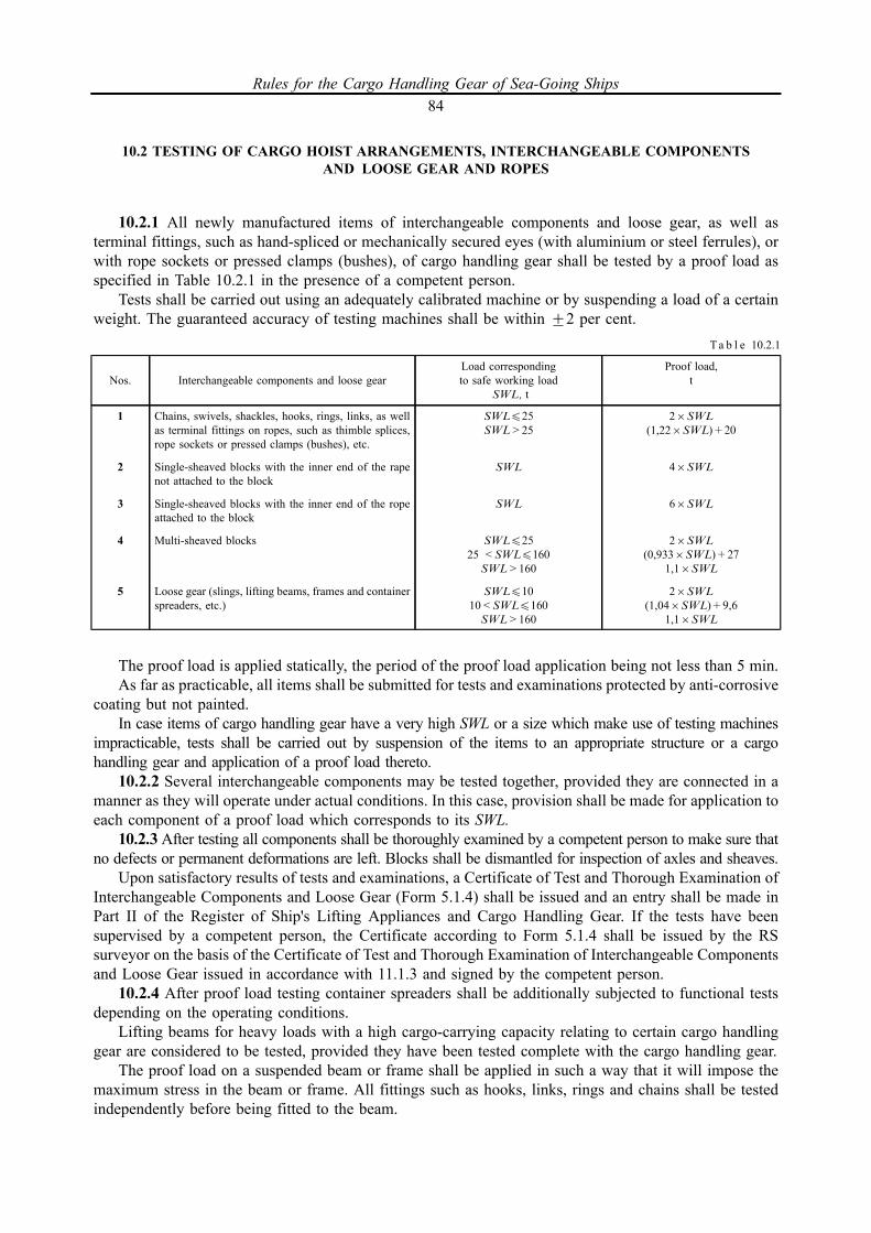
10.2 TESTING OF CARGO HOIST ARRANGEMENTS, INTERCHANGEABLE COMPONENTSAND LOOSE GEAR AND ROPES
10.2.1 All newly manufactured items of interchangeable components and loose gear, as well asterminal fittings, such as hand-spliced or mechanically secured eyes (with aluminium or steel ferrules), orwith rope sockets or pressed clamps (bushes), of cargo handling gear shall be tested by a proof load asspecified in Table 10.2.1 in the presence of a competent person.
Tests shall be carried out using an adequately calibrated machine or by suspending a load of a certainweight. The guaranteed accuracy of testing machines shall be within +2 per cent.
The proof load is applied statically, the period of the proof load application being not less than 5 min.As far as practicable, all items shall be submitted for tests and examinations protected by anti-corrosive
coating but not painted.In case items of cargo handling gear have a very high SWL or a size which make use of testing machines
impracticable, tests shall be carried out by suspension of the items to an appropriate structure or a cargohandling gear and application of a proof load thereto.
10.2.2 Several interchangeable components may be tested together, provided they are connected in amanner as they will operate under actual conditions. In this case, provision shall be made for application toeach component of a proof load which corresponds to its SWL.
10.2.3 After testing all components shall be thoroughly examined by a competent person to make sure thatno defects or permanent deformations are left. Blocks shall be dismantled for inspection of axles and sheaves.
Upon satisfactory results of tests and examinations, a Certificate of Test and Thorough Examination ofInterchangeable Components and Loose Gear (Form 5.1.4) shall be issued and an entry shall be made inPart II of the Register of Ship's Lifting Appliances and Cargo Handling Gear. If the tests have beensupervised by a competent person, the Certificate according to Form 5.1.4 shall be issued by the RSsurveyor on the basis of the Certificate of Test and Thorough Examination of Interchangeable Componentsand Loose Gear issued in accordance with 11.1.3 and signed by the competent person.
10.2.4 After proof load testing container spreaders shall be additionally subjected to functional testsdepending on the operating conditions.
Lifting beams for heavy loads with a high cargo-carrying capacity relating to certain cargo handlinggear are considered to be tested, provided they have been tested complete with the cargo handling gear.
The proof load on a suspended beam or frame shall be applied in such a way that it will impose themaximum stress in the beam or frame. All fittings such as hooks, links, rings and chains shall be testedindependently before being fitted to the beam.
Nos. Interchangeable components and loose gearLoad correspondingto safe working load
SWL, t
Proof load,t
1
2
3
4
5
Chains, swivels, shackles, hooks, rings, links, as wellas terminal fittings on ropes, such as thimble splices,rope sockets or pressed clamps (bushes), etc.
Single-sheaved blocks with the inner end of the rapenot attached to the block
Single-sheaved blocks with the inner end of the ropeattached to the block
Multi-sheaved blocks
Loose gear (slings, lifting beams, frames and containerspreaders, etc.)
SWL425
SWL>25
SWL
SWL
SWL425
25 <SWL4160
SWL>160
SWL410
10<SWL4160
SWL>160
26SWL
(1,226SWL)+20
46SWL
66SWL
26SWL
(0,9336SWL)+27
1,16SWL
26SWL
(1,046SWL)+9,6
1,16SWL
Ta b l e 10.2.1
Rules for the Cargo Handling Gear of Sea-Going Ships84
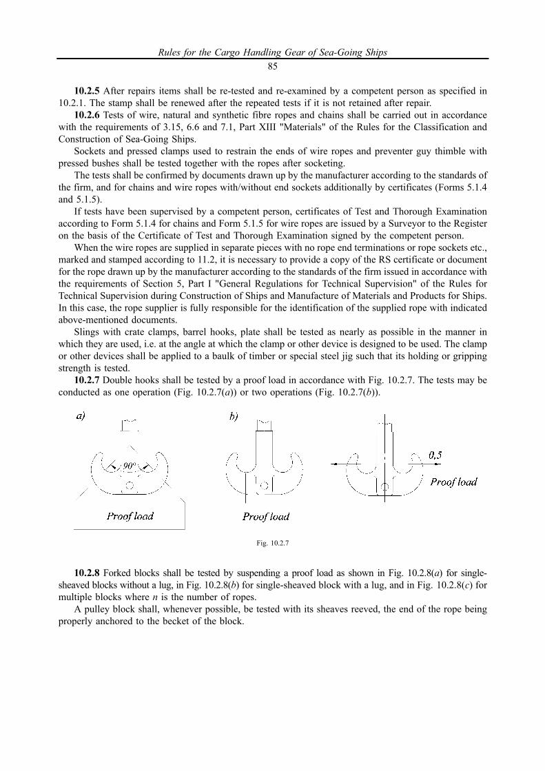
10.2.5 After repairs items shall be re-tested and re-examined by a competent person as specified in10.2.1. The stamp shall be renewed after the repeated tests if it is not retained after repair.
10.2.6 Tests of wire, natural and synthetic fibre ropes and chains shall be carried out in accordancewith the requirements of 3.15, 6.6 and 7.1, Part XIII "Materials" of the Rules for the Classification andConstruction of Sea-Going Ships.
Sockets and pressed clamps used to restrain the ends of wire ropes and preventer guy thimble withpressed bushes shall be tested together with the ropes after socketing.
The tests shall be confirmed by documents drawn up by the manufacturer according to the standards ofthe firm, and for chains and wire ropes with/without end sockets additionally by certificates (Forms 5.1.4and 5.1.5).
If tests have been supervised by a competent person, certificates of Test and Thorough Examinationaccording to Form 5.1.4 for chains and Form 5.1.5 for wire ropes are issued by a Surveyor to the Registeron the basis of the Certificate of Test and Thorough Examination signed by the competent person.
When the wire ropes are supplied in separate pieces with no rope end terminations or rope sockets etc.,marked and stamped according to 11.2, it is necessary to provide a copy of the RS certificate or documentfor the rope drawn up by the manufacturer according to the standards of the firm issued in accordance withthe requirements of Section 5, Part I "General Regulations for Technical Supervision" of the Rules forTechnical Supervision during Construction of Ships and Manufacture of Materials and Products for Ships.In this case, the rope supplier is fully responsible for the identification of the supplied rope with indicatedabove-mentioned documents.
Slings with crate clamps, barrel hooks, plate shall be tested as nearly as possible in the manner inwhich they are used, i.e. at the angle at which the clamp or other device is designed to be used. The clampor other devices shall be applied to a baulk of timber or special steel jig such that its holding or grippingstrength is tested.
10.2.7 Double hooks shall be tested by a proof load in accordance with Fig. 10.2.7. The tests may beconducted as one operation (Fig. 10.2.7(a)) or two operations (Fig. 10.2.7(b)).
10.2.8 Forked blocks shall be tested by suspending a proof load as shown in Fig. 10.2.8(a) for single-sheaved blocks without a lug, in Fig. 10.2.8(b) for single-sheaved block with a lug, and in Fig. 10.2.8(c) formultiple blocks where n is the number of ropes.
A pulley block shall, whenever possible, be tested with its sheaves reeved, the end of the rope beingproperly anchored to the becket of the block.
Fig. 10.2.7
Rules for the Cargo Handling Gear of Sea-Going Ships85
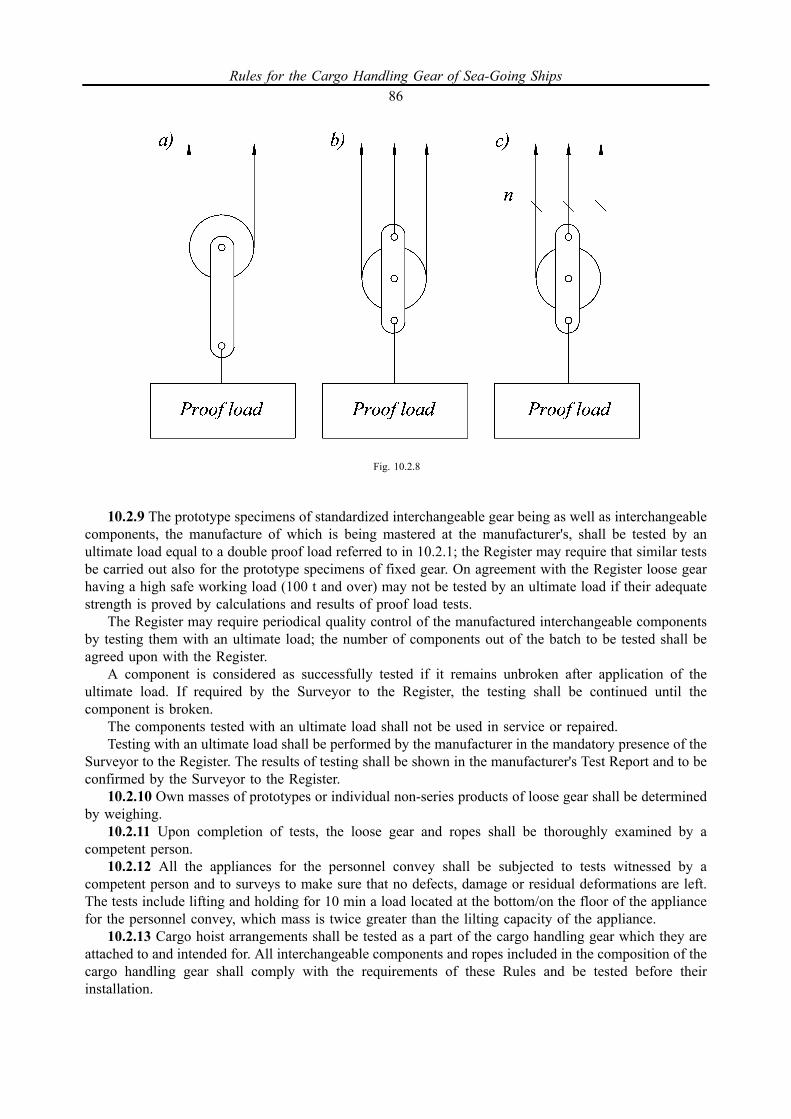
10.2.9 The prototype specimens of standardized interchangeable gear being as well as interchangeablecomponents, the manufacture of which is being mastered at the manufacturer's, shall be tested by anultimate load equal to a double proof load referred to in 10.2.1; the Register may require that similar testsbe carried out also for the prototype specimens of fixed gear. On agreement with the Register loose gearhaving a high safe working load (100 t and over) may not be tested by an ultimate load if their adequatestrength is proved by calculations and results of proof load tests.
The Register may require periodical quality control of the manufactured interchangeable componentsby testing them with an ultimate load; the number of components out of the batch to be tested shall beagreed upon with the Register.
A component is considered as successfully tested if it remains unbroken after application of theultimate load. If required by the Surveyor to the Register, the testing shall be continued until thecomponent is broken.
The components tested with an ultimate load shall not be used in service or repaired.Testing with an ultimate load shall be performed by the manufacturer in the mandatory presence of the
Surveyor to the Register. The results of testing shall be shown in the manufacturer's Test Report and to beconfirmed by the Surveyor to the Register.
10.2.10 Own masses of prototypes or individual non-series products of loose gear shall be determinedby weighing.10.2.11 Upon completion of tests, the loose gear and ropes shall be thoroughly examined by a
competent person.10.2.12 All the appliances for the personnel convey shall be subjected to tests witnessed by a
competent person and to surveys to make sure that no defects, damage or residual deformations are left.The tests include lifting and holding for 10 min a load located at the bottom/on the floor of the appliancefor the personnel convey, which mass is twice greater than the lilting capacity of the appliance.10.2.13 Cargo hoist arrangements shall be tested as a part of the cargo handling gear which they are
attached to and intended for. All interchangeable components and ropes included in the composition of thecargo handling gear shall comply with the requirements of these Rules and be tested before theirinstallation.
Fig. 10.2.8
Rules for the Cargo Handling Gear of Sea-Going Ships86

10.3 TESTING AND EXAMINATIONS OF MOUNTED CARGO HANDLING GEAR
10.3.1 The assembled cranes, winches and reels of the derrick boom gear shall be tested and examinedby a competent person at the manufacturer's in accordance with the testing program approved by theRegister, using the proof loads given in Table 10.3.4.
The tests and examinations shall be proved by the Certificate issued by the Register or documentdrawn up by the manufacturer declaring compliance of material or product to the RS requirements signedby a competent person.
Marking of the tested cranes, winches and reels shall be done as specified in 11.2.Gear and assemblies subject to loading shall be thermally insulated and painted after testing and
examination.10.3.2 Prior to testing and examination of the cargo handling gear upon installation on board the ship,
the following documents shall be presented to the surveyor issued in accordance with the requirements ofSection 5, Part I "General Regulations for Technical Supervision" of the Rules for Technical Supervisionduring Construction of Ships and Manufacture of Materials and Products for Ships signed by a competentperson; manufacturer's reports proving that the cargo handling gear is in conformity with the technicaldocumentation approved by the Register, reports on quality control of works and quality of welded joints,RS certificates and documents for materials and products issued by the manufacturer in accordance withthe requirements of Section 5, Part I "General Regulations for Technical Supervision" of the Rules forTechnical Supervision during Construction of Ships and Manufacture of Materials and Products for Ships,and documents on heat treatment.
In case of structural alterations in cargo handling gear as a result of re-rigging or repairs, the scope ofthe technical documentation to be submitted shall be in accordance with structural alterations made.
For testing and inspection of cargo handling gear in service that have not been re-rigged, replaced orrepaired, the scope of the technical documentation to be submitted shall be as specified in 11.1.
10.3.3 Cargo handling gear shall be submitted for tests in the fixed-up state.Prior to testing, they shall be thoroughly examined by a responsible representative of the manufacturer
who has been involved in installation of the cargo handling gear on board or by another person who isresponsible for performance of the tests. The cargo handling gear may be submitted for testing, providedno defects have been found during the examination that may affect the safety of the tests.
10.3.4 Upon installation on board and prior to being taken into use, all cranes, hoists and derricks with theirwinches and all the accessories shall be tested with a proof load the weight of which shall not be less than thefigure determined from Table 10.3.4 depending on the SWL and shall not exceed it by more than 2,5 %.
The tests during the initial and periodical surveys shall be carried out with a proof load only. Betweenthe periodical tests conducted after replacement or repair of any load bearing item and in case where aneed in additional test arises (e.g. upon closing out the remarks and/or upon fulfilling the requirements setforward by the surveyor after the proof load tests have been carried out), use of securely fixed spring orhydraulic dynamometers instead of proof load is allowed during periodic surveys. The dynamometers maybe used, provided that the rigging allows to subject the particular item to the same stresses (to bedetermined by calculation) as if the cargo handling gear had been tested by a proof load and the SWL of thecargo handling gear had not exceeded 15 t.
The dynamometers shall be calibrated with an accuracy within +2 per cent. During the tests theirreadings shall remain constant for at least five minutes.
SWL, t Proof load
Under 2020 to 50Over 50
1,256SWL
SWL+ 5 t1,16SWL
Ta b l e 10.3.4
Rules for the Cargo Handling Gear of Sea-Going Ships87
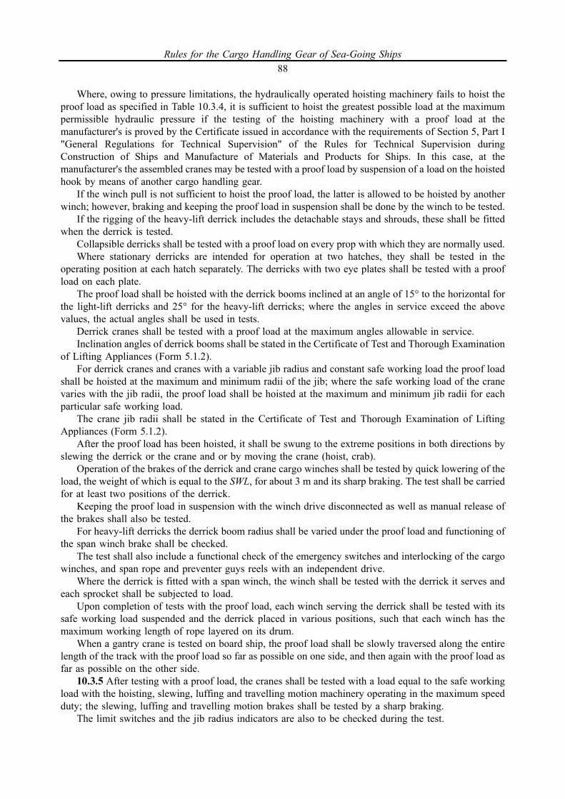
Where, owing to pressure limitations, the hydraulically operated hoisting machinery fails to hoist theproof load as specified in Table 10.3.4, it is sufficient to hoist the greatest possible load at the maximumpermissible hydraulic pressure if the testing of the hoisting machinery with a proof load at themanufacturer's is proved by the Certificate issued in accordance with the requirements of Section 5, Part I"General Regulations for Technical Supervision" of the Rules for Technical Supervision duringConstruction of Ships and Manufacture of Materials and Products for Ships. In this case, at themanufacturer's the assembled cranes may be tested with a proof load by suspension of a load on the hoistedhook by means of another cargo handling gear.
If the winch pull is not sufficient to hoist the proof load, the latter is allowed to be hoisted by anotherwinch; however, braking and keeping the proof load in suspension shall be done by the winch to be tested.
If the rigging of the heavy-lift derrick includes the detachable stays and shrouds, these shall be fittedwhen the derrick is tested.
Collapsible derricks shall be tested with a proof load on every prop with which they are normally used.Where stationary derricks are intended for operation at two hatches, they shall be tested in the
operating position at each hatch separately. The derricks with two eye plates shall be tested with a proofload on each plate.
The proof load shall be hoisted with the derrick booms inclined at an angle of 15° to the horizontal forthe light-lift derricks and 25° for the heavy-lift derricks; where the angles in service exceed the abovevalues, the actual angles shall be used in tests.
Derrick cranes shall be tested with a proof load at the maximum angles allowable in service.Inclination angles of derrick booms shall be stated in the Certificate of Test and Thorough Examination
of Lifting Appliances (Form 5.1.2).For derrick cranes and cranes with a variable jib radius and constant safe working load the proof load
shall be hoisted at the maximum and minimum radii of the jib; where the safe working load of the cranevaries with the jib radii, the proof load shall be hoisted at the maximum and minimum jib radii for eachparticular safe working load.
The crane jib radii shall be stated in the Certificate of Test and Thorough Examination of LiftingAppliances (Form 5.1.2).
After the proof load has been hoisted, it shall be swung to the extreme positions in both directions byslewing the derrick or the crane and or by moving the crane (hoist, crab).
Operation of the brakes of the derrick and crane cargo winches shall be tested by quick lowering of theload, the weight of which is equal to the SWL, for about 3 m and its sharp braking. The test shall be carriedfor at least two positions of the derrick.
Keeping the proof load in suspension with the winch drive disconnected as well as manual release ofthe brakes shall also be tested.
For heavy-lift derricks the derrick boom radius shall be varied under the proof load and functioning ofthe span winch brake shall be checked.
The test shall also include a functional check of the emergency switches and interlocking of the cargowinches, and span rope and preventer guys reels with an independent drive.
Where the derrick is fitted with a span winch, the winch shall be tested with the derrick it serves andeach sprocket shall be subjected to load.
Upon completion of tests with the proof load, each winch serving the derrick shall be tested with itssafe working load suspended and the derrick placed in various positions, such that each winch has themaximum working length of rope layered on its drum.
When a gantry crane is tested on board ship, the proof load shall be slowly traversed along the entirelength of the track with the proof load so far as possible on one side, and then again with the proof load asfar as possible on the other side.
10.3.5 After testing with a proof load, the cranes shall be tested with a load equal to the safe workingload with the hoisting, slewing, luffing and travelling motion machinery operating in the maximum speedduty; the slewing, luffing and travelling motion brakes shall be tested by a sharp braking.
The limit switches and the jib radius indicators are also to be checked during the test.
Rules for the Cargo Handling Gear of Sea-Going Ships88
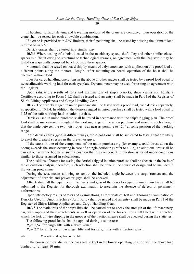
If hoisting, luffing, slewing and travelling motions of the crane are combined, then operation of thecrane shall be tested for each allowable combination.
If a crane is provided with SWL limiters, their functioning shall be tested by hoisting the ultimate loadreferred to in 5.5.3.
Derrick cranes shall be tested in a similar way.10.3.6 Where testing of a hoist located in the machinery space, shaft alley and other similar closed
spaces is difficult owing to structural or technological reasons, on agreement with the Register it may betested on a specially equipped bench outside these spaces.
Monorails shall be tested on board ship by means of a dynamometer with application of a proof load atdifferent points along the monorail length. After mounting on board, operation of the hoist shall bechecked without load.
Eyes for cargo handling operations in the above or other spaces shall be tested by a proof load equal totwice allowable working load for each eye plate. Dynamometer may be used for testing on agreement withthe Register.
Upon satisfactory results of tests and examinations of ship's derricks, ship's cranes and hoists, aCertificate according to Form 5.1.2 shall be issued and an entry shall be made in Part I of the Register ofShip's Lifting Appliances and Cargo Handling Gear.
10.3.7 The derricks rigged in union purchase shall be tested with a proof load, each derrick separately,as specified in 10.3.4. In addition, the derricks rigged in union purchase shall be tested with a load equal to1,25 of the safe working load in union purchase.
Derricks used in union purchase shall be tested in accordance with the ship’s rigging plan. The proofload shall be maneuvered throughout the working range of the union purchase and raised to such a heightthat the angle between the two hoist ropes is as near as possible to 1208 at some position of the workingrange.
If the derricks are rigged in different ways, those positions shall be subjected to testing that are likelyto exert the greatest stresses in the preventer guys.
If the stress in one of the components of the union purchase rig (for example, axial thrust down theboom) exceeds the stress occurring in case of a single derrick rig (refer to 4.2.7), an additional test shall becarried out with the booms in such a position that the component in question is tested under conditionssimilar to those assumed in calculations.
The positions of booms for testing the derricks rigged in union purchase shall be chosen on the basis ofthe calculation analysis; therefore, such selection shall be done in the course of design and be included inthe testing programme.
During the test, means allowing to control the included angle between the cargo runners and theadjustment of derricks and preventer guys shall be checked.
After testing, all the equipment, machinery and gear of the derricks rigged in union purchase shall besubmitted to the Register for thorough examination to ascertain the absence of defects or permanentdeformations.
Upon satisfactory results of tests and examinations, a Certificate of Test and Thorough Examination ofDerricks Used in Union Purchase (Form 5.1.3) shall be issued and an entry shall be made in Part I of theRegister of Ship's Lifting Appliances and Cargo Handling Gear.
10.3.8 The static tests of the ship's lifts shall be carried out to check the strength of the lift machinery,car, wire ropes and their attachments as well as operation of the brakes. For a lift fitted with a tractionwinch the lack of wire slipping in the grooves of the traction sheave shall be checked during the static test.
The following proof loads shall be applied during a static test:Pst= 1,5P for cargo lifts with a drum winch;Pst= 2P for all types of passenger lifts and for cargo lifts with a traction winch
where P is safe working load of the lift.
In the course of the static test the car shall be kept in the lowest operating position with the above loadapplied for at least 10 min.
Rules for the Cargo Handling Gear of Sea-Going Ships89
The static test of the lift with a traction winch may be substituted by a thrice repeated downwardmovement of the laden car with a load exceeding the safe working load of the lift by 50 per cent.
10.3.9 Dynamic tests shall be carried out to check the operation of the lift machinery, brake, grippingdevices and buffers. The proof load applied for the dynamic test shall be equal to:
Pdyn=1,1P
where P is safe working load of the lift.
When testing the gripping devices for smooth braking and hydraulic buffers, the effect of the winchbrake shall be disregarded.
10.3.10 The operation of winch, brake and buffers shall be checked at the rated speed. When buffersare tested, the switches of the upper and ground floors shall be isolated. Testing of gripping devices andbuffers shall be carried out with the brake released. If a spring failure or seizing of plunger occurs duringthe buffer testing, the test results are considered unsatisfactory.
10.3.11 Testing of gripping devices tripped by the overspeed governors is carried out at the rated speedof the lift movement.
When gripping devices are not tripped by the overspeed governors, the car (counterweight) at itslowest level is placed on the support or suspended to the auxiliary rope. The suspension ropes are paid outafter which the support is removed (the auxiliary rope is cut out). The way travelled by the car(counterweight) in free fall from the starting point to its landing on gripping devices shall not exceed100 mm.
Gripping devices may be tested by another efficient method approved by the Register.10.3.12 After testing by a proof load the lift shall be functionally tested by a load equal to its safe
working load. As this takes place, control and signalling systems, door contacts, limit switches and othersafety devices are checked. The efficiency of lift operation shall be also checked during sea trials of theship.
Upon satisfactory results of tests and examinations of the shift lifts, a Certificate of Test and ThoroughExamination of Lifts (Form 5.1.6) shall be issued and an entry shall be made in Part I of the Register ofShip's Lifting Appliances and Cargo Handling Gear.
10.3.13 The ship's elevating platforms shall be statically tested with a proof load equal to 1,25 of thesafe working load.
The dynamic tests of ship's elevating platforms shall be carried out with a proof load equal to 1,1 timesthe safe working load according to the applicable requirements of this Chapter.
10.3.14 After testing with a proof load a ship's elevating platform shall be functionally tested by a loadequal to its safe working load depending on the operating conditions.
The functional test shall include several full transport operations depending on the operatingconditions (with trailers and tractors or similar vehicles loaded on the platform). Having regard to 8.2.3.4,platform deflections shall be measured and breaking of one of the supporting appliances. All safetydevices, securing devices for hatchway covers and locking devices to hold the platform at the deck levelshall be carefully checked. If the platform is not provided with locking devices at the level of workingdecks during cargo handling operations, the maximum clearance between the platform and deck shall notexceed 20 mm.
Upon satisfactory results of tests and examinations, a Certificate according to form 5.1.2 shall be issued andan entry shall be made in Part I of the Register of Ship's Lifting Appliances and Cargo Handling Gear.
10.3.15 After testing the assembled cargo handling gear, its metal structures, machinery, equipmentand safety devices, gear and ropes of the cargo handling gear shall be submitted to the Register forthorough examination to ascertain the absence of defects or permanent deformations.
If any defects are found in the process of the examination, that may endanger the safe use of the cargohandling appliance, the defective items or assemblies shall be either replaced or repaired and the test shallthen be repeated.
Stamping of cargo handling gear after testing shall be done as described in 11.2.3.
Rules for the Cargo Handling Gear of Sea-Going Ships90

10.4 PERIODICAL SURVEYS, EXAMINATIONS AND TESTS
10.4.1 All derricks and gear (including span chain stoppers) permanently attached to derricks, mastsand decks shall be surveyed by the Surveyor the Register at least once every 12 months and be thoroughlyexamined by the Surveyor to the Register at least once every 5 years.
The results of examinations and surveys shall be entered in Part I of the Register of Ship's LiftingAppliances and Cargo Handling Gear.
10.4.2 Ship's and deck cranes, hoists and derrick winches, derrick cranes shall be thoroughly examinedby the Surveyor to the Register at least once every 12 months.
The results of examinations shall be entered in Part I of the Register of Ship's Lifting Appliances andCargo Handling Gear.
10.4.3 All interchangeable components and loose gear shall be thoroughly examined by theRS surveyor at least once every 12 months.
Examinations may include:hammer tests;ultrasonic and/or radiographic testing;dismantling of concealed components where appropriate.The results of the examination shall be entered to Part II "Ship's Cargo Handling Gear Lifting
Appliances" of the Register.10.4.4 Appliances for the personnel convey shall be thoroughly examined at least every 12 months in
accordance with 10.2.12.Based on the results of the examination, the Certificate of Test and Thorough Examination of
Interchangeable Components and Loosing Gear (Form 5.1.4) shall be issued, and the results of theexamination shall be entered to Part II "Ship's Cargo Handling Gear Lifting Appliances" of the Register.
10.4.5 Periodical surveys and thorough examinations, as wellas annual surveys shall be carried out toascertain that certificates on testing cargo handling gear, interchangeable components and loose gear andropes, appropriate marking and stamps, and entries about periodical heat treatment of interchangeablecomponents are available, as well as to evaluate the condition of metal structures and their parts andassemblies, machinery and gear of the cargo handling gear.
If defects are found during a periodical survey that may endanger safe use of the cargo handling gear,or wear is found exceeding the allowable vaues, the defective or worn-out parts shall be replaced orrepaired and the defects eliminated.
Concealed spaces of metal structures inaccessible for examination shall be tested by air underexcessive pressure 0,03 MPa with application of foaming solution or by other testing methods.
The measurements of residual thickness of metal structures shall be carried out at least onceevery 5 years.
Occasional surveys and tests shall be carried out, if necessary, after repair or replacement as specifiedin 10.5.
10.4.6 Periodical tests of the cargo handling gear mounted on board a ship shall be carried out at leastonce every 5 years in accordance with the appropriate requirements of 10.3.
Occasional tests conducted in accordance with 10.5 will be regarded as periodical tests.The tests and associated examinations shall be confirmed by a Certificate of Test and Thorough
Examination of Lifting Appliances (Form 5.1.2).10.4.7 Periodical surveys of cargo handling gear of ships not engaged in international voyages may be
combined with annual surveys of the ship, having regard to the submissions before the assigned date andextensions permitted.10.4.8 No cargo handling gear, interchangeable components and loose gear shall be used if:they have not undergone examinations and surveys in accordance with 10.4.1 to 10.4.5;in the view of the competent person, they are not safe for use.
Rules for the Cargo Handling Gear of Sea-Going Ships91
10.5 OCCASIONAL EXAMINATIONS AND TESTS
10.5.1 In case of placement, re-rigging or repair of the cargo handling gear, their machinery, metalstructures or gear, the mounted cargo handling gear shall be examined and tested in accordance withappropriate requirements of 10.3. Such examinations and tests shall, in particular, be carried out in thefollowing cases:.1 after the replacement of the cargo handling gear as a whole or putting it in another place;.2 after the re-rigging of the cargo handling gear, major overhaul or repair after an accident;.3 after major overhaul of machinery and fixed gear of the cargo handling gear, alterations or
replacement of their metal structures;.4 if the height of the span rope fastening has been changed or fastenings of shrouds or stays have been
shifted;.5 after replacement or major repair of a winch or a brake, after replacement of the car, counterweight,
electric motor, suspension ropes, winch drum, after repair or replacement of the traction sheave;.6 after removal of a cargo handling gear because of certain reasons and its re-positioning in the
original place.After replacement of loose and interchangeable components and ropes, testing of the mounted cargo
handling gear is not needed, however, they must have a Certificate of Test and Thorough Examination ofInterchangeable Components and Loose Gear and Certificate of Test and Thorough Examination of Wire Rope.
After replacement of spreaders the cargo handling gear shall be subjected to operational tests with asuspended spreader and a container in service conditions.
After replacement of cargo-gripping devices, overspeed governors or a buffer static tests of a ship's liftmay be omitted.
In case of alterations in the wiring diagram or replacement of cables in the control circuit, as well as ofmodifications in the design of limit switches, door contacts, automatic locks, deck switches, centralizeddeck apparatus or any other devices performing the same functions, the static and dynamic tests of theship's lift may be dispensed with. In such case, it is sufficient to run the tests in accordance with 10.3.12.
Occasional examinations and tests shall be confirmed by an appropriate Certificate of Test andThorough Examination (Forms 5.1.2 and 5.1.4).
10.5.2 After accidents with the cargo handling gear which have taken place in the course of its servicean occasional examination of the cargo handling gear shall be carried out to find out the technical reasonsfor the accident.
The extent of the examination required in that case shall be to the satisfaction of the Surveyor to theRegister. The examination shall be carried out regardless of the validity of certificates for the cargohandling gear.
Rules for the Cargo Handling Gear of Sea-Going Ships92
10.6 LIMITS OF WEAR
10.6.1 The present standards of wear are tentative and may be altered depending on the specificoperating conditions of a component and the type of wear. In order to determine more precisely the effectof wear on the strength and reliability of the component, calculation methods may be used.
The standards given below refer to places liable to the maximum wear.10.6.2 The components with 10 per cent wear and more regarding of thickness or diameter as well as
the components with cracks, fractures or permanent deformations shall not be allowed for use.When determining the wear of the articulated joints of derrick heel goosenecks and heel lugs, derrick
span eye plate swivels, they shall be treated as plain bearings. The greatest diametral clearances shallcomply with manufacturer standards.
10.6.3 A wire rope shall not be used if:.1 5 per cent and more of the total number of wires in the rope are broken in any length equal to 10
times the rope diameter;.2 there is any tendency towards birdcaging (i.e. separation of the strands or wires);.3 a strand is broken;.4 excessive wear is present which manifests itself by flat wire surfaces;.5 it shows signs of corrosion, particularly of the internal corrosion;.6 broken wires appear in one stand only or are concentrated in a shorter length of rope than ten
diameters or appear in the tucks of a splice;.7 there is more than one broken wire immediately adjacent to a compressed metal ferrule (pressed
clamp/bush) or fitting;.8 the rope diameter is less than 90 per cent of its initial value.10.6.4 Natural and synthetic fibre ropes shall not be allowed for use in case of broken or rotten yarns,
considerable wear or deformation.10.6.5 Metal masts, derricks, winch foundations, as well as metal structures of cranes and loose gear,
having a residual thickness equal to 80 per cent and less of their initial thickness shall not be allowed for use.10.6.6 Wear of lift parts and assemblies shall not exceed the standards established by the manufacturer
or by those given below.10.6.6.1 Wear of collars and seals is determined by the amount of oil leakage.10.6.6.2 The clearance between armature of the brake electromagnet and the yoke shall not exceed 4 mm.10.6.6.3 The clearance between the rope and the groove bottom shall be not less than 2 mm.10.6.6.4 The limits of uneven wear of grooves relative to each other shall be such as to allow the
balancing suspension to compensate for the rope running without disconnection of the contact used tocontrol shifting of the balance-beam lever.
10.6.6.5 When wear of the grooves exceeds the above limits the sheave shall be grooved or renewed.Grooving of the sheaves is permitted only once.
10.6.6.6 Wire ropes are considered to be defective depending on the number of wire breaks within thelength of one step of a lay specified in Table 10.6.6.6-1.
The number of breaks in one step of a lay, at which the rope of the construction specified inTable 10.6.6.6-1 is considered to be defective, shall be determined on the basis of the data given in thetable for the rope with the nearest number of strands and number of wires in the cross-section;
For example, the rope construction 8619=152 wires with one natural fibre core comes near to therope 6619=114 wires with one natural fibre core. To determine the criterion for rejection, the number ofbreaks in one step of a lay given in Table 10.6.6.6-1 for the rope construction 6619=114 wires with onenatural fibre core shall be multiplied by factor 96 : 72=1,33 where 96 and 72 are numbers of wires inexternal strands of the former and the latter, respectively;
In case of wear of external strands of the rope or corrosion of wires, the number of wire breaks withinthe length of one step of a lay as a sign for rejection shall be reduced according to the data ofTable 10.6.6.6-2.
Rules for the Cargo Handling Gear of Sea-Going Ships93
If wear or corrosion of wires is 40 per cent or more of the initial diameter of wires, the rope shall berejected.
Where the car is suspended on two ropes, each rope shall be rejected separately, substitution of moreworn-out rope being permitted.
In case of wire breaks within the length of one step of a lay the number of which does not lead to rejectionand in case of permissible wear of external strands, the rope is allowed for use subject to close supervision ofits condition.
In case a broken strand is found in the rope, further use of the rope is not allowed.The number of wire breaks within the length of one step of a lay of the overspeed governor is not
exceed 20.Where the car is suspended on three or more ropes, their rejection shall be based on the arithmetical
mean which is determined proceeding from the maximum num-ber of wire breaks within the length of onestep of a lay.
In this case, the allowable number of wire breaks in one of the ropes may be exceeded but not morethan by 50 per cent as compared to the values given in Table 10.6.6.6-1.
10.6.6.7 Wear of shells of the car and counterweight shoes is allowed, provided the total side clearancebetween the wear surface of the guide and the shell is not more than 4 mm and the total face clearancemeasured by the rod gauge does not exceed 8 mm.
10.6.6.8 The brake block coatings may be used as long as their thickness in the mid-portion and at theedges will not be reduced to 1/2 and 1/3 of their original thickness, respectively.
10.6.6.9 Wear of worm-and-worm gear of the winch is checked by the value of play in worm gearing.With the balanced suspension rope runs leading to the car and counterweight (or with the fully
slackened ropes), as well as with the fully compressed brake blocks the worm is turned by the wheel to theleft and to the right up to the perceptible stop. The idle running of the worm shall not exceed 1/10 of onecomplete revolution.
Wear of external strands or corrosion of wires accordingto rope diameter, in per cent
Number of wire breaks within the length of one step of a lay, in per cent, relative tothe values given in Table 10.6.6.6-1
10152025
30 and over
8575706050
Ta b l e 10.6.6.6-2Requirements for rope rejection relating to wear of external strands or corrosion of wires
Initial safety factor with Rules ratio D/d
(refer to 7.1.4)
Rope construction
6619=114 and one natural fibre core 6637=222 and one natural fibre core
Number of wire breaks within the length of one step of a lay
cross one-sided cross one-sided
less than 99, 1011, 1213, 1415, 16over 16
141618202224
789101112
232629323538
121314161819
N o t e . In calculating wire breaks the factors are assumed as follows: 1 for break of a thin wire; 1,7 for break of a thickwire.
Ta b l e 10.6.6.6.-1Number of wire breaks within the length of one step
of a lay at which the rope shall be rejected
Rules for the Cargo Handling Gear of Sea-Going Ships94

10.6.7 Loose gear shall be removed from service for scrapping if:.1 wear in eyes of chain links or the saddle of hooks exceeds 8 per cent;.2 permanent elongation in sling chains exceeds 5 per cent;.3 the cross-section of a chain link is reduced by more than 12 per cent;.4 jaw openings of hooks have increased by more than 10 per cent.
Rules for the Cargo Handling Gear of Sea-Going Ships95
11 DOCUMENTATION AND MARKING
11.1 DOCUMENTS
11.1.1 Ships and mobile offshore drilling units, cargo handling gear of which are subject to survey bythe Register shall be provided (as required for the appliances installed) with the following documents:.1 Register of Ship's Lifting Appliances and Cargo Handling Gear, Form 5.1.1;.2 Certificate of Test and Thorough Examination of Lifting Appliances, Form 5.1.2;.3 Certificate of Test and Thorough Examination of Derricks Used in Union Purchase, Form 5.1.3;.4 Certificate of Test and Thorough Examination of Interchangeable Components and Loosing Gear,
Form 5.1.4;.5 Certificate of Test and Thorough Examination of Wire Rope, Form 5.1.5;.6 Certificate of Test and Thorough Examination of Lifts, Form 5.1.6;.7 documents for ropes drawn up by the manufacturer declaring compliance with the RS requirements
or RS Certificates issued according to the requirements of Section 5, Part I "General Regulations forTechnical Supervision" of the Rules for Technical Supervision during Construction of Ships andManufacture of Materials and Products for Ships;.8 Instructions on Operation of Ship's Derricks Used in Union Purchase.11.1.2 Entries in the Register of Ship's Lifting Appliances and Cargo Handing Gear and Certificates
shall be made in Russian and for ships engaged in international voyages, also in English.11.1.3 Particulars of the tested item to be given in the Certificate of Test and Thorough Examination of
Interchangeable Components and Loosing Gear (Form 5.1.4) shall contain a designation according to thestandard or safe working load for non-standard parts, type of material and of heat treatment together withthe following dimensions:.1 for shackles_ diameter of pin, and in case of an uncommonly sized jaw opening, also the clear jaw
opening and the diameter of shackle in the middle of the bow;.2 for swivel suspensions of blocks, swivels and turnbuckles _ diameter of thread;.3 for blocks _ diameter measured in the bottom of sheave and axle diameter;.4 for chains _ gauge and type of link (short-link, long-link);.5 connecting links _ gauge of link and its length.11.1.4 Availability of valid certificates issued by other classification societies whose requirements are
recognized by the Register as equivalent to the requirements of these Rules is sufficient to consider thecargo handling gear fit for safe use. If, however, there is any doubt as to the state of the cargo handlinggear or its compliance with the certificates issued, the cargo handling gear may be subjected to a test orexamination in accordance with these Rules, irrespective of the certificates available.
Rules for the Cargo Handling Gear of Sea-Going Ships96
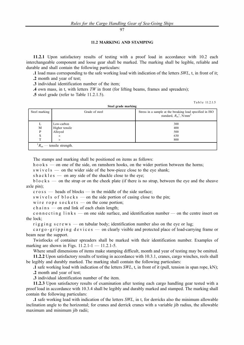
11.2 MARKING AND STAMPING
11.2.1 Upon satisfactory results of testing with a proof load in accordance with 10.2 eachinterchangeable component and loose gear shall be marked. The marking shall be legible, reliable anddurable and shall contain the following particulars:.1 load mass corresponding to the safe working load with indication of the letters SWL, t, in front of it;.2 month and year of test;.3 individual identification number of the item;.4 own mass, in t, with letters TW in front (for lifting beams, frames and spreaders);.5 steel grade (refer to Table 11.2.1.5).
The stamps and marking shall be positioned on items as follows:h o o k s _ on one of the side, on ramshorn hooks, on the wider portion between the horns;s w i v e l s _ on the wider side of the bow-piece close to the eye shank;s h a c k l e s _ on any side of the shackle close to the eye;b l o c k s _ on the strap or on the cheek plate (if there is no strap, between the eye and the sheave
axle pin);c r o s s _ heads of blocks _ in the middle of the side surface;s w i v e l s o f b l o c k s _ on the side portion of casing close to the pin;w i r e r o p e s o c k e t s _ on the cone portion;c h a i n s _ on end link of each chain length;c o n n e c t i n g l i n k s _ on one side surface, and identification number _ on the centre insert on
the lock;r i g g i n g s c r e w s _ on tubular body; identification number also on the eye or lug;c a r g o - g r i p p i n g d e v i c e s _ on clearly visible and protected place of load-carrying frame or
beam near the support.Twistlocks of container spreaders shall be marked with their identification number. Examples of
marking are shown in Figs. 11.2.1-1 _ 11.2.1-5.Where small dimensions of items make stamping difficult, month and year of testing may be omitted.11.2.2 Upon satisfactory results of testing in accordance with 10.3.1, cranes, cargo winches, reels shall
be legibly and durably marked. The marking shall contain the following particulars:.1 safe working load with indication of the letters SWL, t, in front of it (pull, tension in span rope, kN);.2 month and year of test;.3 individual identification number of the item.11.2.3 Upon satisfactory results of examination after testing each cargo handling gear tested with a
proof load in accordance with 10.3.4 shall be legibly and durably marked and stamped. The marking shallcontain the following particulars:.1 safe working load with indication of the letters SWL, in t, for derricks also the minimum allowable
inclination angle to the horizontal; for cranes and derrick cranes with a variable jib radius, the allowablemaximum and minimum jib radii;
Steel marking Grade of steel Stress in a sample at the breaking load specified in ISOstandard, Rm
1, N/mm2
L
M
P
S
T
Low-carbonHigher tensileAlloyed
»»
300400500630800
1Rm _ tensile strength.
Ta b l e 11.2.1.5Steel grade marking
Rules for the Cargo Handling Gear of Sea-Going Ships97

where the safe working load varies with a jib radius, the marking shall contain the maximum andminimum jib radii for each appropriate safe working load; for passenger lifts, allowable number ofpassengers.
Each derrick shall be legibly marked with its SWL, as follows:used only in a single purchase _ SWL xt;used additionally with the lower cargo block _ SWL x/xt;used in union purchase _ SWL(U) xt where x is safe working load;
t
Fig. 11.2.1-1 Marking of hooks
t
08 _ 908
Fig. 11.2.1-2 Marking of ramshorn hooks
Safe working load
Identification number
and stamp
Material grade
SWL5T
P
MAR
KS
Fig. 11.2.1-3 Marking of shackles
Material grade
Safe working load
Identification numberand stampWelding
MAR
KS
SWL2t
T
Fig. 11.2.1-4 Marking of chains
SWL5t
Fig. 11.2.1-5 Marking of blocks
Rules for the Cargo Handling Gear of Sea-Going Ships98
.2 month and year of test;
.3 identification number.1.2.4 Winches of lifts shall be provided with the plate containing manufacturer's name, type, rated
traction force, manufacturer's number, date of manufacture.11.2.5 The gripping devices and overspeed governors shall be provided with the plate containing
manufacturer's name, type, rated safe working load and speed for which they are designed, manufacturer'snumber and date of manufacture.
11.2.6 Hydraulic buffers shall be provided with the plate containing manufacturer's name, type, ratedspeed for which they are designed, manufacturer's No. and date of manufacture.
11.2.7 One of the suspension ropes shall be provided with the plate containing data of the rated diameter,construction, rated breaking strength, standard number, type and date of putting into operation.
11.2.8 The marking shall be clear and durable and the places of marking shall be distinctively painted.Where marking on the item may affect safe operation, marking shall be put on a plate, disc, etc. made
of acceptable material and permanently fixed to the item.11.2.9 If the size of marking according to 11.2.3.1 is too big, information on intermediate values of the
safe working load of the crane may be reduced on agreement with the Surveyor.In such cases, for cranes the safe working load of which varies with a jib radius a metal plate
containing jib radii for each appropriate safe working load shall be provided with a plate to be fitted in thecabin of a crane driver in a conspicuous and easily accessible position.
11.2.10 On derricks and on metal structures of cranes the marking shall be painted, punched or weldedon. Ship's elevating platforms shall be provided with inscriptions on the platform or on the plates. Theletters and figures shall be painted in a dark colour on a light background, or in a light colour on a darkbackground within a frame of indentations or welding spots.
11.2.11 Marking shall be made in letters and Arabic figures at least 77 mm high. Marking of the safeworking load on lifting beams, girders, spreaders and othe similar devices shall be put in a conspicuousplace; height of the letters shall allow operators to easily read them.
Where marking is put on directly on an interchangeable component, the height of the letter forcomponents shall not exceed the values given below for the following safe working loads:
up to 2 t _ 3,0 mm;from 2 to 8 t _ 4,5 mm;more than _ 6,0 mm.When marking interchangeable components of round section, such as chains, etc., the height of the
letters shall not exceed the values given below for the components with the following diameters:up to and including 12,5 mm _ 3,0 mm;from 12,5 to 26 mm _ 4,5 mm;more than 26 mm _ 6,0 mmIf the material is too hard or if direct marking affects or is liable to affect the subsequent safe use of the
cargo handling gear or its components, and/or at the request of a competent person, the marking shall bemade on some other suitable item of durable material permanently attached to the cargo handling gear,such as a tablet, disc or ferrule. Marking on such items may be larger than the dimensions indicated above.
Examples of marking are given in Table 11.2.11.11.2.12 Besides the hoisting particulars referred to in 11.2.3, every cargo derrick and crane shall be
marked with its ship inventory number.The order of numbering is as follows:.1 all light-lift derricks as well as derricks with the safe working load of 10 t and more positioned
outside the ship's centre line, beginning from ahead starboard to port;.2 all heavy-lift derricks positioned in the ship's centre line beginning from ahead;.3 cranes, separately from derricks, beginning from ahead starboard to port.
Rules for the Cargo Handling Gear of Sea-Going Ships99
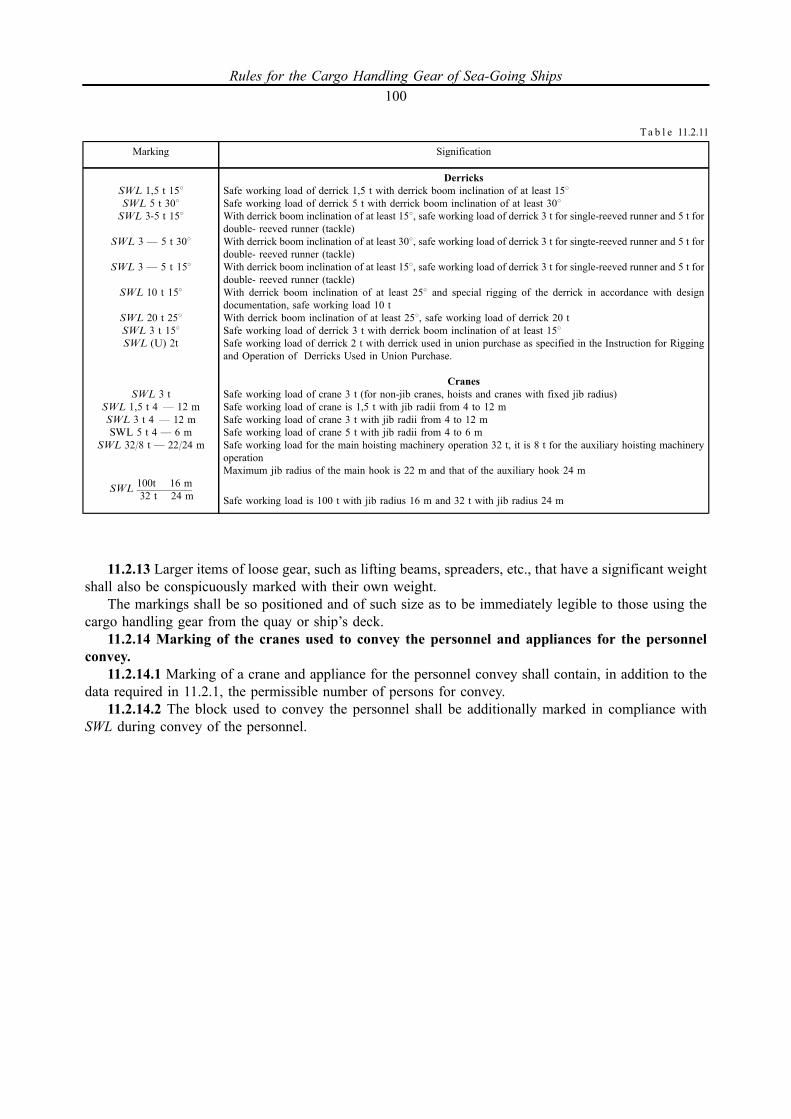
11.2.13 Larger items of loose gear, such as lifting beams, spreaders, etc., that have a significant weightshall also be conspicuously marked with their own weight.
The markings shall be so positioned and of such size as to be immediately legible to those using thecargo handling gear from the quay or ship’s deck.11.2.14 Marking of the cranes used to convey the personnel and appliances for the personnel
convey.11.2.14.1 Marking of a crane and appliance for the personnel convey shall contain, in addition to the
data required in 11.2.1, the permissible number of persons for convey.11.2.14.2 The block used to convey the personnel shall be additionally marked in compliance with
SWL during convey of the personnel.
Marking Signification
SWL 1,5 t 158SWL 5 t 308SWL 3-5 t 158
SWL 3 _ 5 t 308
SWL 3 _ 5 t 158
SWL 10 t 158
SWL 20 t 258SWL 3 t 158
SWL (U) 2t
SWL 3 tSWL 1,5 t 4 _ 12 m
SWL 3 t 4 _ 12 mSWL 5 t 4 _ 6 m
SWL 32/8 t _ 22/24 m
SWL100t 16 m32 t 24 m
DerricksSafe working load of derrick 1,5 t with derrick boom inclination of at least 158Safe working load of derrick 5 t with derrick boom inclination of at least 308With derrick boom inclination of at least 158, safe working load of derrick 3 t for single-reeved runner and 5 t fordouble- reeved runner (tackle)With derrick boom inclination of at least 308, safe working load of derrick 3 t for singte-reeved runner and 5 t fordouble- reeved runner (tackle)With derrick boom inclination of at least 158, safe working load of derrick 3 t for single-reeved runner and 5 t fordouble- reeved runner (tackle)With derrick boom inclination of at least 258 and special rigging of the derrick in accordance with designdocumentation, safe working load 10 tWith derrick boom inclination of at least 258, safe working load of derrick 20 tSafe working load of derrick 3 t with derrick boom inclination of at least 158Safe working load of derrick 2 t with derrick used in union purchase as specified in the Instruction for Riggingand Operation of Derricks Used in Union Purchase.
CranesSafe working load of crane 3 t (for non-jib cranes, hoists and cranes with fixed jib radius)Safe working load of crane is 1,5 t with jib radii from 4 to 12 mSafe working load of crane 3 t with jib radii from 4 to 12 mSafe working load of crane 5 t with jib radii from 4 to 6 mSafe working load for the main hoisting machinery operation 32 t, it is 8 t for the auxiliary hoisting machineryoperationMaximum jib radius of the main hook is 22 m and that of the auxiliary hook 24 m
Safe working load is 100 t with jib radius 16 m and 32 t with jib radius 24 m
Ta b l e 11.2.11
Rules for the Cargo Handling Gear of Sea-Going Ships100

12 TECHNICAL SUPERVISION OF CARGO HANDLING GEAR IN USE
12.1 GENERAL
12.1.1 Between surveys and examinations carried out by the Surveyor to the Register the responsibilityfor continuous supervision of keeping the cargo handling gear in conformity with certificates issued by theRegister and with these Rules, the maintenance of the established limitations of the permissible safeworking load, jib radii of cranes and inclination angles of derrick booms, control of adjustment of derricksand preventer guys and also of the angle between the cargo runners when in union purchase, and thekeeping of the cargo handling gear in the state fit for safe use, rests with the ship's officers.
Rules for the Cargo Handling Gear of Sea-Going Ships101

12.2 PERIODICAL EXAMINATIONS OF INTERCHANGEABLE COMPONENTS AND LOOSE GEAR,AND ROPES BY SHIP'S OFFICERS
12.2.1 All interchangeable components and loose gear, and ropes shall be carefully examined at leastonce every three monhs by a responsible person assigned by the master. If defects are found out duringsuch an examination. The results shall be entered in Part III of the Register of Ship's Lifting Appliancesand Cargo Handling Gear.
Besides, interchangeable components and loose gear, and ropes shall be carefully examined by aresponsible person every time before use of the cargo handling gear. In this case, an entry in Part III of theRegister of Ship's Lifting Appliances and Cargo Handling Gear is made only if defects are found.
If broken wires are found in a rope, the rope shall be examined at least once a month.
Rules for the Cargo Handling Gear of Sea-Going Ships102

APPENDIX
NOMENCLATURE OF MAIN STRUCTURES, MACHINERY AND GEAR OF CARGO HANDLINGGEAR SUBJECT TO SURVEY BY THE REGISTER (TO 1.3.3 OF THE RULES)
1 SHIP'S DERRICKS
1.1 Winches and reels:
cargo winches;span winches;guy winches;span reels;preventer guy reels.1.2 Metal structures:
cargo masts;short posts for mounting derrick heel fittings;cross trees;cross members;derrick booms;derrick boom supports;seats of winches and reels;stiffening of ship's structure in way of masts, winches and eye plates.
Rules for the Cargo Handling Gear of Sea-Going Ships103

1.3 Ropes and gear:
1.3.1 Interchangeable components:blocks;hooks;chains;shackles;swivels;rigging screws;thimbles, rope sockets, pressed clamps of the ropes;triangular and polygonal plates;derrick head eye fittings;cross-head forks of blocks;accessories of the cross members type, which are regular items of heavy lift-derricks;stops for fastening preventer guys with pressed-on bushes.1.3.2 Fixed gear:derrick head eye plates, span ropes, slewing and preventer guys;eye plates secured on ship's hull, deck or metal structures;derrick heel fittings;span eye plates with bearings;derrick heel goosenecks with bearings;built-in sheaves of the booms with collars.1.3.3 Loose gear:slings;lifting beams;frames;container spreaders;other similar gear.1.3.4 Ropes:shrouds and stays;cargo runners, span ropes, tackles and slewing guy pendants;preventer guys and boom head guys in union purchase.
2 CRANES AND HOISTS
2.1 Machinery:
hoisting machinery;luffing machinery;slewing machinery;travelling motion machinery;brakes.2.2 Metal structures:
bridges;gantries;jibs;frames;foundations;stiffening of ship's hulls, pontoons and docks in way of cranes;fixed and turning columns;balance beams and rods of movable counterweights;supports for derricks when stowed for sea.
Rules for the Cargo Handling Gear of Sea-Going Ships104
2.3 Ropes and gear:
2.3.1 Loose gear:blocks;hooks;chains;shackles;swivels;thimbles, rope sockets and pressed clamps of ropes;accessories of the cross members type, which are regular items of heavy cranes.2.3.2 Fixed gear:eye plates;trunnions, axles with bearings;lead screws;rollers.2.3.3 Loose gear being part of the ship:slings;lifting beams;frames;container spreaders;other similar gear.2.3.4 Ropes:cargo runners;derrick ropes;grab ropes.
Rules for the Cargo Handling Gear of Sea-Going Ships105
2.4 Safety devices:
limit switches;jib radius automatic indicators;safe working load limiter;signalling devices;interlocking devices;safety buttons or switches.
3 LIFTS
3.1 Metal structures with loose gear:
trunks;guides;cabins;ceilings;foundations.3.2 Lift equipment:
trunk doors;counterweights;stops and buffers.3.3 Lift winches (of drum and traction type):
cargo shafts;couplings;base plate;brakes;drums.3.4 Safety devices:
gripping devices;overspeed governors;lowering and lifting limit switches.3.5 Ropes and items of cable run and fastening of ropes (sheaves, cleat casings, cleats, couplings,
clips, hold-down straps, etc.)
4 SHIP'S ELEVATING PLATFORMS
4.1 Platforms
4.2 Platform equipment:
guides;shoes;blocking devices;buffers;locking devices;guard railings;drives (mechanical or hydraulic).4.3 Supporting appliances:
ropes with guides;chains with guides;fastenings;lever-pull system;
Rules for the Cargo Handling Gear of Sea-Going Ships106

hydraulic structural elements;gear racks;spindles.4.4 Safety devices.
5 ELECTRICAL EQUIPMENT OF CARGO HANDLING GEAR
5.1 Electric motors.5.2 Electric brakes.5.3 Control stands.5.4 Limit switches.5.5 Safety buttons or switches.5.6 Control device of load mass.5.7 Cabling.5.8 Other electrical equipment required for safe operation of cargo handling gear.
N o t e . The Nomenclature when applied to specific cargo handling gear, varies together with the design of the latter.However, the items listed in these Rules, as well as the stress-bearing essential elements of the cargo handling gear are subject totechnical supervision in all cases.
All cargo handling gear, their machinery, metal structures, ropes and gear, as well as safety devices, as specified in theNomenclature are subject to technical supervision of the Register regarding implementation of the Rule requirements forstructure and calculations and, in case of technical supervision during manufacture and repair, also regarding the materials used,heat treatment, welding of the essential stress-bearing components in conformity with the specific requirements of these Rulesand with the appropriate general requirements set forth in Part III "Equipment, Arrangements and Outfit", Part XIII "Materials"and Part XIV "Welding" of the Rules for the Classification and Construction of Sea-Going Ships.
Rules for the Cargo Handling Gear of Sea-Going Ships107

Российский морской регистр судоходства
Правила по грузоподъемным устройствам морских судов
Russian Maritime Register of Shipping
Rules for the Cargo Handling Gear of Sea-Going Ships
The edition is preparedby Russian Maritime Register of Shipping
8, Dvortsovaya Naberezhnaya,191186, St. Petersburg,Russian Federationwww.rs-class.org/en/
Related Documents


![Accident Report - Cargo Gear Failure[1]](https://static.cupdf.com/doc/110x72/540832fcdab5cac6598b4787/accident-report-cargo-gear-failure1.jpg)