October 16 th , 2015 For tender Electrical This document should not be used for construction purposes Government of Canada Dufferin Project Project no. 201202310 Electrical Specifications 2787-000-00

Welcome message from author
This document is posted to help you gain knowledge. Please leave a comment to let me know what you think about it! Share it to your friends and learn new things together.
Transcript

October 16th, 2015
For tender
Electrical This document should not be used for construction purposes
Government of Canada Dufferin Project Project no. 201202310 Electrical Specifications 2787-000-00
Government of Canada Divisions 23, 26 and 28 Dufferin Project Electrical Project no. 201202310 Page 1 of 1
2787-000-00 Pageau Morel & Associates Inc. Building Consultants
TABLE OF CONTENTS
Refer to attached drawings list on the following page.
ELECTRICAL SPECIFICATIONS
Division 23 Heating Ventilation/Air Conditioning
Section 23 82 30 Electrical Heating Units
Division 26 Electrical
Section 26 05 20 Electrical Conductors Cables and Accessories
Section 26 05 30 Electrical Conduits, Boxes and Accessories
Section 26 09 20 Lighting Control Devices
Section 26 20 00 Low Voltage Electrical Distribution
Section 26 27 00 Wiring Devices
Section 26 30 00 Electrical Power Generating Equipment
Section 26 50 00 Lighting
Division 27 Communications
Section 27 10 05 Structured Cabling
Division 28 Electronic Safety and Security
Section 28 31 00 Fire Detection and Alarm
Page 1 de/of 1
Électricité / Electrical Divisions 23, 26 ,28
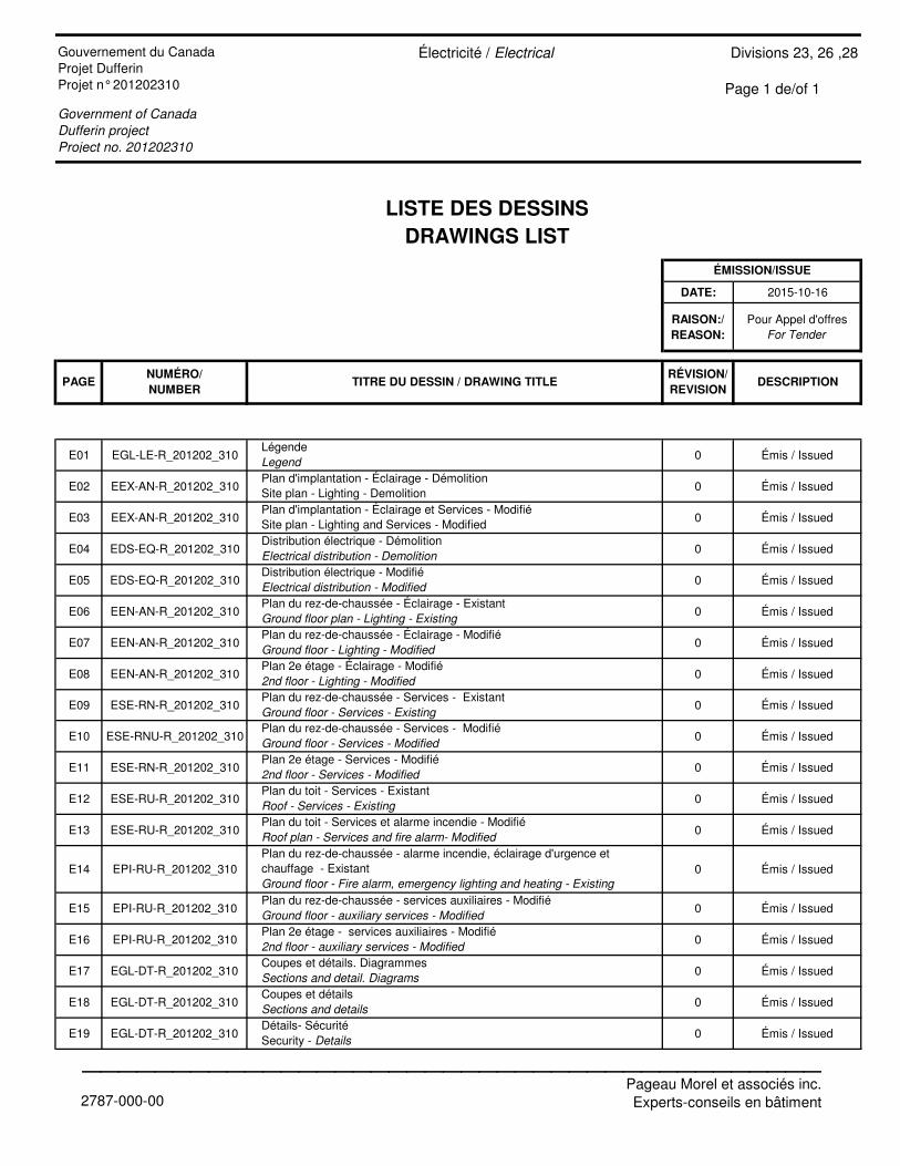
LISTE DES DESSINS
DRAWINGS LIST
DATE: 2015-10-16
RAISON:/
REASON:
Pour Appel d'offresFor Tender
E01 EGL-LE-R_201202_310 0 Émis / Issued
E02 EEX-AN-R_201202_310 0 Émis / Issued
E03 EEX-AN-R_201202_310 0 Émis / Issued
E04 EDS-EQ-R_201202_310 0 Émis / Issued
E05 EDS-EQ-R_201202_310 0 Émis / Issued
E06 EEN-AN-R_201202_310 0 Émis / Issued
E07 EEN-AN-R_201202_310 0 Émis / Issued
E08 EEN-AN-R_201202_310 0 Émis / Issued
E09 ESE-RN-R_201202_310 0 Émis / Issued
E10 ESE-RNU-R_201202_310 0 Émis / Issued
E11 ESE-RN-R_201202_310 0 Émis / Issued
E12 ESE-RU-R_201202_310 0 Émis / Issued
E13 ESE-RU-R_201202_310 0 Émis / Issued
E14 EPI-RU-R_201202_310 0 Émis / Issued
E15 EPI-RU-R_201202_310 0 Émis / Issued
E16 EPI-RU-R_201202_310 0 Émis / Issued
E17 EGL-DT-R_201202_310 0 Émis / Issued
E18 EGL-DT-R_201202_310 0 Émis / Issued
E19 EGL-DT-R_201202_310 0 Émis / Issued
Coupes et détailsSections and details
Plan 2e étage - services auxiliaires - Modifié2nd floor - auxiliary services - Modified
Plan 2e étage - Services - Modifié2nd floor - Services - Modified
Government of Canada
Dufferin project
Project no. 201202310
Gouvernement du CanadaProjet DufferinProjet n° 201202310
Plan d'implantation - Éclairage - DémolitionSite plan - Lighting - Demolition
TITRE DU DESSIN / DRAWING TITLE
Plan du rez-de-chaussée - Services - ExistantGround floor - Services - Existing
Plan du rez-de-chaussée - Éclairage - ExistantGround floor plan - Lighting - Existing
Distribution électrique - DémolitionElectrical distribution - Demolition
Plan 2e étage - Éclairage - Modifié2nd floor - Lighting - Modified
Plan du toit - Services et alarme incendie - ModifiéRoof plan - Services and fire alarm- Modified
Plan d'implantation - Éclairage et Services - ModifiéSite plan - Lighting and Services - Modified
RÉVISION/
REVISIONDESCRIPTION
LégendeLegend
Détails- SécuritéSecurity - Details
ÉMISSION/ISSUE
Plan du rez-de-chaussée - services auxiliaires - ModifiéGround floor - auxiliary services - Modified
NUMÉRO/
NUMBERPAGE
Distribution électrique - ModifiéElectrical distribution - Modified
Plan du rez-de-chaussée - Éclairage - ModifiéGround floor - Lighting - Modified
Plan du rez-de-chaussée - Services - ModifiéGround floor - Services - Modified
Plan du toit - Services - ExistantRoof - Services - Existing
Plan du rez-de-chaussée - alarme incendie, éclairage d'urgence et chauffage - ExistantGround floor - Fire alarm, emergency lighting and heating - Existing
Coupes et détails. DiagrammesSections and detail. Diagrams
2787-000-00
_________________________________________Pageau Morel et associés inc.Experts-conseils en bâtiment
Government of Canada Section 23 82 30 Dufferin Project Electrical Heating Units Project no. 201202310 Page i
2787-000-00 Pageau Morel & Associates Inc. Building Consultants
TABLE OF CONTENTS
PART 1 - GENERAL ............................................................................................................................................... 1
1.1 General ..................................................................................................................................................................... 1 1.2 Scope of Work .......................................................................................................................................................... 1 1.3 Shop Drawings to be submitted ................................................................................................................................ 1
PART 2 - PRODUCTS ............................................................................................................................................ 2
2.1 Heating Equipment ................................................................................................................................................... 2 2.2 Heating Cables ......................................................................................................................................................... 3
PART 3 - EXECUTION ........................................................................................................................................... 4
3.1 Heating Apparatus .................................................................................................................................................... 4
Government of Canada Section 23 82 30 Dufferin Project Electrical Heating Units Project no. 201202310 Page 1
2787-000-00 Pageau Morel & Associates Inc. Building Consultants
PART 1 - GENERAL
1.1 General
1.1.1 Section 20 05 00 – "General Requirements Concerning Common Work Results" applies.
1.2 Scope of Work
1.2.1 Works of this section include, but are not limited to: the supply, handling, transportation, set up and installation of all systems and their accessories hereafter mentioned or shown on the drawings and which are to be operational. In general, all major parts of the works consist of, but are not limited to:
• Offices heating; • Thermostats; • Heating Control.
1.3 Shop Drawings to be submitted
1.3.1 The following shop drawings shall be submitted regarding Section 20 05 00 – "General Requirements Concerning Common Work Results".
1.3.2 The following shop drawings shall be submitted:
• Electronic baseboard and accessories; • Forced air heaters; • Unit heaters; • Thermostats; • Relays and transformers; • Heating cables.
Government of Canada Section 23 82 30 Dufferin Project Electrical Heating Units Project no. 201202310 Page 2
2787-000-00 Pageau Morel & Associates Inc. Building Consultants
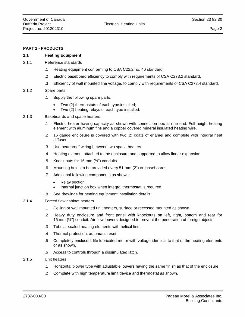
PART 2 - PRODUCTS
2.1 Heating Equipment
2.1.1 Reference standards
.1 Heating equipment conforming to CSA C22.2 no. 46 standard.
.2 Electric baseboard efficiency to comply with requirements of CSA C273.2 standard.
.3 Efficiency of wall mounted line voltage, to comply with requirements of CSA C273.4 standard.
2.1.2 Spare parts
.1 Supply the following spare parts:
• Two (2) thermostats of each type installed; • Two (2) heating relays of each type installed.
2.1.3 Baseboards and space heaters
.1 Electric heater having capacity as shown with connection box at one end. Full height heating element with aluminum fins and a copper covered mineral insulated heating wire.
.2 16 gauge enclosure is covered with two (2) coats of enamel and complete with integral heat diffuser.
.3 Use heat proof wiring between two space heaters.
.4 Heating element attached to the enclosure and supported to allow linear expansion.
.5 Knock outs for 16 mm (½") conduits.
.6 Mounting holes to be provided every 51 mm (2") on baseboards.
.7 Additional following components as shown:
• Relay section; • Internal junction box when integral thermostat is required.
.8 See drawings for heating equipment installation details.
2.1.4 Forced flow cabinet heaters
.1 Ceiling or wall mounted unit heaters, surface or recessed mounted as shown.
.2 Heavy duty enclosure and front panel with knockouts on left, right, bottom and rear for 16 mm (½") conduit. Air flow louvers designed to prevent the penetration of foreign objects.
.3 Tubular scaled heating elements with helical fins.
.4 Thermal protection, automatic reset.
.5 Completely enclosed, life lubricated motor with voltage identical to that of the heating elements or as shown.
.6 Access to controls through a dissimulated latch.
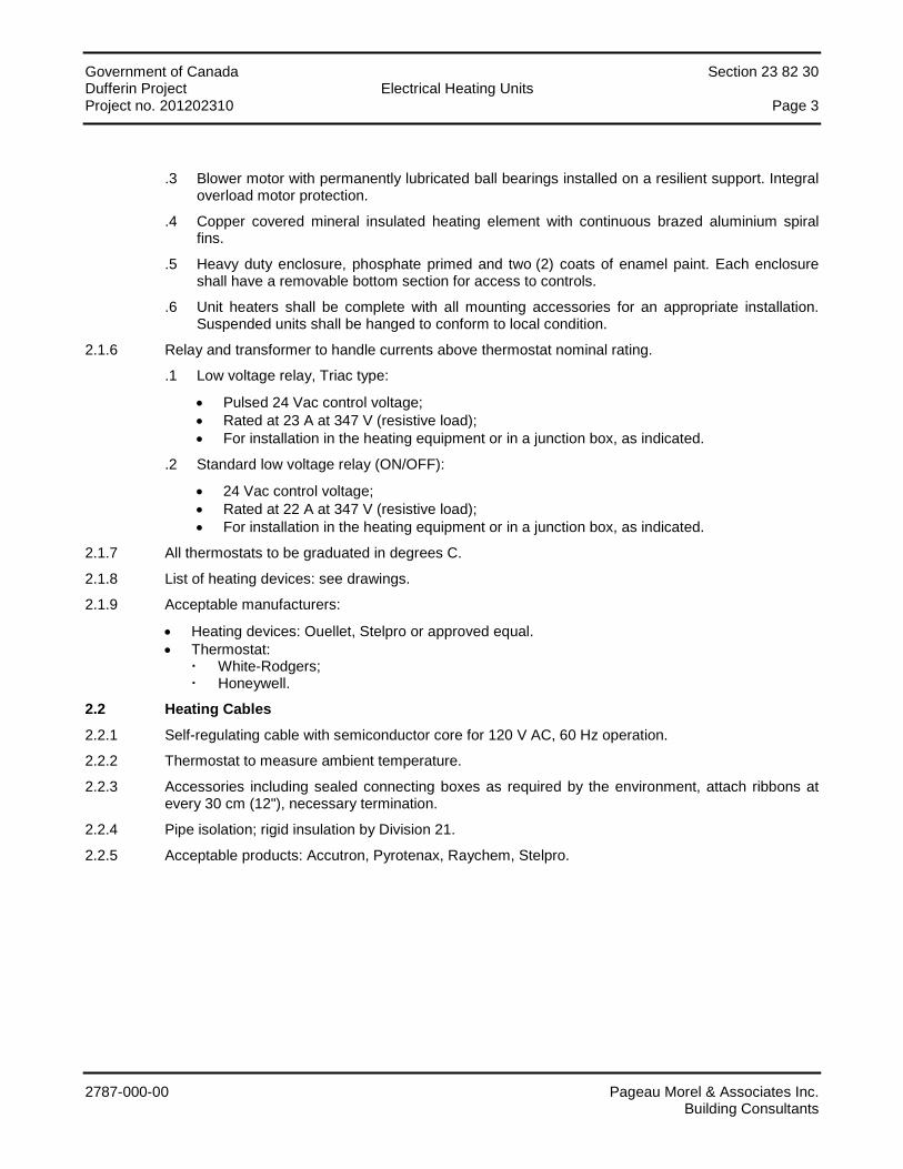
2.1.5 Unit heaters
.1 Horizontal blower type with adjustable louvers having the same finish as that of the enclosure.
.2 Complete with high temperature limit device and thermostat as shown.
Government of Canada Section 23 82 30 Dufferin Project Electrical Heating Units Project no. 201202310 Page 3
2787-000-00 Pageau Morel & Associates Inc. Building Consultants
.3 Blower motor with permanently lubricated ball bearings installed on a resilient support. Integral overload motor protection.
.4 Copper covered mineral insulated heating element with continuous brazed aluminium spiral fins.
.5 Heavy duty enclosure, phosphate primed and two (2) coats of enamel paint. Each enclosure shall have a removable bottom section for access to controls.
.6 Unit heaters shall be complete with all mounting accessories for an appropriate installation. Suspended units shall be hanged to conform to local condition.
2.1.6 Relay and transformer to handle currents above thermostat nominal rating.
.1 Low voltage relay, Triac type:
• Pulsed 24 Vac control voltage; • Rated at 23 A at 347 V (resistive load); • For installation in the heating equipment or in a junction box, as indicated.
.2 Standard low voltage relay (ON/OFF):
• 24 Vac control voltage; • Rated at 22 A at 347 V (resistive load); • For installation in the heating equipment or in a junction box, as indicated.
2.1.7 All thermostats to be graduated in degrees C.
2.1.8 List of heating devices: see drawings.
2.1.9 Acceptable manufacturers:
• Heating devices: Ouellet, Stelpro or approved equal. • Thermostat:
White-Rodgers; Honeywell.
2.2 Heating Cables
2.2.1 Self-regulating cable with semiconductor core for 120 V AC, 60 Hz operation.
2.2.2 Thermostat to measure ambient temperature.
2.2.3 Accessories including sealed connecting boxes as required by the environment, attach ribbons at every 30 cm (12"), necessary termination.
2.2.4 Pipe isolation; rigid insulation by Division 21.
2.2.5 Acceptable products: Accutron, Pyrotenax, Raychem, Stelpro.

Government of Canada Section 23 82 30 Dufferin Project Electrical Heating Units Project no. 201202310 Page 4
2787-000-00 Pageau Morel & Associates Inc. Building Consultants
PART 3 - EXECUTION
3.1 Heating Apparatus
3.1.1 Convectors and baseboard heaters:
.1 Install baseboard heaters to walls with expansion anchors.
.2 Install the grounding conductor so as to insure the ground continuity between baseboard heaters and accessories.
.3 When baseboards are supplied with wire troughs remove knockouts, install insulating bushings between each baseboard to prevent conductor insulation damage.
.4 Execute connections between apparatus and control devices as shown.
.5 Execute connections to electric supply circuits and control circuits.
.6 Baseboards shall be installed at 100 mm (4") from the floor.
3.1.2 Unit heaters:
.1 Suspend units from the ceiling or mount them on walls as shown, strictly following the manufacturer's recommendation (clearances around the heaters).
.2 Execute connections between unit heaters and control devices as shown.
3.1.3 Forced flow heaters: installed forced flow heaters according to manufacturer's recommendations.
3.1.4 Tests:
.1 Execute tests on heating apparatus.
.2 Insure the proper operation of the heating equipment and control devices.
.3 Check the operation of the thermal cut out by blocking the airflow.
.4 Check the operation of the tripping device once the motor overload relay has operated.
3.1.5 The breaker supplying power to the heating cable must have a ground fault circuit interrupter with a trigger threshold of 30 mA.
END OF SECTION
Government of Canada Section 26 05 20 Dufferin Project Electrical Conductors, Cables and Accessories Project no. 201202310 Page i
2787-000-00 Pageau Morel & Associates Inc. Building Consultants
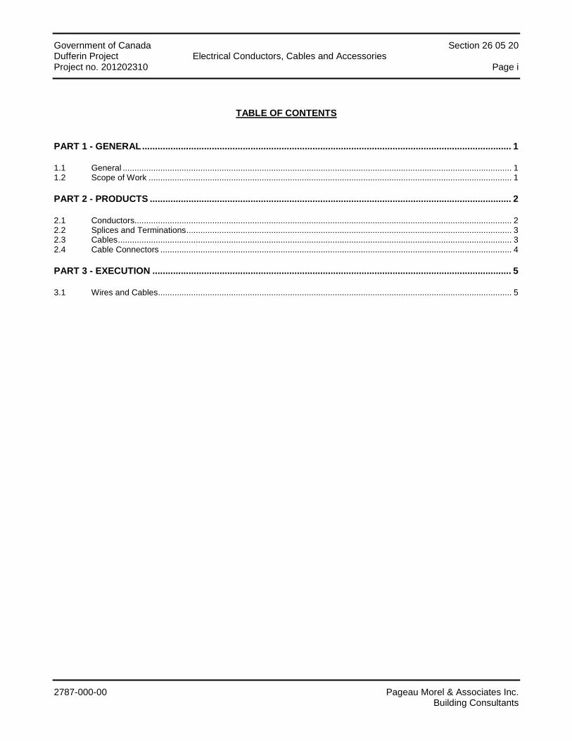
TABLE OF CONTENTS
PART 1 - GENERAL ............................................................................................................................................... 1
1.1 General ..................................................................................................................................................................... 1 1.2 Scope of Work .......................................................................................................................................................... 1
PART 2 - PRODUCTS ............................................................................................................................................ 2
2.1 Conductors................................................................................................................................................................ 2 2.2 Splices and Terminations .......................................................................................................................................... 3 2.3 Cables ....................................................................................................................................................................... 3 2.4 Cable Connectors ..................................................................................................................................................... 4
PART 3 - EXECUTION ........................................................................................................................................... 5
3.1 Wires and Cables ...................................................................................................................................................... 5
Government of Canada Section 26 05 20 Dufferin Project Electrical Conductors, Cables and Accessories Project no. 201202310 Page 1
2787-000-00 Pageau Morel & Associates Inc. Building Consultants
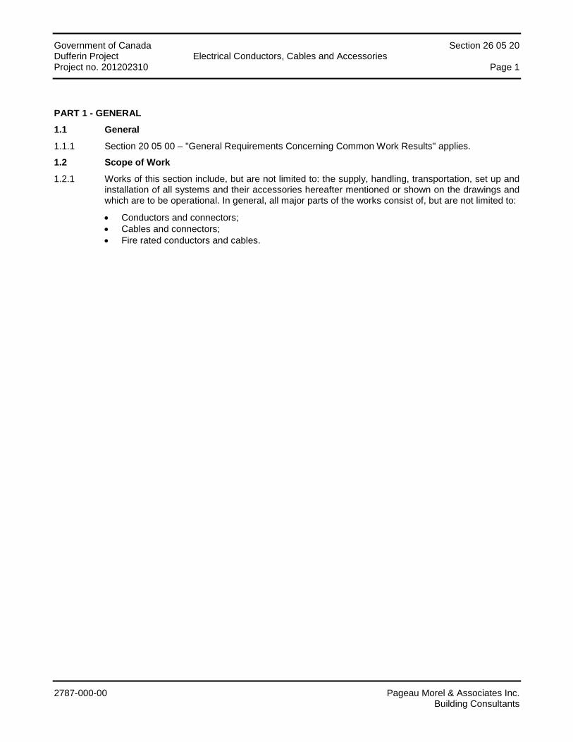
PART 1 - GENERAL
1.1 General
1.1.1 Section 20 05 00 – "General Requirements Concerning Common Work Results" applies.
1.2 Scope of Work
1.2.1 Works of this section include, but are not limited to: the supply, handling, transportation, set up and installation of all systems and their accessories hereafter mentioned or shown on the drawings and which are to be operational. In general, all major parts of the works consist of, but are not limited to:
• Conductors and connectors; • Cables and connectors; • Fire rated conductors and cables.
Government of Canada Section 26 05 20 Dufferin Project Electrical Conductors, Cables and Accessories Project no. 201202310 Page 2
2787-000-00 Pageau Morel & Associates Inc. Building Consultants
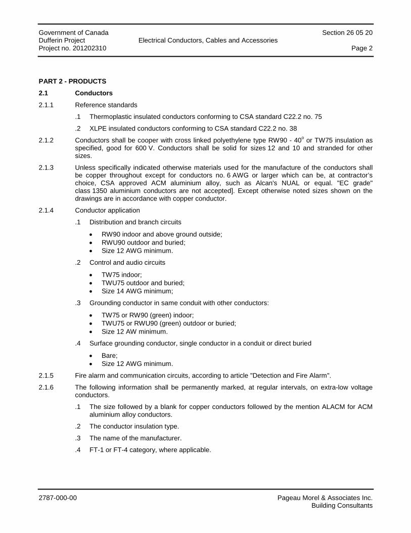
PART 2 - PRODUCTS
2.1 Conductors
2.1.1 Reference standards
.1 Thermoplastic insulated conductors conforming to CSA standard C22.2 no. 75
.2 XLPE insulated conductors conforming to CSA standard C22.2 no. 38
2.1.2 Conductors shall be cooper with cross linked polyethylene type RW90 - 40o or TW75 insulation as specified, good for 600 V. Conductors shall be solid for sizes 12 and 10 and stranded for other sizes.
2.1.3 Unless specifically indicated otherwise materials used for the manufacture of the conductors shall be copper throughout except for conductors no. 6 AWG or larger which can be, at contractor’s choice, CSA approved ACM aluminium alloy, such as Alcan's NUAL or equal. "EC grade" class 1350 aluminium conductors are not accepted]. Except otherwise noted sizes shown on the drawings are in accordance with copper conductor.
2.1.4 Conductor application
.1 Distribution and branch circuits
• RW90 indoor and above ground outside; • RWU90 outdoor and buried; • Size 12 AWG minimum.
.2 Control and audio circuits
• TW75 indoor; • TWU75 outdoor and buried; • Size 14 AWG minimum;
.3 Grounding conductor in same conduit with other conductors:
• TW75 or RW90 (green) indoor; • TWU75 or RWU90 (green) outdoor or buried; • Size 12 AW minimum.
.4 Surface grounding conductor, single conductor in a conduit or direct buried
• Bare; • Size 12 AWG minimum.
2.1.5 Fire alarm and communication circuits, according to article "Detection and Fire Alarm".
2.1.6 The following information shall be permanently marked, at regular intervals, on extra-low voltage conductors.
.1 The size followed by a blank for copper conductors followed by the mention ALACM for ACM aluminium alloy conductors.
.2 The conductor insulation type.
.3 The name of the manufacturer.
.4 FT-1 or FT-4 category, where applicable.
Government of Canada Section 26 05 20 Dufferin Project Electrical Conductors, Cables and Accessories Project no. 201202310 Page 3
2787-000-00 Pageau Morel & Associates Inc. Building Consultants
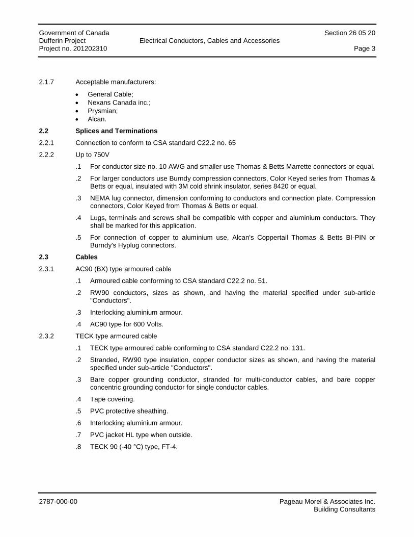
2.1.7 Acceptable manufacturers:
• General Cable; • Nexans Canada inc.; • Prysmian; • Alcan.
2.2 Splices and Terminations
2.2.1 Connection to conform to CSA standard C22.2 no. 65
2.2.2 Up to 750V
.1 For conductor size no. 10 AWG and smaller use Thomas & Betts Marrette connectors or equal.
.2 For larger conductors use Burndy compression connectors, Color Keyed series from Thomas & Betts or equal, insulated with 3M cold shrink insulator, series 8420 or equal.
.3 NEMA lug connector, dimension conforming to conductors and connection plate. Compression connectors, Color Keyed from Thomas & Betts or equal.
.4 Lugs, terminals and screws shall be compatible with copper and aluminium conductors. They shall be marked for this application.
.5 For connection of copper to aluminium use, Alcan's Coppertail Thomas & Betts BI-PIN or Burndy's Hyplug connectors.
2.3 Cables
2.3.1 AC90 (BX) type armoured cable
.1 Armoured cable conforming to CSA standard C22.2 no. 51.
.2 RW90 conductors, sizes as shown, and having the material specified under sub-article "Conductors".
.3 Interlocking aluminium armour.
.4 AC90 type for 600 Volts.
2.3.2 TECK type armoured cable
.1 TECK type armoured cable conforming to CSA standard C22.2 no. 131.
.2 Stranded, RW90 type insulation, copper conductor sizes as shown, and having the material specified under sub-article "Conductors".
.3 Bare copper grounding conductor, stranded for multi-conductor cables, and bare copper concentric grounding conductor for single conductor cables.
.4 Tape covering.
.5 PVC protective sheathing.
.6 Interlocking aluminium armour.
.7 PVC jacket HL type when outside.
.8 TECK 90 (-40 °C) type, FT-4.
Government of Canada Section 26 05 20 Dufferin Project Electrical Conductors, Cables and Accessories Project no. 201202310 Page 4
2787-000-00 Pageau Morel & Associates Inc. Building Consultants
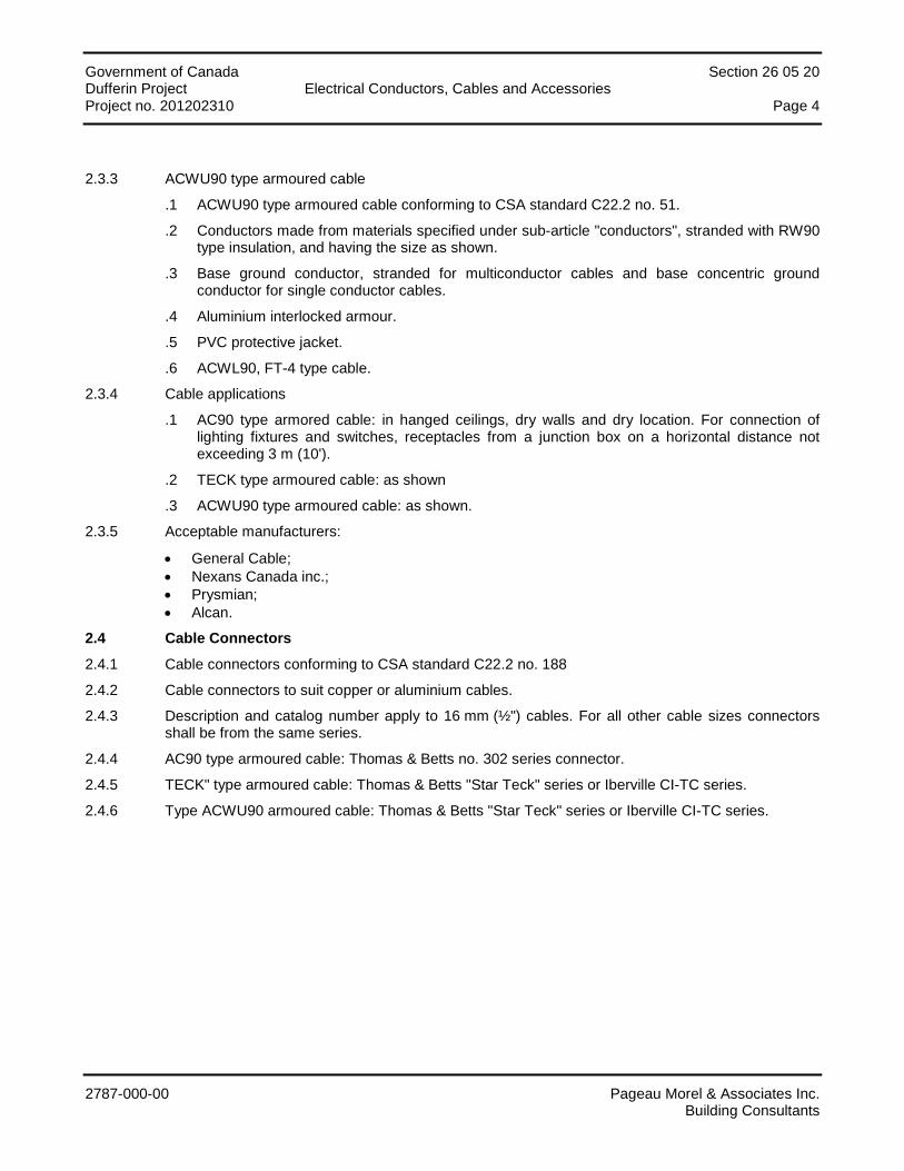
2.3.3 ACWU90 type armoured cable
.1 ACWU90 type armoured cable conforming to CSA standard C22.2 no. 51.
.2 Conductors made from materials specified under sub-article "conductors", stranded with RW90 type insulation, and having the size as shown.
.3 Base ground conductor, stranded for multiconductor cables and base concentric ground conductor for single conductor cables.
.4 Aluminium interlocked armour.
.5 PVC protective jacket.
.6 ACWL90, FT-4 type cable.
2.3.4 Cable applications
.1 AC90 type armored cable: in hanged ceilings, dry walls and dry location. For connection of lighting fixtures and switches, receptacles from a junction box on a horizontal distance not exceeding 3 m (10').
.2 TECK type armoured cable: as shown
.3 ACWU90 type armoured cable: as shown.
2.3.5 Acceptable manufacturers:
• General Cable; • Nexans Canada inc.; • Prysmian; • Alcan.
2.4 Cable Connectors
2.4.1 Cable connectors conforming to CSA standard C22.2 no. 188
2.4.2 Cable connectors to suit copper or aluminium cables.
2.4.3 Description and catalog number apply to 16 mm (½") cables. For all other cable sizes connectors shall be from the same series.
2.4.4 AC90 type armoured cable: Thomas & Betts no. 302 series connector.
2.4.5 TECK" type armoured cable: Thomas & Betts "Star Teck" series or Iberville CI-TC series.
2.4.6 Type ACWU90 armoured cable: Thomas & Betts "Star Teck" series or Iberville CI-TC series.
Government of Canada Section 26 05 20 Dufferin Project Electrical Conductors, Cables and Accessories Project no. 201202310 Page 5
2787-000-00 Pageau Morel & Associates Inc. Building Consultants
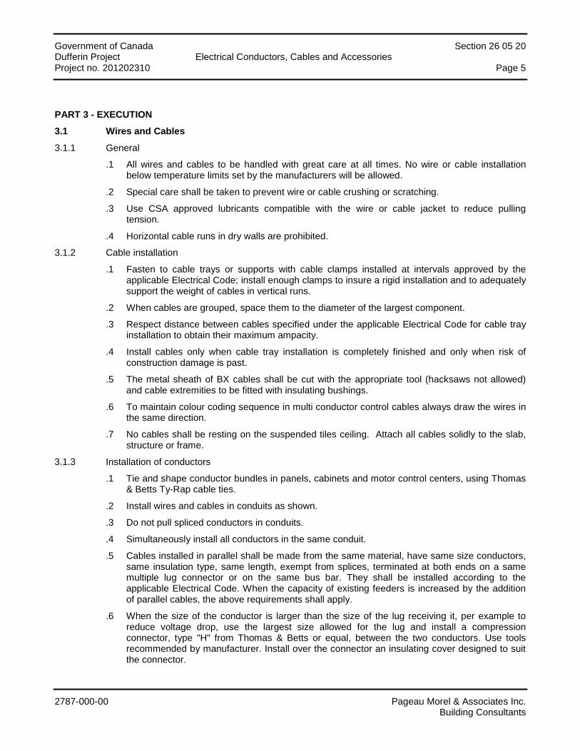
PART 3 - EXECUTION
3.1 Wires and Cables
3.1.1 General
.1 All wires and cables to be handled with great care at all times. No wire or cable installation below temperature limits set by the manufacturers will be allowed.
.2 Special care shall be taken to prevent wire or cable crushing or scratching.
.3 Use CSA approved lubricants compatible with the wire or cable jacket to reduce pulling tension.
.4 Horizontal cable runs in dry walls are prohibited.
3.1.2 Cable installation
.1 Fasten to cable trays or supports with cable clamps installed at intervals approved by the applicable Electrical Code; install enough clamps to insure a rigid installation and to adequately support the weight of cables in vertical runs.
.2 When cables are grouped, space them to the diameter of the largest component.
.3 Respect distance between cables specified under the applicable Electrical Code for cable tray installation to obtain their maximum ampacity.
.4 Install cables only when cable tray installation is completely finished and only when risk of construction damage is past.
.5 The metal sheath of BX cables shall be cut with the appropriate tool (hacksaws not allowed) and cable extremities to be fitted with insulating bushings.
.6 To maintain colour coding sequence in multi conductor control cables always draw the wires in the same direction.
.7 No cables shall be resting on the suspended tiles ceiling. Attach all cables solidly to the slab, structure or frame.
3.1.3 Installation of conductors
.1 Tie and shape conductor bundles in panels, cabinets and motor control centers, using Thomas & Betts Ty-Rap cable ties.
.2 Install wires and cables in conduits as shown.
.3 Do not pull spliced conductors in conduits.
.4 Simultaneously install all conductors in the same conduit.
.5 Cables installed in parallel shall be made from the same material, have same size conductors, same insulation type, same length, exempt from splices, terminated at both ends on a same multiple lug connector or on the same bus bar. They shall be installed according to the applicable Electrical Code. When the capacity of existing feeders is increased by the addition of parallel cables, the above requirements shall apply.
.6 When the size of the conductor is larger than the size of the lug receiving it, per example to reduce voltage drop, use the largest size allowed for the lug and install a compression connector, type "H" from Thomas & Betts or equal, between the two conductors. Use tools recommended by manufacturer. Install over the connector an insulating cover designed to suit the connector.
Government of Canada Section 26 05 20 Dufferin Project Electrical Conductors, Cables and Accessories Project no. 201202310 Page 6
2787-000-00 Pageau Morel & Associates Inc. Building Consultants
3.1.4 Sealing barriers
.1 When cables pass vertically through a concrete slab, MCT type from Nelson, multicable transit barriers shall be used to seal the path.
.2 When horizontal cable runs pass through a concrete or concrete block wall, fire insulating barriers similar to the "Fire Stop" system shall be installed. An elastomeric compound jointly used with fire proof panels shall render the installation to IEEE 634 standard.
3.1.5 Installation des conducteurs et câbles d’alliage d’aluminium ACM
.1 After skinning the cable, brush the conductors, apply an oxyde inhibitor composite as manufactured by Alcan, Burndy (Penetrox) or Ideal (Nualox) on the conductor et procede with the connection to the equipment. The equipment shall be homologated for use with ACM aluminum alloy cables.
.2 Use connectors approved for both aluminum alloy and copper cables.
.3 When sucj a connector is not approved for aluminum alloy, use proper aluminium to copper adapter, approved by CSA.
END OF SECTION
Government of Canada Section 26 05 30 Dufferin Project Electrical Conduits, Boxes and Accessories Project no. 201202310 Page i
2787-000-00 Pageau Morel & Associates Inc. Building Consultants
TABLE OF CONTENTS
PART 1 - GENERAL ............................................................................................................................................... 1
1.1 General ..................................................................................................................................................................... 1 1.2 Scope of Work .......................................................................................................................................................... 1 1.3 Shop Drawings and Technical Data .......................................................................................................................... 1
PART 2 - PRODUCTS ............................................................................................................................................ 2
2.1 Communication Cable Trays System ........................................................................................................................ 2 2.2 Conduits .................................................................................................................................................................... 3 2.3 Conduit Supports ...................................................................................................................................................... 3 2.4 Conduit Connectors .................................................................................................................................................. 4 2.5 Splitter Troughs, Cabinets, Junction and Pull Boxes ................................................................................................ 5 2.6 Boxes ........................................................................................................................................................................ 5 2.7 Empty Conduit Systems for Telecommunication, Access Control, Cable TV, Data and Fiber Optics ....................... 7
PART 3 - EXECUTION ........................................................................................................................................... 8
3.1 Installation of cable trays .......................................................................................................................................... 8 3.2 Cables trays .............................................................................................................................................................. 8 3.3 Conduits .................................................................................................................................................................... 9 3.4 Boxes, Splitter Troughs and Cabinets ..................................................................................................................... 13 3.5 Empty Conduit System for Telephone, Communication, Cable TV and Data ......................................................... 13
Government of Canada Electrical Section 26 05 30 Dufferin Project Conduits, boxes and accessories Project no. 201202310 Page 1
2787-000-00 Pageau Morel & Associates Inc. Building Consultants
PART 1 - GENERAL
1.1 General
1.1.1 Section 20 05 00 – "General Requirements Concerning Common Work Results" applies.
1.2 Scope of Work
1.2.1 Works of this section include, but are not limited to: the supply, handling, transportation, set up and installation of all systems and their accessories hereafter mentioned or shown on the drawings and which are to be operational. In general, all major parts of the works consist of, but are not limited to:
• Electrical conduits and accessories; • Cable trays; • Splitter through; • Connection boxes; • Raceways.
1.3 Shop Drawings and Technical Data
1.3.1 Submit shop drawings and technical data regarding Section 20 05 00 – "General Requirements Concerning Common Work Results".
1.3.2 Submit shop drawing and technical data of the following items:
• Cable trays; • Splitter through and cabinets; • Cabinets.
Government of Canada Electrical Section 26 05 30 Dufferin Project Conduits, boxes and accessories Project no. 201202310 Page 2
2787-000-00 Pageau Morel & Associates Inc. Building Consultants
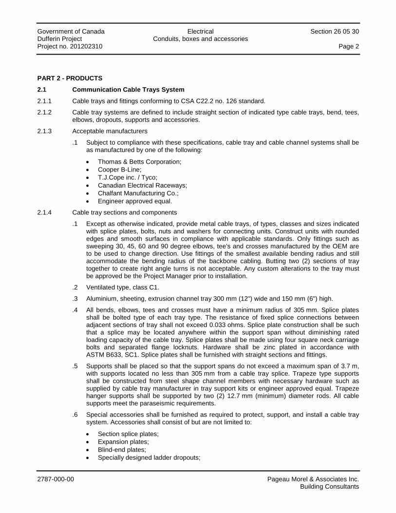
PART 2 - PRODUCTS
2.1 Communication Cable Trays System
2.1.1 Cable trays and fittings conforming to CSA C22.2 no. 126 standard.
2.1.2 Cable tray systems are defined to include straight section of indicated type cable trays, bend, tees, elbows, dropouts, supports and accessories.
2.1.3 Acceptable manufacturers
.1 Subject to compliance with these specifications, cable tray and cable channel systems shall be as manufactured by one of the following:
• Thomas & Betts Corporation; • Cooper B-Line; • T.J.Cope inc. / Tyco; • Canadian Electrical Raceways; • Chalfant Manufacturing Co.; • Engineer approved equal.
2.1.4 Cable tray sections and components
.1 Except as otherwise indicated, provide metal cable trays, of types, classes and sizes indicated with splice plates, bolts, nuts and washers for connecting units. Construct units with rounded edges and smooth surfaces in compliance with applicable standards. Only fittings such as sweeping 30, 45, 60 and 90 degree elbows, tee's and crosses manufactured by the OEM are to be used to change direction. Use fittings of the smallest available bending radius and still accommodate the bending radius of the backbone cabling. Butting two (2) sections of tray together to create right angle turns is not acceptable. Any custom alterations to the tray must be approved be the Project Manager prior to installation.
.2 Ventilated type, class C1.
.3 Aluminium, sheeting, extrusion channel tray 300 mm (12") wide and 150 mm (6") high.
.4 All bends, elbows, tees and crosses must have a minimum radius of 305 mm. Splice plates shall be bolted type of each tray type. The resistance of fixed splice connections between adjacent sections of tray shall not exceed 0.033 ohms. Splice plate construction shall be such that a splice may be located anywhere within the support span without diminishing rated loading capacity of the cable tray. Splice plates shall be made using four square neck carriage bolts and separated flange locknuts. Hardware shall be zinc plated in accordance with ASTM B633, SC1. Splice plates shall be furnished with straight sections and fittings.
.5 Supports shall be placed so that the support spans do not exceed a maximum span of 3.7 m, with supports located no less than 305 mm from a cable tray splice. Trapeze type supports shall be constructed from steel shape channel members with necessary hardware such as supplied by cable tray manufacturer in tray support kits or engineer approved equal. Trapeze hanger supports shall be supported by two (2) 12.7 mm (minimum) diameter rods. All cable supports meet the paraseismic requirements.
.6 Special accessories shall be furnished as required to protect, support, and install a cable tray system. Accessories shall consist of but are not limited to:
• Section splice plates; • Expansion plates; • Blind-end plates; • Specially designed ladder dropouts;
Government of Canada Electrical Section 26 05 30 Dufferin Project Conduits, boxes and accessories Project no. 201202310 Page 3
2787-000-00 Pageau Morel & Associates Inc. Building Consultants
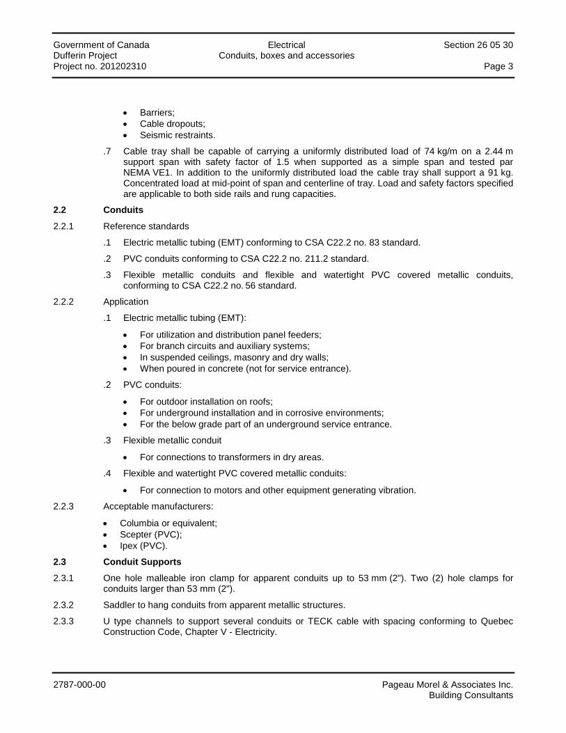
• Barriers; • Cable dropouts; • Seismic restraints.
.7 Cable tray shall be capable of carrying a uniformly distributed load of 74 kg/m on a 2.44 m support span with safety factor of 1.5 when supported as a simple span and tested par NEMA VE1. In addition to the uniformly distributed load the cable tray shall support a 91 kg. Concentrated load at mid-point of span and centerline of tray. Load and safety factors specified are applicable to both side rails and rung capacities.
2.2 Conduits
2.2.1 Reference standards
.1 Electric metallic tubing (EMT) conforming to CSA C22.2 no. 83 standard.
.2 PVC conduits conforming to CSA C22.2 no. 211.2 standard.
.3 Flexible metallic conduits and flexible and watertight PVC covered metallic conduits, conforming to CSA C22.2 no. 56 standard.
2.2.2 Application
.1 Electric metallic tubing (EMT):
• For utilization and distribution panel feeders; • For branch circuits and auxiliary systems; • In suspended ceilings, masonry and dry walls; • When poured in concrete (not for service entrance).
.2 PVC conduits:
• For outdoor installation on roofs; • For underground installation and in corrosive environments; • For the below grade part of an underground service entrance.
.3 Flexible metallic conduit
• For connections to transformers in dry areas.
.4 Flexible and watertight PVC covered metallic conduits:
• For connection to motors and other equipment generating vibration.
2.2.3 Acceptable manufacturers:
• Columbia or equivalent; • Scepter (PVC); • Ipex (PVC).
2.3 Conduit Supports
2.3.1 One hole malleable iron clamp for apparent conduits up to 53 mm (2"). Two (2) hole clamps for conduits larger than 53 mm (2").
2.3.2 Saddler to hang conduits from apparent metallic structures.
2.3.3 U type channels to support several conduits or TECK cable with spacing conforming to Quebec Construction Code, Chapter V - Electricity.
Government of Canada Electrical Section 26 05 30 Dufferin Project Conduits, boxes and accessories Project no. 201202310 Page 4
2787-000-00 Pageau Morel & Associates Inc. Building Consultants
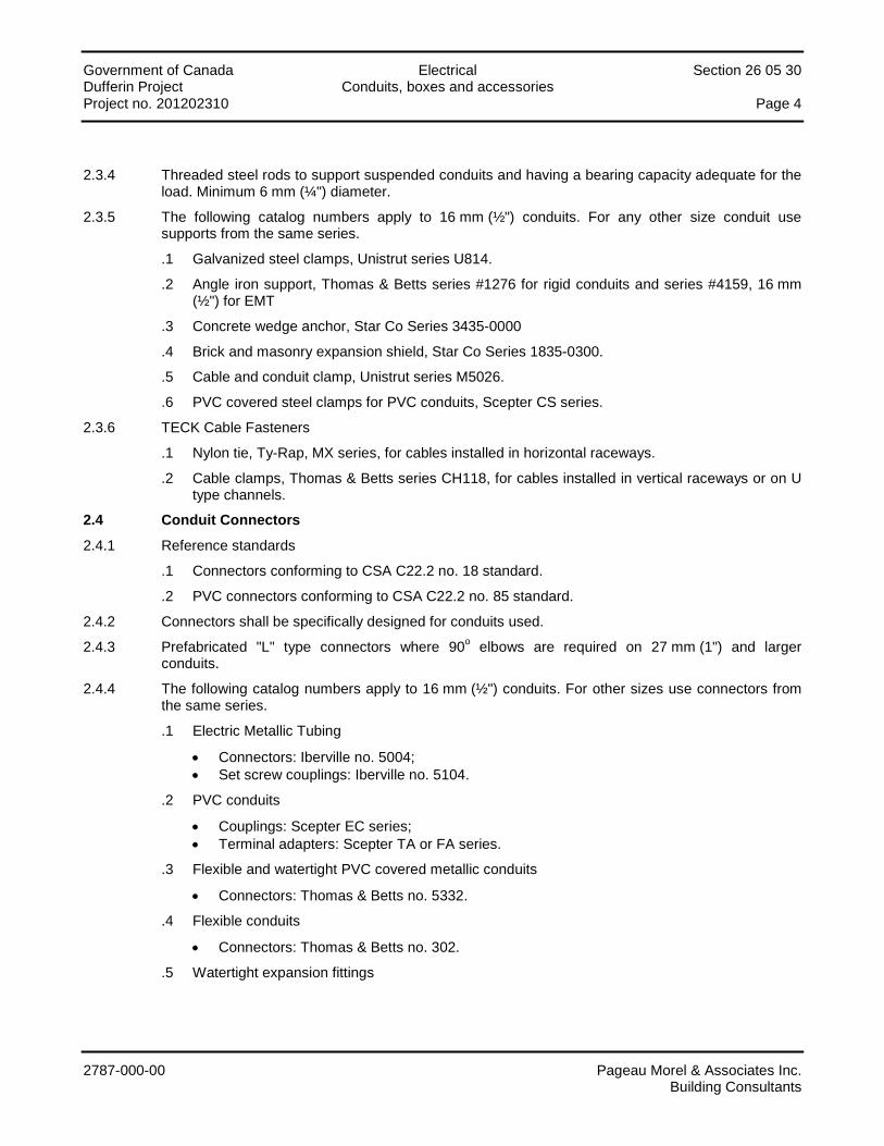
2.3.4 Threaded steel rods to support suspended conduits and having a bearing capacity adequate for the load. Minimum 6 mm (¼") diameter.
2.3.5 The following catalog numbers apply to 16 mm (½") conduits. For any other size conduit use supports from the same series.
.1 Galvanized steel clamps, Unistrut series U814.
.2 Angle iron support, Thomas & Betts series #1276 for rigid conduits and series #4159, 16 mm (½") for EMT
.3 Concrete wedge anchor, Star Co Series 3435-0000
.4 Brick and masonry expansion shield, Star Co Series 1835-0300.
.5 Cable and conduit clamp, Unistrut series M5026.
.6 PVC covered steel clamps for PVC conduits, Scepter CS series.
2.3.6 TECK Cable Fasteners
.1 Nylon tie, Ty-Rap, MX series, for cables installed in horizontal raceways.
.2 Cable clamps, Thomas & Betts series CH118, for cables installed in vertical raceways or on U type channels.
2.4 Conduit Connectors
2.4.1 Reference standards
.1 Connectors conforming to CSA C22.2 no. 18 standard.
.2 PVC connectors conforming to CSA C22.2 no. 85 standard.
2.4.2 Connectors shall be specifically designed for conduits used.
2.4.3 Prefabricated "L" type connectors where 90o elbows are required on 27 mm (1") and larger conduits.
2.4.4 The following catalog numbers apply to 16 mm (½") conduits. For other sizes use connectors from the same series.
.1 Electric Metallic Tubing
• Connectors: Iberville no. 5004; • Set screw couplings: Iberville no. 5104.
.2 PVC conduits
• Couplings: Scepter EC series; • Terminal adapters: Scepter TA or FA series.
.3 Flexible and watertight PVC covered metallic conduits
• Connectors: Thomas & Betts no. 5332.
.4 Flexible conduits
• Connectors: Thomas & Betts no. 302.
.5 Watertight expansion fittings

Government of Canada Electrical Section 26 05 30 Dufferin Project Conduits, boxes and accessories Project no. 201202310 Page 5
2787-000-00 Pageau Morel & Associates Inc. Building Consultants
2.5 Splitter Troughs, Cabinets, Junction and Pull Boxes
2.5.1 Reference standards
.1 Pull and junction boxes and with hinged covers conforming to CSA C22.2 no. 40 standard.
.2 Splitter troughs conforming to CSA C22.2 no. 76 standard.
2.5.2 Splitter troughs
.1 Sheet metal enclosure with welded edges and hinged shaped cover with locking facility when closed.
.2 Copper bus bars c/w terminals corresponding to the number and size of the incoming and outgoing conductors as shown.
.3 Unless otherwise indicated the splitter troughs shall have sufficient length to accommodate the layout of the secondary equipment.
.4 Supply at least three space terminals for each terminal size in 400 A and less splitter troughs.
2.5.3 Junction and pull boxes
.1 Welded steel boxes with screw fastened flat cover for surface mounting.
.2 Cover with a 25 mm (1") minimum trim compatible with recessed pull and junction boxes.
2.5.4 Acceptable manufacturers:
• Bel; • Roger Girard; • Iberville.
2.6 Boxes
2.6.1 Reference standards
.1 Outlet and branch circuit boxes conforming to CSA C22.2 no. 18 standard.
.2 PVC boxes conforming to CSA C22.2 no. 85 standard.
2.6.2 General
.1 Box dimensions to conform to Quebec Construction Code, Chapter V - Electricity.
.2 Outlet boxes shall be gauged where several wiring devices are to be installed at the same location.
.3 Covers for boxes which are not used for wiring devices shall be plain.
.4 Gauged outlet boxes shall be complete with barrier when outlets from separate systems are grouped together.
.5 Knock down boxes are not acceptable except when used on outlets with non metallic sheathed cable.
2.6.3 Ganged outlet boxes
Electro galvanized steel boxes, for single or multiple recessed mounting of wiring devices in steel studded gypsum board walls, having minimum dimensions 76 mm x 51 mm x 51 mm (3" x 2" x 2") or as shown, series 1102. 102 mm x 102 mm (4" x 4") boxes with extension when more than one conduit penetrate one side with plaster ring where required, Thomas & Betts series 52151 or 52171.

Government of Canada Electrical Section 26 05 30 Dufferin Project Conduits, boxes and accessories Project no. 201202310 Page 6
2787-000-00 Pageau Morel & Associates Inc. Building Consultants
2.6.4 Surface mounted outlet boxes
.1 Electro galvanized steel boxes for EMT connected outlets, 102 mm x 60 mm x 48 mm (4" x 2⅜" x 2") minimum size.
.2 FS or FD type cast iron surface mounted boxes, single or ganged, with manufactured threaded openings for rigid conduits, mounting ears and without prepunch opening.
2.6.5 Ceiling outlets boxes
.1 102 mm (4") octagonal boxes for lighting fixture and ceiling outlets, Thomas & Betts series 54151 or 54171.
2.6.6 Plaster or ceramic tile outlet boxes
.1 102 mm (4") sided or larger boxes with extension and plaster ring for recessed wiring devices in plaster or ceramic tile walls, Thomas & Betts series 52151 or 52171.
2.6.7 347 Volts outlet boxes
.1 347 V electro galvanized steel boxes for 347 V switches, Thomas & Betts series MBD-HV.
2.6.8 Masonry outlet boxes
.1 Electro galvanized gauged outlet boxes for recessed single wiring device installation in apparent masonry walls (concrete bricks or blocks), Thomas & Betts series MB.
2.6.9 Concrete boxes
.1 Electro galvanized steel boxes for flush mounting of wiring devices in concrete, with compatible extension and plaster rings where required, Thomas & Betts series 52151 or 52171.
2.6.10 Floor boxes
.1 Electro galvanized steel floor boxes concrete tight, with adjustable collar with surface finishing brass plate. Compatible with single or double receptacles as required.
.2 Adjustable cast floor boxes, watertight and concrete tight, with threaded 16 mm (½") and 21 mm (¾") openings; minimum depth 76 mm (3").
2.6.11 Outlet boxes for non-metallic sheathed cable.
.1 Electro galvanized outlet boxes for non metallic sheathed cable, may be disassembled and gauged with set screws, shall have minimum dimension of 76 mm x 51 mm x 63 mm (3" x 2" x 2 ½") with two twin sheathed cable clamps, Thomas & Betts series 1104.
2.6.12 PVC conduit boxes
.1 PVC boxes shall be used on PVC conduit networks.
2.6.13 Outdoor boxes
.1 Weatherproof designed for covers with four screws and for surface mounting.
2.6.14 Acceptable manufacturers:
• Iberville; • Thomas & Betts; • Roger Girard; • Bel; • Crouse Hinds; • Appleton.
Government of Canada Electrical Section 26 05 30 Dufferin Project Conduits, boxes and accessories Project no. 201202310 Page 7
2787-000-00 Pageau Morel & Associates Inc. Building Consultants
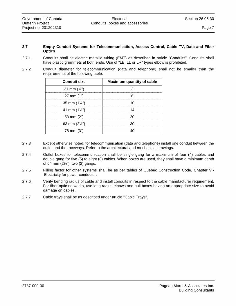
2.7 Empty Conduit Systems for Telecommunication, Access Control, Cable TV, Data and Fiber Optics
2.7.1 Conduits shall be electric metallic tubing (EMT) as described in article "Conduits". Conduits shall have plastic grummets at both ends. Use of "LB, LL or LR" types elbow is prohibited.
2.7.2 Conduit diameter for telecommunication (data and telephone) shall not be smaller than the requirements of the following table:
Conduit size Maximum quantity of cable
21 mm (¾") 3
27 mm (1") 6
35 mm (1¼") 10
41 mm (1½") 14
53 mm (2") 20
63 mm (2½") 30
78 mm (3") 40
2.7.3 Except otherwise noted, for telecommunication (data and telephone) install one conduit between the outlet and the raceways. Refer to the architectural and mechanical drawings.
2.7.4 Outlet boxes for telecommunication shall be single gang for a maximum of four (4) cables and double gang for five (5) to eight (8) cables. When boxes are used, they shall have a minimum depth of 64 mm (2½"), two (2) gangs.
2.7.5 Filling factor for other systems shall be as per tables of Quebec Construction Code, Chapter V - Electricity for power conductor.
2.7.6 Verify bending radius of cable and install conduits in respect to the cable manufacturer requirement. For fiber optic networks, use long radius elbows and pull boxes having an appropriate size to avoid damage on cables.
2.7.7 Cable trays shall be as described under article "Cable Trays".
Government of Canada Electrical Section 26 05 30 Dufferin Project Conduits, boxes and accessories Project no. 201202310 Page 8
2787-000-00 Pageau Morel & Associates Inc. Building Consultants
PART 3 - EXECUTION
3.1 Installation of cable trays
3.1.1 Subcontractor qualification
.1 Only experienced Data Subcontractor will be considered for the work. Subcontractors must be able to provide evidence of having performed work of a similar type as specified. Subcontractor must be trained and authorized by the manufacturers they represent. All bidders must include evidence of their certification and references in bids. Subcontractors shall have tools and test equipment necessary for the installation and testing of the cable tray systems. Subcontractor shall list the type and manufacturer of all test equipment to be used.
3.1.2 Installation
.1 Prior to and during installation, refer to the system layout or approval drawings containing all elements of the system. Installer shall comply with complete system instruction sheets.
.2 Install cable trays as indicated. Installation shall be in accordance with equipment manufacturer's instructions, and with recognized industry practices to ensure that cable tray equipment comply with requirements of OESC and applicable CSA Standards. Reference NEMA VE2 for general cable tray installation guidelines.
.3 The communication cable trays shown diagrammatically on the drawings. Subcontractor to review the installation on site to view the exact location where these infrastructure items are to be installed or routed. Subcontractor to coordinate communications infrastructure items with other electrical and mechanical work as necessary to properly integrate installation of cable tray work with other work.
.4 All cable trays are to be properly grounded with a minimum 6 AWG ground wire (or as required by local building codes) to the telecommunication grounds bus bar in Distribution Room and/or IT Closet. The grounding cable shall be bounded to all sections of the cable tray.
.5 Provide sufficient space encompassing cable trays to permit access for installing and maintaining cables. A minimum clearance of 305 mm is to be maintained above cable tray for routing cables and maintenance purposes.
.6 Cable tray fitting supports shall be located such that they meet the strength requirements of straight sections. Install fitting supports per NEMA VE2 guidelines, or in accordance with manufacturer's instructions.
3.1.3 Testing
.1 Testing cable trays to ensure electrical continuity of bonding and grounding connections, and to demonstrate compliance with specified maximum grounding resistance.
.2 Manufacturer shall provide test reports witnessed by an independent testing laboratory of the "worst case" loading conditions outlined in this specification and performed in accordance with the latest revision of NEMA VE1, including test reports verifying rung load capacity in accordance with NEMA VE1.
3.2 Cables trays
3.2.1 Install the whole cable tray network as shown.
3.2.2 Install cable tray supports on both sides as per manufacturer and seismic engineer recommandations.
3.2.3 When cable trays pass through a floor, pour a concrete curb around the opening.
Government of Canada Electrical Section 26 05 30 Dufferin Project Conduits, boxes and accessories Project no. 201202310 Page 9
2787-000-00 Pageau Morel & Associates Inc. Building Consultants
3.2.4 Remove burrs and sharp edges to prevent injuring to personnel and cable damage.
3.2.5 Cable installation in cable trays.
.1 Install cables one at a time.
.2 Drop cables into cable trays; should pulling of cables be required use rollers.
.3 Attach cables with nylon ties at 6 m (18') intervals in horizontal cable tray runs.
3.2.6 Ground cable trays according to article "Grounding and mass continuity".
3.2.7 Sealing barriers
.1 In fire rated walls and floors, make opening large enough for the passage of the cable tray.
.2 After cable installation rebuild fire proofing integrity to its original value using the method given under "Wires and cables".
3.2.8 Add mobile joints to the rigid cable tray sections when they pass through a structural expansion joint.
3.3 Conduits
3.3.1 General
.1 All conduits are not shown on the drawings. Those that are shown are only represented schematically. When the specified conduit size is indicated, do not install smaller diameter conduits.
.2 All conduits shall be concealed except those installed in mechanical and electrical rooms.
.3 Apparent conduits shall be installed in such a manner as not to decrease the headroom and to use the less possible space.
.4 All supply conduits to panels, motor control centers etc., and all conduits for motor branch circuits shall be complete with a green ground conductor sized according to table 16 of the Quebec Construction Code, Chapter V - Electricity.
3.3.2 Bending and cutting of conduits
.1 Bend conduits cold and insure that the resulting flattening does not reduce the original conduit diameter by more than 1/10. Conduits having a flattening greater than 1/10 diam. or which have twisted bends shall be considered defective and shall be replaced.
.2 All conduits greater than 21 mm (¾") diam. shall be mechanically bent.
.3 Bending radii shall not be smaller than manufactured bends.
.4 Rigid conduits threaded on site shall have long enough threaded sections to allow good conduit tightening.
.5 Conduit ends to be reamed to remove bars which could damage conductors.
3.3.3 Installation of conduits
.1 All electrical conduits to be fastened with appropriate clamps. Electrical conduits shall not be attached to suspended ceilings, plumbing, ventilation or air conditioning ducts or any other apparatus. Steel cables or holed straps shall not be accepted.
.2 Unless otherwise shown, conduits shall not pass through structural elements.
Government of Canada Electrical Section 26 05 30 Dufferin Project Conduits, boxes and accessories Project no. 201202310 Page 10
2787-000-00 Pageau Morel & Associates Inc. Building Consultants
.3 All surface mounted metallic conduits shall be fastened with malleable iron clamps, bolts and anchors. Follow Quebec Construction Code, Chapter V - Electricity for spacing.
.4 Flexible conduits shall be fastened with TY-RAP plastic straps from Thomas & Betts.
.5 When conduits are grouped, they shall be mounted on suspended or surface mounted galvanized U shaped steel channels.
.6 Attach single suspended conduits with steel clamps.
.7 Rod diameters and support spacing shall be determined from the configuration of the grouped conduits. Support channels shall be as manufactured by Unistrut, Wieland or Burndy.
.8 Install conduits parallel to steam or hot water pipes spacing them at least 150 mm (6") horizontally and 75 mm (3") vertically.
.9 Conduit runs to include a maximum of three 90° elbows or a length of 30 m (100'). Provide cable supports in vertical runs according to the spacing shown in table 21 of the Quebec Construction Code, Chapter V - Electricity. The supports shall be mounted in a box and be manufactured by O-Z/Gedney. Each run extremity to end into a box.
.10 Expansion sleeves to be installed at building expansion joints and on long and straight conduit runs. Electrical continuity to be insured by flexible links compatible with the materials and according to the Quebec Construction Code, Chapter V - Electricity.
.11 All conduits to be capped to prevent foreign objects from entering during the construction.
.12 Corrosive cleaning agents shall not be used. Remove and replace the obstructed section.
.13 Insure that conduit interior is dry before proceeding with cable pulling.
.14 Supply and install a polypropylene rope in empty conduits to ease the eventual pulling of wire or cables.
.15 Each motor connections to end with a watertight flexible conduit section.
.16 Conduit installation to be such as to insure electric continuity of grounding.
3.3.4 Apparent conduits
.1 Conduits to be installed parallel to or perpendicular to building site lines.
.2 Leave a 1,500 mm (60") clearance for conduits installed in the back of gas operated infrared heaters.
.3 When required conduits shall be installed on girder ribs.
3.3.5 Concealed conduits
.1 Horizontal conduit runs in masonry walls and dry walls are prohibited.
.2 Unless indicated otherwise, conduits may not be installed in concrete topping or terrazzo.
3.3.6 Underground conduits, direct burial
.1 Conduits shall be buried to the specified depth.
.2 Install grouped conduits on undisturbed soil or on 150 mm (6") thick granular fill compacted to 95% dry Proctor Index.
.3 Before proceeding with conduit installation excavate the whole path to insure that no obstacles will interfere with the conduit.
Government of Canada Electrical Section 26 05 30 Dufferin Project Conduits, boxes and accessories Project no. 201202310 Page 11
2787-000-00 Pageau Morel & Associates Inc. Building Consultants
.4 Install conduits to specified levels and grades with minimum slope of 1:400 for water drainage.
.5 Install conduits according to the specified layout using preformed rigid plaster interlocking spacers to achieve a 50 mm (2") minimum vertical and horizontal spacing. Spacing slips to be not more than 1,500 mm (60") from one another and bottom rows to be installed at specified grade. Joints on successive layers to be staggered by 750 mm (30").
.6 Apply a thick coat of bituminous paint on all joints to render them waterproof (except for joints on PVC conduits).
.7 Use galvanized steel conduits for that part of the conduit run which emerges beyond the definitive ground level.
.8 Perform transposition and direction changes with 5° elbows.
.9 Use bell ends at access to conduits in manholes and buildings.
.10 Use conduit adapter sleeves to mate metallic to non-metallic conduits.
.11 Cut, trim and ream conduit ends, to manufacturer's recommendations, to obtain finished conduit ends similar to the manufactured ones.
.12 Protect the conduit array with a 150 mm (6") thick sand layer over conduit row.
.13 Install a Brady Identaline tape marker with the "Underground power line" warning, above the conduit run, before backfilling.
3.3.7 Underground conduits, concrete encased
.1 Conduits shall be buried to the specified depth.
.2 Install grouped conduits on undisturbed soil or on 150 mm (6") thick granular fill compacted to 95% dry Proctor Index.
.3 Before proceeding with conduit installation excavate the whole path to insure that no obstacles will interfere with the conduit. Bottom of the trench shall be leveled to maintain a minimum concrete depth of 75 mm (3") under conduits.
.4 Install conduits to specified levels and grades with minimum slope of 1:400 for water drainage.
.5 Install conduits according to the specified layout using preformed rigid plaster interlocking spacers to achieve a 50 mm (2") minimum vertical and horizontal spacing. Spacing slips to be not more than 1,200 mm (48") from one another and bottom rows to be installed at specified grade. Joints on successive layers to be staggered by 600 mm (24"). Install on each side of conduits, formwork to maintain a minimum thickness of 50 mm (2") of concrete besides conduit and give a rectangular, regular and uniform shape to the duct bank. Install, when indicated, reinforcing rods.
.6 Use galvanized steel conduits for that part of the conduit run which emerges beyond the definitive ground level.
.7 Perform direction variations with 5° elbows. Except otherwise noted, perform direction changes with elbows having at least, 1,500 mm radius for medium voltage, 900 mm for low voltage and 600 mm for telecommunications. Number of elbows shall be kept to minimum.
.8 Use bell ends at access to conduits in manholes and buildings.
.9 Use conduit adapter sleeves to mate metallic to non-metallic conduits.
.10 Cut, trim and ream conduit ends, to manufacturer's recommendations, to obtain finished conduit ends similar to the manufactured ones.
Government of Canada Electrical Section 26 05 30 Dufferin Project Conduits, boxes and accessories Project no. 201202310 Page 12
2787-000-00 Pageau Morel & Associates Inc. Building Consultants
.11 Immediately after placing of concrete, pull through each duct a rigid mandrel not less than 300 mm long and of a diameter 6mm less than internal diameter of duct, followed by stiff bristle brush to remove sand, earth and other foreign matter. Avoid disturbing or damaging ducts where concrete has not set completely. Pull stiff bristle brush through each duct immediately before pulling-in cables.
.12 Install 19 mm thick wood panels between conduits for electricity and conduits for telecoms.
.13 Pouring of concrete shall be done without interruption on all length or up to a construction joint. Concrete shall be compacted by hand with a wooden strip or equal to avoid empty spaces between conduits or along formwork. Use of concrete vibrating equipment is forbidden.
.14 Install a Brady Identaline tape marker with the "Underground power line" warning, above the conduit run, before backfilling.
3.3.8 Concrete encased conduits, in floors and walls
.1 Install conduits without interfering with steel armature. Organize conduits to reduce at strict minimum quantity of cross-overs.
.2 Do not install in concrete slabs conduits having a diameter larger than 25% of the slab thickness. Encase conduits with minimum 25 mm (1") concrete cover.
.3 Protect conduits at their point of emergence from the concrete mass.
.4 Before the pouring of the concrete, install sleeves where conduits pass through concrete walls or slabs.
.5 Install oversized sleeves where conduits are to pass through a water repellent membrane. Install sealing paste between the sleeve and conduit.
.6 Tamp concrete around all conduits.
3.3.9 Conduits under a slab on ground.
.1 Conduits 27 mm (1") and larger shall be installed under the slab and encased in a 75 mm (3") thick concrete mass. Install a 50 mm (2") thick sand layer between the concrete mass and the slab.
3.3.10 Flexible non metallic conduits
.1 Flexible non-metallic conduits, encased in concrete, shall not be installed at low temperature, to prevent breakages. All damaged flexible conduits shall be replaced by other flexible non-metallic conduits before the concrete pouring as surface mounted electric metallic tubing after the concrete pouring.
3.3.11 Vertical runs .1 In vertical runs install pull boxes at the minimum spacing required by the Quebec Construction
Code, Chapter V - Electricity in Table 21. Support medium voltage cables with R type from O-Z/Gedney for high tension and Q type for the rest.
3.3.12 Conduit inside ventilation systems .1 Seal all conduits penetrating into ventilation systems to supply equipment inside the systems to
prevent air leaks at the penetration points. 3.3.13 Conduit fittings
.1 Fittings for threaded rigid conduits shall be coated with red lead before being threaded.
.2 Electric metallic tubing couplings shall be of the set screw type.
Government of Canada Electrical Section 26 05 30 Dufferin Project Conduits, boxes and accessories Project no. 201202310 Page 13
2787-000-00 Pageau Morel & Associates Inc. Building Consultants
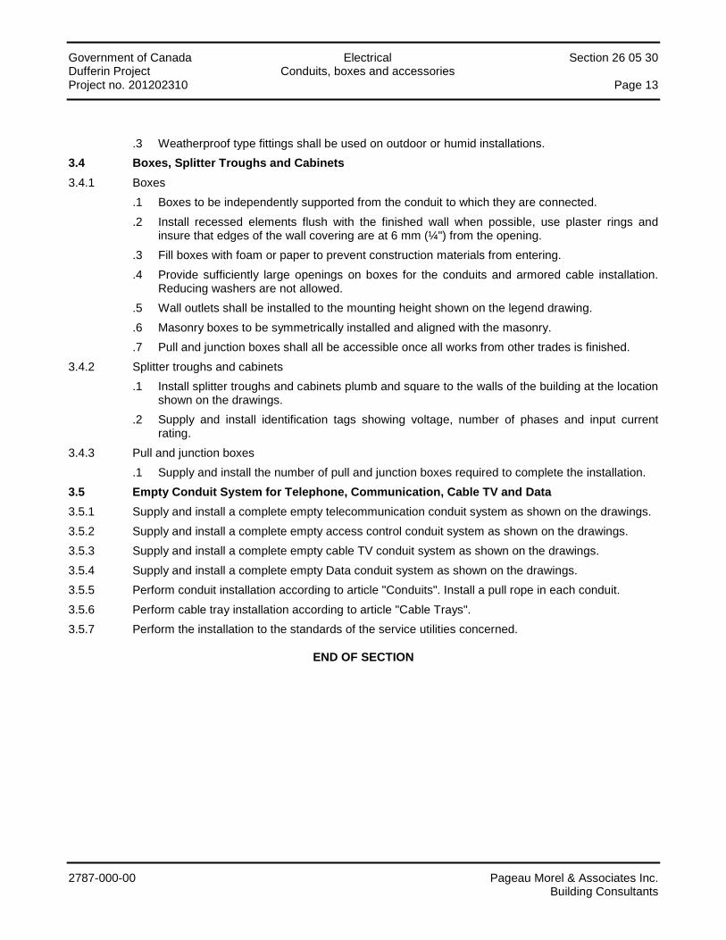
.3 Weatherproof type fittings shall be used on outdoor or humid installations. 3.4 Boxes, Splitter Troughs and Cabinets 3.4.1 Boxes
.1 Boxes to be independently supported from the conduit to which they are connected.
.2 Install recessed elements flush with the finished wall when possible, use plaster rings and insure that edges of the wall covering are at 6 mm (¼") from the opening.
.3 Fill boxes with foam or paper to prevent construction materials from entering.
.4 Provide sufficiently large openings on boxes for the conduits and armored cable installation. Reducing washers are not allowed.
.5 Wall outlets shall be installed to the mounting height shown on the legend drawing.
.6 Masonry boxes to be symmetrically installed and aligned with the masonry.
.7 Pull and junction boxes shall all be accessible once all works from other trades is finished. 3.4.2 Splitter troughs and cabinets
.1 Install splitter troughs and cabinets plumb and square to the walls of the building at the location shown on the drawings.
.2 Supply and install identification tags showing voltage, number of phases and input current rating.
3.4.3 Pull and junction boxes .1 Supply and install the number of pull and junction boxes required to complete the installation.
3.5 Empty Conduit System for Telephone, Communication, Cable TV and Data 3.5.1 Supply and install a complete empty telecommunication conduit system as shown on the drawings. 3.5.2 Supply and install a complete empty access control conduit system as shown on the drawings. 3.5.3 Supply and install a complete empty cable TV conduit system as shown on the drawings. 3.5.4 Supply and install a complete empty Data conduit system as shown on the drawings. 3.5.5 Perform conduit installation according to article "Conduits". Install a pull rope in each conduit. 3.5.6 Perform cable tray installation according to article "Cable Trays". 3.5.7 Perform the installation to the standards of the service utilities concerned.
END OF SECTION
Government of Canada Section 26 09 20 Dufferin Project Lighting Control Devices Project no. 201202310 Page i
2787-000-00 Pageau Morel & Associates Inc. Building Consultants
TABLE OF CONTENTS
PART 1 - GENERAL ............................................................................................................................................... 1
1.1 General ..................................................................................................................................................................... 1 1.2 Scope of Work .......................................................................................................................................................... 1 1.3 Shop Drawings and Technical data .......................................................................................................................... 1
PART 2 - PRODUCTS ............................................................................................................................................ 2
2.1 Extra-low voltage lighting control .............................................................................................................................. 2
PART 3 - EXECUTION ........................................................................................................................................... 5
3.1 Extra-low Voltage Lighting Control ............................................................................................................................ 5
APPENDIX
Extra-low Voltage Relay Panels
Government of Canada Section 26 09 20 Dufferin Project Lighting Control Devices Project no. 201202310 Page 1
2787-000-00 Pageau Morel & Associates Inc. Building Consultants
PART 1 - GENERAL
1.1 General
1.1.1 Section 20 05 00 – "General Requirements Concerning Common Work Results" applies.
1.2 Scope of Work
1.2.1 Works of this section include, but are not limited to: the supply, handling, transportation, set up and installation of all systems and their accessories hereafter mentioned or shown on the drawings and which are to be operational. In general, all major parts of the works consist of, but are not limited to:
• Low voltage lighting control; • Relay panels; • Main switch; • Extra-low voltage switches.
1.3 Shop Drawings and Technical data
1.3.1 Submit shop drawings and technical data regarding Section 20 05 00 – "General Requirements Concerning Common Work Results".
1.3.2 Low voltage lighting control supplier shall prepare shop drawings showing all interconnection wiring between components.
1.3.3 Submit shop drawing and technical data of the following items:
• Relay panels and accessories; • Relays; • Extra-low voltage switches; • Graphic connectors; • Control transformers; • Graphic editor.
Government of Canada Section 26 09 20 Dufferin Project Lighting Control Devices Project no. 201202310 Page 2
2787-000-00 Pageau Morel & Associates Inc. Building Consultants
PART 2 - PRODUCTS
2.1 Extra-low voltage lighting control
2.1.1 Reference standards
.1 Lighting controls conforming to applicable CSA standards.
2.1.2 General
.1 The extra-low voltage lighting control shall be complete and designed to switch remote lighting networks ON or OFF with the help of the following devices:
• Momentary contact extra-low voltage switches; • Plug-in type extra-low voltage relay; • Control transformers; • Centralized normal control switches; • Relay panels; • Interface computer.
.2 The control system shall meet all requirements and accomplish all defined functions.
.3 The system shall be pre-assembled by the manufacturer.
.4 The description is based on products manufactured by "Les Produits Électriques PDM Ltée".
2.1.3 Wall switches
.1 Single pole, two ways, momentary contact remote control switches, for standard duty, nominal rating of 1.5 A, 24 V, single pushbutton type. [from Douglas no. WR8501].
.2 The solid state internal circuit shall continuously indicate the status of the associated relay. A green LED shall indicate that the relay is OFF and the red LED shall indicate that the relay is ON.
.3 The switches shall perform ON-OFF and monitor functions over one (1) pair of wires.
2.1.4 Relay panels
.1 A relay panel with enclosure shall be installed, as shown, at each lighting distribution panel. This enclosure shall be surface mounted with hinged doors, gauge 14 cold rolled steel, painted ASA 61 grey and shall have the following components:
• Mounting plate; • 40 VA current limiting control transformer; • Plug-in control relays; • Two (2) lighting circuit screwed protection barriers; • Integral plug-in relay base with integral terminals equal in number to the relay panel
capacity and mounted on the back plate; • Barriers between 120 V and 347 V.
.2 Relay panels to be PDM model PWEX which can accommodate 120 V and 347 V relays.
.3 Each relay panel to be complete with a MC-6000 A interface module. The interface modules shall be controlled by the building management computer, it shall receive its signal through a momentary contact.
Government of Canada Section 26 09 20 Dufferin Project Lighting Control Devices Project no. 201202310 Page 3
2787-000-00 Pageau Morel & Associates Inc. Building Consultants
2.1.5 Controls
.1 Manual control stations to include a single pole pushbutton with integral electronic circuit continuously monitoring the state of the corresponding lighting relay.
2.1.6 Extra-low voltage relays
.1 Low voltage relays shall be of the rough service type, from Douglas no. WR-6161 suitable for mounting on a metal support. When double pole relays are required, from Douglas type no. WR6162 mounted on a metallic support shall be used.
.2 The load contacts of the relays shall be rated at 20 A at 347 V inductive, 2,400 W at 120 V. Relays to be complete with mechanical ON-OFF visual indicator, visible from the exterior. Relay shall be CSA and UL approved.
.3 Nominal operating voltage shall be 24 V rectified a.c.
.4 Relay shall be installed in relay panels and zone boxes.
2.1.7 Transformers
.1 Transformers conforming to CSA C22.2 no. 66 standard
.2 Extra-low voltage control transformer, category 2 input voltage 347 Va.c., 60 Hz, 24 Volts output at 40 VA with integral current limiter.
.3 The system's control transformer secondaries shall not be operated in parallel and these shall be no common poles.
2.1.8 Interface computer
.1 An interface computer shall be supplied for each 32 relay group in each panel.
.2 The electric supply of the panel interface shall be from a dedicated 24 V transformer.
.3 All interface computers shall be daisy chained to one another and to the central computer through a four (4) wire control channel. The four (4) wire channel shall be made from two (2) no. 22 AWG individually shielded twisted pain, good for 150 V such as Belden no. 8728. These wires to be installed in a separate conduit.
.4 Each interface computer shall:
• Supply an ON-OFF command signal, with status indication, between the central computer and adjacent relay panel through the four (4) wire control channel;
• Supply 32 ON-OFF controls and 32 status indication plus 16 programmable utility inputs; • Able to receive or transmit control signals from other interface computers as well as from
the central computer; • Transmit central control signals even though the power supply is out; • Operate all local relays through a local switch during power failure; • Interface with external devices such as clocks, photocells, etc.; • Interface with regular telephone system through the central computer's special telephone
interface; • Able to accommodate all required local switches for each control relay without the need to
add further components. Each relay shall be controlled directly from the corresponding local switch without any intervention from the central computer;
• Directly connected between the extra-low voltage switch and corresponding control relay. Status indication to be achieved through the same wiring. The memory indexing for status indication at the central computer shall also use this same wiring.
Government of Canada Section 26 09 20 Dufferin Project Lighting Control Devices Project no. 201202310 Page 4
2787-000-00 Pageau Morel & Associates Inc. Building Consultants
2.1.9 Acceptable manufacturers:
The system description is based on products manufactured by PDM, acceptable manufacturers are:
• PDM; • Gentec.

Government of Canada Section 26 09 20 Dufferin Project Lighting Control Devices Project no. 201202310 Page 5
2787-000-00 Pageau Morel & Associates Inc. Building Consultants
PART 3 - EXECUTION
3.1 Extra-low Voltage Lighting Control
3.1.1 Locate and install components as shown on drawings and according to manufacturer's recommendations.
3.1.2 Conduit, box and wiring
.1 Supply and install all required conduits and wiring between control console and relays, relay panels etc. All wiring for the lighting control shall be in electric metallic tubing.
3.1.3 Wall switch
.1 Supply, install and connect all switches.
3.1.4 Relay panel
.1 Wiring between relays and control console shall be done with multi conductor cables. Coordinate the operation of the interface with the central console to insure the availability of one or more pulses to close lighting fixtures at a given time.
3.1.5 Tests
.1 Test according to "Specific Requirements Concerning Common Work Results for Electrical" Section.
END OF SECTION
Government of Canada Section 26 09 20 Dufferin Project Lighting Control Devices Project no. 201202310 Page 1
2787-000-00 Pageau Morel & Associates Inc. Building Consultants
APPENDIX
Extra-low Voltage Relay Panels
GENDARMERIE ROYALE DU CANADA / GRC
PROJET DUFFERIN
2015-10-16
ÉLECTRICITÉ DIVISION 16
ANNEXE 6
PAGE 1 DE 4
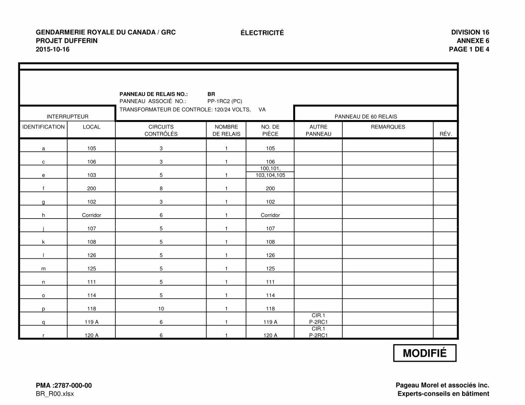
PANNEAU DE RELAIS NO.: BR
PANNEAU ASSOCIÉ NO.: PP-1RC2 (PC)
TRANSFORMATEUR DE CONTROLE: 120/24 VOLTS, VA PANNEAU DE 60 RELAIS
IDENTIFICATION LOCAL CIRCUITS NOMBRE NO. DE AUTRE REMARQUESCONTRÔLÉS DE RELAIS PIÈCE PANNEAU RÉV.
a 105 3 1 105
c 106 3 1 106100,101,
e 103 5 1 103,104,105
f 200 8 1 200
g 102 3 1 102
h Corridor 6 1 Corridor
j 107 5 1 107
INTERRUPTEUR
j 107 5 1 107
k 108 5 1 108
l 126 5 1 126
m 125 5 1 125
n 111 5 1 111
o 114 5 1 114
p 118 10 1 118CIR.1
q 119 A 6 1 119 A P-2RC1CIR.1
r 120 A 6 1 120 A P-2RC1
MODIFIÉ
PMA :2787-000-00
BR_R00.xlsxPageau Morel et associés inc.
Experts-conseils en bâtiment
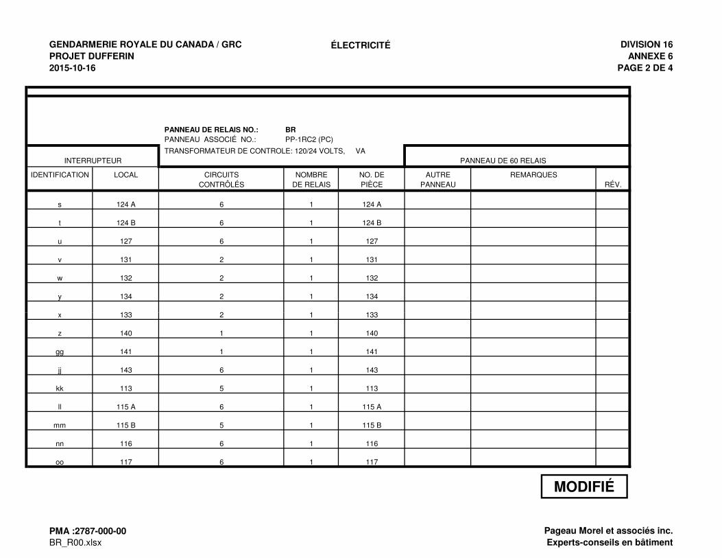
GENDARMERIE ROYALE DU CANADA / GRC
PROJET DUFFERIN
2015-10-16
ÉLECTRICITÉ DIVISION 16
ANNEXE 6
PAGE 2 DE 4
PANNEAU DE RELAIS NO.: BR
PANNEAU ASSOCIÉ NO.: PP-1RC2 (PC)
TRANSFORMATEUR DE CONTROLE: 120/24 VOLTS, VA PANNEAU DE 60 RELAIS
IDENTIFICATION LOCAL CIRCUITS NOMBRE NO. DE AUTRE REMARQUESCONTRÔLÉS DE RELAIS PIÈCE PANNEAU RÉV.
s 124 A 6 1 124 A
t 124 B 6 1 124 B
u 127 6 1 127
v 131 2 1 131
w 132 2 1 132
y 134 2 1 134
x 133 2 1 133
INTERRUPTEUR
x 133 2 1 133
z 140 1 1 140
gg 141 1 1 141
jj 143 6 1 143
kk 113 5 1 113
ll 115 A 6 1 115 A
mm 115 B 5 1 115 B
nn 116 6 1 116
oo 117 6 1 117
MODIFIÉ
PMA :2787-000-00
BR_R00.xlsxPageau Morel et associés inc.
Experts-conseils en bâtiment
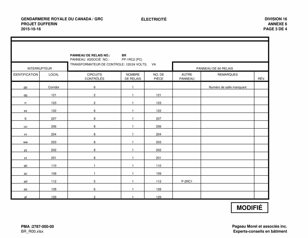
GENDARMERIE ROYALE DU CANADA / GRC
PROJET DUFFERIN
2015-10-16
ÉLECTRICITÉ DIVISION 16
ANNEXE 6
PAGE 3 DE 4
PANNEAU DE RELAIS NO.: BR
PANNEAU ASSOCIÉ NO.: PP-1RC2 (PC)
TRANSFORMATEUR DE CONTROLE: 120/24 VOLTS, VA PANNEAU DE 60 RELAIS
IDENTIFICATION LOCAL CIRCUITS NOMBRE NO. DE AUTRE REMARQUESCONTRÔLÉS DE RELAIS PIÈCE PANNEAU RÉV.
pp Corridor 6 1 Numéro de salle manquant
qq 121 2 1 121
rr 123 2 1 123
ss 122 6 1 122
tt 207 8 1 207
uu 206 8 1 206
vv 204 8 1 204
INTERRUPTEUR
vv 204 8 1 204
ww 203 8 1 203
yy 202 8 1 202
zz 201 8 1 201
ab 110 1 1 110
ac 109 1 1 109
ad 112 5 1 112 P-2RC1
ae 128 6 1 128
af 129 2 1 129
MODIFIÉ
PMA :2787-000-00
BR_R00.xlsxPageau Morel et associés inc.
Experts-conseils en bâtiment
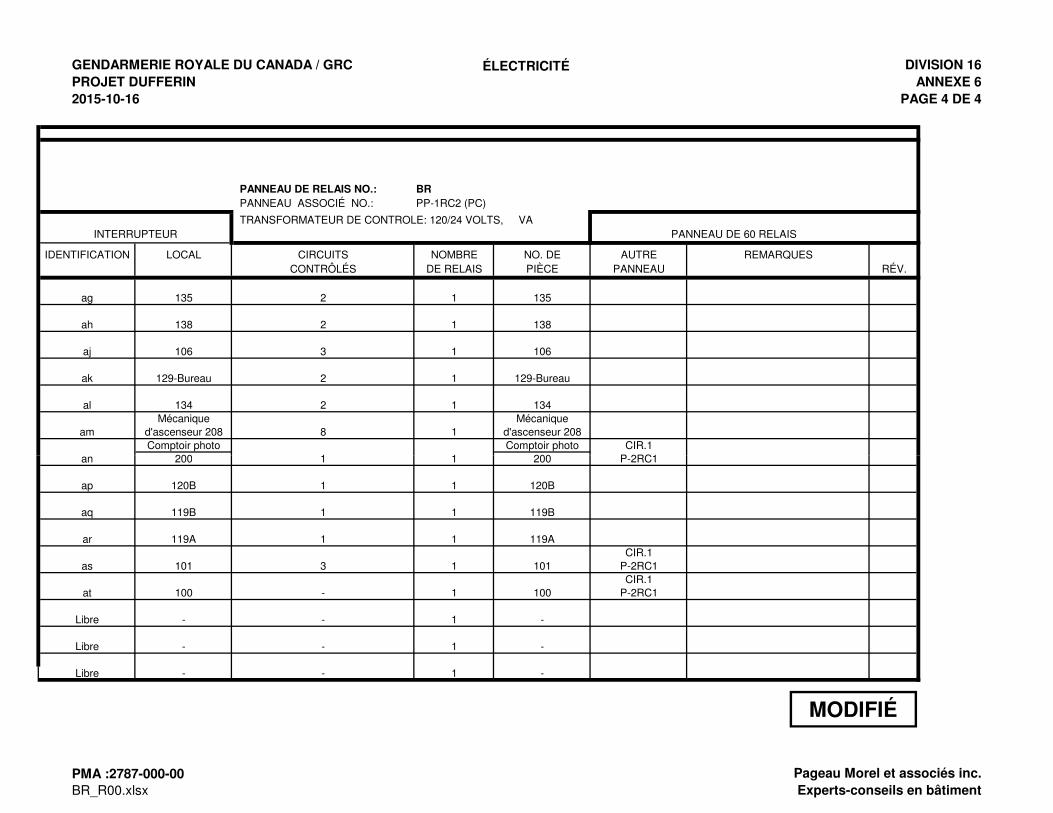
GENDARMERIE ROYALE DU CANADA / GRC
PROJET DUFFERIN
2015-10-16
ÉLECTRICITÉ DIVISION 16
ANNEXE 6
PAGE 4 DE 4
PANNEAU DE RELAIS NO.: BR
PANNEAU ASSOCIÉ NO.: PP-1RC2 (PC)
TRANSFORMATEUR DE CONTROLE: 120/24 VOLTS, VA PANNEAU DE 60 RELAIS
IDENTIFICATION LOCAL CIRCUITS NOMBRE NO. DE AUTRE REMARQUESCONTRÔLÉS DE RELAIS PIÈCE PANNEAU RÉV.
ag 135 2 1 135
ah 138 2 1 138
aj 106 3 1 106
ak 129-Bureau 2 1 129-Bureau
al 134 2 1 134Mécanique Mécanique
am d'ascenseur 208 8 1 d'ascenseur 208Comptoir photo Comptoir photo CIR.1
an 200 1 1 200 P-2RC1
INTERRUPTEUR
an 200 1 1 200 P-2RC1
ap 120B 1 1 120B
aq 119B 1 1 119B
ar 119A 1 1 119ACIR.1
as 101 3 1 101 P-2RC1CIR.1
at 100 - 1 100 P-2RC1
Libre - - 1 -
Libre - - 1 -
Libre - - 1 -
MODIFIÉ
PMA :2787-000-00
BR_R00.xlsxPageau Morel et associés inc.
Experts-conseils en bâtiment
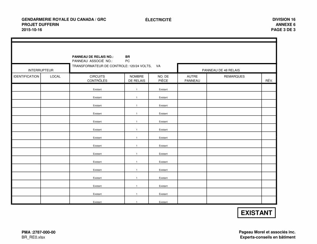
GENDARMERIE ROYALE DU CANADA / GRC
PROJET DUFFERIN
2015-10-16
ÉLECTRICITÉ DIVISION 16
ANNEXE 6
PAGE 3 DE 3
PANNEAU DE RELAIS NO.: BR
PANNEAU ASSOCIÉ NO.: PC
TRANSFORMATEUR DE CONTROLE: 120/24 VOLTS, VA PANNEAU DE 48 RELAIS
IDENTIFICATION LOCAL CIRCUITS NOMBRE NO. DE AUTRE REMARQUESCONTRÔLÉS DE RELAIS PIÈCE PANNEAU RÉV.
Existant 1 Existant
Existant 1 Existant
Existant 1 Existant
Existant 1 Existant
Existant 1 Existant
Existant 1 Existant
Existant 1 Existant
INTERRUPTEUR
Existant 1 Existant
Existant 1 Existant
Existant 1 Existant
Existant 1 Existant
Existant 1 Existant
Existant 1 Existant
Existant 1 Existant
Existant 1 Existant
Existant 1 Existant
EXISTANT
PMA :2787-000-00
BR_RE0.xlsxPageau Morel et associés inc.
Experts-conseils en bâtiment
Government of Canada Section 26 20 00 Dufferin Project Low Voltage Electrical Distribution Project no. 201202310 Page i
2787-000-00 Pageau Morel & Associates Inc. Building Consultants
TABLE OF CONTENTS
PART 1 - GENERAL ............................................................................................................................................... 1
1.1 General ..................................................................................................................................................................... 1 1.2 Scope of Work .......................................................................................................................................................... 1 1.3 Shop Drawings and Technical Data .......................................................................................................................... 1
PART 2 - PRODUCTS ............................................................................................................................................ 2
2.1 Electric Entrance ....................................................................................................................................................... 2 2.2 Metering Cabinet ....................................................................................................................................................... 2 2.3 Grounding and Bonding ............................................................................................................................................ 2 2.4 Dry Type Transformers Up to 600 V ......................................................................................................................... 3 2.5 Starters Up to 600 V ................................................................................................................................................. 4 2.6 Contactors................................................................................................................................................................. 6 2.7 Circuit Breaker Type Distribution Panels .................................................................................................................. 6 2.8 Utilization Panels ...................................................................................................................................................... 7 2.9 Molded Case Circuit Breakers .................................................................................................................................. 7 2.10 Safety Switches ........................................................................................................................................................ 8 2.11 Maintenance switches ............................................................................................................................................... 9 2.12 Fuses ........................................................................................................................................................................ 9 2.13 HID Lighting Contactor ............................................................................................................................................ 10
PART 3 - EXECUTION ......................................................................................................................................... 11
3.1 Service Entrance ..................................................................................................................................................... 11 3.2 Metering Cabinets ................................................................................................................................................... 11 3.3 Earthing and Grounding .......................................................................................................................................... 11 3.4 Dry Type Transformer Up to 600 V ......................................................................................................................... 13 3.5 Starters Up to 600 V ............................................................................................................................................... 13 3.6 Panels ..................................................................................................................................................................... 14 3.7 Molded Case Circuit Breaker .................................................................................................................................. 15 3.8 Safety and Maintenance Switches .......................................................................................................................... 15 3.9 Fuses ...................................................................................................................................................................... 15 3.10 HID Lighting Contactors .......................................................................................................................................... 15
APPENDIX
Electrical Panels
Government of Canada Section 26 20 00 Dufferin Project Low Voltage Electrical Distribution Project no. 201202310 Page 1
2787-000-00 Pageau Morel & Associates Inc. Building Consultants
PART 1 - GENERAL
1.1 General
1.1.1 Section 20 05 00 – "General Requirements Concerning Common Work Results" applies.
1.2 Scope of Work
1.2.1 Works of this section include, but are not limited to: the supply, handling, transportation, set up and installation of all systems and their accessories hereafter mentioned and/or shown on the drawings and which are to be operational. In general, all major parts of the works consist of, but are not limited to:
• Metering cabinets; • Contactors; • Starters; • Distribution and utilization panels; • Safety switches; • Circuit-breaker; • Fuses.
1.3 Shop Drawings and Technical Data
1.3.1 Submit shop drawings and technical data regarding Section 20 05 00 – "General Requirements Concerning Common Work Results".
1.3.2 Submit shop drawing and technical data of the following items:
• Metering cabinets; • Contactors; • Distribution and utilization panels; • Safety switches; • Circuit-breaker; • Fuses.
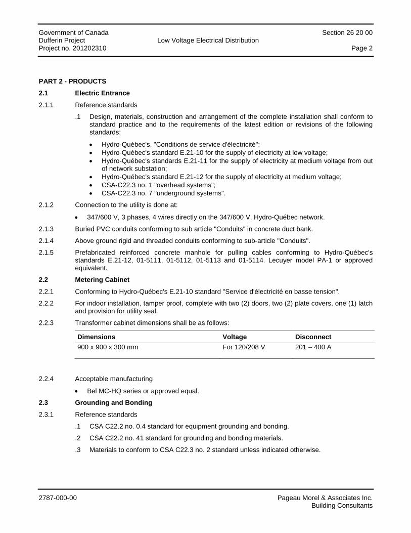
Government of Canada Section 26 20 00 Dufferin Project Low Voltage Electrical Distribution Project no. 201202310 Page 2
2787-000-00 Pageau Morel & Associates Inc. Building Consultants
PART 2 - PRODUCTS
2.1 Electric Entrance
2.1.1 Reference standards
.1 Design, materials, construction and arrangement of the complete installation shall conform to standard practice and to the requirements of the latest edition or revisions of the following standards:
• Hydro-Québec's, "Conditions de service d'électricité"; • Hydro-Québec's standard E.21-10 for the supply of electricity at low voltage; • Hydro-Québec's standards E.21-11 for the supply of electricity at medium voltage from out
of network substation; • Hydro-Québec's standard E.21-12 for the supply of electricity at medium voltage; • CSA-C22.3 no. 1 "overhead systems"; • CSA-C22.3 no. 7 "underground systems".
2.1.2 Connection to the utility is done at:
• 347/600 V, 3 phases, 4 wires directly on the 347/600 V, Hydro-Québec network.
2.1.3 Buried PVC conduits conforming to sub article "Conduits" in concrete duct bank.
2.1.4 Above ground rigid and threaded conduits conforming to sub-article "Conduits".
2.1.5 Prefabricated reinforced concrete manhole for pulling cables conforming to Hydro-Québec's standards E.21-12, 01-5111, 01-5112, 01-5113 and 01-5114. Lecuyer model PA-1 or approved equivalent.
2.2 Metering Cabinet
2.2.1 Conforming to Hydro-Québec's E.21-10 standard "Service d'électricité en basse tension".
2.2.2 For indoor installation, tamper proof, complete with two (2) doors, two (2) plate covers, one (1) latch and provision for utility seal.
2.2.3 Transformer cabinet dimensions shall be as follows:
Dimensions Voltage Disconnect 900 x 900 x 300 mm For 120/208 V 201 – 400 A
2.2.4 Acceptable manufacturing
• Bel MC-HQ series or approved equal.
2.3 Grounding and Bonding
2.3.1 Reference standards
.1 CSA C22.2 no. 0.4 standard for equipment grounding and bonding.
.2 CSA C22.2 no. 41 standard for grounding and bonding materials.
.3 Materials to conform to CSA C22.3 no. 2 standard unless indicated otherwise.
Government of Canada Section 26 20 00 Dufferin Project Low Voltage Electrical Distribution Project no. 201202310 Page 3
2787-000-00 Pageau Morel & Associates Inc. Building Consultants
2.3.2 Copper bus bars
.1 Rectangular cross-section pure copper having a conductivity of 98%.
.2 Sizes as shown
2.3.3 Conductors
.1 Bare; stranded, 98% conductivity copper.
.2 Insulated: type TW75 or RW90.
.3 Size: as shown.
2.3.4 Connectors
.1 Exothermical welds similar to the Cadweld process.
.2 Split bolt type: Burndy series KS Servit or approved equivalent.
.3 Compression type: Burndy Hyground system or approved equivalent.
.4 For elevated floors: Burndy no. GRF4C-3 or approved equivalent.
2.3.5 Unless otherwise noted, EMT may be used for equipment grounding of all branch circuits. A grounding conductor is required for all feeder and motor circuits and for outlets on dedicated circuits.
2.3.6 Tightening torques recommended by the manufacturers or applicable Electrical Code shall be respected for all bolted-on connections.
2.4 Dry Type Transformers Up to 600 V
2.4.1 General
.1 Dry type transformers conforming to CSA C22.2 no. 47 and C9 standards.
.2 Single phase or three phases transformers as shown.
.3 All transformers shall meet the requirements of the C802 standard as per the following criteria's:
• Shall comply with efficiency standards described in CSA C802.2 or EPA "ENERGY STAR"; • The linear efficiency band as per CSA C802 shall be met between 35% to 65% of the
maximum kVA indicated on the transformer name plate.
.4 Equipment protected for installation in sprinkler protected rooms.
2.4.2 Three phases power type transformers above 15 kVA
.1 ANN type.
.2 Class 220 °C insulation with winding temperature rise not exceeding 150 oC.
.3 Copper windings. Three (3) primary windings, delta connected. Three (3) secondary windings, wye connected, with grounded neutral.
.4 Dielectric insulation good for 1.2 kV.
.5 BIL: 10 kV.
.6 With four 2.5% taps: 2 FCAN and 2 FCBN.
.7 NEMA 1 type ventilated enclosure, or as shown, with lifting eyes and front and side removable metallic panels or installed in the service entrance cabinet as shown.
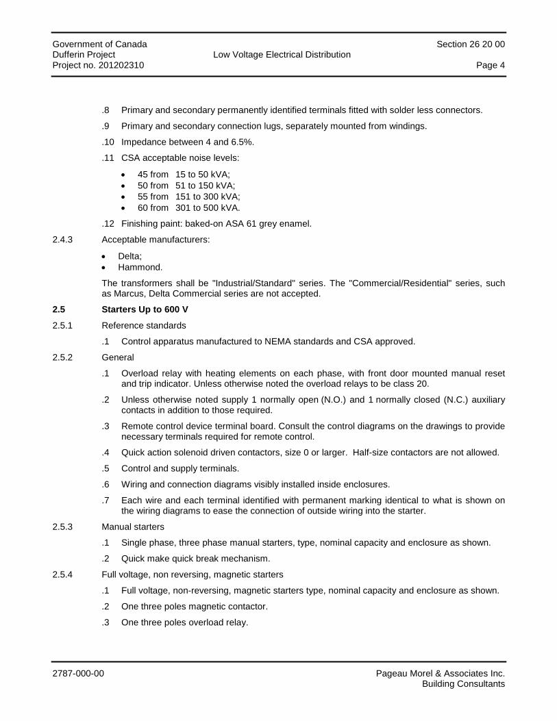
Government of Canada Section 26 20 00 Dufferin Project Low Voltage Electrical Distribution Project no. 201202310 Page 4
2787-000-00 Pageau Morel & Associates Inc. Building Consultants
.8 Primary and secondary permanently identified terminals fitted with solder less connectors.
.9 Primary and secondary connection lugs, separately mounted from windings.
.10 Impedance between 4 and 6.5%.
.11 CSA acceptable noise levels:
• 45 from 15 to 50 kVA; • 50 from 51 to 150 kVA; • 55 from 151 to 300 kVA; • 60 from 301 to 500 kVA.
.12 Finishing paint: baked-on ASA 61 grey enamel.
2.4.3 Acceptable manufacturers:
• Delta; • Hammond.
The transformers shall be "Industrial/Standard" series. The "Commercial/Residential" series, such as Marcus, Delta Commercial series are not accepted.
2.5 Starters Up to 600 V
2.5.1 Reference standards
.1 Control apparatus manufactured to NEMA standards and CSA approved.
2.5.2 General
.1 Overload relay with heating elements on each phase, with front door mounted manual reset and trip indicator. Unless otherwise noted the overload relays to be class 20.
.2 Unless otherwise noted supply 1 normally open (N.O.) and 1 normally closed (N.C.) auxiliary contacts in addition to those required.
.3 Remote control device terminal board. Consult the control diagrams on the drawings to provide necessary terminals required for remote control.
.4 Quick action solenoid driven contactors, size 0 or larger. Half-size contactors are not allowed.
.5 Control and supply terminals.
.6 Wiring and connection diagrams visibly installed inside enclosures.
.7 Each wire and each terminal identified with permanent marking identical to what is shown on the wiring diagrams to ease the connection of outside wiring into the starter.
2.5.3 Manual starters
.1 Single phase, three phase manual starters, type, nominal capacity and enclosure as shown.
.2 Quick make quick break mechanism.
2.5.4 Full voltage, non reversing, magnetic starters
.1 Full voltage, non-reversing, magnetic starters type, nominal capacity and enclosure as shown.
.2 One three poles magnetic contactor.
.3 One three poles overload relay.
Government of Canada Section 26 20 00 Dufferin Project Low Voltage Electrical Distribution Project no. 201202310 Page 5
2787-000-00 Pageau Morel & Associates Inc. Building Consultants
2.5.5 Combination starters
.1 As shown the above mentioned starters shall be of the combination type with circuit breaker lever operated from outside the enclosure and having a device which permits:
• The installation of three padlocks in the "OFF" position; • The unit to be locked in the "ON" position; • To independently lock the enclosure door; • The prevention of operating the starter with the enclosure door open.
.2 The circuit breakers shall conform to article "Molded case circuit breakers"
.3 Fusible disconnects to conform to article "Safety switches"
2.5.6 Pushbuttons
.1 Heavy duty flush mounted black pushbutton with one (1) N.O. contact and one (1) N.F. contact having a 10 A rating complete with escutcheon as shown; red stop-lock pushbutton with lock pushed in position.
.2 In a CSA type 1 enclosure, in a starter enclosure or as shown.
2.5.7 Stop lock pushbutton
.1 Same pushbutton as described previously with possibility to be locked in the pushed in position. The key allows the pushbutton to be reset.
2.5.8 Selectors
.1 In a CSA type 1 enclosure, in a starter enclosure or as shown.
.2 One, two or three position, maintained contact, heavy duty selector switch with standard lever or key barrel operator and 10 A, 120 V a.c. contact arrangement as shown.
2.5.9 Pilot lamps
.1 In a CSA type 1 enclosure, in a starter enclosure or as shown.
.2 Heavy duty transformer type pilot lamps, lens colour as shown, 120 V power supply, lamp voltage compatible with transformer secondary label as shown.
2.5.10 Control transformer
.1 Control transformer conforming to CSA C22.2 no. 66 standard, single phase, dry type, primary voltage as shown with 120V secondary complete with secondary fuse in series with starter coil.
.2 Size transformer according to control circuit loading and add 20% spare capacity.
.3 Tight regulation of output voltage within the range of magnetic coils and excitation solenoids.
2.5.11 Thermistor heat probes
.1 Motors having a nominal capacity of 30 HP and above are fitted with PTC type thermistor heat probes; install a Siemens 3RN1 trip unit, or approved equal, inside the starter enclosure, or outside in a separate enclosure installed near the starter, if the starter enclosure is too small. These thermistor heat probes shall be embedded in the motor winding and shall be supplied with the motor.
Government of Canada Section 26 20 00 Dufferin Project Low Voltage Electrical Distribution Project no. 201202310 Page 6
2787-000-00 Pageau Morel & Associates Inc. Building Consultants
2.5.12 Single phasing protection unit
.1 All motors with a nominal capacity of 10HP and above shall be protected against single phasing with a Controlab model DSP-1L or equivalent device installed inside the starter enclosure.
2.5.13 Material identification
.1 Nameplates supplied and installed according to specifications
2.5.14 Acceptable NEMA manufacturers:
• Cutler-Hammer; • Allen Bradley; • Schneider (Square D); • Siemens.
2.6 Contactors
2.6.1 Contactors conforming to CSA C22.2 no. 14.
2.6.2 Mechanically held contactors, electrically operated by control devices, as indicated.
2.6.3 Contactors designed for the type of load they are controlling.
2.6.4 Contractors with two N.O. auxiliary contacts and two N.C. auxiliary contacts, except otherwise noted.
2.6.5 Contactors installed in a NEMA 1 enclosure except otherwise noted.
2.6.6 Selectors, pilot lights and accessories as per article "Starters up to 600 V".
2.6.7 Minimum control transformer size according to control circuit load plus 20% space capacity.
2.6.8 Acceptable manufacturers:
• Cutler-Hammer; • Allen Bradley; • Schneider (Square D); • Siemens.
2.7 Circuit Breaker Type Distribution Panels
2.7.1 Distribution panels conforming to CSA C22.2 no. 29 standard.
2.7.2 Supplied by the same and only manufacturer.
2.7.3 Voltage 120/208 V and 347/600 V.
2.7.4 Arrange bus bars per phase order. All circuits shall be identified by a letter, as shown on drawings.
2.7.5 Panels shall have bus bars, and number of branch circuits and circuit breakers as shown.
2.7.6 Bus bars shall be copper, with full capacity neutral.
2.7.7 For surface or flush mounting as shown on drawings.
2.7.8 Panel bus bars to be compatible with bolted-on circuit breakers.
2.7.9 Standard finish: ASA 61 grey baked enamel.
2.7.10 Circuit breakers: conforming to article "Molded case circuit breakers".
Government of Canada Section 26 20 00 Dufferin Project Low Voltage Electrical Distribution Project no. 201202310 Page 7
2787-000-00 Pageau Morel & Associates Inc. Building Consultants
2.7.11 Acceptable manufacturers:
• Bolted-on circuit breaker panels: Cutler-Hammer, model PRL4; Equal from Siemens.
• Plug-on circuit breaker panels: Cutler-Hammer, model PRL5P; Schneider (Square D), model I-Line; Equal from Siemens.
2.8 Utilization Panels
2.8.1 Utilization panels conforming to CSA C22.2 no. 29 standard.
2.8.2 Supplied by the same and only manufacturer.
2.8.3 Voltage 120/208 V and 347/600 V.
2.8.4 Arrange bus bars so that odd numbered circuit breakers be on the left and even numbered circuit breaker be on the right of the panel. Each circuit shall be identified.
2.8.5 Panels to have bus bars sizes, number and capacity of branch circuit's breakers as shown.
2.8.6 Panels shall be complete with door, lock and two keys each.
2.8.7 Bus bars to be copper with full capacity neutral.
2.8.8 Branch circuit bars to be compatible with bolted-on circuit breaker.
2.8.9 Standard finish ASA 61, grey.
2.8.10 Acceptable manufacturers:
• For voltages up to 240 V: Cutler-Hammer, model PRL1a; Schneider (Square D), model NQ; Equal from Siemens.
• For voltages up to 600 V: Cutler-Hammer, model PRL2a; Schneider (Square D), model NF; Equal from Siemens.
2.9 Molded Case Circuit Breakers
2.9.1 Molded case circuit breakers conforming to CSA C22.2 no. 5 standard.
2.9.2 Circuit protection devices contained in plastic insulated enclosures.
2.9.3 Bolted to the panel bus bars.
2.9.4 Quick make quick break mechanism.
2.9.5 Manually operated.
2.9.6 Complete with thermal and magnetic trip unit compensated for an ambient temperature of 40oC (104oF).
2.9.7 Multipole breakers to have a common trip device and operating lever.
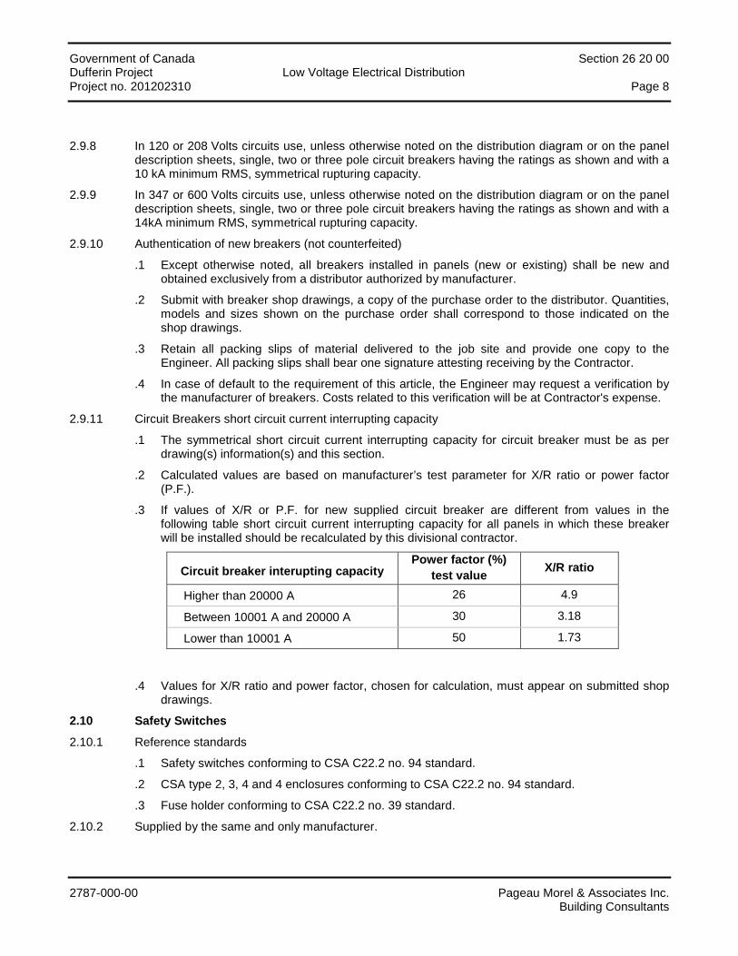
Government of Canada Section 26 20 00 Dufferin Project Low Voltage Electrical Distribution Project no. 201202310 Page 8
2787-000-00 Pageau Morel & Associates Inc. Building Consultants
2.9.8 In 120 or 208 Volts circuits use, unless otherwise noted on the distribution diagram or on the panel description sheets, single, two or three pole circuit breakers having the ratings as shown and with a 10 kA minimum RMS, symmetrical rupturing capacity.
2.9.9 In 347 or 600 Volts circuits use, unless otherwise noted on the distribution diagram or on the panel description sheets, single, two or three pole circuit breakers having the ratings as shown and with a 14kA minimum RMS, symmetrical rupturing capacity.
2.9.10 Authentication of new breakers (not counterfeited)
.1 Except otherwise noted, all breakers installed in panels (new or existing) shall be new and obtained exclusively from a distributor authorized by manufacturer.
.2 Submit with breaker shop drawings, a copy of the purchase order to the distributor. Quantities, models and sizes shown on the purchase order shall correspond to those indicated on the shop drawings.
.3 Retain all packing slips of material delivered to the job site and provide one copy to the Engineer. All packing slips shall bear one signature attesting receiving by the Contractor.
.4 In case of default to the requirement of this article, the Engineer may request a verification by the manufacturer of breakers. Costs related to this verification will be at Contractor's expense.
2.9.11 Circuit Breakers short circuit current interrupting capacity
.1 The symmetrical short circuit current interrupting capacity for circuit breaker must be as per drawing(s) information(s) and this section.
.2 Calculated values are based on manufacturer’s test parameter for X/R ratio or power factor (P.F.).
.3 If values of X/R or P.F. for new supplied circuit breaker are different from values in the following table short circuit current interrupting capacity for all panels in which these breaker will be installed should be recalculated by this divisional contractor.
Circuit breaker interupting capacity Power factor (%)
test value X/R ratio
Higher than 20000 A 26 4.9
Between 10001 A and 20000 A 30 3.18
Lower than 10001 A 50 1.73
.4 Values for X/R ratio and power factor, chosen for calculation, must appear on submitted shop drawings.
2.10 Safety Switches
2.10.1 Reference standards
.1 Safety switches conforming to CSA C22.2 no. 94 standard.
.2 CSA type 2, 3, 4 and 4 enclosures conforming to CSA C22.2 no. 94 standard.
.3 Fuse holder conforming to CSA C22.2 no. 39 standard.
2.10.2 Supplied by the same and only manufacturer.
Government of Canada Section 26 20 00 Dufferin Project Low Voltage Electrical Distribution Project no. 201202310 Page 9
2787-000-00 Pageau Morel & Associates Inc. Building Consultants
2.10.3 With or without fuse in a type CSA 1 metallic enclosure for indoor installation and type 3 enclosure for outdoor or wet installations.
2.10.4 Complete with facility to lock the lever in the "closed" or "open" position with three padlocks.
2.10.5 Mechanically latched door with preventing its opening when the switch is closed (screw driver defeatable mechanism).
2.10.6 Each switch fuse holder to be appropriate for the type of fuse specified and shown without the use of adapters.
2.10.7 Quick make, quick break mechanism.
2.10.8 Heavy duty construction
2.10.9 Safety switches for elevator controllers shall be fitted with one type C auxiliary contact. Connect this contact to the elevator controller with two (2) # 14 AWG conductor inside a 16 mm (½") conduit.
2.10.10 Standard ASA 61 grey baked enamel finish.
2.10.11 Acceptable manufacturers:
• Cutler-Hammer; • Schneider (Square D); • Siemens.
2.11 Maintenance switches
2.11.1 Reference standards
.1 Safety switches conforming to CSA C22.2 n°94.
.2 CSA type 2, 3, 4 and 4 enclosures conforming to CSA
2.11.2 Supplied by the same and only manufacturer.
2.11.3 Without fuse in a NEMA type 4X non-metallic enclosure.
2.11.4 Complete with facility to lock the lever in the "closed" or "open" position with three (3) padlocks.
2.11.5 "Closed" position would not be possible to engage if the door is open.
2.11.6 With quick make, quick break mechanism.
2.11.7 Heavy duty construction.
2.11.8 Acceptable maufacturers :
• Hubbell, HBLDS series; • Pass & Seymour, PS series; • Leviton, DS series.
2.12 Fuses
2.12.1 Fuses conforming to CSA C22.2 no. 106 and C22.2 no. 248 standards.
2.12.2 High rupturing capacity (HRC) fuses 200kA RMS symmetrical and current limiting fuses.
2.12.3 Spare parts
.1 Supply three (3) fuses of each size and of each type specified.
2.12.4 Supplied by the same and only manufacturer
Government of Canada Section 26 20 00 Dufferin Project Low Voltage Electrical Distribution Project no. 201202310 Page 10
2787-000-00 Pageau Morel & Associates Inc. Building Consultants
2.12.5 Fuse types
.1 Motor and transformer circuits,
• Class J form I, double element, time delayed; • Acceptable manufacturers:
Cooper Bussmann, LPJ type; Or equal from Ferraz Shawmut/Mersen, Littelfuse.
.2 For other circuits
• 0 to 600 A; class J, form I, quick action; • 601 to 2000 A; class L, form I, quick action. • Acceptable manufacturers:
Cooper Bussmann (JKS and KRP); Or equal from Ferraz Shawmut/Mersen, Littelfuse.
2.12.6 Fuses size shown on the drawings is as per the applicable Electrical Code. Fuses are chosen for normal industrial service. Contractor shall use the size recommended by the fuses manufacturer for the type of connected load under normal industrial service and also supply appropriate switches and fuse holders.
2.12.7 Supply an aluminium fuse storage cabinet having a height of 761 mm (30"), a width of 609 mm (24") and a depth of 305 mm (12"). The cabinet shall be complete with three shelves, a front mounted door on hinges with lock. The unit shall have an ASA 61 grey baked enamel finish.
2.13 HID Lighting Contactor
2.13.1 Contactor conforming to CSA C22.2 no. 14 standard.
2.13.2 Mechanically latched, electrically operated as shown.
2.13.3 Specially designed contactors capable of handling the high pressure sodium lamps high inrush current without welding of the contacts, rating as shown.
2.13.4 Contactors to be complete with two (2) N.O. and (2) N.C. auxiliary contacts unless otherwise noted.
2.13.5 Install contactors in a CEMA 1 type enclosure, unless otherwise noted.
2.13.6 The contactor enclosure cover shall be complete with a normal-off-automatic selector switch.
2.13.7 Control transformer as shown installed in the contactor enclosure.
2.13.8 Acceptable manufacturers:
• Cutler-Hammer; • Schneider (Square D); • Siemens; • Allen Bradley.
Government of Canada Section 26 20 00 Dufferin Project Low Voltage Electrical Distribution Project no. 201202310 Page 11
2787-000-00 Pageau Morel & Associates Inc. Building Consultants
PART 3 - EXECUTION
3.1 Service Entrance
3.1.1 Execute the work as shown on the drawings and according to utility standards.
3.1.2 Install underground conduits, underground to overhead laterals and execute mandrel tests according to article "conduits" and to Hydro-Québec standards E.21-11 and E.21.12.
3.1.3 Install prefab concrete manhole for cable pulling and ground according to Hydro-Québec standards E.21-11 and E.21-12.
3.1.4 Install equipment and accessories; make the connections and grounds in the annex room according to Hydro-Québec standard E.21-11.
3.2 Metering Cabinets
3.2.1 Install metering cabinets according to requirements of the utility and as shown on the drawings.
3.3 Earthing and Grounding
3.3.1 General
.1 Install a complete, permanent and continuous system for earthling and grounding of networks, circuits and apparatus. The system shall include electrodes, conductor, connectors and required accessories on drawings to satisfy local authorities.
.2 Install connectors according to manufacturer's recommendations.
.3 Protect surface mounted conductors from damage.
.4 Underground connections and connections to steel structures, ground electrodes and conductive water pipes shall be exothermically welded.
.5 Use mechanical connectors on equipment supplied with grounding terminals.
.6 Use tinned copper conductors on aluminium structures.
.7 Do not install bare copper conductors near lead sheathed cables, which have no insulating jacket.
.8 Soldered connections are not allowed.
.9 Provide a jumper ground cable connected to one end of a flexible conduit link with a ground lug, a solder less terminal, a cable clamp or a screw with Belleville washer.
.10 Install braided links at bus duct joints when the connection is not insured by the material proper.
.11 Install dedicated grounding conductors to connect outdoor lighting, outlet receptacle and lighting systems shown on drawings and the electric sign.
.12 Ground the building steel structure and metallic covering, welding the copper to the steel, as shown.
.13 Makes ground connections in a radial mode only, the connections terminating at one and only one grounding point with copper rod. Avoid loop connections.
.14 Connect the source end of the single conductor cable shield to the source cabinet and provide a non metallic entrance plate at the load end.
.15 Ground secondary distribution cabinets.
Government of Canada Section 26 20 00 Dufferin Project Low Voltage Electrical Distribution Project no. 201202310 Page 12
2787-000-00 Pageau Morel & Associates Inc. Building Consultants
.16 Insure that the grounding method is uniform throughout the installation.
.17 Ground each flag pole with no. 3/0 AWG bare copper conductor.
3.3.2 Electrodes
.1 Install rods used as grounding electrodes and execute connections as shown.
.2 Connect together all independent electrodes.
.3 Use size according to table 17 of the applicable Electrical Code copper conductors to connect electrodes.
.4 Take necessary steps in sandy or rocky terrain to obtain an acceptable ground resistance. Connect as shown.
3.3.3 Neutral Grounding
.1 Make sure that the circuit neutral and the voltage transformer neutrals together with the utility connection neutral are directly connected to the power transformer neutral and are not connected to the main grounding terminal of the substation.
.2 Connect grounding electrodes to neutral conductors for each grounding installation.
.3 Connect the neutral of the substation transformer to the neutral bus bar using a conductor of the same size as the transformer secondary neutral.
3.3.4 Grounding of cable sheaths and cable trays
.1 Ground the source end only of single conductor metallic sheathed cables. Use insulated cable sleeves to interrupt cable sheath continuity at the load end.
.2 Use flexible no. 6 AWG copper wire solidly soldered to the cable sheath. Cable clamp connectors are not allowed.
.3 Connect all conductors together to a grounding lug using a no. 2/0 AWG copper conductor.
.4 Install an insulated grounding conductor on cable trays and ground at 15m (50') intervals along the path.
3.3.5 Low voltage service entrance
.1 Connect the building distribution circuits neutral to the neutral of the low voltage service entrance and connect the utility network grounding conductor to the metering and service entrance cabinets
3.3.6 High or medium voltage service entrance
.1 Connect the building distribution grounding conductor to the utility's medium voltage grounding conductor, which is also the concentric neutral on medium voltage supply cables.
3.3.7 Equipment grounding
.1 Execute overall equipment grounding as shown namely; service connection equipment, transformers, switchgear, conduits, motor frames, motor control centers, starters, control panels, steel structure, generators, alternators, elevators and escalators, distribution panels, exterior lighting networks, traveling cranes, cranes, hoists, ventilation systems, conveyors, combustible lines and others.
Government of Canada Section 26 20 00 Dufferin Project Low Voltage Electrical Distribution Project no. 201202310 Page 13
2787-000-00 Pageau Morel & Associates Inc. Building Consultants
3.3.8 Grounding bus bars
.1 Mount copper bus bars on insulating supports anchored to the electrical room walls.
.2 Connect non electrified elements of equipment installed in the electrical room to the grounding bus bar with individual bare stranded copper conductors as shown.
3.3.9 Communication systems
.1 Ground the telephone, sound, fire alarm and intercom systems as described below.
• Telephone: ground the system according to the requirements of the telephone company. • Sound, fire alarm and intercom systems: as shown.
3.3.10 Tests
.1 Execute tests according to the General Conditions of Section 20 05 02.
.2 Check continuity and measure the grounding network resistance using appropriate methods to the site conditions and to the satisfaction of the Engineer and local competent authorities.
.3 Execute the tests before energizing the electrical equipment.
.4 Disconnect the ground fault indicators during the tests.
3.4 Dry Type Transformer Up to 600 V
3.4.1 Install dry type transformers according to supplied indications.
3.4.2 Install transformers level, upright on "TICO" pads.
3.4.3 Remove shipping blocks after physical installation and just before energizing.
3.4.4 Loosen all insulating pads until there is no compression left on them.
3.4.5 Make only those connections shown on wiring diagram.
3.4.6 Energize transformers, if possible, immediately after the installation work is finished.
3.4.7 Provide a flexible connection on the primary and secondary side of each transformer using flexible conduits. A grounding conductor shall be installed in each flexible connection.
3.4.8 Perform the mechanical grounding of the transformer.
3.5 Starters Up to 600 V
3.5.1 Install starters as shown on the drawings.
3.5.2 Install individual starters on Unistrut type support in order to maintain a spacing around the enclosures when wall mounted. When installed on a free standing structure the supports shall be reinforced with cross members.
3.5.3 Insure that fuses and overload relays are of the appropriate size.
3.5.4 Install control devices and execute interconnections as shown.
3.5.5 Execute on site power and control connections as shown.
3.5.6 Execute interconnections with the fire alarm system.
3.5.7 Perform tests according to the requirements of this specification and of the manufacturer.
3.5.8 Operate switches and contactors to insure their proper operation.
3.5.9 Verify starting and stopping sequences for contactor and relay.

Government of Canada Section 26 20 00 Dufferin Project Low Voltage Electrical Distribution Project no. 201202310 Page 14
2787-000-00 Pageau Morel & Associates Inc. Building Consultants
3.5.10 Insure that sequential controls, safety closures between adjacent starters, material and control devices operate according to specifications.
3.5.11 Variable Frequency drives up to 25 HP.
.1 Provide manufacturer trained representative for startup assistance in coordination with the motor supplier and the external control's supplier.
.2 Execute first parameter adjustments and provide demonstration of programming and set up instructions to the Owner.
3.6 Panels
3.6.1 Install panels where shown and fasten them solidly, plumb and square with adjacent surfaces.
3.6.2 Install surface mounted panels on plywood. Panels to be grouped on common plywood as much as possible.
3.6.3 Connect all circuits to respective loads as shown.
3.6.4 Connect each neutral conductor to the neutral bus bar, each neutral conductor being appropriately identified.
3.6.5 When distribution panels are installed side by side, the enclosures shall be of the same size and welded together. Doors shall have the same size, be perfectly aligned and mounted on separate covers.
3.6.6 For each recessed panel, in addition to the conduits required for the project install four (4) 27 mm (1") conduits between the panels and suspended ceiling. Conduits to terminate in a 450 mm x 450 mm x 125 mm (18" x 18" x 6") box in the ceiling or in a surface mounted box when on an apparent slab.
3.6.7 The following circuit breakers shall be complete with locking devices to restrict their use to authorized personnel only:
.1 Emergency lighting and "EXIT" lights circuits.
.2 Electric generator set heater.
.3 Fire alarm panel.
.4 Door surveillance panel.
.5 Heating cables.
.6 Electric generator set control circuits.
.7 Electric generator set fuel pump.
.8 Camera system and access control system.
.9 Electric generator set battery charger.
.10 Annunciator and control panel.
.11 Carbon monoxide detection system.
.12 Energy management and control system.
.13 Access control system.
Government of Canada Section 26 20 00 Dufferin Project Low Voltage Electrical Distribution Project no. 201202310 Page 15
2787-000-00 Pageau Morel & Associates Inc. Building Consultants
3.7 Molded Case Circuit Breaker
3.7.1 Install circuit breakers and connect as shown.
3.7.2 When a panel is replaced with a new one, the contractor shall verify the compatibility of the existing breakers with the new panel type. New breakers shall be supplied if the existing breakers are not compatible with the new panel and cannot be relocated.
3.8 Safety and Maintenance Switches
3.8.1 Install and connect safety switches including fuses as shown.
3.8.2 Install on each fused safety switch a lamicoid plastic nameplate indicating the size of the fuses installed.
3.9 Fuses
3.9.1 Install fuses in fuse holders just before energizing.
3.9.2 Insure that fuses and holders are perfectly matched.
3.9.3 Insure that the right fuse is used to protect the corresponding circuit.
3.9.4 Store the spare fuses in an orderly manner.
3.10 HID Lighting Contactors
3.10.1 Install lighting contactor enclosures as shown.
3.10.2 Demonstrate the operation of the contactors.
END OF SECTION
Government of Canada Section 26 20 00 Dufferin Project Low Voltage Electrical Distribution Project no. 201202310
2787-000-00 Pageau Morel & Associates Inc. Building Consultants
APPENDIX
Electrical Panels
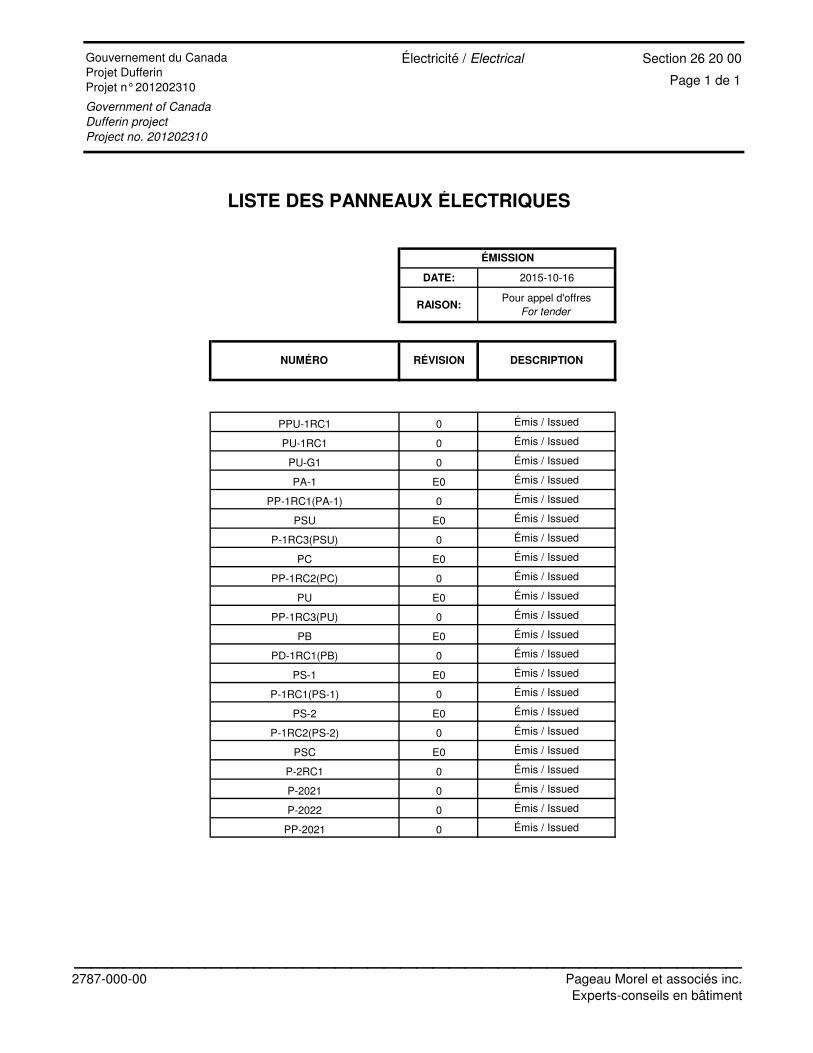
Page 1 de 1Électricité
Section 26 20 00
LISTE DES PANNEAUX ÉLECTRIQUES
DATE: 2015-10-16
RAISON:Pour appel d'offres
For tender
PPU-1RC1 0 Émis / Issued
PU-1RC1 0 Émis / Issued
PU-G1 0 Émis / Issued
PA-1 E0 Émis / Issued
PP-1RC1(PA-1) 0 Émis / Issued
PSU E0 Émis / Issued
P-1RC3(PSU) 0 Émis / Issued
PC E0 Émis / Issued
PP-1RC2(PC) 0 Émis / Issued
PU E0 Émis / Issued
PP-1RC3(PU) 0 Émis / Issued
PB E0 Émis / Issued
PD-1RC1(PB) 0 Émis / Issued
PS-1 E0 Émis / Issued
P-1RC1(PS-1) 0 Émis / Issued
PS-2 E0 Émis / Issued
P-1RC2(PS-2) 0 Émis / Issued
PSC E0 Émis / Issued
P-2RC1 0 Émis / Issued
P-2021 0 Émis / Issued
P-2022 0 Émis / Issued
PP-2021 0 Émis / Issued
ÉMISSION
NUMÉRO RÉVISION DESCRIPTION
Gouvernement du Canada Projet DufferinProjet n° 201202310
Électricité / Electrical
Government of Canada
Dufferin project
Project no. 201202310
2787-000-00
_________________________________________Pageau Morel et associés inc.Experts-conseils en bâtiment
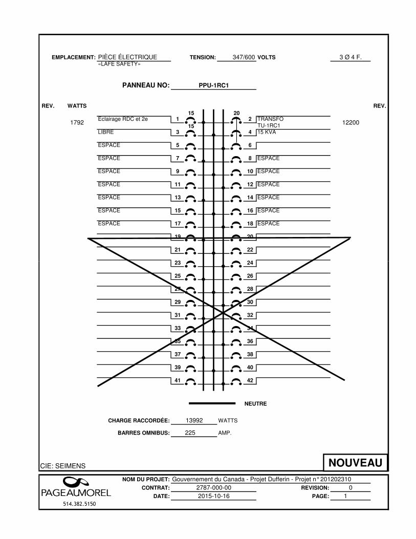
EMPLACEMENT: PIÈCE ÉLECTRIQUE 347/600 VOLTS 3 Ø 4 F.«LAFE SAFETY»
PANNEAU NO:
REV. WATTS REV.
15 20Éclairage RDC et 2e 1 2 TRANSFO
15 TU-1RC1LIBRE 3 4 15 KVA
ESPACE 5 6
ESPACE 7 8 ESPACE
ESPACE 9 10 ESPACE
ESPACE 11 12 ESPACE
ESPACE 13 14 ESPACE
ESPACE 15 16 ESPACE
ESPACE 17 18 ESPACE
19 20
21 22
23 24
TENSION:
PPU-1RC1
122001792
23 24
25 26
27 28
29 30
31 32
33 34
35 36
37 38
39 40
41 42
CHARGE RACCORDÉE:
BARRES OMNIBUS: 225
CIE: SEIMENS
NOM DU PROJET: Gouvernement du Canada - Projet Dufferin - Projet n° 201202310CONTRAT: REVISION: 0
DATE: PAGE: 1514.382.5150
NEUTRE
2787-000-002015-10-16
WATTS
AMP.
13992
NOUVEAU

EMPLACEMENT: PIÈCE ÉLECTRIQUE 120/208 VOLTS 3 Ø 4 F.
PANNEAU NO:
REV. WATTS WATTS REV.
15 50TCAI 1 2 SERVICES 15 GÉNÉRATRICETCAI 3 4 P-G1
15 LIBRE 5 6
ESPACE 7 8 ESPACE ESPACE 9 10 ESPACE ESPACE 11 12 ESPACE
13 14
15 16
17 18
1519 20
15 1521 22
15 1523 24
500
500
TENSION:
PU-1RC1
11200
23 24
15 1525 26
15 1527 28
15 1529 30
15 1531 32
15 1533 34
1535 36
37 38
39 40
41 42
CHARGE RACCORDÉE:
BARRES OMNIBUS: 225
CIE: SEIMENS
NOM DU PROJET: Gouvernement du Canada - Projet Dufferin - Projet n° 201202310CONTRAT: REVISION: 0
DATE: PAGE: 1514.382.5150
12200
NEUTRE
2787-000-002015-10-16
WATTS
AMP.
MODIFIÉ
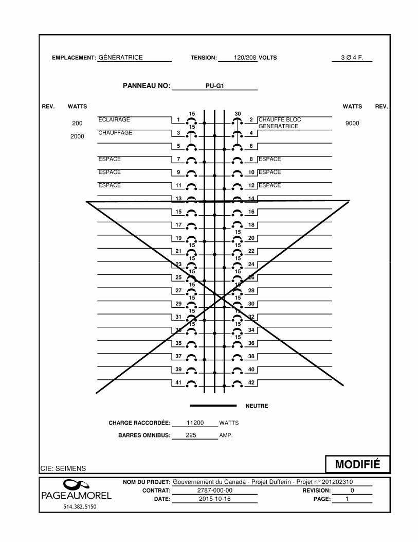
EMPLACEMENT: GÉNÉRATRICE 120/208 VOLTS 3 Ø 4 F.
PANNEAU NO:
REV. WATTS WATTS REV.
15 30ÉCLAIRAGE 1 2 CHAUFFE BLOC 15 GÉNÉRATRICECHAUFFAGE 3 4
5 6
ESPACE 7 8 ESPACE ESPACE 9 10 ESPACE ESPACE 11 12 ESPACE
13 14
15 16
17 18
1519 20
15 1521 22
15 1523 24
200
2000
TENSION:
PU-G1
9000
23 24
15 1525 26
15 1527 28
15 1529 30
15 1531 32
15 1533 34
1535 36
37 38
39 40
41 42
CHARGE RACCORDÉE:
BARRES OMNIBUS: 225
CIE: SEIMENS
NOM DU PROJET: Gouvernement du Canada - Projet Dufferin - Projet n° 201202310CONTRAT: REVISION: 0
DATE: PAGE: 1514.382.5150
11200
NEUTRE
2787-000-002015-10-16
WATTS
AMP.
MODIFIÉ
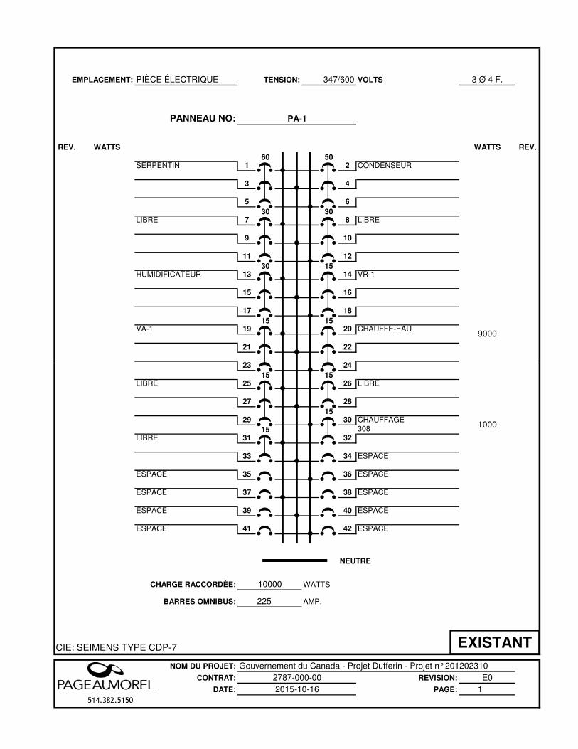
EMPLACEMENT: PIÈCE ÉLECTRIQUE 347/600 VOLTS 3 Ø 4 F.
PANNEAU NO:
REV. WATTS WATTS REV.
60 50SERPENTIN 1 2 CONDENSEUR
3 4
5 6
30 30LIBRE 7 8 LIBRE
9 10
11 12
30 15HUMIDIFICATEUR 13 14 VR-1
15 16
17 18
15 15VA-1 19 20 CHAUFFE-EAU
21 22
23 24
TENSION:
PA-1
9000
23 24
15 15LIBRE 25 26 LIBRE
27 28
1529 30 CHAUFFAGE
15 308LIBRE 31 32
33 34 ESPACE
ESPACE 35 36 ESPACE
ESPACE 37 38 ESPACE
ESPACE 39 40 ESPACE
ESPACE 41 42 ESPACE
CHARGE RACCORDÉE:
BARRES OMNIBUS: 225
CIE: SEIMENS TYPE CDP-7
NOM DU PROJET: Gouvernement du Canada - Projet Dufferin - Projet n° 201202310CONTRAT: REVISION: E0
DATE: PAGE: 1514.382.5150
NEUTRE
2787-000-002015-10-16
WATTS
AMP.
1000
10000
EXISTANT
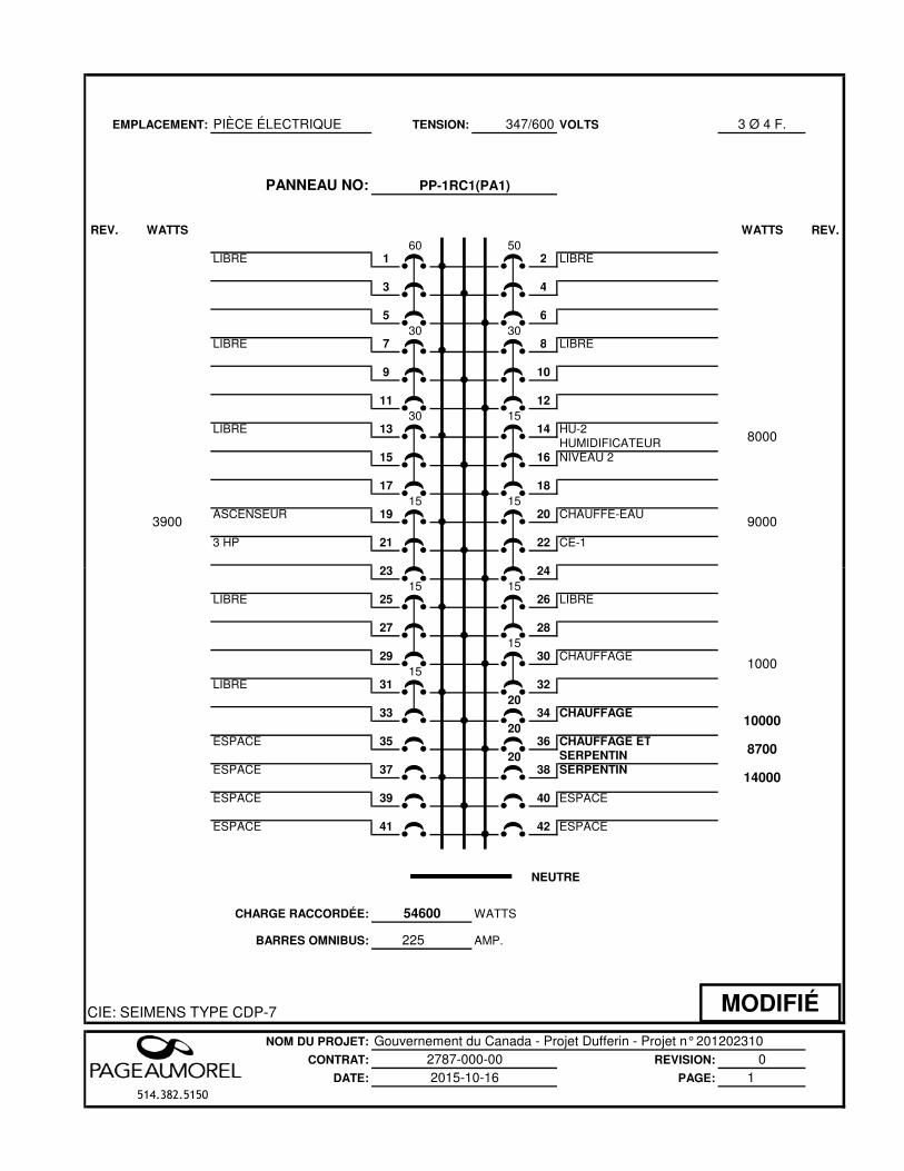
EMPLACEMENT: PIÈCE ÉLECTRIQUE 347/600 VOLTS 3 Ø 4 F.
PANNEAU NO:
REV. WATTS WATTS REV.
60 50LIBRE 1 2 LIBRE
3 4
5 6
30 30LIBRE 7 8 LIBRE
9 10
11 12
30 15LIBRE 13 14 HU-2
HUMIDIFICATEUR15 16 NIVEAU 2
17 18
15 15ASCENSEUR 19 20 CHAUFFE-EAU
3 HP 21 22 CE-1
23 24
TENSION:
PP-1RC1(PA1)
8000
90003900
23 24
15 15LIBRE 25 26 LIBRE
27 28
1529 30 CHAUFFAGE
15LIBRE 31 32
2033 34 CHAUFFAGE
20ESPACE 35 36 CHAUFFAGE ET
20 SERPENTINESPACE 37 38 SERPENTIN
ESPACE 39 40 ESPACE
ESPACE 41 42 ESPACE
CHARGE RACCORDÉE:
BARRES OMNIBUS: 225
CIE: SEIMENS TYPE CDP-7
NOM DU PROJET: Gouvernement du Canada - Projet Dufferin - Projet n° 201202310CONTRAT: REVISION: 0
DATE: PAGE: 1514.382.5150
10000
NEUTRE
2787-000-002015-10-16
WATTS
AMP.
1000
8700
14000
54600
MODIFIÉ
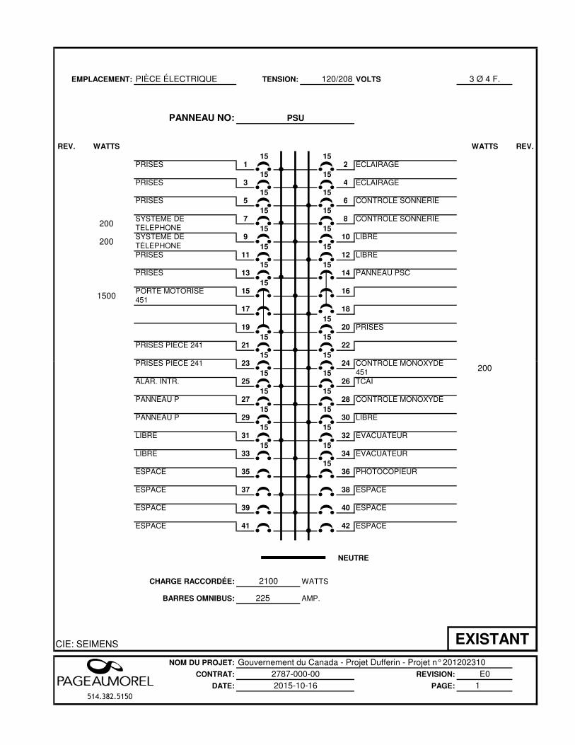
EMPLACEMENT: PIÈCE ÉLECTRIQUE 120/208 VOLTS 3 Ø 4 F.
PANNEAU NO:
REV. WATTS WATTS REV.
15 15PRISES 1 2 ÉCLAIRAGE
15 15PRISES 3 4 ÉCLAIRAGE
15 15PRISES 5 6 CONTRÔLE SONNERIE
15 15SYSTÈME DE 7 8 CONTRÔLE SONNERIETÉLÉPHONE 15 15SYSTÈME DE 9 10 LIBRETÉLÉPHONE 15 15PRISES 11 12 LIBRE
15 15PRISES 13 14 PANNEAU PSC
15PORTE MOTORISE 15 16451
17 18
1519 20 PRISES
15 15PRISES PIECE 241 21 22
15 15PRISES PIECE 241 23 24 CONTRÔLE MONOXYDE
TENSION:
PSU
200
1500
200
PRISES PIECE 241 23 24 CONTRÔLE MONOXYDE15 15 451
ALAR. INTR. 25 26 TCAI15 15
PANNEAU P 27 28 CONTRÔLE MONOXYDE15 15
PANNEAU P 29 30 LIBRE15 15
LIBRE 31 32 ÉVACUATEUR15 15
LIBRE 33 34 ÉVACUATEUR 15
ESPACE 35 36 PHOTOCOPIEUR
ESPACE 37 38 ESPACE
ESPACE 39 40 ESPACE
ESPACE 41 42 ESPACE
CHARGE RACCORDÉE:
BARRES OMNIBUS: 225
CIE: SEIMENS
NOM DU PROJET: Gouvernement du Canada - Projet Dufferin - Projet n° 201202310CONTRAT: REVISION: E0
DATE: PAGE: 1514.382.5150
NEUTRE
2787-000-002015-10-16
WATTS
AMP.
200
2100
EXISTANT
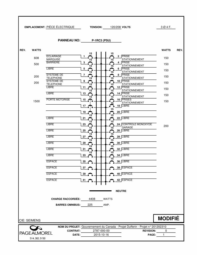
EMPLACEMENT: PIÈCE ÉLECTRIQUE 120/208 VOLTS 3 Ø 4 F.
PANNEAU NO:
REV. WATTS WATTS REV.
15 15ÉCLAIRAGE 1 2 PRISEMARQUISE 15 15 STATIONNEMENTBARRIÈRE 3 4 PRISE
15 15 STATIONNEMENTLIBRE 5 6 PRISE
15 15 STATIONNEMENTSYSTÈME DE 7 8 PRISETÉLÉPHONE 15 15 STATIONNEMENTSYSTÈME DE 9 10 PRISETÉLÉPHONE 15 15 STATIONNEMENTLIBRE 11 12 PRISE
15 15 STATIONNEMENTLIBRE 13 14 PRISE
15 15 STATIONNEMENTPORTE MOTORISE 15 16 PRISES
15 STATIONNEMENT17 18 LIBRE
1519 20 LIBRE
15 15LIBRE 21 22 LIBRE
15 15LIBRE 23 24 CONTRÔLE MONOXYDE
200
1500
200
608
500
150
150
150
150
150
150
TENSION:
P-1RC3 (PSU)
150
150
LIBRE 23 24 CONTRÔLE MONOXYDE15 15 GARAGE
LIBRE 25 26 LIBRE15 15
LIBRE 27 28 LIBRE15 15
LIBRE 29 30 LIBRE15 15
LIBRE 31 32 LIBRE15 15
LIBRE 33 34 LIBRE 15
ESPACE 35 36 LIBRE
ESPACE 37 38 ESPACE
ESPACE 39 40 ESPACE
ESPACE 41 42 ESPACE
CHARGE RACCORDÉE:
BARRES OMNIBUS: 225
CIE: SEIMENS
NOM DU PROJET: Gouvernement du Canada - Projet Dufferin - Projet n° 201202310CONTRAT: REVISION: 0
DATE: PAGE: 1514.382.5150
4408
200
NEUTRE
2787-000-002015-10-16
WATTS
AMP.
MODIFIÉ
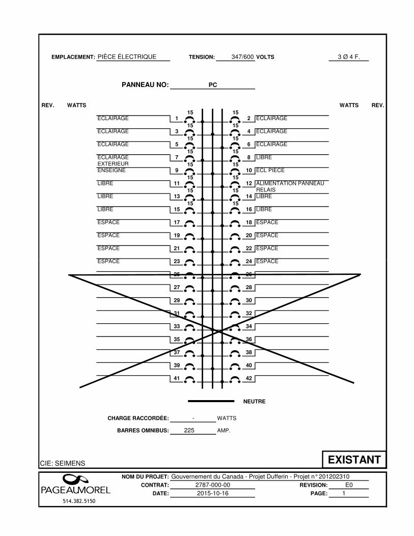
EMPLACEMENT: PIÈCE ÉLECTRIQUE 347/600 VOLTS 3 Ø 4 F.
PANNEAU NO:
REV. WATTS WATTS REV.
15 15ÉCLAIRAGE 1 2 ÉCLAIRAGE
15 15ÉCLAIRAGE 3 4 ÉCLAIRAGE
15 15ÉCLAIRAGE 5 6 ÉCLAIRAGE
15 15ÉCLAIRAGE 7 8 LIBREEXTÉRIEUR 15 15ENSEIGNE 9 10 ECL PIECE
15 15LIBRE 11 12 ALIMENTATION PANNEAU
15 15 RELAISLIBRE 13 14 LIBRE
15 15LIBRE 15 16 LIBRE
ESPACE 17 18 ESPACE
ESPACE 19 20 ESPACE
ESPACE 21 22 ESPACE
ESPACE 23 24 ESPACE
TENSION:
PC
ESPACE 23 24 ESPACE
25 26
27 28
29 30
31 32
33 34
35 36
37 38
39 40
41 42
CHARGE RACCORDÉE:
BARRES OMNIBUS: 225
CIE: SEIMENS
NOM DU PROJET: Gouvernement du Canada - Projet Dufferin - Projet n° 201202310CONTRAT: REVISION: E0
DATE: PAGE: 1514.382.5150
-
NEUTRE
2787-000-002015-10-16
WATTS
AMP.
EXISTANT
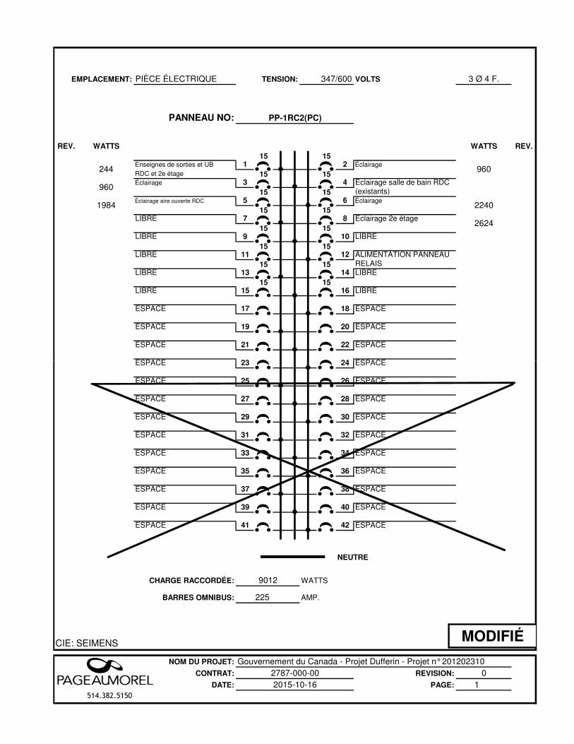
EMPLACEMENT: PIÈCE ÉLECTRIQUE 347/600 VOLTS 3 Ø 4 F.
PANNEAU NO:
REV. WATTS WATTS REV.
15 15Enseignes de sorties et UB 1 2 ÉclairageRDC et 2e étage 15 15Éclairage 3 4 Éclairage salle de bain RDC
15 15 (existants) Éclairage aire ouverte RDC 5 6 Éclairage
15 15LIBRE 7 8 Éclairage 2e étage
15 15LIBRE 9 10 LIBRE 15 15LIBRE 11 12 ALIMENTATION PANNEAU
15 15 RELAISLIBRE 13 14 LIBRE
15 15LIBRE 15 16 LIBRE
ESPACE 17 18 ESPACE
ESPACE 19 20 ESPACE
ESPACE 21 22 ESPACE
ESPACE 23 24 ESPACE
TENSION:
PP-1RC2(PC)
960
2624
2240
960
1984
244
ESPACE 23 24 ESPACE
ESPACE 25 26 ESPACE
ESPACE 27 28 ESPACE
ESPACE 29 30 ESPACE
ESPACE 31 32 ESPACE
ESPACE 33 34 ESPACE
ESPACE 35 36 ESPACE
ESPACE 37 38 ESPACE
ESPACE 39 40 ESPACE
ESPACE 41 42 ESPACE
CHARGE RACCORDÉE:
BARRES OMNIBUS: 225
CIE: SEIMENS
NOM DU PROJET: Gouvernement du Canada - Projet Dufferin - Projet n° 201202310CONTRAT: REVISION: 0
DATE: PAGE: 1514.382.5150
NEUTRE
2787-000-002015-10-16
WATTS
AMP.
9012
MODIFIÉ
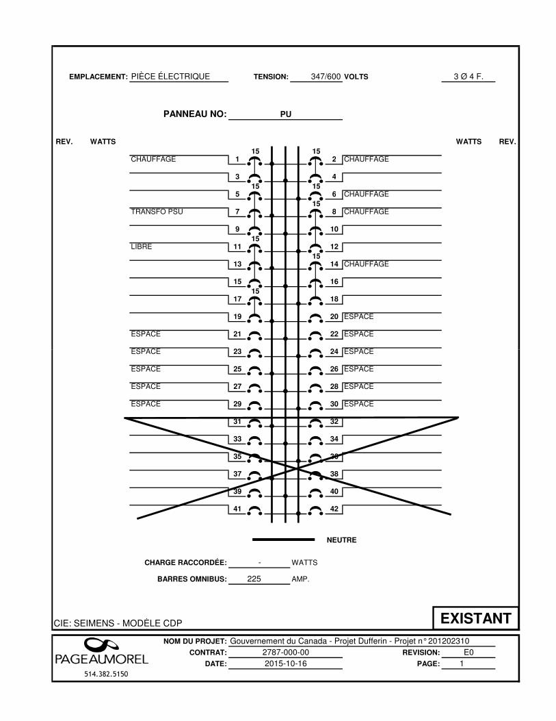
EMPLACEMENT: PIÈCE ÉLECTRIQUE 347/600 VOLTS 3 Ø 4 F.
PANNEAU NO:
REV. WATTS WATTS REV.
15 15CHAUFFAGE 1 2 CHAUFFAGE
3 4
15 15 5 6 CHAUFFAGE
15TRANSFO PSU 7 8 CHAUFFAGE
9 10
15LIBRE 11 12
1513 14 CHAUFFAGE
15 16
1517 18
19 20 ESPACE
ESPACE 21 22 ESPACE
ESPACE 23 24 ESPACE
TENSION:
PU
ESPACE 23 24 ESPACE
ESPACE 25 26 ESPACE
ESPACE 27 28 ESPACE
ESPACE 29 30 ESPACE
31 32
33 34
35 36
37 38
39 40
41 42
CHARGE RACCORDÉE:
BARRES OMNIBUS: 225
CIE: SEIMENS - MODÈLE CDP
NOM DU PROJET: Gouvernement du Canada - Projet Dufferin - Projet n° 201202310CONTRAT: REVISION: E0
DATE: PAGE: 1514.382.5150
-
NEUTRE
2787-000-002015-10-16
WATTS
AMP.
EXISTANT
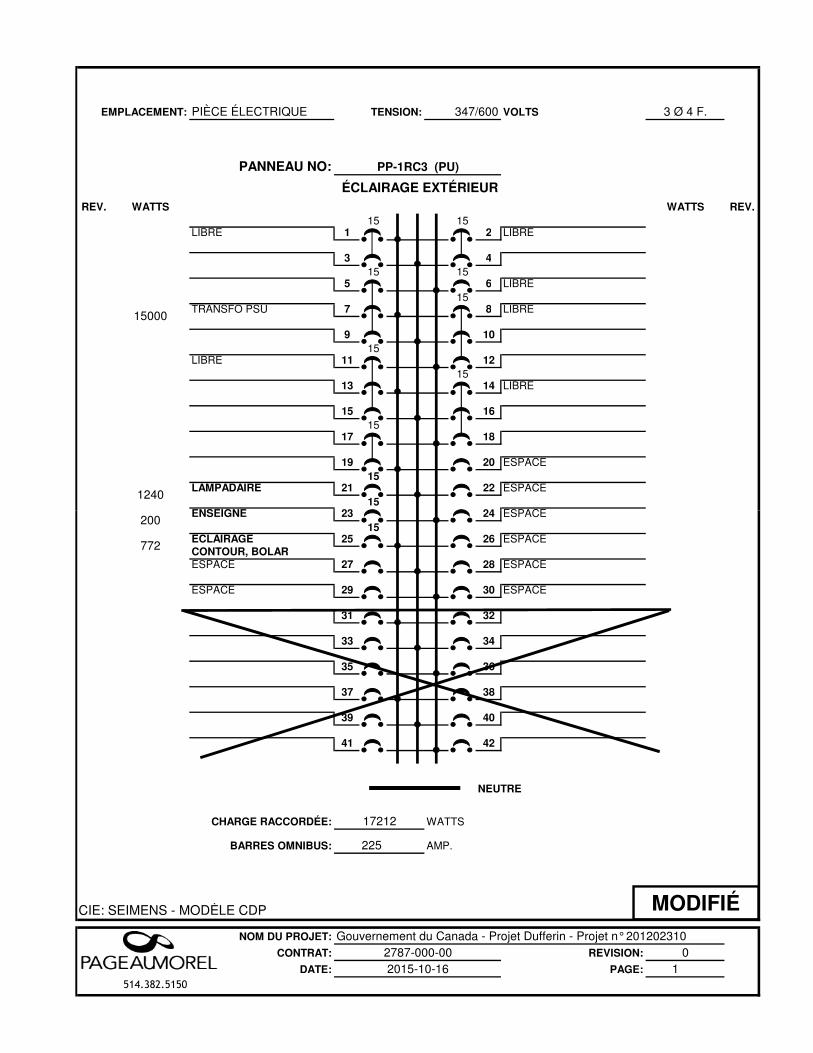
EMPLACEMENT: PIÈCE ÉLECTRIQUE 347/600 VOLTS 3 Ø 4 F.
PANNEAU NO:
REV. WATTS WATTS REV.
15 15LIBRE 1 2 LIBRE
3 4
15 15 5 6 LIBRE
15TRANSFO PSU 7 8 LIBRE
9 10
15LIBRE 11 12
1513 14 LIBRE
15 16
1517 18
19 20 ESPACE15
LAMPADAIRE 21 22 ESPACE15
ENSEIGNE 23 24 ESPACE
TENSION:
PP-1RC3 (PU)
ÉCLAIRAGE EXTÉRIEUR
1240
15000
ENSEIGNE 23 24 ESPACE15
ÉCLAIRAGE 25 26 ESPACECONTOUR, BOLARESPACE 27 28 ESPACE
ESPACE 29 30 ESPACE
31 32
33 34
35 36
37 38
39 40
41 42
CHARGE RACCORDÉE:
BARRES OMNIBUS: 225
CIE: SEIMENS - MODÈLE CDP
NOM DU PROJET: Gouvernement du Canada - Projet Dufferin - Projet n° 201202310CONTRAT: REVISION: 0
DATE: PAGE: 1514.382.5150
NEUTRE
2787-000-002015-10-16
WATTS
AMP.
200
772
17212
MODIFIÉ
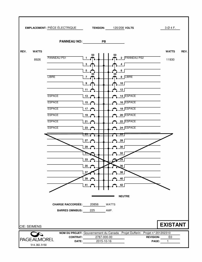
EMPLACEMENT: PIÈCE ÉLECTRIQUE 120/208 VOLTS 3 Ø 4 F.
PANNEAU NO:
REV. WATTS WATTS REV.
50 50PANNEAU PS1 1 2 PANNEAU PS2
3 4
5 6
30 30LIBRE 7 8 LIBRE
9 10
11 12
ESPACE 13 14 ESPACE
ESPACE 15 16 ESPACE
ESPACE 17 18 ESPACE
ESPACE 19 20 ESPACE
ESPACE 21 22 ESPACE
ESPACE 23 24 ESPACE
TENSION:
PB
119308926
ESPACE 23 24 ESPACE
25 26
27 28
29 30
31 32
33 34
35 36
37 38
39 40
41 42
CHARGE RACCORDÉE:
BARRES OMNIBUS: 225
CIE: SEIMENS
NOM DU PROJET: Gouvernement du Canada - Projet Dufferin - Projet n° 201202310CONTRAT: REVISION: E0
DATE: PAGE: 1514.382.5150
NEUTRE
2787-000-002015-10-16
WATTS
AMP.
20856
EXISTANT
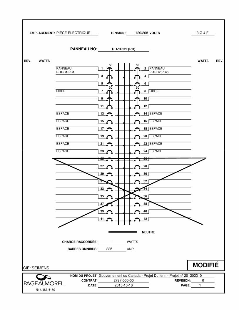
EMPLACEMENT: PIÈCE ÉLECTRIQUE 120/208 VOLTS 3 Ø 4 F.
PANNEAU NO:
REV. WATTS WATTS REV.
50 50PANNEAU 1 2 PANNEAU P-1RC1(PS1) P-1RC2(PS2)
3 4
5 6
30 30LIBRE 7 8 LIBRE
9 10
11 12
ESPACE 13 14 ESPACE
ESPACE 15 16 ESPACE
ESPACE 17 18 ESPACE
ESPACE 19 20 ESPACE
ESPACE 21 22 ESPACE
ESPACE 23 24 ESPACE
TENSION:
PD-1RC1 (PB)
ESPACE 23 24 ESPACE
25 26
27 28
29 30
31 32
33 34
35 36
37 38
39 40
41 42
CHARGE RACCORDÉE:
BARRES OMNIBUS: 225
CIE: SEIMENS
NOM DU PROJET: Gouvernement du Canada - Projet Dufferin - Projet n° 201202310CONTRAT: REVISION: 0
DATE: PAGE: 1514.382.5150
-
NEUTRE
2787-000-002015-10-16
WATTS
AMP.
MODIFIÉ
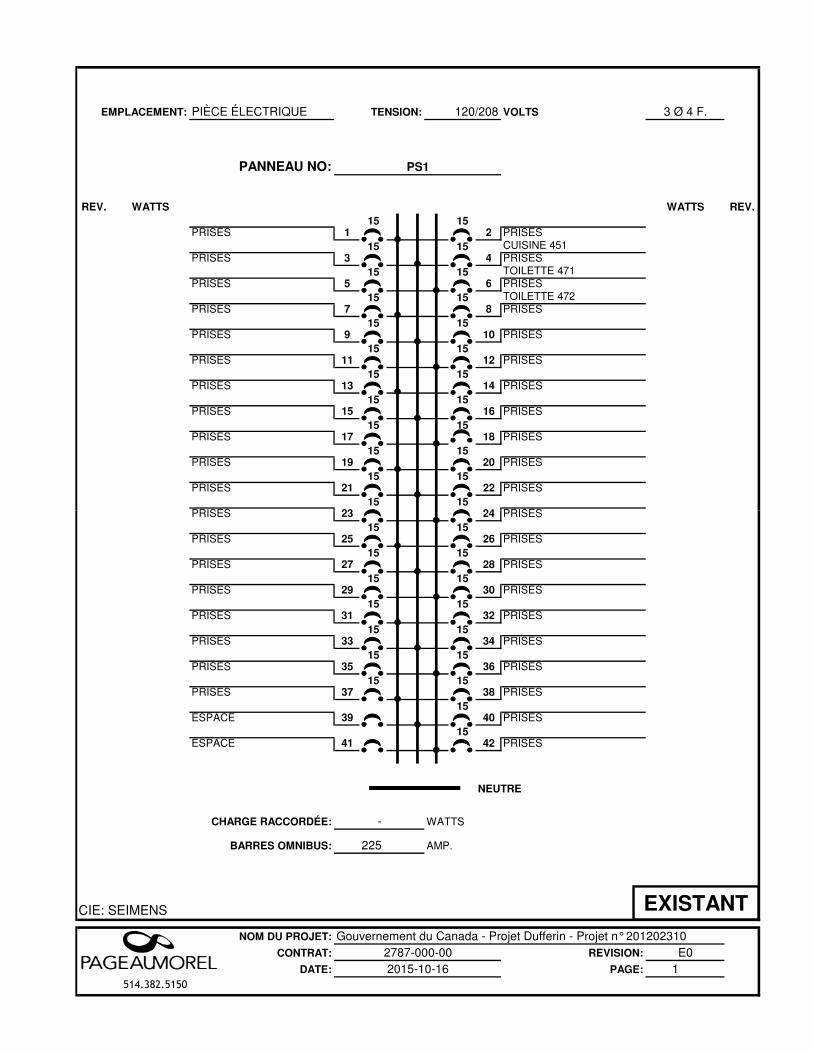
EMPLACEMENT: PIÈCE ÉLECTRIQUE 120/208 VOLTS 3 Ø 4 F.
PANNEAU NO:
REV. WATTS WATTS REV.
15 15PRISES 1 2 PRISES
15 15 CUISINE 451PRISES 3 4 PRISES
15 15 TOILETTE 471PRISES 5 6 PRISES
15 15 TOILETTE 472PRISES 7 8 PRISES
15 15PRISES 9 10 PRISES
15 15PRISES 11 12 PRISES
15 15PRISES 13 14 PRISES
15 15PRISES 15 16 PRISES
15 15PRISES 17 18 PRISES
15 15PRISES 19 20 PRISES
15 15PRISES 21 22 PRISES
15 15PRISES 23 24 PRISES
TENSION:
PS1
PRISES 23 24 PRISES15 15
PRISES 25 26 PRISES15 15
PRISES 27 28 PRISES15 15
PRISES 29 30 PRISES15 15
PRISES 31 32 PRISES15 15
PRISES 33 34 PRISES15 15
PRISES 35 36 PRISES15 15
PRISES 37 38 PRISES15
ESPACE 39 40 PRISES15
ESPACE 41 42 PRISES
CHARGE RACCORDÉE:
BARRES OMNIBUS: 225
CIE: SEIMENS
NOM DU PROJET: Gouvernement du Canada - Projet Dufferin - Projet n° 201202310CONTRAT: REVISION: E0
DATE: PAGE: 1514.382.5150
-
NEUTRE
2787-000-002015-10-16
WATTS
AMP.
EXISTANT
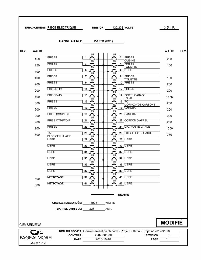
EMPLACEMENT: PIÈCE ÉLECTRIQUE 120/208 VOLTS 3 Ø 4 F.
PANNEAU NO:
REV. WATTS WATTS REV.
15 15PRISES 1 2 PRISES
15 15 CUISINEPRISES 3 4 PRISES
15 15 TOILETTEPRISES 5 6 LIBRE
15 15PRISES 7 8 PRISES
15 15 TOILETTEPRISES 9 10 PRISES
15 15PRISES+TV 11 12 PRISES
15 25PRISES+TV 13 14 PORTE GARAGE
15 15 1/2 HPPRISES 15 16 PC
15 15 MOPNOXYDE CARBONEPRISES 17 18 CAMERA
15 15PRISE COMPTOIR 19 20 CAMERA
15 15PRISE COMPTOIR 21 22 CORDON D'APPEL
15 15PRISES 23 24 M.O. POSTE GARDE
200
TENSION:
P-1RC1 (PS1)
200
100
200
200
100
200
200
1176
200
150
300
150
200
200
400
300
200
200
400
200
PRISES 23 24 M.O. POSTE GARDE15 15
TAI 25 26 FRIGO POSTE GARDEBLOC CELLULAIRE 15 15LIBRE 27 28 LIBRE
15 15LIBRE 29 30 LIBRE
15 15LIBRE 31 32 LIBRE
15 15LIBRE 33 34 LIBRE
15 15LIBRE 35 36 LIBRE
15 15LIBRE 37 38 LIBRE
20 15NETTOYAGE 39 40 LIBRE
20 15NETTOYAGE 41 42 LIBRE
CHARGE RACCORDÉE:
BARRES OMNIBUS: 225
CIE: SEIMENS
NOM DU PROJET: Gouvernement du Canada - Projet Dufferin - Projet n° 201202310CONTRAT: REVISION: 0
DATE: PAGE: 1514.382.5150
NEUTRE
2787-000-002015-10-16
WATTS
AMP.
750
1000200
500
8926
500
500
MODIFIÉ
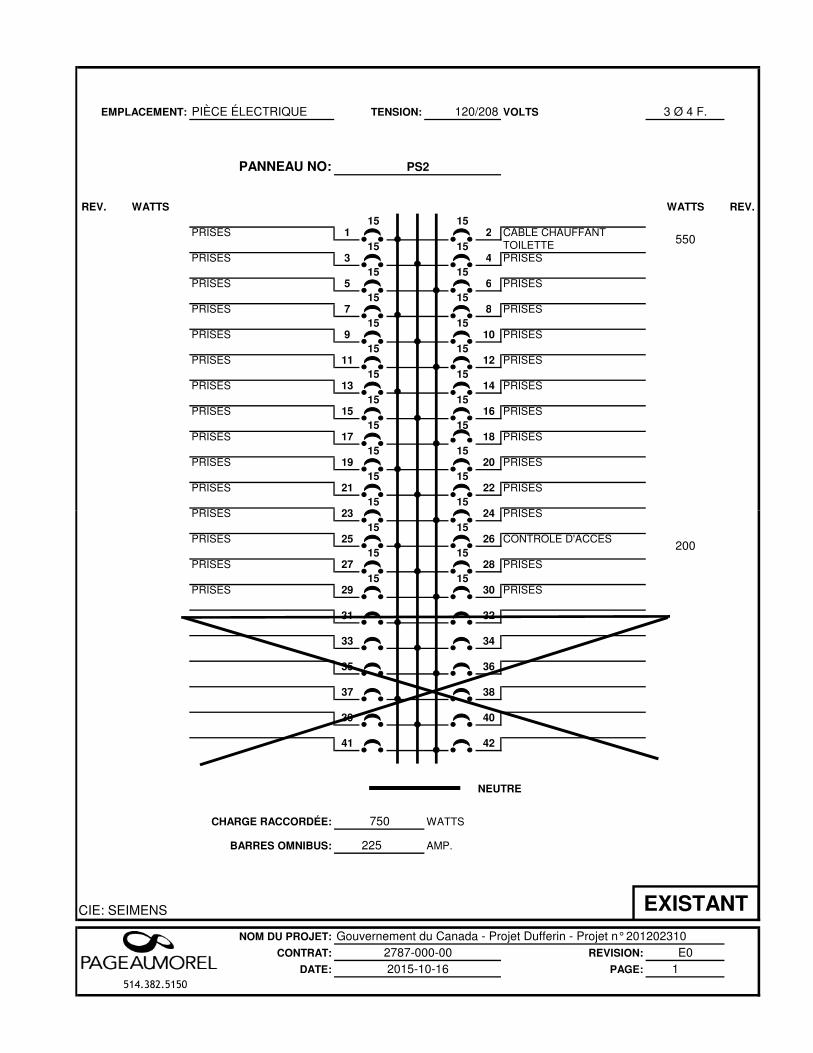
EMPLACEMENT: PIÈCE ÉLECTRIQUE 120/208 VOLTS 3 Ø 4 F.
PANNEAU NO:
REV. WATTS WATTS REV.
15 15PRISES 1 2 CABLE CHAUFFANT
15 15 TOILETTE PRISES 3 4 PRISES
15 15PRISES 5 6 PRISES
15 15PRISES 7 8 PRISES
15 15PRISES 9 10 PRISES
15 15PRISES 11 12 PRISES
15 15PRISES 13 14 PRISES
15 15PRISES 15 16 PRISES
15 15PRISES 17 18 PRISES
15 15PRISES 19 20 PRISES
15 15PRISES 21 22 PRISES
15 15PRISES 23 24 PRISES
TENSION:
PS2
550
PRISES 23 24 PRISES15 15
PRISES 25 26 CONTRÔLE D'ACCÈS15 15
PRISES 27 28 PRISES15 15
PRISES 29 30 PRISES
31 32
33 34
35 36
37 38
39 40
41 42
CHARGE RACCORDÉE:
BARRES OMNIBUS: 225
CIE: SEIMENS
NOM DU PROJET: Gouvernement du Canada - Projet Dufferin - Projet n° 201202310CONTRAT: REVISION: E0
DATE: PAGE: 1514.382.5150
NEUTRE
2787-000-002015-10-16
WATTS
AMP.
200
750
EXISTANT
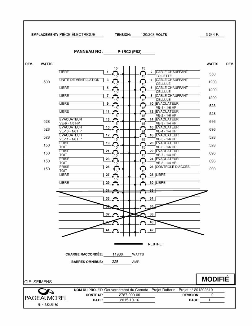
EMPLACEMENT: PIÈCE ÉLECTRIQUE 120/208 VOLTS 3 Ø 4 F.
PANNEAU NO:
REV. WATTS WATTS REV.
15 15LIBRE 1 2 CÂBLE CHAUFFANT 15 15 TOILETTEUNITÉ DE VENTILLATION 3 4 CÂBLE CHAUFFANT
15 15 CELLULELIBRE 5 6 CÂBLE CHAUFFANT 15 15 CELLULELIBRE 7 8 CÂBLE CHAUFFANT
15 15 CELLULELIBRE 9 10 ÉVACUATEUR 15 15 VE-1 - 1/6 HPLIBRE 11 12 ÉVACUATEUR
15 15 VE-2 - 1/6 HPÉVACUATEUR 13 14 ÉVACUATEUR VE-9 - 1/6 HP 15 15 VE-3 - 1/4 HPÉVACUATEUR 15 16 ÉVACUATEUR VE-10 - 1/6 HP 15 15 VE-4 - 1/4 HPÉVACUATEUR 17 18 ÉVACUATEUR VE-11 - 1/6 HP 15 15 VE-5 - 1/6 HPPRISE 19 20 ÉVACUATEUR TOIT 15 15 VE-6 - 1/6 HPPRISE 21 22 ÉVACUATEUR TOIT 15 15 VE-7 - 1/4 HPPRISE 23 24 ÉVACUATEUR
150
150
528
528
528
500
696
528
696
528
1200
1200
528
528
696
TENSION:
P-1RC2 (PS2)
550
1200
PRISE 23 24 ÉVACUATEUR TOIT 15 15 VE-8 - 1/4 HPPRISE 25 26 CONTRÔLE D'ACCÈSTOIT 15 15LIBRE 27 28 LIBRE
15 15LIBRE 29 30 LIBRE
31 32
33 34
35 36
37 38
39 40
41 42
CHARGE RACCORDÉE:
BARRES OMNIBUS: 225
CIE: SEIMENS
NOM DU PROJET: Gouvernement du Canada - Projet Dufferin - Projet n° 201202310CONTRAT: REVISION: 0
DATE: PAGE: 1514.382.5150
11930
150
150 200
696
NEUTRE
2787-000-002015-10-16
WATTS
AMP.
MODIFIÉ
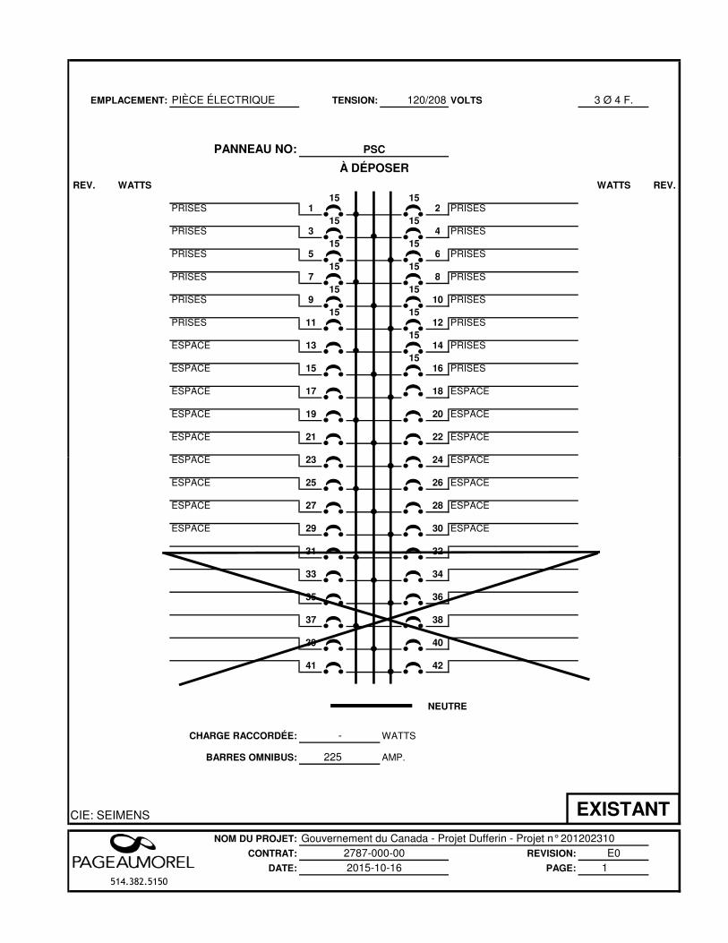
EMPLACEMENT: PIÈCE ÉLECTRIQUE 120/208 VOLTS 3 Ø 4 F.
PANNEAU NO:
REV. WATTS WATTS REV.
15 15PRISES 1 2 PRISES
15 15PRISES 3 4 PRISES
15 15PRISES 5 6 PRISES
15 15PRISES 7 8 PRISES
15 15PRISES 9 10 PRISES
15 15PRISES 11 12 PRISES
15ESPACE 13 14 PRISES
15ESPACE 15 16 PRISES
ESPACE 17 18 ESPACE
ESPACE 19 20 ESPACE
ESPACE 21 22 ESPACE
ESPACE 23 24 ESPACE
TENSION:
PSC
À DÉPOSER
ESPACE 23 24 ESPACE
ESPACE 25 26 ESPACE
ESPACE 27 28 ESPACE
ESPACE 29 30 ESPACE
31 32
33 34
35 36
37 38
39 40
41 42
CHARGE RACCORDÉE:
BARRES OMNIBUS: 225
CIE: SEIMENS
NOM DU PROJET: Gouvernement du Canada - Projet Dufferin - Projet n° 201202310CONTRAT: REVISION: E0
DATE: PAGE: 1514.382.5150
-
NEUTRE
2787-000-002015-10-16
WATTS
AMP.
EXISTANT
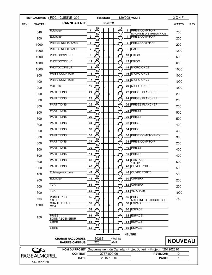
EMPLACEMENT: RDC - CUISINE- 309 120/208 VOLTS 3 Ø 4 F.
PANNEAU NO:
15 15Éclairage 1 2 PRISE COMPTOIR
15 15 MACHINE DISTRIBUTRICEÉclairage 3 4 PRISE COMPTOIR
20 15PRISES NETTOYAGE 5 6 PRISE COMPTOIR
20 15PRISES NETTOYAGE 7 8 CAFÉ
20 15PHOTOCOPIEUR 9 10 FRIGO
20 15PHOTOCOPIEUR 11 12 FRIGO
20 15PHOTOCOPIEUR 13 14 MICRO-ONDE
15 15PRISE COMPTOIR 15 16 MICRO-ONDE
15 15PRISE COMPTOIR 17 18 MICRO-ONDE
15 15VOLETS 19 20 MICRO-ONDE
15 15PARTITIONS 21 22 PRISES PLANCHER
15 15PARTITIONS 23 24 PRISES PLANCHER
15 15PARTITIONS 25 26 PRISES PLANCHER
15 15PARTITIONS 27 28 PRISES
15 15PARTITIONS 29 30 PRISES
15 15PARTITIONS 31 32 PRISES
15 15PARTITIONS 33 34 PRISES
15 15
600
1000
200
200
200
1200
1000
1000
540 750
600
WATTS
200
TENSION:
P-2RC1WATTSREV. REV.
1000
1000
200
1000
1000
1000
300
300
300
400
200
300
1000
200
200
300
300
300
500
400
400
500
15 15PARTITIONS 35 36 PRISE COMPTOIR+TV
15 15PARTITIONS 37 38 PRISE COMPTOIR
15 15PARTITIONS 39 40 PRISES
15 15PARTITIONS 41 42 PRISES
15 15PARTITIONS 43 44 FONTAINE
15 15 1/4 HPPARTITIONS 45 46 OUVRE PORTE
15 15Éclairage nocturne 47 48 OUVRE PORTE
15 15Éclairage 49 50 CAMÉRA
15 15TCAI 51 52 CAMÉRA
15 25TCAI 53 54 VE-A 1/2hp
15 15POMPE PS-1 55 56 PRISE1/3 HP 15 MACHINE DISTRIBUTRICECHAUFFE EAU 57 58 ESPACECE-2 59 60 ESPACE
15PRISE 61 62 ESPACESOUS ASCENSEUR 15LIBRE 63 64 ESPACE
15LIBRE 65 66 ESPACE
CHARGE RACCORDÉE:
BARRES OMNIBUS: 225
NOM DU PROJET:
CONTRAT: REVISION: 0DATE: PAGE: 1
514.382.5150
30266
2015-10-16
NEUTRE
WATTSAMP.
Gouvernement du Canada - Projet Dufferin - Projet n° 2012023102787-000-00
500
864
1500
100
200
500
300
150
300
300
300
300
300
300
200
400
200
200
500
692
500
400
750
1920
NOUVEAU
514.382.5150
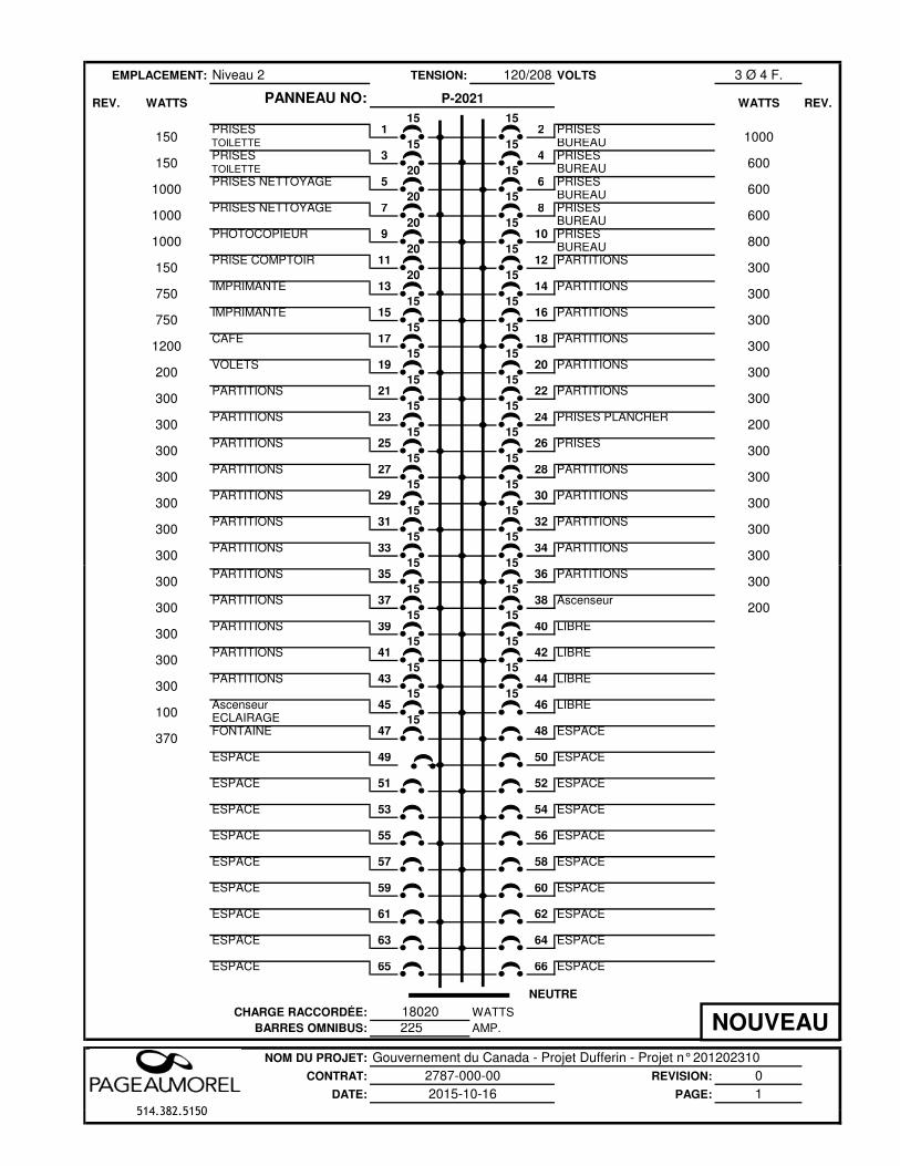
EMPLACEMENT: Niveau 2 120/208 VOLTS 3 Ø 4 F.
PANNEAU NO:
15 15PRISES 1 2 PRISESTOILETTE 15 15 BUREAUPRISES 3 4 PRISESTOILETTE 20 15 BUREAUPRISES NETTOYAGE 5 6 PRISES
20 15 BUREAUPRISES NETTOYAGE 7 8 PRISES
20 15 BUREAUPHOTOCOPIEUR 9 10 PRISES
20 15 BUREAUPRISE COMPTOIR 11 12 PARTITIONS
20 15IMPRIMANTE 13 14 PARTITIONS
15 15IMPRIMANTE 15 16 PARTITIONS
15 15CAFÉ 17 18 PARTITIONS 15 15VOLETS 19 20 PARTITIONS
15 15PARTITIONS 21 22 PARTITIONS
15 15PARTITIONS 23 24 PRISES PLANCHER
15 15PARTITIONS 25 26 PRISES
15 15PARTITIONS 27 28 PARTITIONS
15 15PARTITIONS 29 30 PARTITIONS
15 15PARTITIONS 31 32 PARTITIONS
15 15PARTITIONS 33 34 PARTITIONS
15 15
300
300
300
300300
300
300
300
300
300
300
300
300
1200
200
300
150
750
750
1000
1000
1000
150 1000
800
WATTS
150
TENSION:
P-2021WATTSREV. REV.
300
300
200
600
600
600
300
300
15 15PARTITIONS 35 36 PARTITIONS
15 15PARTITIONS 37 38 Ascenseur
15 15 PARTITIONS 39 40 LIBRE
15 15 PARTITIONS 41 42 LIBRE
15 15 PARTITIONS 43 44 LIBRE
15 15 Ascenseur 45 46 LIBREÉCLAIRAGE 15 FONTAINE 47 48 ESPACE
ESPACE 49 50 ESPACE
ESPACE 51 52 ESPACE
ESPACE 53 54 ESPACE
ESPACE 55 56 ESPACE
ESPACE 57 58 ESPACE
ESPACE 59 60 ESPACE
ESPACE 61 62 ESPACE
ESPACE 63 64 ESPACE
ESPACE 65 66 ESPACE
CHARGE RACCORDÉE:
BARRES OMNIBUS: 225
NOM DU PROJET:
CONTRAT: REVISION: 0DATE: PAGE: 1
514.382.5150
300
300
300
300
200
300
100
370
300
18020
2015-10-16
NEUTRE
WATTSAMP.
Gouvernement du Canada - Projet Dufferin - Projet n° 2012023102787-000-00
NOUVEAU
514.382.5150
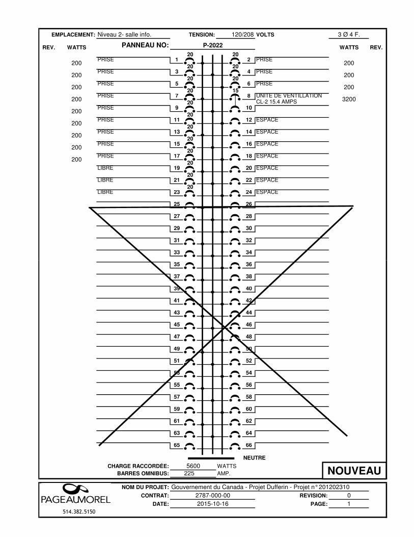
EMPLACEMENT: Niveau 2- salle info. 120/208 VOLTS 3 Ø 4 F.
PANNEAU NO:
20 20PRISE 1 2 PRISE
20 20 PRISE 3 4 PRISE
20 20 PRISE 5 6 PRISE
20 15 PRISE 7 8 UNITÉ DE VENTILLATION
20 CL-2 15.4 AMPSPRISE 9 10
20 PRISE 11 12 ESPACE
20 PRISE 13 14 ESPACE
20 PRISE 15 16 ESPACE
20 PRISE 17 18 ESPACE
20 LIBRE 19 20 ESPACE
20 LIBRE 21 22 ESPACE
20 LIBRE 23 24 ESPACE
25 26
27 28
29 30
31 32
33 34
200
200
3200
200 200
WATTS
200
TENSION:
P-2022WATTSREV. REV.
200
200
200
200
200
200
200
35 36
37 38
39 40
41 42
43 44
45 46
47 48
49 50
51 52
53 54
55 56
57 58
59 60
61 62
63 64
65 66
CHARGE RACCORDÉE:
BARRES OMNIBUS: 225
NOM DU PROJET:
CONTRAT: REVISION: 0DATE: PAGE: 1
514.382.5150
5600
2015-10-16
NEUTRE
WATTSAMP.
Gouvernement du Canada - Projet Dufferin - Projet n° 2012023102787-000-00
NOUVEAU
514.382.5150
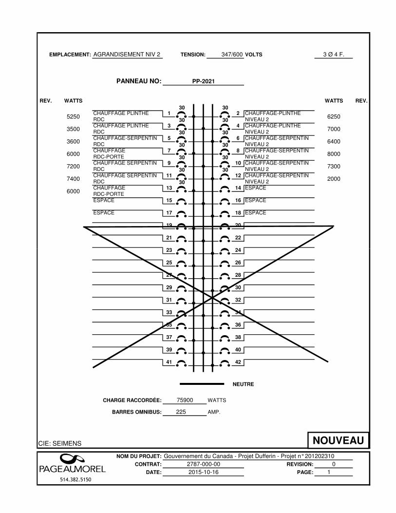
EMPLACEMENT: AGRANDISEMENT NIV 2 347/600 VOLTS 3 Ø 4 F.
PANNEAU NO:
REV. WATTS WATTS REV.
30 30CHAUFFAGE PLINTHE 1 2 CHAUFFAGE-PLINTHERDC 30 30 NIVEAU 2CHAUFFAGE PLINTHE 3 4 CHAUFFAGE-PLINTHERDC 30 30 NIVEAU 2CHAUFFAGE-SERPENTIN 5 6 CHAUFFAGE-SERPENTINRDC 30 30 NIVEAU 2CHAUFFAGE 7 8 CHAUFFAGE-SERPENTINRDC-PORTE 30 30 NIVEAU 2CHAUFFAGE SERPENTIN 9 10 CHAUFFAGE-SERPENTINRDC 30 30 NIVEAU 2CHAUFFAGE SERPENTIN 11 12 CHAUFFAGE-SERPENTINRDC 30 NIVEAU 2CHAUFFAGE 13 14 ESPACERDC-PORTE ESPACE 15 16 ESPACE
ESPACE 17 18 ESPACE
19 20
21 22
23 24
TENSION:
PP-2021
6250
8000
7300
2000
7000
6400
3500
3600
5250
6000
7400
6000
7200
23 24
25 26
27 28
29 30
31 32
33 34
35 36
37 38
39 40
41 42
CHARGE RACCORDÉE:
BARRES OMNIBUS: 225
CIE: SEIMENS
NOM DU PROJET: Gouvernement du Canada - Projet Dufferin - Projet n° 201202310CONTRAT: REVISION: 0
DATE: PAGE: 1514.382.5150
NEUTRE
2787-000-002015-10-16
WATTS
AMP.
75900
NOUVEAU
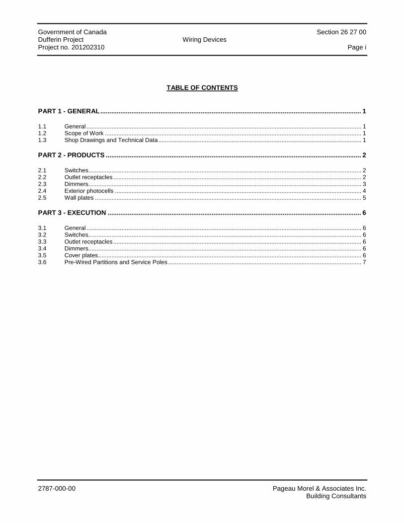
Government of Canada Section 26 27 00 Dufferin Project Wiring Devices Project no. 201202310 Page i
2787-000-00 Pageau Morel & Associates Inc. Building Consultants
TABLE OF CONTENTS
PART 1 - GENERAL ............................................................................................................................................... 1
1.1 General ..................................................................................................................................................................... 1 1.2 Scope of Work .......................................................................................................................................................... 1 1.3 Shop Drawings and Technical Data .......................................................................................................................... 1
PART 2 - PRODUCTS ............................................................................................................................................ 2
2.1 Switches.................................................................................................................................................................... 2 2.2 Outlet receptacles ..................................................................................................................................................... 2 2.3 Dimmers.................................................................................................................................................................... 3 2.4 Exterior photocells .................................................................................................................................................... 4 2.5 Wall plates ................................................................................................................................................................ 5
PART 3 - EXECUTION ........................................................................................................................................... 6
3.1 General ..................................................................................................................................................................... 6 3.2 Switches.................................................................................................................................................................... 6 3.3 Outlet receptacles ..................................................................................................................................................... 6 3.4 Dimmers.................................................................................................................................................................... 6 3.5 Cover plates .............................................................................................................................................................. 6 3.6 Pre-Wired Partitions and Service Poles .................................................................................................................... 7
Government of Canada Section 26 27 00 Dufferin Project Wiring Devices Project no. 201202310 Page 1
2787-000-00 Pageau Morel & Associates Inc. Building Consultants
PART 1 - GENERAL
1.1 General
1.1.1 Section 20 05 00 – "General Requirements Concerning Common Work Results" applies.
1.2 Scope of Work
1.2.1 Works of this section include, but are not limited to: the supply, handling, transportation, set up and installation of all systems and their accessories hereafter mentioned and/or shown on the drawings and which are to be operational. In general, all major parts of the works consist of, but are not limited to:
• Switches; • Outlet receptacles; • Special wiring devices; • Count-down timers; • Dimmers; • Daylight sensors; • Exterior photocells; • Wall plates.
1.3 Shop Drawings and Technical Data
1.3.1 Submit shop drawings and technical data regarding Section 20 05 00 – "General Requirements Concerning Common Work Results".
1.3.2 Submit shop drawing and technical data of the following items:
• Switches; • Outlet receptacles; • Special wiring devices; • Count-down timers; • Dimmers; • Occupancy sensors; • Daylight sensors; • Exterior photocells; • Wall plates.
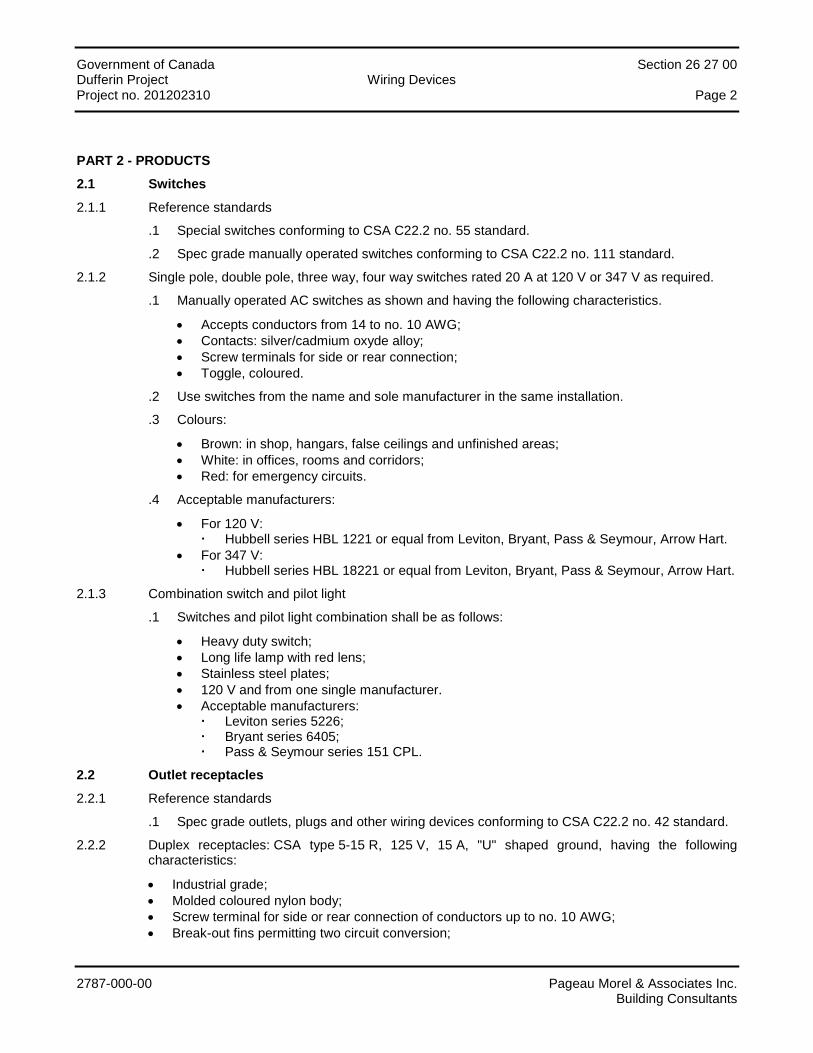
Government of Canada Section 26 27 00 Dufferin Project Wiring Devices Project no. 201202310 Page 2
2787-000-00 Pageau Morel & Associates Inc. Building Consultants
PART 2 - PRODUCTS
2.1 Switches
2.1.1 Reference standards
.1 Special switches conforming to CSA C22.2 no. 55 standard.
.2 Spec grade manually operated switches conforming to CSA C22.2 no. 111 standard.
2.1.2 Single pole, double pole, three way, four way switches rated 20 A at 120 V or 347 V as required.
.1 Manually operated AC switches as shown and having the following characteristics.
• Accepts conductors from 14 to no. 10 AWG; • Contacts: silver/cadmium oxyde alloy; • Screw terminals for side or rear connection; • Toggle, coloured.
.2 Use switches from the name and sole manufacturer in the same installation.
.3 Colours:
• Brown: in shop, hangars, false ceilings and unfinished areas; • White: in offices, rooms and corridors; • Red: for emergency circuits.
.4 Acceptable manufacturers:
• For 120 V: Hubbell series HBL 1221 or equal from Leviton, Bryant, Pass & Seymour, Arrow Hart.
• For 347 V: Hubbell series HBL 18221 or equal from Leviton, Bryant, Pass & Seymour, Arrow Hart.
2.1.3 Combination switch and pilot light
.1 Switches and pilot light combination shall be as follows:
• Heavy duty switch; • Long life lamp with red lens; • Stainless steel plates; • 120 V and from one single manufacturer. • Acceptable manufacturers:
Leviton series 5226; Bryant series 6405; Pass & Seymour series 151 CPL.
2.2 Outlet receptacles
2.2.1 Reference standards
.1 Spec grade outlets, plugs and other wiring devices conforming to CSA C22.2 no. 42 standard.
2.2.2 Duplex receptacles: CSA type 5-15 R, 125 V, 15 A, "U" shaped ground, having the following characteristics:
• Industrial grade; • Molded coloured nylon body; • Screw terminal for side or rear connection of conductors up to no. 10 AWG; • Break-out fins permitting two circuit conversion;
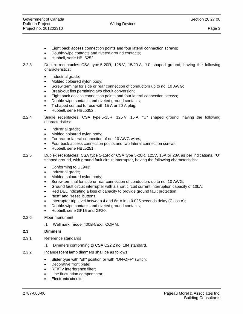
Government of Canada Section 26 27 00 Dufferin Project Wiring Devices Project no. 201202310 Page 3
2787-000-00 Pageau Morel & Associates Inc. Building Consultants
• Eight back access connection points and four lateral connection screws; • Double-wipe contacts and riveted ground contacts; • Hubbell, serie HBL5252.
2.2.3 Duplex receptacles: CSA type 5-20R, 125 V, 15/20 A, "U" shaped ground, having the following characteristics:
• Industrial grade; • Molded coloured nylon body; • Screw terminal for side or rear connection of conductors up to no. 10 AWG; • Break-out fins permitting two circuit conversion; • Eight back access connection points and four lateral connection screws; • Double-wipe contacts and riveted ground contacts; • T shaped contact for use with 15 A or 20 A plug; • Hubbell, serie HBL5352.
2.2.4 Single receptacles: CSA type 5-15R, 125 V, 15 A, "U" shaped ground, having the following characteristics:
• Industrial grade; • Molded coloured nylon body; • For rear or lateral connection of no. 10 AWG wires; • Four back access connection points and two lateral connection screws; • Hubbell, serie HBL5251.
2.2.5 Duplex receptacles: CSA type 5-15R or CSA type 5-20R, 125V, 15A or 20A as per indications. "U" shaped ground, with ground fault circuit interrupter, having the following characteristics:
• Conforming to UL943; • Industrial grade; • Molded coloured nylon body; • Screw terminal for side or rear connection of conductors up to no. 10 AWG; • Ground fault circuit interrupter with a short circuit current interruption capacity of 10kA; • Red DEL indicating a loss of capacity to provide ground fault protection; • "test" and "reset" buttons; • Interrupter trip level between 4 and 6mA in a 0.025 seconds delay (Class A); • Double-wipe contacts and riveted ground contacts; • Hubbell, serie GF15 and GF20.
2.2.6 Floor monument
.1 Wellmark, model 400B-5EXT COMM.
2.3 Dimmers
2.3.1 Reference standards
.1 Dimmers conforming to CSA C22.2 no. 184 standard.
2.3.2 Incandescent lamp dimmers shall be as follows:
• Slider type with "off" position or with "ON-OFF" switch; • Decorative front plate; • RFI/TV interference filter; • Line fluctuation compensator; • Electronic circuits;
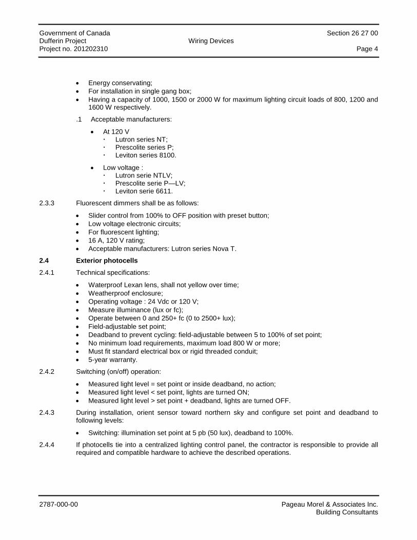
Government of Canada Section 26 27 00 Dufferin Project Wiring Devices Project no. 201202310 Page 4
2787-000-00 Pageau Morel & Associates Inc. Building Consultants
• Energy conservating; • For installation in single gang box; • Having a capacity of 1000, 1500 or 2000 W for maximum lighting circuit loads of 800, 1200 and
1600 W respectively.
.1 Acceptable manufacturers:
• At 120 V Lutron series NT; Prescolite series P; Leviton series 8100.
• Low voltage : Lutron serie NTLV; Prescolite serie P—LV; Leviton serie 6611.
2.3.3 Fluorescent dimmers shall be as follows:
• Slider control from 100% to OFF position with preset button; • Low voltage electronic circuits; • For fluorescent lighting; • 16 A, 120 V rating; • Acceptable manufacturers: Lutron series Nova T.
2.4 Exterior photocells
2.4.1 Technical specifications:
• Waterproof Lexan lens, shall not yellow over time; • Weatherproof enclosure; • Operating voltage : 24 Vdc or 120 V; • Measure illuminance (lux or fc); • Operate between 0 and 250+ fc (0 to 2500+ lux); • Field-adjustable set point; • Deadband to prevent cycling: field-adjustable between 5 to 100% of set point; • No minimum load requirements, maximum load 800 W or more; • Must fit standard electrical box or rigid threaded conduit; • 5-year warranty.
2.4.2 Switching (on/off) operation:
• Measured light level = set point or inside deadband, no action; • Measured light level < set point, lights are turned ON; • Measured light level > set point + deadband, lights are turned OFF.
2.4.3 During installation, orient sensor toward northern sky and configure set point and deadband to following levels:
• Switching: illumination set point at 5 pb (50 lux), deadband to 100%.
2.4.4 If photocells tie into a centralized lighting control panel, the contractor is responsible to provide all required and compatible hardware to achieve the described operations.
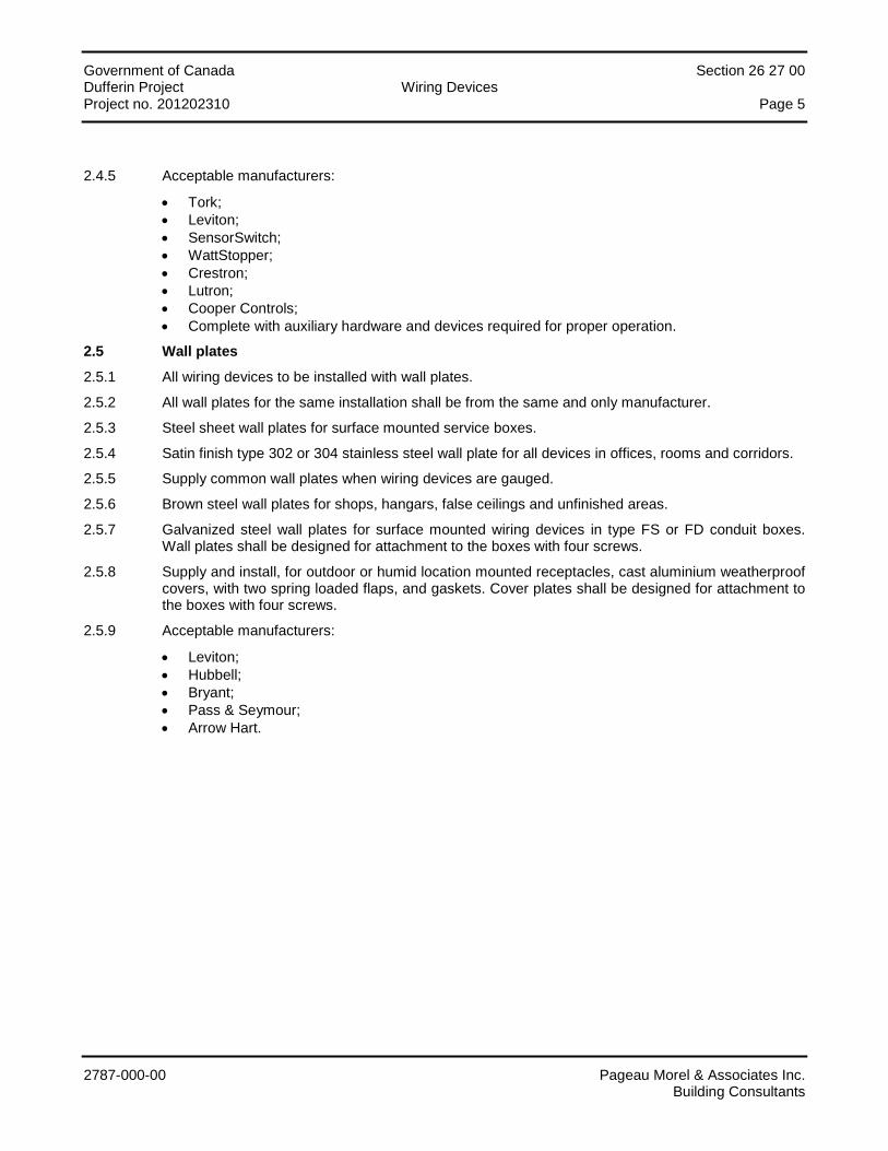
Government of Canada Section 26 27 00 Dufferin Project Wiring Devices Project no. 201202310 Page 5
2787-000-00 Pageau Morel & Associates Inc. Building Consultants
2.4.5 Acceptable manufacturers:
• Tork; • Leviton; • SensorSwitch; • WattStopper; • Crestron; • Lutron; • Cooper Controls; • Complete with auxiliary hardware and devices required for proper operation.
2.5 Wall plates
2.5.1 All wiring devices to be installed with wall plates.
2.5.2 All wall plates for the same installation shall be from the same and only manufacturer.
2.5.3 Steel sheet wall plates for surface mounted service boxes.
2.5.4 Satin finish type 302 or 304 stainless steel wall plate for all devices in offices, rooms and corridors.
2.5.5 Supply common wall plates when wiring devices are gauged.
2.5.6 Brown steel wall plates for shops, hangars, false ceilings and unfinished areas.
2.5.7 Galvanized steel wall plates for surface mounted wiring devices in type FS or FD conduit boxes. Wall plates shall be designed for attachment to the boxes with four screws.
2.5.8 Supply and install, for outdoor or humid location mounted receptacles, cast aluminium weatherproof covers, with two spring loaded flaps, and gaskets. Cover plates shall be designed for attachment to the boxes with four screws.
2.5.9 Acceptable manufacturers:
• Leviton; • Hubbell; • Bryant; • Pass & Seymour; • Arrow Hart.
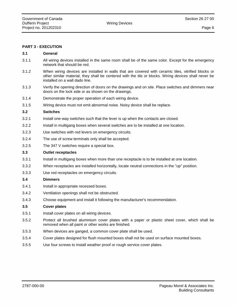
Government of Canada Section 26 27 00 Dufferin Project Wiring Devices Project no. 201202310 Page 6
2787-000-00 Pageau Morel & Associates Inc. Building Consultants
PART 3 - EXECUTION
3.1 General
3.1.1 All wiring devices installed in the same room shall be of the same color. Except for the emergency network that should be red.
3.1.2 When wiring devices are installed in walls that are covered with ceramic tiles, vitrified blocks or other similar material, they shall be centered with the tile or blocks. Wiring devices shall never be installed on a wall dado line.
3.1.3 Verify the opening direction of doors on the drawings and on site. Place switches and dimmers near doors on the lock side or as shown on the drawings.
3.1.4 Demonstrate the proper operation of each wiring device.
3.1.5 Wiring device must not emit abnormal noise. Noisy device shall be replace.
3.2 Switches
3.2.1 Install one-way switches such that the lever is up when the contacts are closed.
3.2.2 Install in multigang boxes when several switches are to be installed at one location.
3.2.3 Use switches with red levers on emergency circuits.
3.2.4 The use of screw terminals only shall be accepted.
3.2.5 The 347 V switches require a special box.
3.3 Outlet receptacles
3.3.1 Install in multigang boxes when more than one receptacle is to be installed at one location.
3.3.2 When receptacles are installed horizontally, locate neutral connections in the "up" position.
3.3.3 Use red receptacles on emergency circuits.
3.4 Dimmers
3.4.1 Install in appropriate recessed boxes.
3.4.2 Ventilation openings shall not be obstructed.
3.4.3 Choose equipment and install it following the manufacturer's recommendation.
3.5 Cover plates
3.5.1 Install cover plates on all wiring devices.
3.5.2 Protect all brushed aluminium cover plates with a paper or plastic sheet cover, which shall be removed when all paint or other works are finished.
3.5.3 When devices are ganged, a common cover plate shall be used.
3.5.4 Cover plates designed for flush mounted boxes shall not be used on surface mounted boxes.
3.5.5 Use four screws to install weather proof or rough service cover plates.

Government of Canada Section 26 27 00 Dufferin Project Wiring Devices Project no. 201202310 Page 7
2787-000-00 Pageau Morel & Associates Inc. Building Consultants
3.6 Pre-Wired Partitions and Service Poles
3.6.1 Division26 contractor shall coordinate with other Divisions 23, 27 and 28 prior to perform his installation.
3.6.2 Contractor shall verify with the pre-wired partition and service poles supplier the correspondence and the amount of conductors to be connected to each cable or box provided by the partition manufacturer.
3.6.3 He shall obtain from the Owner a copy of the approved shop drawing from the pre-wired partition and service poles supplier. In case of discrepancy with the drawings, contact the Engineer and the Owner
END OF SECTION
Government of Canada Section 26 30 00 Dufferin Project Electrical Power Generating Equipment Project no. 201202310 Page i
2787-000-00 Pageau Morel & Associates Inc. Building Consultants
TABLE OF CONTENTS
PART 1 - GENERAL ............................................................................................................................................... 1
1.1 General ..................................................................................................................................................................... 1 1.2 Scope of Work .......................................................................................................................................................... 1 1.3 Shop Drawings and Technical Data .......................................................................................................................... 1 1.4 Factory Tests to Perform........................................................................................................................................... 1
PART 2 - PRODUCTS ............................................................................................................................................ 2
2.1 Electric Generator Set ............................................................................................................................................... 2 2.2 Automatic Transfer Switch ........................................................................................................................................ 9
PART 3 - EXECUTION ......................................................................................................................................... 11
3.1 Electric Generator Set ............................................................................................................................................. 11 3.2 Automatic Transfer Switch ...................................................................................................................................... 12
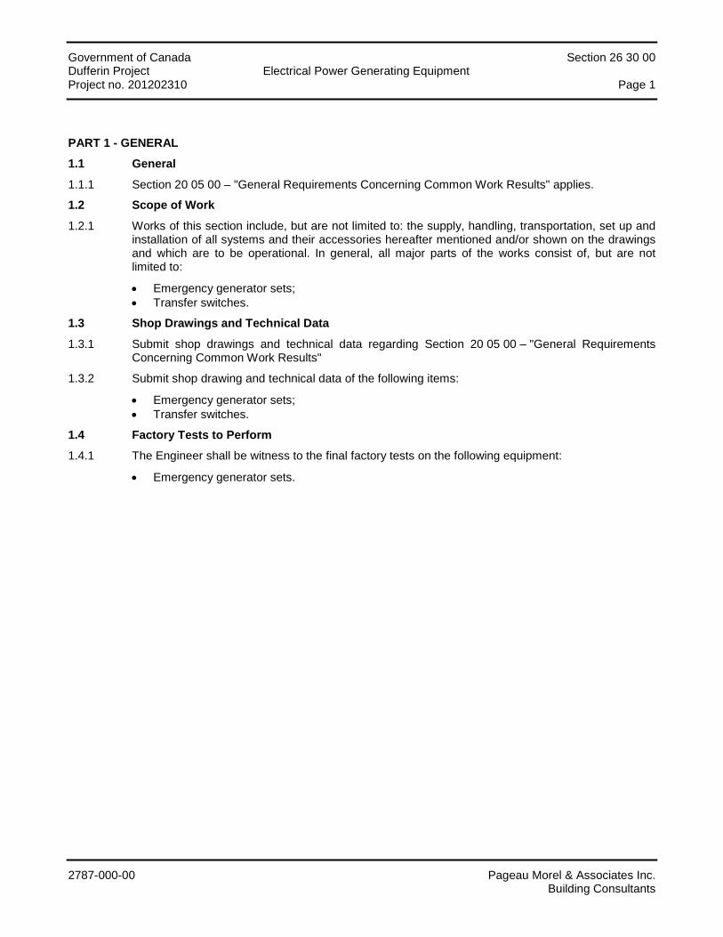
Government of Canada Section 26 30 00 Dufferin Project Electrical Power Generating Equipment Project no. 201202310 Page 1
2787-000-00 Pageau Morel & Associates Inc. Building Consultants
PART 1 - GENERAL
1.1 General
1.1.1 Section 20 05 00 – "General Requirements Concerning Common Work Results" applies.
1.2 Scope of Work
1.2.1 Works of this section include, but are not limited to: the supply, handling, transportation, set up and installation of all systems and their accessories hereafter mentioned and/or shown on the drawings and which are to be operational. In general, all major parts of the works consist of, but are not limited to:
• Emergency generator sets; • Transfer switches.
1.3 Shop Drawings and Technical Data
1.3.1 Submit shop drawings and technical data regarding Section 20 05 00 – "General Requirements Concerning Common Work Results"
1.3.2 Submit shop drawing and technical data of the following items:
• Emergency generator sets; • Transfer switches.
1.4 Factory Tests to Perform
1.4.1 The Engineer shall be witness to the final factory tests on the following equipment:
• Emergency generator sets.
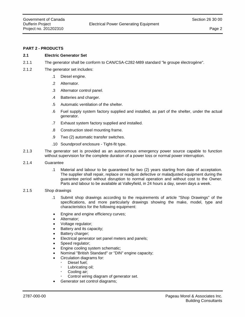
Government of Canada Section 26 30 00 Dufferin Project Electrical Power Generating Equipment Project no. 201202310 Page 2
2787-000-00 Pageau Morel & Associates Inc. Building Consultants
PART 2 - PRODUCTS
2.1 Electric Generator Set
2.1.1 The generator shall be conform to CAN/CSA-C282-M89 standard "le groupe électrogène".
2.1.2 The generator set includes:
.1 Diesel engine.
.2 Alternator.
.3 Alternator control panel.
.4 Batteries and charger.
.5 Automatic ventilation of the shelter.
.6 Fuel supply system factory supplied and installed, as part of the shelter, under the actual generator.
.7 Exhaust system factory supplied and installed.
.8 Construction steel mounting frame.
.9 Two (2) automatic transfer switches.
.10 Soundproof enclosure - Tight-fit type.
2.1.3 The generator set is provided as an autonomous emergency power source capable to function without supervision for the complete duration of a power loss or normal power interruption.
2.1.4 Guarantee
.1 Material and labour to be guaranteed for two (2) years starting from date of acceptation. The supplier shall repair, replace or readjust defective or maladjusted equipment during the guarantee period without disruption to normal operation and without cost to the Owner. Parts and labour to be available at Valleyfield, in 24 hours a day, seven days a week.
2.1.5 Shop drawings
.1 Submit shop drawings according to the requirements of article "Shop Drawings" of the specifications, and more particularly drawings showing the make, model, type and characteristics for the following equipment:
• Engine and engine efficiency curves; • Alternator; • Voltage regulator; • Battery and its capacity; • Battery charger; • Electrical generator set panel meters and panels; • Speed regulator; • Engine cooling system schematic; • Nominal "British Standard" or "DIN" engine capacity; • Circulation diagrams for:
Diesel fuel; Lubricating oil; Cooling air; Control wiring diagram of generator set.
• Generator set control diagrams;
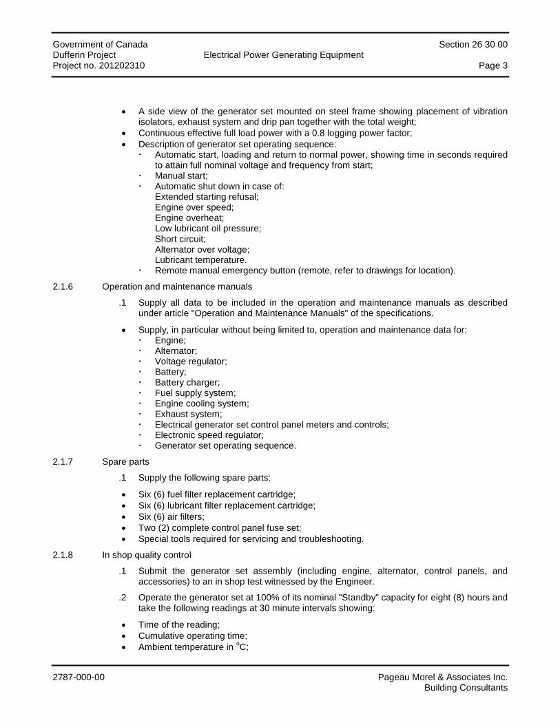
Government of Canada Section 26 30 00 Dufferin Project Electrical Power Generating Equipment Project no. 201202310 Page 3
2787-000-00 Pageau Morel & Associates Inc. Building Consultants
• A side view of the generator set mounted on steel frame showing placement of vibration isolators, exhaust system and drip pan together with the total weight;
• Continuous effective full load power with a 0.8 logging power factor; • Description of generator set operating sequence:
Automatic start, loading and return to normal power, showing time in seconds required to attain full nominal voltage and frequency from start;
Manual start; Automatic shut down in case of:
Extended starting refusal; Engine over speed; Engine overheat; Low lubricant oil pressure; Short circuit; Alternator over voltage; Lubricant temperature.
Remote manual emergency button (remote, refer to drawings for location).
2.1.6 Operation and maintenance manuals
.1 Supply all data to be included in the operation and maintenance manuals as described under article "Operation and Maintenance Manuals" of the specifications.
• Supply, in particular without being limited to, operation and maintenance data for: Engine; Alternator; Voltage regulator; Battery; Battery charger; Fuel supply system; Engine cooling system; Exhaust system; Electrical generator set control panel meters and controls; Electronic speed regulator; Generator set operating sequence.
2.1.7 Spare parts
.1 Supply the following spare parts:
• Six (6) fuel filter replacement cartridge; • Six (6) lubricant filter replacement cartridge; • Six (6) air filters; • Two (2) complete control panel fuse set; • Special tools required for servicing and troubleshooting.
2.1.8 In shop quality control
.1 Submit the generator set assembly (including engine, alternator, control panels, and accessories) to an in shop test witnessed by the Engineer.
.2 Operate the generator set at 100% of its nominal "Standby" capacity for eight (8) hours and take the following readings at 30 minute intervals showing:
• Time of the reading; • Cumulative operating time; • Ambient temperature in oC;
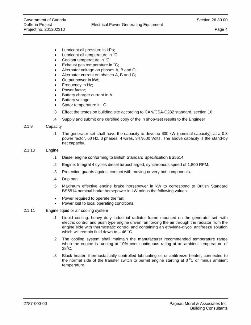
Government of Canada Section 26 30 00 Dufferin Project Electrical Power Generating Equipment Project no. 201202310 Page 4
2787-000-00 Pageau Morel & Associates Inc. Building Consultants
• Lubricant oil pressure in kPa; • Lubricant oil temperature in oC; • Coolant temperature in oC; • Exhaust gas temperature in oC; • Alternator voltage on phases A, B and C; • Alternator current on phases A, B and C; • Output power in kW; • Frequency in Hz; • Power factor; • Battery charger current in A; • Battery voltage; • Stator temperature in oC.
.3 Effect the testes on building site according to CAN/CSA-C282 standard, section 10.
.4 Supply and submit one certified copy of the in shop-test results to the Engineer
2.1.9 Capacity
.1 The generator set shall have the capacity to develop 600 kW (nominal capacity), at a 0.8 power factor, 60 Hz, 3 phases, 4 wires, 347/600 Volts. The above capacity is the stand-by net capacity.
2.1.10 Engine
.1 Diesel engine conforming to British Standard Specification BS5514.
.2 Engine: Integral 4 cycles diesel turbocharged, synchronous speed of 1,800 RPM.
.3 Protection guards against contact with moving or very hot components.
.4 Drip pan
.5 Maximum effective engine brake horsepower in kW to correspond to British Standard BS5514 nominal brake horsepower in kW minus the following values:
• Power required to operate the fan; • Power lost to local operating conditions.
2.1.11 Engine liquid or air cooling system
.1 Liquid cooling: heavy duty industrial radiator frame mounted on the generator set, with electric control and push type engine driven fan forcing the air through the radiator from the engine side with thermostatic control and containing an ethylene-glycol antifreeze solution which will remain fluid down to – 46 oC.
.2 The cooling system shall maintain the manufacturer recommended temperature range when the engine is running at 10% over continuous rating at an ambient temperature of 38oC.
.3 Block heater: thermostatically controlled lubricating oil or antifreeze heater, connected to the normal side of the transfer switch to permit engine starting at 0 oC or minus ambient temperature.
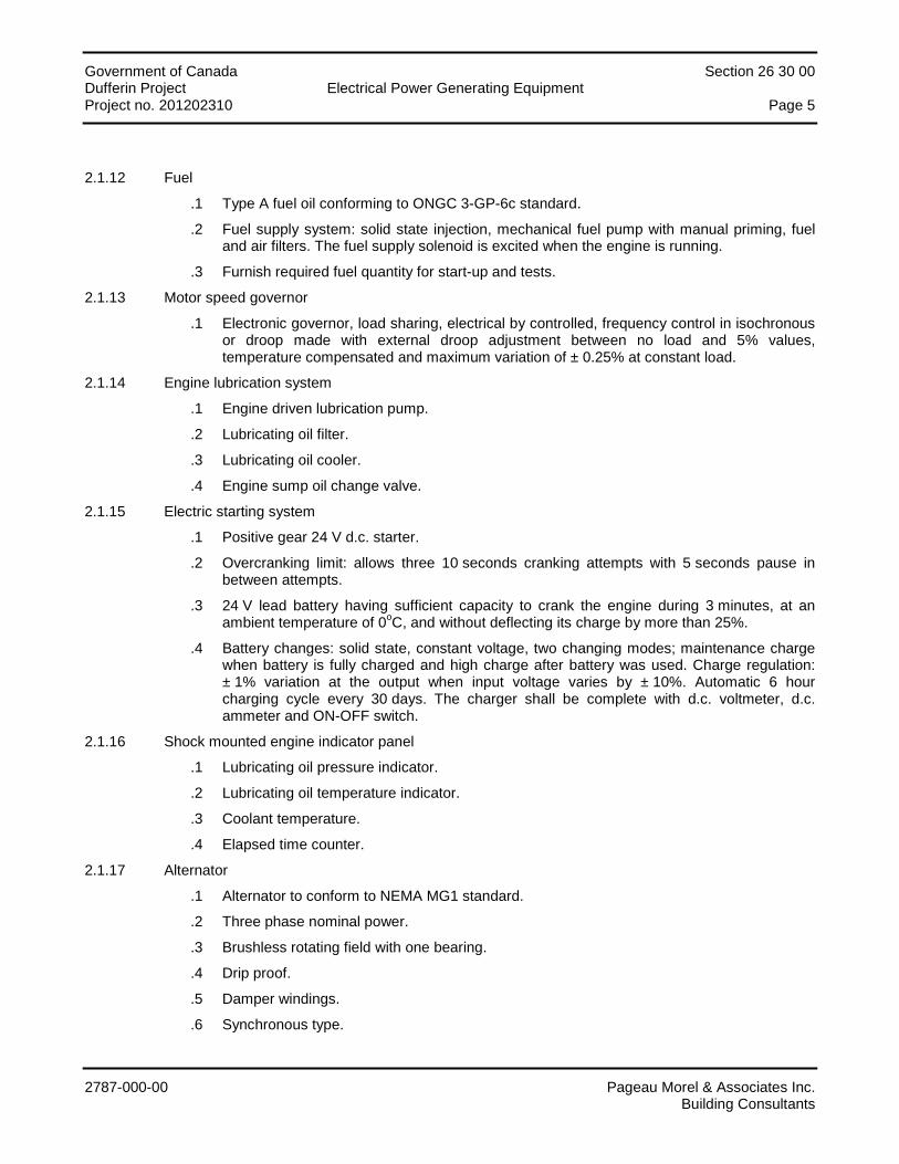
Government of Canada Section 26 30 00 Dufferin Project Electrical Power Generating Equipment Project no. 201202310 Page 5
2787-000-00 Pageau Morel & Associates Inc. Building Consultants
2.1.12 Fuel
.1 Type A fuel oil conforming to ONGC 3-GP-6c standard.
.2 Fuel supply system: solid state injection, mechanical fuel pump with manual priming, fuel and air filters. The fuel supply solenoid is excited when the engine is running.
.3 Furnish required fuel quantity for start-up and tests.
2.1.13 Motor speed governor
.1 Electronic governor, load sharing, electrical by controlled, frequency control in isochronous or droop made with external droop adjustment between no load and 5% values, temperature compensated and maximum variation of ± 0.25% at constant load.
2.1.14 Engine lubrication system
.1 Engine driven lubrication pump.
.2 Lubricating oil filter.
.3 Lubricating oil cooler.
.4 Engine sump oil change valve.
2.1.15 Electric starting system
.1 Positive gear 24 V d.c. starter.
.2 Overcranking limit: allows three 10 seconds cranking attempts with 5 seconds pause in between attempts.
.3 24 V lead battery having sufficient capacity to crank the engine during 3 minutes, at an ambient temperature of 0oC, and without deflecting its charge by more than 25%.
.4 Battery changes: solid state, constant voltage, two changing modes; maintenance charge when battery is fully charged and high charge after battery was used. Charge regulation: ± 1% variation at the output when input voltage varies by ± 10%. Automatic 6 hour charging cycle every 30 days. The charger shall be complete with d.c. voltmeter, d.c. ammeter and ON-OFF switch.
2.1.16 Shock mounted engine indicator panel
.1 Lubricating oil pressure indicator.
.2 Lubricating oil temperature indicator.
.3 Coolant temperature.
.4 Elapsed time counter.
2.1.17 Alternator
.1 Alternator to conform to NEMA MG1 standard.
.2 Three phase nominal power.
.3 Brushless rotating field with one bearing.
.4 Drip proof.
.5 Damper windings.
.6 Synchronous type.
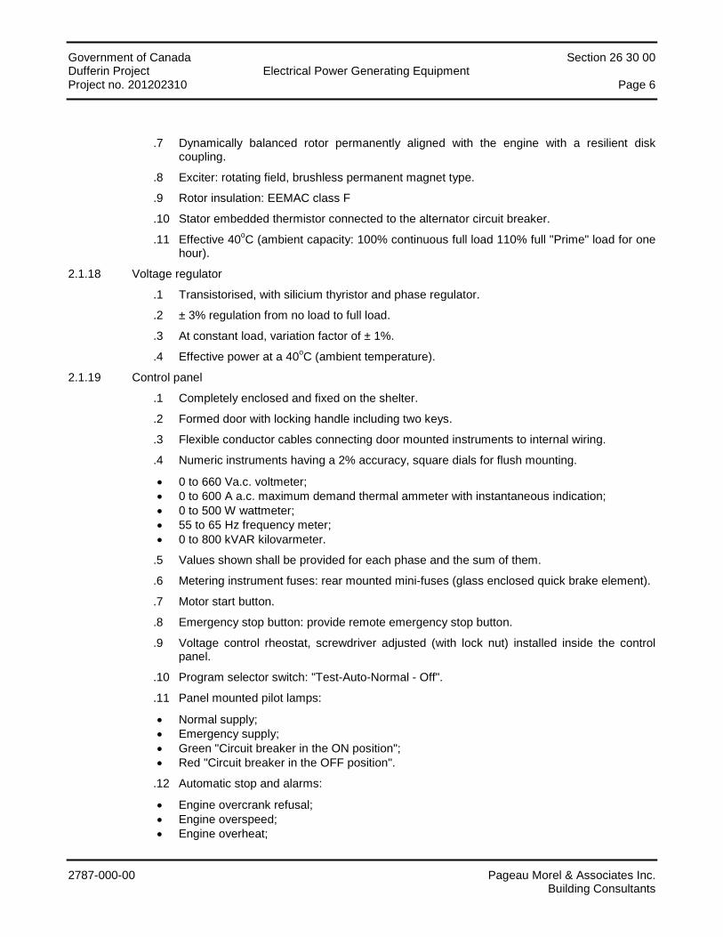
Government of Canada Section 26 30 00 Dufferin Project Electrical Power Generating Equipment Project no. 201202310 Page 6
2787-000-00 Pageau Morel & Associates Inc. Building Consultants
.7 Dynamically balanced rotor permanently aligned with the engine with a resilient disk coupling.
.8 Exciter: rotating field, brushless permanent magnet type.
.9 Rotor insulation: EEMAC class F
.10 Stator embedded thermistor connected to the alternator circuit breaker.
.11 Effective 40oC (ambient capacity: 100% continuous full load 110% full "Prime" load for one hour).
2.1.18 Voltage regulator
.1 Transistorised, with silicium thyristor and phase regulator.
.2 ± 3% regulation from no load to full load.
.3 At constant load, variation factor of ± 1%.
.4 Effective power at a 40oC (ambient temperature).
2.1.19 Control panel
.1 Completely enclosed and fixed on the shelter.
.2 Formed door with locking handle including two keys.
.3 Flexible conductor cables connecting door mounted instruments to internal wiring.
.4 Numeric instruments having a 2% accuracy, square dials for flush mounting.
• 0 to 660 Va.c. voltmeter; • 0 to 600 A a.c. maximum demand thermal ammeter with instantaneous indication; • 0 to 500 W wattmeter; • 55 to 65 Hz frequency meter; • 0 to 800 kVAR kilovarmeter.
.5 Values shown shall be provided for each phase and the sum of them.
.6 Metering instrument fuses: rear mounted mini-fuses (glass enclosed quick brake element).
.7 Motor start button.
.8 Emergency stop button: provide remote emergency stop button.
.9 Voltage control rheostat, screwdriver adjusted (with lock nut) installed inside the control panel.
.10 Program selector switch: "Test-Auto-Normal - Off".
.11 Panel mounted pilot lamps:
• Normal supply; • Emergency supply; • Green "Circuit breaker in the ON position"; • Red "Circuit breaker in the OFF position".
.12 Automatic stop and alarms:
• Engine overcrank refusal; • Engine overspeed; • Engine overheat;
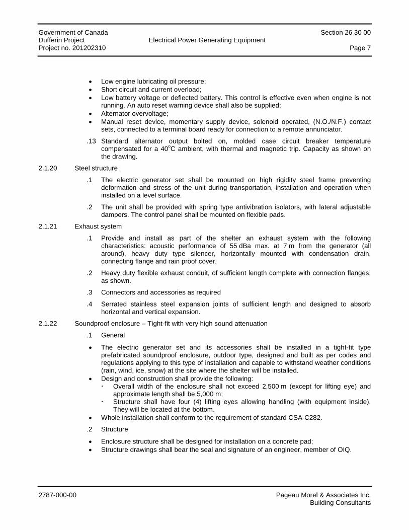
Government of Canada Section 26 30 00 Dufferin Project Electrical Power Generating Equipment Project no. 201202310 Page 7
2787-000-00 Pageau Morel & Associates Inc. Building Consultants
• Low engine lubricating oil pressure; • Short circuit and current overload; • Low battery voltage or deflected battery. This control is effective even when engine is not
running. An auto reset warning device shall also be supplied; • Alternator overvoltage; • Manual reset device, momentary supply device, solenoid operated, (N.O./N.F.) contact
sets, connected to a terminal board ready for connection to a remote annunciator.
.13 Standard alternator output bolted on, molded case circuit breaker temperature compensated for a 40oC ambient, with thermal and magnetic trip. Capacity as shown on the drawing.
2.1.20 Steel structure
.1 The electric generator set shall be mounted on high rigidity steel frame preventing deformation and stress of the unit during transportation, installation and operation when installed on a level surface.
.2 The unit shall be provided with spring type antivibration isolators, with lateral adjustable dampers. The control panel shall be mounted on flexible pads.
2.1.21 Exhaust system
.1 Provide and install as part of the shelter an exhaust system with the following characteristics: acoustic performance of 55 dBa max. at 7 m from the generator (all around), heavy duty type silencer, horizontally mounted with condensation drain, connecting flange and rain proof cover.
.2 Heavy duty flexible exhaust conduit, of sufficient length complete with connection flanges, as shown.
.3 Connectors and accessories as required
.4 Serrated stainless steel expansion joints of sufficient length and designed to absorb horizontal and vertical expansion.
2.1.22 Soundproof enclosure – Tight-fit with very high sound attenuation
.1 General
• The electric generator set and its accessories shall be installed in a tight-fit type prefabricated soundproof enclosure, outdoor type, designed and built as per codes and regulations applying to this type of installation and capable to withstand weather conditions (rain, wind, ice, snow) at the site where the shelter will be installed.
• Design and construction shall provide the following: Overall width of the enclosure shall not exceed 2,500 m (except for lifting eye) and
approximate length shall be 5,000 m; Structure shall have four (4) lifting eyes allowing handling (with equipment inside).
They will be located at the bottom. • Whole installation shall conform to the requirement of standard CSA-C282.
.2 Structure
• Enclosure structure shall be designed for installation on a concrete pad; • Structure drawings shall bear the seal and signature of an engineer, member of OIQ.

Government of Canada Section 26 30 00 Dufferin Project Electrical Power Generating Equipment Project no. 201202310 Page 8
2787-000-00 Pageau Morel & Associates Inc. Building Consultants
.3 Soundproofing
• Maximum sound level allowed is 55 dBA at a distance of 7 meters. An inlet and outlet shall have acoustic insulation. Enclosure walls shall also have acoustic insulation;
• Perform sound level measurement tests. Manufacturer shall certify the acoustic performance of the shelter and furnish a test report prepared by an independent acoustician engineer. Sound level shall be measured at 10 different locations around the shelter, in an open space, at full load.
.4 Enclosure construction
• Enclosure shall include steel maintenance doors, insulated, on sides and ends giving access to all components for inspection and maintenance;
• Hinges, locks, outdoor screws and other hardware to be stainless steel; • Enclosure frame shall be steel; • All exterior and interior surfaces to be sandblasted. Apply primer and urethane based paint
everywhere, color as per architect. No logo or trademark will be authorized on the outside of the shelter;
• Enclosure shall have all openings required for power and control cables Cable entrance will be underneath.
.5 Electrical equipment
• Furnish and install following equipments: one (1) 100 A distribution panel, 120/208 V, type NEMA 12 c/w main breaker; Two (2) weather type lighting fixtures, with 100 W lamp, 120 VAC, with toggle
switches; One (1) battery operated emergency lighting unit with two (2) lamps LED 4 W. Include
one DC switch with 0-15 min timer; One (1) 100 A breaker distribution panel, 120/208 VAC with main breaker, CEMA-12
type; One (1) 15 A, 120 VAC duplex receptacles; One (1) electric unit heater 208 VAC, c/w thermostat, having sufficient capacity to
maintain temperature at 10oC inside the enclosure when the generator set is at rest. • Wiring inside the shelter shall be RW-90 type in EMT type conduit.
.6 Ventilation system
• Air intake of the enclosure shall be located at the end of the enclosure and include motorized dampers opening at generator set starting and louvers. Exhaust air shall be located at the other end of the enclosure in vertical position and include motorized dampers and louvers;
• Louvers shall be the same color as the enclosure and have bird screen; • Dampers shall have thermal insulation.
.7 Fuel system
• Sub-base double wall steel fuel tank, capacity corresponding to 24 hours of operation at full load, built and certified as per CSA B139 standard and UL and ULC standards. Piping shall be black carbon seamless steel, as per applicable CSA standards. Following accessories are included: Emptying valve; Visual level indicator; Fill line connection; Overflow line connection;
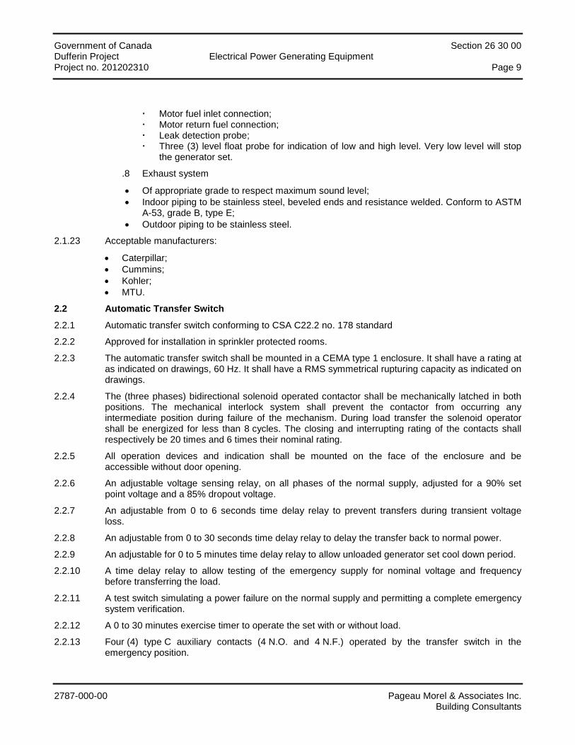
Government of Canada Section 26 30 00 Dufferin Project Electrical Power Generating Equipment Project no. 201202310 Page 9
2787-000-00 Pageau Morel & Associates Inc. Building Consultants
Motor fuel inlet connection; Motor return fuel connection; Leak detection probe; Three (3) level float probe for indication of low and high level. Very low level will stop
the generator set.
.8 Exhaust system
• Of appropriate grade to respect maximum sound level; • Indoor piping to be stainless steel, beveled ends and resistance welded. Conform to ASTM
A-53, grade B, type E; • Outdoor piping to be stainless steel.
2.1.23 Acceptable manufacturers:
• Caterpillar; • Cummins; • Kohler; • MTU.
2.2 Automatic Transfer Switch
2.2.1 Automatic transfer switch conforming to CSA C22.2 no. 178 standard
2.2.2 Approved for installation in sprinkler protected rooms.
2.2.3 The automatic transfer switch shall be mounted in a CEMA type 1 enclosure. It shall have a rating at as indicated on drawings, 60 Hz. It shall have a RMS symmetrical rupturing capacity as indicated on drawings.
2.2.4 The (three phases) bidirectional solenoid operated contactor shall be mechanically latched in both positions. The mechanical interlock system shall prevent the contactor from occurring any intermediate position during failure of the mechanism. During load transfer the solenoid operator shall be energized for less than 8 cycles. The closing and interrupting rating of the contacts shall respectively be 20 times and 6 times their nominal rating.
2.2.5 All operation devices and indication shall be mounted on the face of the enclosure and be accessible without door opening.
2.2.6 An adjustable voltage sensing relay, on all phases of the normal supply, adjusted for a 90% set point voltage and a 85% dropout voltage.
2.2.7 An adjustable from 0 to 6 seconds time delay relay to prevent transfers during transient voltage loss.
2.2.8 An adjustable from 0 to 30 seconds time delay relay to delay the transfer back to normal power.
2.2.9 An adjustable for 0 to 5 minutes time delay relay to allow unloaded generator set cool down period.
2.2.10 A time delay relay to allow testing of the emergency supply for nominal voltage and frequency before transferring the load.
2.2.11 A test switch simulating a power failure on the normal supply and permitting a complete emergency system verification.
2.2.12 A 0 to 30 minutes exercise timer to operate the set with or without load.
2.2.13 Four (4) type C auxiliary contacts (4 N.O. and 4 N.F.) operated by the transfer switch in the emergency position.
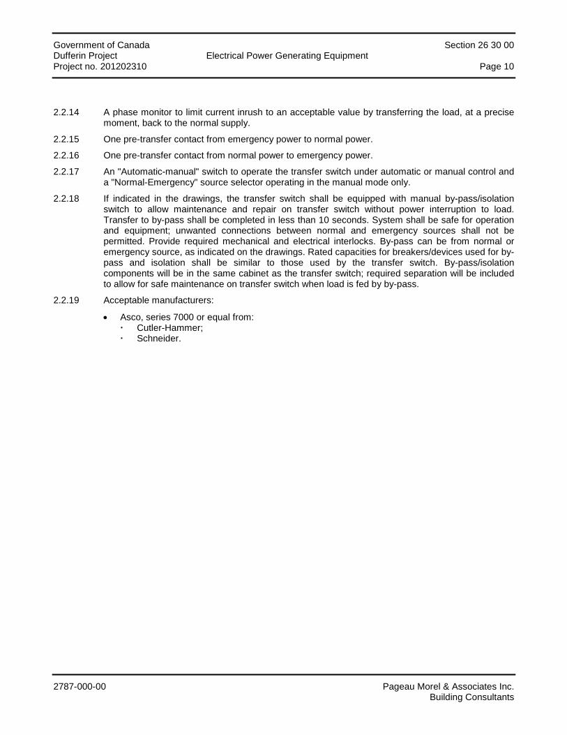
Government of Canada Section 26 30 00 Dufferin Project Electrical Power Generating Equipment Project no. 201202310 Page 10
2787-000-00 Pageau Morel & Associates Inc. Building Consultants
2.2.14 A phase monitor to limit current inrush to an acceptable value by transferring the load, at a precise moment, back to the normal supply.
2.2.15 One pre-transfer contact from emergency power to normal power.
2.2.16 One pre-transfer contact from normal power to emergency power.
2.2.17 An "Automatic-manual" switch to operate the transfer switch under automatic or manual control and a "Normal-Emergency" source selector operating in the manual mode only.
2.2.18 If indicated in the drawings, the transfer switch shall be equipped with manual by-pass/isolation switch to allow maintenance and repair on transfer switch without power interruption to load. Transfer to by-pass shall be completed in less than 10 seconds. System shall be safe for operation and equipment; unwanted connections between normal and emergency sources shall not be permitted. Provide required mechanical and electrical interlocks. By-pass can be from normal or emergency source, as indicated on the drawings. Rated capacities for breakers/devices used for by-pass and isolation shall be similar to those used by the transfer switch. By-pass/isolation components will be in the same cabinet as the transfer switch; required separation will be included to allow for safe maintenance on transfer switch when load is fed by by-pass.
2.2.19 Acceptable manufacturers:
• Asco, series 7000 or equal from: Cutler-Hammer; Schneider.
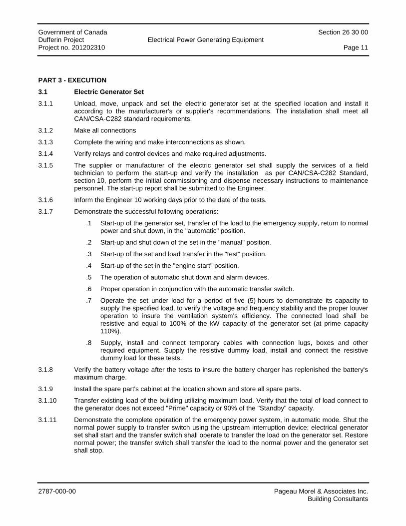
Government of Canada Section 26 30 00 Dufferin Project Electrical Power Generating Equipment Project no. 201202310 Page 11
2787-000-00 Pageau Morel & Associates Inc. Building Consultants
PART 3 - EXECUTION
3.1 Electric Generator Set
3.1.1 Unload, move, unpack and set the electric generator set at the specified location and install it according to the manufacturer's or supplier's recommendations. The installation shall meet all CAN/CSA-C282 standard requirements.
3.1.2 Make all connections
3.1.3 Complete the wiring and make interconnections as shown.
3.1.4 Verify relays and control devices and make required adjustments.
3.1.5 The supplier or manufacturer of the electric generator set shall supply the services of a field technician to perform the start-up and verify the installation as per CAN/CSA-C282 Standard, section 10, perform the initial commissioning and dispense necessary instructions to maintenance personnel. The start-up report shall be submitted to the Engineer.
3.1.6 Inform the Engineer 10 working days prior to the date of the tests.
3.1.7 Demonstrate the successful following operations:
.1 Start-up of the generator set, transfer of the load to the emergency supply, return to normal power and shut down, in the "automatic" position.
.2 Start-up and shut down of the set in the "manual" position.
.3 Start-up of the set and load transfer in the "test" position.
.4 Start-up of the set in the "engine start" position.
.5 The operation of automatic shut down and alarm devices.
.6 Proper operation in conjunction with the automatic transfer switch.
.7 Operate the set under load for a period of five (5) hours to demonstrate its capacity to supply the specified load, to verify the voltage and frequency stability and the proper louver operation to insure the ventilation system's efficiency. The connected load shall be resistive and equal to 100% of the kW capacity of the generator set (at prime capacity 110%).
.8 Supply, install and connect temporary cables with connection lugs, boxes and other required equipment. Supply the resistive dummy load, install and connect the resistive dummy load for these tests.
3.1.8 Verify the battery voltage after the tests to insure the battery charger has replenished the battery's maximum charge.
3.1.9 Install the spare part's cabinet at the location shown and store all spare parts.
3.1.10 Transfer existing load of the building utilizing maximum load. Verify that the total of load connect to the generator does not exceed "Prime" capacity or 90% of the "Standby" capacity.
3.1.11 Demonstrate the complete operation of the emergency power system, in automatic mode. Shut the normal power supply to transfer switch using the upstream interruption device; electrical generator set shall start and the transfer switch shall operate to transfer the load on the generator set. Restore normal power; the transfer switch shall transfer the load to the normal power and the generator set shall stop.
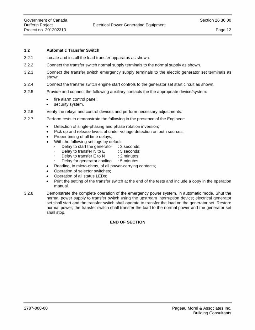
Government of Canada Section 26 30 00 Dufferin Project Electrical Power Generating Equipment Project no. 201202310 Page 12
2787-000-00 Pageau Morel & Associates Inc. Building Consultants
3.2 Automatic Transfer Switch
3.2.1 Locate and install the load transfer apparatus as shown.
3.2.2 Connect the transfer switch normal supply terminals to the normal supply as shown.
3.2.3 Connect the transfer switch emergency supply terminals to the electric generator set terminals as shown.
3.2.4 Connect the transfer switch engine start controls to the generator set start circuit as shown.
3.2.5 Provide and connect the following auxiliary contacts the the appropriate device/system:
• fire alarm control panel; • security system.
3.2.6 Verify the relays and control devices and perform necessary adjustments.
3.2.7 Perform tests to demonstrate the following in the presence of the Engineer:
• Detection of single-phasing and phase rotation inversion; • Pick up and release levels of under voltage detection on both sources; • Proper timing of all time delays; • With the following settings by default:
Delay to start the generator : 3 seconds; Delay to transfer N to E : 5 seconds; Delay to transfer E to N : 2 minutes; Delay for generator cooling : 5 minutes.
• Reading, in micro-ohms, of all power-carrying contacts; • Operation of selector switches; • Operation of all status LEDs; • Print the setting of the transfer switch at the end of the tests and include a copy in the operation
manual.
3.2.8 Demonstrate the complete operation of the emergency power system, in automatic mode. Shut the normal power supply to transfer switch using the upstream interruption device; electrical generator set shall start and the transfer switch shall operate to transfer the load on the generator set. Restore normal power; the transfer switch shall transfer the load to the normal power and the generator set shall stop.
END OF SECTION
Government of Canada Section 26 50 00 Dufferin Project Lighting Project no. 201202310 Page i
2787-000-00 Pageau Morel & Associates Inc. Building Consultants
TABLE OF CONTENTS
PART 1 - GENERAL ............................................................................................................................................... 1
1.1 General ..................................................................................................................................................................... 1 1.2 Scope of Work .......................................................................................................................................................... 1 1.3 Shop Drawings and Technical Data .......................................................................................................................... 1
PART 2 - PRODUCTS ............................................................................................................................................ 2
2.1 Lighting Fixtures ........................................................................................................................................................ 2 2.2 Ballasts ..................................................................................................................................................................... 2 2.3 Lamps ....................................................................................................................................................................... 4 2.4 Battery Operated Emergency Lighting ...................................................................................................................... 5 2.5 Exit Signs .................................................................................................................................................................. 6
PART 3 - EXECUTION ........................................................................................................................................... 7
3.1 Lighting Fixtures ........................................................................................................................................................ 7 3.2 Battery Operated Emergency Lighting ...................................................................................................................... 8 3.3 Exit Signs .................................................................................................................................................................. 8
APPENDIX
List of lighting fixtures
Government of Canada Section 26 50 00 Dufferin Project Lighting Project no. 201202310 Page 1
2787-000-00 Pageau Morel & Associates Inc. Building Consultants
PART 1 - GENERAL
1.1 General
1.1.1 Section 20 05 00 – "General Requirements Concerning Common Work Results" applies.
1.2 Scope of Work
1.2.1 Works of this section include, but are not limited to: the supply, handling, transportation, set up and installation of all systems and their accessories hereafter mentioned and/or shown on the drawings and which are to be operational. In general, all major parts of the works consist of, but are not limited to:
• Lighting fixtures; • Ballasts; • Lamps; • Exit signs; • Emergency lighting.
1.3 Shop Drawings and Technical Data
1.3.1 Submit shop drawings and technical data regarding Section 20 05 00 – "General Requirements Concerning Common Work Results".
1.3.2 Submit shop drawing and technical data of the following items:
• Lighting fixtures (one (1) per fixture type); • Ballasts; • Lamps; • Poles; • Exit signs; • Battery operated emergency lighting.
Government of Canada Section 26 50 00 Dufferin Project Lighting Project no. 201202310 Page 2
2787-000-00 Pageau Morel & Associates Inc. Building Consultants
PART 2 - PRODUCTS
2.1 Lighting Fixtures
2.1.1 Reference standards
.1 Lighting fixtures conforming to applicable standards.
2.1.2 Shop drawings
.1 Submit for approval all lighting fixtures photometric data, physical and electrical characteristics. Data to be established by an independent testing laboratory.
.2 Submit one separate shop drawing including all required information of each lighting fixture type.
2.1.3 Fluorescent lighting fixtures having a power feed higher than 150 volts to ground shall have an integral disconnect device, factory installed, and shall bear a permanent marking identifying the device, located in a visible location near the device.
2.1.4 Prepainted steel reflectors and housings shall have a high glass uniform finish exempt from blemishes or corrosion marks.
2.1.5 Manufacturing standards is given through the manufacturers catalog numbers in the list of lighting fixtures given in appendix.
2.1.6 Diffusers shall be made from pure prismatic acrylic, having low brilliance, 3 mm (0.125") thickness and of the K12-A type.
2.1.7 Approved manufacturers: As defined in the list of lighting fixtures.
2.2 Ballasts
2.2.1 Reference standards
.1 Fluorescent lamp ballasts conforming to CAN/CSA-C654 and other applicable CSA standards.
.2 High intensity discharge ballasts conforming to ANSI C82.4 and other applicable CSA standards.
2.2.2 Electronic ballasts shall conform to all ANSI and IEEE standards concerning total harmonic distortion and transients, such as IEEE 587 and ANSI C62.41. They shall conform to ANSI C82.11 standard for electronic ballasts. They shall bear the UL and CSA class P label.
2.2.3 They shall further conform to Communications Canada standards and to FCC (Federal Communication Commission) part 18, 15J standard for electromagnetic parasites (EMI) and radio frequency interference.
2.2.4 Supply lighting fixtures with integral ballasts, unless otherwise stated on drawings or in this specification.
2.2.5 Submit the shop drawing of the fixture and the technical specification of the ballast, along with the test report completed by LSC or any other recognized company.
2.2.6 Electronic ballasts for fluorescent lamps:
• Instant Start ballasts; • 120 V or 347 V as shown; • Class A nominal sound level; • Maximum crest factor: 1.7; • Minimum power factor: 98%;
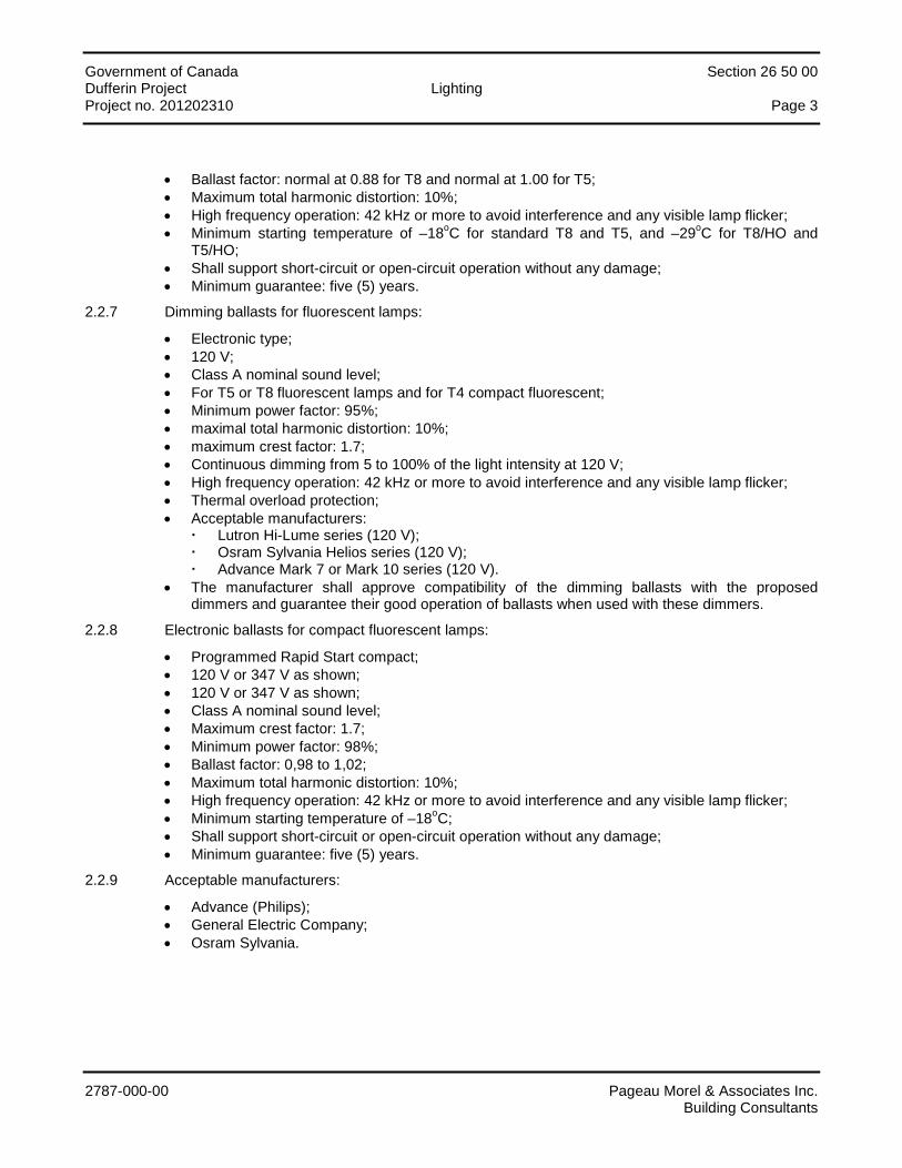
Government of Canada Section 26 50 00 Dufferin Project Lighting Project no. 201202310 Page 3
2787-000-00 Pageau Morel & Associates Inc. Building Consultants
• Ballast factor: normal at 0.88 for T8 and normal at 1.00 for T5; • Maximum total harmonic distortion: 10%; • High frequency operation: 42 kHz or more to avoid interference and any visible lamp flicker; • Minimum starting temperature of –18oC for standard T8 and T5, and –29oC for T8/HO and
T5/HO; • Shall support short-circuit or open-circuit operation without any damage; • Minimum guarantee: five (5) years.
2.2.7 Dimming ballasts for fluorescent lamps:
• Electronic type; • 120 V; • Class A nominal sound level; • For T5 or T8 fluorescent lamps and for T4 compact fluorescent; • Minimum power factor: 95%; • maximal total harmonic distortion: 10%; • maximum crest factor: 1.7; • Continuous dimming from 5 to 100% of the light intensity at 120 V; • High frequency operation: 42 kHz or more to avoid interference and any visible lamp flicker; • Thermal overload protection; • Acceptable manufacturers:
Lutron Hi-Lume series (120 V); Osram Sylvania Helios series (120 V); Advance Mark 7 or Mark 10 series (120 V).
• The manufacturer shall approve compatibility of the dimming ballasts with the proposed dimmers and guarantee their good operation of ballasts when used with these dimmers.
2.2.8 Electronic ballasts for compact fluorescent lamps:
• Programmed Rapid Start compact; • 120 V or 347 V as shown; • 120 V or 347 V as shown; • Class A nominal sound level; • Maximum crest factor: 1.7; • Minimum power factor: 98%; • Ballast factor: 0,98 to 1,02; • Maximum total harmonic distortion: 10%; • High frequency operation: 42 kHz or more to avoid interference and any visible lamp flicker; • Minimum starting temperature of –18oC; • Shall support short-circuit or open-circuit operation without any damage; • Minimum guarantee: five (5) years.
2.2.9 Acceptable manufacturers:
• Advance (Philips); • General Electric Company; • Osram Sylvania.
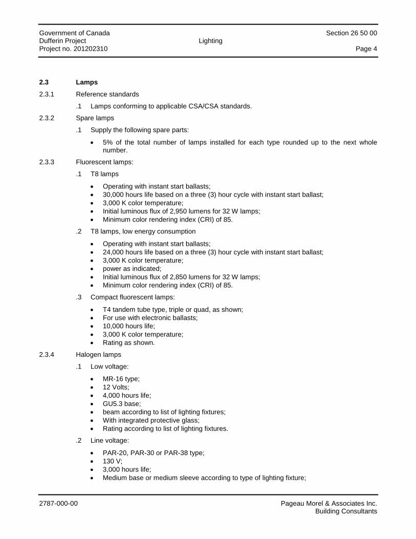
Government of Canada Section 26 50 00 Dufferin Project Lighting Project no. 201202310 Page 4
2787-000-00 Pageau Morel & Associates Inc. Building Consultants
2.3 Lamps
2.3.1 Reference standards
.1 Lamps conforming to applicable CSA/CSA standards.
2.3.2 Spare lamps
.1 Supply the following spare parts:
• 5% of the total number of lamps installed for each type rounded up to the next whole number.
2.3.3 Fluorescent lamps:
.1 T8 lamps
• Operating with instant start ballasts; • 30,000 hours life based on a three (3) hour cycle with instant start ballast; • 3,000 K color temperature; • Initial luminous flux of 2,950 lumens for 32 W lamps; • Minimum color rendering index (CRI) of 85.
.2 T8 lamps, low energy consumption
• Operating with instant start ballasts; • 24,000 hours life based on a three (3) hour cycle with instant start ballast; • 3,000 K color temperature; • power as indicated; • Initial luminous flux of 2,850 lumens for 32 W lamps; • Minimum color rendering index (CRI) of 85.
.3 Compact fluorescent lamps:
• T4 tandem tube type, triple or quad, as shown; • For use with electronic ballasts; • 10,000 hours life; • 3,000 K color temperature; • Rating as shown.
2.3.4 Halogen lamps
.1 Low voltage:
• MR-16 type; • 12 Volts; • 4,000 hours life; • GU5.3 base; • beam according to list of lighting fixtures; • With integrated protective glass; • Rating according to list of lighting fixtures.
.2 Line voltage:
• PAR-20, PAR-30 or PAR-38 type; • 130 V; • 3,000 hours life; • Medium base or medium sleeve according to type of lighting fixture;
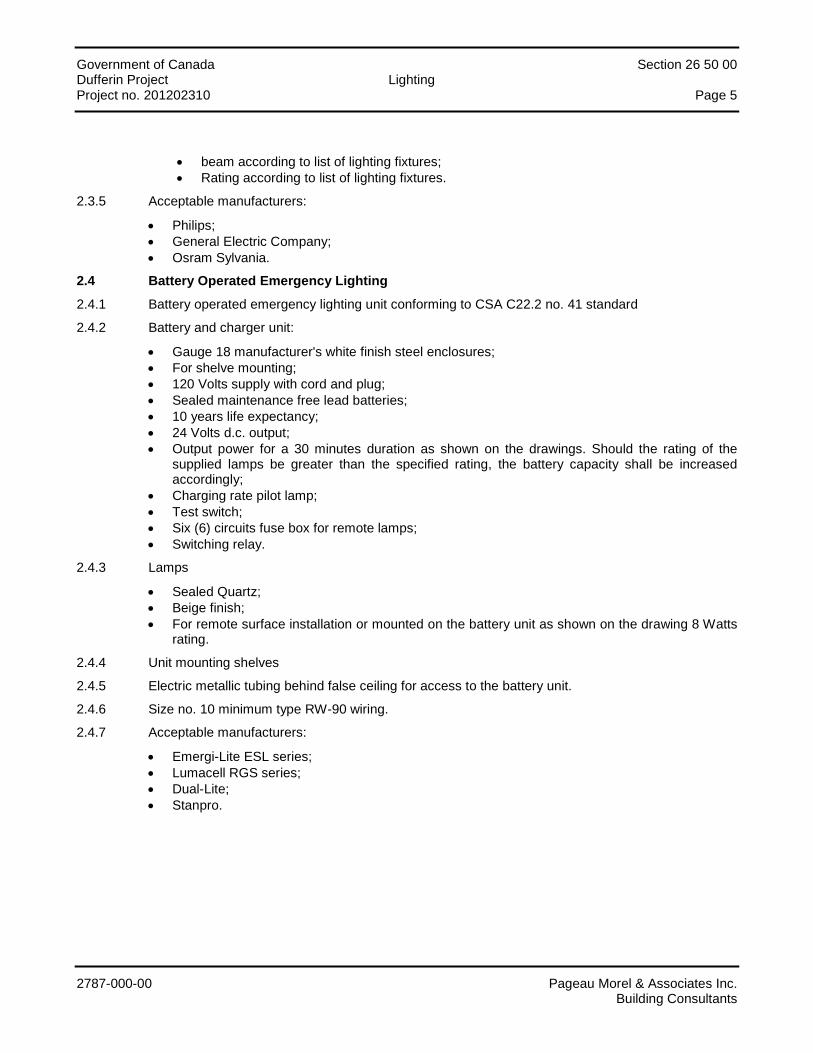
Government of Canada Section 26 50 00 Dufferin Project Lighting Project no. 201202310 Page 5
2787-000-00 Pageau Morel & Associates Inc. Building Consultants
• beam according to list of lighting fixtures; • Rating according to list of lighting fixtures.
2.3.5 Acceptable manufacturers:
• Philips; • General Electric Company; • Osram Sylvania.
2.4 Battery Operated Emergency Lighting
2.4.1 Battery operated emergency lighting unit conforming to CSA C22.2 no. 41 standard
2.4.2 Battery and charger unit:
• Gauge 18 manufacturer's white finish steel enclosures; • For shelve mounting; • 120 Volts supply with cord and plug; • Sealed maintenance free lead batteries; • 10 years life expectancy; • 24 Volts d.c. output; • Output power for a 30 minutes duration as shown on the drawings. Should the rating of the
supplied lamps be greater than the specified rating, the battery capacity shall be increased accordingly;
• Charging rate pilot lamp; • Test switch; • Six (6) circuits fuse box for remote lamps; • Switching relay.
2.4.3 Lamps
• Sealed Quartz; • Beige finish; • For remote surface installation or mounted on the battery unit as shown on the drawing 8 Watts
rating.
2.4.4 Unit mounting shelves
2.4.5 Electric metallic tubing behind false ceiling for access to the battery unit.
2.4.6 Size no. 10 minimum type RW-90 wiring.
2.4.7 Acceptable manufacturers:
• Emergi-Lite ESL series; • Lumacell RGS series; • Dual-Lite; • Stanpro.
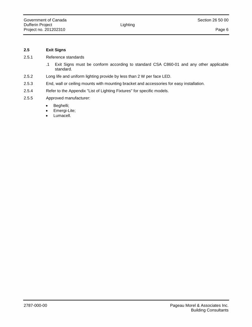
Government of Canada Section 26 50 00 Dufferin Project Lighting Project no. 201202310 Page 6
2787-000-00 Pageau Morel & Associates Inc. Building Consultants
2.5 Exit Signs
2.5.1 Reference standards
.1 Exit Signs must be conform according to standard CSA C860-01 and any other applicable standard.
2.5.2 Long life and uniform lighting provide by less than 2 W per face LED.
2.5.3 End, wall or ceiling mounts with mounting bracket and accessories for easy installation.
2.5.4 Refer to the Appendix "List of Lighting Fixtures" for specific models.
2.5.5 Approved manufacturer:
• Beghelli; • Emergi-Lite; • Lumacell.
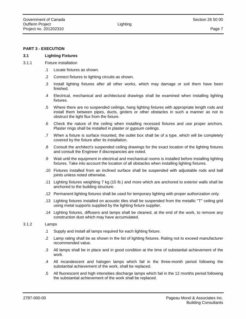
Government of Canada Section 26 50 00 Dufferin Project Lighting Project no. 201202310 Page 7
2787-000-00 Pageau Morel & Associates Inc. Building Consultants
PART 3 - EXECUTION
3.1 Lighting Fixtures
3.1.1 Fixture installation
.1 Locate fixtures as shown.
.2 Connect fixtures to lighting circuits as shown.
.3 Install lighting fixtures after all other works, which may damage or soil them have been finished.
.4 Electrical, mechanical and architectural drawings shall be examined when installing lighting fixtures.
.5 Where there are no suspended ceilings, hang lighting fixtures with appropriate length rods and install them between pipes, ducts, girders or other obstacles in such a manner as not to obstruct the light flux from the fixture.
.6 Check the nature of the ceiling when installing recessed fixtures and use proper anchors. Plaster rings shall be installed in plaster or gypsum ceilings.
.7 When a fixture is surface mounted, the outlet box shall be of a type, which will be completely covered by the fixture after its installation.
.8 Consult the architect's suspended ceiling drawings for the exact location of the lighting fixtures and consult the Engineer if discrepancies are noted.
.9 Wait until the equipment in electrical and mechanical rooms is installed before installing lighting fixtures. Take into account the location of all obstacles when installing lighting fixtures.
.10 Fixtures installed from an inclined surface shall be suspended with adjustable rods and ball joints unless noted otherwise.
.11 Lighting fixtures weighting 7 kg (15 lb.) and more which are anchored to exterior walls shall be anchored to the building structure.
.12 Permanent lighting fixtures shall be used for temporary lighting with proper authorization only.
.13 Lighting fixtures installed on acoustic tiles shall be suspended from the metallic "T" ceiling grid using metal supports supplied by the lighting fixture supplier.
.14 Lighting fixtures, diffusers and lamps shall be cleaned, at the end of the work, to remove any construction dust which may have accumulated.
3.1.2 Lamps
.1 Supply and install all lamps required for each lighting fixture.
.2 Lamp rating shall be as shown in the list of lighting fixtures. Rating not to exceed manufacturer recommended value.
.3 All lamps shall be in place and in good condition at the time of substantial achievement of the work.
.4 All incandescent and halogen lamps which fail in the three-month period following the substantial achievement of the work, shall be replaced.
.5 All fluorescent and high intensities discharge lamps which fail in the 12 months period following the substantial achievement of the work shall be replaced.

Government of Canada Section 26 50 00 Dufferin Project Lighting Project no. 201202310 Page 8
2787-000-00 Pageau Morel & Associates Inc. Building Consultants
3.1.3 Ballasts
.1 Noisy ballasts shall be replaced immediately.
3.2 Battery Operated Emergency Lighting
3.2.1 Group battery units and install lampheads distance as indicated.
3.2.2 Install all battery units and lampheads after all other works, which may damage or soil them, have been finished.
3.2.3 Check the nature of ceilings or walls when installing recessed fixtures and use proper anchors. Plaster rings shall be installed in plaster or gypsum ceilings or wall.
3.2.4 The Contractor must take into account the location of all obstacles such as beam, pipes, duct in such a manner as not to obstruct the light distribution from the fixture.
3.2.5 Battery units and lampheads must be cleaned, at the end of the work, to remove any construction dust which may have accumulated. Connect all battery units as per indications.
3.2.6 Check that every battery charger is working properly simulate electrical power failure tot validate the proper functioning of the system.
3.2.7 All lamps which fail in the four (4) months period following the substantial achievement of the work shall be replaced.
3.3 Exit Signs
3.3.1 Install all exit signs after all other works, which may damage or soil them, have been finished.
3.3.2 The contractor must take into account the location of all obstacles such as beam, pipes, duct in such a manner as not to obstruct the visibility of the exit sign.
3.3.3 When an exit sign is surface mount, the electrical shall be install in such a manner that the final installation does not show any part of the box or it's cover.
3.3.4 Exit signs must be cleaned, at the end of the work, to remove any construction dust which may have accumulated. Connect all exit signs as per indications.
END OF SECTION

Government of Canada Section 26 50 00 Dufferin Project Lighting Project no. 201202310
2787-000-00 Pageau Morel & Associates Inc. Building Consultants
APPENDIX
List of Lighting Fixtures
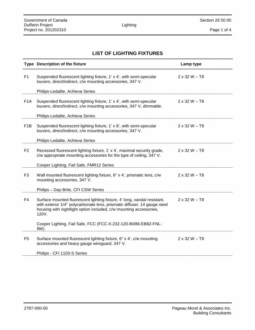
Government of Canada Section 26 50 00 Dufferin Project Lighting Project no. 201202310 Page 1 of 4
2787-000-00 Pageau Morel & Associates Inc. Building Consultants
LIST OF LIGHTING FIXTURES
Type Description of the fixture Lamp type
F1 Suspended fluorescent lighting fixture, 1’ x 4’, with semi-specular louvers, direct/indirect, c/w mounting accessories, 347 V.
Philips-Ledalite, Achieva Series
2 x 32 W – T8
F1A Suspended fluorescent lighting fixture, 1’ x 4’, with semi-specular louvers, direct/indirect, c/w mounting accessories, 347 V, dimmable.
Philips-Ledalite, Achieva Series
2 x 32 W – T8
F1B Suspended fluorescent lighting fixture, 1’ x 8’, with semi-specular louvers, direct/indirect, c/w mounting accessories, 347 V.
Philips-Ledalite, Achieva Series
2 x 32 W – T8
F2 Recessed fluorescent lighting fixture, 1’ x 4’, maximal security grade, c/w appropriate mounting accessories for the type of ceiling, 347 V.
Cooper Lighting, Fail Safe, FMR12 Series
2 x 32 W – T8
F3 Wall mounted fluorescent lighting fixture, 6" x 4’, prismatic lens, c/w mounting accessories, 347 V.
Philips – Day-Brite, CFI CSW Series
2 x 32 W – T8
F4 Surface mounted fluorescent lgihting fixture, 4’ long, vandal resistant, with exterior 1/4’’ polycarbonate lens, prismatic diffuser, 14 gauge steel housing with nightlight option included, c/w mounting accessories, 120V.
Cooper Lighting, Fail Safe, FCC (FCC-X-232-120-80/86-EB82-FNL-9W)
2 x 32 W – T8
F5 Surface mounted fluorescent lgihting fixture, 6" x 4’, c/w mounting accessories and heavy gauge wireguard, 347 V.
Philips - CFI 1103-S Series
2 x 32 W – T8
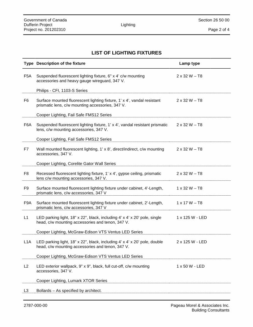
Government of Canada Section 26 50 00 Dufferin Project Lighting Project no. 201202310 Page 2 of 4
2787-000-00 Pageau Morel & Associates Inc. Building Consultants
LIST OF LIGHTING FIXTURES
Type Description of the fixture Lamp type
F5A Suspended fluorescent lighting fixture, 6" x 4’ c/w mounting accessories and heavy gauge wireguard, 347 V.
Philips - CFI, 1103-S Series
2 x 32 W – T8
F6 Surface mounted fluorescent lighting fixture, 1’ x 4’, vandal resistant prismatic lens, c/w mounting accessories, 347 V.
Cooper Lighting, Fail Safe FMS12 Series
2 x 32 W – T8
F6A Suspended fluorescent lighting fixture, 1’ x 4’, vandal resistant prismatic lens, c/w mounting accessories, 347 V.
Cooper Lighting, Fail Safe FMS12 Series
2 x 32 W – T8
F7 Wall mounted fluorescent lighting, 1’ x 8’, direct/indirect, c/w mounting accessories, 347 V.
Cooper Lighting, Corelite Gator Wall Series
2 x 32 W – T8
F8 Recessed fluorescent lighting fixture, 1’ x 4’, gypse ceiling, prismatic lens c/w mounting accessories, 347 V.
2 x 32 W – T8
F9 Surface mounted fluorescent lighting fixture under cabinet, 4’-Length, prismatic lens, c/w accessories, 347 V
1 x 32 W – T8
F9A Surface mounted fluorescent lighting fixture under cabinet, 2’-Length, prismatic lens, c/w accessories, 347 V
1 x 17 W – T8
L1 LED parking light, 18" x 22", black, including 4’ x 4’ x 20’ pole, single head, c/w mounting accessories and tenon, 347 V.
Cooper Lighting, McGraw-Edison VTS Ventus LED Series
1 x 125 W - LED
L1A LED parking light, 18" x 22", black, including 4’ x 4’ x 20’ pole, double head, c/w mounting accessories and tenon, 347 V.
Cooper Lighting, McGraw-Edison VTS Ventus LED Series
2 x 125 W - LED
L2 LED exterior wallpack, 9" x 9", black, full cut-off, c/w mounting accessories, 347 V.
Cooper Lighting, Lumark XTOR Series
1 x 50 W - LED
L3 Bollards – As specified by architect.
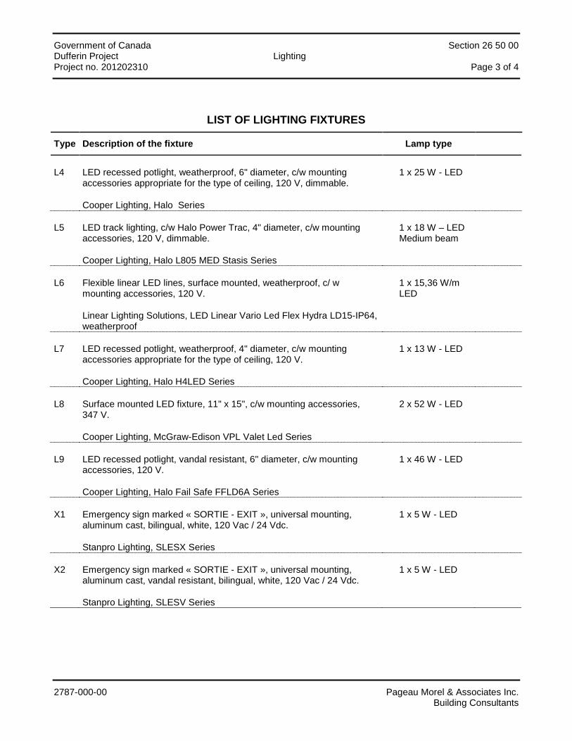
Government of Canada Section 26 50 00 Dufferin Project Lighting Project no. 201202310 Page 3 of 4
2787-000-00 Pageau Morel & Associates Inc. Building Consultants
LIST OF LIGHTING FIXTURES
Type Description of the fixture Lamp type
L4 LED recessed potlight, weatherproof, 6" diameter, c/w mounting accessories appropriate for the type of ceiling, 120 V, dimmable.
Cooper Lighting, Halo Series
1 x 25 W - LED
L5 LED track lighting, c/w Halo Power Trac, 4" diameter, c/w mounting accessories, 120 V, dimmable.
Cooper Lighting, Halo L805 MED Stasis Series
1 x 18 W – LED Medium beam
L6 Flexible linear LED lines, surface mounted, weatherproof, c/ w mounting accessories, 120 V.
Linear Lighting Solutions, LED Linear Vario Led Flex Hydra LD15-IP64, weatherproof
1 x 15,36 W/m LED
L7 LED recessed potlight, weatherproof, 4" diameter, c/w mounting accessories appropriate for the type of ceiling, 120 V.
Cooper Lighting, Halo H4LED Series
1 x 13 W - LED
L8 Surface mounted LED fixture, 11" x 15", c/w mounting accessories, 347 V.
Cooper Lighting, McGraw-Edison VPL Valet Led Series
2 x 52 W - LED
L9 LED recessed potlight, vandal resistant, 6" diameter, c/w mounting accessories, 120 V.
Cooper Lighting, Halo Fail Safe FFLD6A Series
1 x 46 W - LED
X1 Emergency sign marked « SORTIE - EXIT », universal mounting, aluminum cast, bilingual, white, 120 Vac / 24 Vdc.
Stanpro Lighting, SLESX Series
1 x 5 W - LED
X2 Emergency sign marked « SORTIE - EXIT », universal mounting, aluminum cast, vandal resistant, bilingual, white, 120 Vac / 24 Vdc.
Stanpro Lighting, SLESV Series
1 x 5 W - LED

Government of Canada Section 26 50 00 Dufferin Project Lighting Project no. 201202310 Page 4 of 4
2787-000-00 Pageau Morel & Associates Inc. Building Consultants
Notes:
1. Only the specified products will be considered. When more than one product is specified, the choice is left open. For non vandal resistant and maximum security fixtures, equivalents from Acuity, Cooper or Philips shall be accepted.
2. Substitution may be proposed at the time of tendering only providing that they are proposed on the "Request for Substitution Form".
The proof of equivalence shall be done after the bid, not at the time of the bid.
Supply specification data for the proposed and specified product. The Engineer reserves the right to request a sample of each fixture.
Government of Canada Section 27 10 05 Dufferin Project Structured Cabling Project no. 201202310 Page i
2787-000-00 Pageau Morel & Associates Inc. Building Consultants
TABLE OF CONTENTS
PART 1 - GENERAL ............................................................................................................................................... 1
1.1 System description .................................................................................................................................................... 1 1.2 Scope of works ......................................................................................................................................................... 1 1.3 References................................................................................................................................................................ 1 1.4 Submittals ................................................................................................................................................................. 2 1.5 Categories 6 certification and product selection ........................................................................................................ 2 1.6 Outlet locations ......................................................................................................................................................... 2
PART 2 - PRODUCTS ............................................................................................................................................ 3
2.1 General ..................................................................................................................................................................... 3 2.2 Category 6 four-pair twisted pair cable ..................................................................................................................... 3 2.3 Category 6 connectors .............................................................................................................................................. 3 2.4 Outlets ...................................................................................................................................................................... 3 2.5 Rack mount patch panels and horizontal cable manager ......................................................................................... 4 2.6 UTP CAT. 6 RJ45-RJ45 Patch cords ........................................................................................................................ 4 2.7 Rack and accessories ............................................................................................................................................... 4 2.8 Velcro Tie .................................................................................................................................................................. 4
PART 3 - EXECUTION ........................................................................................................................................... 5
3.1 Initiation meeting ....................................................................................................................................................... 5 3.2 Rack and accessories ............................................................................................................................................... 5 3.3 Termination ............................................................................................................................................................... 5 3.4 Horizontal distribution cables .................................................................................................................................... 5 3.5 Outlets ...................................................................................................................................................................... 6 3.6 Labeling .................................................................................................................................................................... 6 3.7 Field quality control ................................................................................................................................................... 7
Government of Canada Section 27 10 05 Dufferin Project Structured Cabling Project no. 201202310 Page 1
2787-000-00 Pageau Morel & Associates Inc. Building Consultants
PART 1 - GENERAL
1.1 System description
1.1.1 Structured telecommunications wiring system consist of unshielded-twisted-pair cables, terminations, connectors, cross-connection hardware and related equipment installed inside building for occupant's telecommunications systems, including voice over IP, data, and AV.
1.1.2 In general, each workstation will be wired with two communication cables, unless otherwise indicated in drawings. All horizontal cables link work areas to the telecom room located on the second floor.
1.2 Scope of works
1.2.1 Works of this section include, but are not limited to: the supply, handling, transportation, set up and installation of all systems and their accessories hereafter mentioned and/or shown on the drawings and which are to be operational. In general, all major parts of the works consist of, but are not limited to:
.1 Equipment rack in the telecom room.
.2 Horizontal copper distribution network based on 4-pair cables, Category 6 certified.
.3 Rack mount RJ45 patch panels.
.4 Wall mount outlets and modular furniture telecommunication outlets.
.5 Copper patch cords and junction cords.
.6 The labeling and the documentation of the entire cabling system.
.7 Tests and reports.
.8 The manufacturer certification of the structured cabling system.
1.3 References
1.3.1 Canadian Standards Association (CSA International)
.1 CSA-C22.2 No. 214-02, Communications Cables (Bi-National standard with UL 444).
.2 CSA-C22.2 No. 232-M1988(R2004), Optical Fibber Cables.
1.3.2 Telecommunications Industry Association (TIA)/Electronic Industries Alliance (EIA)
.1 TIA/EIA 568-C.0, Generic Telecommunications Cabling for Customer Premises;
.2 TIA/EIA 568-C.1, Commercial Building Telecommunications Cabling Standard;
.3 TIA/EIA 568-C.2, Balanced Twisted-Pair Telecommunication Cabling and Components Standard;
.4 TIA/EIA 568-C.3, Optical Fibber Cabling Components Standard;
.5 TIA/EIA 569-C, Commercial Building Standards for Telecommunications Pathways and Spaces;
.6 TIA/EIA-606-B, Administration Standard for the Commercial Telecommunications Infrastructure.
.7 TIA TSB-140, Telecommunications Systems Bulletin - Additional Guidelines for Field-Testing Length, Loss and Polarity of Optical Fibber Cabling Systems.

Government of Canada Section 27 10 05 Dufferin Project Structured Cabling Project no. 201202310 Page 2
2787-000-00 Pageau Morel & Associates Inc. Building Consultants
.8 TIA/EIA 607-B , Generic telecommunications bonding and grounding (Earthing) for customer premises;
1.4 Submittals
1.4.1 The following shop drawings shall be submitted for approval, supply four hard copies for each.
.1 Categories 6 UTP copper cable;
.2 RJ 45 patch panels and horizontal cable manager;
.3 Wall mount and modular furniture telecommunication outlets;
.4 Copper patch cords;
.5 Copper junction cords;
.6 Rack and accessories.
1.4.2 As-built Records and Drawings:
.1 Provide and place one hard copy of as-built records in the telecom room in a plan holder.
1.5 Categories 6 certification and product selection
1.5.1 The manufacturer Categories 6 certification is requested for this project.
1.5.2 All the wiring system components described here will be provided from Belden or Panduit, unless otherwise specified.
1.5.3 Even if subcontractors intervene as workers or technical advisor, the Owner will address request only to the main contractor.
1.5.4 All works will be done and controlled by telecommunication technicians, contractors and project managers with sufficient know how and skills for installation of communication networks supporting voice, data and multimedia transmissions, following the manufacturer requirements and in compliance with its approved methods.
1.5.5 The technicians and subcontractors must have followed the manufacturer training and have the sufficient expertise to install and test those equipment. The manufacturer certification of the technicians and subcontractors is required.
1.6 Outlet locations
1.6.1 The outlet location shown on the drawings is approximate. The exact location shall satisfy and shall be conform to instructions and requirements of the current specification and satisfy the conditions at the moment of installation. Consult the Engineer if required.
1.6.2 Do not install outlets back to back in the same wall; leave a minimum of 150 mm (6") space between boxes.
1.6.3 The Engineer may request the relocation of outlets, without cost or credit, providing that the request be made prior to the installation, inside a 3.05 m (10') radius of the original location and that the installation is similar to the original type.
1.6.4 Make necessary adjustments when interior finish is completed.

Government of Canada Section 27 10 05 Dufferin Project Structured Cabling Project no. 201202310 Page 3
2787-000-00 Pageau Morel & Associates Inc. Building Consultants
PART 2 - PRODUCTS
2.1 General
2.1.1 The indicated products are from Belden, equivalent Panduit products shall be approved.
2.1.2 The Owner may change the indicated product colors.
2.2 Category 6 four-pair twisted pair cable
2.2.1 Transmission cable, Category 6 certified, compliant with the standards TIA/EIA-568-C, ANSI/CEA S-80-576, last revision, ACNOR C22.2 No 214-94, approved CSA FT-4 (CMR), to be used in plenum.
2.2.2 Four pairs of twisted conductors, #23 AWG, thermoplastic insulation, PVC jacket FT4 (CMR) certified, white color, overall diameter less than 6,6 mm, minimum bend radius of 25.4 mm at 20°C ± 1°C, without damage to the conductors and the jacket.
2.2.3 The following information items will be printed on the jacket at regular interval:
.1 Manufacturer;
.2 Model;
.3 Transmission category;
.4 Manufactured date.
2.2.4 Horizontal distribution, model Belden Gigaflex 2400 series, FT4, 4-pair, white color.
2.3 Category 6 connectors
2.3.1 Category 6 RJ 45 connector, T568-A termination method, compliant with the standard EIA/TIA-568-C and the section “Category 6 certification and product selection”.
2.3.2 For the horizontal distribution, models Belden GigaFlex PS6 Module T568A/B or approved equivalent. White color for the user end and black color for the telecommunication end.
2.3.3 All connectors will be supplied with Protective Cap.
2.4 Outlets
2.4.1 Wall mount outlet
.1 Faceplate to be mounted on single or dual gang electrical box, flush and vertical mount, accommodating 2 and 4 modules (RJ45 connectors).
.2 Model Belden AX10143 Interface Plate, 2-port or approved equivalent, color to be coordinated with the Architect.
.3 Model Belden AX10143 Interface Plate, 4-port or approved equivalent, color to be coordinated with the Architect.
2.4.2 Modular furniture outlet
.1 Faceplate to be mounted in modular furniture’s, flush and horizontal mount, accommodating 4 modules (RJ45 connectors).
.2 Model Belden AX100927 MDVO Modular Furniture Adapter, 4-port.
.3 Color to be coordinated with the Architect.
Government of Canada Section 27 10 05 Dufferin Project Structured Cabling Project no. 201202310 Page 4
2787-000-00 Pageau Morel & Associates Inc. Building Consultants
2.4.3 Monument outlet
.1 Coordinate the right models on site.
2.4.4 Supply and install outlets as indicated in drawings, supply blank plate and blank insert at any unused outlet location. Use Belden MDVO Blank Inserts, with same color as the faceplate.
2.5 Rack mount patch panels and horizontal cable manager
2.5.1 Horizontal distribution patch panel, 19 inches EIA rack mountable, Category 6 certified. Model Belden GigaFlex Patch Panel Category 6, 2U, 48 ports RJ45, black color.
2.5.2 Identification zone for each port in the front, in compliant with EIA/TIA-606-B.
2.5.3 Horizontal cable manager, 2U, model Belden BHH192U, black color.
2.6 UTP CAT. 6 RJ45-RJ45 Patch cords
2.6.1 Patch and junction cords model Belden IBDN PS6+ modular Cord or approved equivalent, Category 6 certified, CMR FT4 rated, RJ45-RJ45 connectors.
2.6.2 The patch and junction cords will be installed by the Owner.
2.6.3 Description and quantities:
.1 Cat.6 patch cord, 1.5m length (5 feet), white color, quantity = 80.
.2 Cat.6 junction cord, 2.1 m length (7 feet), beige color, quantity = 80.
2.7 Rack and accessories
2.7.1 EIA 19 inches rack mount, 2 posts, model Belden AX101174 rack kit, including 2 vertical cable manager (AX101180).
2.8 Velcro Tie
2.8.1 Use Velcro tie to join cables together where needed. Velcro tie, elastic and flexible, plastic material, model PANDUIT TAK-TY.

Government of Canada Section 27 10 05 Dufferin Project Structured Cabling Project no. 201202310 Page 5
2787-000-00 Pageau Morel & Associates Inc. Building Consultants
PART 3 - EXECUTION
3.1 Initiation meeting
3.1.1 The Owner and the Consultant will meet with the communications cabling contractor as soon as the contractor is known. The purpose of this meeting will be to complete and review the scope of works, materials, address any questions from the contractor, and review installation best practices. In addition, the contractor may elect to view mock-ups of all major information system components.
3.1.2 Project execution, the works will be completed following all Owner general instructions.
3.1.3 The quantities to be supplied shall be as indicated in drawings and specifications.
3.2 Rack and accessories
3.2.1 Validate the exact locations with the Owner prior the final installation.
3.2.2 The rack will be bolted to the concrete floor.
3.2.3 The rack will be bounded to the local telecommunication grounding bus bar using its own 6 AWG cable, in compliance with TIA/EIA 607-B.
3.2.4 Protect the rack against dust during works.
3.3 Termination
3.3.1 Install termination and cross-connect hardware (RJ45 patch panels and horizontal cable managers) in the telecom room and according to manufacturers' instructions. Install one horizontal cable manager for each path panel.
3.3.2 Do not exceed the minimum bed radius of cables.
3.3.3 Once installed, the patch cords do not support any coercion to avoid any damage or modification of the cable internal structure.
3.3.4 During works, do not let patch cords on the floor to avoid walking on or to be damaged.
3.3.5 Identify and label all patch cords.
3.3.6 Identification and labeling shall be completed as indicated in drawings and in accordance to TIA/EIA-606-B.
3.3.7 Use Velcro ties to harness all patch cords.
3.4 Horizontal distribution cables
3.4.1 Do not install cables if all wall and ceiling where painting works are not completed. It’s formally forbidden to paint any communication cable. Coordinate all works with the other Divisions.
3.4.2 Refer to the « sealing barriers » section for crossing fireproof floors, walls and ceilings.
3.4.3 Install and terminate all cables at the locations indicated in drawings.
3.4.4 Install horizontal cables as indicated in conduits and cabletray.
3.4.5 Do not fill conduits more than 40% conduit capacity as per TIA-569-C.
3.4.6 Do not remove cable jacket more than 25 mm at each end. Do not open the pair twist more than 13 mm.
3.4.7 Use indicated Velcro ties to harness cables together.
3.4.8 Do not install cable in length greater than 90 m.
Government of Canada Section 27 10 05 Dufferin Project Structured Cabling Project no. 201202310 Page 6
2787-000-00 Pageau Morel & Associates Inc. Building Consultants
3.4.9 Do not exceed the minimum bed radius of cables.
3.4.10 All cables will be terminated. All pairs will be terminated.
3.4.11 Any cable s installed with any splice will be rejected.
3.4.12 Any damaged cable will be substituted.
3.4.13 Once installed, the cables do not support any coercion to avoid any damage or modification of the cable internal structure.
3.4.14 During works, do not let cable on the floor to avoid walking on or to be damaged.
3.4.15 Do not install cable at distance less than 300 mm from fluorescent lights.
3.4.16 Do not install cable at distance less than 65 mm from conduit hosting electrical conductors with a power under 2 kVA, except if crossing at 90 degres. If the electrical power is more than 2 kVA, the minimum distance shall be at least 300 mm.
3.4.17 Do not install cable without protection.
3.4.18 Coordinate the cable installation in the office furniture’s with the other Divisions.
3.4.19 Proceed to performance tests of all cables.
3.4.20 Identify and label all cables as indicated and in accordance to TIA/EIA-606-B.
3.5 Outlets
3.5.1 Install all outlets as indicated in drawings (locations, mounting elevation, and accessories). Validate the exact locations and mounting elevation with the Owner.
3.5.2 Cut cables to avoid excessive cable lengths and to not exceed the minimum bend radius.
3.5.3 Do not remove cable jacket more than 25 mm at each end. Do not open the pair twist more than 13 mm.
3.5.4 Terminate the conductors using the tool advised by the manufacturer.
3.5.5 Identify and install the outlet.
3.5.6 Perform the performance tests.
3.5.7 Install blank insert and blank plate in all unused port and outlet locations, colors should be as indicated.
3.6 Labeling
3.6.1 The Contractor will supply the wiring system document as specified in the standard ANSI/EIA/TIA 606-B.
3.6.2 A unique identifier is associated with each element of the infrastructure to be identified and serves as the key to finding the recorded information within the administration system selected.
3.6.3 Regardless of the services, all data plugs will be identified using the floor level number and a sequential numbering listed in 3 digits, identifier examples: 1-121, 1-012, 2-214.
3.6.4 For each level, the numbering will begin in the north east of the floor, and go on using clockwise circular movement.
3.6.5 Labeling
.1 Adhesive labels will be used for plugs, patch panels, and other component.

Government of Canada Section 27 10 05 Dufferin Project Structured Cabling Project no. 201202310 Page 7
2787-000-00 Pageau Morel & Associates Inc. Building Consultants
.2 The label will be printed in a single font, black color on white background. Any hand writes label will be refused.
.3 The label will be placed on the top of the faceplate.
.4 The labels on the faceplates will be installed both on the outside and the inside of the outlet.
.5 Both cable ends will be identified using the same identifier, at 6 inches from the extremity.
3.7 Field quality control
3.7.1 The Owner and the Consultant will conduct post installation inspections in addition to those conducted by the overall project architectural and engineering design team. These inspections will be to ensure that installation meets the bid specifications.
3.7.2 All communications cabling installed is required to be certified prior to its acceptance.
3.7.3 This certification shall be completed by qualified personnel using test equipment designed to perform these specified tests.
3.7.4 Perform tests of all installed cables, in both the Permanent Link and Channel configurations, using Category 6 certified level III tester compliant to TIA/EIA-568-C.2.
3.7.5 Cables shall be tested after all jacks are securely inserted into the outlet faceplate and into the patch panel.
3.7.6 Cables shall be tested after the outlet faceplate is securely fastened in its final, permanent position onto the outlet box.
3.7.7 The contractor shall provide proof that the tester has been properly calibrated by the tester manufacturer within the previous 12 months.
3.7.8 Any cable failing the certification test must be remediated. Remediation may include to redo the termination or to replace the cable. No cables passing within tolerance only (Conditional Pass*) will be accepted.
3.7.9 Test all horizontal UTP cables as specified below and correct all deficiencies.
3.7.10 Provide record of results as hard copy and electronic record on CD to: TIA/TSB-140.
END OF SECTION
Government of Canada Section 28 31 00 Dufferin Project Fire Detection and Alarm Project no. 201202310 Page i
2787-000-00 Pageau Morel & Associates Inc. Building Consultants
TABLE OF CONTENTS
PART 1 - GENERAL ............................................................................................................................................... 1
1.1 General ..................................................................................................................................................................... 1 1.2 Scope of Work .......................................................................................................................................................... 1 1.3 Shop Drawings and Technical Data .......................................................................................................................... 1
PART 2 - PRODUCTS ............................................................................................................................................ 2
2.1 Fire Alarm ................................................................................................................................................................. 2
PART 3 - EXECUTION ........................................................................................................................................... 9
3.1 Fire Alarm System .................................................................................................................................................... 9
APPENDIX
Fire Alarm: List of Alarms and Functions
Government of Canada Section 28 31 00 Dufferin Project Fire Detection and Alarm Project no. 201202310 Page 1
2787-000-00 Pageau Morel & Associates Inc. Building Consultants
PART 1 - GENERAL
1.1 General
1.1.1 Section 20 05 00 – "General Requirements Concerning Common Work Results" applies.
1.2 Scope of Work
1.2.1 Works of this section include, but are not limited to: the supply, handling, transportation, set up and installation of all systems and their accessories hereafter mentioned and/or shown on the drawings and which are to be operational. In general, all major parts of the works consist of, but are not limited to:
• Fire alarm system; • Detection devices; • Signaling devices.
1.3 Shop Drawings and Technical Data
1.3.1 Submit shop drawings and technical data regarding Section 20 05 00 – "General Requirements Concerning Common Work Results".
1.3.2 Submit shop drawing and technical data of the following items:
• Fire alarm panel and components; • Network wiring diagram; • Detection devices; • Signaling devices.
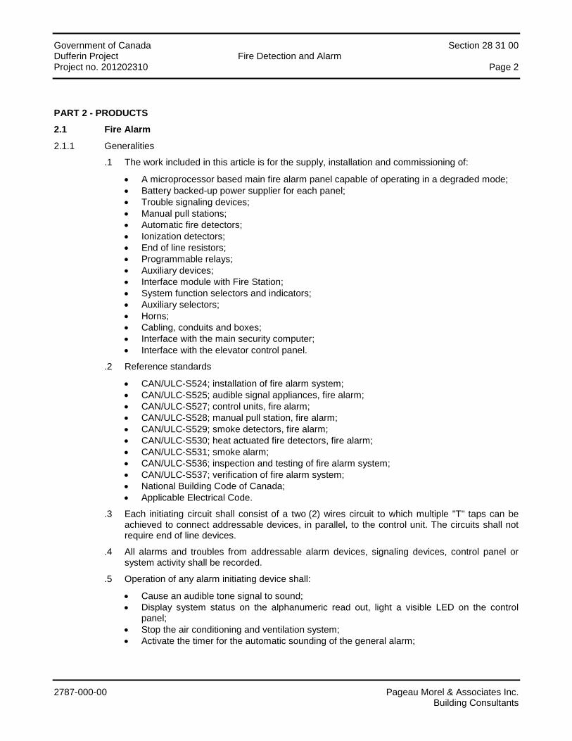
Government of Canada Section 28 31 00 Dufferin Project Fire Detection and Alarm Project no. 201202310 Page 2
2787-000-00 Pageau Morel & Associates Inc. Building Consultants
PART 2 - PRODUCTS
2.1 Fire Alarm
2.1.1 Generalities
.1 The work included in this article is for the supply, installation and commissioning of:
• A microprocessor based main fire alarm panel capable of operating in a degraded mode; • Battery backed-up power supplier for each panel; • Trouble signaling devices; • Manual pull stations; • Automatic fire detectors; • Ionization detectors; • End of line resistors; • Programmable relays; • Auxiliary devices; • Interface module with Fire Station; • System function selectors and indicators; • Auxiliary selectors; • Horns; • Cabling, conduits and boxes; • Interface with the main security computer; • Interface with the elevator control panel.
.2 Reference standards
• CAN/ULC-S524; installation of fire alarm system; • CAN/ULC-S525; audible signal appliances, fire alarm; • CAN/ULC-S527; control units, fire alarm; • CAN/ULC-S528; manual pull station, fire alarm; • CAN/ULC-S529; smoke detectors, fire alarm; • CAN/ULC-S530; heat actuated fire detectors, fire alarm; • CAN/ULC-S531; smoke alarm; • CAN/ULC-S536; inspection and testing of fire alarm system; • CAN/ULC-S537; verification of fire alarm system; • National Building Code of Canada; • Applicable Electrical Code.
.3 Each initiating circuit shall consist of a two (2) wires circuit to which multiple "T" taps can be achieved to connect addressable devices, in parallel, to the control unit. The circuits shall not require end of line devices.
.4 All alarms and troubles from addressable alarm devices, signaling devices, control panel or system activity shall be recorded.
.5 Operation of any alarm initiating device shall:
• Cause an audible tone signal to sound; • Display system status on the alphanumeric read out, light a visible LED on the control
panel; • Stop the air conditioning and ventilation system; • Activate the timer for the automatic sounding of the general alarm;

Government of Canada Section 28 31 00 Dufferin Project Fire Detection and Alarm Project no. 201202310 Page 3
2787-000-00 Pageau Morel & Associates Inc. Building Consultants
• Perform functions as described in the alarm function schedule table for the fire alarm system.
.6 The fire alarm panel shall allow:
• The stopping of the alarm by pressing the corresponding push-button.; • The stopping of the general alarm timer; • The manual sounding of the general alarm.
.7 Acceptable manufacturers:
• This specification is based on products from series MXL/MXLV from Siemens; • Similar products from following manufacturers are considered equal:
Simplex Grinnell, series 4100.
.8 Quality Control
Material and equipment shall meet CSA C22.2, NEMA, IEEE and all other appropriate standard, it shall be ULC listed and it shall bear the ULC label.
.9 Shop Drawings
• Submit shop drawings as specified in Section 20 05 02; • Shop drawings to at least include:
A list of all components and equipment proposed; Data sheets for each proposed component; Amplifiers and system peak capacity based on 2 watts for every required speaker; Large scale drawing of alarm central station showing all components; Complete one (1) line riser diagram showing interconnection between alarm,
extinguishing devices, auxiliary systems; A table showing details of each zone supplied by each amplifier and showing the
wattage connected on each zone and the total amplifier load. Table shall identify results before and after adjustment.
.10 Operation and maintenance manuals
Submit operation and maintenance manuals according to the requirements of Section 20 05 02. Manuals to at least include:
• Information operation and maintenance manuals of the complete fire alarm system to facilitate operation and routine maintenance and repair to the system;
• All technical data with illustration showing modules and catalog number; • One (1) copy of all shop drawings; • Hard copy of system programming code including logic function; • Verification by a CFAA certified technician and report signed on a CFAA report form; • A table showing the detail of each zone supplied by each amplifier and showing the
wattage connected on each zone and the total amplifier load.
2.1.2 Operation of the system
.1 The system shall display an alarm or fault condition for any addressable detection device. The display shall occur simultaneously on an 80 characters (min.) alphanumeric display.
Status visual indications shall show the conditions of all major panel components.
.2 The system shall detect any number of alarms, from addressable devices, simultaneously.
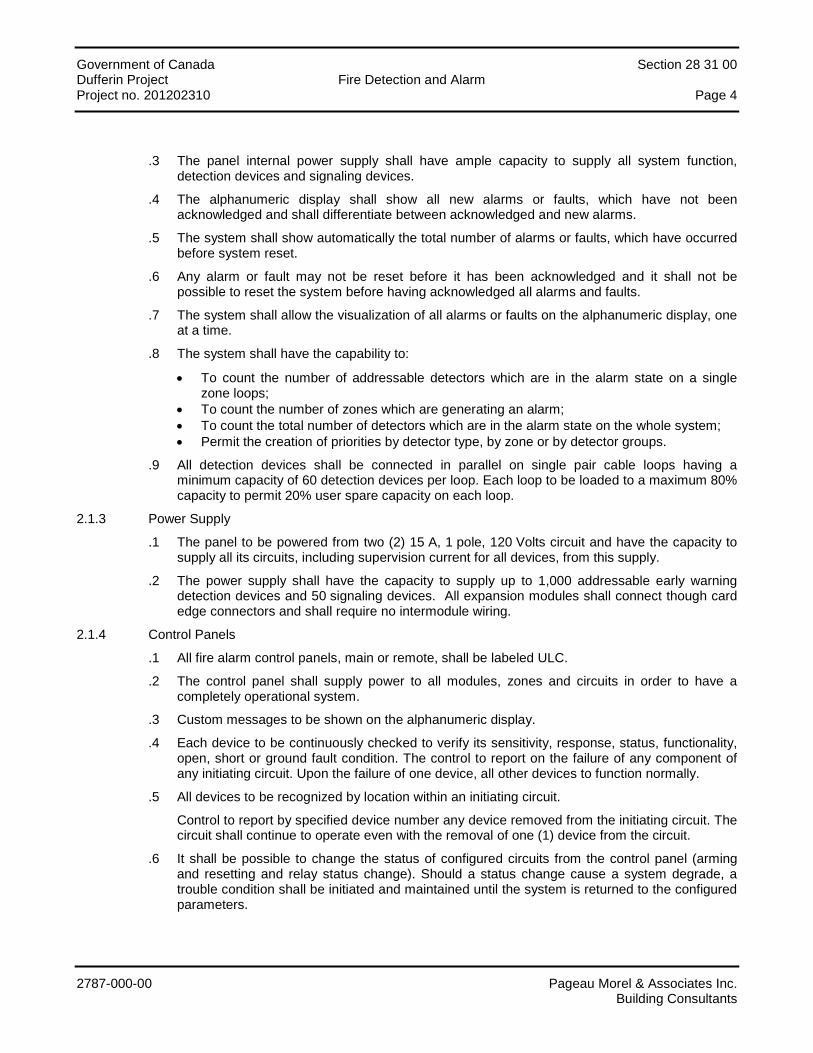
Government of Canada Section 28 31 00 Dufferin Project Fire Detection and Alarm Project no. 201202310 Page 4
2787-000-00 Pageau Morel & Associates Inc. Building Consultants
.3 The panel internal power supply shall have ample capacity to supply all system function, detection devices and signaling devices.
.4 The alphanumeric display shall show all new alarms or faults, which have not been acknowledged and shall differentiate between acknowledged and new alarms.
.5 The system shall show automatically the total number of alarms or faults, which have occurred before system reset.
.6 Any alarm or fault may not be reset before it has been acknowledged and it shall not be possible to reset the system before having acknowledged all alarms and faults.
.7 The system shall allow the visualization of all alarms or faults on the alphanumeric display, one at a time.
.8 The system shall have the capability to:
• To count the number of addressable detectors which are in the alarm state on a single zone loops;
• To count the number of zones which are generating an alarm; • To count the total number of detectors which are in the alarm state on the whole system; • Permit the creation of priorities by detector type, by zone or by detector groups.
.9 All detection devices shall be connected in parallel on single pair cable loops having a minimum capacity of 60 detection devices per loop. Each loop to be loaded to a maximum 80% capacity to permit 20% user spare capacity on each loop.
2.1.3 Power Supply
.1 The panel to be powered from two (2) 15 A, 1 pole, 120 Volts circuit and have the capacity to supply all its circuits, including supervision current for all devices, from this supply.
.2 The power supply shall have the capacity to supply up to 1,000 addressable early warning detection devices and 50 signaling devices. All expansion modules shall connect though card edge connectors and shall require no intermodule wiring.
2.1.4 Control Panels
.1 All fire alarm control panels, main or remote, shall be labeled ULC.
.2 The control panel shall supply power to all modules, zones and circuits in order to have a completely operational system.
.3 Custom messages to be shown on the alphanumeric display.
.4 Each device to be continuously checked to verify its sensitivity, response, status, functionality, open, short or ground fault condition. The control to report on the failure of any component of any initiating circuit. Upon the failure of one device, all other devices to function normally.
.5 All devices to be recognized by location within an initiating circuit.
Control to report by specified device number any device removed from the initiating circuit. The circuit shall continue to operate even with the removal of one (1) device from the circuit.
.6 It shall be possible to change the status of configured circuits from the control panel (arming and resetting and relay status change). Should a status change cause a system degrade, a trouble condition shall be initiated and maintained until the system is returned to the configured parameters.
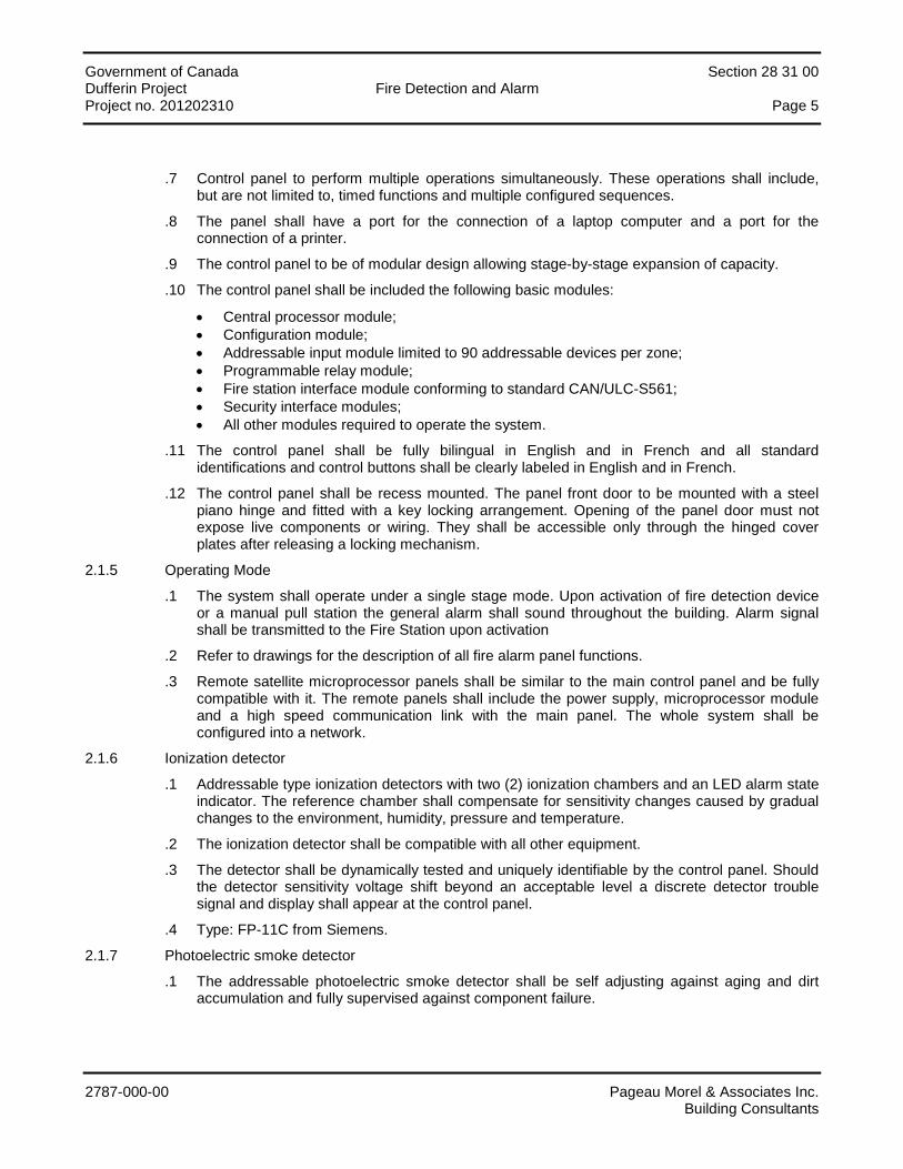
Government of Canada Section 28 31 00 Dufferin Project Fire Detection and Alarm Project no. 201202310 Page 5
2787-000-00 Pageau Morel & Associates Inc. Building Consultants
.7 Control panel to perform multiple operations simultaneously. These operations shall include, but are not limited to, timed functions and multiple configured sequences.
.8 The panel shall have a port for the connection of a laptop computer and a port for the connection of a printer.
.9 The control panel to be of modular design allowing stage-by-stage expansion of capacity.
.10 The control panel shall be included the following basic modules:
• Central processor module; • Configuration module; • Addressable input module limited to 90 addressable devices per zone; • Programmable relay module; • Fire station interface module conforming to standard CAN/ULC-S561; • Security interface modules; • All other modules required to operate the system.
.11 The control panel shall be fully bilingual in English and in French and all standard identifications and control buttons shall be clearly labeled in English and in French.
.12 The control panel shall be recess mounted. The panel front door to be mounted with a steel piano hinge and fitted with a key locking arrangement. Opening of the panel door must not expose live components or wiring. They shall be accessible only through the hinged cover plates after releasing a locking mechanism.
2.1.5 Operating Mode
.1 The system shall operate under a single stage mode. Upon activation of fire detection device or a manual pull station the general alarm shall sound throughout the building. Alarm signal shall be transmitted to the Fire Station upon activation
.2 Refer to drawings for the description of all fire alarm panel functions.
.3 Remote satellite microprocessor panels shall be similar to the main control panel and be fully compatible with it. The remote panels shall include the power supply, microprocessor module and a high speed communication link with the main panel. The whole system shall be configured into a network.
2.1.6 Ionization detector
.1 Addressable type ionization detectors with two (2) ionization chambers and an LED alarm state indicator. The reference chamber shall compensate for sensitivity changes caused by gradual changes to the environment, humidity, pressure and temperature.
.2 The ionization detector shall be compatible with all other equipment.
.3 The detector shall be dynamically tested and uniquely identifiable by the control panel. Should the detector sensitivity voltage shift beyond an acceptable level a discrete detector trouble signal and display shall appear at the control panel.
.4 Type: FP-11C from Siemens.
2.1.7 Photoelectric smoke detector
.1 The addressable photoelectric smoke detector shall be self adjusting against aging and dirt accumulation and fully supervised against component failure.

Government of Canada Section 28 31 00 Dufferin Project Fire Detection and Alarm Project no. 201202310 Page 6
2787-000-00 Pageau Morel & Associates Inc. Building Consultants
.2 The detector shall have the capability of operating one (1) remote alarm or auxiliary relay. The remote alarm indicator or auxiliary relay is normally operated by the associated detector. However, the system shall be capable of being programmed to operate the alarm indicator or relay independently of the associated detector. All detectors and/or relays connected to the circuit can be in alarm or activated simultaneously.
2.1.8 Infrared flame detectors
.1 The flame detector shall respond to an infrared radiation. The detector shall consist of a lead sulphide photoelectric cell mounted behind a lens and infrared filter and of band pass amplifier, on integrator and a timer.
.2 The sensitivity of the detector and the timer cycle shall be adjustable. The operation of any of the flame detectors shall initiate an alarm signal at the control panel.
.3 The detector head shall be of the plug-in and twist-lock type and shall include a printed circuit board supporting all necessary components. The detector base shall include an alarm pilot lamp.
.4 The detector shall be designed so that a short circuit or accidental grounding of the pilot lamp wiring will not prevent a genuine detector alarm and will not cause false alarms.
.5 Detector shall be mountable on standard 102 mm (4") octagonal boxes or be supplied with proper adapter hardware. The adapters shall have the same finish and color, as the flame detectors.
.6 Type: DF1101-FX from Siemens.
2.1.9 Thermal detector
.1 The addressable thermal detector shall be of the fixed 135 °F, rate compensation type with built in alarm indicating lamp and be fully supervised against component failure. Model: FPT-11C C/W DB-11C from Siemens.
2.1.10 Manual pull-station
.1 The addressable manual pull-station shall be single stage, French inscription, metal or polycarbonate body and semi recessed mounting.
.2 Model: MSI-51BC for single stage or MSI-30BC for two (2) stages from Siemens
2.1.11 Addressable interface module (MIA)
.1 Addressable interface module shall provide supervision of devices with short-circuiting contacts.
.2 Model: TRI-S, TRI-D or TRI-R from Siemens.
2.1.12 Addressable relay module (MRA)
.1 Control relays used to interface the fire alarm system with other systems shall have 2 A minimum, 120Vac/24Vdc dry type C contacts.
.2 Model: TRI from Siemens.
2.1.13 Loop isolation modules
.1 Loop isolation modules shall be installed to isolate the zones or floors shown on the drawings. Under a short circuit on one part of the loop, these devices shall maintain the unaffected part of the loop in operation on the other zones and floors.
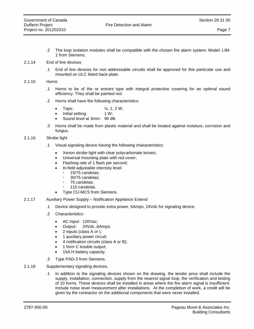
Government of Canada Section 28 31 00 Dufferin Project Fire Detection and Alarm Project no. 201202310 Page 7
2787-000-00 Pageau Morel & Associates Inc. Building Consultants
.2 The loop isolation modules shall be compatible with the chosen fire alarm system: Model: LIM-1 from Siemens.
2.1.14 End of line devices
.1 End of line devices for non addressable circuits shall be approved for this particular use and mounted on ULC listed back-plate.
2.1.15 Horns
.1 Horns to be of the re entrant type with integral protective covering for an optimal sound efficiency. They shall be painted red.
.2 Horns shall have the following characteristics:
• Taps: ¼, 1, 2 W; • Initial setting: 1 W; • Sound level at 3mm: 90 dB.
.3 Horns shall be made from plastic material and shall be treated against moisture, corrosion and fungus.
2.1.16 Strobe light
.1 Visual signaling device having the following characteristics:
• Xenon strobe light with clear polycarbonate lenses; • Universal mounting plate with red cover; • Flashing rate of 1 flash per second; • In-field adjustable intensity level:
15/75 candelas; 30/75 candelas; 75 candelas; 110 candelas.
• Type CU-MCS from Siemens.
2.1.17 Auxiliary Power Supply – Notification Appliance Extend
.1 Device designed to provide extra power, 6Amps, 24Vdc for signaling device.
.2 Characteristics:
• AC input: 120Vac; • Output: 24Vdc.,6Amps; • 2 inputs (class A or ); • 1 auxiliary power circuit; • 4 notification circuits (class A or B); • 1 form C trouble output; • 15A.H battery capacity.
.3 Type PAD-3 from Siemens.
2.1.18 Supplementary signaling devices.
.1 In addition to the signaling devices shown on the drawing, the tender price shall include the supply, installation, connection, supply from the nearest signal loop, the verification and testing of 10 horns. These devices shall be installed in areas where the fire alarm signal is insufficient. Include noise level measurement after installations. At the completion of work, a credit will be given by the contractor on the additional components that were never installed.

Government of Canada Section 28 31 00 Dufferin Project Fire Detection and Alarm Project no. 201202310 Page 8
2787-000-00 Pageau Morel & Associates Inc. Building Consultants
2.1.19 Cabling
.1 Normal power for the fire alarm system shall be provided by the 120 V, 60 Hz building supply circuits.
.2 All cabling shall comply with the first part of the applicable Electrical Code and provincial regulations in force. When specified, conductors shall be twisted and/or shielded with on aluminium ribbon and a tinned copper drain wire. Conductors shall be insulated for at least 300 V. Minimum requirements shall be:
• Detection circuits: no. 18 AWG twisted and shielded pairs; • Emergency telephone circuits: no. 16 AWG twisted and shielded pairs; • Horns and bells circuits: no. 16 AWG; • Command circuits and combustion product detector power circuits: no. 14 AWG; • Interface circuits with ventilation control cabinets and ventilation motor starters:
no. 14 AWG; • Interface circuits with ventilation motor starters and ventilation control cabinets:
no. 14 AWG ; • Cabling between main panel and satellite panels: no. 18 AWG twisted and five (5) shielded
pairs.
.3 Cables or conductors shall be mechanically protected by metallic conduit with set screw couplings or aluminium armor.
.4 Cables or conductors protected by metallic conduit do not require a bounding conductor.
.5 Cables or conductors protected by metallic armor require a bounding conductor that shall be bare copper or green jacketed and insulated copper. If circuit voltage is less than 50 V, a bounding conductor is not required.
.6 Trouble signaling device circuits outside the building shall be protected by temporary suppression of gas discharge zinc oxide varistors.
.7 Do not wire up any 120 VA.C. circuit in the same conduit than extra-low voltage, trouble signaling device or alarm device circuit conduit.
.8 Main fire alarm panel shall be connected to an appropriate grounding electrode located inside the building. Raceway is not acceptable.
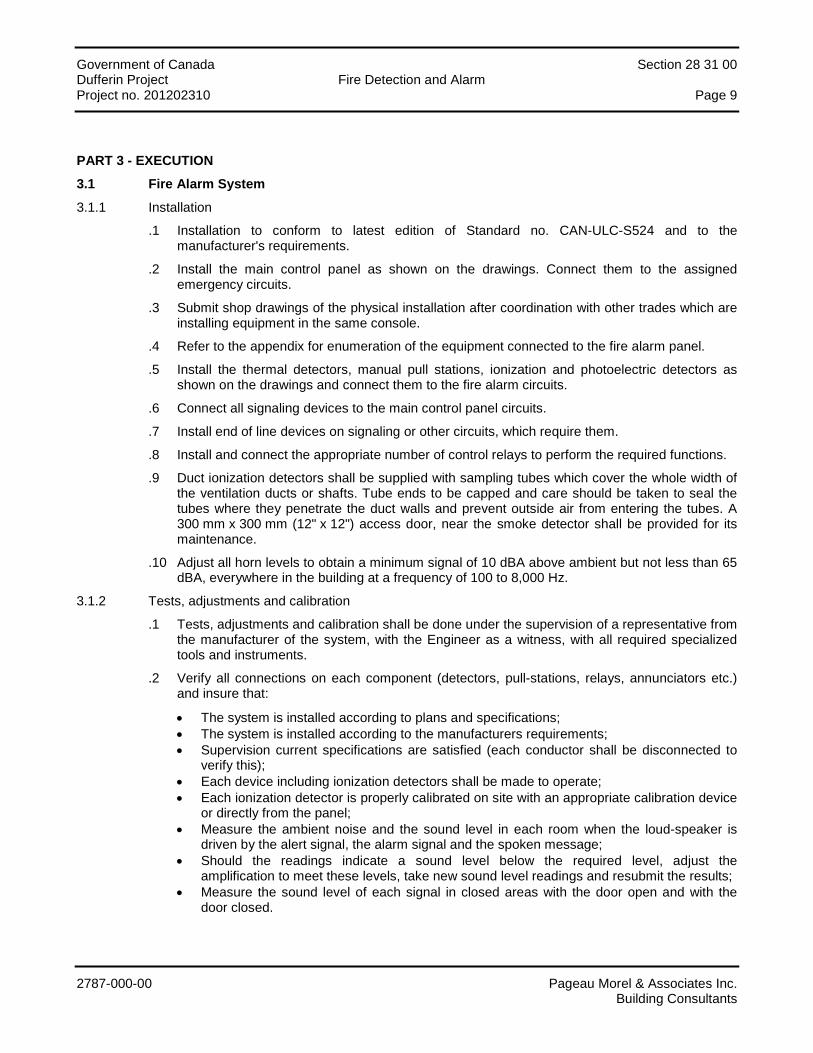
Government of Canada Section 28 31 00 Dufferin Project Fire Detection and Alarm Project no. 201202310 Page 9
2787-000-00 Pageau Morel & Associates Inc. Building Consultants
PART 3 - EXECUTION
3.1 Fire Alarm System
3.1.1 Installation
.1 Installation to conform to latest edition of Standard no. CAN-ULC-S524 and to the manufacturer's requirements.
.2 Install the main control panel as shown on the drawings. Connect them to the assigned emergency circuits.
.3 Submit shop drawings of the physical installation after coordination with other trades which are installing equipment in the same console.
.4 Refer to the appendix for enumeration of the equipment connected to the fire alarm panel.
.5 Install the thermal detectors, manual pull stations, ionization and photoelectric detectors as shown on the drawings and connect them to the fire alarm circuits.
.6 Connect all signaling devices to the main control panel circuits.
.7 Install end of line devices on signaling or other circuits, which require them.
.8 Install and connect the appropriate number of control relays to perform the required functions.
.9 Duct ionization detectors shall be supplied with sampling tubes which cover the whole width of the ventilation ducts or shafts. Tube ends to be capped and care should be taken to seal the tubes where they penetrate the duct walls and prevent outside air from entering the tubes. A 300 mm x 300 mm (12" x 12") access door, near the smoke detector shall be provided for its maintenance.
.10 Adjust all horn levels to obtain a minimum signal of 10 dBA above ambient but not less than 65 dBA, everywhere in the building at a frequency of 100 to 8,000 Hz.
3.1.2 Tests, adjustments and calibration
.1 Tests, adjustments and calibration shall be done under the supervision of a representative from the manufacturer of the system, with the Engineer as a witness, with all required specialized tools and instruments.
.2 Verify all connections on each component (detectors, pull-stations, relays, annunciators etc.) and insure that:
• The system is installed according to plans and specifications; • The system is installed according to the manufacturers requirements; • Supervision current specifications are satisfied (each conductor shall be disconnected to
verify this); • Each device including ionization detectors shall be made to operate; • Each ionization detector is properly calibrated on site with an appropriate calibration device
or directly from the panel; • Measure the ambient noise and the sound level in each room when the loud-speaker is
driven by the alert signal, the alarm signal and the spoken message; • Should the readings indicate a sound level below the required level, adjust the
amplification to meet these levels, take new sound level readings and resubmit the results; • Measure the sound level of each signal in closed areas with the door open and with the
door closed.

Government of Canada Section 28 31 00 Dufferin Project Fire Detection and Alarm Project no. 201202310 Page 10
2787-000-00 Pageau Morel & Associates Inc. Building Consultants
.3 Proceed to the verifications of all new components according to CAN/ULC-S537 standard and produce a detailed test report.
.4 Place at the manufacturer's disposal one (1) qualified electrician and one (1) apprentice for the duration of the test, calibration and verification period.
.5 Immediately after the test, calibration and verification period, submit the following to the Engineer:
• A certificate attesting that the work has been done to his satisfaction; • An insurance certificate, specific to this project, good for one (1) year, to the amount of
$1,000,000 for injuries, personal liabilities and damages; • A complete list showing the exact location (room number) of each component; • A complete list enumerating the quantity and model number of each component on the
site; • A table of sound levels showing the ambient noise, the alert signal, the alarm signal and
the spoken message for each room and with the door open and closed when applicable.
END OF SECTION
Government of Canada Section 28 31 00 Dufferin Project Fire Detection and Alarm Project no. 201202310
2787-000-00 Pageau Morel & Associates Inc. Building Consultants
APPENDIX
Fire Alarm: List of Alarms and Functions
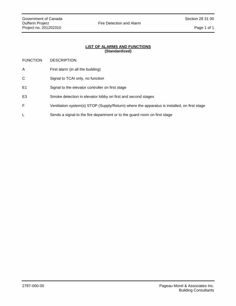
Government of Canada Section 28 31 00 Dufferin Project Fire Detection and Alarm Project no. 201202310 Page 1 of 1
2787-000-00 Pageau Morel & Associates Inc. Building Consultants
LIST OF ALARMS AND FUNCTIONS (Standardized)
FUNCTION DESCRIPTION
A First alarm (in all the building)
C Signal to TCAI only, no function
E1 Signal to the elevator controller on first stage
E3 Smoke detection in elevator lobby on first and second stages
F Ventilation system(s) STOP (Supply/Return) where the apparatus is installed, on first stage
L Sends a signal to the fire department or to the guard room on first stage
Related Documents


