INSTALLATION, OPERATION AND MAINTENANCE INSTRUCTIONS SFMV THERMOSTATIC MIXING VALVE SUPPLY FIXTURE 1. Please leave this documentation with the owner of the fixture when finished. 3. Check your installation for compliance with plumbing and other applicable codes. LIMITED WARRANTY Acorn Controls warrants that its products are free from defects in material or workmanship under normal use and service for a period of one year from date of shipment. Acorn's liability under this warranty shall be discharged solely by replacement of repair of defective material, provided Acorn is notified in writing within one year from date of shipment, F.O.B. Industry, California. NOTES TO THE INSTALLER: 2. Please read this entire booklet before beginning the installation. UNITED STATES AND CANADA This warranty does not cover installation or labor charges and does not apply to materials, which have been damaged by other causes such as mishandling or improper care or abnormal use. The repair or replacement of the defective materials shall constitute the sole remedy of the Buyer and the sole remedy of Acorn under this warranty. Acorn shall not be liable under any circumstances for incidental, consequential or direct charges caused by defects in materials, or any delay in the repair or replacement thereof. This warranty is in lieu of all other warranties expressed or implied. Product maintenance instructions are issued with each unit and disregard or non-compliance with these instructions will constitute an abnormal use condition and void the warranty. 1.800.743.8259 [email protected] FOR TECHNICAL ASSISTANCE Manual #7802-118-000 Model SFMV Series WWW.ACORNENG.COM ACORN ENGINEERING COMPANY P.O. BOX 3527 CITY OF INDUSTRY, CA 91744 UNITED STATES OF AMERICA Acorn Controls Division of Acorn Engineering Company®, A member of Morris Group International™ Federal Public Law 111-380 (No Lead) Date: 02/13/19 Patent #9,898,017

Welcome message from author
This document is posted to help you gain knowledge. Please leave a comment to let me know what you think about it! Share it to your friends and learn new things together.
Transcript

INSTALLATION, OPERATION AND MAINTENANCE INSTRUCTIONS
SFMV THERMOSTATIC MIXING VALVE SUPPLY FIXTURE
1. Please leave this documentation with the owner of the fixture when finished.
3. Check your installation for compliance with plumbing and other applicable codes.
LIMITED WARRANTY
Acorn Controls warrants that its products are free from defects in material or workmanship under normal use and service for a period of one year from date of shipment. Acorn's liability under this warranty shall be discharged solely by replacement of repair of defective material, provided Acorn is notified in writing within one year from date of shipment, F.O.B. Industry, California.
NOTES TO THE INSTALLER:
2. Please read this entire booklet before beginning the installation.
UNITED STATES AND CANADA
This warranty does not cover installation or labor charges and does not apply to materials, which have been damaged by other causes such as mishandling or improper care or abnormal use. The repair or replacement of the defective materials shall constitute the sole remedy of the Buyer and the sole remedy of Acorn under this warranty. Acorn shall not be liable under any circumstances for incidental, consequential or direct charges caused by defects in materials, or any delay in the repair or replacement thereof. This warranty is in lieu of all other warranties expressed or implied. Product maintenance instructions are issued with each unit and disregard or non-compliance with these instructions will constitute an abnormal use condition and void the warranty.
1.800.743.8259
FOR TECHNICAL ASSISTANCE
Manual #7802-118-000
Model SFMV Series
WWW.ACORNENG.COM
ACORN ENGINEERING COMPANYP.O. BOX 3527CITY OF INDUSTRY, CA 91744
UNITED STATES OF AMERICA
Acorn Controls Division of Acorn Engineering Company®, A member of Morris Group International™
FederalPublic Law111-380 (No Lead)
Date: 02/13/19
Patent #9,898,017

Page 2 of 15
SFMV Installation & Operation Manual
Ÿ Properly design the system to minimize pressure and temperature variations.
Acorn Controls is not responsible for damages resulting from improper installation and/or maintenance. Installation of this valve shall be in accordance with Uniform Plumbing Code.
You are required to thoroughly read all installation instructions and product safety information before beginning the installation of this product.
FAILURE TO READ AND FOLLOW PROPER INSTALLATION AND MAINTENANCE INSTRUCTIONS MAY RESULT IN PRODUCT FAILURE WHICH CAN CAUSE PROPERTY DAMAGE, PERSONAL INJURY AND/OR DEATH.
TO ENSURE ACCURATE AND RELIABLE OPERATION OF THIS PRODUCT, IT IS ESSENTIAL TO:
Ÿ Implement an annual maintenance program to ensure proper operation and temperature setting of valve(s).
Ÿ This valve is factory preset. However, it can be adjusted. It is the responsibility of the installer and or facility maintenance personnel to make sure valve outlet temperature is properly set.
1. Wall anchors, screws, nuts and washers as required.
2. Lead-free solder and flux for sealing water connections.
(Not provided by Acorn)
4. Wrench and an Allen wrench.
3. Pipe fittings.
Ÿ To ensure proper installation review the manual thoroughly to verify rough-ins before beginning any work.
Ÿ Installation and field adjustment are the responsibility of the installer.
Ÿ Maximum water pressure is 125 PSI (8.62 bar). Maximum inlet hot water temperature is 180°F (82°C). Temperature adjustment range* is 100°F-160°F (38°C-71°C). Valve assembly must be drained prior to being subjected to freezing temperatures. Valve includes integral check valves.
Ÿ Flush supply lines of all foreign material such as pipe dope, chips or solder prior to connecting to mixing valve.
WARNING:! SUPPLIES REQUIRED:
Acorn Controls Division of Acorn Engineering Company®, A member of Morris Group International™
*Under Normal Operating Conditions
! IMPORTANT
Manual #7802-118-000
MV17-1
21.2(80.3)
26(98.4)
30(113.6)
36.7(139)
45(170.3)
52(196.7)
15(56.8)
FLOW RATEGPM (LPM)
6.7
42.4(160.6)
52(196.7)
60(227.1)
73.5(278.2)
90(340.7)
104(393.4)
30(113.6)
FLOW RATEGPM (LPM)
13.4
70.7(167.7)
86.6(327.8)
100(378.5)
122.5(463.6)
150(567.8)
173.2(655.7)
50(189)
FLOW RATEGPM (LPM)
22.4
106(401.5)
130(491.7)
150(567.8)
183.7(695.4)
225(851.7)
259.8(983.5)
75(284)
FLOW RATEGPM (LPM)
33.5
PRESSUREDROP
10(69)
7(26.7)
15(103)
8.7(32.8)
20(138)
10(37.9)
30(207)
12.3(46.4)
45(310)
15(56.8)
60(414)
17.3(65.6)
5(34)
5(19)
FLOW RATEGPM (LPM)
PSID (kPa)CV
2.215 GPM(56.8 LPM)
MV17-245 GPM(170 LPM)
MV17-390 GPM(341 LPM)
MV17-4150 GPM(568 LPM)
MV17-5225 GPM(852 LPM)
Date: 02/13/19

Page 3 of 15
ALL DIMENSIONS ARE IN INCHES (MM).NOTE;
ROUGH-IN DIMENSIONS:
Acorn Controls Division of Acorn Engineering Company®, A member of Morris Group International™
SFMV Installation & Operation Manual
SFMV-11/2"
23-1/4"(591)
SFMV-2
SFMV-3
SFMV-4
INLET "A" "B" "C" "D"OUTLET
1/2"NCT NCT
3/4" 1"NCT NCT
1" 1-1/4"NCT NCT
1-1/4" 1-1/2"NCT NCT
17-1/4"(438)
17-7/8"(454)
23-1/4"(591)
SFMV-51-1/2" 2"NCT NCT
"A"
"B"
"A"
"B"
"A"
"C"
"D"
"C"
"E"
"F"
"A"
"E" "F"
22-1/4"(565)
13"(330)
SFMV-T-T-ITG
SFMV-B-T-ITG
SFMV-B-B-ITG
SFMV-B-SL-ITG
“G"
7"(178)
"G"
18-5/8"(473)
25-1/2"(648)
19-1/4"(489)
23"(584)
23"(584)
13-5/8"(346)
7-1/2"(190)
16-3/4"(425)
23"(584)
17-1/2"(445)
19-7/8"(505)
18-3/4"(476)
12-5/8"(321)
6-3/4"(171)
10-3/4"(273)
18-5/8"(473)
15-5/8"(397)
17"(432)
15-3/4"(400)
9-5/8"(244)
5-1/4"(133)
7-3/4"(197)
15"(381)
13"(330)
12-7/8"(327)
10-5/8"(270)
7-7/8"(200)
4-1/2"(114)
Manual #7802-118-000 Date: 02/13/19

Page 4 of 15
NOTE;ALL DIMENSIONS ARE IN INCHES (MM).
ROUGH-IN DIMENSIONS:
Acorn Controls Division of Acorn Engineering Company®, A member of Morris Group International™
SFMV Installation & Operation Manual
Manual #7802-118-000
SFMV-1 1/2"
17-1/4"(438)
SFMV-2
SFMV-3
SFMV-4
INLET "A" "B" "C" "D"OUTLET
1/2"NCT NCT
3/4" 1"NCT NCT
1" 1-1/4"NCT NCT
1-1/4" 1-1/2"NCT NCT
25-3/8"(645)
22-3/8"(568)
22-1/4"(565)
SFMV-5 1-1/2" 2"NCT NCT
"E" "F"
23"(584)
13-1/2"(343)
“G"
"H"
"J"
"D"
"I"
"C"
"A"
"E"
"C"
"F"
"A"
"A"
"A"
"B"
"A"
"B"
"A"
-CWB
-CWB
-CWB
-CWB
-CWB
"H" "I"
26-5/8"(676)
3-1/2"(89)
"J"
SFMV-B-OB-CWB-ITG SFMV-T-OT-CWB-ITG
SFMV-B-OSL-CWB-ITG SFMV-B-OT-CWB-ITG
18-5/8"(473)
28-1/4"(718)
23-3/8"(594)
23"(584)
23"(584)
15-5/8"(397)
29-5/8"(752)
3-1/4"(83)
16-3/4"(425)
24"(610)
19"(483)
18-3/4"(476)
20"(508)
12-7/8"(327)
25-3/8"(645)
2-3/4"(70)
10-3/4"(273)
21-3/8"(543)
17-3/8"(441)
15-3/4"(400)
17"(432)
8-7/8"(225)
18-1/2"(470)
2"(51)
7-3/4"(197)
16"(406)
13-1/2"(343)
10-5/8"(270)
12-7/8"(327)
6-5/8"(168)
14-5/8"(371)
1-3/4"(44)
"G"
15-5/8"(397)
13-1/4"(337)
14"(356)
6-3/4"(171)
7"(178)
7-1/2"(190)
9-5/8"(244)
5-1/4"(133)
8"(203)
4-1/2"(114)
Date: 02/13/19

Page 6 of 15Acorn Controls Division of Acorn Engineering Company®, A member of Morris Group International™
Manual #7802-118-000
SFMV Installation & Operation Manual
CAUSE SOLUTIONPROBLEM
1. SET POINT DIFFICULT TO SET ORCANNOT BE REACHED
SUPPLY TEMPS NOT WITHINSPECIFIED LIMITS
HOT AND COLD SUPPLIES ARE REVERSED
CHECK DIFFERENTIAL TEMPERATUREBETWEEN SUPPLIES AND OUTLET
REINSTALL VALVE WITH SUPPLIESCONNECTED TO MARKED INLETS
2. DOES NOT MAINTAIN OUTLETTEMPERATURE OR CHANGES
FLUCTUATION IN SUPPLY PRESSURES
CHECK VALVE/FILTERS BLOCKEDWITH DEBRIS
CHECK DIFFERENTIAL TEMPERATUREBETWEEN SUPPLIES AND OUTLET
CLEAN CHECK VALVES/FILTERSOVER TIME
3. DISCHARGE TEMPERATURE TOOHOT OR TOO COLD
VALVE NOT ADJUSTED PROPERLY READJUST VALVE TEMPERATURE PERINSTALLATION INSTRUCTIONS
4. CROSS FLOW CHECK VALVES FOULED CLEAN CHECK VALVES/FILTERS
5 NO FLOW FROM VALVE HOT OR COLD SUPPLY FAILUREOR SHUTOFFS CLOSED
OPEN SHUTOFFS OR RESTORE HOT AND COLD SUPPLIES
CHECK VALVE/FILTERS BLOCKEDWITH DEBRIS
CLEAN CHECK VALVES AND FILTERS
*Under Normal Operating Conditions.
Valve Specifications Continues:
Minimum Flow Rate per ASSE 1017*:MV17-1: ...................................................... 0.5 GPM (1.9 LPM)MV17-2: ......................................................... 1 GPM (3.8 LPM)MV17-3: ......................................................... 2 GPM (7.6 LPM)MV17-4: ....................................................... 3 GPM (11.4 LPM)MV17-5: ....................................................... 4 GPM (15.1 LPM)
Outlet Temp. Range: ....................... 100°F-160°F (38°C-71°C)
Flow Rate at 45 PSI (310 kPa) differential:MV17-1: ..................................................... 15 GPM (56.8 LPM)MV17-2: ...................................................... 45 GPM (170 LPM)MV17-3: ...................................................... 90 GPM (341 LPM)MV17-4: .................................................... 150 GPM (568 LPM) MV17-5: .................................................... 225 GPM (852 LPM)
Valve Specifications:
Maximum Hot Water Supply Temp: ..................... 180°F (82°C)
Minimum Hot Water Supply* ...................................... 5°F (3°C) Above Set Point
Maximum Operating Pressure: ................... 125 PSI (861 kPa)
TROUBLESHOOTING:
PIPING DETAILS:
NOTE:ASSE 1017 performance based on actual demand or recirculation pump flow rate or a combination of both. See FEATURES regarding control performance at ZERO GPM user demand.
TYPICAL SHOWER PIPING DETAIL
MV17 SERIESVALVE
TYPICAL SINGLE TEMP LAVATORY PIPING DETAIL
HOTWATERSUPPLY
COLDWATERSUPPLY
HOTWATERSUPPLY
COLDWATERSUPPLY
MV17 SERIESVALVE
LAVATORYMIXINGVALVES
SHOWERVALVES
Date: 02/13/19

Page 5 of 15
1. Loosen locknut. Detail A
5. Re-check temperature.
1. Locate mixing valve in a suitable place accessible for servicing and adjusting. Valve should be as close as possible to point of use.
5. Turn on fixture and allow to run until water temperature stabilizes. Measure water temperature. If water is not at desired temperature adjust as needed, (refer to adjustment section below).
2. Thoroughly flush supplies.
4. Turn on supplies and inspect for leaks. Tighten connections if leak(s) detected.
2. Turn on fixture so temperature can stabilize.
3. Using Allen wrench turn adjustment stem counter-clockwise for hotter or clockwise for colder outlet temperature. Detail B
4. Tighten locknut to prevent any unauthorized or accidental temperature adjustment.
3. Connect Hot and Cold supplies to mixing valve inlets and outlet to fixture(s). Supply lines by others.
INSTALLATION:
TEMPERATURE ADJUSTMENT:
Acorn Controls Division of Acorn Engineering Company®, A member of Morris Group International™
DETAIL A DETAIL B
WRENCH
LOCKNUT
ALLENWRENCH
ADJUSTMENTSTEM
SFMV Installation & Operation Manual
TYPICAL INSTALLATION
1/2” NCT RISER,
CONNECTIONS
INSTALLER PROVIDED
SUPPLIES AND
Manual #7802-118-000 Date: 02/13/19

Page 7 of 15
Acorn Controls Division of Acorn Engineering Company®, A member of Morris Group International™
SFMV Installation & Operation Manual
Manual #7802-118-000
ROUGH-IN DIMENSIONS FOR OPTIONAL -TBV
SFMV-1 1/2"
17-1/4"(438)
SFMV-2
SFMV-3
SFMV-4
INLET "A" "B" "C" "D"OUTLET
1/2"NCT NCT
3/4" 1"NCT NCT
1" 1-1/4"NCT NCT
1-1/4" 1-1/2"NCT NCT
3-1/4"(82)
SFMV-5 1-1/2" 2"NCT NCT
"E" "F"
12"(305)
"G"
11-1/4"(286)
12"(305)
13-1/2"(343)
-CWB
-CWB
-CWB
-CWB
-CWB
"H" "I"
18-3/8"(467)
"J"
10-7/8"(276)
11"(279)
10-1/4"(260)
18-5/8"(473)
4-1/8"(105)
9-3/4"(248)
13-3/8"(340)
17"(432)
16-1/4"(413)
2-7/8"(73)
26-1/4"(667)
10-1/2"(267)
36-5/8"(930)
19"(483)
3"(76)
10-3/4"(273)
3"(76)
9"(229)
9-1/4"(235)
11-5/8"(295)
7-3/4"(197)
2-3/4"(70)
6-1/2"(165)
24"(610)
3"(76)
26"(660)
13-5/8"(346)
8-3/8"(213)
8"(203)
6-5/8"(168)
8-7/8"(225)
"K" "L"
48"(1219)
7-3/8"(187)
"M"
3-3/4"(95)
4"(102)
4-1/4"(108)
49-3/8"(1254)
8-1/4"(210)
45-1/4"(1149)
8-1/2"(216)
41-3/4"(1060)
5-1/4"(133)
33-1/2"(851)
5-1/4"(133)
2-1/4"(57)
2"(51)
"C"
"D"
"E"
"G" "H"
"F"
"I"
"J"
"B"
"M"
"L"
"K""I"
3"(76)
3"(76)
3"(76)
3"(76)
1/2" NCTRETURN LINE
9-1/2"(241)
8-1/2"(216)
"A"
24"(610)
26"(660)
26-1/4"(667)
26-1/4"(667)
36-5/8"(930)
36-5/8"(930)
5
4
32
1
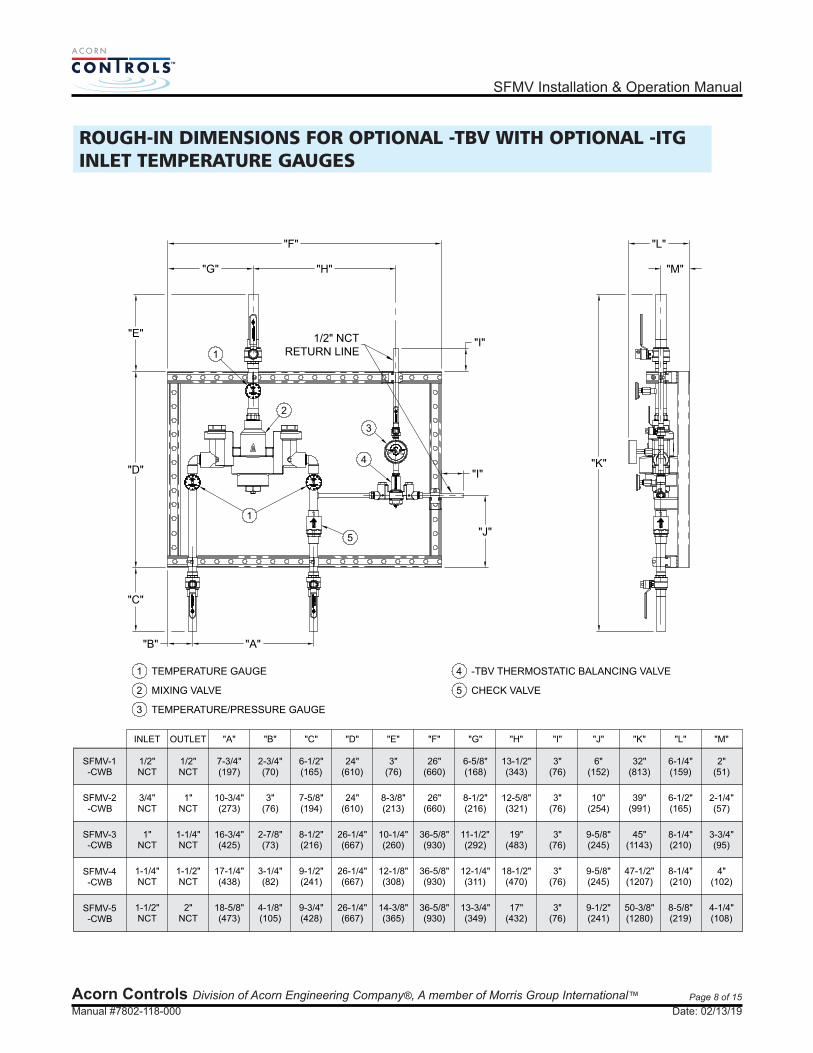
1 TEMPERATURE GAUGE
2 MIXING VALVE
3 TEMPERATURE/PRESSURE GAUGE
4 -TBV THERMOSTATIC BALANCING VALVE
5 CHECK VALVE
Date: 02/13/19
Page 8 of 15
Acorn Controls Division of Acorn Engineering Company®, A member of Morris Group International™
SFMV Installation & Operation Manual
Manual #7802-118-000
ROUGH-IN DIMENSIONS FOR OPTIONAL -TBV WITH OPTIONAL -ITGINLET TEMPERATURE GAUGES
SFMV-1 1/2"
17-1/4"(438)
SFMV-2
SFMV-3
SFMV-4
INLET "A" "B" "C" "D"OUTLET
1/2"NCT NCT
3/4" 1"NCT NCT
1" 1-1/4"NCT NCT
1-1/4" 1-1/2"NCT NCT
SFMV-5 1-1/2" 2"NCT NCT
"E" "F"
12-1/8"(308)
"G"
-CWB
-CWB
-CWB
-CWB
-CWB
"H" "I" "J"
9-5/8"(245)
9-1/2"(241)
18-5/8"(473)
14-3/8"(365)
16-3/4"(425)
26-1/4"(667)
10-1/4"(260)
10-3/4"(273)
24"(610)
8-3/8"(213)
7-3/4"(197)
24"(610)
3"(76)
10"(254)
6"(152)
"K" "L"
47-1/2"(1207)
"M"
50-3/8"(1280)
45"(1143)
39"(991)
32"(813)
"A""B"
"C"
"D"
"E"
"G" "H"
"F"
"J"
"I""K"
"M"
"L"
3"(76)
3"(76)
3"(76)
3"(76)
3"(76)
9-3/4"(428)
7-5/8"(194)
6-1/2"(165)
9-1/2"(241)
8-1/2"(216)
8-1/4"(210)
3-3/4"(95)
4"(102)
4-1/4"(108)
8-5/8"(219)
8-1/4"(210)
6-1/2"(165)
6-1/4"(159)
2-1/4"(57)
2"(51)
11-1/2"(292)
12-1/4"(311)
13-3/4"(349)
18-1/2"(470)
17"(432)
36-5/8"(930)
19"(483)
26"(660)
12-5/8"(321)
26"(660)
13-1/2"(343)
8-1/2"(216)
6-5/8"(168)
3-1/4"(82)
4-1/8"(105)
2-7/8"(73)
3"(76)
2-3/4"(70)
1/2" NCTRETURN LINE
"I"
36-5/8"(930)
36-5/8"(930)
26-1/4"(667)
26-1/4"(667)
9-5/8"(245)
1 TEMPERATURE GAUGE
2 MIXING VALVE
3 TEMPERATURE/PRESSURE GAUGE
4 -TBV THERMOSTATIC BALANCING VALVE
5 CHECK VALVE
1
2
3
4
1
5
Date: 02/13/19

Page 9 of 15
Acorn Controls Division of Acorn Engineering Company®, A member of Morris Group International™
SFMV Installation & Operation Manual
Manual #7802-118-000
ROUGH-IN DIMENSIONS FOR MULTI-VALVE & OPTIONAL -CVS ASSEMBLIES
"C"
"D"
"C" "E"
"F"
“B" "A"
"I"
"H"
"G"
"J"
SFMMV-231-1/4"
INLET "A" "B" "C" "D"OUTLET
2"NCT NCT
1-1/2" 2"NCT NCT
2" 2-1/2"NCT NCT
1-1/4" 2"NCT NCT
3-3/4"(95)
40-3/4"(1035)
1-1/2" 2-1/2"NCT NCT
"E" "F"
10"(254)
"G"
49-3/4"(1264)
7-3/4"(197)
36"(914)
2-3/4"(70)
9-1/8"(232)
41-1/2"(1054)
3-1/2"(89)
8-3/4"(222)
37"(940)
30"(762)
3-3/4"(95)
4-1/2"(114)
36-1/2"(927)
10"(254)
37" 45-1/2"(1156)
2" 3"NCT NCT
1-1/2" 2"NCT NCT
2" 3"NCT NCT
2" 3"NCT NCT
3" 4"NCT NCT
10-1/8"(257)
60"(1524)
10-3/8"(264)
69"(1753)
41-1/2"(1054)
50-1/2"(1283)
9-3/8"(238)
40-1/2(1029)
8-7/8"(225)
49-1/2"(1257)
"H" "I" "J"
15-3/4"(400)
10-1/2"(267)
17-3/4"(451)
12-1/2"(318)
4-1/4"(108)
16-1/4"(413)
11-1/8"(283)
14"(356)
9"(229)
4"(102)
19-1/4"(489)
13-1/4"(337)
20-1/2"(521)
14-1/2"(368)
4-7/8"(124)
19"(483)
13-1/2"(343)
16-1/4"(413)
11"(279)
17-1/2"(445)
12"(305)
4-1/4"(108)
SFMMV-24
SFMMV-25
SFMMV-33
SFMMV-34
SFMMV-35
SFMMV-44
SFMMV-45
SFMMV-55
SFMMV-555
4-1/2"(114)
4-1/2"(114)
4-1/2"(114)
4-1/2"(114)
4-1/2"(114)
4-1/2"(114)
4-1/2"(114)
4-1/2"(114)
4-1/2"(114)
30"(762)
30"(762)
30"(762)
30"(762)
(940)
37"(940)
37"(940)
37"(940)
45-1/2"(1156)
4"(102)
36"(914)
36"(914)
36"(914)
36"(914)
36-1/2"(927)
36-1/2"(927)
41-1/2"(1054)
41-1/2"(1054)
41-1/2"(1054)
41-1/2"(1054)
45-1/2"(1156)
14"(356)
9"(229)
4"(102)
3-1/2"(89)
40-3/4"(1035)
49-3/4"(1264)
4"(102)
2-3/4"(70)
3-1/2"(89)
40-3/4"(1035)
49-3/4"(1264)
4"(102)
2-3/4"(70)
2-3/4"(70)
2-3/4"(70)
10"(254)
4-1/4"(108)
4-1/4"(108)
41-1/2"(1054)
50-1/2"(1283)
#SFMMV-33-CWB-1-1/4”-HWB-1-1/4”SHOWN FOR REFERENCE
Date: 02/13/19

Page 10 of 15
Acorn Controls Division of Acorn Engineering Company®, A member of Morris Group International™
SFMV Installation & Operation Manual
Manual #7802-118-000
ROUGH-IN DIMENSIONS FOR MULTI-VALVE & OPTIONAL -CVS & -TBV ASSEMBLIES
SFMMV-231-1/4"
INLET "A" "B" "C" "D"OUTLET
2"NCT NCT
1-1/2" 2"NCT NCT
2" 2-1/2"NCT NCT
1-1/4" 2"NCT NCT
3-3/4"(95)
50-1/2"(1283)
1-1/2" 2-1/2"NCT NCT
"E" "F"
10"(254)
"G"
59-1/2"(1511)
7-3/4"(197)
36"(914)
2-3/4"(70)
9-1/8"(232)
54-1/4"(1378)
3-1/2"(89)
8-3/4"(222)
30"(762)
3-3/4"(95)
4-1/2"(114)
46-1/2"(1181)
10"(254)
48-7/8" 55-1/2"(1410)
2" 3"NCT NCT
1-1/2" 2"NCT NCT
2" 3"NCT NCT
2" 3"NCT NCT
10-1/8"(257)
9-3/8"(238)
51-1/2(1308)
8-7/8"(225)
60-1/2"(1537)
"H" "I" "J"
15-3/4"(400)
10-1/2"(267)
17-3/4"(451)
12-1/2"(318)
4-1/4"(108)
16-1/4"(413)
11-1/8"(283)
14"(356)
9"(229)
4"(102)
19-1/4"(489)
13-1/4"(337)
19"(483)
13-1/2"(343)
16-1/4"(413)
11"(279)
17-1/2"(445)
12"(305)
4-1/4"(108)
SFMMV-24
SFMMV-25
SFMMV-33
SFMMV-34
SFMMV-35
SFMMV-44
SFMMV-45
SFMMV-55
4-1/2"(114)
4-1/2"(114)
4-1/2"(114)
4-1/2"(114)
4-1/2"(114)
4-1/2"(114)
4-1/2"(114)
4-1/2"(114)
30"(762)
30"(762)
30"(762)
30"(762)
(1241)
56-1/2"(1435)
4"(102)
36"(914)
36"(914)
36"(914)
47-1/2"(1206)
48"(1219)
57"(1448)
14"(356)
9"(229)
4"(102)
3-1/2"(89)
59-1/2"(1511)
4"(102)
2-3/4"(70)
3-1/2"(89)
4"(102)
2-3/4"(70)
2-3/4"(70)
10"(254)
4-1/4"(108)
4-1/4"(108)
"K" "L" "M"
11"(279)
9-1/4"(235)
10-7/8"(276)
9"(229)
9-7/8"(251)
3"(76)
3"(76)
3"(76)
3"(76)
3"(76)
3"(76)
3"(76)
3"(76)
3"(76)
48-7/8"(1241)
9-1/4"(235)
48-7/8"(1241)
9"(229)
9-7/8"(251)
50-1/2"(1283)
48-7/8"(1241)
9-1/4"(235)
9-7/8"(251)
54-1/4"(1378)
9-1/4"(235)
11"(279)
51-1/2(1308)
48-7/8"(1241)
59-1/2"(1511)
9-1/4"(235)
9-7/8"(251)
51-1/2(1308)
54-1/4"(1378)
9-1/4"(235)
11"(279)
60-1/2"(1537)
51-1/2(1308)
54-1/4"(1378)
60-1/2"(1537)
9-1/4"(235)
11"(279)
"B" “A" "K""C"
"D"
"C""E"
"F"
"I"
"H"
"J"
"G"
"L"
"M"
#SFMMV-23-CWB-3/4”-HWB-3/4-TBV”SHOWN FOR REFERENCE
Date: 02/13/19

A C O R N
RECIRCULATING PIPING DIAGRAM:
WATERHEATER
C
C
T
T
EXPANSIONTANK
HIGH TEMPERATUREHOT WATER FIXTURES
LOW TEMPERATUREHOT WATER FIXTURES
HEATTRAP
CONTROLVALVE
BALANCINGVALVE
LOW TEMPFIXTURERETURN
HIGH TEMPFIXTURE RETURN
T
C
CHECK VALVE
BALANCING VALVE
TEMP/PRESSURE GAUGE
CIRCULATOR
FLOW DIRECTION
C SELECT FLOW RATE NECESSARY TO ENSURE MIXING VALVE ISOPERATING AT AN ASSE 1017 MINIMUM CERTIFIED FLOW RATE.SEE LITERATURE.
COLDWATER
SUPPLY
TYPICAL CONTINUOUS RECIRCULATION
A HEAT TRAP IS RECOMMENDED IF THE MIXING VALVE IS ABOVE THE WATER HEATER.
NOTE: TO BALANCE THE SYSTEM, BEGIN WITH DIVERTING 80% OF THE RETURN WATER TO COLD SIDE OF THE TEMPERING VALVE (20% OF THE HOT WATER SOURCE). CONTINUE ADJUSTING UNTIL SYSTEM IS FULLY BALANCED.
Page 11 of 15Acorn Controls Division of Acorn Engineering Company®, A member of Morris Group International™
SFMV Installation & Operation Manual
Manual #7802-118-000
Mechanical Balancing (continuous pump operation): To balance the system, begin with the circuit setter/mechanical balancing valve set to 20% open to the hot water source (80% closed). Turn on the recirculation pump and wait for tempered water to reach the recirc pump/temperature gauge. Give it enough time for the temperatures to stabilize. If the return temperature is too high, close the balancing valve 20%. If the return temperature is too cold, open the balancing valve 20%. Continue balancing in this fashion until the system is stable. Verify the temperature setting again after 24 hours.
Zone Valve(s): The TZV's are factory set to maintain a loop temperature of 110°F. Temperature adjustments can be made in approx. 5°F increments/decrements by rotating the -TBV stem one full turn CCW or CW respectively. Be sure to allow enough time for the loop to change temperature and stabilize before readjusting. If recirc pump deadheading is a concern, it is recommended to add a pump bypass valve or to manually adjust the TZV in the longest loop/zone to full hot. This can later be adjusted to a lower temperature as the system stabilizes and reaches an equilibrium point.
Recirculation System Settings: All balancing of the recirculation loop(s) should be done after the mixing valve is set and delivering the proper temperature to all fixtures. Ensure the final fixture on the longest loop has the proper setting. Depending which type of recirc system you have, please perform the balancing procedure outlined below. Ensure there is no system demand while making these adjustments as your settings will be affected if there is.
Mechanical Balancing (with Aquastat): To balance the system, begin with the circuit setter/mechanical balancing valve set to 20% open to the hot water source (80% closed). Turn on the recirculation pump and wait for tempered water to reach the recirc pump/temperature gauge. Give it enough time for the temperatures to stabilize. If the recirc pump is short cycling or if there are large temperature swings when the pump turns on, close the balancing valve another 20%. If the temperature starts to decrease you will need to open the balancing valve 20%. Continue balancing in this fashion until the system is stable. Verify the temperature setting again after 24 hours.
Optional Thermostatic Balancing Valve with or without continuous pump): The MV17 and the -TBV valves are factory set to 120°F and 110°F respectively. If the temperature of the mixing valve is not changed, the -TBV should be factory set to maintain your loop temp at 110°F. If the mixing valve has been adjusted up or down, the -TBV will need to be adjusted accordingly. Adjustments can be made in approximately 10°F increments/decrements by rotating the -TBV stem one full turn CCW or CW respectively. Be sure to allow enough time for the loop to change temperature and stabilize before readjusting.
Date: 02/13/19

Page 12 of 15Acorn Controls Division of Acorn Engineering Company®, A member of Morris Group International™
Manual #7802-118-000
A C O R N
SFMV Installation & Operation Manual
-TBV ADJUSTMENT:
1. Set -TBV to ful l cold by turning locknut counterclockwise to loosen and using an Allen wrench turning adjustment stem clockwise. DETAILS “A” and “B”.
4. Monitor the thermometer shown in DETAIL “C”. Wait for tempered water to recirculate through the facility and for the temperature to stabilize.
2. Make sure the master mixing valve is set and the final fixture is being supplied with the required temperature. After verifying the final fixture’s temperature, turn off all fixtures. While adjusting the -TBV there should be little to no system draw/usage. This will provide the best results.
3. Open the ball valve shown in DETAIL “C” and turn on the recirculation pump. Ensure the pump is sized to meet the minimum flow of the master mixing valve and to meet the heat loss of the recirculation loop during periods of low/no system demand.
5. While holding boiler return pipe, slowly rotate adjustment screw counterclockwise until you feel the warm return water begin to flow through the return to boiler line. Stop rotating the screw. DETAIL “C”.
NOTE: The return temperature is affected by the master mixing valve outlet temperature. If the master mixer is not to operating temperature, controlling poorly or if the total system flow rate (pump flow and/or usage) is less than required by the master mixer, the performance of the -TBV will be affected and the observed return temperatures will fluctuate.
If the valve gets out of adjustment and you're not sure what the current setting is, use the following instructions to reset.
6. Monitor the return temperature allowing enough time for the return temperature to stabilize. If the return temperature is too hot or too cold, rotate the adjusting stem CW or CCW respectively. When making these adjustments, assume one revolution of the adjusting stem will change the set temperature by 10°F and wait for the gauge to show the changes. Ideally the return temperature should be set from 5° to 15°F less than that of the master mixer.
8. Over the next 24 hours monitor and ensure the return temperatures are being maintained under both low (typically nighttime, no/low usage) and normal system draw/demand.
7. At this point -TBV is set. Secure adjustment screw by turning locknut clockwise until tight.
LOCKNUT
WRENCH
DETAIL "A"
ALLENWRENCH
ADJUSTMENTSTEM
DETAIL "B"
DETAIL "C"
ALLENWRENCH
TEMPERATURE/PRESSURE GAUGE
BALLVALVE
ADJUSTMENTSCREW
RETURN TOBOILER
Date: 02/13/19

Page 13 of 15
NOTE:Individual parts not available for purchase, sold in Repair Kits only. Parts called out for reference only.
REPAIR PARTS: MV17 VALVE
Acorn Controls Division of Acorn Engineering Company®, A member of Morris Group International™
SFMV Installation & Operation Manual
O-RINGS SHOULD BE LUBRICATED WITH AN NSF APPROVED LUBRICANT. CARE SHOULD BE EXERCISED WHILE INSERTING COMPONENTS INTO VALVE BODY DURING RE-ASSEMBLY.
! IMPORTANT
Manual #7802-118-000
VALVE BODYSHOWN FORREFERENCE
2B
1B
3A
4A
4B
ITEM DESCRIPTION ITEM DESCRIPTION
KIT NUMBERDESCRIPTION
COMPLETE REBUILD KIT
INTERNAL REPAIR KIT
BONNET / STEM REPLACEMENT
CHECK-STOP / STRAINER KIT
ADJUSTMENT STEM LOCKNUT6
VALVE BONNET7
BONNET O-RING8
ADJUSTMENT STEM9
ADJUSTMENT STEM O-RING10
SHUTTLE O-RING
11
SHUTTLE
12
13
THERMOSTATIC MOTOR14
LOWER SPRING
15
INLET SCREEN (x 2)
16
CHECK VALVE (x 2)
17
CHECK VALVE BONNET O-RING (x 2)
18
CHECK VALVE BONNET (x 2)
19
FUNNEL
UPPER SPRING
20
ITEM
1B
2B
3B
4B
KIT NUMBER KIT NUMBER KIT NUMBER KIT NUMBER
ITEM DESCRIPTION
MV17CP-1 MV17CP-2 MV17CP-3 MV17CP-4 MV17CP-5
11
12
13
14
15
16
17
18
19
20
20
19
18
17
KIT NUMBERDESCRIPTION
COMPLETE REBUILD KIT 7806-500-001
INTERNAL REPAIR KIT 7806-510-001
BONNET / STEM REPLACEMENT 7806-502-001
CHECK / STRAINER KIT 7801-503-001
ITEM
1A
2A
3A
4A
KIT NUMBER
7809-500-001
7809-510-001
7809-502-001
7808-503-001
KIT NUMBER
7811-500-001
7811-510-001
7811-502-001
7808-503-001
KIT NUMBER KIT NUMBER
7812-500-001
7812-510-001
7812-502-001
7804-503-001
7810-500-001
7810-510-001
7810-502-001
7808-503-001
MV17-1 MV17-2 MV17-3 MV17-4 MV17-5
1A
3B
4B
4A
7806-500-010
7806-510-010
7806-502-010
7801-503-010
7809-500-010
7809-510-010
7809-502-010
7808-503-010
7811-500-010
7811-510-010
7811-502-010
7808-503-010
7812-500-010
7812-510-010
7812-502-010
7804-503-010
7810-500-010
7810-510-010
7810-502-010
7808-503-010
8
2A
6
7
8
9
10
NOTE:IF STEM 9 IS DAMAGED DURING REPLACEMENTOF INTERNAL COMPONENTS, KIT 3A OR 3B WILLHAVE TO BE ORDERED
5
CHECK/STRAINER KIT LESS BONNET 7801-503-0025 7808-503-002 7808-503-0027804-503-002 7808-503-002
5 7801-503-002 7808-503-002 7808-503-0027804-503-002 7808-503-002
5
CHECK/STRAINER KIT LESS BONNET
Date: 02/13/19

Page 14 of 15Acorn Controls Division of Acorn Engineering Company®, A member of Morris Group International™
Manual #7802-118-000
REPAIR PARTS: MV17-CVS VALVE
SFMV Installation & Operation Manual
NOTE:Individual parts not available for purchase, sold in Repair Kits only. Parts called out for reference only.
O-RINGS SHOULD BE LUBRICATED WITH AN NSF APPROVED LUBRICANT. CARE SHOULD BE EXERCISED WHILE INSERTING COMPONENTS INTO VALVE BODY DURING RE-ASSEMBLY.
! IMPORTANT
ITEM DESCRIPTION ITEM DESCRIPTION
ADJUSTMENT STEM LOCKNUT5
VALVE BONNET6
BONNET O-RING7
ADJUSTMENT STEM8
ADJUSTMENT STEM O-RING9
SHUTTLE
10
SHUTTLE O-RING
11
12
THERMOSTATIC MOTOR13
LOWER SPRING
14
INLET SCREEN (x 2)
15
CHECK VALVE (x 2)
16
SPRING CAP (x2)
17
CVS CHECK VALVE SPRING (x 2)
18
FUNNEL
UPPER SPRING
19
ITEM DESCRIPTION
DESCRIPTION
COMPLETE REBUILD KIT
INTERNAL REPAIR KIT
BONNET / STEM REPLACEMENT
CHECK / STRAINER KIT
ITEM
1
2
3
4
7809-520-001
7809-521-001
KIT NUMBER KIT NUMBER KIT NUMBER
7810-520-001
7810-521-001
7810-522-001
7808-523-001
MV17-3-CVS MV17-4-CVS MV17-5-CVS
CHECK VALVE BONNET O-RING (x 2)
CHECK VALVE BONNET (x 2)
20
21
21
20
19
18
17
16
15
14
13
12
11
10
7
2
1
4
3
9
8
7
6
5
21
20
19
18
17
16
7802-522-002
7811-520-001
7811-530-001
7811-522-001
NOTE:IF STEM 8 IS DAMAGED DURING REPLACEMENTOF INTERNAL COMPONENTS KIT, 3 WILL HAVETO BE ORDERED
7808-523-001 7808-523-001
4
CHECK/STRAINER KIT LESS BONNET4A 7808-523-002 7808-523-002 7808-523-002
4A4A
Date: 02/13/19

Page 15 of 15Acorn Controls Division of Acorn Engineering Company®, A member of Morris Group International™
Manual #7802-118-000
NOTE:Individual parts not available for purchase, sold in Repair Kits only. Parts called out for reference only.
REPAIR PARTS: -TBV
SFMV Installation & Operation Manual
O-RINGS SHOULD BE LUBRICATED WITH AN NSF APPROVED LUBRICANT. CARE SHOULD BE EXERCISED WHILE INSERTING COMPONENTS INTO VALVE BODY DURING RE-ASSEMBLY.
! IMPORTANT
ITEM DESCRIPTION
ADJUSTMENT STEM LOCKNUT5
VALVE BONNET6
BONNET O-RING7
ADJUSTMENT STEM8
ADJUSTMENT STEM O-RING9
SHUTTLE O-RING10
SHUTTLE
11
ITEM DESCRIPTION
12
THERMOSTATIC MOTOR13
LOWER SPRING
14
INLET SCREEN
15
CHECK VALVE (x 2)
16
CHECK VALVE BONNET O-RING (x 2)
17
CHECK VALVE BONNET (x 2)
18
FUNNEL
UPPER SPRING
19
KIT NUMBER DESCRIPTION
COMPLETE REBUILD KIT7813-500-001
INTERNAL REPAIR KIT7813-501-001 CHECK VALVE KIT LESS BONNET7813-503-002
CHECK VALVE KIT7813-503-001
ITEM KIT NUMBER DESCRIPTIONITEM
1
2 4A
4
ITEM DESCRIPTION
5
6
7
8
9
10
11
12
13
14
17
18
19
15
4
2
1
16
VALVE BODYSHOWN FORREFERENCE
17
18
194
3
NOTE:IF STEM 8 IS DAMAGED DURING REPLACEMENTOF INTERNAL COMPONENTS, KIT 3 WILL HAVETO BE ORDERED
4A
4A
BONNET / STEM REPLACEMENT 7813-502-0013
Date: 02/13/19
Related Documents