For Review. Confidential - ACS A multiple microcapillary reactor for organic synthesis Journal: Industrial & Engineering Chemistry Research Manuscript ID: ie-2009-01674h.R1 Manuscript Type: Article Date Submitted by the Author: Complete List of Authors: Hornung, Christian; University of Cambridge, Chemical Engineering & Biotechnology Hallmark, Bart; University of Cambridge Baumann, Marcus; University of Cambridge, Department of Chemistry Baxendale, Ian; University of Cambridge, Department of Chemistry Ley, Steven; University of Cambridge, Department of Chemistry Hester, Patrick; Lamina Dielectrics Ltd. Clayton, Patrick; Lamina Dielectrics Ltd. Mackley, Malcolm; Cambridge University, Department of Chemical Engineering ACS Paragon Plus Environment Submitted to Industrial & Engineering Chemistry Research

Welcome message from author
This document is posted to help you gain knowledge. Please leave a comment to let me know what you think about it! Share it to your friends and learn new things together.
Transcript

For Review. Confidential - ACS
A multiple microcapillary reactor for organic synthesis
Journal: Industrial & Engineering Chemistry Research
Manuscript ID: ie-2009-01674h.R1
Manuscript Type: Article
Date Submitted by the Author:
Complete List of Authors: Hornung, Christian; University of Cambridge, Chemical Engineering & Biotechnology Hallmark, Bart; University of Cambridge Baumann, Marcus; University of Cambridge, Department of
Chemistry Baxendale, Ian; University of Cambridge, Department of Chemistry Ley, Steven; University of Cambridge, Department of Chemistry Hester, Patrick; Lamina Dielectrics Ltd. Clayton, Patrick; Lamina Dielectrics Ltd. Mackley, Malcolm; Cambridge University, Department of Chemical Engineering
ACS Paragon Plus Environment
Submitted to Industrial & Engineering Chemistry Research

For Review. Confidential - ACS
1
A multiple microcapillary reactor for organic synthesis
Christian H. Hornung*, Bart Hallmark
*, Marcus Baumann
†, Ian R. Baxendale
†, Steven V. Ley
†, Patrick
Hester‡, Patrick Clayton
‡, Malcolm R. Mackley
*
* Department of Chemical Engineering and Biotechnology, University of Cambridge, Pembroke St.,
Cambridge, CB2 3RA, UK.
† Department of Chemistry, University of Cambridge, Lensfield Road, Cambridge, CB2 1EW, UK.
‡ Lamina Dielectrics Ltd., Daux Road, Billingshurst, RH14 9SJ, UK.
E-mail: [email protected]
Abstract
This paper presents process characteristics and proof of concept reactions for a newly developed
microreactor system, termed the Cambridge Disc Microreactor (CDM), using plastic Microcapillary
Flow Discs (MFDs). These flat reactor discs were constructed from a flexible, temperature resilient,
solvent resistant fluoropolymer Microcapillary Film (MCF) comprising of 10 parallel capillary channels
with mean hydraulic diameters typically between 150 and 400 µm. The MFDs were heated inside the
microreactor via conductive heat transfer from two heated surfaces, which were in contact with the flat
outer surfaces of the disc. This allowed continuous flow processing of liquid phase reactions through the
reactor at elevated temperatures and pressures at a precisely controlled residence time. The process
characteristics of the reactor system were established experimentally by investigating the hydraulic
response and the temperature profile or modelled analytically such that the residence time characteristics
inside the device could be predicted. A series of organic chemical reactions, namely electrophilic
Page 1 of 29
ACS Paragon Plus Environment
Submitted to Industrial & Engineering Chemistry Research
123456789101112131415161718192021222324252627282930313233343536373839404142434445464748495051525354555657585960

For Review. Confidential - ACS
2
fluorination and the formation of various mono- and bicyclic heteroaromatic compounds, were
conducted in the system at temperatures between 110 and 120 °C.
Introduction
The recent emergence of integrated reactor technology for laboratory scale continuous flow processing
of liquid phase chemistry presents an interesting alternative to classical batch processing in glass
apparatus.1-7
Using micro- and meso-fluidic devices, these reactor systems give the opportunity to carry
out continuous or semi-batch reactions for small quantities of product in a fully confined and controlled
environment.8,9
Current microreactor technologies include chip-based reactors, individual or bundled
capillaries, micro-mixer units, micro falling films, micro bubble columns, liquid-liquid extractors or lab-
scale packed bed assemblies.10-12
These reactors can be made from a variety of materials, including
glass, metal, silica, polymers and ceramics. A key benefit of capillary based flow reactors over classical
batch processing is the ability to increase the reactor throughput by a simple numbering-up of the basic
flow-components, as opposed to a classical scale-up approach, which often requires several design steps,
ranging from normal laboratory scale through a pilot-plant stage to the final production scale. This
approach can be viable for various synthetic applications with small production volumes such as
pharmaceuticals or speciality chemicals. Currently, many of the laboratory scale flow chemistry systems
are only capable of operating with a small number of reactor channels making numbering-up to small
production scale impractical. These impracticalities stem from some of the reactor designs having a
relatively large physical footprint in comparison to their reactor volume; from complex or inefficient
thermal control and from their reliance on expensive reactor cartridges, requiring regular replacement
and escalating production costs. Reactor systems circumventing these restrictions would be able to
bridge the gap between laboratory and small-scale production, allowing for quick development of new
reactions and shortening the lead-time between discovery and manufacture.
This paper describes a novel multi-channel microreactor that can be used for a broad range of liquid
phase reactions in organic synthesis. The reactor system shows good potential for process scale-up due
Page 2 of 29
ACS Paragon Plus Environment
Submitted to Industrial & Engineering Chemistry Research
123456789101112131415161718192021222324252627282930313233343536373839404142434445464748495051525354555657585960

For Review. Confidential - ACS
3
to the presence of several microchannels per cartridge (10 at present) and the simplicity of arranging a
number of these devices to function in parallel. The reactor cartridges are made from a thermoplastic
film, which is manufactured by a continuous extrusion process.13
The manufacturing costs for the
cartridges are low, leading to the potential of using these microreactor devices as disposable units.
Hence, issues relating to cleaning and sterilisation of microfluidic components are eliminated, removing
what is usually a time-consuming, costly and complex procedure. In this paper the design of the
apparatus, its process characteristics and the performance during three chemically different reactions are
described.
The Cambridge Disc Microreactor system
The Cambridge Disc Microreactor (CDM)14
system uses disposable disc-shaped plastic cartridges
containing multiple microchannels with diameters of typically 200 to 400 µm and with lengths of up to
typically 30 m. These reactor cartridges, termed Microcapillary Flow Discs (MFDs), can be readily
heated up to temperatures of 150 ºC. They are fabricated from a flat polymer film in which bundles of
parallel capillaries are embedded; this structure is termed a Microcapillary Film (MCF) and is
manufactured by an extrusion process suitable for a series of different thermoplastic materials. In this
extrusion process, a polymer melt is extruded over an array of gas injectors that are connected to air at
ambient conditions, placed near the exit of a rectangular extrusion die.13
The molten extrudate,
containing an array of continuous, linear capillaries is quenched and solidified either by passing over a
set of chilled rollers (e.g. in the case of polyethylene) or through a water bath (e.g. in the case of
fuorinated polymers). For this work, MCFs with a mean capillary diameter of 200 µm were fabricated.
The thickness of such a film is 0.5 mm and its width is 4 mm. For these capillary diameters, and the
chosen process flow rates, the flow within each capillary is characterised as essentially laminar.15
For
use in the CDM, MCFs were made from fluorinated ethylene propylene (FEP), a highly temperature and
solvent resistant thermoplastic, which has proved to be a very reliable polymer for chemical reactions up
to temperatures of around 150 ºC.14
FEP withstands repeated use of all commonly used solvents,
Page 3 of 29
ACS Paragon Plus Environment
Submitted to Industrial & Engineering Chemistry Research
123456789101112131415161718192021222324252627282930313233343536373839404142434445464748495051525354555657585960

For Review. Confidential - ACS
4
including tetrahydrofuran, dimethyl sulfoxide, toluene or chlorinated solvents such as dichloromethane,
which soften or dissolve a wide range of other polymers, such as polystyrenes, polyurethanes or epoxide
derived polymers. Lengths of MCF were coiled in a double spiral fashion to form MFDs, which had a
capillary length of 30 m and a combined reaction volume of 9 ml. These discs were suitable to carry out
liquid phase organic synthesis with reaction times of between a few minutes and several hours. Figure 1
shows a microscope image of an MCF cross section, a side view of a typical MCF, an MCF connector,
an MFD and two images of the reactor. The double spiral configuration allows for both the inlet and the
outlet of the reactor to be positioned on the outer edge of the MFD; the reaction mixture enters the disc
tangentially at the circumference, progresses concentrically to the centre and subsequently from the
centre back to the circumference, where it exits the disc at the outlet. A more detailed description of the
reactor, the MCF extrusion process and the fabrication of MFDs can be found in previous
publications.13,16,17
-- FIGURE 1 --
The connection between an MFD and standard microfluidic tubing or pumping devices was achieved
using standard microfluidic fittings and a highly solvent resistant epoxy resin (Robnor Resins
PX439XS). To fabricate the connector, short sections of commercially available FEP tubing with an
outer diameter of 5/16 inch were sleeved over the ends of the MCF leads that entered and exited the
MFD, and then filled with epoxy. Whilst curing, the connector was kept in a vertical orientation and the
lower end of the FEP tube was blocked using BluTack™ to prevent epoxy from escaping. Following the
curing stage, the end face of the connector was cut perpendicular to the capillaries, resulting in a flat,
burr-free, face. The completed connector was then connected to standard Upchurch pipe-fittings
(Upchurch Scientific P-684, U-660 and U-662).
The CDM is a reactor heater unit (see figure 1e), which can perform continuous flow liquid phase
reactions using a single MFD at controlled temperatures between ambient and 200 ºC. It should be noted
Page 4 of 29
ACS Paragon Plus Environment
Submitted to Industrial & Engineering Chemistry Research
123456789101112131415161718192021222324252627282930313233343536373839404142434445464748495051525354555657585960

For Review. Confidential - ACS
5
that due to potential softening of the FEP at high temperatures, in combination with organic solvents, the
use of MFDs made from FEP is restricted to temperatures of 150 ºC.14
The MFD is placed on a
retractable ‘drawer’, in between two metal heater plates (see figure. 1f). When the ‘drawer’ is retracted
into the reactor housing, the upper lid is automatically closed bringing both heater plates in contact with
the MFD. The heater plates contain two flat silicon heaters, each with a maximum power output of
either 100 W or 200 W. The temperature of each heater is sensed by a thermocouple and controlled by a
PID control unit. A control panel on the front of the reactor unit operates both the automatic drawer
mechanism and the PID controllers; this panel also displays the measured temperature of the heater
plates. The flow through the MFD was provided using either one or several externally located HPLC
pumps, in combination with microfluidic tubing, connectors and back pressure regulators.
Process characteristics
a) Hydraulic response
Because of the elliptical nature of capillaries inside MCFs, an equivalent diameter, deq, 18
was
introduced using equation (1) in order to calculate the pressure drop along a film.
0.253 3
2 2
32eq
a bd
a b
= +
(1)
Here, a and b are the major and minor semi-axes of the ellipse. The ellipse aspect ratio, a/b, of the
capillaries used in this work was in the range between 1.0 and 1.4. The Hagen-Poiseuille equation for
laminar flow, shown in equation (2) 19
, was used to predict the pressure drop, ∆p, along MCFs, based on
the capillary length, lc, the equivalent diameter, deq, the fluid viscosity, µ , and the volumetric flow
rate, V& .
Vd
lp
eq
c &4
128
πµ
=∆ (2)
Page 5 of 29
ACS Paragon Plus Environment
Submitted to Industrial & Engineering Chemistry Research
123456789101112131415161718192021222324252627282930313233343536373839404142434445464748495051525354555657585960

For Review. Confidential - ACS
6
For multiple capillary films, the total volumetric flow through one film was split proportionally
between the individual capillaries according to their size, with the larger capillaries receiving a higher
flow rate fraction. The calculation of the flow rate fraction was based on the assumption that, under
conditions of continuous flow, the pressure drop at a given distance from the inlet, lx, in each capillary
of an MCF was identical. Therefore, the flow rate fraction was proportional to deq4. For each capillary,
the Reynolds number, Re, was calculated based on the mean or net flow velocity, vm, through the
capillary and its mean hydraulic diameter, dc:
Re m cv dρµ
= (3)
Here, ρ is the fluid density. Note that dc and deq can have different values, depending on the ellipticity
of the capillary. The capillary net flow velocity, vm, can be calculated using equation (4), where Acs is the
cross-sectional area of the capillary.
cs
mA
Vv
&
= (4)
The Fanning friction factor, f, in a straight capillary is defined in equation (5) 19
.
l
p
v
df
m
c ∆=
22ρ
(5)
A series of pressure drop experiments at different temperatures and with two different process fluids
have been carried out in the CDM, using a simple experimental configuration consisting of a single
HPLC pump, a pressure transducer and the reactor. The liquid flow rate was adjusted between 0.2 and
1 ml/min using a Knauer-100 HPLC pump, and the pressure drop was monitored using a pressure
transducer (Keller PA-21SR/35bar/81520) with a digital read out. The capillary outlets were open to
atmospheric pressure and fluid exiting the MFD was collected and weighed using a balance (Sartorius
L2200) to gravimetrically calibrate the flow rate. To examine the effect of varying fluid viscosity, two
Page 6 of 29
ACS Paragon Plus Environment
Submitted to Industrial & Engineering Chemistry Research
123456789101112131415161718192021222324252627282930313233343536373839404142434445464748495051525354555657585960

For Review. Confidential - ACS
7
liquids were used: deionised water and hexane, each at 25 °C and 60 °C. Figure 2a compares the
experimental results with predictions using equation (2).
The experimental data for water (hollow blue data points) and for hexane (filled green data points)
show a good agreement with the linear theoretical predictions (lines), which were calculated for a mean
equivalent capillary diameter of 200 µm. This value is very close to the measured mean hydraulic
capillary diameter of the investigated MCF which lay between 192 and 205 µm. These values were
determined from microscope images, showing that there is a slight variation in capillary diameter along
their length. When this data is plotted as the Fanning friction factor, f, divided by the mean Reynolds
number of the MCF, it shows a very good agreement with the theoretical model for laminar flow in a
cylindrical pipe, which is plotted here as a black line representing 16/Re (see figure 2b). The fact that
microcapillaries are not perfectly cylindrical but have a slightly elliptical cross section is believed to be
partially responsible for the small deviation of the experimental data from theory.15
-- FIGURE 2 --
b) Temperature profile
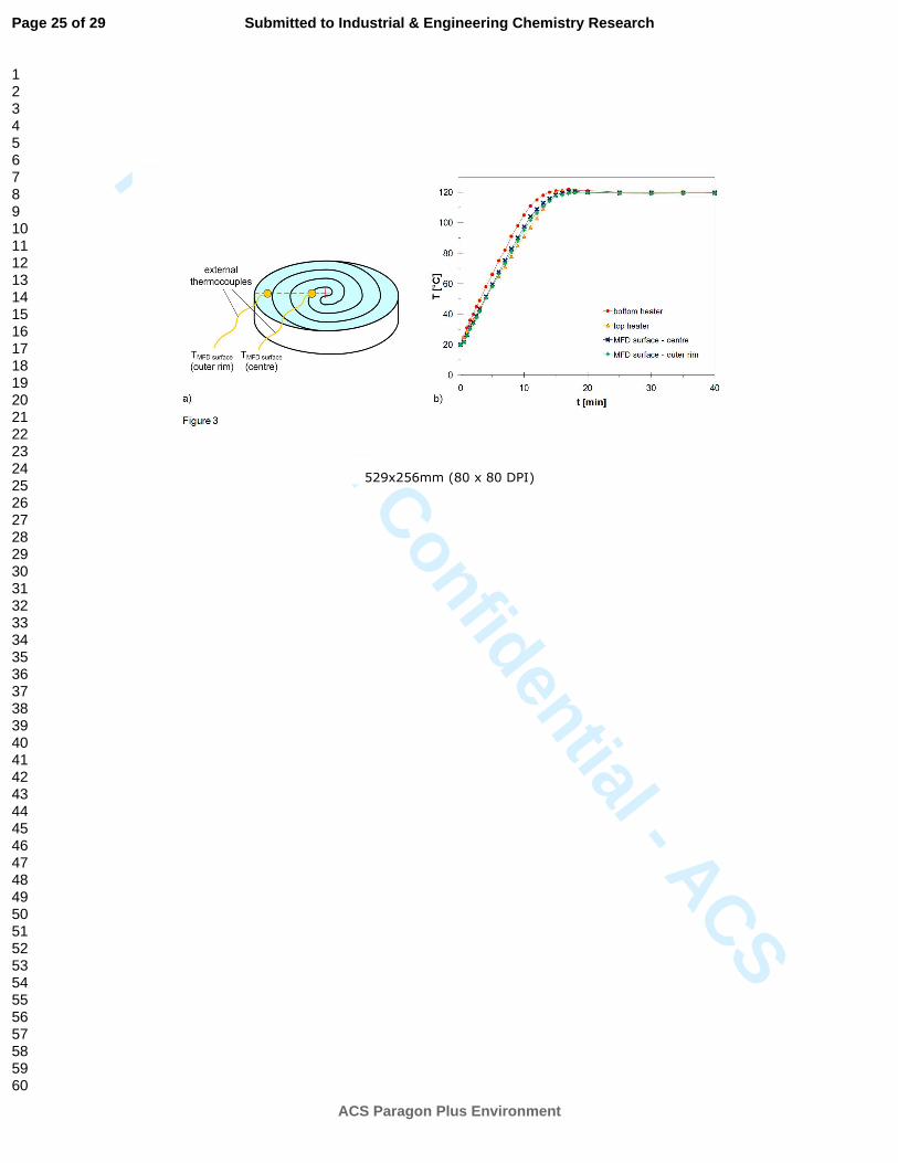
The temperature profile of an MFD inside the CDM (with 2 x 100 W heaters) during heating and at
steady state was measured using four K-type thermocouples. In addition to the two inbuilt
thermocouples of the reactor, which monitor the temperature of the top and bottom heater plate, two
external thermocouples were attached to the top surface of the MFD using heat resistant Kapton tape.
The later two thermocouples measured the surface temperature of the plastic disc at two positions: close
to the centre (centre of reactor pathway) and close to the outer rim (close to the inlet and outlet of reactor
pathway). Figure 3 shows schematically the position of the external thermocouples and the heating
profile of a typical experiment, where the temperature set point of the reactor was set to 120 °C.
-- FIGURE 3 --
Page 7 of 29
ACS Paragon Plus Environment
Submitted to Industrial & Engineering Chemistry Research
123456789101112131415161718192021222324252627282930313233343536373839404142434445464748495051525354555657585960

For Review. Confidential - ACS
8
The data was taken using acetonitrile (MeCN) as the process fluid at a constant flow rate of
0.5 ml/min. A 75 psi back pressure regulator was positioned in-line after the reactor, in order to prevent
the liquid from boiling inside the capillaries. It was observed that the reactor reached the desired
temperature after a heating period of roughly 18 minutes. After this initial transient period, the
temperature of both hot plates equilibrated to the set temperature of 120 ºC. The temperatures measured
on the disc’s surface also followed the same trend and reached the same value as the plates in the steady
state region after roughly 18 minutes. By fitting two heaters with double the power (2 x 200 W) to a
newer version of the reactor, the heating period was be substantially decreased. Repeating these
experiments for several runs at set temperatures between 80 and 160 ºC has shown that the measured
temperature on the MFD surface under steady state conditions was never more than 1% below the set
point value. Varying the flow rate through the disc between 0.5 and 1.5 ml/min did not result in lower
MFD surface temperatures; consequently it can be concluded, that the CDM heaters are capable of
accurately controlling the reaction temperature inside MFDs. This allows for a quasi-isothermal
operation of liquid phase reactions up to 200 ºC for a complete range of practical flow rates.
c) Residence time characterisation
In any continuous flow process where chemical reactions occur, the residence time characteristics of
the reactor can be of significant importance and reveal useful information. In general, a near plug flow
response is most desirable, although in reality rarely achieved. Perfect plug flow characteristics imply
that each fluid element passing through the reactor has the same residence time and therefore also
reaction time, which means that the entire reaction mixture is processed under identical conditions,
given a uniform temperature profile. A residence time distribution (RTD) that strongly deviates from
plug flow, resulting in a spread of the reaction mixture slug as it is passed through the reactor, can lead
to a reduced conversion rate or selectivity. Previous experimental studies of residence time
characteristics in 19 capillary MCFs were carried out using fibre optic probes and step change
Page 8 of 29
ACS Paragon Plus Environment
Submitted to Industrial & Engineering Chemistry Research
123456789101112131415161718192021222324252627282930313233343536373839404142434445464748495051525354555657585960

For Review. Confidential - ACS
9
concentration inputs.20
This data was compared to analytical models assuming plug flow superimposed
by axial dispersion. The MCFs showed residence time characteristics close to plug flow, which can be
explained by the small dimensions of the capillaries in combination with the low flow velocities.
Laminar flow in tubular systems usually leads to considerable dispersion because of the parabolic
velocity profile that develops across the tube; however, in slowly flowing systems with small channel
diameters, molecular diffusion effects are dominant. The small diameters of many microreactors ensure
that these effects, first described by G. I. Taylor in 1953,21
result in a narrower distribution than
expected from the parabolic velocity profile associated with laminar flow. Thus, the RTD in
microreactors is often close to plug flow. With his theory, Taylor introduced an effective diffusion
coefficient, Dax, which characterises the axial dispersion in the system. Soluble matter of a known
concentration injected into a flow through a pipe with diameter, dc, is dispersed relative to a plane,
which moves with the velocity vm = ½ vmax exactly as though it were diffused by a mass transport
process with the effective diffusion coefficient, Dax (see equation 6).
2 2
192
c max
d vD D
D= + (6)
Here, D is the diffusion coefficient, which for the herein presented model was assumed to be a
concentration independent, material specific constant, and was set to 1 x 10⁻¹⁰
m2/s. This lies within the
range of literature values for comparable systems, such as the work by Robinson.22
The theoretical Dax
can be compared to experimental values, which were calculated from residence time curves taken with
fibre optic probes in the 19 capillary MCFs described in earlier work.20
How close the RTD in a reactor
is to a plug flow profile, can be characterised by the axial dispersion number, sometimes also called
Peclet-number, Pe, which is defined as:
Pe m c
ax
v lD
= (7).
The higher the value of Pe, the closer the flow is to ideal plug flow. According to Levenspiel23
a
system with Pe > 100 can be considered as plug flow-like. In systems with Pe < 100, substantial axial
dispersion occurs. Table 1 compares theoretical predictions based on Taylor’s model, calculated for a
Page 9 of 29
ACS Paragon Plus Environment
Submitted to Industrial & Engineering Chemistry Research
123456789101112131415161718192021222324252627282930313233343536373839404142434445464748495051525354555657585960

For Review. Confidential - ACS
10
10 capillary MCF to previous experimental data from a 19 capillary MCF20
for a range of practicable
flow rates. The corresponding minimum and maximum Re, Dax and Pe were derived from the estimated
process limits of a 10 capillary MCF (model data) and the investigated operation window of a 19
capillary MCF (experimental data). Upper flow rate limits are usually determined by the maximum
pressure build-up inside the capillaries and lower limits by the minimum pump flow rate. Model and
experimental data values have a similar magnitude and show the same trend. The predicted minimum
Pe-number of a 30 metre long 10 capillary MCF of 181 leads to the conclusion that even at the
maximum operating flow rate of 1.5 ml/min, the RTD inside such an MFD would be plug flow-like.
These theoretical predictions need to be verified by experimental investigations, which will be
conducted in future work.
-- TABLE 1 --
Organic synthesis reactions
Three different reactions at temperatures between 110 and 120 ºC were chosen to validate the MFD
technology. These include a fluorination reaction and the formation of various heterocyclic compounds.
The reactions were performed on different scales; either as a small-scale run, where a short ‘slug’
containing a few mg of material was processed, or a fully continuous run producing several grams over a
given processing time. In the ‘slug injection’ runs, the reagents were either premixed and therefore only
one pump was used for the reaction or they were mixed continuously in a T-piece using two feed pumps.
The fully continuous runs were always performed using a two-pump configuration. The operating modes
used for these two experiments are shown schematically in figure 4. The objective in these reactions was
to achieve both high conversion and purity of the product in a reliable fashion using a device capable of
operating across a broad range of production scales.
-- FIGURE 4 --
Page 10 of 29
ACS Paragon Plus Environment
Submitted to Industrial & Engineering Chemistry Research
123456789101112131415161718192021222324252627282930313233343536373839404142434445464748495051525354555657585960

For Review. Confidential - ACS
11
a) Fluorination
As previously demonstrated, flow reactors are ideal instruments for the incorporation of fluorine24-27
into
organic substrates as the flow arrangement naturally allows for the convenient and safe handling of
hazardous fluorinating reagents. In order to evaluate the CDM, an electrophilic fluorination reaction was
performed using the commercially available reagent Selectfluor®. In earlier work, it was found that this
reagent is well suited for α-fluorination of carbonyl compounds when the reaction is performed at
temperatures around 120 °C. Using the CDM in the ‘slug injection’ mode, the desired monofluorinated
product as shown in scheme 1 was obtained in high yield and purity after scavenging the ionic
Selectfluor® reagent using a mixture of two commercially available resins: QP-SA (Quadrapure sulfonic
acid) and QP-DMA (Quadrapure dimethyl amine base).28
-- SCHEME 1 --
b) Formation of bicyclic heteroaromatic compounds
The formation of heterocyclic scaffolds in a selective and highly efficient manner is a key component
of today’s pharmaceutical chemistry programs, as these compounds allow for the evaluation of structure
activity relationships (SAR) for many new drug compounds.29
Imidazo[1,2-a]pyridines and related
substances are a well described class of bicyclic compounds which can be found in many GABA
receptor modulators such as zolpidem (Ambien), a drug used in the treatment of insomnia, as well as
some brain disorders. Their synthesis can be accomplished by a Hantzsch-type condensation between a
2-aminopyridine and an α-haloketone and is usually performed at elevated temperature (see scheme 2).
The flow process to prepare these compounds involves mixing the two starting materials in a 1:1 ratio
followed by the passage of this mixture as a slug through the CDM at 120 °C. It was found that
complete conversion could be achieved with a residence time of 20 minutes giving the desired
Page 11 of 29
ACS Paragon Plus Environment
Submitted to Industrial & Engineering Chemistry Research
123456789101112131415161718192021222324252627282930313233343536373839404142434445464748495051525354555657585960

For Review. Confidential - ACS
12
compounds in high yield after treatment with a basic QP-DMA resin in order to remove the initially
formed HBr salt from the product.
-- SCHEME 2 –
c) Oxazole formation
A second example of heterocycle formation using the CDM system, involved the synthesis of
bifunctional oxazoles, which can be prepared conveniently from urea derivatives via a condensation
with bromoethyl pyruvate.30
Similar reactions have been reported in traditional batch mode, however,
the need to reflux the reaction mixture for extended periods of time often leads to the formation of
undesired by-products. In comparison, we could obtain the desired amino oxazole product after
23 minute reaction time at 110 °C in continuous flow with an isolated yield of 83% after an aqueous
work-up. This interesting building block was reproducibly prepared using full continuous operation
mode on scales of 15 mmol with a total flow rate of 0.4 ml/min (scheme 3).
-- SCHEME 3 --
Summary and conclusions
This paper reports the evaluation of a novel continuous flow microreactor system (the Cambridge Disc
Microreactor or CDM) for liquid phase reactions up to 150 °C. It was demonstrated that plastic
Microcapillary Flow Discs which are manufactured from fluoropolymer Microcapillary Films, can be
used as reusable reactor cartridge. Each MFD had 10 parallel channels with capillary diameters of
200 µm and a length of 30 m. It is worth highlighting that these dimensions and number of capillaries is
not the limit of the current system and both lower and higher volumetric throughputs could easily be
achieved. Practical limits for the current CDM configuration are capillary diameters in the range of
400 µm at a length of several metres. Furthermore, it is possible to run several of these discs in parallel,
Page 12 of 29
ACS Paragon Plus Environment
Submitted to Industrial & Engineering Chemistry Research
123456789101112131415161718192021222324252627282930313233343536373839404142434445464748495051525354555657585960

For Review. Confidential - ACS
13
which has already been shown in previous work.17
MFDs can provide a low cost solution for micro- and
meso-scale flow chemistry, which enables this technology to bridge the gap between laboratory scale
and small production scale. The CDM system could provide a platform to carry out development of new
synthesis routes in the laboratory and then progress these processes to small production scale by simply
increasing the number of reactor units. The optimisation of the reaction conditions could be carried out
using a single disc, whilst the production reactor could be operated using multiple discs, featuring
hundreds or even thousands of microcapillaries run in parallel. This so-called numbering-up or scale-out
does not require the redesign and optimisation steps usually associated with the classical scale-up
approach. We believe that MFD technology is very suitable for this concept due to its design and
flexible manufacturing process. Table 2 presents theoretical scale-out calculations based on the herein
presented work and practical limitations.
-- TABLE 2 --
The proof of concept reactions described in this paper established the use of fluoropolymer MFDs for
organic synthesis at elevated temperatures and demonstrated that MFD technology has certain strategic
advantages over chip-based microreactor designs, such as longer reactor length leading to longer
reaction times and low manufacturing costs. The low manufacturing cost of the device provides the
option to use it as a disposable component, despite the fact that the MFDs exhibited sufficient
robustness to enable extended and repeated usage. MFDs are able to operate at elevated pressure,
provide excellent temperature control coupled with fast heat transfer and can offer a controlled
residence / reaction time of between seconds and hours.
MFDs can sustain higher pressures than standard laboratory glassware reactors, which enables the
generation of pressurised flows inside the microchannels yielding beneficial effects in terms of higher
boiling points, greater solubility and higher diffusion rates. Due to the use of fluorinated polymer, an
Page 13 of 29
ACS Paragon Plus Environment
Submitted to Industrial & Engineering Chemistry Research
123456789101112131415161718192021222324252627282930313233343536373839404142434445464748495051525354555657585960

For Review. Confidential - ACS
14
excellent solvent and temperature resistance could be achieved, which makes MFDs suitable for almost
all organic processes, at temperatures typically up to 150 °C.
With the help of manufacturing technologies such as rapid prototyping, it will be possible to modify
the CDM connectors such that the ten parallel channels can be individually addressed. In this mode the
CDM will have a powerful potential for screening multiple reactions under identical processing
conditions. This work is currently under investigation.
Experimental Section
Starting materials, reagents, and solvents were obtained from commercial suppliers and were used
without further purification. 1H NMR spectra were recorded on a Bruker Avance DPX-400 or Bruker
DPX-600 spectrometer with residual chloroform as the internal reference (δ = 7.26 ppm).
Ethyl-2-fluoro-3-oxo-3-phenylpropanoate (1):
Yield: 98%, tR = 4.27 min, m/z = 209.1 (M-H+);
1H-NMR (600 MHz, CDCl3) δ/ppm 8.02 (2H, d, J =
8.4 Hz), 7.62 (1H, t, J = 8.4 Hz), 7.48 (2H, t, J = 8.4 Hz), 5.87 (1H, d, J = 48.6 Hz), 4.28 (2H, qd, J =
2.4, 7.2 Hz), 1.23 (3H, t, J = 7.2 Hz); 13
C-NMR (150 MHz, CDCl3) δ/ppm 189.5 (C, d, J = 20 Hz),
164.9 (C, d, J = 24 Hz), 134.5 (CH), 133.4 (C, d, J = 2 Hz), 129.5 (2CH, d, J = 2 Hz), 128.8 (2CH), 89.9
(CHF, d, J = 197 Hz), 62.6 (CH2), 13.9 (CH3); 19
F-NMR (376 MHz, CDCl3): δ/ppm -190.5 (s); IR (neat)
ν = 2985.6 (w), 1758.5 (s), 1693.2 (s), 1597.7 (m), 1449.7 (m), 1372.27 (m), 1242.5 (s), 1202.0 (s),
1096.1 (s), 1015.0 (s), 976.4 (m), 943.0 (w), 925.3 (w), 882.8 (m), 854.1 (w), 771.4 (w), 746.6 (w),
688.1 (s) cm-1
; HRMS calculated for C11H12O3F 211.0770, found 211.0779.
4-(8-bromo-6-methylimidazo[1,2-a]pyridine-2-yl)benzonitrile (2):
Yield 80%; tR= 4.09 min, m/z=313.8 (M+H+);
1H-NMR (600 MHz, CDCl3): δ/ppm 8.03 (2H, d, J =
8.4 Hz), 7.88 (1H, s), 7.86 (1H, s), 7.65 (2H, d, J = 8.4 Hz), 7.32 (1H, s), 2.30 (3H, s); 13
C-NMR (150
MHz, CDCl3): δ/ppm 143.8 (C), 142.9 (C), 137.8 (C), 132.7 (C), 132.4 (2CH), 130.9 (CH), 126.5
Page 14 of 29
ACS Paragon Plus Environment
Submitted to Industrial & Engineering Chemistry Research
123456789101112131415161718192021222324252627282930313233343536373839404142434445464748495051525354555657585960

For Review. Confidential - ACS
15
(2CH), 123.1 (C), 122.9 (CH), 119.1 (C), 111.0 (C), 110.9 (CH), 17.9 (CH3); IR (neat) ν=2222.8 (m),
1609.7 (m), 1519.9 (s), 1476.9 (s), 1414.1 (m), 1340.1 (s), 1294.5 (s), 1268.7 (m), 1208.9 (m), 1022.8
(s), 943.9 (s), 873.1 (m), 844.8 (s0, 832.3 (s), 739.6 (s), 706.2 (s), 666.8 (m) cm-1
; HRMS calculated for
C15H11N3Br 312.0136, found 312.0147.
Ethyl-6-chloroimidazo[1,2-b]pyridazine-2-ylcarboxylate (3):
Yield 87%; tR= 3.51 min, m/z=225.8 (M+H+);
1H-NMR (600 MHz, CDCl3): δ/ppm 8.41 (1H, s), 7.97
(1H, d, J = 9.6 Hz), 7.13 (1H, d, J = 9.6 Hz), 4.22 (2H, q, J = 7.2 Hz), 1.40 (3H, t, J = 7.2 Hz); 13
C-
NMR (150 MHz, CDCl3): δ/ppm 162.4 (C), 148.9 (C), 137.7 (C), 136.9 (C), 128.4 (CH), 121.3 (CH),
121.0 (CH), 61.6 (CH2), 14.4 (CH3); IR (neat) ν=3079.8 (s), 3024.7 (s), 1731.6 (s0, 1531.9 (m), 1516.5
(m), 1456.5 (m), 1374.4 (m), 1298.8 (s), 1238.3 (m), 1186.0 (s), 1138.6 (s), 1118.7 (s), 1092.8 (s),
1022.6 (s), 939.6 (m), 838.0 (s), 796.1 (m), 749.6 (s), 730.2 (s), 712.1 (s) cm-1
; HRMS calculated for
C9H9N3O2Cl 226.0383, found 226.0394.
Ethyl-2-(allylamine)-oxazole-4-carboxylate (4):
Yield:83%; tR = 3.64 min, m/z = 197.0 (M+H+);
1H-NMR (600 MHz, CDCl3) δ/ppm 7.72 (1H, s), 5.92
(1H, ddd, J = 5.4, 10.8, 16.8 Hz), 5.52 (1H, br s), 5.24 (1H, dd, J = 1.2, 16.8 Hz), 5.15 (1H, dd, J = 1.2,
10.2 Hz), 4.32 (2H, q, J = 7.2 Hz), 4.00 (2H, dd, J = 6.0 Hz), 1.33 (3H, t, J = 7.2 Hz); 13
C-NMR (150
MHz, CDCl3) δ/ppm 161.8 (C), 161.1 (C), 137.5 (CH), 134.2 (CH), 133.0 (C), 116.5 (CH2), 60.8 (CH2),
45.5 (CH2), 14.3 (CH3); IR (neat) ν = 3164.2 (w), 2983.7 (w), 1722.4 (s), 1654.9 (s), 1421.3 (m), 1332.9
(m), 1244.3 (s), 1129.7 (s), 1093.4 (s), 1029.0 (m), 997.3 (m), 930.3 (s), 711.7 (s) cm-1
; HRMS
calculated for C9H13N2O3 197.0925, found 197.0926.
Acknowledgements
Page 15 of 29
ACS Paragon Plus Environment
Submitted to Industrial & Engineering Chemistry Research
123456789101112131415161718192021222324252627282930313233343536373839404142434445464748495051525354555657585960

For Review. Confidential - ACS
16
We gratefully acknowledge financial support from the Engineering and Physical Science Research
Council (C.H. Hornung), the Royal Society (I.R. Baxendale), the Cambridge European Trust and the
Ralph Raphael Studentship award (M. Baumann ), and the BP Endowment (S.V. Ley).
References
(1) Seeberger, P. H.; Blume, T. New Avenues to Efficient Chemical Synthesis, Emerging Technologies;
Springer, Berlin, Germany, 2007.
(2) Hodge, P. Organic synthesis using polymer-supported reagents, catalysts and scavengers in simple
laboratory flow systems. Curr. Opin. Chem. Biol. 2003, 7, 362.
(3) Kirschning, A.; Solodenko, W.; Mennecke, K. Combining Enabling Techniques in Organic
Synthesis: Continuous Flow Processes with Heterogenized Catalysts. Chem..Eur. J. 2006, 12, 5972.
(4) Ahmed-Omer, B.; Brandt, J. C.; Wirth, T. Advanced organic synthesis using microreactor
technology. Org. Biomol. Chem. 2007, 5, 733.
(5) Mason, B. P.; Price, K. E.; Steinbacher, J. L.; Bogdan, A. R.; McQuade, D. T. Greener Approaches
to Organic Synthesis Using Microreactor Technology. Chem. Rev. 2007, 107, 2300.
(6) Steven V. Ley, S. V.; Baxendale I. R. New Tools for Molecule Makers: Emerging Technologies.
Systems Chemistry May 26th – 30th, 2008, Bozen, Italy.
(7) Sahoo, H. R.; Kralj, J. G.; Jensen, K. F. Multi-step Continuous Flow Microchemical Synthesis
involving Multiple Reactions and Separations. Angew. Chemie Int. Ed. 2007, 46, 5704.
(8) DeWitt, S. H. Microreactors for chemical synthesis. Curr. Opin. Chem. Biol. 1999, 3, 350.
(9) deMello, A.; Wootton, R. But what is it good for? Applications of microreactor technology for the
fine chemical industry. Lab Chip 2002, 2, 7N.
(10) Hessel, V.; Hardt, S.; Löwe, H. Chemical Micro Process Engineering (1), Fundamentals,
Modelling and Reactions; Wiley-VCH, Weinheim, Germany, 2004.
(11) Jähnisch, K.; Hessel, V.; Löwe, H; Baerns, M. Chemistry in Microstructured Reactors. Angew.
Chem. Ind. Ed. 2004, 43, 406.
Page 16 of 29
ACS Paragon Plus Environment
Submitted to Industrial & Engineering Chemistry Research
123456789101112131415161718192021222324252627282930313233343536373839404142434445464748495051525354555657585960

For Review. Confidential - ACS
17
(12) Kralj, J. G.; Sahoo, H. R.; Jensen, K.F. Integrated continuous microfluidic liquid-liquid
extraction. Lab Chip 2007, 7, 256.
(13) Hallmark, B.; Mackley, M. R.; Gadala-Maria. F. Hollow microcapillary arrays in thin plastic film.
Adv. Eng. Mat. 2005, 7(6), 545.
(14) http://www.laminadielectrics.com/
(15) Hornung, C. H.; Hallmark, B.; Hesketh, R. P.; Mackley, M. R. The fluid flow and heat transfer
performance of thermoplastic microcapillary films. J. Micromech. Microeng. 2006, 16, 434.
(16) Hallmark, B.; Gadala-Maria, F.; Mackley, M. R. The melt processing of polymer microcapillary
film (MCF), J. Non-Newtownian Fluid Mech. 2005, 128, 83.
(17) Hornung, C. H.; Mackley, M. R.; Baxendale, I. R.; Ley, S. V. A Microcapillary Flow Disc
Reactor for Organic Synthesis. Org. Process Res. Dev. 2007, 11, 399.
(18) Lamb, H. Hydrodynamics, 6th edition; Dover, New York, USA, 1945.
(19) Perry, R. H.; Green, D. W. Perry’s Chemical Engineer’s Handbook, 7th edition; McGraw-Hill
Co., New York, USA, 1997.
(20) Hornung, C. H.; Mackley M. R. The measurement and characterisation of residence time
distributions for laminar liquid flow in plastic microcapillary arrays. Chem. Eng. Sci. 2009, 64, 3889.
(21) Taylor, G. Dispersion of soluble matter in solvent flowing slowly through a tube, Proc. R. Soc A
1953, 219, 186.
(22) Robinson, C. The Diffusion Coefficients of Dye Solutions and their Interpretation. Proc. R. Soc A
1935, 148, 681.
(23) Levenspiel, O. Chemical Reaction Engineering, 3rd Edition; John Wiley & Sons, New York,
USA, 1999.
(24) Baumann, M.; Baxendale, I. R.; Martin, L. J.; Ley, S. V. Development of Fluorination Methods
using Continuous-Flow Microreactors. Tetrahedron 2009, 65, 6611.
(25) Baumann, M.; Baxendale, I. R.; Ley, S. V. The Use of diethylaminosulfurtrifluoride (DAST) for
Fluorination in a Continuous Flow Microreactor. Synlett 2008, 14, 2111.
Page 17 of 29
ACS Paragon Plus Environment
Submitted to Industrial & Engineering Chemistry Research
123456789101112131415161718192021222324252627282930313233343536373839404142434445464748495051525354555657585960

For Review. Confidential - ACS
18
(26) Gustafsson, T.; Gilmour, R.; Seeberger, P. H. Fluorination reactions in microreactors. Chem.
Commun. 2008, 3022.
(27) Chambers, R. D.; Fox, M. A.; Sandford, G.; Trmcic, J.; Goeta, A. Elemental fluorine: Part 20.
Direct fluorination of deactivated aromatic systems using microreactor techniques. J. Fluorine Chem.
2007, 128, 29.
(28) http://www.reaxa.com/
(29) Baxendale, I. R; Hayward, J. J.; Ley, S. V.; Tranmer, G. K. Pharmaceutical Strategy and
Innovation: An Academics Perspective. ChemMedChem. 2007, 2, 768.
(30) Baumann, M.; Baxendale, I. R.; Ley, S. V.; Smith, C. D.; Tranmer, G. K. Fully Automated
Continuous Flow Synthesis of 4,5-Disubstituted Oxazoles. Org. Lett. 2006, 8(23), 5231.
Page 18 of 29
ACS Paragon Plus Environment
Submitted to Industrial & Engineering Chemistry Research
123456789101112131415161718192021222324252627282930313233343536373839404142434445464748495051525354555657585960

For Review. Confidential - ACS
19
Figure 1. Photographic images of various reactor components: a) microscope image of MCF cross
section containing 10 capillaries, b) side view of a single film, c) double spiral MFD, d) cylindrical
MCF inlet unit with two plastic fittings and a plastic ferrule, e) Cambridge Disc Microreactor;14
f) design drawing of the Cambridge Disc Microreactor showing the drawer mechanism.14
Figure 2. a) Comparison of experimental pressure drop with analytical predictions for two different
working liquids and two different temperatures, deq = 200 µm, capillary length = 33 m; b) Fanning
friction factor, f, in a 10-capillary film plotted against the mean Reynolds number, for two different
temperatures; the line represents the theoretical law f = 16/Re.
Figure 3. a) schematic drawing of an MFD showing the position of the two external thermocouples,
one being attached to the top surface of the disc at its outer rim, the second being attached to the top
surface close to the centre of the disc, b) Heating profile of an MFD inside the reactor, showing both the
transient period (t = 0 to 18 min) and steady state (t > 18 min); the reactor operates with two 100 W
heaters; target temperature: 120 °C; flow rate through disc: 0.5 ml/min.
Figure 4. Schematic overview of two different operation modes used for chemical reactions inside a
CDM; top: ‘slug injection’ mode, using two sample loops, for processing small amounts of liquid
(typical volume per sample loop: 1 to 5 ml); bottom: continuous mode for fully continuous flow
processing of larger volumes (typically >10 ml).
Page 19 of 29
ACS Paragon Plus Environment
Submitted to Industrial & Engineering Chemistry Research
123456789101112131415161718192021222324252627282930313233343536373839404142434445464748495051525354555657585960

For Review. Confidential - ACS
20
Scheme 1. Electrophilic fluorination of ethyl 3-oxo-3-phenylpropanoate using the fluorinating agent
Selectfluor® in a Cambridge Disc Microreactor, using the ‘slug injection’ mode.
Scheme 2: Synthesis of bicyclic heteroaromatic compounds at elevated temperatures in a Cambridge
Disc Microreactor, using the ‘slug injection’ mode.
Scheme 3: Synthesis of amino oxazoles at elevated temperatures in a Cambridge Disc Microreactor,
using the continuous mode.
Page 20 of 29
ACS Paragon Plus Environment
Submitted to Industrial & Engineering Chemistry Research
123456789101112131415161718192021222324252627282930313233343536373839404142434445464748495051525354555657585960

For Review. Confidential - ACS
21
Table 1. Comparison of theoretical RTD data calculated for a 10 capillary MFD (lc = 30 m, dc =
200 µm) with experimental data from a 19 capillary MFD20
(lc = 10 m, dc = 222 µm); upper and lower
flow rate boundaries are shown together with corresponding values for Re, Dax and Pe; for the given
conditions, RTD in 10 capillary MFD is expected to be plug flow-like as Pe > 100.
10 capillary MFD - model 19 capillary MFD - experimental
30 m MCF, dc = 200 µm 10 m MCF, dc = 222 µm
min. flow rate max. flow rate low flow rate high flow rate
flow rate [ml/min] 0.1 1.5 0.5 2.0
Re [-] 1.14 17.1 2.52 10.1
Dax [mm2/s] 64 14315 579 4492
Pe [-] 2714 181 190 98
Page 21 of 29
ACS Paragon Plus Environment
Submitted to Industrial & Engineering Chemistry Research
123456789101112131415161718192021222324252627282930313233343536373839404142434445464748495051525354555657585960

For Review. Confidential - ACS
22
Table 2. Comparison of typical reactor specifications for laboratory and productions scale, both using
Microcapillary Flow Discs.
Laboratory Scale Production Scale
optimisation of reaction conditions for production of g- to kg-quantities
1 x MFD (10 capillaries) 20 x MFD (20 capillaries each)
no. of capillaries 10 400
capillary diameter 200 to 400 µm 400 µm
capillary length 10 to 30 m 30 m
reactor volume 3 to 40 ml 1600 ml
throughput
(at 30 min reaction time)
0.1 to 1.3 ml/min 53.4 ml/min (3.2 l/h)
Page 22 of 29
ACS Paragon Plus Environment
Submitted to Industrial & Engineering Chemistry Research
123456789101112131415161718192021222324252627282930313233343536373839404142434445464748495051525354555657585960

For Review. Confidential - ACS
b)
a)
e)
c) d)
f)
Figure 1
Page 23 of 29
ACS Paragon Plus Environment
Submitted to Industrial & Engineering Chemistry Research
123456789101112131415161718192021222324252627282930313233343536373839404142434445464748495051525354555657585960

For Review. Confidential - ACS
569x254mm (80 x 80 DPI)
Page 24 of 29
ACS Paragon Plus Environment
Submitted to Industrial & Engineering Chemistry Research
123456789101112131415161718192021222324252627282930313233343536373839404142434445464748495051525354555657585960
For Review. Confidential - ACS
529x256mm (80 x 80 DPI)
Page 25 of 29
ACS Paragon Plus Environment
Submitted to Industrial & Engineering Chemistry Research
123456789101112131415161718192021222324252627282930313233343536373839404142434445464748495051525354555657585960

For Review. Confidential - ACS
125x57mm (300 x 300 DPI)
Page 26 of 29
ACS Paragon Plus Environment
Submitted to Industrial & Engineering Chemistry Research
123456789101112131415161718192021222324252627282930313233343536373839404142434445464748495051525354555657585960

For Review. Confidential - ACS
144x59mm (300 x 300 DPI)
Page 27 of 29
ACS Paragon Plus Environment
Submitted to Industrial & Engineering Chemistry Research
123456789101112131415161718192021222324252627282930313233343536373839404142434445464748495051525354555657585960

For Review. Confidential - ACS
123x54mm (300 x 300 DPI)
Page 28 of 29
ACS Paragon Plus Environment
Submitted to Industrial & Engineering Chemistry Research
123456789101112131415161718192021222324252627282930313233343536373839404142434445464748495051525354555657585960
Related Documents