Local Self Government Department Government of Kerala Quality Assurance Handbook for Resilient Reconstruction of Flood Damaged Rural Roads June 2020 Project Management Unit, Rebuild Kerala Initiative

Welcome message from author
This document is posted to help you gain knowledge. Please leave a comment to let me know what you think about it! Share it to your friends and learn new things together.
Transcript

Local Self Government Department
Government of Kerala
Quality Assurance Handbook
for
Resilient Reconstruction of
Flood Damaged Rural Roads
June 2020
Project Management Unit, Rebuild Kerala Initiative


III
QUALITY ASSURANCE HANDBOOK FOR RURAL ROADS
VOLUME I
CONTENTS
PAGE NO.
FOREWORD
PREFACE
ABBREVIATIONS
CHAPTER1 INTRODUCTION 1 to5
CHAPTER 2 QUALITYMANAGEMENTSYSTEM 7 to10
CHAPTER 3 QUALITY CONTROL OF WORKS
Section 100
105
GENERAL
Construction Equipment
13 to 15
108 Setting Out
109&110 Public Utilities and Environment
114 Methodology & Sequence of Work
Section 200 SITE CLEARANCE
201& 202 Site Clearance 19
Section 300
301
EARTHWORKS
Embankment Construction
23 to 38
302 Earthwork in Cutting
303 Subgrade Construction
304 Rock Cutting
306 Fly ash Embankment Construction
307 Surface Drains
Section 400
401
GRANULAR SUB-BASES, BASES & SURFACINGS
Granular Sub-Base
41 to 79
IV
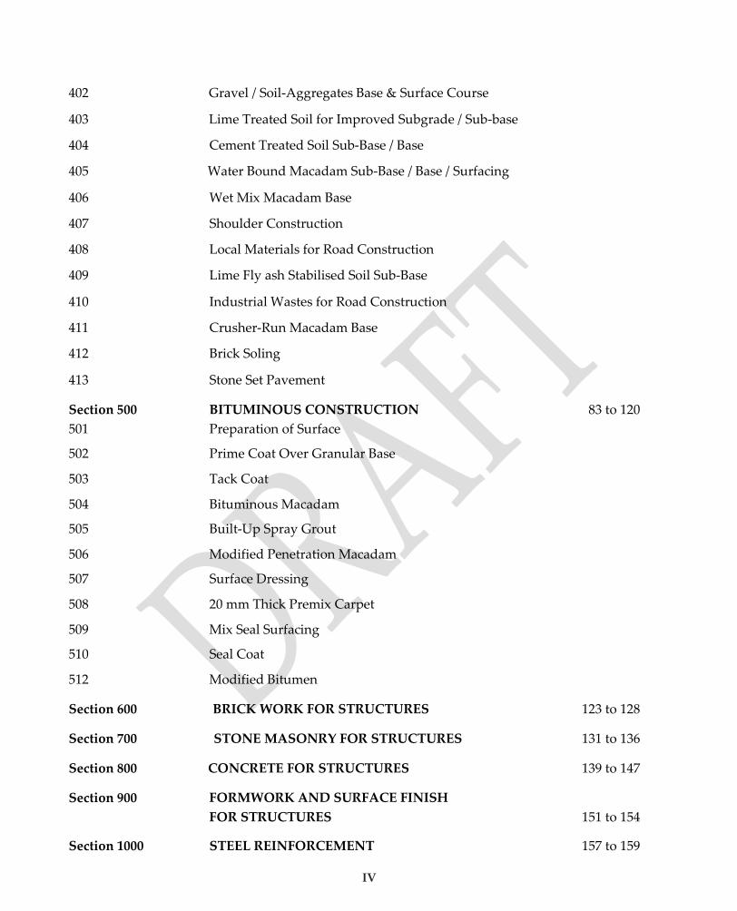
402 Gravel / Soil-Aggregates Base & Surface Course
403 Lime Treated Soil for Improved Subgrade / Sub-base
404 Cement Treated Soil Sub-Base / Base
405 Water Bound Macadam Sub-Base / Base / Surfacing
406 Wet Mix Macadam Base
407 Shoulder Construction
408 Local Materials for Road Construction
409 Lime Fly ash Stabilised Soil Sub-Base
410 Industrial Wastes for Road Construction
411 Crusher-Run Macadam Base
412 Brick Soling
413 Stone Set Pavement
Section 500
501
BITUMINOUS CONSTRUCTION
Preparation of Surface
83 to 120
502 Prime Coat Over Granular Base
503 Tack Coat
504 Bituminous Macadam
505 Built-Up Spray Grout
506 Modified Penetration Macadam
507 Surface Dressing
508 20 mm Thick Premix Carpet
509 Mix Seal Surfacing
510 Seal Coat
512 Modified Bitumen
Section 600 BRICK WORK FOR STRUCTURES 123 to 128
Section 700 STONE MASONRY FOR STRUCTURES 131 to 136
Section 800 CONCRETE FOR STRUCTURES 139 to 147
Section 900 FORMWORK AND SURFACE FINISH
FOR STRUCTURES
151 to 154
Section 1000 STEEL REINFORCEMENT 157 to 159

V
Section 1100 PIPE CULVERTS 163 to 166
Section 1200 RCC SLAB CULVERTS AND MINOR BRIDGES 169 to 177
Section 1300 PROTECTION WORKS AND DRAINAGE 181 to 185
Section 1400 CEMENT CONCRETE CAUSEWAY 189 to 193
Section 1500 CEMENT CONCRETE PAVEMENT 197 to 215
1501 Plain Cement Concrete Pavement
1502 Roller Compacted Concrete Pavement
1503 Rectangular Concrete Block Pavement
1504 Interlocking Concrete Block Pavement
Section 1600 HILL ROAD CONSTRUCTION 219 to 222
Section 1700 TRAFFIC SIGNS, MARKINGS &
OTHER ROAD APPURTENANCES
225 to 227
Section 1900: MAINTENANCE 231 to 241
1901, 1902 & 1903 Maintenance of Earthworks
1904 Maintenance of Bituminous Surface Road
1905 Maintenance of Gravel Road
1906 Maintenance of WBM Road
1908,1909 Maintenance of Culverts and Causeways
1910,11,12,13,14 &15
CHAPETR 4
Maintenance of Road Signs, Markings &Appurtenance
QUALITY MONITORING BY NATIONAL/STATE
QUALITY MONITIORS
s
243 to 274
Appendices
Appendix-1
Handfeel Tests
App. 1 / 1 to 1 / 8
Appendix-2 Guidelines for Appropriate Technology for
Rural Road Construction
App. 2 / 1 to 2 / 2
Appendix-3 List of IRC Publication App. 3 / 1 to 3 / 7
Appendix-4 List of MORD and MOSRTH Publications App. 4 / 1 to 4 / 2
VOLUME II
EQUIPMENT AND PROCEDURES FOR TESTS

VIII

IX
ABBREVIATIONS
AE : AssistantEngineer
AIV : Aggregate Impact Value
BOQ : Bill ofQuantities
CBR : California Bearing Ratio
CD : Cross-Drainage
CRMB : Crumb Rubber Modified Bitumen
cum : Cubic metre
EE : ExecutiveEngineer
g : Gram
GBFS : Granulated Blast Furnace Slag
GSB : GranularSub-Base
GTS : Grand Triangulation Survey
h : Hour
IS : IndianStandard
JE : JuniorEngineer
kg : Kilogram
km : Kilometre
kN : Kilo Newton
l : Litre
m : Metre
MB : ModifiedBinder
ml : Millilitre
mm : Millimetre
MORD : Ministry of RuralDevelopment
MORTH : Ministry of Road Transport & Highways
MOSRTH : Ministry of Shipping, Road Transport & Highways
MPa : MegaPascal

X
MPM : Modified Penetration Macadam
MS : MediumSetting
NRRDA : National Rural Roads Development Agency
NQM : National QualityMonitor
OMC : Optimum Moisture Content
PMB : Polymer Modified Bitumen
RMB : Rubber Modified Bitumen
RS : RapidSetting
SQC : State Quality Coordinator
SQM : State Quality Monitor
sqm : Squaremetre
SS : Slow Setting
UCS : Unconfined Compressive Strength
WBM : Water BoundMacadam
WMM : Wet MixMacadam

2
CHAPTER 1
INTRODUCTION
1. BACKGROUND
Kerala experienced an abnormally high rainfall from 1st June 2018 to 19th August 2018. This
resulted in severe flooding in 13 out of the14 districts in the State. As per IMD data, Kerala
received 2346.6 mm of rainfall from 1st June 2018 to 19th August 2018 in contrast to an expected
1649.5 mm of rainfall. This rainfall was about 42% above the normal. Further, the rainfall over
Kerala during June, July and 1st to 19th of August was 15%, 18% and 164% respectively, above
normal. The flood with torrential rains left hundreds dead, thousands homeless and it devastated
the livelihood of lakhs. Unusual downpour during the month of August followed by inundation
and landslips inflicted severe damages to households, public buildings, roads, bridges etc.
Thirty-five out of the fifty-four dam shutters within the state were opened, for the first time in
history. First time in 26 years 5 gates of the Malampuzha dam of Palakkad were opened. Heavy
rains in Wayanad and Idukki have caused severe landslides and have left the hilly locations
isolated. The floods destroyed 27,000 houses and submerged 45,000 hectares of farmland. About
a million people were evacuated, mainly from Chengannur, Pandanad, Edanad, Aranmula,
Kozhencherry, Ayiroor, Ranni, Pandalam, Kuttanad, Malappuram, Aluva, Chalakudy,
Thiruvalla, Eraviperoor, Vallamkulam, N.Paravur, Vypin Island and Palakkad. A great number
of LSGD roads were also damaged. Many of the places were isolated. The people of Kerala and
its Government showed unparalleled courage and enthusiasm in recovering the immediate crisis.
However, the flood demands us to make new rules and standards in constructing new road
infrastructure and also in rehabilitation of old ones.
Road connectivity is a key component of rural development by promoting access to economic
and social services and thereby generating increased agricultural incomes and productive
employment opportunities. It is also a key ingredient in ensuring poverty reduction.

3
Rebuild Kerala Initiative is a State Government initiative aimed at rebuilding life in Kerala after
the floods understanding the fact that high quality and durable road infrastructure is a pre
requisite for social, economic and industrial development of any state.
In Kerala, Local Self-Government Institutions have been meaningfully empowered through
massive transfer of resources as well as administrative powers. Local self-government
Institutions have emerged as effective agencies for the implementation of developmental
programs. They are responsible for maintenance of rural & urban roads and other civil assets
within their respective jurisdictional areas except for limited number of civil and road assets
managed by other agencies.
It has become the need of the hour for transportation agencies to get updated and form new rules
of managing the risks and to develop new maintenance strategies for reducing the vulnerability
of transportation assets to extreme events. With this view point, as a part of Rebuild Kerala
Initiative, the Government of Kerala has constituted the Project Management Unit (PMU) for the
reconstruction of damaged road assets owned by Local Self Government Institutes. The PMU
along with its field units is expected to prepare Detailed Project Report and Bidding Documents
for the road works in various Local Bodies, using best possible alignment, rehabilitation and
resilient recovery post 2018 floods and landslides. The road shall confirm to standards of IRC and
shall be constructed following the MoRD/MoRTH specifications.
The Vision of this unit is
• To create sustainable and resilient LSGI roads and allied structures that are scientifically
designed as well as ecologically friendly, for improved productivity and economic
efficiency of transport that will act as catalyst to the overall development of the State of
Kerala.
PMU will conduct detailed engineering studies of the damaged assets and prepare detailed
reports for restoration/ reconstruction incorporating new technologies, develop new strategies
and frameworks for work execution and post construction maintenance and also to formulate
and implement a state-of-the-art quality control mechanism. This handbook describes the quality
control mechanism proposed for the works undertaken as part of the above project. The hand

4
book is prepared based on the quality assurance handbook of PMGSY which is the only
authoritative document regarding quality control of rural roads. Required inputs are also taken
from the Kerala Public Works Department Quality Control Manual.
2. QUALITYASSURANCE
Ensuring the quality of the road works is the responsibility of the Project Management Unit
(PMU), who is implementing the Program. To this end, various levels of quality control
mechanisms will be established. The PMU shall issue general guidelines on Quality Control and
prescribe a methodology to regulate the quality control process at works level. Quality Control
Registers containing the results of tests prescribed in the Quality Control Handbook shall
invariably be maintained for each of the road works. The contractor shall set up a site Quality
Control Laboratory or he will seek assistance of State Government laboratories/Government
Engineering Colleges/Selected Self Financing Colleges for the required tests at various levels at
his own expense. The contractor shall collect the samples in the presence of the engineer and the
chainage and date of collection of the sample has to be recorded and shall perform all the tests
prescribed by the Quality Control Handbook at his own expense under the supervision and
direction of the Engineer-in-charge at various levels of quality control. Payments shall not be
made to the Contractor unless quality control tests are regularly conducted, recorded and have
been found to be successful.
The frequency of tests prescribed in the handbook is as per the Quality Control Handbook of
PMGSY. The provisions in the manual will be applicable to all works executed by the Project
Management Unit, Rebuild Kerala Initiative, LSGD.
3. QUALITYCONTROL
The Quality Control on PMURKI Roads and Cross-Drainage Works shall be exercised as follows:
(i) Quality Control Tests on Materials before incorporation in the Works:
4
All materials before incorporation in the work shall be tested by the Contractor for the tests
indicated under ‘Tests to be carried out Prior to Construction’. The tests shall be carried out from
each source identified by the Contractor. The test samples shall be representative of the material
available from the source. Any change / variation in the quality of material with depth of strata
shall be reported. Important tests like the Moisture-Density relationship
(ProctorCompaction),Aggregate ImpactValue, Plasticity Index, CBR and any other tests specified
by the Engineer shall invariably be carried out in the presence of a representative of the
Engineer, who will not be below the rank of Assistant Engineer. The test results shall form the
basis for approval of the source and the material for incorporation in the work and shall be
approved by the Engineer. For manufactured items, however, such as concrete pipes, Ready
Mix Concrete, elastomeric bearings etc, a test certificate obtained by the Manufacturer from an
approved Test House shall be accepted and testing during construction shall be done as per
provisions of the handbook.
(ii) Quality Control Tests During Construction:
During execution of the work, quality control for workmanship and ensuring conformance to
specifications shall be exercised on the basis of the tests indicated under ‘Field Quality Control
Tests During Construction’. The tests shall be carried out by the Contractor independently in the
presence of Employer’s representative, normally an Assistant Engineer. The Assistant Engineer
shall record the results in his own handwriting. The Contractor shall be fully responsible for all
the tests carried out for the work. The Assistant Engineer / Assistant Executive Engineer during their
site visits shall have a few tests carried out in their presence and sign the Quality Control
Register.
(iii) StagePassing:
Supervisory officers of the level of AE and AEE shall exercise quality control checks and certify
the work of various stages on the basis of tests and their frequencies indicated under
‘QualityControl Checks’. The officer certifying the work at various stages as prescribed shall be
responsible for the quality and quantity of the work certified by him.
(iv) Procedure to form part of the Contract:
The prescribed tests, frequencies and the procedure for stage passing by Supervisory Officers
5
shall be mandatory and shall form part of the Contract.
(v) RandomChecks
Where random checking has been recommended, the procedure to be adopted for random
checking shall be as follows:
(i) The complete section to be checked shall be divided into ten subsections of equal length viz.0-
100 m, 100-200m, 200-300m. Of these,only two sub-sections shall be selected for carrying out
tests by draw of lots.
(ii) Longitudinal profile shall be tested by a 3 m straight edge in a stretch of atleast 9 mlength.
(iii) Transverse profile viz. camber / crossfall / super elevation shall be tested using camber templates
at two or three locations for each 100 mlength.
(iv) During bituminous mix construction, temperature measurement shall be done by metallic
contact thermometer with digitaldisplay and in NO case the compaction of the mix shall be
carried out at temperatures lower than 120 degC, irrespective of the type of bitumen used. The
compaction temperatures are to be recorded in the field book by the engineer who is in charge at
the construction site.
(vi) Simple/Hand-FeelTests
For monitoring the quality of work, generally it may not be possible to carry out the detailed
quality control tests and therefore, for the purpose of quality monitoring simple hand-feel tests
can be performed. Normally various simple tests have been used by the experienced practicing
engineers in the field to make a quick assessment of the quality of the product. However, these
procedures have not been standardized and involve human judgement. Therefore, these tests
which provide useful guidance for supervisory officers during inspections, should by no means
be used as a replacement of the specified quality control tests. Some simple hand-feel tests which
are useful for quality monitoring are given in Appendix I.
4. COVERAGE OF THE HANDBOOK
This hand book covers Quality Management System and Quality Control Requirements
mandated for the implementation of the PMURKI works. It covers quality management system
and describes in detail quality control of works by Field Units and supervisory staff and quality

6
monitoring by Engineering Colleges for various activities of construction. This handbook is
prepared based on the Quality ontrol Hand book I of PMGSY and PWD quality control manual.
Tests which are unavailable in PMGSY handbook is adopted from PWD quality control manual.
Some new technologies adopted which is not covered by both the above manuals are taken from
available literature. It is suggested to adopt PMGSY Quality Control Manual Volume II for
relevant types of equipment and test procedures. All construction specifications and tests should
be in compliance with MoRD/MoRTH specifications.
5. FLOW CHART
A typical flow chart for quality assurance checks during the construction of rural roads is given
as an illustration in Figure 1.1.

5
Material
tests
Not
Possible
Possible
Undertake construction
Earthwork
Granular sub-base
eg Water BoundMacadam
Premix carpet
Road Signs
Borrow area (Earthwork)
Quarry (Aggregates) eg Supplier (Bitumen,cement,
steel & paint)
Gradation, size
Specific gravity
Atterberg limits
eg Aggregate impactvalue
Flakiness index
Soundness
Waterabsorption
Stripping value
Density,CBR
• Sampling • Frequency • Acceptance criteria
Trials,
if necessary
Workmanship tests
Yes
operations, layer by layer (as per Specifications)
Organise resources • Men • Materials • Machinery
(Workmanship)
Acceptable No
Line, level, grade
Cross section, camber
eg Thickness
Compactiondensity
CC Strength
All works completed
No deficiency
• Sampling • Frequency • Acceptance criteria
Figure 1.1: Typical Flow Chart for Quality Assurance in Road Works
Notes:
1. Field units shall maintain proper quality control records in the prescribedformats.
2. In addition to the quality control exercised by the PIU as described above, additional quality monitoring checks will be carried out by second and thirdtiers.
Open to traffic
Inspection Deficiency
Remedy the deficiency
Go to next layer or next component Reject the work
Not acceptable
Carry out tests for each layer (as per procedure)
Remedy the deficiency
Convey approval to go ahead
Undertake cost efficient steps to improve quality
Select alternative source
Select Source of Material
Road Component
Fo
r so
il a
nd
ag
gre
gate
s
Not
Acceptable
Carry out tests on quality of materials
(as per procedure)
Acceptable

10
CHAPTER 2
QUALITY MANAGEMENT SYSTEM
1. INTRODUCTION
Rural Road Projects are often very small in size and widely scattered in remote areas with very
limited basic facilities like ready availability of electric supply, drinking water and road access
to heavy plant / equipment etc. The material specifications generally incorporate the use of a
wide variety of low cost locally available materials. The speed of construction is relatively slow
and the available resources as well as skills with small contractors are at a relatively lower level.
It is, therefore, necessary that while developing a suitable Quality Management System for
construction work, such constraints are kept in view. The types of quality control tests and their
frequency have also to be judiciously selected so as to be achievable under the prevailing
conditions.
Keeping the above factors in mind, a three tier quality management system together with a
simplified practical approach to Quality Assurance in Rural Road works is prescribed as detailed
in subsequent paragraphs.
2. THREE TIER SET UP FOR QUALITY MANAGEMENTM
The three tier quality management mechanism comprises:
(a) First Tier: In-house quality control by the executing agency (PIU)
(b) Second Tier: Independent quality control set up by Engineering Colleges of the State.
(c) Third Tier: The Project Management unit.
3. FIRST TIER
The PIU will be the first tier, whose primary responsibility will be to ensure that all the
materials utilized and the workmanship conform to the prescribed specifications. The first tier
11
of quality management has the primary function of quality control through enforcement of
technical standards and quality control requirements through regular testing,close supervision
and inspection. As the first tier, the PIU will supervise the work during construction using
quality control laboratory set up by the contractor or laboratory of Engineering Colleges. The
expense of setting up of onsite laboratories and the testing fee of Engineering Colleges will be
met by the Contractor from his overhead charges. It shall also ensure that all the tests
prescribed are carried out at the specified time and place by the specified person/ authority.
The PIU is envisaged as a first tier of quality management with the primary function of
construction supervision and quality control. The quality management functions of the PIU
shall include thefollowing:
(i) Conducting investigation and data collection for preparation of Detailed Project Reports
following MoRD Specifications for Rural Roads, Rural Roads Manual and other relevant IRC
specifications by themselves or with the help of consultants as the case may be.
(ii) Supervising the construction work.
(iii) Ensuring that:
(a) The selected material suppliers (Aggregate quarry, Cement, Bitumen and admixture
suppliers) shall satisfy the material specifications prescribed for the work. This has to be
on the basis of test results of samples collected from the suppliers prior to initiation of the
work.It is also mandatory that the Engineer in charge of the site should cross check the
material’s physical properties when they are procured at site.
(b) Prior to construction, the Engineer has to make a visual assessment of the entire road
stretch, and a Present Serviceability Rating (PSR) has to be recorded in the field book. The
PSR rating can be made at intervals of 150-200 m, depending on the length of the entire
road stretch.
(c) Contractors have brought the necessary machinery and equipment tosite.
(d) Field laboratory has been established or Engineering colleges for tests approved.
(e) Key engineering personnel have been deployed by the Contractorand

12
(f) The work programme has beenapproved.
(iv) Supervising Site Quality Control arrangements including materials and workmanship,
primarily through testing as per provisions of the Quality Assurance Hand book.
(v) The following frequency of inspection visits to site by PIU staff is recommended while the work
is inprogress:
(a) Assistant Engineer –Daily
(b) Assistant Executive Engineer – Twice aweek
(c) Executive Engineer – Once aweek
(vi) Taking timely action to ensure replacement of defective material and rectification of defective
workmanship.
(vii) Based on the inspection reports of the third party quality monitoring mechanism (second tier
of quality management), adequate rectification measures are to be effected through the
contractor to the satisfaction of the third party monitoring mechanism.
To ensure effective Quality Control on materials and workmanship, the following procedure
shall befollowed:
A monthly return of the tests shall be submitted in the prescribed proforma by the AE to the
AEE in the first week of every month. The AEE will review this return regularly to see that the
Quality Control tests are being performed at the desired frequency and with the desired
accuracy. The AEE will also verify that the Non Conformance Reports (NCR) are being issued
by the AE whenever non- conformance occurs and the Contractor is taking action promptly on
the NCR. Payment to the Contractor shall be regulated by the AEE as per the returns of the
Quality Control tests. The process has to be monitored by the EE and any deviation will be the
personal responsibility of the EE.
The EE in charge of the Division is responsible for the proper functioning of the PIU. Their
inspection and quality testing supervision will therefore be counted as part of effective
supervision of the first tier of quality management (and not as a second tier of quality
management). The EEshall:
13
(i) During his visits to the work, oversee the operations of the quality control testing procedure and
record his observations in the Quality Control Register. The EE will also verify that the Non-
Conformance Reports are issued in time and action is being taken by Contractor promptly.
(ii) Prepare Abstract Inspection Reports which shall be sent to the PMU for information.
4. SECOND TIER
Function of the second tier of independent quality management is to ensure that the Quality
Management System at the site is functioning satisfactorily, conduct random checks by testing
and suggest possible improvements where required.
As the Second tier of the Quality Control structure, periodic inspections will be carried out by
Authorized Faculty from Engineering Colleges approved by the PMURKI. This job will be a
consultancy work for the Engineering Colleges. The engineering colleges are expected to be
actively involved in the quality control system of the RKI projects for enhancement of onsite
quality of works. A team of 3 experienced faculties (One each from Structural Engineering,
Highway Engineering, and Geotechnical Engineering specialization) having expertise in field
studies have to be formulated for this work. The designated faculties would perform further all
correspondence with the PIU. Engineering colleges shall ensure the participation of students also
in the quality control mechanism of works thus equipping and building a community of
professionals who are industry friendly and competent. The officers of this tier from Engineering
Colleges has to carry out regular inspections and also get samples of materials used and tested in
the respective college laboratories they belong or the satisfactory facility provided by the
ontractor. Each of the field visits should be documented properly with necessary photograph.
For this, they have to carry out field visits, collect materials (if required) and report:
(a) Independent quality tests to verify that the quality management system achieving its intended
objectives.
(b) Systemic flaws in the quality control process and action to improve theprocess.
(c) A PSR rating of the road immediately after construction. The PSR rating can be made at intervals
of 150-200 m, depending on the length of the entire road stretch.
The independent quality monitoring system will conduct tests as prescribed in the Quality

14
Assurance Handbook. The role of second tier in monitoring the quality of the work is of crucial
importance duringconstruction stage and therefore the appointed Engineering Colleges are
required to carry out inspections at appropriate stages of work underprogress.
The third party quality monitoring mechanism will intimate the test compliance/incompliance to
PIU. The cost of the tests performed by the second tier shall be borne by the Contractor.
5. THIRD TIER
The third tier of the quality management system is the Project Management Unit (PMU). The
function will be to oversee the satisfactory functioning of the Quality control mechanism in the
projects. This function would also involve overseeing the follow up action on the reports of the
Tier 2 supervision mechanism. The PMU shall inspect the road works with particular reference
to Quality. They may take samples from the site and get them examined by any competent
Technical Agency / Institution if found necessary. They shall maintain a record of the general
functioning of the Quality Control mechanism in the state. The objective of this third tier of
quality mechanism is to monitor the quality of road works executed by the PIU with a view to
ensuring that the road works under the programme conform to standards and to see whether
the quality management mechanism in the system is effective. The PMU will continuously
monitor the functioning of the first and second tiers of quality control. The cost of the tests
performed by the PMU shall be borne by the Contractor.
6. QUALITY CONTROL
A unique quality control system is proposed for the PMU RKI projects in 3 tiers as detailed
above. In case quality check by Tier 2 or Tier 3 reveals ‘unsatisfactory’ work, the PIU shall
ensure that the contractor replaces the material or rectifies the workmanship (as the case may
be) within the time period stipulated. The authority to approve the rectification work will be the
respective tier who has suggested the non-conformity. In sum, the PIU as the first level of
quality control is directly responsible for quality management,i.e, ensuring that at all times the
contractor is delivering quality in materials and workmanship in accordance with the
specifications of the DPR and conditions of the contract. The second level of quality control, of
Engineering Colleges are responsible for Quality control i.e. ensuring that the contractor and
the PIUs are working to achieve quality standards as per the prescribed standards. The third
level of quality control is in reality a quality assurance mechanism. The PMU is expected to

15
randomly inspect works to ensure that the Quality control systems are working satisfactorily
and will deliver the requisite quality. The three sub-systems are thus not interchangeable, and
need to work in tandem.
7. SPECIFICATIONS AND CODES OF PRACTICE
The specifications and codes of practice laid down by Ministry of Rural Development, Indian
Roads Congress, MoRTH and Bureau of Indian Standards are required to be followed in
construction of PMU RKI roads.

Quality Assurance Handbook for Rural Roads
11
CHAPTER 3
QUALITY
CONTROLOF WORKS
SECTION 100
GENERAL

15
105. CONSTRUCTION EQUIPMENT
1. For ensuring quality of work, an appropriate technology must be adopted. In the context of
rural roads, an appropriate technology implies an optimum blend of manual methods and
mechanical equipment of adequate capacity which may also involve use of agricultural
implements towed by tractor.
2. Ensure that the equipment deployed is appropriate to the work and is properly operated and
maintained.
3. Arrange a trial run of the equipment before commencement of thework.
4. Ensure that no equipment is deployed at or removed from the site of work without prior
approval of theemployer.
108. SETTING OUT
A Methodology
1. Establish working bench marks at 250 m intervals and also at or near all drainage structures
and bridges on the road. All the bench marks should be tied with the Reference Bench Mark in
thearea.
2. In hilly areas, reference pillars handed over by the Engineer to the Contractor shall work as
benchmarks.
3. Establish centre line of the carriageway and have it referenced by marker pegs and chainage
boards set near the road land boundary at 50 m intervals for roads in plain and rolling terrains.
For roads in hilly areas and on curves in plains, the interval of reference pegs should be 20 m.
For sharp curves, the interval should be 10 m and for hair pin bends the interval should be 5m.
4. For hill roads, the valley side top edge of reference pillar shall be at ground level. The top levels
of reference pillars should be tied with the level of Bench Mark adopted in theDPR.
5. For hill roads, back cutting line shall be demarcated on the hill face by digging, taking into
account the designed slope of hill cutting. Back pillars showing the requisite information
should be located at about 1.5 m away (towards hill side) from the back cutting line.
Alternatively, back pillars can also be fixed on any permanent existing structures in difficult
terrain. Check distance of back cutting line from referencepegs.
6. Prepare a schedule of reference dimensions and maintain the markers / reference pillars until
the works reach finished formation level and are accepted by theEngineer.
7. Verify the dimensions and levels, shown on the drawings or mentioned in contract documents,
on the site and inform the Engineer of any apparent errors ordiscrepancies.
8. The lines and levels of formation, side slopes, drainage works, carriageway and shoulders
should be carefully set out and frequently checked, care being taken to ensure that correct
gradients and cross-sections are obtainedeverywhere.
9. The plan dimensions of the foundations for culverts shall be set out at the bottom of foundation

16
trench and checked with reference to original line of reference and axis.
B Quality ControlRequirements
1. HorizontalAlignment
Horizontal alignment shall be reckoned with respect to the centre line of the carriageway as
shown on the drawings.
2. The permitted tolerances are given in Table108.1
TABLE 108.1: PERMITTED TOLERANCES
Alignment Plain and Rolling Terrain Hilly Terrain
Edges of carriageway ± 20 mm ± 30 mm
Edges of roadway and / lower layers of pavement ± 30 mm ± 50 mm
C Do’s andDon’ts
Do’s Don’ts
1. Check whether Reference benchmark is indicated on thedrawings.
2. Regularly check the working benchmarks as work proceeds.
3. Arrange safety of survey benchmarks, monuments, beacons etc. and reference pillars in hilly areas
4. Check layout ofCurves.
5. Supply a copy of survey file containing the necessary data to the Engineer for hisrecord.
1. Don’t commence work until the initial center line is established by marker pegs and cross sections at specified intervals have been approved by the Engineer.
2. Do not remove reference pegs, pillars or markers without approval of the Engineer.
109 & 110. PUBLIC UTILITIES AND ENVIRONMENT
A Methodology
1. Verify at site, public utilities like water pipes, sewers, electric lines, telephone cables etc.
included in contractdocuments.
2. Arrange for regular meetings with various agencies owning utilities at the commencement and
throughout the duration of theworks.
3. Temporarily support the utilities affected by theworks.
4. Assist agencies owning the utilities in carrying out the works with approval of theEngineer.
5. Abide by all laws, rules and regulations in force governing pollution and environment and wild
life protection, applicable in thearea.
6. Obtain approval of concerned authorities for obtaining materials from quarries and for locating
plant andequipment.
17
B Do’s andDon’ts
Do’s Don’ts
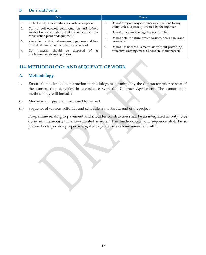
1. Protect utility services during constructionperiod.
2. Control soil erosion, sedimentation and reduce levels of noise, vibration, dust and emissions from construction plant andequipment.
3. Keep the roadside and surroundings clean and free from dust, mud or other extraneousmaterial.
4. Cut material should be disposed of at predetermined dumping places.
1. Do not carry out any clearance or alterations to any utility unless especially ordered by theEngineer.
2. Do not cause any damage to publicutilities.
3. Do not pollute natural water-courses, pools, tanks and reservoirs.
4. Do not use hazardous materials without providing protective clothing, masks, shoes etc. to theworkers.
114. METHODOLOGY AND SEQUENCE OF WORK
A. Methodology
1. Ensure that a detailed construction methodology is submitted by the Contractor prior to start of
the construction activities in accordance with the Contract Agreement. The construction
methodology will include:-
(i) Mechanical Equipment proposed to beused.
(ii) Sequence of various activities and schedule from start to end of theproject.
Programme relating to pavement and shoulder construction shall be an integrated activity to be
done simultaneously in a coordinated manner. The methodology and sequence shall be so
planned as to provide proper safety, drainage and smooth movement of traffic.

Quality Assurance Handbook for Rural Roads
17
SECTION 200
SITE CLEARANCE
19
201 & 202. SITE CLEARANCE
A Methodology
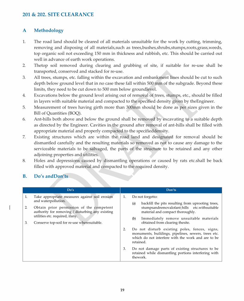
1. The road land should be cleared of all materials unsuitable for the work by cutting, trimming,
removing and disposing of all materials,such as trees,bushes,shrubs,stumps,roots,grass,weeds,
top organic soil not exceeding 150 mm in thickness and rubbish, etc. This should be carried out
well in advance of earth work operations.
2. Thetop soil removed during clearing and grubbing of site, if suitable for re-use shall be
transported, conserved and stacked for re-use.
3. All trees, stumps, etc. falling within the excavation and embankment lines should be cut to such
depth below ground level that in no case these fall within 500 mm of the subgrade. Beyond these
limits, they need to be cut down to 500 mm below groundlevel.
4. Excavations below the ground level arising out of removal of trees, stumps, etc., should be filled
in layers with suitable material and compacted to the specified density given by theEngineer.
5. Measurement of trees having girth more than 300mm should be done as per sizes given in the
Bill of Quantities (BOQ).
6. Ant-hills both above and below the ground shall be removed by excavating to a suitable depth
as directed by the Engineer. Cavities in the ground after removal of ant-hills shall be filled with
appropriate material and properly compacted to the specifieddensity.
7. Existing structures which are within the road land and designated for removal should be
dismantled carefully and the resulting materials so removed as not to cause any damage to the
serviceable materials to be salvaged, the parts of the structure to be retained and any other
adjoining properties and utilities.
8. Holes and depressions caused by dismantling operations or caused by rats etc.shall be back
filled with approved material and compacted to the required density.
B. Do’s andDon’ts
Do’s Don’ts
1. Take appropriate measures against soil erosion and waterpollution.
2. Obtain prior permission of the competent authority for removing / disturbing any existing utilities etc. required, ifany.
3. Conserve top-soil for re-use wheresuitable.
1. Do not forgetto:
(a) backfill the pits resulting from uprooting trees, stumpsandremovalofant-hills etc.withsuitable material and compact thoroughly.
(b) Immediately remove unsuitable materials obtained from clearing thesite.
2. Do not disturb existing poles, fences, signs, monuments, buildings, pipelines, sewers, trees etc. which do not interfere with the work and are to be retained.
3. Do not damage parts of existing structures to be retained while dismantling portions interfering with thework.

Quality Assurance Handbook for Rural Roads
21
SECTION 300
EARTH WORK
24
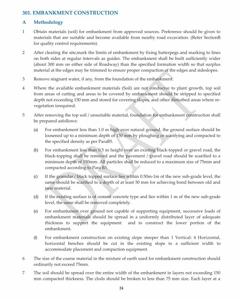
301. EMBANKMENT CONSTRUCTION
A Methodology
1 Obtain materials (soil) for embankment from approved sources. Preference should be given to
materials that are suitable and become available from nearby road excavation. (Refer SectionB
for quality control requirements).
2 After clearing the site,mark the limits of embankment by fixing batterpegs and marking to lines
on both sides at regular intervals as guides. The embankment shall be built sufficiently wider
(about 300 mm on either side of Roadway) than the specified formation width so that surplus
material at the edges may be trimmed to ensure proper compaction of the edges and sideslopes.
3 Remove stagnant water, if any, from the foundation of the embankment.
4 Where the available embankment materials (Soil) are not conducive to plant growth, top soil
from areas of cutting and areas to be covered by embankment should be stripped to specified
depth not exceeding 150 mm and stored for covering slopes, and other disturbed areas where re-
vegetation isrequired.
5 After removing the top soil / unsuitable material, foundation for embankment construction shall
be prepared asfollows:
(a) For embankment less than 1.0 m high over natural ground, the ground surface should be
loosened up to a minimum depth of 150 mm by ploughing or scarifying and compacted to
the specified density as per ParaB5.
(b) For embankment less than 0.5 m height over an existing black-topped or gravel road, the
black-topping shall be removed and the pavement / gravel road should be scarified to a
minimum depth of 150mm. All particles shall be reduced to a maximum size of 75mm and
compacted according to Para B5.
(c) If the granular / black topped surface lies within 0.50m-1m of the new sub-grade level, the
same should be scarified to a depth of at least 50 mm for achieving bond between old and
new material.
(d) If the existing surface is of cement concrete type and lies within 1 m of the new sub-grade
level, the same shall be removed completely.
(e) For embankment over ground not capable of supporting equipment, successive loads of
embankment materials should be spread in a uniformly distributed layer of adequate
thickness to support the equipment and to construct the lower portion of the
embankment.
(f) For embankment construction on existing slope steeper than 1 Vertical: 4 Horizontal,
horizontal benches should be cut in the existing slope to a sufficient width to
accommodate placement and compaction equipment.
6 The size of the coarse material in the mixture of earth used for embankment construction should
ordinarily not exceed 75mm.
7 The soil should be spread over the entire width of the embankment in layers not exceeding 150
mm compacted thickness. The clods should be broken to less than 75 mm size. Each layer at a

25
moisture content within (±)2% of the optimum moisture content, should be thoroughly
compacted by roller, to the specified requirements as per Para B.5 and finished parallel to the
final cross- section of the embankment. (Compacted layer thickness can be increased upto 200
mm if heavy vibratory rollers are used).
8 Compaction of soil should be done at OMC with a tolerance limit of (±)2 percent. If the moisture
content of soil is out side these limits, itshall be made good by adding water or drying by
aeration and exposure to sun till the moisture content is acceptable for compaction.
9 Each layer should be compacted to atleast 97 percent of the Standard Proctor Density. The top
300 mm of the embankment constituting the subgrade should be compacted to 100 percent
Standard Proctor Density according to Para B.5.
10 Ensure that longitudinal and cross profiles are inconformity with the approved drawings.
11 Approval of the Engineer should be obtained for each finished layer. Subsequent layers shall be
placed only after the finished layer has been tested and accepted by Engineer. (Such an approval
would require surface level and compaction control tests).
12 When an existing embankment and/or sub-grade is to be widened and its slopes are steeper than
1 vertical to 4 horizontal, continuous horizontal benches, each at least 300 mm wide, should be
cut in to the old slope for ensuring adequate bond with the fresh embankment/sub-grade
material to be added.
13 When the width of the widened portions is insufficient to permit the use of conventional rollers,
compaction shall be carried out with the help of small vibratory rollers/plate compacters/ power
rammers or any other equipment approved by the Engineer.
14 The filling around culverts and bridges, for forming approaches up to a distance of twice the
height of the road from the back of abutment should bed one with granular materials and
should not be placed until the concrete or masonry has been in position for 14 days. Approval
for the sequence of work and equipment should be obtained from the Engineer before taking up
the work.
B Quality ControlRequirements
1. Materials
(a.) The material used in embankment, sub-grade, shoulders, etc. shall be soil, moorum, gravel, a
mixture of these or other material approved by the Engineer. It shall be free from logs, stumps,
roots, rubbish, etc.
The following types of material shall be considered unsuitable:
(i) Material from swamps, marshes andbogs
(ii) Peat, log, stump and perishable material; soil classified as OL, OI, OH or Pt as perIS:1498-1970.
(iii) Materials susceptible to spontaneous combustion
(iv) Clay having liquid limit exceeding 70 and plasticity index exceeding 45.
(v) Material with salts resulting in leaching action e.g. sodic soils (pH >8.5)
(vi) Expansive clay with free swelling index exceeding 50 percent

27
(vii) Materials in a frozencondition
(viii) Fill materials with a soluble sulphate content exceeding 1.9 gm of sulphate, (expressed as
SO3) per litre, if deposited within 500 mm or other distance described in the Contract, of
concrete,cement bound materials or other cementitious materials forming part of
permanent works
(ix) Material with a total sulphate content (expressed as SO3) exceeding 0.5 per cent by mass, if
deposited with in 500 mm or other distance described in the Contract,of metallic items
forming part of permanent works
(b) The size of coarse material shall not ordinarily exceed 75 mm when placed in embankment and
50 mm when placed insub-grade.
(c) Only the materials satisfying the density requirements given in Table301.1 should be used for
the embankment.
TABLE 301.1: MINIMUM DENSITY REQUIREMENT FOR SUITABILITY OF EMBANKMENT/SUB-GRADE MATERIALS
Type of Work Max. laboratory dry unit weight
(a) Embankment not subject to flooding-
- height upto 3m
- height more than 3m
IS:2720, Part 7
Not less than 14.4 kN / m3
Not less than 15.2 kN / m3
(b) Embankment subject to flooding Not less than 15.2 kN / m3
2. HorizontalAlignment
The alignment shall be reckoned with respect to the centre line of the carriageway as shown on
the drawings. The edges of the roadway as constructed shall be within the following tolerances
indicated in Table 301.2:
TABLE 301.2: PERMITTED TOLERANCES FOR EDGES OF CARRIAGEWAY AND ROADWAY
Description Plain and Rolling Terrains
Hilly Terrain
Edges of carriageway (±) 20mm (±) 30mm
Edges of roadway and lower layers of pavement (±) 30mm (±) 50mm
3. SurfaceLevels
The permitted tolerance in surface level for sub-grade will be +20 mm and (-) 25 mm.
4. SurfaceRegularity
The maximum allowable difference between the road surface and underside of a 3 m straight
edge shall be 20 mm for the longitudinal profile and 15 mm for the cross profile.
28
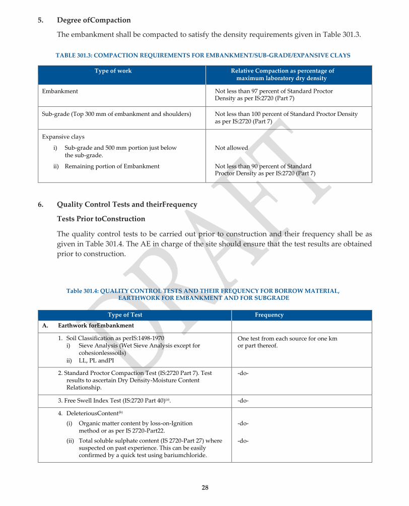
5. Degree ofCompaction
The embankment shall be compacted to satisfy the density requirements given in Table 301.3.
TABLE 301.3: COMPACTION REQUIREMENTS FOR EMBANKMENT/SUB-GRADE/EXPANSIVE CLAYS
Type of work Relative Compaction as percentage of maximum laboratory dry density
Embankment Not less than 97 percent of Standard Proctor Density as per IS:2720 (Part 7)
Sub-grade (Top 300 mm of embankment and shoulders) Not less than 100 percent of Standard Proctor Density as per IS:2720 (Part 7)
Expansive clays
i) Sub-grade and 500 mm portion just below the sub-grade.
ii) Remaining portion of Embankment
Not allowed
Not less than 90 percent of Standard Proctor Density as per IS:2720 (Part 7)
6. Quality Control Tests and theirFrequency
Tests Prior toConstruction
The quality control tests to be carried out prior to construction and their frequency shall be as
given in Table 301.4. The AE in charge of the site should ensure that the test results are obtained
prior to construction.
Table 301.4: QUALITY CONTROL TESTS AND THEIR FREQUENCY FOR BORROW MATERIAL, EARTHWORK FOR EMBANKMENT AND FOR SUBGRADE
Type of Test Frequency
A. Earthwork forEmbankment
1. Soil Classification as perIS:1498-1970 i) Sieve Analysis (Wet Sieve Analysis except for
cohesionlesssoils) ii) LL, PL andPI
One test from each source for one km or part thereof.
2. Standard Proctor Compaction Test (IS:2720 Part 7). Test results to ascertain Dry Density-Moisture Content Relationship.
-do-
3. Free Swell Index Test (IS:2720 Part 40)(a). -do-
4. DeleteriousContent(b)
(i) Organic matter content by loss-on-Ignition method or as per IS 2720-Part22.
(ii) Total soluble sulphate content (IS 2720-Part 27) where suspected on past experience. This can be easily confirmed by a quick test using bariumchloride.
-do-
-do-
29
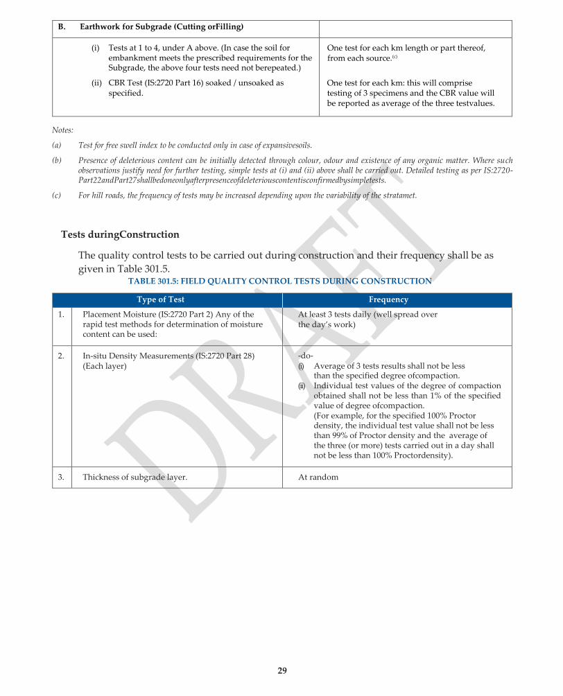
B. Earthwork for Subgrade (Cutting orFilling)
(i) Tests at 1 to 4, under A above. (In case the soil for embankment meets the prescribed requirements for the Subgrade, the above four tests need not berepeated.)
(ii) CBR Test (IS:2720 Part 16) soaked / unsoaked as specified.
One test for each km length or part thereof, from each source.(c)
One test for each km: this will comprise testing of 3 specimens and the CBR value will be reported as average of the three testvalues.
Notes:
(a) Test for free swell index to be conducted only in case of expansivesoils.
(b) Presence of deleterious content can be initially detected through colour, odour and existence of any organic matter. Where such observations justify need for further testing, simple tests at (i) and (ii) above shall be carried out. Detailed testing as per IS:2720- Part22andPart27shallbedoneonlyafterpresenceofdeleteriouscontentisconfirmedbysimpletests.
(c) For hill roads, the frequency of tests may be increased depending upon the variability of the stratamet.
Tests duringConstruction
The quality control tests to be carried out during construction and their frequency shall be as
given in Table 301.5. TABLE 301.5: FIELD QUALITY CONTROL TESTS DURING CONSTRUCTION
Type of Test Frequency
1. Placement Moisture (IS:2720 Part 2) Any of the rapid test methods for determination of moisture content can be used:
At least 3 tests daily (well spread over the day’s work)
2. In-situ Density Measurements (IS:2720 Part 28) (Each layer)
-do- (i) Average of 3 tests results shall not be less
than the specified degree ofcompaction. (ii) Individual test values of the degree of compaction
obtained shall not be less than 1% of the specified value of degree ofcompaction. (For example, for the specified 100% Proctor density, the individual test value shall not be less than 99% of Proctor density and the average of the three (or more) tests carried out in a day shall not be less than 100% Proctordensity).
3. Thickness of subgrade layer. At random
28
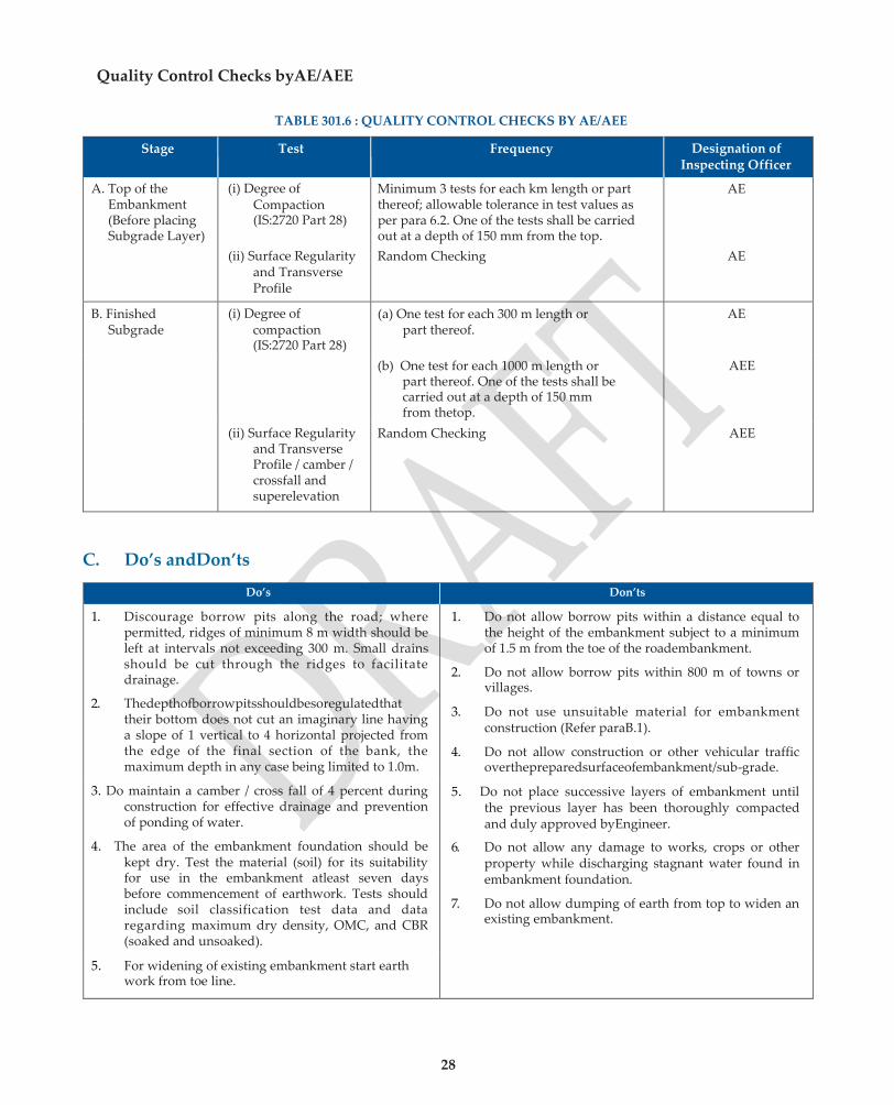
Quality Control Checks byAE/AEE
TABLE 301.6 : QUALITY CONTROL CHECKS BY AE/AEE
Stage Test Frequency Designation of Inspecting Officer
A. Top of the Embankment (Before placing Subgrade Layer)
(i) Degree of Compaction (IS:2720 Part 28)
Minimum 3 tests for each km length or part thereof; allowable tolerance in test values as per para 6.2. One of the tests shall be carried out at a depth of 150 mm from the top.
AE
(ii) Surface Regularity and Transverse Profile
Random Checking AE
B. Finished Subgrade
(i) Degree of compaction (IS:2720 Part 28)
(a) One test for each 300 m length or part thereof.
AE
(b) One test for each 1000 m length or part thereof. One of the tests shall be carried out at a depth of 150 mm from thetop.
AEE
(ii) Surface Regularity and Transverse Profile / camber / crossfall and superelevation
Random Checking AEE
C. Do’s andDon’ts
Do’s Don’ts
1. Discourage borrow pits along the road; where permitted, ridges of minimum 8 m width should be left at intervals not exceeding 300 m. Small drains should be cut through the ridges to facilitate drainage.
2. Thedepthofborrowpitsshouldbesoregulatedthat their bottom does not cut an imaginary line having a slope of 1 vertical to 4 horizontal projected from the edge of the final section of the bank, the maximum depth in any case being limited to 1.0m.
1. Do not allow borrow pits within a distance equal to the height of the embankment subject to a minimum of 1.5 m from the toe of the roadembankment.
2. Do not allow borrow pits within 800 m of towns or villages.
3. Do not use unsuitable material for embankment construction (Refer paraB.1).
4. Do not allow construction or other vehicular traffic overthepreparedsurfaceofembankment/sub-grade.
3. Do maintain a camber / cross fall of 4 percent during construction for effective drainage and prevention of ponding of water.
5. Do not place successive layers of embankment until the previous layer has been thoroughly compacted and duly approved byEngineer.
4. The area of the embankment foundation should be kept dry. Test the material (soil) for its suitability for use in the embankment atleast seven days before commencement of earthwork. Tests should include soil classification test data and data regarding maximum dry density, OMC, and CBR (soaked and unsoaked).
6. Do not allow any damage to works, crops or other property while discharging stagnant water found in embankment foundation.
7. Do not allow dumping of earth from top to widen an existing embankment.
5. For widening of existing embankment start earth work from toe line.

33
302. EARTHWORK IN CUTTING
A. Methodology
1. After site clearance, the limits of excavation should be set out true to lines, curves,
slopes, grades and cross-sections as shown on the drawings by constructing reference
pillars, back cutting lines, reference lines (1.5 m away from formation lines on hill and
valley sides)
2. If directed, the top soil shall be stripped to specified depths and stock piled for reuse,as
detailed in sub-section301.
3. Excavation shall be done manually or mechanically using dozers. After excavation, the
sides of excavated area should be trimmed and the area contoured to minimise erosion
and ponding, allowing natural drainage to takeplace.
4. Cross drainage works like scuppers or small culverts 1 to 2 m span and side drains,
shall be so constructed along the formation cutting work, as to have least interference
with the existing drainage.
5. Thecutformation,whichwillserveassub-grade, should be checked for its field density
and if the field dry density of the material in the top 300 mm portion is less than 100
per cent of maximum Proctor density, the formation materials hall be loosened to a
depth of 500 mm and compacted in layers to 100 per cent Standard Proctor Density
(IS:2720-Part7).
6. In hilly areas, cutting should be done from top to bottom. Special attention should also
be paid to side slopes and side drains incutting.
7. Rock when encountered in road excavation shall be removed upto the formation level.
Where unstable shales or other unsuitable materials are encountered at the formation
level,these shall be excavated to the extent of 500 mm below the formationlevel.
8. In rocky formation, the surface irregularities shall be corrected with granular base
material to achieve the specified profile andlevels.
9. Where blasting is involved for rock cutting, guidelines given in sub-section 304 shall be
followed.
10. Excavation in marshes shall begin at one end and proceed in one direction across the
entire marsh immediately ahead of backfilling to ensure complete removal or
displacement ofmuck.
11. For widening of existing pavement, the existing shoulders shall be removed to their full

34
width and upto sub-grade level to enable proper compaction in the widenedportions.
B. Quality ControlRequirements
1. HorizontalAlignment
The horizontal alignment should be reckoned with respect to the centre line of the
carriage way as shown on the drawings. The edges of the roadway as constructed
should be correct within a tolerance limit of (±) 30 mm in plain and rolling terrain and
(±) 50 mm in hillyterrain.
2. Finishing
No point on the slopes shall vary from the designated slopes by more than 150 mm
measured at right angles to the slope (300 mm in case of rock excavation).
3. SurfaceLevels
The tolerance in surface level for sub-grade will be (+) 20 mm and (–) 25 mm.
4. SurfaceRegularity
The maximum allowable difference between the sub-grade surface and underside of a
3m straight edge shall be 20 mm for the longitudinal profile and 15 mm for the
crossprofile.
5. Quality ControlTests
Subgrade material shall be tested as per tests given in Table301.4(B). If the material in
the subgrade has a density of less than 100% of maximum dry density (IS:2720Part7),
the same shall be loosened to a depth of 500 mm (depth could be reduced to 300 mm if
insitu density is not less than 95% of maximum dry density) and compacted in layers to
100% of maximum dry density. The density of compaction shall be tested as per Table
301.5 and checked as per Table301.6.
35
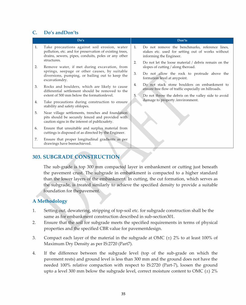
C. Do’s andDon’ts
Do’s Don’ts
1. Take precautions against soil erosion, water pollution, etc. and for preservation of existing trees, drains, sewers, pipes, conduits, poles or any other structures.
2. Remove water, if met during excavation, from springs, seepage or other causes, by suitable diversions, pumping, or bailing out to keep the excavationdry.
3. Rocks and boulders, which are likely to cause differential settlement should be removed to the extent of 500 mm below the formationlevel.
4. Take precautions during construction to ensure stability and safety ofslopes.
5. Near village settlements, trenches and foundation pits should be securely fenced and provided with caution signs in the interest of publicsafety.
6. Ensure that unsuitable and surplus material from cuttings is disposed of as directed by the Engineer.
7. Ensure that proper longitudinal gradients as per drawings have beenachieved.
1. Do not remove the benchmarks, reference lines, stakes etc. used for setting out of works without informing the Engineer.
2. Do not let the loose material / debris remain on the slopes of cutting / along theroad.
3. Do not allow the rock to protrude above the formation level at anypoint.
4. Do not stack stone boulders on embankment to ensure free flow of traffic especially on hillroads.
5. Do not throw the debris on the valley side to avoid damage to property /environment.
303. SUBGRADE CONSTRUCTION
The sub-grade is top 300 mm compacted layer in embankment or cutting just beneath
the pavement crust. The subgrade in embankment is compacted to a higher standard
than the lower layers of the embankment. In cutting, the cut formation, which serves as
the subgrade, is treated similarly to achieve the specified density to provide a suitable
foundation for thepavement.
A Methodology
1. Setting out, dewatering, stripping of top-soil etc. for subgrade construction shall be the
same as for embankment construction described in sub-section301.
2. Ensure that the soil for subgrade meets the specified requirements in terms of physical
properties and the specified CBR value for pavementdesign.
3. Compact each layer of the material in the subgrade at OMC (±) 2% to at least 100% of
Maximum Dry Density as per IS:2720 (Part7).
4. If the difference between the subgrade level (top of the sub-grade on which the
pavement rests) and ground level is less than 300 mm and the ground does not have the
needed 100% relative compaction with respect to IS:2720 (Part-7), loosen the ground
upto a level 300 mm below the subgrade level, correct moisture content to OMC (±) 2%

36
and compact in layers to 100% of the maximum dry density as per IS:2720 (Part7).
5. If the subgrade soil does not possess the requisite engineering properties like highly
plastic black cotton soil, kuttanad clay and other weaksoils yielding very low soaked
CBR values, the same should be improved in strength (CBR) and workability by
treatment with additives like lime/cement etc.as described in sub-sections 403 and 404 or
by mechanical stabilization.
6. In conditions where salt concentration is in excess of 0.2%, capillary cut-off of coarses
and should be provided below the subgrade as shown in the drawings to check the
upward movement of moisture from below.
7. For a road in cutting, prepare the subgrade in accordance with subsection 302 to receive
a sub- basecourse.
8. Ensure that the subgrade is compacted and finished to the design strength consistent
with other physicalrequirements.
9. Maintain the surface of subgrade, at all times during construction, at such a cross fall as
will shed water and prevent ponding.
B. Quality ControlRequirements
1. Materials
(i) The material used for subgrades shall be soil, moorum, gravel, a mixture of these
or any other approved material. Material considered unsuitable for embankment
construction as per subsection 301 shall not be used forsub-grade.
(ii) The material for subgrade shall be non-expansive innature.
(iii) Where an expansive clay with acceptable “freeswellingindex” value is used as a
fill material in embankment, the sub-grade and top 500 mm portion of the
embankment just below the sub-grade shall be non-expansive innature.
(iv) Any fill material which yields a maximum dry laboratory unit weight of less
than16.5kN/ m3 determined as per IS:2720 (Part 7) shall be considered unsuitable
for use insubgrade.
(v) The size of coarse material in the soil shall ordinarily not exceed 50 mm when
placed in the subgrade.
2. SurfaceLevel
The permissible tolerances in surface levels of subgrade shall be (+) 20 mm and (-) 25
mm.
3. SurfaceRegularity
37
The maximum allowable difference between the subgrade and underside of a 3 m
straight edge shall not exceed 20 mm for longitudinal profile and 15 mm for cross
profile.
4. Quality ControlTests
The Quality Control Tests on Earthwork for Subgrade (in cutting or filling) and their
frequency, prior to construction, shall be as per Table 301.4(B).
The Field Quality Control tests during construction shall be as per Table301.5.
The Quality Checks shall be as per Table 301.6(B).
C. Do’s andDon’ts
Do’s Don’ts
1. Do ensure that borrow area material for use in sub- grade satisfies the specified requirements and design CBR.
1. Do not proceed with sub-grade work until the foundation for sub-grade has been duly approved by the Engineer.
2. Do ensure that all layers in sub-grade are compacted to 100% Proctor Density as per IS: 2720 (Part 7).
2. Do not allow construction traffic or other vehicular traffic over the prepared surface ofsub-grade.
304. ROCK CUTTING
I RockExcavation
A Methodology
1. Guidelines on BlastingOperations
Ensurethat-
(i) all the statutory laws, regulations, rules, etc. pertaining to the acquisition,
transport, storage, handling and use of explosives are followed and information
describing pertinent blasting method and procedures is furnished by the
Contractor prior to starting the work. Detailed safety aspects are given in Annex-
300.2 of Specifications for RuralRoads.
(ii) the magazine for the storage of explosive is built to the designs and specifications
of the Inspection General Explosives, Nagpur and located at the approvedsite.
(iii) no unauthorized person is admitted into themagazine.
(iv) no match sticks or inflammable material shall be allowed in the magazine.
(v) all explosives are stored in a secure manner and such storage places shall be
clearly marked.

38
(vi) the blasting operations remainin the charge of competent and experienced
supervisors and workmen who are thoroughly acquainted with the details of
handling explosives and blasting operations.
(vii) the blasting is carried out during fixed hours of the day, preferably during the
mid-day luncheon hour or at the close of thework.
(viii) all public utility companies having structures in proximity of the site of work are
notified sufficiently in advance of the blastingwork.
(ix) for blasting work within 50 m of any railway track or structures, the concerned
Railway Authority is notified sufficiently in advance of the blastingwork.
(x) red danger flags are displayed prominently in all directions during the blasting
operations. The flags are planted 200 m from the blasting site in alldirections.
(xi) sufficient safety arrangements shall be made, including positioning of manpower
at proper locations to ensure that all persons including workmen are excluded
from the flagged area at least 10 minutes before thefiring.
(xii) blasting is as light as possible, consistent with thorough breakage of material.
(xiii) when blasting is done with powder or dynamite, the procedure outlined in Clause
304.2.4 of MoRD Specifications for Rural Roads isfollowed.
(xiv) at a time, not more than 10 charges are prepared andfired.
(xv) after blasting operations, all loose residual material below sub-grade is compacted
and any material removed from below sub-grade is replaced with
suitablematerial.
2. In case of misfire, follow the procedure laid down in clause 304.2.5 of Specifications for
Rural Roads.
3. Maintain a day-to-day account of the explosives in an approved register. Such account
shall be open to inspection at alltimes.
4. Sufficient arrangements should be made like posting of guards at proper locations so
that no person enters the area of influence during the blastingoperations.
B. Quality ControlRequirements
1. All the materials, tools and equipment used for blasting operations shall be of
approvedtype.
2. Excavation by blasting shall be to the lines indicated in drawings, with the least
disturbance to the adjacent material.

39
3. The magazine shall have a lightningconductor.
4. The fuse to be used in wet locations shall be sufficiently water-resistant as to be
unaffected when immersed in water for 30minutes.
5. The rate of burning of the fuse shall be uniform and definitely known to permit such a
length being cut as will permit sufficient time to the firer to reach a safe point before
explosion takes place.
6. Detonators shall be capable of giving effective blasting of theexplosives.
7. The blasting powder, explosives, detonators, fuses, etc. shall be fresh and not damaged
due to dampness, moisture or any othercause.
8. The charge holes shall be drilled to required depths and at suitableplaces.
38
C Do’s and Don’ts
Do’s Don’ts
1. Provide information describing pertinent blasting procedures, and dimensions to Engineer prior to starting any phase of the operation,
2. Display prominently the following information in the lobby ofmagazine:
(a) A copy of the relevant rules regarding safe storage both in English and in the language with which the workers concerned are familiar.
(b) A statement of up-to-date stock in the magazine.
(c) A certificate showing the latest date of testing of the lightning conductor.
(d) A notice that smoking is strictlyprohibited.
3. Do intimate the hours of blasting to the people in vicinity.
4. Do drill the charge holes to required depths and at suitableplaces.
5. Do ensure that the man-in-charge counts the number of explosions and ensures that all the charges have exploded before allowing workmen back to thesite.
1. Do not perform blasting operation without written permission ofEngineer.
2. Do not store explosives closer than 300 m from the road or from any building or camping area or place of humanoccupancy.
3. Do not keep any damaged blasting powder, explosives, detonators, fuses etc. atsite.
4. Do not use any method of blasting which leads to overshooting.
5. Do not undertake blasting aftersunset.
6. Do no expose dynamite to the sun or allow it to get damp.
7. Do not ram or pound the charge but press firmly into place.
II Pre-splitting Rock ExcavationSlopes
A Methodology
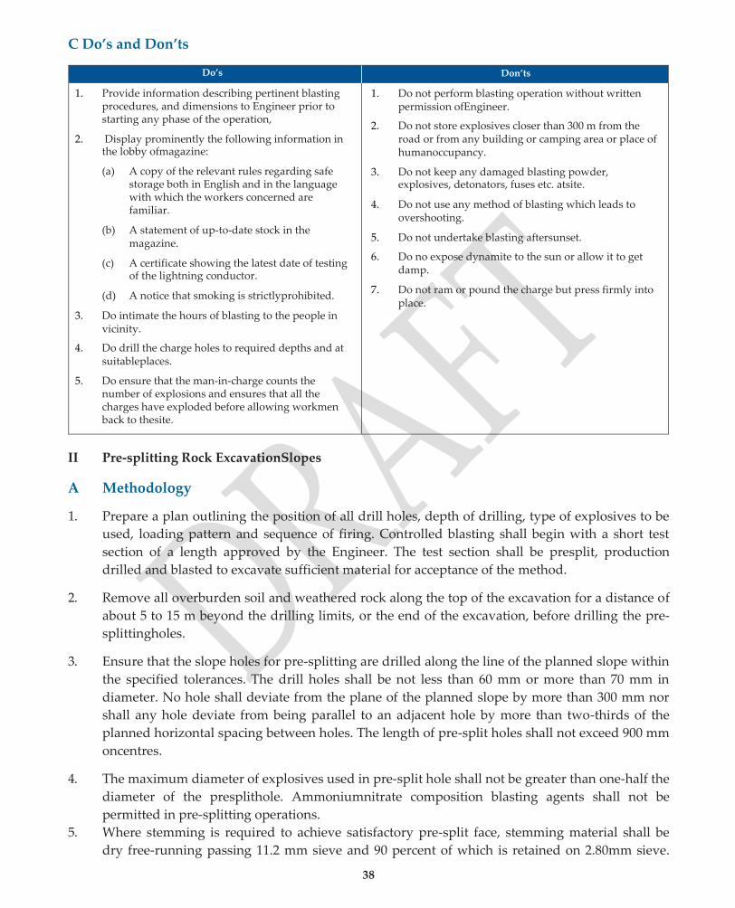
1. Prepare a plan outlining the position of all drill holes, depth of drilling, type of explosives to be
used, loading pattern and sequence of firing. Controlled blasting shall begin with a short test
section of a length approved by the Engineer. The test section shall be presplit, production
drilled and blasted to excavate sufficient material for acceptance of the method.
2. Remove all overburden soil and weathered rock along the top of the excavation for a distance of
about 5 to 15 m beyond the drilling limits, or the end of the excavation, before drilling the pre-
splittingholes.
3. Ensure that the slope holes for pre-splitting are drilled along the line of the planned slope within
the specified tolerances. The drill holes shall be not less than 60 mm or more than 70 mm in
diameter. No hole shall deviate from the plane of the planned slope by more than 300 mm nor
shall any hole deviate from being parallel to an adjacent hole by more than two-thirds of the
planned horizontal spacing between holes. The length of pre-split holes shall not exceed 900 mm
oncentres.
4. The maximum diameter of explosives used in pre-split hole shall not be greater than one-half the
diameter of the presplithole. Ammoniumnitrate composition blasting agents shall not be
permitted in pre-splitting operations.
5. Where stemming is required to achieve satisfactory pre-split face, stemming material shall be
dry free-running passing 11.2 mm sieve and 90 percent of which is retained on 2.80mm sieve.
39
Stemmed pre-split holes shall be completely filled to the collar.
B Quality ControlRequirements
1. Quality control requirements for rock cutting mentioned in Para IB above shallapply.
2. Drilling operations shall be controlled by the use of proper equipment andtechnique.
3. Only standard cartridge explosives prepared and packaged by explosive manufacturing firms
shall be used in pre-split holes.
4. The presplit face shall not deviate by more than 300mm from the plane passing through adjacent
holes.
5. When completed, the average plane of the slope shall conform to the slopes indicated on the
drawings and at no point shall the completed slopes vary from the designated slopes by more
than 300 mm as measured perpendicular to the plane of theslope.
6. In no case shall any portion of the slope encroach on the side drains.
C Do’s andDon’ts
Do’s and Don’ts for rock cutting mentioned in Para IC shall apply, in addition to the following:
Do’s Don’ts
1. Ensure that drill holes are not less than 60 mm or more than 75 mm indiameter.
1. Do not drill any portion of production hole within 2.5 m of a pre-splitplane.
2. Do not allow any portion of the slope to encroach on the sidedrains.
306. FLYASH EMBANKMENT CONSTRUCTION
A Methodology
1. Preparationoffoundationforembankment,settingout,dewatering,strippingoftop-soilshallbe as for
Embankment Construction detailed in sub-section301.
2. The side soil cover, of required width shall be provided along with the flyash core and shall be
simultaneously compacted as the embankment progressesupwards.
3. Spread fill material to specified width, grade and slope by mechanical means. For small works
manual method may beused.
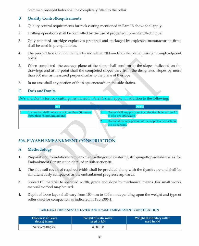
4. Depth of loose layer shall vary from 100 mm to 400 mm depending upon the weight and type of
roller used for compaction as indicated in Table306.1.
TABLE 306.1 THICKNESS OF LAYER FOR FLYASH EMBANKMENT CONSTRUCTION
Thickness of Layer
(loose) in mm Weight of static roller
used in kN Weight of vibratory roller
used in kN
Not exceeding 200 80 to 100

40
Not exceeding 400 80 to 100
250 60 to 80
100 to 150 10 to 15
5. Moisture content of fill material before commencement of compaction, shall be within (±) 2% of
the optimum moisture content when determined as per IS:2720 (Part-7). Moisture content of the
cover soil shall be maintained atOMC.
6. If water is required to be added to the fill material, the same shall be sprinkled from a water
bowserwithoutflooding.Thewatershallbemixedthoroughlybyblading,discingorharrowing.
7. Compaction of flyash should start as early as possible after spreading. Each layer of flyash shall
be thoroughly compacted to the specified density. When vibratory roller is used for compaction,
twopasseswithoutvibrationfollowedby5to8passeswithvibrationshallnormallybesufficient to
compact eachlayer.
8. The compaction of flyash core and earth cover on the sides shall proceed simultaneously. After
construction, flyash embankment shall conform to thefollowing:
(i) Minimum dry density after compaction as percentageof
maximum dry density determined as per IS2720(Part-7) 98%
(ii) Minimum dry density after compaction, when used in
bridge abutments for embankment length equal to 1.5
times the height of the embankment, as percentageof
maximum dry density determined as per IS 2720(Part7) 100%
9. On the top of flyash embankment, at least 500 mm thick selected earth embankment shall be
provided, out of which top 300 mm shall be sub-grade as per sub-section303.
10. Following precautions should be taken while handlingflyash:
(i) Flyash(PondAsh)shouldbedeliveredtositeincovereddumpertruckstominimizelossof
moisture and dusting preferably duringnight.
(ii) Stockpiling of flyash at site should beavoided.
(iii) If stockpiling at site cannot be avoided, dusting shall be prevented by spraying water on
stockpilesatregularintervalsandbykeepingthestockpilecoveredwithtarpaulinorathin layer
of material not subject to dusting e.g. soil or granularmaterial.
(iv) Traffic should be restricted in areas where flyash is temporarily stockpiled atsite.
B. Quality ControlRequirements
1. Material
(a) Flyash (PondAsh):
Particlesizeanalysis,MaximumDryDensityandOptimumMoistureContentasperIS:2720(Part-
7),Graphofdrydensityplottedagainstmoisturecontentforthistestshallbesubmittedforapproval of
Engineer, before execution ofwork.
41
(b) Soil:
Soil for cover to the flyash embankment shall satisfy the requirements of a suitable material for
embankment construction as per sub-section 301.
(c) Subgrade:
Subgrade shall conform to the requirements of sub-section 303.
2. Quality control tests and their frequency shall be as indicated in Table 301.4 to301.5.
C Do’s andDon’ts
Do’s Don’ts
1. Checktheplacementmoisturecontentoffillmaterial which should be within (±) 2% of theOMC.
1. Do not allow addition of side cover subsequent to the construction of the flyashcore.
2. Place subsequent layer only after finished layer has been tested for density requirements and duly approved by theEngineer.
3. Remove the material in soft areas where requisite density requirements have not been achieved and replace the same by approved material, bring moisturecontenttopermissiblelimitsandrecompact to the requireddensity.
2. Donotallowtrafficinareaswhereflyashistemporarily stockpiled and kept moist to avoiddusting.
3. Do not allow construction traffic or other vehicular traffic directly over the prepared surface of embankment /subgrade.
4. Do transportation of fly-ash, normally atnight.
307. SURFACE DRAINS
A. Methodology
1. Ensure that the surface drains / roadside ditches are provided strictly according to the Drainage
Plan for theroad.
2. Excavate to the specified lines, grades, levels anddimensions.
3. Remove all excavated material from the area adjoining the drains. If the excavated material is
foundsuitable,utilizeinembankment/sub-gradeconstruction,otherwisedisposeofthematerial away
from the roadsite.
4. Ensure that the excavated bed and sides of the drains are in conformity with the specified
dimensions, levels andslopes.
5. Protectthesurfaceofdrains/roadsideditcheswithturfcoverorothersuitableliningasshownon the
drawings. Consult the local agricultural department for selecting the appropriate species of
grass/vegetation.
6. Provide proper gradients and fix the invert for quick disposal of water to theoutfall.
7. For any stretch of the rural road passing through a built-up area, ensure that any water coming
from the adjacent habitations discharges only into the drain and is not allowed to flow over the
roadsurface.
8. Anysharpedges,wherecut/fillsurfacesmeetthegroundlevel,shouldberoundedofftoprevent erosion
and promoteturfing.

42
9. Provide safe outlets to natural or artificial watercourses.
10. Provide catch water / intercepting drains on hill slopes to intercept water from upper reaches,
such drains to be provided over stable slopes only, outside any slide or unstableareas.
B. Quality ControlRequirements
1. Materials
(a) Where the soil is erodible, line the drain with random masonry coursed with 1:5 cement-
sandmortar,aspersubsection700oranyothersuitablematerialasshownonthedrawings.
(b) Theturfandvarietyofgrassusedforerosioncontrolmustmeetthespecifiedrequirements for use
in thearea.
(c) The materials used for other types of linings like brick masonry, stone masonry etc. must
meet the relevant specifications given in Sections 600 & 700respectively.
2. Dimensions
The cross-section and side slopes should conform to the specified dimensions.
C. Do’s andDon’ts
Do’s Don’ts
1. Ensurethatthegradientsareadequateforfreeflow of water to the outlet without overflowing or ponding or unduesiltation.
2. Doensurethatgrass,whenusedasaliningformsa firm denseturf.
3. Take special precautions in built-up areas to make sure that water from any adjacent habitations does not flow over theroad.
4. Takecaretoseethatadrain/roadsideditchisdeep enough to drain the sub-base / basecourse.
1. Do not provide ordinarily side slopes steeper than 2:1 to avoid damage byerosion.
2. Donotleaveanyroadsideditch/drainunlinedevenif it be a grasslining.
3. Do not leave any sharp edges within the cross-section to avoid damage byerosion.
4. Donotallowthebottomofroadsideditch/draintobe below the bed of the cross-stream at anoutlet.
5. Do not provide any catch water / intercepting drain in any slide area / unstablearea.
Quality Assurance Handbook for Rural Roads
39
SECTION 400
GRANULAR SUB-BASES,
BASES & SURFACINGS
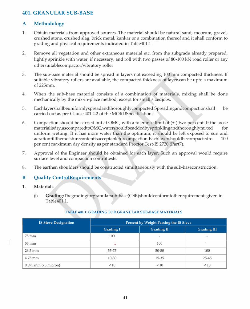
41
401. GRANULAR SUB-BASE
A Methodology
1. Obtain materials from approved sources. The material should be natural sand, moorum, gravel, crushed stone, crushed slag, brick metal, kankar or a combination thereof and it shall conform to grading and physical requirements indicated in Table401.1
2. Remove all vegetation and other extraneous material etc. from the subgrade already prepared,
lightly sprinkle with water, if necessary, and roll with two passes of 80-100 kN road roller or any
othersuitablecompactor/vibratory roller
3. The sub-base material should be spread in layers not exceeding 100 mm compacted thickness. If suitable vibratory rollers are available, the compacted thickness of layer can be upto a maximum of 225mm.
4. When the sub-base material consists of a combination of materials, mixing shall be done mechanically by the mix-in-place method, except for small sizedjobs.
5. Eachlayershallbeuniformlyspreadandthoroughlycompacted.Spreadingandcompactionshall be carried out as per Clause 401.4.2 of the MORDSpecifications.
6. Compaction should be carried out at OMC, with a tolerance limit of (± ) two per cent. If the loose materialisdry,ascomparedtoOMC,watershouldbeaddedbysprinklingandthoroughlymixed for uniform wetting. If it has more water than the optimum, it should be left exposed to sun and aerationtillthemoisturecontentisacceptableforcompaction.Eachlayershouldbecompactedto 100 per cent maximum dry density as per standard Proctor Test-IS 2720 (Part7).
7. Approval of the Engineer should be obtained for each layer. Such an approval would require surface level and compaction controltests.
8. The earthen shoulders should be constructed simultaneously with the sub-baseconstruction.
B Quality ControlRequirements
1. Materials
(i) Grading:Thegradingforgranularsub-base(GSB)shouldconformtotherequirementsgiven in Table401.1.
TABLE 401.1: GRADING FOR GRANULAR SUB-BASE MATERIALS
IS Sieve Designation Percent by Weight Passing the IS Sieve
Grading I Grading II Grading III
75 mm 100 - -
53 mm - 100 -
26.5 mm 55-75 50-80 100
4.75 mm 10-30 15-35 25-45
0.075 mm (75 micron) < 10 < 10 < 10

42
(ii) Atterberg limits: the material passing 425 micron sieve when tested according to IS: 2720 (part5)shallhaveliquidlimitandplasticityindexnotmorethan25and6percentrespectively.
(iii) On clayey subgrades, the material passing IS Sieve 0.075 mm should not exceed 5 percent.
(iv) CBR value: The material with a minimum CBR value of 20 will be acceptable for granular sub-base.Incasethesub-basematerialoftherequisiteCBRisnotavailablewithineconomical leads, the sub-base material meeting any of the specified grading and other requirements with a soaked CBR of not less than 15 can be permitted with the approval of the competent authority.
(v) The wet aggregate Impact Value (IS:5640) shall not exceed50.
2. HorizontalAlignment
Theedgesofthesub-baseshallbecorrectwithinatolerancelimitof(±)30mminplainandrolling terrain and (±) 50 mm for hillyterrain.
3. SurfaceLevels
The tolerance in surface level for granular sub-base will be restricted to (+) 10 mm and (-) 20 mm. A grid of 10 m by 2.5 m may be formed to check the surface level. The cross profile should conform to the required camber.
4. SurfaceRegularity
The maximum permitted difference between the sub-base and 3 m straight edge shall be 12 mm for longitudinal profile and 10 mm for cross profile. The cross profile should conform to the required camber.
5. Degree ofCompaction
Densityshallbe100percentofmaximumdrydensityforthematerialdeterminedasperIS:2720, Part7.
6. Quality ControlTests
Tests Prior toConstruction
(i) The quality control tests to be carried out prior to construction are indicated in Table401.2.
(ii) For existing approved sources, the test frequency shall be as indicated in Table401.2.
(iii) For new sources, test frequencies shall be increased to atleast three tests for each source (average of threetests).
(iv) The samples shall be taken at representative locations and at mean depth of proposed excavation.

43
TABLE 401.2 : QUALITY CONTROL TESTS PRIOR TO CONSTRUCTION
Type of Test Frequency
1. Soil Classification as per IS:1498. i) Wet Sieve Analysis, except for cohesionlesssoils ii) Liquid and PlasticLimits
Average of three tests from each source.
2. Combined Grading and Plasticity tests on materials from different sources, mixed in the design proportions. This shall be done when materials from more than one source arecombined.
One test on the combined material for 500 m length of road or part thereof.
3. Proctor Compaction Test (IS:2720 Part 7). One test on the material from each source or on the combined material, as the case may be.
4. Wet Aggregate Impact Value Test (IS:5640) where soft / marginal aggregates are used e.g, Laterite, Kankar, Brick Ballast etc.
One test from each source identified by the Contractor.
5. CBR test (IS:2720 Part 16) on representative sample compacted at 100% Proctor dry density.
One test per km length. (average of a set of three specimens).
Note: Where materials from more than one source are to be combined in the desired proportions, the tests at Sl. Nos. 2, 3 and 5 should be carried out on the combined material.
Tests DuringConstruction
The field quality control tests during construction are indicated in Table 401.3.
TABLE 401.3 : QUALITY CONTROL TESTS DURING CONSTRUCTION
Type of Test Frequency
1. Wet Sieve Analysis (IS:2720 Part 4) on the GSB material combined in the design proportions from various sources.
Atleast one test to be carried out daily.
2. Liquid and Plastic Limit tests (IS:2720 Part 5). -do-
3. Placement Moisture Content: Any of the rapid methods for determination of moisture content can be used. (IS:2720 Part 2)
Atleast 3 tests to be carried out daily, well spread over the day’s work.
4. Insitu Density measurements (IS:2720 Part 28). -do-
5. Thickness of Compacted layer At random
Quality Control Checks byAE/EE
The quality control checks by AE / EE are indicated in Table 401.4.
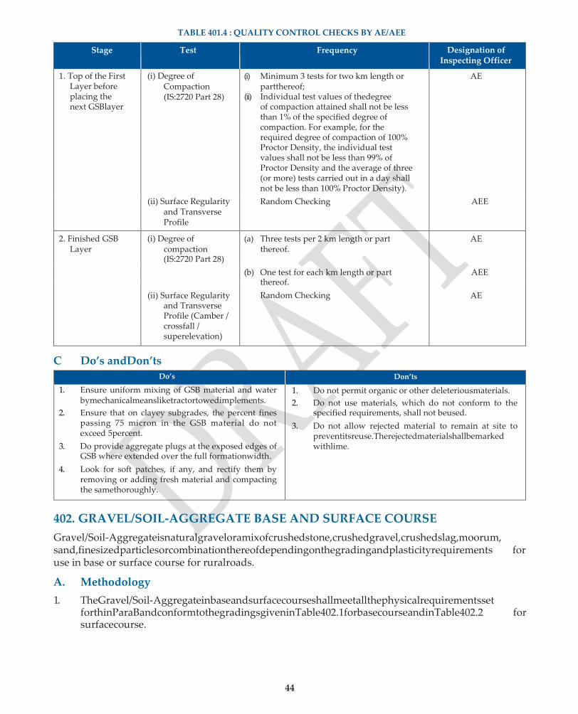
44
TABLE 401.4 : QUALITY CONTROL CHECKS BY AE/AEE
Stage Test Frequency Designation of Inspecting Officer
1. Top of the First Layer before placing the next GSBlayer
(i) Degree of Compaction (IS:2720 Part 28)
(i) Minimum 3 tests for two km length or partthereof;
(ii) Individual test values of thedegree of compaction attained shall not be less than 1% of the specified degree of compaction. For example, for the required degree of compaction of 100% Proctor Density, the individual test values shall not be less than 99% of Proctor Density and the average of three (or more) tests carried out in a day shall not be less than 100% Proctor Density).
AE
(ii) Surface Regularity and Transverse Profile
Random Checking AEE
2. Finished GSB Layer
(i) Degree of compaction (IS:2720 Part 28)
(a) Three tests per 2 km length or part thereof.
(b) One test for each km length or part
thereof.
Random Checking
AE
AEE
(ii) Surface Regularity
and Transverse Profile (Camber / crossfall / superelevation)
AE
C Do’s andDon’ts
Do’s Don’ts
1. Ensure uniform mixing of GSB material and water bymechanicalmeansliketractortowedimplements.
2. Ensure that on clayey subgrades, the percent fines passing 75 micron in the GSB material do not exceed 5percent.
3. Do provide aggregate plugs at the exposed edges of GSB where extended over the full formationwidth.
4. Look for soft patches, if any, and rectify them by removing or adding fresh material and compacting the samethoroughly.
1. Do not permit organic or other deleteriousmaterials.
2. Do not use materials, which do not conform to the specified requirements, shall not beused.
3. Do not allow rejected material to remain at site to preventitsreuse.Therejectedmaterialshallbemarked withlime.
402. GRAVEL/SOIL-AGGREGATE BASE AND SURFACE COURSE
Gravel/Soil-Aggregateisnaturalgraveloramixofcrushedstone,crushedgravel,crushedslag,moorum, sand,finesizedparticlesorcombinationthereofdependingonthegradingandplasticityrequirements for use in base or surface course for ruralroads.
A. Methodology
1. TheGravel/Soil-Aggregateinbaseandsurfacecourseshallmeetallthephysicalrequirementsset forthinParaBandconformtothegradingsgiveninTable402.1forbasecourseandinTable402.2 for surfacecourse.

45
2. BeforereceivingtheGravel/Soil-Aggregatematerial,thesub-base/base,asthecasemaybe,shall be prepared to the specified lines and cross fall. Any existing ruts, predominant irregularities or soft yielding places should be corrected and rolled until a firm surface isobtained.
3. TheGravel/Soil-Aggregatematerialmeetingallthespecifiedrequirementsshallbespreadonthe prepared surface with the help of a grader of adequate capacity, for maintaining the required slope andgrade.
4. Where combination of different materials is required for obtaining the Gravel / Soil-Aggregate meetingthespecifiedrequirements,mixingshallbedonemechanicallybythemix-in-placemethod.
5. The equipment for mix-in-place shall be a tractor-towed rotavator or similar equipment capable of mixing the materials to the desireddegree.
6. Itmustbeensuredthatpriortocompaction,themoisturecontentiswithin2percentoftheoptimum moisturecontent,makingdueallowanceforevaporationlosses.Afteraddingtherequiredquantity ofwater,thematerialshouldbeprocessedbymechanicalmeansliketractor-toweddischarrows/ rotavators until the layer is uniformly wet.
7. Rolling shall be carried out as per Para 402.4.2 of MoRDSpecifications.
8. Thedensitytobeachievedshouldbe100%ofthemaximumdrydensityforthematerialdetermined as per IS:2720 (Part7).
9. Anyloose,segregatedorotherwisedefectiveareasshouldbemadegoodtofullthicknessoflayer andre-compacted.
B. Quality ControlRequirements
1. Materials
(i) The grading for Gravel / Soil-Aggregate Base shall conform to the requirements given in Table 402.1 while the grading for Gravel / Soil-Aggregate Surface Course shall conform to the requirements given in Table 402.2. For the fraction passing 4.75 mm, wet sieve analysis should bedone.
TABLE 402.1: GRADING AND PLASTICITY REQUIREMENTS FOR BASE COURSE
IS Sieve desperation Percent by Weight Passing IS Sieve
Grading A Grading B Grading C
53 mm 100
37.5 mm 97–100 100
26.5 mm 97–100 100
19 mm 67–81 97–100
9.5 mm 56–70 67–79
4.75 mm 33–47 39–53 47–59
425 µ 10–19 12–21 12–21
75 µ 4.0–8.0 4.0–8.0 4.0–8.0
Note: The Liquid Limit shall not exceed 25 and PI shall not exceed 6.
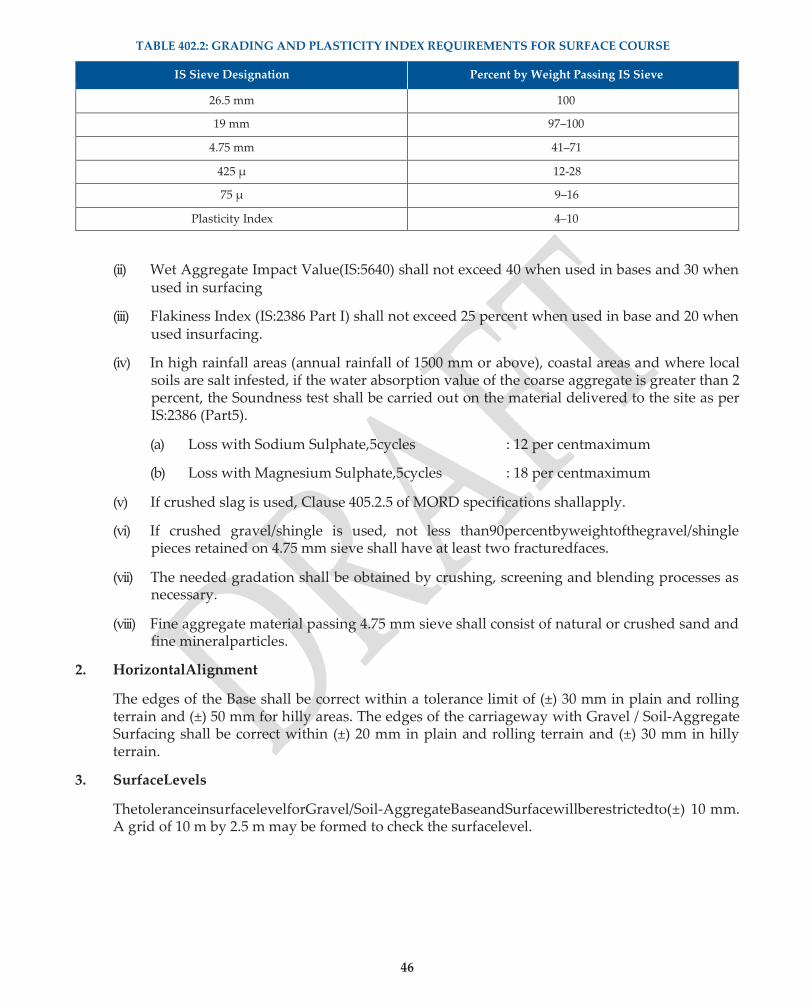
46
TABLE 402.2: GRADING AND PLASTICITY INDEX REQUIREMENTS FOR SURFACE COURSE
IS Sieve Designation Percent by Weight Passing IS Sieve
26.5 mm 100
19 mm 97–100
4.75 mm 41–71
425 µ 12-28
75 µ 9–16
Plasticity Index 4–10
(ii) Wet Aggregate Impact Value(IS:5640) shall not exceed 40 when used in bases and 30 when
used in surfacing
(iii) Flakiness Index (IS:2386 Part I) shall not exceed 25 percent when used in base and 20 when used insurfacing.
(iv) In high rainfall areas (annual rainfall of 1500 mm or above), coastal areas and where local soils are salt infested, if the water absorption value of the coarse aggregate is greater than 2 percent, the Soundness test shall be carried out on the material delivered to the site as per IS:2386 (Part5).
(a) Loss with Sodium Sulphate,5cycles : 12 per centmaximum
(b) Loss with Magnesium Sulphate,5cycles : 18 per centmaximum
(v) If crushed slag is used, Clause 405.2.5 of MORD specifications shallapply.
(vi) If crushed gravel/shingle is used, not less than90percentbyweightofthegravel/shingle pieces retained on 4.75 mm sieve shall have at least two fracturedfaces.
(vii) The needed gradation shall be obtained by crushing, screening and blending processes as necessary.
(viii) Fine aggregate material passing 4.75 mm sieve shall consist of natural or crushed sand and fine mineralparticles.
2. HorizontalAlignment
The edges of the Base shall be correct within a tolerance limit of (±) 30 mm in plain and rolling terrain and (±) 50 mm for hilly areas. The edges of the carriageway with Gravel / Soil-Aggregate Surfacing shall be correct within (±) 20 mm in plain and rolling terrain and (±) 30 mm in hilly terrain.
3. SurfaceLevels
ThetoleranceinsurfacelevelforGravel/Soil-AggregateBaseandSurfacewillberestrictedto(±) 10 mm. A grid of 10 m by 2.5 m may be formed to check the surfacelevel.
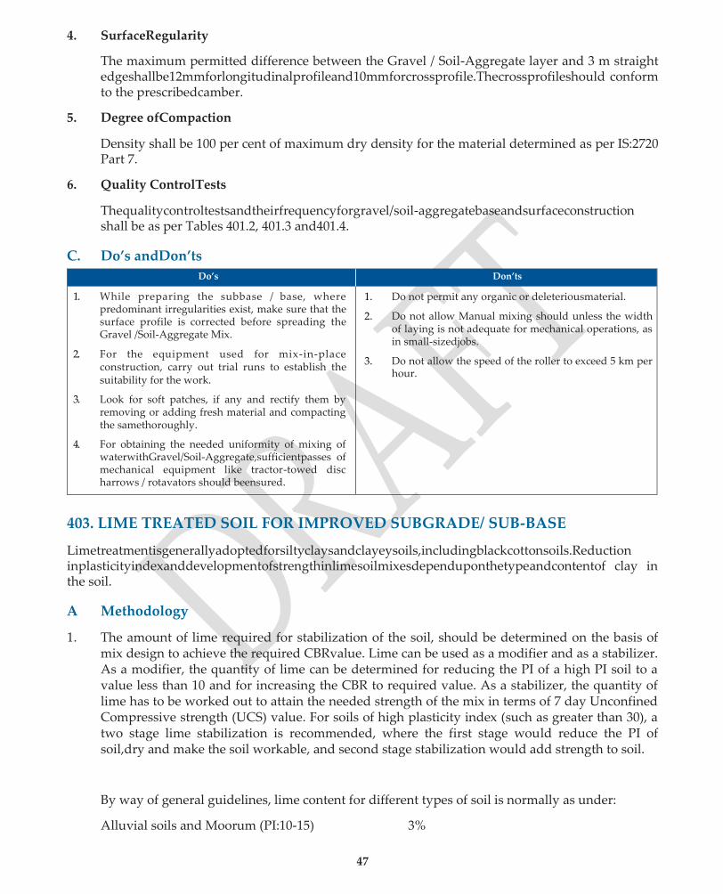
47
4. SurfaceRegularity
The maximum permitted difference between the Gravel / Soil-Aggregate layer and 3 m straight edgeshallbe12mmforlongitudinalprofileand10mmforcrossprofile.Thecrossprofileshould conform to the prescribedcamber.
5. Degree ofCompaction
Density shall be 100 per cent of maximum dry density for the material determined as per IS:2720 Part 7.
6. Quality ControlTests
Thequalitycontroltestsandtheirfrequencyforgravel/soil-aggregatebaseandsurfaceconstruction shall be as per Tables 401.2, 401.3 and401.4.
C. Do’s andDon’ts
Do’s Don’ts
1. While preparing the subbase / base, where predominant irregularities exist, make sure that the surface profile is corrected before spreading the Gravel /Soil-Aggregate Mix.
2. For the equipment used for mix-in-place construction, carry out trial runs to establish the suitability for the work.
3. Look for soft patches, if any and rectify them by removing or adding fresh material and compacting the samethoroughly.
4. For obtaining the needed uniformity of mixing of waterwithGravel/Soil-Aggregate,sufficientpasses of mechanical equipment like tractor-towed disc harrows / rotavators should beensured.
1. Do not permit any organic or deleteriousmaterial.
2. Do not allow Manual mixing should unless the width of laying is not adequate for mechanical operations, as in small-sizedjobs.
3. Do not allow the speed of the roller to exceed 5 km per hour.
403. LIME TREATED SOIL FOR IMPROVED SUBGRADE/ SUB-BASE
Limetreatmentisgenerallyadoptedforsiltyclaysandclayeysoils,includingblackcottonsoils.Reduction inplasticityindexanddevelopmentofstrengthinlimesoilmixesdependuponthetypeandcontentof clay in the soil.
A Methodology
1. The amount of lime required for stabilization of the soil, should be determined on the basis of mix design to achieve the required CBRvalue. Lime can be used as a modifier and as a stabilizer. As a modifier, the quantity of lime can be determined for reducing the PI of a high PI soil to a value less than 10 and for increasing the CBR to required value. As a stabilizer, the quantity of lime has to be worked out to attain the needed strength of the mix in terms of 7 day Unconfined Compressive strength (UCS) value. For soils of high plasticity index (such as greater than 30), a two stage lime stabilization is recommended, where the first stage would reduce the PI of soil,dry and make the soil workable, and second stage stabilization would add strength to soil.
By way of general guidelines, lime content for different types of soil is normally as under:
Alluvial soils and Moorum (PI:10-15) 3%

48
Clays / BC soil of medium plasticity (PI:15-30) 3-5%
Highly expansive Clays (PI :over30) 5-6%

48
2. The pulverization of soil clods and mixing of pulverized soil should be accomplished by using tractor-towedimplements.ThepulverizationofclodsshallmeettherequirementsofTable403.1.
TABLE 403.1 SOIL PULVERISATION REQUIREMENTS FOR LIME STABILIZATION
IS Sieve Designation Percent passing
26.5 mm 100
5.6 mm 80
3. Thethicknessofanylayertobetreatedshallbe100mmwhencompacted.Themaximumthickness shall
be 200 mm provided the plant is accepted by theEngineer. 4. The amount of lime to be added has to be determined by performing mix design. The mix design
procedure provided by National lime Association can be adopted. The target strength specification corresponding to which optimum lime dosage is to be fixed shall be as per the clause B.5.
5. Lime may be mixed with the prepared material either in slurry form or dry state as approved by the Engineer. The top of windrowed material may be flattened or slightly trenched to receive the lime. The distance to which lime is to be spread upon the prepared material ahead of mixing operation shall be determined by the Engineer for which trial runs areadvisable.
6. In soils of high plasticity, it is a good practice to pre-condition the soil by addition of 2% lime in the first instance and leaving it overnight before adding the remaining portion of lime the nextday. This would dry the soil, reduce the PI. After adding the remaining portion of lime, the soil has to be thoroughly mixed at water (OMC + 2%)of the treated soil, and allow hydrationto occur. This duration of this period (Mellowing period) has to based on engineering judgment.
7. Appropriatetractor-towedequipment,approvalbytheEngineer,aresuitableforvariousoperations in the construction process, like pulverization of soil clods by tractor-towed disc harrows and mixingofsoilwithlimebytractor-towedRotavator.Manualmixingmaybepermittedonlywhere the width of laying is not adequate for mechanical operations as in small-sizedjobs.
8. The moisture content of soil-lime mix at compaction shall be within (±) 2% of optimum moisture content determined on the basis of IS:2720 (Part 7). Immediately after spreading, grading and levelling of the mixed material, compaction shall be carried out. During rolling, the surface shall be checked for grade and camber. A density of at least 100% of the maximum dry density of the material, as determined in accordance with IS:2720 (Part 7) shall beachieved.
9. Thesub-baseshallbecuredbymoistcuringwithwaterforaperiodof7daysafterwhichsubsequent pavement courses shall be laid to prevent the surface from drying out and becomingfriable.
B Quality ControlRequirements
1. Materials
(i) Soil:ForthelimetreatmenttobeeffectiveinbringingaboutsignificantreductioninPIand increaseintheCBRvalue,thePIofthesoiltobetreatedshouldgenerallybehigherthan10.
(ii) Lime: Lime for lime-soil stabilization work shall be commercial dry lime slaked at site or pre-slaked lime delivered to the site in suitable packing. The lime shall have purity of not less than 70% by weight of CaO when tested in accordance withIS:1514
(iii) Water: The water to be used for lime stabilization shall be clean and free from injurious

49
substances. Potable water shall bepreferred.

49
2. HorizontalAlignment
Theedgesofthesub-baseshallbecorrectwithinatolerancelimitof(±)30mminplainandrolling terrain and (±) 50 mm in hillyterrain.
3. SurfaceLevels
The tolerance in surface levels for lime-treated improved subgrade shall be (+) 20 mm and (-) 25 mm; while for the lime-treated soil subbase shall be (+) 10 mm and (-) 20 mm. A grid of 10 m by 2.5 m may be formed to check the surface level.
4. SurfaceRegularity
The maximum permitted difference between the sub-base and 3 m straight edge shall be 12 mm for longitudinal profile and 10 mm for cross profile.
Incaseofimprovedsubgrade,themaximumpermitteddifferenceshallbe20mmforlongitudinal profileand15mmforcrossprofile.Thetransverseprofileshallconformtotheprescribedcamber.
5. Degree ofCompaction
When lime is used for improving the subgrade, the soil-lime mix shall be tested for CBR value. When lime stabilized soil is used in a sub-base it shall be tested for CBR value / unconfined compressive strength (UCS).
The laboratory CBR / UCS value shall be atleast 1.5 times the minimum field value of CBR / UCS stipulated in the Contract.
6. Quality ControlTests
Tests Prior toConstruction
The quality control tests to be carried out prior to construction are indicated in Table 403.2.
Table 403.2 : QUALITY CONTROL TESTS PRIOR TO CONSTRUCTION
Type of Test Frequency
1. Purity of Lime (IS:1514) One test for each lot of lime
2. Determination of optimum quantity of lime to attain the specified reduction in PI and / or to achieve the specified CBR
Mean of two tests.
3. Plasticity Index test (IS:2720 Part 5) of the lime-treated soil (mixed with the required amount of lime)
Mean of two tests per km length on the representative sample of a lime-treated soil mix with the required amount of lime.
4. CBR (IS:2720 Part 16) or Unconfined Compressive Strength (IS:4332 Part 5) if specified.
One test on a set of 3 specimens per km length.
Tests DuringConstruction
The quality control tests to be carried out during construction are indicated in Table 403.3.
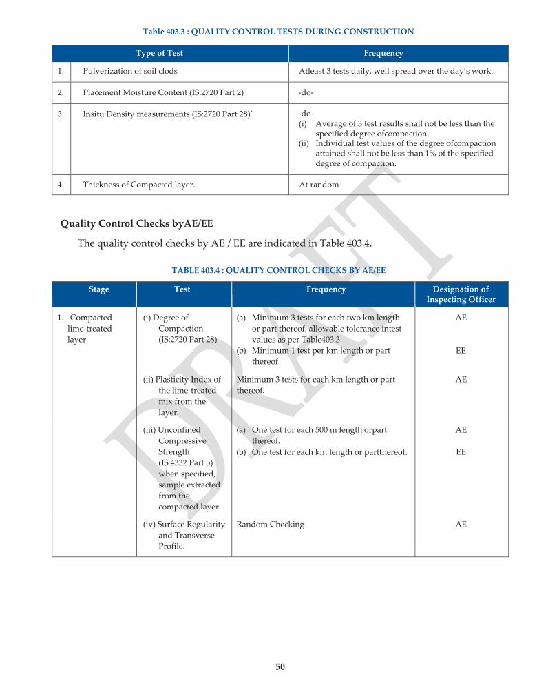
50
Table 403.3 : QUALITY CONTROL TESTS DURING CONSTRUCTION
Type of Test Frequency
1. Pulverization of soil clods Atleast 3 tests daily, well spread over the day’s work.
2. Placement Moisture Content (IS:2720 Part 2) -do-
3. Insitu Density measurements (IS:2720 Part 28)` -do- (i) Average of 3 test results shall not be less than the
specified degree ofcompaction. (ii) Individual test values of the degree ofcompaction
attained shall not be less than 1% of the specified degree of compaction.
4. Thickness of Compacted layer. At random
Quality Control Checks byAE/EE
The quality control checks by AE / EE are indicated in Table 403.4.
TABLE 403.4 : QUALITY CONTROL CHECKS BY AE/EE
Stage Test Frequency Designation of Inspecting Officer
1. Compacted
lime-treated
layer
(i) Degree of
Compaction
(IS:2720 Part 28)
(a) Minimum 3 tests for each two km length
or part thereof; allowable tolerance intest
values as per Table403.3
(b) Minimum 1 test per km length or part
thereof
AE
EE
(ii) Plasticity Index of
the lime-treated
mix from the
layer.
Minimum 3 tests for each km length or part
thereof.
AE
(iii) Unconfined
Compressive
Strength
(IS:4332 Part 5)
when specified,
sample extracted
from the
compacted layer.
(a) One test for each 500 m length orpart
thereof.
(b) One test for each km length or partthereof.
AE
EE
(iv) Surface Regularity
and Transverse
Profile.
Random Checking AE
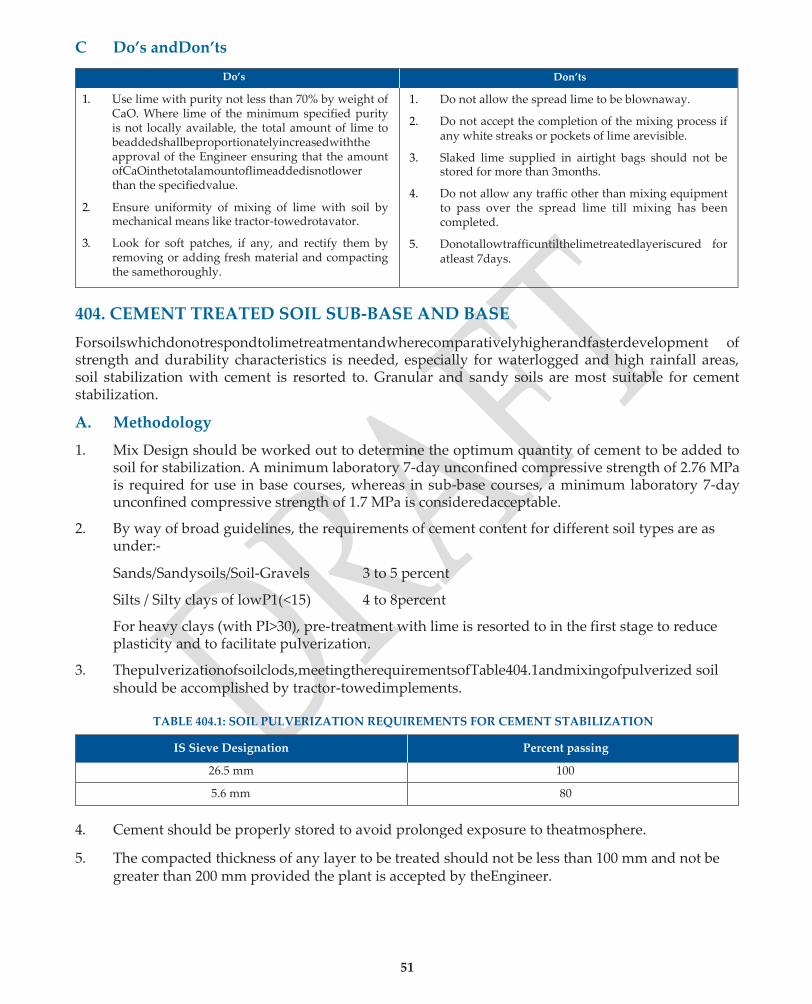
51
C Do’s andDon’ts
Do’s Don’ts
1. Use lime with purity not less than 70% by weight of CaO. Where lime of the minimum specified purity is not locally available, the total amount of lime to beaddedshallbeproportionatelyincreasedwiththe approval of the Engineer ensuring that the amount ofCaOinthetotalamountoflimeaddedisnotlower than the specifiedvalue.
2. Ensure uniformity of mixing of lime with soil by mechanical means like tractor-towedrotavator.
3. Look for soft patches, if any, and rectify them by removing or adding fresh material and compacting the samethoroughly.
1. Do not allow the spread lime to be blownaway.
2. Do not accept the completion of the mixing process if any white streaks or pockets of lime arevisible.
3. Slaked lime supplied in airtight bags should not be stored for more than 3months.
4. Do not allow any traffic other than mixing equipment to pass over the spread lime till mixing has been completed.
5. Donotallowtrafficuntilthelimetreatedlayeriscured for atleast 7days.
404. CEMENT TREATED SOIL SUB-BASE AND BASE
Forsoilswhichdonotrespondtolimetreatmentandwherecomparativelyhigherandfasterdevelopment of strength and durability characteristics is needed, especially for waterlogged and high rainfall areas, soil stabilization with cement is resorted to. Granular and sandy soils are most suitable for cement stabilization.
A. Methodology
1. Mix Design should be worked out to determine the optimum quantity of cement to be added to soil for stabilization. A minimum laboratory 7-day unconfined compressive strength of 2.76 MPa is required for use in base courses, whereas in sub-base courses, a minimum laboratory 7-day unconfined compressive strength of 1.7 MPa is consideredacceptable.
2. By way of broad guidelines, the requirements of cement content for different soil types are as under:-
Sands/Sandysoils/Soil-Gravels 3 to 5 percent
Silts / Silty clays of lowP1(<15) 4 to 8percent
For heavy clays (with PI>30), pre-treatment with lime is resorted to in the first stage to reduce plasticity and to facilitate pulverization.
3. Thepulverizationofsoilclods,meetingtherequirementsofTable404.1andmixingofpulverized soil should be accomplished by tractor-towedimplements.
TABLE 404.1: SOIL PULVERIZATION REQUIREMENTS FOR CEMENT STABILIZATION
IS Sieve Designation Percent passing
26.5 mm 100
5.6 mm 80
4. Cement should be properly stored to avoid prolonged exposure to theatmosphere.
5. The compacted thickness of any layer to be treated should not be less than 100 mm and not be greater than 200 mm provided the plant is accepted by theEngineer.
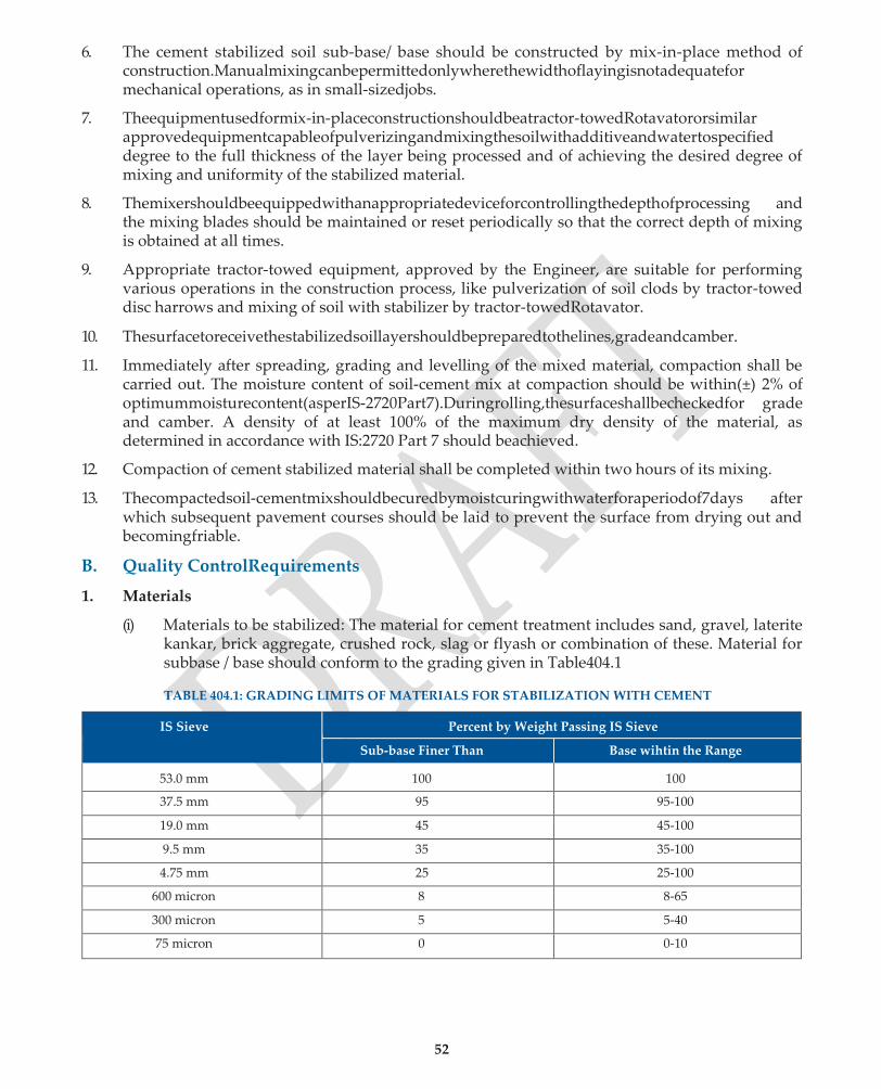
52
6. The cement stabilized soil sub-base/ base should be constructed by mix-in-place method of construction.Manualmixingcanbepermittedonlywherethewidthoflayingisnotadequatefor mechanical operations, as in small-sizedjobs.
7. Theequipmentusedformix-in-placeconstructionshouldbeatractor-towedRotavatororsimilar approvedequipmentcapableofpulverizingandmixingthesoilwithadditiveandwatertospecified degree to the full thickness of the layer being processed and of achieving the desired degree of mixing and uniformity of the stabilized material.
8. Themixershouldbeequippedwithanappropriatedeviceforcontrollingthedepthofprocessing and the mixing blades should be maintained or reset periodically so that the correct depth of mixing is obtained at all times.
9. Appropriate tractor-towed equipment, approved by the Engineer, are suitable for performing various operations in the construction process, like pulverization of soil clods by tractor-towed disc harrows and mixing of soil with stabilizer by tractor-towedRotavator.
10. Thesurfacetoreceivethestabilizedsoillayershouldbepreparedtothelines,gradeandcamber.
11. Immediately after spreading, grading and levelling of the mixed material, compaction shall be carried out. The moisture content of soil-cement mix at compaction should be within(±) 2% of optimummoisturecontent(asperIS-2720Part7).Duringrolling,thesurfaceshallbecheckedfor grade and camber. A density of at least 100% of the maximum dry density of the material, as determined in accordance with IS:2720 Part 7 should beachieved.
12. Compaction of cement stabilized material shall be completed within two hours of its mixing.
13. Thecompactedsoil-cementmixshouldbecuredbymoistcuringwithwaterforaperiodof7days after which subsequent pavement courses should be laid to prevent the surface from drying out and becomingfriable.
B. Quality ControlRequirements
1. Materials
(i) Materials to be stabilized: The material for cement treatment includes sand, gravel, laterite kankar, brick aggregate, crushed rock, slag or flyash or combination of these. Material for subbase / base should conform to the grading given in Table404.1
TABLE 404.1: GRADING LIMITS OF MATERIALS FOR STABILIZATION WITH CEMENT
IS Sieve Percent by Weight Passing IS Sieve
Sub-base Finer Than Base wihtin the Range
53.0 mm 100 100
37.5 mm 95 95-100
19.0 mm 45 45-100
9.5 mm 35 35-100
4.75 mm 25 25-100
600 micron 8 8-65
300 micron 5 5-40
75 micron 0 0-10

53
For use in base course, the Liquid limit and Plasticity Index shall not exceed 45% and 20% respectively.
(ii) Cement: Cement shall comply with the requirements of IS:269, 455 or1489
(iii) Lime: (If needed for pretreatment) as per Sub-section403.
(iv) Water:Thewaterforcementstabilizationshallbecleanandfreefrominjurioussubstances.
2. HorizontalAlignment
The edges of the cement stabilized soil layer should be correct within a tolerance limit of (±) 30 mm in plain and rolling terrains and (± )50 mm in hilly terrain.
3. SurfaceLevels
Thetoleranceinsurfacelevelsforcementtreatedsoilsub-basewillberestrictedto(+)10mmand (–)20mmwhileforcement-treatedsoilbase,itwillberestrictedto(±)10mm.Agridof10mx2.5 m may be formed to check the surfacelevels.
4. SurfaceRegularity
The maximum permitted difference between the cement stabilized soil layer and 3 m straight edge shall be 12 mm for longitudinal profile and 10 mm for cross profile.
5. Minimum CompressiveStrength
For use in base and sub-base courses, minimum 7-day unconfined compressive strength of 2.76 MPa and 1.7 MPa respectively is required.
6. QUALITY CONTROLTESTS
Tests Prior toConstruction
The quality control tests to be carried out prior to construction are indicated in Table 404.2.
Table 404.2 : QUALITY CONTROL TESTS PRIOR TO CONSTRUCTION
Type of Test Frequency
1. Quality of cement and Purity of Lime (IS:1514) (if used for pre-treatment)
One test for each lot
2. Unconfined Compressive Strength Test (IS:4332 Part 5)
One test on a set of 3 specimens per km length.
Tests DuringConstruction
The quality control tests to be carried out during construction are indicated in Table 404.3.
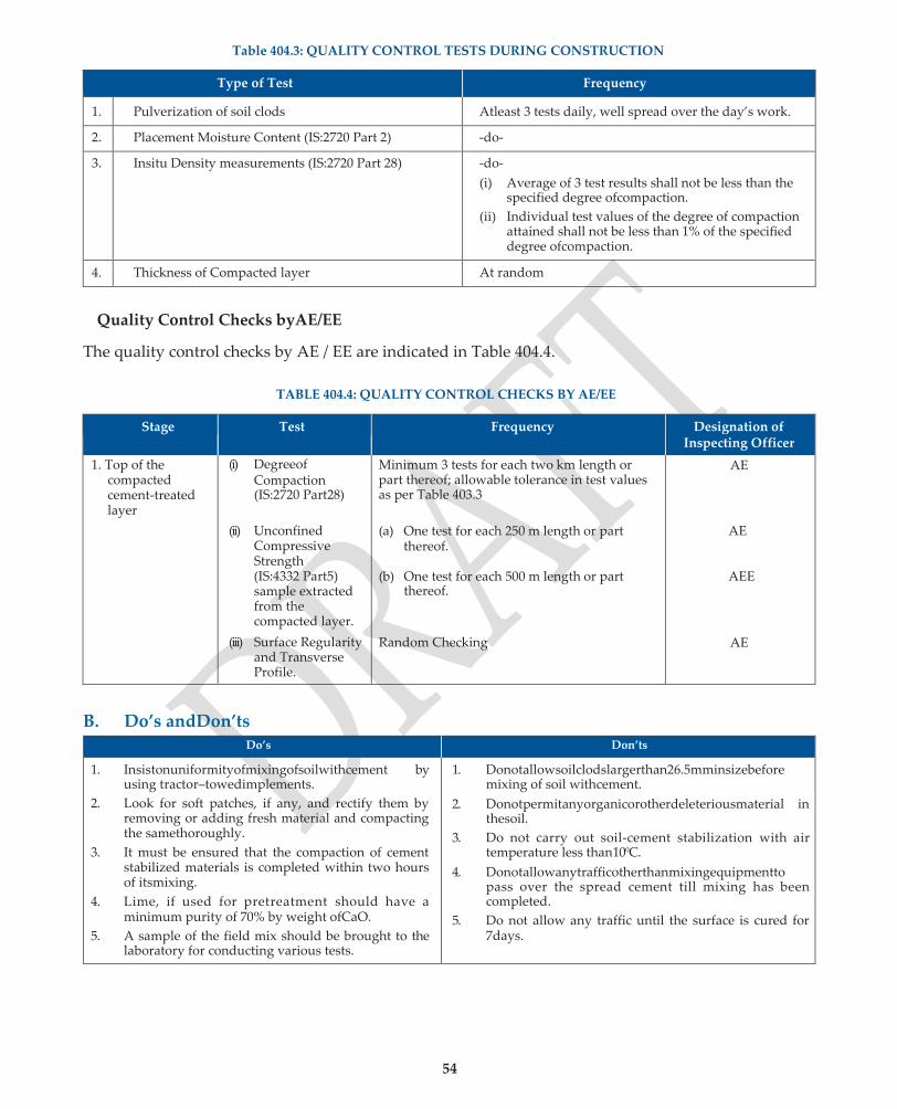
54
Table 404.3: QUALITY CONTROL TESTS DURING CONSTRUCTION
Type of Test Frequency
1. Pulverization of soil clods Atleast 3 tests daily, well spread over the day’s work.
2. Placement Moisture Content (IS:2720 Part 2) -do-
3. Insitu Density measurements (IS:2720 Part 28) -do-
(i) Average of 3 test results shall not be less than the specified degree ofcompaction.
(ii) Individual test values of the degree of compaction attained shall not be less than 1% of the specified degree ofcompaction.
4. Thickness of Compacted layer At random
Quality Control Checks byAE/EE
The quality control checks by AE / EE are indicated in Table 404.4.
TABLE 404.4: QUALITY CONTROL CHECKS BY AE/EE
Stage Test Frequency Designation of Inspecting Officer
1. Top of the compacted cement-treated layer
(i) Degreeof Compaction (IS:2720 Part28)
(ii) Unconfined
Compressive Strength (IS:4332 Part5) sample extracted from the compacted layer.
(iii) Surface Regularity and Transverse Profile.
Minimum 3 tests for each two km length or part thereof; allowable tolerance in test values as per Table 403.3
(a) One test for each 250 m length or part
thereof.
(b) One test for each 500 m length or part thereof.
Random Checking
AE
AE
AEE
AE
B. Do’s andDon’ts Do’s Don’ts
1. Insistonuniformityofmixingofsoilwithcement by using tractor–towedimplements.
2. Look for soft patches, if any, and rectify them by removing or adding fresh material and compacting the samethoroughly.
3. It must be ensured that the compaction of cement stabilized materials is completed within two hours of itsmixing.
4. Lime, if used for pretreatment should have a minimum purity of 70% by weight ofCaO.
5. A sample of the field mix should be brought to the laboratory for conducting various tests.
1. Donotallowsoilclodslargerthan26.5mminsizebefore mixing of soil withcement.
2. Donotpermitanyorganicorotherdeleteriousmaterial in thesoil.
3. Do not carry out soil-cement stabilization with air temperature less than100C.
4. Donotallowanytrafficotherthanmixingequipmentto pass over the spread cement till mixing has been completed.
5. Do not allow any traffic until the surface is cured for 7days.
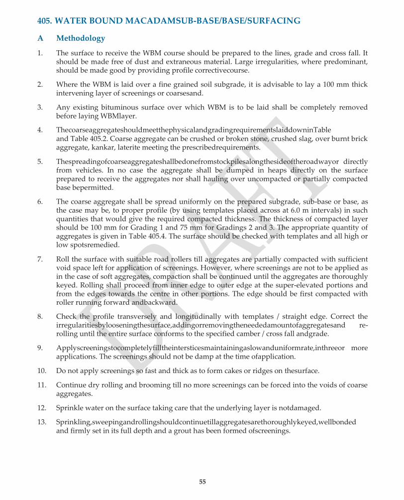
55
405. WATER BOUND MACADAMSUB-BASE/BASE/SURFACING
A Methodology
1. The surface to receive the WBM course should be prepared to the lines, grade and cross fall. It should be made free of dust and extraneous material. Large irregularities, where predominant, should be made good by providing profile correctivecourse.
2. Where the WBM is laid over a fine grained soil subgrade, it is advisable to lay a 100 mm thick intervening layer of screenings or coarsesand.
3. Any existing bituminous surface over which WBM is to be laid shall be completely removed before laying WBMlayer.
4. ThecoarseaggregateshouldmeetthephysicalandgradingrequirementslaiddowninTable and Table 405.2. Coarse aggregate can be crushed or broken stone, crushed slag, over burnt brick aggregate, kankar, laterite meeting the prescribedrequirements.
5. Thespreadingofcoarseaggregateshallbedonefromstockpilesalongthesideoftheroadwayor directly from vehicles. In no case the aggregate shall be dumped in heaps directly on the surface prepared to receive the aggregates nor shall hauling over uncompacted or partially compacted base bepermitted.
6. The coarse aggregate shall be spread uniformly on the prepared subgrade, sub-base or base, as the case may be, to proper profile (by using templates placed across at 6.0 m intervals) in such quantities that would give the required compacted thickness. The thickness of compacted layer should be 100 mm for Grading 1 and 75 mm for Gradings 2 and 3. The appropriate quantity of aggregates is given in Table 405.4. The surface should be checked with templates and all high or low spotsremedied.
7. Roll the surface with suitable road rollers till aggregates are partially compacted with sufficient void space left for application of screenings. However, where screenings are not to be applied as in the case of soft aggregates, compaction shall be continued until the aggregates are thoroughly keyed. Rolling shall proceed from inner edge to outer edge at the super-elevated portions and from the edges towards the centre in other portions. The edge should be first compacted with roller running forward andbackward.
8. Check the profile transversely and longitudinally with templates / straight edge. Correct the irregularitiesbylooseningthesurface,addingorremovingtheneededamountofaggregatesand re-rolling until the entire surface conforms to the specified camber / cross fall andgrade.
9. Applyscreeningstocompletelyfilltheintersticesmaintainingaslowanduniformrate,inthreeor more applications. The screenings should not be damp at the time ofapplication.
10. Do not apply screenings so fast and thick as to form cakes or ridges on thesurface.
11. Continue dry rolling and brooming till no more screenings can be forced into the voids of coarse aggregates.
12. Sprinkle water on the surface taking care that the underlying layer is notdamaged.
13. Sprinkling,sweepingandrollingshouldcontinuetillaggregatesarethoroughlykeyed,wellbonded and firmly set in its full depth and a grout has been formed ofscreenings.

56
14. In case the screenings are not of crushable type such as moorum or gravel, it is necessary to add binding material (PI between 4 and 6)afterapplicationofscreenings.Thebindingmaterialshould beappliedintwoormorelayersat a slow and uniform pace. Generally,thequantityrequiredfor10m2of75mmthicknessofWBMis0.06to0.09m3andfor100mmthickness,thecorrespondingquantity would be 0.08 to 0.10m3.
In case WBM surface is not to be covered with Bituminous surfacing, PI of binding material shall be between 4 and 10.
15. The process of water sprinkling, sweeping and rolling should continue till the resulting slurry forms a wave ahead ofroller.
16. ThecompactedWBMcourseshouldbeallowedtocompletelydryandsetbeforethenextpavement course is laid or traffic isallowed.
17. The earthen shoulders should be constructed simultaneously with the WBM construction in accordance with Sub-Section407.
18. ThefinishedsurfaceofWBMshouldconformtotheprescribedtolerancesgiveninParaB.Where thesurfaceirregularityexceedsthetolerances,theWBMlayershouldbescarifiedtoitsfulldepth over the affected area and corrected by adding or removing and replacing with freshmaterial.
B Quality ControlRequirements
1. Materials
(i) CoarseAggregate
(a) Physicalrequirements
Physicalrequirementsofcoarseaggregateforwaterboundmacadamforsub-base,baseand surfacing should conform to the requirements given in Table 405.1. If the water absorption of aggregate is greater than 2 per cent, Soundness test should be carriedout.
TABLE405.1:PHYSICALREQUIREMENTSOFCOARSEAGGREGATESFORWBM
Test Sub-base Base Surfacing
Aggregate Impact value Less than 50 Less than 40 Less than 30
Flakiness index Less than 30 Less than 25 Less than 20
Soundness test -Loss with Sodium Sulphate -Loss with Magnesium Sulphate
Less than12% Less than18%
Less than12% Less than18%
Less than12% Less than18%
Aggregates like brick bats, kankar, laterite etc. which get softened in presence of water shall be tested for Aggregate Impact Value under wet conditions in accordance with IS:5640.
(b) Grading:
ThecoarseaggregatesshouldconformtothegradingspecifiedintheContractandmeetthe requirements given in Table405.2.
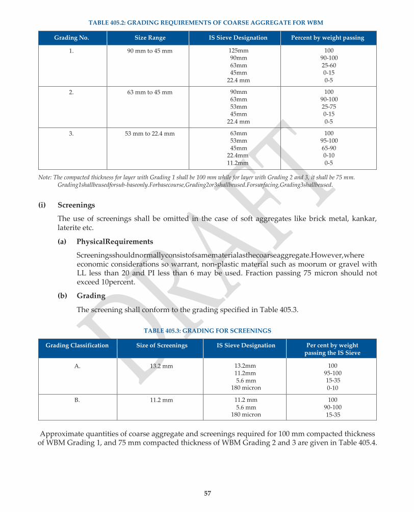
57
TABLE 405.2: GRADING REQUIREMENTS OF COARSE AGGREGATE FOR WBM
Grading No. Size Range IS Sieve Designation Percent by weight passing
1. 90 mm to 45 mm 125mm 90mm 63mm 45mm
22.4 mm
100 90-100 25-60 0-15 0-5
2. 63 mm to 45 mm 90mm 63mm 53mm 45mm
22.4 mm
100 90-100 25-75 0-15 0-5
3. 53 mm to 22.4 mm 63mm 53mm 45mm
22.4mm 11.2mm
100 95-100 65-90 0-10 0-5
Note: The compacted thickness for layer with Grading 1 shall be 100 mm while for layer with Grading 2 and 3, it shall be 75 mm. Grading1shallbeusedforsub-baseonly.Forbasecourse,Grading2or3shallbeused.Forsurfacing,Grading3shallbeused.
(i) Screenings
The use of screenings shall be omitted in the case of soft aggregates like brick metal, kankar, laterite etc.
(a) PhysicalRequirements
Screeningsshouldnormallyconsistofsamematerialasthecoarseaggregate.However,where economic considerations so warrant, non-plastic material such as moorum or gravel with LL less than 20 and PI less than 6 may be used. Fraction passing 75 micron should not exceed 10percent.
(b) Grading
The screening shall conform to the grading specified in Table 405.3.
TABLE 405.3: GRADING FOR SCREENINGS
Grading Classification Size of Screenings IS Sieve Designation Per cent by weight passing the IS Sieve
A. 13.2 mm 13.2mm 11.2mm 5.6 mm
180 micron
100 95-100 15-35 0-10
B. 11.2 mm 11.2 mm 5.6 mm
180 micron
100 90-100 15-35
Approximate quantities of coarse aggregate and screenings required for 100 mm compacted thickness of WBM Grading 1, and 75 mm compacted thickness of WBM Grading 2 and 3 are given in Table 405.4.

58
TABLE 405.4: APPROXIMATE QUANTITIES OF COARSE AGGREGATE AND SCREENINGS REQUIRED FOR 100/ 75 mm COMPACTED THICKNESS OF WBM SUB-BASE/BASE/ SURFACING COURSE FOR 10 m2 AREA
Classification
Course Aggregate Screenings
Size Range
Compacted thickness
in mm
Loose Quantitym3
Stone Screenings Crushable screenings such as Moorum
or gravel
Grading classification & Size mm
For WBM Sub-base/Base
course (loosequantity)
m3
Properties Loose Quantitym3
Grading 1 90 to 45 mm
100 1.21 to 1.43
Type A13.2 0.27 to 0.30 LL<20:; PI<6 Percent passing 0.075 mm <10
0.30 to 0.32
Grading 2 63 to
45 mm 75 0.91 to 1.07 Type A13.2 0.12 to 0.15 -do- 0.22 to 0.24
Grading 2 63 to 45 mm
75 0.91 to 1.07 Type B11.2 0.20 to 0.22 -do- 0.22 to 0.24
Grading 3 53 to 22.4 mm
75 0.91 to 1.07 Type B11.2 0.18 to 0.21 -do- 0.22 to 0.24
(iii) Binding Material
Application of binding material may not be necessary when the screenings used are of crushable type. Binding material if used as a filler material shall comprise of a suitable material approved bytheEngineerhavingaPlasticityIndex(PI)ofvaluelessthan6forsubbase/basecourseand4– 10forsurfacingcourseasdeterminedinaccordancewithIS:2720(Part5).Thequantityofbinding materialwilldependuponthetypeofscreenings.Forestimationofquantities,thefollowingmay be adopted: 75 Quantity for 75 mm compacted thickness WBM = 0.06 – 0.09 m3 / 10m2.
Quantity for 100 mm compacted thickness WBM = 0.08 – 0.10 m3 / 10 m2.
2. HorizontalAlignment
TheedgesoftheWBMsub-base/basewillbecorrectwithinatolerancelimitof(±)30mminplain and rolling terrain and (±) 50 mm in hilly terrain. The edge of carriageway with WBM surfacing shallbecorrectwithinatolerancelimitof(±)20mminplainandrollingterrainand(±)30mmin hillyterrain.
3. SurfaceLevel
The tolerance in surface levels of the WBM would be as under:
(a) Sub-basecourse (+) 10 mm, (-) 20mm
(b) Basecourse (±) 15mm
(c) SurfacingCourse (±) 10 mm
(A grid of 10 m by 2.5 m may be formed to check the surface levels).

59
4. SurfaceRegularity
Themaximumallowabledifferencebetweentheroadsurfaceand3mstraightedgeshallbeasper Table405.5.
TABLE 405.5: MAXIMUM PERMITTED UNDULATIONS MEASURED WITH 3 M STRAIGHT EDGE
Type of Construction Maximum permissible difference
Longitudinal Profile BasCross Profile
WBM Grade 1 15 mm 12 mm
WBM Grade 2 / Grade 3 12 mm 8 mm
5. Quality ControlTests
Tests Prior toConstruction
The quality control tests to be carried out prior to construction are indicated in Table 405.6.
Table 405.6: QUALITY CONTROL TESTS PRIOR TO CONSTRUCTION
Type of Test Frequency
1. Aggregate Impact Value Test (IS:2386 Part 4) One test from each identified source.
2. Aggregate Water Absorption Test (IS:2386 Part 3) -do-
3. Soundness Test of Aggregates (where water absorption, as at 2 above, exceeds 2%) (IS:2386 Part 5).
-do-
4. Grading, LL and PI of Crushable Screenings (IS:2720 Part 5) (where Screenings are to be used from the same source as the Stone Aggregates, this test is not needed).
-do-
5. LL and PI of the Binding Material, when used. -do-
Tests DuringConstruction
The quality control tests to be carried out during construction are indicated in Table 405.7.
TABLE 405.7 : QUALITY CONTROL TESTS DURING CONSTRUCTION
Type of Test Frequency
1. Grading of Stone Aggregates and Screenings (IS:2386 Part 1)
Atleast 2 tests to be carried out for a day’s work.
2. Flakiness Index of Stone Aggregates (IS:2386 Part 1 -do-
3. PI of Crushable Screenings / binding material (IS:2720 Part 5)
Atleast 2 tests to be carried out for a day’s work.
4. Aggregate impact value (IS:2386-Part 4) At random one test per km
5. Thickness of Compacted layer. At random
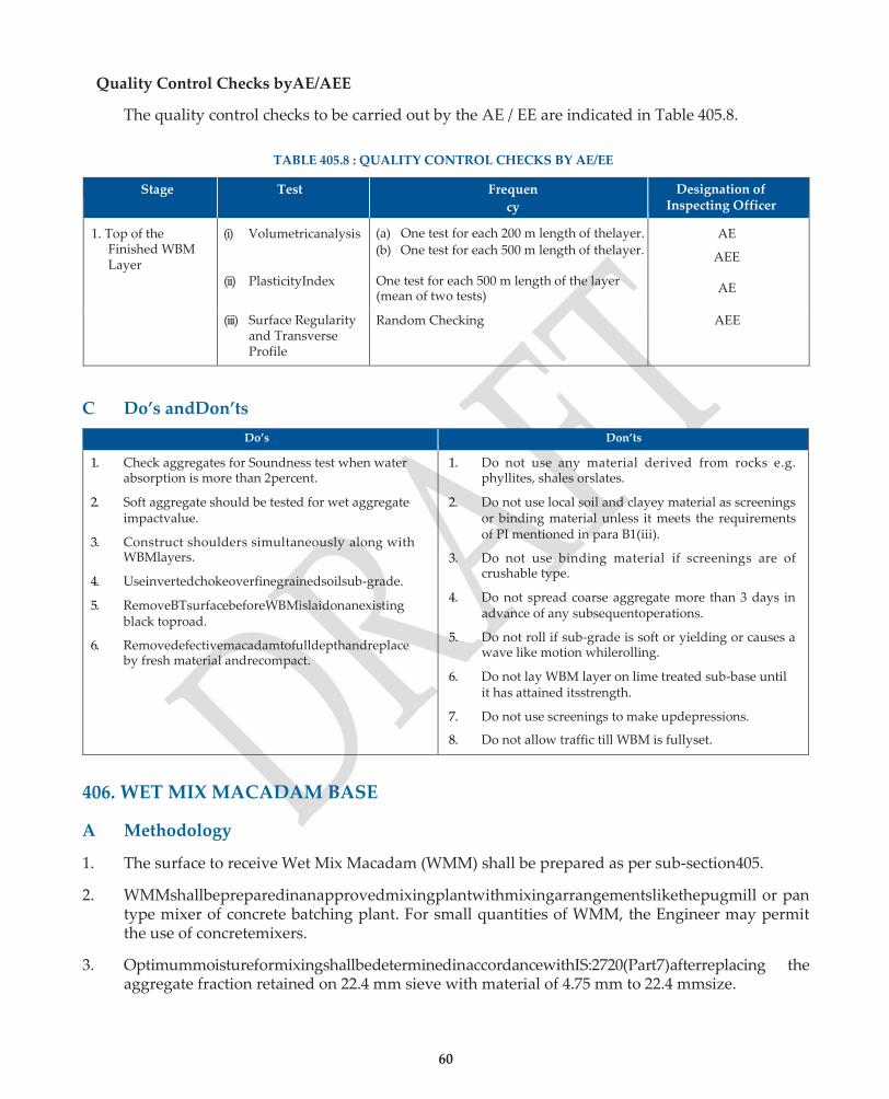
60
Quality Control Checks byAE/AEE
The quality control checks to be carried out by the AE / EE are indicated in Table 405.8.
TABLE 405.8 : QUALITY CONTROL CHECKS BY AE/EE
Stage Test Frequen
cy
Designation of Inspecting Officer
1. Top of the Finished WBM Layer
(i) Volumetricanalysis
(ii) PlasticityIndex
(iii) Surface Regularity
and Transverse Profile
(a) One test for each 200 m length of thelayer.
(b) One test for each 500 m length of thelayer.
One test for each 500 m length of the layer (mean of two tests)
AE
AEE
AE
Random Checking AEE
C Do’s andDon’ts
Do’s Don’ts
1. Check aggregates for Soundness test when water absorption is more than 2percent.
2. Soft aggregate should be tested for wet aggregate impactvalue.
3. Construct shoulders simultaneously along with WBMlayers.
4. Useinvertedchokeoverfinegrainedsoilsub-grade.
5. RemoveBTsurfacebeforeWBMislaidonanexisting black toproad.
6. Removedefectivemacadamtofulldepthandreplace by fresh material andrecompact.
1. Do not use any material derived from rocks e.g. phyllites, shales orslates.
2. Do not use local soil and clayey material as screenings or binding material unless it meets the requirements of PI mentioned in para B1(iii).
3. Do not use binding material if screenings are of crushable type.
4. Do not spread coarse aggregate more than 3 days in advance of any subsequentoperations.
5. Do not roll if sub-grade is soft or yielding or causes a wave like motion whilerolling.
6. Do not lay WBM layer on lime treated sub-base until it has attained itsstrength.
7. Do not use screenings to make updepressions.
8. Do not allow traffic till WBM is fullyset.
406. WET MIX MACADAM BASE
A Methodology
1. The surface to receive Wet Mix Macadam (WMM) shall be prepared as per sub-section405.
2. WMMshallbepreparedinanapprovedmixingplantwithmixingarrangementslikethepugmill or pan type mixer of concrete batching plant. For small quantities of WMM, the Engineer may permit the use of concretemixers.
3. OptimummoistureformixingshallbedeterminedinaccordancewithIS:2720(Part7)afterreplacing the aggregate fraction retained on 22.4 mm sieve with material of 4.75 mm to 22.4 mmsize.
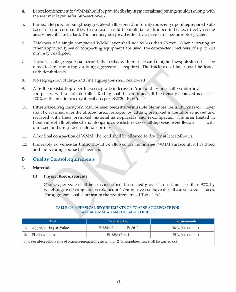
61
4. LateralconfinementforWMMshouldbeprovidedbylayingmaterialinadjoiningshouldersalong with the wet mix layer, refer Sub-section407.
5. Immediatelyuponmixing,theaggregatesshallbespreaduniformlyandevenlyupontheprepared sub-base, in required quantities. In no case should the material be dumped in heaps, directly on the area where it is to be laid. The mix may be spread either by a paver-finisher or motor grader.
6. Thickness of a single compacted WMM layer shall not be less than 75 mm. When vibrating or other approved types of compacting equipment are used, the compacted thickness of up to 200 mm may beadopted.
7. Thesurfaceofaggregateshallbecarefullycheckedwithtemplatesandallhighorlowspotsshould be remedied by removing / adding aggregate as required. The thickness of layer shall be tested with depthblocks.
8. No segregation of large and fine aggregates shall beallowed.
9. Afterthemixislaidtoproperthickness,gradeandcrossfall/camber,thesameshallbeuniformly compacted with a suitable roller. Rolling shall be continued till the density achieved is at least 100% of the maximum dry density as per IS:2720 (Part7).
10. IfthesurfaceirregularityofWMMcourseexceedsthepermissibletolerances,thefullthicknessof layer shall be scarified over the affected area, reshaped by adding premixed material or removed and replaced with fresh premixed material as applicable and re-compacted. The area treated in thismannershallnotbelessthan5mlongand2mwide.Innocaseshalldepressionsbefilledup with unmixed and un-graded materials orfines.
11. After final compaction of WMM, the road shall be allowed to dry for at least 24hours.
12. Preferably no vehicular traffic should be allowed on the finished WMM surface till it has dried and the wearing course has beenlaid.
B Quality Controlrequirements
1. Materials
(i) PhysicalRequirements
Coarse aggregate shall be crushed stone. If crushed gravel is used, not less than 90% by weightofgravel/shinglepiecesretainedon4.75mmsieveshallhaveatleasttwofractured faces. The aggregate shall conform to the requirements of Table406.1
TABLE 406.1: PHYSICAL REQUIREMENTS OF COARSE AGGREGATE FOR
WET MIX MACADAM FOR BASE COURSES
Test Test Method Requirements
1. Aggregate ImpactValue IS:2386 (Part 4) or IS: 5640 40 % (maximum)
2. FlakinessIndex IS :2386 (Part 1) 25 % (maximum)
If water absorption value of coarse aggregate is greater than 2 %, soundness test shall be carried out.
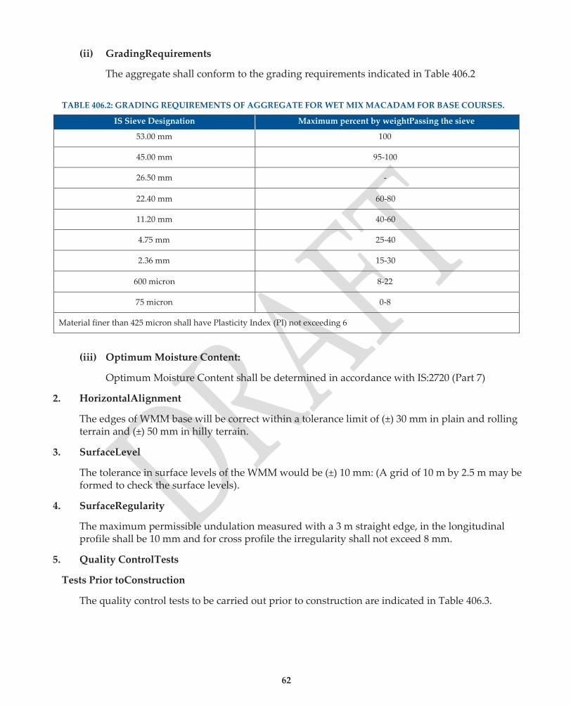
62
(ii) GradingRequirements
The aggregate shall conform to the grading requirements indicated in Table 406.2
TABLE 406.2: GRADING REQUIREMENTS OF AGGREGATE FOR WET MIX MACADAM FOR BASE COURSES.
IS Sieve Designation Maximum percent by weightPassing the sieve
53.00 mm 100
45.00 mm 95-100
26.50 mm -
22.40 mm 60-80
11.20 mm 40-60
4.75 mm 25-40
2.36 mm 15-30
600 micron 8-22
75 micron 0-8
Material finer than 425 micron shall have Plasticity Index (PI) not exceeding 6
(iii) Optimum Moisture Content:
Optimum Moisture Content shall be determined in accordance with IS:2720 (Part 7)
2. HorizontalAlignment
The edges of WMM base will be correct within a tolerance limit of (±) 30 mm in plain and rolling terrain and (±) 50 mm in hilly terrain.
3. SurfaceLevel
The tolerance in surface levels of the WMM would be (±) 10 mm: (A grid of 10 m by 2.5 m may be formed to check the surface levels).
4. SurfaceRegularity
The maximum permissible undulation measured with a 3 m straight edge, in the longitudinal profile shall be 10 mm and for cross profile the irregularity shall not exceed 8 mm.
5. Quality ControlTests
Tests Prior toConstruction
The quality control tests to be carried out prior to construction are indicated in Table 406.3.
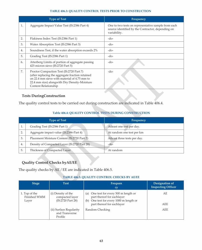
63
TABLE 406.3: QUALITY CONTROL TESTS PRIOR TO CONSTRUCTION
Type of Test Frequency
1. Aggregate Impact Value Test (IS:2386 Part 4) One to two tests on representative sample from each source identified by the Contractor, depending on variability.
2. Flakiness Index Test (IS:2386 Part 1) -do-
3. Water Absorption Test (IS:2386 Part 3) -do-
4. Soundness Test, if the water absorption exceeds 2% -do-
5. Grading Test (IS:2386 Part 1) -do-
6. Atterberg Limits of portion of aggregate passing 425 micron sieve (IS:2720 Part 5)
-do-
7. Proctor Compaction Test (IS:2720 Part 7) (after replacing the aggregate fraction retained on 22.4 mm sieve with material of 4.75 mm to 22.4 mm size) alongwith Dry Density-Moisture Content Relationship
-do-
Tests DuringConstruction
The quality control tests to be carried out during construction are indicated in Table 406.4.
Table 406.4: QUALITY CONTROL TESTS DURING CONSTRUCTION
Type of Test Frequency
1. Grading Test (IS:2386 Part 1) Atleast one test per day.
2. Aggregate impact value (IS:2386-Part 4) At random one test per km
3. Placement Moisture Content (IS:2720 Part 2) Atleast three tests per day.
4. Density of Compacted Layer (IS:2720 Part 28) -do-
5. Thickness of Compacted Layer At random
Quality Control Checks byAE/EE
The quality checks by AE / EE are indicated in Table 406.5.
TABLE 406.5: QUALITY CONTROL CHECKS BY AE/EE
Stage Test Frequen
cy
Designation of Inspecting Officer
1. Top of the Finished WMM Layer
(i) Density of the compacted layer (IS:2720 Part 28)
(a) One test for every 500 m length or part thereof for eachlayer
(b) One test for every 1000 m length or part thereof for eachlayer
AE
AEE
(ii) Surface Regularity and Transverse Profile
Random Checking AEE
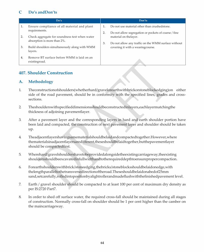
64
C Do’s andDon’ts
Do’s Don’ts
1. Ensure compliance of all material and plant
requirements.
2. Check aggregate for soundness test when water
absorption is more than 2%.
3. Build shoulders simultaneously along with WMM
layers.
4. Remove BT surface before WMM is laid on an
existingroad.
1. Do not use material other than crushedstone.
2. Do not allow segregation or pockets of coarse / fine
material on thelayer.
3. Do not allow any traffic on the WMM surface without
covering it with a wearingcourse.
407. Shoulder Construction
A. Methodology
1. Theconstructionofshoulders(whetherhard/gravelorearthwithbrickorstoneblockedging)on either side of the road pavement, should be in conformity with the specified lines, grades and cross-sections.
2. Theshoulderswithspecifieddimensionsshouldbeconstructedinlayers,eachlayermatchingthe thickness of adjoining pavementlayer.
3. After a pavement layer and the corresponding layers in hard and earth shoulder portion have been laid and compacted, the construction of next pavement layer and shoulder should be taken up.
4. Theadjacentlayershavingsamematerialshouldbelaidandcompactedtogether.However,where thematerialsinadjacentlayersaredifferent,theseshouldbelaidtogether,butthepavementlayer should be compactedfirst.
5. Wherehard/gravelshouldershavetobeprovidedalongsidetheexistingcarriageway,theexisting shouldersshouldbeexcavatedinfullwidthandtotherequireddepthtoensurepropercompaction.
6. Forearthshoulderswithbrick/stoneedging,thebricks/stoneblocksshouldbelaidonedge,with thelengthparalleltothetransversedirectionoftheroad.Theseshouldbelaidonabedof25mm sand,setcarefully,rolledintopositionbyalightrollerandmadeflushwiththefinishedpavement level.
7. Earth / gravel shoulder should be compacted to at least 100 per cent of maximum dry density as per IS:2720 Part7.
8. In order to shed off surface water, the required cross-fall should be maintained during all stages of construction. Normally cross-fall on shoulder should be 1 per cent higher than the camber on the maincarriageway.
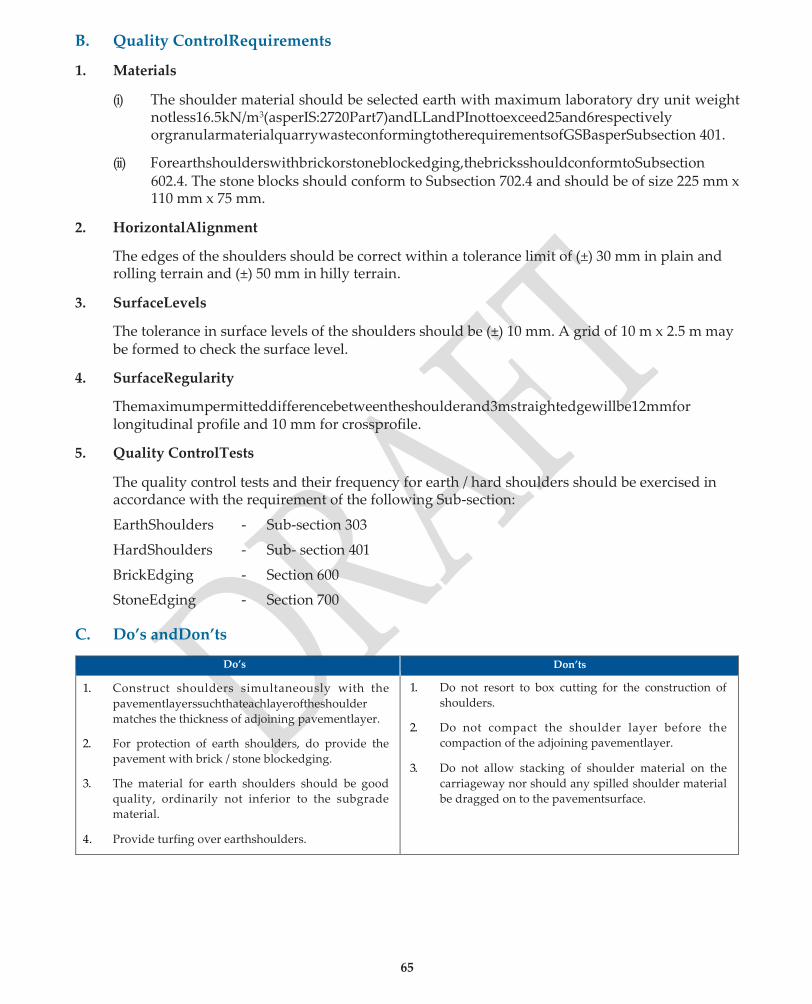
65
B. Quality ControlRequirements
1. Materials
(i) The shoulder material should be selected earth with maximum laboratory dry unit weight notless16.5kN/m3(asperIS:2720Part7)andLLandPInottoexceed25and6respectively orgranularmaterialquarrywasteconformingtotherequirementsofGSBasperSubsection 401.
(ii) Forearthshoulderswithbrickorstoneblockedging,thebricksshouldconformtoSubsection 602.4. The stone blocks should conform to Subsection 702.4 and should be of size 225 mm x 110 mm x 75 mm.
2. HorizontalAlignment
The edges of the shoulders should be correct within a tolerance limit of (±) 30 mm in plain and rolling terrain and (±) 50 mm in hilly terrain.
3. SurfaceLevels
The tolerance in surface levels of the shoulders should be (±) 10 mm. A grid of 10 m x 2.5 m may be formed to check the surface level.
4. SurfaceRegularity
Themaximumpermitteddifferencebetweentheshoulderand3mstraightedgewillbe12mmfor longitudinal profile and 10 mm for crossprofile.
5. Quality ControlTests
The quality control tests and their frequency for earth / hard shoulders should be exercised in accordance with the requirement of the following Sub-section:
EarthShoulders - Sub-section 303
HardShoulders - Sub- section 401
BrickEdging - Section 600
StoneEdging - Section 700
C. Do’s andDon’ts
Do’s Don’ts
1. Construct shoulders simultaneously with the
pavementlayerssuchthateachlayeroftheshoulder
matches the thickness of adjoining pavementlayer.
2. For protection of earth shoulders, do provide the
pavement with brick / stone blockedging.
3. The material for earth shoulders should be good
quality, ordinarily not inferior to the subgrade
material.
1. Do not resort to box cutting for the construction of
shoulders.
2. Do not compact the shoulder layer before the
compaction of the adjoining pavementlayer.
3. Do not allow stacking of shoulder material on the
carriageway nor should any spilled shoulder material
be dragged on to the pavementsurface.
4. Provide turfing over earthshoulders.

66
408. Local materials for road construction
1. The local materials for rural road construction cover the locally available soils and aggregates (including low grade / marginal aggregates) which are both, suitable and economical, for incorporation as such or after suitable processing in lieu of the conventionally used high quality materials.
2. It is always economically and technically prudent to use locally available materials as much as possible instead of transporting conventional quality materials from long distances involving uneconomicalleads.
3. Usuallysomeprocessingofthelocallyavailablematerialsisrequiredtomaketheirbestuse.This Sub-sectionbringsoutthequalityaspectsofprocessingthelocallyavailablematerialstousethem to the maximum potential.
4. Constructionaspectsfortheuseofthesematerialsaresimilartotheconventionalqualitymaterials and as such, reference to the relevant Sub-sections have been made as to their methodology for construction.
5. To achieve the maximized use of locally available materials, it is essential that adequate soil and materials surveys in the vicinity of the project site are carried out rather than only depending on the well-established old pre-investigated quarries. The general guidelines regarding the field surveys of locally available soils, moorums, gravels and aggregates are given in Annex408.1.
A. Methodology
1. Therepresentativesamplesofnaturallyoccurringsoils,moorums,gravels,soft/hardaggregates, any industrial wastes and stabilizers like lime etc. should be subjected to laboratory testing. The tests to be carried out should be relevant to their use in specific layer(s) for which reference may be made to previoussubsections.
2. When the locally available naturally occurring materials or industrial wastes do not meet the engineeringpropertiesrequiredforuseinanylayerofthepavementcrust,appropriateprocessing like modification / stabilization technique required to render these materials suitable for use in any of the pavement layer(s) should be carried out as per the guidance given in Tables 408.1 and 408.2.
3. WherethenaturallyoccurringGravels/Soil-Gravelmixturesmeetboththegradingandplasticity requirements for use in sub-base and base courses, these can be used as such. However, if these materialsarefoundtobedeficientingradingonly,processingbymechanicalstabilizationtechnique can be resorted to so as to meet the grading requirements. Where these local materials are found to be overly plastic, mixing with local sand in the required proportion is often the bestsolution.
4. Out of the possible alternative uses of the local materials as such or after suitable processing, select the ones which are both, suitable andeconomical.

67
TABLE 408.1 APPROPRIATE PROCESSING/STABILIZATION TECHNIQUES
Sl. No. Soil/Aggregate Properties Processing/Stabilization Technique Test Procedure
1. Sands, moorums / gravels having missing fractions and clayey soils.
Mechanical Stabilization to meet the prescribed grading and plasticity requirements.
Refer Sub-sections 401
and 402.
2. Medium and heavy clays having PI>10 and containing atleast 15 percent of material finer than 425 micron.
Lime Stabilisation Stabilization to meet the specified LL and PI requirements and to improve the CBR value.
Refer Sub-section 403.
3. Granular soils deficient in cohesion for adequate compaction and strength.
Cement Stabilization to improve strength (CBR / UCS).
Refer Sub-section 404.
4. Soils of medium plasticity and clayey soils not reactive to lime.
Lime-flyash Stabilization to reduce PI and increased strength in terms of CBR / UCS.
Refer Sub-section 409
5. Heavy clays with PI>30 and very low CBR value.
Two-stage Lime / Cement Stabilization and increased strength.
Refer Sub-section 404.
TABLE 408.2 APPROPRIATE PROCESSING AND USE OF LOCAL MATERIALS IN SUBBASE/BASE
Sl.No. State of Occurrence of Material Manner of Use in the Pavement Test/Quality Requirements
1. Kankar, Laterite, Dhandla etc. found in blocks or large discrete particles.
As WBM without screenings / filler after breaking the material, broadly meeting the required sizes.
Wet Aggregate Impact Value (IS:5640) not to exceed 50, 40 and 30 when used in sub-base, base and surfacing respectively.
2. Naturally occurring gravels without appreciable amount of soil.
Directly as a granular layer for sub-base / base course.
PI should not exceed 6 when used in lower courses. Evaluated for strength by soakedCBR.
3. Soil-gravel with appreciable amount of soil.
Directly as soil-gravel for sub-base / base.
The material should be well-graded and the PI restricted as for Sl. No. 2 above. Evaluated for strength by soaked CBR value.
5. For construction procedure, relevant Sub-sections apply, asunder:-
(a) Use of locally availableaggregates:-
1. AsWBM Clause 405.3 shallapply
2. AsGSB Clause 401.4 shallapply
3. As soil-gravel mix for subbase, baseorsurfacing Clause 402.4 shallapply
(b) Use of stabilizedsoil:-
1. MechanicalStabilization Clause 401.4 shallapply
2. LimeStabilization Clause 403.3 shallapply
3. CementStabilization Clause 404.3 shallapply
4. Lime-FlyashStabilization Clause 409.5 shallapply
5. Two-stage (Lime-Cement) Stabilization Clause 404.3 shallapply
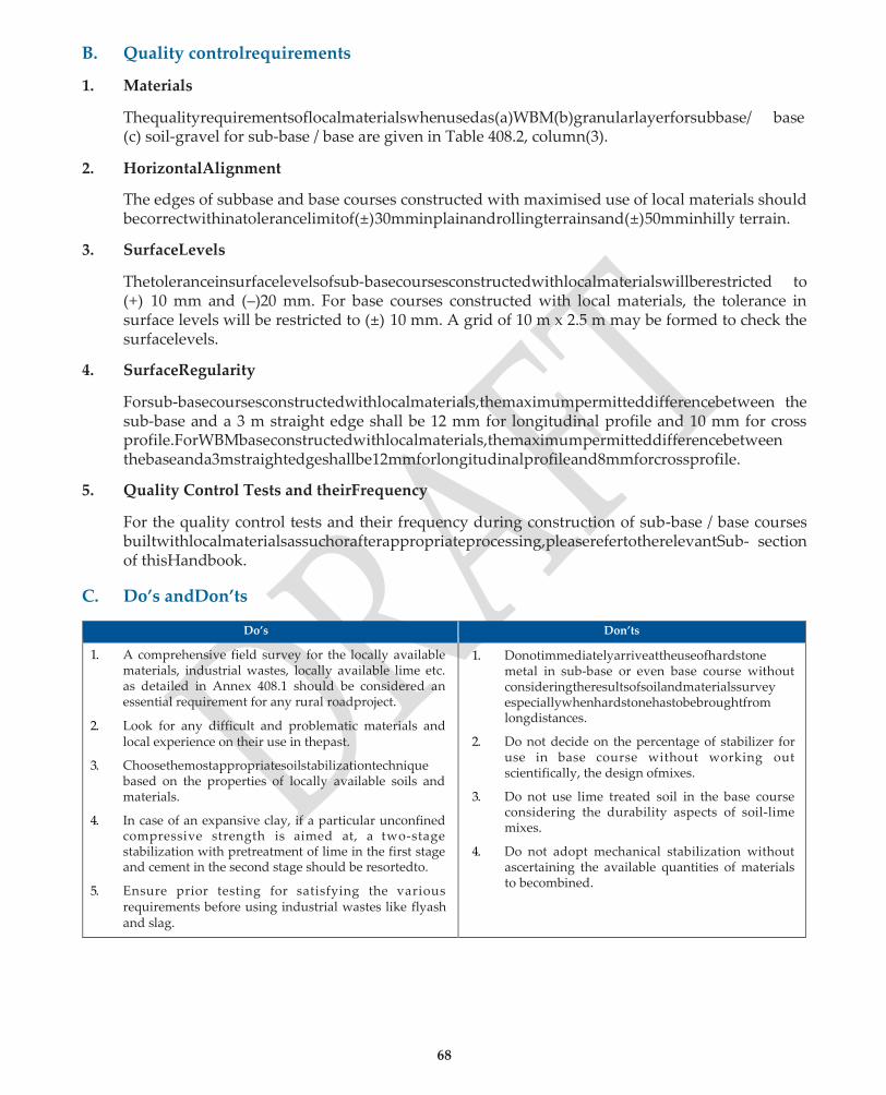
68
B. Quality controlrequirements
1. Materials
Thequalityrequirementsoflocalmaterialswhenusedas(a)WBM(b)granularlayerforsubbase/ base (c) soil-gravel for sub-base / base are given in Table 408.2, column(3).
2. HorizontalAlignment
The edges of subbase and base courses constructed with maximised use of local materials should becorrectwithinatolerancelimitof(±)30mminplainandrollingterrainsand(±)50mminhilly terrain.
3. SurfaceLevels
Thetoleranceinsurfacelevelsofsub-basecoursesconstructedwithlocalmaterialswillberestricted to (+) 10 mm and (–)20 mm. For base courses constructed with local materials, the tolerance in surface levels will be restricted to (±) 10 mm. A grid of 10 m x 2.5 m may be formed to check the surfacelevels.
4. SurfaceRegularity
Forsub-basecoursesconstructedwithlocalmaterials,themaximumpermitteddifferencebetween the sub-base and a 3 m straight edge shall be 12 mm for longitudinal profile and 10 mm for cross profile.ForWBMbaseconstructedwithlocalmaterials,themaximumpermitteddifferencebetween thebaseanda3mstraightedgeshallbe12mmforlongitudinalprofileand8mmforcrossprofile.
5. Quality Control Tests and theirFrequency
For the quality control tests and their frequency during construction of sub-base / base courses builtwithlocalmaterialsassuchorafterappropriateprocessing,pleaserefertotherelevantSub- section of thisHandbook.
C. Do’s andDon’ts
Do’s Don’ts
1. A comprehensive field survey for the locally available materials, industrial wastes, locally available lime etc. as detailed in Annex 408.1 should be considered an essential requirement for any rural roadproject.
2. Look for any difficult and problematic materials and local experience on their use in thepast.
3. Choosethemostappropriatesoilstabilizationtechnique based on the properties of locally available soils and materials.
4. In case of an expansive clay, if a particular unconfined compressive strength is aimed at, a two-stage stabilization with pretreatment of lime in the first stage and cement in the second stage should be resortedto.
5. Ensure prior testing for satisfying the various requirements before using industrial wastes like flyash and slag.
1. Donotimmediatelyarriveattheuseofhardstone metal in sub-base or even base course without consideringtheresultsofsoilandmaterialssurvey especiallywhenhardstonehastobebroughtfrom longdistances.
2. Do not decide on the percentage of stabilizer for use in base course without working out scientifically, the design ofmixes.
3. Do not use lime treated soil in the base course considering the durability aspects of soil-lime mixes.
4. Do not adopt mechanical stabilization without ascertaining the available quantities of materials to becombined.

69
Guidelines for carrying out Soil and Materials Survey
Annex 408.1
• Examine any existing information on the geological and soil conditions likely to be met.
• Along the centre line, have a single line of borings / test pits made, wherever there is a visible change in the soil type. If same soil conditions prevail, at least 3 borings / test pits per kilometre length or a double line offset 15 m to 30m.
• Test pits 1 m x 1 m may be taken to a depth upto 1.5 m, generally the maximum depth of borrow pits.
• Use of hand-operated post hole auger willhelp.
• Forahighembankment,boringtobetakentoadepthabouttwicetheheightoftheembankment, if possibility exists of a soft underlying material.
• Get indication of the depth of Ground Water Table(GWT) and itsfluctuations.
• Note change in vegetation, indicative of subsoil conditions.
• Carry out field identification of the local materials by hand-feeltests.
• Samples to be collected for classification tests from each boring (generally 2 to 5 kg sample is enough). Location and depth of strata to be tagged on to the samplebag.
• For each soil type or group, a 20 kg sample will be required for compaction and strength (CBR) tests.
• Neighbouring quarries and cuttings should be inspected and representative samples of all aggregates (soft and hard) collected for laboratorytesting.
• Besides collecting representative samples of naturally occurring soils, moorums, gravels, soft / hard aggregates, any industrial wastes and stabilizers like lime from roadside kilns etc. should also be collected for laboratory testing.
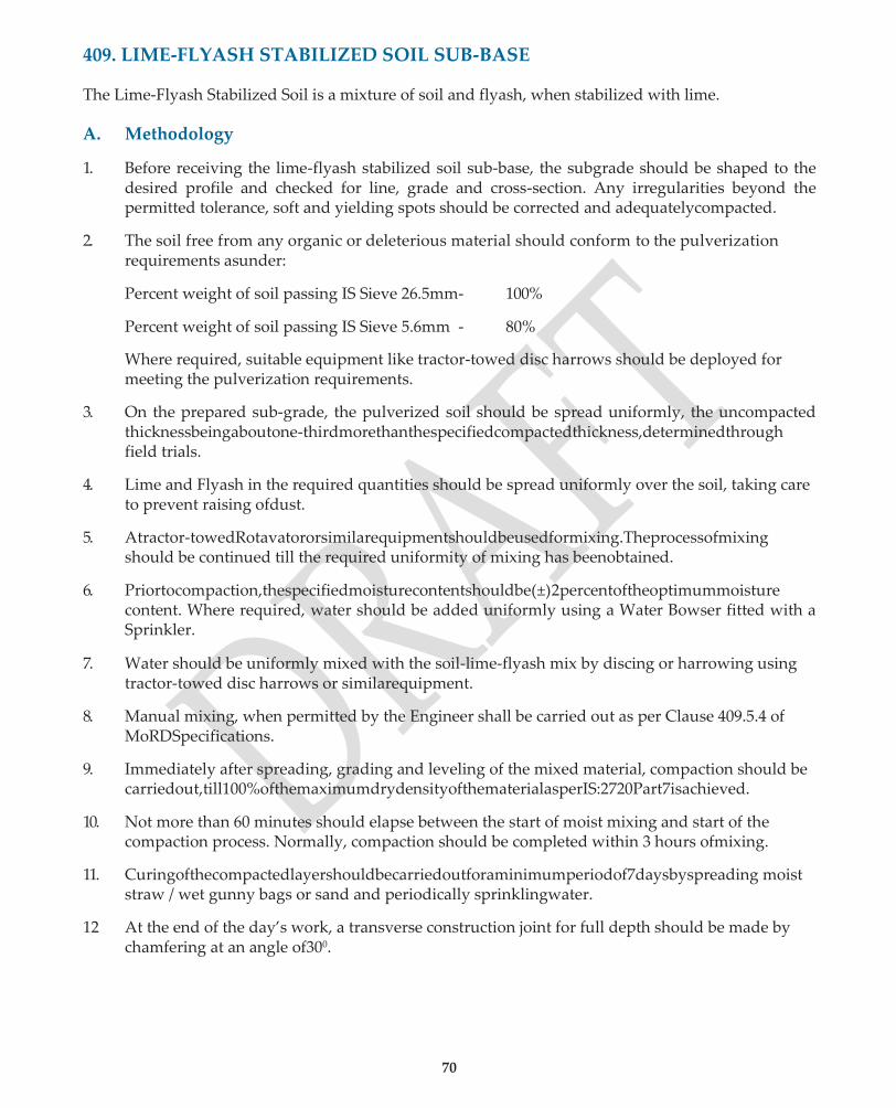
70
409. LIME-FLYASH STABILIZED SOIL SUB-BASE
The Lime-Flyash Stabilized Soil is a mixture of soil and flyash, when stabilized with lime.
A. Methodology
1. Before receiving the lime-flyash stabilized soil sub-base, the subgrade should be shaped to the desired profile and checked for line, grade and cross-section. Any irregularities beyond the permitted tolerance, soft and yielding spots should be corrected and adequatelycompacted.
2. The soil free from any organic or deleterious material should conform to the pulverization requirements asunder:
Percent weight of soil passing IS Sieve 26.5mm- 100%
Percent weight of soil passing IS Sieve 5.6mm - 80%
Where required, suitable equipment like tractor-towed disc harrows should be deployed for meeting the pulverization requirements.
3. On the prepared sub-grade, the pulverized soil should be spread uniformly, the uncompacted thicknessbeingaboutone-thirdmorethanthespecifiedcompactedthickness,determinedthrough field trials.
4. Lime and Flyash in the required quantities should be spread uniformly over the soil, taking care to prevent raising ofdust.
5. Atractor-towedRotavatororsimilarequipmentshouldbeusedformixing.Theprocessofmixing should be continued till the required uniformity of mixing has beenobtained.
6. Priortocompaction,thespecifiedmoisturecontentshouldbe(±)2percentoftheoptimummoisture content. Where required, water should be added uniformly using a Water Bowser fitted with a Sprinkler.
7. Water should be uniformly mixed with the soil-lime-flyash mix by discing or harrowing using tractor-towed disc harrows or similarequipment.
8. Manual mixing, when permitted by the Engineer shall be carried out as per Clause 409.5.4 of MoRDSpecifications.
9. Immediately after spreading, grading and leveling of the mixed material, compaction should be carriedout,till100%ofthemaximumdrydensityofthematerialasperIS:2720Part7isachieved.
10. Not more than 60 minutes should elapse between the start of moist mixing and start of the compaction process. Normally, compaction should be completed within 3 hours ofmixing.
11. Curingofthecompactedlayershouldbecarriedoutforaminimumperiodof7daysbyspreading moist straw / wet gunny bags or sand and periodically sprinklingwater.
12 At the end of the day’s work, a transverse construction joint for full depth should be made by chamfering at an angle of300.
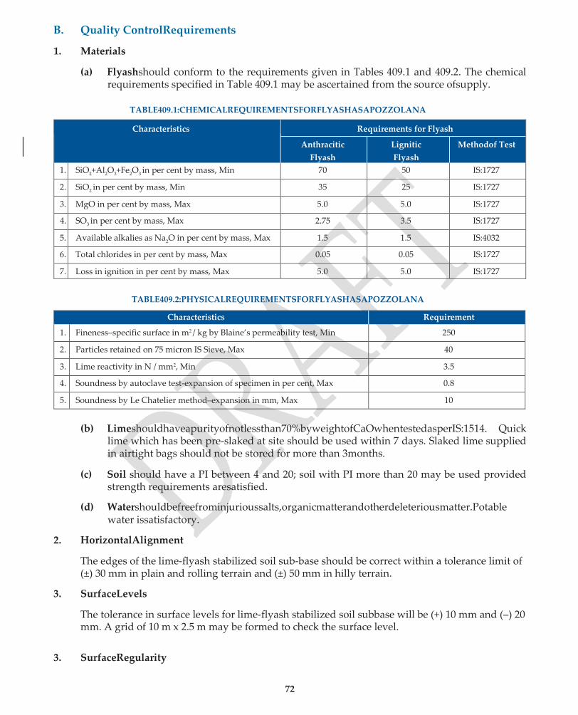
72
B. Quality ControlRequirements
1. Materials
(a) Flyashshould conform to the requirements given in Tables 409.1 and 409.2. The chemical requirements specified in Table 409.1 may be ascertained from the source ofsupply.
TABLE409.1:CHEMICALREQUIREMENTSFORFLYASHASAPOZZOLANA
Characteristics Requirements for Flyash
Anthracitic
Flyash
Lignitic
Flyash
Methodof Test
1. SiO2+Al2O3+Fe2O3 in per cent by mass, Min 70 50 IS:1727
2. SiO2 in per cent by mass, Min 35 25 IS:1727
3. MgO in per cent by mass, Max 5.0 5.0 IS:1727
4. SO3 in per cent by mass, Max 2.75 3.5 IS:1727
5. Available alkalies as Na2O in per cent by mass, Max 1.5 1.5 IS:4032
6. Total chlorides in per cent by mass, Max 0.05 0.05 IS:1727
7. Loss in ignition in per cent by mass, Max 5.0 5.0 IS:1727
TABLE409.2:PHYSICALREQUIREMENTSFORFLYASHASAPOZZOLANA
Characteristics Requirement
1. Fineness–specific surface in m2 / kg by Blaine’s permeability test, Min 250
2. Particles retained on 75 micron IS Sieve, Max 40
3. Lime reactivity in N / mm2, Min 3.5
4. Soundness by autoclave test-expansion of specimen in per cent, Max 0.8
5. Soundness by Le Chatelier method–expansion in mm, Max 10
(b) Limeshouldhaveapurityofnotlessthan70%byweightofCaOwhentestedasperIS:1514. Quick lime which has been pre-slaked at site should be used within 7 days. Slaked lime supplied in airtight bags should not be stored for more than 3months.
(c) Soil should have a PI between 4 and 20; soil with PI more than 20 may be used provided strength requirements aresatisfied.
(d) Watershouldbefreefrominjurioussalts,organicmatterandotherdeleteriousmatter.Potable water issatisfactory.
2. HorizontalAlignment
The edges of the lime-flyash stabilized soil sub-base should be correct within a tolerance limit of (±) 30 mm in plain and rolling terrain and (±) 50 mm in hilly terrain.
3. SurfaceLevels
The tolerance in surface levels for lime-flyash stabilized soil subbase will be (+) 10 mm and (–) 20 mm. A grid of 10 m x 2.5 m may be formed to check the surface level.
3. SurfaceRegularity
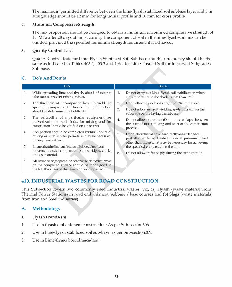
73
The maximum permitted difference between the lime-flyash stabilized soil subbase layer and 3 m straight edge should be 12 mm for longitudinal profile and 10 mm for cross profile.
4. Minimum CompressiveStrength
The mix proportion should be designed to obtain a minimum unconfined compressive strength of 1.5 MPa after 28 days of moist curing. The component of soil in the lime-flyash-soil mix can be omitted, provided the specified minimum strength requirement is achieved.
5. Quality ControlTests
Quality Control tests for Lime-Flyash Stabilized Soil Sub-base and their frequency should be the same as indicated in Tables 403.2, 403.3 and 403.4 for Lime Treated Soil for Improved Subgrade / Sub-base.
C. Do’s AndDon’ts
Do’s Don’ts
1. While spreading lime and flyash, ahead of mixing, take care to prevent raising ofdust.
2. The thickness of uncompacted layer to yield the specified compacted thickness after compaction should be determined by fieldtrials.
3. The suitability of a particular equipment for pulverization of soil clods, for mixing and for compaction should be verified on a teststrip.
4. Compaction should be completed within 3 hours of mixing or such shorter periods as may be necessary during dryweather.
5. Ensurethatthefinalsurfaceiswellclosed,freefrom movement under compaction planes, ridges, cracks or loosematerial.
6. All loose or segregated or otherwise defective areas on the completed surface should be made good to the full thickness of the layer andre-compacted.
1. Do not carry out Lime-flyash soil stabilization when air temperature in the shade is less than100C.
2. Donotallowanysoilclodslargerthan26.5mminsize.
3. Do not allow any soft yielding spots, ruts etc. on the subgrade before laying thesubbase.
4. Do not allow more than 60 minutes to elapse between the start of moist mixing and start of the compaction process.
5. Donotallowtherollertobeardirectlyonhardenedor partially hardened treated material previously laid other than those what may be necessary for achieving the specified compaction at thejoint.
6. Do not allow traffic to ply during the curingperiod.
410. INDUSTRIAL WASTES FOR ROAD CONSTRUCTION
This Subsection covers two commonly used industrial wastes, viz, (a) Flyash (waste material from Thermal Power Stations) in road embankment, subbase / base courses and (b) Slags (waste materials from Iron and Steel industries)
A. Methodology
I. Flyash (PondAsh)
1. Use in flyash embankment construction: As per Sub-section306.
2. Use in lime-flyash stabilized soil sub-base: as per Sub-section309.
3. Use in Lime-flyash boundmacadam:
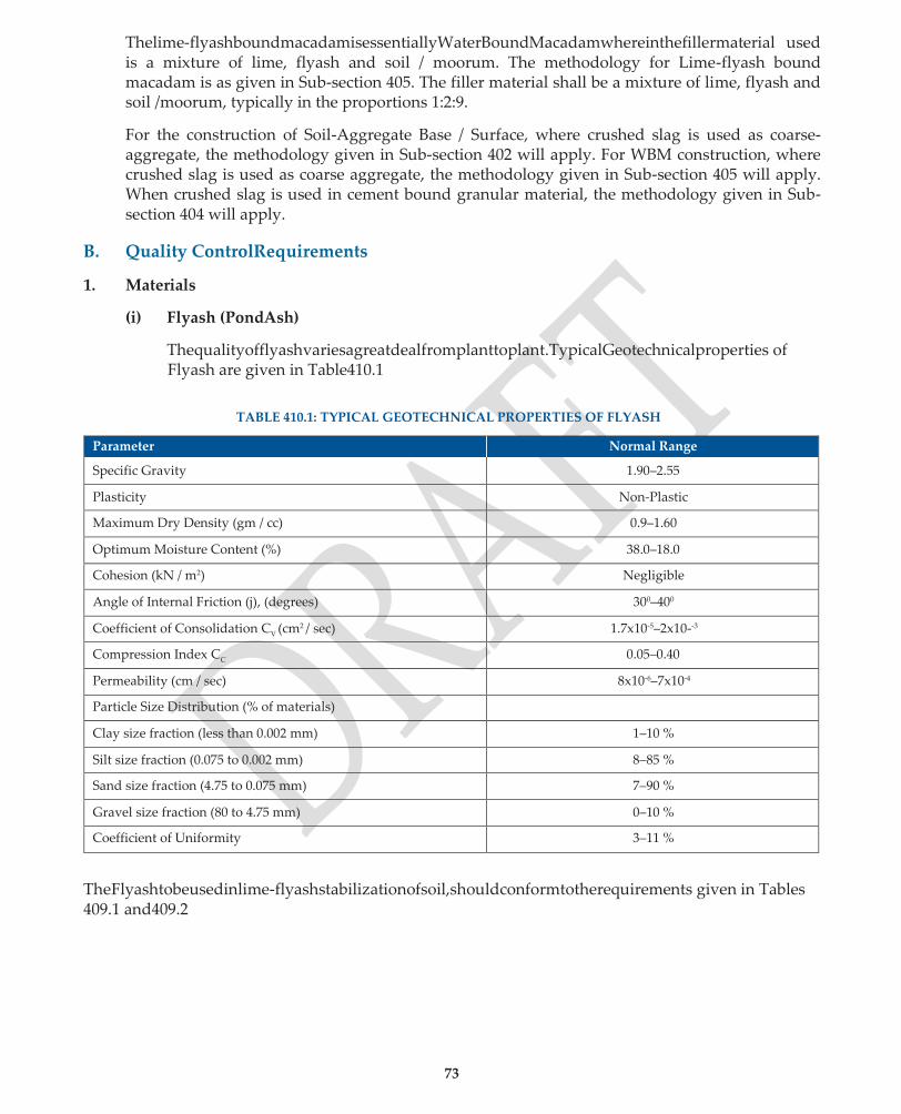
73
Thelime-flyashboundmacadamisessentiallyWaterBoundMacadamwhereinthefillermaterial used is a mixture of lime, flyash and soil / moorum. The methodology for Lime-flyash bound macadam is as given in Sub-section 405. The filler material shall be a mixture of lime, flyash and soil /moorum, typically in the proportions 1:2:9.
For the construction of Soil-Aggregate Base / Surface, where crushed slag is used as coarse- aggregate, the methodology given in Sub-section 402 will apply. For WBM construction, where crushed slag is used as coarse aggregate, the methodology given in Sub-section 405 will apply. When crushed slag is used in cement bound granular material, the methodology given in Sub- section 404 will apply.
B. Quality ControlRequirements
1. Materials
(i) Flyash (PondAsh)
Thequalityofflyashvariesagreatdealfromplanttoplant.TypicalGeotechnicalproperties of Flyash are given in Table410.1
TABLE 410.1: TYPICAL GEOTECHNICAL PROPERTIES OF FLYASH
Parameter Normal Range
Specific Gravity 1.90–2.55
Plasticity Non-Plastic
Maximum Dry Density (gm / cc) 0.9–1.60
Optimum Moisture Content (%) 38.0–18.0
Cohesion (kN / m2) Negligible
Angle of Internal Friction (j), (degrees) 300–400
Coefficient of Consolidation CV (cm2 / sec) 1.7x10⁻⁵–2x10--3
Compression Index CC 0.05–0.40
Permeability (cm / sec) 8x10⁻⁶–7x10⁻⁴
Particle Size Distribution (% of materials)
Clay size fraction (less than 0.002 mm) 1–10 %
Silt size fraction (0.075 to 0.002 mm) 8–85 %
Sand size fraction (4.75 to 0.075 mm) 7–90 %
Gravel size fraction (80 to 4.75 mm) 0–10 %
Coefficient of Uniformity 3–11 %
TheFlyashtobeusedinlime-flyashstabilizationofsoil,shouldconformtotherequirements given in Tables 409.1 and409.2

74
(ii) Slag
The broad types of slag used in Base / sub-base construction are:-
1. Blast FurnaceSlag
2. Granular Blast FurnaceSlag
3. Steel Slag
Physical characteristics of Blast furnace slag and steel furnace slag are given in Table 410.2
TABLE 410.2: TEST RESULTS SHOWING PHYSICAL CHARACTERISTICS
OF BLAST FURNACE SLAG AND STEEL FURNAGE SLAG
Physical Properties Test Method Blast Furnace Steel Slag
Aggregate impact value (%) IS:2386 (Part 4) 18–24 8–11
Aggregate crushing value (%) IS:2386 (Part 4) 24–26 15–18
Los Angeles abrasion value (%) IS:2386 (Part 4) 28–32 9–10
Water absorption (%) IS:2386 (Part 3) 1.5–2.5 1–1.4
Specific gravity IS:2386 (Part 3) 2.65 3.22
It may be noted that some varieties of Steel Slag are found lacking in stability in the presence of water. Suchvarietiesneedtobeleftforweatheringinstockpilesforsufficientlylongperiodsoftimetorender them suitable for road works. In general, the unit weight of slag should not be less than 11.2 kN /m3.
2. HorizontalAlignment
When used in subbase and base courses, the edges should be correct within tolerance limit of (±) 30 mm in plain and rolling terrain and (±) 50 mm in hilly terrain.
3. SurfaceLevels
When used in sub-bases, the tolerance in surface levels will be (+)10 mm and (–) 20 mm. When usedinbasecourses,thetoleranceinsurfacelevelswillberestrictedto(±)10mm.Agridof10m x 2.5 m may be formed to check the surfacelevel.
4. SurfaceRegularity
When used in sub-base courses, the maximum permitted difference between the subbase layer and 3 m straight edge should be 12 mm for longitudinal profile and 10 mm for cross profile. However,whenusedinbasecourses,thepermitteddifferencesshouldbe12mmforlongitudinal profile and 8 mm for crossprofile.
5. Quality ControlTests
(a) Flyash (PondAsh)
• Foruseofflyashinembankmentconstruction,theQualityControltestsgiveninSub- section 306 shallapply.
• ForuseofflyashinLime-flyashstabilizedsoilsubbase,theQualityControltestsgiven in Sub-section 409 shallapply.

75
• For use of flyash in Lime-flyash bound macadam, the Quality Control tests given in Sub-section 405 shallapply.
(b) Slag
• For use of slag in a Gravel / Soil-Aggregate base / surface, the Quality Control tests given in Sub-section 402 willapply.
• For use of slag in WBM construction, the Quality Control tests given in Sub-section 405 willapply.
• For use of slag in Cement Treated Sub-base / Base, the Quality Control tests given in Sub-section 404 willapply.
C. Do’s andDon’ts
Do’s Don’ts
1. Flyashembankmentsshouldbecoveredonthesides andtopbyselectedsoiltopreventerosion.Thickness of earth cover on side slopes is typically 1 to 3m.
2. The work on flyash embankment should be so organizedthatthesupplyofflyashtothesiteequals the Contractor’s demand for an efficient rate of placement.
3. The flyash to be used in road works should always betestedinthelaboratorytoensurethatitmeetsthe required geotechnical properties or as a pozzolana as the case maybe.
4. The compaction of flyash core and soil cover must be carried outsimultaneously.
5. ThelimeusedinSubbase/Basecoursesmusthavea purity of not less than 70% by weight ofCaO.
1. Do not stockpile flyash at thesite.
2. Do not transport flyash in open trucks without cover to avoid dust nuisance & environmentalpollution.
3. Do not use crushed slag as coarse aggregate without laboratory testing and verifying that it meets all the specified requirements.
4. Do not use those varieties of steel slag which lack stabilityinthepresenceofwaterowingtothehydration of calcium oxide. If such varieties are to be used, these should be left for weathering in stockpiles for sufficiently long periods oftime.
411. CRUSHER RUN MACADAM BASE
A. Methodology
1. The existing surface to receive the crushed stone base should be prepared to the specified lines, grade and cross-section. All ruts, deformations and soft spots should be repaired and the surface compacted to the required density before placing the aggregate basethereon.
2. Lateralconfinementforconstructingthecrushedstoneaggregatebaseshouldbeprovidedasper Sub-section406.
3. The aggregate should be uniformly deposited on the prepared surface and distributed over the surfacetothespecifieddepth.Afterdistribution,thematerialshallbeblademixedtofulldepthof layerbyalternatelybladingtheentirelayertothecenterandbacktotheedgesofroad.Thematerial shallthenbespreadandfinishedtotherequiredcross-sectionallevels,linesandgradesbymeans of suitable tractor –towedappliances.
4. Water should be applied before and during the blading, spreading andconstruction.
5. Thelayershallthenbecompactedwiththeuseofasmoothwheelrollerof80to100kNorvibratory roller to 100% of maximum dry density determined as per IS:2720 (Part7)
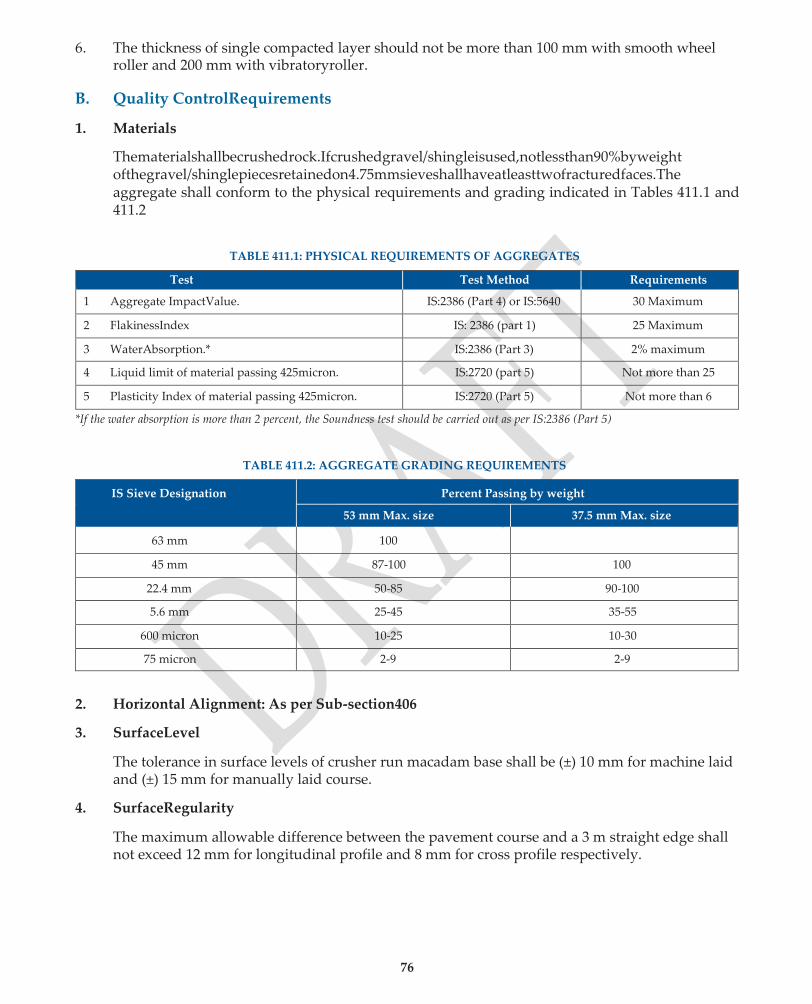
76
6. The thickness of single compacted layer should not be more than 100 mm with smooth wheel roller and 200 mm with vibratoryroller.
B. Quality ControlRequirements
1. Materials
Thematerialshallbecrushedrock.Ifcrushedgravel/shingleisused,notlessthan90%byweight ofthegravel/shinglepiecesretainedon4.75mmsieveshallhaveatleasttwofracturedfaces.The aggregate shall conform to the physical requirements and grading indicated in Tables 411.1 and 411.2
TABLE 411.1: PHYSICAL REQUIREMENTS OF AGGREGATES
Test Test Method Requirements
1 Aggregate ImpactValue. IS:2386 (Part 4) or IS:5640 30 Maximum
2 FlakinessIndex IS: 2386 (part 1) 25 Maximum
3 WaterAbsorption.* IS:2386 (Part 3) 2% maximum
4 Liquid limit of material passing 425micron. IS:2720 (part 5) Not more than 25
5 Plasticity Index of material passing 425micron. IS:2720 (Part 5) Not more than 6
*If the water absorption is more than 2 percent, the Soundness test should be carried out as per IS:2386 (Part 5)
TABLE 411.2: AGGREGATE GRADING REQUIREMENTS
IS Sieve Designation Percent Passing by weight
53 mm Max. size 37.5 mm Max. size
63 mm 100
45 mm 87-100 100
22.4 mm 50-85 90-100
5.6 mm 25-45 35-55
600 micron 10-25 10-30
75 micron 2-9 2-9
2. Horizontal Alignment: As per Sub-section406
3. SurfaceLevel
The tolerance in surface levels of crusher run macadam base shall be (±) 10 mm for machine laid and (±) 15 mm for manually laid course.
4. SurfaceRegularity
The maximum allowable difference between the pavement course and a 3 m straight edge shall not exceed 12 mm for longitudinal profile and 8 mm for cross profile respectively.
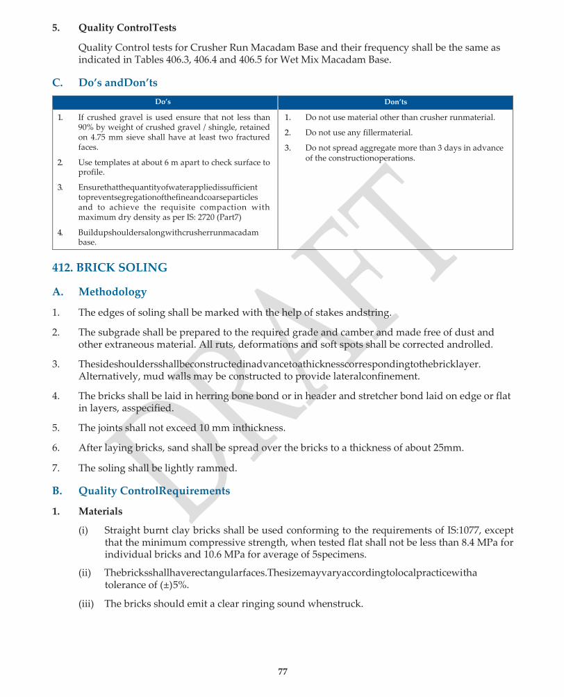
77
5. Quality ControlTests
Quality Control tests for Crusher Run Macadam Base and their frequency shall be the same as indicated in Tables 406.3, 406.4 and 406.5 for Wet Mix Macadam Base.
C. Do’s andDon’ts
Do’s Don’ts
1. If crushed gravel is used ensure that not less than 90% by weight of crushed gravel / shingle, retained on 4.75 mm sieve shall have at least two fractured faces.
2. Use templates at about 6 m apart to check surface to profile.
3. Ensurethatthequantityofwaterappliedissufficient topreventsegregationofthefineandcoarseparticles and to achieve the requisite compaction with maximum dry density as per IS: 2720 (Part7)
4. Buildupshouldersalongwithcrusherrunmacadam base.
1. Do not use material other than crusher runmaterial.
2. Do not use any fillermaterial.
3. Do not spread aggregate more than 3 days in advance of the constructionoperations.
412. BRICK SOLING
A. Methodology
1. The edges of soling shall be marked with the help of stakes andstring.
2. The subgrade shall be prepared to the required grade and camber and made free of dust and other extraneous material. All ruts, deformations and soft spots shall be corrected androlled.
3. Thesideshouldersshallbeconstructedinadvancetoathicknesscorrespondingtothebricklayer. Alternatively, mud walls may be constructed to provide lateralconfinement.
4. The bricks shall be laid in herring bone bond or in header and stretcher bond laid on edge or flat in layers, asspecified.
5. The joints shall not exceed 10 mm inthickness.
6. After laying bricks, sand shall be spread over the bricks to a thickness of about 25mm.
7. The soling shall be lightly rammed.
B. Quality ControlRequirements
1. Materials
(i) Straight burnt clay bricks shall be used conforming to the requirements of IS:1077, except that the minimum compressive strength, when tested flat shall not be less than 8.4 MPa for individual bricks and 10.6 MPa for average of 5specimens.
(ii) Thebricksshallhaverectangularfaces.Thesizemayvaryaccordingtolocalpracticewitha tolerance of (±)5%.
(iii) The bricks should emit a clear ringing sound whenstruck.

78
2. Horizontal Alignment: As per Sub-section401
The edge of the brick sling shall be within a tolerance limit of (±) 30 mm in plain and rolling terrain and (±) 50 mm for hilly terrain.
3. SurfaceEvenness
Themaximumallowabledifferencebetweenthebricksolingsurfaceanda3mstraightedgeshall not exceed 10 mm for both the longitudinal and cross profiles, when placed parallel with, or at right angles to the centerline.
C. Do’s andDon’ts
Do’s Don’ts
1. Trimtheinsideofshouldersverticalandremoveany 1. Do not excavate into the finished formationlayer.
spillage.
2. Allowsandtoremainonsolingtillasubsequent 2. Do not allow any traffic on bricksoling.
pavement layer is laid.
413. STONE SET PAVEMENT
A Stone Set Pavement has a pavement crust comprising of 100 mm compacted GSB, 75 mm WBM (Grading2)Baseand150mmthickhammer-dressedStonesetspavedonabeddingsandlayeroverthe WBM Base. It is best suited where good quality stones are locally available as also craftsmen with knowledge of stonepaving.
A. Methodology
1. OverasuitablypreparedsubgradeasperSub-section303,constructionof100mmthickcompacted GSB will be carried out as per Sub-section401.
2. The construction of 75 mm thick WBM (Grading 2), will be carried out as per Sub-section405.
3. Aproperlygradedcoarsesandbeddinglayerof40mmcompactedthicknesswillbelaidoverthe WBMBase.
4. This will be followed by laying of hammer-dressed stones in the herringbone or stretcher bond pattern.
5. ThestoneswillbecompactedintobeddingsandovertheWBMBase,boundedbyEdgestoneslaid with their longitudinal axis parallel to the length of the road.
6. The joint gaps will be filled with fine sand, stone dust, or sand-cement mortar as specified. Joints can also be sealed with hot sand-bitumenmix.
7. If sand-cement mortar is used for filling joints, moist curing is required for at least oneweek.
8. Stone sets should be laid in sections not exceeding 12 m in length, with longitudinal axis of the stone sets parallel to the length of theroad.

79
B. Quality ControlRequirements
1. Materials
(i) Thequalitycontrolrequirementsforthematerialsinthesubgrade,100mmGSBand75mm WBM (Grading 2) Base as given in Sub-section 303. 401 & 405 shallapply.
(ii) The Stone sets should be rectangular in shape, 250-300 mm in length, 150- 200 mm in width and 150 mm in depth, with tolerance of (±) 12mm.
(iii) Edge stones should be 350 – 400 mm in length, 150-200 mm in width and not less than 350 mm indepth
(iv) The Stone set should meet the following physicalrequirements.
(a) Aggregate Impact Value (IS:2386 Part 4) not more than30
(b) Water Absorption (IS:2386 Part 3) not more than2%
(c) Polished Stone Value (BS:812Part114) not less than55
(v) StonesnormallyusedareGranite,Basalt,SandstoneandLimestone.StonesfromSedimentary rock should not beused.
(vi) Thestonesetsshouldbehammer-dressedontoptotheextentthatthemaximumdepression of the dressed surface from a straight edge applied across any part of the surface does not exceed 20 mm. The dressing on the sides should be similarly carried out so as to obtain a mortar joint not exceeding 20 mm inwidth.
2. HorizontalAlignment
The edges of the stone set pavement should be correct within a tolerance limit of (±)20 mm in plain and rolling terrains and (±) 30 mm in hilly terrain.
3. SurfaceLevels
ThetoleranceinsurfacelevelsofaStoneSetPavementwillberestrictedto(±)15mm.Agridof10 m x 2.5 m may be formed to check the surfacelevel.
4. SurfaceRegularity
ThemaximumpermitteddifferencebetweentheStoneSetPavementand3mstraightedgeshould be 12 mm for longitudinal profile and 10 mm for crossprofile.
C. Do’s andDon’ts
Do’s Don’ts
1. TheStonesetsshouldnotonlybetestedforAIVand water absorption, but also for the Polished Stone Value.
2. The types of Stones normally found suitable are Granite, Basalt Sand-stone orLimestone.
3. Make sure that the bedding layer is a properly graded coarse sand with a compacted thickness of 40mm.
1. Do not use any Sedimentary stone in the Stone Set Pavement.
2. Do not open the road immediately to traffic if sand- cement mortar is used for fillingjoints.
3. Do not leave the stone sets uncompacted into the beddinglayer.

Quality Assurance Handbook for Rural Roads
81
SECTION 500
BITUMINOUS
CONSTRUCTION
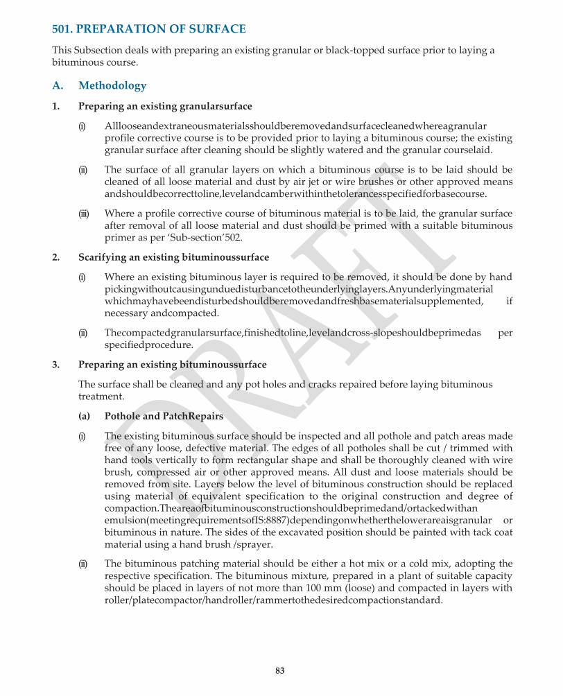
83
501. PREPARATION OF SURFACE
This Subsection deals with preparing an existing granular or black-topped surface prior to laying a bituminous course.
A. Methodology
1. Preparing an existing granularsurface
(i) Alllooseandextraneousmaterialsshouldberemovedandsurfacecleanedwhereagranular profile corrective course is to be provided prior to laying a bituminous course; the existing granular surface after cleaning should be slightly watered and the granular courselaid.
(ii) The surface of all granular layers on which a bituminous course is to be laid should be cleaned of all loose material and dust by air jet or wire brushes or other approved means andshouldbecorrecttoline,levelandcamberwithinthetolerancesspecifiedforbasecourse.
(iii) Where a profile corrective course of bituminous material is to be laid, the granular surface after removal of all loose material and dust should be primed with a suitable bituminous primer as per ‘Sub-section’502.
2. Scarifying an existing bituminoussurface
(i) Where an existing bituminous layer is required to be removed, it should be done by hand pickingwithoutcausingunduedisturbancetotheunderlyinglayers.Anyunderlyingmaterial whichmayhavebeendisturbedshouldberemovedandfreshbasematerialsupplemented, if necessary andcompacted.
(ii) Thecompactedgranularsurface,finishedtoline,levelandcross-slopeshouldbeprimedas per specifiedprocedure.
3. Preparing an existing bituminoussurface
The surface shall be cleaned and any pot holes and cracks repaired before laying bituminous treatment.
(a) Pothole and PatchRepairs
(i) The existing bituminous surface should be inspected and all pothole and patch areas made free of any loose, defective material. The edges of all potholes shall be cut / trimmed with hand tools vertically to form rectangular shape and shall be thoroughly cleaned with wire brush, compressed air or other approved means. All dust and loose materials should be removed from site. Layers below the level of bituminous construction should be replaced using material of equivalent specification to the original construction and degree of compaction.Theareaofbituminousconstructionshouldbeprimedand/ortackedwithan emulsion(meetingrequirementsofIS:8887)dependingonwhetherthelowerareaisgranular or bituminous in nature. The sides of the excavated position should be painted with tack coat material using a hand brush /sprayer.
(ii) The bituminous patching material should be either a hot mix or a cold mix, adopting the respective specification. The bituminous mixture, prepared in a plant of suitable capacity should be placed in layers of not more than 100 mm (loose) and compacted in layers with roller/platecompactor/handroller/rammertothedesiredcompactionstandard.

84
(iii) Inthefinallayer,themixshouldbespreadslightlyproudofthesurfacesothatafterrolling, the surface shall be flush with the adjoiningsurface.
(iv) Where required, a Seal Coat should be applied as per the specified procedure. The surface levels should be checked using a 3 m straightedge.
(b) CrackSealing
(i) The fine cracks (less than 3 mm in width) should be sealed by Fog Spray, which is a very lightapplicationoflowviscositySlowSettingEmulsion.Priortothistreatment,itisimportant thatthesurfaceisthoroughlycleaned,preferablywithcompressedair.TheFogSprayshould beappliedatarateof0.5-1.0litre/m2ofthespecifiedemulsion,using 0.5-1.0litre/m2 of the specified emulsion, using an approved hand-held ‘sprayer. For sites in sub-zero temperatures, Medium Curing Cutback as per IS 217can be used.
(ii) The wide cracks (more than 3 mm in width) should be filled with crusher dust or other approvedfinematerialpassing4.75mmsievetoalevelabout5mmbelowtheroadsurface level. After sweeping the surface clear of dust, Slow Setting emulsion should be poured intothecracks,minimizinganyspillage.Ifspillagedoesoccur,crusherdustshouldbeapplied to blot up the spillage. Isolated areas, with wide cracks, shall be cut and patched as per Section501.
3. Profile CorrectiveCourse
(i) Where specified, a profile corrective course should beprovided.
(ii) Afterpreparingthesurfaceasexplainedabove,theprofilecorrectivecoursewiththespecified material should be laid and compacted to the requirements of the particularspecification.
(iii) A tack coat as per Sub-section 503 should be applied over a primed granular surface or an existing bituminous surface prior to laying the bituminous profile corrective course.
(iv) Short sags or depressions in the surface should be corrected by laying profile corrective course in the form of flat wedges(layers).
The thickness of layer at any point should not be more than 100 mm.
Where the profile corrective course is laid in more than one layer, successive layers should completely extend over and fully cover the underlying layer.
B. Quality ControlRequirements
1. Material
(i) Crusherstonedustforcrackfillingshouldbeafine-grainedmaterial,passing4.75mmsieve.
(ii) The bituminous mixture to be used for patching should be either a hot mix or cold mix in accordance with appropriatespecifications.
(iii) The material for profile corrective course should meet relevantspecifications.
(iv) The binder for prime coat and crack filling should be a Slow Setting bituminous emulsion (SS-1 grade) as per IS:8887. For sub-zero temperatures, however, a Medium Curing (MC) Cutback conforming to IS:217 can be used. Prime coat should be applied as per Sub-section 502.

85
(v) The binder for tack coat and its application should be as per sub-section503.
2. The prepared surface should comply with the permitted tolerances in respect of horizontal alignment, surface levels and surface regularity specified for basecourse.
(i) HorizontalAlignment
Edgesofthe (±) 30 mm in plain (±)50 mm in hilly
pavementlayer and rolling terrainterrain
(ii) Surfacelevels
GranularSurface (±)15 mm
Bituminous Surface (±) 10mm
(iii) Surface Regularity
Granular /Bituminous Surface
Longitudinal Profile 12 mm
Transverse Profile 8mm
C. Do’s andDon’ts
Do’s Don’ts
1. Remove dust from the surface being prepared byair jet or other approvedmeans.
2. Whererequired,anexistingbituminouslayershould be scarified carefully without undue disturbance to the underlyinglayers
3. The edges of all potholes should be cut / trimmed vertically
4. In the final layer, the mix should be spread slightly proud of thesurface.
5. After back filling in layers, an excavated pothole, ensure the compaction of each layer by a small Roller / Plate Compactor or at least aRammer
1. Do not lay a bituminous layer without properly preparing thesurface.
2. Do not lay any bituminous material on a granular surface without priming thesurface.
3. Do not use a bituminous mixture to fill the portion belowthelevelofbituminousconstructionwhilefilling apothole.
4. Donotallowanyspillageofbinderonthesurfacewhile pouring the binder into widecracks.
5. Do not allow traffic over profile correctivecourse.
502. PRIME COAT OVER GRANULAR BASE
A Methodology
1. Bituminous primer should be slow setting bitumen emulsion, use of cutback being restricted to areas having subzero temperature or for emergencyoperations.
2. Theprimecoatshouldbeappliedonlyonthetopmostgranularbaselayer,overwhichbituminous treatment is to be applied. The granular base surface should be swept clean of dust and loose particles and where required, lightly and uniformly sprinkled with water to moist thesurface.
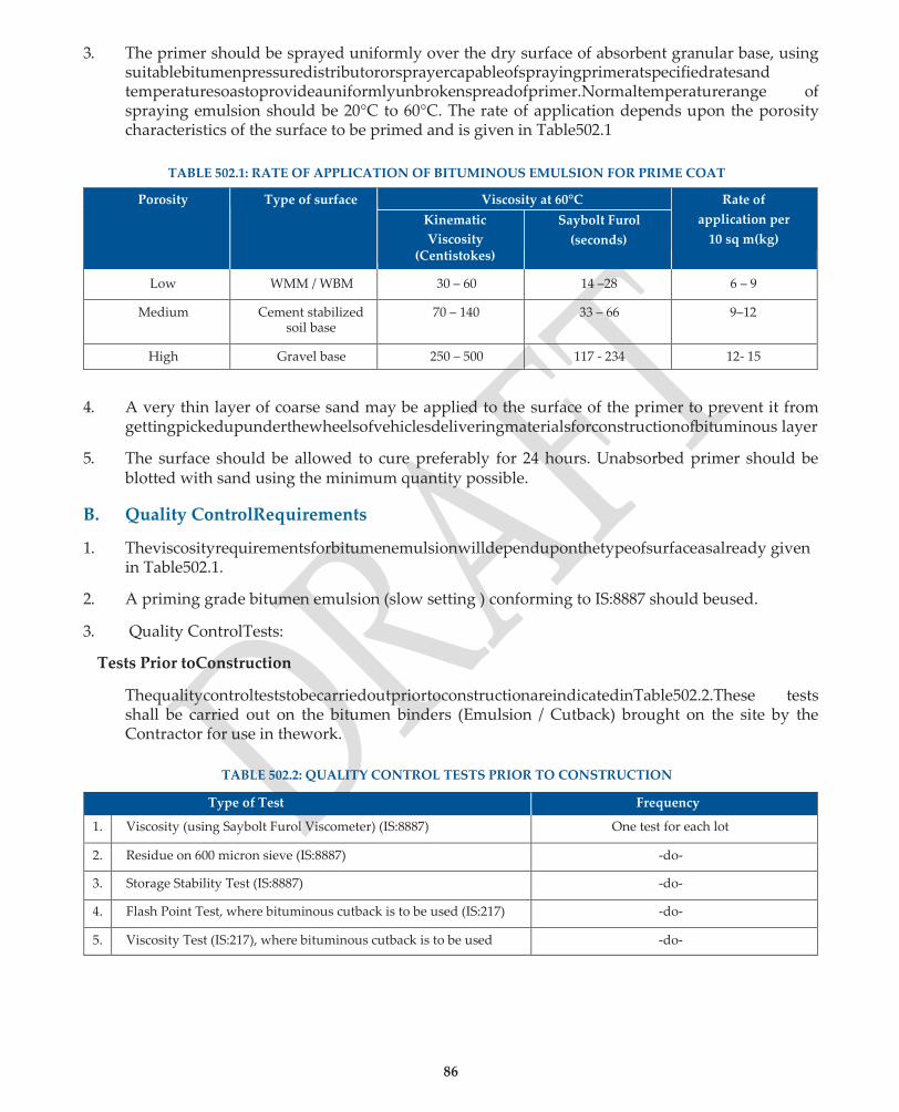
86
3. The primer should be sprayed uniformly over the dry surface of absorbent granular base, using suitablebitumenpressuredistributororsprayercapableofsprayingprimeratspecifiedratesand temperaturesoastoprovideauniformlyunbrokenspreadofprimer.Normaltemperaturerange of spraying emulsion should be 20°C to 60°C. The rate of application depends upon the porosity characteristics of the surface to be primed and is given in Table502.1
TABLE 502.1: RATE OF APPLICATION OF BITUMINOUS EMULSION FOR PRIME COAT
Porosity Type of surface Viscosity at 60°C Rate of
application per
10 sq m(kg)
Kinematic
Viscosity (Centistokes)
Saybolt Furol
(seconds)
Low WMM / WBM 30 – 60 14 –28 6 – 9
Medium Cement stabilized soil base
70 – 140 33 – 66 9–12
High Gravel base 250 – 500 117 - 234 12- 15
4. A very thin layer of coarse sand may be applied to the surface of the primer to prevent it from
gettingpickedupunderthewheelsofvehiclesdeliveringmaterialsforconstructionofbituminous layer
5. The surface should be allowed to cure preferably for 24 hours. Unabsorbed primer should be blotted with sand using the minimum quantity possible.
B. Quality ControlRequirements
1. Theviscosityrequirementsforbitumenemulsionwilldependuponthetypeofsurfaceasalready given in Table502.1.
2. A priming grade bitumen emulsion (slow setting ) conforming to IS:8887 should beused.
3. Quality ControlTests:
Tests Prior toConstruction
ThequalitycontrolteststobecarriedoutpriortoconstructionareindicatedinTable502.2.These tests shall be carried out on the bitumen binders (Emulsion / Cutback) brought on the site by the Contractor for use in thework.
TABLE 502.2: QUALITY CONTROL TESTS PRIOR TO CONSTRUCTION
Type of Test Frequency
1. Viscosity (using Saybolt Furol Viscometer) (IS:8887) One test for each lot
2. Residue on 600 micron sieve (IS:8887) -do-
3. Storage Stability Test (IS:8887) -do-
4. Flash Point Test, where bituminous cutback is to be used (IS:217) -do-
5. Viscosity Test (IS:217), where bituminous cutback is to be used -do-
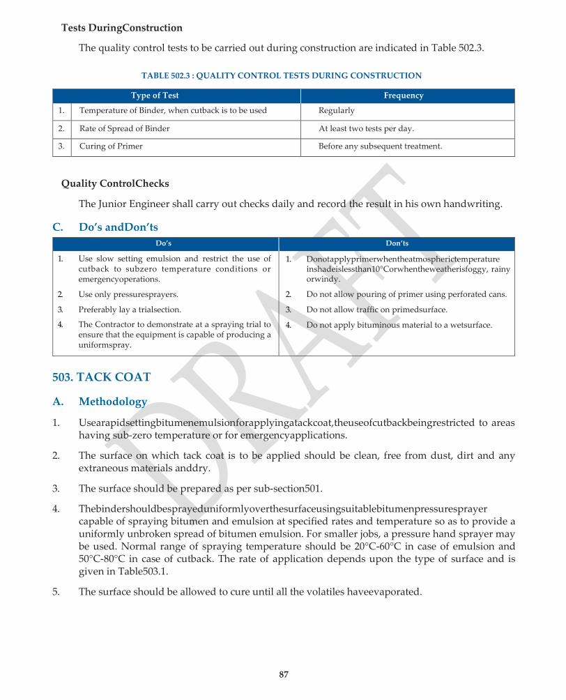
87
Tests DuringConstruction
The quality control tests to be carried out during construction are indicated in Table 502.3.
TABLE 502.3 : QUALITY CONTROL TESTS DURING CONSTRUCTION
Type of Test Frequency
1. Temperature of Binder, when cutback is to be used Regularly
2. Rate of Spread of Binder At least two tests per day.
3. Curing of Primer Before any subsequent treatment.
Quality ControlChecks
The Junior Engineer shall carry out checks daily and record the result in his own handwriting.
C. Do’s andDon’ts
Do’s Don’ts
1. Use slow setting emulsion and restrict the use of cutback to subzero temperature conditions or emergencyoperations.
2. Use only pressuresprayers.
3. Preferably lay a trialsection.
4. The Contractor to demonstrate at a spraying trial to ensure that the equipment is capable of producing a uniformspray.
1. Donotapplyprimerwhentheatmospherictemperature inshadeislessthan10°Corwhentheweatherisfoggy, rainy orwindy.
2. Do not allow pouring of primer using perforated cans.
3. Do not allow traffic on primedsurface.
4. Do not apply bituminous material to a wetsurface.
503. TACK COAT
A. Methodology
1. Usearapidsettingbitumenemulsionforapplyingatackcoat,theuseofcutbackbeingrestricted to areas having sub-zero temperature or for emergencyapplications.
2. The surface on which tack coat is to be applied should be clean, free from dust, dirt and any extraneous materials anddry.
3. The surface should be prepared as per sub-section501.
4. Thebindershouldbesprayeduniformlyoverthesurfaceusingsuitablebitumenpressuresprayer capable of spraying bitumen and emulsion at specified rates and temperature so as to provide a uniformly unbroken spread of bitumen emulsion. For smaller jobs, a pressure hand sprayer may be used. Normal range of spraying temperature should be 20°C-60°C in case of emulsion and 50°C-80°C in case of cutback. The rate of application depends upon the type of surface and is given in Table503.1.
5. The surface should be allowed to cure until all the volatiles haveevaporated.

88
B. Quality ControlRequirements
1. Materials
(i) Binder for TackCoat
Rapid setting bituminous emulsion Grade RS-1 complying with IS:1887 as specified in Contract. For sites at sub-zero temperature: Cutback Bitumen (Medium Curing Grade) as per IS:217.
(ii) Rate of application ofBinder
TABLE 503.1: RATE OF APPLICATION OF BINDER FOR TACK COAT
Type of Surface Quantity of emulsion per sqm area (kg)
Normal Bituminous surfaces 0.20 to 0.25
Dry and hungry bituminous surfaces 0.25 to 0.30
Granular (primed) 0.25 to 0.30
Cement Concrete Pavement 0.30 to 0.35
2. Quality ControlTests
The quality control tests and their frequencies would be same as for Prime Coat in Tables 502.2 and 502.3.
C. Do’s andDon’ts
Do’s Don’ts
1. Plan the work so that no more than the necessary tackcoatfortheday’soperationisplacedonsurface.
2. Handle bituminous cutback carefully to avoid fire mishap.
1. Donotapplytackcoatwhenatmospherictemperature is less than 10OC or when weather is foggy, rainy or windy.
2. Do not apply tack coat on a wetsurface.
3. DonotallowanyequipmentorvehiclesonTackCoat.
504. Bituminous Macadam
A. Methodology
1. Prepare the base on which bituminous macadam course is to be laid and shape to the specified lines, grade andcross-section.
2. Apply tack coat over the base preparatory to laying of the bituminousmacadam.
3. Bituminous Macadam should be prepared in a Hot Mix Plant of adequate capacity Ensure manufacturing and rolling temperatures for Bituminous Macadam as given in Table504.1.

89
TABLE 504.1: MANUFACTURING AND ROLLING TEMPERATURES FOR BITUMINOUS MIXES
Bitumen Viscosity grade
Bitumen Mixing (oC)
Aggregate Mixing (oC)
Mixed Material (oC)
Laying (oC)
Rolling (oC)
VG-40 160-170 160-175 160-170 Min. 150 Min. 100
VG-30 150-165 150-170 150-165 Min. 140 Min. 90
VG-20 145-165 145-170 145-165 Min. 135 Min. 85
VG-10 140-160 140-165 140-160 Min. 130 Min. 80
4. Transferthemixedmaterialquicklytositeofworkandlaybymeansofanapprovedself-propelled mechanicalpaver.
5. Commence initial rolling with 80-100 kN rollers (three-wheel or tandem type), beginning from the edge and progressing towards the centre longitudinally. On super elevated portions, rolling should progress from lower to upper edge parallel to centre line of pavement. Thereafter, do intermediate rolling with vibratory or pneumatic tyred road rollers. This should be followed by final rolling while the material is still workable.
6. Anyhighspotsordepressionsnoticedaftertherollerhaspassedoverthewholeareaonceshould be
corrected by removing or adding premixed material. Rolling should recommence thereafter. Each pass should have an overlap of at least one-third of the track made in the preceding pass. Rolling should be continued till all rolIer marks have been eliminated.
7. For single lane roads no longitudinal joint is required, while for double-lane roads longitudinal joints may be required depending on the paverwidth.
8. For making longitudinal or transverse joint, cut the edges of the bituminous layer laid earlier to their full depth so as to expose fresh surface and apply a thin coat of binder. Lay adjacent new layer and compact flush with the existinglayer.
9. Cover the bituminous macadam with the wearing course within a period of 48 hours. If there is any delay in providing wearing course the bituminous macadam surface should be covered with a seal coat before opening totraffic.
B. Quality ControlRequirements
1. Material
The Bituminous Macadam shall be composed of aggregate meeting the physical requirements indicated in Table 504.2 and a paving bitumen of viscosity grade complying with IS:73 or as specified in the Contract. The grading and binder requirements shall be in conformity with the requirements indicated in Table 504.3.

90
TABLE 504.2: PHYSICAL REQUIREMENTS FOR AGGREGATES FOR BITUMINOUS MACADAM
Property Test Specification
Particle Shape Flakiness Index IS:2386 Part 1 Max. 25 per cent
Strength Aggregate Impact Value IS:2386 Part 4 Max. 30 per cent
Durability Soundness IS:2386 Part 5 Loss in Weight
SodiumSulphate Magnesium Sulphate
Max. 12 per cent Max. 18 per cent
Water Absorption Water Absorption IS:2386 Part 3 Max. 2 per cent
Stripping Coating and Stripping of bitumen- aggregate mixtures IS:6241
Min. retained coating: 95 per cent.
TABLE 504.3: COMPOSITION OF BITUMINOUS MACADAM
IS Sieve (mm) Cumulative Per centPassing
by weight of TotalAggregate
26.5 100
19 90-100
13.2 56-88
4.75 16-36
2.36 4-19
0.03 2-10
0.075 0-5
Bitumen content, % by weight of total mixture 3.3-3.5
Bitumen Viscosity Grade VG10 to VG30
IncolderregionsofIndiaorwherethepercentpassing0.075mmsieveisonthehighersideoftherange, appropriate bitumen contents may be upto 0.5 percent higher, subject to the approval of theEngineer.
2. HorizontalAlignment
The edges of the bituminous macadam base should be correct within a tolerance limit of (±) 30 mm in plain and rolling terrain and (±) 50 mm in hilly terrain
3. SurfaceLevel
The tolerance in surface level of the bituminous macadam would be (±) 6 mm.
4. SurfaceRegularity
Themaximumallowabledifferencebetweentheroadsurfaceanda3mstraightedgewouldbe12 mm for longitudinal profile and 8 mm for crossprofile.
5. Quality ControlTests
Tests Prior toConstruction
The quality control tests to be carried out prior to construction are indicated in Table 504.4.
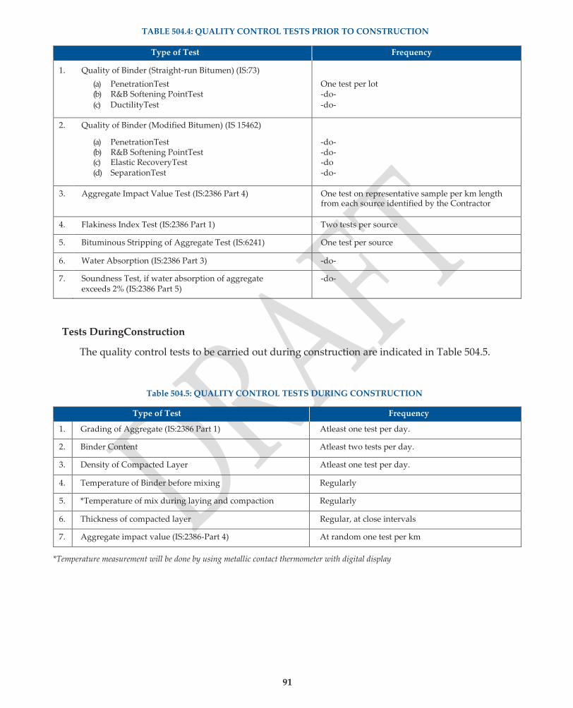
91
TABLE 504.4: QUALITY CONTROL TESTS PRIOR TO CONSTRUCTION
Type of Test Frequency
1. Quality of Binder (Straight-run Bitumen) (IS:73)
(a) PenetrationTest (b) R&B Softening PointTest (c) DuctilityTest
One test per lot -do- -do-
2. Quality of Binder (Modified Bitumen) (IS 15462)
(a) PenetrationTest (b) R&B Softening PointTest (c) Elastic RecoveryTest (d) SeparationTest
-do- -do- -do -do-
3. Aggregate Impact Value Test (IS:2386 Part 4) One test on representative sample per km length from each source identified by the Contractor
4. Flakiness Index Test (IS:2386 Part 1) Two tests per source
5. Bituminous Stripping of Aggregate Test (IS:6241) One test per source
6. Water Absorption (IS:2386 Part 3) -do-
7. Soundness Test, if water absorption of aggregate exceeds 2% (IS:2386 Part 5)
-do-
Tests DuringConstruction
The quality control tests to be carried out during construction are indicated in Table 504.5.
Table 504.5: QUALITY CONTROL TESTS DURING CONSTRUCTION
Type of Test Frequency
1. Grading of Aggregate (IS:2386 Part 1) Atleast one test per day.
2. Binder Content Atleast two tests per day.
3. Density of Compacted Layer Atleast one test per day.
4. Temperature of Binder before mixing Regularly
5. *Temperature of mix during laying and compaction Regularly
6. Thickness of compacted layer Regular, at close intervals
7. Aggregate impact value (IS:2386-Part 4) At random one test per km
*Temperature measurement will be done by using metallic contact thermometer with digital display
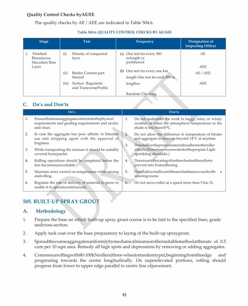
92
Quality Control Checks byAE/EE
The quality checks by AE / AEE are indicated in Table 504.6.
Table 504.6: QUALITY CONTROL CHECKS BY AE/AEE
Stage Test Frequency Designation of Inspecting Officer
1. Finished Bituminous Macadam Base Layer
(i) Density of compacted layer
(ii) Binder Content part thereof
(iii) Surface Regularity and TransverseProfile
(a) One test for every 500 m length or partthereof
(b) One test for every one km
length One test for each 500 m
lengthor
Random Checking
AE
AEE
AE / AEE
AEE
C. Do’s and Don’ts
Do’s Don’ts
1. Ensurethatstoneaggregateconformstothephysical requirements and grading requirements and aredry and clean.
2. In case the aggregate has poor affinity to bitumen use anti stripping agent with the approval of Engineer.
3. While transporting the mixture it should be suitably covered bytarpaulin.
4. Rolling operations should be completed before the mix becomesunworkable
5. Maintain strict control on temperature while mixing androlling.
6. Regulate the rate of delivery of material to paver to enable it to operatecontinuously.
1. Do not undertake the work in foggy, rainy or windy weather or when the atmospheric temperature in the shade is less than10OC.
2. Do not allow the difference in temperature of binder and aggregate to increase beyond 14OC at anytime.
3. Donotallowthepremixmaterialtoadheretotheroller wheels.(Donotuseexcesswaterforthepurpose.Light sprinkling shoulddo.)
4. Donotuselubricatingoilonthewheelsoftherollerto prevent mix fromadhering.
5. Donotallowtrafficuntilthemixhasbeencoveredwith a wearingcourse.
6. Do not move roller at a speed more than 5 km /h.
505. BUILT-UP SPRAY GROUT
A. Methodology
1. Prepare the base on which built-up spray grout course is to be laid to the specified lines, grade andcross-section.
2. Apply tack coat over the base preparatory to laying of the built-up spraygrout.
3. Spreadthecoarseaggregatesuniformlybymechanicalmeansorothersuitablemethodattherate of 0.5 cum per 10 sqm area. Remedy all high spots and depressions by removing or adding aggregates.
4. Commencerollingwith80-100kNrollers(three-wheelortandemtype),beginningfromtheedge and progressing towards the centre longitudinally. On superelevated portions, rolling should progress from lower to upper edge parallel to centre line ofpavement.
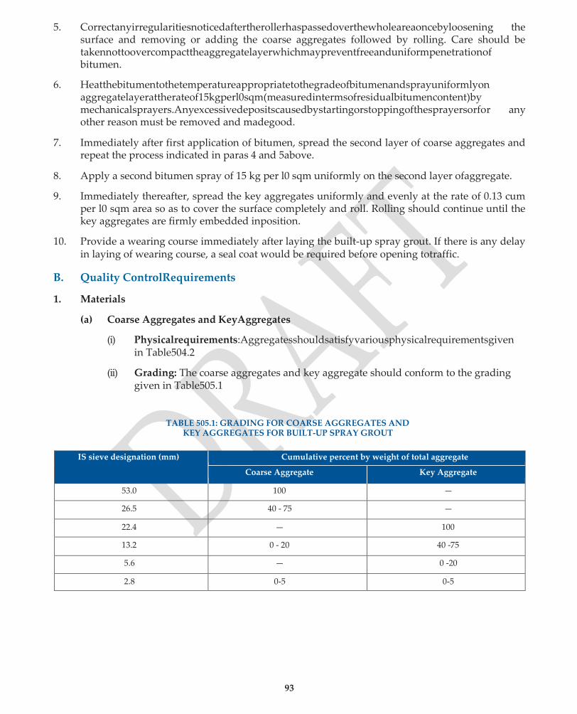
93
5. Correctanyirregularitiesnoticedaftertherollerhaspassedoverthewholeareaoncebyloosening the surface and removing or adding the coarse aggregates followed by rolling. Care should be takennottoovercompacttheaggregatelayerwhichmaypreventfreeanduniformpenetrationof bitumen.
6. Heatthebitumentothetemperatureappropriatetothegradeofbitumenandsprayuniformlyon aggregatelayerattherateof15kgperl0sqm(measuredintermsofresidualbitumencontent)by mechanicalsprayers.Anyexcessivedepositscausedbystartingorstoppingofthesprayersorfor any other reason must be removed and madegood.
7. Immediately after first application of bitumen, spread the second layer of coarse aggregates and repeat the process indicated in paras 4 and 5above.
8. Apply a second bitumen spray of 15 kg per l0 sqm uniformly on the second layer ofaggregate.
9. Immediately thereafter, spread the key aggregates uniformly and evenly at the rate of 0.13 cum per l0 sqm area so as to cover the surface completely and roll. Rolling should continue until the key aggregates are firmly embedded inposition.
10. Provide a wearing course immediately after laying the built-up spray grout. If there is any delay in laying of wearing course, a seal coat would be required before opening totraffic.
B. Quality ControlRequirements
1. Materials
(a) Coarse Aggregates and KeyAggregates
(i) Physicalrequirements:Aggregatesshouldsatisfyvariousphysicalrequirementsgiven in Table504.2
(ii) Grading: The coarse aggregates and key aggregate should conform to the grading given in Table505.1
TABLE 505.1: GRADING FOR COARSE AGGREGATES AND
KEY AGGREGATES FOR BUILT-UP SPRAY GROUT
IS sieve designation (mm) Cumulative percent by weight of total aggregate
Coarse Aggregate Key Aggregate
53.0 100 —
26.5 40 - 75 —
22.4 — 100
13.2 0 - 20 40 -75
5.6 — 0 -20
2.8 0-5 0-5

94
(b) Bitumen
The binder should be paving bitumen of viscosity grade complying with IS:73 or an appropriate grade of emulsion complying with IS:8887, where permitted or specified in the contract.
2. HorizontalAlignment
The edges of the Built-up Spray Grout layer should be correct within a tolerance limit of (±) 30 mm in plain and rolling terrain and (±) 50 mm in hilly terrain.
3. SurfaceLevel
The tolerance in surface level of the Built-up spray grout should be (±) 6 mm.
4. SurfaceRegularity
The maximum allowable difference between the road surface and a 3 m straight edge should be 12 mm for longitudinal profile and 8 mm for cross profile.
5. Quality ControlTests
Tests Prior toConstruction
The quality control tests to be carried out prior to construction are indicated in Table 505.2.
TABLE 505.2 : QUALITY CONTROL TESTS PRIOR TO CONSTRUCTION
Type of Test Frequency
1. Quality of Binder (Straight-run Bitumen) (IS:73)
(a) PenetrationTest
(b) R&B Softening PointTest
(c) DuctilityTest
One test per lot
-do-
-do-
2. Quality of Binder (Modified Bitumen) (IS:15462)
(a) PenetrationTest
(b) R&B Softening PointTest
(c) Elastic Recovery Test(d) SeparationTest
-do-
-do-
-do-
3. Aggregate Impact Value Test (IS:2386 Part 4) One test on representative sample per km length
from each source identified by the Contractor
4. Flakiness Index Test (IS:2386 Part 1) -do-
5. Bitumen Stripping of Aggregate Test (IS:6241) -do-
6. Water Absorption (IS:2386 Part 3) -do-
7. Soundness Test, if water absorption of aggregate
exceeds 2% (IS:2386 Part 5)
-do-
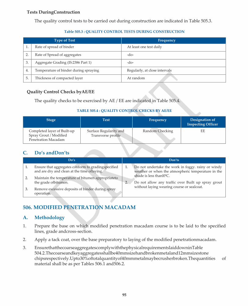
95
Tests DuringConstruction
The quality control tests to be carried out during construction are indicated in Table 505.3.
Table 505.3 : QUALITY CONTROL TESTS DURING CONSTRUCTION
Type of Test Frequency
1. Rate of spread of binder At least one test daily
2. Rate of Spread of aggregates -do-
3. Aggregate Grading (IS:2386 Part 1) -do-
4. Temperature of binder during spraying Regularly, at close intervals
5. Thickness of compacted layer At random
Quality Control Checks byAE/EE
The quality checks to be exercised by AE / EE are indicated in Table 505.4.
TABLE 505.4 : QUALITY CONTROL CHECKS BY AE/EE
Stage Test Frequency Designation of Inspecting Officer
Completed layer of Built-up Spray Grout / Modified Penetration Macadam
Surface Regularity and Transverse profile
Random Checking EE
C. Do’s andDon’ts
Do’s Don’ts
1. Ensure that aggregates conform to gradingspecified and are dry and clean at the time oflaying.
2. Maintain the temperature of bitumen appropriateto the grade ofbitumen.
3. Remove excessive deposits of binder during spray operation.
1. Do not undertake the work in foggy. rainy or windy weather or when the atmospheric temperature in the shade is less thanl00C.
2. Do not allow any traffic over Built up spray grout without laying wearing course or sealcoat.
506. MODIFIED PENETRATION MACADAM
A. Methodology
1. Prepare the base on which modified penetration macadam course is to be laid to the specified lines, grade andcross-section.
2. Apply a tack coat, over the base preparatory to laying of the modified penetrationmacadam.
3. EnsurethatthecoarseaggregatescomplywiththephysicalrequirementslaiddowninTable 504.2.Thecoarseandkeyaggregatesshallbe40mmsizehandbrokenmetaland12mmsizestone chipsrespectively.Upto30%oftotalquantityof40mmmetalmaybecrusherbroken.Thequantities of material shall be as per Tables 506.1 and506.2.
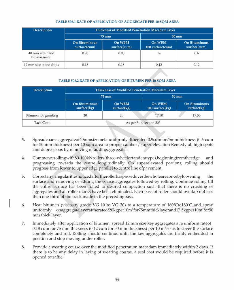
96
TABLE 506.1 RATE OF APPLICATION OF AGGREGATE PER 10 SQM AREA
Description Thickness of Modified Penetration Macadam layer
75 mm 50 mm
On Bituminous surface(cum)
On WBM
surface(cum)
On WBM
100 surface(cum) On Bituminous
surface(cum)
40 mm size hand broken metal
0.90 0.90 0.6 0.6
12 mm size stone chips 0.18 0.18 0.12 0.12
TABLE 506.2 RATE OF APPLICATION OF BITUMEN PER 10 SQM AREA
Description Thickness of Modified Penetration Macadam layer
75 mm 50 mm
On Bituminous surface(kg)
On WBM surface(kg)
On WBM 100 surface(kg)
On Bituminous surface(kg)
Bitumen for grouting 20 20 17.50 17.50
Tack Coat As per Sub-section 503
3. Spreadcoarseaggregateof40mmsizemetaluniformlyattherateof0.9cumfor75mmthickness (0.6 cum for 50 mm thickness) per 10 sqm area to proper camber / super-elevation Remedy all high spots and depressions by removing or addingaggregates.
4. Commencerollingwith80-100kNrollers(three-wheelortandemtype),beginningfromtheedge and progressing towards the centre longitudinally. On superelevated portions, rolling should progress from lower to upper edge parallel to centre line ofpavement.
5. Correctanyirregularitiesnoticedaftertherollerhaspassedoverthewholeareaoncebyloosening the surface and removing or adding the coarse aggregates followed by rolling. Continue rolling till the entire surface has been rolled to desired compaction such that there is no crushing of aggregates and all roller marks have been eliminated. Each pass of roller should overlap not less than one-third of the track made in the precedingpass.
6. Heat bitumen (viscosity grade VG 10 to VG 30) to a temperature of 1600Cto1800C and spray uniformly onaggregatelayerattherateof20kgper10m2for75mmthicklayerand17.5kgper10m2for50 mm thick layer.
7. Immediately after application of bitumen, spread 12 mm size key aggregates at a uniform rateof 0.18 cum for 75 mm thickness (0.12 cum for 50 mm thickness) per 10 m2 so as to cover the surface completely and roll. Rolling should continue until the key aggregates are firmly embedded in position and stop moving under roller.
8. Provide a wearing course over the modified penetration macadam immediately within 2 days. If there is to be any delay in laying of wearing course, a seal coat would be required before it is opened totraffic.

97
B. Quality ControlRequirements
1. Materials
Aggregates should satisfy the requirements given in Table 504.2
Bitumen shall be of paving grade S-35 to S-90
2. HorizontalAlignment
The edges of the Modified Penetration Macadam layer should be correct within a tolerance limit of (±) 30 mm in plain and rolling terrains and (±) 50 mm in hilly terrain.
3. SurfaceLevels
The tolerance in surface level of the Modified Penetration Macadam should be (±) 6 mm.
4. SurfaceRegularity
Themaximumallowabledifferencebetweentheroadsurfaceanda3mstraightedgewouldbe12 mm for longitudinal profile and 8 mm for crossprofile.
5. Quality ControlTests
The quality control tests and their frequencies would be as per Table 505.2, 505.3 and 505.4.
C. Do’s andDon’ts
Do’s Don’ts
1. Ensure that aggregates conform to gradingspecified and are dry and clean at the time oflaying.
2. Maintain the temperature of bitumen appropriateto the grade ofbitumen.
3. Remove excessive deposits of binder during spray operation.
1. Do not undertake the work in foggy. rainy or windy weather or when the atmospheric temperature in the shade is less thanl00C.
2. Do not allow any traffic over Built up spray grout without laying wearing course or sealcoat.
507. SURFACE DRESSING
A. Methodology
1. Design the surface dressing following the guidelines given in IRC 10:-2005 to determine the rate of spread of binder and stone chippings for actual conditions covering traffic level, type and size ofchippings,existingsurfaceandclimate.Anydeviationbetweenthequantitiesandspreadrates as specified in the contract and those as per actual design will be brought out and got approved from the competent authority before making any change duringconstruction.
2. Prepare the base on which surface dressing is to be laid to the specified lines, grade and cross- section as per Sub-section 501. If the base is of granular material, a prime coat should be applied as per Sub-section502.
3. Applythebinder(atspecifiedtemperature)asperrateofspreadofbindergiveninTable507.1or as designed with an appropriate bitumen distributor fitted with a spray bar. Binder shall be sprayed / distributed uniformly over the prepared base, with self propelled or towed sprayer, capableofsupplyingthebinderatspecifiedratetoprovideauniformlyunbrokenspreadofbinder.

98
TABLE 507.1: NOMINAL RATES OF SPREAD OF BINDER AND CHIPPINGS.
Nominal Chipping Size (mm)
Binder (Penetration grade bitumen) kg/m2
Bitumen emulsion (kg/m2)
Aggregate (cum/m2)
13.2 1.0 1.5 0.010
9.5 0.9 1.4 0.008
6.3 0.75 1.1 0.004
3. The application temperature for the penetration grade binder used shall be as specified inTable 507.2. In case of modified binder application temperatures shall be as indicated in Sub-section 512.
TABLE 507.2: SPRAYING TEMPERATURES FOR BINDERS.
Binder Whirlinq spray Jets Slot Jets
Min 0C Max 0C Min 0C Max 0C
Penetration Grade 80 / 100 180 200 165 175
Penetration Grade 180 / 200 170 190 155 165
4. Immediately after application of binder, spread clean dry stone aggregate at the rate given in
Table 507.1 or as designed with the help of a mechanically operated chip spreader, in a single layer. In case of emulsion as a binder, the aggregate may be slightlydamp.
5. Immediately after spreading of aggregates, roll the surface with the help of suitable road rollers. Commencerollingfromtheedgesandprogresstowardsthecenterexceptinsuperelevatedportions whereitshallproceedfromtheloweredgetothehigheredge.Eachpassshouldhaveanoverlap ofnotlessthanone-thirdofthetrackmadeintheprecedingpass.Spreadadditionalstonechipsto make up irregularities, if any. Rolling should continue until all aggregate particles are firmly embedded in the bituminous binder and present a uniform closedsurface.
6. Where two-coat surface dressing is specified in the contract, the second coat should be applied after the first coat is exposed to traffic for 2 to 3 weeks. Procedures stated here-in-above will apply. The road may be opened to traffic 24 hours after the work of rolling is complete. In exceptional circumstances, traffic may be allowed immediately after rolling provided the traffic speed is limited to 20 km / h until the followingday.
7. Where use of precoated chips is specified, the first step will be to precoat chips. The stone chips will be heated to 1600C and mixed with 0.75 to 1% of paving bitumen by weight heated to its applicationtemperature.Theprecoatedchipsshallbecuredforoneweekortillsuchtimeasthey becomenon-sticky.
B. Quality ControlRequirements
1. Materials
(a) StoneChippings
(i) Physicalrequirements:
StonechippingsshouldsatisfytherequirementsgiveninTable504.2exceptthatwater absorption shall be 1% maximum.
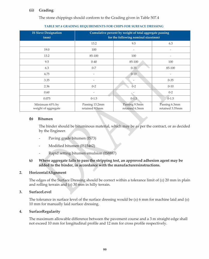
99
(ii) Grading:
The stone chippings should conform to the Grading given in Table 507.4
TABLE 507.4 GRADING REQUIREMENTS FOR CHIPS FOR SURFACE DRESSING
IS Sieve Designation
(mm)
Cumulative percent by weight of total aggregate passing
for the following nominal sizes(mm)
13.2 9.5 6.3
19.0 100 - -
13.2 85-100 100 -
9.5 0-40 85-100 100
6.3 0-7 0-35 85-100
4.75 - 0-10 -
3.35 - - 0-35
2.36 0-2 0-2 0-10
0.60 - - 0-2
0.075 0-1.5 0-1.5 0-1.5
Minimum 65% by weight of aggregate
Passing 13.2mm
retained 9.5mm
Passing 9.5mm
retained 6.3mm
Passing 6.3mm
retained 3.35mm
(b) Bitumen
The binder should be bituminous material, which may be as per the contract, or as decided by the Engineer.
- Paving grade bitumen (IS73)
- Modified bitumen (IS15462)
- Rapid setting bitumen emulsion (IS8887)
(c) Where aggregate fails to pass the stripping test, an approved adhesion agent may be added to the binder, in accordance with the manufacturersinstructions.
2. HorizontalAlignment
The edges of the Surface Dressing should be correct within a tolerance limit of (±) 20 mm in plain and rolling terrain and (±) 30 mm in hilly terrain.
3. SurfaceLevel
The tolerance in surface level of the surface dressing would be (±) 6 mm for machine laid and (±) 10 mm for manually laid surface dressing.
4. SurfaceRegularity
The maximum allowable difference between the pavement course and a 3 m straight edge shall not exceed 10 mm for longitudinal profile and 12 mm for cross profile respectively.

100
5. Quality ControlTests
Tests Prior toConstruction
The quality control tests to be carried out prior to construction are indicated in Table 507.5.
Table 507.5 : QUALITY CONTROL TESTS PRIOR TO CONSTRUCTION
Type of Test Frequency
1. Quality of Binder (Straight-run Bitumen) (IS:73)
(a) PenetrationTest (b) R&B Softening PointTest (c) DuctilityTest
One Set of tests per lot (Average of three tests) -do- -do-
2. Quality of Binder (Bitumen Emulsion) (a) Viscosity(IS:8887) (b) Residue on 600 micron sieve(IS:8887) (c) Storage Stability Test(IS:8887)
-do- -do- -do—
3. Quality of Binder (Modified Bitumen) (IS:15462) (a) PenetrationTest (b) R&B Softening PointTest (c) Elastic Recovery Test(d) SeparationTest
-do- -do- -do—do-
4. Aggregate Impact Value Test (IS:2386 Part 4) One test per km length on representative sample from each source identified by the Contractor
5. Flakiness Index Test (IS:2386 Part 1) -do-
6. Bitumen Stripping of Aggregate Test (IS:6241) -do-
7. Water Absorption (IS:2386 Part 3) -do-
Tests DuringConstruction
The quality control tests to be carried out during construction are indicated in Table 507.6.
TABLE 507.6 : QUALITY CONTROL TESTS DURING CONSTRUCTION
Type of Test Frequency
1. Rate of spread of binder At least two tests per day
2. Rate of Spread of aggregate (Annex – IV) -do-
3. Grading of Aggregate (IS:2386 Part 1) At least one test per day
4. Temperature of binder during spraying (Annex - I) Regularly, at close intervals.
5. Storage stability Test for Bitumen Emulsion One test per day
6. Aggregate impact value (IS:2386-Part 4) At random one test per km
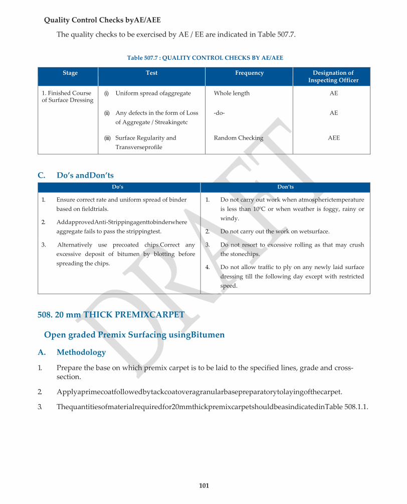
101
Quality Control Checks byAE/AEE
The quality checks to be exercised by AE / EE are indicated in Table 507.7.
Table 507.7 : QUALITY CONTROL CHECKS BY AE/AEE
Stage Test Frequency Designation of Inspecting Officer
1. Finished Course of Surface Dressing
(i) Uniform spread ofaggregate
(ii) Any defects in the form of Loss
of Aggregate / Streakingetc
(iii) Surface Regularity and
Transverseprofile
Whole length
-do-
Random Checking
AE
AE
AEE
C. Do’s andDon’ts
Do’s Don’ts
1. Ensure correct rate and uniform spread of binder
based on fieldtrials.
2. AddapprovedAnti-Strippingagenttobinderwhere
aggregate fails to pass the strippingtest.
1. Do not carry out work when atmospherictemperature
is less than 100C or when weather is foggy, rainy or
windy.
2. Do not carry out the work on wetsurface.
3. Alternatively use precoated chips.Correct any
excessive deposit of bitumen by blotting before
spreading the chips.
3. Do not resort to excessive rolling as that may crush
the stonechips.
4. Do not allow traffic to ply on any newly laid surface
dressing till the following day except with restricted
speed.
508. 20 mm THICK PREMIXCARPET
Open graded Premix Surfacing usingBitumen
A. Methodology
1. Prepare the base on which premix carpet is to be laid to the specified lines, grade and cross- section.
2. Applyaprimecoatfollowedbytackcoatoveragranularbasepreparatorytolayingofthecarpet.
3. Thequantitiesofmaterialrequiredfor20mmthickpremixcarpetshouldbeasindicatedinTable 508.1.1.

102
TABLE 508.1.1 : QUANTITIES OF MATERIAL REQUIRED FOR 10 m2 AREA
Aggregate Quantity
(a) Nominal size 13.2 mm (passing 22.4 mm sieve and
retained on 11.2 mm sieve)
0.18 m3
(b) Nominal size 11.2 mm (passing 13.2 mm sieve and
retained on 5.6 mm sieve)
0.09 m3
Total 0.27 m3
Binder
(a) For 0.18 m3 of 13.2 mm nominal size stone at 52 kg
bitumen per m3
9.5 kg
(b) For 0.09 m3 of 11.2 mm nominal size stone at 56 kg
bitumen per m3
5.1 kg
Total 14.6 kg
Prepare the mix in a hot mix plant of suitable size with separate dryer arrangement for aggregate.
3. Mixingshouldbethoroughtoensurethatahomogenousmixtureisobtained.Thetemperatureof bitumen at the time of mixing should be in the range of 1500 C to 1630 C and that of aggregates 1550Cto1630C,providedthatthedifferencebetweenthetemperatureofaggregateandthebinder should not exceed 140C. If modified bitumen is used, temperature should be as recommended in Subsection 512. The temperature at the time of discharge of the mixture should be between l30°C and160°C.
4. Locate hot mix plant near the work site. The mixed material should be transported quickly to the site of work and laid uniformly by suitablemeans.
5. The premixed material shall be spread on the road surface withrakes.
6. Commencerollingwith80-100kNrollers(three-wheelortandemtype),beginningfromtheedge and progressing towards the centre longitudinally. (On superelevated portions, rolling should progressfromlowertoupperedgeparalleltocentrelineofpavement).Continuerollingoperations till a smooth uniform surface is achieved and all roller marks are eliminated. Each pass should have an overlap of at least one-third of the track made in the precedingpass.
7. Correctanyhighspotsordepressionsnoticedaftertherollerhaspassedoverthewholeareaonce by removing or adding premixed material andrecompacting.
8. Provide a seal coat to the surface immediately after laying the carpet as per details in Sub-section 510.
9. Ordinarily, the road may be opened to traffic after laying the seal coat with restrictions given in Subsection510.

103
B. Quality ControlRequirements
1. Materials
(a) Aggregates
Aggregates shall conform to the physical requirements indicated in Table 508.1.2
TABLE 508.1.2 PHYSICAL REQUIREMENTS OF STONE AGGREGATE
Property Test Specification
Particle shape Flakiness index (IS:2386 Part 1) Max. 25 %
Strength Aggregate Impact Value (IS:2386 Part 4) Max. 30 %
Durability Soundness (IS:2386 Part 5)
Sodium sulphate
Magnesium sulphate
Max. 12%
Max. 18%
Water absorption Water Absorption (IS:2386 Part 3) Max. 1 %
Stripping Coating and stripping of bitumen aggregate
mixture. (IS:6241)
Minimum retained
coating 95 %
(b) Binder
The binder shall be a penetration grade bitumen of a suitable grade S-65 / 90 depending on climatic condition of the area or of the type as specified in the Contract. Where modified binder is specified Subsection 512 should be followed.
2. HorizontalAlignment
The edges of the carriageway with Premix Carpet should be correct within a tolerance limit of (±) 20 mm in plain and rolling terrain and (±) 30 mm in hilly terrain.
3. SurfaceLevel
The tolerance in surface level of the surface dressing would be (±) 6 mm for machine laid work and (±) 10 mm for work executed manually.
4. SurfaceRegularity
The maximum allowable difference between the pavement course and a 3 m straight edge shall not exceed 8 mm for both the longitudinal profile and the cross profile.
5. Quality ControlTests
Tests Prior toConstruction
The quality control tests to be carried out prior to construction are indicated in Table 508.1.3.

104
Table 508.1.3: QUALITY CONTROL TESTS PRIOR TO CONSTRUCTION
1. Quality of Binder (Straight-runBitumen) (a) Penetration Test(IS:73) (b) R&B Softening Point Test(IS:73) (c) Ductility Test(IS:73)
One set of tests per lot -do- -do-
2. Quality of Binder (Bitumen Emulsion)
(a) Viscosity(IS:8887) (b) Residue on 600 micron sieve(IS:8887) (c) Storage Stability Test(IS:8887)
-do- -do- -do-
3. Quality of Binder (Modified Bitumen) (IS 15462)
(a) PenetrationTest (b) Softening PointTest (c) Elastic RecoveryTest (d) SeparationTest
-do- -do- -do- -do-
4. Aggregate Impact Value Test (IS:2386 Part 4) One test per km length on representative sample from each source identified by the Contractor
5. Flakiness Index Test (IS:2386 Part 1) -do-
6. Bitumen Stripping of Aggregate Test (IS:6241) -do-
7. Water Absorption (IS:2386 Part 3) -do-
Tests DuringConstruction
The quality control tests to be carried out during construction are indicated in Table 508.1.4.
TABLE 508.1.4: QUALITY CONTROL TESTS DURING CONSTRUCTION
Type of Test Frequency
1. Grading of Aggregates (IS:2386 Part 1) At least two tests per day
2. Binder Content before seal coat At least two tests per day
3. Temperature of Binder Regular close intervals
4. Thickness of layer Regularly at close intervals
5. Aggregate impact value (IS:2386-Part 4) At random one test per km
Quality Control Checks byAE/AEE
The quality checks to be exercised by AE / AEE are indicated in Table 508.1.5.
TABLE 508.1.5: QUALITY CONTROL CHECKS BY AE/AEE
Stage Test Frequency Designation of Inspecting Officer
1. Finished Pre Mix Carpet Surfacing
(i) Binder Content before providing seal coat
(ii) Visual inspection of finishedsurface
(iii) Surface Regularity and Transverseprofile
One test for every 500 m length of the layer
AE
Full length AEE
Random Checking AE

105
C. Do’s andDon’ts
Do’s Don’ts
1. Ensure that aggregates for premix carpet and seal coat conform to the prescribed physical andgrading requirements and are clean anddry.
2. Exercise strict control over mixing and laying temperature as per specifications using appropriate thermometers.
3. Rolling operations should be completed before the temperature of the mix falls below100oC.
1. Do not allow manualmixing.
2. Do not undertake the work in foggy, rainy or windy weather or when the atmospheric temperature in the shade is less than 10oC or when the surface iswet.
3. Donotallowthepremixmaterialtoadheretotheroller wheels.Donotuseexcesswaterforthepurpose.Light sprinkling shoulddo.
4. Donotallowtherollertostandonnewlylaidmaterial.
5. Do not allow any traffic without laying seal coat over the premixcarpet.
508.2 PREMIX CARPET USING BITUMEN EMULSION
A. Methodology
1. Preparethebaseonwhichpremixcarpetistobelaidtothespecifiedlines,gradeandcrosssection
2. Apply a tack coat over an existing prepared black topsurface.
3. The quantities of material required for 20 mm thick premix carpet should be as indicatedbelow
(i) Aggregate as per Table 508.1.1 of Sub-section508.1
(ii) Binder : Cationic BitumenEmulsion
(a) For 0.18 m3 of 13.2 mm nominal size stone at 78 kg cationic bitumen emulsion perm3
14.0 kg
(b) For 0.09 m3 of 11.2 mm nominal size stone at 84 kg cationic bitumen emulsion perm3
7.5 kg
Total 21.5 kg
4. Premix bitumen emulsion and aggregates in a suitable mixture such as cold mixing plant as per IS:5435 (revised) or concretemixture
5. Spread the premix to the desired thickness, grade, cross fall within 10 minutes of applying the tack coat and ensure that all levelling, raking is completed within 20 minutes of themixing.
6. Roll the surface as per Para 6 & 7 of the methodology described in Sub-section508.1
7. Provide a seal coat as specified in the contract within 4-6 hours after laying the premix carpet. Follow Sub-section 510 for the work on sealcoat.
8. Preferably,theroadshouldbeopenedtotrafficafter24hoursoflayingthesealcoat.Insinglelane roads traffic may ordinarily be allowed after 6-8 hours with the care that the speed is rigorously restricted to not more than 16 km /h.
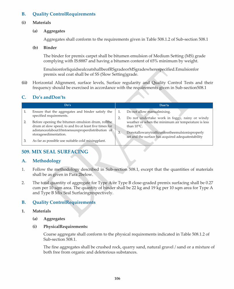
106
B. Quality ControlRequirements
(i) Materials
(a) Aggregates
Aggregates shall conform to the requirements given in Table 508.1.2 of Sub-section 508.1
(b) Binder
The binder for premix carpet shall be bitumen emulsion of Medium Setting (MS) grade complying with IS:8887 and having a bitumen content of 65% minimum by weight.
EmulsionforliquidsealcoatshallbeofRSgradeorMSgradewherespecified.Emulsionfor premix seal coat shall be of SS (Slow Setting)grade.
(ii) Horizontal Alignment, surface levels, Surface regularity and Quality Control Tests and their frequency should be exercised in accordance with the requirements given in Sub-section508.1
C. Do’s andDon’ts
Do’s Don’ts
1. Ensure that the aggregates and binder satisfy the specified requirements.
2. Before opening the bitumen emulsion drum, rollthe drum at slow speed, to and fro at least five times for adistanceofabout10mtoensureproperdistribution of storagesedimentation.
3. As far as possible use suitable cold mixingplant.
1. Do not allow manualmixing.
2. Do not undertake work in foggy, rainy or windy weather or when the minimum air temperature is less than 10OC.
3. Donotallowanytrafficunlesstheemulsionisproperly set and the surface has acquired adequatestability
509. MIX SEAL SURFACING
A. Methodology
1. Follow the methodology described in Sub-section 508.1, except that the quantities of materials shall be as given in Para 2below.
2. The total quantity of aggregate for Type A or Type B close-graded premix surfacing shall be 0.27 cum per 10 sqm area. The quantity of binder shall be 22 kg and 19 kg per 10 sqm area for Type A and Type B Mix Seal Surfacingrespectively.
B. Quality ControlRequirements
1. Materials
(a) Aggregates
(i) PhysicalRequirements:
Coarse aggregate shall conform to the physical requirements indicated in Table 508.1.2 of Sub-section 508.1.
The fine aggregates shall be crushed rock, quarry sand, natural gravel / sand or a mixture of both free from organic and deleterious substances.

107
(ii) AggregateGrading:
The combined coarse and fine aggregates shall conform to one of the gradings given in Table 509.1
TABLE 509.1 AGGREGATE GRADATION FOR MIX SEAL SURFACING
IS sieve designation (mm) Cumulative percent by weight passing
Type A Type B
13.2 — 100
11.2 100 88 -100
5.6 52 -88 31 -52
2.8 14 -38 5 -25
0.090 0 -5 0 -5
(b) Binder
Requirements specified in Sub-section 508.1 shall apply.
2. HorizontalAlignment
Surface levels, surface regularity and quality control tests and frequencies shall be exercised as per the requirement given in Sub-section 508.1
C. Do’s andDon’ts
(i) Follow do’s and don’ts given under Sub-section508.1
(ii) Generally, Mix Seal Surfacing should not be placed directly over WBMbase.
510. SEAL COAT
The seal coat shall be any of the three types mentioned below:
TypeA: Liquid seal coat comprising of an application of layer of bituminous binder followed by a cover of stonechips.
TypeB: Premixed seal coat comprising of a thin application of fine aggregate premixed with bituminousbinder.
TypeC: Premixed seal coat comprising of an application of 6.7 mm size stone chips premixed with bituminousbinder.
A. Methodology
Apply seal coat immediately after laying the bituminous course. The surface should be clean and free of dust and extraneous material before application of the seal coat.
1. Type A Seal coat withbitumen:
(i) Apply heated bitumen with a temperature between 1500C and 1630C uniformly with the help of a bitumensprayer.

108
(ii) Immediately thereafter, spread stone chips over the bitumen layer at a uniform rate, preferably,withthehelpofamechanicalgritspreadersoastocoverthesurfacecompletely.
(iii) Commence rolling with 80-100 kN rollers (3-wheel or tandem type), beginning from the edgeandprogressingtowardsthecentrelongitudinally.Onsuperelevatedportions,rolling should progress from lower to upper edge parallel to centre line of pavement. If required, spreadadditionalchipsbyhandtomakeupirregularities.Continuerollingoperationsuntil all aggregate particles are firmly embedded and present a uniform closedsurface.
2. Type A seal coat withemulsion
(i) Apply emulsion uniformly over the prepared surface by mechanicalsprayers.
(ii) Immediately after application of emulsion, spread aggregate uniformly and evenly by mechanicalmeans;
(iii) Roll the surface following the procedure given in Para 1 (iii)above.
3. Type B seal coat withbitumen
(i) Follow the methodology described in Paras 4 & 5 for preparing the premix in Sub-section 508.1
(ii) Rollthesurfacewith80to100kNrollerasperproceduregiveninPara8&9ofmethodology in Sub-section508.1
(iii) Continue rolling of the mix until the voids in the bituminous surface are completely sealed and a smooth and uniform surface isobtained.
4. Type B seal coat withemulsion
Follow the methodology described in Sub-section 508.2 except that for small jobs manual mixing may be required.
5. Type C sealcoat
Paras 4 to 7 of Sub-section 508.1 dealing with methodology for premix carpet may be referred to for preparation of the mix, spreading and rolling the same.
6. TrafficonTypeBandTypeCsealcoatmaybeallowedaftercompletionofrollingoperationsand the surface is at ambient temperature. Traffic on Type A seal coat may be allowed only on the following day. In exceptional circumstances the road with Type A seal coat may be opened to traffic immediately after rolling but the traffic speed should be restricted to 16 km / h until the followingday.
B. Quality ControlRequirements
1. Materials
(a) Aggregates
Aggregate shall conform to the physical requirements indicated in Table 508.1.2. Quantities and grading requirements for aggregates are given in Table 510.1.
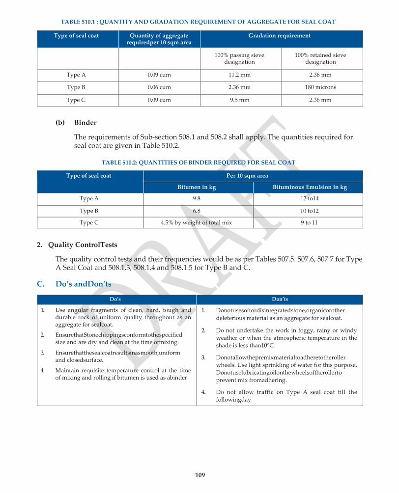
109
TABLE 510.1 : QUANTITY AND GRADATION REQUIREMENT OF AGGREGATE FOR SEAL COAT
Type of seal coat Quantity of aggregate requiredper 10 sqm area
Gradation requirement
100% passing sieve
designation 100% retained sieve
designation
Type A 0.09 cum 11.2 mm 2.36 mm
Type B 0.06 cum 2.36 mm 180 microns
Type C 0.09 cum 9.5 mm 2.36 mm
(b) Binder
The requirements of Sub-section 508.1 and 508.2 shall apply. The quantities required for seal coat are given in Table 510.2.
TABLE 510.2: QUANTITIES OF BINDER REQUIRED FOR SEAL COAT
Type of seal coat Per 10 sqm area
Bitumen in kg Bituminous Emulsion in kg
Type A 9.8 12 to14
Type B 6.8 10 to12
Type C 4.5% by weight of total mix 9 to 11
2. Quality ControlTests
The quality control tests and their frequencies would be as per Tables 507.5. 507.6, 507.7 for Type A Seal Coat and 508.1.3, 508.1.4 and 508.1.5 for Type B and C.
C. Do’s andDon’ts
Do’s Don’ts
1. Use angular fragments of clean, hard, tough and durable rock of uniform quality throughout as an aggregate for sealcoat.
2. EnsurethatStonechippingsconformtothespecified size and are dry and clean at the time ofmixing.
3. Ensurethatthesealcoatresultsinasmooth,uniform and closedsurface.
4. Maintain requisite temperature control at the time of mixing and rolling if bitumen is used as abinder
1. Donotusesoftordisintegratedstone,organicorother
deleterious material as an aggregate for sealcoat.
2. Do not undertake the work in foggy, rainy or windy
weather or when the atmospheric temperature in the
shade is less than10°C.
3. Donotallowthepremixmaterialtoadheretotheroller
wheels. Use light sprinkling of water for this purpose.
Donotuselubricatingoilonthewheelsoftherollerto
prevent mix fromadhering.
4. Do not allow traffic on Type A seal coat till the
followingday.

2304 DENSE BITUMINOUS MACADAM (DBM)
The specifications for the design and construction of Dense Bituminous Macadam are giver under
Clause 505 of MoRTH Specifications (5th revision 2013).
2304.1 Materials
a) The bitumen shall be viscosity graded paving bitumen complying with IS: 73 or as
specified in thecontract.
b) The coarse aggregate shall be crushed rock retaining on 2.36 mmsieve.
c) The physical properties of coarse aggregate shall be as given in table 2300-6 (Ref: Table 500-
8 of MoRTHSpecifications).
d) Table 2300-6: Physical requirements for coarse aggregates for DBM
Property Test Code Specification
Cleanliness Grain size analysis
IS: 2386 (Part 1) Max 5%passing 75 micronsieve
Particle
shape
Flakiness and
Elongation Indices
(Combined)
IS: 2386 (Part 1)
Max 35%
Strength*
Los Angeles Abrasion value
IS: 2386 (Part 4) Max 35%
Aggregate Impact value IS: 2386 (Part 4) Max 27%
Durability
Soundness – Sodium Sulphate
(5 cycles)
IS: 2386 (Part 5)
Max 12%
Soundness –
Magnesium Sulphate
(5cycles)
IS: 2386 (Part 5)
Max 18%
Porosity Water absorption IS: 2386 (Part 3) Max 2%
Bitumen
adhesion
Coating and
stripping of bitumen aggregate
mixtures
IS: 6241
Minimum 95%
coating retained
Water sensitivity
Retained tensile strength** AASHTO 283 Min 80%
*Any one of these shall need to be satisfied.
**Anti-stripping agent shall be added if the value falls below 80%.
e) The filler shall be finely divided mineral matter such as rock dust, hydrated lime or
cement. The grading limits of filler shall be as given in table 2300-7 (Ref: Table 500-9 of
MoRTHSpecifications).
Table 2300-7: Grading requirements for mineral filler
IS sieve mm Cumulative percentage passing by
total weight of aggregate
0.600 100
0.300 95-100
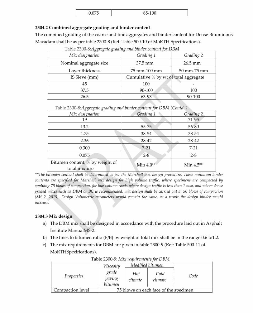
0.075 85-100
2304.2 Combined aggregate grading and binder content
The combined grading of the coarse and fine aggregates and binder content for Dense Bituminous
Macadam shall be as per table 2300-8 (Ref: Table 500-10 of MoRTH Specifications).
Table 2300-8:Aggregate grading and binder content for DBM
Mix designation Grading 1 Grading 2
Nominal aggregate size 37.5 mm 26.5 mm
Layer thickness 75 mm-100 mm 50 mm-75 mm
IS Sieve (mm) Cumulative % by wt of total aggregate
45 100 -
37.5 90-100 100
26.5 63-93 90-100
Table 2300-8:Aggregate grading and binder content for DBM (Contd..)
Mix designation Grading 1 Grading 2 19 - 71-95
13.2 55-75 56-80
4.75 38-54 38-54
2.36 28-42 28-42
0.300 7-21 7-21
0.075 2-8 2-8
Bitumen content, % by weight of
total mixture Min 4.0** Min 4.5**
**The bitumen content shall be determined as per the Marshall mix design procedure. These minimum binder
contents are specified for Marshall mix design for high volume traffic, where specimens are compacted by
applying 75 blows of compaction, for low volume roads where design traffic is less than 1 msa, and where dense
graded mixes such as DBM or BC is recommended, mix design shall be carried out at 50 blows of compaction
(MS-2, 2015). Design Volumetric parameters would remain the same, as a result the design binder would
increase.
2304.3 Mix design
a) The DBM mix shall be designed in accordance with the procedure laid out in Asphalt
Institute ManualMS-2.
b) The fines to bitumen ratio (F/B) by weight of total mix shall be in the range 0.6 to1.2.
c) The mix requirements for DBM are given in table 2300-9 (Ref: Table 500-11 of
MoRTHSpecifications).
Table 2300-9: Mix requirements for DBM
Properties
Viscosity
grade
paving
bitumen
Modified bitumen Code Hot
climate
Cold
climate
Compaction level 75 blows on each face of the specimen
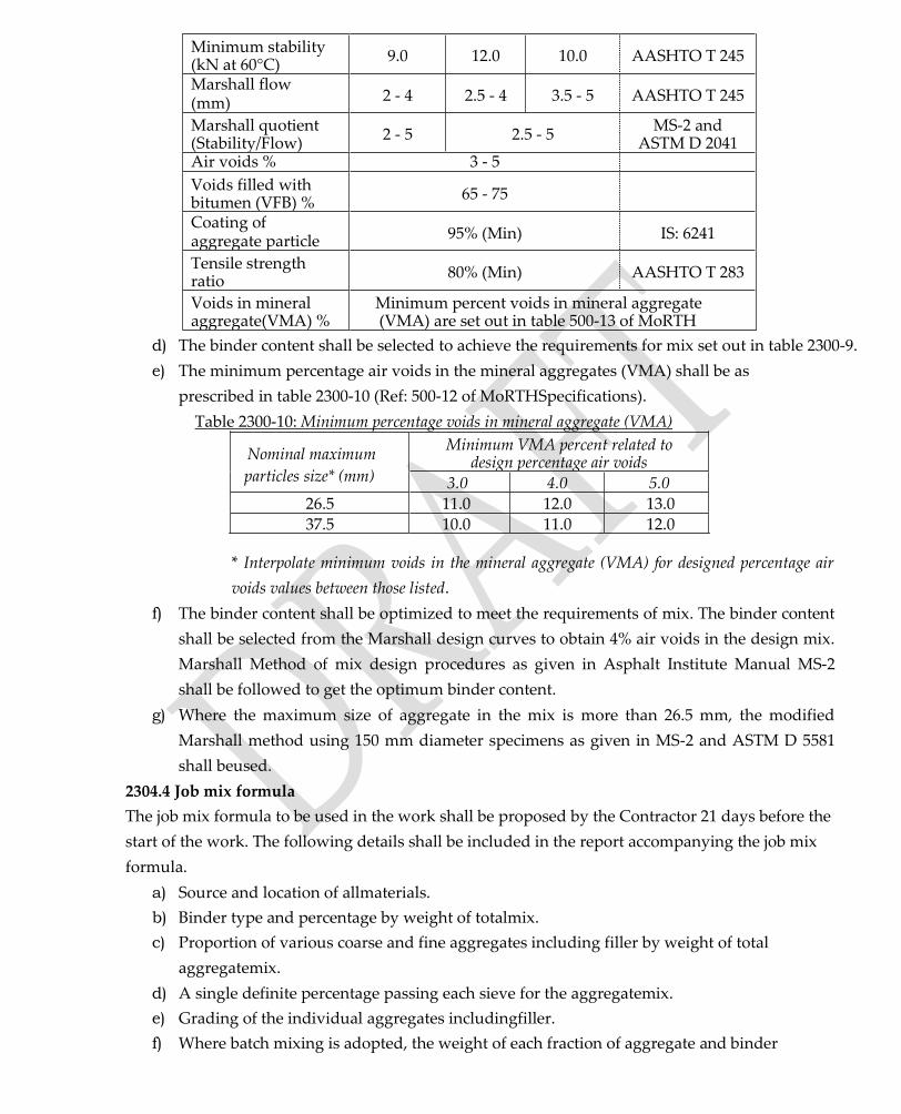
Minimum stability (kN at 60°C)
9.0 12.0 10.0 AASHTO T 245
Marshall flow (mm) 2 - 4 2.5 - 4 3.5 - 5 AASHTO T 245
Marshall quotient (Stability/Flow)
2 - 5 2.5 - 5 MS-2 and
ASTM D 2041 Air voids % 3 - 5
Voids filled with bitumen (VFB) %
65 - 75
Coating of aggregate particle 95% (Min) IS: 6241
Tensile strength ratio
80% (Min) AASHTO T 283
Voids in mineral aggregate(VMA) %
Minimum percent voids in mineral aggregate (VMA) are set out in table 500-13 of MoRTH
d) The binder content shall be selected to achieve the requirements for mix set out in table 2300-9.
e) The minimum percentage air voids in the mineral aggregates (VMA) shall be as
prescribed in table 2300-10 (Ref: 500-12 of MoRTHSpecifications).
Table 2300-10: Minimum percentage voids in mineral aggregate (VMA)
Nominal maximum
particles size* (mm)
Minimum VMA percent related to design percentage air voids
3.0 4.0 5.0
26.5 11.0 12.0 13.0 37.5 10.0 11.0 12.0
* Interpolate minimum voids in the mineral aggregate (VMA) for designed percentage air
voids values between those listed.
f) The binder content shall be optimized to meet the requirements of mix. The binder content
shall be selected from the Marshall design curves to obtain 4% air voids in the design mix.
Marshall Method of mix design procedures as given in Asphalt Institute Manual MS-2
shall be followed to get the optimum binder content.
g) Where the maximum size of aggregate in the mix is more than 26.5 mm, the modified
Marshall method using 150 mm diameter specimens as given in MS-2 and ASTM D 5581
shall beused.
2304.4 Job mix formula
The job mix formula to be used in the work shall be proposed by the Contractor 21 days before the
start of the work. The following details shall be included in the report accompanying the job mix
formula.
a) Source and location of allmaterials.
b) Binder type and percentage by weight of totalmix.
c) Proportion of various coarse and fine aggregates including filler by weight of total
aggregatemix.
d) A single definite percentage passing each sieve for the aggregatemix.
e) Grading of the individual aggregates includingfiller.
f) Where batch mixing is adopted, the weight of each fraction of aggregate and binder

perbatch.
g) Test results of the physical properties of the aggregates to be used in thework.
h) Test results of the volumetric analysis of the mix such as maximum specific gravity of the
loose mix (Gmm), densities of the compacted specimens for various binder contents, voids
in mineral aggregates (VMA), air voids in the compacted mix (Va), voids filled with
bitumen(VFB).
i) Reports on the Marshall test viz., stability &flow.
j) Mixing temperature and compactingtemperature.
k) Marshall design curves showing stability, flow, density, air voids, VMA and VFB plotted
against different bindercontents.
2304.5 Approval of the job mix formula
a) Approval of the job mix formula shall be given by the Engineer after conducting necessary
acceptance tests using the samples of materials proposed to be used in thework.
b) A revised mix design shall be carried out and a new job mix formula approved once a
change in source of the material isrequired.
2304.6 Plant and field trials
a) After approval of the job mix formula, plant trials must be carried out to establish that a
uniform mix is produced and the variations of individual fractions are within the
permitted tolerance specified in table 2300-11 (Ref: Table 500-13 of MoRTHSpecifications).
b) After the successful completion of plant trials, field trials are carriedout.
c) The field trials will establish if the paving machineries and procedures are sufficient to
produce a satisfactory pavementlayer.
d) Density of the finished paving shall be determined by taking cores no sooner than 24 hours
after finishing thelayer.
Table 2300-11: Permissible variations in the actual mix from the job mix formula
Description Base/binder course
Aggregate passing 19 mm sieve or larger ± 8% Aggregate passing 13.2 mm,9.5 mm ± 7%
Aggregate passing 4.75 mm ± 6% Aggregate passing 2.36 mm, 1.18 mm, 0.600 mm ± 5%
Aggregate passing 0.300 mm, 0.150 mm ± 4% Aggregate passing 0.075 mm ± 2% Binder content ± 0.3%
Mixing temperature ± 10°C
e) The minimum field density required is 92% or more than the theoretical maximum specific
gravity (Gmm) obtained on the day of compaction in accordance with ASTM D 2041. This
means not more than 8% air voids is allowed in the compacted layer ofDBM.
2304.7 Construction
a) The layer on which the DBM is to be placed shall be prepared in accordance with Clause
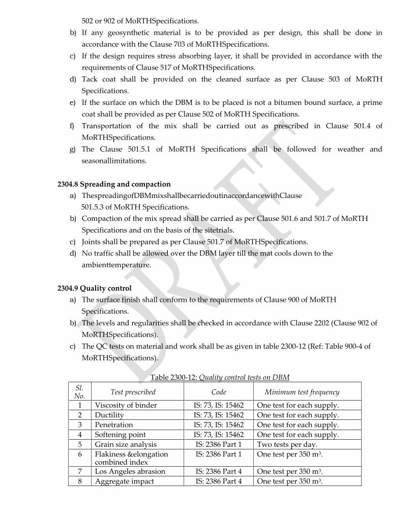
502 or 902 of MoRTHSpecifications.
b) If any geosynthetic material is to be provided as per design, this shall be done in
accordance with the Clause 703 of MoRTHSpecifications.
c) If the design requires stress absorbing layer, it shall be provided in accordance with the
requirements of Clause 517 of MoRTHSpecifications.
d) Tack coat shall be provided on the cleaned surface as per Clause 503 of MoRTH
Specifications.
e) If the surface on which the DBM is to be placed is not a bitumen bound surface, a prime
coat shall be provided as per Clause 502 of MoRTH Specifications.
f) Transportation of the mix shall be carried out as prescribed in Clause 501.4 of
MoRTHSpecifications.
g) The Clause 501.5.1 of MoRTH Specifications shall be followed for weather and
seasonallimitations.
2304.8 Spreading and compaction
a) ThespreadingofDBMmixshallbecarriedoutinaccordancewithClause
501.5.3 of MoRTH Specifications.
b) Compaction of the mix spread shall be carried as per Clause 501.6 and 501.7 of MoRTH
Specifications and on the basis of the sitetrials.
c) Joints shall be prepared as per Clause 501.7 of MoRTHSpecifications.
d) No traffic shall be allowed over the DBM layer till the mat cools down to the
ambienttemperature.
2304.9 Quality control
a) The surface finish shall conform to the requirements of Clause 900 of MoRTH
Specifications.
b) The levels and regularities shall be checked in accordance with Clause 2202 (Clause 902 of
MoRTHSpecifications).
c) The QC tests on material and work shall be as given in table 2300-12 (Ref: Table 900-4 of
MoRTHSpecifications).
Table 2300-12: Quality control tests on DBM
Sl. No.
Test prescribed Code Minimum test frequency
1 Viscosity of binder IS: 73, IS: 15462 One test for each supply.
2 Ductility IS: 73, IS: 15462 One test for each supply.
3 Penetration IS: 73, IS: 15462 One test for each supply.
4 Softening point IS: 73, IS: 15462 One test for each supply.
5 Grain size analysis IS: 2386 Part 1 Two tests per day.
6 Flakiness &elongation combined index
IS: 2386 Part 1 One test per 350 m3.
7 Los Angeles abrasion IS: 2386 Part 4 One test per 350 m3.
8 Aggregate impact IS: 2386 Part 4 One test per 350 m3.

9 Water absorption IS: 2386 Part 3 One test for each source.
10 Stripping IS: 6241 One test for each source.
11 Soundness IS: 2386 Part 5 One test for each source.
12 Sand equivalent IS: 2720 Part 37 One test for each source.
13 Plasticity index IS: 2720 Part 5 One test for each source.
14 Temperature check - At regular intervals.
15 Binder content ASTM D 2172 Two tests per day.
16 Aggregate mix grading IS: 2386 Part 1 Two tests per day.
17 Marshall test AASHTO T 245 Three tests per 400 tonnes.
18 Max sp. gravity of mix AASHTO T 209 Three tests per 400 tonnes.
19 Volumetric analysis Asphalt Institute MS-2 (2015)
Three tests per 400 tonnes.
20 Moisture susceptibility AASHTO T 283 One test for each mix.
21 Layer density One test per 700 m2 area.
2314 BITUMINOUS CONCRETE (BC) SURFACING
Bituminous concrete surfacing is done in accordance with requirement of IRC: 29- 1968. The
construction of BC wearing and profile corrective courses is given in Clause 507 of MoRTH
Specifications for Road and Bridge works (5th edition 2013).
2314.1 Materials
a) Paving bitumen complying with IS: 73 shall be used for designing BCmix.
b) Coarse aggregates shall be crushed rock retained on 2.36 mm sieve. The source of
aggregate shall be approved only after testing for stripping. The physical
requirementsforcoarseaggregatesspecifiedintable2300-33(Ref:Table
500.16 of MoRTH Specifications) shall be achieved.
Table 2300-33: Physical requirements for coarse aggregate for BC
Property Test Code Specification
Cleanliness
(Dust) Grain size analysis
IS:2386
Part 1
Max.5%passing
0.075 mmsieve
Particle
shape
Flakiness and elongation
indices (Combined)
IS:2386
Part 1 Max 35%
Strength Los Angeles abrasion value
or aggregate impact value
IS:2386
Part 4
Max30%
Max24%
Durability
Soundness -
Sodium sulphate
IS:2386
Part 5 Max 12%
Soundness -
Magnesium sulphate
IS:2386
Part 5 Max 18%
Polishing Polished stone value BS: 812-
114 Min 55
Porosity Water absorption IS: 2386
Part 3 Max 2%
Stripping Coating and stripping of
bitumen aggregate mix
IS: 6241
Retained coating
95% Min

Water
sensitivity Retained tensile strength*
AASHTO
T 283 Min 80%
*If the minimum retained tensile test strength falls below 80%, use of anti-stripping agent is
recommended to meet the requirement.
c) Fine aggregates shall consist of crushed or naturally occurring mineral material or a
combination of the two passing IS 2.36 mm sieve and retained on 75 micron. They shall be
clean, hard, durable, dry and free from dust, and soft or friable matter, organic or other
deleteriousimpurities.
d) The fine aggregate shall have a sand equivalent value of not less than 50 when
testedasperIS:2720(Part37).Theplasticityindexofthefractionpassing .425 mm sieve shall not
exceed 4, when tested in accordance with IS: 2720 (Part 5).
e) Filler shall be finely divided mineral matter such as rock dust, hydrated lime or cement as
approved by the Engineer. When the aggregates fail to meet the water sensitively test, then
2% hydrated lime by weight of aggregate shall be added without any additionalpayment.
f) The combined aggregate grading shall be tested by wet sieving method as per IS: 2386 Part
I. The combined grading shall be within the limits specified in table 2300-34 (Ref: Table
500-17 of MoRTHSpecifications).
Table 2300-34: Composition of bituminous concrete mix
Grading 1 2
Nominal maximum aggregate size*
19 mm 13.2 mm
Layer thickness 50 mm 30-40 mm
IS Sieve1(mm) Cumulative % by weight
of total aggregate passing 45 - -
37.5 - -
26.5 100 - 19 90-100 100
13.2 59-79 90-100
9.5 52-72 70-88
4.75 35-55 53-71 2.36 28-44 42-58 1.18 20-34 34-48
0.6 15-27 26-38
0.3 10-20 18-28 0.15 5-3 12-20 0.075 2-8 4-10
Bitumen content % by mass of total mix
Min 5.2** Min 5.4**
*The nominal maximum aggregate size is the largest specified sieve size upon which any of the aggregate
isretained.
**Corresponds to specific gravity of the aggregate being 2.7. In case aggregates have specific gravity more
than 2.7, the minimum bitumen content can be reduced proportionately. Further, for regions where highest
daily mean air temperature is 30°C or lower and lowest daily mean air temperature is -10°C or lower, the

bitumen content may be increased by0.5%.
2314.2 Bituminous concrete mix requirement
a) The BC mix shall meet the requirements stipulated for dense graded bituminous macadam
(DBM) in table 2300-9 (Ref: Table 500-11 of MoRTH Specifications).
b) The minimum percentage of air voids in mineral aggregate (VMA) conditions shall be
satisfied for the selected nominal maximum size of aggregates (Table 2300-10).
c) Binder content shall be optimised to achieve the requirements specified for the bituminous
mix, and the traffic volume of theroad.
2314.3 Job mix formula
a) The job mix formula proposed for the work shall be given in writing at least 30 days before
the start of the work and got approved by theEngineer.
b) The job mix shall be approved only after independent testing by the Engineer using the
same materials proposed for thework.
c) The job mix formula shall be changed by repeat tests, if the source of the material or the
propertieschanges.
2314.4 Plant and field trials
a) After the job mix formula is approved, the Contractor shall carry out plant trials to set the
plant for producing a uniform mix conforming to the specificationrequirements.
b) The variations in quantities of the ingredients shall not exceed the prescribed limits given
in table 2300-35 (Ref: Table 500-18 of MoRTHSpecifications).
Table 2300-35: Permissible variations in plant mix from the job mix formula
Description Permissible variation
Aggregate passing 19 mm sieve or larger ± 7%
Aggregate passing 13.2 mm, 9.5 mm ± 6%
Aggregate passing 4.75 mm ± 5% Aggregate passing 2.36 mm, 1.18 mm, 0.6 mm ± 4% Aggregate passing 0.3 mm, 0.15 mm ± 3%
Aggregate passing 0.075 mm ±1.5%
Binder content ±0.3% Mixing temperature ±10C
c) Once the plant trials are successful, field trials shall be carried out, to demonstrate that the
mix can be properly laid and compacted to satisfy the requirementsstipulated.
d) Fielding trials shall be preferably done on an area outside the projectroad.
e) Once the plant and field trials are approved, the same methodology shall be followed for
laying the mix in the projectroad.
2314.5 Construction
a) Laying shall be suspended during rain, fog and dust storms or if free standing water is
present on thesurface.
b) Bituminous work shall not be carried out if the temperature of the surface to be laid is
below10C.
c) The surface on which the mix to be placed shall be cleaned by means of a mechanical
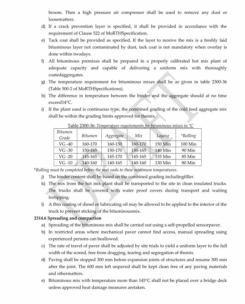
broom. Then a high pressure air compressor shall be used to remove any dust or
loosematters.
d) If a crack prevention layer is specified, it shall be provided in accordance with the
requirement of Clause 522 of MoRTHSpecification.
e) Tack coat shall be provided as specified. If the layer to receive the mix is a freshly laid
bituminous layer not contaminated by dust, tack coat is not mandatory when overlay is
done within twodays.
f) All bituminous premixes shall be prepared in a properly calibrated hot mix plant of
adequate capacity and capable of delivering a uniform mix with thoroughly
coatedaggregates.
g) The temperature requirement for bituminous mixes shall be as given in table 2300-36
(Table 500-2 of MoRTHSpecifications).
h) The difference in temperature between the binder and the aggregate should at no time
exceed14C.
i) If the plant used is continuous type, the combined grading of the cold feed aggregate mix
shall be within the grading limits approved for themix.
Table 2300-36: Temperature requirements for bituminous mixes in °C
Bitumen
Grade Bitumen Aggregate Mix Laying *Rolling
VG -40 160-170 160-150 160-170 150 Min 100 Min
VG -30 150-165 150-170 150-165 140 Min 90 Min
VG -20 145-165 145-170 145-165 135 Min 85 Min
VG -10 140-160 140-165 140-160 130 Min 80 Min
*Rolling must be completed before the mat cools to these minimum temperatures.
j) The binder content shall be based on the combined grading includingfiller.
k) The mix from the hot mix plant shall be transported to the site in clean insulated trucks.
The trucks shall be covered with water proof covers during transport and waiting
fortipping.
l) A thin coating of diesel or lubricating oil may be allowed to be applied to the interior of the
truck to prevent sticking of the bituminousmix.
2314.6 Spreading and compaction
a) Spreading of the bituminous mix shall be carried out using a self-propelled sensorpaver.
b) In restricted areas where mechanical paver cannot find access, manual spreading using
experienced persons can beallowed.
c) The rate of travel of paver shall be adjusted by site trials to yield a uniform layer to the full
width of the screed, free from dragging, tearing and segregation of themix.
d) Paving shall be stopped 300 mm before expansion joints of structures and resume 300 mm
after the joint. The 600 mm left unpaved shall be kept clean free of any paving materials
and othermatters.
e) Bituminous mix with temperature more than 145°C shall not be placed over a bridge deck
unless approved heat damage measures aretaken.
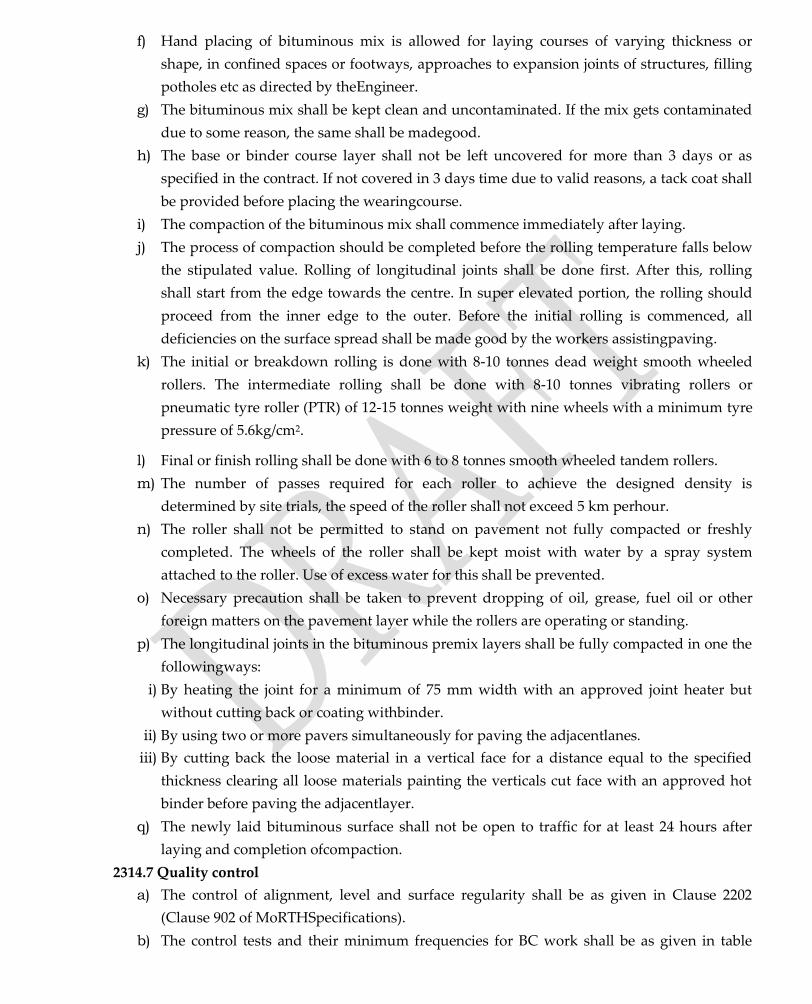
f) Hand placing of bituminous mix is allowed for laying courses of varying thickness or
shape, in confined spaces or footways, approaches to expansion joints of structures, filling
potholes etc as directed by theEngineer.
g) The bituminous mix shall be kept clean and uncontaminated. If the mix gets contaminated
due to some reason, the same shall be madegood.
h) The base or binder course layer shall not be left uncovered for more than 3 days or as
specified in the contract. If not covered in 3 days time due to valid reasons, a tack coat shall
be provided before placing the wearingcourse.
i) The compaction of the bituminous mix shall commence immediately after laying.
j) The process of compaction should be completed before the rolling temperature falls below
the stipulated value. Rolling of longitudinal joints shall be done first. After this, rolling
shall start from the edge towards the centre. In super elevated portion, the rolling should
proceed from the inner edge to the outer. Before the initial rolling is commenced, all
deficiencies on the surface spread shall be made good by the workers assistingpaving.
k) The initial or breakdown rolling is done with 8-10 tonnes dead weight smooth wheeled
rollers. The intermediate rolling shall be done with 8-10 tonnes vibrating rollers or
pneumatic tyre roller (PTR) of 12-15 tonnes weight with nine wheels with a minimum tyre
pressure of 5.6kg/cm2.
l) Final or finish rolling shall be done with 6 to 8 tonnes smooth wheeled tandem rollers.
m) The number of passes required for each roller to achieve the designed density is
determined by site trials, the speed of the roller shall not exceed 5 km perhour.
n) The roller shall not be permitted to stand on pavement not fully compacted or freshly
completed. The wheels of the roller shall be kept moist with water by a spray system
attached to the roller. Use of excess water for this shall be prevented.
o) Necessary precaution shall be taken to prevent dropping of oil, grease, fuel oil or other
foreign matters on the pavement layer while the rollers are operating or standing.
p) The longitudinal joints in the bituminous premix layers shall be fully compacted in one the
followingways:
i) By heating the joint for a minimum of 75 mm width with an approved joint heater but
without cutting back or coating withbinder.
ii) By using two or more pavers simultaneously for paving the adjacentlanes.
iii) By cutting back the loose material in a vertical face for a distance equal to the specified
thickness clearing all loose materials painting the verticals cut face with an approved hot
binder before paving the adjacentlayer.
q) The newly laid bituminous surface shall not be open to traffic for at least 24 hours after
laying and completion ofcompaction.
2314.7 Quality control
a) The control of alignment, level and surface regularity shall be as given in Clause 2202
(Clause 902 of MoRTHSpecifications).
b) The control tests and their minimum frequencies for BC work shall be as given in table

2300-37 (Ref: Table 900-4 of MoRTHSpecifications).
Table 2300-37: Quality control tests for bituminous concrete (BC)
Sl. No.
Test prescribed Code Minimum test frequency
1 Viscosity of binder IS: 73, IS: 15462 One test for each supply.
2 Ductility IS: 73, IS: 15462 One test for each supply. 3 Penetration IS: 73, IS: 15462 One test for each supply. 4 Softening point IS: 73, IS: 15462 One test for each supply. 5 Grain size analysis IS: 2386 Part 1 Two tests per day.
6 Flakiness & elongation IS: 2386 Part 1 One test per 350 m3. 7 Los Angeles Abrasion IS: 2386 Part 4 One test per 350 m3.
8 Aggregate impact IS: 2386 Part 4 One test per 350 m3. 9 Water absorption IS: 2386 Part 3 One test for each source.
10 Stripping IS: 6241 One test for each source.
11 Soundness IS: 2386 Part 5 One test for each source. 12 Sand equivalent IS: 2720 Part 37 One test for each source. 13 Plasticity index IS: 2720 Part 5 One test for each source. 14 Temperature check - At regular intervals.
15 Binder content ASTM D 2172 Two tests per day.
16 Mix grading IS: 2386 Part 1 Two tests per day. 17 Marshall test AASHTO T 245 Three tests per 400 tonnes. 18 Max sp. gravity of mix AASHTO T 209 Three tests per 400 tonnes.
19 Volumetric analysis MS-2 Three tests per 400 tonnes.
20 Moisture susceptibility AASHTO T 283 One test for each mix type.
21 Layer density - One test per 700 m2 area.
511. EMULSIFIED AGGREGATE BASE
1. Scope
This work consists of laying and compacting clean, crushed and graded aggregate, premixed
with adequate amount of water, emulsion and filler on a prepared sub-base/base of existing
pavement as the case may be, in accordance with the requirements of its specifications. The
material shall be laid in one or more layers, as directed by the engineer, based on the cross
section of the layer. The thickness of a single layer to be compacted should within 100mm to
150mm. The technique of strengthening the base using emulsification can be considered under
the category of modification (residual bitumen < 1.5%) and stabilization (residual bitumen >
1.5%). The strength aspects in the specification given below is applicable only to the method of
stabilization
2. Materials
2.1.Aggregates
2.1.1. Physical Requirements
The aggregates shall confirm to the physical requirements specified in Table1.
Table 1. Physical Requirements of Aggregates
TEST METHOD REQUIREMENT

Aggregate Impact Value IS:2386 (Part 4) or IS:5640 < 40%
Flakiness Index IS:2386 (Part 1) <25%
2.1.2. Grading Requirements
The crushed stone aggregates shall conform to the grading given in Table 2.
Table 2. Recommended Gradation for Emulsified Aggregate Base
Sieve Size (mm) Required Range
45 100
37.5 87 - 100
26.5 77 - 100
19 66 - 99
13.2 67 - 87
4.75 33 - 50
2.36 25 - 47
0.6 12 - 27
0.3 8 - 21
0.075 2 - 9
The aggregates from Reclaimed Asphalt Pavement (RAP) can also be used in the mix.
However, the use of RAP must be limited to 50%, as it may not have the required gradation to
produce a good mix. RAP alone may have poor internal friction and addition of crusher dust
containing particle size from 6mm to 0.075mm and fines passing 0.075mm will add angle of
internal friction and some cohesion to the RAP mixes. It should be ensured that RAP materials
used in mix is produced through proper pulverization technique, so as to meet the required
gradation
2.2.Emulsion
2.2.1. Type
Since the aggregate mix consist of sufficient amount of fines, slow setting- type 2 (SS-2)
emulsion with a minimum residual bitumen content of 60% is recommended for the mix
preparation. This will help to avoid premature breaking of emulsion during mixing and
compaction. The quality of emulsion shall comply the specifications of BIS: 8887 (2004)
2.2.2. Dosage
The amount of emulsion to be used in the mix should be decided based on proper mix design
procedure recommended in IRC 37-2012, Annex IX, with consideration to strength aspects. The
minimum emulsion content satisfying the following strength requirements can be selected as the
design emulsion content.
Table 3. Strength Requirements for Emulsified Aggregate Mixes
STRENGTH TEST SPECIMEN DIAMETER MINIMUM STRENGTH
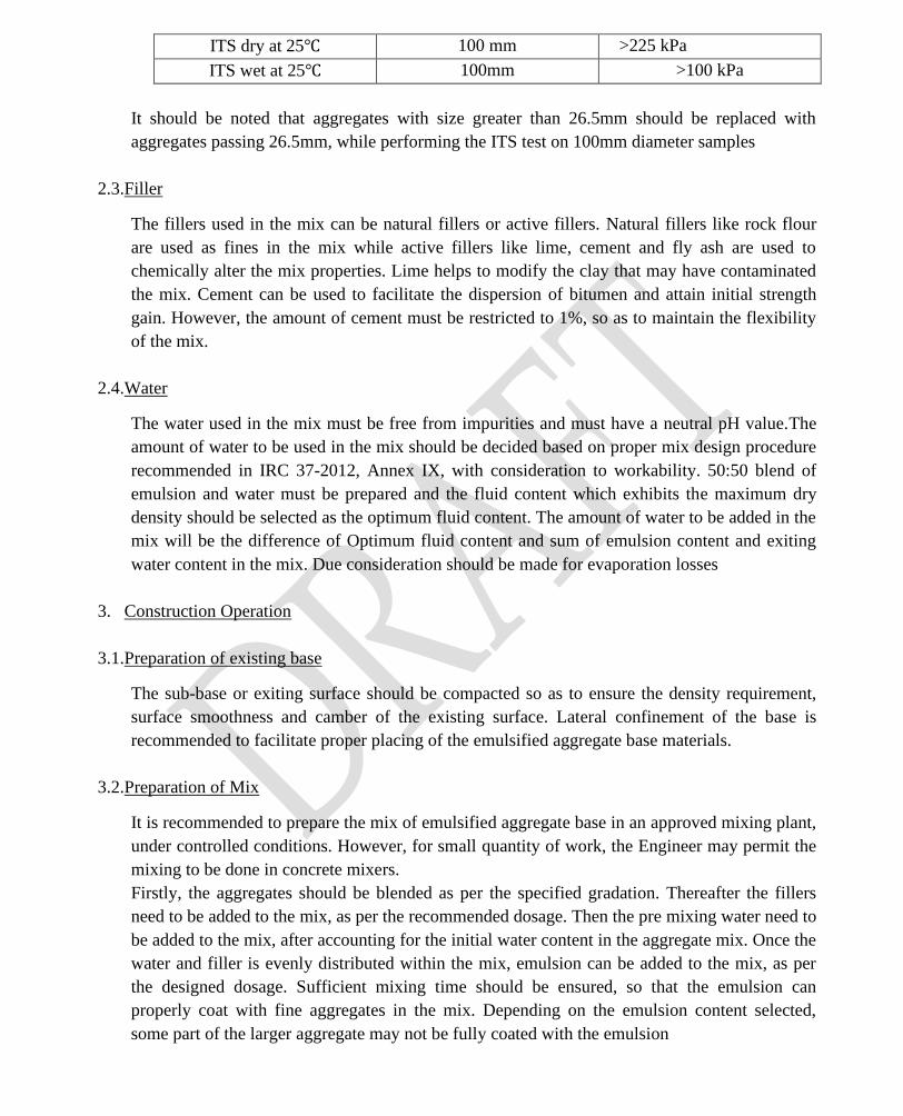
ITS dry at 25℃ 100 mm >225 kPa
ITS wet at 25℃ 100mm >100 kPa
It should be noted that aggregates with size greater than 26.5mm should be replaced with
aggregates passing 26.5mm, while performing the ITS test on 100mm diameter samples
2.3.Filler
The fillers used in the mix can be natural fillers or active fillers. Natural fillers like rock flour
are used as fines in the mix while active fillers like lime, cement and fly ash are used to
chemically alter the mix properties. Lime helps to modify the clay that may have contaminated
the mix. Cement can be used to facilitate the dispersion of bitumen and attain initial strength
gain. However, the amount of cement must be restricted to 1%, so as to maintain the flexibility
of the mix.
2.4.Water
The water used in the mix must be free from impurities and must have a neutral pH value.The
amount of water to be used in the mix should be decided based on proper mix design procedure
recommended in IRC 37-2012, Annex IX, with consideration to workability. 50:50 blend of
emulsion and water must be prepared and the fluid content which exhibits the maximum dry
density should be selected as the optimum fluid content. The amount of water to be added in the
mix will be the difference of Optimum fluid content and sum of emulsion content and exiting
water content in the mix. Due consideration should be made for evaporation losses
3. Construction Operation
3.1.Preparation of existing base
The sub-base or exiting surface should be compacted so as to ensure the density requirement,
surface smoothness and camber of the existing surface. Lateral confinement of the base is
recommended to facilitate proper placing of the emulsified aggregate base materials.
3.2.Preparation of Mix
It is recommended to prepare the mix of emulsified aggregate base in an approved mixing plant,
under controlled conditions. However, for small quantity of work, the Engineer may permit the
mixing to be done in concrete mixers.
Firstly, the aggregates should be blended as per the specified gradation. Thereafter the fillers
need to be added to the mix, as per the recommended dosage. Then the pre mixing water need to
be added to the mix, after accounting for the initial water content in the aggregate mix. Once the
water and filler is evenly distributed within the mix, emulsion can be added to the mix, as per
the designed dosage. Sufficient mixing time should be ensured, so that the emulsion can
properly coat with fine aggregates in the mix. Depending on the emulsion content selected,
some part of the larger aggregate may not be fully coated with the emulsion

3.3.Spreading and Compaction of Mix
Immediately after the mixing, the blend of emulsified aggregates should be spread uniformly
and evenly upon the prepared sub-base in required thickness. It is recommended to lay the
aggregates to a thickness of 100mm to 150mm and then compact to three-fourth of its thickness.
Spreading and compaction should be done without any delay, so as avoid premature breaking of
emulsion. Special care must be taken during the compaction of mixes with higher percentage of
RAP, so as to ensure sufficient density and avoid permanent deformation during initial traffic. It
is recommended to spread the mix using mechanical means like pavers. However, for smaller
quantity of work, manual spreading may be permitted, as in case of concrete mixes. The surface
of the layer shall be carefully checked using levels and all kinds of undulation needs to be
corrected. Segregation of large or fine particles should not be allowed at any cases. The
aggregate should be of uniform gradation with no pockets of fine materials. Roller with 80 to
100KN weight, operating at 5kmph can be used for compaction.
3.4.Curing and Opening to traffic
The major concern of using emulsified aggregate base, is the rate of strength gain during the
initial period. It should be strictly ensured that the construction of emulsified aggregate base is
done only in dry climactic conditions, without any possible chances of rain. The rate of
evaporation of water from the emulsion will help to facilitate the strength gain. No kinds of
vehicles should be permitted during the initial 24 hours, so as to avoid the occurrence of
permanent deformation. Two wheelers, car and LCV can be permitted on the surface after the
initial 24 hours of construction. The surface layer can be constructed after 14 days of curing.
Heavier commercial vehicles should be permitted to use the road facility only after the
construction of surface layer or 14 days of curing of emulsified aggregate base, in special cases.
2208 WET MIX MACADAM
Wet mix Macadam (WMM) is constructed as a subbase or base and in accordance with IRC: 109.
The detailed specification and construction procedures for the work are given under Clause 406 of
MoRTH Specification for Road and Bridge works (5th revision2013).
2208.1 Materials
a) The coarse aggregates shall be crushedstone.
b) The physical requirements of coarse aggregates for WMM sub-base/base layer is give in
table 2200-13 (Ref: Table 400-12 of MoRTHSpecifications).
Table 2200-13: Physical requirements of coarse aggregate for WMM
Sl. No.
Test Code Minimum
requirement
1 Los Angeles Abrasion value*
IS: 2386 (Part 4)
40% (Max)
2 Aggregate Impact value* IS: 2386 (Part 4)
30% (Max)
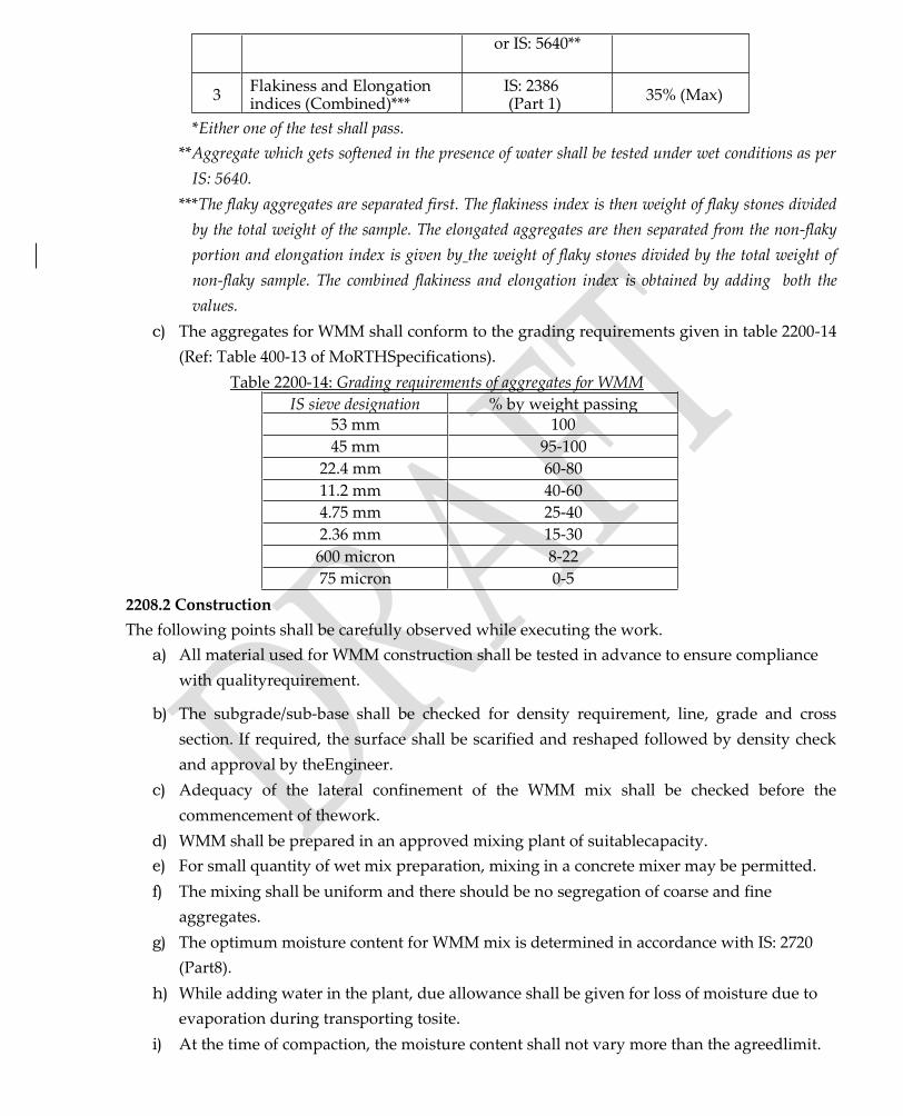
or IS: 5640**
3 Flakiness and Elongation indices (Combined)***
IS: 2386 (Part 1)
35% (Max)
*Either one of the test shall pass.
**Aggregate which gets softened in the presence of water shall be tested under wet conditions as per
IS: 5640.
***The flaky aggregates are separated first. The flakiness index is then weight of flaky stones divided
by the total weight of the sample. The elongated aggregates are then separated from the non-flaky
portion and elongation index is given by the weight of flaky stones divided by the total weight of
non-flaky sample. The combined flakiness and elongation index is obtained by adding both the
values.
c) The aggregates for WMM shall conform to the grading requirements given in table 2200-14
(Ref: Table 400-13 of MoRTHSpecifications).
Table 2200-14: Grading requirements of aggregates for WMM
IS sieve designation % by weight passing 53 mm 100
45 mm 95-100
22.4 mm 60-80
11.2 mm 40-60
4.75 mm 25-40
2.36 mm 15-30
600 micron 8-22
75 micron 0-5
2208.2 Construction
The following points shall be carefully observed while executing the work.
a) All material used for WMM construction shall be tested in advance to ensure compliance
with qualityrequirement.
b) The subgrade/sub-base shall be checked for density requirement, line, grade and cross
section. If required, the surface shall be scarified and reshaped followed by density check
and approval by theEngineer.
c) Adequacy of the lateral confinement of the WMM mix shall be checked before the
commencement of thework.
d) WMM shall be prepared in an approved mixing plant of suitablecapacity.
e) For small quantity of wet mix preparation, mixing in a concrete mixer may be permitted.
f) The mixing shall be uniform and there should be no segregation of coarse and fine
aggregates.
g) The optimum moisture content for WMM mix is determined in accordance with IS: 2720
(Part8).
h) While adding water in the plant, due allowance shall be given for loss of moisture due to
evaporation during transporting tosite.
i) At the time of compaction, the moisture content shall not vary more than the agreedlimit.

j) The wet mix shall be spread by the paver finisher or motorgrader.
k) After spreading, the surface of the aggregate shall be carefully checked with a template.
Any high or low spots noticed shall be removed or filled up, as required.
l) The thickness of the layer shall be checked using depthblocks.
m) Rolling of the spread material shall begin immediately from edge to thecentre.
n) In curve portions, rolling shall proceed from inner edge to theouter.
o) Rolling shall continue till the required density is achieved. By site trials number of passes
required by each roller to achieve the specified level of compaction can be determined.
p) After final compaction, the layer is allowed to dry for 24hours.
q) No traffic shall be allowed over the WMM layer till the wearing course islaid.
2208.3 Quality Control
The control tests and their minimum frequencies for WMM are given in table 2200-15 (Ref: Table
900-3 of MoRTH Specifications). The QC tests shall be carried out even if the quantity of materials
or work done is less than that specified in the frequency for testing.
Table 2200-15: QC tests for WMM
Sl. No.
Test Code Minimum desirable
frequency 1 Gradation IS: 2386(Part 1) One test per 200 m3.
2 Aggregate Impact Value*
IS: 2386 (Part 4) or IS: 5640
One test per 1000 m3.
3 Los Angeles Abrasion value*
IS: 2386 (Part 4) One test per 1000 m3.
4
Flakiness and elongation indices (Combined)
IS: 2386 (Part 1)
One test per 500 m3.
5 Atterberg limits IS: 2720 (Part 5) One test per 200 m3.
6 Moisture content prior to compaction IS: 2720 (Part 2) One test per 400 m3.
7 Dry density of compacted layer
IS: 2720 (Part 28) A set of three tests per 1000 m2.
*Either one of the test shall pass.
2208.4 Rectification of surface irregularities
a) If the surface irregularity of the WMM layer exceeds the permissible tolerance, the same
shall berectified.
b) Such areas shall be scarified to the full depth, excess material removed or fresh material
added, as found necessary and recompacted to the requireddensity.
c) In no case, the depression shall be filled up with unmixed or ungraded materials orfines.
512. MODIFIED BITUMEN
ThisSub-sectiondealswiththehandlingoftheModifiedBitumensandimportantteststobecarriedout during execution of the works in which their use isspecified.
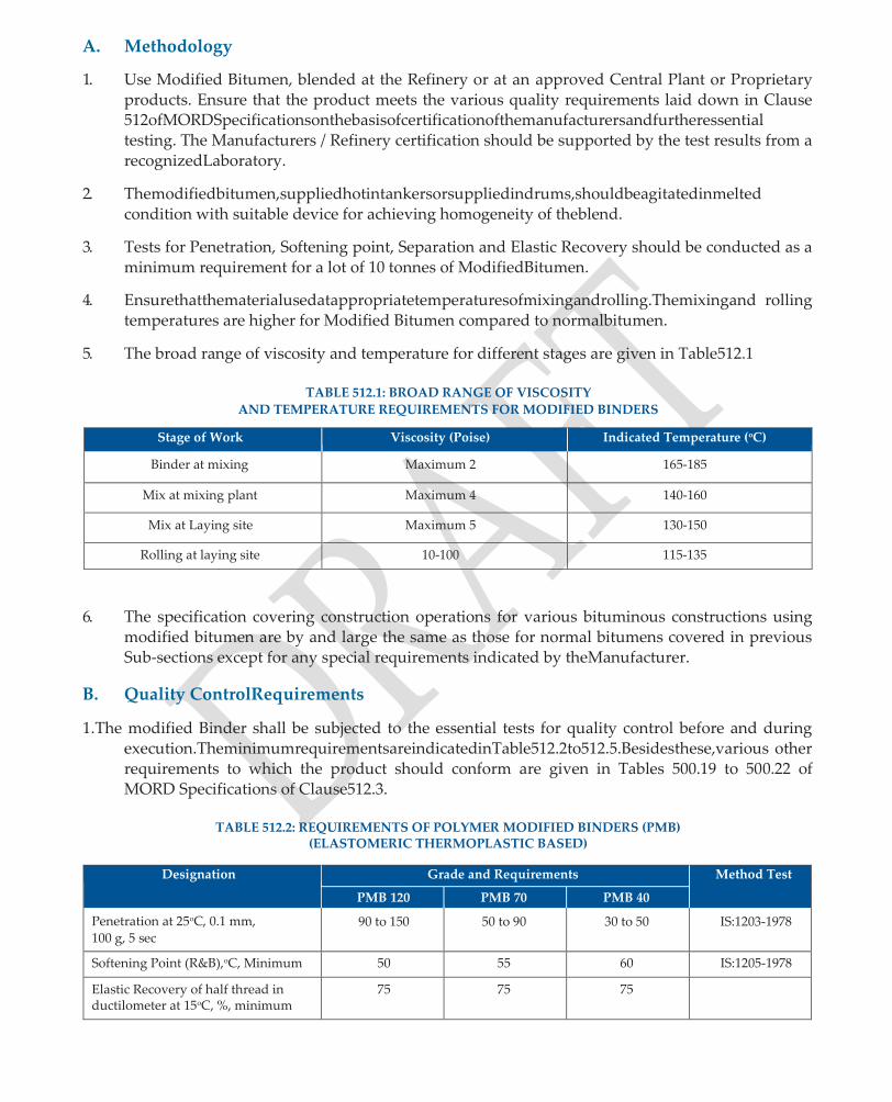
A. Methodology
1. Use Modified Bitumen, blended at the Refinery or at an approved Central Plant or Proprietary products. Ensure that the product meets the various quality requirements laid down in Clause 512ofMORDSpecificationsonthebasisofcertificationofthemanufacturersandfurtheressential testing. The Manufacturers / Refinery certification should be supported by the test results from a recognizedLaboratory.
2. Themodifiedbitumen,suppliedhotintankersorsuppliedindrums,shouldbeagitatedinmelted condition with suitable device for achieving homogeneity of theblend.
3. Tests for Penetration, Softening point, Separation and Elastic Recovery should be conducted as a minimum requirement for a lot of 10 tonnes of ModifiedBitumen.
4. Ensurethatthematerialusedatappropriatetemperaturesofmixingandrolling.Themixingand rolling temperatures are higher for Modified Bitumen compared to normalbitumen.
5. The broad range of viscosity and temperature for different stages are given in Table512.1
TABLE 512.1: BROAD RANGE OF VISCOSITY
AND TEMPERATURE REQUIREMENTS FOR MODIFIED BINDERS
Stage of Work Viscosity (Poise) Indicated Temperature (oC)
Binder at mixing Maximum 2 165-185
Mix at mixing plant Maximum 4 140-160
Mix at Laying site Maximum 5 130-150
Rolling at laying site 10-100 115-135
6. The specification covering construction operations for various bituminous constructions using modified bitumen are by and large the same as those for normal bitumens covered in previous Sub-sections except for any special requirements indicated by theManufacturer.
B. Quality ControlRequirements
1.The modified Binder shall be subjected to the essential tests for quality control before and during execution.TheminimumrequirementsareindicatedinTable512.2to512.5.Besidesthese,various other requirements to which the product should conform are given in Tables 500.19 to 500.22 of MORD Specifications of Clause512.3.
TABLE 512.2: REQUIREMENTS OF POLYMER MODIFIED BINDERS (PMB)
(ELASTOMERIC THERMOPLASTIC BASED)
Designation Grade and Requirements Method Test
PMB 120 PMB 70 PMB 40
Penetration at 25oC, 0.1 mm,
100 g, 5 sec 90 to 150 50 to 90 30 to 50 IS:1203-1978
Softening Point (R&B),oC, Minimum 50 55 60 IS:1205-1978
Elastic Recovery of half thread in ductilometer at 15oC, %, minimum
75 75 75
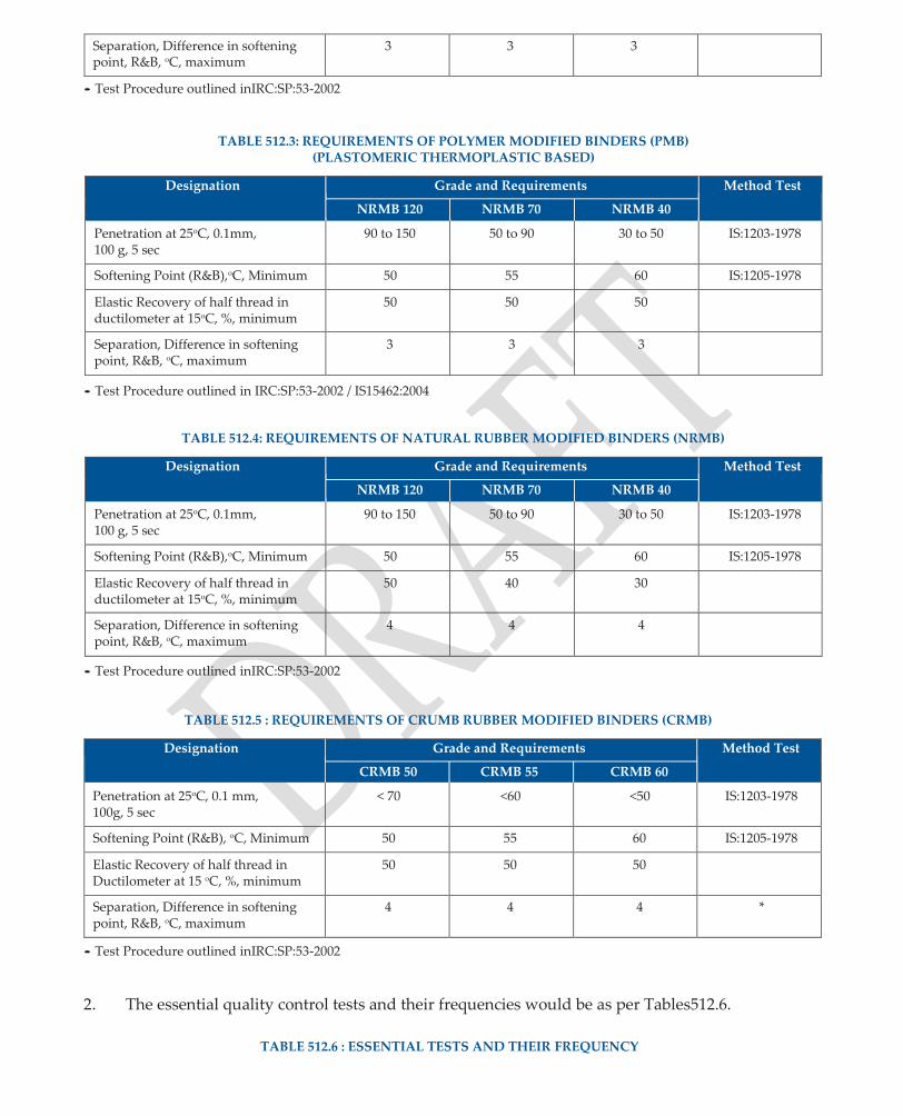
Separation, Difference in softening point, R&B, oC, maximum
3 3 3
• Test Procedure outlined inIRC:SP:53-2002
TABLE 512.3: REQUIREMENTS OF POLYMER MODIFIED BINDERS (PMB)
(PLASTOMERIC THERMOPLASTIC BASED)
Designation Grade and Requirements Method Test
NRMB 120 NRMB 70 NRMB 40
Penetration at 25oC, 0.1mm, 100 g, 5 sec
90 to 150 50 to 90 30 to 50 IS:1203-1978
Softening Point (R&B),oC, Minimum 50 55 60 IS:1205-1978
Elastic Recovery of half thread in ductilometer at 15oC, %, minimum
50 50 50
Separation, Difference in softening point, R&B, oC, maximum
3 3 3
• Test Procedure outlined in IRC:SP:53-2002 / IS15462:2004
TABLE 512.4: REQUIREMENTS OF NATURAL RUBBER MODIFIED BINDERS (NRMB)
Designation Grade and Requirements Method Test
NRMB 120 NRMB 70 NRMB 40
Penetration at 25oC, 0.1mm, 100 g, 5 sec
90 to 150 50 to 90 30 to 50 IS:1203-1978
Softening Point (R&B),oC, Minimum 50 55 60 IS:1205-1978
Elastic Recovery of half thread in ductilometer at 15oC, %, minimum
50 40 30
Separation, Difference in softening point, R&B, oC, maximum
4 4 4
• Test Procedure outlined inIRC:SP:53-2002
TABLE 512.5 : REQUIREMENTS OF CRUMB RUBBER MODIFIED BINDERS (CRMB)
Designation Grade and Requirements Method Test
CRMB 50 CRMB 55 CRMB 60
Penetration at 25oC, 0.1 mm, 100g, 5 sec
< 70 <60 <50 IS:1203-1978
Softening Point (R&B), oC, Minimum 50 55 60 IS:1205-1978
Elastic Recovery of half thread in Ductilometer at 15 oC, %, minimum
50 50 50
Separation, Difference in softening point, R&B, oC, maximum
4 4 4 *
• Test Procedure outlined inIRC:SP:53-2002
2. The essential quality control tests and their frequencies would be as per Tables512.6.
TABLE 512.6 : ESSENTIAL TESTS AND THEIR FREQUENCY

Test Test Method Frequency
Quality of Binder • PenetrationIS:1203· • Softening PointIS:1205· • Elastic RecoveryIS:15462-2004· • SeparationIS:15462-2004
One Test per lot of 10 tonnes for each source.
C. DO’s andDon’ts
Do’s Don’ts
1. Agitatemodifiedbitumenusingsuitablemechanical stirrers from time to time to avoidseparation.
2. Obtain tests certificates and details of otheressential requirements to be followed in itsuse.
1. Do not modify bitumen atsite.
2. Do not multiple heat modifiedbitumen.

DETERMINATION OF TEMPERATURE OF BINDER
ANNEX- I
Thetemperatureofbituminousbindershallbedeterminedwiththehelpofacalibratedmetalliccontact thermometer with digital (LCD / LED) display. The range of thermometer for different types of bituminous material and their accuracy shall be asunder:
(1) MeltedBitumen : ambient to 200oC accuracy + 1oC
(2) Cutbackbitumen : ambient to 100oC accuracy + 0.5oC
(3) Bitumenemulsion : ambient to 80oC accuracy + 0.5oC
ANNEX- II
RATE OF SPREAD OF BINDER IN SURFACE DRESSING AND MODIFIED PENETRATION MACADAM
Lightmetaltraysof200mmx200mmand30mmdepthareweighedandnumbered.Theseareplaced at intervals along the road in the path of bitumen distributor between the wheel tracks. After the distributor has passed over, the trays are removed and wrapped in weight sheets of paper so that they can be handed, stocked and weighed as soon as convenient. The spacing and the number of trays can bevariedtosuittheparticularconditionsattheconstructionsite,butatleastfivetraysshouldnormally be used. The tray test gives a measure of variation in rate of spread of bitumen along the road and a good approximation to the average rate of spread ofbitumen.
Thetraysareweightedcorrecttofirstplaceofdecimal.Themaximumlongitudinaldistributionerrorin rate of spread of bitumen should be within +10 per cent of the specified rate of spread of bitumen. Similarly transverse distribution of bitumen can be checked by placing a number of trays to collect bitumen sprayed over each 50 mm width of spray bar. The variation in transverse distribution should be within + 20 per cent from the mean. The extreme 150 mm width at either side of the sprayed area need not be taken intoaccount.
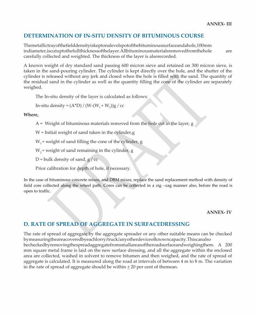
DETERMINATION OF IN-SITU DENSITY OF BITUMINOUS COURSE
ANNEX- III
Themetallictrayofthefielddensityiskeptonalevelspotofthebituminoussurfaceandahole,100mm indiameter,iscutuptothefullthicknessofthelayer.Allbituminousmaterialsremovedfromthehole are carefully collected and weighted. The thickness of the layer is alsorecorded.
A known weight of dry standard sand passing 600 micron sieve and retained on 300 micron sieve, is taken in the sand-pouring cylinder. The cylinder is kept directly over the hole, and the shutter of the cylinder is released without any jerk and closed when the hole is filled with the sand. The quantity of the residual sand in the cylinder as well as the quantity filling the cone of the cylinder are separately weighed.
The In-situ density of the layer is calculated as follows:
In-situ density = (A*D) / (W-(W1 + W2))g / cc
Where,
A = Weight of bituminous materials removed from the hole cut in the layer, g
W = Initial weight of sand taken in the cylinder,g
W1 = weight of sand filling the cone of the cylinder, g
W2 = weight of sand remaining in the cylinder, g
D = bulk density of sand, g / cc
Prior calibration for depth of hole, if necessary.
In the case of bituminous concrete mixes, and DBM mixes, replace the sand replacement method with density of
field core collected along the wheel path. Cores can be collected in a zig –zag manner also, before the road is
open to traffic.
D. RATE OF SPREAD OF AGGREGATE IN SURFACEDRESSING
ANNEX- IV
The rate of spread of aggregate by the aggregate spreader or any other suitable means can be checked bymeasuringtheareacoveredbyeachlorry/truck/anyotherdeviceofknowncapacity.Thiscanalso becheckedbyremovingthespreadaggregatefromsmallareasoftheroadsurfaceandweighingthem. A 200 mm square metal frame is laid on the new surface dressing, and all the aggregate within the enclosed area are collected, washed in solvent to remove bitumen and then weighed, and the rate of spread of aggregate is calculated. It is measured along the road at intervals of between 4 m to 8 m. The variation in the rate of spread of aggregate should be within + 20 per cent of themean.
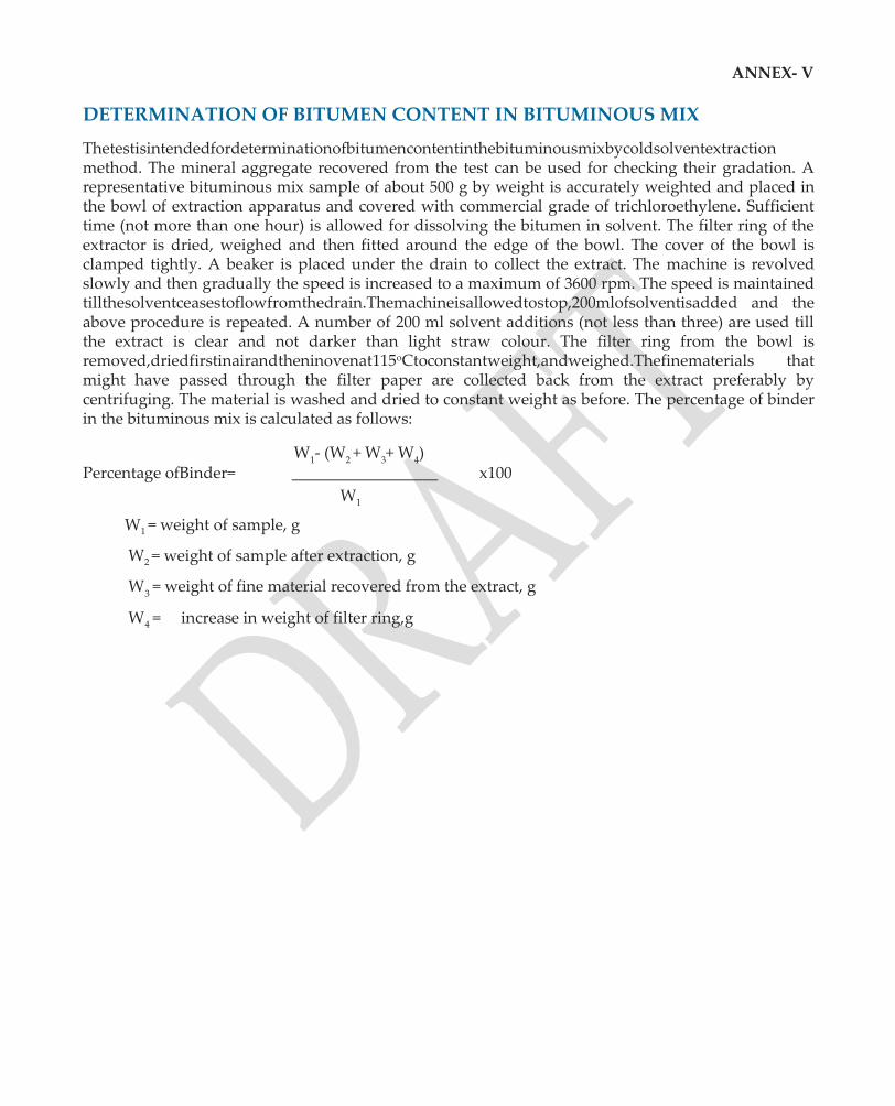
DETERMINATION OF BITUMEN CONTENT IN BITUMINOUS MIX
ANNEX- V
Thetestisintendedfordeterminationofbitumencontentinthebituminousmixbycoldsolventextraction method. The mineral aggregate recovered from the test can be used for checking their gradation. A representative bituminous mix sample of about 500 g by weight is accurately weighted and placed in the bowl of extraction apparatus and covered with commercial grade of trichloroethylene. Sufficient time (not more than one hour) is allowed for dissolving the bitumen in solvent. The filter ring of the extractor is dried, weighed and then fitted around the edge of the bowl. The cover of the bowl is clamped tightly. A beaker is placed under the drain to collect the extract. The machine is revolved slowly and then gradually the speed is increased to a maximum of 3600 rpm. The speed is maintained tillthesolventceasestoflowfromthedrain.Themachineisallowedtostop,200mlofsolventisadded and the above procedure is repeated. A number of 200 ml solvent additions (not less than three) are used till the extract is clear and not darker than light straw colour. The filter ring from the bowl is removed,driedfirstinairandtheninovenat115oCtoconstantweight,andweighed.Thefinematerials that might have passed through the filter paper are collected back from the extract preferably by centrifuging. The material is washed and dried to constant weight as before. The percentage of binder in the bituminous mix is calculated as follows:
W1- (W
2 + W
3+ W
4)
Percentage ofBinder= x100
W1
W1 = weight of sample, g
W2 = weight of sample after extraction, g
W3 = weight of fine material recovered from the extract, g
W4 = increase in weight of filter ring,g
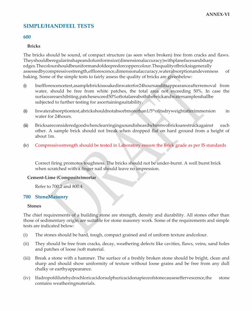
ANNEX-VI
SIMPLE/HANDFEEL TESTS
600
Bricks
The bricks should be sound, of compact structure (as seen when broken) free from cracks and flaws. Theyshouldberegularinshapeandofuniformsize(dimensionalaccuracy)withplanefacesandsharp edges.Thecolourshouldbeuniformandofdeepredorcoppercolour.Thequalityofbricksisgenerally assessedbycompressivestrength,efflorescence,dimensionalaccuracy,waterabsorptionandevenness of baking. Some of the simple tests to fairly assess the quality of bricks are givenbelow:
(i) Inefflorescencetest,asamplebrickissoakedinwaterfor24hoursanditsappearanceafterremoval from water, should be free from white patches, the total area not exceeding 50%. In case the surfaceareaexhibiting,patchesexceed50%oftotalareaboththebrickandwatersamplesshallbe subjected to further testing for ascertainingsuitability.
(ii) Inwaterabsorptiontest,abrickshouldnotabsorbmorethan1/5thofitsdryweightafterimmersion in water for 24hours.
(iii) Bricksareconsideredgoodwhenclearringingsoundisheardwhentwobricksarestruckagainst each other. A sample brick should not break when dropped flat on hard ground from a height of about 1m.
(iv) Compressivestrength should be tested in Laboratory ensure the Brick grade as per IS standards
Correct firing promotes toughness. The bricks should not be under-burnt. A well burnt brick when scratched with a finger nail should leave no impression.
Cement-Lime (Composite)mortar
Refer to 700.2 and 800.4
700 StoneMasonry
Stones
The chief requirements of a building stone are strength, density and durability. All stones other than those of sedimentary origin are suitable for stone masonry work. Some of the requirements and simple tests are indicated below:
(i) The stones should be hard, tough, compact grained and of uniform texture andcolour.
(ii) They should be free from cracks, decay, weathering defects like cavities, flaws, veins, sand holes and patches of loose /soft material.
(iii) Break a stone with a hammer. The surface of a freshly broken stone should be bright, clean and sharp and should show uniformity of texture without loose grains and be free from any dull chalky or earthyappearance.
(iv) Ifadropofdilutehydrochloricacidorsulphuricacidonapieceofstonecauseseffervescence,the stone contains weatheringmaterials.
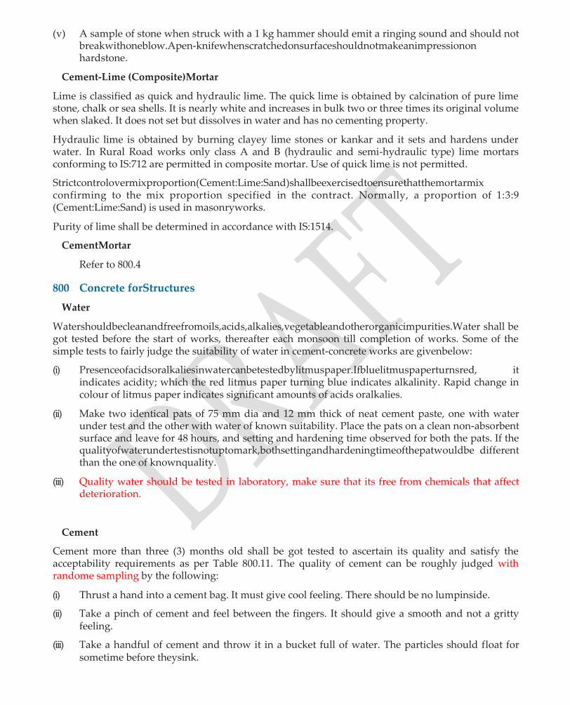
(v) A sample of stone when struck with a 1 kg hammer should emit a ringing sound and should not breakwithoneblow.Apen-knifewhenscratchedonsurfaceshouldnotmakeanimpressionon hardstone.
Cement-Lime (Composite)Mortar
Lime is classified as quick and hydraulic lime. The quick lime is obtained by calcination of pure lime stone, chalk or sea shells. It is nearly white and increases in bulk two or three times its original volume when slaked. It does not set but dissolves in water and has no cementing property.
Hydraulic lime is obtained by burning clayey lime stones or kankar and it sets and hardens under water. In Rural Road works only class A and B (hydraulic and semi-hydraulic type) lime mortars conforming to IS:712 are permitted in composite mortar. Use of quick lime is not permitted.
Strictcontrolovermixproportion(Cement:Lime:Sand)shallbeexercisedtoensurethatthemortarmix confirming to the mix proportion specified in the contract. Normally, a proportion of 1:3:9 (Cement:Lime:Sand) is used in masonryworks.
Purity of lime shall be determined in accordance with IS:1514.
CementMortar
Refer to 800.4
800 Concrete forStructures
Water
Watershouldbecleanandfreefromoils,acids,alkalies,vegetableandotherorganicimpurities.Water shall be got tested before the start of works, thereafter each monsoon till completion of works. Some of the simple tests to fairly judge the suitability of water in cement-concrete works are givenbelow:
(i) Presenceofacidsoralkaliesinwatercanbetestedbylitmuspaper.Ifbluelitmuspaperturnsred, it indicates acidity; which the red litmus paper turning blue indicates alkalinity. Rapid change in colour of litmus paper indicates significant amounts of acids oralkalies.
(ii) Make two identical pats of 75 mm dia and 12 mm thick of neat cement paste, one with water under test and the other with water of known suitability. Place the pats on a clean non-absorbent surface and leave for 48 hours, and setting and hardening time observed for both the pats. If the qualityofwaterundertestisnotuptomark,bothsettingandhardeningtimeofthepatwouldbe different than the one of knownquality.
(iii) Quality water should be tested in laboratory, make sure that its free from chemicals that affect deterioration.
Cement
Cement more than three (3) months old shall be got tested to ascertain its quality and satisfy the acceptability requirements as per Table 800.11. The quality of cement can be roughly judged with randome sampling by the following:
(i) Thrust a hand into a cement bag. It must give cool feeling. There should be no lumpinside.
(ii) Take a pinch of cement and feel between the fingers. It should give a smooth and not a gritty feeling.
(iii) Take a handful of cement and throw it in a bucket full of water. The particles should float for sometime before theysink.

(iv) Take about 100 gm of cement and mix it with water to make a stiff paste. Make a cake with sharp edges. Put it on a glass plate and slowly take it under water in a bucket, without disturbing the shape of cake. After 24 hours, the cake should retain its original shape and gain somestrength.
(v) Setting time: Make a stiff paste of neat cement and water, and form it into a pat of about 75 mm diaand12to25mmthick.Thepatshouldcommencetosetin30to60minutes.Thecommencement of setting can be roughly estimated by pressing the uncut end of a lead pencil into mass. The resistance to piercing increases suddenly when setting commences. In 18 to 24 hours, the pat should have hardened sufficiently so that a scratch can be made with a thumbnail.
(vi) Soundness: Boil the set pat (as above) in water for about 5 hours. The pat should remain sound and hard and should not swell, crack or disintegrate, but may show only hair cracks. Reject cement if pat shows radial cracks or curl orcrumble.
(vii) Fineness:Inthesievetest,100gmcementiscorrectlyweighedandplacedon90micronsieve.Air set lumps, if any, are broken down with fingers. The sample is sieved for 15 minutes and the residue left on the sieve is weighed. The amount of residue should not exceed 10% forOPC.
Sand or FineAggregate
Thesandshouldbesharp,clean,chemicallyinert,coarseandgrittytothetouchandfreefromsilt/clay and organic impurities. The general quality of sand can be assessed by random sampling asbelow:
(i) Presence of Silt or Clay: Rub a sample of sand between damp hands and note the discolouration causedonthepalm.Ifthesandisclear,thepalmwouldbestainedslightly.Ifthehandsstaydirty after sand has been thrown away, it indicates too much of silt orclay.
(ii) Sedimentation: Place, without drying, a sample of sand in a 200 ml measuring cylinder upto 100 ml mark. Add clean water upto 150 ml mark. Shake the contents vigorously and allow it to settle for 3 hours. The height of the silt visible as a layer above the sand is expressed as a percentage of the sandbelow.
(iii) Organic impurities: Shake the sample with an equal volume of 3% solution of NaOH (Caustic soda)andallowittosettlefor24hours.Examinethecolouroftheliquidabovethesand.Clearor paleyellowcolourshowsthatthesampleistolerablyfreefromorganicimpurities.Darkyellowor brown tinge shows that the sand should be washed and tested again. If on retesting, dark yellow colour persists, the sand should berejected.
Cement-Mortar
(i) The cement mortar if unused for more than 30 minutes after addition of water shall be rejected and removed fromsite.
(ii) The mix proportion of cement: sand can be checked asfollows:
Takeabout200gmofgreencementmortarandadd100mlofwaterinameasuringjarandshake the contents well and allow the contents to settle. While the sand gets deposited at the bottom, cement shall settle above. From the volumes of each, the approximate proportion of cement and sand can bedetermined.
(iii) Consistency: Mortar consistency can be checked by thefollowing:
(a) If a small quantity of mortar is dropped from a trowel, the trowel ought to be left perfectly clean.

(b) A little mortar worked gently in the hands should be easily moulded into a ball; on the surface of which water wouldappear.
(c) When the ball is dropped from a height of half a meter (500 mm) on a hard surface, it must retain its roundedshape.
CoarseAggregates
Coarseaggregatesshallbehard,strong,non-porous,freefromfriable,elongatedandlaminatedparticles. They shall be clean and free from clay, coal, vegetable and other organicmaterial.
Two simple tests to check the suitability of stone aggregates are given below:
(i) If the aggregates of a known quantity absorb more than 10 percent of their weight after 24 hours immersion in water, they are considered porous and areavoidable.
(ii) IfMicainclusionspersistonthesurface,thestoneaggregatesshallberejectedaspresenceofMica affects durability ofconcrete.
However, the detailed tests indicated in Table 800.13 are to be conducted before the use of coarse aggregates in concrete bridgeworks.
CementConcrete
The principal requirements of concrete include workability, strength, durability, impermeability, and volume changes. Some of the simple tests to determine quality of concrete are described below:
(i) Consistency: The concrete can be considered to satisfy consistency requirement if an ordinary iron rammer sinks into concrete mixture by its own weight. It shall run-off a showel unless showelledveryquickly;andshallspreadoutandsettletoalevelsurfaceafterwheelingforabout 8 m distance in a wheelbarrow.
(ii) Workability: Take a handful of concrete in left hand and make a round ball with both hands. If a ballcanbemaintainedforawhile,itisindicativeofa‘workablemix’.Anyloworhighcontentof water cannot make a good ball ofconcrete.
(iii) Slump test should be done at site before placing of concrete, Slump value should be as per IS Standards as per type work/ construction otherwise will be rejected
(iv) Compressive strength test and water absorption test/ Permeability test should done in laboratory by taking random sampling at site.
(v) Concrete bridge worksCompressive strength test, Split Tensile/ Flexural strength test and water absorption test/ Permeability test should done in laboratory by taking random sampling at site.
(vi) Alkali Silica Reaction(ASR):
Alkali Silica reactivity is noticed in aggregates crushed with siliceous rock. When aggregates are immersed in water, a slight increase in volume occurs. If alkali content in Portland cement is less than 0.6 percent by weight, no harmful reaction occurs.
The Basalt rocks found in parts of Deccan plateau, Madhya Pradesh, Kathiawar peminsula of Gujarat, J&K, Jharkhand and West Bengal should be viewed with caution. Similarly, some lime- stonescontainingchertmodulesoccurringinMadhyaPradesh,Rajasthan,PunjabandAssamare reactive.
DuetoASR,normallydamppatchesarevisibleatthejunctionofcracks,theedgesofcracksoften appearlightincolour,theconcreteoftenhasanuncharacteristicpinkishappearanceintheaffected areas. There will be negligible spalling of concrete but exudation may occur from some of the

cracks.
If aggregates are suspect of likely positive ASR on the basis of past performance or any evidence, it is always recommended that the aggregates are tested as per IS:2386 part 7 before they are approved for the use for making concrete.

Quality Assurance Handbook for Rural Roads
121
SECTION 600
BRICKWORK FOR
STRUCTURES

600 : BRICKWORK FOR STRUCTURES
A. Methodology
A1 GeneralBrickwork
1. Soakallbricksforaminimumperiodofonehourbeforeuseandremovefromtanksufficientlyin advance so that they are skin dry before actuallaying.
2. Before laying the bricks in foundation, hack the top surface of the foundation block, clean, wet and spread a layer of mortar of 12 mm (minimum) thickness, to prepare the surface. In case of masonryworksrestingonrockbase,layalevelinglayerof150mm(average)thicknessinconcrete of M10grade.
3. Lay all brickwork in English bond, even and true to line, plumb or specified batter and level. Break all joints in successive courses and lay jointsaccurately.
4. Lay all bricks with frogs up, if any on a full bed of mortar. Slightly press the bricks so that the mortar gets into all hollow space of bricks to ensure proper adhesion. Flush all joints and pack with mortar, to fill all hollowspaces.
5. Build brickwork in uniform layers so that no part of brickwork shall rise more than one metre above the general construction level, to avoid unequal settlement and improperjointing.
6. Remove all loose bricks and mortar while joining partially set or entirely set brick masonry with newoneandroughenandwetwithcementslurrytoachieveproperbond.Incaseofverticaland inclined joints, achieve proper bond by inter locking thebricks.
7. Tool all joints on exposed faces to give a concave finish, the thickness of joint not exceeding 10 mm.
8. Keep masonry work in cement mortar constantly moist on all faces for a minimum period of sevendays.Leavethetopofmasonryworkfloodedwithwateratthecloseoftheday.Duringhot weatherwetorcoverallfinishedorpartlycompletedworktopreventrapiddryingofbrickwork. Maintainwateringandcuringatthecloseofday’sworkorforotherperiodofcessationofworks.
9. Erect single scaffolding for plastering, pointing and any finishing in which one end of the put- logs / pole shall rest in the hole provided in the header course of brick masonry. Provide double scaffolding having two independent supports clear of the work when brick work is exposed and not to befinished.
A2 Brick masonryarch
1. Erect scaffolding to withstand design loads and allowing approach to each part ofwork.
2. Erect centering to the correct curvature, supported on joints themselves or independently from the groundbelow.
3. Layfullscaleshapeofarchonaleveledplatformnearthesiteandmarksizeofbrickandmortar. Place alternate brick lengthwise and widthwise in outer rings of arch. Place remaining bricks in the inner part of arch to have uniformlength.
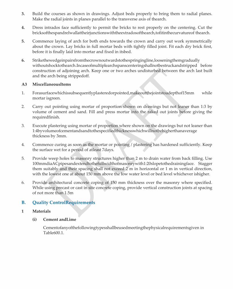
3. Build the courses as shown in drawings. Adjust beds properly to bring them to radial planes. Make the radial joints in planes parallel to the transverse axis of thearch.
4. Dress intrados face sufficiently to permit the bricks to rest properly on the centering. Cut the bricksofthespandrelwallattheirjunctionswiththeextradosofthearch,tofitinthecurvatureof thearch.
5. Commence laying of arch for both ends towards the crown and carry out work symmetrically about the crown. Lay bricks in full mortar beds with tightly filled joint. Fit each dry brick first, before it is finally laid into mortar and fixed in itsbed.
6. Strikethewedgeinpairsfromthecrownoutwardstothespringingline,looseningthemgradually withoutshocktothearch.Incaseofmultiplearchspanscenteringshallnotbestruckandstripped before construction of adjoining arch. Keep one or two arches undisturbed between the arch last built and the arch being strippedoff.
A3 MiscellaneousItems
1. Forasurfacewhichissubsequentlyplasteredorpointed,makeoutthejointstoadepthof15mm while mortar isgreen.
2. Carry out pointing using mortar of proportion shown on drawings but not leaner than 1:3 by volume of cement and sand. Fill and press mortar into the raked out joints before giving the requiredfinish.
3. Execute plastering using mortar of proportion where shown on the drawings but not leaner than 1:4byvolumeofcementandsandtothespecifiedthicknesswhichwillnotbehigherthanaverage thickness by 3mm.
4. Commence curing as soon as the mortar or pointing / plastering has hardened sufficiently. Keep the surface wet for a period of atleast 7days.
5. Provide weep holes to masonry structures higher than 2 m to drain water from back filling. Use 100mmdiaACpipesandextendtothefullwidthofmasonrywith1:20slopetothedrainingface. Stagger them suitably and their spacing shall not exceed 2 m in horizontal or 1 m in vertical direction, with the lowest one at about 150 mm above the low water level or bed level whichever ishigher.
6. Provide architectural concrete coping of 150 mm thickness over the masonry where specified. While using precast or cast in site concrete coping, provide vertical construction joints at spacing of not more than 1.5m
B. Quality ControlRequirements
1 Materials
(i) Cement andLime
Cementofanyofthefollowingtypesshallbeusedmeetingthephysicalrequirementsgiven in Table600.1.

TABLE 600.1: CEMENT AND LIME
Type Grade IS Code
Ordinary Portland Cement 33 IS: 269
Blast Furnace Slag Cement - IS:455
Portland Pozzolana Cement Fly ash based IS:1489-Part1
Portland Pozzolana Cement Calcined Clay Based IS:1489-Part II
Sulphate Resistance Portland Cement *
- IS:12330
Lime in Cement-Lime (Composite) Mortar
Type A and B IS:712
* Use in masonry structures which are likely to be affected by the presence of sulphates in surrounding soil or in ground water in concentration of 0.2 percent and 0.03 percentrespectively.
(ii) Sand/Stone Dust/MarbleDust
Sand or Stone Dust or Marble Dust shall consist of hard, durable and clean particles of natural sand, crushed gravel, crushed marble or suitable combinations there of and shall conform to the requirements given in Table 600.2
TABLE 600.2: SAND/STONE/MARBLE DUST
Material IS Code
Sand IS:2116
Stone / Marble Dust IS:383
(iii) Cement SandMortar
Cement Sand mortar shall in general conform to IS:2250 and its consistency and water retentivity shall be determined as per the code.
The recommended values of consistency and water retentivity are given in Table 600.3
TABLE 600.3 CONSISTENCY AND WATER RETENTIVITY
Property Work Value
Consistency - Laying of solid brick walls 90-130mm
- Filling cavities 130-150 mm
Water retentivity(Flow of suction) Masonry work with high suction characteristics
More than 70% of flow before suction
Refer to Sub-section 800 for the strength requirement of mortar using 33 Grade cement.
(iv) Bricks
First class bricks of any of the following two types shall be used in masonry works. The physical requirements of bricks are given in Table 600.4
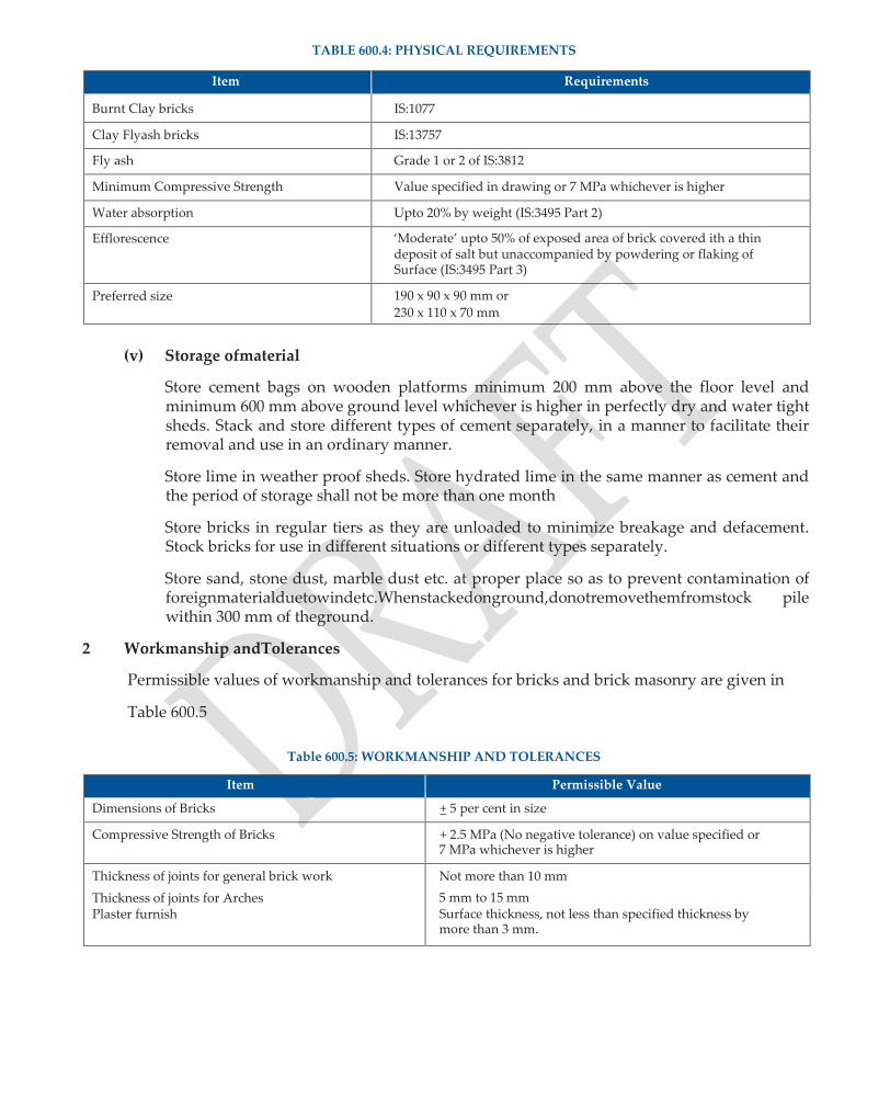
TABLE 600.4: PHYSICAL REQUIREMENTS
Item Requirements
Burnt Clay bricks IS:1077
Clay Flyash bricks IS:13757
Fly ash Grade 1 or 2 of IS:3812
Minimum Compressive Strength Value specified in drawing or 7 MPa whichever is higher
Water absorption Upto 20% by weight (IS:3495 Part 2)
Efflorescence ‘Moderate’ upto 50% of exposed area of brick covered ith a thin deposit of salt but unaccompanied by powdering or flaking of Surface (IS:3495 Part 3)
Preferred size 190 x 90 x 90 mm or
230 x 110 x 70 mm
(v) Storage ofmaterial
Store cement bags on wooden platforms minimum 200 mm above the floor level and minimum 600 mm above ground level whichever is higher in perfectly dry and water tight sheds. Stack and store different types of cement separately, in a manner to facilitate their removal and use in an ordinary manner.
Store lime in weather proof sheds. Store hydrated lime in the same manner as cement and the period of storage shall not be more than one month
Store bricks in regular tiers as they are unloaded to minimize breakage and defacement. Stock bricks for use in different situations or different types separately.
Store sand, stone dust, marble dust etc. at proper place so as to prevent contamination of foreignmaterialduetowindetc.Whenstackedonground,donotremovethemfromstock pile within 300 mm of theground.
2 Workmanship andTolerances
Permissible values of workmanship and tolerances for bricks and brick masonry are given in
Table 600.5
Table 600.5: WORKMANSHIP AND TOLERANCES
Item Permissible Value
Dimensions of Bricks + 5 per cent in size
Compressive Strength of Bricks + 2.5 MPa (No negative tolerance) on value specified or 7 MPa whichever is higher
Thickness of joints for general brick work Not more than 10 mm
Thickness of joints for Arches Plaster furnish
5 mm to 15 mm Surface thickness, not less than specified thickness by more than 3 mm.
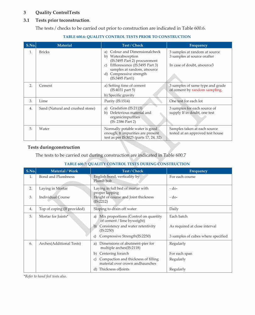
3 Quality ControlTests
3.1 Tests prior toconstruction.
The tests / checks to be carried out prior to construction are indicated in Table 600.6.
TABLE 600.6: QUALITY CONTROL TESTS PRIOR TO CONSTRUCTION
S.No. Material Test / Check Frequency
1. Bricks a) Colour and Dimensionalcheck b) Waterabsorption
(IS:3495 Part 2) procurement c) Efflorescence (IS:3495 Part 3)
samples at random, atsource d) Compressive strength
(IS:3495 Part1)
3 samples at random at source 3 samples at source orafter
In case of doubt, atsource3
2. Cement a) Setting time of cement (IS:4031 part 5)
b) Specific gravity
3 samples of same type and grade of cement by random sampling.
3. Lime Purity (IS:1514) One test for each lot
4. Sand (Natural and crushed stone) a) Gradation (IS:2115) b) Deleterious material and
organicimpurities (IS: 2386 Part 2)
3 samples for each source of supply If in doubt, one test
5. Water Normally potable water is good enough. If impurities are present test as per IS:3025 (parts 17, 24, 32)
Samples taken at each source tested at an approved test house
Tests duringconstruction
The tests to be carried out during construction are indicated in Table 600.7
TABLE 600.7: QUALITY CONTROL TESTS DURING CONSTRUCTION
S.No. Material / Work Test / Check Frequency
1. Bond and Plumbness English bond, verticality by Plumb bob
For each course
2.
3.
Laying in Mortar
Individual Course
Laying in full bed of mortar with proper lapping Height of course and Joint thickness (IS:2212)
- do-
- do-
4. Top of coping (If provided) Sloping to drain off water Daily
5. Mortar for Joints* a) Mix proportions (Control on quantity of cement / lime byweight)
b) Consistency and water retentivity (IS:2250)
c) Compressive Strength(IS:2250)
Each batch
As required at close interval
3 samples of cubes where specified
6. Arches(Additional Tests) a) Dimensions of abutment-pier for multiple arches(IS:2118)
b) Centering forarch
c) Compaction and thickness of filling material over crown andhaunches
d) Thickness ofJoints
Regularly
For each span
Regularly
Regularly
*Refer to hand feel tests also.
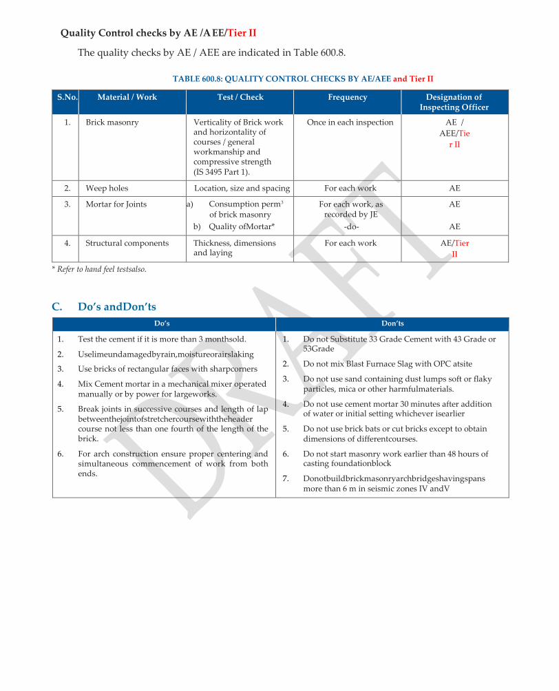
Quality Control checks by AE /AEE/Tier II
The quality checks by AE / AEE are indicated in Table 600.8.
TABLE 600.8: QUALITY CONTROL CHECKS BY AE/AEE and Tier II
S.No. Material / Work Test / Check Frequency Designation of Inspecting Officer
1. Brick masonry Verticality of Brick work and horizontality of courses / general workmanship and compressive strength (IS 3495 Part 1).
Once in each inspection AE /
AEE/Tie
r II
2. Weep holes Location, size and spacing For each work AE
3. Mortar for Joints a) Consumption perm3
of brick masonry
b) Quality ofMortar*
For each work, as recorded by JE
-do-
AE
AE
4. Structural components Thickness, dimensions and laying
For each work AE/Tier
II
* Refer to hand feel testsalso.
C. Do’s andDon’ts
Do’s Don’ts
1. Test the cement if it is more than 3 monthsold.
2. Uselimeundamagedbyrain,moistureorairslaking
3. Use bricks of rectangular faces with sharpcorners
4. Mix Cement mortar in a mechanical mixer operated manually or by power for largeworks.
5. Break joints in successive courses and length of lap betweenthejointofstretchercoursewiththeheader course not less than one fourth of the length of the brick.
6. For arch construction ensure proper centering and simultaneous commencement of work from both ends.
1. Do not Substitute 33 Grade Cement with 43 Grade or 53Grade
2. Do not mix Blast Furnace Slag with OPC atsite
3. Do not use sand containing dust lumps soft or flaky particles, mica or other harmfulmaterials.
4. Do not use cement mortar 30 minutes after addition of water or initial setting whichever isearlier
5. Do not use brick bats or cut bricks except to obtain dimensions of differentcourses.
6. Do not start masonry work earlier than 48 hours of casting foundationblock
7. Donotbuildbrickmasonryarchbridgeshavingspans more than 6 m in seismic zones IV andV

Quality Assurance Handbook for Rural Roads
129
SECTION 700
STONE MASONRY
FOR STRUCTURES

700 : STONE MASONRY FOR STRUCTURES
A. Methodology
A1 General Stone MasonryWork
1. Dressthestonesofrequiredsize(leastdimensionnotlessthan150mm)andquantityandimmerse in water for 24 hours before use. Use only rectangular shaped bond stones orheaders.
2. Laymasonryworktolines,levelsanddimensionsasshownonthedrawings.Thestonesshallbe laid on their natural beds in horizontal courses. Keep height of each course same, fine tool every stone on all bed joints with faces full andtrue.
3. Lay outer layers of masonry first, fix the location of headers and bond stones and lay them. Lay stones in the hearting on their broadest face to ensure filling the spaces betweenstones.
4. Whenthereistobevariationintheheightofthecourses,placelargercoursesatlowerlevelswith heights of courses decreasing gradually towards the top of thewall.
5. Intaperedwalls,thebedsofthestonesandplanesofcoursesshallbekeptrightangletothebatter. In case of piers with batter on both sides, keep the coursehorizontal.
6. Lay all stones, full in mortar both in bed and vertical joints and settled carefully in place with a wooden mallet, immediately on placement and solidly embedded in mortar before it hasset.
7. Beforelayingfirstcourseofstonemasonryonrock,placeconcretelevellingcourse(ofM10grade) of average thickness of 150mm.
8. Incaseanystonealreadysetinmortar,isdisturbedorthejointbroken,takeitoutwithoutdisturbing the adjacent stones and joint. Reset the stone in fresh mortar after removing dry mortar and thoroughly cleaning the stones andjoints.
9. Provide sufficient transverse bonds by the use of bond stones or set of bond stones extending fromthefronttothebackofthewallfromoutsidetotheinteriorandviceversa,overlappingeach other by 150 mm(minimum).
10. Use selected quoin stones and arrange to bond alternately long and short in bothdirections.
11. Make vertical joints truly vertical and staggered as far as possible. Keep the distance between vertical joints of upper and lower layer, more than half the height of thecourse.
A2 Stone MasonryArches
1. Erect scaffolding and centering as per Sub-section600
2. Lay a full scale shape of arch on a leveled platform near the construction site and mark size of each stone and mortarthickness.
3. Cut stones sizes accordingly. For outer ring of arch, choose long length and short length stones alternately. For inner part of arch, choose uniform length of stones, as far aspossible.
4. Adopt full size voussoirs throughout, with bond not less than their thickness as shown in the drawings.

5. Adjustbedstobringthemtoradialplanes.Keeptheplanesofradialjoints,paralleltothetransverse axis of thearch.
6. Sufficiently dress the intrados face, to permit the stones to rest properly on thecentering.
7. Cut the stones of the spandrel wall at their junctions with extrados of arch, to fit in the curvature ofarch.
8. Commencelayingofarchesfrombothendstowardsthecrownandcarryoutworksystematically with stones being placed in full mortar beds and joints grouted ifrequired.
A3 Miscellaneousitems
1. Carryout pointing, finishing and curing as detailed in Sub-section600.
2. Provide architectural stone or concrete coping of 150 mm thick over stone masonry. Provide vertical joints as specified in Sub-section600.
3. Provide weep holes as specified in brick masonry. Alternatively, locate the weep holes at the same height of course on which they are formed, the size being not less than 80 x 150mm.
B. Quality ControlRequirements
1. Materials
(i) Cement andlime
Same as in Section 600
(ii) Sand or Stone Dust or MarbleDust
Same as in Section 600
(iii) Cement SandMortar
Same as in Section 600
Adopt Cement mortar not leaner than 1:5, above bed ground level and 1:4 below bed / ground level. Mix proportion for arches not leaner than 1:4
(iv) Stone
Use stone which is hard, sound, free from cracks, decay, weathering, defects like cavities, flaws,sandholesandpatchesoflooseorsoftmaterials.Donotusestoneswithroundsurface.
The Specifications and requirements of stones shall satisfy those given in Table 700.1
TABLE 700.1: REQUIREMENTS OF STONES
Item Requirements
1. Least Dimension (IS:1597 Part 1) 150 mm
2. Water Absorption in stone (IS:1124) 5 percent of its weight
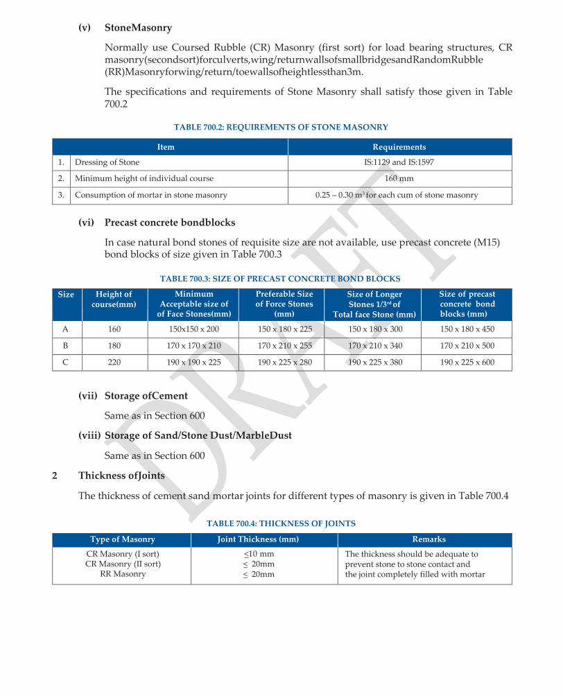
(v) StoneMasonry
Normally use Coursed Rubble (CR) Masonry (first sort) for load bearing structures, CR masonry(secondsort)forculverts,wing/returnwallsofsmallbridgesandRandomRubble (RR)Masonryforwing/return/toewallsofheightlessthan3m.
The specifications and requirements of Stone Masonry shall satisfy those given in Table 700.2
TABLE 700.2: REQUIREMENTS OF STONE MASONRY
Item Requirements
1. Dressing of Stone IS:1129 and IS:1597
2. Minimum height of individual course 160 mm
3. Consumption of mortar in stone masonry 0.25 – 0.30 m3 for each cum of stone masonry
(vi) Precast concrete bondblocks
In case natural bond stones of requisite size are not available, use precast concrete (M15) bond blocks of size given in Table 700.3
TABLE 700.3: SIZE OF PRECAST CONCRETE BOND BLOCKS
Size Height of course(mm)
Minimum Acceptable size of
of Face Stones(mm)
Preferable Size of Force Stones
(mm)
Size of Longer Stones 1/3rd of
Total face Stone (mm)
Size of precast concrete bond blocks (mm)
A 160 150x150 x 200 150 x 180 x 225 150 x 180 x 300 150 x 180 x 450
B 180 170 x 170 x 210 170 x 210 x 255 170 x 210 x 340 170 x 210 x 500
C 220 190 x 190 x 225 190 x 225 x 280 190 x 225 x 380 190 x 225 x 600
(vii) Storage ofCement
Same as in Section 600
(viii) Storage of Sand/Stone Dust/MarbleDust
Same as in Section 600
2 Thickness ofJoints
The thickness of cement sand mortar joints for different types of masonry is given in Table 700.4
TABLE 700.4: THICKNESS OF JOINTS
Type of Masonry Joint Thickness (mm) Remarks
CR Masonry (I sort) CR Masonry (II sort)
RR Masonry
<10 mm < 20mm < 20mm
The thickness should be adequate to prevent stone to stone contact and the joint completely filled with mortar
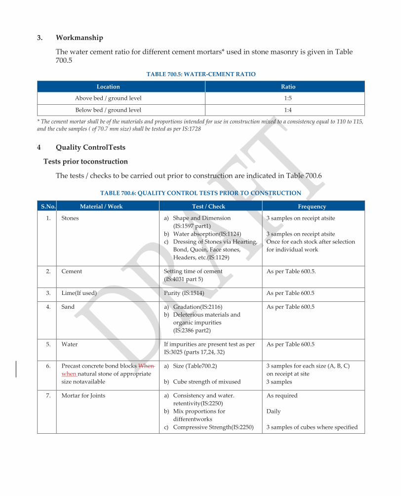
3. Workmanship
The water cement ratio for different cement mortars* used in stone masonry is given in Table 700.5
TABLE 700.5: WATER-CEMENT RATIO
Location Ratio
Above bed / ground level 1:5
Below bed / ground level 1:4
* The cement mortar shall be of the materials and proportions intended for use in construction mixed to a consistency equal to 110 to 115, and the cube samples ( of 70.7 mm size) shall be tested as per IS:1728
4 Quality ControlTests
Tests prior toconstruction
The tests / checks to be carried out prior to construction are indicated in Table 700.6
TABLE 700.6: QUALITY CONTROL TESTS PRIOR TO CONSTRUCTION
S.No. Material / Work Test / Check Frequency
1. Stones a) Shape and Dimension
(IS:1597 part1)
b) Water absorption(IS:1124)
c) Dressing of Stones via Hearting,
Bond, Quoin, Face stones,
Headers, etc.(IS:1129)
3 samples on receipt atsite
3 samples on receipt atsite
Once for each stock after selection
for individual work
2. Cement Setting time of cement
(IS:4031 part 5)
As per Table 600.5.
3. Lime(If used) Purity (IS:1514) As per Table 600.5
4. Sand a) Gradation(IS:2116)
b) Deleterious materials and
organic impurities
(IS:2386 part2)
As per Table 600.5
5. Water If impurities are present test as per
IS:3025 (parts 17,24, 32)
As per Table 600.5
6. Precast concrete bond blocks When
when natural stone of appropriate
size notavailable
a) Size (Table700.2)
b) Cube strength of mixused
3 samples for each size (A, B, C)
on receipt at site
3 samples
7. Mortar for Joints a) Consistency and water.
retentivity(IS:2250)
b) Mix proportions for
differentworks
c) Compressive Strength(IS:2250)
As required
Daily
3 samples of cubes where specified
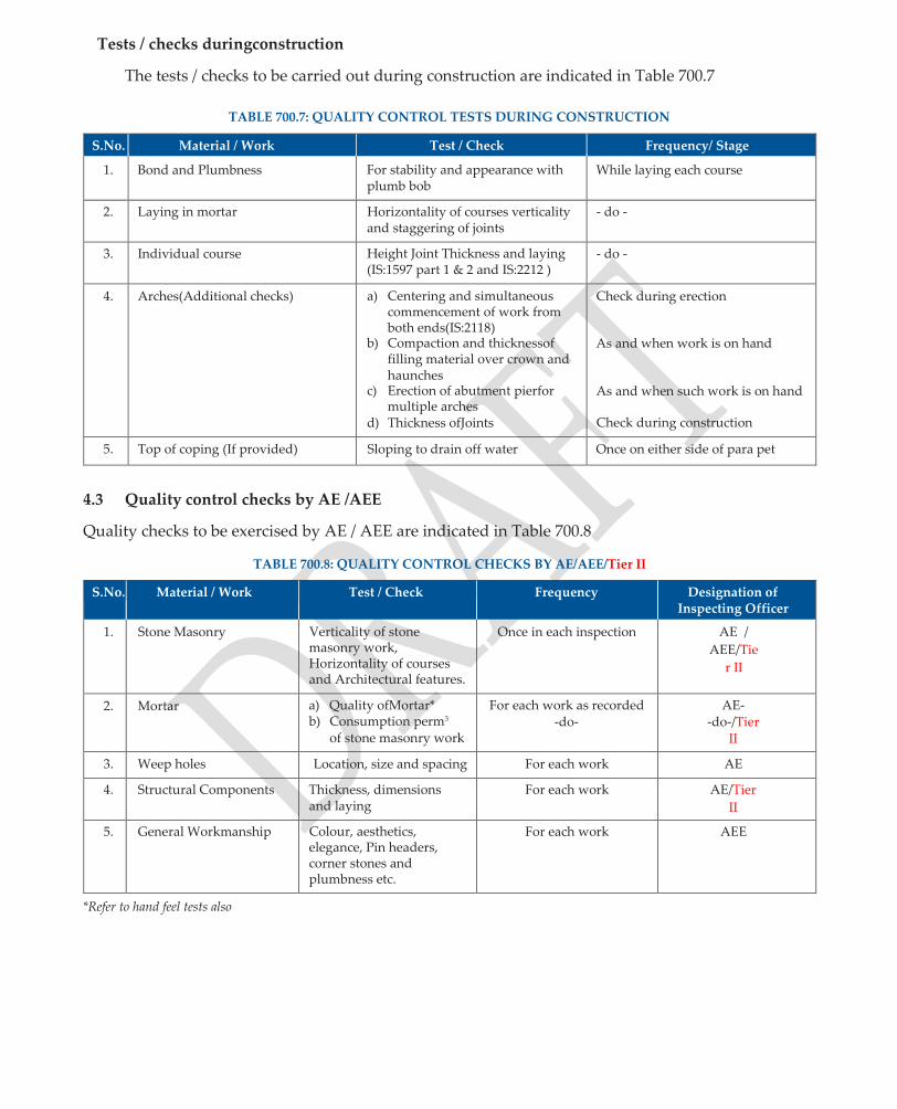
Tests / checks duringconstruction
The tests / checks to be carried out during construction are indicated in Table 700.7
TABLE 700.7: QUALITY CONTROL TESTS DURING CONSTRUCTION
S.No. Material / Work Test / Check Frequency/ Stage
1. Bond and Plumbness For stability and appearance with plumb bob
While laying each course
2. Laying in mortar Horizontality of courses verticality and staggering of joints
- do -
3. Individual course Height Joint Thickness and laying (IS:1597 part 1 & 2 and IS:2212 )
- do -
4. Arches(Additional checks) a) Centering and simultaneous commencement of work from both ends(IS:2118)
b) Compaction and thicknessof filling material over crown and haunches
c) Erection of abutment pierfor multiple arches
d) Thickness ofJoints
Check during erection
As and when work is on hand
As and when such work is on hand
Check during construction
5. Top of coping (If provided) Sloping to drain off water Once on either side of para pet
4.3 Quality control checks by AE /AEE
Quality checks to be exercised by AE / AEE are indicated in Table 700.8
TABLE 700.8: QUALITY CONTROL CHECKS BY AE/AEE/Tier II
S.No. Material / Work Test / Check Frequency Designation of Inspecting Officer
1. Stone Masonry Verticality of stone masonry work, Horizontality of courses and Architectural features.
Once in each inspection AE /
AEE/Tie
r II
2. Mortar a) Quality ofMortar* b) Consumption perm3
of stone masonry work
For each work as recorded -do-
AE- -do-/Tier
II
3. Weep holes Location, size and spacing For each work AE
4. Structural Components Thickness, dimensions and laying
For each work AE/Tier
II
5. General Workmanship Colour, aesthetics, elegance, Pin headers, corner stones and plumbness etc.
For each work AEE
*Refer to hand feel tests also

C. Do’s andDon’ts Do’s Don’ts
1. Fit each stone dry, correct in accuracy by cutting, before finally laid in mortar and fixed inbed.
2. Mix mortar thoroughly and pour fluid mortar in joints.
3. Restrict use of chips to fillinterstices
4. Ensure that mortar is confined to joints without smearing thefaces.
5. Protect stone masonry during construction against rain orfrost.
1. Do not have any dry or hollow space in masonry nor use water to push mortar intojoints.
2. Do not dress or hammer masonry once placed in position
3. Do not use quantity of chips more than 20 per cent of the quantity of stonemasonry.
4. Do not use stone masonry arch bridges having span more than 6 m in seismic zones IV andV

Quality Assurance Handbook for Rural Roads
137
SECTION 800
CONCRETE FOR
STRUCTURES

800 CONCRETE FOR STRUCTURES
A. Methodology
A 1 General
1. Plan all activities before mixing and placing of concrete in Works. This includes procurement of materials, sample testing of cement, coarse and fine aggregates, water and trial mix of the ingredients to achieve the desired strength andworkability.
2. Estimate the total quantity of concrete required for the day’s work besides additional quantity required for sampling (cubes, cylinders, beams) and plan production of concrete. All ingredients of concrete shall be specified byweight.
3. Fibre reinforced Concrete required for Bridges /Culverts, like. Hood end Steel fibre (15 to 20mm size), Polypropylene Fibre– (mixed plain or inter linked of size 10mm to 20mm) etc. For the deck for portion bridges or Deck Slab Polypropylene (Mixed Plain & linked of size 10mm to 20mm) Fibre reinforced concrete is required.
A 2 Production of Concrete
1. Designate concrete in grades viz M10, M15, M20, M25, M30 where the characteristic strength of concrete is defined as the strength of concrete below which not more than 5 percent of the results are expected tofall.
2. Choose Design Mix of grades higher than M20 for large works. For culverts and small bridges involving small quantity of concrete, nominal mix of grades M20 and M25 may be used with adequate supervision and quality controlmeasures.
3. The suggested grades of concrete (based on 20 mm aggregate) together with cement content, maximum water-cement ratio for different exposure conditions indicated in Table800.1.
TABLE 800.1: CEMENT CONTENT AND WATER CEMENT RATIO
Grade of Concrete Minimum Cement Content (kg/m3 )
Minimum Water Cement Ratio
Condition of Exposure Normal Severe Normal Severe Normal Severe
a) Plain Cement Concrete (PCC)
M 15 M 20 250 310 0.50 0.45
b) Reinforced Cement Concrete (RCC)
M 20 M 25 310 400 0.45 0.40
4. Use Mechanical mixer (min. one bag capacity) fitted with water measuring device for culverts
and small bridges with length less than 60 m and individual span less than 15 m. However for controlmixofM25forsuperstructure,usemechanicalmixerofminimum200litrecapacityhaving integral weigh batching facility, automatic water measuring and dispensingdevice.
5. Avoid hand mixing of concrete for use in structural concrete except for isolated culverts (upto 2 m) in remote areas or for certain other reasons. Add 10% extra cement in such situations.
6. Use Admixtures where necessary to meet specific requirements ofconcrete.
7. RMC Plant concrete May Prefer, but ensure all the quality Check should be done asspecified in the
handbook

A3 Transportation, Placing and Compaction ofConcrete.
1.After mixing, transport concrete to the formwork as quickly as possible in wheel borrows to site. Transport and place concrete such that no contamination, segregation or loss of its constituent materials or ingress of foreign material or water takes place.
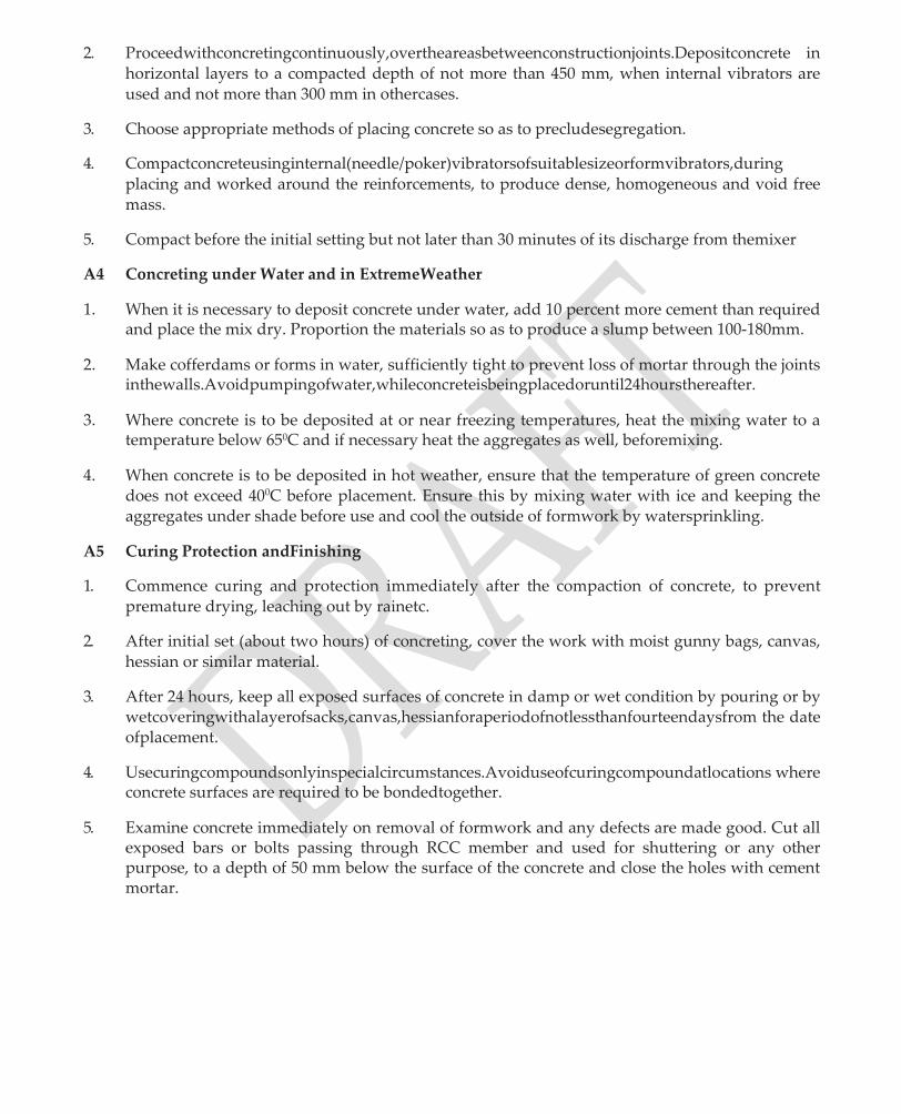
2. Proceedwithconcretingcontinuously,overtheareasbetweenconstructionjoints.Depositconcrete in horizontal layers to a compacted depth of not more than 450 mm, when internal vibrators are used and not more than 300 mm in othercases.
3. Choose appropriate methods of placing concrete so as to precludesegregation.
4. Compactconcreteusinginternal(needle/poker)vibratorsofsuitablesizeorformvibrators,during placing and worked around the reinforcements, to produce dense, homogeneous and void free mass.
5. Compact before the initial setting but not later than 30 minutes of its discharge from themixer
A4 Concreting under Water and in ExtremeWeather
1. When it is necessary to deposit concrete under water, add 10 percent more cement than required and place the mix dry. Proportion the materials so as to produce a slump between 100-180mm.
2. Make cofferdams or forms in water, sufficiently tight to prevent loss of mortar through the joints inthewalls.Avoidpumpingofwater,whileconcreteisbeingplacedoruntil24hoursthereafter.
3. Where concrete is to be deposited at or near freezing temperatures, heat the mixing water to a temperature below 650C and if necessary heat the aggregates as well, beforemixing.
4. When concrete is to be deposited in hot weather, ensure that the temperature of green concrete does not exceed 400C before placement. Ensure this by mixing water with ice and keeping the aggregates under shade before use and cool the outside of formwork by watersprinkling.
A5 Curing Protection andFinishing
1. Commence curing and protection immediately after the compaction of concrete, to prevent premature drying, leaching out by rainetc.
2. After initial set (about two hours) of concreting, cover the work with moist gunny bags, canvas, hessian or similar material.
3. After 24 hours, keep all exposed surfaces of concrete in damp or wet condition by pouring or by wetcoveringwithalayerofsacks,canvas,hessianforaperiodofnotlessthanfourteendaysfrom the date ofplacement.
4. Usecuringcompoundsonlyinspecialcircumstances.Avoiduseofcuringcompoundatlocations where concrete surfaces are required to be bondedtogether.
5. Examine concrete immediately on removal of formwork and any defects are made good. Cut all exposed bars or bolts passing through RCC member and used for shuttering or any other purpose, to a depth of 50 mm below the surface of the concrete and close the holes with cement mortar.
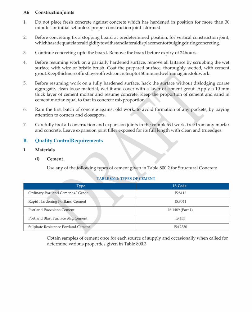
A6 ConstructionJoints
1. Do not place fresh concrete against concrete which has hardened in position for more than 30 minutes or initial set unless proper construction joint isformed.
2. Before concreting fix a stopping board at predetermined position, for vertical construction joint, whichhasadequatelateralrigiditytowithstandlateraldisplacementorbulgingduringconcreting.
3. Continue concreting upto the board. Remove the board before expiry of 24hours.
4. Before resuming work on a partially hardened surface, remove all laitance by scrubbing the wet surface with wire or bristle brush. Coat the prepared surface, thoroughly wetted, with cement grout.Keepthicknessoffirstlayeroffreshconcreteupto150mmandwellramagainstoldwork.
5. Before resuming work on a fully hardened surface, hack the surface without dislodging coarse aggregate, clean loose material, wet it and cover with a layer of cement grout. Apply a 10 mm thick layer of cement mortar and resume concrete. Keep the proportion of cement and sand in cement mortar equal to that in concrete mixproportion.
6. Ram the first batch of concrete against old work, to avoid formation of any pockets, by paying attention to corners and closespots.
7. Carefully tool all construction and expansion joints in the completed work, free from any mortar and concrete. Leave expansion joint filler exposed for its full length with clean and trueedges.
B. Quality ControlRequirements
1 Materials
(i) Cement
Use any of the following types of cement given in Table 800.2 for Structural Concrete
TABLE 800.2: TYPES OF CEMENT
Type IS Code
Ordinary Portland Cement 43 Grade IS:8112
Rapid Hardening Portland Cement IS:8041
Portland Pozzolana Cement IS:1489 (Part 1)
Portland Blast Furnace Slag Cement IS:455
Sulphate Resistance Portland Cement IS:12330
Obtain samples of cement once for each source of supply and occasionally when called for determine various properties given in Table 800.3
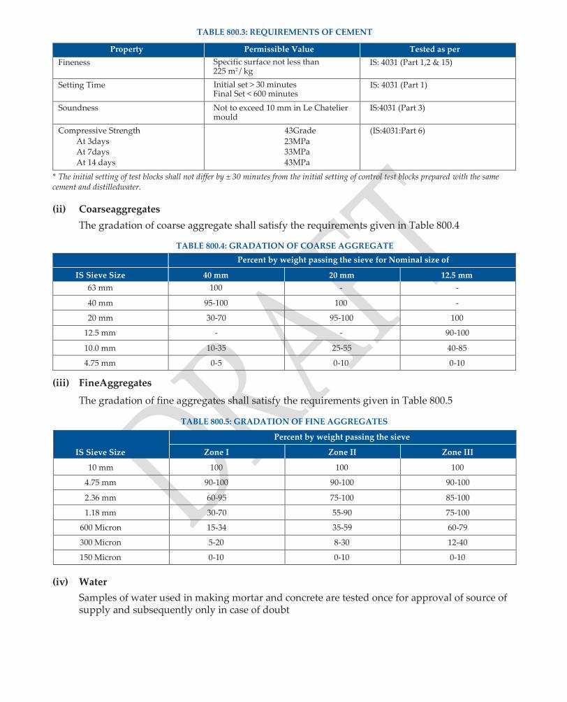
TABLE 800.3: REQUIREMENTS OF CEMENT
Property Permissible Value Tested as per
Fineness Specific surface not less than 225 m2 / kg
IS: 4031 (Part 1,2 & 15)
Setting Time Initial set > 30 minutes Final Set < 600 minutes
IS: 4031 (Part 1)
Soundness Not to exceed 10 mm in Le Chatelier mould
IS:4031 (Part 3)
Compressive Strength
At 3days At 7days At 14 days
43Grade
23MPa 33MPa
43MPa
(IS:4031:Part 6)
* The initial setting of test blocks shall not differ by ± 30 minutes from the initial setting of control test blocks prepared with the same cement and distilledwater.
(ii) Coarseaggregates
The gradation of coarse aggregate shall satisfy the requirements given in Table 800.4
TABLE 800.4: GRADATION OF COARSE AGGREGATE
Percent by weight passing the sieve for Nominal size of
IS Sieve Size 40 mm 20 mm 12.5 mm
63 mm 100 - -
40 mm 95-100 100 -
20 mm 30-70 95-100 100
12.5 mm - - 90-100
10.0 mm 10-35 25-55 40-85
4.75 mm 0-5 0-10 0-10
(iii) FineAggregates
The gradation of fine aggregates shall satisfy the requirements given in Table 800.5
TABLE 800.5: GRADATION OF FINE AGGREGATES
IS Sieve Size
Percent by weight passing the sieve
Zone I Zone II Zone III
10 mm 100 100 100
4.75 mm 90-100 90-100 90-100
2.36 mm 60-95 75-100 85-100
1.18 mm 30-70 55-90 75-100
600 Micron 15-34 35-59 60-79
300 Micron 5-20 8-30 12-40
150 Micron 0-10 0-10 0-10
(iv) Water
Samples of water used in making mortar and concrete are tested once for approval of source of supply and subsequently only in case of doubt
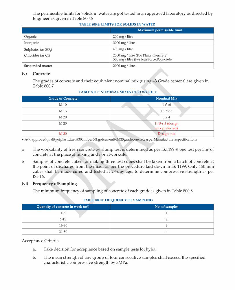
The permissible limits for solids in water are got tested in an approved laboratory as directed by Engineer as given in Table 800.6
TABLE 800.6: LIMITS FOR SOLIDS IN WATER
Maximum permissible limit
Organic 200 mg / litre
Inorganic 3000 mg / litre
Sulphates (as SO4) 400 mg / litre
Chlorides (as Cl) 2000 mg / litre (For Plain Concrete) 500 mg / litre (For ReinforcedConcrete
Suspended matter 2000 mg / litre
(v) Concrete
The grades of concrete and their equivalent nominal mix (using 43 Grade cement) are given in Table 800.7
TABLE 800.7: NOMINAL MIXES OF CONCRETE
Grade of Concrete Nominal Mix
M 10 1 :3 :6
M 15 1:2 ½: 5
M 20 1:2:4
M 25 1: 1½ :3 (design
mix preferred)
M 30 Design mix
• Addapprovedqualityofplasticizer@300mlper50kgofcementtoM25gradeconcreteasperManufacturersspecifications
a. The workability of fresh concrete by slump test is determined as per IS:1199 @ one test per 3m3 of concrete at the place of mixing and / or atworksite.
b. Samples of concrete cubes for making three test cubes shall be taken from a batch of concrete at the point of discharge from the mixer as per the procedure laid down in IS: 1199. Only 150 mm cubes shall be made cured and tested at 28-day age, to determine compressive strength as per IS:516.
(vi) Frequency ofSampling
The minimum frequency of sampling of concrete of each grade is given in Table 800.8
TABLE 800.8: FREQUENCY OF SAMPLING
Quantity of concrete in work (m3) No. of samples
1-5 1
6-15 2
16-30 3
31-50 4
Acceptance Criteria
a. Take decision for acceptance based on sample tests lot bylot.
b. The mean strength of any group of four consecutive samples shall exceed the specified characteristic compressive strength by 3MPa.

c. The strength of any sample shall not be less than the specified compressive strength minus 3MPa.
d. The quality of concrete represented by test results shall include the batches from which the first and last samples were taken, together with all interveningbatches.
(vii) Sulphate and ChlorideContent
The total water soluble sulphate and chloride contents in concrete shall not exceed the values given in Table 800.9
TABLE 800.9: SULPHATE AND CHLORIDE CONTENTS
Details Content
Sulphate content as (SO3) 4 percent
Chloride content 0.3 percent by mass of cement (Moderate condition)
(As Chloride ion) 0.20 percent by mass of cement (Severe condition)
(viii) Use of plums in ordinaryconcrete
StoneplumsshallnotbeusedinRCCorConcretelaidinwater.Thegeneralrequirementsforthe usage of plums are given in Table800.10
TABLE 800.10 REQUIREMENT FOR USAGE OF PLUMS
Size 160-300 mm (Maximum dimension not to exceed 1 / 3 least dimension of member)
Quantity of Plums in works Not to exceed 15 percent by volume
(ix). Storage of Materials (Cement, Fine and CoarseAggregates)
a. The requirements of storage for cement and fine aggregates are as per Sub-section600.
b. Storedifferentsizesofcoarseaggregatesinseparatestockpilessufficientlyawayfromeach othertopreventintermixing.Keeptheheightofindividualstockpilebelow120mm,unless otherwise permitted. When placed directly on hard ground, do not remove them from stockpile within 300 mm of the ground. Use the bottom 300 mm of stockpile only after thorough cleaning of thematerial.
2. Tolerances
The accuracy of the measuring devices used for different ingredients shall fall within the limits given in Table 800.11
TABLE 800.11: ACCURACY OF MEASURING DEVICES
Measurement Quantity in each batch
Cement ± 3% of cement quantity
Water ± 3% of water
Aggregate ± 3% of aggregate
Admixture ± 5% of admixture
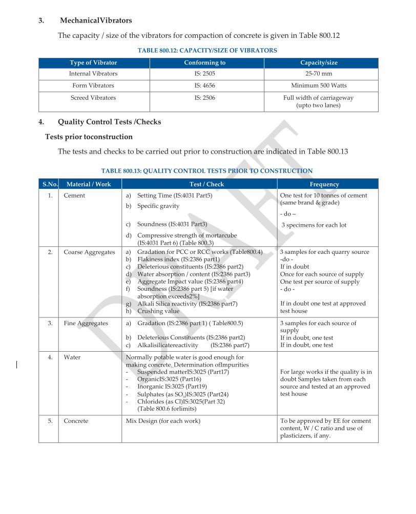
3. MechanicalVibrators
The capacity / size of the vibrators for compaction of concrete is given in Table 800.12
TABLE 800.12: CAPACITY/SIZE OF VIBRATORS
Type of Vibrator Conforming to Capacity/size
Internal Vibrators IS: 2505 25-70 mm
Form Vibrators IS: 4656 Minimum 500 Watts
Screed Vibrators IS: 2506 Full width of carriageway (upto two lanes)
4. Quality Control Tests /Checks
Tests prior toconstruction
The tests and checks to be carried out prior to construction are indicated in Table 800.13
TABLE 800.13: QUALITY CONTROL TESTS PRIOR TO CONSTRUCTION
S.No. Material / Work Test / Check Frequency
1. Cement a) Setting Time (IS:4031 Part5)
b) Specific gravity
c) Soundness (IS:4031 Part3)
d) Compressive strength of mortarcube (IS:4031 Part 6) (Table 800.3)
One test for 10 tonnes of cement (same brand & grade)
- do –
3 specimens for each lot
2. Coarse Aggregates a) Gradation for PCC or RCC works (Table800.4) b) Flakiness index (IS:2386 part1) c) Deleterious constituents (IS:2386 part2) d) Water absorption / content (IS:2386 part3) e) Aggregate Impact value (IS:2386 part4) f) Soundness (IS:2386 part 5) [if water
absorption exceeds2%] g) Alkali Silica reactivity (IS:2386 part7) h) Crushing value
3 samples for each quarry source -do - If in doubt Once for each source of supply One test per source of supply - do -
If in doubt one test at approved test house
3. Fine Aggregates a) Gradation (IS:2386 part 1) ( Table800.5)
b) Deleterious Constituents (IS:2386 part2) c) Alkalisilicatereactivity (IS:2386 part7)
3 samples for each source of supply If in doubt, one test If in doubt, one test
4. Water Normally potable water is good enough for making concrete. Determination ofImpurities - Suspended matterIS:3025 (Part17) - OrganicIS:3025 (Part16) - Inorganic IS:3025 (Part19)
- Sulphates (as SO3)IS:3025 (Part24) - Chlorides (as Cl)IS:3025(Part 32)
(Table 800.6 forlimits)
For large works if the quality is in doubt Samples taken from each source and tested at an approved test house
5. Concrete Mix Design (for each work) To be approved by EE for cement content, W / C ratio and use of plasticizers, if any.
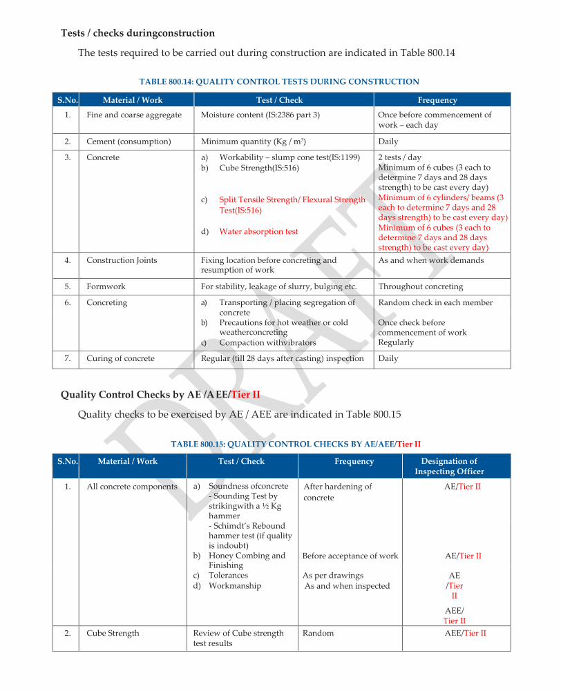
Tests / checks duringconstruction
The tests required to be carried out during construction are indicated in Table 800.14
TABLE 800.14: QUALITY CONTROL TESTS DURING CONSTRUCTION
S.No. Material / Work Test / Check Frequency
1. Fine and coarse aggregate Moisture content (IS:2386 part 3) Once before commencement of work – each day
2. Cement (consumption) Minimum quantity (Kg / m3) Daily
3. Concrete a) Workability – slump cone test(IS:1199)
b) Cube Strength(IS:516)
c) Split Tensile Strength/ Flexural Strength
Test(IS:516)
d) Water absorption test
2 tests / day Minimum of 6 cubes (3 each to determine 7 days and 28 days strength) to be cast every day) Minimum of 6 cylinders/ beams (3 each to determine 7 days and 28 days strength) to be cast every day) Minimum of 6 cubes (3 each to determine 7 days and 28 days strength) to be cast every day)
4. Construction Joints Fixing location before concreting and resumption of work
As and when work demands
5. Formwork For stability, leakage of slurry, bulging etc. Throughout concreting
6. Concreting a) Transporting / placing segregation of concrete
b) Precautions for hot weather or cold weatherconcreting
c) Compaction withvibrators
Random check in each member
Once check before commencement of work Regularly
7. Curing of concrete Regular (till 28 days after casting) inspection Daily
Quality Control Checks by AE /AEE/Tier II
Quality checks to be exercised by AE / AEE are indicated in Table 800.15
TABLE 800.15: QUALITY CONTROL CHECKS BY AE/AEE/Tier II
S.No. Material / Work Test / Check Frequency Designation of Inspecting Officer
1. All concrete components a) Soundness ofconcrete - Sounding Test by strikingwith a ½ Kg hammer - Schimdt’s Rebound hammer test (if quality is indoubt)
b) Honey Combing and Finishing
c) Tolerances d) Workmanship
After hardening of
concrete
AE/Tier II
Before acceptance of work
AE/Tier II
As per drawings
As and when inspected AE
/Tier II
AEE/Tier II
2. Cube Strength Review of Cube strength test results
Random AEE/Tier II

3 Split Tensile Strength/
Flexural Strength Test
Review of Split Tensile Strength/ Flexural Strength Teststrength test results
Random AEE/Tier II
4 Water Absorption Test Review of Water Absorption test results
Random AEE/Tier II
5 Materials Review of Material Quality Random Tier II

C. Do’s andDon’ts
Do’s Don’ts
1. Usecementofthesamegradeandsamesourcefora
singlework.
2. Use 20 mm (nominal) size aggregate forRCC.
3. Use potable water with pH value between 6 and 8
for producingconcrete.
4. Determine moisture content in both fine and coarse
aggregates as frequently as possible toadjust.
5. Remix concrete, if there is segregation after
unloading from themixer.
6. Compact before initial setting of concrete but not
laterthan30minutesofitsdischargefromthemixer.
1. Do not mix different types of cement or mix Blast
Furnace Slag with Ordinary Portland Cement atsite.
2. Donotusefineaggregateshavingpositivealkali-silica
reaction.
3. Donotuseseawaterformixingandcuringofconcrete.
4. Do not increase water content in concrete mix to
‘enhance’ itsworkability
5. Do not use of aggregates or wooden pieces to provide
cover to reinforcements instead of concretebriquettes.
6. Do not drop concrete into place freely from a height
exceeding 1.5m.
7. Do not change or increase the number of construction
joints from those shown indrawings.
8. Donotclubdifferentlotsforthepurposeofacceptance.

Quality Assurance Handbook for Rural Roads
149
SECTION 900
FORMWORK AND
SURFACE FINISH FOR
STRUCTURES

900 FORMWORK AND SURFACE FINISH FORSTRUCTURES
A Methodology
A1 Design andErection
1. Examineallmaterialsandcomponentsusedforformwork,fordamageorexcessivedeterioration before use and reuse only if found suitable afterrepairs.
2. Fortimberformwork,inspectforphysicaldamages,besidessignsofattackbydecay,rotorinsect attack or development ofsplits.
3. Usefamiliarmaterialsliketimber,steel,plywood,concreteandmasonryforfalsework.Formetal forms, the thickness should be adequate to keep them true to shape. Use counter sunk bolts and permit use of approved internal steel ties or steel or plasticspacers.
4. Ensure false work (formwork + temporary support system) is designed to meet the requirements ofpermanentstructureincludingeaseoferectionanddismantlingandisapprovedbytheEngineer.
5. Provide proper and safe access to all parts of formwork forinspection.
6. Make the formwork robust and use ballies of 100 mm dia of heights not more than 4 m. Provide crossanddiagonalbracingsof75mmdia(ballies)inbothdirections.Formetalforms,thediagonal bracings shall be of the same size of angles used forcolumns.
7. Checkfordesigndeficienciessuchasshoringorreshoring,insufficientallowanceforunsymmetrical or eccentric loading due to placement sequence ofconcrete.
8. Pay attention to detailing which otherwise may cause instability, local failure or progressive collapse. Lay emphasis on attention todetails.
9. In case of false work erected on normal ground, ensure distribution of loading to the ground, through timber or base plates to avoid differential settlement.
10. Control the alignment of the distribution members, so that shores of the falsework system are centrally placed on themember.
11. Make the forms tight and sufficiently rigid by the use of ties and bracings to prevent any displacement or sagging between thesupports.
A2 Preparation beforeconcreting
1. Apply a coat of oil or grease as release agent, inside the surfaces of forms to prevent adhesion of concrete toformwork.
2. Maketheformworkleakprooftopreventescapeofcementslurryduringcompactionwithvibrators. Clean the forms thoroughly just beforeconcreting.
3. Lineformworkwithaprovenmaterialtoprovidesmoothfinishofuniformtextureandappearance, without leaving stain on concrete.
A3 Removal ofFormwork
1. Plan removal of formwork (deshuttering and decentering) in advance. Give due consideration to the local conditions viz. character of structure, weather and materials used inmix.
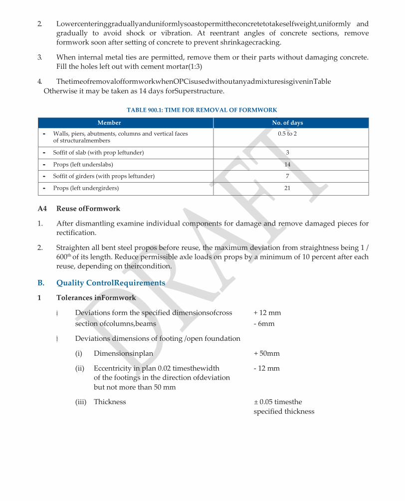
2. Lowercenteringgraduallyanduniformlysoastopermittheconcretetotakeselfweight,uniformly and gradually to avoid shock or vibration. At reentrant angles of concrete sections, remove formwork soon after setting of concrete to prevent shrinkagecracking.
3. When internal metal ties are permitted, remove them or their parts without damaging concrete. Fill the holes left out with cement mortar(1:3)
4. ThetimeofremovalofformworkwhenOPCisusedwithoutanyadmixturesisgiveninTable
Otherwise it may be taken as 14 days forSuperstructure.
TABLE 900.1: TIME FOR REMOVAL OF FORMWORK
Member No. of days
• Walls, piers, abutments, columns and vertical faces of structuralmembers
0.5 to 2
• Soffit of slab (with prop leftunder) 3
• Props (left underslabs) 14
• Soffit of girders (with props leftunder) 7
• Props (left undergirders) 21
A4 Reuse ofFormwork
1. After dismantling examine individual components for damage and remove damaged pieces for rectification.
2. Straighten all bent steel propos before reuse, the maximum deviation from straightness being 1 / 600th of its length. Reduce permissible axle loads on props by a minimum of 10 percent after each reuse, depending on theircondition.
B. Quality ControlRequirements
1 Tolerances inFormwork
(a) Deviations form the specified dimensionsofcross + 12 mm
section ofcolumns,beams - 6mm
(b) Deviations dimensions of footing /open foundation
(i) Dimensionsinplan + 50mm
(ii) Eccentricity in plan 0.02 timesthewidth - 12 mm of the footings in the direction ofdeviation
but not more than 50 mm
(iii) Thickness ± 0.05 timesthe
specified thickness

2. Quality ControlTests
Tests prior toconstruction
The Quality Control tests to be carried out prior to construction are indicated in Table 900.2
TABLE 900.2: QUALITY CONTROL TESTS PRIOR TO CONSTRUCTION
S. No. Test Frequency
1. Thickness of Steel tubes Before usage / Procurement
2. Dia of ‘ballies’ - do -
3. Size of panels (steel sheets / timber planks) -do-
4. Formwork if in reuse (Clause 909 of MORD Specifications) To be approved by AE
5. Design of formwork To be approved by AEE/Tier II
Tests duringconstruction
The quality control tests to be carried out during construction are indicated in Table 900.3
TABLE 900.3: QUALITY CONTROL TESTS DURING CONSTRUCTION
S. No. Test Frequency
1. Clamps for strength and stability of Form work Regular
2. Camber and Surface smoothness At the end of erection work
3. Mortar tightness Before concreting
4. Supporting system on ground (To prevent settlement and distribution of load)
Check before concreting
5. Safe access onto and about the formwork Regularly during concreting
6. Height of panels for supporting structures and return walls Check before concreting
Quality Control Checks by AE /AEE
The Quality Control checks to be carried out by AE / AEE are indicated in Table 900.4.
TABLE 900.4: QUALITY CONTROL CHECKS BY AE/AEE/Tier II
S. No. Test / Check Designation of Inspecting Officer
1. Time for removal of formwork AE
2. Damages to concrete members due to settlement of support system
AE/Tier II
3. Deviations from specified dimensions of concrete members AE/Tier II
4. Shutter finish of members (Smoothness / Sharpness / honey combing)
AE/Tier II

C. Do’s andDon’ts
Do’s Don’ts
1. Use large size panels to keep the number of joints to aminimum.
2. Use clamps of adequate strength to hold the forms together.
3. Avoid sharp corners by providing fillets of 25 x 25 mm (minimum) size at all angles offormwork.
4. Usescrewjacksorhardwoodwedgestomakeupfor any settlement of formwork before and after concreting.
5. Provide suitable camber of 1 / 500 of span in horizontal members to counter the effects of any deflection.
6. Use angle iron (not steel bars) bracings for column supports.
1. Do not use form panels of height less than 1.0 m for abutments, piers and returnwalls.
2. Do not permit deflection of unsupported areas more than 3 mm or 0.003 of span whichever isless.
3. Do not allow releasing agent come into contact with reinforcement.
4. Do not keep centering and shuttering on soft or filled upearth.
5. Do not allow stagnation of water near the base plate supporting thestaging.
6. Do not use more than one plank / timber block at the base of a prop to plug the gap, ifany.

Quality Assurance Handbook for Rural Roads
155
SECTION 1000
STEEL REINFORCEMENT

1000 STEEL REINFORCEMENT
A. Methodology
A1 Bending andPlacing
1. Usenewsteelofthesametypeandgradeformainreinforcementinconstruction.Useofdifferent type of same grade steel as secondary reinforcement may be allowedexceptionally.
2. Straighten the bars which get bent during transportation or handling. Bend rebars cold to the specified shape and dimensions using a proper bar bender operated by hand or power to obtain correct radii of bands andshape.
3. Place reinforcement bars accurately in position as shown on drawings. Make the skeleton of reinforcement rigid by tying all bars crossing one another at every intersections using annealed bindingwire.
4. Positionthebarsonindustriallyproducedpolymercoverblocksorconcretecoverblocksofrequired thickness, to provide cover toreinforcement.
5. Positiontheverticalprojectedreinforcementfromsub-structureorfoundation,bymeansoftimber templates with slots cut in them accurately or with cover blocks tied to thereinforcement.
6. Separatelayersofreinforcementbyspacerbarsatamaximumlengthof1m,keepingtheminimum dia of spacer bar as next higher size of mainreinforcement
7. At construction joints, bend aside reinforcing bars and bend back to the original position, by ensuring that concrete around the bar is not damaged beyond thebend.
A2 Splicing, Welding and Substitution of barsizes
1. Stagger the lapped splices as per the provisions in IRC:21 and at located points along the span where stresses arelow.
2. Keep a minimum spacing between overlapped bars of 25 mm or 1¼ times the maximum size of coarse aggregate whichever isgreater.
3. Barsarecleanedofallloosescale,rust,greaseetc,beforecarryingoutweldingbymetalarcwelding process
4. Butt weld all bars except bars of dia less than 20 mm, which are to be lap,welded.
5. Locate welded joints well away from the bends and not less than twice the bar dia from abend.
6. Substitute bars where necessary with the same type and grade after ensuring the minimum area provided is equivalent to the original at each crosssection.
A3 Storage andProtection
1. Store reinforcement bars on blocks, racks or platforms or other supports about 300-450 mm above the surface of the ground, in a clean and dry condition.

B. Quality ControlRequirements
1. Material:-
(i) The Steel reinforcement used and works executed shall conform to the requirements given in Table1000.1
TABLE 1000.1: REQUIREMENTS OF REBARS
Grade Designation Bar type conforming to governing BIS Specification
Characteristic strength (fy ) MPa
Elastic Modulus GPa
Fe 240 IS:432 Part I Mild Steel 240 200
Fe 415 IS:1786 High Strength Deformed Bars (HYSD) or Thermotechnically Treated (TMT) bars
415 200
Fe 500/ Fe550D IS:1786 High Strength Deformed Bars (HYSD) or Thermotechnically Treated (TMT) bars
500/550 200
(ii) The workmanship for welding of steel reinforcements shall conform to the specifications given in Table1000.2
TABLE 1000.2: WORKMANSHIP FOR WELDING
Welding of Mild Steel IS:432
Welding Method IS:2751 and IS:9417
MS Electrodes for welding IS: 814
Inspection of Welds IS: 8222
2. Tolerances
The Reinforcement shall be placed within tolerances given in Table 1000.3
TABLE 1000.3: TOLERANCES FOR COVER
Member/Cover Tolerance
Members with effective depth less than 200 mm ± 10 mm
Members with effective depth more than 200 mm ± 15 mm
Cover + 10 mm (No minus tolerance permitted for cover)
3. Quality ControlTests
Tests prior toconstruction
The Quality Control tests to be carried out prior to construction are indicated in Table 1000.4
TABLE 1000.4: QUALITY CONTROL TESTS PRIOR TO CONSTRUCTION
S. No. Test Frequency
1. Grade, percentage elongation and ultimate tensile strength (For culverts and small bridges)* (IS:432 part 1 and IS:1786)
3 random samples from each supplier per 1000kg(certificate from an approved test house) &Tier II
2. Pitch of the Ribs and Nominal Diameter (Clause 1002 of MoRD Specifications)
Random checking
3. Protection of Steel (Clause 1003 of MoRD Specifications) Regularly
4. Substitution of bar sizes Approval by AE / AEE before execution of work

5. Detailing of reinforcement cages Approval by AE / AEE before execution of work
* For Major Works frequency of testing may beincreased
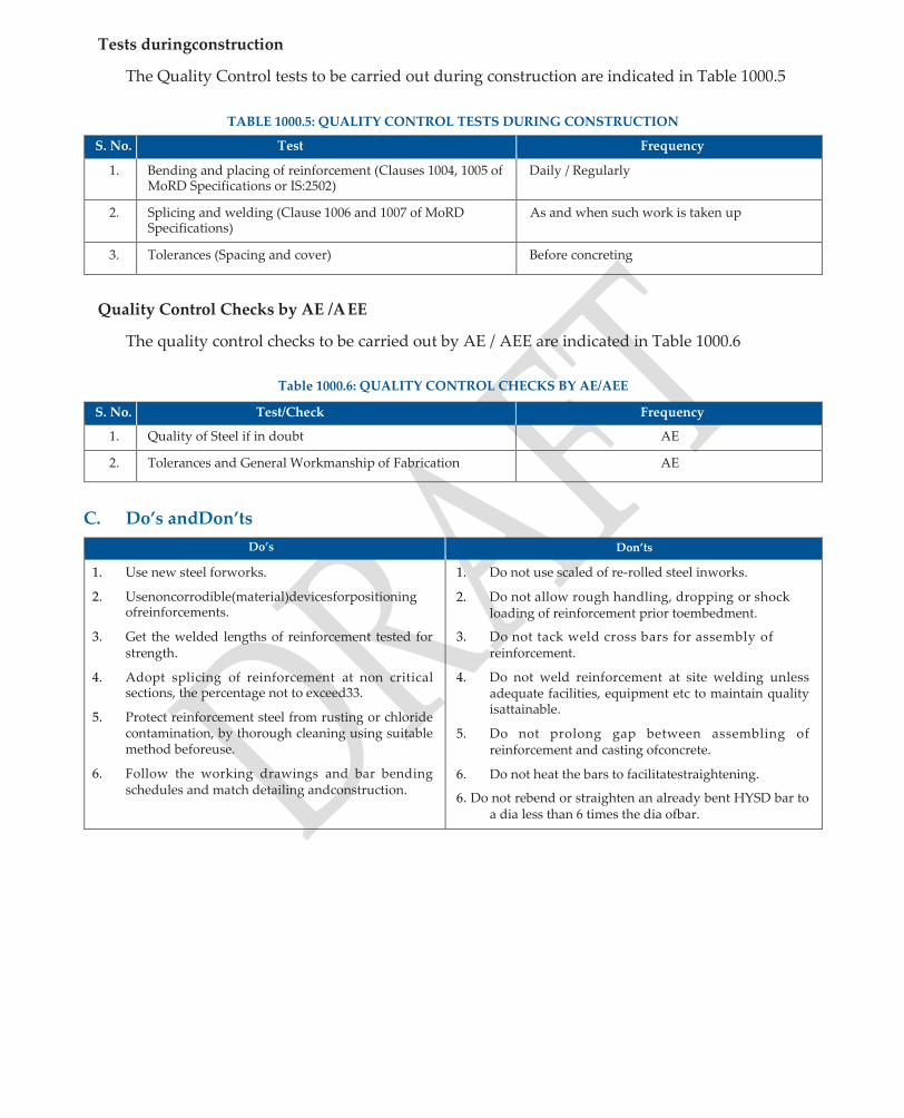
Tests duringconstruction
The Quality Control tests to be carried out during construction are indicated in Table 1000.5
TABLE 1000.5: QUALITY CONTROL TESTS DURING CONSTRUCTION
S. No. Test Frequency
1. Bending and placing of reinforcement (Clauses 1004, 1005 of MoRD Specifications or IS:2502)
Daily / Regularly
2. Splicing and welding (Clause 1006 and 1007 of MoRD Specifications)
As and when such work is taken up
3. Tolerances (Spacing and cover) Before concreting
Quality Control Checks by AE /AEE
The quality control checks to be carried out by AE / AEE are indicated in Table 1000.6
Table 1000.6: QUALITY CONTROL CHECKS BY AE/AEE
S. No. Test/Check Frequency
1. Quality of Steel if in doubt AE
2. Tolerances and General Workmanship of Fabrication AE
C. Do’s andDon’ts
Do’s Don’ts
1. Use new steel forworks.
2. Usenoncorrodible(material)devicesforpositioning ofreinforcements.
3. Get the welded lengths of reinforcement tested for strength.
4. Adopt splicing of reinforcement at non critical sections, the percentage not to exceed33.
5. Protect reinforcement steel from rusting or chloride contamination, by thorough cleaning using suitable method beforeuse.
6. Follow the working drawings and bar bending schedules and match detailing andconstruction.
1. Do not use scaled of re-rolled steel inworks.
2. Do not allow rough handling, dropping or shock loading of reinforcement prior toembedment.
3. Do not tack weld cross bars for assembly of reinforcement.
4. Do not weld reinforcement at site welding unless adequate facilities, equipment etc to maintain quality isattainable.
5. Do not prolong gap between assembling of reinforcement and casting ofconcrete.
6. Do not heat the bars to facilitatestraightening.
6. Do not rebend or straighten an already bent HYSD bar to a dia less than 6 times the dia ofbar.

Quality Assurance Handbook for Rural Roads
161
SECTION 1100
PIPE CULVERTS

1100: PIPE CULVERTS
A. Methodology
A1 Excavation forpipes
1. Lay the pipes in shallow excavation of natural ground or in open trenches cut in existing embankments taken down to requiredlevel.
2. Forembankmentsofheightoffillmorethan3m,orthreetimestheexternaldiaofpipeabovebed level, construct the embankment to the level above the top of the pipe (equal to external dia of pipe)andwidthnotlessthanfivetimesthediaofpipe.Laythepipeintrenchaftertheconstruction ofembankments.
3. If spongy, soft or other unstable material is met with at the location of pipe culvert, remove the material to the required depth, width and length, and back fill with approved granular material properly shaped and compacted to the requiredlevel.
4. Where rock or bouldery strata is met with, take down excavation to atleast 200 mm below the bottom level of pipe, remove all loose material and fill the space with approvedearth.
A2 Loading and Unloading ofPipes
1. Make arrangements for lifting, loading and unloading of pipes from factory / yard to site, such that no undue strain or damage occurs due to fall orimpact.
2. Formanualunloadingfromtrucks,rolldownpipesonapairofskidshookedontothetrucksand control movement with a rope passing round thepipes.
A3 Laying ofPipes
1. Preload the areas to induce major portion of settlement before the pipe isinstalled.
2. Provideabeddingsurfaceoffirmfoundationofuniformdensity,throughoutthelengthofculvert with specified bedding material depending on dia of pipe and height of fill abovepipe.
3. Lower the pipes in bed either by tripod pulley arrangement or by manual labour using chain pulley blocks in a manner to place them in proper position withoutdamage.
4. Whentwoormorepipesarelaidadjacenttoeachother,placethemseparatedbyadistanceequal to half the dia of the pipe subject to a minimum space of 450mm.
5. When pipes are laid in two layers, keep the centers of pipes such that when joined shall form equilateraltriangles.
6. Lay the pipes as specified in IS:783, for different conditions such as positive projecting condition, trench conditionetc.
7. Lay the pipes on the prepared foundation, commencing from outlet and proceed towards the inlet.Incaseofpipeswithbellmouth,keepthebelledendfacingtheupstream.Keeptheinvertof pipe minimum 150 mm below average bed level. However, if the invert level is more than 300 mm, a catch pit of size 1500 x 1000 mm upto ground level should beconstructed.
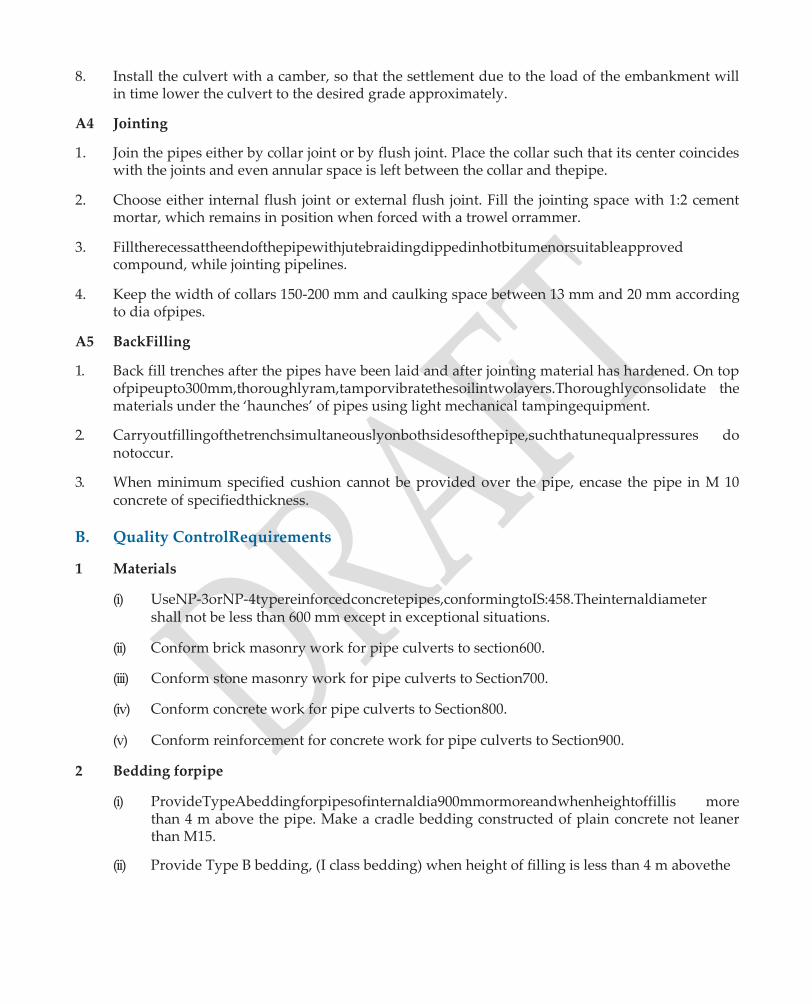
8. Install the culvert with a camber, so that the settlement due to the load of the embankment will in time lower the culvert to the desired grade approximately.
A4 Jointing
1. Join the pipes either by collar joint or by flush joint. Place the collar such that its center coincides with the joints and even annular space is left between the collar and thepipe.
2. Choose either internal flush joint or external flush joint. Fill the jointing space with 1:2 cement mortar, which remains in position when forced with a trowel orrammer.
3. Filltherecessattheendofthepipewithjutebraidingdippedinhotbitumenorsuitableapproved compound, while jointing pipelines.
4. Keep the width of collars 150-200 mm and caulking space between 13 mm and 20 mm according to dia ofpipes.
A5 BackFilling
1. Back fill trenches after the pipes have been laid and after jointing material has hardened. On top ofpipeupto300mm,thoroughlyram,tamporvibratethesoilintwolayers.Thoroughlyconsolidate the materials under the ‘haunches’ of pipes using light mechanical tampingequipment.
2. Carryoutfillingofthetrenchsimultaneouslyonbothsidesofthepipe,suchthatunequalpressures do notoccur.
3. When minimum specified cushion cannot be provided over the pipe, encase the pipe in M 10 concrete of specifiedthickness.
B. Quality ControlRequirements
1 Materials
(i) UseNP-3orNP-4typereinforcedconcretepipes,conformingtoIS:458.Theinternaldiameter shall not be less than 600 mm except in exceptional situations.
(ii) Conform brick masonry work for pipe culverts to section600.
(iii) Conform stone masonry work for pipe culverts to Section700.
(iv) Conform concrete work for pipe culverts to Section800.
(v) Conform reinforcement for concrete work for pipe culverts to Section900.
2 Bedding forpipe
(i) ProvideTypeAbeddingforpipesofinternaldia900mmormoreandwhenheightoffillis more than 4 m above the pipe. Make a cradle bedding constructed of plain concrete not leaner than M15.
(ii) Provide Type B bedding, (I class bedding) when height of filling is less than 4 m abovethe
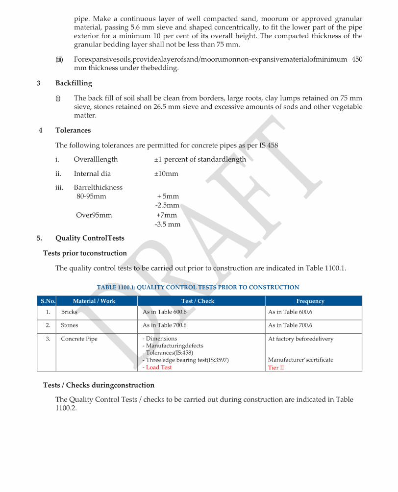
pipe. Make a continuous layer of well compacted sand, moorum or approved granular material, passing 5.6 mm sieve and shaped concentrically, to fit the lower part of the pipe exterior for a minimum 10 per cent of its overall height. The compacted thickness of the granular bedding layer shall not be less than 75 mm.
(iii) Forexpansivesoils,providealayerofsand/moorumonnon-expansivematerialofminimum 450 mm thickness under thebedding.
3 Backfilling
(i) The back fill of soil shall be clean from borders, large roots, clay lumps retained on 75 mm sieve, stones retained on 26.5 mm sieve and excessive amounts of sods and other vegetable matter.
4 Tolerances
The following tolerances are permitted for concrete pipes as per IS 458
i. Overalllength ±1 percent of standardlength
ii. Internal dia ±10mm
iii. Barrelthickness 80-95mm + 5mm
-2.5mm
Over95mm +7mm
-3.5 mm
5. Quality ControlTests
Tests prior toconstruction
The quality control tests to be carried out prior to construction are indicated in Table 1100.1.
TABLE 1100.1: QUALITY CONTROL TESTS PRIOR TO CONSTRUCTION
S.No. Material / Work Test / Check Frequency
1. Bricks As in Table 600.6 As in Table 600.6
2. Stones As in Table 700.6 As in Table 700.6
3. Concrete Pipe - Dimensions - Manufacturingdefects - Tolerances(IS:458) - Three edge bearing test(IS:3597) - Load Test
At factory beforedelivery
Manufacturer’scertificate
Tier II
Tests / Checks duringconstruction
The Quality Control Tests / checks to be carried out during construction are indicated in Table 1100.2.

TABLE 1100.2: QUALITY CONTROL TESTS DURING CONSTRUCTION
S.No. Material / Work Test / Check Frequency
1. Bedding - Materials (As perspecification) - Length, width andthickness - Pre formation of cradle to lay pipes in
bedding - Top and bottomlevels
While laying
2. Laying and Jointing of pipe - Invert level - Longitudinalgradient - Spacing when 2 or more pipes are laid in a
row or staggeredcolumns. - Jointing ofpipes
Before back filling
3. Backfill - Filling of trench on both sides (simultaneously)
- Tamping aroundpipe
During filling earth / granular material around pipe after laying
4. Cushion over pipes Thickness While filling
5. Brick / Stone Masonry for head walls
Clause No 600.7 or Clause 700.7 As per Clause No. 600.7 or 700.7
6. Side slopes on Head walls - Slope
- Stonepitching Before construction of guard stones
Quality control checks by AE /AEE/Tier II
The quality control checks by AE / AEE are indicated in Table 1100.3.
TABLE 1100.3: QUALITY CONTROL CHECKS BY AE /A EE/Tier II
S. No. Item / Stage Test / Check Designation of Inspecting Officer
1. Head walls / Return walls Plumbness AE
2. Roadway Camber, width, tolerance in level AE
3. Weep holes Size and Spacing AE
4. Protection works - Materialused - Thickness & length ofapron
AE
5. Cushion over pipes Thickness of earthwork over pipes AEE
6. General Workmanship - Inlet and outlet gradient ofpipes - Clear spacing between rows ofpipes - Roadway alignment /camber
AEE/Tier II
C. Do’s andDon’ts
Do’s Don’ts
1. Carry pavement crust, over pipeculverts
2. Keepthetrenchesfreefromwateruntilthepipesare installed and jointshardened.
3. Keepthetrenchinembankmentoneithersideofpipe toaboutone-fourthdiaofpipesubjecttoaminimum of 150 mm but not more than one-third dia of pipe or 300mm.
4. Maintainalongitudinalslopeofpipenotflatterthan bed slope to ensure self-cleaning(suggested minimum value 1 /100).
1. Do not allow humps or dips in the vertical profile of the road at the location of pipeculverts.
2. Do not use defective pipes or those found damaged during laying.
3. Do not permit traffic unless the depth of earth filling above the top of pipe line is at least 600mm.
Quality Assurance Handbook for Rural Roads
167
SECTION 1200
RCC SLAB CULVERTS
AND MINOR BRIDGES

1200: RCC SLAB CULVERTS AND MINOR BRIDGES
General
Aculvertisacrossdrainagestructurehavingatotallengthof6morlessbetweentheinnerfacesofdirt walls or extreme ventway boundaries measured at right angles. A minor bridge is a bridge having a total length upto 60 m. A small bridge is a bridge where the overall length of bridge between the inner facesofdirtwallsisupto30mandwhereindividualspanisnotmorethan10m.Inruralroads,individual span lengths upto 15 m are usedexceptionally.
In this section different items of RCC solid slabs, box culverts, and composite bridges have been dealt with.Thecrosssectionsoffoundations,substructuressuchasabutments,returnwallsbesidesdesignof superstructure,drainagespouts,railings,parapetsetc.andallotherdetailsshallbestrictlyinaccordance with contractdocuments.
Forminorbridgeshavingoveralllengthof30mandabove,amethodstatementforconstructionindicating items (a) to (j) as per clause 1201 (xi) of MoRD Specifications for Rural Roads, shall besubmitted.
A. Methodology
A1 Foundations
1. Taketheminimumdepthoffoundationuptothestratumhavingspecifiedbearingcapacityshown ondrawingbutnotlessthan2mbelowthescourlevelwherenobedprotectionisprovidedor1.5 m below the protected bedlevel.
2. In case of rocky bed, ensure embedment of foundation into the rock below, the minimum depth being 500 mm for hard rocks and 1200 mm for soft erodiblerocks.
3. Provide300mmthickplainconcreteM15gradefooting,unlessotherwisespecifiedonthedrawings. Provide a minimum offset of 150 mm for the base ofsubstructure.
4. Setoutplandimensionofthefoundationatthebottomoffoundationtrenchandcheckwithrespect to original reference line andaxis.
5. Before laying foundation concrete, clean the earth surface of all loose material and sprinkle water to wet. Provide side formwork as per required dimensions andheight.
6. Lay foundation concrete continuously to the required thickness upto the level of construction jointproposed.
7. Finish the concrete surface smooth with a trowel and ensure curing as specified in Section800.
8. Carryout dewatering where necessary for laying of concrete so as to keep the water level below foundation level with adequate provisions /precautions.
9. Remove loose sand laid on foundation before commencement of back filling. Refill all spaces excavated and not occupied by permanent work with earth upto surface of surrounding ground. In case of excavation in rock, fill the circular space with M15concrete.

A2 Substructures
This item covers piers, abutments, wing walls, return walls, pier and abutment caps and RCC dirt walls.
1. AdopteitherBrickMasonryorCoursedRubble(CR)StonemasonryorPlainorReinforcedConcrete forpiers,abutmentsandwing/returnwalls.Forwingandreturnwallsupto3mheightuseRandom Rubble (RR)masonry.
2. Before commencing the masonry / concrete work, scrub the foundation with wire brush and remove all loose material and wet thesurface.
3. Make provision for weep holes in solid (non spill through) abutments and provide backfill.
4. Provide vertical expansion gaps of 20mm width between abutments and wingwalls.
5. Provide coping for wing / return walls in plainconcrete.
6. Provide dirt wall as perspecification.
7. Provide RCC pier and abutment caps as shown on the drawings. For Slab bridges, cast surface of pier and abutment caps and pedestalshorizontal.
8. ProvideRCCdirtwallwithspecificationsofformwork,reinforcementandconcreteasperSections 800, 900and1000.
A3 Superstructures
(a) Reinforced Concrete SolidSlabs
1. Set out dimension, lines and level and check with respect to permanent reference lines and permanent benchmarks.
2. CarryoutRCCworkconformingtotheprovisionofformworksteelreinforcementandstructural concrete given in sections 900, 1000 and 800respectively.
3. Whereadjacentspanofslabhasalreadybeencastinplace,expansionjointandfillerboardabutting the already cast span shall form the shutter for the adjacentspan.
4. Cast whole of the slab with reinforcement embedded for road kerb andrailings.
5. Use vibrators as per Table 800.12 for compaction ofconcrete.
6. Provide wearing coat after the deck slab has been cast true to lines andlevels.
(b) RCC BoxCell
Choose box culvert when safe bearing capacity of soil is less than 150 kN / m2 and when angle of friction is less than 15o.
1. Prepare M10 Grade cement concrete bearing surface as shown in drawings or clause 1203.4 of MORD Specifications before construction of boxcell.
2. Keep the top of the raft in bottom of box cell 300 mm below the lowest bedlevel.
3. Place the reinforcement cages in the shuttering as perdrawings.

4. Construct box section in minimum M25 concrete or as specified, with a maximum of one construction joint located in the web below the fillet between deck slab andweb.
5. Carryout concreting operation continuously upto the construction joint.
6. Ensure proper compaction of concrete using screed or form vibrator for concrete in top slab of box. Use needle vibrators to ensure compaction of concrete inwebs.
7. Providepressurereliefpipesof100mmdia.Markanareaof500mmx500mmbelowthepressure relief pipe in the form of inverted filter as per clause 1302 of MoRDSpecifications.
8. Provide cut off walls and protective apron as shown indrawing.
9. Provide earth cushion and / or pavement on the top slabs (carriageway) after specified period of curing of all the boxcells.
10. Provide400mmthickplaincementconcreteparapetasperClause1208.4ofMoRDSpecifications.
(c) Composite type (RCC deck slab on steelgirders)
Choose Composite type bridges in hill areas or where problems of centering are foreseen for casting of superstructure
1. Provide simply supported spans for composite type superstructure consisting of longitudinal steel girders with RCC solid slabdecking.
2. ProvideshearconnectorsofappropriatesizeandspacingasshownindrawingsbetweentheSteel girder and RCC deck to ensure compositeaction.
3. Ensure the composite section of steel beams and RCC slab and shear connectors conforming to IRC:22 and IRC:24 and carry out welding works as per Table1000.2.
4. Cast the RCC deck slab with steel reinforcements in place as per Sections 800, 900 and1000.
5. CarryoutpaintingandprotectivecoatingonStructuralsteelcomponentsinaccordancewithIS:1477, with a minimum of three coats of paints or a metal coating followed by two coats ofpaint.
A4 Appurtenances
(a) WearingCoat
Bothbituminousandconcretepavementsusedintheadjacentroadworks,arecarriedoverculverts andminorbridgesaswearingsurface.However,separatebituminousorcementconcretewearing coats are to be laid on RCC slab bridges, as shown indrawings.
1. Use 20 mm thick premix carpet with seal coat as bituminous wearing coat on culverts having earth cushions and pavement carried over suchculverts.
2. Onminorbridgesandculvertswithoutearthcushion,provide40mmthickBituminousMacadam (BM) covered with 20 mm thick premix carpet and sealcoat.
3. Where cement concrete pavement is being built for the road, carry the same over box culverts with earth cushion or slabculverts.

3. Provide 75 mm cement concrete wearing coat of M30 grade for isolated RCC slab bridges or submersible structures wherespecified.
4. Keepacrossslopeof2.5percentfordeckslablevelinlongitudinalprofilefordrainageandensure curing earlier to prevent formation of shrinkagecracks.
(b) Bearings and ExpansionJoints
1. ProvideonlyelastomericbearingsforRCCslabbridgesofspanlengthmorethan10mconforming to IRC:83 partII.
2. Make provision for robust, durable, watertight and replaceable expansion joints, if needed. Such joints shall be designed site specific or adopted as shown indrawings.
3. Install deck joints in accordance with manufacturer’srecommendation.
4. Forthespecificationsoffillerjoints,buriedjoints,compressionsealjointsandslabsealexpansion joints refer to section 1200.7 of the MoRD Specifications for RuralRoads.
(c) Railings/Parapets
Bridgerailingsincludeportionofthestructureerectedonandabovethekerbfortheprotectionof pedestrians and traffic and constructed after the centering for falsework released. Adopt either metal or cast-in-situ concrete railings for RCC slab culverts and minor bridges as specified in the drawings.
1. Adopt all pipe sections and steel elements of railings, conforming to IS:1239 aftergalvanizing.
2. Adjust railings carefully prior to fixing in place, to ensure proper matching at abutting joints and correct alignment and camber throughout their length.
3. Protect all steel rail elements, pipe terminal sections, posts, nuts and both hardware and other steel fittings against corrosion, by galvanizing or painting.
4. Constructportionoftherailingorparapettobecastinplaceinaccordancewiththerequirements for structural concrete as per Section 800 and reinforcement as per Section1000.
5. For RCC slab culverts and minor bridges having overall length not exceeding 30 m, provide parapets of 400 mm thickness (minimum) in PCC of M15 or brick or stone masonry as shown in drawings.
6. Use forms of either single width board or line with suitable material dulyapproved.
7. Constructallmouldings,panelworkandbevelstripsasperdrawingsandfinishallcorners,true, sharp and cleancut.
(d) Approachslabs
1. Approachslabsarenotneededonculverts/orminorbridgeshavingoveralllengthnotexceeding 30 m bridges and road pavement is continued in the full formation width between wing walls / Returns.
2. Whenspecified,adoptaminimumlengthof3.5mandminimumthicknessof300mmforapproach slab. Provide a 150 mm thick base in M10 concrete for approachslab.

3. Provide12mmdiasteelbarsat150mmc/cinbothdirectionsatbothtopandbottomofapproach slab and execute concreting work as per Section800.
(e) Drainagespouts
1. Fix rigid drainage spouts of 100 mm dia, at a spacing not exceeding 10m.
2. Use corrosion resistant material for drainagespouts.
3. Ensure suitable camber in the carriageway surface for transversedrainage.
4. Seal the shrinkage cracks around drainage assembly with polysulphide or bituminous sealant, after setting of deck slabconcrete.
(f) Filling
Filling around culverts and bridges should be done with non-cohesive soils.
(g) SectionalDetails
1. Forplainconcretestructures,provideaminimumskinreinforcementof2.5kg/m2onallexposed surfaces in horizontal and vertical directions keeping a spacing not more than 200 mm in each direction.
2. For RCC approach slabs provide a reinforcement of 12 mm dia @ 150 mm c / c at both top and bottom side, in both thedirections.
3. For structural steel RCC slab composite superstructures, provide haunches of 150 mm x 150 mm between top of steel girder and soffit of slab. Locate the sides of haunches 45o from the outside edge of the base of theconnections.
B. Quality ControlRequirements
(1) Materials Table/Clause
Bricks Table 600.4
Stones Tables 700.1 &700.2
Cement Clause602.2/702.2/802.2
Coarseaggregate Clause802.3
Sand Clause 602.5 /802.4
Water Clause802.5
Steel Reinforcement Clause 1002
StructuralSteel Clause 505 ofIRC:24
StructuralConcrete Table 800.2 to800.12
ToleranceinFormwork As per B of Section900
PolysulphideSealant IS:1834
or Bituminous Sealant
Fibres
Type, specification and Dosage depends on Applications and Concrete Mix Design
Specification of Hook-end steel Fibers
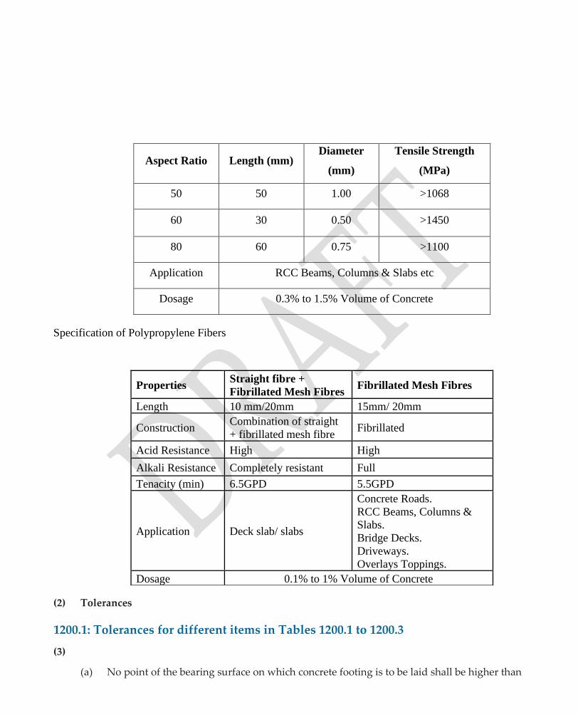
Specification of Polypropylene Fibers
(2) Tolerances
1200.1: Tolerances for different items in Tables 1200.1 to 1200.3
(3)
(a) No point of the bearing surface on which concrete footing is to be laid shall be higher than
Aspect Ratio Length (mm) Diameter
(mm)
Tensile Strength
(MPa)
50 50 1.00 >1068
60 30 0.50 >1450
80 60 0.75 >1100
Application RCC Beams, Columns & Slabs etc
Dosage 0.3% to 1.5% Volume of Concrete
Properties Straight fibre +
Fibrillated Mesh Fibres Fibrillated Mesh Fibres
Length 10 mm/20mm 15mm/ 20mm
Construction Combination of straight
+ fibrillated mesh fibre Fibrillated
Acid Resistance High High
Alkali Resistance Completely resistant Full
Tenacity (min) 6.5GPD 5.5GPD
Application Deck slab/ slabs
Concrete Roads.
RCC Beams, Columns &
Slabs.
Bridge Decks.
Driveways.
Overlays Toppings.
Dosage 0.1% to 1% Volume of Concrete

the foundinglevel.
(b) VariationinDimensions : +50mm
: -10mm
(c) Misplacement from specified positioninplan : 15mm
(d) Surface irregularities measured with 3 mstraightedge : 5mm
(e) Variation of levelsattop : ±25mm
1200.2: Tolerances in Sub-structures
(i) Sub-Structure
(a) Variation in cross sectional dimensions : +10 mm
: -5 mm
(b) Misplacement from specified positioninPlan : 10 mm
(c) Variation of levels atthetop : ±10 mm
(d) Surface irregularities measured with 3 mstraightedge : 5 mm
(e) Bearingareas : 3 mm
(iii) Superstructure
(a) Variations in overall depthorwidth : ±5 mm
(b) Variations in overall length and length : Shall not exceed
between bearings ± 10 mm or ± 0.1 percent of span
length whichever is less.
(c) Surface irregularities whenmeasuredwith : 5 mm
3 m straight edge or template
3 Quality control tests
3.1 Tests prior to construction
(a) Material / Work

TABLE 1200.1: QUALITY CONTROL TESTS PRIOR TO CONSTRUCTION
S.No. Material / Work Test Frequency
1. Cement Fine / Coarse
Aggregates and water and
Concrete for Structures
Tests as in Table 800.13 As in Table 800.13
2. Steel Reinforcement (For
culverts and minor bridges)
Tests as in Table 1000.4 As in Table 1000.4
3. Plant & Equipment and
other arrangements for
concrete production
a) Working condition of concrete mixers
including stand byarrangement
b) Measuring boxes / scales for cement,
fine and coarseaggregates
c) Standard measuring cans (1 / 2, 1, 2, 5
litre capacity) forwater
d) Needle, plate and screedvibrators
e) Arrangements for protection of concrete
in hot, cold and rainyweather
f) Tools and equipment for finishing and
curing.
g) Formwork (As per Table900.2)
Check by AE before
commencement of concreting
The tests and checks to be carried out prior to construction are listed in Table 1200.1
(b) Manufactureditems:
Other checks to be done on ‘Manufactured items’ prior to construction indicated in Table 1200.2.
TABLE 1200.2: QUALITY CONTROL TESTS PRIOR TO CONSTRUCTION
S.No. Material / Work Test / Check Frequency
1. Elastomeric bearings
(IRC-83 part II)For
Spans > 10m
Approved Test house report obtained by
Manufacturer.
To be approved by AE / EE
before procurement
2. Expansion Joints
(IRC:SP:70)
Performance report (To be furnished by
manufacturer)
-do-
3. Shear connectors
(For composite bridges)
Dia, length and yield strength -do-
4. Plasticizer (If used to
improve workability of
concrete)
As per Manufacturer’s test reports. - do -

Tests / checks duringconstruction.
The Tests / Checks to be carried out during construction are indicated in Table 1200.3
TABLE 1200.3: QUALITY CONTROL TESTS DURING CONSTRUCTION
S.No. Material / Work Test / Check Frequency / Stage
1. Concrete for Structures For constituentsas in Table 800.14 As in Table 800.14
2. Concreting
- ForFoundation
- ForSubstructure
Dewatering, before laying of foundation
concrete
Form panel size and jointing to prevent
bleeding
For each foundation work
For each work
3. Cube Strength Results Analysis of Test results (Clause No 815 of
MoRD Specifications)
During construction of
substructures / super-structures
separately
4. Formwork Tests as in Table 900.3 As in Table 900.3
5. Reinforcement cage a) Dia and spacing of Reinforcements in
cage as perdrawing
b) Size and placement of briquettes for
supporting the reinforcements i.e. to
provide bottom and sidecovers
c) Cleaning rust on reinforcements with
wirebrushing
d) Other checks as per Table1000.5
Before commencement of
concreting
- do -
Before placement and
compaction of concrete
6. - All concrete** works a) Temperature Control & Control of
W / C ratio (As per time & season
of work) ofmix
b) Workability(IS:1199)
c) Compaction
d) Curing
Regularly
Twice in a day.
Ensure compaction by needle
vibrator
To commence 24 h after casting.
7. Expansion Joint assemblies Installation as per Manufacturer’s
specification
At each Joint location
8. Sealants To be installed as per Manufacturer’s
specification.
After hardening of concrete
9. Kerbs, Drain pipes,
Railings / Parapets
- Separateformwork
- Spacing
- Dimensions
As and when work is taken up
10. Elastomeric bearings Correct positioning on pedestals Before concreting
** Refer to Table 800.14 also
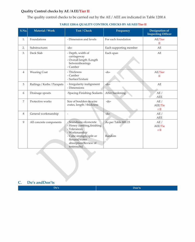
Quality Control checks by AE /AEE/Tier II
The quality control checks to be carried out by the AE / AEE are indicated in Table 1200.4
TABLE 1200.4: QUALITY CONTROL CHECKS BY AE/AEE/Tier II
S.No. Material / Work Test / Check Frequency Designation of Inspecting Officer
1. Foundations - Dimension and levels For each foundation AE/Tier
II
2. Substructures -do- Each supporting member AE
3. Deck Slab - Depth, width of carriageway
- Overall length /Length betweenbearings
- Camber
Each span AE
4 Wearing Coat - Thickness - Camber - SurfaceTexture
-do- AE/Tier
II
5 Railings / Kerbs / Parapets - Irregularity inalignment - Dimensions
-do- AE
6 Drainage spouts -Spacing-Finishing-Sealants After hardening AE /
AEE
7 Protective works Size of boulders in wire crates, length / thickness
-do- AE /
AEE/Tie
r II
8 General workmanship - -do- AE /
AEE
9 All concrete components - Soundness ofconcrete - Honey combing,finishing - Tolerances - Workmanship - Cube strength/split or
flexural/water absorption(Review of testresults)*
As per Table 800.15
Random
AE /
AEE/Tie
r II
C. Do’s andDon’ts Do’s Don’ts

1. For gravity type masonry or concrete return / wing wallpreparethesurfaceoffoundationsimilartothat ofabutments.
2. In case of concrete piers, keep the number of horizontal construction jointsminimum.
3. Cast the top surface of pedestal for placing the bearingshorizontal.
4. Cast theportionsofdeckslab(nearexpansionjoints) along withreinforcements.
5.4.
6.5. Rough finish the surface of deck slab before hardening, to ensure bonding of wearing coat later.
6. Protect structural steel components of thecomposite type superstructure againstcorrosion.
7. For box culverts, strictly follow the sequence of construction and location of constructionjoints.
8. Complete the protection works before the flood season to prevent damage of foundation by flooding..
1. Donotallowanypointofthebearingsurfaceonwhich concrete footing is to be laid to be higher than the foundinglevel.
2. Do not provide any construction joint in the concrete footing.
3. DonotresorttolayeredconstructionofthickRCCsolid slabs, to avoid coldjoints.
4. Do not provide any construction joint at the junction of web and fillet between web and deck slab for T- beam and slabbridges.
5. Do not allow any irregularity in the alignment of the deck forrailings.
6. Do not provide expansion joints for multi-cell box culverts with earthcushion.
7. Donotpermittrafficonsuperstructurepriorto28days of curing of the deckconcrete.
8. Do not provide overlays on wearing coats (thereby increasing dead load ondeck).

Quality Assurance Handbook for Rural Roads
179
SECTION 1300
PROTECTION WORKS
AND DRAINAGE

1300: PROTECTION WORKS AND DRAINAGE
A. Methodology
General
In this section, the construction and quality control aspects of aprons, pitching on slopes, masonry flooring over cement concrete bedding, curtain wall besides chute, roadside and hill drains have been dealt with.
Apron
1. Keep the length of apron not less than twice the depth of curtainwall.
2. Level the surface on which the apron is to be laid and prepare for the length and width as shown on drawings. In case the surface is below low water level, raise the ground level by dumping earth, moorum, brick bats, stones, etc., so that apron can be laidthereon.
3. Provideflexibleapronbeyondcurtainwallsforaminimumdistanceof3monupstreamsideand 6 m on downstream side unless specifiedotherwise.
4. For regular and orderly disposition of stone in apron, build template cross walls in dry masonry, of about 1 m thickness and full height specified at 30 m intervals all along the length. Hand pack stone within these walls.
5. Use wire crates of galvanized steel wire of 4 mm dia with apertures not less than 150mm.
6. Useinsitubuiltwire-cratesofsize2mx1mx0.3mto7.5mx3mx0.6mandsecurelystayat1.5 m intervals orless.
7. Place the crates in position before filling inboulders.
Pitching onSlopes
1. Usequarrystoneofminimum225mmthicknessor30kgaspitchingorasspecified,andspallsof minimum 25 mm size to fill the voids. Alternatively, PCC blocks of 190 x 190 x 225 mm size (minimum) in M15 Concrete can be used forpitching.
2. Provide one or two layers of graded materials (filter medium) of 150 mm thick or as specified under the pitching to drain off the seepage water and prevent erosion of basematerial.
3. Trim the sides of banks to the required slope and provide before laying the pitching. Fill the depressions and thoroughly compact beforehand.
4. Start the lowest course of pitching from the toe wall and build courses upwards. Use either dry rubble or brick masonry for toewall.
5. Use dry masonry, when two or more layers of stones are to be laid to obtain design thickness of pitching and bond the stones well. Template cross walls in dry masonry can be built, as done for aprons.
6. When bricks are to be laid in more than one layer, ensure proper bonding the adjacent layers by means of sufficient number of pin headers extending from one layer to theother.

ToeProtection
The toe wall shall be in dry RR matting conforming to the Clause 1302.5 of MORD Specifications for Rural Roads or as per drawings. Toe protection shall be done by constructing a toe wall, retaining / breast wall or close bamboo walling at the junction of embankment slope and general ground level, to protect the embankment from damages.
1. Use dry rubble or brick masonry for toewalls.
2. While using bamboo walling, examine the ballies of 65mm to 75mm dia from a distance of 1.2m from wider end. Paint the entire length in coaltar.
3. Choose lengths between 1.2m and 3m and drive the ballies into the ground at close intervals of 150mmc/c.Useatleastthreehalfsplitrunner/staysatequalspacingforhorizontalstiffnessand fix them withnails.
4. Line the exposed surface of bamboo walling with sheets made of cut drums and fix withnails.
Rubble Stone/Brickflooring
1. Where specified provide rigid flooring under culverts and extend for a minimum distance of 1.5 m on upstream side and 3m on downstream side or as shown indrawings.
2. Excavate trench for laying foundation of bed protection and lay 150 mm thick cement concrete of M10 grade, so as to commence pavingwork.
3. Where rubble stone is specified as flooring, carryout the work with flat stones 150 mm thick, which are bedded on a 25 mm thick layer of 1:5 cement mortar. Fill the joints with 1:3 cement mortar.
4. Wherebricksaretobeused,carryouttheworkon150mmthickbrickonedge,witheachlayerof brick bedded on 25 mm thick 1:5 cement mortar. Fill in the joints with 1:3 cementmortar.
5. Keep the top of flooring 300 mm below the lowest bed level and extend the flooring. Extend the line connecting the end of splayed wing walls on either side of the culvert /bridge.
6. Adoptdryrubblestone/brickflooringatCDworkswherethevelocityofflowislessthan1.5m/ sec by keeping the top of flooring 300 mm below the low bedlevel.
7. Lay the rubble stones closely, breaking joints and fill all joints with spalls of proper size and wedged in with rammers to ensure tightpacking.
8. Whendrybrickistobeused,followtheprocedureasaboveonapreparedbaseandlayinoneor more layers. Ensure properbond.
Curtainwall
Enclose flooring by curtain walls in cement concrete (M 10) or stone / brick masonry in cement mortar 1:4 and take to a depth of atleast 1.5 m on u / s side and 2 m on d / s side below the floor level.
Chute drain, Roadside drain, Hillside drain, Catch waterdrain
1. Provide rectangular or trapezoidal chute drains of specified dimensions in sections of road embankment,ofheightmorethan8matminimum10mintervals.Providetheminembankment

slopesinapproachesofbridgesandonhorizontalcurvesconnectedatthetowoftheembankment with parallel open drains discharging into a nearby nallah or CDwork.
2. Locatetheopendrainatthetoeofembankmentfarawayfromatimaginaryslopeof4(horizontal)
: 1 (vertical).
3. Construct hill side drains as per clause 1606.1 of the MORD Specifications for RuralRoads.
4. Buildcatchwater/interceptingdrainsonhillslopestointerceptwaterflooringfromupperreaches and guide such flow into culverts. Adopt trapezoidal shape and linethem.
5. Refer to IRC:SP:42 ‘Guidelines on Road Drainage’ for more details and design ofsection.
Protection of Vented Causeways and SubmersibleBridges
Damages to submerged structures occur due to out flanking at one or both banks, heavy erosion on downstream side, collapse of headwalls and washing of paved surface. The design of such structures is inter woven taking protection aspects into consideration.
1. For vented causeways, prepare the stream bed crossing by stabilizing with crushed stone, riprap or rubble after removal of silt and compact the base and core to reduce futuresettlement.
2. Provide side drains on either side along the side slopes which are rubble pitched. Take the side drains at least 10 m away from the edge of main causeway junction, to meet the streamproper.
3. Provide face walls to protect the edges of the structure and to prevent erosion of core material. Build face walls of the approaches strong enough to avoid damage during floods. Seal the joints in concrete face walls to prevent ingress of water to thecore.
4. MaketheapproachesofcausewaysinCementConcretepavementlaidoverWBMorinStoneSet pavement, to prevent their damage due to frequent overtopping.
5. In case of submersible bridges, provide bed protection for the whole bed-width of water course plus 3 m on bothsides.
6. Provideaminimumfoundationdepthof1.5monu/ssideand2.5mondownstreamsideforcut offwall.
7. In the case of submersible bridge, anchor the deck slabs of span length (<15m) with piers, to counter the water currentforces.
8. Provide RCC guard stones at 1.2 m c / c for both vented and non-ventedcauseways.
9. Providedebrisarrestersonupstreamsidetopreventdamagetosubmersiblebridges,duetofloating trees andbranches.
10. Provideapronsforsubmersiblebridgesonbothu/sandd/ssidesasperIRC:89.
B. Quality ControlRequirements
1. Stones andApron
Thesizeandweightofstonesforlayingboulderapronshallconformtotherequirementgivenin Table 1300.1

TABLE 1300.1: STONES FOR APRON
Mean Design Velocity m/sec Minimum size and weight of stone
Diameter (mm) Weight (kg)
Upto 2.0 220 25
2.5 300 40
3.0 380 76
3.5 510 184
4.0 670 417
2. Stones for pitching onslopes
The size and weight of stones for pitching on slopes shall conform to the requirements given in Table 1300.2
TABLE 1300.2: STONES FOR PITCHING
Mean Design Velocity m/sec Minimum size and weight of stone
Slope 2:1 Slope 3:1
Diameter (mm) Weight (kg) Diameter (mm) Weight (kg)
Upto 2.0 220 25 220 25
2.5 300 40 300 40
3.0 300 40 300 40
3.5 350 59 300 40
4.0 450 126 350 59
Where the required size stone are not available for use in wire crates, CC blocks in M15 grade weighing not less than 25 kg may be used.
3. Coatings onWires
The galvanizing coating shall conform to IS: 4826 and that of annealed steel wire for wire crates shall conform to IS: 280
4. Quality ControlTests
Tests prior toconstruction
The Quality Control tests to be carried out prior to construction are indicated in Table 1300.3
TABLE 1300.3: QUALITY CONTROL TESTS PRIOR TO CONSTRUCTION
S. No. Test / Check Frequency
1. Size and weight of stones in apron / slope / flooring etc. (Table 1300.1 and 1300.2)
At quarry site before procurement
2. Wire crates (Size and mesh size) Before procurement
3. Cement concrete blocks (Weight and Size) Before procurement
4. Gradation of Filter media
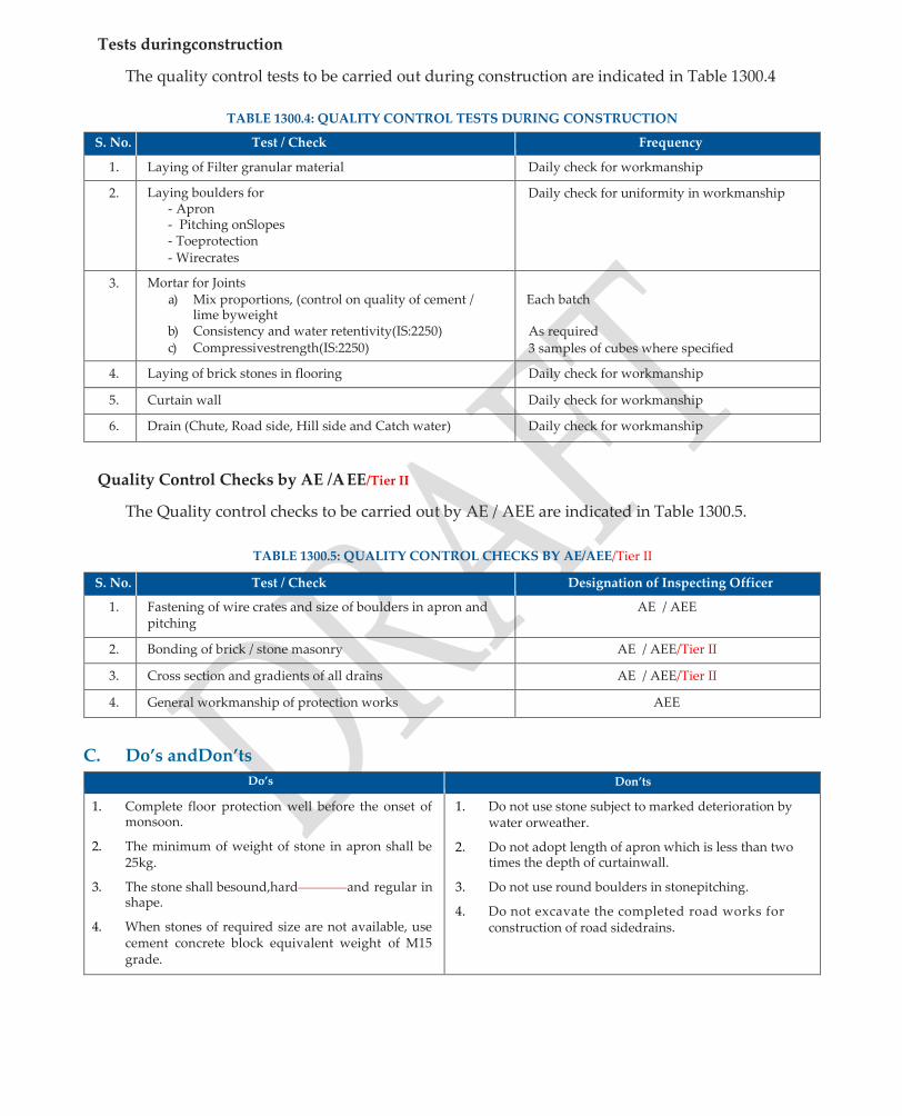
Tests duringconstruction
The quality control tests to be carried out during construction are indicated in Table 1300.4
TABLE 1300.4: QUALITY CONTROL TESTS DURING CONSTRUCTION
S. No. Test / Check Frequency
1. Laying of Filter granular material Daily check for workmanship
2. Laying boulders for - Apron - Pitching onSlopes - Toeprotection - Wirecrates
Daily check for uniformity in workmanship
3. Mortar for Joints a) Mix proportions, (control on quality of cement /
lime byweight b) Consistency and water retentivity(IS:2250) c) Compressivestrength(IS:2250)
Each batch
As required
3 samples of cubes where specified
4. Laying of brick stones in flooring Daily check for workmanship
5. Curtain wall Daily check for workmanship
6. Drain (Chute, Road side, Hill side and Catch water) Daily check for workmanship
Quality Control Checks by AE /AEE/Tier II
The Quality control checks to be carried out by AE / AEE are indicated in Table 1300.5.
TABLE 1300.5: QUALITY CONTROL CHECKS BY AE/AEE/Tier II
S. No. Test / Check Designation of Inspecting Officer
1. Fastening of wire crates and size of boulders in apron and pitching
AE / AEE
2. Bonding of brick / stone masonry AE / AEE/Tier II
3. Cross section and gradients of all drains AE / AEE/Tier II
4. General workmanship of protection works AEE
C. Do’s andDon’ts
Do’s Don’ts
1. Complete floor protection well before the onset of monsoon.
2. The minimum of weight of stone in apron shall be 25kg.
3. The stone shall besound,hard and regular in shape.
4. When stones of required size are not available, use cement concrete block equivalent weight of M15 grade.
1. Do not use stone subject to marked deterioration by water orweather.
2. Do not adopt length of apron which is less than two times the depth of curtainwall.
3. Do not use round boulders in stonepitching.
4. Do not excavate the completed road works for construction of road sidedrains.
Quality Assurance Handbook for Rural Roads
187
SECTION 1400
CEMENT CONCRETE
CAUSEWAYS

1400 : CEMENT CONCRETE CAUSEWAYS
Underthissectionqualityaspectsofdifferentsubmersiblestructuresviz.,Irish/FlushCauseway,Vented Causeway and Submersible Bridges for rural roads are dealtwith:
A. Methodology
A1 FlushCauseway
1. Chooseflushcauseway(Paveddip)tocrossashallowwatercoursebyadoptinggeneralguidelines given in clause 1401.0 of MORD Specifications for RuralRoads.
2. Keep top level of floor of causeway same as that of bed ofwater-course.
3. Build cut-off walls in brick masonry on stone masonry or plain cement concrete with suitable formwork as per provisions given in sections 600, 700, 800 and 900 respectively of thisManual.
4. Excavate for laying of foundation of u/s and d/s cut-off walls. Keep it sufficiently deep to avoid exposureduetoscouring.AdoptaPCCfootingof150mmthicknessinM15grade,laidonalayer of 100 mm thick lean concrete(M10)
5. Adoptaplaincementconcreteslabofminimumthickness200mminaminimumgradeofM30as paved dip. Provide construction joints 4-6m apart and seal them withpolysulphide.
6. Provideu/sandd/sprotectionworks,apron,pitchingasperrequirement.
7. Provide guide posts /stones at required spacing.
A2 Vented PipeCauseways
1. Choose vented pipe causeway to cater to low flows through circular vents which overtop during monsoon. Usually RCC pipes (NP3 or NP4) are used for providing circularvents.
2. Follow the same methodology as detailed in section 1100 of this Manual for laying of RCCPipes.
3. For headwalls or other ancillary works, adopt the requirements given in Section1300.
4. Take foundation and head walls sufficiently deep to avoid exposure to scouring in erosive strata. Batter the d / s side headwall on the outside and round thecorners.
5. Adopt rectangular or arch on type vents instead of circular pipe as per localpractice.
6. Raiseendportionoffacewallsandprotectentiretopofcausewaybywelldesirablenon-erodible wearingcoat.
A3 SubmersibleBridges
For design and construction of submersible bridges, adopt prevailing practice in the State or Guidelines given in IRC:SP:20.
1. Makethedeckslabsheavytowithstanddrag,upliftandlateralforceduetooverflowandupstream pressure.
2. Fix the location and levels of pier cap, abutment cap, pedestals and anchorage arrangements to ensure properalignment.

3. Give streamline slope to pier cap, abutment cap andpedestals.
4. Carryout foundation works as per section 1200.
5. The works in brick or stone masonry or in RCC are carried out as per the sections 600, 700 and 1200respectively.
6. Provide chamfers of 40 mm x 40 mm for corners of all submerged elements if they are not streamlined.
7. Provideventholesof100mmdia(withPVCpipes)toreducetheupliftpressureonsuperstructure during submergence, their minimum number being, three per span in bothdirections.
A4 Ancillary Items (Wearing coat, Railing, Kerbs, Warning signs, Floodgauges)
1. Provide75mmthickC.C.wearingcoatinM30gradewithacrossslopeof2.5percenttowardsd/ s side of deck slab in submergible bridge. For vented causeways adopt 200 mm thick RCCSlab.
2. Discontinuewearingcoatatexpansionjointlocations.Extendjointfillersuptothetopofwearing coat.
3. For CC wearing coat, provide 8 mm dia bars @ 200 mm c / c reducing to 100 mm c / c in both directions over a strip length of 300 mm near expansionjoint.
4. Use open type or filler joint with appropriate noseprotection.
5. Use metal railing of collapsible or removable or tubular type for submersiblebridges.
6. Use discontinuous kerbs 300 mm wide at 1.8 m c / c on both sides, the continuous length of each piece being 1.5m.
7. Locateadvancewarning/cautionarysignsatabout200mfromthebeginningofsubmergedportion of causeways and submersible bridges, to indicate speed limit, depth of submergenceetc.
8. Installfloodgaugesat15mintervalsonsubmergedsectionofapproachesandsubmersiblebridges, regarding depth of flow above road level bridgedeck.
B. Quality ControlRequirements
Various components of flush and vented causeways besides submersible bridges shall conform to relevant provisions of the MORD Specifications and IS Codes listed below:
1. Material
(i) Bricks Section 600
(ii) Stones Section700
(iii) Cement Section 800
(iv) Sand Section 800
(v) CoarseAggregates Section800

(vi) Water for construction
Section 800
(vii) Steel Section 1000
2. Components/ Works
(i) Earthwork Section 300
(ii) RCCPipe Section 1100, 1400
(iii) Vented Box Section 1200
(iv) DrainageSpout Section 1200
(v) CCPavement Section 1500
(vi) Floodgauges IRC:67
(vii) Stainless steel bars
(rust, acid and heat resistant)
IS:6603
viii) Painting of RCC posts / stones IS:164
3 Quality ControlTests
Thequalitycontroltests/checkslistedhereincovercausewaysandsubmersiblebridgeswherein materials such as brick or stone masonry, plain or reinforced concrete are used. The openings in causeways could be of concrete pipes or rectangular / arch semicircular vents inRCC.
Tests prior toconstruction
The quality control tests to be carried out prior to construction are indicated in Table 1400.1
TABLE 1400.1: QUALITY CONTROL TESTS PRIOR TO CONSTRUCTION
S.No. Material Test / Check Frequency
1. Bricks As in Table 600.6 Table 600.6
2. Stones As in Table 700.6 Table 700.6
3. Concrete Materials As in Table 800.13 Table 800.13
4. Stainless Steel bars (For submersible bridges)
Rust, acid and heat resistance (IS:6603) Before procurement
5. Steel reinforcement As in Table 1000.4 Table 1000.4
6. Cement pipes (If used) As in Table 1100.1 Table 1100.1
7. Plant equipment for production of concrete
As in Table 1200.1 Table 1200.1
8. Pavement Materials a) Sub-base (Table401.2) b) WBM (Table405.6) c) Cement concrete (Table800.13)
Table401.2 Table405.6 Table 800.13

2. Tests duringconstruction
The Quality Control Tests / checks to be carried out during construction are indicated in Table 1400.2
TABLE 1400.2: QUALITY CONTROL TESTS DURING CONSTRUCTION
S.No. Material / Work Test / Check Frequency
1. All concrete works a) Workability(IS:1199) b) Cube strength(IS:516) c) Curing
As per Table 1200.3
2. Concrete for foundation substructure, super- structure (For submersible bridges)
a) Dewatering b) Formpanels, c) Jointing, d) Cover toreinforcements
As per Table 1200.3
3. Formwork Design, Erection, Camber, etc. As per Table 900.3
4. Reinforcement cage Dia, spacing, cover as per drawings - do -
5. Kerbs, drain pipes railings / parapets
As indicated in drawings - do -
6. Bearings & Expansion Joints Manufacturer’s Specification - do -
7. Jointing of pipes & bedding As per Table 1100.2 During construction
8. Cement Concrete
Pavement (Additional tests) As per Table 1501.3 (Items 5,6,7 & 8) Table 1501.3 (Items 5,6,7 & 8)
9. Equipment for handling pipes (prior to lowering)
- Adequacy of chain pulleyblock
- Stability of Tripod arrangementetc. Check by AE
3. Quality Control checks by AE /AEE/Tier II
The quality control checks by AE / AEE are indicated in Table 1400.3.
TABLE 1400.3: QUALITY CONTROL CHECKS BY AE/AEE/Tier II
S.No. Material / Work Test / Check Frequency Designation of Inspecting Officer
1. All plain and RCC components
a) Compressive(cube) Strength (IS: 516)
b) Honey combing and finishing
c) Workmanship
At the end of work (Analysis of Test Results) Before acceptance of work As and when inspected
AE /AEE/Tier II
AE / AEE AE / AEE AE /AEE
2. Wearing coat Camber / tolerances / levels
At the end of work
AE
3. Approaches a) Gradient
b) PavementSurface One check on each side of approach along centre line
AE / AEE/Tier II
4. Protection works a) Pitching ofSlopes b) Thickness & Length
ofApron c) Head, Faceand
Cut off walls
Before onset of monsoon AE
E/T
ier
II
5. CC Pavement Item 2 of Table 1501.4 Before acceptance of work AE / AEE

C. Do’s andDon’ts
Do’s Don’ts
1. LocateCausewaysandSubmersiblebridgesfaraway from the confluence ofstreams.
2. Adaptsubmersiblebridgeswhichblendaesthetically in the environment.
3. Adopt guide post / stone of 250 mm dia of specified height embedded full depth in concrete pavement and in approach portion of causeway. Paint them withalternativeblackandwhitebandswithordinary paint.
4. Permittrafficoncausewaysandsubmersiblebridges aftersealingofconstructionjointsand28dayscuring period ofconcrete.
5. Protect the stream bed on upstream and downstream of causeway by providing aprons and other protectiveworks.
6. Anchor the superstructure of submersible bridges with piers and abutments by using stainless steel anchorrods.
7. Atsubmersiblebridges/causeways,followthesame profileastheflankingroadsectionwithoutanybreak in grade line. Provide properly designed vertical curves to avoidjerks.
1. Do not choose submersible bridge if the meanvelocity of stream is high (exceeding 6m /sec).
2. Do not use composite type superstructure of steel girder with CC solid slab decking for submersible bridges.
3. Donotusefixedtyperailingsforsubmersiblebridges.
4. Do not adopt masonry substructure if the depth of foundation is more than 7m.
5. Do not use dry rubble masonry in retaining walls / breast walls and if necessary in approaches ofsubmersiblebridges.
6. Do not use metallic bearings for submersiblebridges.
7. Do not provide gradients steeper than 1 in 20 on both ends ofcauseways.
Quality Assurance Handbook for Rural Roads
195
SECTION 1500
CEMENT CONCRETE
PAVEMENT
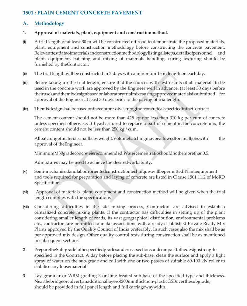
1501 : PLAIN CEMENT CONCRETE PAVEMENT
A. Methodology
1. Approval of materials, plant, equipment and constructionmethod.
(i) A trial length of at least 30 m will be constructed off road to demonstrate the proposed materials, plant, equipment and construction methodology before constructing the concrete pavement. Relevanttestdataofmaterialsandconstructionmethodologylistingallsteps,detailsofpersonnel and plant, equipment, batching and mixing of materials handling, curing texturing should be furnished by theContractor.
(ii) The trial length will be constructed in 2 days with a minimum 15 m length on eachday.
(iii) Before taking up the trial length, ensure that the sources with test results of all materials to be used in the concrete work are approved by the Engineer well in advance, (at least 30 days before theiruse),andthemixdesignbasedonlaboratorytrialmixesusingapprovedmaterialsissubmitted for approval of the Engineer at least 30 days prior to the paving of triallength.
(iv) ThemixdesignshallbebasedonthecompressivestrengthofconcreteasspecifiedintheContract.
The cement content should not be more than 425 kg nor less than 310 kg per cum of concrete unless specified otherwise. If flyash is used to replace a part of cement in the concrete mix, the cement content should not be less than 250 kg / cum.
Allbatchingofmaterialsshallbebyweight.Volumebatchingmaybeallowedforsmalljobswith the approval of theEngineer.
MinimumM30gradeconcreteisrecommended.Watercementratioshouldnotbemorethan0.5.
Admixtures may be used to achieve the desiredworkability.
(v) Semi-mechanisedandlabourorientedconstructiontechniqueswillbepermitted.Plant,equipment and tools required for preparation and laying of concrete are listed in Clause 1501.11.2 of MoRD Specifications.
(vi) Approval of materials, plant, equipment and construction method will be given when the trial length complies with the specifications
(vii) Considering difficulties in the site mixing process, Contractors are advised to establish centralized concrete mixing plants. If the contractor has difficulties in setting up of the plant considering smaller length of roads, its vast geographical distribution, environmental problems etc., contractors are permitted to make associations with already established Private Ready Mix Plants approved by the Quality Council of India preferably. In such cases also the mix shall be as per approved mix design. Other quality control tests during construction shall be as mentioned in subsequent sections.
2 PreparetheSub-gradetothespecifiedgradesandcross-sectionsandcompacttothedesignstrength specified in the Contract. A day before placing the sub-base, clean the surface and apply a light spray of water on the sub-grade and roll with one or two passes of suitable 80-100 kN roller to stabilise any loosematerial.
3 Lay granular or WBM grading 3 or lime treated sub-base of the specified type and thickness. Nearthebridgeorculvert,anadditionallayerof200mmthicknon-plasticGSBoverthesubgrade, should be provided in full panel length and full carriagewaywidth.

4 Provide a separation membrane (125 micron thick plastic sheet) between sub-base and concrete slab. It should be laid withoutcreases.
5 Mark location and type of the joints on either side of the surface of the sub-base, with redpaint.
(i) Contractionjointsshallbemechanicallysawnjointsspaced2.5mto3.75m.Lengthofpanelinthe direction of traffic shall not be less than the width of the pavement. Joints shall be cut when the pavement is neither too soft nor too hard and is able to bear the weight of the machine and crew. Normally it may vary from 8 to 12 hours depending on weatherconditions.
(ii) Construction joints shall be butt joints and placed after a day’s work is over or when work is suspended for more than 30minutes.
(iii) Expansion joints shall be provided near bridges and slab culverts and consist of a bitumen impregnated joint / premoulded synthetic joint filler board, about 20 mm thick, and dowelbars.
(iv) Longitudinal joints shall be provided for a two-lane road and shall besaw-cut.
6 Allsideformsshallbeofmildsteelchannelsorfabricatedplateswithadjustablejacksattheback and of depth equal to the thickness of pavement. Plant, equipment and tools required for preparation and laying of pavement concrete are listed in Clause 1501.11.2 of Specifications for RuralRoads.
7 Pavement concrete shall either be produced near the site, using approved concrete mixers of at least 0.2 cum capacity or readymade concrete conforming to the specified properties of strength and workability. The selection between the above two shall be as per discretion of the engineer-in-charge.
8 Check the slump of concrete. It should be in the range of 30 mm ±10mm
9 Concrete shall be placed between the side forms and shall be levelled with rakes and shovels. In concretepanelshavingacuteangles,abarmatof10mmdiaribbedsteelbarsat150mmcenterto center in both directions shall be provided at 50 mm below the top of slab, in the entirepanel.
10 Around man-holes or other openings in pavement, place 12 mm thick pre-moulded board as per IS:1838 and bar mats beforeconcreting.
11 Compact concrete by a vibrating screed supplemented by two internalvibrators.
12 As soon as practicable after compaction of concrete, smoothen the surface with a longitudinal float operated from the work bridge. Just before the concrete becomes non-plastic, it shall be textured with a long handled steel or fibrebrush.
13 After completion of texturing, before the concrete has taken its initial set, the edges of the slab shall be carefully finished so as to leave the pavement edges smooth and true toline.
14 After completion of the finalizing operations, the surface of the pavement shall be covered with wet Hessian cloth, burlap or jute mats. They shall be maintained fully wetted and in position for 24hours.Upontheremovalofthewetcoveringouttheendof24hours,joint cutting shall be done to the design depth as per drawing using approved machinery and theslabshallbethoroughlywetted and then cured by approved curing compounds.
15 After minimum of 28 days after casting the concrete pavement, joint groove at contraction joint shall be widened to 10 mm width and to a depth 18 to 20 mm and shall besealed.
B. Quality ControlRequirements
1. Material
(i) Cement

Cement shall be capable of achieving the design strength and may be
(a) Ordinary Portland Cement, 43 GradeIS:8112
(b) Ordinary Portland Pozzalana cement,IS:1489
(c) Portland Blast Furnace Slag cement,IS:455
(d) OrdinaryPortlandCement(OPC),53GradeIS:12269,(tobeusedonlywhenapartofcement is replaced with mineral admixtures like flyash, metakaolin etc.).)
(e) Ifthesoilaroundhassolublesaltslikesulphatesinexcessof0.5%,byweightofsoil,cement used shall be sulphate resistant and shall conform toIS:12330.
(ii) Admixture
Chemical admixture conforming to IS:6925 and IS:9103 may be used to improve workability of concrete. Mineral admixture like fly-ash shall conform to IS: 3812.
(iii) Aggregate
(a) Aggregate for pavement concrete shall conform to IS:383 but with a Los Angeles Abrasion testvaluenotmorethan35%orWetAggregateImpactValuenotexceeding30%.Thelimits and deleterious material shall not exceed the requirements set out in IS383.
(b) Thetotalchloridecontentexpressedaschlorideioncontentshallnotexceed0.06%byweight.
(c) Total sulphate content expressed as sulphuric anhydride (SO3) shall not exceed 0.25% by
weight.
(d) Coarseaggregateshallbeclean,hard,strong,dense,nonporousanddurablecrushedstone or crushedgravel.
The maximum size of coarse aggregate shall not exceed 25 mm. It shall not have a flakiness index more than 35% and water absorption exceeding 5%.
(e) Fine aggregate shall be clean natural sand or crushed stone sand or a mixture of both. It shall not contain deleterious material beyond the following limits:
• Clay :4%
• Coal and lignite :1%
• Material passing Sieve No. 75 micron: 4% in natural sand and 15% in crushedsand.
(f) Coarse and fine aggregates, after blending shall conform to the gradation requirements mentioned in Table 1501.1
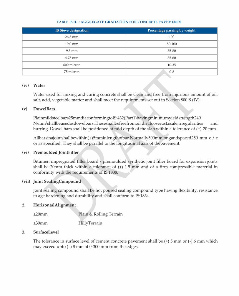
TABLE 1501.1: AGGREGATE GRADATION FOR CONCRETE PAVEMENTS
IS Sieve designation Percentage passing by weight
26.5 mm 100
19.0 mm 80-100
9.5 mm 55-80
4.75 mm 35-60
600 micron 10-35
75 micron 0-8
(iv) Water
Water used for mixing and curing concrete shall be clean and free from injurious amount of oil, salt, acid, vegetable matter and shall meet the requirements set out in Section 800 B (IV).
(v) DowelBars
Plainmildsteelbars25mmdiaconformingtoIS:432(Part1)havingminimumyieldstrength240 N/mm2shallbeusedasdowelbars.Theseshallbefreefromoil,dirt,looserust,scale,irregularities and burring. Dowel bars shall be positioned at mid depth of the slab within a tolerance of (±) 20 mm.
Allbarsinajointshallbewithin(±)5mminlengthofbar.Normally500mmlongandspaced250 mm c / c or as specified. They shall be parallel to the longitudinal axis of thepavement.
(vi) Premoulded JointFiller
Bitumen impregnated filler board / premoulded synthetic joint filler board for expansion joints shall be 20mm thick within a tolerance of (+) 1.5 mm and of a firm compressible material in conformity with the requirements of IS:1838.
(vii) Joint SealingCompound
Joint sealing compound shall be hot poured sealing compound type having flexibility, resistance to age hardening and durability and shall conform to IS:1834.
2. HorizontalAlignment
±20mm Plain & Rolling Terrain
±30mm HillyTerrain
3. SurfaceLevel
The tolerance in surface level of cement concrete pavement shall be (+) 5 mm or (-) 6 mm which may exceed upto (–) 8 mm at 0-300 mm from the edges.
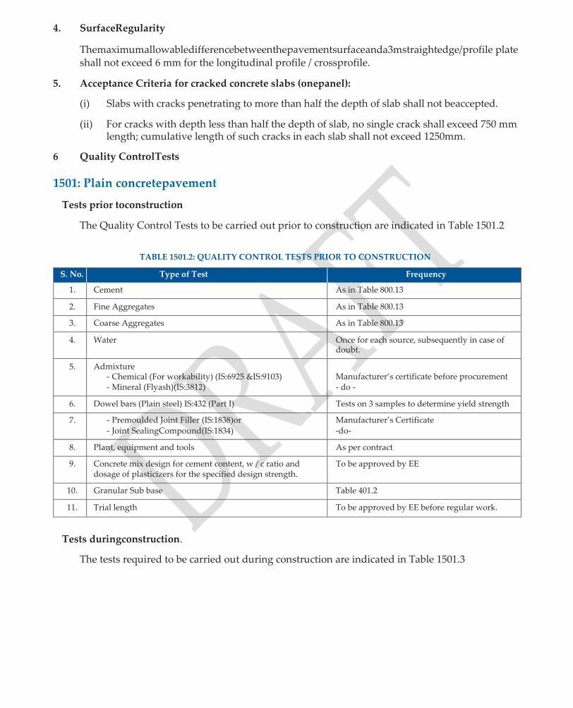
4. SurfaceRegularity
Themaximumallowabledifferencebetweenthepavementsurfaceanda3mstraightedge/profile plate shall not exceed 6 mm for the longitudinal profile / crossprofile.
5. Acceptance Criteria for cracked concrete slabs (onepanel):
(i) Slabs with cracks penetrating to more than half the depth of slab shall not beaccepted.
(ii) For cracks with depth less than half the depth of slab, no single crack shall exceed 750 mm length; cumulative length of such cracks in each slab shall not exceed 1250mm.
6 Quality ControlTests
1501: Plain concretepavement
Tests prior toconstruction
The Quality Control Tests to be carried out prior to construction are indicated in Table 1501.2
TABLE 1501.2: QUALITY CONTROL TESTS PRIOR TO CONSTRUCTION
S. No. Type of Test Frequency
1. Cement As in Table 800.13
2. Fine Aggregates As in Table 800.13
3. Coarse Aggregates As in Table 800.13
4. Water Once for each source, subsequently in case of doubt.
5. Admixture - Chemical (For workability) (IS:6925 &IS:9103) - Mineral (Flyash)(IS:3812)
Manufacturer’s certificate before procurement - do -
6. Dowel bars (Plain steel) IS:432 (Part I) Tests on 3 samples to determine yield strength
7. - Premoulded Joint Filler (IS:1838)or
- Joint SealingCompound(IS:1834)
Manufacturer’s Certificate
-do-
8. Plant, equipment and tools As per contract
9. Concrete mix design for cement content, w / c ratio and dosage of plasticizers for the specified design strength.
To be approved by EE
10. Granular Sub base Table 401.2
11. Trial length To be approved by EE before regular work.
Tests duringconstruction.
The tests required to be carried out during construction are indicated in Table 1501.3

TABLE 1501.3: QUALITY CONTROL TESTS DURING CONSTRUCTION
S. No. Tests / Check Frequency
1.
2.
3.
4.
5.
6.
7.
8.
9.
10.
11.
Subgrade & Subbase
Gradation and moisture content of aggregate for CC pavement
Concrete workability (Slump cone tests IS:1199)
Strength of Concrete (IS:516)
Straightness of side forms (steel)(For paralleling and possible settlement and securing position beforeconcreting)
Size, spacing, paralleling of Dowel bars and location of different joints
Batching and Mixing of materials
Hot / Cold weather concreting including compaction
Compaction equipment (Needle, Screed and Plate vibrators)
Separation membrane (thickness and laying)
Levels and Alignment
(i) Leveltolerance
(ii) Surface Regularity (Transverse and Longitudinal including camber /cross slope)
(iii) Width of pavement and position of pavingedges work Regularly at gridpoints
(iv) Pavementthickness (v) Alignment ofjoints (vi) Depth of DowelBars (vii) Texturing andEdging
As in Tables 301.5 & 401.3
Minimum once per day.
One test per 3 cum of concrete at paving site.
Minimum 6 cubes and 6 beams (3 each for 7 day & 28 day strength) per day.
To be checked daily
To be checked prior to casting of concrete at the location.
Check for measurements and proper mixing
Checks Regularly
For continuous working and stand by arrangement
Prior to laying of pavement concrete
Clause 1802.3; to be checked for each day’s work Regularly
Clause 1802.2; to be checked for each day’s
To be checked for each day’s work -do- -do- -do
Quality Control Checks by AE /AEE/Tier II
The quality control checks to be carried out be AE / AEE are indicated in Table 1501.4
TABLE 1501.4: QUALITY CONTROL CHECKS BY AE/AEE/Tier II
S. No. Tests Frequency Designation of
Inspecting Officer
1. Review of cube and beam test data
Regularly AE/Tier
II
2. Quality Checks by AE / AEE
- Width thickness ofpavement
- Surfacelevels
- Surfaceregularity
- Surfacetexture
- Transversejoints
At random
-do-
-do-
-do-
Every Joint
AE
AE
AE
AE
AE
3. Joints (Expansion / Contraction)
- Joint alignment, dimensions & filling ofjoints
- Cracking ofslabs
Every joint
Cracked slabs
AE / AEE
AE / AEE/Tier II
4. Paving near culverts and bridges At each site AE / AEE
5. Performance of 30 m Trial length For each work EE

C. Do’s andDon’ts
Do’s Don’ts
1. Back fill properly, surface trenches and soft spots in the sub-grade and compact the same. Remove all organic and extraneous material from subgrade.
2. Saw cutting of joints should be done when concrete is neither too soft nor toohard.
3. Ensure that side forms are sufficiently robust and rigid to support the weight and pressure caused by paving equipment.
4. Do make provisions to maintain sufficient supply of tarpaulin or other water proof cloth during placement of concrete when rain isexpected.
4.5. The Coarse aggregate shall be free from dirt, flint, chalecedony or other silica.
6. Use fine aggregate free from soft particles of clay, shale, loam cemented particles, mica and other foreignmatter.
7. Ensure sufficiency and accuracy of material, plant and equipment and methods of construction by laying a trial length of at least 30m.
8. Measure workability of the concrete at the time of placing with slump coneTest.
9. Provide proper construction joint if concreting is suspended for more than 30 minutes. Use bulk head to retain theconcrete.
1. Do not lay sub-base on a sub grade softened byrain
2. Do not expose concrete slab for a period of more than half an hour for saw cutting ofjoints.
3. Do not provide any vertical step between the adjacent side forms greater than 3mm
4. Do not carry out concreting work when concrete temperature is more than 300C or less than 50C at the point of placing and ambient temperature is greater than 350C
5. Do not use disintegrated, soft, flaky, elongated,highly angular or splintery coarseaggregate.
6. Do not vibrate concrete excessively to prevent flow of mortar to thetop.
7. Donotallownormalworkinguntilthetriallengthhas beenapproved.
8. Do not walk on freshly laid concrete to place covering forcuring.
9. Do not allow any traffic, including construction vehicles on the finished surface of concrete pavement till the joints are permanentlysealed.
1502: ROLLER COMPACTED CONCRETE PAVEMENT
A. Methodology
1.Lay a trial length of minimum 30 m length as detailed in sub-section 1501 A (i) To (iii). Roll thetrial length as per rolling sequence in Table No. 1502.1. If waves appear on top of the rolled surface in front of roller during construction of trial length, the moisture content shall be varied and strength redetermined. Determine natural moisture content on day to day basis, before production of themix.
TABLE 1502.1: ROLLING SEQUENCE FOR ROLLER COMPACTED CONCRETE PAVEMENT
Sl. No.
Type of Roller No. of Static passes
No. of vibrating passes
Remarks
1 Double drum tandem roller
2
Nil Nil 4-6
Breakdown rolling Vibratory rolling with amplitude 0.8-0.4 mm
Smoothening
1-2 Nil
or
2 Single front drum steel roller with rear tyres of rubber
1 Nil
1-2
Nil 4-5
Nil
Breakdown rolling Vibratory rolling with amplitude descending from 0.8 to 0.4mm Smoothening

2. Checkthein-situdensityoffreshlylaidRollerCompactedConcretePavement(RCCP),afterrolling, with sand replacement method with 200 mm dia density hole. Three density holes shall be made alongadiagonalwhichbisectsthetriallengthwithnoholeswithin0.5mofedgefromeitherside. Average density of these three holes shall be taken as 100%. Later on the field density of regular work shall not be less than 97% of thisdensity.
3. The trial length shall be cut over one metre length and reversed to inspect the bottom surface to
check any segregation of the mix. Relay the trial length if the same does not comply with specifications.
4. Take core density of RCCP after 28 days. A minimum of three cores shall be taken for each day’s work and average of these shall be the core density for the day’s work. Strength of cores shall be determinedaspersub-section1501.23.5ofMoRDSpecifications.CheckthehomogeneityofRCCP from thesecores.
5. Mix design for RCCP, based on weighed proportion of all ingredients, shall be prepared and got approved from Engineer 30 days prior to laying of trial length. Mix design shall be based on the flexural strength of concrete as perIRC:44.
6. Use flyash in RCCP as 15-35 percent replacement of cement and shall have a zeroslump.
7. The water content may be kept within 5 to 7 % of the weight of cement, aggregates and other dry material.Determinetheoptimummoisturecontentbymakingmixesat0.5%increments.Ifconcrete istransportedbytippers,watercontentmaybekept2%higherthantheoptimummoisturecontent.
8. The cement content of concrete shall be within 310 kg and 425 kg per cum of concrete unless specifiedotherwiseinthecontract.Iffly-ashisusedtoreplaceapartofcement,cementinconcrete shall not be less than 250 kg per cum. Flexural strength of concrete shall not be less than 3.5 MPa. The design mix shall be minimum M30 gradealso.
9. Produce concrete near the site, using approved concrete mixers of at least 0.2 cumcapacity.
10. Fix the side forms as detailed in sub-section 1501 A6 these shall conform toIRC:43.
11. Placetheconcretebetweenthesideformsseparatedbyadistanceequaltothewidthofcarriageway in a continuous manner without any breakage / stoppage. Carry the concrete to the placement location in wheelbarrows.
12. For placing of concrete by semi-mechanised tools, ascertain actual prodding during field trials. Placethemixwithwheelbarrow/steelpanswithrotarymotionandspreaduniformlywithshovels and rakes. Use a wooden screed 3 m by 125 mm by 50 mm in a sawing motion to level the mix before rolling.
13. For placing concrete with a paver, the equipment shall be capable of laying material in one layer in full width without segregation to the specified thickness. The paver shall have high amplitude temping bars to give good initial compaction. When paving is done by a paver, pavement width shall be 300 mm extra on bothsides
14. TherollingshallbecarriedoutinsequenceindicatedinTableNo.1502.1.Attheendofrolling,no rollermarksshallbevisible.Ifthicknessofconcreteislessortherearehighspotsascheckedwith

a3mstraightedge,rakeopentheareaandaddextramaterialorremoveextramaterial.Checkthe in-situdensitybysandreplacementmethodandiffielddensityislessthan97%ofthetriallength, use additional passes of roller to achieve at least 97% of density of triallength.
15. The final time of rolling shall not exceed 100 minutes from the time of mixing water when the temperature is between 250C and 300C, and 120 minutes when the same is less than or equal to 250C.Noconcretingistobedonewhenthetemperatureislessthan40Cormorethan400C.Chilled water should be used to bring the temperature of concrete to 300C. Take precautions indicated in IRC:15 when ambient temperature is below 50C or more than400C.
16. Carry RCCP over hume pipe culverts. In case of existing or new bridges / culverts, RCCP shall abut the deck / approach slab and a construction joint should beprovided.
17. No longitudinal joint shall be provided if the width of carriageway is less than 4 m. RCCP shall have only transverse contraction joints at 5 m center. These shall be saw-cut after 6-12 hours of laying or initial hardening. The width of joints shall be 6-8 mm and depth one-fourth of RCCP slab. These shall be filled with hot pouring sealing compound in accordance with sub-section 1501.22.4 of MORD Specifications and in accordance withIS:1834.
18. CoverRCCP,withinonetotwohoursaftercompaction,bylayingwethessianintwo-threelayers for first 24 hours. After the first day’s curing, small earthen rectangles / dykes about 50 mm high transverselyandlongitudinallyshallbemadeandfilledwithwaterforatleast14days.Incaseof flyash concrete, the period shall be 16days.
19. Freshly laid RCCP shall be protected by not allowing traffic for a minimum period of 28days.
B. Quality ControlRequirements
1. Material
Cement, Water, Coarse and Fine aggregates for roller compacted concrete shall meet the requirementofmaterialindicatedinSection1501B,exceptthatthegradingofblendedcoarseand fine aggregates shall be in conformity with the requirements indicated in Table No.1502.2.
TABLE 1502.2: AGGREGATE GRADATION FOR RCCP
IS Sieve designation Percentage passing by weight
26.5 mm 100
19.0 mm 80-100
9.5 mm 55-75
4.75 mm 35-60
600 micron 10-35
75 micron 0-8
Fly-ash may be from anthracitic coal or lignite collected by electro-static precipitator. Bottom ash or pool ash shall not be used as a replacement of cement. Flyash shall conform to the physical requirements indicated in Table No. 1502.3.

TABLE NO. 1502.3: PHYSICAL REQUIREMENT OF FLYASH AS CONCRETE ADMIXTURE (IS: 3812)
Sl. No. Characteristics Requirement of grade 1 fly-ash
1 Fineness, specific surface area in m2 / kg by Blaine’s
permeability test, 320 m2 / kg minimum
2 Particles retained on 45 micron IS sieve 34% maximum
3 Lime reactivity average compressive strength 4.5 N / mm2
4 Soundness by autoclave test expansion of specimen 0.8% maximum
5 Drying shrinkage 0.15% maximum
Quality Control requirements for Horizontal Alignment, Surface Level, Surface Regularity, and AcceptanceCriteriaforcrackedconcreteslabsandstrengthofconcreteasdescribedinsubsection 1501 C shallapply.
2 Quality ControlTests
Tests prior toconstruction
The Quality Control tests to be carried out prior to construction are indicated in Table 1502.4
TABLE 1502.4: QUALITY CONTROL TESTS PRIOR TO CONSTRUCTION
S. No. Tests Frequency
1. Materials for concrete As in Table 1501.2
2. Concrete Mix design (With and without mineral admixtures) Approval by EE for cement content w / c ratio
and use of plasticizers
3. Plants, Equipment and tools As per contract
4. Trial length before commencement of regular work Approval by EE
5. Granular Sub base As in Table 401.3
6. Design Parameters (Grade of concrete, width, thickness
and details of joints)
As per construction drawings.
Tests duringconstruction
The quality control tests to be carried out during construction are indicated in Table 1502.5
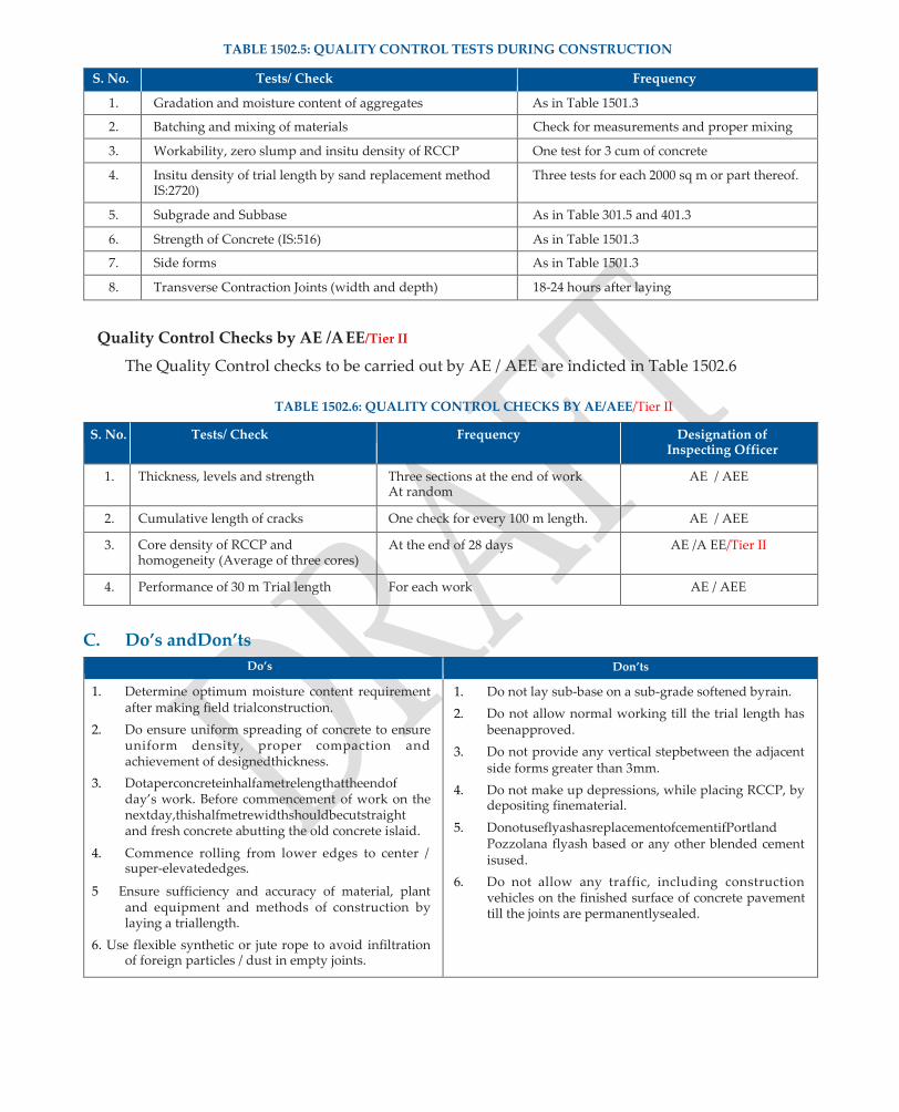
TABLE 1502.5: QUALITY CONTROL TESTS DURING CONSTRUCTION
S. No. Tests/ Check Frequency
1. Gradation and moisture content of aggregates As in Table 1501.3
2. Batching and mixing of materials Check for measurements and proper mixing
3. Workability, zero slump and insitu density of RCCP One test for 3 cum of concrete
4. Insitu density of trial length by sand replacement method IS:2720)
Three tests for each 2000 sq m or part thereof.
5. Subgrade and Subbase As in Table 301.5 and 401.3
6. Strength of Concrete (IS:516) As in Table 1501.3
7. Side forms As in Table 1501.3
8. Transverse Contraction Joints (width and depth) 18-24 hours after laying
Quality Control Checks by AE /AEE/Tier II
The Quality Control checks to be carried out by AE / AEE are indicted in Table 1502.6
TABLE 1502.6: QUALITY CONTROL CHECKS BY AE/AEE/Tier II
S. No. Tests/ Check Frequency Designation of Inspecting Officer
1. Thickness, levels and strength Three sections at the end of work At random
AE / AEE
2. Cumulative length of cracks One check for every 100 m length. AE / AEE
3. Core density of RCCP and homogeneity (Average of three cores)
At the end of 28 days AE /A EE/Tier II
4. Performance of 30 m Trial length For each work AE / AEE
C. Do’s andDon’ts
Do’s Don’ts
1. Determine optimum moisture content requirement after making field trialconstruction.
2. Do ensure uniform spreading of concrete to ensure uniform density, proper compaction and achievement of designedthickness.
3. Dotaperconcreteinhalfametrelengthattheendof day’s work. Before commencement of work on the nextday,thishalfmetrewidthshouldbecutstraight and fresh concrete abutting the old concrete islaid.
4. Commence rolling from lower edges to center / super-elevatededges.
5 Ensure sufficiency and accuracy of material, plant and equipment and methods of construction by laying a triallength.
6. Use flexible synthetic or jute rope to avoid infiltration of foreign particles / dust in empty joints.
1. Do not lay sub-base on a sub-grade softened byrain.
2. Do not allow normal working till the trial length has beenapproved.
3. Do not provide any vertical stepbetween the adjacent side forms greater than 3mm.
4. Do not make up depressions, while placing RCCP, by depositing finematerial.
5. DonotuseflyashasreplacementofcementifPortland Pozzolana flyash based or any other blended cement isused.
6. Do not allow any traffic, including construction vehicles on the finished surface of concrete pavement till the joints are permanentlysealed.

1503: RECTANGULAR CONCRETE BLOCK PAVEMENT
A. Methodology
1. The rectangular concrete blocks should preferably be cast using block manufacturing machine or semi mechanized means as per clause 1503.6 of MoRDspecifications.
2. Ensureatriallengthof30mislaidfordemonstratingtheprocedureandequipmentforlayingthe mainpavement.
3. Prepare the subgrade to the specified grades, lines and cross-sections and uniformly compact to the design strength. Subgrade shall have a camber of 3 percent and the soaked CBR not less than 4percent.
4. Lay cement concrete pavement over a 75 mm thick WBM (Gr.2 or 3) base layer, extended by at least150mmbeyondtheedgeblocks.ThesubbaselayerbelowtheWBMbaseshallbeaGSBlayer or WBM Gr.1 100 mm compactedthickness.
5. Lay 25 mm thick (compacted) bedding sand conforming to grading requirements indicated in Table No. 1503.1 uniformly over the base course. The bedding sand shall have about 6 percent moisture content to facilitate its spreading and compaction and shall be compacted with a hand rammer, preferably plate compactor and the surface levelled using ascreed.
6. Thepatternforpavingblocksshallbeherringboneorstretcher.Thejointsbetweenstretcherbond shall be staggered by about half the length ofstretcher.
7. The concrete blocks for pavement shall be 450 mm x 300 mm x 150 mm size and Restraint blocks shallbeof300mmx300mmx200mmsize.Thecementcontentshallbebetween310and425kg/ cum unless specified otherwise in the contract. Extra blocks to the extent of 5 percent should be manufactured and properly stored for subsequent use for maintenancepurposes.
8. The width of joint shall be between 2 mm and 4 mm. On curves non-uniform joint width may have to be resorted to. When space does not permit the use of cut piece of blocks, the use of premixed or dry packed concrete isrecommended.
9. After a section has been paved, start compaction with a suitable vibratory plate compactor in the following sequence ofoperations.
(i) Apply three passes of a standard vibrating plate compactor of weight 0.9 kN, with plate area not less than 0.3m2
(ii) Spread a thin layer of joint filling sand on the top of paved blocks and sweep into joints
using suitable brooms. The sand shall be vibrated into the joints by moving the vibrating plate compactor and more sand shall be applied till the joints are wellpacked.
(iii) Clean excess sand from the top of blockpavement.
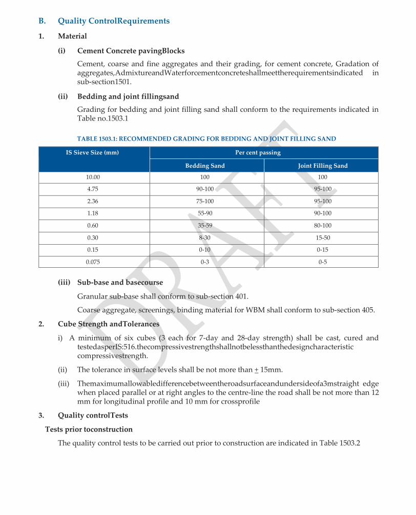
B. Quality ControlRequirements
1. Material
(i) Cement Concrete pavingBlocks
Cement, coarse and fine aggregates and their grading, for cement concrete, Gradation of aggregates,AdmixtureandWaterforcementconcreteshallmeettherequirementsindicated in sub-section1501.
(ii) Bedding and joint fillingsand
Grading for bedding and joint filling sand shall conform to the requirements indicated in Table no.1503.1
TABLE 1503.1: RECOMMENDED GRADING FOR BEDDING AND JOINT FILLING SAND
IS Sieve Size (mm) Per cent passing
Bedding Sand Joint Filling Sand
10.00 100 100
4.75 90-100 95-100
2.36 75-100 95-100
1.18 55-90 90-100
0.60 35-59 80-100
0.30 8-30 15-50
0.15 0-10 0-15
0.075 0-3 0-5
(iii) Sub-base and basecourse
Granular sub-base shall conform to sub-section 401.
Coarse aggregate, screenings, binding material for WBM shall conform to sub-section 405.
2. Cube Strength andTolerances
i) A minimum of six cubes (3 each for 7-day and 28-day strength) shall be cast, cured and testedasperIS:516.thecompressivestrengthshallnotbelessthanthedesigncharacteristic compressivestrength.
(ii) The tolerance in surface levels shall be not more than + 15mm.
(iii) Themaximumallowabledifferencebetweentheroadsurfaceandundersideofa3mstraight edge when placed parallel or at right angles to the centre-line the road shall be not more than 12 mm for longitudinal profile and 10 mm for crossprofile
3. Quality controlTests
Tests prior toconstruction
The quality control tests to be carried out prior to construction are indicated in Table 1503.2
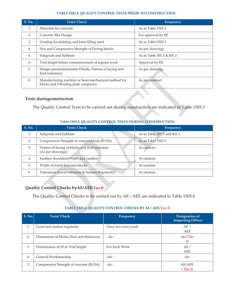
TABLE 1503.2: QUALITY CONTROL TESTS PRIOR TO CONSTRUCTION
S. No. Tests/ Check Frequency
1. Materials for concrete As in Table 1501.2
2. Concrete Mix Design For approval by EE
3. Grading for bedding and Joint filling sand As in Table 1503.1
4. Size and Compressive Strength of Paving blocks As per drawings
5. Subgrade and Subbase As in Table 301.5 & 401.3
6. Trial length before commencement of regular work Approval by EE
7. Design parameters(Joints Details, Pattern of laying and End restraints)
As per drawing
8. Manufacturing machine or Semi mechanized method for blocks and Vibrating plate compactor
As per contract
Tests duringconstruction
The Quality Control Tests to be carried out during construction are indicated in Table 1503.3
Table 1503.3: QUALITY CONTROL TESTS DURING CONSTRUCTION
S. No. Tests/ Check Frequency
1. Subgrade and Subbase As in Table 301.5 and 401.3
2. Compressive Strength of concreteblock (IS:516) As in Table 1501.3
3. Pattern of laying of blocks and End restraints (As per drawings)
At random
4. Earthen shoulders(Width and camber) At random
5. Width of Joints between blocks At random
6. Tolerances (Level tolerance & Surface Regularity) At random
Quality Control Checks byAE/AEE/Tier II
The Quality Control Checks to be carried out by AE / AEE are indicated in Table 1503.4
TABLE 1503.4: QUALITY CONTROL CHECKS BY AE / AEE/Tier II
S. No. Tests/ Check Frequency Designation of Inspecting Officer
1. Level and surface regularity Once for every work AE /
AEE
2. Dimensions of blocks (Size and thickness) - do - -do-/Tier
II
3. Performance of 30 m Trial length For Each Work AE /
AEE
4. General Workmanship -do- -do-
5 Compressive Strength of concrete (IS:516) -do- AE/AEE
/ Tier II

C. Do ’s andDon’ts
Do’s Don’ts
1. Use only mechanised or semi-mechanised methods for manufacturing blocks and ensure that blocks are properlycured.
2. Ensure proper bedding and filling of joints using vibratorycompactor.
1. Do not use cement concrete with a characteristic compressive strength less than 30MPa.

1504: INTERLOCKING CONCRETE BLOCK PAVEMENT
A. Methodology
1. Concrete Paving Blocks shall conform to the relevant ISStandard.
2. Ensureatriallengthof30mislaidfordemonstratingtheprocedureandequipmentforlayingthe mainpavement.
3. Prepare the sub-grade to the specified grades and cross-sections and uniformly compact to the design strength. Sub-grade shall have a camber of 3% and of soaked CBR not less than 4%.
4. Lay a minimum 100 mm thick granular / stabilized base course conforming to sub-section 402. The base course shall be extended at least 300 mm beyond the edgerestraints.
5. Layinterlockingconcreteblockpavementovera100mmthickgranularsub-baselayerconforming to sub-section 401 or over a 100 mm thick WBM Gr. 1 conforming to sub-section405.
6. Lay 25 mm thick (compacted) bedding sand conforming to grading requirements indicated in TableNo.1503.1uniformlyoverthebasecourse.Thebeddingsandshallhaveabout6%moisture contenttofacilitateitsspreadingandcompaction.Compactwithahandrammer;preferablyplate compactor and readjust the level using ascreed.
7. Thepatternforpavingblocksshallbeherringboneorstretcher.Thejointsbetweenstretcherbond shall be staggered by about half the length ofstretcher.
8. The minimum thickness of paving blocks shall be 80 mm for projected traffic upto 100 vehicles per day and 100 mm for projected traffic from 100 to 250 vehicles per day. The dimensions and tolerances for paving blocks shall meet the requirements of Table1504.1.
9. The average 28 days compressive strength of 8 blocks shall not be less than 30 MPa and strength of individual block shall not be less than 26 MPa. The edge blocks shall have equivalent cube compressive strength not less than 30MPa.
1. Compressiontestingmachineofadequatecapacityshallbeusedfortestingtheblocks.Theblocks shall be stored for 24 + 4 hours in water maintained at a temperature of 20 + 5OC before testing. Theloadshallbeappliedwithoutshockandincreasedcontinuously@15+3N/mm2/minuteand themaximumloadthatcanbeappliedtoaspecimenshallbenoted.Apparentcompressivestrength shall be calculated by dividing the maximum load by the plan area. This shall then be multiplied withacorrectionfactor,asindicatedinTable1504.2toobtainthecorrectivecompressivestrength.
2. The width of joint shall be between 2 mm and 4 mm. On curves non-uniform joint width may have to be resorted to. When space does not permit the use of cut piece of blocks, the use of premixed or dry packed concrete is recommended. After a section has been paved, compaction with a vibratory plate compactor shall be done in the following sequence ofoperations.
(i) The blocks shall be vibrated with three passes of a standard vibrating plate compactor of adequatecapacity.
(ii) A thin layer of joint filling sand as per clause 1503.2.6 shall be spread on the top of paved blocks and swept into joints using suitablebrooms.

(iii) The sand shall be vibrated into the joints by making three passes of thecompactor.
(iv) Excess sand from the top of block pavement shall be sweptclean.
B. Quality ControlRequirements
1. Material
(i) Concrete paving blocks shall conform to the relevant ISStandard.
(ii) Grading for bedding and joint filling sand for interlocking concrete block pavement shall meet the requirements indicated in Table1503.1
2. The tolerance in surface levels in transverse profile shall not be more than + 10mm.
3. The maximum allowable difference between the road surface and underside of a 3 m straight edge when measured in the longitudinal profile shall not be more than 12mm.
4. The dimensions and tolerances of paving blocks shall conform to the requirements indicated in Table1504.1.Aspectratioistheratiooflengthtothicknessofblocks.Chamferisthebevelededge, provided on the top surface of a block. Plan area is the horizontal area bounded by the vertical faces. Wearing surface area is the horizontal area bounded by the vertical faces, minus the area reduced due to the presence ofchamfer.
TABLE 1504.1: DIMENSIONS AND TOLERANCES FOR PAVING BLOCKS
S. No. Dimension Recommended Values Tolerance Limit
1 Width W To be specified by Manufacturer + 2 mm
2 Length L To be specified by Manufacturer + 2 mm
3 Thickness T 60 to 80 mm + 3 mm
4 Aspect Ratio L / T Maximum: 4.0 + 0.2
5 Chamfer (Arris) Minimum: 5 mmMaximum: 7 mm + 1 mm
6 Plan Area Maximum 0.03 sqm + 0.001 sqm
7 Wearing Face Area Minimum 75% of plan area - 1 %
8 Squareness NIL + 2 mm
TABLE 1504.2: CORRECTION FACTORS FOR THICKNESS
AND CHAMFER OF PAVING BLOCK FOR CALCULATION OF COMPRESSIVE STRENGTH.
Paving Block Thickness (mm) Correction Factor for
Plain Block Chamfered Block
60 1.00 1.06
80 1.12 1.18
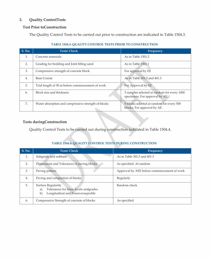
2. Quality ControlTests
Test Prior toConstruction
The Quality Control Tests to be carried out prior to construction are indicated in Table 1504.3.
TABLE 1504.3: QUALITY CONTROL TESTS PRIOR TO CONSTRUCTION
S. No. Tests/ Check Frequency
1. Concrete materials As in Table 1501.2
2. Grading for bedding and Joint filling sand As in Table 1503.1
3. Compressive strength of concrete block For approval by EE
4. Base Course As in Table 301.5 and 401.3
5. Trial length of 30 m before commencement of work For Approval by EE
6. Block size and thickness 5 samples selected at random for every 1000
specimens. For approval by AE.
7. Water absorption and compressive strength of blocks 5 blocks selected at random for every 500
blocks. For approval by AE.
Tests duringConstruction
Quality Control Tests to be carried out during construction indicated in Table 1504.4.
TABLE 1504.4: QUALITY CONTROL TESTS DURING CONSTRUCTION
S. No. Tests/ Check Frequency
1. Subgrade and subbase As in Table 301.5 and 401.3
2. Dimensions and Tolerances of paving blocks As specified. At random
3. Paving pattern Approval by AEE before commencement of work
4. Paving and compaction of blocks Regularly
5. Surface Regularity
a) Tolerances for lines, levels andgrades
b) Longitudinal and Transverseprofile
Random check
6. Compressive Strength of concrete of blocks As specified

Quality Control Checks by AE /AEE
The Quality Control Checks to be carried out by AE / AEE are indicated in Table 1504.5
TABLE 1504.5: QUALITY CONTROL CHECKS BY AE / AEE /Tier II
S. No. Tests/ Check Frequency Designation of Inspecting Officer
1. Tolerance for lines, levels and grades Random check AE /A EE
2. Performance of 30 m trial length For each work AE /A EE
3. Water absorption and Compressive Strength (5 out of 500 blocks selected at random)
-do- - AE /A EE/Tier II
4. General workmanship -do- -do-
C. Do ’s andDon’ts
Do’s Don’ts
1. Layatriallengthof30mandgetthesameapproved fromEngineer.
2. Maintain a buffer of specified quantity of paving blocks required formaintenance.
1. Do not use blocks with water absorption (for an average of 5 blocks) greater than 6% bymass.

Quality Assurance Handbook for Rural Roads
217
SECTION 1600
HILL ROAD CONSTRUCTION
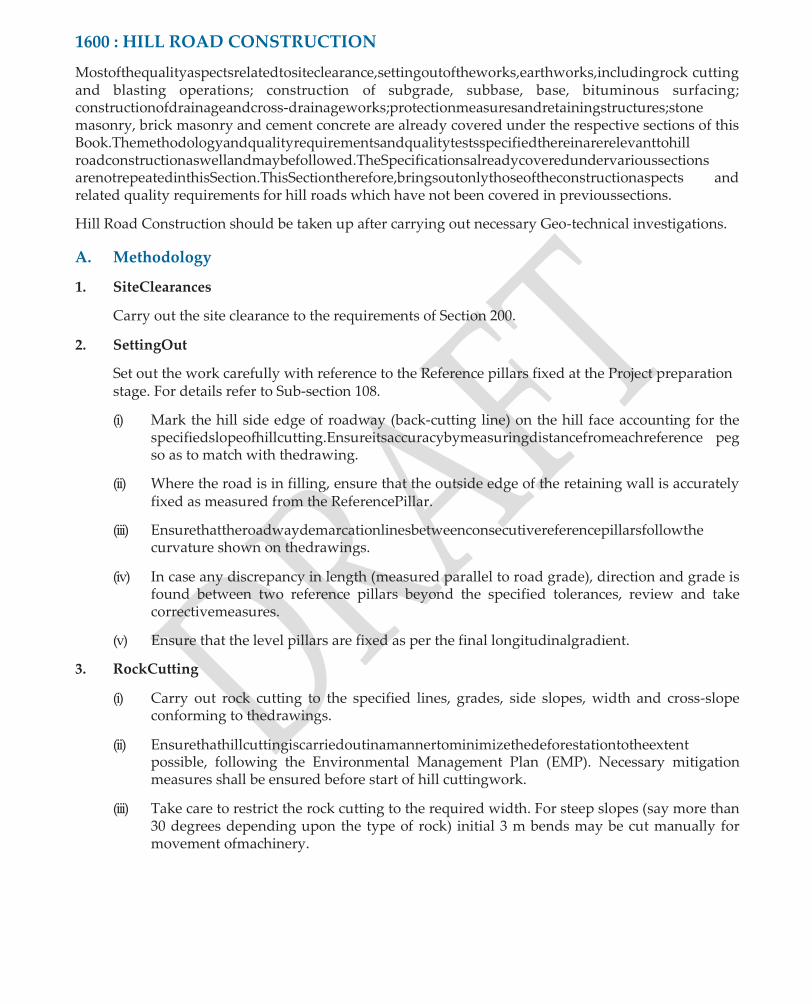
1600 : HILL ROAD CONSTRUCTION
Mostofthequalityaspectsrelatedtositeclearance,settingoutoftheworks,earthworks,includingrock cutting and blasting operations; construction of subgrade, subbase, base, bituminous surfacing; constructionofdrainageandcross-drainageworks;protectionmeasuresandretainingstructures;stone masonry, brick masonry and cement concrete are already covered under the respective sections of this Book.Themethodologyandqualityrequirementsandqualitytestsspecifiedthereinarerelevanttohill roadconstructionaswellandmaybefollowed.TheSpecificationsalreadycoveredundervarioussections arenotrepeatedinthisSection.ThisSectiontherefore,bringsoutonlythoseoftheconstructionaspects and related quality requirements for hill roads which have not been covered in previoussections.
Hill Road Construction should be taken up after carrying out necessary Geo-technical investigations.
A. Methodology
1. SiteClearances
Carry out the site clearance to the requirements of Section 200.
2. SettingOut
Set out the work carefully with reference to the Reference pillars fixed at the Project preparation stage. For details refer to Sub-section 108.
(i) Mark the hill side edge of roadway (back-cutting line) on the hill face accounting for the specifiedslopeofhillcutting.Ensureitsaccuracybymeasuringdistancefromeachreference peg so as to match with thedrawing.
(ii) Where the road is in filling, ensure that the outside edge of the retaining wall is accurately fixed as measured from the ReferencePillar.
(iii) Ensurethattheroadwaydemarcationlinesbetweenconsecutivereferencepillarsfollowthe curvature shown on thedrawings.
(iv) In case any discrepancy in length (measured parallel to road grade), direction and grade is found between two reference pillars beyond the specified tolerances, review and take correctivemeasures.
(v) Ensure that the level pillars are fixed as per the final longitudinalgradient.
3. RockCutting
(i) Carry out rock cutting to the specified lines, grades, side slopes, width and cross-slope conforming to thedrawings.
(ii) Ensurethathillcuttingiscarriedoutinamannertominimizethedeforestationtotheextent possible, following the Environmental Management Plan (EMP). Necessary mitigation measures shall be ensured before start of hill cuttingwork.
(iii) Take care to restrict the rock cutting to the required width. For steep slopes (say more than 30 degrees depending upon the type of rock) initial 3 m bends may be cut manually for movement ofmachinery.

The prescribed roadway width for hilly terrain is inclusive of parapet and hillside drains. Extra widening on curves and in snow bound areas should be done as per Drawings.
(iv) Resort to slope benching to improve sightdistance.
(v) Make provision for 2 to 3 passing places per kilometrelength.
(vi) Where hairpin bends are to be provided, ensure that the hill slopes are stable and gentle. The hairpin bend will be provided as a circular curve with transitions at eitherend.
(vii) Follow procedure and safety precautions for rock cutting as per Sub-section304.
(viii) Ensure that excavation work starts along back cutting line. Also ensure that completion plan and verification of curve radii and longitudinal gradients is carried out at site. Defects if any shall be correctedimmediately.
3. Preparation of cut formation forSubgrade
Prepare as per the requirements of Sub-section302.
4. Retaining Walls, Breast Walls and Gabionstructures
(i) Construct retaining / breast walls, and Gabion structures, conforming to theDrawings.
(ii) The foundation bed should be sloped towards thehillside.
(iii) Resort to stepping up of the foundation bed of retaining walls in stablerocks.
(iv) The masonry for retaining / breast walls should conform to Sub-section700.
(v) Ensure that the top level of the retaining wall matches the adjoining shoulderedge.
(vi) Ensure that full section is constructed as per thedrawings.
(vii) Ensure that approved filter material is provided behind the wall before back filling. Also ensure that back filling is done only after the masonry work is approved by theEngineer.
5. PavementConstruction
PreparesubgradetotherequirementsofSubsection303andconstructsubbase,baseandbituminous surfacing in accordance with the requirements of the respectivesubsections.
6. Drainage
Carryoutexcavationfordrainsalongwithhillsidecuttingconformingtotheshape,sizeandgrades as shown on thedrawings.
(i) Provide lining asspecified.
(ii) Locate catchwater drains over stable slopes outside the periphery of the slidearea.
7. Cross DrainageWorks
(i) Use locally available stone for construction of Scuppers with dry stone masonry. Ensure a minimum cushion of 600 mm over corbelling, conforming to Clause 1606.5 of MORD Specification.

(ii) CementConcreteCauseways:Constructcausewaysasperdrawingsandconformingtothe requirements of Section1400
(iii) Pipe Culverts: Construct pipe culverts conforming to requirement of Section1100.
8. ProtectionWorks
Ensure that protection works are constructed conforming to the Drawings and Section 1300.
9. SafetyMeasures
(i) Providetrafficsigns,guideposts,railings/parapetsinaccordancewiththerequirementsof Section1700.
(ii) Security manpower should be deployed for ensuring that any person including labourers are removed from the flagged area at least 10 minutes before thefiring.
B. Quality Control Requirements
1. Materials
(i) MasonryWork : Conforming to Section 700
(ii) Sub-Base, Base,
Bituminous Works :
Conforming to Sections 400 & 500
(iii) CementConcrete : Conforming to Section 800
(iv) Pitching/Apron : Conforming to Section 1300
(v) Steel : Conforming to Section 1000
2. The tolerances for width of formation, longitudinal grade, grade compensation and super- elevation shall be asfollows:
a) Widthofformation (+) 5% (-)1%
b) Longitudinal profile (±) 5% of the specifiedgrade
c) Gradecompensation (±) 5% of the specifiedgradient
d) Super-elevation (±) 5% of the specifiedsuper-elevation
3. The tolerances for layout of hairpin bends shall be asfollows:
a) Length (+)0.5%
b) Direction (±) 20minutes
c) Grade (±)0.2%
4. The tolerances in the various courses of pavement should conform to the provisions given in the relevant Sub-sections of thisHandbook.
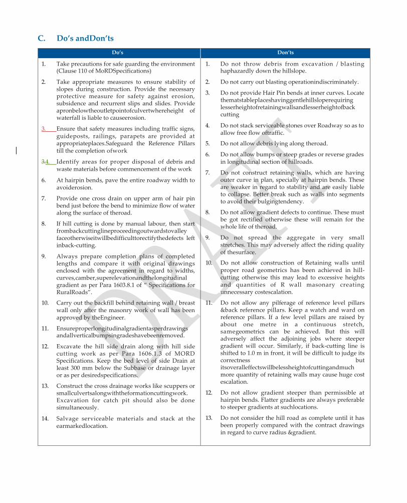
C. Do’s andDon’ts
Do’s Don’ts
1. Take precautions for safe guarding the environment (Clause 110 of MoRDSpecifications)
2. Take appropriate measures to ensure stability of slopes during construction. Provide the necessary protective measure for safety against erosion, subsidence and recurrent slips and slides. Provide apronbelowtheoutletpointofculvertwhereheight of waterfall is liable to causeerosion.
3. Ensure that safety measures including traffic signs, guideposts, railings, parapets are provided at appropriateplaces.Safeguard the Reference Pillars till the completion ofwork
3.4. Identify areas for proper disposal of debris and waste materials before commencement of the work
6. At hairpin bends, pave the entire roadway width to avoiderosion.
7. Provide one cross drain on upper arm of hair pin bend just before the bend to minimize flow of water along the surface of theroad.
8. If hill cutting is done by manual labour, then start frombackcuttinglineproceedingoutwardstovalley faceotherwiseitwillbedifficulttorectifythedefects left inback-cutting.
9. Always prepare completion plans of completed lengths and compare it with original drawings enclosed with the agreement in regard to widths, curves,camber,superelevationandthelongitudinal gradient as per Para 1603.8.1 of “ Specifications for RuralRoads”.
10. Carry out the backfill behind retaining wall / breast wall only after the masonry work of wall has been approved by theEngineer.
11. Ensureproperlongitudinalgradientasperdrawings andallverticalbumpsingradeshavebeenremoved.
12. Excavate the hill side drain along with hill side cutting work as per Para 1606.1.3 of MORD Specifications. Keep the bed level of side Drain at least 300 mm below the Subbase or drainage layer or as per desiredspecifications.
13. Construct the cross drainage works like scuppers or smallculvertsalongwiththeformationcuttingwork. Excavation for catch pit should also be done simultaneously.
14. Salvage serviceable materials and stack at the earmarkedlocation.
1. Do not throw debris from excavation / blasting haphazardly down the hillslope.
2. Do not carry out blasting operationindiscriminately.
3. Do not provide Hair Pin bends at inner curves. Locate thematstableplaceshavinggentlehillsloperequiring lesserheightofretainingwallsandlesserheightofback cutting
4. Do not stack serviceable stones over Roadway so as to allow free flow oftraffic.
5. Do not allow debris lying along theroad.
6. Do not allow bumps or steep grades or reverse grades in longitudinal section of hillroads.
7. Do not construct retaining walls, which are having outer curve in plan, specially at hairpin bends. These are weaker in regard to stability and are easily liable to collapse. Better break such as walls into segments to avoid their bulgingtendency.
8. Do not allow gradient defects to continue. These must be got rectified otherwise these will remain for the whole life of theroad.
9. Do not spread the aggregate in very small stretches. This may adversely affect the riding quality of thesurface.
10. Do not allow construction of Retaining walls until proper road geometrics has been achieved in hill- cutting otherwise this may lead to excessive heights and quantities of R wall masonary creating unnecessary costescalation.
11. Do not allow any pilferage of reference level pillars &back reference pillars. Keep a watch and ward on reference pillars. If a few level pillars are raised by about one metre in a continuous stretch, samegeometrics can be achieved. But this will adversely affect the adjoining jobs where steeper gradient will occur. Similarly, if back-cutting line is shifted to 1.0 m in front, it will be difficult to judge its correctness but itsoveralleffectswillbelessheightofcuttingandmuch more quantity of retaining walls may cause huge cost escalation.
12. Do not allow gradient steeper than permissible at hairpin bends. Flatter gradients are always preferable to steeper gradients at suchlocations.
13. Do not consider the hill road as complete until it has been properly compared with the contract drawings in regard to curve radius &gradient.

Quality Assurance Handbook for Rural Roads
223
SECTION 1700
TRAFFIC SIGNS,
MARKINGS & OTHER
ROAD APPURTENANCES

1700. TRAFFIC SIGNS AND MARKINGS
A. Methodology
I TrafficSigns
1. The colour, configuration, size, location and dimensions of different road signs shall be in conformitywiththeCodeofPracticeforRoadSignsIRC:67.Thelanguageofinscriptionandfont forinformatorysignsshallalsobeinconformitywiththeCodeofPracticeforRoadSignsIRC:67.
2. Signs shall be semi-reflective, fixed over mild steel sheeting duly stove enameled in white colour infrontandgreycolourontheback,redengineeringgradetapeonbordersandrequiredmessage in non-reflective black sheeting of Engineering gradetape.
3. Road signs, in particular, the cautionary / warning and mandatory / regulatory signs in the approaches to level crossings or narrow bridges may be reflectroised using luminous paints or other similar reflectivematerial.
4. It is desirable that cautionary / warning and mandatory signs are fabricated through the process of screen-printing. In other cases, signs may have inscription / message having cut letters of non- reflective black sheeting which shall be bonded well with the basesheeting.
5. The informatory signs on PMURKI roads shall have prescribed with dimensions 1.5x.9 and 1.2x.6.
6. Concrete for footings shall be of minimum M15 grade. Reinforcing steel shall conform to the requirements of IS:1786. High strength bolts, nuts and washers shall conform to IS:1367. Plates and support sections shall conform toIS:2062.
7. Sign posts, their foundations and sign mountings should be so constructed as to hold them in a proper position against normal wind loads or displacement byvandalism.
8. Normally signs with an area upto 0.90 sqm can be mounted on a single post and for greater area two or more supports shall beprovided.
9. Sign supports may be of mild steel (MS), reinforced concrete (RC) or galvanized iron (GI). The post ends should be firmly fixed to theground.
10. The signs and supports, except the reflectorised portion and GI posts, shall be thoroughly de- scaled,cleaned,primedandpaintedwithtwocoatsofepoxypaint.Theportionofmildsteelpost below ground should be painted with three coats of red leadpaint.
11. The signs should be fixed to the MS posts by welding and to the RC or GI posts by bolts and washers. After the nuts have been tightened, the tails of the bolts should be furred over with a hammer to preventremoval.
12. TheextremeedgeoftheRoadSignadjacenttothehighwayshouldbeatadistanceofatleast2.0m from the edge of the carriageway. In no case any part of the Road Sign shall come in the way of vehiculartraffic.
13. The lowest edge of Road Sign shall not be less than 2.0 m above the crown ofpavement.

II. RoadMarkings
1. The road markings should be in conformity with the Code of Practice for Road Markings with paints IRC:35.
2. Paining may be done by machine or by hand, preferably bymachine.
3. The finished road markings should be free from ruggedness on sides and ends and these should be parallel to the general alignment of the carriageway. The upper surface of the lines should be free fromstreaks.
B. Quality ControlRequirements
1. TrafficSigns
The materials should conform to the following requirements.
(i) Concrete: Concrete for footing shall be of the grade shown on the Contract drawings or of minimum M15 grade conforming to Section 801 of theseSpecifications.
(ii) Reinforcingsteel: ReinforcingsteelshallconformtotherequirementsofIS:1786unless otherwise shown on thedrawing.
(iii) Bolts, nuts, washers: High strength bolts shall conform toIS:1367
(iv) M.S.Sheets,Platesandsupports:Platesandsupportsectionsforthesignpostsshallconform to IS:2062 or any other relevant ISSpecifications.
(v) Reflectorised paint: Reflectorised paint shall conform to IS:5 or the manufacturer’s specifications in case of proprietary product and as approved by theEngineer.
(vi) Non reflectorised paint: Non-reflectorised paint shall conform to IS:164 and as approved by theEngineer.
(vii) Engineering grade sheeting: This sheeting shall be enclosed lens type consisting of microscopiclenselementsembeddedbeneaththesurfaceofasmooth,flexible,transparent, water-proof plastic, resulting in a non-exposed lens optical reflecting system. The retro- reflective surface after cleaning with soap and water and in dry condition shall have the minimumcoefficientofretro-reflection(determinedinaccordancewithASTMStandard)as indicated in Table1700.1.
When totally wet, the sheeting shall not show less than 90 per cent of the values, of retro- reflectionindicatedinTable1700.1.Attheendof5years,thesheetingshallretainatleast50 per cent of its originalretro-reflectance.
TABLE 1700.1: ACCEPTABLE MINIMUM COEFFICIENT OF RETROREFLECTION
FORENGINEERINGGRADESHEETING(CANDELASPERLUXPERSQUAREMETRE)
Observation angle in degree
Entrance angle in degree
White Yellow Orange Green Red Blue
0.2 - 4 70 50 25 9.0 14.5 4.0
0.2 + 30 30 22 7.0 3.5 6.0 1.7
0.5 - 4 30 25 13.5 4.5 7.5 2.0
0.5 + 30 15 13 4.0 2.2 3.0 0.8

(viii) Signswithamaximumsidedimensionnotexceeding600mmshallnotbelessthan1.5mm thick.Allothersshallbeatleast2mmthick.Thethicknessofthesheetshallberelatedtothe size of the sign board and its support and shall be such that it does not bend or deform under the prevailing wind and otherloads.
(ix) In respect of sign sizes not covered by IRC:67, the structural details (thickness, etc.) shall be as per the approveddrawings.
2. RoadMarkings
Ordinary paints shall be used for road markings, conforming to IS:164. These shall have a wear resistance of at least 4 hours under accelerated laboratory test. Yellow colour (conforming to IS colour No. 356) as given in IS:164, white and black colours are the standard colours used for markings.
C. Do’s andDon’ts
Do’s Don’ts
1. Insist on a minimum three year warranty for theMS or GI sheets being purchased from thesupplier.
2. Ensure that the edge of the Road Sign adjacent to the road is at least 2.0 m away from the edge of the carriageway.
1. DonotkeepthelowestedgeofRoadSignlessthan2.0 m above the crown of theroad
2. Do not cause inconvenience to traffic while painting operations are inprogress.

Quality Assurance Handbook for Rural Roads
229
SECTION 1900
MAINTENANCE

1901, 1902, 1903, 1907 & 1914: maintenance of earthworks & DRAINS
The maintenance of Earthworks in this Sub-section includes restoration of rain cuts, maintenance of earthen shoulders, embankment slopes and drains.
A. Methodology
I. Restoration of RainCuts
1. Clear the area affected by rain cuts of all loose soil and then provide benching. The width of benches should be at least 300 mm and should extend continuously for a sufficient length, the height of benches being in the range of 150-300mm.
2. Lay fresh material, meeting the requirements of a suitable fill material (as per Sub-section 301) in layersnotexceeding250mmloosethicknessandcompactatamoisturecontentequaltooptimum ±2%.Carryoutcompactionusingplatecompactors/rammersorbysuitableimplementshandled manually.
3. Ensure that the finished work conforms to the specified alignment, levels andslopes.
II. Maintenance of EarthenShoulders
1. Formakingupofanearthenshoulderwhereextrasoilisrequiredtobeadded,loosentheexisting earthen shoulder to receive fresh soil. Make up the deficiency in layers of loose thickness not exceeding 250 mm. After ensuring the placement moisture in the loose soil layer at optimum ± 2%,compactthelayertoobtain97%to100%ofmaximumdrydensityinaccordancewithIS:2720 (Part 7). For compaction, an 80 to 100 kN smooth wheel roller, plate vibrator, hand-held roller or even a hand rammer can be used, provided the specified dry density isachieved.
2. Whereearthisrequiredtobeexcavatedfromtheshoulder,removehighspots/excesseartheither using equipment like grader or by manual means using hand tools. The resulting surface should beuniformandhaveafielddensityofatleast97%ofmaximumdrydensityasperIS:2720(Part7), otherwise excavate / loosen the surface to a depth of 150 mm and compact to 97% to 100% of maximum dry density as per IS:2720 (Part 7), making sure that the moisture content prior to compaction is at OMC± 2%. The compacted layer should be finished to the required crossfall.
3. All obstructions like tree branches, heaps of soil, debris etc. must be removed, and disposed of to an off-road dumping place. This task should be performed alongwith other tasks like patching shoulders, grass cutting, cleaning ditchesetc.
4. Carryoutweedcuttingandbushclearingatleastonceayearaftertherainyseasonormoreoften whereclimaticconditionssowarrant.Wherelongstretchesofshouldervegetationistobecutand the work cannot be done by hand tools, use an agricultural tractor towed mower /ripper.
III. Maintenance of Slopes andDrains
1. Togetherwithclearingunwantedvegetationonshoulders,clearingofslopesanddrains/ditches should also be carriedout.
2. Carry out reshaping, re-grading and deepening of ditches / drains preferably by tractor-towed grader, wherever possible, otherwise by manual methods. Alignment should be set by stringline and the materials within the stringline should be cut and removed. Cross-section, grading and depthshouldbecheckedandcorrected.Excessmaterialmustberemovedfromthesiteandshould never be spread over theroad.
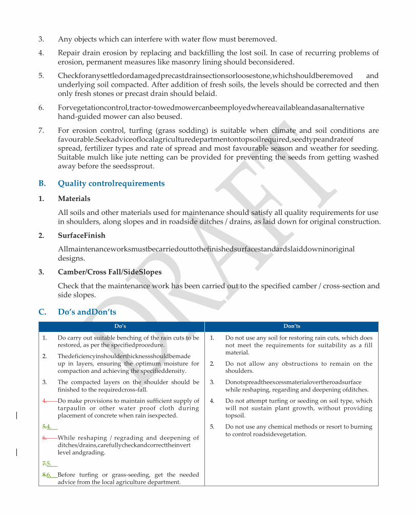
3. Any objects which can interfere with water flow must beremoved.
4. Repair drain erosion by replacing and backfilling the lost soil. In case of recurring problems of erosion, permanent measures like masonry lining should beconsidered.
5. Checkforanysettledordamagedprecastdrainsectionsorloosestone,whichshouldberemoved and underlying soil compacted. After addition of fresh soils, the levels should be corrected and then only fresh stones or precast drain should belaid.
6. Forvegetationcontrol,tractor-towedmowercanbeemployedwhereavailableandasanalternative hand-guided mower can also beused.
7. For erosion control, turfing (grass sodding) is suitable when climate and soil conditions are favourable.Seekadviceoflocalagriculturedepartmentontopsoilrequired,seedtypeandrateof spread, fertilizer types and rate of spread and most favourable season and weather for seeding. Suitable mulch like jute netting can be provided for preventing the seeds from getting washed away before the seedssprout.
B. Quality controlrequirements
1. Materials
All soils and other materials used for maintenance should satisfy all quality requirements for use in shoulders, along slopes and in roadside ditches / drains, as laid down for original construction.
2. SurfaceFinish
Allmaintenanceworksmustbecarriedouttothefinishedsurfacestandardslaiddowninoriginal designs.
3. Camber/Cross Fall/SideSlopes
Check that the maintenance work has been carried out to the specified camber / cross-section and side slopes.
C. Do’s andDon’ts
Do’s Don’ts
1. Do carry out suitable benching of the rain cuts to be restored, as per the specifiedprocedure.
2. Thedeficiencyinshoulderthicknessshouldbemade up in layers, ensuring the optimum moisture for compaction and achieving the specifieddensity.
3. The compacted layers on the shoulder should be finished to the requiredcross-fall.
4. Do make provisions to maintain sufficient supply of tarpaulin or other water proof cloth during placement of concrete when rain isexpected.
5.4.
6. While reshaping / regrading and deepening of ditches/drains,carefullycheckandcorrecttheinvert level andgrading.
7.5.
8.6. Before turfing or grass-seeding, get the needed advice from the local agriculture department.
1. Do not use any soil for restoring rain cuts, which does not meet the requirements for suitability as a fill material.
2. Do not allow any obstructions to remain on the shoulders.
3. Donotspreadtheexcessmaterialovertheroadsurface while reshaping, regarding and deepening ofditches.
4. Do not attempt turfing or seeding on soil type, which will not sustain plant growth, without providing topsoil.
5. Do not use any chemical methods or resort to burning to control roadsidevegetation.

1904 : MAINTENANCE OF BITUMINOUS SURFACE ROAD
It is considered an essential requirement prior to undertaking any maintenance measures that the road beinspectedatleastonceayearandthatthepastrecordofperformance,maintenanceandtrafficdatais available with the Maintenance Engineer.
A. Methodology
1. After a field inspection, determine the areasfor
(i) Surface defects like fatty surfaces, smooth surfaces, streaking and hungrysurfaces
(ii) Cracks-hair-line cracks, alligator cracks, longitudinal cracks, edge cracks, shrinkage cracks and reflectioncracks.
(iii) Deformation-slippage,rutting,corrugation,shoving,shallowdepressions,settlementsand upheavals;and
(iv) Disintegration – stripping, loss of aggregates, ravelling, pot-holes and edgebreaking.
2. SurfaceDefects
Fattysurfaces
(i) If the bleeding is fairly uniform and the surface is free from irregularities, application of coveraggregatesorsand(sandblottingorsand-blinding)wouldbesuccessful.Theaggregate or sand used shall be of small size, clean and regular, and may be heated, ifnecessary.
(ii) Anopen-gradedpremixsurfacingwithalowbitumencontentcanabsorbtheexcessbinder.
(iii) A liquid seal coat, with special care taken to select the rate of application of the binder and the quantity and size of cover aggregates, can also beeffective.
(iv) Special methods such as the burning of the excessbinder.
(v) In case of large areas of fatty surface having irregularities, removal of the affected layer in the area and replacing it with layer having a properly designed mix, may benecessary.
Streaking
Repair for longitudinal and transverse streaking is to remove the streaked surface and apply a new surface treatment. It is always desirable to prevent longitudinal and transverse streaking thantocorrectit.Whenevermechanicalequipmentisusedforsprayingofbitumen,manufacturer’s recommendations of the bitumen distributor should be carefully adheredto.
HungrySurface
A slurry seal may be used as a repair measure. It is applied in an average thickness of 2-5 mm.
As an emergency repair, a fog seal may be used.
3. Cracks
The treatment for cracks would depend on whether the pavement remains structurally sound or has become distorted or unsound.

Incasethepavementremainsstructurallysound,thenthecracksshouldbefilledwithabituminous binder having a low viscosity so that it can be poured and worked into the cracks. Cut back bitumen and emulsions are generally suitable. All loose materials are removed from the cracks with brooms and if necessary, with compressed air jetting. The binder is poured with a pouring can and a hand squeegee is used to assist the penetration of the binder into the cracks. Light sanding of the cracks is then done to prevent traffic picking up thebinder.
Ifthecracksarewideenoughaslurrysealorsandbituminouspremix,orsandbituminouspremix patching can be used to fill thecracks.
Ifthecracksarefine(crazing)andextendoverlargeareas,alight-cut-backoranemulsifiedbitumen (fog seal) can be broomed into the cracks and lightly sounded to prevent the picking up of the binder by thetraffic.
4 Deformation
Slippage
Remove the surface layer around the area affected upto the point where good bond between the surfacingandthelayerunderneathexistsandpatchingtheareawithpremixmaterialafteratack coat.
Rutting
Fillthedepressionorgrooveinthewheeltrackswithpremixopen-gradedordense-gradedpatching materialsandcompacttothedesiredlevels.Thelimitsofthedepressionarefirstdeterminedwith a string line and marked on the surface. After applying a suitable tack coat, the premix is spread andcompacted.
Situations indicative of shear failure or subgrade movement generally require excavation. The job should be carefully assessed. The area to be opened up should as far as possible be limited to that which can be completed and made safe in a day’s working.
Corrugations
Ifthesurfaceisthin,thesameisscarified,includingsomeportionsoftheunderlyingwater-bound macadam base, and the scarified material is recompacted. A new surfacing layer is thenlaid.
Cuttingofhighspotswithabladewithorwithoutheatingandadditionoflevellingcoursematerials can also be resortedto.
Spreading of sand bituminous premix with a drag spreader with its blade adjusted to just clear the high spots can also be an effective way of making up the corrugations. The area is then thoroughly rolled.
Shoving
Remove the material in the affected area down to a firm base and lay a stable premix patch.
Shallowdepression
Fill up the depression with premix materials, open-graded or dense-graded and compact to the desired profile as the surrounding pavement.
Settlement andUpheaval
If settlements and upheavals indicate an inherent weakness in the fill or subgrade, it may be necessary to excavate the defective fill and upto bottom of subgrade and do the embankment afresh under properly controlled conditions. Material having good drainage qualities should be preferred. Under-drains may become necessary in locations where lack of drainage has been identifiedasthecauseoffailure.Wherethecauseofdeformationisinadequatepavementthickness, then properly designed pavement shall be provided. Frost-affected regions may need thorough investigations and a complete reconstruction of thepavement.
5. Disintegration
Stripping
Inthecaseofsurfacedressing,hotcoarsesandheatedtoatleast1500Candspreadovertheaffected areas,maybeusedtoreplacethelostaggregates.Afterspreading,itshouldberolledimmediately sothatitwillbeseatedintothebitumen.Ifaggregatesareonlypartiallywhippedoff,aliquidseal may be the solution.
In other cases the existing bituminous mix should be removed and a fresh one laid. As a precautionary measure, a suitable anti-stripping agent should be added to the bitumen, at the time ofconstruction.
Loss ofAggregate
Ifthelossofaggregatesisduetoageingandhardeningofthebinder,theconditionmayberectified by applying liquid seal, fog seal or slurryseal.
If the loss of aggregates has occurred over large isolated areas, the best thing to do would be to provide another surface dressing layer, after carefully cleaning the surface.
If the loss of aggregates has taken place in small isolated patches, a liquid seal would be sufficient.
Ravelling
Ravelledsurfaceiscorrectedbyaddingmorequantityofbinder,therateofapplicationdepending upon the condition of existing surface and degree of hardening occurred to the binder. If the ravelling has not developed too far, the condition may be corrected by a simple application of a cut-back bitumen covered with coarse sand, or a slurry seal can be applied. Where the ravelling has progressed far, a renewal coat with premix material would benecessary.
Pot-hole
Fill pot holes with premix open-graded or dense-graded patching or penetration patching as per clause 501.2.3.1 of MoRD Specifications.
Edge-breaking (Frayededges)
Theshoulderandthepavementmaterialintheaffectedareashouldbefullyremovedtoaregular section with vertical sides. The pavement and the shoulders should be built up simultaneously with thorough compaction. A bituminous surface similar to that in the adjacent reach should be laid. The shoulder should have an adequate slope to drain away the water. A slope one per cent steeperthanthecamberofthebituminoussurfaceshouldbefoundgenerallynecessaryforearthen
shoulders. In order to prevent the edges from getting broken again, the maintenance operations shouldincludeperiodicinspectionoftheshoulderconditionandreplacementofwornoutshoulder material with adequate compaction. In sandy areas where the soil is likely to be eroded by wind and rain, it may be advantageous to have brick paving at least for some width to protect the edges. Surface and subsurface drainage, wherever deficient, should beimproved.
II Periodic Surface Renewal
Whentheconditionsurveydatarevealstheneedforsurfacerenewal,provide20mmthickPremix CarpetasperSub-section508andsealcoatasperSub-section510.Priortolayingasurfacerenewal, clean the existing surface of all dust and cake mud by wire brushes andbrooms.
1905: MAINTENANCE OF GRAVEL ROAD
Itisconsideredanessentialrequirementpriortoundertakinganymaintenancemeasuresthatthe Gravel road can be inspected atleast once a year and that the past record of performance, maintenance and traffic is available with the MaintenanceEngineer.
A. Methodology
I. Routine MaintenanceMeasures
1. Where loss of profile is observed on a gravel road, drag the accumulated material from the roadsides/shoulderstothecenter,usinganapprovedtractor-towedgraderandcompactbyroller. Ifasuitablemechanicalgraderisnotavailable,adoptmanualmethods.Priortorollercompaction, ensure that the gravel is at optimum moisture content ±2%
2. Where the surface is corrugated, rectify it by grading with a mechanical grader or by using a tractor-towed drag of approved design. The scrapped material should be spread over the surface androllercompacted.Priortocompaction,ensurethatthematerialisatoptimummoisturecontent ± 2%
3. Repair all local depressions, ruts, potholes and erosion gullies, replacing or adding new surface materialofspecifiedpropertiesasperSub-section402andthencompactthereplaced/newsurface material by road roller. Before undetaking repairs, the affected area should first be cleaned of all loose material, bringing it to a regular rectangular shape with the help of spades and pick axes and hand ramming the bottom surface. The prepared area should be filled up with gravel of specifiedpropertiesandrollercompacted,ensuringthatpriortocompaction,themoisturecontent is at the optimum ±2%.
II. Periodic SurfaceRenewal
Prior to regravelling, scarify the old surface and provide additional gravel 50 mm to 75 mm in loosethicknessmeetingspecifiedrequirements(asperSub-section402)overthescarifiedsurface. Afterbringingthemoisturecontentoftheadditionalgraveltooptimum ± 2%,compacttheloose gravel layer to the maximum dry density as per IS:2720 (Part7).
B. Quality ControlRequirements
1. Materials
Any gravel used for routine maintenance repairs and for periodic regravelling should conform to the requirements as per Sub-section 402.
2. SurfaceFinish
Thesurfacefinishaftertheroutinemaintenancerepairsandperiodicregravellingshouldconform to the requirements laid down in Sub-section402.
3. Camber/Cross-fall
Check that the final surface conforms to the specified camber / cross fall.
C. Do’s andDon’ts
Do’s Don’ts
1. Do ensure that any gravel used for repairs, whether as salvaged material or as fresh material meets the specified requirements for use in the layer in question.
2. The grader should start from the edges of the road and work towards thecenter.
3. The surface of a gravel road should be improved by dragging with the use of an approveddrag.
4. Do make sure that prior to filling up local depressions, ruts, potholes and erosion gullies, the affected area is first cleaned of all loose material, brought to a regular shape and the bottom surface hand-rammed.
1. Do not allow heavy grading, without the provision of additional surface material if the remaining thickness of gravel is less than 75mm
2. Do not use any scrapped gravel for repairs, if it does not meet the specifiedrequirements.
3. Do not spread additional gravel for re-gravelling on the old surface without scarifying the oldsurface.
4. Do not start roller compaction unless the material to be compacted is at a moisture content equal to OMC ± 2%.
5. Do not use manual methods for making up the loss of profile without the approval of theEngineer.
1906: MAINTENANCE OF WBM ROAD
ItisconsideredanessentialrequirementpriortoundertakinganymaintenancemeasuresthattheWBM road be inspected once a year and that the past record of performance, maintenance and traffic data is available with the Maintenance Engineer.
A. Methodology
I. RoutineMaintenance
1. Afterafieldinspection,determinetheareasfor(a)fillinguppotholes(b)fillingupruts,(c)rectifying corrugated surface, (d) repairing damaged edges and (e) rectifying ravelledsurface.
2. Before filling up a pothole, remove all loose material from the pothole upto the firm base, cut the affected area made into a regular rectangular shape with sides of the hole kept vertical. Fill the preparedpotholespacewithaggregateofthesamesizeandtypeasusedintheoriginallayerand apply screenings and binding material of the same type (if found suitable) as used in original constructionovertheaggregateandcompactbyhandrammer.Afterwatering,compactthelayer again by hand rammer first and then by a roadroller.
3. Cleantheruttedpotionofallloosematerialandsprinklewithwaterandshapetheruttedportion intoarectangularportionwithflatbottom.Fillthepreparedrutportionwithsalvagedmaterial,if found suitable and / or fresh suitable aggregates and roll after addition of screenings, binding material and watering following the standard procedure as per Sub-section 405. After rolling, provide a 6 mm sand layer over the finished surface and lightly sprinkle withwater.
3. Remove any damaged portions at the edges, replace by fresh material androll.
4. Any corrugated surface formed by excess blindage material should be rectified by removing all excess blindage material by dragging or brooming. Where corrugations develop in WBM course itself, a renewal layer of WBM will berequired.
5. Finehaircracksonthesurfaceareusuallyindicativeofravellingtakingplacelater.Thistendency for ravelling can be remedied by blending with good binding material and watering the surface. Where ravelling has developed prominently, resurfacing should be carriedout.
II. Periodic SurfaceRenewal
Where the condition survey data reveals the need for surface renewal, provide a 75 mm thick layerofWBMgrading3asperSub-section405.Priortolayingasurfacerenewal,cleantheexisting surface of all dust and caked mud by wire brushes and brooms. After light sprinkling of water, scarifythesurfaceandscreenthesalvagedmaterialstobeusedlater,iffoundsuitable.Thesalvaged material together with fresh additional material should be spread and dry rolled followed by application of screenings and binding material, and wet rolling as per Sub-section405.
B. Quality ControlRequirements
1. Materials
Thequalityofstoneaggregates,screeningsandbindingmaterialusedforroutinemaintenanceas wellasperiodicsurfacerenewalshouldconformtotherequirementslaiddowninSubsection405 for WBMconstruction.
2. SurfaceFinish
The surface finish requirements after carrying out various maintenance measures should also conform to the surface finish requirements laid down in Subsection 405.
3. Camber/Crossfall
Camber / Crossfall should be checked for ensuring conformance with the specified requirements.
C. Do’s andDon’ts
Do’s Don’ts
1. Make sure that all materials used in maintenance repairsi.e.,coarseaggregatesscreeningsandbinding material meet the quality requirements laid down in Subsection405.
2. While filling potholes, keep the surface slightly proud of the surroundingarea.
3. While repairing damaged portions of edges, rolling of the edge and shoulder should be carried out simultaneously and the cross profile of the shoulder remedied bygrading.
1. Do not use the salvaged material for repairs, if these do not meet all the qualityrequirements.
2. Do not ignore the presence of fine hairline cracks on WBMsurfaceastheseareindicativeofseriousravelling to occurlater.
3. Do not provide resurfacing unless the old surface has been scarified.
4. DonotallowtrafficimmediatelyafterlayingtheWBM surface renewal.
4. After providing surface renewal, a 6 mm layer of coarsesandshouldbeprovidedandlightlysprinkled withwater.

1908 : MAINTENANCE OF CULVERTS AND SMALL BRIDGES
General: Under this Section the maintenance aspects of all the culverts and small bridges are covered.
A. Methodology
1. Inspect approaches of CD works for possible erosion and settlement, besides any damage due to movement of cattle between stream androadway.
2. Examine floor protection to assess extent of cracking / damage to the floor condition and cut off walls, apronsetc.
3. Observe any abnormal change of channel flow and movement of debris, floating material, sand / silt andboulders.
4. Examine the general condition of foundation, pier, abutment, wing, return walls, springing of arches, headwalls, cut off walls for any damages due to scouring / earthpressure.
5. Checkforgrowthofvegetationinallstructuralcomponentsforcrackinginconcrete,looseningof brick/stonemasonrywork,openingofjointsatcrownsection,separationofarchrings/spandrel walls, settlement/tilt of foundation etc.
6. Check for condition of inlets, outlets and catch pits of pipe culverts / arches / boxes from inside and on outerfaces for growth of vegetation, erosion and choking ofculverts.
7. For concrete members examine for signs of distress such as cracking, spalling / corrosion of embedded steeletc.
8. Examinedrainagespouts,guideposts,railings,parapetsguardstones,kerbsandwearingcoatfor durability and for safety of pedestrians andanimals.
B. Quality ControlRequirements
1. Clearandcleandebrisofsandandsiltfromculvertopeningandcatchwaterpitincludinggrowth of vegetation at inlet and outlet. Remove and dump the same far away from waterchannel.
2. Undertakerepairsfordamagescausedduetoerosion,cracksandspallsandtosubstructuresand protectionworks.
3. Inspect general condition of foundation and for separation of arch rings and spandrel walls and carry outrepairs.
C. Materials
1. Carry out repairs on cement based components / parts with cementmortar.
2. Inject epoxy grout for sealing of cracks and filling of voids in concrete, under pressure, following Manufacturer’sspecification.
3. CarryoutrepairsonconcretedeckslabswithMethylMethacrylate(MMA)orTrimethylPropane, Trimethacrylate as per Manufacturer’sspecification.
4. Carry out repairs to approaches and banks periodically with localsoil.
5. Use brick or stone masonry for repair of components made of the samematerials.
1909: MAINTENANCE OF CAUSEWAYS
A. Methodology
1. Checkforadequacyofwaterwayandanyabnormalchangeinflowpatternofchannelonu/sand d / s side after each flood season, including outflanking.
2. Examine major damages caused by outflanking or cavitation, causing collapse of head walls, damages to paved surface and fill material that holds multiple pipes /openings.
3. Checktheconditionofventsforaccumulationofsand/debrisetc.andcheckforaccumulationof debris on the surface of causeway after each submergence andclean.
4. Checktheapproachesforerosion/washoutandfacewallsandheadwallsforlooseningofmaterial.
5. Checktheconditionofguideposts/guardstones/kerbsincludingslopesofapproaches.
6. Check any damages to d / s protection works like CC blocks, stone pitching and wirecrates.
7. Check the functioning of flood gauge of causeways and submersible bridges before onset of monsoon.
B. Quality ControlRequirements
1. Carryout repairs to the submerged portions of the structure with the same parentmaterial.
2. Removegrowthofvegetationindifferentcomponentsdebris/floatingmaterialonbothu/sand d / s side of causeway as well asroadway.
3. Carryoutrepairstoguideposts/guardstones/kerbs,debrisarrestersandroadway.
4. Undertake minor repairs to flood gauges and otherancillaries.
5. Undertake repairs to the damages caused by out flanking, collapse of head walls and to paved roadwaysurface.
C. Materials
1. Carry out repairs to concrete components on cement plaster with the samematerial.
2. Use stones / bricks for replacement of parts or to repair localdamages
3. Use local soil if suitable, for repairs to embankments approachesetc.
1910: MAINTENANCE OF ROAD SIGNS
A. Methodology
1. All road signs should be inspected at least four times a year both in day andnight.
2. Allsignsalongwiththepostsshallbemaintainedinproperpositionandkeptcleanandlegibleat alltimes.
3. Damaged signs shall be replaced immediately. All road signs alongwith the posts should be maintained in proper position and kept clean and legible at alltimes

4. A schedule of painting of the posts and signs periodically shall be maintained. Painting the signs may be undertaken after every twoyears.
5. Tree branches, plantations, weeds, shrubbery and mud etc. shall not be allowed to obscure the sign.
B. Quality ControlRequirements
1. Materials
The material for repair / fabrication of signs shall conform to subsection 1701 and IRC:67.
1911, 1912, 1913 & 1915 MAINTENANCE OF MARKINGS & APPURTENANCES
A. Methodology
1. Allroadmarkingsshallbemaintainedsoastobeclearlyvisibletothedriver.Anyearlyschedule ofre-paintingthemarkingsshouldbemaintainedtoensurepropermaintenanceofthemarkings.
2. The material for maintenance of road markings shall be in conformity with subsection1702.
3. Repainting and lettering on kilometre and 200-m stones shall be as per guidelines indicated in IRC:8&IRC:26.Thestonesshallbemaintainedinproperpositionandkeptcleanandlegibleatall times. Damaged as well as tilted stones shall be fixed, repaired / replacedimmediately.
4. Plantation, weeds, shrubbery and mud etc. shall not be allowed to obscure the stones /signs.
5. Iron, wooden or concrete posts for road delineators shall be repainted regularly, especially after the rains to keep them clean and visible. The ground around the delineators, hazard markers, roadway indicators and object markers should be kept clean by cutting grass / weeds and bushes etc. periodically to maintain the visibility of the delineators.
6. The material for repair / replacement of road delineators, hazard markers, roadway indicators and object markers shall conform to the guidelines included inIRC:79.
7. Allbranchesoftreesextendingabovetheroadwayshallbecutortrimmedsoastoprovideaclear height of 5 m above the road surface andshoulders.
8. Allshrubs,grassandweedsintheroadwaylandshallbetrimmedanddebrisremovedtoasuitable location as directed by Engineer to ensure unobstructed sight distance of adequatelength.
9. The parapet walls of culverts, minor bridges and tree trunks shall be cleaned of all scales, dirt or loose material and applied two coats of white wash using good unslakedlime.

CHAPTER 4
QUALITYMONITORING
1. General
As part of an overall Quality Management System, the aspect of ‘Quality Control’ is to be treated as distinctly different from ‘Quality Monitoring’, both at Tier 2 and Tier 3 levels. The aspect of Quality Control of Works has been dealt with in detail in Chapter 3 of this Hand Book. This Chapter deals with Quality Monitoring which essentially involves only expeditious random checking by specially appointed Tier 2 Quality Monitors of selected engineering colleges to ensure that the works are indeed being carried out as per the prescribedstandards.
In the three-tier system of Quality Management being adopted for PMU-RKI roads constructed by the Project Management Unit,whilethefirsttierisanin-housequalitycontrol bytheexecutingagency PIUs,thesecondtierisanindependentqualitycheckandmonitoringbyfaculty of selected engineering colleges in theState.Inthethirdtierofqualitymanagement, the PMU will ensure the proper functioning of the first two tiers. Themainobjectiveofquality monitoringatthesecondandthirdtiersistoverifywhetherthequalityofroadworksexecutedby thePIUsconformstothespecifiedstandardsandtoseeifthesystemofquality management in the system is indeedeffective.
2. Role of The QualityMonitors
TheroleofthequalitymonitorsismoreofprovidingguidancetothePIUs than to pinpoint specific faults. Accordingly, the Quality Monitors are required to bring out the weaknessesorshortcomingsinthequalitycontrolsystembeingadoptedbythesystem andtoprovide a feed back for improvement. This role can be fulfilled by the field inspections of the PMU-RKI worksbyQualityMonitorsduringdifferentstagesofconstructionandalsothroughinspectionof completedworks.
Itmaybepointedoutherethatatthetier 2 level,therehastobeamorerigorousandinvolvedrole ofthe engineering college faculty requiringmorefrequentvisitscomparedtothePMU officers.
3. Field Inspections by QualityMonitors
3.1The field inspections by Quality Monitors need to be so organised that every Quality Monitor is able to inspect the PMU RKI road works during different stages of construction like Setting Out, Earthwork, Subgrade, Sub-base, Base, Surfacing and Drainage system, including culverts and bridges, besides completed works. Since the duration of such field inspections will be short, the Quality Monitors will have to depend largely on visual inspection, simple hand-feel tests, use of simple gadgets like Camber Board and Straight Edges etc. available in the Field Laboratory. Itisonly in exceptional suspect cases that detailed laboratory tests may be necessary. The Quality Monitorsneedtobearinmindthatallthechecksmadebythemshouldbeinaccordancewiththe provisions made in the approved Plans and Bill of Quantities forming part of theContract.
3.2 For purposes of Quality Monitoring, only random checks are envisaged. For soils and other road

materials being used at site, a representative sample from the borrow pit in use or stockpiled materialcanbecollectedatrandom.Similarly,whilecheckingplacementmoisturecontentduring compaction,arandomsamplecanbecollectedanditsmoisturecontentdeterminedusingaRapid MoistureMeter.Forinsitudensitydeterminationbysandreplacementmethod,thelocationofthe testcanbeselectedatrandom.Asimilarapproachcanbeadoptedduringbituminousandcement concreteconstruction.However,whereacompletedsectionistobechecked,theentirecompleted section should be divided into 10 sub-sections, of equal length. Two such sub-sections may be selectedatrandomforcarryingouttheneededtests.Thelongitudinalprofileshouldbetestedby a 3 m straight edge in a stretch of atleast 9 m length and the transverse profile at two or three locations at each 100 mlength.
4. ITEMS TO BE CHECKED BY QUALITYMONITORS
The various items to be checked by the Quality Monitors are given below, with respect to the MORD Specifications for Rural Roads.
1. Section 100 :General
QualityArrangements
Attention toQuality
Setting out and Geometrics
2. Section 300 :Earthwork
Earthwork and Subgrade / Improved Subgrade in Embankment /Cutting
3 Section 400 : Granular Sub-bases, Bases andSurfacings
Granular Sub-base / Stabilized SoilSub-base
Base Course : Water BoundMacadam
Shoulders
4 Section 500 : BituminousConstruction
Prime Coat
Tack Coat
Bituminous Layer-SurfaceDressing
Bituminous Layer-Premix Carpet 5 Section 1100 : Pipe Culverts, Section 1200 : R.C.C Slab Culverts and Minor Bridges and
Section 1400: Cement Concrete Causeways and SubmersibleBridges
Cross-DrainageWorks
6 Section 1300 : Protection Works andDrainage
Side Drains and Catch WaterDrains
7 Section 1500 : Cement ConcretePavement
Cement Concrete / Semi-RigidPavements
8 Section 1700 : Traffic Signs, Markings and Other RoadAppurtenances
Road Furniture andMarkings
1. SECTION 100: GENERAL
1.1: Quality Arrangements
On-going
Atanyparticularstageofconstructione.g,SettingOut,Earthwork/Subgrade,Sub-base,Base,Surfacing, and Cross-Drainage works, it is necessary to check thefollowing:-
(a) Check,ifthefieldlaboratoryhasbeensetupatanappropriatelocationandhasthebasicfacilities to carry out the needed quality controltests.
(b) Check, if out of the specified List of Essential Equipment pertaining to that stage of construction, any items are missing.
(c) Check whether all the items needed are indeed in working order and that, wherever needed, the necessarycalibrationshavebeendone.Forexample,standardsandusedintheinsitudensitytest by Sand Replacement method and calibration of Rapid Moisture Meter or any otherequipment.
(d) Check, if the Laboratory Technician / Junior Engineer carrying out the quality control tests is adequatelytrainedandiscompetenttocarryoutalltheneededfieldandlaboratorytestsreliably.
ATTENTION TOQUALITY
1. Verification of Quality ControlRegisters
◆ Checkthedatesforwhichthetestresultshavebeenenteredfordifferentstagesofconstruction in the Quality Control Registers. Ascertain if the Registers are uptodate and for each day, the type and number of tests carried out are as specified and that all calculations have been doneproperly.SpotcheckingoftheAbstractoftestswiththefilled-inproformaeofvarious tests is alsonecessary.
2. Verification of Test Results on the basis of FieldTests
◆ Check on the criterion adopted for acceptance, rejection or conditional acceptance of the work in progress. For example, adequacy of the level of compaction in a finished layer, basedonaminimumof3insitudensitytestscarriedoutonthefinishedlayer(Table301.5). Where the acceptance criterion was not satisfied, check if a Non-Conformance Report was filled up or any other action wastaken.
◆ Check, whether adequate action was taken on each of the Non-Conformance Reports to rectify thedefects.
◆ Check, the compliance of observations made earlier by QualityMonitors.
SETTING OUT ANDGEOMETRICS
1. SettingOut
(a) Check the Reference Bench Mark and the Working BenchMarks.
(b) Check,ifthecentrelineofthecarriagewayisaccuratelyestablishedandreferencedevery50 mintervalsinplainandrollingterrainand20mintervalsinhillyterrainwithacloserspacing of 10 m on sharp curves, 5 m on hairpin bends with marker pegs and chainageboards.

2. Width ofRoadway
(a) Takeatleast3measurementsoftheRoadwaywidthperkmlength,orpartthereof.Measuring Tapes(availableintheFieldLaboratory)canbeusedforthepurpose.Thethreelocationsfor measurements per km length or part thereof may be selected atrandom.
(b) Determine the mean of the 3 measurements per km length and compare with the specified width of roadway. Permissible tolerances are asunder:
±30 mm in plain and rolling terrains
±50 mm in hilly terrain
3. CarriagewayWidth
(a) Take atleast 3 measurements of the carriageway width per km length or part thereof. Measuring Tapes (available in the Field Laboratory) can be used for the purpose. The three locations for measurements per km length or part thereof may be selected atrandom.
(b) Determine the mean of the 3 measurements per km length and compare with the specified width of carriageway. Permissible tolerances are asunder:
±20 mm in plain and rolling terrains
±30 mm in hilly terrain
4. Camber
Takeatleast3measurementsofcamber,usingaCamberBoard(availableintheFieldLaboratory) per km length, or part thereof, following the procedure as shown in Annex 100.1. Note the discrepancies between the specified camber and the camber actually provided. Two designs of the commonly used Camber Board are shown in Annex100.2.
5. Superelevation and Extra Widening atCurves
(a) Alongthecircularcurveportionoftheroad,measurethecarriagewaywidthatthreeselected chainages, using a measuring tape. The mean of the three observations will give the width of the carriageway provided along the circular curve. The difference between the mean carriageway width along the curve and the carriageway width along the straight reaches gives the extra widening provided along the curve, which should be compared with the design value of extrawidening.
(b) The widening should be effected by increasing the width at an approximately uniform rate along the transition curve. The extra width should be contained over the full length of the circularcurve.
(c) Theamountofsuperelevationprovidedalongacurvecanbedeterminedbyusingastraight edge as shown in Annex 100.3, spririt level and measuring tape. The measured amount of superelevation should be compared with the superelevation designed for thecurve.
6. Longitudinal Gradient in Case of Road in Hilly/ RollingTerrain
Longitudinal gradients can be checked expeditiously, using simple Dumpy Level and staff. Reasonably accurate checks on gradient can be considered by using suitable Hand Level or even CalibratedSpiritLevels,dependingonavailability.Thesechecksshouldbecarriedoutat3critical locations per km length or part thereof and mean of the three observationsdetermined.

ANNEX100.1
[Source : Overseas Road Note 2 : Maintenance Techniques for District Engineers, 2nd Edition, TRRL (UK) 1985], Adapted Version
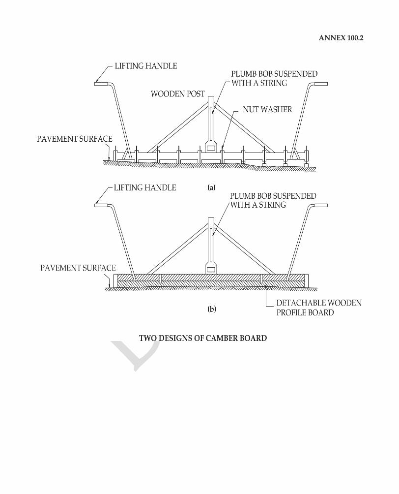
ANNEX 100.2
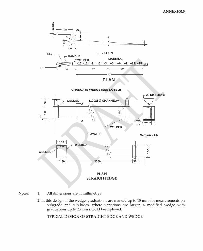
25DIA
HANDLE
WELDED
165
145 20
12
1
5 30
ANNEX100.3
ELEVATION
MARKING
-15 -12 -9 -6 -3 +3 +6 +9 +12 +15 3 0
5R 300 300
600
PLAN
GRADUATE WEDGE (SEE NOTE 2)
20 Dia Handle
WELDED A
(100x50) CHANNEL 5R
A
WELDED
25 50 25 10
ELAVATOR Section - AA
WELDED
PLAN
STRAIGHTEDGE
Notes: 1. All dimensions are in millimetres
2. In this design of the wedge, graduations are marked up to 15 mm. for measurements on subgrade and sub-bases, where variations are larger, a modified wedge with graduations up to 25 mm should beemployed.
TYPICAL DESIGN OF STRAIGHT EDGE AND WEDGE
100 WELDED
50 3000 50
10
10
6
60
21
DIA
31
24
2
30
16
10
0
10
0

2. SECTION 300 :EARTHWORK
: Earthwork and Subgrade/ Improved Subgrade in Embankment/Cutting
1. Quality of Material for Embankment/ Subgrade/ ImprovedSubgrade
(a) For earthwork in embankment, check its suitability by soil type and its soil group. This can bedeterminedbyadoptingaVisualSoilClassificationSystem,usingonlyhand-feeltests,as shown at Annex 1. Details of the three hand-feel tests required for classifying fine-grained soils are given in Appendix-1, paras 1.1, 1.2 and1.3.
A quick supplementary procedure for determining the presence of clay is performed by cutting a lump of dry or slightly moist soil with a knife. A shining surface imparted to the soil indicates highly plastic clay, while a dull surface silt or clay of slight plasticity.
Using the following the suitability of soil as a fill material can be ascertained:
• DryUnitWeightestimatedfromthesoilgroupasperTable(Annex300.2)onAverage Engineering Properties of SoilGroups.
• Wherever suspect, Deleterious Material Content (Appendix 1, Para 4) should be determined.
• Wherever suspect, pH value to be determined using litmus paper strips (if pH>8.5, the soil is sodic in nature and unsuitable foruse)
Check,ifthesubgradesoilmeetsalltherequirementsoffillmaterialasabove,hasthe maximum dry unit weight (Proctor Test) and soaked CBR not less than the specified value.
(b) Whereaclayeysubgradesoil/blackcottonsoilwithverylowCBRvalueistobeimproved by lime treatment, as per the provisions of the Contract, check from records if the purity of lime used for the purpose has been tested. It should be not less than 70% by weight of quicklime(CaO).
(c) Check the lime treated soil for its Plasticity Index(PI).
(d) Check,ifpriortomixingofsoilwithlime,pulverizationofsoilclodswascarriedoutasper requirements i.e, 100% passing 26.5 mm sieve and 80% passing 5.6 mmsieve.
(e) Check, if the mixing of pulverised soil with lime was carried out thoroughly by using appropriate equipment like tractor-towed disc harrows / tractor-towedRotavator.
2. Compaction
(a) Check, if the moisture content in the soil during compaction is close to the optimum by taking a handful of the wet soil on the palm of hand and attempting to make a ball out of it (Appendix1,Para5).Themoisturecontentatwhichtheballofwetsoilcanretainitsround shape is approximately the optimum. At moisture contents below the optimum, the ball tendstocrumblewhileatmoisturecontentswetofoptimum,thewaterwilltendtooozeout ofsurface.

(b) Carry out an insitu density test each at the following twolocations:
(i) close to the edge of theroadway
(ii) any location selected atrandom
(c) Ifatlocation(i),theinsitudensityislowerthanthelowerspecifiedlimit,itgoestoshowthat proper precautions in regard to trimming at the verges were not taken by building the embankment initially wider than the design embankment and then trimming at theedges.
(d) At location (ii), the insitu density test result should not be lower than the lower specified limit. If the actual insitu density obtained at the time of checking is lower than the lower specified limit, check on the action taken to rectify the defect and if any Non-Conformance Report was filledup.
(e) Check, if the improved subgrade was compacted to 100% Proctordensity.
(f) Check, if the improved subgrade just after compaction was properly cured for 7 days with wet gunny bags, moist straw or sand, periodically sprinkled withwater.
3. Side Slopes andProfile
(a) Simple gadgets for estimating the side slopes from the horizontal distance (horizontality ensuredbyaspiritlevel)andverticalheightofaTorLframe(Appendix1,Para1.8)canbe used for monitoring the actual side slopes of a completedembankment.
(b) A set of 3 observations can be expeditiously taken per km length, using suchgadgets.
4. Stability and Workmanship of Cut Slopes
(in case of hilly/ rollingterrain)
(a) As per the design requirements of Cut Slopes, check if all the needed measures have been takenforerosioncontrol(byprovidingsuitablespeciesofvegetation),drainage(catchwater drains etc) and retaining structures like breast walls / retaining wallsetc.
(b) Check on the actual slope(s) provided; extent and type of vegetation provided; the cross- section,liningandgradientsofdrainsprovided;dimensionsadoptedandmaterialsusedin retaining structures, to see if they all meet the designrequirements.
5. Adequacy of Slope Protection (in case of high embankments/ hilly/ rolling terrain)
(a) Check, using the simple gadgets described earlier, if the actual slopes provided are indeed within permissible tolerances of the designslopes.
(b) Inordertoavoidanyraincutsalongtheslopes,checkifthetypeofvegetationprovidedfor erosion control is of the right species and that wherever required, top soil was indeed providedoncompletedembankmentslopesbeforeplantingvegetation.Ifnot,thedeficiencies should be pointedout.
(c) Check, if any design requirements like provision of stone pitching or gabions etc. are implemented satisfactorily by examining the quality of stone pitching (e.g if the drainage layer underneath has indeed been provided and the size and quality of stones meet the specified requirements) and in case of gabions, the wire mesh of the crate is plastic coated etc.
(d) Check, if the drainage system provided is as per the design requirements. Any deficiencies observed should be broughtout.
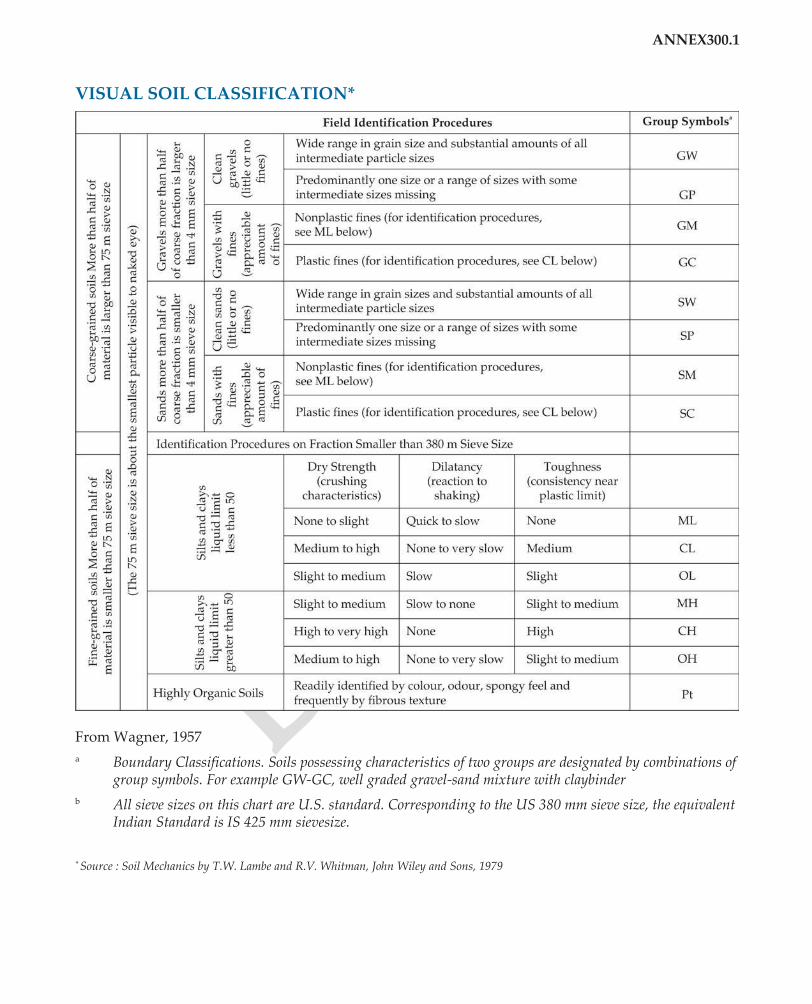
ANNEX300.1
VISUAL SOIL CLASSIFICATION*
From Wagner, 1957
a Boundary Classifications. Soils possessing characteristics of two groups are designated by combinations of group symbols. For example GW-GC, well graded gravel-sand mixture with claybinder
b All sieve sizes on this chart are U.S. standard. Corresponding to the US 380 mm sieve size, the equivalent Indian Standard is IS 425 mm sievesize.
* Source : Soil Mechanics by T.W. Lambe and R.V. Whitman, John Wiley and Sons, 1979
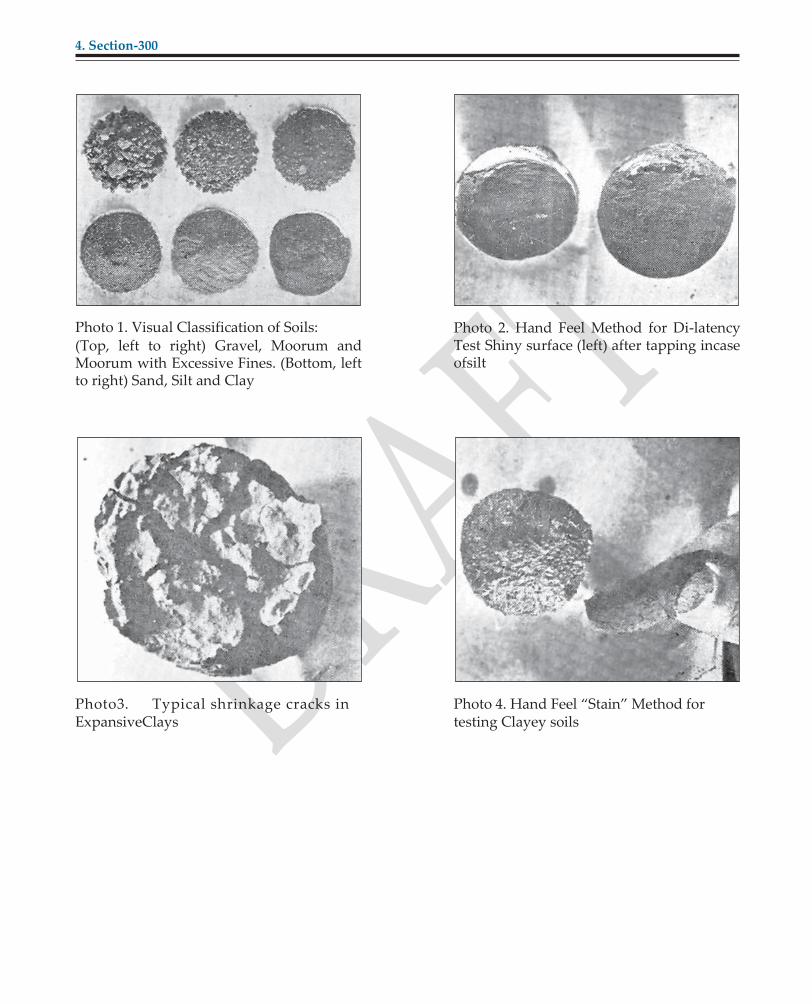
4. Section-300
Photo 1. Visual Classification of Soils: (Top, left to right) Gravel, Moorum and Moorum with Excessive Fines. (Bottom, left to right) Sand, Silt and Clay
Photo 2. Hand Feel Method for Di-latency Test Shiny surface (left) after tapping incase ofsilt
Photo3. Typical shrinkage cracks in ExpansiveClays
Photo 4. Hand Feel “Stain” Method for testing Clayey soils
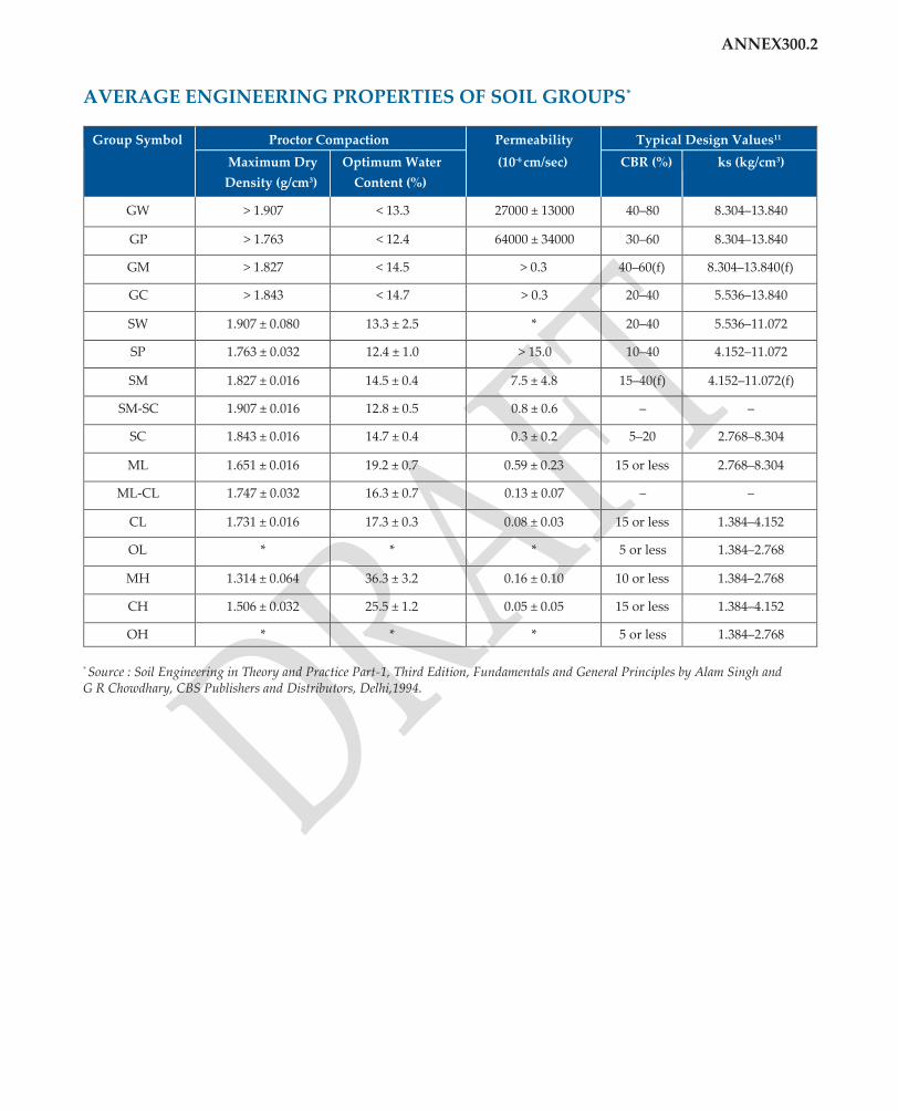
ANNEX300.2
AVERAGE ENGINEERING PROPERTIES OF SOIL GROUPS*
Group Symbol Proctor Compaction Permeability
(10-6 cm/sec)
Typical Design Values11
Maximum Dry
Density (g/cm3)
Optimum Water
Content (%)
CBR (%) ks (kg/cm3)
GW > 1.907 < 13.3 27000 ± 13000 40–80 8.304–13.840
GP > 1.763 < 12.4 64000 ± 34000 30–60 8.304–13.840
GM > 1.827 < 14.5 > 0.3 40–60(f) 8.304–13.840(f)
GC > 1.843 < 14.7 > 0.3 20–40 5.536–13.840
SW 1.907 ± 0.080 13.3 ± 2.5 * 20–40 5.536–11.072
SP 1.763 ± 0.032 12.4 ± 1.0 > 15.0 10–40 4.152–11.072
SM 1.827 ± 0.016 14.5 ± 0.4 7.5 ± 4.8 15–40(f) 4.152–11.072(f)
SM-SC 1.907 ± 0.016 12.8 ± 0.5 0.8 ± 0.6 – –
SC 1.843 ± 0.016 14.7 ± 0.4 0.3 ± 0.2 5–20 2.768–8.304
ML 1.651 ± 0.016 19.2 ± 0.7 0.59 ± 0.23 15 or less 2.768–8.304
ML-CL 1.747 ± 0.032 16.3 ± 0.7 0.13 ± 0.07 – –
CL 1.731 ± 0.016 17.3 ± 0.3 0.08 ± 0.03 15 or less 1.384–4.152
OL * * * 5 or less 1.384–2.768
MH 1.314 ± 0.064 36.3 ± 3.2 0.16 ± 0.10 10 or less 1.384–2.768
CH 1.506 ± 0.032 25.5 ± 1.2 0.05 ± 0.05 15 or less 1.384–4.152
OH * * * 5 or less 1.384–2.768
* Source : Soil Engineering in Theory and Practice Part-1, Third Edition, Fundamentals and General Principles by Alam Singh and G R Chowdhary, CBS Publishers and Distributors, Delhi,1994.

3. SECTION 400 : GRANULAR SUB-BASES, BASES AND SURFACINGS
3.1: Granular Sub-Base/ Stabilized Soil Sub-Base
1. Quality ofMaterial
(a) GranularSub-Base
(i) Check the PI of the fines present in the GSB. This can be quickly done by using one of the following simple hand feeltests.
• Take two or three handfuls of GSB material and take away stone pieces larger than 5 mm.Addenoughwatertobeabletopackthematerialintoaball.Pickupahandfulof themoistmaterialandsqueezeitintoaball.ForuseinGSB,themoistmaterialshould not leave a stain on the hand. When dried, the ball may be broken with very slight force.
• Forroughlycheckingtheplasticityoffines,takeahandfulofGSBmaterialpassingISS 425 micron (or just even a window screen) and add the minimum amount of water that will mould the material into a ball. A suitable GSB material will be difficult to roll; in any case not thinner than 7.5 mm in diameter. If the diameter is less than 4 mm, the fines are too plastic for use inGSB.
• By using Uppal’s Plasticity Syringe (Appendix 1, Para1.4).
(ii) If grading is suspect, compare the sieve analysis, using relevant sieve sizes, for material coarser than the prescribed maximum size of material and for the percentage passing 75 micron sizesieve.
(b) Stabilized SoilSub-Base
(i) Wherealime-treatedsoilsub-basehasbeenprovidedforintheContract,checkfromQuality ControlRegisters,thepurityoflimeused,itsamountaddedandPlasticityIndexofthemix. Verifyfromthelaboratorytestvalues,recordedinQualityControlRegisters,thatthestrength in terms of UCS / CBR is not less than the minimum specifiedrequirement.
(ii) Where a cement-treated soil sub-base has been provided for in the Contract, check on the type of cement used and the amount added. Verify from the laboratory test values that the laboratory 7-day unconfined compressive strength (UCS) obtained for the mix is not less than the minimum specified requirement of 1.7MPa.
2. Mixing of Soil with Stabilizer in Stabilized SoilSub-Base
◆ Check,fromrecords,ifpriortomixingofsoilwithlime/cement,pulverizationofsoilclods was carried out as per requirements i.e., 100% passing 26.5 mm sieve and 80% passing 5.6 mmsieve.
◆ Check, if the mixing of pulverized soil with lime / cement, was carried out thoroughly by using appropriate equipment like tractor-towed disc harrows / tractor-towedRotavator.

3. Compaction
◆ Check, if for lime treated soil sub-base, compaction is completed within 3 hours of mixing andforcementtreatedsoilsubbase,within2hoursofmixingorsuchshorterperiodasmay be found necessary in dryweather.
◆ Carry out an insitu density test on the compacted subbase layer and compare it with the specified density. If one test result does not meet the specified density requirements, take 2 more samples at random and then apply the criteria as given in Table301.5.
4. Thickness ofLayer
◆ Determine the thickness of compacted layer at random by digging a pit. If it does not meet the requirement, determine the thickness at two morelocations.
5. Curing of StabilizedSubbase
◆ Check,ifcuringofthecompactedstabilizedsoillayeriscarriedoutfor7daysbyspreading wet gunny bags / moist straw or sand, sprinkling waterperiodically.
◆ Check that no ponding of water was resorted to forcuring
◆ Check that no traffic is allowed to ply duringcuring
6. SurfaceRegularity
◆ Using a 3 m Straight Edge, the undulations observed should not exceed 12 mm in the Longitudinal Profile and not more than 10 mm in the CrossProfile.
BASE COURSE: WATER BOUNDMACADAM
1. Quality of Material (for OngoingWorks)
◆ Grading of Coarse Aggregates : Check grading for coarse aggregate on at least one sample from each kmlength.
◆ Flaky and Elongated Aggregates : Visually observe if the proportion of flaky aggregate exceeds the specified limit.
◆ Grading of Screenings : If softer aggregates like brick ballast are used, screenings may not be required. Where screenings are to be used, a representative sample should be subjected to a grading test. If it does not meet the specified grading requirements, two more samples shouldbetakenandaverageofthethreetestresultsshouldbetaken.Similarly,asampleof screeningspassing425micronsieveshouldbecheckedforPlasticityIndexusingtheSyringe method.
◆ PlasticityofBindingMaterial:WheretheScreeningsusedareofacrushabletype,binding materialisnotrequired.Theplasticityindexofthebindingmaterial(onsamplepassing425 micron sieve) can be checked using simple syringe test (Appendix 1, Para8).
2. CompletedSection
For random checking of completed WBM layer, the following procedure shall be followed.
(i) Dig a pit 0.5 m x 0.5 m in area into the compacted WBM layer and take out all the WBM material from thepit.
Test 1
Refill the pit with the dug material without compacting. If the pit can be filled by using not more than65%ofthedugmaterial,itisindicativeofadequatecompactionanduseofspecifiedquantity of all materials combined together.
Test 2
(ii) Separate out the portions of the WBM material passing and retained on 11.2 mm size sieve when Type B Screenings have been used. Where Type A Screenings have been used, the proportions of WBM material passing and retained on 13.2 mm size sieve should bedetermined.
(iii) Measure the loose volumes of the two portions using cylinders of known volume and compare thecombinedvolumewiththecombinedspecifiedquantitiesofCoarseAggregate+Screenings+ BindingMaterial.
(iv) Thevolumeofmaterialretainedon11.2mmsizesieve(or13.2mmsizesieve,asthecasemaybe) shallbecomparedwiththespecifiedquantitiesofcoarseaggregateviz0.91to1.07cumper10sq m for WBM gradings 2 and 3. Due allowance shall be made for crushing duringrolling.
(v) The material passing 11.2 mm size sieve (or 13.2 mm size sieve, as the case may be) shall be compared with the specified quantities of Stone Screenings and Binding Material or Crushable Screenings as the case maybe.
(vi) For the Coarse Aggregates, the quality may be checked by conducting an Aggregate Impact Test and determining the presence of any oversizeaggregates.
(vii) ForthefinerfractionspassingIS425micronsizesieve,thePlasticityIndexshallbedeterminedto check that it is less than6.
SHOULDERS
1. Quality of Material inShoulders
Check, by visual classification, the type of material used in the shoulders.
2. Degree ofCompaction
Check the degree of compaction of the shoulder material by an insitu density test @ atleast one testperkmlength,orpartthereof.Ifitdoesnotmeetthespecifiedrequirementof100%compaction, two more insitu density tests should be conducted and all the 3 test resultsreported.
3. Crossfall
Determinethecrossfall,usingappropriateStraightEdge,ontheshoulders.Checkifthemeasured crossfallis1%higherthanthecamberonthemaincarriageway.Ifnot,thesameshouldbereported.
4. Provision of Brick/ Stone BlockEdging
Check, if the quality of Bricks / Stone Blocks used meet the specified requirements.
5. Provision of GravelShoulders
Where there is a provision of gravel shoulders in the Contract, check if the gravel used meets all the quality requirements and has been compacted to the specified density.

4. SECTION 500: BITUMINOUSCONSTRUCTION
PrimeCoat
1. Material
Check that Slow Setting bituminous emulsion with required viscosity and quantity as per Table 502.1 has been used and that where bituminous cutback has been used, it is only in situations of sub-zero temperatures or in emergency applications.
2. Application of BituminousPrimer
(i) Check if the surface to be primed has been properlyprepared.
(ii) Check that only self-propelled or towed sprayer is used and that spraying with the use of a perforated canister has not been resortedto.
(iii) Check if the rate of spray of primer has been checked by a tray test at least twice aday.
(iv) Check if the sprayed primer is cured for atleast 24 hours before opening totraffic.
TackCoat
1. Material
(i) Check, if the type of binder used for tack coat is a bituminous emulsion of RS-1 grade and not a straight-run bitumen.
(ii) Check, if a bituminous cutback is used, it is only in areas of sub-zero temperature or in emergencyapplications.
(iii) Check that the rate of application of bituminous emulsion has been selected on the basis of the type of receiving surface as per MORDSpecifications.
2. Application ofBinder
(i) Check, if the surface receiving the tack coat has been properlyprepared.
(ii) Check that only self-propelled or towed sprayer is used and that spraying with the use of a perforated canister has not been resortedto.
(iii) Check, if the rate of spray of binder has been checked by a tray test, atleast twice aday.
(iv) Check that the tack coat has been left to cure until all volatiles have evaporated and that no traffic is allowed to ply on the tackcoat.
Bituminous Wearing Course-SurfaceDressing
1. Aggregate
(i) Check, if the size of aggregate in use is appropriate to the surface on which it is being laid and the anticipated traffic on theroad.
(ii) Check, visually, if the flaky aggregates do not exceed the permissiblelimit.

(iii) Check the aggregate for gradation (atleast one test per km length) to see if it meets the specifiedrequirements.
(iv) Check, that the aggregates are not undergoing any amount ofcrushing.
(v) Check,ifthe‘AverageLeastDimension’oftheaggregatehasbeendeterminedscientifically and rate of spread of aggregate is according to the DesignChart.
(vi) Wherepre-coatedstonechipsareused,checkifthemixingofstonechipsandpavingbitumen wascarriedoutinasuitablemixerandthatthestonechipsandbitumenwereheatedtothe specifiedtemperatures.
(vii) Checkifthepre-coatedchipswereallowedtocureforatleastoneweekoruntiltheybecome non-sticky, beforespreading.
2. Bitumen
(i) Check,ifthebitumenisofspecifiedpenetration/viscositygradeandisheatedtotherequired temperature, using a calibrated thermometer.
(ii) Check, if the surface receiving the surface dressing has been properly prepared and where required, properlyprimed.
3. Rate of Spread ofAggregate
Check the rate of spread of aggregate as explained earlier.
4. Rate of Spread ofBinder
(i) Check,iftherateofsprayofbituminousbinderhasbeenscientificallydeterminedbyusing thedesignchart(consideringtheclimate,thetypeofreceivingsurfaceandtypeofmaterials used etc.) and that a tray test is being used to determine the actual rate of spray of bitumen in thefield.
(ii) CheckifsprayingofbituminousbinderwascarriedoutbyaPressureDistributororatleast by hand held lance sprayer at propertemperature.
5. Checking CompletedSurface
For completed surface dressing, check:-
(i) Ifthesizeofaggregateusedisappropriatetothetypeofreceivingsurfaceandtheanticipated traffic.
(ii) If the proportion of flaky and elongated aggregates is not more than the permissiblelimits.
(iii) If there is any ravelling / loss of aggregate /streaking.
(iv) If the edges of surface dressing are within a tolerance limit of ±20 mm in plain and rolling terrain and ±30 mm in hillyterrain.
(v) If the surface regularity was measured with a 3 m StraightEdge.

Bituminous Wearing Course : Premix Carpet/Mix SealSurfacing
1. Aggregate
(i) Checkforthegradationofaggregateatthehotmixplant;alsovisuallycheckiftheproportion of flaky and elongated aggregates is within specifiedlimits.
(ii) Checkthetemperaturesofheatedaggregate,heatedbinderandthemixatthehotmixplant to be within the specified limits, using appropriatethermometers.
(iii) Check the temperature of the mix at the time of laying themix.
2. Equipment
Checkthatthehotmixplantusedforthepreparationofpremixhasaseparatedryerarrangement for aggregate and is of appropriate capacity andtype.
3. Checking CompletedProject
For completed projects, check:-
(i) The thickness of layer by making test pits atrandom.
(ii) The binder content from testresults.
(iii) The edges to be within ±20 mm in plain and rolling terrain and ±30 mm in hillyterrain.
(iv) Surface regularity at random, using a 3 m straightedge.
(v) The types of visible surface defects, ifany.

5. SECTION 1100:PIPECULVERTS
SECTION 1200: R.C.C SLAB CULVERTS AND MINOR BRIDGES
SECTION 1400: CEMENT CONCRETE CAUSEWAYS
AND SUBMERSIBLE BRIDGES
Cross DrainageWorks
1. Quality ofMaterials
(i) Checkfromtheregistersofqualitycontroltests,theresultsoftestsonconstituentsofcement concrete(coarseandfineaggregates,waterandsettingtimeofcement),steelreinforcement, bricks and stonesetc.
(ii) Check the test results on 7 day / 28 day strength as per Specifications of concrete and workability of fresh concrete (Slump test) etc. duringconstruction.
(iii) Check the Manufacturers’ Certificates for the physical and chemical test results on cement, test results on concrete / hume pipes, bearings and plasticizers where used, sealantsetc.
2. Quality ofWorkmanship
(i) In ongoing projects, check on the time for removal offormwork.
(ii) Check for any damage to concrete members due to settlement of supportsystem.
(iii) Check visually for any honeycombing inconcrete.
(iv) For PipeCulverts:
• Check the dia of pipes and defects, ifany
• Check for inlet and outlet gradients ofpipes
• Check clear spacing between rows ofpipes
• Check the thickness of earth cushion overpipes
• Check for plumbness in head Walls / ReturnWalls.
• Check dimensions for bedding ofpipes.
(v) Slab Culverts/ MinorBridges
• Checkthedeckslabfordepthandwidthofcarriageway,overalllength/ lengthbetween bearings, andcamber.
• Where quality of any concrete member is in doubt, check for soundness of concrete after hardening by striking with a 0.5 kg hammer or Schmidt’s ReboundHammer.
• Check the Railings / Kerbs / Parapets for the specified dimensions and irregularities in alignment.

(vi) ProtectiveWorks:
• Check on the size and spacing of weep holes, whereapplicable.
• Check on the size of boulders, wire crates, length / thickness as may beapplicable.
• Check for any signs of soilerosion.
• Check the length ofapron.
(vii) Cement ConcreteCauseway
• Check the provision of guard stones, guide posts, warning signs and floodgauges.
• Check the adequacy of vents (their number andspacing).
• Check that the approaches are incutting.
• Check whether road crust has been provided in the entire width of theapproaches.
(viii) SubmersibleBridges
• Check the provision of anchorages to deck slab with piers /abutments.
• Check the provision of rounded /streamlined chamfers to all concrete elements.
• Check provisions of steps in slope pitching for inspection of submersiblebridges
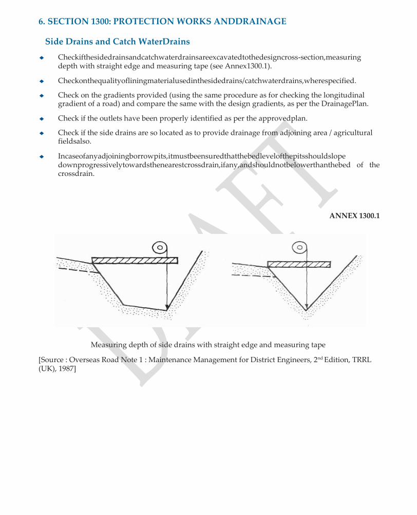
6. SECTION 1300: PROTECTION WORKS ANDDRAINAGE
Side Drains and Catch WaterDrains
◆ Checkifthesidedrainsandcatchwaterdrainsareexcavatedtothedesigncross-section,measuring depth with straight edge and measuring tape (see Annex1300.1).
◆ Checkonthequalityofliningmaterialusedinthesidedrains/catchwaterdrains,wherespecified.
◆ Check on the gradients provided (using the same procedure as for checking the longitudinal gradient of a road) and compare the same with the design gradients, as per the DrainagePlan.
◆ Check if the outlets have been properly identified as per the approvedplan.
◆ Check if the side drains are so located as to provide drainage from adjoining area / agricultural fieldsalso.
◆ Incaseofanyadjoiningborrowpits,itmustbeensuredthatthebedlevelofthepitsshouldslope downprogressivelytowardsthenearestcrossdrain,ifany,andshouldnotbelowerthanthebed of the crossdrain.
ANNEX 1300.1
Measuring depth of side drains with straight edge and measuring tape
[Source : Overseas Road Note 1 : Maintenance Management for District Engineers, 2nd Edition, TRRL (UK), 1987]
7. SECTION 1500: CEMENT CONCRETEPAVEMENT
Cement Concrete/ Semi-RigidPavements
1. Quality ofMaterials
(i) Check on the Manufacturer’s Certificate on the type / grade of cement in use and results of any tests carried out at site like the setting time.
(ii) Check on the cement storage features and the length ofstorage.
(iii) Check from the Quality Control Registers, the test results obtained on coarse aggregates, fine aggregates and water used in cement concrete and on concrete blocks where block pavement is to beconstructed.
(iv) ChecktheManufacturers’Certificateontheadmixturewhereused,pre-mouldedjointfiller etc.
(v) Checkthecementcontent,water/cementratioanddosageofplasticizer,whereused,inthe mixdesign.
(vi) Check the results on 7 day and 28 day strength ofconcrete.
(vii) Conduct independent cube compressive strength test by independently collecting samples
during concrete work.
(viii) Checktheresultsonconcreteworkability(Slumpconetests),onetestper4cumofconcrete at paving site or one test for each dumper laid at plantsite.
(ix) Check on the results of aggregate gradation and moisturecontent.
(x) Checktheadequacyofplant/equipmentusedforthemanufactureandplacementofconcrete.
(xi) Check whether a Trial Length was constructed andapproved.
2. Quality ofWorkmanship
◆ Check on thefollowing
• Widthofpavement;permissibletolerancesonedgesofcarriageway±20mminplain/rolling terrains, ±30 mm inhills.
• Surface Levels : Check whether surface levels have been checked ornot.
• Surface Regularity : the max permissible undulations measured with 3 m Straight Edge = 6 mm.
• Surface texture to be evaluatedvisually.
• Adequacy of setting of concrete, quality of joints, the joint sealing compound used, joint alignment and dimensions.
• Straightness of side forms(steel)
• Size, spacing, paralleling of dowelbars.

◆ In case of cracked concrete slabs (one panel), the acceptance criteria would be asunder:
• Slabs with cracks penetrating to more than half the depth of slab should not beaccepted.
• Forcrackswithdepthlessthanhalfthedepthofslab,nosinglecrackshouldexceed750mm length, cumulative length of such cracks in each slab should not exceed 1250mm.
◆ Checkonthethicknessofthepavementbyactualmeasurementsevery100mlengthofpavement.
8. SECTION 1700: TRAFFIC SIGNS, MARKINGS AND OTHER ROAD APPURTENANCES
Road Furniture andMarkings
1. TrafficSigns
General
Check, if the colour, shape, size and location of all traffic signs is as per the specified requirements.
EnsurethatthecitizenInformationBoardisinstalledandlocatedattherightplacewithrespectto thecarriageway.
Check, if all sign boards are clearly visible and not hidden by plantation.
Logo and Informatory Sign Boards
(a) Material
Check on the following from Supplier’s Certificate / Warranty Card.
• Concrete for footing should be of minimum M 15Grade.
• Reinforcing steel should meet the requirement ofIS:1786.
• Bolts, nuts, washers: High strength bolts should conform toIS:1367
• MS Sheets, Plates and Supports for the sign posts should conform toIS:2062
• Reflectorised Paint should conform to IS:5 or the Manufacturer’s specification in case of proprietaryproduct.
• Non-Reflectorised Paint should conform toIS:1614.
• Engineering grade sheeting should be enclosed lens type. When totally wet, the sheetingshouldnotshowlesthan90%ofthevaluesofraetro-reflectiongiveninTable 1700.1 of MORDSpecifications.
• Signswithamaximumsidedimensionnotexceeding600mmshouldnotbelessthan 1.5 mm thick. All others should be atleast 2 mm thick.
(b) Installation
• Sign posts, their foundations and sign mounting should be so constructed as to hold these in a proper and permanent position against normal storm wind loads or displacement by vandalisin.
• All components of signs and supports, other than the reflective portion and GI posts shouldbethoroughlydescaled,cleaned,primedandpaintedwithtwocoatsofepoxy paint.
• Thesignsshouldbefixedtothepostsbyweldinginthecaseofsteelpostsandbybolts and washers of suitable size in the case of reinforced concrete of GIposts.

2. RoadMarkings
• Check that there are no centre-line markings on single-laneroads.
• Check if the colour, width and layout of road markings is in accordance with the specified requirements.
• Check if only standard yellow colour (conforming to IS Colour No. 356), white and black colours are used formarkings.
• Check,ifthefinishedlinesarefreefromruggednessonsidesandendsandareintrueplane with the general alignment of thecarriageway.
• Check, if the Contractor maintains traffic control while painting operations are inprogress.
3. 200 m/ KilometreStones
• These may be made of local stones, concrete or any other locally available material. The stonesshouldbebeddedintothegroundtoaminimumgripof600mmwithadequateplain cement concrete M 10 gradefoundations.
• The dimensions of the stones, size, arrangement of letters and script should be as per IRC:8 andIRC:26.
• Kilometre stones should be located on left side of the direction of travel on the road, and fixed at right angles to the centre-line ofcarriageway.

Appendix-1/1
SIMPLE/HAND-FEELTESTS
APPENDIX - 1
HAND-FEEL TESTS FOR MATERIALS
1. SOILS
DilatancyTest
Remove all particles larger than IS 425 micron sieve size and prepare a pat of moist soil with a volumeofabout8000mm3.Makethesoilsoftbyaddingwaterifnecessary.Placethepatofsoilon theopenpalmofonehandandshakehorizontallybystrikingagainsttheotherhand,anumberof times. A positive reaction consists of the appearance of water on the surface of the pat rendering the surface glossy, which disappears when the sample is squeezed between the fingers, the pat stiffens and begins to crumble. The rapidity of appearance of water during shaking and its disappearance during squeezing signify the nature of fines in the soil pat. While clean fine sands give the quickest reaction, a plastic clay shows no reaction at all and silts will show a fairly quick reaction by way of a shinysurface.
Dry StrengthTest
RemoveallparticleslargerthanIS425micronsievesizeandmouldapatofsoiltotheconsistency of putty by adding water, if necessary. Dry the pat by air drying or under the sun or in an oven and test its strength by breaking and crumbling between fingers. The strength of dried pat of soil isindicativeofitsplasticityandthenature,aswellasquantityofthecolloidalfraction.Drystrength increaseswithincreasingplasticityandisofaveryhighorderinhighlyswellingtypeBlackCotton soils. While the CH soils exhibit high dry strength, the silts and silty fine sands have only slight dry strength but can be distinguished by the feel when powdering the dried sample: fine sands feel gritty while silts give a smoothfeel.
ToughnessTest
Remove all particles larger than the IS 425 micron sieve size and mould a soil specimen of about 12 mm cube in size, at the consistency of putty. If the soil sample is too dry, adequate amount of water should be added to bring it to the consistency of putty; if too sticky, allow it to lose some moisture by evaporation. Roll out the specimen by hand on a smooth surface or between palms into a thread about 3 mm diameter. The thread should then be folded and re-rolled separately. During such a manipulation, the thread stiffens, loses its plasticity and crumbles at a moisture content corresponding to the Plastic Limit. Lump together the pieces of crumbled thread, apply kneadingactionuntilthelumpcrumbles.TougherthethreadnearthePlasticLimitandstifferthe lump when it finally crumbles, higher the plasticity and more potent is the colloidal clay fraction in the soil. Weakness of the thread at Plastic Limit and quick loss of cohesion of the lump below thePlasticLimitsignifyclayoflowplasticityorsuchmaterialswhichoccurbelowthe“A”-linein the PlasticityChart.
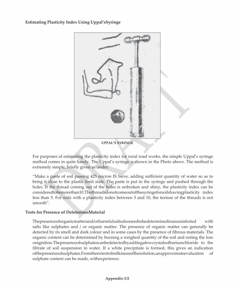
Appendix-1/2
Estimating Plasticity Index Using Uppal’sSyringe
UPPAL’S SYRINGE
For purposes of estimating the plasticity index for rural road works, the simple Uppal’s syringe method comes in quite handy. The Uppal’s syringe is shown in the Photo above. The method is extremely simple, briefly given as under:
“Make a paste of soil passing 425 micron IS Sieve, adding sufficient quantity of water so as to bring it close to the plastic limit state. The paste is put in the syringe and pushed through the holes. If the thread coming out of the holes is unbroken and shiny, the plasticity index can be consideredtobemorethan10.Thethreadsdonotcomeoutofthesyringeforsoilshavingplasticity index less than 5. For soils with a plasticity index between 5 and 10, the texture of the threads is not smooth”.
Tests for Presence of DeleteriousMaterial
Thepresenceoforganicmatterand/orharmfulsaltsalsoneedtobedeterminedinareasinfested with salts like sulphates and / or organic matter. The presence of organic matter can generally be detected by its smell and dark colour and in some cases by the presence of fibrous materials. The organic content can be determined by burning a weighed quantity of the soil and noting the loss onignition.Thepresenceofsulphatescanbedetectedbyaddingafewcrystalsofbariumchloride to the filtrate of soil suspension in water. If a white precipitate is formed, this gives an indication ofthepresenceofsulphates.Fromtheextentofmilkinessofthesolution,anapproximateevaluation of sulphate content can be made, withexperience.
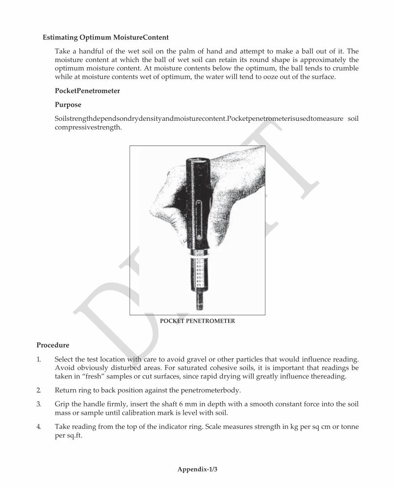
Appendix-1/3
Estimating Optimum MoistureContent
Take a handful of the wet soil on the palm of hand and attempt to make a ball out of it. The moisture content at which the ball of wet soil can retain its round shape is approximately the optimum moisture content. At moisture contents below the optimum, the ball tends to crumble while at moisture contents wet of optimum, the water will tend to ooze out of the surface.
PocketPenetrometer
Purpose
Soilstrengthdependsondrydensityandmoisturecontent.Pocketpenetrometerisusedtomeasure soil compressivestrength.
POCKET PENETROMETER
Procedure
1. Select the test location with care to avoid gravel or other particles that would influence reading. Avoid obviously disturbed areas. For saturated cohesive soils, it is important that readings be taken in “fresh” samples or cut surfaces, since rapid drying will greatly influence thereading.
2. Return ring to back position against the penetrometerbody.
3. Grip the handle firmly, insert the shaft 6 mm in depth with a smooth constant force into the soil mass or sample until calibration mark is level with soil.
4. Take reading from the top of the indicator ring. Scale measures strength in kg per sq cm or tonne per sq.ft.
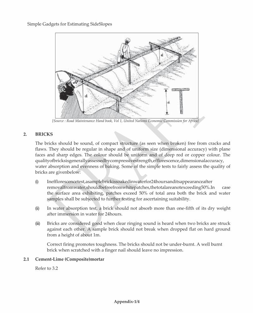
Appendix-1/4
Simple Gadgets for Estimating SideSlopes
[Source : Road Maintenance Hand book, Vol 1, United Nations Economic Commission for Africa]
2. BRICKS
The bricks should be sound, of compact structure (as seen when broken) free from cracks and flaws. They should be regular in shape and of uniform size (dimensional accuracy) with plane faces and sharp edges. The colour should be uniform and of deep red or copper colour. The qualityofbricksisgenerallyassessedbycompressivestrength,efflorescence,dimensionalaccuracy, water absorption and evenness of baking. Some of the simple tests to fairly assess the quality of bricks are givenbelow:
(i) Inefflorescencetest,asamplebrickissoakedinwaterfor24hoursanditsappearanceafter removalfromwater,shouldbefreefromwhitepatches,thetotalareanotexceeding50%.In case the surface area exhibiting, patches exceed 50% of total area both the brick and water samples shall be subjected to further testing for ascertaining suitability.
(ii) In water absorption test, a brick should not absorb more than one-fifth of its dry weight after immersion in water for 24hours.
(iii) Bricks are considered good when clear ringing sound is heard when two bricks are struck against each other. A sample brick should not break when dropped flat on hard ground from a height of about 1m.
Correct firing promotes toughness. The bricks should not be under-burnt. A well burnt brick when scratched with a finger nail should leave no impression.
2.1 Cement-Lime (Composite)mortar
Refer to 3.2

Appendix-1/5
3. STONEMASONRY
Stones
The principle requirements of a building stone are strength, density and durability. All stones other than those of sedimentary origin are suitable for stone masonry work. Some of the requirements and simple tests are indicated below:
(i) The stones should be hard, tough, compact grained and of uniform texture andcolour.
(ii) They should be free from cracks, decay, weathering defects like cavities, flaws, veins, sand holes and patches of loose /soft material.
(iii) Break a stone with a hammer. The surface of a freshly broken stone should be bright, clean andsharpandshouldshowuniformityoftexturewithoutloosegrainsandbefreefromany dull chalky or earthyappearance.
(iv) Ifadropofdilutehydrochloricacidorsulphuricacidonapieceofstonecauseseffervescence, the stone contains weathering materials.
(v) Asampleofstonewhenstruckwitha1kghammershouldemitaringingsoundandshould not break with one blow. A pen-knife when scratched on surface should not make an impressions on hardstone.
Cement-Lime (Composite)Mortar
Lime is classified as quick and hydraulic lime. The quick lime is obtained by calcination of pure lime stone, chalk or sea shells. It is nearly white and increases in bulk two or three times its originalvolumewhenslaked.Itdoesnotsetbutdissolvesinwaterandhasnocementingproperty.
Hydrauliclimeisobtainedbyburningclayeylimestonesorkankaranditsetsandhardensunder water.InRuralRoadworksonlyclassAandB(hydraulicandsemi-hydraulictype)limemortars conforming to IS:712 are permitted in composite mortar. Use of quick lime is notpermitted.
Strictcontrolovermixproportion(Cement:Lime:Sand)shallbeexercisedtoensurethatthemortar mix conforming to the mix proportion specified in the contract. Normally, a proportion of 1:3:9 (Cement:Lime:Sand) is used in masonryworks.
Purity of lime shall be determined in accordance with IS:1514.
CementMortar
Refer to 4.4
4. CONCRETE FORSTRUCTURES
Water
Water should be clean and free from oils, acids, alkalies, vegetable and other organic impurities. Water shall be got tested before the start of works, thereafter each monsoon till completion of works. Some of the simple tests to fairly judge the suitability of water in cement-concrete works are given below:
(i) Presence of acids or alkalies in water can be tested by litmus paper. If blue litmus paper turns red, it indicates acidity; while the red litmus paper turning blue indicates alkalinity. Rapid change in colour of litmus paper indicates significant amounts of acids oralkalies.
Appendix-1/6
(ii) Maketwoidenticalpatsof75mmdiaand12mmthickofneatcementpaste,onewithwater under test and the other with water of known suitability. Place the pats on a clean non- absorbentsurfaceandleavefor48hours,andsettingandhardeningtimeobservedforboth thepats.Ifthequalityofwaterundertestisnotuptomark,bothsettingandhardeningtime of the pat would be different from the one of knownquality.
Cement
Cement more than three (3) months old shall be got tested to ascertain its quality and satisfy the acceptability requirements as per Table 800.11. The quality of cement can be roughly judged by the following:
(i) Thrustahandintoacementbag.Itmustgivecoolfeeling.Thereshouldbenolumpinside.
(ii) Take a pinch of cement and feel between the fingers. It should give a smooth and not a grittyfeeling.
(iii) Take a handful of cement and throw it in a bucket full of water. The particles should float for sometime before theysink.
(iv) Take about 100 gm of cement and mix it with water to make a stiff paste. Make a cake with sharp edges. Put it on a glass plate and slowly take it under water in a bucket, without disturbing the shape of cake. After 24 hours, the cake should retain its original shape and gain somestrength.
(v) Settingtime:Makeastiffpasteofneatcementandwater,andformitintoapatofabout75 mm dia and 12 to 25 mm thick. The pat should commence to set in 30 to 60 minutes. The commencement of setting can be roughly estimated by pressing the uncut end of a lead pencil into mass. The resistance to piercing increases suddenly when setting commences. In 18 to 24 hours, the pat should have hardened sufficiently so that a scratch can be made with a thumb nail.
(vi) Soundness: Boil the set pat (as above) in water for about 5 hours. The pat should remain soundandhardandshouldnotswell,crackordisintegrate,butmayshowonlyhaircracks. Reject cement if pat shows radial cracks or curl orcrumble.
(vii) Fineness: In the sieve test, 100 gm cement is correctly weighed and placed on 90 micron sieve. Air set lumps, if any, are broken down with fingers. The sample is sieved for 15 minutes and the residue left on the sieve is weighed. The amount of residue should not exceed 10% forOPC.
Sand or FineAggregate
The sand should be sharp, clean, chemically inert, coarse and gritty to the touch and free from silt / clay and organic impurities. The general quality of sand can be assessed as below:
(i) Presence of Silt or Clay: Rub a sample of sand between damp hands and note the discolouration caused on the palm. If the sand is clear, the palm would be stained slightly. Ifthehandsstaydirtyaftersandhasbeenthrownaway,itindicatestoomuchofsiltorclay.
(ii) Sedimentation: Place, without drying, a sample of sand in a 200 ml measuring cylinder upto 100 ml mark. Add clean water upto 150 ml mark. Shake the contents vigorously and allowittosettlefor3hours.Theheightofthesiltvisibleasalayerabovethesandisexpressed as a percentage of the sandbelow.

Appendix-1/7
(iii) Organicimpurities:Shakethesamplewithanequalvolumeof3%solutionofNaOH(Caustic
soda) and allow it to settle for 24 hours. Examine the colour of the liquid above the sand. Clearorpaleyellowcolourshowsthatthesampleistolerablyfreefromorganicimpurities. Dark yellow or brown tinge shows that the sand should be washed and tested again. If on retesting, dark yellow colour persists, the sand should berejected.
Cement-Mortar
(i) The cement mortar if unused for more than 30 minutes after addition of water shall be rejected and removed fromsite.
(ii) The mix proportion of cement: sand can be checked asfollows:
Take about 200 gm of green cement mortar and add 100 ml of water in a measuring jar and shakethecontentswellandallowthecontentstosettle.Whilethesandgetsdepositedatthe bottom,cementshallsettleabove.Fromthevolumesofeach,theapproximateproportionof cement and sand can bedetermined.
(iii) Consistency: Mortar consistency can be checked by thefollowing:
(a) If a small quantity of mortar is dropped from a trowel, the trowel ought to be left perfectlyclean.
(b) Alittlemortarworkedgentlyinthehandsshouldbeeasilymouldedintoaball;onthe surface of which water wouldappear.
(c) When the ball is dropped from a height of half a meter (500 mm) on a hard surface, it must retain its roundedshape.
CoarseAggregate
Coarse aggregates shall be hard, strong, non-porous, free from friable, elongated and laminated particles. They shall be clean and free from clay, coal, vegetable and other organic material.
Two simple tests to check the suitability of stone aggregates are given below:
(i) If the aggregates of a known quantity absorb more than 10 percent of their weight after 24 hours immersion in water, they are considered porous and areavoidable.
(ii) IfMicainclusionspersistonthesurface,thestoneaggregatesshallberejectedaspresenceof Mica affects durability ofconcrete.
However, the detailed tests indicated in Table 800.13 are to be conducted before the use of coarse aggregates in concrete bridge works.
CementConcrete
The principal requirements of concrete include workability, strength, durability, impermeability, and volume changes. Some of the simple tests to determine quality of concrete are described below:
(i) Consistency:Theconcretecanbeconsideredtosatisfyconsistencyrequirementifanordinary iron rammer sinks into concrete mixture by its own weight. It shall run-off a showel unless showelled very quickly; and shall spread out and settle to a level surface after wheeling for about 8 m distance in a wheelbarrow.

Appendix-1/8
(ii) Workability:Takeahandfulofconcreteinlefthandandmakearoundballwithbothhands. If a ball can be maintained for a while, it is indicative of a ‘workable mix’. Any low or high content of water cannot make a good ball ofconcrete.
(iii) Alkali Silica Reaction(ASR):
Alkali Silica reactivity is noticed in aggregates crushed with siliceous rock. When aggregates are immersed in water, a slight increase in volume occurs. If alkali content in Portland cement is less than 0.6 percent by weight, no harmful reaction occurs.
The Basalt rocks found in parts of Deccan plateau, Madhya Pradesh, Kathiawar peninsula of Gujarat,Jammu&Kashmir,JharkhandandWestBengalshouldbeviewedwithcaution.Similarly, somelime-stonescontainingchertmodulesoccurringinMadhyaPradesh,Rajasthan,Punjaband Assam arereactive.
DuetoASR,normallydamppatchesarevisibleatthejunctionofcracks,theedgesofcracksoften appearlightincolour,theconcreteoftenhasanuncharacteristicpinkishappearanceintheaffected areas. There will be negligible spalling of concrete but exudation may occur from some of the cracks.
If aggregates are suspect of likely positive ASR on the basis of past performance or any evidence, it is always recommended that the aggregates are tested as per IS:2386 part 7 before they are approved for use in making concrete.

Appendix-2/1
APPENDIX -2
(Refer Section105)
GUIDELINES FOR APPROPRIATE TECHNOLOGY FOR RURAL ROAD CONSTRUCTION
Inviewoftheruralroadprojectsbeingrelativelysmallinsize,thesitesofworkgenerallyscatteredand level of accessibility of project site often being poor, there is need for adopting appropriate technology. An appropriate technology is a blend of manual methods and small capacity mechanical equipment generally using agricultural implements towed by tractor, which would attain the desired quality standards at minimumcost.
The Construction Equipment which best meets the quality requirements at minimum cost for various construction operations are mostly tractor-towed, since agricultural tractors are increasingly becoming available in rural areas. Moreover, agricultural tractors are not used for agricultural purposes all the yearroundandcanbeutilizedforroadconstructionandmaintenanceworksforsufficientlylongperiods of time during the year. The appropriate technologies which can be adopted for the more common construction operations are asunder:
1. Earthwork and SubgradeConstruction
• For clearing, grubbingandexcavation : Rippers towed by agriculturaltractor
• For haulingofearth : Agriculturaltractor-trailer
• For spreading of soilinlayers : Spreading blades attachedto agricultural tractor
• Foraddingwater : Water Bowser towed by agriculturaltractor
• For mixing of soilwithwater : Agricultural tractor-towed discharrows
• For compaction inearthworkand : 80-100 kN staticsmooth- subgradeconstruction wheeled road roller for compacted
hickness of 100mm.
2. MechanicalStabilization
Besides the appropriate equipment list under 1 above, for the mixing of different locally available materials for mechanical stabilization, an agricultural tractor-towed Rotavator can be used.
3. Lime/Cement Stabilized SoilConstruction
• Pulverization ofsoilclods : Agricultural tractor-towed discharrows
• Addingwater : Agricultural tractor-towed water browser
• Spreading of Lime /Cementstablizer : Placing bags of lime/cement overpulverizedsoil at predetermined distances for spreading
the required quantities
• Mixing of soil with stabilizer : Agricultural tractor-towed Rotavator
• Compaction : 80-100 kN smooth-wheeledRoller

Appendix-2/2
• Curing : Covering the compacted stabilized soil surface with wet gunny bags and sprinkling water.
4. SurfaceDressing
• ApplyingPrimeCoat : Hand-held lance with sprayer operated byCompressor
• HeatingBitumen : Bitumen Boiler of smallcapacity
• ApplyingBinder : Hand-held lance with sprayer, operated byCompressor
• Spreadingstonechips : Agricultural tractor-towed SpreaderBox
• Rolling : 80-100 kN smooth -wheeledroller
5. PremixCarpet
• ApplyingPrimeCoat : Hand-held lance provided with sprayer, operated bycompressor
• ApplyingTackCoat : Hand-held lance provided with sprayer, operated bycompressor
• Mixing of aggregates andbitumenin : Mini Hot Mix Plant, capacity of with specified quantities around 6 tonnes /hour
• Transporting from the mixer to site : Tarpaulin- coveredtractor- trailer or hand barrows

Appendix-3/1
LIST OF IRC PUBLICATIONS
APPENDIX-3
Sr.
No. Code/
Document No. Title of the Publication
1. ROADS
1.(A). Transport Planning, Traffic Assessment & Policies
1. IRC:3-1983 Dimensions & Weights of Road Design Vehicles (First Revision)
2. IRC:9-1972 Traffic Census on Non-Urban Roads(First Revision)
3. IRC:71-1977 Recommended Practice for Preparation of Notations
4. IRC:SP:24-1984 Guidelines on the Choice and Planning of Appropriate Technology in Road Construction
1. (B). Road Geometric & Design Features
1. IRC:12-1983 Recommended Practice for Location and Layout of Roadside Motor-Fuel Filling and Motor-Fuel Filling-cum-Service Stations (Second Revision)
2. IRC:32-1969 Standard for Vertical and Horizontal Clearances of Overhead Electric Power and Telecommunication Lines as Related to Roads
3. IRC:38-1988 Guidelines for Design of Horizontal Curves for Highways and Design Tables (First Revision)
4. IRC:39-1986 Standards for Road-Rail Level Crossings (First Revision)
5. IRC:54-1974 Lateral and Vertical Clearances at Underpasses for Vehicular Traffic
6. IRC:64-1990 Guidelines for Capacity of Roads in Rural Areas (First Revision)
7. IRC:66-1976 Recommended Practice for Sight Distance on Rural Highways
8. IRC:70-1977 Guidelines on Regulation and Control of Mixed Traffic in Urban Areas
9. IRC:73-1980 Geometric Design Standards for Rural (Non-Urban Highways)
10. IRC:80-1981 Type Designs for Pick-up Bus Stops on Rural (i.e. Non-Urban) Highways
11. IRC:86-1983 Geometric Design Standards for Urban Roads in Plains
12. IRC:98-1997 Guidelines on Accommodation of Underground Utility Services Along and Across Roads in Urban Areas (First Revision)
13. IRC:99-1988 Tentative Guidelines on the Provision of Speed Breakers for Control of Vehicular Speeds on Minor Roads

Appendix-3/2
Sr. No.
Code/ Document No.
Title of the Publication
14. IRC:103-1988 Guidelines for Pedestrian Facilities
15. IRC:106-1990 Guidelines for Capacity of Urban Roads in Plain Areas
16. IRC:SP:23-1983 Vertical Curves for Highways
17. IRC:SP:41-1994 Guidelines on Design of At-Grade Intersections in Rural & Urban Areas
1.(C). Road Markings
1. IRC:30-1968 Standard Letters and Numerals of Different Heights for Use on Highway Signs
2. IRC:35-1997 Code of Practice for Road Markings(with Paints) (First Revision)
1.(D). Road Furniture &Signage
1. IRC:8-1980 Type Designs for Highway Kilometre Stones (Second Revision)
2. IRC:25-1967 Type Designs for Boundary Stones
3. IRC:26-1967 Type Design for 200-Metre Stones
4. IRC:31-1969 Route Marker Signs for State Routes
5. IRC:67-2001 Code of Practice for Road Signs (First Revision)
6. IRC:79-1981 Recommended Practice for Road Delineators
7. IRC:SP:31-1992 New Traffic Signs
1.(E). Road Safety & Traffic Management
1. IRC:53-1982 Road Accident Forms A-1 and 4 (First Revision)
2. IRC:SP:27-1984 Report Containing Recommendations of IRC Regional Workshops on Highway Safety
3. IRC:SP:32-1988 Road Safety for Children (5-12 Years old)
4. IRC:SP:44-1994 Highway Safety Code
5. IRC:SP:55-2001 Guidelines for Safety in Construction Zones
1.(F). Embankment Construction & Erosion Control
1. IRC:10-1961 Recommended Practice for Borrow pits for Road Embankments Constructed by Manual Operation
2. IRC:28-1967 Tentative Specifications for the Construction of Stabilised Soil Roads with Soft Aggregate in Areas of Moderate and High Rainfall
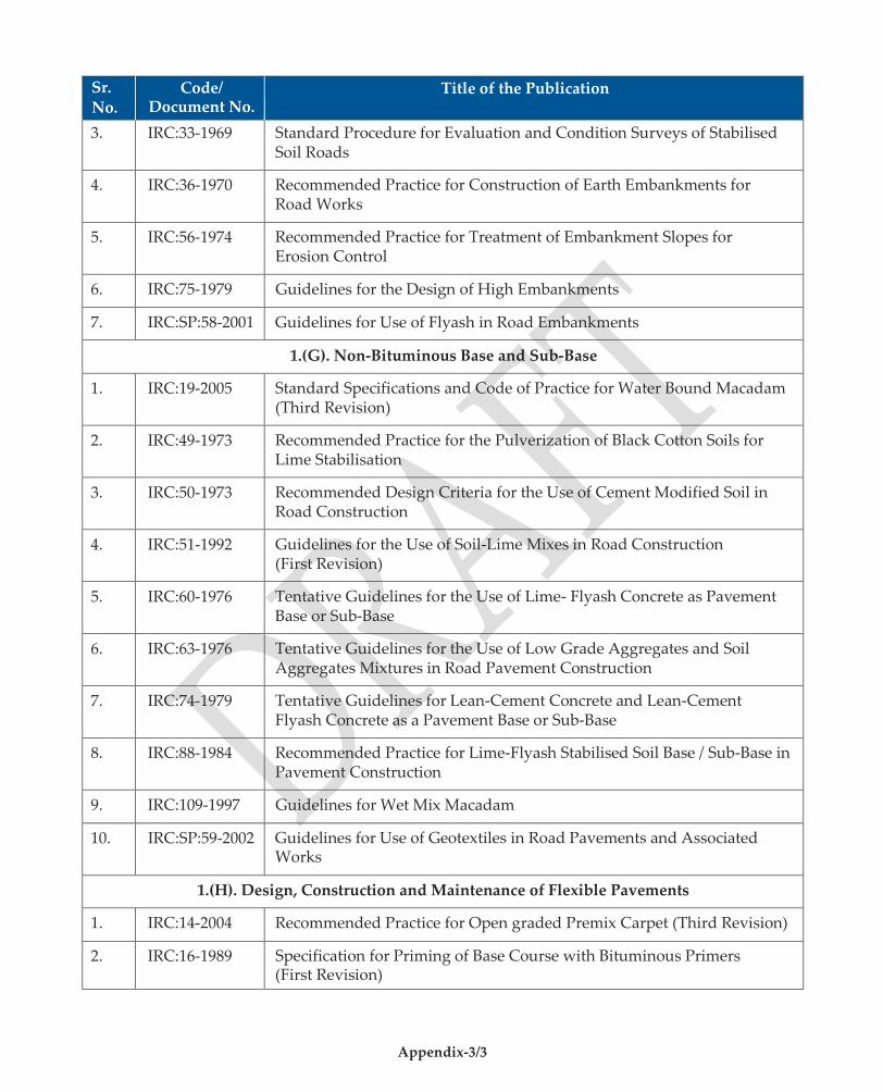
Appendix-3/3
Sr. No.
Code/ Document No.
Title of the Publication
3. IRC:33-1969 Standard Procedure for Evaluation and Condition Surveys of Stabilised Soil Roads
4. IRC:36-1970 Recommended Practice for Construction of Earth Embankments for Road Works
5. IRC:56-1974 Recommended Practice for Treatment of Embankment Slopes for Erosion Control
6. IRC:75-1979 Guidelines for the Design of High Embankments
7. IRC:SP:58-2001 Guidelines for Use of Flyash in Road Embankments
1.(G). Non-Bituminous Base and Sub-Base
1. IRC:19-2005 Standard Specifications and Code of Practice for Water Bound Macadam (Third Revision)
2. IRC:49-1973 Recommended Practice for the Pulverization of Black Cotton Soils for Lime Stabilisation
3. IRC:50-1973 Recommended Design Criteria for the Use of Cement Modified Soil in Road Construction
4. IRC:51-1992 Guidelines for the Use of Soil-Lime Mixes in Road Construction (First Revision)
5. IRC:60-1976 Tentative Guidelines for the Use of Lime- Flyash Concrete as Pavement Base or Sub-Base
6. IRC:63-1976 Tentative Guidelines for the Use of Low Grade Aggregates and Soil Aggregates Mixtures in Road Pavement Construction
7. IRC:74-1979 Tentative Guidelines for Lean-Cement Concrete and Lean-Cement Flyash Concrete as a Pavement Base or Sub-Base
8. IRC:88-1984 Recommended Practice for Lime-Flyash Stabilised Soil Base / Sub-Base in Pavement Construction
9. IRC:109-1997 Guidelines for Wet Mix Macadam
10. IRC:SP:59-2002 Guidelines for Use of Geotextiles in Road Pavements and Associated Works
1.(H). Design, Construction and Maintenance of Flexible Pavements
1. IRC:14-2004 Recommended Practice for Open graded Premix Carpet (Third Revision)
2. IRC:16-1989 Specification for Priming of Base Course with Bituminous Primers (First Revision)
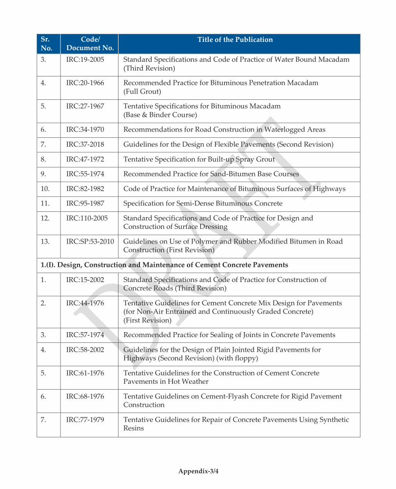
Appendix-3/4
Sr. No.
Code/ Document No.
Title of the Publication
3. IRC:19-2005 Standard Specifications and Code of Practice of Water Bound Macadam (Third Revision)
4. IRC:20-1966 Recommended Practice for Bituminous Penetration Macadam (Full Grout)
5. IRC:27-1967 Tentative Specifications for Bituminous Macadam (Base & Binder Course)
6. IRC:34-1970 Recommendations for Road Construction in Waterlogged Areas
7. IRC:37-2018 Guidelines for the Design of Flexible Pavements (Second Revision)
8. IRC:47-1972 Tentative Specification for Built-up Spray Grout
9. IRC:55-1974 Recommended Practice for Sand-Bitumen Base Courses
10. IRC:82-1982 Code of Practice for Maintenance of Bituminous Surfaces of Highways
11. IRC:95-1987 Specification for Semi-Dense Bituminous Concrete
12. IRC:110-2005 Standard Specifications and Code of Practice for Design and Construction of Surface Dressing
13. IRC:SP:53-2010 Guidelines on Use of Polymer and Rubber Modified Bitumen in Road Construction (First Revision)
1.(I). Design, Construction and Maintenance of Cement Concrete Pavements
1. IRC:15-2002 Standard Specifications and Code of Practice for Construction of Concrete Roads (Third Revision)
2. IRC:44-1976 Tentative Guidelines for Cement Concrete Mix Design for Pavements (for Non-Air Entrained and Continuously Graded Concrete) (First Revision)
3. IRC:57-1974 Recommended Practice for Sealing of Joints in Concrete Pavements
4. IRC:58-2002 Guidelines for the Design of Plain Jointed Rigid Pavements for Highways (Second Revision) (with floppy)
5. IRC:61-1976 Tentative Guidelines for the Construction of Cement Concrete Pavements in Hot Weather
6. IRC:68-1976 Tentative Guidelines on Cement-Flyash Concrete for Rigid Pavement Construction
7. IRC:77-1979 Tentative Guidelines for Repair of Concrete Pavements Using Synthetic Resins
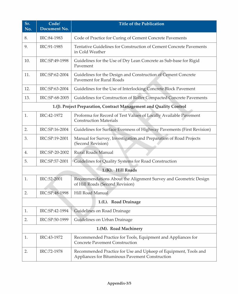
Appendix-3/5
Sr. No.
Code/ Document No.
Title of the Publication
8. IRC:84-1983 Code of Practice for Curing of Cement Concrete Pavements
9. IRC:91-1985 Tentative Guidelines for Construction of Cement Concrete Pavements in Cold Weather
10. IRC:SP:49-1998 Guidelines for the Use of Dry Lean Concrete as Sub-base for Rigid Pavement
11. IRC:SP:62-2004 Guidelines for the Design and Construction of Cement Concrete Pavement for Rural Roads
12. IRC:SP:63-2004 Guidelines for the Use of Interlocking Concrete Block Pavement
13. IRC:SP-68-2005 Guidelines for Construction of Roller Compacted Concrete Pavements
1.(J). Project Preparation, Contract Management and Quality Control
1. IRC:42-1972 Proforma for Record of Test Values of Locally Available Pavement Construction Materials
2. IRC:SP:16-2004 Guidelines for Surface Evenness of Highway Pavements (First Revision)
3. IRC:SP:19-2001 Manual for Survey, Investigation and Preparation of Road Projects (Second Revision)
4. IRC:SP-20-2002 Rural Roads Manual
5. IRC:SP:57-2001 Guidelines for Quality Systems for Road Construction
1.(K). Hill Roads
1. IRC:52-2001 Recommendations About the Alignment Survey and Geometric Design of Hill Roads (Second Revision)
2. IRC:SP:48-1998 Hill Road Manual
1.(L). Road Drainage
1. IRC:SP:42-1994 Guidelines on Road Drainage
2. IRC:SP:50-1999 Guidelines on Urban Drainage
1.(M). Road Machinery
1. IRC:43-1972 Recommended Practice for Tools, Equipment and Appliances for Concrete Pavement Construction
2. IRC:72-1978 Recommended Practice for Use and Upkeep of Equipment, Tools and Appliances for Bituminous Pavement Construction
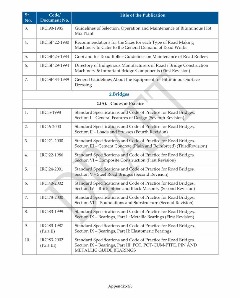
Appendix-3/6
Sr. No.
Code/ Document No.
Title of the Publication
3. IRC:90-1985 Guidelines of Selection, Operation and Maintenance of Bituminous Hot Mix Plant
4. IRC:SP:22-1980 Recommendations for the Sizes for each Type of Road Making Machinery to Cater to the General Demand of Road Works
5. IRC:SP:25-1984 Gopi and his Road Roller-Guidelines on Maintenance of Road Rollers
6. IRC:SP:29-1994 Directory of Indigenous Manufacturers of Road / Bridge Construction Machinery & Important Bridge Components (First Revision)
7. IRC:SP:34-1989 General Guidelines About the Equipment for Bituminous Surface Dressing
2.Bridges
2.(A). Codes of Practice
1. IRC:5-1998 Standard Specifications and Code of Practice for Road Bridges, Section I – General Features of Design (Seventh Revision)
2. IRC:6-2000 Standard Specifications and Code of Practice for Road Bridges, Section II – Loads and Stresses (Fourth Revision)
3. IRC:21-2000 Standard Specifications and Code of Practice for Road Bridges, Section III – Cement Concrete (Plain and Reinforced) (ThirdRevision)
4. IRC:22-1986 Standard Specifications and Code of Practice for Road Bridges, Section VI – Composite Construction (First Revision)
5. IRC:24-2001 Standard Specifications and Code of Practice for Road Bridges, Section V – Steel Road Bridges (Second Revision)
6. IRC:40-2002 Standard Specifications and Code of Practice for Road Bridges, Section IV – Brick, Stone and Block Masonry (Second Revision)
7. IRC:78-2000 Standard Specifications and Code of Practice for Road Bridges, Section VII – Foundations and Substructure (Second Revision)
8. IRC:83-1999 Standard Specifications and Code of Practice for Road Bridges, Section IX – Bearings, Part I : Metallic Bearings (First Revision)
9. IRC:83-1987
(Part II) Standard Specifications and Code of Practice for Road Bridges, Section IX – Bearings, Part II: Elastomeric Bearings
10. IRC:83-2002
(Part III) Standard Specifications and Code of Practice for Road Bridges, Section IX – Bearings, Part III: POT, POT-CUM-PTFE, PIN AND METALLIC GUIDE BEARINGS

Appendix-3/7
Sr. No.
Code/ Document No.
Title of the Publication
11. IRC:87-1984 Guidelines for the Design and Erection of Falsework for Road Bridges
12. IRC:89-1997 Guidelines for Design and Construction of River Training & Control Works for Road Bridges (First Revision)
2.(B). Inspection, Maintenance & Rehabilitation
1. IRC:SP:35-1990 Guidelines for Inspection and Maintenance of Bridges
2. IRC:SP:40-1993 Guidelines on Techniques for Strengthening and Rehabilitation of Bridges
3. IRC:SP:52-1999 Bridge Inspector’s Reference Manual
2.(C). Project Preparation, Contract Management & Quality Control
1. IRC:SP:47-1998 Guidelines on Quality Systems for Road Bridges (Plain, Reinforced, Prestressed and Composite Concrete)
2. IRC:SP:54-1999 Project Preparation Manual for Bridges
2.(D). Other Important Publications
1. IRC:7-1971 Recommended Practice for Numbering Bridges and Culverts (First Revision)
2. IRC:SP:13-2004 Guidelines for the Design of Small Bridges and Culverts (First Revision)
3. IRC:SP:51-1999 Guidelines for Load Testing of Bridges

Appendix-4/1
APPENDIX-4
LIST OF MINISTRY OF RURAL DEVELOPMENT AND MINISTRY OF SHIPPING, ROAD TRANSPORT & HIGHWAYS PUBLICATIONS
Sr.
No. Code/
Document No. Title of the Publication
I. Ministry of Rural Development(MoRD)
1. MoRD Specifications for Rural Roads, 2004
2. MoRD Standard Data Book for Analysis of Rates, 2004
3. NRRDA PMGSY Handbook on Quality Control: Road Works, 2002
4. NRRDA PMGSY Operations Manual, 2005
5. NRRDA PMGSY Draft Guidelines for Quality Monitoring by National Quality Monitors.
II. Ministry of Shipping, Road Transport and Highways(MoSRTH)
6. MoRT&H Pocketbook for Bridge Engineers, 2000 (First Revision)
7. MoRT&H Pocketbook for Highway Engineers, 2002 (Second Revision)
8. MoRT&H Manual for Maintenance of Roads, 1983
9. MoRT&H Report of the Committee on Norms for Maintenance of Roads in India, 2001
10. MoRT&H Guidelines for Maintenance Management of Primary, Secondary and Urban Roads, 2004
11. MoRT&H Standard Plans for 3.0 m to 10.0 m Span Reinforced Cement Concrete Solid Slab Structure with and without Footpaths for Highways, 1991
12. MoRT&H Standard Plans for Highway Bridges R.C.C. T-Beam & Slab Superstructure – Span from 10 m to 24 m with 12 m width, 1991
13. MoRT&H Standard Plans for Highway Bridges PSC Girder and RC Slab Composite Superstructure for 30 m Span with and without Footpaths, 35 m Span with Footpaths and 40 m Span without Footpaths, 1991
14. MoRT&H Standard Drawings for Road Bridges – R.C.C. Solid Slab Superstructure (15° & 30° SKEW) Span 4.0 m to 10.0 m (with and without Footpaths), 1992
15. MoRT&H Standard Drawings for Road Bridges R.C.C. Solid Slab Superstructure (22.5º Skew) R.E. Span 4 m to 10 m (with and without Footpath), 1996
16. MoRT&H Standard Plan for Highway Bridges – Prestressed Concrete Beam & RCC Slab Type Superstructure Volume-II

Appendix-4/2
Sr. No.
Code/ Document No.
Title of the Publication
17. MoRT&H Standard Plans for Single, Double and Triple Cell Box Culverts with and without Earth Cushion
18. MoRT&H Type Designs for Intersections on National Highways, 1992
19. MoRT&H Manual for Safety in Road Design
Related Documents