1 For Gold & PlATINUM SErIES SErVICE MANUAl Table of Contents 1. Precaution 2. Part Names And Functions 3. Dimension 4. Refrigerant Cycle Diagram 5. Printed Circuit Board Connector Wiring Diagram of Outdoor unit 6. Installation Details 7. Operation Characteristics 8. Electronic Function 9. Troubleshooting WARNING Installation MUST conform with local building codes or, in the absence of local codes, with the National Electrical Code NFPA70/ANSI C1-1993 or current edition and Canadian Electrical Code Part1 CSA C.22.1. The information contained in the manual is intended for use by a qualified service technician familiar with safety procedures and equipped with the proper tools and test instruments Installation or repairs made by unqualified persons can result in hazards to you and others. Failure to carefully read and follow all instructions in this manual can result in equipment malfunction, property damage, personal injury and/or death. This service is only for service engineer to use. Revision V2.1: 1812.

Welcome message from author
This document is posted to help you gain knowledge. Please leave a comment to let me know what you think about it! Share it to your friends and learn new things together.
Transcript
1
For Gold & PlATINUM SErIES
SErVICE MANUAl
Table of Contents1. Precaution2. Part Names And Functions3. Dimension4. Refrigerant Cycle Diagram5. Printed Circuit Board Connector Wiring Diagram of
Outdoor unit6. Installation Details7. Operation Characteristics8. Electronic Function9. Troubleshooting
WARNING Installation MUST conform with local building codes or, in the absence of local codes, with the
National Electrical Code NFPA70/ANSI C1-1993 or current edition and Canadian Electrical
Code Part1 CSA C.22.1.
The information contained in the manual is intended for use by a qualified service technicianfamiliar with safety procedures and equipped with the proper tools and test instruments
Installation or repairs made by unqualified persons can result in hazards to you and others.
Failure to carefully read and follow all instructions in this manual can result in equipmentmalfunction, property damage, personal injury and/or death.
This service is only for service engineer to use.
Revision V2.1: 1812.
2
CONTENTS1. Precaution.............................................................................................................................................................. 3
1.1 Safety Precaution........................................................................................................................... 31.2 Warning....................................................................................................................................................3
2. Part Names And Functions.............................................................................................................................62.1 Model Names of Indoor/Outdoor units................................................................................62.2 Part names of Indoor/Outdoor units..................................................................................7
3. Dimension.................................................................................................................................................................83.1 Indoor Unit..........................................................................................................................................83.2 Outdoor Unit.....................................................................................................................................13
4. Refrigerant Cycle Diagram........................................................................................................................145. Wiring Diagram.................................................................................................................................................. 176 Installation Details...................................................................................................................................... 23
6.1 Wrench torque sheet for installation...........................................................................236.2 Connecting the cables...............................................................................................................236.3 Pipe length and the elevation............................................................................................236.4 Installation for the first time.......................................................................................236.5 Adding the refrigerant after running the system for many years............256.6 Re-installation while the indoor unit need to be repaired........................256.7 Re-installation while the outdoor unit need to be repaired..................... 26
7. Operation Characteristics........................................................................................................................288. Electronic Function...................................................................................................................................... 29
8.1 Abbreviation.....................................................................................................................................298.2 Display function........................................................................................................................... 298.3 Main Protection..............................................................................................................................308.4 Operation Modes and Functions............................................................................................30
9. Troubleshooting................................................................................................................................................389.1 Indoor Unit Error Display..................................................................................................... 399.2 Outdoor unit error display(not available)...............................................................409.3 Diagnosis and Solution.............................................................................................................40
3
1. Precaution
1.1 Safety Precaution
To prevent injury to the user or other people and property damage, thefollowing instructions must be followed.
Incorrect operation due to ignoring instruction will cause harm or damage.
Before service the unit, be sure to read this service manual at first.
1.2 Warning
Installation Do not use a defective or underrated circuit breaker. Use this appliance
on a dedicated circuit.
There is risk of fire or electric shock.
For electrical work, contact the dealer, seller, a qualified electrician,or an authorized service center.
Do not disassemble or repair the product, there is risk of fire or electric
shock.
Always ground the product.There is risk of fire or electric shock.
Install the panel and the cover of control box securely.There is risk of fire of electric shock.
Always install a dedicated circuit and breaker.Improper wiring or installation may cause electric shock.
Use the correctly rated breaker of fuse.There is risk of fire or electric shock.
Do not modify or extend the power cable.There is risk of fire or electric shock.
Do not install, remove, or reinstall the unit by yourself (customer).There is risk of fire, electric shock, explosion, or injury.
Be caution when unpacking and installing the product.Sharp edges could cause injury, be especially careful of the case edges and
the fins on the condenser and evaporator.
For installation, always contact the dealer or an authorized servicecenter.
Do not install the product on a defective installation stand.
Be sure the installation area does not deteriorate with age.If the base collapses, the air conditioner could fall with it, causing property
damage, product failure, and personal injury.
Do not let the air conditioner run for a long time when the humidity isvery high and a door or a window is left open.
Take care to ensure that power cable could not be pulled out or damagedduring operation.
There is risk of fire or electric shock.
Do not place anything on the power cable.There is risk of fire or electric shock.
4
Do not plug or unplug the power supply plug during operation.There is risk of fire or electric shock.
Do not touch (operation) the product with wet hands.
Do not place a heater or other appliance near the power cable.There is risk of fire and electric shock.
Do not allow water to run into electrical parts.It may cause fire, failure of the product, or electric shock.
Do not store or use flammable gas or combustible near the product.There is risk of fire or failure of product.
Do not use the product in a tightly closed space for a long time.Oxygen deficiency could occur.
When flammable gas leaks, turn off the gas and open a window for ventilationbefore turn the product on.
If strange sounds or smoke comes from product, turn the breaker off ordisconnect the power supply cable.
There is risk of electric shock or fire.
Stop operation and close the window in storm or hurricane. If possible,remove the product from the window before the hurricane arrives.
There is risk of property damage, failure of product, or electric shock.
Do not open the inlet grill of the product during operation. (Do not touchthe electrostatic filter, if the unit is so equipped.)
There is risk of physical injury, electric shock, or product failure.
When the product is soaked, contact an authorized service center.There is risk of fire or electric shock.
Be caution that water could not enter the product.There is risk of fire, electric shock, or product damage.
Ventilate the product from time to time when operating it together witha stove etc.
There is risk of fire or electric shock.
Turn the main power off when cleaning or maintaining the product.There is risk of electric shock.
When the product is not be used for a long time, disconnect the power supplyplug or turn off the breaker.
There is risk of product damage or failure, or unintended operation.
Take care to ensure that nobody could step on or fall onto the outdoorunit.
This could result in personal injury and product damage.
CAUTION Always check for gas (refrigerant) leakage after installation or repair
of product.
Low refrigerant levels may cause failure of product.
Install the drain hose to ensure that water is drained away properly.A bad connection may cause water leakage.
Keep level even when installing the product.It can avoid vibration of water leakage.
5
Do not install the product where the noise or hot air from the outdoorunit could damage the neighborhoods.
It may cause a problem for your neighbors.
Use two or more people to lift and transport the product.
Do not install the product where it will be exposed to sea wind (salt spray)directly.
It may cause corrosion on the product. Corrosion, particularly on the condenser
and evaporator fins, could cause product malfunction or inefficient operation.
Operational Do not expose the skin directly to cool air for long time. (Do not sit
in the draft).
Do not use the product for special purposes, such as preserving foods,works of art etc. It is a consumer air conditioner, not a precision refrigerant
system.
There is risk of damage or loss of property.
Do not block the inlet or outlet of air flow.
Use a soft cloth to clean. Do not use harsh detergents, solvents, etc.There is risk of fire, electric shock, or damage to the plastic parts of the
product.
Do not touch the metal parts of the product when removing the air filter.They are very sharp.
Do not step on or put anything on the product. (outdoor units)
Always insert the filter securely. Clean the filter every two weeks ormore often if necessary.
A dirty filter reduces the efficiency of the air conditioner and could cause
product malfunction or damage.
Do not insert hands or other objects through air inlet or outlet whilethe product is operated.
Do not drink the water drained from the product.
Use a firm stool or ladder when cleaning or maintaining the product.Be careful and avoid personal injury.
Replace the all batteries in the remote control with new ones of the sametype. Do not mix old and new batteries or different types of batteries.
There is risk of fire or explosion.
Do not recharge or disassemble the batteries. Do not dispose of batteriesin a fire.
They may burn of explode.
If the liquid from the batteries gets onto your skin or clothes, wash itwell with clean water. Do not use the remote of the batteries have leaked.
6
2. Part Names And Functions
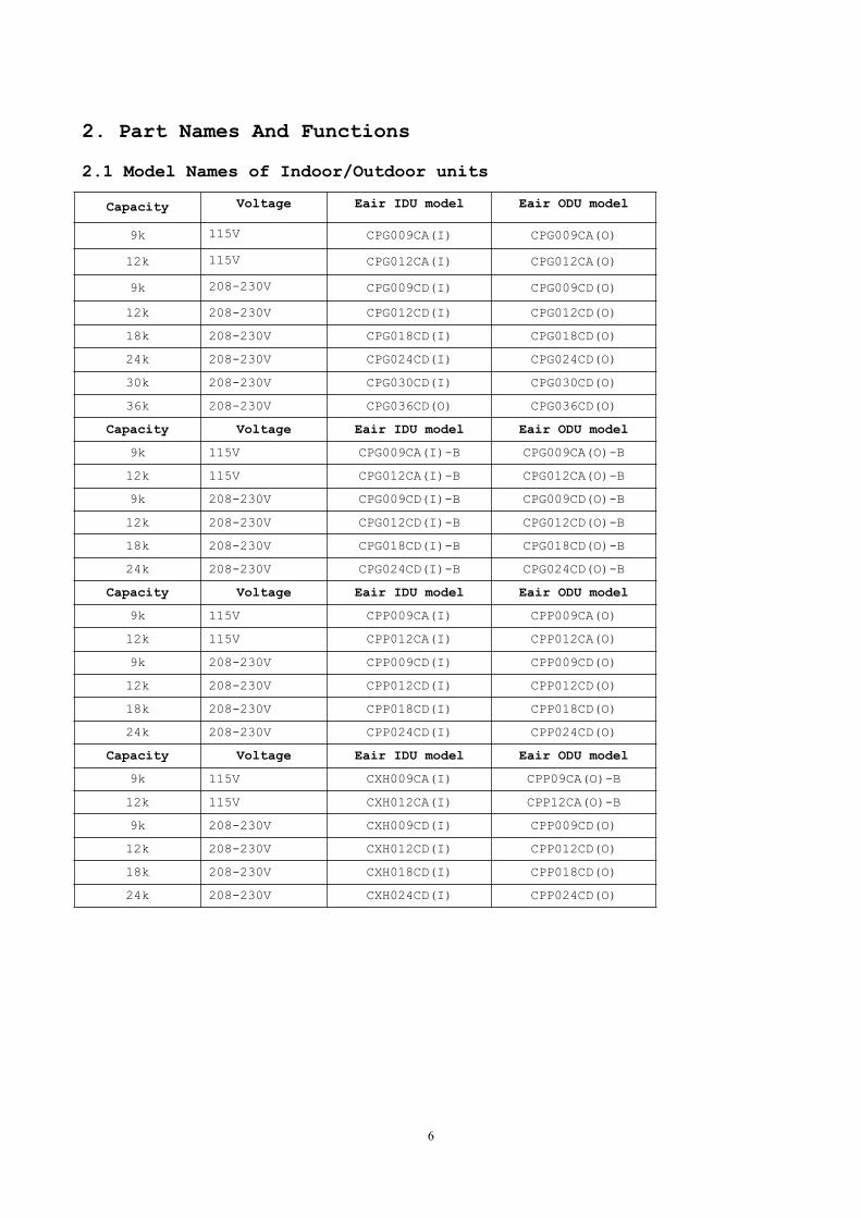
2.1 Model Names of Indoor/Outdoor units
Capacity Voltage Eair IDU model Eair ODU model
9k 115V CPG009CA(I) CPG009CA(O)
12k 115V CPG012CA(I) CPG012CA(O)
9k 208-230V CPG009CD(I) CPG009CD(O)
12k 208-230V CPG012CD(I) CPG012CD(O)
18k 208-230V CPG018CD(I) CPG018CD(O)
24k 208-230V CPG024CD(I) CPG024CD(O)
30k 208-230V CPG030CD(I) CPG030CD(O)
36k 208-230V CPG036CD(O) CPG036CD(O)
Capacity Voltage Eair IDU model Eair ODU model
9k 115V CPG009CA(I)-B CPG009CA(O)-B
12k 115V CPG012CA(I)-B CPG012CA(O)-B
9k 208-230V CPG009CD(I)-B CPG009CD(O)-B
12k 208-230V CPG012CD(I)-B CPG012CD(O)-B
18k 208-230V CPG018CD(I)-B CPG018CD(O)-B
24k 208-230V CPG024CD(I)-B CPG024CD(O)-B
Capacity Voltage Eair IDU model Eair ODU model
9k 115V CPP009CA(I) CPP009CA(O)
12k 115V CPP012CA(I) CPP012CA(O)
9k 208-230V CPP009CD(I) CPP009CD(O)
12k 208-230V CPP012CD(I) CPP012CD(O)
18k 208-230V CPP018CD(I) CPP018CD(O)
24k 208-230V CPP024CD(I) CPP024CD(O)
Capacity Voltage Eair IDU model Eair ODU model
9k 115V CXH009CA(I) CPP09CA(O)-B
12k 115V CXH012CA(I) CPP12CA(O)-B
9k 208-230V CXH009CD(I) CPP009CD(O)
12k 208-230V CXH012CD(I) CPP012CD(O)
18k 208-230V CXH018CD(I) CPP018CD(O)
24k 208-230V CXH024CD(I) CPP024CD(O)
7
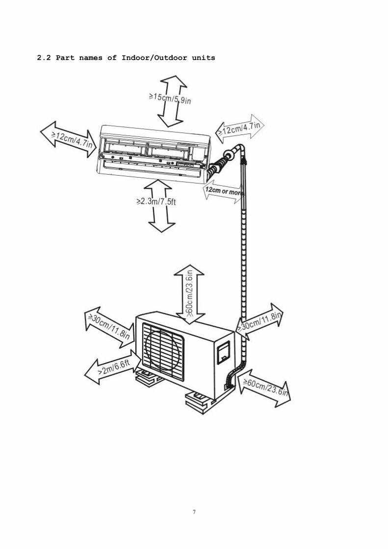
2.2 Part names of Indoor/Outdoor units
8
3. Dimension
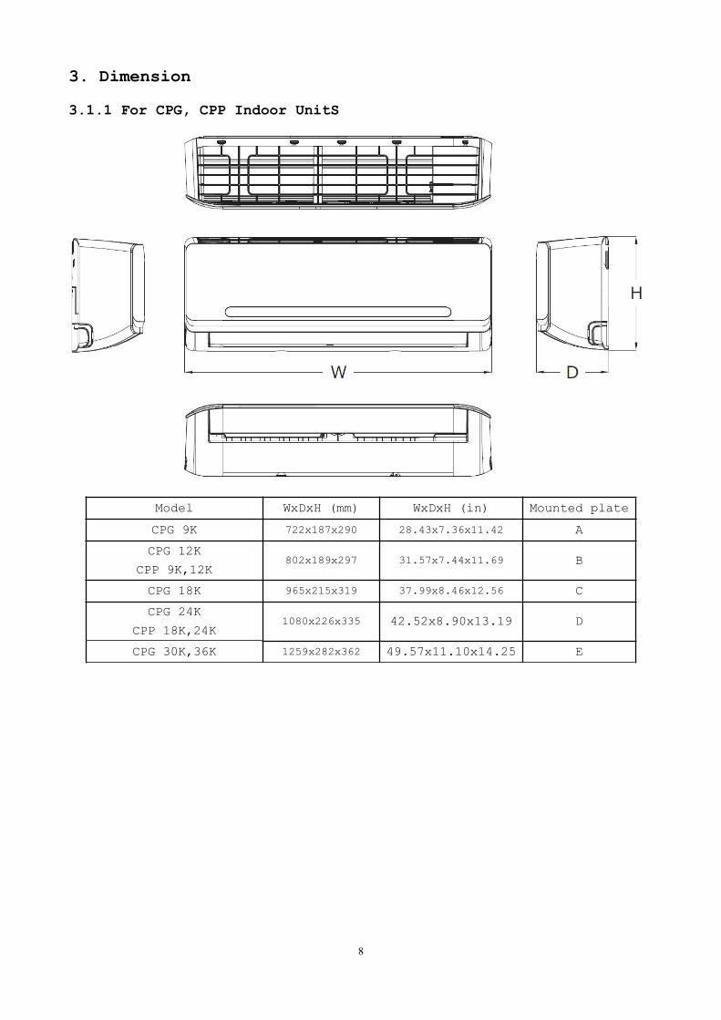
3.1.1 For CPG, CPP Indoor UnitS
Model WxDxH (mm) WxDxH (in) Mounted plate
CPG 9K 722x187x290 28.43x7.36x11.42 A
CPG 12K
CPP 9K,12K802x189x297 31.57x7.44x11.69 B
CPG 18K 965x215x319 37.99x8.46x12.56 C
CPG 24K
CPP 18K,24K1080x226x335 42.52x8.90x13.19 D
CPG 30K,36K 1259x282x362 49.57x11.10x14.25 E
9
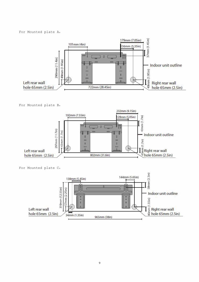
For Mounted plate A,
For Mounted plate B,
For Mounted plate C,
10
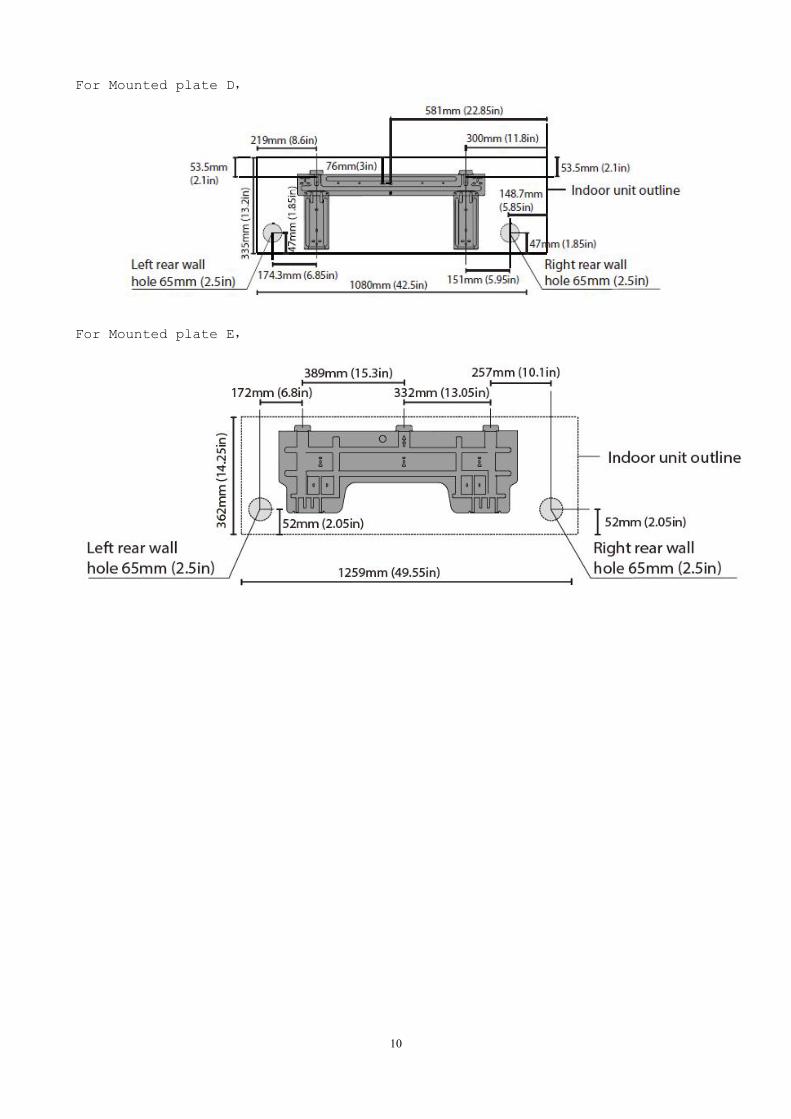
For Mounted plate D,
For Mounted plate E,
11
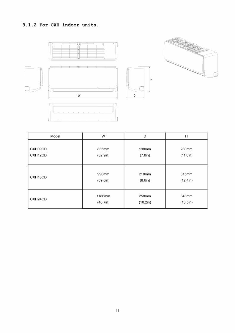
3.1.2 For CXH indoor units.
W D
Model W D H
CXH09CD
CXH12CD
835mm
(32.9in)
198mm
(7.8in)
280mm
(11.0in)
CXH18CD990mm
(39.0in)
218mm
(8.6in)
315mm
(12.4in)
CXH24CD1186mm
(46.7in)
258mm
(10.2in)
343mm
(13.5in)
12
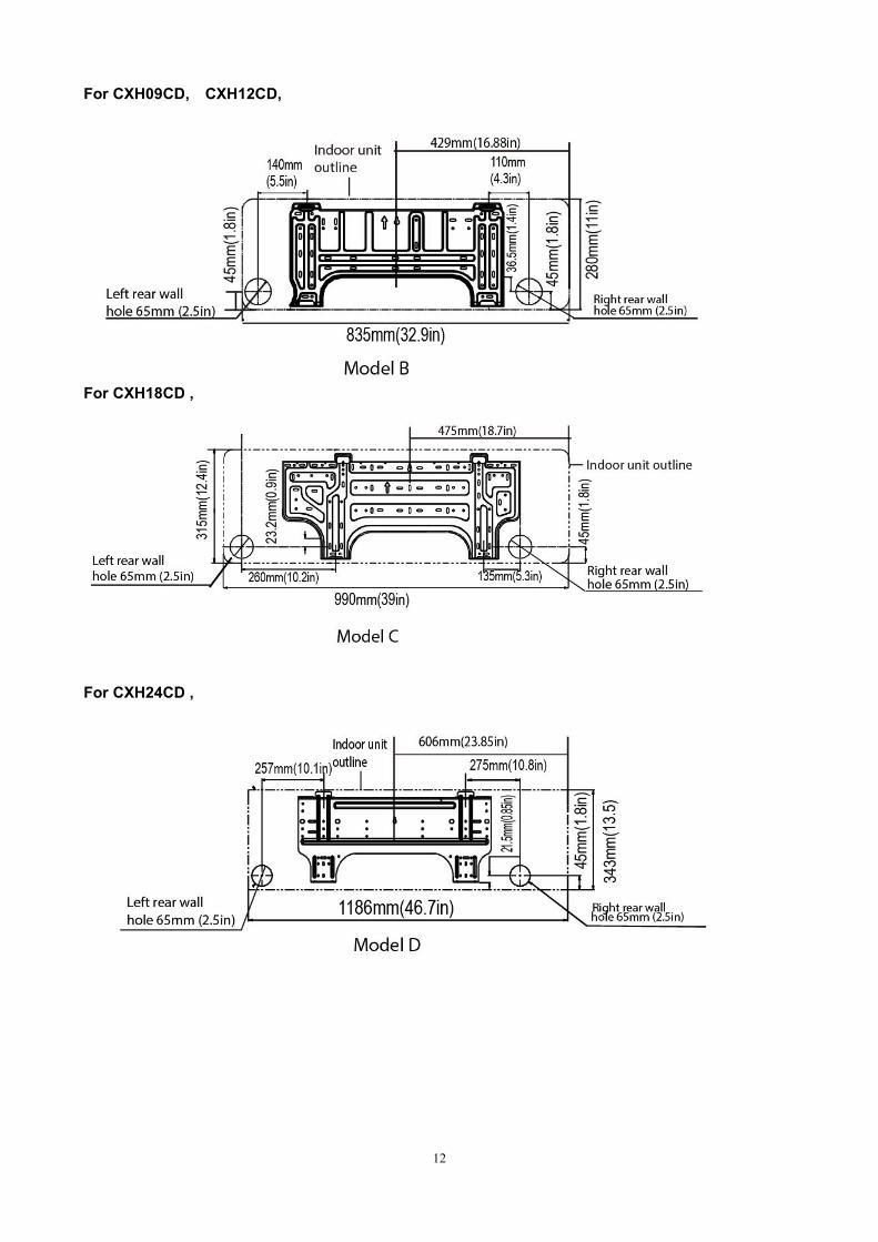
For CXH09CD, CXH12CD,
For CXH18CD ,
For CXH24CD ,
13
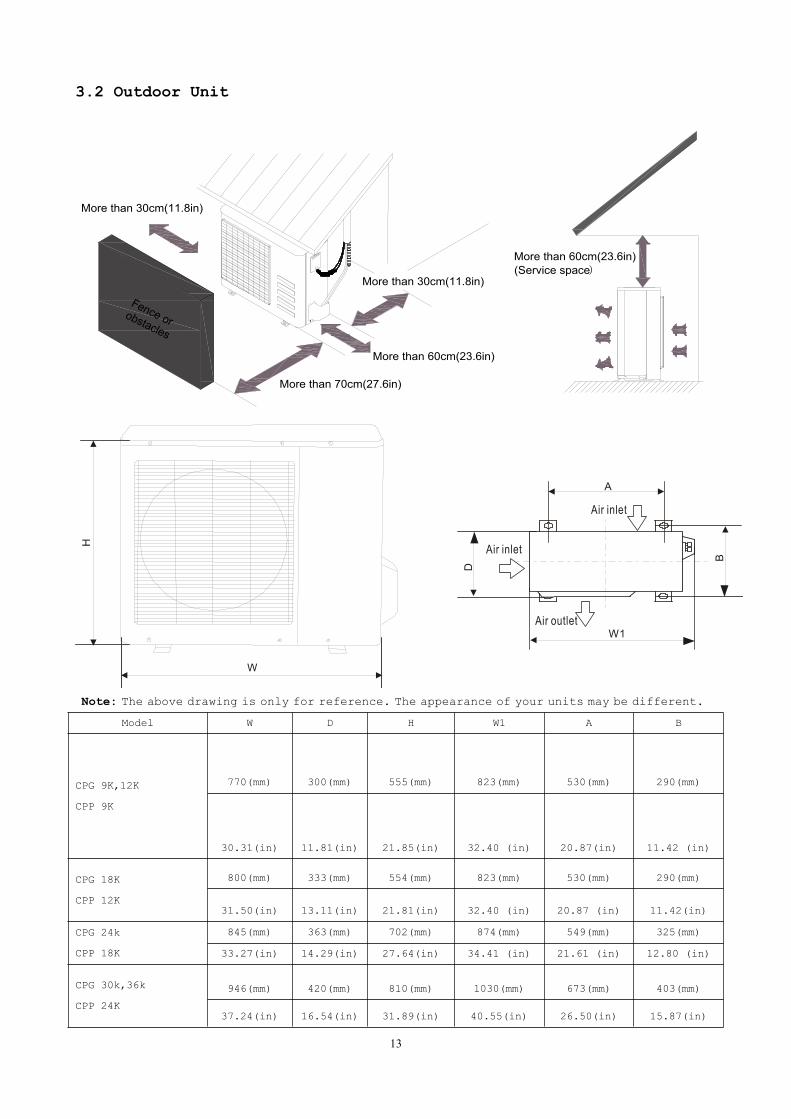
3.2 Outdoor Unit
More than 60cm(23.6in)
More than 70cm(27.6in)
More than 30cm(11.8in)
More than 60cm(23.6in)(Service space)
Fence orobstacles
More than 30cm(11.8in)
Note: The above drawing is only for reference. The appearance of your units may be different.
Model W D H W1 A B
CPG 9K,12K
CPP 9K
770(mm) 300(mm) 555(mm) 823(mm) 530(mm) 290(mm)
30.31(in) 11.81(in) 21.85(in) 32.40 (in) 20.87(in) 11.42 (in)
CPG 18K
CPP 12K
800(mm) 333(mm) 554(mm) 823(mm) 530(mm) 290(mm)
31.50(in) 13.11(in) 21.81(in) 32.40 (in) 20.87 (in) 11.42(in)
CPG 24k
CPP 18K
845(mm) 363(mm) 702(mm) 874(mm) 549(mm) 325(mm)
33.27(in) 14.29(in) 27.64(in) 34.41 (in) 21.61 (in) 12.80 (in)
CPG 30k,36k
CPP 24K
946(mm) 420(mm) 810(mm) 1030(mm) 673(mm) 403(mm)
37.24(in) 16.54(in) 31.89(in) 40.55(in) 26.50(in) 15.87(in)
14
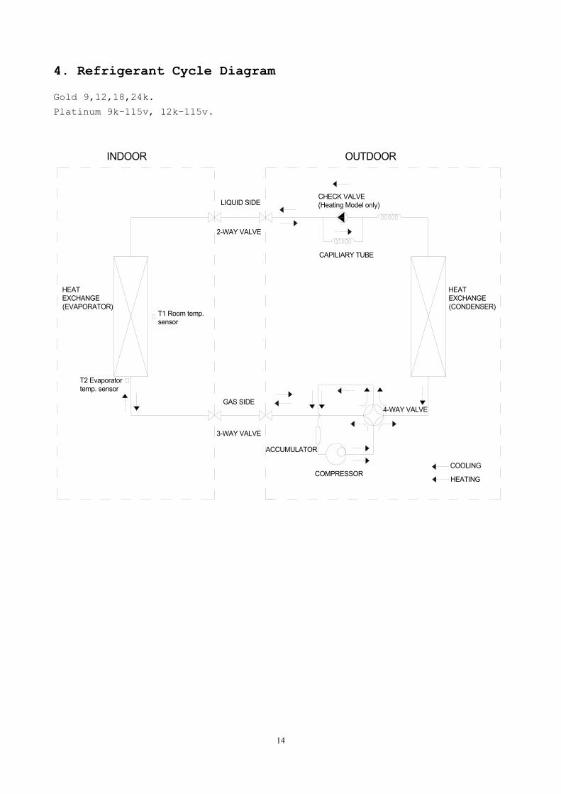
4. Refrigerant Cycle Diagram
Gold 9,12,18,24k.
Platinum 9k-115v, 12k-115v.
LIQUID SIDE
GAS SIDE
HEATEXCHANGE(EVAPORATOR)
HEATEXCHANGE(CONDENSER)
COMPRESSOR
2-WAY VALVE
3-WAY VALVE
4-WAY VALVE
COOLING
HEATING
T2 Evaporatortemp. sensor
T1 Room temp.sensor
ACCUMULATOR
INDOOR OUTDOOR
CHECK VALVE(Heating Model only)
CAPILIARY TUBE
15
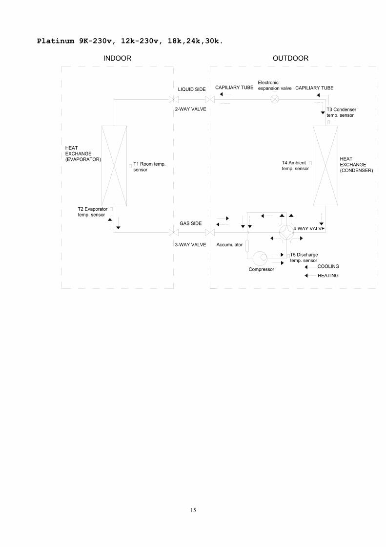
Platinum 9K-230v, 12k-230v, 18k,24k,30k.
LIQUID SIDE
GAS SIDE
HEATEXCHANGE(EVAPORATOR) HEAT
EXCHANGE(CONDENSER)
Compressor
2-WAY VALVE
3-WAY VALVE
4-WAY VALVE
COOLING
HEATING
T2 Evaporatortemp. sensor
T1 Room temp.sensor
T3 Condensertemp. sensor
T5 Dischargetemp. sensor
T4 Ambienttemp. sensor
INDOOR OUTDOOR
Electronicexpansion valveCAPILIARY TUBE
Accumulator
CAPILIARY TUBE
16
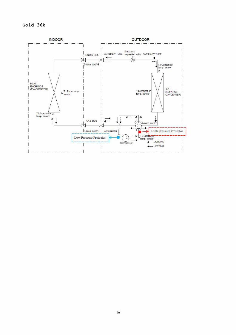
Gold 36k
17
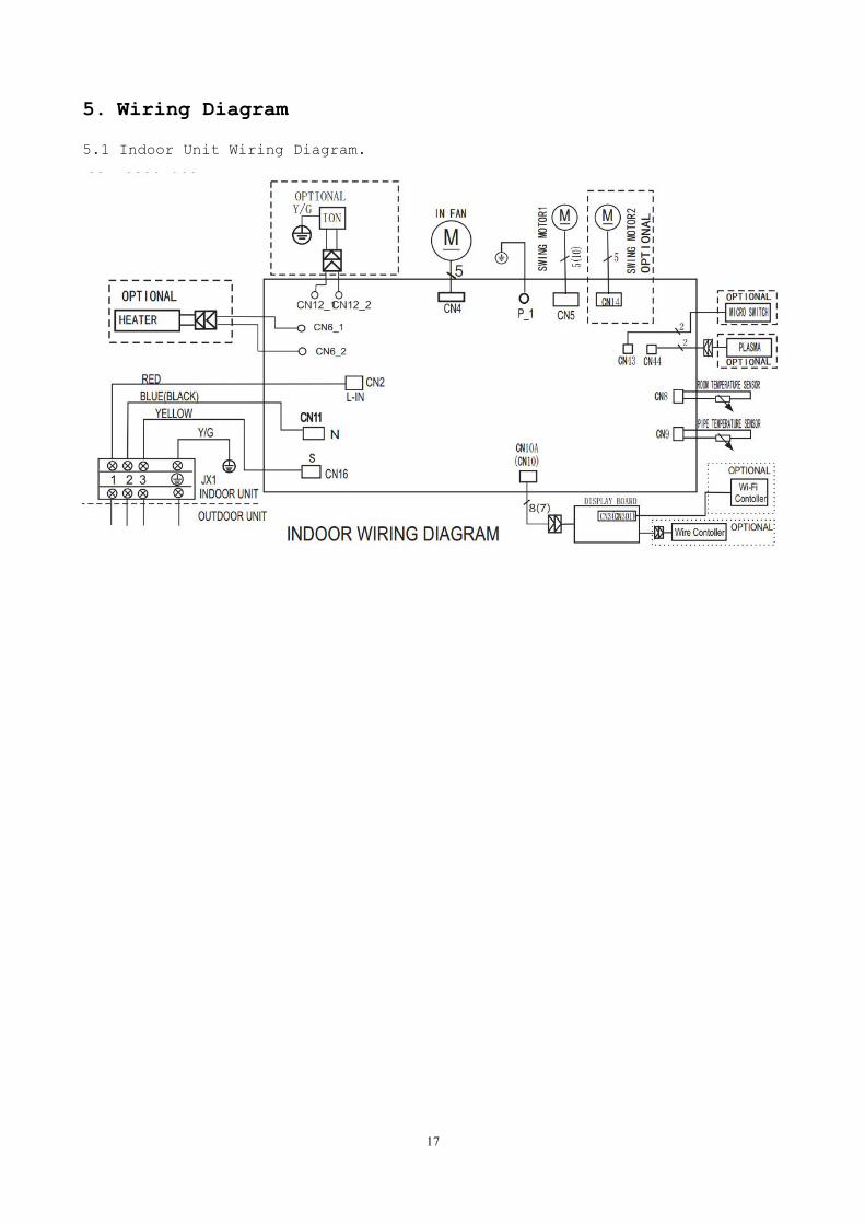
5. Wiring Diagram
5.1 Indoor Unit Wiring Diagram.
18
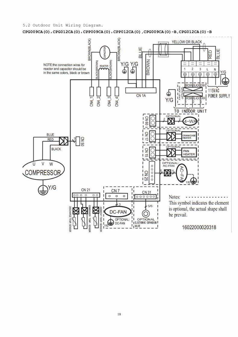
5.2 Outdoor Unit Wiring Diagram.
CPG009CA(O),CPG012CA(O),CPP009CA(O),CPP012CA(O),CPG009CA(O)-B,CPG012CA(O)-B
19
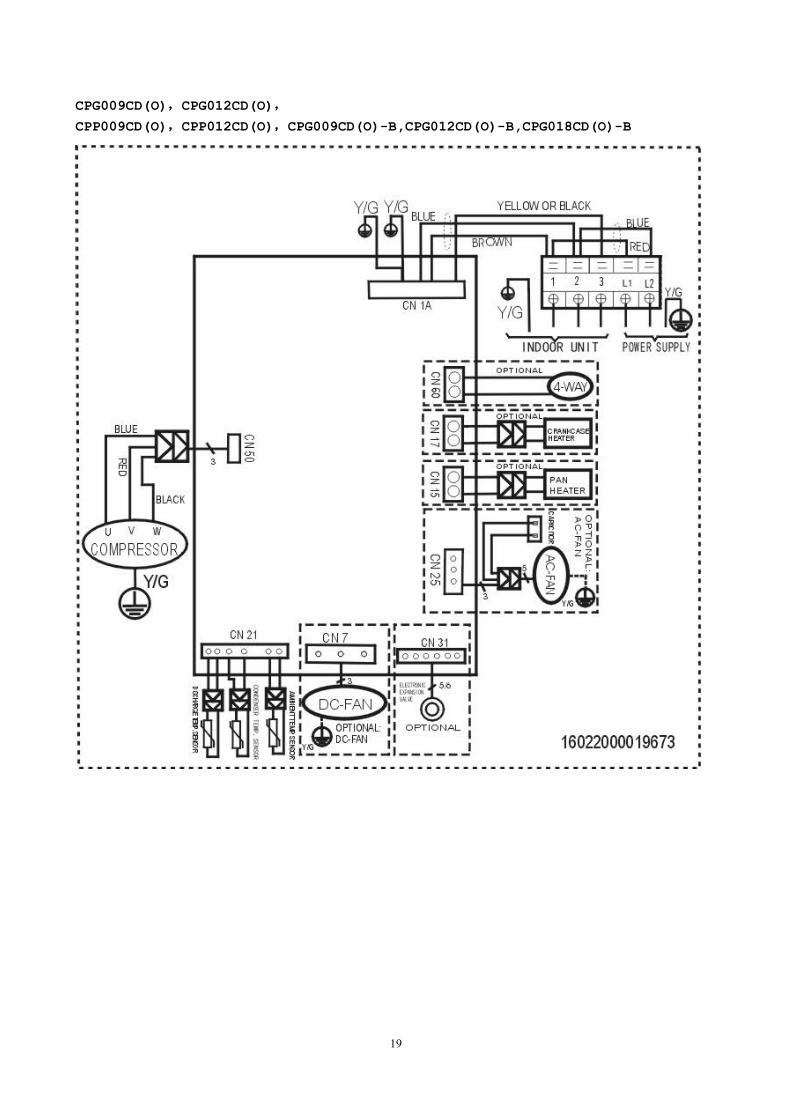
CPG009CD(O),CPG012CD(O),
CPP009CD(O),CPP012CD(O),CPG009CD(O)-B,CPG012CD(O)-B,CPG018CD(O)-B
20
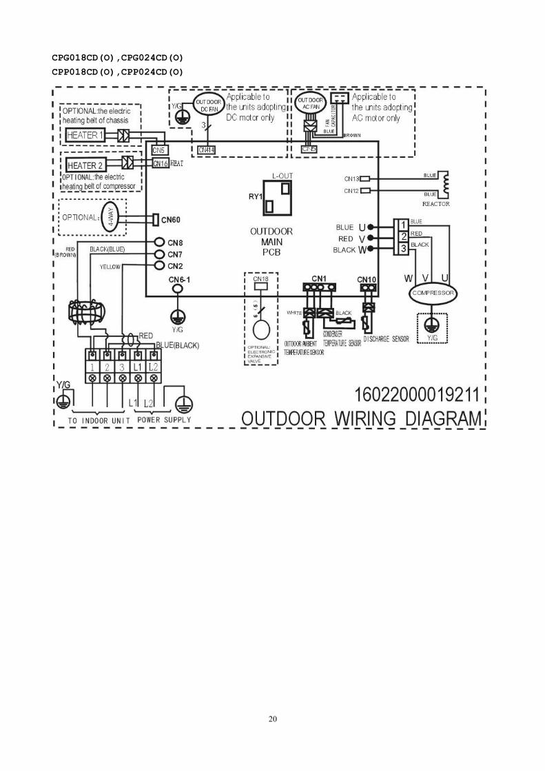
CPG018CD(O),CPG024CD(O)
CPP018CD(O),CPP024CD(O)
21
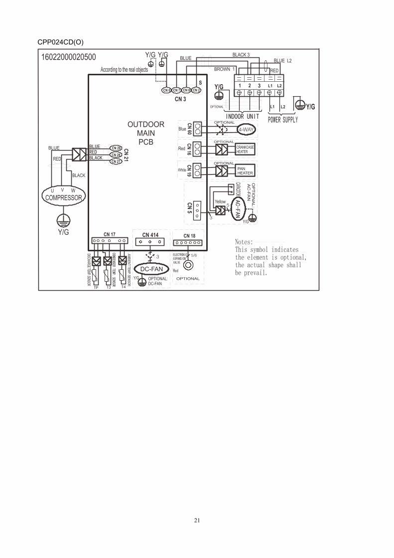
CPP024CD(O)
22
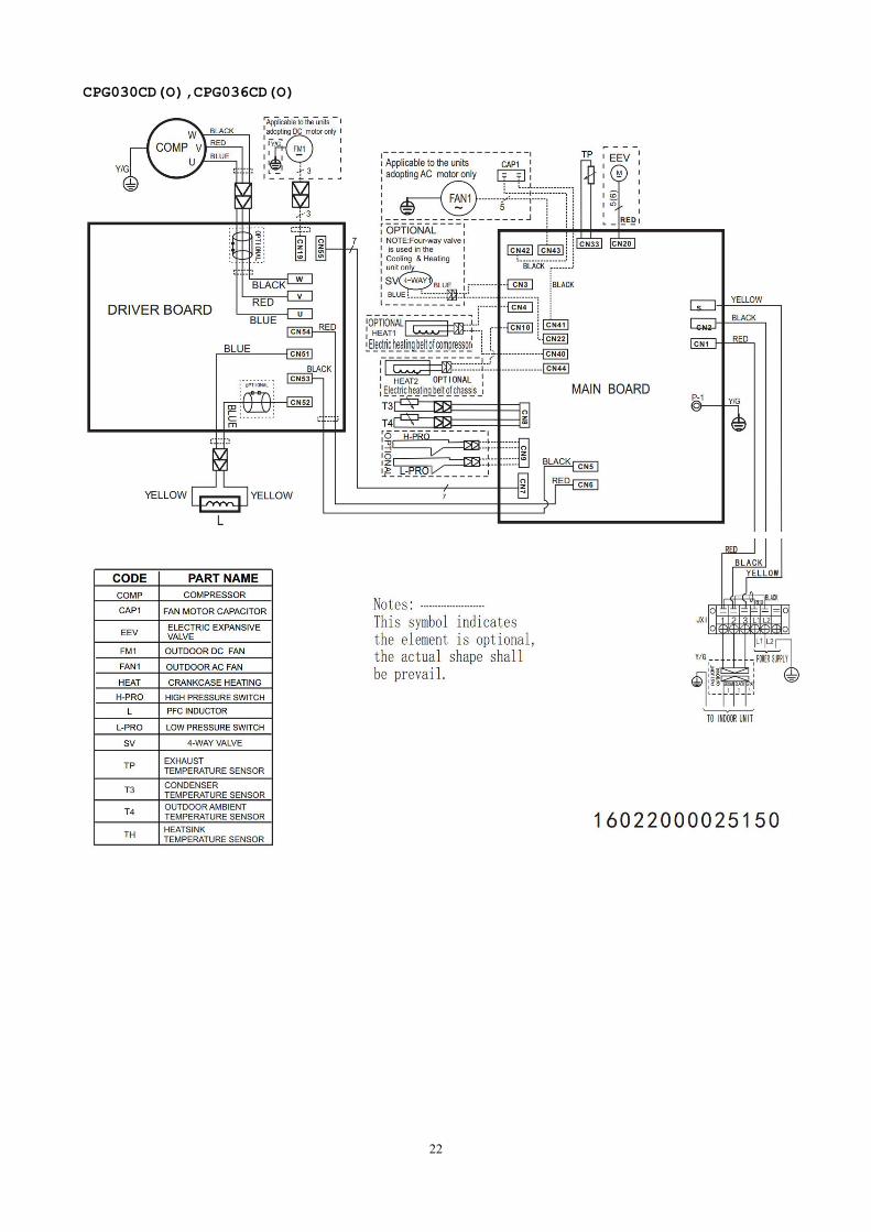
CPG030CD(O),CPG036CD(O)
23
6 Installation Details
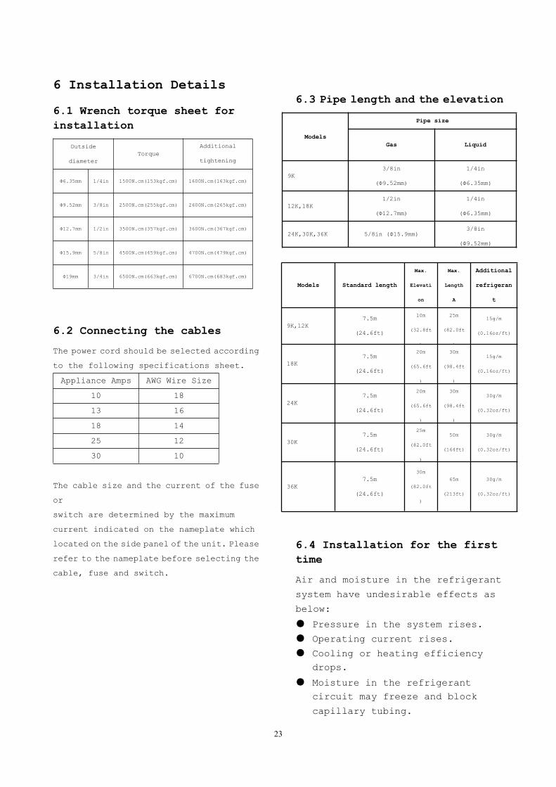
6.1 Wrench torque sheet forinstallation
Outside
diameterTorque
Additional
tightening
torqueФ6.35mm 1/4in 1500N.cm(153kgf.cm) 1600N.cm(163kgf.cm)
Ф9.52mm 3/8in 2500N.cm(255kgf.cm) 2600N.cm(265kgf.cm)
Ф12.7mm 1/2in 3500N.cm(357kgf.cm) 3600N.cm(367kgf.cm)
Ф15.9mm 5/8in 4500N.cm(459kgf.cm) 4700N.cm(479kgf.cm)
Ф19mm 3/4in 6500N.cm(663kgf.cm) 6700N.cm(683kgf.cm)
6.2 Connecting the cables
The power cord should be selected according
to the following specifications sheet.
Appliance Amps AWG Wire Size
10 18
13 16
18 14
25 12
30 10
The cable size and the current of the fuse
or
switch are determined by the maximum
current indicated on the nameplate which
located on the side panel of the unit. Please
refer to the nameplate before selecting the
cable, fuse and switch.
6.3 Pipe length and the elevation
Models
Pipe size
Gas Liquid
9K3/8in
(Ф9.52mm)
1/4in
(Ф6.35mm)
12K,18K1/2in
(Ф12.7mm)
1/4in
(Ф6.35mm)
24K,30K,36K 5/8in (Ф15.9mm)3/8in
(Ф9.52mm)
Models Standard length
Max.
Elevati
on
Max.
Length
A
Additional
refrigeran
t
9K,12K7.5m
(24.6ft)
10m
(32.8ft
)
25m
(82.0ft
)
15g/m
(0.16oz/ft)
18K7.5m
(24.6ft)
20m
(65.6ft
)
30m
(98.4ft
)
15g/m
(0.16oz/ft)
24K7.5m
(24.6ft)
20m
(65.6ft
)
30m
(98.4ft
)
30g/m
(0.32oz/ft)
30K7.5m
(24.6ft)
25m
(82.0ft
)
50m
(164ft)
30g/m
(0.32oz/ft)
36K7.5m
(24.6ft)
30m
(82.0ft
)
65m
(213ft)
30g/m
(0.32oz/ft)
6.4 Installation for the firsttime
Air and moisture in the refrigerant
system have undesirable effects as
below:
Pressure in the system rises.
Operating current rises.
Cooling or heating efficiencydrops.
Moisture in the refrigerantcircuit may freeze and block
capillary tubing.
24
Water may lead to corrosion ofparts in the refrigerant system.
Therefore, the indoor units and
the pipes between indoor and outdoor
units must be leak tested and
evacuated to remove gas and moisture
from the system.
Gas leak check (Soap water
method):
Apply soap water or a liquid
neutral detergent on the indoor unit
connections or outdoor unit
connections by a soft brush to check
for leakage of the connecting points
of the piping. If bubbles come out, the
pipes have leakage.
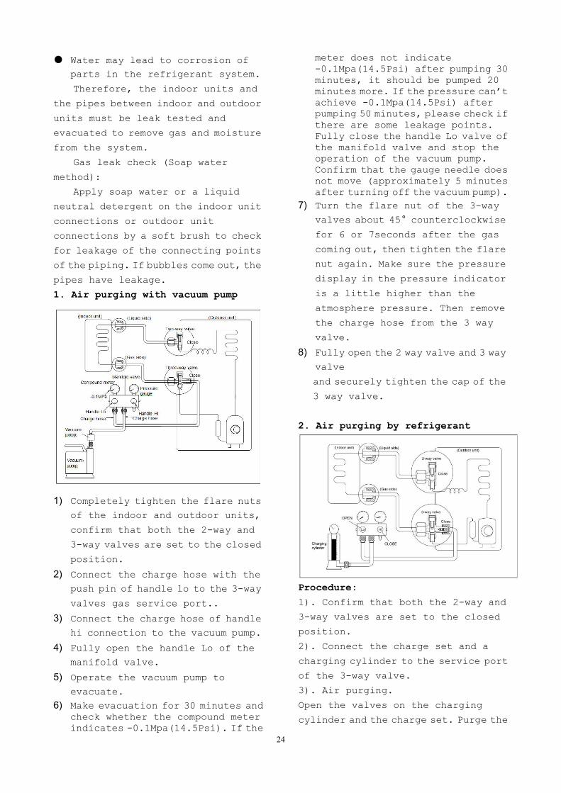
1. Air purging with vacuum pump
1) Completely tighten the flare nuts
of the indoor and outdoor units,
confirm that both the 2-way and
3-way valves are set to the closed
position.
2) Connect the charge hose with the
push pin of handle lo to the 3-way
valves gas service port..
3) Connect the charge hose of handle
hi connection to the vacuum pump.
4) Fully open the handle Lo of the
manifold valve.
5) Operate the vacuum pump to
evacuate.6) Make evacuation for 30 minutes and
check whether the compound meterindicates -0.1Mpa(14.5Psi). If the
meter does not indicate-0.1Mpa(14.5Psi) after pumping 30minutes, it should be pumped 20minutes more. If the pressure can’tachieve -0.1Mpa(14.5Psi) afterpumping 50 minutes, please check ifthere are some leakage points.Fully close the handle Lo valve ofthe manifold valve and stop theoperation of the vacuum pump.Confirm that the gauge needle doesnot move (approximately 5 minutesafter turning off the vacuum pump).
7) Turn the flare nut of the 3-way
valves about 45° counterclockwise
for 6 or 7seconds after the gas
coming out, then tighten the flare
nut again. Make sure the pressure
display in the pressure indicator
is a little higher than the
atmosphere pressure. Then remove
the charge hose from the 3 way
valve.
8) Fully open the 2 way valve and 3 way
valve
and securely tighten the cap of the
3 way valve.
2. Air purging by refrigerant
Procedure:
1). Confirm that both the 2-way and
3-way valves are set to the closed
position.
2). Connect the charge set and a
charging cylinder to the service port
of the 3-way valve.
3). Air purging.
Open the valves on the charging
cylinder and the charge set. Purge the
25
air by loosening the flare nut on the
2-way valve approximately 45’ for 3
seconds then closing it for 1 minute;
repeat 3 times.
After purging the air, use a torque
wrench to tighten the flare nut on the
2-way valve.
4). Check the gas leakage.
Check the flare connections for gas
leakage.
5). Discharge the refrigerant.
Close the valve on the charging
cylinder and discharge the
refrigerant by loosening the flare nut
on the 2-way valve approximately 45’
until the gauge indicates
0.3Mpa(43.5Psi) to 0.5 Mpa(72.5Psi).
6). Disconnect the charge set and the
charging cylinder, and set the 2-way
and 3-way valves to the open position.
Be sure to use a hexagonal wrench to
operate the valve stems.
7). Mount the valve stems nuts and the
service port cap.
Be sure to use a torque wrench to
tighten the service port cap to a
torque 18N·m.
Be sure to check the gas leakage.
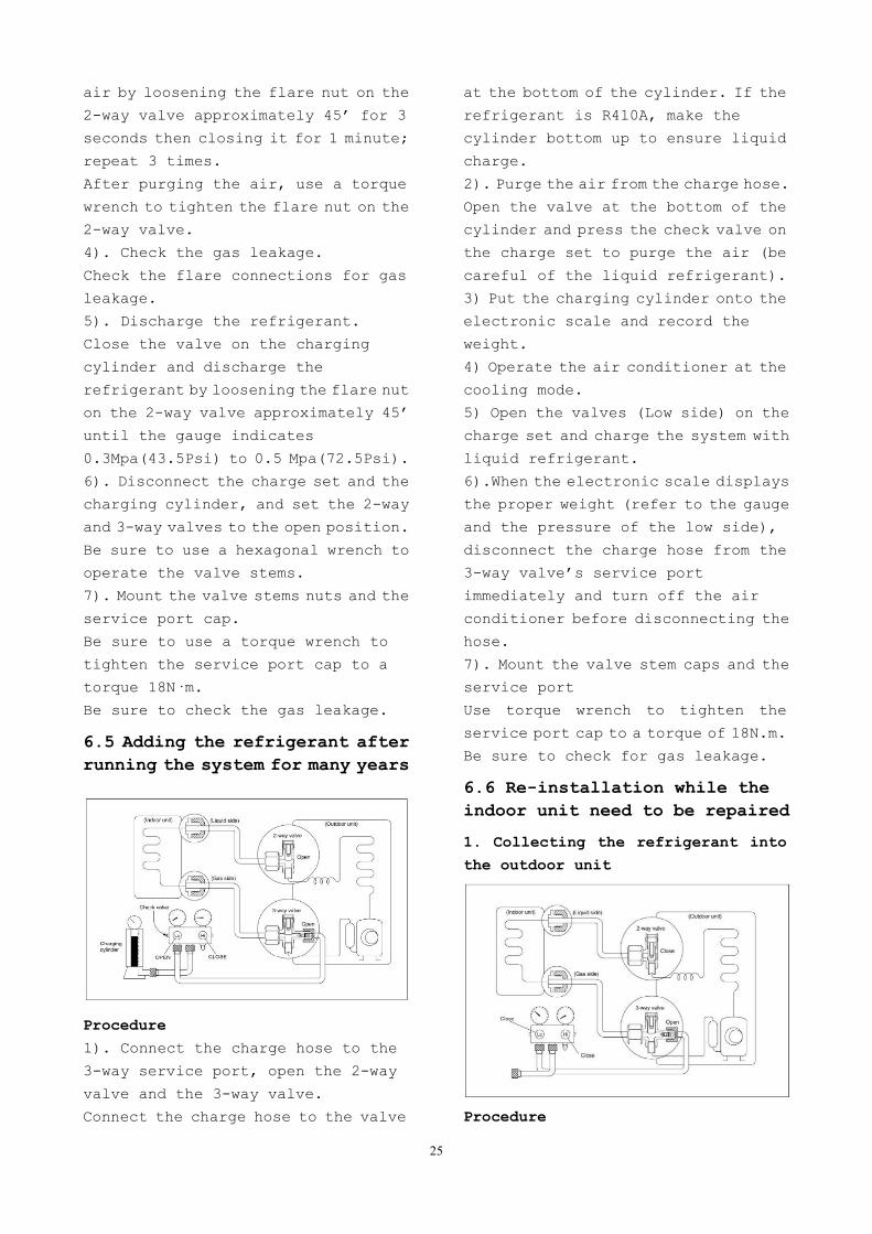
6.5 Adding the refrigerant afterrunning the system for many years
Procedure
1). Connect the charge hose to the
3-way service port, open the 2-way
valve and the 3-way valve.
Connect the charge hose to the valve
at the bottom of the cylinder. If the
refrigerant is R410A, make the
cylinder bottom up to ensure liquid
charge.
2). Purge the air from the charge hose.
Open the valve at the bottom of the
cylinder and press the check valve on
the charge set to purge the air (be
careful of the liquid refrigerant).
3) Put the charging cylinder onto the
electronic scale and record the
weight.
4) Operate the air conditioner at the
cooling mode.
5) Open the valves (Low side) on the
charge set and charge the system with
liquid refrigerant.
6).When the electronic scale displays
the proper weight (refer to the gauge
and the pressure of the low side),
disconnect the charge hose from the
3-way valve’s service port
immediately and turn off the air
conditioner before disconnecting the
hose.
7). Mount the valve stem caps and the
service port
Use torque wrench to tighten the
service port cap to a torque of 18N.m.
Be sure to check for gas leakage.
6.6 Re-installation while theindoor unit need to be repaired
1. Collecting the refrigerant into
the outdoor unit
Procedure
26
1). Confirm that both the 2-way and
3-way valves are set to the opened
position
Remove the valve stem caps and confirm
that the valve stems are in the opened
position.
Be sure to use a hexagonal wrench to
operate the valve stems.
2). Connect the charge hose with the
push pin of handle lo to the 3-way
valves gas service port.
3). Air purging of the charge hose.
Open the handle Lo valve of the
manifold valve slightly to purge air
from the charge hose for 5 seconds and
then close it quickly.
4). Set the 2-way valve to the close
position.
5). Operate the air conditioner at the
cooling cycle and stop it when the
gauge indicates 0.1Mpa(14.5Psi).
6). Set the 3-way valve to the closed
position immediately
Do this quickly so that the gauge ends
up indicating 0.3Mpa(43.5Psi) to 0.5
Mpa(72.5Psi).
Disconnect the charge set, and tighten
the 2-way and 3-way valve’s stem nuts.
Use a torque wrench to tighten the
3-way valves service port cap to a
torque of 18N.m.
Be sure to check for gas leakage.
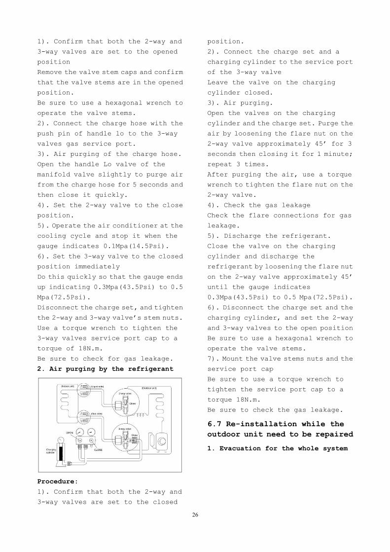
2. Air purging by the refrigerant
Procedure:
1). Confirm that both the 2-way and
3-way valves are set to the closed
position.
2). Connect the charge set and a
charging cylinder to the service port
of the 3-way valve
Leave the valve on the charging
cylinder closed.
3). Air purging.
Open the valves on the charging
cylinder and the charge set. Purge the
air by loosening the flare nut on the
2-way valve approximately 45’ for 3
seconds then closing it for 1 minute;
repeat 3 times.
After purging the air, use a torque
wrench to tighten the flare nut on the
2-way valve.
4). Check the gas leakage
Check the flare connections for gas
leakage.
5). Discharge the refrigerant.
Close the valve on the charging
cylinder and discharge the
refrigerant by loosening the flare nut
on the 2-way valve approximately 45’
until the gauge indicates
0.3Mpa(43.5Psi) to 0.5 Mpa(72.5Psi).
6). Disconnect the charge set and the
charging cylinder, and set the 2-way
and 3-way valves to the open position
Be sure to use a hexagonal wrench to
operate the valve stems.
7). Mount the valve stems nuts and the
service port cap
Be sure to use a torque wrench to
tighten the service port cap to a
torque 18N.m.
Be sure to check the gas leakage.
6.7 Re-installation while theoutdoor unit need to be repaired
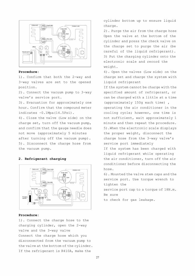
1. Evacuation for the whole system
27
Procedure:
1). Confirm that both the 2-way and
3-way valves are set to the opened
position.
2). Connect the vacuum pump to 3-way
valve’s service port.
3). Evacuation for approximately one
hour. Confirm that the compound meter
indicates -0.1Mpa(14.5Psi).
4). Close the valve (Low side) on the
charge set, turn off the vacuum pump,
and confirm that the gauge needle does
not move (approximately 5 minutes
after turning off the vacuum pump).
5). Disconnect the charge hose from
the vacuum pump.
2. Refrigerant charging
Procedure:
1). Connect the charge hose to the
charging cylinder, open the 2-way
valve and the 3-way valve
Connect the charge hose which you
disconnected from the vacuum pump to
the valve at the bottom of the cylinder.
If the refrigerant is R410A, make the
cylinder bottom up to ensure liquid
charge.
2). Purge the air from the charge hose
Open the valve at the bottom of the
cylinder and press the check valve on
the charge set to purge the air (be
careful of the liquid refrigerant).
3) Put the charging cylinder onto the
electronic scale and record the
weight.
4). Open the valves (Low side) on the
charge set and charge the system with
liquid refrigerant
If the system cannot be charge with the
specified amount of refrigerant, or
can be charged with a little at a time
(approximately 150g each time) ,
operating the air conditioner in the
cooling cycle; however, one time is
not sufficient, wait approximately 1
minute and then repeat the procedure.
5).When the electronic scale displays
the proper weight, disconnect the
charge hose from the 3-way valve’s
service port immediately
If the system has been charged with
liquid refrigerant while operating
the air conditioner, turn off the air
conditioner before disconnecting the
hose.
6). Mounted the valve stem caps and the
service port. Use torque wrench to
tighten the
service port cap to a torque of 18N.m.
Be sure
to check for gas leakage.
28
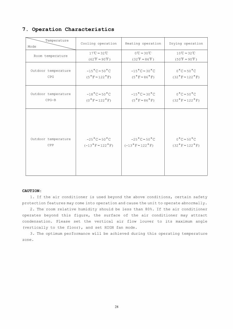
7. Operation Characteristics
Temperature
ModeCooling operation Heating operation Drying operation
Room temperature17~32
(62~90)
0~30
(32~86)
10~32
(50~90)
Outdoor temperature
CPG
-15°C~50°C
(5°F~122°F)
-15°C~30°C
(5°F~86°F)
0°C~50°C
(32°F~122°F)
Outdoor temperature
CPG-B
-18°C~50°C
(0°F~122°F)
-15°C~30°C
(5°F~86°F)
0°C~50°C
(32°F~122°F)
Outdoor temperature
CPP
-25°C~50°C
(-13°F~122°F)
-25°C~50°C
(-13°F~122°F)
0°C~50°C
(32°F~122°F)
CAUTION:
1. If the air conditioner is used beyond the above conditions, certain safety
protection features may come into operation and cause the unit to operate abnormally.
2. The room relative humidity should be less than 80%. If the air conditioner
operates beyond this figure, the surface of the air conditioner may attract
condensation. Please set the vertical air flow louver to its maximum angle
(vertically to the floor), and set HIGH fan mode.
3. The optimum performance will be achieved during this operating temperature
zone.
29
8. Electronic Function
8.1 Abbreviation
T1: Indoor room temperature
T2: Coil temperature of evaporator
T3: Coil temperature of condenser
T4: Outdoor ambient temperature
T5: Compressor discharge
temperature
8.2 Display function
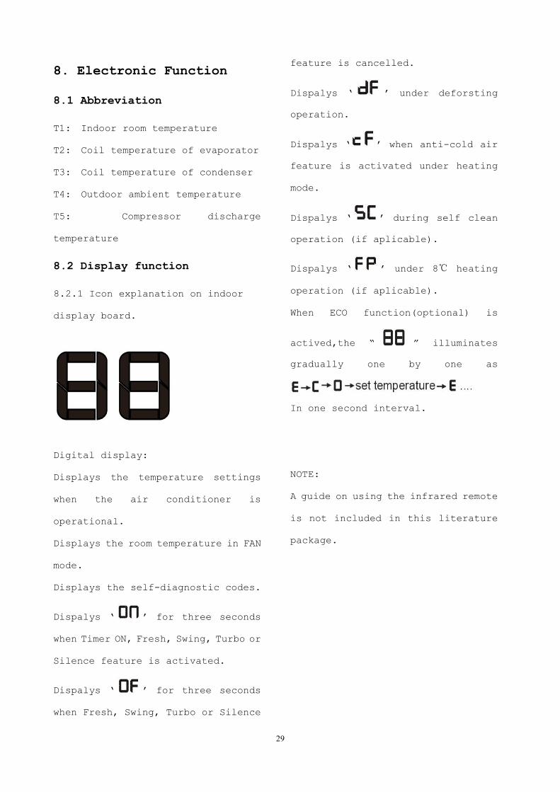
8.2.1 Icon explanation on indoor
display board.
Digital display:
Displays the temperature settings
when the air conditioner is
operational.
Displays the room temperature in FAN
mode.
Displays the self-diagnostic codes.
Dispalys ‘ ’ for three seconds
when Timer ON, Fresh, Swing, Turbo or
Silence feature is activated.
Dispalys ‘ ’ for three seconds
when Fresh, Swing, Turbo or Silence
feature is cancelled.
Dispalys ‘ ’ under deforsting
operation.
Dispalys ‘ ’ when anti-cold air
feature is activated under heating
mode.
Dispalys ‘ ’ during self clean
operation (if aplicable).
Dispalys ‘ ’ under 8 heating
operation (if aplicable).
When ECO function(optional) is
actived,the “ ” illuminates
gradually one by one as
In one second interval.
NOTE:
A guide on using the infrared remote
is not included in this literature
package.
30
8.3 Main Protection
8.3.1 Three minutes delay at restart
for compressor
1 minute delay for the 1st time
stand-up and 3 minutes delay for
others.
8.3.2 Temperature protection of
compressor top
The unit will stop working when the
compressor top temp. protector cut
off, and will restart after the
compressor top temp. protector
restart.
8.3.3 Temperature protection of
compressor discharge
Compressor discharge temp. T5>115for 5s, compressor stops.
8.3.4 Fan speed is out of control
When indoor fan speed keeps too low
(300RPM) for certain time, the unit
will stop and the LED will display the
failure
8.3.5 Inverter module protection
The Inverter module has a protection
function about current, voltage and
temperature. If these protections
happen, the corresponding code will
display on indoor unit and the unit
will stop working.
8.3.6 Indoor fan delayed open
function
When the unit starts up, the louver
will be active immediately and the
indoor fan will open 7s later.
If the unit runs in heating mode, the
indoor fan will be also controlled by
anti-cold wind function.
8.3.7 Compressor preheating
functions
Preheating permitting condition:
When T4(outdoor ambient temperature)
<3°C, the preheating function will beactivated.
8.3.8 Sensor protection at open
circuit and breaking disconnection.
When there’s only one temperature
sensor in malfunction , the air
conditioner will keep working but
show the error code, in case of any
emergency use.
When there’s more than one
temperature sensor in malfunction,
the air conditioner will stop
working.
8.4 Operation Modes and Functions
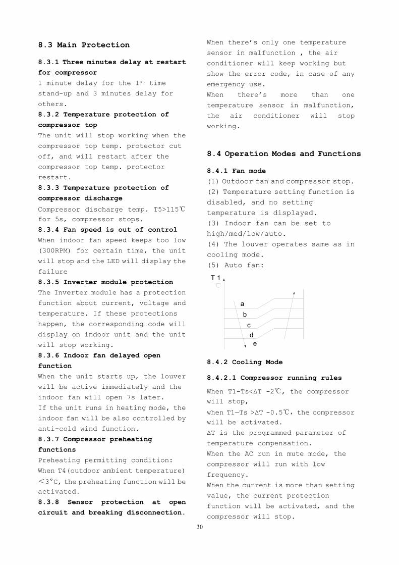
8.4.1 Fan mode
(1) Outdoor fan and compressor stop.(2) Temperature setting function isdisabled, and no settingtemperature is displayed.(3) Indoor fan can be set tohigh/med/low/auto.(4) The louver operates same as incooling mode.(5) Auto fan:
ab
cd
T 1
e
8.4.2 Cooling Mode
8.4.2.1 Compressor running rules
When T1-Ts<ΔT -2, the compressorwill stop,
when T1—Ts >ΔT -0.5,the compressorwill be activated.
ΔT is the programmed parameter of
temperature compensation.
When the AC run in mute mode, the
compressor will run with low
frequency.
When the current is more than setting
value, the current protection
function will be activated, and the
compressor will stop.
31
8.4.2.2 Outdoor fan running rules
The outdoor unit will be run at
different fan speed according to T4.
For different outdoor units, the fan
speeds are different.
T 4
A +
A
B
C
D
E
8.4.2.3 Indoor fan running rules
In cooling mode, indoor fan runs all
the time and the speed can be selected
as high, medium, low and auto.
The indoor fan is controlled as below:
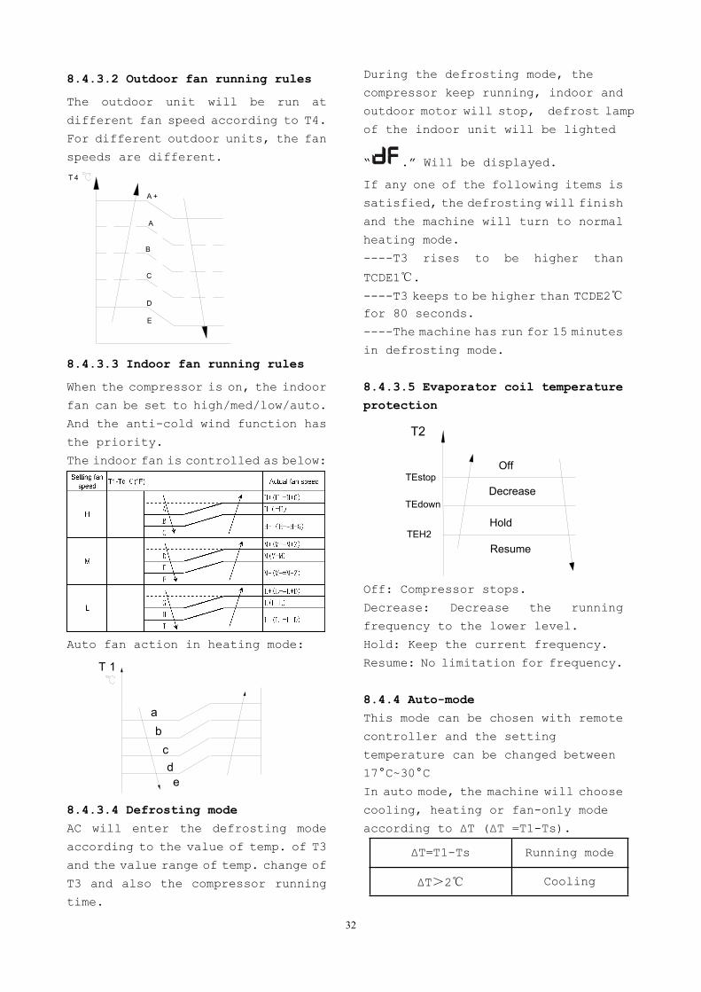
The auto fan acts as below rules:
ab
cd
T 1
e
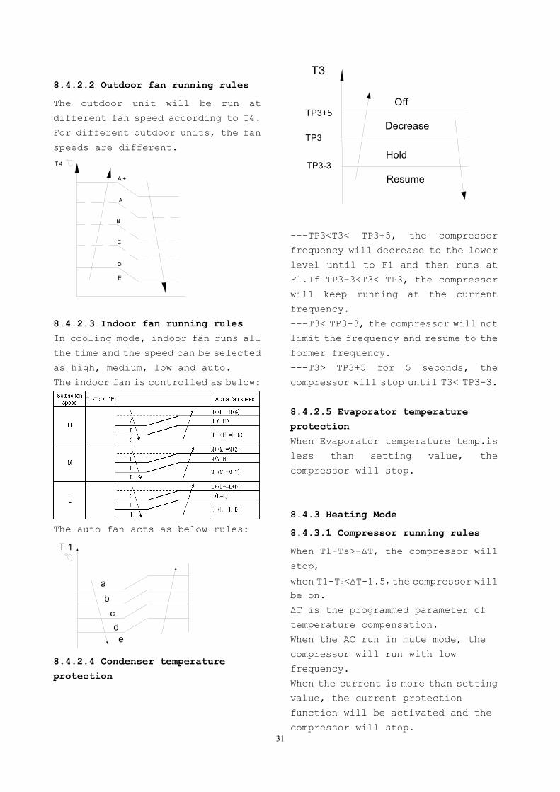
8.4.2.4 Condenser temperature
protection
TP3+5
T3
Resume
Off
DecreaseTP3
TP3-3Hold
---TP3<T3< TP3+5, the compressor
frequency will decrease to the lower
level until to F1 and then runs at
F1.If TP3-3<T3< TP3, the compressor
will keep running at the current
frequency.
---T3< TP3-3, the compressor will not
limit the frequency and resume to the
former frequency.
---T3> TP3+5 for 5 seconds, the
compressor will stop until T3< TP3-3.
8.4.2.5 Evaporator temperature
protection
When Evaporator temperature temp.is
less than setting value, the
compressor will stop.
8.4.3 Heating Mode
8.4.3.1 Compressor running rules
When T1-Ts>-ΔT, the compressor will
stop,
when T1-TS<ΔT-1.5,the compressor willbe on.
ΔT is the programmed parameter of
temperature compensation.
When the AC run in mute mode, the
compressor will run with low
frequency.
When the current is more than setting
value, the current protection
function will be activated and the
compressor will stop.
32
8.4.3.2 Outdoor fan running rules
The outdoor unit will be run at
different fan speed according to T4.
For different outdoor units, the fan
speeds are different.
T 4
A +
A
B
C
D
E
8.4.3.3 Indoor fan running rules
When the compressor is on, the indoor
fan can be set to high/med/low/auto.
And the anti-cold wind function has
the priority.
The indoor fan is controlled as below:
Auto fan action in heating mode:
ab
cd
T 1
e
8.4.3.4 Defrosting mode
AC will enter the defrosting mode
according to the value of temp. of T3
and the value range of temp. change of
T3 and also the compressor running
time.
During the defrosting mode, the
compressor keep running, indoor and
outdoor motor will stop, defrost lamp
of the indoor unit will be lighted
“ .” Will be displayed.
If any one of the following items is
satisfied, the defrosting will finish
and the machine will turn to normal
heating mode.
----T3 rises to be higher than
TCDE1.
----T3 keeps to be higher than TCDE2for 80 seconds.
----The machine has run for 15 minutes
in defrosting mode.
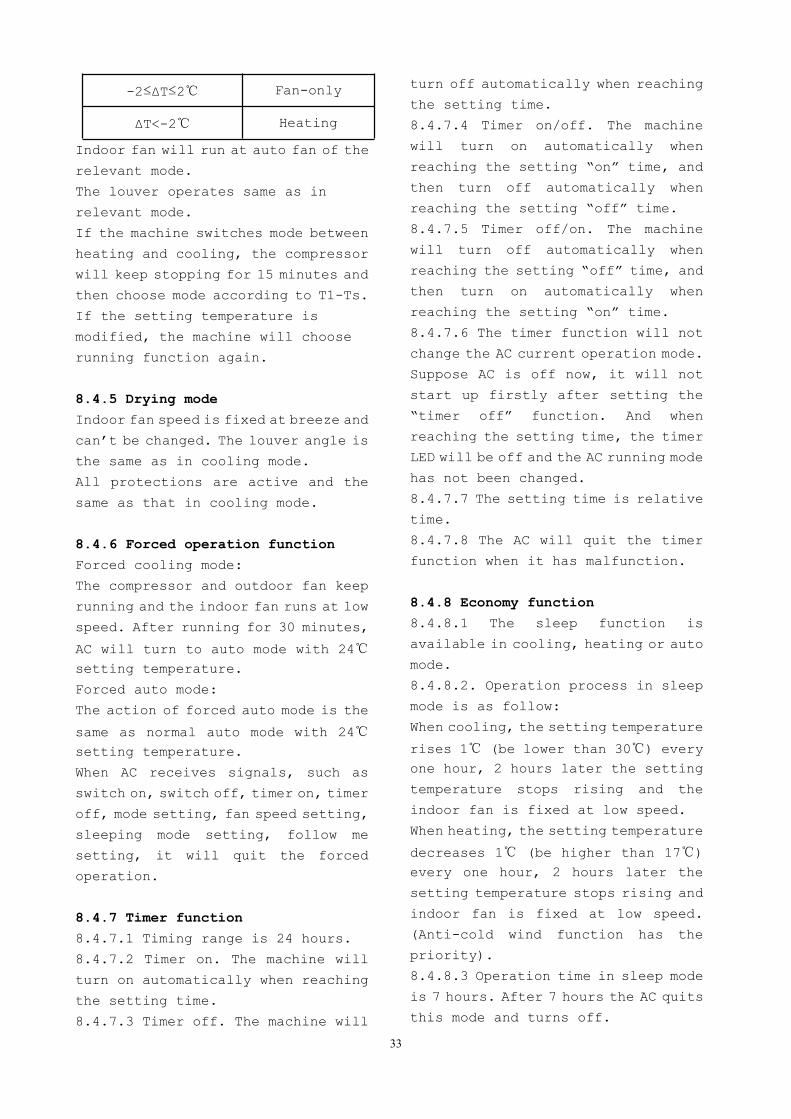
8.4.3.5 Evaporator coil temperature
protection
TEstop
T2
Resume
Off
DecreaseTEdown
TEH2Hold
Off: Compressor stops.
Decrease: Decrease the running
frequency to the lower level.
Hold: Keep the current frequency.
Resume: No limitation for frequency.
8.4.4 Auto-mode
This mode can be chosen with remote
controller and the setting
temperature can be changed between
17°C~30°C
In auto mode, the machine will choose
cooling, heating or fan-only mode
according to ΔT (ΔT =T1-Ts).
ΔT=T1-Ts Running mode
ΔT>2 Cooling
33
-2≤ΔT≤2 Fan-only
ΔT<-2 Heating
Indoor fan will run at auto fan of the
relevant mode.
The louver operates same as in
relevant mode.
If the machine switches mode between
heating and cooling, the compressor
will keep stopping for 15 minutes and
then choose mode according to T1-Ts.
If the setting temperature is
modified, the machine will choose
running function again.
8.4.5 Drying mode
Indoor fan speed is fixed at breeze and
can’t be changed. The louver angle is
the same as in cooling mode.
All protections are active and the
same as that in cooling mode.
8.4.6 Forced operation function
Forced cooling mode:
The compressor and outdoor fan keep
running and the indoor fan runs at low
speed. After running for 30 minutes,
AC will turn to auto mode with 24setting temperature.
Forced auto mode:
The action of forced auto mode is the
same as normal auto mode with 24setting temperature.
When AC receives signals, such as
switch on, switch off, timer on, timer
off, mode setting, fan speed setting,
sleeping mode setting, follow me
setting, it will quit the forced
operation.
8.4.7 Timer function
8.4.7.1 Timing range is 24 hours.
8.4.7.2 Timer on. The machine will
turn on automatically when reaching
the setting time.
8.4.7.3 Timer off. The machine will
turn off automatically when reaching
the setting time.
8.4.7.4 Timer on/off. The machine
will turn on automatically when
reaching the setting “on” time, and
then turn off automatically when
reaching the setting “off” time.
8.4.7.5 Timer off/on. The machine
will turn off automatically when
reaching the setting “off” time, and
then turn on automatically when
reaching the setting “on” time.
8.4.7.6 The timer function will not
change the AC current operation mode.
Suppose AC is off now, it will not
start up firstly after setting the
“timer off” function. And when
reaching the setting time, the timer
LED will be off and the AC running mode
has not been changed.
8.4.7.7 The setting time is relative
time.
8.4.7.8 The AC will quit the timer
function when it has malfunction.
8.4.8 Economy function
8.4.8.1 The sleep function is
available in cooling, heating or auto
mode.
8.4.8.2. Operation process in sleep
mode is as follow:
When cooling, the setting temperature
rises 1 (be lower than 30) everyone hour, 2 hours later the setting
temperature stops rising and the
indoor fan is fixed at low speed.
When heating, the setting temperature
decreases 1 (be higher than 17)every one hour, 2 hours later the
setting temperature stops rising and
indoor fan is fixed at low speed.
(Anti-cold wind function has the
priority).
8.4.8.3 Operation time in sleep mode
is 7 hours. After 7 hours the AC quits
this mode and turns off.
34
8.4.8.4 Timer setting is available
8.4.9 Auto-Restart function
The indoor unit is equipped with
auto-restart function, which is
carried out through an auto-restart
module. In case of a sudden power
failure, the module memorizes the
setting conditions before the power
failure. The unit will resume the
previous operation setting (not
including swing function)
automatically after 3 minutes when
power returns.
If the memorization condition is
forced cooling mode, the unit will run
in cooling mode for 30 minutes and turn
to auto mode as 24 setting temp.If AC is off before power off and AC
is required to start up now, the
compressor will have 1 minute delay
when power on. Other conditions, the
compressor will have 3 minutes delay
when restarts.
8.4.10 Refrigerant Leakage Detection
With this new technology, the display
area will show “EC” when the outdoor
unit detects refrigerant leakage.
This function is only available in
cooling mode.
8.4.11 Louver Position Memory
Function
When starting the unit again after
shutting down, its louver will
restore to the angle originally set by
the user, but the precondition is that
the angle must be within the allowable
range, if it exceeds, it will memorize
the maximum angle of the louver.
During operation, if the power fails
or the end user shuts down the unit in
the turbo mode, the louver will
restore to the default angle.
8.4.12 8 Heating(optional)In heating operation, the preset
temperature of the air conditioner
can be as lower as 8, which keeps the
room temperature steady at 8 andprevents household things freezing
when the house is unoccupied for a long
time in severe cold weather.
8.4.13 Self clean(optional)
For heat pump models which are
provided with this function, after
running in cooling or drying mode, if
the user press “Self Clean” button on
remote controller, firstly, indoor
unit runs in fan only mode for a while,
then low heat operation and finally
runs in fan only again. This function
can keep the inside of indoor unit dry
and prevent breeding of mold.
8.4.14 Follow me (optional)
1) If the indoor PCB receives the
signal which
results from pressing the FOLLOW ME
button on remote controller, the
buzzer will emit a sound and this
indicates the follow me function is
initiated. But when the indoor PCB
receives signal which sent from
remote controller every 3 minutes,
the buzzer will not respond. When the
unit is running with follow me
function, the PCB will control the
unit according to the temperature
from follow me signal, and the
temperature collection function of
room temperature sensor will be
shielded, but the error detective
function of room temperature sensor
will be still valid.
2) When the follow me function is
available,
the PCB will control the unit
according to the room temperature
35
from the remote controller and the
setting temperature.
3) The PCB will take action to the
mode
change information from remote
controller signal, but it will not
affected by the setting temperature.
4) When the unit is running with
follow me
function, if the PCB doesn’t receive
any signal from remote controller for
7 minutes or pressing FOLLOW ME button
again, the follow me function will be
turned off automatically, and the
temperature will control the unit
according to the room temperature
detected from its own room
temperature sensor and setting
temperature.
8.4.15 Silence operation(optional)
Press the “silence” button on remote
controller to initiate SILENCE
function. When the Silence function
is activated, the compressor running
frequency will keep lower than F2 and
the indoor unit will bring faint
breeze, which will reduce the noise to
the lowest level and create a quiet and
comfortable room for you.
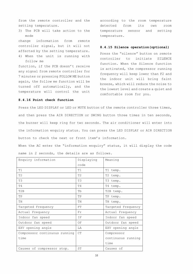
8.4.16 Point check function
Press the LED DISPLAY or LED or MUTE button of the remote controller three times,
and then press the AIR DIRECTION or SWING button three times in ten seconds,
the buzzer will keep ring for two seconds. The air conditioner will enter into
the information enquiry status. You can press the LED DISPLAY or AIR DIRECTION
button to check the next or front item’s information.
When the AC enter the “information enquiry” status, it will display the code
name in 2 seconds, the details are as follows.
Enquiry information Displaying
code
Meaning
T1 T1 T1 temp.
T2 T2 T2 temp.
T3 T3 T3 temp.
T4 T4 T4 temp.
T2B Tb T2B temp.
TP TP TP temp.
TH TH TH temp.
Targeted Frequency FT Targeted Frequency
Actual Frequency Fr Actual Frequency
Indoor fan speed IF Indoor fan speed
Outdoor fan speed OF Outdoor fan speed
EXV opening angle LA EXV opening angle
Compressor continuous running
time
CT Compressor
continuous running
time
Causes of compressor stop. ST Causes of
36
compressor stop.
Reserve A0
Reserve A1
Reserve 0
Reserve 1
Reserve 2
Reserve 3
Reserve 4
Reserve 5
Reserve 6
Reserve L
Reserve A
Reserve U
Reserve T
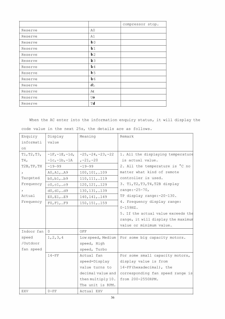
When the AC enter into the information enquiry status, it will display the
code value in the next 25s, the details are as follows.
Enquiry
informati
on
Display
value
Meaning Remark
T1,T2,T3,
T4,
T2B,TP,TH
,
Targeted
Frequency
,
Actual
Frequency
-1F,-1E,-1d,
-1c,-1b,-1A
-25,-24,-23,-22
,-21,-20
1. All the displaying temperature
is actual value.
2. All the temperature is °C no
matter what kind of remote
controller is used.
3. T1,T2,T3,T4,T2B display
range:-25~70,
TP display range:-20~130.
4. Frequency display range:
0~159HZ.
5. If the actual value exceeds the
range, it will display the maximum
value or minimum value.
-19—99 -19—99
A0,A1,…A9 100,101,…109
b0,b1,…b9 110,111,…119
c0,c1,…c9 120,121,…129
d0,d1,…d9 130,131,…139
E0,E1,…E9 140,141,…149
F0,F1,…F9 150,151,…159
Indoor fan
speed
/Outdoor
fan speed
0 OFF
1,2,3,4 Low speed, Medium
speed, High
speed, Turbo
For some big capacity motors.
14-FF Actual fan
speed=Display
value turns to
decimal value and
then multiply 10.
The unit is RPM.
For some small capacity motors,
display value is from
14-FF(hexadecimal), the
corresponding fan speed range is
from 200-2550RPM.
EXV 0-FF Actual EXV
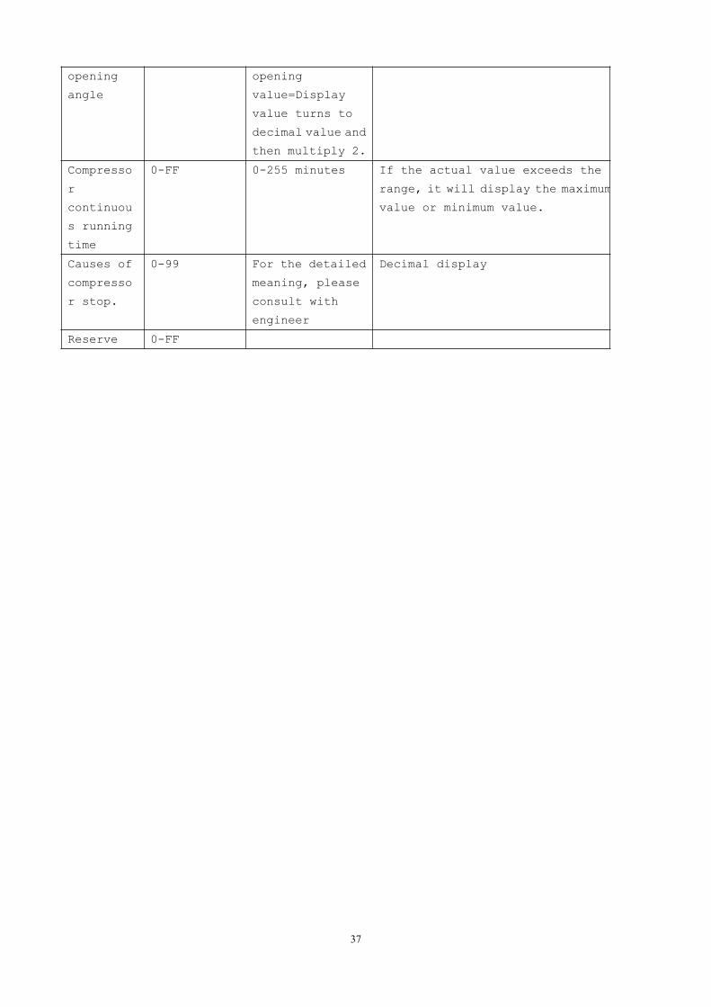
37
opening
angle
opening
value=Display
value turns to
decimal value and
then multiply 2.
Compresso
r
continuou
s running
time
0-FF 0-255 minutes If the actual value exceeds the
range, it will display the maximum
value or minimum value.
Causes of
compresso
r stop.
0-99 For the detailed
meaning, please
consult with
engineer
Decimal display
Reserve 0-FF
38
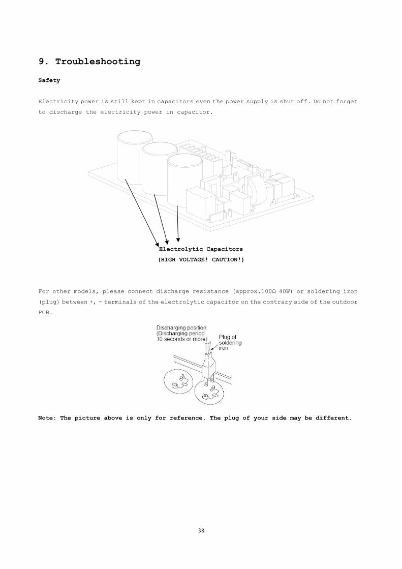
9. Troubleshooting
Safety
Electricity power is still kept in capacitors even the power supply is shut off. Do not forget
to discharge the electricity power in capacitor.
Electrolytic Capacitors
(HIGH VOLTAGE! CAUTION!)
For other models, please connect discharge resistance (approx.100Ω 40W) or soldering iron
(plug) between +, - terminals of the electrolytic capacitor on the contrary side of the outdoor
PCB.
Note: The picture above is only for reference. The plug of your side may be different.
39
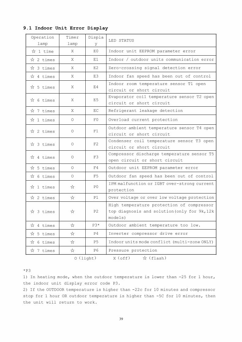
9.1 Indoor Unit Error Display
Operation
lamp
Timer
lamp
Displa
yLED STATUS
1 time X E0 Indoor unit EEPROM parameter error
2 times X E1 Indoor / outdoor units communication error
3 times X E2 Zero-crossing signal detection error
4 times X E3 Indoor fan speed has been out of control
5 times X E4Indoor room temperature sensor T1 open
circuit or short circuit
6 times X E5Evaporator coil temperature sensor T2 open
circuit or short circuit
7 times X EC Refrigerant leakage detection
1 times O F0 Overload current protection
2 times O F1Outdoor ambient temperature sensor T4 open
circuit or short circuit
3 times O F2Condenser coil temperature sensor T3 open
circuit or short circuit
4 times O F3Compressor discharge temperature sensor T5
open circuit or short circuit
5 times O F4 Outdoor unit EEPROM parameter error
6 times O F5 Outdoor fan speed has been out of control
1 times P0IPM malfunction or IGBT over-strong current
protection
2 times P1 Over voltage or over low voltage protection
3 times P2
High temperature protection of compressor
top diagnosis and solution(only for 9k,12k
models)
4 times P3* Outdoor ambient temperature too low.
5 times P4 Inverter compressor drive error
6 times P5 Indoor units mode conflict (multi-zone ONLY)
7 times P6 Pressure protection
O(light) X(off) (flash)
*P3
1) In heating mode, when the outdoor temperature is lower than -25 for 1 hour,
the indoor unit display error code P3.
2) If the OUTDOOR temperature is higher than -22c for 10 minutes and compressor
stop for 1 hour OR outdoor temperature is higher than -5C for 10 minutes, then
the unit will return to work.
40
9.2 Outdoor unit error display(not available)9.3 Diagnosis and Solution9.3.1 EEPROM parameter error diagnosis and solution(E0/F4)
Error Code E0/F4
Malfunction decision
conditions
Indoor or outdoor PCB main chip does not receive
feedback from EEPROM chip.
Supposed causes Installation mistake
PCB faulty
Trouble shooting:
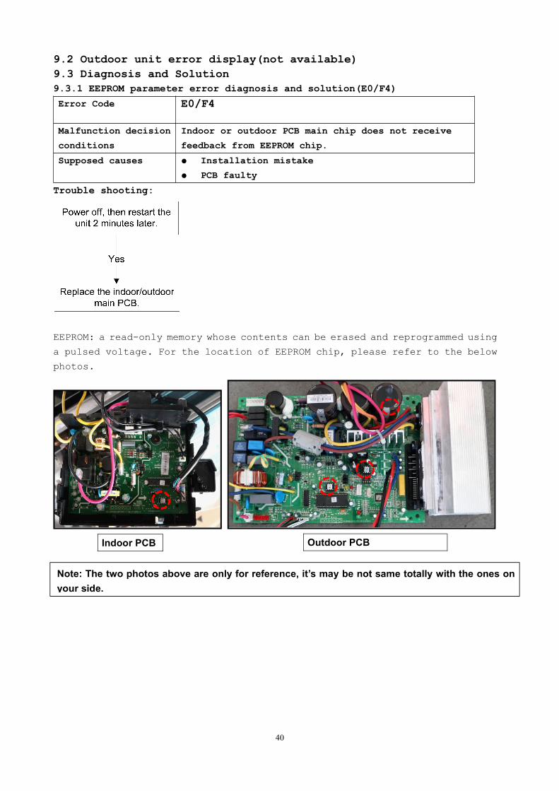
EEPROM: a read-only memory whose contents can be erased and reprogrammed using
a pulsed voltage. For the location of EEPROM chip, please refer to the below
photos.
Indoor PCB Outdoor PCB
Note: The two photos above are only for reference, it’s may be not same totally with the ones onyour side.

41
9.3.2 Indoor / outdoor unit’s communication diagnosis and solution(E1)
Error Code E1
Malfunction
decision
conditions
Indoor unit does not receive the feedback from outdoor
unit during 110 seconds and this condition happens four
times continuously.
Supposed causes Wiring mistake
Indoor or outdoor PCB faulty
Trouble shooting:
* Vs is the voltage between S and N ( for 115V 2014 models)
*Vs is the voltage between 2 and 3 ( for 2015 models)
*
42
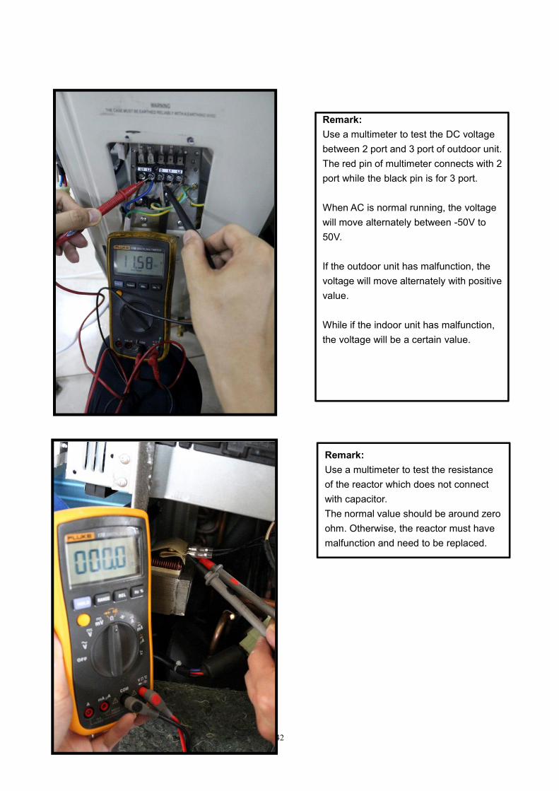
Remark:Use a multimeter to test the DC voltagebetween 2 port and 3 port of outdoor unit.The red pin of multimeter connects with 2port while the black pin is for 3 port.
When AC is normal running, the voltagewill move alternately between -50V to50V.
If the outdoor unit has malfunction, thevoltage will move alternately with positivevalue.
While if the indoor unit has malfunction,the voltage will be a certain value.
Remark:Use a multimeter to test the resistanceof the reactor which does not connectwith capacitor.The normal value should be around zeroohm. Otherwise, the reactor must havemalfunction and need to be replaced.
43
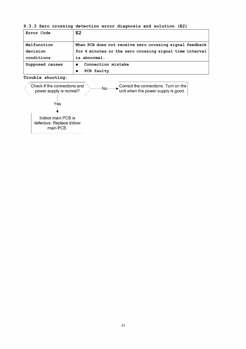
9.3.3 Zero crossing detection error diagnosis and solution (E2)
Error Code E2
Malfunction
decision
conditions
When PCB does not receive zero crossing signal feedback
for 4 minutes or the zero crossing signal time interval
is abnormal.
Supposed causes Connection mistake
PCB faulty
Trouble shooting:
44
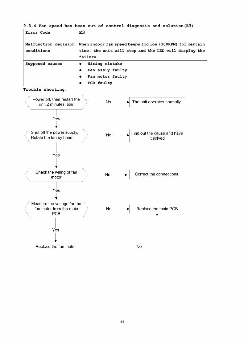
9.3.4 Fan speed has been out of control diagnosis and solution(E3)
Error Code E3
Malfunction decision
conditions
When indoor fan speed keeps too low (300RPM) for certain
time, the unit will stop and the LED will display the
failure.
Supposed causes Wiring mistake
Fan ass’y faulty
Fan motor faulty
PCB faulty
Trouble shooting:
45
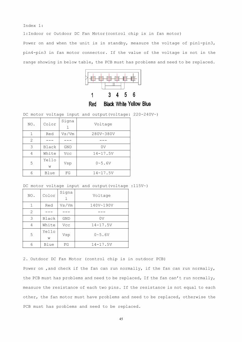
Index 1:
1:Indoor or Outdoor DC Fan Motor(control chip is in fan motor)
Power on and when the unit is in standby, measure the voltage of pin1-pin3,
pin4-pin3 in fan motor connector. If the value of the voltage is not in the
range showing in below table, the PCB must has problems and need to be replaced.
DC motor voltage input and output(voltage: 220-240V~)
NO. ColorSigna
lVoltage
1 Red Vs/Vm 280V~380V
2 --- --- ---
3 Black GND 0V
4 White Vcc 14-17.5V
5Yello
wVsp 0~5.6V
6 Blue FG 14-17.5V
DC motor voltage input and output(voltage :115V~)
NO. ColorSigna
lVoltage
1 Red Vs/Vm 140V~190V
2 --- --- ---
3 Black GND 0V
4 White Vcc 14-17.5V
5Yello
wVsp 0~5.6V
6 Blue FG 14-17.5V
2. Outdoor DC Fan Motor (control chip is in outdoor PCB)
Power on ,and check if the fan can run normally, if the fan can run normally,
the PCB must has problems and need to be replaced, If the fan can’t run normally,
measure the resistance of each two pins. If the resistance is not equal to each
other, the fan motor must have problems and need to be replaced, otherwise the
PCB must has problems and need to be replaced.
46
3. Indoor AC Fan Motor
Power on and set the unit running in fan mode at high fan speed. After running
for 15 seconds, measure the voltage of pin1 and pin2. If the value of the voltage
is less than 100V(208~240V power supply)or 50V(115V power supply), the PCB must
has problems and need to be replaced.
47
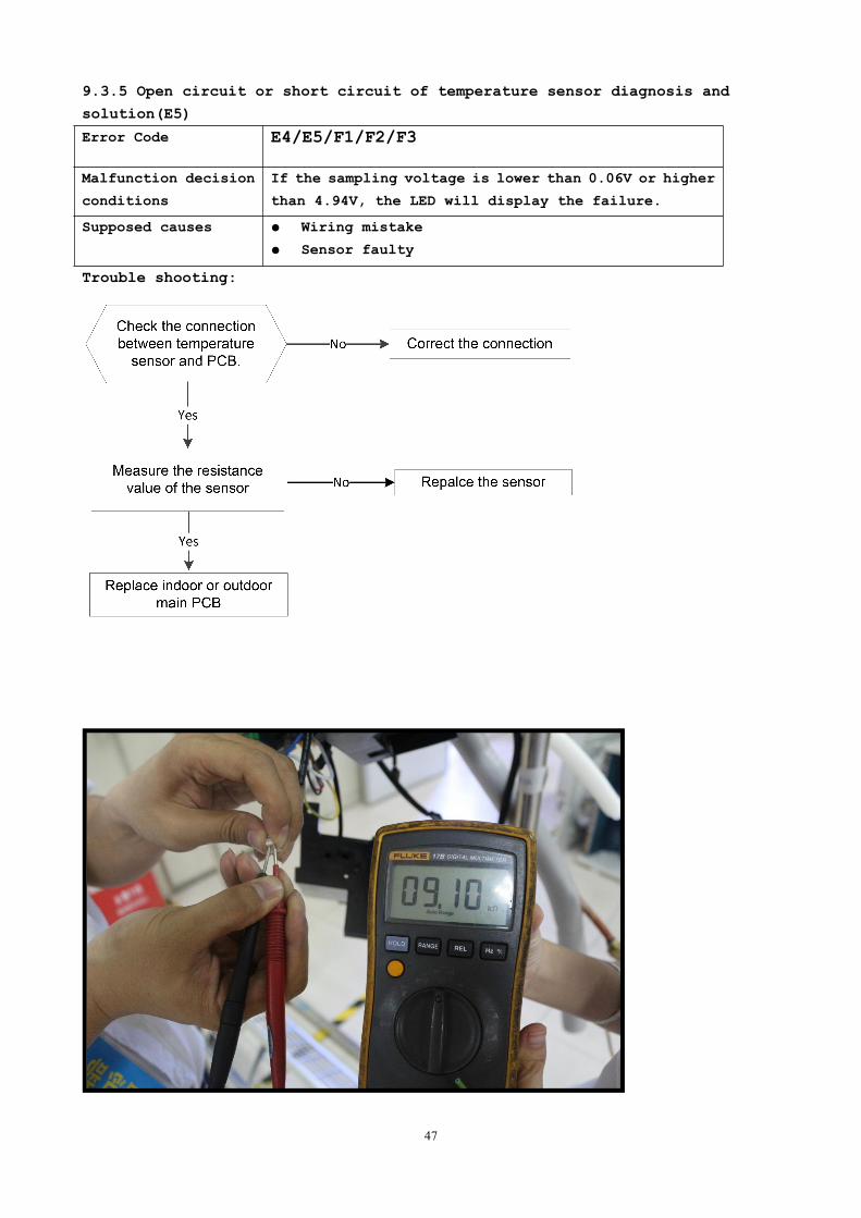
9.3.5 Open circuit or short circuit of temperature sensor diagnosis and
solution(E5)
Error Code E4/E5/F1/F2/F3
Malfunction decision
conditions
If the sampling voltage is lower than 0.06V or higher
than 4.94V, the LED will display the failure.
Supposed causes Wiring mistake
Sensor faulty
PCB faultyTrouble shooting:
48
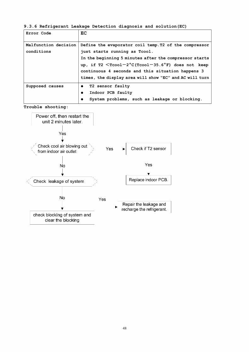
9.3.6 Refrigerant Leakage Detection diagnosis and solution(EC)
Error Code EC
Malfunction decision
conditions
Define the evaporator coil temp.T2 of the compressor
just starts running as Tcool.
In the beginning 5 minutes after the compressor starts
up, if T2 <Tcool-2°C(Tcool-35.6°F) does not keep
continuous 4 seconds and this situation happens 3
times, the display area will show “EC” and AC will turn
off.Supposed causes T2 sensor faulty
Indoor PCB faulty
System problems, such as leakage or blocking.
Trouble shooting:
49
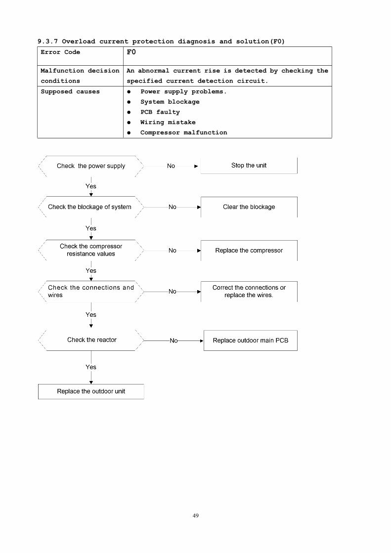
9.3.7 Overload current protection diagnosis and solution(F0)
Error Code F0
Malfunction decision
conditions
An abnormal current rise is detected by checking the
specified current detection circuit.
Supposed causes Power supply problems.
System blockage
PCB faulty
Wiring mistake
Compressor malfunction
50
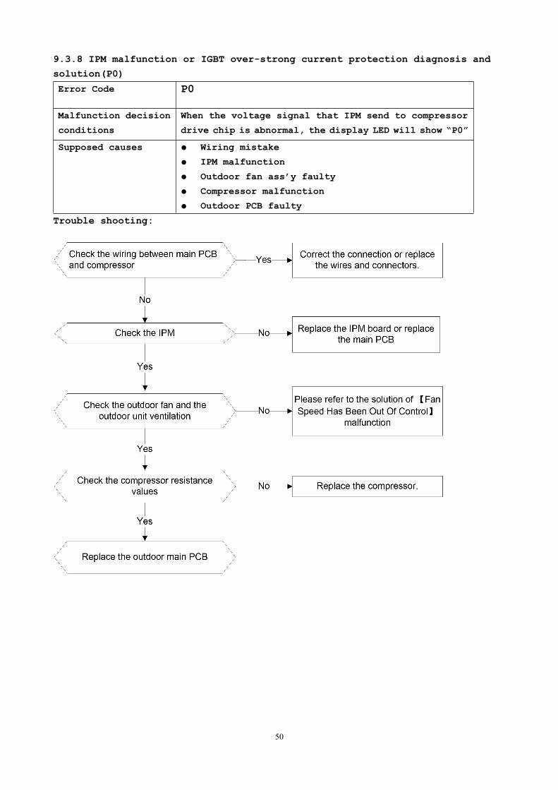
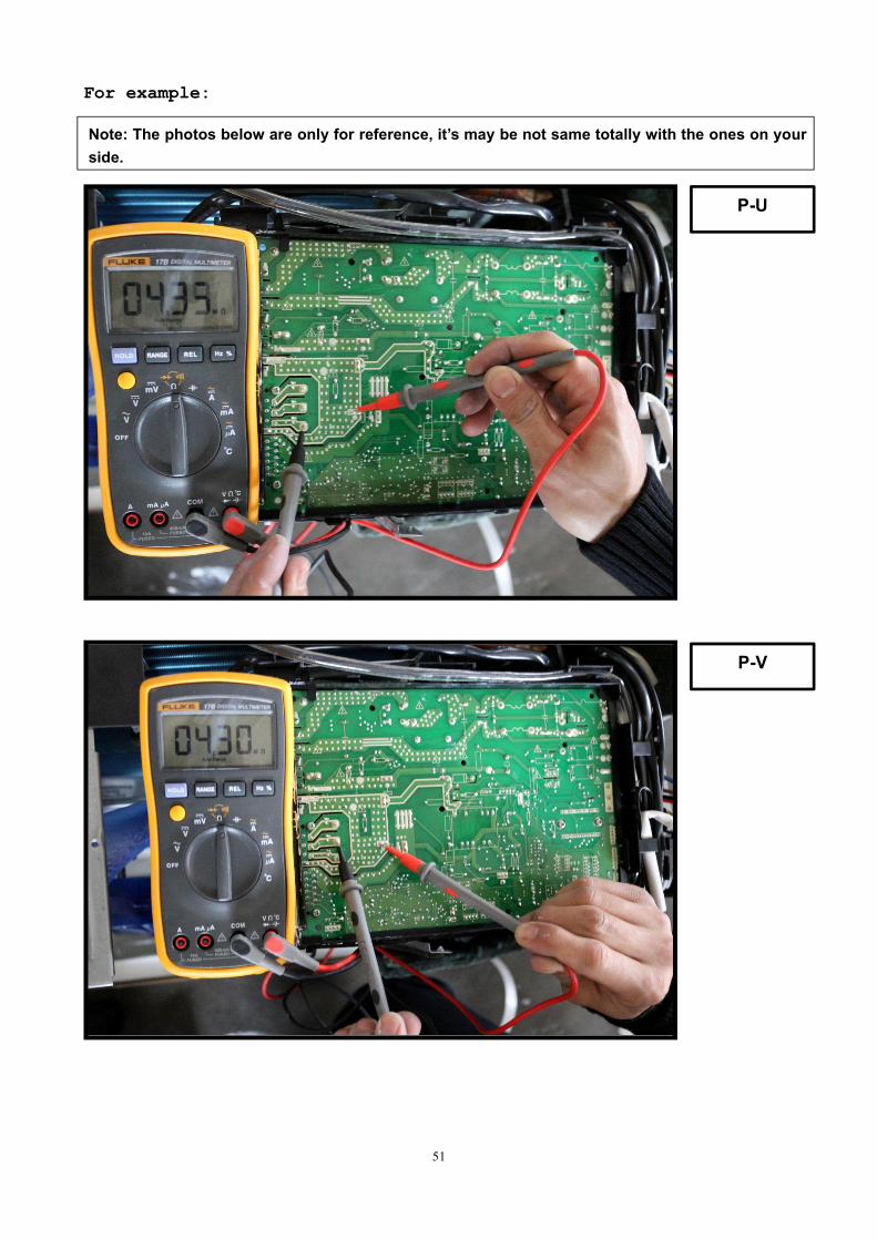
9.3.8 IPM malfunction or IGBT over-strong current protection diagnosis and
solution(P0)
Error Code P0
Malfunction decision
conditions
When the voltage signal that IPM send to compressor
drive chip is abnormal, the display LED will show “P0”
and AC will turn off.Supposed causes Wiring mistake
IPM malfunction
Outdoor fan ass’y faulty
Compressor malfunction
Outdoor PCB faulty
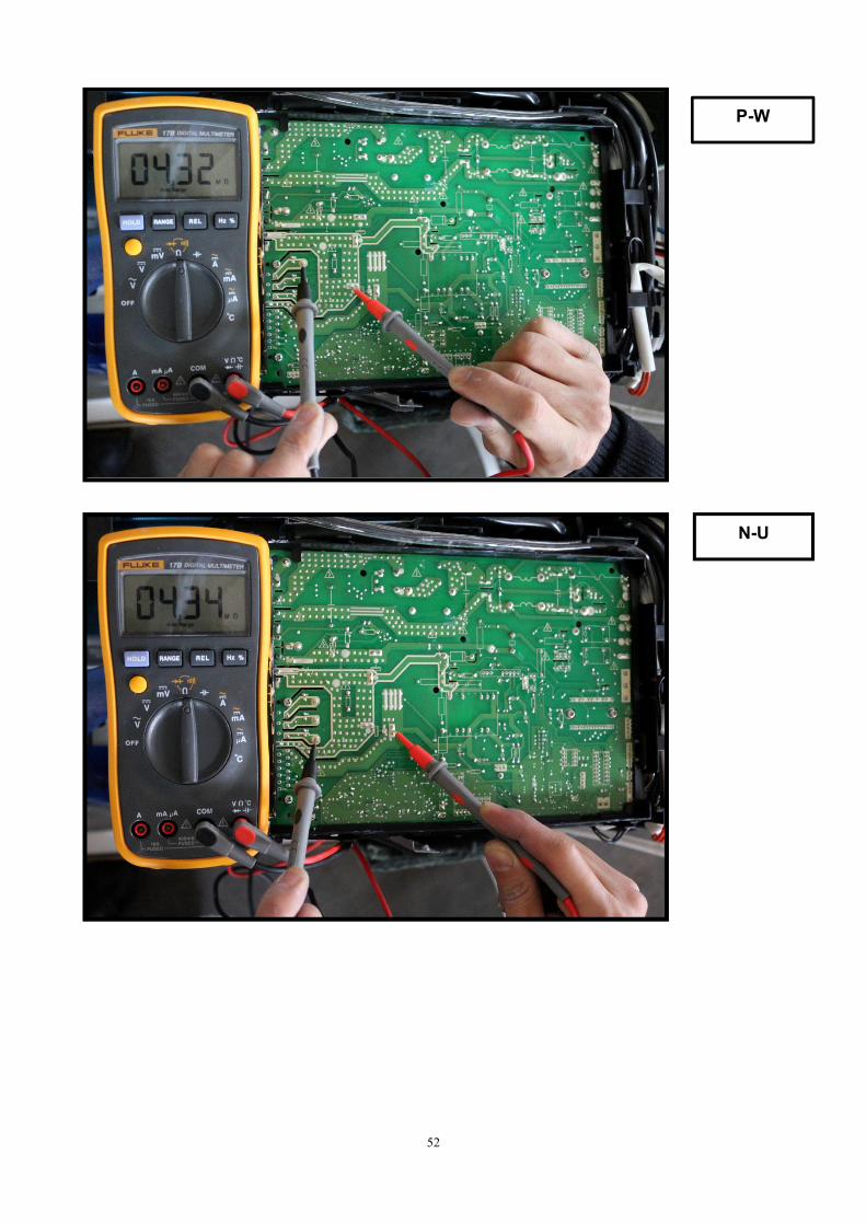
Trouble shooting:
51
For example:
P-U
P-V
Note: The photos below are only for reference, it’s may be not same totally with the ones on yourside.
52
P-W
N-U
53
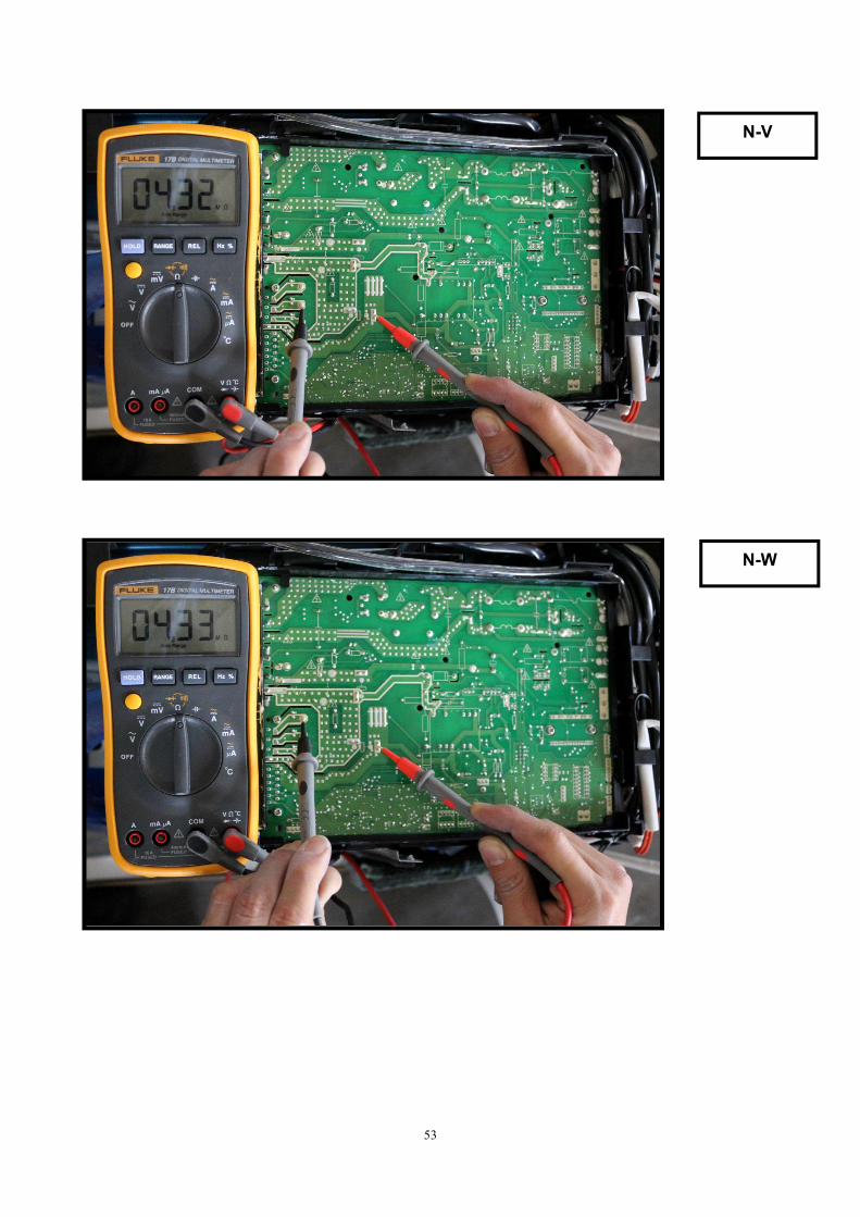
N-V
N-W
54
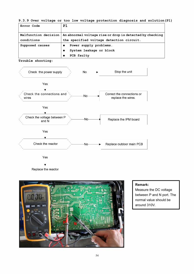
9.3.9 Over voltage or too low voltage protection diagnosis and solution(P1)
Error Code P1
Malfunction decision
conditions
An abnormal voltage rise or drop is detected by checking
the specified voltage detection circuit.
Supposed causes Power supply problems.
System leakage or block
PCB faulty
Trouble shooting:
Remark:Measure the DC voltagebetween P and N port. Thenormal value should bearound 310V.
P N
55
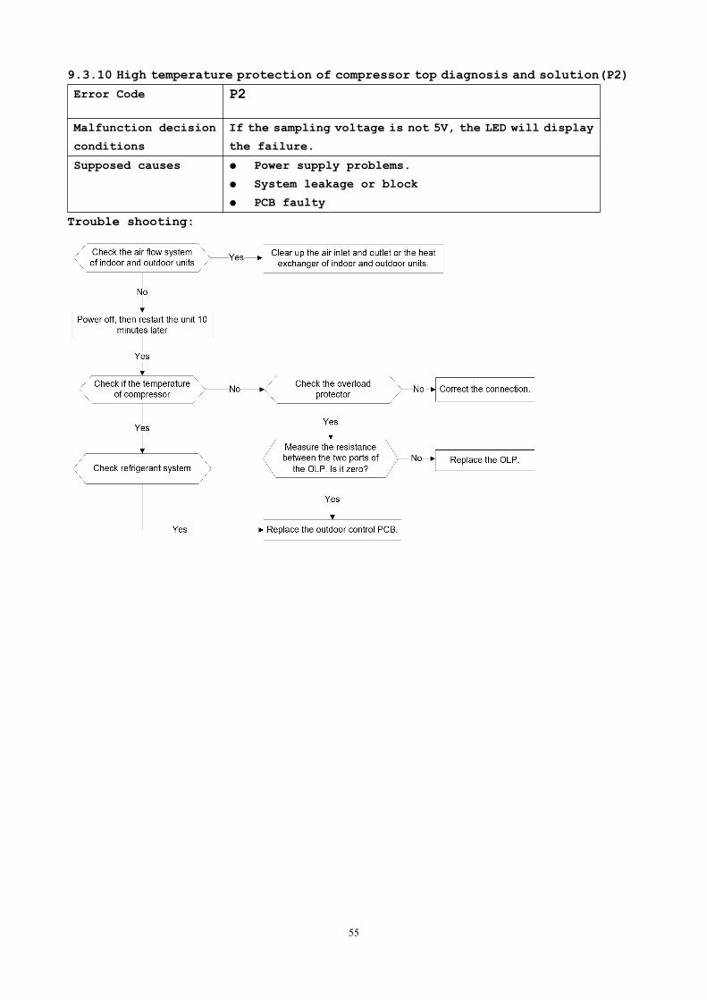
9.3.10 High temperature protection of compressor top diagnosis and solution(P2)
Error Code P2
Malfunction decision
conditions
If the sampling voltage is not 5V, the LED will display
the failure.
Supposed causes Power supply problems.
System leakage or block
PCB faulty
Trouble shooting:
56
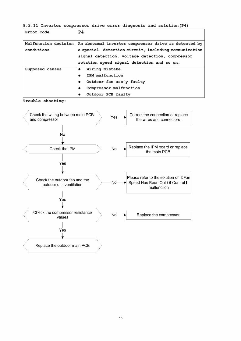
9.3.11 Inverter compressor drive error diagnosis and solution(P4)
Error Code P4
Malfunction decision
conditions
An abnormal inverter compressor drive is detected by
a special detection circuit, including communication
signal detection, voltage detection, compressor
rotation speed signal detection and so on.
Supposed causes Wiring mistake
IPM malfunction
Outdoor fan ass’y faulty
Compressor malfunction
Outdoor PCB faulty
Trouble shooting:
57
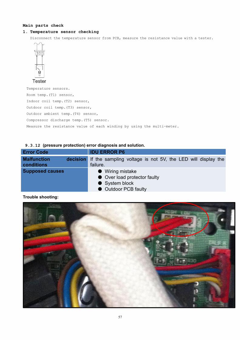
Main parts check
1. Temperature sensor checkingDisconnect the temperature sensor from PCB, measure the resistance value with a tester.
Temperature sensors.
Room temp.(T1) sensor,
Indoor coil temp.(T2) sensor,
Outdoor coil temp.(T3) sensor,
Outdoor ambient temp.(T4) sensor,
Compressor discharge temp.(T5) sensor.
Measure the resistance value of each winding by using the multi-meter.
9.3.12 (pressure protection) error diagnosis and solution.Error Code IDU ERROR P6Malfunction decisionconditions
If the sampling voltage is not 5V, the LED will display thefailure.
Supposed causes Wiring mistake Over load protector faulty System block Outdoor PCB faulty
Trouble shooting:
58
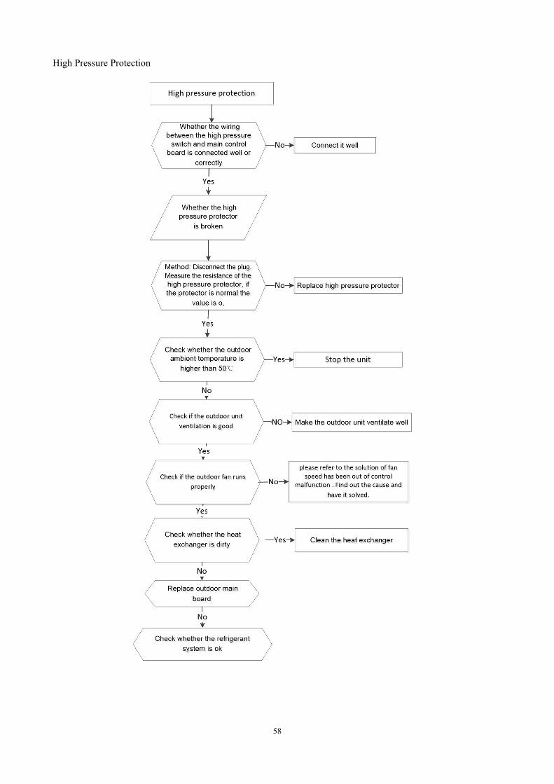
High Pressure Protection
59
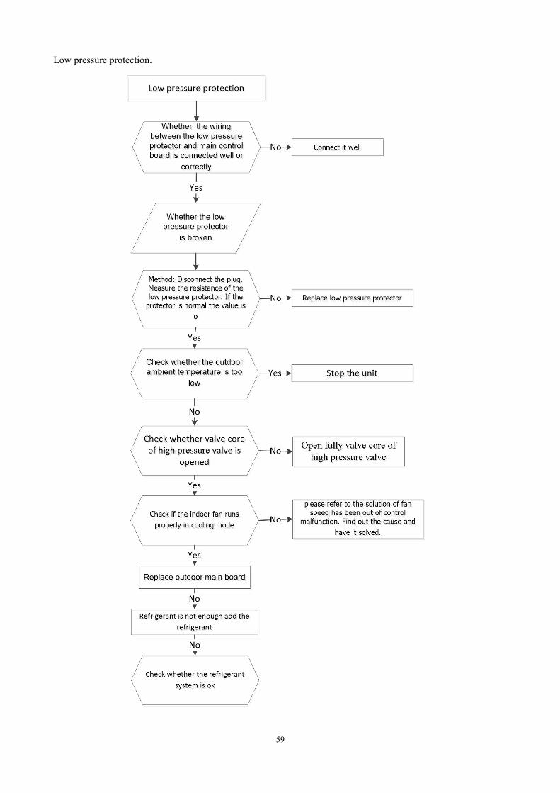
Low pressure protection.
60
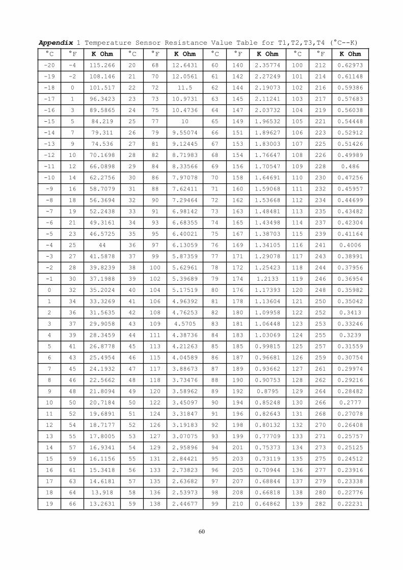
Appendix 1 Temperature Sensor Resistance Value Table for T1,T2,T3,T4 (°C--K)
°C °F K Ohm °C °F K Ohm °C °F K Ohm °C °F K Ohm
-20 -4 115.266 20 68 12.6431 60 140 2.35774 100 212 0.62973
-19 -2 108.146 21 70 12.0561 61 142 2.27249 101 214 0.61148
-18 0 101.517 22 72 11.5 62 144 2.19073 102 216 0.59386
-17 1 96.3423 23 73 10.9731 63 145 2.11241 103 217 0.57683
-16 3 89.5865 24 75 10.4736 64 147 2.03732 104 219 0.56038
-15 5 84.219 25 77 10 65 149 1.96532 105 221 0.54448
-14 7 79.311 26 79 9.55074 66 151 1.89627 106 223 0.52912
-13 9 74.536 27 81 9.12445 67 153 1.83003 107 225 0.51426
-12 10 70.1698 28 82 8.71983 68 154 1.76647 108 226 0.49989
-11 12 66.0898 29 84 8.33566 69 156 1.70547 109 228 0.486
-10 14 62.2756 30 86 7.97078 70 158 1.64691 110 230 0.47256
-9 16 58.7079 31 88 7.62411 71 160 1.59068 111 232 0.45957
-8 18 56.3694 32 90 7.29464 72 162 1.53668 112 234 0.44699
-7 19 52.2438 33 91 6.98142 73 163 1.48481 113 235 0.43482
-6 21 49.3161 34 93 6.68355 74 165 1.43498 114 237 0.42304
-5 23 46.5725 35 95 6.40021 75 167 1.38703 115 239 0.41164
-4 25 44 36 97 6.13059 76 169 1.34105 116 241 0.4006
-3 27 41.5878 37 99 5.87359 77 171 1.29078 117 243 0.38991
-2 28 39.8239 38 100 5.62961 78 172 1.25423 118 244 0.37956
-1 30 37.1988 39 102 5.39689 79 174 1.2133 119 246 0.36954
0 32 35.2024 40 104 5.17519 80 176 1.17393 120 248 0.35982
1 34 33.3269 41 106 4.96392 81 178 1.13604 121 250 0.35042
2 36 31.5635 42 108 4.76253 82 180 1.09958 122 252 0.3413
3 37 29.9058 43 109 4.5705 83 181 1.06448 123 253 0.33246
4 39 28.3459 44 111 4.38736 84 183 1.03069 124 255 0.3239
5 41 26.8778 45 113 4.21263 85 185 0.99815 125 257 0.31559
6 43 25.4954 46 115 4.04589 86 187 0.96681 126 259 0.30754
7 45 24.1932 47 117 3.88673 87 189 0.93662 127 261 0.29974
8 46 22.5662 48 118 3.73476 88 190 0.90753 128 262 0.29216
9 48 21.8094 49 120 3.58962 89 192 0.8795 129 264 0.28482
10 50 20.7184 50 122 3.45097 90 194 0.85248 130 266 0.2777
11 52 19.6891 51 124 3.31847 91 196 0.82643 131 268 0.27078
12 54 18.7177 52 126 3.19183 92 198 0.80132 132 270 0.26408
13 55 17.8005 53 127 3.07075 93 199 0.77709 133 271 0.25757
14 57 16.9341 54 129 2.95896 94 201 0.75373 134 273 0.25125
15 59 16.1156 55 131 2.84421 95 203 0.73119 135 275 0.24512
16 61 15.3418 56 133 2.73823 96 205 0.70944 136 277 0.23916
17 63 14.6181 57 135 2.63682 97 207 0.68844 137 279 0.23338
18 64 13.918 58 136 2.53973 98 208 0.66818 138 280 0.22776
19 66 13.2631 59 138 2.44677 99 210 0.64862 139 282 0.22231
61
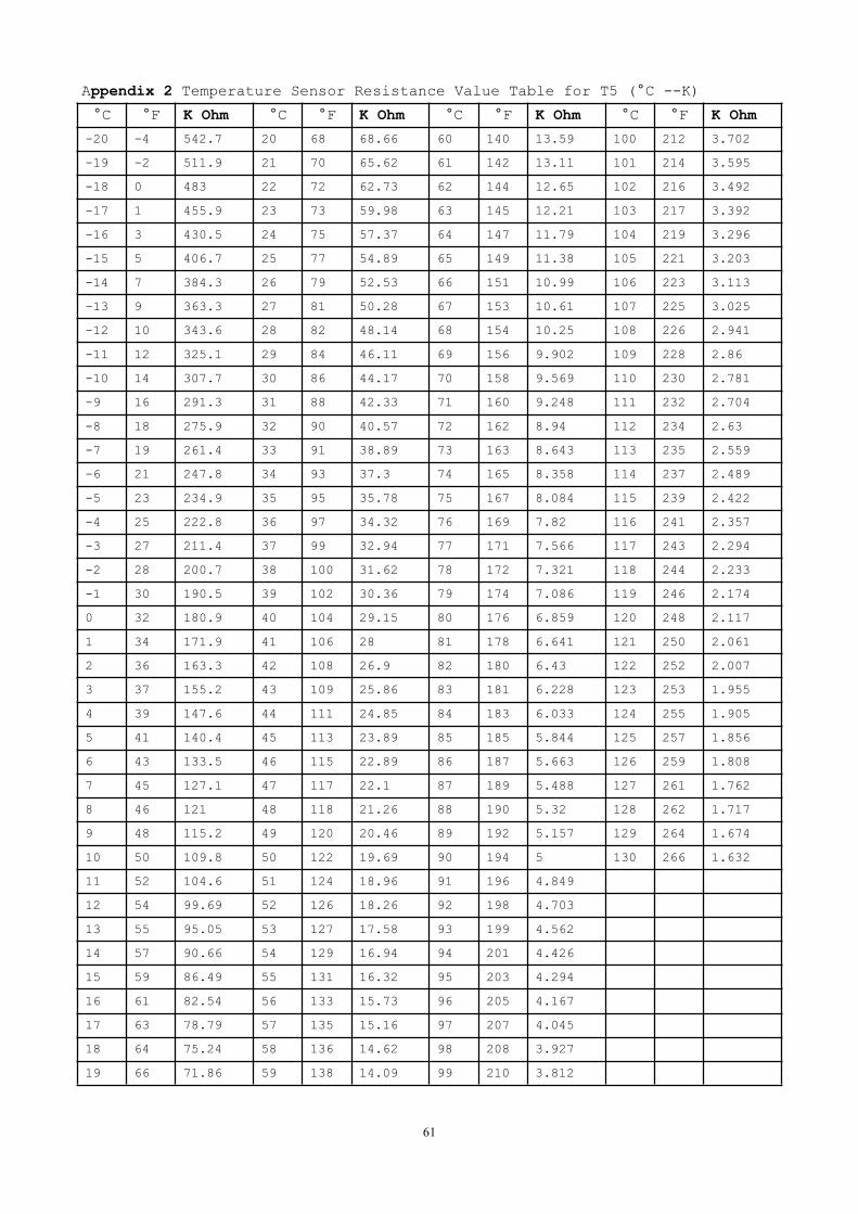
Appendix 2 Temperature Sensor Resistance Value Table for T5 (°C --K)
°C °F K Ohm °C °F K Ohm °C °F K Ohm °C °F K Ohm
-20 -4 542.7 20 68 68.66 60 140 13.59 100 212 3.702
-19 -2 511.9 21 70 65.62 61 142 13.11 101 214 3.595
-18 0 483 22 72 62.73 62 144 12.65 102 216 3.492
-17 1 455.9 23 73 59.98 63 145 12.21 103 217 3.392
-16 3 430.5 24 75 57.37 64 147 11.79 104 219 3.296
-15 5 406.7 25 77 54.89 65 149 11.38 105 221 3.203
-14 7 384.3 26 79 52.53 66 151 10.99 106 223 3.113
-13 9 363.3 27 81 50.28 67 153 10.61 107 225 3.025
-12 10 343.6 28 82 48.14 68 154 10.25 108 226 2.941
-11 12 325.1 29 84 46.11 69 156 9.902 109 228 2.86
-10 14 307.7 30 86 44.17 70 158 9.569 110 230 2.781
-9 16 291.3 31 88 42.33 71 160 9.248 111 232 2.704
-8 18 275.9 32 90 40.57 72 162 8.94 112 234 2.63
-7 19 261.4 33 91 38.89 73 163 8.643 113 235 2.559
-6 21 247.8 34 93 37.3 74 165 8.358 114 237 2.489
-5 23 234.9 35 95 35.78 75 167 8.084 115 239 2.422
-4 25 222.8 36 97 34.32 76 169 7.82 116 241 2.357
-3 27 211.4 37 99 32.94 77 171 7.566 117 243 2.294
-2 28 200.7 38 100 31.62 78 172 7.321 118 244 2.233
-1 30 190.5 39 102 30.36 79 174 7.086 119 246 2.174
0 32 180.9 40 104 29.15 80 176 6.859 120 248 2.117
1 34 171.9 41 106 28 81 178 6.641 121 250 2.061
2 36 163.3 42 108 26.9 82 180 6.43 122 252 2.007
3 37 155.2 43 109 25.86 83 181 6.228 123 253 1.955
4 39 147.6 44 111 24.85 84 183 6.033 124 255 1.905
5 41 140.4 45 113 23.89 85 185 5.844 125 257 1.856
6 43 133.5 46 115 22.89 86 187 5.663 126 259 1.808
7 45 127.1 47 117 22.1 87 189 5.488 127 261 1.762
8 46 121 48 118 21.26 88 190 5.32 128 262 1.717
9 48 115.2 49 120 20.46 89 192 5.157 129 264 1.674
10 50 109.8 50 122 19.69 90 194 5 130 266 1.632
11 52 104.6 51 124 18.96 91 196 4.849
12 54 99.69 52 126 18.26 92 198 4.703
13 55 95.05 53 127 17.58 93 199 4.562
14 57 90.66 54 129 16.94 94 201 4.426
15 59 86.49 55 131 16.32 95 203 4.294
16 61 82.54 56 133 15.73 96 205 4.167
17 63 78.79 57 135 15.16 97 207 4.045
18 64 75.24 58 136 14.62 98 208 3.927
19 66 71.86 59 138 14.09 99 210 3.812
62
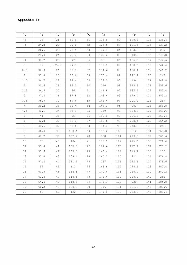
Appendix 3:
°C °F °C °F °C °F °C °F °C °F
-5 23 21 69.8 51 123.8 82 179.6 113 235.4
-4 24.8 22 71.6 52 125.6 83 181.4 114 237.2
-3 26.6 23 73.4 53 127.4 84 183.2 115 239
-2 28.4 24 75.2 54 129.2 85 185 116 240.8
-1 30.2 25 77 55 131 86 186.8 117 242.6
0 32 25.5 77.9 56 132.8 87 188.6 118 244.4
0.5 32.9 26 78.8 57 134.6 88 190.4 119 246.2
1 33.8 27 80.6 58 136.4 89 192.2 120 248
1.5 34.7 28 82.4 59 138.2 90 194 121 249.8
2 35.6 29 84.2 60 140 91 195.8 122 251.6
2.5 36.5 30 86 61 141.8 92 197.6 123 253.4
3 37.4 31 87.8 62 143.6 93 199.4 124 255.2
3.5 38.3 32 89.6 63 145.4 94 201.2 125 257
4 39.2 33 91.4 64 147.2 95 203 126 258.8
4.5 40.1 34 93.2 65 149 96 204.8 127 260.6
5 41 35 95 66 150.8 97 206.6 128 262.4
6 42.8 36 96.8 67 152.6 98 208.4 129 264.2
7 44.6 37 98.6 68 154.4 99 210.2 130 266
8 46.4 38 100.4 69 156.2 100 212 131 267.8
9 48.2 39 102.2 70 158 101 213.8 132 269.6
10 50 40 104 71 159.8 102 215.6 133 271.4
11 51.8 41 105.8 72 161.6 103 217.4 134 273.2
12 53.6 42 107.6 73 163.4 104 219.2 135 275
13 55.4 43 109.4 74 165.2 105 221 136 276.8
14 57.2 44 111.2 75 167 106 222.8 137 278.6
15 59 45 113 76 168.8 107 224.6 138 280.4
16 60.8 46 114.8 77 170.6 108 226.4 139 282.2
17 62.6 47 116.6 78 172.4 109 228.2 140 284
18 64.4 48 118.4 79 174.2 110 230 141 285.8
19 66.2 49 120.2 80 176 111 231.8 142 287.6
20 68 50 122 81 177.8 112 233.6 143 289.4
63
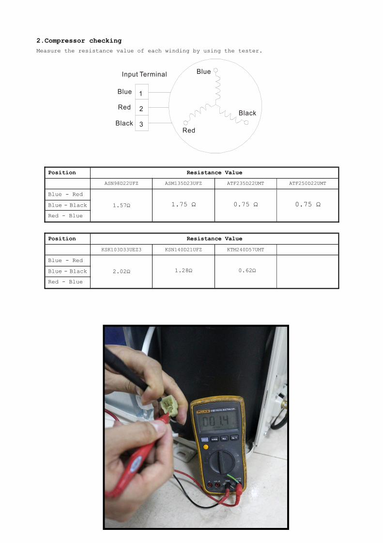
2.Compressor checkingMeasure the resistance value of each winding by using the tester.
Position Resistance Value
ASN98D22UFZ ASM135D23UFZ ATF235D22UMT ATF250D22UMT
Blue - Red
1.57Ω 1.75 Ω 0.75 Ω 0.75 ΩBlue - Black
Red - Blue
Position Resistance Value
KSK103D33UEZ3 KSN140D21UFZ KTM240D57UMT
Blue - Red
2.02Ω 1.28Ω 0.62ΩBlue - Black
Red - Blue
64
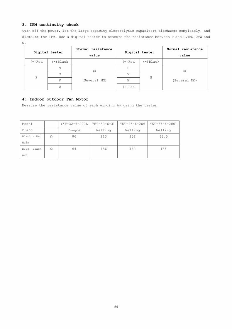
3. IPM continuity checkTurn off the power, let the large capacity electrolytic capacitors discharge completely, and
dismount the IPM. Use a digital tester to measure the resistance between P and UVWN; UVW and
N.
Digital testerNormal resistance
valueDigital tester
Normal resistance
value
(+)Red (-)Black
∞
(Several MΩ)
(+)Red (-)Black
∞
(Several MΩ)P
N U
NU V
V W
W (+)Red
4: Indoor outdoor Fan MotorMeasure the resistance value of each winding by using the tester.
Model YKT-32-6-202L YKT-32-6-3L YKT-48-6-206 YKT-63-6-200L
Brand Tongde Welling Welling Welling
Black – Red
Main
Ω 86 213 152 88.5
Blue –Black
AUX
Ω 64 156 142 138
65
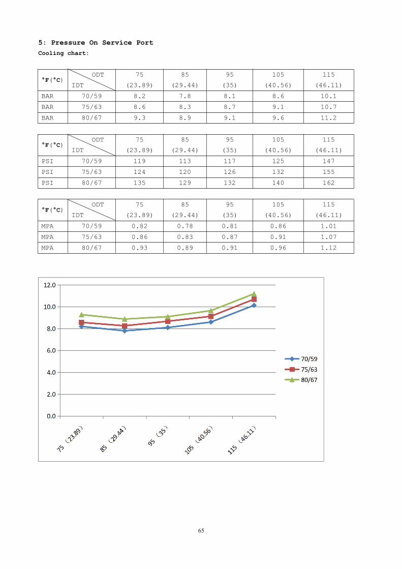
5: Pressure On Service PortCooling chart:
°F(°C)ODT
IDT
75
(23.89)
85
(29.44)
95
(35)
105
(40.56)
115
(46.11)
BAR 70/59 8.2 7.8 8.1 8.6 10.1
BAR 75/63 8.6 8.3 8.7 9.1 10.7
BAR 80/67 9.3 8.9 9.1 9.6 11.2
°F(°C)ODT
IDT
75
(23.89)
85
(29.44)
95
(35)
105
(40.56)
115
(46.11)
PSI 70/59 119 113 117 125 147
PSI 75/63 124 120 126 132 155
PSI 80/67 135 129 132 140 162
°F(°C)ODT
IDT
75
(23.89)
85
(29.44)
95
(35)
105
(40.56)
115
(46.11)
MPA 70/59 0.82 0.78 0.81 0.86 1.01
MPA 75/63 0.86 0.83 0.87 0.91 1.07
MPA 80/67 0.93 0.89 0.91 0.96 1.12
66
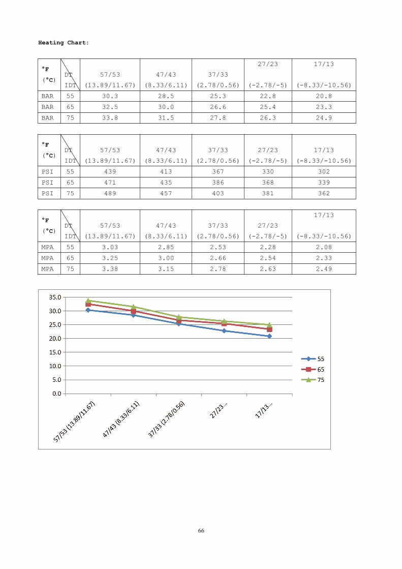
Heating Chart:
°F
(°C)
O
DT
IDT
57/53
(13.89/11.67)
47/43
(8.33/6.11)
37/33
(2.78/0.56)
27/23
(-2.78/-5)
17/13
(-8.33/-10.56)
BAR 55 30.3 28.5 25.3 22.8 20.8
BAR 65 32.5 30.0 26.6 25.4 23.3
BAR 75 33.8 31.5 27.8 26.3 24.9
°F
(°C)
O
DT
IDT
57/53
(13.89/11.67)
47/43
(8.33/6.11)
37/33
(2.78/0.56)
27/23
(-2.78/-5)
17/13
(-8.33/-10.56)
PSI 55 439 413 367 330 302
PSI 65 471 435 386 368 339
PSI 75 489 457 403 381 362
°F
(°C)
O
DT
IDT
57/53
(13.89/11.67)
47/43
(8.33/6.11)
37/33
(2.78/0.56)
27/23
(-2.78/-5)
17/13
(-8.33/-10.56)
MPA 55 3.03 2.85 2.53 2.28 2.08
MPA 65 3.25 3.00 2.66 2.54 2.33
MPA 75 3.38 3.15 2.78 2.63 2.49
67
Update log
1,1/21/2017,P14, change the 36K cycling diagram. Add low and high pressure
protector on the diagram.
2,1/21/2017.P54, Add P6 error code and trouble shooting.
3, 12/18/2018, add CPG-B, CHX*(I) Models.
Related Documents