Ziza® Interior Lighting Package Installation Procedures R Part Number ES2523973 for BMW E39 (5 Series) (1996-2003) This tutorial is provided as a courtesy by ECS Tuning. Proper service and repair procedures are vital to the safe, reliable operation of all motor vehicles as well as the personal safety of those performing the repairs. Standard safety procedures and precautions (including use of safety goggles and proper tools and equipment) should be followed at all times to eliminate the possibility of personal injury or improper service which could damage the vehicle or compromise its safety. Although this material has been prepared with the intent to provide reliable information, no warranty (express or implied) is made as to its accuracy or completeness. Neither is any liability assumed for loss or damage resulting from reliance on this mate- rial. SPECIFICALLY, NO WARRANTY OF MERCHANTABILITY, FITNESS FOR A PARTICULAR PURPOSE OR ANY OTHER WARRANTY IS MADE OR TO BE IMPLIED WITH RESPECT TO THIS MATERIAL. In no event will ECS Tuning, Incorporated or its affiliates be liable for any damages, direct or indirect, consequential or compensatory, arising out of the use of this material.

Welcome message from author
This document is posted to help you gain knowledge. Please leave a comment to let me know what you think about it! Share it to your friends and learn new things together.
Transcript
Ziza® Interior Lighting Package Installation Procedures
R
Part Number ES2523973
for BMW E39(5 Series)
(1996-2003) This tutorial is provided as a courtesy by ECS Tuning.
Proper service and repair procedures are vital to the safe, reliable operation of all motor vehicles as well as the personal safety of those performing the repairs. Standard safety procedures and precautions (including use of safety goggles and proper tools and equipment) should be followed at all times to eliminate the possibility of personal injury or improper service which could damage the vehicle or compromise its safety.
Although this material has been prepared with the intent to provide reliable information, no warranty (express or implied) is made as to its accuracy or completeness. Neither is any liability assumed for loss or damage resulting from reliance on this mate-rial. SPECIFICALLY, NO WARRANTY OF MERCHANTABILITY, FITNESS FOR A PARTICULAR PURPOSE OR ANY OTHER WARRANTY IS MADE OR TO BE IMPLIED WITH RESPECT TO THIS MATERIAL. In no event will ECS Tuning, Incorporated or its affiliates be liable for any damages, direct or indirect, consequential or compensatory, arising out of the use of this material.
Address: 1000 Seville Road, Wadsworth, OH 44281 Phone: 1.800.924.5172 Web: www.ecstuning.com
Page - 2
Ziza Interior Lighting Package InstallationES2523973
Fits BMW E39 5-Series
R
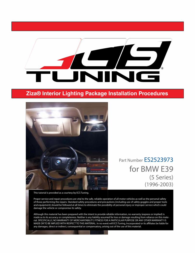
Kit Contents5-chip wedge base white LED (qty 4)9-chip wedge base white LED (qty 1)
36mm white LED festoon (qty 5)42 mm white LED festoon (qty 8)
ToolsTrim removal tool – ES517779 (Kit)
R
LED Installation InstructionsInterior Lighting Kit for BMW E39ES2523973
Make the job easier and prevent damage to headliners and other interior trim with ECS Tuning Trim and Molding
Removal Tool Sets: ES2500877 and ES517779.
This tutorial explains how to install the LEDs in your Ziza Interior Lighting Kit.

Address: 1000 Seville Road, Wadsworth, OH 44281 Phone: 1.800.924.5172 Web: www.ecstuning.com
Ziza Interior Lighting Package InstallationES2523973
Fits BMW E39 5-Series
R
Bulb TypesThis kit includes three bulb types, classified by their general shape.
FESTOON - Conventional incandescent festoon bulbs have a shape and general appearance that is similar to a glass fuse.
Metal caps attached to both ends of a glass tube are sealed to the tube and attached to the bulb filament. End caps mount the bulb in its holder and also conduct electrical current.
LED festoon lights have the same pointed end caps, but are attached to a bank of LEDs instead of a filament tube.
WEDGE - Wedge style bulbs get their name from the shape of the bulb base. The tapered end of the bulb “wedges” into the bulb socket.
LED wedge lights fit the bulb socket like a filament bulb, but are polarity sensitive.
BAYONET - The bayonet base is formed by a metal tube with radial pins on its side that engage holes or tabs in the bulb socket. A central electrical nub contact at the tapered base of the bulb connects the bulb to voltage.
While these are also polarity sensitive, the socket design automatically orients the bulb, ensuring correct polarity.
What are LEDs?LEDs are Light Emitting Diodes, solid state devices that emit light when connected to electrical current. They have no moving parts or wire filaments to burn out. They emit a whiter light, run cooler, and last longer that the incandescent (filament style bulbs) we are replacing in this tutorial.
Unlike filament bulbs, LEDs are polarity sensitive. They have plus and minus (positive and negative) electrical terminals that must match the polarity of the applied voltage. Installing the bulbs “backwards” in the light bulb sockets (with reversed polarity) will not harm them, but they will not light. Flipping the bulb 180 degrees in the electrical connector cures this problem.
festoon
wedge
bayonet
Address: 1000 Seville Road, Wadsworth, OH 44281 Phone: 1.800.924.5172 Web: www.ecstuning.com
Page - 4
Ziza Interior Lighting Package InstallationES2523973
Fits BMW E39 5-Series
R
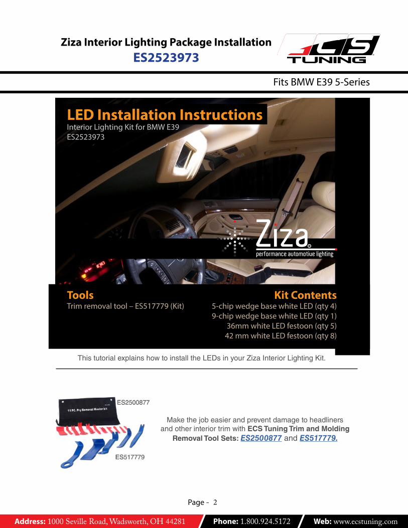
LEDbackfront
notchlens frontnon mar pry tool
Bulbs
festoon
assembly removal
incandescent
electrical connector
lens backspring bulb retainer
lens side clip
metal collar in trim panel
retaining clip (plastic or metal)
notch
General Tips• When prying down on the assemblies to remove them, pry on the notched end of
the lens. Insert the narrow tool tip between the lens plastic and any metal collar used to reinforce the lens mounting hole. Push in on the retaining clip first to compress and release it. Then pry down.
• The spring bulb retainer is also the circuit conductor. If necessary, gently bend the metal retainer so it holds the bulb tight. This will help prevent intermittent or flickering LED operation caused by a loose connection.
• Install the bulbs with the LEDs facing toward the lens.
Address: 1000 Seville Road, Wadsworth, OH 44281 Phone: 1.800.924.5172 Web: www.ecstuning.com
Page - 5
Ziza Interior Lighting Package InstallationES2523973
Fits BMW E39 5-Series
R
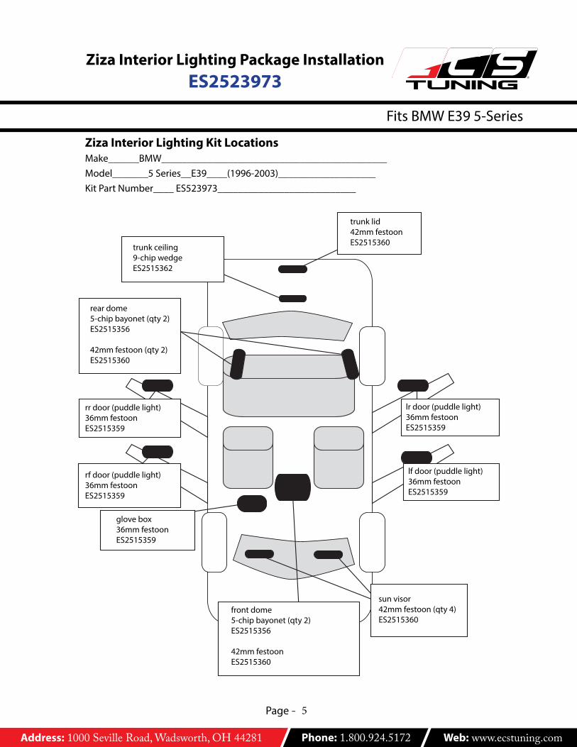
rf door (puddle light)36mm festoonES2515359
lf door (puddle light)36mm festoonES2515359
rr door (puddle light)36mm festoonES2515359
lr door (puddle light)36mm festoonES2515359
trunk lid42mm festoonES2515360
Ziza Interior Lighting Kit LocationsMake______BMW____________________________________________Model_______5 Series__E39____(1996-2003)___________________Kit Part Number____ ES523973___________________________
rear dome5-chip bayonet (qty 2)ES2515356
42mm festoon (qty 2)ES2515360
glove box36mm festoonES2515359
sun visor42mm festoon (qty 4)ES2515360
front dome5-chip bayonet (qty 2)ES2515356
42mm festoonES2515360
trunk ceiling9-chip wedgeES2515362
Address: 1000 Seville Road, Wadsworth, OH 44281 Phone: 1.800.924.5172 Web: www.ecstuning.com
Page - 6
Ziza Interior Lighting Package InstallationES2523973
Fits BMW E39 5-Series
R
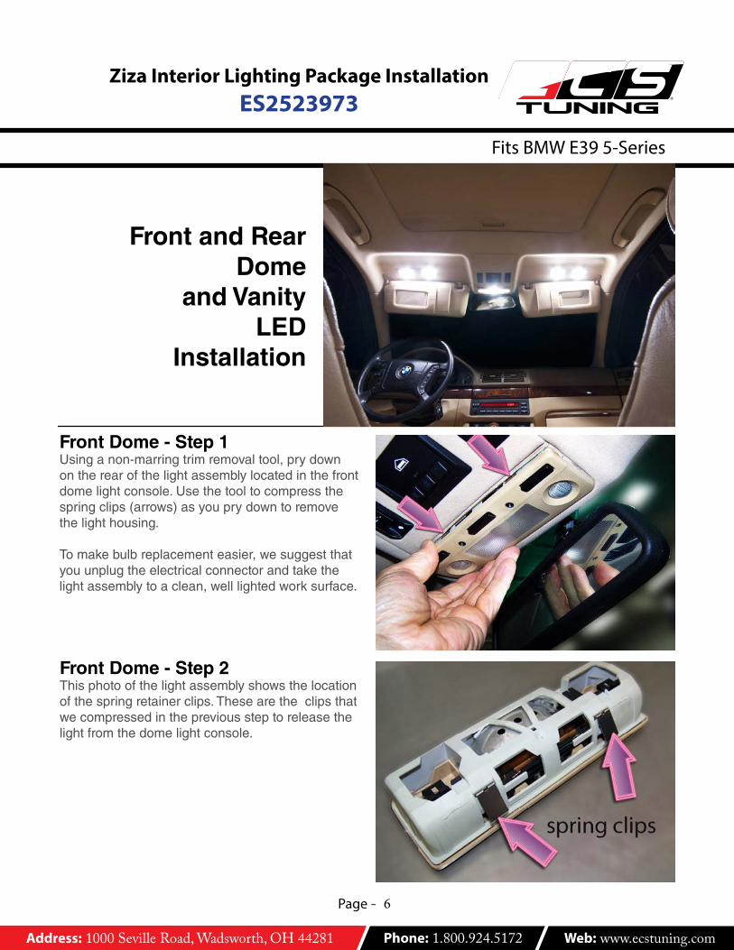
Front Dome - Step 1Using a non-marring trim removal tool, pry down on the rear of the light assembly located in the front dome light console. Use the tool to compress the spring clips (arrows) as you pry down to remove the light housing.
To make bulb replacement easier, we suggest that you unplug the electrical connector and take the light assembly to a clean, well lighted work surface.
Front and Rear Dome
and Vanity LED
Installation
Front Dome - Step 2This photo of the light assembly shows the location of the spring retainer clips. These are the clips that we compressed in the previous step to release the light from the dome light console.
Address: 1000 Seville Road, Wadsworth, OH 44281 Phone: 1.800.924.5172 Web: www.ecstuning.com
Page - 7
Ziza Interior Lighting Package InstallationES2523973
Fits BMW E39 5-Series
R
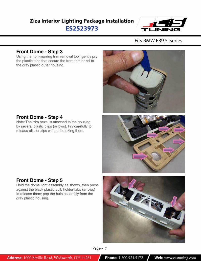
Front Dome - Step 3Using the non-marring trim removal tool, gently pry the plastic tabs that secure the front trim bezel to the gray plastic outer housing.
Front Dome - Step 4Note: The trim bezel is attached to the housing by several plastic clips (arrows). Pry carefully to release all the clips without breaking them.
Front Dome - Step 5Hold the dome light assembly as shown, then press against the black plastic bulb holder tabs (arrows) to release them; pop the bulb assembly from the gray plastic housing.

Address: 1000 Seville Road, Wadsworth, OH 44281 Phone: 1.800.924.5172 Web: www.ecstuning.com
Page - 8
Ziza Interior Lighting Package InstallationES2523973
Fits BMW E39 5-Series
R
Front Dome - Step 6The bulb assembly holds a single festoon and two bayonet base filament bulbs.
Front Dome - Step 7Note that the two bayonet filament bulbs are installed at an angle in the bulb sockets. This is normal.
The new 5-chip bayonet base LEDs must be installed at the same angle or they will not work.
Front Dome - Step 8This photo shows how the new LED is installed at the same angle as the glass bulb it replaces.
Install both bayonet LEDs and a 42mm festoon LED array in the center bulb holder.
Address: 1000 Seville Road, Wadsworth, OH 44281 Phone: 1.800.924.5172 Web: www.ecstuning.com
Page - 9
Ziza Interior Lighting Package InstallationES2523973
Fits BMW E39 5-Series
R
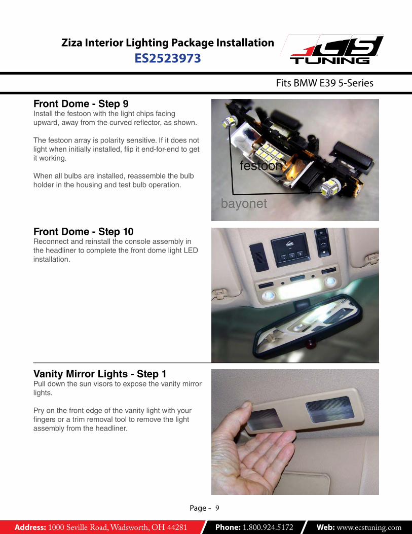
Front Dome - Step 9Install the festoon with the light chips facing upward, away from the curved reflector, as shown.
The festoon array is polarity sensitive. If it does not light when initially installed, flip it end-for-end to get it working.
When all bulbs are installed, reassemble the bulb holder in the housing and test bulb operation.
Vanity Mirror Lights - Step 1Pull down the sun visors to expose the vanity mirror lights.
Pry on the front edge of the vanity light with your fingers or a trim removal tool to remove the light assembly from the headliner.
Front Dome - Step 10Reconnect and reinstall the console assembly in the headliner to complete the front dome light LED installation.
Address: 1000 Seville Road, Wadsworth, OH 44281 Phone: 1.800.924.5172 Web: www.ecstuning.com
Page - 10
Ziza Interior Lighting Package InstallationES2523973
Fits BMW E39 5-Series
R
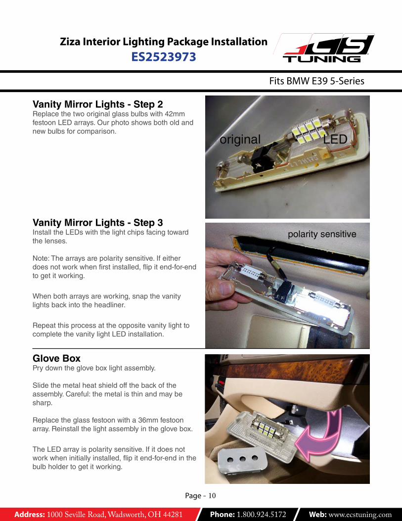
Vanity Mirror Lights - Step 2Replace the two original glass bulbs with 42mm festoon LED arrays. Our photo shows both old and new bulbs for comparison.
Vanity Mirror Lights - Step 3Install the LEDs with the light chips facing toward the lenses.
Note: The arrays are polarity sensitive. If either does not work when first installed, flip it end-for-end to get it working.
When both arrays are working, snap the vanity lights back into the headliner.
Repeat this process at the opposite vanity light to complete the vanity light LED installation.
Glove BoxPry down the glove box light assembly.
Slide the metal heat shield off the back of the assembly. Careful: the metal is thin and may be sharp.
Replace the glass festoon with a 36mm festoon array. Reinstall the light assembly in the glove box.
The LED array is polarity sensitive. If it does not work when initially installed, flip it end-for-end in thebulb holder to get it working.
Address: 1000 Seville Road, Wadsworth, OH 44281 Phone: 1.800.924.5172 Web: www.ecstuning.com
Page - 11
Ziza Interior Lighting Package InstallationES2523973
Fits BMW E39 5-Series
R
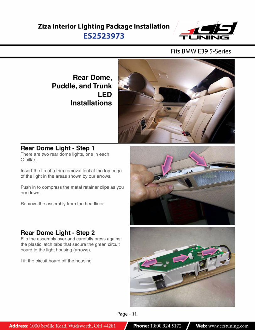
Rear Dome,Puddle, and Trunk
LEDInstallations
Rear Dome Light - Step 1There are two rear dome lights, one in eachC-pillar.
Insert the tip of a trim removal tool at the top edge of the light in the areas shown by our arrows.
Push in to compress the metal retainer clips as you pry down.
Remove the assembly from the headliner.
Rear Dome Light - Step 2Flip the assembly over and carefully press against the plastic latch tabs that secure the green circuit board to the light housing (arrows).
Lift the circuit board off the housing.

Address: 1000 Seville Road, Wadsworth, OH 44281 Phone: 1.800.924.5172 Web: www.ecstuning.com
Page - 12
Ziza Interior Lighting Package InstallationES2523973
Fits BMW E39 5-Series
R
Rear Dome Light - Step 3Install one bayonet and one 42mm festoon LED in place of the original glass filament bulbs.
Test LED operation and flip the festoon end-for-end if it does not illuminate when initially tested.
Snap the circuit board with bulbs back into the housing.
Rear Dome Light - Step 4Snap the housing back into the headliner and repeat the process at the opposite C-pillar to complete the rear dome LED installation.
Puddle Lamps - Step 1There is one puddle lamp in each door bottom.
Pry at the notched end of each puddle lamp assembly to remove it.
Address: 1000 Seville Road, Wadsworth, OH 44281 Phone: 1.800.924.5172 Web: www.ecstuning.com
Page - 13
Ziza Interior Lighting Package InstallationES2523973
Fits BMW E39 5-Series
R
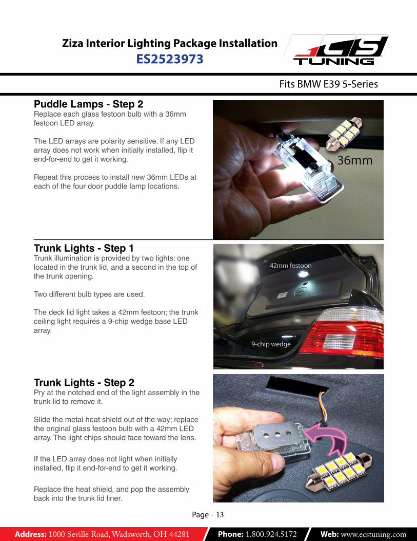
Puddle Lamps - Step 2Replace each glass festoon bulb with a 36mm festoon LED array.
The LED arrays are polarity sensitive. If any LED array does not work when initially installed, flip it end-for-end to get it working.
Repeat this process to install new 36mm LEDs at each of the four door puddle lamp locations.
Trunk Lights - Step 1Trunk illumination is provided by two lights: one located in the trunk lid, and a second in the top of the trunk opening.
Two different bulb types are used.
The deck lid light takes a 42mm festoon; the trunk ceiling light requires a 9-chip wedge base LED array.
Trunk Lights - Step 2Pry at the notched end of the light assembly in the trunk lid to remove it.
Slide the metal heat shield out of the way; replace the original glass festoon bulb with a 42mm LED array. The light chips should face toward the lens.
If the LED array does not light when initially installed, flip it end-for-end to get it working.
Replace the heat shield, and pop the assembly back into the trunk lid liner.

Address: 1000 Seville Road, Wadsworth, OH 44281 Phone: 1.800.924.5172 Web: www.ecstuning.com
Page - 14
Ziza Interior Lighting Package InstallationES2523973
Fits BMW E39 5-Series
R
Trunk Lights - Step 3Pry at the notched end of the light assembly in the trunk ceiling. Remove it.
Slide the metal heat shield out of the way; replace the original glass wedge base bulb with a 9-chip wedge base LED array.
If the LED array does not light when initially installed, remove and rotate it 180 degrees in the wedge bulb socket.
Replace the heat shield, and pop the assembly back in place in the trunk ceiling.
This concludes the installation of the Ziza Interior Light Kit.
Make the job easier and prevent damage to headliners and other interior trim with ECS Tuning Trim and Molding
Removal Tool Sets: ES2500877 and ES517779.
Related Documents