RQHA PITA137 © R.O.Jansen PITA137 A Folding RQH Antenna © R.O.Jansen PA0ROJ Saeftinge 102 2036 GC Haarlem Nederland 023-5360700 Copyright R.O.Jansen Werkgroep Kunstmanen 1/14

Welcome message from author
This document is posted to help you gain knowledge. Please leave a comment to let me know what you think about it! Share it to your friends and learn new things together.
Transcript
RQHA PITA137 © R.O.Jansen
PITA137
A Folding RQH Antenna
© R.O.Jansen PA0ROJ Saeftinge 102 2036 GC Haarlem Nederland 023-5360700
Copyright R.O.Jansen Werkgroep Kunstmanen 1/14

RQHA PITA137 © R.O.Jansen 1 January 2000
The PITA137
For a number of years I have been taking my weather satellite receiver and a Resonant Quadrafilar Helical Antenna along on my holidays outside the Netherlands. On these occasions, I try to receive signals from weather satellites, which happen to be passing by. I record these signals on my DCC recorder, for decoding once I return home, with e.g. WXtoimg or SatSignal. This provides me with images of the area visited. Until two years ago (1998) I used a RQH constructed from thin coax cable. Although this was extremely foldable, it was also very sensitive to mis-matching. Matching the very low characteristic impedance of about 25 Ohm was an additional problem. I therefore searched for a simple system, to construct a RQH with an impedance of about 50 Ohms, which could be assembled and disassembled quickly. A couple of years ago I noticed in a space programme how “self unfolding” aerials were being used. Furthermore I have in my collection of military communication equipment a “portable” transceiver (RT-196/PRC-6) which the Americans used in the Korean war. The antenna for this transceiver consists of a number of aluminium strips, which have a width-wise hollow shape. Once these strips are unlocked they stretch to about 50 cm. After use, they are simply wound around the transceiver again and locked. It occurred to me that a steel measuring tape exhibits similar behaviour. A new design for a RQH to accompany me on my vacation was thus born. This antenna is easily constructed on a home-brew basis, it shows good reproducibility and takes up hardly any luggage space. I tested a prototype of this aerial in September 1999 in Lombok (Indonesia) and the final design during my last vacation (third/fourth week December 1999) in Goa province, (India). Note 1 The requirements for this new design were: Easy to reproduce with simple tools Use of easily obtainable materials from a “hobby shop” A symmetrical model, i.e. two equal dipoles (loops). An impedance of around 50 Ohms. No antenna amplifier to be used. A reproducible 90 degree phase shift between the two dipoles. A correctly BALanced-UNbalanced circuit, which is essential for a uniform all-around radiation pattern, i.e. no nulls. In terms of baggage, it should not be too heavy or take up too much space. I settled for a RQH design which uses two equal dipoles. The vertical components should consist of pieces of metal (measuring) tape, which could be rolled up. After many experiments and visits to my local hardware store and “hobby shops”, I finally decided that the “Stanley” MYLAR coated (to prevent corrosion) measuring tape, which has a width of 19mm would be most suitable. The height : diameter relationship of this antenna was chosen in such a way that maximum sensitivity would occur at about 30
Copyright R.O.Jansen Werkgroep Kunstmanen 2/14
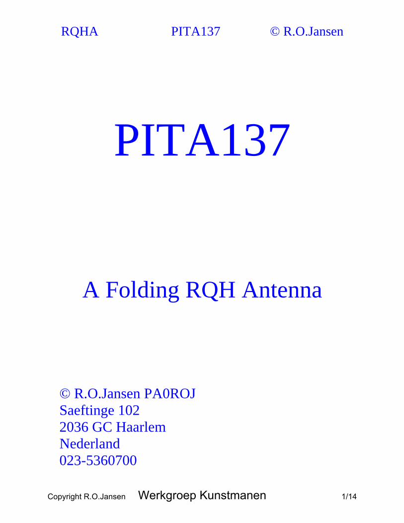
RQHA PITA137 © R.O.Jansen degrees above the horizon. However should would be constructors require maximum sensitivity at the horizon, choose a longer, albeit thinner imaginary cylinder. Since we require 4 pieces, each 90 cm long for the two dipoles, it would appear that a 5 meter “refill” is the cheapest solution. WARNING: Protect eyes when opening and unwinding the tape and do not do this in the presence of others. The strip, once released will unroll into a 5 meter long strip with lightning fast speed! Be extremely careful and use safety glasses! Cut 4 pieces of 90 cm from this tape with tin snips, or something similar. Do not use the scissors out of the sewing basket. This would render them useless for other uses, as a result of the high quality of the hardened tape. Next drill a 4mm hole in the middle, on both sides of the tapes, 1cm from the tape ends. As the tape is produced from hardened steel and additionally has a very slippery surface, the drill may quite easily slide. I solved this problem by producing a template from a couple of pieces of scrap wood and a piece of steel strip, in which I drilled a 4 mm hole. Refer photo 1. When drilling the strips, use safety glasses and protective gloves!
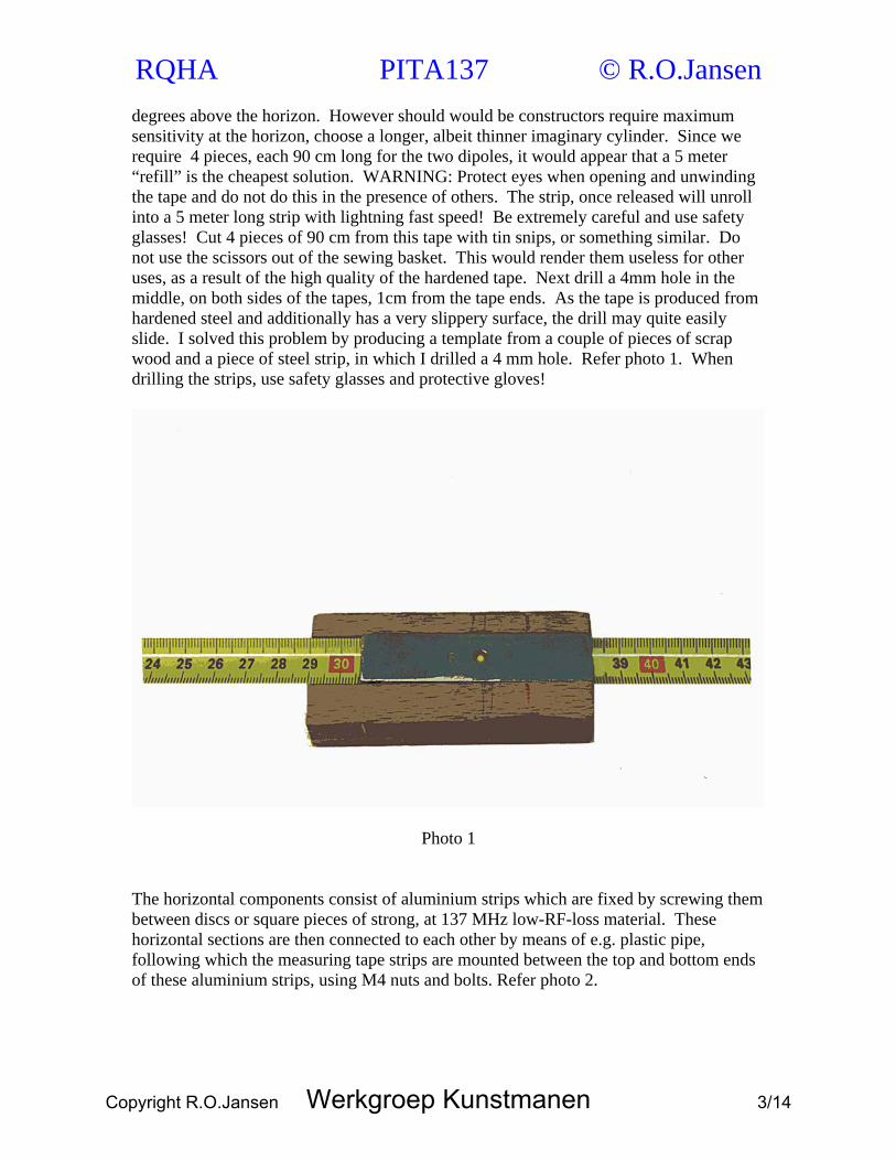
Photo 1 The horizontal components consist of aluminium strips which are fixed by screwing them between discs or square pieces of strong, at 137 MHz low-RF-loss material. These horizontal sections are then connected to each other by means of e.g. plastic pipe, following which the measuring tape strips are mounted between the top and bottom ends of these aluminium strips, using M4 nuts and bolts. Refer photo 2.
Copyright R.O.Jansen Werkgroep Kunstmanen 3/14
RQHA PITA137 © R.O.Jansen
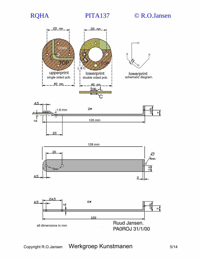
Photo 2 The 8 strips are produced from 15mm wide, 2mm thick aluminium strip. The quality should be semi-rigid, or better still rigid. Drill two 3mm holes on one end of these strips and one 4mm hole at the other end. Place the side in which the 4mm hole has been drilled in a vice and bend at right angles. Refer figure 1.
Copyright R.O.Jansen Werkgroep Kunstmanen 4/14
RQHA PITA137 © R.O.Jansen
Copyright R.O.Jansen Werkgroep Kunstmanen 5/14
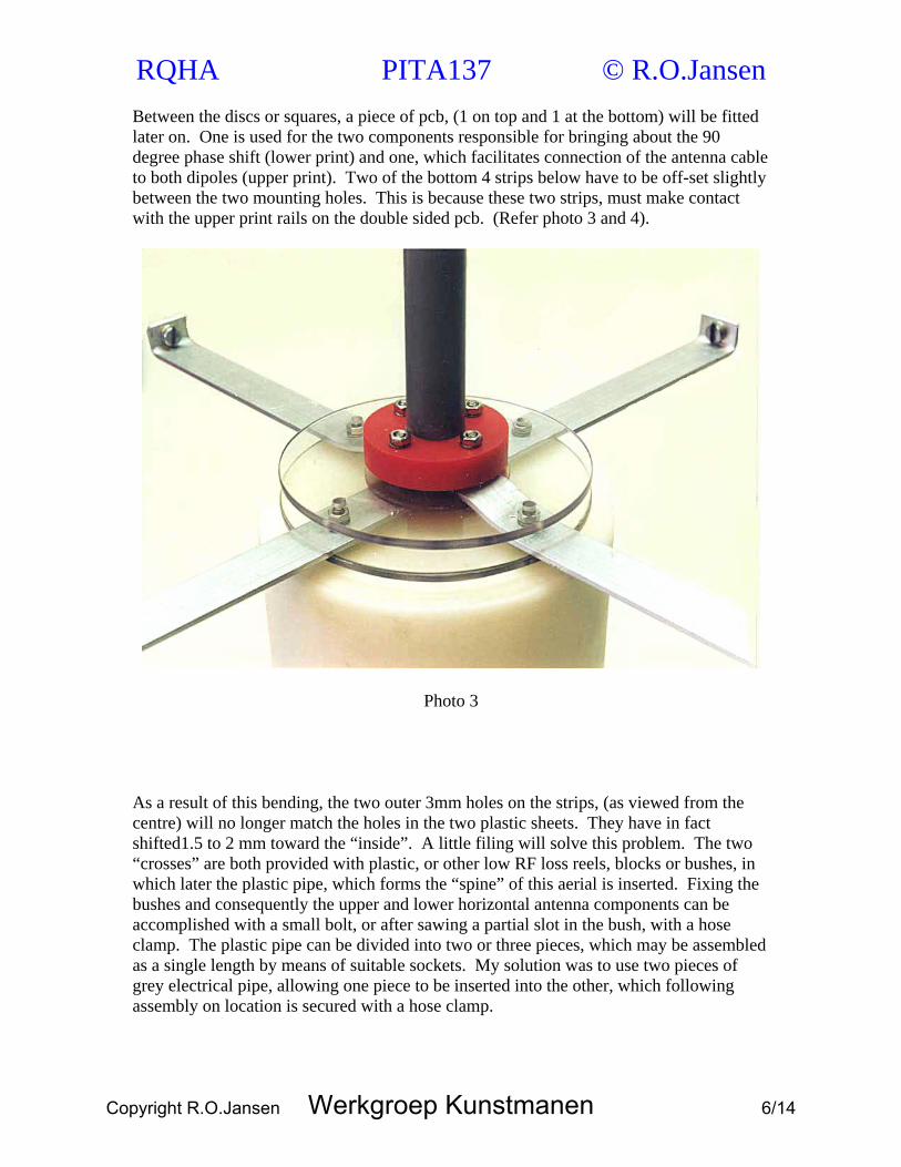
RQHA PITA137 © R.O.Jansen Between the discs or squares, a piece of pcb, (1 on top and 1 at the bottom) will be fitted later on. One is used for the two components responsible for bringing about the 90 degree phase shift (lower print) and one, which facilitates connection of the antenna cable to both dipoles (upper print). Two of the bottom 4 strips below have to be off-set slightly between the two mounting holes. This is because these two strips, must make contact with the upper print rails on the double sided pcb. (Refer photo 3 and 4).
Photo 3 As a result of this bending, the two outer 3mm holes on the strips, (as viewed from the centre) will no longer match the holes in the two plastic sheets. They have in fact shifted1.5 to 2 mm toward the “inside”. A little filing will solve this problem. The two “crosses” are both provided with plastic, or other low RF loss reels, blocks or bushes, in which later the plastic pipe, which forms the “spine” of this aerial is inserted. Fixing the bushes and consequently the upper and lower horizontal antenna components can be accomplished with a small bolt, or after sawing a partial slot in the bush, with a hose clamp. The plastic pipe can be divided into two or three pieces, which may be assembled as a single length by means of suitable sockets. My solution was to use two pieces of grey electrical pipe, allowing one piece to be inserted into the other, which following assembly on location is secured with a hose clamp.
Copyright R.O.Jansen Werkgroep Kunstmanen 6/14

RQHA PITA137 © R.O.Jansen
Photo 4 The 90 degree phase shift. In order to obtain the required 90 degree phase shift between the two dipoles, which is essential if circular polarisation is to be achieved, I have applied a not commonly used approach (Note 2). Once the aerial has been assembled and the “crosses” have been mechanically turned 90 degrees in relation to one another, the two crosses are pushed a little closer to each other, so that the measuring tape will assume a curved shape, which results in a pure imaginary cylindrical shape. The materials chosen will produce an aerial with a characteristic impedance of approximately 50 Ohms. Connection at the bottom of the two dipoles which are at right angles to each other, is effected with a piece of double sided pcb. The copper tracks above are identical to those underneath, however they are mechanically rotated 90 degrees in relation to each other (refer photo 4). Thus by filing or cutting appropriate channels on both the top and bottom side of this double sided pcb, the two dipoles are electrically separated from one another, (refer photo 5).
Copyright R.O.Jansen Werkgroep Kunstmanen 7/14
RQHA PITA137 © R.O.Jansen
Photo 5
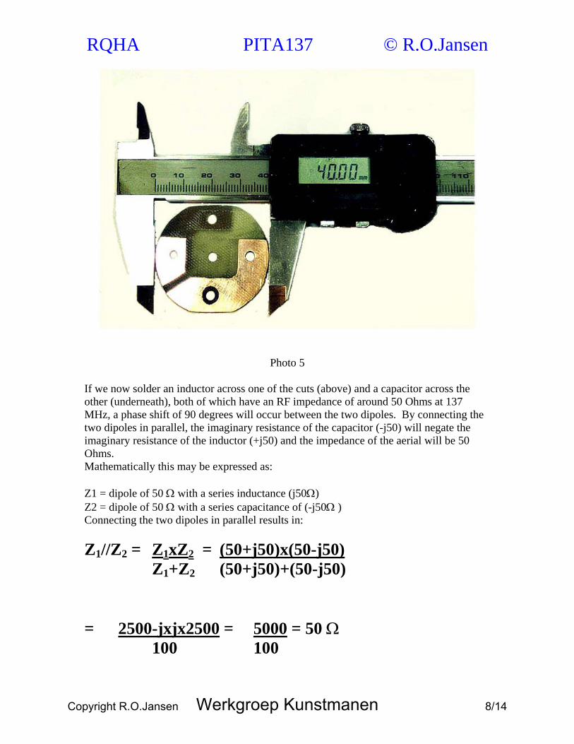
If we now solder an inductor across one of the cuts (above) and a capacitor across the other (underneath), both of which have an RF impedance of around 50 Ohms at 137 MHz, a phase shift of 90 degrees will occur between the two dipoles. By connecting the two dipoles in parallel, the imaginary resistance of the capacitor (-j50) will negate the imaginary resistance of the inductor (+j50) and the impedance of the aerial will be 50 Ohms. Mathematically this may be expressed as: Z1 = dipole of 50 Ω with a series inductance (j50Ω) Z2 = dipole of 50 Ω with a series capacitance of (-j50Ω ) Connecting the two dipoles in parallel results in: Z1//Z2 = Z1xZ2 = (50+j50)x(50-j50) Z1+Z2 (50+j50)+(50-j50)
= 2500-jxjx2500 = 5000 = 50 Ω 100 100
Copyright R.O.Jansen Werkgroep Kunstmanen 8/14
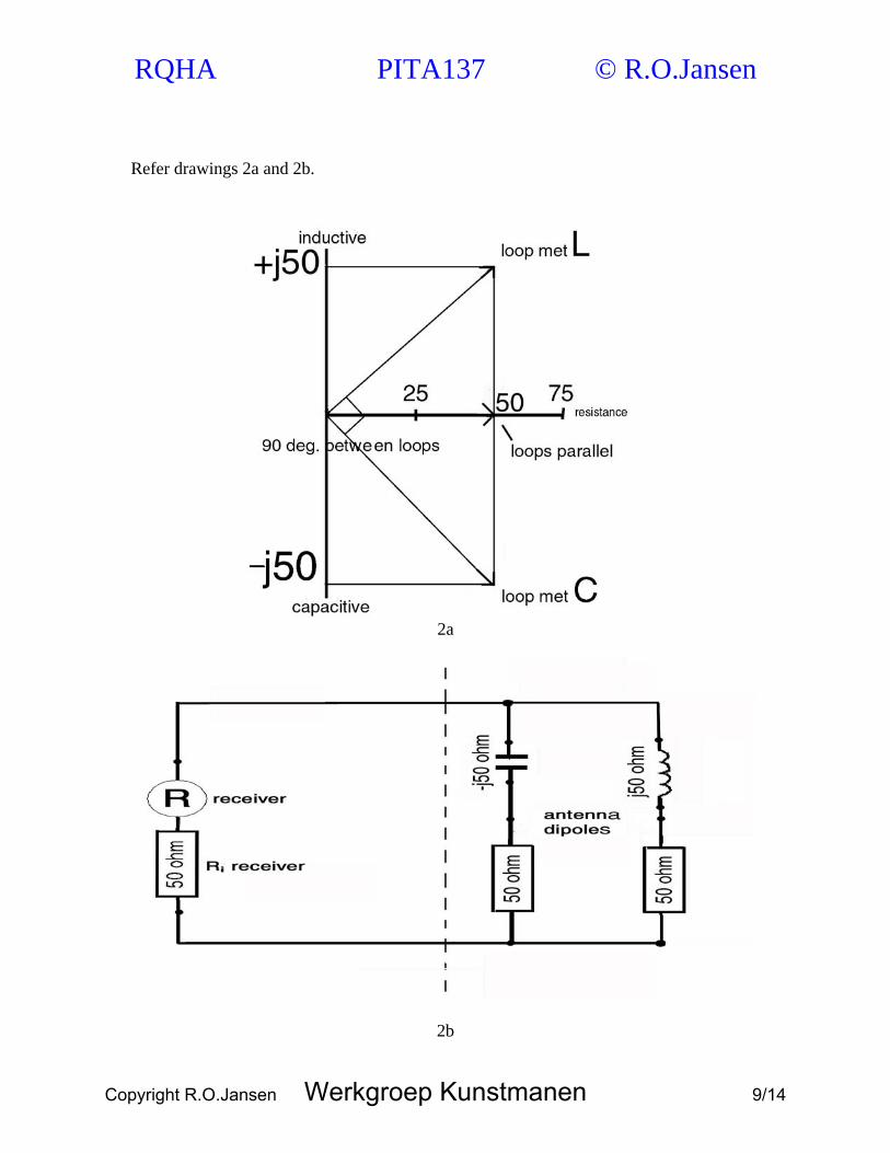
RQHA PITA137 © R.O.Jansen Refer drawings 2a and 2b.
2a
2b
Copyright R.O.Jansen Werkgroep Kunstmanen 9/14

RQHA PITA137 © R.O.Jansen Remove some of the copper surrounding the 3 mm holes and use insulated washers to prevent that the upper printed tracks make contact with the lower tracks. Although the dimensions of each individual dipole were chosen for them to be resonant at 137 MHz, the individual resonant frequencies will now be either lower (series inductor) or higher (series capacitor). The resonant frequency of the aerial will nevertheless revert to 137 MHz, once the two dipoles have been connected in parallel. By using a smd capacitor and inductance, a mechanically stable construction will be achieved. (refer photo 6 and figure 3).
Photo 6
Copyright R.O.Jansen Werkgroep Kunstmanen 10/14

RQHA PITA137 © R.O.Jansen The coax cable from the receiver to the dipoles is connected at the top, by means of a small pcb. (Both pcb’s do not have to be etched! Using a small file to remove unwanted copper is sufficient ). The antenna coax cable may be soldered directly to the pcb. In order to allow easy connection, I used a SMA chassis connector on the pcb for this purpose (refer photo 7). If desired, a 137 MHz pre-amplifier may also be connected.
Photo 7 For the BALUN, I used a solution, which in contrast to all other options is the only one, which will almost completely eliminate the skin effect, independent of frequency and phase shift, without mismatch. This thus results in a perfect match between the symmetrical dipoles and the asymmetric coaxial cable Note 3. This BALUN is constructed by pushing 10 torroidal cores of the FT23-43 type, as high up as possible on the piece of coax which protrudes from the pcb, (I used thin Teflon coax with a diameter of 2.35mm). For those wishing to know more about the why's and how's, I suggest you take a look at our Technote dealing with this type of aerial (Library Working Group Kunstmanen). If a larger diameter coax cable is used, e.g. RG58/U, 10 FB43-2401 torroidal cores could be pushed up along this cable. Important is that the cores are of type 43 and that the inside of the core fits as snugly as possible around the coax cable. Refer photo 8 and figure 4.
Copyright R.O.Jansen Werkgroep Kunstmanen 11/14

RQHA PITA137 © R.O.Jansen
Photo 8
Fig. 4
Copyright R.O.Jansen Werkgroep Kunstmanen 12/14
RQHA PITA137 © R.O.Jansen Materials needed: 4 pieces measuring tape, each 90 cm in length at a width of 19mm. Cut these pieces from a 5 meter Stanley measuring tape refill – No 0-32-607 8 aluminium strips, 15mm wide and 2 mm thickness 4 round (or square sheets of polycarbonate (Lexan, Makrolon or similar) or other plastic material with an approximate diameter of 90 mm and a minimum thickness of 3mm. 2 pieces 1.6mm thickness pcb (1 single sided, 1 double sided) at 40mm diameter A few pieces plastic 40 mm round, intended only for fixing both of the “crosses” to the central pipe. One or several pieces of tubing. I used two pieces of grey electrical conduit, which can be slid into one another (external16 and 19 mm). A hose clamp (15-25 mm) to secure the centre pipe. 1 (or combination of two) SMD capacitors approximately 23.3 pF. 1 Inductor approximately 58.1 nH 10 torroidal cores type Amidon FT23-43 (when using thin coax) or FB43-2401 (when using RG58/U). Note 4 8 M4 bolts with matching (rounded) nuts) to secure the measuring tape. 16 M3 bolts with matching nuts, the length of which will depend on the thickness of the plastic pieces etc. Various Nylon and metal(spring) washers. I used stainless steel for the metal components to make the system weatherproof. The aerial may be strung along a piece of Nylon string or simply placed on a table (wood, plastic or similar), another alternative is to use a tripod (photo 9). The drawings and images should be sufficient to clarify construction details. Should you have any questions relating to this aerial, I can be reached via E-mail or by telephone. Phone +31 23-5360700 (between 17:15 and 18:45 UTC) E-mail [email protected] or [email protected] Note1. Of course it is not necessary to travel to distant warm countries to test receivers and/or aerials. However the difference lies between sitting somewhere on a cold low lying spot, with chattering teeth, under a grey sky and in the rain, or in sitting at a white sandy beach under an umbrella, with a cold (local) drink, observing the fishermen and dolphins. This makes it worthwhile, for me to spend my vacation budget as much as possible in warmer climes. Additionally it provides me with a unique opportunity to receive weather images of areas which I cannot cover in the Netherlands. Note 2. UKW-Berichte (VHF) 3/85. Genaue Zirkular-Polarisation-und wie man sie erzielen kann (Exact circular polarisation and how this can be achieved) Matjaz Vidmar, YU3UMV Note 3. Reflections. Transmission lines and Antennas. Walter Maxwell, W2DU, Chapter 21-1 (Adapted from QST, March 1983). More about RQHA www.iag.net/~w2du
Copyright R.O.Jansen Werkgroep Kunstmanen 13/14
RQHA PITA137 © R.O.Jansen Note 4. The Amidon Ferrite Beads (type 43) is available from Baend Hendriksen of he Netherlands. http://www.xs4all.nl/~barendh/indexeng.htm Finally, my thanks to Chris van Lint (Hong Kong) for his translation (Dutch>English).
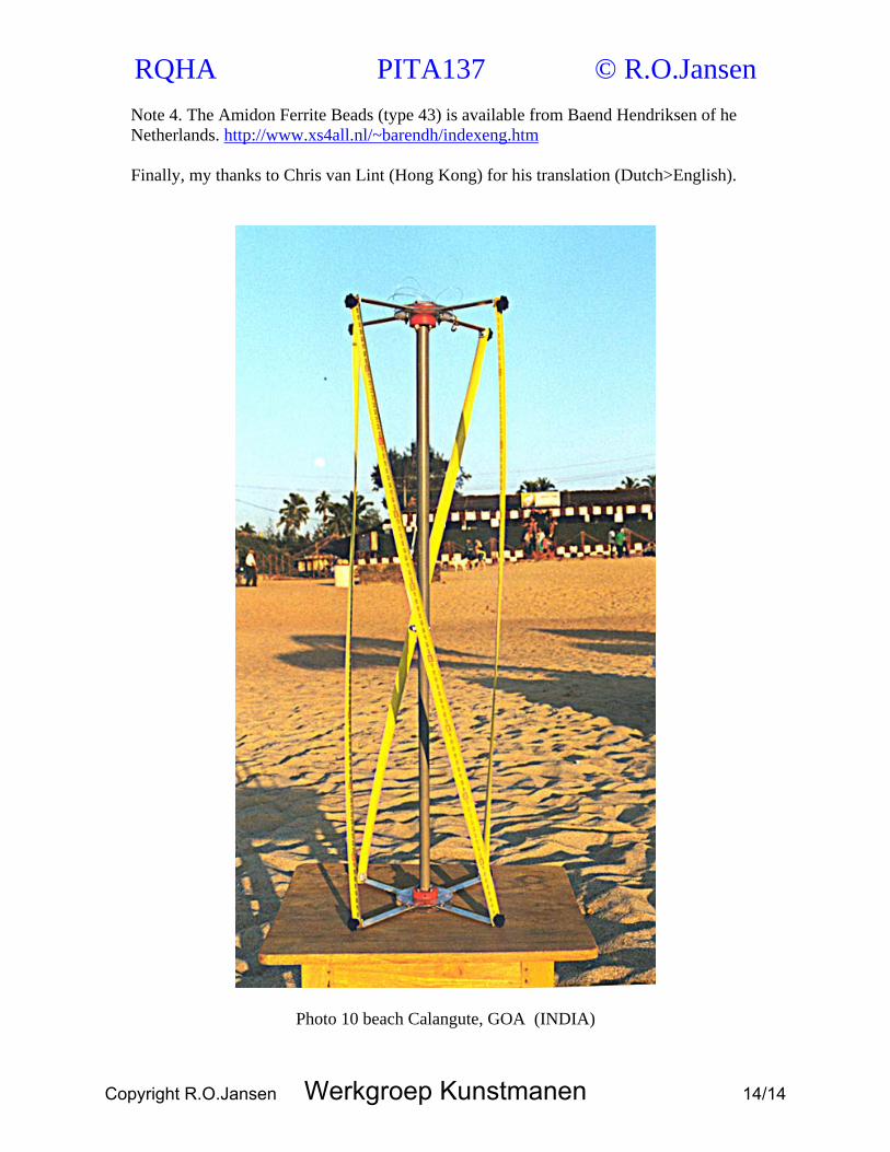
Photo 10 beach Calangute, GOA (INDIA)
Copyright R.O.Jansen Werkgroep Kunstmanen 14/14
Related Documents