Chp.12 Cont. – Examples to design Footings

Welcome message from author
This document is posted to help you gain knowledge. Please leave a comment to let me know what you think about it! Share it to your friends and learn new things together.
Transcript

Chp.12 Cont. – Examplesto design Footings

ExampleExampleDesign a square footing to support a 18 in. square column tied interior column reinforced with 8 #9 bars. The column carries an unfactored axial dead load of 245 k and an axial live load of 200 k. The base of the footing is 4 ft. below final grade and allowable soil pressure is 5 k/ft2 Use fc = 3 ksi and fy = 60 ksi

Example 1Example 1
Assume a depth of footing. (2 ft or 24 in.) The weight of concrete and the soil are:
23c lb/ft 300
in. 12ft. 1* in. 24*lb/ft 150 dW
23sss lb/ft 200
in. 12ft. 1* in. 24ft 4*lb/ft 100
dW
Example 1Example 1
The effective soil pressure is given as:
22
222
scseff
k/ft 5.4lb/ft 4500lb/ft 200lb/ft 300lb/ft 5000
WWqq

Example 1Example 1Calculate the size of the footing:
ft 10 Useft 94.9footing of Side
ft 98.9k/ft 5.4k 445footing of Area
k 445 k 200 k 245Loads Actual2
2
LLDL
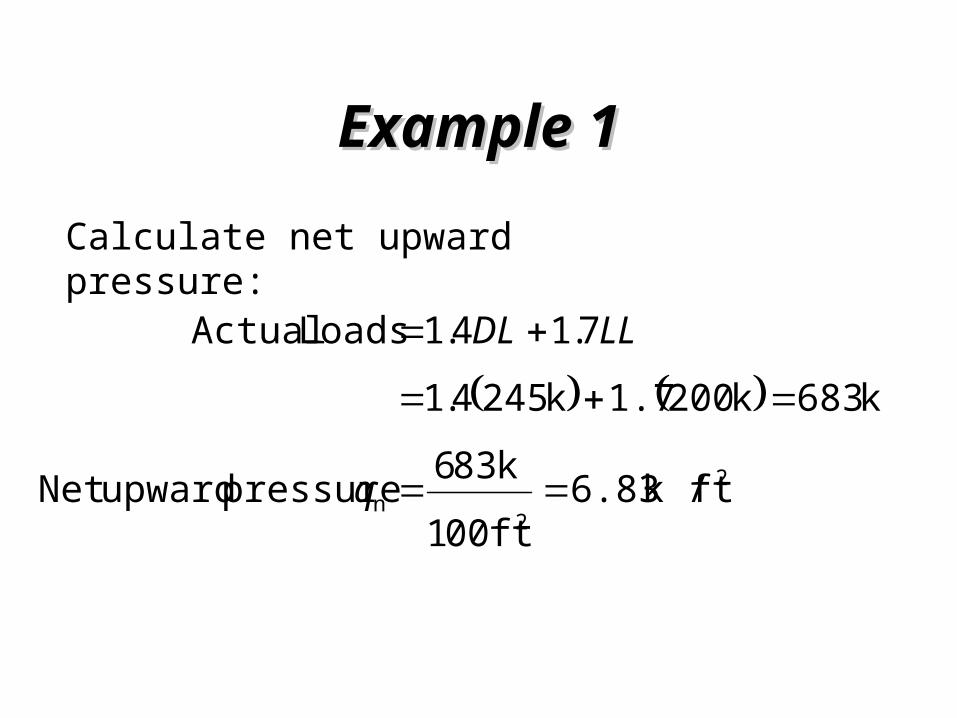
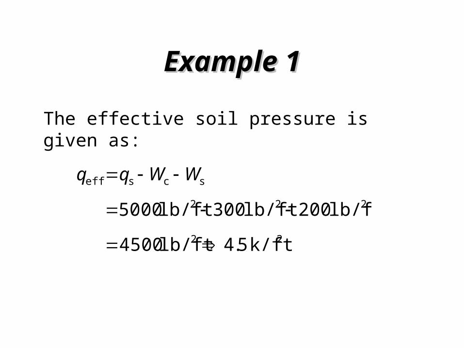
Example 1Example 1Calculate net upward pressure:
2
2n ftk / 6.83
ft 001k 836 pressure upwardNet
k 683 k 2001.7 k 2454.17.14.1Loads Actual
q
LLDL
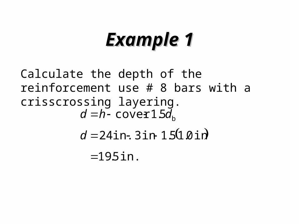
Example 1Example 1Calculate the depth of the reinforcement use # 8 bars with a crisscrossing layering.
in. 5.19
in 0.15.1in 3 in. 245.1cover b
ddhd

Example 1Example 1Calculate perimeter for two-way shear or punch out shear. The column is 18 in. square.
ft 125.3in 12ft 1in. 5.19 in. 18
in. 150in. 5.19 in. 1844o
dc
dcb

Example 1Example 1Calculate the shear Vu
k 616ft 125.3k/ft 6.83k 683 22
2nuu
dcqPV
1ft 10ft 10
The shape parameter
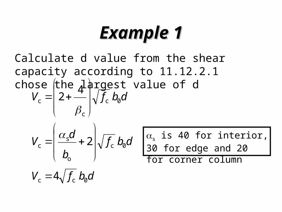
Example 1Example 1Calculate d value from the shear capacity according to 11.12.2.1 chose the largest value of d
dbfV 0c
c
c 42
dbfV 0cc 4
dbfbdV 0c
o
sc 2
s is 40 for interior, 30 for edge and 20 for corner column

Example 1Example 1The depth of the footing can be calculated by using two way shear
in. 1.19
in 150400040.85k 1lb 1000k 616
4 0c
u
bf
Vd
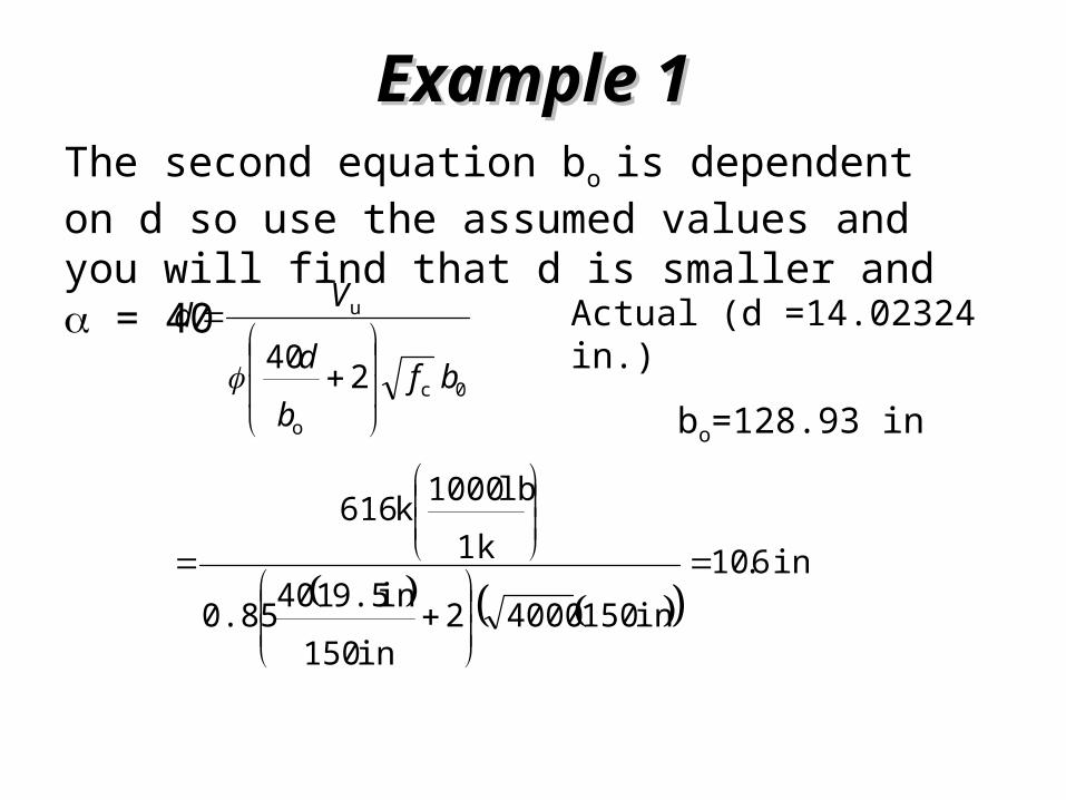
Example 1Example 1The second equation bo is dependent on d so use the assumed values and you will find that d is smaller and = 40
in. 6.10
in 15040002in 150in 9.51400.85
k 1lb 1000k 616
2400c
o
u
bfbd
Vd
Actual (d =14.02324 in.)
bo=128.93 in

Example 1Example 1The depth of the footing can be calculated by using one-way shear
k 3.179ft 625.2ft 10k/ft 83.622
2
2nu
dcLlqV
ft 625.2
in 12ft 1in 5.19
2in 12ft 1in 18
2ft 10
22
dcL
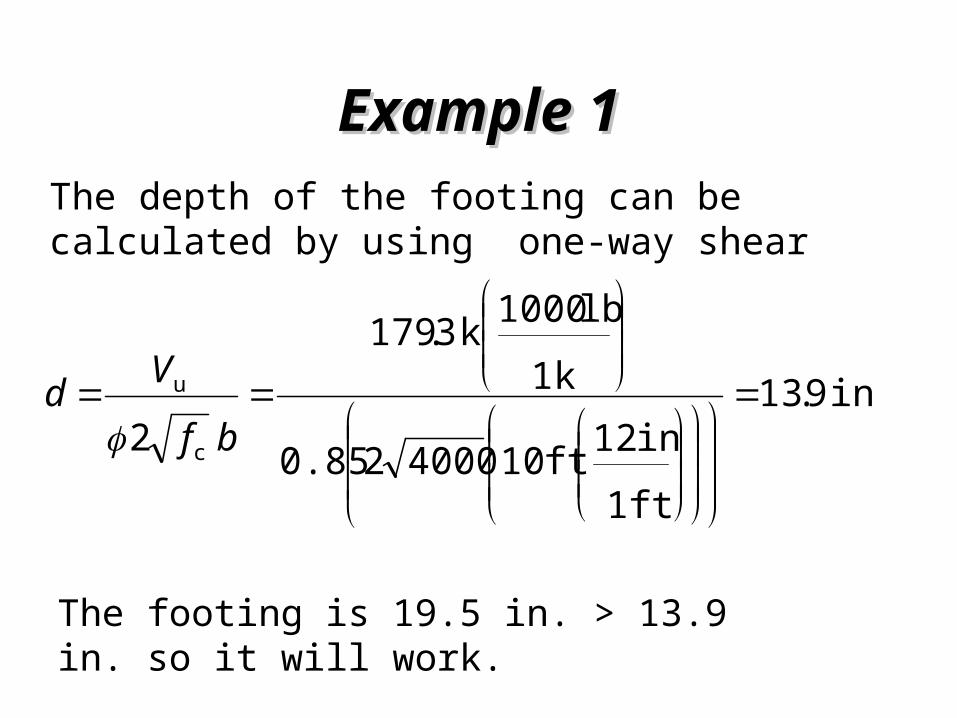
Example 1Example 1The depth of the footing can be calculated by using one-way shear
in. 9.13
ft 1in 12ft 10400020.85
k 1lb 1000k 3.179
2 c
u
bf
Vd
The footing is 19.5 in. > 13.9 in. so it will work.

Example 1Example 1Calculate the bending moment of the footing at the edge of the column
ft 25.42
in 12ft 1in 18
2ft 10
22
cL
ft-k 8.616ft 102ft 25.4ft 25.4k/ft 83.6
222
22nu
b
cLcLqM
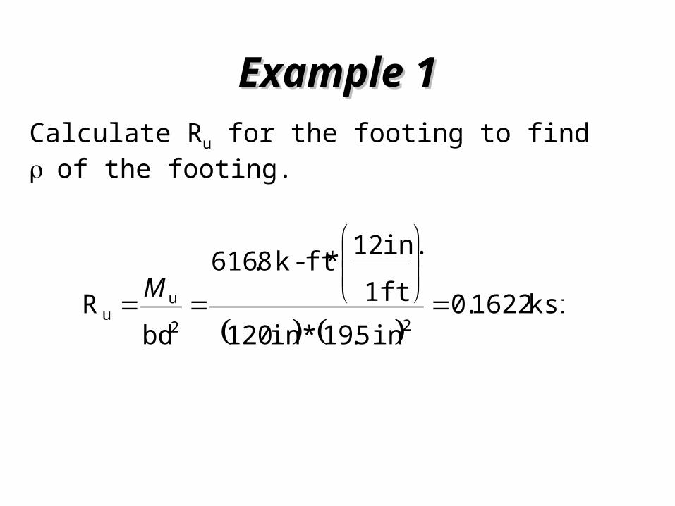
Example 1Example 1Calculate Ru for the footing to find of the footing.
ksi 1622.0
in 5.19*in 120ft 1in. 12*ft-k 8.616
bdR
22u
u
M
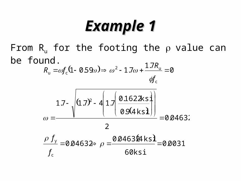
Example 1Example 1From Ru for the footing the value can be found.
0031.0ksi 60
ksi 404632.004632.0
04632.02
ksi 49.0ksi 1622.07.147.17.1
07.17.159.01
c
y
2
c
u2cu
f
f
fRfR

Example 1Example 1Compute the area of steel needed
2s in 23.7in. 5.19
ft 1in. 12ft 1000309.0
bdA
The minimum amount of steel for shrinkage is 2s in 18.5in. 24in. 1200018.0 0018.0 bhAThe minimum amount of steel for flexure is
2
y
s in 8.7in. 9.51in. 12060000200 200
bd
fA Use
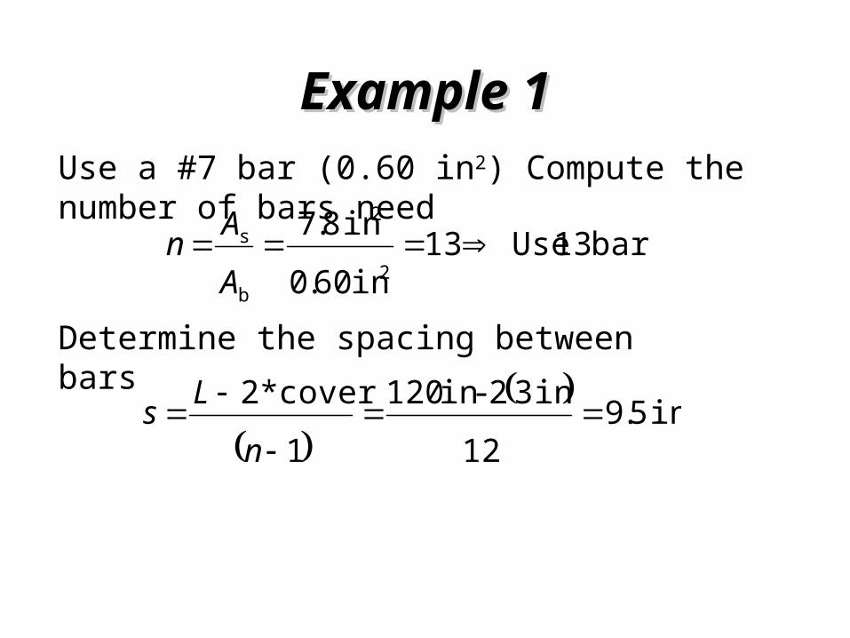
Example 1Example 1Use a #7 bar (0.60 in2) Compute the number of bars need
bars 13 Use13in 60.0in 8.7
2
2
b
s AAn
Determine the spacing between bars
in 5.9
12in 32 -in 120
1cover*2
nLs

Example 1Example 1Check the bearing stress. The bearing strength N1, at the base of the column, 18 in x 18 in., 0.7 k 771in 18ksi 485.07.085.0 2
1c1 AfN
The bearing strength, N2, at the top of the footing is
11
212 2 N
AANN

Example 1Example 1
The bearing strength, N2, at the top of the footing is
k 1542k 771222 6.67ft 25.2ft 100
122
2
1
2 NNAA
22
1
222
ft 25.2in. 12ft 1in 18
ft 100ft 10
A
A

Example 1Example 1Pu =683 k < N1, bearing stress is adequate. The minimum area of dowels is required. 22
1 in 62.1in 18*005.0005.0 A
Use minimum number of bars is 4, so use 4 # 8 bars placed at the four corners of the column.
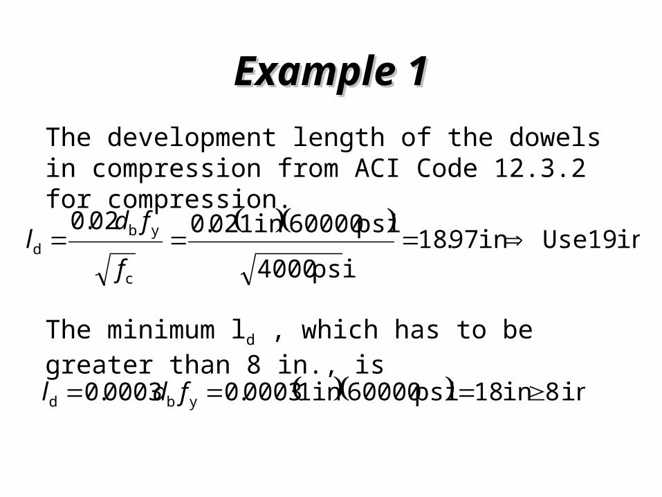
Example 1Example 1The development length of the dowels in compression from ACI Code 12.3.2 for compression.
in 19 Usein 97.18psi 4000
psi 60000in 102.002.0
c
ybd
f
fdl
The minimum ld , which has to be greater than 8 in., is
in 8 in 18psi 60000in 10003.00003.0 ybd fdl
Example 1Example 1
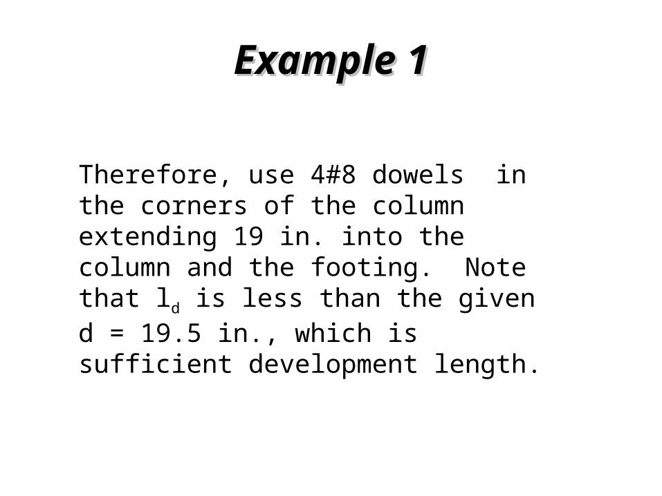
Therefore, use 4#8 dowels in the corners of the column extending 19 in. into the column and the footing. Note that ld is less than the given d = 19.5 in., which is sufficient development length.
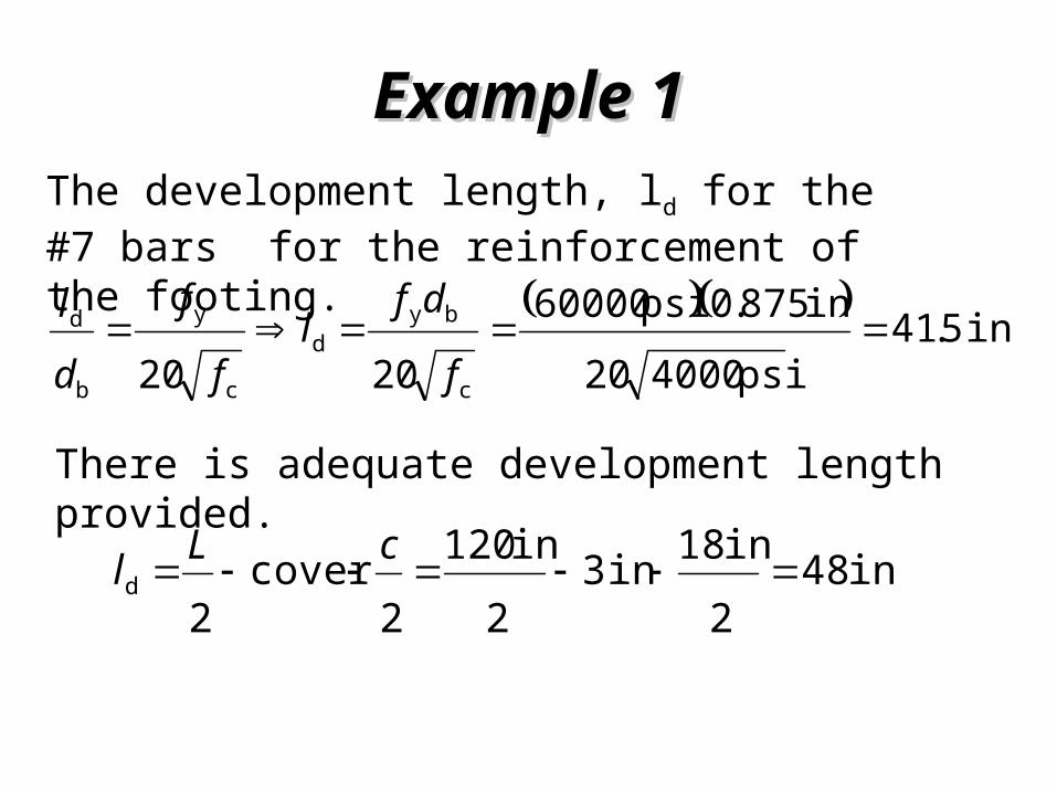
Example 1Example 1The development length, ld for the #7 bars for the reinforcement of the footing. in 5.41
psi 400020in 875.0psi 60000
2020 c
byd
c
y
b
d f
dfl
f
f
dl
There is adequate development length provided.
in 482in 18in 3
2in 120
2cover
2d
cLl

Example 1 - Final DesignExample 1 - Final Design
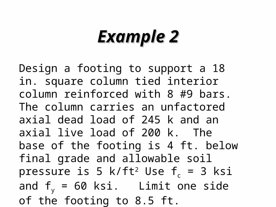
Example 2Example 2Design a footing to support a 18 in. square column tied interior column reinforced with 8 #9 bars. The column carries an unfactored axial dead load of 245 k and an axial live load of 200 k. The base of the footing is 4 ft. below final grade and allowable soil pressure is 5 k/ft2 Use fc = 3 ksi and fy = 60 ksi. Limit one side of the footing to 8.5 ft.

Example 2Example 2
Assume a depth of footing. (2 ft or 24 in.) The weight of concrete and the soil are:
23c lb/ft 300
in. 12ft. 1* in. 24*lb/ft 150 dW
23sss lb/ft 200
in. 12ft. 1* in. 24ft 4*lb/ft 100
dW

Example 2Example 2
The effective soil pressure is given as:
22
222
scseff
k/ft 5.4lb/ft 4500lb/ft 200lb/ft 300lb/ft 5000
WWqq
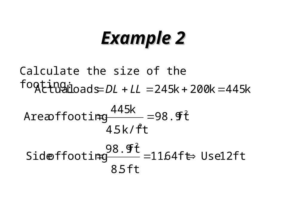
Example 2Example 2Calculate the size of the footing:
ft 12 Useft 64.11ft 5.8ft 98.9footing of Side
ft 98.9k/ft 5.4k 445footing of Area
k 445 k 200 k 245Loads Actual
2
22
LLDL
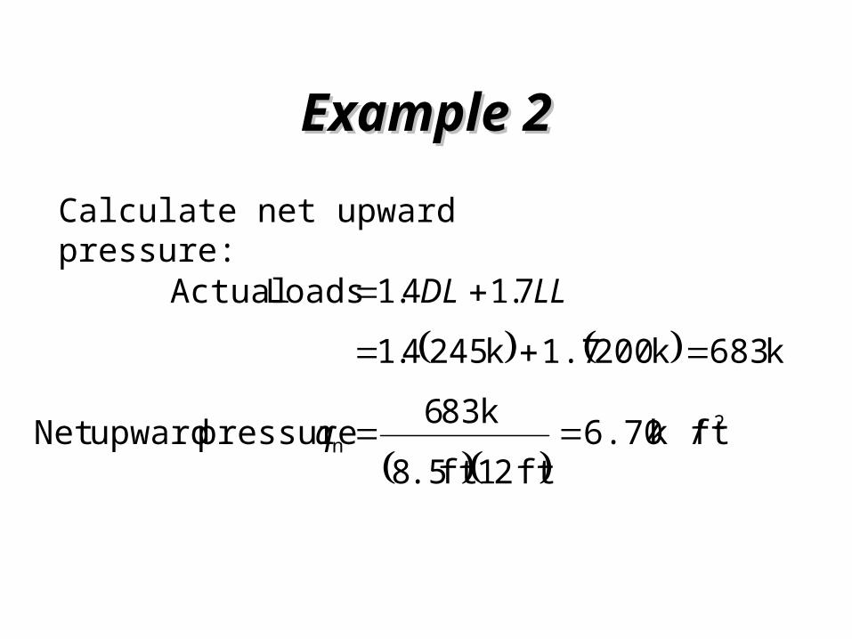
Example 2Example 2Calculate net upward pressure:
2
n ftk / 6.70ft 21ft .58
k 836 pressure upwardNet
k 683 k 2001.7 k 2454.17.14.1Loads Actual
q
LLDL

Example 2Example 2Calculate the depth of the reinforcement use # 8 bars with a crisscrossing layering.
in. 5.19
in 0.15.1in 3 in. 245.1cover b
ddhd
Example 2Example 2
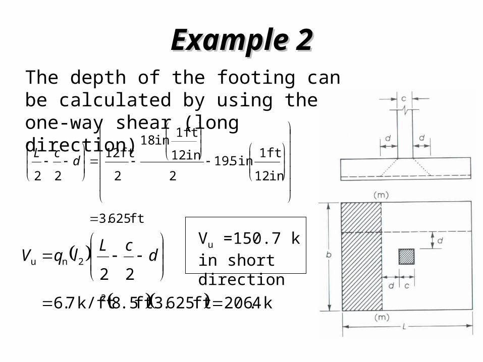
k 4.206ft 625.3ft .58k/ft 7.622
2
2nu
dcLlqV
ft 625.3
in 12ft 1in 5.19
2in 12ft 1in 18
2ft 12
22
dcL
Vu =150.7 k in short direction
The depth of the footing can be calculated by using the one-way shear (long direction)

Example 2Example 2The depth of the footing can be calculated by using one-way shear design
in. 8.18
ft 1in 12ft .58400020.85
k 1lb 1000k 4.206
2 c
u
bf
Vd
The footing is 19.5 in. > 18.8 in. so it will work.
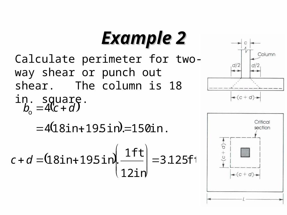
Example 2Example 2Calculate perimeter for two-way shear or punch out shear. The column is 18 in. square.
ft 125.3in 12ft 1in. 5.19 in. 18
in. 150in. 5.19 in. 1844o
dc
dcb
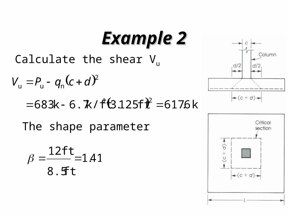
Example 2Example 2Calculate the shear Vu
k 6.617ft 125.3k/ft 6.7k 683 22
2nuu
dcqPV
41.1ft 8.5ft 12
The shape parameter
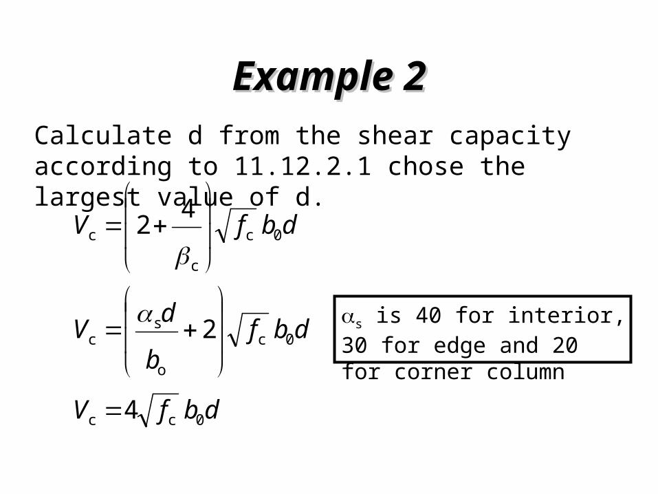
Example 2Example 2Calculate d from the shear capacity according to 11.12.2.1 chose the largest value of d.
dbfV 0c
c
c 42
dbfV 0cc 4
dbfbdV 0c
o
sc 2
s is 40 for interior, 30 for edge and 20 for corner column

Example 2Example 2The depth of the footing can be calculated for the two way shear
in. 8.15
in 150400041.1420.85
k 1lb 1000k 6.617
42 0c
u
bf
Vd
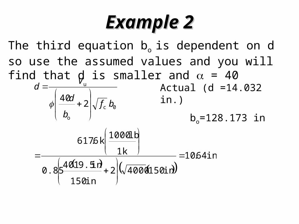
Example 2Example 2The third equation bo is dependent on d so use the assumed values and you will find that d is smaller and = 40
in. 64.10
in 15040002in 150in 9.51400.85
k 1lb 1000k 6.617
2400c
o
u
bfbd
Vd
Actual (d =14.032 in.)
bo=128.173 in
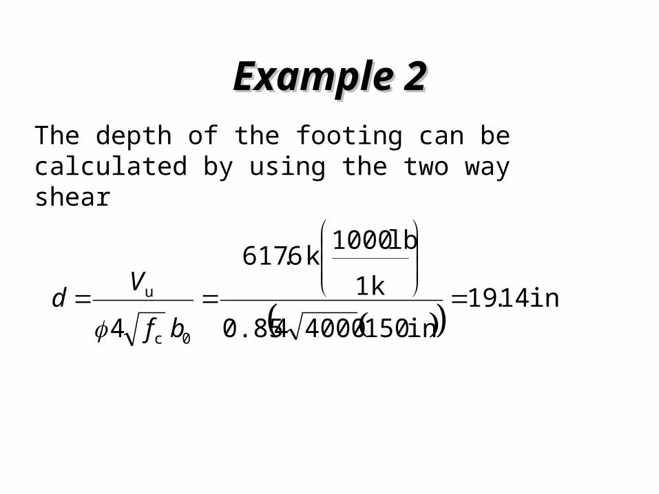
Example 2Example 2The depth of the footing can be calculated by using the two way shear
in. 14.19
in 150400040.85k 1lb 1000k 6.617
4 0c
u
bf
Vd

Example 2Example 2Calculate the bending moment of the footing at the edge of the column (long direction)
ft 25.52
in 12ft 1in 18
2ft 12
22
cL
ft-k 8.784ft .582ft 25.5ft 25.5k/ft 7.6
222
22nu
b
cLcLqM

Example 2Example 2Calculate Ru for the footing to find of the footing.
ksi 2428.0
in 5.19*ft 1in 12ft 8.5
ft 1in. 12*ft-k 8.784
bdR
22u
u
M

Example 2Example 2Use the Ru for the footing to find .
00469.0ksi 60
ksi 407036.007036.0
07036.02
ksi 49.0ksi 2428.07.147.17.1
07.17.159.01
c
y
2
c
u2cu
f
f
fRfR
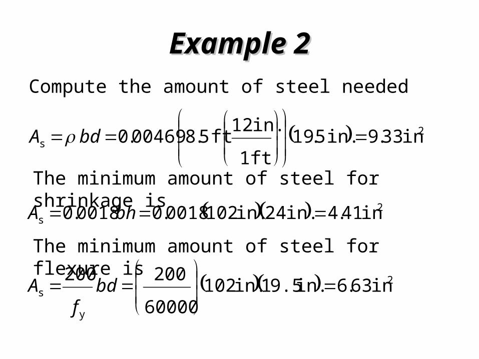
Example 2Example 2Compute the amount of steel needed
2s in 33.9in. 5.19
ft 1in. 12ft 5.800469.0
bdA
The minimum amount of steel for shrinkage is 2s in 41.4in. 24in. 1020018.0 0018.0 bhAThe minimum amount of steel for flexure is
2
y
s in 63.6in. 9.51in. 10260000200 200
bd
fA
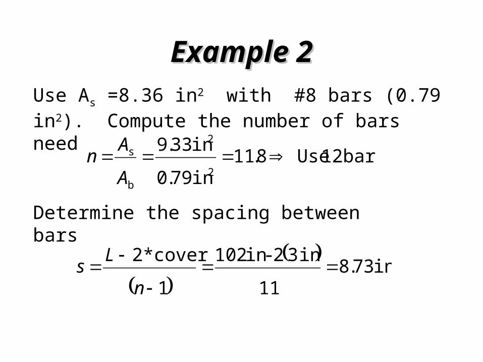
Example 2Example 2Use As =8.36 in2 with #8 bars (0.79 in2). Compute the number of bars need bars 12 Use8.11
in 79.0in 33.9
2
2
b
s AAn
Determine the spacing between bars
in 73.8
11in 32 -in 102
1cover*2
nLs
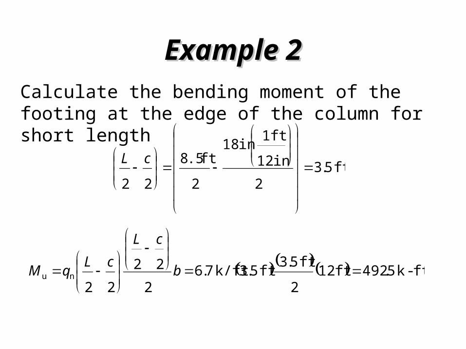
Example 2Example 2Calculate the bending moment of the footing at the edge of the column for short length
ft 5.32
in 12ft 1in 18
2ft .58
22
cL
ft-k 5.492ft 122ft 5.3ft 5.3k/ft 7.6
222
22nu
b
cLcLqM
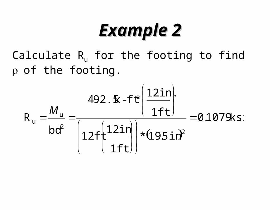
Example 2Example 2Calculate Ru for the footing to find of the footing.
ksi 1079.0
in 5.19*ft 1in 12ft 12
ft 1in. 12*ft-k 92.54
bdR
22u
u
M
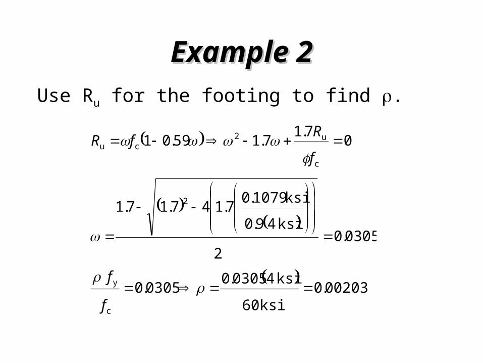
Example 2Example 2Use Ru for the footing to find .
00203.0ksi 60ksi 40305.00305.0
0305.02
ksi 49.0ksi 1079.07.147.17.1
07.17.159.01
c
y
2
c
u2cu
f
f
fRfR

Example 2Example 2Compute the amount of steel needed
2s in 72.5in. 5.19
ft 1in. 12ft 1200203.0
bdA
The minimum amount of steel for shrinkage is 2s in 22.6in. 24in. 1440018.0 0018.0 bhAThe minimum amount of steel for flexure is
2
y
s in 36.9in. 9.51in. 14460000200 200
bd
fA

Example 2Example 2Use As =9.36 in2 with #6 bar (0.44 in2) Compute the number of bars need
bars 22 Use3.21in 44.0in 36.9
2
2
b
s AAn
Calculate the reinforcement bandwidth
83.0141.1
21
2entreinforcem Total
bandwidthin ent Reinforcem

Example 2Example 2The number of bars in the 8.5 ft band is 0.83(22)=19 bars .
So place 19 bars in 8.5 ft section and 2 bars in each in (12ft -8.5ft)/2 =1.75 ft of the band.
bars 2 Use5.121922
2bars band - bars # Totalbar # outside
Example 2Example 2
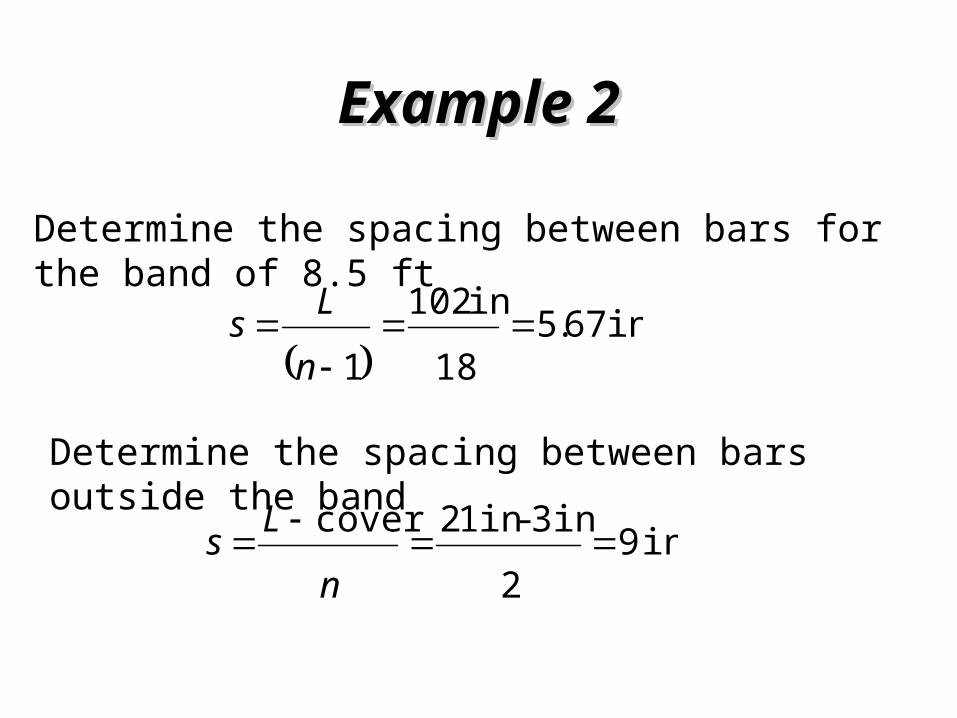
Determine the spacing between bars for the band of 8.5 ft
in 67.5
18in 102
1
nLs
Determine the spacing between bars outside the band
in 923in-in 12cover
n
Ls
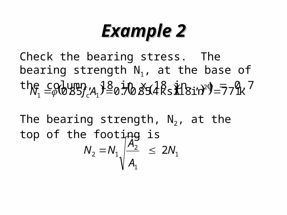
Example 2Example 2Check the bearing stress. The bearing strength N1, at the base of the column, 18 in x 18 in., 0.7 k 771in 18ksi 485.07.085.0 2
1c1 AfN
The bearing strength, N2, at the top of the footing is
11
212 2 N
AANN
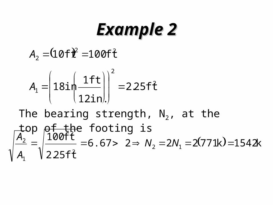
Example 2Example 2
The bearing strength, N2, at the top of the footing is
k 1542k 771222 6.67ft 25.2ft 100
122
2
1
2 NNAA
22
1
222
ft 25.2in. 12ft 1in 18
ft 100ft 10
A
A
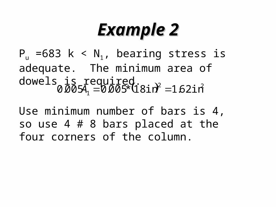
Example 2Example 2Pu =683 k < N1, bearing stress is adequate. The minimum area of dowels is required. 22
1 in 62.1in 18*005.0005.0 A
Use minimum number of bars is 4, so use 4 # 8 bars placed at the four corners of the column.

Example 2Example 2The development length of the dowels in compression from ACI Code 12.3.2 for compression.
in 19 Usein 97.18psi 4000
psi 60000in 102.002.0
c
ybd
f
fdl
The minimum ld , which has to be greater than 8 in., is
in 8 in 18psi 60000in 10003.00003.0 ybd fdl
Example 2Example 2
Therefore, use 4#8 dowels in the corners of the column extending 19 in. into the column and the footing. Note that ld is less than the given d = 19.5 in., which is sufficient development length.
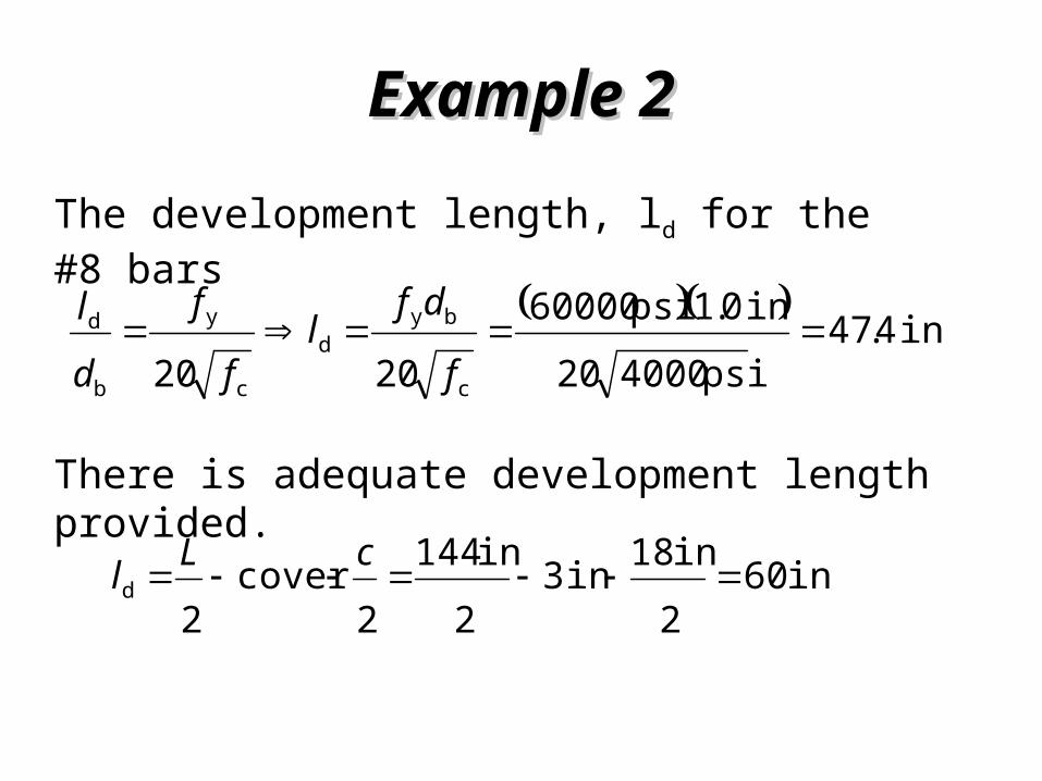
Example 2Example 2The development length, ld for the #8 bars
in 4.47psi 400020in 0.1psi 60000
2020 c
byd
c
y
b
d f
dfl
f
f
dl
There is adequate development length provided.
in 602in 18in 3
2in 144
2cover
2d
cLl
Example 2Example 2
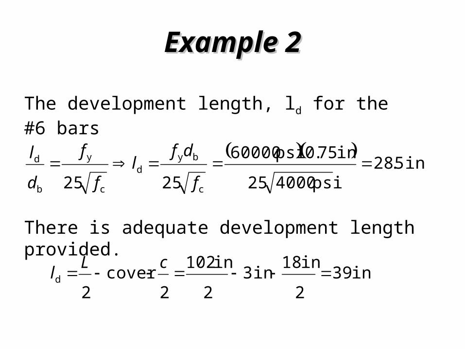
The development length, ld for the #6 bars
in 5.28psi 400025
in 75.0psi 600002525 c
byd
c
y
b
d f
dfl
f
f
dl
There is adequate development length provided.
in 392in 18in 3
2in 102
2cover
2d
cLl
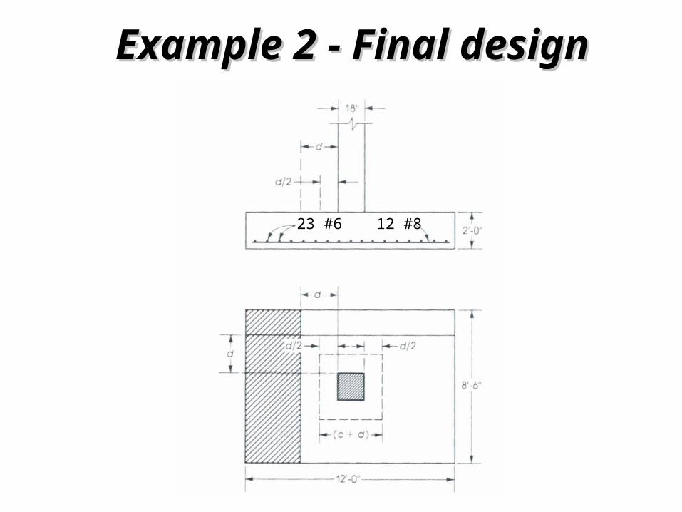
Example 2 - Final designExample 2 - Final design
12 #823 #6
Related Documents