PWIE, SP B.3 NCSRD activities in 2021: analysis of reference and plasma-exposed samples – plans and capabilities D. Mergia, A. Lagoyannis, P. Tsavalas, M. Axiotis NCSR “Demokritos” (NCSRD) PWIE

Welcome message from author
This document is posted to help you gain knowledge. Please leave a comment to let me know what you think about it! Share it to your friends and learn new things together.
Transcript

PWIE, SP B.3 NCSRD activities in 2021: analysis of reference and plasma-exposed samples – plans and capabilities
D. Mergia, A. Lagoyannis, P. Tsavalas, M. Axiotis
NCSR “Demokritos” (NCSRD)
PWIE
Dina Mergia| PWIE-SP B.2 & B.3| Zoom| KoM 11 June 2021| 2
Experimental capabilities for surface analysis of plasma
facing materials (1)
Ion Beam Analysis
Rutherford Backscattering Spectroscopy
(RBS)
Nuclear Reaction Analysis (NRA)
Particle Induced X-ray/Gamma-ray
Emission (PIXE/PIGE) spectroscopy
Time-of-Flight Elastic Recoil Detection
Analysis (ToF-ERDA) from early 2022
Milli- and micro-beam μ-B
eam
RBS , NRA, ERDA …
Charged-particle induced X-rays
Auger Spectrom.
Ato
mic
ph
ys
ics
multipurpose
scattering chamber 4 HPGe detect.
array γ - spectrometry charged-part.
irradiations
d-filled gas-cell
Tritiated Ti-target (rotating) n
eu
tro
n i
rrad
iati
on
s
γ - calorimetry
5.5 MV TANDEM Accelerator
Contact: Tassos Lagoyannis, [email protected]
New ion sources (TORVIS & SNICS II) to
be installed in early 2022 providing the
ability to use ions up to Iodine
Ion sources
Analyzing
magnet
Switching
magnet
Dina Mergia| PWIE-SP B.2 & B.3| Zoom| KoM 11 June 2021| 3
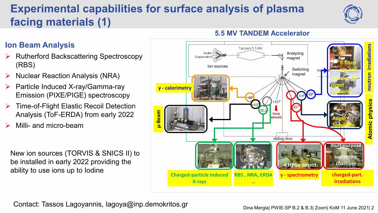
Chamber’s features: Load – lock chamber 3 – axis motorized sample holder Rotatable target holder Heating / Cooling Long range microscope for precision CCD camera for sample Monitoring
Detectors:
PIXE low energy Si(Li) detector at 45o
PIGE HPGe detector at 45o
STIM detector at 0o
RBS SSB detector at 170o
NRA SSB detector at 150o
Experimental capabilities for surface analysis of plasma
facing materials (2)
µ-beam Facility
Spatial resolution 1.2 μm x 2 μm

Dina Mergia| PWIE-SP B.2 & B.3| Zoom| KoM 11 June 2021| 4
Experimental capabilities for surface analysis of plasma
facing materials (3)
X-ray Fluorescence Spectroscopy (XRF)
Elemental analysis for Z>11
X-ray diffraction/reflectivity (XRD/XRR)
Normal and incidence angle
High speed linear position sensitive detector
In-situ studies from LN2 up to 1500C (XRD) or up to 800 C (XRR)
Scanning Electron Microscopy (SEM) with EDX spectroscopy
<1 nm resolution 0.2-30 kV (new FEG-SEM microscope purchase under way)
Transmission Electron Microscopy (TEM)
Atomic Force Microscopy (AFM)
X-ray Photoelectron Spectroscopy (XPS)
Mechanical properties using depth-sensing nano- & micro-indentation
XRF
XRD/XRR - furnace setup

Dina Mergia| PWIE-SP B.2 & B.3| Zoom| KoM 11 June 2021| 5
ILW-1
OPL
Enhanced erosion (>11 μm)
and deposited particles rich in
Ni are observed.
50 μm
50 μm
Ni rich Be rich
Be top layer became
thinner: erosion <11 μm
Comparison between ILW-1 and ILW-2
4D14
OPL
Be Tiles from JET tokamak: Erosion Combined NRA and SEM investigation
P. Tsavalas et al, Phys. Scr. T170 (2017) 014049
ILW-2
OPL 3.5 4.0 4.5
Inte
nsity (
Arb
. U
nits)
Energy (MeV)
Be
Bulk
Be
Top Layer Ni
Interlayer
Be Bulk
ILW-2 OPL
Reference
3.5 4.0 4.5
Be
Bulk Ni
Interlayer
Be
Top Layer
Be
Bulk
Inte
nsity (
Arb
. U
nits)
Energy (MeV)
Be
Top Layer Ni
Interlayer
ILW-1 OPL
Reference

Dina Mergia| PWIE-SP B.2 & B.3| Zoom| KoM 11 June 2021| 6
4 6 8 10
CuNiFeTi
Inte
nsity (
Lo
g A
rb. U
nits)
Energy (keV)
ILW-2 IWGL OUTER
ILW-1 IWGL OUTER
Reference
Ti Cr Mn Fe NiCu Zr W
0.01
0.1
1
10
100
Ti Cr Mn Fe Ni W
Rel
ativ
e C
on
c. (
at%
)
Element
ILW-1 DP
ILW-1 OPL
ILW-2 OPL
ILW-1 IWGL CENTRE
ILW-1 IWGL OUTER
ILW-2 IWGL OUTER
ILW-1 IWGL WING
Reference
40 50 60 70 80
ILW-1 IWGL WING
ILW-2 IWGL OUTER
ILW-1 IWGL OUTER
Reference
ILW-1 OPL
ILW-2 OPL
ILW-1 IWGL CENTRE
BeNi
BeO
Ni
Fe
Be
Inte
nsity (
arb
. u
nits)
2 (degrees)
DP
• Presence of BeO compound
• Formation of BeNi compound
Be Tiles from JET tokamak: Material deposition & compound formation
XRF & XRD investigation
XRD XRF
P. Tsavalas et al, Phys. Scr. T170 (2017) 014049
Dina Mergia| PWIE-SP B.2 & B.3| Zoom| KoM 11 June 2021| 7
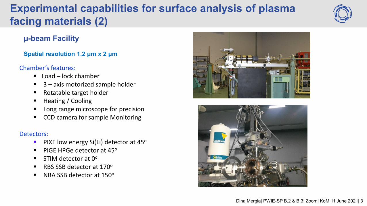
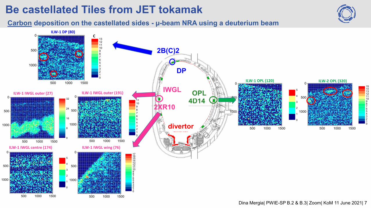
Be castellated Tiles from JET tokamak Carbon deposition on the castellated sides - µ-beam NRA using a deuterium beam
4D14 2XR10
2B(C)2
DP
IWGL OPL
divertor
500 1000 1500
1000
500
0
012345678910111213
ILW-1 DP (80) C
500 1000 1500
1000
500
0
0
1
2
3
4
5
ILW-1 OPL (120) ILW-2 OPL (320)
ILW-1 IWGL outer (191)
500 1000 1500
1000
500
0
0
1
2
3
4
5
6
7
8
9
10
11
500 1000 1500
1000
500
0
0
8
16
24
32
ILW-1 IWGL outer (27)
500 1000 1500
1000
500
0
0
1
2
3
4
5
500 1000 1500
1000
500
0
01234567891011121314151617
ILW-1 IWGL centre (174) ILW-1 IWGL wing (76)
500 1000 1500
1000
500
0
0123456789101112131415

Dina Mergia| PWIE-SP B.2 & B.3| Zoom| KoM 11 June 2021| 8
NRA results from W lamellae – use of 2H micro-beam Carbon deposition
0 5 10 15 20 25 30 350.0
0.2
0.4
0.6
Depth (1018
at/cm2)
0.0
0.2
0.4
0.6
(ILW1) A23, 7
(ILW1) C3, 12 area 1 0.0
0.2
0.4
0.6
Ca
rbo
n C
on
ce
ntr
atio
n (
at%
) (ILW1) C3,12 area 2
0 2 4
1
10
100
1000
10000
100000
Inte
nsity (
co
un
ts)
Energy (MeV)
experimental
simulatedW(d,d)W
12C(d,p
0)
13C
16O(d,p
0)
17O
Pile up Be reactions
Sample 7
250 500 750 1000
250
500
750
1000(ILW1) A23, 7
250 500 750 1000
250
500
750
1000
(ILW1) C3,12 (2)
250 500 750 1000
250
500
750
1000(ILW1) C3, 12 (1)
Lamella Exp.
Period
Sample C Amount (1017 at/cm2)
Deposition
Thickness (1018 at/cm2)
C3 ILW1 12 (2) 24.8 10.7
C3 ILW1 12 (1) 166 33
A23 ILW1 7 2.21 10
ILW
1
ILW1
Measure
d surface
Measured
surface
Measured
surface
Investigation of carbon deposition &
carbon depth profile in W lamellae
from JET tokamak
P. Tsavalas et al. PFMC-18, 2021
Dina Mergia| PWIE-SP B.2 & B.3| Zoom| KoM 11 June 2021| 9
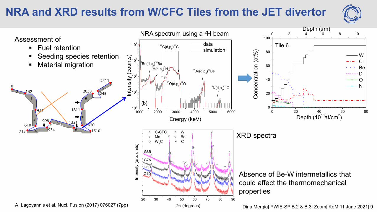
1000 2000 3000 4000 5000 600010
0
101
102
103
104
Inte
nsity (
co
un
ts)
Energy (keV)
data
simulation
9Be(d,p
1)
10Be
2H(d,p
0)
3H
12C(d,p
0)
13C
16O(d.p
0)
17O
9Be(d,p
0)
10Be
14N(d,a
1)
12C
(b)
NRA and XRD results from W/CFC Tiles from the JET divertor
NRA spectrum using a 2H beam
0 20 40 60 800
20
40
60
80
100
W
C
Be
D
O
N
Co
nce
ntr
ation
(at%
)
Depth (1018
at/cm2)
Tile 6
0 2 4 6 8 10
Depth (m)
20 30 40 50 60 70 80 90
G6C
G7A
G8B
Inte
nsity (
arb
. u
nits)
2(degrees)
C-CFC W
Mo Be
W2C C
G4D
XRD spectra
Absence of Be-W intermetallics that
could affect the thermomechanical
properties
A. Lagoyannis et al, Nucl. Fusion (2017) 076027 (7pp)
Assessment of
Fuel retention
Seeding species retention
Material migration
Dina Mergia| PWIE-SP B.2 & B.3| Zoom| KoM 11 June 2021| 10
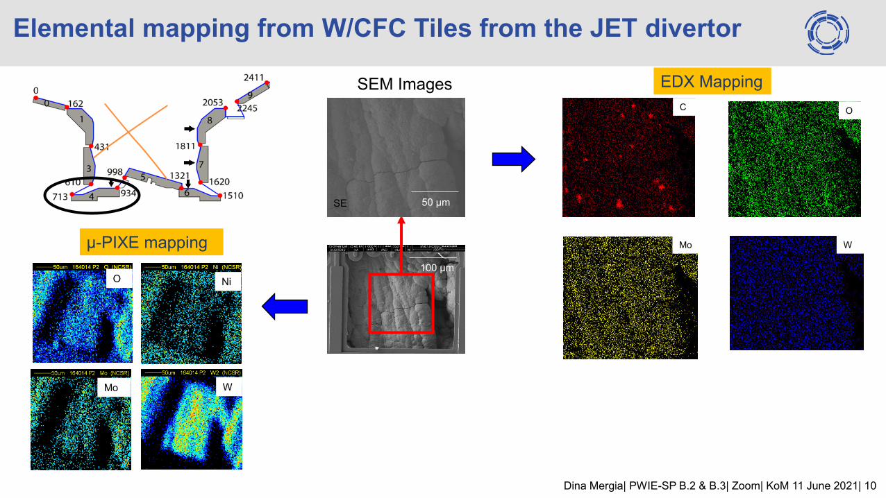
Elemental mapping from W/CFC Tiles from the JET divertor
μ-PIXE mapping
C
Mo
O
W
SEM Images EDX Mapping
50 μm SE
Mo
O
W
Ni
100 μm

Dina Mergia| PWIE-SP B.2 & B.3| Zoom| KoM 11 June 2021| 11
2021 workplan
Analysis of reference and plasma exposed Be or W samples from the various devices
Problems to be addressed
• Material deposition, depth profiles, compound formation
• Erosion
• Fuel retention
• Seeding species retention
• Microstructural changes
• Mechanical properties using depth-sensing indentation techniques
In-situ XRD annealing of plasma exposed samples to assess
i) temperature effects on compound formation due to material deposition
ii) microstructural changes.
Samples to be identified and specific problems to de defined
Suggestions for collaborations welcome (please send an email to [email protected] to discuss)
D007 RBS, SEM, XRD and XRF characterization of selected Be reference coatings and plasma-exposed
samples
Related Documents