FOCUS kWh Solid-State Meter Technical Manual Bulletin 160 Revision 2.5

Welcome message from author
This document is posted to help you gain knowledge. Please leave a comment to let me know what you think about it! Share it to your friends and learn new things together.
Transcript

FOCUS kWh Solid-State Meter
Technical Manual
Bulletin 160
Revision 2.5
i
Information in this document is subject to change without notice. No part of this document may be reproduced or transmitted in any form or by any means, electronic or mechanical, for any purpose without the express written permission of Landis+Gyr, Inc.. © 2003 Landis+Gyr, Inc. All rights reserved. For further information, contact: Landis+Gyr, Inc. Meter Division 2800 Duncan Road Lafayette, IN 47904-5012 USA Tel. 765-742-1001 Document History
Title: FOCUS Solid State Meter Technical Manual
Document Number: Bulletin 160
Revision Date Description
Level Issued
Original (1.0) 1/04 Initial Issue
2.0 10/19/04 Rev. Cellnet FCC#
2.1 11/8/04 add note #3 to FCC info.
2.2 11/1/05 add Neptune FCC#
2.3 12/13/05 add Industry Canada Verbiage
2.4 10/10/06 add Current Technologies FCC #
2.5 12/22/06 add accessories

ii
TABLE OF CONTENTS
PURPOSE .......................................................................................................................... IV
TARGET GROUP.................................................................................................................. IV
CONDITIONS...................................................................................................................... IV
SAFETY WARNINGS ............................................................................................................. IV
1. INTRODUCTION TO THE FOCUS..................................................................................... 1
2. THE FOCUS METER FAMILY........................................................................................... 4
3. METER ASSEMBLY ........................................................................................................ 5
4. APPLICATION INFORMATION........................................................................................... 7
5. OVERVIEW OF ELECTRONIC HARDWARE .......................................................................... 12
6. CONFIGURING THE METER ........................................................................................... 15
7. METER CALIBRATION .................................................................................................. 16
8. DATA RETENTION ...................................................................................................... 17
9. PULSE OUTPUTS ........................................................................................................ 18
10. FOCUS ACCESSORIES................................................................................................. 20
11. PRODUCT SPECIFICATION ............................................................................................ 22
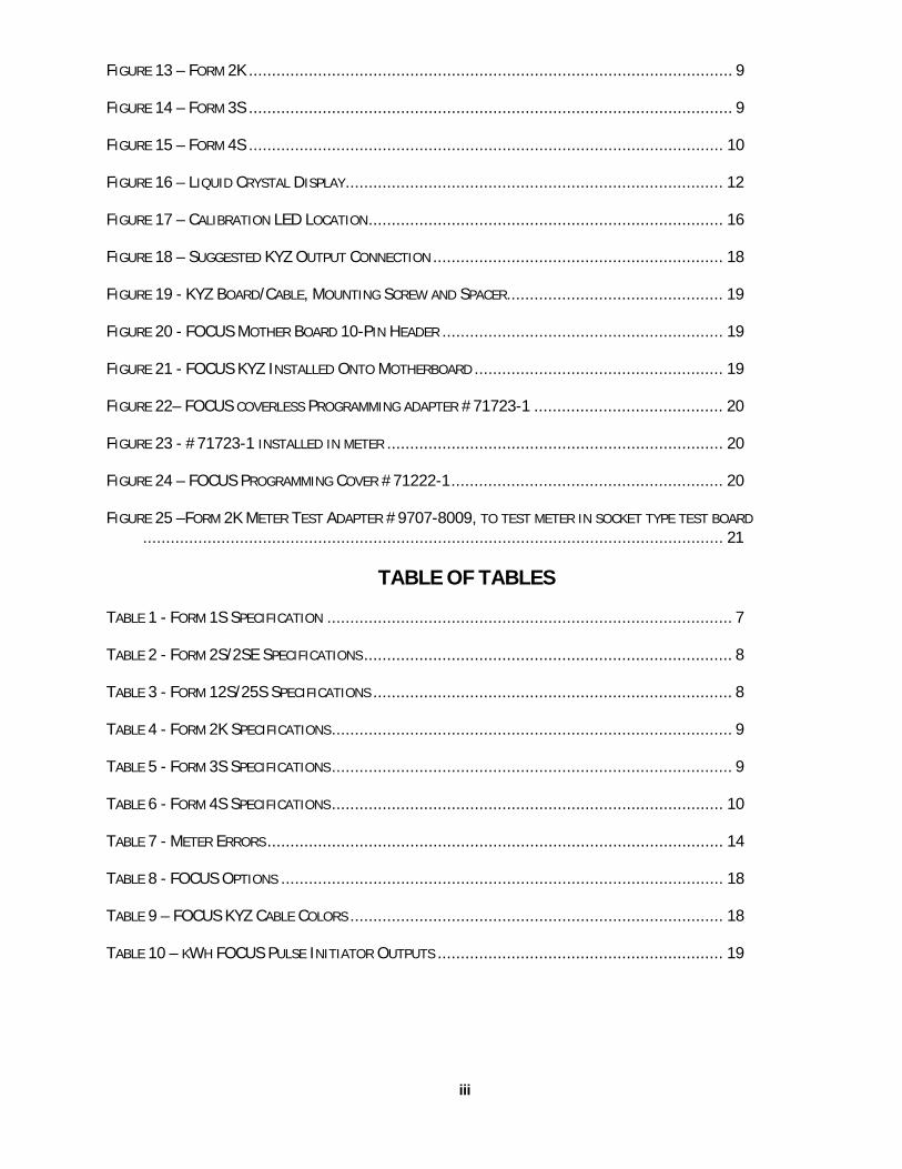
TABLE OF FIGURES
FIGURE 1- BASIC OPERATION DIAGRAM ................................................................................... 1
FIGURE 2 – METER ASSEMBLY................................................................................................ 1
FIGURE 3 - METER ASSEMBLY EXPLODED VIEW.......................................................................... 2
FIGURE 4 - BASEPLATE ASSEMBLY EXPLODED VIEW .................................................................... 2
FIGURE 5 - ELECTRONICS HOUSING ASSEMBLY EXPLODED VIEW.................................................... 3
FIGURE 6 – KWH FOCUS...................................................................................................... 4
FIGURE 7 – REMOVAL OF ELECTRONICS HOUSING ...................................................................... 5
FIGURE 11 – FORM 1S ......................................................................................................... 7
FIGURE 12 – FORM 2S, 2SE.................................................................................................. 8
iii
FIGURE 13 – FORM 2K ......................................................................................................... 9
FIGURE 14 – FORM 3S ......................................................................................................... 9
FIGURE 15 – FORM 4S ....................................................................................................... 10
FIGURE 16 – LIQUID CRYSTAL DISPLAY.................................................................................. 12
FIGURE 17 – CALIBRATION LED LOCATION............................................................................. 16
FIGURE 18 – SUGGESTED KYZ OUTPUT CONNECTION ............................................................... 18
FIGURE 19 - KYZ BOARD/CABLE, MOUNTING SCREW AND SPACER............................................... 19
FIGURE 20 - FOCUS MOTHER BOARD 10-PIN HEADER ............................................................. 19
FIGURE 21 - FOCUS KYZ INSTALLED ONTO MOTHERBOARD ...................................................... 19
FIGURE 22– FOCUS COVERLESS PROGRAMMING ADAPTER #71723-1 ......................................... 20
FIGURE 23 - #71723-1 INSTALLED IN METER ......................................................................... 20
FIGURE 24 – FOCUS PROGRAMMING COVER #71222-1........................................................... 20
FIGURE 25 –FORM 2K METER TEST ADAPTER #9707-8009, TO TEST METER IN SOCKET TYPE TEST BOARD.............................................................................................................................. 21
TABLE OF TABLES
TABLE 1 - FORM 1S SPECIFICATION ........................................................................................ 7
TABLE 2 - FORM 2S/2SE SPECIFICATIONS................................................................................ 8
TABLE 3 - FORM 12S/25S SPECIFICATIONS .............................................................................. 8
TABLE 4 - FORM 2K SPECIFICATIONS....................................................................................... 9
TABLE 5 - FORM 3S SPECIFICATIONS....................................................................................... 9
TABLE 6 - FORM 4S SPECIFICATIONS..................................................................................... 10
TABLE 7 - METER ERRORS................................................................................................... 14
TABLE 8 - FOCUS OPTIONS ................................................................................................ 18
TABLE 9 – FOCUS KYZ CABLE COLORS ................................................................................. 18
TABLE 10 – KWH FOCUS PULSE INITIATOR OUTPUTS .............................................................. 19
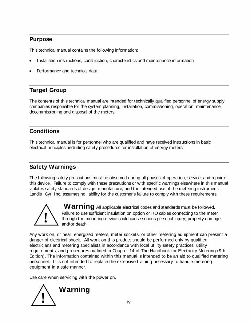
Purpose
This technical manual contains the following information:
• Installation instructions, construction, characteristics and maintenance information
• Performance and technical data
Target Group
The contents of this technical manual are intended for technically qualified personnel of energy supply companies responsible for the system planning, installation, commissioning, operation, maintenance, decommissioning and disposal of the meters.
Conditions
This technical manual is for personnel who are qualified and have received instructions in basic electrical principles, including safety procedures for installation of energy meters.
Safety Warnings
The following safety precautions must be observed during all phases of operation, service, and repair of this device. Failure to comply with these precautions or with specific warnings elsewhere in this manual violates safety standards of design, manufacture, and the intended use of the metering instrument. Landis+Gyr, Inc. assumes no liability for the customer's failure to comply with these requirements.
Warning All applicable electrical codes and standards must be followed. Failure to use sufficient insulation on option or I/O cables connecting to the meter through the mounting device could cause serious personal injury, property damage, and/or death.
! Any work on, or near, energized meters, meter sockets, or other metering equipment can present a danger of electrical shock. All work on this product should be performed only by qualified electricians and metering specialists in accordance with local utility safety practices, utility requirements, and procedures outlined in Chapter 14 of The Handbook for Electricity Metering (9th Edition). The information contained within this manual is intended to be an aid to qualified metering personnel. It is not intended to replace the extensive training necessary to handle metering equipment in a safe manner.
Use care when servicing with the power on.
! Warning
iv

v
The use of I/O cables in ungrounded services could cause serious personal injury, property damage, and/or death
The FOCUS does not have an auto-ranging power supply. Care should be taken to ensure that meters are installed correctly, matching meter form and voltage with the installation.
1.1.1. Published Specifications The FOCUS kWh is designed in accordance with the specifications listed below.
1.1.2. Institute for Electrical and Electronic Engineers (IEEE) • IEEE Recommended Practice on Surge Voltages in Low-Voltage AC Power Circuits-C62.41-1991
1.1.3. American National Standards Institute (ANSI) • American National Standard Code for Electricity Metering, ANSI C12.1-2001
• American National Standard for Watt-Hour Meters, ANSI C12.10-1997
• American National Standard Method of Salt Spray (Fog) Testing, ANSI/ASTM B117-73, (Z 118.1-1974)
• American National Standard for Electricity Meters 0.2 and 0.5 Accuracy Classes, ANSI C12.20-2002
1.1.4. Underwriters Laboratories (UL) • Underwriters Laboratories UL 746C, “Polymeric Materials – Electrical Equipment Evaluations,”
December 27, 1995.
1.1.5. Canadian Specifications • National Standard of Canada, "Specifications for Approval of Type of Electricity Meters, Instrument
Transformers and Auxiliary Devices", CAN3C17M84
• Ontario Hydro, "Oscillatory Transient Interference Immunity Test", A-28M-82
• Canadian Standard for Terminal Equipment, Terminal Systems, Network Protection Devices, Connection Arrangements and Hearing Aids Compatibility, CS-03
Industry Canada This Class B digital apparatus meets all requirements of the Canadian Interference Causing Equipment Regulations. Operation is subject to the following two conditions: (1) this device may not cause harmful interference, and (2) this device must accept any interference received, including interference that may cause undesired operation. Cet appareillage numérique de la classe B répond à toutes les exigences de l'interférence canadienne causant des règlements d'équipement. L'opération est sujette aux deux conditions suivantes: (1) ce dispositif peut ne pas causer l'interférence nocive, et (2) ce dispositif doit accepter n'importe quelle interférence reçue, y compris l'interférence qui peut causer l'opération peu désirée.
vi
1.1.6. FCC Information: This device complies with part 15 of the FCC rules. Operation is subject to the following three conditions:
(1) This device may not cause harmful interference, and
(2) This device must accept any interference received, including interference that may cause undesired operation.
(3) For RF exposure, service personnel are to maintain a minimum of 20cm from the RF communications transmitter once installed.
Changes or modifications not expressly approved by Landis+Gyr could void the user’s authority to operate the equipment. Do not change the original antenna without pre-approval from the original meter manufacturer. This will violate the FCC regulations of using the radio.
Note: Some FOCUS meters may contain AMR modules with RF communications. This equipment has been tested and found to comply with the limits for a class B digital device, pursuant to part 15 of the FCC Rules. These limits are designed to provide reasonable protection against harmful interference in a residential installation. This equipment uses and can radiate radio frequency energy and, if not installed and used in accordance with the instructions, may cause harmful interference to radio communications. However, there is no guarantee that interference will not occur in a particular installation. If this equipment does cause harmful interference to radio or television reception, which can be determined by turning the equipment off and on, the user is encouraged to try to correct the interference by one or more of the following measures:
- Reorient or relocate the receiving antenna.
- Increase the separation between the equipment and receiver.
- Connect the equipment into an outlet on a circuit different from that to which the receiver is connected.
- Consult Landis+Gyr or an authorized technician for help.
Following are FCC identification numbers for radio systems currently used on FOCUS:
Cellnet FCC ID: ROV-CLTR900M Neptune FCC ID: P2SNTGSRFE01 StatSignal FCC ID: ROV-1MWR9165
Current Technologies FCC ID: TY7210-0137-0001
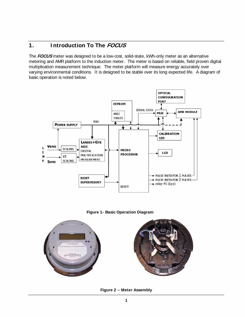
1. Introduction To The FOCUS
The FOCUS meter was designed to be a low-cost, solid-state, kWh-only meter as an alternative metering and AMR platform to the induction meter. The meter is based on reliable, field proven digital multiplication measurement technique. The meter platform will measure energy accurately over varying environmental conditions. It is designed to be stable over its long expected life. A diagram of basic operation is noted below.
Figure 1- Basic Operation Diagram
Figure 2 – Meter Assembly
1
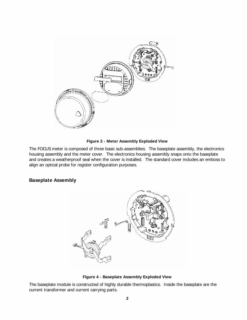
Figure 3 - Meter Assembly Exploded View
The FOCUS meter is composed of three basic sub-assemblies: The baseplate assembly, the electronics housing assembly and the meter cover. The electronics housing assembly snaps onto the baseplate and creates a weatherproof seal when the cover is installed. The standard cover includes an emboss to align an optical probe for register configuration purposes.
Baseplate Assembly
Figure 4 - Baseplate Assembly Exploded View
The baseplate module is constructed of highly durable thermoplastics. Inside the baseplate are the current transformer and current carrying parts.
2
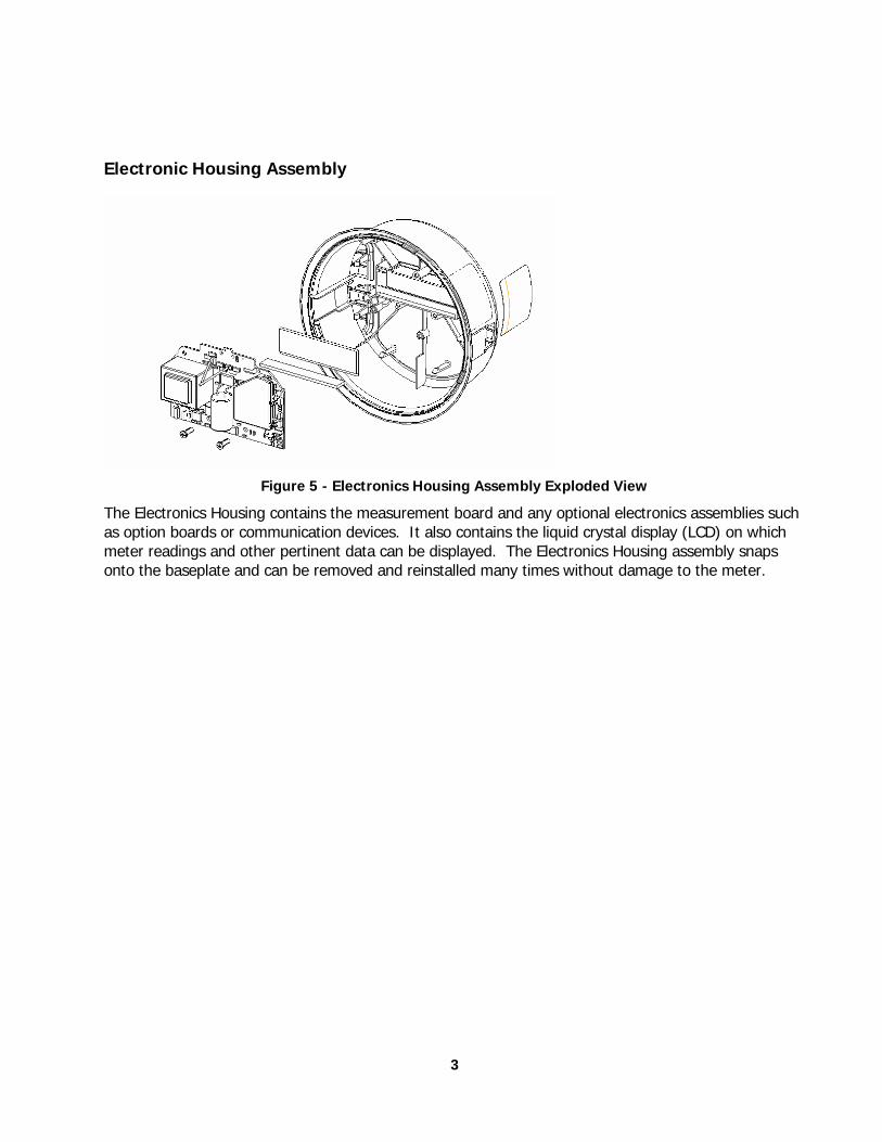
Electronic Housing Assembly
Figure 5 - Electronics Housing Assembly Exploded View
The Electronics Housing contains the measurement board and any optional electronics assemblies such as option boards or communication devices. It also contains the liquid crystal display (LCD) on which meter readings and other pertinent data can be displayed. The Electronics Housing assembly snaps onto the baseplate and can be removed and reinstalled many times without damage to the meter.
3

2. The FOCUS Meter Family
The FOCUS provides more than just reliability and accurate billing data. The FOCUS is designed to be a building block for a complete metering system. Each FOCUS has built-in compatibility for a variety of AMR packages. Any of these can be factory installed. Some can be added to the meter dependent upon the meter vintage and respective AMR technology.
Register Types The FOCUS kWh is an active energy “kWh-only” meter. It is capable of measuring and displaying kilowatt-hours delivered to and received from a load.
The energy accumulation register has capacity to display 999999 kWh for all meter forms without overflowing.
The meter supports four energy metric displays:
• +kWh (energy delivered to the load)
• -kWh (energy received from the load)
• NET kWh (the net energy consumed by the load, or negative kWh subtracted from positive kWh)
• ADDED kWh (negative kWh added to positive kWh-also referred to as security mode)
Figure 6 – kWh FOCUS
4
3. Meter Assembly
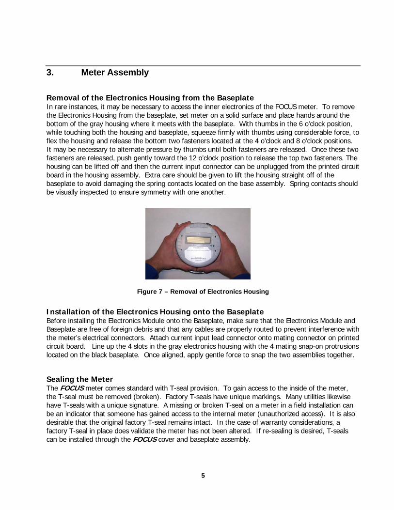
Removal of the Electronics Housing from the Baseplate In rare instances, it may be necessary to access the inner electronics of the FOCUS meter. To remove the Electronics Housing from the baseplate, set meter on a solid surface and place hands around the bottom of the gray housing where it meets with the baseplate. With thumbs in the 6 o’clock position, while touching both the housing and baseplate, squeeze firmly with thumbs using considerable force, to flex the housing and release the bottom two fasteners located at the 4 o’clock and 8 o’clock positions. It may be necessary to alternate pressure by thumbs until both fasteners are released. Once these two fasteners are released, push gently toward the 12 o’clock position to release the top two fasteners. The housing can be lifted off and then the current input connector can be unplugged from the printed circuit board in the housing assembly. Extra care should be given to lift the housing straight off of the baseplate to avoid damaging the spring contacts located on the base assembly. Spring contacts should be visually inspected to ensure symmetry with one another.
F
Installation of the ElectroBefore installing the Electronics Baseplate are free of foreign dethe meter’s electrical connectorscircuit board. Line up the 4 slolocated on the black baseplate.
Sealing the Meter The FOCUS meter comes standthe T-seal must be removed (brhave T-seals with a unique signbe an indicator that someone hdesirable that the original factorfactory T-seal in place does valican be installed through the FO
igure 7 – Removal of Electronics Housing
nics Housing onto the Baseplate Module onto the Baseplate, make sure that the Electronics Module and bris and that any cables are properly routed to prevent interference with . Attach current input lead connector onto mating connector on printed ts in the gray electronics housing with the 4 mating snap-on protrusions Once aligned, apply gentle force to snap the two assemblies together.
ard with T-seal provision. To gain access to the inside of the meter, oken). Factory T-seals have unique markings. Many utilities likewise ature. A missing or broken T-seal on a meter in a field installation can as gained access to the internal meter (unauthorized access). It is also y T-seal remains intact. In the case of warranty considerations, a date the meter has not been altered. If re-sealing is desired, T-seals CUS cover and baseplate assembly.
5
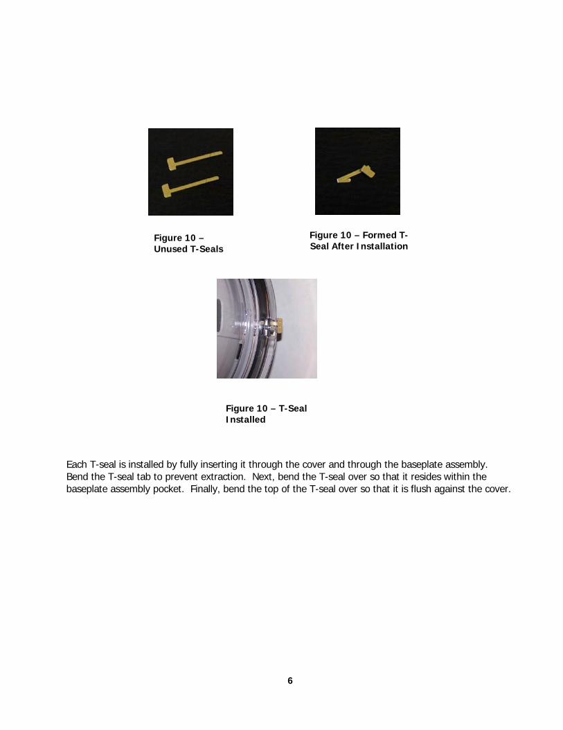
Figure 10 – Unused T-Seals
Figure 10 – Formed T-Seal After Installation
Figure 10 – T-Seal Installed
Each T-seal is installed by fully inserting it through the cover and through the baseplate assembly. Bend the T-seal tab to prevent extraction. Next, bend the T-seal over so that it resides within the baseplate assembly pocket. Finally, bend the top of the T-seal over so that it is flush against the cover.
6
4. Application Information
Available Meter Forms The FOCUS is available in the following meter forms:
4.1.1. S-Base • Transformer rated: Class 10 & 20: 3S, 4S
• Self-contained: class 100: 1S
• Self-contained: class 200: 2S, 12S and 25S (Network)
• Self-contained: class 320: 2SE
4.1.2. K-Base • Self-contained: class 480: 2K
Meter Form Schematic Diagrams
Self-contained meter forms
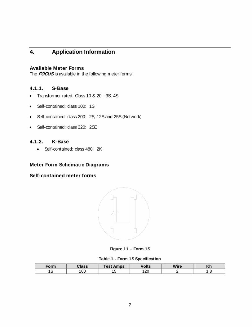
Figure 11 – Form 1S
Table 1 - Form 1S Specification
Form Class Test Amps Volts Wire Kh 1S 100 15 120 2 1.8
7
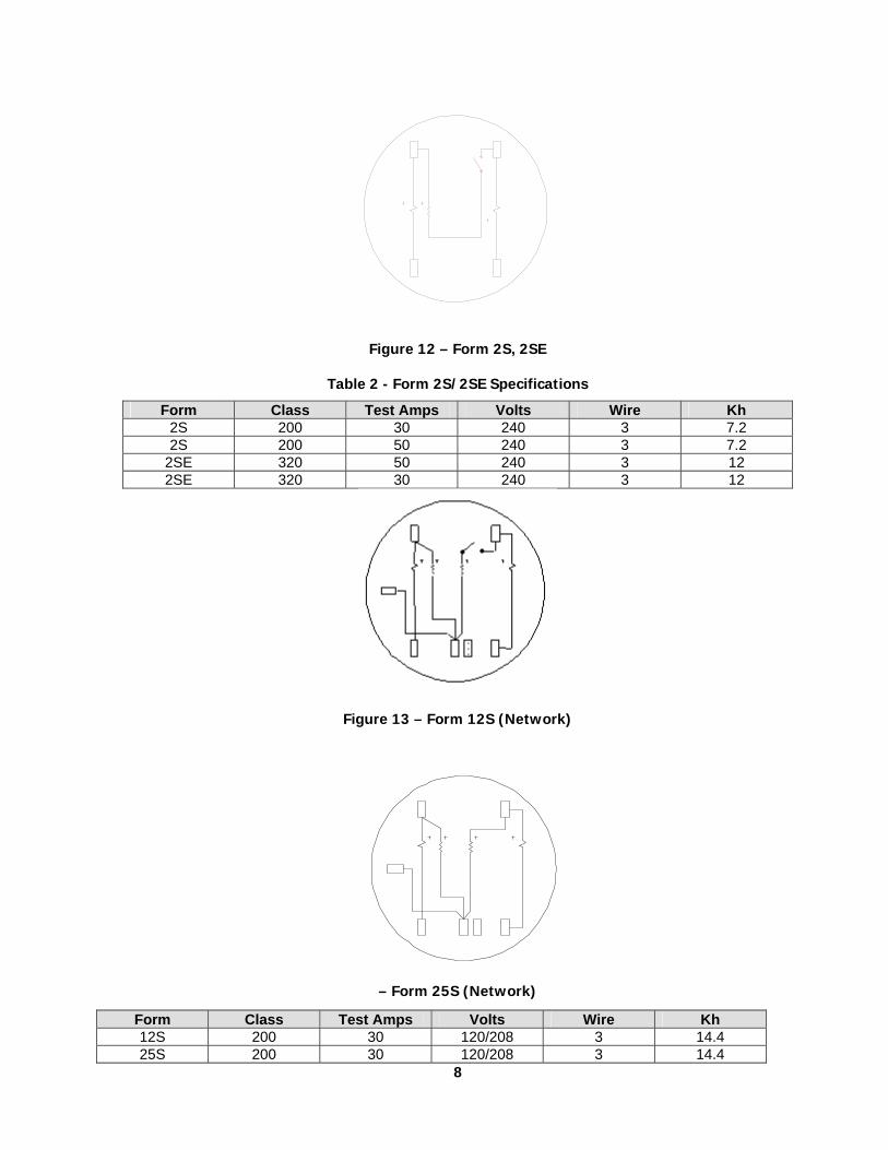
Figure 12 – Form 2S, 2SE
Table 2 - Form 2S/2SE Specifications
Form Class Test Amps Volts Wire Kh 2S 200 30 240 3 7.2 2S 200 50 240 3 7.2
2SE 320 50 240 3 12 2SE 320 30 240 3 12
Figure 13 – Form 12S (Network)
– Form 25S (Network)
8
Form Class Test Amps Volts Wire Kh 12S 200 30 120/208 3 14.4 25S 200 30 120/208 3 14.4
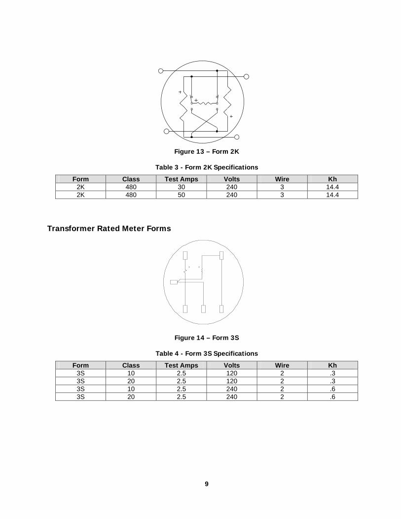
Figure 13 – Form 2K
Table 3 - Form 2K Specifications
Form Class Test Amps Volts Wire Kh 2K 480 30 240 3 14.4 2K 480 50 240 3 14.4
Transformer Rated Meter Forms
Figure 14 – Form 3S
Table 4 - Form 3S Specifications
Form Class Test Amps Volts Wire Kh 3S 10 2.5 120 2 .3 3S 20 2.5 120 2 .3 3S 10 2.5 240 2 .6 3S 20 2.5 240 2 .6
9
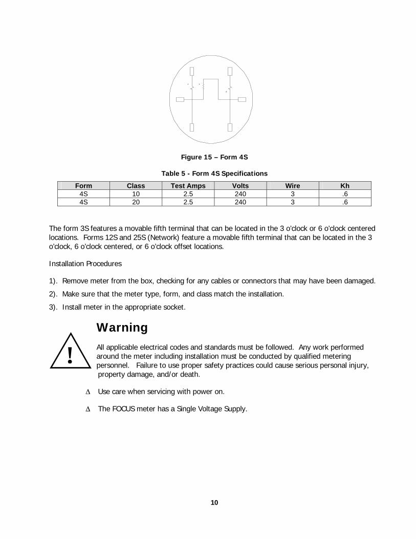
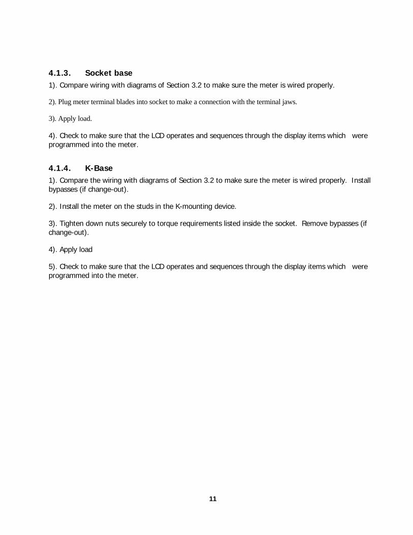
Figure 15 – Form 4S
Table 5 - Form 4S Specifications
Form Class Test Amps Volts Wire Kh 4S 10 2.5 240 3 .6 4S 20 2.5 240 3 .6
The form 3S features a movable fifth terminal that can be located in the 3 o’clock or 6 o’clock centered locations. Forms 12S and 25S (Network) feature a movable fifth terminal that can be located in the 3 o’clock, 6 o’clock centered, or 6 o’clock offset locations.
Installation Procedures
1). Remove meter from the box, checking for any cables or connectors that may have been damaged.
2). Make sure that the meter type, form, and class match the installation.
3). Install meter in the appropriate socket.
Warning All applicable electrical codes and standards must be followed. Any work performed around the meter including installation must be conducted by qualified metering personnel. Failure to use proper safety practices could cause serious personal injury,
property damage, and/or death.
! ∆ Use care when servicing with power on.
∆ The FOCUS meter has a Single Voltage Supply.
10
11
4.1.3. Socket base 1). Compare wiring with diagrams of Section 3.2 to make sure the meter is wired properly.
2). Plug meter terminal blades into socket to make a connection with the terminal jaws.
3). Apply load.
4). Check to make sure that the LCD operates and sequences through the display items which were programmed into the meter.
4.1.4. K-Base 1). Compare the wiring with diagrams of Section 3.2 to make sure the meter is wired properly. Install bypasses (if change-out).
2). Install the meter on the studs in the K-mounting device.
3). Tighten down nuts securely to torque requirements listed inside the socket. Remove bypasses (if change-out).
4). Apply load
5). Check to make sure that the LCD operates and sequences through the display items which were programmed into the meter.
5. Overview of Electronic Hardware
5.1.1. LCD Display
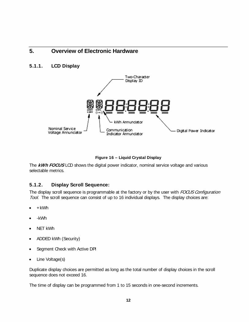
Figure 16 – Liquid Crystal Display
The kWh FOCUS LCD shows the digital power indicator, nominal service voltage and various selectable metrics.
5.1.2. Display Scroll Sequence: The display scroll sequence is programmable at the factory or by the user with FOCUS Configuration Tool. The scroll sequence can consist of up to 16 individual displays. The display choices are:
• +kWh
• -kWh
• NET kWh
• ADDED kWh (Security)
• Segment Check with Active DPI
• Line Voltage(s)
Duplicate display choices are permitted as long as the total number of display choices in the scroll sequence does not exceed 16.
The time of display can be programmed from 1 to 15 seconds in one-second increments.
12
13
When internal meter errors occur, error codes will be added to the end of the scroll sequence.
The segment check display does not affect the DPI. This permits a user to use the DPI for timing when a segment check is being displayed during a scroll sequence.
A two character programmable alphanumeric label can be associated with each display. This two-character field is used to identify the value displayed. It can be left blank if desired.
5.1.3. Display Format The display accommodates the following digit formats:
• 6x1
• 5x1
• 4x1
• 4x10 (Four digit display with the least significant digit representing 10kWh per increment)
The energy display format is programmable at the factory or by the user with FOCUS Configuration Tool. Display format does not affect the segment check, meter error codes or line voltage readings.
5.1.4. Digital Power Indicator The FOCUS kWh has a digital power indicator similar to the Landis+Gyr traditional “caterpillar” and consists of six segments.
The DPI moves from left to right at a rate proportional to energy delivered to the load and moves from right to left at a rate proportional to the energy received from the load.
The DPI makes one revolution for each Kh of metered energy.
Each DPI segment on/off transition is observable when occurring at a maximum rate of one on/off transition each .45 second at –20ºC and above.
5.1.5. Power Up Display Sequence All FOCUS kWh display segments, including the DPI segments, illuminate after the meter is powered up regardless of the display sequence program. This segment check display persists for less than five seconds upon meter power-up, after which time the display begins its programmed scroll sequence.
14
Diagnostics/Error Codes
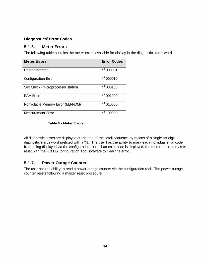
5.1.6. Meter Errors The following table contains the meter errors available for display in the diagnostic status word.
Meter Errors Error Codes
Unprogrammed *1 000001
Configuration Error *1 000010
Self Check (microprocessor status) *1 000100
RAM Error *1 001000
Nonvolatile Memory Error (EEPROM) *1 010000
Measurement Error *1 100000
Table 6 - Meter Errors
All diagnostic errors are displayed at the end of the scroll sequence by means of a single six-digit diagnostic status word prefixed with a *1. The user has the ability to mask each individual error code from being displayed via the configuration tool. If an error code is displayed, the meter must be master reset with the FOCUS Configuration Tool software to clear the error.
5.1.7. Power Outage Counter The user has the ability to read a power outage counter via the configuration tool. The power outage counter resets following a master reset procedure.
15
6. Configuring the Meter
6.1.1. Configuration Port The ability to configure the meter is provided through a secure meter configuration port. A cover mounted optical configuration port accommodates meter configuration by the user. The configuration port is designed to be used in a meter shop environment, (room temperature/ambient lighting conditions). The configuration port interface supports a read/write security function.
The configuration port can be completely disabled by means of a mechanical plug placed into the right-side optic port so that meter communications cannot be enabled without breaking the meter security seal to remove the plug. This option is available for utilities that require the meter seal to be broken and cover removed to allow reconfiguration of the meter.
6.1.2. Initial Power-Up and Operation KWH FOCUS meters are always shipped programmed in a configuration defined at the time an order is placed. They are ready for field installation.
6.1.3. Billing Data Reset/Preset The contents of the +kWh and–kWh accumulation registers are user programmable through an optical configuration port. In its simplest form, this feature allows the user to reset the contents of the +kWh and –kWh accumulation registers. This feature also enables the user to clear any accumulated energy following meter verification testing.
The user also has the ability to enter initial energy values into the +kWh and –kWh accumulation registers. This feature allows a user to pre-load energy values into a replacement meter before it goes into service.
The user can perform this function in a meter shop
6.1.4. Display Multiplier The user has the ability to program a display multiplier. kWh values contained in the energy registers are multiplied by the display multiplier prior to being displayed in the LCD. The display multiplier does not affect the contents of the internal energy registers. If direct reading is desired on transformer rated installations, it can be accommodated via this programmable multiplier.
The display multiplier can be any value from 1 to 240.
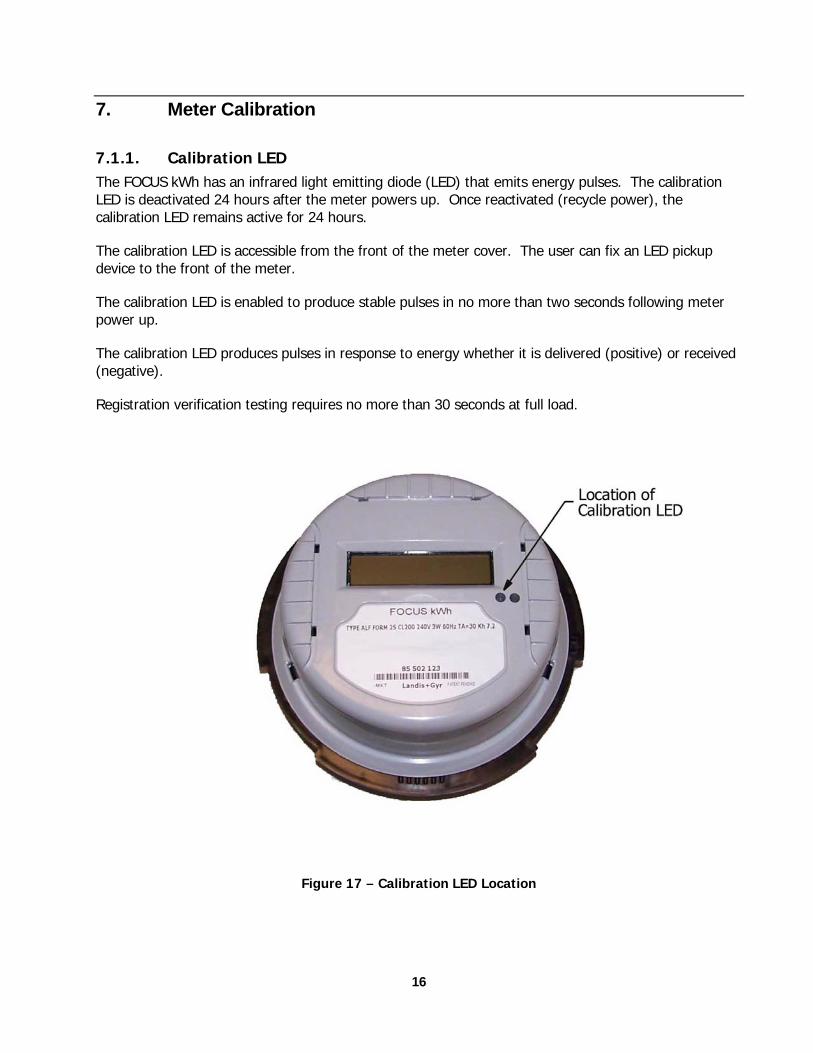
7. Meter Calibration
7.1.1. Calibration LED The FOCUS kWh has an infrared light emitting diode (LED) that emits energy pulses. The calibration LED is deactivated 24 hours after the meter powers up. Once reactivated (recycle power), the calibration LED remains active for 24 hours.
The calibration LED is accessible from the front of the meter cover. The user can fix an LED pickup device to the front of the meter.
The calibration LED is enabled to produce stable pulses in no more than two seconds following meter power up.
The calibration LED produces pulses in response to energy whether it is delivered (positive) or received (negative).
Registration verification testing requires no more than 30 seconds at full load.
Figure 17 – Calibration LED Location
16
17
7.1.2. Factory Calibration The meter is calibrated at the factory as part of the manufacturing process. Calibration constants are stored in nonvolatile memory. These constants are not alterable once programmed except through another calibration cycle at the factory. Sufficient security features are provided to prevent the user from altering the calibration constants stored within the meter.
7.1.3. Customer Calibration Adjustment FOCUS kWh calibration is adjustable. Calibration biases may be adjusted by means of a calibration tool via the configuration port.
It is believed that the FOCUS meter will not need recalibration during its life but allowance for adjustments has been provided should the utility want to modify the registration at some point in time.
8. Data Retention
All billing data is stored in nonvolatile memory. Billing data is retained during loss of power to the meter.
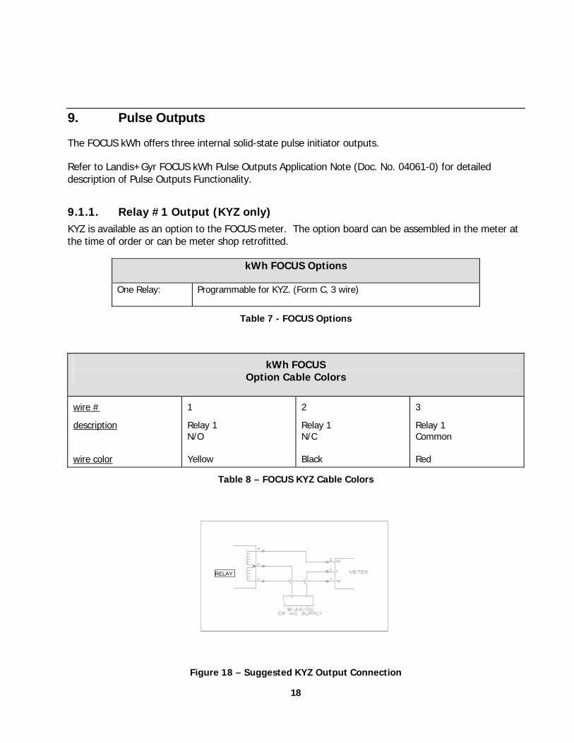
9. Pulse Outputs
The FOCUS kWh offers three internal solid-state pulse initiator outputs.
Refer to Landis+Gyr FOCUS kWh Pulse Outputs Application Note (Doc. No. 04061-0) for detailed description of Pulse Outputs Functionality.
9.1.1. Relay #1 Output (KYZ only) KYZ is available as an option to the FOCUS meter. The option board can be assembled in the meter at the time of order or can be meter shop retrofitted.
kWh FOCUS Options
One Relay: Programmable for KYZ. (Form C, 3 wire)
Table 7 - FOCUS Options
kWh FOCUS Option Cable Colors
wire #
description wire color
1
Relay 1 N/O Yellow
2
Relay 1 N/C Black
3
Relay 1 Common Red
Table 8 – FOCUS KYZ Cable Colors
RELAY
Figure 18 – Suggested KYZ Output Connection
18
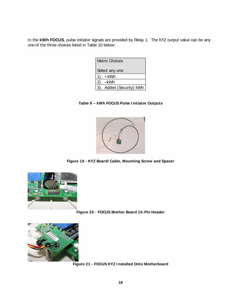
In the kWh FOCUS, pulse initiator signals are provided by Relay 1. The KYZ output value can be any one of the three choices listed in Table 10 below:
Metric Choices
Select any one 1). +kWh 2). –kWh 3). Added (Security) kWh
Table 9 – kWh FOCUS Pulse Initiator Outputs
Figure 19 - KYZ Board/Cable, Mounting Screw and Spacer
Figure 20 - FOCUS Mother Board 10-Pin Header
Figure 21 - FOCUS KYZ Installed Onto Motherboard
19
9.1.2. Communications (Pulse Initiator 1 and 2) FOCUS kWh provides two scalable TTL-level pulse outputs for interfacing with pulse accumulating AMR modules. Each output is user configurable to function in one of two operating modes: 1) Quadrature Pulse and 2) Differential +kWh Pulse. These are used only for configuration of factory installed or field retrofitted AMR modules (under glass).
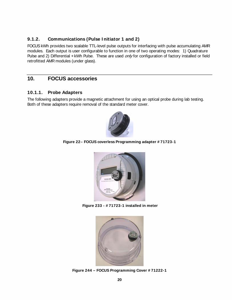
10. FOCUS accessories
10.1.1. Probe Adapters The following adapters provide a magnetic attachment for using an optical probe during lab testing. Both of these adapters require removal of the standard meter cover.
Figure 22– FOCUS coverless Programming adapter #71723-1
Figure 233 - #71723-1 installed in meter
Figure 244 – FOCUS Programming Cover #71222-1
20
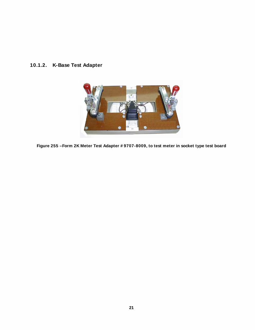
10.1.2. K-Base Test Adapter
Figure 255 –Form 2K Meter Test Adapter #9707-8009, to test meter in socket type test board
21
22
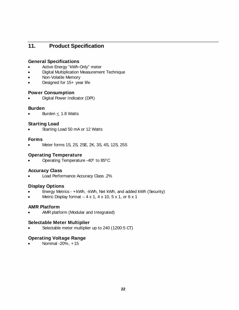
11. Product Specification
General Specifications • Active Energy “kWh-Only” meter • Digital Multiplication Measurement Technique • Non-Volatile Memory • Designed for 15+ year life
Power Consumption • Digital Power Indicator (DPI)
Burden • Burden < 1.8 Watts
Starting Load • Starting Load 50 mA or 12 Watts
Forms • Meter forms 1S, 2S, 2SE, 2K, 3S, 4S, 12S, 25S
Operating Temperature • Operating Temperature -40º to 85ºC
Accuracy Class • Load Performance Accuracy Class .2%
Display Options • Energy Metrics - +kWh, -kWh, Net kWh, and added kWh (Security) • Metric Display format – 4 x 1, 4 x 10, 5 x 1, or 6 x 1
AMR Platform • AMR platform (Modular and Integrated)
Selectable Meter Multiplier • Selectable meter multiplier up to 240 (1200:5 CT)
Operating Voltage Range • Nominal -20%, +15

23
Related Documents