Name: ................................................................................................ Roll No: .............................................................................................. Branch:.................................................................SEM:…………........... Academic Year: .................................................................................... Empower youth - Architects of Future World Estd: 2008 METHODIST COLLEGE OF ENGINEERING & TECHNOLOGY Approved by AICTE New Delhi | Affiliated to Osmania University, Hyderabad Abids, Hyderabad, Telangana, 500001 BE V Semester For the Students admitted in AICTE Scheme DEPARTMENT OF MECHANICAL ENGINEERING LABORATORY MANUAL FLUID MECHANICS & HYDRAULIC MACHINERY LABORATORY

Welcome message from author
This document is posted to help you gain knowledge. Please leave a comment to let me know what you think about it! Share it to your friends and learn new things together.
Transcript
Name: ................................................................................................
Roll No: ..............................................................................................
Branch:.................................................................SEM:…………...........
Academic Year: ....................................................................................
Empower youth - Architects of Future World
Estd: 2008
METHODIST COLLEGE OF ENGINEERING & TECHNOLOGY Approved by AICTE New Delhi | Affiliated to Osmania University, Hyderabad
Abids, Hyderabad, Telangana, 500001
BE V Semester
For the Students admitted in AICTE Scheme
DEPARTMENT OF MECHANICAL ENGINEERING
LABORATORY MANUAL
FLUID MECHANICS & HYDRAULIC MACHINERY LABORATORY

Estd: 2008
METHODIST COLLEGE OF ENGINEERING & TECHNOLOGY Approved by AICTE New Delhi | Affiliated to Osmania University, Hyderabad
Abids, Hyderabad, Telangana, 500001
VISION
To produce ethical, socially conscious and innovative
professionals who would contribute to sustainable
technological development of the society.
MISSION
To impart quality engineering education with latest
technological developments and interdisciplinary skills
to make students succeed in professional practice.
To encourage research culture among faculty and
students by establishing state of art laboratories and
exposing them to modern industrial and organizational
practices.
To inculcate humane qualities like environmental
consciousness, leadership, social values, professional
ethics and engage in independent and lifelong learning
for sustainable contribution to the society.
Estd: 2008
METHODIST COLLEGE OF ENGINEERING & TECHNOLOGY Approved by AICTE New Delhi | Affiliated to Osmania University, Hyderabad
Abids, Hyderabad, Telangana, 500001
DEPARTMENT OF MECHANICAL ENGINEERING
LABORATORY MANUAL
FLUID MECHANICS & HYDRAULIC MACHINERY LABORATORY
(PC593ME)
Prepared by
Mr. K. Srinivasa Raghavan Assistant Professor. Mech. Engg. Mr. M. Prasad, Assistant Professor. Mech. Engg.
DEPARTMENT OF MECHANICAL ENGINEERING
VISION
To be a reputed centre of excellence in the field of mechanical engineering by
synergizing innovative technologies and research for the progress of society.
MISSION
To impart quality education by means of state-of-the-art infrastructure.
To involve in trainings and activities on leadership qualities and social
responsibilities.
To inculcate the habit of life-long learning, practice professional ethics and
service the society.
To establish industry- institute interaction for stake holder development.

DEPARTMENT OF MECHANICAL ENGINEERING
After 3-5 years of graduation, the graduates will be able to:
PEO1: Excel as engineers with technical skills, and work with complex
engineering systems.
PEO2: Capable to be entrepreneurs, work on global issues, and contribute to
industry and society through service activities and/or professional organizations.
PEO3: Lead and engage diverse teams with effective communication and
managerial skills.
PEO4: Develop commitment to pursue life-long learning in the chosen
profession and/or progress towards an advanced degree
DEPARTMENT OF MECHANICAL ENGINEERING
PROGRAM OUTCOMES Engineering Graduates will be able to:
Po1. Engineering knowledge: Apply the basic knowledge of mathematics, science
and engineering fund a mentals along with the specialized knowledge of mechanical engineering to understand complex engineering problems.
PO2. Problem analysis: Identify, formulate, design and analyse complex
mechanical engineering problems using knowledge of science and engineering.
Po3. Design/development of solutions: Develop solutions for complex
engineering problems, design and develop system components or processes that meet the specified needs with appropriate consideration of the public health and safety, and the cultural, societal, and environmental considerations.
PO4. Conduct investigations of complex problems: Formulate engineering
problems, conduct investigations and solve using research-based knowledge.
PO5. Modern tool usage: Use the modern engineering skills, techniques and tools
that include IT tools necessary for mechanical engineering practice.
Po6. The engineer and society: Apply the contextual knowledge to assess societal,
health, safety, legal and cultural issues and the consequent responsibilities relevant to the professional engineering practice.
PO7. Environment and sustainability: Understand the impact of the professional
engineering solutions in societal and environmental contexts, and demonstrate the knowledge of, and need for sustainable development.
PO8. Ethics: Apply ethical principles and commit to professional ethics and
responsibilities during professional practice.
PO9. Individual and team work: Function effectively as an individual, and as a
member or leader in diverse teams, and in multidisciplinary settings.
PO10.Communication: Communicate effectively on complex engineering activities
to various groups, ability to write effective reports and make effective presentations.
PO11. Project management and finance: Demonstrate and apply the knowledge
to understand the management principles and financial aspects in multidisciplinary environments.
PO12. Life-long learning: Recognize the need for, and have the preparation and
ability to engage in Independent and life-long learning in the broadest context of technological change.
PROGRAM SPECIFIC OUTCOMES
Mechanical Engineering Graduates will be able to:
PSO1: Apply the knowledge of CAD/CAM/CAE tools to analyse, design and develop
the products and processes related to Mechanical Engineering.
PSO 2: Solve problems related to mechanical systems by applying the principles of
modern manufacturing technologies.
PSO 3: Exhibit the knowledge and skill relevant to HVAC and IC Engines.
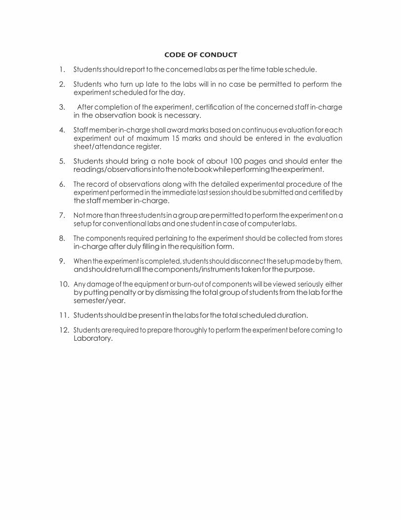
CODE OF CONDUCT
1. Students should report to the concerned labs as per the time table schedule.
2. Students who turn up late to the labs will in no case be permitted to perform the experiment scheduled for the day.
3. After completion of the experiment, certification of the concerned staff in-charge in the observation book is necessary.
4. Staff member in-charge shall award marks based on continuous evaluation for each experiment out of maximum 15 marks and should be entered in the evaluation sheet/attendance register.
5. Students should bring a note book of about 100 pages and should enter the readings/observations into the note book while performing the experiment.
6. The record of observations along with the detailed experimental procedure of the experiment performed in the immediate last session should be submitted and certified by the staff member in-charge.
7. Not more than three students in a group are permitted to perform the experiment on a setup for conventional labs and one student in case of computer labs.
8. The components required pertaining to the experiment should be collected from stores in-charge after duly filling in the requisition form.
9. When the experiment is completed, students should disconnect the setup made by them, and should return all the components/instruments taken for the purpose.
10. Any damage of the equipment or burn-out of components will be viewed seriously either by putting penalty or by dismissing the total group of students from the lab for the semester/year.
11. Students should be present in the labs for the total scheduled duration.
12. Students are required to prepare thoroughly to perform the experiment before coming to Laboratory.
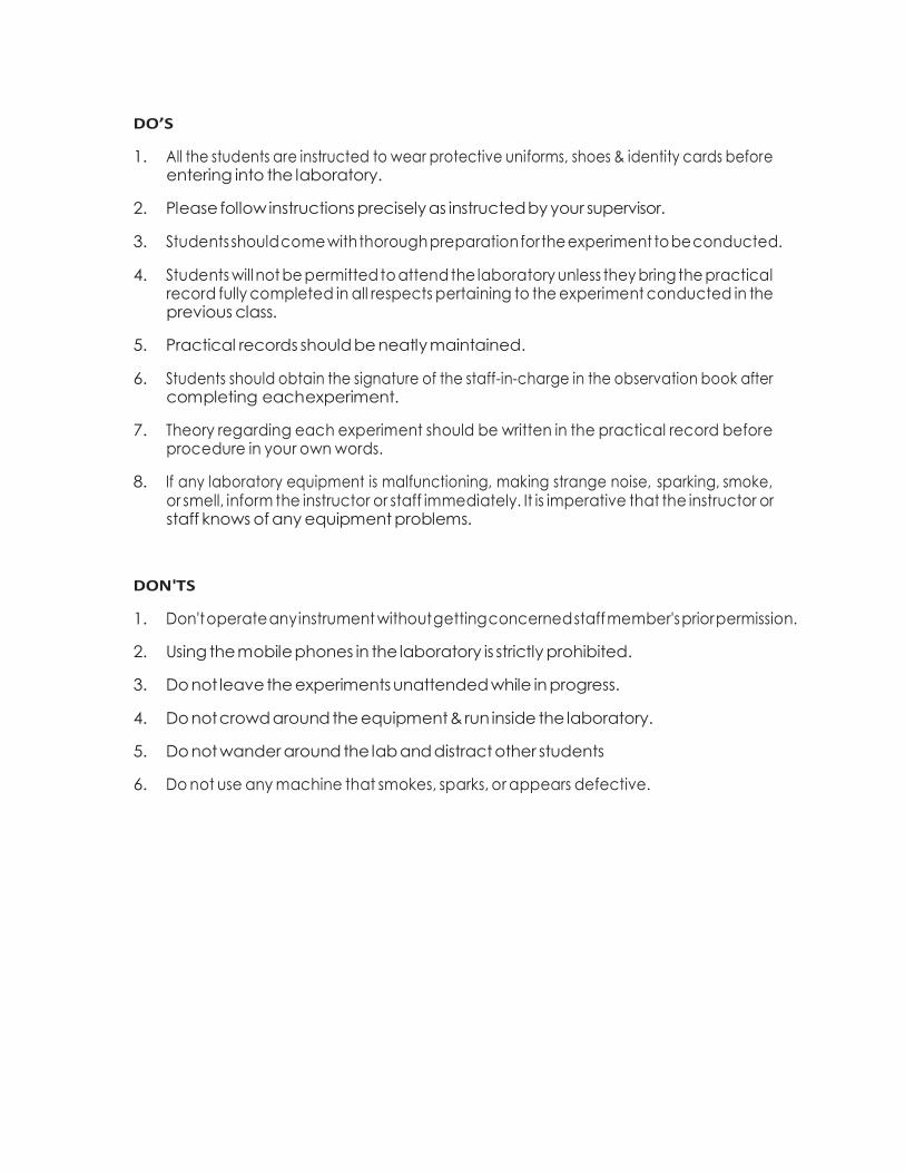
DO’S
1. All the students are instructed to wear protective uniforms, shoes & identity cards before entering into the laboratory.
2. Please follow instructions precisely as instructed by your supervisor.
3. Students should come with thorough preparation for the experiment to be conducted.
4. Students will not be permitted to attend the laboratory unless they bring the practical record fully completed in all respects pertaining to the experiment conducted in the previous class.
5. Practical records should be neatly maintained.
6. Students should obtain the signature of the staff-in-charge in the observation book after completing each experiment.
7. Theory regarding each experiment should be written in the practical record before procedure in your own words.
8. If any laboratory equipment is malfunctioning, making strange noise, sparking, smoke, or smell, inform the instructor or staff immediately. It is imperative that the instructor or staff knows of any equipment problems.
DON'TS
1. Don't operate any instrument without getting concerned staff member's prior permission.
2. Using the mobile phones in the laboratory is strictly prohibited.
3. Do not leave the experiments unattended while in progress.
4. Do not crowd around the equipment & run inside the laboratory.
5. Do not wander around the lab and distract other students
6. Do not use any machine that smokes, sparks, or appears defective.
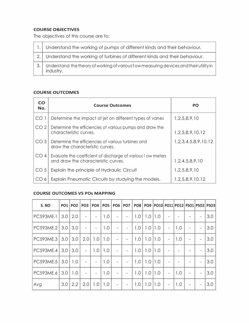
COURSE OBJECTIVES
The objectives of this course are to:
1. Understand the working of pumps of different kinds and their behaviour.
2. Understand the working of turbines of different kinds and their behaviour.
3. Understand the theory of working of various ow measuring devices and their utility in industry.
COURSE OUTCOMES
CO No.
Course Outcomes PO
CO 1 Determine the impact of jet on different types of vanes 1,2,5,8,9,10
CO 2 Determine the efficiencies of various pumps and draw the characteristic curves.
1,2,5,8,9,10,12
CO 3 Determine the efficiencies of various turbines and draw the characteristic curves.
1,2,3,4,5,8,9,10,12
CO 4 Evaluate the coefficient of discharge of various ow meters and draw the characteristic curves.
1,2,4,5,8,9,10
CO 5 Explain the principle of Hydraulic Circuit 1,2,5,8,9,10
CO 6 Explain Pneumatic Circuits by studying the models. 1,2,5,8,9,10,12
COURSE OUTCOMES VS POs MAPPING
S. NO PO1 PO2 PO3 PO4 PO5 PO6 PO7 PO8 PO9 PO10 PO11 PO12 PSO1 PSO2 PSO3
PC593ME.1 3.0 2.0 - - 1.0 - - 1.0 1.0 1.0 - - - - 3.0
PC593ME.2 3.0 3.0 - - 1.0 - - 1.0 1.0 1.0 - 1.0 - - 3.0
PC593ME.3 3.0 3.0 2.0 1.0 1.0 - - 1.0 1.0 1.0 - 1.0 - - 3.0
PC593ME.4 3.0 3.0 - 1.0 1.0 - - 1.0 1.0 1.0 - - - - 3.0
PC593ME.5 3.0 1.0 - - 1.0 - - 1.0 1.0 1.0 - - - - 3.0
PC593ME.6 3.0 1.0 - - 1.0 - - 1.0 1.0 1.0 - 1.0 - - 3.0
Avg 3.0 2.2 2.0 1.0 1.0 - - 1.0 1.0 1.0 - 1.0 - - 3.0
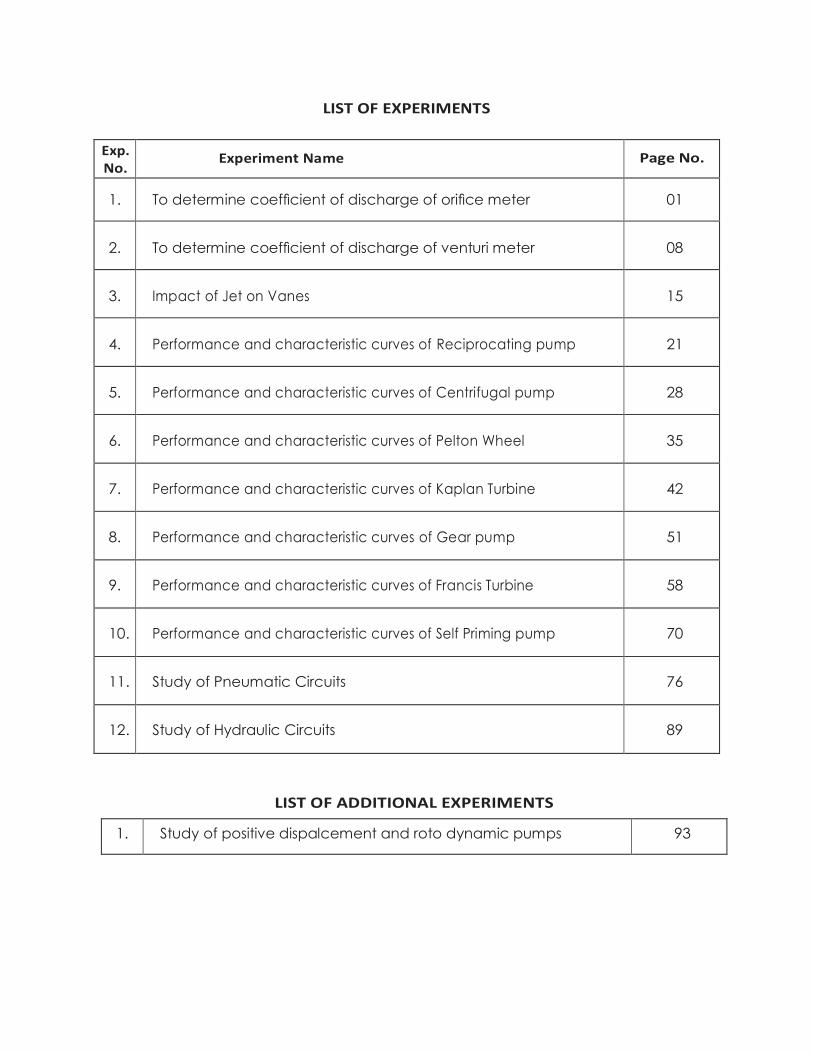
LIST OF EXPERIMENTS
Exp. No.
Experiment Name Page No.
1. To determine coefficient of discharge of orifice meter 01
2.
To determine coefficient of discharge of venturi meter
08
3.
Impact of Jet on Vanes
15
4.
Performance and characteristic curves of Reciprocating pump
21
5.
Performance and characteristic curves of Centrifugal pump
28
6. Performance and characteristic curves of Pelton Wheel 35
7. Performance and characteristic curves of Kaplan Turbine 42
8. Performance and characteristic curves of Gear pump 51
9. Performance and characteristic curves of Francis Turbine 58
10. Performance and characteristic curves of Self Priming pump 70
11. Study of Pneumatic Circuits 76
12. Study of Hydraulic Circuits 89
LIST OF ADDITIONAL EXPERIMENTS
1. Study of positive dispalcement and roto dynamic pumps 93

INDEX
Experiment No
Experiment Name
Date
Page No Marks Remarks/
Signature P R V T

Experiment No
Experiment Name
Date
Page No Marks Remarks/
Signature P R V T
Methodist College of Engineering & Technology
Department of Mechanical Engineering
BE V SEMESTER FLUID MECHANICS & HYDRAULIC MACHINERY LAB MANUAL Page 1
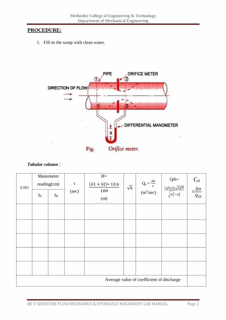
EXPERIMENT - 01
EXPERIMENT ON ORIFICEMETER
AIM:
To demonstrate the use of Orificemeter as flowmeter and to determine the Co-
efficient of discharge.
APPARATUS:
1. Measuring tank to measure flow rate.
2. A pipe line with Orificemeter.
3. Tappings with ball valves are provided at inlet & Throat of Orificemeter and those are
connected to double column Manometer.
4. A constant steady supply of water with a means of varying the flow rate using
Monobloc pump.
5. Stop watch
THEORY:
An Orifice meter is used to measure the discharge in any closed surface. Orifice meter works
on the principle that by reducing the cross section area of the flow passage, a pressure
difference between the two sections is developed and this difference enables the
determination of the discharge through the pipe. In a water distribution system and in
processing industries it is necessary to measure the volume of liquid flowing through a pipe
line. The orifice meter is introduced in the pipeline to achieve this. Hence knowledge of the
value of the coefficient of discharge of the orifice meter is a must. Orifice meter consists of a
flat circular plate with a circular hole called orifice, which is concentric with the pipe axis
pressure tapings are connected to pipe wall on the both sides of the plate. So that the
difference in the fluid pressure on both sides of the orifice plate are measured. As the fluid
passes through the orifice meter, a lot of eddies are formed and there is a loss of energy due
to which the actual discharge Qa , is far less than Qth which is given by
Qth=𝑐𝑑𝑎1𝑎2√2𝑔𝐻
√𝑎12−𝑎2
2
Where 𝑐𝑑= Coefficient of discharge
𝑎1= area of inlet pipe of the Orificemeter
𝑎2= area of Orificemeter
Specifications:
Area of Measuring tank A = 0.12 m2
Diameter of Orificemeter d = 12.5 mm
Diameter of the inlet pipe of the Orificemeter D = 25 mm
Methodist College of Engineering & Technology
Department of Mechanical Engineering
BE V SEMESTER FLUID MECHANICS & HYDRAULIC MACHINERY LAB MANUAL Page 2
PROCEDURE:
1. Fill-in the sump with clean water.
Tabular column :
S.NO
Manometer
reading(cm) t
(sec)
H=
(ℎ1 + ℎ2)∗ 12.6
100
(m)
√ℎ Qa =
𝐴𝑅
𝑡
(m3/sec)
Qth=
𝑐𝑑𝑎1𝑎2√2𝑔𝐻
√𝑎12−𝑎2
2
Cd
=𝑄𝑎
𝑄𝑡ℎ
h1 h2
Average value of coefficient of discharge
Methodist College of Engineering & Technology
Department of Mechanical Engineering
BE V SEMESTER FLUID MECHANICS & HYDRAULIC MACHINERY LAB MANUAL Page 3
2. Keep the delivery valve open.
3. Adjust the flow through the control valve of the pump.
4. Note down the differential head reading in the manometer.( Expel if any air is there
by opening the drain cocks provided with manometer).
5. Operate the butterfly valve to note down the collecting tank readings against the
known time and keep it open when the readings are taken.
6. Change the flow rate & repeat the experiment.
7. The observations are tabulated and coefficient of discharge of Orificemeter is
computed
Calculations:
1. Theoretical discharge
Qth= 𝑐𝑑𝑎1𝑎2√2𝑔𝐻
√𝑎12−𝑎2
2
Where cd = 1
𝑎1= area of inlet pipe of the Orificemeter= 𝜋𝐷2
4m2
𝑎2= area of Orificemeter = 𝜋𝑑2
4m2
H= Loss of head= (ℎ1 + ℎ2) ∗ 12.6
100m
2. Actual discharge
Qa = 𝐴 𝑋 𝑅
1000 𝑋 𝑡 m3 / sec
Where A = Area of Measuring tank in m2.
R = Rise of Water level for time t sec in mtrs
3. Coefficient of discharge
Cd = 𝐴𝑐𝑡𝑢𝑎𝑙 𝑑𝑖𝑠𝑐ℎ𝑎𝑟𝑔𝑒
𝑇ℎ𝑒𝑜𝑟𝑒𝑡𝑖𝑐𝑎𝑙 𝑑𝑖𝑠𝑐ℎ𝑎𝑟𝑔𝑒 =
𝑄𝑎
𝑄𝑡ℎ
Methodist College of Engineering & Technology
Department of Mechanical Engineering
BE V SEMESTER FLUID MECHANICS & HYDRAULIC MACHINERY LAB MANUAL Page 4
Precautions:
1. All the joints should be leak proof and water tight
2. Manometer should be filled to about half the height with mercury
3. All valves on the pressure feed pipes and manometer should be closed to prevent
damage and over loading of the manometer before starting the motor.
4. Ensure that gauge glass and meter scale assembly of the measuring tank is fixed
vertically and water tight
5. Ensure that the pump is primed before starting the motor
6. Remove the air bubbles in differential manometer by opening air release valve
7. Take the differential manometer readings without parallax error
8. Ensure that the electric switch does not come in contact with water
9. The water filled in the sump tank should be 2 inches below the upper end.
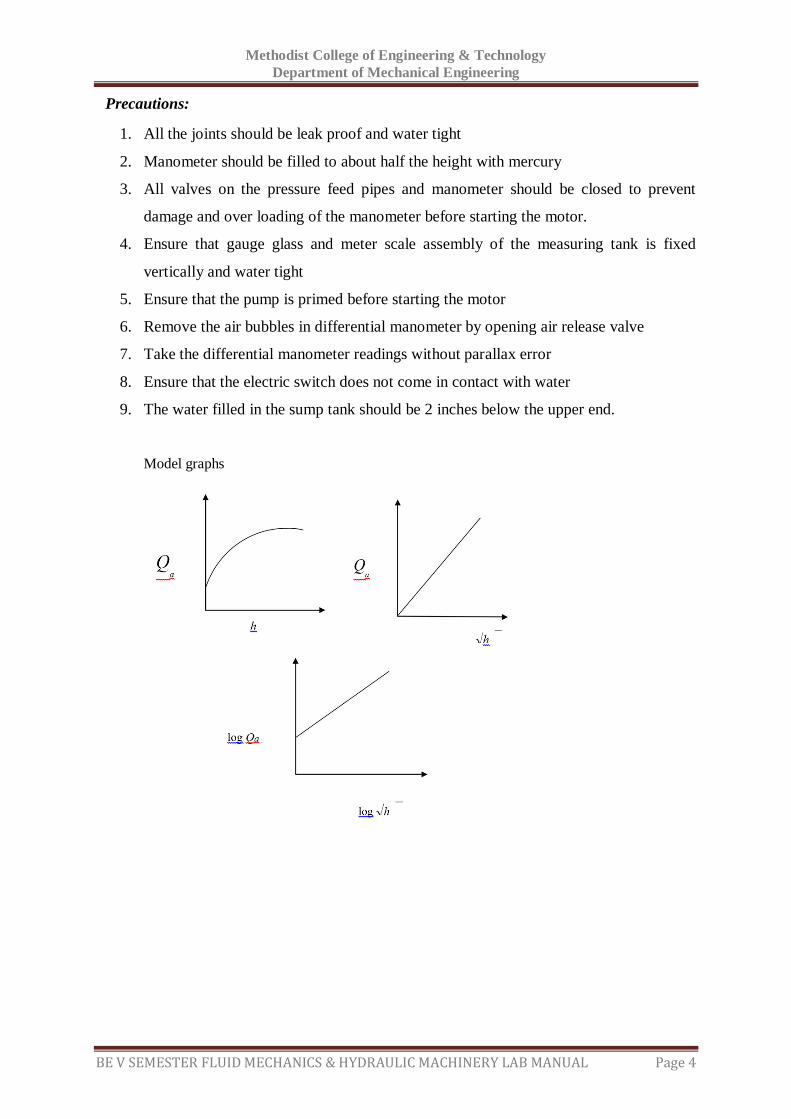
Model graphs

Methodist College of Engineering & Technology
Department of Mechanical Engineering
BE V SEMESTER FLUID MECHANICS & HYDRAULIC MACHINERY LAB MANUAL Page 5
Space For Calculations
Methodist College of Engineering & Technology
Department of Mechanical Engineering
BE V SEMESTER FLUID MECHANICS & HYDRAULIC MACHINERY LAB MANUAL Page 6
RESULT & CONCLUSIONS:
Coefficient of discharge of Orificemeter ( Cd) =
Methodist College of Engineering & Technology
Department of Mechanical Engineering
BE V SEMESTER FLUID MECHANICS & HYDRAULIC MACHINERY LAB MANUAL Page 7
VIVA QUESTIONS:
For which one, the coefficient of discharge is smaller, venturimeter or
Orificemeter?
What is the reason for smaller value of C d ?
What is Orifice meter?
What is the principle of Orifice meter?
For discharge measurement through pipes which is having cheaper arrangement and
whose installation requires a smaller length?
What are the parts of
Orifice
What is the thickness of the plate t?
What is the diameter of the orifice?
Where two pressure taps are provided?
Where upstream pressure tap is located?
At which section on the downstream side the pressure tap is provided quite close to
orifice plate?
Maximum possible pressure difference that exists between upstream side of the
orifice plate and downstream side of the orifice plate is measured by means of what?
Where there is a greater loss of energy, whether in venturi meter or in
orifice meter?
Why there is a greater loss of energy in orifice meter?
What is value of c d ?
When an orifice is called large orifice?
On what the position of downstream pressure tap depends?
What is manometer liquid ?
Where the velocity of flow is maximum and pressure is minimum?
What is vena contract?
Which diameter is less orifice or pipe?
What is the range of bevel angle in Orificemeter?
Methodist College of Engineering & Technology
Department of Mechanical Engineering
BE V SEMESTER FLUID MECHANICS & HYDRAULIC MACHINERY LAB MANUAL Page 8
EXPERIMENT - 02
EXPERIMENT ON VENTURIMETER
AIM:
To demonstrate the use of Venturimeter as flowmeter and to determine the coefficient
of discharge.
APPARATUS:
1. Measuring tank to measure flow rate.
2. A pipe line with a Venturimeter.
3. Tappings with ball valves are provided at inlet & Throat of Venturimeter and those
are connected to double column Manometer.
4. A constant steady supply of water with a means of varying the flow rate using
Monobloc pump.
5. Stop watch
THEORY:
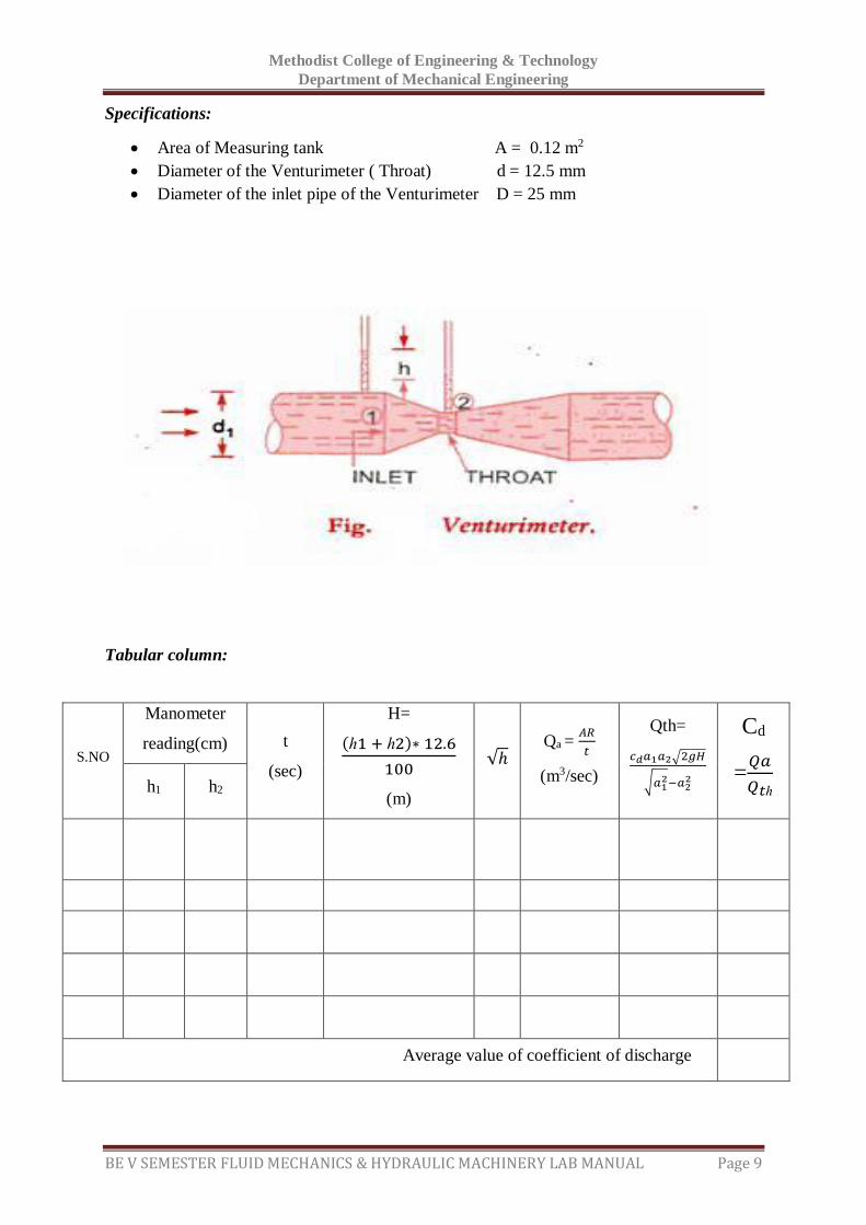
Venturimeter is a device invented by Ciemens Herchel in 1887 and named by him after
Venturi, who experimented with diverging tubes for the measurement of rate of flow in pipe
lines. The basic principle on which Venturimeter works is that by reducing the cross-sectional
area of the flow passage, a difference of pressure is created and the measurement of the
pressure difference enables the determination of the discharge through the pipes. The fluid
flowing the pipe is led through a contracting section to a throat which has a smaller cross
section area than the pipe, so that the velocity is accomplished by a fall in N/m2 .The
magnitude of which depends upon the rate of flow so that by measuring the pressure drop, the
discharge can be calculated. Beyond the throat the fluid is in a pipe of slowly diverging
section, the pressure increasing as velocity falls.
In a water distribution system and in processing industries it is necessary to measure the
volume of liquid flowing through a pipe line. The Venturimeter is introduced in the pipeline
to achieve this. Hence knowledge of the value of the coefficient of discharge of the
Venturimeter is a must. The velocity of flow through a Venturimeter is obtained by applying
Bernoulli’s theorem. The theoretical discharge can be calculated by using the velocity
obtained.
Qth=𝑐𝑑𝑎1𝑎2√2𝑔𝐻
√𝑎12−𝑎2
2
Where 𝑐𝑑= Coefficient of discharge
𝑎1= area of inlet pipe of the Venturimeter ; a2 = area of throat of Venturimeter
Methodist College of Engineering & Technology
Department of Mechanical Engineering
BE V SEMESTER FLUID MECHANICS & HYDRAULIC MACHINERY LAB MANUAL Page 9
Specifications:
Area of Measuring tank A = 0.12 m2
Diameter of the Venturimeter ( Throat) d = 12.5 mm
Diameter of the inlet pipe of the Venturimeter D = 25 mm
Tabular column:
S.NO
Manometer
reading(cm) t
(sec)
H=
(ℎ1 + ℎ2)∗ 12.6
100
(m)
√ℎ Qa =
𝐴𝑅
𝑡
(m3/sec)
Qth=
𝑐𝑑𝑎1𝑎2√2𝑔𝐻
√𝑎12−𝑎2
2
Cd
=𝑄𝑎
𝑄𝑡ℎ
h1 h2
Average value of coefficient of discharge
Methodist College of Engineering & Technology
Department of Mechanical Engineering
BE V SEMESTER FLUID MECHANICS & HYDRAULIC MACHINERY LAB MANUAL Page 10
PROCEDURE:
1. Start the motor, Open the gate valve , allow the water to flow through pipe full
2. Reject the air bubbles if any by slowly raising the pinch cock
3. Note the manometric fluid levels h1 and h2 in the two limbs of the manometer
4. Collect the water in the collecting tank up to 10 cm rise(R) of water level and
note down corresponding time (t)taken to rise that level
5. Repeat the above procedure by gradually increasing the flow and note down
the required readings.
6. The observations are tabulated and coefficient of discharge of Venturimeter is
computed.
Calculations :
1. Theoretical discharge
Qth=𝑐𝑑𝑎1𝑎2√2𝑔𝐻
√𝑎12−𝑎2
2
Where cd = 1
𝑎1= area of inlet pipe of the Venturimeter= 𝜋𝐷2
4m2
𝑎2= area of Venturimeter = 𝜋𝑑2
4m2
H= Loss of head= (ℎ1 + ℎ2) ∗(13.6−1)
100m
2. Actual discharge
Qa = 𝐴 𝑋 𝑅
1000 𝑋 𝑡 m3 / sec
Where A = Area of Measuring tank in m2.
R = Rise of Water level for time t sec in mtrs
3. Coefficient of discharge
Cd = 𝐴𝑐𝑡𝑢𝑎𝑙 𝑑𝑖𝑠𝑐ℎ𝑎𝑟𝑔𝑒
𝑇ℎ𝑒𝑜𝑟𝑒𝑡𝑖𝑐𝑎𝑙 𝑑𝑖𝑠𝑐ℎ𝑎𝑟𝑔𝑒 =
𝑄𝑎
𝑄𝑡ℎ
Methodist College of Engineering & Technology
Department of Mechanical Engineering
BE V SEMESTER FLUID MECHANICS & HYDRAULIC MACHINERY LAB MANUAL Page 11
Precautions:
1. All the joints should be leak proof and water tight
2. Manometer should be filled to about half the height with mercury
3. All valves on the pressure feed pipes and manometer should be closed to prevent
damage and over loading of the manometer before starting the motor.
4. Ensure that gauge glass and meter scale assembly of the measuring tank is fixed
vertically and water tight
5. Ensure that the pump is primed before starting the motor
6. Remove the air bubbles in differential manometer by opening air release valve
7. Take the differential manometer readings without parallax error
8. Ensure that the electric switch does not come in contact with water
9. The water filled in the sump tank should be 2 inches below the upper.
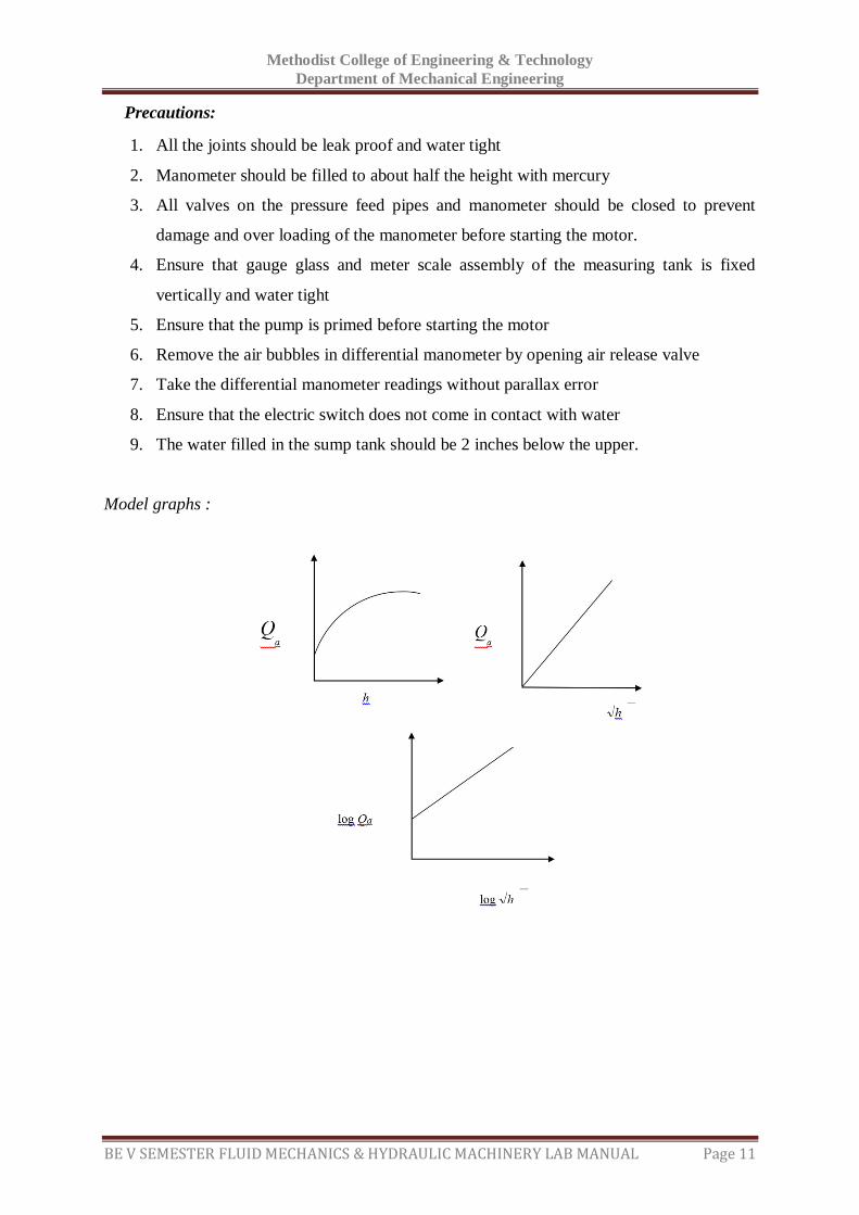
Model graphs :

Methodist College of Engineering & Technology
Department of Mechanical Engineering
BE V SEMESTER FLUID MECHANICS & HYDRAULIC MACHINERY LAB MANUAL Page 12
Space For Calculations
Methodist College of Engineering & Technology
Department of Mechanical Engineering
BE V SEMESTER FLUID MECHANICS & HYDRAULIC MACHINERY LAB MANUAL Page 13
RESULT & CONCLUSIONS:
Coefficient of Venturimeter ( Cd ) =
Methodist College of Engineering & Technology
Department of Mechanical Engineering
BE V SEMESTER FLUID MECHANICS & HYDRAULIC MACHINERY LAB MANUAL Page 14
VIVA QUESTIONS:
What is the basic principle of Venturimeter?
What are the parts of Venturimeter?
What is convergent cone?
What is throat of Venturi meter?
What is divergent cone?
Where pressure taps are provided?
Which part is smaller, convergent cone or divergent cone? Why?
Which cross-sectional area is smaller than cross sectional area of
inlet section?
Where velocity of flow greater?
Between which sections the pressure difference can be determined? Which part is
smaller, convergent cone or divergent cone? Why?
Where velocity of flow greater?
What we should do for getting greater accuracy in the measurement of the pressure
difference?
Where separation of flow occurs?
Between which section the pressure difference can be determined?
How pressure difference is determined?
Where pressure is low in Venturimeter?
Which cross-sectional area is smaller than cross sectional area of inlet section?
Which portion is not used for discharge measurement?
Where separation of flow occurs?
How pressure difference is determined?
Where pressure is low in Venturimeter?
Which portion is not used for discharge measurement?
Methodist College of Engineering & Technology
Department of Mechanical Engineering
BE V SEMESTER FLUID MECHANICS & HYDRAULIC MACHINERY LAB MANUAL Page 15
EXPERIMENT - 03
IMPACT OF JET ON VANES
AIM:
To determine the coefficient of impact of jet- vane combination by comparing the
actual force with theoretical force for stationary vanes of different shapes Viz., Hemi-
spherical, flat and inclined plate.
THEORY:
It is a closed circuit water re-circulation system consisting of sump tank, Monobloc pump set,
jet/ vane chamber, rotameter for flow rate measurement, direct reading, and digital force
indicator. The water is drawn from the sump tank by Monobloc centrifugal pump and
delivers it vertically to the nozzle through rotameter. The rotameter is a direct indicating flow
rate instrument which gives the discharge in LPM (liters per minute) which is determined by
the top position of the float. The flow control valve is also provided for controlling the water
into the nozzle. The water is issued out of nozzle as jet. The jet is made to strike the vane, the
force of which is transferred directly to the force indicator (mechanical). The force is read in
kgf. A provision is made to change the size of nozzle/ jet and the vanes of different shapes.
When the jet of water is directed to hit the vane of any particular shape, the force is exerted
on it by the fluid in the opposite direction. The amount of force exerted depends on the
diameter of jet, shape of vane, fluid density and flow rate of water. More importantly, it also
depends on whether the vane is moving or stationary. In our present case, we are concerned
about the force exerted on the stationary vanes. The following are the theoretical formulae for
different shapes of vane, based on flow rate.
1. Hemi- spherical Ft = 2𝜌𝐴𝑉2
𝑔
2. Flat plate Ft = 𝜌𝐴𝑉2
𝑔
3. Inclined plate Ft = 𝜌𝐴𝑉2
𝑔sin 𝜃 sin 𝜃
Where g = 9.81 m / s2
A = area of jet in m2 = 𝜋
4𝑑2 (d= diameter of the nozzle)
𝜌 = density of water = 1000 kg/m3
V = Velocity of jet in m/s2
𝜃 =Angle made by the deflected jet with the axis of the striking jet = 600
Ft = theoretical force.
Fa = actual force developed as indicated by force indicator in kg
Methodist College of Engineering & Technology
Department of Mechanical Engineering
BE V SEMESTER FLUID MECHANICS & HYDRAULIC MACHINERY LAB MANUAL Page 16
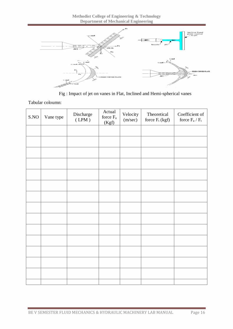
Fig : Impact of jet on vanes in Flat, Inclined and Hemi-spherical vanes
Tabular coloumn:
S.NO Vane type Discharge
( LPM )
Actual
force Fa
(Kgf)
Velocity
(m/sec)
Theoretical
force Ft (kgf)
Coefficient of
force Fa / Ft
Methodist College of Engineering & Technology
Department of Mechanical Engineering
BE V SEMESTER FLUID MECHANICS & HYDRAULIC MACHINERY LAB MANUAL Page 17
PROCEDURE:
1) Fix the required diameter jet, and the vane of required shape in position and zero the
force indicator
2) Keep the delivery valve closed and switch on the pump
3) Close the front transparent cover tightly
4) Open the delivery valve and adjust the flow rate of water as read on the Rota meter
5) Note down the water flow rate (LPM), actual force, head at nozzle and tabulate the
readings.
6) Repeat the experiment for different flow rate of water.
7) Switch off the pump after the experiment is over and close the delivery valve.
Precautions:
1) Unload the motor before switch off
2) Take the rotameter reading without parallax error.
3) Don’t switch on the motor when the jet chamber door is open.
Formulae:
1. Discharge Q = a x V
Velocity V =𝑄
𝑎
2. Hemi- spherical Ft = 2𝜌𝐴𝑉2
𝑔
Flat plate Ft = 𝜌𝐴𝑉2
𝑔
Inclined plate Ft = 𝜌𝐴𝑉2
𝑔sin 𝜃 sin 𝜃
3. Coefficient of force = 𝐹𝑎
𝐹𝑡
Model graph:

Methodist College of Engineering & Technology
Department of Mechanical Engineering
BE V SEMESTER FLUID MECHANICS & HYDRAULIC MACHINERY LAB MANUAL Page 18
Space For Calculations

Methodist College of Engineering & Technology
Department of Mechanical Engineering
BE V SEMESTER FLUID MECHANICS & HYDRAULIC MACHINERY LAB MANUAL Page 19
RESULT & CONCLUSIONS:
The coefficient of impact of jet vane combination for different type of vanes is found to be ---
----------
Methodist College of Engineering & Technology
Department of Mechanical Engineering
BE V SEMESTER FLUID MECHANICS & HYDRAULIC MACHINERY LAB MANUAL Page 20
VIVA QUESTIONS:
Define the term Impact of Jet?
Write the formula for force exerted by a jet of water on a stationary & moving
plate?
Write the formula for force exerted by a jet of water on a curved plate at center & at
one of the tips of the jet?
What is an impulse momentum equation?
Define the terms momentum, moment & impulse?
Explain the term dynamic machines.
Methodist College of Engineering & Technology
Department of Mechanical Engineering
BE V SEMESTER FLUID MECHANICS & HYDRAULIC MACHINERY LAB MANUAL Page 21
EXPERIMENT - 04
PERFORMANCE TEST ON RECIPROCATING PUMP
AIM:
To conduct a test at various heads and estimate the performance of given
reciprocating pump.
APPARATUS:
Reciprocating pump
Stop watch
Collecting tank
THEORY:
Pump is a mechanical device which converts the mechanical energy into hydraulic energy.
Pumps are classified into two categories, they are rotodynamic pumps and positive
displacement pumps. Reciprocating pumps will come under positive displacement pumps. It
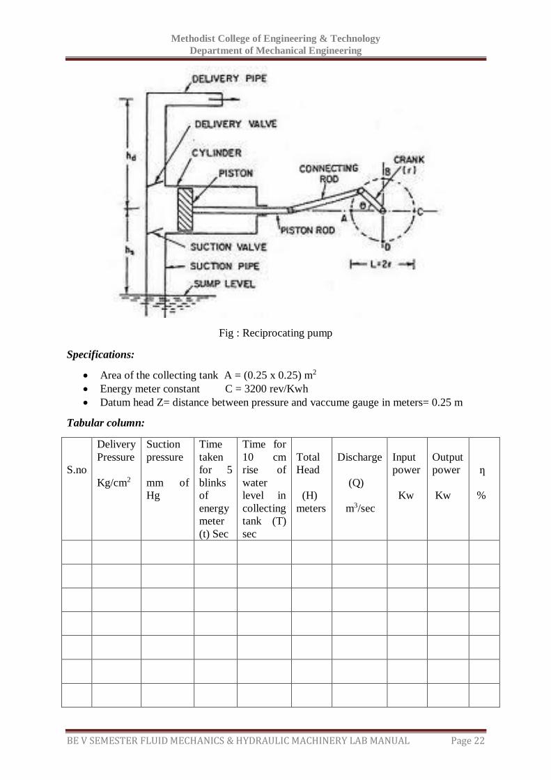
has a plunger (Piston) move to and fro in a closed cylinder. The cylinder is connected to
suction and delivery pipes and are fitted with non-return valves to admit the liquid in one
direction only. The suction non-return valve allows liquid only to enter into the cylinder and
delivery non-return valve allows the liquid only to escape out from the cylinder into the
delivery pipe.
The piston is connected to a crank by means of connecting rod. As the crank is rotated at
uniform speed by prime mover, the plunger moves to and fro thus creating continuous flow of
liquid. For more uniform flow, an air vessel is fitted before the suction valve and delivery
after delivery valve. This contributes for more uniform flow of liquid and also saves energy
input to the pump from the prime mover. These pumps are used for high head and low flow
rate application.
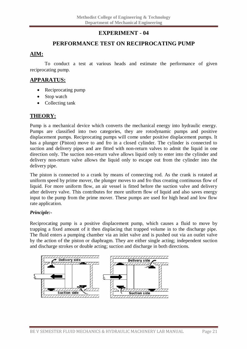
Principle:- Reciprocating pump is a positive displacement pump, which causes a fluid to move by
trapping a fixed amount of it then displacing that trapped volume in to the discharge pipe.
The fluid enters a pumping chamber via an inlet valve and is pushed out via an outlet valve
by the action of the piston or diaphragm. They are either single acting; independent suction
and discharge strokes or double acting; suction and discharge in both directions.
Methodist College of Engineering & Technology
Department of Mechanical Engineering
BE V SEMESTER FLUID MECHANICS & HYDRAULIC MACHINERY LAB MANUAL Page 22
Fig : Reciprocating pump
Specifications:
Area of the collecting tank A = (0.25 x 0.25) m2
Energy meter constant C = 3200 rev/Kwh
Datum head Z= distance between pressure and vaccume gauge in meters= 0.25 m
Tabular column:
S.no
Delivery
Pressure
Kg/cm2
Suction
pressure
mm of
Hg
Time
taken
for 5
blinks
of
energy
meter
(t) Sec
Time for
10 cm
rise of
water
level in
collecting
tank (T)
sec
Total
Head
(H)
meters
Discharge
(Q)
m3/sec
Input
power
Kw
Output
power
Kw
ƞ
%
Methodist College of Engineering & Technology
Department of Mechanical Engineering
BE V SEMESTER FLUID MECHANICS & HYDRAULIC MACHINERY LAB MANUAL Page 23
Reciprocating pumps are self priming and are suitable for very high heads at low flows. They
deliver reliable discharge flows and is often used for metering duties because of constancy of
flow rate. The flow rate is changed only by adjusting the rpm of the driver. These pumps
deliver a highly pulsed flow. If a smooth flow is required then the discharge flow system has
to include additional features such as accumulators. An automatic relief valve set at a safe
pressure is used on the discharge side of all positive displacement pumps.
PROCEDURE: 1. Start the motor keeping the delivery valve fully open.
2. Note down vaccume gauge and pressure gauge reading by adjusting the delivery valve
to required head say 0.2 meter.
3. Note down the time required for the rise of 10 cm water in the collecting tank by
using stop watch.
4. Note down the time taken for X revolutions of energy meter disk.
5. Repeat the steps from 2 to 5 for various heads by regulating the delivery valve.
Precautions:
Unload the motor before switch off.
Take the reading without parallax error.
Formulae:
1. Total head (H) = Delivery head + Suction head + Datum Head
Delivery head = Kg/cm² x 10 = meters.
Suction head = 𝑚𝑚 𝑜𝑓 𝐻𝑔 ×13.6
1000
Datum head = Distance between pressure and vacuum gauge in meters
2. Discharge Q =𝐴𝑋ℎ
𝑡m3/sec
Where t = time taken for 10 cm raise of water level in seconds.
3. Input power (I.P) = 𝑋×3600×0.70×0.80
𝐶×𝑇𝑘𝑤
Where X = no. of blinks of light of energy meter (say 5)
T = Time for energy meter blinking in seconds
C = Energy meter constant (3200)
0.70 = Motor efficiency
0.80 = Belt efficiency (or) Transmission efficiency
Methodist College of Engineering & Technology
Department of Mechanical Engineering
BE V SEMESTER FLUID MECHANICS & HYDRAULIC MACHINERY LAB MANUAL Page 24
4. Output power (O.P.) = 𝑊×𝑄×𝐻
1000𝑘𝑤
Where W = Specific weight of water (9810 N/m3)
Q = Discharge
H = Total head
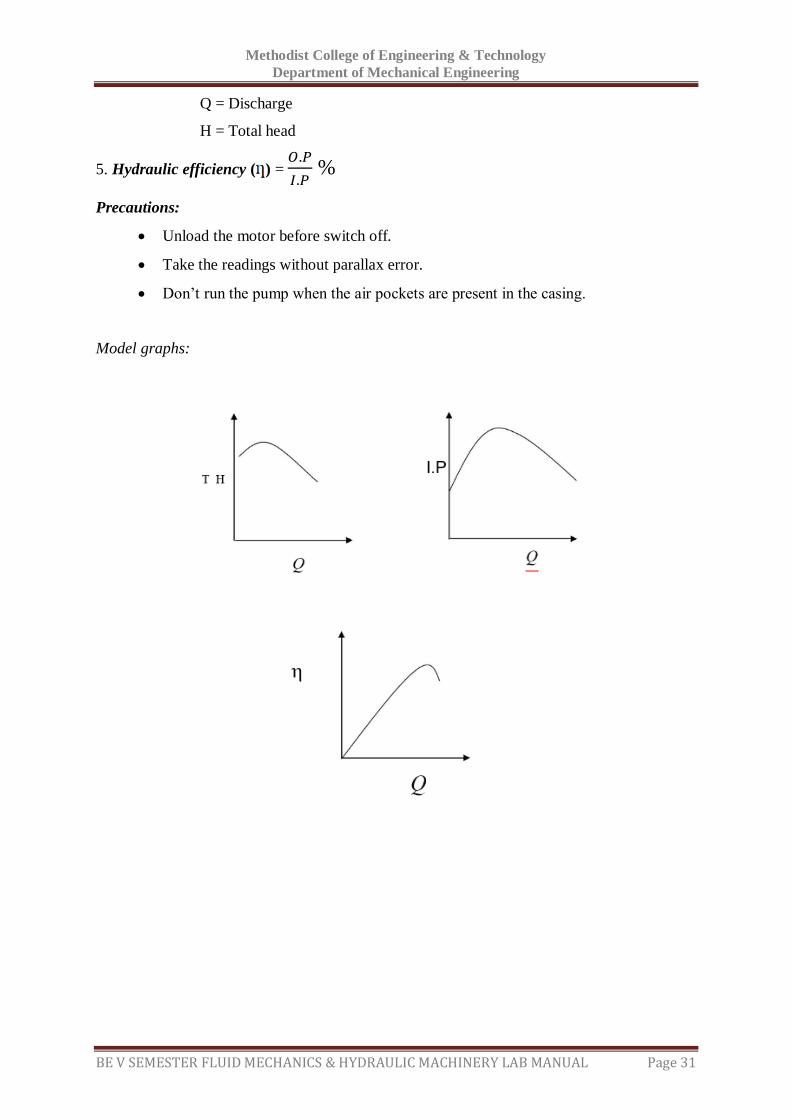
5. Hydraulic efficiency ( ) = 𝑂.𝑃
𝐼.𝑃 %
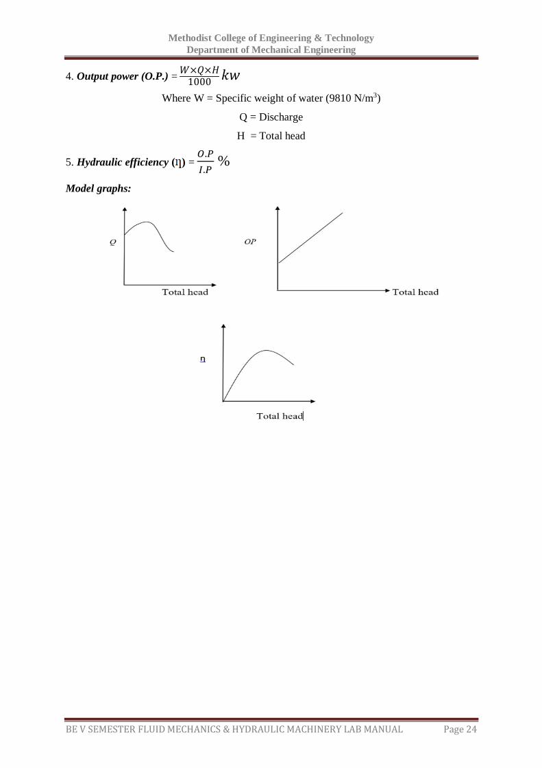
Model graphs:

Methodist College of Engineering & Technology
Department of Mechanical Engineering
BE V SEMESTER FLUID MECHANICS & HYDRAULIC MACHINERY LAB MANUAL Page 25
Space For Calculations

Methodist College of Engineering & Technology
Department of Mechanical Engineering
BE V SEMESTER FLUID MECHANICS & HYDRAULIC MACHINERY LAB MANUAL Page 26
RESULT & CONCLUSIONS:
The efficiency of reciprocating pump is found to be ----------------------
Methodist College of Engineering & Technology
Department of Mechanical Engineering
BE V SEMESTER FLUID MECHANICS & HYDRAULIC MACHINERY LAB MANUAL Page 27
VIVA QUESTIONS:
What is an air vessel?
What is negative slip in case of reciprocating pump?
What do you understand by single acting & double acting pump?
What is the function of air vessel in a reciprocating pump?
Define slip of a pump?
Define a reciprocating pump?
What are the main parts of the reciprocating pump?
Define slip of reciprocating pump?
How do you classify the reciprocating pumps
What is the working principle of a reciprocating pump?
Define indicator diagram.
Write the formulae for discharge of a single acting and double acting reciprocating
pump.
What are the factors that influence the speed of the reciprocating pump.
Methodist College of Engineering & Technology
Department of Mechanical Engineering
BE V SEMESTER FLUID MECHANICS & HYDRAULIC MACHINERY LAB MANUAL Page 28
EXPERIMENT - 05
PERFORMANCE TEST ON CENTRIFUAGAL PUMP
AIM:
To conduct a test at various heads of given centrifugal pump and to find its efficiency.
APPARATUS:
Centrifugal pump
Stop watch
Collecting tank
THEORY:
In general a pump may be defined as a mechanical device which, when interposed in a pipe
line, converts the mechanical energy supplied to it from some external source into hydraulic
energy, thus resulting in the flow of liquid from lower potential to higher potential. Pumps
are classified into two categories, they are Rotodynamic and positive displacement pumps.
Centrifugal pump will comes under Rotodynamic pumps. Centrifugal pumps consist of an
impeller rotating inside a casing. The impeller is a wheel with series of backward curved
vanes. Depending upon the cover plates provide to the impeller vanes the impeller are
divided as closed, semi-closed and open impellers. The casing is an air tight chamber. It
consists of suction and delivery arrangements and supporting for bearings. Commonly used
casing are volute casing, vortex casing and casing with guide blades. Due to the centrifugal
force developed by the rotation of impeller, water enters at the eye of the impeller and leaves
at the outward periphery. In the casing a part of the velocity head (kinetic energy) of the
water into pressure head.
Centrifugal pumps compared to reciprocating pumps are simple in construction, more
suitable for handling viscous, turbid (muddy) liquids, can be directly coupled to high speed
electric motors (without any speed reduction ) & easy to maintain. But, their hydraulic heads
at low flow rates is limited, and hence not suitable for very high heads compared to
Reciprocating pump of same capacity. But, still in most cases, this is the only type of pump
which is being widely used for agricultural applications because of its practical suitability.
Specifications:
Area of collecting tank = 0.3 x 0.3 m2
Energy meter constant = 3200 imp/kwh
Datum head = difference between suction and delivery gauges Z = 0.28 m
Methodist College of Engineering & Technology
Department of Mechanical Engineering
BE V SEMESTER FLUID MECHANICS & HYDRAULIC MACHINERY LAB MANUAL Page 29
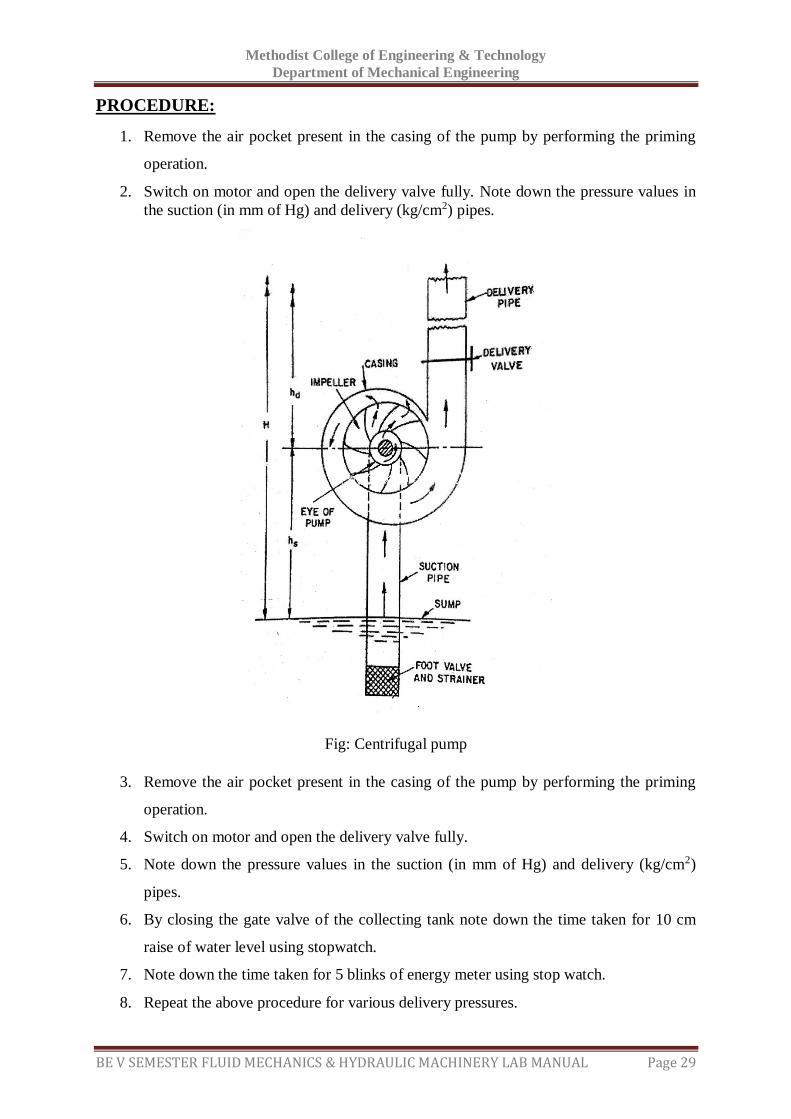
PROCEDURE:
1. Remove the air pocket present in the casing of the pump by performing the priming
operation.
2. Switch on motor and open the delivery valve fully. Note down the pressure values in
the suction (in mm of Hg) and delivery (kg/cm2) pipes.
Fig: Centrifugal pump
3. Remove the air pocket present in the casing of the pump by performing the priming
operation.
4. Switch on motor and open the delivery valve fully.
5. Note down the pressure values in the suction (in mm of Hg) and delivery (kg/cm2)
pipes.
6. By closing the gate valve of the collecting tank note down the time taken for 10 cm
raise of water level using stopwatch.
7. Note down the time taken for 5 blinks of energy meter using stop watch.
8. Repeat the above procedure for various delivery pressures.
Methodist College of Engineering & Technology
Department of Mechanical Engineering
BE V SEMESTER FLUID MECHANICS & HYDRAULIC MACHINERY LAB MANUAL Page 30
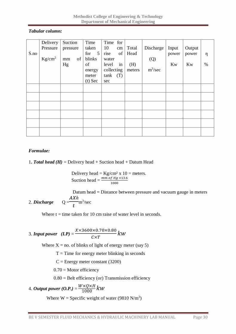
Tabular column:
S.no
Delivery
Pressure
Kg/cm2
Suction
pressure
mm of
Hg
Time
taken
for 5
blinks
of
energy
meter
(t) Sec
Time for
10 cm
rise of
water
level in
collecting
tank (T)
sec
Total
Head
(H)
meters
Discharge
(Q)
m3/sec
Input
power
Kw
Output
power
Kw
ƞ
%
Formulae:
1. Total head (H) = Delivery head + Suction head + Datum Head
Delivery head = Kg/cm² x 10 = meters.
Suction head = 𝑚𝑚 𝑜𝑓 𝐻𝑔 ×13.6
1000
Datum head = Distance between pressure and vacuum gauge in meters
2. Discharge Q =𝐴𝑋ℎ
𝑡m3/sec
Where t = time taken for 10 cm raise of water level in seconds.
3. Input power (I.P) = 𝑋×3600×0.70×0.80
𝐶×𝑇𝑘𝑤
Where X = no. of blinks of light of energy meter (say 5)
T = Time for energy meter blinking in seconds
C = Energy meter constant (3200)
0.70 = Motor efficiency
0.80 = Belt efficiency (or) Transmission efficiency
4. Output power (O.P.) = 𝑊×𝑄×𝐻
1000𝑘𝑤
Where W = Specific weight of water (9810 N/m3)
Methodist College of Engineering & Technology
Department of Mechanical Engineering
BE V SEMESTER FLUID MECHANICS & HYDRAULIC MACHINERY LAB MANUAL Page 31
Q = Discharge
H = Total head
5. Hydraulic efficiency ( ) = 𝑂.𝑃
𝐼.𝑃 %
Precautions:
Unload the motor before switch off.
Take the readings without parallax error.
Don’t run the pump when the air pockets are present in the casing.
Model graphs:

Methodist College of Engineering & Technology
Department of Mechanical Engineering
BE V SEMESTER FLUID MECHANICS & HYDRAULIC MACHINERY LAB MANUAL Page 32
Space For Calculations
Methodist College of Engineering & Technology
Department of Mechanical Engineering
BE V SEMESTER FLUID MECHANICS & HYDRAULIC MACHINERY LAB MANUAL Page 33
RESULT & CONCLUSIONS:
The efficiency of centrifugal pump is found to be -----------------
Methodist College of Engineering & Technology
Department of Mechanical Engineering
BE V SEMESTER FLUID MECHANICS & HYDRAULIC MACHINERY LAB MANUAL Page 34
VIVA QUESTIONS:
What is priming of a pump?
Why it is necessary to prime a pump?
What is cavitation? Where does it occur in a centrifugal pump?
Write the effects of cavitation?
What are the main parts of a centrifugal pump?
Distinguish between the positive and non-positive displacement pumps.
The centrifugal pump acts as a ---- reverse of an inward radial flow reaction turbine
Define pumps?
Define a centrifugal pump?
Write the working principle of a centrifugal pump?
Define the following terms:
Write the Efficiencies of a centrifugal pump?
Define specific speed of centrifugal pump?
Define the characteristic curves and why these curves are necessary?
Write the types of the characteristic curves?
What is priming of centrifugal pump?
What is the principle of working of a Centrifugal Pump?
Classify hydraulic pumps.
Methodist College of Engineering & Technology
Department of Mechanical Engineering
BE V SEMESTER FLUID MECHANICS & HYDRAULIC MACHINERY LAB MANUAL Page 35
EXPERIMENT - 06
PELTON WHEEL
AIM:
To estimate the performance of the Pelton wheel.
APPARATUS:
Pelton wheel test rig
Tachometer
THEORY:
Turbine is a hydraulic machine which converts hydraulic energy into mechanical energy
further the mechanical energy will be converted into electrical energy by coupling the turbine
shaft with the shaft of an electrical generator. There are two types of turbines viz., impulse
and reaction turbines. Impulse turbines in which only Kinetic energy available at the inlet
whereas in case of a reaction turbine both kinetic energy and pressure energy will be available
at inlet.
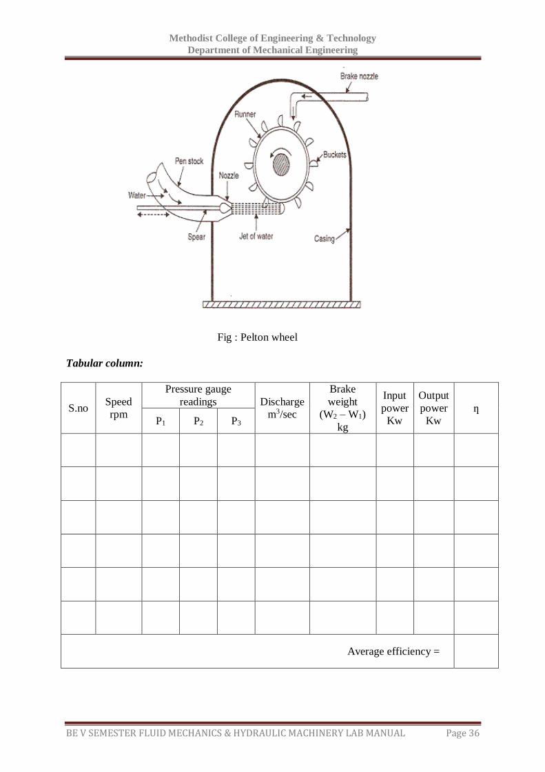
Pelton wheel is an impulse turbine which is used to utilize high heads for generation of
electricity. The flow in turbine is in tangential direction. It consists of a runner mounted on a
shaft. To this a brake drum is attached to apply brakes over the speed of the turbine. A casing
is fixed over the runner. All the available head is converted into velocity energy by means of
spear and nozzle arrangement. The spear can be positioned in 8 places that is, 1/8, 2/8, 3/8,
4/8, 5/8 6/8, 7/8 and 8/8 of nozzle opening. The jet of water then strikes the buckets of the
Pelton wheel runner. The buckets are in shape of double cups joined at middle portion. The jet
strikes the knife edge of the buckets with least resistance and shock. The jet is deflected
through more than 160o to 170o. While the specific speed of Pelton wheel changes from 10 to
100 passing along the buckets, the velocity of water is reduced and hence the impulsive force
is supplied to the cups which in turn are moved and hence the shaft is rotated. The supply of
water is arranged by means of centrifugal pump. The speed of turbine is measured with
tachometer.
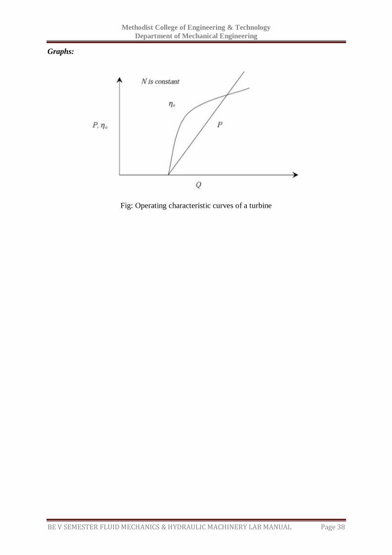
The performance of the turbine can be evaluated with the help of main and operating
characteristic curves. Head supplied to the turbine kept constant for getting the main
characteristic curves, whereas by keeping speed constant operating characteristic curves are
obtained. Unit quantities like unit speed, unit discharge and unit power are useful to predict
the behavior of the turbine at various working heads. Specific speed can be useful for
comparing the different types of turbines. The specific speed of Pelton wheel ranges from 8.5
to 50.
Methodist College of Engineering & Technology
Department of Mechanical Engineering
BE V SEMESTER FLUID MECHANICS & HYDRAULIC MACHINERY LAB MANUAL Page 36
Fig : Pelton wheel
Tabular column:
S.no Speed
rpm
Pressure gauge
readings Discharge
m3/sec
Brake
weight
(W2 – W1)
kg
Input
power
Kw
Output
power
Kw
ƞ
P1 P2 P3
Average efficiency =
Methodist College of Engineering & Technology
Department of Mechanical Engineering
BE V SEMESTER FLUID MECHANICS & HYDRAULIC MACHINERY LAB MANUAL Page 37
PROCEDURE:
1. Close the gate valve fully and start the pump.
2. See that the pump rotator rotes in proper direction.
3. Open the gate valve to get rated speed and the turbine inlet pressure,
Venturimeter inlet pressure and Venturimeter throat pressure.
4. Repeat the above procedure for different loads keeping the speed constant by
operating the gate valve.
5. Remove the load completely, close the gate valve and stop the pump.
Formulae:
1. Discharge Q = 𝑎1𝑎2√2𝑔ℎ
√𝑎12−𝑎2
2 m3/sec
Where h= (P1- P2) X 10 m
P1= inlet pressure; P2 = Throat pressure
d1= diameter of Venturimeter at inlet = 50 mm
d2= diameter of Venturimeter at throat = 25 mm
a1= 𝜋
4𝑑1
2 m2; a2 = 𝜋
4𝑑2
2 m2
2. Input power = 9.81 X supply head in meters (H) X discharge KW
Where supply head H = P3 X 10 m
3. Output power = 2𝜋𝑁𝑇
60000 KW
Where N = R.P.Mof the turbine shaft
T = Torque of the turbine shaft = (w2 – w1) X R X 9.81
(w2 – w1) = load applied on the turbine
R = radius of the brakedrum with rope in meters = 0.13 m
4. Efficiency = 𝑜𝑢𝑡𝑝𝑢𝑡 𝑝𝑜𝑤𝑒𝑟
𝑖𝑛𝑝𝑢𝑡 𝑝𝑜𝑤𝑒𝑟 ×𝑓𝑟𝑖𝑐𝑡𝑖𝑜𝑛𝑎𝑙 𝑒𝑓𝑓𝑖𝑐𝑖𝑒𝑛𝑐𝑦 x 100
Where frictional efficiency = 0.28
Precautions:
Keep away from the rotating elements of the machine
Methodist College of Engineering & Technology
Department of Mechanical Engineering
BE V SEMESTER FLUID MECHANICS & HYDRAULIC MACHINERY LAB MANUAL Page 38
Graphs:
Fig: Operating characteristic curves of a turbine

Methodist College of Engineering & Technology
Department of Mechanical Engineering
BE V SEMESTER FLUID MECHANICS & HYDRAULIC MACHINERY LAB MANUAL Page 39
Space For Calculations

Methodist College of Engineering & Technology
Department of Mechanical Engineering
BE V SEMESTER FLUID MECHANICS & HYDRAULIC MACHINERY LAB MANUAL Page 40
RESULT & CONCLUSIONS:
The efficiency of the Pelton wheel at constant speed is found to be ------------
Methodist College of Engineering & Technology
Department of Mechanical Engineering
BE V SEMESTER FLUID MECHANICS & HYDRAULIC MACHINERY LAB MANUAL Page 41
VIVA QUESTIONS:
What is the basic difference between an impulse & reaction turbine?
What is the basic difference between a tangential flow & radial flow turbine?
What is basic difference between axial flow & mixed flow turbine?
What do you mean specific speed of a turbine?
Define unit speed, unit power & unit discharge?
Define hydraulic machines?
Define turbines?
The study of hydraulic machines consists of what?
Define the term Gross head.
Define net head?
Define Hydraulic efficiency?
Define Mechanical efficiency?
Define Volumetric efficiency?
Define Overall efficiency?
The pelton wheel (or) pelton turbine is ---- a tangential flow impulse turbine
Write the classification of hydraulic turbines according to the type of energy
at inlet?
Write the classification of hydraulic turbines according to the direction of flow
through runner?
Write the classification of hydraulic turbines according to the head at the inlet of
turbine?
Write the classification of hydraulic turbines according to the specific speed of the
turbine?
Why the draft tube is not used for Pelton turbine?
Methodist College of Engineering & Technology
Department of Mechanical Engineering
BE V SEMESTER FLUID MECHANICS & HYDRAULIC MACHINERY LAB MANUAL Page 42
EXPERIMENT - 07
KAPLAN TURBINE
AIM:
To determine efficiency of Kaplan turbine
APPARATUS:
Kaplan turbine test rig.
THEORY:
Hydraulic or water turbines are the machines which use the energy of water
(hydropower) and convert it into mechanical energy. Thus the turbine becomes the prime
mover to run the electrical generators to produce the electricity viz., hydro electric power.
The turbines are classified as impulse and reaction turbines. In impulse turbine, the head of
water is completely converted into a jet, which impulses the force on the turbine. In reaction
turbine, it is the pressure of the flowing water, which rotates the runner of the turbine.
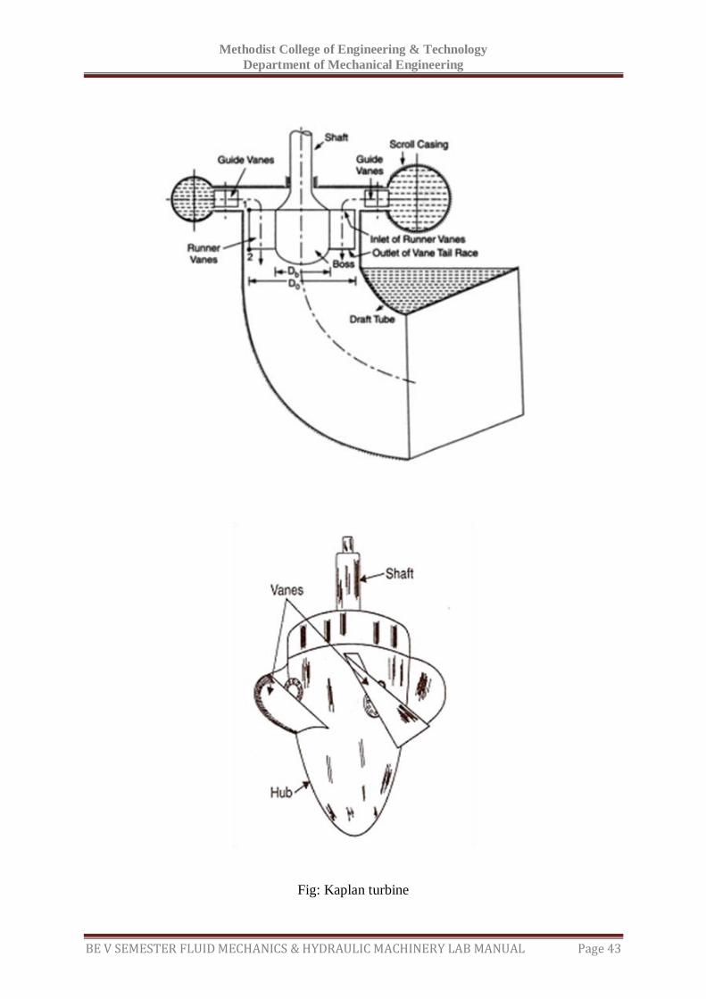
Kaplan turbine is an axial flow reaction turbine. It consists of a runner mounted on a shaft
and enclosed in a special casing with guide vanes. The cross section of flow between the
guide vanes can be varied. This is known as gate opening which usually kept as 1/4, 1/2, 3/4
or full. The water enters the volute casing which completely surrounds the runner. From the
casing the water passes between stationary guide vanes, mounted all around the periphery of
the runner. The function of these guide vanes is to direct the water on to the runner at the
required angle. Each vane is pivoted by a suitable mechanism so that all may be turned in
synchronism so as to alter the flow rate of machine and it passage through the runner. The
water is deflected by runner blades so that angular momentum is changed.
The Kaplan turbine consists of main components such as propeller (runner), scroll casing and
draft tube. Between the scroll casing and the runner, the water turns through right angle and
passes through the runner and thus rotating the shaft. When guide vane angles are varied,
high efficiency can be maintained over wide range of operating conditions.
Specifications:
Brake drum radius = 0.15 m
Inlet diameter of Venturimeter = 0.15 m
Throat diameter of Venturimeter = 0.075 m
Co-efficient of discharge = 0.80
PROCEDURE:
1. Keep the butter fly valve (or) gate valve closed.
2. Keep the load on brake drum (spring balance) at minimum.
3. Press the green button of the supply pump starter and then release.
Methodist College of Engineering & Technology
Department of Mechanical Engineering
BE V SEMESTER FLUID MECHANICS & HYDRAULIC MACHINERY LAB MANUAL Page 43
Fig: Kaplan turbine
Methodist College of Engineering & Technology
Department of Mechanical Engineering
BE V SEMESTER FLUID MECHANICS & HYDRAULIC MACHINERY LAB MANUAL Page 44
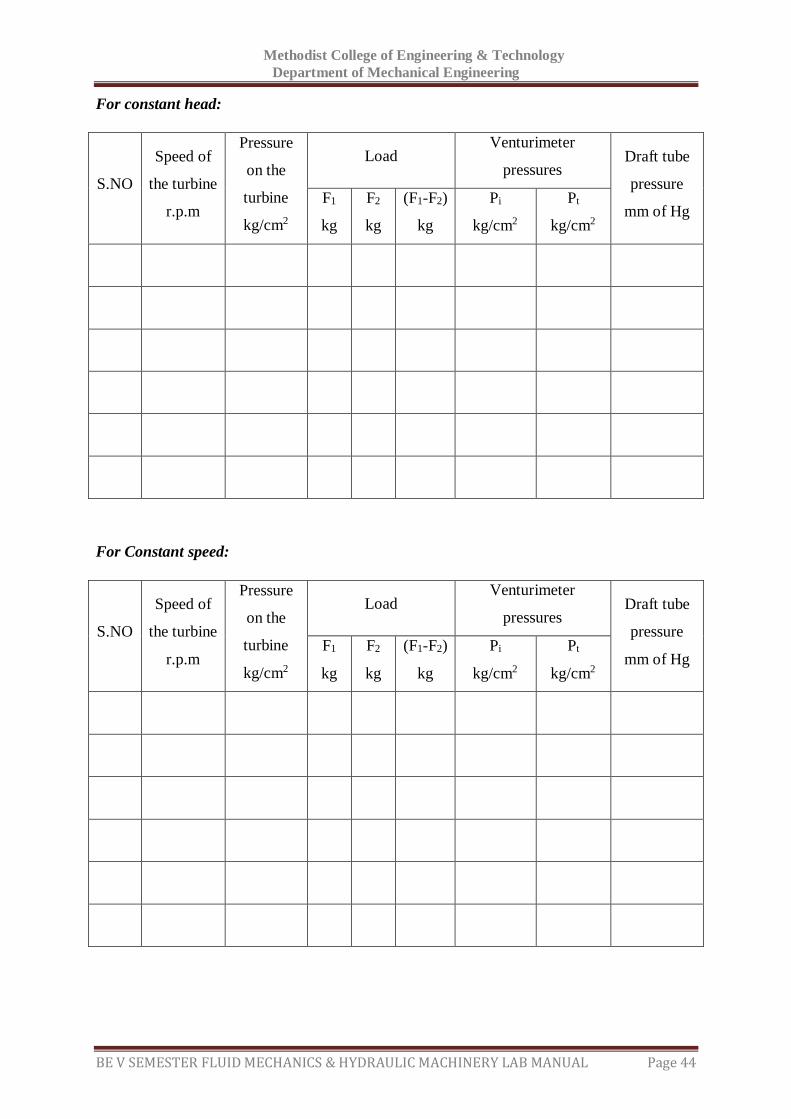
For constant head:
S.NO
Speed of
the turbine
r.p.m
Pressure
on the
turbine
kg/cm2
Load Venturimeter
pressures Draft tube
pressure
mm of Hg F1
kg
F2
kg
(F1-F2)
kg
Pi
kg/cm2
Pt
kg/cm2
For Constant speed:
S.NO
Speed of
the turbine
r.p.m
Pressure
on the
turbine
kg/cm2
Load Venturimeter
pressures Draft tube
pressure
mm of Hg F1
kg
F2
kg
(F1-F2)
kg
Pi
kg/cm2
Pt
kg/cm2
Methodist College of Engineering & Technology
Department of Mechanical Engineering
BE V SEMESTER FLUID MECHANICS & HYDRAULIC MACHINERY LAB MANUAL Page 45
4. a) Slowly open the gate so that the turbine rotor picks up the speed and attains the
Maximum at full opening of the gate.
b) Slowly open the brake drum cooling valve and allow very little water before loading the
brake drum.
c) Slowly operate the hand wheel on the rope of spring balance to increase the load on the
brake drum. Set the spring balance reading.
d) For different loads on the brake drum, note down the speed, head on turbine,
Venturimeter pressure gauge readings and draft tube vaccume.
5. Close the gate then switch off the supply water.
6. Follow the procedure described below for taking down the reading for evaluating the
performance characteristics of the Kaplan turbine.
To obtain constant head characteristics:
1. Keep the gate valve closed and start the pump.
2. Slowly open the gate valve and set the pressure on the gauge.
3. For different load on the brake drum, set the head constant by operating the gate valve and
Tabulate the readings.
To obtain constant speed characteristics:
1. For different loads on the brake drum, change the gate valve position, so that the speed is
held constant.
2. Repeat the experiment for different speeds, say 1500 rpm, 1000 r.p.m and tabulate the
results.
3. The above readings will be utilized for drawing constant speed characteristics Viz.,
a) load Vs efficiency
b) Discharge VS efficiency
Formulae:
1. Head on turbine H = 10(P +𝑃𝑉
760) m
Where P is pressure gauge reading in kg/cm2
PV is the vaccume gauge reading
2. Discharge of water(flow rate) through turbine = flow rate by Venturimeter
Q = Cd
a1a2√2gh
√a12−a2
2
Methodist College of Engineering & Technology
Department of Mechanical Engineering
BE V SEMESTER FLUID MECHANICS & HYDRAULIC MACHINERY LAB MANUAL Page 46
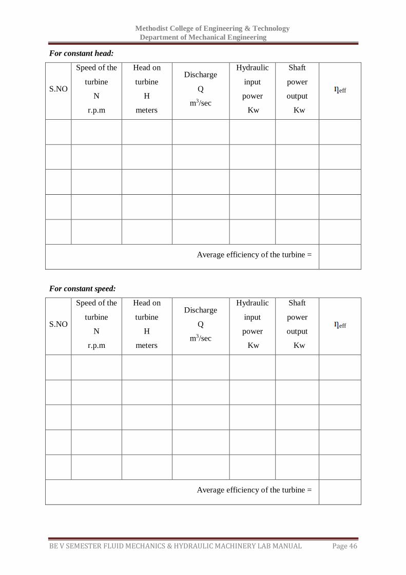
For constant head:
S.NO
Speed of the
turbine
N
r.p.m
Head on
turbine
H
meters
Discharge
Q
m3/sec
Hydraulic
input
power
Kw
Shaft
power
output
Kw
eff
Average efficiency of the turbine =
For constant speed:
S.NO
Speed of the
turbine
N
r.p.m
Head on
turbine
H
meters
Discharge
Q
m3/sec
Hydraulic
input
power
Kw
Shaft
power
output
Kw
eff
Average efficiency of the turbine =
Methodist College of Engineering & Technology
Department of Mechanical Engineering
BE V SEMESTER FLUID MECHANICS & HYDRAULIC MACHINERY LAB MANUAL Page 47
Where Cd = Coefficient of discharge = 0.80
a1= area of inlet section= 𝜋𝐷2
4 m2
a2= area of throat section= 𝜋𝑑2
4 m2
Loss of head h= 12.6 x (Pi-Pt) x 0.76 m of water
Where (Pi-Pt) = differential head across Venturimeter in kg/cm2
760 mm of Hg = 1 kg/cm2
3. Turbine output (mechanical output)= 2𝜋𝑁𝑇
4500 HP
=2𝜋𝑁(𝐹𝑖− 𝐹𝑡 )
4500 𝐻𝑃
4. Hydraulic input to turbine = 𝑊𝑄𝐻
75 𝐻𝑃
W= Specific weight of water =9810 N/m3
5. Turbine efficiency eff =Mechanical output
Hydraulic inputx 100
Precautions:
Don’t shutdown when the loads present on the brake drum.
Keep away from the rotating elements of the machine.
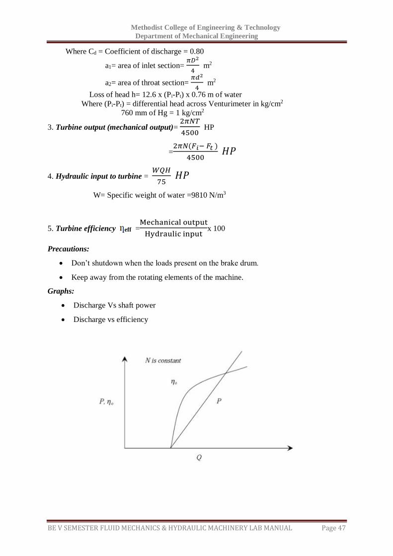
Graphs:
Discharge Vs shaft power
Discharge vs efficiency

Methodist College of Engineering & Technology
Department of Mechanical Engineering
BE V SEMESTER FLUID MECHANICS & HYDRAULIC MACHINERY LAB MANUAL Page 48
Space For Calculations

Methodist College of Engineering & Technology
Department of Mechanical Engineering
BE V SEMESTER FLUID MECHANICS & HYDRAULIC MACHINERY LAB MANUAL Page 49
RESULT & CONCLUSIONS:
The efficiency of Kaplan turbine is found to be (i) at constant head -------------
(ii) at constant speed-----------
Methodist College of Engineering & Technology
Department of Mechanical Engineering
BE V SEMESTER FLUID MECHANICS & HYDRAULIC MACHINERY LAB MANUAL Page 50
VIVA QUESTIONS:
What is meant by a turbine?
What are the differences between turbine and pump?
What are the different types of turbines?
Kaplan comes under impulse turbine (or) reaction turbine?
What is the difference between Pelton wheel and Kaplan turbine applications wise?
Which type of flow will exist in Kaplan turbine?
What is meant by Draft tube?
Draft tubes are required in Impulse turbines (or) reaction turbines?
Where draft tube will be fitted for reaction turbines?
Is draft tube is compulsory in reaction turbines?
What is meant by specific speed of the turbine?
What is the formula for input power of a Kaplan turbine?
What is meant by Performance characteristic curves?
What are the different types of performance characteristic curves?
What is the equipment used for measuring the discharge in Kaplan turbine?
How maintain the constant speed during the experiment with the applying of load.
What is meant by unit quantities?
What is the difference between specific speed and unit speed?
Methodist College of Engineering & Technology
Department of Mechanical Engineering
BE V SEMESTER FLUID MECHANICS & HYDRAULIC MACHINERY LAB MANUAL Page 51
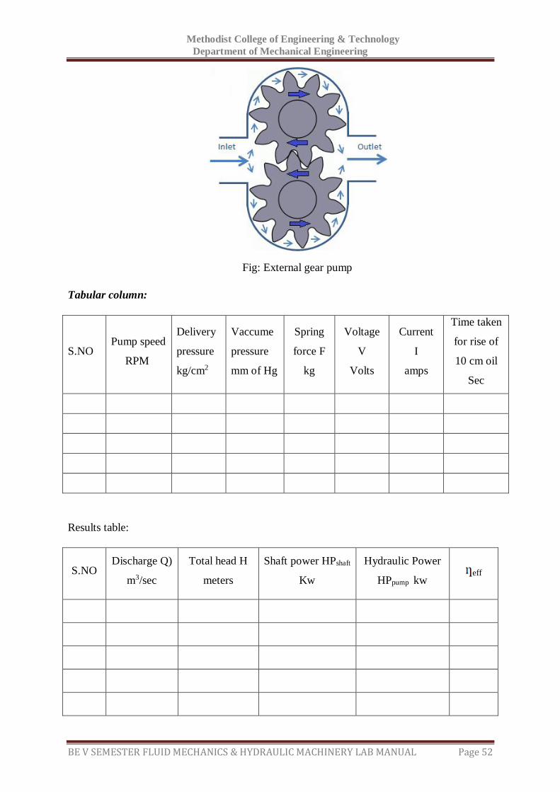
EXPERIMENT - 08
GEAR PUMP
AIM:
To determine the efficiency of gear pump.
APPARATUS:
Gear pump test rig
Stop watch
THEORY:
In general a gear pump may be defined as a mechanical device which, when interposed in a
pipe line, converts the mechanical energy supplied to it from some external source into
hydraulic energy, thus resulting in the flow of liquid from lower potential to higher potential.
The present gear pump test rig is a self contained unit operated on closed circuit
(recirculation) Basis. Main components are gear pump, D.C. motor, collecting tank and sump,
control panel. All these are mounted on rigid frame work.
The test rig has the following provisions:
1. To run the pump at various speeds using D.C.motor thyristor speed controller.
2. To measure the input/shaft horse power to the pump using torque weighing system
connected to stator of D.C.motor.
3. To measure the overall input horse power to the D.C.motor using digital voltmeter
and ammeter.
4. To measure the speed/RPM of the pump.
5. To measure the delivery and suction heads using pressure and vaccume gauges
separately.(the delivery head pressure tapping is connected upstream of delivery valve
and that of the suction tapping downstream of suction valve)
6. To change the head and flow rate using control valves.
7. To measure the discharge using collecting tank fitted with tank level indicator/gauge
glass.
PROCEDURE: 1. Keep the delivery valve open and suction valve open.
2. Keep the speed control knob at zero.
Methodist College of Engineering & Technology
Department of Mechanical Engineering
BE V SEMESTER FLUID MECHANICS & HYDRAULIC MACHINERY LAB MANUAL Page 52
Fig: External gear pump
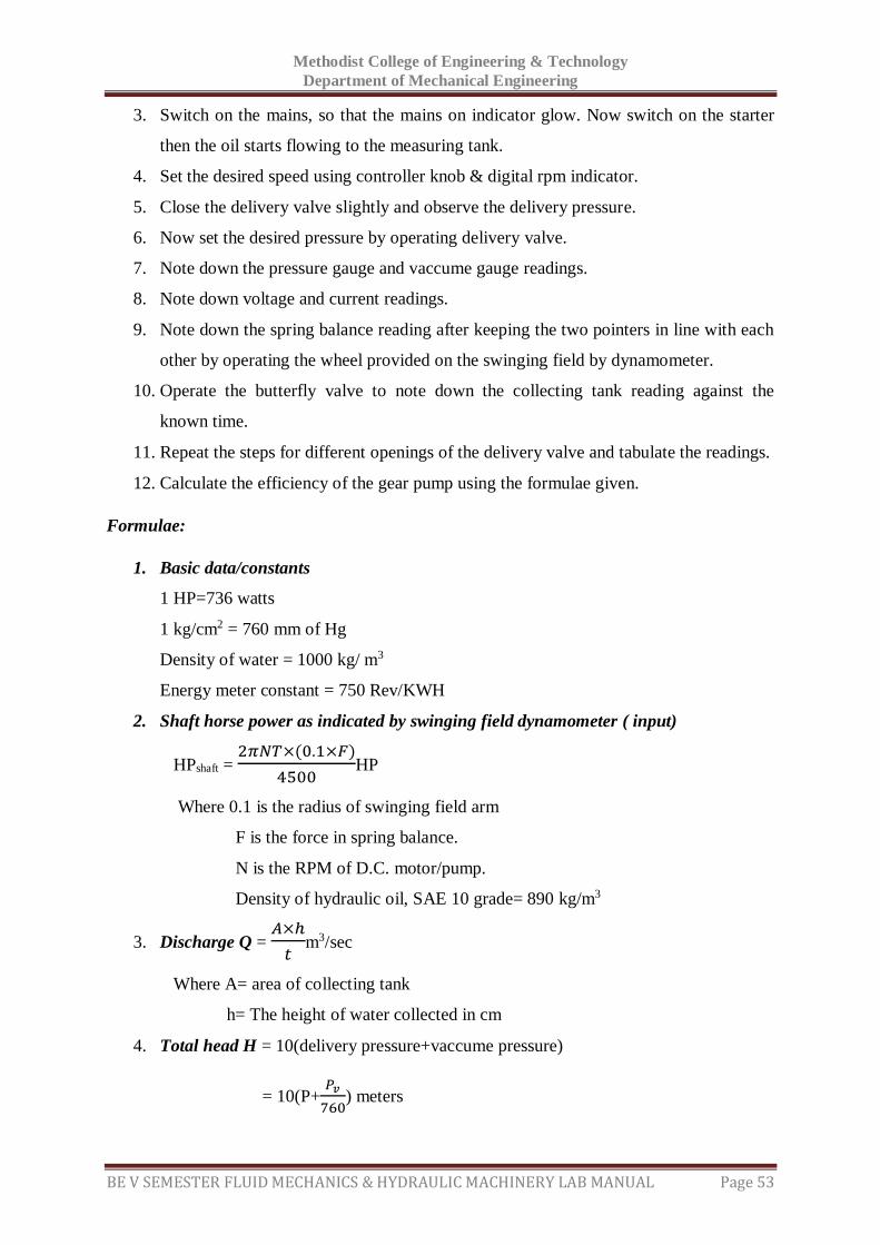
Tabular column:
S.NO Pump speed
RPM
Delivery
pressure
kg/cm2
Vaccume
pressure
mm of Hg
Spring
force F
kg
Voltage
V
Volts
Current
I
amps
Time taken
for rise of
10 cm oil
Sec
Results table:
S.NO Discharge Q)
m3/sec
Total head H
meters
Shaft power HPshaft
Kw
Hydraulic Power
HPpump kw eff
Methodist College of Engineering & Technology
Department of Mechanical Engineering
BE V SEMESTER FLUID MECHANICS & HYDRAULIC MACHINERY LAB MANUAL Page 53
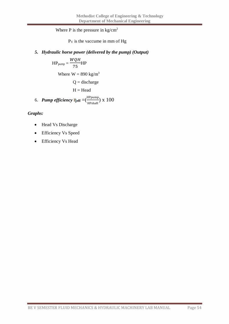
3. Switch on the mains, so that the mains on indicator glow. Now switch on the starter
then the oil starts flowing to the measuring tank.
4. Set the desired speed using controller knob & digital rpm indicator.
5. Close the delivery valve slightly and observe the delivery pressure.
6. Now set the desired pressure by operating delivery valve.
7. Note down the pressure gauge and vaccume gauge readings.
8. Note down voltage and current readings.
9. Note down the spring balance reading after keeping the two pointers in line with each
other by operating the wheel provided on the swinging field by dynamometer.
10. Operate the butterfly valve to note down the collecting tank reading against the
known time.
11. Repeat the steps for different openings of the delivery valve and tabulate the readings.
12. Calculate the efficiency of the gear pump using the formulae given.
Formulae:
1. Basic data/constants
1 HP=736 watts
1 kg/cm2 = 760 mm of Hg
Density of water = 1000 kg/ m3
Energy meter constant = 750 Rev/KWH
2. Shaft horse power as indicated by swinging field dynamometer ( input)
HPshaft = 2𝜋𝑁𝑇×(0.1×𝐹)
4500HP
Where 0.1 is the radius of swinging field arm
F is the force in spring balance.
N is the RPM of D.C. motor/pump.
Density of hydraulic oil, SAE 10 grade= 890 kg/m3
3. Discharge Q = 𝐴×ℎ
𝑡m3/sec
Where A= area of collecting tank
h= The height of water collected in cm
4. Total head H = 10(delivery pressure+vaccume pressure)
= 10(P+𝑃𝑣
760) meters
Methodist College of Engineering & Technology
Department of Mechanical Engineering
BE V SEMESTER FLUID MECHANICS & HYDRAULIC MACHINERY LAB MANUAL Page 54
Where P is the pressure in kg/cm2
PV is the vaccume in mm of Hg
5. Hydraulic horse power (delivered by the pump) (Output)
HPpump = 𝑊𝑄𝐻
75HP
Where W = 890 kg/m3
Q = discharge
H = Head
6. Pump efficiency eff =(HPpump
HPshaft) x 100
Graphs:
Head Vs Discharge
Efficiency Vs Speed
Efficiency Vs Head

Methodist College of Engineering & Technology
Department of Mechanical Engineering
BE V SEMESTER FLUID MECHANICS & HYDRAULIC MACHINERY LAB MANUAL Page 55
Space For Calculations

Methodist College of Engineering & Technology
Department of Mechanical Engineering
BE V SEMESTER FLUID MECHANICS & HYDRAULIC MACHINERY LAB MANUAL Page 56
RESULT & CONCLUSIONS:
The efficiency of gear pump is found to be-------------------
Methodist College of Engineering & Technology
Department of Mechanical Engineering
BE V SEMESTER FLUID MECHANICS & HYDRAULIC MACHINERY LAB MANUAL Page 57
VIVA QUESTIONS:
What is meant by a gear pump ?
What are the different types of gear pumps?
Which type gear pump is using in this laboratory?
What is the oil using in this lab for experimentation?
What is the difference between Centrifugal pump and Gear pump
What are the applications of Gear pump?
What is the formula for Output power developed by the Gear pump.
Methodist College of Engineering & Technology
Department of Mechanical Engineering
BE V SEMESTER FLUID MECHANICS & HYDRAULIC MACHINERY LAB MANUAL Page 58
EXPERIMENT - 09
FRANCIS TURBINE
AIM:
To determine efficiency of Francis turbine
APPARATUS:
Francis turbine test rig.
THEORY:
The turbines are classified as impulse and reaction types. In impulse turbine, the head of
water is completely converted into a jet, which impulses the forces on turbine, in reaction
turbine; it is the pressure of the following water, which rotates the runner of the turbine. Of
many types of turbine, the pelton wheel, ,most commonly used, falls into the category of
turbines .while Francis and Kaplan falls in the category of impulse reaction turbines.
Normally, pelton wheel (impulse turbine) requires high heads and low
Discharge .while Francis and Kaplan (reaction turbines) require relatively low heads and high
discharge.
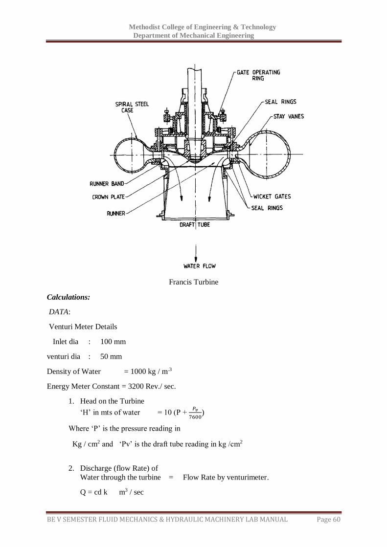
While the impulse turbine is discussed elsewhere in standard text books, Francis turbine, the
reaction type which is of present concern consists of main components such as (runner) scroll
casing and draft tube. Between the scroll casing and the runner, the water turns through
right angle into the axial direction and passes through the runner and thus rotating the runner
shaft. The runner has eight fixed blades since it is transparent
You can visualize all the inside parts of flow in the scroll casing.
The actual experimental facility supplied consists of a centrifugal pump set, turbine unit,
sump tank, arranged in such way that the whole unit works on recalculating water system.
The centrifugal pump set supplies the water from the sump tank to the turbine through control
valve. And then flow through the venturimeter. The water after passing through the turbine
unit enters the sump tank through the draft tube.
The loading of turbine is achieved by electrical AC generator connected to lamp
bank .the provisions for measurement of electrical energy by energy meter & voltmeter and
ammeter, turbine speed by digital RPM indicator , head on the turbine and draft tube vacuum
by digital pressure indicator, to venturimeter measure the discharge into the turbine,.
Specification:
Supply pump / motor capacity : 10 HP ,3 PH ,440 Volts
Turbine : 150 mm dia impeller
Run away speed 3000 RPM (Approx)
Loading : a) AC Generator
b) Head on turbine by digital pressure indicator and draft
tube vacuum By pressure gauge and vacuum gauge.
c) Electrical loading change by switches
d )Load measure by energy meter
e) Turbine speed by digital RPM indicator.
Methodist College of Engineering & Technology
Department of Mechanical Engineering
BE V SEMESTER FLUID MECHANICS & HYDRAULIC MACHINERY LAB MANUAL Page 59
f) Supply water control by gate valve.
Electrical supply: 3 ph, 440 v. A.C. 20 A with neutral and earth.
PROCEDURE: 1. Connect the supply pump / motor unit to3 ph, 440 v, 20 A, electrical supply, with
neutral and earth connections and ensure the correct direction of pump /motor unit.
2. Keep the gate closed.
3. Keep the electrical load at minimum, by keeping all the switches at ‘OFF’ position.
4. Press the green button of the supply pump starter and then release.
5. Slowly open the gate so that the turbine rotor picks up the speed and attains maximum
at full opening of the gate.
6. Note down the voltage and current, speed, pressure, vacuum on the control panel,
venturimeter reading.
7. gate valve/ guide vanes also can be used for speed control.and head control
8. Close the gate and then switch ‘OFF’ the supply set.
9. Follow the procedure described below for taking down the reading for evaluating the
performance characteristic of the Francis turbine.
To Obtain Constant Speed Characteristics:
(Operating charecterstics)
1. Keep the gate opening at maximum.
2. for different electrical loads on the turbine / generator , change the control valve
so that the speed is held constant.
3. Reduce the gate opening setting to different position and repeat ( 2 ) for Different
speeds 1500 RPM ,1000 RPM and tabulate the results.
4. The above readings will be utilized for drawing constant speed.
Characteristics viz.,
a) Percentage of full load Vs efficiency.
b) Efficiency and BHP vs Discharge Characteristics.
To Obtain Constant Head Characteristics:
(Main characteristics)
1. Keep the gate closed, and start the pump.
2. Select control valve position.
3. Slowly open the gate and set the pressure on the gauge.
4. For different electrical loads, change the gate valve position, and maintain the
constant head and tabulate the result as given in table II.
Methodist College of Engineering & Technology
Department of Mechanical Engineering
BE V SEMESTER FLUID MECHANICS & HYDRAULIC MACHINERY LAB MANUAL Page 60
Francis Turbine
Calculations:
DATA:
Venturi Meter Details
Inlet dia : 100 mm
venturi dia : 50 mm
Density of Water = 1000 kg / m.3
Energy Meter Constant = 3200 Rev./ sec.
1. Head on the Turbine
‘H’ in mts of water = 10 (P + 𝑃𝑣
7600)
Where ‘P’ is the pressure reading in Kg / cm2 and ‘Pv’ is the draft tube reading in kg /cm2
2. Discharge (flow Rate) of
Water through the turbine = Flow Rate by venturimeter.
Q = cd k m3 / sec
Methodist College of Engineering & Technology
Department of Mechanical Engineering
BE V SEMESTER FLUID MECHANICS & HYDRAULIC MACHINERY LAB MANUAL Page 61
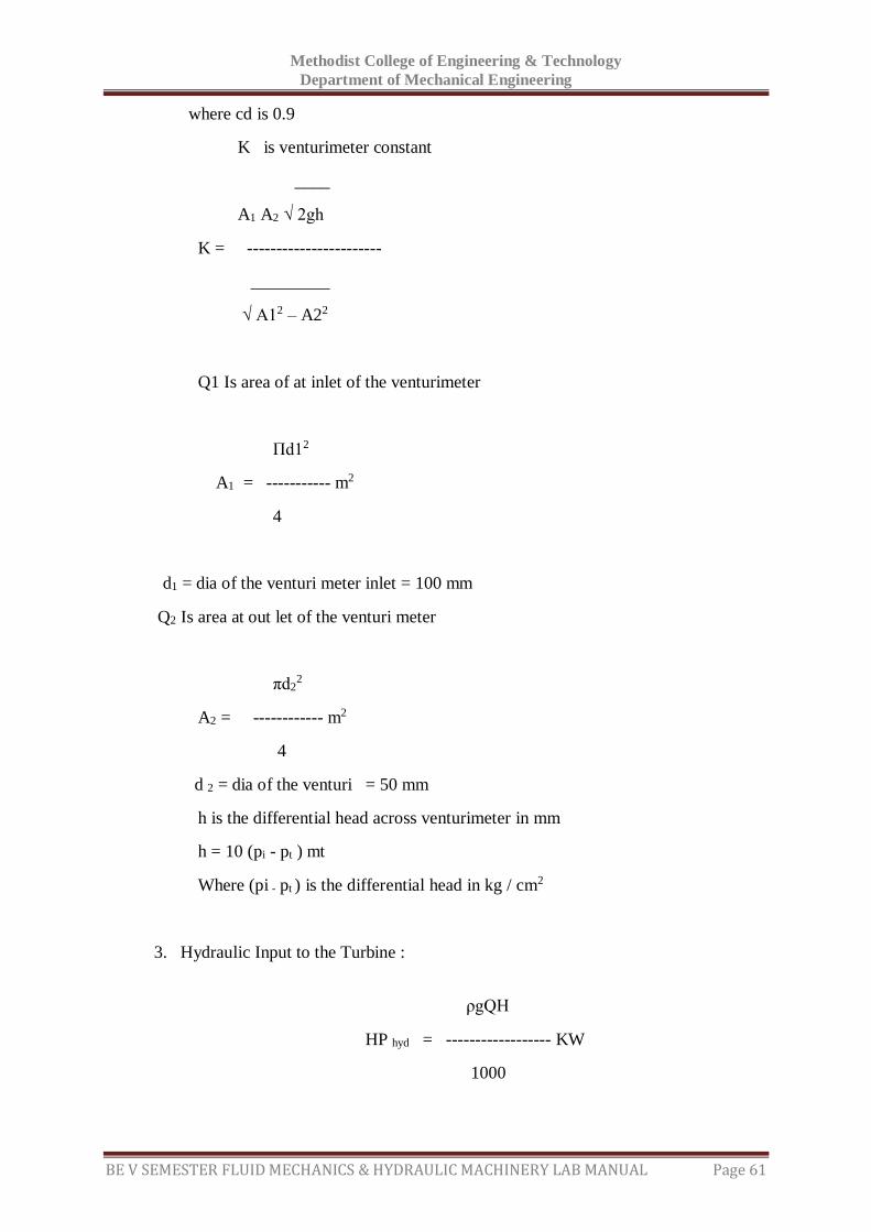
where cd is 0.9
K is venturimeter constant
____
A1 A2 √ 2gh
K = -----------------------
_________
√ A12 – A22
Q1 Is area of at inlet of the venturimeter
Πd12
A1 = ----------- m2
4
d1 = dia of the venturi meter inlet = 100 mm
Q2 Is area at out let of the venturi meter
πd22
A2 = ------------ m2
4
d 2 = dia of the venturi = 50 mm
h is the differential head across venturimeter in mm
h = 10 (pi - pt ) mt
Where (pi - pt ) is the differential head in kg / cm2
3. Hydraulic Input to the Turbine :
ρgQH
HP hyd = ------------------ KW
1000
Methodist College of Engineering & Technology
Department of Mechanical Engineering
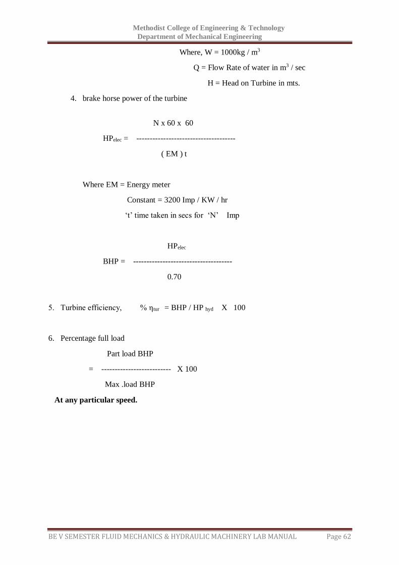
BE V SEMESTER FLUID MECHANICS & HYDRAULIC MACHINERY LAB MANUAL Page 62
Where, W = 1000kg / m3
Q = Flow Rate of water in m3 / sec
H = Head on Turbine in mts.
4. brake horse power of the turbine
N x 60 x 60
HPelec = -------------------------------------
( EM ) t
Where EM = Energy meter
Constant = 3200 Imp / KW / hr
‘t’ time taken in secs for ‘N’ Imp
HPelec
BHP = -------------------------------------
0.70
5. Turbine efficiency, % ηtur = BHP / HP hyd X 100
6. Percentage full load
Part load BHP
= -------------------------- X 100
Max .load BHP
At any particular speed.
Methodist College of Engineering & Technology
Department of Mechanical Engineering
BE V SEMESTER FLUID MECHANICS & HYDRAULIC MACHINERY LAB MANUAL Page 63
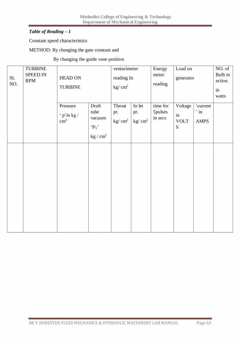
Table of Reading – 1
Constant speed characteristics
METHOD: By changing the gate constant and
By changing the guide vane position
SL
NO.
TURBINE
SPEED IN
RPM
HEAD ON
TURBINE
venturimeter
reading In
kg/ cm2
Energy
meter
reading
Load on
generator
NO. of
Bulb in
action.
in
watts
Pressure
‘ p’in kg /
cm2
Draft
tube
vacuum
‘PV’
kg / cm2
Throat
pr.
kg/ cm2
In let
pr.
kg/ cm2
time for
5pulses
in secs
Voltage
in
VOLT
S
‘current
’ in
AMPS
Methodist College of Engineering & Technology
Department of Mechanical Engineering
BE V SEMESTER FLUID MECHANICS & HYDRAULIC MACHINERY LAB MANUAL Page 64
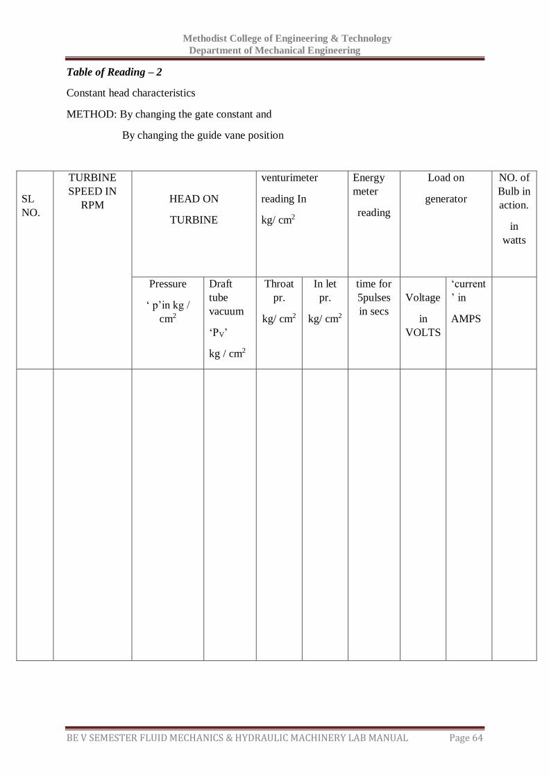
Table of Reading – 2
Constant head characteristics
METHOD: By changing the gate constant and
By changing the guide vane position
SL
NO.
TURBINE
SPEED IN
RPM
HEAD ON
TURBINE
venturimeter
reading In
kg/ cm2
Energy
meter
reading
Load on
generator
NO. of
Bulb in
action.
in
watts
Pressure
‘ p’in kg /
cm2
Draft
tube
vacuum
‘PV’
kg / cm2
Throat
pr.
kg/ cm2
In let
pr.
kg/ cm2
time for
5pulses
in secs
Voltage
in
VOLTS
‘current
’ in
AMPS
Methodist College of Engineering & Technology
Department of Mechanical Engineering
BE V SEMESTER FLUID MECHANICS & HYDRAULIC MACHINERY LAB MANUAL Page 65
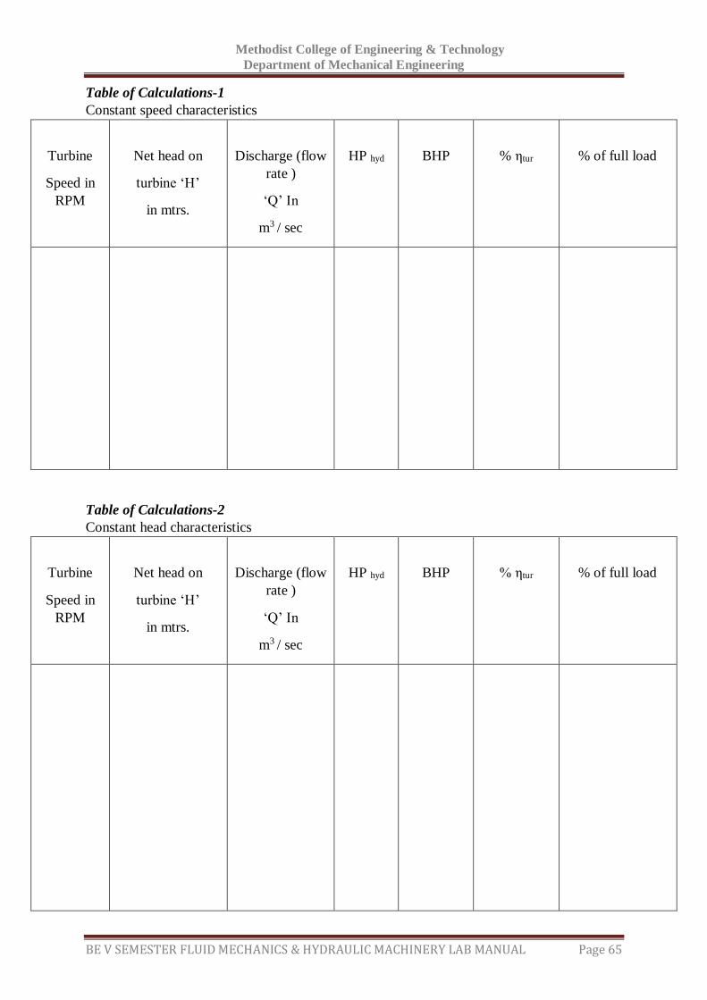
Table of Calculations-1
Constant speed characteristics
Turbine
Speed in
RPM
Net head on
turbine ‘H’
in mtrs.
Discharge (flow
rate )
‘Q’ In
m3 / sec
HP hyd
BHP
% ηtur
% of full load
Table of Calculations-2
Constant head characteristics
Turbine
Speed in
RPM
Net head on
turbine ‘H’
in mtrs.
Discharge (flow
rate )
‘Q’ In
m3 / sec
HP hyd
BHP
% ηtur
% of full load
Methodist College of Engineering & Technology
Department of Mechanical Engineering
BE V SEMESTER FLUID MECHANICS & HYDRAULIC MACHINERY LAB MANUAL Page 66
Precautions:
1. Do not start pump set if the supply voltage is less than 400 v
2. do not forget to give electrical earth and neutral connections correctly otherwise,
the RPM indicator gets burns if connections are wrong
3. Frequently, at least once in three months, grease all visual moving parts.
4. finally, fill in the with clean water free from foreign material
Change the everyday / week.
5. At least every day operate the unit for five minutes to prevent any clogging of The
moving parts.
6. To start and stop the supply pump, always keep gate valve closed.
7. Gradual opening and closing of the gate valve is recommended for smooth
operation.
8. In case of any major fault, please write to manufacturer, and do not attempt to
repair.
Graphs:
Discharge Vs shaft power
Discharge vs efficiency

Methodist College of Engineering & Technology
Department of Mechanical Engineering
BE V SEMESTER FLUID MECHANICS & HYDRAULIC MACHINERY LAB MANUAL Page 67
Space For Calculations
Methodist College of Engineering & Technology
Department of Mechanical Engineering
BE V SEMESTER FLUID MECHANICS & HYDRAULIC MACHINERY LAB MANUAL Page 68
RESULT & CONCLUSIONS:
The efficiency of Francis turbine is found to be (i) at constant head -------------
(ii) at constant speed-----------
Methodist College of Engineering & Technology
Department of Mechanical Engineering
BE V SEMESTER FLUID MECHANICS & HYDRAULIC MACHINERY LAB MANUAL Page 69
VIVA QUESTIONS:
What is meant by a turbine?
What are the differences between turbine and pump?
What are the different types of turbines?
Francis comes under impulse turbine (or) reaction turbine?
What is the difference between Pelton wheel and Francis turbine applications wise?
Which type of flow will exist in Francis turbine?
What is meant by Draft tube?
Draft tubes are required in Impulse turbines (or) reaction turbines?
Where draft tube will be fitted for reaction turbines?
Is draft tube is compulsory in reaction turbines?
What is meant by specific speed of the turbine?
What is meant by Performance characteristic curves?
What are the different types of performance characteristic curves?
How maintain the constant speed during the experiment with the applying of load.
What is meant by unit quantities?
What is the difference between specific speed and unit speed?
Methodist College of Engineering & Technology
Department of Mechanical Engineering
BE V SEMESTER FLUID MECHANICS & HYDRAULIC MACHINERY LAB MANUAL Page 70
EXPERIMENT - 10
SELF-PRIMING PUMP
AIM:
To determine the efficiency of self priming pump.
APPARATUS:
Self priming pump
Stop watch
Collecting tank
THEORY:
A self-priming centrifugal pump has two phases of operation: priming mode and pumping
mode
In its priming mode, the pump essentially acts as a liquid-ring pump. The rotating impeller
generates a vacuum at the impeller’s ‘eye’ which draws air into the pump from the suction
line. At the same time, it also creates a cylindrical ring of liquid on the inside of the pump
casing. This effectively forms a gas-tight seal, stopping air returning from the discharge line
to the suction line. Air bubbles are trapped in the liquid within the impeller’s vanes and
transported to the discharge port. There, the air is expelled and the liquid returns under
gravity to the reservoir in the pump housing.
Gradually, liquid rises up the suction line as it is evacuated. This process continues until
liquid replaces all the air in the suction piping and the pump. At this stage, the normal
pumping mode commences, and liquid is discharged.
When the pump is shut off, the design of the priming chamber (normally involving a ‘goose-
neck’ on the suction piping) ensures that enough liquid is retained so that the pump can self-
prime on the next occasion it is used. If a pump has not been used for a while, it is important
to check for losses from the casing due to leaks or evaporation before starting it.
Specifications:
Area of collecting tank = 0.4 x 0.4 m2
Energy meter constant = 3200 imp/kwh
Datum head = difference between suction and delivery gauges Z = 0.3 m
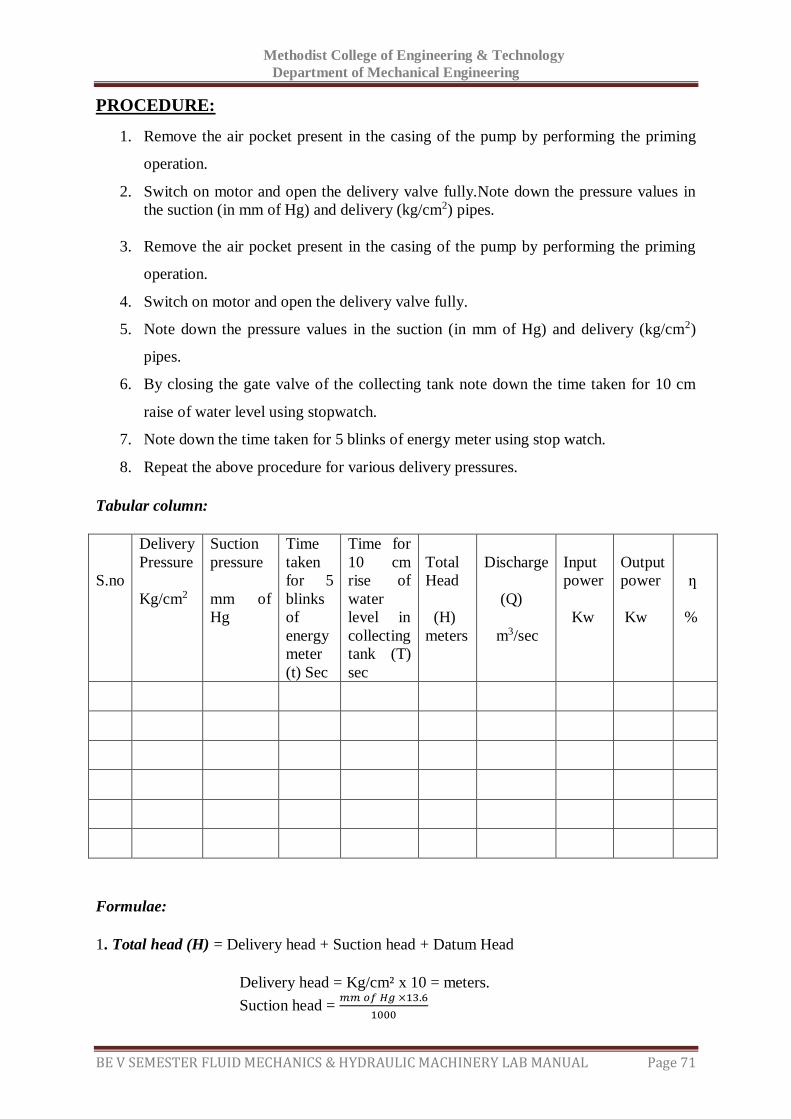
Methodist College of Engineering & Technology
Department of Mechanical Engineering
BE V SEMESTER FLUID MECHANICS & HYDRAULIC MACHINERY LAB MANUAL Page 71
PROCEDURE:
1. Remove the air pocket present in the casing of the pump by performing the priming
operation.
2. Switch on motor and open the delivery valve fully.Note down the pressure values in
the suction (in mm of Hg) and delivery (kg/cm2) pipes.
3. Remove the air pocket present in the casing of the pump by performing the priming
operation.
4. Switch on motor and open the delivery valve fully.
5. Note down the pressure values in the suction (in mm of Hg) and delivery (kg/cm2)
pipes.
6. By closing the gate valve of the collecting tank note down the time taken for 10 cm
raise of water level using stopwatch.
7. Note down the time taken for 5 blinks of energy meter using stop watch.
8. Repeat the above procedure for various delivery pressures.
Tabular column:
S.no
Delivery
Pressure
Kg/cm2
Suction
pressure
mm of
Hg
Time
taken
for 5
blinks
of
energy
meter
(t) Sec
Time for
10 cm
rise of
water
level in
collecting
tank (T)
sec
Total
Head
(H)
meters
Discharge
(Q)
m3/sec
Input
power
Kw
Output
power
Kw
ƞ
%
Formulae:
1. Total head (H) = Delivery head + Suction head + Datum Head
Delivery head = Kg/cm² x 10 = meters.
Suction head = 𝑚𝑚 𝑜𝑓 𝐻𝑔 ×13.6
1000
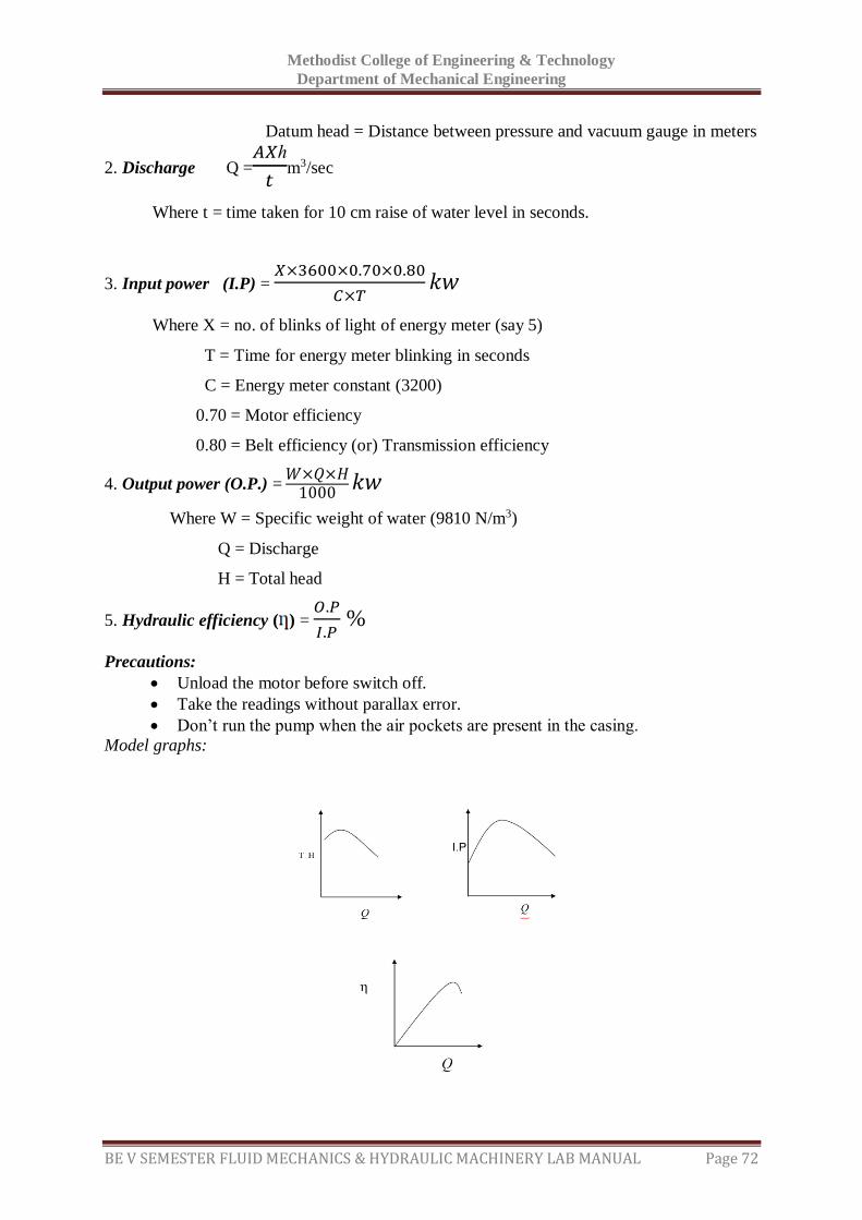
Methodist College of Engineering & Technology
Department of Mechanical Engineering
BE V SEMESTER FLUID MECHANICS & HYDRAULIC MACHINERY LAB MANUAL Page 72
Datum head = Distance between pressure and vacuum gauge in meters
2. Discharge Q =𝐴𝑋ℎ
𝑡m3/sec
Where t = time taken for 10 cm raise of water level in seconds.
3. Input power (I.P) = 𝑋×3600×0.70×0.80
𝐶×𝑇𝑘𝑤
Where X = no. of blinks of light of energy meter (say 5)
T = Time for energy meter blinking in seconds
C = Energy meter constant (3200)
0.70 = Motor efficiency
0.80 = Belt efficiency (or) Transmission efficiency
4. Output power (O.P.) = 𝑊×𝑄×𝐻
1000𝑘𝑤
Where W = Specific weight of water (9810 N/m3)
Q = Discharge
H = Total head
5. Hydraulic efficiency ( ) = 𝑂.𝑃
𝐼.𝑃 %
Precautions:
Unload the motor before switch off.
Take the readings without parallax error.
Don’t run the pump when the air pockets are present in the casing.
Model graphs:

Methodist College of Engineering & Technology
Department of Mechanical Engineering
BE V SEMESTER FLUID MECHANICS & HYDRAULIC MACHINERY LAB MANUAL Page 73
Space For Calculations
Methodist College of Engineering & Technology
Department of Mechanical Engineering
BE V SEMESTER FLUID MECHANICS & HYDRAULIC MACHINERY LAB MANUAL Page 74
RESULT & CONCLUSIONS:
The efficiency of self priming pump is found to be -----------------
Methodist College of Engineering & Technology
Department of Mechanical Engineering
BE V SEMESTER FLUID MECHANICS & HYDRAULIC MACHINERY LAB MANUAL Page 75
VIVA QUESTIONS:
What is priming of a pump?
Why it is necessary to prime a pump?
Write the effects of cavitation?
What are the main parts of a self priming pump?
Distinguish between the positive and non-positive displacement pumps.
Define pumps?
Write the working principle of a self priming pump?
Define specific speed of self priming pump?
Define the characteristic curves and why these curves are necessary?
Write the types of the characteristic curves?
Classify hydraulic pumps.
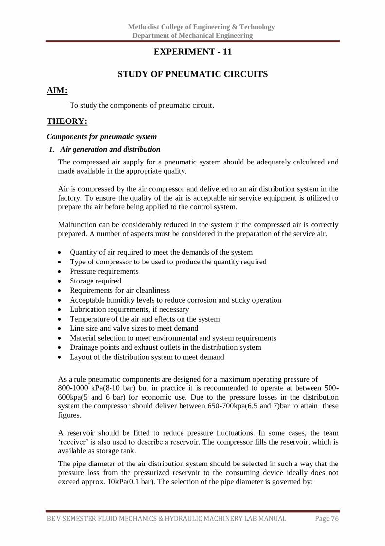
Methodist College of Engineering & Technology
Department of Mechanical Engineering
BE V SEMESTER FLUID MECHANICS & HYDRAULIC MACHINERY LAB MANUAL Page 76
EXPERIMENT - 11
STUDY OF PNEUMATIC CIRCUITS
AIM:
To study the components of pneumatic circuit.
THEORY:
Components for pneumatic system
1. Air generation and distribution
The compressed air supply for a pneumatic system should be adequately calculated and
made available in the appropriate quality.
Air is compressed by the air compressor and delivered to an air distribution system in the
factory. To ensure the quality of the air is acceptable air service equipment is utilized to
prepare the air before being applied to the control system.
Malfunction can be considerably reduced in the system if the compressed air is correctly
prepared. A number of aspects must be considered in the preparation of the service air.
Quantity of air required to meet the demands of the system
Type of compressor to be used to produce the quantity required
Pressure requirements
Storage required
Requirements for air cleanliness
Acceptable humidity levels to reduce corrosion and sticky operation
Lubrication requirements, if necessary
Temperature of the air and effects on the system
Line size and valve sizes to meet demand
Material selection to meet environmental and system requirements
Drainage points and exhaust outlets in the distribution system
Layout of the distribution system to meet demand
As a rule pneumatic components are designed for a maximum operating pressure of
800-1000 kPa(8-10 bar) but in practice it is recommended to operate at between 500-
600kpa(5 and 6 bar) for economic use. Due to the pressure losses in the distribution
system the compressor should deliver between 650-700kpa(6.5 and 7)bar to attain these
figures.
A reservoir should be fitted to reduce pressure fluctuations. In some cases, the team
‘receiver’ is also used to describe a reservoir. The compressor fills the reservoir, which is
available as storage tank.
The pipe diameter of the air distribution system should be selected in such a way that the
pressure loss from the pressurized reservoir to the consuming device ideally does not
exceed approx. 10kPa(0.1 bar). The selection of the pipe diameter is governed by:
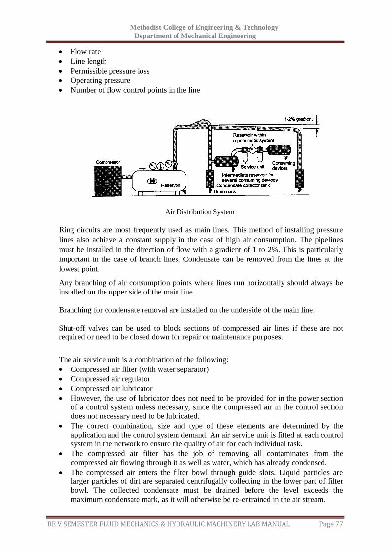
Methodist College of Engineering & Technology
Department of Mechanical Engineering
BE V SEMESTER FLUID MECHANICS & HYDRAULIC MACHINERY LAB MANUAL Page 77
Flow rate
Line length
Permissible pressure loss
Operating pressure
Number of flow control points in the line
Ring circuits are most frequently used as main lines. This method of installing pressure
lines also achieve a constant supply in the case of high air consumption. The pipelines
must be installed in the direction of flow with a gradient of 1 to 2%. This is particularly
important in the case of branch lines. Condensate can be removed from the lines at the
lowest point.
Any branching of air consumption points where lines run horizontally should always be
installed on the upper side of the main line.
Branching for condensate removal are installed on the underside of the main line.
Shut-off valves can be used to block sections of compressed air lines if these are not
required or need to be closed down for repair or maintenance purposes.
The air service unit is a combination of the following:
Compressed air filter (with water separator)
Compressed air regulator
Compressed air lubricator
However, the use of lubricator does not need to be provided for in the power section
of a control system unless necessary, since the compressed air in the control section
does not necessary need to be lubricated.
The correct combination, size and type of these elements are determined by the
application and the control system demand. An air service unit is fitted at each control
system in the network to ensure the quality of air for each individual task.
The compressed air filter has the job of removing all contaminates from the
compressed air flowing through it as well as water, which has already condensed.
The compressed air enters the filter bowl through guide slots. Liquid particles are
larger particles of dirt are separated centrifugally collecting in the lower part of filter
bowl. The collected condensate must be drained before the level exceeds the
maximum condensate mark, as it will otherwise be re-entrained in the air stream.
Air Distribution System
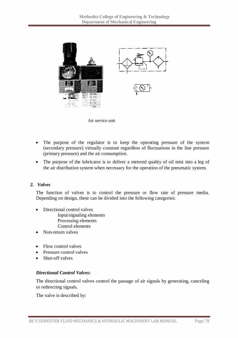
Methodist College of Engineering & Technology
Department of Mechanical Engineering
BE V SEMESTER FLUID MECHANICS & HYDRAULIC MACHINERY LAB MANUAL Page 78
The purpose of the regulator is to keep the operating pressure of the system
(secondary pressure) virtually constant regardless of fluctuations in the line pressure
(primary pressure) and the air consumption.
The purpose of the lubricator is to deliver a metered quality of oil mist into a leg of
the air distribution system when necessary for the operation of the pneumatic system.
2. Valves
The function of valves is to control the pressure or flow rate of pressure media.
Depending on design, these can be divided into the following categories:
Directional control valves
Input/signaling elements
Processing elements
Control elements
Non-return valves
Flow control valves
Pressure control valves
Shut-off valves
Directional Control Valves:
The directional control valves control the passage of air signals by generating, canceling
or redirecting signals.
The valve is described by:
Air service unit
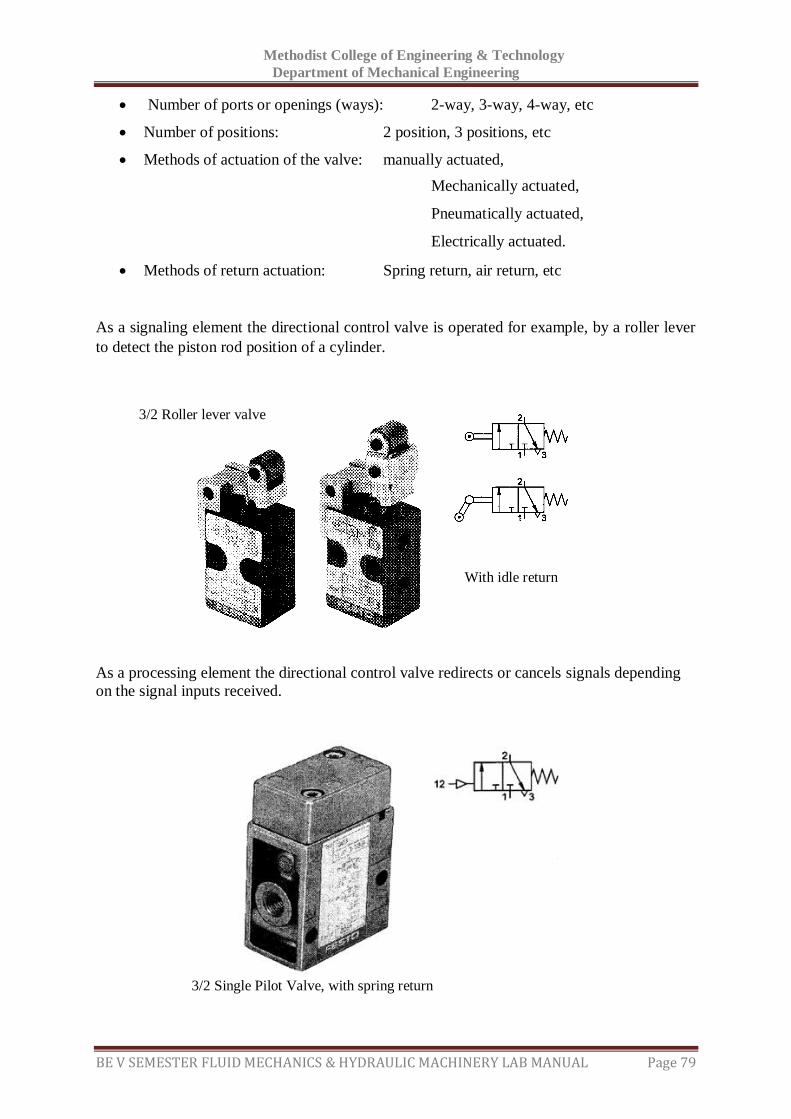
Methodist College of Engineering & Technology
Department of Mechanical Engineering
BE V SEMESTER FLUID MECHANICS & HYDRAULIC MACHINERY LAB MANUAL Page 79
Number of ports or openings (ways): 2-way, 3-way, 4-way, etc
Number of positions: 2 position, 3 positions, etc
Methods of actuation of the valve: manually actuated,
Mechanically actuated,
Pneumatically actuated,
Electrically actuated.
Methods of return actuation: Spring return, air return, etc
As a signaling element the directional control valve is operated for example, by a roller lever
to detect the piston rod position of a cylinder.
As a processing element the directional control valve redirects or cancels signals depending
on the signal inputs received.
3/2 Single Pilot Valve, with spring return
With idle return
3/2 Roller lever valve
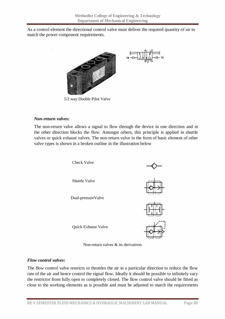
Methodist College of Engineering & Technology
Department of Mechanical Engineering
BE V SEMESTER FLUID MECHANICS & HYDRAULIC MACHINERY LAB MANUAL Page 80
As a control element the directional control valve must deliver the required quantity of air to
match the power component requirements.
Non-return valves:
The non-return valve allows a signal to flow through the device in one direction and in
the other direction blocks the flow. Amongst others, this principle is applied in shuttle
valves or quick exhaust valves. The non-return valve in the form of basic element of other
valve types is shown in a broken outline in the illustration below
Non-return valves & its derivatives
Flow control valves:
The flow control valve restricts or throttles the air in a particular direction to reduce the flow
rate of the air and hence control the signal flow. Ideally it should be possible to infinitely vary
the restrictor from fully open to completely closed. The flow control valve should be fitted as
close to the working elements as is possible and must be adjusted to match the requirements
5/2 way Double Pilot Valve
Check Valve
Shuttle Valve
Dual-pressureValve
Quick Exhaust Valve
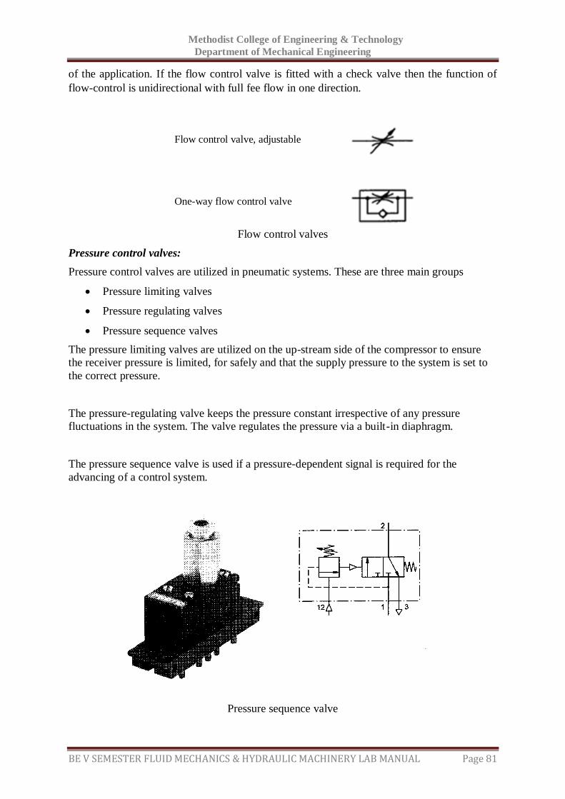
Methodist College of Engineering & Technology
Department of Mechanical Engineering
BE V SEMESTER FLUID MECHANICS & HYDRAULIC MACHINERY LAB MANUAL Page 81
of the application. If the flow control valve is fitted with a check valve then the function of
flow-control is unidirectional with full fee flow in one direction.
Flow control valves
Pressure control valves:
Pressure control valves are utilized in pneumatic systems. These are three main groups
Pressure limiting valves
Pressure regulating valves
Pressure sequence valves
The pressure limiting valves are utilized on the up-stream side of the compressor to ensure
the receiver pressure is limited, for safely and that the supply pressure to the system is set to
the correct pressure.
The pressure-regulating valve keeps the pressure constant irrespective of any pressure
fluctuations in the system. The valve regulates the pressure via a built-in diaphragm.
The pressure sequence valve is used if a pressure-dependent signal is required for the
advancing of a control system.
Pressure sequence valve
Flow control valve, adjustable
One-way flow control valve

Methodist College of Engineering & Technology
Department of Mechanical Engineering
BE V SEMESTER FLUID MECHANICS & HYDRAULIC MACHINERY LAB MANUAL Page 82
When the applied control signal reaches the set pressure, the3/2-way valve incorporated at
this point is actuated. Conversely, the valve reverses, if the control signal falls below the set
pressure.
Combination valves:
The combined functions of various elements can produce a new function. An example is the
time delay valve, which is the combination of a one-way flow control valve, a reservoir and a
3/2-way directional control valve.
Depending on the setting of the throttling screw, a greater or lesser amount of air flows per
unit of time into the air reservoir. When the necessary control pressure has built-up, the valve
switches to through flow. This switching position is maintained for as long as the control
signal is applied.
Other combinational valves include the
Two-hand start unit.
Pulse generator.
Stepper modules
Memory modules
3. Processing elements (processors):
To support the directional control valves at the processing level, there are various elements,
which condition the control signals for a task. The elements are:
Dual pressure valve (AND function)
Shuttle valve (OR function)
A shuttle valve permits the combination of two input signals into an OR function. The OR
gate has two inputs and one output. An output signal is generated, if pressure is applied at one
of the two inputs.
Time Delay Valve
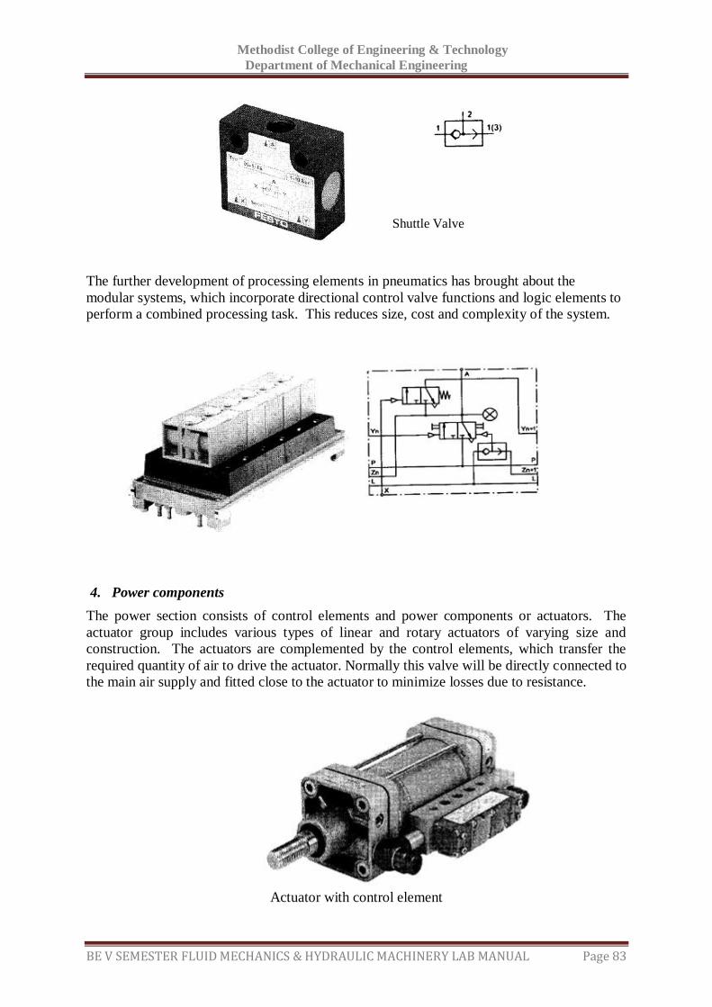
Methodist College of Engineering & Technology
Department of Mechanical Engineering
BE V SEMESTER FLUID MECHANICS & HYDRAULIC MACHINERY LAB MANUAL Page 83
The further development of processing elements in pneumatics has brought about the
modular systems, which incorporate directional control valve functions and logic elements to
perform a combined processing task. This reduces size, cost and complexity of the system.
4. Power components
The power section consists of control elements and power components or actuators. The
actuator group includes various types of linear and rotary actuators of varying size and
construction. The actuators are complemented by the control elements, which transfer the
required quantity of air to drive the actuator. Normally this valve will be directly connected to
the main air supply and fitted close to the actuator to minimize losses due to resistance.
Actuator with control element
Shuttle Valve
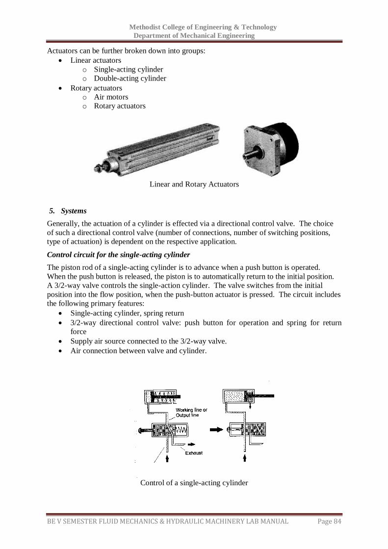
Methodist College of Engineering & Technology
Department of Mechanical Engineering
BE V SEMESTER FLUID MECHANICS & HYDRAULIC MACHINERY LAB MANUAL Page 84
Actuators can be further broken down into groups:
Linear actuators
o Single-acting cylinder
o Double-acting cylinder
Rotary actuators
o Air motors
o Rotary actuators
Linear and Rotary Actuators
5. Systems
Generally, the actuation of a cylinder is effected via a directional control valve. The choice
of such a directional control valve (number of connections, number of switching positions,
type of actuation) is dependent on the respective application.
Control circuit for the single-acting cylinder
The piston rod of a single-acting cylinder is to advance when a push button is operated.
When the push button is released, the piston is to automatically return to the initial position.
A 3/2-way valve controls the single-action cylinder. The valve switches from the initial
position into the flow position, when the push-button actuator is pressed. The circuit includes
the following primary features:
Single-acting cylinder, spring return
3/2-way directional control valve: push button for operation and spring for return
force
Supply air source connected to the 3/2-way valve.
Air connection between valve and cylinder.
Control of a single-acting cylinder
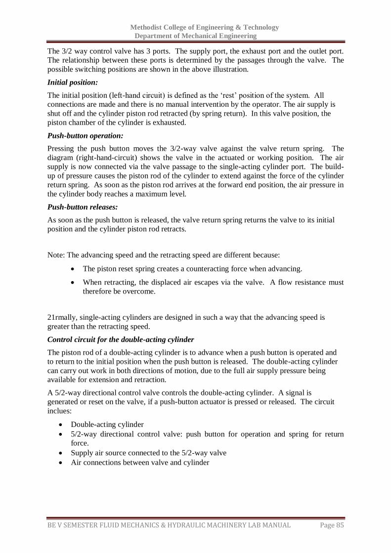
Methodist College of Engineering & Technology
Department of Mechanical Engineering
BE V SEMESTER FLUID MECHANICS & HYDRAULIC MACHINERY LAB MANUAL Page 85
The 3/2 way control valve has 3 ports. The supply port, the exhaust port and the outlet port.
The relationship between these ports is determined by the passages through the valve. The
possible switching positions are shown in the above illustration.
Initial position:
The initial position (left-hand circuit) is defined as the ‘rest’ position of the system. All
connections are made and there is no manual intervention by the operator. The air supply is
shut off and the cylinder piston rod retracted (by spring return). In this valve position, the
piston chamber of the cylinder is exhausted.
Push-button operation:
Pressing the push button moves the 3/2-way valve against the valve return spring. The
diagram (right-hand-circuit) shows the valve in the actuated or working position. The air
supply is now connected via the valve passage to the single-acting cylinder port. The build-
up of pressure causes the piston rod of the cylinder to extend against the force of the cylinder
return spring. As soon as the piston rod arrives at the forward end position, the air pressure in
the cylinder body reaches a maximum level.
Push-button releases:
As soon as the push button is released, the valve return spring returns the valve to its initial
position and the cylinder piston rod retracts.
Note: The advancing speed and the retracting speed are different because:
The piston reset spring creates a counteracting force when advancing.
When retracting, the displaced air escapes via the valve. A flow resistance must
therefore be overcome.
21rmally, single-acting cylinders are designed in such a way that the advancing speed is
greater than the retracting speed.
Control circuit for the double-acting cylinder
The piston rod of a double-acting cylinder is to advance when a push button is operated and
to return to the initial position when the push button is released. The double-acting cylinder
can carry out work in both directions of motion, due to the full air supply pressure being
available for extension and retraction.
A 5/2-way directional control valve controls the double-acting cylinder. A signal is
generated or reset on the valve, if a push-button actuator is pressed or released. The circuit
inclues:
Double-acting cylinder
5/2-way directional control valve: push button for operation and spring for return
force.
Supply air source connected to the 5/2-way valve
Air connections between valve and cylinder
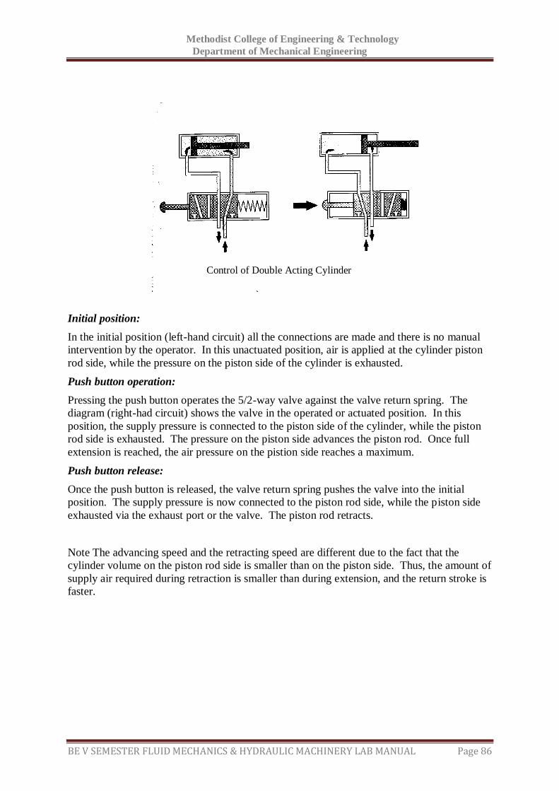
Methodist College of Engineering & Technology
Department of Mechanical Engineering
BE V SEMESTER FLUID MECHANICS & HYDRAULIC MACHINERY LAB MANUAL Page 86
Initial position:
In the initial position (left-hand circuit) all the connections are made and there is no manual
intervention by the operator. In this unactuated position, air is applied at the cylinder piston
rod side, while the pressure on the piston side of the cylinder is exhausted.
Push button operation:
Pressing the push button operates the 5/2-way valve against the valve return spring. The
diagram (right-had circuit) shows the valve in the operated or actuated position. In this
position, the supply pressure is connected to the piston side of the cylinder, while the piston
rod side is exhausted. The pressure on the piston side advances the piston rod. Once full
extension is reached, the air pressure on the pistion side reaches a maximum.
Push button release:
Once the push button is released, the valve return spring pushes the valve into the initial
position. The supply pressure is now connected to the piston rod side, while the piston side
exhausted via the exhaust port or the valve. The piston rod retracts.
Note The advancing speed and the retracting speed are different due to the fact that the
cylinder volume on the piston rod side is smaller than on the piston side. Thus, the amount of
supply air required during retraction is smaller than during extension, and the return stroke is
faster.
Control of Double Acting Cylinder

Methodist College of Engineering & Technology
Department of Mechanical Engineering
BE V SEMESTER FLUID MECHANICS & HYDRAULIC MACHINERY LAB MANUAL Page 87
RESULT & CONCLUSIONS:
Methodist College of Engineering & Technology
Department of Mechanical Engineering
BE V SEMESTER FLUID MECHANICS & HYDRAULIC MACHINERY LAB MANUAL Page 88
VIVA QUESTIONS:
1. What is the function of a pneumatic valve?
2. How do you classify pneumatic valves?
3. What is the function of a Direction control valve?
4. What are functions of a check valve?
5. What is the last element in pneumatic circuit?
6. What is the operating cost of pneumatic circuit when compared with the hydraulic
circuit?
7. What are the components of a pneumatic circuit ?
Methodist College of Engineering & Technology
Department of Mechanical Engineering
BE V SEMESTER FLUID MECHANICS & HYDRAULIC MACHINERY LAB MANUAL Page 89
EXPERIMENT - 12
STUDY OF HYDRAULIC CIRCUITS
AIM:
To study the componenets of pneumatic circuit.
THEORY:
The application of circuits in Industrial Control Systems and Machine Tools using Hydraulic
Components are innumerable.
Here follow few of such circuits within scope of components supplied with the trainer.
Accompanying circuit diagrams are self explanatory. The 'T' branch connections are shown
where they actually exist. Thus. Students need not interpreted the diagrams and correlate with
actual components on the board. Only thing the student to do is, connect the pipes as shown
in diagram and complete the experiment.
1. Study of 4 / 3 Way Tandem Center Direction Control Valve
Connect components as per circuit diagram. At the central position of the direction control
valve pressurized oil will be bypassed to reservoir, thus no pressure will be developed.
When spool of direction valve is shifted in front oil will flow from 'P' port to 'A' of
Direction Control valve. 'B' port will be connected to drain port 'T'. Rod of double acting
cylinder will extend on one side and when reaches extreme position it will stop. Now full
system pressure will be built-up and relief valve will release the oil pressure. When Spool
of direction valve is shifted in back position the cylinder rod will retract reversibly in the
same manner as explained above.
As single shaft extension cylinder is used velocities in both directions will be unequal and
inversely proportional to areas on both sides. Force will develop upon the pressure setting
of relief valve and piston area.
Study of Pressure Relief Valve
Connect components as per circuit diagram. At the central position of the direction control
valve pressurized oil will be bypassed to reservoir, thus no pressure will be developed.
When spool of direction valve is shifted in front oil will flow from 'P' port to 'A' of
Direction Control valve. 'B' port will be connected to drain port' T' rod of double acting
cylinder will extend on one side and when reaches extreme position it will stop. When
Spool of direction valve is shifted in back position the cylinder rod will retract in the same
manner as explained above.
Observe the speed of the piston rod of cylinder in both the operation above.
Now, reduce the pressure setting on the Pressure Relief Valve, by rotating the knob
anticlockwise direction and repeat the procedure as above.
It is noticed that the speed of the cylinder decreases in both forward and reverse direction
due to decrease in flow of oil to it. This is due to the reason that most of the oil received
Methodist College of Engineering & Technology
Department of Mechanical Engineering
BE V SEMESTER FLUID MECHANICS & HYDRAULIC MACHINERY LAB MANUAL Page 90
from the pump is being bypassed or bleed off to the reservoir tank by the 'T' port of the
Pressure Relief Valve.
Study of Operation/Speed Control of Double Acting Cylinder
Repeat the procedure same as mentioned in the Circuit No.1. The cylinder extend and
retract position is observed.
Now, for Speed Control follow the procedure given below.
Increase the flow of oil by rotating the knob of Flow Control Valve in anticlockwise
Direction, the speed of the Cylinder increases both in the forward and reverse direction.
Now, Decrease the flow of oil by rotating the knob of Flow Control Valve in Clockwise
Direction, the speed of the cylinder decreases both in the forward and reverse direction.
Study of Meter-In Circuit:
If supplied fluid rate to cylinder is controlled by any type of flow control valve, it is called
as Meter In type Flow Control Circuit.
For this, select the hose with the Throttle Check valve fitted inline. Connect the same to
the port 'A' of the Double acting cylinder as shown in the circuit. Check the symbol
marked on the valve. Connect the port, 'B' by another ordinary hose.
Due to this type of circuit the flow of oil going to the cylinder can be increased or
decreased and the speed of the cylinder in forward stroke can be increased or decreased.
Study of Meter Out Circuit:
If the flow rate of Oil coming out or returning from the cylinder is controlled, it is called
as Meter Out type circuit. This is to be done by connecting the hose with Throttle check
valve to the port 'B' of the cylinder. By adjusting the sleeve of the throttle check valve
flow rate can be changed. In this case the speed of retraction can be increased or
decreased.

Methodist College of Engineering & Technology
Department of Mechanical Engineering
BE V SEMESTER FLUID MECHANICS & HYDRAULIC MACHINERY LAB MANUAL Page 91
RESULT & CONCLUSIONS:
Methodist College of Engineering & Technology
Department of Mechanical Engineering
BE V SEMESTER FLUID MECHANICS & HYDRAULIC MACHINERY LAB MANUAL Page 92
VIVA QUESTIONS:
1. What are the basic components of Hydraulic Circuit?
2. What is meant by an actuator? How it is used?
3. What are the various types of pumps used in hydraulic circuit?
4. What are the properties of oils used in hydraulic system?
5. What are the applications of Hydraulic System?
6. What is the use of pressure regulating valve?
7. What are the various types of valves used in hydraulic circuit?
Methodist College of Engineering & Technology
Department of Mechanical Engineering
BE V SEMESTER FLUID MECHANICS & HYDRAULIC MACHINERY LAB MANUAL Page 93
EXPERIMENT - 13
STUDY OF POSITIVE DISPALCEMENT AND ROTO DYNAMIC
PUMPS
AIM:
To study the positive displacement and roto dynamic pumps with the help of models.
THEORY:
Pump is a hydraulic Machine which converts Mechanical energy into Hydraulic energy.
Pumps are mainly classified into two types viz., Positive displacement pumps and roto
dynamic pumps.
Positive displacement pump:
A positive displacement (PD) pump moves a fluid by repeatedly enclosing a fixed volume
and moving it mechanically through the system. The pumping action is cyclic and can be
driven by pistons, screws, gears, rollers, diaphragms or vanes.
Reciprocating positive displacement pumps:
A Reciprocating Positive Displacement pump works by the repeated back-and-forth
movement (strokes) of either a piston, plunger or diaphragm (Figure 1). These cycles are
called reciprocation.
In a piston pump, the first stroke of the piston creates a vacuum, opens an inlet valve,
closes the outlet valve and draws fluid into the piston chamber (the suction phase). As the
motion of the piston reverses, the inlet valve, now under pressure, is closed and the outlet
valve opens allowing the fluid contained in the piston chamber to be discharged (the
compression phase). The bicycle pump is a simple example. Piston pumps can also be
double acting with inlet and outlet valves on both sides of the piston. While the piston is
in suction on one side, it is in compression on the other. More complex, radial versions
are often used in industrial applications.
Plunger pumps operate in a similar way. The volume of fluid moved by a piston pump
depends on the cylinder volume; in a plunger pump it depends on the plunger size. The
seal around the piston or plunger is important to maintain the pumping action and to
avoid leaks. In general, a plunger pump seal is easier to maintain since it is stationary at
the top of the pump cylinder whereas the seal around a piston is repeatedly moving up
and down inside the pump chamber.
A diaphragm pump uses a flexible membrane instead of a piston or plunger to move
fluid. By expanding the diaphragm, the volume of the pumping chamber is increased and
fluid is drawn into the pump. Compressing the diaphragm decreases the volume and
expels some fluid. Diaphragm pumps have the advantage of being hermetically sealed
systems making them ideal for pumping hazardous fluids.
The cyclic action of reciprocating pumps creates pulses in the discharge with the fluid
accelerating during the compression phase and slowing during the suction phase. This
can cause damaging vibrations in the installation and often some form of damping or
smoothing is employed. Pulsing can also be minimized by using two (or more) pistons,
plungers or diaphragms with one in its compression phase whilst the other is in suction.
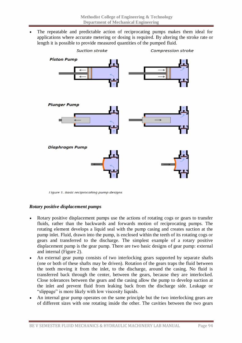
Methodist College of Engineering & Technology
Department of Mechanical Engineering
BE V SEMESTER FLUID MECHANICS & HYDRAULIC MACHINERY LAB MANUAL Page 94
The repeatable and predictable action of reciprocating pumps makes them ideal for
applications where accurate metering or dosing is required. By altering the stroke rate or
length it is possible to provide measured quantities of the pumped fluid.
Rotary positive displacement pumps
Rotary positive displacement pumps use the actions of rotating cogs or gears to transfer
fluids, rather than the backwards and forwards motion of reciprocating pumps. The
rotating element develops a liquid seal with the pump casing and creates suction at the
pump inlet. Fluid, drawn into the pump, is enclosed within the teeth of its rotating cogs or
gears and transferred to the discharge. The simplest example of a rotary positive
displacement pump is the gear pump. There are two basic designs of gear pump: external
and internal (Figure 2).
An external gear pump consists of two interlocking gears supported by separate shafts
(one or both of these shafts may be driven). Rotation of the gears traps the fluid between
the teeth moving it from the inlet, to the discharge, around the casing. No fluid is
transferred back through the center, between the gears, because they are interlocked.
Close tolerances between the gears and the casing allow the pump to develop suction at
the inlet and prevent fluid from leaking back from the discharge side. Leakage or
“slippage” is more likely with low viscosity liquids.
An internal gear pump operates on the same principle but the two interlocking gears are
of different sizes with one rotating inside the other. The cavities between the two gears
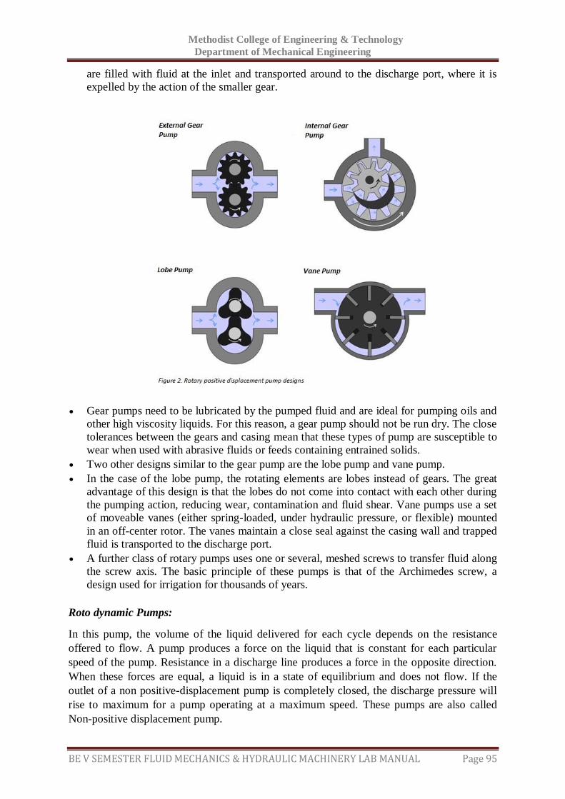
Methodist College of Engineering & Technology
Department of Mechanical Engineering
BE V SEMESTER FLUID MECHANICS & HYDRAULIC MACHINERY LAB MANUAL Page 95
are filled with fluid at the inlet and transported around to the discharge port, where it is
expelled by the action of the smaller gear.
Gear pumps need to be lubricated by the pumped fluid and are ideal for pumping oils and
other high viscosity liquids. For this reason, a gear pump should not be run dry. The close
tolerances between the gears and casing mean that these types of pump are susceptible to
wear when used with abrasive fluids or feeds containing entrained solids.
Two other designs similar to the gear pump are the lobe pump and vane pump.
In the case of the lobe pump, the rotating elements are lobes instead of gears. The great
advantage of this design is that the lobes do not come into contact with each other during
the pumping action, reducing wear, contamination and fluid shear. Vane pumps use a set
of moveable vanes (either spring-loaded, under hydraulic pressure, or flexible) mounted
in an off-center rotor. The vanes maintain a close seal against the casing wall and trapped
fluid is transported to the discharge port.
A further class of rotary pumps uses one or several, meshed screws to transfer fluid along
the screw axis. The basic principle of these pumps is that of the Archimedes screw, a
design used for irrigation for thousands of years.
Roto dynamic Pumps:
In this pump, the volume of the liquid delivered for each cycle depends on the resistance
offered to flow. A pump produces a force on the liquid that is constant for each particular
speed of the pump. Resistance in a discharge line produces a force in the opposite direction.
When these forces are equal, a liquid is in a state of equilibrium and does not flow. If the
outlet of a non positive-displacement pump is completely closed, the discharge pressure will
rise to maximum for a pump operating at a maximum speed. These pumps are also called
Non-positive displacement pump.
Methodist College of Engineering & Technology
Department of Mechanical Engineering
BE V SEMESTER FLUID MECHANICS & HYDRAULIC MACHINERY LAB MANUAL Page 96
Types of roto dynamic pumps:
Rotodynamic pumps can be classified on various factors such as design, construction, applications, service etc.
According to the types of stages:
o Single stage pumps:
It is known as single impeller pump.
It is simple in design and easy in maintenance.
It is ideal for large flow rates and low pressure installations.
o Two stage pump:
It has two impellers operating side by side.
It is used for medium use applications.
o Multistage Pumps:
It has three or more impellers in series.
They are used for high head applications.
According to the type of case – split:
o Axial split:
In these types of pumps the volute casing is split axially and split line at which
the pump casing separates is at the shaft’s center – line.
They are typically mounted horizontally due to ease in installation and
maintenance.
o Radial split:
In it pump case is split radially, the volute casing split is perpendicular to shaft
centre line.
According to the types of impeller design.
o Single suction:
It has single suction impeller which allows fluid to enter blades only through a
single opening.
It has a simple design but the impeller has higher axial thrust imbalance due to
flow coming through one side of impeller.
o Double Suction:
It has double suction impeller which allows fluid to enter from both the sides of
blades.
They are most common types of pumps.
According to the type of volute:
o Single volute pump:
It is usually used for low capacity pumps, as it has small volute size.
Small size volute casting is difficult but is good in quality.
They have higher radial loads.
o Double volute pump:
It has two volutes which are placed 180 degrees apart.
It has a good capability of balancing radial loads.
It is the most common design used.
According to the shaft orientation:
o Horizontal Centrifugal pumps:
Easily available.
Easy to install, inspect, maintain and service.

Methodist College of Engineering & Technology
Department of Mechanical Engineering
BE V SEMESTER FLUID MECHANICS & HYDRAULIC MACHINERY LAB MANUAL Page 97
It is suitable for low pressure.
o Vertical Centrifugal pumps:
Requires large headroom for installation, servicing and maintenance.
It can easily withstand higher pressure loads.
It is more expensive than horizontal pumps.
Centrifugal pump is the most commonly used roto dynamic pump.

Methodist College of Engineering & Technology
Department of Mechanical Engineering
BE V SEMESTER FLUID MECHANICS & HYDRAULIC MACHINERY LAB MANUAL Page 98
RESULT & CONCLUSIONS:
Methodist College of Engineering & Technology
Department of Mechanical Engineering
BE V SEMESTER FLUID MECHANICS & HYDRAULIC MACHINERY LAB MANUAL Page 99
VIVA QUESTIONS:
What is priming of a pump?
Why it is necessary to prime a pump?
What are the main parts of a centrifugal pump?
Distinguish between the positive and non-positive displacement pumps.
The centrifugal pump acts as a ---- reverse of an inward radial flow reaction turbine
Define pumps?
Define a centrifugal pump?
Classify hydraulic pumps.
What is an air vessel?
What do you understand by single acting & double acting pump?
Define slip of a pump?
Define a reciprocating pump?
What are the main parts of the reciprocating pump?
Define indicator diagram.

Approved by AICTE New Delhi | Affiliated to Osmania University, Hyderabad
Abids, Hyderabad, Telangana, 500001
METHODISTCOLLEGE OF ENGINEERING & TECHNOLOGY
Estd: 2008
Related Documents