1111-6185912-rev.1 FAST S.p.A. 3 SELECTION, INSTALLATION, USE AND MAINTENANCE MANUAL FM Series Air handling units Air flow from 900 to 95.000 m³/h AHU N° 04.07.051 Range FM

Welcome message from author
This document is posted to help you gain knowledge. Please leave a comment to let me know what you think about it! Share it to your friends and learn new things together.
Transcript

1111
-618
5912
-rev
.1
FAST S.p.A.
3
SELECTION, INSTALLATION, USE
AND MAINTENANCE MANUAL
FM SeriesAir handling units
Air fl ow from 900 to 95.000 m³/h
AHU N° 04.07.051
Range FM

Information about documentation 4
Basic Safety Rules 4
Identification 5
Unit description 6
Technical Data 7
Component description 9
Filtration 11
Coil 16
Humidification 20
Fan sections 21
Motors 23
Silencers 24
Heat recovery unit 24
Empty sections 24
Multizone 24
Dimensions 25
Transport and handling 41
Installation 41
Connections 44
First start-up checks 49
Maintenance 50
Disposal 51
Index English
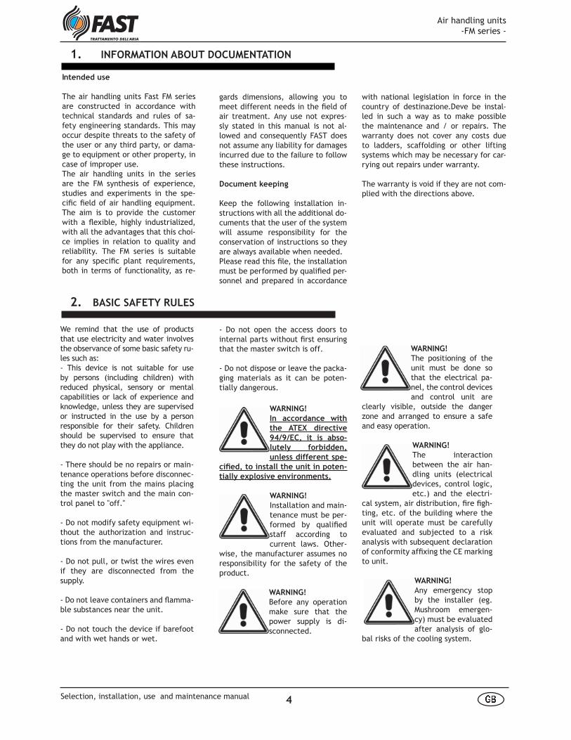
WARNING!
The positioning of the unit must be done so that the electrical pa-nel, the control devices and control unit are
clearly visible, outside the danger zone and arranged to ensure a safe and easy operation.
WARNING!
The interaction between the air han-dling units (electrical devices, control logic, etc.) and the electri-
cal system, air distribution, fi re fi gh-ting, etc. of the building where the unit will operate must be carefully evaluated and subjected to a risk analysis with subsequent declaration of conformity affi xing the CE marking to unit.
WARNING!
Any emergency stop by the installer (eg. Mushroom emergen-cy) must be evaluated after analysis of glo-
bal risks of the cooling system.
- Do not open the access doors to internal parts without fi rst ensuring that the master switch is off.
- Do not dispose or leave the packa-ging materials as it can be poten-tially dangerous.
WARNING!
In accordance with
the ATEX directive
94/9/EC, it is abso-
lutely forbidden,
unless different spe-
cifi ed, to install the unit in poten-
tially explosive environments.
WARNING!
Installation and main-tenance must be per-formed by qualifi ed staff according to current laws. Other-
wise, the manufacturer assumes no responsibility for the safety of the product.
WARNING!
Before any operation make sure that the power supply is di-sconnected.
1. INFORMATION ABOUT DOCUMENTATION
Intended use
The air handling units Fast FM series are constructed in accordance with technical standards and rules of sa-fety engineering standards. This may occur despite threats to the safety of the user or any third party, or dama-ge to equipment or other property, in case of improper use.The air handling units in the series are the FM synthesis of experience, studies and experiments in the spe-cifi c fi eld of air handling equipment. The aim is to provide the customer with a fl exible, highly industrialized, with all the advantages that this choi-ce implies in relation to quality and reliability. The FM series is suitable for any specifi c plant requirements, both in terms of functionality, as re-
We remind that the use of products that use electricity and water involves the observance of some basic safety ru-les such as:- This device is not suitable for use by persons (including children) with reduced physical, sensory or mental capabilities or lack of experience and knowledge, unless they are supervised or instructed in the use by a person responsible for their safety. Children should be supervised to ensure that they do not play with the appliance.
- There should be no repairs or main-tenance operations before disconnec-ting the unit from the mains placing the master switch and the main con-trol panel to "off."
- Do not modify safety equipment wi-thout the authorization and instruc-tions from the manufacturer.
- Do not pull, or twist the wires even if they are disconnected from the supply.
- Do not leave containers and fl amma-ble substances near the unit.
- Do not touch the device if barefoot and with wet hands or wet.
2. BASIC SAFETY RULES
gards dimensions, allowing you to meet different needs in the fi eld of air treatment. Any use not expres-sly stated in this manual is not al-lowed and consequently FAST does not assume any liability for damages incurred due to the failure to follow these instructions.
Document keeping
Keep the following installation in-structions with all the additional do-cuments that the user of the system will assume responsibility for the conservation of instructions so they are always available when needed.Please read this fi le, the installation must be performed by qualifi ed per-sonnel and prepared in accordance
with national legislation in force in the country of destinazione.Deve be instal-led in such a way as to make possible the maintenance and / or repairs. The warranty does not cover any costs due to ladders, scaffolding or other lifting systems which may be necessary for car-rying out repairs under warranty.
The warranty is void if they are not com-plied with the directions above.
Air handling units -FM series -
4� �Selection, installation, use and maintenance manual

- available static pressure of supply and exhaust (if any) fans;- power and n° of poles of fan electric motors;- voltage, number of phases and cycles of the fan motors.
Each air handling unit is identifi ed by a se-rial number.This serial number is marked on the plate placed on the inspection door of the sup-ply fan section.On the same plate are indicated also:- air handling unit model;- supply and exhaust ( if any ) fan air fl ow;
3. IDENTIFICATION
XXXX� � � � � � � � � � � � �� � � � � � � � � � � � � � � � � � � � � � � � � � � � � � � � � � � � � � � � � � � � � � � � � ! " # $ % & & & & ' ( � � ) * � � � � + , ' - . '! , / # 0 % 1 2 2 23 4 5 6 7 5 8 7 5 9 3 : ; 1 2 2� � � � � ' � � � � � � � � ' + �< = > ? @ A B C @ D @E @ F G @ H I J K L M N L L O M K MP L M M
Necessary supply and room conditions for installation:
Operating voltage ±10% than nominal voltage (EN 60204)
Frequency ±1% constant frequency ±2% for a short period (EN 60204)
Operating room temperature 5-40°C (EN 60204)
Operating room humidity From 30% to 95%, without condensation or icing (EN 60204)
Altitude Up to 1000 m above sea level (EN 60204)
Q R S T U VW X Y Y XZ [ W \ [ ] ^Z ^ _ X Y X ` a X b ] ` X _ _ c ^ d ] e fZ X d a _ g ` h f b g ` h f f X c ^ d ] e f i jk l m n o p nq m r s k l m n o p n
The identifi cation of the air handling unit through the serial number is man-datory to semplify the data search and give fast answers to the customer.
WARNING!
The logic of opening / closing of the dampers (if any) should be designed in such a way that does not lead to the central are-
as of excessive over-pressure / vacuum resulting in damage to the components of the plant itself or to the people and animals.
WARNING!
Keep the electrical panel and wiring away from elec-tric and magnetic fi elds which may interfere with type inverter, power sup-
ply line of heavy loads, etc.
WARNING!
Do not block the air ope-ning vents.Do not connect and di-sconnect any remote terminal with the exi-
sting power.
Air handling units -FM series -
5� �
Selection, installation, use and maintenance manual

4. UNIT DESCRIPTION
The new air handling units structure presents a new softer and ergonomic line made of aluminium profi les with both externally and internally rounded edges. It is so possible to avoid internal dust heaps, typical of the sharp edges, with better quality and healthier treated air making also easier the unit cleaning.The FM series includes the following characteristics:- self supporting structure with aluminium framework and fiberglass reinforced nylon;
- unified panels with real thickness of 50 mm, manufactured with the most qualified materials (galvanized sheets, galvanized prepainted sheets, aluminium alloy, stainless steel) and injected poliurethane and rockwool for the insulation panel;- innovat ive systems for a i r humidifi cation with particular care of the air salubrity, to avoid developing of moulds and bacteria, and paying attention to the waste of water;
- all the components are inside the casing and therefore the treated airflow is completely separated from the external weather conditions that could penalize functions and performances of the air handling units;- a wide range of accessories and executions are provided to give to the custom an immediate view and check of all operating conditions of the air handling units.
t u v wt u x yt u w zt u w {t u | }t u ~ yt u � z w� ��� � �
� � � � � � � � � � � � � � � � � � � � � � � � � � � � � � � � � � � � � � �t u � vt u y zt u y ~t u v w� � � � � � � � � � � � � � � �
� � � � � ¡ ¢ £ ¤ � ¥ ¦ � § ¨ © ª« ¬ ®« ® ¬
¯ ° ± ² ³¯ ° ² ´ ±¯ ° ² µ ¶¯ ° · ² ¸¯ ° ¹ ´ ²¯ ° ¹ µ ´¯ ° ¸ ² º¯ ° µ ´ ¹¯ ° µ µ ±» ¼½¾¿ À
¶ ³ ¶ Á ¶ ¶ ¶ ² ¶ Á ¶ ¶ ¶ ¹ ¶ Á ¶ ¶ ¶ µ ¶ Á ¶ ¶ ¶ ´ ¶ ¶ Á ¶ ¶ ¶ ´ ³ ¶ Á ¶ ¶ ¶¯ ° ´ ´ º¯ ° ´ · ²¯ ° ´ º ²¯ ° ³ ± ¸¯ ° ³ µ ¹Â Ã Ä Å Æ Ç È É Å Ê Ë Ì Í Î Ï Ð
Ñ Ò Ó Ô Õ Õ Ô Ö × Ø Ù Ó Ú Û Ô Ü Ý Þ Õ ßà á â ãä ã á âMod
elM
odel
Air flow [m3/h]
Air flow [m3/h]
face velocity [m/s]
face velocity [m/s]
Air handling units -FM series -
6� �Selection, installation, use and maintenance manual

m/s for heating coils).The front dimensions and the lengths of the AHUs are modular according to a basic dimension of 160 mm (1/4 mo-dule), 320 mm (1/2 module) and 640 mm (1 module).Widths start from a single module up to a maximum of 7 modules.
5. TECHNICAL DATA
Dimensionsext.
Dimensionsint.
Coilssurface
Flow m3/s Flow m3/h INCR.
FM hm wm h w hi wi Face velocity [m/s] Face velocity [m/s]
mod mod mm mm mm mm m2 2,0 2,5 3 3,5 2,0 2,5 3,0 3,5
13 0,75 1 645 735 410 620 0,13 0,25 0,32 0,38 0,44 907 1.134 1.361 1.588
20 1 1 805 735 570 620 0,20 0,40 0,50 0,60 0,71 1.452 1.814 2.177 2.540 60,0%
28 1 1,25 805 895 570 780 0,28 0,56 0,70 0,84 0,97 2.004 2.506 3.007 3.508 38,1%
35 1 1,5 805 1055 570 940 0,35 0,70 0,87 1,04 1,22 2.506 3.132 3.758 4.385 25,0%
42 1 1,75 805 1215 570 1100 0,40 0,85 1,06 1,27 1,49 3.059 3.823 4.588 5.352 22,1%
50 1 2 805 1375 570 1260 0,50 1,00 1,25 1,50 1,76 3.612 4.514 5.417 6.320 18,1%
57 1,5 1,5 1125 1055 890 940 0,57 1,13 1,41 1,70 1,98 4.072 5.090 6.107 7.125 12,7%
69 1,5 1,75 1125 1215 890 1100 0,70 1,38 1,73 2,07 2,42 4.970 6.213 7.455 8.698 22,1%
82 1,5 2 1125 1375 890 1260 0,80 1,63 2,04 2,45 2,85 5.869 7.336 8.803 10.270 18,1%
105 1,5 2,5 1125 1695 890 1580 1,06 2,11 2,63 3,16 3,69 7.582 9.477 11.372 11.372 29,2%
119 2 2 1445 1375 1210 1260 1,20 2,38 2,98 3,57 4,17 8.577 10.722 12.866 15.010 13,1%
154 2 2,5 1445 1695 1210 1580 1,54 3,08 3,85 4,62 5,39 11.081 13.851 16.621 19.391 29,2%
194 2,5 2,5 1765 1695 1530 1580 1,93 3,89 4,86 5,83 6,80 13.997 17.496 20.995 24.494 26,3%
237 2,5 3 1765 2015 1530 1900 2,37 4,74 5,92 7,11 8,29 17.055 21.319 25.583 29.847 21,9%
286 3 3 2085 2015 1850 1900 2,86 5,72 7,16 8,59 10,02 20.609 25.761 30.913 36.065 20,8%
342 3 3,5 2085 2335 1850 2200 3,42 6,84 8,55 10,26 11,97 24.618 30.772 36.926 43.081 19,5%
413 3,5 3,5 2405 2335 2170 2200 4,13 8,25 10,32 12,38 14,44 29.711 37.139 44.566 51.994 20,7%
480 3,5 4 2405 2655 2170 2540 4,80 9,60 12,00 14,40 16,79 34.549 43.187 51.824 51.824 16,3%
547 3,5 4,5 2405 2975 2170 2860 5,47 10,94 13,68 16,41 19,15 39.388 49.235 59.081 68.928 14,0%
614 3,5 5 2405 3295 2170 3180 6,14 12,29 15,36 18,43 21,50 44.226 55.283 66.339 77.396 12,3%
681 3,5 5,5 2405 3615 2170 3500 6,81 13,63 17,04 20,44 23,85 49.064 61.331 73.597 85.863 10,9%
749 3,5 6 2405 3935 2170 3820 7,49 14,97 18,72 22,46 26,20 53.903 67.379 80.854 94.330 9,9%
816 3,5 6,5 2405 4255 2170 4140 8,16 16,32 20,40 24,48 28,55 58.741 73.427 88.112 88.112 9,0%
883 3,5 7 2405 4575 2170 4460 8,83 17,66 22,08 26,49 30,91 63.580 79.475 95.369 95.369 8,2%
Sizing of FM air handling units is based on a modular approach that permits the maxi-mum standardisation of components while offering a complete range of possible capa-cities.The selection of the the size shall be done in conformity to the air face velocity at coils (max 3 m/s for cooling coils and max 4
Heights are from a minimum of 0.75 modules to a maximum of 3.5 modu-les.
FM series is in compliance with EN1886 di-rective concerning mechanical resistance, air leakages, thermal performances and acoustic insulation.
The exact coupling between frame and panels allows to reach the air leakage va-lues according to the UNI EN 1886 leaka-ges, TÜV laboratories certified.
The declared performances are confirmed by EUROVENT certifica-tion.
In the table below are the technical data and dimensions of the 24 planned sizes for the FM central air handling.A module corresponds to a length of 640 mm.The table below shows:-Ahu size: FM code represents the dm2 of the coils front surface;- Nominal height of system in modules (hm);
-Nominal width of system in modules (wm);-Overall height of system including feet (h);-Overall width of system (w);-Internal height (hi);-Internal width (wi);-Face area of coils (S);-Flow in m3/s corresponding to face velo-
city on coils of 2, 2.5, 3 and 3.5 m/s;-Flow in m3/h corresponding to face velocity on coils of 2, 2.5, 3 and 3.5 m/s;- Percentage increase of the surface coil front and then the scale of size n compared to n-1.
Air handling units -FM series -
7� �
Selection, installation, use and maintenance manual
13
20
28
35
42
50
57
69
82
105
119
154
194
237
286
342
413
480
883
816
749
681
614
547
735
895
1055
1215
1375
1695
2015
2335
2655
2975
3295
3615
3935
4255
4575
645
525
805
685 1005
1125 1445 1765
1325 1645 1965
2085 2405
2285
11.25
1.5
1.75
22.5
33.5
44.5
55.5
66.5
7
Larghezza [m
m]
Larghezza m
odulare [m
oduli]
0.75 1 1.5 2 2.5 3 3.5 Altezza [moduli]
Altezza telaio [mm]
Altezza con piedini/basamento [mm]
A B C D
A: sovrapponibili per trasporto
B: trasportabili in containerlongitudinalmente
C: trasportabili in containertrasversalmente
D: trasportabili su autocarrolongitudinalmente
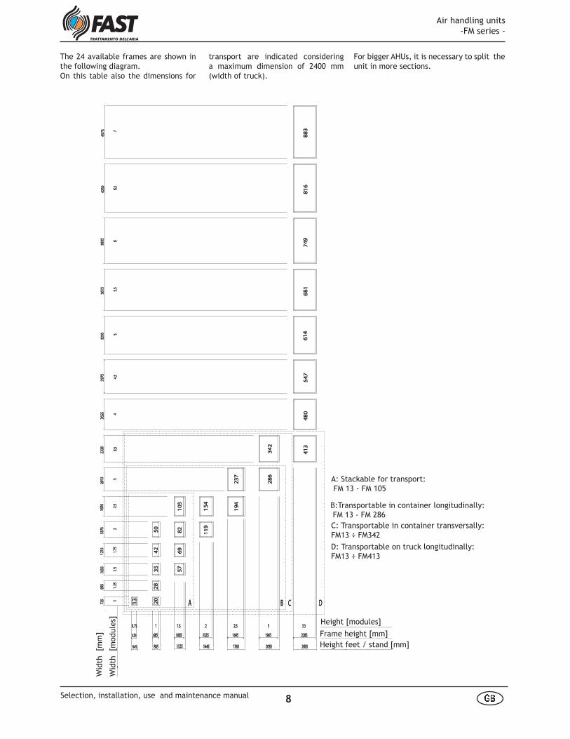
The 24 available frames are shown in the following diagram. On this table also the dimensions for
transport are indicated considering a maximum dimension of 2400 mm (width of truck).
For bigger AHUs, it is necessary to split the unit in more sections.
A: Stackable for transport: FM 13 - FM 105
B:Transportable in container longitudinally: FM 13 - FM 286C: Transportable in container transversally: FM13 ÷ FM342
D: Transportable on truck longitudinally:FM13 ÷ FM413
Height [modules]
Frame height [mm]
Height feet / stand [mm]
Wid
th [m
odul
es]
Wid
th [m
m]
Air handling units -FM series -
8� �Selection, installation, use and maintenance manual
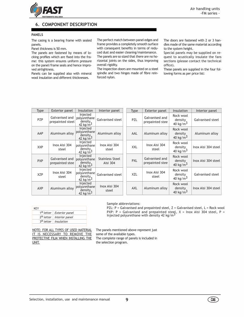
The doors are fastened with 2 or 3 han-dles made of the same material according to the system height. Special panels may be supplied on re-quest to acustically insulate the fans sections (please contact the technical offi ce). These panels are supplied in the four fol-lowing forms as per price list:
6. COMPONENT DESCRIPTION
The perfect match between panel edges and frame provides a completely smooth surface with consequent benefi ts in terms of redu-ced dust and easier cleaning/maintenance.The panels are so sized that there are no ho-rizontal joints on the sides, thus improving overall rigidity.The inspection doors are mounted on a steel spindle and two hinges made of fi bre rein-forced nylon.
Type Exterior panel Insulation Interior panel
PZPGalvanised and
prepainted steel
Injected polyurethane
density 42 kg/m3
Galvanised steel
AAP Aluminum alloy
Injectedpolyurethane
density42 kg/m3
Aluminum alloy
XXPInox Aisi 304
steel
Injectedpolyurethane
density42 kg/m3
Inox Aisi 304 steel
PXPGalvanised and prepainted stee
Injectedpolyurethane
density42 kg/m3
Stainless SteelAisi 304
XZPInox Aisi 304
steel
Injectedpolyurethane
density42 kg/m3
Galvanised steel
AXP Aluminum alloy
Injectedpolyurethane
density42 kg/m3
Inox Aisi 304 steel
KEY
1a letter Exterior panel
2a letter Interior panel
3a letter Insulation
PANELS
The casing is a bearing frame with sealed panels.Panel thickness is 50 mm.The panels are fastened by means of lo-cking profi les which are fi xed into the fra-me: this system ensures uniform pressure on the panel/frame seals and hence impro-ved airtightness. Panels can be supplied also with mineral wool insulation and different thicknesses.
Sample abbreviations:PZL: P = Galvanised and prepainted steel, Z = Galvanised steel, L = Rock woolPXP: P = Galvanised and prepainted steel, X = Inox Aisi 304 steel, P = Injected polyurethane with density 42 kg/m3
NOTE: FOR ALL TYPES OF USED MATERIAL IT IS NECESSARY TO REMOVE THE PROTECTIVE FILM WHEN INSTALLING THE UNIT.
The panels mentioned above represent just some of the available types.The complete range of panels is included in the selection program.
Type Exterior panel Insulation Interior panel
PZLGalvanised and prepainted stee
Rock wool density
40 kg/m3Galvanised steel
AAL Aluminum alloyRock wool
density40 kg/m3
Aluminum alloy
XXLInox Aisi 304
steel
Rock wool density
40 kg/m3Inox Aisi 304 steel
PXLGalvanised and prepainted stee
Rock wool density
40 kg/m3Inox Aisi 304 steel
XZLInox Aisi 304
steel
Rock wool density
40 kg/m3Galvanised steel
AXL Aluminum alloyRock wool
density40 kg/m3
Inox Aisi 304 steel
Air handling units -FM series -
9 å æSelection, installation, use and maintenance manual
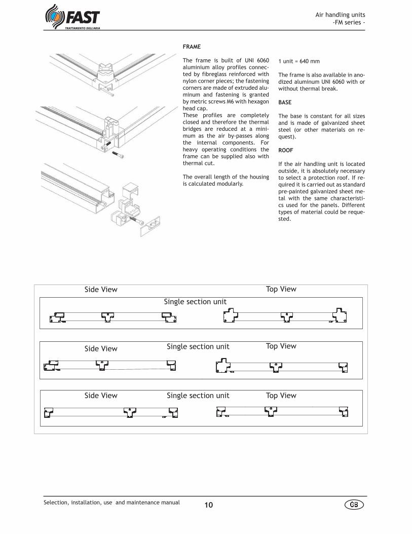
FRAME
The frame is built of UNI 6060 aluminium alloy profiles connec-ted by fibreglass reinforced with nylon corner pieces; the fastening corners are made of extruded alu-minum and fastening is granted by metric screws M6 with hexagon head cap.These profiles are completely closed and therefore the thermal bridges are reduced at a mini-mum as the air by-passes along the internal components. For heavy operating conditions the frame can be supplied also with thermal cut.
The overall length of the housing is calculated modularly.
1 unit = 640 mm
The frame is also available in ano-dized aluminum UNI 6060 with or without thermal break.
BASE
The base is constant for all sizes and is made of galvanized sheet steel (or other materials on re-quest).
ROOF
If the air handling unit is located outside, it is absolutely necessary to select a protection roof. If re-quired it is carried out as standard pre-painted galvanized sheet me-tal with the same characteristi-cs used for the panels. Different types of material could be reque-sted.
VISTE FRONTALI VISTE DALL'ALTOSEZIONE MONOBLOCCO
SEZIONE INIZIALE
SEZIONE INTERMEDIA
Side View
Side View
Side View
Top View
Top View
Top View
Single section unit
Single section unit
Single section unit
Air handling units -FM series -
10 å æSelection, installation, use and maintenance manual
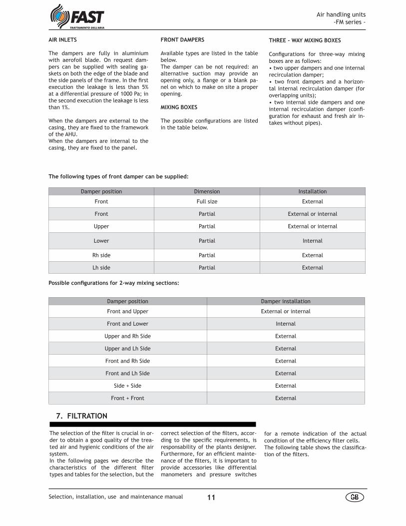
THREE - WAY MIXING BOXES
Confi gurations for three-way mixing boxes are as follows:• two upper dampers and one internal recirculation damper;• two front dampers and a horizon-tal internal recirculation damper (for overlapping units);• two internal side dampers and one internal recirculation damper (confi -guration for exhaust and fresh air in-takes without pipes).
AIR INLETS
The dampers are fully in aluminium with aerofoil blade. On request dam-pers can be supplied with sealing ga-skets on both the edge of the blade and the side panels of the frame. In the fi rst execution the leakage is less than 5% at a differential pressure of 1000 Pa; in the second execution the leakage is less than 1%.
When the dampers are external to the casing, they are fi xed to the framework of the AHU. When the dampers are internal to the casing, they are fi xed to the panel.
Damper position Dimension Installation
Front Full size External
Front Partial External or internal
Upper Partial External or internal
Lower Partial Internal
Rh side Partial External
Lh side Partial External
Damper position Damper installation
Front and Upper External or internal
Front and Lower Internal
Upper and Rh Side External
Upper and Lh Side External
Front and Rh Side External
Front and Lh Side External
Side + Side External
Front + Front External
The following types of front damper can be supplied:
Possible confi gurations for 2-way mixing sections:
FRONT DAMPERS
Available types are listed in the table below.The damper can be not required: an alternative suction may provide an opening only, a fl ange or a blank pa-nel on which to make on site a proper opening.
MIXING BOXES
The possible confi gurations are listed in the table below.
for a remote indication of the actual condition of the effi ciency fi lter cells. The following table shows the classifi ca-tion of the fi lters.
The selection of the fi lter is crucial in or-der to obtain a good quality of the trea-ted air and hygienic conditions of the air system.In the following pages we describe the characteristics of the different fi lter types and tables for the selection, but the
7. FILTRATION
correct selection of the fi lters, accor-ding to the specifi c requirements, is responsability of the plants designer. Furthermore, for an effi cient mainte-nance of the fi lters, it is important to provide accessories like differential manometers and pressure switches
Air handling units -FM series -
11 å æSelection, installation, use and maintenance manual
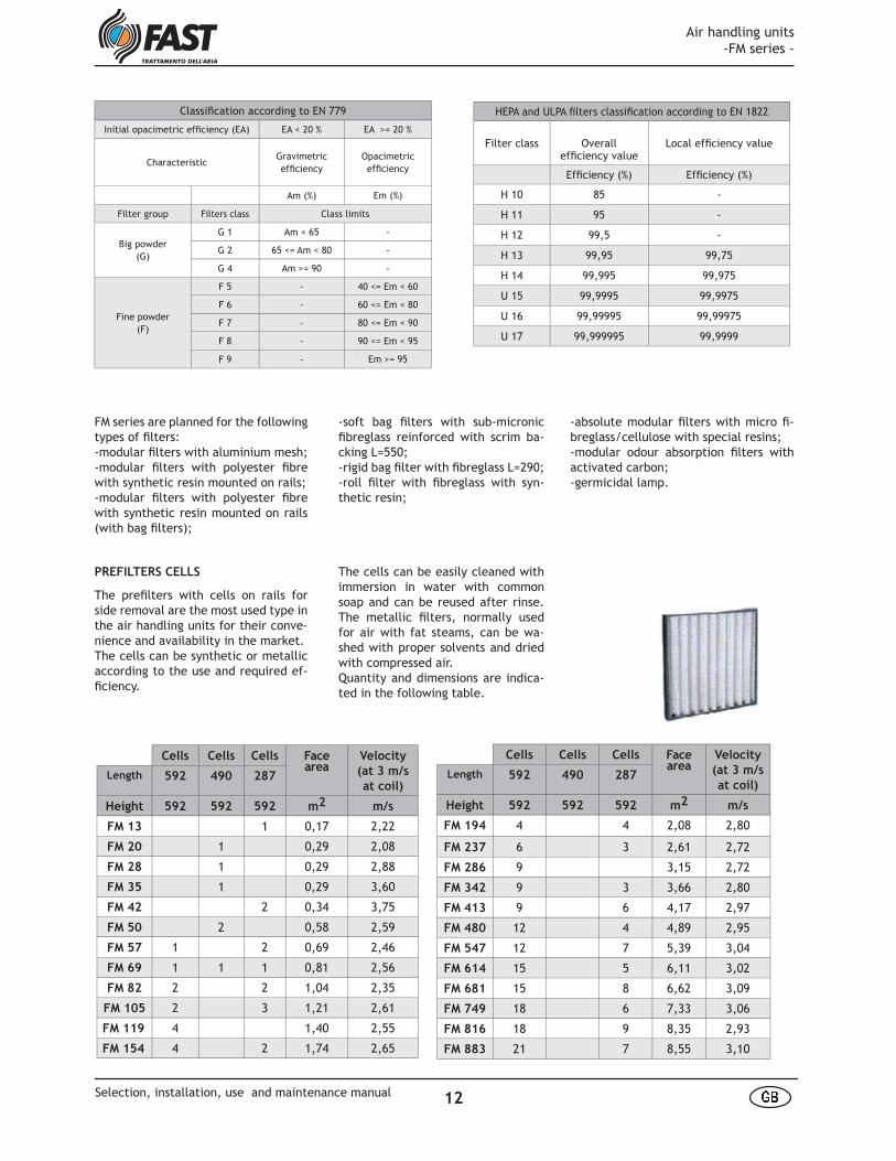
PREFILTERS CELLS
The prefi lters with cells on rails for side removal are the most used type in the air handling units for their conve-nience and availability in the market.The cells can be synthetic or metallic according to the use and required ef-fi ciency.
Classifi cation according to EN 779
Initial opacimetric effi ciency (EA) EA < 20 % EA >= 20 %
CharacteristicGravimetriceffi ciency
Opacimetriceffi ciency
Am (%) Em (%)
Filter group Filters class Class limits
Big powder (G)
G 1 Am < 65 -
G 2 65 <= Am < 80 -
G 4 Am >= 90 -
Fine powder (F)
F 5 - 40 <= Em < 60
F 6 - 60 <= Em < 80
F 7 - 80 <= Em < 90
F 8 - 90 <= Em < 95
F 9 - Em >= 95
HEPA and ULPA fi lters classifi cation according to EN 1822
Filter class Overalleffi ciency value
Local effi ciency value
Effi ciency (%) Effi ciency (%)
H 10 85 -
H 11 95 -
H 12 99,5 -
H 13 99,95 99,75
H 14 99,995 99,975
U 15 99,9995 99,9975
U 16 99,99995 99,99975
U 17 99,999995 99,9999
FM series are planned for the following types of fi lters:-modular fi lters with aluminium mesh;-modular fi lters with polyester fi bre with synthetic resin mounted on rails;-modular fi lters with polyester fi bre with synthetic resin mounted on rails (with bag fi lters);
Cells Cells Cells Face area
Velocity
(at 3 m/s
at coil)Length 592 490 287
Height 592 592 592 m2 m/s
FM 13 1 0,17 2,22
FM 20 1 0,29 2,08
FM 28 1 0,29 2,88
FM 35 1 0,29 3,60
FM 42 2 0,34 3,75
FM 50 2 0,58 2,59
FM 57 1 2 0,69 2,46
FM 69 1 1 1 0,81 2,56
FM 82 2 2 1,04 2,35
FM 105 2 3 1,21 2,61
FM 119 4 1,40 2,55
FM 154 4 2 1,74 2,65
Cells Cells Cells Face area
Velocity
(at 3 m/s
at coil)Length 592 490 287
Height 592 592 592 m2 m/s
FM 194 4 4 2,08 2,80
FM 237 6 3 2,61 2,72
FM 286 9 3,15 2,72
FM 342 9 3 3,66 2,80
FM 413 9 6 4,17 2,97
FM 480 12 4 4,89 2,95
FM 547 12 7 5,39 3,04
FM 614 15 5 6,11 3,02
FM 681 15 8 6,62 3,09
FM 749 18 6 7,33 3,06
FM 816 18 9 8,35 2,93
FM 883 21 7 8,55 3,10
-soft bag fi lters with sub-micronic fi breglass reinforced with scrim ba-cking L=550; -rigid bag fi lter with fi breglass L=290;-roll fi lter with fi breglass with syn-thetic resin;
-absolute modular fi lters with micro fi -breglass/cellulose with special resins;-modular odour absorption fi lters with activated carbon; -germicidal lamp.
The cells can be easily cleaned with immersion in water with common soap and can be reused after rinse. The metallic fi lters, normally used for air with fat steams, can be wa-shed with proper solvents and dried with compressed air.Quantity and dimensions are indica-ted in the following table.
Air handling units -FM series -
12 å æSelection, installation, use and maintenance manual
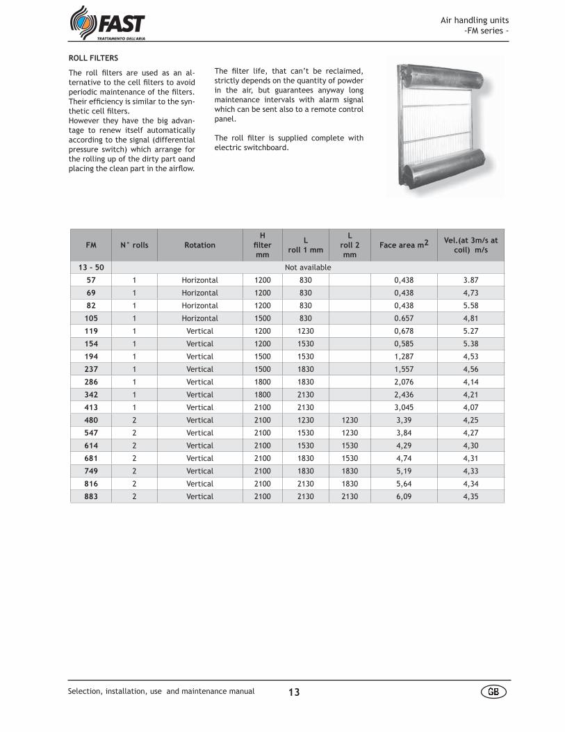
ROLL FILTERS
The roll fi lters are used as an al-ternative to the cell fi lters to avoid periodic maintenance of the fi lters. Their effi ciency is similar to the syn-thetic cell fi lters.However they have the big advan-tage to renew itself automatically according to the signal (differential pressure switch) which arrange for the rolling up of the dirty part oand placing the clean part in the airfl ow.
FM N° rolls Rotation
H
fi lter
mm
L
roll 1 mm
L
roll 2
mm
Face area m2 Vel.(at 3m/s at
coil) m/s
13 - 50 Not available
57 1 Horizontal 1200 830 0,438 3.87
69 1 Horizontal 1200 830 0,438 4,73
82 1 Horizontal 1200 830 0,438 5.58
105 1 Horizontal 1500 830 0.657 4,81
119 1 Vertical 1200 1230 0,678 5.27
154 1 Vertical 1200 1530 0,585 5.38
194 1 Vertical 1500 1530 1,287 4,53
237 1 Vertical 1500 1830 1,557 4,56
286 1 Vertical 1800 1830 2,076 4,14
342 1 Vertical 1800 2130 2,436 4,21
413 1 Vertical 2100 2130 3,045 4,07
480 2 Vertical 2100 1230 1230 3,39 4,25
547 2 Vertical 2100 1530 1230 3,84 4,27
614 2 Vertical 2100 1530 1530 4,29 4,30
681 2 Vertical 2100 1830 1530 4,74 4,31
749 2 Vertical 2100 1830 1830 5,19 4,33
816 2 Vertical 2100 2130 1830 5,64 4,34
883 2 Vertical 2100 2130 2130 6,09 4,35
The fi lter life, that can’t be reclaimed, strictly depends on the quantity of powder in the air, but guarantees anyway long maintenance intervals with alarm signal which can be sent also to a remote control panel.
The roll fi lter is supplied complete with electric switchboard.
Air handling units -FM series -
13 å æSelection, installation, use and maintenance manual

ABSOLUTE FILTERS
The absolute fi lters are generally used to guarantee aseptic air condi-tions and air salubrity.The most common applications are related to AHUs for hospitals (ope-rating theatre and similar), for elec-tronic and chemical industry.
These fi lters must be placed after the supply fan sections and must be preceded by higher effi ciency fi lters (i.e. cell fi lters and soft bag fi lters). It is advisable to provide, as accessory, a differential pressure switch that indicates the fi lter fouling in order to plan its substitution.Particular care is given to the design of the seating de-vices for the cells to avoid air by-pass and to make the maintenance easier.
Cells Cells Cells Face area
Velocity
(at 3 m/s
at coil)Lengt 592 490 287
Height 592 592 592 m2 m/s
FM 13 1 0,17 2,22
FM 20 1 0,29 2,08
FM 28 1 0,29 2,88
FM 35 1 0,29 3,60
FM 42 1 0,29 4,39
FM 50 2 0,58 2,59
FM 57 1 2 0,63 2,69
FM 69 1 2 0,63 3,29
FM 82 2 2 0,92 2,66
FM 105 2 3 1,09 2,90
FM 119 2 2 1,28 2,79
FM 154 2 2 1 1,45 3,18
Cells Cells Cells Face area
Velocity
(at 3 m/s
at coil)Lengt 592 490 287
Height 592 592 592 m2 m/s
FM 194 4 4 2,08 2,80
FM 237 6 3 2,61 2,72
FM 286 9 3,15 2,72
FM 342 9 3 3,66 2,80
FM 413 9 6 4,17 2,97
FM 480 12 4 4,89 2,95
FM 547 12 7 5,39 3,04
FM 614 15 5 6,11 3,02
FM 681 15 8 6,62 3,09
FM 749 18 6 7,33 3,06
FM 816 18 9 7,84 3,12
FM 883 21 7 8,55 3,10
Cells Face area
Velocity (at 3
m/s at coil)Lenght 592 490 287 287
Height 592 592 592 490 m2 m/s
FM 13 1 0,17 2,22
FM 20 1 0,29 2,08
FM 28 1 0,29 2,88
FM 35 1 1 0,29 3,60
FM 42 1 1 0,29 4,39
FM 50 2 0,58 2,59
FM 57 1 2 0,63 2,69
FM 69 1 2 0,63 3,29
FM 82 2 2 0,92 2,66
FM 105 2 3 1,09 2,90
FM 119 2 2 1,28 2,79
FM 154 2 2 1 1 1,45 3,18
Cells Face area
Velocity (at 3
m/s at coil)Lenght 592 490 287 287
Height 592 592 592 490 m2 m/s
FM 194 4 4 1 2,08 2,80
FM 237 6 3 2,61 2,72
FM 286 9 3,15 2,72
FM 342 9 3 3,66 2,80
FM 413 9 6 1 4,17 2,97
FM 480 12 4 4,89 2,95
FM 547 12 7 1 5,39 3,04
FM 614 15 5 6,11 3,02
FM 681 15 8 1 6,62 3,09
FM 749 18 6 7,33 3,06
FM 816 18 9 1 7,84 3,12
FM 883 21 7 8,55 3,10
vent by-pass of the not fi ltered air. The extraction is possible in the inspection room upstream the cells to allow an easy access to the maintenance staff.Special executions for specifi c uses (i.e. hospitals, pharmaceutical industry, chemical industry etc) and particular requirements can be studied by our tech-nical offi ce upon request.
BAG FILTERS
Bag fi lters are available as soft bag or rigid fi lters according to the project requirements. They should generally be fi tted togheter with pre-fi lters, cells or roll types, to im-prove their life catching the pollu-ting particles. They can be followed by fi lters with higher effi ciency. The bag fi lters are seated in a bearing frame with neoprene gasket to pre-
Air handling units -FM series -
14 å æSelection, installation, use and maintenance manual

Cells Cells Cells Face area
Velocity
(at 3 m/s
at coil)Lengt 592 490 287
Height 592 592 592 m2 m/s
FM 13 1 0,17 2,22
FM 20 1 0,29 2,08
FM 28 1 0,29 2,88
FM 35 1 0,29 3,60
FM 42 1 0,29 4,39
FM 50 2 0,58 2,59
FM 57 1 2 0,63 2,69
FM 69 1 2 0,63 3,29
FM 82 2 2 0,92 2,66
FM 105 2 3 1,09 2,90
FM 119 2 2 1,28 2,79
FM 154 2 2 1 1,45 3,18
Cells Cells Cells Face area
Velocity
(at 3 m/s
at coil)Lengt 592 490 287
Height 592 592 592 m2 m/s
FM 194 4 4 2,08 2,80
FM 237 6 3 2,61 2,72
FM 286 9 3,15 2,72
FM 342 9 3 3,66 2,80
FM 413 9 6 4,17 2,97
FM 480 12 4 4,89 2,95
FM 547 12 7 5,39 3,04
FM 614 15 5 6,11 3,02
FM 681 15 8 6,62 3,09
FM 749 18 6 7,33 3,06
FM 816 18 9 7,84 3,12
FM 883 21 7 8,55 3,10
reduced need for maintenance, the low energy consumption and the possibility of using them up to very high operating temperatures.For further information please con-tact the Technical Department.
ELECTROSTATIC FILTERS
The electrostatic fi lters are used when elevate fi ltrating performan-ces are requested, even on very small particles, together with limi-ted pressure drops.The system uses polarised electro-des, positively loaded and fed with
roughly 10.000V tension and me-tallic plates loaded in the opposi-te way. The creation of an intense electrostatic fi eld generates positi-ve ions which capture the polluting particles present in the air.The advantages deriving from the use of electrostatic fi lters are the
The sections are complete with lam-ps, wiring and terminal box for the connection to electric current.
GERMICIDAL LAMPS
They are generally used in series with very high effi ciency fi lters and their use is advisable when bacte-ria and germs, always present in the air, must be controlled on the sup-ply and exhaust air.
The lamps, their power and location have been defi ned by our technical offi ce for most common applica-tions; particular solutions can be studied for special purposes.
OUR TECHNICAL DEPARTMENT CAN VERIFY FURTHER FILTRATION SYSTEMS NOT LISTED ABOVE.
ACTIVATED CARBON FILTERS
The activated carbon fi lters are used for the absorption of odours and toxic substances from the ai-rfl ow both on supply and exhaust air (i.e. human odours, odours from kitchens, some components of smo-ke, idrocarbon vapours diluted in the air etc.).
These fi ltering systems must be be pre-ceded by higher effi ciency fi lters to improve their life and assure the best effi ciency.The sections are perfectly accessible for the maintenance and can be use rechargeble or disposable cells.
Air handling units -FM series -
15 å æSelection, installation, use and maintenance manual
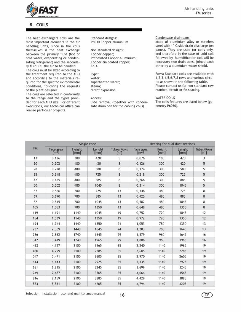
Standard designs:P6030 Copper-aluminium
Non-standard designs:Copper-copper;Prepainted Copper-aluminium;Copper-tin coated copper;Fe-Al
Type:water;superheated water;steam;direct expansion.
Access:Side removal (together with conden-sate drain pan for the cooling coils).
The heat exchangers coils are the most important elements in the air handling units, since in the coils themselves is the heat exchange between the primary fl uid (hot or cold water, evaporating or conden-sating refrigerant) and the seconda-ry fl uid,i.e. the air to be handled.The coils must be sized according to the treatment required to the AHU and according to the materials re-quired for the specifi c evironmental conditions, following the requests of the plant designer.The coils are selected in conformity to the range and the types provi-ded for each AHU size. For different executions, our technical offi ce can realize particular projects.
FMSingle zone Heating for dual duct sections
Face area[m2]
Height[mm]
Lenght[mm]
Tubes/Rows[n°]
Face area[m2]
Height[mm]
Lenght[mm]
Tubes/Rows[n°]
13 0,126 300 420 5 0,076 180 420 3
20 0,202 480 420 8 0,126 300 420 5
28 0,278 480 580 8 0,174 300 580 5
35 0,348 480 725 8 0,218 300 725 5
42 0,425 480 885 8 0,266 300 885 5
50 0,502 480 1045 8 0,314 300 1045 5
57 0,566 780 725 13 0,348 480 725 8
69 0,690 780 885 13 0,425 480 885 8
82 0,815 780 1045 13 0,502 480 1045 8
105 1,053 780 1350 13 0,648 480 1350 8
119 1,191 1140 1045 19 0,752 720 1045 12
154 1,539 1140 1350 19 0,972 720 1350 12
194 1,944 1440 1350 24 1,053 780 1350 13
237 2,369 1440 1645 24 1,283 780 1645 13
286 2,862 1740 1645 29 1,579 960 1645 16
342 3,419 1740 1965 29 1,886 960 1965 16
413 4,127 2100 1965 35 2,240 1140 1965 19
480 4,799 2100 2285 35 2,605 1140 2285 19
547 5,471 2100 2605 35 2,970 1140 2605 19
614 6,143 2100 2925 35 3,335 1140 2925 19
681 6,815 2100 3245 35 3,699 1140 3245 19
749 7,487 2100 3565 35 4,064 1140 3565 19
816 8,159 2100 3885 35 4,429 1140 3885 19
883 8,831 2100 4205 35 4,794 1140 4205 19
8. COILS
Condensate drain pans:Made of aluminium alloy or stainless steel with 1” G side drain discharge (on panel). They are used for coils only, and therefore in the case of cold coil followed by humidifi cation coil will be necessary two drain pans, joined each other by a aluminium water shield.
Rows: Standard coils are available with 1,2,3,4,5,6,7,8 rows and various circu-its as shown in the following table.Please contact us for non-standard row number, circuit or fi n spacing.
WATER COILSThe coils features are listed below (ge-ometry P6030).
Air handling units -FM series -
16 å æSelection, installation, use and maintenance manual

Manifolds diameter for multizone heating, P6030 water coils (according to the circuits)
FM H L Manifold diameter
mm mm R1,2 R2,2 R3,2 R4,1 R4,2 R6,1 R6,2 R8,1 R8,2
13 300 420 1” 1/2" 1" 1" 1" 1" 1" 1" 1"
20 480 420 1" 1" 1" 1" 1" 1" 1" 1" 1"
28 480 580 1” 1" 1" 1" 1" 1" 1" 1" 1"
35 480 725 1" 1" 1" 1" 1" 1" 1" 1" 1"
42 480 885 1" 1" 1" 1-1/2" 1-1/2" 1-1/2" 1-1/2" 1-1/2" 1-1/2"
50 480 1045 1" 1" 1" 1-1/2" 1-1/2" 1-1/2" 1-1/2" 1-1/2" 1-1/2"
57 780 725 1" 1" 1" 1" 1" 1-1/2" 1-1/2" 1-1/2" 1-1/2"
69 780 885 1" 1" 1" 1-1/2" 1-1/2" 1-1/2" 1-1/2" 1-1/2" 1-1/2"
82 780 1045 1" 1" 1-1/2" 1-1/2" 1-1/2" 1-1/2" 1-1/2" 2-1/2" 2-1/2"
105 780 1350 1" 1" 1-1/2" 1-1/2" 1-1/2" 1-1/2" 1-1/2" 2-1/2" 2-1/2"
119 1140 1045 1" 1-1/2" 2" 2" 2" 2" 2" 2-1/2" 2-1/2"
154 1140 1350 1" 1-1/2" 2" 2" 2" 2-1/2" 2-1/2" 2-1/2" 2-1/2"
194 1440 1350 1-1/2" 1-1/2" 2" 2-1/2" 2-1/2" 2-1/2" 2-1/2" 3" 3"
237 1440 1645 1-1/2" 1-1/2" 2" 2-1/2" 2-1/2" 2-1/2" 2-1/2" 3" 3"
286 1740 1645 1-1/2" 2-1/2" 2" 2-1/2" 2-1/2" 3" 3" 4" 4"
342 1740 1965 1-1/2" 2-1/2" 2-1/2" 2-1/2" 2-1/2" 3" 3" 4" 4"
413 2100 1965 2" 2-1/2" 2-1/2" 3" 3" 3" 3" 4" 4"
480 2100 2285 2" 2-1/2" 2-1/2" 3" 3" 4" 4" 4" 4"
547 2100 2605 2" 2-1/2" 2-1/2" 3" 3" 4" 4" 4" 4"
614 2100 2925 2" 2-1/2" 2-1/2" 3" 3" 4" 4" 4" 4"
681 2100 3245 2" 2-1/2" 2-1/2" 3" 3" 4" 4" 4" 4"
749 2100 3565 2" 2-1/2" 2-1/2" 3" 3" 4" 4" 4" 4"
816 2100 3885 2" 2-1/2" 2-1/2" 3" 3" 4" 4" 4" 4"
883 2100 4205 2" 2-1/2" 2-1/2" 3" 3" 4" 4" 4" 4"
FM H L Manifold diameter
mm mm R1,3 R2,3 R3,3 R4,3
13 180 420 1" 1" 1" 1"
20 300 420 1" 1" 1" 1"
28 300 580 1" 1" 1" 1"
35 300 725 1" 1" 1" 1"
42 300 885 1" 1" 1" 1"
50 300 1045 1" 1" 1" 1"
57 480 725 1" 1" 1" 1"
69 480 885 1" 1" 1" 1"
82 480 1045 1" 1" 1" 1"
105 480 1350 1" 1" 1" 1"
119 720 1045 1" 1" 1" 1-1/2"
154 720 1350 1" 1" 1" 1-1/2"
194 780 1350 1" 1" 1-1/2" 2"
237 780 1645 1" 1" 1-1/2" 2"
286 960 1645 1" 1" 1-1/2" 2"
342 960 1965 1" 1" 1-1/2" 2"
413 1140 1965 1" 1-1/2" 1-1/2" 2"
480 1140 2285 1" 1-1/2" 1-1/2" 2"
547 1140 2605 1" 1-1/2" 1-1/2" 2"
614 1140 2925 1" 1-1/2" 1-1/2" 2"
681 1140 3245 1" 1-1/2" 1-1/2" 2"
749 1140 3565 1" 1-1/2" 1-1/2" 2"
816 1140 3885 1" 1-1/2" 1-1/2" 2"
883 1140 4205 1" 1-1/2" 1-1/2" 2"
Manifolds diameter for single-zone, P6030 water coils (according to the circuits)
Air handling units -FM series -
17 å æSelection, installation, use and maintenance manual
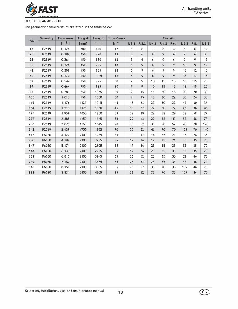
DIRECT EXPANSION COIL
FMGeometry Face area Height Lenght Tubes/rows Circuits
[m2 ] [mm] [mm] [n°] R 3.1 R 3.2 R 4.1 R 4.2 R 6.1 R 6.2 R 8.1 R 8.2
13 P2519 0.126 300 420 12 3 6 3 6 4 6 6 12
20 P2519 0.189 450 420 18 3 6 6 9 6 9 6 9
28 P2519 0.261 450 580 18 3 6 6 9 6 9 9 12
35 P2519 0.326 450 725 18 6 9 6 9 9 18 9 12
42 P2519 0.398 450 885 18 6 9 6 9 9 18 12 18
50 P2519 0.470 450 1045 18 6 9 6 9 9 18 12 18
57 P2519 0.544 750 725 30 7 9 10 15 15 18 15 20
69 P2519 0.664 750 885 30 7 9 10 15 15 18 15 20
82 P2519 0.784 750 1045 30 9 15 15 20 18 30 20 30
105 P2519 1.013 750 1350 30 9 15 15 20 22 30 24 30
119 P2519 1.176 1125 1045 45 13 22 22 30 22 45 30 36
154 P2519 1.519 1125 1350 45 13 22 22 30 27 45 36 45
194 P2519 1.958 1450 1350 58 22 29 29 58 29 58 58 77
237 P2519 2.385 1450 1645 58 29 43 29 58 43 58 58 77
286 P2519 2.879 1750 1645 70 35 52 35 70 52 70 70 140
342 P2519 3.439 1750 1965 70 35 52 46 70 70 105 70 140
413 P6030 4.127 2100 1965 35 10 17 14 35 21 35 28 35
480 P6030 4.799 2100 2285 35 17 26 17 35 21 35 35 70
547 P6030 5.471 2100 2605 35 17 26 23 35 35 52 35 70
614 P6030 6.143 2100 2925 35 17 26 23 35 35 52 35 70
681 P6030 6.815 2100 3245 35 26 52 23 35 35 52 46 70
749 P6030 7.487 2100 3565 35 26 52 23 35 35 52 46 70
816 P6030 8.159 2100 3885 35 26 52 35 70 35 105 46 70
883 P6030 8.831 2100 4205 35 26 52 35 70 35 105 46 70
The geometric characteristics are listed in the table below.
Air handling units -FM series -
18 å æSelection, installation, use and maintenance manual
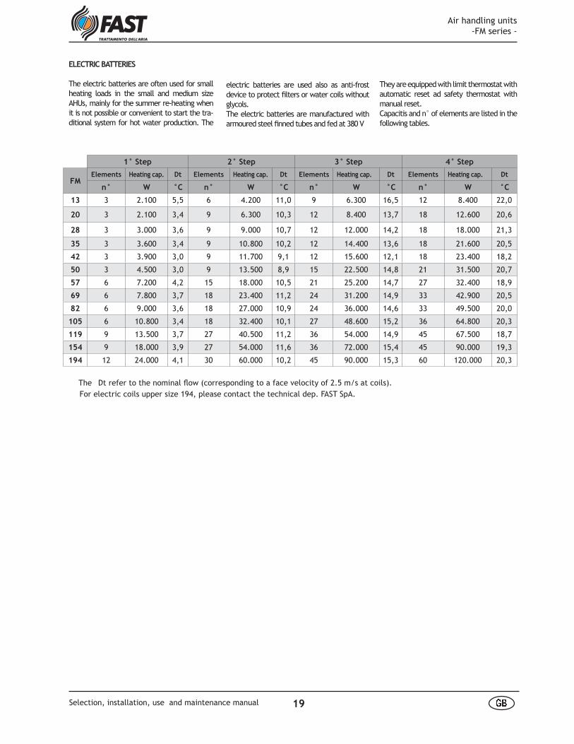
The Dt refer to the nominal fl ow (corresponding to a face velocity of 2.5 m/s at coils).
1° Step 2° Step 3° Step 4° Step
FMElements Heating cap. Dt Elements Heating cap. Dt Elements Heating cap. Dt Elements Heating cap. Dt
n° W °C n° W °C n° W °C n° W °C
13 3 2.100 5,5 6 4.200 11,0 9 6.300 16,5 12 8.400 22,0
20 3 2.100 3,4 9 6.300 10,3 12 8.400 13,7 18 12.600 20,6
28 3 3.000 3,6 9 9.000 10,7 12 12.000 14,2 18 18.000 21,3
35 3 3.600 3,4 9 10.800 10,2 12 14.400 13,6 18 21.600 20,5
42 3 3.900 3,0 9 11.700 9,1 12 15.600 12,1 18 23.400 18,2
50 3 4.500 3,0 9 13.500 8,9 15 22.500 14,8 21 31.500 20,7
57 6 7.200 4,2 15 18.000 10,5 21 25.200 14,7 27 32.400 18,9
69 6 7.800 3,7 18 23.400 11,2 24 31.200 14,9 33 42.900 20,5
82 6 9.000 3,6 18 27.000 10,9 24 36.000 14,6 33 49.500 20,0
105 6 10.800 3,4 18 32.400 10,1 27 48.600 15,2 36 64.800 20,3
119 9 13.500 3,7 27 40.500 11,2 36 54.000 14,9 45 67.500 18,7
154 9 18.000 3,9 27 54.000 11,6 36 72.000 15,4 45 90.000 19,3
194 12 24.000 4,1 30 60.000 10,2 45 90.000 15,3 60 120.000 20,3
electric batteries are used also as anti-frost device to protect fi lters or water coils without glycols.The electric batteries are manufactured with armoured steel fi nned tubes and fed at 380 V
ELECTRIC BATTERIES
The electric batteries are often used for small heating loads in the small and medium size AHUs, mainly for the summer re-heating when it is not possible or convenient to start the tra-ditional system for hot water production. The
They are equipped with limit thermostat with automatic reset ad safety thermostat with manual reset.Capacitis and n° of elements are listed in the following tables.
For electric coils upper size 194, please contact the technical dep. FAST SpA.
Air handling units -FM series -
19 å æSelection, installation, use and maintenance manual
AIR WASHER
The system is made up by two opposi-te ramps, on which nebulizing nozzles are placed, included in a waterproof aluminium alloy (standard) or stain-less steel chamber internal to the ca-sing of the air-handling unit. The sy-stem is complete with connections and pump/s and main pan (400 mm high) with drain hole, overfl ow hole, fi lter, fl oating valve, drop eliminators before and after the ramps. It is possible also to provide a model with 2 nozzle ramps and one recirculation pump, or 2 noz-zle ramps and 2 recirculation pumps.
WATER/AIR COMPRESSED AIR HUMIDI-FICATION
The system is made up of special ato-mised nozzles, fed with compressed water and air in separate lines. An accurate installation and the respect of the minimum distances with the following components in the air fl ow allow for a nebulization of the water in extremely small droplets, thus avoi-ding the risk of condensation. In this way very elevate effi ciencies are ob-tained and, thanks to the automatic cleaning of the nebulizing heads, are low maintenance costs.The system is supplied complete with all necessary components mounted for the correct operation (ramp, self-clea-ning nozzles, pipes and feeding cabinet with modulating control).
ULTRASOUND HUMIDIFICATION
The humidifi cation system with ultra-sounds provides for the use of a high-frequency piezoelectric transducer which, vibrating at extremely high frequency generates the cavitation of the water with its subsequent nebu-lization. The main advantages of this system are: high effi ciency, low ener-getic consumption, reduced water con-sumption, long duration, installation easiness and safety of usage.For further information please contact our Technical Department.
The humidifi cation is a very important tre-atment to obtain an optimum indoor air quality. The humidifi yng system described below shall be selected in conformity to their use and to the available fl uid.It is obvious that the fact that moulds and bacteria fi nd a favourable ambient on hu-mid surfaces and in stagnant water must be taken in account: therefore FAST pro-vides drainable pans and small pump traps to limit the quantity of water in the sy-stem.The evaporating decks are of the anti-mould type and can be also equipped with humidity sensor to stop the waterfl ow as soon as the evaporating deck is wet, limi-ting the water consumption and maintai-ning the drain pan almost dry.The steam system with centralized steam production are particularly indicated for small fl ows and for applications where the air healthiness is very important (i.e. ho-spitals).
EVAPORATING DECK HUMIDIFICATION
The following constructive types may be provided for:
a - paper evaporating deck thick 100 mm and water;b - paper evaporating deck thick 200 mm and water;c - paper evaporating deck thick 100 mm and recirculating pump;d - paper evaporating deck thick 200 mm and recirculating pump;e - PVC evaporating deck thick 100 mm and recirculating pump;f - PVC evaporating deck thick 200 mm and recirculating pump;g - paper evaporating deck thick 100 mm and water control through humidity sensor at evaporating deck and solenoid valve;h - paper evaporating deck thick 200 mm and water control through humidity sensor at evaporating deck and solenoid valve;
STEAM HUMIDIFICATION
The following constructive types may be provided for:
a - with steam manifold only;b - with steam producer.
9. HUMIDIFICATION
CONDENSATE DRAIN PAN
- For compressed water and air humidifi -cation and steam humidifi cation: alumi-nium alloy or stainless internal drain pan (h=50 mm) with 1” G drain;- For evaporating deck humidifi cation (type a. or b.): aluminium alloy or stain-less steel internal drain pan (h=50 mm) and fi berglass reinforced polypropilene pump trap with 1” GJ drain and 1” GJ supply;- For wet deck humidifi cation (type g. or h.): aluminium alloy or stainless steel internal drain pan (h=50 mm) and fi ber-glass reinforced polypropilene trap with 1” GJ discharge and integration with so-lenoid valve; - For wet deck humidifi cation (type c.,d.,e.,f.): aluminium alloy internal drain pan (h=50 mm) and fi berglass rein-forced polypropilene pump trap with 1” GJ discharge and integration with fl oa-ting valve;- For air washer humidifi cation: stainless steel water pan (h=400 mm).
For sizes FM13, FM20, FM28 the pump trap is manufactured in aluminium alloy.
DROP SEPARATORS
The drop separator, carefully designed to obtain the maximum effi ciency of water drop treatment, because of the required treatments generated inside the unit (humidifi cation and dehumidi-fi cation), is provided as optional com-ponent or as standard.Droplet eliminators are always lateral-ly accessible and are necessary in the following cases:- cooling coils: air velocity more than 2.6 m/s;- spray deck humidifi ers: air velocity more than 2.6 m/s;- steam and compressed water/air hu-midifi cation;- air washers (with inlet fl ow rectifi er).
Materials:- galvanized steel;- aluminium alloy;- 304 AISI steel;- poly-propylene (standard).
Air handling units -FM series -
20 å æSelection, installation, use and maintenance manual

-Sizes:fan sizes are selected according to the required capacity and pressure. The si-zes are shown in the following table for each size of air handling unit, with re-ference to the outside diameter of the wheel in mm.
-Orientation:available fan orientations are shown in the following table. An even fi nal number means right orien-tation; an odd fi nal number refers to left orientation.The choice of the orientation depends on the real plant confi guration of the AHU and shall consider more than the inspection side of the AHU also the la-yout of the supply ducts to minimize the pressure drop at the AHU-duct junction.
FANS
The fans are the most important compo-nents in the air handling units since the fan-motor assembly is the only moving part and therefore subject to possible problems of wear, noise, manitenance, safety. A correct selection for size and models together with a careful selection of the supplier assures an optimum per-formance for the AHU’s life.FAST provides for each size of AHU dif-ferent fan sizes and models to better match the plant requirements in terms of effi ciency, noise level and operating fl exibility.
- Series:all fan units are in complieance with se-ries DIN 323 R20 (square outlet) of the following types:- forward curved blades;- backward curved blades;- backward curved blades with air foil profi le.
10. FAN SECTIONS
COMPATIBILITY TABLE FANS / AHUs
Fan sizesFM
13 180
20 200 225
28 200 225 250
35 225 250 280
42 225 250 280
50 250 280
57 280 315 355 400
69 315 355 400
82 315 355 400
105 355 400
119 400 450 500 560
154 450 500 560
194 500 560 630 710
237 560 630 710
286 560 630 710 800
342 630 710 800 900
413 630 710 800 900
480 710 800
547 710 800 900
614 800 900 1000
681 NOT AVAILABLE IN THE BACKWARD BLADES VERSION 900 1000
749 900 1000
816 900 1000
883 900 1000
- Anti-vibration mounts:
standard versions have rubber (60°Sh) anti-vibration mounts and anti-vibra-tion seals on the outlet port. From fan size 450 up, the system can be optio-nally supplied with spring supports (minimum efficiency 80%). In this case the dimensions may be subject to modification, with reference to the indicated ones (please contact our Technical Department).
The ventilating sections are supplied as standard with:safety guard behind inspection door replacing enclosure panel;earth wire between motor cradle and main frame.
Air handling units -FM series -
21 å æSelection, installation, use and maintenance manual
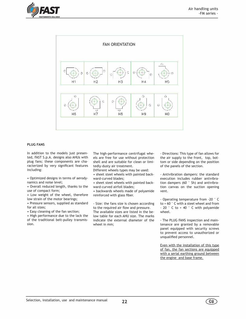
FAN ORIENTATION
PLUG FANS
The high-performance centrifugal whe-els are free for use without protection shell and are suitable for clean or limi-tedly-dusty air treatment.Different wheels types may be used:• sheet steel wheels with painted back-ward-curved blades;• sheet steel wheels with painted back-ward-curved airfoil blades;• backwards wheels made of polyamide reinforced with glass fi ber.
- Size: the fans size is chosen according to the required air fl ow and pressure. The available sizes are listed in the be-low table for each AHU size. The marks indicate the external diameter of the wheel in mm;
In addition to the models just presen-ted, FAST S.p.A. designs also AHUs with plug fans; these components are cha-racterized by very signifi cant features including:
• Optimized designs in terms of aerody-namics and noise level;• Overall reduced length, thanks to the use of compact form;• Low weight of the wheel, therefore low strain of the motor bearings;• Pressure sensors, supplied as standard for all sizes;• Easy cleaning of the fan section;• High performance due to the lack the of the traditional belt-pulley transmis-sion.
- Directions: This type of fan allows for the air supply to the front, top, bot-tom or side depending on the position of the panels of the section.
- Antivibration dampers: the standard execution includes rubber antivibra-tion dampers (60 ° Sh) and antivibra-tion canvas on the suction opening vent.
- Operating temperature from -20 ° C to + 60 ° C with a steel wheel and from - 20 ° C to + 40 ° C with polyamide wheel.
- The PLUG FANS inspection and main-tenance are granted by a removable panel equipped with security screws to prevent access to unauthorized or unqualifi ed personnel.
Even with the installation of this type of fan, the fan sections are equipped with a serial earthing ground between the engine and base frame.
Air handling units -FM series -
22 å æSelection, installation, use and maintenance manual

Motors are single speed (2, 4, 6 po-les depending on fan speed) or (as optional) two speeds with 4/6, 4/8 poles and single winding.
Fans can be optionally supplied with inveter.
DRIVESThe pulleys may be fi x or variable for a better setting of the fan speed.
11. MOTORS
Motors are three-phase asynchronous with cage rotor, totally enclosed de-sign with external ventilation. Electri-cal characteristics of the motors are in compliance with the IEC 60034-1, while dimensional characteristics are in com-pliance with IEC 60072-1 and IEC 34-7 (IM B3 - IM1001).
Protection class: IP55Stator winding class: F
The transmission belts may be of the fol-lowing types: SPA, SPB or SPC.Pulleys are supplied with “Taperlock” taper bushes and are statically and dyna-mically balanced.The belt tensioning device grants an easy maintenance.
FAN SIZES
180 200 225 250 280 315 355 400 450 500 560 630 710
FM
13 180A 200A 225A
20 180A 200A 225A 250A 280A
28 225A 250A 280A 315ABC
35 280A 315ABC 355ABC
42 280A 315ABC 355ABC
50 280A 315ABC 355ABC
57 315ABC 355ABC 400ABC 450ABC
69 355ABC 400ABC 450ABC 500BC
82 450ABC 500BC 560BC
105 450ABC 500BC 560BC
119 500BC 560BC 630BC
154 560BC 630BC 710BC
A = Polyamide wheelB = Steel sheet and painted wheel with backwards curved bladesC = Steel sheet painted wheel with backwards curved blades and airfoil profil
FAN SIZES
630 710 800 900 1000 1120 1250
FM
194 630BC 710BC 800BC
237 710BC 800BC 900BC
286 800BC 900BC 1000BC
342 800BC 900BC 1000BC
413 900BC 1000BC 1120BC
480 1000BC 1120BC
547 1000BC 1120BC
614 1120BC 1250BC
681 1120BC 1250B
749 1120BC 1250B
816 1250B
883 1250B
B = Steel sheet and painted wheel with backward curved bladesC = Steel sheet and painted wheel with backward curved blades, and airfoil profile.
PLUG FANS COMPATIBILITY TABLES
Air handling units -FM series -
23 å æSelection, installation, use and maintenance manual

The multizone section, more than containing the heating and cooling coils fitted in parallel, is equipped with unified dampers one for each zone to be served.The Dual duct section is similar to the multizone but does not include the cojugate dampers since the mi-
The heat recovery units are even more used in installation where it is necessa-ry, for the room air quality or for diffe-rent processes, to use high volumes of fresh air rather than return air.The use of heat recovery units is more valid for large fresh air volumes and for high temperature difference between exhaust and fresh air.Types:- static cross fl ow recuperator with syn-thetic fi lters and aluminium alloy con-densate drain pan;- static cross fl ow with by-pass damper
12. SILENCERS
13. HEAT RECOVERY UNITS
The empty sections can be provided to allow a better maintenance of the AHU and the insertion of antifreeze detec-tors.
14. EMPTY SECTIONS
The Multizone/Dual duct sections are generally used where the control of room temperature is obtained by mi-xing two airflows of different tempe-ratures, also serving different zones of the building with the same AHU.
xing of the two airstrams are obtained in terminal units near to the rooms.For the selection of the multizone sec-tion it is necessary to know the quantity of zones, their flowrate and the posi-tion on the front section of the AHU.
(to by-pass the recovery unit in the free-cooling mode), synthetic fi lters and aluminium alloy condensate drain pan;- cross fl ow static with recirculation damper (3 dampers set with recove-ry unit), with synthetic media fi lters and aluminium alloy condensate drain pan.Further types can be supplied af-ter consulting the technical de-partment:- heat pipes;- rotary recuperator (sensible or to-tal recovery);- with double coil.
Effi ciency:Three sizes of cross fl ow recovery sy-stems with different effi ciency are avai-lable for each air handling size.
Installation:horizontal axis;
Air handling unit confi guration:- exhaust and supply in line;- overlapped exhaust and supply sec-tions.
Characteristics are indicated below. Length:• 325 mm , • 650 mm, • 975 mmDesign:
- basic;- with aluminium alloy condensate drain pan h=mm 50 and side discharge;- with inspection door.
Sound attenuation [dB]
Lenght [mm] 63 Hz 125 Hz 250 Hz 500 Hz 1000 Hz 2000 Hz 4000 Hz 8000 Hz
560 2 5 10 17 18 22 26 13
880 5 10 18 26 29 39 41 20
1200 7 14 24 35 39 48 48 28
1520 9 16 30 44 45 48 48 31
15. MULTIZONE / DUAL DUCT SECTIONS
Noise is one of the polluting factors in air conditioning. It is important to reduce as much as possible the noise from the fans with an accurate selec-tion of the fan type and size. If not enough it is possible to provide sound attenuators on the supply and/or exhaust fans sections.
Baffle length
560 mm880 mm1200 mm1520 mm
Baffle thickness: 200 mm
Air passage width: min. 105 mm, max. 114 mm
Construction:
Rockwool with air contact surfaces pro-tected with plastic film; enclosed in ex-panded galvanised steel mesh.
Sound attenuation at various frequencies is shown below:
Air handling units -FM series -
24 å æSelection, installation, use and maintenance manual
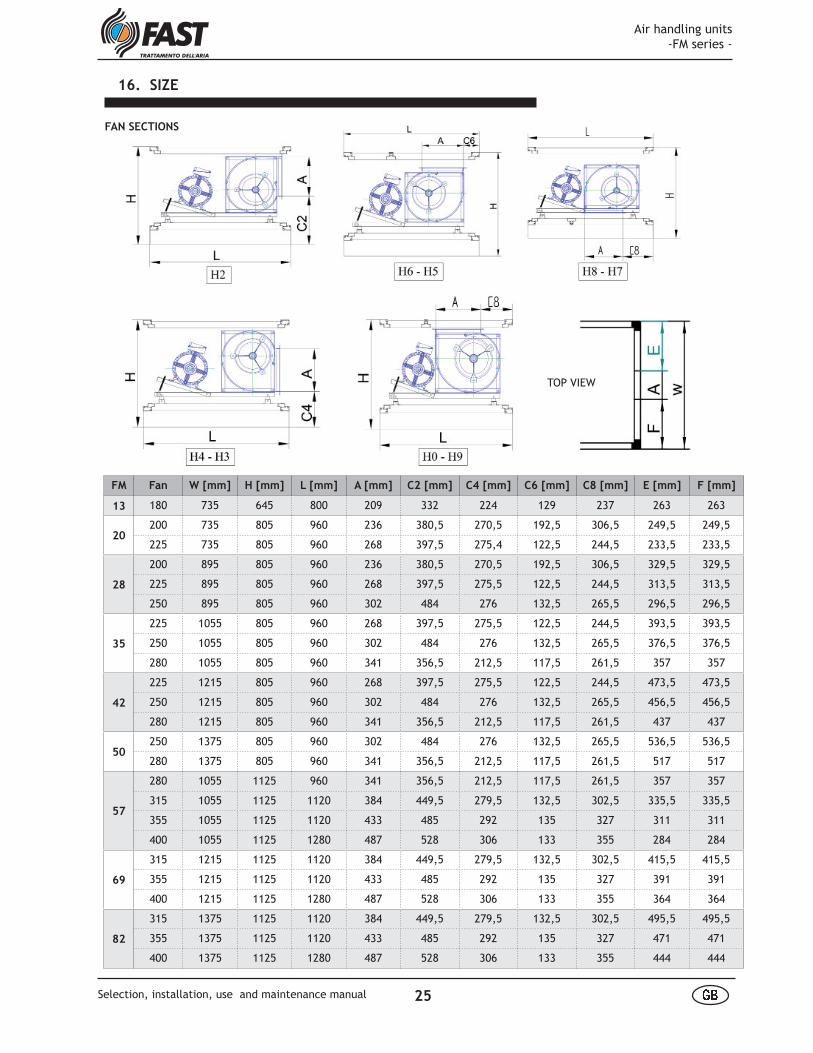
16. SIZE
FM Fan W [mm] H [mm] L [mm] A [mm] C2 [mm] C4 [mm] C6 [mm] C8 [mm] E [mm] F [mm]
13 180 735 645 800 209 332 224 129 237 263 263
20200 735 805 960 236 380,5 270,5 192,5 306,5 249,5 249,5
225 735 805 960 268 397,5 275,4 122,5 244,5 233,5 233,5
28
200 895 805 960 236 380,5 270,5 192,5 306,5 329,5 329,5
225 895 805 960 268 397,5 275,5 122,5 244,5 313,5 313,5
250 895 805 960 302 484 276 132,5 265,5 296,5 296,5
35
225 1055 805 960 268 397,5 275,5 122,5 244,5 393,5 393,5
250 1055 805 960 302 484 276 132,5 265,5 376,5 376,5
280 1055 805 960 341 356,5 212,5 117,5 261,5 357 357
42
225 1215 805 960 268 397,5 275,5 122,5 244,5 473,5 473,5
250 1215 805 960 302 484 276 132,5 265,5 456,5 456,5
280 1215 805 960 341 356,5 212,5 117,5 261,5 437 437
50250 1375 805 960 302 484 276 132,5 265,5 536,5 536,5
280 1375 805 960 341 356,5 212,5 117,5 261,5 517 517
57
280 1055 1125 960 341 356,5 212,5 117,5 261,5 357 357
315 1055 1125 1120 384 449,5 279,5 132,5 302,5 335,5 335,5
355 1055 1125 1120 433 485 292 135 327 311 311
400 1055 1125 1280 487 528 306 133 355 284 284
69
315 1215 1125 1120 384 449,5 279,5 132,5 302,5 415,5 415,5
355 1215 1125 1120 433 485 292 135 327 391 391
400 1215 1125 1280 487 528 306 133 355 364 364
82
315 1375 1125 1120 384 449,5 279,5 132,5 302,5 495,5 495,5
355 1375 1125 1120 433 485 292 135 327 471 471
400 1375 1125 1280 487 528 306 133 355 444 444
FAN SECTIONS
TOP VIEW
Air handling units -FM series -
25 å æSelection, installation, use and maintenance manual
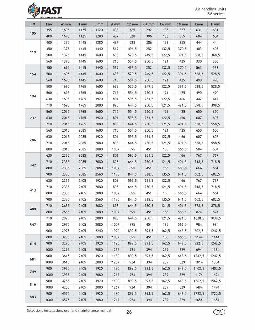
FM Fan W mm H mm L mm A mm C2 mm C4 mm C6 mm C8 mm Emm F mm
105355 1695 1125 1120 433 485 292 135 327 631 631
400 1695 1125 1280 487 528 306 133 355 604 604
119
400 1375 1445 1280 487 528 306 133 355 444 444
450 1375 1445 1440 569 496,5 252 132,5 370,5 403 403
500 1375 1445 1600 638 520,5 249,5 122,5 391,5 368,5 368,5
560 1375 1445 1600 715 554,5 250,5 121 425 330 330
154
450 1695 1445 1440 569 496,5 252 132,5 370,5 563 563
500 1695 1445 1600 638 520,5 249,5 122,5 391,5 528,5 528,5
560 1695 1445 1600 715 554,5 250,5 121 425 490 490
194
500 1695 1765 1600 638 520,5 249,5 122,5 391,5 528,5 528,5
560 1695 1765 1600 715 554,5 250,5 121 425 490 490
630 1695 1765 1920 801 595,5 251,5 122,5 466 447 447
710 1695 1765 2080 898 644,5 250,5 121,5 491,5 398,5 398,5
237
560 2015 1765 1600 715 554,5 250,5 121 425 650 650
630 2015 1765 1920 801 595,5 251,5 122,5 466 607 607
710 2015 1765 2080 898 644,5 250,5 121,5 491,5 558,5 558,5
286
560 2015 2085 1600 715 554,5 250,5 121 425 650 650
630 2015 2085 1920 801 595,5 251,5 122,5 466 607 607
710 2015 2085 2080 898 644,5 250,5 121,5 491,5 558,5 558,5
800 2015 2085 2080 1007 895 451 185 566,5 504 504
342
630 2335 2085 1920 801 595,5 251,5 122,5 466 767 767
710 2335 2085 2080 898 644,5 250,5 121,5 491,5 718,5 718,5
800 2335 2085 2080 1007 895 451 185 566,5 664 664
900 2335 2085 2560 1130 844,5 338,5 135,5 641,5 602,5 602,5
413
630 2335 2405 1920 801 595,5 251,5 122,5 466 767 767
710 2335 2405 2080 898 644,5 250,5 121,5 491,5 718,5 718,5
800 2335 2405 2080 1007 895 451 185 566,5 664 664
900 2335 2405 2560 1130 844,5 338,5 135,5 641,5 602,5 602,5
480710 2655 2405 2080 898 644,5 250,5 121,5 491,5 878,5 878,5
800 2655 2405 2080 1007 895 451 185 566,5 824 824
547
710 2975 2405 2080 898 644,5 250,5 121,5 491,5 1038,5 1038,5
800 2975 2405 2080 1007 895 451 185 566,5 984 984
900 2975 2405 2240 1920 899,5 393,5 162,5 443,5 602,5 1242,5
614
800 3295 2405 2080 1007 895 451 185 566,5 1144 1144
900 3295 2405 1920 1120 899,5 393,5 162,5 643,5 922,5 1242,5
1000 3295 2405 2080 1267 924 394 239 829 694 1334
681900 3615 2405 1920 1130 899,5 393,5 162,5 643,5 1242,5 1242,5
1000 3615 2405 2080 1267 924 394 239 829 1014 1334
749900 3935 2405 1920 1130 899,5 393,5 162,5 643,5 1402,5 1402,5
1000 3935 2405 2080 1267 924 394 239 829 1174 1494
816900 4255 2405 1920 1130 899,5 393,5 162,5 643,5 1562,5 1562,5
1000 4255 2405 2080 1267 924 394 239 829 1494 1494
883900 4575 2405 1920 1130 899,5 393,5 162,5 643,5 1722,5 1722,5
1000 4575 2405 2080 1267 924 394 239 829 1654 1654
Air handling units -FM series -
26 å æSelection, installation, use and maintenance manual
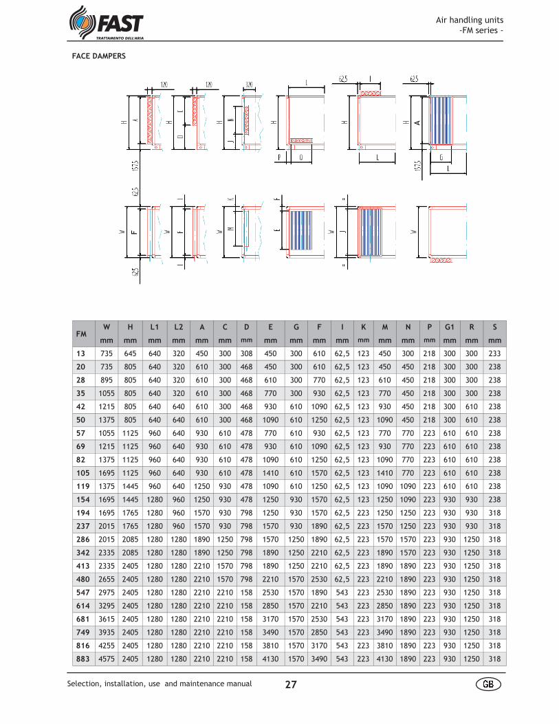
FACE DAMPERS
A
F
FMW H L1 L2 A C D E G F I K M N P G1 R S
mm mm mm mm mm mm mm mm mm mm mm mm mm mm mm mm mm mm
13 735 645 640 320 450 300 308 450 300 610 62,5 123 450 300 218 300 300 233
20 735 805 640 320 610 300 468 450 300 610 62,5 123 450 450 218 300 300 238
28 895 805 640 320 610 300 468 610 300 770 62,5 123 610 450 218 300 300 238
35 1055 805 640 320 610 300 468 770 300 930 62,5 123 770 450 218 300 300 238
42 1215 805 640 640 610 300 468 930 610 1090 62,5 123 930 450 218 300 610 238
50 1375 805 640 640 610 300 468 1090 610 1250 62,5 123 1090 450 218 300 610 238
57 1055 1125 960 640 930 610 478 770 610 930 62,5 123 770 770 223 610 610 238
69 1215 1125 960 640 930 610 478 930 610 1090 62,5 123 930 770 223 610 610 238
82 1375 1125 960 640 930 610 478 1090 610 1250 62,5 123 1090 770 223 610 610 238
105 1695 1125 960 640 930 610 478 1410 610 1570 62,5 123 1410 770 223 610 610 238
119 1375 1445 960 640 1250 930 478 1090 610 1250 62,5 123 1090 1090 223 610 610 238
154 1695 1445 1280 960 1250 930 478 1250 930 1570 62,5 123 1250 1090 223 930 930 238
194 1695 1765 1280 960 1570 930 798 1250 930 1570 62,5 223 1250 1250 223 930 930 318
237 2015 1765 1280 960 1570 930 798 1570 930 1890 62,5 223 1570 1250 223 930 930 318
286 2015 2085 1280 1280 1890 1250 798 1570 1250 1890 62,5 223 1570 1570 223 930 1250 318
342 2335 2085 1280 1280 1890 1250 798 1890 1250 2210 62,5 223 1890 1570 223 930 1250 318
413 2335 2405 1280 1280 2210 1570 798 1890 1250 2210 62,5 223 1890 1890 223 930 1250 318
480 2655 2405 1280 1280 2210 1570 798 2210 1570 2530 62,5 223 2210 1890 223 930 1250 318
547 2975 2405 1280 1280 2210 2210 158 2530 1570 1890 543 223 2530 1890 223 930 1250 318
614 3295 2405 1280 1280 2210 2210 158 2850 1570 2210 543 223 2850 1890 223 930 1250 318
681 3615 2405 1280 1280 2210 2210 158 3170 1570 2530 543 223 3170 1890 223 930 1250 318
749 3935 2405 1280 1280 2210 2210 158 3490 1570 2850 543 223 3490 1890 223 930 1250 318
816 4255 2405 1280 1280 2210 2210 158 3810 1570 3170 543 223 3810 1890 223 930 1250 318
883 4575 2405 1280 1280 2210 2210 158 4130 1570 3490 543 223 4130 1890 223 930 1250 318
Air handling units -FM series -
27 å æSelection, installation, use and maintenance manual
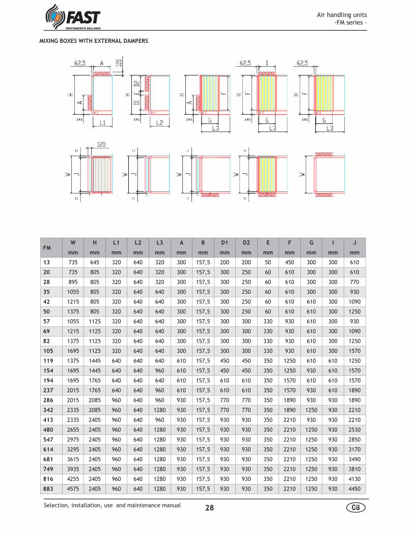
MIXING BOXES WITH EXTERNAL DAMPERS
FMW H L1 L2 L3 A B D1 D2 E F G I J
mm mm mm mm mm mm mm mm mm mm mm mm mm mm
13 735 645 320 640 320 300 157,5 200 200 50 450 300 300 610
20 735 805 320 640 320 300 157,5 300 250 60 610 300 300 610
28 895 805 320 640 320 300 157,5 300 250 60 610 300 300 770
35 1055 805 320 640 640 300 157,5 300 250 60 610 300 300 930
42 1215 805 320 640 640 300 157,5 300 250 60 610 610 300 1090
50 1375 805 320 640 640 300 157,5 300 250 60 610 610 300 1250
57 1055 1125 320 640 640 300 157,5 300 300 330 930 610 300 930
69 1215 1125 320 640 640 300 157,5 300 300 330 930 610 300 1090
82 1375 1125 320 640 640 300 157,5 300 300 330 930 610 300 1250
105 1695 1125 320 640 640 300 157,5 300 300 330 930 610 300 1570
119 1375 1445 640 640 640 610 157,5 450 450 350 1250 610 610 1250
154 1695 1445 640 640 960 610 157,5 450 450 350 1250 930 610 1570
194 1695 1765 640 640 640 610 157,5 610 610 350 1570 610 610 1570
237 2015 1765 640 640 960 610 157,5 610 610 350 1570 930 610 1890
286 2015 2085 960 640 960 930 157,5 770 770 350 1890 930 930 1890
342 2335 2085 960 640 1280 930 157,5 770 770 350 1890 1250 930 2210
413 2335 2405 960 640 960 930 157,5 930 930 350 2210 930 930 2210
480 2655 2405 960 640 1280 930 157,5 930 930 350 2210 1250 930 2530
547 2975 2405 960 640 1280 930 157,5 930 930 350 2210 1250 930 2850
614 3295 2405 960 640 1280 930 157,5 930 930 350 2210 1250 930 3170
681 3615 2405 960 640 1280 930 157,5 930 930 350 2210 1250 930 3490
749 3935 2405 960 640 1280 930 157,5 930 930 350 2210 1250 930 3810
816 4255 2405 960 640 1280 930 157,5 930 930 350 2210 1250 930 4130
883 4575 2405 960 640 1280 930 157,5 930 930 350 2210 1250 930 4450
Air handling units -FM series -
28 å æSelection, installation, use and maintenance manual
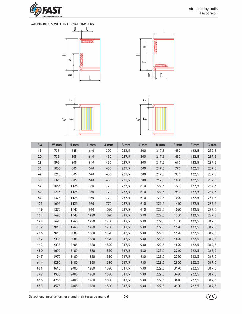
MIXING BOXES WITH INTERNAL DAMPERS
FM W mm H mm L mm A mm B mm C mm D mm E mm F mm G mm
13 735 645 640 300 232,5 300 217,5 450 122,5 232,5
20 735 805 640 450 237,5 300 217,5 450 122,5 237,5
28 895 805 640 450 237,5 300 217,5 610 122,5 237,5
35 1055 805 640 450 237,5 300 217,5 770 122,5 237,5
42 1215 805 640 450 237,5 300 217,5 930 122,5 237,5
50 1375 805 640 450 237,5 300 217,5 1090 122,5 237,5
57 1055 1125 960 770 237,5 610 222,5 770 122,5 237,5
69 1215 1125 960 770 237,5 610 222,5 930 122,5 237,5
82 1375 1125 960 770 237,5 610 222,5 1090 122,5 237,5
105 1695 1125 960 770 237,5 610 222,5 1410 122,5 237,5
119 1375 1445 960 1090 237,5 610 222,5 1090 122,5 237,5
154 1695 1445 1280 1090 237,5 930 222,5 1250 122,5 237,5
194 1695 1765 1280 1250 317,5 930 222,5 1250 122,5 317,5
237 2015 1765 1280 1250 317,5 930 222,5 1570 122,5 317,5
286 2015 2085 1280 1570 317,5 930 222,5 1570 122,5 317,5
342 2335 2085 1280 1570 317,5 930 222,5 1890 122,5 317,5
413 2335 2405 1280 1890 317,5 930 222,5 1890 122,5 317,5
480 2655 2405 1280 1890 317,5 930 222,5 2210 222,5 317,5
547 2975 2405 1280 1890 317,5 930 222,5 2530 222,5 317,5
614 3295 2405 1280 1890 317,5 930 222,5 2850 222,5 317,5
681 3615 2405 1280 1890 317,5 930 222,5 3170 222,5 317,5
749 3935 2405 1280 1890 317,5 930 222,5 3490 222,5 317,5
816 4255 2405 1280 1890 317,5 930 222,5 3810 222,5 317,5
883 4575 2405 1280 1890 317,5 930 222,5 4130 222,5 317,5
Air handling units -FM series -
29 å æSelection, installation, use and maintenance manual

3-WAY MIXING BOXES WITH EXTERNAL DAMPERS
FM W mm H mm L1 mm L2 mm L3 mm L4 mm A mm B mm C mm
13 735 645 800 320 320 640 300 610 190
20 735 805 800 320 320 640 300 610 190
28 895 805 800 320 320 640 300 770 190
35 1055 805 800 320 320 640 300 930 190
42 1215 805 800 320 320 640 300 1090 190
50 1375 805 800 320 320 640 300 1250 190
57 1055 1125 1120 480 480 960 450 930 190
69 1215 1125 1120 480 480 960 450 1090 190
82 1375 1125 1120 480 480 960 450 1250 190
105 1695 1125 1120 480 480 960 450 1570 190
119 1375 1445 1440 640 640 960 610 1250 190
154 1695 1445 1600 640 640 960 610 1570 350
194 1695 1765 1920 800 800 1280 770 1570 350
237 2015 1765 1920 800 800 1280 770 1890 350
286 2015 2085 2240 960 960 1280 930 1890 350
342 2335 2085 2240 960 960 1280 930 2210 350
413 2335 2405 2240 960 960 1280 930 2210 350
480 2655 2405 2240 960 960 1280 930 2530 350
547 2975 2405 2240 960 960 1280 930 2850 350
614 3295 2405 2240 960 960 1280 930 3170 350
681 3615 2405 2240 960 960 1280 930 3490 350
749 3935 2405 2240 960 960 1280 930 3810 350
816 4255 2405 2240 960 960 1280 930 4130 350
883 4575 2405 2240 960 960 1280 930 4450 350
Air handling units -FM series -
30 å æSelection, installation, use and maintenance manual

3-WAY MIXING BOXES WITH INTERNAL DAMPERS
FM W mm H mm C mm D mm CONFIG. L mm A mm B mm X mm Y mm
13 735 645 300 232,5 L 1280 450 450 75 755
20 735 805 450 237,5 L 1280 450 450 75 755
28 895 805 450 237,5 L 1600 450 770 75 755
35 1055 805 450 237,5 L 1600 450 770 75 755
42 1215 805 450 237,5 Z 1600 770 1090 75 435
50 1375 805 450 237,5 Z 1600 770 1090 75 435
57 1055 1125 770 237,5 Z 1280 770 770 75 435
69 1215 1125 770 237,5 Z 1600 770 1090 75 435
82 1375 1125 770 237,5 Z 1600 770 1090 75 435
105 1695 1125 770 237,5 Z 1920 1090 1410 75 435
119 1375 1445 1090 237,5 Z 1920 1090 1410 75 435
154 1695 1445 1090 237,5 Z 2240 1250 1730 75 435
194 1695 1765 1250 317,5 Z 1920 1250 1570 175 175
237 2015 1765 1250 317,5 Z 2240 1570 1890 175 175
286 2015 2085 1570 317,5 Z 2240 1570 1890 175 175
342 2335 2085 1570 317,5 Z 2560 1890 1890 175 175
413 2335 2405 1890 317,5 Z 2560 1890 1890 175 175
480 2655 2405 1890 317,5 S 2240 1890 1890 222,5 222,5
547 2975 2405 1890 317,5 S 2240 1890 1890 222,5 222,5
614 3295 2405 1890 317,5 S 2240 1890 1890 222,5 222,5
681 3615 2405
749 3935 2405Contact FAST technical department
816 4255 2405
883 4575 2405
Air handling units -FM series -
31 å æSelection, installation, use and maintenance manual

FILTERS
ç è é ê ë ì í î ï ð ï ñ ì í ò ó ô õ ô ö ÷ ø õ ù ô ú û ü ó ýí þ ÿ � ë � � ï � � ì íé ÿ ñ � � � í� � � � � � ï � � ì í �ê ì � � è î ì � ï � � ì î í � � ê ë � î é ÿ � ê � ï �� � ê � ï � � ì ñ ê � î ê é � �� � � � � � � � � � � � � � � � � � � � � �� í é � � í � � í é � � � ì � ï � � ì î í î é � � � ï � í � î é � � � ï � � ì î í � � � è ì í ð ì î � ï ê ï ñ ì í � ð ì î � ï ê þ ñ � � � � è í
5
Bag Rigid bag
Absolute Roll
SyntheticsCorrugatedand metal
Carboni
Germicyda lamps
FM H1 mm H3 mm H2 mm L1 mm L2 mm L3 mm L4 mm L5 mm
13 645 --- 1125 320 640 960 1280 480
20 805 --- 1125 320 640 960 1280 480
28 805 --- 1125 320 640 960 1280 480
35 805 --- 1125 320 640 960 1280 480
42 805 --- 1125 320 640 960 1280 480
50 805 --- 1125 320 640 960 1280 480
57 (1) 1125 1125 1125 320 640 960 1280 480
69 (1) 1125 1125 1125 320 640 960 1280 480
82 1125 1125 1125 320 640 960 1280 480
105 1125 1125 1125 320 640 960 1280 ---
119 1445 1445 1445 320 640 960 1280 480
154 1445 1445 1445 320 640 960 1280 ---
194 1765 1765 1765 320 640 960 1280 ---
237 1765 1765 1765 320 640 960 1280 ---
286 2085 2085 2085 320 640 960 1280 ---
342 2085 2085 2085 320 640 960 1280 ---
413 2405 2405 2405 320 640 960 1280 ---
480 2405 2405 2405 320 640 960 1280 ---
547 2405 2405 2405 320 640 960 1280 ---
614 2405 2405 2405 320 640 960 1280 ---
681 2405 2405 2405 320 640 960 1280 ---
749 2405 2405 2405 320 640 960 1280 ---
816 2405 2405 2405 320 640 960 1280 ---
883 2405 2405 2405 320 640 960 1280 ---
(1) Separate enclosure with a width equal to the FM 82(2) Horizontal roller filter up to size 105 including
Frame Drawer
Air handling units -FM series -
32 å æSelection, installation, use and maintenance manual
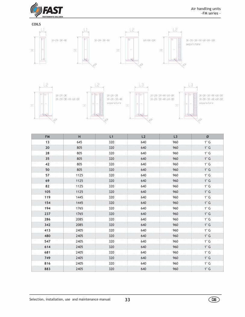
COILS
FM H L1 L2 L3 Ø
13 645 320 640 960 1" G
20 805 320 640 960 1" G
28 805 320 640 960 1" G
35 805 320 640 960 1" G
42 805 320 640 960 1" G
50 805 320 640 960 1" G
57 1125 320 640 960 1" G
69 1125 320 640 960 1" G
82 1125 320 640 960 1" G
105 1125 320 640 960 1" G
119 1445 320 640 960 1" G
154 1445 320 640 960 1" G
194 1765 320 640 960 1" G
237 1765 320 640 960 1" G
286 2085 320 640 960 1" G
342 2085 320 640 960 1" G
413 2405 320 640 960 1" G
480 2405 320 640 960 1" G
547 2405 320 640 960 1" G
614 2405 320 640 960 1" G
681 2405 320 640 960 1" G
749 2405 320 640 960 1" G
816 2405 320 640 960 1" G
883 2405 320 640 960 1" G
Air handling units -FM series -
33 å æSelection, installation, use and maintenance manual
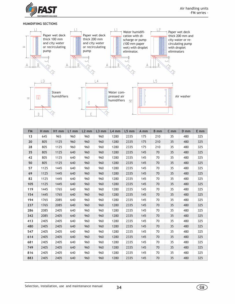
HUMIDIFIING SECTIONS� � � � � ! � " # $ % & ' ( ) * ) ' $ +) # � + ( ) * * ) & �# , ) " ( & � ( ) - . ) " $ � & '/ 0 0 � � 12 3 4 5 6 7 5 8 9 5 : ; 8 < = : ;> ? ? @ @ 3 A 9 : = 8 B7 3 8 5 6 C 6 6 5 : = 6 : D E 3 8 = A F4 D @ 4 � � � � � ! � " # $ % & ' ( ) * ) ' $ +) # � + ( ) * * ) & � # , ) " ( & � ( )- . ) " $ � & ' G 0 0 � � 12 3 4 5 6 7 5 8 9 5 : ; 8 < = : ;H ? ? @ @ 3 A 9 : = 8 B7 3 8 5 6 C 6 6 5 : = 6 : D E 3 8 = A F4 D @ 4 � � � % � ! � " # $ � & ' ( ) * ) ' $+ ) # � + ( ) * * ) & � # , ) " ( & � ( )- . ) " $ � & ' / 0 0 � � 1) $ . I ( # * # $ ) � * )J & � $ ) K K I $ ) .2 3 4 5 6 7 5 8 9 5 : ; 8 < = : ;> ? ? @ @ 3 A 9 : = 8 B7 3 8 5 6 C 6 6 5 : = 6 : D E 3 8 = A F4 D @ 4 7 = 8 < 9 6 C 4 E 5 85 E = @ = A 3 8 C 6 L � � � % � ! � " # $ � & ' ( ) * ) ' $+ ) # � + ( ) * * ) & � # , ) " ( & � ( )- . ) " $ � & ' G 0 0 � � 1) $ . I ( # * # $ ) � * )J & � $ ) K K I $ ) .2 3 4 5 6 7 5 8 9 5 : ; 8 < = : ;H ? ? @ @ 3 A 9 : = 8 B7 3 8 5 6 C 6 6 5 : = 6 : D E 3 8 = A F4 D @ 4 7 = 8 < 9 6 C 4 E 5 85 E = @ = A 3 8 C 6 L� � � % � ! � " # $ � & ' +, # ( ) � *M 8 5 3 @< D @ = 9 = N = 5 6 L � � � % � ! � " # $ � & ' +) # � ) $ # � *" & � ( * � � OP 3 8 5 6 : C @ 4 6 5 L L 5 93 = 6 < D @ = 9 = N = 5 6 L Q # , ) � * R # � *S = 6 7 3 L < 5 6Steam
humidifiers Air washer
Paper wet deck thick 100 mm and city water or recirculating pump
Paper wet deck thick 200 mm and city water or recirculating pump
Water humidifi-cation with di-scharge or pump (100 mm paper wet) with droplet eliminator.
Paper wet deck thick 200 mm and city water or re-circulating pump with droplet eliminators
Water com-pressed air humidifiers
FM H mm H1 mm L1 mm L2 mm L3 mm L4 mm L5 mm A mm B mm C mm D mm E mm
13 645 965 960 960 960 1280 2335 175 210 35 480 325
20 805 1125 960 960 960 1280 2335 175 210 35 480 325
28 805 1125 960 960 960 1280 2335 175 210 35 480 325
35 805 1125 640 960 960 1280 2335 145 70 35 480 325
42 805 1125 640 960 960 1280 2335 145 70 35 480 325
50 805 1125 640 960 960 1280 2335 145 70 35 480 325
57 1125 1445 640 960 960 1280 2335 145 70 35 480 325
69 1125 1445 640 960 960 1280 2335 145 70 35 480 325
82 1125 1445 640 960 960 1280 2335 145 70 35 480 325
105 1125 1445 640 960 960 1280 2335 145 70 35 480 325
119 1445 1765 640 960 960 1280 2335 145 70 35 480 325
154 1445 1765 640 960 960 1280 2335 145 70 35 480 325
194 1765 2085 640 960 960 1280 2335 145 70 35 480 325
237 1765 2085 640 960 960 1280 2335 145 70 35 480 325
286 2085 2405 640 960 960 1280 2335 145 70 35 480 325
342 2085 2405 640 960 960 1280 2335 145 70 35 480 325
413 2405 2405 640 960 960 1280 2335 145 70 35 480 325
480 2405 2405 640 960 960 1280 2335 145 70 35 480 325
547 2405 2405 640 960 960 1280 2335 145 70 35 480 325
614 2405 2405 640 960 960 1280 2335 145 70 35 480 325
681 2405 2405 640 960 960 1280 2335 145 70 35 480 325
749 2405 2405 640 960 960 1280 2335 145 70 35 480 325
816 2405 2405 640 960 960 1280 2335 145 70 35 480 325
883 2405 2405 640 960 960 1280 2335 145 70 35 480 325
Air handling units -FM series -
34 å æSelection, installation, use and maintenance manual
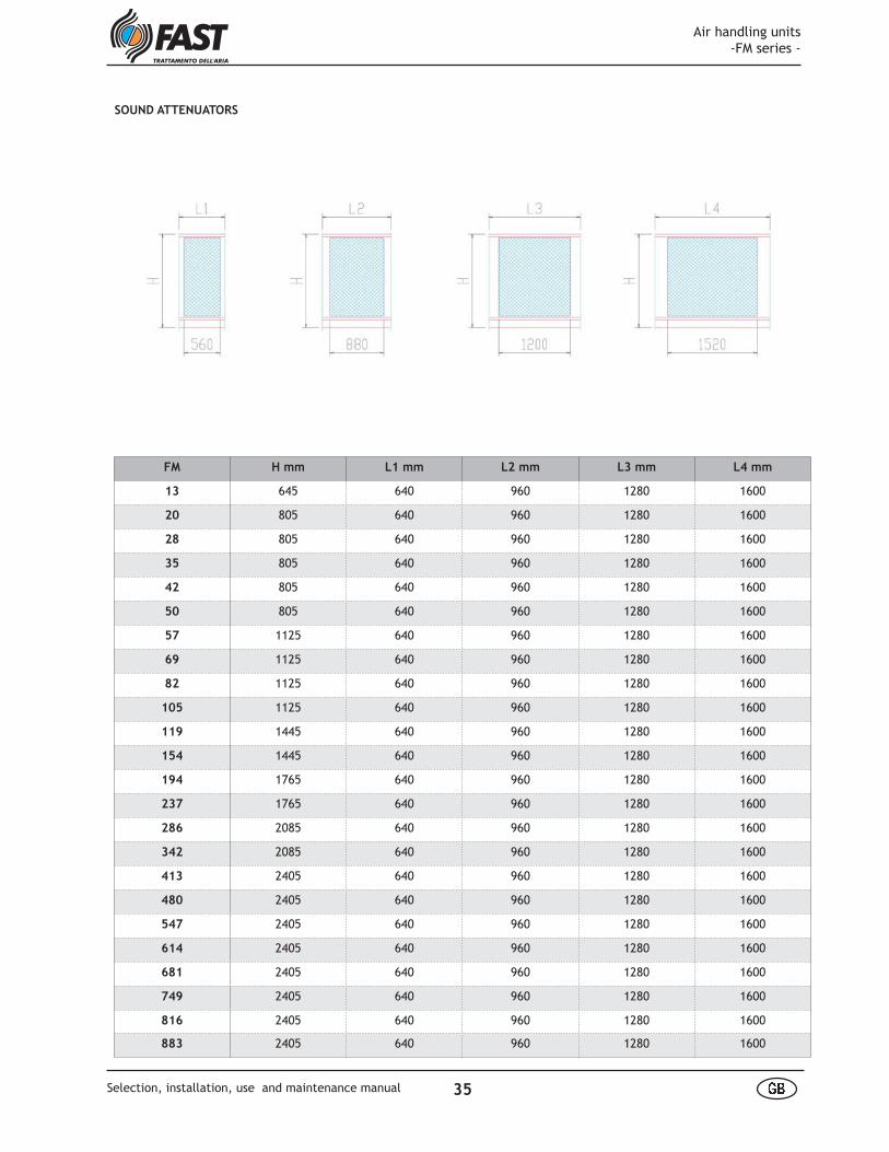
SOUND ATTENUATORS
FM H mm L1 mm L2 mm L3 mm L4 mm
13 645 640 960 1280 1600
20 805 640 960 1280 1600
28 805 640 960 1280 1600
35 805 640 960 1280 1600
42 805 640 960 1280 1600
50 805 640 960 1280 1600
57 1125 640 960 1280 1600
69 1125 640 960 1280 1600
82 1125 640 960 1280 1600
105 1125 640 960 1280 1600
119 1445 640 960 1280 1600
154 1445 640 960 1280 1600
194 1765 640 960 1280 1600
237 1765 640 960 1280 1600
286 2085 640 960 1280 1600
342 2085 640 960 1280 1600
413 2405 640 960 1280 1600
480 2405 640 960 1280 1600
547 2405 640 960 1280 1600
614 2405 640 960 1280 1600
681 2405 640 960 1280 1600
749 2405 640 960 1280 1600
816 2405 640 960 1280 1600
883 2405 640 960 1280 1600
Air handling units -FM series -
35 å æSelection, installation, use and maintenance manual
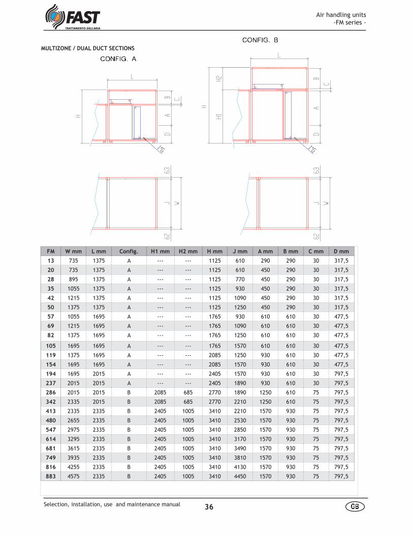
T U V W X Y Z [ T U V W X Y Z \
FM W mm L mm Config. H1 mm H2 mm H mm J mm A mm B mm C mm D mm
13 735 1375 A --- --- 1125 610 290 290 30 317,5
20 735 1375 A --- --- 1125 610 450 290 30 317,5
28 895 1375 A --- --- 1125 770 450 290 30 317,5
35 1055 1375 A --- --- 1125 930 450 290 30 317,5
42 1215 1375 A --- --- 1125 1090 450 290 30 317,5
50 1375 1375 A --- --- 1125 1250 450 290 30 317,5
57 1055 1695 A --- --- 1765 930 610 610 30 477,5
69 1215 1695 A --- --- 1765 1090 610 610 30 477,5
82 1375 1695 A --- --- 1765 1250 610 610 30 477,5
105 1695 1695 A --- --- 1765 1570 610 610 30 477,5
119 1375 1695 A --- --- 2085 1250 930 610 30 477,5
154 1695 1695 A --- --- 2085 1570 930 610 30 477,5
194 1695 2015 A --- --- 2405 1570 930 610 30 797,5
237 2015 2015 A --- --- 2405 1890 930 610 30 797,5
286 2015 2015 B 2085 685 2770 1890 1250 610 75 797,5
342 2335 2015 B 2085 685 2770 2210 1250 610 75 797,5
413 2335 2335 B 2405 1005 3410 2210 1570 930 75 797,5
480 2655 2335 B 2405 1005 3410 2530 1570 930 75 797,5
547 2975 2335 B 2405 1005 3410 2850 1570 930 75 797,5
614 3295 2335 B 2405 1005 3410 3170 1570 930 75 797,5
681 3615 2335 B 2405 1005 3410 3490 1570 930 75 797,5
749 3935 2335 B 2405 1005 3410 3810 1570 930 75 797,5
816 4255 2335 B 2405 1005 3410 4130 1570 930 75 797,5
883 4575 2335 B 2405 1005 3410 4450 1570 930 75 797,5
MULTIZONE / DUAL DUCT SECTIONS
Air handling units -FM series -
36 å æSelection, installation, use and maintenance manual
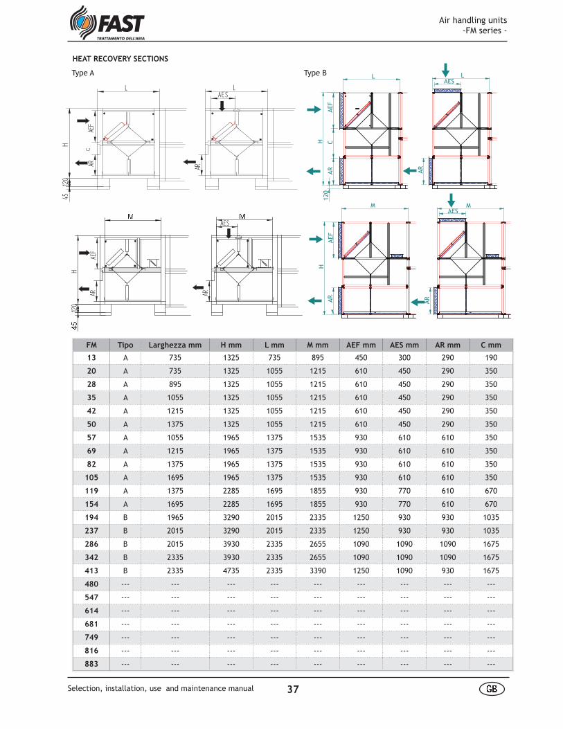
LAE
FAR
LAES
AR
H12
045 ] ]
AEF
AR AR
AES
H12
0_̂
C
FM Tipo Larghezza mm H mm L mm M mm AEF mm AES mm AR mm C mm
13 A 735 1325 735 895 450 300 290 190
20 A 735 1325 1055 1215 610 450 290 350
28 A 895 1325 1055 1215 610 450 290 350
35 A 1055 1325 1055 1215 610 450 290 350
42 A 1215 1325 1055 1215 610 450 290 350
50 A 1375 1325 1055 1215 610 450 290 350
57 A 1055 1965 1375 1535 930 610 610 350
69 A 1215 1965 1375 1535 930 610 610 350
82 A 1375 1965 1375 1535 930 610 610 350
105 A 1695 1965 1375 1535 930 610 610 350
119 A 1375 2285 1695 1855 930 770 610 670
154 A 1695 2285 1695 1855 930 770 610 670
194 B 1965 3290 2015 2335 1250 930 930 1035
237 B 2015 3290 2015 2335 1250 930 930 1035
286 B 2015 3930 2335 2655 1090 1090 1090 1675
342 B 2335 3930 2335 2655 1090 1090 1090 1675
413 B 2335 4735 2335 3390 1250 1090 930 1675
480 --- --- --- --- --- --- --- --- ---
547 --- --- --- --- --- --- --- --- ---
614 --- --- --- --- --- --- --- --- ---
681 --- --- --- --- --- --- --- --- ---
749 --- --- --- --- --- --- --- --- ---
816 --- --- --- --- --- --- --- --- ---
883 --- --- --- --- --- --- --- --- ---
HEAT RECOVERY SECTIONS
M
AES
AR
AEF
CAR
AES
AR
AEF
AR
120
HH
M
LLType A Type B
Air handling units -FM series -
37 å æSelection, installation, use and maintenance manual
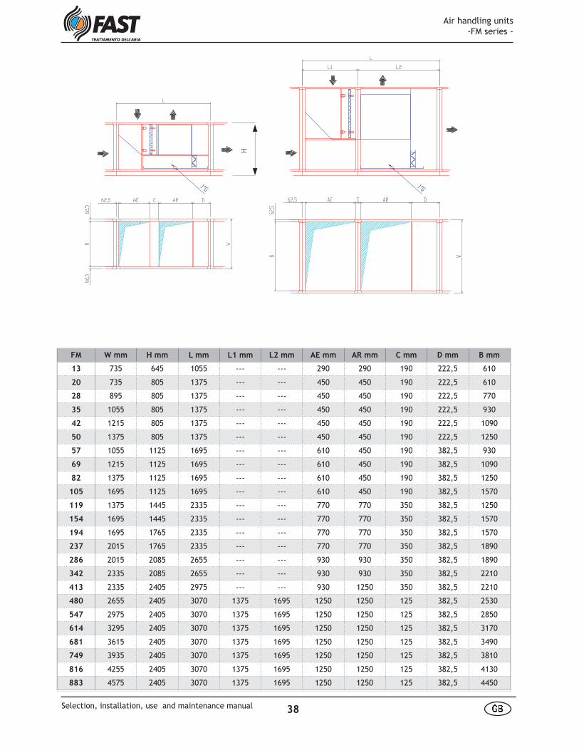
H
FM W mm H mm L mm L1 mm L2 mm AE mm AR mm C mm D mm B mm
13 735 645 1055 --- --- 290 290 190 222,5 610
20 735 805 1375 --- --- 450 450 190 222,5 610
28 895 805 1375 --- --- 450 450 190 222,5 770
35 1055 805 1375 --- --- 450 450 190 222,5 930
42 1215 805 1375 --- --- 450 450 190 222,5 1090
50 1375 805 1375 --- --- 450 450 190 222,5 1250
57 1055 1125 1695 --- --- 610 450 190 382,5 930
69 1215 1125 1695 --- --- 610 450 190 382,5 1090
82 1375 1125 1695 --- --- 610 450 190 382,5 1250
105 1695 1125 1695 --- --- 610 450 190 382,5 1570
119 1375 1445 2335 --- --- 770 770 350 382,5 1250
154 1695 1445 2335 --- --- 770 770 350 382,5 1570
194 1695 1765 2335 --- --- 770 770 350 382,5 1570
237 2015 1765 2335 --- --- 770 770 350 382,5 1890
286 2015 2085 2655 --- --- 930 930 350 382,5 1890
342 2335 2085 2655 --- --- 930 930 350 382,5 2210
413 2335 2405 2975 --- --- 930 1250 350 382,5 2210
480 2655 2405 3070 1375 1695 1250 1250 125 382,5 2530
547 2975 2405 3070 1375 1695 1250 1250 125 382,5 2850
614 3295 2405 3070 1375 1695 1250 1250 125 382,5 3170
681 3615 2405 3070 1375 1695 1250 1250 125 382,5 3490
749 3935 2405 3070 1375 1695 1250 1250 125 382,5 3810
816 4255 2405 3070 1375 1695 1250 1250 125 382,5 4130
883 4575 2405 3070 1375 1695 1250 1250 125 382,5 4450
Air handling units -FM series -
38 å æSelection, installation, use and maintenance manual
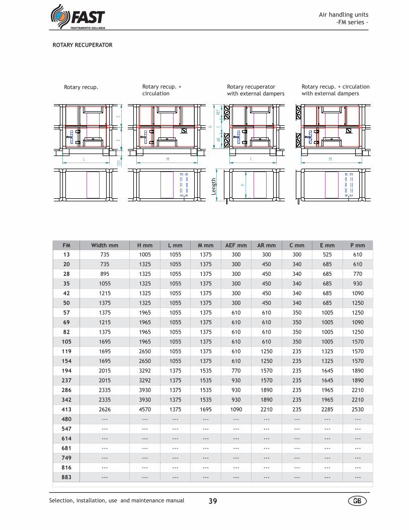
FM Width mm H mm L mm M mm AEF mm AR mm C mm E mm P mm
13 735 1005 1055 1375 300 300 300 525 610
20 735 1325 1055 1375 300 450 340 685 610
28 895 1325 1055 1375 300 450 340 685 770
35 1055 1325 1055 1375 300 450 340 685 930
42 1215 1325 1055 1375 300 450 340 685 1090
50 1375 1325 1055 1375 300 450 340 685 1250
57 1375 1965 1055 1375 610 610 350 1005 1250
69 1215 1965 1055 1375 610 610 350 1005 1090
82 1375 1965 1055 1375 610 610 350 1005 1250
105 1695 1965 1055 1375 610 610 350 1005 1570
119 1695 2650 1055 1375 610 1250 235 1325 1570
154 1695 2650 1055 1375 610 1250 235 1325 1570
194 2015 3292 1375 1535 770 1570 235 1645 1890
237 2015 3292 1375 1535 930 1570 235 1645 1890
286 2335 3930 1375 1535 930 1890 235 1965 2210
342 2335 3930 1375 1535 930 1890 235 1965 2210
413 2626 4570 1375 1695 1090 2210 235 2285 2530
480 --- --- --- --- --- --- --- --- ---
547 --- --- --- --- --- --- --- --- ---
614 --- --- --- --- --- --- --- --- ---
681 --- --- --- --- --- --- --- --- ---
749 --- --- --- --- --- --- --- --- ---
816 --- --- --- --- --- --- --- --- ---
883 --- --- --- --- --- --- --- --- ---
Larg
hezz
aAE
FC
AR
H
L M
EE
120 ML
P
Recup. rotativo Recup. rotativocon ricircolo
Recup. rotativocon serrande esterne
Recup. rotativo + ricircolo con serrande esterne
ROTARY RECUPERATOR
Rotary recup. Rotary recup. + circulation
Rotary recuperator with external dampers
Rotary recup. + circulation with external dampers
Leng
th
Air handling units -FM series -
39 å æSelection, installation, use and maintenance manual
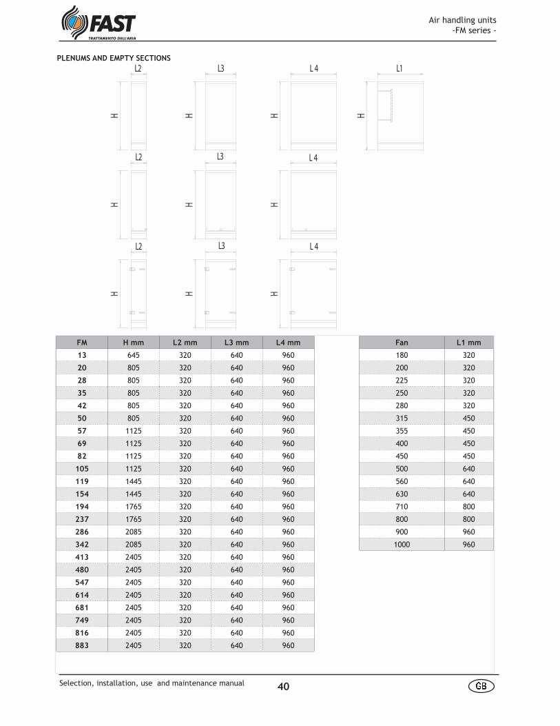
L1
HHHH
HHH
HH H
L2 L3 L 4
L2
L2 L3
L3
L 4
L 4
PLENUMS AND EMPTY SECTIONS
FM H mm L2 mm L3 mm L4 mm Fan L1 mm
13 645 320 640 960 180 320
20 805 320 640 960 200 320
28 805 320 640 960 225 320
35 805 320 640 960 250 320
42 805 320 640 960 280 320
50 805 320 640 960 315 450
57 1125 320 640 960 355 450
69 1125 320 640 960 400 450
82 1125 320 640 960 450 450
105 1125 320 640 960 500 640
119 1445 320 640 960 560 640
154 1445 320 640 960 630 640
194 1765 320 640 960 710 800
237 1765 320 640 960 800 800
286 2085 320 640 960 900 960
342 2085 320 640 960 1000 960
413 2405 320 640 960
480 2405 320 640 960
547 2405 320 640 960
614 2405 320 640 960
681 2405 320 640 960
749 2405 320 640 960
816 2405 320 640 960
883 2405 320 640 960
Air handling units -FM series -
40 å æSelection, installation, use and maintenance manual
dles;- Packages with fl exible connections ;- For sections to be loaded one on top of the other, wooden beams shall be positioned between the two sections.
CHECKS AT MATERIAL RECEIPT
When air handling units are received on site, it’s necessary to do some preliminary checks to verify that no damages have been occurred during transport. Potential damages should be marked on transport document.The checks are the following:-dampers: check integrity of shafts, gears and blades.-fi lters: check quantity and type;-coils: check integrity of manifolds and fi ns (if visible);-fan-motor assembly: check fi xing;-panels and baseframe: check integri-ty.-roof: check integrity.
17. TRANSPORT AND HANDLING
PACKING
The air handling units FM series are usually supplied without packing, except for fi lter cells (high and ab-solute effi ciency) and for assembling accessories which are supplied in cartoon boxes and are to be instal-led by customer.Upon request the air handling units can be supplied with polyetilenre fi lm, on pallets + polyetilene fi lm, in crate or in wooden box.
TRANSPORT
The transportability of the air han-dling units reguarding dimensional aspects is shown at pag.8.The tran-sport must be done according to the folllowing indications:- Packages must be securely fi xed at trucks fl oor;-Packages to prevent damages to all external parts of the casing like headers, connections,dampers, han-
WARNINGS AND SAFETY REGULATIONS
18. INSTALLATION
The following regulations when in-stalling, starting up, using and ser-vicing the air handling units must be taken into account:
When lifting, bear in mind that the centre of gravity of the unit may be off-centre.
Make sure that ropes and hooks are correctly fi xed.
Make sure that the unit and all its electric parts have been correctly earthed prior to starting up the unit.
Make sure that the fan opening vent has been connected to ducting or is covered by a protective grille prior to starting up the unit.
Never use the unit to support other equipment.
STOCKING AT SITE
The air handling units without roof must be stocked inside the building.The supply/exhaust openings must be pro-tected to avoid materials, powder or lit-tle animals entering the sections, and the dampers must be closed (and sealed with nylon fi lms if stocked outside the building)until the air handling units are connected to the ducts of the plant.The air handling units supplied in more sections shall be placed near to the other to avoid entering of external materials.
Do not use the station as a walkway or scaffold; if it is necessary to climb on the roof of the air handling unit it is required:1) to use all PPE necessary to avert the dangers encountered during the analy-sis phase of the residual risks;2) to prepare a proper weight distri-bution to prevent the breakthrough of the sheet metal roof (by leaning remo-vable supporting beams on very large surfaces).
Never stack tools, spare parts, etc. on top of the unit.
Before opening the unit, make sure that all electrical parts have been switched off. In particular, make sure that the fan is off and cannot be star-ted prior to opening inspection doors.
Do not open inspection panels when the fan is operating (especially sec-tions under pressure of the unit).
Always fi t the protective carter over the fan section before starting up the unit.
Make sure that all panels and hatches are properly closed.
Beware of sharp edges inside the unit.
Beware of roof corners of the outdoor units.
Beware of the heat exchange coils: dan-ger of burning.
Beware of the potential danger of burning deriving from steam humidifi ers.
Beware of the self-controlled dampers, which could close suddenly.
- And 'well, after installation, remove all traces of protective material applied to the surface of the side panels and top of the unit.
- Pay attention to the holes left open after removal of the lifting lugs of the unit: you must close them with the bolts and screws used for the mounting lugs and seal them with sealant silicone to prevent water in-fi ltration.
Air handling units -FM series -
41 å æSelection, installation, use and maintenance manual

Warning! The fastening must always be done using the holes marked with the yellow/back label.
When lifting the AHU please use a calibra or put a bar between the cables to eliminate the horizontal component of the force which could damage the roof of the AHU.During lifting be careful not to da-mage the outcoming parts like dam-pers, manifolds, drains and handles.
HANDLING AND POSITIONING
The air handling units FM series are built for the litfi ng from the bottom. The cor-ners feet and the base, when supplied, are equipped with holes for the lifting to be used as follows:sections with corner sockets only: the lif-ting can be done with hooks to anchor in the holes shown in the underlying fi gure B or ropes to be anchored to two 2" pipes passing from one side of the section to the other through the hole B;sections with continuous base: the han-dling can be done with ropes anchored to two 2 "pipes passing from one side of the section out through the hole A.
MINIMUM TECHNICAL CLEARANCES
In the positioning of the AHU it is impor-tant to provide the necessary space for the ordinary and extra ordinary mainte-nance.The best solution can be achived lea-
The positioning may be done using two transpallets, one for each section side, operating at the longer sides.Alternatively the positioning can be done by moving the ahu sections on pipes as they were rolls. The sections without continous base can be slided directly on the fl oor.
The fan-motor assembly are fi xed on antivibration supports; it is advisable, anyway, to place between baseframe and technical fl oor an antivibration mat.
ving at headers and inspection side a space 700 mm min wide and lae-ving at the opposite side a distance equal to the AHU’s width plus 100 mm in order to remove the coils at
the opposite side respect to the hea-ders without disassemble the valves assembly (fig.A)If the AHU must be placed at one wall, leave at inspection side a cor-ridor with the sae width of the AHU plus 100 mm (fig. B).
B
A
Air handling units -FM series -
42 å æSelection, installation, use and maintenance manual
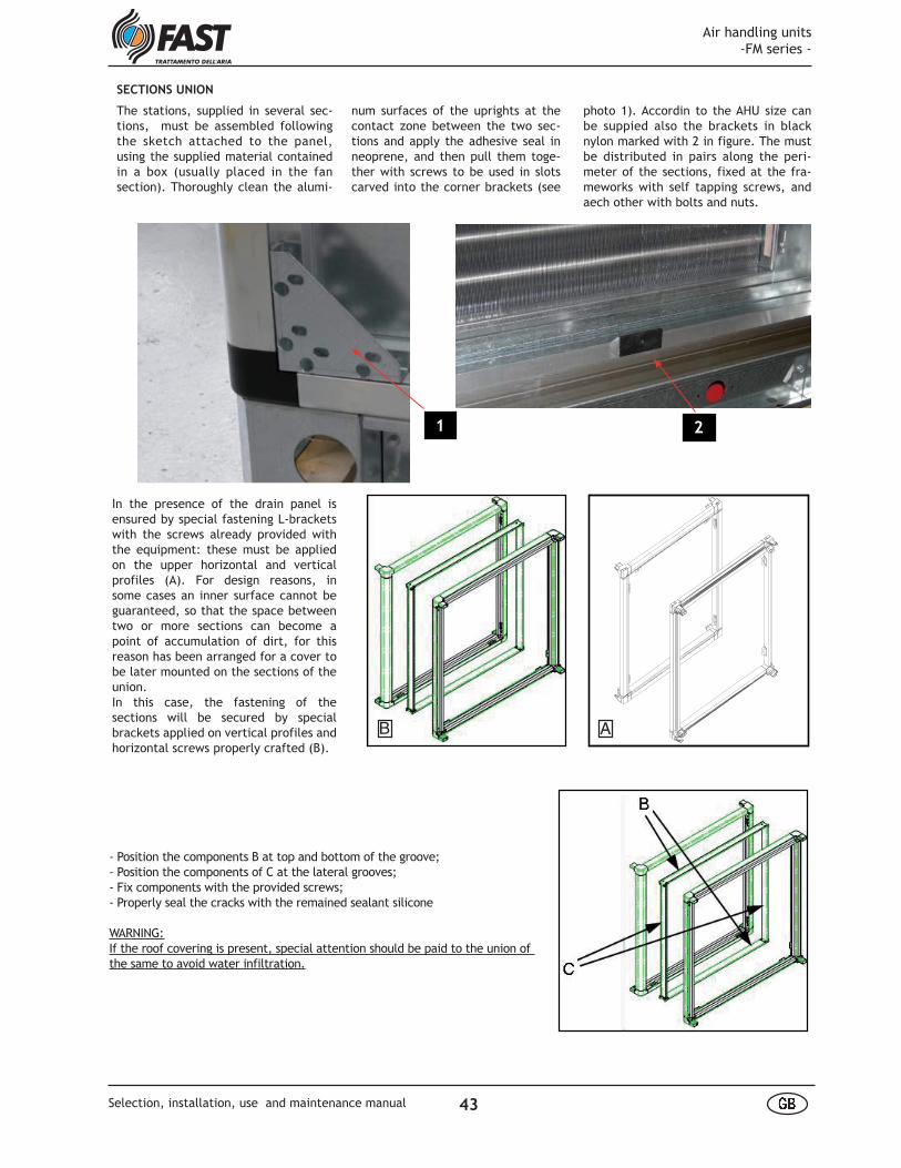
num surfaces of the uprights at the contact zone between the two sec-tions and apply the adhesive seal in neoprene, and then pull them toge-ther with screws to be used in slots carved into the corner brackets (see
SECTIONS UNION
The stations, supplied in several sec-tions, must be assembled following the sketch attached to the panel, using the supplied material contained in a box (usually placed in the fan section). Thoroughly clean the alumi-
photo 1). Accordin to the AHU size can be suppied also the brackets in black nylon marked with 2 in figure. The must be distributed in pairs along the peri-meter of the sections, fixed at the fra-meworks with self tapping screws, and aech other with bolts and nuts.
- Position the components B at top and bottom of the groove;- Position the components of C at the lateral grooves;- Fix components with the provided screws;- Properly seal the cracks with the remained sealant silicone
WARNING:If the roof covering is present, special attention should be paid to the union of the same to avoid water infiltration.
In the presence of the drain panel is ensured by special fastening L-brackets with the screws already provided with the equipment: these must be applied on the upper horizontal and vertical profiles (A). For design reasons, in some cases an inner surface cannot be guaranteed, so that the space between two or more sections can become a point of accumulation of dirt, for this reason has been arranged for a cover to be later mounted on the sections of the union.In this case, the fastening of the sections will be secured by special brackets applied on vertical profiles and horizontal screws properly crafted (B).
AB
2 1
Air handling units -FM series -
43 å æSelection, installation, use and maintenance manual
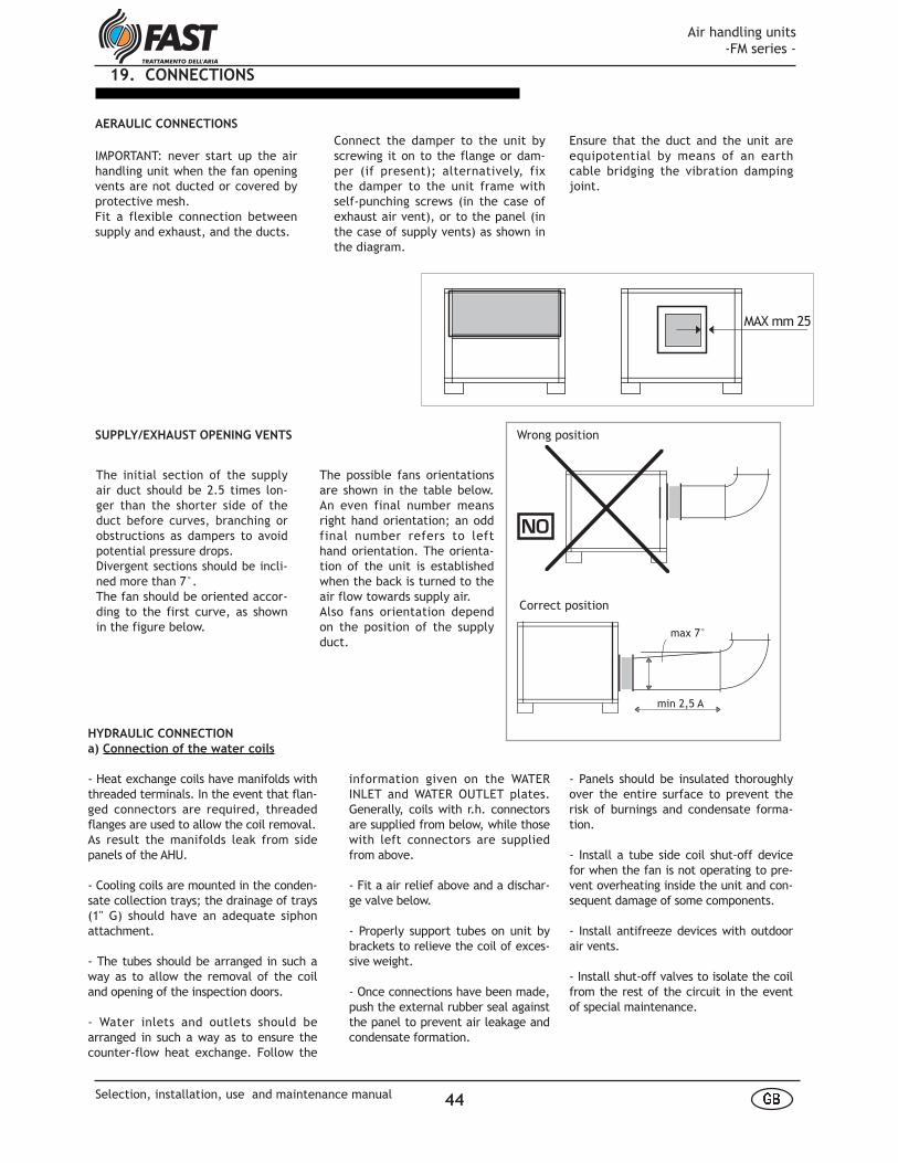
The initial section of the supply air duct should be 2.5 times lon-ger than the shorter side of the duct before curves, branching or obstructions as dampers to avoid potential pressure drops. Divergent sections should be incli-ned more than 7°.The fan should be oriented accor-ding to the first curve, as shown in the figure below.
HYDRAULIC CONNECTION
a) Connection of the water coils
- Heat exchange coils have manifolds with threaded terminals. In the event that flan-ged connectors are required, threaded flanges are used to allow the coil removal.As result the manifolds leak from side panels of the AHU.
- Cooling coils are mounted in the conden-sate collection trays; the drainage of trays (1" G) should have an adequate siphon attachment.
- The tubes should be arranged in such a way as to allow the removal of the coil and opening of the inspection doors.
- Water inlets and outlets should be arranged in such a way as to ensure the counter-flow heat exchange. Follow the
Correct position
Wrong positionSUPPLY/EXHAUST OPENING VENTS
information given on the WATER INLET and WATER OUTLET plates. Generally, coils with r.h. connectors are supplied from below, while those with left connectors are supplied from above.
- Fit a air relief above and a dischar-ge valve below.
- Properly support tubes on unit by brackets to relieve the coil of exces-sive weight.
- Once connections have been made, push the external rubber seal against the panel to prevent air leakage and condensate formation.
- Panels should be insulated thoroughly over the entire surface to prevent the risk of burnings and condensate forma-tion.
- Install a tube side coil shut-off device for when the fan is not operating to pre-vent overheating inside the unit and con-sequent damage of some components.
- Install antifreeze devices with outdoor air vents.
- Install shut-off valves to isolate the coil from the rest of the circuit in the event of special maintenance.
NO
min 2,5 A
max 7°
The possible fans orientations are shown in the table below. An even final number means right hand orientation; an odd final number refers to left hand orientation. The orienta-tion of the unit is established when the back is turned to the air flow towards supply air. Also fans orientation depend on the position of the supply duct.
MAX mm 25
AERAULIC CONNECTIONS
IMPORTANT: never start up the air handling unit when the fan opening vents are not ducted or covered by protective mesh.Fit a flexible connection between supply and exhaust, and the ducts.
19. CONNECTIONS
Connect the damper to the unit by screwing it on to the flange or dam-per (if present); alternatively, fix the damper to the unit frame with self-punching screws (in the case of exhaust air vent), or to the panel (in the case of supply vents) as shown in the diagram.
Ensure that the duct and the unit are equipotential by means of an earth cable bridging the vibration damping joint.
Air handling units -FM series -
44 å æSelection, installation, use and maintenance manual

Water input should be regulated by the so-lenoid valve supplied, served by an elec-tronic control device connected in series to an room humidistat and a limit humidi-stat on the delivery duct (humidistats not supplied).See paragraph 44 for the drainage tube connection.Infeed and drainage connectors are loca-ted underneath the tank in the unit base.
Infeed: 1 -1/2" GJDrainage: 1" GJ
e) Connection of wet deck humidifi ers
with pump
This type of humidifi er involves connection of the water input and drainage tubes. Water input should be regulated by a valve (not supplied); while during normal ope-ration infeed is regulated by a fl oat valve (see C in fi gure). A pump (D) served by an room humidistat and a limit humidistat (not supplied) on the supply duct supplies water to the hu-midifi er. See paragraph for connection of the drai-nage tube.
Infeed and drainage connectors are loca-ted underneath the tank in the unit base.
Infeed: 1" GJDrainage: 1" GJ
Preliminary operations:- connect the pump (three-phase);- check that the water level is approx. 20 mm below the level of the metal tank; adjust the fl oat valve as required by tur-ning screw C and/or the adjusting the po-sition of the fl oat B on the control rod;- regulate the water fl ow of the deck adju-sting by-pass valve A; check that the pack is completely wetted without splashing;- check that the fi lter mesh E is inserted
b) Connection of the direct expansion
coils
For a proper connection of the direct ex-pansion coils to the cooling system plea-se follow these guidelines:
• Make sure that the exchange takes is in the counterfl ow;
• the cooling system must be equipped with all the regulation and safety devi-ces to prevent any damage to the coil;
• piping shall be sized and equipped with appropriate traps so as to permit the oil circulation and lubrication of the compressor;
• paying attention to vibrations tran-smitted to the expansion coil that could lead to break of the welding.
c) Connection of city water wet deck hu-
midifi ers
This type of humidifi er involves the wa-ter input connection and drainage tubes. Water input should be regulated by a so-lenoid valve (not supplied) served by an ambient humidistat and a potential hu-midistat on the supply duct (humidistats not supplied). Drainage must be connected according to indications in page 44.Infeed and drainage connectors are lo-cated underneath the tank in the unit base.
Infeed diameter: 1" GJDrainage diameter: 1" GJ
d) Connection of wet deck humidifi ers
with feed control
This type of humidifi er involves connec-tion of the water input and drainage tu-bes.
A
B
G
H FE
C
D
along its entire height on the pump support guides;- check the position of evaporating deck F and of separator G; both are extractable. The evaporating deck is laterally protected by the spray guard H.
f) Connection of air washer
- Due to the weight of the water con-tained in drain pan, air washers must be supported along the entire length of the tank. - Assemble and connect the supplied pumps to the suction and supply con-nectors.- Secure pumps to the floor surface at the same level as the unit base. - Adjust the float valve so that the water level is approx. 20 mm below the overflow device.
g) Connection of steam humidifi er
The sections of the steam humidifier are supplied in a standard format, supplied with steam distributor tube. It has the infeed connectors for 1" G steam and 3/8" GJ for condensate re-covery.The tube can be connected to regu-lation valves for central steam pro-duction or to submerged electrode steam generators. If purchased as a unit accessory, the submerged electrode type steam ge-nerator is supplied mounted onto the side of the unit, already connected to the steam and condensate connec-tions. For maintenance instructions, please refer to the manual supplied with the equipment. Steam humidifiers come with drop separator and condensate drain pan (1"G drainage). Refer to paragraph pag 47 for connection instructions.
Air handling units -FM series -
45 ` aSelection, installation, use and maintenance manual

Protection class: IP55Stator coil class: BMotors are single pole (2, 4, 6 poles, depending on fan speed) or on request double polarity 4/6, 4/8 poles with single coil.
Single-speed, twin-voltage electric motors with direct start-up are star connected if mains voltage is higher, or delta connected if lower:
motor 220/380 V: delta connection 220V voltage star connection 380V voltagemotor 380/660 V: delta connection 380V voltage
All motors can operate in either direc-tion. Direction of rotation can be chan-ged inverting the connections to the stator terminals.
W2 U2 V2
L1 L2 L3
L1 L2 L3
L1 L2 L3
L1 L2 L3
L1 L2 L3
L1 L2 L3
W2 U2 V2
U1 V1 W1
U1 V1 W1
U2 V2 W2
U1 V1 W1
U2 V2 W2
U1 V1 W1
U2 V2 W2
U1 V1 W1
U2 V2 W2
U1 V1 W1
single pole motors
Low speedDelta Low speed
1 windingDahlander 4/8 Poles
2 windings4/6 Poles
High Speed High SpeedStar
twin pole motors
ELECTRICAL CONNECTIONS
Air handling units are usually supplied without wiring connections. Installators are responsible for:- wiring:- fan motors- humidification pumps- roll filters- reductor- limitswitch- pressure switch- pressure switches- lamps- electrical batteries
MOTOR CONNECTIONS
Available motors vare asynchronous, three-phase cage rotor motors with closed casing and external ventilation. Electrical specifications are in com-pliance with IEC 34-1 and CEI 2-3 n°1110 requirements, while dimensio-nal characteristics comply with IEC 72 and UNEL 13113-71-IM B3.
In the case of two-speed motors, check the wiring diagram supplied.
Wiring connections of three-phase motors are shown in the general dia-gram below. Refer in all cases to the diagram inside or outside the motor terminal plate.
Air handling units -FM series -
46 ` aSelection, installation, use and maintenance manual
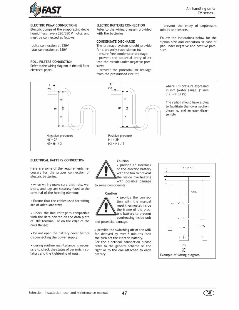
Caution
• provide an interlock of the electric battery with the fan to prevent the inside overheating with possible damage
to some components.
Caution
• provide the connec-tion with the manual reset thermostat inside the frame of the elec-tric battery to prevent overheating inside unit
and potential damage.
• provide the switching off of the AHU fan delayed by over 5 minutes than the turn off the electric battery.For the electrical connection please refer to the general scheme on the right or to the one attached to each battery.
- prevent the entry of unpleasant odours and insects.
Follow the indications below for the siphon size and execution in case of pan under negative and positive pres-sure.
ELECTRIC BATTERIES CONNECTION
Refer to the wiring diagram provided with the batteries
CONDENSATE DISCHARGE
The drainage system should provide for a properly sized siphon to:- ensure free condensate drainage;- prevent the potential entry of air into the circuit under negative pres-sure;- prevent the potential air leakage from the pressurised circuit;
ELECTRIC PUMP CONNECTIONS
Electric pumps of the evaporating decks humidifi ers have a 220/380 V motor, and must be connected as follows:
-delta connection at 220V-star connection at 380V
ROLL FILTERS CONNECTION
Refer to the wiring diagram in the roll fi lter electrical panel.
ELECTRICAL BATTERY CONNECTION
Here are some of the requirements ne-cessary for the proper connection of electric batteries:
• when wiring make sure that nuts, wa-shers, and lugs are securely fi xed to the terminal of the heating element;
• Ensure that the cables used for wiring are of adequate size;
• Check the line voltage is compatible with the data printed on the data plate of the terminal, or on the edge of the coils fl ange;
• Do not open the battery cover before disconnecting the power supply;
• during routine maintenance is neces-sary to check the status of ceramic insu-lators and the tightening of nuts;
P
neg.
H
H
H1
P
pos.
H
H
H1
Negative pressure:H1 = 2PH2= H1 / 2
Positive pressureH1 = 2PH2 = H1 / 2
Pneg.
Ppos. where P is pressure expressed
in mm (water gauge) (1 mm c.a. = 9.81 Pa)
The siphon should have a plug to facilitate the lower section cleaning, and an easy disas-sembly.
FUSIBILI
I-0
Example of wiring diagram
Air handling units -FM series -
47 ` aSelection, installation, use and maintenance manual

EARTHING
All electrical utilities must be connec-ted to earth.All unit sections must be connected to earth.For this purpose all unit sections have an M8 screw for connection to the plant earth. The screw is identified by a pla-te, and is positioned in the vicinity of one if the section base supports, as in-dicated by in the figure below.
knobs. Depending on the size of the unit, it may be necessary to remove the anti-splash net over the fan gril-le. Remove the threaded bars from the fan partition.
Roll filters: usually supplied already assembled. To disassemble and re-assemble the filters, please refer to the supplied manufacturer's instruc-tions.
Activated carbon filters: cartrid-ges are usually supplied assembled. To fit the cartridge, slide it into its seat, then rotate in a clockwise di-rection by approx. 5°.
INSTALLATION OF FILTER CELLS
-Plane filter cells (synthetic or metal) on guides: usually supplied already installed. If not installed, cells must be slided on to the guides. Make sure that the cells are correctly clipped to one another to facilitate removal for maintenance.
-Plane filter cells (synthetic or metal) on frame, bag filters, rigid bag filters: usually supplied in boxes placed insi-de the unit. They must be frontally slided on to the frame, and fixed with the supplied clips (see figure A).
-Absolute filters: they are always sup-plied inside the unit. They must be frontally slided on to the frames, and fixed with supplied brackets and
For earthing using the connectors marked with the symbol chart on the right.
A
1 - Typical filter configuration with "drawer"NB: In some cases, the filter cells are not mounted on the frame holder in-ballate but are left in their containers
2 - In order to extract the entire filters, which runs on rails, please pull the omega profiles top and bot-tom (indicated with A) to ease the pressure of the filter frame against the seals.
3 - It is now possible to remove the filter (or just the frame if the filters are provided) sliding it on the rails.
Instructions for the extraction and insertion of the filter frame in the case of "slide" configuration:
To place and fix the filters please do the below steps in reverse order.
Air handling units -FM series -
48 ` aSelection, installation, use and maintenance manual
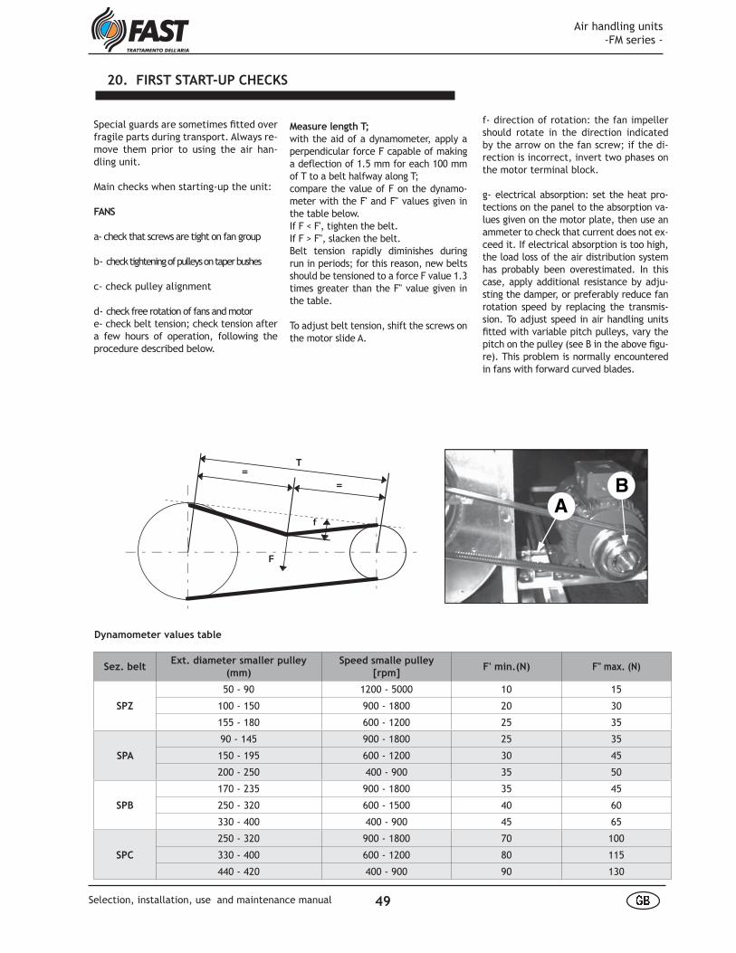
f- direction of rotation: the fan impeller should rotate in the direction indicated by the arrow on the fan screw; if the di-rection is incorrect, invert two phases on the motor terminal block.
g- electrical absorption: set the heat pro-tections on the panel to the absorption va-lues given on the motor plate, then use an ammeter to check that current does not ex-ceed it. If electrical absorption is too high, the load loss of the air distribution system has probably been overestimated. In this case, apply additional resistance by adju-sting the damper, or preferably reduce fan rotation speed by replacing the transmis-sion. To adjust speed in air handling units fi tted with variable pitch pulleys, vary the pitch on the pulley (see B in the above fi gu-re). This problem is normally encountered in fans with forward curved blades.
Measure length T;
with the aid of a dynamometer, apply a perpendicular force F capable of making a deflection of 1.5 mm for each 100 mm of T to a belt halfway along T;compare the value of F on the dynamo-meter with the F' and F" values given in the table below.If F < F', tighten the belt.If F > F", slacken the belt.Belt tension rapidly diminishes during run in periods; for this reason, new belts should be tensioned to a force F value 1.3 times greater than the F" value given in the table.
To adjust belt tension, shift the screws on the motor slide A.
Special guards are sometimes fi tted over fragile parts during transport. Always re-move them prior to using the air han-dling unit.
Main checks when starting-up the unit:
FANS
a- check that screws are tight on fan group
b- check tightening of pulleys on taper bushes
c- check pulley alignment
d- check free rotation of fans and motore- check belt tension; check tension after a few hours of operation, following the procedure described below.
Sez. beltExt. diameter smaller pulley
(mm)
Speed smalle pulley
[rpm]F' min.(N) F" max. (N)
SPZ
50 - 90 1200 - 5000 10 15
100 - 150 900 - 1800 20 30
155 - 180 600 - 1200 25 35
SPA
90 - 145 900 - 1800 25 35
150 - 195 600 - 1200 30 45
200 - 250 400 - 900 35 50
SPB
170 - 235 900 - 1800 35 45
250 - 320 600 - 1500 40 60
330 - 400 400 - 900 45 65
SPC
250 - 320 900 - 1800 70 100
330 - 400 600 - 1200 80 115
440 - 420 400 - 900 90 130
Dynamometer values table
A
B
f
F
T
=
=
20. FIRST START-UP CHECKS
Air handling units -FM series -
49 ` aSelection, installation, use and maintenance manual

ELECTRIC PUMPS
- direction of rotation- calibration of thermal protections- electrical absorption- adjustment of by-pass valve
FILTERS
- correct positioning and fi xing of cells- cleanliness of cells and unit inte-rior
21. MAINTENANCE
HEAT EXCHANGE
Before a possible test the thermal performance of heat exchangers is recommended to:• check the correct connection of the coil;• check the temperature of the fl uid;• check the correct operation of the control logic and of the adjustment (three-way valves, actuators, etc.).
Maintenance should be carried out according to the intervals indicated in the table below. Intervals are indica-
Component Phase Check Instrument Limit Scheduled
Fan section
•Checking tension belt,•Checking wear belts,•Control mounting pulleys,•Control wheel cleaning,•Control bearings noise.
•Instrumental•Visual•Visual•Visual•Visual
Dynamometer
•two-monthly•two-monthly•two-monthly•two-monthly•two-monthly
•Synthetic filters,•Bag filters,•Absolute fi lters,•Rollers filters.
•Fouling Control,•Fouling Control,•Fouling Control,•Low coil control.
•Visual•Instrumental•Instrumental•Visual
ManometerManometer
300 Pa600 Pa
•biweekly•biweekly•biweekly•to report
Droplet-separatorhumidifier
•Obstruction control package,•Tank cleaning,•Clean water filter,•Tank emptying,•Water level.
•Visual
•Visual
•two-monthly•two-monthly•two-monthly•a fine stagione•two-monthly
Heat exchanger coil
•Control cleaning pack,•Control of the cleaning tank condensation
•Visual•Visual
•each year•each year
Humidificationwasher
•Check operation of nozzles •Visual •two-monthly
•Tank cleaning •two-monthly
•Clean pump filter •two-monthly
•Water level •Visual •two-monthly
HUMIDIFIERs
- correct positioning of evaporator pack- correct connection to mains supply and adjustment of fl oat valve
DAMPERS
- operating mode (manual and automatic if applicable)- position: bear in mind that unit start-up with closed dampers may not be possi-ble if fans have a maximum static head greater than 2000 Pa (unless otherwise specifi ed with the order).
tive: in the case of fi lters, for exam-ple, maintenance requirements may vary according to unit applications.
Fans maintenance may be more re-gular if the unit operates continuou-sly.
Air handling units -FM series -
50 ` aSelection, installation, use and maintenance manual

TROUBLESHOOTING
FAULT POSSIBLE CAUSE CHECK REMEDIES
Motor out of absorption range
Excess capacity- Capacity and static pressure;- Fan speed
- Reduce fan rotation speed;- Create load loss in ducting
Excessive air flow Air distribution system load loss has been overestimated.
- Capacity and static pressure- Fan speed
- Reduce fan rotation speed;- Create load loss in ducting;
Insufficient air flowAir distribution system load loss has been underestimated
- Capacity and static pressure;- Fan speed
Increase fan speed according to motor power rating and max. fan speed
Excessive noise
- Flow too high- Head too high
- Capacity- Static pressure
-Reduce air flow.-Increase flow to avoid fan pump zone.
Bearings are damaged Bearings Replace bearings
Metal components damaged. State of components Replace damaged parts
Rotating parts off balance. Vibrations in base Balance fan impeller
Water entrainment
- Flow too high.- Siphon is clogged. - No siphon.- Excess water flow.
- Flow.
- By-pass adjustment.
- Reduce flow.- Clean siphon.- Fit a siphon.- Adjust by-pass valve to reduce water flow.
Excess belt wear- Belts slack.- Pulleys off line.
- Belt tension.- Pulley alignment.
- Tighten belts.- Align pulleys.
Set temperature notreached
. Air flow too high.- Inlet temperature not accounted for.- Air in coil.- Water flow insufficient.- Water temperature too low.
- Air flow.
- Reduce air flow.
- Bleed air from coil.
22. DISPOSAL
At the end of their operating life, the FM units must be disposed according to the current laws.The main components including the unit of the FM series are made from:
• Galvanised sheet steel (panels, fan, internal beams);
• aluminium sheet metal (condensate drain pan, coil fins, recuperator, damper, frame motors, unit frame);
• copper (coil tubes, electric motor windings);
• polyurethane foam (insulation of the sandwich panels);• rock wool (silencers, insulating san-
dwich panels);
N.B. Bear in mind that air handling units are integrated into a general system. For this reason, faults may be caused by other system components, incorrect interaction between the unit and system, or ambient conditions different from those specified for unit design.
Air handling units -FM series -
51 ` aSelection, installation, use and maintenance manual


Technical data shown in this booklet are not binding.FAST S.p.A. shall have thr right to introduce at any time whatever modifications deemed necessary to the improvement of the product
Manual printed on recycled paper.
FAST S.p.A. TRATTAMENTO DELL'ARIA35044 Montagnana (PD) - ItalyVia Luppia Alberi, 170Tel. (+39) 0429 806311 - Fax 0429 806340E-mail: [email protected]://www.fastaer.com
1111
-618
5912
-rev
.1
Related Documents