FM Receivers FM receivers, like AM receivers, utilize the superheterodyne principle, but they operate at much higher frequencies (88 - 108 MHz). A limiter is often used to ensure the received signal is constant in amplitude before it enters the discriminator or detector.

Welcome message from author
This document is posted to help you gain knowledge. Please leave a comment to let me know what you think about it! Share it to your friends and learn new things together.
Transcript

FM Receivers
FM receivers, like AM receivers, utilize
the superheterodyne principle, but
they operate at much higher
frequencies (88 - 108 MHz).
A limiter is often used to ensure the
received signal is constant in
amplitude before it enters the
discriminator or detector.

Block Diagram of FM Receiver

FM Demodulators
The FM demodulators must convert
frequency variations of the input signal
into amplitude variations at the output.
The Foster-Seeley discriminator and its
variant, the ratio detector are
commonly found in older receivers.
They are based on the principle of
slope detection using resonant
circuits.

Slope Detector
La Ca produce an output voltage
proportional to the input frequency.
Center frequency is place at the center
of the most linear portion of the
voltage versus-frequency curve
When IF deviates above or below fc ,
output voltage increases or decreases
Tuned circuit converts frequency
variation to voltage variation

S-curve Characteristics of FM Detectors
fIF
d
d
fi
vo
Em

Balanced Slope Detector
Two single-ended slope detectors
connected in parallel and fed 180 o out of
phase
Phase inversion accomplished by center-
tapping secondary winding
Top tuned circuit is tuned to a frequency
above the IF center frequency by approx.
1.33 X f (1.33 X 75 k = 100kHz )
Similarly, the lower to 100 kHz bellow the IF
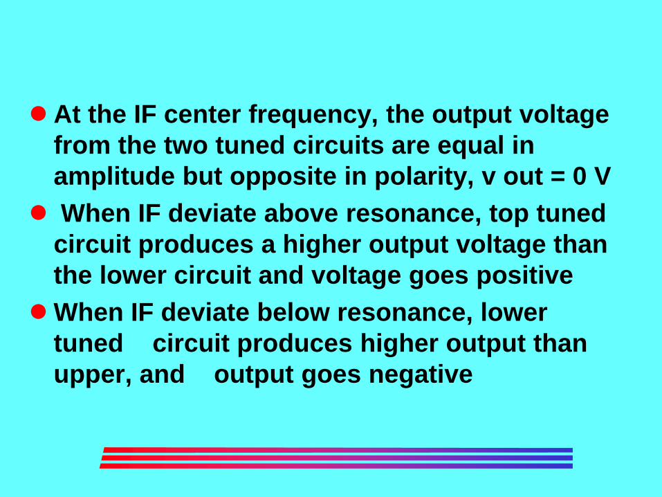
At the IF center frequency, the output voltage
from the two tuned circuits are equal in
amplitude but opposite in polarity, v out = 0 V
When IF deviate above resonance, top tuned
circuit produces a higher output voltage than
the lower circuit and voltage goes positive
When IF deviate below resonance, lower
tuned circuit produces higher output than
upper, and output goes negative

Foster-Seely Discriminator
Similar to balanced slope detector
Output voltage versus frequency deviation
is more linear
Only one tuned circuit: easier to tune
Slope-detector and Foster-Seely
discriminator respond to amplitude variation
as well as frequency deviation: must be
preceded by a separate limiter circuit

Ratio Detector
Advantages over slope detector &
Foster-Seely: It is insensitive to
amplitude variation in input signal
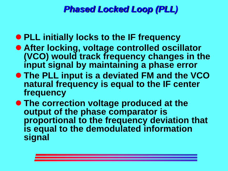
Phased Locked Loop (PLL)
PLL initially locks to the IF frequency
After locking, voltage controlled oscillator (VCO) would track frequency changes in the input signal by maintaining a phase error
The PLL input is a deviated FM and the VCO natural frequency is equal to the IF center frequency
The correction voltage produced at the output of the phase comparator is proportional to the frequency deviation that is equal to the demodulated information signal

PLL FM Detector
PLL detectors are commonly found in
modern FM receivers.
f
Phase
Detector
LPF
Demodulated
output
VCO
FM IF
Signal
Amplitude Limiter

Amplitude Limiter
Most frequency discriminators use envelope
detection to extract the intelligence from the
FM wave form
Envelope detection will demodulate incident
amplitude variations as well as frequency
variation
Transmission noise and interference add to
the signal to produce unwanted amplitude
variations

In the receiver, unwanted AM and
random noise are demodulated along
with the signal: unwanted distortion is
produced
A limiter circuit is used to produce a
constant amplitude output for all input
signal above a specified threshold
level

FM Stereo Broadcasting: Baseband Spectra
To maintain compatibility with mono
system, FM stereo uses a form of FDM
or frequency-division multiplexing to
combine the left and right channel
information:
L+R
(mono) kHz
L-R L-R
.05 15 23 38 53 60 74 67
19 kHz Pilot
Carrier SCA
(optional)

FM Stereo Broadcasting
To enable the L and R channels to be reproduced at the receiver, the L-R and L+R signals are required. These are sent as a DSBSC AM signal with a suppressed subcarrier at 38 kHz.
The purpose of the 19 kHz pilot is for proper detection of the DSBSC AM signal.
The optional Subsidiary Carrier Authorization (SCA) signal is normally used for services such as background music for stores and offices.

2006
Chapter 7: Angle Modulation Transmission
• What is Angle modulation
• What is the difference between frequency and phase modulation
• What is direct and indirect modulation
• Deviation sensitivity, phase deviation, modulation index
• Bandwidth of angle-modulated wave
• Bandwidth requirements
• Phasor representation of angle-modulated wave
• Frequency up-conversion
• FM transmitters
• Angle modulation versus AM

2006
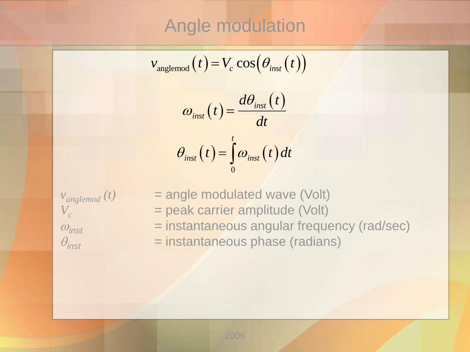
Angle modulation
anglemod cosc instv t V t
inst(t) = instantaneous phase (radians)
Question:
What is the instantaneous frequency?
2006
Angle modulation
anglemod cosc instv t V t
vanglemod (t) = angle modulated wave (Volt)
Vc = peak carrier amplitude (Volt)
inst = instantaneous angular frequency (rad/sec)
inst = instantaneous phase (radians)
inst
inst
d tt
dt
0
t
inst instt t dt
2006
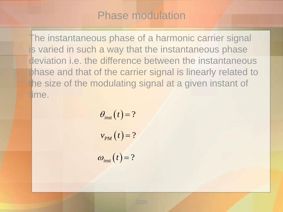
Phase modulation
The instantaneous phase of a harmonic carrier signal
is varied in such a way that the instantaneous phase
deviation i.e. the difference between the instantaneous
phase and that of the carrier signal is linearly related to
the size of the modulating signal at a given instant of
time.
?PMv t
?inst t
?inst t

2006
Phase modulation
The instantaneous phase of a harmonic carrier signal
is varied in such a way that the instantaneous phase
deviation i.e. the difference between the instantaneous
phase and that of the carrier signal is linearly related to
the size of the modulating signal at a given instant of
time.
cosPM c c p m cv t V t K v t
c p minst m
inst c p
d t K v td t dv tt K
dt dt dt
inst c p mt t K v t
Kp is the phase deviation sensitivity (rad/Volt)

2006
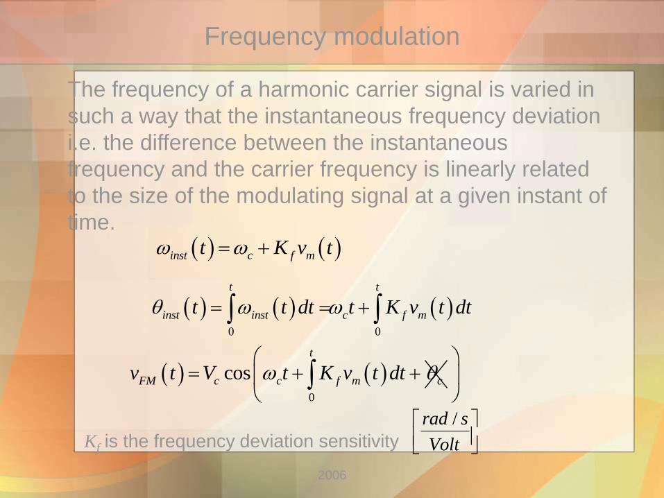
Frequency modulation
The frequency of a harmonic carrier signal is varied in
such a way that the instantaneous frequency deviation
i.e. the difference between the instantaneous
frequency and the carrier frequency is linearly related
to the size of the modulating signal at a given instant of
time.
?FMv t
?inst t
?inst t
2006
Frequency modulation
The frequency of a harmonic carrier signal is varied in
such a way that the instantaneous frequency deviation
i.e. the difference between the instantaneous
frequency and the carrier frequency is linearly related
to the size of the modulating signal at a given instant of
time.
0
cos
t
FM c c f m cv t V t K v t dt
0 0
t t
inst inst c f mt t dt t K v t dt
Kf is the frequency deviation sensitivity
inst c f mt K v t
/rad s
Volt

2006
PM: inst c p mt t K v t
cosPM c c p mv t V t K v t
c p minst m
inst c p
d t K v td t dv tt K
dt dt dt
Kp is the deviation sensitivity
FM: inst c f mt K v t
0 0
t t
inst inst c f mt t dt t K v t dt
0
cos
t
FM c c f mv t V t K v t dt
Kf is the deviation sensitivity
TASK: Make block diagrams of PM and FM modulators
2006
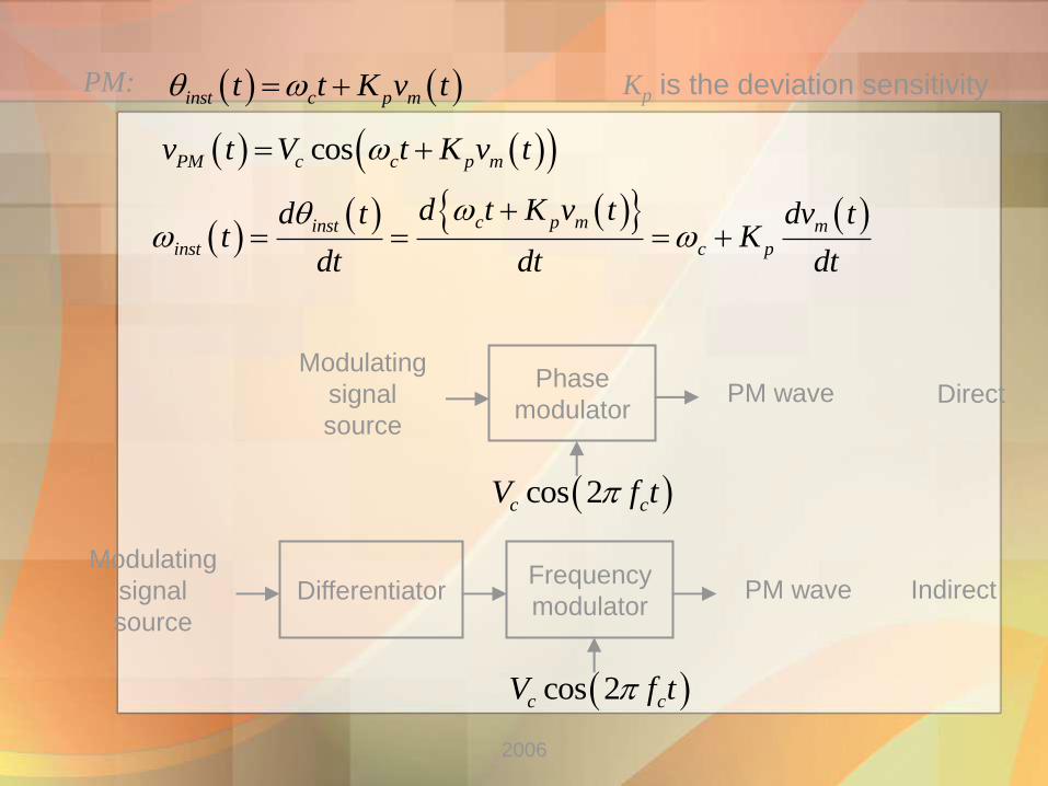
PM: inst c p mt t K v t
cosPM c c p mv t V t K v t
c p minst m
inst c p
d t K v td t dv tt K
dt dt dt
Kp is the deviation sensitivity
Modulating
signal
source
Differentiator Frequency
modulator PM wave
cos 2c cV f t
Phase
modulator PM wave
cos 2c cV f t
Modulating
signal
source
Direct
Indirect
2006
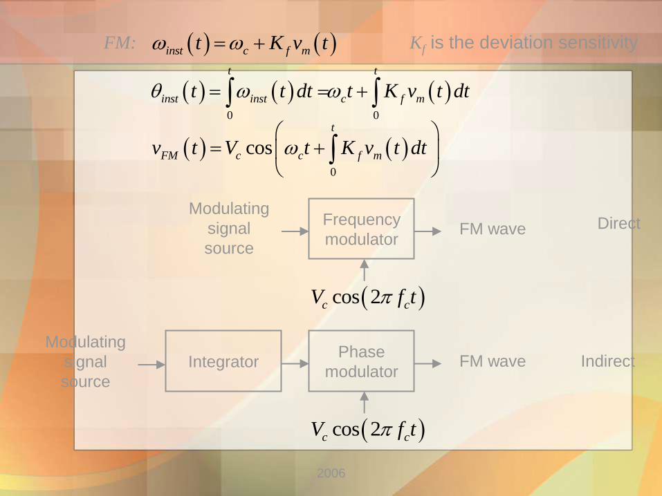
FM: inst c f mt K v t
0 0
t t
inst inst c f mt t dt t K v t dt
0
cos
t
FM c c f mv t V t K v t dt
Modulating
signal
source
Integrator Phase
modulator FM wave
cos 2c cV f t
Frequency
modulator FM wave
cos 2c cV f t
Modulating
signal
source
Kf is the deviation sensitivity
Direct
Indirect

2006
Frequency modulation of single frequency signal
cosm m mv t V t
cos cosPM c c p m mv t V t K V t
PM:
FM: cosm m mv t V t
0
cos cos
cos sin
t
FM c c f m m
f m
c c m
m
v t V t K V t dt
K VV t t

2006
PM and FM of sine-wave signal
?
?
Carrier
Modulating
signal
2006
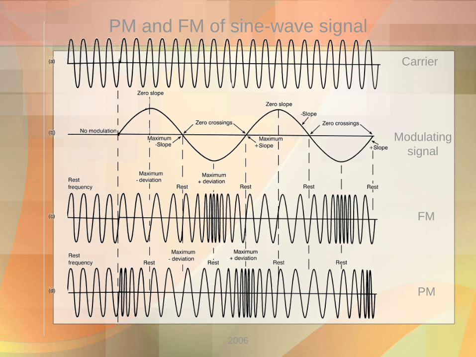
PM and FM of sine-wave signal
FM
PM
Carrier
Modulating
signal

2006
Phase Deviation and Modulation Index
cos cosangle c c mv t V t m t
m is the peak phase deviation or modulation index
cos cosPM c c p m mv t V t K V t
p mm K V
cos sinf m
FM c c m
m
K Vv t V t t
f m
m
K Vm
(radians)
PM:
FM:
(unitless)

2006
Frequency Deviation
FM:
f mK V
cos sinf m
FM c c m
m
K Vv t V t t
cosinst c f m mt K V t
inst
inst
d tt
dt
f m
m
K Vm
(peak) frequency deviation
f m
m m
K Vm
cos cosPM c c p m mv t V t K V t PM:
sininst c p m m mt K V t
p m mK V (peak) frequency deviation
p mm K V
p m m
p m
m m
K Vm K V
FM
PM
dependent of the frequency
independent of the frequency

2006
PM and FM of sine-wave signal
f mK V p mK V
f m
FM
m
K Vm
PM p mm K V f mK V
f m mK V

2006
Bessel function of the first kind
cos cosangle c c mv t V t m t
cos cos cos2
n
n
nm J m n
nJ m is the Bessel function of the first kind
cos2
angle c n c m
n
nv t V J m t n t
0
1 1
2 2
cos
cos cos2 2
cos 2 cos 2 .....
c
angle c c m c m
c m c m
J m t
v t V J m t J m t
J m t J m t
m is the modulation index
f m
m
K Vm
p mm K V
FM
PM

2006
Relation AM and angle mod
cos 2cos s2
o22
c 2c c c c mam mfm mv t f tE f f tft
0
1 1
2 2
cos
cos cos2 2
cos 2 cos 2 .....
c
angle c c m c m
c m c m
J m t
v t V J m t J m t
J m t J m t

2006
Bessel function of the first kind

2006
Bandwidth requirements of Angle-mod waves
m < 1 ( fm >>> f ) 2 mB f (Hz)
1 Low-index modulation (narrowband FM)
2 High-index modulation (wideband FM)
m > 10 (f >>> fm ) 2B f
2 mB nf
2 f
where n is the number of significant sidebands
3 Actual bandwidth (look at Bessel table page 266)
4 Carson’s rule (approx 98 % of power)
2 mB f f
f m
m m m
K V fm
f

2006
FM modulator
f = 10 kHz
fm = 10 kHz
Vc = 10 V
fc = 500 kHz
Example
Draw the spectrum?
What is the bandwidth using Bessel table?
What is the bandwidth using Carson’s rule?

2006
f = 10 kHz
fm = 10 kHz
Vc = 10 V
fc = 500 kHz
m =1
Example
Fig 7-7

2006
Phasor representation of Angle-mod wave
m < 1 (narrowband FM)
Fig 7-9
2006
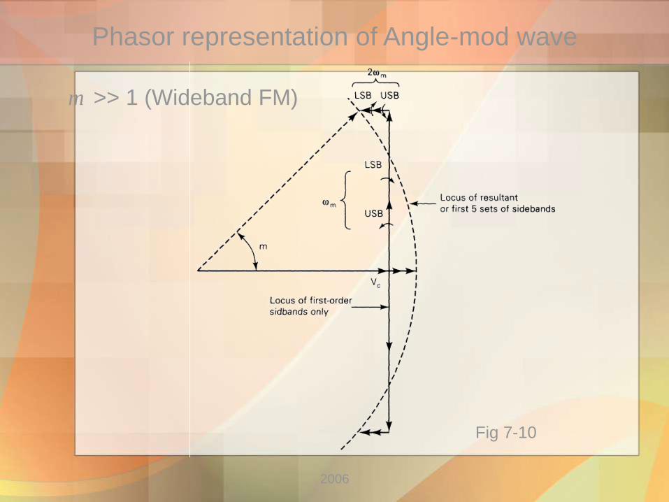
Phasor representation of Angle-mod wave
m >> 1 (Wideband FM)
Fig 7-10

2006
Average Power of Angle-mod wave
2
2
cc
VP
R (W)
Pc = carrier power (Watts)
Vc = peak unmodulated carrier voltage (volts)
R = load resistance (ohms)
2 2 2
mod _ _2 1 1cos cos 2 2
2 2
angle c un c un
t c c
v t V VP t t t t
R R R
Instantaneous power in angle-mod carrier is
2 2 22 2
_ un 1 22 2 2.....
2 2 2 2 2
c nct
V V V VVP
R R R R R
Instantaneous power in unmodulated carrier is
So the average power of the angle-mod carrier is equal to the
unmodulated carrier

2006
Frequency and Phase modulators
Direct FM Modulator
Fig 7-16
2006
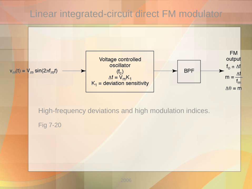
Linear integrated-circuit direct FM modulator
High-frequency deviations and high modulation indices.
Fig 7-20

2006
Frequency up-conversion heterodyne method
With FM and PM modulators, the carrier at the output is generally
somewhat lower than the desired frequency of transmission
Fig 7-24 a
2006
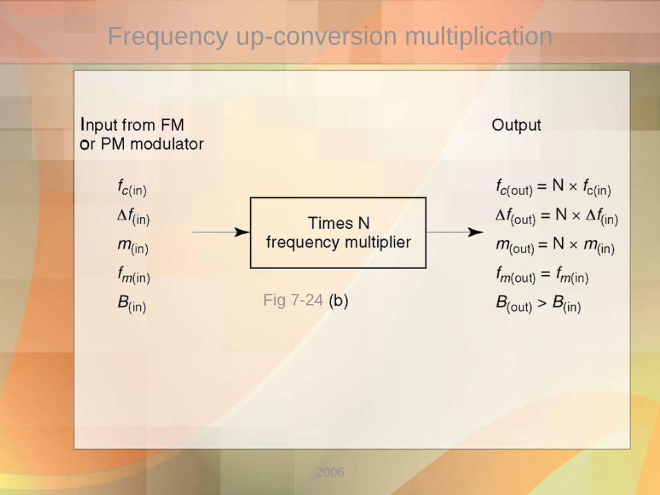
Frequency up-conversion multiplication
Fig 7-24

2006
Indirect FM Transmitter
0
1 1
2 2
cos
cos cos2 2
cos 2 cos 2 .....
c
angle c c m c m
c m c m
J m t
v t V J m t J m t
J m t J m t
15 kHzmf
200 kHzcf
Fig 7-27

2006
Indirect FM Transmitter
m < 1
Problem !!!!!!
max arctan m m
c c
V Vm
V V
15 kHzmf
200 kHzcf
Fig 7-28
2006
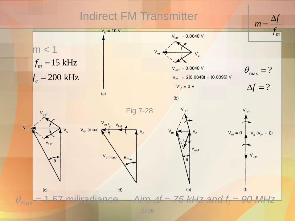
Indirect FM Transmitter
m < 1
max = 1.67 miliradiance
max ?
m
fm
f
?f
15 kHzmf
200 kHzcf
Aim f = 75 kHz and ft = 90 MHz
Fig 7-28

2006
Armstrong Indirect FM Transmitter
Where are the frequency conversions ?
Fig 7-27
2006
Angle mod versus AM
Advantages of Angle modulation
• Noise immunity
• Noise performance and signal-to-noise improvement
• Capture effect
• Power utilization and efficiency
Disadvantages of Angle modulation
• Bandwidth
• Circuit complexity and costs

2006
End Lecture 7

2006
Next lecture: Chapter 8
Angle modulation reception
Summary and Outlook
g
Related Documents