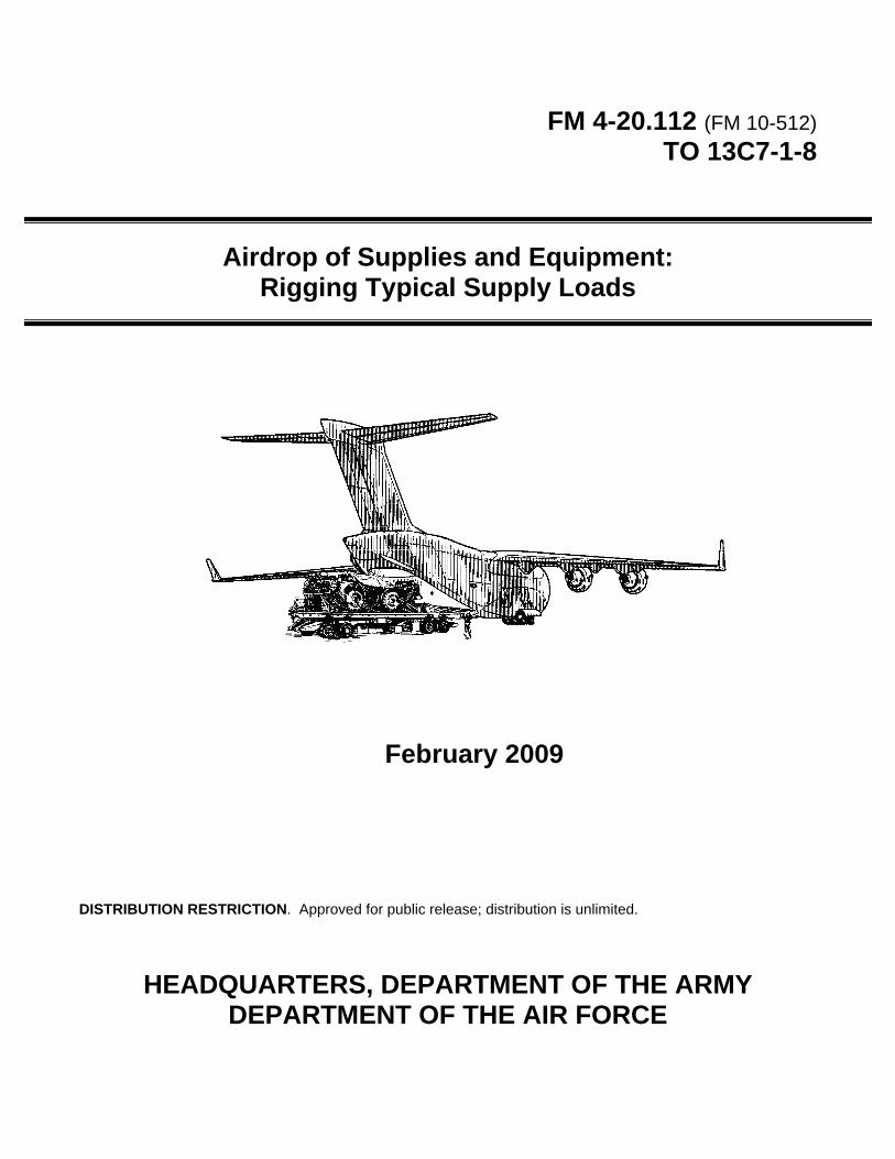
FM 4-20.112 (FM 10-512) TO 13C7-1-8 Airdrop of Supplies and Equipment: Rigging Typical Supply Loads February 2009 DISTRIBUTION RESTRICTION. Approved for public release; distribution is unlimited. HEADQUARTERS, DEPARTMENT OF THE ARMY DEPARTMENT OF THE AIR FORCE

Welcome message from author
This document is posted to help you gain knowledge. Please leave a comment to let me know what you think about it! Share it to your friends and learn new things together.
Transcript
FM 4-20.112 (FM 10-512) TO 13C7-1-8
Airdrop of Supplies and Equipment: Rigging Typical Supply Loads
February 2009
DISTRIBUTION RESTRICTION. Approved for public release; distribution is unlimited.
HEADQUARTERS, DEPARTMENT OF THE ARMY DEPARTMENT OF THE AIR FORCE

This publication is available at Army Knowledge Online (www.us.army.mil) and General Dennis J. Reimer Training and Doctrine
Digital Library at (www.train.army.mil).
*FM 4-20.112/ TO 13C7-1-8
Distribution Restriction: Approved for public release; distribution is unlimited.
*This publication supersedes FM 4-20.112/TO 13C7-1-8, DATED 7 May 2004.
i
Field Manual No. 4-20.112 Technical Order No. 13C7-1-8
Headquarters Department of the Army
Department of the Air Force
Washington, DC, 20 February 2009
AIRDROP OF SUPPLIES AND EQUIPMENT: RIGGING TYPICAL SUPPLY LOADS
Contents Page
PREFACE ........................................................................................................... viii Scope................................................................................................................... viii User Information .................................................................................................. viii
Chapter 1 GENERAL INFORMATION ............................................................................... 1-1 Description of Items ............................................................................................ 1-1 Special Considerations ....................................................................................... 1-1 Air Force Unilateral Loads .................................................................................. 1-1
Chapter 2 RIGGING SUPPLY LOADS ON AN 8-FOOT, TYPE V PLATFORM FOR LOW-VELOCITY AIRDROP ........................................................................................ 2-1 SECTION I-RIGGING BULK SUPPLIES ........................................................... 2-1 Description of Load............................................................................................. 2-1 Preparing Platform .............................................................................................. 2-1 Placing Honeycomb............................................................................................ 2-3 Positioning and Securing Load ........................................................................... 2-4 Constructing and Installing Endboards .............................................................. 2-6 Installing Lashings .............................................................................................. 2-8 Installing Parachute Stowage Platform ............................................................ 2-11 Installing Suspension Slings and Deadman’s Tie ............................................ 2-12 Preparing and Stowing Cargo Parachutes ....................................................... 2-13 Installing the Release System .......................................................................... 2-14 Installing Extraction System ............................................................................. 2-15 Placing Extraction Parachute ........................................................................... 2-16 Installing Provisions for Emergency Restraints ................................................ 2-16
Contents
ii FM 4-20.112/TO 13C7-1-8 20 February 2009
Marking Rigged Load ........................................................................................ 2-16 Equipment Required ......................................................................................... 2-16 SECTION II-RIGGING BULK SUPPLIES IN A-22 CARGO BAGS ................. 2-20 Description of Load ........................................................................................... 2-20 Preparing Platform ............................................................................................ 2-20 Placing Honeycomb .......................................................................................... 2-20 Preparing, Stowing and Rigging Load .............................................................. 2-21 Positioning Load ............................................................................................... 2-21 Installing Lashings ............................................................................................ 2-22 Installing Suspension Slings and Deadman’s Tie ............................................. 2-26 Installing Parachute Stowage Platform ............................................................. 2-27 Installing Parachutes ......................................................................................... 2-28 Installing the Release System ........................................................................... 2-29 Installing the Extraction System ........................................................................ 2-30 Placing Extraction Parachute ............................................................................ 2-31 Installing Provisions for Emergency Restraints ................................................ 2-31 Marking Rigged Load ........................................................................................ 2-31 Equipment Required ......................................................................................... 2-31
Chapter 3 RIGGING SUPPLY LOADS ON A 12-FOOT, TYPE V PLATFORM FOR LOW-VELOCITY AIRDROP ........................................................................................ 3-1 Description of Load ............................................................................................. 3-1 Preparing Platform .............................................................................................. 3-1 Placing Honeycomb ............................................................................................ 3-3 Positioning and Securing Load ........................................................................... 3-4 Constructing and Installing Endboards ............................................................... 3-6 Installing Lashings .............................................................................................. 3-8 Installing Suspension Slings and Deadman’s Tie ............................................. 3-11 Installing Parachute Stowage Platform ............................................................. 3-12 Preparing and Stowing Cargo Parachutes ....................................................... 3-13 Installing the Release System ........................................................................... 3-14 Installing the Extraction System ........................................................................ 3-16 Placing Extraction Parachute ............................................................................ 3-17 Installing Provisions for Emergency Restraints ................................................ 3-17 Marking Rigged Load ........................................................................................ 3-17 Equipment Required ......................................................................................... 3-17
Chapter 4 RIGGING FORWARD AREA SURGICAL TEAM (FAST) EQUIPMENT ON A 12-FOOT, TYPE V PLATFORM FOR LOW-VELOCITY AIRDROP ....................... 4-1 Description of Load ............................................................................................. 4-1 Preparing Platform .............................................................................................. 4-1 Positioning Lashings ........................................................................................... 4-3 Constructing and Forming Storage Box Components ........................................ 4-5 Preparing Honeycomb Stacks .......................................................................... 4-10 Positioning Honeycomb Stacks and Assembling Sides of Storage Box .......... 4-11 Positioning Drop Items ...................................................................................... 4-12 Closing and Securing Box ................................................................................. 4-12 Installing Lashings ............................................................................................ 4-15 Installing Suspension Slings and Deadman’s Tie ............................................. 4-19
Contents
20 February 2009 FM 4-20.112/TO 13C7-1-8 iii
Preparing and Stowing Cargo Parachutes ....................................................... 4-20 Installing the Release System .......................................................................... 4-21 Installing the Extraction System ....................................................................... 4-22 Placing Extraction Parachute ........................................................................... 4-23 Installing Provisions for Emergency Restraints ................................................ 4-23 Marking Rigged Load ....................................................................................... 4-23 Equipment Required ......................................................................................... 4-23
Chapter 5 RIGGING SUPPLY LOADS ON A 16-FOOT, TYPE V PLATFORM FOR LOW-VELOCITY AIRDROP ........................................................................................ 5-1 SECTION I-RIGGING 105-MILLIMETER (MM) AMMUNITION ........................ 5-1 Description of Load............................................................................................. 5-1 Preparing Platform .............................................................................................. 5-1 Building Honeycomb Stacks and Placing First Stack ........................................ 5-3 Positioning and Securing First Ammunition Stack ............................................. 5-4 Constructing and Placing Endboards ................................................................. 5-7 Installing Lashings on First Ammunition Stack ................................................... 5-8 Positioning and Securing Second Ammunition Stack ...................................... 5-12 Installing Lashings on Second Ammunition Stack ........................................... 5-14 Installing Load Cover, Suspension Slings and Deadman’s Tie ....................... 5-18 Installing Parachutes ........................................................................................ 5-19 Installing the Release System .......................................................................... 5-20 Installing the Extraction System ....................................................................... 5-21 Placing Extraction Parachute ........................................................................... 5-22 Installing Provisions for Emergency Restraints ................................................ 5-22 Marking Rigged Load ....................................................................................... 5-22 Equipment Required ......................................................................................... 5-22 SECTION II-RIGGING 155-MILLIMETER (MM) AMMUNITION ..................... 5-26 Description of Load........................................................................................... 5-26 Preparing Platform ............................................................................................ 5-26 Building Honeycomb Stacks and Placing First Stack ...................................... 5-28 Positioning and Securing First Ammunition Stack ........................................... 5-29 Constructing Endboards ................................................................................... 5-31 Installing Lashings on First Ammunition Stack and First and Second Endboards ........................................................................................................ 5-32 Positioning Second Ammunition Stack and Third and Fourth Endboards ....... 5-35 Lashing Second Ammunition Stack and Third and Fourth Endboards ............ 5-35 Installing Suspension Slings and Deadman’s Tie ............................................ 5-38 Installing Parachutes ........................................................................................ 5-39 Installing the Release System .......................................................................... 5-40 Installing the Extraction System ....................................................................... 5-41 Placing Extraction Parachute ........................................................................... 5-42 Installing Provisions for Emergency Restraints ................................................ 5-42 Marking Rigged Load ....................................................................................... 5-42 Equipment Required ......................................................................................... 5-42 SECTION III-RIGGING 20-MILLIMETER (MM) AMMUNITION ...................... 5-46 Description of Load........................................................................................... 5-46 Preparing Platform ............................................................................................ 5-46
Contents
iv FM 4-20.112/TO 13C7-1-8 20 February 2009
Building Honeycomb Stacks and Placing First Stack ....................................... 5-48 Positioning and Securing First Ammunition Stack ............................................ 5-49 Constructing and Placing Endboards ............................................................... 5-50 Lashing First Ammunition Stack and First and Second Endboards ................. 5-51 Positioning Endboards, Placing Second Ammunition Stack, and Pre-Positioning Lashings ......................................................................................... 5-56 Lashing Second Ammunition Stack and Third and Fourth Endboards ............. 5-58 Installing Load Cover, Suspension Slings and Deadman’s Tie ........................ 5-64 Installing Parachutes ......................................................................................... 5-66 Installing the Release System ........................................................................... 5-67 Installing the Extraction System ........................................................................ 5-68 Placing Extraction Parachute ............................................................................ 5-69 Installing Provisions for Emergency Restraints ................................................ 5-69 Marking Rigged Load ........................................................................................ 5-69 Equipment Required ......................................................................................... 5-69 SECTION IV-RIGGING MASS SUPPLY BOX ................................................. 5-73 Description of Load ........................................................................................... 5-73 Preparing Platform ............................................................................................ 5-73 Placing Lashings on Platform ........................................................................... 5-75 Constructing and Forming Storage Box Components ...................................... 5-76 Loading and Closing the Boxes ........................................................................ 5-80 Installing Lashings ............................................................................................ 5-81 Installing Load Cover, Suspension Slings and Deadman’s Tie ........................ 5-91 Installing Parachutes ......................................................................................... 5-92 Installing the Release System ........................................................................... 5-93 Installing the Extraction System ........................................................................ 5-94 Placing Extraction Parachute ............................................................................ 5-95 Installing Provisions for Emergency Restraints ................................................ 5-95 Marking Rigged Load ........................................................................................ 5-95 Equipment Required ......................................................................................... 5-95
Chapter 6 RIGGING MASS SUPPLY BOX ON A 20-FOOT, TYPE V PLATFORM FOR LOW-VELOCITY AIRDROP ........................................................................................ 6-1 Description of Load ............................................................................................. 6-1 Preparing Platform .............................................................................................. 6-1 Placing Lashings on Platform ............................................................................. 6-3 Constructing and Forming Storage Box Components ........................................ 6-4 Loading and Closing the Boxes .......................................................................... 6-8 Installing Lashings .............................................................................................. 6-8 Installing Load Cover, Suspension Slings and Deadman’s Tie ........................ 6-17 Installing Parachutes ......................................................................................... 6-18 Installing the Release System ........................................................................... 6-19 Installing the Extraction System ........................................................................ 6-20 Placing Extraction Parachute ............................................................................ 6-21 Installing Provisions for Emergency Restraints ................................................ 6-21 Marking Rigged Load ........................................................................................ 6-21 Equipment Required ......................................................................................... 6-21
Contents
20 February 2009 FM 4-20.112/TO 13C7-1-8 v
Chapter 7 RIGGING PALLETIZED LOAD SYSTEM (PLS) ON A 24-FOOT, TYPE V PLATFORM FOR LOW-VELOCITY AIRDROP ................................................ 7-1 SECTION I-RIGGING 105-MILLIMETER (MM) AMMUNITION ........................ 7-1 Description of Load............................................................................................. 7-1 Preparing Platform .............................................................................................. 7-1 Preparing and Positioning Honeycomb .............................................................. 7-3 Preparing PLS Pallet .......................................................................................... 7-7 Positioning PLS Pallet on Platform ..................................................................... 7-9 Lashing PLS Pallet to Platform ......................................................................... 7-10 Placing and Lashing the Load .......................................................................... 7-13 Installing and Safetying Suspension Slings ..................................................... 7-21 Building Parachute Stowage Platform .............................................................. 7-23 Installing Cargo Parachutes ............................................................................. 7-24 Installing the Release System .......................................................................... 7-25 Installing the Extraction System ....................................................................... 7-26 Placing Extraction Parachute ........................................................................... 7-27 Installing Provisions for Emergency Restraints ................................................ 7-27 Marking Rigged Load ....................................................................................... 7-27 Equipment Required ......................................................................................... 7-27 SECTION II-RIGGING A-22 CARGO BAGS ................................................... 7-31 Description of Load........................................................................................... 7-31 Preparing Platform ............................................................................................ 7-31 Preparing and Positioning Honeycomb ............................................................ 7-33 Preparing PLS Pallet ........................................................................................ 7-37 Positioning PLS Pallet on Platform ................................................................... 7-39 Lashing PLS Pallet to Platform ......................................................................... 7-40 Placing and Lashing the Load .......................................................................... 7-43 Installing and Safetying Suspension Slings ..................................................... 7-49 Building Parachute Stowage Platform and Installing Cargo Parachutes ......... 7-51 Installing the Release System .......................................................................... 7-53 Installing the Extraction System ....................................................................... 7-54 Placing Extraction Parachute ........................................................................... 7-55 Installing Provisions for Emergency Restraints ................................................ 7-55 Marking Rigged Load ....................................................................................... 7-55 Equipment Required ......................................................................................... 7-55
Chapter 8 RIGGING 155-MILLIMETER (MM) AMMUNITION MODULAR ARTILLERY CHARGE SYSTEM PACKAGE (MACS PAC) ON A TYPE V PLATFORM FOR LOW-VELOCITY AIRDROP .............................................................................. 8-1 Section I-Rigging the MACS PAC on an 8-Foot, Type V Platform ............... 8-1 Description of Load............................................................................................. 8-1 Preparing Platform .............................................................................................. 8-1 Building Honeycomb Stacks ............................................................................... 8-3 Positioning Lashings on the Platform ................................................................. 8-5 Positioning the Honeycomb Stack on the Platform ............................................ 8-6 Positioning and Securing the Ammunition Stack ............................................... 8-7 Constructing the Front Endboard ..................................................................... 8-14 Constructing the Rear Endboard ...................................................................... 8-15
Contents
vi FM 4-20.112/TO 13C7-1-8 20 February 2009
Lashing the Ammunition Stack and the Endboards .......................................... 8-16 Installing Suspension Slings and Deadman’s Tie ............................................. 8-21 Preparing and Stowing Cargo Parachutes ....................................................... 8-22 Installing the Release System ........................................................................... 8-24 Installing the Extraction System ........................................................................ 8-25 Placing Extraction Parachute ............................................................................ 8-26 Installing Provisions for Emergency Restraints ................................................ 8-26 Marking Rigged Load ........................................................................................ 8-26 Equipment Required ......................................................................................... 8-26 Section II-Rigging the MACS PAC on a 12-Foot, Type V Platform ............. 8-30 Description of Load ........................................................................................... 8-30 Preparing Platform ............................................................................................ 8-30 Building Honeycomb Stacks ............................................................................. 8-32 Positioning Lashings on the Platform ............................................................... 8-36 Positioning the Honeycomb Stacks on the Platform ......................................... 8-37 Positioning and Securing the Ammunition Stacks ............................................ 8-39 Constructing the Front Endboard ...................................................................... 8-53 Constructing the Rear Endboard ...................................................................... 8-54 Lashing the Ammunition Stack and the Endboards .......................................... 8-55 Installing Suspension Slings and Deadman’s Tie ............................................. 8-60 Building and Positioning Parachute Stowage Platform .................................... 8-61 Preparing and Stowing Cargo Parachutes ....................................................... 8-62 Installing the Release System ........................................................................... 8-63 Installing the Extraction System ........................................................................ 8-64 Placing Extraction Parachute ............................................................................ 8-65 Installing Provisions for Emergency Restraints ................................................ 8-65 Marking Rigged Load ........................................................................................ 8-65 Equipment Required ......................................................................................... 8-65 SECTION III-RIGGING THE MACS PAC ON A 16-FOOT, TYPE V PLATFORM ...................................................................................................... 8-69 Description of Load ........................................................................................... 8-69 Preparing Platform ............................................................................................ 8-69 Building Honeycomb Stacks 1 and 2 and Positioning Stack 1 ......................... 8-71 Positioning and Securing the First Ammunition Stack ...................................... 8-72 Constructing Endboards ................................................................................... 8-77 Lashing the First Ammunition Stack and Using the First And Second Endboards ......................................................................................................... 8-78 Positioning Stack 2 and Positioning and Securing the Second Ammunition Stack ................................................................................................................. 8-81 Lashing the Second Ammunition Stack and Using the Third And Fourth Endboards ......................................................................................................... 8-85 Installing Suspension Slings and Deadman’s Tie ............................................. 8-88 Building and Positioning Parachute Stowage Platform .................................... 8-89 Preparing and Stowing Cargo Parachutes ....................................................... 8-90 Installing the Release System ........................................................................... 8-91 Installing the Extraction System ........................................................................ 8-92 Placing Extraction Parachute ............................................................................ 8-93
Contents
20 February 2009 FM 4-20.112/TO 13C7-1-8 vii
Installing Provisions for Emergency Restraints ................................................ 8-93 Marking Rigged Load ....................................................................................... 8-93 Equipment Required ......................................................................................... 8-93 SECTION IV-RIGGING THE MACS PAC ON A 20-FOOT, TYPE V PLATFORM ...................................................................................................... 8-97 Description of Load........................................................................................... 8-97 Preparing Platform ............................................................................................ 8-97 Building and Positioning Honeycomb Stack 1 .................................................. 8-99 Positioning and Securing the First Ammunition Stack ................................... 8-100 Constructing Endboards ................................................................................. 8-108 Lashing the First Ammunition Stack and Using the First And Second Endboards ...................................................................................................... 8-110 Building and Positioning Honeycomb Stack 2 ................................................ 8-115 Positioning and Securing the Second Ammunition Stack .............................. 8-116 Lashing the Second Ammunition Stack and Using the Third and Fourth Endboards ...................................................................................................... 8-120 Installing Suspension Slings and Deadman’s Tie .......................................... 8-124 Preparing and Stowing Cargo Parachutes ..................................................... 8-125 Installing the Release System ........................................................................ 8-126 Installing the Extraction System ..................................................................... 8-127 Placing Extraction Parachute ......................................................................... 8-128 Installing Provisions for Emergency Restraints .............................................. 8-128 Marking Rigged Load ..................................................................................... 8-128 Equipment Required ....................................................................................... 8-128
GLOSSARY .......................................................................................... Glossary-1 REFERENCES .................................................................................. References-3 INDEX .......................................................................................................... Index-1
viii FM 4-20.112/TO 13C7-1-8 20 February 2009
Preface
SCOPE This manual tells and shows how to prepare and rig mass supply loads. Procedures are given for typical loads that can be contained by the methods shown. These procedures are meant as a guide, and may be adapted to specific loads. Procedures are also given for some specific ammunition loads. This manual is designed for all parachute riggers. This publication applies to the Active Army, the Army National Guard (ARNG)/Army National Guard of the United States (ARNGUS), and the United States Army Reserve (USAR) unless otherwise stated.
USER INFORMATION The proponent of this publication is HQ TRADOC. You are encouraged to report any errors or omissions and to suggest ways of making this a better manual. Army personnel, send your comments on DA Form 2028 directly to: Director Aerial Delivery and Field Services Department USA Quartermaster Center and School 710 Adams Avenue Fort Lee, Virginia 23801-1502 Air Force personnel, route your reports on AFTO Form 22 through your respective command Weapons and Tactics to: Headquarters Air Mobility Command (AMC/A39T) 402 Scott Drive, Unit 3A1 Scott AFB, Illinois 62225-5302
Preface
20 February 2009 FM 4-20.112/TO 13C7-1-8 ix
HQ AMC/A39T will consolidate and forward changes to: Director Aerial Delivery and Field Services Department USA Quartermaster Center and School 710 Adams Avenue Fort Lee, Virginia 23801-1502 Also send information copy of AFTO Form 22 to: 584 CBSS/GBMUDE 380 Richard Ray Blvd STE 104 Robins AFB, Georgia 31098-1640 Unless this publication states otherwise, masculine nouns and pronouns do not refer exclusively to men.

This page intentionally left blank.
20 February 2009 FM 4-20.112/TO 13C7-1-8 1-1
Chapter 1
General Information
DESCRIPTION OF ITEMS 1-1. Bulk supplies consisting of rations, fuels, lubricants, ammunition, and various unit equipment can be rigged on standard airdrop platforms using the procedures given in this manual. Items packaged in containers or units of the same size, such as rations and ammunition are rigged using lashings and endboards. These procedures can be adapted for loads that are different from the specific ammunition loads shown. Some items are more easily rigged in A-22 containers. Items of varying and irregular size can be padded, secured, and contained in mass supply boxes on 12, 16, and 20-foot platforms. Additionally, items using endboards and A-22 containers are shown rigged using the palletized load system (PLS).
CAUTION The load weight may vary from the loads shown. Be sure that each load weight, parachute requirements, CB, lashing effectiveness, and tip-off curve computed according to FM 4-20.102/MCRP 4-11.3J/NAVSEA SS400-AB-MMO-010/TO 13C7-1-5.
SPECIAL CONSIDERATIONS 1-2. Special considerations for this manual are given below.
• The loads covered in this manual may include hazardous materials as defined in AFMAN(I) 24-204/TM 38-250. If included, the hazardous materials must be packaged, marked, and labeled as required by AFMAN(I) 24-204/TM 38-250.
CAUTION Only ammunition listed in FM 4-20.153/MCRP 4-11.3B/TO 13C7-18-41 may be airdropped.
• A copy of this manual must be available to the joint airdrop inspectors during the before- and after-loading inspection.
AIR FORCE UNILATERAL LOADS 1-3. Air Force unilateral loads are used to support wing airdrop proficiency requirements. The loads are designed as an alternative to actual rigged loads, using the procedures for rigging mass supplies on an 8-foot, type V platform. Ballast for the unilateral platform loads normally consists of railroad ties, lumber or ammo boxes filled with dirt or rocks, however any material may be used as long as it is sufficiently restrained. The following exceptions to FM 4-20.102/MCRP 4-11.3J/NAVSEA SS400-AB-MMO-010/TO 13C7-1-5 and this manual are authorized for Air Force unilateral loads only:
Chapter 1
1-2 FM 4-20.112/TO 13C7-1-8 20 February 2009
CAUTION The load weight may vary from the loads shown. Be sure that each load weight, parachute requirements, CB, lashing effectiveness, and tip-off curve computed according to FM 4-20.102/MCRP 4-11.3J/NAVSEA SS400-AB-MMO-010/TO 13C7-1-5.
• Honeycomb is not required under the ballast; however, due to the lack of honeycomb, the life span of the type V platform may be reduced. Units must inspect the platform for cracks, loose rivets, delaminating panels, and general damage prior to each drop. All loads must be re-rigged and re-inspected after each airdrop according to TM 10-1670-268-20&P/TO 13C7-52-22.
• Honeycomb or a suitable substitute (felt covered plywood) must be used to provide a flat and stable surface for the parachutes and releases.
20 February 2009 FM 4-20.112/TO 13C7-1-8 2-1
Chapter 2
Rigging Supply Loads on an 8-Foot, Type V Platform for Low-Velocity Airdrop
SECTION I-RIGGING BULK SUPPLIES
DESCRIPTION OF LOAD 2-1. Bulk supplies consisting of rations, equipment, fuel, ammunition, or other items of general supply are rigged on an 8-foot, type V airdrop platform with G-11 cargo parachutes. Items packaged or configured so that they can be restrained by endboards and lashings can be airdropped using these procedures. Modifications to the honeycomb, endboards, and lashings may be necessary to allow for items of different sizes and shapes from those shown. For extraction purposes, the rigged load must weigh at least 2,520 pounds. Refer to FM 4-20.102/MCRP 4-11.3J/NAVSEA SS400-AB-MMO-010/TO 13C7-1-5 for the weight limitations for the number of parachutes to be used.
PREPARING PLATFORM 2-2. Prepare an 8-foot, type V platform as shown in Figure 2-1.
Chapter 2
2-2 FM 4-20.112/TO 13C7-1-8 20 February 2009
Step:
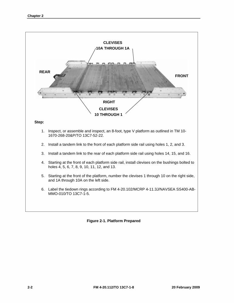
1. Inspect, or assemble and inspect, an 8-foot, type V platform as outlined in TM 10-1670-268-20&P/TO 13C7-52-22.
2. Install a tandem link to the front of each platform side rail using holes 1, 2, and 3.
3. Install a tandem link to the rear of each platform side rail using holes 14, 15, and 16.
4. Starting at the front of each platform side rail, install clevises on the bushings bolted to holes 4, 5, 6, 7, 8, 9, 10, 11, 12, and 13.
5. Starting at the front of the platform, number the clevises 1 through 10 on the right side, and 1A through 10A on the left side.
6. Label the tiedown rings according to FM 4-20.102/MCRP 4-11.3J/NAVSEA SS400-AB-MMO-010/TO 13C7-1-5.
Figure 2-1. Platform Prepared
CLEVISES 10A THROUGH 1A
CLEVISES 10 THROUGH 1
FRONT REAR
RIGHT
Rigging Supply Loads on an 8-Foot, Type V Platform for Low-Velocity Airdrop
20 February 2009 FM 4-20.112/TO 13C7-1-8 2-3
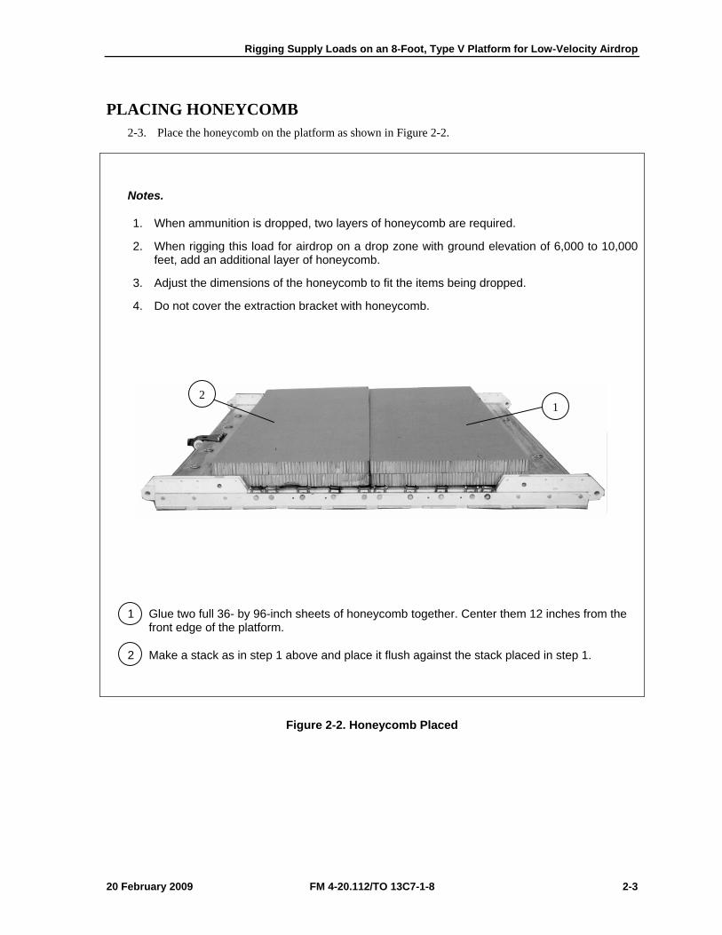
PLACING HONEYCOMB 2-3. Place the honeycomb on the platform as shown in Figure 2-2.
Notes.
1. When ammunition is dropped, two layers of honeycomb are required.
2. When rigging this load for airdrop on a drop zone with ground elevation of 6,000 to 10,000 feet, add an additional layer of honeycomb.
3. Adjust the dimensions of the honeycomb to fit the items being dropped.
4. Do not cover the extraction bracket with honeycomb.
1 Glue two full 36- by 96-inch sheets of honeycomb together. Center them 12 inches from the front edge of the platform.
2 Make a stack as in step 1 above and place it flush against the stack placed in step 1.
Figure 2-2. Honeycomb Placed
2 1
Chapter 2
2-4 FM 4-20.112/TO 13C7-1-8 20 February 2009
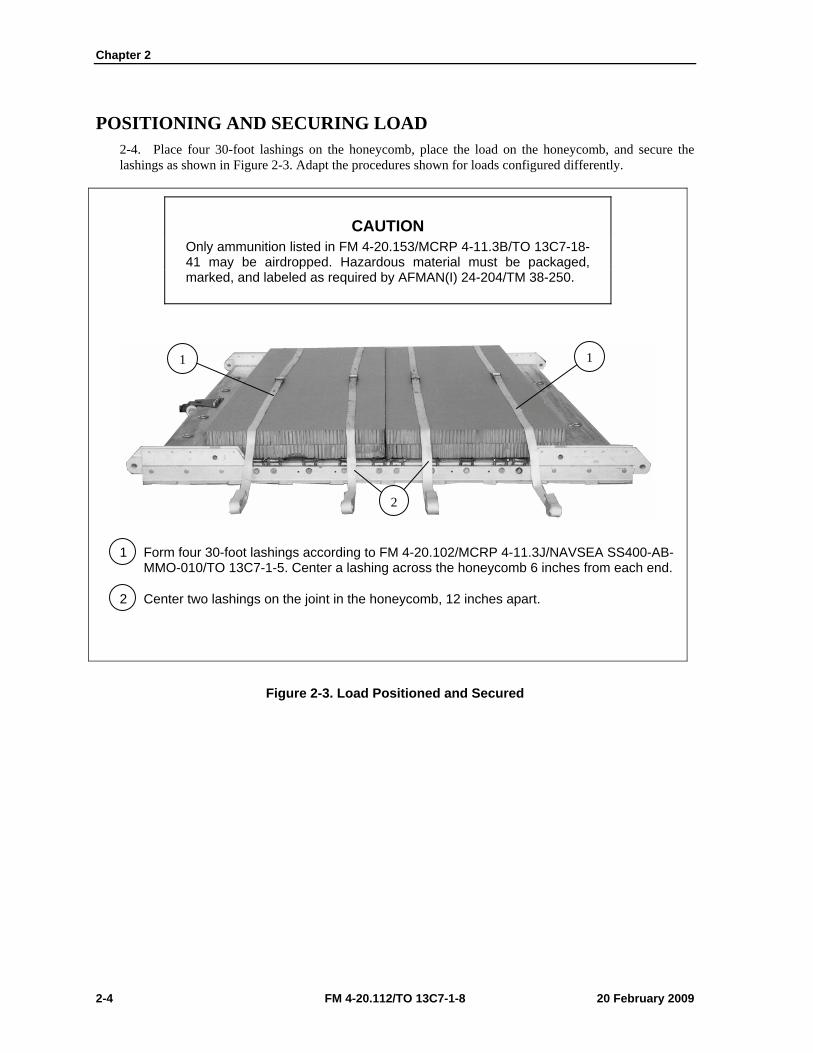
POSITIONING AND SECURING LOAD 2-4. Place four 30-foot lashings on the honeycomb, place the load on the honeycomb, and secure the lashings as shown in Figure 2-3. Adapt the procedures shown for loads configured differently.
CAUTION Only ammunition listed in FM 4-20.153/MCRP 4-11.3B/TO 13C7-18-41 may be airdropped. Hazardous material must be packaged, marked, and labeled as required by AFMAN(I) 24-204/TM 38-250.
1 Form four 30-foot lashings according to FM 4-20.102/MCRP 4-11.3J/NAVSEA SS400-AB-MMO-010/TO 13C7-1-5. Center a lashing across the honeycomb 6 inches from each end.
2 Center two lashings on the joint in the honeycomb, 12 inches apart.
Figure 2-3. Load Positioned and Secured
1 1
2
Rigging Supply Loads on an 8-Foot, Type V Platform for Low-Velocity Airdrop
20 February 2009 FM 4-20.112/TO 13C7-1-8 2-5
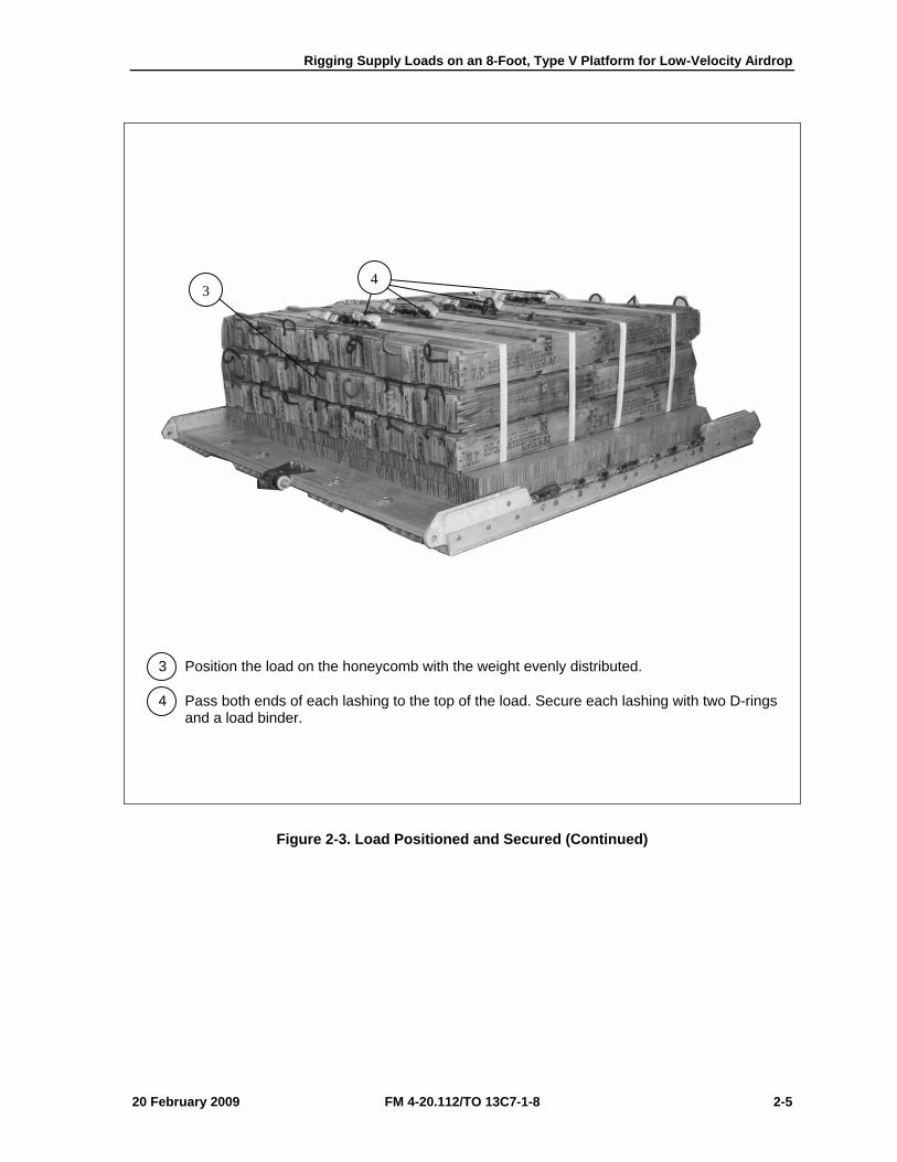
3 Position the load on the honeycomb with the weight evenly distributed.
4 Pass both ends of each lashing to the top of the load. Secure each lashing with two D-rings and a load binder.
Figure 2-3. Load Positioned and Secured (Continued)
43
Chapter 2
2-6 FM 4-20.112/TO 13C7-1-8 20 February 2009
CONSTRUCTING AND INSTALLING ENDBOARDS 2-5. Construct the endboards and install them on the load as shown in Figure 2-4.
Notes.
1. This drawing is not to scale.
2. All dimensions are in inches.
3. The dimensions of the endboards will vary, depending on the load being rigged. The endboards must be even with the top of the load.
1 Construct two endboards using one 3/4- by 28- by 96-inch piece of plywood for each endboard. Make cutouts as shown.
Note. Tape or pad the cutouts in the endboards to protect the lashings from sharp edges.
Figure 2-4. Endboards Constructed and Installed
1
Rigging Supply Loads on an 8-Foot, Type V Platform for Low-Velocity Airdrop
20 February 2009 FM 4-20.112/TO 13C7-1-8 2-7
Note. Loads longer than the one shown may be secured in this way, if the lashings are pre-positioned under the honeycomb and endboards, and secured at both ends to the tiedown rings as shown in steps 4 and 5. Do not cover the extraction bracket.
2 Place one endboard against the front of the load.
3 Place one endboard against the rear of the load.
4 Pass the free end of a 15-foot lashing through tiedown ring A4 and through its own D-ring. Pull the free end of the lashing over the top of the load.
5 Pass the free end of a 15-foot lashing through tiedown ring D4 and through its own D-ring. Pull the free end of the lashing over the top of the load.
6 Secure the end of the lashing positioned in step 4 to tiedown ring A1 with a D-ring and a load binder.
7 Secure the end of the lashing positioned in step 5 to tiedown ring B1 with a D-ring and a load binder.
Figure 2-4. Endboards Constructed and Installed (Continued)
A1
B1
D4
A4
4 5
3
6 7
2
Chapter 2
2-8 FM 4-20.112/TO 13C7-1-8 20 February 2009
INSTALLING LASHINGS 2-6. Lash the load to the platform according to FM 4-20.102/MCRP 4-11.3J/NAVSEA SS400-AB-MMO-010/TO 13C7-1-5 and as shown in Figures 2-5 through 2-7.
Lashing Number
Tiedown Clevis
Number
Instructions
1 1 and 1A Pass a lashing through clevis 1 and through its own D-ring, over the top of the load, and to clevis 1A. Secure the lashing to clevis 1A with a D-ring and a load binder.
2 4 and 4A Pass a lashing through clevis 4 and through its own D-ring, over the top of the load, and to clevis 4A. Secure the lashing to clevis 4A with a D-ring and a load binder.
3 7 and 7A Pass a lashing through clevis 7 and through its own D-ring, over the top of the load, and to clevis 7A. Secure the lashing to clevis 7A with a D-ring and a load binder.
4 10 and 10A Pass a lashing through clevis 10 and through its own D-ring, over the top of the load, and to clevis 10A. Secure the lashing to clevis 10A with a D-ring and a load binder.
Figure 2-5. Lashings 1 Through 4 Installed
1
3
4
14710
2
Rigging Supply Loads on an 8-Foot, Type V Platform for Low-Velocity Airdrop
20 February 2009 FM 4-20.112/TO 13C7-1-8 2-9
Note. Position the load binders so that they will be accessible for retightening and inspection when the load is fully rigged. Lashing Number Tiedown Clevis
Number Instructions
5 2 and 2A Pass a 15-foot lashing through clevis 2 and through its own D-ring, and through the lower cutout in the front endboard. Pass another lashing through clevis 2A and through its own D-ring, and through the lower cutout in the front endboard. Secure the lashings together in the middle of the front endboard with two D-rings and a load binder.
6 3 and 3A Pass a 15-foot lashing through clevis 3 and through its own D-ring, and through the upper cutout in the front endboard. Pass another lashing through clevis 3A and through its own D-ring, and through the upper cutout in the front endboard. Secure the lashings together in the middle of the front endboard with two D-rings and a load binder.
7 5 and 5A Pass a 15-foot lashing through clevis 5 and through its own D-ring, and through the upper cutout in the front endboard. Pass another lashing through clevis 5A and through its own D-ring, and through the upper cutout in the front endboard. Secure the lashings together in the middle of the front endboard with two D-rings and a load binder.
Figure 2-6. Lashings 5 Through 7 Installed
5
6
7
23
5
Chapter 2
2-10 FM 4-20.112/TO 13C7-1-8 20 February 2009
Lashing Number
Tiedown Clevis
Number
Instructions
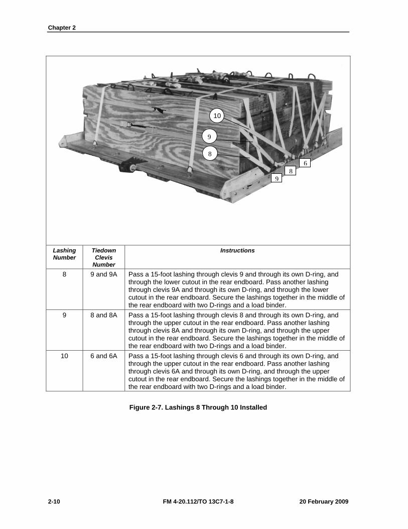
8 9 and 9A Pass a 15-foot lashing through clevis 9 and through its own D-ring, and through the lower cutout in the rear endboard. Pass another lashing through clevis 9A and through its own D-ring, and through the lower cutout in the rear endboard. Secure the lashings together in the middle of the rear endboard with two D-rings and a load binder.
9 8 and 8A Pass a 15-foot lashing through clevis 8 and through its own D-ring, and through the upper cutout in the rear endboard. Pass another lashing through clevis 8A and through its own D-ring, and through the upper cutout in the rear endboard. Secure the lashings together in the middle of the rear endboard with two D-rings and a load binder.
10 6 and 6A Pass a 15-foot lashing through clevis 6 and through its own D-ring, and through the upper cutout in the rear endboard. Pass another lashing through clevis 6A and through its own D-ring, and through the upper cutout in the rear endboard. Secure the lashings together in the middle of the rear endboard with two D-rings and a load binder.
Figure 2-7. Lashings 8 Through 10 Installed
8
9
10
98
6
Rigging Supply Loads on an 8-Foot, Type V Platform for Low-Velocity Airdrop
20 February 2009 FM 4-20.112/TO 13C7-1-8 2-11
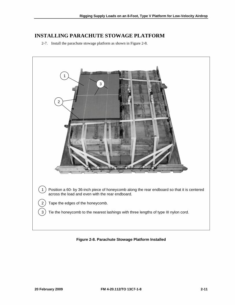
INSTALLING PARACHUTE STOWAGE PLATFORM 2-7. Install the parachute stowage platform as shown in Figure 2-8.
1 Position a 60- by 36-inch piece of honeycomb along the rear endboard so that it is centered across the load and even with the rear endboard.
2 Tape the edges of the honeycomb.
3 Tie the honeycomb to the nearest lashings with three lengths of type III nylon cord.
Figure 2-8. Parachute Stowage Platform Installed
3
1
2
Chapter 2
2-12 FM 4-20.112/TO 13C7-1-8 20 February 2009
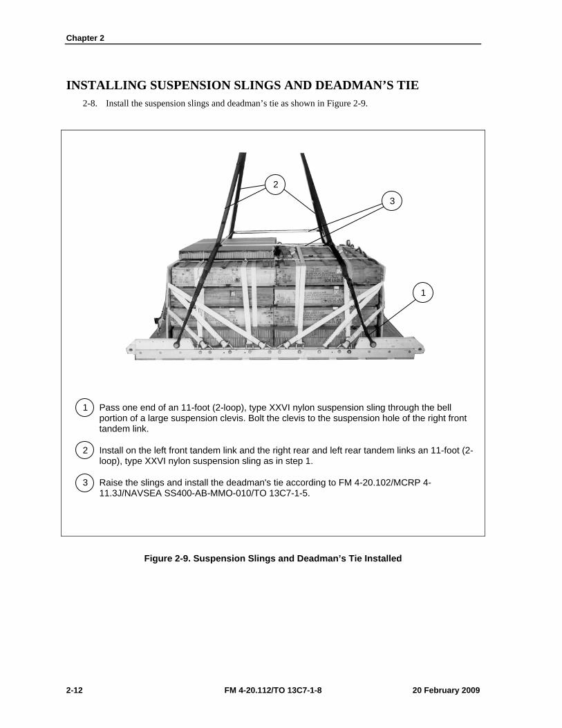
INSTALLING SUSPENSION SLINGS AND DEADMAN’S TIE 2-8. Install the suspension slings and deadman’s tie as shown in Figure 2-9.
1 Pass one end of an 11-foot (2-loop), type XXVI nylon suspension sling through the bell portion of a large suspension clevis. Bolt the clevis to the suspension hole of the right front tandem link.
2 Install on the left front tandem link and the right rear and left rear tandem links an 11-foot (2-loop), type XXVI nylon suspension sling as in step 1.
3 Raise the slings and install the deadman's tie according to FM 4-20.102/MCRP 4-11.3J/NAVSEA SS400-AB-MMO-010/TO 13C7-1-5.
Figure 2-9. Suspension Slings and Deadman’s Tie Installed
2
3
1
Rigging Supply Loads on an 8-Foot, Type V Platform for Low-Velocity Airdrop
20 February 2009 FM 4-20.112/TO 13C7-1-8 2-13
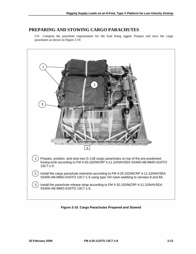
PREPARING AND STOWING CARGO PARACHUTES 2-9. Compute the parachute requirements for the load being rigged. Prepare and stow the cargo parachutes as shown in Figure 2-10.
1 Prepare, position, and stow two G-11B cargo parachutes on top of the pre-positioned honeycomb according to FM 4-20.102/MCRP 4-11.3J/NAVSEA SS400-AB-MMO-010/TO 13C7-1-5.
2 Install the cargo parachute restraints according to FM 4-20.102/MCRP 4-11.3J/NAVSEA SS400-AB-MMO-010/TO 13C7-1-5 using type VIII nylon webbing to clevises 8 and 8A.
3 Install the parachute release strap according to FM 4-20.102/MCRP 4-11.3J/NAVSEA SS400-AB-MMO-010/TO 13C7-1-5.
Figure 2-10. Cargo Parachutes Prepared and Stowed
1
2
3
8
Chapter 2
2-14 FM 4-20.112/TO 13C7-1-8 20 February 2009
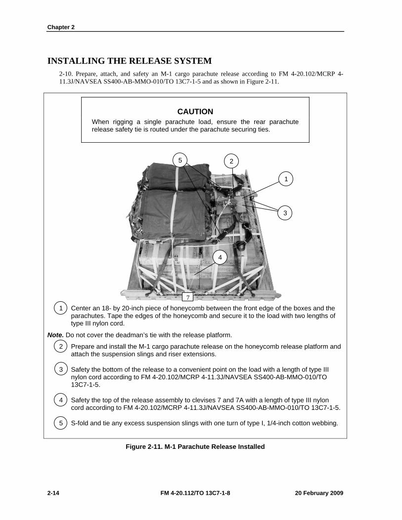
INSTALLING THE RELEASE SYSTEM 2-10. Prepare, attach, and safety an M-1 cargo parachute release according to FM 4-20.102/MCRP 4-11.3J/NAVSEA SS400-AB-MMO-010/TO 13C7-1-5 and as shown in Figure 2-11.
CAUTION When rigging a single parachute load, ensure the rear parachute release safety tie is routed under the parachute securing ties.
1 Center an 18- by 20-inch piece of honeycomb between the front edge of the boxes and the parachutes. Tape the edges of the honeycomb and secure it to the load with two lengths of type III nylon cord.
Note. Do not cover the deadman’s tie with the release platform.
2 Prepare and install the M-1 cargo parachute release on the honeycomb release platform and attach the suspension slings and riser extensions.
3 Safety the bottom of the release to a convenient point on the load with a length of type III nylon cord according to FM 4-20.102/MCRP 4-11.3J/NAVSEA SS400-AB-MMO-010/TO 13C7-1-5.
4 Safety the top of the release assembly to clevises 7 and 7A with a length of type III nylon cord according to FM 4-20.102/MCRP 4-11.3J/NAVSEA SS400-AB-MMO-010/TO 13C7-1-5.
5 S-fold and tie any excess suspension slings with one turn of type I, 1/4-inch cotton webbing.
Figure 2-11. M-1 Parachute Release Installed
7
4
5 2
1
3
Rigging Supply Loads on an 8-Foot, Type V Platform for Low-Velocity Airdrop
20 February 2009 FM 4-20.112/TO 13C7-1-8 2-15
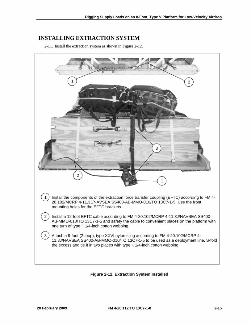
INSTALLING EXTRACTION SYSTEM 2-11. Install the extraction system as shown in Figure 2-12.
1 Install the components of the extraction force transfer coupling (EFTC) according to FM 4-20.102/MCRP 4-11.3J/NAVSEA SS400-AB-MMO-010/TO 13C7-1-5. Use the front mounting holes for the EFTC brackets.
2 Install a 12-foot EFTC cable according to FM 4-20.102/MCRP 4-11.3J/NAVSEA SS400-AB-MMO-010/TO 13C7-1-5 and safety the cable to convenient places on the platform with one turn of type I, 1/4-inch cotton webbing.
3 Attach a 9-foot (2-loop), type XXVI nylon sling according to FM 4-20.102/MCRP 4-11.3J/NAVSEA SS400-AB-MMO-010/TO 13C7-1-5 to be used as a deployment line. S-fold the excess and tie it in two places with type I, 1/4-inch cotton webbing.
Figure 2-12. Extraction System Installed
2 1
3
1 2

Chapter 2
2-16 FM 4-20.112/TO 13C7-1-8 20 February 2009
PLACING EXTRACTION PARACHUTE 2-12. Select the extraction parachute and extraction line needed using the extraction line requirements table in FM 4-20.102/MCRP 4-11.3J/NAVSEA SS400-AB-MMO-010/TO 13C7-1-5. Place the extraction parachute and line on the load for installation in the aircraft.
INSTALLING PROVISIONS FOR EMERGENCY RESTRAINTS 2-13. Select and install the provisions for the emergency aft restraints according to the emergency aft restraint requirements table in FM 4-20.102/MCRP 4-11.3J/NAVSEA SS400-AB-MMO-010/TO 13C7-1-5.
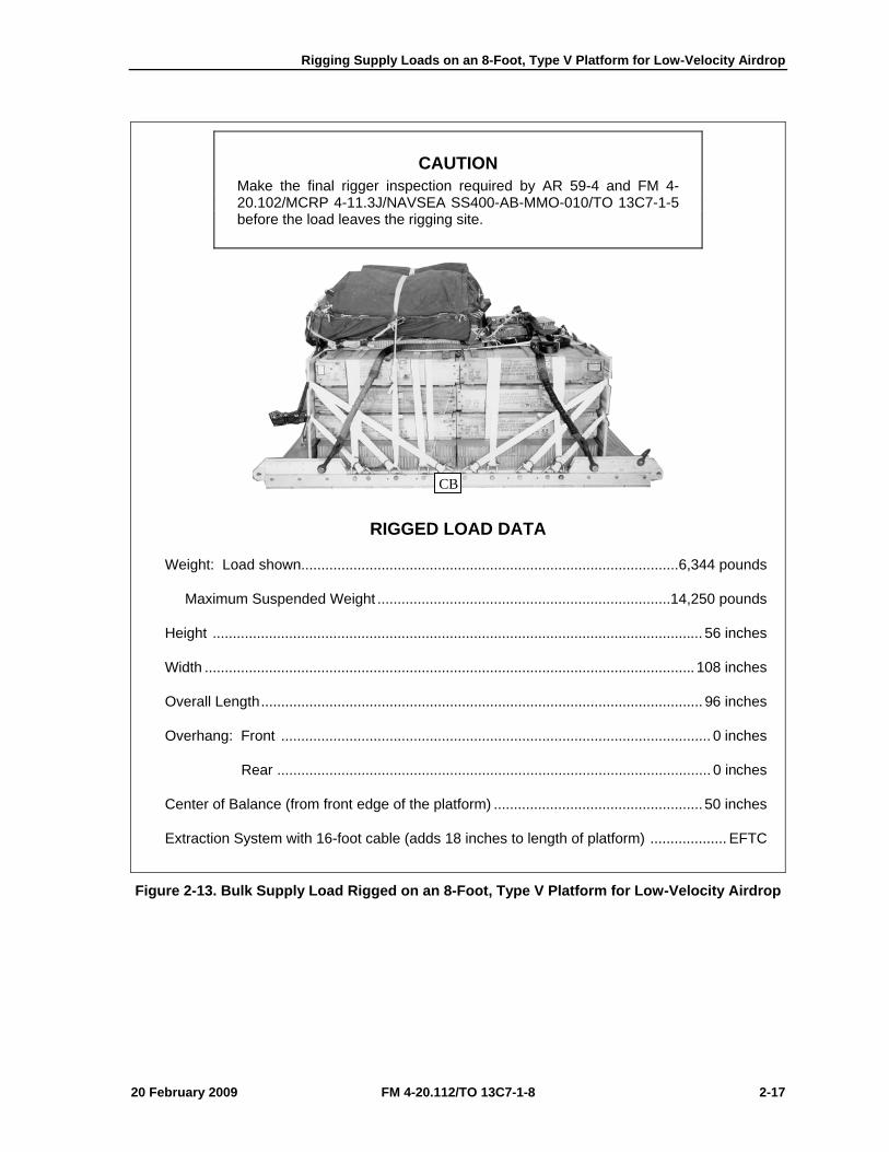
MARKING RIGGED LOAD 2-14. Mark the rigged load according to FM 4-20.102/MCRP 4-11.3J/NAVSEA SS400-AB-MMO-010/TO 13C7-1-5, and as shown in Figure 2-13. Complete Shipper’s Declaration for Dangerous Goods. If the load varies from the one shown, the weight, height, CB, and parachute requirements must be recomputed.
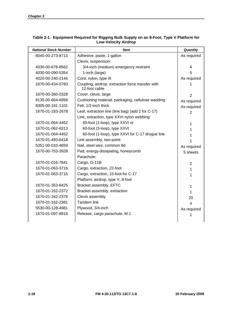
EQUIPMENT REQUIRED 2-15. Use the equipment listed in Table 2-1 to rig this load.
Rigging Supply Loads on an 8-Foot, Type V Platform for Low-Velocity Airdrop
20 February 2009 FM 4-20.112/TO 13C7-1-8 2-17
CAUTION Make the final rigger inspection required by AR 59-4 and FM 4-20.102/MCRP 4-11.3J/NAVSEA SS400-AB-MMO-010/TO 13C7-1-5 before the load leaves the rigging site.
RIGGED LOAD DATA
Weight: Load shown.............................................................................................. 6,344 pounds
Maximum Suspended Weight ......................................................................... 14,250 pounds
Height .......................................................................................................................... 56 inches
Width .......................................................................................................................... 108 inches
Overall Length .............................................................................................................. 96 inches
Overhang: Front ........................................................................................................... 0 inches
Rear ............................................................................................................ 0 inches
Center of Balance (from front edge of the platform) .................................................... 50 inches
Extraction System with 16-foot cable (adds 18 inches to length of platform) ................... EFTC
Figure 2-13. Bulk Supply Load Rigged on an 8-Foot, Type V Platform for Low-Velocity Airdrop
CB
Chapter 2
2-18 FM 4-20.112/TO 13C7-1-8 20 February 2009
Table 2-1. Equipment Required for Rigging Bulk Supply on an 8-Foot, Type V Platform for Low-Velocity Airdrop
National Stock Number Item Quantity 8040-00-273-8713
4030-00-678-8562 4030-00-090-5354 4020-00-240-2146 1670-00-434-5783
1670-00-360-0328 8135-00-664-6958 8305-00-191-1101 1670-01-183-2678
1670-01-064-4452 1670-01-062-6313 1670-01-064-4452 1670-01-493-6418 5351-00-010-4659 1670-00-753-3928
1670-01-016-7841 1670-01-063-3716 1670-01-063-3715
1670-01-353-8425 1670-01-162-2372 1670-01-162-2376 1670-01-162-2381 5530-00-128-4981 1670-01-097-8816
Adhesive, paste, 1-gallon Clevis, suspension: 3/4-inch (medium) emergency restraint 1-inch (large) Cord, nylon, type III Coupling, airdrop, extraction force transfer with 12-foot cable Cover, clevis, large Cushioning material, packaging, cellulose wadding Felt, 1/2-inch thick Leaf, extraction line (line bag) (add 2 for C-17) Line, extraction, type XXVI nylon webbing: 60-foot (1-loop), type XXVI or 60-foot (3-loop), type XXVI 60-foot (1-loop), type XXVI for C-17 drogue line Link assembly, two-point: Nail, steel wire, common 8d Pad, energy-dissipating, honeycomb Parachute: Cargo, G-11B Cargo, extraction, 22-foot Cargo, extraction, 15-foot for C-17 Platform, airdrop, type V, 8-foot Bracket assembly, EFTC Bracket assembly, extraction Clevis assembly Tandem link Plywood, 3/4-inch Release, cargo parachute, M-1
As required 4 5
As required 1 2
As required As required
2 1 1 1 1
As required 5 sheets
2 1 1 1 1
20 4
As required 1
Rigging Supply Loads on an 8-Foot, Type V Platform for Low-Velocity Airdrop
20 February 2009 FM 4-20.112/TO 13C7-1-8 2-19
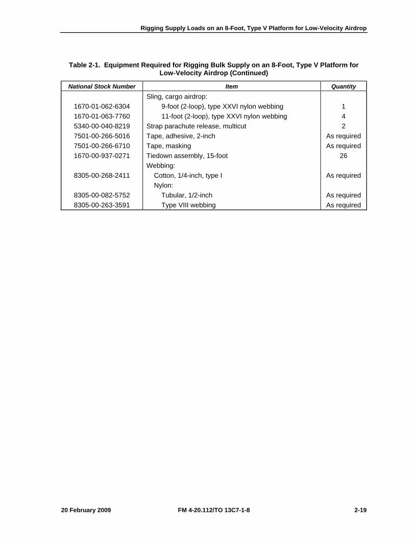
Table 2-1. Equipment Required for Rigging Bulk Supply on an 8-Foot, Type V Platform for Low-Velocity Airdrop (Continued)
National Stock Number Item Quantity
1670-01-062-6304 1670-01-063-7760 5340-00-040-8219 7501-00-266-5016 7501-00-266-6710 1670-00-937-0271
8305-00-268-2411
8305-00-082-5752 8305-00-263-3591
Sling, cargo airdrop: 9-foot (2-loop), type XXVI nylon webbing 11-foot (2-loop), type XXVI nylon webbing Strap parachute release, multicut Tape, adhesive, 2-inch Tape, masking Tiedown assembly, 15-foot Webbing: Cotton, 1/4-inch, type I Nylon: Tubular, 1/2-inch Type VIII webbing
1 4 2
As required As required
26
As required
As required As required
Chapter 2
2-20 FM 4-20.112/TO 13C7-1-8 20 February 2009
SECTION II-RIGGING BULK SUPPLIES IN A-22 CARGO BAGS
DESCRIPTION OF LOAD 2-16. Bulk supplies consisting of rations, equipment, fuel, ammunition, or other items of general supply are rigged on an 8-foot, type V airdrop platform with G-11 cargo parachutes. Items are packaged or configured so that they can be contained in A-22 cargo bags and can be airdropped using these procedures. For extraction purposes, the rigged load must weigh at least 2,520 pounds. Refer to FM 4-20.102/MCRP 4-11.3J/NAVSEA SS400-AB-MMO-010/TO 13C7-1-5 for the weight limitations and for the number of parachutes to be used.
PREPARING PLATFORM 2-17. Prepare an 8-foot, type V platform as described in paragraph 2-2 and as previously shown in Figure 2-1.
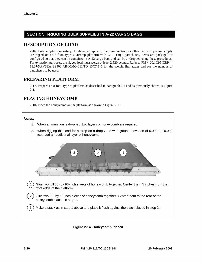
PLACING HONEYCOMB 2-18. Place the honeycomb on the platform as shown in Figure 2-14.
Notes.
1. When ammunition is dropped, two layers of honeycomb are required.
2. When rigging this load for airdrop on a drop zone with ground elevation of 6,000 to 10,000 feet, add an additional layer of honeycomb.
1 Glue two full 36- by 96-inch sheets of honeycomb together. Center them 5 inches from the front edge of the platform.
2 Glue two 96- by 13-inch pieces of honeycomb together. Center them to the rear of the honeycomb placed in step 1.
3 Make a stack as in step 1 above and place it flush against the stack placed in step 2.
Figure 2-14. Honeycomb Placed
3 2 1
Rigging Supply Loads on an 8-Foot, Type V Platform for Low-Velocity Airdrop
20 February 2009 FM 4-20.112/TO 13C7-1-8 2-21
PREPARING, STOWING AND RIGGING LOAD 2-19. Prepare, stow, and rig the load in four A-22 cargo bags according to FM 4-20.103/MCRP 4-11.3C/TO 13C7-1-11, paragraphs 9-5 through 9-7. Attach the suspension webs according to paragraph 9-9.
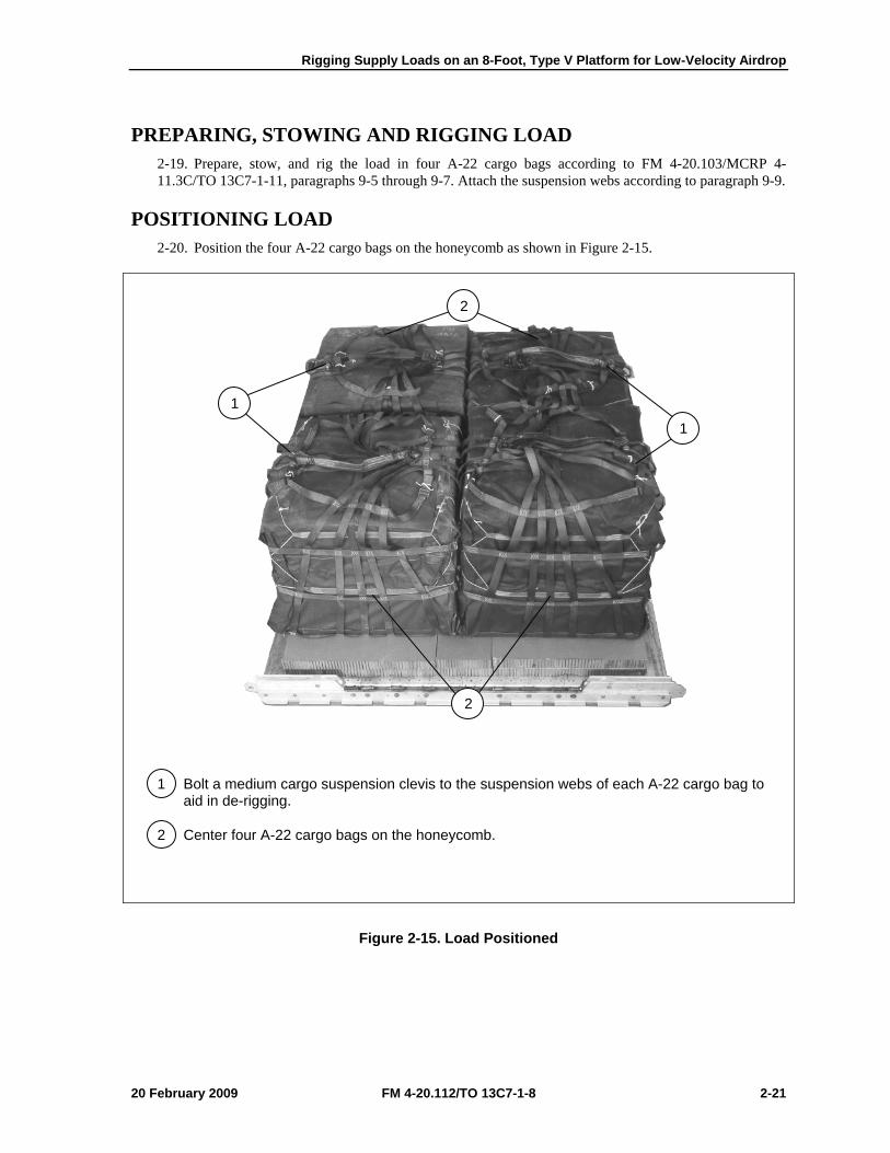
POSITIONING LOAD 2-20. Position the four A-22 cargo bags on the honeycomb as shown in Figure 2-15.
1 Bolt a medium cargo suspension clevis to the suspension webs of each A-22 cargo bag to aid in de-rigging.
2 Center four A-22 cargo bags on the honeycomb.
Figure 2-15. Load Positioned
1
2
1
2

Chapter 2
2-22 FM 4-20.112/TO 13C7-1-8 20 February 2009
INSTALLING LASHINGS 2-21. Use twelve 15-foot tie-down assemblies to lash the load to the platform. Install the lashings as shown in Figures 2-16 through 2-19 and according to FM 4-20.102/MCRP 4-11.3J/NAVSEA SS400-AB-MMO-010/TO 13C7-1-5.
CAUTION Only ammunition listed in FM 4-20.153/MCRP 4-11.3B/TO 13C7-18-41 may be airdropped. Hazardous material must be packaged, marked, and labeled as required by AFMAN(I) 24-204/TM 38-250.
1 Pass the free end of a 15-foot lashing through tiedown ring A4 and through its own D-ring. Pull the free end of the lashing over the top of the load, and through both of the suspension clevises on the right side. Secure the free end of the lashing to tiedown ring A1 with a D-ring and a load binder.
2 Pass the free end of a 15-foot lashing through tiedown ring D4 and through its own D-ring. Pull the free end of the lashing over the top of the load, and through both of the suspension clevises on the left side. Secure the free end of the lashing to tiedown ring B1 with a D-ring and a load binder.
Figure 2-16. Lashings 1 and 2 Installed
1 2
1 2
REAR
A1 B1
D4 A4
FRONT
Rigging Supply Loads on an 8-Foot, Type V Platform for Low-Velocity Airdrop
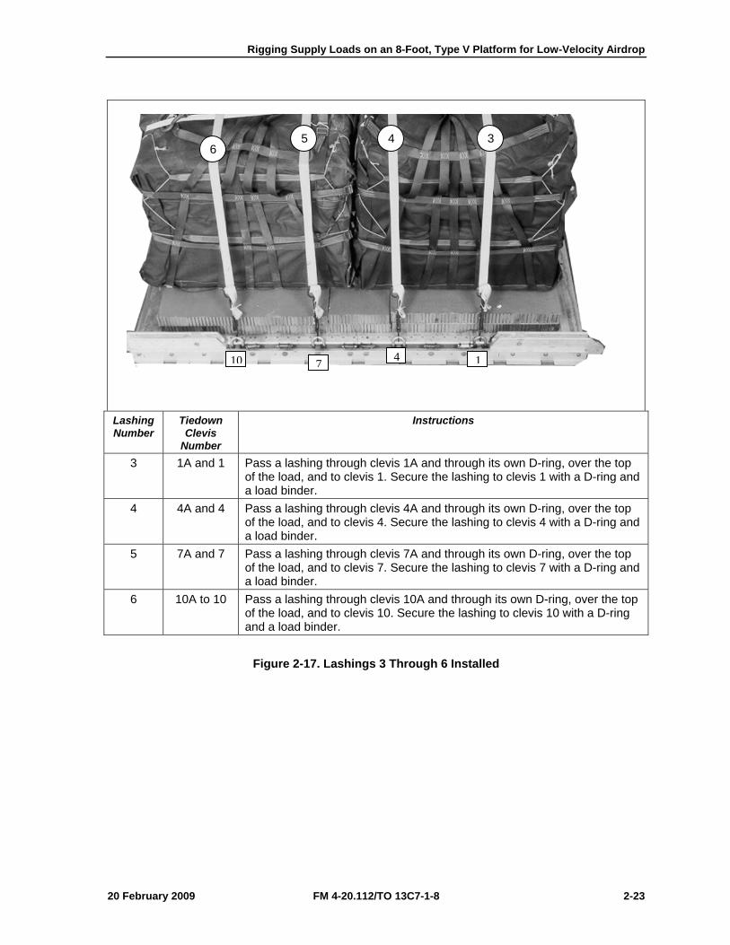
20 February 2009 FM 4-20.112/TO 13C7-1-8 2-23
Lashing Number
Tiedown Clevis
Number
Instructions
3 1A and 1 Pass a lashing through clevis 1A and through its own D-ring, over the top of the load, and to clevis 1. Secure the lashing to clevis 1 with a D-ring and a load binder.
4 4A and 4 Pass a lashing through clevis 4A and through its own D-ring, over the top of the load, and to clevis 4. Secure the lashing to clevis 4 with a D-ring and a load binder.
5 7A and 7 Pass a lashing through clevis 7A and through its own D-ring, over the top of the load, and to clevis 7. Secure the lashing to clevis 7 with a D-ring and a load binder.
6 10A to 10 Pass a lashing through clevis 10A and through its own D-ring, over the top of the load, and to clevis 10. Secure the lashing to clevis 10 with a D-ring and a load binder.
Figure 2-17. Lashings 3 Through 6 Installed
3 4 5 6
14710
Chapter 2
2-24 FM 4-20.112/TO 13C7-1-8 20 February 2009
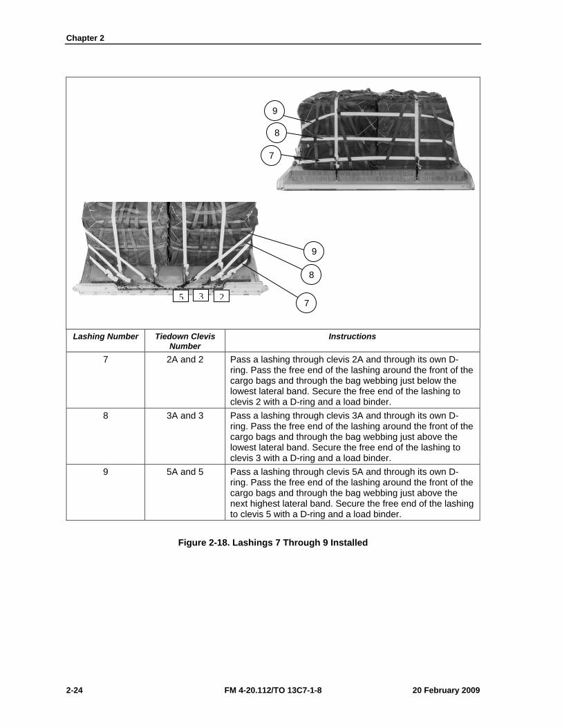
Lashing Number Tiedown Clevis
Number Instructions
7 2A and 2 Pass a lashing through clevis 2A and through its own D-ring. Pass the free end of the lashing around the front of the cargo bags and through the bag webbing just below the lowest lateral band. Secure the free end of the lashing to clevis 2 with a D-ring and a load binder.
8 3A and 3 Pass a lashing through clevis 3A and through its own D-ring. Pass the free end of the lashing around the front of the cargo bags and through the bag webbing just above the lowest lateral band. Secure the free end of the lashing to clevis 3 with a D-ring and a load binder.
9 5A and 5 Pass a lashing through clevis 5A and through its own D-ring. Pass the free end of the lashing around the front of the cargo bags and through the bag webbing just above the next highest lateral band. Secure the free end of the lashing to clevis 5 with a D-ring and a load binder.
Figure 2-18. Lashings 7 Through 9 Installed
9
8
7
9
8
7 5 3 2
Rigging Supply Loads on an 8-Foot, Type V Platform for Low-Velocity Airdrop
20 February 2009 FM 4-20.112/TO 13C7-1-8 2-25
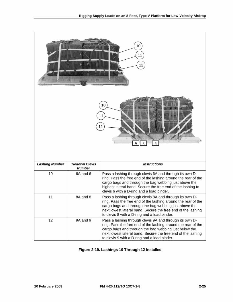
Lashing Number Tiedown Clevis
Number Instructions
10 6A and 6 Pass a lashing through clevis 6A and through its own D-ring. Pass the free end of the lashing around the rear of the cargo bags and through the bag webbing just above the highest lateral band. Secure the free end of the lashing to clevis 6 with a D-ring and a load binder.
11 8A and 8 Pass a lashing through clevis 8A and through its own D-ring. Pass the free end of the lashing around the rear of the cargo bags and through the bag webbing just above the next lowest lateral band. Secure the free end of the lashing to clevis 8 with a D-ring and a load binder.
12 9A and 9 Pass a lashing through clevis 9A and through its own D-ring. Pass the free end of the lashing around the rear of the cargo bags and through the bag webbing just below the next lowest lateral band. Secure the free end of the lashing to clevis 9 with a D-ring and a load binder.
Figure 2-19. Lashings 10 Through 12 Installed
10
12
11
10
11
12
9 8 6
Chapter 2
2-26 FM 4-20.112/TO 13C7-1-8 20 February 2009
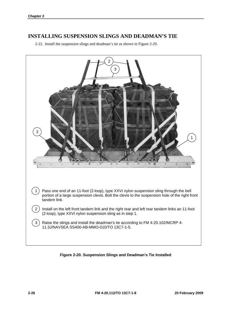
INSTALLING SUSPENSION SLINGS AND DEADMAN’S TIE 2-22. Install the suspension slings and deadman’s tie as shown in Figure 2-20.
1 Pass one end of an 11-foot (2-loop), type XXVI nylon suspension sling through the bell portion of a large suspension clevis. Bolt the clevis to the suspension hole of the right front tandem link.
2 Install on the left front tandem link and the right rear and left rear tandem links an 11-foot (2-loop), type XXVI nylon suspension sling as in step 1.
3 Raise the slings and install the deadman's tie according to FM 4-20.102/MCRP 4-11.3J/NAVSEA SS400-AB-MMO-010/TO 13C7-1-5.
Figure 2-20. Suspension Slings and Deadman’s Tie Installed
2
3
1 2
Rigging Supply Loads on an 8-Foot, Type V Platform for Low-Velocity Airdrop
20 February 2009 FM 4-20.112/TO 13C7-1-8 2-27
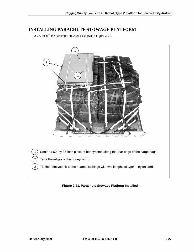
INSTALLING PARACHUTE STOWAGE PLATFORM 2-23. Install the parachute stowage as shown in Figure 2-21.
1 Center a 60- by 36-inch piece of honeycomb along the rear edge of the cargo bags.
2 Tape the edges of the honeycomb.
3 Tie the honeycomb to the nearest lashings with two lengths of type III nylon cord.
Figure 2-21. Parachute Stowage Platform Installed
3
2
1
Chapter 2
2-28 FM 4-20.112/TO 13C7-1-8 20 February 2009
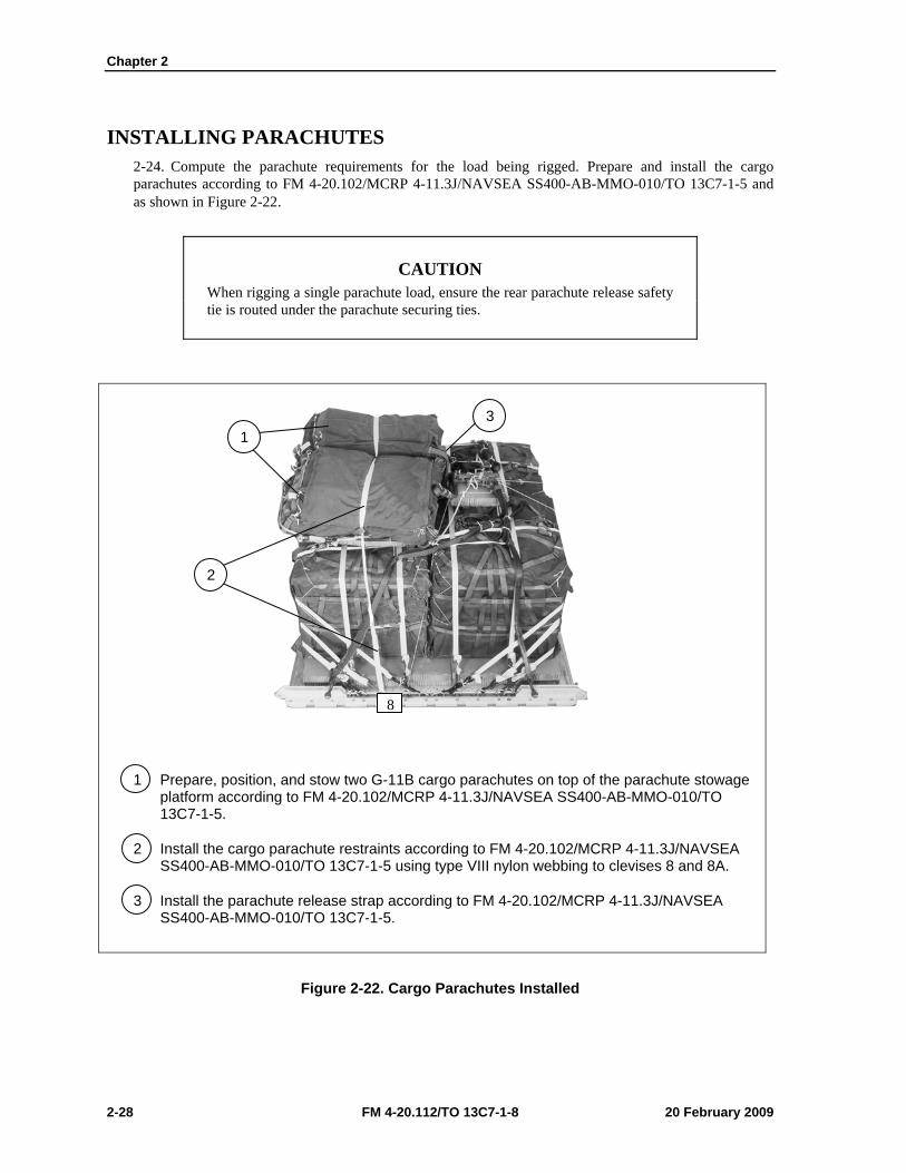
INSTALLING PARACHUTES 2-24. Compute the parachute requirements for the load being rigged. Prepare and install the cargo parachutes according to FM 4-20.102/MCRP 4-11.3J/NAVSEA SS400-AB-MMO-010/TO 13C7-1-5 and as shown in Figure 2-22.
CAUTION When rigging a single parachute load, ensure the rear parachute release safety tie is routed under the parachute securing ties.
1 Prepare, position, and stow two G-11B cargo parachutes on top of the parachute stowage platform according to FM 4-20.102/MCRP 4-11.3J/NAVSEA SS400-AB-MMO-010/TO 13C7-1-5.
2 Install the cargo parachute restraints according to FM 4-20.102/MCRP 4-11.3J/NAVSEA SS400-AB-MMO-010/TO 13C7-1-5 using type VIII nylon webbing to clevises 8 and 8A.
3 Install the parachute release strap according to FM 4-20.102/MCRP 4-11.3J/NAVSEA SS400-AB-MMO-010/TO 13C7-1-5.
Figure 2-22. Cargo Parachutes Installed
3 1
2
8
Rigging Supply Loads on an 8-Foot, Type V Platform for Low-Velocity Airdrop
20 February 2009 FM 4-20.112/TO 13C7-1-8 2-29
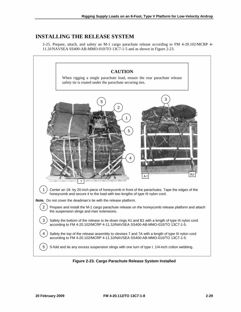
INSTALLING THE RELEASE SYSTEM 2-25. Prepare, attach, and safety an M-1 cargo parachute release according to FM 4-20.102/MCRP 4-11.3J/NAVSEA SS400-AB-MMO-010/TO 13C7-1-5 and as shown in Figure 2-23.
CAUTION When rigging a single parachute load, ensure the rear parachute release safety tie is routed under the parachute securing ties.
1 Center an 18- by 20-inch piece of honeycomb in front of the parachutes. Tape the edges of the honeycomb and secure it to the load with two lengths of type III nylon cord.
Note. Do not cover the deadman’s tie with the release platform.
2 Prepare and install the M-1 cargo parachute release on the honeycomb release platform and attach the suspension slings and riser extensions.
3 Safety the bottom of the release to tie-down rings A1 and B1 with a length of type III nylon cord according to FM 4-20.102/MCRP 4-11.3J/NAVSEA SS400-AB-MMO-010/TO 13C7-1-5.
4 Safety the top of the release assembly to clevises 7 and 7A with a length of type III nylon cord according to FM 4-20.102/MCRP 4-11.3J/NAVSEA SS400-AB-MMO-010/TO 13C7-1-5.
5 S-fold and tie any excess suspension slings with one turn of type I, 1/4-inch cotton webbing.
Figure 2-23. Cargo Parachute Release System Installed
5 2
1
5
4
3
B1A17
Chapter 2
2-30 FM 4-20.112/TO 13C7-1-8 20 February 2009
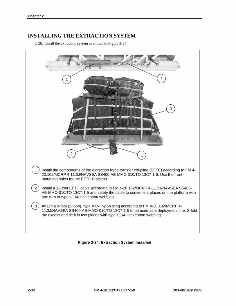
INSTALLING THE EXTRACTION SYSTEM 2-26. Install the extraction system as shown in Figure 2-24.
1 Install the components of the extraction force transfer coupling (EFTC) according to FM 4-20.102/MCRP 4-11.3J/NAVSEA SS400-AB-MMO-010/TO 13C7-1-5. Use the front mounting holes for the EFTC brackets.
2 Install a 12-foot EFTC cable according to FM 4-20.102/MCRP 4-11.3J/NAVSEA SS400-AB-MMO-010/TO 13C7-1-5 and safety the cable to convenient places on the platform with one turn of type I, 1/4-inch cotton webbing.
3 Attach a 9-foot (2-loop), type XXVI nylon sling according to FM 4-20.102/MCRP 4-11.3J/NAVSEA SS400-AB-MMO-010/TO 13C7-1-5 to be used as a deployment line. S-fold the excess and tie it in two places with type I, 1/4-inch cotton webbing.
Figure 2-24. Extraction System Installed
1 2
3
2 1

Rigging Supply Loads on an 8-Foot, Type V Platform for Low-Velocity Airdrop
20 February 2009 FM 4-20.112/TO 13C7-1-8 2-31
PLACING EXTRACTION PARACHUTE 2-27. Select the extraction parachute and extraction line needed using the extraction line requirements table in FM 4-20.102/MCRP 4-11.3J/NAVSEA SS400-AB-MMO-010/TO 13C7-1-5. Place the extraction parachute and line on the load for installation in the aircraft.
INSTALLING PROVISIONS FOR EMERGENCY RESTRAINTS 2-28. Select and install the provisions for the emergency aft restraints according to the emergency aft restraint requirements table in FM 4-20.102/MCRP 4-11.3J/NAVSEA SS400-AB-MMO-010/TO 13C7-1-5.
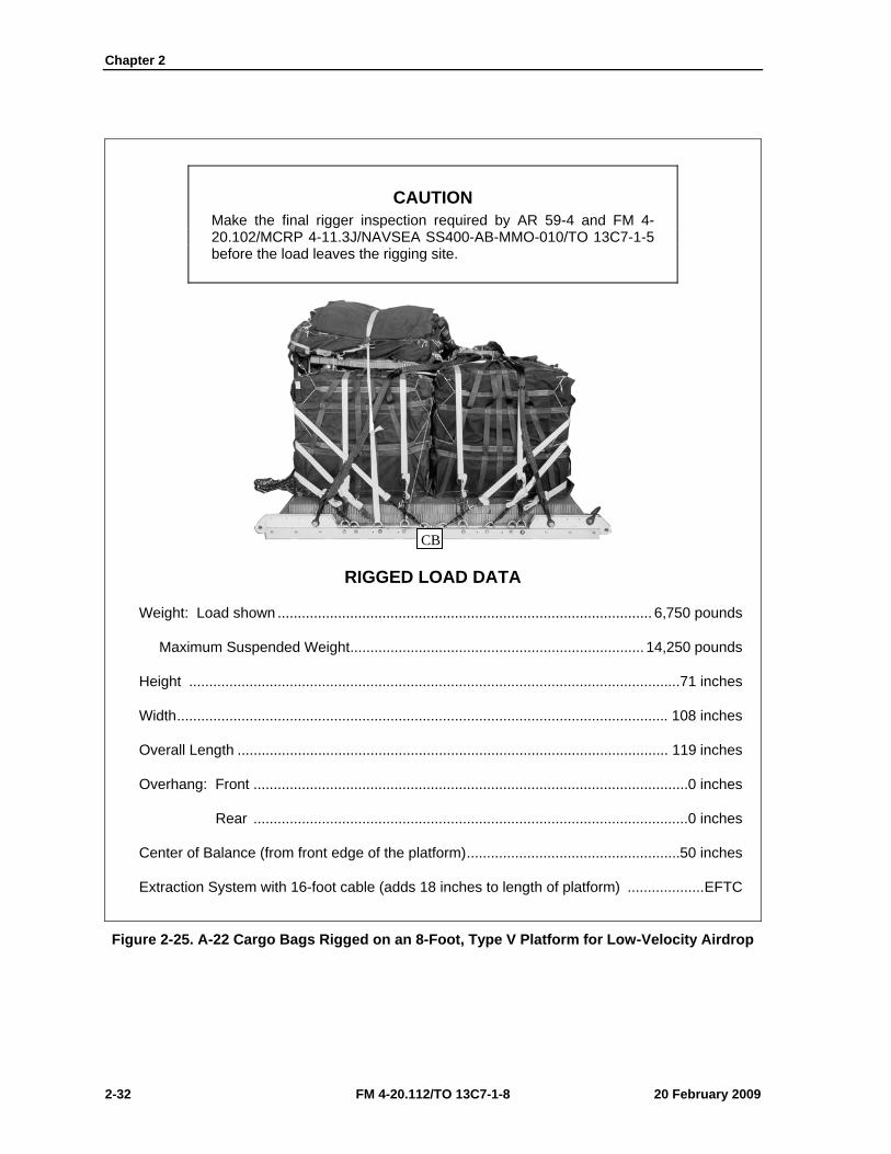
MARKING RIGGED LOAD 2-29. Mark the rigged load according to FM 4-20.102/MCRP 4-11.3J/NAVSEA SS400-AB-MMO-010/TO 13C7-1-5, and as shown in Figure 2-25. Complete Shipper’s Declaration for Dangerous Goods. If the load varies from the one shown, the weight, height, CB, and parachute requirements must be recomputed.
EQUIPMENT REQUIRED 2-30. Use the equipment listed in Table 2-2 to rig this load.
Chapter 2
2-32 FM 4-20.112/TO 13C7-1-8 20 February 2009
CAUTION Make the final rigger inspection required by AR 59-4 and FM 4-20.102/MCRP 4-11.3J/NAVSEA SS400-AB-MMO-010/TO 13C7-1-5 before the load leaves the rigging site.
RIGGED LOAD DATA
Weight: Load shown ............................................................................................. 6,750 pounds
Maximum Suspended Weight ......................................................................... 14,250 pounds
Height ..........................................................................................................................71 inches
Width .......................................................................................................................... 108 inches
Overall Length ........................................................................................................... 119 inches
Overhang: Front ............................................................................................................ 0 inches
Rear ............................................................................................................ 0 inches
Center of Balance (from front edge of the platform) .....................................................50 inches
Extraction System with 16-foot cable (adds 18 inches to length of platform) ................... EFTC
Figure 2-25. A-22 Cargo Bags Rigged on an 8-Foot, Type V Platform for Low-Velocity Airdrop
CB
Rigging Supply Loads on an 8-Foot, Type V Platform for Low-Velocity Airdrop
20 February 2009 FM 4-20.112/TO 13C7-1-8 2-33
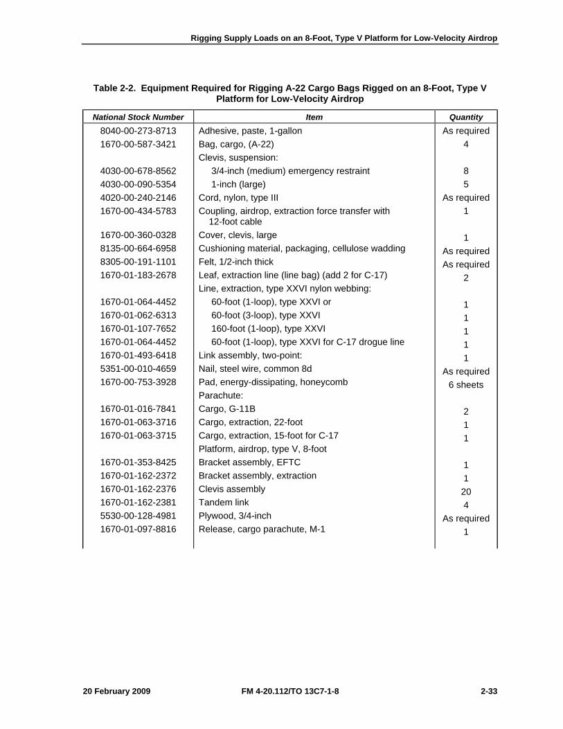
Table 2-2. Equipment Required for Rigging A-22 Cargo Bags Rigged on an 8-Foot, Type V Platform for Low-Velocity Airdrop
National Stock Number Item Quantity 8040-00-273-8713 1670-00-587-3421
4030-00-678-8562 4030-00-090-5354 4020-00-240-2146 1670-00-434-5783
1670-00-360-0328 8135-00-664-6958 8305-00-191-1101 1670-01-183-2678
1670-01-064-4452 1670-01-062-6313 1670-01-107-7652 1670-01-064-4452 1670-01-493-6418 5351-00-010-4659 1670-00-753-3928
1670-01-016-7841 1670-01-063-3716 1670-01-063-3715
1670-01-353-8425 1670-01-162-2372 1670-01-162-2376 1670-01-162-2381 5530-00-128-4981 1670-01-097-8816
Adhesive, paste, 1-gallon Bag, cargo, (A-22) Clevis, suspension: 3/4-inch (medium) emergency restraint 1-inch (large) Cord, nylon, type III Coupling, airdrop, extraction force transfer with 12-foot cable Cover, clevis, large Cushioning material, packaging, cellulose wadding Felt, 1/2-inch thick Leaf, extraction line (line bag) (add 2 for C-17) Line, extraction, type XXVI nylon webbing: 60-foot (1-loop), type XXVI or 60-foot (3-loop), type XXVI 160-foot (1-loop), type XXVI 60-foot (1-loop), type XXVI for C-17 drogue line Link assembly, two-point: Nail, steel wire, common 8d Pad, energy-dissipating, honeycomb Parachute: Cargo, G-11B Cargo, extraction, 22-foot Cargo, extraction, 15-foot for C-17 Platform, airdrop, type V, 8-foot Bracket assembly, EFTC Bracket assembly, extraction Clevis assembly Tandem link Plywood, 3/4-inch Release, cargo parachute, M-1
As required 4 8 5
As required 1 1
As required As required
2 1 1 1 1 1
As required 6 sheets
2 1 1 1 1
20 4
As required 1
Chapter 2
2-34 FM 4-20.112/TO 13C7-1-8 20 February 2009
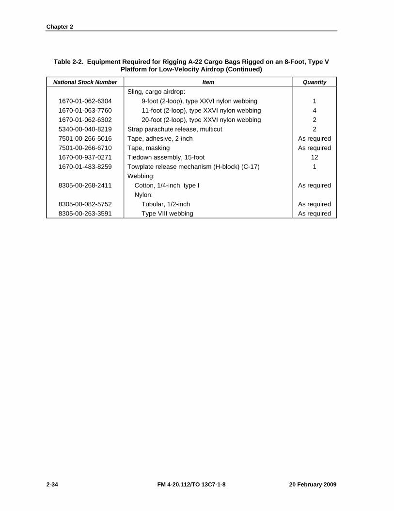
Table 2-2. Equipment Required for Rigging A-22 Cargo Bags Rigged on an 8-Foot, Type V Platform for Low-Velocity Airdrop (Continued)
National Stock Number Item Quantity
1670-01-062-6304 1670-01-063-7760 1670-01-062-6302 5340-00-040-8219 7501-00-266-5016 7501-00-266-6710 1670-00-937-0271 1670-01-483-8259
8305-00-268-2411
8305-00-082-5752 8305-00-263-3591
Sling, cargo airdrop: 9-foot (2-loop), type XXVI nylon webbing 11-foot (2-loop), type XXVI nylon webbing 20-foot (2-loop), type XXVI nylon webbing Strap parachute release, multicut Tape, adhesive, 2-inch Tape, masking Tiedown assembly, 15-foot Towplate release mechanism (H-block) (C-17) Webbing: Cotton, 1/4-inch, type I Nylon: Tubular, 1/2-inch Type VIII webbing
1 4 2 2
As required As required
12 1
As required
As required As required
20 February 2009 FM 4-20.112/TO 13C7-1-8 3-1
Chapter 3
Rigging Supply Loads on a 12-Foot, Type V Platform for Low-Velocity Airdrop
DESCRIPTION OF LOAD 3-1. Bulk supplies consisting of rations, equipment, fuel, ammunition, or other items of general supply are rigged on a 12-foot, type V airdrop platform with G-11 cargo parachutes. Items packaged or configured so that they can be restrained by endboards and lashings can be airdropped using these procedures. Modifications to the honeycomb, endboards, and lashings may be necessary to allow for items of different sizes and shapes from those shown. For extraction purposes, the rigged load must weigh at least 3,780 pounds. Refer to FM 4-20.102/MCRP 4-11.3J/NAVSEA SS400-AB-MMO-010/TO 13C7-1-5 for the weight limitations for the number of parachutes to be used.
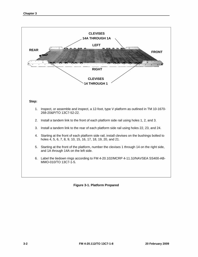
PREPARING PLATFORM 3-2. Prepare a 12-foot, type V platform as shown in Figure 3-1.
Chapter 3
3-2 FM 4-20.112/TO 13C7-1-8 20 February 2009
Step:
1. Inspect, or assemble and inspect, a 12-foot, type V platform as outlined in TM 10-1670-268-20&P/TO 13C7-52-22.
2. Install a tandem link to the front of each platform side rail using holes 1, 2, and 3.
3. Install a tandem link to the rear of each platform side rail using holes 22, 23, and 24.
4. Starting at the front of each platform side rail, install clevises on the bushings bolted to holes 4, 5, 6, 7, 8, 9, 10, 15, 16, 17, 18, 19, 20, and 21.
5. Starting at the front of the platform, number the clevises 1 through 14 on the right side, and 1A through 14A on the left side.
6. Label the tiedown rings according to FM 4-20.102/MCRP 4-11.3J/NAVSEA SS400-AB-MMO-010/TO 13C7-1-5.
Figure 3-1. Platform Prepared
CLEVISES 14A THROUGH 1A
CLEVISES 14 THROUGH 1
LEFT
RIGHT
FRONT REAR
Rigging Supply Loads on a 12-Foot, Type V Platform for Low-Velocity Airdrop
20 February 2009 FM 4-20.112/TO 13C7-1-8 3-3
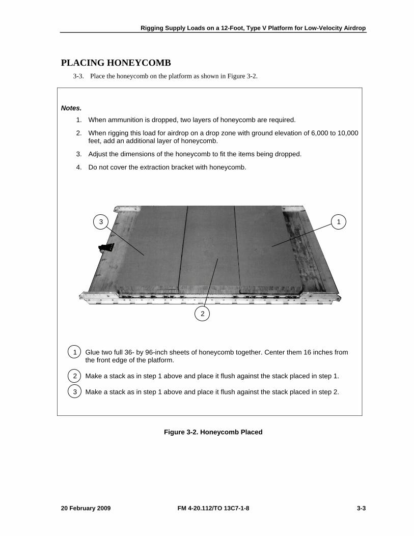
PLACING HONEYCOMB 3-3. Place the honeycomb on the platform as shown in Figure 3-2.
Notes.
1. When ammunition is dropped, two layers of honeycomb are required.
2. When rigging this load for airdrop on a drop zone with ground elevation of 6,000 to 10,000 feet, add an additional layer of honeycomb.
3. Adjust the dimensions of the honeycomb to fit the items being dropped.
4. Do not cover the extraction bracket with honeycomb.
1 Glue two full 36- by 96-inch sheets of honeycomb together. Center them 16 inches from the front edge of the platform.
2 Make a stack as in step 1 above and place it flush against the stack placed in step 1.
3 Make a stack as in step 1 above and place it flush against the stack placed in step 2.
Figure 3-2. Honeycomb Placed
1
2
3
Chapter 3
3-4 FM 4-20.112/TO 13C7-1-8 20 February 2009
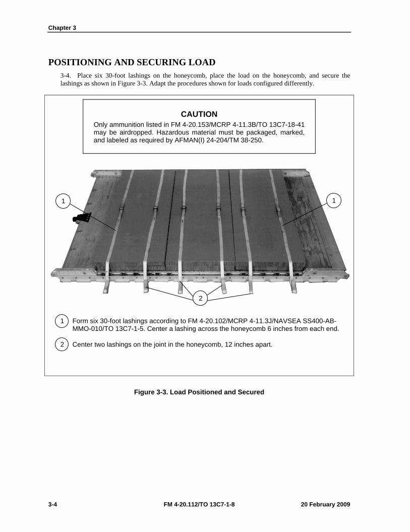
POSITIONING AND SECURING LOAD 3-4. Place six 30-foot lashings on the honeycomb, place the load on the honeycomb, and secure the lashings as shown in Figure 3-3. Adapt the procedures shown for loads configured differently.
CAUTION Only ammunition listed in FM 4-20.153/MCRP 4-11.3B/TO 13C7-18-41 may be airdropped. Hazardous material must be packaged, marked, and labeled as required by AFMAN(I) 24-204/TM 38-250.
1 Form six 30-foot lashings according to FM 4-20.102/MCRP 4-11.3J/NAVSEA SS400-AB-MMO-010/TO 13C7-1-5. Center a lashing across the honeycomb 6 inches from each end.
2 Center two lashings on the joint in the honeycomb, 12 inches apart.
Figure 3-3. Load Positioned and Secured
1
2
1
Rigging Supply Loads on a 12-Foot, Type V Platform for Low-Velocity Airdrop
20 February 2009 FM 4-20.112/TO 13C7-1-8 3-5
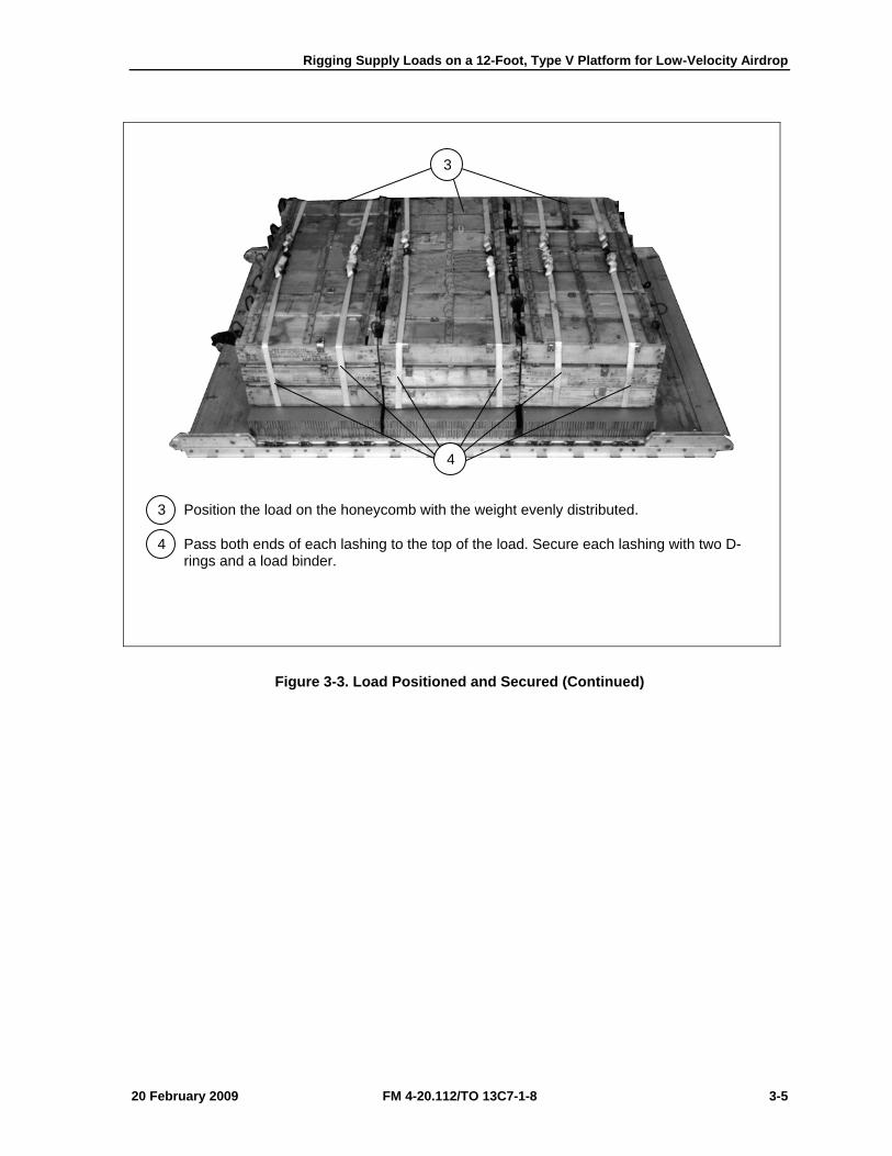
3 Position the load on the honeycomb with the weight evenly distributed.
4 Pass both ends of each lashing to the top of the load. Secure each lashing with two D-rings and a load binder.
Figure 3-3. Load Positioned and Secured (Continued)
3
4
Chapter 3
3-6 FM 4-20.112/TO 13C7-1-8 20 February 2009
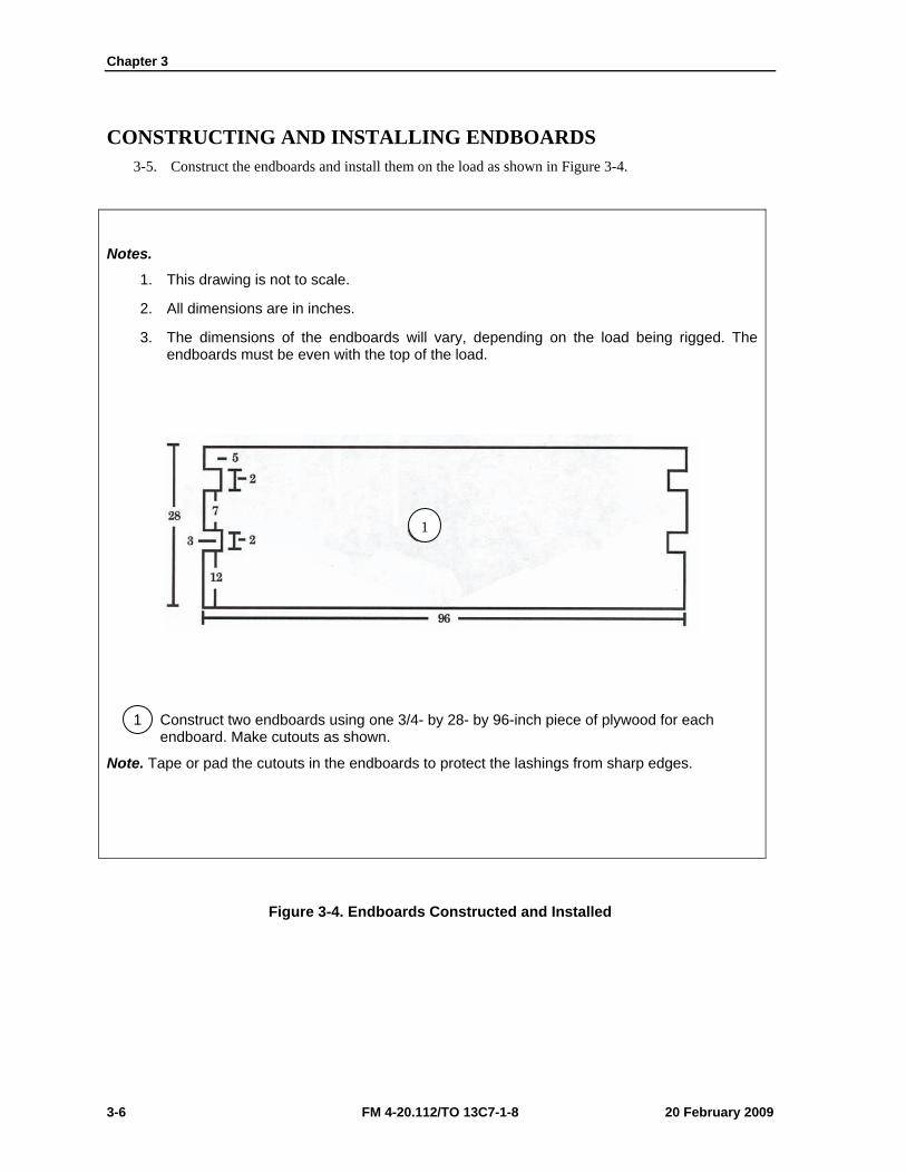
CONSTRUCTING AND INSTALLING ENDBOARDS 3-5. Construct the endboards and install them on the load as shown in Figure 3-4.
Notes.
1. This drawing is not to scale.
2. All dimensions are in inches.
3. The dimensions of the endboards will vary, depending on the load being rigged. The endboards must be even with the top of the load.
1 Construct two endboards using one 3/4- by 28- by 96-inch piece of plywood for each endboard. Make cutouts as shown.
Note. Tape or pad the cutouts in the endboards to protect the lashings from sharp edges.
Figure 3-4. Endboards Constructed and Installed
1

Rigging Supply Loads on a 12-Foot, Type V Platform for Low-Velocity Airdrop
20 February 2009 FM 4-20.112/TO 13C7-1-8 3-7
Note. Loads longer than the one shown may be secured in this way, if the lashings are pre-positioned under the honeycomb and endboards, and secured at both ends to the tie-down rings as shown in steps 4 and 5. Do not cover the extraction bracket.
2 Place one endboard against the front of the load.
3 Place one endboard against the rear of the load.
4 Pass the free end of a 15-foot lashing through tie-down ring A6 and through its own D-ring. Pull the free end of the lashing over the top of the load.
5 Pass the free end of a 15-foot lashing through tie-down ring D6 and through its own D-ring. Pull the free end of the lashing over the top of the load.
6 Secure the end of the lashing positioned in step 4 to tie-down ring A1 with a D-ring and a load binder.
7 Secure the end of the lashing positioned in step 5 to tie-down ring B1 with a D-ring and a load binder.
Figure 3-4. Endboards Constructed and Installed (Continued)
27
6
3
4
5
B1
A1
D6
A6
Chapter 3
3-8 FM 4-20.112/TO 13C7-1-8 20 February 2009
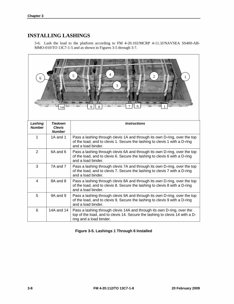
INSTALLING LASHINGS 3-6. Lash the load to the platform according to FM 4-20.102/MCRP 4-11.3J/NAVSEA SS400-AB-MMO-010/TO 13C7-1-5 and as shown in Figures 3-5 through 3-7.
Lashing Number
Tiedown Clevis
Number
Instructions
1 1A and 1 Pass a lashing through clevis 1A and through its own D-ring, over the top of the load, and to clevis 1. Secure the lashing to clevis 1 with a D-ring and a load binder.
2 6A and 6 Pass a lashing through clevis 6A and through its own D-ring, over the top of the load, and to clevis 6. Secure the lashing to clevis 6 with a D-ring and a load binder.
3 7A and 7 Pass a lashing through clevis 7A and through its own D-ring, over the top of the load, and to clevis 7. Secure the lashing to clevis 7 with a D-ring and a load binder.
4 8A and 8 Pass a lashing through clevis 8A and through its own D-ring, over the top of the load, and to clevis 8. Secure the lashing to clevis 8 with a D-ring and a load binder.
5 9A and 9 Pass a lashing through clevis 9A and through its own D-ring, over the top of the load, and to clevis 9. Secure the lashing to clevis 9 with a D-ring and a load binder.
6 14A and 14 Pass a lashing through clevis 14A and through its own D-ring, over the top of the load, and to clevis 14. Secure the lashing to clevis 14 with a D-ring and a load binder.
Figure 3-5. Lashings 1 Through 6 Installed
6 5 4
3
2 1
14 9 8 7 6 1
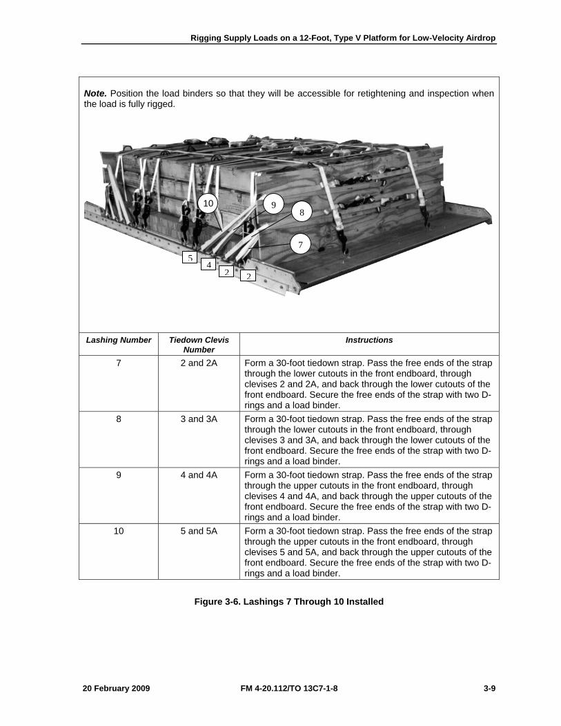
Rigging Supply Loads on a 12-Foot, Type V Platform for Low-Velocity Airdrop
20 February 2009 FM 4-20.112/TO 13C7-1-8 3-9
Note. Position the load binders so that they will be accessible for retightening and inspection when the load is fully rigged.
Lashing Number Tiedown Clevis
Number Instructions
7 2 and 2A Form a 30-foot tiedown strap. Pass the free ends of the strap through the lower cutouts in the front endboard, through clevises 2 and 2A, and back through the lower cutouts of the front endboard. Secure the free ends of the strap with two D-rings and a load binder.
8 3 and 3A Form a 30-foot tiedown strap. Pass the free ends of the strap through the lower cutouts in the front endboard, through clevises 3 and 3A, and back through the lower cutouts of the front endboard. Secure the free ends of the strap with two D-rings and a load binder.
9 4 and 4A Form a 30-foot tiedown strap. Pass the free ends of the strap through the upper cutouts in the front endboard, through clevises 4 and 4A, and back through the upper cutouts of the front endboard. Secure the free ends of the strap with two D-rings and a load binder.
10 5 and 5A Form a 30-foot tiedown strap. Pass the free ends of the strap through the upper cutouts in the front endboard, through clevises 5 and 5A, and back through the upper cutouts of the front endboard. Secure the free ends of the strap with two D-rings and a load binder.
Figure 3-6. Lashings 7 Through 10 Installed
98
7
224
5
10
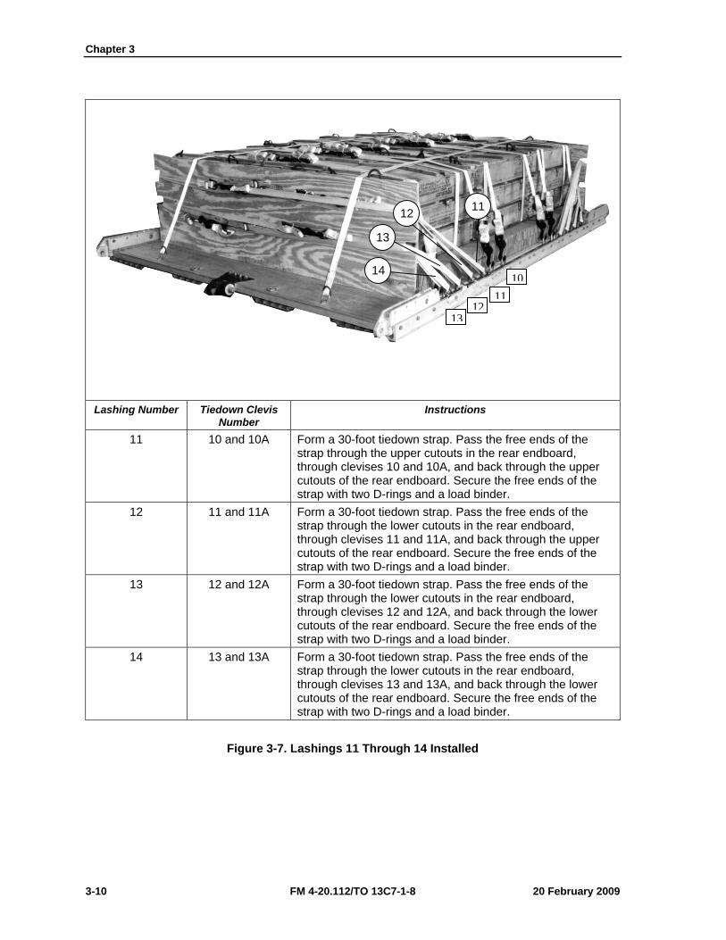
Chapter 3
3-10 FM 4-20.112/TO 13C7-1-8 20 February 2009
Lashing Number Tiedown Clevis
Number Instructions
11 10 and 10A Form a 30-foot tiedown strap. Pass the free ends of the strap through the upper cutouts in the rear endboard, through clevises 10 and 10A, and back through the upper cutouts of the rear endboard. Secure the free ends of the strap with two D-rings and a load binder.
12 11 and 11A Form a 30-foot tiedown strap. Pass the free ends of the strap through the lower cutouts in the rear endboard, through clevises 11 and 11A, and back through the upper cutouts of the rear endboard. Secure the free ends of the strap with two D-rings and a load binder.
13 12 and 12A Form a 30-foot tiedown strap. Pass the free ends of the strap through the lower cutouts in the rear endboard, through clevises 12 and 12A, and back through the lower cutouts of the rear endboard. Secure the free ends of the strap with two D-rings and a load binder.
14 13 and 13A Form a 30-foot tiedown strap. Pass the free ends of the strap through the lower cutouts in the rear endboard, through clevises 13 and 13A, and back through the lower cutouts of the rear endboard. Secure the free ends of the strap with two D-rings and a load binder.
Figure 3-7. Lashings 11 Through 14 Installed
11 12
13
14 10
13
1112
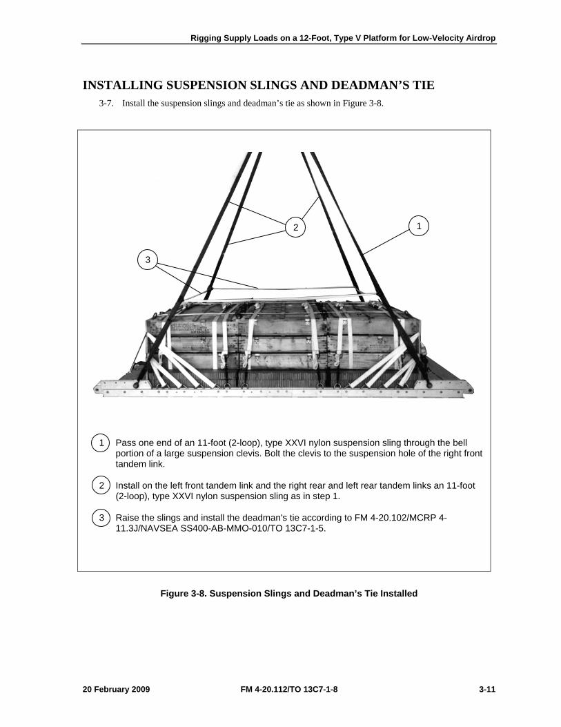
Rigging Supply Loads on a 12-Foot, Type V Platform for Low-Velocity Airdrop
20 February 2009 FM 4-20.112/TO 13C7-1-8 3-11
INSTALLING SUSPENSION SLINGS AND DEADMAN’S TIE 3-7. Install the suspension slings and deadman’s tie as shown in Figure 3-8.
1 Pass one end of an 11-foot (2-loop), type XXVI nylon suspension sling through the bell portion of a large suspension clevis. Bolt the clevis to the suspension hole of the right front tandem link.
2 Install on the left front tandem link and the right rear and left rear tandem links an 11-foot (2-loop), type XXVI nylon suspension sling as in step 1.
3 Raise the slings and install the deadman's tie according to FM 4-20.102/MCRP 4-11.3J/NAVSEA SS400-AB-MMO-010/TO 13C7-1-5.
Figure 3-8. Suspension Slings and Deadman’s Tie Installed
2 1
3
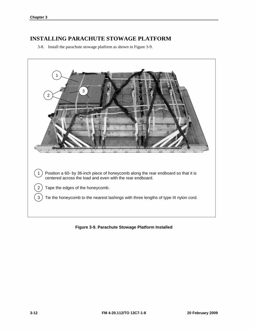
Chapter 3
3-12 FM 4-20.112/TO 13C7-1-8 20 February 2009
INSTALLING PARACHUTE STOWAGE PLATFORM 3-8. Install the parachute stowage platform as shown in Figure 3-9.
1 Position a 60- by 36-inch piece of honeycomb along the rear endboard so that it is centered across the load and even with the rear endboard.
2 Tape the edges of the honeycomb.
3 Tie the honeycomb to the nearest lashings with three lengths of type III nylon cord.
Figure 3-9. Parachute Stowage Platform Installed
2 3
1
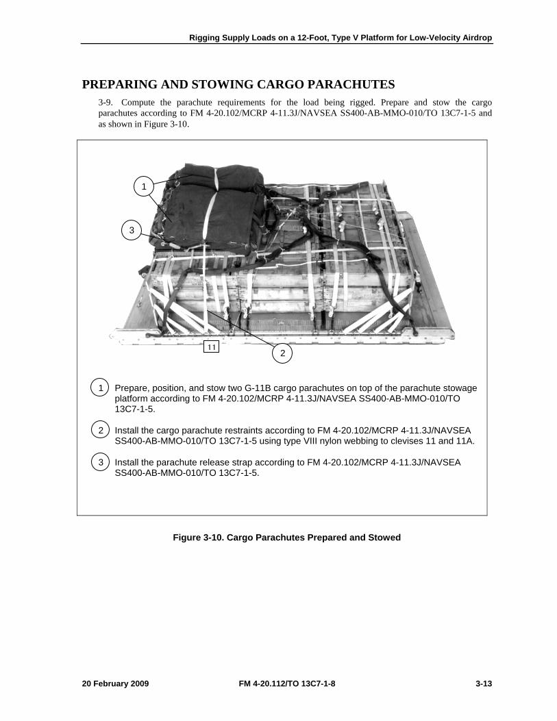
Rigging Supply Loads on a 12-Foot, Type V Platform for Low-Velocity Airdrop
20 February 2009 FM 4-20.112/TO 13C7-1-8 3-13
PREPARING AND STOWING CARGO PARACHUTES 3-9. Compute the parachute requirements for the load being rigged. Prepare and stow the cargo parachutes according to FM 4-20.102/MCRP 4-11.3J/NAVSEA SS400-AB-MMO-010/TO 13C7-1-5 and as shown in Figure 3-10.
1 Prepare, position, and stow two G-11B cargo parachutes on top of the parachute stowage platform according to FM 4-20.102/MCRP 4-11.3J/NAVSEA SS400-AB-MMO-010/TO 13C7-1-5.
2 Install the cargo parachute restraints according to FM 4-20.102/MCRP 4-11.3J/NAVSEA SS400-AB-MMO-010/TO 13C7-1-5 using type VIII nylon webbing to clevises 11 and 11A.
3 Install the parachute release strap according to FM 4-20.102/MCRP 4-11.3J/NAVSEA SS400-AB-MMO-010/TO 13C7-1-5.
Figure 3-10. Cargo Parachutes Prepared and Stowed
1
3
2 11
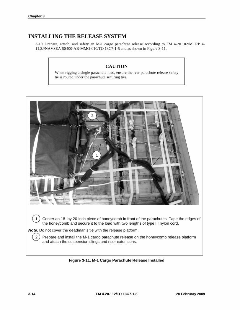
Chapter 3
3-14 FM 4-20.112/TO 13C7-1-8 20 February 2009
INSTALLING THE RELEASE SYSTEM 3-10. Prepare, attach, and safety an M-1 cargo parachute release according to FM 4-20.102/MCRP 4-11.3J/NAVSEA SS400-AB-MMO-010/TO 13C7-1-5 and as shown in Figure 3-11.
CAUTION When rigging a single parachute load, ensure the rear parachute release safety tie is routed under the parachute securing ties.
1 Center an 18- by 20-inch piece of honeycomb in front of the parachutes. Tape the edges of the honeycomb and secure it to the load with two lengths of type III nylon cord.
Note. Do not cover the deadman’s tie with the release platform.
2 Prepare and install the M-1 cargo parachute release on the honeycomb release platform and attach the suspension slings and riser extensions.
Figure 3-11. M-1 Cargo Parachute Release Installed
1
2
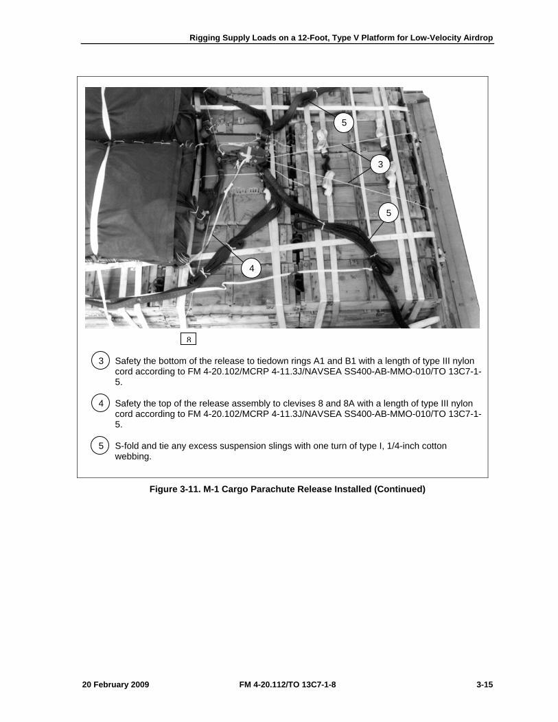
Rigging Supply Loads on a 12-Foot, Type V Platform for Low-Velocity Airdrop
20 February 2009 FM 4-20.112/TO 13C7-1-8 3-15
3 Safety the bottom of the release to tiedown rings A1 and B1 with a length of type III nylon cord according to FM 4-20.102/MCRP 4-11.3J/NAVSEA SS400-AB-MMO-010/TO 13C7-1-5.
4 Safety the top of the release assembly to clevises 8 and 8A with a length of type III nylon cord according to FM 4-20.102/MCRP 4-11.3J/NAVSEA SS400-AB-MMO-010/TO 13C7-1-5.
5 S-fold and tie any excess suspension slings with one turn of type I, 1/4-inch cotton webbing.
Figure 3-11. M-1 Cargo Parachute Release Installed (Continued)
4
5
3
5
8
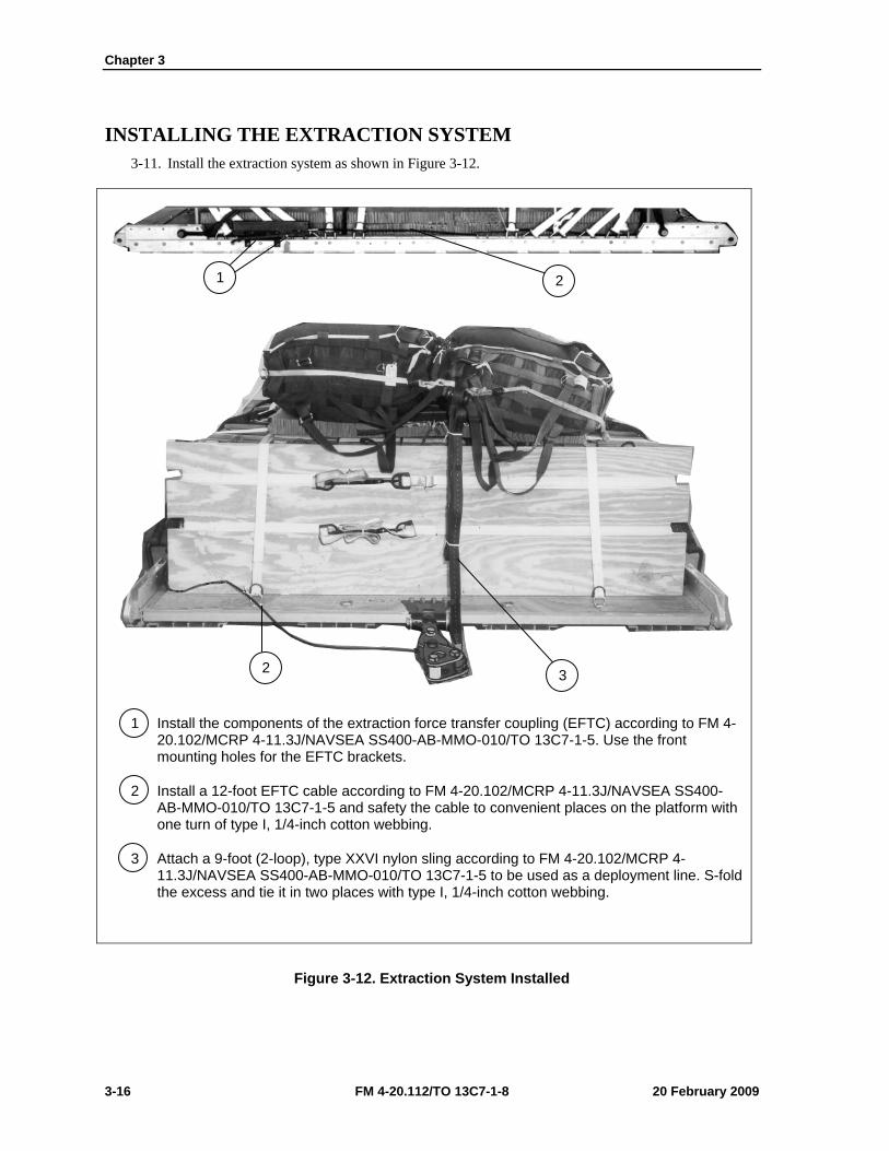
Chapter 3
3-16 FM 4-20.112/TO 13C7-1-8 20 February 2009
INSTALLING THE EXTRACTION SYSTEM 3-11. Install the extraction system as shown in Figure 3-12.
1 Install the components of the extraction force transfer coupling (EFTC) according to FM 4-20.102/MCRP 4-11.3J/NAVSEA SS400-AB-MMO-010/TO 13C7-1-5. Use the front mounting holes for the EFTC brackets.
2 Install a 12-foot EFTC cable according to FM 4-20.102/MCRP 4-11.3J/NAVSEA SS400-AB-MMO-010/TO 13C7-1-5 and safety the cable to convenient places on the platform with one turn of type I, 1/4-inch cotton webbing.
3 Attach a 9-foot (2-loop), type XXVI nylon sling according to FM 4-20.102/MCRP 4-11.3J/NAVSEA SS400-AB-MMO-010/TO 13C7-1-5 to be used as a deployment line. S-fold the excess and tie it in two places with type I, 1/4-inch cotton webbing.
Figure 3-12. Extraction System Installed
1 2
2 3

Rigging Supply Loads on a 12-Foot, Type V Platform for Low-Velocity Airdrop
20 February 2009 FM 4-20.112/TO 13C7-1-8 3-17
PLACING EXTRACTION PARACHUTE 3-12. Select the extraction parachute and extraction line needed using the extraction line requirements table in FM 4-20.102/MCRP 4-11.3J/NAVSEA SS400-AB-MMO-010/TO 13C7-1-5. Place the extraction parachute and line on the load for installation in the aircraft.
INSTALLING PROVISIONS FOR EMERGENCY RESTRAINTS 3-13. Select and install the provisions for the emergency aft restraints according to the emergency aft restraint requirements table in FM 4-20.102/MCRP 4-11.3J/NAVSEA SS400-AB-MMO-010/TO 13C7-1-5.
MARKING RIGGED LOAD 3-14. Mark the rigged load according to FM 4-20.102/MCRP 4-11.3J/NAVSEA SS400-AB-MMO-010/TO 13C7-1-5, and as shown in Figure 3-13. Complete Shipper’s Declaration for Dangerous Goods. If the load varies from the one shown, the weight, height, CB, and parachute requirements must be recomputed.
EQUIPMENT REQUIRED 3-15. Use the equipment listed in Table 3-1 to rig this load.
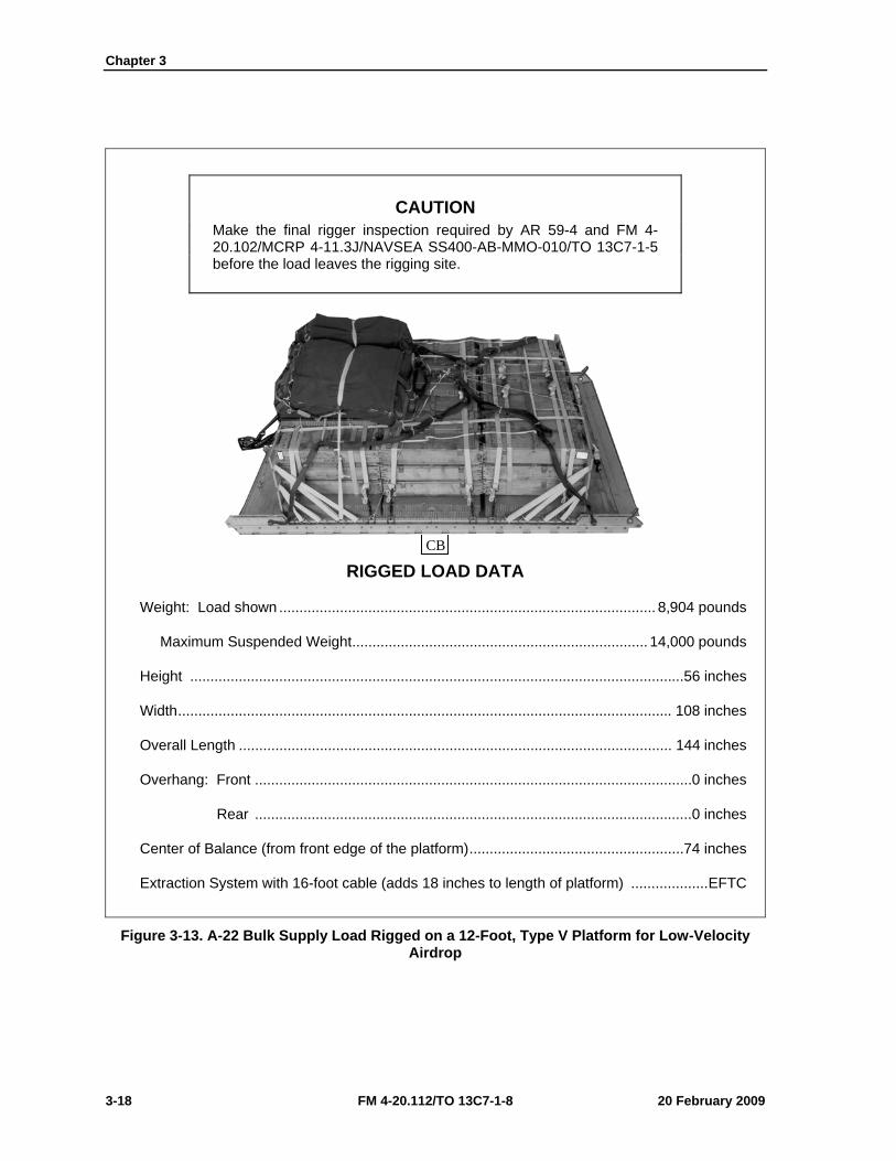
Chapter 3
3-18 FM 4-20.112/TO 13C7-1-8 20 February 2009
CAUTION Make the final rigger inspection required by AR 59-4 and FM 4-20.102/MCRP 4-11.3J/NAVSEA SS400-AB-MMO-010/TO 13C7-1-5 before the load leaves the rigging site.
RIGGED LOAD DATA
Weight: Load shown ............................................................................................. 8,904 pounds
Maximum Suspended Weight ......................................................................... 14,000 pounds
Height ..........................................................................................................................56 inches
Width .......................................................................................................................... 108 inches
Overall Length ........................................................................................................... 144 inches
Overhang: Front ............................................................................................................ 0 inches
Rear ............................................................................................................ 0 inches
Center of Balance (from front edge of the platform) .....................................................74 inches
Extraction System with 16-foot cable (adds 18 inches to length of platform) ................... EFTC
Figure 3-13. A-22 Bulk Supply Load Rigged on a 12-Foot, Type V Platform for Low-Velocity Airdrop
CB
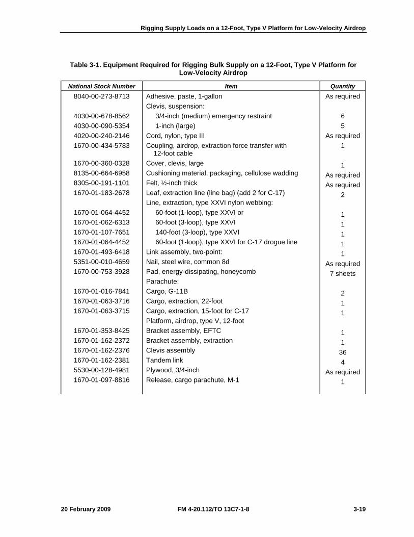
Rigging Supply Loads on a 12-Foot, Type V Platform for Low-Velocity Airdrop
20 February 2009 FM 4-20.112/TO 13C7-1-8 3-19
Table 3-1. Equipment Required for Rigging Bulk Supply on a 12-Foot, Type V Platform for Low-Velocity Airdrop
National Stock Number Item Quantity 8040-00-273-8713
4030-00-678-8562 4030-00-090-5354 4020-00-240-2146 1670-00-434-5783
1670-00-360-0328 8135-00-664-6958 8305-00-191-1101 1670-01-183-2678
1670-01-064-4452 1670-01-062-6313 1670-01-107-7651 1670-01-064-4452 1670-01-493-6418 5351-00-010-4659 1670-00-753-3928
1670-01-016-7841 1670-01-063-3716 1670-01-063-3715
1670-01-353-8425 1670-01-162-2372 1670-01-162-2376 1670-01-162-2381 5530-00-128-4981 1670-01-097-8816
Adhesive, paste, 1-gallon Clevis, suspension: 3/4-inch (medium) emergency restraint 1-inch (large) Cord, nylon, type III Coupling, airdrop, extraction force transfer with 12-foot cable Cover, clevis, large Cushioning material, packaging, cellulose wadding Felt, ½-inch thick Leaf, extraction line (line bag) (add 2 for C-17) Line, extraction, type XXVI nylon webbing: 60-foot (1-loop), type XXVI or 60-foot (3-loop), type XXVI 140-foot (3-loop), type XXVI 60-foot (1-loop), type XXVI for C-17 drogue line Link assembly, two-point: Nail, steel wire, common 8d Pad, energy-dissipating, honeycomb Parachute: Cargo, G-11B Cargo, extraction, 22-foot Cargo, extraction, 15-foot for C-17 Platform, airdrop, type V, 12-foot Bracket assembly, EFTC Bracket assembly, extraction Clevis assembly Tandem link Plywood, 3/4-inch Release, cargo parachute, M-1
As required 6 5
As required 1 1
As required As required
2 1 1 1 1 1
As required 7 sheets
2 1 1 1 1
36 4
As required 1
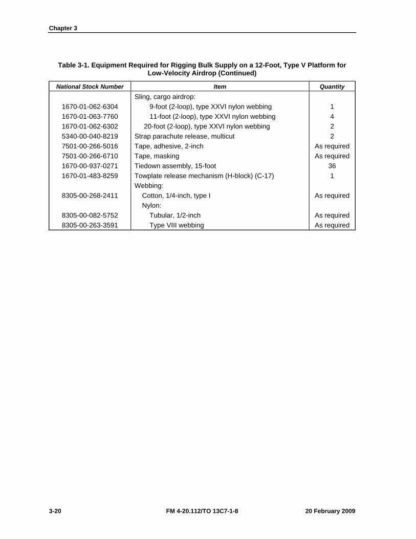
Chapter 3
3-20 FM 4-20.112/TO 13C7-1-8 20 February 2009
Table 3-1. Equipment Required for Rigging Bulk Supply on a 12-Foot, Type V Platform for Low-Velocity Airdrop (Continued)
National Stock Number Item Quantity
1670-01-062-6304 1670-01-063-7760 1670-01-062-6302 5340-00-040-8219 7501-00-266-5016 7501-00-266-6710 1670-00-937-0271 1670-01-483-8259
8305-00-268-2411
8305-00-082-5752 8305-00-263-3591
Sling, cargo airdrop: 9-foot (2-loop), type XXVI nylon webbing 11-foot (2-loop), type XXVI nylon webbing 20-foot (2-loop), type XXVI nylon webbing Strap parachute release, multicut Tape, adhesive, 2-inch Tape, masking Tiedown assembly, 15-foot Towplate release mechanism (H-block) (C-17) Webbing: Cotton, 1/4-inch, type I Nylon: Tubular, 1/2-inch Type VIII webbing
1 4 2 2
As required As required
36 1
As required
As required As required
20 February 2009 FM 4-20.112/TO 13C7-1-8 4-1
Chapter 4
Rigging Forward Area Surgical Team (FAST) Equipment on a 12-Foot, Type V Platform for Low-Velocity Airdrop
DESCRIPTION OF LOAD 4-1. The FAST equipment is rigged as a bulk supply load on a 12-foot, type V airdrop platform with G-11 cargo parachutes. These procedures may be used to rig other bulk supply loads consisting of rations, equipment, fuel, lubricants, ammunition or other items of general supply. As load weights can vary widely, the parachute requirements must be computed for each load. For extraction purposes, the rigged load must weigh at least 3,780 pounds. Refer to FM 4-20.102/MCRP 4-11.3J/NAVSEA SS400-AB-MMO-010/TO 13C7-1-5 for the weight limitations for the number of parachutes to be used.
PREPARING PLATFORM 4-2. Prepare a 12-foot, type V platform as shown in Figure 4-1.
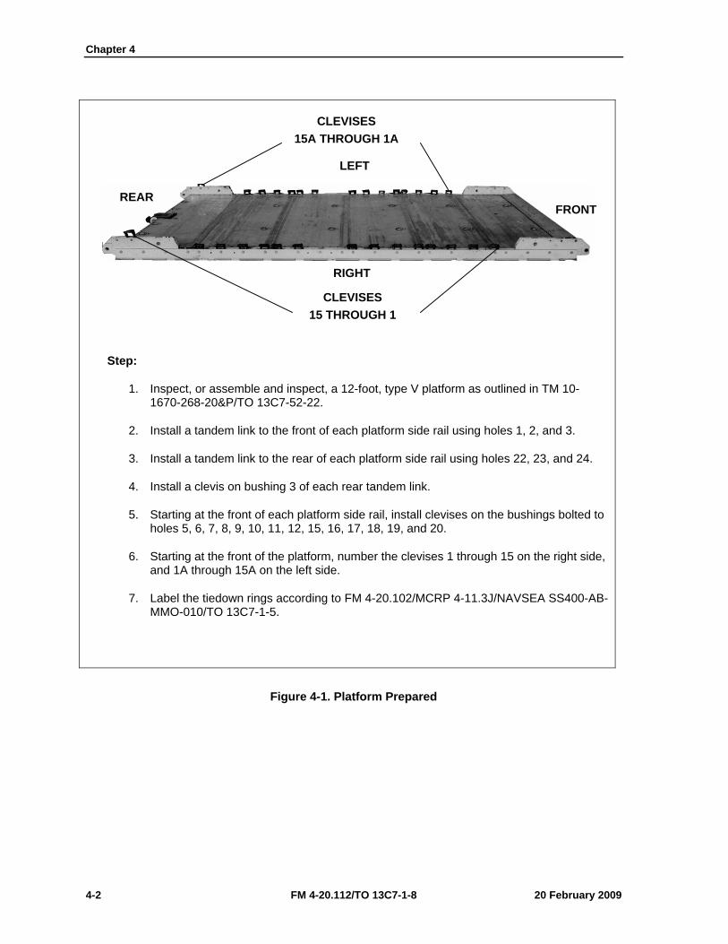
Chapter 4
4-2 FM 4-20.112/TO 13C7-1-8 20 February 2009
Step:
1. Inspect, or assemble and inspect, a 12-foot, type V platform as outlined in TM 10-1670-268-20&P/TO 13C7-52-22.
2. Install a tandem link to the front of each platform side rail using holes 1, 2, and 3.
3. Install a tandem link to the rear of each platform side rail using holes 22, 23, and 24.
4. Install a clevis on bushing 3 of each rear tandem link.
5. Starting at the front of each platform side rail, install clevises on the bushings bolted to holes 5, 6, 7, 8, 9, 10, 11, 12, 15, 16, 17, 18, 19, and 20.
6. Starting at the front of the platform, number the clevises 1 through 15 on the right side, and 1A through 15A on the left side.
7. Label the tiedown rings according to FM 4-20.102/MCRP 4-11.3J/NAVSEA SS400-AB-MMO-010/TO 13C7-1-5.
Figure 4-1. Platform Prepared
CLEVISES 15A THROUGH 1A
CLEVISES 15 THROUGH 1
LEFT
RIGHT
FRONT REAR
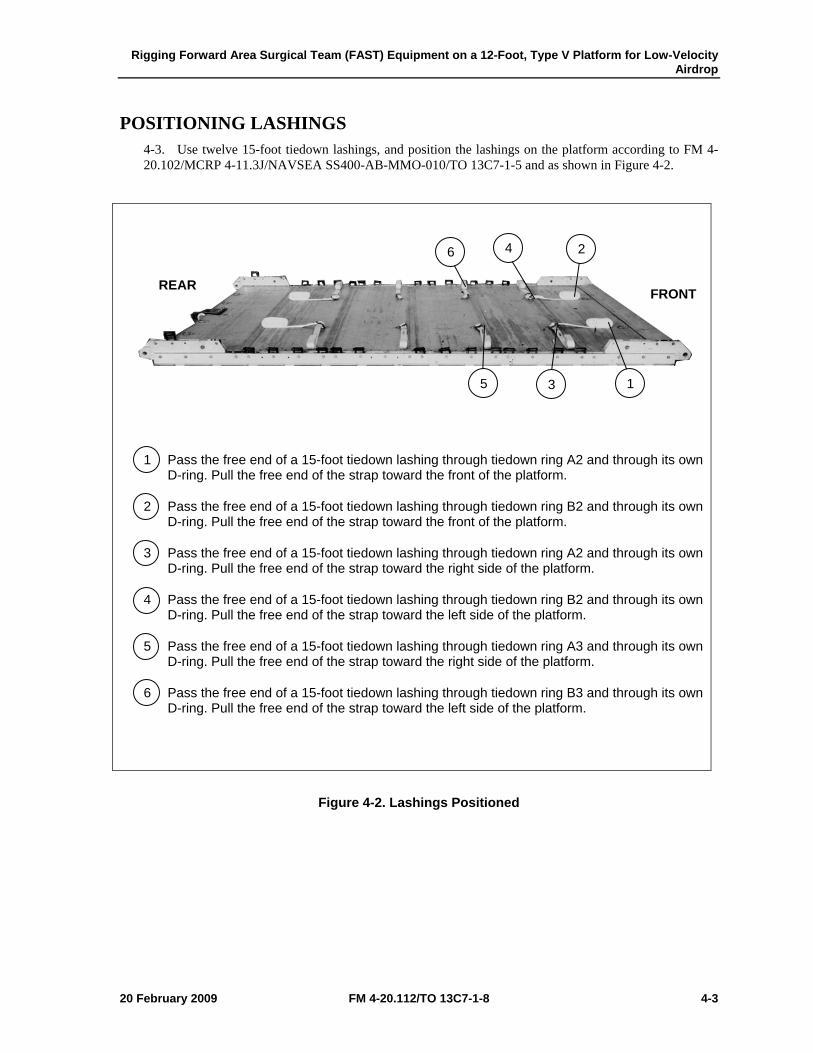
Rigging Forward Area Surgical Team (FAST) Equipment on a 12-Foot, Type V Platform for Low-Velocity Airdrop
20 February 2009 FM 4-20.112/TO 13C7-1-8 4-3
POSITIONING LASHINGS 4-3. Use twelve 15-foot tiedown lashings, and position the lashings on the platform according to FM 4-20.102/MCRP 4-11.3J/NAVSEA SS400-AB-MMO-010/TO 13C7-1-5 and as shown in Figure 4-2.
1 Pass the free end of a 15-foot tiedown lashing through tiedown ring A2 and through its own D-ring. Pull the free end of the strap toward the front of the platform.
2 Pass the free end of a 15-foot tiedown lashing through tiedown ring B2 and through its own D-ring. Pull the free end of the strap toward the front of the platform.
3 Pass the free end of a 15-foot tiedown lashing through tiedown ring A2 and through its own D-ring. Pull the free end of the strap toward the right side of the platform.
4 Pass the free end of a 15-foot tiedown lashing through tiedown ring B2 and through its own D-ring. Pull the free end of the strap toward the left side of the platform.
5 Pass the free end of a 15-foot tiedown lashing through tiedown ring A3 and through its own D-ring. Pull the free end of the strap toward the right side of the platform.
6 Pass the free end of a 15-foot tiedown lashing through tiedown ring B3 and through its own D-ring. Pull the free end of the strap toward the left side of the platform.
Figure 4-2. Lashings Positioned
3 5 1
6 4 2
FRONT REAR
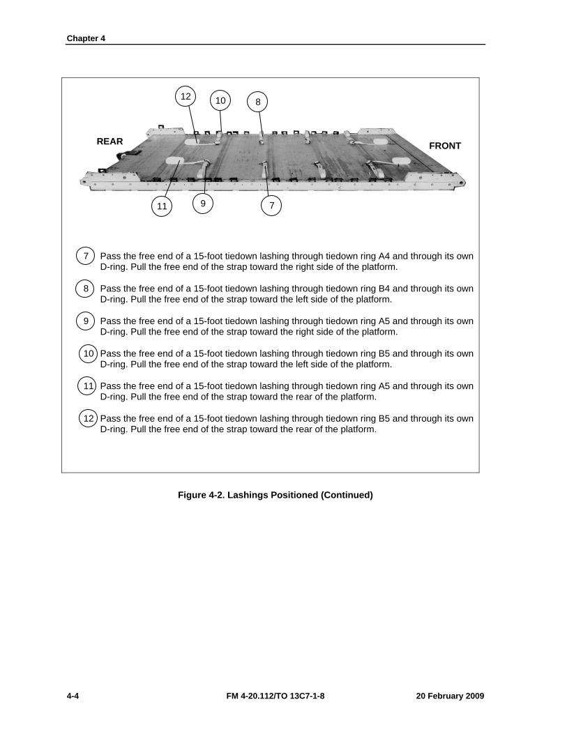
Chapter 4
4-4 FM 4-20.112/TO 13C7-1-8 20 February 2009
7 Pass the free end of a 15-foot tiedown lashing through tiedown ring A4 and through its own D-ring. Pull the free end of the strap toward the right side of the platform.
8 Pass the free end of a 15-foot tiedown lashing through tiedown ring B4 and through its own D-ring. Pull the free end of the strap toward the left side of the platform.
9 Pass the free end of a 15-foot tiedown lashing through tiedown ring A5 and through its own D-ring. Pull the free end of the strap toward the right side of the platform.
10 Pass the free end of a 15-foot tiedown lashing through tiedown ring B5 and through its own D-ring. Pull the free end of the strap toward the left side of the platform.
11 Pass the free end of a 15-foot tiedown lashing through tiedown ring A5 and through its own D-ring. Pull the free end of the strap toward the rear of the platform.
12 Pass the free end of a 15-foot tiedown lashing through tiedown ring B5 and through its own D-ring. Pull the free end of the strap toward the rear of the platform.
Figure 4-2. Lashings Positioned (Continued)
8 10 12
7 9 11
FRONT REAR
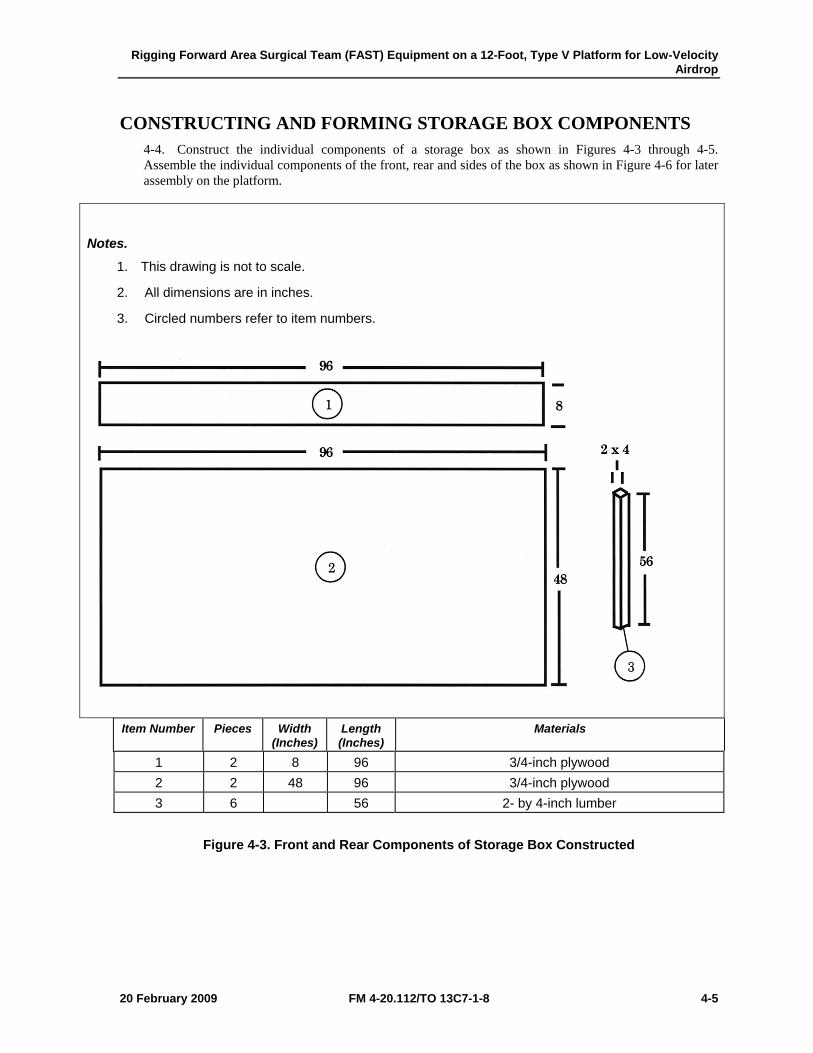
Rigging Forward Area Surgical Team (FAST) Equipment on a 12-Foot, Type V Platform for Low-Velocity Airdrop
20 February 2009 FM 4-20.112/TO 13C7-1-8 4-5
CONSTRUCTING AND FORMING STORAGE BOX COMPONENTS 4-4. Construct the individual components of a storage box as shown in Figures 4-3 through 4-5. Assemble the individual components of the front, rear and sides of the box as shown in Figure 4-6 for later assembly on the platform.
Notes.
1. This drawing is not to scale.
2. All dimensions are in inches.
3. Circled numbers refer to item numbers.
Item Number Pieces Width (Inches)
Length (Inches)
Materials
1 2 8 96 3/4-inch plywood 2 2 48 96 3/4-inch plywood 3 6 56 2- by 4-inch lumber
Figure 4-3. Front and Rear Components of Storage Box Constructed
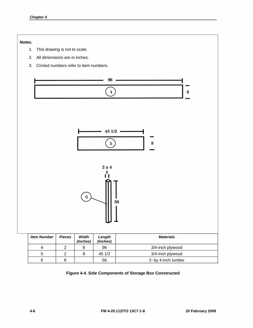
Chapter 4
4-6 FM 4-20.112/TO 13C7-1-8 20 February 2009
Notes.
1. This drawing is not to scale.
2. All dimensions are in inches.
3. Circled numbers refer to item numbers.
Item Number Pieces Width (Inches)
Length (Inches)
Materials
4 2 8 96 3/4-inch plywood 5 2 8 45 1/2 3/4-inch plywood 6 8 56 2- by 4-inch lumber
Figure 4-4. Side Components of Storage Box Constructed

Rigging Forward Area Surgical Team (FAST) Equipment on a 12-Foot, Type V Platform for Low-Velocity Airdrop
20 February 2009 FM 4-20.112/TO 13C7-1-8 4-7
Notes.
1. This drawing is not to scale.
2. All dimensions are in inches.
3. Circled numbers refer to item numbers.
Item Number Pieces Width (Inches)
Length (Inches)
Materials
7 2 48 96 3/4-inch plywood 8 2 48 45 1/2 3/4-inch plywood
Figure 4-4. Side Components of Storage Box Constructed (Continued)
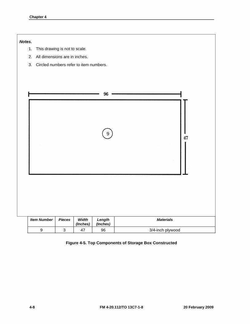
Chapter 4
4-8 FM 4-20.112/TO 13C7-1-8 20 February 2009
Notes.
1. This drawing is not to scale.
2. All dimensions are in inches.
3. Circled numbers refer to item numbers.
Item Number Pieces Width (Inches)
Length (Inches)
Materials
9 3 47 96 3/4-inch plywood
Figure 4-5. Top Components of Storage Box Constructed
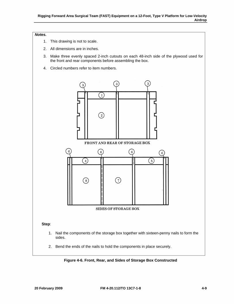
Rigging Forward Area Surgical Team (FAST) Equipment on a 12-Foot, Type V Platform for Low-Velocity Airdrop
20 February 2009 FM 4-20.112/TO 13C7-1-8 4-9
Notes.
1. This drawing is not to scale.
2. All dimensions are in inches.
3. Make three evenly spaced 2-inch cutouts on each 48-inch side of the plywood used for the front and rear components before assembling the box.
4. Circled numbers refer to item numbers.
Step:
1. Nail the components of the storage box together with sixteen-penny nails to form the sides.
2. Bend the ends of the nails to hold the components in place securely.
Figure 4-6. Front, Rear, and Sides of Storage Box Constructed
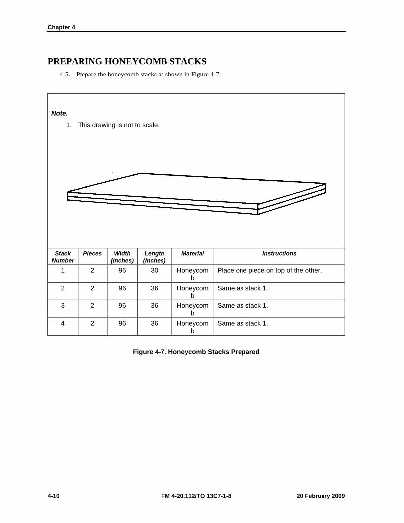
Chapter 4
4-10 FM 4-20.112/TO 13C7-1-8 20 February 2009
PREPARING HONEYCOMB STACKS 4-5. Prepare the honeycomb stacks as shown in Figure 4-7.
Note.
1. This drawing is not to scale.
Stack Number
Pieces Width (Inches)
Length (Inches)
Material Instructions
1 2 96 30 Honeycomb
Place one piece on top of the other.
2 2 96 36 Honeycomb
Same as stack 1.
3 2 96 36 Honeycomb
Same as stack 1.
4 2 96 36 Honeycomb
Same as stack 1.
Figure 4-7. Honeycomb Stacks Prepared
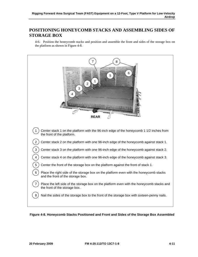
Rigging Forward Area Surgical Team (FAST) Equipment on a 12-Foot, Type V Platform for Low-Velocity Airdrop
20 February 2009 FM 4-20.112/TO 13C7-1-8 4-11
POSITIONING HONEYCOMB STACKS AND ASSEMBLING SIDES OF STORAGE BOX
4-6. Position the honeycomb stacks and position and assemble the front and sides of the storage box on the platform as shown in Figure 4-8.
1 Center stack 1 on the platform with the 96-inch edge of the honeycomb 1 1/2 inches from the front of the platform.
2 Center stack 2 on the platform with one 96-inch edge of the honeycomb against stack 1.
3 Center stack 3 on the platform with one 96-inch edge of the honeycomb against stack 2.
4 Center stack 4 on the platform with one 96-inch edge of the honeycomb against stack 3.
5 Center the front of the storage box on the platform against the front of stack 1.
6 Place the right side of the storage box on the platform even with the honeycomb stacks and the front of the storage box.
7 Place the left side of the storage box on the platform even with the honeycomb stacks and the front of the storage box.
8 Nail the sides of the storage box to the front of the storage box with sixteen-penny nails.
Figure 4-8. Honeycomb Stacks Positioned and Front and Sides of the Storage Box Assembled
8 7
6 5
1 2
3
4
REAR
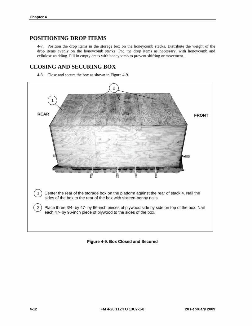
Chapter 4
4-12 FM 4-20.112/TO 13C7-1-8 20 February 2009
POSITIONING DROP ITEMS 4-7. Position the drop items in the storage box on the honeycomb stacks. Distribute the weight of the drop items evenly on the honeycomb stacks. Pad the drop items as necessary, with honeycomb and cellulose wadding. Fill in empty areas with honeycomb to prevent shifting or movement.
CLOSING AND SECURING BOX 4-8. Close and secure the box as shown in Figure 4-9.
1 Center the rear of the storage box on the platform against the rear of stack 4. Nail the sides of the box to the rear of the box with sixteen-penny nails.
2 Place three 3/4- by 47- by 96-inch pieces of plywood side by side on top of the box. Nail each 47- by 96-inch piece of plywood to the sides of the box.
Figure 4-9. Box Closed and Secured
FRONT REAR
2
1
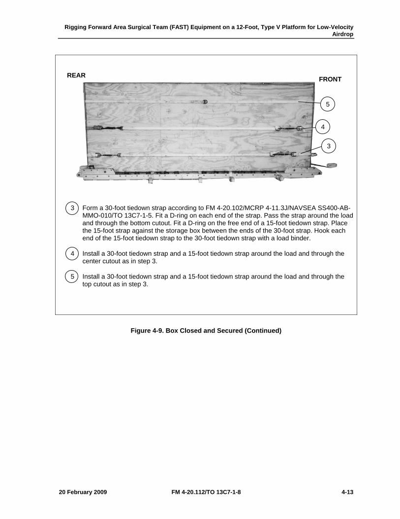
Rigging Forward Area Surgical Team (FAST) Equipment on a 12-Foot, Type V Platform for Low-Velocity Airdrop
20 February 2009 FM 4-20.112/TO 13C7-1-8 4-13
3 Form a 30-foot tiedown strap according to FM 4-20.102/MCRP 4-11.3J/NAVSEA SS400-AB-MMO-010/TO 13C7-1-5. Fit a D-ring on each end of the strap. Pass the strap around the load and through the bottom cutout. Fit a D-ring on the free end of a 15-foot tiedown strap. Place the 15-foot strap against the storage box between the ends of the 30-foot strap. Hook each end of the 15-foot tiedown strap to the 30-foot tiedown strap with a load binder.
4 Install a 30-foot tiedown strap and a 15-foot tiedown strap around the load and through the center cutout as in step 3.
5 Install a 30-foot tiedown strap and a 15-foot tiedown strap around the load and through the top cutout as in step 3.
Figure 4-9. Box Closed and Secured (Continued)
5
4
3
FRONT REAR
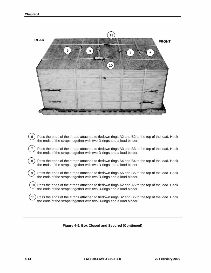
Chapter 4
4-14 FM 4-20.112/TO 13C7-1-8 20 February 2009
6 Pass the ends of the straps attached to tiedown rings A2 and B2 to the top of the load. Hook the ends of the straps together with two D-rings and a load binder.
7 Pass the ends of the straps attached to tiedown rings A3 and B3 to the top of the load. Hook the ends of the straps together with two D-rings and a load binder.
8 Pass the ends of the straps attached to tiedown rings A4 and B4 to the top of the load. Hook the ends of the straps together with two D-rings and a load binder.
9 Pass the ends of the straps attached to tiedown rings A5 and B5 to the top of the load. Hook the ends of the straps together with two D-rings and a load binder.
10 Pass the ends of the straps attached to tiedown rings A2 and A5 to the top of the load. Hook the ends of the straps together with two D-rings and a load binder.
11 Pass the ends of the straps attached to tiedown rings B2 and B5 to the top of the load. Hook the ends of the straps together with two D-rings and a load binder.
Figure 4-9. Box Closed and Secured (Continued)
6 7
11
10
9 8
FRONT REAR
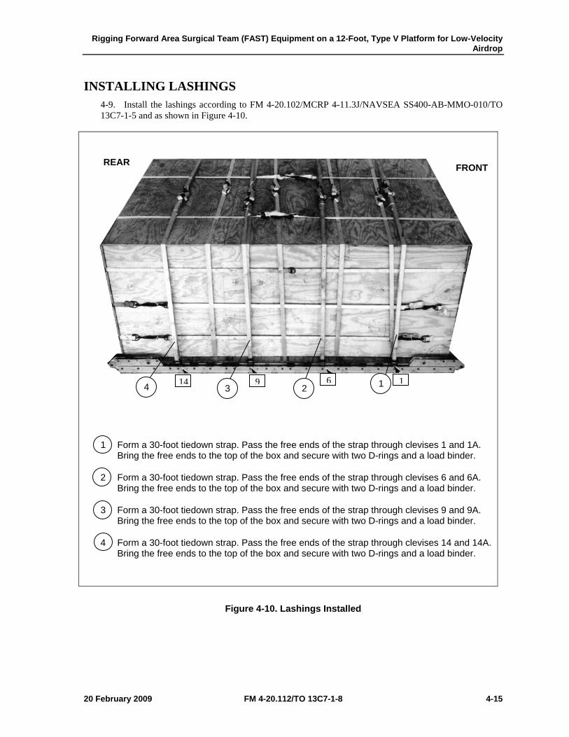
Rigging Forward Area Surgical Team (FAST) Equipment on a 12-Foot, Type V Platform for Low-Velocity Airdrop
20 February 2009 FM 4-20.112/TO 13C7-1-8 4-15
INSTALLING LASHINGS 4-9. Install the lashings according to FM 4-20.102/MCRP 4-11.3J/NAVSEA SS400-AB-MMO-010/TO 13C7-1-5 and as shown in Figure 4-10.
1 Form a 30-foot tiedown strap. Pass the free ends of the strap through clevises 1 and 1A. Bring the free ends to the top of the box and secure with two D-rings and a load binder.
2 Form a 30-foot tiedown strap. Pass the free ends of the strap through clevises 6 and 6A. Bring the free ends to the top of the box and secure with two D-rings and a load binder.
3 Form a 30-foot tiedown strap. Pass the free ends of the strap through clevises 9 and 9A. Bring the free ends to the top of the box and secure with two D-rings and a load binder.
4 Form a 30-foot tiedown strap. Pass the free ends of the strap through clevises 14 and 14A. Bring the free ends to the top of the box and secure with two D-rings and a load binder.
Figure 4-10. Lashings Installed
FRONT REAR
4 3 2 1 14 9 6 1
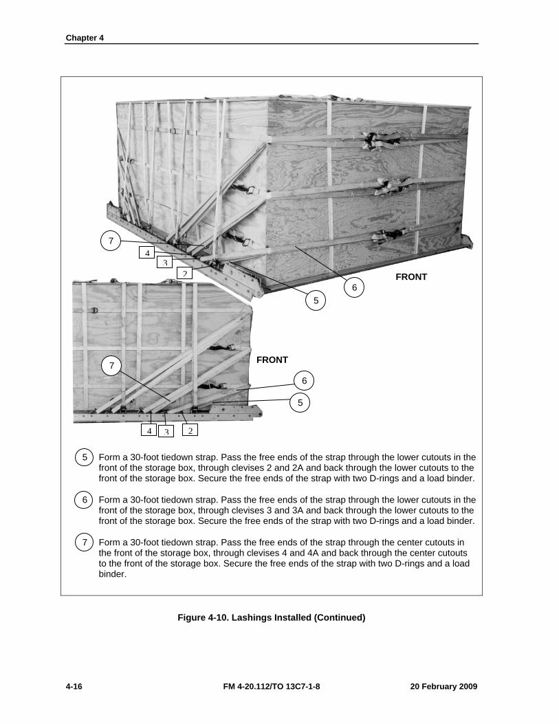
Chapter 4
4-16 FM 4-20.112/TO 13C7-1-8 20 February 2009
5 Form a 30-foot tiedown strap. Pass the free ends of the strap through the lower cutouts in the front of the storage box, through clevises 2 and 2A and back through the lower cutouts to the front of the storage box. Secure the free ends of the strap with two D-rings and a load binder.
6 Form a 30-foot tiedown strap. Pass the free ends of the strap through the lower cutouts in the front of the storage box, through clevises 3 and 3A and back through the lower cutouts to the front of the storage box. Secure the free ends of the strap with two D-rings and a load binder.
7 Form a 30-foot tiedown strap. Pass the free ends of the strap through the center cutouts in the front of the storage box, through clevises 4 and 4A and back through the center cutouts to the front of the storage box. Secure the free ends of the strap with two D-rings and a load binder.
Figure 4-10. Lashings Installed (Continued)
6 5
7
6
5
7
43
2
4 3 2
FRONT
FRONT
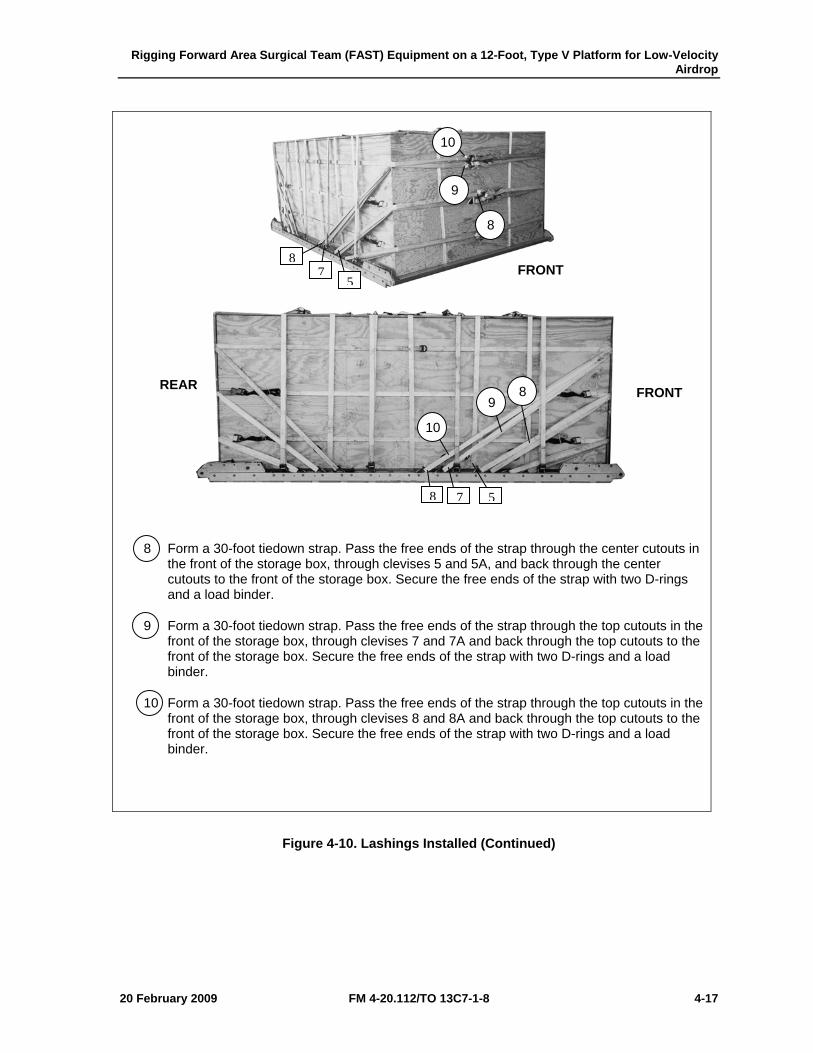
Rigging Forward Area Surgical Team (FAST) Equipment on a 12-Foot, Type V Platform for Low-Velocity Airdrop
20 February 2009 FM 4-20.112/TO 13C7-1-8 4-17
8 Form a 30-foot tiedown strap. Pass the free ends of the strap through the center cutouts in the front of the storage box, through clevises 5 and 5A, and back through the center cutouts to the front of the storage box. Secure the free ends of the strap with two D-rings and a load binder.
9 Form a 30-foot tiedown strap. Pass the free ends of the strap through the top cutouts in the front of the storage box, through clevises 7 and 7A and back through the top cutouts to the front of the storage box. Secure the free ends of the strap with two D-rings and a load binder.
10 Form a 30-foot tiedown strap. Pass the free ends of the strap through the top cutouts in the front of the storage box, through clevises 8 and 8A and back through the top cutouts to the front of the storage box. Secure the free ends of the strap with two D-rings and a load binder.
Figure 4-10. Lashings Installed (Continued)
87
5
8 7 5
10
9
8
10
9 8
FRONT
FRONT REAR
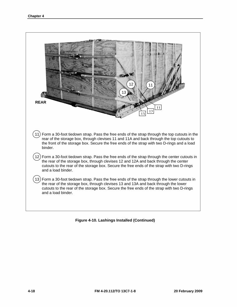
Chapter 4
4-18 FM 4-20.112/TO 13C7-1-8 20 February 2009
11 Form a 30-foot tiedown strap. Pass the free ends of the strap through the top cutouts in the rear of the storage box, through clevises 11 and 11A and back through the top cutouts to the front of the storage box. Secure the free ends of the strap with two D-rings and a load binder.
12 Form a 30-foot tiedown strap. Pass the free ends of the strap through the center cutouts in the rear of the storage box, through clevises 12 and 12A and back through the center cutouts to the rear of the storage box. Secure the free ends of the strap with two D-rings and a load binder.
13 Form a 30-foot tiedown strap. Pass the free ends of the strap through the lower cutouts in the rear of the storage box, through clevises 13 and 13A and back through the lower cutouts to the rear of the storage box. Secure the free ends of the strap with two D-rings and a load binder.
Figure 4-10. Lashings Installed (Continued)
REAR
13 1211
13
12 11
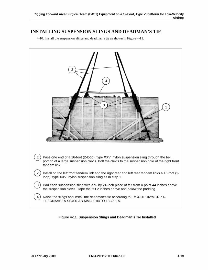
Rigging Forward Area Surgical Team (FAST) Equipment on a 12-Foot, Type V Platform for Low-Velocity Airdrop
20 February 2009 FM 4-20.112/TO 13C7-1-8 4-19
INSTALLING SUSPENSION SLINGS AND DEADMAN’S TIE 4-10. Install the suspension slings and deadman’s tie as shown in Figure 4-11.
1 Pass one end of a 16-foot (2-loop), type XXVI nylon suspension sling through the bell portion of a large suspension clevis. Bolt the clevis to the suspension hole of the right front tandem link.
2 Install on the left front tandem link and the right rear and left rear tandem links a 16-foot (2-loop), type XXVI nylon suspension sling as in step 1.
3 Pad each suspension sling with a 9- by 24-inch piece of felt from a point 44 inches above the suspension clevis. Tape the felt 2 inches above and below the padding.
4 Raise the slings and install the deadman's tie according to FM 4-20.102/MCRP 4-11.3J/NAVSEA SS400-AB-MMO-010/TO 13C7-1-5.
Figure 4-11. Suspension Slings and Deadman’s Tie Installed
1
2
3
4
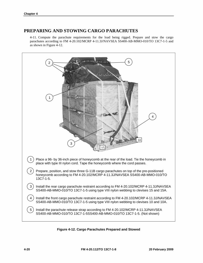
Chapter 4
4-20 FM 4-20.112/TO 13C7-1-8 20 February 2009
PREPARING AND STOWING CARGO PARACHUTES 4-11. Compute the parachute requirements for the load being rigged. Prepare and stow the cargo parachutes according to FM 4-20.102/MCRP 4-11.3J/NAVSEA SS400-AB-MMO-010/TO 13C7-1-5 and as shown in Figure 4-12.
1 Place a 96- by 36-inch piece of honeycomb at the rear of the load. Tie the honeycomb in place with type III nylon cord. Tape the honeycomb where the cord passes.
2 Prepare, position, and stow three G-11B cargo parachutes on top of the pre-positioned honeycomb according to FM 4-20.102/MCRP 4-11.3J/NAVSEA SS400-AB-MMO-010/TO 13C7-1-5.
3 Install the rear cargo parachute restraint according to FM 4-20.102/MCRP 4-11.3J/NAVSEA SS400-AB-MMO-010/TO 13C7-1-5 using type VIII nylon webbing to clevises 15 and 15A.
4 Install the front cargo parachute restraint according to FM 4-20.102/MCRP 4-11.3J/NAVSEA SS400-AB-MMO-010/TO 13C7-1-5 using type VIII nylon webbing to clevises 10 and 10A.
5 Install the parachute release strap according to FM 4-20.102/MCRP 4-11.3J/NAVSEA SS400-AB-MMO-010/TO 13C7-1-5SS400-AB-MMO-010/TO 13C7-1-5. (Not shown)
Figure 4-12. Cargo Parachutes Prepared and Stowed
10
15
2
1
4
3
5
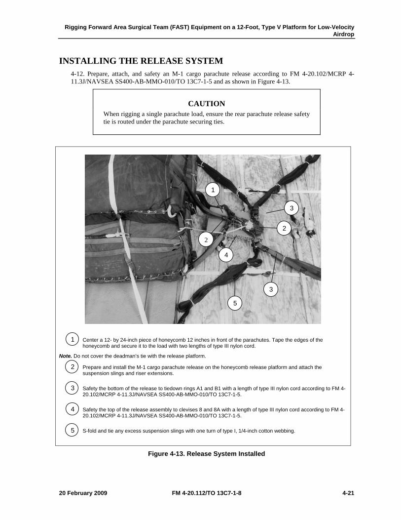
Rigging Forward Area Surgical Team (FAST) Equipment on a 12-Foot, Type V Platform for Low-Velocity Airdrop
20 February 2009 FM 4-20.112/TO 13C7-1-8 4-21
INSTALLING THE RELEASE SYSTEM 4-12. Prepare, attach, and safety an M-1 cargo parachute release according to FM 4-20.102/MCRP 4-11.3J/NAVSEA SS400-AB-MMO-010/TO 13C7-1-5 and as shown in Figure 4-13.
CAUTION When rigging a single parachute load, ensure the rear parachute release safety tie is routed under the parachute securing ties.
1 Center a 12- by 24-inch piece of honeycomb 12 inches in front of the parachutes. Tape the edges of the honeycomb and secure it to the load with two lengths of type III nylon cord.
Note. Do not cover the deadman’s tie with the release platform.
2 Prepare and install the M-1 cargo parachute release on the honeycomb release platform and attach the suspension slings and riser extensions.
3 Safety the bottom of the release to tiedown rings A1 and B1 with a length of type III nylon cord according to FM 4-20.102/MCRP 4-11.3J/NAVSEA SS400-AB-MMO-010/TO 13C7-1-5.
4 Safety the top of the release assembly to clevises 8 and 8A with a length of type III nylon cord according to FM 4-20.102/MCRP 4-11.3J/NAVSEA SS400-AB-MMO-010/TO 13C7-1-5.
5 S-fold and tie any excess suspension slings with one turn of type I, 1/4-inch cotton webbing.
Figure 4-13. Release System Installed
1
2
3
3
4
5
2
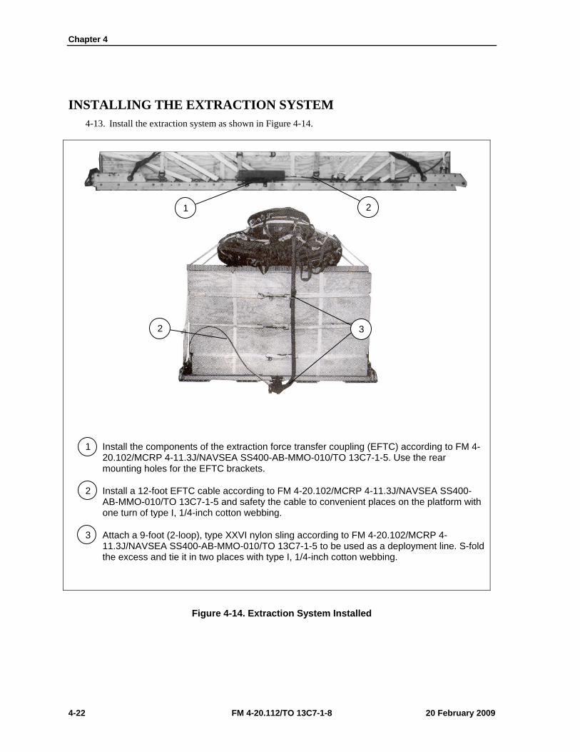
Chapter 4
4-22 FM 4-20.112/TO 13C7-1-8 20 February 2009
INSTALLING THE EXTRACTION SYSTEM 4-13. Install the extraction system as shown in Figure 4-14.
1 Install the components of the extraction force transfer coupling (EFTC) according to FM 4-20.102/MCRP 4-11.3J/NAVSEA SS400-AB-MMO-010/TO 13C7-1-5. Use the rear mounting holes for the EFTC brackets.
2 Install a 12-foot EFTC cable according to FM 4-20.102/MCRP 4-11.3J/NAVSEA SS400-AB-MMO-010/TO 13C7-1-5 and safety the cable to convenient places on the platform with one turn of type I, 1/4-inch cotton webbing.
3 Attach a 9-foot (2-loop), type XXVI nylon sling according to FM 4-20.102/MCRP 4-11.3J/NAVSEA SS400-AB-MMO-010/TO 13C7-1-5 to be used as a deployment line. S-fold the excess and tie it in two places with type I, 1/4-inch cotton webbing.
Figure 4-14. Extraction System Installed
2 1
3 2
Rigging Forward Area Surgical Team (FAST) Equipment on a 12-Foot, Type V Platform for Low-Velocity Airdrop
20 February 2009 FM 4-20.112/TO 13C7-1-8 4-23
PLACING EXTRACTION PARACHUTE 4-14. Select the extraction parachute and extraction line needed using the extraction line requirements table in FM 4-20.102/MCRP 4-11.3J/NAVSEA SS400-AB-MMO-010/TO 13C7-1-5. Place the extraction parachute and line on the load for installation in the aircraft.
INSTALLING PROVISIONS FOR EMERGENCY RESTRAINTS 4-15. Select and install the provisions for the emergency aft restraints according to the emergency aft restraint requirements table in FM 4-20.102/MCRP 4-11.3J/NAVSEA SS400-AB-MMO-010/TO 13C7-1-5.
MARKING RIGGED LOAD 4-16. Mark the rigged load according to FM 4-20.102/MCRP 4-11.3J/NAVSEA SS400-AB-MMO-010/TO 13C7-1-5, and as shown in Figure 4-15. Complete Shipper’s Declaration for Dangerous Goods. If the load varies from the one shown, the weight, height, CB, and parachute requirements must be recomputed.
EQUIPMENT REQUIRED 4-17. Use the equipment listed in Table 4-1 to rig this load.
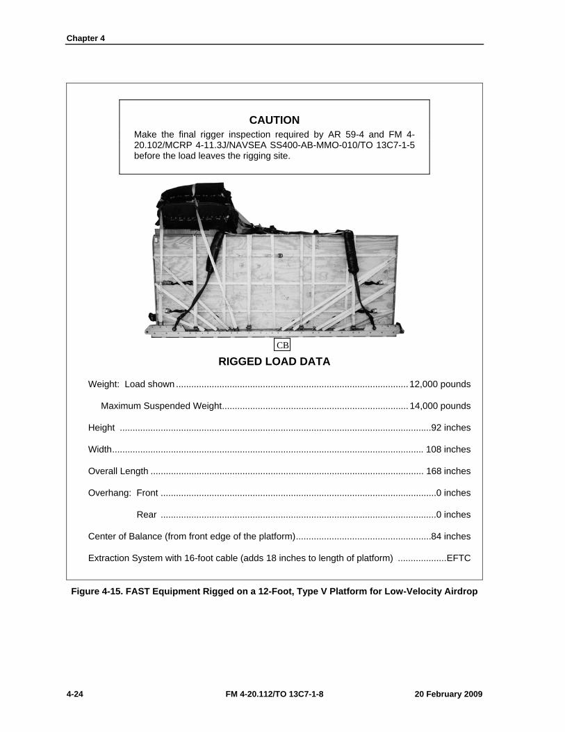
Chapter 4
4-24 FM 4-20.112/TO 13C7-1-8 20 February 2009
CAUTION Make the final rigger inspection required by AR 59-4 and FM 4-20.102/MCRP 4-11.3J/NAVSEA SS400-AB-MMO-010/TO 13C7-1-5 before the load leaves the rigging site.
RIGGED LOAD DATA
Weight: Load shown ........................................................................................... 12,000 pounds
Maximum Suspended Weight ......................................................................... 14,000 pounds
Height ..........................................................................................................................92 inches
Width .......................................................................................................................... 108 inches
Overall Length ........................................................................................................... 168 inches
Overhang: Front ............................................................................................................ 0 inches
Rear ............................................................................................................ 0 inches
Center of Balance (from front edge of the platform) .....................................................84 inches
Extraction System with 16-foot cable (adds 18 inches to length of platform) ................... EFTC
Figure 4-15. FAST Equipment Rigged on a 12-Foot, Type V Platform for Low-Velocity Airdrop
CB
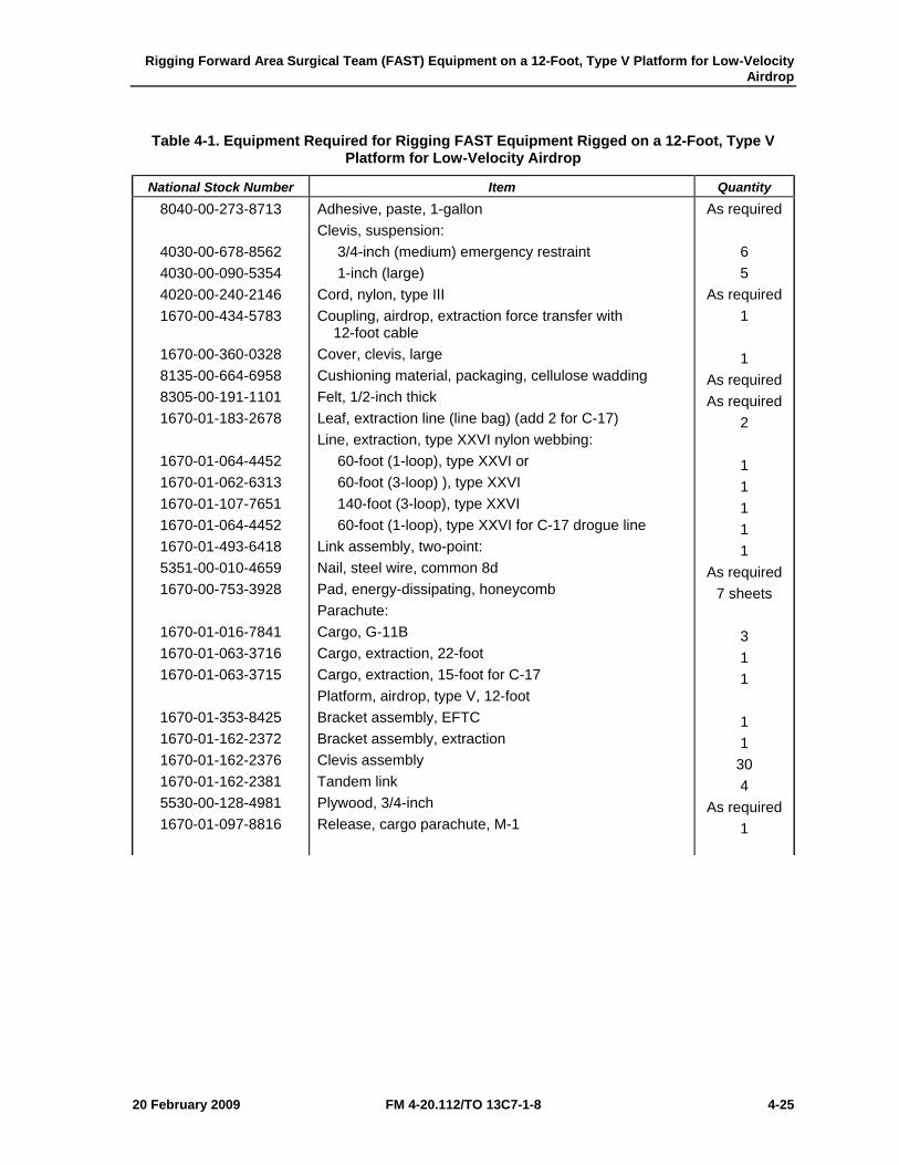
Rigging Forward Area Surgical Team (FAST) Equipment on a 12-Foot, Type V Platform for Low-Velocity Airdrop
20 February 2009 FM 4-20.112/TO 13C7-1-8 4-25
Table 4-1. Equipment Required for Rigging FAST Equipment Rigged on a 12-Foot, Type V Platform for Low-Velocity Airdrop
National Stock Number Item Quantity 8040-00-273-8713
4030-00-678-8562 4030-00-090-5354 4020-00-240-2146 1670-00-434-5783
1670-00-360-0328 8135-00-664-6958 8305-00-191-1101 1670-01-183-2678
1670-01-064-4452 1670-01-062-6313 1670-01-107-7651 1670-01-064-4452 1670-01-493-6418 5351-00-010-4659 1670-00-753-3928
1670-01-016-7841 1670-01-063-3716 1670-01-063-3715
1670-01-353-8425 1670-01-162-2372 1670-01-162-2376 1670-01-162-2381 5530-00-128-4981 1670-01-097-8816
Adhesive, paste, 1-gallon Clevis, suspension: 3/4-inch (medium) emergency restraint 1-inch (large) Cord, nylon, type III Coupling, airdrop, extraction force transfer with 12-foot cable Cover, clevis, large Cushioning material, packaging, cellulose wadding Felt, 1/2-inch thick Leaf, extraction line (line bag) (add 2 for C-17) Line, extraction, type XXVI nylon webbing: 60-foot (1-loop), type XXVI or 60-foot (3-loop) ), type XXVI 140-foot (3-loop), type XXVI 60-foot (1-loop), type XXVI for C-17 drogue line Link assembly, two-point: Nail, steel wire, common 8d Pad, energy-dissipating, honeycomb Parachute: Cargo, G-11B Cargo, extraction, 22-foot Cargo, extraction, 15-foot for C-17 Platform, airdrop, type V, 12-foot Bracket assembly, EFTC Bracket assembly, extraction Clevis assembly Tandem link Plywood, 3/4-inch Release, cargo parachute, M-1
As required 6 5
As required 1 1
As required As required
2 1 1 1 1 1
As required 7 sheets
3 1 1 1 1
30 4
As required 1

Chapter 4
4-26 FM 4-20.112/TO 13C7-1-8 20 February 2009
Table 4-1. Equipment Required for Rigging FAST Equipment Rigged on a 12-Foot, Type V Platform for Low-Velocity Airdrop (Continued)
National Stock Number Item Quantity
1670-01-062-6304 1670-01-063-7761 1670-01-062-6313 5340-00-040-8219 7501-00-266-5016 7501-00-266-6710 1670-00-937-0271 1670-01-483-8259
8305-00-268-2411
8305-00-082-5752 8305-00-263-3591
Sling, cargo airdrop: 9-foot (2-loop), type XXVI nylon webbing 16-foot (2-loop), type XXVI nylon webbing 60-foot (3-loop), type XXVI nylon webbing Strap parachute release, multicut Tape, adhesive, 2-inch Tape, masking Tiedown assembly, 15-foot Towplate release mechanism (H-block) (C-17) Webbing: Cotton, 1/4-inch, type I Nylon: Tubular, 1/2-inch Type VIII webbing
1 4 3 2
As required As required
47 1
As required
As required As required
20 February 2009 FM 4-20.112/TO 13C7-1-8 5-1
Chapter 5
Rigging Supply Loads on a 16-Foot, Type V Platform for Low-Velocity Airdrop
SECTION I-RIGGING 105-MILLIMETER (MM) AMMUNITION
DESCRIPTION OF LOAD 5-1. Bulk supplies consisting of rations, equipment, fuel, ammunition, or other items of general supply are rigged on a 16-foot, type V airdrop platform with G-11 cargo parachutes. One hundred and forty boxes of 105-mm ammunition are shown. All 105-mm ammunition packaged as shown and listed in FM 4-20.153/MCRP 4-11.3B/TO 13C7-18-41, as certified for low-velocity airdrop, may be rigged using these procedures. Each load must weigh at least 5,040 pounds, including parachutes. Refer to FM 4-20.102/MCRP 4-11.3J/NAVSEA SS400-AB-MMO-010/TO 13C7-1-5 for the weight limitations for the number of parachutes to be used.
PREPARING PLATFORM 5-2. Prepare a 16-foot, type V platform as shown in Figure 5-1.

Chapter 5
5-2 FM 4-20.112/TO 13C7-1-8 20 February 2009
Step:
1. Inspect, or assemble and inspect, a 16-foot, type V platform as outlined in TM 10-1670-268-20&P/TO 13C7-52-22.
2. Install a tandem link to the front of each platform side rail using holes 1, 2, and 3.
3. Install a tandem link to the rear of each platform side rail using holes 30, 31, and 32.
4. Install clevises on bushing 3 of each front tandem link.
5. Install clevises on bushings 3 and 4 of each rear tandem link.
6. Starting at the front of each platform side rail, install clevises on the bushings bolted to holes 4, 8, 9, 10, 11 (triple), 12, 13, 14, 15 (triple), 16, 17, 18, 20, 21, 22, 23, 24, 25, 27, 28, (triple), and 29.
7. Starting at the front of the platform, number the clevises 1 through 27 on the right side, and 1A through 27A on the left side.
8. Label the tiedown rings according to FM 4-20.102/MCRP 4-11.3J/NAVSEA SS400-AB-MMO-010/TO 13C7-1-5.
Note. Refer to FM 4-20.102/MCRP 4-11.3J/NAVSEA SS400-AB-MMO-010/TO 13C7-1-5 (Table 2-2) when adding additional parachutes for heavier loads for the suspension/tandem link positioning.
Figure 5-1. Platform Prepared
CLEVISES 27A THROUGH 1A
CLEVISES 27 THROUGH 1
RIGHT
LEFT FRONT REAR
Rigging Supply Loads on a 16-Foot, Type V Platform for Low-Velocity Airdrop
20 February 2009 FM 4-20.112/TO 13C7-1-8 5-3
BUILDING HONEYCOMB STACKS AND PLACING FIRST STACK 5-3. Build the honeycomb stack for the first stack of ammunition and place it on the platform as shown in Figure 5-2. Build the stack for the second stack of ammunition as shown in Figure 5-2. Set the second honeycomb stack aside.
Notes.
1. When ammunition is dropped, two layers of honeycomb are required as shown in Figure 5-3.
2. When rigging this load for airdrop on a drop zone with ground elevation of 6,000 to 10,000 feet, add an additional layer of honeycomb. However, the height of this load cannot exceed 100 inches.
3. Adjust the dimensions of the honeycomb to fit the items being dropped.
4. Do not cover the extraction bracket with honeycomb.
5. All dimensions are in inches.
Stack Number
Pieces Width (Inches)
Length (Inches)
Material Instructions
1 and 2 3 87 12 Honeycomb
Glue honeycomb flush together and center 17 ½ inches from the front edge of the platform.
3 87 24 Honeycomb
Glue honeycomb flush together and center 13 1/2 inches from the rear of the stack placed above.
3 87 12 Honeycomb
Glue honeycomb flush together and center 13 1/2 inches from the rear of the stack placed above.
2 87 36 Honeycomb
Glue one piece flush with the front edge. Glue one piece flush with the rear edge, leaving a 3-inch gap in the center.
Figure 5-2. Honeycomb for First Ammunition Stack Prepared and Placed
17 1/2
13 1/2 13 1/2
Chapter 5
5-4 FM 4-20.112/TO 13C7-1-8 20 February 2009
POSITIONING AND SECURING FIRST AMMUNITION STACK 5-4. Position and secure the first stack of 105-mm ammunition as shown in Figure 5-3.
CAUTION Only ammunition listed in FM 4-20.153/MCRP 4-11.3B/TO 13C7-18-41 may be airdropped. Hazardous material must be packaged, marked, and labeled as required by AFMAN(I) 24-204/TM 38-250.
1 Form two 30-foot lashings according to FM 4-20.102/MCRP 4-11.3J/NAVSEA SS400-AB-MMO-010/TO 13C7-1-5. Center them over the honeycomb as shown.
2 Place seven ammunition boxes on the rear side of stack 1. Let the boxes overhang the rear edge by 1 inch.
Figure 5-3. Ammunition Positioned and Secured
2
1
Rigging Supply Loads on a 16-Foot, Type V Platform for Low-Velocity Airdrop
20 February 2009 FM 4-20.112/TO 13C7-1-8 5-5
3 Place a 36- by 87-inch piece of honeycomb over the boxes.
4 Place seven ammunition boxes flush with the first layer of boxes.
5 Place a 36- by 87-inch piece of honeycomb over the boxes placed in step 4.
6 Place three layers of boxes flush over the layers already placed.
7 Secure the pre-positioned lashing over the boxes with two D-rings and a load binder.
8 Place a 36- by 87-inch piece of honeycomb on edge against the boxes. Fit the honeycomb into the 3-inch slot in the center of the honeycomb stack.
9 Place a 10- by 87-inch piece of honeycomb on edge over the piece placed in step 8.
Figure 5-3. Ammunition Positioned and Secured (Continued)
7 9
8
6
5 4 3
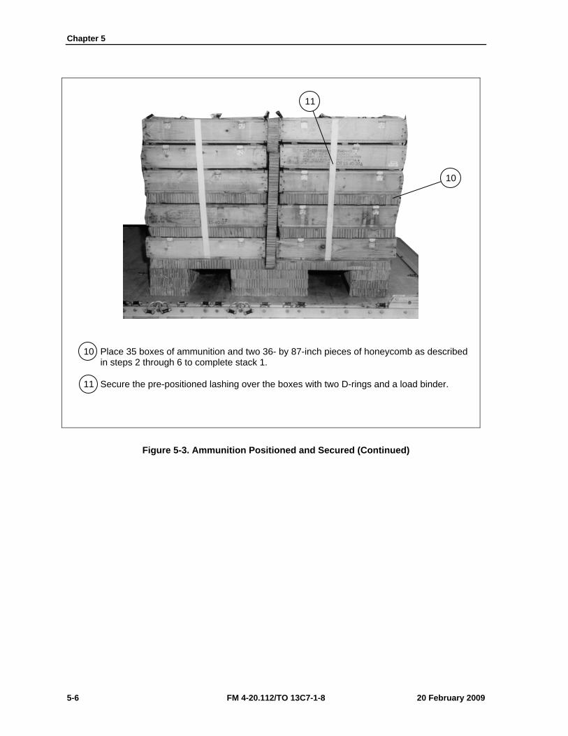
Chapter 5
5-6 FM 4-20.112/TO 13C7-1-8 20 February 2009
10 Place 35 boxes of ammunition and two 36- by 87-inch pieces of honeycomb as described in steps 2 through 6 to complete stack 1.
11 Secure the pre-positioned lashing over the boxes with two D-rings and a load binder.
Figure 5-3. Ammunition Positioned and Secured (Continued)
10
11
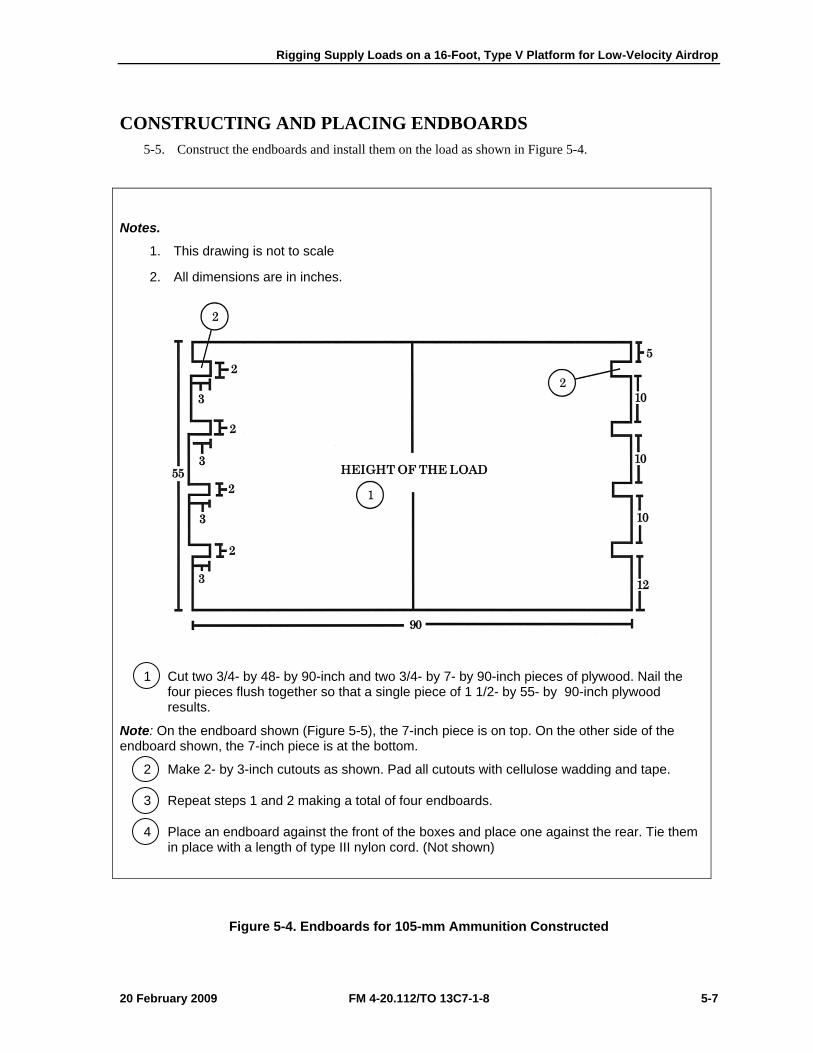
Rigging Supply Loads on a 16-Foot, Type V Platform for Low-Velocity Airdrop
20 February 2009 FM 4-20.112/TO 13C7-1-8 5-7
CONSTRUCTING AND PLACING ENDBOARDS 5-5. Construct the endboards and install them on the load as shown in Figure 5-4.
Notes.
1. This drawing is not to scale
2. All dimensions are in inches.
1 Cut two 3/4- by 48- by 90-inch and two 3/4- by 7- by 90-inch pieces of plywood. Nail the four pieces flush together so that a single piece of 1 1/2- by 55- by 90-inch plywood results.
Note: On the endboard shown (Figure 5-5), the 7-inch piece is on top. On the other side of the endboard shown, the 7-inch piece is at the bottom.
2 Make 2- by 3-inch cutouts as shown. Pad all cutouts with cellulose wadding and tape.
3 Repeat steps 1 and 2 making a total of four endboards.
4 Place an endboard against the front of the boxes and place one against the rear. Tie them in place with a length of type III nylon cord. (Not shown)
Figure 5-4. Endboards for 105-mm Ammunition Constructed
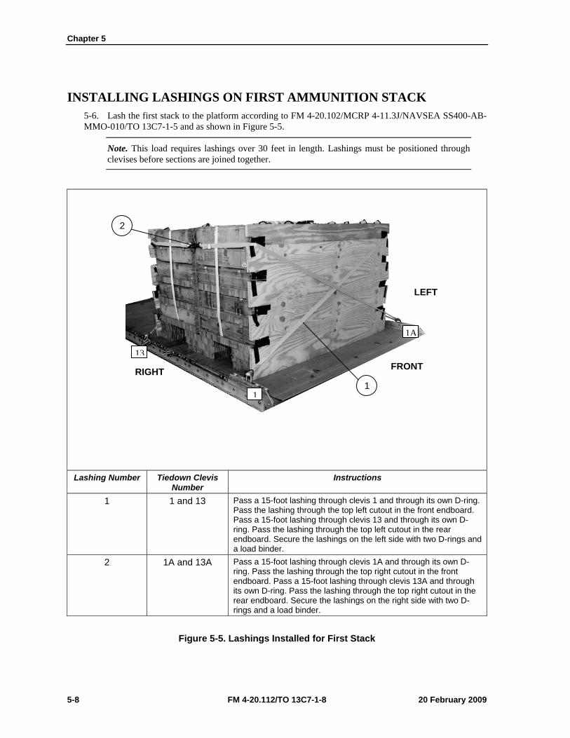
Chapter 5
5-8 FM 4-20.112/TO 13C7-1-8 20 February 2009
INSTALLING LASHINGS ON FIRST AMMUNITION STACK 5-6. Lash the first stack to the platform according to FM 4-20.102/MCRP 4-11.3J/NAVSEA SS400-AB-MMO-010/TO 13C7-1-5 and as shown in Figure 5-5.
Note. This load requires lashings over 30 feet in length. Lashings must be positioned through clevises before sections are joined together.
Lashing Number Tiedown Clevis
Number Instructions
1 1 and 13 Pass a 15-foot lashing through clevis 1 and through its own D-ring. Pass the lashing through the top left cutout in the front endboard. Pass a 15-foot lashing through clevis 13 and through its own D-ring. Pass the lashing through the top left cutout in the rear endboard. Secure the lashings on the left side with two D-rings and a load binder.
2 1A and 13A Pass a 15-foot lashing through clevis 1A and through its own D-ring. Pass the lashing through the top right cutout in the front endboard. Pass a 15-foot lashing through clevis 13A and through its own D-ring. Pass the lashing through the top right cutout in the rear endboard. Secure the lashings on the right side with two D-rings and a load binder.
Figure 5-5. Lashings Installed for First Stack
2
1 1
13
1A
FRONT
LEFT
RIGHT
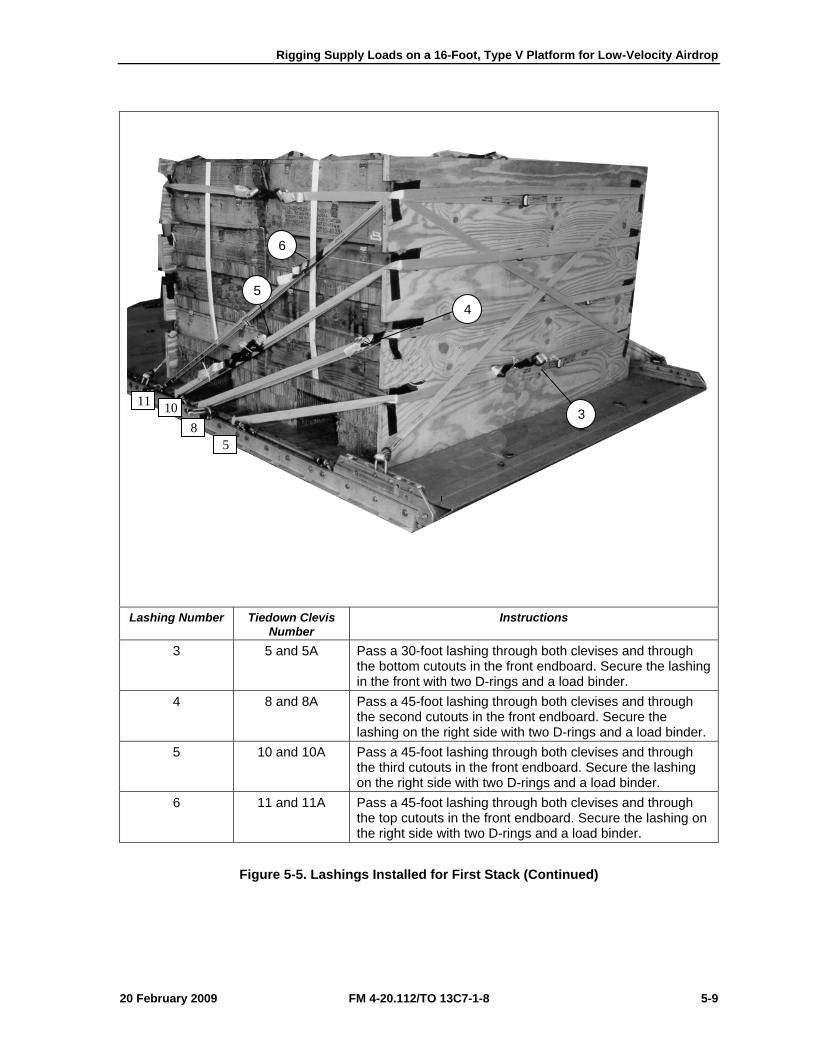
Rigging Supply Loads on a 16-Foot, Type V Platform for Low-Velocity Airdrop
20 February 2009 FM 4-20.112/TO 13C7-1-8 5-9
Lashing Number Tiedown Clevis
Number Instructions
3 5 and 5A Pass a 30-foot lashing through both clevises and through the bottom cutouts in the front endboard. Secure the lashing in the front with two D-rings and a load binder.
4 8 and 8A Pass a 45-foot lashing through both clevises and through the second cutouts in the front endboard. Secure the lashing on the right side with two D-rings and a load binder.
5 10 and 10A Pass a 45-foot lashing through both clevises and through the third cutouts in the front endboard. Secure the lashing on the right side with two D-rings and a load binder.
6 11 and 11A Pass a 45-foot lashing through both clevises and through the top cutouts in the front endboard. Secure the lashing on the right side with two D-rings and a load binder.
Figure 5-5. Lashings Installed for First Stack (Continued)
3
5 4
6
11
5 8
10
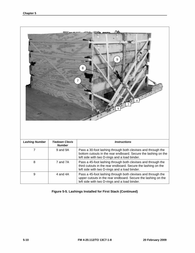
Chapter 5
5-10 FM 4-20.112/TO 13C7-1-8 20 February 2009
Lashing Number Tiedown Clevis
Number Instructions
7 9 and 9A Pass a 30-foot lashing through both clevises and through the bottom cutouts in the rear endboard. Secure the lashing on the left side with two D-rings and a load binder.
8 7 and 7A Pass a 45-foot lashing through both clevises and through the third cutouts in the rear endboard. Secure the lashing on the left side with two D-rings and a load binder.
9 4 and 4A Pass a 45-foot lashing through both clevises and through the upper cutouts in the rear endboard. Secure the lashing on the left side with two D-rings and a load binder.
Figure 5-5. Lashings Installed for First Stack (Continued)
9
8
7
97
4
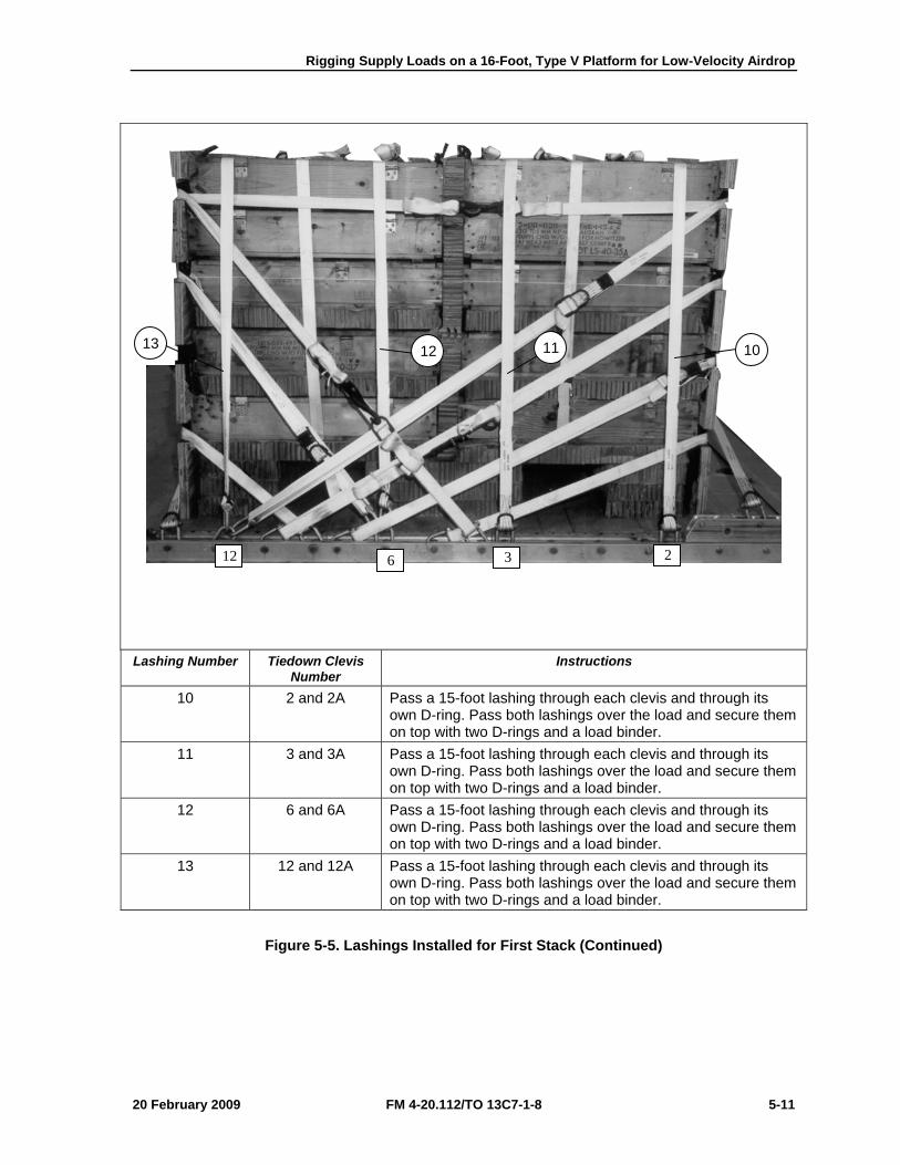
Rigging Supply Loads on a 16-Foot, Type V Platform for Low-Velocity Airdrop
20 February 2009 FM 4-20.112/TO 13C7-1-8 5-11
Lashing Number Tiedown Clevis
Number Instructions
10 2 and 2A Pass a 15-foot lashing through each clevis and through its own D-ring. Pass both lashings over the load and secure them on top with two D-rings and a load binder.
11 3 and 3A Pass a 15-foot lashing through each clevis and through its own D-ring. Pass both lashings over the load and secure them on top with two D-rings and a load binder.
12 6 and 6A Pass a 15-foot lashing through each clevis and through its own D-ring. Pass both lashings over the load and secure them on top with two D-rings and a load binder.
13 12 and 12A Pass a 15-foot lashing through each clevis and through its own D-ring. Pass both lashings over the load and secure them on top with two D-rings and a load binder.
Figure 5-5. Lashings Installed for First Stack (Continued)
13 12 11 10
12 6 3 2
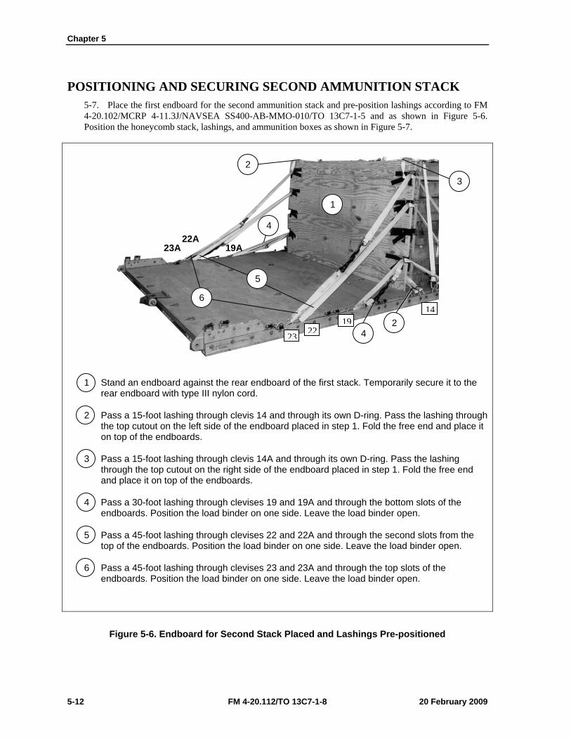
Chapter 5
5-12 FM 4-20.112/TO 13C7-1-8 20 February 2009
POSITIONING AND SECURING SECOND AMMUNITION STACK 5-7. Place the first endboard for the second ammunition stack and pre-position lashings according to FM 4-20.102/MCRP 4-11.3J/NAVSEA SS400-AB-MMO-010/TO 13C7-1-5 and as shown in Figure 5-6. Position the honeycomb stack, lashings, and ammunition boxes as shown in Figure 5-7.
1 Stand an endboard against the rear endboard of the first stack. Temporarily secure it to the rear endboard with type III nylon cord.
2 Pass a 15-foot lashing through clevis 14 and through its own D-ring. Pass the lashing through the top cutout on the left side of the endboard placed in step 1. Fold the free end and place it on top of the endboards.
3 Pass a 15-foot lashing through clevis 14A and through its own D-ring. Pass the lashing through the top cutout on the right side of the endboard placed in step 1. Fold the free end and place it on top of the endboards.
4 Pass a 30-foot lashing through clevises 19 and 19A and through the bottom slots of the endboards. Position the load binder on one side. Leave the load binder open.
5 Pass a 45-foot lashing through clevises 22 and 22A and through the second slots from the top of the endboards. Position the load binder on one side. Leave the load binder open.
6 Pass a 45-foot lashing through clevises 23 and 23A and through the top slots of the endboards. Position the load binder on one side. Leave the load binder open.
Figure 5-6. Endboard for Second Stack Placed and Lashings Pre-positioned
2
4
3
2 4
5
6
1
23A 22A
19A
1419
2223
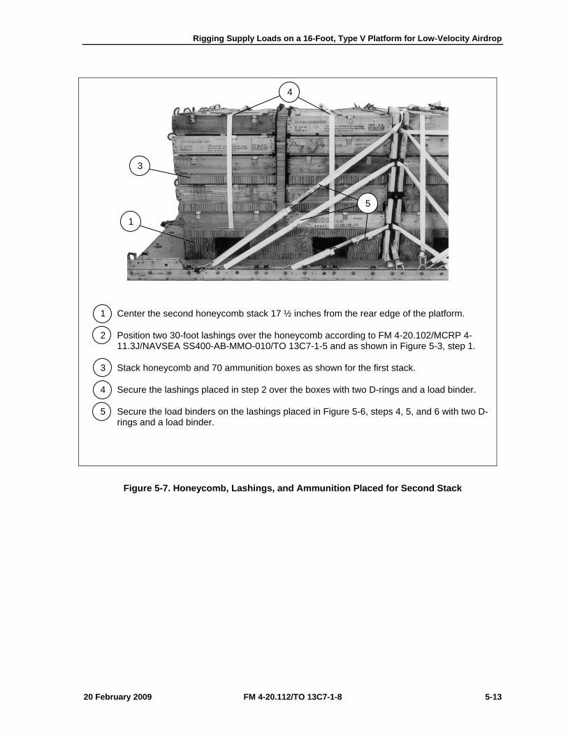
Rigging Supply Loads on a 16-Foot, Type V Platform for Low-Velocity Airdrop
20 February 2009 FM 4-20.112/TO 13C7-1-8 5-13
1 Center the second honeycomb stack 17 ½ inches from the rear edge of the platform.
2 Position two 30-foot lashings over the honeycomb according to FM 4-20.102/MCRP 4-11.3J/NAVSEA SS400-AB-MMO-010/TO 13C7-1-5 and as shown in Figure 5-3, step 1.
3 Stack honeycomb and 70 ammunition boxes as shown for the first stack.
4 Secure the lashings placed in step 2 over the boxes with two D-rings and a load binder.
5 Secure the load binders on the lashings placed in Figure 5-6, steps 4, 5, and 6 with two D-rings and a load binder.
Figure 5-7. Honeycomb, Lashings, and Ammunition Placed for Second Stack
4
5
3
1
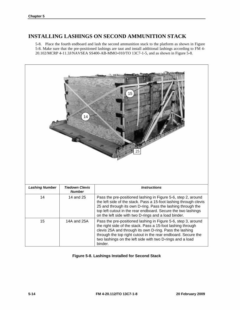
Chapter 5
5-14 FM 4-20.112/TO 13C7-1-8 20 February 2009
INSTALLING LASHINGS ON SECOND AMMUNITION STACK 5-8. Place the fourth endboard and lash the second ammunition stack to the platform as shown in Figure 5-8. Make sure that the pre-positioned lashings are taut and install additional lashings according to FM 4-20.102/MCRP 4-11.3J/NAVSEA SS400-AB-MMO-010/TO 13C7-1-5, and as shown in Figure 5-8.
Lashing Number Tiedown Clevis
Number Instructions
14 14 and 25 Pass the pre-positioned lashing in Figure 5-6, step 2, around the left side of the stack. Pass a 15-foot lashing through clevis 25 and through its own D-ring. Pass the lashing through the top left cutout in the rear endboard. Secure the two lashings on the left side with two D-rings and a load binder.
15 14A and 25A Pass the pre-positioned lashing in Figure 5-6, step 3, around the right side of the stack. Pass a 15-foot lashing through clevis 25A and through its own D-ring. Pass the lashing through the top right cutout in the rear endboard. Secure the two lashings on the left side with two D-rings and a load binder.
Figure 5-8. Lashings Installed for Second Stack
14
15
25
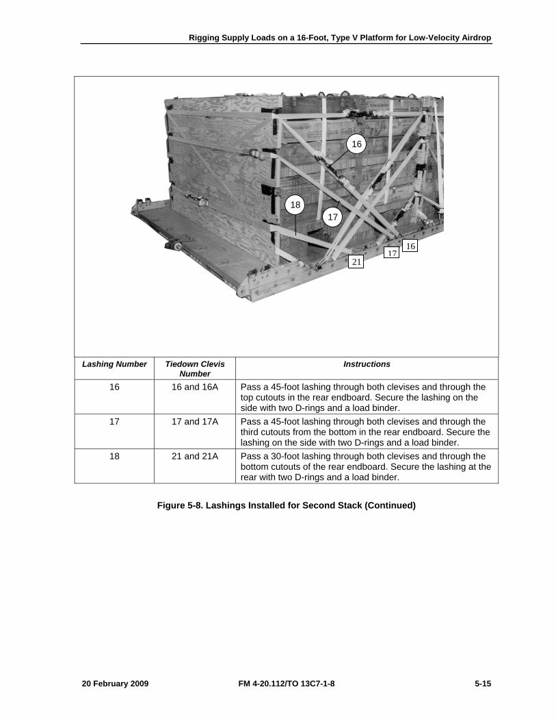
Rigging Supply Loads on a 16-Foot, Type V Platform for Low-Velocity Airdrop
20 February 2009 FM 4-20.112/TO 13C7-1-8 5-15
Lashing Number Tiedown Clevis
Number Instructions
16 16 and 16A Pass a 45-foot lashing through both clevises and through the top cutouts in the rear endboard. Secure the lashing on the side with two D-rings and a load binder.
17 17 and 17A Pass a 45-foot lashing through both clevises and through the third cutouts from the bottom in the rear endboard. Secure the lashing on the side with two D-rings and a load binder.
18 21 and 21A Pass a 30-foot lashing through both clevises and through the bottom cutouts of the rear endboard. Secure the lashing at the rear with two D-rings and a load binder.
Figure 5-8. Lashings Installed for Second Stack (Continued)
18
16
17
2117
16
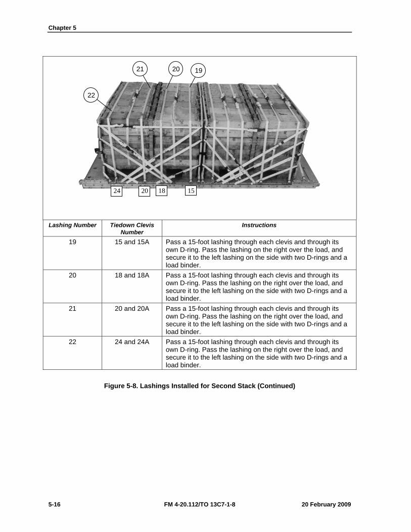
Chapter 5
5-16 FM 4-20.112/TO 13C7-1-8 20 February 2009
Lashing Number Tiedown Clevis
Number Instructions
19 15 and 15A Pass a 15-foot lashing through each clevis and through its own D-ring. Pass the lashing on the right over the load, and secure it to the left lashing on the side with two D-rings and a load binder.
20 18 and 18A Pass a 15-foot lashing through each clevis and through its own D-ring. Pass the lashing on the right over the load, and secure it to the left lashing on the side with two D-rings and a load binder.
21 20 and 20A Pass a 15-foot lashing through each clevis and through its own D-ring. Pass the lashing on the right over the load, and secure it to the left lashing on the side with two D-rings and a load binder.
22 24 and 24A Pass a 15-foot lashing through each clevis and through its own D-ring. Pass the lashing on the right over the load, and secure it to the left lashing on the side with two D-rings and a load binder.
Figure 5-8. Lashings Installed for Second Stack (Continued)
19 20 21
22
24 20 18 15
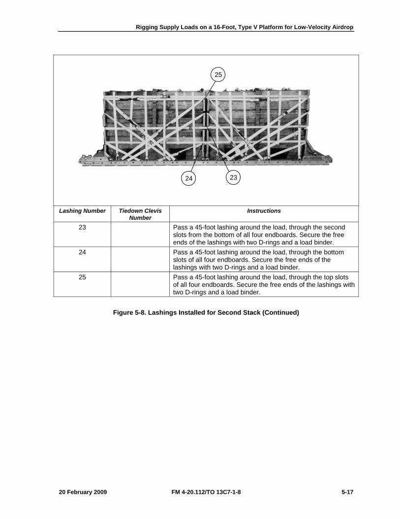
Rigging Supply Loads on a 16-Foot, Type V Platform for Low-Velocity Airdrop
20 February 2009 FM 4-20.112/TO 13C7-1-8 5-17
Lashing Number Tiedown Clevis
Number Instructions
23 Pass a 45-foot lashing around the load, through the second slots from the bottom of all four endboards. Secure the free ends of the lashings with two D-rings and a load binder.
24 Pass a 45-foot lashing around the load, through the bottom slots of all four endboards. Secure the free ends of the lashings with two D-rings and a load binder.
25 Pass a 45-foot lashing around the load, through the top slots of all four endboards. Secure the free ends of the lashings with two D-rings and a load binder.
Figure 5-8. Lashings Installed for Second Stack (Continued)
25
24 23
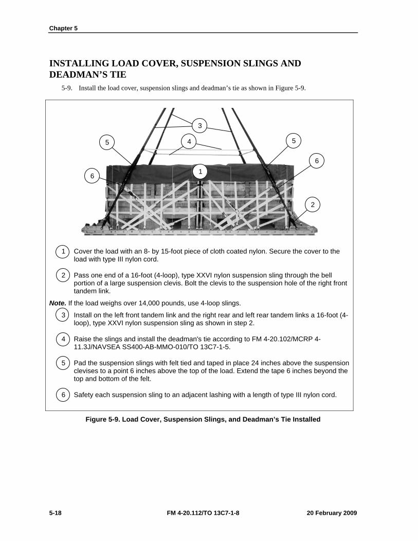
Chapter 5
5-18 FM 4-20.112/TO 13C7-1-8 20 February 2009
INSTALLING LOAD COVER, SUSPENSION SLINGS AND DEADMAN’S TIE
5-9. Install the load cover, suspension slings and deadman’s tie as shown in Figure 5-9.
1 Cover the load with an 8- by 15-foot piece of cloth coated nylon. Secure the cover to the load with type III nylon cord.
2 Pass one end of a 16-foot (4-loop), type XXVI nylon suspension sling through the bell portion of a large suspension clevis. Bolt the clevis to the suspension hole of the right front tandem link.
Note. If the load weighs over 14,000 pounds, use 4-loop slings.
3 Install on the left front tandem link and the right rear and left rear tandem links a 16-foot (4-loop), type XXVI nylon suspension sling as shown in step 2.
4 Raise the slings and install the deadman's tie according to FM 4-20.102/MCRP 4-11.3J/NAVSEA SS400-AB-MMO-010/TO 13C7-1-5.
5 Pad the suspension slings with felt tied and taped in place 24 inches above the suspension clevises to a point 6 inches above the top of the load. Extend the tape 6 inches beyond the top and bottom of the felt.
6 Safety each suspension sling to an adjacent lashing with a length of type III nylon cord.
Figure 5-9. Load Cover, Suspension Slings, and Deadman’s Tie Installed
3
4
2
6
5
6
5
1
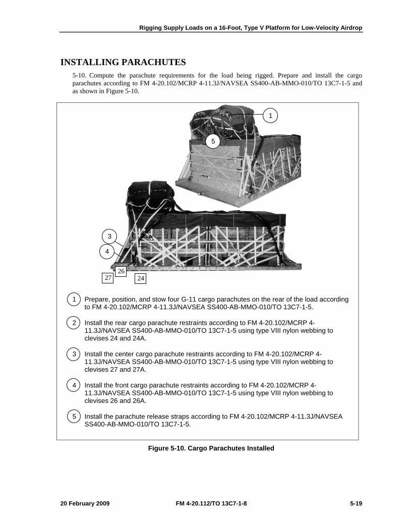
Rigging Supply Loads on a 16-Foot, Type V Platform for Low-Velocity Airdrop
20 February 2009 FM 4-20.112/TO 13C7-1-8 5-19
INSTALLING PARACHUTES 5-10. Compute the parachute requirements for the load being rigged. Prepare and install the cargo parachutes according to FM 4-20.102/MCRP 4-11.3J/NAVSEA SS400-AB-MMO-010/TO 13C7-1-5 and as shown in Figure 5-10.
1 Prepare, position, and stow four G-11 cargo parachutes on the rear of the load according to FM 4-20.102/MCRP 4-11.3J/NAVSEA SS400-AB-MMO-010/TO 13C7-1-5.
2 Install the rear cargo parachute restraints according to FM 4-20.102/MCRP 4-11.3J/NAVSEA SS400-AB-MMO-010/TO 13C7-1-5 using type VIII nylon webbing to clevises 24 and 24A.
3 Install the center cargo parachute restraints according to FM 4-20.102/MCRP 4-11.3J/NAVSEA SS400-AB-MMO-010/TO 13C7-1-5 using type VIII nylon webbing to clevises 27 and 27A.
4 Install the front cargo parachute restraints according to FM 4-20.102/MCRP 4-11.3J/NAVSEA SS400-AB-MMO-010/TO 13C7-1-5 using type VIII nylon webbing to clevises 26 and 26A.
5 Install the parachute release straps according to FM 4-20.102/MCRP 4-11.3J/NAVSEA SS400-AB-MMO-010/TO 13C7-1-5.
Figure 5-10. Cargo Parachutes Installed
1
5
3
4
27 26
24
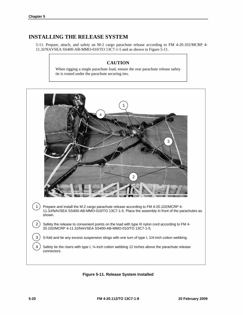
Chapter 5
5-20 FM 4-20.112/TO 13C7-1-8 20 February 2009
INSTALLING THE RELEASE SYSTEM 5-11. Prepare, attach, and safety an M-2 cargo parachute release according to FM 4-20.102/MCRP 4-11.3J/NAVSEA SS400-AB-MMO-010/TO 13C7-1-5 and as shown in Figure 5-11.
CAUTION When rigging a single parachute load, ensure the rear parachute release safety tie is routed under the parachute securing ties.
1 Prepare and install the M-2 cargo parachute release according to FM 4-20.102/MCRP 4-11.3J/NAVSEA SS400-AB-MMO-010/TO 13C7-1-5. Place the assembly in front of the parachutes as shown.
2 Safety the release to convenient points on the load with type III nylon cord according to FM 4-20.102/MCRP 4-11.3J/NAVSEA SS400-AB-MMO-010/TO 13C7-1-5.
3 S-fold and tie any excess suspension slings with one turn of type I, 1/4-inch cotton webbing.
4 Safety tie the risers with type I, ¼-inch cotton webbing 12 inches above the parachute release connectors.
Figure 5-11. Release System Installed
1
3
2
4
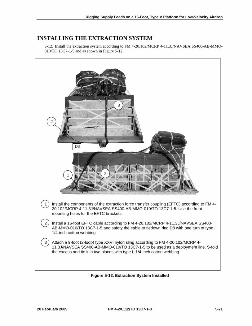
Rigging Supply Loads on a 16-Foot, Type V Platform for Low-Velocity Airdrop
20 February 2009 FM 4-20.112/TO 13C7-1-8 5-21
INSTALLING THE EXTRACTION SYSTEM 5-12. Install the extraction system according to FM 4-20.102/MCRP 4-11.3J/NAVSEA SS400-AB-MMO-010/TO 13C7-1-5 and as shown in Figure 5-12.
1 Install the components of the extraction force transfer coupling (EFTC) according to FM 4-20.102/MCRP 4-11.3J/NAVSEA SS400-AB-MMO-010/TO 13C7-1-5. Use the front mounting holes for the EFTC brackets.
2 Install a 16-foot EFTC cable according to FM 4-20.102/MCRP 4-11.3J/NAVSEA SS400-AB-MMO-010/TO 13C7-1-5 and safety the cable to tiedown ring D8 with one turn of type I, 1/4-inch cotton webbing.
3 Attach a 9-foot (2-loop) type XXVI nylon sling according to FM 4-20.102/MCRP 4-11.3J/NAVSEA SS400-AB-MMO-010/TO 13C7-1-5 to be used as a deployment line. S-fold the excess and tie it in two places with type I, 1/4-inch cotton webbing.
Figure 5-12. Extraction System Installed
3
2
2 1
D8
Chapter 5
5-22 FM 4-20.112/TO 13C7-1-8 20 February 2009
PLACING EXTRACTION PARACHUTE 5-13. Select the extraction parachute and extraction line needed using the extraction line requirements table in FM 4-20.102/MCRP 4-11.3J/NAVSEA SS400-AB-MMO-010/TO 13C7-1-5. Place the extraction parachute and line on the load for installation in the aircraft.
INSTALLING PROVISIONS FOR EMERGENCY RESTRAINTS 5-14. Select and install the provisions for the emergency aft restraints according to the emergency aft restraint requirements table in FM 4-20.102/MCRP 4-11.3J/NAVSEA SS400-AB-MMO-010/TO 13C7-1-5.
MARKING RIGGED LOAD 5-15. Mark the rigged load according to FM 4-20.102/MCRP 4-11.3J/NAVSEA SS400-AB-MMO-010/TO 13C7-1-5, and as shown in Figure 5-13. Complete Shipper’s Declaration for Dangerous Goods. If the load varies from the one shown, the weight, height, CB, and parachute requirements must be recomputed.
EQUIPMENT REQUIRED 5-16. Use the equipment listed in Table 5-1 to rig this load.
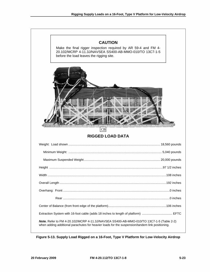
Rigging Supply Loads on a 16-Foot, Type V Platform for Low-Velocity Airdrop
20 February 2009 FM 4-20.112/TO 13C7-1-8 5-23
CAUTION Make the final rigger inspection required by AR 59-4 and FM 4-20.102/MCRP 4-11.3J/NAVSEA SS400-AB-MMO-010/TO 13C7-1-5 before the load leaves the rigging site.
RIGGED LOAD DATA
Weight: Load shown .......................................................................................................... 18,560 pounds
Minimum Weight: ............................................................................................................ 5,040 pounds
Maximum Suspended Weight ........................................................................................ 20,000 pounds
Height ................................................................................................................................... 97 1/2 inches
Width ......................................................................................................................................... 108 inches
Overall Length ........................................................................................................................... 192 inches
Overhang: Front ........................................................................................................................... 0 inches
Rear ........................................................................................................................... 0 inches
Center of Balance (from front edge of the platform) ................................................................... 106 inches
Extraction System with 16-foot cable (adds 18 inches to length of platform) ................................... EFTC
Note. Refer to FM 4-20.102/MCRP 4-11.3J/NAVSEA SS400-AB-MMO-010/TO 13C7-1-5 (Table 2-2) when adding additional parachutes for heavier loads for the suspension/tandem link positioning.
Figure 5-13. Supply Load Rigged on a 16-Foot, Type V Platform for Low-Velocity Airdrop
CB
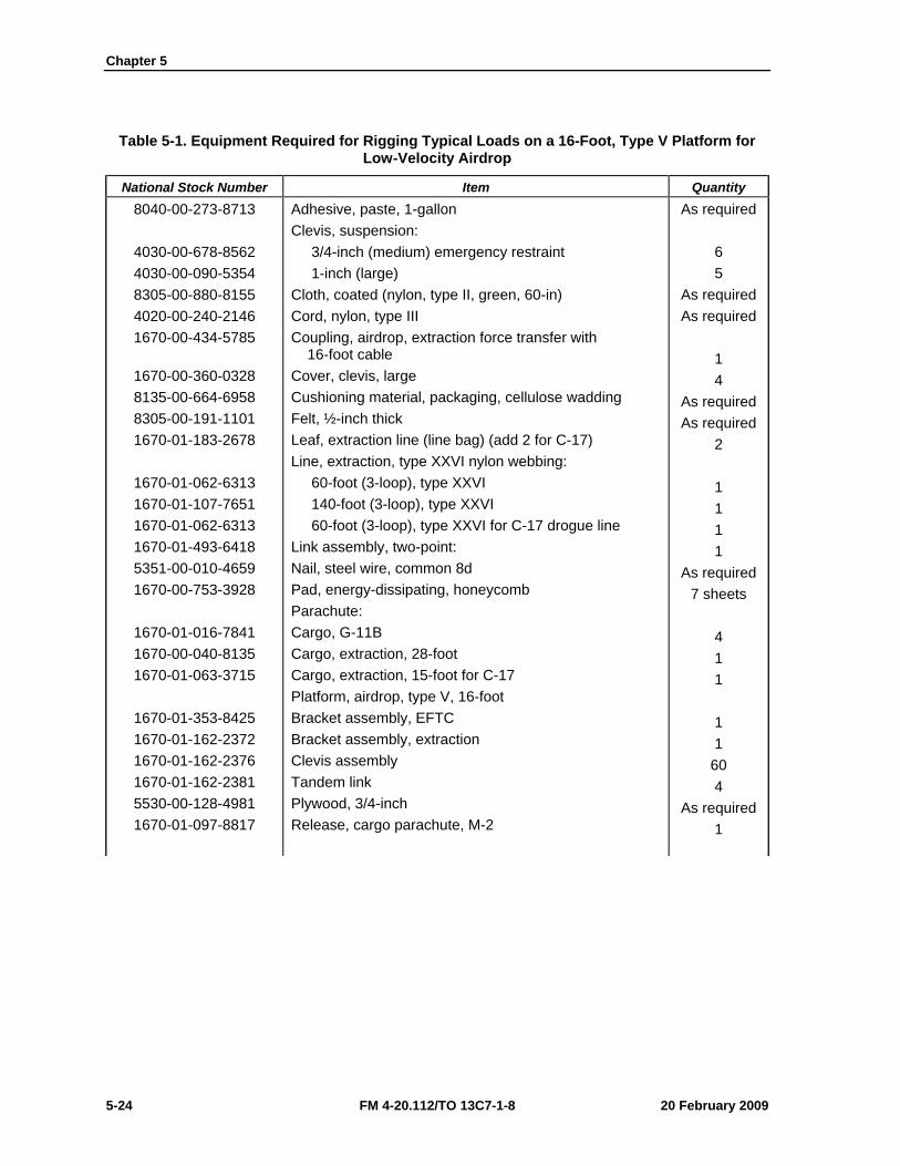
Chapter 5
5-24 FM 4-20.112/TO 13C7-1-8 20 February 2009
Table 5-1. Equipment Required for Rigging Typical Loads on a 16-Foot, Type V Platform for Low-Velocity Airdrop
National Stock Number Item Quantity 8040-00-273-8713
4030-00-678-8562 4030-00-090-5354 8305-00-880-8155 4020-00-240-2146 1670-00-434-5785
1670-00-360-0328 8135-00-664-6958 8305-00-191-1101 1670-01-183-2678
1670-01-062-6313 1670-01-107-7651 1670-01-062-6313 1670-01-493-6418 5351-00-010-4659 1670-00-753-3928
1670-01-016-7841 1670-00-040-8135 1670-01-063-3715
1670-01-353-8425 1670-01-162-2372 1670-01-162-2376 1670-01-162-2381 5530-00-128-4981 1670-01-097-8817
Adhesive, paste, 1-gallon Clevis, suspension: 3/4-inch (medium) emergency restraint 1-inch (large) Cloth, coated (nylon, type II, green, 60-in) Cord, nylon, type III Coupling, airdrop, extraction force transfer with 16-foot cable Cover, clevis, large Cushioning material, packaging, cellulose wadding Felt, ½-inch thick Leaf, extraction line (line bag) (add 2 for C-17) Line, extraction, type XXVI nylon webbing: 60-foot (3-loop), type XXVI 140-foot (3-loop), type XXVI 60-foot (3-loop), type XXVI for C-17 drogue line Link assembly, two-point: Nail, steel wire, common 8d Pad, energy-dissipating, honeycomb Parachute: Cargo, G-11B Cargo, extraction, 28-foot Cargo, extraction, 15-foot for C-17 Platform, airdrop, type V, 16-foot Bracket assembly, EFTC Bracket assembly, extraction Clevis assembly Tandem link Plywood, 3/4-inch Release, cargo parachute, M-2
As required 6 5
As required As required
1 4
As required As required
2 1 1 1 1
As required 7 sheets
4 1 1 1 1
60 4
As required 1
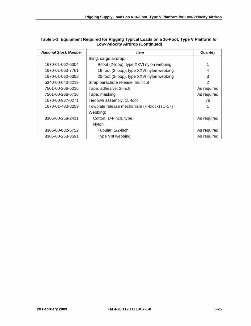
Rigging Supply Loads on a 16-Foot, Type V Platform for Low-Velocity Airdrop
20 February 2009 FM 4-20.112/TO 13C7-1-8 5-25
Table 5-1. Equipment Required for Rigging Typical Loads on a 16-Foot, Type V Platform for Low-Velocity Airdrop (Continued)
National Stock Number Item Quantity
1670-01-062-6304 1670-01-063-7761 1670-01-062-6302 5340-00-040-8219 7501-00-266-5016 7501-00-266-6710 1670-00-937-0271 1670-01-483-8259
8305-00-268-2411
8305-00-082-5752 8305-00-263-3591
Sling, cargo airdrop: 9-foot (2-loop), type XXVI nylon webbing 16-foot (2-loop), type XXVI nylon webbing 20-foot (3-loop), type XXVI nylon webbing Strap parachute release, multicut Tape, adhesive, 2-inch Tape, masking Tiedown assembly, 15-foot Towplate release mechanism (H-block) (C-17) Webbing: Cotton, 1/4-inch, type I Nylon: Tubular, 1/2-inch Type VIII webbing
1 4 3 2
As required As required
76 1
As required
As required As required
Chapter 5
5-26 FM 4-20.112/TO 13C7-1-8 20 February 2009
SECTION II-RIGGING 155-MILLIMETER (MM) AMMUNITION
DESCRIPTION OF LOAD 5-17. Ninety-six 155-mm projectiles and 72 powder canisters are rigged for low-velocity airdrop on a 16-foot, type V airdrop platform. All 155-mm ammunition packaged as shown and listed in FM 4-20.153/MCRP 4-11.3B/TO 13C7-18-41, as certified for low-velocity airdrop, may be rigged using these procedures. The load uses three G-11 cargo parachutes. Each load must weigh at least 5,040 pounds, including parachutes. Refer to 4-20.102/MCRP 4-11.3J/NAVSEA SS400-AB-MMO-010/TO 13C7-1-5 for the weight limitations for the number of parachutes to be used.
PREPARING PLATFORM 5-18. Prepare a 16-foot, type V platform as shown in Figure 5-14.
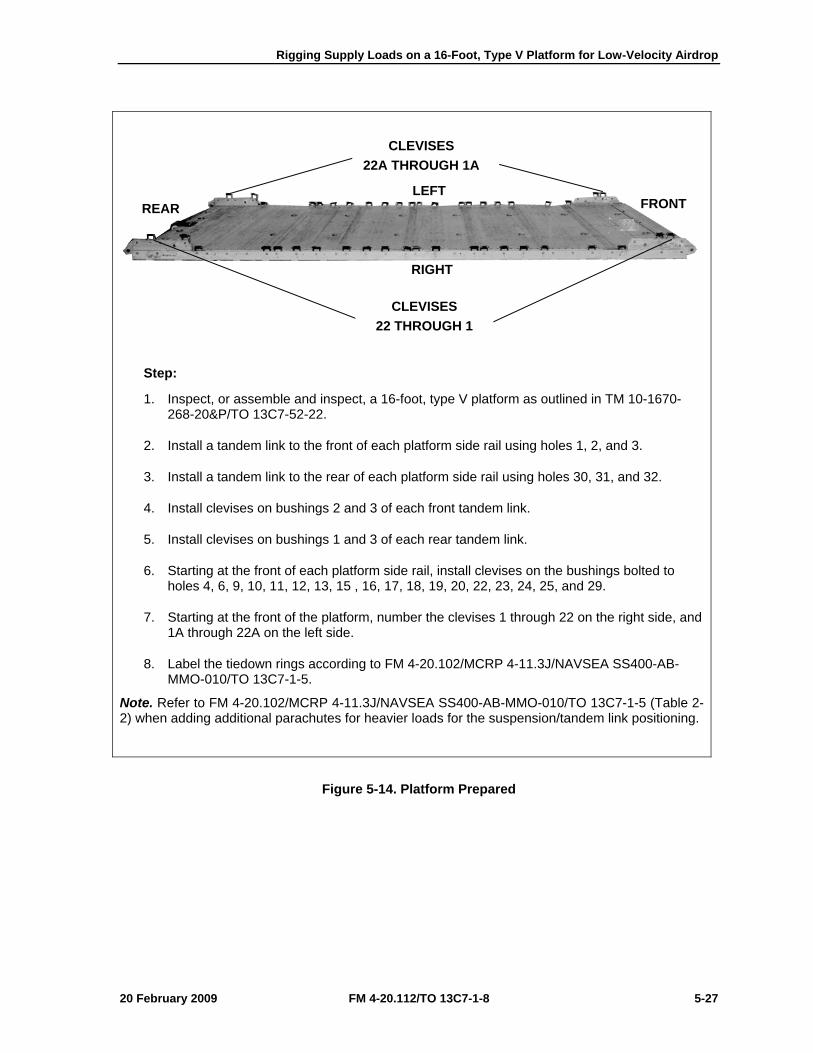
Rigging Supply Loads on a 16-Foot, Type V Platform for Low-Velocity Airdrop
20 February 2009 FM 4-20.112/TO 13C7-1-8 5-27
Step:
1. Inspect, or assemble and inspect, a 16-foot, type V platform as outlined in TM 10-1670-268-20&P/TO 13C7-52-22.
2. Install a tandem link to the front of each platform side rail using holes 1, 2, and 3.
3. Install a tandem link to the rear of each platform side rail using holes 30, 31, and 32.
4. Install clevises on bushings 2 and 3 of each front tandem link.
5. Install clevises on bushings 1 and 3 of each rear tandem link.
6. Starting at the front of each platform side rail, install clevises on the bushings bolted to holes 4, 6, 9, 10, 11, 12, 13, 15 , 16, 17, 18, 19, 20, 22, 23, 24, 25, and 29.
7. Starting at the front of the platform, number the clevises 1 through 22 on the right side, and 1A through 22A on the left side.
8. Label the tiedown rings according to FM 4-20.102/MCRP 4-11.3J/NAVSEA SS400-AB-MMO-010/TO 13C7-1-5.
Note. Refer to FM 4-20.102/MCRP 4-11.3J/NAVSEA SS400-AB-MMO-010/TO 13C7-1-5 (Table 2-2) when adding additional parachutes for heavier loads for the suspension/tandem link positioning.
Figure 5-14. Platform Prepared
CLEVISES 22A THROUGH 1A
CLEVISES 22 THROUGH 1
RIGHT
LEFT FRONT REAR
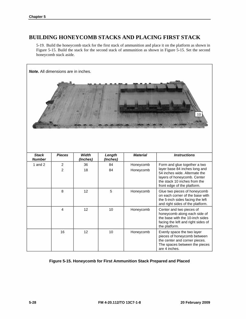
Chapter 5
5-28 FM 4-20.112/TO 13C7-1-8 20 February 2009
BUILDING HONEYCOMB STACKS AND PLACING FIRST STACK 5-19. Build the honeycomb stack for the first stack of ammunition and place it on the platform as shown in Figure 5-15. Build the stack for the second stack of ammunition as shown in Figure 5-15. Set the second honeycomb stack aside.
Note. All dimensions are in inches.
Stack Number
Pieces Width (Inches)
Length (Inches)
Material Instructions
1 and 2 2 2
36 18
84 84
Honeycomb Honeycomb
Form and glue together a two layer base 84 inches long and 54 inches wide. Alternate the layers of honeycomb. Center the stack 10 inches from the front edge of the platform.
8 12 5 Honeycomb Glue two pieces of honeycomb on each corner of the base with the 5-inch sides facing the left and right sides of the platform.
4 12 10 Honeycomb Center and two pieces of honeycomb along each side of the base with the 10-inch sides facing the left and right sides of the platform.
16 12 10 Honeycomb Evenly space the two layer pieces of honeycomb between the center and corner pieces. The spaces between the pieces are 4 inches.
Figure 5-15. Honeycomb for First Ammunition Stack Prepared and Placed
10
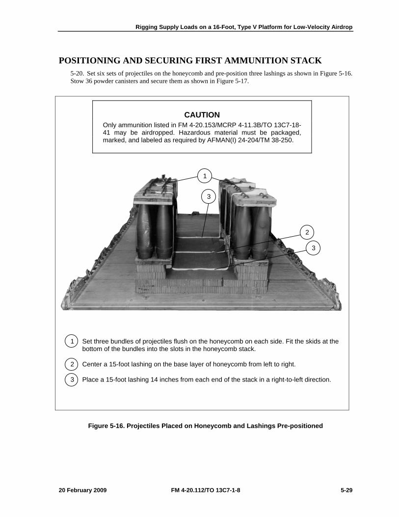
Rigging Supply Loads on a 16-Foot, Type V Platform for Low-Velocity Airdrop
20 February 2009 FM 4-20.112/TO 13C7-1-8 5-29
POSITIONING AND SECURING FIRST AMMUNITION STACK 5-20. Set six sets of projectiles on the honeycomb and pre-position three lashings as shown in Figure 5-16. Stow 36 powder canisters and secure them as shown in Figure 5-17.
CAUTION Only ammunition listed in FM 4-20.153/MCRP 4-11.3B/TO 13C7-18-41 may be airdropped. Hazardous material must be packaged, marked, and labeled as required by AFMAN(I) 24-204/TM 38-250.
1 Set three bundles of projectiles flush on the honeycomb on each side. Fit the skids at the bottom of the bundles into the slots in the honeycomb stack.
2 Center a 15-foot lashing on the base layer of honeycomb from left to right.
3 Place a 15-foot lashing 14 inches from each end of the stack in a right-to-left direction.
Figure 5-16. Projectiles Placed on Honeycomb and Lashings Pre-positioned
1
3
2
3
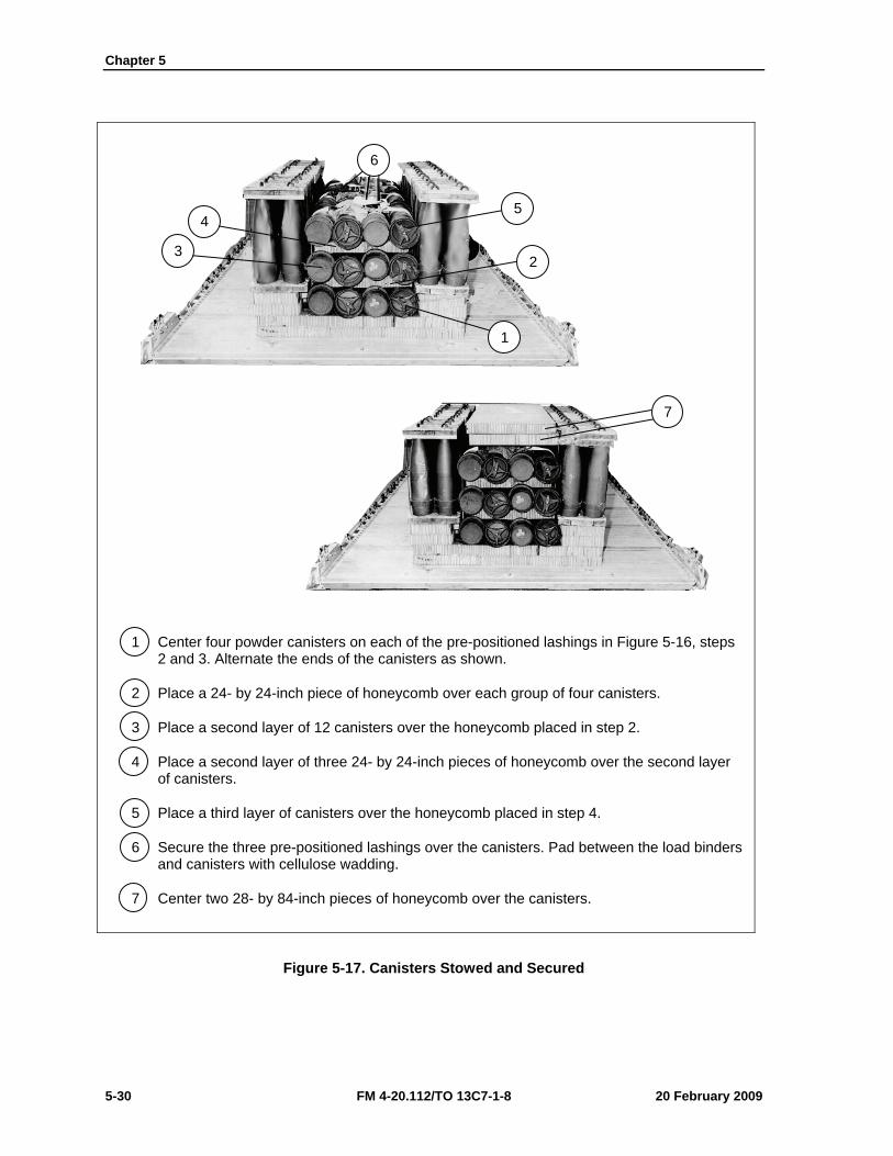
Chapter 5
5-30 FM 4-20.112/TO 13C7-1-8 20 February 2009
1 Center four powder canisters on each of the pre-positioned lashings in Figure 5-16, steps 2 and 3. Alternate the ends of the canisters as shown.
2 Place a 24- by 24-inch piece of honeycomb over each group of four canisters.
3 Place a second layer of 12 canisters over the honeycomb placed in step 2.
4 Place a second layer of three 24- by 24-inch pieces of honeycomb over the second layer of canisters.
5 Place a third layer of canisters over the honeycomb placed in step 4.
6 Secure the three pre-positioned lashings over the canisters. Pad between the load binders and canisters with cellulose wadding.
7 Center two 28- by 84-inch pieces of honeycomb over the canisters.
Figure 5-17. Canisters Stowed and Secured
7
1
2 3
4 5
6
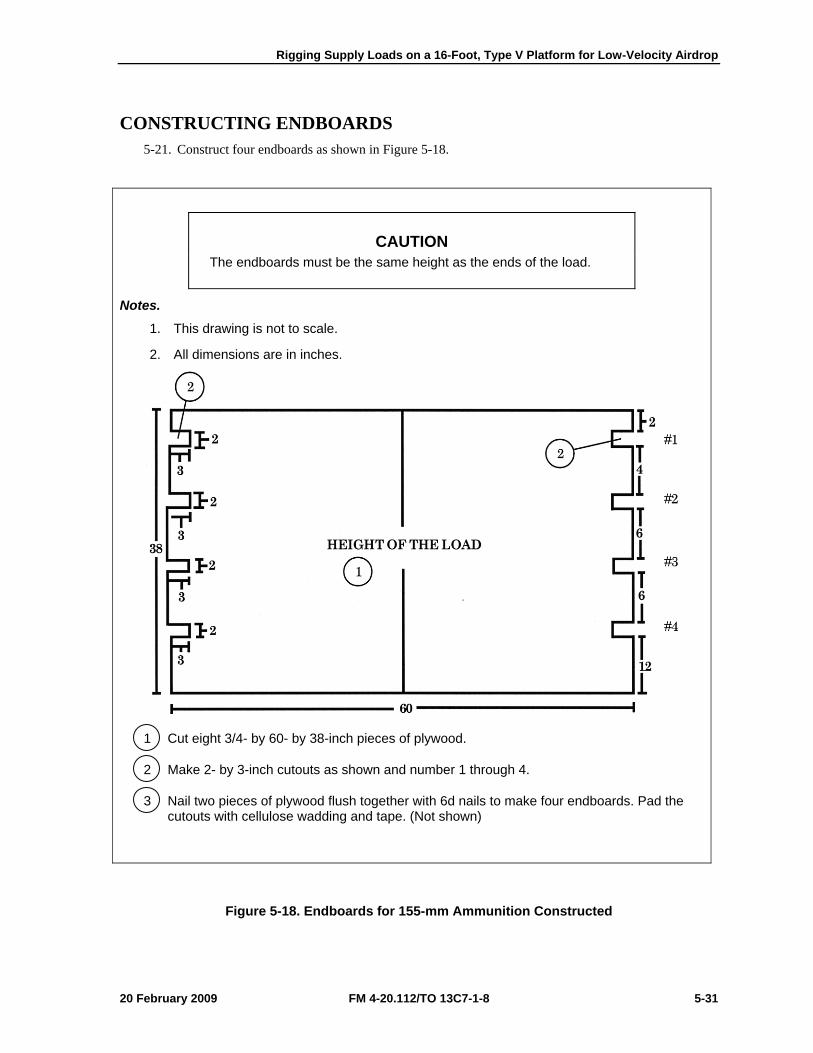
Rigging Supply Loads on a 16-Foot, Type V Platform for Low-Velocity Airdrop
20 February 2009 FM 4-20.112/TO 13C7-1-8 5-31
CONSTRUCTING ENDBOARDS 5-21. Construct four endboards as shown in Figure 5-18.
CAUTION The endboards must be the same height as the ends of the load.
Notes.
1. This drawing is not to scale.
2. All dimensions are in inches.
1 Cut eight 3/4- by 60- by 38-inch pieces of plywood.
2 Make 2- by 3-inch cutouts as shown and number 1 through 4.
3 Nail two pieces of plywood flush together with 6d nails to make four endboards. Pad the cutouts with cellulose wadding and tape. (Not shown)
Figure 5-18. Endboards for 155-mm Ammunition Constructed
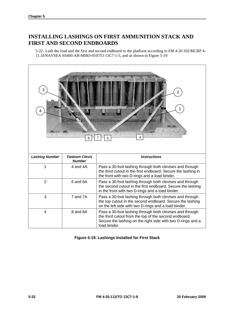
Chapter 5
5-32 FM 4-20.112/TO 13C7-1-8 20 February 2009
INSTALLING LASHINGS ON FIRST AMMUNITION STACK AND FIRST AND SECOND ENDBOARDS
5-22. Lash the load and the first and second endboard to the platform according to FM 4-20.102/MCRP 4-11.3J/NAVSEA SS400-AB-MMO-010/TO 13C7-1-5, and as shown in Figure 5-19
Lashing Number Tiedown Clevis
Number Instructions
1 4 and 4A Pass a 30-foot lashing through both clevises and through the third cutout in the first endboard. Secure the lashing in the front with two D-rings and a load binder.
2 6 and 6A Pass a 30-foot lashing through both clevises and through the second cutout in the first endboard. Secure the lashing in the front with two D-rings and a load binder.
3 7 and 7A Pass a 30-foot lashing through both clevises and through the top cutout in the second endboard. Secure the lashing on the left side with two D-rings and a load binder.
4 8 and 8A Pass a 30-foot lashing through both clevises and through the third cutout from the top of the second endboard. Secure the lashing on the right side with two D-rings and a load binder.
Figure 5-19. Lashings Installed for First Stack
4
1
2 3
4
8 7 6
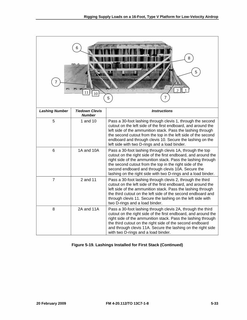
Rigging Supply Loads on a 16-Foot, Type V Platform for Low-Velocity Airdrop
20 February 2009 FM 4-20.112/TO 13C7-1-8 5-33
Lashing Number Tiedown Clevis
Number Instructions
5 1 and 10 Pass a 30-foot lashing through clevis 1, through the second cutout on the left side of the first endboard, and around the left side of the ammunition stack. Pass the lashing through the second cutout from the top in the left side of the second endboard and through clevis 10. Secure the lashing on the left side with two D-rings and a load binder.
6 1A and 10A Pass a 30-foot lashing through clevis 1A, through the top cutout on the right side of the first endboard, and around the right side of the ammunition stack. Pass the lashing through the second cutout from the top in the right side of the second endboard and through clevis 10A. Secure the lashing on the right side with two D-rings and a load binder.
7 2 and 11 Pass a 30-foot lashing through clevis 2, through the third cutout on the left side of the first endboard, and around the left side of the ammunition stack. Pass the lashing through the third cutout on the left side of the second endboard and through clevis 11. Secure the lashing on the left side with two D-rings and a load binder.
8 2A and 11A Pass a 30-foot lashing through clevis 2A, through the third cutout on the right side of the first endboard, and around the right side of the ammunition stack. Pass the lashing through the third cutout on the right side of the second endboard and through clevis 11A. Secure the lashing on the right side with two D-rings and a load binder.
Figure 5-19. Lashings Installed for First Stack (Continued)
1210 11
8
5
6
7
5 7
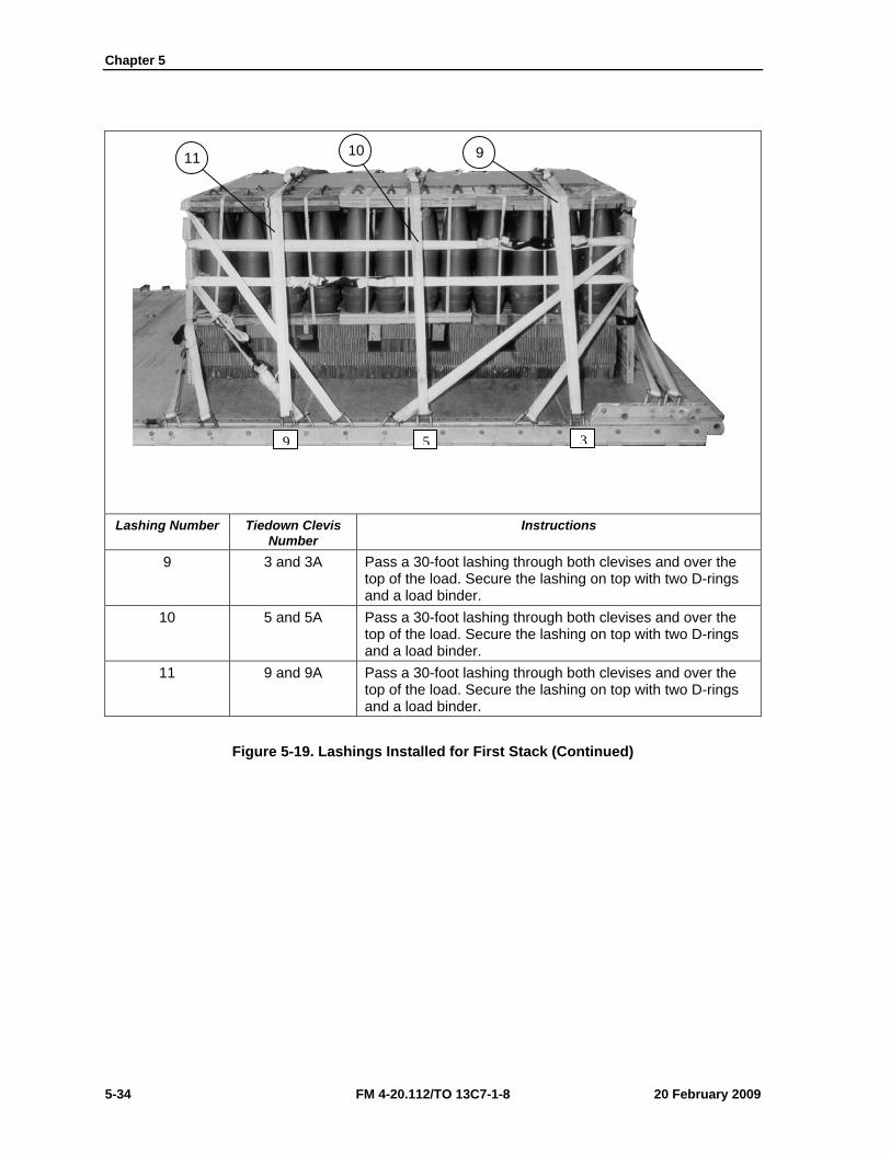
Chapter 5
5-34 FM 4-20.112/TO 13C7-1-8 20 February 2009
Lashing Number Tiedown Clevis
Number Instructions
9 3 and 3A Pass a 30-foot lashing through both clevises and over the top of the load. Secure the lashing on top with two D-rings and a load binder.
10 5 and 5A Pass a 30-foot lashing through both clevises and over the top of the load. Secure the lashing on top with two D-rings and a load binder.
11 9 and 9A Pass a 30-foot lashing through both clevises and over the top of the load. Secure the lashing on top with two D-rings and a load binder.
Figure 5-19. Lashings Installed for First Stack (Continued)
11 10 9
359
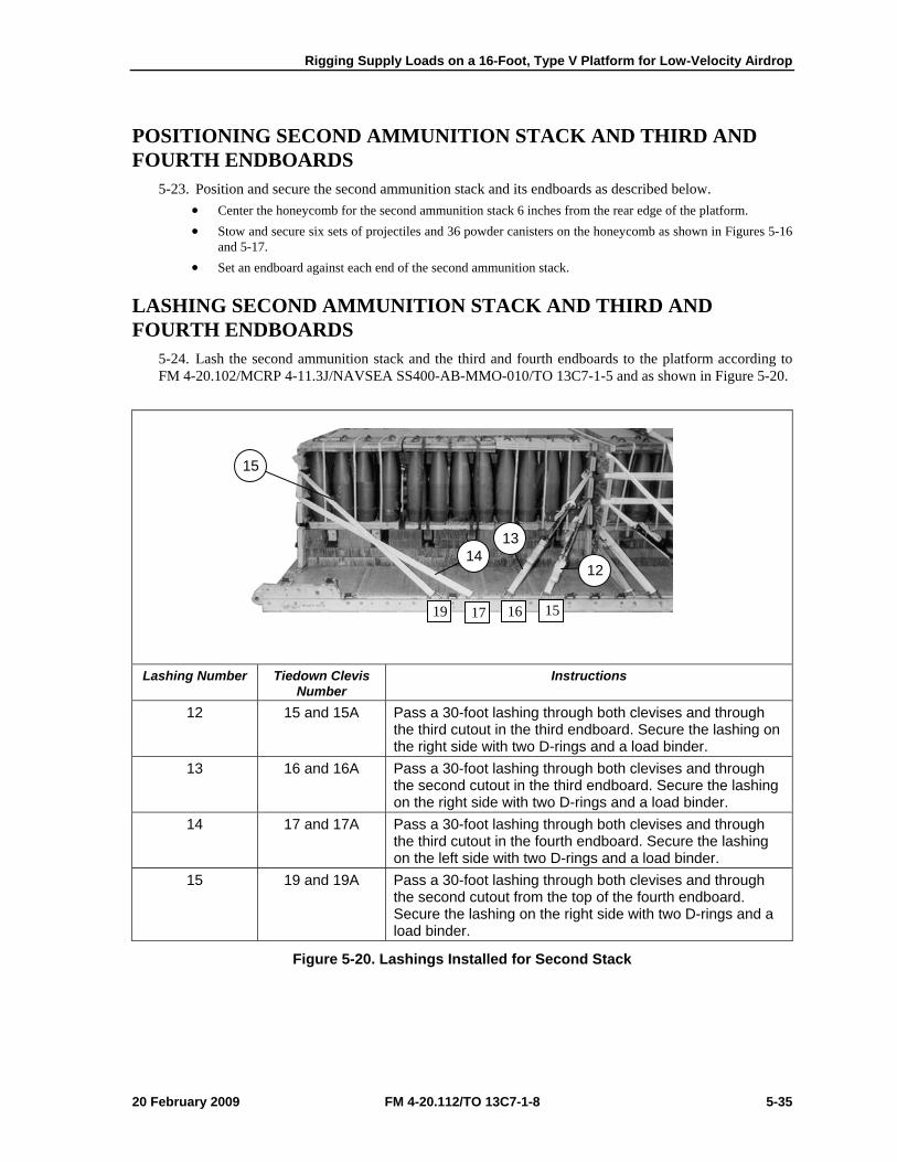
Rigging Supply Loads on a 16-Foot, Type V Platform for Low-Velocity Airdrop
20 February 2009 FM 4-20.112/TO 13C7-1-8 5-35
POSITIONING SECOND AMMUNITION STACK AND THIRD AND FOURTH ENDBOARDS
5-23. Position and secure the second ammunition stack and its endboards as described below. • Center the honeycomb for the second ammunition stack 6 inches from the rear edge of the platform. • Stow and secure six sets of projectiles and 36 powder canisters on the honeycomb as shown in Figures 5-16
and 5-17. • Set an endboard against each end of the second ammunition stack.
LASHING SECOND AMMUNITION STACK AND THIRD AND FOURTH ENDBOARDS
5-24. Lash the second ammunition stack and the third and fourth endboards to the platform according to FM 4-20.102/MCRP 4-11.3J/NAVSEA SS400-AB-MMO-010/TO 13C7-1-5 and as shown in Figure 5-20.
Lashing Number Tiedown Clevis
Number Instructions
12 15 and 15A Pass a 30-foot lashing through both clevises and through the third cutout in the third endboard. Secure the lashing on the right side with two D-rings and a load binder.
13 16 and 16A Pass a 30-foot lashing through both clevises and through the second cutout in the third endboard. Secure the lashing on the right side with two D-rings and a load binder.
14 17 and 17A Pass a 30-foot lashing through both clevises and through the third cutout in the fourth endboard. Secure the lashing on the left side with two D-rings and a load binder.
15 19 and 19A Pass a 30-foot lashing through both clevises and through the second cutout from the top of the fourth endboard. Secure the lashing on the right side with two D-rings and a load binder.
Figure 5-20. Lashings Installed for Second Stack
13
15
14 12
15 161719
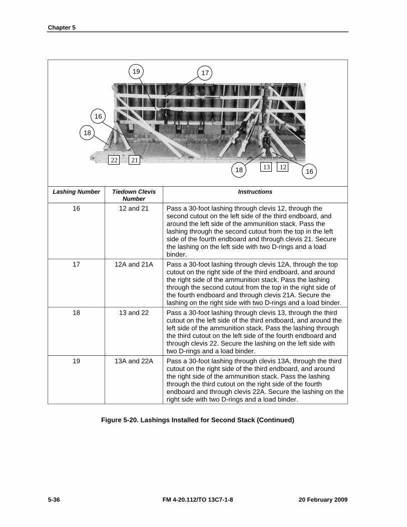
Chapter 5
5-36 FM 4-20.112/TO 13C7-1-8 20 February 2009
Lashing Number Tiedown Clevis
Number Instructions
16 12 and 21 Pass a 30-foot lashing through clevis 12, through the second cutout on the left side of the third endboard, and around the left side of the ammunition stack. Pass the lashing through the second cutout from the top in the left side of the fourth endboard and through clevis 21. Secure the lashing on the left side with two D-rings and a load binder.
17 12A and 21A Pass a 30-foot lashing through clevis 12A, through the top cutout on the right side of the third endboard, and around the right side of the ammunition stack. Pass the lashing through the second cutout from the top in the right side of the fourth endboard and through clevis 21A. Secure the lashing on the right side with two D-rings and a load binder.
18 13 and 22 Pass a 30-foot lashing through clevis 13, through the third cutout on the left side of the third endboard, and around the left side of the ammunition stack. Pass the lashing through the third cutout on the left side of the fourth endboard and through clevis 22. Secure the lashing on the left side with two D-rings and a load binder.
19 13A and 22A Pass a 30-foot lashing through clevis 13A, through the third cutout on the right side of the third endboard, and around the right side of the ammunition stack. Pass the lashing through the third cutout on the right side of the fourth endboard and through clevis 22A. Secure the lashing on the right side with two D-rings and a load binder.
Figure 5-20. Lashings Installed for Second Stack (Continued)
18
16
19 17
18 16
22 21 13 12
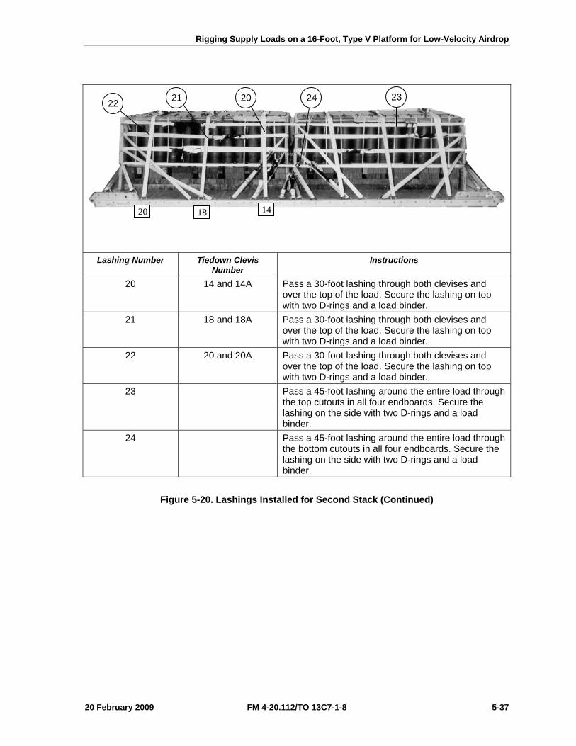
Rigging Supply Loads on a 16-Foot, Type V Platform for Low-Velocity Airdrop
20 February 2009 FM 4-20.112/TO 13C7-1-8 5-37
Lashing Number Tiedown Clevis Number
Instructions
20 14 and 14A Pass a 30-foot lashing through both clevises and over the top of the load. Secure the lashing on top with two D-rings and a load binder.
21 18 and 18A Pass a 30-foot lashing through both clevises and over the top of the load. Secure the lashing on top with two D-rings and a load binder.
22 20 and 20A Pass a 30-foot lashing through both clevises and over the top of the load. Secure the lashing on top with two D-rings and a load binder.
23 Pass a 45-foot lashing around the entire load through the top cutouts in all four endboards. Secure the lashing on the side with two D-rings and a load binder.
24 Pass a 45-foot lashing around the entire load through the bottom cutouts in all four endboards. Secure the lashing on the side with two D-rings and a load binder.
Figure 5-20. Lashings Installed for Second Stack (Continued)
22 21 20 24 23
20 18 14
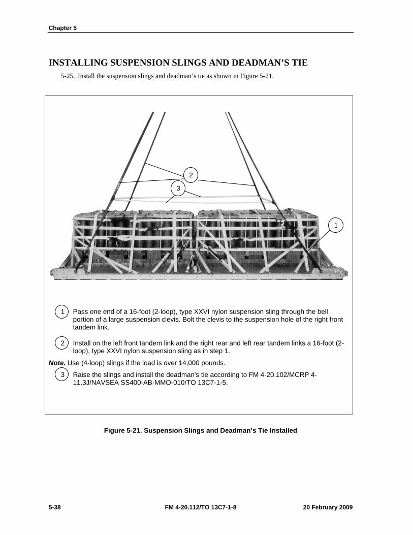
Chapter 5
5-38 FM 4-20.112/TO 13C7-1-8 20 February 2009
INSTALLING SUSPENSION SLINGS AND DEADMAN’S TIE 5-25. Install the suspension slings and deadman’s tie as shown in Figure 5-21.
1 Pass one end of a 16-foot (2-loop), type XXVI nylon suspension sling through the bell portion of a large suspension clevis. Bolt the clevis to the suspension hole of the right front tandem link.
2 Install on the left front tandem link and the right rear and left rear tandem links a 16-foot (2-loop), type XXVI nylon suspension sling as in step 1.
Note. Use (4-loop) slings if the load is over 14,000 pounds.
3 Raise the slings and install the deadman's tie according to FM 4-20.102/MCRP 4-11.3J/NAVSEA SS400-AB-MMO-010/TO 13C7-1-5.
Figure 5-21. Suspension Slings and Deadman’s Tie Installed
3
2
1
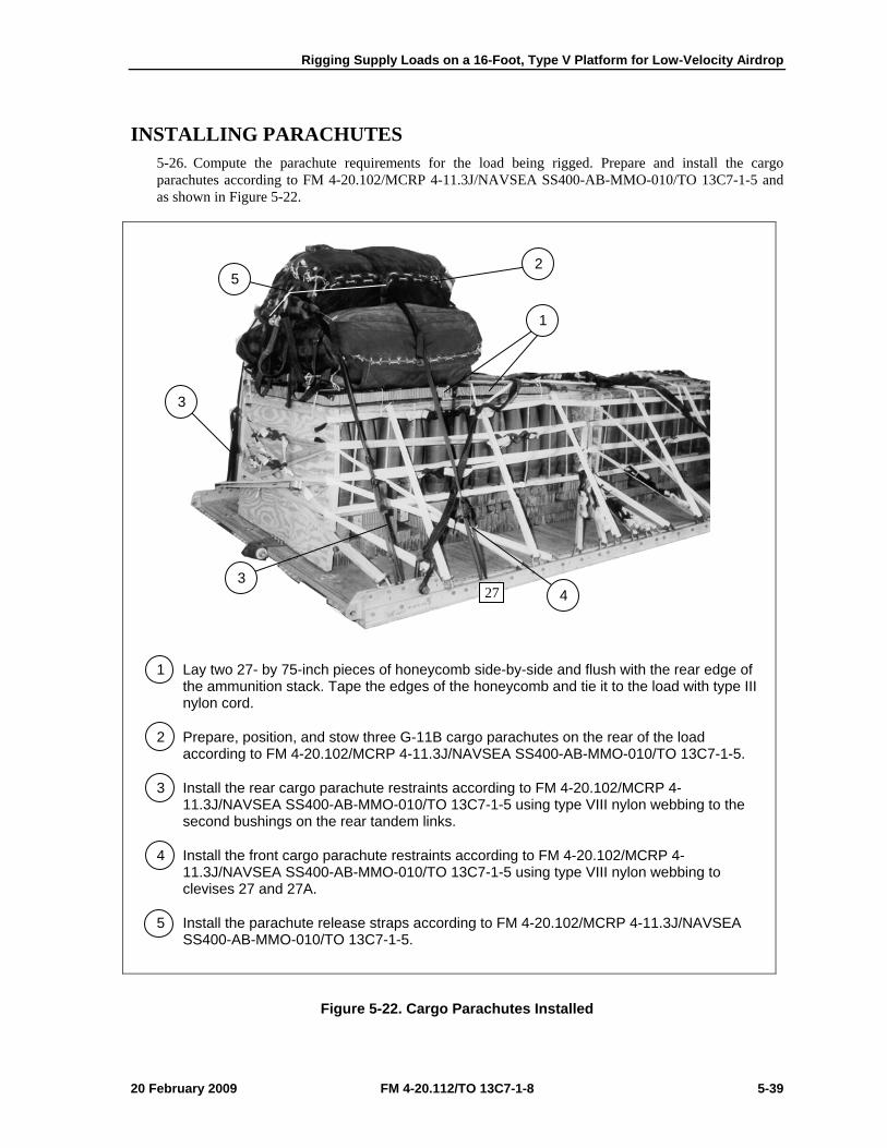
Rigging Supply Loads on a 16-Foot, Type V Platform for Low-Velocity Airdrop
20 February 2009 FM 4-20.112/TO 13C7-1-8 5-39
INSTALLING PARACHUTES 5-26. Compute the parachute requirements for the load being rigged. Prepare and install the cargo parachutes according to FM 4-20.102/MCRP 4-11.3J/NAVSEA SS400-AB-MMO-010/TO 13C7-1-5 and as shown in Figure 5-22.
1 Lay two 27- by 75-inch pieces of honeycomb side-by-side and flush with the rear edge of the ammunition stack. Tape the edges of the honeycomb and tie it to the load with type III nylon cord.
2 Prepare, position, and stow three G-11B cargo parachutes on the rear of the load according to FM 4-20.102/MCRP 4-11.3J/NAVSEA SS400-AB-MMO-010/TO 13C7-1-5.
3 Install the rear cargo parachute restraints according to FM 4-20.102/MCRP 4-11.3J/NAVSEA SS400-AB-MMO-010/TO 13C7-1-5 using type VIII nylon webbing to the second bushings on the rear tandem links.
4 Install the front cargo parachute restraints according to FM 4-20.102/MCRP 4-11.3J/NAVSEA SS400-AB-MMO-010/TO 13C7-1-5 using type VIII nylon webbing to clevises 27 and 27A.
5 Install the parachute release straps according to FM 4-20.102/MCRP 4-11.3J/NAVSEA SS400-AB-MMO-010/TO 13C7-1-5.
Figure 5-22. Cargo Parachutes Installed
2 5
1
3
4 3
27
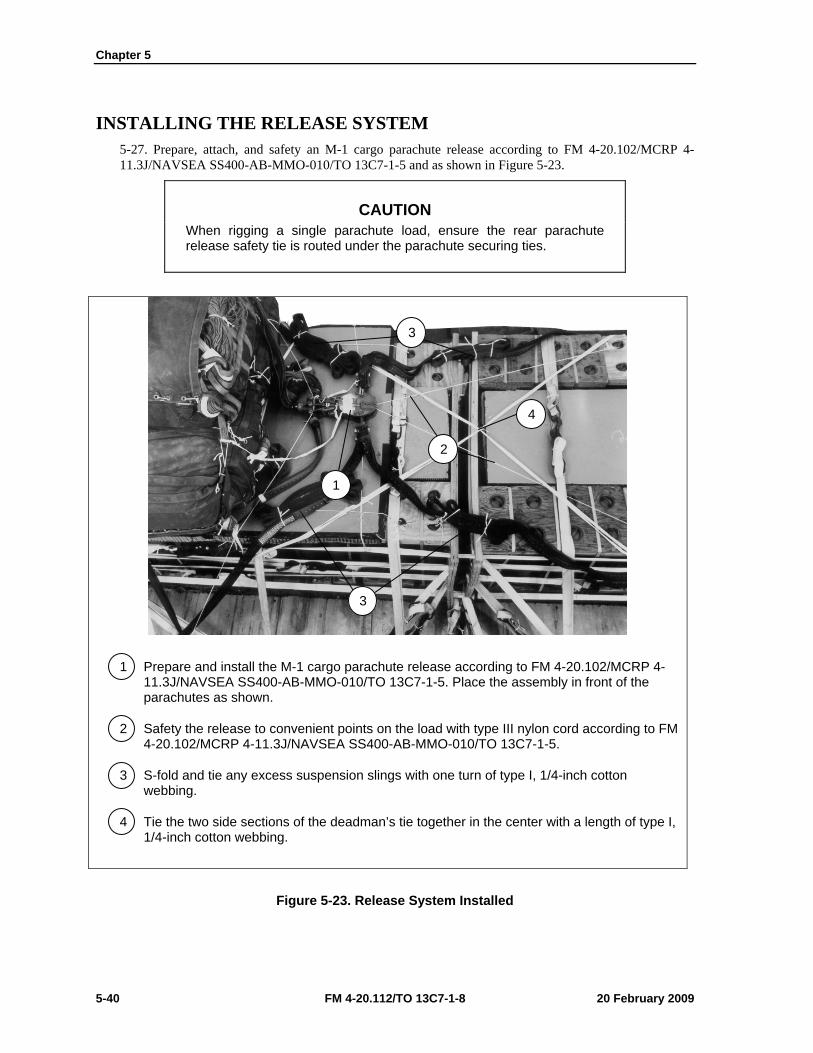
Chapter 5
5-40 FM 4-20.112/TO 13C7-1-8 20 February 2009
INSTALLING THE RELEASE SYSTEM 5-27. Prepare, attach, and safety an M-1 cargo parachute release according to FM 4-20.102/MCRP 4-11.3J/NAVSEA SS400-AB-MMO-010/TO 13C7-1-5 and as shown in Figure 5-23.
CAUTION When rigging a single parachute load, ensure the rear parachute release safety tie is routed under the parachute securing ties.
1 Prepare and install the M-1 cargo parachute release according to FM 4-20.102/MCRP 4-11.3J/NAVSEA SS400-AB-MMO-010/TO 13C7-1-5. Place the assembly in front of the parachutes as shown.
2 Safety the release to convenient points on the load with type III nylon cord according to FM 4-20.102/MCRP 4-11.3J/NAVSEA SS400-AB-MMO-010/TO 13C7-1-5.
3 S-fold and tie any excess suspension slings with one turn of type I, 1/4-inch cotton webbing.
4 Tie the two side sections of the deadman’s tie together in the center with a length of type I, 1/4-inch cotton webbing.
Figure 5-23. Release System Installed
3
2
4
1
3
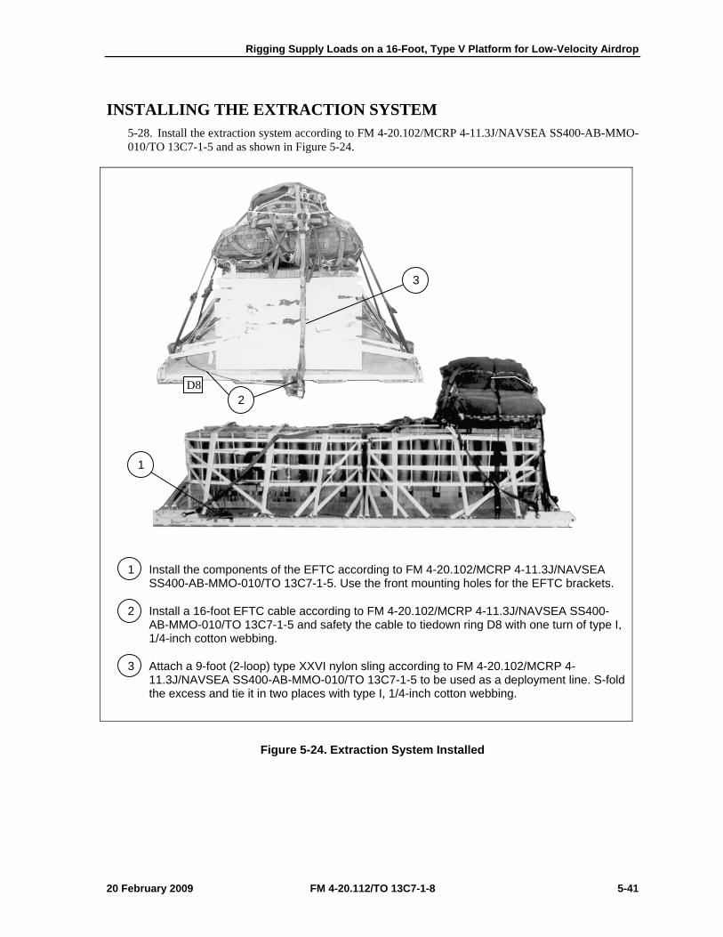
Rigging Supply Loads on a 16-Foot, Type V Platform for Low-Velocity Airdrop
20 February 2009 FM 4-20.112/TO 13C7-1-8 5-41
INSTALLING THE EXTRACTION SYSTEM 5-28. Install the extraction system according to FM 4-20.102/MCRP 4-11.3J/NAVSEA SS400-AB-MMO-010/TO 13C7-1-5 and as shown in Figure 5-24.
1 Install the components of the EFTC according to FM 4-20.102/MCRP 4-11.3J/NAVSEA SS400-AB-MMO-010/TO 13C7-1-5. Use the front mounting holes for the EFTC brackets.
2 Install a 16-foot EFTC cable according to FM 4-20.102/MCRP 4-11.3J/NAVSEA SS400-AB-MMO-010/TO 13C7-1-5 and safety the cable to tiedown ring D8 with one turn of type I, 1/4-inch cotton webbing.
3 Attach a 9-foot (2-loop) type XXVI nylon sling according to FM 4-20.102/MCRP 4-11.3J/NAVSEA SS400-AB-MMO-010/TO 13C7-1-5 to be used as a deployment line. S-fold the excess and tie it in two places with type I, 1/4-inch cotton webbing.
Figure 5-24. Extraction System Installed
3
2
1
D8

Chapter 5
5-42 FM 4-20.112/TO 13C7-1-8 20 February 2009
PLACING EXTRACTION PARACHUTE 5-29. Select the extraction parachute and extraction line needed using the extraction line requirements table in FM 4-20.102/MCRP 4-11.3J/NAVSEA SS400-AB-MMO-010/TO 13C7-1-5. Place the extraction parachute and line on the load for installation in the aircraft.
INSTALLING PROVISIONS FOR EMERGENCY RESTRAINTS 5-30. Select and install the provisions for the emergency aft restraints according to the emergency aft restraint requirements table in FM 4-20.102/MCRP 4-11.3J/NAVSEA SS400-AB-MMO-010/TO 13C7-1-5.
MARKING RIGGED LOAD 5-31. Mark the rigged load according to FM 4-20.102/MCRP 4-11.3J/NAVSEA SS400-AB-MMO-010/TO 13C7-1-5, and as shown in Figure 5-25. Complete Shipper’s Declaration for Dangerous Goods. If the load varies from the one shown, the weight, height, CB, and parachute requirements must be recomputed.
EQUIPMENT REQUIRED 5-32. Use the equipment listed in Table 5-2 to rig this load.

Rigging Supply Loads on a 16-Foot, Type V Platform for Low-Velocity Airdrop
20 February 2009 FM 4-20.112/TO 13C7-1-8 5-43
CAUTION Make the final rigger inspection required by AR 59-4 and FM 4-20.102/MCRP 4-11.3J/NAVSEA SS400-AB-MMO-010/TO 13C7-1-5 before the load leaves the rigging site.
RIGGED LOAD DATA
Weight: Load shown .......................................................................................................... 13,300 pounds
Minimum Weight: ............................................................................................................ 5,040 pounds
Maximum Suspended Weight ........................................................................................ 14,250 pounds
Height ......................................................................................................................................... 86 inches
Width ......................................................................................................................................... 108 inches
Overall Length ........................................................................................................................... 192 inches
Overhang: Front ........................................................................................................................... 0 inches
Rear ........................................................................................................................... 0 inches
Center of Balance (from front edge of the platform) ................................................................... 101 inches
Extraction System with 16-foot cable (adds 18 inches to length of platform) ................................... EFTC
Note. Refer to FM 4-20.102/MCRP 4-11.3J/NAVSEA SS400-AB-MMO-010/TO 13C7-1-5 (Table 2-2) when adding additional parachutes for heavier loads for the suspension/tandem link positioning.
Figure 5-25. 155-mm Ammunition Rigged on a 16-Foot, Type V Platform for Low-Velocity Airdrop
CB

Chapter 5
5-44 FM 4-20.112/TO 13C7-1-8 20 February 2009
Table 5-2. Equipment Required for Rigging 155-mm Ammunition on a 16-Foot, Type V Platform for Low-Velocity Airdrop
National Stock Number Item Quantity 8040-00-273-8713
4030-00-678-8562 4030-00-090-5354 8305-00-880-8155 4020-00-240-2146 1670-00-434-5785
1670-00-360-0328 8135-00-664-6958 8305-00-191-1101 1670-01-183-2678
1670-01-062-6313 1670-01-107-7651 1670-01-062-6313 1670-01-493-6418 5351-00-010-4659 1670-00-753-3928
1670-01-016-7841 1670-01-063-3716 1670-01-063-3715
1670-01-353-8425 1670-01-162-2372 1670-01-162-2376 1670-01-162-2381 5530-00-128-4981 1670-01-097-8817
Adhesive, paste, 1-gallon Clevis, suspension: 3/4-inch (medium) emergency restraint 1-inch (large) Cloth, coated (nylon, type II, green, 60-in) Cord, nylon, type III Coupling, airdrop, extraction force transfer with 16-foot cable Cover, clevis, large Cushioning material, packaging, cellulose wadding Felt, ½-inch thick Leaf, extraction line (line bag) (add 2 for C-17) Line, extraction, type XXVI nylon webbing: 60-foot (3-loop), type XXVI 140-foot (3-loop), type XXVI 60-foot (3-loop), type XXVI for C-17 drogue line Link assembly, two-point: Nail, steel wire, common 8d Pad, energy-dissipating, honeycomb Parachute: Cargo, G-11 Cargo, extraction, 22-foot Cargo, extraction, 15-foot for C-17 Platform, airdrop, type V, 16-foot Bracket assembly, EFTC Bracket assembly, extraction Clevis assembly Tandem link Plywood, 3/4-inch Release, cargo parachute, M-1
As required 4 5
As required As required
1 3
As required As required
2 1 2 1 1
As required 13 sheets
3 1 1 1 1
44 4
As required 1
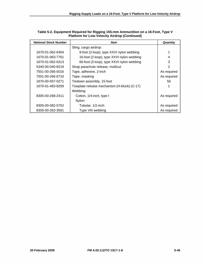
Rigging Supply Loads on a 16-Foot, Type V Platform for Low-Velocity Airdrop
20 February 2009 FM 4-20.112/TO 13C7-1-8 5-45
Table 5-2. Equipment Required for Rigging 155-mm Ammunition on a 16-Foot, Type V Platform for Low-Velocity Airdrop (Continued)
National Stock Number Item Quantity
1670-01-062-6304 1670-01-063-7761 1670-01-062-6313 5340-00-040-8219 7501-00-266-5016 7501-00-266-6710 1670-00-937-0271 1670-01-483-8259
8305-00-268-2411
8305-00-082-5752 8305-00-263-3591
Sling, cargo airdrop: 9-foot (2-loop), type XXVI nylon webbing 16-foot (2-loop), type XXVI nylon webbing 60-foot (3-loop), type XXVI nylon webbing Strap parachute release, multicut Tape, adhesive, 2-inch Tape, masking Tiedown assembly, 15-foot Towplate release mechanism (H-block) (C-17) Webbing: Cotton, 1/4-inch, type I Nylon: Tubular, 1/2-inch Type VIII webbing
1 4 3 2
As required As required
56 1
As required
As required As required
Chapter 5
5-46 FM 4-20.112/TO 13C7-1-8 20 February 2009
SECTION III-RIGGING 20-MILLIMETER (MM) AMMUNITION
DESCRIPTION OF LOAD 5-33. Two hundred forty boxes of 20-mm ammunition are rigged for low-velocity airdrop on a 16-foot, type V airdrop platform. All 20-mm ammunition packaged as shown and listed in FM 4-20.153/MCRP 4-11.3B/TO 13C7-18-41, as certified for low-velocity airdrop, may be rigged using these procedures. This load uses five G-11 cargo parachutes. Each load must weigh at least 5,040 pounds, including parachutes. Refer to FM 4-20.102/MCRP 4-11.3J/NAVSEA SS400-AB-MMO-010/TO 13C7-1-5 for the weight limitations for the number of parachutes to be used.
PREPARING PLATFORM 5-34. Prepare a 16-foot, type V platform as shown in Figure 5-26.
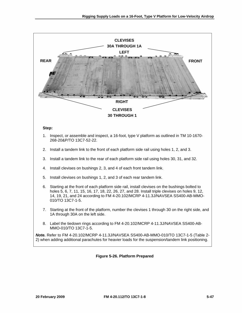
Rigging Supply Loads on a 16-Foot, Type V Platform for Low-Velocity Airdrop
20 February 2009 FM 4-20.112/TO 13C7-1-8 5-47
Step:
1. Inspect, or assemble and inspect, a 16-foot, type V platform as outlined in TM 10-1670-268-20&P/TO 13C7-52-22.
2. Install a tandem link to the front of each platform side rail using holes 1, 2, and 3.
3. Install a tandem link to the rear of each platform side rail using holes 30, 31, and 32.
4. Install clevises on bushings 2, 3, and 4 of each front tandem link.
5. Install clevises on bushings 1, 2, and 3 of each rear tandem link.
6. Starting at the front of each platform side rail, install clevises on the bushings bolted to holes 5, 6, 7, 11, 15, 16, 17, 18, 22, 26, 27, and 28. Install triple clevises on holes 9, 12, 14, 19, 21, and 24 according to FM 4-20.102/MCRP 4-11.3J/NAVSEA SS400-AB-MMO-010/TO 13C7-1-5.
7. Starting at the front of the platform, number the clevises 1 through 30 on the right side, and 1A through 30A on the left side.
8. Label the tiedown rings according to FM 4-20.102/MCRP 4-11.3J/NAVSEA SS400-AB-MMO-010/TO 13C7-1-5.
Note. Refer to FM 4-20.102/MCRP 4-11.3J/NAVSEA SS400-AB-MMO-010/TO 13C7-1-5 (Table 2-2) when adding additional parachutes for heavier loads for the suspension/tandem link positioning.
Figure 5-26. Platform Prepared
CLEVISES 30A THROUGH 1A
CLEVISES 30 THROUGH 1
RIGHT
LEFT
FRONT REAR

Chapter 5
5-48 FM 4-20.112/TO 13C7-1-8 20 February 2009
BUILDING HONEYCOMB STACKS AND PLACING FIRST STACK 5-35. Build the honeycomb stack for the first stack of ammunition and place it on the platform according to FM 4-20.102/MCRP 4-11.3J/NAVSEA SS400-AB-MMO-010/TO 13C7-1-5 and as shown in Figure 5-27. Build the stack for the second stack of ammunition as shown in Figure 5-27. Set the second honeycomb stack aside.
1 Center two 15- by 75-inch pieces of honeycomb lengthwise on the platform, 19 inches from the front edge.
2 Place two 36- by 75-inch pieces of honeycomb flush on each side of the pieces placed in step 1.
3 Center a 30-foot lashing 10 inches from each end of the honeycomb.
4 Center a 30-foot lashing 26 inches from the front edge of the honeycomb, and another 30-foot lashing 26 inches from the rear.
Figure 5-27. Honeycomb for First Ammunition Stack Prepared and Placed
19”
4
1 2
3
FRONT REAR
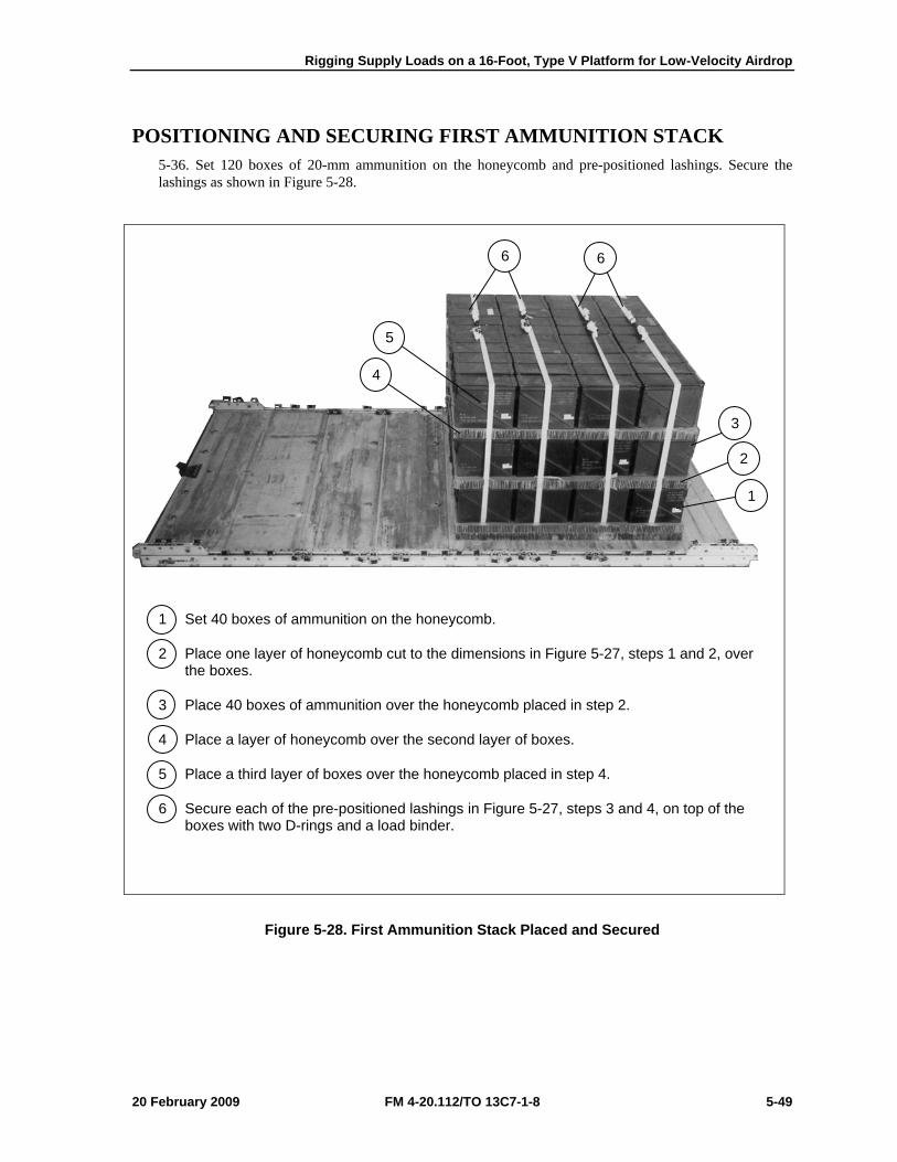
Rigging Supply Loads on a 16-Foot, Type V Platform for Low-Velocity Airdrop
20 February 2009 FM 4-20.112/TO 13C7-1-8 5-49
POSITIONING AND SECURING FIRST AMMUNITION STACK 5-36. Set 120 boxes of 20-mm ammunition on the honeycomb and pre-positioned lashings. Secure the lashings as shown in Figure 5-28.
1 Set 40 boxes of ammunition on the honeycomb.
2 Place one layer of honeycomb cut to the dimensions in Figure 5-27, steps 1 and 2, over the boxes.
3 Place 40 boxes of ammunition over the honeycomb placed in step 2.
4 Place a layer of honeycomb over the second layer of boxes.
5 Place a third layer of boxes over the honeycomb placed in step 4.
6 Secure each of the pre-positioned lashings in Figure 5-27, steps 3 and 4, on top of the boxes with two D-rings and a load binder.
Figure 5-28. First Ammunition Stack Placed and Secured
6 6
5
4
3
2
1
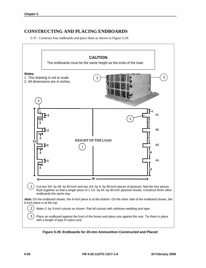
Chapter 5
5-50 FM 4-20.112/TO 13C7-1-8 20 February 2009
CONSTRUCTING AND PLACING ENDBOARDS 5-37. Construct four endboards and place them as shown in Figure 5-29.
CAUTION The endboards must be the same height as the ends of the load.
Notes. 1. This drawing is not to scale 2. All dimensions are in inches.
1 Cut two 3/4- by 48- by 90-inch and two 3/4- by 6- by 90-inch pieces of plywood. Nail the four pieces flush together so that a single piece of 1 1/2- by 54- by 90-inch plywood results. Construct three other endboards the same way.
Note. On the endboard shown, the 6-inch piece is at the bottom. On the other side of the endboard shown, the 6-inch piece is at the top.
2 Make 2- by 3-inch cutouts as shown. Pad all cutouts with cellulose wadding and tape.
3 Place an endboard against the front of the boxes and place one against the rear. Tie them in place with a length of type III nylon cord.
Figure 5-29. Endboards for 20-mm Ammunition Constructed and Placed
3 3
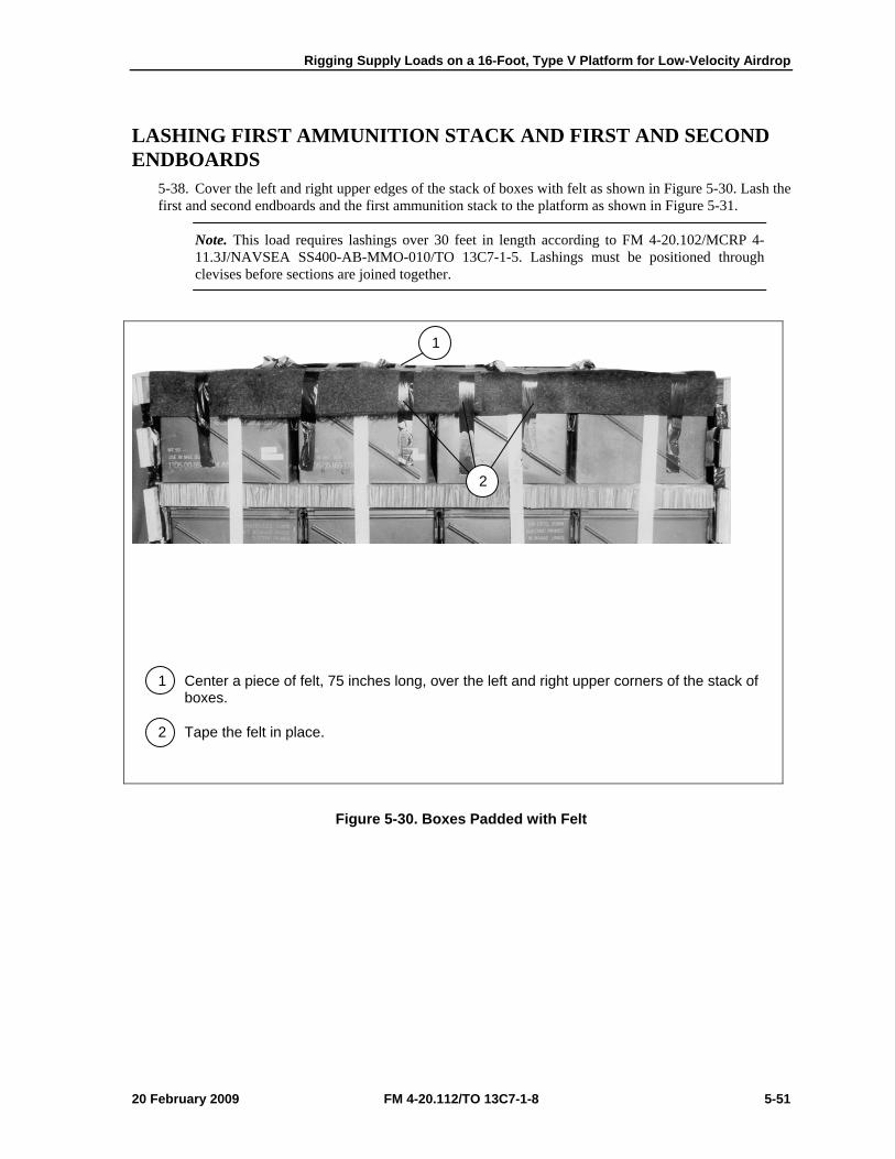
Rigging Supply Loads on a 16-Foot, Type V Platform for Low-Velocity Airdrop
20 February 2009 FM 4-20.112/TO 13C7-1-8 5-51
LASHING FIRST AMMUNITION STACK AND FIRST AND SECOND ENDBOARDS
5-38. Cover the left and right upper edges of the stack of boxes with felt as shown in Figure 5-30. Lash the first and second endboards and the first ammunition stack to the platform as shown in Figure 5-31.
Note. This load requires lashings over 30 feet in length according to FM 4-20.102/MCRP 4-11.3J/NAVSEA SS400-AB-MMO-010/TO 13C7-1-5. Lashings must be positioned through clevises before sections are joined together.
1 Center a piece of felt, 75 inches long, over the left and right upper corners of the stack of boxes.
2 Tape the felt in place.
Figure 5-30. Boxes Padded with Felt
2
1
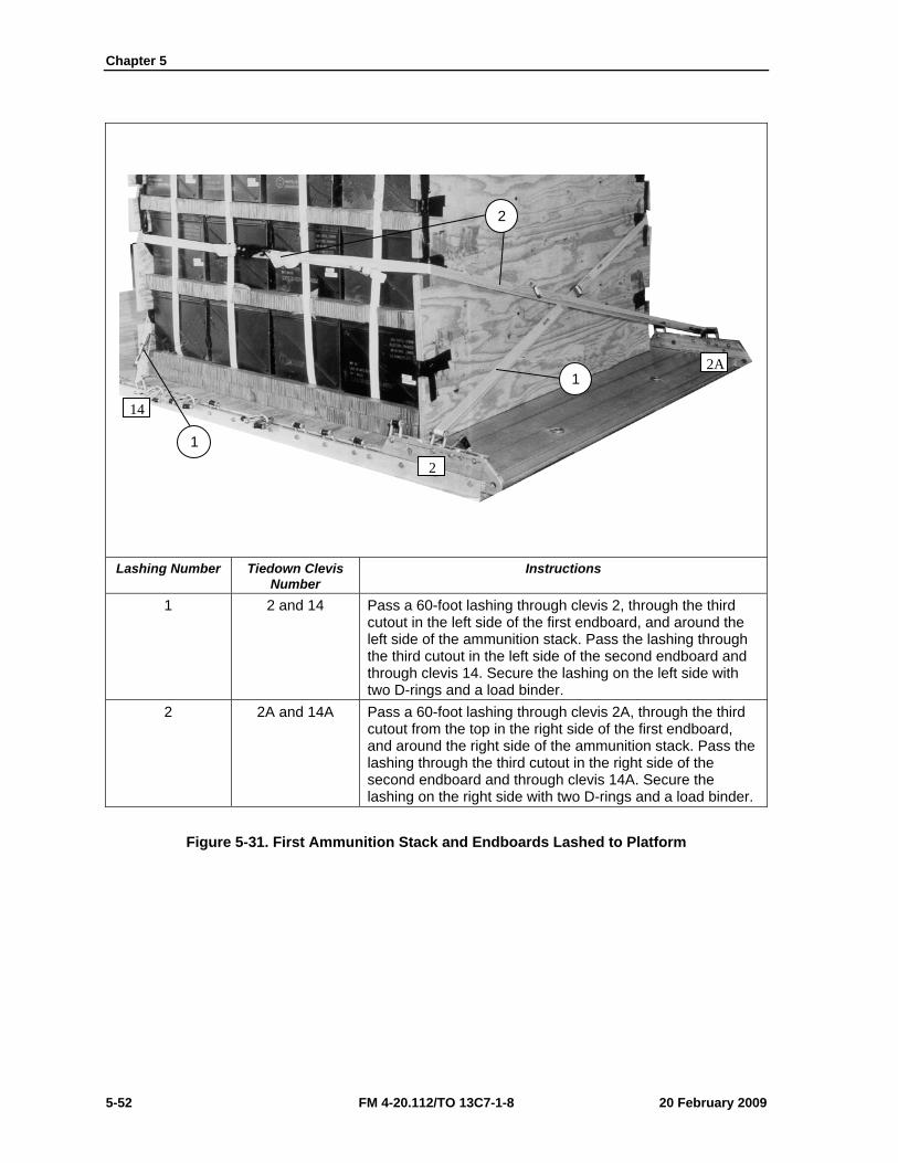
Chapter 5
5-52 FM 4-20.112/TO 13C7-1-8 20 February 2009
Lashing Number Tiedown Clevis
Number Instructions
1 2 and 14 Pass a 60-foot lashing through clevis 2, through the third cutout in the left side of the first endboard, and around the left side of the ammunition stack. Pass the lashing through the third cutout in the left side of the second endboard and through clevis 14. Secure the lashing on the left side with two D-rings and a load binder.
2 2A and 14A Pass a 60-foot lashing through clevis 2A, through the third cutout from the top in the right side of the first endboard, and around the right side of the ammunition stack. Pass the lashing through the third cutout in the right side of the second endboard and through clevis 14A. Secure the lashing on the right side with two D-rings and a load binder.
Figure 5-31. First Ammunition Stack and Endboards Lashed to Platform
1
2
14
1
2
2A
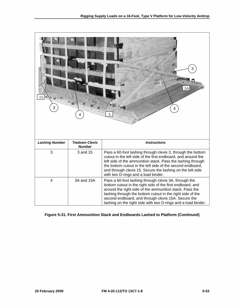
Rigging Supply Loads on a 16-Foot, Type V Platform for Low-Velocity Airdrop
20 February 2009 FM 4-20.112/TO 13C7-1-8 5-53
Lashing Number Tiedown Clevis
Number Instructions
3 3 and 15 Pass a 60-foot lashing through clevis 3, through the bottom cutout in the left side of the first endboard, and around the left side of the ammunition stack. Pass the lashing through the bottom cutout in the left side of the second endboard, and through clevis 15. Secure the lashing on the left side with two D-rings and a load binder.
4 3A and 15A Pass a 60-foot lashing through clevis 3A, through the bottom cutout in the right side of the first endboard, and around the right side of the ammunition stack. Pass the lashing through the bottom cutout in the right side of the second endboard, and through clevis 15A. Secure the lashing on the right side with two D-rings and a load binder.
Figure 5-31. First Ammunition Stack and Endboards Lashed to Platform (Continued)
3
4 4
3
15
3A
3
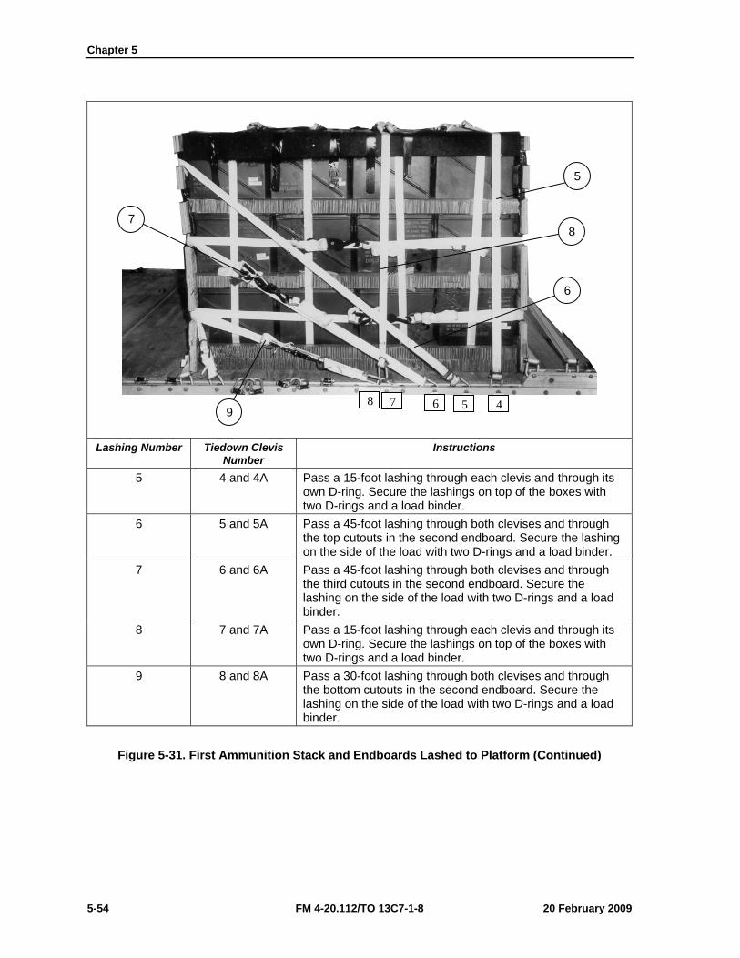
Chapter 5
5-54 FM 4-20.112/TO 13C7-1-8 20 February 2009
Lashing Number Tiedown Clevis
Number Instructions
5 4 and 4A Pass a 15-foot lashing through each clevis and through its own D-ring. Secure the lashings on top of the boxes with two D-rings and a load binder.
6 5 and 5A Pass a 45-foot lashing through both clevises and through the top cutouts in the second endboard. Secure the lashing on the side of the load with two D-rings and a load binder.
7 6 and 6A Pass a 45-foot lashing through both clevises and through the third cutouts in the second endboard. Secure the lashing on the side of the load with two D-rings and a load binder.
8 7 and 7A Pass a 15-foot lashing through each clevis and through its own D-ring. Secure the lashings on top of the boxes with two D-rings and a load binder.
9 8 and 8A Pass a 30-foot lashing through both clevises and through the bottom cutouts in the second endboard. Secure the lashing on the side of the load with two D-rings and a load binder.
Figure 5-31. First Ammunition Stack and Endboards Lashed to Platform (Continued)
5
8
6
7
9 45678
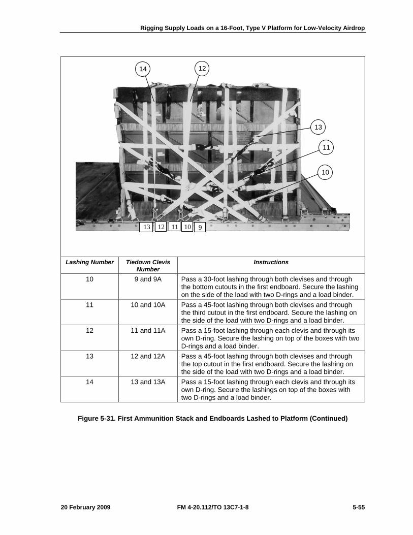
Rigging Supply Loads on a 16-Foot, Type V Platform for Low-Velocity Airdrop
20 February 2009 FM 4-20.112/TO 13C7-1-8 5-55
Lashing Number Tiedown Clevis
Number Instructions
10 9 and 9A Pass a 30-foot lashing through both clevises and through the bottom cutouts in the first endboard. Secure the lashing on the side of the load with two D-rings and a load binder.
11 10 and 10A Pass a 45-foot lashing through both clevises and through the third cutout in the first endboard. Secure the lashing on the side of the load with two D-rings and a load binder.
12 11 and 11A Pass a 15-foot lashing through each clevis and through its own D-ring. Secure the lashing on top of the boxes with two D-rings and a load binder.
13 12 and 12A Pass a 45-foot lashing through both clevises and through the top cutout in the first endboard. Secure the lashing on the side of the load with two D-rings and a load binder.
14 13 and 13A Pass a 15-foot lashing through each clevis and through its own D-ring. Secure the lashings on top of the boxes with two D-rings and a load binder.
Figure 5-31. First Ammunition Stack and Endboards Lashed to Platform (Continued)
9101112 13
10
11
13
14 12
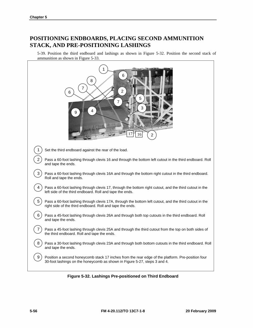
Chapter 5
5-56 FM 4-20.112/TO 13C7-1-8 20 February 2009
POSITIONING ENDBOARDS, PLACING SECOND AMMUNITION STACK, AND PRE-POSITIONING LASHINGS
5-39. Position the third endboard and lashings as shown in Figure 5-32. Position the second stack of ammunition as shown in Figure 5-33.
1 Set the third endboard against the rear of the load.
2 Pass a 60-foot lashing through clevis 16 and through the bottom left cutout in the third endboard. Roll and tape the ends.
3 Pass a 60-foot lashing through clevis 16A and through the bottom right cutout in the third endboard. Roll and tape the ends.
4 Pass a 60-foot lashing through clevis 17, through the bottom right cutout, and the third cutout in the left side of the third endboard. Roll and tape the ends.
5 Pass a 60-foot lashing through clevis 17A, through the bottom left cutout, and the third cutout in the right side of the third endboard. Roll and tape the ends.
6 Pass a 45-foot lashing through clevis 26A and through both top cutouts in the third endboard. Roll and tape the ends.
7 Pass a 45-foot lashing through clevis 25A and through the third cutout from the top on both sides of the third endboard. Roll and tape the ends.
8 Pass a 30-foot lashing through clevis 23A and through both bottom cutouts in the third endboard. Roll and tape the ends.
9 Position a second honeycomb stack 17 inches from the rear edge of the platform. Pre-position four 30-foot lashings on the honeycomb as shown in Figure 5-27, steps 3 and 4.
Figure 5-32. Lashings Pre-positioned on Third Endboard
1 6
8
2 7
6
7
4
5
3
2
9
17 16
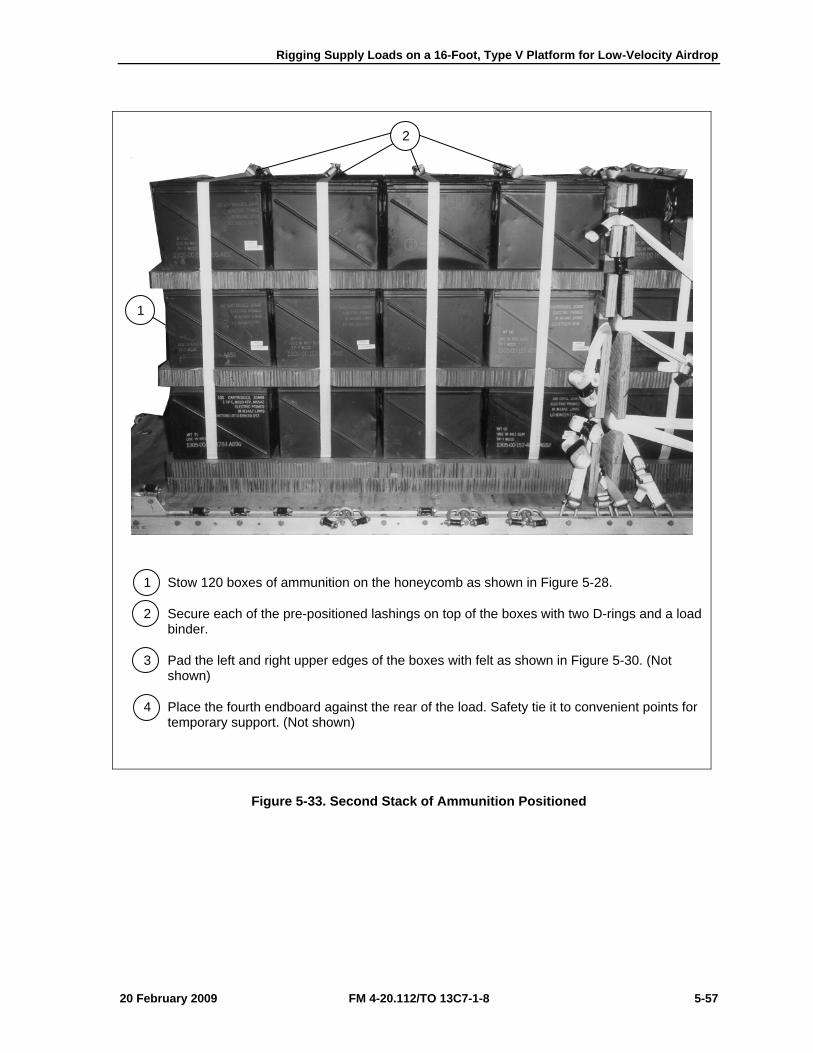
Rigging Supply Loads on a 16-Foot, Type V Platform for Low-Velocity Airdrop
20 February 2009 FM 4-20.112/TO 13C7-1-8 5-57
1 Stow 120 boxes of ammunition on the honeycomb as shown in Figure 5-28.
2 Secure each of the pre-positioned lashings on top of the boxes with two D-rings and a load binder.
3 Pad the left and right upper edges of the boxes with felt as shown in Figure 5-30. (Not shown)
4 Place the fourth endboard against the rear of the load. Safety tie it to convenient points for temporary support. (Not shown)
Figure 5-33. Second Stack of Ammunition Positioned
2
1
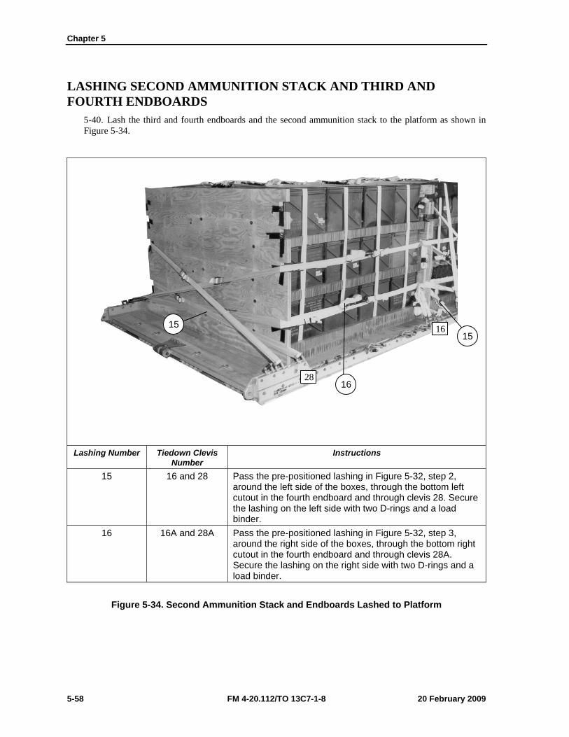
Chapter 5
5-58 FM 4-20.112/TO 13C7-1-8 20 February 2009
LASHING SECOND AMMUNITION STACK AND THIRD AND FOURTH ENDBOARDS
5-40. Lash the third and fourth endboards and the second ammunition stack to the platform as shown in Figure 5-34.
Lashing Number Tiedown Clevis
Number Instructions
15 16 and 28 Pass the pre-positioned lashing in Figure 5-32, step 2, around the left side of the boxes, through the bottom left cutout in the fourth endboard and through clevis 28. Secure the lashing on the left side with two D-rings and a load binder.
16 16A and 28A Pass the pre-positioned lashing in Figure 5-32, step 3, around the right side of the boxes, through the bottom right cutout in the fourth endboard and through clevis 28A. Secure the lashing on the right side with two D-rings and a load binder.
Figure 5-34. Second Ammunition Stack and Endboards Lashed to Platform
28
16 15
16
15
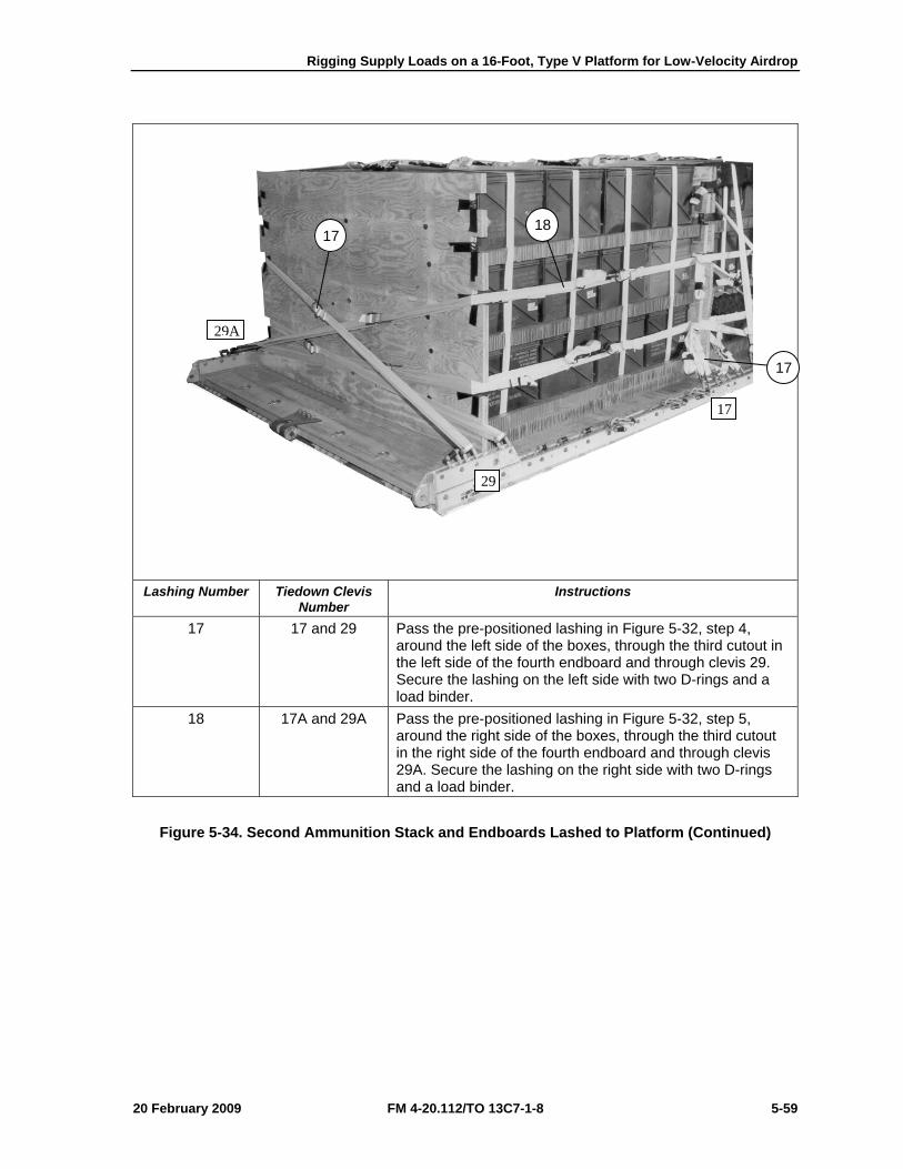
Rigging Supply Loads on a 16-Foot, Type V Platform for Low-Velocity Airdrop
20 February 2009 FM 4-20.112/TO 13C7-1-8 5-59
Lashing Number Tiedown Clevis
Number Instructions
17 17 and 29 Pass the pre-positioned lashing in Figure 5-32, step 4, around the left side of the boxes, through the third cutout in the left side of the fourth endboard and through clevis 29. Secure the lashing on the left side with two D-rings and a load binder.
18 17A and 29A Pass the pre-positioned lashing in Figure 5-32, step 5, around the right side of the boxes, through the third cutout in the right side of the fourth endboard and through clevis 29A. Secure the lashing on the right side with two D-rings and a load binder.
Figure 5-34. Second Ammunition Stack and Endboards Lashed to Platform (Continued)
17
17 18
29A
29
17
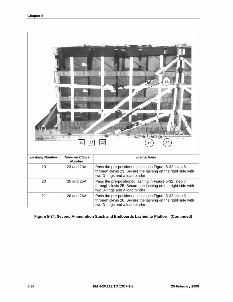
Chapter 5
5-60 FM 4-20.112/TO 13C7-1-8 20 February 2009
Lashing Number Tiedown Clevis
Number Instructions
19 23 and 23A Pass the pre-positioned lashing in Figure 5-32, step 8 through clevis 23. Secure the lashing on the right side with two D-rings and a load binder.
20 25 and 25A Pass the pre-positioned lashing in Figure 5-32, step 7 through clevis 25. Secure the lashing on the right side with two D-rings and a load binder.
21 26 and 26A Pass the pre-positioned lashing in Figure 5-32, step 6 through clevis 26. Secure the lashing on the right side with two D-rings and a load binder.
Figure 5-34. Second Ammunition Stack and Endboards Lashed to Platform (Continued)
21
20 19 26 25 23
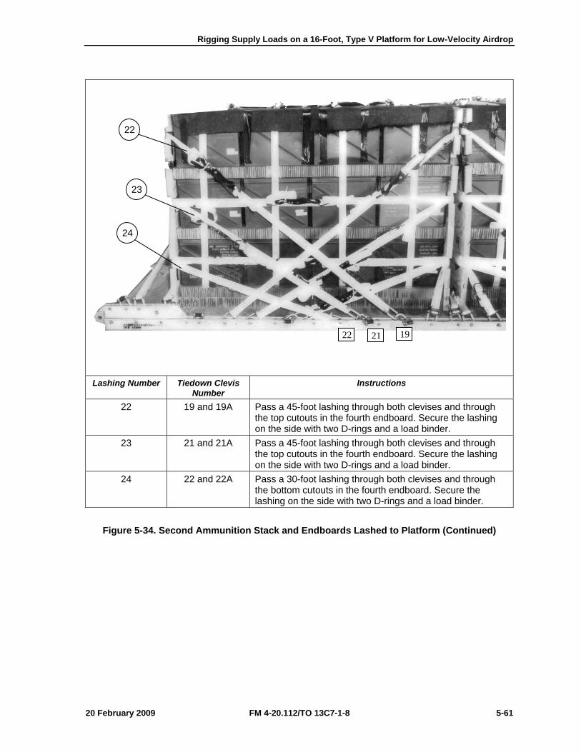
Rigging Supply Loads on a 16-Foot, Type V Platform for Low-Velocity Airdrop
20 February 2009 FM 4-20.112/TO 13C7-1-8 5-61
Lashing Number Tiedown Clevis
Number Instructions
22 19 and 19A Pass a 45-foot lashing through both clevises and through the top cutouts in the fourth endboard. Secure the lashing on the side with two D-rings and a load binder.
23 21 and 21A Pass a 45-foot lashing through both clevises and through the top cutouts in the fourth endboard. Secure the lashing on the side with two D-rings and a load binder.
24 22 and 22A Pass a 30-foot lashing through both clevises and through the bottom cutouts in the fourth endboard. Secure the lashing on the side with two D-rings and a load binder.
Figure 5-34. Second Ammunition Stack and Endboards Lashed to Platform (Continued)
22
23
24
22 21 19
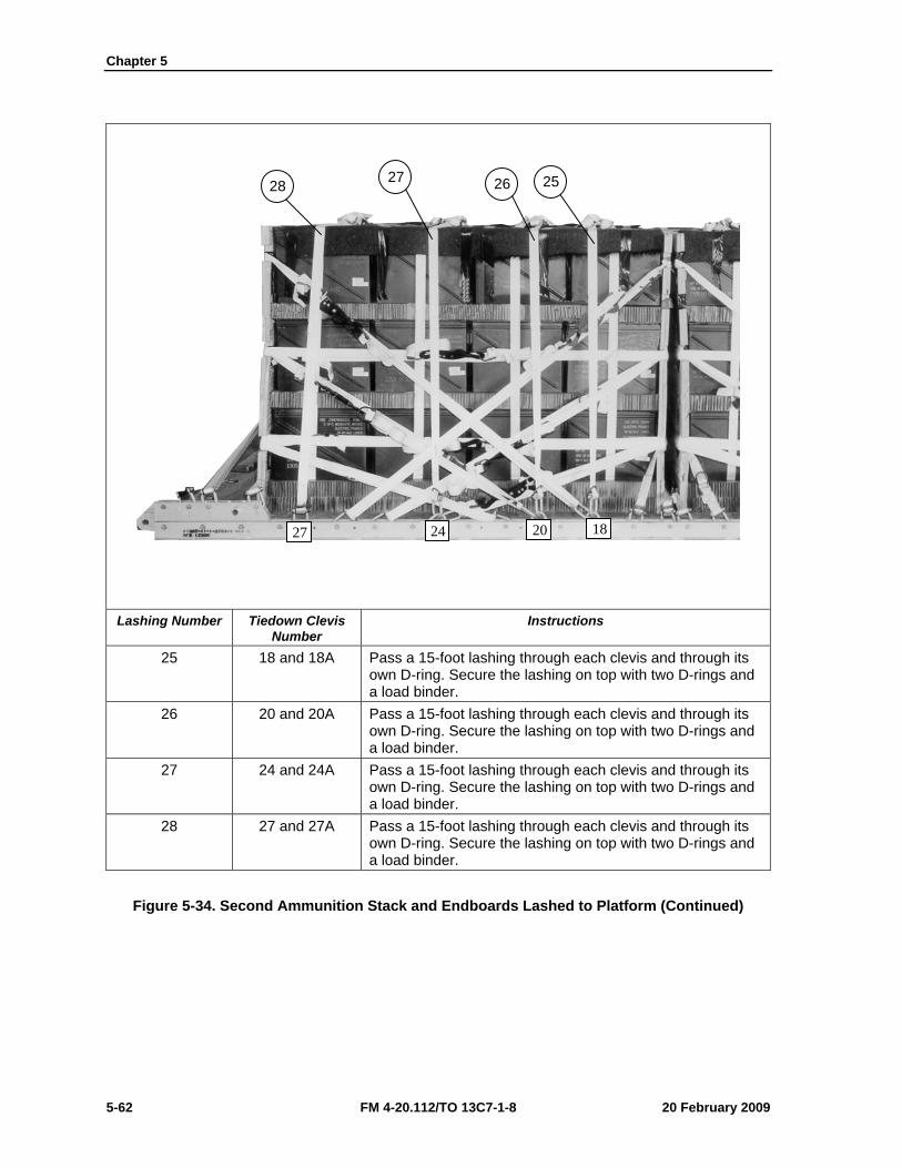
Chapter 5
5-62 FM 4-20.112/TO 13C7-1-8 20 February 2009
Lashing Number Tiedown Clevis
Number Instructions
25 18 and 18A Pass a 15-foot lashing through each clevis and through its own D-ring. Secure the lashing on top with two D-rings and a load binder.
26 20 and 20A Pass a 15-foot lashing through each clevis and through its own D-ring. Secure the lashing on top with two D-rings and a load binder.
27 24 and 24A Pass a 15-foot lashing through each clevis and through its own D-ring. Secure the lashing on top with two D-rings and a load binder.
28 27 and 27A Pass a 15-foot lashing through each clevis and through its own D-ring. Secure the lashing on top with two D-rings and a load binder.
Figure 5-34. Second Ammunition Stack and Endboards Lashed to Platform (Continued)
28 27 26
2024 18
25
27
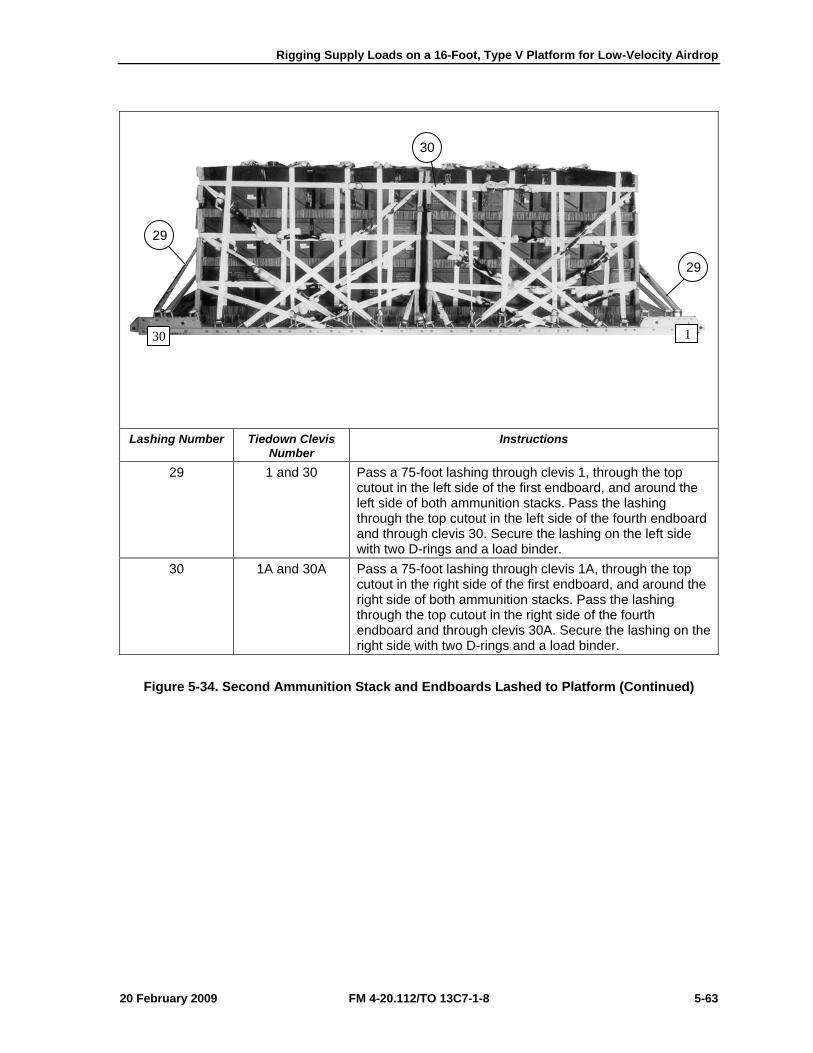
Rigging Supply Loads on a 16-Foot, Type V Platform for Low-Velocity Airdrop
20 February 2009 FM 4-20.112/TO 13C7-1-8 5-63
Lashing Number Tiedown Clevis
Number Instructions
29 1 and 30 Pass a 75-foot lashing through clevis 1, through the top cutout in the left side of the first endboard, and around the left side of both ammunition stacks. Pass the lashing through the top cutout in the left side of the fourth endboard and through clevis 30. Secure the lashing on the left side with two D-rings and a load binder.
30 1A and 30A Pass a 75-foot lashing through clevis 1A, through the top cutout in the right side of the first endboard, and around the right side of both ammunition stacks. Pass the lashing through the top cutout in the right side of the fourth endboard and through clevis 30A. Secure the lashing on the right side with two D-rings and a load binder.
Figure 5-34. Second Ammunition Stack and Endboards Lashed to Platform (Continued)
29
30
1
29
30
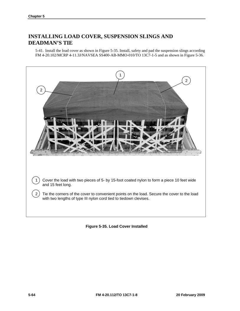
Chapter 5
5-64 FM 4-20.112/TO 13C7-1-8 20 February 2009
INSTALLING LOAD COVER, SUSPENSION SLINGS AND DEADMAN’S TIE
5-41. Install the load cover as shown in Figure 5-35. Install, safety and pad the suspension slings according FM 4-20.102/MCRP 4-11.3J/NAVSEA SS400-AB-MMO-010/TO 13C7-1-5 and as shown in Figure 5-36.
1 Cover the load with two pieces of 5- by 15-foot coated nylon to form a piece 10 feet wide and 15 feet long.
2 Tie the corners of the cover to convenient points on the load. Secure the cover to the load with two lengths of type III nylon cord tied to tiedown clevises.
Figure 5-35. Load Cover Installed
1 2
2
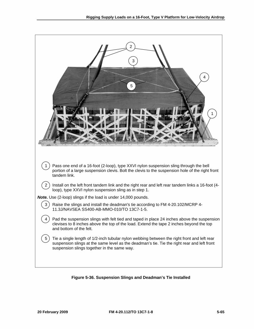
Rigging Supply Loads on a 16-Foot, Type V Platform for Low-Velocity Airdrop
20 February 2009 FM 4-20.112/TO 13C7-1-8 5-65
1 Pass one end of a 16-foot (2-loop), type XXVI nylon suspension sling through the bell portion of a large suspension clevis. Bolt the clevis to the suspension hole of the right front tandem link.
2 Install on the left front tandem link and the right rear and left rear tandem links a 16-foot (4-loop), type XXVI nylon suspension sling as in step 1.
Note. Use (2-loop) slings if the load is under 14,000 pounds.
3 Raise the slings and install the deadman's tie according to FM 4-20.102/MCRP 4-11.3J/NAVSEA SS400-AB-MMO-010/TO 13C7-1-5.
4 Pad the suspension slings with felt tied and taped in place 24 inches above the suspension clevises to 8 inches above the top of the load. Extend the tape 2 inches beyond the top and bottom of the felt.
5 Tie a single length of 1/2-inch tubular nylon webbing between the right front and left rear suspension slings at the same level as the deadman’s tie. Tie the right rear and left front suspension slings together in the same way.
Figure 5-36. Suspension Slings and Deadman’s Tie Installed
3
4
2
5
1
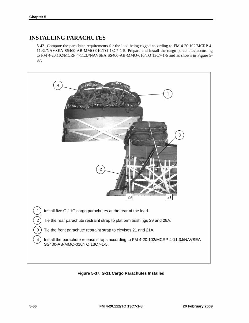
Chapter 5
5-66 FM 4-20.112/TO 13C7-1-8 20 February 2009
INSTALLING PARACHUTES 5-42. Compute the parachute requirements for the load being rigged according to FM 4-20.102/MCRP 4-11.3J/NAVSEA SS400-AB-MMO-010/TO 13C7-1-5. Prepare and install the cargo parachutes according to FM 4-20.102/MCRP 4-11.3J/NAVSEA SS400-AB-MMO-010/TO 13C7-1-5 and as shown in Figure 5-37.
1 Install five G-11C cargo parachutes at the rear of the load.
2 Tie the rear parachute restraint strap to platform bushings 29 and 29A.
3 Tie the front parachute restraint strap to clevises 21 and 21A.
4 Install the parachute release straps according to FM 4-20.102/MCRP 4-11.3J/NAVSEA SS400-AB-MMO-010/TO 13C7-1-5.
Figure 5-37. G-11 Cargo Parachutes Installed
4
1
3
2
2129
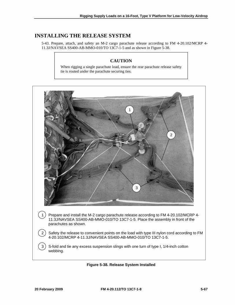
Rigging Supply Loads on a 16-Foot, Type V Platform for Low-Velocity Airdrop
20 February 2009 FM 4-20.112/TO 13C7-1-8 5-67
INSTALLING THE RELEASE SYSTEM 5-43. Prepare, attach, and safety an M-2 cargo parachute release according to FM 4-20.102/MCRP 4-11.3J/NAVSEA SS400-AB-MMO-010/TO 13C7-1-5 and as shown in Figure 5-38.
CAUTION When rigging a single parachute load, ensure the rear parachute release safety tie is routed under the parachute securing ties.
1 Prepare and install the M-2 cargo parachute release according to FM 4-20.102/MCRP 4-11.3J/NAVSEA SS400-AB-MMO-010/TO 13C7-1-5. Place the assembly in front of the parachutes as shown.
2 Safety the release to convenient points on the load with type III nylon cord according to FM 4-20.102/MCRP 4-11.3J/NAVSEA SS400-AB-MMO-010/TO 13C7-1-5.
3 S-fold and tie any excess suspension slings with one turn of type I, 1/4-inch cotton webbing.
Figure 5-38. Release System Installed
1
2
3
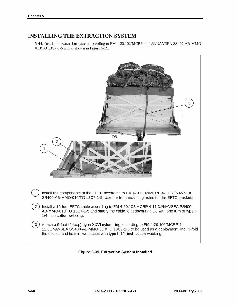
Chapter 5
5-68 FM 4-20.112/TO 13C7-1-8 20 February 2009
INSTALLING THE EXTRACTION SYSTEM 5-44. Install the extraction system according to FM 4-20.102/MCRP 4-11.3J/NAVSEA SS400-AB-MMO-010/TO 13C7-1-5 and as shown in Figure 5-39.
1 Install the components of the EFTC according to FM 4-20.102/MCRP 4-11.3J/NAVSEA SS400-AB-MMO-010/TO 13C7-1-5. Use the front mounting holes for the EFTC brackets.
2 Install a 16-foot EFTC cable according to FM 4-20.102/MCRP 4-11.3J/NAVSEA SS400-AB-MMO-010/TO 13C7-1-5 and safety the cable to tiedown ring D8 with one turn of type I, 1/4-inch cotton webbing.
3 Attach a 9-foot (2-loop), type XXVI nylon sling according to FM 4-20.102/MCRP 4-11.3J/NAVSEA SS400-AB-MMO-010/TO 13C7-1-5 to be used as a deployment line. S-fold the excess and tie it in two places with type I, 1/4-inch cotton webbing.
Figure 5-39. Extraction System Installed
3
2
1
D8
Rigging Supply Loads on a 16-Foot, Type V Platform for Low-Velocity Airdrop
20 February 2009 FM 4-20.112/TO 13C7-1-8 5-69
PLACING EXTRACTION PARACHUTE 5-45. Select the extraction parachute and extraction line needed using the extraction line requirements table in FM 4-20.102/MCRP 4-11.3J/NAVSEA SS400-AB-MMO-010/TO 13C7-1-5. Place the extraction parachute and line on the load for installation in the aircraft.
INSTALLING PROVISIONS FOR EMERGENCY RESTRAINTS 5-46. Select and install the provisions for the emergency aft restraints according to the emergency aft restraint requirements table in FM 4-20.102/MCRP 4-11.3J/NAVSEA SS400-AB-MMO-010/TO 13C7-1-5.
MARKING RIGGED LOAD 5-47. Mark the rigged load according to FM 4-20.102/MCRP 4-11.3J/NAVSEA SS400-AB-MMO-010/TO 13C7-1-5, and as shown in Figure 5-40. Complete Shipper’s Declaration for Dangerous Goods. If the load varies from the one shown, the weight, height, CB, and parachute requirements must be recomputed.
EQUIPMENT REQUIRED 5-48. Use the equipment listed in Table 5-3 to rig this load.
Chapter 5
5-70 FM 4-20.112/TO 13C7-1-8 20 February 2009
CAUTION Make the final rigger inspection required by AR 59-4 and FM 4-20.102/MCRP 4-11.3J/NAVSEA SS400-AB-MMO-010/TO 13C7-1-5 before the load leaves the rigging site.
RIGGED LOAD DATA
Weight: Load shown ........................................................................................... 26,060 pounds
Minimum Weight: ............................................................................................................ 5,040 pounds
Maximum Suspended Weight ........................................................................................ 25,000 pounds
Height ........................................................................................................................................ 92 inches
Width ......................................................................................................................................... 108 inches
Overall Length .......................................................................................................................... 192 inches
Overhang: Front .......................................................................................................................... 0 inches
Rear .......................................................................................................................... 0 inches
Center of Balance (from front edge of the platform) .................................................................... 91 inches
Extraction System with 16-foot cable (adds 18 inches to length of platform) ................................... EFTC
Note. Refer to FM 4-20.102/MCRP 4-11.3J/NAVSEA SS400-AB-MMO-010/TO 13C7-1-5 (Table 2-2) when adding additional parachutes for heavier loads for the suspension/tandem link positioning.
Figure 5-40. 20-mm Ammunition Rigged on a 16-Foot, Type V Platform for Low-Velocity Airdrop
CB
Rigging Supply Loads on a 16-Foot, Type V Platform for Low-Velocity Airdrop
20 February 2009 FM 4-20.112/TO 13C7-1-8 5-71
Table 5-3. Equipment Required for Rigging 20-mm Ammunition on a 16-Foot, Type V Platform for Low-Velocity Airdrop
National Stock Number Item Quantity 8040-00-273-8713
4030-00-090-5354 8305-00-880-8155 4020-00-240-2146 1670-00-434-5785
1670-00-360-0328 8135-00-664-6958 8305-00-191-1101 1670-01-183-2678
1670-01-062-6313 1670-01-107-7651 1670-01-062-6313 1670-01-493-6418 5351-00-010-4659 1670-00-753-3928
1670-01-016-7841 1670-00-040-8135 1670-01-063-3715
1670-01-353-8425 1670-01-162-2372 1670-01-162-2376 1670-01-162-2381 5530-00-128-4981 1670-01-097-8817
Adhesive, paste, 1-gallon Clevis, suspension: 1-inch (large) Cloth, coated (nylon, type II, green, 60-in) Cord, nylon, type III Coupling, airdrop, extraction force transfer with 16-foot cable Cover, clevis, large Cushioning material, packaging, cellulose wadding Felt, ½-inch thick Leaf, extraction line (line bag) (add 2 for C-17) Line, extraction, type XXVI nylon webbing: 60-foot (3-loop), type XXVI 140-foot (3-loop), type XXVI 60-foot (3-loop), type XXVI for C-17 drogue line Link assembly, two-point: Nail, steel wire, common 8d Pad, energy-dissipating, honeycomb Parachute: Cargo, G-11 Cargo, extraction, 28-foot Cargo, extraction, 15-foot for C-17 Platform, airdrop, type V, 16-foot Bracket assembly, EFTC Bracket assembly, extraction Clevis assembly Tandem link Plywood, 3/4-inch Release, cargo parachute, M-2
As required 7
As required As required
1 5
As required As required
2 1 2 1 1
As required 20 sheets
5 1 1 1 1
72 4
As required 1

Chapter 5
5-72 FM 4-20.112/TO 13C7-1-8 20 February 2009
Table 5-3. Equipment Required for Rigging 20-mm Ammunition on a 16-Foot, Type V Platform for Low-Velocity Airdrop (Continued)
National Stock Number Item Quantity
1670-01-062-6304 1670-01-063-7761 1670-01-062-6311 5340-00-040-8219 7501-00-266-5016 7501-00-266-6710 1670-00-937-0271 1670-01-483-8259
8305-00-268-2411
8305-00-082-5752 8305-00-263-3591
Sling, cargo airdrop: 9-foot (2-loop), type XXVI nylon webbing 16-foot (2-loop), type XXVI nylon webbing 120-foot (2-loop), type XXVI nylon webbing Strap parachute release, multicut Tape, adhesive, 2-inch Tape, masking Tie-down assembly, 15-foot Towplate release mechanism (H-block) (C-17) Webbing: Cotton, 1/4-inch, type I Nylon: Tubular, 1/2-inch Type VIII webbing
1 4 3 2
As required As required
106 1
As required
As required As required
Rigging Supply Loads on a 16-Foot, Type V Platform for Low-Velocity Airdrop
20 February 2009 FM 4-20.112/TO 13C7-1-8 5-73
SECTION IV-RIGGING MASS SUPPLY BOX
DESCRIPTION OF LOAD 5-49. Two mass supply boxes are rigged for low-velocity airdrop on a 16-foot, type V airdrop platform. Loads may include any bulk items of general supply that can be packed into the box without shifting the load. Each load must weigh at least 5,040 pounds, including parachutes. Refer to FM 4-20.102/MCRP 4-11.3J/NAVSEA SS400-AB-MMO-010/TO 13C7-1-5 for the weight limitations for the number of parachutes to be used.
PREPARING PLATFORM 5-50. Prepare a 16-foot, type V platform as shown in Figure 5-41.
Chapter 5
5-74 FM 4-20.112/TO 13C7-1-8 20 February 2009
Step:
1. Inspect, or assemble and inspect, a 16-foot, type V platform as outlined in TM 10-1670-268-20&P/TO 13C7-52-22.
2. Install a tandem link to the front of each platform side rail using holes 1, 2, and 3.
3. Install a tandem link to the rear of each platform side rail using holes 30, 31, and 32.
4. Install clevises on bushings 1 and 2 of each front tandem link.
5. Install clevises on bushings 2 and 3 of each rear tandem link.
6. Starting at the front of each platform side rail, install clevises on the bushings bolted to holes 7, 8, 9, 10, 11, 13, 15, 16, 17, 18, 19, 21, 22, 23, 24, 25, 26, and 27. Install triple clevises on holes 5 and 28 according to FM 4-20.102/MCRP 4-11.3J/NAVSEA SS400-AB-MMO-010/TO 13C7-1-5.
7. Starting at the front of the platform, number the clevises 1 through 26 on the right side, and 1A through 26A on the left side.
8. Label the tiedown rings according to FM 4-20.102/MCRP 4-11.3J/NAVSEA SS400-AB-MMO-010/TO 13C7-1-5.
Note. Refer to FM 4-20.102/MCRP 4-11.3J/NAVSEA SS400-AB-MMO-010/TO 13C7-1-5 (Table 2-2) when adding additional parachutes for heavier loads for the suspension/tandem link positioning.
Figure 5-41. Platform Prepared
CLEVISES 26A THROUGH 1A
CLEVISES 26 THROUGH 1
RIGHT
LEFT
FRONT REAR
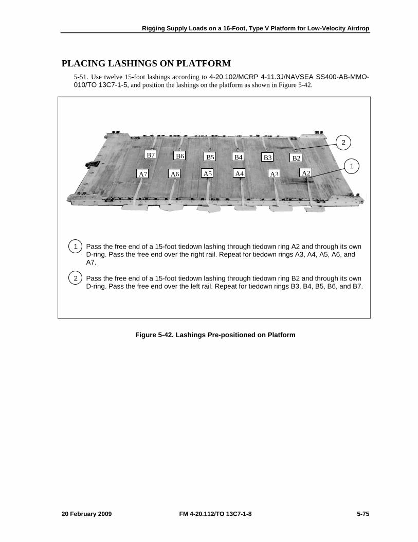
Rigging Supply Loads on a 16-Foot, Type V Platform for Low-Velocity Airdrop
20 February 2009 FM 4-20.112/TO 13C7-1-8 5-75
PLACING LASHINGS ON PLATFORM 5-51. Use twelve 15-foot lashings according to 4-20.102/MCRP 4-11.3J/NAVSEA SS400-AB-MMO-010/TO 13C7-1-5, and position the lashings on the platform as shown in Figure 5-42.
1 Pass the free end of a 15-foot tiedown lashing through tiedown ring A2 and through its own D-ring. Pass the free end over the right rail. Repeat for tiedown rings A3, A4, A5, A6, and A7.
2 Pass the free end of a 15-foot tiedown lashing through tiedown ring B2 and through its own D-ring. Pass the free end over the left rail. Repeat for tiedown rings B3, B4, B5, B6, and B7.
Figure 5-42. Lashings Pre-positioned on Platform
B7 B6 B5 B4 B3 B2
A7 A6 A5 A4 A3 A2 1
2
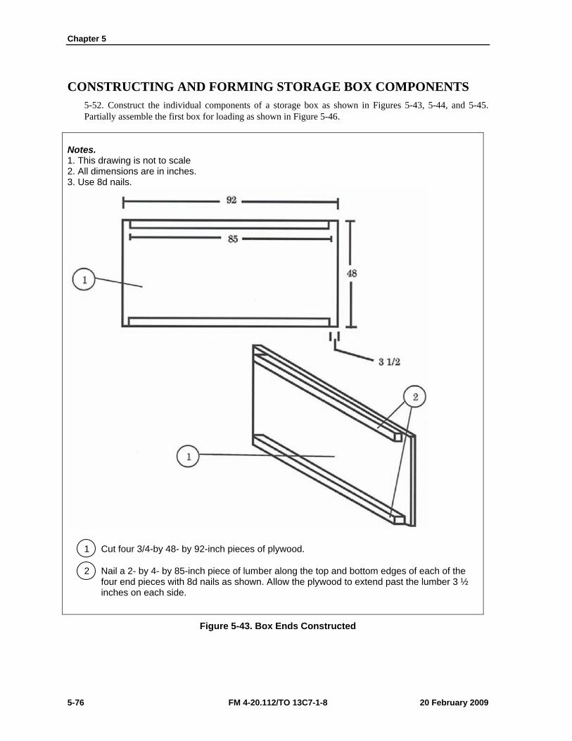
Chapter 5
5-76 FM 4-20.112/TO 13C7-1-8 20 February 2009
CONSTRUCTING AND FORMING STORAGE BOX COMPONENTS 5-52. Construct the individual components of a storage box as shown in Figures 5-43, 5-44, and 5-45. Partially assemble the first box for loading as shown in Figure 5-46.
Notes. 1. This drawing is not to scale 2. All dimensions are in inches. 3. Use 8d nails.
1 Cut four 3/4-by 48- by 92-inch pieces of plywood.
2 Nail a 2- by 4- by 85-inch piece of lumber along the top and bottom edges of each of the four end pieces with 8d nails as shown. Allow the plywood to extend past the lumber 3 ½ inches on each side.
Figure 5-43. Box Ends Constructed

Rigging Supply Loads on a 16-Foot, Type V Platform for Low-Velocity Airdrop
20 February 2009 FM 4-20.112/TO 13C7-1-8 5-77
Notes. 1. This drawing is not to scale. 2. All dimensions are in inches. 3. Use 8d nails.
1 Cut four 3/4- by 48- by 90-inch pieces of plywood. Face the finished sides of the plywood up.
2 Make 2- by 3-inch cutouts as shown in each of the four sides. Face the 12-inch cutout to the right on two pieces, and to the left on the other two.
3 Nail a 2- by 4- by 84 1/2-inch piece of lumber on edge along the top and bottom interior edges of each of the four sides with 8d nails. Allow the plywood to extend past the lumber 2 3/4 inches on each end at the top. Overhang at the bottom is 2 3/4 inches at the small-notched end and 3/4 inches at the larger notched end.
4 Cut six pieces of 2- by 4- by 45-inch lumber for each of the four sides. Nail a piece of this lumber between each of the pieces of lumber placed in step 3 flush with the ends. Space the four remaining pieces as shown and nail them in place.
Figure 5-44. Box Sides Constructed
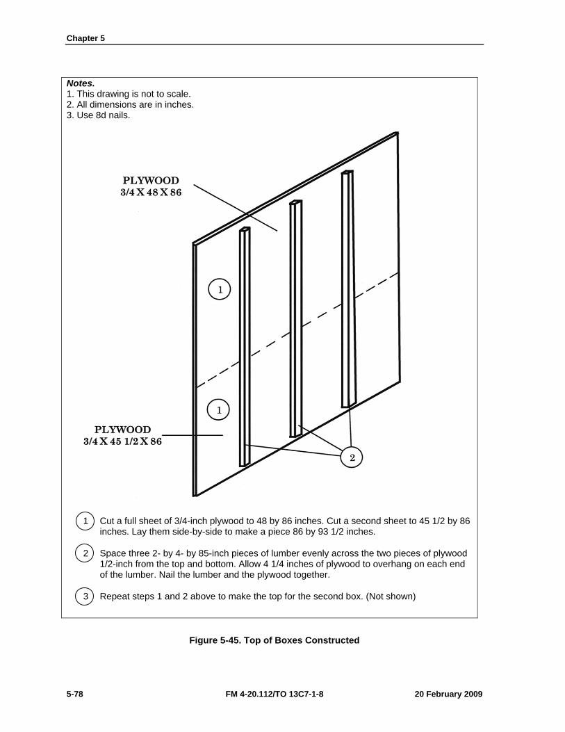
Chapter 5
5-78 FM 4-20.112/TO 13C7-1-8 20 February 2009
Notes. 1. This drawing is not to scale. 2. All dimensions are in inches. 3. Use 8d nails.
1 Cut a full sheet of 3/4-inch plywood to 48 by 86 inches. Cut a second sheet to 45 1/2 by 86 inches. Lay them side-by-side to make a piece 86 by 93 1/2 inches.
2 Space three 2- by 4- by 85-inch pieces of lumber evenly across the two pieces of plywood 1/2-inch from the top and bottom. Allow 4 1/4 inches of plywood to overhang on each end of the lumber. Nail the lumber and the plywood together.
3 Repeat steps 1 and 2 above to make the top for the second box. (Not shown)
Figure 5-45. Top of Boxes Constructed
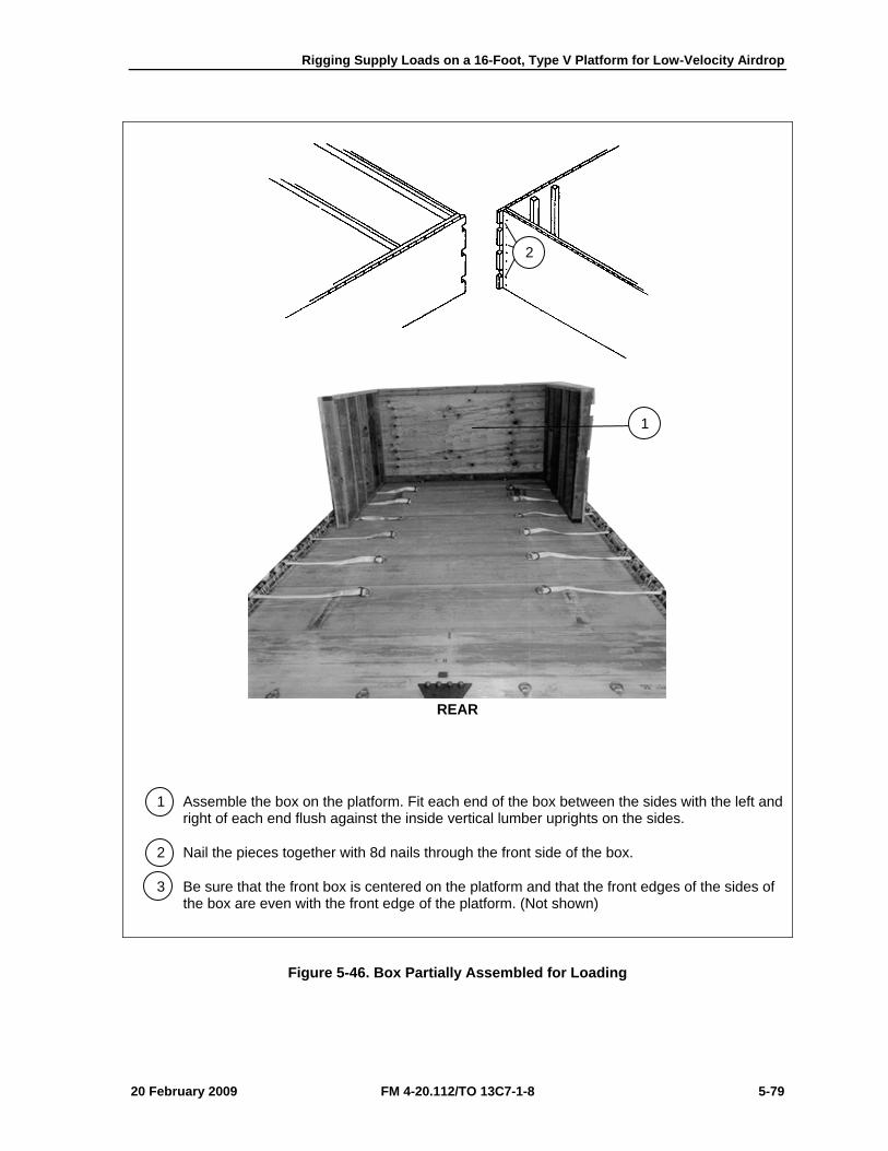
Rigging Supply Loads on a 16-Foot, Type V Platform for Low-Velocity Airdrop
20 February 2009 FM 4-20.112/TO 13C7-1-8 5-79
1 Assemble the box on the platform. Fit each end of the box between the sides with the left and right of each end flush against the inside vertical lumber uprights on the sides.
2 Nail the pieces together with 8d nails through the front side of the box.
3 Be sure that the front box is centered on the platform and that the front edges of the sides of the box are even with the front edge of the platform. (Not shown)
Figure 5-46. Box Partially Assembled for Loading
1
2
REAR
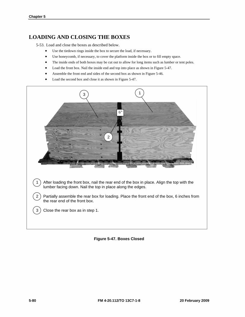
Chapter 5
5-80 FM 4-20.112/TO 13C7-1-8 20 February 2009
LOADING AND CLOSING THE BOXES 5-53. Load and close the boxes as described below.
• Use the tiedown rings inside the box to secure the load, if necessary. • Use honeycomb, if necessary, to cover the platform inside the box or to fill empty space. • The inside ends of both boxes may be cut out to allow for long items such as lumber or tent poles. • Load the front box. Nail the inside end and top into place as shown in Figure 5-47. • Assemble the front end and sides of the second box as shown in Figure 5-46. • Load the second box and close it as shown in Figure 5-47.
1 After loading the front box, nail the rear end of the box in place. Align the top with the lumber facing down. Nail the top in place along the edges.
2 Partially assemble the rear box for loading. Place the front end of the box, 6 inches from the rear end of the front box.
3 Close the rear box as in step 1.
Figure 5-47. Boxes Closed
6”
1 3
2
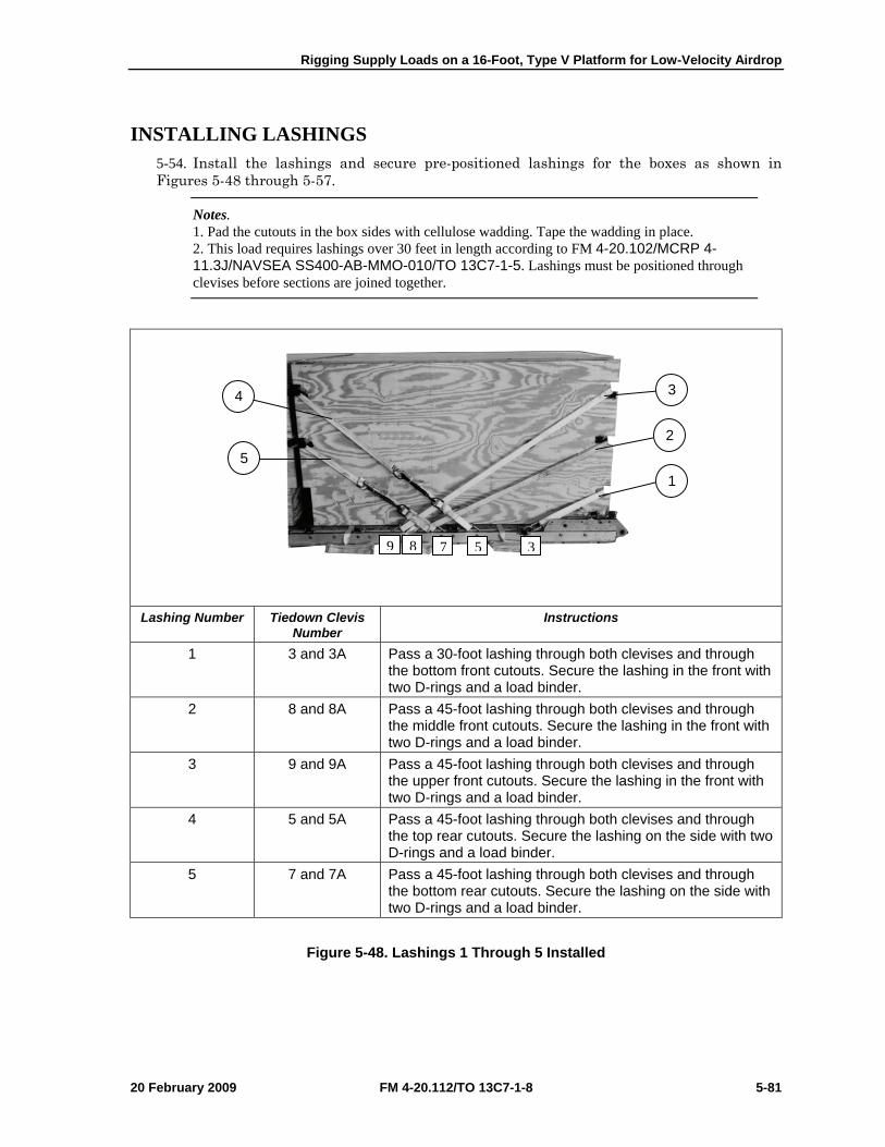
Rigging Supply Loads on a 16-Foot, Type V Platform for Low-Velocity Airdrop
20 February 2009 FM 4-20.112/TO 13C7-1-8 5-81
INSTALLING LASHINGS 5-54. Install the lashings and secure pre-positioned lashings for the boxes as shown in Figures 5-48 through 5-57.
Notes. 1. Pad the cutouts in the box sides with cellulose wadding. Tape the wadding in place. 2. This load requires lashings over 30 feet in length according to FM 4-20.102/MCRP 4-11.3J/NAVSEA SS400-AB-MMO-010/TO 13C7-1-5. Lashings must be positioned through clevises before sections are joined together.
Lashing Number Tiedown Clevis
Number Instructions
1 3 and 3A Pass a 30-foot lashing through both clevises and through the bottom front cutouts. Secure the lashing in the front with two D-rings and a load binder.
2 8 and 8A Pass a 45-foot lashing through both clevises and through the middle front cutouts. Secure the lashing in the front with two D-rings and a load binder.
3 9 and 9A Pass a 45-foot lashing through both clevises and through the upper front cutouts. Secure the lashing in the front with two D-rings and a load binder.
4 5 and 5A Pass a 45-foot lashing through both clevises and through the top rear cutouts. Secure the lashing on the side with two D-rings and a load binder.
5 7 and 7A Pass a 45-foot lashing through both clevises and through the bottom rear cutouts. Secure the lashing on the side with two D-rings and a load binder.
Figure 5-48. Lashings 1 Through 5 Installed
9 8 7 5 3
4
5
3
2
1
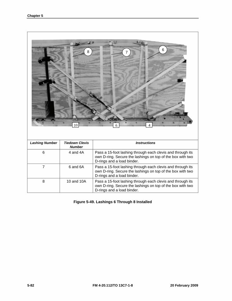
Chapter 5
5-82 FM 4-20.112/TO 13C7-1-8 20 February 2009
Lashing Number Tiedown Clevis
Number Instructions
6 4 and 4A Pass a 15-foot lashing through each clevis and through its own D-ring. Secure the lashings on top of the box with two D-rings and a load binder.
7 6 and 6A Pass a 15-foot lashing through each clevis and through its own D-ring. Secure the lashings on top of the box with two D-rings and a load binder.
8 10 and 10A Pass a 15-foot lashing through each clevis and through its own D-ring. Secure the lashings on top of the box with two D-rings and a load binder.
Figure 5-49. Lashings 6 Through 8 Installed
10 6 4
8 7 6
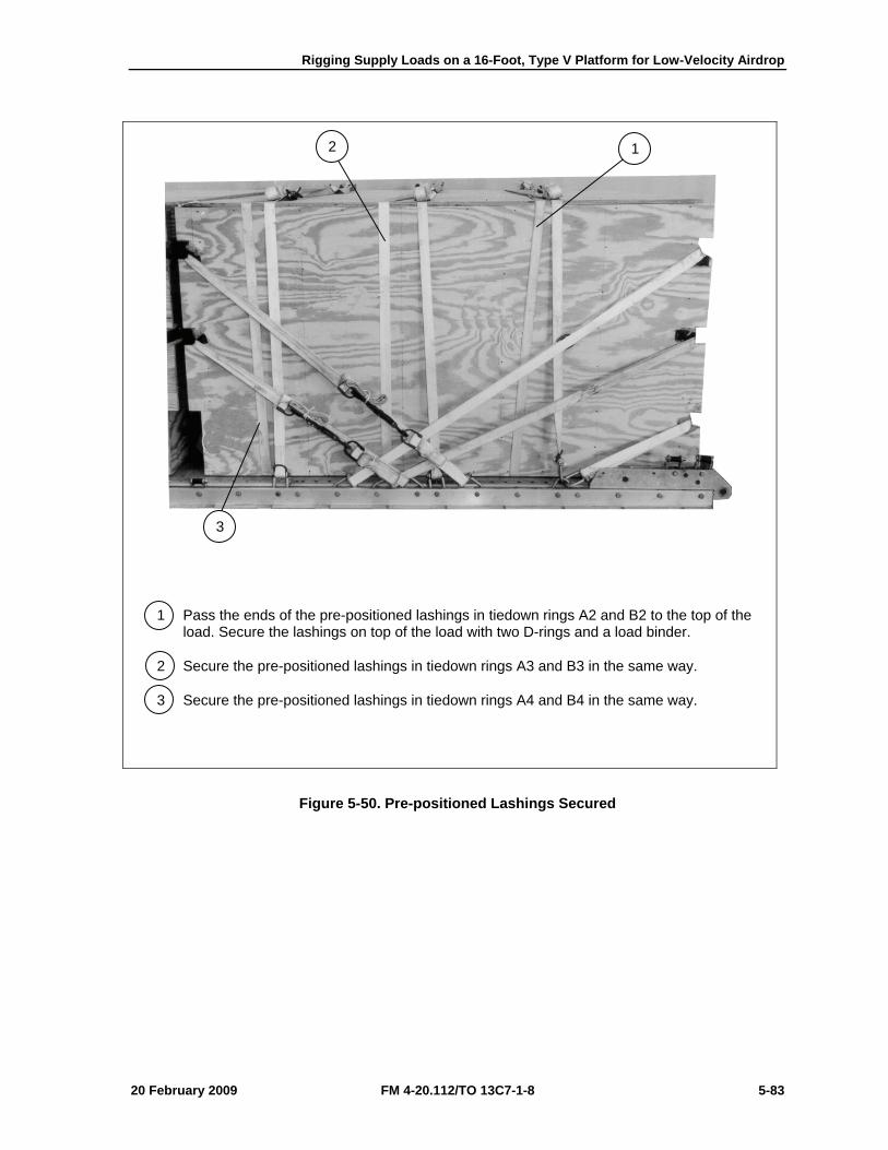
Rigging Supply Loads on a 16-Foot, Type V Platform for Low-Velocity Airdrop
20 February 2009 FM 4-20.112/TO 13C7-1-8 5-83
1 Pass the ends of the pre-positioned lashings in tiedown rings A2 and B2 to the top of the load. Secure the lashings on top of the load with two D-rings and a load binder.
2 Secure the pre-positioned lashings in tiedown rings A3 and B3 in the same way.
3 Secure the pre-positioned lashings in tiedown rings A4 and B4 in the same way.
Figure 5-50. Pre-positioned Lashings Secured
2 1
3
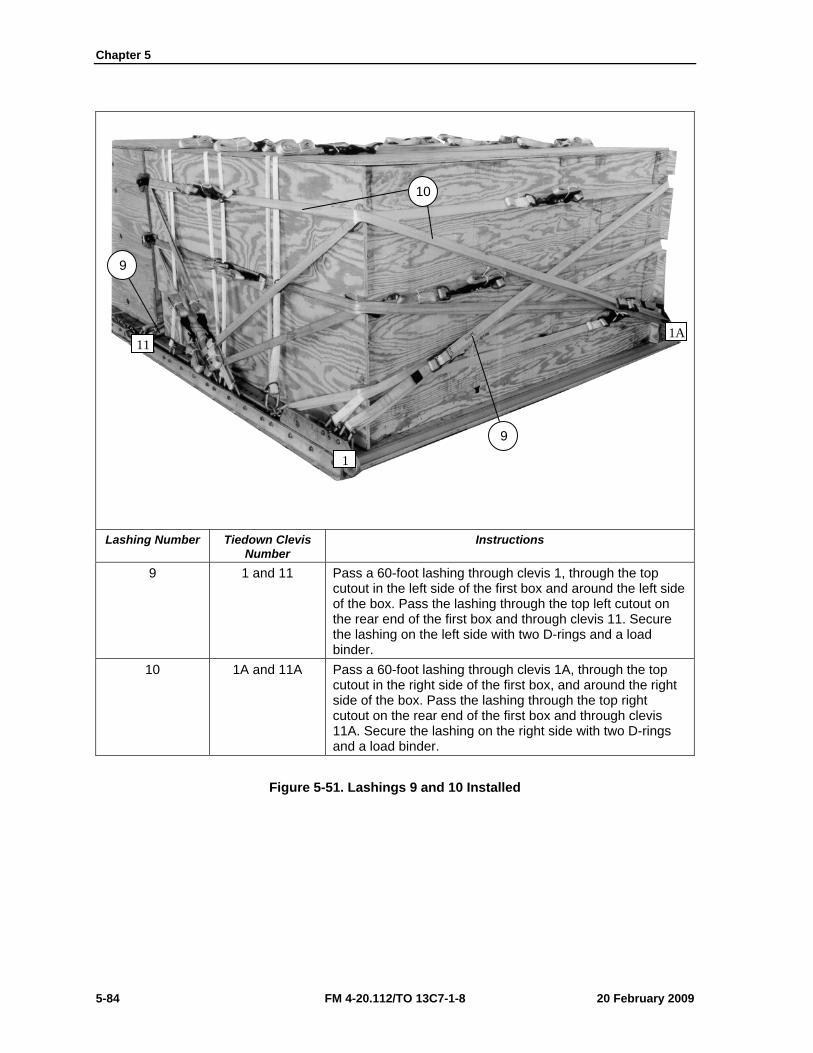
Chapter 5
5-84 FM 4-20.112/TO 13C7-1-8 20 February 2009
Lashing Number Tiedown Clevis
Number Instructions
9 1 and 11 Pass a 60-foot lashing through clevis 1, through the top cutout in the left side of the first box and around the left side of the box. Pass the lashing through the top left cutout on the rear end of the first box and through clevis 11. Secure the lashing on the left side with two D-rings and a load binder.
10 1A and 11A Pass a 60-foot lashing through clevis 1A, through the top cutout in the right side of the first box, and around the right side of the box. Pass the lashing through the top right cutout on the rear end of the first box and through clevis 11A. Secure the lashing on the right side with two D-rings and a load binder.
Figure 5-51. Lashings 9 and 10 Installed
1
11 1A
9
9
10
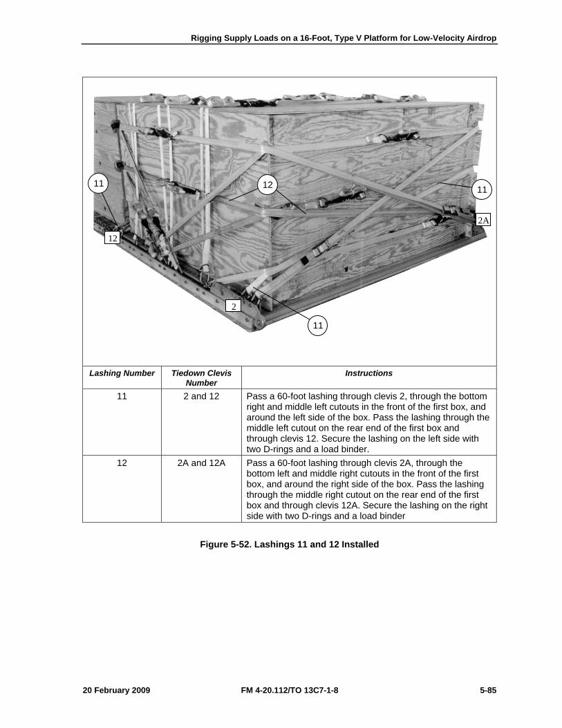
Rigging Supply Loads on a 16-Foot, Type V Platform for Low-Velocity Airdrop
20 February 2009 FM 4-20.112/TO 13C7-1-8 5-85
Lashing Number Tiedown Clevis
Number Instructions
11 2 and 12 Pass a 60-foot lashing through clevis 2, through the bottom right and middle left cutouts in the front of the first box, and around the left side of the box. Pass the lashing through the middle left cutout on the rear end of the first box and through clevis 12. Secure the lashing on the left side with two D-rings and a load binder.
12 2A and 12A Pass a 60-foot lashing through clevis 2A, through the bottom left and middle right cutouts in the front of the first box, and around the right side of the box. Pass the lashing through the middle right cutout on the rear end of the first box and through clevis 12A. Secure the lashing on the right side with two D-rings and a load binder
Figure 5-52. Lashings 11 and 12 Installed
2
12
2A
11 12
11
11
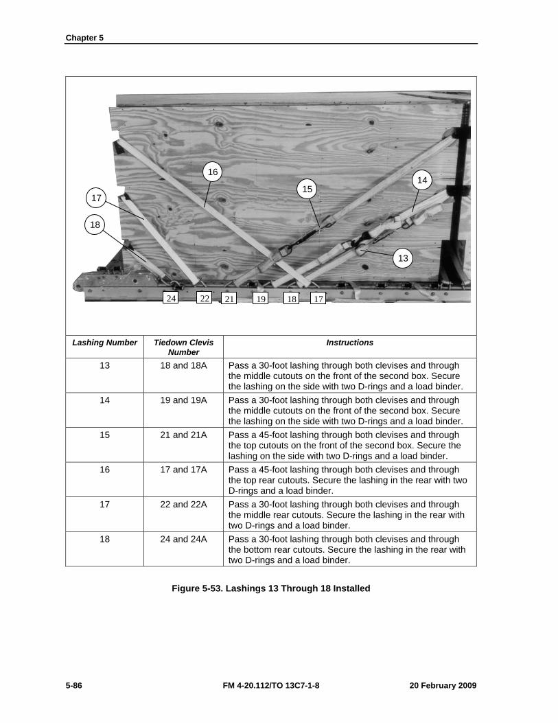
Chapter 5
5-86 FM 4-20.112/TO 13C7-1-8 20 February 2009
Lashing Number Tiedown Clevis
Number Instructions
13 18 and 18A Pass a 30-foot lashing through both clevises and through the middle cutouts on the front of the second box. Secure the lashing on the side with two D-rings and a load binder.
14 19 and 19A Pass a 30-foot lashing through both clevises and through the middle cutouts on the front of the second box. Secure the lashing on the side with two D-rings and a load binder.
15 21 and 21A Pass a 45-foot lashing through both clevises and through the top cutouts on the front of the second box. Secure the lashing on the side with two D-rings and a load binder.
16 17 and 17A Pass a 45-foot lashing through both clevises and through the top rear cutouts. Secure the lashing in the rear with two D-rings and a load binder.
17 22 and 22A Pass a 30-foot lashing through both clevises and through the middle rear cutouts. Secure the lashing in the rear with two D-rings and a load binder.
18 24 and 24A Pass a 30-foot lashing through both clevises and through the bottom rear cutouts. Secure the lashing in the rear with two D-rings and a load binder.
Figure 5-53. Lashings 13 Through 18 Installed
17
18
16
15 14
13
24 22 21 19 18 17
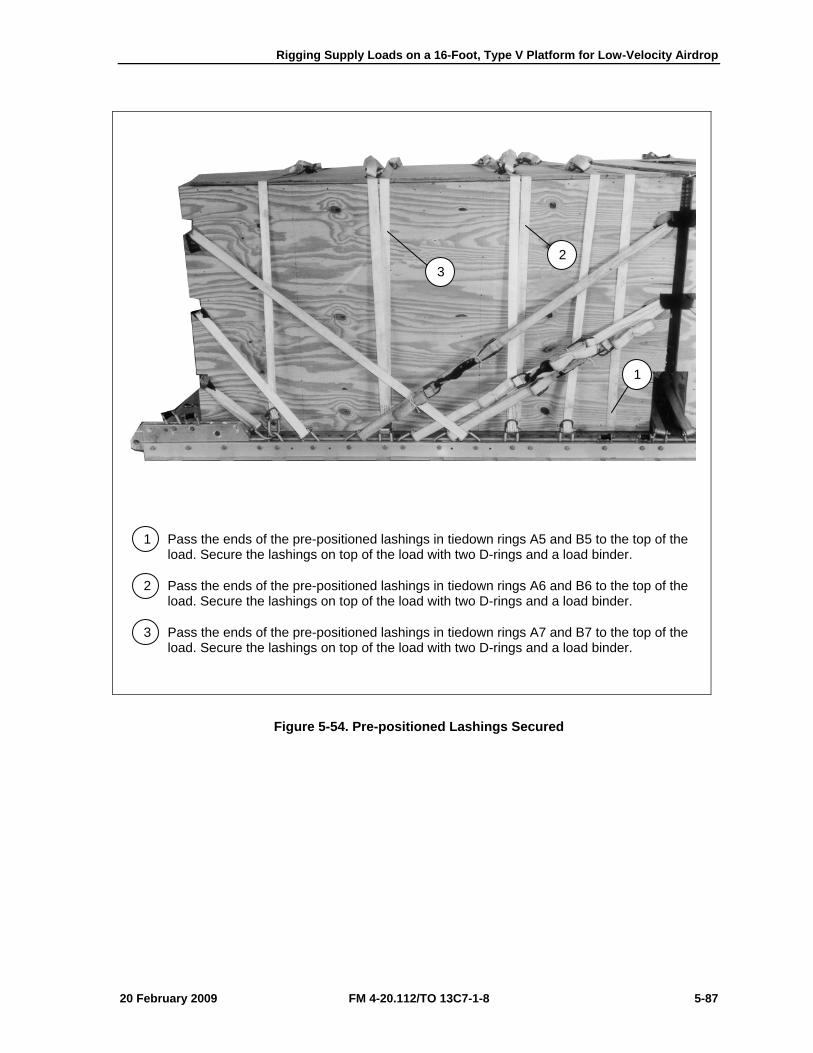
Rigging Supply Loads on a 16-Foot, Type V Platform for Low-Velocity Airdrop
20 February 2009 FM 4-20.112/TO 13C7-1-8 5-87
1 Pass the ends of the pre-positioned lashings in tiedown rings A5 and B5 to the top of the load. Secure the lashings on top of the load with two D-rings and a load binder.
2 Pass the ends of the pre-positioned lashings in tiedown rings A6 and B6 to the top of the load. Secure the lashings on top of the load with two D-rings and a load binder.
3 Pass the ends of the pre-positioned lashings in tiedown rings A7 and B7 to the top of the load. Secure the lashings on top of the load with two D-rings and a load binder.
Figure 5-54. Pre-positioned Lashings Secured
3 2
1
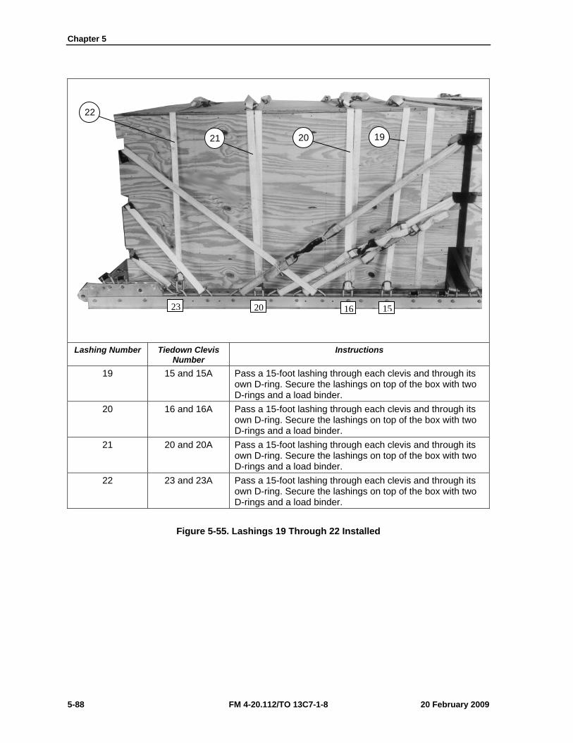
Chapter 5
5-88 FM 4-20.112/TO 13C7-1-8 20 February 2009
Lashing Number Tiedown Clevis
Number Instructions
19 15 and 15A Pass a 15-foot lashing through each clevis and through its own D-ring. Secure the lashings on top of the box with two D-rings and a load binder.
20 16 and 16A Pass a 15-foot lashing through each clevis and through its own D-ring. Secure the lashings on top of the box with two D-rings and a load binder.
21 20 and 20A Pass a 15-foot lashing through each clevis and through its own D-ring. Secure the lashings on top of the box with two D-rings and a load binder.
22 23 and 23A Pass a 15-foot lashing through each clevis and through its own D-ring. Secure the lashings on top of the box with two D-rings and a load binder.
Figure 5-55. Lashings 19 Through 22 Installed
162023 15
22
21 20 19
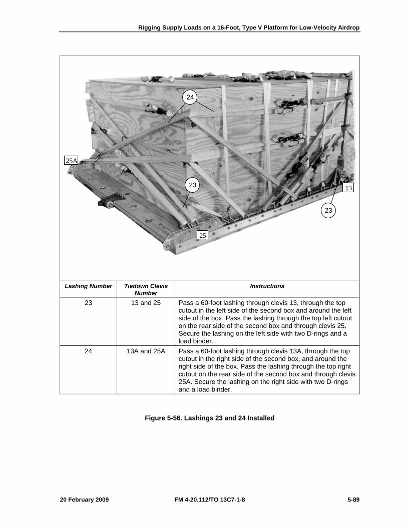
Rigging Supply Loads on a 16-Foot, Type V Platform for Low-Velocity Airdrop
20 February 2009 FM 4-20.112/TO 13C7-1-8 5-89
Lashing Number Tiedown Clevis
Number Instructions
23 13 and 25 Pass a 60-foot lashing through clevis 13, through the top cutout in the left side of the second box and around the left side of the box. Pass the lashing through the top left cutout on the rear side of the second box and through clevis 25. Secure the lashing on the left side with two D-rings and a load binder.
24 13A and 25A Pass a 60-foot lashing through clevis 13A, through the top cutout in the right side of the second box, and around the right side of the box. Pass the lashing through the top right cutout on the rear side of the second box and through clevis 25A. Secure the lashing on the right side with two D-rings and a load binder.
Figure 5-56. Lashings 23 and 24 Installed
24
23
23
25
13
25A
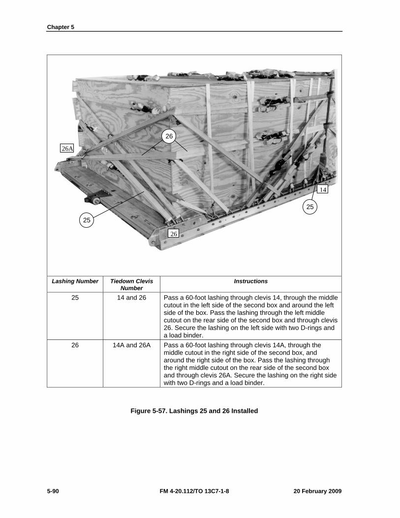
Chapter 5
5-90 FM 4-20.112/TO 13C7-1-8 20 February 2009
Lashing Number Tiedown Clevis
Number Instructions
25 14 and 26 Pass a 60-foot lashing through clevis 14, through the middle cutout in the left side of the second box and around the left side of the box. Pass the lashing through the left middle cutout on the rear side of the second box and through clevis 26. Secure the lashing on the left side with two D-rings and a load binder.
26 14A and 26A Pass a 60-foot lashing through clevis 14A, through the middle cutout in the right side of the second box, and around the right side of the box. Pass the lashing through the right middle cutout on the rear side of the second box and through clevis 26A. Secure the lashing on the right side with two D-rings and a load binder.
Figure 5-57. Lashings 25 and 26 Installed
25
26
14
26A
26
25
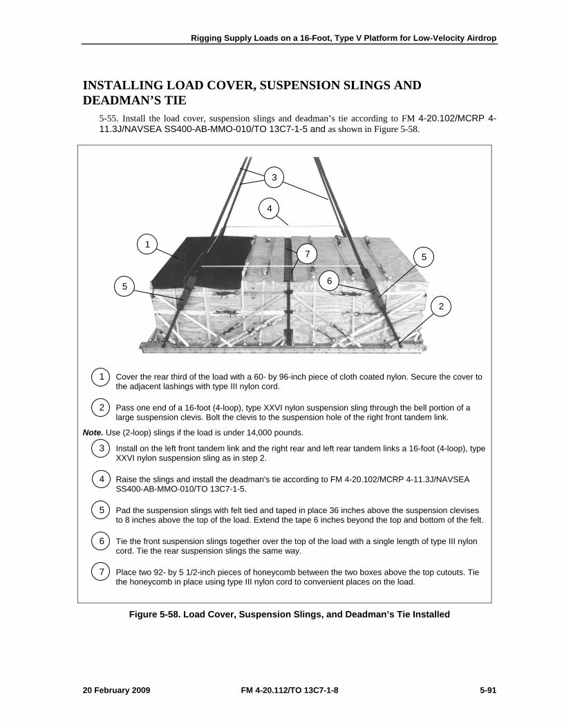
Rigging Supply Loads on a 16-Foot, Type V Platform for Low-Velocity Airdrop
20 February 2009 FM 4-20.112/TO 13C7-1-8 5-91
INSTALLING LOAD COVER, SUSPENSION SLINGS AND DEADMAN’S TIE
5-55. Install the load cover, suspension slings and deadman’s tie according to FM 4-20.102/MCRP 4-11.3J/NAVSEA SS400-AB-MMO-010/TO 13C7-1-5 and as shown in Figure 5-58.
1 Cover the rear third of the load with a 60- by 96-inch piece of cloth coated nylon. Secure the cover to the adjacent lashings with type III nylon cord.
2 Pass one end of a 16-foot (4-loop), type XXVI nylon suspension sling through the bell portion of a large suspension clevis. Bolt the clevis to the suspension hole of the right front tandem link.
Note. Use (2-loop) slings if the load is under 14,000 pounds.
3 Install on the left front tandem link and the right rear and left rear tandem links a 16-foot (4-loop), type XXVI nylon suspension sling as in step 2.
4 Raise the slings and install the deadman's tie according to FM 4-20.102/MCRP 4-11.3J/NAVSEA SS400-AB-MMO-010/TO 13C7-1-5.
5 Pad the suspension slings with felt tied and taped in place 36 inches above the suspension clevises to 8 inches above the top of the load. Extend the tape 6 inches beyond the top and bottom of the felt.
6 Tie the front suspension slings together over the top of the load with a single length of type III nylon cord. Tie the rear suspension slings the same way.
7 Place two 92- by 5 1/2-inch pieces of honeycomb between the two boxes above the top cutouts. Tie the honeycomb in place using type III nylon cord to convenient places on the load.
Figure 5-58. Load Cover, Suspension Slings, and Deadman’s Tie Installed
2
5 7
5
4
1
6
3
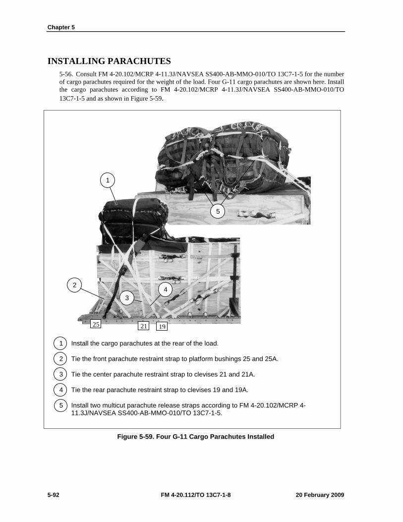
Chapter 5
5-92 FM 4-20.112/TO 13C7-1-8 20 February 2009
INSTALLING PARACHUTES 5-56. Consult FM 4-20.102/MCRP 4-11.3J/NAVSEA SS400-AB-MMO-010/TO 13C7-1-5 for the number of cargo parachutes required for the weight of the load. Four G-11 cargo parachutes are shown here. Install the cargo parachutes according to FM 4-20.102/MCRP 4-11.3J/NAVSEA SS400-AB-MMO-010/TO 13C7-1-5 and as shown in Figure 5-59.
1 Install the cargo parachutes at the rear of the load.
2 Tie the front parachute restraint strap to platform bushings 25 and 25A.
3 Tie the center parachute restraint strap to clevises 21 and 21A.
4 Tie the rear parachute restraint strap to clevises 19 and 19A.
5 Install two multicut parachute release straps according to FM 4-20.102/MCRP 4-11.3J/NAVSEA SS400-AB-MMO-010/TO 13C7-1-5.
Figure 5-59. Four G-11 Cargo Parachutes Installed
5
1
4 2
3
25 21 19
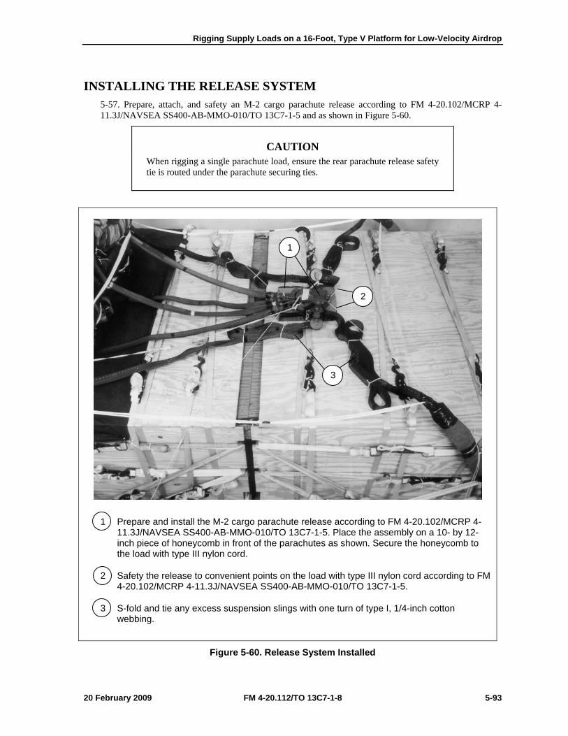
Rigging Supply Loads on a 16-Foot, Type V Platform for Low-Velocity Airdrop
20 February 2009 FM 4-20.112/TO 13C7-1-8 5-93
INSTALLING THE RELEASE SYSTEM 5-57. Prepare, attach, and safety an M-2 cargo parachute release according to FM 4-20.102/MCRP 4-11.3J/NAVSEA SS400-AB-MMO-010/TO 13C7-1-5 and as shown in Figure 5-60.
CAUTION When rigging a single parachute load, ensure the rear parachute release safety tie is routed under the parachute securing ties.
1 Prepare and install the M-2 cargo parachute release according to FM 4-20.102/MCRP 4-11.3J/NAVSEA SS400-AB-MMO-010/TO 13C7-1-5. Place the assembly on a 10- by 12-inch piece of honeycomb in front of the parachutes as shown. Secure the honeycomb to the load with type III nylon cord.
2 Safety the release to convenient points on the load with type III nylon cord according to FM 4-20.102/MCRP 4-11.3J/NAVSEA SS400-AB-MMO-010/TO 13C7-1-5.
3 S-fold and tie any excess suspension slings with one turn of type I, 1/4-inch cotton webbing.
Figure 5-60. Release System Installed
1
2
3
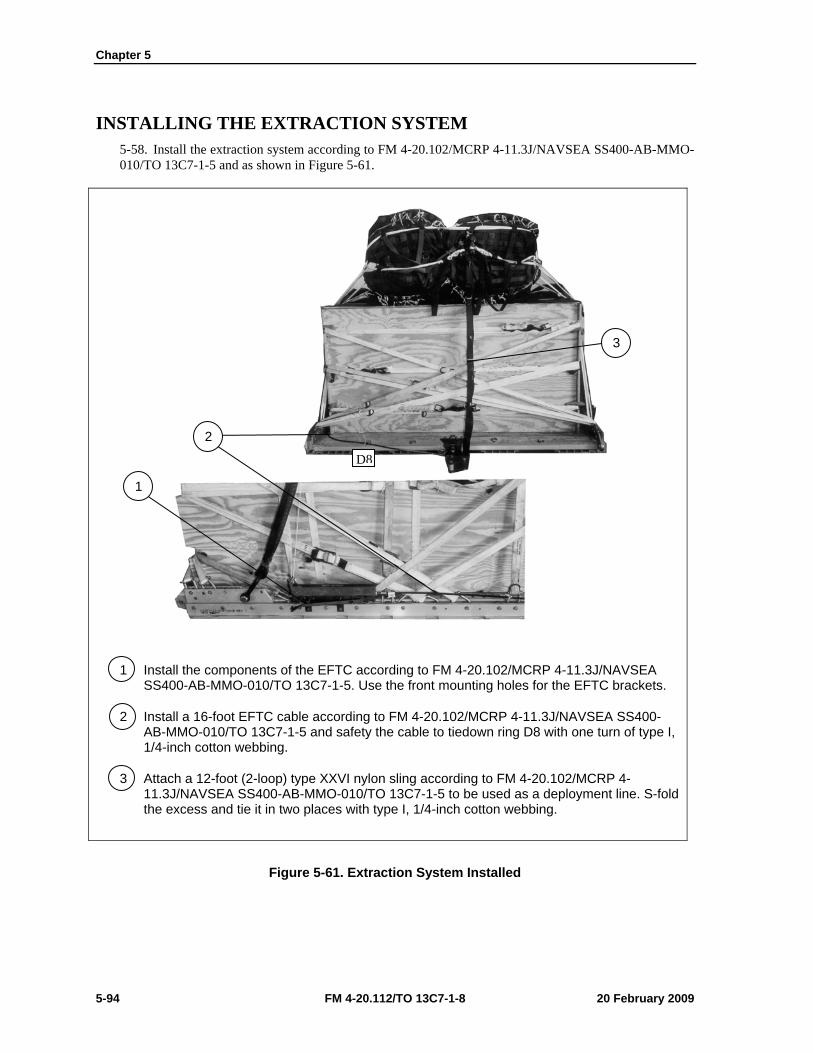
Chapter 5
5-94 FM 4-20.112/TO 13C7-1-8 20 February 2009
INSTALLING THE EXTRACTION SYSTEM 5-58. Install the extraction system according to FM 4-20.102/MCRP 4-11.3J/NAVSEA SS400-AB-MMO-010/TO 13C7-1-5 and as shown in Figure 5-61.
1 Install the components of the EFTC according to FM 4-20.102/MCRP 4-11.3J/NAVSEA SS400-AB-MMO-010/TO 13C7-1-5. Use the front mounting holes for the EFTC brackets.
2 Install a 16-foot EFTC cable according to FM 4-20.102/MCRP 4-11.3J/NAVSEA SS400-AB-MMO-010/TO 13C7-1-5 and safety the cable to tiedown ring D8 with one turn of type I, 1/4-inch cotton webbing.
3 Attach a 12-foot (2-loop) type XXVI nylon sling according to FM 4-20.102/MCRP 4-11.3J/NAVSEA SS400-AB-MMO-010/TO 13C7-1-5 to be used as a deployment line. S-fold the excess and tie it in two places with type I, 1/4-inch cotton webbing.
Figure 5-61. Extraction System Installed
3
2
1
D8
Rigging Supply Loads on a 16-Foot, Type V Platform for Low-Velocity Airdrop
20 February 2009 FM 4-20.112/TO 13C7-1-8 5-95
PLACING EXTRACTION PARACHUTE 5-59. Select the extraction parachute and extraction line needed using the extraction line requirements table in FM 4-20.102/MCRP 4-11.3J/NAVSEA SS400-AB-MMO-010/TO 13C7-1-5. Place the extraction parachute and line on the load for installation in the aircraft.
INSTALLING PROVISIONS FOR EMERGENCY RESTRAINTS 5-60. Select and install the provisions for the emergency aft restraints according to the emergency aft restraint requirements table in FM 4-20.102/MCRP 4-11.3J/NAVSEA SS400-AB-MMO-010/TO 13C7-1-5.
MARKING RIGGED LOAD 5-61. Mark the rigged load according to FM 4-20.102/MCRP 4-11.3J/NAVSEA SS400-AB-MMO-010/TO 13C7-1-5, and as shown in Figure 5-62. Complete Shipper’s Declaration for Dangerous Goods. If the load varies from the one shown, the weight, height, CB, and parachute requirements must be recomputed.
EQUIPMENT REQUIRED 5-62. Use the equipment listed in Table 5-4 to rig this load.
Note. Table does not include materials which may be needed to pad and restrain supplies inside the boxes.
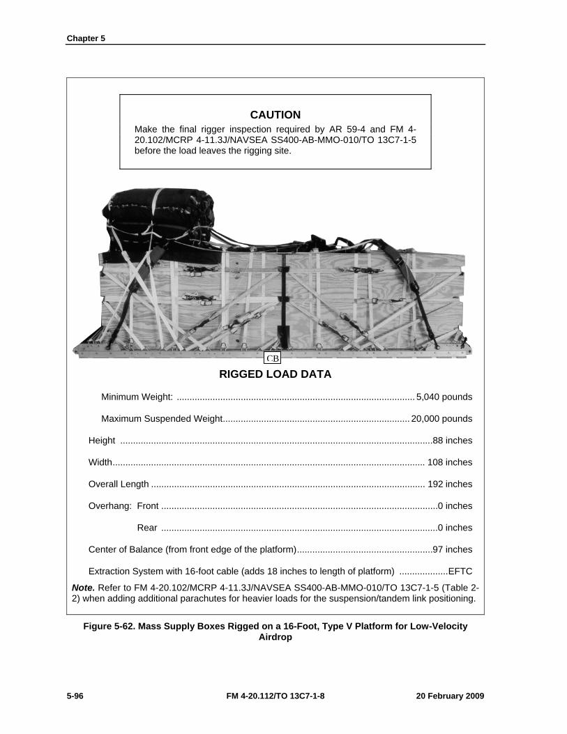
Chapter 5
5-96 FM 4-20.112/TO 13C7-1-8 20 February 2009
CAUTION Make the final rigger inspection required by AR 59-4 and FM 4-20.102/MCRP 4-11.3J/NAVSEA SS400-AB-MMO-010/TO 13C7-1-5 before the load leaves the rigging site.
RIGGED LOAD DATA
Minimum Weight: ............................................................................................. 5,040 pounds
Maximum Suspended Weight ......................................................................... 20,000 pounds
Height ..........................................................................................................................88 inches
Width .......................................................................................................................... 108 inches
Overall Length ........................................................................................................... 192 inches
Overhang: Front ............................................................................................................ 0 inches
Rear ............................................................................................................ 0 inches
Center of Balance (from front edge of the platform) .....................................................97 inches
Extraction System with 16-foot cable (adds 18 inches to length of platform) ................... EFTC
Note. Refer to FM 4-20.102/MCRP 4-11.3J/NAVSEA SS400-AB-MMO-010/TO 13C7-1-5 (Table 2-2) when adding additional parachutes for heavier loads for the suspension/tandem link positioning.
Figure 5-62. Mass Supply Boxes Rigged on a 16-Foot, Type V Platform for Low-Velocity Airdrop
CB

Rigging Supply Loads on a 16-Foot, Type V Platform for Low-Velocity Airdrop
20 February 2009 FM 4-20.112/TO 13C7-1-8 5-97
Table 5-4. Equipment Required for Rigging Mass Supply Boxes on a 16-Foot, Type V Platform for Low-Velocity Airdrop
National Stock Number Item Quantity 8040-00-273-8713
4030-00-090-5354 8305-00-880-8155 4020-00-240-2146 1670-00-434-5785
1670-00-360-0328 8135-00-664-6958 8305-00-191-1101 1670-01-183-2678
1670-01-062-6313 1670-01-107-7651 1670-01-062-6313 1670-01-493-6418 5351-00-010-4659 1670-00-753-3928
1670-01-016-7841 1670-00-040-8135 1670-01-063-3715
1670-00-128-4981 1670-01-353-8425 1670-01-162-2372 1670-01-162-2376 1670-01-162-2381 1670-01-097-8817
Adhesive, paste, 1-gallon Clevis, suspension: 1-inch (large) Cloth, coated (nylon, type II, green, 60-in) Cord, nylon, type III Coupling, airdrop, extraction force transfer with 16-foot cable Cover, clevis, large Cushioning material, packaging, cellulose wadding Felt, ½-inch thick Leaf, extraction line (line bag) (add 2 for C-17) Line, extraction, type XXVI nylon webbing: 60-foot (3-loop), type XXVI 140-foot (3-loop), type XXVI 60-foot (3-loop), type XXVI for C-17 drogue line Link assembly, two-point: Nail, steel wire, common 8d Pad, energy-dissipating, honeycomb Parachute: Cargo, G-11 Cargo, extraction, 28-foot Cargo, extraction, 15-foot for C-17 Platform, airdrop, type V, 16-foot Plywood, ¾- by 48- by 96-inches Bracket assembly, EFTC Bracket assembly, extraction Clevis assembly Tandem link Release, cargo parachute, M-2
As required 5
As required As required
1 4
As required As required
2 1 1 1 1
As required 1 sheet
4 1 1
12 sheets 1 1
56 4 1
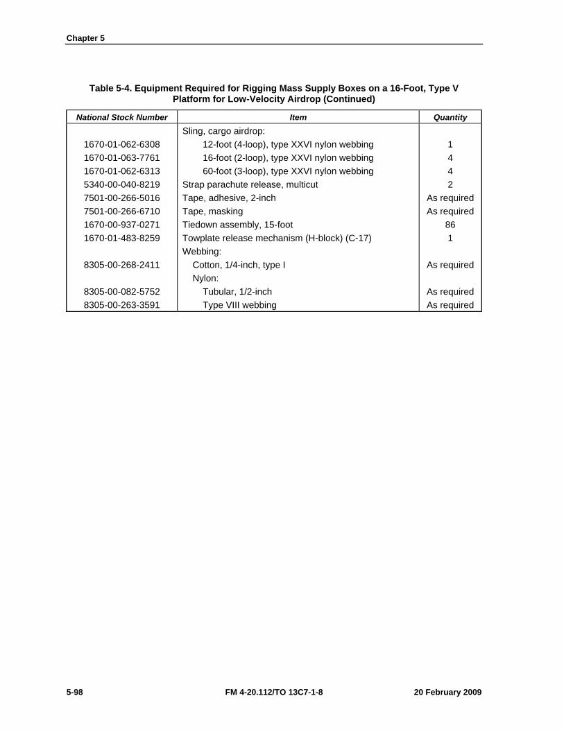
Chapter 5
5-98 FM 4-20.112/TO 13C7-1-8 20 February 2009
Table 5-4. Equipment Required for Rigging Mass Supply Boxes on a 16-Foot, Type V Platform for Low-Velocity Airdrop (Continued)
National Stock Number Item Quantity
1670-01-062-6308 1670-01-063-7761 1670-01-062-6313 5340-00-040-8219 7501-00-266-5016 7501-00-266-6710 1670-00-937-0271 1670-01-483-8259
8305-00-268-2411
8305-00-082-5752 8305-00-263-3591
Sling, cargo airdrop: 12-foot (4-loop), type XXVI nylon webbing 16-foot (2-loop), type XXVI nylon webbing 60-foot (3-loop), type XXVI nylon webbing Strap parachute release, multicut Tape, adhesive, 2-inch Tape, masking Tiedown assembly, 15-foot Towplate release mechanism (H-block) (C-17) Webbing: Cotton, 1/4-inch, type I Nylon: Tubular, 1/2-inch Type VIII webbing
1 4 4 2
As required As required
86 1
As required
As required As required
20 February 2009 FM 4-20.112/TO 13C7-1-8 6-1
Chapter 6
Rigging Mass Supply Box on a 20-Foot, Type V Platform for Low-Velocity Airdrop
DESCRIPTION OF LOAD 6-1. Two mass supply boxes are rigged for low-velocity airdrop on a 20-foot, type V airdrop platform. Loads may include any bulk items of general supply that can be packed into the box without shifting the load. Each load must weigh at least 6,300 pounds, including parachutes. Refer to FM 4-20.102/MCRP 4-11.3J/NAVSEA SS400-AB-MMO-010/TO 13C7-1-5 for the weight limitations for the number of parachutes to be used.
PREPARING PLATFORM 6-2. Prepare a 20-foot, type V platform as shown in Figure 6-1.
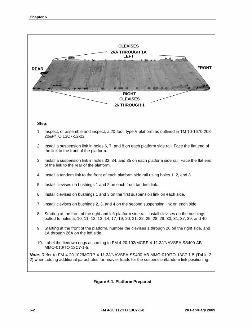
Chapter 6
6-2 FM 4-20.112/TO 13C7-1-8 20 February 2009
Step:
1. Inspect, or assemble and inspect, a 20-foot, type V platform as outlined in TM 10-1670-268-20&P/TO 13C7-52-22.
2. Install a suspension link in holes 6, 7, and 8 on each platform side rail. Face the flat end of the link to the front of the platform.
3. Install a suspension link in holes 33, 34, and 35 on each platform side rail. Face the flat end of the link to the rear of the platform.
4. Install a tandem link to the front of each platform side rail using holes 1, 2, and 3.
5. Install clevises on bushings 1 and 2 on each front tandem link.
6. Install clevises on bushings 1 and 3 on the first suspension link on each side.
7. Install clevises on bushings 2, 3, and 4 on the second suspension link on each side.
8. Starting at the front of the right and left platform side rail, install clevises on the bushings bolted to holes 5, 10, 11, 12, 13, 14, 17, 19, 20, 21, 22, 25, 28, 29, 30, 31, 37, 39, and 40.
9. Starting at the front of the platform, number the clevises 1 through 26 on the right side, and 1A through 26A on the left side.
10. Label the tiedown rings according to FM 4-20.102/MCRP 4-11.3J/NAVSEA SS400-AB-MMO-010/TO 13C7-1-5.
Note. Refer to FM 4-20.102/MCRP 4-11.3J/NAVSEA SS400-AB-MMO-010/TO 13C7-1-5 (Table 2-2) when adding additional parachutes for heavier loads for the suspension/tandem link positioning.
Figure 6-1. Platform Prepared
CLEVISES 26A THROUGH 1A
CLEVISES 26 THROUGH 1
RIGHT
LEFT
FRONT REAR
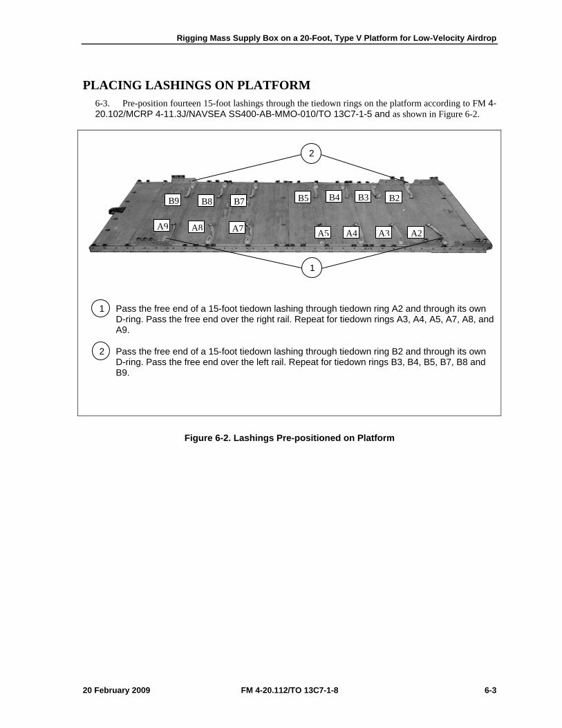
Rigging Mass Supply Box on a 20-Foot, Type V Platform for Low-Velocity Airdrop
20 February 2009 FM 4-20.112/TO 13C7-1-8 6-3
PLACING LASHINGS ON PLATFORM 6-3. Pre-position fourteen 15-foot lashings through the tiedown rings on the platform according to FM 4-20.102/MCRP 4-11.3J/NAVSEA SS400-AB-MMO-010/TO 13C7-1-5 and as shown in Figure 6-2.
1 Pass the free end of a 15-foot tiedown lashing through tiedown ring A2 and through its own D-ring. Pass the free end over the right rail. Repeat for tiedown rings A3, A4, A5, A7, A8, and A9.
2 Pass the free end of a 15-foot tiedown lashing through tiedown ring B2 and through its own D-ring. Pass the free end over the left rail. Repeat for tiedown rings B3, B4, B5, B7, B8 and B9.
Figure 6-2. Lashings Pre-positioned on Platform
B9 B8 B7 B5 B4 B3
A9 A8 A7 A5 A4 A3 A2
B2
1
2
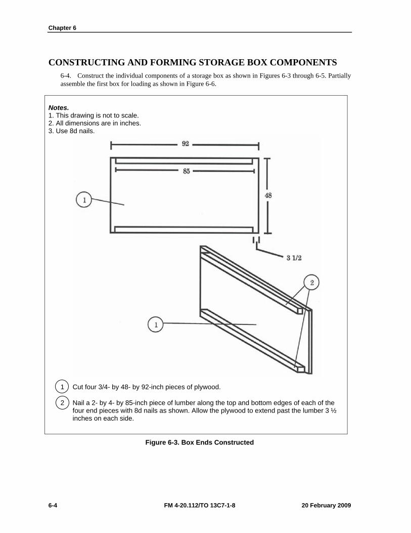
Chapter 6
6-4 FM 4-20.112/TO 13C7-1-8 20 February 2009
CONSTRUCTING AND FORMING STORAGE BOX COMPONENTS 6-4. Construct the individual components of a storage box as shown in Figures 6-3 through 6-5. Partially assemble the first box for loading as shown in Figure 6-6.
Notes. 1. This drawing is not to scale. 2. All dimensions are in inches. 3. Use 8d nails.
1 Cut four 3/4- by 48- by 92-inch pieces of plywood.
2 Nail a 2- by 4- by 85-inch piece of lumber along the top and bottom edges of each of the four end pieces with 8d nails as shown. Allow the plywood to extend past the lumber 3 ½ inches on each side.
Figure 6-3. Box Ends Constructed
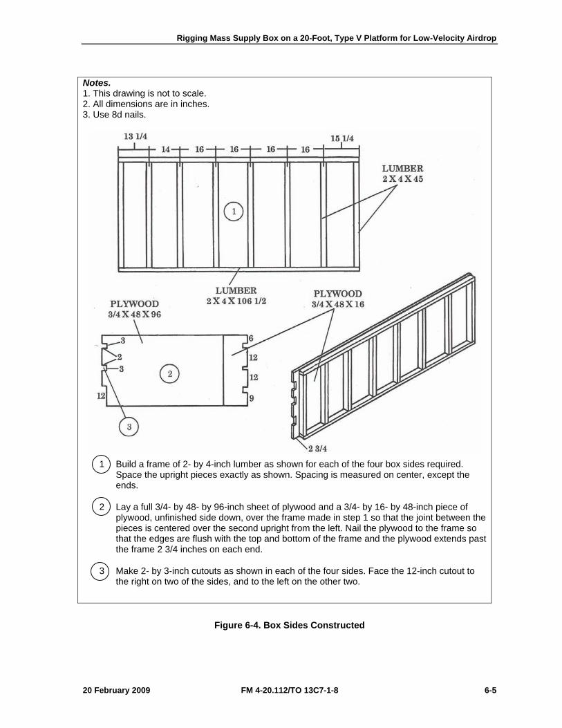
Rigging Mass Supply Box on a 20-Foot, Type V Platform for Low-Velocity Airdrop
20 February 2009 FM 4-20.112/TO 13C7-1-8 6-5
Notes. 1. This drawing is not to scale. 2. All dimensions are in inches. 3. Use 8d nails.
1 Build a frame of 2- by 4-inch lumber as shown for each of the four box sides required. Space the upright pieces exactly as shown. Spacing is measured on center, except the ends.
2 Lay a full 3/4- by 48- by 96-inch sheet of plywood and a 3/4- by 16- by 48-inch piece of plywood, unfinished side down, over the frame made in step 1 so that the joint between the pieces is centered over the second upright from the left. Nail the plywood to the frame so that the edges are flush with the top and bottom of the frame and the plywood extends past the frame 2 3/4 inches on each end.
3 Make 2- by 3-inch cutouts as shown in each of the four sides. Face the 12-inch cutout to the right on two of the sides, and to the left on the other two.
Figure 6-4. Box Sides Constructed
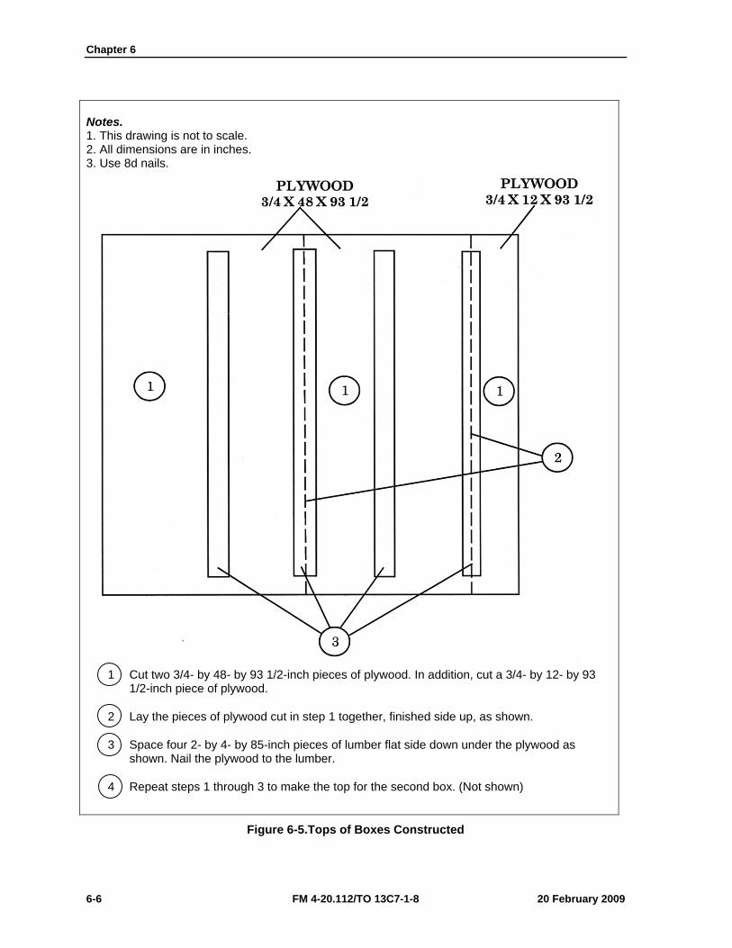
Chapter 6
6-6 FM 4-20.112/TO 13C7-1-8 20 February 2009
Notes. 1. This drawing is not to scale. 2. All dimensions are in inches. 3. Use 8d nails.
1 Cut two 3/4- by 48- by 93 1/2-inch pieces of plywood. In addition, cut a 3/4- by 12- by 93 1/2-inch piece of plywood.
2 Lay the pieces of plywood cut in step 1 together, finished side up, as shown.
3 Space four 2- by 4- by 85-inch pieces of lumber flat side down under the plywood as shown. Nail the plywood to the lumber.
4 Repeat steps 1 through 3 to make the top for the second box. (Not shown)
Figure 6-5.Tops of Boxes Constructed
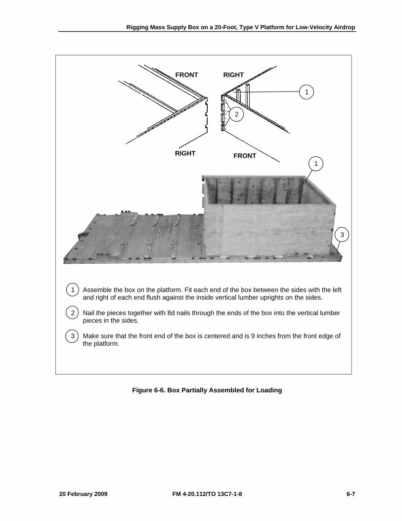
Rigging Mass Supply Box on a 20-Foot, Type V Platform for Low-Velocity Airdrop
20 February 2009 FM 4-20.112/TO 13C7-1-8 6-7
1 Assemble the box on the platform. Fit each end of the box between the sides with the left and right of each end flush against the inside vertical lumber uprights on the sides.
2 Nail the pieces together with 8d nails through the ends of the box into the vertical lumber pieces in the sides.
3 Make sure that the front end of the box is centered and is 9 inches from the front edge of the platform.
Figure 6-6. Box Partially Assembled for Loading
1
2
1
3
FRONT RIGHT
FRONT RIGHT
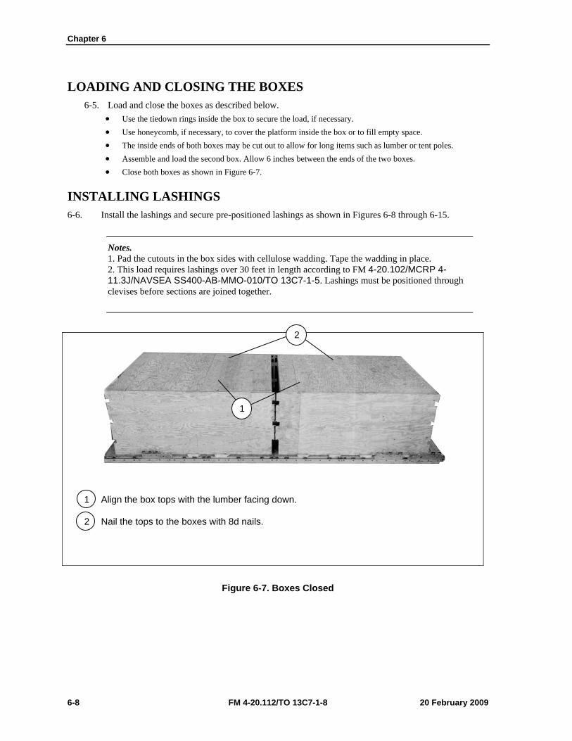
Chapter 6
6-8 FM 4-20.112/TO 13C7-1-8 20 February 2009
LOADING AND CLOSING THE BOXES 6-5. Load and close the boxes as described below.
• Use the tiedown rings inside the box to secure the load, if necessary. • Use honeycomb, if necessary, to cover the platform inside the box or to fill empty space. • The inside ends of both boxes may be cut out to allow for long items such as lumber or tent poles. • Assemble and load the second box. Allow 6 inches between the ends of the two boxes. • Close both boxes as shown in Figure 6-7.
INSTALLING LASHINGS 6-6. Install the lashings and secure pre-positioned lashings as shown in Figures 6-8 through 6-15.
Notes. 1. Pad the cutouts in the box sides with cellulose wadding. Tape the wadding in place. 2. This load requires lashings over 30 feet in length according to FM 4-20.102/MCRP 4-11.3J/NAVSEA SS400-AB-MMO-010/TO 13C7-1-5. Lashings must be positioned through clevises before sections are joined together.
1 Align the box tops with the lumber facing down.
2 Nail the tops to the boxes with 8d nails.
Figure 6-7. Boxes Closed
1
2
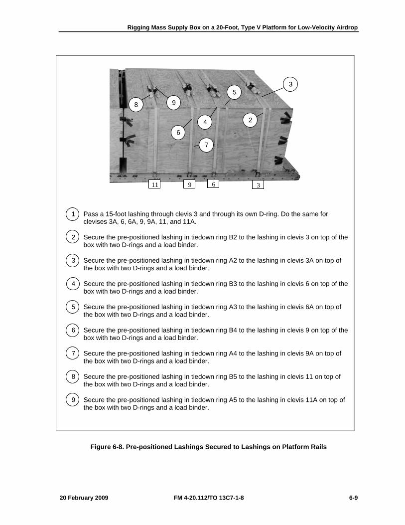
Rigging Mass Supply Box on a 20-Foot, Type V Platform for Low-Velocity Airdrop
20 February 2009 FM 4-20.112/TO 13C7-1-8 6-9
1 Pass a 15-foot lashing through clevis 3 and through its own D-ring. Do the same for clevises 3A, 6, 6A, 9, 9A, 11, and 11A.
2 Secure the pre-positioned lashing in tiedown ring B2 to the lashing in clevis 3 on top of the box with two D-rings and a load binder.
3 Secure the pre-positioned lashing in tiedown ring A2 to the lashing in clevis 3A on top of the box with two D-rings and a load binder.
4 Secure the pre-positioned lashing in tiedown ring B3 to the lashing in clevis 6 on top of the box with two D-rings and a load binder.
5 Secure the pre-positioned lashing in tiedown ring A3 to the lashing in clevis 6A on top of the box with two D-rings and a load binder.
6 Secure the pre-positioned lashing in tiedown ring B4 to the lashing in clevis 9 on top of the box with two D-rings and a load binder.
7 Secure the pre-positioned lashing in tiedown ring A4 to the lashing in clevis 9A on top of the box with two D-rings and a load binder.
8 Secure the pre-positioned lashing in tiedown ring B5 to the lashing in clevis 11 on top of the box with two D-rings and a load binder.
9 Secure the pre-positioned lashing in tiedown ring A5 to the lashing in clevis 11A on top of the box with two D-rings and a load binder.
Figure 6-8. Pre-positioned Lashings Secured to Lashings on Platform Rails
3 5
2
6
9
4
7
8
36911
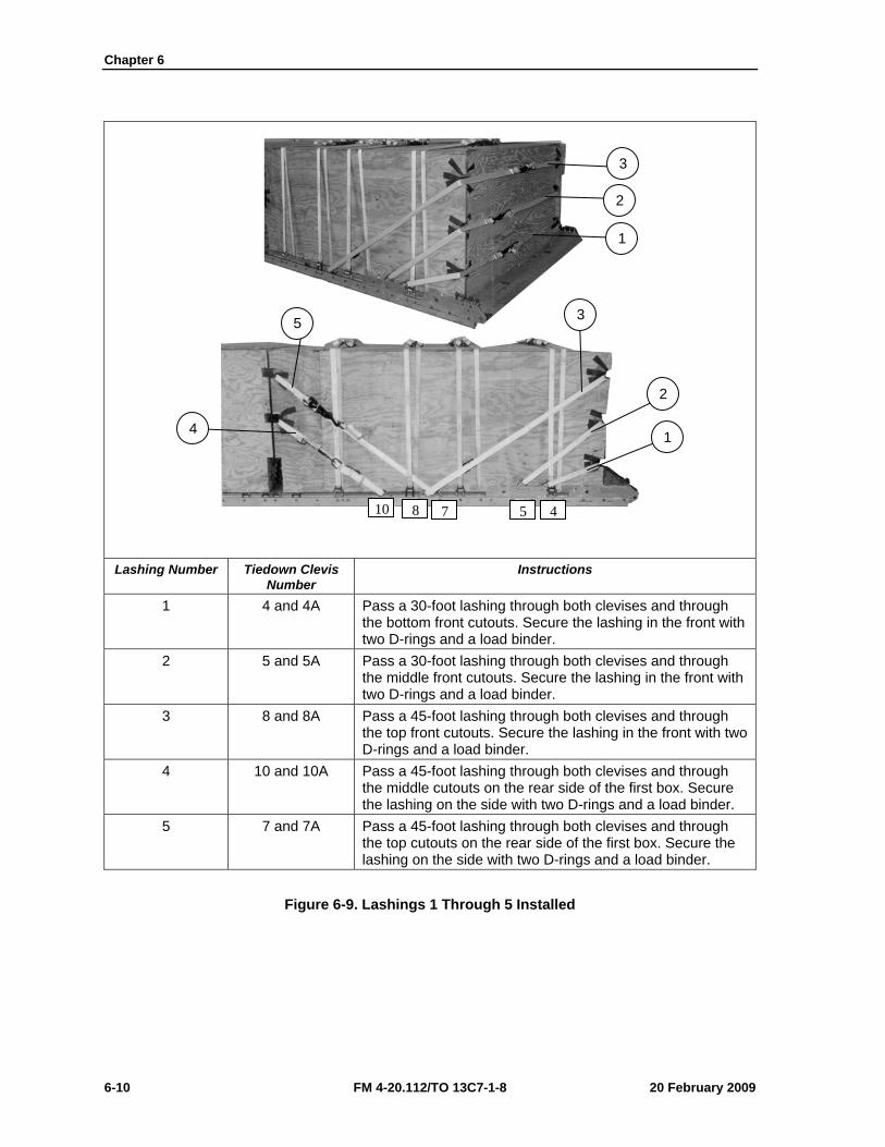
Chapter 6
6-10 FM 4-20.112/TO 13C7-1-8 20 February 2009
Lashing Number Tiedown Clevis
Number Instructions
1 4 and 4A Pass a 30-foot lashing through both clevises and through the bottom front cutouts. Secure the lashing in the front with two D-rings and a load binder.
2 5 and 5A Pass a 30-foot lashing through both clevises and through the middle front cutouts. Secure the lashing in the front with two D-rings and a load binder.
3 8 and 8A Pass a 45-foot lashing through both clevises and through the top front cutouts. Secure the lashing in the front with two D-rings and a load binder.
4 10 and 10A Pass a 45-foot lashing through both clevises and through the middle cutouts on the rear side of the first box. Secure the lashing on the side with two D-rings and a load binder.
5 7 and 7A Pass a 45-foot lashing through both clevises and through the top cutouts on the rear side of the first box. Secure the lashing on the side with two D-rings and a load binder.
Figure 6-9. Lashings 1 Through 5 Installed
3
2
1
5 3
2
1 4
10 8 7 5 4
Rigging Mass Supply Box on a 20-Foot, Type V Platform for Low-Velocity Airdrop
20 February 2009 FM 4-20.112/TO 13C7-1-8 6-11
Lashing Number Tiedown Clevis
Number Instructions
6 1 and 12 Pass a 60-foot lashing through clevis 1, through the top cutout in the left side of the first box and around the left side of the box. Pass the lashing through the top left cutout on the rear side of the first box and through clevis 12. Secure the lashing on the left side with two D-rings and a load binder.
7 1A and 12A Pass a 60-foot lashing through clevis 1A, through the top cutout in the right side of the first box and around the right side of the box. Pass the lashing through the top right cutout on the rear end of the first box and through clevis 12A. Secure the lashing on the right side with two D-rings and a load binder.
Figure 6-10. Lashings 6 and 7 Installed
7
6
6
12
1
1A
Chapter 6
6-12 FM 4-20.112/TO 13C7-1-8 20 February 2009
Lashing Number Tiedown Clevis
Number Instructions
8 2 and 13 Pass a 60-foot lashing through clevis 2, through the middle left cutout in the left side of the first box, and around the left side of the box. Pass the lashing through the middle left cutout on the rear end of the first box and through clevis 13. Secure the lashing on the left side with two D-rings and a load binder.
9 2A and 13A Pass a 60-foot lashing through clevis 2A, through the middle right cutout in the right side of the first box and around the right side of the box. Pass the lashing through the middle right cutout on the rear end of the first box and through clevis 13A. Secure the lashing on the right side with two D-rings and a load binder.
Figure 6-11. Lashings 8 and 9 Installed
13
2
2A
8 9 8
Rigging Mass Supply Box on a 20-Foot, Type V Platform for Low-Velocity Airdrop
20 February 2009 FM 4-20.112/TO 13C7-1-8 6-13
1 Pass a 15-foot lashing through clevis 16 and through its own D-ring. Do the same for clevises 16A, 18, 18A, 21, 21A, 24, and 24A.
2 Secure the pre-positioned lashing in tiedown ring B7 to the lashing in clevis 16 on top of the box with two D-rings and a load binder.
3 Secure the pre-positioned lashing in tiedown ring A7 to the lashing in clevis 16A on top of the box with two D-rings and a load binder.
4 Secure the pre-positioned lashing in tiedown ring B8 to the lashing in clevis 18 on top of the box with two D-rings and a load binder.
5 Secure the pre-positioned lashing in tiedown ring A8 to the lashing in clevis 18A on top of the box with two D-rings and a load binder.
6 Secure the pre-positioned lashing in tiedown ring B9 to the lashing in clevis 21 on top of the box with two D-rings and a load binder.
7 Secure the pre-positioned lashing in tiedown ring A9 to the lashing in clevis 21A on top of the box with two D-rings and a load binder.
8 Secure the lashings in clevises 24 and 24A together on top of the box with two D-rings and a load binder.
Figure 6-12. Pre-positioned Lashings Secured to Lashings on Platform Rails
8
6 7
5
3 2
4
24 21 18 16
Chapter 6
6-14 FM 4-20.112/TO 13C7-1-8 20 February 2009
Lashing Number Tiedown Clevis
Number Instructions
10 17 and 17A Pass a 30-foot lashing through both clevises and through the middle cutouts in the front end of the second box. Secure the lashing on the side with two D-rings and a load binder.
11 19 and 19A Pass a 45-foot lashing through both clevises and through the top cutouts in the front end of the second box. Secure the lashing on the side with two D-rings and a load binder.
12 20 and 20A Pass a 45-foot lashing through both clevises and through the top rear cutouts. Secure the lashing in the rear with two D-rings and a load binder.
13 22 and 22A Pass a 30-foot lashing through both clevises and through the middle rear cutouts. Secure the lashing in the rear with two D-rings and a load binder.
14 23 and 23A Pass a 30-foot lashing through both clevises and through the bottom rear cutouts. Secure the lashing in the rear with two D-rings and a load binder.
Figure 6-13. Lashings 10 Through 14 Installed
11 12
13
14
10
23 22 20 19 17
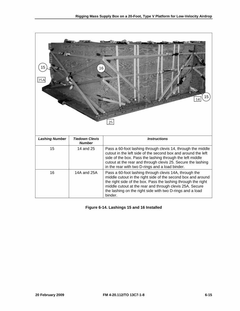
Rigging Mass Supply Box on a 20-Foot, Type V Platform for Low-Velocity Airdrop
20 February 2009 FM 4-20.112/TO 13C7-1-8 6-15
Lashing Number Tiedown Clevis
Number Instructions
15 14 and 25 Pass a 60-foot lashing through clevis 14, through the middle cutout in the left side of the second box and around the left side of the box. Pass the lashing through the left middle cutout at the rear and through clevis 25. Secure the lashing in the rear with two D-rings and a load binder.
16 14A and 25A Pass a 60-foot lashing through clevis 14A, through the middle cutout in the right side of the second box and around the right side of the box. Pass the lashing through the right middle cutout at the rear and through clevis 25A. Secure the lashing on the right side with two D-rings and a load binder.
Figure 6-14. Lashings 15 and 16 Installed
15
16 15
25A
25
14
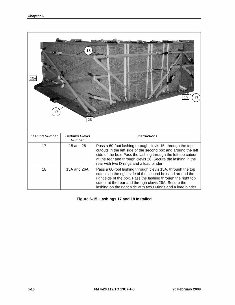
Chapter 6
6-16 FM 4-20.112/TO 13C7-1-8 20 February 2009
Lashing Number Tiedown Clevis
Number Instructions
17 15 and 26 Pass a 60-foot lashing through clevis 15, through the top cutouts in the left side of the second box and around the left side of the box. Pass the lashing through the left top cutout at the rear and through clevis 26. Secure the lashing in the rear with two D-rings and a load binder.
18 15A and 26A Pass a 60-foot lashing through clevis 15A, through the top cutouts in the right side of the second box and around the right side of the box. Pass the lashing through the right top cutout at the rear and through clevis 26A. Secure the lashing on the right side with two D-rings and a load binder.
Figure 6-15. Lashings 17 and 18 Installed
17
18
26A
26
15
17
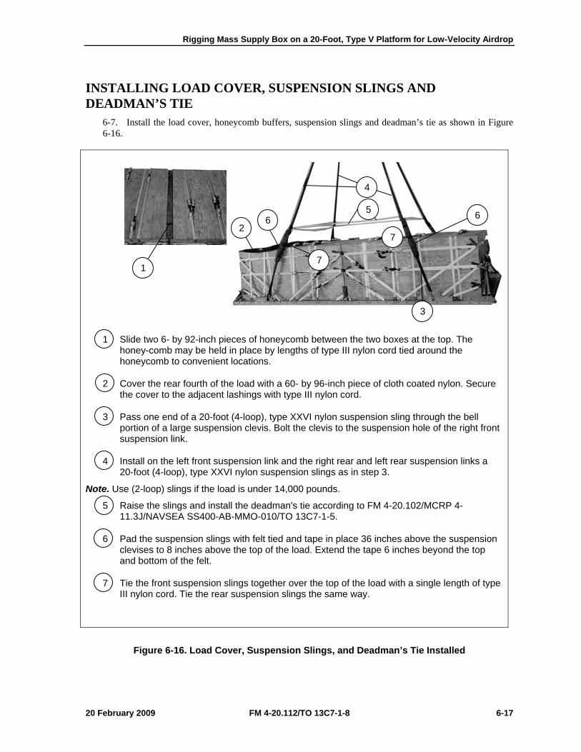
Rigging Mass Supply Box on a 20-Foot, Type V Platform for Low-Velocity Airdrop
20 February 2009 FM 4-20.112/TO 13C7-1-8 6-17
INSTALLING LOAD COVER, SUSPENSION SLINGS AND DEADMAN’S TIE
6-7. Install the load cover, honeycomb buffers, suspension slings and deadman’s tie as shown in Figure 6-16.
1 Slide two 6- by 92-inch pieces of honeycomb between the two boxes at the top. The honey-comb may be held in place by lengths of type III nylon cord tied around the honeycomb to convenient locations.
2 Cover the rear fourth of the load with a 60- by 96-inch piece of cloth coated nylon. Secure the cover to the adjacent lashings with type III nylon cord.
3 Pass one end of a 20-foot (4-loop), type XXVI nylon suspension sling through the bell portion of a large suspension clevis. Bolt the clevis to the suspension hole of the right front suspension link.
4 Install on the left front suspension link and the right rear and left rear suspension links a 20-foot (4-loop), type XXVI nylon suspension slings as in step 3.
Note. Use (2-loop) slings if the load is under 14,000 pounds.
5 Raise the slings and install the deadman's tie according to FM 4-20.102/MCRP 4-11.3J/NAVSEA SS400-AB-MMO-010/TO 13C7-1-5.
6 Pad the suspension slings with felt tied and tape in place 36 inches above the suspension clevises to 8 inches above the top of the load. Extend the tape 6 inches beyond the top and bottom of the felt.
7 Tie the front suspension slings together over the top of the load with a single length of type III nylon cord. Tie the rear suspension slings the same way.
Figure 6-16. Load Cover, Suspension Slings, and Deadman’s Tie Installed
4
1
6 2
5 6
3
7
7
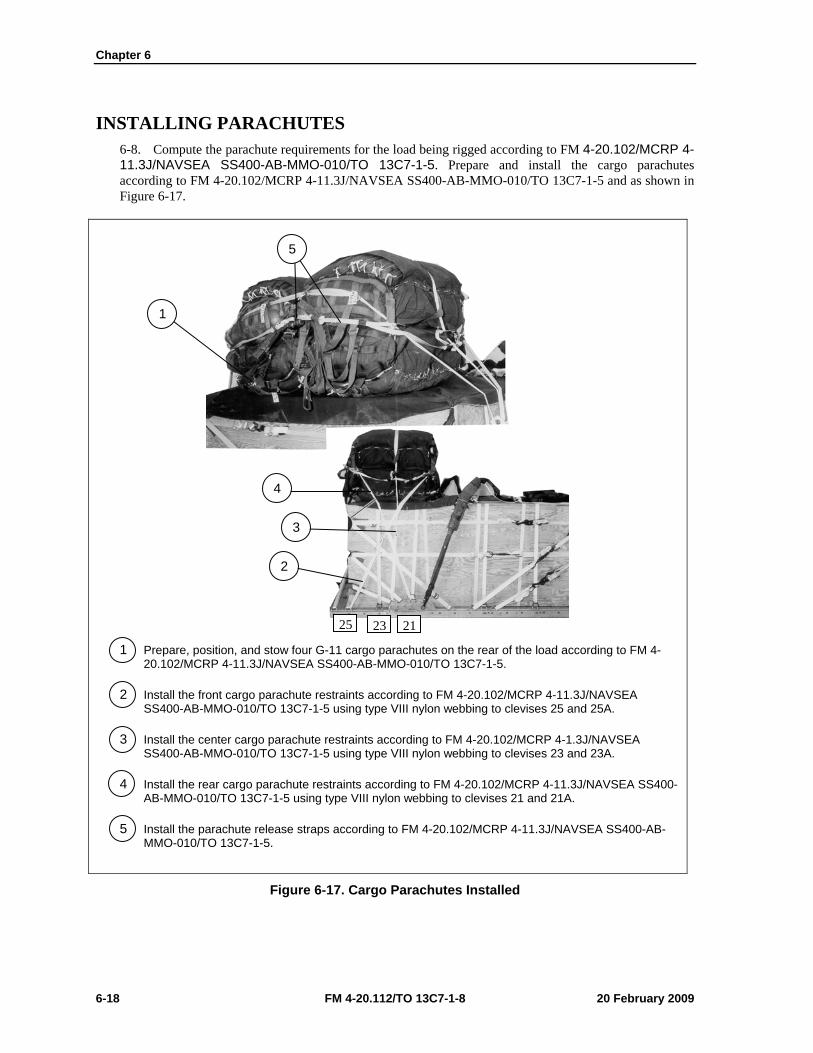
Chapter 6
6-18 FM 4-20.112/TO 13C7-1-8 20 February 2009
INSTALLING PARACHUTES 6-8. Compute the parachute requirements for the load being rigged according to FM 4-20.102/MCRP 4-11.3J/NAVSEA SS400-AB-MMO-010/TO 13C7-1-5. Prepare and install the cargo parachutes according to FM 4-20.102/MCRP 4-11.3J/NAVSEA SS400-AB-MMO-010/TO 13C7-1-5 and as shown in Figure 6-17.
1 Prepare, position, and stow four G-11 cargo parachutes on the rear of the load according to FM 4-20.102/MCRP 4-11.3J/NAVSEA SS400-AB-MMO-010/TO 13C7-1-5.
2 Install the front cargo parachute restraints according to FM 4-20.102/MCRP 4-11.3J/NAVSEA SS400-AB-MMO-010/TO 13C7-1-5 using type VIII nylon webbing to clevises 25 and 25A.
3 Install the center cargo parachute restraints according to FM 4-20.102/MCRP 4-1.3J/NAVSEA SS400-AB-MMO-010/TO 13C7-1-5 using type VIII nylon webbing to clevises 23 and 23A.
4 Install the rear cargo parachute restraints according to FM 4-20.102/MCRP 4-11.3J/NAVSEA SS400-AB-MMO-010/TO 13C7-1-5 using type VIII nylon webbing to clevises 21 and 21A.
5 Install the parachute release straps according to FM 4-20.102/MCRP 4-11.3J/NAVSEA SS400-AB-MMO-010/TO 13C7-1-5.
Figure 6-17. Cargo Parachutes Installed
5
1
4
3
25 23 21
2
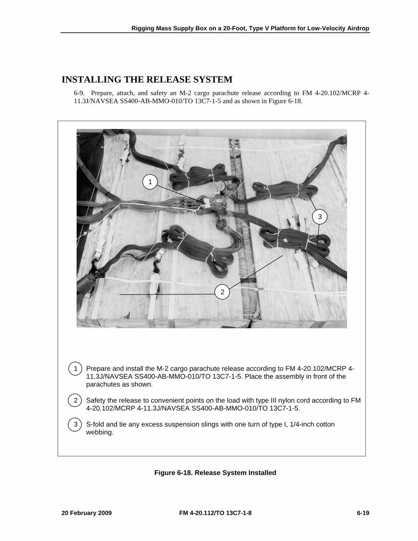
Rigging Mass Supply Box on a 20-Foot, Type V Platform for Low-Velocity Airdrop
20 February 2009 FM 4-20.112/TO 13C7-1-8 6-19
INSTALLING THE RELEASE SYSTEM 6-9. Prepare, attach, and safety an M-2 cargo parachute release according to FM 4-20.102/MCRP 4-11.3J/NAVSEA SS400-AB-MMO-010/TO 13C7-1-5 and as shown in Figure 6-18.
1 Prepare and install the M-2 cargo parachute release according to FM 4-20.102/MCRP 4-11.3J/NAVSEA SS400-AB-MMO-010/TO 13C7-1-5. Place the assembly in front of the parachutes as shown.
2 Safety the release to convenient points on the load with type III nylon cord according to FM 4-20.102/MCRP 4-11.3J/NAVSEA SS400-AB-MMO-010/TO 13C7-1-5.
3 S-fold and tie any excess suspension slings with one turn of type I, 1/4-inch cotton webbing.
Figure 6-18. Release System Installed
2
3
1
2
1
3
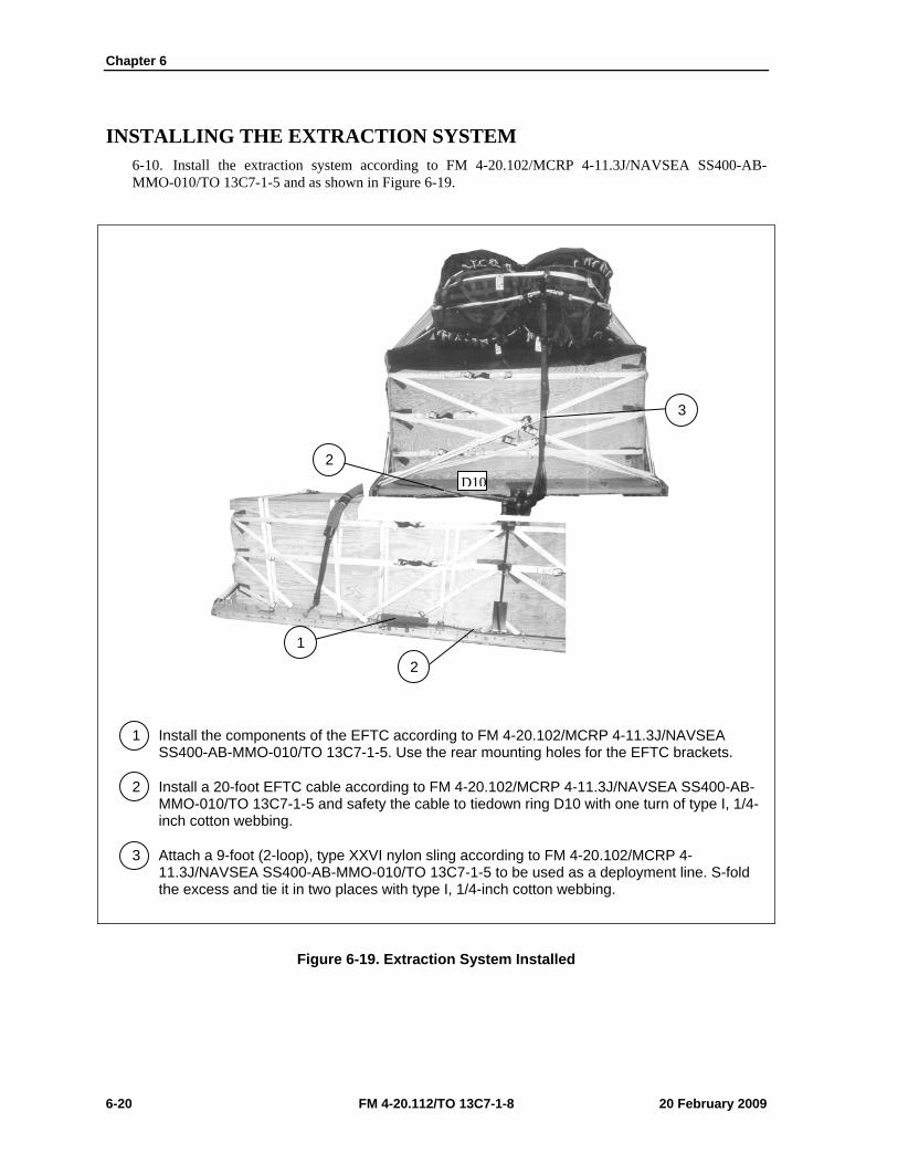
Chapter 6
6-20 FM 4-20.112/TO 13C7-1-8 20 February 2009
INSTALLING THE EXTRACTION SYSTEM 6-10. Install the extraction system according to FM 4-20.102/MCRP 4-11.3J/NAVSEA SS400-AB-MMO-010/TO 13C7-1-5 and as shown in Figure 6-19.
1 Install the components of the EFTC according to FM 4-20.102/MCRP 4-11.3J/NAVSEA SS400-AB-MMO-010/TO 13C7-1-5. Use the rear mounting holes for the EFTC brackets.
2 Install a 20-foot EFTC cable according to FM 4-20.102/MCRP 4-11.3J/NAVSEA SS400-AB-MMO-010/TO 13C7-1-5 and safety the cable to tiedown ring D10 with one turn of type I, 1/4-inch cotton webbing.
3 Attach a 9-foot (2-loop), type XXVI nylon sling according to FM 4-20.102/MCRP 4-11.3J/NAVSEA SS400-AB-MMO-010/TO 13C7-1-5 to be used as a deployment line. S-fold the excess and tie it in two places with type I, 1/4-inch cotton webbing.
Figure 6-19. Extraction System Installed
1 2
3
D102
Rigging Mass Supply Box on a 20-Foot, Type V Platform for Low-Velocity Airdrop
20 February 2009 FM 4-20.112/TO 13C7-1-8 6-21
PLACING EXTRACTION PARACHUTE 6-11. Select the extraction parachute and extraction line needed using the extraction line requirements table in FM 4-20.102/MCRP 4-11.3J/NAVSEA SS400-AB-MMO-010/TO 13C7-1-5. Place the extraction parachute and line on the load for installation in the aircraft.
INSTALLING PROVISIONS FOR EMERGENCY RESTRAINTS 6-12. Select and install the provisions for the emergency aft restraints according to the emergency aft restraint requirements table in FM 4-20.102/MCRP 4-11.3J/NAVSEA SS400-AB-MMO-010/TO 13C7-1-5.
MARKING RIGGED LOAD 6-13. Mark the rigged load according to FM 4-20.102/MCRP 4-11.3J/NAVSEA SS400-AB-MMO-010/TO 13C7-1-5, and as shown in Figure 6-20. Complete Shipper’s Declaration for Dangerous Goods. If the load varies from the one shown, the weight, height, CB, and parachute requirements must be recomputed.
EQUIPMENT REQUIRED 6-14. Use the equipment listed in Table 6-1 to rig this load.
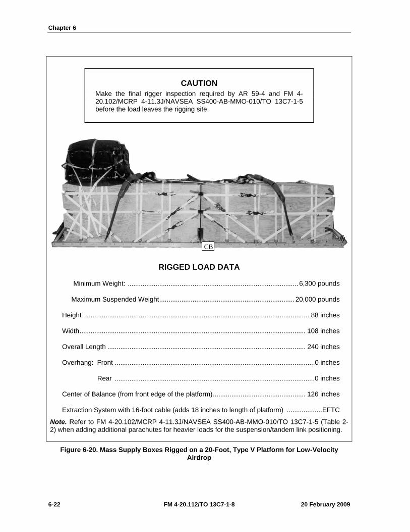
Chapter 6
6-22 FM 4-20.112/TO 13C7-1-8 20 February 2009
CAUTION Make the final rigger inspection required by AR 59-4 and FM 4-20.102/MCRP 4-11.3J/NAVSEA SS400-AB-MMO-010/TO 13C7-1-5 before the load leaves the rigging site.
RIGGED LOAD DATA
Minimum Weight: ............................................................................................ 6,300 pounds
Maximum Suspended Weight ......................................................................... 20,000 pounds
Height ......................................................................................................................... 88 inches
Width .......................................................................................................................... 108 inches
Overall Length ........................................................................................................... 240 inches
Overhang: Front ............................................................................................................0 inches
Rear ............................................................................................................0 inches
Center of Balance (from front edge of the platform) .................................................. 126 inches
Extraction System with 16-foot cable (adds 18 inches to length of platform) ................... EFTC
Note. Refer to FM 4-20.102/MCRP 4-11.3J/NAVSEA SS400-AB-MMO-010/TO 13C7-1-5 (Table 2-2) when adding additional parachutes for heavier loads for the suspension/tandem link positioning.
Figure 6-20. Mass Supply Boxes Rigged on a 20-Foot, Type V Platform for Low-Velocity Airdrop
CB
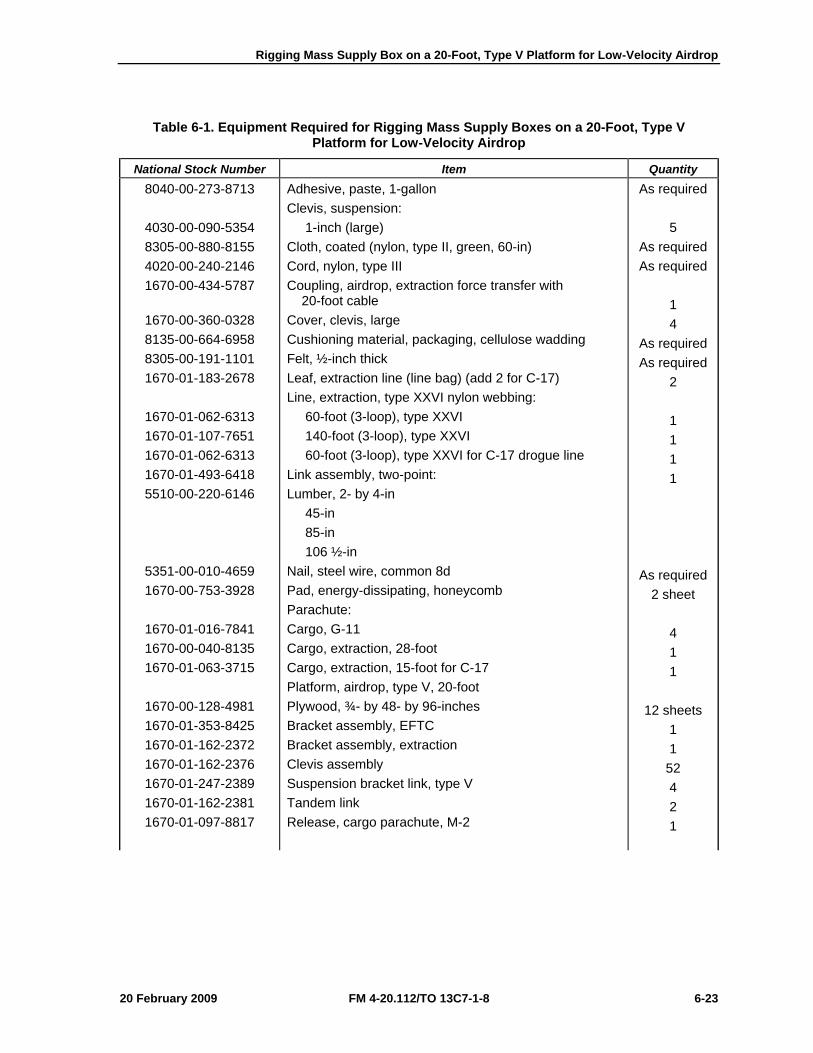
Rigging Mass Supply Box on a 20-Foot, Type V Platform for Low-Velocity Airdrop
20 February 2009 FM 4-20.112/TO 13C7-1-8 6-23
Table 6-1. Equipment Required for Rigging Mass Supply Boxes on a 20-Foot, Type V Platform for Low-Velocity Airdrop
National Stock Number Item Quantity 8040-00-273-8713
4030-00-090-5354 8305-00-880-8155 4020-00-240-2146 1670-00-434-5787
1670-00-360-0328 8135-00-664-6958 8305-00-191-1101 1670-01-183-2678
1670-01-062-6313 1670-01-107-7651 1670-01-062-6313 1670-01-493-6418 5510-00-220-6146
5351-00-010-4659 1670-00-753-3928
1670-01-016-7841 1670-00-040-8135 1670-01-063-3715
1670-00-128-4981 1670-01-353-8425 1670-01-162-2372 1670-01-162-2376 1670-01-247-2389 1670-01-162-2381 1670-01-097-8817
Adhesive, paste, 1-gallon Clevis, suspension: 1-inch (large) Cloth, coated (nylon, type II, green, 60-in) Cord, nylon, type III Coupling, airdrop, extraction force transfer with 20-foot cable Cover, clevis, large Cushioning material, packaging, cellulose wadding Felt, ½-inch thick Leaf, extraction line (line bag) (add 2 for C-17) Line, extraction, type XXVI nylon webbing: 60-foot (3-loop), type XXVI 140-foot (3-loop), type XXVI 60-foot (3-loop), type XXVI for C-17 drogue line Link assembly, two-point: Lumber, 2- by 4-in 45-in 85-in 106 ½-in Nail, steel wire, common 8d Pad, energy-dissipating, honeycomb Parachute: Cargo, G-11 Cargo, extraction, 28-foot Cargo, extraction, 15-foot for C-17 Platform, airdrop, type V, 20-foot Plywood, ¾- by 48- by 96-inches Bracket assembly, EFTC Bracket assembly, extraction Clevis assembly Suspension bracket link, type V Tandem link Release, cargo parachute, M-2
As required 5
As required As required
1 4
As required As required
2 1 1 1 1
As required 2 sheet
4 1 1
12 sheets 1 1
52 4 2 1

Chapter 6
6-24 FM 4-20.112/TO 13C7-1-8 20 February 2009
Table 6-1. Equipment Required for Rigging Mass Supply Boxes on a 20-Foot, Type V Platform for Low-Velocity Airdrop (Continued)
National Stock Number Item Quantity
1670-01-062-6304 1670-01-064-4453 1670-01-062-6313 5340-00-040-8219 7501-00-266-5016 7501-00-266-6710 1670-00-937-0271 1670-01-483-8259
8305-00-268-2411
8305-00-082-5752 8305-00-263-3591
Sling, cargo airdrop: 9-foot (2-loop), type XXVI nylon webbing 20-foot (4-loop), type XXVI nylon webbing 60-foot (3-loop), type XXVI nylon webbing Strap parachute release, multicut Tape, adhesive, 2-inch Tape, masking Tie-down assembly, 15-foot Towplate release mechanism (H-block) (C-17) Webbing: Cotton, 1/4-inch, type I Nylon: Tubular, 1/2-inch Type VIII webbing
1 4 4 2
As required As required
93 1
As required
As required As required
20 February 2009 FM 4-20.112/TO 13C7-1-8 7-1
Chapter 7
Rigging Palletized Load System (PLS) on a 24-Foot, Type V Platform for Low-Velocity Airdrop
SECTION I-RIGGING 105-MILLIMETER (MM) AMMUNITION
DESCRIPTION OF LOAD 7-1. The palletized load system (PLS) can be moved from the drop zone and transported on a specially designed truck. Bulk supplies are lashed to the pallet, giving the load integrity for transport. The pallet has swivel rings along the sides for lashing the load. The pallet and load are lashed to the airdrop platform for low-velocity airdrop. The load shown consists of 245 boxes of 105-millimeter ammunition. Adapt these procedures to rig other items of bulk supplies. Ammunition listed in FM 4-20.153/MCRP 4-11.3B/TO 13C7-18-41, as certified for low-velocity airdrop, may be rigged using these procedures. The rigged load may not be more than 100 inches high. Refer to FM 4-20.102/MCRP 4-11.3J/NAVSEA SS400-AB-MMO-010/TO 13C7-1-5 for the weight limitations and for the number of parachutes to be used.
PREPARING PLATFORM 7-2. Prepare a 24-foot, type V platform as shown in Figure 7-1.
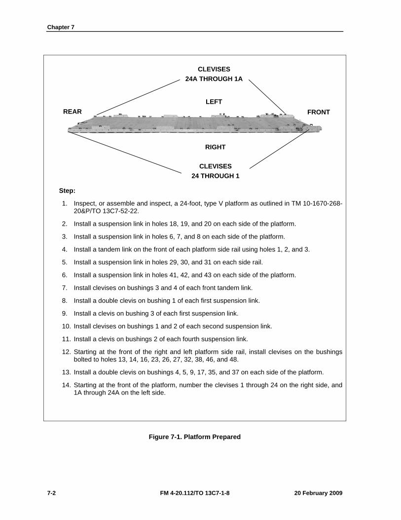
Chapter 7
7-2 FM 4-20.112/TO 13C7-1-8 20 February 2009
Step:
1. Inspect, or assemble and inspect, a 24-foot, type V platform as outlined in TM 10-1670-268-20&P/TO 13C7-52-22.
2. Install a suspension link in holes 18, 19, and 20 on each side of the platform.
3. Install a suspension link in holes 6, 7, and 8 on each side of the platform.
4. Install a tandem link on the front of each platform side rail using holes 1, 2, and 3.
5. Install a suspension link in holes 29, 30, and 31 on each side rail.
6. Install a suspension link in holes 41, 42, and 43 on each side of the platform.
7. Install clevises on bushings 3 and 4 of each front tandem link.
8. Install a double clevis on bushing 1 of each first suspension link.
9. Install a clevis on bushing 3 of each first suspension link.
10. Install clevises on bushings 1 and 2 of each second suspension link.
11. Install a clevis on bushings 2 of each fourth suspension link.
12. Starting at the front of the right and left platform side rail, install clevises on the bushings bolted to holes 13, 14, 16, 23, 26, 27, 32, 38, 46, and 48.
13. Install a double clevis on bushings 4, 5, 9, 17, 35, and 37 on each side of the platform.
14. Starting at the front of the platform, number the clevises 1 through 24 on the right side, and 1A through 24A on the left side.
Figure 7-1. Platform Prepared
CLEVISES 24 THROUGH 1
RIGHT
LEFT FRONT
CLEVISES 24A THROUGH 1A
REAR

Rigging Palletized Load System (PLS) on a 24-Foot, Type V Platform for Low-Velocity Airdrop
20 February 2009 FM 4-20.112/TO 13C7-1-8 7-3
PREPARING AND POSITIONING HONEYCOMB 7-3. Prepare ten honeycomb stacks as shown in Figures 7-2 through 7-4. Position the stacks on the platform as shown in Figure 7-5.
Stack Number
Pieces Width (Inches)
Length (Inches)
Material Instructions
1, 2, 5, and 6
1 1
24 24
76 76
Honeycomb
¾-inch plywood
Glue plywood flush over honeycomb to form base.
3 18 76 Honeycomb
Center and glue on base.
2 18 76 ¾-inch plywood
Glue flush over honeycomb.
7 18 *3 1/2 2- by 4-inch lumber
Nail one piece flush over each end of the plywood. Center a third piece between the ends. Space two pieces evenly between each end piece and the center piece.
1 12 76 ¾-inch plywood
Center and nail over lumber.
1 6 76 ¾-inch plywood
Center and nail over plywood.
* Two- by four-inch lumber is actually 3 ½ inches wide.
Figure 7-2. Stacks 1, 2, 5 and 6 Prepared

Chapter 7
7-4 FM 4-20.112/TO 13C7-1-8 20 February 2009
Stack Number
Pieces Width (Inches)
Length (Inches)
Material Instructions
3 and 4 4 2
24 24
96 96
Honeycomb
¾-inch plywood
Glue plywood flush over honeycomb to form base.
9 24 *3 1/2 2- by 4-inch lumber
Nail one piece flush over each end of the plywood. Center a third piece between the ends. Space three pieces evenly between each end piece and the center piece
1 24 96 ¾-inch plywood
Center and nail over lumber.
1 12 96 ¾-inch plywood
Center and nail over plywood.
1 6 96 ¾-inch plywood
Center and nail over plywood.
* Two- by four-inch lumber is actually 3 ½ inches wide.
Figure 7-3. Stacks 3 and 4 Prepared

Rigging Palletized Load System (PLS) on a 24-Foot, Type V Platform for Low-Velocity Airdrop
20 February 2009 FM 4-20.112/TO 13C7-1-8 7-5
Stack Number
Pieces Width (Inches)
Length (Inches)
Material Instructions
7, 8, 9, and 10
4 16 84 Honeycomb
Glue flush to form base.
2 9 84 Honeycomb
Glue flush on one side of base.
1 9 84 ¾-inch plywood
Center and glue over honeycomb.
1 9 84 Honeycomb
Center and glue over plywood.
1 *3 1/2 84 2- by 4-inch lumber
Center and glue on honeycomb.
* Two- by four-inch lumber is actually 3 ½ inches wide.
Figure 7-4. Stacks 7, 8, 9, and 10 Prepared

Chapter 7
7-6 FM 4-20.112/TO 13C7-1-8 20 February 2009
Notes. 1. This drawing is not to scale 2. All dimensions are in inches.
Stack Number
Position of Stack on the Platform
1 Place flush with the front edge of the platform and 24 inches from the right inside platform edge.
2 Place flush with the front edge of the platform and 24 inches from the left inside platform edge.
3 Place against and aligned behind stack 1. 4 Place against and aligned behind stack 2. 5 Place against and aligned behind stack 3. 6 Place against and aligned behind stack 4. 7 Place 32 inches from the front edge of the platform and flush with the right sides of
stacks 1 and 3. 8 Place 32 inches from the front edge of the platform and flush with the left sides of
stacks 2 and 4. 9 Place 22 inches to the rear of stack 7 and flush with the right sides of stacks 3 and 5. 10 Place 22 inches to the rear of stack 8 and flush with the left sides of stacks 4 and 6.
Figure 7-5. Honeycomb Stacks Positioned on Platform
10 8 24
2
1
46
5 3
9 722 32
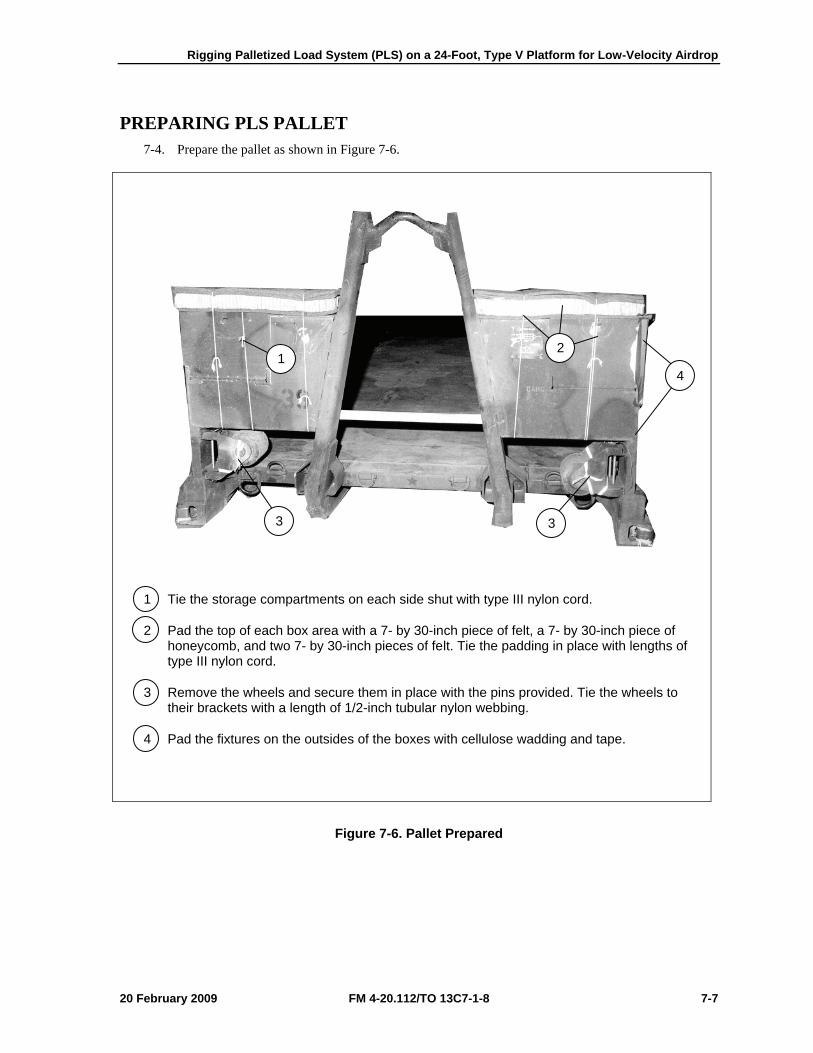
Rigging Palletized Load System (PLS) on a 24-Foot, Type V Platform for Low-Velocity Airdrop
20 February 2009 FM 4-20.112/TO 13C7-1-8 7-7
PREPARING PLS PALLET 7-4. Prepare the pallet as shown in Figure 7-6.
1 Tie the storage compartments on each side shut with type III nylon cord.
2 Pad the top of each box area with a 7- by 30-inch piece of felt, a 7- by 30-inch piece of honeycomb, and two 7- by 30-inch pieces of felt. Tie the padding in place with lengths of type III nylon cord.
3 Remove the wheels and secure them in place with the pins provided. Tie the wheels to their brackets with a length of 1/2-inch tubular nylon webbing.
4 Pad the fixtures on the outsides of the boxes with cellulose wadding and tape.
Figure 7-6. Pallet Prepared
1 2
4
3 3
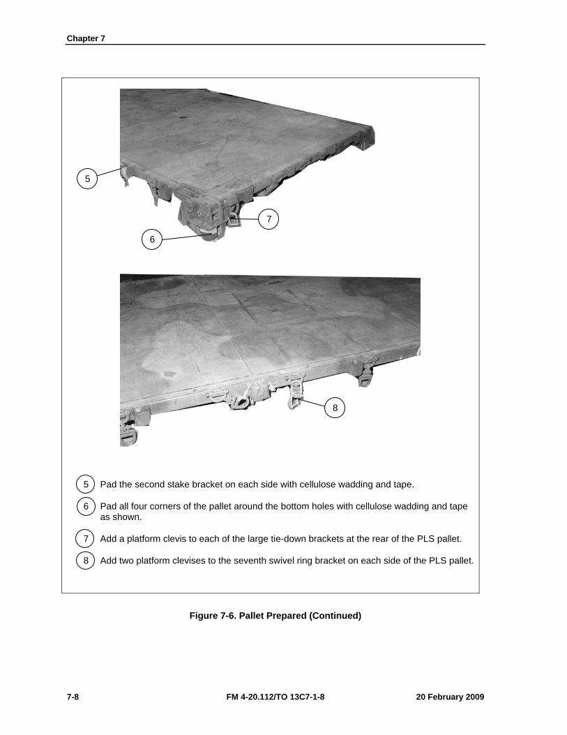
Chapter 7
7-8 FM 4-20.112/TO 13C7-1-8 20 February 2009
5 Pad the second stake bracket on each side with cellulose wadding and tape.
6 Pad all four corners of the pallet around the bottom holes with cellulose wadding and tape as shown.
7 Add a platform clevis to each of the large tie-down brackets at the rear of the PLS pallet.
8 Add two platform clevises to the seventh swivel ring bracket on each side of the PLS pallet.
Figure 7-6. Pallet Prepared (Continued)
8
6
7
5
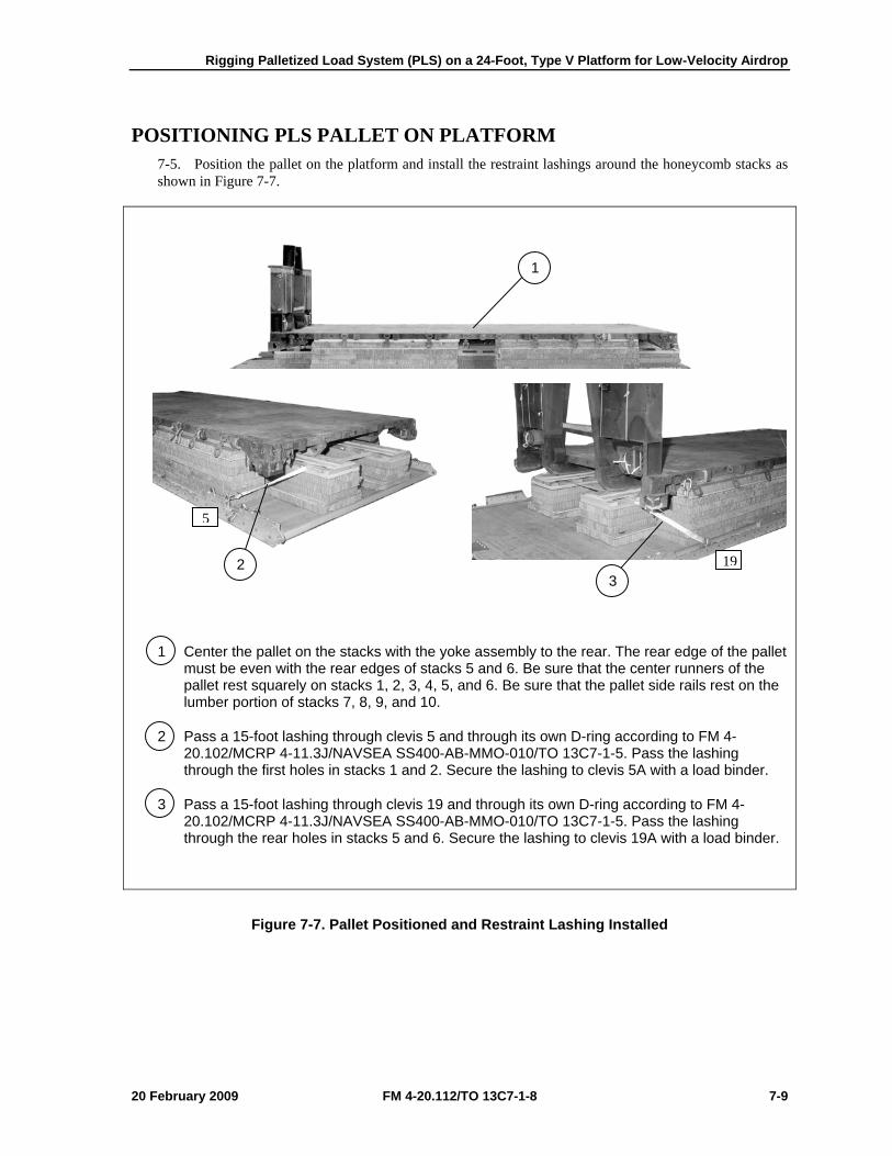
Rigging Palletized Load System (PLS) on a 24-Foot, Type V Platform for Low-Velocity Airdrop
20 February 2009 FM 4-20.112/TO 13C7-1-8 7-9
POSITIONING PLS PALLET ON PLATFORM 7-5. Position the pallet on the platform and install the restraint lashings around the honeycomb stacks as shown in Figure 7-7.
1 Center the pallet on the stacks with the yoke assembly to the rear. The rear edge of the pallet must be even with the rear edges of stacks 5 and 6. Be sure that the center runners of the pallet rest squarely on stacks 1, 2, 3, 4, 5, and 6. Be sure that the pallet side rails rest on the lumber portion of stacks 7, 8, 9, and 10.
2 Pass a 15-foot lashing through clevis 5 and through its own D-ring according to FM 4-20.102/MCRP 4-11.3J/NAVSEA SS400-AB-MMO-010/TO 13C7-1-5. Pass the lashing through the first holes in stacks 1 and 2. Secure the lashing to clevis 5A with a load binder.
3 Pass a 15-foot lashing through clevis 19 and through its own D-ring according to FM 4-20.102/MCRP 4-11.3J/NAVSEA SS400-AB-MMO-010/TO 13C7-1-5. Pass the lashing through the rear holes in stacks 5 and 6. Secure the lashing to clevis 19A with a load binder.
Figure 7-7. Pallet Positioned and Restraint Lashing Installed
1
2 3
5
19
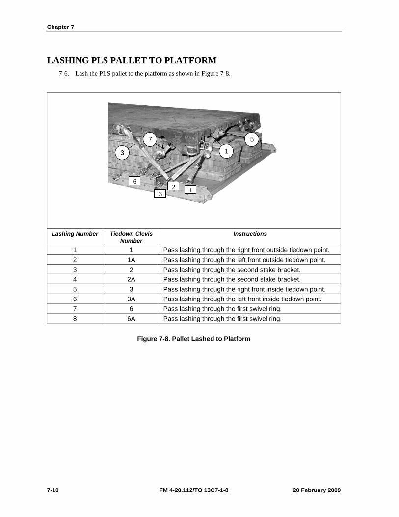
Chapter 7
7-10 FM 4-20.112/TO 13C7-1-8 20 February 2009
LASHING PLS PALLET TO PLATFORM 7-6. Lash the PLS pallet to the platform as shown in Figure 7-8.
Lashing Number Tiedown Clevis
Number Instructions
1 1 Pass lashing through the right front outside tiedown point. 2 1A Pass lashing through the left front outside tiedown point. 3 2 Pass lashing through the second stake bracket. 4 2A Pass lashing through the second stake bracket. 5 3 Pass lashing through the right front inside tiedown point. 6 3A Pass lashing through the left front inside tiedown point. 7 6 Pass lashing through the first swivel ring. 8 6A Pass lashing through the first swivel ring.
Figure 7-8. Pallet Lashed to Platform
7
3 1
5
6
32 1
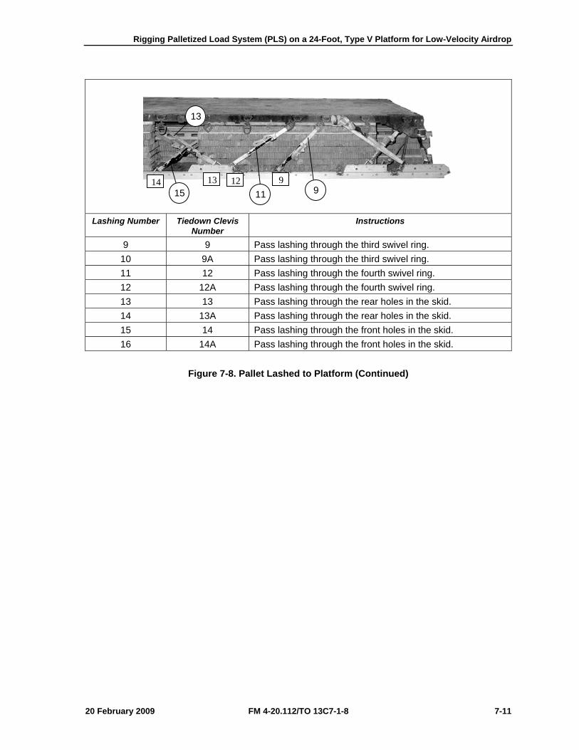
Rigging Palletized Load System (PLS) on a 24-Foot, Type V Platform for Low-Velocity Airdrop
20 February 2009 FM 4-20.112/TO 13C7-1-8 7-11
Lashing Number Tiedown Clevis
Number Instructions
9 9 Pass lashing through the third swivel ring. 10 9A Pass lashing through the third swivel ring. 11 12 Pass lashing through the fourth swivel ring. 12 12A Pass lashing through the fourth swivel ring. 13 13 Pass lashing through the rear holes in the skid. 14 13A Pass lashing through the rear holes in the skid. 15 14 Pass lashing through the front holes in the skid. 16 14A Pass lashing through the front holes in the skid.
Figure 7-8. Pallet Lashed to Platform (Continued)
14 13 12 9
13
15 11 9
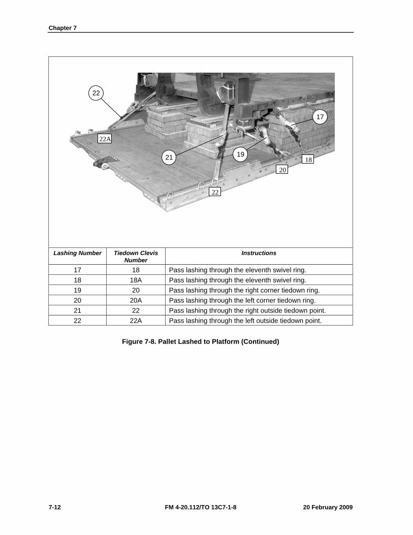
Chapter 7
7-12 FM 4-20.112/TO 13C7-1-8 20 February 2009
Lashing Number Tiedown Clevis
Number Instructions
17 18 Pass lashing through the eleventh swivel ring. 18 18A Pass lashing through the eleventh swivel ring. 19 20 Pass lashing through the right corner tiedown ring. 20 20A Pass lashing through the left corner tiedown ring. 21 22 Pass lashing through the right outside tiedown point. 22 22A Pass lashing through the left outside tiedown point.
Figure 7-8. Pallet Lashed to Platform (Continued)
22
21 19
17
22A
22
2018
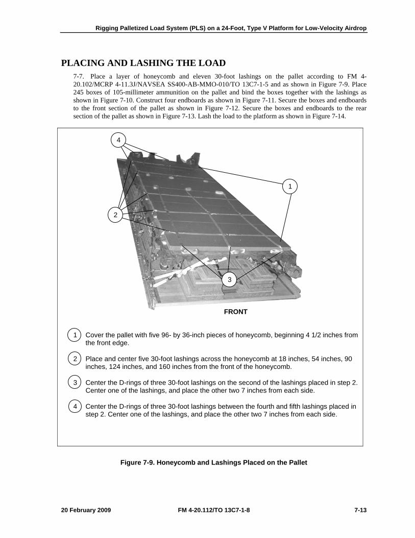
Rigging Palletized Load System (PLS) on a 24-Foot, Type V Platform for Low-Velocity Airdrop
20 February 2009 FM 4-20.112/TO 13C7-1-8 7-13
PLACING AND LASHING THE LOAD 7-7. Place a layer of honeycomb and eleven 30-foot lashings on the pallet according to FM 4-20.102/MCRP 4-11.3J/NAVSEA SS400-AB-MMO-010/TO 13C7-1-5 and as shown in Figure 7-9. Place 245 boxes of 105-millimeter ammunition on the pallet and bind the boxes together with the lashings as shown in Figure 7-10. Construct four endboards as shown in Figure 7-11. Secure the boxes and endboards to the front section of the pallet as shown in Figure 7-12. Secure the boxes and endboards to the rear section of the pallet as shown in Figure 7-13. Lash the load to the platform as shown in Figure 7-14.
1 Cover the pallet with five 96- by 36-inch pieces of honeycomb, beginning 4 1/2 inches from the front edge.
2 Place and center five 30-foot lashings across the honeycomb at 18 inches, 54 inches, 90 inches, 124 inches, and 160 inches from the front of the honeycomb.
3 Center the D-rings of three 30-foot lashings on the second of the lashings placed in step 2. Center one of the lashings, and place the other two 7 inches from each side.
4 Center the D-rings of three 30-foot lashings between the fourth and fifth lashings placed in step 2. Center one of the lashings, and place the other two 7 inches from each side.
Figure 7-9. Honeycomb and Lashings Placed on the Pallet
FRONT
4
1
2
3
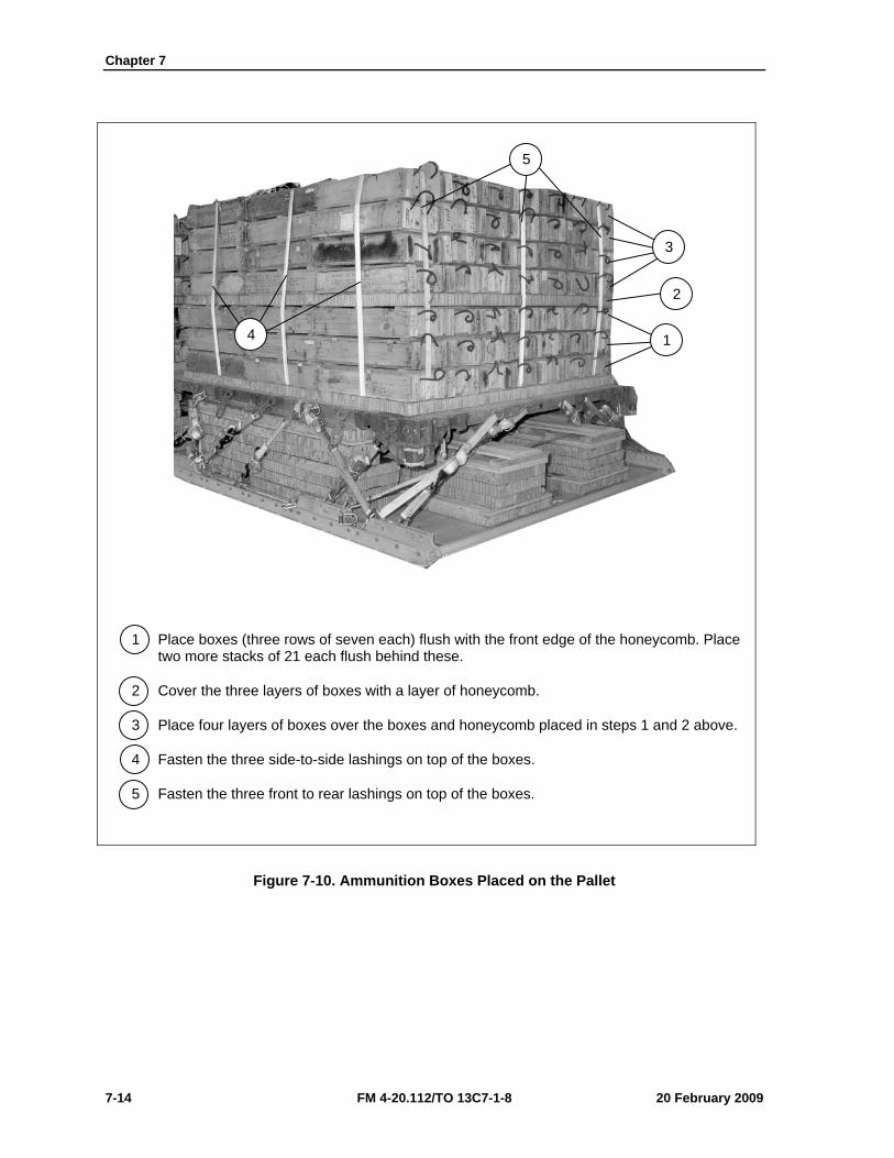
Chapter 7
7-14 FM 4-20.112/TO 13C7-1-8 20 February 2009
1 Place boxes (three rows of seven each) flush with the front edge of the honeycomb. Place two more stacks of 21 each flush behind these.
2 Cover the three layers of boxes with a layer of honeycomb.
3 Place four layers of boxes over the boxes and honeycomb placed in steps 1 and 2 above.
4 Fasten the three side-to-side lashings on top of the boxes.
5 Fasten the three front to rear lashings on top of the boxes.
Figure 7-10. Ammunition Boxes Placed on the Pallet
5
3
2
1 4
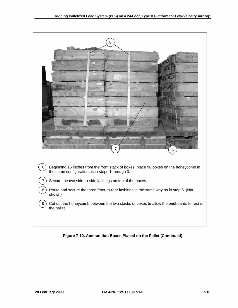
Rigging Palletized Load System (PLS) on a 24-Foot, Type V Platform for Low-Velocity Airdrop
20 February 2009 FM 4-20.112/TO 13C7-1-8 7-15
6 Beginning 16 inches from the front stack of boxes, place 98 boxes on the honeycomb in the same configuration as in steps 1 through 3.
7 Secure the two side-to-side lashings on top of the boxes.
8 Route and secure the three front-to-rear lashings in the same way as in step 5. (Not shown)
9 Cut out the honeycomb between the two stacks of boxes to allow the endboards to rest on the pallet.
Figure 7-10. Ammunition Boxes Placed on the Pallet (Continued)
8
7 6
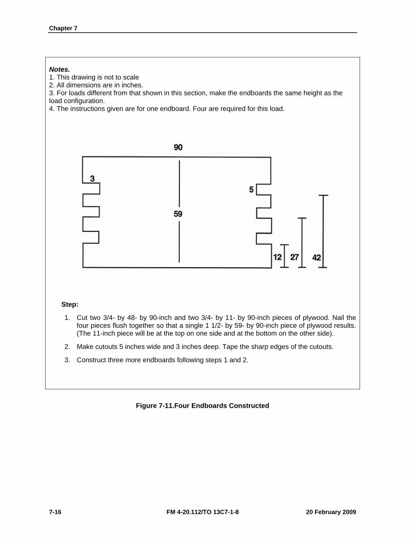
Chapter 7
7-16 FM 4-20.112/TO 13C7-1-8 20 February 2009
Notes. 1. This drawing is not to scale 2. All dimensions are in inches. 3. For loads different from that shown in this section, make the endboards the same height as the load configuration. 4. The instructions given are for one endboard. Four are required for this load.
Step:
1. Cut two 3/4- by 48- by 90-inch and two 3/4- by 11- by 90-inch pieces of plywood. Nail the four pieces flush together so that a single 1 1/2- by 59- by 90-inch piece of plywood results. (The 11-inch piece will be at the top on one side and at the bottom on the other side).
2. Make cutouts 5 inches wide and 3 inches deep. Tape the sharp edges of the cutouts.
3. Construct three more endboards following steps 1 and 2.
Figure 7-11.Four Endboards Constructed
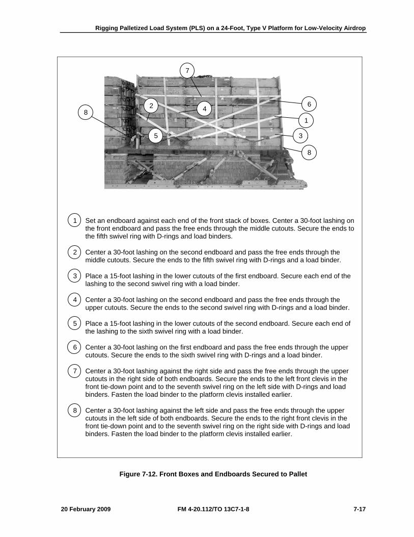
Rigging Palletized Load System (PLS) on a 24-Foot, Type V Platform for Low-Velocity Airdrop
20 February 2009 FM 4-20.112/TO 13C7-1-8 7-17
1 Set an endboard against each end of the front stack of boxes. Center a 30-foot lashing on the front endboard and pass the free ends through the middle cutouts. Secure the ends to the fifth swivel ring with D-rings and load binders.
2 Center a 30-foot lashing on the second endboard and pass the free ends through the middle cutouts. Secure the ends to the fifth swivel ring with D-rings and a load binder.
3 Place a 15-foot lashing in the lower cutouts of the first endboard. Secure each end of the lashing to the second swivel ring with a load binder.
4 Center a 30-foot lashing on the second endboard and pass the free ends through the upper cutouts. Secure the ends to the second swivel ring with D-rings and a load binder.
5 Place a 15-foot lashing in the lower cutouts of the second endboard. Secure each end of the lashing to the sixth swivel ring with a load binder.
6 Center a 30-foot lashing on the first endboard and pass the free ends through the upper cutouts. Secure the ends to the sixth swivel ring with D-rings and a load binder.
7 Center a 30-foot lashing against the right side and pass the free ends through the upper cutouts in the right side of both endboards. Secure the ends to the left front clevis in the front tie-down point and to the seventh swivel ring on the left side with D-rings and load binders. Fasten the load binder to the platform clevis installed earlier.
8 Center a 30-foot lashing against the left side and pass the free ends through the upper cutouts in the left side of both endboards. Secure the ends to the right front clevis in the front tie-down point and to the seventh swivel ring on the right side with D-rings and load binders. Fasten the load binder to the platform clevis installed earlier.
Figure 7-12. Front Boxes and Endboards Secured to Pallet
7
2 8 4
6
1
8
3 5
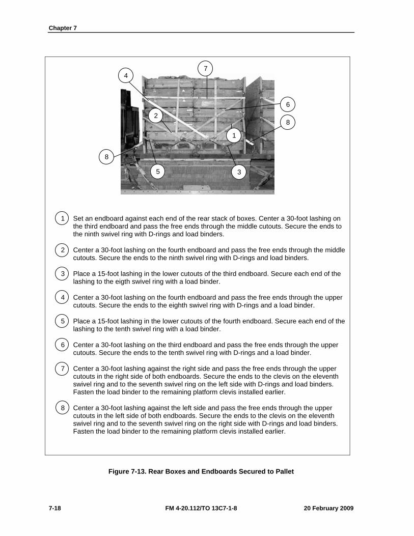
Chapter 7
7-18 FM 4-20.112/TO 13C7-1-8 20 February 2009
1 Set an endboard against each end of the rear stack of boxes. Center a 30-foot lashing on the third endboard and pass the free ends through the middle cutouts. Secure the ends to the ninth swivel ring with D-rings and load binders.
2 Center a 30-foot lashing on the fourth endboard and pass the free ends through the middle cutouts. Secure the ends to the ninth swivel ring with D-rings and load binders.
3 Place a 15-foot lashing in the lower cutouts of the third endboard. Secure each end of the lashing to the eigth swivel ring with a load binder.
4 Center a 30-foot lashing on the fourth endboard and pass the free ends through the upper cutouts. Secure the ends to the eighth swivel ring with D-rings and a load binder.
5 Place a 15-foot lashing in the lower cutouts of the fourth endboard. Secure each end of the lashing to the tenth swivel ring with a load binder.
6 Center a 30-foot lashing on the third endboard and pass the free ends through the upper cutouts. Secure the ends to the tenth swivel ring with D-rings and a load binder.
7 Center a 30-foot lashing against the right side and pass the free ends through the upper cutouts in the right side of both endboards. Secure the ends to the clevis on the eleventh swivel ring and to the seventh swivel ring on the left side with D-rings and load binders. Fasten the load binder to the remaining platform clevis installed earlier.
8 Center a 30-foot lashing against the left side and pass the free ends through the upper cutouts in the left side of both endboards. Secure the ends to the clevis on the eleventh swivel ring and to the seventh swivel ring on the right side with D-rings and load binders. Fasten the load binder to the remaining platform clevis installed earlier.
Figure 7-13. Rear Boxes and Endboards Secured to Pallet
3
8
1
6
7
2
4
8
5
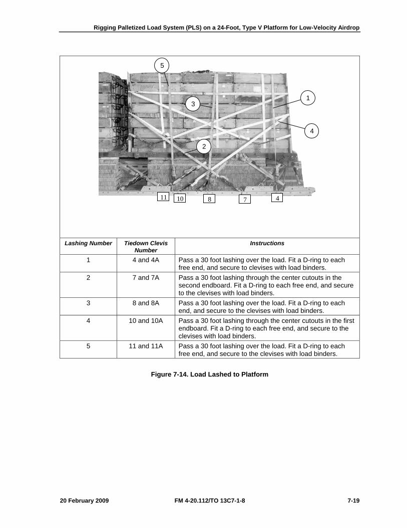
Rigging Palletized Load System (PLS) on a 24-Foot, Type V Platform for Low-Velocity Airdrop
20 February 2009 FM 4-20.112/TO 13C7-1-8 7-19
Lashing Number Tiedown Clevis
Number Instructions
1 4 and 4A Pass a 30 foot lashing over the load. Fit a D-ring to each free end, and secure to clevises with load binders.
2 7 and 7A Pass a 30 foot lashing through the center cutouts in the second endboard. Fit a D-ring to each free end, and secure to the clevises with load binders.
3 8 and 8A Pass a 30 foot lashing over the load. Fit a D-ring to each end, and secure to the clevises with load binders.
4 10 and 10A Pass a 30 foot lashing through the center cutouts in the first endboard. Fit a D-ring to each free end, and secure to the clevises with load binders.
5 11 and 11A Pass a 30 foot lashing over the load. Fit a D-ring to each free end, and secure to the clevises with load binders.
Figure 7-14. Load Lashed to Platform
4
1 3
5
2
4781011
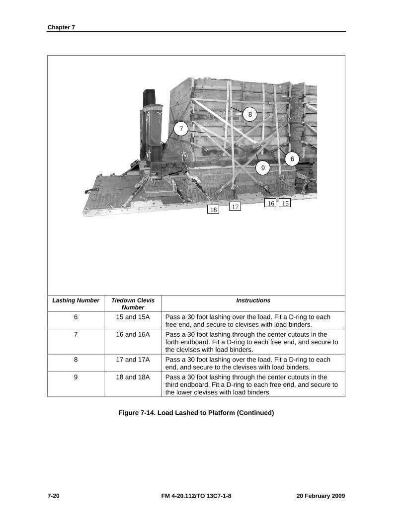
Chapter 7
7-20 FM 4-20.112/TO 13C7-1-8 20 February 2009
Lashing Number Tiedown Clevis
Number Instructions
6 15 and 15A Pass a 30 foot lashing over the load. Fit a D-ring to each free end, and secure to clevises with load binders.
7 16 and 16A Pass a 30 foot lashing through the center cutouts in the forth endboard. Fit a D-ring to each free end, and secure to the clevises with load binders.
8 17 and 17A Pass a 30 foot lashing over the load. Fit a D-ring to each end, and secure to the clevises with load binders.
9 18 and 18A Pass a 30 foot lashing through the center cutouts in the third endboard. Fit a D-ring to each free end, and secure to the lower clevises with load binders.
Figure 7-14. Load Lashed to Platform (Continued)
18 17 16 15
7
8
9 6
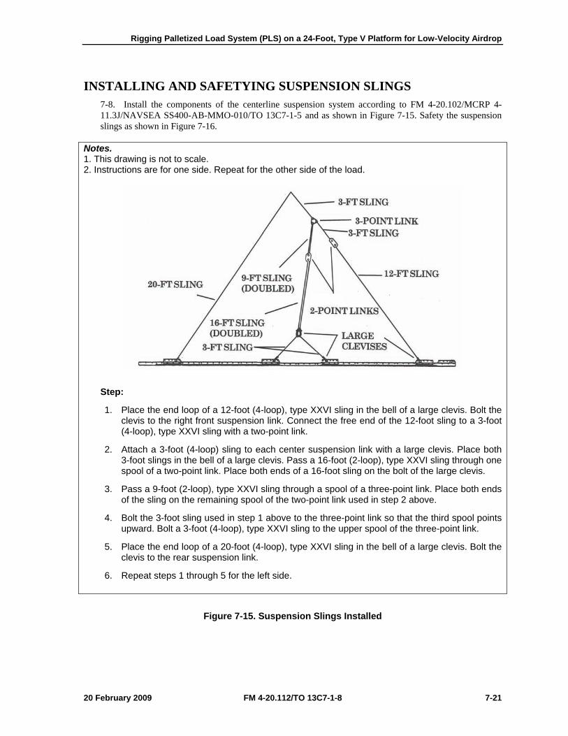
Rigging Palletized Load System (PLS) on a 24-Foot, Type V Platform for Low-Velocity Airdrop
20 February 2009 FM 4-20.112/TO 13C7-1-8 7-21
INSTALLING AND SAFETYING SUSPENSION SLINGS 7-8. Install the components of the centerline suspension system according to FM 4-20.102/MCRP 4-11.3J/NAVSEA SS400-AB-MMO-010/TO 13C7-1-5 and as shown in Figure 7-15. Safety the suspension slings as shown in Figure 7-16.
Notes. 1. This drawing is not to scale. 2. Instructions are for one side. Repeat for the other side of the load.
Step:
1. Place the end loop of a 12-foot (4-loop), type XXVI sling in the bell of a large clevis. Bolt the clevis to the right front suspension link. Connect the free end of the 12-foot sling to a 3-foot (4-loop), type XXVI sling with a two-point link.
2. Attach a 3-foot (4-loop) sling to each center suspension link with a large clevis. Place both 3-foot slings in the bell of a large clevis. Pass a 16-foot (2-loop), type XXVI sling through one spool of a two-point link. Place both ends of a 16-foot sling on the bolt of the large clevis.
3. Pass a 9-foot (2-loop), type XXVI sling through a spool of a three-point link. Place both ends of the sling on the remaining spool of the two-point link used in step 2 above.
4. Bolt the 3-foot sling used in step 1 above to the three-point link so that the third spool points upward. Bolt a 3-foot (4-loop), type XXVI sling to the upper spool of the three-point link.
5. Place the end loop of a 20-foot (4-loop), type XXVI sling in the bell of a large clevis. Bolt the clevis to the rear suspension link.
6. Repeat steps 1 through 5 for the left side.
Figure 7-15. Suspension Slings Installed
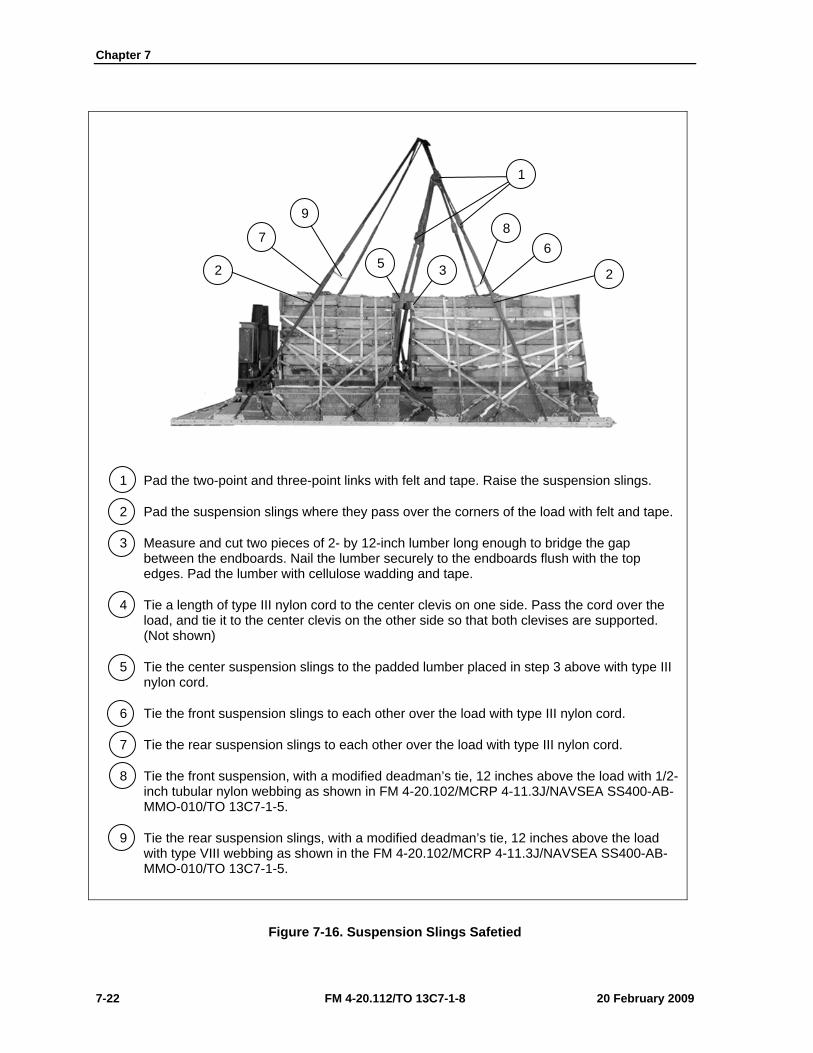
Chapter 7
7-22 FM 4-20.112/TO 13C7-1-8 20 February 2009
1 Pad the two-point and three-point links with felt and tape. Raise the suspension slings.
2 Pad the suspension slings where they pass over the corners of the load with felt and tape.
3 Measure and cut two pieces of 2- by 12-inch lumber long enough to bridge the gap between the endboards. Nail the lumber securely to the endboards flush with the top edges. Pad the lumber with cellulose wadding and tape.
4 Tie a length of type III nylon cord to the center clevis on one side. Pass the cord over the load, and tie it to the center clevis on the other side so that both clevises are supported. (Not shown)
5 Tie the center suspension slings to the padded lumber placed in step 3 above with type III nylon cord.
6 Tie the front suspension slings to each other over the load with type III nylon cord.
7 Tie the rear suspension slings to each other over the load with type III nylon cord.
8 Tie the front suspension, with a modified deadman’s tie, 12 inches above the load with 1/2-inch tubular nylon webbing as shown in FM 4-20.102/MCRP 4-11.3J/NAVSEA SS400-AB-MMO-010/TO 13C7-1-5.
9 Tie the rear suspension slings, with a modified deadman’s tie, 12 inches above the load with type VIII webbing as shown in the FM 4-20.102/MCRP 4-11.3J/NAVSEA SS400-AB-MMO-010/TO 13C7-1-5.
Figure 7-16. Suspension Slings Safetied
1
8 6
2 5 3
9
7
2
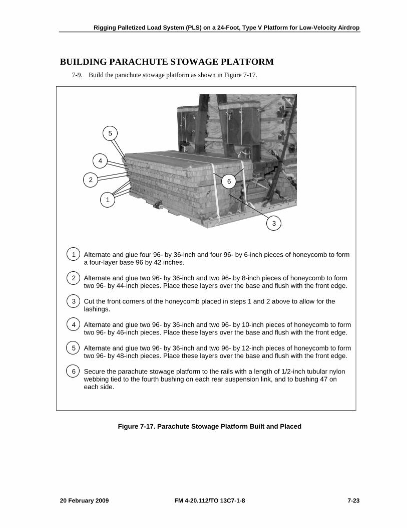
Rigging Palletized Load System (PLS) on a 24-Foot, Type V Platform for Low-Velocity Airdrop
20 February 2009 FM 4-20.112/TO 13C7-1-8 7-23
BUILDING PARACHUTE STOWAGE PLATFORM 7-9. Build the parachute stowage platform as shown in Figure 7-17.
1 Alternate and glue four 96- by 36-inch and four 96- by 6-inch pieces of honeycomb to form a four-layer base 96 by 42 inches.
2 Alternate and glue two 96- by 36-inch and two 96- by 8-inch pieces of honeycomb to form two 96- by 44-inch pieces. Place these layers over the base and flush with the front edge.
3 Cut the front corners of the honeycomb placed in steps 1 and 2 above to allow for the lashings.
4 Alternate and glue two 96- by 36-inch and two 96- by 10-inch pieces of honeycomb to form two 96- by 46-inch pieces. Place these layers over the base and flush with the front edge.
5 Alternate and glue two 96- by 36-inch and two 96- by 12-inch pieces of honeycomb to form two 96- by 48-inch pieces. Place these layers over the base and flush with the front edge.
6 Secure the parachute stowage platform to the rails with a length of 1/2-inch tubular nylon webbing tied to the fourth bushing on each rear suspension link, and to bushing 47 on each side.
Figure 7-17. Parachute Stowage Platform Built and Placed
6
3
5
4
2
1
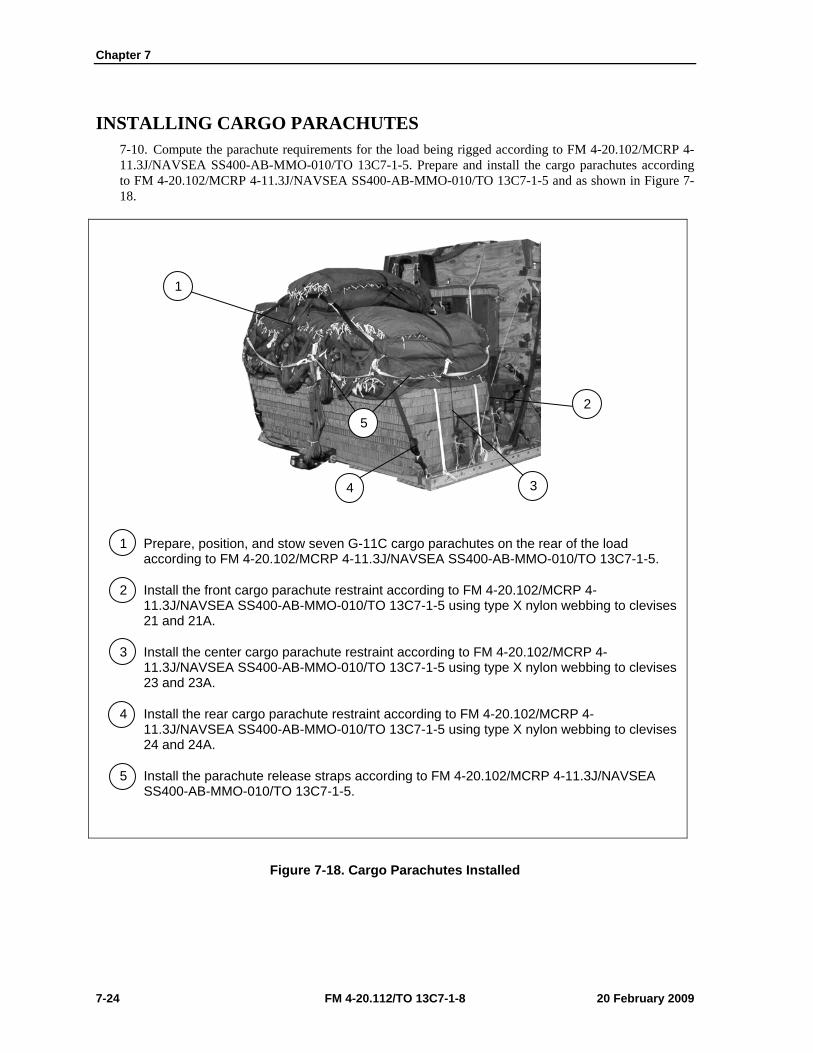
Chapter 7
7-24 FM 4-20.112/TO 13C7-1-8 20 February 2009
INSTALLING CARGO PARACHUTES 7-10. Compute the parachute requirements for the load being rigged according to FM 4-20.102/MCRP 4-11.3J/NAVSEA SS400-AB-MMO-010/TO 13C7-1-5. Prepare and install the cargo parachutes according to FM 4-20.102/MCRP 4-11.3J/NAVSEA SS400-AB-MMO-010/TO 13C7-1-5 and as shown in Figure 7-18.
1 Prepare, position, and stow seven G-11C cargo parachutes on the rear of the load according to FM 4-20.102/MCRP 4-11.3J/NAVSEA SS400-AB-MMO-010/TO 13C7-1-5.
2 Install the front cargo parachute restraint according to FM 4-20.102/MCRP 4-11.3J/NAVSEA SS400-AB-MMO-010/TO 13C7-1-5 using type X nylon webbing to clevises 21 and 21A.
3 Install the center cargo parachute restraint according to FM 4-20.102/MCRP 4-11.3J/NAVSEA SS400-AB-MMO-010/TO 13C7-1-5 using type X nylon webbing to clevises 23 and 23A.
4 Install the rear cargo parachute restraint according to FM 4-20.102/MCRP 4-11.3J/NAVSEA SS400-AB-MMO-010/TO 13C7-1-5 using type X nylon webbing to clevises 24 and 24A.
5 Install the parachute release straps according to FM 4-20.102/MCRP 4-11.3J/NAVSEA SS400-AB-MMO-010/TO 13C7-1-5.
Figure 7-18. Cargo Parachutes Installed
2
3
1
5
4
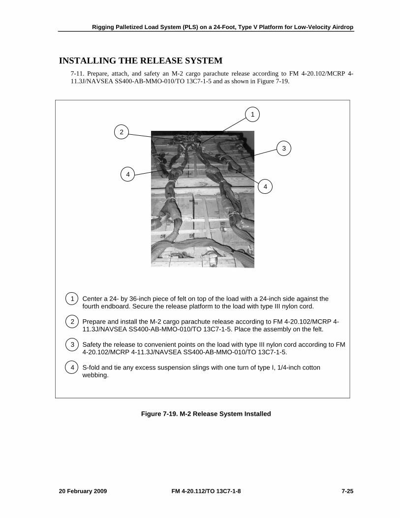
Rigging Palletized Load System (PLS) on a 24-Foot, Type V Platform for Low-Velocity Airdrop
20 February 2009 FM 4-20.112/TO 13C7-1-8 7-25
INSTALLING THE RELEASE SYSTEM 7-11. Prepare, attach, and safety an M-2 cargo parachute release according to FM 4-20.102/MCRP 4-11.3J/NAVSEA SS400-AB-MMO-010/TO 13C7-1-5 and as shown in Figure 7-19.
1 Center a 24- by 36-inch piece of felt on top of the load with a 24-inch side against the fourth endboard. Secure the release platform to the load with type III nylon cord.
2 Prepare and install the M-2 cargo parachute release according to FM 4-20.102/MCRP 4-11.3J/NAVSEA SS400-AB-MMO-010/TO 13C7-1-5. Place the assembly on the felt.
3 Safety the release to convenient points on the load with type III nylon cord according to FM 4-20.102/MCRP 4-11.3J/NAVSEA SS400-AB-MMO-010/TO 13C7-1-5.
4 S-fold and tie any excess suspension slings with one turn of type I, 1/4-inch cotton webbing.
Figure 7-19. M-2 Release System Installed
4
4
3
2
1

Chapter 7
7-26 FM 4-20.112/TO 13C7-1-8 20 February 2009
INSTALLING THE EXTRACTION SYSTEM 7-12. Install the extraction system according to FM 4-20.102/MCRP 4-11.3J/NAVSEA SS400-AB-MMO-010/TO 13C7-1-5 and as shown in Figure 7-20.
1 Install the components of the EFTC according to FM 4-20.102/MCRP 4-11.3J/NAVSEA SS400-AB-MMO-010/TO 13C7-1-5. Use the rear mounting holes for the EFTC brackets.
2 Install a 24-foot EFTC cable according to FM 4-20.102/MCRP 4-11.3J/NAVSEA SS400-AB-MMO-010/TO 13C7-1-5 and safety the cable to tiedown ring D10 with one turn of type I, 1/4-inch cotton webbing.
3 Attach a 9-foot (2-loop), type XXVI nylon sling according to FM 4-20.102/MCRP 4-11.3J/NAVSEA SS400-AB-MMO-010/TO 13C7-1-5 to be used as a deployment line. S-fold the excess and tie it in two places with type I, 1/4-inch cotton webbing.
Figure 7-20. Extraction System Installed
1
3
2
D10

Rigging Palletized Load System (PLS) on a 24-Foot, Type V Platform for Low-Velocity Airdrop
20 February 2009 FM 4-20.112/TO 13C7-1-8 7-27
PLACING EXTRACTION PARACHUTE 7-13. Select the extraction parachute and extraction line needed using the extraction line requirements table in FM 4-20.102/MCRP 4-11.3J/NAVSEA SS400-AB-MMO-010/TO 13C7-1-5. Place the extraction parachute and line on the load for installation in the aircraft.
INSTALLING PROVISIONS FOR EMERGENCY RESTRAINTS 7-14. Select and install the provisions for the emergency aft restraints according to the emergency aft restraint requirements table in FM 4-20.102/MCRP 4-11.3J/NAVSEA SS400-AB-MMO-010/TO 13C7-1-5.
MARKING RIGGED LOAD 7-15. Mark the rigged load according to FM 4-20.102/MCRP 4-11.3J/NAVSEA SS400-AB-MMO-010/TO 13C7-1-5, and as shown in Figure 7-21. Complete Shipper’s Declaration for Dangerous Goods. If the load varies from the one shown, the weight, height, CB, and parachute requirements must be recomputed.
EQUIPMENT REQUIRED 7-16. Use the equipment listed in Table 7-1 to rig this load.
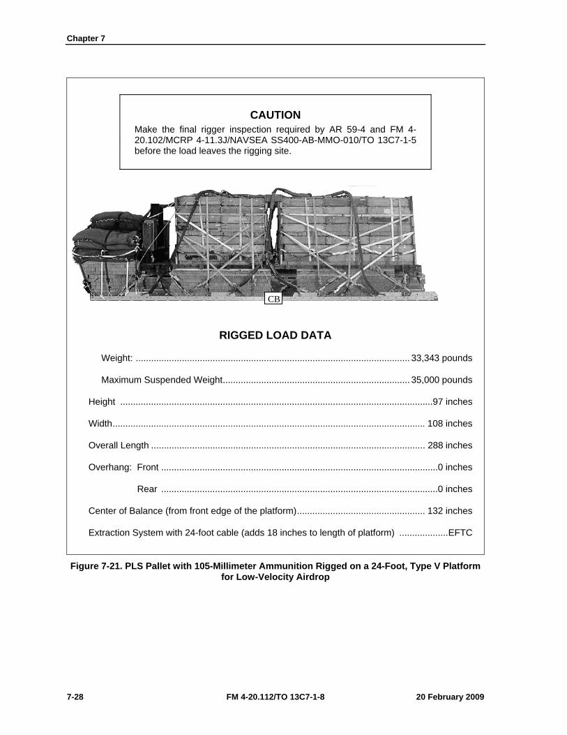
Chapter 7
7-28 FM 4-20.112/TO 13C7-1-8 20 February 2009
CAUTION Make the final rigger inspection required by AR 59-4 and FM 4-20.102/MCRP 4-11.3J/NAVSEA SS400-AB-MMO-010/TO 13C7-1-5 before the load leaves the rigging site.
RIGGED LOAD DATA
Weight: ........................................................................................................... 33,343 pounds
Maximum Suspended Weight ......................................................................... 35,000 pounds
Height ..........................................................................................................................97 inches
Width .......................................................................................................................... 108 inches
Overall Length ........................................................................................................... 288 inches
Overhang: Front ............................................................................................................ 0 inches
Rear ............................................................................................................ 0 inches
Center of Balance (from front edge of the platform) .................................................. 132 inches
Extraction System with 24-foot cable (adds 18 inches to length of platform) ................... EFTC
Figure 7-21. PLS Pallet with 105-Millimeter Ammunition Rigged on a 24-Foot, Type V Platform for Low-Velocity Airdrop
CB
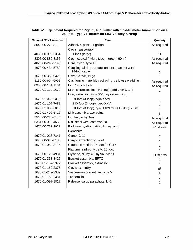
Rigging Palletized Load System (PLS) on a 24-Foot, Type V Platform for Low-Velocity Airdrop
20 February 2009 FM 4-20.112/TO 13C7-1-8 7-29
Table 7-1. Equipment Required for Rigging PLS Pallet with 105-Millimeter Ammunition on a 24-Foot, Type V Platform for Low-Velocity Airdrop
National Stock Number Item Quantity 8040-00-273-8713
4030-00-090-5354 8305-00-880-8155 4020-00-240-2146 1670-00-434-5782
1670-00-360-0328 8135-00-664-6958 8305-00-191-1101 1670-01-183-2678
1670-01-062-6313 1670-01-107-7651 1670-01-062-6313 1670-01-493-6418 5510-00-220-6146 5351-00-010-4659 1670-00-753-3928
1670-01-016-7841 1670-00-040-8135 1670-01-063-3715
1670-00-128-4981 1670-01-353-8425 1670-01-162-2372 1670-01-162-2376 1670-01-247-2389 1670-01-162-2381 1670-01-097-8817
Adhesive, paste, 1-gallon Clevis, suspension: 1-inch (large) Cloth, coated (nylon, type II, green, 60-in) Cord, nylon, type III Coupling, airdrop, extraction force transfer with 24-foot cable Cover, clevis, large Cushioning material, packaging, cellulose wadding Felt, ½-inch thick Leaf, extraction line (line bag) (add 2 for C-17) Line, extraction, type XXVI nylon webbing: 60-foot (3-loop), type XXVI 140-foot (3-loop), type XXVI 60-foot (3-loop), type XXVI for C-17 drogue line Link assembly, two-point: Lumber, 2- by 4-in Nail, steel wire, common 8d Pad, energy-dissipating, honeycomb Parachute: Cargo, G-11 Cargo, extraction, 28-foot Cargo, extraction, 15-foot for C-17 Platform, airdrop, type V, 20-foot Plywood, ¾- by 48- by 96-inches Bracket assembly, EFTC Bracket assembly, extraction Clevis assembly Suspension bracket link, type V Tandem link Release, cargo parachute, M-2
As required
14 As required As required
1 7
As required As required
2 1 1 1 5
As required As required 46 sheets
7 1 1 1
11 sheets 1 1
68 8 2 1
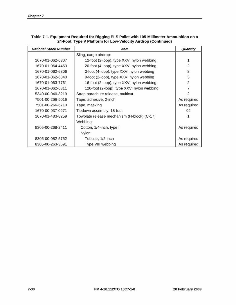
Chapter 7
7-30 FM 4-20.112/TO 13C7-1-8 20 February 2009
Table 7-1. Equipment Required for Rigging PLS Pallet with 105-Millimeter Ammunition on a 24-Foot, Type V Platform for Low-Velocity Airdrop (Continued)
National Stock Number Item Quantity
1670-01-062-6307 1670-01-064-4453 1670-01-062-6306 1670-01-062-6340 1670-01-063-7761 1670-01-062-6311 5340-00-040-8219 7501-00-266-5016 7501-00-266-6710 1670-00-937-0271 1670-01-483-8259
8305-00-268-2411
8305-00-082-5752 8305-00-263-3591
Sling, cargo airdrop: 12-foot (2-loop), type XXVI nylon webbing 20-foot (4-loop), type XXVI nylon webbing 3-foot (4-loop), type XXVI nylon webbing 9-foot (2-loop), type XXVI nylon webbing 16-foot (2-loop), type XXVI nylon webbing 120-foot (2-loop), type XXVI nylon webbing Strap parachute release, multicut Tape, adhesive, 2-inch Tape, masking Tiedown assembly, 15-foot Towplate release mechanism (H-block) (C-17) Webbing: Cotton, 1/4-inch, type I Nylon: Tubular, 1/2-inch Type VIII webbing
1 2 8 3 2 7 2
As required As required
92 1
As required
As required As required
Rigging Palletized Load System (PLS) on a 24-Foot, Type V Platform for Low-Velocity Airdrop
20 February 2009 FM 4-20.112/TO 13C7-1-8 7-31
SECTION II-RIGGING A-22 CARGO BAGS
DESCRIPTION OF LOAD 7-17. The palletized load system can be moved from the drop zone and transported on a specially designed truck. Bulk supplies are lashed to the pallet, giving the load integrity for transport. The pallet has swivel rings along the sides for lashing the load. The pallet is lashed to the airdrop platform for low-velocity airdrop. The load shown consists of eight A-22 cargo bags. Adapt these procedures to rig other items of bulk supplies. Ammunition listed in FM 4-20.153/MCPR 4-11.3B/TO 13C7-18-41, as certified for low-velocity airdrop, may be rigged using these procedures. The rigged load may not be more than 100 inches high. Refer to FM 4-20.102/MCRP 4-11.3J/NAVSEA SS400-AB-MMO-010/TO 13C7-1-5 for the weight limitations for the number of parachutes to be used.
PREPARING PLATFORM 7-18. Prepare a 24-foot, type V platform as shown in Figure 7-22.
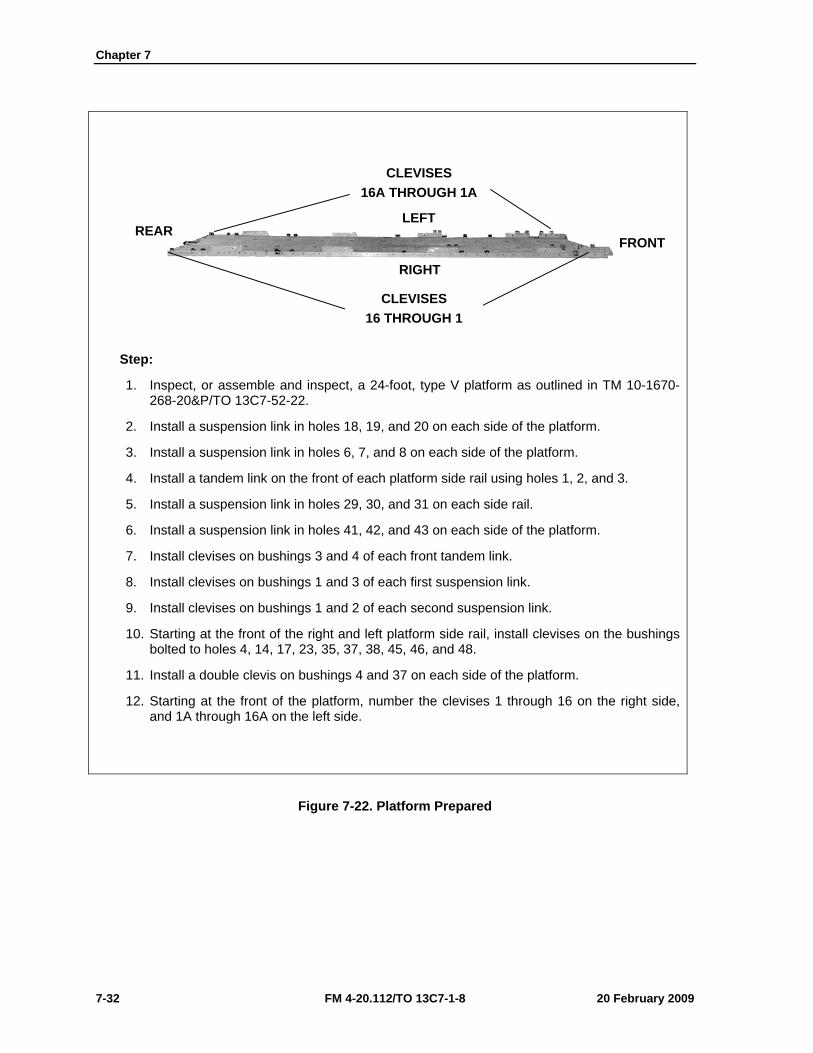
Chapter 7
7-32 FM 4-20.112/TO 13C7-1-8 20 February 2009
Step:
1. Inspect, or assemble and inspect, a 24-foot, type V platform as outlined in TM 10-1670-268-20&P/TO 13C7-52-22.
2. Install a suspension link in holes 18, 19, and 20 on each side of the platform.
3. Install a suspension link in holes 6, 7, and 8 on each side of the platform.
4. Install a tandem link on the front of each platform side rail using holes 1, 2, and 3.
5. Install a suspension link in holes 29, 30, and 31 on each side rail.
6. Install a suspension link in holes 41, 42, and 43 on each side of the platform.
7. Install clevises on bushings 3 and 4 of each front tandem link.
8. Install clevises on bushings 1 and 3 of each first suspension link.
9. Install clevises on bushings 1 and 2 of each second suspension link.
10. Starting at the front of the right and left platform side rail, install clevises on the bushings bolted to holes 4, 14, 17, 23, 35, 37, 38, 45, 46, and 48.
11. Install a double clevis on bushings 4 and 37 on each side of the platform.
12. Starting at the front of the platform, number the clevises 1 through 16 on the right side, and 1A through 16A on the left side.
Figure 7-22. Platform Prepared
CLEVISES 16 THROUGH 1
RIGHT
LEFT
FRONT
CLEVISES 16A THROUGH 1A
REAR
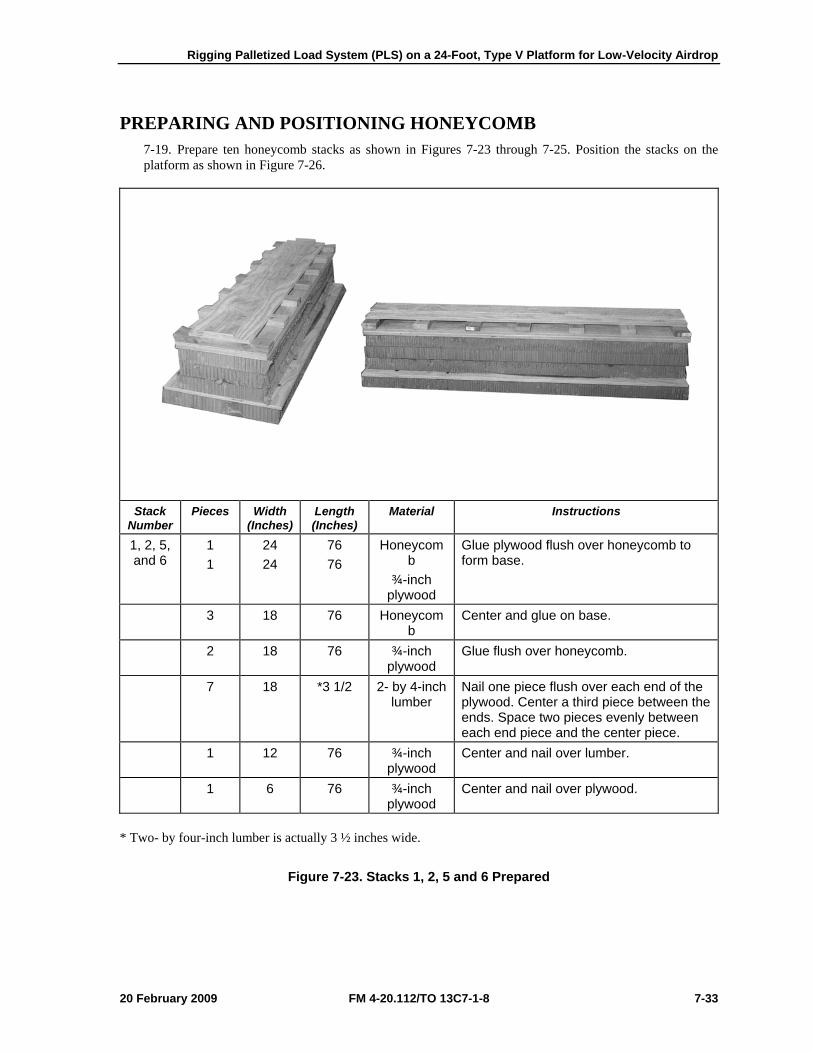
Rigging Palletized Load System (PLS) on a 24-Foot, Type V Platform for Low-Velocity Airdrop
20 February 2009 FM 4-20.112/TO 13C7-1-8 7-33
PREPARING AND POSITIONING HONEYCOMB 7-19. Prepare ten honeycomb stacks as shown in Figures 7-23 through 7-25. Position the stacks on the platform as shown in Figure 7-26.
Stack Number
Pieces Width (Inches)
Length (Inches)
Material Instructions
1, 2, 5, and 6
1 1
24 24
76 76
Honeycomb
¾-inch plywood
Glue plywood flush over honeycomb to form base.
3 18 76 Honeycomb
Center and glue on base.
2 18 76 ¾-inch plywood
Glue flush over honeycomb.
7 18 *3 1/2 2- by 4-inch lumber
Nail one piece flush over each end of the plywood. Center a third piece between the ends. Space two pieces evenly between each end piece and the center piece.
1 12 76 ¾-inch plywood
Center and nail over lumber.
1 6 76 ¾-inch plywood
Center and nail over plywood.
* Two- by four-inch lumber is actually 3 ½ inches wide.
Figure 7-23. Stacks 1, 2, 5 and 6 Prepared
Chapter 7
7-34 FM 4-20.112/TO 13C7-1-8 20 February 2009
Stack Number
Pieces Width (Inches)
Length (Inches)
Material Instructions
3 and 4 4 2
24 24
96 96
Honeycomb
¾-inch plywood
Glue plywood flush over honeycomb to form base.
9 24 *3 1/2 2- by 4-inch lumber
Nail one piece flush over each end of the plywood. Center a third piece between the ends. Space three pieces evenly between each end piece and the center piece.
1 24 96 ¾-inch plywood
Center and nail over lumber.
1 12 96 ¾-inch plywood
Center and nail over plywood.
1 6 96 ¾-inch plywood
Center and nail over plywood.
* Two- by four-inch lumber is actually 3 ½ inches wide.
Figure 7-24. Stacks 3 and 4 Prepared
Rigging Palletized Load System (PLS) on a 24-Foot, Type V Platform for Low-Velocity Airdrop
20 February 2009 FM 4-20.112/TO 13C7-1-8 7-35
Stack Number
Pieces Width (Inches)
Length (Inches)
Material Instructions
7, 8, 9, and 10
4 16 84 Honeycomb
Glue flush to form base.
2 9 84 Honeycomb
Glue flush on one side of base.
1 9 84 ¾-inch plywood
Center and glue over honeycomb.
1 9 84 Honeycomb
Center and glue over plywood.
1 *3 1/2 84 2- by 4-inch lumber
Center and glue on honeycomb.
* Two- by four-inch lumber is actually 3 ½ inches wide.
Figure 7-25. Stacks 7, 8, 9, and 10 Prepared
Chapter 7
7-36 FM 4-20.112/TO 13C7-1-8 20 February 2009
Notes. 1. This drawing is not to scale 2. All dimensions are in inches.
Stack Number
Position of Stack on the Platform
1 Place flush with the front edge of the platform and 24 inches from the right inside platform edge.
2 Place flush with the front edge of the platform and 24 inches from the left inside platform edge.
3 Place against and aligned behind stack 1. 4 Place against and aligned behind stack 2. 5 Place against and aligned behind stack 3. 6 Place against and aligned behind stack 4. 7 Place 32 inches from the front edge of the platform and flush with the right sides of
stacks 1 and 3. 8 Place 32 inches from the front edge of the platform and flush with the left sides of
stacks 2 and 4. 9 Place 22 inches to the rear of stack 7 and flush with the right sides of stacks 3 and 5. 10 Place 22 inches to the rear of stack 8 and flush with the left sides of stacks 4 and 6.
Figure 7-26. Honeycomb Stacks Positioned on Platform
10 8 24
2
1
46
5 3
9 722 32

Rigging Palletized Load System (PLS) on a 24-Foot, Type V Platform for Low-Velocity Airdrop
20 February 2009 FM 4-20.112/TO 13C7-1-8 7-37
PREPARING PLS PALLET 7-20. Prepare the pallet as shown in Figure 7-27.
1 Tie the storage compartments on each side shut with type III nylon cord.
2 Pad the top of each box area with a 7- by 30-inch piece of felt, a 7- by 30-inch piece of honeycomb, and two 7- by 30-inch pieces of felt. Tie the padding in place with lengths of type III nylon cord.
3 Remove the wheels and secure them in place with the pins provided. Tie the wheels to their brackets with a length of 1/2-inch tubular nylon webbing.
4 Pad the fixtures on the outsides of the boxes with cellulose wadding and tape.
Figure 7-27. Pallet Prepared
1 2
4
3 3

Chapter 7
7-38 FM 4-20.112/TO 13C7-1-8 20 February 2009
5 Pad the first, second, third, fifth, and ninth stake brackets on each side with cellulose wadding and tape.
6 Pad all four corners of the PLS pallet around the bottom holes with cellulose wadding and tape as shown.
7 Add a platform clevis to each of the large tiedown brackets at the rear of the PLS pallet.
8 Add two platform clevises on the bracket for sixth swivel ring bracket on each side. Tie the seventh swivel ring to the stake bracket with type I, 1/4-inch cotton webbing.
9 Add three platform clevises to the fourth swivel ring bracket on each side of the PLS pallet.
10 Add two clevises to the eleventh swivel ring bracket on each side of the PLS pallet.
Figure 7-27. Pallet Prepared (Continued)
5
5
9
5
10 5 8
7
6
Rigging Palletized Load System (PLS) on a 24-Foot, Type V Platform for Low-Velocity Airdrop
20 February 2009 FM 4-20.112/TO 13C7-1-8 7-39
POSITIONING PLS PALLET ON PLATFORM 7-21. Position the pallet on the platform and install the restraint lashings around the honeycomb stacks according to FM 4-20.102/MCRP 4-11.3J/NAVSEA SS400-AB-MMO-010/TO 13C7-1-5 and as shown in Figure 7-28.
1 Center the pallet on the stacks with the yoke assembly to the rear. The rear edge of the pallet must be even with the rear edges of stacks 5 and 6. Be sure that the center runners of the pallet rest squarely on stacks 1, 2, 3, 4, 5, and 6. Be sure that the pallet side rails rest on the lumber portion of stacks 7, 8, 9, and 10.
2 Pass a 15-foot lashing through clevis 4 and through its own D-ring. Pass the lashing through the first holes in stacks 1 and 2. Secure the lashing to clevis 4A with a load binder.
3 Pass a 15-foot lashing through clevis 12 and through its own D-ring. Pass the lashing through the rear holes in stacks 5 and 6. Secure the lashing to clevis 12A with a load binder.
Figure 7-28. Pallet Positioned and Restraint Lashing Installed
1
2 3
4
12
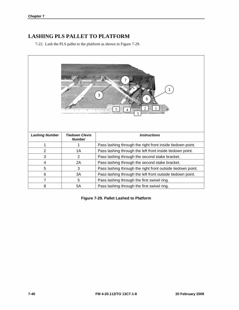
Chapter 7
7-40 FM 4-20.112/TO 13C7-1-8 20 February 2009
LASHING PLS PALLET TO PLATFORM 7-22. Lash the PLS pallet to the platform as shown in Figure 7-29.
Lashing Number Tiedown Clevis
Number Instructions
1 1 Pass lashing through the right front inside tiedown point. 2 1A Pass lashing through the left front inside tiedown point. 3 2 Pass lashing through the second stake bracket. 4 2A Pass lashing through the second stake bracket. 5 3 Pass lashing through the right front outside tiedown point. 6 3A Pass lashing through the left front outside tiedown point. 7 5 Pass lashing through the first swivel ring. 8 5A Pass lashing through the first swivel ring.
Figure 7-29. Pallet Lashed to Platform
3 1
7
5
5 43
2 1
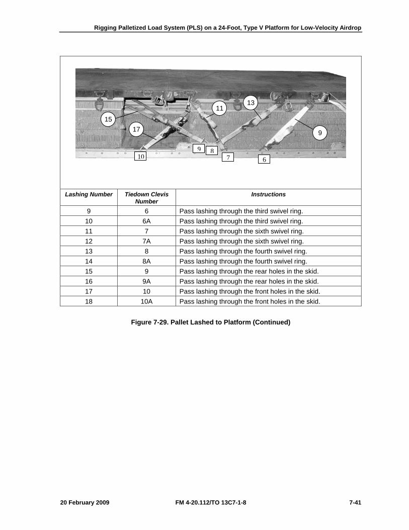
Rigging Palletized Load System (PLS) on a 24-Foot, Type V Platform for Low-Velocity Airdrop
20 February 2009 FM 4-20.112/TO 13C7-1-8 7-41
Lashing Number Tiedown Clevis
Number Instructions
9 6 Pass lashing through the third swivel ring. 10 6A Pass lashing through the third swivel ring. 11 7 Pass lashing through the sixth swivel ring. 12 7A Pass lashing through the sixth swivel ring. 13 8 Pass lashing through the fourth swivel ring. 14 8A Pass lashing through the fourth swivel ring. 15 9 Pass lashing through the rear holes in the skid. 16 9A Pass lashing through the rear holes in the skid. 17 10 Pass lashing through the front holes in the skid. 18 10A Pass lashing through the front holes in the skid.
Figure 7-29. Pallet Lashed to Platform (Continued)
9
13 11
15 17
69
78
10
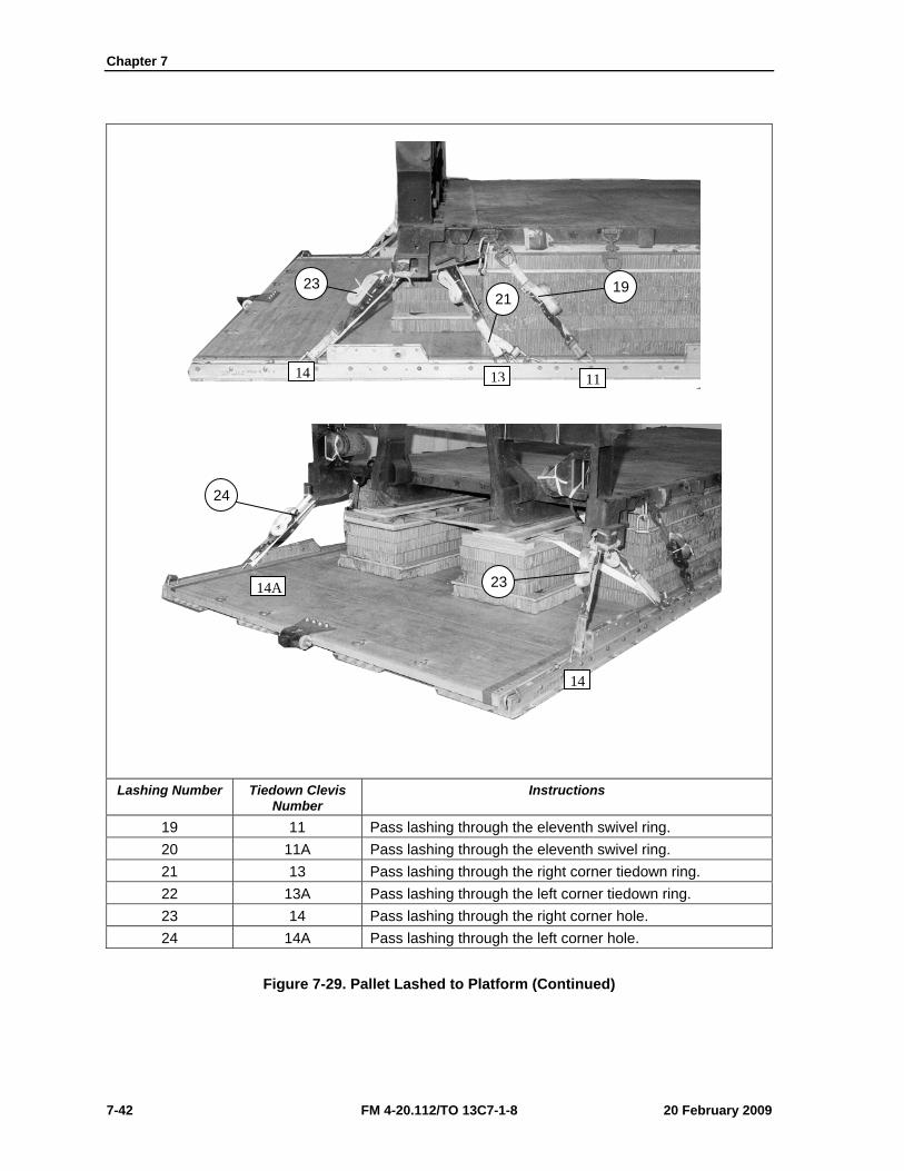
Chapter 7
7-42 FM 4-20.112/TO 13C7-1-8 20 February 2009
Lashing Number Tiedown Clevis
Number Instructions
19 11 Pass lashing through the eleventh swivel ring. 20 11A Pass lashing through the eleventh swivel ring. 21 13 Pass lashing through the right corner tiedown ring. 22 13A Pass lashing through the left corner tiedown ring. 23 14 Pass lashing through the right corner hole. 24 14A Pass lashing through the left corner hole.
Figure 7-29. Pallet Lashed to Platform (Continued)
19 21
23
24
23
14 13 11
14
14A
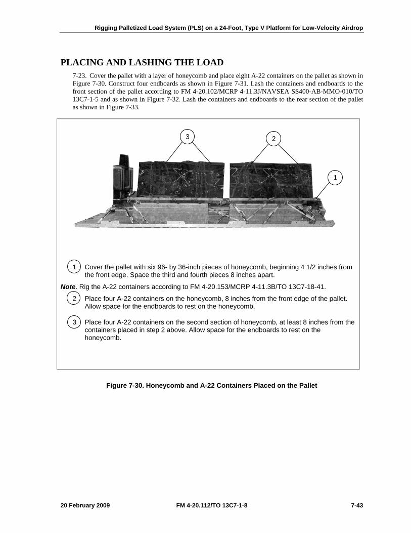
Rigging Palletized Load System (PLS) on a 24-Foot, Type V Platform for Low-Velocity Airdrop
20 February 2009 FM 4-20.112/TO 13C7-1-8 7-43
PLACING AND LASHING THE LOAD 7-23. Cover the pallet with a layer of honeycomb and place eight A-22 containers on the pallet as shown in Figure 7-30. Construct four endboards as shown in Figure 7-31. Lash the containers and endboards to the front section of the pallet according to FM 4-20.102/MCRP 4-11.3J/NAVSEA SS400-AB-MMO-010/TO 13C7-1-5 and as shown in Figure 7-32. Lash the containers and endboards to the rear section of the pallet as shown in Figure 7-33.
1 Cover the pallet with six 96- by 36-inch pieces of honeycomb, beginning 4 1/2 inches from the front edge. Space the third and fourth pieces 8 inches apart.
Note. Rig the A-22 containers according to FM 4-20.153/MCRP 4-11.3B/TO 13C7-18-41.
2 Place four A-22 containers on the honeycomb, 8 inches from the front edge of the pallet. Allow space for the endboards to rest on the honeycomb.
3 Place four A-22 containers on the second section of honeycomb, at least 8 inches from the containers placed in step 2 above. Allow space for the endboards to rest on the honeycomb.
Figure 7-30. Honeycomb and A-22 Containers Placed on the Pallet
1
3 2
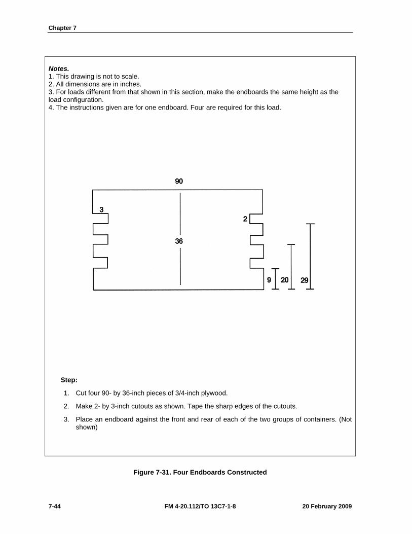
Chapter 7
7-44 FM 4-20.112/TO 13C7-1-8 20 February 2009
Notes. 1. This drawing is not to scale. 2. All dimensions are in inches. 3. For loads different from that shown in this section, make the endboards the same height as the load configuration. 4. The instructions given are for one endboard. Four are required for this load.
Step:
1. Cut four 90- by 36-inch pieces of 3/4-inch plywood.
2. Make 2- by 3-inch cutouts as shown. Tape the sharp edges of the cutouts.
3. Place an endboard against the front and rear of each of the two groups of containers. (Not shown)
Figure 7-31. Four Endboards Constructed
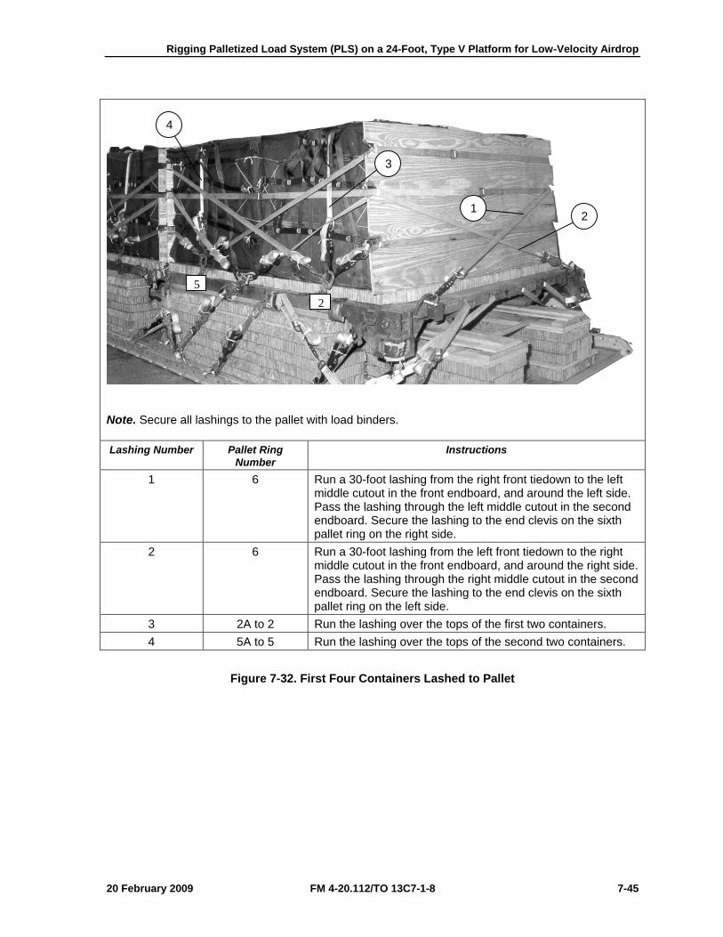
Rigging Palletized Load System (PLS) on a 24-Foot, Type V Platform for Low-Velocity Airdrop
20 February 2009 FM 4-20.112/TO 13C7-1-8 7-45
Note. Secure all lashings to the pallet with load binders. Lashing Number Pallet Ring
Number Instructions
1 6 Run a 30-foot lashing from the right front tiedown to the left middle cutout in the front endboard, and around the left side. Pass the lashing through the left middle cutout in the second endboard. Secure the lashing to the end clevis on the sixth pallet ring on the right side.
2 6 Run a 30-foot lashing from the left front tiedown to the right middle cutout in the front endboard, and around the right side. Pass the lashing through the right middle cutout in the second endboard. Secure the lashing to the end clevis on the sixth pallet ring on the left side.
3 2A to 2 Run the lashing over the tops of the first two containers. 4 5A to 5 Run the lashing over the tops of the second two containers.
Figure 7-32. First Four Containers Lashed to Pallet
4
3
1 2
25

Chapter 7
7-46 FM 4-20.112/TO 13C7-1-8 20 February 2009
Note. Secure all lashings to the pallet with load binders. Lashing Number Pallet Ring
Number Instructions
5 2A to 2 Run a lashing from the second pallet ring on each side through the lower cutouts in the first endboard.
6 4 and 4A Run a 30-foot lashing from one of the end clevises on the fourth pallet ring on each side through the middle cutouts in the first endboard.
7 5 and 5A Run a 30-foot lashing from the fifth pallet ring on both sides through the upper cutouts in the first endboard.
8 5A to 5 Run a lashing from the fifth pallet ring on each side through the lower cutouts in the second endboard.
9 4 and 4A Run a 30-foot lashing from the remaining end clevis on the fourth pallet ring on each side through the middle cutouts on the second endboard.
10 2 and 2A Run a 30-foot lashing from the second pallet ring on each side through the upper cutouts in the second endboard.
Figure 7-32. First Four Containers Lashed to Pallet (Continued)
10
7
6
5
8 9
5 4 2
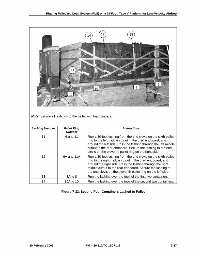
Rigging Palletized Load System (PLS) on a 24-Foot, Type V Platform for Low-Velocity Airdrop
20 February 2009 FM 4-20.112/TO 13C7-1-8 7-47
Note. Secure all lashings to the pallet with load binders. Lashing Number Pallet Ring
Number Instructions
11 6 and 11 Run a 30-foot lashing from the end clevis on the sixth pallet ring to the left middle cutout in the third endboard, and around the left side. Pass the lashing through the left middle cutout to the rear endboard. Secure the lashing to the end clevis on the eleventh pallet ring on the right side.
12 6A and 11A Run a 30-foot lashing from the end clevis on the sixth pallet ring to the right middle cutout in the third endboard, and around the right side. Pass the lashing through the right middle cutout to the rear endboard. Secure the lashing to the end clevis on the eleventh pallet ring on the left side.
13 8A to 8 Run the lashing over the tops of the first two containers. 14 10A to 10 Run the lashing over the tops of the second two containers.
Figure 7-33. Second Four Containers Lashed to Pallet
11
14 12 13
11
10 86
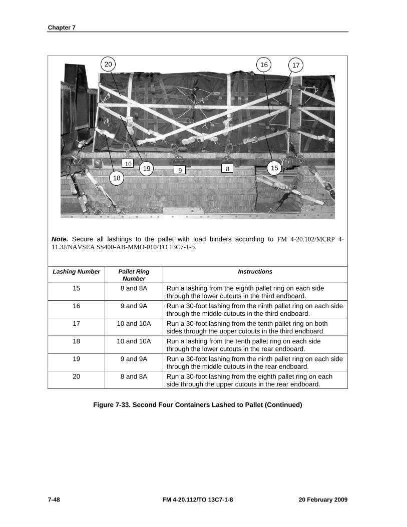
Chapter 7
7-48 FM 4-20.112/TO 13C7-1-8 20 February 2009
Note. Secure all lashings to the pallet with load binders according to FM 4-20.102/MCRP 4-11.3J/NAVSEA SS400-AB-MMO-010/TO 13C7-1-5. Lashing Number Pallet Ring
Number Instructions
15 8 and 8A Run a lashing from the eighth pallet ring on each side through the lower cutouts in the third endboard.
16 9 and 9A Run a 30-foot lashing from the ninth pallet ring on each side through the middle cutouts in the third endboard.
17 10 and 10A Run a 30-foot lashing from the tenth pallet ring on both sides through the upper cutouts in the third endboard.
18 10 and 10A Run a lashing from the tenth pallet ring on each side through the lower cutouts in the rear endboard.
19 9 and 9A Run a 30-foot lashing from the ninth pallet ring on each side through the middle cutouts in the rear endboard.
20 8 and 8A Run a 30-foot lashing from the eighth pallet ring on each side through the upper cutouts in the rear endboard.
Figure 7-33. Second Four Containers Lashed to Pallet (Continued)
10 9 819
18 15
17 16 20
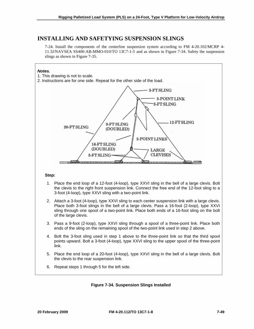
Rigging Palletized Load System (PLS) on a 24-Foot, Type V Platform for Low-Velocity Airdrop
20 February 2009 FM 4-20.112/TO 13C7-1-8 7-49
INSTALLING AND SAFETYING SUSPENSION SLINGS 7-24. Install the components of the centerline suspension system according to FM 4-20.102/MCRP 4-11.3J/NAVSEA SS400-AB-MMO-010/TO 13C7-1-5 and as shown in Figure 7-34. Safety the suspension slings as shown in Figure 7-35.
Notes. 1. This drawing is not to scale. 2. Instructions are for one side. Repeat for the other side of the load.
Step:
1. Place the end loop of a 12-foot (4-loop), type XXVI sling in the bell of a large clevis. Bolt the clevis to the right front suspension link. Connect the free end of the 12-foot sling to a 3-foot (4-loop), type XXVI sling with a two-point link.
2. Attach a 3-foot (4-loop), type XXVI sling to each center suspension link with a large clevis. Place both 3-foot slings in the bell of a large clevis. Pass a 16-foot (2-loop), type XXVI sling through one spool of a two-point link. Place both ends of a 16-foot sling on the bolt of the large clevis.
3. Pass a 9-foot (2-loop), type XXVI sling through a spool of a three-point link. Place both ends of the sling on the remaining spool of the two-point link used in step 2 above.
4. Bolt the 3-foot sling used in step 1 above to the three-point link so that the third spool points upward. Bolt a 3-foot (4-loop), type XXVI sling to the upper spool of the three-point link.
5. Place the end loop of a 20-foot (4-loop), type XXVI sling in the bell of a large clevis. Bolt the clevis to the rear suspension link.
6. Repeat steps 1 through 5 for the left side.
Figure 7-34. Suspension Slings Installed
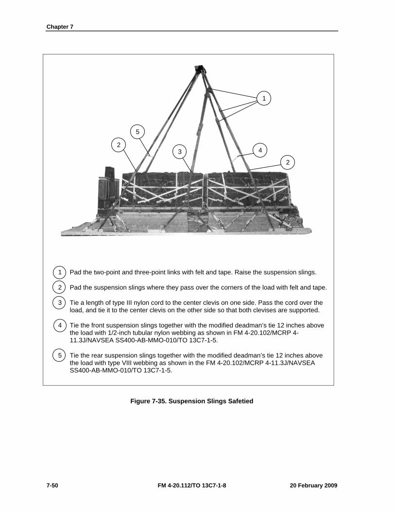
Chapter 7
7-50 FM 4-20.112/TO 13C7-1-8 20 February 2009
1 Pad the two-point and three-point links with felt and tape. Raise the suspension slings.
2 Pad the suspension slings where they pass over the corners of the load with felt and tape.
3 Tie a length of type III nylon cord to the center clevis on one side. Pass the cord over the load, and tie it to the center clevis on the other side so that both clevises are supported.
4 Tie the front suspension slings together with the modified deadman’s tie 12 inches above the load with 1/2-inch tubular nylon webbing as shown in FM 4-20.102/MCRP 4-11.3J/NAVSEA SS400-AB-MMO-010/TO 13C7-1-5.
5 Tie the rear suspension slings together with the modified deadman’s tie 12 inches above the load with type VIII webbing as shown in the FM 4-20.102/MCRP 4-11.3J/NAVSEA SS400-AB-MMO-010/TO 13C7-1-5.
Figure 7-35. Suspension Slings Safetied
1
4
2 3
5
2
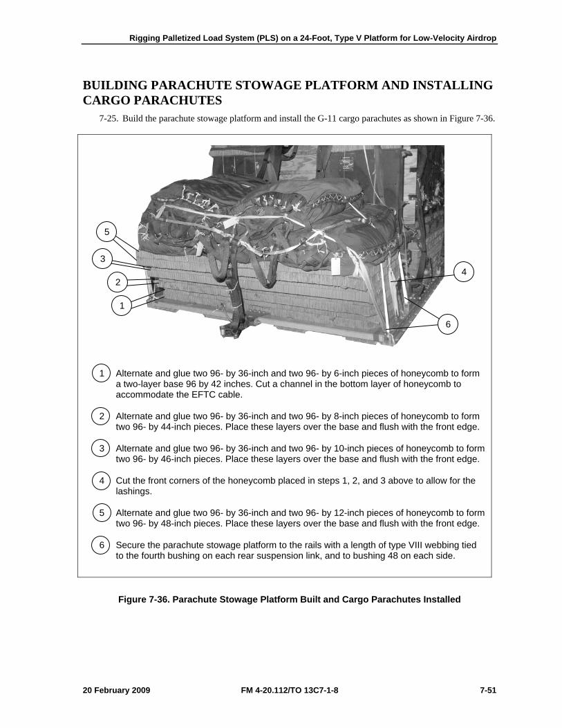
Rigging Palletized Load System (PLS) on a 24-Foot, Type V Platform for Low-Velocity Airdrop
20 February 2009 FM 4-20.112/TO 13C7-1-8 7-51
BUILDING PARACHUTE STOWAGE PLATFORM AND INSTALLING CARGO PARACHUTES
7-25. Build the parachute stowage platform and install the G-11 cargo parachutes as shown in Figure 7-36.
1 Alternate and glue two 96- by 36-inch and two 96- by 6-inch pieces of honeycomb to form a two-layer base 96 by 42 inches. Cut a channel in the bottom layer of honeycomb to accommodate the EFTC cable.
2 Alternate and glue two 96- by 36-inch and two 96- by 8-inch pieces of honeycomb to form two 96- by 44-inch pieces. Place these layers over the base and flush with the front edge.
3 Alternate and glue two 96- by 36-inch and two 96- by 10-inch pieces of honeycomb to form two 96- by 46-inch pieces. Place these layers over the base and flush with the front edge.
4 Cut the front corners of the honeycomb placed in steps 1, 2, and 3 above to allow for the lashings.
5 Alternate and glue two 96- by 36-inch and two 96- by 12-inch pieces of honeycomb to form two 96- by 48-inch pieces. Place these layers over the base and flush with the front edge.
6 Secure the parachute stowage platform to the rails with a length of type VIII webbing tied to the fourth bushing on each rear suspension link, and to bushing 48 on each side.
Figure 7-36. Parachute Stowage Platform Built and Cargo Parachutes Installed
4
6
5
3
2
1
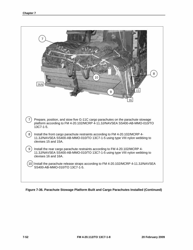
Chapter 7
7-52 FM 4-20.112/TO 13C7-1-8 20 February 2009
7 Prepare, position, and stow five G-11C cargo parachutes on the parachute stowage platform according to FM 4-20.102/MCRP 4-11.3J/NAVSEA SS400-AB-MMO-010/TO 13C7-1-5.
8 Install the front cargo parachute restraints according to FM 4-20.102/MCRP 4-11.3J/NAVSEA SS400-AB-MMO-010/TO 13C7-1-5 using type VIII nylon webbing to clevises 15 and 15A.
9 Install the rear cargo parachute restraints according to FM 4-20.102/MCRP 4-11.3J/NAVSEA SS400-AB-MMO-010/TO 13C7-1-5 using type VIII nylon webbing to clevises 16 and 16A.
10 Install the parachute release straps according to FM 4-20.102/MCRP 4-11.3J/NAVSEA SS400-AB-MMO-010/TO 13C7-1-5.
Figure 7-36. Parachute Stowage Platform Built and Cargo Parachutes Installed (Continued)
8
9
10
7
16A
16
15
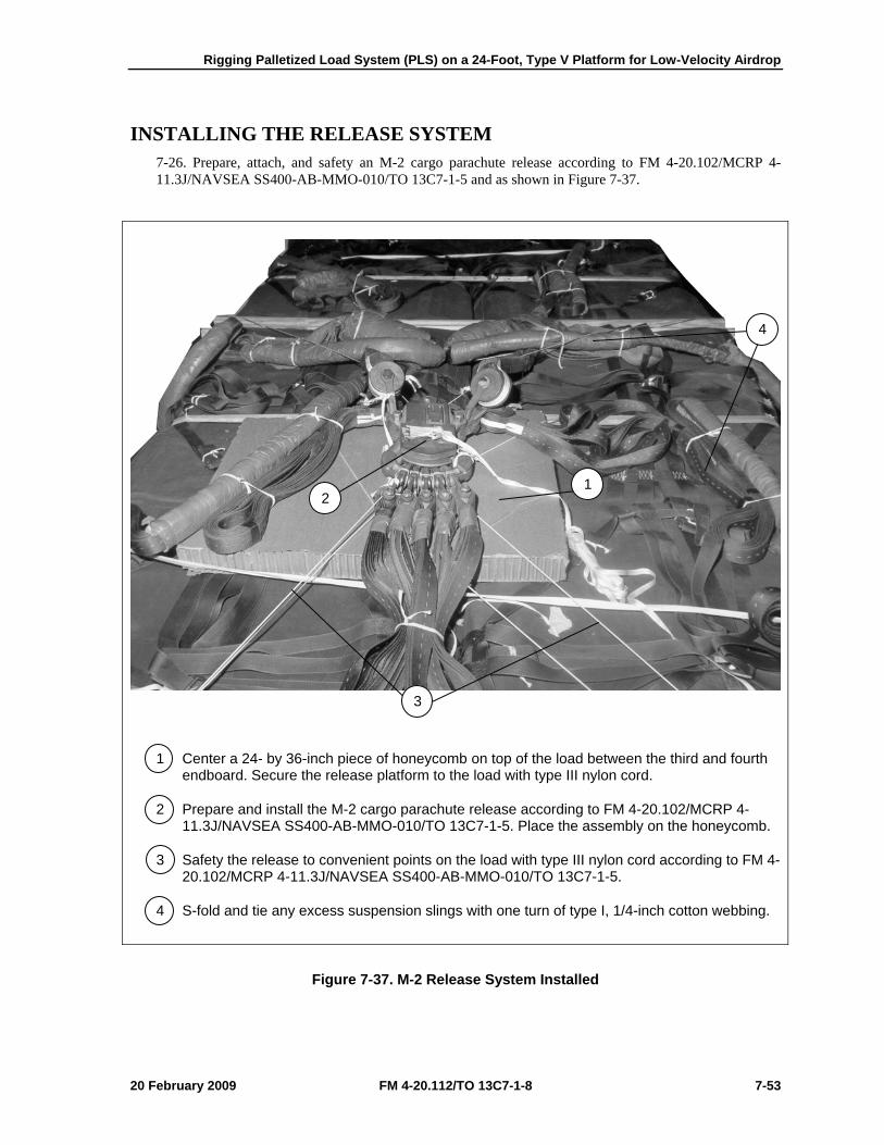
Rigging Palletized Load System (PLS) on a 24-Foot, Type V Platform for Low-Velocity Airdrop
20 February 2009 FM 4-20.112/TO 13C7-1-8 7-53
INSTALLING THE RELEASE SYSTEM 7-26. Prepare, attach, and safety an M-2 cargo parachute release according to FM 4-20.102/MCRP 4-11.3J/NAVSEA SS400-AB-MMO-010/TO 13C7-1-5 and as shown in Figure 7-37.
1 Center a 24- by 36-inch piece of honeycomb on top of the load between the third and fourth endboard. Secure the release platform to the load with type III nylon cord.
2 Prepare and install the M-2 cargo parachute release according to FM 4-20.102/MCRP 4-11.3J/NAVSEA SS400-AB-MMO-010/TO 13C7-1-5. Place the assembly on the honeycomb.
3 Safety the release to convenient points on the load with type III nylon cord according to FM 4-20.102/MCRP 4-11.3J/NAVSEA SS400-AB-MMO-010/TO 13C7-1-5.
4 S-fold and tie any excess suspension slings with one turn of type I, 1/4-inch cotton webbing.
Figure 7-37. M-2 Release System Installed
4
2 1
3
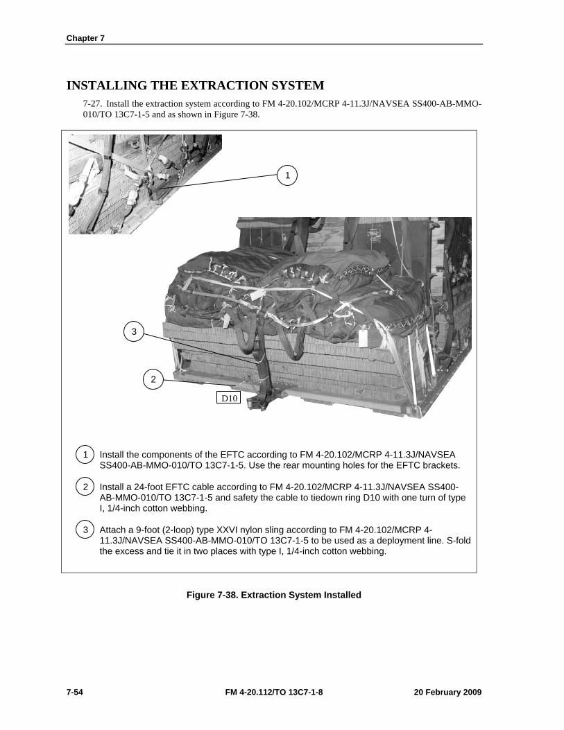
Chapter 7
7-54 FM 4-20.112/TO 13C7-1-8 20 February 2009
INSTALLING THE EXTRACTION SYSTEM 7-27. Install the extraction system according to FM 4-20.102/MCRP 4-11.3J/NAVSEA SS400-AB-MMO-010/TO 13C7-1-5 and as shown in Figure 7-38.
1 Install the components of the EFTC according to FM 4-20.102/MCRP 4-11.3J/NAVSEA SS400-AB-MMO-010/TO 13C7-1-5. Use the rear mounting holes for the EFTC brackets.
2 Install a 24-foot EFTC cable according to FM 4-20.102/MCRP 4-11.3J/NAVSEA SS400-AB-MMO-010/TO 13C7-1-5 and safety the cable to tiedown ring D10 with one turn of type I, 1/4-inch cotton webbing.
3 Attach a 9-foot (2-loop) type XXVI nylon sling according to FM 4-20.102/MCRP 4-11.3J/NAVSEA SS400-AB-MMO-010/TO 13C7-1-5 to be used as a deployment line. S-fold the excess and tie it in two places with type I, 1/4-inch cotton webbing.
Figure 7-38. Extraction System Installed
1
3
3
2
D10
Rigging Palletized Load System (PLS) on a 24-Foot, Type V Platform for Low-Velocity Airdrop
20 February 2009 FM 4-20.112/TO 13C7-1-8 7-55
PLACING EXTRACTION PARACHUTE 7-28. Select the extraction parachute and extraction line needed using the extraction line requirements table in FM 4-20.102/MCRP 4-11.3J/NAVSEA SS400-AB-MMO-010/TO 13C7-1-5. Place the extraction parachute and line on the load for installation in the aircraft.
INSTALLING PROVISIONS FOR EMERGENCY RESTRAINTS 7-29. Select and install the provisions for the emergency aft restraints according to the emergency aft restraint requirements table in FM 4-20.102/MCRP 4-11.3J/NAVSEA SS400-AB-MMO-010/TO 13C7-1-5.
MARKING RIGGED LOAD 7-30. Mark the rigged load according to FM 4-20.102/MCRP 4-11.3J/NAVSEA SS400-AB-MMO-010/TO 13C7-1-5, and as shown in Figure 7-39. Complete Shipper’s Declaration for Dangerous Goods. If the load varies from the one shown, the weight, height, CB, and parachute requirements must be recomputed.
EQUIPMENT REQUIRED 7-31. Use the equipment listed in Table 7-2 to rig this load.
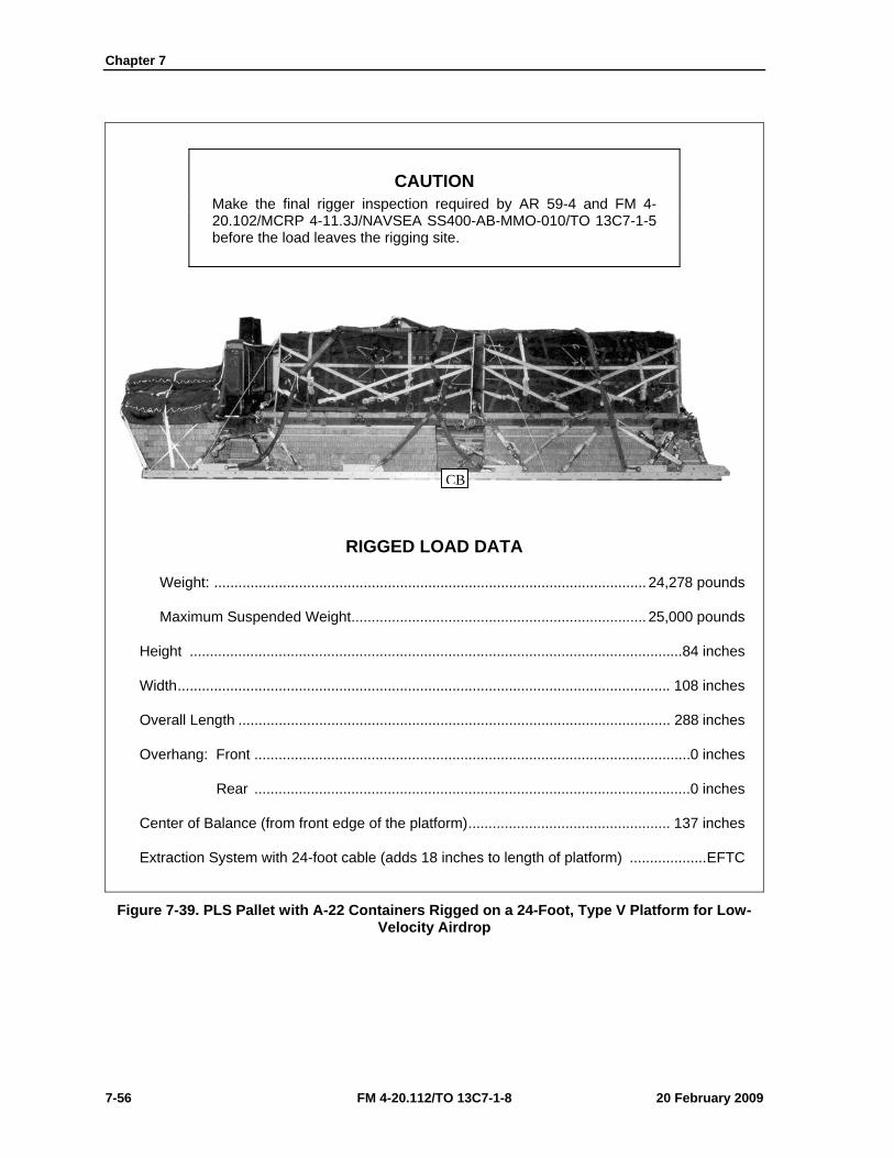
Chapter 7
7-56 FM 4-20.112/TO 13C7-1-8 20 February 2009
CAUTION Make the final rigger inspection required by AR 59-4 and FM 4-20.102/MCRP 4-11.3J/NAVSEA SS400-AB-MMO-010/TO 13C7-1-5 before the load leaves the rigging site.
RIGGED LOAD DATA
Weight: ........................................................................................................... 24,278 pounds
Maximum Suspended Weight ......................................................................... 25,000 pounds
Height ..........................................................................................................................84 inches
Width .......................................................................................................................... 108 inches
Overall Length ........................................................................................................... 288 inches
Overhang: Front ............................................................................................................ 0 inches
Rear ............................................................................................................ 0 inches
Center of Balance (from front edge of the platform) .................................................. 137 inches
Extraction System with 24-foot cable (adds 18 inches to length of platform) ................... EFTC
Figure 7-39. PLS Pallet with A-22 Containers Rigged on a 24-Foot, Type V Platform for Low-Velocity Airdrop
CB
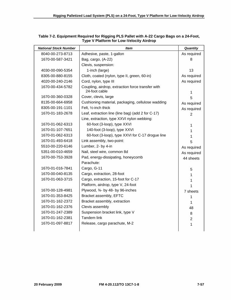
Rigging Palletized Load System (PLS) on a 24-Foot, Type V Platform for Low-Velocity Airdrop
20 February 2009 FM 4-20.112/TO 13C7-1-8 7-57
Table 7-2. Equipment Required for Rigging PLS Pallet with A-22 Cargo Bags on a 24-Foot, Type V Platform for Low-Velocity Airdrop
National Stock Number Item Quantity 8040-00-273-8713 1670-00-587-3421
4030-00-090-5354 8305-00-880-8155 4020-00-240-2146 1670-00-434-5782
1670-00-360-0328 8135-00-664-6958 8305-00-191-1101 1670-01-183-2678
1670-01-062-6313 1670-01-107-7651 1670-01-062-6313 1670-01-493-6418 5510-00-220-6146 5351-00-010-4659 1670-00-753-3928
1670-01-016-7841 1670-00-040-8135 1670-01-063-3715
1670-00-128-4981 1670-01-353-8425 1670-01-162-2372 1670-01-162-2376 1670-01-247-2389 1670-01-162-2381 1670-01-097-8817
Adhesive, paste, 1-gallon Bag, cargo, (A-22) Clevis, suspension: 1-inch (large) Cloth, coated (nylon, type II, green, 60-in) Cord, nylon, type III Coupling, airdrop, extraction force transfer with 24-foot cable Cover, clevis, large Cushioning material, packaging, cellulose wadding Felt, ½-inch thick Leaf, extraction line (line bag) (add 2 for C-17) Line, extraction, type XXVI nylon webbing: 60-foot (3-loop), type XXVI 140-foot (3-loop), type XXVI 60-foot (3-loop), type XXVI for C-17 drogue line Link assembly, two-point: Lumber, 2- by 4-in Nail, steel wire, common 8d Pad, energy-dissipating, honeycomb Parachute: Cargo, G-11 Cargo, extraction, 28-foot Cargo, extraction, 15-foot for C-17 Platform, airdrop, type V, 24-foot Plywood, ¾- by 48- by 96-inches Bracket assembly, EFTC Bracket assembly, extraction Clevis assembly Suspension bracket link, type V Tandem link Release, cargo parachute, M-2
As required 8
13 As required As required
1 5
As required As required
2 1 1 1 5
As required As required 44 sheets
5 1 1 1
7 sheets 1 1
48 8 2 1

Chapter 7
7-58 FM 4-20.112/TO 13C7-1-8 20 February 2009
Table 7-2. Equipment Required for Rigging PLS Pallet with A-22 Cargo Bags on a 24-Foot, Type V Platform for Low-Velocity Airdrop (Continued)
National Stock Number Item Quantity
1670-01-062-6307 1670-01-064-4453 1670-01-062-6306 1670-01-062-6340 1670-01-063-7761 1670-01-062-6311 5340-00-040-8219 7501-00-266-5016 7501-00-266-6710 1670-00-937-0271 1670-01-483-8259
8305-00-268-2411
8305-00-082-5752 8305-00-263-3591
Sling, cargo airdrop: 12-foot (2-loop), type XXVI nylon webbing 20-foot (4-loop), type XXVI nylon webbing 3-foot (4-loop), type XXVI nylon webbing 9-foot (2-loop), type XXVI nylon webbing 16-foot (2-loop), type XXVI nylon webbing 120-foot (2-loop), type XXVI nylon webbing Strap parachute release, multicut Tape, adhesive, 2-inch Tape, masking Tie-down assembly, 15-foot Towplate release mechanism (H-block) (C-17) Webbing: Cotton, 1/4-inch, type I Nylon: Tubular, 1/2-inch Type VIII webbing
1 2 8 3 2 7 2
As required As required
58 1
As required
As required As required
20 February 2009 FM 4-20.112/TO 13C7-1-8 8-1
Chapter 8
Rigging 155-Millimeter (MM) Ammunition Modular Artillery Charge System Package (MACS PAC) on a Type V Platform
for Low-Velocity Airdrop
SECTION I-RIGGING THE MACS PAC ON AN 8-FOOT, TYPE V PLATFORM
DESCRIPTION OF LOAD 8-1. Forty-eight 155-millimeter projectiles, twenty-four (M231) powder canisters and six fuse cans are rigged for low-velocity airdrop on an 8-foot, type V airdrop platform. The load uses two G-11B cargo parachutes.
Notes. 1. The load shown is using metal crates. However, wooden crates may be used with three lashings and a load binder. 2. If the metal locking rods are missing, three lashings, D-rings and load binders will be needed.
PREPARING PLATFORM 8-2. Prepare an 8-foot, type V platform as shown in Figure 8-1.
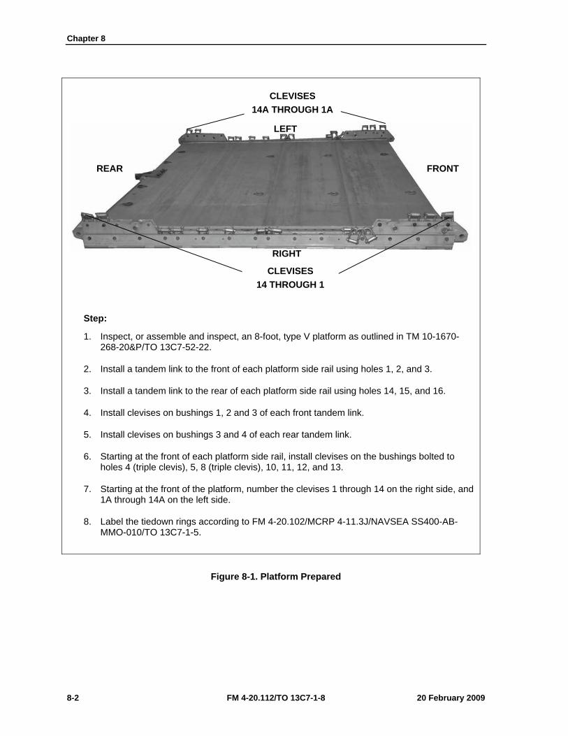
Chapter 8
8-2 FM 4-20.112/TO 13C7-1-8 20 February 2009
Step:
1. Inspect, or assemble and inspect, an 8-foot, type V platform as outlined in TM 10-1670-268-20&P/TO 13C7-52-22.
2. Install a tandem link to the front of each platform side rail using holes 1, 2, and 3.
3. Install a tandem link to the rear of each platform side rail using holes 14, 15, and 16.
4. Install clevises on bushings 1, 2 and 3 of each front tandem link.
5. Install clevises on bushings 3 and 4 of each rear tandem link.
6. Starting at the front of each platform side rail, install clevises on the bushings bolted to holes 4 (triple clevis), 5, 8 (triple clevis), 10, 11, 12, and 13.
7. Starting at the front of the platform, number the clevises 1 through 14 on the right side, and 1A through 14A on the left side.
8. Label the tiedown rings according to FM 4-20.102/MCRP 4-11.3J/NAVSEA SS400-AB-MMO-010/TO 13C7-1-5.
Figure 8-1. Platform Prepared
CLEVISES 14A THROUGH 1A
CLEVISES 14 THROUGH 1
RIGHT
LEFT
FRONT REAR
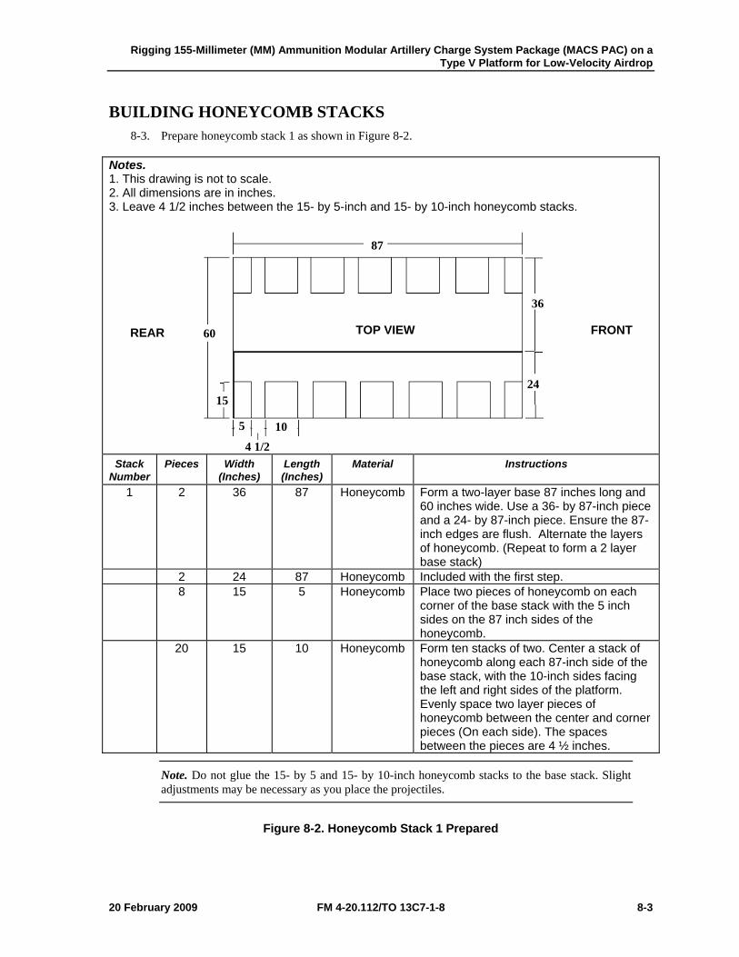
Rigging 155-Millimeter (MM) Ammunition Modular Artillery Charge System Package (MACS PAC) on a Type V Platform for Low-Velocity Airdrop
20 February 2009 FM 4-20.112/TO 13C7-1-8 8-3
BUILDING HONEYCOMB STACKS 8-3. Prepare honeycomb stack 1 as shown in Figure 8-2.
Notes. 1. This drawing is not to scale. 2. All dimensions are in inches. 3. Leave 4 1/2 inches between the 15- by 5-inch and 15- by 10-inch honeycomb stacks.
Stack Number
Pieces Width (Inches)
Length (Inches)
Material Instructions
1 2 36 87 Honeycomb Form a two-layer base 87 inches long and 60 inches wide. Use a 36- by 87-inch piece and a 24- by 87-inch piece. Ensure the 87-inch edges are flush. Alternate the layers of honeycomb. (Repeat to form a 2 layer base stack)
2 24 87 Honeycomb Included with the first step. 8 15 5 Honeycomb Place two pieces of honeycomb on each
corner of the base stack with the 5 inch sides on the 87 inch sides of the honeycomb.
20 15 10 Honeycomb Form ten stacks of two. Center a stack of honeycomb along each 87-inch side of the base stack, with the 10-inch sides facing the left and right sides of the platform. Evenly space two layer pieces of honeycomb between the center and corner pieces (On each side). The spaces between the pieces are 4 ½ inches.
Note. Do not glue the 15- by 5 and 15- by 10-inch honeycomb stacks to the base stack. Slight adjustments may be necessary as you place the projectiles.
Figure 8-2. Honeycomb Stack 1 Prepared
TOP VIEW FRONT REAR
87
60
36
15 24
4 1/2
5 10
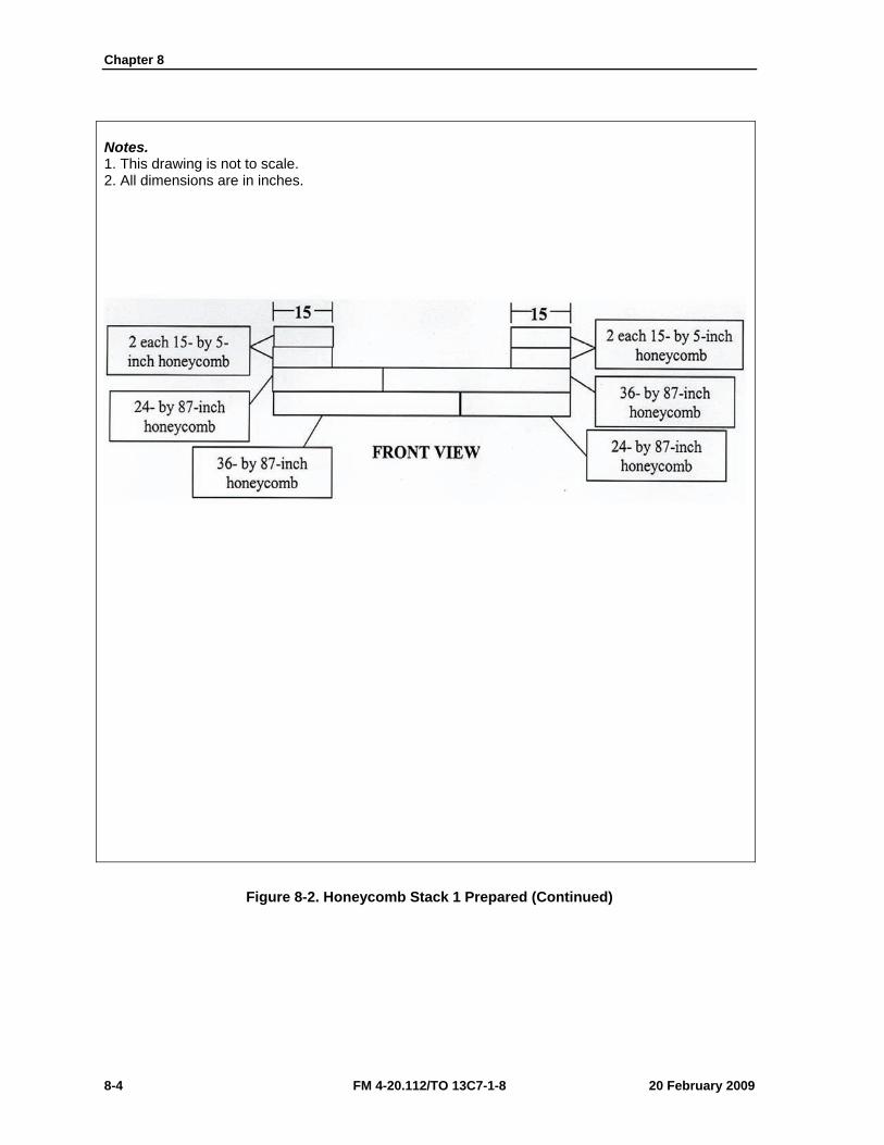
Chapter 8
8-4 FM 4-20.112/TO 13C7-1-8 20 February 2009
Notes. 1. This drawing is not to scale. 2. All dimensions are in inches.
Figure 8-2. Honeycomb Stack 1 Prepared (Continued)
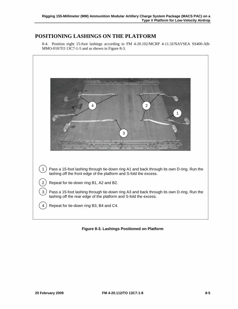
Rigging 155-Millimeter (MM) Ammunition Modular Artillery Charge System Package (MACS PAC) on a Type V Platform for Low-Velocity Airdrop
20 February 2009 FM 4-20.112/TO 13C7-1-8 8-5
POSITIONING LASHINGS ON THE PLATFORM 8-4. Position eight 15-foot lashings according to FM 4-20.102/MCRP 4-11.3J/NAVSEA SS400-AB-MMO-010/TO 13C7-1-5 and as shown in Figure 8-3.
1 Pass a 15-foot lashing through tie-down ring A1 and back through its own D-ring. Run the lashing off the front edge of the platform and S-fold the excess.
2 Repeat for tie-down ring B1, A2 and B2.
3 Pass a 15-foot lashing through tie-down ring A3 and back through its own D-ring. Run the lashing off the rear edge of the platform and S-fold the excess.
4 Repeat for tie-down ring B3, B4 and C4.
Figure 8-3. Lashings Positioned on Platform
1
2 4
3
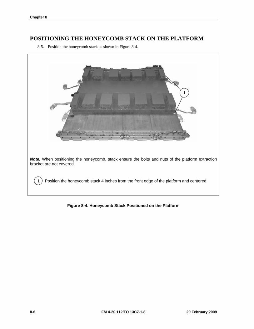
Chapter 8
8-6 FM 4-20.112/TO 13C7-1-8 20 February 2009
POSITIONING THE HONEYCOMB STACK ON THE PLATFORM 8-5. Position the honeycomb stack as shown in Figure 8-4.
Note. When positioning the honeycomb, stack ensure the bolts and nuts of the platform extraction bracket are not covered.
1 Position the honeycomb stack 4 inches from the front edge of the platform and centered.
Figure 8-4. Honeycomb Stack Positioned on the Platform
1
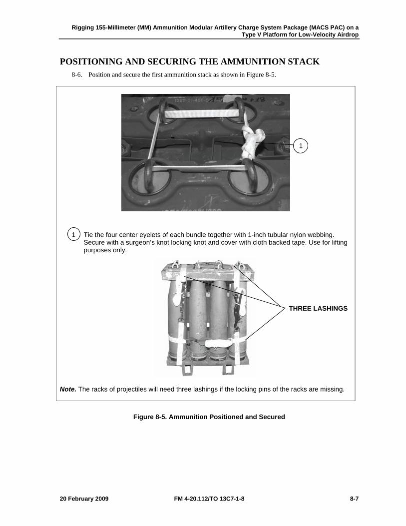
Rigging 155-Millimeter (MM) Ammunition Modular Artillery Charge System Package (MACS PAC) on a Type V Platform for Low-Velocity Airdrop
20 February 2009 FM 4-20.112/TO 13C7-1-8 8-7
POSITIONING AND SECURING THE AMMUNITION STACK 8-6. Position and secure the first ammunition stack as shown in Figure 8-5.
1 Tie the four center eyelets of each bundle together with 1-inch tubular nylon webbing. Secure with a surgeon’s knot locking knot and cover with cloth backed tape. Use for lifting purposes only.
Note. The racks of projectiles will need three lashings if the locking pins of the racks are missing.
Figure 8-5. Ammunition Positioned and Secured
THREE LASHINGS
1
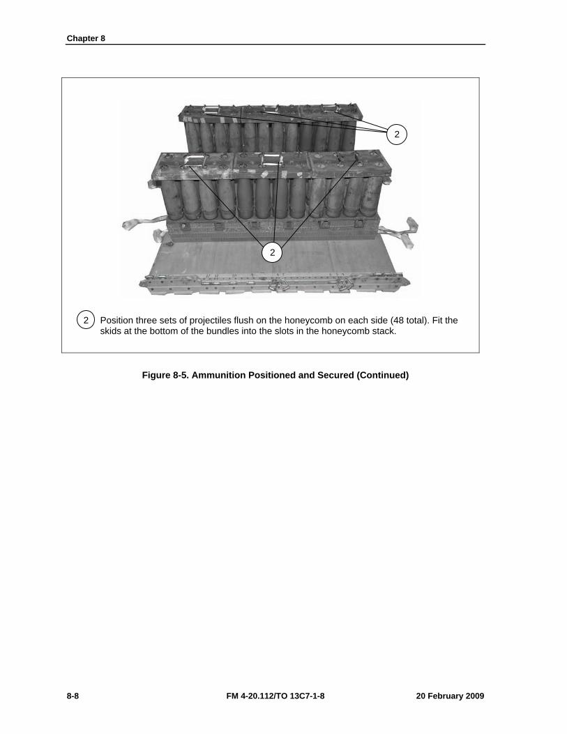
Chapter 8
8-8 FM 4-20.112/TO 13C7-1-8 20 February 2009
2 Position three sets of projectiles flush on the honeycomb on each side (48 total). Fit the skids at the bottom of the bundles into the slots in the honeycomb stack.
Figure 8-5. Ammunition Positioned and Secured (Continued)
2
2
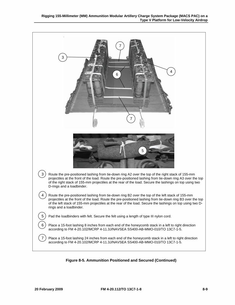
Rigging 155-Millimeter (MM) Ammunition Modular Artillery Charge System Package (MACS PAC) on a Type V Platform for Low-Velocity Airdrop
20 February 2009 FM 4-20.112/TO 13C7-1-8 8-9
3 Route the pre-positioned lashing from tie-down ring A2 over the top of the right stack of 155-mm projectiles at the front of the load. Route the pre-positioned lashing from tie-down ring A3 over the top of the right stack of 155-mm projectiles at the rear of the load. Secure the lashings on top using two D-rings and a loadbinder.
4 Route the pre-positioned lashing from tie-down ring B2 over the top of the left stack of 155-mm projectiles at the front of the load. Route the pre-positioned lashing from tie-down ring B3 over the top of the left stack of 155-mm projectiles at the rear of the load. Secure the lashings on top using two D-rings and a loadbinder.
5 Pad the loadbinders with felt. Secure the felt using a length of type III nylon cord.
6 Place a 15-foot lashing 8 inches from each end of the honeycomb stack in a left to right direction according to FM 4-20.102/MCRP 4-11.3J/NAVSEA SS400-AB-MMO-010/TO 13C7-1-5.
7 Place a 15-foot lashing 24 inches from each end of the honeycomb stack in a left to right direction according to FM 4-20.102/MCRP 4-11.3J/NAVSEA SS400-AB-MMO-010/TO 13C7-1-5.
Figure 8-5. Ammunition Positioned and Secured (Continued)
3
4
7
7
6
5
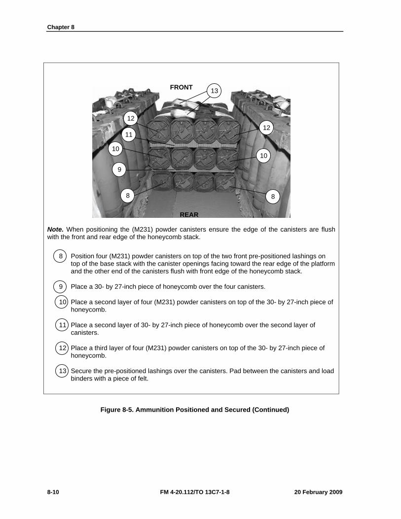
Chapter 8
8-10 FM 4-20.112/TO 13C7-1-8 20 February 2009
Note. When positioning the (M231) powder canisters ensure the edge of the canisters are flush with the front and rear edge of the honeycomb stack.
8 Position four (M231) powder canisters on top of the two front pre-positioned lashings on top of the base stack with the canister openings facing toward the rear edge of the platform and the other end of the canisters flush with front edge of the honeycomb stack.
9 Place a 30- by 27-inch piece of honeycomb over the four canisters.
10 Place a second layer of four (M231) powder canisters on top of the 30- by 27-inch piece of honeycomb.
11 Place a second layer of 30- by 27-inch piece of honeycomb over the second layer of canisters.
12 Place a third layer of four (M231) powder canisters on top of the 30- by 27-inch piece of honeycomb.
13 Secure the pre-positioned lashings over the canisters. Pad between the canisters and load binders with a piece of felt.
Figure 8-5. Ammunition Positioned and Secured (Continued)
8 8
9
10 10
11 12
12
13 FRONT
REAR
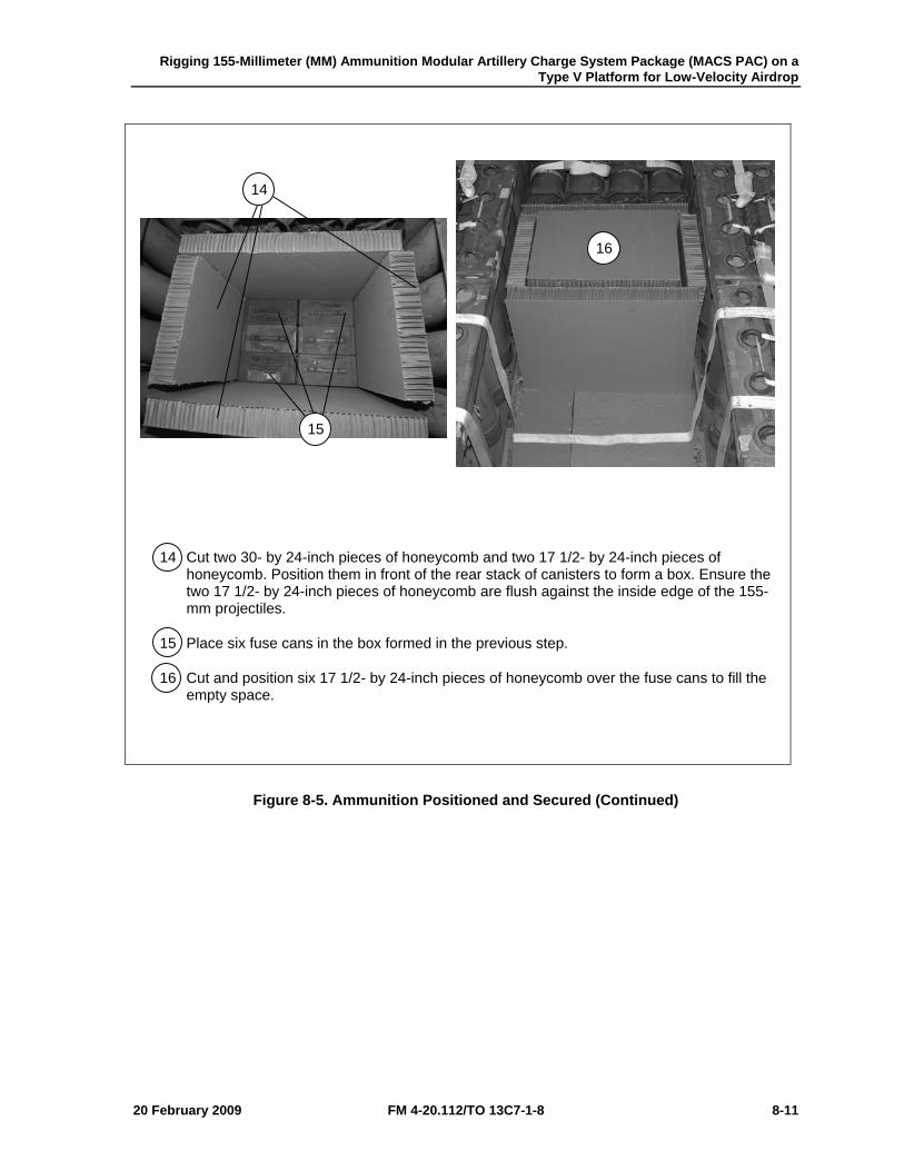
Rigging 155-Millimeter (MM) Ammunition Modular Artillery Charge System Package (MACS PAC) on a Type V Platform for Low-Velocity Airdrop
20 February 2009 FM 4-20.112/TO 13C7-1-8 8-11
14 Cut two 30- by 24-inch pieces of honeycomb and two 17 1/2- by 24-inch pieces of honeycomb. Position them in front of the rear stack of canisters to form a box. Ensure the two 17 1/2- by 24-inch pieces of honeycomb are flush against the inside edge of the 155-mm projectiles.
15 Place six fuse cans in the box formed in the previous step.
16 Cut and position six 17 1/2- by 24-inch pieces of honeycomb over the fuse cans to fill the empty space.
Figure 8-5. Ammunition Positioned and Secured (Continued)
14
15
16
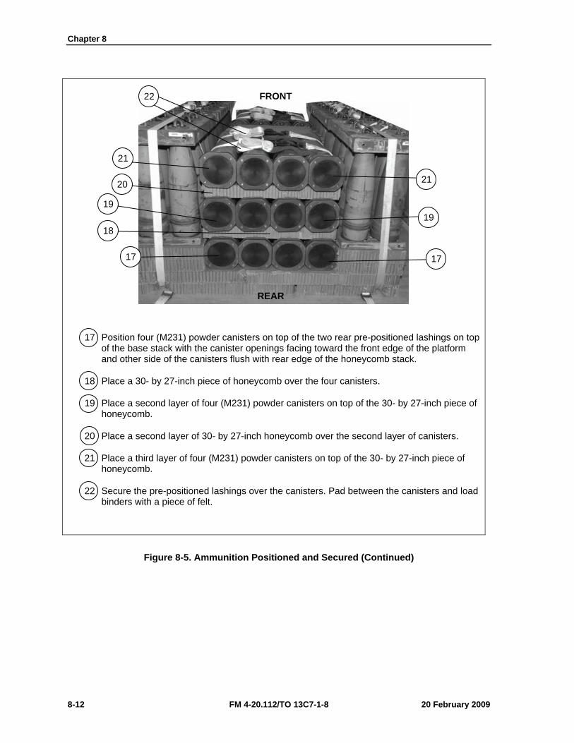
Chapter 8
8-12 FM 4-20.112/TO 13C7-1-8 20 February 2009
17 Position four (M231) powder canisters on top of the two rear pre-positioned lashings on top of the base stack with the canister openings facing toward the front edge of the platform and other side of the canisters flush with rear edge of the honeycomb stack.
18 Place a 30- by 27-inch piece of honeycomb over the four canisters.
19 Place a second layer of four (M231) powder canisters on top of the 30- by 27-inch piece of honeycomb.
20 Place a second layer of 30- by 27-inch honeycomb over the second layer of canisters.
21 Place a third layer of four (M231) powder canisters on top of the 30- by 27-inch piece of honeycomb.
22 Secure the pre-positioned lashings over the canisters. Pad between the canisters and load binders with a piece of felt.
Figure 8-5. Ammunition Positioned and Secured (Continued)
17 17
18
19 19
20 21
21
22 FRONT
REAR
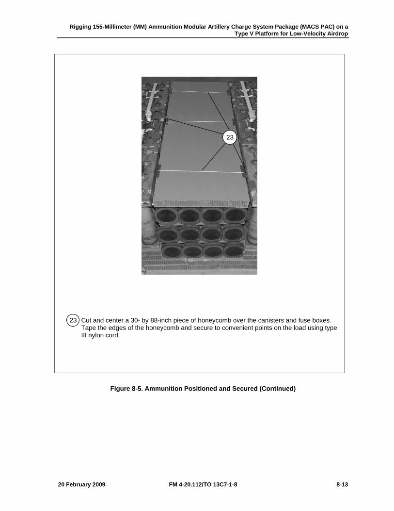
Rigging 155-Millimeter (MM) Ammunition Modular Artillery Charge System Package (MACS PAC) on a Type V Platform for Low-Velocity Airdrop
20 February 2009 FM 4-20.112/TO 13C7-1-8 8-13
23 Cut and center a 30- by 88-inch piece of honeycomb over the canisters and fuse boxes. Tape the edges of the honeycomb and secure to convenient points on the load using type III nylon cord.
Figure 8-5. Ammunition Positioned and Secured (Continued)
23
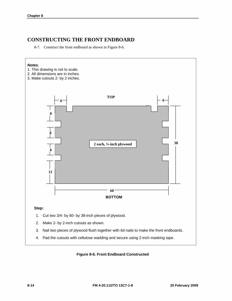
Chapter 8
8-14 FM 4-20.112/TO 13C7-1-8 20 February 2009
CONSTRUCTING THE FRONT ENDBOARD 8-7. Construct the front endboard as shown in Figure 8-6.
Notes. 1. This drawing is not to scale. 2. All dimensions are in inches. 3. Make cutouts 2- by 2 inches.
Step:
1. Cut two 3/4- by 60- by 38-inch pieces of plywood.
2. Make 2- by 2-inch cutouts as shown.
3. Nail two pieces of plywood flush together with 6d nails to make the front endboards.
4. Pad the cutouts with cellulose wadding and secure using 2-inch masking tape.
Figure 8-6. Front Endboard Constructed
38
60
6
12
6
6
6
8
2 each, ¾-inch plywood
TOP
BOTTOM
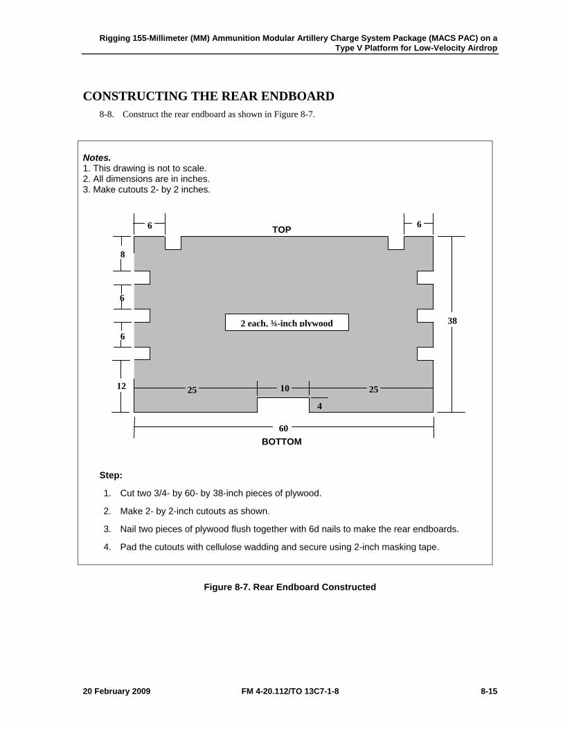
Rigging 155-Millimeter (MM) Ammunition Modular Artillery Charge System Package (MACS PAC) on a Type V Platform for Low-Velocity Airdrop
20 February 2009 FM 4-20.112/TO 13C7-1-8 8-15
CONSTRUCTING THE REAR ENDBOARD 8-8. Construct the rear endboard as shown in Figure 8-7.
Notes. 1. This drawing is not to scale. 2. All dimensions are in inches. 3. Make cutouts 2- by 2 inches.
Step:
1. Cut two 3/4- by 60- by 38-inch pieces of plywood.
2. Make 2- by 2-inch cutouts as shown.
3. Nail two pieces of plywood flush together with 6d nails to make the rear endboards.
4. Pad the cutouts with cellulose wadding and secure using 2-inch masking tape.
Figure 8-7. Rear Endboard Constructed
38
60
6
12
6
6
6
8
2 each, ¾-inch plywood
10
4
25 25
BOTTOM
TOP
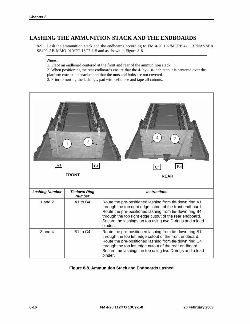
Chapter 8
8-16 FM 4-20.112/TO 13C7-1-8 20 February 2009
LASHING THE AMMUNITION STACK AND THE ENDBOARDS 8-9. Lash the ammunition stack and the endboards according to FM 4-20.102/MCRP 4-11.3J/NAVSEA SS400-AB-MMO-010/TO 13C7-1-5 and as shown in Figure 8-8.
Notes. 1. Place an endboard centered at the front and rear of the ammunition stack. 2. When positioning the rear endboards ensure that the 4- by- 10-inch cutout is centered over the platform extraction bracket and that the nuts and bolts are not covered. 3. Prior to routing the lashings, pad with cellulose and tape all cutouts.
Lashing Number Tiedown Ring
Number Instructions
1 and 2 A1 to B4 Route the pre-positioned lashing from tie-down ring A1 through the top right edge cutout of the front endboard. Route the pre-positioned lashing from tie-down ring B4 through the top right edge cutout of the rear endboard. Secure the lashings on top using two D-rings and a load binder.
3 and 4 B1 to C4 Route the pre-positioned lashing from tie-down ring B1 through the top left edge cutout of the front endboard. Route the pre-positioned lashing from tie-down ring C4 through the top left edge cutout of the rear endboard. Secure the lashings on top using two D-rings and a load binder.
Figure 8-8. Ammunition Stack and Endboards Lashed
FRONT REAR
A1 B1 B4 C4
1 2
3 4
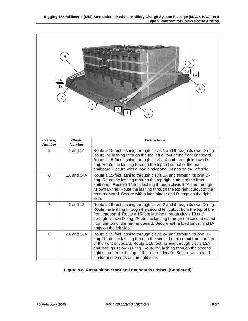
Rigging 155-Millimeter (MM) Ammunition Modular Artillery Charge System Package (MACS PAC) on a Type V Platform for Low-Velocity Airdrop
20 February 2009 FM 4-20.112/TO 13C7-1-8 8-17
Lashing Number
Clevis Number
Instructions
5 1 and 14 Route a 15-foot lashing through clevis 1 and through its own D-ring. Route the lashing through the top left cutout of the front endboard. Route a 15-foot lashing through clevis 14 and through its own D-ring. Route the lashing through the top left cutout of the rear endboard. Secure with a load binder and D-rings on the left side.
6 1A and 14A Route a 15-foot lashing through clevis 1A and through its own D-ring. Route the lashing through the top right cutout of the front endboard. Route a 15-foot lashing through clevis 14A and through its own D-ring. Route the lashing through the top right cutout of the rear endboard. Secure with a load binder and D-rings on the right side.
7 2 and 13 Route a 15-foot lashing through clevis 2 and through its own D-ring. Route the lashing through the second left cutout from the top of the front endboard. Route a 15-foot lashing through clevis 13 and through its own D-ring. Route the lashing through the second cutout from the top of the rear endboard. Secure with a load binder and D-rings on the left side.
8 2A and 13A Route a 15-foot lashing through clevis 2A and through its own D-ring. Route the lashing through the second right cutout from the top of the front endboard. Route a 15-foot lashing through clevis 13A and through its own D-ring. Route the lashing through the second right cutout from the top of the rear endboard. Secure with a load binder and D-rings on the right side.
Figure 8-8. Ammunition Stack and Endboards Lashed (Continued)
5
5 6
7
7
8
12
14 13
1A 2A
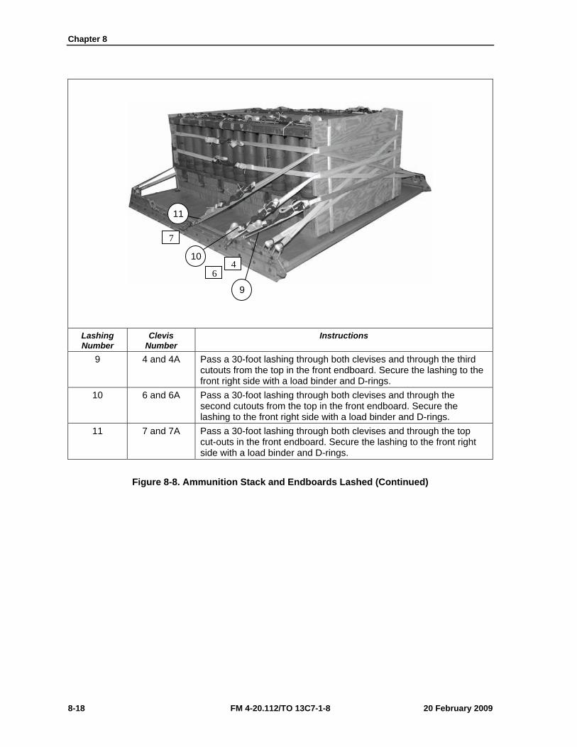
Chapter 8
8-18 FM 4-20.112/TO 13C7-1-8 20 February 2009
Lashing Number
Clevis Number
Instructions
9 4 and 4A Pass a 30-foot lashing through both clevises and through the third cutouts from the top in the front endboard. Secure the lashing to the front right side with a load binder and D-rings.
10 6 and 6A Pass a 30-foot lashing through both clevises and through the second cutouts from the top in the front endboard. Secure the lashing to the front right side with a load binder and D-rings.
11 7 and 7A Pass a 30-foot lashing through both clevises and through the top cut-outs in the front endboard. Secure the lashing to the front right side with a load binder and D-rings.
Figure 8-8. Ammunition Stack and Endboards Lashed (Continued)
9
10
11
46
7
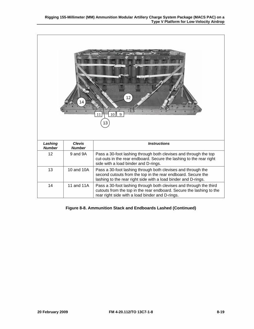
Rigging 155-Millimeter (MM) Ammunition Modular Artillery Charge System Package (MACS PAC) on a Type V Platform for Low-Velocity Airdrop
20 February 2009 FM 4-20.112/TO 13C7-1-8 8-19
Lashing Number
Clevis Number
Instructions
12 9 and 9A Pass a 30-foot lashing through both clevises and through the top cut-outs in the rear endboard. Secure the lashing to the rear right side with a load binder and D-rings.
13 10 and 10A Pass a 30-foot lashing through both clevises and through the second cutouts from the top in the rear endboard. Secure the lashing to the rear right side with a load binder and D-rings.
14 11 and 11A Pass a 30-foot lashing through both clevises and through the third cutouts from the top in the rear endboard. Secure the lashing to the rear right side with a load binder and D-rings.
Figure 8-8. Ammunition Stack and Endboards Lashed (Continued)
12
13
14
91011
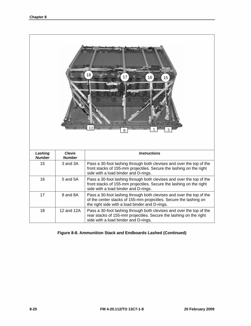
Chapter 8
8-20 FM 4-20.112/TO 13C7-1-8 20 February 2009
Lashing Number
Clevis Number
Instructions
15 3 and 3A Pass a 30-foot lashing through both clevises and over the top of the front stacks of 155-mm projectiles. Secure the lashing on the right side with a load binder and D-rings.
16 5 and 5A Pass a 30-foot lashing through both clevises and over the top of the front stacks of 155-mm projectiles. Secure the lashing on the right side with a load binder and D-rings.
17 8 and 8A Pass a 30-foot lashing through both clevises and over the top of the of the center stacks of 155-mm projectiles. Secure the lashing on the right side with a load binder and D-rings.
18 12 and 12A Pass a 30-foot lashing through both clevises and over the top of the rear stacks of 155-mm projectiles. Secure the lashing on the right side with a load binder and D-rings.
Figure 8-8. Ammunition Stack and Endboards Lashed (Continued)
18 17 16 15
312 8 5
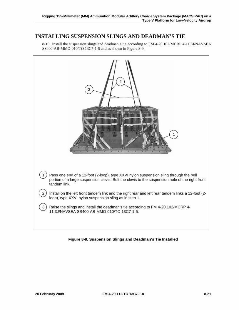
Rigging 155-Millimeter (MM) Ammunition Modular Artillery Charge System Package (MACS PAC) on a Type V Platform for Low-Velocity Airdrop
20 February 2009 FM 4-20.112/TO 13C7-1-8 8-21
INSTALLING SUSPENSION SLINGS AND DEADMAN’S TIE 8-10. Install the suspension slings and deadman’s tie according to FM 4-20.102/MCRP 4-11.3J/NAVSEA SS400-AB-MMO-010/TO 13C7-1-5 and as shown in Figure 8-9.
1 Pass one end of a 12-foot (2-loop), type XXVI nylon suspension sling through the bell portion of a large suspension clevis. Bolt the clevis to the suspension hole of the right front tandem link.
2 Install on the left front tandem link and the right rear and left rear tandem links a 12-foot (2-loop), type XXVI nylon suspension sling as in step 1.
3 Raise the slings and install the deadman's tie according to FM 4-20.102/MCRP 4-11.3J/NAVSEA SS400-AB-MMO-010/TO 13C7-1-5.
Figure 8-9. Suspension Slings and Deadman’s Tie Installed
1
2
3
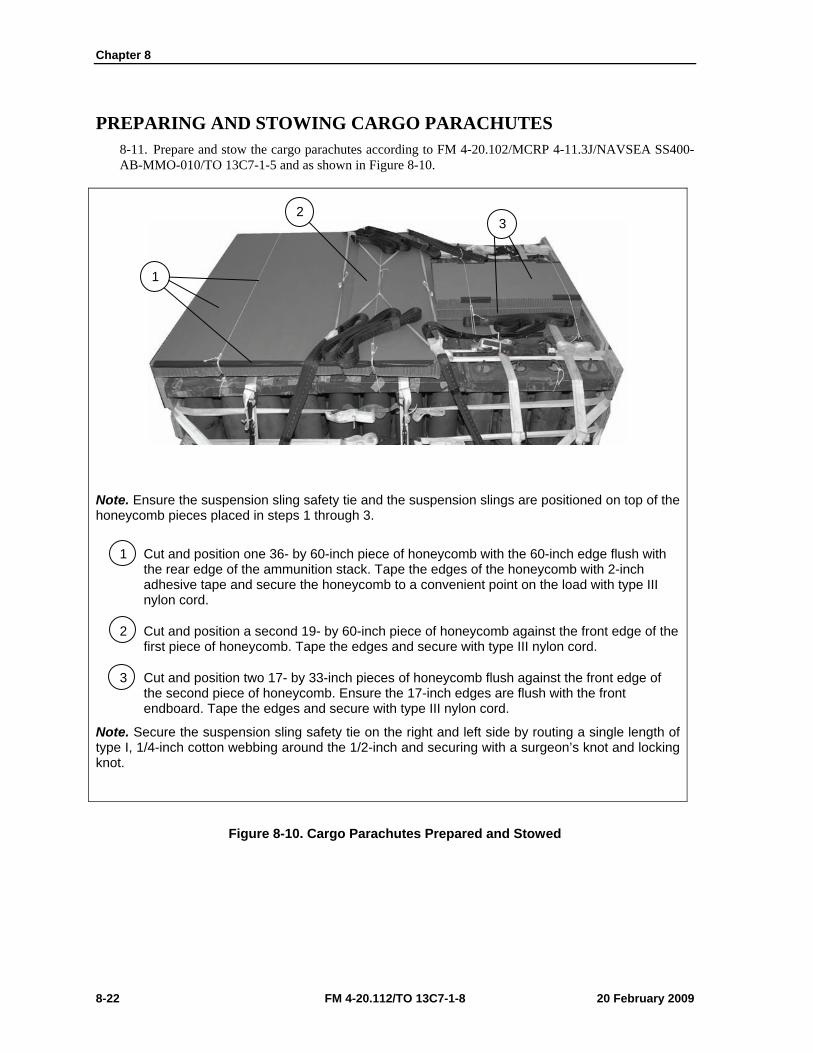
Chapter 8
8-22 FM 4-20.112/TO 13C7-1-8 20 February 2009
PREPARING AND STOWING CARGO PARACHUTES 8-11. Prepare and stow the cargo parachutes according to FM 4-20.102/MCRP 4-11.3J/NAVSEA SS400-AB-MMO-010/TO 13C7-1-5 and as shown in Figure 8-10.
Note. Ensure the suspension sling safety tie and the suspension slings are positioned on top of the honeycomb pieces placed in steps 1 through 3.
1 Cut and position one 36- by 60-inch piece of honeycomb with the 60-inch edge flush with the rear edge of the ammunition stack. Tape the edges of the honeycomb with 2-inch adhesive tape and secure the honeycomb to a convenient point on the load with type III nylon cord.
2 Cut and position a second 19- by 60-inch piece of honeycomb against the front edge of the first piece of honeycomb. Tape the edges and secure with type III nylon cord.
3 Cut and position two 17- by 33-inch pieces of honeycomb flush against the front edge of the second piece of honeycomb. Ensure the 17-inch edges are flush with the front endboard. Tape the edges and secure with type III nylon cord.
Note. Secure the suspension sling safety tie on the right and left side by routing a single length of type I, 1/4-inch cotton webbing around the 1/2-inch and securing with a surgeon’s knot and locking knot.
Figure 8-10. Cargo Parachutes Prepared and Stowed
1
2 3
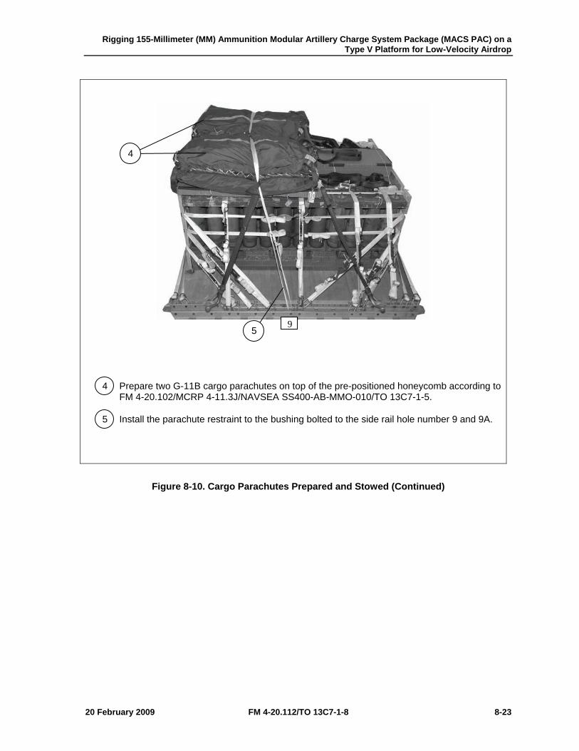
Rigging 155-Millimeter (MM) Ammunition Modular Artillery Charge System Package (MACS PAC) on a Type V Platform for Low-Velocity Airdrop
20 February 2009 FM 4-20.112/TO 13C7-1-8 8-23
4 Prepare two G-11B cargo parachutes on top of the pre-positioned honeycomb according to FM 4-20.102/MCRP 4-11.3J/NAVSEA SS400-AB-MMO-010/TO 13C7-1-5.
5 Install the parachute restraint to the bushing bolted to the side rail hole number 9 and 9A.
Figure 8-10. Cargo Parachutes Prepared and Stowed (Continued)
9
4
5
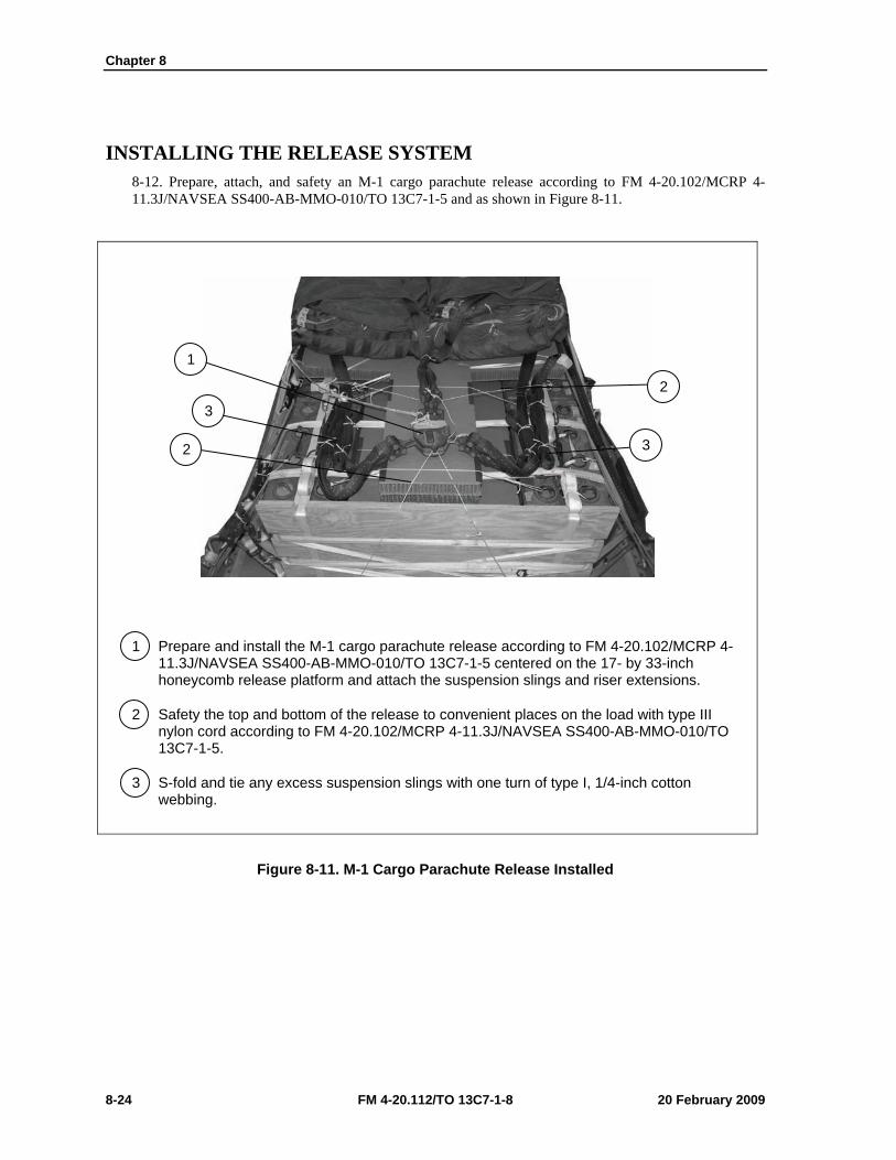
Chapter 8
8-24 FM 4-20.112/TO 13C7-1-8 20 February 2009
INSTALLING THE RELEASE SYSTEM 8-12. Prepare, attach, and safety an M-1 cargo parachute release according to FM 4-20.102/MCRP 4-11.3J/NAVSEA SS400-AB-MMO-010/TO 13C7-1-5 and as shown in Figure 8-11.
1 Prepare and install the M-1 cargo parachute release according to FM 4-20.102/MCRP 4-11.3J/NAVSEA SS400-AB-MMO-010/TO 13C7-1-5 centered on the 17- by 33-inch honeycomb release platform and attach the suspension slings and riser extensions.
2 Safety the top and bottom of the release to convenient places on the load with type III nylon cord according to FM 4-20.102/MCRP 4-11.3J/NAVSEA SS400-AB-MMO-010/TO 13C7-1-5.
3 S-fold and tie any excess suspension slings with one turn of type I, 1/4-inch cotton webbing.
Figure 8-11. M-1 Cargo Parachute Release Installed
1
2
2 3
3
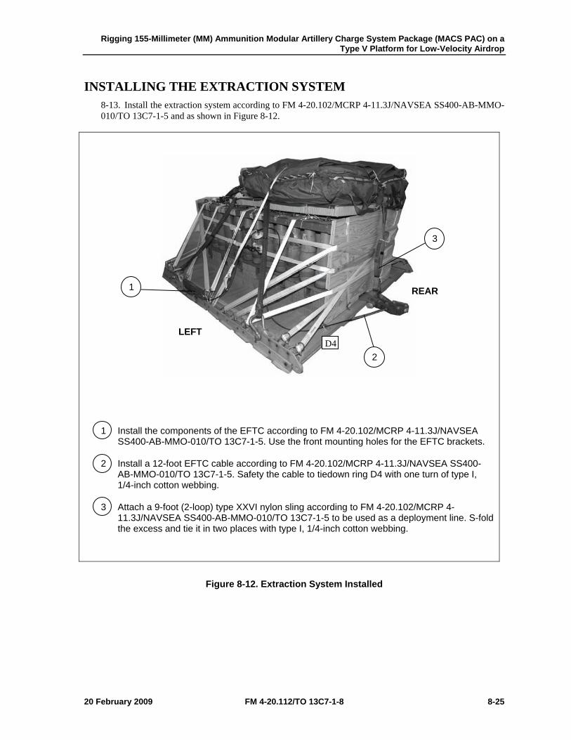
Rigging 155-Millimeter (MM) Ammunition Modular Artillery Charge System Package (MACS PAC) on a Type V Platform for Low-Velocity Airdrop
20 February 2009 FM 4-20.112/TO 13C7-1-8 8-25
INSTALLING THE EXTRACTION SYSTEM 8-13. Install the extraction system according to FM 4-20.102/MCRP 4-11.3J/NAVSEA SS400-AB-MMO-010/TO 13C7-1-5 and as shown in Figure 8-12.
1 Install the components of the EFTC according to FM 4-20.102/MCRP 4-11.3J/NAVSEA SS400-AB-MMO-010/TO 13C7-1-5. Use the front mounting holes for the EFTC brackets.
2 Install a 12-foot EFTC cable according to FM 4-20.102/MCRP 4-11.3J/NAVSEA SS400-AB-MMO-010/TO 13C7-1-5. Safety the cable to tiedown ring D4 with one turn of type I, 1/4-inch cotton webbing.
3 Attach a 9-foot (2-loop) type XXVI nylon sling according to FM 4-20.102/MCRP 4-11.3J/NAVSEA SS400-AB-MMO-010/TO 13C7-1-5 to be used as a deployment line. S-fold the excess and tie it in two places with type I, 1/4-inch cotton webbing.
Figure 8-12. Extraction System Installed
D4
1
2
3
REAR
LEFT

Chapter 8
8-26 FM 4-20.112/TO 13C7-1-8 20 February 2009
PLACING EXTRACTION PARACHUTE 8-14. Select the extraction parachute and extraction line needed using the extraction line requirements table in FM 4-20.102/MCRP 4-11.3J/NAVSEA SS400-AB-MMO-010/TO 13C7-1-5. Place the extraction parachute and line on the load for installation in the aircraft.
INSTALLING PROVISIONS FOR EMERGENCY RESTRAINTS 8-15. Select and install the provisions for the emergency aft restraints according to the emergency aft restraint requirements table in FM 4-20.102/MCRP 4-11.3J/NAVSEA SS400-AB-MMO-010/TO 13C7-1-5.
MARKING RIGGED LOAD 8-16. Mark the rigged load according to FM 4-20.102/MCRP 4-11.3J/NAVSEA SS400-AB-MMO-010/TO 13C7-1-5, and as shown in Figure 8-13. Complete Shipper’s Declaration for Dangerous Goods. If the load varies from the one shown, the weight, height, CB, and parachute requirements must be recomputed.
EQUIPMENT REQUIRED 8-17. Use the equipment listed in Table 8-1 to rig this load.
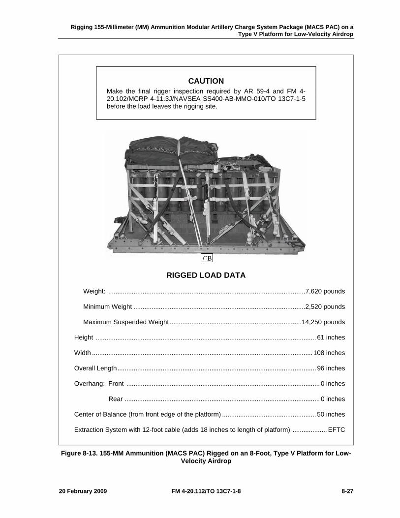
Rigging 155-Millimeter (MM) Ammunition Modular Artillery Charge System Package (MACS PAC) on a Type V Platform for Low-Velocity Airdrop
20 February 2009 FM 4-20.112/TO 13C7-1-8 8-27
CAUTION Make the final rigger inspection required by AR 59-4 and FM 4-20.102/MCRP 4-11.3J/NAVSEA SS400-AB-MMO-010/TO 13C7-1-5 before the load leaves the rigging site.
RIGGED LOAD DATA
Weight: ............................................................................................................. 7,620 pounds
Minimum Weight ............................................................................................... 2,520 pounds
Maximum Suspended Weight ......................................................................... 14,250 pounds
Height .......................................................................................................................... 61 inches
Width .......................................................................................................................... 108 inches
Overall Length .............................................................................................................. 96 inches
Overhang: Front ........................................................................................................... 0 inches
Rear ............................................................................................................ 0 inches
Center of Balance (from front edge of the platform) .................................................... 50 inches
Extraction System with 12-foot cable (adds 18 inches to length of platform) ................... EFTC
Figure 8-13. 155-MM Ammunition (MACS PAC) Rigged on an 8-Foot, Type V Platform for Low-Velocity Airdrop
CB
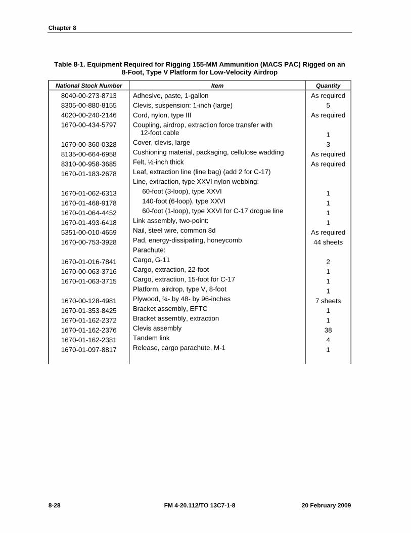
Chapter 8
8-28 FM 4-20.112/TO 13C7-1-8 20 February 2009
Table 8-1. Equipment Required for Rigging 155-MM Ammunition (MACS PAC) Rigged on an 8-Foot, Type V Platform for Low-Velocity Airdrop
National Stock Number Item Quantity 8040-00-273-8713 8305-00-880-8155 4020-00-240-2146 1670-00-434-5797
1670-00-360-0328 8135-00-664-6958 8310-00-958-3685 1670-01-183-2678
1670-01-062-6313 1670-01-468-9178 1670-01-064-4452 1670-01-493-6418 5351-00-010-4659 1670-00-753-3928
1670-01-016-7841 1670-00-063-3716 1670-01-063-3715
1670-00-128-4981 1670-01-353-8425 1670-01-162-2372 1670-01-162-2376 1670-01-162-2381 1670-01-097-8817
Adhesive, paste, 1-gallon Clevis, suspension: 1-inch (large) Cord, nylon, type III Coupling, airdrop, extraction force transfer with 12-foot cable Cover, clevis, large Cushioning material, packaging, cellulose wadding Felt, ½-inch thick Leaf, extraction line (line bag) (add 2 for C-17) Line, extraction, type XXVI nylon webbing: 60-foot (3-loop), type XXVI 140-foot (6-loop), type XXVI 60-foot (1-loop), type XXVI for C-17 drogue line Link assembly, two-point: Nail, steel wire, common 8d Pad, energy-dissipating, honeycomb Parachute: Cargo, G-11 Cargo, extraction, 22-foot Cargo, extraction, 15-foot for C-17 Platform, airdrop, type V, 8-foot Plywood, ¾- by 48- by 96-inches Bracket assembly, EFTC Bracket assembly, extraction Clevis assembly Tandem link Release, cargo parachute, M-1
As required 5
As required 1 3
As required As required
1 1 1 1
As required 44 sheets
2 1 1 1
7 sheets 1 1
38 4 1
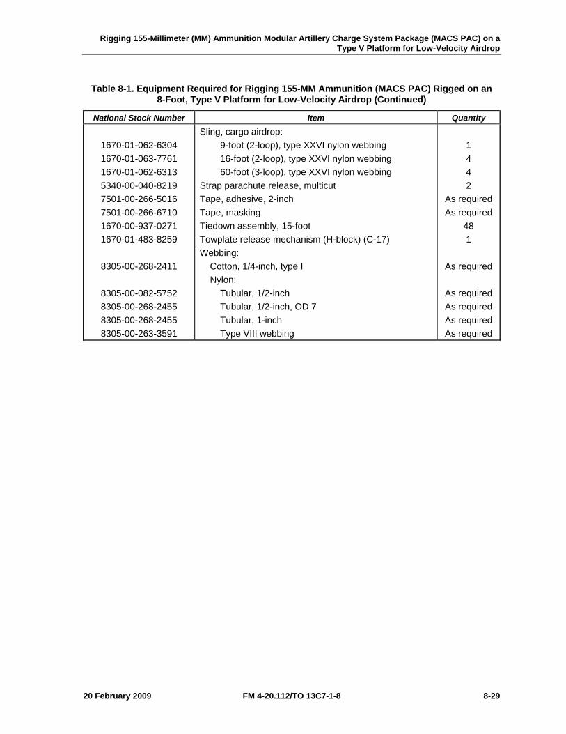
Rigging 155-Millimeter (MM) Ammunition Modular Artillery Charge System Package (MACS PAC) on a Type V Platform for Low-Velocity Airdrop
20 February 2009 FM 4-20.112/TO 13C7-1-8 8-29
Table 8-1. Equipment Required for Rigging 155-MM Ammunition (MACS PAC) Rigged on an 8-Foot, Type V Platform for Low-Velocity Airdrop (Continued)
National Stock Number Item Quantity
1670-01-062-6304 1670-01-063-7761 1670-01-062-6313 5340-00-040-8219 7501-00-266-5016 7501-00-266-6710 1670-00-937-0271 1670-01-483-8259
8305-00-268-2411
8305-00-082-5752 8305-00-268-2455 8305-00-268-2455 8305-00-263-3591
Sling, cargo airdrop: 9-foot (2-loop), type XXVI nylon webbing 16-foot (2-loop), type XXVI nylon webbing 60-foot (3-loop), type XXVI nylon webbing Strap parachute release, multicut Tape, adhesive, 2-inch Tape, masking Tiedown assembly, 15-foot Towplate release mechanism (H-block) (C-17) Webbing: Cotton, 1/4-inch, type I Nylon: Tubular, 1/2-inch Tubular, 1/2-inch, OD 7 Tubular, 1-inch Type VIII webbing
1 4 4 2
As required As required
48 1
As required
As required As required As required As required
Chapter 8
8-30 FM 4-20.112/TO 13C7-1-8 20 February 2009
SECTION II-RIGGING THE MACS PAC ON A 12-FOOT, TYPE V PLATFORM
DESCRIPTION OF LOAD 8-18. Eighty 155-millimeter projectiles, forty (M231) powder canisters and ten fuse cans are rigged for low-velocity airdrop on a 12-foot, type V airdrop platform. The load uses three G-11B cargo parachutes. The total rigged load is 73-inches high, 108-inches in width, and is 162-inches in overall length. The center of balance is 77-inches from the front edge of the platform. The total rigged weight of the load shown is 12,300- pounds.
Notes. 1. The load shown is using metal crates. However, wooden crates may be used with three lashings and a load binder. 2. If the metal locking rods are missing, three lashings, D-rings and load binders will be needed.
PREPARING PLATFORM 8-19. Prepare a 12-foot, type V platform as shown in Figure 8-14.
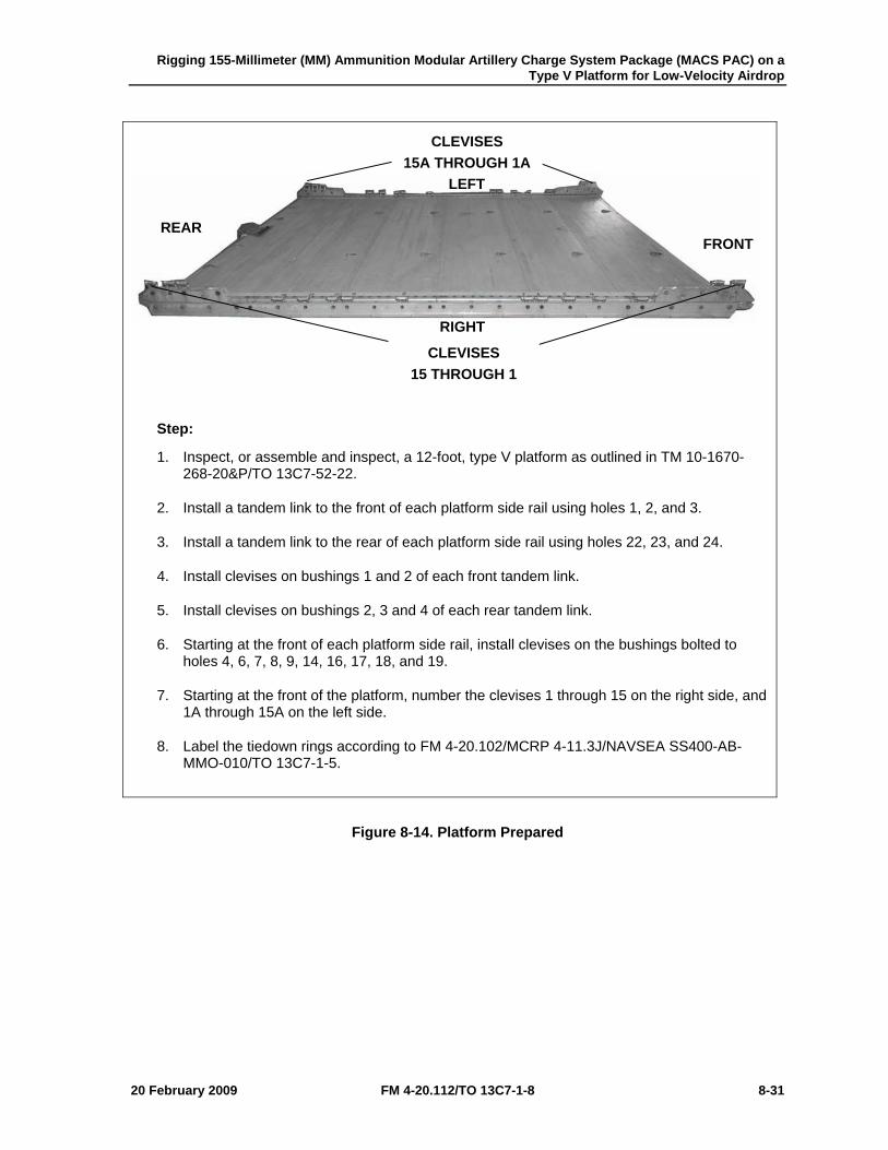
Rigging 155-Millimeter (MM) Ammunition Modular Artillery Charge System Package (MACS PAC) on a Type V Platform for Low-Velocity Airdrop
20 February 2009 FM 4-20.112/TO 13C7-1-8 8-31
Step:
1. Inspect, or assemble and inspect, a 12-foot, type V platform as outlined in TM 10-1670-268-20&P/TO 13C7-52-22.
2. Install a tandem link to the front of each platform side rail using holes 1, 2, and 3.
3. Install a tandem link to the rear of each platform side rail using holes 22, 23, and 24.
4. Install clevises on bushings 1 and 2 of each front tandem link.
5. Install clevises on bushings 2, 3 and 4 of each rear tandem link.
6. Starting at the front of each platform side rail, install clevises on the bushings bolted to holes 4, 6, 7, 8, 9, 14, 16, 17, 18, and 19.
7. Starting at the front of the platform, number the clevises 1 through 15 on the right side, and 1A through 15A on the left side.
8. Label the tiedown rings according to FM 4-20.102/MCRP 4-11.3J/NAVSEA SS400-AB-MMO-010/TO 13C7-1-5.
Figure 8-14. Platform Prepared
CLEVISES 15A THROUGH 1A
CLEVISES 15 THROUGH 1
RIGHT
LEFT
FRONT REAR
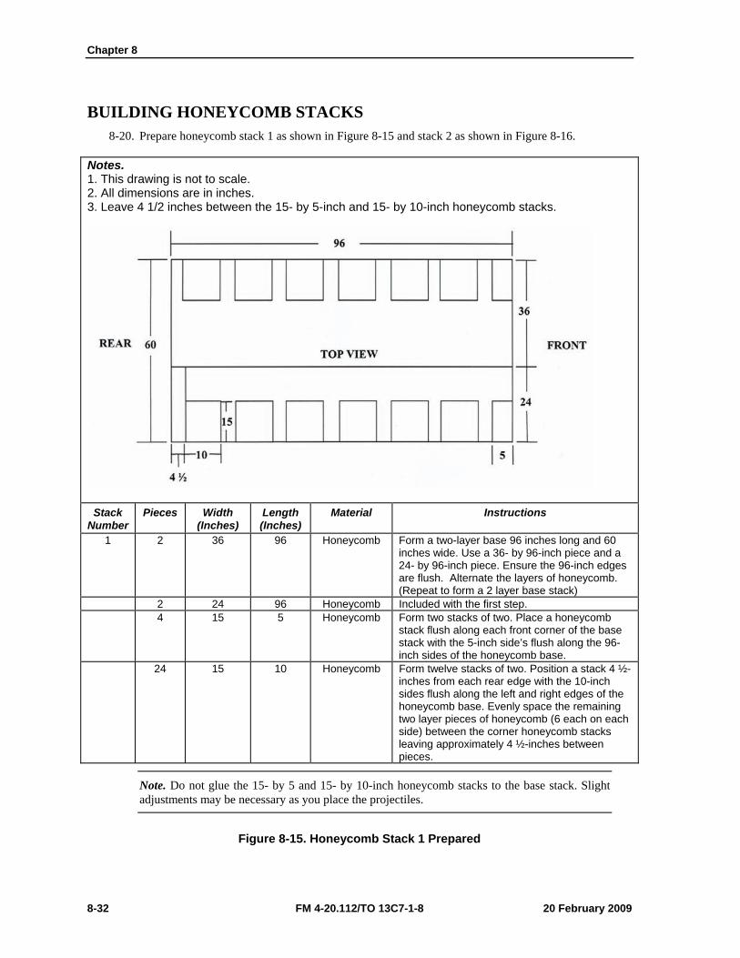
Chapter 8
8-32 FM 4-20.112/TO 13C7-1-8 20 February 2009
BUILDING HONEYCOMB STACKS 8-20. Prepare honeycomb stack 1 as shown in Figure 8-15 and stack 2 as shown in Figure 8-16.
Notes. 1. This drawing is not to scale. 2. All dimensions are in inches. 3. Leave 4 1/2 inches between the 15- by 5-inch and 15- by 10-inch honeycomb stacks.
Stack Number
Pieces Width (Inches)
Length (Inches)
Material Instructions
1 2 36 96 Honeycomb Form a two-layer base 96 inches long and 60 inches wide. Use a 36- by 96-inch piece and a 24- by 96-inch piece. Ensure the 96-inch edges are flush. Alternate the layers of honeycomb. (Repeat to form a 2 layer base stack)
2 24 96 Honeycomb Included with the first step. 4 15 5 Honeycomb Form two stacks of two. Place a honeycomb
stack flush along each front corner of the base stack with the 5-inch side’s flush along the 96-inch sides of the honeycomb base.
24 15 10 Honeycomb Form twelve stacks of two. Position a stack 4 ½-inches from each rear edge with the 10-inch sides flush along the left and right edges of the honeycomb base. Evenly space the remaining two layer pieces of honeycomb (6 each on each side) between the corner honeycomb stacks leaving approximately 4 ½-inches between pieces.
Note. Do not glue the 15- by 5 and 15- by 10-inch honeycomb stacks to the base stack. Slight adjustments may be necessary as you place the projectiles.
Figure 8-15. Honeycomb Stack 1 Prepared
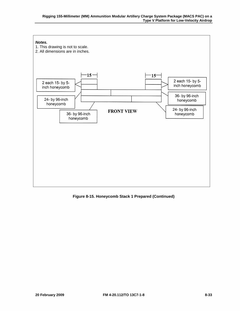
Rigging 155-Millimeter (MM) Ammunition Modular Artillery Charge System Package (MACS PAC) on a Type V Platform for Low-Velocity Airdrop
20 February 2009 FM 4-20.112/TO 13C7-1-8 8-33
Notes. 1. This drawing is not to scale. 2. All dimensions are in inches.
Figure 8-15. Honeycomb Stack 1 Prepared (Continued)
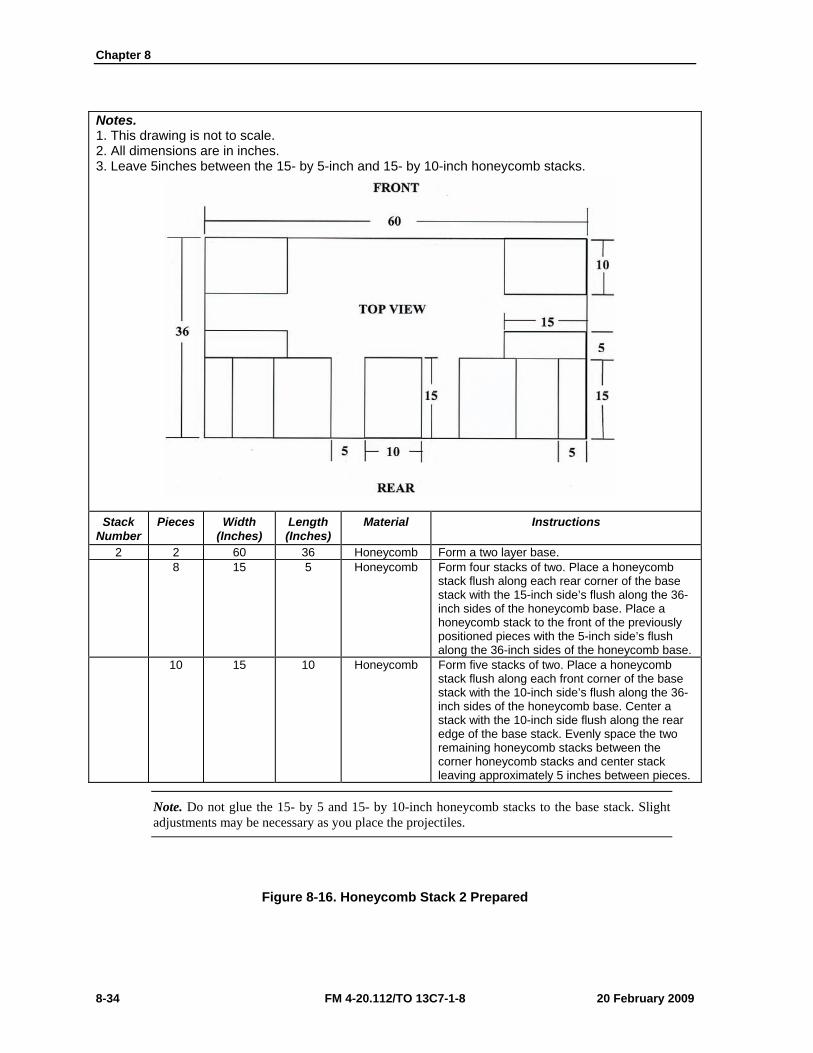
Chapter 8
8-34 FM 4-20.112/TO 13C7-1-8 20 February 2009
Notes. 1. This drawing is not to scale. 2. All dimensions are in inches. 3. Leave 5inches between the 15- by 5-inch and 15- by 10-inch honeycomb stacks.
Stack Number
Pieces Width (Inches)
Length (Inches)
Material Instructions
2 2 60 36 Honeycomb Form a two layer base. 8 15 5 Honeycomb Form four stacks of two. Place a honeycomb
stack flush along each rear corner of the base stack with the 15-inch side’s flush along the 36-inch sides of the honeycomb base. Place a honeycomb stack to the front of the previously positioned pieces with the 5-inch side’s flush along the 36-inch sides of the honeycomb base.
10 15 10 Honeycomb Form five stacks of two. Place a honeycomb stack flush along each front corner of the base stack with the 10-inch side’s flush along the 36-inch sides of the honeycomb base. Center a stack with the 10-inch side flush along the rear edge of the base stack. Evenly space the two remaining honeycomb stacks between the corner honeycomb stacks and center stack leaving approximately 5 inches between pieces.
Note. Do not glue the 15- by 5 and 15- by 10-inch honeycomb stacks to the base stack. Slight adjustments may be necessary as you place the projectiles.
Figure 8-16. Honeycomb Stack 2 Prepared
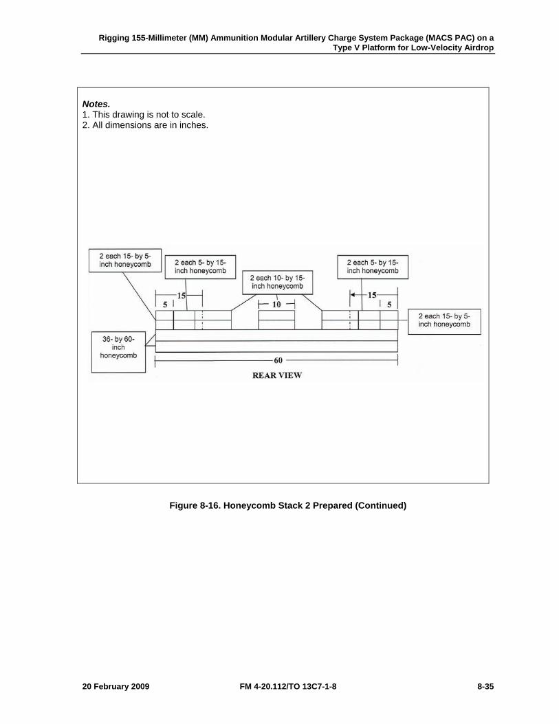
Rigging 155-Millimeter (MM) Ammunition Modular Artillery Charge System Package (MACS PAC) on a Type V Platform for Low-Velocity Airdrop
20 February 2009 FM 4-20.112/TO 13C7-1-8 8-35
Notes. 1. This drawing is not to scale. 2. All dimensions are in inches.
Figure 8-16. Honeycomb Stack 2 Prepared (Continued)
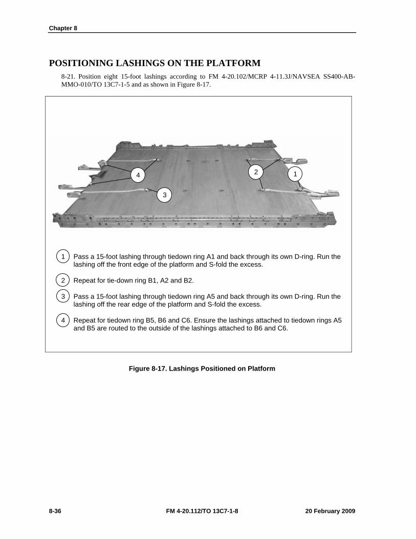
Chapter 8
8-36 FM 4-20.112/TO 13C7-1-8 20 February 2009
POSITIONING LASHINGS ON THE PLATFORM 8-21. Position eight 15-foot lashings according to FM 4-20.102/MCRP 4-11.3J/NAVSEA SS400-AB-MMO-010/TO 13C7-1-5 and as shown in Figure 8-17.
1 Pass a 15-foot lashing through tiedown ring A1 and back through its own D-ring. Run the lashing off the front edge of the platform and S-fold the excess.
2 Repeat for tie-down ring B1, A2 and B2.
3 Pass a 15-foot lashing through tiedown ring A5 and back through its own D-ring. Run the lashing off the rear edge of the platform and S-fold the excess.
4 Repeat for tiedown ring B5, B6 and C6. Ensure the lashings attached to tiedown rings A5 and B5 are routed to the outside of the lashings attached to B6 and C6.
Figure 8-17. Lashings Positioned on Platform
1 2 4
3
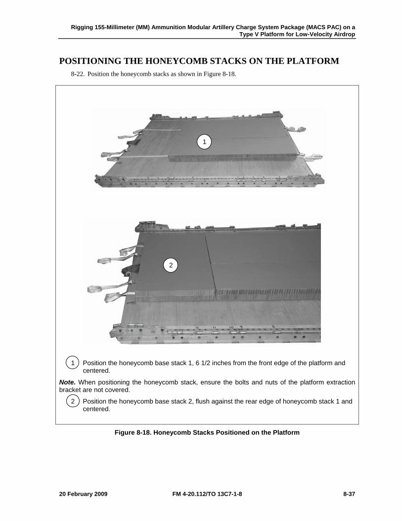
Rigging 155-Millimeter (MM) Ammunition Modular Artillery Charge System Package (MACS PAC) on a Type V Platform for Low-Velocity Airdrop
20 February 2009 FM 4-20.112/TO 13C7-1-8 8-37
POSITIONING THE HONEYCOMB STACKS ON THE PLATFORM 8-22. Position the honeycomb stacks as shown in Figure 8-18.
1 Position the honeycomb base stack 1, 6 1/2 inches from the front edge of the platform and centered.
Note. When positioning the honeycomb stack, ensure the bolts and nuts of the platform extraction bracket are not covered.
2 Position the honeycomb base stack 2, flush against the rear edge of honeycomb stack 1 and centered.
Figure 8-18. Honeycomb Stacks Positioned on the Platform
1
2
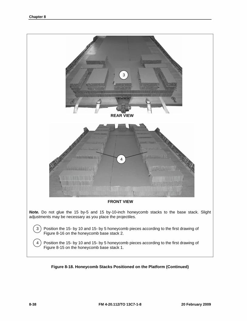
Chapter 8
8-38 FM 4-20.112/TO 13C7-1-8 20 February 2009
Note. Do not glue the 15 by-5 and 15 by-10-inch honeycomb stacks to the base stack. Slight adjustments may be necessary as you place the projectiles.
3 Position the 15- by 10 and 15- by 5 honeycomb pieces according to the first drawing of Figure 8-16 on the honeycomb base stack 2.
4 Position the 15- by 10 and 15- by 5 honeycomb pieces according to the first drawing of Figure 8-15 on the honeycomb base stack 1.
Figure 8-18. Honeycomb Stacks Positioned on the Platform (Continued)
REAR VIEW
4
3
FRONT VIEW

Rigging 155-Millimeter (MM) Ammunition Modular Artillery Charge System Package (MACS PAC) on a Type V Platform for Low-Velocity Airdrop
20 February 2009 FM 4-20.112/TO 13C7-1-8 8-39
POSITIONING AND SECURING THE AMMUNITION STACKS 8-23. Position and secure the ammunition stacks as shown in Figure 8-19.
1 Tie the four center eyelets of each bundle together with 1-inch tubular nylon webbing. Secure with a surgeon’s knot locking knot and cover with cloth backed tape. Use for lifting purposes only.
Note. The racks of projectiles will need three lashings if the locking pins of the racks are missing.
Figure 8-19. Ammunition Positioned and Secured
THREE LASHINGS
1
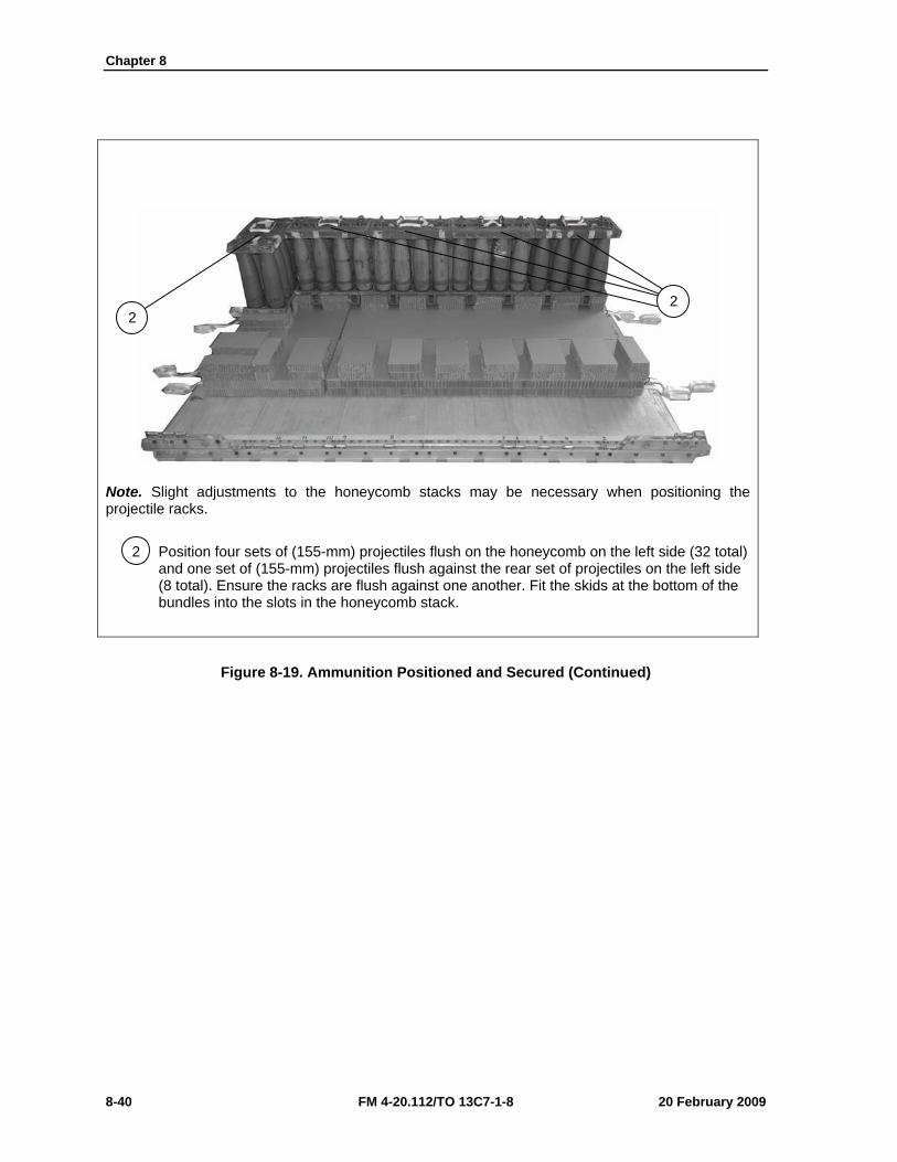
Chapter 8
8-40 FM 4-20.112/TO 13C7-1-8 20 February 2009
Note. Slight adjustments to the honeycomb stacks may be necessary when positioning the projectile racks.
2 Position four sets of (155-mm) projectiles flush on the honeycomb on the left side (32 total) and one set of (155-mm) projectiles flush against the rear set of projectiles on the left side (8 total). Ensure the racks are flush against one another. Fit the skids at the bottom of the bundles into the slots in the honeycomb stack.
Figure 8-19. Ammunition Positioned and Secured (Continued)
2 2
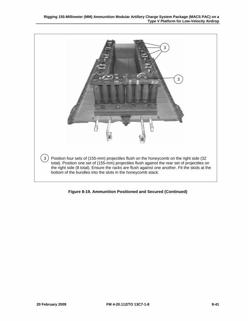
Rigging 155-Millimeter (MM) Ammunition Modular Artillery Charge System Package (MACS PAC) on a Type V Platform for Low-Velocity Airdrop
20 February 2009 FM 4-20.112/TO 13C7-1-8 8-41
3 Position four sets of (155-mm) projectiles flush on the honeycomb on the right side (32 total). Position one set of (155-mm) projectiles flush against the rear set of projectiles on the right side (8 total). Ensure the racks are flush against one another. Fit the skids at the bottom of the bundles into the slots in the honeycomb stack.
Figure 8-19. Ammunition Positioned and Secured (Continued)
3
3
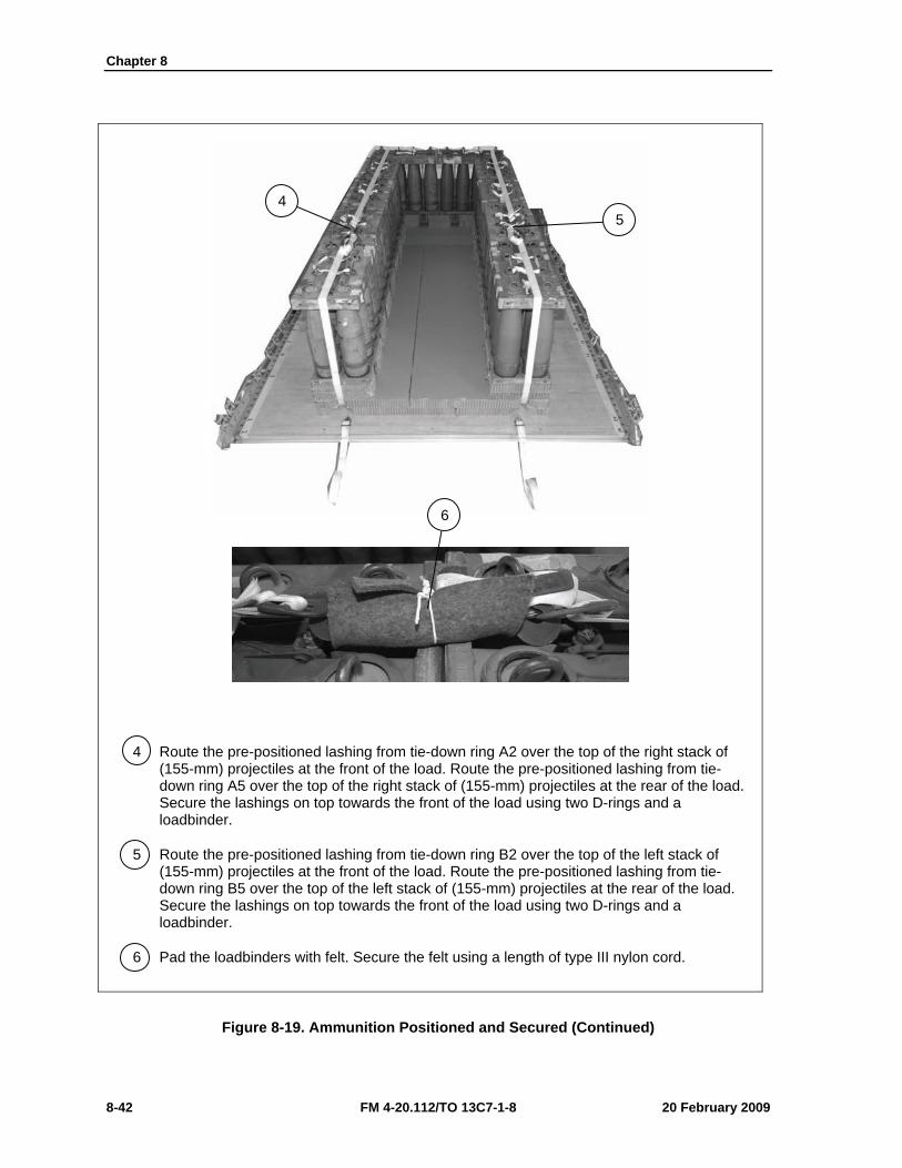
Chapter 8
8-42 FM 4-20.112/TO 13C7-1-8 20 February 2009
4 Route the pre-positioned lashing from tie-down ring A2 over the top of the right stack of (155-mm) projectiles at the front of the load. Route the pre-positioned lashing from tie-down ring A5 over the top of the right stack of (155-mm) projectiles at the rear of the load. Secure the lashings on top towards the front of the load using two D-rings and a loadbinder.
5 Route the pre-positioned lashing from tie-down ring B2 over the top of the left stack of (155-mm) projectiles at the front of the load. Route the pre-positioned lashing from tie-down ring B5 over the top of the left stack of (155-mm) projectiles at the rear of the load. Secure the lashings on top towards the front of the load using two D-rings and a loadbinder.
6 Pad the loadbinders with felt. Secure the felt using a length of type III nylon cord.
Figure 8-19. Ammunition Positioned and Secured (Continued)
6
4 5
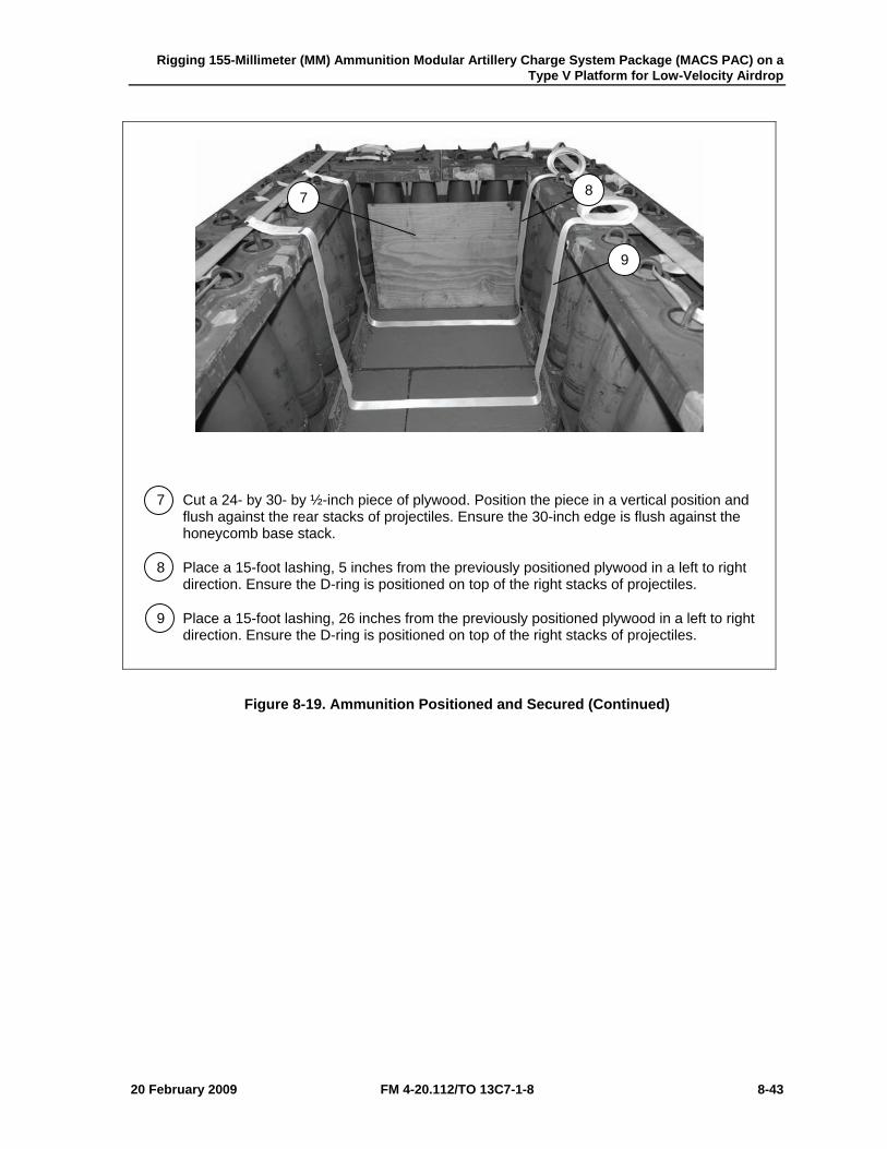
Rigging 155-Millimeter (MM) Ammunition Modular Artillery Charge System Package (MACS PAC) on a Type V Platform for Low-Velocity Airdrop
20 February 2009 FM 4-20.112/TO 13C7-1-8 8-43
7 Cut a 24- by 30- by ½-inch piece of plywood. Position the piece in a vertical position and flush against the rear stacks of projectiles. Ensure the 30-inch edge is flush against the honeycomb base stack.
8 Place a 15-foot lashing, 5 inches from the previously positioned plywood in a left to right direction. Ensure the D-ring is positioned on top of the right stacks of projectiles.
9 Place a 15-foot lashing, 26 inches from the previously positioned plywood in a left to right direction. Ensure the D-ring is positioned on top of the right stacks of projectiles.
Figure 8-19. Ammunition Positioned and Secured (Continued)
7 8
9
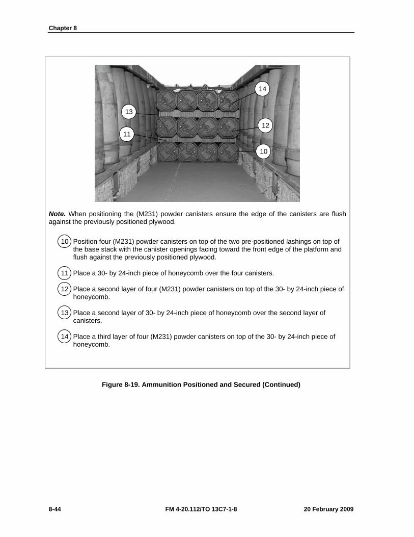
Chapter 8
8-44 FM 4-20.112/TO 13C7-1-8 20 February 2009
Note. When positioning the (M231) powder canisters ensure the edge of the canisters are flush against the previously positioned plywood.
10 Position four (M231) powder canisters on top of the two pre-positioned lashings on top of the base stack with the canister openings facing toward the front edge of the platform and flush against the previously positioned plywood.
11 Place a 30- by 24-inch piece of honeycomb over the four canisters.
12 Place a second layer of four (M231) powder canisters on top of the 30- by 24-inch piece of honeycomb.
13 Place a second layer of 30- by 24-inch piece of honeycomb over the second layer of canisters.
14 Place a third layer of four (M231) powder canisters on top of the 30- by 24-inch piece of honeycomb.
Figure 8-19. Ammunition Positioned and Secured (Continued)
14
10
11
13
12
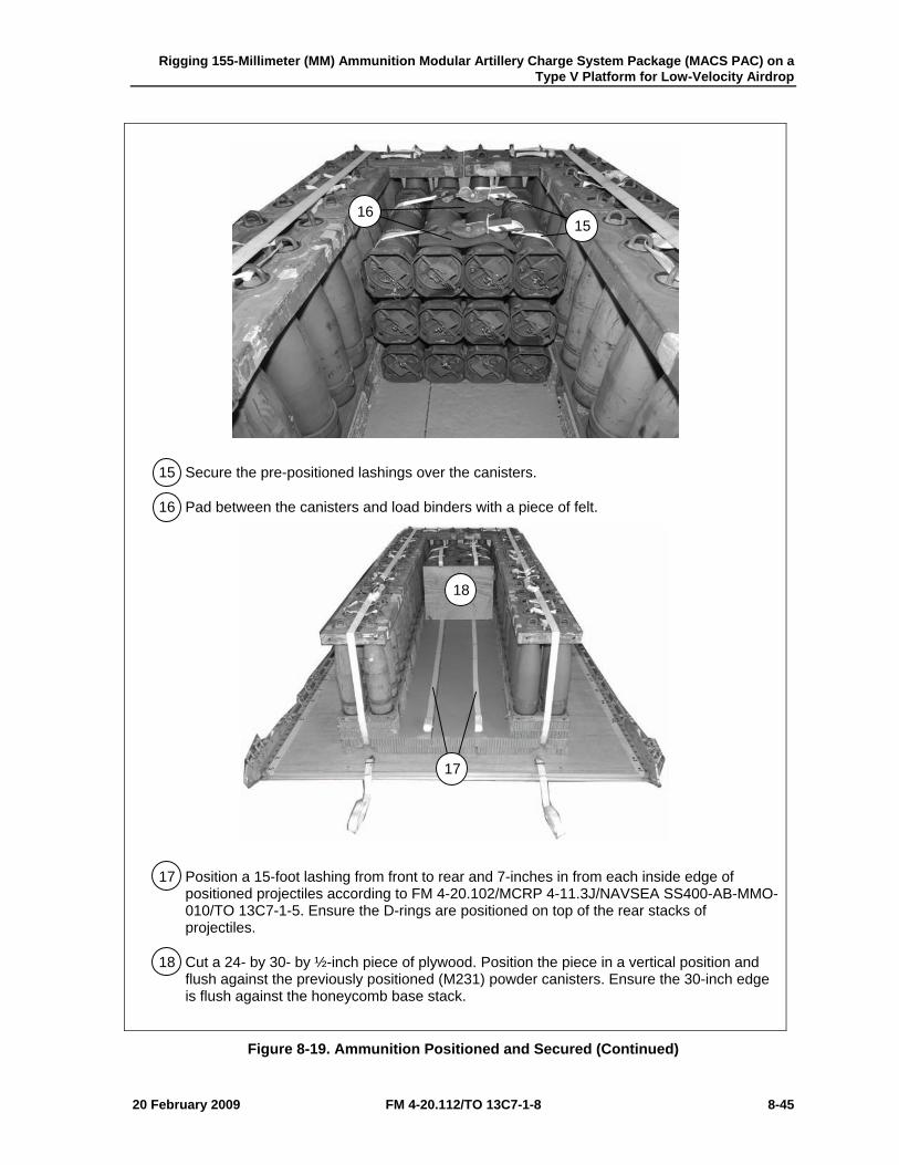
Rigging 155-Millimeter (MM) Ammunition Modular Artillery Charge System Package (MACS PAC) on a Type V Platform for Low-Velocity Airdrop
20 February 2009 FM 4-20.112/TO 13C7-1-8 8-45
15 Secure the pre-positioned lashings over the canisters.
16 Pad between the canisters and load binders with a piece of felt.
17 Position a 15-foot lashing from front to rear and 7-inches in from each inside edge of positioned projectiles according to FM 4-20.102/MCRP 4-11.3J/NAVSEA SS400-AB-MMO-010/TO 13C7-1-5. Ensure the D-rings are positioned on top of the rear stacks of projectiles.
18 Cut a 24- by 30- by ½-inch piece of plywood. Position the piece in a vertical position and flush against the previously positioned (M231) powder canisters. Ensure the 30-inch edge is flush against the honeycomb base stack.
Figure 8-19. Ammunition Positioned and Secured (Continued)
15 16
17
18
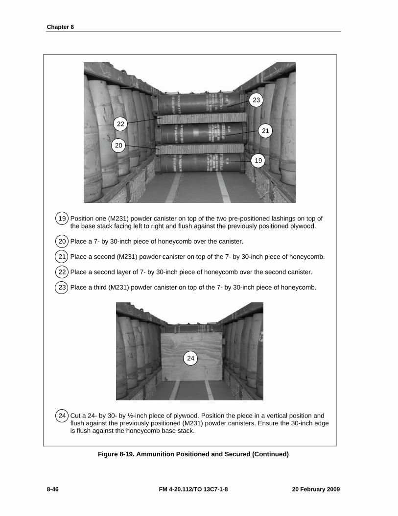
Chapter 8
8-46 FM 4-20.112/TO 13C7-1-8 20 February 2009
19 Position one (M231) powder canister on top of the two pre-positioned lashings on top of the base stack facing left to right and flush against the previously positioned plywood.
20 Place a 7- by 30-inch piece of honeycomb over the canister.
21 Place a second (M231) powder canister on top of the 7- by 30-inch piece of honeycomb.
22 Place a second layer of 7- by 30-inch piece of honeycomb over the second canister.
23 Place a third (M231) powder canister on top of the 7- by 30-inch piece of honeycomb.
24 Cut a 24- by 30- by ½-inch piece of plywood. Position the piece in a vertical position and flush against the previously positioned (M231) powder canisters. Ensure the 30-inch edge is flush against the honeycomb base stack.
Figure 8-19. Ammunition Positioned and Secured (Continued)
23
19
20
22 21
24
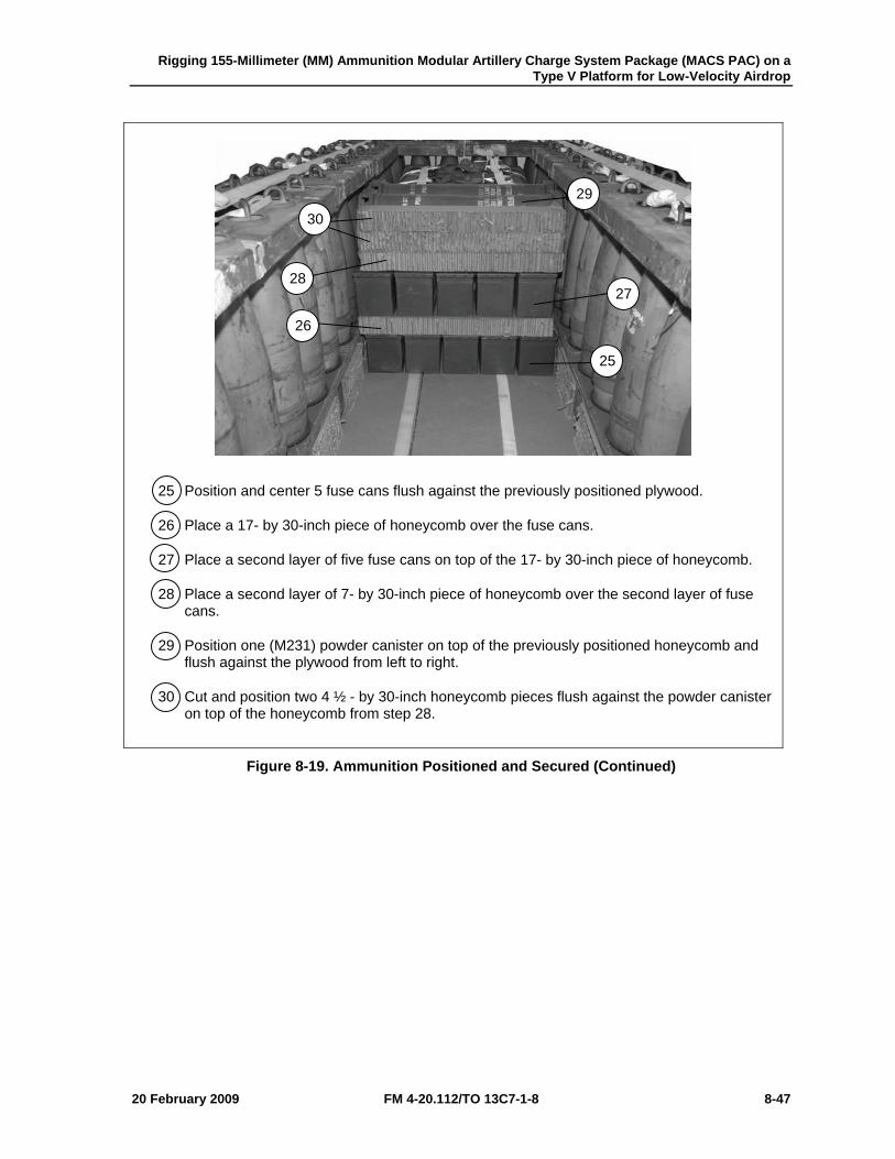
Rigging 155-Millimeter (MM) Ammunition Modular Artillery Charge System Package (MACS PAC) on a Type V Platform for Low-Velocity Airdrop
20 February 2009 FM 4-20.112/TO 13C7-1-8 8-47
25 Position and center 5 fuse cans flush against the previously positioned plywood.
26 Place a 17- by 30-inch piece of honeycomb over the fuse cans.
27 Place a second layer of five fuse cans on top of the 17- by 30-inch piece of honeycomb.
28 Place a second layer of 7- by 30-inch piece of honeycomb over the second layer of fuse cans.
29 Position one (M231) powder canister on top of the previously positioned honeycomb and flush against the plywood from left to right.
30 Cut and position two 4 ½ - by 30-inch honeycomb pieces flush against the powder canister on top of the honeycomb from step 28.
Figure 8-19. Ammunition Positioned and Secured (Continued)
29
25
26
28 27
30
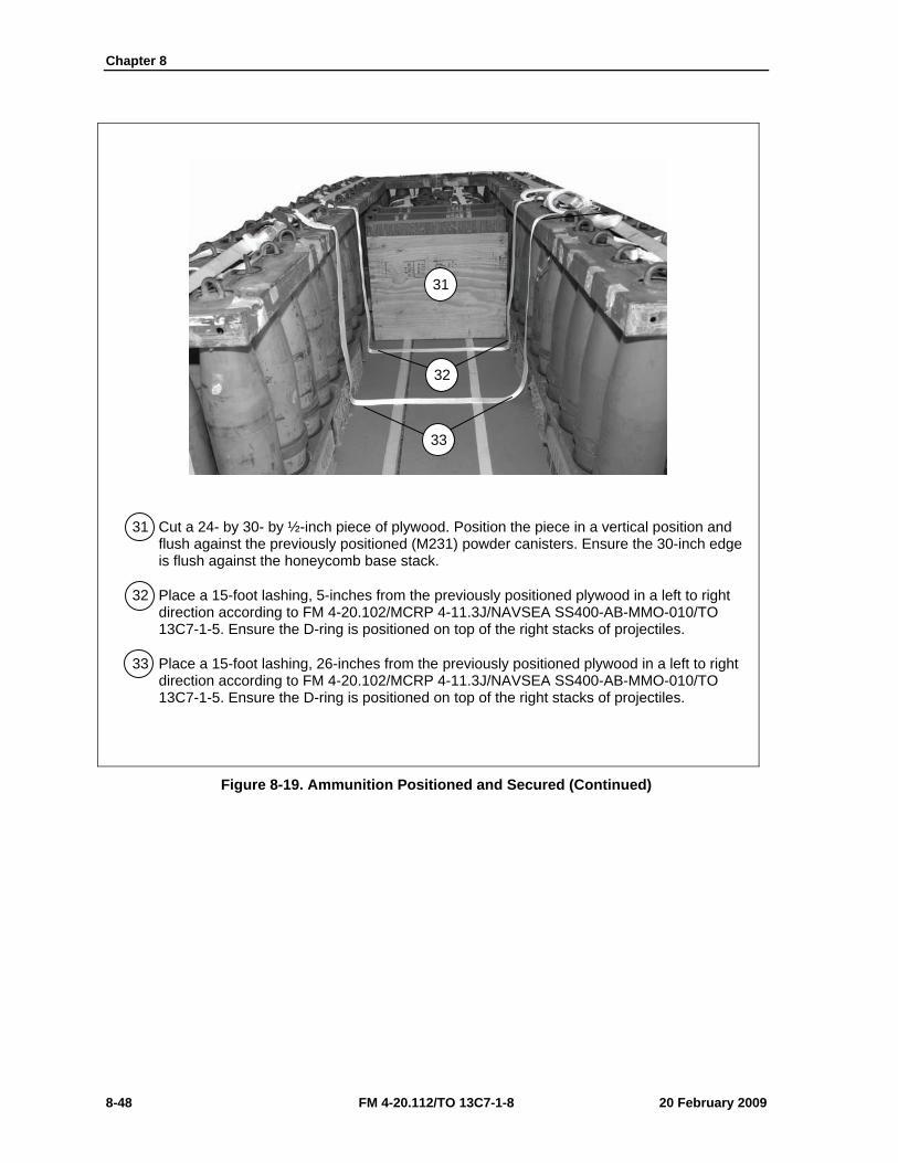
Chapter 8
8-48 FM 4-20.112/TO 13C7-1-8 20 February 2009
31 Cut a 24- by 30- by ½-inch piece of plywood. Position the piece in a vertical position and flush against the previously positioned (M231) powder canisters. Ensure the 30-inch edge is flush against the honeycomb base stack.
32 Place a 15-foot lashing, 5-inches from the previously positioned plywood in a left to right direction according to FM 4-20.102/MCRP 4-11.3J/NAVSEA SS400-AB-MMO-010/TO 13C7-1-5. Ensure the D-ring is positioned on top of the right stacks of projectiles.
33 Place a 15-foot lashing, 26-inches from the previously positioned plywood in a left to right direction according to FM 4-20.102/MCRP 4-11.3J/NAVSEA SS400-AB-MMO-010/TO 13C7-1-5. Ensure the D-ring is positioned on top of the right stacks of projectiles.
Figure 8-19. Ammunition Positioned and Secured (Continued)
31
32
33
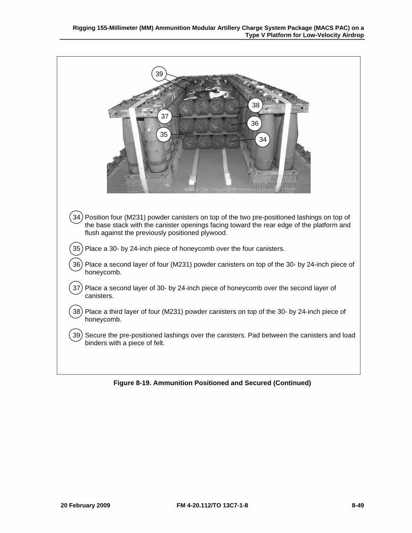
Rigging 155-Millimeter (MM) Ammunition Modular Artillery Charge System Package (MACS PAC) on a Type V Platform for Low-Velocity Airdrop
20 February 2009 FM 4-20.112/TO 13C7-1-8 8-49
34 Position four (M231) powder canisters on top of the two pre-positioned lashings on top of the base stack with the canister openings facing toward the rear edge of the platform and flush against the previously positioned plywood.
35 Place a 30- by 24-inch piece of honeycomb over the four canisters.
36 Place a second layer of four (M231) powder canisters on top of the 30- by 24-inch piece of honeycomb.
37 Place a second layer of 30- by 24-inch piece of honeycomb over the second layer of canisters.
38 Place a third layer of four (M231) powder canisters on top of the 30- by 24-inch piece of honeycomb.
39 Secure the pre-positioned lashings over the canisters. Pad between the canisters and load binders with a piece of felt.
Figure 8-19. Ammunition Positioned and Secured (Continued)
34 35
36 37
38
39
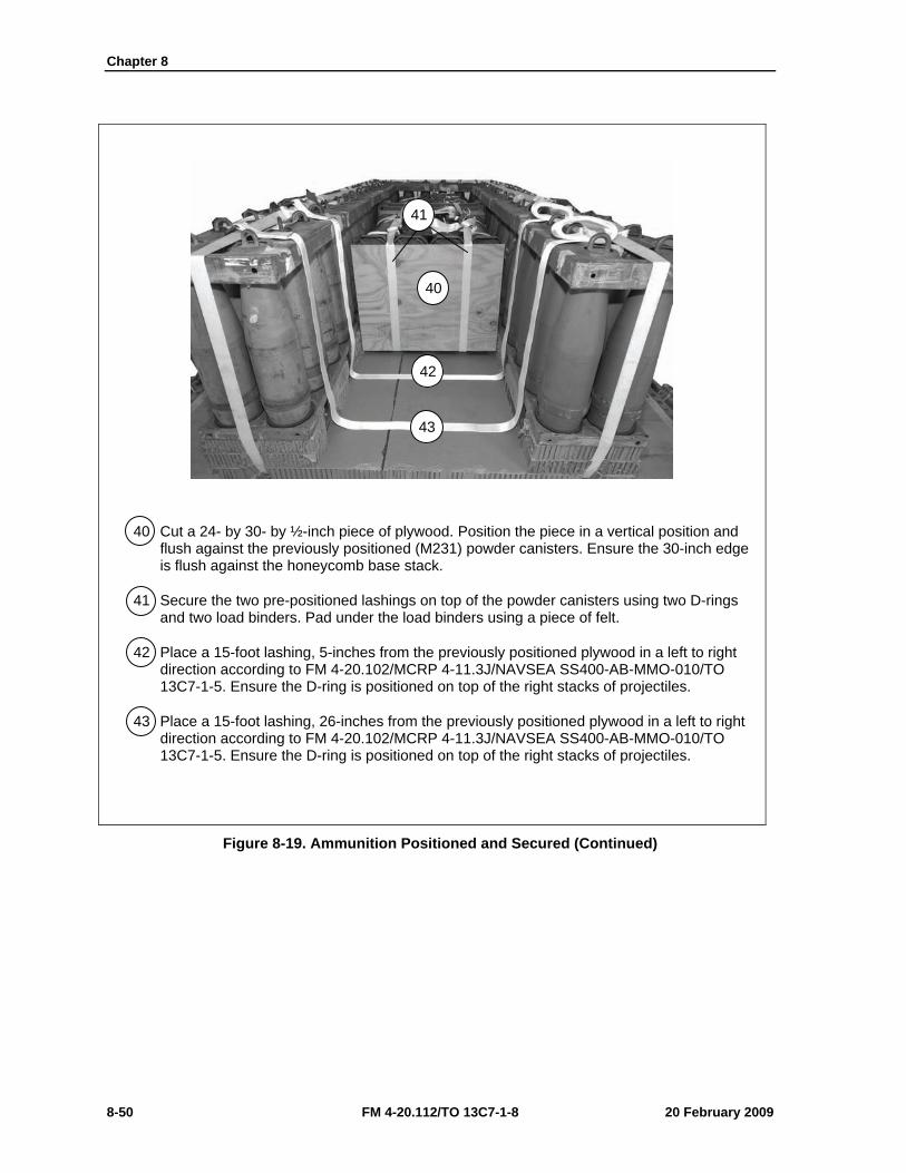
Chapter 8
8-50 FM 4-20.112/TO 13C7-1-8 20 February 2009
40 Cut a 24- by 30- by ½-inch piece of plywood. Position the piece in a vertical position and flush against the previously positioned (M231) powder canisters. Ensure the 30-inch edge is flush against the honeycomb base stack.
41 Secure the two pre-positioned lashings on top of the powder canisters using two D-rings and two load binders. Pad under the load binders using a piece of felt.
42 Place a 15-foot lashing, 5-inches from the previously positioned plywood in a left to right direction according to FM 4-20.102/MCRP 4-11.3J/NAVSEA SS400-AB-MMO-010/TO 13C7-1-5. Ensure the D-ring is positioned on top of the right stacks of projectiles.
43 Place a 15-foot lashing, 26-inches from the previously positioned plywood in a left to right direction according to FM 4-20.102/MCRP 4-11.3J/NAVSEA SS400-AB-MMO-010/TO 13C7-1-5. Ensure the D-ring is positioned on top of the right stacks of projectiles.
Figure 8-19. Ammunition Positioned and Secured (Continued)
40
41
42
43
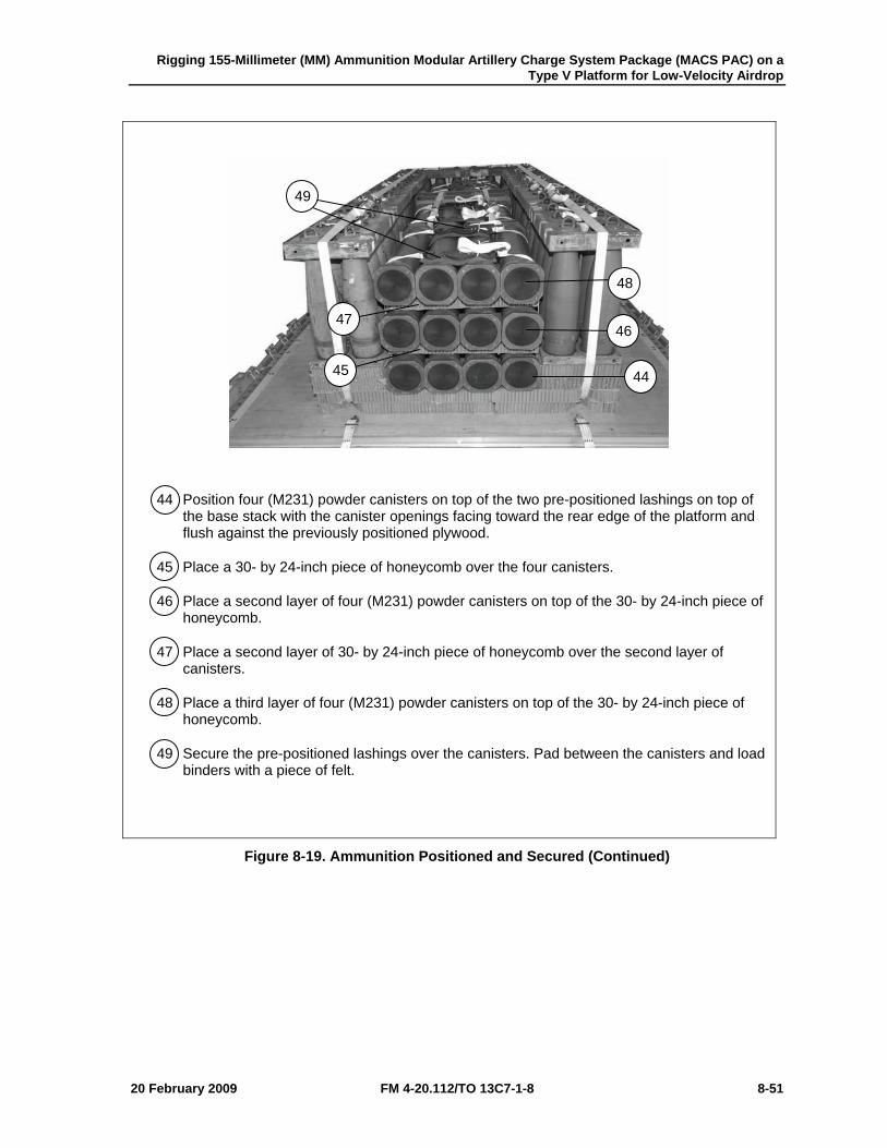
Rigging 155-Millimeter (MM) Ammunition Modular Artillery Charge System Package (MACS PAC) on a Type V Platform for Low-Velocity Airdrop
20 February 2009 FM 4-20.112/TO 13C7-1-8 8-51
44 Position four (M231) powder canisters on top of the two pre-positioned lashings on top of the base stack with the canister openings facing toward the rear edge of the platform and flush against the previously positioned plywood.
45 Place a 30- by 24-inch piece of honeycomb over the four canisters.
46 Place a second layer of four (M231) powder canisters on top of the 30- by 24-inch piece of honeycomb.
47 Place a second layer of 30- by 24-inch piece of honeycomb over the second layer of canisters.
48 Place a third layer of four (M231) powder canisters on top of the 30- by 24-inch piece of honeycomb.
49 Secure the pre-positioned lashings over the canisters. Pad between the canisters and load binders with a piece of felt.
Figure 8-19. Ammunition Positioned and Secured (Continued)
44 45
46 47
48
49
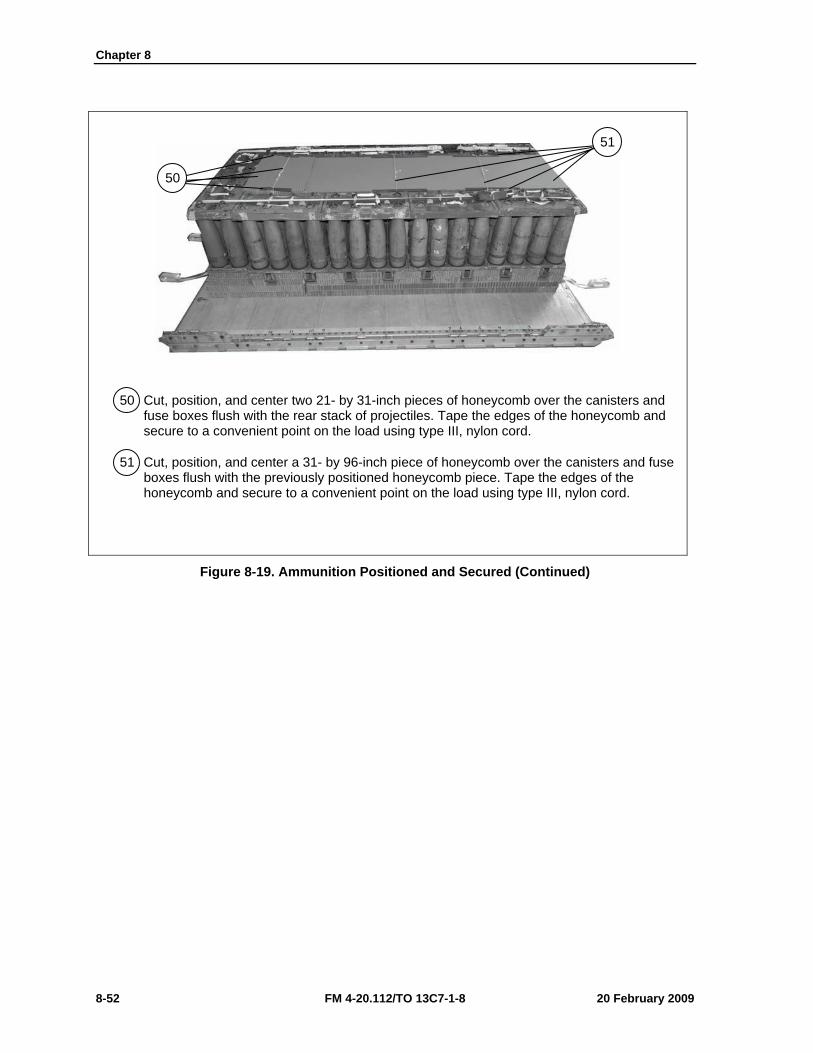
Chapter 8
8-52 FM 4-20.112/TO 13C7-1-8 20 February 2009
50 Cut, position, and center two 21- by 31-inch pieces of honeycomb over the canisters and fuse boxes flush with the rear stack of projectiles. Tape the edges of the honeycomb and secure to a convenient point on the load using type III, nylon cord.
51 Cut, position, and center a 31- by 96-inch piece of honeycomb over the canisters and fuse boxes flush with the previously positioned honeycomb piece. Tape the edges of the honeycomb and secure to a convenient point on the load using type III, nylon cord.
Figure 8-19. Ammunition Positioned and Secured (Continued)
50
51
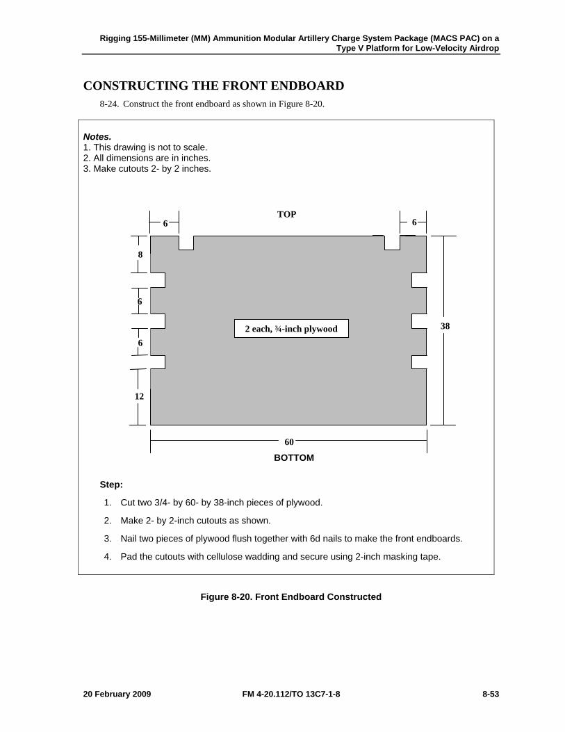
Rigging 155-Millimeter (MM) Ammunition Modular Artillery Charge System Package (MACS PAC) on a Type V Platform for Low-Velocity Airdrop
20 February 2009 FM 4-20.112/TO 13C7-1-8 8-53
CONSTRUCTING THE FRONT ENDBOARD 8-24. Construct the front endboard as shown in Figure 8-20.
Notes. 1. This drawing is not to scale. 2. All dimensions are in inches. 3. Make cutouts 2- by 2 inches.
Step:
1. Cut two 3/4- by 60- by 38-inch pieces of plywood.
2. Make 2- by 2-inch cutouts as shown.
3. Nail two pieces of plywood flush together with 6d nails to make the front endboards.
4. Pad the cutouts with cellulose wadding and secure using 2-inch masking tape.
Figure 8-20. Front Endboard Constructed
38
60
6
12
6
6
6
8
2 each, ¾-inch plywood
TOP
BOTTOM
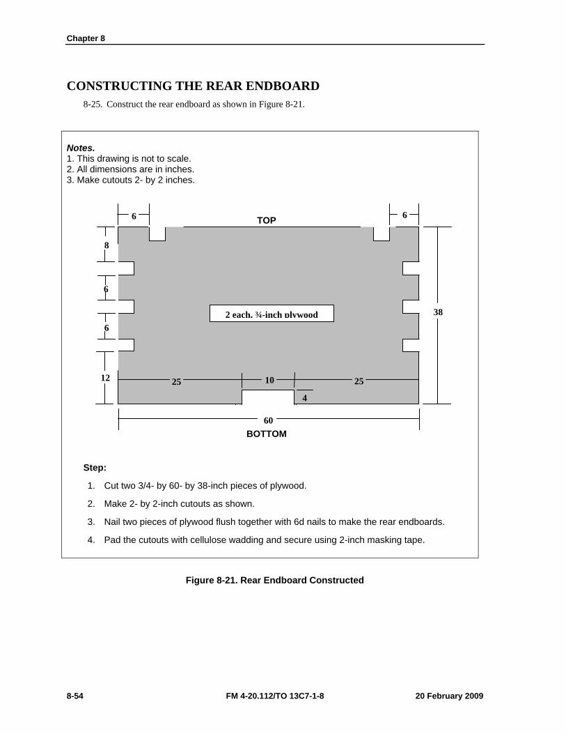
Chapter 8
8-54 FM 4-20.112/TO 13C7-1-8 20 February 2009
CONSTRUCTING THE REAR ENDBOARD 8-25. Construct the rear endboard as shown in Figure 8-21.
Notes. 1. This drawing is not to scale. 2. All dimensions are in inches. 3. Make cutouts 2- by 2 inches.
Step:
1. Cut two 3/4- by 60- by 38-inch pieces of plywood.
2. Make 2- by 2-inch cutouts as shown.
3. Nail two pieces of plywood flush together with 6d nails to make the rear endboards.
4. Pad the cutouts with cellulose wadding and secure using 2-inch masking tape.
Figure 8-21. Rear Endboard Constructed
38
60
6
12
6
6
6
8
2 each, ¾-inch plywood
10
4
25 25
BOTTOM
TOP
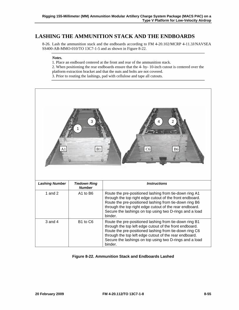
Rigging 155-Millimeter (MM) Ammunition Modular Artillery Charge System Package (MACS PAC) on a Type V Platform for Low-Velocity Airdrop
20 February 2009 FM 4-20.112/TO 13C7-1-8 8-55
LASHING THE AMMUNITION STACK AND THE ENDBOARDS 8-26. Lash the ammunition stack and the endboards according to FM 4-20.102/MCRP 4-11.3J/NAVSEA SS400-AB-MMO-010/TO 13C7-1-5 and as shown in Figure 8-22.
Notes. 1. Place an endboard centered at the front and rear of the ammunition stack. 2. When positioning the rear endboards ensure that the 4- by- 10-inch cutout is centered over the platform extraction bracket and that the nuts and bolts are not covered. 3. Prior to routing the lashings, pad with cellulose and tape all cutouts.
Lashing Number Tiedown Ring
Number Instructions
1 and 2 A1 to B6 Route the pre-positioned lashing from tie-down ring A1 through the top right edge cutout of the front endboard. Route the pre-positioned lashing from tie-down ring B6 through the top right edge cutout of the rear endboard. Secure the lashings on top using two D-rings and a load binder.
3 and 4 B1 to C6 Route the pre-positioned lashing from tie-down ring B1 through the top left edge cutout of the front endboard. Route the pre-positioned lashing from tie-down ring C6 through the top left edge cutout of the rear endboard. Secure the lashings on top using two D-rings and a load binder.
Figure 8-22. Ammunition Stack and Endboards Lashed
A1 B1
1
3
C6 B6
4 2
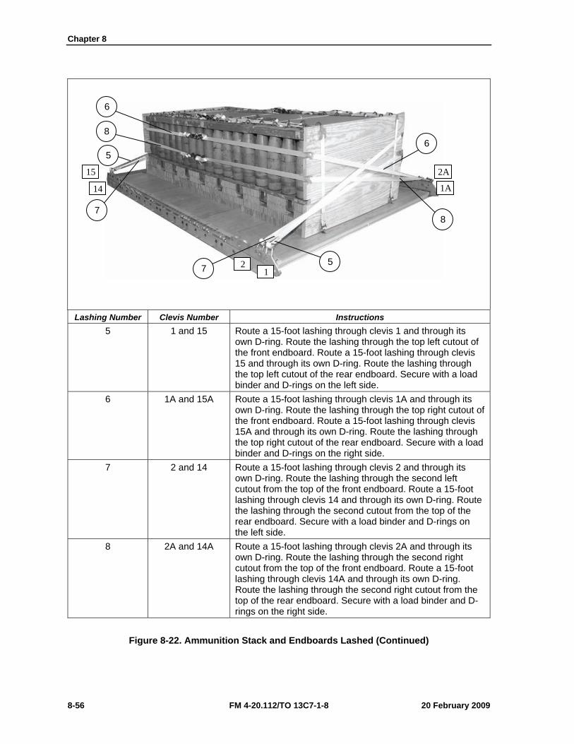
Chapter 8
8-56 FM 4-20.112/TO 13C7-1-8 20 February 2009
Lashing Number Clevis Number Instructions
5 1 and 15 Route a 15-foot lashing through clevis 1 and through its own D-ring. Route the lashing through the top left cutout of the front endboard. Route a 15-foot lashing through clevis 15 and through its own D-ring. Route the lashing through the top left cutout of the rear endboard. Secure with a load binder and D-rings on the left side.
6 1A and 15A Route a 15-foot lashing through clevis 1A and through its own D-ring. Route the lashing through the top right cutout of the front endboard. Route a 15-foot lashing through clevis 15A and through its own D-ring. Route the lashing through the top right cutout of the rear endboard. Secure with a load binder and D-rings on the right side.
7 2 and 14 Route a 15-foot lashing through clevis 2 and through its own D-ring. Route the lashing through the second left cutout from the top of the front endboard. Route a 15-foot lashing through clevis 14 and through its own D-ring. Route the lashing through the second cutout from the top of the rear endboard. Secure with a load binder and D-rings on the left side.
8 2A and 14A Route a 15-foot lashing through clevis 2A and through its own D-ring. Route the lashing through the second right cutout from the top of the front endboard. Route a 15-foot lashing through clevis 14A and through its own D-ring. Route the lashing through the second right cutout from the top of the rear endboard. Secure with a load binder and D-rings on the right side.
Figure 8-22. Ammunition Stack and Endboards Lashed (Continued)
8
5
6
6
7
8
5
7 12
15
14 1A
2A
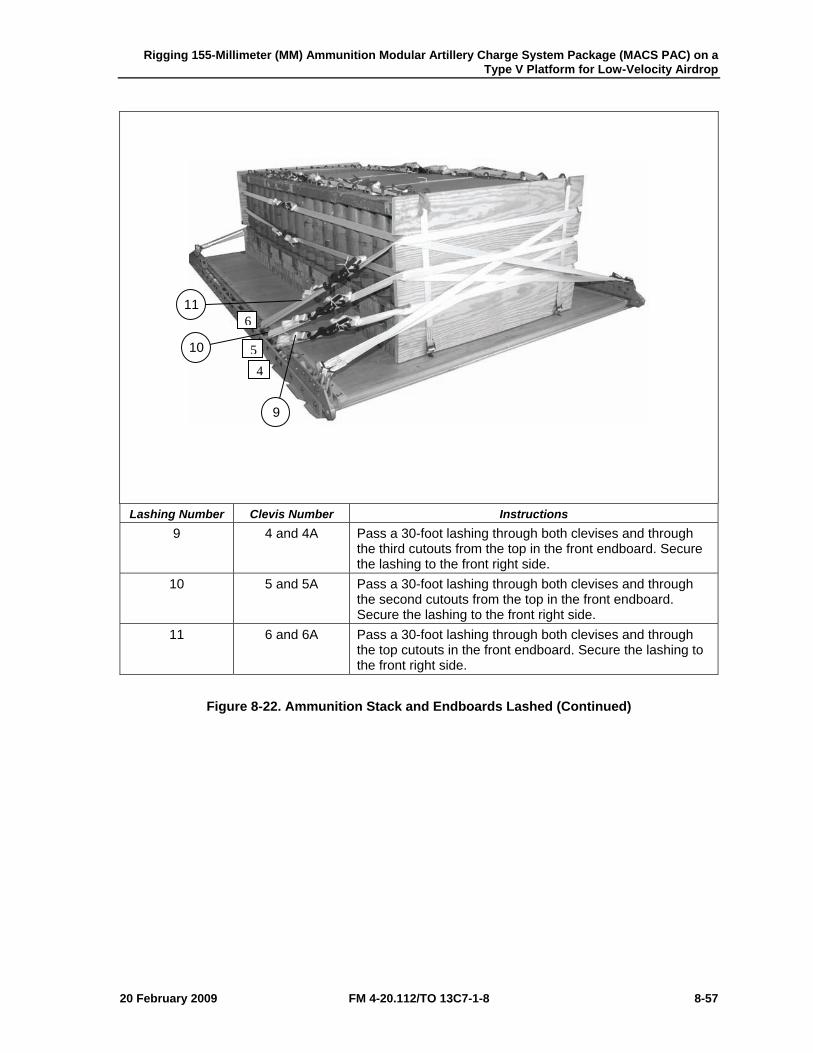
Rigging 155-Millimeter (MM) Ammunition Modular Artillery Charge System Package (MACS PAC) on a Type V Platform for Low-Velocity Airdrop
20 February 2009 FM 4-20.112/TO 13C7-1-8 8-57
Lashing Number Clevis Number Instructions
9 4 and 4A Pass a 30-foot lashing through both clevises and through the third cutouts from the top in the front endboard. Secure the lashing to the front right side.
10 5 and 5A Pass a 30-foot lashing through both clevises and through the second cutouts from the top in the front endboard. Secure the lashing to the front right side.
11 6 and 6A Pass a 30-foot lashing through both clevises and through the top cutouts in the front endboard. Secure the lashing to the front right side.
Figure 8-22. Ammunition Stack and Endboards Lashed (Continued)
4 5
611
10
9
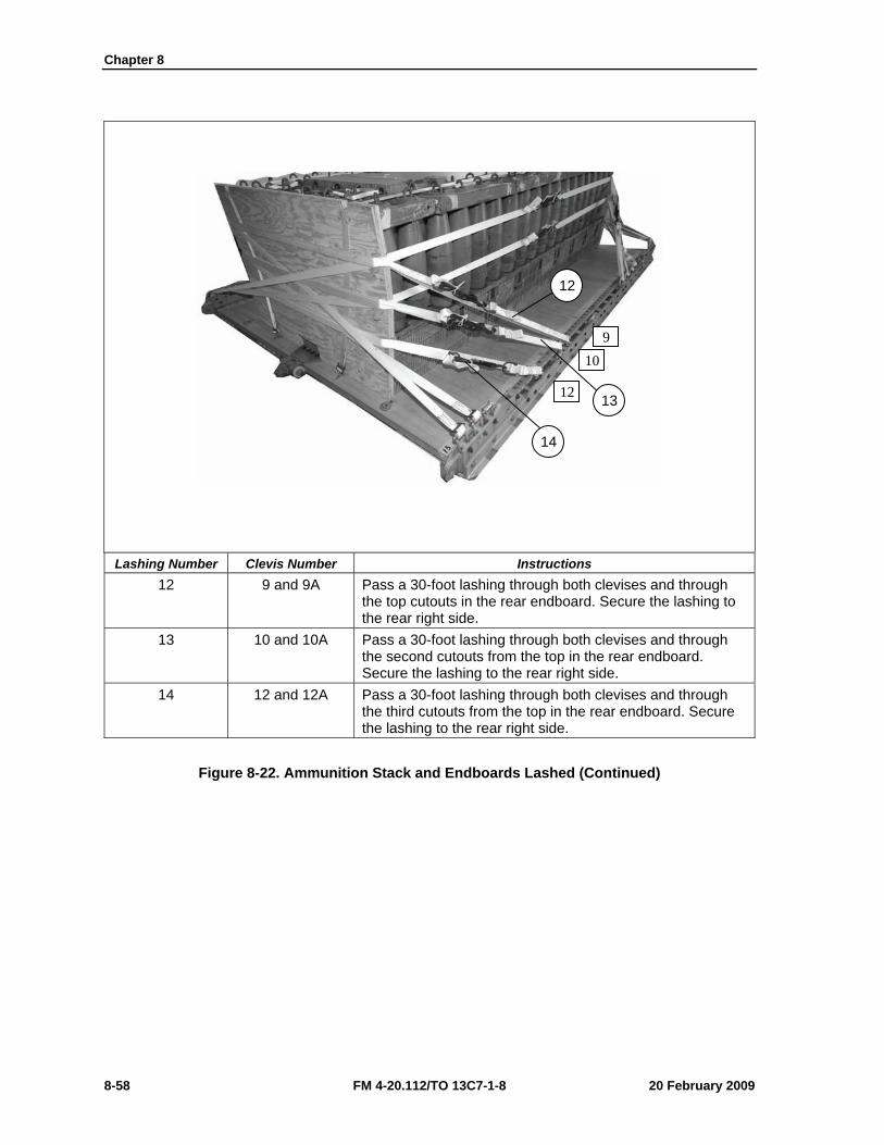
Chapter 8
8-58 FM 4-20.112/TO 13C7-1-8 20 February 2009
Lashing Number Clevis Number Instructions
12 9 and 9A Pass a 30-foot lashing through both clevises and through the top cutouts in the rear endboard. Secure the lashing to the rear right side.
13 10 and 10A Pass a 30-foot lashing through both clevises and through the second cutouts from the top in the rear endboard. Secure the lashing to the rear right side.
14 12 and 12A Pass a 30-foot lashing through both clevises and through the third cutouts from the top in the rear endboard. Secure the lashing to the rear right side.
Figure 8-22. Ammunition Stack and Endboards Lashed (Continued)
12
910
12 13
14
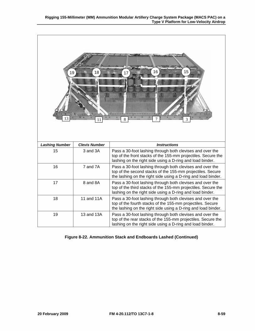
Rigging 155-Millimeter (MM) Ammunition Modular Artillery Charge System Package (MACS PAC) on a Type V Platform for Low-Velocity Airdrop
20 February 2009 FM 4-20.112/TO 13C7-1-8 8-59
Lashing Number Clevis Number Instructions
15 3 and 3A Pass a 30-foot lashing through both clevises and over the top of the front stacks of the 155-mm projectiles. Secure the lashing on the right side using a D-ring and load binder.
16 7 and 7A Pass a 30-foot lashing through both clevises and over the top of the second stacks of the 155-mm projectiles. Secure the lashing on the right side using a D-ring and load binder.
17 8 and 8A Pass a 30-foot lashing through both clevises and over the top of the third stacks of the 155-mm projectiles. Secure the lashing on the right side using a D-ring and load binder.
18 11 and 11A Pass a 30-foot lashing through both clevises and over the top of the fourth stacks of the 155-mm projectiles. Secure the lashing on the right side using a D-ring and load binder.
19 13 and 13A Pass a 30-foot lashing through both clevises and over the top of the rear stacks of the 155-mm projectiles. Secure the lashing on the right side using a D-ring and load binder.
Figure 8-22. Ammunition Stack and Endboards Lashed (Continued)
15 16 17 18 19
3 7811 13
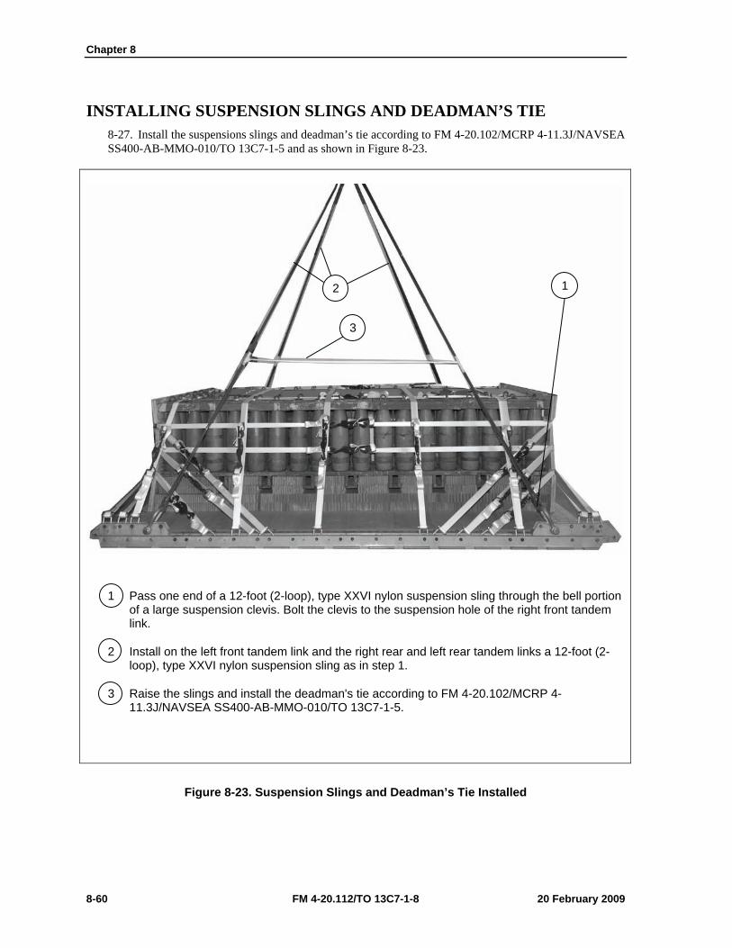
Chapter 8
8-60 FM 4-20.112/TO 13C7-1-8 20 February 2009
INSTALLING SUSPENSION SLINGS AND DEADMAN’S TIE 8-27. Install the suspensions slings and deadman’s tie according to FM 4-20.102/MCRP 4-11.3J/NAVSEA SS400-AB-MMO-010/TO 13C7-1-5 and as shown in Figure 8-23.
1 Pass one end of a 12-foot (2-loop), type XXVI nylon suspension sling through the bell portion of a large suspension clevis. Bolt the clevis to the suspension hole of the right front tandem link.
2 Install on the left front tandem link and the right rear and left rear tandem links a 12-foot (2-loop), type XXVI nylon suspension sling as in step 1.
3 Raise the slings and install the deadman's tie according to FM 4-20.102/MCRP 4-11.3J/NAVSEA SS400-AB-MMO-010/TO 13C7-1-5.
Figure 8-23. Suspension Slings and Deadman’s Tie Installed
1 2
3
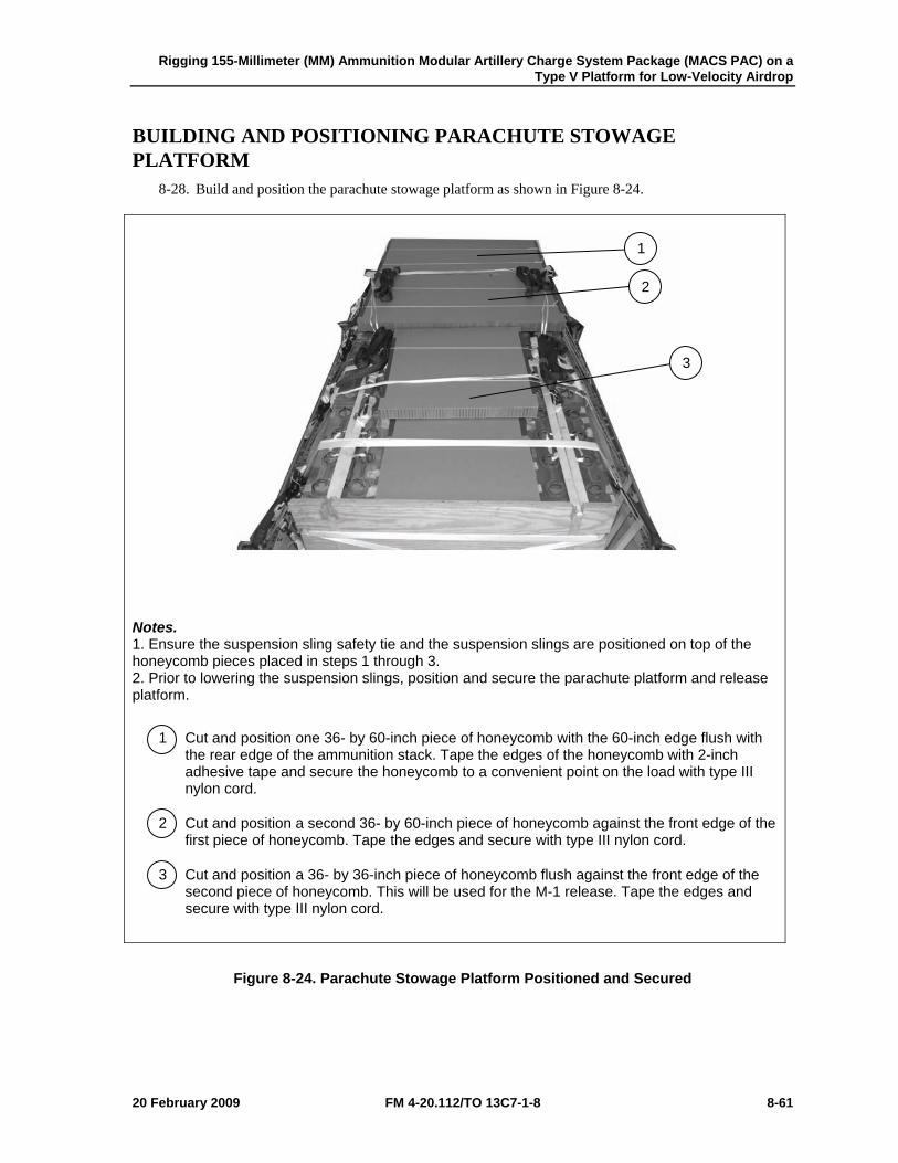
Rigging 155-Millimeter (MM) Ammunition Modular Artillery Charge System Package (MACS PAC) on a Type V Platform for Low-Velocity Airdrop
20 February 2009 FM 4-20.112/TO 13C7-1-8 8-61
BUILDING AND POSITIONING PARACHUTE STOWAGE PLATFORM
8-28. Build and position the parachute stowage platform as shown in Figure 8-24.
Notes. 1. Ensure the suspension sling safety tie and the suspension slings are positioned on top of the honeycomb pieces placed in steps 1 through 3. 2. Prior to lowering the suspension slings, position and secure the parachute platform and release platform.
1 Cut and position one 36- by 60-inch piece of honeycomb with the 60-inch edge flush with the rear edge of the ammunition stack. Tape the edges of the honeycomb with 2-inch adhesive tape and secure the honeycomb to a convenient point on the load with type III nylon cord.
2 Cut and position a second 36- by 60-inch piece of honeycomb against the front edge of the first piece of honeycomb. Tape the edges and secure with type III nylon cord.
3 Cut and position a 36- by 36-inch piece of honeycomb flush against the front edge of the second piece of honeycomb. This will be used for the M-1 release. Tape the edges and secure with type III nylon cord.
Figure 8-24. Parachute Stowage Platform Positioned and Secured
1
2
3
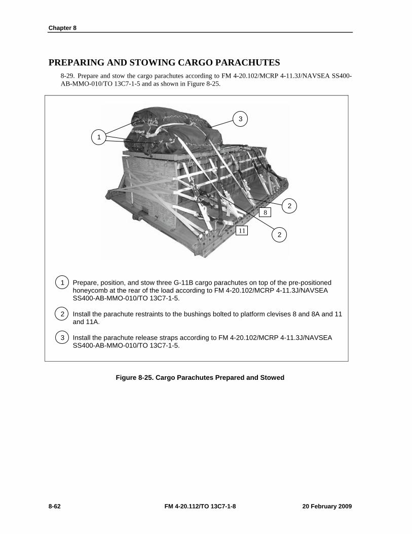
Chapter 8
8-62 FM 4-20.112/TO 13C7-1-8 20 February 2009
PREPARING AND STOWING CARGO PARACHUTES 8-29. Prepare and stow the cargo parachutes according to FM 4-20.102/MCRP 4-11.3J/NAVSEA SS400-AB-MMO-010/TO 13C7-1-5 and as shown in Figure 8-25.
1 Prepare, position, and stow three G-11B cargo parachutes on top of the pre-positioned honeycomb at the rear of the load according to FM 4-20.102/MCRP 4-11.3J/NAVSEA SS400-AB-MMO-010/TO 13C7-1-5.
2 Install the parachute restraints to the bushings bolted to platform clevises 8 and 8A and 11 and 11A.
3 Install the parachute release straps according to FM 4-20.102/MCRP 4-11.3J/NAVSEA SS400-AB-MMO-010/TO 13C7-1-5.
Figure 8-25. Cargo Parachutes Prepared and Stowed
11
8
3
1
2
2

Rigging 155-Millimeter (MM) Ammunition Modular Artillery Charge System Package (MACS PAC) on a Type V Platform for Low-Velocity Airdrop
20 February 2009 FM 4-20.112/TO 13C7-1-8 8-63
INSTALLING THE RELEASE SYSTEM 8-30. Prepare, attach, and safety an M-1 cargo parachute release according to FM 4-20.102/MCRP 4-11.3J/NAVSEA SS400-AB-MMO-010/TO 13C7-1-5 and as shown in Figure 8-26.
1 Prepare and install the M-1 cargo parachute release according to FM 4-20.102/MCRP 4-11.3J/NAVSEA SS400-AB-MMO-010/TO 13C7-1-5 and position the M-1 cargo parachute release assembly centered on the 36- by 36-inch honeycomb release platform.
2 Attach the suspension slings and riser extensions according to FM 4-20.102/MCRP 4-11.3J/NAVSEA SS400-AB-MMO-010/TO 13C7-1-5.
3 S-fold the excess suspension slings and riser extensions. Secure with type I ¼-inch cotton webbing.
4 Restrain the parachute release according to FM 4-20.102/MCRP 4-11.3J/NAVSEA SS400-AB-MMO-010/TO 13C7-1-5.Tape the loose deadman’s using a single wrap of masking tape.
5 Secure the arming wire and lanyard to the parachute carrying handle. S-fold any excess in the lanyard and secure using a single wrap of masking tape.
Figure 8-26. M-1 Cargo Parachute Release Installed
1
2
3 3
3
3
5 4
4
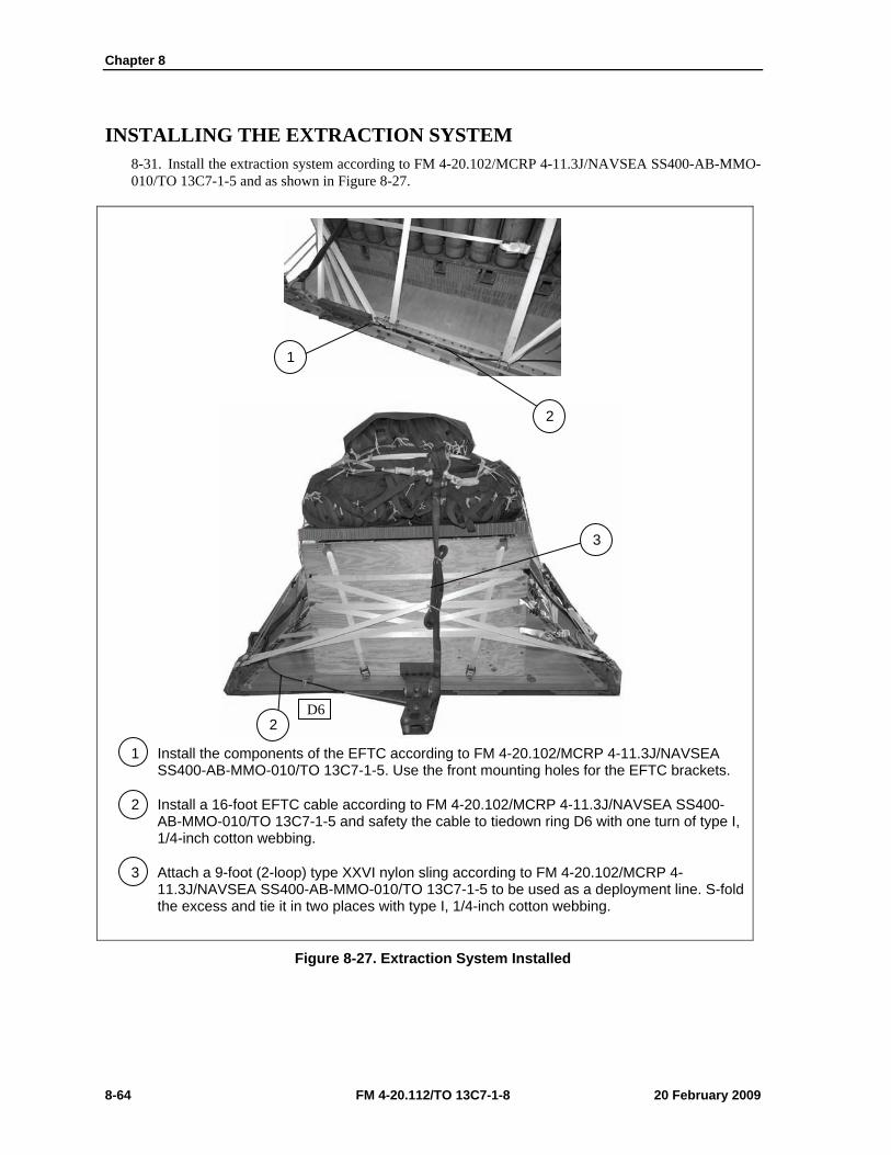
Chapter 8
8-64 FM 4-20.112/TO 13C7-1-8 20 February 2009
INSTALLING THE EXTRACTION SYSTEM 8-31. Install the extraction system according to FM 4-20.102/MCRP 4-11.3J/NAVSEA SS400-AB-MMO-010/TO 13C7-1-5 and as shown in Figure 8-27.
1 Install the components of the EFTC according to FM 4-20.102/MCRP 4-11.3J/NAVSEA SS400-AB-MMO-010/TO 13C7-1-5. Use the front mounting holes for the EFTC brackets.
2 Install a 16-foot EFTC cable according to FM 4-20.102/MCRP 4-11.3J/NAVSEA SS400-AB-MMO-010/TO 13C7-1-5 and safety the cable to tiedown ring D6 with one turn of type I, 1/4-inch cotton webbing.
3 Attach a 9-foot (2-loop) type XXVI nylon sling according to FM 4-20.102/MCRP 4-11.3J/NAVSEA SS400-AB-MMO-010/TO 13C7-1-5 to be used as a deployment line. S-fold the excess and tie it in two places with type I, 1/4-inch cotton webbing.
Figure 8-27. Extraction System Installed
1
2
2
3
D6
Rigging 155-Millimeter (MM) Ammunition Modular Artillery Charge System Package (MACS PAC) on a Type V Platform for Low-Velocity Airdrop
20 February 2009 FM 4-20.112/TO 13C7-1-8 8-65
PLACING EXTRACTION PARACHUTE 8-32. Select the extraction parachute and extraction line needed using the extraction line requirements table in FM 4-20.102/MCRP 4-11.3J/NAVSEA SS400-AB-MMO-010/TO 13C7-1-5. Place the extraction parachute and line on the load for installation in the aircraft.
INSTALLING PROVISIONS FOR EMERGENCY RESTRAINTS 8-33. Select and install the provisions for the emergency aft restraints according to the emergency aft restraint requirements table in FM 4-20.102/MCRP 4-11.3J/NAVSEA SS400-AB-MMO-010/TO 13C7-1-5.
MARKING RIGGED LOAD 8-34. Mark the rigged load according to FM 4-20.102/MCRP 4-11.3J/NAVSEA SS400-AB-MMO-010/TO 13C7-1-5, and as shown in Figure 8-28. Complete Shipper’s Declaration for Dangerous Goods. If the load varies from the one shown, the weight, height, CB, and parachute requirements must be recomputed.
EQUIPMENT REQUIRED 8-35. Use the equipment listed in Table 8-2 to rig this load.
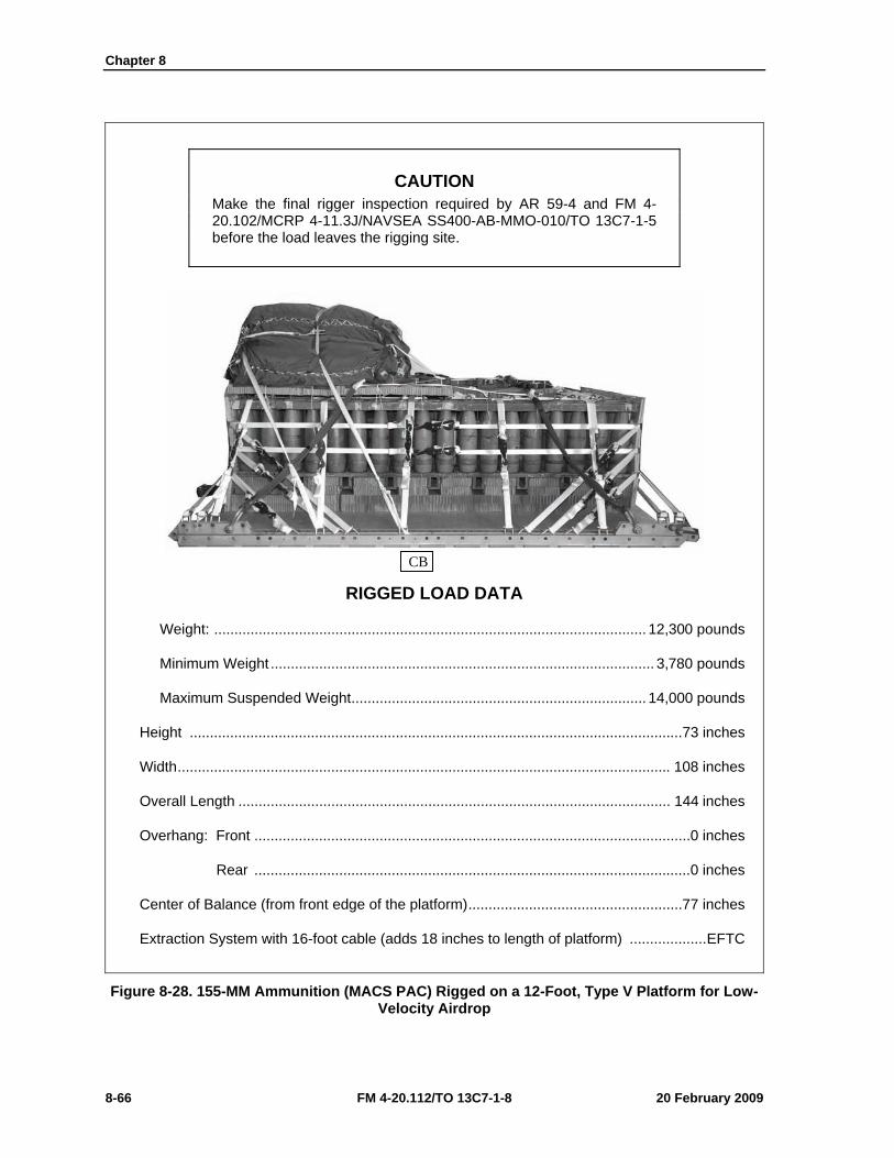
Chapter 8
8-66 FM 4-20.112/TO 13C7-1-8 20 February 2009
CAUTION Make the final rigger inspection required by AR 59-4 and FM 4-20.102/MCRP 4-11.3J/NAVSEA SS400-AB-MMO-010/TO 13C7-1-5 before the load leaves the rigging site.
RIGGED LOAD DATA
Weight: ........................................................................................................... 12,300 pounds
Minimum Weight ............................................................................................... 3,780 pounds
Maximum Suspended Weight ......................................................................... 14,000 pounds
Height ..........................................................................................................................73 inches
Width .......................................................................................................................... 108 inches
Overall Length ........................................................................................................... 144 inches
Overhang: Front ............................................................................................................ 0 inches
Rear ............................................................................................................ 0 inches
Center of Balance (from front edge of the platform) .....................................................77 inches
Extraction System with 16-foot cable (adds 18 inches to length of platform) ................... EFTC
Figure 8-28. 155-MM Ammunition (MACS PAC) Rigged on a 12-Foot, Type V Platform for Low-Velocity Airdrop
CB
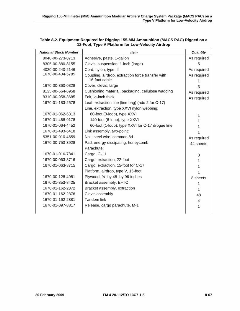
Rigging 155-Millimeter (MM) Ammunition Modular Artillery Charge System Package (MACS PAC) on a Type V Platform for Low-Velocity Airdrop
20 February 2009 FM 4-20.112/TO 13C7-1-8 8-67
Table 8-2. Equipment Required for Rigging 155-MM Ammunition (MACS PAC) Rigged on a 12-Foot, Type V Platform for Low-Velocity Airdrop
National Stock Number Item Quantity 8040-00-273-8713 8305-00-880-8155 4020-00-240-2146 1670-00-434-5785
1670-00-360-0328 8135-00-664-6958 8310-00-958-3685 1670-01-183-2678
1670-01-062-6313 1670-01-468-9178 1670-01-064-4452 1670-01-493-6418 5351-00-010-4659 1670-00-753-3928
1670-01-016-7841 1670-00-063-3716 1670-01-063-3715
1670-00-128-4981 1670-01-353-8425 1670-01-162-2372 1670-01-162-2376 1670-01-162-2381 1670-01-097-8817
Adhesive, paste, 1-gallon Clevis, suspension: 1-inch (large) Cord, nylon, type III Coupling, airdrop, extraction force transfer with 16-foot cable Cover, clevis, large Cushioning material, packaging, cellulose wadding Felt, ½-inch thick Leaf, extraction line (line bag) (add 2 for C-17) Line, extraction, type XXVI nylon webbing: 60-foot (3-loop), type XXVI 140-foot (6-loop), type XXVI 60-foot (1-loop), type XXVI for C-17 drogue line Link assembly, two-point: Nail, steel wire, common 8d Pad, energy-dissipating, honeycomb Parachute: Cargo, G-11 Cargo, extraction, 22-foot Cargo, extraction, 15-foot for C-17 Platform, airdrop, type V, 16-foot Plywood, ¾- by 48- by 96-inches Bracket assembly, EFTC Bracket assembly, extraction Clevis assembly Tandem link Release, cargo parachute, M-1
As required 5
As required As required
1 3
As required As required
1 1 1 1
As required 44 sheets
3 1 1 1
8 sheets 1 1
48 4 1
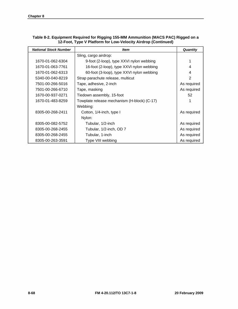
Chapter 8
8-68 FM 4-20.112/TO 13C7-1-8 20 February 2009
Table 8-2. Equipment Required for Rigging 155-MM Ammunition (MACS PAC) Rigged on a 12-Foot, Type V Platform for Low-Velocity Airdrop (Continued)
National Stock Number Item Quantity
1670-01-062-6304 1670-01-063-7761 1670-01-062-6313 5340-00-040-8219 7501-00-266-5016 7501-00-266-6710 1670-00-937-0271 1670-01-483-8259
8305-00-268-2411
8305-00-082-5752 8305-00-268-2455 8305-00-268-2455 8305-00-263-3591
Sling, cargo airdrop: 9-foot (2-loop), type XXVI nylon webbing 16-foot (2-loop), type XXVI nylon webbing 60-foot (3-loop), type XXVI nylon webbing Strap parachute release, multicut Tape, adhesive, 2-inch Tape, masking Tiedown assembly, 15-foot Towplate release mechanism (H-block) (C-17) Webbing: Cotton, 1/4-inch, type I Nylon: Tubular, 1/2-inch Tubular, 1/2-inch, OD 7 Tubular, 1-inch Type VIII webbing
1 4 4 2
As required As required
52 1
As required
As required As required As required As required

Rigging 155-Millimeter (MM) Ammunition Modular Artillery Charge System Package (MACS PAC) on a Type V Platform for Low-Velocity Airdrop
20 February 2009 FM 4-20.112/TO 13C7-1-8 8-69
SECTION III-RIGGING THE MACS PAC ON A 16-FOOT, TYPE V PLATFORM
DESCRIPTION OF LOAD 8-36. Ninety-six 155-mm projectiles, 72 power canisters and 12 fuse cans are rigged for low-velocity airdrop on a 16-foot, type V platform. The load uses three G-11B cargo parachutes. Refer to FM 4-20.102/MCRP 4-11.3J/NAVSEA SS400-AB-MMO-010/TO 13C7-1-5 for the weight limitations and for the number of parachutes to be used.
Notes. 1. The load shown is using metal crates. However, wooden crates may be used with three lashings and a load binder. 2. If the metal locking rods are missing, three lashings, D-rings and load binders will be needed.
PREPARING PLATFORM 8-37. Prepare a 16-foot, type V platform as shown in Figure 8-29.
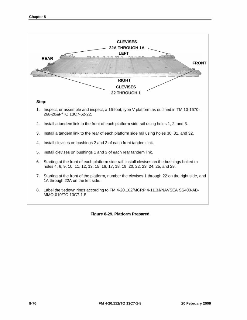
Chapter 8
8-70 FM 4-20.112/TO 13C7-1-8 20 February 2009
Step:
1. Inspect, or assemble and inspect, a 16-foot, type V platform as outlined in TM 10-1670-268-20&P/TO 13C7-52-22.
2. Install a tandem link to the front of each platform side rail using holes 1, 2, and 3.
3. Install a tandem link to the rear of each platform side rail using holes 30, 31, and 32.
4. Install clevises on bushings 2 and 3 of each front tandem link.
5. Install clevises on bushings 1 and 3 of each rear tandem link.
6. Starting at the front of each platform side rail, install clevises on the bushings bolted to holes 4, 6, 9, 10, 11, 12, 13, 15, 16, 17, 18, 19, 20, 22, 23, 24, 25, and 29.
7. Starting at the front of the platform, number the clevises 1 through 22 on the right side, and 1A through 22A on the left side.
8. Label the tiedown rings according to FM 4-20.102/MCRP 4-11.3J/NAVSEA SS400-AB-MMO-010/TO 13C7-1-5.
Figure 8-29. Platform Prepared
CLEVISES 22A THROUGH 1A
CLEVISES 22 THROUGH 1
RIGHT
LEFT
FRONT REAR
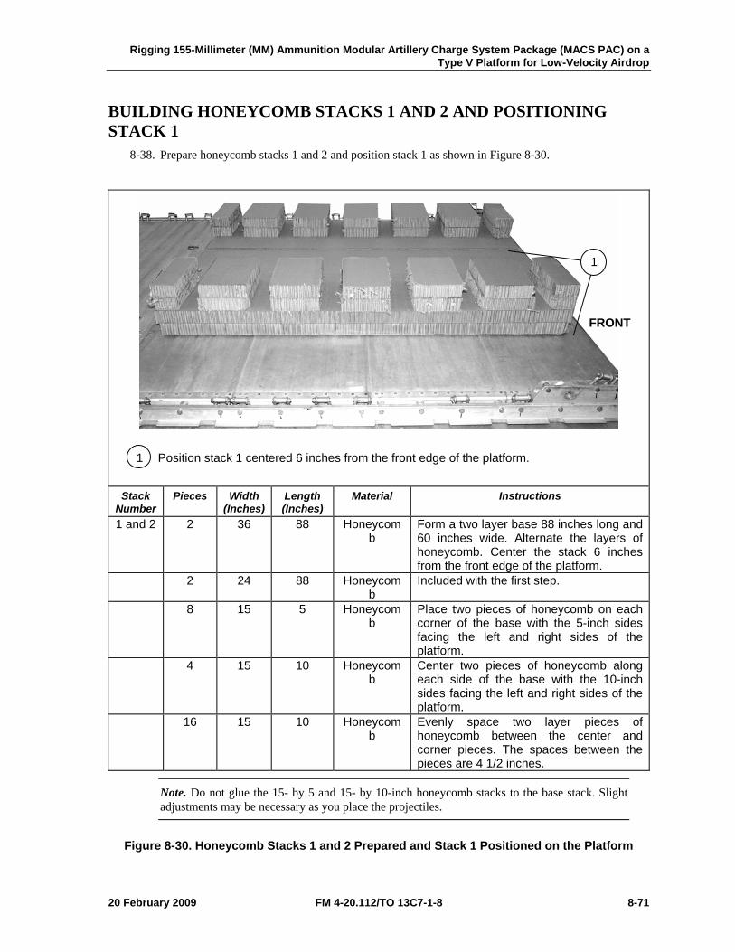
Rigging 155-Millimeter (MM) Ammunition Modular Artillery Charge System Package (MACS PAC) on a Type V Platform for Low-Velocity Airdrop
20 February 2009 FM 4-20.112/TO 13C7-1-8 8-71
BUILDING HONEYCOMB STACKS 1 AND 2 AND POSITIONING STACK 1
8-38. Prepare honeycomb stacks 1 and 2 and position stack 1 as shown in Figure 8-30.
1 Position stack 1 centered 6 inches from the front edge of the platform.
Stack
Number Pieces Width
(Inches) Length (Inches)
Material Instructions
1 and 2 2 36 88 Honeycomb
Form a two layer base 88 inches long and 60 inches wide. Alternate the layers of honeycomb. Center the stack 6 inches from the front edge of the platform.
2 24 88 Honeycomb
Included with the first step.
8 15 5 Honeycomb
Place two pieces of honeycomb on each corner of the base with the 5-inch sides facing the left and right sides of the platform.
4 15 10 Honeycomb
Center two pieces of honeycomb along each side of the base with the 10-inch sides facing the left and right sides of the platform.
16 15 10 Honeycomb
Evenly space two layer pieces of honeycomb between the center and corner pieces. The spaces between the pieces are 4 1/2 inches.
Note. Do not glue the 15- by 5 and 15- by 10-inch honeycomb stacks to the base stack. Slight adjustments may be necessary as you place the projectiles.
Figure 8-30. Honeycomb Stacks 1 and 2 Prepared and Stack 1 Positioned on the Platform
1
FRONT
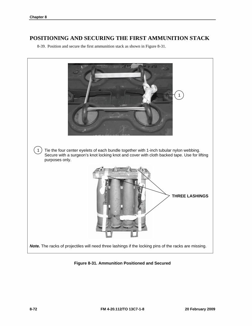
Chapter 8
8-72 FM 4-20.112/TO 13C7-1-8 20 February 2009
POSITIONING AND SECURING THE FIRST AMMUNITION STACK 8-39. Position and secure the first ammunition stack as shown in Figure 8-31.
1 Tie the four center eyelets of each bundle together with 1-inch tubular nylon webbing. Secure with a surgeon’s knot locking knot and cover with cloth backed tape. Use for lifting purposes only.
Note. The racks of projectiles will need three lashings if the locking pins of the racks are missing.
Figure 8-31. Ammunition Positioned and Secured
THREE LASHINGS
1
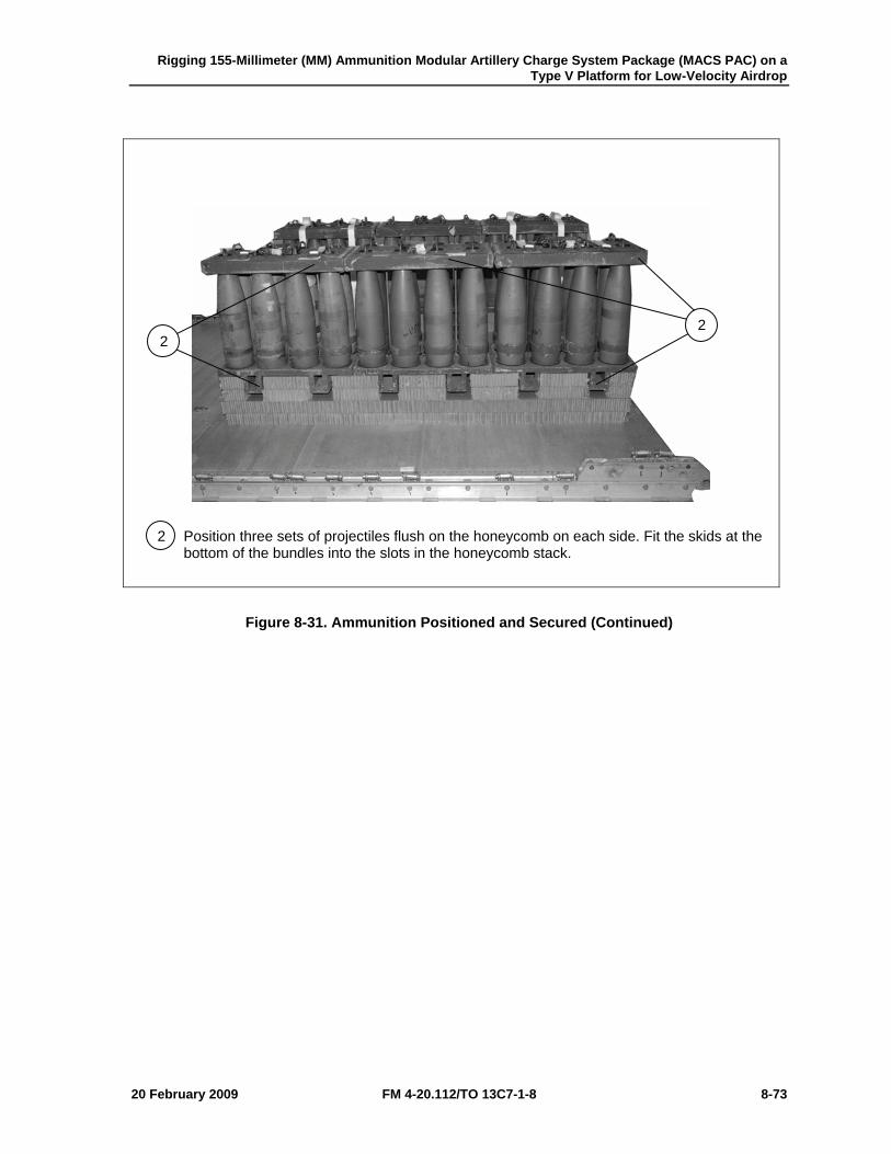
Rigging 155-Millimeter (MM) Ammunition Modular Artillery Charge System Package (MACS PAC) on a Type V Platform for Low-Velocity Airdrop
20 February 2009 FM 4-20.112/TO 13C7-1-8 8-73
2 Position three sets of projectiles flush on the honeycomb on each side. Fit the skids at the bottom of the bundles into the slots in the honeycomb stack.
Figure 8-31. Ammunition Positioned and Secured (Continued)
2 2
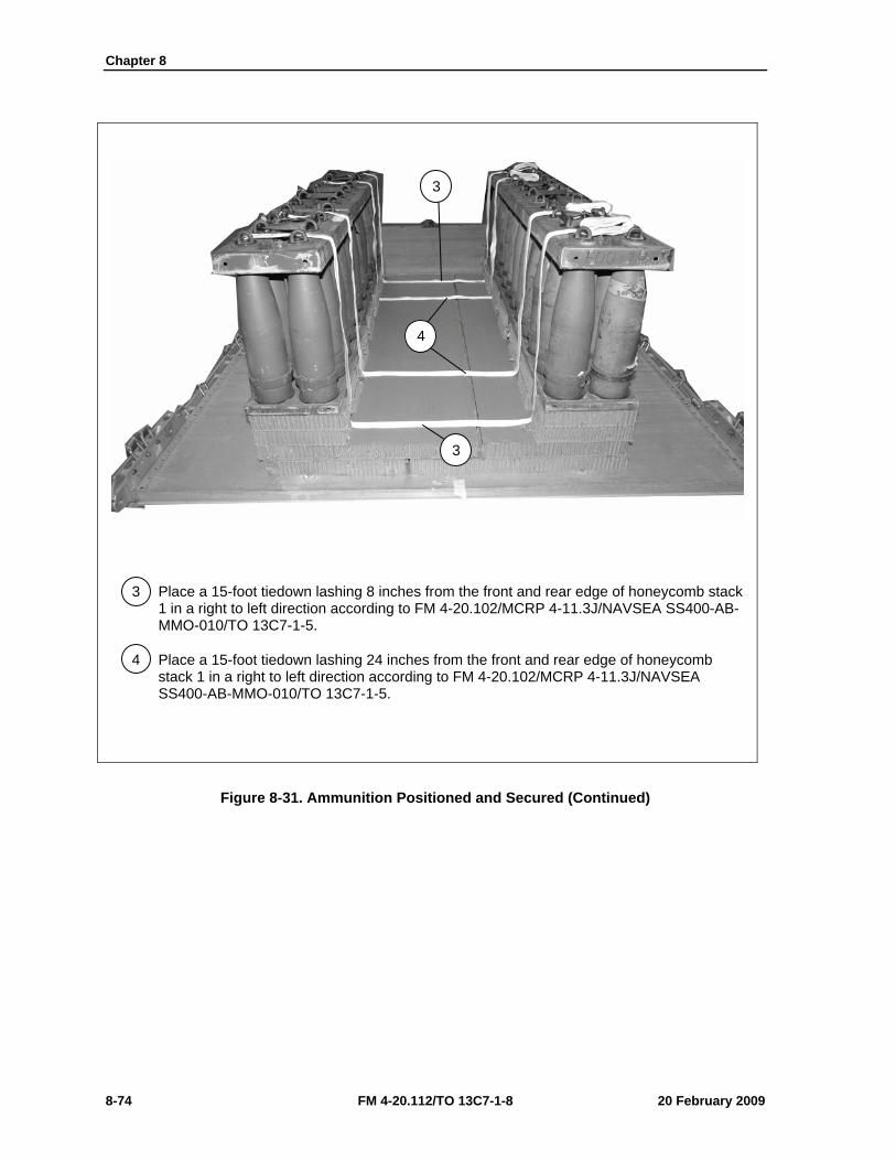
Chapter 8
8-74 FM 4-20.112/TO 13C7-1-8 20 February 2009
3 Place a 15-foot tiedown lashing 8 inches from the front and rear edge of honeycomb stack 1 in a right to left direction according to FM 4-20.102/MCRP 4-11.3J/NAVSEA SS400-AB-MMO-010/TO 13C7-1-5.
4 Place a 15-foot tiedown lashing 24 inches from the front and rear edge of honeycomb stack 1 in a right to left direction according to FM 4-20.102/MCRP 4-11.3J/NAVSEA SS400-AB-MMO-010/TO 13C7-1-5.
Figure 8-31. Ammunition Positioned and Secured (Continued)
3
4
3
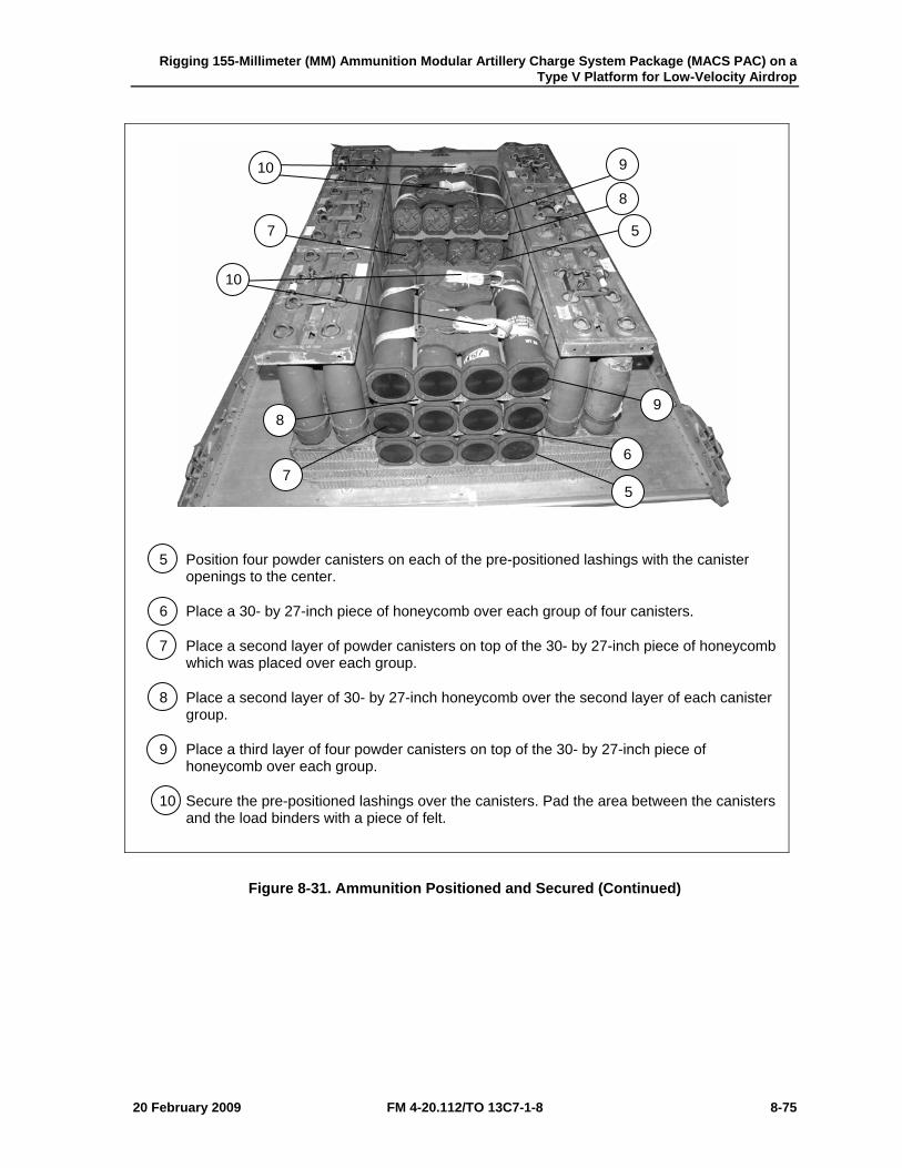
Rigging 155-Millimeter (MM) Ammunition Modular Artillery Charge System Package (MACS PAC) on a Type V Platform for Low-Velocity Airdrop
20 February 2009 FM 4-20.112/TO 13C7-1-8 8-75
5 Position four powder canisters on each of the pre-positioned lashings with the canister openings to the center.
6 Place a 30- by 27-inch piece of honeycomb over each group of four canisters.
7 Place a second layer of powder canisters on top of the 30- by 27-inch piece of honeycomb which was placed over each group.
8 Place a second layer of 30- by 27-inch honeycomb over the second layer of each canister group.
9 Place a third layer of four powder canisters on top of the 30- by 27-inch piece of honeycomb over each group.
10 Secure the pre-positioned lashings over the canisters. Pad the area between the canisters and the load binders with a piece of felt.
Figure 8-31. Ammunition Positioned and Secured (Continued)
5
5
6 7
7
8
8
9
9
10
10
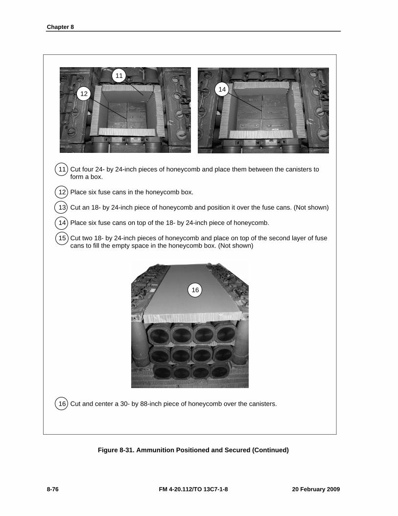
Chapter 8
8-76 FM 4-20.112/TO 13C7-1-8 20 February 2009
11 Cut four 24- by 24-inch pieces of honeycomb and place them between the canisters to form a box.
12 Place six fuse cans in the honeycomb box.
13 Cut an 18- by 24-inch piece of honeycomb and position it over the fuse cans. (Not shown)
14 Place six fuse cans on top of the 18- by 24-inch piece of honeycomb.
15 Cut two 18- by 24-inch pieces of honeycomb and place on top of the second layer of fuse cans to fill the empty space in the honeycomb box. (Not shown)
16 Cut and center a 30- by 88-inch piece of honeycomb over the canisters.
Figure 8-31. Ammunition Positioned and Secured (Continued)
11
12 14
16
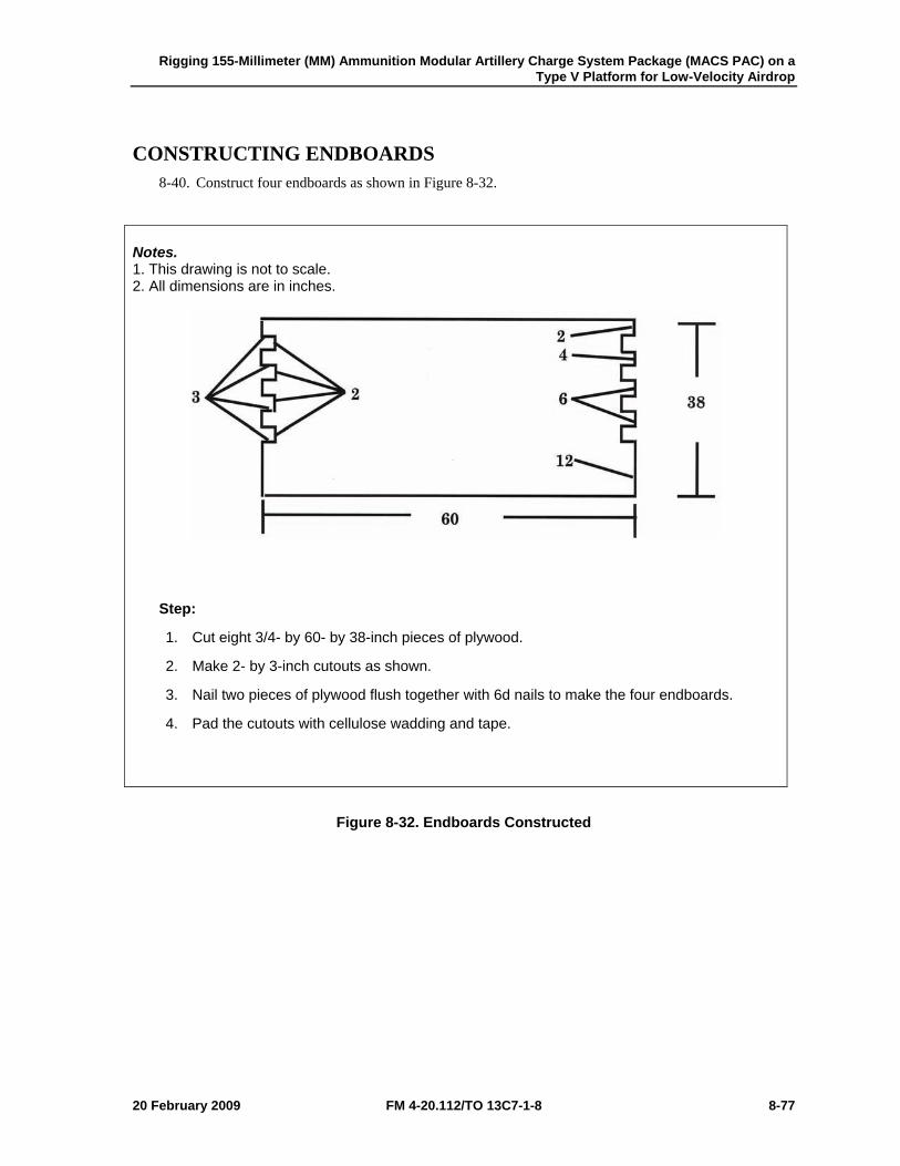
Rigging 155-Millimeter (MM) Ammunition Modular Artillery Charge System Package (MACS PAC) on a Type V Platform for Low-Velocity Airdrop
20 February 2009 FM 4-20.112/TO 13C7-1-8 8-77
CONSTRUCTING ENDBOARDS 8-40. Construct four endboards as shown in Figure 8-32.
Notes. 1. This drawing is not to scale. 2. All dimensions are in inches.
Step:
1. Cut eight 3/4- by 60- by 38-inch pieces of plywood.
2. Make 2- by 3-inch cutouts as shown.
3. Nail two pieces of plywood flush together with 6d nails to make the four endboards.
4. Pad the cutouts with cellulose wadding and tape.
Figure 8-32. Endboards Constructed
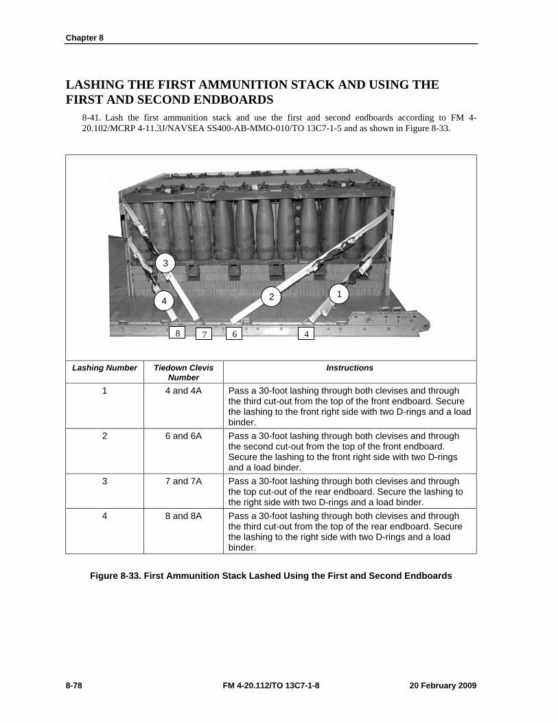
Chapter 8
8-78 FM 4-20.112/TO 13C7-1-8 20 February 2009
LASHING THE FIRST AMMUNITION STACK AND USING THE FIRST AND SECOND ENDBOARDS
8-41. Lash the first ammunition stack and use the first and second endboards according to FM 4-20.102/MCRP 4-11.3J/NAVSEA SS400-AB-MMO-010/TO 13C7-1-5 and as shown in Figure 8-33.
Lashing Number Tiedown Clevis
Number Instructions
1 4 and 4A Pass a 30-foot lashing through both clevises and through the third cut-out from the top of the front endboard. Secure the lashing to the front right side with two D-rings and a load binder.
2 6 and 6A Pass a 30-foot lashing through both clevises and through the second cut-out from the top of the front endboard. Secure the lashing to the front right side with two D-rings and a load binder.
3 7 and 7A Pass a 30-foot lashing through both clevises and through the top cut-out of the rear endboard. Secure the lashing to the right side with two D-rings and a load binder.
4 8 and 8A Pass a 30-foot lashing through both clevises and through the third cut-out from the top of the rear endboard. Secure the lashing to the right side with two D-rings and a load binder.
Figure 8-33. First Ammunition Stack Lashed Using the First and Second Endboards
1 4
3
2
467 8
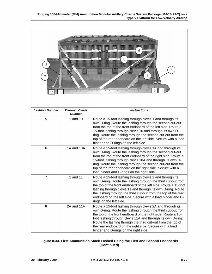
Rigging 155-Millimeter (MM) Ammunition Modular Artillery Charge System Package (MACS PAC) on a Type V Platform for Low-Velocity Airdrop
20 February 2009 FM 4-20.112/TO 13C7-1-8 8-79
Lashing Number Tiedown Clevis
Number Instructions
5 1 and 10 Route a 15-foot lashing through clevis 1 and through its own D-ring. Route the lashing through the second cut-out from the top of the front endboard of the left side. Route a 15-foot lashing through clevis 10 and through its own D-ring. Route the lashing through the second cut-out from the top of the rear endboard on the left side. Secure with a load binder and D-rings on the left side.
6 1A and 10A Route a 15-foot lashing through clevis 1A and through its own D-ring. Route the lashing through the second cut-out from the top of the front endboard of the right side. Route a 15-foot lashing through clevis 10A and through its own D-ring. Route the lashing through the second cut-out from the top of the rear endboard on the right side. Secure with a load binder and D-rings on the right side.
7 2 and 11 Route a 15-foot lashing through clevis 2 and through its own D-ring. Route the lashing through the third cut-out from the top of the front endboard of the left side. Route a 15-foot lashing through clevis 11 and through its own D-ring. Route the lashing through the third cut-out from the top of the rear endboard on the left side. Secure with a load binder and D-rings on the left side.
8 2A and 11A Route a 15-foot lashing through clevis 2A and through its own D-ring. Route the lashing through the third cut-out from the top of the front endboard of the right side. Route a 15-foot lashing through clevis 11A and through its own D-ring. Route the lashing through the third cut-out from the top of the rear endboard on the right side. Secure with a load binder and D-rings on the right side.
Figure 8-33. First Ammunition Stack Lashed Using the First and Second Endboards (Continued)
1 2 10 11
7
5 5
7
8
6
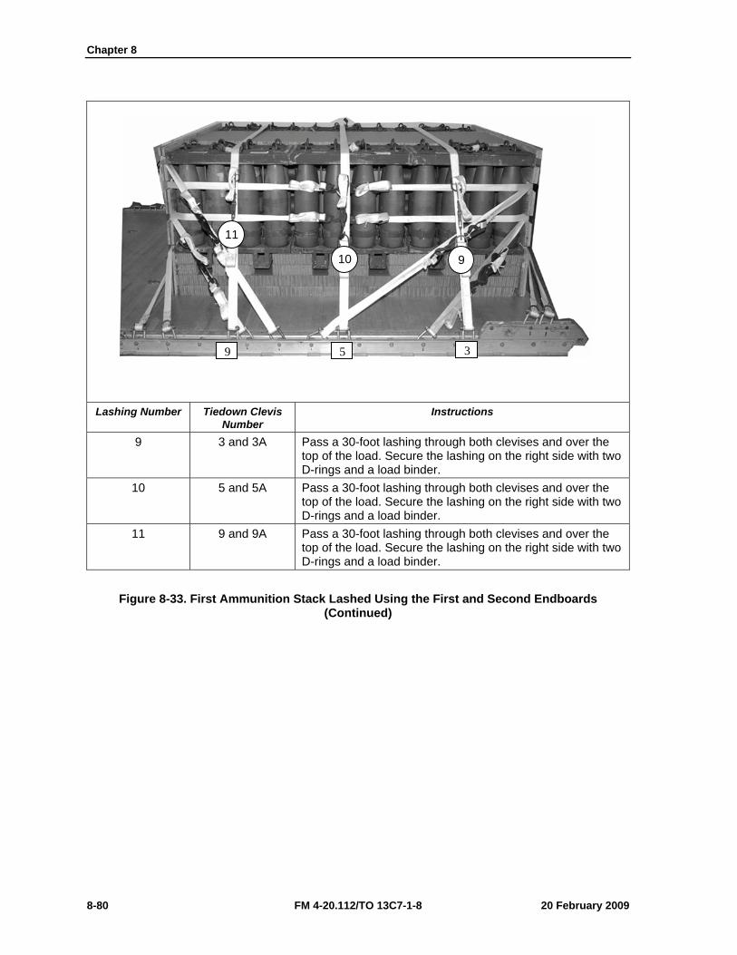
Chapter 8
8-80 FM 4-20.112/TO 13C7-1-8 20 February 2009
Lashing Number Tiedown Clevis
Number Instructions
9 3 and 3A Pass a 30-foot lashing through both clevises and over the top of the load. Secure the lashing on the right side with two D-rings and a load binder.
10 5 and 5A Pass a 30-foot lashing through both clevises and over the top of the load. Secure the lashing on the right side with two D-rings and a load binder.
11 9 and 9A Pass a 30-foot lashing through both clevises and over the top of the load. Secure the lashing on the right side with two D-rings and a load binder.
Figure 8-33. First Ammunition Stack Lashed Using the First and Second Endboards (Continued)
9 5 3
11
10 9
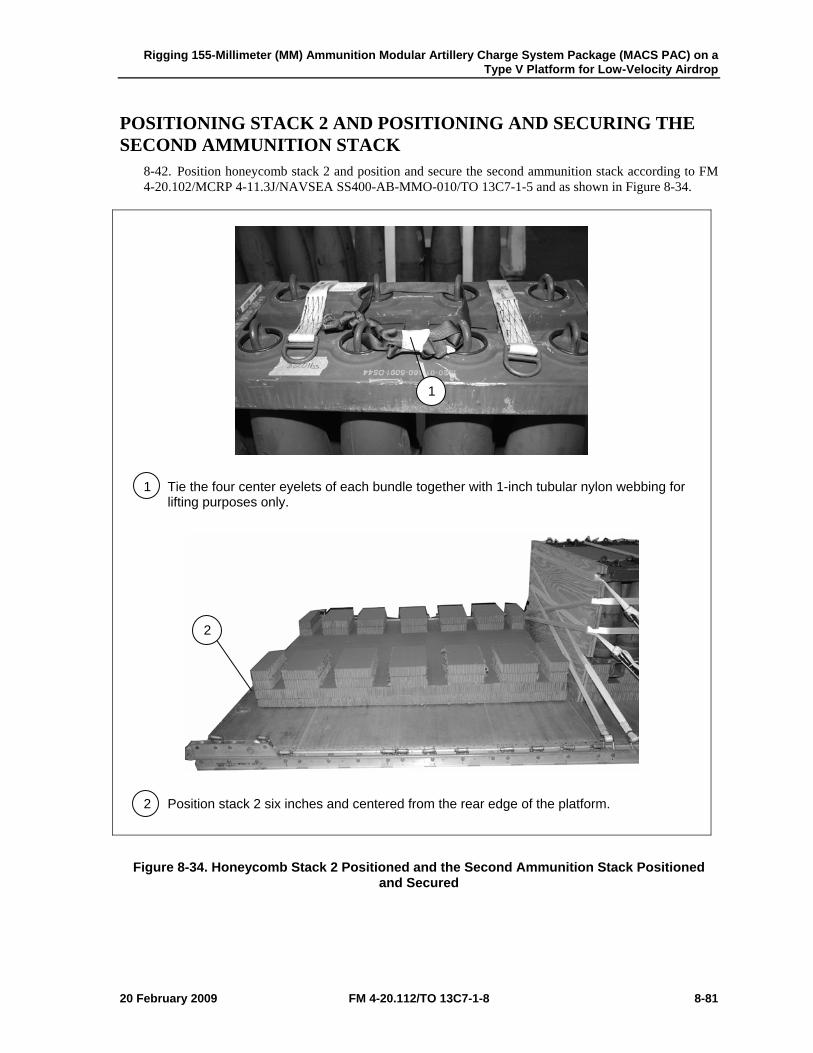
Rigging 155-Millimeter (MM) Ammunition Modular Artillery Charge System Package (MACS PAC) on a Type V Platform for Low-Velocity Airdrop
20 February 2009 FM 4-20.112/TO 13C7-1-8 8-81
POSITIONING STACK 2 AND POSITIONING AND SECURING THE SECOND AMMUNITION STACK
8-42. Position honeycomb stack 2 and position and secure the second ammunition stack according to FM 4-20.102/MCRP 4-11.3J/NAVSEA SS400-AB-MMO-010/TO 13C7-1-5 and as shown in Figure 8-34.
1 Tie the four center eyelets of each bundle together with 1-inch tubular nylon webbing for lifting purposes only.
2 Position stack 2 six inches and centered from the rear edge of the platform.
Figure 8-34. Honeycomb Stack 2 Positioned and the Second Ammunition Stack Positioned and Secured
1
2
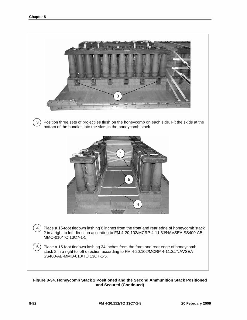
Chapter 8
8-82 FM 4-20.112/TO 13C7-1-8 20 February 2009
3 Position three sets of projectiles flush on the honeycomb on each side. Fit the skids at the bottom of the bundles into the slots in the honeycomb stack.
4 Place a 15-foot tiedown lashing 8 inches from the front and rear edge of honeycomb stack 2 in a right to left direction according to FM 4-20.102/MCRP 4-11.3J/NAVSEA SS400-AB-MMO-010/TO 13C7-1-5.
5 Place a 15-foot tiedown lashing 24 inches from the front and rear edge of honeycomb stack 2 in a right to left direction according to FM 4-20.102/MCRP 4-11.3J/NAVSEA SS400-AB-MMO-010/TO 13C7-1-5.
Figure 8-34. Honeycomb Stack 2 Positioned and the Second Ammunition Stack Positioned and Secured (Continued)
3
4
5
4
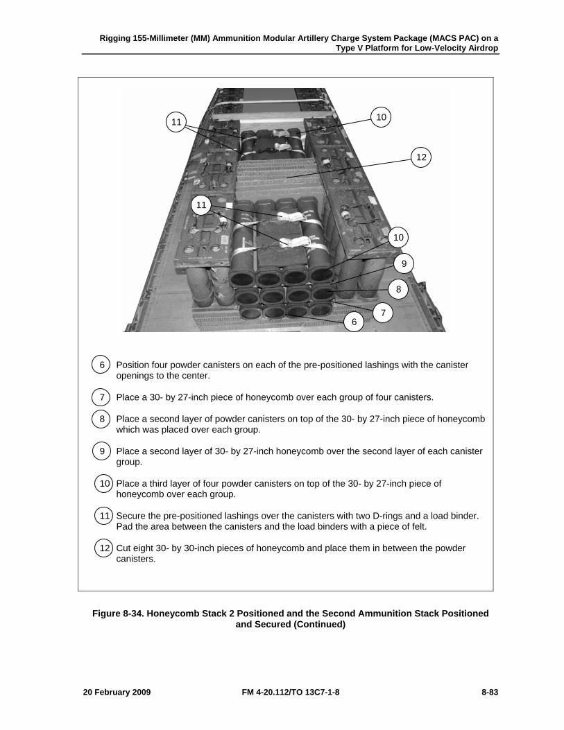
Rigging 155-Millimeter (MM) Ammunition Modular Artillery Charge System Package (MACS PAC) on a Type V Platform for Low-Velocity Airdrop
20 February 2009 FM 4-20.112/TO 13C7-1-8 8-83
6 Position four powder canisters on each of the pre-positioned lashings with the canister openings to the center.
7 Place a 30- by 27-inch piece of honeycomb over each group of four canisters.
8 Place a second layer of powder canisters on top of the 30- by 27-inch piece of honeycomb which was placed over each group.
9 Place a second layer of 30- by 27-inch honeycomb over the second layer of each canister group.
10 Place a third layer of four powder canisters on top of the 30- by 27-inch piece of honeycomb over each group.
11 Secure the pre-positioned lashings over the canisters with two D-rings and a load binder. Pad the area between the canisters and the load binders with a piece of felt.
12 Cut eight 30- by 30-inch pieces of honeycomb and place them in between the powder canisters.
Figure 8-34. Honeycomb Stack 2 Positioned and the Second Ammunition Stack Positioned and Secured (Continued)
6 7
8
9
10
10
11
11
12
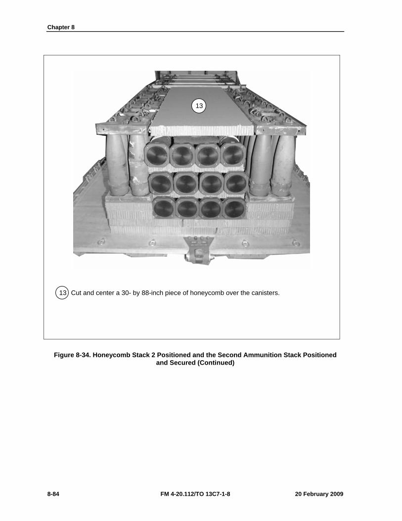
Chapter 8
8-84 FM 4-20.112/TO 13C7-1-8 20 February 2009
13 Cut and center a 30- by 88-inch piece of honeycomb over the canisters.
Figure 8-34. Honeycomb Stack 2 Positioned and the Second Ammunition Stack Positioned and Secured (Continued)
13
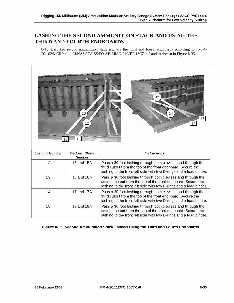
Rigging 155-Millimeter (MM) Ammunition Modular Artillery Charge System Package (MACS PAC) on a Type V Platform for Low-Velocity Airdrop
20 February 2009 FM 4-20.112/TO 13C7-1-8 8-85
LASHING THE SECOND AMMUNITION STACK AND USING THE THIRD AND FOURTH ENDBOARDS
8-43. Lash the second ammunition stack and use the third and fourth endboards according to FM 4-20.102/MCRP 4-11.3J/NAVSEA SS400-AB-MMO-010/TO 13C7-1-5 and as shown in Figure 8-35.
Lashing Number Tiedown Clevis
Number Instructions
12 15 and 15A Pass a 30-foot lashing through both clevises and through the third cutout from the top of the front endboard. Secure the lashing to the front left side with two D-rings and a load binder.
13 16 and 16A Pass a 30-foot lashing through both clevises and through the second cutout from the top of the front endboard. Secure the lashing to the front left side with two D-rings and a load binder.
14 17 and 17A Pass a 30-foot lashing through both clevises and through the third cutout from the top of the front endboard. Secure the lashing to the front left side with two D-rings and a load binder.
15 19 and 19A Pass a 30-foot lashing through both clevises and through the second cutout from the top of the front endboard. Secure the lashing to the front left side with two D-rings and a load binder.
Figure 8-35. Second Ammunition Stack Lashed Using the Third and Fourth Endboards
13
12
15
14
16 15
1719
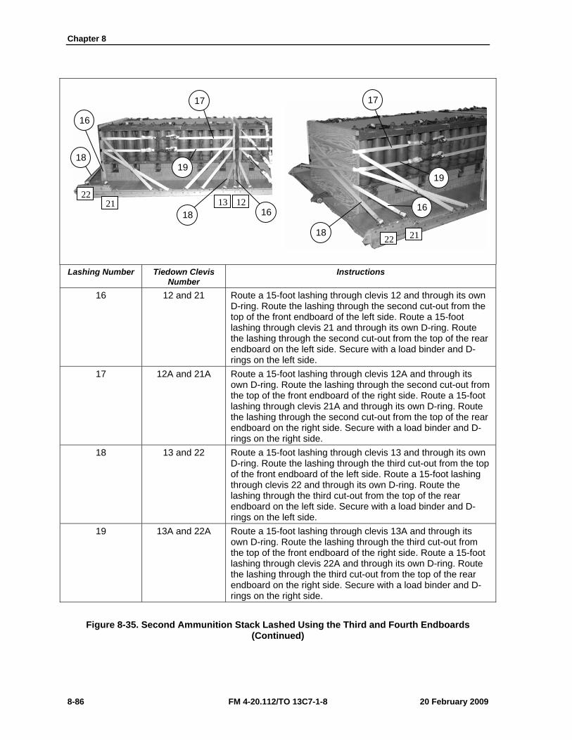
Chapter 8
8-86 FM 4-20.112/TO 13C7-1-8 20 February 2009
Lashing Number Tiedown Clevis
Number Instructions
16 12 and 21 Route a 15-foot lashing through clevis 12 and through its own D-ring. Route the lashing through the second cut-out from the top of the front endboard of the left side. Route a 15-foot lashing through clevis 21 and through its own D-ring. Route the lashing through the second cut-out from the top of the rear endboard on the left side. Secure with a load binder and D-rings on the left side.
17 12A and 21A Route a 15-foot lashing through clevis 12A and through its own D-ring. Route the lashing through the second cut-out from the top of the front endboard of the right side. Route a 15-foot lashing through clevis 21A and through its own D-ring. Route the lashing through the second cut-out from the top of the rear endboard on the right side. Secure with a load binder and D-rings on the right side.
18 13 and 22 Route a 15-foot lashing through clevis 13 and through its own D-ring. Route the lashing through the third cut-out from the top of the front endboard of the left side. Route a 15-foot lashing through clevis 22 and through its own D-ring. Route the lashing through the third cut-out from the top of the rear endboard on the left side. Secure with a load binder and D-rings on the left side.
19 13A and 22A Route a 15-foot lashing through clevis 13A and through its own D-ring. Route the lashing through the third cut-out from the top of the front endboard of the right side. Route a 15-foot lashing through clevis 22A and through its own D-ring. Route the lashing through the third cut-out from the top of the rear endboard on the right side. Secure with a load binder and D-rings on the right side.
Figure 8-35. Second Ammunition Stack Lashed Using the Third and Fourth Endboards (Continued)
17
19
16
18
17
19
16
18
18 16
22 21 13 12
21 22
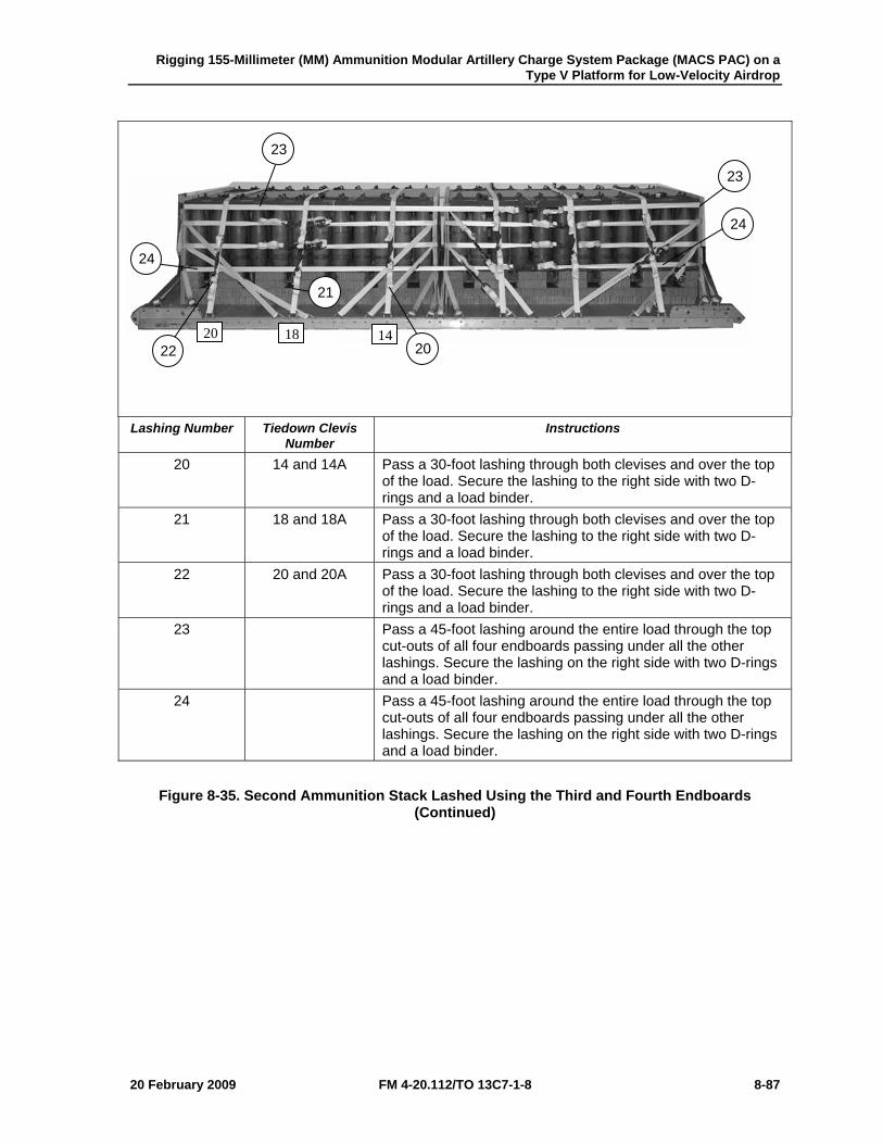
Rigging 155-Millimeter (MM) Ammunition Modular Artillery Charge System Package (MACS PAC) on a Type V Platform for Low-Velocity Airdrop
20 February 2009 FM 4-20.112/TO 13C7-1-8 8-87
Lashing Number Tiedown Clevis
Number Instructions
20 14 and 14A Pass a 30-foot lashing through both clevises and over the top of the load. Secure the lashing to the right side with two D-rings and a load binder.
21 18 and 18A Pass a 30-foot lashing through both clevises and over the top of the load. Secure the lashing to the right side with two D-rings and a load binder.
22 20 and 20A Pass a 30-foot lashing through both clevises and over the top of the load. Secure the lashing to the right side with two D-rings and a load binder.
23 Pass a 45-foot lashing around the entire load through the top cut-outs of all four endboards passing under all the other lashings. Secure the lashing on the right side with two D-rings and a load binder.
24 Pass a 45-foot lashing around the entire load through the top cut-outs of all four endboards passing under all the other lashings. Secure the lashing on the right side with two D-rings and a load binder.
Figure 8-35. Second Ammunition Stack Lashed Using the Third and Fourth Endboards (Continued)
23
24
23
24
21
22 20 20 18 14
Chapter 8
8-88 FM 4-20.112/TO 13C7-1-8 20 February 2009
INSTALLING SUSPENSION SLINGS AND DEADMAN’S TIE 8-44. Install the suspension slings and deadman’s tie according to FM 4-20.102/MCRP 4-11.3J/NAVSEA SS400-AB-MMO-010/TO 13C7-1-5 and as shown in Figure 8-36.
1 Pass one end of a 16-foot (2-loop), type XXVI nylon suspension sling through the bell portion of a large suspension clevis. Bolt the clevis to the suspension hole of the right front tandem link.
2 Install on the left front tandem link and the right rear and left rear tandem links a 16-foot (2-loop), type XXVI nylon suspension sling as in step 1.
3 Raise the slings and install the deadman's tie according to FM 4-20.102/MCRP 4-11.3J/NAVSEA SS400-AB-MMO-010/TO 13C7-1-5.
Figure 8-36. Suspension Slings and Deadman’s Tie Installed
2
3
1
Rigging 155-Millimeter (MM) Ammunition Modular Artillery Charge System Package (MACS PAC) on a Type V Platform for Low-Velocity Airdrop
20 February 2009 FM 4-20.112/TO 13C7-1-8 8-89
BUILDING AND POSITIONING PARACHUTE STOWAGE PLATFORM
8-45. Build and position the parachute stowage platform as shown in Figure 8-37.
1 Position one 36- by 60-inch piece of honeycomb flush on the rear edge of the ammunition stack. Tape the edges of the honeycomb with 2-inch adhesive tape and secure the honeycomb to the lateral lashings with type III nylon cord.
2 Position another 36- by 60-inch piece of honeycomb flush against the first piece of honeycomb. Tape the edges of the honeycomb with 2-inch adhesive tape and secure the honeycomb to the lateral lashings with type III nylon cord. Make sure the deadman’s tie and suspension slings are on top of the honeycomb.
Figure 8-37. Parachute Stowage Platform Positioned and Secured
1 2
Chapter 8
8-90 FM 4-20.112/TO 13C7-1-8 20 February 2009
PREPARING AND STOWING CARGO PARACHUTES 8-46. Prepare and stow the cargo parachutes according to FM 4-20.102/MCRP 4-11.3J/NAVSEA SS400-AB-MMO-010/TO 13C7-1-5 and as shown in Figure 8-38.
1 Prepare, position, and stow three G-11B cargo parachutes on top of the pre-positioned honeycomb according to FM 4-20.102/MCRP 4-11.3J/NAVSEA SS400-AB-MMO-010/TO 13C7-1-5.
2 Install the rear cargo parachute restraint using type VIII nylon webbing on the second bushing on the rear suspension link.
3 Install the front cargo parachute restraint using type VIII nylon webbing on bushing 27.
4 Install the parachute release straps according to FM 4-20.102/MCRP 4-11.3J/NAVSEA SS400-AB-MMO-010/TO 13C7-1-5.
Figure 8-38. Cargo Parachutes Prepared and Stowed
4 1
3 2
Rigging 155-Millimeter (MM) Ammunition Modular Artillery Charge System Package (MACS PAC) on a Type V Platform for Low-Velocity Airdrop
20 February 2009 FM 4-20.112/TO 13C7-1-8 8-91
INSTALLING THE RELEASE SYSTEM 8-47. Prepare, attach, and safety an M-1 cargo parachute release according to FM 4-20.102/MCRP 4-11.3J/NAVSEA SS400-AB-MMO-010/TO 13C7-1-5 and as shown in Figure 8-39.
1 Prepare and install the M-1 cargo parachute release on the front portion of the honeycomb parachute platform and attach the suspension slings and riser extensions.
2 Safety the top and bottom of the release to convenient places on the load with type III nylon cord according to FM 4-20.102/MCRP 4-11.3J/NAVSEA SS400-AB-MMO-010/TO 13C7-1-5.
3 S-fold and tie any excess suspension slings with one turn of type I, 1/4-inch cotton webbing.
4 Tie the two sections of the deadman’s tie together in the center with a length of type I, 1/4-inch cotton webbing.
Figure 8-39. M-1 Cargo Parachute Release Installed
2
2 1
3
4
3
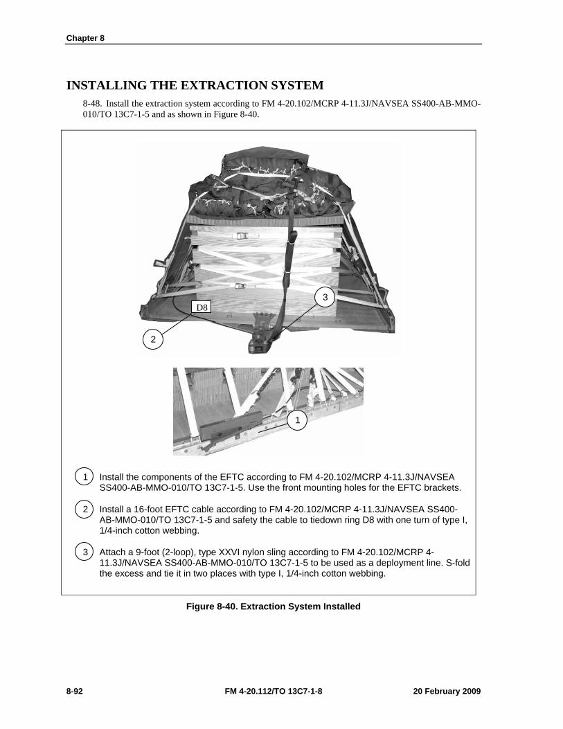
Chapter 8
8-92 FM 4-20.112/TO 13C7-1-8 20 February 2009
INSTALLING THE EXTRACTION SYSTEM 8-48. Install the extraction system according to FM 4-20.102/MCRP 4-11.3J/NAVSEA SS400-AB-MMO-010/TO 13C7-1-5 and as shown in Figure 8-40.
1 Install the components of the EFTC according to FM 4-20.102/MCRP 4-11.3J/NAVSEA SS400-AB-MMO-010/TO 13C7-1-5. Use the front mounting holes for the EFTC brackets.
2 Install a 16-foot EFTC cable according to FM 4-20.102/MCRP 4-11.3J/NAVSEA SS400-AB-MMO-010/TO 13C7-1-5 and safety the cable to tiedown ring D8 with one turn of type I, 1/4-inch cotton webbing.
3 Attach a 9-foot (2-loop), type XXVI nylon sling according to FM 4-20.102/MCRP 4-11.3J/NAVSEA SS400-AB-MMO-010/TO 13C7-1-5 to be used as a deployment line. S-fold the excess and tie it in two places with type I, 1/4-inch cotton webbing.
Figure 8-40. Extraction System Installed
1
2
3 D8

Rigging 155-Millimeter (MM) Ammunition Modular Artillery Charge System Package (MACS PAC) on a Type V Platform for Low-Velocity Airdrop
20 February 2009 FM 4-20.112/TO 13C7-1-8 8-93
PLACING EXTRACTION PARACHUTE 8-49. Select the extraction parachute and extraction line needed using the extraction line requirements table in FM 4-20.102/MCRP 4-11.3J/NAVSEA SS400-AB-MMO-010/TO 13C7-1-5. Place the extraction parachute and line on the load for installation in the aircraft.
INSTALLING PROVISIONS FOR EMERGENCY RESTRAINTS 8-50. Select and install the provisions for the emergency aft restraints according to the emergency aft restraint requirements table in FM 4-20.102/MCRP 4-11.3J/NAVSEA SS400-AB-MMO-010/TO 13C7-1-5.
MARKING RIGGED LOAD 8-51. Mark the rigged load according to FM 4-20.102/MCRP 4-11.3J/NAVSEA SS400-AB-MMO-010/TO 13C7-1-5, and as shown in Figure 8-41. Complete Shipper’s Declaration for Dangerous Goods. If the load varies from the one shown, the weight, height, CB, and parachute requirements must be recomputed.
EQUIPMENT REQUIRED 8-52. Use the equipment listed in Table 8-3 to rig this load.
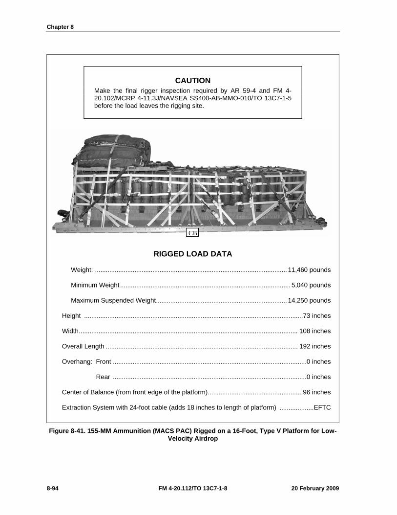
Chapter 8
8-94 FM 4-20.112/TO 13C7-1-8 20 February 2009
CAUTION Make the final rigger inspection required by AR 59-4 and FM 4-20.102/MCRP 4-11.3J/NAVSEA SS400-AB-MMO-010/TO 13C7-1-5 before the load leaves the rigging site.
RIGGED LOAD DATA
Weight: ........................................................................................................... 11,460 pounds
Minimum Weight ............................................................................................... 5,040 pounds
Maximum Suspended Weight ......................................................................... 14,250 pounds
Height ..........................................................................................................................73 inches
Width .......................................................................................................................... 108 inches
Overall Length ........................................................................................................... 192 inches
Overhang: Front ............................................................................................................ 0 inches
Rear ............................................................................................................ 0 inches
Center of Balance (from front edge of the platform) .....................................................96 inches
Extraction System with 24-foot cable (adds 18 inches to length of platform) ................... EFTC
Figure 8-41. 155-MM Ammunition (MACS PAC) Rigged on a 16-Foot, Type V Platform for Low-Velocity Airdrop
CB
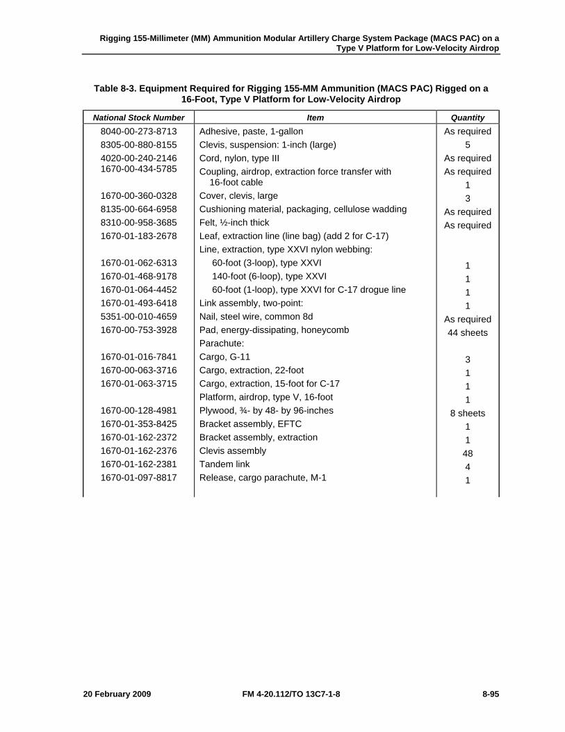
Rigging 155-Millimeter (MM) Ammunition Modular Artillery Charge System Package (MACS PAC) on a Type V Platform for Low-Velocity Airdrop
20 February 2009 FM 4-20.112/TO 13C7-1-8 8-95
Table 8-3. Equipment Required for Rigging 155-MM Ammunition (MACS PAC) Rigged on a 16-Foot, Type V Platform for Low-Velocity Airdrop
National Stock Number Item Quantity 8040-00-273-8713 8305-00-880-8155 4020-00-240-2146 1670-00-434-5785
1670-00-360-0328 8135-00-664-6958 8310-00-958-3685 1670-01-183-2678
1670-01-062-6313 1670-01-468-9178 1670-01-064-4452 1670-01-493-6418 5351-00-010-4659 1670-00-753-3928
1670-01-016-7841 1670-00-063-3716 1670-01-063-3715
1670-00-128-4981 1670-01-353-8425 1670-01-162-2372 1670-01-162-2376 1670-01-162-2381 1670-01-097-8817
Adhesive, paste, 1-gallon Clevis, suspension: 1-inch (large) Cord, nylon, type III Coupling, airdrop, extraction force transfer with 16-foot cable Cover, clevis, large Cushioning material, packaging, cellulose wadding Felt, ½-inch thick Leaf, extraction line (line bag) (add 2 for C-17) Line, extraction, type XXVI nylon webbing: 60-foot (3-loop), type XXVI 140-foot (6-loop), type XXVI 60-foot (1-loop), type XXVI for C-17 drogue line Link assembly, two-point: Nail, steel wire, common 8d Pad, energy-dissipating, honeycomb Parachute: Cargo, G-11 Cargo, extraction, 22-foot Cargo, extraction, 15-foot for C-17 Platform, airdrop, type V, 16-foot Plywood, ¾- by 48- by 96-inches Bracket assembly, EFTC Bracket assembly, extraction Clevis assembly Tandem link Release, cargo parachute, M-1
As required 5
As required As required
1 3
As required As required
1 1 1 1
As required 44 sheets
3 1 1 1
8 sheets 1 1
48 4 1

Chapter 8
8-96 FM 4-20.112/TO 13C7-1-8 20 February 2009
Table 8-3. Equipment Required for Rigging 155-MM Ammunition (MACS PAC) Rigged on a 16-Foot, Type V Platform for Low-Velocity Airdrop (Continued)
National Stock Number Item Quantity
1670-01-062-6304 1670-01-063-7761 1670-01-062-6313 5340-00-040-8219 7501-00-266-5016 7501-00-266-6710 1670-00-937-0271 1670-01-483-8259
8305-00-268-2411
8305-00-082-5752 8305-00-268-2455 8305-00-268-2455 8305-00-263-3591
Sling, cargo airdrop: 9-foot (2-loop), type XXVI nylon webbing 16-foot (2-loop), type XXVI nylon webbing 60-foot (3-loop), type XXVI nylon webbing Strap parachute release, multicut Tape, adhesive, 2-inch Tape, masking Tiedown assembly, 15-foot Towplate release mechanism (H-block) (C-17) Webbing: Cotton, 1/4-inch, type I Nylon: Tubular, 1/2-inch Tubular, 1/2-inch, OD 7 Tubular, 1-inch Type VIII webbing
1 4 4 2
As required As required
52 1
As required
As required As required As required As required
Rigging 155-Millimeter (MM) Ammunition Modular Artillery Charge System Package (MACS PAC) on a Type V Platform for Low-Velocity Airdrop
20 February 2009 FM 4-20.112/TO 13C7-1-8 8-97
SECTION IV-RIGGING THE MACS PAC ON A 20-FOOT, TYPE V PLATFORM
DESCRIPTION OF LOAD 8-53. Ninety-six 155-mm projectiles, 79 power canisters and 15 fuse cans are rigged for low-velocity airdrop on a 20-foot, type V platform. The load uses three G-11B cargo parachutes. Refer to FM 4-20.102/MCRP 4-11.3J/NAVSEA SS400-AB-MMO-010/TO 13C7-1-5 for the weight limitations and for the number of parachutes to be used.
Notes. 1. The load shown is using metal crates. However, wooden crates may be used with three lashings and a load binder. 2. If the metal locking rods are missing, three lashings, D-rings and load binders will be needed.
PREPARING PLATFORM 8-54. Prepare a 20-foot, type V platform as shown in Figure 8-42.
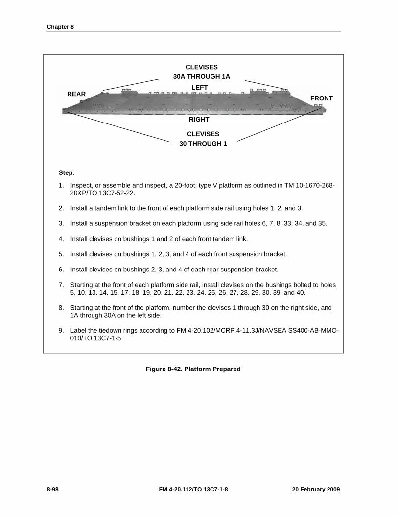
Chapter 8
8-98 FM 4-20.112/TO 13C7-1-8 20 February 2009
Step:
1. Inspect, or assemble and inspect, a 20-foot, type V platform as outlined in TM 10-1670-268-20&P/TO 13C7-52-22.
2. Install a tandem link to the front of each platform side rail using holes 1, 2, and 3.
3. Install a suspension bracket on each platform using side rail holes 6, 7, 8, 33, 34, and 35.
4. Install clevises on bushings 1 and 2 of each front tandem link.
5. Install clevises on bushings 1, 2, 3, and 4 of each front suspension bracket.
6. Install clevises on bushings 2, 3, and 4 of each rear suspension bracket.
7. Starting at the front of each platform side rail, install clevises on the bushings bolted to holes 5, 10, 13, 14, 15, 17, 18, 19, 20, 21, 22, 23, 24, 25, 26, 27, 28, 29, 30, 39, and 40.
8. Starting at the front of the platform, number the clevises 1 through 30 on the right side, and 1A through 30A on the left side.
9. Label the tiedown rings according to FM 4-20.102/MCRP 4-11.3J/NAVSEA SS400-AB-MMO-010/TO 13C7-1-5.
Figure 8-42. Platform Prepared
CLEVISES 30 THROUGH 1
RIGHT
LEFT FRONT REAR
CLEVISES 30A THROUGH 1A
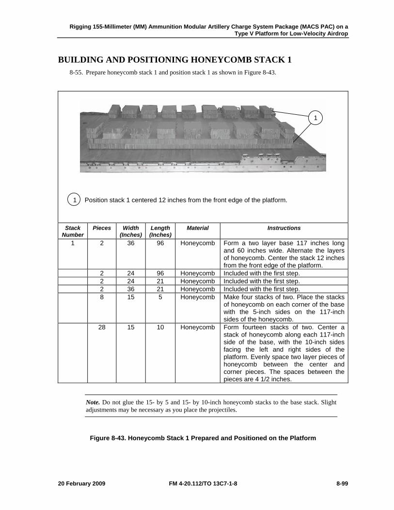
Rigging 155-Millimeter (MM) Ammunition Modular Artillery Charge System Package (MACS PAC) on a Type V Platform for Low-Velocity Airdrop
20 February 2009 FM 4-20.112/TO 13C7-1-8 8-99
BUILDING AND POSITIONING HONEYCOMB STACK 1 8-55. Prepare honeycomb stack 1 and position stack 1 as shown in Figure 8-43.
1 Position stack 1 centered 12 inches from the front edge of the platform.
Stack Number
Pieces Width (Inches)
Length (Inches)
Material Instructions
1 2 36 96 Honeycomb Form a two layer base 117 inches long and 60 inches wide. Alternate the layers of honeycomb. Center the stack 12 inches from the front edge of the platform.
2 24 96 Honeycomb Included with the first step. 2 24 21 Honeycomb Included with the first step. 2 36 21 Honeycomb Included with the first step. 8 15 5 Honeycomb Make four stacks of two. Place the stacks
of honeycomb on each corner of the base with the 5-inch sides on the 117-inch sides of the honeycomb.
28 15 10 Honeycomb Form fourteen stacks of two. Center a stack of honeycomb along each 117-inch side of the base, with the 10-inch sides facing the left and right sides of the platform. Evenly space two layer pieces of honeycomb between the center and corner pieces. The spaces between the pieces are 4 1/2 inches.
Note. Do not glue the 15- by 5 and 15- by 10-inch honeycomb stacks to the base stack. Slight adjustments may be necessary as you place the projectiles.
Figure 8-43. Honeycomb Stack 1 Prepared and Positioned on the Platform
1
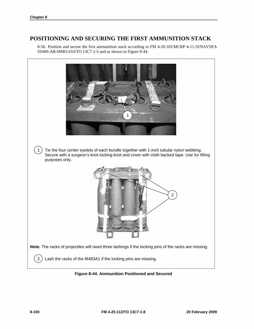
Chapter 8
8-100 FM 4-20.112/TO 13C7-1-8 20 February 2009
POSITIONING AND SECURING THE FIRST AMMUNITION STACK 8-56. Position and secure the first ammunition stack according to FM 4-20.102/MCRP 4-11.3J/NAVSEA SS400-AB-MMO-010/TO 13C7-1-5 and as shown in Figure 8-44.
1 Tie the four center eyelets of each bundle together with 1-inch tubular nylon webbing. Secure with a surgeon’s knot locking knot and cover with cloth backed tape. Use for lifting purposes only.
Note. The racks of projectiles will need three lashings if the locking pins of the racks are missing.
2 Lash the racks of the M483A1 if the locking pins are missing.
Figure 8-44. Ammunition Positioned and Secured
1
2
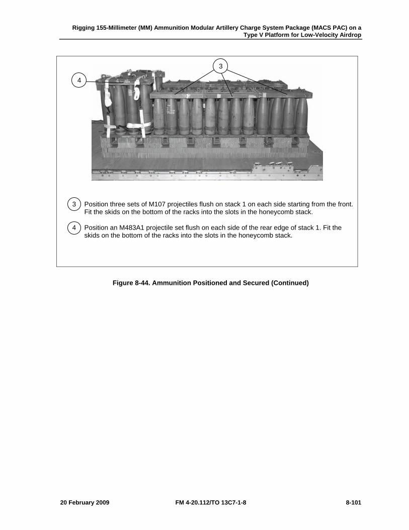
Rigging 155-Millimeter (MM) Ammunition Modular Artillery Charge System Package (MACS PAC) on a Type V Platform for Low-Velocity Airdrop
20 February 2009 FM 4-20.112/TO 13C7-1-8 8-101
3 Position three sets of M107 projectiles flush on stack 1 on each side starting from the front. Fit the skids on the bottom of the racks into the slots in the honeycomb stack.
4 Position an M483A1 projectile set flush on each side of the rear edge of stack 1. Fit the skids on the bottom of the racks into the slots in the honeycomb stack.
Figure 8-44. Ammunition Positioned and Secured (Continued)
3
4

Chapter 8
8-102 FM 4-20.112/TO 13C7-1-8 20 February 2009
5 Place a 15-foot tiedown lashing 10 inches from the front and rear edge of honeycomb stack 1 in a right to left direction according to FM 4-20.102/MCRP 4-11.3J/NAVSEA SS400-AB-MMO-010/TO 13C7-1-5.
6 Place a 15-foot tiedown lashing 24 inches from the front and rear edge of honeycomb stack 1 in a right to left direction according to FM 4-20.102/MCRP 4-11.3J/NAVSEA SS400-AB-MMO-010/TO 13C7-1-5.
Figure 8-44. Ammunition Positioned and Secured (Continued)
5
6
5
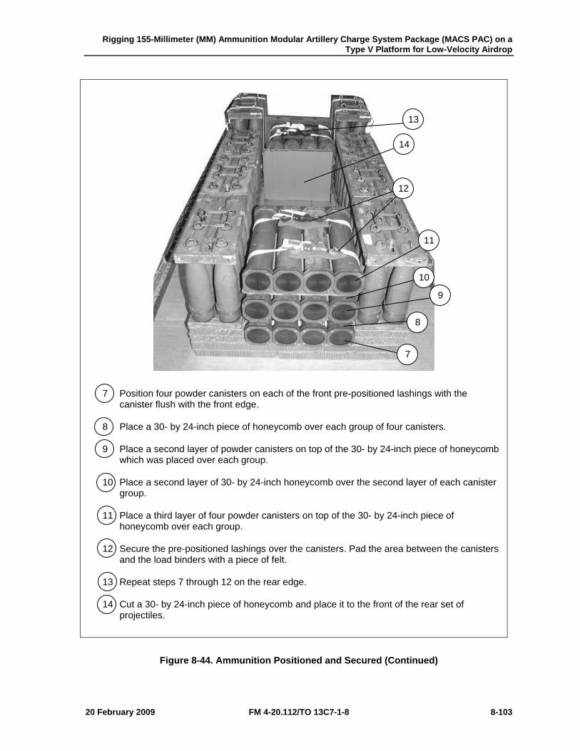
Rigging 155-Millimeter (MM) Ammunition Modular Artillery Charge System Package (MACS PAC) on a Type V Platform for Low-Velocity Airdrop
20 February 2009 FM 4-20.112/TO 13C7-1-8 8-103
7 Position four powder canisters on each of the front pre-positioned lashings with the canister flush with the front edge.
8 Place a 30- by 24-inch piece of honeycomb over each group of four canisters.
9 Place a second layer of powder canisters on top of the 30- by 24-inch piece of honeycomb which was placed over each group.
10 Place a second layer of 30- by 24-inch honeycomb over the second layer of each canister group.
11 Place a third layer of four powder canisters on top of the 30- by 24-inch piece of honeycomb over each group.
12 Secure the pre-positioned lashings over the canisters. Pad the area between the canisters and the load binders with a piece of felt.
13 Repeat steps 7 through 12 on the rear edge.
14 Cut a 30- by 24-inch piece of honeycomb and place it to the front of the rear set of projectiles.
Figure 8-44. Ammunition Positioned and Secured (Continued)
7
8
9
10
11
12
13
14
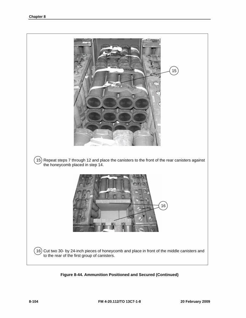
Chapter 8
8-104 FM 4-20.112/TO 13C7-1-8 20 February 2009
15 Repeat steps 7 through 12 and place the canisters to the front of the rear canisters against the honeycomb placed in step 14.
16 Cut two 30- by 24-inch pieces of honeycomb and place in front of the middle canisters and to the rear of the first group of canisters.
Figure 8-44. Ammunition Positioned and Secured (Continued)
15
16
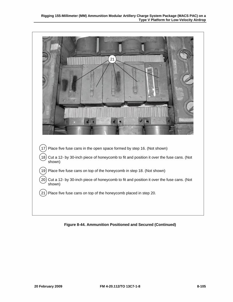
Rigging 155-Millimeter (MM) Ammunition Modular Artillery Charge System Package (MACS PAC) on a Type V Platform for Low-Velocity Airdrop
20 February 2009 FM 4-20.112/TO 13C7-1-8 8-105
17 Place five fuse cans in the open space formed by step 16. (Not shown)
18 Cut a 12- by 30-inch piece of honeycomb to fit and position it over the fuse cans. (Not shown)
19 Place five fuse cans on top of the honeycomb in step 18. (Not shown)
20 Cut a 12- by 30-inch piece of honeycomb to fit and position it over the fuse cans. (Not shown)
21 Place five fuse cans on top of the honeycomb placed in step 20.
Figure 8-44. Ammunition Positioned and Secured (Continued)
21
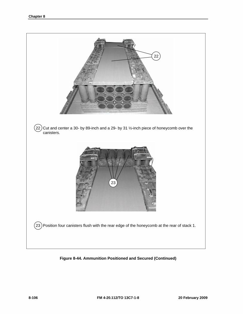
Chapter 8
8-106 FM 4-20.112/TO 13C7-1-8 20 February 2009
22 Cut and center a 30- by 89-inch and a 29- by 31 ½-inch piece of honeycomb over the canisters.
23 Position four canisters flush with the rear edge of the honeycomb at the rear of stack 1.
Figure 8-44. Ammunition Positioned and Secured (Continued)
22
23
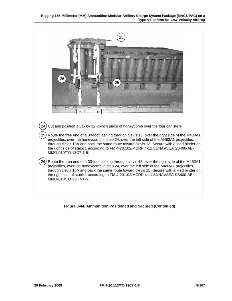
Rigging 155-Millimeter (MM) Ammunition Modular Artillery Charge System Package (MACS PAC) on a Type V Platform for Low-Velocity Airdrop
20 February 2009 FM 4-20.112/TO 13C7-1-8 8-107
24 Cut and position a 31- by 32 ½-inch piece of honeycomb over the four canisters.
25 Route the free end of a 30-foot lashing through clevis 13, over the right side of the M483A1 projectiles, over the honeycomb in step 24, over the left side of the M483A1 projectiles, through clevis 13A and back the same route toward clevis 13. Secure with a load binder on the right side of stack 1 according to FM 4-20.102/MCRP 4-11.3J/NAVSEA SS400-AB-MMO-010/TO 13C7-1-5.
26 Route the free end of a 30-foot lashing through clevis 15, over the right side of the M483A1 projectiles, over the honeycomb in step 24, over the left side of the M483A1 projectiles, through clevis 15A and back the same route toward clevis 15. Secure with a load binder on the right side of stack 1 according to FM 4-20.102/MCRP 4-11.3J/NAVSEA SS400-AB-MMO-010/TO 13C7-1-5.
Figure 8-44. Ammunition Positioned and Secured (Continued)
1315
25 26
25
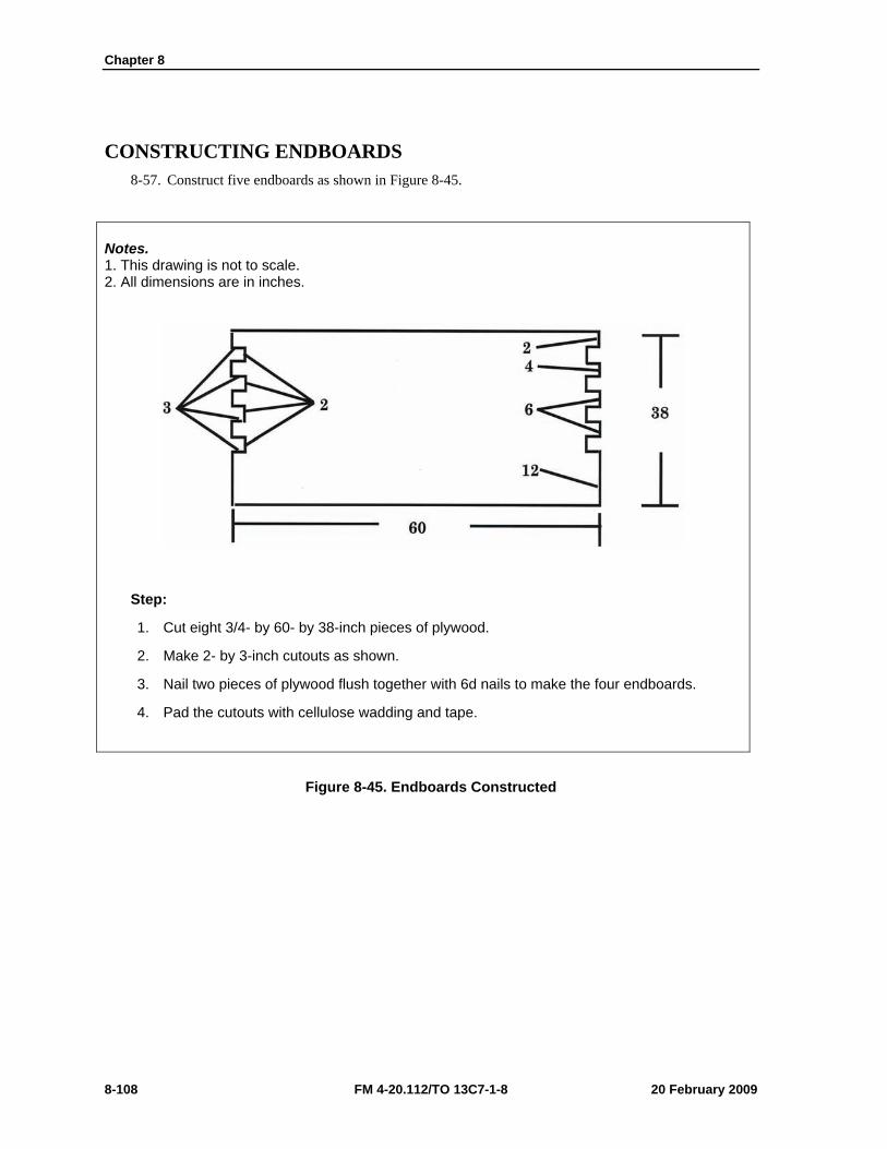
Chapter 8
8-108 FM 4-20.112/TO 13C7-1-8 20 February 2009
CONSTRUCTING ENDBOARDS 8-57. Construct five endboards as shown in Figure 8-45.
Notes. 1. This drawing is not to scale. 2. All dimensions are in inches.
Step:
1. Cut eight 3/4- by 60- by 38-inch pieces of plywood.
2. Make 2- by 3-inch cutouts as shown.
3. Nail two pieces of plywood flush together with 6d nails to make the four endboards.
4. Pad the cutouts with cellulose wadding and tape.
Figure 8-45. Endboards Constructed
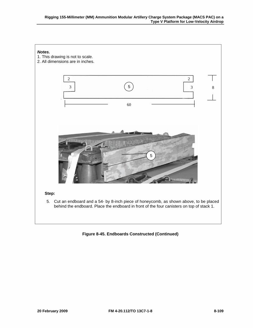
Rigging 155-Millimeter (MM) Ammunition Modular Artillery Charge System Package (MACS PAC) on a Type V Platform for Low-Velocity Airdrop
20 February 2009 FM 4-20.112/TO 13C7-1-8 8-109
Notes. 1. This drawing is not to scale. 2. All dimensions are in inches.
Step:
5. Cut an endboard and a 54- by 8-inch piece of honeycomb, as shown above, to be placed behind the endboard. Place the endboard in front of the four canisters on top of stack 1.
Figure 8-45. Endboards Constructed (Continued)
3 3
2 2
60
85
5
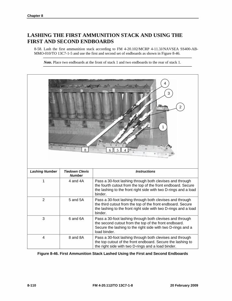
Chapter 8
8-110 FM 4-20.112/TO 13C7-1-8 20 February 2009
LASHING THE FIRST AMMUNITION STACK AND USING THE FIRST AND SECOND ENDBOARDS
8-58. Lash the first ammunition stack according to FM 4-20.102/MCRP 4-11.3J/NAVSEA SS400-AB-MMO-010/TO 13C7-1-5 and use the first and second set of endboards as shown in Figure 8-46.
Note. Place two endboards at the front of stack 1 and two endboards to the rear of stack 1.
Lashing Number Tiedown Clevis
Number Instructions
1 4 and 4A Pass a 30-foot lashing through both clevises and through the fourth cutout from the top of the front endboard. Secure the lashing to the front right side with two D-rings and a load binder.
2 5 and 5A Pass a 30-foot lashing through both clevises and through the third cutout from the top of the front endboard. Secure the lashing to the front right side with two D-rings and a load binder.
3 6 and 6A Pass a 30-foot lashing through both clevises and through the second cutout from the top of the front endboard. Secure the lashing to the right side with two D-rings and a load binder.
4 8 and 8A Pass a 30-foot lashing through both clevises and through the top cutout of the front endboard. Secure the lashing to the right side with two D-rings and a load binder.
Figure 8-46. First Ammunition Stack Lashed Using the First and Second Endboards
4568
4
3
2
1
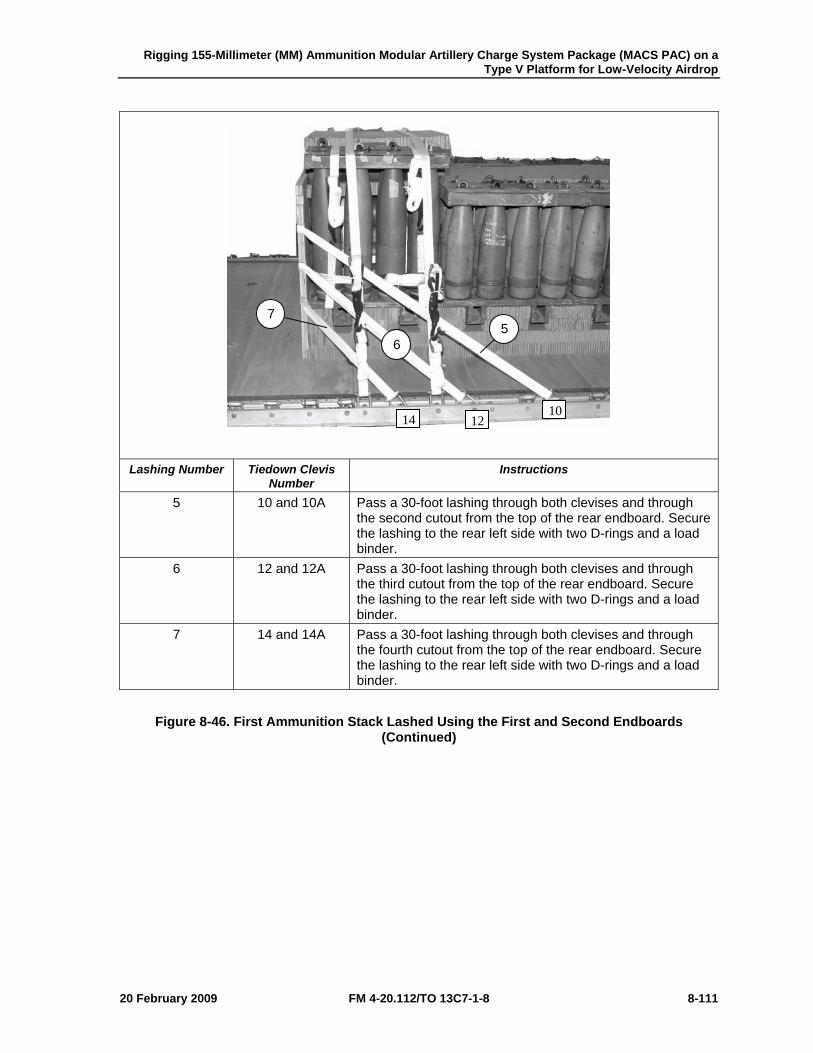
Rigging 155-Millimeter (MM) Ammunition Modular Artillery Charge System Package (MACS PAC) on a Type V Platform for Low-Velocity Airdrop
20 February 2009 FM 4-20.112/TO 13C7-1-8 8-111
Lashing Number Tiedown Clevis
Number Instructions
5 10 and 10A Pass a 30-foot lashing through both clevises and through the second cutout from the top of the rear endboard. Secure the lashing to the rear left side with two D-rings and a load binder.
6 12 and 12A Pass a 30-foot lashing through both clevises and through the third cutout from the top of the rear endboard. Secure the lashing to the rear left side with two D-rings and a load binder.
7 14 and 14A Pass a 30-foot lashing through both clevises and through the fourth cutout from the top of the rear endboard. Secure the lashing to the rear left side with two D-rings and a load binder.
Figure 8-46. First Ammunition Stack Lashed Using the First and Second Endboards (Continued)
5 7
6
101214
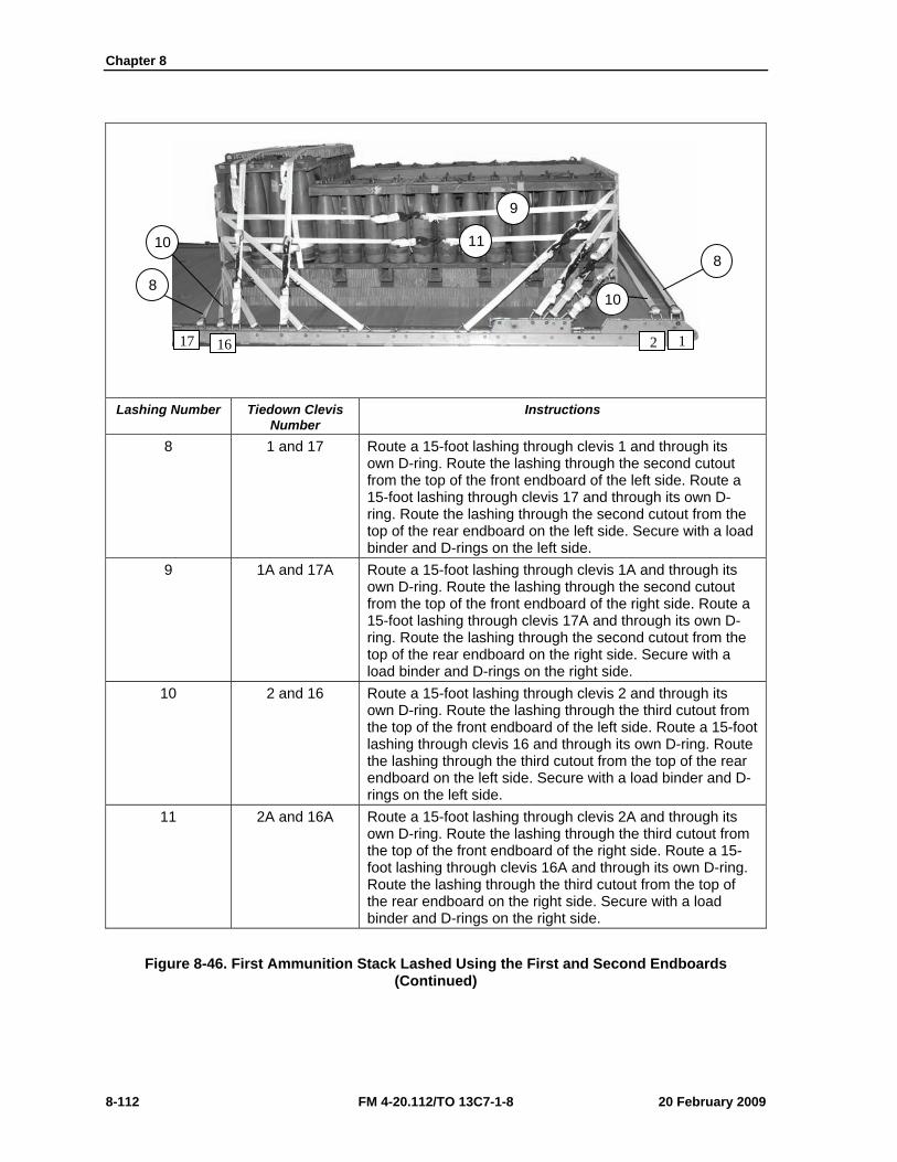
Chapter 8
8-112 FM 4-20.112/TO 13C7-1-8 20 February 2009
Lashing Number Tiedown Clevis
Number Instructions
8 1 and 17 Route a 15-foot lashing through clevis 1 and through its own D-ring. Route the lashing through the second cutout from the top of the front endboard of the left side. Route a 15-foot lashing through clevis 17 and through its own D-ring. Route the lashing through the second cutout from the top of the rear endboard on the left side. Secure with a load binder and D-rings on the left side.
9 1A and 17A Route a 15-foot lashing through clevis 1A and through its own D-ring. Route the lashing through the second cutout from the top of the front endboard of the right side. Route a 15-foot lashing through clevis 17A and through its own D-ring. Route the lashing through the second cutout from the top of the rear endboard on the right side. Secure with a load binder and D-rings on the right side.
10 2 and 16 Route a 15-foot lashing through clevis 2 and through its own D-ring. Route the lashing through the third cutout from the top of the front endboard of the left side. Route a 15-foot lashing through clevis 16 and through its own D-ring. Route the lashing through the third cutout from the top of the rear endboard on the left side. Secure with a load binder and D-rings on the left side.
11 2A and 16A Route a 15-foot lashing through clevis 2A and through its own D-ring. Route the lashing through the third cutout from the top of the front endboard of the right side. Route a 15-foot lashing through clevis 16A and through its own D-ring. Route the lashing through the third cutout from the top of the rear endboard on the right side. Secure with a load binder and D-rings on the right side.
Figure 8-46. First Ammunition Stack Lashed Using the First and Second Endboards (Continued)
1 2 17 16
9
11
10
8 10
8
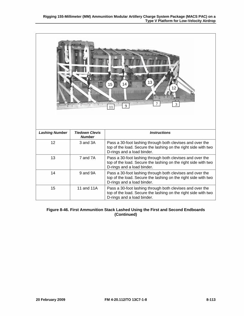
Rigging 155-Millimeter (MM) Ammunition Modular Artillery Charge System Package (MACS PAC) on a Type V Platform for Low-Velocity Airdrop
20 February 2009 FM 4-20.112/TO 13C7-1-8 8-113
Lashing Number Tiedown Clevis
Number Instructions
12 3 and 3A Pass a 30-foot lashing through both clevises and over the top of the load. Secure the lashing on the right side with two D-rings and a load binder.
13 7 and 7A Pass a 30-foot lashing through both clevises and over the top of the load. Secure the lashing on the right side with two D-rings and a load binder.
14 9 and 9A Pass a 30-foot lashing through both clevises and over the top of the load. Secure the lashing on the right side with two D-rings and a load binder.
15 11 and 11A Pass a 30-foot lashing through both clevises and over the top of the load. Secure the lashing on the right side with two D-rings and a load binder.
Figure 8-46. First Ammunition Stack Lashed Using the First and Second Endboards (Continued)
3 7911
12 13 14 15
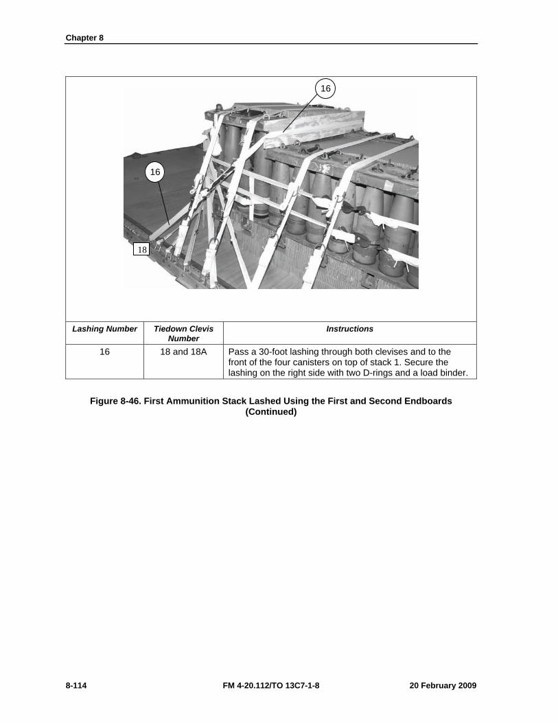
Chapter 8
8-114 FM 4-20.112/TO 13C7-1-8 20 February 2009
Lashing Number Tiedown Clevis
Number Instructions
16 18 and 18A Pass a 30-foot lashing through both clevises and to the front of the four canisters on top of stack 1. Secure the lashing on the right side with two D-rings and a load binder.
Figure 8-46. First Ammunition Stack Lashed Using the First and Second Endboards (Continued)
18
16
16
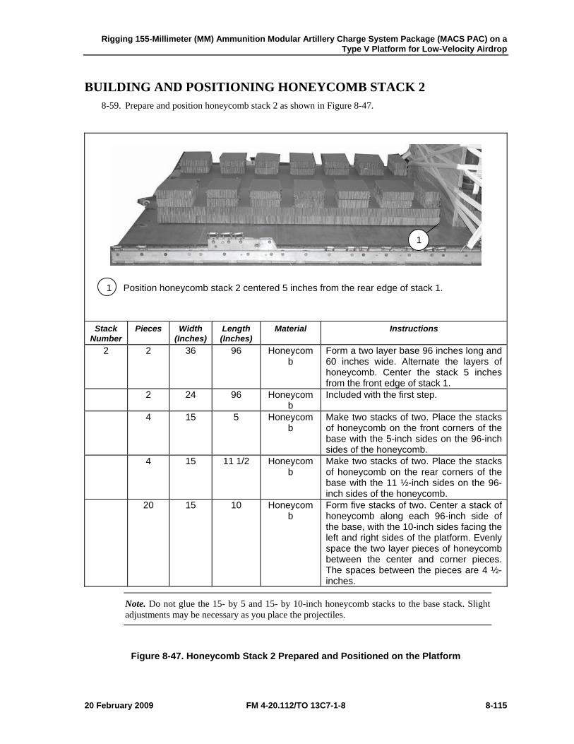
Rigging 155-Millimeter (MM) Ammunition Modular Artillery Charge System Package (MACS PAC) on a Type V Platform for Low-Velocity Airdrop
20 February 2009 FM 4-20.112/TO 13C7-1-8 8-115
BUILDING AND POSITIONING HONEYCOMB STACK 2 8-59. Prepare and position honeycomb stack 2 as shown in Figure 8-47.
1 Position honeycomb stack 2 centered 5 inches from the rear edge of stack 1.
Stack Number
Pieces Width (Inches)
Length (Inches)
Material Instructions
2 2 36 96 Honeycomb
Form a two layer base 96 inches long and 60 inches wide. Alternate the layers of honeycomb. Center the stack 5 inches from the front edge of stack 1.
2 24 96 Honeycomb
Included with the first step.
4 15 5 Honeycomb
Make two stacks of two. Place the stacks of honeycomb on the front corners of the base with the 5-inch sides on the 96-inch sides of the honeycomb.
4 15 11 1/2 Honeycomb
Make two stacks of two. Place the stacks of honeycomb on the rear corners of the base with the 11 ½-inch sides on the 96-inch sides of the honeycomb.
20 15 10 Honeycomb
Form five stacks of two. Center a stack of honeycomb along each 96-inch side of the base, with the 10-inch sides facing the left and right sides of the platform. Evenly space the two layer pieces of honeycomb between the center and corner pieces. The spaces between the pieces are 4 ½-inches.
Note. Do not glue the 15- by 5 and 15- by 10-inch honeycomb stacks to the base stack. Slight adjustments may be necessary as you place the projectiles.
Figure 8-47. Honeycomb Stack 2 Prepared and Positioned on the Platform
1
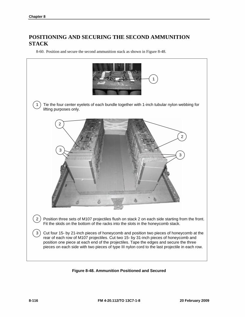
Chapter 8
8-116 FM 4-20.112/TO 13C7-1-8 20 February 2009
POSITIONING AND SECURING THE SECOND AMMUNITION STACK
8-60. Position and secure the second ammunition stack as shown in Figure 8-48.
1 Tie the four center eyelets of each bundle together with 1-inch tubular nylon webbing for lifting purposes only.
2 Position three sets of M107 projectiles flush on stack 2 on each side starting from the front. Fit the skids on the bottom of the racks into the slots in the honeycomb stack.
3 Cut four 15- by 21-inch pieces of honeycomb and position two pieces of honeycomb at the rear of each row of M107 projectiles. Cut two 15- by 31-inch pieces of honeycomb and position one piece at each end of the projectiles. Tape the edges and secure the three pieces on each side with two pieces of type III nylon cord to the last projectile in each row.
Figure 8-48. Ammunition Positioned and Secured
1
2
2
3 3
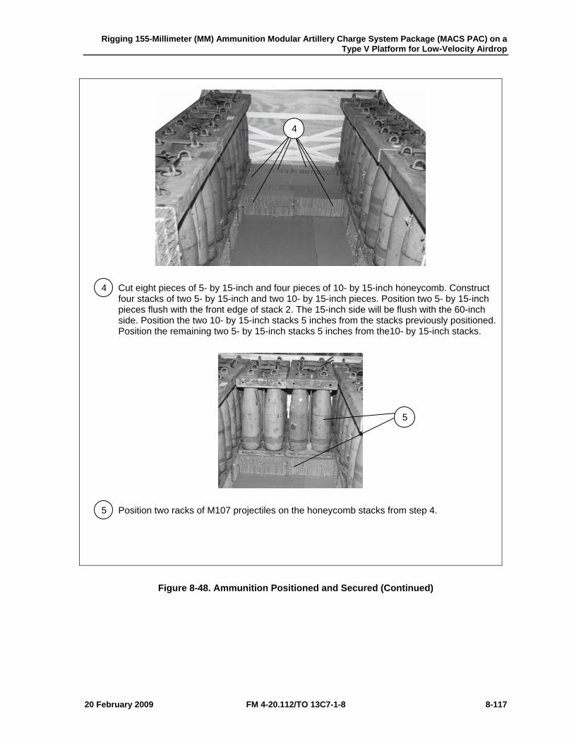
Rigging 155-Millimeter (MM) Ammunition Modular Artillery Charge System Package (MACS PAC) on a Type V Platform for Low-Velocity Airdrop
20 February 2009 FM 4-20.112/TO 13C7-1-8 8-117
4 Cut eight pieces of 5- by 15-inch and four pieces of 10- by 15-inch honeycomb. Construct four stacks of two 5- by 15-inch and two 10- by 15-inch pieces. Position two 5- by 15-inch pieces flush with the front edge of stack 2. The 15-inch side will be flush with the 60-inch side. Position the two 10- by 15-inch stacks 5 inches from the stacks previously positioned. Position the remaining two 5- by 15-inch stacks 5 inches from the10- by 15-inch stacks.
5 Position two racks of M107 projectiles on the honeycomb stacks from step 4.
Figure 8-48. Ammunition Positioned and Secured (Continued)
4
5
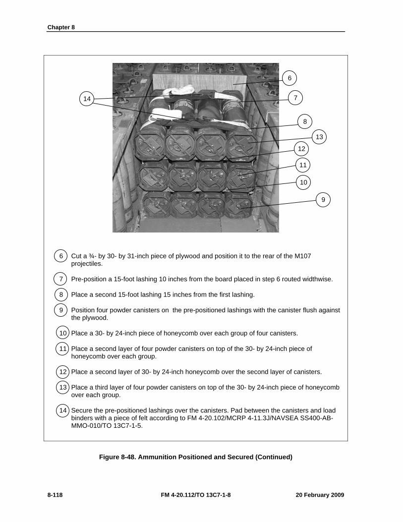
Chapter 8
8-118 FM 4-20.112/TO 13C7-1-8 20 February 2009
6 Cut a ¾- by 30- by 31-inch piece of plywood and position it to the rear of the M107 projectiles.
7 Pre-position a 15-foot lashing 10 inches from the board placed in step 6 routed widthwise.
8 Place a second 15-foot lashing 15 inches from the first lashing.
9 Position four powder canisters on the pre-positioned lashings with the canister flush against the plywood.
10 Place a 30- by 24-inch piece of honeycomb over each group of four canisters.
11 Place a second layer of four powder canisters on top of the 30- by 24-inch piece of honeycomb over each group.
12 Place a second layer of 30- by 24-inch honeycomb over the second layer of canisters.
13 Place a third layer of four powder canisters on top of the 30- by 24-inch piece of honeycomb over each group.
14 Secure the pre-positioned lashings over the canisters. Pad between the canisters and load binders with a piece of felt according to FM 4-20.102/MCRP 4-11.3J/NAVSEA SS400-AB-MMO-010/TO 13C7-1-5.
Figure 8-48. Ammunition Positioned and Secured (Continued)
6
14 7
8
13
12
11
10
9
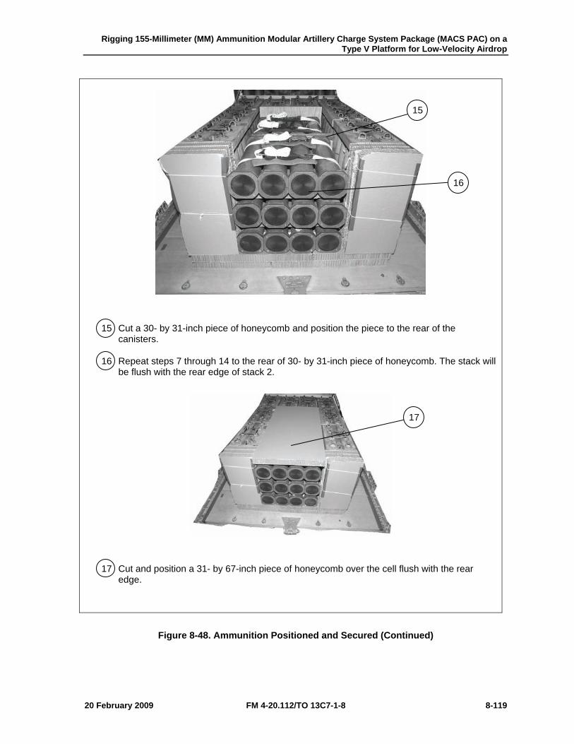
Rigging 155-Millimeter (MM) Ammunition Modular Artillery Charge System Package (MACS PAC) on a Type V Platform for Low-Velocity Airdrop
20 February 2009 FM 4-20.112/TO 13C7-1-8 8-119
15 Cut a 30- by 31-inch piece of honeycomb and position the piece to the rear of the canisters.
16 Repeat steps 7 through 14 to the rear of 30- by 31-inch piece of honeycomb. The stack will be flush with the rear edge of stack 2.
17 Cut and position a 31- by 67-inch piece of honeycomb over the cell flush with the rear edge.
Figure 8-48. Ammunition Positioned and Secured (Continued)
15
16
17
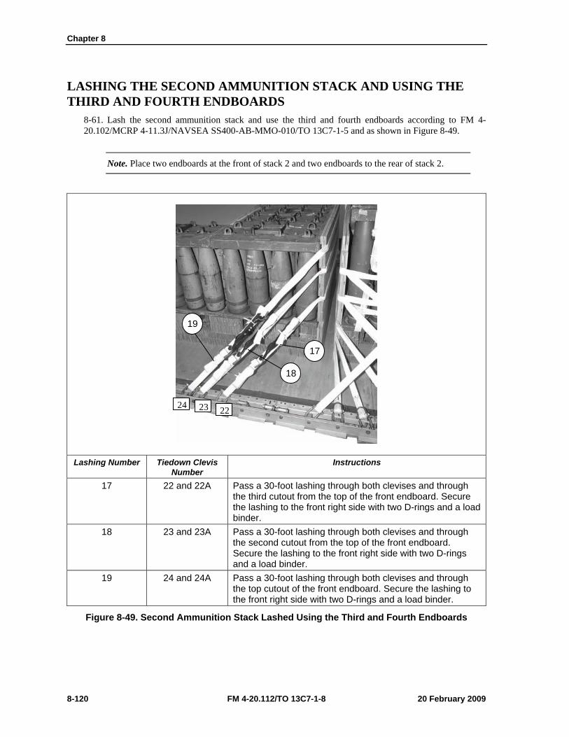
Chapter 8
8-120 FM 4-20.112/TO 13C7-1-8 20 February 2009
LASHING THE SECOND AMMUNITION STACK AND USING THE THIRD AND FOURTH ENDBOARDS
8-61. Lash the second ammunition stack and use the third and fourth endboards according to FM 4-20.102/MCRP 4-11.3J/NAVSEA SS400-AB-MMO-010/TO 13C7-1-5 and as shown in Figure 8-49.
Note. Place two endboards at the front of stack 2 and two endboards to the rear of stack 2.
Lashing Number Tiedown Clevis
Number Instructions
17 22 and 22A Pass a 30-foot lashing through both clevises and through the third cutout from the top of the front endboard. Secure the lashing to the front right side with two D-rings and a load binder.
18 23 and 23A Pass a 30-foot lashing through both clevises and through the second cutout from the top of the front endboard. Secure the lashing to the front right side with two D-rings and a load binder.
19 24 and 24A Pass a 30-foot lashing through both clevises and through the top cutout of the front endboard. Secure the lashing to the front right side with two D-rings and a load binder.
Figure 8-49. Second Ammunition Stack Lashed Using the Third and Fourth Endboards
17
18
19
2223 24
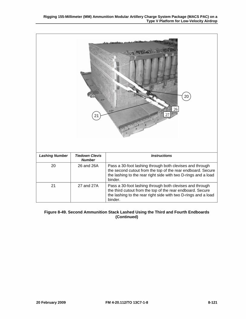
Rigging 155-Millimeter (MM) Ammunition Modular Artillery Charge System Package (MACS PAC) on a Type V Platform for Low-Velocity Airdrop
20 February 2009 FM 4-20.112/TO 13C7-1-8 8-121
Lashing Number Tiedown Clevis
Number Instructions
20 26 and 26A Pass a 30-foot lashing through both clevises and through the second cutout from the top of the rear endboard. Secure the lashing to the rear right side with two D-rings and a load binder.
21 27 and 27A Pass a 30-foot lashing through both clevises and through the third cutout from the top of the rear endboard. Secure the lashing to the rear right side with two D-rings and a load binder.
Figure 8-49. Second Ammunition Stack Lashed Using the Third and Fourth Endboards (Continued)
20
21 26
27
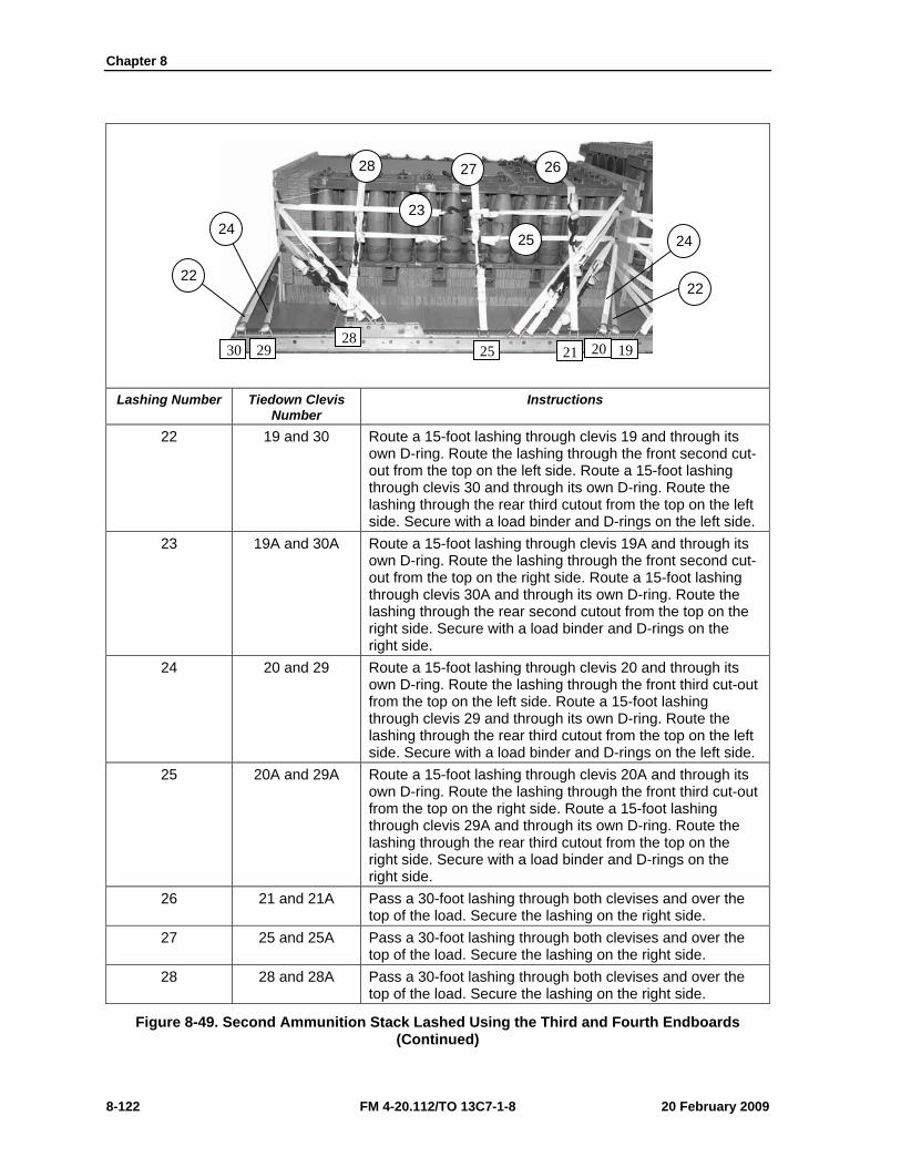
Chapter 8
8-122 FM 4-20.112/TO 13C7-1-8 20 February 2009
Lashing Number Tiedown Clevis
Number Instructions
22 19 and 30 Route a 15-foot lashing through clevis 19 and through its own D-ring. Route the lashing through the front second cut-out from the top on the left side. Route a 15-foot lashing through clevis 30 and through its own D-ring. Route the lashing through the rear third cutout from the top on the left side. Secure with a load binder and D-rings on the left side.
23 19A and 30A Route a 15-foot lashing through clevis 19A and through its own D-ring. Route the lashing through the front second cut-out from the top on the right side. Route a 15-foot lashing through clevis 30A and through its own D-ring. Route the lashing through the rear second cutout from the top on the right side. Secure with a load binder and D-rings on the right side.
24 20 and 29 Route a 15-foot lashing through clevis 20 and through its own D-ring. Route the lashing through the front third cut-out from the top on the left side. Route a 15-foot lashing through clevis 29 and through its own D-ring. Route the lashing through the rear third cutout from the top on the left side. Secure with a load binder and D-rings on the left side.
25 20A and 29A Route a 15-foot lashing through clevis 20A and through its own D-ring. Route the lashing through the front third cut-out from the top on the right side. Route a 15-foot lashing through clevis 29A and through its own D-ring. Route the lashing through the rear third cutout from the top on the right side. Secure with a load binder and D-rings on the right side.
26 21 and 21A Pass a 30-foot lashing through both clevises and over the top of the load. Secure the lashing on the right side.
27 25 and 25A Pass a 30-foot lashing through both clevises and over the top of the load. Secure the lashing on the right side.
28 28 and 28A Pass a 30-foot lashing through both clevises and over the top of the load. Secure the lashing on the right side.
Figure 8-49. Second Ammunition Stack Lashed Using the Third and Fourth Endboards (Continued)
22 22
19 30
23
25 24
24
202928
25 21
26 27 28
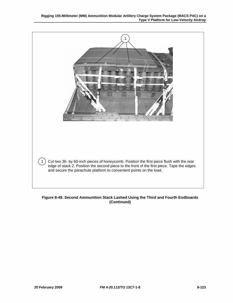
Rigging 155-Millimeter (MM) Ammunition Modular Artillery Charge System Package (MACS PAC) on a Type V Platform for Low-Velocity Airdrop
20 February 2009 FM 4-20.112/TO 13C7-1-8 8-123
1 Cut two 36- by 60-inch pieces of honeycomb. Position the first piece flush with the rear edge of stack 2. Position the second piece to the front of the first piece. Tape the edges and secure the parachute platform to convenient points on the load.
Figure 8-49. Second Ammunition Stack Lashed Using the Third and Fourth Endboards (Continued)
1
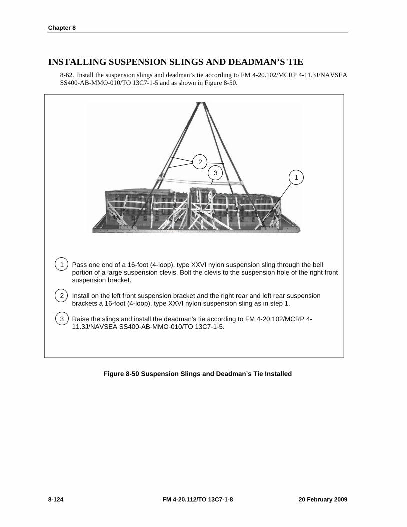
Chapter 8
8-124 FM 4-20.112/TO 13C7-1-8 20 February 2009
INSTALLING SUSPENSION SLINGS AND DEADMAN’S TIE 8-62. Install the suspension slings and deadman’s tie according to FM 4-20.102/MCRP 4-11.3J/NAVSEA SS400-AB-MMO-010/TO 13C7-1-5 and as shown in Figure 8-50.
1 Pass one end of a 16-foot (4-loop), type XXVI nylon suspension sling through the bell portion of a large suspension clevis. Bolt the clevis to the suspension hole of the right front suspension bracket.
2 Install on the left front suspension bracket and the right rear and left rear suspension brackets a 16-foot (4-loop), type XXVI nylon suspension sling as in step 1.
3 Raise the slings and install the deadman's tie according to FM 4-20.102/MCRP 4-11.3J/NAVSEA SS400-AB-MMO-010/TO 13C7-1-5.
Figure 8-50 Suspension Slings and Deadman’s Tie Installed
1
2 3
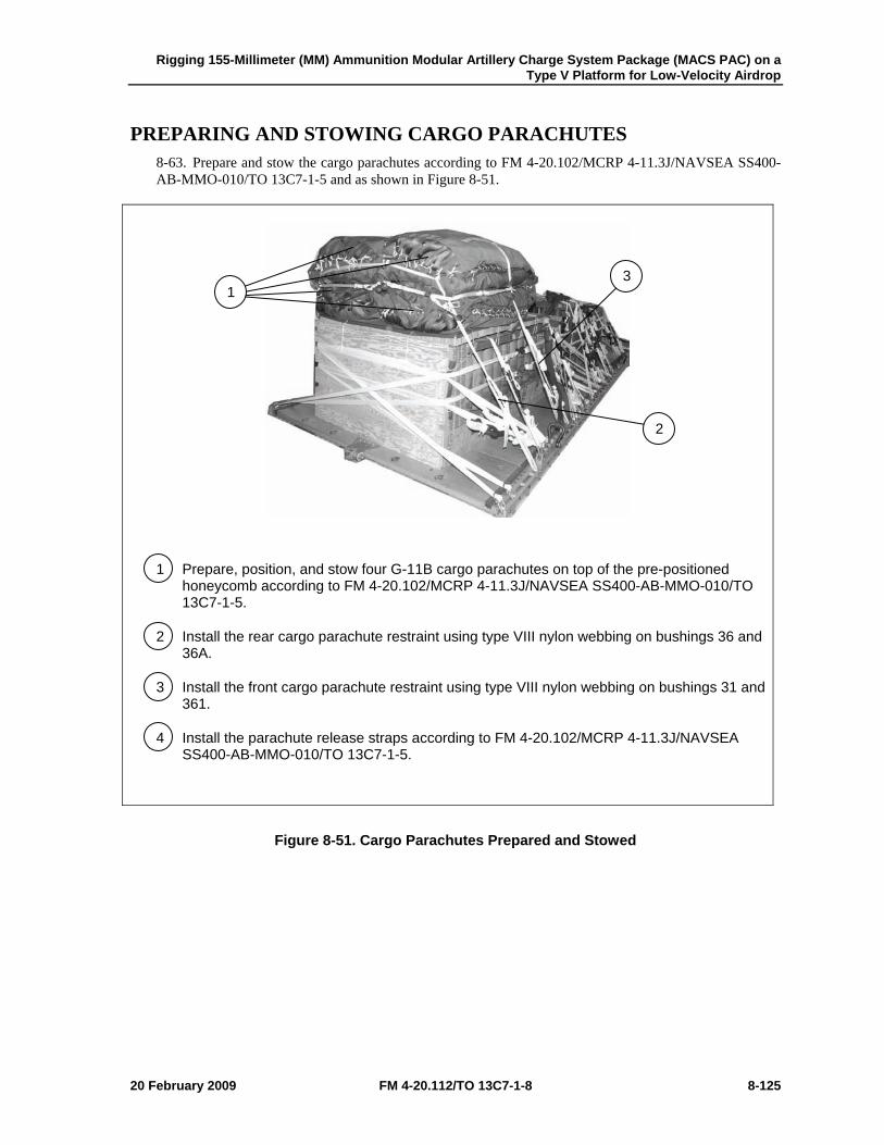
Rigging 155-Millimeter (MM) Ammunition Modular Artillery Charge System Package (MACS PAC) on a Type V Platform for Low-Velocity Airdrop
20 February 2009 FM 4-20.112/TO 13C7-1-8 8-125
PREPARING AND STOWING CARGO PARACHUTES 8-63. Prepare and stow the cargo parachutes according to FM 4-20.102/MCRP 4-11.3J/NAVSEA SS400-AB-MMO-010/TO 13C7-1-5 and as shown in Figure 8-51.
1 Prepare, position, and stow four G-11B cargo parachutes on top of the pre-positioned honeycomb according to FM 4-20.102/MCRP 4-11.3J/NAVSEA SS400-AB-MMO-010/TO 13C7-1-5.
2 Install the rear cargo parachute restraint using type VIII nylon webbing on bushings 36 and 36A.
3 Install the front cargo parachute restraint using type VIII nylon webbing on bushings 31 and 361.
4 Install the parachute release straps according to FM 4-20.102/MCRP 4-11.3J/NAVSEA SS400-AB-MMO-010/TO 13C7-1-5.
Figure 8-51. Cargo Parachutes Prepared and Stowed
3
2
1
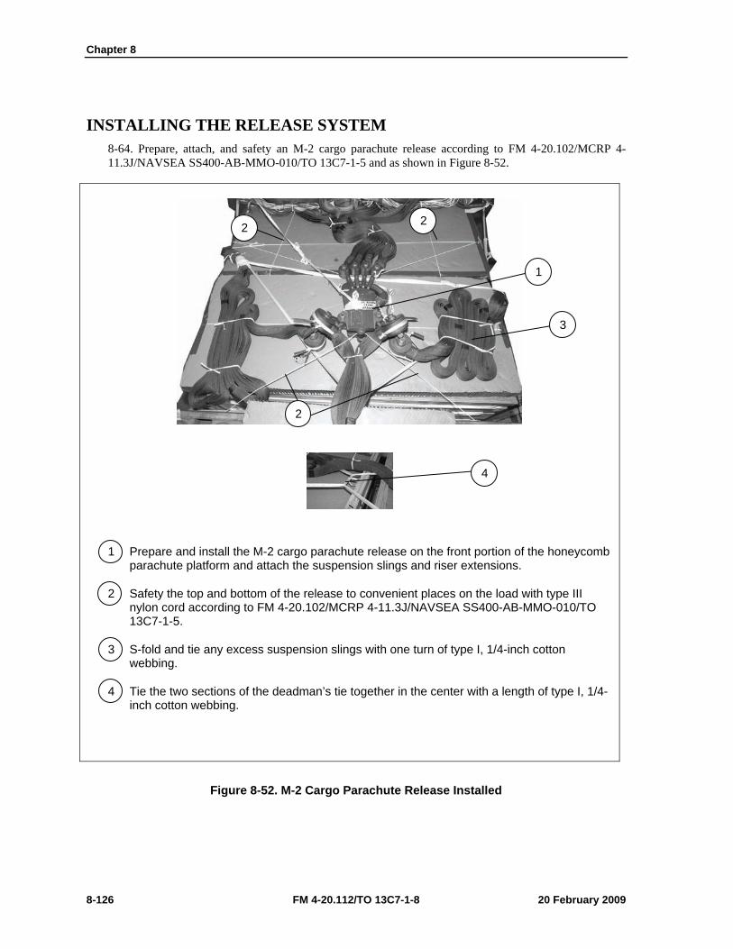
Chapter 8
8-126 FM 4-20.112/TO 13C7-1-8 20 February 2009
INSTALLING THE RELEASE SYSTEM 8-64. Prepare, attach, and safety an M-2 cargo parachute release according to FM 4-20.102/MCRP 4-11.3J/NAVSEA SS400-AB-MMO-010/TO 13C7-1-5 and as shown in Figure 8-52.
1 Prepare and install the M-2 cargo parachute release on the front portion of the honeycomb parachute platform and attach the suspension slings and riser extensions.
2 Safety the top and bottom of the release to convenient places on the load with type III nylon cord according to FM 4-20.102/MCRP 4-11.3J/NAVSEA SS400-AB-MMO-010/TO 13C7-1-5.
3 S-fold and tie any excess suspension slings with one turn of type I, 1/4-inch cotton webbing.
4 Tie the two sections of the deadman’s tie together in the center with a length of type I, 1/4-inch cotton webbing.
Figure 8-52. M-2 Cargo Parachute Release Installed
3
1
4
2
2 2
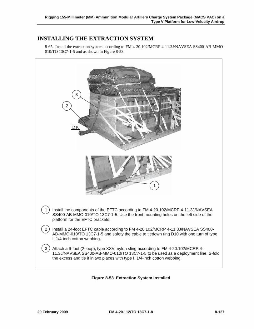
Rigging 155-Millimeter (MM) Ammunition Modular Artillery Charge System Package (MACS PAC) on a Type V Platform for Low-Velocity Airdrop
20 February 2009 FM 4-20.112/TO 13C7-1-8 8-127
INSTALLING THE EXTRACTION SYSTEM 8-65. Install the extraction system according to FM 4-20.102/MCRP 4-11.3J/NAVSEA SS400-AB-MMO-010/TO 13C7-1-5 and as shown in Figure 8-53.
1 Install the components of the EFTC according to FM 4-20.102/MCRP 4-11.3J/NAVSEA SS400-AB-MMO-010/TO 13C7-1-5. Use the front mounting holes on the left side of the platform for the EFTC brackets.
2 Install a 24-foot EFTC cable according to FM 4-20.102/MCRP 4-11.3J/NAVSEA SS400-AB-MMO-010/TO 13C7-1-5 and safety the cable to tiedown ring D10 with one turn of type I, 1/4-inch cotton webbing.
3 Attach a 9-foot (2-loop), type XXVI nylon sling according to FM 4-20.102/MCRP 4-11.3J/NAVSEA SS400-AB-MMO-010/TO 13C7-1-5 to be used as a deployment line. S-fold the excess and tie it in two places with type I, 1/4-inch cotton webbing.
Figure 8-53. Extraction System Installed
2
3
1
D10
Chapter 8
8-128 FM 4-20.112/TO 13C7-1-8 20 February 2009
PLACING EXTRACTION PARACHUTE 8-66. Select the extraction parachute and extraction line needed using the extraction line requirements table in FM 4-20.102/MCRP 4-11.3J/NAVSEA SS400-AB-MMO-010/TO 13C7-1-5. Place the extraction parachute and line on the load for installation in the aircraft.
INSTALLING PROVISIONS FOR EMERGENCY RESTRAINTS 8-67. Select and install the provisions for the emergency aft restraints according to the emergency aft restraint requirements table in FM 4-20.102/MCRP 4-11.3J/NAVSEA SS400-AB-MMO-010/TO 13C7-1-5.
MARKING RIGGED LOAD 8-68. Mark the rigged load according to FM 4-20.102/MCRP 4-11.3J/NAVSEA SS400-AB-MMO-010/TO 13C7-1-5, and as shown in Figure 8-54. Complete Shipper’s Declaration for Dangerous Goods. If the load varies from the one shown, the weight, height, CB, and parachute requirements must be recomputed.
EQUIPMENT REQUIRED 8-69. Use the equipment listed in Table 8-4 to rig this load.
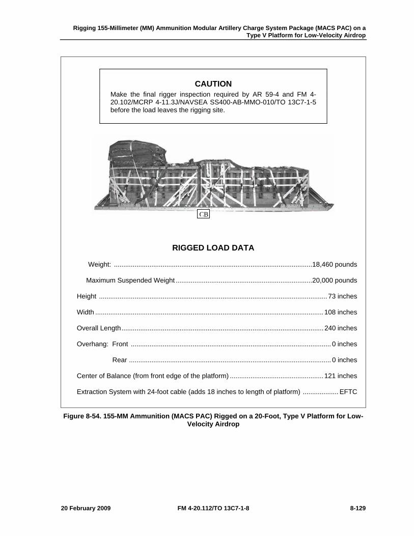
Rigging 155-Millimeter (MM) Ammunition Modular Artillery Charge System Package (MACS PAC) on a Type V Platform for Low-Velocity Airdrop
20 February 2009 FM 4-20.112/TO 13C7-1-8 8-129
CAUTION Make the final rigger inspection required by AR 59-4 and FM 4-20.102/MCRP 4-11.3J/NAVSEA SS400-AB-MMO-010/TO 13C7-1-5 before the load leaves the rigging site.
RIGGED LOAD DATA
Weight: .......................................................................................................... 18,460 pounds
Maximum Suspended Weight ......................................................................... 20,000 pounds
Height .......................................................................................................................... 73 inches
Width .......................................................................................................................... 108 inches
Overall Length ............................................................................................................ 240 inches
Overhang: Front ........................................................................................................... 0 inches
Rear ............................................................................................................ 0 inches
Center of Balance (from front edge of the platform) .................................................. 121 inches
Extraction System with 24-foot cable (adds 18 inches to length of platform) ................... EFTC
Figure 8-54. 155-MM Ammunition (MACS PAC) Rigged on a 20-Foot, Type V Platform for Low-Velocity Airdrop
CB
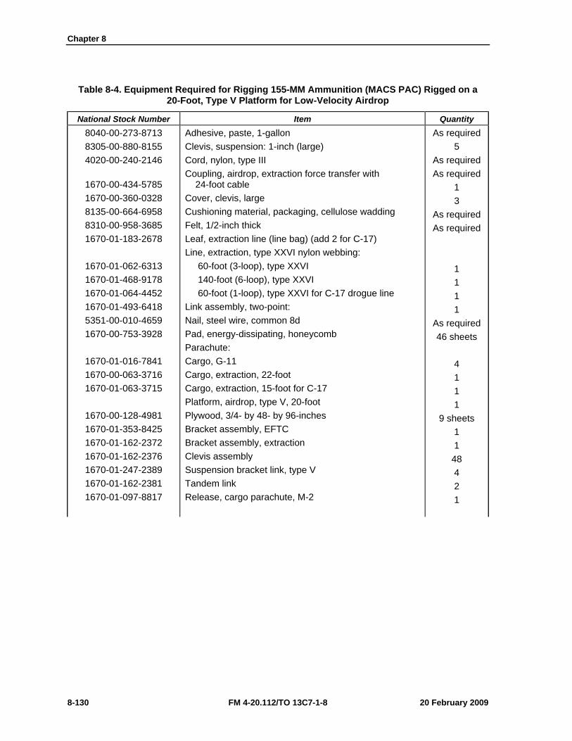
Chapter 8
8-130 FM 4-20.112/TO 13C7-1-8 20 February 2009
Table 8-4. Equipment Required for Rigging 155-MM Ammunition (MACS PAC) Rigged on a 20-Foot, Type V Platform for Low-Velocity Airdrop
National Stock Number Item Quantity 8040-00-273-8713 8305-00-880-8155 4020-00-240-2146
1670-00-434-5785 1670-00-360-0328 8135-00-664-6958 8310-00-958-3685 1670-01-183-2678
1670-01-062-6313 1670-01-468-9178 1670-01-064-4452 1670-01-493-6418 5351-00-010-4659 1670-00-753-3928
1670-01-016-7841 1670-00-063-3716 1670-01-063-3715
1670-00-128-4981 1670-01-353-8425 1670-01-162-2372 1670-01-162-2376 1670-01-247-2389 1670-01-162-2381 1670-01-097-8817
Adhesive, paste, 1-gallon Clevis, suspension: 1-inch (large) Cord, nylon, type III Coupling, airdrop, extraction force transfer with 24-foot cable Cover, clevis, large Cushioning material, packaging, cellulose wadding Felt, 1/2-inch thick Leaf, extraction line (line bag) (add 2 for C-17) Line, extraction, type XXVI nylon webbing: 60-foot (3-loop), type XXVI 140-foot (6-loop), type XXVI 60-foot (1-loop), type XXVI for C-17 drogue line Link assembly, two-point: Nail, steel wire, common 8d Pad, energy-dissipating, honeycomb Parachute: Cargo, G-11 Cargo, extraction, 22-foot Cargo, extraction, 15-foot for C-17 Platform, airdrop, type V, 20-foot Plywood, 3/4- by 48- by 96-inches Bracket assembly, EFTC Bracket assembly, extraction Clevis assembly Suspension bracket link, type V Tandem link Release, cargo parachute, M-2
As required 5
As required As required
1 3
As required As required
1 1 1 1
As required 46 sheets
4 1 1 1
9 sheets 1 1
48 4 2 1
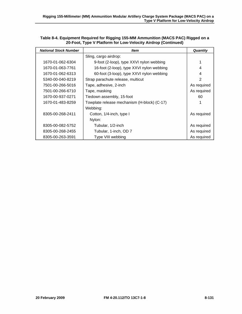
Rigging 155-Millimeter (MM) Ammunition Modular Artillery Charge System Package (MACS PAC) on a Type V Platform for Low-Velocity Airdrop
20 February 2009 FM 4-20.112/TO 13C7-1-8 8-131
Table 8-4. Equipment Required for Rigging 155-MM Ammunition (MACS PAC) Rigged on a 20-Foot, Type V Platform for Low-Velocity Airdrop (Continued)
National Stock Number Item Quantity
1670-01-062-6304 1670-01-063-7761 1670-01-062-6313 5340-00-040-8219 7501-00-266-5016 7501-00-266-6710 1670-00-937-0271 1670-01-483-8259
8305-00-268-2411
8305-00-082-5752 8305-00-268-2455 8305-00-263-3591
Sling, cargo airdrop: 9-foot (2-loop), type XXVI nylon webbing 16-foot (2-loop), type XXVI nylon webbing 60-foot (3-loop), type XXVI nylon webbing Strap parachute release, multicut Tape, adhesive, 2-inch Tape, masking Tiedown assembly, 15-foot Towplate release mechanism (H-block) (C-17) Webbing: Cotton, 1/4-inch, type I Nylon: Tubular, 1/2-inch Tubular, 1-inch, OD 7 Type VIII webbing
1 4 4 2
As required As required
60 1
As required
As required As required As required

This page intentionally left blank.
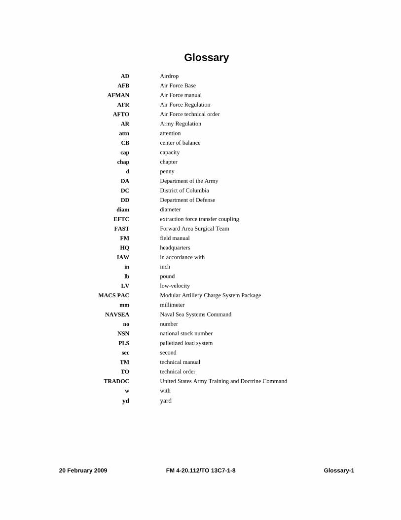
20 February 2009 FM 4-20.112/TO 13C7-1-8 Glossary-1
Glossary AD Airdrop
AFB Air Force Base AFMAN Air Force manual
AFR Air Force Regulation AFTO Air Force technical order
AR Army Regulation attn attention CB center of balance cap capacity
chap chapter d penny
DA Department of the Army DC District of Columbia DD Department of Defense
diam diameter EFTC extraction force transfer coupling FAST Forward Area Surgical Team
FM field manual HQ headquarters
IAW in accordance with in inch lb pound
LV low-velocity MACS PAC Modular Artillery Charge System Package
mm millimeter NAVSEA
no Naval Sea Systems Command number
NSN national stock number PLS palletized load system
sec second TM technical manual TO technical order
TRADOC United States Army Training and Doctrine Command w with
yd yard

This page intentionally left blank.
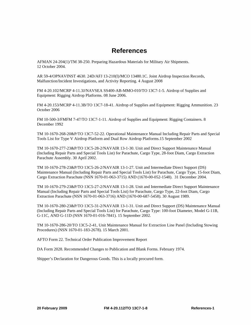
20 February 2009 FM 4-20.112/TO 13C7-1-8 References-1
References AFMAN 24-204(1)/TM 38-250. Preparing Hazardous Materials for Military Air Shipments. 12 October 2004. AR 59-4/OPNAVINST 4630. 24D/AFJ 13-210(I)/MCO 13480.1C. Joint Airdrop Inspection Records, Malfunction/Incident Investigations, and Activity Reporting. 4 August 2008 FM 4-20.102/MCRP 4-11.3J/NAVSEA SS400-AB-MMO-010/TO 13C7-1-5. Airdrop of Supplies and Equipment: Rigging Airdrop Platforms. 08 June 2006. FM 4-20.153/MCRP 4-11.3B/TO 13C7-18-41. Airdrop of Supplies and Equipment: Rigging Ammunition. 23 October 2006 FM 10-500-3/FMFM 7-47/TO 13C7-1-11. Airdrop of Supplies and Equipment: Rigging Containers. 8 December 1992 TM 10-1670-268-20&P/TO 13C7-52-22. Operational Maintenance Manual Including Repair Parts and Special Tools List for Type V Airdrop Platform and Dual Row Airdrop Platforms.15 September 2002 TM 10-1670-277-23&P/TO 13C5-28-2/NAVAIR 13-1-30. Unit and Direct Support Maintenance Manual (Including Repair Parts and Special Tools List) for Parachute, Cargo Type, 28-foot Diam, Cargo Extraction Parachute Assembly. 30 April 2002. TM 10-1670-278-23&P/TO 13C5-26-2/NAVAIR 13-1-27. Unit and Intermediate Direct Support (DS) Maintenance Manual (Including Repair Parts and Special Tools List) for Parachute, Cargo Type, 15-foot Diam, Cargo Extraction Parachute (NSN 1670-01-063-3715) AND (1670-00-052-1548). 31 December 2004. TM 10-1670-279-23&P/TO 13C5-27-2/NAVAIR 13-1-28. Unit and Intermediate Direct Support Maintenance Manual (Including Repair Parts and Special Tools List) for Parachute, Cargo Type, 22-foot Diam, Cargo Extraction Parachute (NSN 1670-01-063-3716) AND (1670-00-687-5458). 30 August 1989. TM 10-1670-280-23&P/TO 13C5-31-2/NAVAIR 13-1-31. Unit and Direct Support (DS) Maintenance Manual (Including Repair Parts and Special Tools List) for Parachute, Cargo Type: 100-foot Diameter, Model G-11B, G-11C, AND G-11D (NSN 1670-01-016-7841). 15 September 2002. TM 10-1670-286-20/TO 13C5-2-41, Unit Maintenance Manual for Extraction Line Panel (Including Stowing Procedures) (NSN 1670-01-183-2678). 15 March 2001. AFTO Form 22. Technical Order Publication Improvement Report DA Form 2028. Recommended Changes to Publication and Blank Forms. February 1974. Shipper’s Declaration for Dangerous Goods. This is a locally procured form.

This page intentionally left blank.
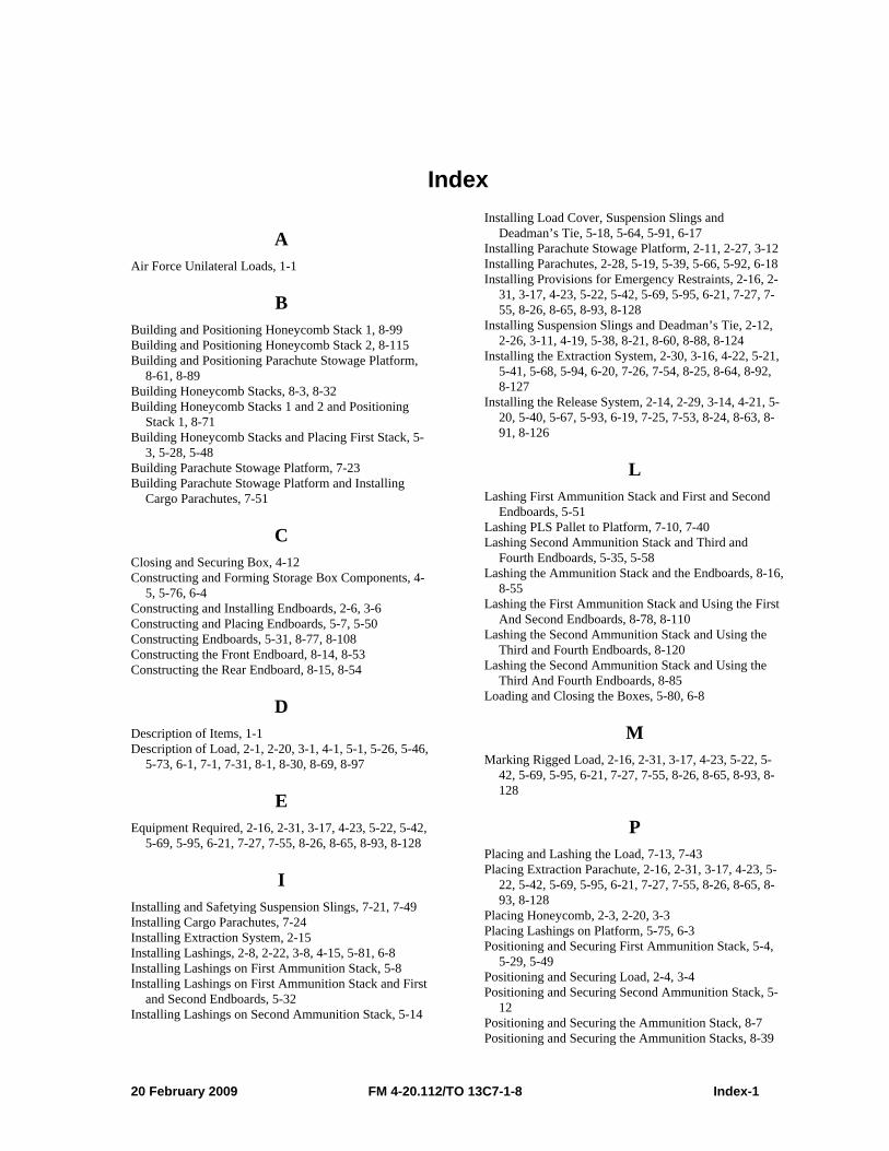
20 February 2009 FM 4-20.112/TO 13C7-1-8 Index-1
Index
A Air Force Unilateral Loads, 1-1
B Building and Positioning Honeycomb Stack 1, 8-99 Building and Positioning Honeycomb Stack 2, 8-115 Building and Positioning Parachute Stowage Platform,
8-61, 8-89 Building Honeycomb Stacks, 8-3, 8-32 Building Honeycomb Stacks 1 and 2 and Positioning
Stack 1, 8-71 Building Honeycomb Stacks and Placing First Stack, 5-
3, 5-28, 5-48 Building Parachute Stowage Platform, 7-23 Building Parachute Stowage Platform and Installing
Cargo Parachutes, 7-51
C Closing and Securing Box, 4-12 Constructing and Forming Storage Box Components, 4-
5, 5-76, 6-4 Constructing and Installing Endboards, 2-6, 3-6 Constructing and Placing Endboards, 5-7, 5-50 Constructing Endboards, 5-31, 8-77, 8-108 Constructing the Front Endboard, 8-14, 8-53 Constructing the Rear Endboard, 8-15, 8-54
D Description of Items, 1-1 Description of Load, 2-1, 2-20, 3-1, 4-1, 5-1, 5-26, 5-46,
5-73, 6-1, 7-1, 7-31, 8-1, 8-30, 8-69, 8-97
E Equipment Required, 2-16, 2-31, 3-17, 4-23, 5-22, 5-42,
5-69, 5-95, 6-21, 7-27, 7-55, 8-26, 8-65, 8-93, 8-128
I Installing and Safetying Suspension Slings, 7-21, 7-49 Installing Cargo Parachutes, 7-24 Installing Extraction System, 2-15 Installing Lashings, 2-8, 2-22, 3-8, 4-15, 5-81, 6-8 Installing Lashings on First Ammunition Stack, 5-8 Installing Lashings on First Ammunition Stack and First
and Second Endboards, 5-32 Installing Lashings on Second Ammunition Stack, 5-14
Installing Load Cover, Suspension Slings and Deadman’s Tie, 5-18, 5-64, 5-91, 6-17
Installing Parachute Stowage Platform, 2-11, 2-27, 3-12 Installing Parachutes, 2-28, 5-19, 5-39, 5-66, 5-92, 6-18 Installing Provisions for Emergency Restraints, 2-16, 2-
31, 3-17, 4-23, 5-22, 5-42, 5-69, 5-95, 6-21, 7-27, 7-55, 8-26, 8-65, 8-93, 8-128
Installing Suspension Slings and Deadman’s Tie, 2-12, 2-26, 3-11, 4-19, 5-38, 8-21, 8-60, 8-88, 8-124
Installing the Extraction System, 2-30, 3-16, 4-22, 5-21, 5-41, 5-68, 5-94, 6-20, 7-26, 7-54, 8-25, 8-64, 8-92, 8-127
Installing the Release System, 2-14, 2-29, 3-14, 4-21, 5-20, 5-40, 5-67, 5-93, 6-19, 7-25, 7-53, 8-24, 8-63, 8-91, 8-126
L Lashing First Ammunition Stack and First and Second
Endboards, 5-51 Lashing PLS Pallet to Platform, 7-10, 7-40 Lashing Second Ammunition Stack and Third and
Fourth Endboards, 5-35, 5-58 Lashing the Ammunition Stack and the Endboards, 8-16,
8-55 Lashing the First Ammunition Stack and Using the First
And Second Endboards, 8-78, 8-110 Lashing the Second Ammunition Stack and Using the
Third and Fourth Endboards, 8-120 Lashing the Second Ammunition Stack and Using the
Third And Fourth Endboards, 8-85 Loading and Closing the Boxes, 5-80, 6-8
M Marking Rigged Load, 2-16, 2-31, 3-17, 4-23, 5-22, 5-
42, 5-69, 5-95, 6-21, 7-27, 7-55, 8-26, 8-65, 8-93, 8-128
P Placing and Lashing the Load, 7-13, 7-43 Placing Extraction Parachute, 2-16, 2-31, 3-17, 4-23, 5-
22, 5-42, 5-69, 5-95, 6-21, 7-27, 7-55, 8-26, 8-65, 8-93, 8-128
Placing Honeycomb, 2-3, 2-20, 3-3 Placing Lashings on Platform, 5-75, 6-3 Positioning and Securing First Ammunition Stack, 5-4,
5-29, 5-49 Positioning and Securing Load, 2-4, 3-4 Positioning and Securing Second Ammunition Stack, 5-
12 Positioning and Securing the Ammunition Stack, 8-7 Positioning and Securing the Ammunition Stacks, 8-39
Index
Index-2 FM 4-20.112/TO 13C7-1-8 20 February 2009
Positioning and Securing the First Ammunition Stack, 8-72, 8-100
Positioning and Securing the Second Ammunition Stack, 8-116
Positioning Drop Items, 4-12 Positioning Endboards, Placing Second Ammunition
Stack, and Pre-Positioning Lashings, 5-56 Positioning Honeycomb Stacks and Assembling Sides of
Storage Box, 4-11 Positioning Lashings, 4-3 Positioning Lashings on the Platform, 8-5, 8-36 Positioning Load, 2-21 Positioning PLS Pallet on Platform, 7-9, 7-39 Positioning Second Ammunition Stack and Third and
Fourth Endboards, 5-35 Positioning Stack 2 and Positioning and Securing the
Second Ammunition Stack, 8-81 Positioning the Honeycomb Stack on the Platform, 8-6 Positioning the Honeycomb Stacks on the Platform, 8-37 Preparing and Positioning Honeycomb, 7-3, 7-33 Preparing and Stowing Cargo Parachutes, 2-13, 3-13, 4-
20, 8-22, 8-62, 8-90, 8-125
Preparing Honeycomb Stacks, 4-10 Preparing Platform, 2-1, 2-20, 3-1, 4-1, 5-1, 5-26, 5-46,
5-73, 6-1, 7-1, 7-31, 8-1, 8-30, 8-69, 8-97 Preparing PLS Pallet, 7-7, 7-37 Preparing, Stowing and Rigging Load, 2-21
R RIGGED LOAD DATA, 2-17, 2-32, 3-18, 4-24, 5-23, 5-
43, 5-70, 5-96, 6-22, 7-28, 7-56, 8-27, 8-66, 8-94, 8-129
S Scope, viii Special Considerations, 1-1
U User Information, viii
FM 4-20.112 (FM 10-512) TO 13C7-1-8
20 February 2009
By Order of the Secretary of the Army:
GEORGE W. CASEY, JR. General, United States Army Chief of Staff Official:
JOYCE E. MORROW
Administrative Assistant to the Secretary of the Army 0903407
DISTRIBUTION: To be distributed in accordance with the initial distribution number 110897, requirements for FM 4-20.112.
By order of the Secretary of the Air Force BRUISE CARLSON MICHAEL T. MOSELEY General, USAF General, USAF Command AFMC Chief of Staff

PIN: 081474-000
Related Documents