FM 10-67-1 HEADQUARTERS DEPARTMENT OF THE ARMY CONCEPTS AND EQUIPMENT OF PETROLEUM OPERATIONS DISTRIBUTION RESTRICTION: APPROVED FOR PUBLIC RELEASE; DISTRIBUTION IS UNLIMITED

Welcome message from author
This document is posted to help you gain knowledge. Please leave a comment to let me know what you think about it! Share it to your friends and learn new things together.
Transcript

FM 10-67-1HEADQUARTERS
DEPARTMENT OF THE ARMY
CONCEPTS AND EQUIPMENT OF PETROLEUM
OPERATIONS
DISTRIBUTION RESTRICTION:
APPROVED FOR PUBLIC RELEASE; DISTRIBUTION IS UNLIMITED
*FM 10-67-1
i
FIELD MANUALHeadquartersNo. 10-67-1 Department of the Army
Washington, DC, 2 April 1998
CONCEPTS AND EQUIPMENT OFPETROLEUM OPERATIONS
Table of Contents
PagePREFACE iv
PART ONE -GENERAL CONSIDERATIONS
CHAPTER 1. ENVIRONMENTAL RESPONSIBILITY 1-1
CHAPTER 2 SAFETY, HEALTH, AND FIRE FIGHTING 2-1Section I General Safety 2-1Section II Petroleum Fire Fighting 2-14Section III Aircraft Refueling Safety 2-18Section IV Health Hazards 2-26
CHAPTER 3 QUANTITY AND QUALITY CONTROL 3-1Section I Accountability and Inventory 3-1Section II Petroleum Product Measurement 3-7Section III Sampling 3-5Section IV Petroleum Quality Maintenance 3-31
PART TWO-PETROLEUM TERMINAL AND PIPELINE OPERATIONS
CHAPTER 4 WATERFRONT OPERATIONS 4-1Section I Loading and Unloading Facilities 4-1Section II Tank Vessels 4-4Section III Loading and Unloading Operations 4-7
CHAPTER 5 OFFSHORE PETROLEUM DISCHARGE SYSTEM 5-1Section I OPDS Tankers 5-1Section II Major Components (OPDS) Tanker 5-2Section III Beach Termination Unit Procedures 5-10Section IV Planning and Administrative Considerations 5-13Section V Communications and Installation 5-13
CHAPTER 6 TACTICAL PETROLEUM TERMINAL (TPT) 6-1Section I Concept and Primary Components 6-1Section II System Components` 6-5Section III Tank Farm Installation 6-12Section IV Terminal Operations 6-27Section V Maintenance 6-32
DISTRIBUTION RESTRICTION: Approved for public release; distribution is unlimited.

FM 10-67-1
ii
*This publication supersedes FM 10-18, 03 Dec 1986; FM 10-20, 29 Feb 1984; FM 10-68, 29 May 1987; FM 10-69, 22 Oct 1986; FM 10-70-1, 27 Dec 1983, FM 10-71, 12 May 1978.CHAPTER 7 INLAND PETROLEUM DISTRIBUTION SYSTEM (IPDS) 7-1Section I System Components 7-1Section II Installation 7-10Section III System Operation 7-16Section IV Maintenance 7-27
CHAPTER 8 CONTROL OF PRODUCT IN PIPELINES 8-1
CHAPTER 9 PIPELINE OPERATIONS 9-1Section I Duties of Personnel 9-1Section II Pipeline Communications System 9-3Section III Schedules 9-5Section IV Line Operations 9-10Section V Dispatching Records and Controls 9-13
CHAPTER 10 PETROLEUM INSTALLATION MAINTENANCE 10-1Section I Tank Farms and Pipeline Surroundings 10-1Section II Waterfront Facilities 10-4
CHAPTER 11 TANK CAR OPERATIONS 11-1Section I Tank Cars and Facilities 11-1Section II Procedures for Loading Tank Cars 11-5Section III Procedures for Unloading Tank Cars 11-9
CHAPTER 12 TANKS, TANK CARS, AND TANK VEHICLES MAINTENANCEAND CLEANING
12-1
Section I Storage Tanks and Tank Maintenance 12-1Section II Tank Cleaning Precautions and Equipment 12-12Section III Storage Tank Cleaning 12-18Section IV Tank Car and Tank Vehicle Cleaning 12-27
PART THREE-AIRCRAFT REFUELING
CHAPTER 13 AVIATION FUELS 13-1Section I Description of Fuels 13-1Section II Quality Surveillance 13-2
CHAPTER 14 AIRCRAFT REFUELING EQUIPMENT 14-1
CHAPTER 15 REFUELING FROM REFUELING SYSTEMS 15-1Section I Forward Area Refueling Equipment 15-1Section II Temporary amd Semipermanent Refueling Systems 15-11Section III HEMTT Tanker Aviation Refueling System 15-24Section IV Fatcow (CH-47) Fare 15-33Section V C-17 FARP Using the HTARS 15-34
CHAPTER 16 REFUELING FROM TANK VEHICLES 16-1Section I Refueling Vehicles 16-1Section II Refueling Operations 16-3
CHAPTER 17 DEFUELING 17-1

*FM 10-67-1
iii
CHAPTER 18 OTHER WAYS OF TRANSPORTING PETROLEUM 18-1Section I External Loads 18-1Section II Aerial Bulk Fuel Delivery System 18-8Section III Wet-Wing Defueling 18-12
CHAPTER 19 AIRCRAFT FIRE FIGHTING AND RESCUE TRAINING 19-1Section I Basic Fire-Fighting Training 19-1Section II Basic Crash Rescue Training 19-8Section III Tactical Fire-Fighting and Rescue Training 19-12
PART FOUR-PETROLEUM SUPPLY POINT OPERATIONS
CHAPTER 20 PUMPS 20-1Section I Hand-Operated Pumps 20-1Section II Power-Driven Pumps 20-3
CHAPTER 21 FILTER/SEPARATORS 21-1
CHAPTER 22 STORAGE CONTAINERS AND HANDLING EQUIPMENT 22-1Section I Packaged Petroleum Products and Fuels 22-1Section II Bulk Petroleum Containers 22-14
CHAPTER 23 FUEL SYSTEM SUPPLY POINT 23-1
CHAPTER 24 UNIT AND VEHICLES USED TO TRANSPORT BULKPETROLEUM
24-1
Section I Tank and Pump Unit 24-1Section II Tank Trucks 24-6Section III Tank Semitrailers 24-10Section IV Other Considerations of Tank Vehicles 24-24
CHAPTER 25 REFUEL ON THE MOVE 25-1
CHAPTER 26 CLASS III SUPPLY POINT 26-1Section I Movement 26-1Section II Site Selection 26-4Section III Layout 26-7Section IV Operation 26-12
CHAPTER 27 HOSELINE OUTFIT (ASSAULT HOSE LINE) 27-1
CHAPTER 28 RECEIPT, STORAGE, AND ISSUE OF BULK PETROLEUM 28-1Section I Bulk Petroleum Operations 28-1Section II Receipt 28-2Section III Storage 28-7Section IV Issue 28-8
APPENDIX A ALLOWABLE OUTAGE FOR EXPANSION OF PETROLEUMPRODUCTS IN STORAGE TANKS
A-1
APPENDIX B TANK STRAPPING B-1
APPENDIX C FUNDAMENTALS OF PIPELINE HYDRAULICS C-1 Section I Physical Properties of Petroleum Liquids C-1

FM 10-67-1
iv
Section II Flow in Pipelines C-7 Section III Examples of Flow C-18APPENDIX D PMCS CHECKLISTS D-1
APPENDIX E WATER DETECTION (AQUA-GLO) TEST E-1
APPENDIX F PROCEDURES FOR TESTING RESISTANCE TO GROUND F-1
APPENDIX G FILTER MEMBRANE COLOR RATINGS FOR PARTICULATECONTAMINATION IN AVIATION TURBINE FUELS
G-1
APPENDIX H STANDARD PETROLEUM CONTAINERS H-1
APPENDIX I VOLUME CONVERSION I-1
APPENDIX J CHECKLIST FOR DELIVERY AND UNLOADING J-1
APPENDIX K CONVERSION CHARTS FOR TANK CARS, TANK TRUCKS ANDUS/NATO FUEL CODES AND PLACARD ID NUMBERS
K-1
APPENDIX L PETROLEUM PRODUCT AND CRUDE OIL FACTORS L-1
APPENDIX M FLOW CONVERSION CHART M-1
APPENDIX N MATERIAL SAFETY DATA SHEETS N-1
APPENDIX O FORCE PROVIDER O-1
GLOSSARY Glossary-1
Section I Acronyms and Abbreviations Glossary-1
Section II Terms Glossary-5
REFERENCES Reference-1

*FM 10-67-1
v
INDEX Index-1
PREFACE
This manual is a guide for commanders, staff officers, supervisors, and other personnel concerned with petroleumconcepts, equipment, and operations.
This manual is a consolidation of FMs 10-18, 10-20, 10-68, 10-69, 10-70-1, and 10-71. This manual is dividedinto four parts. Part One describes general considerations of petroleum operations to include environmentalprotection, safety, and accountability. Part Two describes bulk petroleum distribution systems. Part Threedescribes Army aircraft refueling operations. Part Four describes petroleum handling equipment as well as ClassIII supply point operations. This manual is oriented toward tactical field operations and deals with theresponsibilities of both management and operator personnel. It can be used in conventional and NBC warfare.However, this manual cannot be cited as an authority for requisitions. Requisitions must be based on authoritysuch as tables of allowances or TOEs.
The proponent for this publication is HQ TRADOC. Send comments and recommendations on DA FORM 2028(Recommended Changes to Publications and Blank Forms) directly to:
COMMANDERUSACASCOM TRAINING DIRECTORATEATTN ATCL AQ801 LEE AVENUEFORT LEE VA 23801-1713
Unless this publication states otherwise, masculine nouns and pronouns do not refer exclusively to men.

PART ONE
GENERAL CONSIDERATIONS
The three chapters in this part give general considerations for all petroleum operationsin the areas of environmental protection, safety, and accountability. This includes generalguidelines for conducting any type of aviation-related activities, to include refuelingoperations. The rest of the chapters in the book give specific considerations in these areasrelated to various types of petroleum operations. Anyone involved in planning, evaluating,or conducting petroleum operations should be thoroughly familiar with the contents ofthese three chapters. They should routinely refamiliarize themselves with them, as well asthe other chapters in the book pertaining to the type of operation with which they areinvolved.

FM 10-67-1
1-1
CHAPTER 1
PETROLEUM UNIT ENVIRONMENTAL RESPONSIBILITIES
“The Army environmental vision is to be a national leader in environmental and natural resource responsibilitiesfor present and future generations as an integral part of our mission.”
SCOPE OF ENVIRONMENTAL RESPONSIBILITY
We must take care of the environment (that is, practice environmental stewardship). The definition of ste w-ardship is taking care of property while also caring about the rights of others. We must plan our operations wit h-out harming the environment. Good environmental stewardship lets leaders take care of soldiers and their fam i-lies. It also saves resources vital to combat readiness.
The Army has the huge task of reducing the environmental impact on its installations and units throughout theUnited States and the world. Within CONUS, the Army owns 20 million acres of land (an area about half the sizeof Virginia). This shows the vastness of this task. Each area of our daily operation has some effect on the env i-ronment.
The Army is renewing its emphasis on taking care of the environment. Petroleum and water units by theirnature have a huge impact on the environment. It is critical for the leaders and soldiers in these units to followsafe, legal environmental practices. By doing so, they protect their health and the health of those around them.They also prevent long term environmental damage that can lead to fines and other legal actions.
ENVIRONMENTAL PROTECTION STEWARDSHIP GOALS AND REQUIREMENTSThe Army no longer just complies with laws , they want to be a leader in environmental protection. To do this,
the Army has set goals and requirements for its leaders to follow.
Goals
• Make sure operations comply with standards. Do not receive a notice of violation or a fine for not followinglocal, state, and federal environmental regulations.
• Clean up installations. Begin restoring all contaminated sites by 2000.
• Prevent future pollution. Reduce all hazardous waste and toxic releases.
• Integrate NEPA procedures into all operations.
• Protect natural and cultural resources.
Requirements
All Army actions require an appraisal be done on potential environmental impacts of said action. All keyArmy decision makers and planners are required to attend NEPA training.
ROLE OF ENVIRONMENTAL STEWARDSHIP IN LEADERSHIP
A leader who cares for the environment also cares for his people. He does this by reducing or eliminating u n-due health risks. He saves resources (soldiers or money) vital to his mission. He keeps training areas in excellentcondition for training far into the future. He preserves cultural artifacts for study by future generations. Also, heteaches the basic moral duty of soldiers to protect and preserve the United States of America and its allies.

FM 10-67-1
1-2
ENVIRONMENTAL RESPONSIBILITIES OF PERSONNEL
Personnel at all levels must protect our environment. This includes soldiers, NCOs, officers, commanders,and appointed personnel.
Soldiers
These duties include--
• Follow installation environmental policies, unit SOPs, ARs, and environmental laws and regulations.
• Make sound decisions in everyday activities.
• Advise the chain of command on techniques to ensure environmental regulations are followed.
• Identify the environmental risks in individual and team tasks.
• Support the Army recycling program.
• Report HM and HW spills immediately.
NCOs
These responsibilities include--
• Always consider the environment in day-to-day decisions.
• Make sure soldiers know the Army’s environmental ethic.
• Train soldiers to be good environmental stewards.
• Be committed to environmental protection.
• Identify environmental risk associated with tasks.
• Plan and conduct environmentally sustainable actions and training.
• Protect the environment during training and other activities.
• Analyze the influence of the environment on your mission.
• Integrate environmental considerations into unit activities.
• Train peers and soldiers to identify the environmental effects of plans, actions, and missions.
• Counsel soldiers on the importance of protecting the environment and the results of not complying with e n-vironmental laws.
• Incorporate environmental considerations in AARs.
• Support the Army recycling program.
• Report HM and HW spills immediately.
Officers
These duties include--
• Build an environmental ethic in soldiers.
• Train and counsel subordinate leaders on stewardship.
• Seek advice on required personnel training from the local environmental coordinator.
• Lead by example.
• Enforce compliance with laws and regulations.
• Always consider the environment in making day-to-day decisions.
• Make sure subordinates know the Army’s environmental ethic.

FM 10-67-1
1-3
• Train subordinates to be good environmental stewards.
• Commit subordinate leaders to protect the environment.
• Analyze the influence of the environment on the mission.
• Integrate environmental considerations into unit activities, to include identifying the environmental risks a s-sociated with unit tasks.
Unit Commanders The commander must build an environmental ethic in his soldiers. The commander sets the tone for enviro n-
mental compliance. He is totally responsible for complying with all applicable environmental laws in the unit.Commanders train their subordinates on stewardship and counsel them on doing what is right. They must lead byexample and enforce compliance with laws. Commanders should--
• Seek advice on required personnel training from the local environmental coordinator.
• Consider the environment in making daily decisions.
• Know about the NEPA, HM, HW, HAZCOM efforts, and spill contingencies.
• Commit subordinates to environmental protection.
• Make sure officers and NCOs know the environmental ethic and train them to be good environmental ste w-ards.
• Counsel officers and NCOs on the importance of protecting the environment and the results of violatinglaws.
• Ensure officers and NCOs comply with requirements when reporting hazardous substance spills.
• Ensure environmental concerns are addressed throughout the training.
• Identify and assess the environmental consequences of proposed programs and activities.
• Plan and conduct training that complies with environmental laws--including marking areas as “off-limits”during training exercises.
• Discuss environmental concerns during briefings, meeting, and AARs.
• Establish and sustain unit environmental awareness training.
• Appoint an environmental compliance officer and a HW coordinator (the same person can serve both pos i-tions). These appointments ensure environmental compliance occurs at the unit level.
• Ensure the unit SOP covers environmental considerations, conservation, natural resources, and spill proc e-dures.
• Support the Army pollution prevention/recycling program.
• Report HM and waste spills immediately.
• Conduct environmental self-assessment or internal environmental compliance assessments.
• Meet with key installation environmental POCs.
Appointed Personnel
These personnel are appointed by the commander and should receive formal training. Their responsibilitiesinclude--
• Act as an advisor on environmental regulatory compliance during training, operations, and logistics fun c-tions.
• Serve as the commander’s eyes and ears for environmental matters.
• Be the liaison between the unit and higher headquarters who are responsible for managing the enviro n-mental compliance programs and who can provide information on training requirements certifications that unitpersonnel need.
FM 10-67-1
1-4
THE UNIT-LEVEL ENVIRONMENTAL TRAINING PROGRAM
An effective training program allows personnel to carry out their responsibilities. TC 5-400 is the basic ma n-ual for environmental stewardship. Commanders ensure all personnel are trained on environmental issues. Heappoints an environmental compliance officer/HW coordinator. This person works with other environmental pe r-sonnel. He also makes sure environmental laws are followed. The commander meets with the battalion S3 and S4officers and other environmental personnel. He finds what their requirements concerning environmental trainingand qualifications of unit personnel, ECAS inspections that may affect the unit, and common environmental pro b-lem areas and how to avoid them. The commander also makes sure the SOP details environmental issues and pr o-cedures the unit must follow. The training program should cover—
• HM management
• HW management
• HAZCOM
• Pollution prevention and HAZMIN
• Recycling program
• Spill prevention/response plan

FM 10-67-1
2-1
CHAPTER 2
SAFETY, HEALTH, AND FIRE FIGHTING SECTION
Section I. General Safety
GENERAL PETROLEUM SAFETY
Handling petroleum products presents many unique safety hazards. However, handling POL products co r-rectly is very safe. This chapter gives POL receipt, storage, and issue safety procedures. Table 2-1, page 2-2, listssome general safety procedures. Explosions and fires caused by ignition of combustible mixtures of POL vaporsand air causes some of the most serious POL-related accidents. Thus, controlling POL vapor formation and ign i-tion sources at all times is critical. Table 2-2, page 2-3, and Table 2-3, page 2-4, give control methods. Table 2-4,page 2-5, gives safety precautions unique to POL transfer and storage.
SAFETY TRAINING
Safety training is the key to preventing accidents. Safety training must start during the soldier’s initial entrytraining and it must continue throughout his military service. All fuel handlers should know about petroleum.They must also know the safety principles for handling and using petroleum products. In addition, they shouldknow self-care techniques, fire prevention, and first aid and emergency safety proc edures.
PETROLEUM FIRE AND EXPLOSION HAZARDS
The primary danger while handling petroleum is the chance of a fire or explosion. The paragraphs below d e-scribe petroleum properties affecting flammability and explosive characteristics. They also discuss issues andtechniques related to reducing the chance of fire and explosion when storing and handling petroleum products.Here are some terms that you must know.
Flash Point
A fuel’s flash point is the lowest temperature the fuel’s vapor will catch fire momentarily (flash) when exposedto a flame. The lower a fuel’s flash point, the more dangerous it is. Some sample flash points are: AVGAS, -50°F,JP-4, -10°F; and JP-8, 100°F. These flash points show that fuels give off ignitable vapors at temperatures normallyfound in Army units. Aviation-related fuels can ignite even in sub-zero temper atures.
Explosive Range
Petroleum vapor and air may form a range of mixtures that are flammable, and possibly explosive. This rangeis called the mixture’s “flammability limit,” “explosive range,” or “explosive limit.” A mixture in the explosiverange ignites when it contacts a spark, flame, or other ignition source. In open spaces, this causes an intense fire.In enclosed spaces (such as an empty tanker), the mixture explodes. Gasoline’s explosive range, for example, isfrom 1 to 8 percent by volume of gasoline vapor per given air volume . Any mixture above 8 percent by volume ofgasoline vapor does not ignite because it is too “rich.” For example, there is not enough oxygen present to burn thefuel. This is known as the mixture’s upper explosive limit. A mixture less than 1 percent by volume of gasolinevapor does not ignite because it is too “lean.” For example, there is not enough fuel in the air to burn. This isknown as the mixture’s lower explosive limit. A mixture’s lower explosive limit is formed at about the product’sflash point. Thus, AVGAS vapors can burn or explode at temperatures as low as -50 °F. Explosive ranges varyamong fuel types. They form over temperature ranges normally found by the military. The key point is an emptyor nearly empty petroleum tank or container is still very dange rous due to remaining fuel vapors.

FM 10-67-1
2-2
Table 2-1. Petroleum safety precautions.
RULES REMARKS
No Smoking Strictly enforce NO SMOKING rules.
No Smoking Signs Post NO SMOKING WITHIN 50 FEET signs where they can be seen.
Fire Extinguishers Place fire extinguishers and other fire fighting equipment within easy reach but where itwill be safe from a fire.
Flame-and Spark-Producing Equip-ment
Do not use open flames, heating stoves, electrical tools, or other such apparatus in p e-troleum storage and work areas.
Explosion-ProofEquipment
Use only authorized tools, equipment, and clothing. Use explosion proof lights andflashlights.
Tools Keep tools and equipment in safe and good working condition.
Equipment Bondingand Grounding
Bond and ground pumps, tank vehicles, and storage tanks.
Notched-HandleNozzles
Ensure notched handles are only on nozzles with automatic shutoffs. Tend all nozzlesconstantly while they are being used in refueling operations. If you must use notchedhandles on nozzles that do not have automatic shutoffs, make sure the notches aremodified so that the nozzles must be held open by hand.
Spills Control spills with a proactive spill prevention program. Immediately clean up andreport spills.
Leaks Place drainage tubs or containers under hose connections, faucets, and similar equi p-ment. Repair leaks at once. Replace defective hoses, gaskets, and fa ucets.
Inspections Inspect equipment, safety devices, and work areas frequently to ensure safety and tocorrect hazards.
Ventilation Make sure work and storage areas are well ventilated.
Fuel Vapors Avoid exposure to fuel vapors for long periods.
Protective Clothing Wear fuel-resistant or rubber gloves and protective clothing to keep fuel off the skin.Wear ear protection when working in high noise a reas.
Work Area Keep the work area free of loose tools, lumber, and other objects that may cause acci-dents.
First Aid Training Train personnel to give first aid and artificial respiration.
Solvents Use only authorized solvents for cleaning.
Flame and SparkArrestors
Put flame and spark arrestors on all equipment in and near petroleum storage areas.
Nylon Clothing Never wear nylon clothing when handling petroleum because high electrostatic chargesbuild up in nylon fabric.

FM 10-67-1
2-3
Table 2-2. Precautions for controlling vapor formation.RULES REMARKS
Avoid spills. Fill container carefully (whether filling a 5-gallon can, tank vehicle, orstorage tank) and avoid overflow.
Use drip pans, catchbasins, or absorbentmaterials.
Place them where there may be drips or spills.
Inspect frequently forleaks.
Always inspect tank seams, joints, piping, valves, or pumps for leaks.
Clean up spills orleaks at once.
Treat the area as especially hazardous until vapors are gone. When v a-pors are gone, remove the spill.
Beware of flammablevapors in empty con-tainers.
Be very careful around empty pipeline or storage tanks, drums, cans, orcontainers that have held a flammable product. They are potentiallymore dangerous than a filled container.
Inspect drums andcontainers before use.
Inspect drums and containers before using. Mark them with some signof approval if they are fit for use.
Keep containersclosed.
Close empty or full containers for flammable products.
Open drum bungscarefully.
Be very careful when opening drums filled with flammable products ifthe drums have been subjected to increased temperature or agitationsince they were filled. This prevents the sudden release of pressure thatcan produce a vapor-air mixture that may include some product.
Beware of unventi-lated spaces.
Be careful around unventilated or confined spaces or pits.
Do not use gasolinefor cleaning.
Do not use gasoline and carbon tetrachloride (because it is toxic) forcleaning. Use only authorized cleaning solvents
Consult with otherswhen conductingventilating and vapor-freeing operations.
Consult other area operations that could be sources of ignition

FM 10-67-1
2-4
Table 2-3. Precautions for controlling ignition sources
RULES REMARKS
No Smoking Strictly enforce NO SMOKING rules. Post NO SMOKING WITHIN 50 FEETsigns where they can be seen.
No Matches orCigarette Lighters
Collect matches and cigarette lighters at the checkpoint before entering the faci l-ity.
No handling ofProducts DuringElectrical Storms.
Place fire extinguishers and other fire fighting equipment within easy reach butwhere it will be safe from a fire.
Disposal of Waste Do not use open flames, heating stoves, electrical tools, or other such apparatus inpetroleum storage and work areas.
Explosion-proofEquipment
Use only authorized tools, equipment, and clothing. Use explosion proof lightsand flashlights.
Tools Keep tools and equipment in safe and good working condition.
Equipment Bond-ing and Grounding
Bond and ground pumps, tank vehicles, and storage tanks.
Notched-HandleNozzles
Ensure notched handles are only on nozzles with automatic shutoffs. Tend allnozzles constantly while they are being used in refueling operations. If you mustuse notched handles on nozzles that do not have automatic shutoffs, make sure thenotches are modified so that the nozzles must be held open by hand.
Spills Control spills with a proactive spill prevention program. Immediately clean upand report spills.
Leaks Place drainage tubs or containers under hose connections, faucets, and similarequipment. Repair leaks at once. Replace defective hoses, gaskets, and fa ucets.
Inspections Inspect equipment, safety devices, and work areas frequently to ensure safety andto correct hazards.
Ventilation Make sure work and storage areas are well ventilated.
Fuel Vapors Avoid exposure to fuel vapors for long periods.
Protective Clothing Wear fuel-resistant or rubber gloves and protective clothing to keep fuel off theskin. Wear ear protection when working in high noise a reas.
Work Area Keep the work area free of loose tools, lumber, and other objects that may causeaccidents.
First Aid Training Train personnel to give first aid and artificial respiration.
Solvents Use only authorized solvents for cleaning.
Flame and SparkArrestors
Put flame and spark arrestors on all equipment in and near petroleum storage a r-eas.
Nylon Clothing Never wear nylon clothing when handling petroleum because high electrostaticcharges build up in nylon fabric.

FM 10-67-1
2-5
Table 2-4. Precautions for transferring and storing petroleum products.
RULES REMARKS
Bond and ground equipment For all petroleum operations, always bond and ground equipment.
Avoid overhead filling. If you cannot avoid overhead filling, put the filling line inside the tank sothat the fuel will be disturbed as little as possible.
Use walkways. Always use walkways to cross tank fire walls. Always use walkways asmuch as possible.
Ventilate and clean vehiclesand containers.
Collapsible tanks, railway tank cars, and tank vehicles must be cleaned andventilated as prescribed in this FM.
Observe safety rules whenrefueling aircraft.
Observe all safety precautions described in this chapter.
Observe safety rules whenoperating, loading, andtransferring products.
Observe all safety precautions described in this chapter.
Vapor Pressure
Vapor pressure is a measure of a fuel’s tendency to form vapors (known as its volatility). Laboratory techn i-cians normally use the Reid method to determine a liquid’s vapor pressure. They determine vapor pressures at100°F for comparison purposes. Knowing a liquid’s vapor pressure has little practical application for petroleumhandlers. However, petroleum products’ relatively high vapor pressures (and in particular, gasoline and aviationfuels high vapor pressures) further show how easily fuels form explosive vapor mixtures in normal temper atures.
Distillation Range
Petroleum products are a mixture of hundreds of different chemical compounds. They boil (vaporize) over arelatively broad temperature range compared to pure substances. This temperature range is known as a product’sdistillation range. A product’s distillation range is another relative volatility indicator. A product with a relativelylow distillation range might vaporize in hoses or pumps, causing “vapor lock.” Aviation fuels in particular havedistillation ranges in the temperature ranges encountered during military operations.
Electrostatic Susceptibility
This is the relative degree a fuel will take on or build up a static electrical charge. Aviation peculiar fuels (JP-4 in particular) have relatively high electro static susceptibilities. This multiplies the danger of these highly vol a-tile, flammable f uels.
Autoignition Temperature
This is the lowest temperature a fuel itself (as opposed to its vapor) will catch fire spontaneously. Some sa m-ple autoignition temperatures are: AVGAS, 825° to 960°F; JP-4, 470° to 480°F; JP-8, 440° to 475°F. Low autoig-nition temperatures present a particular hazard in aviation refueling operations. An idling turbine engine (such asa helicopter engine) produces an exhaust with a temperature between 440 ° to 475°F. Even after the engine is shutdown, its temperature stays in this range for quite a time. If this engine temperature radiates to JP-4 or JP-8, thefuel could catch fire or explode. This could happen if a helicopter exhaust blows on a piece of refuel equipment ora fuel handler drags a hose across a hot engine.

FM 10-67-1
2-6
SPECIFIC FUEL FIRE AND EXPLOSION HAZARDS
Fire and explosion hazards related to specific fuel types are given as follows.
Fuel Oil
Boiler fuels are not flammable at ordinary temperatures because of their high flash point. However, fuel oilsheated above their flash points can easily ignite. They produce a hot fire that may be difficult to put out. Fuel oilalso may have been mixed with lower flash point products that will increase its fla mmability.
Diesel Fuel
Diesel fuels will not ignite at normal storage temperatures unless they are contaminated with a more volatileproduct. They easily ignite if heated above their flash points. Once ignited, they produce a hot fire that may behard to put out. These fuels spread quickly on both land and water and burn completely. An open flame or hotexhaust manifold can easily ignite a spray of diesel fuel from a leak or a sudden tank ove rflow.
Kerosene
Kerosene presents safety hazards similar to those of diesel fuel and fuel oil. Kerosene is not easy to ignite atnormal operational temperatures. Ho wever, once it is ignited it will form a hot fire that is difficult to put out .
Gasoline
Gasoline, along with jet fuels, is a greater fire and explosion hazard than the fuels discussed above. Gasolineforms explosive mixtures above its surface, at gage openings or vents at temperatures above -70 °F. Vapors fromany size gasoline spill easily form explosive mixtures. Gasoline vapors, as all petroleum vapors, are heavier thanair. This causes them to spread for long distances along the ground and collect in low places. Such vapors igniteeasily. The resultant flash and explosion will travel back to the fuel source igniting it. Preventing small gasolineleaks is difficult. Therefore, there is always a danger of ignition from sparks and flames in gasoline storage andhandling areas. Prevent gasoline vapor accumulation by proper storage facility ventilation and maintenance.Never allow gasoline to enter any drain line or sewer not designed to handle petroleum pro ducts.
Jet Fuels
Jet fuel flammability characteristics vary with fuel grade. However, follow the same safety precautions whenhandling all jet fuels. This is particularly important at large storage and handling sites where tanks and equipmenthandle several different fuel grades. JP-4 presents the most extreme safety hazard. JP-8 is replacing JP-4 as theArmy’s primary aviation fuel. However, JP-4 is still used in some areas. JP-4 is very dangerous because it formsexplosive mixtures over all normal storage and operating temperatures. It also creates large quantities of staticelectricity when pumped and handled. Follow these precautions when storing and handling jet f uels:
• Use as small a storage tank as necessary to support the mission. When using hard wall storage tanks, avoidshallow tanks with large surface areas for jet fuel storage. If available, use floating roof storage tanks.
• Do not use overhead fill lines that permit product free-fall.
• Keep air out of fill lines.
• Use water bottoms in fixed tanks only when absolutely necessary. When using water bottoms, keep inletconnections above the water to reduce agitation. Water with entrained air rising through fuel creates a static ele c-tricity charge. Bubbles bursting on the fuel surface also create static ele ctricity.
• When pumping fuel, you should pump at a reduced flow rate until the fuel submerges the tank inlet. Alsoreduce the pumping rate when the fuel level is near the tank top to reduce the risk of flas hover to parts of the roof.
• Continually check bonding and grounding connections. Take special care to bond and ground gaging andsampling equipment properly.

FM 10-67-1
2-7
FUEL PROPERTIES AND BEHAVIOR AFTER COMBUSTION
Other fuel properties determine behavior after ignition. They also determine fire and explosion control mea s-ures. These properties are given below.
Heat of Combustion
One relative measure of fire intensity or severity is the amount of heat produced as the fuel burns. Aviationpeculiar fuels such as JP-4 and AVGAS have higher heats of combustion than multipurpose or motor fuels.Therefore, they produce more severe fires. In any case, all petroleum fires are intense. They require prompt actionto quench the large amounts of heat they pr oduce.
Flame Spread Rate
Aviation fuels containing gasoline (AVGAS) and gasoline and kerosene mixtures (JET B, JP-4) have flamespread rates of from 700 to 800 feet per minute. Kerosene-based fuels (JP-5, JP-8, Jet A-1, DF-2) have flamespread rates of approximately 100 feet per minute. Flame spread through a mist of any fuel type is nearly instant a-neous.
Specific Gravity
Specific gravity is a relative measure of liquid density. Water’s specific gravity is 1.0. All petroleum productshave a specific gravity less than 1.0. For example, AVGASs specific gravity is .70 and JP-4’s specific gravity is.78. This means they are lighter than water and will float on any water surface. Using water to put out a petr o-leum fire will cause it to spread as petroleum is carried along on the water stream flowing away from the fire. Forthis reason, use foams or dry chemicals, if possible, to put out petroleum fires.
Solubility
Fuels will not dissolve in water. This means water-based foams can be used for putting out p etroleum fires.
FLAMMABLE AND COMBUSTIBLE PRODUCTS
Hazardous liquids (including petroleum products) are classified as flammable and combustible. In these broadcategories, there are several class designations based on a liquid’s volatility. Flammable liquids (Class I) have aflash point below 100°F (37.8 C) and a vapor pressure not above 40 PSI (absolute) at 100°F. Combustible liquids(Classes II and III) have a flash point at or above 100 ° F (37.8°C). Table 2-5 describes the various flammable andcombustible liquids classes. Heated liquids are more volatile. Therefore, heated combustible liquids require thesame safety precautions as flammable liquids.
Table 2-5. Flammable and combustible liquids.CLASSIFICATION FLASH POINT (°F) BOILING POINT (°F)
Flammables:Class 1Class 1AClass 1BClass 1C
Combustibles:Class IIClass IIIAClass IIIB
Below 100Below 73Above 73At or above 73 and below 100
At or above 100 and below 140At or above 140 and below 200At or above 200
Below 100At or above 100
*Reprinted with permission from NFPA 30, Flammable and Combustible Liquids Code , Copyright 1984, National FireProtection Association, Quincy, MA 02269. This reprinted material is not the complete and official position of the NFPA on the refe r-enced subject which is represented only by the standard in its entirety.

FM 10-67-1
2-8
IGNITION SOURCES
Fires and explosions need an ignition source to start. Petroleum storage and handling sites require constantmonitoring to detect and eliminate ignition sources. Some common ignition sources are as follows.
Smoking and Matches
Smoking and matches are the greatest single cause of fires. Units operating Class III supply points shouldprohibit any smoking-related materials in the supply point. Collect all smoking materials at the entrance chec k-point. Return these items at the exit checkpoint. Post NO SMOKING WITHIN 50 FEET signs at all petroleumhandling, storage, and transfer a reas.
Poor Housekeeping
Relatively small heat sources easily ignite trash, rags, scrap wood and other such items. Place such materialsin closed metal containers. Dispose of them appropriately each day. Use only fire resistant wall lockers and cu p-boards for storage in petroleum supply areas. Never store newspapers or rags in them. Discard petroleum waste inan environmentally safe manner IAW local procedures. Label safety cans or other flammable liquid waste contai n-ers with a flash point below 100 ° F (37.8° C) (such as gasoline or JP-4) IAW 49CFR Part 172. Do not use wastecans larger than 10 gallons. Take steps to control grass and weeds in POL supply points.
Mechanical or Friction Sparks
Friction or impact between metals and other hard substances can cause sparks. These sparks can ignite fla m-mable products and rubbish. Carefully control spark sources such as tools and grinding wheels around petroleumproducts and vapors. Nonsparking tools may cause sparks in certain uses. If available, use them; however, treatthem as a potential source of sparks also.
Electrical equipment
Electrical equipment and wires create fire hazards when they produce exposed electrical currents (arcs andsparks) or when they create excessive amounts of heat. An arc is a continuous current stream through the air(similar to lightning). Operating knife switches and circuit breakers often produce arcs. The rotating parts ofmotors, generators, and similar machines produce arcs and sparks when operating. Overloaded electrical circuitsproduce hazards in two ways. One is by the large amounts of heat they produce. This heat may be enough to i g-nite a petroleum vapor mixture. The second is by arcing through worn or thin insulation. An oil-insulated switchor circuit breaker, designed to quench arcs from interrupted current, becomes a hazard when overloaded becausethe insulating oil vaporizes. Never put a penny or other conductive materials on the back of a blown plug fuse. Acircuit overload can result. Likewise, never use fuses with a higher capacity than the circuit needs. Fixed andportable lights, generators, power tools, and extension cords present the same hazards. Use only explosion-proofelectrical equipment where flammable vapors exist. This equipment should comply with Underwriters’ LaboratoryIncorporated standards. Also, all wiring and grounding must comply with the National Electric Code. Permit onlylicensed operators to operate generators. Allow absolutely no one to work on a vehicle’s or aircraft’s electricalsystem during refueling operations. This includes touching or moving batteries or using battery chargers. Allowvehicle or aircraft radios to be on to receive messages during refueling. However, do not allow radio transmissionsdue to the danger of arcing.
Static ElectricityStatic electricity is an electrical charge built up in a material by friction with another electrically dissimilar mat e-rial. You can create static electricity on yourself by rubbing your feet across a carpet. On a low humidity day, youcan then dissipate the charge by touching something metal such as a doorknob or car door. This produces a sparkand a shock to you as the charge dissipates. In the military, the flow of petroleum through hoses and pumps andinto and out of metal tanks produce static electricity. Also, the flow of steam, air, and other gases through tank,pump and hose systems produces these charges. Aircraft or vehicles moving through the air or along roads producestatic electrical buildup on them. This buildup cannot be predicted or prevented. However, it is not a danger untilit builds into a charge that can spark. Petroleum handlers should assume the presence of static electricity duringall petroleum transfer operations. They can prevent sparking by two methods: bonding and grounding (discussed

FM 10-67-1
2-9
below). Operators must properly bond and ground all equipment involved in a petroleum transfer operation beforethe start of the operation. Effective bonding and grounding must continue for the entire operation. Petroleumhandlers should inspect ground wires and rods daily. They should repair any damage immediately. They shouldtest the grounding system every five years. They should also test it after repairing damage. Static drag chains usedon civilian vehicles to dissipate static electricity are not authorized on military veh icles.
Spontaneous Heating
Spontaneous heating of a combustible material takes place when its characteristics and the right enviro n-mental conditions cause a heat-producing chemical reaction. The heat can build to the point where the materialignites on its own. This is called spontaneous combustion. It may happen even if the material is not exposed to anexternal heat source. One common source of spontaneous heating is oil- or paint-soaked waste or rags, particularlythose soaked with linseed oil and paint dryers. Petroleum handlers should consult MSDSs for the products theyhandle to see if they are subject to spontaneous heating and combustion, and if so, under what conditions. Manyfactors affect the start and speed of spontaneous heating and combustion. The process may take seconds or weekswith the same end result. Oxygen in the air or in oxygen-producing chemicals (oxidizers) accelerates the process.Here are several ways to help prevent spontaneous heating and co mbustion.
• Closely follow storage and safety instructions on all MSDSs.
• Keep storage and handling areas for petroleum and petroleum-based items properly ventilated.
• Do not use lockers or supply cupboards to store oily waste and rags. Instead, place them in airtight metalcontainers. Discard them as soon as possible IAW environmentally-safe local proc edures.
Welding and Cutting
All welding methods present fire hazards. Welding-associated heat causes increased petroleum vaporization.Welding throws off molten metal globules that can ignite the vapors or liquid petroleum. Welding equipment’sopen flame can ignite vapors. Welding may not ignite vapors immediately; however, it can start smoldering fires inmaterials near the area. Eliminating these hazards completely is difficult or impossible. However, those involvedin welding near petroleum products or equipment must closely control the welding process to prevent fires or e x-plosions. Thoroughly clean and reduce vapors to acceptable safety levels in storage tanks, tank cars, tank vehicles,drums, and vehicle fuel tanks before cutting or welding them. Check local policies for doing such work. Usuallyyou must get a permit from the local fire marshal before starting.
Radar
The beam of high frequency radar equipment can ignite a flammable vapor-air mixture. It can ignite themixture by inducing heat in solid materials in the beam’s path or by intensifying an existing electrical charge orstray current to the point where it will arc or discharge as a spark.
• Dangers. The degree of danger depends on the radar unit’s peak power output. Some radar types are moredangerous than others.
• Safety measures. Take the following safety measures when handling fuel near these types of radar.
••Airborne weather-mapping radar. The crew of an aircraft with a weather-mapping radar unit must shutdown the radar before and during aircraft ref ueling.
••Airborne surveillance radar. Airborne surveillance units must shut down before the aircraft approacheswithin 300 feet of a refueling or fuel storage area.
••Airfield surface-detection radar. Do not refuel an aircraft or store aviation fuel within 100 feet of the a n-tenna of an airfield surface-detection radar.
••Airfield approach and traffic control radar. Do not refuel an aircraft or store aviation fuel within 300 feetof the antenna of an airfield approach and traffic control radar.

FM 10-67-1
2-10
Open Flames
Any open flame will ignite fuel or a flammable vapor-air mixture. Do not allow any open flame,open-flame device, or lighted smoking materials within 50 feet of a refueling operation. Fuel handling personnelmay not carry lighters or matches. Do not use exposed-flame heaters, welding or cutting torches, and flare potswithin 50 feet of refueling operations.
STATIC ELECTRICITY CONTROL MEASURES
Static electricity is impossible to eliminate. However, there are several safety measures for controlling it andits effects. Petroleum handlers should always assume that static electricity is present during all phases of oper a-tions. This includes long-term storage. Sparking (and a subsequent fire and explosion) from static electricity is areal and ever-present danger in petroleum transfer operations. The two primary static electricity control methodsare bonding and groun ding.
BondingBonding is connecting two electrically conductive objects to equalize electrical potential (static charges) on
them. Bonding does not dissipate static electricity. It equalizes the charge on the two objects to stop the sparkingin the presence of flammable vapors. This will most likely occur when a vehicle or aircraft is being refueled. Inthis case, a fuel handler should bond the refueling vehicle to the vehicle being fueled. Do this by touching the fuelnozzle to the vehicle before the nozzle dust cap or vehicle fuel tank cap is removed. Maintain the bond until therefuel operation is complete and the nozzle dust cap and vehicle fuel cap are replaced. This will reduce vapors incase a spark occurs when the nozzle touches. Bond all equipment being used in a petr oleum handling operation.
Grounding
The earth, particularly soft damp earth, can accept electrical charges. The charges then dissipate harmlessly.To ground equipment, you must provide a conductive electrical path into the ground. This prevents a static chargefrom collecting on the surfaces of equipment where it could discharge as a spark. Fuel handlers form this path byconnecting a conductive cable from the piece of equipment to a conductive metal rod driven into the earth to thelevel of permanent ground moisture. The connection to the equipment must be to a clean unpainted, nonoxidizedmetal surface. Frozen soil (a particular problem in arctic regions) makes it difficult to get a good ground. Fuelhandlers may need to drive in grounding rods at several different locations to as great a depth as possible to grounda single piece of equipment. Another solution is to try to locate a grounding system near a heat source. If there aremetal buildings or underground pipes nearby, a ground connection may be made to them. Rocky or sandy soils arepoor grounds because they have low conductivity. Chemicals can be used to condition the soil and raise its co n-ductivity. Magnesium sulfate (Epsom salts), copper sulfate (blue vitriol), calcium chloride, sodium chloride (co m-mon table salt), and potassium nitrate (saltpeter) are some of the chemicals used for soil conditioning. Table saltwill probably be the easiest to get in the field. To use salt, prepare a grounding site by digging a hole about 1 footdeep and 3 feet across. Mix 5 pounds of salt with 5 gallons of water. Pour the mixture into the hole, and allow itto seep in. Install the ground rod and wire, and keep the soil around the rod moist. Ground rods are usually madeof galvanized iron, galvanized steel, or copper-weld steel. The rod regularly used for grounding is LIN S08698,NSN 5975-00-224-5260. This ground rod is 3/4 inch in diameter and 6 feet long. It is made of galvanized steel. Ithas one pointed end that is driven into the earth and a bolt and nut at the other end for connecting a groundingcable. Use the following procedures to install, mark, test, and inspect ground rods.
• Install. Drive the rod into the earth to a sufficient depth to reach below the permanent ground moisturelevel. On a fixed airfield apron or ramp, drive the rod to a depth where its top is level with the surrounding su r-face. At other facilities, drive the rod to a depth where its top is low enough or high enough so people will not tripover it. If the rod’s top is level with the surrounding surface remove some soil from around the top to give roomfor attaching ground cable clips. Fuel handlers may use-tie-down bolts embedded in concrete ramps at fixed ai r-fields as ground connections if they meet resistance requirements. Make ground connections to tiedown bolts onthe eye of the bolt itself, not the tie-down ring.
• Mark. Encircle each rod installed in a hard surface permanently or semi permanently with an 18 inch d i-ameter yellow circle, with a 2-inch (approximately 5 centimeters) black border surrounding it. These circles mustbe painted on. Stencil in black the words STATIC GROUND CONNECTION and a numeric or alphanumeric rod

FM 10-67-1
2-11
identification code in the circle’s yellow portion. Local policies and conditions determine fixed rod numbering andspacing. No requirement exists to mark temporary ground rods this way.
• Test. Observe ground rods daily for damage. Test them after installation and every five years after or whenobvious damage is discovered and after any damage repair. Appendix F gives detailed testing procedures
••Test requirements. An effective grounding system has a resistance of 10,000 ohms or less. The unit oragency that maintains fixed grounding systems must keep a log identifying each rod, the date tested, and the resi s-tance reading. If a rod’s measured resistance is greater than 10,000 ohms, immediately mark the rodDEFECTIVE-DO NOT USE and remove or replace it as soon as possible.
••Equipment. Test grounding systems with a multimeter. The most commonly used multimeter is TS-352B/U, LIN M81372, NSN 6625-00-553-0142.
GROUNDING AND BONDING TEST METHODS
No quick or easy way exists to test a ground’s adequacy. The testing procedures in Appendix F are relativelycomplex. The required test equipment is bulky and expensive. For these reasons, several approved grounding andbonding methods and levels that meet the Army’s various operational needs are given below.
Method 1
Equipment is grounded to a rod or rods with a measured resistance equal to or less than 10,000 ohms.These rod (or rods) ground both the refueling system or tanker and the vehicle or aircraft being refueled. In add i-tion, the fuel handler bonds the refueling nozzle to the aircraft or vehicle he is refueling. Method 1 is the only a c-ceptable grounding method, unless granted exceptions by appropriate authorities, at any fixed airfield or refuelingpoint. It is the safest method.
Method 2
In some instances, equipment is not available to test resistance to ground. In such cases, fuel handlers canground refueling equipment to untested grounding systems, subject to certain constraints. The unit commanderauthorizes this method when the location, tactical situation, or type of operation makes it impossible to test groundrods or to mark them in the manner appropriate for fixed rods. The grounding rod or rods are driven to a specificdepth in the ground depending on the type of soil (see Table 2-6) at the site. The depth is determined by the no r-mal depth of permanent ground moisture in the various soil types. The fuel handler grounds the refueler and thevehicle or aircraft being refueled are then grounded, and the nozzle is bonded to the aircraft. Use this method onlywhen it is absolutely impossible to use the first method.
Table 2-6. Required depths for ground rodsType of soil Depth of ground rod
Coarse ground, cohesionless sands and gravels 6 feetInorganic clay, claying gravels, grave-sand-clay, claying sands, sandyclay, gravelly clay, and silty clay
4 feet
Silty gravel, gravel-sand-silt, silty sand, sand, silt, peat, muck, andswamp
3 feet
Method 3
In situations where the climate, terrain, or tactical condition make it impossible to secure a satisfactory groundrod, the authorizing commander may waive requirements to ground the aircraft or vehicle being refueled and fueldispenser (system or refueler). The authorizing commander is the commander one level above the operating unit.However, he cannot waive the requirement to bond the fuel dispenser to the vehicle or aircraft under any circu m-stances. Method 3 relies on bonding alone. A bond is made between the aircraft and the refueling system or ref u-eler and between the nozzle and the aircraft. A contact between an unbonded object and the system could producea spark that could set off an explosion or fire. The authorizing commander for method 3 is the commander one

FM 10-67-1
2-12
level above the operating unit. This is the least desirable method since it does nothing to dissipate electricalcharges (ground).
STATIC ELECTRICITY ON PERSONNEL AND CLOTHING
The human body conducts electricity. In a very dry atmosphere, a person can build and hold a charge of se v-eral thousand volts when walking over rugs or working in certain manufacturing oper ations.
Charge Formation
Outer clothing, especially if it is made of wool or synthetic fiber, builds a charge not only by absorbing part ofthe body charge but also by rubbing against the body or underwear. When the wearer takes the charged clothes offor moves them away from the body, the electrical tension or voltage increases to the danger point. If the clothesare wet with fuel, they may burst into flames when removed due to the dissipation of static electricity. Exposednails on worn footwear can also cause sparks. This is a serious danger since fuel spills in refueling areas are co m-mon and fuel vapors near the ground ignite easily. Section III describes the correct clothing and footwear for fuelhandlers.
Safety Measures
Before opening aircraft or vehicle fuel ports or doing any other operation that would let fuel vapors escape intothe air, fuel handlers should bond themselves to the container by taking hold of it with a bare hand. If it is an ai r-craft or piece of metal equipment, they should take hold of a bare metal part with both hands for a few seconds.Although this type of bonding will not completely discharge static electricity, it will equalize the charge of the bodywith the charge on the equipment. Do not remove any piece of clothing within 50 feet of a refueling operation orin an area where a flammable vapor-air mixture may exist. Do not enter a flammable atmosphere after removing agarment. Wait at least 10 minutes before carrying the garment into such an atmosphere. If a fuel handler gets fuelon his clothes, he should leave the refueling areas as soon as refueling is completed. He should then wet theclothes with water before taking them off. If there is not enough water at the site to wet the clothes thoroughly, heshould ground himself to a piece of grounded equipment by taking hold of it before taking off the clothes. A skinirritation from fuel is not fatal; the fire that may follow a static discharge from clothes can be fatal.
SPARKS IN AIRCRAFT FUEL TANKS
Be very careful when first filling a recently repaired aircraft fuel tank or the tank on a new aircraft. When fuelenters an empty tank, the fuel/air mixture in the tank passes through its explosive limits. Also, the flowing fuelcreates large amounts of static electricity that may ignite the mixture. When filling the tank under these condi-tions, make sure the aircraft and refueling equipment are properly bonded and grounded. Pump fuel slowly intothe tank. Also, have the maintenance team fill the fuel tank with nitrogen gas to displace oxygen in the tank. Ifthe tank is filled with nitrogen, fuel may be pumped at a no rmal rate.
TANK VEHICLE OPERATIONS SAFETY
A discussion of specific considerations for tank vehicle operations follows. Refer to the section on aviationrefueling for considerations related to aircraft refue ling.
• Position a tanker in the transfer area so it is headed toward the nearest exit and away from buildings or otherobstructions. Do not let other vehicles block exit routes.
• When possible, conduct petroleum operations on level ground. Always stop the engine, and set the brakes.Always chock the vehicle wheels when it is stopped. To chock the wheels, place an approved chock block betweenthe front and rear tandem tires of the rear axle. Chock the tractor and trailer of tractor-trailer combin ations.
• Space tankers a minimum of 25 feet during transfer operations and when parked. To avoid congestion du r-ing transfer operations and to provide greater safety margins, it is more desirable to maintain a spacing of at least100 feet. Make sure a clear escape route exists in designated tanker parking areas. Be aware that empty tankersare at least, if not more, as dangerous as full tankers due to residual vapors.

FM 10-67-1
2-13
• During all loading, unloading, and fuel-servicing operations, keep tractors coupled to tank semitrailers.However, if the semitrailer is designated and appropriately administered as a temporary storage tank, the tractorcan be disconnected.
• Make sure the manhole cover stays open during all loading, unloading, and fuel-servicing operations. Thisprevents tank collapse in the case of tank vent failure. When opening the manhole cover, stand upwind of thecover to avoid inhaling petr oleum vapors.
• Ensure the receiving vehicle’s driver operates the dispensing nozzle. This will reduce the chance of spills,since the driver should be familiar with his vehicle and can safely fill it to the proper level.
• When the transfer operation is complete, ensure the fuel handler carries the discharge hose back to the tankvehicle. Avoid dragging it on the ground.
• Keep the canvas top and rear curtain of the tractor in place whenever the vehicle is carrying, loading, or u n-loading product. The top and curtain keep the tractor from being splashed with fuel from the vehicle ca twalks.
• Check the pressure vacuum relief valves fr equently in cold weather to be sure they are operating properly.
• Use tire chains on fuel tankers for traction on ice or in snow. Take them off on dry pavement to preventtheir destruction.
TANK VEHICLE SAFETY
A discussion of specific safety steps to take when using tank vehicles for fueling operations fo llows.
• Post NO SMOKING signs around the area of operations, and enforce them. Prohibit smoking related mat e-rials around tank vehicles and in petr oleum storage areas.
• Keep a fire extinguisher manned and ready for use. At permanent fueling installations, build a covered sto r-age point near the fuel handling area for fire extinguishers and other fire extinguishing materials and equipment.Inspect fire extinguishers monthly for serviceability. Record the inspection date and the initials or name of theinspector on a tag. Attach the tag to the inspected extinguisher.
• Bond and ground all vehicles and equipment before any operation or while parked for long periods in desi g-nated parking areas. Facilitate bonding and grounding vehicles involved in a fuel transfer by touching the hose,drop tube, or discharge nozzle to the fill cap before removing it. Keep the nozzle in contact with the fill opening atall times during a transfer operation. When the operation is complete, close the fill cover before disconnectingbonding and grounding cables. Stop operations if there is an enemy attack, electrical storm, or fire in the area.Keep all possible sources of vapor ignition away during fuel tran sfer operations.
• Top load vehicles only during an emergency and when authorized by the commander. Top loading greatlyincreases the static electricity buildup and fuel vapors in the vehicle. It also increases the chances of a fuel spill.When top-loading, make sure the drop tube or discharge hose is close to the bottom of the tank. Pump fuel at areduced rate until the end of the tube is covered; then switch to a normal rate. Have someone constantly observethe fuel level in the tank to prevent overfilling.
• Make sure all electrical equipment used around tankers is in good working condition and labeled as expl o-sion-proof (if such equipment is available). Use explosion-proof extension lights, flashlights, and electric lanterns.Do not neglect normal safety procedures just because equipment is supposedly expl osion-proof.
• Do not drag hoses across the rear decks of combat vehicles or near their exhaust systems. Armor plates andexhaust pipes become hot during operation and could damage hoses and cause a fire. Immediately stop fuel flow,and close the manhole cover if there is a tank compartment fire. Avoid driving near fires.
• Remove fuel-soaked clothes immediately. Before doing this, wet the clothes with water. If no water is avail-able, temporarily ground yourself by holding a piece of grounded equipment with both hands. Then remove yourhands from the grounded equi pment, and take off your clothes.

FM 10-67-1
2-14
Section II. Petroleum Fire Fighting
FIRE INSPECTIONS
The key to petroleum fire safety is an active prevention program. Conduct periodic fire inspections. Makesure all possible fire prevention precautions are in place and being followed. Ensure your inspection program co v-ers your whole operations. Here are some key inspection points.
• Fire extinguishers. Make sure fire extinguishers are fully charged, properly placed, and clearly marked.They must also be protected, ready for use, and available in the number and type r equired.
• Fire water systems. Inspect for evidence of periodic testing of hydrants, standpipes and drains (when theseitems are present). They must be pr otected against freezing and physical damage.
• Fire hoses and couplings. Inspect fire hoses and to make sure they meet availability, quantity, and pressurerequirements. Also, ensure they can be used with the existing water system and any other equipment that might beneeded for a large fire.
• Check all equipment, grounds, bonds, and cathodic protection devices. Correct any conditions that may be asource of ignition. If they cannot be corrected immed iately, report it.
• Check dikes around storage tanks for serviceability and adequacy. Ensure dike drains are closed exceptduring supervised draining.
• Inspect pumps for leaks and spills. Ensure leaks and spills are cleaned up and reported immediately. I n-spect pump houses, if present, for proper housekeeping and proper ventilation.
• Inspect permanent tank farms to see that dry grass and weeds have been cut. Ensure the cuttings are r e-moved from dikes and tank areas.
• Check areas near where open flames for possible sources of flammable vapor release. Ensure NOSMOKING signs are posted in such locations to ensure that there is no smoking within 100 feet of fuel oper ations.
• Automatic opening and closing fire doors and windows (if present) must be kept in good operating conditionand free from obstructions.
• Post and enforce rules covering those areas that permit hot work, such as cutting and wel ding.
• Mark pipelines, valves, and other equipment according to MIL-STD 101 or 161.
FIRE-FIGHTING PLAN
To fight and extinguish petroleum fires effectively requires A good plan. Every Class III supply point oper a-tion should have a fire prevention and firefighting plan. This plan may be very simple or complex. No matterwhat, it should cover in detail all possible fire problems. It should also cover firefighting resources, to include firedepartments and engineer firefighting teams (where available). Soldiers and their supervisors at the Class III su p-ply point have the primary responsibility for controlling and extinguishing fires. However, they should immed i-ately notify their chain of command and outside support agencies such as the fire department when a fire breaksout. Ensure your firefighting plan covers these areas.
Fire Extinguishers
The primary method for fighting petroleum fires at smaller Class III supply points is portable, carbon dioxidefire extinguishers. Place one at each pump, collapsible tank, receiving and issuing point, can and drum cleaningand filling area, and packaged product storage area. Place other extinguishers where soldiers can get to them andcritical areas of the supply point quickly. Develop a supply point map showing extinguisher locations. Place amap at each checkpoint and at several locations in the area of operation. Identify and develop other ways to exti n-guish fires, such as water or sand. Water is particularly important for controlling and quenching larger fires. If nonatural water sources exist, request water storage and distribution support in the su pply point.

FM 10-67-1
2-15
Personnel
Assign two people to each fire extinguisher in the supply point. Make sure all soldiers in the supply pointknow and practice procedures for using the fire extinguishers. Also form a fire fighting team that drills extensivelyon fire fighting techniques to quickly react to and extinguish larger fires. A five person team is appropriate for theunit level supply point.
Evacuation Routes
Setup evacuation routes for vehicles and personnel. If a fire breaks out, all vehicles must be quickly movedfrom the area. Personnel not involved in fighting the fire must also leave. Evacuation routes should be the mostdirect route out of the supply point. Show these routes on the maps with the fire extinguisher placement.
Fire Drills
Use fire drills to train personnel to react quickly to fires. Fire drills should be as realistic as possible. Evacu a-tion routes should be used and fire extinguishers manned. Conduct a fire drill at least once a month or when thereis personnel tur nover.
Fire Investigation
Investigate all fires. Do this to gain knowledge that may help prevent future fires. It is very important toknow how and why a fire started. Check for an unsafe working condition or an improper act done by a soldier.
CLASSES OF FIRES
Underwriters’ Laboratories, Incorporated groups fires into Class A, B, and C. The National Fire ProtectionAssociation groups them into Class A, B, C, and D. The four classes are described below.
• Class A. These are fires in combustibles such as wood, brush, grass, and rubbish. Water is the best agent forputting out Class A fires.
• Class B. These are fires in flammable liquids such as gasoline and other fuels, solvents, lubricants, paints,and similar substances that leave no embers. A smothering or diluting agent puts out Class B fires best.
• Class C. These are fires involving live electrical equipment such as motors, switches, and transformers. Asmothering agent puts out C fires best. The smothering agent must not be an electrical condu ctor.
• Class D. These are fires in combustible metals such as titanium, zirconium, sodium, and potassium. Asmothering agent puts out Class D fires best.
PRINCIPLES OF EXTINGUISHING FIRES
Fires require three elements to keep burning. They are fuel, heat and oxygen. Eliminating or sufficientlycontrolling one or more of these elements will extinguish the fire. The procedures to control these elements aregiven below.
• Fuel control. Immediately shut off the fuel flow, if possible. If the fire is in a broken pipeline, plug thebreak if possible. Then stop the flow at the nearest valve, and use foam on the burning fuel pools. Do not use w a-ter and foam together. Water will destroy the foam’s effectiveness and cause the fuel to spread. For burning gas,shut off the flow and then put out the flame. Depending on the rate of flow of fuel into the fire, the danger of e s-caping gas, and a possible explosion, could be as great as the danger of combustion. When the danger of escapinggas is greater, it may be better to direct initial efforts at extinguishing the blaze, then cutting off the fuel flow.
• Heat control. Heat is transmitted by radiation, conduction, and convection. Heat radiates in all directions,and it is a hazard to storage tanks near a blaze. Heat is conducted through a solid or liquid substance. Convectiontakes place as heated air rises from the fire and circulates. This transfers heat to all combustibles in the area.Water in streams, spray, or fog is the best way to reduce heat and vapor. However, only trained people should usethis method. Inexperienced people might cause the fire to spread when using water to extinguish it. Usually, thebest way to protect a storage tank near a fire is to cool it with water.

FM 10-67-1
2-16
• Air control. It is impossible to remove all air in the area of a fire. However, fire fighters can dilute the air,smother the fire, or both. Diluting the air means reducing the percentage of oxygen in the air to the point it can nolonger support combustion. To smother the fire, use foam or similar agents to cut off all air at the combustionsurface.
• Diluting air. Dilute air by using carbon dioxide, water fog, mist, or steam. The diluting action does not takeplace all at once. Continue diluting until the fire goes out. Carbon dioxide is a dry, noncorrosive gas that does notreact chemically when it comes in contact with most substances. It does not conduct electricity. It is not a healthhazard except in great concentration. Water fog dilutes the air and also helps protect personnel because it screensheat and washes fumes and smoke from the air. Live steam also does a good job of diluting. However, it also i n-creases the heat in the area of the fire. Steam does a better job of diluting when applied to the top of a storage tank.
• Smother. Foam is one of the best ways to blanket and smother a petroleum fire. To do this, spread a tightcovering of foam on the burning surface to cut off all air. Foam spreads easily on the top of a burning tank. Foamtends to break down in a fire. Continue to apply foam long and fast enough to let the tank cool below the fuel i g-nition temperature. The depth of foam needed can vary from a few inches for a small tank to several feet for alarge tank. The foam source should furnish enough foam to put out a fire in the largest, protected single arearather than several small fires at one time. Fuel handlers can also smother small fires with sand, wet burlap, or ablanket.
• Air agitation. Those fighting fires in fixed storage tanks can use air agitation to help control or possibly putout fires. This method is not designed, nor is it recommended, to replace other methods of fighting or controllingfires. However, it can supplement other methods. It also can be used to fight fires when no other methods arereadily available. The method involves pumping compressed air into the bottom of a burning tank to cause turb u-lence in the fuel stored in the tank. This lifts and mixes cool product with the hot product near the tank top. Thiscooling effect helps reduce vapors from the hot fuel. Any bottom water present in the tank is also mixed with thefuel in the tank. This helps quench the fire. This method works best with high flash point products (diesel fuels,fuel oils, kerosenes).
FIRE EXTINGUISHER TYPES
Trained personnel may use solid water streams, water sprays, and water fogs to control or extinguish fires inspecific situations. However, the primary fire fighting tool is usually fire extinguishers. The Army uses both por t-able hand extinguishers and wheeled units. Portable hand fire extinguishers are effective only in a fire’s earlieststages. They are called first-aid appliances. Portable hand fire extinguishers, except pump-tank units, are avai l-able in different sizes and types , The pump-tank unit uses water or an antifreeze solution (usually calcium chloridewith corrosion inhibitors). Wheeled fire extinguishers offer more flexibility because they have longer hoses andgreater capacities. Locate fire extinguishers (or signs indicating the closest one) throughout the supply point. Theextinguishers must be in working order. Table 2-7 gives the rules for use and upkeep of fire extinguishers. Table2-8, page 2-17, gives the types of portable fire extinguishers.
Table 2-7. Use and upkeep of fire extinguishers.Know HOW to operate the fire extinguisherKnow WHICH extinguisher to use for each type of fire.CHECK monthly to make sure extinguishers are in placeINSPECT monthly to see if extinguishers have been damagedRECHARGE extinguishers immediately after use.Have trained personnel EXAMINE extinguishers at least twice a year to make sure they are in goodworking condition. The inspection date and initials or name of the inspector must be recorded on aTEST all pressure extinguishers hydrostaticallyy every 5 to 12 years (this depends on the exti n-guishers).FOLLOW MANUFACTURER’S INSTRUCTIONS exactly for charging, maintaining, and usingthe extinguisher. Use TM 5-315 as a guide.

FM 10-67-1
2-17
Table 2-8. Portable fire extinguisher types.TYPE AGENT EFFECT USE EXPELLANT ELECTRICAL
CONDUCTORSUBJECT
TOFREEZING
Soda-acid Water Cooling andquenching
Class A CO2 gas fromchemical rea ction
Yes Yes
Antifreeze Calciumchloride
Cooling andquenching
Class A Stored pressure,cartridge, orchemicals
Yes No
Loaded stream Alkali-metalsalts
Cooling,quenching andretarding.
Class AClass B
Cartridge orchemicals
Yes No
Carbon dioxide Gas and dry ice Diluting orsmothering
Class BClass C
Self-containedpressure
No No
Dry chemical Treated sodiumbicarbonate
Smothering Class BClass C
Gas or cartridge No No
BCF Bromochlorodi-fluromethane
Interferencewith chemicalchain reaction offire
Class AClass BClass C
Self-containedpressure
No No
Purple K Potassium bi-carbonate
Smothering Class BClass C
CO2 gas No No
• Soda-acid. The soda-acid extinguisher is the most common water-solution extinguisher type that uses gaspressure as the expellant. The chemicals in the extinguisher are sodium bicarbonate (baking soda) and sulfuricacid. The sodium bicarbonate is in water-solution form in the extinguisher, and the acid is contained in a looselystoppered glass bottle. When someone inverts the extinguisher, a chemical reaction produces carbon dioxide thatbuilds up pressure and expels the water. Use this extinguisher type for Class A fires only.
• Antifreeze. The antifreeze extinguisher contains a calcium chloride solution charge. The expellant is gasfrom carbon dioxide cartridges or from a chemical reaction. The operator charges the extinguisher by inverting itand bumping it on the floor or by squeezing a valve lever. Use this type of exti nguisher for Class A fires.
• Loaded-stream. The loaded stream extinguisher is charged with an alkali-metal salt solution and other salts.Potassium salts are part of the charge. The way the agent works on a fire differs with the class of the fire. It putsout Class A fires immediately and helps keep them from starting again. The way it works on small Class B fires isunclear. The agent produces no smothering vapor, but there seems to be a chemical reaction that tends to holddown combustion.
• Carbon dioxide. The carbon dioxide (CO 2) extinguisher comes in many sizes. The charge of liquid carbondioxide under 800 to 900-PSI pressure is released by a hand valve at the top of the unit. A tube runs from the topto the bottom of the unit. This tube allows the release of only liquid carbon dioxide until the extinguisher usesabout 80 percent of its charge. Gaseous carbon dioxide then flows until the charge exhausts. The charge flows ina high-velocity stream, and a horn or flaring nozzle keeps it from being diluted. When the operator releases thecharge and it enters the horn, the chilling effect turns about 30 percent of the charge into dry ice or snow. Coolingof the gas as it expands causes this. Carbon dioxide dilutes air in Class B fires. It works well on Class C fires b e-cause it is not a conductor.
• Dry chemical. The dry chemical extinguisher is available in a wide range of sizes. The chief agent is s o-dium bicarbonate powder with additives that produce water repellency and free flow. The expellant is carbon d i-oxide, nitrogen, or compressed air. The extinguisher puts out the fire by smothering it. It works well on Class Band C fires.
• Halon 1211. Halon contains fluorocarbons that degrade the atmosphere’s ozone layer. Because of this, apresidential directive has discontinued its use. Units should contact local environmental offices for disposition

FM 10-67-1
2-18
instructions for Halon and Halon fire extinguishers. Less harmful substances with similar fire extinguishing cha r-acteristics (such as FM-200) are repla cing Halon.
• Purple K. The purple K extinguisher is a dry chemical extinguisher using the extinguishing agent potassiumbicarbonate (KHCO3), commonly called purple K. Carbon dioxide gas discharges the purple K in a wide streamfrom a low-velocity nozzle. This fire extinguisher works by smothering and is designed for use on Class B and Cfires. Purple K is highly corrosive. Purple K extinguishers usually have a 20-pound c apacity.
SECTION III. Aircraft Refueling Safety
BONDING AND GROUNDING DURING AIRCRAFT REFUELING
Bonding is the only static electricity control measure required for the aircraft itself during refueling. The ref u-eling system must be grounded. Also, grounding at a separate grounding point and bonding are required for su p-port equipment connected to the aircraft and for any other operations requiring electr ical earthing.
AIR TRAFFIC CONTROL
Safe aircraft refueling requires some form of ATC. Each refueling point serving more than one aircraft r e-quires an air traffic controller or some other adequately trained person for air traffic control. This person controlsand directs refueling traffic and resupply aircraft. He provides flight personnel with information such as wind d i-rection and velocity and remaining fuel supply. This information also includes enemy activity in the immediatearea, lan ding hazards or obstructions, and emergency situations.
Required Skill
MOS 93H or pathfinder personnel have the required ATC skills. These soldiers are fully qualified to controlmilitary air traffic at either fixed or temporary ai rfields.
Required Equipment
Fixed airfields have ATC communications equipment permanently installed. Large semipermanent or tempo-rary refueling points use radio-equipped vehicles or temporary radio control towers for ATC. As a minimum, ATCrequires an ATC-trained soldier with an FM radio capable of ground-to-air and ground-to-ground communication.
Provision of Service
Airborne and airmobile organization TOEs authorize air traffic control and pathfinder personnel. If an avi a-tion unit sets up and operates a refueling point, it provides air traffic controllers or pathfinders. If a CSS unit e s-tablishes the point, either the supported aviation unit or the command tasking the unit to establish the refuel pointprovides the necessary ATC point.
AIRCRAFT MARSHALING SIGNALS
A soldier on the ground is responsible for d irecting aircraft into position for refueling. The Armyuses the directional signals in STANAG 3117 for this. Figure 2-1, pages 19, 20, and 21 gives these standard si g-nals.

FM 10-67-1
2-19
Position of ground guide fora rotary-wing aircraft.
Proceed to next ground guide.Indicates direction of next groundguide.
Assume Guidance. Arms above headin vertical position with palms facinginward.
Move ahead. Arms a little apartwith palms facing backward andrepeatedly moved upward andbackward from shoulder height.
Figure 2-1. Aircraft marshaling signals

FM 10-67-1
2-20
Cut engine(s) or stop rotor(s).Either arm and hand level withshoulder with palm down;draw the extended hand acrossneck in a “throat cutting”motion.
Hook up load. Rope climbingmotion with hands.
Release load. Left arm forwardhorizontally with fists clenched;extended right hand makinghorizontal slicing motion belowleft arm with palm down.
Load has not been released. Bendhorizontally across chest with fistclenched and palm turned down; open right hand pointed up verticallyto center of left fist.
Figure 2-1. Aircraft marshaling signals (continued)

FM 10-67-1
2-21
Figure 2-1. Aircraft marshaling signals (continued)

FM 10-67-1
2-22
LANDING AIDS
Semipermanent refueling points and forward area refueling points require landing aids. Landing aids aregiven below.
• Semipermanent Refueling Points. Semipermanent refueling points require lighted and marked airfields andlanding pads. Use the information b elow to light and mark the semipermanent refueling point.
• •Lighting . Units operating large semipermanent airfields, heliports, and refueling points must properly lightthem for night operation. Engineers can guide them on the appropriate airfield light set and power source forlong-term use. The emergency runway marker light set (LIN L64131, NSN 6230-00-542-6680) should be used fortemporary lighting. This set includes 12 beanbag lights in a carrying case. Batteries (NSN 6135-00-050-3280) arerequisitioned separately. Settings on the light allow it to give off a steady beam, either vertical or horizontal, orflash. Each has a clear lens and five colored lenses (amber, blue, green, red, and opaque). The set comes with twospare bulbs for each light (NSN 6240-00-761-0979) and with four tent pins per light to anchor the light to theground. The lights, because of their flexible, weighted beanbag bases, can be used to mark obstructions such asstumps, rocks, and trees. The lights are not explosion proof. For night operations, units operating the refuel pointshould clearly define landing areas with lights to ensure adequate spacing between refueling ai rcraft.
• •Markings. Large semipermanent airfields and refueling points may have cement or asphalt landing pads.Mark paved pads with reflective tape. Number regular landing pads, and letter pads at refueling nozzles. If thelanding pads are not paved, mark them (number or letter as appropriate) with reflective paint. Reflective paintworks well on most surfaces. Also, use reflective paint to mark existing aircraft hazards that cannot be markedwith reflective tape. Use AR 385-30 for guidance on marking landing and refueling areas on the field. Using PSPor other similar types of marking or surfacing panels is not recommended. Even when such items are well a n-chored with pegs, the rotor wash from helicopters can pull them free and draw them up into the rotors. In add i-tion, their use is not desirable in an area of potential fuel spills. Fuel soaks into the ground under the PSP and v a-porizes slowly, creating both fire and health ha zards.
• Forward Area Refueling Points. Properly lighting and marking forward refueling area refueling points isvery important. You must make lighting and marking visible to pilots while concealing them from threat forces.If threat forces discover refueling operations, they will try to disrupt those operations. Threat forces can destroyrefueling operations. They will use aircraft, maneuver forces, special operations teams, sabotage and reconnai s-sance units, and nets of direct action and support agents. All personnel should be aware of the tactical situation.They must have current information on the opposing forces so they can effectively plan ref ueling point security.
• •Lighting. In a forward area, usually you light landing zones only when US or friendly forces have air sup e-riority. If night lighting is required, use the beanbag light set. The inverted Y is the recommended system for a p-proach cues. Use at least two lights to mark the touchdown point. All lights should be hooded or turned upsidedown for security until the last practical moment when helicopters are inbound. Figure 2-2 shows the layout of theinverted Y.
Figure 2-2. Inverted Y

FM 10-67-1
2-23
• •Markings. Refueling points in forward areas must be camouflaged. Pilots locate such points by tactical c o-ordinates and by using guidance from the air traffic controller. In a nontactical area, use reflective paint to markthe refueling point.
DANGERS FROM AIRCRAFTFire is the greatest danger to personnel in refueling operations. Other dangers to personnel working around
aircraft come from rotor blades, propellers, rotor and prop wash, jet engine exhaust, and live armaments. Thesedangers and appropriate safety measures are given below.
Rotor Blades The most serious danger is that of being struck by the main rotor blades during rapid refueling or by the main
or tail rotor blades on approaching or leaving the aircraft. Remember that the ends of the main rotor blades droopwhen the engine is idling, so there is less clearance at the ends of the blades than at the rotor hub. People a p-proaching the helicopter should keep their head down when approaching a helicopter. Be especially careful ifthere is a rise in the ground or anything lying on the ground. Go around, not over , such obstructions. Approachthe helicopter from the side, never from the rear. (The tip of the tail rotor may be as low as 1 1/2 feet off theground, and the pilot cannot see the tail of his helicopter.) To move from one side of a helicopter to the other, a l-ways go around the front, never around the rear.
Propeller Do not touch the propeller of an aircraft. If the aircraft engine is still warm, moving the propeller could make
the engine turn over and start. Rotor and Prop Wash
The danger in rotor and prop wash is flying debris. The rotor wash creates a doughnut-shaped pattern-a-rushof wind that blows downward under the blades and then curves up and over to suck objects into the rotor hub.Even small objects, such as a flight cap with wings pinned on it, can be sucked into the rotor hub with such forcethat rotor blades can shear off the wings and cause them to become dangerous projectiles. Keep the refueling areafree of trash and debris that could injure personnel or damage aircraft if sucked up or blown out by rotor or propwash. Wear the clothing specified in this chapter. Do not wear anything loose that could be sucked off by the r o-tor wash. Keep shirt sleeves rolled down and buttoned to protect arms. Beware of the area behind propellerswhere even light objects can become projectiles.
Jet Engine Exhaust The danger in jet exhaust is its high heat which can cause burns. Stay away from the exhaust and exhaust
vents. Remember the temperature of an idling turbine engine is between 470 ° and 500°F.Live Armament
Live armaments may accidentally fire during refueling operations. Check with the copilot of the aircraft tomake sure all armaments are on SAFE before approaching the aircraft. Aviation unit commanders must developand enforce SOPs designed to provide for maximum safety from armaments during ground oper ations.
SWITCH FUELING AIRCRAFTSwitch fueling is fueling an aircraft with a fuel of flammability characteristics different from those of the fuel
already in the tank. The flammability characteristics of the mixed fuel will be different from the two fuels i n-volved. The danger is that, if a spark should occur in the tank, the vapor-air mixture above the fuel may be in theflammable range and an explosion could result. The electrostatic potential that could cause such a spark existsinside the tank on the fuel’s surface. This static danger cannot be removed by bonding the nozzle to the fill port.Because bonding the nozzle to the aircraft does not protect against a spark on the fuel surface in the tank, takeother protective measures when switch fueling. One protective measure is to use an antistatic additive. If the a l-ternative or emergency fuel contains the required concentration of antistatic additive, the additive will not ignite byan electrostatic spark. However, many commercial fuel suppliers are not equipped to inject the additive. If an a n-tistatic additive cannot be used, the nozzle flow rate should not exceed 50 percent of rated flow. Cutting the flowin half helps two ways. It allows more time for the static charge on the fuel surface to dissipate. It also reducessplashing and misting inside the tank as the fuel is added. Aircraft commanders know the civilian aviation indu s-try uses only Jet A or A1 kerosene grade jet fuels. Refueling aircraft containing JP-4 with these fuels constitutesswitch fueling. Changing to JP-4 after using a kerosene-grade fuel also constitutes switch fueling (JP-8 is a ker o-sene-grade fuel). Only use altern ative or emergency fuels as prescribed in TB 55-9150-200-24.

FM 10-67-1
2-24
DANGERS FROM FUELS
The main day-to-day dangers from fuel, outside of fire, are its effects on the human body. Lead is a deadlypoison that accumulates in the body, especially in the liver. It can cause nerve damage and death. The body easilyabsorbs lead through the skin. It can also absorb lead through the lungs by breathing vapors of leaded fuels likeAVGAS. Another danger from fuel is skin irritation. Aviation fuels take the natural fats and oils out of skin. Thefuel leaves skin rough, dry, chapped, and cracked. Infections start easily in dry skin cracks. JP-4, especially if itstays on the skin any length of time, can cause blisters. Fuel is both painful and dangerous if it gets in the eyes,nasal passages, or mouth. It can be fatal if swallowed. You can prevent and treat these problems as given below.
• Prevention. The best way to control skin irritation from aviation fuels is to avoid contact with them. Thereare two ways of doing this. First, wear the clothing specified in this chapter. Second, handle the fuels carefully.In open-port refueling, the danger comes from overfilling the tanks or losing control of the open nozzle in a powersurge caused by closing another nozzle in the system. When the tank is almost full, slow the rate of flow from thenozzle. Watch the tank carefully so as not to overfill it. To keep from losing control of the nozzle in a powersurge, hold the nozzle firmly and keep it pushed in as far as it will go into the aircraft port.
• First Aid. If AVGAS or jet propulsion fuel comes in contact with skin, wash it off immediately with soapand water. In forward areas with limited water supplies, use canteen water to wash off the fuel. If aviation fuelgets in the eyes or mouth, flush them thoroughly and repeatedly with water. Do not swallow the water. Do notinduce vomiting. Get medical help as quickly as possible. If possible, establish a permanent eyewash at a refue l-ing site. If aviation fuel gets on clothes, remove them promptly and carefully by following the procedures in thischapter. These procedures protect the soldier from the danger of a static spark igniting his clothes as he removesthem. MSDS’s give first aid procedures for exposure to hazardous m aterials.
PROTECTIVE CLOTHING
Personnel must wear protective clothing when handling fuels. It is the command's responsibility to ensure thatall protective clothing required by the MSDS is provided to the aviation fuel handler. Clothing includes field wear,goggles, hearing protection, gloves, and boots. Each is discussed in T able 2-9, page 2-26.
WEAR OF CLOTHING AND PERSONAL ITEMS
Wear shirt sleeves rolled down and buttoned. Do not wear or carry loose items of clothing . Do not wear thewool sweater when refueling as the material produces static electricity. Do not carry anything in shirt pockets b e-cause items may fall out of them and cause sparks or fall into the fuel tank. Do not wear jewelry that might sparkagainst metal surfaces. Ensure footwear is not damaged. Exposed nails can cause sparks.
MISSION-ORIENTED PROTECTIVE POSTURE GEAR
MOPP gear restricts movement and activities. Also, it makes it difficult to perform even the simplest tasks.Wear MOPP gear only when threat forces have used NBC weapons or are likely to do so. MOPP gear should beworn during NBC training exercises.
SIGNSFive signs are used as warning or other notices in aircraft refueling operations. These signs and their restri c-
tions are given below.
• No Smoking. Post NO SMOKING signs 50 feet from the refueling area to warn personnel that they cannotbring lighted smoking materials, lighters or matches into the area.
• Passenger Marshaling Area. If there is no terminal building, clearly mark a passenger marshaling area atleast 50 feet from any refueling area and at least 50 feet from the fuel supply storage area. See that personnel,other than members of the aircraft crew, get off the plane and go to the terminal or passenger marshaling area b e-fore refueling starts. Passengers may not return to the aircraft until refueling is co mpleted.
• Restricted Area. Post RESTRICTED AREA signs at semipermanent or temporary refueling point where v e-hicles, repair tools, or activities could pose a spark danger. Post RESTRICTED AREA signs to keep unauthorizedpersonnel and vehicles at least 50 feet from any refueling area.
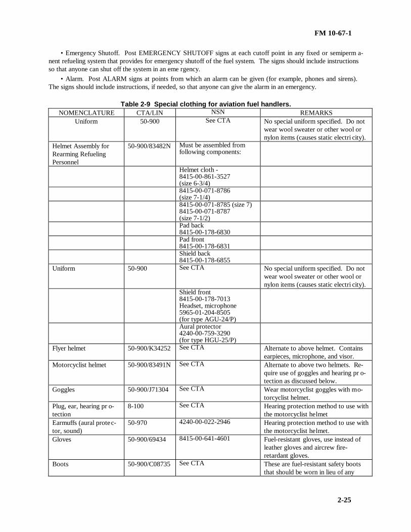
FM 10-67-1
2-25
• Emergency Shutoff. Post EMERGENCY SHUTOFF signs at each cutoff point in any fixed or semiperm a-nent refueling system that provides for emergency shutoff of the fuel system. The signs should include instructionsso that anyone can shut off the system in an eme rgency.
• Alarm. Post ALARM signs at points from which an alarm can be given (for example, phones and sirens).The signs should include instructions, if needed, so that anyone can give the alarm in an emergency.
Table 2-9 Special clothing for aviation fuel handlers.NOMENCLATURE CTA/LIN NSN REMARKS
Uniform 50-900 See CTA No special uniform specified. Do notwear wool sweater or other wool ornylon items (causes static electri city).
Helmet Assembly forRearming RefuelingPersonnel
50-900/83482N Must be assembled fromfollowing components:
Helmet cloth -8415-00-861-3527(size 6-3/4)8415-00-071-8786(size 7-1/4)8415-00-071-8785 (size 7)8415-00-071-8787(size 7-1/2)Pad back8415-00-178-6830Pad front8415-00-178-6831Shield back8415-00-178-6855
Uniform 50-900 See CTA No special uniform specified. Do notwear wool sweater or other wool ornylon items (causes static electri city).
Shield front8415-00-178-7013Headset, microphone5965-01-204-8505(for type AGU-24/P)Aural protector4240-00-759-3290(for type HGU-25/P)
Flyer helmet 50-900/K34252 See CTA Alternate to above helmet. Containsearpieces, microphone, and visor.
Motorcyclist helmet 50-900/83491N See CTA Alternate to above two helmets. Re-quire use of goggles and hearing pr o-tection as discussed below.
Goggles 50-900/J71304 See CTA Wear motorcyclist goggles with mo-torcyclist helmet.
Plug, ear, hearing pr o-tection
8-100 See CTA Hearing protection method to use withthe motorcyclist helmet
Earmuffs (aural protec-tor, sound)
50-970 4240-00-022-2946 Hearing protection method to use withthe motorcyclist helmet.
Gloves 50-900/69434 8415-00-641-4601 Fuel-resistant gloves, use instead ofleather gloves and aircrew fire-retardant gloves.
Boots 50-900/C08735 See CTA These are fuel-resistant safety bootsthat should be worn in lieu of any

FM 10-67-1
2-26
other type of boot.
Section IV. Health Hazards
PETROLEUM HEALTH HAZARDS
All petroleum products present health hazards. Fuel handlers cannot eliminate these hazards. However, theyshould understand them. They should also know the measures to reduce them to a minimum. The right healthprotection measures will allow fuel handlers to work with petroleum products with no ill effects. FM 21-11 givesmore information.
PETROLEUM HAZARD CLASSIFICATION
Petroleum health hazards are classified according to the type of petroleum contamination present. Petroleumcontaminant classifications are dust, gas or vapor, or liquid. Contaminants are further classified by their effect onthe body (their physiological effect). (Physiological effects affect the body’s organ, tissue, and cell function.)Contaminant classifications by physiological effects are toxic, anesthetic, or irritant. Petroleum inhaled into thelungs, ingested into the digestive system, or touching the skin causes these effects. Any given petroleum productcan be hazardous in more than one contaminant form. It can also produce a combination of physiological e ffects.
DUSTS
Dusts are solid particles of substances that result from mechanic. They come from operations such as grin d-ing, scraping, buffing, riveting, rivet cutting, or drilling. Dusts also come from handling dust-producing materials(as in sanding or sand-blasting). Evaporation or burning of liquids and residues containing finely divided su b-stances also cause dusts. Some dusts are hazardous because they are flammable. Dusts of all combustible su b-stances ignite or explode under certain conditions. Consider makeup and physical properties, length of exposure,and quantity when evaluating dust hazards. There are three types of dusts: toxic, fibrosis-producing, and nu isance.
• Toxic. Toxic dusts injure body organs and tissues when inhaled into the lungs. If ingested into the digestivesystem, they attack the body through the liver. Certain toxic dusts also irritate the skin. Lead, manganese, me r-cury, arsenic, and their compounds make toxic dusts. Cleaning and repairing tanks that contained leaded gasolineproduce one of the most toxic dusts fuel handlers will encounter. Lead dust and fumes also result from burningsludge from leaded gasoline. Lead’s toxic effects build up in the body. However, the body can resist lead poiso n-ing if it is given enough time between exposures. If it is not, each exposure adds to the effects of the one before it.Units should have their soldiers tested for lead period ically.
• Fibrosis-Producing. Fibrosis-producing dusts injure the lungs in such a way that normal tissue is replacedwith fibrous or scar tissue. The most common example is dust containing silica. It causes the disease called silic o-sis. People who run grinding or polishing machines or sanding and sandblasting equipment may be exposed tosuch dusts.
• Nuisance. These dusts may not cause severe injury, but they may cause inflammation and respiratory ai l-ments. Personal allergies may add to the effect of dusts.
GASES AND VAPOR
People often use the terms gas and vapor to mean the same thing. However, there is a difference. A gas existssolely as a gas at ordinary temperature and pressures. For example, oxygen is only present as a gas at the pressuresand temperatures normally found on the earth. The only way to make it into a liquid or solid is to place it underextremely high or extremely low temperatures. This involves hundreds of degrees below those normally found. Avapor is the gas form of a substance that is also a solid or liquid at ordinary temperatures and pressures. Petroleumfuels are liquid at normal pressures and temperatures, but it gives off small quantities of gaseous petroleum (petr o-leum vapor) Gases and vapors are divided into four groups depending on their effects on the body: poisons(toxic), asphyxiants, anesthetics, or irritants. A gas or vapor can have multiple effects on the body. These effectsare given below.
• Poisons. Poisonous or toxic gases and vapors have various effects on the body. They can injure or destroyorgans, the blood forming system, tissues, or bones. The most poisonous gases or vapors are hydrogen sulfide

FM 10-67-1
2-27
(found in crude oils with high sulfur content) and tetraethyllead vapors (found in leaded gasoline). Fuel handlersshould avoid concentrations of these potentially fatal vapors at all times. Other dangerous gases, listed in order oftoxicity, are: sulfur dioxide, ammonia, methyl bromide, butane, propane, and the various forms of freon. (Freon isoften used as a refrigerant.) The carbon dioxide in fire extinguishers is slightly toxic. Carbon tetrachloride, oftenused in various cleaning fluids and in some fire extinguishers, is toxic, and its effects build up in the body. It canalso decompose into another highly toxic gas, phosgene. For these reasons, carbon tetrachloride is no longer a p-proved for use in extinguishing fires. All vapors from flammable products are toxic to some degree.
• Asphyxiants. Simple asphyxiants are gases and vapors that keep the lungs from getting oxygen. In otherwords, they replace the oxygen that is in the air. Some asphyxiants are methane and its related hydrocarbons, h y-drogen and acetylene (used in welding and torch-cutting). Another dangerous, commonly encountered asphyxiantis carbon monoxide. Carbon monoxide is produced by running engines and any type of fire. Carbon monoxidechemically reacts with blood in such a way that the blood is unable to absorb enough oxygen to sustain the organsof the body. Carbon monoxide is tasteless and odorless. Victims gradually become extremely sleepy, and event u-ally pass out without realizing what is happening to them. The key to defeating asphyxiants is proper ventilationof areas where they are present.
• Anesthetics. Anesthetic gases and vapors have a narcotic effect that depresses the central nervous system tothe point where breathing failure occurs. All hydrocarbon vapors (which includes petroleum products) have thiseffect. The most narcotics are acetone, the ethers, benzene, naphthas, gasolines, and jet fuels. Other anestheticsare hydrocarbon derivatives that contain members of the chlorine family. Exposure to burning hydrocarbon vaporscan cause tremors of the heart ventricles. The narcotic effects of gasoline and jet fuel increase with their aromaticcontent.
• Irritants. Irritant gases and vapors inflame the lungs and respiratory tract. They may cause pneumonia andother pulmonary diseases or make the victim more susceptible to them. Most flammable gases and vapors irritantswhether they are poisonous, narcotic, or neither.
LIQUIDS
Flammable liquid products can cause internal medical problems if swallowed. Liquid petroleum is also easilyabsorbed through the skin, causing sim ilar problems. These effects are given below.
• Inside the Body. Flammable liquid products are harmful if they contact the skin in the mouth and potentiallyfatal if someone swallows them. If someone gets petroleum in their eyes and mouth, flush their eyes and mouththoroughly and repeatedly with water. They should get medical help at once.
• On the Skin. Flammable liquid petroleum also causes skin contamination. The seriousness of skin contam i-nation depends on the substance. The most serious effects result from contact with strong acids, alkalis, and rocketfuels. Effects from gasoline, jet fuel, and solvents are less serious, but still very harmful. Fuels, solvents, paints,lacquers, and varnishes dry up natural fats and oils on the skin. This leaves the skin harsh, dry, and chapped.This condition is known as dermatitis. These unnatural skin openings or lesions increase the chances of infection.If a soldier gets petroleum on his skin, he should wash it off at once with soap and water. If a soldier soaks hisclothes with fuel, he should wet them with water before taking them off. If no water is available, he should groundhimself by taking hold of a grounded piece of equipment. This step prevents sparking from static electricity.
FUMES AND MISTS
People often use the term “fume” to mean the same thing as gas or vapor. Fumes are actually small particlesin the air of solids that can turn directly from solids to vapors without becoming liquid first. This process is calledsublimation. Dry ice, iodine, and sulfur are some of the commonly found substances that do this. Lead compoundsfound in paint and leaded gasolines also form fumes. Fumes differ from dusts in that dusts cannot return to theirsolid form.

FM 10-67-1
3-1
CHAPTER 3
QUANTITY AND QUALITY CONTROL
Section I. Accountability and Inventory
PETROLEUM ACCOUNTING RECORDS AND REPORTS
Soldiers storing or transferring class III products must accurately account for receipt, issue, and stocks on handfor both bulk and packaged products. The biggest challenge in accounting for Class III products (particularly bulkproducts) is adequately measuring them. This section discusses petroleum accounting records and reports. It alsodiscusses petroleum measurement techniques. DA Pamphlet 710-2-1 or 710-2-2 (as appropriate) give detailed pr o-cedures for bulk petroleum accounting procedures. A discussion of accountability forms follows.
• Daily Status Report. Soldiers operating a Class III facility submit reports showing quantities of product r e-ceived, issued, and on hand. They submit this report at the times required by their higher headquarters. The r e-port is in the format required by higher headquarters. Although they usually submit this report once a day, co m-manders may adjust this fr equency to meet operational needs.
• DD Form 1348-1. Soldiers receiving petroleum into a Class III facility use DD Form 1348-1 (Figure 3-1,page 3-2) to record the receipt. They complete the receipt by verifying the types and amounts of product listed arecorrect. They then sign and date the form in block 7.
• DA Form 2765-1. Customers use DA Form 2765-1 (Figure 3-2, page 3-2) to request packaged and bulkproducts. They may also use it to turn in excess cans, drums, or supplies. Soldiers making an issue should writethe issue quantity on the form, initial, and date it. ULLS S4 automates this form.
• DA Form 3643. (Figure 3-3, page 3-3) This form is the basic accountability record for receipts and issues ata supply point. The vehicle operator or convoy commander signs the form to acknowledge product r eceipt.
• DA Form 3644. Soldiers doing accountability post summarized information from DA Form 3643 to DAForm 3644 (Figure 3-4, page 3-4) to show total monthly issues and receipts. Soldiers at the supply point or theirnext higher headquarters may prepare this report. If soldiers at the supply point prepare the report, they must sendit to the responsible centralized stock accounting section for accounting record a djustment.
• DA Form 4702-R. Units use DA Form 4702-R (Figure 3-5, page 3-4) to report all losses or gains revealedby monthly inventories. They may locally reproduce this form on 8 ½- by 10-inch paper. Inventory losses r e-flected on this form that exceed those allowed by DA Pamphlet 710-2-2 or that are disapproved by the approvingauthority are cause for initiating a report of survey. Gains in excess of the allowable limit must be investigated todetermine the cause. A copy of the investigation report must be attached to DA Form 4702-R as a supportingdocument.
• DA Form 2064. Personnel operating Class III storage facilities must establish a stock record card or pro p-erty record for each type or grade of product. They use DA Form (Figure 3-6, page 3-5) to post accountable rec-ords.
• Stock/Property Records. Keep day-by-day stock/property records to show where and how much of eachproduct is on hand at a storage facility. Two different forms can be used for this purpose: DA Form 1296 (Figure3-7, page 3-5) and DA Form 3-8 (Figures 3-8, page 3-6).
• DA Form 3853-1. This form is used to record physical inventories of bulk fuel. The use of this form is givenin DA Pamphlet 710-2-1 and 710-2-2.

FM 10-67-1
3-2
Figure 3-1. DD Form 1348-1 (DOD Single Item release/Receipt Document)
Figure 3-2. DA Form 2765-1 (Request for Issue or Turn-In)
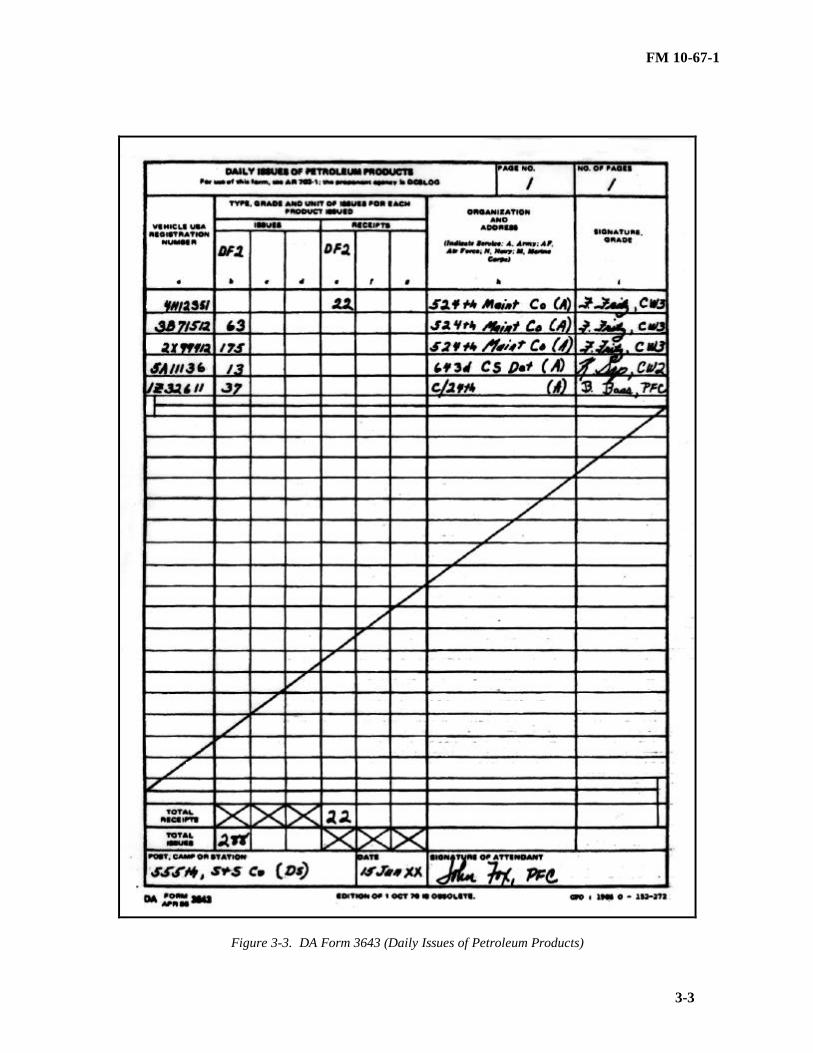
FM 10-67-1
3-3
Figure 3-3. DA Form 3643 (Daily Issues of Petroleum Products)

FM 10-67-1
3-4
Figure 3-4. DA Form 3644 (Monthly Abstract of Issues of Petroleum Products and Operating Supplies)
Figure 3-5. DA Form 4702-R (Monthly Bulk Petroleum Accounting Summary)

FM 10-67-1
3-5
Figure 3-6. DA Form 2064 (Document Register for Supply Actions)
Figure 3-7. DA Form 1296 ( Stock Accounting Record)

FM 10-67-1
3-6
Figure 3-8. DA Form 3328 (Property Record)
Petroleum Products Inventory
Specific procedures are used to inventory petroleum products. These procedures are given below.
• Packaged Petroleum Products. Inventory all packaged petroleum products at least once a year according toprocedures in AR 735-5. Adjust any inventory discrepancies according to AR 735-11.
• Bulk Products. Inventory all bulk petroleum products as of 0800 on the last day of the month. Post it withinthree working days according to DA Pamphlet 710-2-1. Use DA Form 4702-R to record the inventory. Followthese steps to record the inventory.
••Enter the opening inventory on the accounting summary. The opening inventory is the total amount ofbulk petroleum on hand at the beginning of the month. Record physical inventories on DA Form 3853-1 (use theremarks block for petroleum tank vehicles).
••On the next two lines, enter a summary of all monthly receipts and issues of bulk petroleum given on DAForm 3644.
••Enter the closing inventory to the summary. Estimate the closing inventory for collapsible tanks by su b-tracting i ssue totals from receipt totals.

FM 10-67-1
3-7
••Record the monthly loss on the summary. Calculate the monthly loss by subtracting the closing inventoryfrom the closing book balance.
••Enter the maximum allowable loss on the form. Determine the maximum allowable loss by adding theopening inventory to the receipts. Then multiply this figure by .01 for motor gasolines, aviation gasolines, andturbine fuels (except JP-8), and .005 for all other fuels (including JP-8).
••If the monthly loss is greater than the maximum allowable loss and the dollar value is greater than $500,prepare a DA Form 4697 according to AR 710-2.
Section II Petroleum Product Measurement
BULK PETROLEUM PRODUCT MEASUREMENT
Bulk petroleum products are measured in two steps. These steps are given below.
• The first step is to gage the product. Gaging consists of measuring the bottom sediment and water and thetemperature and height of the product. The height of product in a storage tank can be determined by measuringinnage or outage (ullage). Innage is the depth of the product from its surface to the tank bottom or datum plate.Outage (ullage) is the height of space above the liquid from a reference point on the tank to the surface of theproduct. Gaging is used to determine the amount of product on hand and the amount of water in storage tanks.Also, it is used to detect leaks or unauthorized withdrawals and to d etermine tank ullages for receiving shipments.
• The second step is to calculate the net quantity of the product at 60°F. This step is needed because pe-troleum volume varies with temperature. The standard temperature on which to base accountability measurementis 60°. AR 710-2 gives gaging and volume correction policies.
MEASURING EQUIPMENT
Special equipment is needed to measure bulk petroleum. Innage and outage, are the two basic ways of mea s-uring bulk petroleum. Innage is the depth of the product from its surface to the tank bottom or datum plate. Ou t-age (also called ullage) is the height of space above the liquid from a reference point on the tank to the surface ofthe product. This equipment is given below.
Tape and Bob
The two types of tape and bob are innage and outage. They are used to measure petroleum in fixed storagetanks. Both are graduated on one side to 1/8-inch divisions. Figure 3-9, 3-8, shows an innage tape and bob. Thetip of the bob is the zero point of the tape and bob. Figure 3-10, page 3-9, shows an outage tape and bob. The zeropoint is the point of contact between the snap and the eye of the bob.
Petroleum Gage Stick
A petroleum gage stick is used to determine the innage of a tank vehicle or a nonpressurized tank car. Thestick is graduated in 1/8-inch divisions from the bottom upward. The bottom of the stick usually has a hard metaltip. The gage stick should be long enough to gage the entire height of a tank. When using the stick, make sure tolower it vertically into the tank as shown in Figure 3-11, page 3-9, step A. Make sure it does not rest on a rivethead or other object within the tank. When lowering the stick, be do not splash the product and cause an inacc u-rate cut.
Tank Vehicle Gage Stick
Each tank vehicle has its own gage stick which is graduated in 25-gallon divisions. The only difference in usebetween this stick and the petroleum gage stick is that the product cut is recorded in gallons. Estimate as closely aspossible the indicated volume when the cut mark falls between divisions. The 5,000-gallon tank semitrailers havegage sticks marked at the top to show which scale to use for each tank compartment.

FM 10-67-1
3-8
Yardstick
A yardstick, along with the graph shown in Figure 3-11, page 3-9, step B, can be used as a field expedient todetermine the approximate number of gallons in a 55-gallon drum. To do this, place the drum in a vertical pos i-tion. Lower the yardstick into the drum to get a wet-inch-depth reading. Then use the line on the graph to get theapproximate number of gallons at 60°F.
Figure 3-9. Innage tape and bob

FM 10-67-1
3-9
Figure 3-10. Outage tape and bob

FM 10-67-1
3-10
Figure 3-11. Petroleum gage stick and yardstick
Tank Car Gage Stick
Use the tank car gage stick to determine dome innage and shell outage in nonpressurized rail tank cars thathave shell outages of 1 foot or less. If the tank car has more than 1 foot of shell outage, use a petroleum gage stickor an innage tape and bob. The tank car gage stick is made of hardwood or similar material. It is 36 inches long.The stick (Figure 3-12) has two scales, with a common zero mark 12 inches from the lower end, graduated upwardand downward in 1/8-inch divisions. A brass angle is used to position the gage stick. The angle is attached at thezero mark on the gage stick. Use the gage stick as given below.
• Taking the gage. Insert the gage stick, with the short end down, through the dome hatch into the tank car sothat the angle rests on the tank shell at the gaging point (Figure 3-13, page 3-11). The gaging point should be thehighest point of the tank car shell on a line with the lengthwise center of the car. Find where the shell platesoverlap along the centerline of the tank. Select a gaging point on the interior of the tank. If the product level is inthe dome and the gaging stick is not visible, it may be necessary to probe with the end of the stick to find it. Makesure the angle does not rest on a rivet head and that the stick is vertical.
• Recording the gage. Take the stick out. Read the product cut on the scale to the nearest 1/8 inch. If the cutis below the zero mark, record it as the dome innage. Get at least two readings that are the same to make sure thatthe gage is accurate.
Figure 3-12. Tank car gage stick

FM 10-67-1
3-11
Figure 3-13. Using the tank car gage stick to determine dome innage and shell outage
Portable Petroleum Sampling and Gaging Kit
The portable petroleum sampling and gaging kit (Figure 3-14, page 3-12) is used at bulk storage facilities. Itis used to gage tanks and to measure product temperature. Also, it is used to detect bottom sediment and water, tomake volume calculations, and to sample fuels. The kit is referenced in SC 6680-90-CL-N01. It weighs 22pounds. The kit consists of an aluminum carrying case fitted with measuring and sampling equipment. The majorparts of the kit are listed below.
• Olive drab, aluminum carrying case
• Cup-case thermometer, 0° to 180°F range
• Innage tape and bob
• Hydrometers, ranging from 19° to 81° API gravity
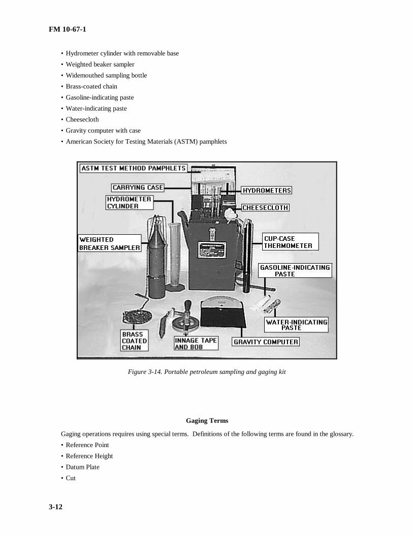
FM 10-67-1
3-12
• Hydrometer cylinder with removable base
• Weighted beaker sampler
• Widemouthed sampling bottle
• Brass-coated chain
• Gasoline-indicating paste
• Water-indicating paste
• Cheesecloth
• Gravity computer with case
• American Society for Testing Materials (ASTM) pamphlets
Figure 3-14. Portable petroleum sampling and gaging kit
Gaging Terms
Gaging operations requires using special terms. Definitions of the following terms are found in the glossary.
• Reference Point
• Reference Height
• Datum Plate
• Cut

FM 10-67-1
3-13
• Opening Gage
• Closing Gage
• Total Measured Quantity
• Bottom Sediment and Water
• Net Quantity of Product
• Delivered Quantity at 60°F
• API Gravity
Degrees API = (141.5/(API @ 60°F / 60°F)) –131.5
GAGING PROCEDURES
All petroleum storage containers must be gaged IAW AR 710-2. General safety gaging procedures are givenbelow.
General Precautions and Procedures
Follow these precautions and procedures during any gaging operation:
• Never conduct gaging operations in an electrical storm.
• Ensure soldiers doing the gaging check to see that the tank vehicles and tanks being gaged are properlybonded and grounded. Before starting gaging operations, they should ground themselves by touching their barehands to the tank shell being gaged.
• Ensure supervisors do a safety risk assessment on whether soldiers should wear field gear during gaging o p-erations. Although field gear can fall off and contaminate fuel and possibly create static electricity discharges,these factors should be balanced against the facts that a soldier could be severely injured from falling off tank veh i-cles or possibly injured due to the tactical situation (sniper fire, riots during contingency operations). In forwardareas on tank vehicles, soldiers should wear full field gear, since the danger from related injuries is high and e x-plosion and contamination dangers are relatively low. For operations on large fixed tanks in rear or garrison areas,soldiers should remove all loose uniform and field gear items that may potentially fall into the tank, since injuryrisks are relatively low, but the results of a static electricity discharge or fuel contamination are large.
• Open all hatches from the upwind side to allow the wind to blow vapors away from the gager. Avoidbreathing vapors and fumes. Never allow soldiers to conduct gaging operations or any other petroleum operationalone. Train soldiers to recognize the symptoms of excess vapor inhalation and the steps to take if someone isovercome with petroleum vapors.
• Stand on the gaging platform, if the tank has one. Avoid standing on the roof.
• Keep the tape in a tape and bob against the rim of the gaging hatch at all times to avoid buildup of staticelectricity. Wipe the tape clean and dry after each use.
• Gage all incoming bulk deliveries for water bottoms before the products are received. Drain off any waterfound in tank cars or tank vehicles before discharging the product.
• Allow as much time as possible for water, solids, and bubbles to settle before gaging after adding fresh stockto a fixed storage tank. If time permits, allow a two-hour settling time for all aviation, automotive, and diesel f u-els. In ship-to-shore discharge, tanks may be gaged after product has settled for 30 minutes. Then the final di s-charge report can be completed before the vessel sails. Let heavy products, such as burner fuels, settle for at least24 hours.
• Take readings to the nearest 1/8 inch on measuring devices calibrated in inches. Repeat gaging until tworeadings match. If possible, use two gagers to take alternate readings.
• Take the product temperature immediately before or after gaging so that the volume can be corrected to60°F. Quantities of product are volume corrected according to AR 710-2.

FM 10-67-1
3-14
Gaging Tankers and Rail Tank Cars
Gage tankers and rail tank cars with specific measuring devices as described in the paragraph above. Tomeasure bottom sediment and water, do the following:
• Apply a thin, even coat of water-indicating paste to the portion of the gage stick that will be at the interfaceof water and product. Do not apply an excessive amount of paste. This increases the time it takes for the water toreact with the paste. It may also cause inaccurate readings.
• Leave the gage stick in position for 5 to 10 seconds for MOGAS, kerosene, and similar light products and 15to 30 seconds for heavier products. When gaging a vehicle containing a heavy viscous product, apply a thin, evenfilm of light lubricating oil over the water-indicating paste and leave the gage stick in position for at least 60 se c-onds.
• Take the gage stick from the tank, and look at the water cut on the scale. The water should either remove ordiscolor the paste on the portion of the scale that was in the water. Record the water cut as either water innage oroutage.
Gaging Storage Tanks Using Tapes And Bobs
Use innage and outage tape bobs to measure petroleum tanks. They are usually used for large, fixed storagetanks. Procedures for their use follows.
• Innage gage. Review the last innage gage sheet posted to determine expected product level before gaging atank. To get an innage gage using the innage tape and bob, refer to Figure 3-15, page 3-15, and follow the stepsbelow:
••Place product-indicating paste on the tape where product cut is expected. Place the unmarked side of thetape against the metal rim of the gaging hatch reference point.
••Lower the tape and bob into the tank until the bob is a short distance from the bottom. To determine this,compare the length of the unwound tape with the reference height of the tank.
••Unwind the tape slowly until the tip of the bob touches the tank bottom or datum plate. Make sure the bobdoes not rest on a rivet or other obstruction. Make sure the tape is not lowered so far into the tank that the bob tiltsand causes an incorrect gage. To ensure accurate gage, compare the tape reading at the reference point with thereference height of the tank.
••Withdraw the tape quickly, and observe the product cut. Record the cut as the innage gage. If the cut ishard to read, put product-indicating paste on the tape. (Grease or light lubricating oil may be used instead of thepaste.) Gage the tank again. It is usually easier to see the product cut on the back of the tape.
••Get two identical readings to make sure the measurement is correct. When taking opening and closinggages, use the same gaging equipment and hatches for both gages. Make sure the tape is lowered to the samedepth for both gages.

FM 10-67-1
3-15
Figure 3-15. Taking an innage reading using an innage tape and bob
• Outage gage using innage tape and bob. To get an outage gage or ullage using the innage tape, and bob, r e-fer to Figure 3-16, page 3-16, and follow the steps below.
•• Place the unmarked side of the tape against the metal rim of the gaging hatch at the reference point.
•• Lower the tape and bob into the tank until the bob touches the surface of the product.
•• Wait until the bob stops moving. Lower the tape slowly until the bottom of the bob is 2 to 3 inches belowthe surface of the product. Record the reading on the tape at the reference point as the tape reading.
•• Withdraw the tape quickly, and record the product cut on the bob as the bob reading. It is the cut is hardto read, put product-indicating paste on the bob and gage the tank again.
•• To get the outage gage, subtract the bob reading from the tape reading. For example, if the tape reading is6 feet 4 inches and the bob reading is 2¼ inches, the outage gages is 6 feet 1¾ inches.
•• To convert the outage gage to innage gage, subtract the outage gage from the reference height of the tank.

FM 10-67-1
3-16
Figure 3-16. Taking an outage reading using an innage tape and bob
• Outage tape and bob use. To get an outage gage or ullage using an outage tape and bob, refer to Figure 3-17,page 3-17, and follow the steps below.
•• Hold the unmarked side of the tape against the metal rim of the gaging hatch at the reference point.
•• Lower the tape and bob into the tank until the bob touches the surface of the product.
•• Wait until the bob stops moving. Lower the tape slowly until the bottom of the bob is 2 to 3 inches belowthe surface of the product. Record the reading on the tape at the reference point as the tape reading.
•• Withdraw the tape quickly, and record the product cut on the bob as the bob reading. If the product cut ishard to read, put product-indicating paste on the bob and gage the tank again.
•• Add the bob reading to the tape reading to get the outage gage.

FM 10-67-1
3-17
•• Subtract the outage gage from the reference height of the tank to convert outage gage to innage gage.
Figure 3-17. Taking an outage reading using an outage tape and bob
• Bottom sediment and water. Measure for bottom sediment and water each time storage tanks containing li q-uid petroleum products are gaged. This is necessary to find the actual product amount present in the tank. Bottomsediment and water often accumulate in different parts of a tank bottom. They usually accumulate on the side o p-posite a filling line or on either side of an outlet. When the tank has several hatches, take gages from each hatch.Average the gages to get one bottom sediment and water gage for the entire tank. Measure the height of bottomsediment and water by doing the following:
•• Use water-indicating paste to determine the water cut (Figure 3-18, page 3-18). Put a thin, even coat ofpaste on the part of the bob that will be at the point where water and product meet. Be careful not to put so muchpaste on the bob that it will cause a false reading. If the depth of the water is greater than the length of the innagebob, use a water gage bar (Figure 3-19, page 3-19) to measure the water in the tank.
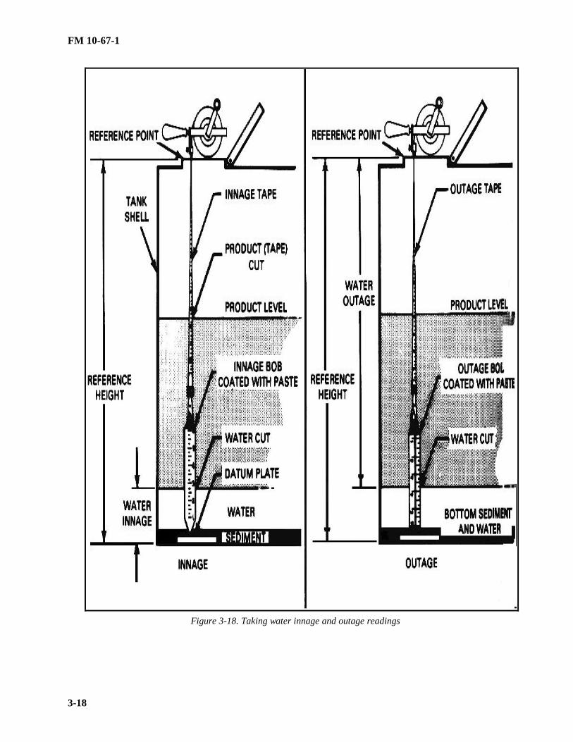
FM 10-67-1
3-18
Figure 3-18. Taking water innage and outage readings

FM 10-67-1
3-19
Figure 3-19. Typical water gage bars
•• Hold the side of the tape against the metal rim of the gaging hatch at the reference point.
•• Lower the tape and bob into the tank until the bob is a short distance from the bottom. Determine this bycomparing the length of the unwound tape with the reference height of the tank.
•• Unwind the tape slowly until the tip of the bob touches the tank bottom or datum plate. Make sure the bobdoes not rest on a rivet or other obstruction. Make sure the tape is not lowered so far into the tank that the bob willtilt and cause an incorrect reading.
•• Keep the tape and bob in the gaging position 5 to 10 seconds for kerosene, gasoline, and other light pro d-ucts. Keep it in position for 15 to 30 seconds for heavier products.
•• Remove the tape and bob from the tank. There should be no paste left on the portion of the bob that was inthe water or the paste should be discolored. Record the water cut as a water innage or outage.
TEMPERATURE MEASUREMENT
During gaging operations, take product temperature. This is necessary to correct the measured quantity toquantity at the standard temperature of 60°F. Volume-correct quantities IAW AR 710-2. When gaging largeamounts of product, take several temperature readings at various depths. An average of these readings gives the

FM 10-67-1
3-20
true product temperature. Table 3-1 gives the minimum number of temperature readings and the measurementlevels for various product depths. As a rule, the cup-case thermometer is used to measure temperature. Table 3-2shows minimum immersion times for the cup-case thermometer in various petroleum products. Temperaturemeasuring procedures are as follows:
• Examine the mercury column of each cup-case thermometer for separations. Replace the thermometer if thecolumn is faulty. Mercury separations cause incorrect readings.
• Inspect the thermometers for accuracy. Expose them, as a group, to the same atmospheric temperature.Compare the readings. Replace any thermometer with a reading that differs from the group by 1°F or more. E n-sure that all tank the rmometers are proved against a reference standard annually.
• Use Table 3-1 to determine the minimum number of readings and the measurement levels required for theoperation. If extreme differences in temperature are suspected, take more readings. Do this to find the true ave r-age temperature of the product.
• Attach the thermometer to the end of a gage tape, brass-coated chain, or cord. If a cord is used, tie knots inthe cord so that they will show when the thermometer reaches the required level.
• Lower the thermometer to the required level. Leave it there at least as long as shown in Table 3-2.
• Take the thermometer out of the tank, and read it at once. Shelter the cup below the hatch to reduce tem-perature changes caused by wind or atmosphere. Withdraw a full cup of product from the tank when taking thereading. Try not to spill it. Record the temperature to the nearest degree Fahrenheit.
• Add all the readings together when measurements are taken at more than one level. Divide this sum by thenumber of readings taken to get the true average temperature of the product.
Table 3-1. Petroleum product temperature measurements.
DEPTH OF PRODUCT
MINIMUM NUMBER OFTEMPERATURE
MEASUREMENTS MEASUREMENT LEVELSMore than 15 feet 3 3 feet below top surface of product
Middle of product3 feet above bottom.
10 to 15 feet 3 3 feet below top surface of product,3 feet above bottom.
Less than 10 feet 1 Middle of Product
Table 3-2. Minimum immersion times for the cup-case thermometer.
PRODUCTTIME
(MINUTES)Automotive gasoline (MOGAS), aviation gasoline
(AVGAS), kerosene, diesel fuel, jet fuel, and grades1 and 2 burner fuel oil 5
Grades 4, 5, 6, and Navy Special burner fuel oil.
15
NOTE: This conforms to Table IV, Minimum Immersion Time for Cup-Case Assembly, API Standard2543, ASTM Designation D 1086. Product listings are not comprehensive

FM 10-67-1
3-21
VOLUME CALCULATIONS
Do volume calculations according to AR 710-2. Capacity tables showing quantities of either innage or outagegages should be based on accurate tank calibration data. The calibration charts should be checked periodically.Also, they should be checked when repairs and modifications are made to the tank. The following paragraphs di s-cuss volume calculations for liquid petroleum products.
• Total Measured Quantity. From the tank capacity table, find the total measured quantity corresponding tothe product gage. If the tank capacity table is an outage table and an innage gage has been obtained, convert theinnage to outage gage. To do this, subtract the innage gage from the reference height. To convert outage gage toinnage gage, subtract the outage gage from the reference height. If using a gage stick calibrated in gallons, dete r-mine total measured quantity directly as according to paragraph on Mea suring Equipment.
• Bottom Sediment and Water. Find the amount of bottom sediment and water corresponding to the watergage from the tank capacity table or from the water cut on gage stick. Subtract this from the total measured qua n-tity to get the net quantity of product, uncorrected.
• API Gravity. Measure the API gravity with the correct hydrometer listed in Table 3-3. This hydrometergives both the API gravity reading and the observed temperature reading of the sample. The observed gravityreading must be converted to API gravity at 60°F using the tables prescribed in AR 710-2-1.
• Volume Correction Factor. Use the volume correction factor to correct fuel volume observed at temperaturesother than 60°F. Do this after getting the API gravity reading at 60°F and the average temperature of product inthe tank. Do volume corrections according to DA Pamphlet 710-2-1. Use the columns in the appropriate table thatcorrespond to the temperatures of the product in the tank and the API gravity recorded on the gage sheet to get thefactor. Enter this factor as the multiplier on the gage sheet. Appendix I gives more detailed procedures for co m-puting volume correction factors.
• Net Quantity of Product. To determine the net quantity of product, multiply the total measured quantity bythe proper volume correction factor. The total measured quantity must be corrected for bottom sediment and water.
• Storage Tank Gage Report. Record gaging information on DA Form 3853-1 (Figure 3-20, page 3-22), DAForm 3853-2, (Figure 3-21, page 3-23) or DA Form 3853-3 (Figure 3-22, page 3-24). Tabulate the information onthese forms every 24 hours to keep an inventory of bulk petroleum products.
Table 3-3. List of equipment required to make volume corrections.NSN ITEM
6630-00-265-7610 Hydrometer, graduated scale, API 9 to 21 range190mm long, 14mm diameter, with thermometer
6630-00-265-7611 Hydrometer, graduated scale, API 19 to 31 range,190mm long, 14mm diameter, with thermometer
6630-00-265-7758 Hydrometer, graduated scale, API 29 to 41 range190mm long, 14mm diameter, with thermometer
6630-00-265-7759 Hydrometer, graduated scale, API 39 to 51 range190mm long, 14mm diameter, with thermometer
6630-00-265-7764 Hydrometer, graduated scale, API 49 to 61 range190mm long, 14mm diameter, with thermometer
6630-00-265-7765 Hydrometer, graduated scale, API 59 to 71 range190mm long, 1 mm diameter, with thermometer
6630-00-815-2267 Hydrometer, graduated scale, API 69 to 81 range190mm long, 14 mm diameter, with diameter
6640-01-020-8801 Cylinder, ungraduated, 300mm high, 28.6 mm
6685-00-239-4937 Cup-case thermometer
6685-00-247-3739 Replacement thermometer

FM 10-67-1
3-22
6850-00-001-4194 Water-indicating paste.
6850-00-270-5526 Fuel-indicating paste
Figure 3-20. DA Form 3853-1 (Innage gage sheet (Using innage tape and bob))

FM 10-67-1
3-23
Figure 3-21. DA FORM 3853-2 (Outage gage sheet (Using innage tape and bob))

FM 10-67-1
3-24

FM 10-67-1
3-25
Figure 3-22. DA Form 3853-3 (Outage gage sheet (Using outage tape and bob))

FM 10-67-1
3-26
Section III. Sampling
TYPES OF SAMPLES
Samples are important because they are used to determine the quality of petroleum products. A sample is asmall amount of petroleum which is representative of the whole product. The sample types are given below.
• Top. A top sample is taken with a bottle or beaker sampler about 6 inches below the product su rface.
• Upper. An upper sample is taken with a bottle or beaker sampler from the middle of the top third of theproduct.
• Middle. A middle sample is taken with a bottle or beaker sampler from the middle of the product.
• Lower. A lower sample is taken with a bottle or beaker sampler from the middle of the bottom third of theproduct.
• Bottom. A bottom sample is taken with a Bacon bomb thief sampler from material or product on the bottomof the tank.
• All-Levels. An all-levels sample is taken by submerging a closed bottle or beaker sampler as close as poss i-ble to the bottom of a tank or container. The sampler is then opened and raised at a uniform rate so that it is 75 to85 percent full when it comes out of the liquid.
• Spot. A spot sample is taken at a specific place in the tank.
• Composite. A composite sample combines individual samples that represent the bulk from which they weretaken. The samples can be a single-tank or a multiple-tank composite sample.
• Single-Tank Composite. A single-tank composite sample is a blend of the upper, middle, and lower samplesof the contents of a tank. The blend has equal parts of the three samples from a tank with uniform cross sections.An upright cylindrical tank has uniform cross sections. The blend from a horizontal cylindrical tank consists ofproportions of the three samples as shown in Table 3-4
• Multiple-Tank Composite. A multiple-tank composite sample is a blend of single, all-levels samples takenfrom tanker or barge compartments that contain the same product. The sample consists of parts in proportion tothe volume of product in each compartment sampled.
• Outlet. An outlet sample is taken with a bottle or beaker sampler at the level of a tank outlet, whether fixedor swing line.
• Drain. A drain sample is taken from the drawoff or discharge valve.• Continuous. A continuous sample is one taken from a pipeline when the product is allowed to collect slowly
in a sampler during the entire flow time. It represents the stream of product during the period of sampling.
Table 3-4. Sampling instructions for horizontal cylindrical tanks.LIQUIDDEPTH,PERCENT OFDIAMETER
SAMPLING LEVELPERCENT OF DIAMETER ABOVE BOTTOM
COMPOSITE SAMPLE,PROPORTIONATE PARTS OF
UPPER MIDDLE LOWER UPPER MIDDLE LOWER100 90 80 70 60 50 40 30 20 10
807570
505050505040
202020202020201510 5
332
445654
33345610101010

FM 10-67-1
3-27
TYPES OF SAMPLERSThere are several different types of samplers used to take liquid petroleum samples. These are given below.• Weighted Beaker. The weighted beaker sampler (Figure 3-23) is a copper bottle permanently attached to a
lead base. A drop cord or brass-coated chain is connected to the stopper so that the sampler can be opened an y-where beneath the surface of the product. This sampler is used to take upper, middle, lower, or all-levels samplesof petroleum products at no more than 16 PSI Reid vapor pressure. It is used to take samples from tank cars, tankvehicles, barges, ship tanks, and shore storage tanks.
• .The Bacon bomb thief may be modified as shown in (Figure 3-24, page 3-27) to speed up operations, saveproduct, and reduce health ha zards.
• Tubular Tank Thief (Tulsa Thief). The tubular tank thief or Tulsa thief (Figure 3-25, page 3-27) is a bottomsampler. It is best suited for taking heavy bottom samples in storage tanks. A chain is used to open the sampler atany depth in the tank.
• Weighted Bottle Plug. The weighted bottle plug sampler (Figure 3-26, page 3-28) is a glass bottle seated inand tied to a metal holder. This sampler is used in the same way as the weighted beaker sampler.
Figure 3-23. Weighted beaker sampler

FM 10-67-1
3-28
Figure 3-24. Bacon bomb thief sampler
Figure 3-25. Tubular tank thief

FM 10-67-1
3-29
Figure 3-26. Weighted bottle plug sampler
SAMPLE SIZE
Sample size varies with product type and the type of test required. As a rule, liquid samples should be 1 gallonand semisolid samples should be 5 pounds. Special samples and samples for testing by the supercharge methodshould be at least 5 gallons, unless otherwise specified. A 5-gallon sample should be submitted when jet fuels aretested for thermal stability.
PROCEDURES AND PRECAUTIONS
ASTM Method D 4057 has specific information on standard sampling procedures. When taking samples,follow the procedures in the ASTM manual and the precautions listed below:
• Make sure all sampling equipment and containers are clean, dry, and free of lint and fibrous mat erial.
• Rinse samplers and containers with a portion of the product being sampled. This is to make sure the productis not contaminated with a previous material. Rinse all cans to remove any soldering flux.
• Clean samplers immediately after use. Store them in a place where they will stay clean until they are usedagain.
• Before taking a continuous sample, draw enough product through the sample connection to displace all theproduct in the sample lines and fittings.
• Do not take samples through storage tank cleanout lines, water drawoffs, bleeder valves, or hoses. Thesesamples are not representative of the product in the tank.
• If a service station tank does not have a manhole or sampling hatch, take the sample from the service hoseafter discharging a volume of product about two times the capacity of the hose.
• Do not fill any sample container above 90 percent of its capacity. If the container is filled to capacity, it mayleak because of thermal expansion of the product.
• Tightly close all sample containers immediately after they are filled. Do no use sealing wax, paraffin, rubbergaskets, pressure-sensitive tape, or similar material to seal containers. Crate light sample containers well so thatthey will withstand shipment.

FM 10-67-1
3-30
• Put gasoline, jet fuel, and kerosene samples in clean, dry cans or brown bottles to protect them from directsunlight.
• Carefully handle all samples of gasoline and jet fuel that require vapor pressure tests. Cool these samples, ifpossible, to prevent the loss of light ends and volatile materials. Try to keep all liquid fuel samples at a temper a-ture between 32° and 42°F to help preserve product characteristics.
• Collect aviation fuel samples in glass bottles if they are to be submitted for water and sediment tests to a l o-cal laboratory. Put the samples in brown glass bottles or clear gas bottles with covers. Such bottles prevent colordye precipitation which is caused by exposure to sunlight. Submit 1-gallon DOT-approved metal sample contai n-ers for gasoline or aviation fuels which will be shipped by a military or commercial activity. Use only samplecontainers that have been rinsed with petroleum ether for sediment tests. Rinse sample containers with the productto be sampled prior to taking the actual sa mple.
SAMPLE IDENTIFICATION
Each petroleum sample shipped to a petroleum laboratory for analysis must have a completed sample tag s e-curely attached. The tag is DA Form 1804 (Figure 3-27, page 3-32). Also, an informal record log must be mai n-tained for all samples sent to the petroleum laboratory. When the sample is from a packaged product, all markingson the container should be copied on the sample tag. Samples of liquid packaged petroleum lubricants in contai n-ers of less than 5 gallons should be sent to the laboratory in the original containers. The same applies to semisolidsin containers of less than 35 pounds. Entries on the sample tag should be typewritten or in pencil. Do not use inkbecause ink will run if fuel is spilled on the tag.
QUALITY SURVEILLANCE CONSIDERATIONS
A fuel must be laboratory tested before and after government acceptance to make sure that it meets specific a-tions. It must be clean and dry. A fuel is clean when it is free of suspended matter, sediment, and emulsions. Afuel is dry when it contains no undissolved water. A clean, dry fuel has a bright appearance, without cloud, haze,or visible solids.
TITLE SAMPLE LOG
A sample log should be maintained to track quality surveillance for storage tanks, facilities, refueling systemsand vehicles, and bulk deliveries. The sample log should contain: date sampled; name of person taking the sa m-ple; sample source; type of sample; date sample results are received; results; and a remarks block.
CONTAMINATION TYPES
Contamination may consist of solid foreign matter, free or emulsified water, mixed fuels or grades of fuel, orall of these. The types of contamination are given below.
• Foreign Matter. Foreign matter can enter fuel from a number of sources such as tanks, pipes, hoses andpumps, and also from people. The foreign matter found most often consists of bits of rust, paint, metal, rubber,lint, dust, and sand. Rust is probably the most common of these. Sediment is the general term applied to solidcontaminants.
• Water. Water is one of the most common contaminants. It can get into fuel through leaks and condensation.Dissolved water in fuel is like vaporized moisture in the air. Fresh or salt water may be present in small dropletsthat produce a cloud effect, in larger droplets that cling to the sides of containers, in very large amounts that settleto the bottom in a separate layer, or in emulsions. Emulsions usually occur when fuel droplets become suspendedin water. This may happen when fuel is agitated in the presence of water, as when it passes through a pump. Theheavier the fuel, the longer the emu lsion may last.

FM 10-67-1
3-31
• Mixed Fuels Or Grades. Mixed fuels or grades of fuels can be as serious as any other form of contamination.Different kinds of fuel must be stored in separate tanks and pumped one at a time so that fuels will not mix inlines, filter/separators, pumps, and refuelers. Be sure to mark all systems (fixed and mobile) to show what type offuel each is handling at the time. Mixed fuels or grades are hard to detect without testing. Only people with agreat deal of experience notice the slight changes in color or odor.
FIELD TESTS FOR CONTAMINATION
There are several ways to check for product contamination in the field. Product temperature and gravity, vi s-ual checks, particulate contamination by color and the Aqua Glo test all provide clues to product contamination.These tests are given below.
• Temperature and Gravity. When a shipment arrives at a Class III facility, take the temperature and APIgravity of the product. Determine the API gravity of the product. Gravity indicates uniformity of fuel more reli a-bly than its quality. If the API gravity is out of range of that of the expected product, or if the difference at thesame temperature is greater than 1/2 degree, do not unload the product until it is laboratory tested, as it may becontaminated.
• Visual Checks. Look at the product carefully each time a transporter is loaded or unloaded. Proper color ina fuel indicates freshness and uniformity but not quality. When the color is off, it does not necessarily mean theproduct is off specification. However, it may show contamination or deterioration that may merit further investig a-tion. If the fuel is cloudy or hazy, it probably contains undissolved water.
• Particulate Contamination. Particulate contamination may be determined using the color method in a fieldenvironment. Samples are checked against a color standard to determine if a product is suitable for use. Thismethod does not replace requirement to have active filter/separators checked every 30 days by a laboratory.
• Aqua-Glo. The Aqua-Glow measures water in PPM. Tests results in excess of 10 PPM indicate aviationfuel is not suitable for Army or Air Force use. Aviation fuel used in Navy and Marine Corps equipment may notexceed 5 PPM.
LABORATORY TESTS
Laboratory tests ensure fuels meet specifications, identify unknown products, detect contamination, verify u n-favorable field tests, and provide the basis for disposition of unacceptable fuel. Laboratory tests include, but are notlimited to, distillation, gravity, corrosion, water tolerance, particulate matter, freeze point, vapor pressure, gumcontent, tetraethyl lead, and sulfur. Fuel must be tested by a laboratory when--
• Requested by petroleum offices.
• The quality of fuel is questioned or it cannot be classified.
• A filter/separator is first placed in service after the filter elements have been changed and every month afterthat.
• Aviation gasoline or jet fuel has been in above ground storage for 30 days, without addition of fresh stocks,in climates where the temperature is 90°F or higher, and when the fuel has been in aboveground or undergroundstorage for 90 days, without addition of fresh stocks, in climates where the temperature is lower than 90°F.
• It is determined that an aviation fuel may be contaminated or commingled. Take samples and submit themto the laboratory for analysis. Do not use the suspected fuel unless laboratory tests prove it is usable.
• Commercial deliveries of bulk fuel are received and samples are required in accordance with AR 710-2, A p-pendix C, and DA Pamphlet 710-2-1, Table 12-3 or 12-4.
• Additional requirements are detailed in MIL-HDBK-200, Table III.

FM 10-67-1
3-32
Section IV. Petroleum Quality Maintenance
INSPECTING AND CLEANING PETROLEUM TANKS
Before using any petroleum tank or tank vehicle, inspect the interior of the tank for serviceability. Check forrust, scale, dirt, foreign objects, and water. If any of these things are in the tank in sufficient levels to cause co n-tamination, clean the tank before using it. Tanks should be cleaned as often as possible to prevent corrosion andpitting of interior surfaces. See Chapter 12 for details on cleaning petroleum tanks.
GENERAL PROCEDURES FOR QUALITY MAINTENANCE
To keep products on specification and prevent contamination, follow these procedures:
• Make sure the product name and grade are stenciled on storage tanks, tank compartments, vehicle manholecovers, pipelines, valves, loading racks, control valves and servicing units.
• When loading and unloading petroleum, make sure the product being loaded or unloaded is the same as theproduct in the receiving tank.
• Make sure a filter/separator is installed in each aviation fuel line between the storage tank and loading point.Take a sample to check the effectiveness of the filter/separator after the elements have been changed and each 30days after.
• Always use operational filter/separators when dispensing fuel.
• Never carry mixed loads of fuel in multicompartment tank vehicles. Convert tankers from one fuel to theother using the procedures in Table K-1, page K-1.
• Each day a tank vehicle is used, recirculate the fuel in the tanker for 3 to 5 minutes. Then take a visual fuelsample and observe it for color brightness, and clarity. Also, if used for aviation refueling, an Aqua-Glo test mustbe performed. Do not use the tanker if the fuel is contaminated.
• After loading and before discharging a tank vehicle, gage the tank for water. If any water is found, drain itimmediately through the gravity discharge outlet. In addition, drain the water from the manual w ater drain valve.
• Do not carry foreign objects in pockets or clothing when working around petroleum tanks. Keep tools awayfrom tank openings.
• Keep hoses in storage compartments when not in use. Do not remove dust caps or plugs from nozzles untilthey are ready for use.

FM 10-67-1
3-33
Figure 3-27. DA Form 1804 (Petroleum Sample)

PART TWO
PETROLEUM TERMINAL AND PIPELINE OPERATIONS
This part describes bulk petroleum distribution systems and covers nine chapters. The bulkpetroleum distribution system is the compilation of equipment needed to provide bulk fuel tousing units anywhere in the theater. This system includes ocean tanker loading and unloadingfacilities, storage terminals, pump station, pipelines, tank vehicles, and tank cars. OPDS is theresponsibility of the US Navy to provide bulk fuel to the high-water mark on shore where theirsystem will interface with the Army’s/Marine Corps’s bulk petroleum distribution system. In barebased environments where bulk fuel facilities do not already exist, one of more TPTs will storeand provide the required quantities of fuel. The IPDS is used to move bulk fuel as far forward inthe theater as practical. The developed theater consists of existing bulk fuel facilities that may ormay not have to be augmented to provide the required quantities of fuel. If the system has toaugmented, the IPDS pipeline and TPT fuel units will be used. Currently, there are no weldedsteel pipelines or bolted steel tanks in the Army bulk petroleum distribution system. The IPDSand TPT are the only pipeline and terminal systems in the inventory. However, the Army mayhave to assist in operating and maintaining existing welded steel pipelines and hard-wall tanks ofvarious sizes in some theater scenarios.

FM 10-67-1
4-1
CHAPTER 4
WATERFRONT OPERATIONS
Section I. Loading and Unloading Facilities
PIERS AND WHARVESPiers and wharves are permanent structures built in protected harbors. They are built using timber,
concrete, or steel. Petroleum base terminals in developed theaters have piers (Figure 4-1) or wharvesequipped to load and unload tankers and barges. Piers or wharves may have single-length berths ormultiple-length berths. A single-length berth (Figure 4-2, page 4-2) is 60 to 80 feet longer than thelargest tanker that uses it. A multiple-length berth (Figure 4-3, page 4-2) should be 110 to 130 feet longerthan the combined lengths of the largest tankers that use it. No vessel should be allowed to dock or moorwithin 50 feet of a vessel that is unloading bulk cargo, unless the depot officer or supervisor and themaster of the vessel transferring cargo agree.
Figure 4-1. Pier at petroleum based terminal

FM 10-67-1
4-2
Figure 4-2. Single-length berth
Figure 4-3. Multiple-length berth

FM 10-67-1
4-3
EQUIPMENT ON PIERS AND WHARVES
Piers and wharves at base terminals are equipped with ship-to-shore hoselines; standard 4-, 6-, 8-, or12-inch pipelines; a loading and unloading manifold; valves; and fittings. Booster pump stations areinstalled where needed. Each facility should have at least one ballast tank with separate pipelines toreceive and discharge water and an oil and water separator to remove product from ballast water during atransfer. A supply of water (preferably fresh water) and fire-fighting equipment must be available at alltimes. The equipment should include fire hoses, foam generators, and foam and carbon dioxide fireextinguishers. If there is a source of steam, it can be used to fight a fire in a confined space, such as atanker compartment. Also, all piers and wharves must have the proper grounding connections for fueltransfer operations.
TEMPORARY STRUCTURES
Existing loading and unloading facilities in a developed theater may also require self-elevating piersand pipeline jetties. These are available through the Army Facilities Components System described inTMs 5-301-1 ,-2,- 3, and -4. The self-elevating pier and pipeline jetty are described below.
Self-Elevating Pier
A self-elevating pier (Figure 4-4) is a steel barge which must be towed into place. It has jacks,caissons, and machinery that raise the pier above the water to form a working platform. Depending uponnavigable conditions at the erection site, self-elevating pier may be employed as single piers butted againsta beach or as finger, marginal, T-head, or L-head piers. TM 55-500 discusses this pier in detail.
Figure 4-4. Self-elevating pier
Pipeline Jetty
A pipeline jetty (Figure 4-5, page 4-4) is a structure made of pilings and timber that extends as far as1,000 feet from the shore. It is only wide enough to support pipelines and to provide a walkway with a40- by 70-foot working platform at the tanker end. The pipeline jetties are used in protected harbors totransfer fuel.

FM 10-67-1
4-4
Figure 4-5. Pipeline jetty
TACTICAL PETROLEUM TERMINAL
The TPT is the Army’s bulk-fuel storage facility. It is a fuel-handling system designed to receive,store, and issue bulk petroleum fuels, specifically diesel fuel and jet fuels. The TPT serves as a baseterminal in an undeveloped theater and can be used in the developed theater to supplement existingfacilities that are inadequate or damaged. For more information see Chapter 6.
OFFSHORE PETROLEUM DISCHARGE SYSTEM
A Navy system that uses a tanker, which is anchored up to 4 miles offshore, and underwater hoselinesto off-load commercial tankers and deliver fuel to the high-water mark in an undeveloped theater. Formore information see Chapter 5.
Section II. Tank Vessels
TANKERS
Tankers move large bulk petroleum cargo with speed and safety. Petroleum base terminals should beable to receive tankers that are at least 600 feet long with a draft of 35 feet. Tankers and their equipmentare described below.
Cargo SpaceMost of a tanker hull is used to carry liquid cargo. Cargo space varies among different types of
tankers. Cargo space is divided into tank compartments by bulkheads which run the length and width ofthe tanker. The tank compartment is usually separated from fore and aft sections of the tanker by narrow,empty, liquid-tight compartments called cofferdams. Each tank compartment has a hatch and liquid-tighthatch cover. An-ullage sounding hole with a hinged cover is usually in each hatch cover. Tankcompartments may have heating coils for heating cargo of heavy oil to viscosities suitable for pumping.
Vent LinesVent lines are usually between each tank and hatch. At the hatch, the vent lines connect to headers.
The headers extend up the masts and have flame arresters at the top. Vapors caused by agitation or hightemperature of product are vented through these lines. Each vent line is fitted with a vacuum relief valve.When vapors condense in the tank because of low temperature, the relief valve permits intake of air torelieve any vacuum created.

FM 10-67-1
4-5
Pipeline and Pumping SystemsA complex cargo line system controls product flow during loading and discharging and while the
vessel is under way. Tank farm pumps or booster pumps are normally used to load tankers. Tankersusually have cargo pumps for pumping cargo ashore through the pipeline. Some tankers also havestripping systems used to strip the tanks dry of ballast.
Fire-Fighting EquipmentTanker fire-fighting equipment for the deck includes fire hoses, axes, buckets, and hand fire
extinguishers. There may be a carbon dioxide fire extinguisher system for protecting fireroom bilges andelectrical machinery. Most tankers also have a steam smothering system that can be used to fight fires.The main line of this system connects to the ship’s auxiliary steam line through the master valve in theboiler room. It runs forward along the deck with a branch for each fuel and cargo tank and cofferdam.Branch lines also run to the forward holds, the pump room, and other areas.
LIQUID-CARGO BARGES
Military liquid-cargo barges are steel watercraft. They move bulk petroleum products. Some aremade for short distance hauls in harbor, coastal, or inland waters. Others are made for self delivery to anoverseas destination and are self-sustaining for extended periods of operation. Barges have no propellingmachinery; therefore, they require the services of a tug to move. A small tug is used for harbors andinland waterways while a large tug is used for coastal and intertheater missions.
Pumps and Piping Systems Some barges require off-vessel equipment for discharging cargo, while other have their own
equipment. Self-discharging vessels generally use electrically powered rotary pumps. The pumps areusually below the deck in the aft section or midship section. As a fire precaution, the pump room iscompletely insulated from the cargo and its gases. The piping systems on barges vary widely. There maybe several pipelines, depending on the number of products carried. Vessels carrying light oils usuallyhave pipelines with bellmouthed fittings. These fittings extend almost to the tank bottom. A stripper line,extending until it is almost flush with the tank bottom, is used to pump any oil left at the bottom of thetank. Vessels carrying heavy fuel oils and asphalts are usually equipped with 12- to 16- inch pumps andsuitable pipelines.
Types of Barges The military has 225-barrel-capacity and 4,160-barrel-capacity steel hull barges in its inventory.
They are described below.
The 225-barrel Steel Barge
The barge (Figure 4-6, page 4-6) can carry limited quantities of liquid (225 barrels) or dry cargo (21long tons) about harbors or inland waterways. Although this barge can carry limited quantities of liquidcargo, it does not have integral liquid-cargo pumps. It has an overall length of 45 feet 6 inches, an 18-foot 6-inch beam, and a molded depth of 3 feet. It has a displacement of 33 long tons loaded and amaximum draft of 1 foot 8 inches loaded. This barge consists of two sections joined end-to-end. Themilitary has limited quantities of this barge remaining in its inventory. It is not considered a bulktransporter because of the limited capacity and the lack of integral pumping capability.

FM 10-67-1
4-6
Figure 4-6. Steel barge with a 225-barrel or 21-ton capacity
The 4,160-Barrel Steel Barge
This barge (Figure 4-7) can carry 4,160 barrels of bulk liquid cargo or 578 long tons of dry cargo.The barge has an overall length of 120 feet, a 33-foot beam, and a molded depth of 10 feet 6 inches. Ithas an integral diesel-engine driven, liquid-cargo pump to receive and discharge liquid cargo.
Figure 4-7. Steel barge with a 4,160-barrel or 578-ton capacity
Uses
Sometimes tank barges are used for temporary storage of bulk petroleum products. However, themain uses for barges include the following:

FM 10-67-1
4-7
• Delivering fuel to and from shore terminals and moored oceangoing vessels which are limited bythe depth of water.
• Topping off partially loaded ocean tankers when docking the tanker would be too expensive orimpossible because of the tide, wind, or depth of water.
• Delivering bulk shipments of gasoline and lubricating oils in refueling operations at harbors and onrivers.
• Removing oil sludge from the tanks of tankers and delivering it to shore tanks.
• Moving petroleum products when it is cheaper to do so by water than by tank car.
Fire-Fighting Equipment
Fire-fighting equipment for the deck includes fire hoses, axes, buckets, and hand fire extinguishers.Most vessels have fire pumps and carbon dioxide for fires below deck. Pressure and flow are controlled bya master valve. In case of fire, carbon dioxide is fed into the cargo tank to smother the flames. Somemodern vessels have an inert gas system fitted to the liquid-cargo tanks. This system provides a positivegas pressure to the cargo tank. The gas is so deficient in oxygen that it renders the atmosphere in theliquid cargo tanks incapable of supporting combustion.
Section III. Loading and Unloading Operations
RESPONSIBILITIES
Commanders of commercial tank vessels and commanding officers of military tank vessels areresponsible for the loading plans for their vessels. Their decisions are final concerning the cargo layout.Petroleum shore inspectors inspect all vessel tanks and pipeline systems before loading. Their decisionson quality control of product are final. The inspectors review the loading plans and consider bulkheads,lines, tank capacities, and trim. In the case of split cargo, the inspectors must ensure that the vessel isphysically able to carry two or more grades of products without contamination. The inspectors make surethat bulkheads are secure and that there are double valves or line blanks to separate and to protect eachsystem. If valves are used they must be lashed and sealed in the proper position and the seal numbersmust be placed on the shipping document. Shore operators must make sure that precautions are takenagainst fire, product contamination, and safety hazards. All loading plans must be coordinated betweenthe ship’s officer and the responsible shore authority. Shore attendants should know loading terms andfactors governing vessel loading and unloading.
LOADING INFORMATION
Below are the various types of data used to describe the loading capacity of a vessel.
• Gross Tonnage. Gross tonnage is the total internal cubic capacity of a vessel less exempted spaces,such as tanks for ballast water. This weight is expressed in units of 100 cubic feet per ton.
• Net Tonnage. Net tonnage is the registered tonnage of a ship after deductions have been made fromthe gross tonnage. Examples of deductions are crew and navigation spaces.
• Light Displacement. Light displacement is the weight of the vessel. This does not include theweight of cargo, passengers, fuel, water, stores, and other items that are needed on a voyage.
• Loaded Displacement. Loaded displacement is the total weight of the vessel. This includes theweight of cargo, passengers, fuel, water, stores, and other items that are needed on a voyage.
• Deadweight Tonnage. Deadweight tonnage is the carrying capacity of a vessel in long tons. It isthe difference between light and loaded displacement.
• Cargo Deadweight Tonnage. Cargo deadweight tonnage is the number of long tons left after theweight of fuel, water, stores, and other items needed on a voyage has been deducted from the totaldeadweight of the vessel.
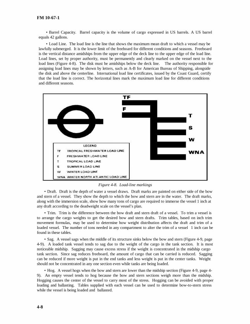
FM 10-67-1
4-8
• Barrel Capacity. Barrel capacity is the volume of cargo expressed in US barrels. A US barrelequals 42 gallons.
• Load Line. The load line is the line that shows the maximum mean draft to which a vessel may belawfully submerged. It is the lower limit of the freeboard for different conditions and seasons. Freeboardis the vertical distance amidships from the upper edge of the deck line to the upper edge of the load line.Load lines, set by proper authority, must be permanently and clearly marked on the vessel next to theload lines (Figure 4-8). The disk must be amidships below the deck line. The authority responsible forassigning load lines may be shown by letters, such as A-B for American Bureau of Shipping, alongsidethe disk and above the centerline. International load line certificates, issued by the Coast Guard, certifythat the load line is correct. The horizontal lines mark the maximum load line for different conditionsand different seasons.
Figure 4-8. Load-line markings
• Draft. Draft is the depth of water a vessel draws. Draft marks are painted on either side of the bowand stern of a vessel. They show the depth to which the bow and stern are in the water. The draft marks,along with the immersion scale, show how many tons of cargo are required to immerse the vessel 1 inch atany draft according to the deadweight scale on the vessel’s plan.
• Trim. Trim is the difference between the bow draft and stern draft of a vessel. To trim a vessel isto arrange the cargo weights to get the desired bow and stern drafts. Trim tables, based on inch trimmovement formulas, may be used to determine how weight distribution affects the draft and trim of aloaded vessel. The number of tons needed in any compartment to alter the trim of a vessel 1 inch can befound in these tables.
• Sag. A vessel sags when the middle of its structure sinks below the bow and stern (Figure 4-9, page4-9). A loaded tank vessel tends to sag due to the weight of the cargo in the tank section. It is mostnoticeable midship. Sagging may cause excess stress if the weight is concentrated in the midship cargotank section. Since sag reduces freeboard, the amount of cargo that can be carried is reduced. Saggingcan be reduced if more weight is put in the end tanks and less weight is put in the center tanks. Weightshould not be concentrated in any one section even while tanks are being loaded.
• Hog. A vessel hogs when the bow and stern are lower than the midship section (Figure 4-9, page 4-9). An empty vessel tends to hog because the bow and stern sections weigh more than the midship.Hogging causes the center of the vessel to carry most of the stress. Hogging can be avoided with properloading and ballasting. Tables supplied with each vessel can be used to determine bow-to-stern stresswhile the vessel is being loaded and ballasted.

FM 10-67-1
4-9
Figure 4-9. Sagging and hogging of vessels
LOADING FACTORS
A number of factors need to be considered by personnel loading a vessel. Some of these factors aregiven below.
Ballast Layout
The amount and distribution of ballast contribute to the seaworthiness, control, and trim of a tanker.Ballast also controls stress vibration in the hull caused by poor weight distribution. The master of a vesselmust select ballast tanks that will distribute weight evenly through the hull. At the same time, the tankcleaning and inspection schedules and the effects of tank corrosion must be considered. If different ballasttanks are used on each voyage, tank corrosion is slowed down and tank life is increased.
Maximum Tonnage
Loading above load lines is a safety hazard. Therefore, load weights must be calculated accurately.The steps for calculating maximum tonnage are as follows:
• The load line to which a vessel can be safely loaded under summer, tropical, fresh water, or otherconditions is determined.
• If a vessel is being loaded in water that may be of a variable specific gravity, the gravity is checkedwith a hydrometer. The vessel’s allowance is checked in tables provided with the vessel.
• Cargo deadweight tonnage is determined by deducting the total weight of the fuel, water (excludingthe water in the boilers), stores, and other items needed on the vessel from the vessel’s deadweighttonnage. This quantity, in long tons, is the maximum allowable weight that can be carried. The weight ofthe scheduled cargo should not exceed this amount.
• The space the scheduled cargo will use in proportion to the weight allowed is then calculated. Thisis done by referring to tables and using the gravity of the scheduled cargo and the number of barrels per

FM 10-67-1
4-10
long ton. Available cargo space then must be checked to make sure that the vessel can hold the scheduledcargo.
• Space is then allowed for cargo expansion. This is done in case the vessel enters regions where thetemperature is higher than that of the product at the loading port. Tables provided with the vessel areused to determine the cargo expansion allowance.
Cargo LayoutThe master of a vessel and the shore petroleum inspector consider weight distribution factors when
they plan the cargo layout so that the cargo is not contaminated by the mixing of one product withanother. There is little chance of this problem on a tanker carrying only one product.
PRELIMINARY PROCEDURES
There are many steps that must be taken before a ship is loaded or unloaded. They are describedbelow.
Preparing Orders
Before a tank vessel docks, the shore terminal command posts written operation orders so that theshore operators can prepare for loading or unloading the vessel. The information that must be shown onthe orders includes the following:
• Estimated time of arrival.
• Kind and amount of petroleum product to be loaded or unloaded.
• Type of vessel.
• Berth to be used.
• Pipelines to be used.
• Number and size of hoses to be connected.
• Tanks into which cargo is to be received.
• Pump stations and pumps to be used.
• Tank and cargo layout.
• Number of samples to be taken and the location to which samples are to be sent.
• Tests required.
• Ballast carried or required at the terminal.
• Location of blends, if used.
• Line cleaning or displacement.
• Pumping facilities aboard the vessel.
• Turnaround time.
• Any special services or unusual requirements, such as blending of FSI, additional lighting, or use ofspill booms.
Notifying Customs and Health Authorities
If a vessel is arriving from a foreign port, customs authorities must be notified so that the cargo canbe declared and the vessel can be inspected. The Public Health Service must be notified so that the crewcan be examined.
Arranging for Dock Personnel, Tugboats, and Pilots
There should be enough shore personnel at their stations to help moor or undock and load or unloadthe vessel. The vessel’s personnel are responsible for the safe docking of the vessel, but the shore
FM 10-67-1
4-11
personnel must help. Arrangements must be made for tugboats and required pilots, when necessary. Allpersonnel concerned with the operation should be told of the grade of product and the tanks being used.
Inspecting Hose
Shore personnel must inspect all connecting hoses for condition and suitability. Cargo hoses shouldbe inspected and maintained according to Chapter 10. Any cracked, worn, or frayed hose must bereplaced. A contaminated hose should be cleaned or replaced, depending on the contamination and theproduct to be handled. There should be enough hose to allow for slack to take care of tide changes,weather, or layout. Too much hose may cut down product flow.
Providing Sufficient Product, Tankage, and Ballast
When the vessel takes on products, there must be enough product in the shore tanks. If the vesselmust unload products, there must be enough shore tankage to handle them. Shore tanks must be gaged byshore personnel. A ship’s representative may witness the gaging. Enough ballast water tankage alsoshould be provided.
Preparing Dock
All needed tools and equipment should be readily available before the vessel arrives. Items thatshould be included are listed below:
• Skiff
• Sampling equipment and sample containers.
• Containers to catch overflows or spills.
• Winches.
• Bolts.
• Gaskets.
• Spool pieces.
• Couplings.
• Clamps.
• Pressure gage.
• Sufficient quantity of ¾ inch rope.
• Block and tackle.
• Explosion-proof flashlights.
• Thermometers.
• Gaging equipment.
• Ladder.
Preparing for Safety
Safety equipment should also be available. These include the following:
• Life preservers.
• Throwable ring with line.
• Fire-fighting equipment.
• First aid kit.
• Stokes basket or equivalent stretcher.

FM 10-67-1
4-12
Preparing to Deal With Spills
Plans for preventing, controlling, and cleaning up spills are required. The SPCC plan is a federallyrequired document. It covers all aspects of facility-wide spill response. The ISCP is the site-specific planfor responding to a spill. It must be included in the facility-wide SPCCP to meet legal requirements. Allpersonnel involved in loading and unloading operations must have had all spill response training inaccordance with these plans. Specific personnel must perform certain specialized functions includingcommand and control, as well as all other spill response team functions. All spill team personnel musttake part in periodic spill response team drills, in accordance with these plans. A spill of oil is reportableif it creates a sheen on the navigable waters of the United States, or if it otherwise meets certain localquantity criteria. The term navigable waters is quite broad. It may include whether it will create a sheenin storm-water runoff into a nearby stream the next time it rains. If a spill is confined so that it mayreasonably be expected not to affect the navigable waters of the United States, it may still be reportabledependent upon the amount involved in accordance with specific permit provisions, and other local, state,and federal requirements. Failure to report oil spills in a proper and timely manner is a criminal offense.It is important that all oil spills be reported immediately up the chain of command. It must be donewithout any delay whatsoever except for those required for personnel safety. At the appropriate level inthe chain of command, the environmental compliance officer shall be notified so that proper, timelynotification of the Coast Guard National Spill Response Center, the Environmental Protection Agency,and other local, state, or host-nation regulatory officials may take place. The following information willbe required in all spill reports.
• Name of the facility.
• Name(s) of the owner or operator of the facility.
• Location of the facility.
• The nature of the spill. This includes the exact type of petroleum product, the amount spilled, andany terrain feature that may present a problem (such as drainage ditches, canyon, or bluff). Also includehow close the spill is to streams, wetlands, endangered species, or other environmentally sensitive items.
• The present status of the deployment of the Army’s spill containment and radiation team. If theteam has not arrived, give the expected arrival time. Decide if other teams are needed.
• Weather conditions.
• Name of the Army’s OSC for the cleanup of the spill and a phone number than he can be reached atall times.
• Date and year of initial facility operation.
• Maximum storage or handling capacity of the facility and normal daily throughput.
• Description of the facility, including maps, flow diagrams, and topographic maps.
• A complete copy of the SPCCP with any amendments.
• The cause(s) of such spills, including a failure analysis of the system or subsystem in which thefailure occurred.
• The corrective actions and/or countermeasures taken. This includes a description of equipmentrepairs and/or replacements, and the cost.
• Other preventive measures taken or planned to keep another spill from occurring.
• If the above information is unavailable, it must not delay the immediate reporting of the spill assoon as possible.
• Other information, as the EPA may reasonably require, pertinent to the plan or spill event.
Designating and Inspecting Facilities
Shore tanks, pump stations, and pumps should be marked order in which they are to be used. Allvalves, except dock valves, to be used during loading or unloading operations must be opened until the

FM 10-67-1
4-13
lines are filled. After the lines are packed, the valves must be closed. Then, tanks should be inspected,gaged, and checked for water. All valves must work and must not leak. If blinds are needed, theirlocation should be in the written order.
Sampling Product
Product in shore tanks scheduled to receive product must be sampled and tested as prescribed in theupdated MIL-HDBK-200. Product carried by the vessel also must be sampled and tested. It may bepossible to board the vessel and take product samples before it is docked to speed unloading.
Preparing Pier Pipelines
Before the vessel is docked, the pier pipelines should be filled, when and where possible, with thesame grade of product that is going to be moved. Unless the pipelines are completely filled or empty,there is no way to get an accurate measurement of product issued or received.
Checking Mooring Lines
• When the vessel is moored, mooring lines should be taut enough to hold it steady. The lines shouldalso be slack enough to allow for the rise and fall of the tide and the change in the vessel’s draft duringproduct transfer. Lines must be watched and adjusted as product is moved and tides rise and fall.
Preparing Gangway and Testing Signal System
As soon as the vessel is docked, vessel personnel should rig a gangway with a safety net underneathso that inspectors and other personnel may board safely. Special equipment may be used if vesselmovement makes rigging a gangway difficult. Vessel access must be according to Coast Guardregulations. The need for access applies mainly to large tank vessels where shore personnel witnesssampling and gaging. The signal used at the dock to regulate product transfer should be tested.
Notifying the Vessel Master of Fire Protection Services
The master of the vessel must be told of fire protection services available at the pier. These servicesinclude power, water, and steam which may be needed to put out fires in the boiler and galley.
PREPARING WATERFRONT OPERATIONS LOG SHEET
Information on the loading or unloading operations must be recorded on a waterfront operations logsheet. This information is used to prepare DD Form 250-1. The log sheet should be kept at thewaterfront terminal. Discrepancies between the shore log and the ship’s log should be identified. Theinformation that the log sheet should include is given below:
• Vessel name and assigned cargo number.
• Date and time of the following actions:
••Vessel arrives in roads.
••Notice is given that vessel is to discharge.
••Vessel is moored.
••Ballast discharge is started.
••Ballast discharge is finished.
••Cargo is inspected and is ready to unload or load.
••Cargo hose or loading arm is connected
••Product is sampled.
••Unloading or loading is started.
••Unloading or loading is resumed.
FM 10-67-1
4-14
••Unloading or loading is finished.
••Cargo hose or loading arm is removed.
••Bunkering is started.
••Bunkering is finished.
••Vessel is released by inspector.
••Vessel leaves berth.
• Seal numbers and their location.
• Vessel draft before, during, and after loading or unloading operations.
• Condition of shore pipeline, such as whether it was full at the start and end of operations.
• Product type.
• Sample number.
• Remarks, such as whether there were delays, what the causes of delays were, and what parties wereresponsible.
FIRE AND SAFETY PRECAUTIONS
When a tank vessel has docked, responsible persons must make sure there are no fires, open flames,or open lights on deck or anywhere near the part of the deck at which the cargo hose is to be connected.Although it is sometimes necessary to keep fires in the boiler room when cargo is being loaded orunloaded, the potential hazard should be weighed. Extreme care should be taken when tugs or othervessels that may have open flames come alongside. Smokestacks of coal burning tugboats, dredges, orpile-driving equipment should have spark arresters. These precautions are very important during thetransfer operation when large amounts of explosive vapors may form. Smoking or flame-spark-producingdevices should not be allowed on the vessel or at the terminal, except in special places. Fire fighters mustnot be allowed to clean out stacks while vessels are docked. No garbage or waste of any kind should bethrown overboard while the vessel is docked. Additional measures are described below.
Caution Signs
Caution signs must be posted. They include NO SMOKING and NO LOITERING signs and trafficdirection markers. A warning sign stating DANGER : THIS VESSEL HANDLING PETROLEUM mustbe posted. A sign stating NO FIRES, NO SMOKING, NO VISITORS should be posted in clear view onthe gangway while product is being loaded or unloaded. The sign must be lettered in red on a whitebackground. When a petroleum cargo is transferred at a mooring or dock, the vessel must display a redflag by day and an all-round red light by night.
Grounding Cable
A grounding cable must be connected between the dock grounding system and the hull of the vessel beforethe cargo hose is connected. This cable must not be removed until after the cargo hose is removed.
Cleanup of Spills
All spills must be cleaned up as soon as possible. Sources of vapor ignition must be eliminated.
Mooring Limitations
No vessel should be allowed to dock or moor within 50 feet of a vessel that is unloading bulk cargo,unless the depot officer or supervisor and the master of the vessel transferring cargo agree.
Mooring Line
At the end of each mooring line, at the bollard or belay pile, there should be a manila or syntheticfiber line that can be cut in an emergency. It is used if there is no other emergency release.

FM 10-67-1
4-15
Relief Valves on Suction Lines
A shutdown of the booster pumps, either through error or power failure, will stop the flow and causethe full delivery head from the vessel’s pumps to back up at the dock. There may also be a surge ofpressure that could burst the hose. Precautions should be taken against these hazards. A battery of reliefvalves may be connected to the pump station suction line. The valves will relieve pressure until vesselpersonnel can be told to shut down the vessel’s pumps.
Inspections
To ensure safe operating procedures, the depot supervisor must inspect conditions both on shore andon the vessel before loading or unloading operations are started. There will usually be at least one deckofficer and one engineer officer on duty aboard a tanker during such operations. This rule may bechanged to suit transfer operations to and from small vessels.
Deck Watch and Hose Watch
During the entire loading or unloading operation, the vessel personnel usually provide a deck watchand the shore organization provides a hose watch. The hose watch observes ship/dock operations, looksfor straining or chafing of the cargo hose, stands by at all times to close the dock valves, and coordinateswith the deck watch to start and stop the operations.
SPILLS
All spills are subject to strict reporting requirements, with potential criminal liability for violations.In case of spill, in any amount, see section on “Preparing to Deal with Spill.” All spills must beminimized. Personnel can limit a spill by closing a valve that was accidentally opened, stopping anypumping through a ruptured line, or plugging a leak. Various methods, equipment, and materials areused to clean up spills. The type of cleanup used is determined by the type of product, where the spilloccurs, weather conditions, and special considerations. Special considerations include closeness todrinking water sources, fishing grounds, wildlife habitats, bathing beaches, and recreational areas.
Spills on Dock or Ship
If there is a spill on the dock or ship, transfer operations must be stopped. If possible, the spill shouldbe bailed into the cargo tank or bulkhead. Remaining product should be absorbed with absorbentmaterial. Care should be taken to remove possible sources of vapor ignition.
Spills on Water A number of steps must be followed when handling product spilled on water. These steps are given
below.
• Containing spills. Spills on calm water can be contained by barriers, such as floating booms.Floating booms are tubular floating sections that usually have a weighted skirt. They are either inflated orfilled with buoyant material. The booms can be installed around unloading tankers, or they can be keptready and used as needed. Once the spill is contained, one end of the boom can be pulled in toconcentrate the spill and make skimming easier. Makeshift booms can be made from inflated fire hoses orfrom railroad ties, telephone poles, or empty drums linked by chains or cables.
• Following Preventive Booming Policy. DFSC practices preventive booming whenever regulationsdictate and according to the following guidance:
••Transfers of nonpersistent fuels such as JP-8 and gasoline must not be boomed, unless ordered bythe Coast Guard.
••Fixed boom will not be required in areas of swift current (1.5 knots or greater) when fuel will bedeflected over the top or under the boom.
••Do not boom in situations deemed unsafe.

FM 10-67-1
4-16
• Removing oil from the water. Some of the product can be removed with the suction pump, piping,and other equipment on a regular skimming boat or a barge. Some skimming boats are designedespecially for removing oil. Others are barges or boats that have been adapted to remove the product fromthe water and store it. Chemical dispersants approved by the(EPA can be used as soon as the spill iscontained, however, they are usually used after some of the product has been removed by skimming.
NOTE: Chemical dispersants must be approved by the EPA.
• Cleaning up. After all product possible has been removed, absorbents, adsorbents, and chemicaldispersants may be used to complete the cleanup. Product is soaked up by an absorbent, but it clings tothe surface of the particles of an adsorbent. If the water is not rough and the slick is limited in size, eitherof these may be used to gather product on the surface. Some absorbents and adsorbents are sawdust,straw, cotton waste, talc, and powdered bark. Sawdust, straw, and cotton waste can be buried. Thesematerials must be disposed of according to EPA regulations. Chemical dispersants break up a slick intotiny droplets so that natural bacteria in the water can consume the product. Dispersants are usuallysprayed from a vessel, from a helicopter or a crop-spraying plane, or from hand-held equipment.Dispersants are useful in rough, open seas where skimming is difficult. Chemicals should never be usednear a freshwater source or where fish or beaches are of prime concern unless fire, safety hazards, or otheremergency conditions exist.
Spills on Shore
Spilled product that comes ashore may be removed mechanically or by detergents. The quicker thecleanup, the less the spread of contaminants.
NOTE: All detergents used must be approved by the EPA.
• Mechanical removal. Where the water is calm, the product can be recovered and disposed of after itis saturated into absorbents or adsorbents. If the product forms pools on the shore, it may be possible topump it into tank trucks. Product from a heavy slick tends to be deposited at the high-water mark, whereit can be removed by bulldozer or by pail and shovel. The process must be repeated as the tide brings inmore product. Sand saturated with product must be removed. If a large amount of sand is removed froma beach, it must be replaced with clean sand.
• Removal with detergents. Detergents may endanger marine life. For that reason, using detergentsfor cleaning up spills is less desirable that removing product by mechanical means. Also, if detergents arenot used properly, they may soak into the beach and create quicksand. When detergents are used, the sandshould be turned over with a cultivator. The detergent should be sprayed on the beach no sooner than onehour before the incoming tide. The tide action rinses the product from the sand and carries it out to sea.The beach should be hosed toward the sea if there is not enough tidal action to remove the product.Detergent may also be sprayed on rocky beaches, harbor walls, and rocky coasts and then hosed towardthe sea.
SAFE HANDLING OF JET FUEL AND KEROSENE
The handling of jet fuel (JP-4 or JP-8) and kerosene creates special hazards. The safety precautionsthat must be followed when jet fuel and kerosene are loaded into tankers, barges, or storage facilities aregiven below.
WARNING
These hazards involve the discharge of static electricity, which is caused by turbulence, low flashpoint,fast rate of flow, and water in the product.
• All water must be removed from the tanks before loading operations begin. Vessel pipelines mustbe drained as much as possible before cargo tanks are stripped to lessen the chances of contamination withwater. The tank bottoms must be hosed down by hand, and all water puddles must be removed. SeeChapter 12 for tank entry procedures.

FM 10-67-1
4-17
• To lessen turbulence, the specified loading rates should not be exceeded by more than 3 feet persecond until the tank inlet is submerged. The proper rate is about 1,000 barrels per hour through a 12-inch line. After the inlet is submerged, the normal loading rate may be used. The loading rate for eachtank should be 3 feet per second. The total loading rate must be no more than the sum of the allowablerates for the tanks being filled . If there is turbulence after the loading inlet is submerged, the reducedrate must be continued until there is no turbulence. This limitation does not apply to dischargeoperations, because the rate of discharge of jet fuel and kerosene is controlled by the receiving activity.
• Ullages, water soundings, temperatures, and samples must not be taken in a tank until the tank hasbeen topped off and flow to the tank has stopped for at least 20 minutes. Meanwhile, other tanks may beloaded at the discretion of the local authority.
LOADING PROCEDURES
As soon as the vessel is docked, the terminal chief should review the loading plans with the master ofthe vessel. They should agree on any changes. The procedures for loading are described below:
Grounding
After the vessel is moored and all safety precautions are taken, and before cargo hoses are connected,the vessel must be grounded to the dock. To ground a vessel, personnel must--
• Inspect the grounding system to verify continuity and testing according to applicable standards.
• Make sure the grounding switch is open.
• Make sure the grounding clamp on the grounding cable is attached to a bare metal surface on thehull of the vessel. It may be necessary to sand a spot on the hull to make a good connection.
• Check the grounding system to see that there are no loose connections.
• Close the grounding switch.
Deballasting
Often, quantities of ballast water, needed to maintain proper vessel trim, are delivered to a terminal.The ballast must be removed from the vessel before it is loaded. It is against regulations to dump watercontaining petroleum products overboard. The best way to deballast at the terminal is to pump the ballastthrough a separate pipeline and oil and water separator to shore ballast tanks. Sometimes tank barges areused as ballast tanks. The terminal may not have a separate pipeline to handle ballast or the vessel maynot have a stripping system. In these cases, cargo lines and pumps may be used if ballast water is cleanand if lines and pumps are drained well after they have been used for ballast. Deballasting proceduresmust be followed carefully because product contamination may result from improper handling of ballastwater. When pumping ballast ashore, personnel must--
• Determine the amount of ballast to be pumped ashore, and make sure the shore tanks have enoughullage to hold it.
• Connect one end of the ballast hose to the ballast pipeline connection on the dock.
• Connect the other end of the ballast hose to the stripping connection on deck.
• Open the valves aboard the vessel to empty the desired tanks.
• Open the correct shore valves to permit pumping to the ballast tank.
• Start the stripping pump.
• Watch the pressure gage to make sure the proper valves are open. If the pressure is higher thannormal, the line may be blocked.
• Permit no ballast water and product to be transferred at the same time unless there is an emergency.Even though the water and product are separated by valves, product may become contaminated.

FM 10-67-1
4-18
• Continue pumping until all possible ballast water is removed from the vessel. Because of heavydeck cargo, it may be necessary to leave ballast in some tanks to stabilize the vessel during loading.Personnel should avoid doing this when possible.
• After all ballast is removed, stop the pump and close the shore valves so that ballast will not drainback into the vessel lines.
• Open valves in cargo lines, except sea suctions, to observe any line drainage into cargo tanks. Theymust make sure that cargo lines are drained completely.
• Make sure that each tank is free of ballast and suitable to receive product. Personnel must cleantanks that are unsuitable to receive product. They should refer to Chapter 12 for guidelines on how toprepare cargo tanks to receive petroleum products.
Inspecting Vessel
Before product is loaded aboard a vessel, each tank compartment and all pumping and cargo linesmust be inspected by the shore petroleum inspector. To certify that they are suitable to receive product,the inspector must-
• Plan the order in which products should be delivered and choose which tanks will be filled first.
• Inspect the hull of the vessel to the extent possible to see that it is not damaged and that there are noleaks.
• Examine the pipelines, pumps, and deck manifold of the vessel for leaks or damage. Make sure thatpumps and piping systems are free of product or water.
• Open all of the valves in the cargo lines, except the sea suction valves which must be sealed. Fromoutside the tank, watch for any line drainage into the cargo tanks. The shore petroleum inspector mustmake sure that the cargo lines are completely drained.
• Inspect the interior of each compartment visually to make sure the tank is suitable to receiveproduct. Use an explosion-proof flashlight. Look for scale, rust, holdover product, residue, water, mud,or anything else that might contaminate product to be loaded. Chapter 12 gives procedures andprecautions on entering tanks.
• Check the ship’s log to determine the last product to be loaded. Chapter 12 contains information onhow to prepare the tank to receive the next product.
• Make sure that all fire and safety precautions have been taken.
Connecting Cargo Hose
The terminal furnishes hoses for loading and unloading vessels that are operated by non-DODpersonnel. These hoses are usually connected and disconnected by shore operators. However, if themaster of the vessel desires, the hoses may be connected or disconnected by vessel personnel at the risk ofthe vessel. When vessels have military operators, the vessel personnel normally connect and disconnecthoses on the vessel and the shore personnel connect and disconnect hoses on the shore. Military tankships, fuel barges, and other vessels usually carry hoses; however shore hoses should be used whenpossible to save time. Most tankers have American standard 4-, 6-, or 8-inch flanges for hose attachment.They will cause no problem. Some tankers may have foreign made flanges or flanges with irregularspacing between the holes that need adapters or C-clamps. Older tankers may use the same spacingbetween holes for both 4- and 6-inch flanges. The terminal should have a set of straight and reducingadapter spools on hand to cover all normal requirements. It should have several sets of bolts, preferably ofalloy steel. In all cases, at least four bolts will be used per coupling unless a camlock flange or C-clamp isused. If C-clamps are used, their strength must be verified by test or calculation. To prevent sliding ortwisting, at least two bolts must be inserted through the vessel flange and hose flange when C-clamps areused. Although it is hazardous to do so, C-clamps may be knocked off in an emergency. Quick-actingclamping devices should be used instead of C-clamps, when possible. To connect a cargo hose, personnelmust--

FM 10-67-1
4-19
• Make sure the vessel is grounded to the dock manifold before any hoses are connected.
• Make sure the hose is suitable for handling product. They check the hoses for
• contamination, cracks, holes, worn or frayed places, or other damage.
• Place drip pans under connections on deck and on dock to catch spills.
• Attach the hose to the hose support. Personnel raise the shore end of the hose in position to coupleit to the dock manifold. They attach the hose flange securely to the manifold connection using all of thebolts. They place the other end of the hose where it can be picked up easily by the ship’s hoist.
• Attach the hose to the ship’s hoist and raise it in position to connect it to the deck manifold. Theyalign the holes of the hose flange and the deck manifold flange and bolt them together securely. The hoseshould be suspended above the deck during transfer.
Connecting Loading Arms
At some tanker loading facilities, marine loading arms (Figure 4-10) are used instead of cargo hose.The arms are operated by cables and hydraulics. Most marine loading arms have hydraulic connectionsinstead of flange connections. To connect loading arms, use the following procedures:
• Make sure the vessel is grounded to the dock manifold before the loading arm is connected.
• Make sure the loading arm is suitable for handling the product. Check for damage or wear.
• Place drip pans under connections on the deck to catch spills.
• Lower the loading arm to make the connection to the deck manifold.
• Attach the loading arm connection to the deck manifold, making sure the seal is tight.
Figure 4-10. Marine loading arm

FM 10-67-1
4-20
Heating Cargoes
When tanks have heater coils, viscous products in the tanks should be heated to prescribedtemperatures before transfer operations begin. Prescribed temperatures must not be exceeded. Very hightemperatures deteriorate products and can cause vapor lock in pumps. Navy special burner fuel oil andheavy lubricating oils should be heated to above 100 °F, but not over 120°F.
Pumping Product
Shore pumps usually are used to load vessels. If possible, the pier lines should be filled with productand samples should be tested before the vessel arrives. All valves to be used on the shore lines should beopened, except those used to prevent cross transfer and the valve at the pier hose connection. Specialprocedures should be followed when jet fuels or kerosene is pumped. Procedures to pump product are asfollows:
• Open the proper valves aboard the vessel so that product will flow to the correct tank from the dockmanifold.
• Open the proper shore valves to permit flow to the vessel.
• Start the pumps, and operate them at a slow speed. Closely watch the pumping pressure shown onthe pressure gage. The gage is usually in the line near the dock manifold. If too much pressure builds upquickly, it means a valve is closed in the line. In this case, shut down the pumps at once. Do not startpumping again until the problem is corrected.
• Watch all hose and line connections for leaks. If there are leaks, stop the pumps immediately. Fixthe leaks before starting again.
• Watch the receiving lines and valves for leaks during the operation. A line walker should inspectthe lines for leaks once every hour.
• Carefully watch for changes in the tide and for slack or pull in the hose. Sudden movement of thevessel may cause damage to the hose and loss of product.
• In case of fire on the vessel or dock or near the shore lines or tank farm area, stop the transferoperations at once and close all the valves. If the tank farm is next to the port, disconnect the cargo hoseand move the vessel a safe distance from shore.
• When an electrical storm is within a 3-mile radius of the transfer operation, stop transfer operationsand close the valves on the vessel and dock. Coordinate on the weather before transfer operations arestarted. Maintain coordination during transfer operations if an electrical storm is probable. If there is noimmediate hazard, the hose may be left connected. If there is an immediate hazard, the hose should bedisconnected and drained and the main block valve on shore should be closed.
• Avoid sudden increases in flow that might cause excessive surge pressure. When the product levelis about 3 feet above the inlet, start the desired pumping rate. If there is still turbulence at this level,continue loading at the maximum allowable rate until it is time to top off the tanks.
• Top off the tanks when they are about 90 percent full. While topping off the tanks, reduce theloading rate to avoid spills or overflow.
• Watch the vessel’s draft during loading so that it will not become overloaded.
• Shut down the pumps and close all of the valves when all the yanks are filled and the vessel hasproper trim.
Performing Follow-Up Procedures
Certain follow-up procedures must be performed after a vessel is loaded. These procedures are asfollows:
• Allow the suspended water and sediment to settle. Gage the contents of each tank compartment,and find the average temperature of the product at 60°F in each tank.

FM 10-67-1
4-21
• Take an all-levels sample of product from each tank compartment that contains the same product.Run a type C test on each sample according to FM 10-67-2. Make a multiple tank composite sample to besent to the laboratory for testing. Use MIL-HDBK-200 as a guide.
• Gage the product in the shore tanks. Find the average temperature of the product. Quantities arevolume corrected according to DA Pamphlet 710-2-2. Compare the quantities delivered from the shoretanks with the quantities received in the vessel’s tanks. Shore gages must be used to get the exact amountdelivered. Note any difference between the amount delivered and the amount received. Report thedifferences to the proper authority.
• Close and securely bolt all compartment hatches when the desired amount of product is loaded andis certified as on specification. Make sure that all ullage sounding holes are covered securely, and seal allareas required by regulation. Record all seal numbers on DD Form 250.
• Pump ballast water into the proper tanks if the vessel needs ballast for proper trim for the voyage.The tanks must be clean before ballast is received. Only clean ballast should be pumped into the tanks.
• Make sure that all line valves are closed. Disconnect the cargo hose, and drain any remainingproduct from the hose. Catch any spills in drip pans placed beneath the hose to drain into the water or onthe dock. If spills occur, wipe them up immediately. Cover the hose ends with blind flanges and gaskets.Store the hose in a shelter or hose rack.
Refueling and Bunkering Tankers
Tankers may be refueled at the port terminal. The same procedures are used to issue fuel as thoseused to load fuel in the tanker. All bunkering operations should be recorded on DD Form 250-1. Samplesmust be taken to detect contamination. All safety precautions must be followed. After refueling,disconnect the refueling hose, open the grounding switch, and disconnect the bonding cable from the ship,in that order.
UNLOADING PROCEDURES
There are a number of procedures that must be followed to properly unload a vessel. Theseprocedures are described below.
Grounding
After the vessel is moored and all safety precautions are taken, the vessel must be grounded to thedock before cargo hoses are connected. To ground a vessel, take the following steps:
• Inspect the grounding system to verify continuity and testing according to applicable standards.
• Make sure the grounding switch is open.
• Make sure the grounding clamp on the ship grounding clamp is attached to a bare metal surface onthe hull of the vessel. It may be necessary to sand a spot on the hull to make a good connection.
• Check the grounding system to see that there are no loose connections.
• Close the grounding switch.
Inspecting Vessel
The master of the vessel and the shore petroleum inspector must review the loading plan of the vesselfor grades and amount of products carried. Also, they must review the layout of the cargo and the order inwhich products should be unloaded. Before unloading operations begin, the shore petroleum inspectormust check the manifest and DD Form 250-1 for serial numbers of valve seals. The inspector must verifythat each seal is intact on isolation valves and sea suction valves. He must document reasons for missingor broken seals. Ullages, temperatures, and water soundings must be taken on each compartment by shippersonnel and witnessed by shore personnel. These readings are recorded on DA Form 3853-3. Greatdifferences in compartment gages after loading and before discharging must be checked promptly. Thevessel’s master must explain these differences in a written statement attached to the ullage report.

FM 10-67-1
4-22
Sampling and Testing Product
If the product aboard the vessel has been inspected on procurement by the government, unloadingoperations may begin after a type C test of an all-levels sample of product from each compartment showsno contamination. Multiple tank composite samples must then be sent to the laboratory for type B-1 tests.If the product aboard the vessel has not been inspected on procurement by the government, the laboratorymust run a type A test on samples from the upper, middle, and lower portions of each tank or an all-levelscomposite sample from each tank before discharge. If no testing facilities are readily available, anyproduct in question should be placed in isolated storage until laboratory tests confirm quality.
Connecting Cargo Hose
The steps for connecting the cargo hose to unload a vessel are the same as those used to connect it toload a vessel. See page 4-18 for these steps.
Connecting Loading Arms
The steps for connecting loading arms to unload a vessel are the same as those used to connect themto load a vessel. See page 4-19 for these steps.
Heating Cargoes
The cargo may need to be heated before it is unloaded. See the information on heating cargoes givenon page 4-20.
Pumping Product
There are certain procedures that must be followed to unload product from vessel to shore. Theseprocedures are as follows:
• Open the proper valves aboard the vessel so that product will flow from the correct tank to thedock manifold.
• Open the proper shore valves to permit flow to the proper shore tank.
• Start the pumps, and operate them at a slow speed. Closely watch the pumping pressure shownon the pressure gage. The gage is usually in the line near the dock manifold. If too much pressure buildsup quickly, it means a valve is closed in the line. In this case, shut down the pumps at once. Do not startpumping again until the problem is corrected.
• Sometimes, shore pumps are used to boost product flow. When this happens, adjust the dischargerate of the vessel and the shore pumps after the pumps are started. This is done to prevent shore locationpump fuel starvation and to decrease discharge time.
• Watch all hose and line connections for leaks. If leaks appear, stop the pumps immediately, andfix the leaks before starting again. A line walker should inspect the lines for leaks at least once everyhour.
• Gage the shore tanks during the unloading operation only as directed in the orders. The JP-5 andJP-8 shore tanks should not be gaged during unloading operations.
• Carefully watch for changes in the tide and for slack or pull in the hose. Sudden movement of thevessel may cause damage to the hose and loss of product.
• In case of fire on the vessel or dock or near the shore line or tank farm area, stop the transferoperations immediately and close all the valves. If the tank farm is next to the port, disconnect the cargohose and move the vessel a safe distance from shore.
• When an electrical storm is within a 3-mile radius of the transfer operation, stop transferoperations and close the valves on the vessel and dock. Coordinate on the weather before transferoperations are started. Maintain coordination during transfer operations if an electrical storm is probable.

FM 10-67-1
4-23
If there is no immediate hazard, the hose may be left connected. If there is an immediate hazard, the hoseshould be disconnected and drained and the main block valve on shore should be closed.
• When all the product has been pumped from one cargo tank, open the valves of the next tankcarrying the same product and close the valves of the empty tank. Be careful not to pump water ashore.The pump should continue operating while tanks are being switched.
• Watch the draft of the vessel during the unloading operation to make sure the vessel maintainsproper trim.
• When the shore tank nears capacity, open the valves leading to the next tank with the sameproduct. Top off the first tank at a slower rate, and close the valves when the first tank is full.
• When the last of a series of vessel cargo tanks carrying the same product is almost empty, reducethe flow of product. When all product has been pumped from the last tank, stop all the pumps and closeall line valves.
Performing Follow-Up Procedures
Certain follow-up procedures must be performed after a vessel is loaded. These procedures are asfollows:
• The petroleum inspector or a representative checks to see that the tank compartments are empty.He then fills out a dry-tank certification on a DD Form 250-1 or on the vessel’s ullage report, or on both.The amount of any product that cannot be pumped ashore will be estimated. The estimate will be enteredon the dry-tank certification.
• A representative of the US government does the final shore tank gaging. Sampling is witnessedby an officer or agent of the vessel or another authorized representative.
• The vessel’s master may decide not to wait until after the product settles to gage the shore tanks.In this case, the estimated amount received, based on gages taken after unloading and before the end ofthe settling period, may be entered on DD Form 250-1. A preliminary check should be made 30 minutesafter receipt. Any two successive gages that agree are used as the correct gage.
• Fresh stocks of product should be allowed to settle for about two hours after they are added toshore tanks. After the product has settled, the final official gages are taken and the volume is correctedaccording to DA Pamphlet 710-2-2. These readings are used for accountability and are noted on DDForm 250-1.
• A composite sample, which is a mixture of upper, middle, and lower samples, is taken from eachshore tank. The sample is tested according to MIL-HDBK-200.
• Ballast water is pumped into the proper tanks if the vessel needs ballast to maintain trim duringthe voyage. Tanks must be clean before ballast is received, and only clean water should be pumpedaboard.
• When all the tanks are empty and the ballast is loaded, all compartment hatches are closed andbolted down securely. All ullage sounding holes should be securely covered.
• All line valves should be closed. The cargo hose must be disconnected, and any remainingproduct must be drained from the hose. Spills are caught in drip pans placed beneath the hose connection.The hose should not be allowed to drain into the water or on the dock. If spills occur, they must be wipedup at once. The hose ends must be covered with blind flanges and gaskets. The hose is stored in a shelteror hose rack.
• The cargo hose must be disconnected, and the grounding switch must be opened. The bondingcable is then disconnected from the ship.

FM 10-67-1
5-1
CHAPTER 5
OFFSHORE PETROLEUM DISCHARGE SYSTEM
Section I. OPDS Tankers
RESPONSIBILITIES
The Offshore Petroleum Discharge System was designed by and for the U.S. Navy, for use with the Army, andMarine Corps, Inland Petroleum Distribution System (IPDS), component parts of the Southwest Asia PetroleumDistribution Operational Project (SWAPDOP). The OPDS is stored on board a selected RRF tanker. It istransported to a theater of operations by the tanker. The U.S. Navy is responsible for installing the OPDS andship-to-shore pipeline to the high-water mark. The OPDS provides 1.2 million gallons per 20-hour day of refinedpetroleum to the beach, from a tanker moored four miles offshore. The petroleum products are delivered from theoffshore tanker to forces onshore where ports or terminal facilities are damaged, inadequate, or nonexistent. Eachtanker is manned by a civilian merchant crew. The crew is train to operate, deploy, and recover the of the OPDS.Military personnel plan, direct, and control all the OPDS operations. The OPDS tanker must be able to beginpumping fuel within 48 hours of arrival. Where required, a permanent SPM will be operating by the seventh dayafter the tanker arrives in the objective area. The OPDS will also provide fuel for aircraft operating from field sitesin the objective area. Table 5-1 gives the current commercial (OPDS) special tankers in the MSC inventory andtheir statistics. Table 5-2 shows the maximum working conditions for the OPDS.
Table 5-1. OPDS tanker statisticsTANKERS LENGTH
(feet)BEAM(feet)
DRAFT(feet)
LONG TONS FUEL CAPACITY(BBL)
S.S. Potomac 620 84 34 27,467 168,000
S.S. American Osprey 661 90 36 34,723 235,000
S.S. Chesapeake 736 102 40 50,023 255,000
S.S. Petersburg 736 102 40 50,063 225,000
S.S. Mount Washington 736 102 40 49,471 269,000
Table 5-2. Maximum conditions for the OPDSOPERATIONS CURRENT
(knot)WIND(knot)
WAVES(feet/height)
Installation 1 9-12 3
SALM 4 27-40 12
Maximum 4 48-55 22-35

FM 10-67-1
5-2
OPDS TANKER SITE SURVEYPrior to positioning the OPDS tanker, a site survey must be conducted. The general requirements for the
tanker site are:
• Water depth at least 15 feet more than full load draft of tanker to permit launching the SALM.
• No obstructions in the area that would endanger the tanker during mooring maneuvers.
• The four-point mooring site to be not more than 24,000 feet from the BTU site.
• The tanker mooring site to be checked is a generally rectangular area of 2000 by 3000 feet, the corners ofwhich will be occupied by the tanker’s anchors.
RESUPPLY OF THE OPDS TANKER
There may be a need for the OPDS tanker to dock in a specific location longer than expected due to theamount of fuel supplies needed at that undeveloped theater of operation. Depending on the water depth,prevailing currents, and the judgment of the tanker’s commander, resupply of the OPDS tanker can be resuppliedin one of three ways:
• A resupply follow-on tanker may moor to the OPDS tanker at the OPDS SPM.
• The tanker may leave its mooring and conduct an underway lightering transfer of fuel from the follow- ontanker at an appropriate location.
• The OPDS tanker can leave the OPDS SPM for another loading port.
OPDS SYSTEM DESCRIPTION
The OPDS was designed to be installed and carried to the operating area on a medium-sized tanker. Thetanker will be manned by a civilian merchant crew. The crew will be trained to operate, deploy, retrieve theOPDS. Other trained OPDS personnel may direct or assist in the tanker operations. Army or Navy personnel aretrained install the components as they are deployed from the tanker. The OPDS consists of five principalsubsystems. They are listed below:
• Commercial tanker with conduit (hoses) handling equipment.
• Conduit system of four nautical miles of flexible, elastomeric, steel reinforced, float/sink conduit on eightlarge storage reels.
• SALM.
• Converted SLWTs.
• BTUs.
Section II. Major Components (OPDS) Tanker
SINGLE ANCHOR LEG MOORING
The SALM is a large, steel, compartmented barge (Figure 5-1, page 5-3). It can be carried to the deploymentsite on the tanker skid beams. The SALM can be towed if needed. Like its commercial counterparts, it provides aSPM for the OPDS tanker that permits the tanker to weathervane around the mooring buoy and continue pumping.The hard piping on the mooring base and the attached hoses provide the capabilities to pump two productssimultaneously with its dual product swivel from the tanker to the beach. Within seven days, and with diverSLWT assistance, the SALM can be installed to provide uninterrupted, all weather product delivery. The SALMpermits a tanker to remain on station and pump in much higher sea states than otherwise is possible in a spreadmoor. Figure 5-2, page 5-4, shows the 48-hour and seven-day OPDS configurations. Some characteristics of theSALM subsystem are listed below:
• SALM base dimensions are length, 150 feet long; beams, 57 feet; and depth, 12 feet.
• It has a dry weight of 839 short tons with all buoys, hose, and anchor chain on board.

FM 10-67-1
5-3
• A series of hull and ballast tanks connected by internal and external piping allow flooding of the base underclose control in water depths of 35 to 200 feet. Practical operational restrictions limit the depth to 190 feet forNavy support divers.
• Two mooring buoys; a shallow water (auxiliary) buoy; and a larger, deep water buoy are provided. The oneused depends on the water depth. The main buoy weighs 55 short tons; the auxiliary buoy weighs about 6.5 tons.When the system is being recovered, a crane reloads both buoys on the SALM base.
• The mooring hawser with two sections of chafe chain attached is stowed in the tanker’s focsle hold. Thehawser is installed after the SALM is deployed.
Figure 5-1. Single anchor leg mooring
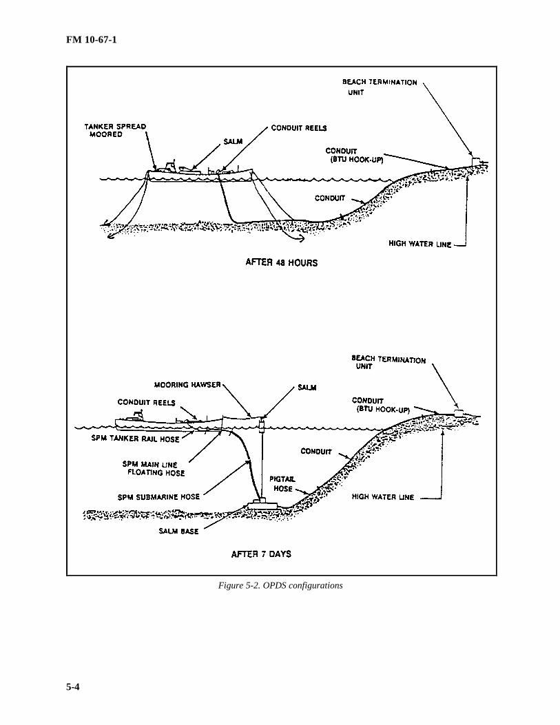
FM 10-67-1
5-4
Figure 5-2. OPDS configurations

FM 10-67-1
5-5
The SLWTs (Figure 5-3) are provided by other forces assigned to the amphibious operation. They provideOPDS with tanker carrier utility boats to make OPDS a stand-alone system. Four SLWTs are required fordeployment of the OPDS. They must be modified for OPDS use with equipment and tools carried on the OPDStanker. Three SLWTs are modified to act as tow tugs and the fourth unit is modified to act as the LRB. As soonas the tanker arrives, the equipment stored in its hold is offloaded onto the SLWTs and taken to a support areawhere the equipment can be installed by the Navy Amphibious Construction Battalion PHIBCB support personnel.Welding and removal of designated tie plates on each of the craft is required.
Figure 5-3. Side loadable warping tug
BEACH TERMINATION UNITS AND EQUIPMENT SET
Two BTUs are carried aboard the OPDS tanker to the deployment site. Depending on the requirement, one orboth BTUs may be installed. The BTU has many functions for the OPDS (Figure 5-4,* see glossary); it is the highwater mark termination of the OPDS. It is the anchor for the shoreward end of the conduit. It controls thepressure and fuel flow distribution through the hoseline from the SALM. It acts as an interface between thehoseline and IPDS. The following is a description of the BTU.
• The BTU steel casing measures 9 feet, 10 inches long; by 4 feet, 9 inches high; and 6 feet high. It weighs8,700 pounds which includes the 1500-pound anchor, 100-foot. wire pendant valves and jewelry normally stowedon top or inside.
• Internal piping includes stop valves, a pig receiver, and pressure flow control valve.
• Gages show inlet pressure, outlet pressure, and pressure in the pig receiver. A product sampling port is inthe recess with the pressure gages.
• Three large, gasketed covers bolted to the top of the BTU enclosure provide access to internals and valves.When the covers are in place, the BTU will float upright and can be towed ashore through surf.
• Roll bars on top of the casing can be used as lift points. Slots at the ends of the bottom frame are forattaching the anchor pendant, pendants to the restraining collar, or for a tow line.

FM 10-67-1
5-6
Figure 5-4. Beach termination unit
BTU Equipment Set
A BTU equipment set consists of two BTUs and component items. The OPDS beach termination equipmentconsists of the following:
• Two BTUs.
• Two 1500-pound Danforth anchors.
• Two 40-foot sections of BTU hook-up hose.
• Two sets of 100-foot pendants and fairleads.
• Two sets of special valve operating wrenches.
• Two conduit restraining bridles and pendant
CONDUIT AND COUPLINGS
There are two types of sea floor conduit manufactured for the OPDS; each has a 6 inch inside diameter andabout an 8-inch outside diameter. They have different handling characteristics and end fittings. Special fittingsare provided to connect one type with the other. Most OPDS conduit is flexible, steel-reinforced elastomer hose. Itis designed in a float-sink configuration. When filled with air, the conduit has a positive buoyancy of about 1.9pounds per foot. When filled with water or petroleum products, it sinks to the sea floor. On the seafloor, it has anegative buoyancy of about 8 pounds per foot. The conduit couplings consist of male and female fittings. Thecouplings are bolted together with six cap screws. The male fitting has a swivel flange that ensures ease ofalignment with the female coupling. Each of the different hoses is listed below.
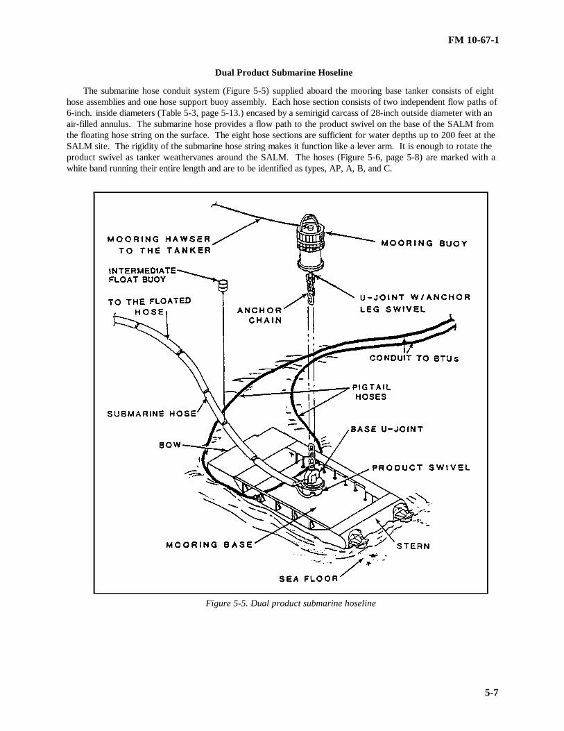
FM 10-67-1
5-7
Dual Product Submarine Hoseline
The submarine hose conduit system (Figure 5-5) supplied aboard the mooring base tanker consists of eighthose assemblies and one hose support buoy assembly. Each hose section consists of two independent flow paths of6-inch. inside diameters (Table 5-3, page 5-13.) encased by a semirigid carcass of 28-inch outside diameter with anair-filled annulus. The submarine hose provides a flow path to the product swivel on the base of the SALM fromthe floating hose string on the surface. The eight hose sections are sufficient for water depths up to 200 feet at theSALM site. The rigidity of the submarine hose string makes it function like a lever arm. It is enough to rotate theproduct swivel as tanker weathervanes around the SALM. The hoses (Figure 5-6, page 5-8) are marked with awhite band running their entire length and are to be identified as types, AP, A, B, and C.
Figure 5-5. Dual product submarine hoseline

FM 10-67-1
5-8
Figure 5-6. Submarine hoses
• Type AP and Type A are marked with three circumferential white bands at each end.
• Type B is marked with two circumferential white bands at each end is the water. It is the depth make-uphoses.
• Type C is marked with one circumferential white band at each end is the surface. It is surface support hosethat interfaces to the floating hoses.
PigTail Hoses or Jumper Hoses
The two SALM pigtail hoses transfer the tanker’s petroleum products from the mooring base to the flexibleconduit. Each of the two SALM (Figure 5-7, page 5-9) pigtail hoses is 320 feet long and similar to the conduit inconstruction. It can be connected to the floating conduit end on the sea’s surface by the SLWT crew after theSALM base is on the seafloor. Both pigtail hoses are capped with a blank towing flange to keep the hoses afloatduring deployment. The hoses are stored on all the tanker’s tenth reel except the S.S. Potomac.

FM 10-67-1
5-9
Figure 5-7. Pig tail hoses
Floating Hoses
The floating hoses transfer the product from the tanker’s manifold to the submarine hoses. This hose systemis comprised of mainline floating hoses and tanker rail hoses. The mainline floating hose system consists of two 6-inch inside diameter hose assemblies, each 560 feet. long. Each assembly contains 14-hose sections of 40 feetlengths (floating mainline hose sections and 1 tanker rail hose section). The floating mainline hose are electricallycontinuous and the tanker rail hoses are electrically discontinuous. All floating hoses are marked by twolongitudinal white stripes spaced 180 degrees apart along their entire length (Figure 5-8).
Figure 5-8. Floating hoses
Flexible Conduit Pipeline
There are 4 nautical miles of 6-inch hoseline included with the OPDS. The system uses high-pressure hoseson ship-mounted reels. Each reel holds 0.5 mile of collapsible hoses; eight reels make up the 4-mile kit. Thehoses, which are not subject to corroding are made out of a smooth high-grade fuel-resistant synthetic-type rubber.They can be damaged and should be routinely inspected. The hoses can be stretched to 33 percent under normalconditions of use. Hose-to-hose and hose-to-fitting connections are made with 6- and 12-bolt flange connectionsthat are designed for a burst pressure of 2,200 PSI. The 6-inch diameter and 1-inch thick hose has a maximumoperating pressure of 740 PSI. The hoses weighs about 19 ½ pounds per foot. The U.S. Coast Guard hydrostaticpressure test is 1,014 feet per section with 24,336 feet per shipset. Petroleum is pumped using two positivedisplacement pumps in parallel (500 GPM each at 700 PSI). High pressure is required by the high head losses thatresult from delivery of 1,000 GPM in the 6-inch hose over the 4-mile (maximum) distance to shore.

FM 10-67-1
5-10
Section III. BTU Procedures
DEPLOYMENT
The BTU is deployed from the OPDS tanker. The following procedures are used for deployment:
• Offload all equipment for the site from the tanker to a designated SLWT for transportation to the beach.
• Where possible, offload equipment directly to shore. If this is not possible, the BTU can be offloaded andtowed ashore by a LARC-V. The anchor, if stored on top of BTU, should be removed and conveyed ashoreseparately.
• Move the BTU and equipment to the BTU site using forklifts or other vehicle.
BTU SITES
The site of the BTU for each beach terminus of the OPDS must be determined early in planning. The locationshould be suitable for connecting to the IPDS. Below is a list of the preparation rules to follow:
• Be above the high water mark.
• Be accessible by road or rough terrain vehicles.
• Have enough soil that permits burying the anchor or establishing a deadman capable of holding 30,000pounds of tension.
• Establish the point from which the tanker/SALM position can be no more than 24,000 feet in the case of asingle conduit line, but not more than 2 nautical miles distant for two conduit lines.
BEACH PREPARATION
Preparing the beach area for receiving the OPDS conduit requires equipment and personnel to set up the BTUsite(s), range markers, lighting, and other items to support the installation of BTUs. Bulldozers help in bringingthe conduit ashore and connecting it to the BTU hookup hose. Specific actions for each of the areas of support aregiven below.
Installing Beach Terminal Unit Bermed Area With Spill Catchment Before performing any POL operation, consult the local environmental coordinator to check for the possible
existence of special permit requirements. The BTU will be installed in a bermed site with a berm liner (Figure 5-9,page 5-11) to contain any fuel or contaminated water spills from the pig catcher. The berm area should be not lessthan 10 by 16 feet to permit personnel to move around inside the enclosure while operating/maintaining the BTU.If the berm floor is sloped, the high side should be seaward. Prepare an 8- by 8- by 3-foot hole 100 feet inlandfrom the BTU site for the BTU anchor. Clear the area between the BTU and the sea to help connect the 40-foothook-up hose and 6-inch ball valve to the BTU.
Installing Range Markers/Lights Install range markers inland from the BTU site if room permits. Markers must be large enough and high
enough for SLWT pilot to see the markers a minimum of 1 mile away. They must be at least 100 feet apart.
Setting up the Maintenance/Support Pier If no harbor or other pier space is available, set up an administrative pier within a mile of the BTU/conduit site
for the OPDS service craft. The pier should be at least 500 yards from the BTU so that it does not interfere withthe SLWTs bringing the conduit to the beach.

FM 10-67-1
5-11
Figure 5-9. BTU with berm liner
Anchoring the BTUDig a hole for the 1,500-pound lightweight BTU anchor which is buried about 100 feet inland of the BTU.
Dimensions of the hole are about 8 by 8 by 3 feet. Lower the anchor in the hole with the shank toward the BTU.Bury the anchor, covering it up to the jew’s harp. Attach the 100-foot wire to the jew’s harp and to the inland endof the BTU.
BTU OPERATIONS
After the BTU is installed and tested by the Navy personnel and flowing fuel, the remaining operations consistof monitoring the flow, correct operation of the flow control valve, and routine maintenance of the BTU. The BTUoperators must maintain continuous communications with the tanker and with the onshore unit. Radio checks willbe conducted regularly by net control. Any failure of radio communications is cause for immediate shutdown bythe tanker. Operations at the BTU continue until fuel requirements are met. There will be interruptions inpumping during refueling of the tanker and when the SALM is being connected to the conduit string. All otherprocedures of the BTU are listed below.

FM 10-67-1
5-12
Controlling the BTU
The BTU is operated by a Navy crewman for the benefit of the Army or Marine Corps onshore. The BTUcrewman takes their orders from the onshore command unless other arrangements are worked out and reflected inthe OPORD. The BTU crewman is trained to operate the BTU valves to perform certain functions during pigging,flowing product, and hydro testing the lines. The Army and Marine Corps should be sufficiently familiar with theoperation of the BTU so they can check valve alignment for the ordered function. Depending on the downstreamarrangement of hoses, valves, and bladders, a misaligned valve in the BTU could divert the wrong fluid into astorage bag and contaminate the bag.
Disconnecting The BTU
The method used for conduit retrieval determines when the BTU hookup hose is disconnected from theconduit. Onshore fuel connections BIU will be disconnected first and cleared from the immediate area. Uncoverthe hook up hose and conduit down to the surf area before disconnecting them. When ready to disconnect the BTUhookup hose from the conduit, secure the restraining collar and bridle to the seafloor conduit end fitting. Shackle abulldozer’s winch wire to a pelican hook to the bridle and take a strain on the winch wire. The pelican hookprovides a positive control for release of the conduit. The hose and conduit are then unbolted and a female pullingcap attached to the male end of the conduit.
Flushing The BTU
Before the BTU can be returned to the tanker, it must be flushed, drained, and dried. The Navy PHIBCB orArmy personnel need a freshwater supply air pump for this procedure. Use a forklift or crane to tilt the BTUcasing once the flushing is completed. Unbolt the BTU hook up hose from the inlet valve flange and prepare forretrieval to tanker.
Retrieving The BTU
The BTU is prepared for recovery by PHIBCB or Army personnel. A designated tow rigged SLWT proceedsto the BTU site. If a pier is available, forces ashore transport the BTU there and load it onto the SLWT. They alsoload the anchor, pendants, hook-up hose, and other fittings. In the absence of a pier, the BTU, anchor, pendants,and fittings are moved to the shoreline. The SLWT passes its forward winch wire to the beach by small craft. Theanchor, fittings, and pendant are then pulled out and lifted on deck with the A-frame. At the tanker, the forwardboom of the tanker lifts the BTU and all its equipment from the SLWT to the forward deck.
Table 5-3. Conduit and hose characteristicsItems Bore
Size(inch)
OutsideDiameterNormal(inch)Body/Ends
MaximumAllowableWorkingPressure(psig)
BurstPressure(psig)
ElectricalContinuity
Conduit 6.00 7.85/8.85 714 2220 No Requirement
Tanker Rail Hose 6.00 10.0/17.5 714 2220 DiscontinuousFloating Hose 6.00 12.0/13.0 714 2220 ContinuousSubmarine A 6.00 28.0/30.0 714 2220 ContinuousHose B 6.00 27.7/29.7 714 2220 Continuous
C 6.00 26.7/29.5 714 2220 ContinuousPigtail Hose 6.00 7.85/8.85 714 2220 No RequirementBTU Hook-up Hose 6.00 7.85/8.85 714 2220 Discontinuous

FM 10-67-1
5-13
Section IV. Planning and Administrative Considerations
OPDS DEPLOYMENT CONSIDERATIONS
When the OPDS tanker arrives, the JLOTS commander holds an OPDS deployment conference on board thetanker. The meeting is to coordinate efforts of the OIC OPDS and all participating OPDS deployment elements.Attendees review the OPDS deployment plan. They refine it for the existing scenario and work out last-minutedetails. The meeting considers all facets of OPDS installation to include:
• Site Surveys. The survey must include maximum steepness of bottom gradient for SALM, 1:25 with goodhoding potential and nonrocky bottom; within 4 nautical miles of beach termination site (2 miles for two products);and known depths.
• Swing Circle for the OPDS Tanker Around the SALM. The swing circle must allow ½ -mile diameter withno bottom hazards and minimum boat traffic in area (except to ship or for security).
• Conduit Route. The route must be free of rocky escarpment or other bottom hazards that would causedamage to the conduit and clear of boat traffic.
• Communications Plan. The plan must include communication networks, procedures, equipment, controlstations and security requirements as needed.
PRODUCT DISCHARGE CONFERENCE
Before the initial pumping of product, the JLOTS commander will hold a PDC. This PDC will ensure safepumping operations and mutual (ship and shore) understanding of procedures. A review and initialing of theOPDS POL communications checklist will also be done. The checklist must be signed whether the deployment isexercise or wartime. The meeting includes the Army Petroleum Operations Officer, the ship’s master, andpumping master. Fuel quality, quantity, and product delivery schedule will be agreed upon before any productdischarge. The OPDS deployment conference may be combined with the PDC. Also with the PDC, the Army orMarine Corps quality control specialists will inspect the ship’s product tanks and take fuel samples. They will testproduct samples IAW MIL-HDBK-200 to ensure the products to be pumped ashore meet specifications.
ENVIRONMENTAL CONSIDERATIONS
The JLOTS commander is responsible for monitoring and keeping the OPDS OIC and ship’s master informedof weather conditions. During deployment and recovery operations, the OPDS OIC will determine when tosuspend operations due to weather. During pumping operations, the ship’s master makes this determination andwill notify the Army or Marine Corps of intent to discontinue operations.
Section V. Communications and Installation
COMMUNICATIONS EQUIPMENT
The OPDS-installed tanker transceivers include as a minimum one each HF, VHF, and SSB or UHFtransmitters and receivers. These units are used for general communications, OPDS deployment/recovery, and forpumping operations. There are 20 portable hand-held 5-watt transceivers (30-75 MHZ) that are part of the TOE.The PHIBCB personnel on the tanker, support craft, and ashore will use those or similar radios in addition tostandard military VHF radios. During deployment and recovery, the Army onshore will use PRC-77 or equivalent.The hand-held VHF radios have a range of about 4 miles at tanker deck level and an operating life of six to eighthours.
OPDS OPERATIONS REQUIREMENTS
During OPDS deployment and recovery, long-range and secure tactical voice communications are not usuallyrequired. Operational communications require sufficient range to reach from the IPDS onshore and the tanker,
FM 10-67-1
5-14
which may be in excess of 20 miles. Also, for tactical reasons, secure voice communications may be required. TheArmy petroleum distribution commander ensures communications equipment is compatible with the OPDS tanker.If the communications equipment is not compatible for product scheduling or off-load operations, the Army unitonshore will provide the necessary equipment.
WARNING
Any person who notices an unsafe condition is authorized to radio to the tanker to stop pumping.
ONSHORE COMMUNICATION PLAN
Good communications are needed throughout all phases of OPDS planning, deployment, recovery andoperation. Most OPDS installation and recovery operations are controlled by soldiers using VHF walkie-talkie,hand-held radios with at least six-channels. The onshore fuels distribution system delivers fuels from the BTU tolocations ashore. It consists of one or more conduits, storage facilities, and pumping stations, as well as relatedmonitoring and control systems.
• A general list of communications areas required for onshore fuels distribution operations is given below.
••Ship-to-shore operation.
••Fuels dispensing.
••Conduit supply
••Conduit pump station operation.
••Conduit security. Dedicated frequencies must be allotted to support these functions.
• The tactical petroleum terminal dispatch center controls the overall system. The dispatch center acts as thefuel scheduling and transportation control center. It may be located up to 100 miles inland.
WARNING
The tanker will stop pumping whenever communications with the beach is list for one minute.
PUMPING COMMUNICATIONS AND CONTROL
There must be a dedicated communications pumping network and a backup network that are manned andoperable every second so that the tanker can be advised to stop the pumps in an emergency. The tanker has pumpshut down buttons in three locations, any one of which can be used to shut down the pumps under emergencyconditions (loss of lubrication, possible pump damage). There is always a tankerman close to at least one of thebuttons, usually to two buttons during pumping operations. However, they will not react until so directed by thebeach. Any person along the flow path is authorized to give a stop pumping order to the tanker if he notices anunsafe condition. The tanker may shut down pumping operations because of equipment or other problems onboard the ship, but will always advise the beach as soon as possible. The Army or Marine Corps must anticipateall problems.
OPERATIONAL PROCEDURES
The sequence of events for the OPDS deployment is as follows:
• OPDS site surveys by UCT or other underwater units.
• The tanker arrives and anchors.
• The arrival conference is held.
FM 10-67-1
5-15
• Deploy tanker mooring area, SALM area, and conduit route marker buoys in surveyed areas.
• The first two of the SLWTs that are outfitted as two tugs are assigned to assist the tanker into the spreadmoor by kedging the two quarter anchors.
• The tanker maneuvers with the help of two tow tugs into it four-point mooring.
• All four SLWTs pull conduit off the tanker and deploy as much as 4 miles of flexible pipeline to the beach.
• Install BTUs, berm if necessary.
• Conduit is pressure-tested. When the tanker is within 2 miles of the BTU site, two flow lines can be laid.Remove kinks and twists. Connect each to a BTU.
• The Product Discharge Conference on the tanker is held.
• Within 48 hours of arrival, the tanker should be ready to pump petroleum products, as directed by the usercommand to the beach at a rate of 1.2 million gallons per 20-hour day.
• Within seven days, and with divers and SLWT assistance, the SALM can be installed to provideuninterrupted, all weather product delivery.

FM 10-67-1
6-1
CHAPTER 6
TACTICAL PETROLEUM TERMINAL
Section I. Concept and Primary Components
Today's highly mobile military forces require a fuel supply system that is easily set up and flexible.The fuel supply system must be able to hold large quantities of fuel. The older steel, welded pipelines havebeen replaced with the new lightweight aluminum, quick-coupled IPDS. The new system for fuel storagenow being used with the IPDS is the TPT as shown in Figure 6-1, page 6-3. The TPT replaces bolted andwelded steel bulk fuel tanks with lightweight collapsible fabric tanks in various capacities. These newtanks can be transported with minimal transportation assets compared to the steel tanks of the past. Theycan be installed in a fraction of the time of the older system. The TPT is a facility designed and packagedfor rapid erection at almost any location for the receipt, storage, and dispensing of liquid fuels. Fuels canbe received into the TPT from the pipeline, tank vehicles, or railcars. The TPT can dispense fuel intotank trucks, 500-gallon collapsible drums, or return fuel to the pipeline for downstream distribution. Thefacility can be disassembled and moved to another location or returned to an equipment storage facility.The TPT can be used as the base terminal receiving fuel from ship-to-shore operations for distributionforward through the pipeline. It can also be used as the head terminal at the end of the IPDS for fuelstorage and further distribution forward by tank vehicle and hoseline to nearby airfields.
PRIMARY COMPONENTSThe standard TPT is modular with three identical Fuel Units. A standard TPT is shown in Figure 6-2,page 6-4. The total TPT is stored in 77 twenty foot ISO containers. A pipeline connection assembly willbe issued when the TPT is to be connected to a pipeline. The primary components are discussed below.
FUEL UNITEach fuel unit consists of three Tank Farm Assemblies, with two 210,000-gallon collapsible
fabric tanks each, a Tanker-Truck Receipt Manifold, a Fuel Dispensing Assembly, a Transfer HoselineAssembly, six Fire Suppression Assemblies, an Optional Tank Configuration and a Fuel Unit SupportAssembly. A total of 24 ISO containers are used to store one Fuel Unit.
• Tank Farm Assembly. The Tank Farm Assembly consists of two 210,000-gallon collapsiblefabric tanks, a hoseline pump and associated hose, valves, and fittings.
• Tanker-Truck Receipt Manifold. The tanker-Truck Receipt manifold consists of a hoselinepump and associated equipment to provide four receiving stations. It is used to receive fuel fromcommercial or military tanker-trucks.
• Fuel Dispensing Assembly. Dispenses fuel directly to bulk fuel tank trucks and 500-gallon,collapsible drums.
• Transfer Hoseline Assembly. There are fifteen 500-foot hoses (7,500-feet) with ends flakedin three tricons. Each tricon also has coupling clamps and tools for connecting the hoses.

FM 10-67-1
6-2
• Fire Suppression Assembly. The main component is the Wheeled Mounted FireExtinguisher. Skid mounted on a two wheeled trailer, the system is designed to apply the dry chemical(Purple K) until the fire is under control and then apply the aqueous film forming foam (AFFF) creating ablanket effect.
• Optional Tank Configuration. Each fuel unit has two 50,000-gallon collapsible fabric tankswith a transfer pump (350-GPM) that can be used for additional storage.
• Fuel Unit Support Assembly. This assembly consists of the fuel unit’s ISIL, two floodlightsets, a hoseline installation and repair assembly, a displacement and evacuation kit, a hoseline suspensionkit and a spare hoseline pump.
PIPELINE CONNECTION ASSEMBLYThe pipeline connection assembly is required if fuel is to be received or issued to the pipeline. It
consists of the following major components.
• Switching Manifold. Allows the TPT to be connected to the pipeline and controls the flowin, out, and within the TPT.
• Contaminated Fuel Module. Consists of two 50,000-gallon collapsible fabric tanks to holdcontaminated fuel for blending or disposal.
• Transfer Hoseline Assembly. There are fifteen 500-foot hoses (7,500 feet) with ends flakedin three tricons. Each tricon also has coupling clamps and tools for connecting the hoses.
• Pipeline Connection Support Assembly. Contains additional ISIL items, Aviation FuelsContamination Test Kit, Hoseline Suspension Kit, Displacement and Evacuation Kit, Hoseline Installationand Repair Assembly, and a Fire Suppression Assembly.
.

FM 10-67-1
6-3
Figure 6-1. Tactical petroleum terminal
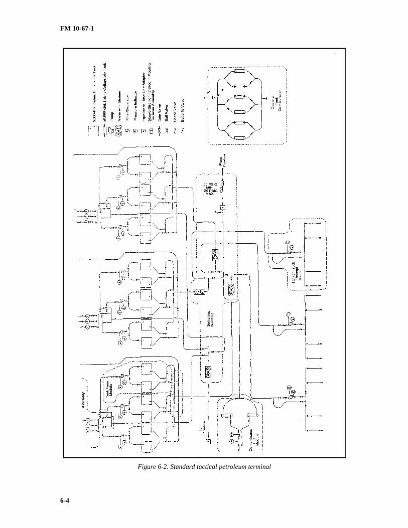
FM 10-67-1
6-4
Figure 6-2. Standard tactical petroleum terminal

FM 10-67-1
6-5
Section II. System Components
THE 210,000-GALLON FABRIC COLLAPSIBLE TANKS
The 210,000-gallon capacity, fabric collapsible, fuel storage tanks also known as BFTA are completewith fittings, accessories, and emergency repair items. The BFTA as shown in Figure 6-3, page 6-9. Formore information on the 5,000 barrel tank see Chapter 22.
THE 50,000-GALLON FABRIC COLLAPSIBLE TANKS
The eight 50,000-gallon fabric collapsible tanks furnished with the TPT are complete with fittings,accessories, and emergency repair items. The 50,000-gallon fabric collapsible tank is shown in Figure 6-4, page 6-10. For more information on the 50,000-gallon tank, see Chapter 22.
THE 600-GPM HOSELINE PUMPS
The 600-GPM hoseline pumps are wheel-mounted, diesel engine-driven, self-priming, air-cooled,centrifugal units. The pump is close-coupled to a turbo-charged diesel engine which can be operatedmanually or automatically through an electric governor. Controls regulating either mode of engineoperation are contained in the control panel mounted directly over the pump. The pump and engine aremounted on a two-wheel trailer assembly with internal towing bar and leveling supports. The 600-GPMhoseline pump has a discharge head of 350 feet and is rated at 2400 RPM. The 600-GPM hoseline pumpis designed to--
• transfer fuel from one tank to another
• pump fuel to the dispensing set
• pump fuel to the associated pipeline or hoseline system
• pump fuels from the tank vehicle receipt manifold to the TPT storage tanks.
THE 350-GPM TRANSFER PUMP
The 350-GPM transfer pump can be field transported with a tow vehicle for short distances. A longdistance move has to be made with a transport vehicle. This pump unit is used in the contaminated fuelmodule with the TPT. The pump can also be easily moved and used as required in other locations andservices. Figure 6-5, page 6-10, shows a 350-GPM pump. For more information on the 350-GPM pumpsee Chapter 20.
METER/STRAINER ASSEMBLY
The four meter/strainer assemblies are aluminum single-case, positive displacement meters with 6-inch double-groove connections. A meter/strainer assembly is shown in Figure 6-6, page 6-11. Themaximum working pressure is 150 PSI. The maximum flow rate is 800 GPM. A large numeral resetcounter mounted on the meter reads out in U.S. gallons. A 0 to 1500 GPM flow indicator is included asan integral part of the assembly. The strainers included in the skid-mounted assembly upstream of eachmeter have 6-inch cast steel strainers with 40-mesh stainless steel baskets with 6-inch double-grooveconnections. The strainers have a 150-PSI working pressure. An air release head is mounted on thestrainer. The meters and strainers are mounted together on a skid for easy handling and a firm setting.Three of the four meters measure fuel into the fuel units. The other meter is supplied for installation inthe hoseline return to the pipeline or to a user facility. The strainers are to protect the meter assemblies.
FILTER-SEPARATORS
There are twelve 350-GPM filter/separators in the system. The filter/separator is shown in Figure 6-7, page 6-11. For more information on the 350-GPM filter/separator see Chapter 21.

FM 10-67-1
6-6
PRESSURE-REGULATING VALVE ASSEMBLY
There is one pressure-regulating valve assembly in the TPT. It consists of a steel skid-mounted, 7-inch pilot-operated, pressure-regulating valve. The valve is controlled so that it will not open unless theupstream pressure is 50 PSI or above. Downstream pressure is limited to a maximum of 125 PSI. Thepressure-regulating valve assembly has a 7-inch flange to 6-inch IPDS single-groove adapters on eachside. Pressure gages are installed in the control manifolding to show pressures on both the upstream anddownstream sides of the valve. To protect the pressure-regulating valve from debris in the pipeline, asleeve strainer is supplied to insert into the scraper receiver at the end of the pipeline supplying fuel to theTPT. The pressure-regulating valve limits pressure into the TPT switching manifold to below 125 PSIand maintains a pipeline pressure of 50 PSI or above in operation and 50 PSI on shutdown. The pressure-regulating valves are supplied as part of the switching manifold supply.
THE 6-INCH PRESSURE CONTROL VALVE ASSEMBLY
There are three 6-inch pressure control valve assemblies in the TPT. These pressure control valvesare back pressure relief/back pressure regulators set at 30 PSI. The unit is skid-mounted and fitted withdouble-groove adapters. These back pressure controllers are installed in the recirculating hoselines fromthe fuel-dispensing assembly back to the tankage to maintain dispensing pressure at a maximum of 30PSI. These control valves are supplied as part of the dispensing assembly.
THE 1 1/2-INCH PRESSURE CONTROL VALVE
There are six 1 1/2-inch pressure control valves in the system, each set at 5 PSI. The end fittings are1 1/2-inch with cam-lock couplings. These valves are part of the two 1 1/2- inch dispensing points ateach dispensing assembly, designated primarily for filling nonvented 500-gallon collapsible drums. Theylimit the loading pressure of the drums to 5 PSI. The valves are supplied as part of the dispensingassembly.
FUEL SAMPLING ASSEMBLY
There is one fuel sampling assembly in the TPT as shown in Figure 6-8, page 6-12. It consists of apipe section with double-groove ends, a 1/2-inch tap into the line, a 1/2-inch ball valve, a 1/2-inch needlevalve, a goose-neck spigot, and a catch basin. A set of hydrometers is supplied with the fuel samplingassembly. This assembly is located on the inlet line to the switching manifold for each TPT to permitperiodic sampling and quality control.
RANGE POLES
The TPT is supplied with 36 range poles Range poles are used to roughly estimate the quantity of fuelin the fabric collapsible tanks in the TPT. Each pole is made of two sections of steel tubing of nominal 11/8-inch outside diameter and of nominal 0.032-inch wall thickness. The pole is 6½ feet long with ahardened steel point permanently fastened to the lower end. The two pole sections are locked togetherwith a spring catch. Both sections are fitted in a two-pocket cotton duck carrying case. Two poles aresupplied for each BFTA. They are driven in the berms on opposite sides of the tank and a cord isstretched across the tank. The cord should be set at 6 feet 8 inches up from the base of the tank, which isthe full level. Attaching a readily visible object, such as a ball, to the cord over the center of the tankmakes estimating tank height easier.
NESTABLE CULVERTS
Nestable culverts are 12-inch corrugated culvert pipe. Hose can be routed through these nestableculverts for protection from traffic weight and any other effects which might cause hose damage. Nestable

FM 10-67-1
6-7
culverts can also be used to protect the hose from rock or from ballast and cinders under a railway spur.The culverts are part of the TPT support assembly.
FLOODLIGHT SETS
There are six floodlight sets in the TPT. A floodlight set is a wheel-mounted diesel engine-drivengenerator with an integrally mounted telescoping tower carrying four high intensity lamps. One set canlight 7.5 acres. It has a generator set that is powered by a 7-cycle, air-cooled, multifuel engine. It carriesa fuel capacity for 18 hours. The setup locations for the six sets are determined by the requirements forthe particular TPT site. Particular attention should be given to the lighting of fuel-dispensing areas, fuelreceipt areas, and heavy operating areas around the pumps and the switching manifold. There is oneportable petroleum aviation fuel contamination kit supplied with the TPT.
FIRE-SUPPRESSION EQUIPMENT
Each TPT is furnished with 19 sets of fire-suppression equipment. Each set contains a skid-mounteddry chemical and AFFF fire extinguisher with a remote wheel-mounted hose cart; Purple K dry chemicals;liquid foam; Kevlar hoods, gloves, coats, boots and trousers. The particular TPT layout determines wherefire-suppression equipment is placed. Whatever locations are selected, they should be readily accessible tothe operators and the fire suppression crew and. These locations should be clearly flagged with prominentsigns. Clothing should be stored in a dry, readily accessible building or container.
HOSE, FITTINGS, AND VALVE ASSEMBLIES
For the most part, the hose, fittings, and valves are used to interconnect the equipment described inTable 6-1, pages 6-33 and 6-34, and Table 6-2, page 6-35. They are preassembled into convenient unitsthat make installation more efficient. There are 12 of these assemblies in the TPT system.
STORAGE AND TRANSFER SYSTEMS
The equipment described previously in this section make up the storage and transfer systemsdescribed below. Installation of these components is covered in Section III of this chapter.
Tank Farm Units
The tank farm units are the primary storage units for fuel in the TPT. Fuel is pumped directly to thefuel-dispensing assembly from the storage tanks of any tank farm unit assembly. Fuel can be pumpedfrom the tank farm unit assembly to another tank farm assembly in the fuel unit or to an associatedpipeline or hoseline system if required in the particular operating area. A tank farm unit consists of twoBFTAs, one 600-GPM hoseline pump, three 6-inch aluminum Ts, seven 6-inch gate valves, couplingadapters, and enough 6-inch hose assemblies (suction and discharge) to connect the components. Rangepoles are provided to estimate the amount of fuel in the collapsible tanks. The maximum distances in thefuel tank spacing is depends on the available hoseline and the minimum distances by safetyconsiderations. The hoseline arrangements shown are examples. Other arrangements may be moresuitable for certain situations.
Contaminated Fuel Unit
The contaminated fuel unit is used to store fuel that has become mixed or contaminated duringtransport to the TPT. This includes the interface which occurs in the pipeline batching and the fuel/waterinterface at the time of the initial purge and fill operation. Tank vehicle connections are provided so thecontaminated product can be transported for blending or disposal. The contaminated fuel unit consists oftwo 50,000-gallon fabric collapsible tanks, a 6-inch aluminum T, a 350-GPM pump, a 3-inch ball valveassembly for loading tank vehicles, two 6-inch aluminum gate valve assemblies, and hoses and fittings toconnect the components. Road access is required to allow the unloading of the 50,000-gallon tanks withtank vehicles.

FM 10-67-1
6-8
Transfer Hoseline Assemblies
Three transfer hoseline assemblies are provided with the TPT. Each assembly provides theconnection between the switching manifold, the tank farm units, and the return manifold to the pipelinesystem. Valve assemblies in the transfer hoseline allow the switching of fuel between the tank farmassemblies. Each transfer hoseline assembly has about--
• 23,000 feet of 6-inch lightweight collapsible discharge hoseline,
• eleven 6-inch double-groove aluminum Ts,
• eleven 6-inch aluminum gate valve assemblies,
• one 6-inch hoseline suspension kit,
• 16 flaking box assemblies,
• one displacement and evacuation kit,
• three 6-inch double-groove coupling clamp sets.
The hoseline is provided in flaking boxes with two 250-foot lengths per box. Four flaking boxes canbe stacked on the bed of a 5-ton cargo truck and flaked out continuously.
Fuel-dispensing Assemblies
Three fuel-dispensing assemblies come with each TPT. The fuel-dispensing assembly is used to issuefuels from a TPT. There is one fuel-dispensing assembly for each of the three fuel units. Using a tankfarm unit as its pumping source and bulk holding point, the fuel-dispensing assembly allows fuel loadingto tanker trucks and 500-gallon collapsible drums. The major components of the fuel-dispensingassembly include three 350-GPM filter/separators, three probe adapters for the portable fuelcontamination testing kit, six loading points for loading tank trucks, and two 500-gallon collapsible drumloading points. About 900 feet of hoseline and valves of various sizes are used to connect the componentsof the dispensing assembly.
Tank Vehicle Receipt Manifold
The three tank vehicle receipt manifolds provide the TPT with the valves, hoselines, and fittingsnecessary to allow the offloading of petroleum products from tank vehicles if required. A bypass linearound the pump is provided, allowing the manifold to be used to load tank vehicles to supplement thefuel-dispensing set, if required. Depending on system requirements, the manifold can be installed fully orpartially. Each of the manifolds has four tank vehicle unloading stations using 7-inch butterfly valveswith 3-inch quick-disconnect couplings. A 600-GPM hoseline pump from the TPT support assembly isused with each manifold. The truck unloading valves are connected to 7-inch suction hose which isconnected to a 6-inch suction hose leading to the pump. The bypass around the pump is made up of 6-inch discharge hose. Three 6-inch aluminum T assemblies and four 6- x 6- by 7-inch aluminum Tsprovide the necessary connection for the manifold. To connect the receipt manifold to the TPT andmaintain a safe separation between the components, 250-foot long 6-inch hoseline sections from thetransfer hoseline kit can be used as needed.
Switching Manifold
The switching manifold controls the flow from the associated pipeline to the tank farm units and thecontaminated fuel unit. It also controls the flow from the tank farm units to a pipeline or a user facility.The manifold is made up of two parts; the receipt manifold and the return manifold. The receipt manifoldreceives fuel from the associated pipeline and tank vehicle receipt manifold and distributes the fuel to the

FM 10-67-1
6-9
tank farm unit. The valves in the switching manifold allows cuts between batches of different fuelsarriving at the TPT from the associated pipeline, and, if necessary, from the tank vehicle receiptmanifolds. The interface goes to the contaminated fuel unit. The return manifold receives fuel from thetank farm units and directs it to the associated pipeline or hoseline user facility. The switching manifoldconsists of--
• Five units of 6-inch, 50-foot discharge hose,
• 50 double-groove coupling clamps,
• Six 6-inch aluminum gate valve assemblies,
• Nine 6-inch aluminum double-groove tees,
• Four meter skid assemblies,
• One pressure regulating valve assembly,
• One sampling assembly,
• Six 6-inch single-groove to double-groove adapters.
Only two of the 6-inch single-groove to double-groove adapters are used in the switching manifold,one in the receipt manifold and the other in the return manifold. The other adapters are available for usein modifications that may be required in certain operating areas. Ideally, the switching manifold shouldbe as compact as possible; however, certain situations may require extra length. The switching manifoldsetup may vary with site conditions and service requirements.
Optional Tank Configuration
The optional tank configuration can be used to replace or supplement the normal BFT's in the tankfarm units or provide for special storage as required. There is one optional tank configuration suppliedwith each TPT. Each tank configuration contains up to six BFTAs, six 7-inch aluminum Y-assemblies,six 7-inch aluminum gate valve assemblies, and four 7-inch aluminum tee assemblies. Connectionsbetween components are made with 7-inch hoseline assemblies, both suction and discharge. Note thateach BFTA comes with a 10-foot section of 7-inch suction hose and a 7-inch aluminum gate valve whichare incorporated into the hoseline layout. Each tank is also supplied with a 4- to 6-inch adapter and a 6-inch cam lock to double-groove adapter to allow the tank to be used separately. Two 6-inch Ts areprovided to be used as required.

FM 10-67-1
6-10
Figure 6-3. The 5,000 barrel fabric collapsible tank
Figure 6-4. The 50,000 gallon fabric collapsible tank
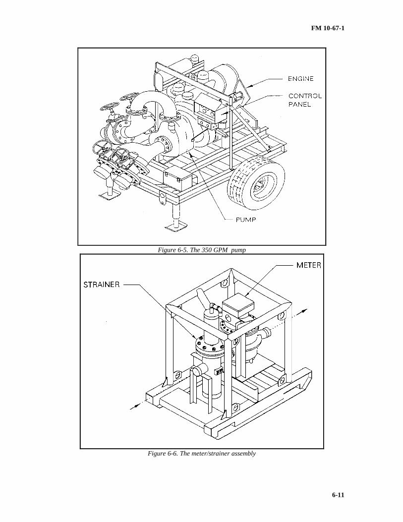
FM 10-67-1
6-11
Figure 6-5. The 350 GPM pump
Figure 6-6. The meter/strainer assembly

FM 10-67-1
6-12
Figure 6-7. Filters separator, liquid fuel
Figure 6-8. Fuel sampling assembly
FM 10-67-1
6-13
Section III. Tank Farm Installation
LAYOUTS
The layout requirements for a TPT must be flexible to fit the particular site and service. Thesearrangements may be modified for practicality at a particular site. The objective in any equipmentarrangement is to provide for efficient and safety in operations. As a general rule, the TPT should bearranged for maximum spacing between tank farm units and fuel units to the extent the particularoperating site requirements and hoseline availability permit. This will provide for the highest level ofsafety for the equipment and the operating personnel without adversely affecting operating efficiency.Specific area service requirements may also affect layout and spacing. For detailed information on TPTlayout, refer to FM 5-482.
Typical TPT Layouts
A typical TPT layout is shown in Figure 6-9, page 6-13. This layout is an example of a TPT whichhas been arranged to make full use of the transfer hoseline provided for wide spacing between fuelmodules. The layout assumes that adequately sized property is available and the equipment is wide spacedfor security reasons. In many locations, due to terrain or operational situations, the layout may have todiffer substantially from that shown. In a relatively secure area or when property available is limited, itwill be appropriate to arrange the system with much closer spacing between fuel units and equipment. Atypical close-spaced TPT layout is shown in Figure 6-10, page 6-14 . It is not imperative to lay outtankage in a straight line. Security demands or terrain may dictate otherwise. Road access should alwaysbe considered when planning a TPT site. Ideally, there should be a limited number of entry points intothe TPT area, with each entry point having a control or checkpoint to monitor and route traffic in and outof the area. A road that can support two-way tank vehicle traffic should run along the perimeter of theTPT site. This road would give access to each fuel unit's fuel-dispensing assembly. In the fuel-dispensingareas, the roadway should be widened to at least 40 feet. Through traffic should be routed away from thefuel-dispensing area. Similar fuel handling areas are needed for the contaminated fuel module and thetanker truck receipt manifolds. Secondary roads should be made for MHE, pumps, fire-suppressionequipment, and maintenance equipment to be moved. Under-road culverts through which hoselines passallow vehicles to cross over the hoselines without damaging them. These culverts are installed asnecessary. The hoseline suspension kit may also be used to provide for crossing under the hoseline.Access must be provided to the pumps and near each tank berm. An important point shown on thegeneral TPT layout is the location of the fire-suppression equipment. A wheel-mounted fire extinguishershould be located near each tank berm, at each fuel-dispensing assembly, at each tank vehicle receiptassembly, and at the contaminated fuel module. Extra units should be stationed at a central point readyfor use anywhere in the TPT. Covered shelters or containers for housing the Kevlar fire-fighting clothingand extra fire fighting supplies should be provided at central, easily accessible locations around the TPT.The 20-pound hand-held fire extinguishers should be distributed and located at each pump, eachfloodlight set, each fuel-dispensing area, and other operating areas at the discretion of the operatingsupervision. Personnel must know where all fire-fighting equipment is located at all times to preventconfusion in an emergency. Readily visible signs flagging the locations of fire extinguishers would behelpful. The floodlight sets should be placed to give light to the fuel-dispensing areas, fuel receipt areas,and heavy operating areas around the pumps and the switching manifold.

FM 10-67-1
6-14
Figure 6-9. Typical wide-spaced TPT layout

FM 10-67-1
6-15
Figure 6-10. Typical closed spaced TPT layout
SITE SELECTION
Using both aerial and ground reconnaissance, the Army will probably preselect a specific site or atleast a desired area in which to set up the TPT. (Refer to FM 5-482 for detailed information on siteselection). There is not a completely ideal site. When picking a site, a decision must be made. Whenevaluating the site, these factors must be considered in site selection.
• Distribution Plan. The need for the terminal in a general area can be decided only by the U.S.Army's distribution plan.
• Relation to the Area System. The ability to supply the terminal with fuel must be considered. Thiswill consider the primary source of supply and the hydraulics of the pipeline to the terminal. In mostcases, the distribution plan will be the main factor. It will cause the associated pipeline system design tobe such that it can deliver to the TPT site selected.
• TPT Site Size. The site selected must be able to hold the equipment and roadways needed. Theprevious paragraphs discuss these site requirements. Compromise and rearrangement of equipment willoften be necessary.
• Suitability of Terrain. The selected site should be reasonably level and well drained especiallywhere the individual storage, loading, and unloading of equipment are planned. The least amount ofearth moving work needed is better. The less, the better. Low and swampy areas should be avoided. Thesite should be as free as possible from heavy obstructions such as large rocks and trees.
• Road Access. If possible, the site should be located relatively near existing road systems capable ofcarrying the traffic involved. There must be access to that road system or a new road may need to beconstructed to connect the roads.

FM 10-67-1
6-16
• Water Availability. Water must be available at the site or making it available at the site. Theoperation must have water available for safety reasons even if it must be hauled to the site. Water must beavailable for the charging of the dry chemical/AFFF wheel-mounted fire extinguisher. It is also neededfor general fire protection and personnel safety.
• Layout. After the site has been selected, a preliminary layout should be made. This shows all themajor equipment and system locations, including tanks, pumps, floodlight sets, fuel-dispensing areas, tankvehicle receipt areas, and the access roads. The characteristics of the site available should be evaluated.Then the preliminary layout should be reviewed and corrected if needed for a final layout on whichequipment locations are firm. Final roadwork and tank pad and berm construction must be based on thisfinal layout.
SITE PREPARATION AND EARTHWORK
Final site selection and subsequently site preparation and earthwork must be based on the layoutdiscussed in the previous paragraph. The site will probably not be ideal; therefore, there must be somegive and take between the layout and site preparation results. Site preparation work should be based on agrading plan that reduces cut and fill operations even if the plan is roughly prepared in the field. Theplan should be based on actual on-site elevations and survey, observation of obstructions, and knowledgeof the types of soils that appear to be present. The first step to prepare the site is to cut an access road tothe site unless one already exists. Stake out the area that must be cleared. Mark where the majorcomponents will be located. Cut, grub, doze, or if necessary, blast major obstructions; for example, trees,boulders, or buildings. Clear and grade the areas where a fuel unit will be located, transfer systemsinstalled, roadways built, and loading and unloading facilities installed. There must be good drainagefrom the site. Plan cuts and fills so that the volume of cut soils roughly equals the required fill for lowspots, tank berms, and roadways. If the area is fairly flat and requires only minimal grading, the materialsfor roadways and tank berms can come from a borrow pit near the site which can, if desired, be convertedto a reserve water storage basin. Keep in mind that the major equipment, most particularly the BFTAs,should be set on virgin or cut soils, if possible, rather than on fill. If tankage must be located on a filledarea, the fill must be compacted as it is placed. Compaction after a deep fill has little effect. Whenextensive fill is required, the slopes must be such as to prevent slides and reduce erosion. As a generalrule, there should be no slopes greater than 2:1 (approximately 25 °) in sandy or loamy soils.
Road
Road must be fully compacted and have good drainage. If possible, they must have at least a surfaceof gravel or crushed rock. Each side of the road should have an adequate swale or ditch for gooddrainage. Drainage culverts should be placed as required. The road, swale, ditch, and drain culvertrequirements will depend on the site and anticipated rainfall. Roads must be constructed to permit readyaccess to all areas for installation, operation, fuel loading and unloading, and fire fighting.
Tank Pad and Berm Construction
Proper tank pad and berm construction is most important to provide for tank operation and protectionfrom spill or a fire resulting from the spill. Tank pads are preferably constructed of a loamy or clay soilcontaining some sand so that a smooth area can be graded and hold its shape. The longest slope should beapproximately 1° (degree) from horizontal. The low point should be where the tank drain will end upwhen the tank is unrolled. A small ditch and a basin for the tank drain line and drain valve can beexcavated by hand at the time the tank is unrolled. The low point permits maximum pump out of the tankand drainage through the drain line. The base of the tank pad area must be virgin, cut, or well compactedsoil. To avoid damage to the tank bottom, sticks, stones, or sharp objects must be removed before the tankis installed. Berms may be constructed before, after, or simultaneously with tank pad construction,depending on job conditions. The tank must be cleared on any rocks or clumps, that roll on to the tankpads during berm construction. Tank pad rough grading should be completed before berm constructionand should be finished after berm construction. The preferred materials are soils containing a fairly high

FM 10-67-1
6-17
clay content to hold shape and sealing. The berm should be compacted as it is constructed. An alternateto graded berms are sandbag berms as described earlier. If a berm drain is installed, as recommended, itshould be laid in a hand-cut trough after the first layer of berm is placed and before the second layer isplaced. Care must be taken to avoid damage by the equipment constructing the berm. This can best behandled by not installing the valve until after the berm is completed and giving the berm drain pipe plentyof cover. When the drain valve is installed, it should be left closed, or the integrity of the berm has beencompromised. Berm liners should be installed after the pad and berm are completed. A light layer of soil(without rocks) may be spread over the liner to protect and hold it in place.
Pads for Other Equipment
To the extent possible, all operating equipment should be set on virgin or cut soils rather than fill. Ifa filled area cannot be avoided, it must be well compacted. This is particularly important for the pumpsand floodlight sets. If available, it is recommended that the areas on which equipment is placed becovered with a 6 to 7-inch layer of coarse gravel or crushed rock. The gravel or crushed rock shouldextend out and around the equipment for several feet. This will provide a high and dry area from whichto operate and maintain the equipment. If coarse gravel or crushed rock is available, place it aroundoften-operated valve stations.
EQUIPMENT INSTALLATION
This section lists the equipment in the recommended installation sequence. Major equipment isinstalled first, followed by major fittings and valve assemblies, and then by the interconnecting hoselines.The transfer hoselines can be laid as soon as the location of the switching manifold is Setup. Whenequipment, valves, fittings and hoses are being installed, internal cleanliness is very important. Sand,rocks, rags, tools, or clothing left inside will block the fuel flow or damage equipment. Leave protectivecaps and plugs in place until actually ready to make a connection. Before closing a joint, inspect the partsbeing assembled and remove any foreign material.
FLOODLIGHT SETS
Install the six floodlight sets that come with the TPT as soon as possible. Sufficient light must beavailable for night TPT installation. Install the floodlight set according to the manufacturer's manual.The location of the sets will depend on characteristics of the field site.
BFTA
Make sure that the tank pads are free of sharp objects and smooth before rolling out the tanks. Thedrain on the tank should be located over the low spot in the pad and the top fitting intended for pumpsuction is the one closest to this drain. Cut a small trench for the drain hose before unrolling that end ofthe tank under which the drain hose will pass. After cutting the trench, install the drain hose and valveassembly. Service, install on assigned pads, and assemble all components of the BFTAs as described inthe TM overpacked with the tanks. Six BFTAs are supplied per fuel unit and 18 per TPT.
The 50,000-Gallon Fabric Collapsible Tanks
Install the 50,000-gallon tanks the same as for the BFTAs.. Service, install on assigned pads, andassemble all components IAW TM 5-5430-210-12. Up to six tanks are in the optional tank configurationand two per contaminated fuel unit.
The 600-GPM Hoseline Pumps

FM 10-67-1
6-18
Three 600-GPM pumps come with each fuel unit and nine per TPT. One 600-GPM pump come withthe tank vehicle receipt manifold and three per TPT. The TPT comes with three spare 600-GPM pumpsfor use as needed. Ground the pumps when they are installed. Install the 600-GPM pumps as far fromthe collapsible tanks as possible without deforming the tank top or causing long unsupported lengths ofsuction hose. The suction hose should lay on the ground without strain on the tank or pump. Pumpengines and exhaust fumes are hot. For safety reasons, keep them as far as practical and distance from thetank will enhance safety. Install, service, and prepare the 600-GPM hoseline pumps for operation IAWthe technical manual overpacked with each pump.
The 350-GPM Transfer Pump
Install the one 350-GPM transfer pump with the contaminated fuel unit. The same preparationprocedures are used as with the 600-GPM pump. Install, service, and prepare the 350-GPM transferpump IAW TM 5-4320-226-14.
Meter Skid Assemblies
Install the meter skid assemblies. Three are supplied per fuel unit supply hoseline and one percommon header to associated pipeline or hoseline system. Service and prepare the assemblies IAW themanufacturer's manuals overpacked with the equipment. Ground the meter skid assemblies when they areinstalled.
Filter Separators
Install, service, and prepare the filter/separators IAW TM 5-4330-211-12. Ground thefilter/separators when they are installed. Three filter/separators are installed with each fuel-dispensingassembly and nine per TPT.
Tank Farm Unit Assembly Hoselines, Valves, and Fittings
The following installation and assembly procedures are based on the shared berm layout shown inFigure 6-11, page 6-18.
• Position crates containing Ts, pumping assembly, and gate valves near their respective installationsites around the fabric collapsible tanks.
• Remove the 6-inch aluminum Ts, gate valves, adapters, coupling clamps, and coupling gaskets fromthe crates. Inspect all items for damage, cleanliness, and quantities required.
• Align mating surfaces of adapters, gate valves, and Ts.
NOTE: When installing coupling clamps and gaskets, liberally apply grease to the gasket and the insidesurface of coupling clamp to prevent pinching during installation. Then, pull the coupling gasket overone grooved end of each mating joint. Ensure the gasket is properly positioned over the fullcircumference of the sealing surfaces. Position the coupling clamp over the gasket. While maintainingalignment of mating parts, lock the coupling clamp securely. Make sure all hoselines, fittings and valvesare clean internally. Foreign materials may stop operations and damage equipment.

FM 10-67-1
6-19
Figure 6-11. Tank farm (Module) assembly layout, typical layout with separate berm constuction, hose,valve, and fitting installation

FM 10-67-1
6-20
Check the position of the 600-GPM hoseline pump
• Place crates containing hose and fittings near their respective installation position.
• Uncrate and position the 6-inch discharge hose assemblies.
• Remove the dust caps and connect the 5-inch suction hose and gate valve assembly to the tankelbows.
• Connect the coupling adapters to the gate valves.
• Connect the 6-inch suction hoses between the coupling adapters and the gate valve assembly.
• Connect the 6-inch suction hose to the T assembly and inlet side of the pump assembly.
• Connect the 6-inch discharge hose between the outlet side of the pump assemblies and the gatevalve.
• Connect the 6-inch gate valve to the transfer hoseline.
• Connect the coupling adapters to the tank elbows.
• Connect the 6-inch discharge hoses between the coupling adapters and gate the valve assemblies.
• Inspect all connections to verify correct installation of coupling clamps, coupling gaskets, andsecurity of cam-lock devices.
CONTAMINATED FUEL UNIT HOSELINES, VALVES, AND FITTINGS
The following assembly and installation procedures are based on the contaminated fuel modulelayout. Make sure all hoselines, fittings, and valves are clean internally. Foreign materials may stopoperations and damage equipment.
• Connect elbows to the outlet ports of the 50,000-gallon tanks. Connect 6- by 7-inch reducers to theelbows.
• Connect the coupling adapters to the 6-inch by 7-inch reducers.
• Install the 6-inch discharge hoses between the coupling adapters and the gate valve assembly.
• Connect the gate valves to the 6-inch T.
• Connect the 6-inch discharge hose between the 6-inch tee and the beginning of the transferhoseline.
• Connect elbows to the inlet ports of the 50,000-gallon tanks.
• Connect 7-inch suction hoses to the tank elbows and 7-inch gate valves.
• Connect the 7-inch suction hoses to the suction side of the 350-GPM transfer pump and the 7-inchgate valve assemblies.
• Connect the 7-inch discharge hoses to the discharge side of the transfer pump.
• Connect the 7- by 3-inch reducer and the 3-inch ball valve assembly to the 7-inch discharge hose.
• Inspect all connections to verify correct installation of the flanges, coupling gaskets, clamps, andsecurity of cam-lock couplings.
TRANSFER HOSELINE ASSEMBLY, VALVES, AND FITTINGS

FM 10-67-1
6-21
One transfer hoseline assembly is supplied with each fuel unit; three assemblies per TPT. Thetransfer hoseline set assemblies are crated in a partially assembled condition to ease packaging andshipping. Some assembly is required to place the Ts and gate valve assemblies in operating conditionbefore installation. The following installation procedures are based on the transfer hoseline assemblylayout. Make sure all hoselines, fittings, and valves are clean internally. Foreign materials may stopoperations and damage equipment.
• Position crates containing 6-inch Ts and gate valve assemblies near their respective installation.
• Remove the 6-inch aluminum Ts, 6-inch aluminum gate valve assemblies, coupling clamps, andcoupling gaskets from the crates.
• Inspect all items for damage, cleanliness, and quantities required.
• Tighten flange adapters to the gate valves, being careful not to damage the gasket.
• Connect the gate valves to the Ts.
• Connect the needed quantity of transfer hoseline between the outlet port of the meter strainers andTs. (Depending on which TPT is available, the transfer hoseline will be supplied either in 250-footlengths stored in flaking boxes or 600-foot lengths stored on hose reels.)
• Inspect all connections to verify correct installation of flanges, coupling gaskets, clamps, andsecurity of cam-lock devices.
Fuel-Dispensing Assemblies
One fuel-dispensing assembly is supplied with each fuel unit; three per TPT. Make sure all hoselines,fittings, and valves are clean internally. Foreign materials may stop operations and damage equipment.
Installation of Coupling Clamp and Gasket
• Liberally apply grease to the gasket and the inside surface of the coupling clamp to preventpinching during installation.
• Pull the coupling gasket over one grooved end of each mating joint.
• Ensure the gasket is properly positioned over the full circumference of the sealing surfaces.
• Position the coupling clamp over the gasket. While maintaining alignment of mating parts, lockthe coupling clamp securely.
• Check the position of the 350-GPM filter separators.
• Connect the 6x6x4 reducing tee adapters, 7-inch dispensing hose, 7-inch gate valves, and adaptersto the inlet side of the filter separator.
• Connect the adapters, water detection kit adapters, 7-inch gate valves, 7-inch dispensing hose,adapter, and 7-inch 6x6x4 reducing tee to the outlet of the filter separators.
• Connect the 6-inch discharge hoses and the 6x6x4 reducing tee.
• Connect the 6-inch ball valve assembly to the 6-inch discharge hose.
• For the first six 6x6x4 reducing tees, install a 7-inch dispensing hose between the 7-inch butterflyvalves and the 7-inch adapter connection on the reducing tees.
• For the two remaining tees, connect the adapter to a 7-inch to 2-inch reducer to the 6x6x4 inchtees.
• Connect the 2-inch to 1 1/2-inch reducer to the 7-inch to 2- inch reducer.
• Connect the 1 1/2-inch ball valve to the 2-inch by 1 1/2- inch reducer.

FM 10-67-1
6-22
• Connect the 1 1/2-inch pressure control valve to the 1 1/2- inch ball valve.
• Install the 1 1/2-inch dispensing hose on the outlet port of the pressure control valve.
• Connect the 1 1/2-inch ball valves to the ends of the 1 1/2-inch dispensing hose.
• Connect the 6-inch ball valve to the last reducing tee.
• Connect the 6-inch pressure control valve to the 6-inch ball valve.
• Inspect all connections to verify correct installation of flanges, coupling gaskets, clamps, andsecurity of cam-lock devices.
NOTE
Liberally apply grease to the gasket and the inside surface of the coupling clamp to preventpinching during installation. Then pull the coupling gasket over one grooved end of each matingjoint. Ensure the gasket is properly positioned over the full circumference of the sealing surfaces.Position the coupling clamp over the gasket. While maintaining alignment of mating parts, lock thecoupling clamp securely.
TANK VEHICLE RECEIPT MANIFOLD HOSELINES, VALVES, AND FITTINGS
The tee assembly used in the tank vehicle receipt manifold is crated in a partially assembled conditionto facilitate packaging and shipping. Some assembly is required to place the unit in operating conditionprior to installation. Make sure all hoselines, fittings, and valves are clean internally. Foreign materialsmay disrupt operations and damage equipment. The following installation procedures are based on thetank vehicle receipt manifold shown in FM 5-482.
• Position crates containing tank vehicle receipt manifold components in their respective installationpositions.
• Remove the components from the crates as required.
• Check the position of the 600-GPM hoseline pump.
• Connect the 6-inch tee to the 6-inch gate valve and discharge hose assembly. Connect these to thedischarge side of the pump.
• Connect the 6-inch suction hose to the suction side of the pump.
• Connect the 6-inch gate valve to one leg of the tee, then connect the 6-inch discharge hose to thegate valves.
• Position and connect the two remaining tees. Install the 6- inch gate valves.
• Connect the suction hoses and 6x6x4 tees.
• Connect the coupling adapters to the tee fittings.
• Connect the 7-inch suction hoses to the coupling adapters.
• Connect the 7-inch butterfly valves to the suction hoses.
• Install the 6-inch caps on the tee fittings.
• Connect the 7-inch by 3-inch reducer to the butterfly valves.
SWITCHING MANIFOLD

FM 10-67-1
6-23
The following assembly and installation procedures are based on the switching manifold shown inFM 5-482. Make sure all hoselines, fittings, and valves are clean internally. Foreign materials maydisrupt operations and damage equipment.
• Position the crates containing the 6-inch aluminum tees, 6- inch gate valves, 6-inch samplingassembly, 6-inch ball valves, hose assemblies, meter skid assemblies, and pressure regulating valveassembly near their respective installation sites as indicated.
• Remove tees, valves, hoseline, pressure regulating valve assembly, sampling assembly, meter skidassemblies, adapters, coupling clamps, and coupling gaskets from the crates.
• Inspect all items for damage, cleanliness, and quantities required.
• Connect the 6-inch tees together to form the configuration shown in FM 5-482.
• Connect the gate valves and ball valve assemblies to the tees.
• Connect the discharge hose between the gate valves and meter strainer assemblies as well asbetween the tee and meter strainer on the return manifold.
• Connect the fuel sampling assembly to the tee as shown in FM 5-482. In some cases hose may bein between the sampling assembly and the switching manifold.
• Install the pressure regulating valve assembly in the pipeline to the switching manifold, upstreamof the fuel sampling assembly or as directed by the operating authority. Six-inch IDS single groove pipeis supplied by the associated pipeline. If the system does not involve an associated pipeline, the feed line(hose or pipe) can be tied directly into the pressure regulator and all downstream conduit can be hoseline.
CAUTION
Upstream (back pressure) and downstream (reduced pressure) pressures are preset as intendedto 50 PSI upstream minimum and 125 PSI downstream maximum. DO NOT bypass upstream ordownstream pilots without supervisory instructions. Bypassing the downstream pilot can result inpressure or reduced pressure control settings without operating authority approval.
• On the return manifold, connect the discharge hose between the outlet side of the meter strainerand the single to double- groove adapter.
• Inspect all connections to verify correct installation of flanges, coupling gaskets, clamps, andsecurity of cam-lock devices.
OPTIONAL TANK CONFIGURATION HOSELINES, VALVES, AND FITTINGS
The following assembly and installation procedures are based on the optional tank configuration.Make sure all hoselines, fittings, and valves are clean internally. Foreign materials may disruptoperations and damage equipment.
• Connect elbows to the 50,000-gallon tanks.
• Connect the 7-inch suction hose assemblies to the elbows.
• Connect the 7-inch suction hose assemblies between the 7- inch suction hose assembles and the wyeassemblies. Ensure the correct hose lengths are installed in the positions shown. Make sure the correctbend radii are maintained.
• Connect the 7-inch suction hoses between the 7-inch tee assembles and the wye assemblies.
• Connect the reducer and coupling adapter to the tee assembly.

FM 10-67-1
6-24
• Connect the tee to the reducer.
• Connect the elbows to the tanks.
• Connect the 7-inch discharge hose assembles and to 7-inch gate valve assemblies.
• Install the wye assemblies to the 7-inch gate valves.
• Install the 7-inch discharge hose between the wye assemblies and the 7-inch tee assemblies.
• Connect the reducer to the 7-inch tee assembly. Connect the coupling adapter to the reducer.
• Connect the tee to the adapter.
• Inspect all connections for correct installation of flanges, coupling gaskets, clamps, and security ofall cam-lock devices.
FIRE SUPPRESSION EQUIPMENT
Check out, service, and install the fire suppression equipment in accordance with the overpackedinstructional manuals and specific instruction of operating management. The wheel-mounted drychemical/AFFF units should be located such that they can be readily put into service at the fuel storageunits, fuel-dispensing sets, the switching manifold, the contaminated fuel module, and the tank vehicleoffloading area. U.S. Marine Technical Manual 07661B-14/1 contains instructions on the drychemical/AFFF unit. The 20-pound fire extinguishers should be placed according to the direct operatingauthority. It is recommended that one be placed near all pumps, floodlights, and loading spots.Placement of the extra extinguishers not specifically located should be just outside the immediateoperating area in a highly visible location.
CAUTION
Thoroughly check out all fire suppression equipment at the time of locating in the unit.Extinguishing equipment must be charged and in working order. Clothing must be clean and ingood condition. Clearly mark storage areas for fire suppression equipment and educate allpersonnel on its location and use prior to bringing flammable fuels to any part of the system.
SAFETY AND NO SMOKING SIGNS
Prepare and install appropriate safety and no smoking signs at designated locations for the specificsite. No smoking is allowed within 50 feet of any system or equipment containing flammable fuels. Setup "No Smoking" signs just outside of this boundary area. Set up "No Smoking" signs around fuel-dispensing and fuel receipt areas. To minimize the threat of smokers, create a well- marked "SmokingPermitted" area well away from the facilities and make that the only area in which smoking is permitted.This area should not be lower than or down wind of the fuel handling area. Set up "Shut Engine Off"signs at fuel-dispensing and receiving areas. Set up "Disconnect Hose Before Moving Vehicle" signs atdispensing and receiving areas. Place the following safety signs at appropriate locations:
• "Danger - Hot Surfaces" - at pump engines.
• "Danger - Moving Parts" - at pump and engines.
• "Danger - Wear Goggle and Gloves" - at sampling position.
• "Watch Your Step" - in congested areas.
PRESSURE TEST SYSTEM

FM 10-67-1
6-25
The TPT system, particularly the hose systems, should be pressure tested before it is placed inoperation. The purpose of the test is to prove the integrity of the system, by locating leaks, blockages, andinstallation faults. The test is not to prove the strength of the materials; therefore, test pressures arelimited to the maximum design operating pressures. A complete test is recommended; however, it isunderstood that some deviation may be required due to specific site conditions and immediate operatingneeds. The extent of pressure testing and the test media used is up the operating authority.
Test Medium.
Tests can be conducted with air, water, or fuel. The medium used is dependent on the conditions atthe specific site and installation/operations management decision. From a safety standpoint, a water testis the safest medium. However, it has certain disadvantages, such as the difficulty of removing all waterfrom the system. Air tests should not be conducted at pressures in excess of 50 PSI and, therefore, cannotbe used to locate leaks that occur at higher pressures. A fuel test can be handled safely if care is taken andthe method will save time and is considered adequate. If a fuel pressure test is conducted, it can behandled in conjunction with the purge and commissioning program. After the test medium has beendecided and the line to be tested is filled, bring the test pressures up and hold them long enough tothoroughly inspect the system for leaks and faults. The test pressure is then taken off the system and theleaks and faults corrected. The system must be retested after these corrections are made. A longer periodof holding the system at test pressures may be opted for at the discretion of the operation/installationauthority.
Maximum Test Pressures.
Testing is for locating leaks, loose connections, blockage in the system, and flaws in construction.Testing will prove the integrity of the facility prior to regular operation. The test pressures listed beloware less than maximum pressures. The operating authority may designate lower pressures at their option.When testing fabric collapsible tanks, no pressure is allowed other than static liquid head plus .10 PSI.Make sure the tank vent is open and clear. The tanks may be filled to approximately 85 percent of theirdesign capacity with fuel. All inlet and outlet valves must be closed and blanked off. Inspect for leaks. Ifany leaks develop, the tank must be emptied and repaired, tank refilled, and inspected for leaks. Ifsections of pipeline, connected with a suction hose, are being tested to higher pressures, the suction hosemust be blanked off and tested separately. Pressure tests may be performed using water, fuel or air. Themaximum test pressures for 7-inch pumps and smaller discharge hoses, valves and fittings are 150 PSIwhen testing with water or fuel. The maximum test pressure for suction hose are 150 PSI when testingwith water or fuel. The maximum test pressure when testing with air is 50 PSI for 7-inch pumps, smallerdischarge hoses, valves and fittings, and suction hoses.
Maximum test pressures for 6-inch pump discharge and transfer hose, valves, and fittings are:
NOTE
Certain fittings are rated at 75 PSI maximum. These items are not to be exposed to testpressure above 75 PSI. They can be isolated or removed during the test.
Test Pressure Source.
Test pressure can be supplied from any source capable of holding the test pressures. The 600-GPMhoseline pump is suitable for testing with water or fuel. An air compressor must be available to proceedwith an air pressure test. All test media, water or fuel, if incompatible with the particular fuel service forwhich the system is intended, must be drained from the system before it is placed in service.

FM 10-67-1
6-26
CAUTION
Under no conditions are air pressure tests to be used on fabric collapsible tanks. Remove allconnecting hoses to tanks to prevent this. Pumping air into fabric tanks can exceed the tanks ventingcapacity, inflate, and possibly rupture the tanks.
Preparation for Testing.
Before the test is begun, actions should be taken to ensure that the test runs smoothly. Be certain thatthere are sufficient gaskets, repair equipment, etc. available. Locate fire suppression equipment near thetesting area and be sure that it is in operating condition (when testing with fuel). Make sure to have atank vehicle and drums available, in case a section has to be drained and have shovels amd materialsavailable to dig and line a pit in case there is a break and spill (when testing with fuel). Have caps andplugs available to blank off the section under test. Valves in the system may be used to isolate hosesections as necessary. After all the TPT equipment, hose, valves, and fittings are physically connected,there should be a meeting of all responsible personnel connected with the testing program. Each phase ofthe test plan including a communication plan shall be discussed and reviewed. Prior to filling a sectionfor test, a final check should be made to verify:
• All valves are in proper position for filling.
• All hoses, valves, and fittings connections are tight and valve packing glands are tight.
• Pumps are in good working condition.
Fuel Test Procedure.
Adjust valves so that fuel can be pumped through the section under test, exhausting air. Slowly pumpfuel into the system, not to exceed a flowrate of 200 GPM. When all air is evacuated, close the dischargevalves, fill the section with fuel, and stop the pump. Check all connections for leaks. If no leaks arefound, start the pump and raise the pressure to 25 PSI, stop the pump, and check the gages. If no leaksare found and gages are okay, start the pump and raise the pressure to the selected test pressure. Stop thepump, check for leaks, and hold the test pressure for a period long enough to inspect the entire systemunder test. If leaks are found, relieve the pressure, drain the leaking section, and make repairs,adjustments, or replacements as necessary. At that point, pressure up the section again to test the repairsmade.
CULVERTS
Install culverts at road crossings where hoselines cross under an area where vehicle traffic is planned.Erect signs advising drivers that there is a crossing at that point. Place "Danger, Hoseline Crossing" signswhere they are needed. Hoselines can be easily damaged by vehicles crossing them. Be sure well coveredculverts are installed where traffic is expected. Permit no vehicles to cross unprotected hose.
HOSELINE SUSPENSION SETS
Install suspension sets at road crossings, small streams, and other areas where a nestable culvert maynot be used.
RANGE POLES
Each BFTA is supplied with two range poles, 36 per TPT. Install the range poles and cords at allBFTA sites.

FM 10-67-1
6-27
PAINT SYSTEM
Paint all metal parts that have not been previously painted or anodized to acceptable standards or thathave deteriorated in shipment and storage. Prepare the surfaces and apply primer in accordance with MILT-704, Type A and finish coat per MIL-E-52798, Type I, sand color.
EQUIPMENT AND LINE IDENTIFICATION MARKING
Mark all major equipment, tanks, pumps, meter-strainers, filter- separators, operating valves, andpump pressure gages with the equipment identification numbers. for efficiency and safety in operations.Equipment that has large enough surfaces should be stencil painted using a color that contrasts well withthe background. Small valves and other small equipment can be marked with metal strips bearing theequipment number and wired in place. This should be done after installation to make sure numbering iscorrect. Consider marking hoselines and pipelines with color-coded bands and direction of flow arrows asdescribed in MIL STD 161. Care must be taken to correct the marking if the service of a marked sectionof hose is changed.
AREA CLEANUP
The installation personnel must clean up the area prior to starting operations. They must remove allconstruction dregs, obstructions, and boxes. Unused materials, hose, fittings, and the like should be storedin a specific area for future use. All dust caps and plugs should be boxed and marked for use in the eventthe system is disassembled for shipment. The ISO container supplied with the TPT for ISIL parts may beused for this purpose.
FINAL INSPECTION
It is important to make a final inspection using a checklist arranged essentially in the order of thisinstallation procedure. This should be done by supervisory and management personnel from both theinstallation and operating groups. The following inspection points should be emphasized:
• Integrity and height of tank berms - closed berm drain valve.
• Floodlight location, operability, and grounding.
• Fabric collapsible tank layout and connections.
• Pump location, operability, servicing, and grounding.
• Meter-strainer flow direction and grounding.
• Filter separator flow direction, test adapter installation, and grounding.
• Hoseline, valves, and fittings couplings closed, flanges tight, valve packing glands tight, valves inoperable position and closed. No sharp bends, proper lay on tank tops, sandbags on free ends and bendssubject to whip, and the general condition of the hoseline.
• Sampling assembly in operable location, joints tight, valves closed, and grounding.
• Fire suppression equipment charged, ready to operate, and in proper location.
• Safety and no smoking signs readable and in proper location.
• Review pressure test results and evidence of corrective action.
• Road crossing protection (culverts and suspension devices) in place where needed.

FM 10-67-1
6-28
• Range poles installed properly with cross cord at correct height.
• Corrective painting complete.
• Equipment identification marking correct and adequate.
• Portable fuel testing kit intact.
• Cleanup of area adequate.
Correct the faults found in the inspection and then reinspect. Do not proceed with the operationsuntil all points affecting the integrity and safety of the system are corrected.
Section IV. Terminal Operations
OPERATIONS ORDER
Each terminal prepares its own operation order. It is based on the daily pumping order issued by thechief dispatcher. The daily pumping order is covered in Chapter 9. The contents and format of theterminal operation order are described below.
NOTE
With the introduction of JP-8 as the single fuel on the battlefield, batching and scheduling maynot be needed in military pipelines and hoselines. However, for purposes of this manual, batchingand scheduling procedures and fixed tankage will be discussed in the event multifuel pipelines arerequired or commercial facilities are operated by Army personnel. Motor gasoline and diesel fuelwill also be discussed in the event commercial facilities are operated by Army personnel.
Contents.
The written operation should include the following for each operation:
• Specific personnel assigned to definite duties.
• Status of line fills and position of interfaces, if any exist.
• Valves, pumps, and tanks to be used.
• Estimated desired flow rates.
• Products and quantities of each product to be received or issued and the time operations are tobegin.
• Desired pumping pressures to be maintained.
• Communications system to be used.
• Fire fighting equipment to have on hand.
• Location of the vessel, if applicable, and its estimated time of arrival; number and size of hoses andlines; and hose-handling equipment to be used.

FM 10-67-1
6-29
• Any special instructions or precautions.
Format.
An operation order should include standard procedures, general orders, and special orders. Theseare discussed below.
• Standard procedures for commonly performed operations normally are prepared in advance. Theseoperations include setting valves and selecting specific pumps.
• General orders include specific individual responsibilities by job assignment and thecommunications system to be used, including the telephone control system. Also, the general ordershould include the fire fighting equipment needed for the operation. The hose-handling equipmentto be used and the number and size of hoses needed for the vessel should also be listed.
• Special orders should show the specific products, the amount of each product to be moved, wherethe products are to go, and the time to start and stop each operation. If a vessel or barge is involvedin the operation and more than one berth is available, the orders should specify the berth to be used.
GENERAL OPERATING RULES AND PROCEDURES
Terminal design, product demands, and the nature of each receipt or issue of product determinespecific operating procedures. However, there are certain rules and procedures that must be followed atany terminal for efficient operation and safety. They are described below.
Personnel Assignments and Training.
All personnel must be trained to know the entire system so that each person will be familiar withwhat the others are doing. Only experienced and qualified personnel should be assigned to independentwork. Each person must receive complete operational instructions and must understand them. Personnelshould be trained to anticipate emergencies so that they can cope with various situations.
Operating Rules.
There are general operating rules that must be followed. They are listed below.
• Product in each fixed tank must be sampled and gaged and each collapsible tank must be sampledbefore and after receipt. The quantities received or issued must be volume corrected according to AR 710-2. All of a dissimilar product must be flushed from common lines and the manifold with the same productbeing received or issued before an opening gage is taken. Sampling and gaging procedures in Chapter 3must be followed. Quality surveillance procedures are covered in Military Handbook 200.
• Operations should be stopped and started slowly and carefully. Valves should be opened and closedslowly and pressures brought up gradually. Pressure gages should be watched so that working pressuresare not exceeded.
• Tank vents must be checked for proper operation before product is pumped into or out of a tank. Astuck or clogged vent will cause pressure buildup in a tank. The only way to check the vent is to detectfume emission by smell or other means or to listen for vent clapping.
• During continuous pumping operations, the receiving tank should not be closed off until anothertank is opened. If the pipeline is not in use, tank valves will normally be closed except where they need tobe left open to relieve line pressure caused by thermoexpansion. All hatches on fixed tankage must beclosed except when in use for gaging or sampling.
• There must be positive communications between personnel at operating points in the system at alltimes.
FM 10-67-1
6-30
• Water bottoms must never be used in fixed tankage unless they are authorized by the propertechnical authority. If water bottoms are authorized, they should be checked monthly for hydrogensulfide. Hydrogen sulfide is corrosive and causes the product to fail the copper strip corrosion test.
• Except to switch tanks, no more than one tank must be open to a line system unless necessary.
• All tanks must be kept as full as practicable to avoid evaporation caused by high temperatures.Two tanks partially filled with the same product should be combined to make one full tank.
• Proper tools for each job must always be available. Keys must be available for locked valves andlocked access pits.
• All safety precautions must be observed. Operations must be stopped when conditions becomeunsafe. Any unusual condition must be investigated before an operation is continued. If a tank starts toleak, its contents must be transferred to another tank at once and necessary precautions must be taken.
• A gate valve must never be forced closed. when a gate valve (rising or nonrising stem) is opened orclosed, the wheel should be turned back at least one-quarter turn from the fully open or closed limit. Thisallows free wheel movement to show the valve is not stuck.
• Valves should always be double-checked to make sure the correct ones are opened or closed. Flowinto or out of a tank must be verified as soon as possible after the start of an operation. Automatic tankgages must be read within 15 minutes of the start of the operation and periodically after that. Jet fueltanks must not be gaged manually while they are being filled or emptied. Extreme caution must be usedwhen tanks containing other products are gaged while they are being filled or emptied.
• All bulk petroleum working tanks are gaged daily. All nonworking tanks are gaged at least once aweek.
Receipt of Product.
There are a number of general procedures that need to be followed when product is pumped intotanks. These procedures are described below.
• For fixed tankage, inspect the empty tanks before they receive the assigned product. If the tank isdirty, free it of vapor and have it cleaned. With all tanks, fixed and collapsible, drain any water collectedin the bottom. If the fixed tank has a water bottom because of leaks, keep the water level below the tankinlet.
• As a general rule, receive into only one tank at a time.
• Watch the tank filling operation closely. For fixed tanks, take a rough gage on all tanks, exceptthose receiving jet fuel, every hour to avoid overflows and report cumulative receipts. DO NOT takeullages, water soundings, temperatures, and samples on any tank receiving jet fuel until at least 20minutes after pumping has stopped and flow has ceased. On collapsible tanks, watch the string line overthe tank to determine when the tank is close to being filled.
• When the tank is nearly filled, open up another tank's valve to divert fuel flow and close off the fulltank. As a general rule, leave 5 percent of the fixed tank capacity for vapor space. On collapsibletankage, the top of the tank should just touch the string line suspended over the tank. Use Appendix A asa guide for outages for different products at different temperatures.
• When pumping jet fuel into an empty fixed tank, limit the flow rate. Do not allow the flow ratethrough the loading line to exceed 3 feet per second until the inlet is covered by at least 3 feet of product.After that, resume the normal flow rate. When pumping gasoline or jet fuel into a vapor-free tank, limitthe flow rate to one-fourth or one-fifth of the maximum flow rate until the inlet is covered by 3 feet ofproduct.
FM 10-67-1
6-31
• After product has had time to settle, drain any water from the tanks. Perform quality surveillanceoperations on the fuel.
Issue of Product.
The first in, first out policy (the issue of oldest stocks first) should be followed, and products shouldnot be mixed. Follow the general procedures below for issuing fuel.
• Average issues seldom require more than one tank on- line at a time. When large issues aremade from tanks with individual pumps, product may have to be issued from two or more tanks at a timeto have the desired flow rate. When this is done, position an operator at each pump to regulate productflow.
• In some facilities, the operators may be able to remotely control individual tank pumpselectronically at the tank, booster pump station, or delivery point. They can shut down pumps quickly inan emergency and operate the pumps without constantly being at each pump. However, an operator mustbe at each pump when gasoline or jet fuel is issued.
• Conduct quality surveillance according to Military Handbook 200.
Intraterminal Transfers
Product may be transferred between tanks in a terminal when the terminal is not receiving productfrom the main pipeline. Product may be circulated to end stratification. All free bottom water should bedrawn off before such operations. Pipelines should be checked periodically during intraterminal transfers.
REMOVAL OF WATER FROM STORAGE TANKS
Water must be periodically removed from both fixed and collapsible storage tanks.
Remove water from fixed tanks as follows:
• Drain the water from jet fuel tanks after each product is received or daily. Test tanks for water withwater-indicating paste each time a tank is gaged. Keep a record of the water checks.
• Drain water bottom from all tanks, except jet fuel tanks, the day after product is received or justbefore product is issued from the tanks.
• Check to see if there is water in tanks that have the water drawoff above the lowest point. If thereis water, install an additional pump and a 3/7-inch water drawoff at the lowest point when the tank isopened for internal inspection.
• Drain the water slowly into tanks or tank vehicles approved for waste water disposal. Do notdischarge tank farm drains into public sewers or waterways. Dispose of waste water in accordance withthe local hazardous waste SOPs.
• Remove water from fuel tanks before it gets high enough to be drawn into the fuel outlet. Forpermanent facilities, a product recovery system should be installed to separate fuel and water mixtures.
LINE DISPLACEMENT
Lines should be kept filled with product. However, lines that are shutdown are sometimes drained toprevent pilferage or sabotage. Temperature changes, pressure loss, or air release may cause inaccurateissues or receipts. Therefore, lines must be filled or packed before each operation. Where there is a loopor double line system, lines may be filled by circulating product in them with or without booster pumps.A line may be filled by allowing air to escape through one or more vents at the high points and at the endof the line. This process is much slower, and it may leave air pockets in the line and cause gaging errors.However, this may be the only means available. Water may be used to displace product only if specifically

FM 10-67-1
6-32
authorized by a technical authority. This process is used as a last resort because it is difficult to removeand dispose of the water completely.
PIPELINE METERS
Pipeline meters may reduce loss of product caused by leaks by allowing more reliable, continuouschecks of pipelines. Also, they may reduce losses from terminal operations by providing a means ofchecking product receipts and deliveries. Meters may not stay accurate when they are in constant use.They should be verified periodically or when their accuracy is in doubt.
RECORDS AND REPORTS
DD Form 250 (Material Inspection and Receiving Report). DD Form 250 is a multipurpose form. Itis used for reporting shipments and receipts of packaged petroleum and related products from contractorsand government-owned or consigned pipeline deliveries. This form also is used to report shipments andreceipts by tank vehicle and tank car from contractors. Instructions for preparing DD Form 250 arecontained in DOD 4140.25-M.
DD Form 250-1 (Tanker/Barge Material Inspection and Receiving Report ). DD Form 250-1 is usedwhen bulk petroleum and related products are moved by tanker or barge. It is used mainly to report originacceptance of the cargo, shipments and receipts of government-owned product, and destination acceptanceof tanker and barge cargo. Instructions for preparing the form are in DOD 4140.25-M.
DA Form 5467-R (Petroleum Products Pipeline Leakage Report). DA Form 5467-R is used to reporta leak found anywhere along the pipeline.
Class III Status Report. A Class III status report must be kept for each terminal in the pipeline systemon a daily basis. Although there is no prescribed form for this report. The report shows the stock status ofthe terminal for the past 24 hours. It is sent to higher headquarters or to the chief dispatcher. File copiesare kept at the terminal and at higher headquarters. These copies are a permanent record of terminalactivities. They are part of the total record for the pipeline system. Minimum information needed in thereport is as follows:
• Supply point number.
• Date.
• Report period.
• Receipts of product, by type, into the terminal.
• Total issues of product, by type, from the terminal.
• Total amount of product on hand, by type, in storage tanks, tank vehicles, barges, and packages atthe end of the period.
• Total ullage available for specific products by tank designation at the end of the period.
• Information on unusable storage. (Location and causes of leaks, ruptures, or other damage; otherreasons for unusable storage space; and anticipated changes in ullage due to maintenance are allreported.)
• Estimated requirements and issues, by type, for the next 24-hour period.
Daily Terminal Inventory Report.
The daily terminal inventory report is used only by coastal terminals that receive products by tanker.The report shows levels of marine terminal bulk fuel stock and permits tanker cargo adjustments beforeloading. Amounts are reported in thousands of barrels to the nearest hundred barrels (for example, 17.2).

FM 10-67-1
6-33
The report is telephoned daily to the subarea petroleum office (SAPO). It gives the location of theterminal and the following information for each product:
• Military inventory in shore tankage.
• Commercial inventory in shore tankage allocated for military use.
• Usable inventory aboard floating storage.
• Days of supply on hand.
• Usable inventory in port tankers being discharged or awaiting discharge.
DA Form 4786 (Petroleum Products Tank Farm Intake Record)
DA Form 4786 is used to record the flow of petroleum products to the storage tank area from thedock area or other point of entry..
DA Form 5463-R (Petroleum Products Tank Farm Outturn Record).
DA Form 5463-R is used to record the flow of petroleum products from the storage tank area to tankcars, tank vehicles, and pipelines. It is used when shipments from the tank farm are consigned tooutgoing vessels, tank cars, or tank vehicles. The form is also used if product is transferred from the dockarea to the loading rack, bypassing terminal storage in emergencies.
Weekly Bulk Petroleum Terminal Message Report.
The bulk petroleum terminal message report (RCS:DLA(W)1884(DFSC-MIN)) is an operationalreport for Defense Fuel Supply Center (DFSC) commodity management and for tanker cargo schedulingreview. The report is also used to answer inquiries from all levels of the federal government. Reports areprepared as of 0800 (local time) on Friday of each week. They are to arrive at DFSC no later than thefollowing Monday. Information copies are sent to the proper joint petroleum office (JPO) and DFSC fuelregion. Instructions for preparing the report are given in DOD 4140.25-M.
DD Form 1788 (Bulk Petroleum Terminal Report)
DD Form 1788 (RCS DLA(M)-1883 (DFSC)) is prepared by each terminal, terminal complex, ortanker serving as floating storage that has custody of products owned by the Defense Logistics Agency(DLA). Reports are prepared monthly. Instructions for preparing and forwarding the report are given inDOD 4140.25-M.
Annual Bulk Petroleum Storage Facilities Report
This report (RCS:DD-M(A)506) gives data on all bulk petroleum storage facilities of 500-barrelcapacity or more, either singly or in manifold systems. The report, in a machine produced format, isprovided annually by the DFSC. It is based on annual review and updates from the military departmentsand DFSC activities. All storage capacity changes, including product allocation changes, in excess of10,000 barrels at any activity must be reported to the DFSC as changes occur. Instructions for preparingthe report are given in DOD 4140.25-M
.
Section V. MaintenanceThis manual covers lubrication, preventive maintenance, and corrective maintenance of the materials
and equipment in a typical TPT. On major items of equipment, such as hoseline pumps, collapsible tanks,and filter separators, refer to the appropriate technical publication for detailed repair and maintenanceprocedures.
LUBRICATION PRACTICES
Mechanical equipment requires lubrication to overcome friction and minimize wear, damage, orcorrosion. A firm lubrication procedure and schedule should be established. When the U.S. Army Lube
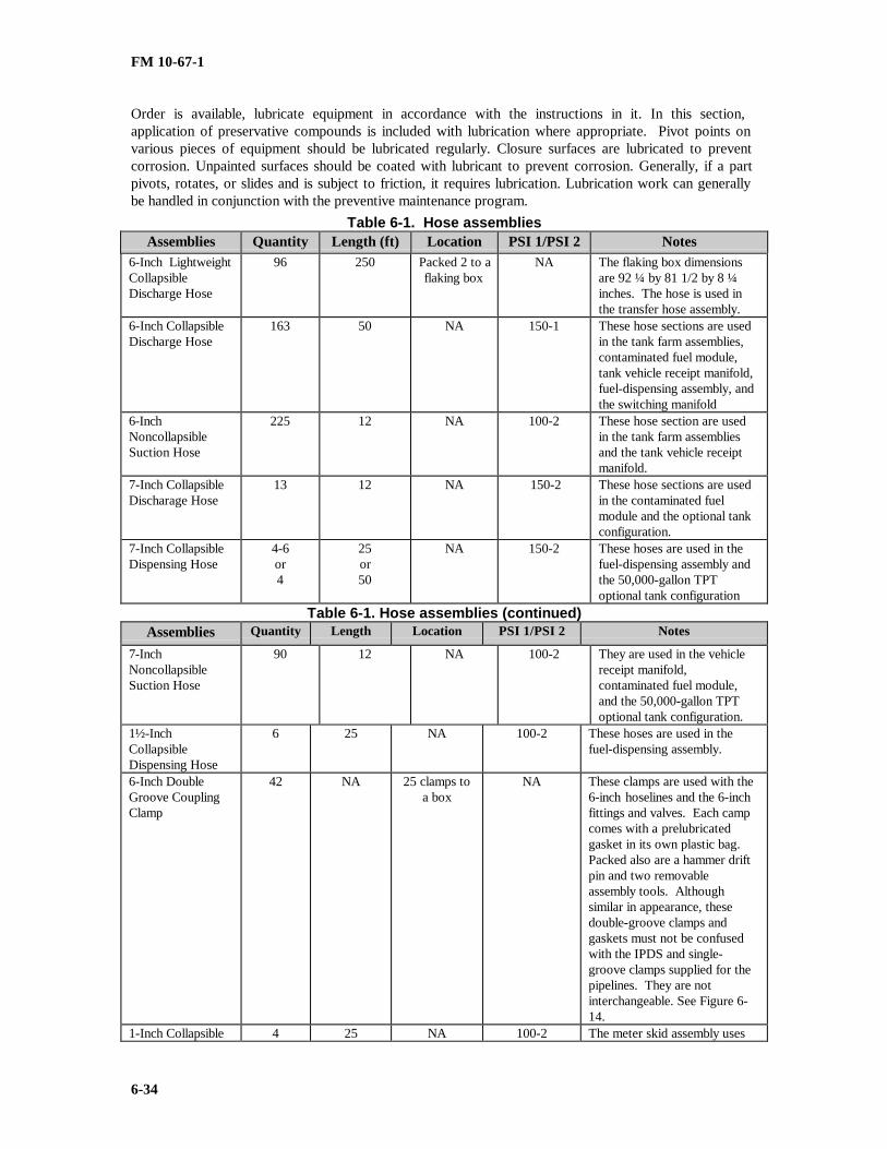
FM 10-67-1
6-34
Order is available, lubricate equipment in accordance with the instructions in it. In this section,application of preservative compounds is included with lubrication where appropriate. Pivot points onvarious pieces of equipment should be lubricated regularly. Closure surfaces are lubricated to preventcorrosion. Unpainted surfaces should be coated with lubricant to prevent corrosion. Generally, if a partpivots, rotates, or slides and is subject to friction, it requires lubrication. Lubrication work can generallybe handled in conjunction with the preventive maintenance program.
Table 6-1. Hose assembliesAssemblies Quantity Length (ft) Location PSI 1/PSI 2 Notes
6-Inch LightweightCollapsibleDischarge Hose
96 250 Packed 2 to aflaking box
NA The flaking box dimensionsare 92 ¼ by 81 1/2 by 8 ¼inches. The hose is used inthe transfer hose assembly.
6-Inch CollapsibleDischarge Hose
163 50 NA 150-1 These hose sections are usedin the tank farm assemblies,contaminated fuel module,tank vehicle receipt manifold,fuel-dispensing assembly, andthe switching manifold
6-InchNoncollapsibleSuction Hose
225 12 NA 100-2 These hose section are usedin the tank farm assembliesand the tank vehicle receiptmanifold.
7-Inch CollapsibleDischarage Hose
13 12 NA 150-2 These hose sections are usedin the contaminated fuelmodule and the optional tankconfiguration.
7-Inch CollapsibleDispensing Hose
4-6or4
25or50
NA 150-2 These hoses are used in thefuel-dispensing assembly andthe 50,000-gallon TPToptional tank configuration
Table 6-1. Hose assemblies (continued)Assemblies Quantity Length Location PSI 1/PSI 2 Notes
7-InchNoncollapsibleSuction Hose
90 12 NA 100-2 They are used in the vehiclereceipt manifold,contaminated fuel module,and the 50,000-gallon TPToptional tank configuration.
1½-InchCollapsibleDispensing Hose
6 25 NA 100-2 These hoses are used in thefuel-dispensing assembly.
6-Inch DoubleGroove CouplingClamp
42 NA 25 clamps toa box
NA These clamps are used with the6-inch hoselines and the 6-inchfittings and valves. Each campcomes with a prelubricatedgasket in its own plastic bag.Packed also are a hammer driftpin and two removableassembly tools. Althoughsimilar in appearance, thesedouble-groove clamps andgaskets must not be confusedwith the IPDS and single-groove clamps supplied for thepipelines. They are notinterchangeable. See Figure 6-14.
1-Inch Collapsible 4 25 NA 100-2 The meter skid assembly uses

FM 10-67-1
6-35
Dispensing Hose this hose for operation.6-Inch Single-Groove CouplingClamp
NA NA NA NA Used throughout TPTs ifavailable. The single-grooveclamps are compatible withdouble grooving. They fit intoonly the firs groove of thecoupled components. Thegasket is similar to that in thedouble-groove coupling; forexample, prelubricated,synthetic rubber, and a C-shaped cross section. Thegasket is compressed when theclamp is closed.
7-Inch Single-Groove CouplingClamp
18 NA NA NA The 7-inch single-groovecoupling clamps have the samedesign characteristics as the 6-inch single-groove couplingclamp.

FM 10-67-1
6-36
Table 6-2. Fitting and valve assembliesAssemblies Quantity PSI 1/PSI 2 Notes
6-Inch Gate ValveAssembly
122 150-2 Gate valve assembly is a part of the tank farm assembly,contaminated fuel module, transfer hoseline assembly,tank vehicle receipt manifold, and the switching manifold.
6-Inch Double-Groove Ball ValveAssembly
13 NA Values are a part of the fuel-dispensing assembly and theswitching manifold.
7-Inch Quick-Disconnect T-Assembly
4 NA 1 male x 2 female— Two each.3 male T— one each.3 female T— one each.All gaskets and bolts are supplied with the Ts. These four7-Inch T-assemblies are part of the 50,000-gallon TPToptional tank configuration.
7-Inch Quick-Disconnect GateValve Assembly
24 NA These gate valves are part of the fuel-dispensing assemblyand the 50,000-gallon TPT optional tank configuration.
7-Inch Quick-Disconnect Y-Assembly
NA NA Two version of this Y-assembly are in the TPT. There arethree units of the two female and one male version andthree units of the two male and one female version. ThisY-assembly is a part of the 50-gallon optional tankconfiguration.
7-Inch QuickDisconnect ButterflyValve Assembly
30 NA The 7-Inch quick-disconnect butterfly valve is part of thefuel-dispensing assembly and the tank vehicle receiptmanifold.
3-Inch Quick-Disconnect BallValve Assembly
1 NA This ball valve assembly is in the contaminated fuelmodule.
1½ -Inch QuickDisconnect BallValve Assembly
12 NA These ball valve assemblies are a part of the fuel-dispensing assembly.

FM-10-67-1
7-1
CHAPTER 7
INLAND PETROLEUM DISTRIBUTION SYSTEM
Section I. System Components
DESCRIPTION
The IPDS is a lightweight, rapidly deployable pipeline and terminal system used in undeveloped theaters.It can interface with an existing fuel source, such as a refinery, or with the Navy’s OPDS. Engineers install thealuminum pipeline and pump stations. An engineer pipeline construction support company can install 3 to 5 milesof aluminum pipe in 24 hours. Quartermaster pipeline and terminal operating units operate and maintain thepipeline and pump stations once they are installed. The IPDS can start at the beach interface unit and run as farinland as practical. It can also start at a TPT or commercial facility. The TPT is discussed in detail in Chapter 6.The aluminum pipe is packaged in ISO shipping containers in 5-mile sets. It takes 13 ISO containers to transport5 miles of pipe with all the related valves and fittings. Pump station intervals depend on system hydraulics. Thenormal interval on level ground is 15 miles. Pipeline hydraulics are briefly discussed in Appendix C. Detailedinformation is provided in FM 5-482. The system is modular in design and can be tailored for any locality ofoperation. Basic components are pipeline, pump stations, and special assemblies.
THE 5-MILE PIPELINE SETSAll components used on the main run of the pipeline are in 5-mile sets. Each set contains material
required for a complete 5 miles. There are 1,404 sections of 19-foot long IPDS single-grooved aluminum pipe withcoupling clamps and gaskets. The pipe is packed in 20-foot ISO containers with 156 sections of pipe in each ofnine containers. An allotment of elbows and coupling clamps for directional changes and expansion/contractiondevices, as well as gate valves, vent assemblies, pipeline anchors, culvert, overcouplings, and repair clamps arepacked in four additional containers. Individual components of the 5-mile pipeline sets are discussed in thefollowing paragraphs.
The 19-Foot Aluminum Pipe SectionsThere are 1,404 sections of 19-foot lengths packaged in nine 20-foot ISO containers. Each container has
156 sections as shown in Figure 7-1, page 7-2. These pipe sections are used in the main run of the pipeline. Theycannot be cut to different lengths due to the varying wall thickness, but each end may be regrooved once ifdamaged.

FM-10-67-1
7-2
Figure 7-1. 19-foot aluminum pipe sections
The 9.5-Foot Aluminum Pipe NipplesThere are also forty-four 9.5-foot long pipe sections (Figure 7-2), or nipples, in each 5-mile set and 10
sections with each pump station. These pipe sections are used anywhere in the pipeline where odd length sectionsare needed. They have a constant wall thickness and can be cut to any length and regrooved using the cutting,grooving, and beveling machine. Each 9.5-foot section has a black line down the length for easy identification ofnipple material.
Figure 7-2. 9 .5 foot aluminum pipe nipples
IPDS Single GroovesThe special groove design is wider than the standard commercial gro ove used with most pipe around the
world and is not interchangeable with the standard groove. The IPDS single grooves are found on the highpressure pipeline and pump stations. The maximum allowable operating pressure is 740 PSI.
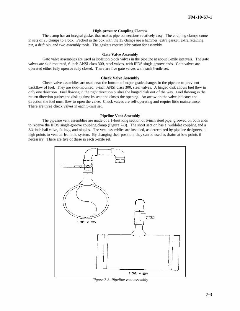
FM-10-67-1
7-3
High-pressure Coupling ClampsThe clamp has an integral gasket that makes pipe connections relatively easy. The coupling clamps come
in sets of 25 clamps to a box. Packed in the box with the 25 clamps are a hammer, extra gasket, extra retainingpin, a drift pin, and two assembly tools. The gaskets require lubrication for assembly.
Gate Valve AssemblyGate valve assemblies are used as isolation block valves in the pipeline at about 1-mile intervals. The gate
valves are skid mounted, 6-inch ANSI class 300, steel valves, with IPDS single groove ends. Gate valves areoperated either fully open or fully closed. There are five gate valves with each 5-mile set.
Check Valve AssemblyCheck valve assemblies are used near the bottom of major grade changes in the pipeline to prev ent
backflow of fuel. They are skid-mounted, 6-inch ANSI class 300, steel valves. A hinged disk allows fuel flow inonly one direction. Fuel flowing in the right direction pushes the hinged disk out of the way. Fuel flowing in thereturn direction pushes the disk against its seat and closes the opening. An arrow on the valve indicates thedirection the fuel must flow to open the valve. Check valves are self-operating and require little maintenance.There are three check valves in each 5-mile set.
Pipeline Vent AssemblyThe pipeline vent assemblies are made of a 1-foot long section of 6-inch steel pipe, grooved on both ends
to receive the IPDS single-groove coupling clamp (Figure 7-3). The short section has a weldolet coupling and a3/4-inch ball valve, fittings, and nipples. The vent assemblies are installed, as determined by pipeline designers, athigh points to vent air from the system. By changing their position, they can be used as drains at low points ifnecessary. There are five of these in each 5-mile set.
Figure 7-3. Pipeline vent assembly

FM-10-67-1
7-4
Pipeline Drain AssemblyThree pipeline drain assemblies with 2-inch ball valves and plugs are in each set. They are similar to the
vent assemblies, however, they are designed to be placed in low areas of the pipeline to aid in fuel recovery whenthe line must be drained.
Elbows and TeesThe IPDS comes with elbows and tees for directional changes in the pipeline (Figure 7-4). Each 5-mile
set has elbows to allow turns and expansion/contraction. There are sixty-two 90-degree, fifty-nine 45-degree, ten22.5-degree, ten 11 1/4-degree, and twelve 6-degree elbows to give flexibility in laying the pipe. There are twosizes of 90-degree elbows in the system. The long elbow is in the elbow set and is used in the pipeline. The shortelbow is only found in pump stations and must not be used on the pipeline.
Figure 7-4. Elbows and tees

FM-10-67-1
7-5
Pipeline AnchorsPipeline movement caused by thermal expansion will usually be in the direction that provides the least
resistance. Anchors (Figure 7-5) are used to direct movement toward expansion devices. Anchors should belocated at midpoints between expansion devices. There are 48 anchors with clamps in each 5-mile pipeline set.
Figure 7-5. Pipeline anchors

FM-10-67-1
7-6
Elevated Critical Gap CrossingsElevated critical gap crossing materials are designed to allow the IPDS pipeline to cross up to 250-feet of
water or a gully. An adequate pipeline expansion system must be provided to compensate for longitudinal thermalexpansion of the pipeline on the crossing. Pipeline anchors are required to isolate the critical gap crossingexpansion system from the main pipeline. There is a 2-foot minimum clearance above the high water level topermit floating debris to pass under the pipeline. Existing bridges may be used for gap crossings. If the bridgeattached system is not practical in the field, the line is routed over the bridge deck using tunnel passage sets. Thecrossing material is part of the pipeline support assembly.
Nestable Steel CulvertNestable steel culverts are used when existing culverts are not available and bridges cannot be used for
roadway crossings. These culverts are easily constructed by two people using only a stitch assembly and bendingbar. There are 80 linear feet of nestable culvert with each 5-mile pipeline set for constructing road crossings.
Cutting, Grooving, and Beveling MachineThe portable pipe cutting, grooving, and beveling machine is used for the end preparation of IPDS pipe
and piping components (Figure 7-6). The machine can bevel IPDS aluminum pipe in preparation for butt welding.It can also groove the pipe to accept the coupling clamp and gasket. The machine consists of a split frame with anexternal chucking system that simultaneously centers and squares the machine on the pipe. It can be powered bypneumatic, electric, and hydraulic drive motors.
Figure 7-6. Cutting, grooving and beveling machine
Hydraulic Drive Head and AnchorThe hydraulic drive head used for installing pipel ine anchors consists of a hydraulic drive head, which
can be mounted on a JV-410 backhoe or the small emplacement excavator digger stick after removing the bucket,and anchor adapter. The anchor is a 1.5-inch square forged steel shaft, 60 inches long with a 6-inch diametertapered helix welded on the bottom. When pressure is applied and the anchor is turned clockwise, it augers itself

FM-10-67-1
7-7
into the ground. A clamp is installed around the pipeline and fastened to the anchor shaft, anchoring the pipe tothe ground.
Tapping MachineThe pipeline hot tapping machine is used for tapping into a pressurized pipeline to install a service tap or
pressure-relief device. These devices can be installed without stopping the flow of fuel in the pipeline. Themachine uses a hole saw and a holder-pilot to cut the pipe. The holder-pilot holds the cut pipe plug after cutting soit can be removed. The machine has an adjustable automatic feed rate for any cutting condition. It comes with aratchet crank for manual operation.
PUMP STATIONSEach pump station has two skid-mounted, diesel engine-driven, mainline pumps (800 GPM). Launcher
and receiver assemblies, a dual in-line strainer assembly, and a floodlight set are also components of pumpstations. Except for the mainline pumps, all pump station equipment will be stored in 20-foot ISO containers.
The 800-GPM Mainline PumpThe 800-GPM mainline pump is a horizontal split case, three-stage centrifigual, skid-mounted unit as
shown in Figure 7-7. It is driven by a turbo-charged diesel engine. The pump contains a connect-disconnectclutch to allow the engine to run without turning the pump. It has an automatic pump controller with two modesof operation: manual engine speed control or discharge pressure control. The manual engine speed control setsthe engine speed (RPM) regardless of the discharge pressure. The discharge pressure control regulates the enginespeed to correspond to the discharge pressure set by the operator. Conditions such as high coolant temperature,low oil pressure, low pump suction pressure, or engine overspeed will allow safety shutdown devices to overrideeither control mode. The instrument panel has a tachometer, voltmeter, lube oil pressure gage, a coolanttemperature gage, and suction and discharge pressure gages. The pump has a discharge head of 1,800 feet and israted at 3,450 RPM. The engine is a 855-cubic-inch, six-cylinder rated at 450 horsepower at 2,100 RPM. Theentire assembly is 281 inches long, 79.5 inches wide, 132 inches high. It weighs about 14,230 pounds.
Figure 7-7. 800-GPM mainline pump

FM-10-67-1
7-8
Scraper Launcher AssemblyThe launcher assembly used to launch the pipeline scraper consists of the steel skid, the launching barrel,
and related piping and valves (Figure 7-8). All components of the launcher assembly are steel. The launchingbarrel has a quick-opening closure, a pressure gage, a drain valve, and vent valve. Located on the bypass is a ballvalve under a 1-inch thermal relief valve. The initial set relief pressure is 740 PSI. The set pressure can beadjusted as necessary, depending on the location of the system. The relief valve discharge is tied into the dischargeline from the vent valve on the launching barrel. A 2-inch diameter, 25-foot long hoseline is connected to the ventand drain to dispose of fuel when the barrel is being emptied. A scraper passage signal is provided on thedownstream part of the assembly. The scraper launcher assemblies are supplied with the pump stations and are onthe outlet side of the pump stations.
Figure 7-8. Scraper launcher assembly
Scraper Receiver AssemblyThe skid-mounted scraper receiver assembly consists of the receiver barrel and the related piping and
valves as shown in Figure 7-9. All components of the receiver assembly are steel. The receiver assembly has aquick-opening closure, a pressure gage, a drain valve, and a vent valve. The set pressure is 990 PSI. The setpressure is to be adjusted, as necessary, depending on the location in the system. A scraper signal is located at theentrance of the receiving barrel.

FM-10-67-1
7-9
Figure 7-9. Scraper receiver assembly
Strainer AssemblyA strainer assembly is installed in pump stations, upstream of the pumps to protect them from damage due
to dirt or debris in the pipeline. The skid-mounted steel strainer assembly has two separate in-line verticalstrainers as shown in Figure 7-10, page 7-10. The strainers have quick-opening closures to allow easy access tothe strainer basket. Each strainer has a differential pressure gage and two ball valves. There is a 1-inch ball valvefor draining the strainer from underneath and a 1/2-inch ball valve for pressure venting. The assembly has four 6-inch gate valves so either strainer can be bypassed for cleaning without interrupting fuel flow. A 1-inch drain hoseis supplied with the strainer assembly.

FM-10-67-1
7-10
Figure 7-10. Strainer assembly
Floodlight SetFloodlight sets are components of the pump stations. Floodlight sets are discussed in Chapter 6.
The 3,000-Gallon Collapsible Fabric TankA 3,000-gallon collapsible fabric tank is installed at each pump station to supply the station with fuel.
The tanks can be filled by connecting to the pipeline or or by tanker-truck. The same hose is used to receive fuelinto the tank and dispense fuel to the 110-gallon tank on the pumps. For detailed information on the 3,000-galloncollapsible fabric tank, refer to Chapter 22.
TACTICAL PETROLEUM TERMINALThe standard TPT has storage capacity of 3,700,000 gallons in eighteen 5,000 barrel (210,000-gallo n),
collapsible fabric tanks. The TPT is modular with three identical fuel units. Each TPT also has one pipelineconnection assembly. The total TPT is stored in 77 ISO containers. For detailed information on the TPT, refer toChapter 6.
Section II. INSTALLATION
PLANNINGGood predeployment and on-site planning are very important for a successful pipeline and pump station
installation operation. This planning includes environmental protection regulations at all levels, including federal,state, local, and host-nation. The role of host nation support, fuel type and quantity to be supplied, location ofexisting facilities, terrain to be crossed, and distances from bulk facilities to using units or terminals are allplanning factors for the IPDS.

FM-10-67-1
7-11
Route ReconnaissanceWhen conducting a site and route reconnaissance, you must have two known points:
• Where the fuel source is or will be located.• Where the forces will be located requiring support.
When you are conducting the physical reconnaissance, on foot or by vehicle, stakes or other marking devices mustbe used to show the actual path of the pipeline. Location of valves, anchors, expansion/contraction devices, andany obstacles must be marked on the trace. Pump station locations can be adjusted somewhat from the locationsselected from the profile and hydraulic analysis. However, every effort should be made to locate pump stationsnear their ideal location.
Pipeline Route SelectionSelecting the best route for the IPDS pipeline is crucial to pro per operation and continuous flow of fuel to
users on the battlefield. As mentioned above, a thorough initial reconnaissance is required to select the bestpipeline route. Even with a thorough reconnaissance, changes may have to be made to the selected pipeline routebecause of unforeseen problems. Changes can be made as long as they do not cause a functional fault in thesystem. The staked-out routes and sites should be clearly recorded on current area maps. The route stakingsshould be line-of-site and readily visible to the route preparation and pipeline-laying crews. Note the type of soilsand terrain so that earth-moving and other route preparation and other route and site preparation activities can beplanned. Select routes that require little grading. If grading is required, gradable soils are preferred over rockyterrain. Avoid steep lateral or axial grades if possible. The fewer special support and guide devices required due toterrain the better. Select a pipeline route that is accessible from existing roadways whenever possible. This willaid in installation, inspection, operation, and maintenance. However, do not lay the pipeline so that it may bedamaged by passing vehicles. The initial reconnaissance must also determine the methods of handling variouspipeline crossing situations. Crossings are grouped into three main categories:
• Elevated critical gap crossings
• Existing bridge crossings
• Road crossings
A route requiring fewer newly constructed gap and stream crossings is better if the hydraulic design of the pipelineis not adversely affected beyond the designed pipeline pumping capabilities. If crossings have to be made, recordthe type of crossing device and the length of the crossing so materials and equipment can be supplied in the correctquantities at the proper location. Stake out the crossing location and record special grading, ditching, or otherearth-moving requirements. Schedule the delivery of materials and work on these crossings before the pipeline-laying crews arrive. When planning pipeline routes, avoid congested or populated areas. Consider camouflageand security against tampering and sabotage.
Pump Station Site Selection
The sites selected for the pipeline pump stations must be compatible with the hydra ulic design of thepipeline and vice versa. As a general rule, pump station siting takes precedence over the pipeline routing.However, the actual site chosen often represents a compromise between the ideal station location and the pipelinerouting. If compromises must be made, always make them on the safe side of the hydraulic design, even if itmeans a more difficult installation process. In the initial reconnaissance, consider the adequacy of the preselectedsites for pump stations. If relocation is required for some reason, note the change on the records and stake thesites. It is assumed that coordination with the host nation refinery or bulk facility has been made if needed. Theinitial reconnaissance should determine the booster pump station locations and a stakeout of it. Determine thepoint of tie-in for the hoseline to the booster pump from the TPT or host nation bulk facility. Determine thefittings, pipe, and hoseline required to be taken from pipeline and TPT stock. If a host nation facility is used, theymust provide the tie-in pipe nozzle and valve at a location acceptable to the facility and the pipeline. Pump station

FM-10-67-1
7-12
sites must be easily accessible. A roadway is the best access; however, a heavy-lift helicopter can be used if aroadway is not available. Set up the pump station if possible on firm soil to support the weight of the equipment.A special foundation, such as compacted backfill, may be needed if the soil is marshy or soft. Make sure that thearea does not flood. Any water accumulation in the area must be able to be pumped out. The area must be about330 square meters (3,552 square feet), about 28 meters (91.9 feet) by 12 meters (39.4 feet). A space of about 8(26.25 feet) by 8 meters (26.25 feet) is required for collapsible fuel tanks used to fuel the pump engines. This areamust be within 60 meters (196.8 feet) of the pump engines but at least 30 meters (100 feet) away from theoperating area. Do not set up the collapsible fuel tanks in an area higher than the pump station operating area.These provisions could include drainage ditches or swales.
SITE AND ROUTE PREPARATION
Prior to installation of the IPDS, the site and route must be prepared. The following paragraphs brieflydescribe these preparations.
Pump Station Access
Pump station sites should be accessible by road for construction, operations, and maintenance. The roadshould be wide enough to permit two-way traffic and turnaround. If the roadway cannot enter the site because ofterrain, decide on another method to move construction and system operating equipment from the nearest roadway.Skid and hoist equipment, tracked vehicles, or heavy-lift helicopters may be used.
Pipeline Access
There must be access to the pipeline, whether there are existing roadways or new ones have to be constructed.Newly constructed roadways should be parallel to the pipeline route. These roadways may be graded at the sametime as the pipeline trace. The main use for these roadways is for construction, inspection, and maintenance; notroutine use. The roads should be at least 10 feet wide, well graded, and well drained. Unless the ground is verysoft and marshy, there is no need for gravel surfacing. If a road construction problem arises, the roadway does nothave to be set up right next to the pipeline. Because the pipeline sections are light, they can be carried shortdistances by two men to the pipeline construction site.
Site Preparation
Depending on accessibility, it may be necessary to prepare the route before the pump station site. The pumpstation sites must be prepared in such a way as to accommodate an acceptable plot plan, access roads, and laydownareas. When preparing sites, remove heavily organic or marshy soils at the planning site and replace them withcompacted nonorganic soils. Slope all sites so that any spills are drained away from the area. Use swales andditches to help drainage. Some areas may require digging and lining a sump to catch any fuel spills. Whenplanning and preparing the pump station sites, designate an area outside of the operating area as a laydown area.This area will be for receiving, sorting out, and controlling the boxes, crates, and equipment delivered for thefacility. This area should be about 3,000 square feet and have road access.
Route Preparation
The pipeline route must be prepared at the same time that the access roadways are prepared. Schedule thisoperation well in advance of the pipeline equipment delivery. Pipeline route preparation provides access forpipeline installation. This surface will be used to lay the pipeline and establish the support, anchoring, andexpansion/contraction system. The pipeline route should be about 10 feet wide. It should have 30-foot wide areasfor the expansion/contraction devices. Lay as much of the pipeline directly on the ground as possible. The idealsituation is continuous ground support; however, at a minimum, the pipeline should be supported every 19 feet.Use earth-moving equipment to remove the high spots and obstructions and fill the low spots. This will increasethe rate at which the pipeline can be laid. A field decision is required to determine specific excavation needs.Consider thoroughly the approaches to crossing situations. Use existing crossing facilities (culverts and bridges) asmuch as possible to prevent unnecessarily tying up construction equipment. As the route is completed, place or

FM-10-67-1
7-13
replace the staking required for the pipeline construction crews. Clearly record all actions you have taken toprepare the route. This will help the pipeline installation crews know of problems they may encounter. Startsandbag filling operations so they will be ready when needed for pipeline support.
EQUIPMENT AND SYSTEM INSTALLATIONOnce the site and route have been prepared begin equipment and system installation. Equipment and
system installation are described below.Pump Station Installation
The pump stations may be installed at the same time or one at a time, depending on the construction schedule.Install the pump station as given below.
• Prepare the pads for the pumps, receiver assemblies, strainer assemblies, and launcher assemblies. Installpads for other equipment as required. Install pads under valves for support or proper elevation if needed.Construct the pad and berms for the 3,000-gallon fabric collapsible fuel tanks. If needed, set up the floodlight setfor operation. Set the pipeline pumps on their pads; anchor and ground them. Pay particular attention to pumpand engine leveling and alignment. Set the strainer assembly in position and anchor it after the piping is installed.Set the receiver, launcher, and strainer assemblies in position and anchor them after the piping is installed.Ground all equipment during installation.
• After the berms and pads are constructed, roll out the 3,000-gallon tank inside the berm. Beforeinstallation, make sure the pad is free of any sharp objects that may puncture the bag. Slight modifications mayhave to be made for specific situations.
• Be careful when installing the piping. Do not cause excessive strain initially or due to pressure andthermal expansion when in operation. Before anchoring the equipment to the pad, adjust the equipment to relieveany possible strain. Enough elbows are supplied with the system to use for elevations and modified layouts. To cutdown on construction time, make the most use of the standard 19-foot pipe sections without having to custom fitpieces. If smaller pipe sections are needed, only the 9.5-foot sections can be cut using the cutting, grooving, andbeveling machine. The best method of assembly is to pipe out from the pumps to the strainer and receiver, andthen to the launcher. In the pump station, hold joint deflection to 1 degree at installation rather than the 2 degreesallowed on the pipeline. Before connecting any pipe sections together or to other equipment, make sure the jointsare clean, both internally and externally.
• Place fire extinguishers in the area where they are clearly visible. Place one fire extinguisher at eachpump, one at the receiver, one at the launcher, and one near the 3,000-gallon fuel tank. Also, place one additionalfire extinguisher just outside the immediate operating area in a highly visible location.
• Install the appropriate safety signs at the proper locations.
• When time permits, erect the lightweight panel buildings over the pumps. Paint all metallic parts that havenot been previously painted or anodized or that have deteriorated during shipment. Lubricate all rotating orsliding surfaces.
• Before starting operations, clean up the area and pressure-test all connections for leaks, expansion, andcontraction. The pressure testing may be done along with the purge and fill operation covered in the next section.Make changes or repairs as necessary.
Pipeline Installation As soon as the site preparation is done and the necessary equipment has been delivered to the construction site,
the pipe-laying crews can start removing the pipe from the ISO containers and stringing it along the route. Pipesections can be carried by two people to the installation site. Keep the protective caps on the pipe until it is readyfor coupling. After stringing the pipe along the route, the pipe-laying and coupling crew follows. The pipe-layingand coupling crews install pipeline using the following procedures:

FM-10-67-1
7-14
• Remove the protective cap from the pipe, align the two pipe sections by laying them in the bottom half ofthe coupling assembly, close the coupling assembly over the top of the pipe, and lock and pin the handle in place.(Prior to installation, place a liberal amount of grease on the inside of the coupling gasket. Make sure there is nodirt or other debris on the gasket or pipe grooves before coupling).
• Make sure there is an adequate supply of elbows on hand to allow for terrain conditions or directionalchanges. Install elbows during the pipe-laying process if the route or terrain requires a change of pipelinedirection. If there are enough elbows available, use them for directional changes instead of cutting and groovingshort pieces of pipe. This will ease the construction process.
• Position expansion/contraction devices are positioned in the pipeline based on the hydraulic design,normally every 50 couplings of 19-foot pipe. The elbows and coupling clamps included in theexpansion/contraction sets must be used only with the expansion/contraction sets. Plan on having a straight piperun of at least three or four sections going into an expansion/contraction device.
• Install isolation gate valve and check valve assemblies in the pipeline as it is laid. These locations arebased on the hydraulic design of the line. Appendix C covers hydraulic pipeline design fundamentals.
• Determine the placement of the vent assemblies according to the elevation survey.
• Install the fuel sampling assemblies 1 mile upstream from each receiver.
• Install the proper pipeline support as the pipeline is laid. Drive in the pipeline anchors after correctalignment has been checked on pipeline joints and couplings to be anchored. Couple the pipeline into receiversand launchers after they have been permanently placed and anchored. Cut and groove nipples from the 9.5-footpipe sections as needed to eliminate as much strain as possible.
• Recheck the expansion/contraction devices, alignment, anchoring, and supports after the line has expandedand contracted through at least 24 hours of temperature changes. Make corrections as necessary before initiallyfilling the pipeline with fuel.
• Make a final inspection of the entire system before starting the pipeline into operation. See Table 7-1 for achecklist of the major points of inspection.

FM-10-67-1
7-15
Table 7-1. Checklist of major points of inspection
Pipeline pumps serviced and properly installed. Anchors in place; pumps grounded and ready foroperation. Check against pump manufacturer's technical manual.
Flood and transfer pumps used as booster pumps serviced and located as instructed. Check forappropriate anchoring and grounding. Ready for operation. Check against pump manufacturer'stechnical manual.
Dual strainer assemblies serviced, installed properly, anchored, grounded, and read to operate.
Receiver assemblies serviced, checked, installed properly, anchored, grounded, and ready to operate.
Launcher assemblies serviced, checked, and installed properly, anchored grounded, and ready tooperate.
All valves operable and accessible. Packing glands tightened. Proper location in system.
Check valves installed in proper flow direction throughout. The directional arrow molded into thevalve body must point in the direction of flow.
ELO pressure regulating assemblies serviced, checked, properly set, grounded, and ready to operate.
Fuel tanks, berms, and hose system properly installed.
Sampling assemblies located and installed properly, grounded, and ready to operate.
Connection into supply source handled properly.
Connection into TPT switching manifolds correct.
All couplings closed and flanges tight throughout system.
Thermal relief valves on receiver and launchers properly set and installed. Ball valves under reliefvalves open.
Evidence that all pressure gages have been precalibrated and are adequate. Any recalibration requiredwill be handled as part of the commissioning program.
All valves except the gate valves installed at 1-mile intervals for isolation are closed.
All piping properly supported and guided in the pipeline.
Pipeline anchoring and expansion/contraction systems installed properly.
Gap crossing and bridge crossing systems properly in place.
All piping properly supported at pump stations.
Floodlight sets at pump stations installed and operable.
All fire-suppression equipment charged, installed in accessible and visible location, and ready for use.
Safety signs installed.
Proper equipment identification marking in place.
All drainage systems, roadways, and road crossings checked.
In addition, ensure all areas are cleaned up and unused equipment and materials are returned to a proper storagearea. Do not start operations until all deficiencies found in the inspection are corrected. Ensure that procedures

FM-10-67-1
7-16
are in place for disposing of all waste fuel. Make sure that operating communications systems are workingproperly. Conduct pressure tests at the same time as the purge and fill operations. Inspect the system during andafter the test for evidence of leaks or other problems. Correct all problems or leaks after the pressure test.
Installation EquipmentSpecialized equipment is ass igned to the pipeline support company for handling, placing, and installing
valves, pumps, and pipeline anchors. Installation equipment consists of:
• Cutting, grooving, and beveling machine,• Hydraulic drive heads for anchor installation,• Pipeline tapping machine,• Deadweight tester,• Surveying level,• Alignment tools,• Supplemental pipeline tool kit.
Refer to FM 5-482 for detailed information on installation equipment.
Section III. System Operation
PUMP STATION OPERATIONS
Ensure all special and local environmental protection requirements are used when the POL systems are beingoperated. Check with the local environmental compliance officer to identify special operating requirements. TheIPDS can begin at the beach termination unit operated by the Navy. It can also begin at a TPT manifold or at ahost nation bulk storage facility. Whatever the beginning point, a booster pump station feeds the 6-inch IPDScoupled aluminum pipeline. The pipeline can be used as a multiproduct pipeline for several types of fuel,including JP-4, JP-8, jet A-1, diesel, and MOGAS. In a multiproduct pipeline system, fuel batching is required.Batching is covered in more detail in Chapter 9 of this manual. In batching of fuel, different fuels have a tendencyto mix where two batches touch, commonly known as the interface. The interface is diverted from the pipeline tothe contaminated fuel tanks at the TPTs. This fuel may be reintroduced as a blending stock, or it may be a wasteproduct of which must be disposed. To avoid waste, keep the interface as short as possible. As JP-8 becomes thesingle fuel on the battlefield, the need to batch fuels in the pipeline will stop. The continued need for MOGAS willrequire packaged fuel supply actions.
Pump Station Start-Up
There are a number of steps to put a pump station on-line. Pump station start-up steps are:
• Check the pump units before actual starting time. Perform before-operation maintenance.• To start both pumps: •• Set POWER ON/OFF switch to ON. •• Set PANEL LIGHT ON/OFF switch to ON if needed. •• Set MODE CONTROL MAN/AUT switch to MAN. •• Turn ENGINE RPM/DISCHARGE PRESSURE control fully clockwise (low speed position). •• Push ENGINE STOP switch in •• Press PRESS TO TEST LAMPS switch. Alarm lights should come on and then go off when push button is
released. •• Verify that clutch is disengaged (down) position. •• Press ENGINE START switch. Keep switch depressed until engine fires. If engine fails to fire, refer to the
Technical Manual Troubleshooting Chart. •• After engine starts, observe ENGINE RPM gage to verify engine is idling at its idle speed (approximately
800 to 1,000 RPM).

FM-10-67-1
7-17
• Warm up pumps, with the pump discharge valves closed, until engines reach an operating temperature of120°F at an idle speed of approximately 800 to 1,000 RPM.
• Ensure that the mainline, bypass, and side valves on the receiver and launcher are open.• Ensure that the strainer is open and ready to operate.• Open the suction valve on both pumps.• When there is suction pressure, vent the air out of the pump case using the four vent valves, in order, from
lowest to highest. Open valve until fuel flows from the pump, then close the valve before proceeding to the nextone. Use a drip pan to catch discharged product. Dispose of all hazardous waste IAW federal, state, local, andhost nation regulatory guidance.
• On the pump to be used, if there is at least 100 PSI suction pressure and increasing, engage clutch andopen the discharge valve slowly. Place pump control in automatic mode and slowly increase the pump enginespeed to the discharge pressure required by the dispatcher. Increase discharge pressure while maintaining 100 PSIsuction pressure. If 100 PSI suction pressure cannot be kept during start-up, notify the dispatcher.
• Shut down the standby pump after the start-up discharge pressure has been attained.
Normal Shutdown
The pipeline dispatcher directs a normal shutdown. To shut down the pump, the operator slowly turns thedischarge pressure control counterclockwise until the engine is idling. He switches to the manual mode anddisengages the clutch. After idling for at least one minute, the operator shuts the engine down. The suction anddischarge gate valves are then fully closed. Pressure should be taken off the pump by bleeding it off through thecasing vents. This prevents pressure buildup due to the sun or atmospheric temperature.
Forced Shutdown
There are several reasons for a forced shutdown. The pump itself has safety shutdown features that includeautomatic shutdown due to:
• Low suction pressure.
• Engine overspeed.
• High coolant temperature.
• Low lube oil pressure.
Other mechanical problems may cause the pump to shut down without starting the automatic shutdownfeatures.
The pump operator should shut down the pump under the following conditions/situations:
• If excessive noise or vibration is noticed.
• If there is a sudden drop in discharge pressure which could be caused by a line break or operating errordownstream, the speed of the pump unit will suddenly increase if the pump is operating in the automatic mode.The operator should adjust the discharge pressure set point downward by rotating the control counterclockwise toreduce the pump speed. If the problem downstream is temporary or minor, this will take care of it until it is solved.If there is a major problem downstream, the pump engine speed will continue to increase. The operator shoulddeliberately shut down the pump unless told otherwise by the dispatcher. If the operator does not or cannot shutdown the pump unit soon enough, it will shut down automatically due to engine overspeed. In the event of asudden drop in discharge pressure when the pump is being operated in the manual mode, the operator shouldreduce the engine speed. If there is a major problem in the pipeline, the discharge pressure will continue to dropand the pump should be shut down unless advised otherwise by the dispatcher.
• A line break or operating error upstream can cause a sudden drop in suction pressure. Unless advisedotherwise by the dispatcher, the operator should deliberately shut the pump down when the suction pressure dropsto 14 PSI. If the pump is not shut down deliberately, it will start slowing down at 14 PSI and shut down if the

FM-10-67-1
7-18
pressure is 10 PSI or under continuously for 15 seconds. If at all possible, manually shut the pump down before itis shut down by any of the automatic safety features. If the pump does shut down automatically, the operatorshould advise the dispatcher and the next upstream and downstream pump stations immediately.
If a shutdown is caused automatically by any of the situations discussed above except a sudden dischargepressure drop and engine overspeed or a sudden suction pressure drop, the operator should begin placing the sparepump on line unless the dispatcher directs otherwise. If the pump is operating in the automatic mode and the lineis blocked down stream, the pump speed will be markedly reduced toward idle speed and the suction pressure willgo up. Unless the operator has prior knowledge of this happening, he should immediately notify the operationsdownstream and the dispatcher. If the line block continues without notice that it is temporary, the pump should beshut down. If the pump is operating in the manual mode and the line is blocked downstream, discharge andsuction pressures will suddenly increase. The operator should immediately reduce the pump speed to reduce thedischarge pressure and should reduce to idle speed if necessary. Under no condition should the discharge pressureexceed 740 PSIG. The operator should immediately notify operations downstream and the dispatcher if thisoccurs. As in the automatic mode, if the line block continues without notice that it is temporary, the pump shouldbe shut down.
Shifting Pumps During Operation
Prior to this operation, the spare pump must be flooded and purged. Open the suction gate valve. Warm thespare pump engine up with the controls in the "manual" position and the clutch disengaged. Engage the clutchwith the engine at idle and open the discharge valve. Set the controls in the automatic mode and gradually movethe control to match the discharge pressure of the operating pump. Monitor the suction pressure closely. The on-line operating pump will automatically slow down and the spare pump will speed up. When the dischargepressures of the two pumps match, gradually move the controls of the operating pump until the engine idles. Thespare pump will speed up and take up the full load. Set the discharge pressure as necessary to hold the system flowrate desired. When the spare pump has the full load and the suction pressures are steady, the pump that waspreviously on line is shut down. The spare pump is now the operating pump.
Pipeline Pump Fueling Facilities
The 3,000-gallon collapsible fabric tanks are used to store fuel for operating the pump stations. There is onecollapsible tank for each pump station. The tanks are located near each pump station and are operated IAW TM 5-5430-210-12. To transfer fuel from the 3,000-gallon tank to the fuel tanks on the pump skids or to an auxiliarytank, connect the hose, valve, and hand pump; then start pumping.
STRAINER ASSEMBLY OPERATIONS
A strainer assembly is installed upstream of the pipeline pumps to protect them from damage due to dirt ordebris in the pipeline. The assembly contains two strainers in parallel. Normally, only one strainer is used at atime with the other one on standby. Strainers are put in service or taken out of service by opening and closing thegate valves in the assembly. Open the valves upstream and downstream of the strainer being put in service beforeclosing the valves of the strainer being taken out of service while the pipeline is operational. Unless a strainer isbeing isolated for depressuring, inspection, or maintenance, leave the discharge valve open and the inlet valveclosed on strainers not in service. This will avoid the possibility of overpressuring due to thermal expansion. Thestrainers collect dirt and debris from the line before it enters the pump. When the strainer has collected sufficientdirt, the pressure differential across the strainer will increase showing that the strainer should be removed fromservice and cleaned. The initial (clean) pressure drop across the strainer will vary with the rate of flow and thedensity/viscosity of the flowing fluid. When the pressure drop has increased to a predetermined PSI (normally notmore than 5 PSI), place the other strainer in service. Block, vent, drain, and open the dirty strainer. Remove thebasket and clean it. Remove any dirt that has accumulated in the bottom of the housing as well. Check thestrainer for damage and wear before placing it back in the housing. Replace the strainer closure, close the drainand vent valves, and open the discharge valve. The clean strainer is then on standby and ready for service when itsmate gets dirty. It is possible that something from the pipeline can cut, break, or badly erode the strainer. An

FM-10-67-1
7-19
indication of this may be that the pressure drop does not increase with usage. If this is the case, disassemble andinspect the strainer as given above. If damage is found, replace or repair the strainer basket.
WARNINGDo not open the strainer closure unless the strainer is blocked in and has been thoroughly depressured byfirst opening the drain valve and then the vent valve. Be sure the drain hose is connected securely androuted to a collection container or sump.
PIPELINE SCRAPER OPERATIONS
Purpose
Scrapers are used to enhance and speed the initial purge and fill operations and to clean the pipeline ofcontaminates and obstructions that cause excessive drop in pressure. Over a period of time debris, scale, andparticles that settle out of the fuel, may collect or build up in the pipeline. Line scrapers are run through thepipeline to prevent the debris from building up in the line. The pipeline dispatcher will schedule the actual scraperoperation on a pumping order. Scrapers are run from the launcher at one pump station to the receiver at the nextpump station. There is a scraper indicator on each barrel that shows when the scraper has been launched andreceived. By walking along the pipeline, the scraper can be heard as it passes each coupling.
Scraper Velocity
Scraper velocities through the 6-inch pipeline at various rates of flow are given in Table 7-2.
Table 7-2. Scraper velocity
Flow (GPM) Velocity(MPH)
100 0.6
200 1.4
300 2.1
400 2.8
500 3.5
600 4.2
750 5.2
Types of Scrapers
Various types of scrapers or pigs for different services are available on the market. Cupped scrapersconstructed entirely of polyurethane have been found to be the most serviceable in the IPDS pipeline. They areintended for general service, including purge and fill operations. Initially, five scrapers have been supplied witheach launcher cleaning.
Launcher Operations
Before a scraper can be launched, the downstream receiver must be ready to trap the scraper. Insert thescraper into the pipeline using the following procedures:
• Check to make sure the launcher bypass valve is fully open.

FM-10-67-1
7-20
• Close the side and mainline valves to isolate the barrel of the launcher assembly.
• Open the launcher assembly vent valve to relieve pressure from the barrel.
• Open the drain valve and drain the fuel from the launcher barrel into a container.
• Open the safety vent on the end closure and then open the launcher barrel end closure.
• Insert the scraper into the launcher barrel. Push the scraper as far as it will go into the launcher barrel.
• Close and tighten the end closure, close the safety vent valve, and close the drain valve.
NOTE: Close the safety vent valve only hand tight. If it leaks after the barrel has been filled, use acrescent wrench to tighten it.
• Set by pushing the flag down.
• Slowly open the side valve completely.
• Close the launcher assembly vent valve when the barrel is full.
• When directed by the dispatcher to launch the scraper, slowly open the mainline valve completely.
• Slowly close the bypass valve. As the bypass valve is closed, the flow is diverted through the barrel causingthe scraper to be carried or forced into the pipeline.
• Watch the scraper indicater (Figure 7-11) for indication that the scraper has been launched. Notify thedispatcher the moment the scraper is launched.
• Open the bypass valve after the scraper has been carried out of the launcher barrel by the flow of fuel.
• Always operate with “wet” barrel, leaving the side, mainline, and bypass valves open.

FM-10-67-1
7-21
Figure 7-11. Scraper indicator
Receiver Operations
The scraper receiver assembly is shown in Figure 7-9, page 7-9 . The recommended standard procedures tooperate the receiver are discussed below. To receive the scraper:
• Make sure the receiver barrel end closure is closed and tight. Ensure the drain valve and safety vents areclosed.
• Open the side, bypass, and mainline valves on the receiver assembly during normal operations.
• Set the scraper indicator.
• Close the bypass valve. This directs the flow of fuel through the barrel.
Remove the scraper from the receiver using the following procedures:
• When the scraper has entered the receiver barrel the scraper indicator will pop up.
• Notify the dispatcher of the scraper arrival.
• Open the bypass valve.
• Close the mainline and side valves.
• Open the receiver barrel vent and drain valve. Drain the product into a suitable container. Dispose ofhazardous waste IAW federal, state, local, and host nation regulatory guidance.
• Open the safety vent and then open the receiver barrel end closure.

FM-10-67-1
7-22
• Remove the scraper and clean out the receiver barrel.
• Close and tighten the end closure safety vent.
• Close the drain valve.
• Open the side valve slowly to fill the receiver with fuel and close the receiver barrel vent.
• After the receiver barrel is full, open the mainline valve.
• During normal operations, leave all valves open. The system should be run with a “wet” barrel.
Tracing of a Scraper
Scrapers are run from the launcher from one pump station to the receiver of the next pump station. There areseveral ways to trace scraper movement in the pipeline. A small battery-operated transmitter attached to thescraper sends a signal which is picked up on a receiver by a pipeline patroller. A magnetized metal scraper can beused with a detector sensitive to magnetic forces. The detector, used by a pipeline patroller, registers an increase inmagnetic activity as the magnetic scraper passes by. Because the IPDS uses aluminum pipe, do not use a chainattached to the scraper. This method could cause damage to the pipe sections.
Stuck Scraper
It is possible that a scraper could get stuck in a line during a run. The scraper can probably be freed byincreasing the pressure in the line. The increased force behind the scraper should push the scraper loose and moveit along with the flow of fuel. Care should be taken not to overpressure the line. If increasing the pressure in theline does not free the scraper, the line must be taken apart to remove the scraper. Do not try to free a stuck scraperby putting another scraper in the line. The second scraper may not free the first one and get stuck behind it.
PURGE, FILL, AND PRESSURE TEST OPERATIONS
Purge and fill operation must remove (purge) all air from the system and fill the system with a pumpable fluid.The pressure test is to prove the integrity of the system. It does not test the strength of the system. Test pressuresare therefore limited to the design maximum allowable operating pressure which is 740 PSI in the IPDS.
Internal Cleanliness Assurance
Installation procedures emphasize the importance of internal cleanliness of the pipeline. If areas of the systemare suspected of containing junk, sand, construction waste, or tools, they should be disassembled and cleaned outbefore the purge, fill, and test is started. The initial purge and fill will clean out the remainder. The remainderwill then collect in the strainers and receivers where it can be removed after the procedures are completed andbefore normal operations start.
Pressure Gages and Relief Valves
Before the purge, fill, and test operations can be started, all pressure gages must be reading correctly. Set thethermal relief valves to the correct relief pressure for their location.
Preparatory Steps
Before the operation can be started, all personnel involved must know their duties and the safety precautionsrequired. Install all fire extinguishers as required. Inspect the pipelines to be filled. Make sure all couplings areproperly closed and there is no excessive coupling deflection. Check that all supports, guides, anchors, andexpansion/contraction devices are in place. Open all intermediate isolation gate valves installed at 1-mile intervals

FM-10-67-1
7-23
in the pipeline. Close all other valves, including all vents, drains, and sampling assembly valves so there is aknown starting condition. Check that adequate fuel is available at the pump stations and that the pumps and otherequipment are ready for operation. Make sure the communication system is operational.
Purge, Fill, and Test Procedures
The pipeline should be initially purged, filled, and pressure-tested with fresh water from a source developed inthe field. Water is injected upstream of the booster pump as close to the host nation facility or TPT as possible.The fill rate is held to about 50 GPM, until the meter and booster pump are flooded and free of air. Once thebooster pump is flooded, the hydraulic power can be supplied with the system pumps. The pumps can also supplythe test pressures required. A fill rate of about 200 GPM is recommended after the system is started. Scrapers arelaunched ahead of the water. High point vents are used as necessary to assist in removing air and vapor.Depending on the quantity of water available, the line may be tested all at once or by section. The test pressuresfor hoselines are not to exceed the design maximum operating pressures. Hold the test pressures long enough tothoroughly inspect the system for leaks and faults. Take the test pressure off the system and correct the leaks andfaults. Retest the system after corrections have been made. To avoid corrosion, remove the water from the systemimmediately after the test is complete by proceeding with the fuel fill operation. In any case, a line only partiallyfilled with water, or not fully drained and dried, must not be exposed to air for any extended period of time. Thefill with fuel takes place promptly after the pressure test is complete with fuel displacing the water. The water isdisposed of at the EOL. Launch scrapers at the first pump station in the line immediately after the fuel/waterinterface has passed to remove remaining water. The fuel/water interface is received into the head terminalcontaminated fuel module and of which is subsequently disposed. Keep all water out of the clean fuel storage tankand hoseline systems. The purge and fill of the head terminal hoselines with fuel can take place after the pipelineis packed with fuel. Or it may take place with fuel from tank vehicles before the pipeline is ready. The purge andfill rate per hoseline should be kept below 200 GPM. The fill rate should be held below 50 GPM until the metersare flooded to avoid possible overspeeding due to high air flow. Purge, fill, and pressure test all hoselines in thismanner before normal operations.
Alternative Purge, Fill, and Test Methods
In some cases, adequate fresh water may not be available for the recommended purge, fill, and test operations.Nevertheless, the system must be commissioned properly. Pressure testing is recommended in any case. The othermethods, listed by preference based on safety, are given below:
• Diesel fuel fill preceded by a freshwater plug.
• Diesel fuel fill preceded by a nitrogen plug.
• Diesel fuel fill--scraper only.
• Jet fuel fill preceded by a water plug.
• Jet fuel fill preceded by a nitrogen plug.
• Jet fuel fill preceded by a diesel plug.
The reference to a plug above means a quantity of a buffer fluid, liquid, or gas, ahead of the fill fluid. Theprocedure is to launch a cupped scraper at the head of the buffer fluid and another ahead of the fill fluid. Thiscreates a plug or buffer zone between the volatile fill fluid and the air in the pipeline. A large quantity of plug isnot required. A plug of 1,000 gallons of water, which is about 650 feet long, is adequate. A 300-cubic footcylinder of nitrogen would provide a plug over 1,000 feet long. The "plug" fluid volume must be maintained. Itmay be necessary to inject more volume due to losses. Due to the difficulty of ensuring that a nitrogen plug has notbeen lost or overly diluted, a new plug volume must be injected at the launcher before each fill and test of apipeline section. If there is any doubt as to the nitrogen plug volume or purity, inject more nitrogen. The order ofthe listing of the purge and fill methods above is related to the volatility and flash point of the fill and test fluid.Avoid explosive fuel/air mixtures in the pipeline. Use less volatile and flammable fluids for testing or initial use inthe pipeline. An initial diesel fuel fill is preferred if available. Jet fuels with relatively high flash points such as JP-5, JP-8, Jet A-1, or other commercial jet fuel grades of known high flash point are acceptable with the plugs listed.

FM-10-67-1
7-24
Jet fuel, JP-4, should be avoided as the initial fill and test fluid due to its low flash point. If it must be used, takespecial care to maintain low flow rates and an adequate buffer plug. MOGAS is not recommended as the initialpurge and fill fluid.
PIPELINE FUEL TRANSFER
The IPDS is designed to operate without direct communications; however, normal operations should beconducted with communications between the dispatcher, the pump stations, and the head terminals. For safetyreasons, the receiving terminal controls fuel transfers. Confirm that the terminal is ready and can receive fuelbefore pumping starts. The terminal must be able to stop the flow of fuel. This includes shutdown due to thecompletion of a planned fuel transfer or for other reasons. Normally, operate the pipeline pumps in the automaticdischarge pressure control mode with the operator setting the control point. Monitor the discharge pressurecontinuously for high pressures in excess of the control set point. Shut the pump down if the discharge pressureexceeds 740 PSI.
Transfer Procedures
Fuel is transferred from the host nation bulk facility or beach termination unit to the head terminal. Pumpingmust start with the supplying bulk facility. Start the booster pump as soon there is enough suction pressure (5 to10 PSI minimum). Start pumping at the pump stations when suction pressures reach 70 to 100 PSI. Keep suctionpressures in this range until relatively steady conditions are established. Then keep them above 50 PSI. Increasepumping rates to 600 GPM or higher, starting with the supplying bulk facility pumps (if available) and then at thebooster pump and the pipeline pump stations. Suction pressure available is the controlling factor. Controlpressure below 125 PSI into the head terminal by the pressure regulating valve assembly at the EOL or TPT intake.Control back pressure in the pipeline at a minimum of 50 PSI.
Shut-Down Procedures
The pipeline is normally shut down by first shutting down the pump station closest to the head terminal. Thepressure regulating valve at the EOL or TPT intake will automatically close when the upstream pressure drops to50 PSI. If the line is blocked in downstream of the EOL or TPT intake pressure regulator, the last closest pumpstation is shut down when the suction pressure begins to increase. The booster pump is shut down when thesuction pressure begins to increase or as the first pump station is shut down. The supplying bulk facility pumps areshut down when the booster pump shuts down. Under these conditions, the line is blocked in fully packed andunder pressure.
Communication Failure
If communications fail and the terminal must stop the flow of fuel, do so by blocking in downstream of theEOL pressure regulating valve, which will cause it to close. The pump in the next upstream pump station will gointo idle or greatly reduce in speed due to the restricted flow and the automatic discharge pressure control. Thesuction pressure will increase rapidly. These indicators will signal the operator to shut the pumps down. Eachpump station downstream in succession will shut down when the operator sees the suction pressure increase or thepump goes into idle or greatly reduces in speed. The booster pumps will shut down when the first pump station inthe line shuts down.
EMERGENCY OPERATING PROCEDURESEmergency operating procedures are given in Table 7-3, pages 7-25, and 7-26. Use these procedures when an
emergency arises.

FM-10-67-1
7-25
Table 7-3. Emergency operating proceduresEmergency Condition Procedure
Pipeline Separation Immediately shut down pumping. The pump immediatelyupstream of the break will possibly shut down on overspeed.Immediately isolate the first upstream and first downstreampump station from the break by closing the appropriate blockvalves.
As soon as possible, close the intermediate isolation gate valveson both sides of the break that are safely accessible.
Route fire-fighting equipment and crews to the area of the break.
If possible to do so safely, isolate the spill with earth diking andditching. Drain the spill away from the pipeline, if possible.
If fire occurs, extinguish the fire and stand by.
Clean up the spill.
Start repairs and recommissioning. Determine the cause of thebreak and take corrective action to avoid recurrence.
Serious Pipeline Leak Shut down pumping in an orderly fashion. Shut down upstreamfirst and downstream when the suction pressure drops to 15 PSI,thus reducing the line pressure as much as possible.
Close the intermediate isolation gate valves closest to and eitherside of the leak.Route fire-fighting equipment and personnel to the leak location.If a fire occurs, extinguish the fire and stand by.If there is a liquid accumulation, clean it up or drain it awayfrom the pipeline when it is possible to do so safely.Depressure and drain the line in the area of the leak as necessaryto repair the leak.Start repairs and recommissioning. Determine the cause of theleak and take corrective action to avoid recurrence.
Hoseline Break or Serious Leak Shut down any transfer taking place in that hoseline.Route fire-fighting equipment and personnel to the leak area.Extinguish any fire and stand by.Block in the hoseline in the section having the leak. Depressureif under pressure. Drain the hoseline in that segment.Move the hoseline away from the spill area, and if possible,repair or replace it.Isolate the spill and clean it up.
Fabric Tank Rupture or Serious Leak Shut down any pumping into that tank.Start pumping out of the tank to another tank that is a safedistance from the ruptured tank. Empty the ruptured tank.Route fire-fighting equipment and personnel to the tank location.Extinguish any fire and stand by.Check the integrity of the berm. Correct to the extent it is safe todo so. If the berm has broken out or is leaking seriously, isolatethe drainage with earthen dikes.Pump out any accumulated fuel inside the berm.

FM-10-67-1
7-26
Repair or replace the tank.

FM-10-67-1
7-27
Table 7-3. Emergency operating procedures (continued)Emergency Condition Procedure
Break or Serious Leak in PumpStation
Shut down the pump station.
Close the block valves on each side of break.
Bring in fire-fighting equipment and personnel. If there is a fire,extinguish it and stand by.
Clean up the spill.
Determine the cause of the break, make corrections, and repairor replace necessary equipment.
Serious Spill Due to Operator Error Immediately shut down the pump or pumps supplying the spill.Shut off valves nearest the spill that can be closed safely.
Move fire-fighting equipment and personnel to the area of thespill. Extinguish any fire and stand by.
Clean up the spill. Educate the persons whose error caused thespill and begin operations.
Overflowing Tank Shut down pumping into that tank.
Start pumping out of the overflowing tank bringing the leveldown to an acceptable point.
Route fire-fighting equipment and personnel to the tank area. Ifa fire results, put it out and stand by.
Pump out any accumulated fuel inside the berm.
Inspect the tank for damage.
Start operations with that tank as necessary.
Fire Immediately shut off flow of fuel to the area. If in a pumpstation or terminal, shut down all operations.
Route fire-fighting equipment and personnel to the area and startextinguishing the fire. When the fire is under control, stand by.
Evacuate personnel not involved in the fire or critical tooperations.
Remove any fuel accumulations that caused the fire or aresubject to reignition.
Determine the cause of the fire and correct it.
Make repairs or replacements as necessary.

FM-10-67-1
7-28
Section IV. Maintenance
LUBRICATION PRACTICES
Mechanical equipment requires lubrication to overcome friction and minimize wear, damage, or corrosion.Lubricate equipment IAW U.S. Army lubrication orders, when available, and other established procedures. Themajor equipment items requiring lubrication are the pumps and engines. Valves and other equipment requirelubrication to keep them operating smoothly. Pivot points on various equipment should be lubricated regularly.Lubricate closure surfaces to prevent corrosion. Coat unpainted surfaces with lubricant or preservative oil toprevent corrosion. Lubrication work can generally be handled along with the preventive maintenance program.
VALVE MAINTENANCE
Valves are devices used in pipelines and terminals to control the flow of fuel. For the most part, they are handoperated. They can start, stop, direct, and slow the fuel stream. There are several kinds of valves; each is designedto do a specific job. This section covers thermal pressure relief valves, pressure regulating valves, gate valves,check valves, ball valves, and needle valves. Each of these valves has special maintenance requirements. Tomaintain the valves in the best possible condition, follow these precautions:
• Never force a valve with a wrench. Try to find out why it is stuck; maybe the packing is too tight.
• Open and close valves slowly to prevent damage.
• Make sure pump station operators know which valves are being opened or closed.
• Try to avoid interrupting pumping operations with maintenance operations.
• Periodically inspect the outside of the valves for dirt; clean as necessary.
• Inspect the outside of the valve for rust. If the outside is corroded, scrape the valve to bare metal, coat withprimer, and paint with approved paint. Do not paint the valve stems.
Valve Removal
Valves on the IPDS are fitted with flanges on each side. These flanges bolt onto flanged fittings, which, inturn, are coupled or welded to the pipeline. If a valve becomes worn or damaged, it should be replaced. To removea valve from a pipeline or terminal follow these steps:
• Block off the line on each side of the defective valve and stage fire-fighting equipment.
• Place a container under the valve to catch any spilled fuel. Dispose of the drained fuel IAW the local SOPfor hazardous materials.
• Remove the flange bolts and gaskets.
• Remove the defective valve.
• Clean the flanges on the new valve with a wire brush. Do not damage the surface of the flange.
• Wipe off dirt with dry-cleaning solvent.
• Coat the new gaskets with grease.
• Lubricate the flange bolts with a thin film of grease.
• Place the gaskets on the flanges and align the valve flanges with the pipe flanges.
• Replace the flange bolts. Work around the flanges, tightening first one bolt and then the bolt exactlyopposite it on the other side of the face of the flange until all the bolts have been tightened evenly.

FM-10-67-1
7-29
• Open the line to fuel flow and check for leaks.
Gate Valve Maintenance
Gate valves are used in pipelines to start or stop the flow of fuel. Gate valves get their names from gates madeup of two disks that are separated by a solid or split wedge. When the disks are lowered into the fuel stream, thewedge forces the disks apart and pushes them against their seats to create a seal. This cuts off fuel flowcompletely. Raising the wedge and disks allows fuel to flow freely and allows scrapers to pass through the valve.Gate valves may have rising stems or nonrising stems. Both types lower a gate slowly into the fuel stream,reducing the amount of surge pressure produced in the line. When a gate valve has a rising stem, the handwheelremains at the same height as it is turned. Turning the wheel counterclockwise causes a threaded stem in thecenter to rise, bringing the gate up with it. Turning the wheel clockwise causes the stem to move down, loweringthe gate into place. One advantage of the rising stem gate valve is that it is easy to tell at a glance whether or notthe gate is open or closed. The stem sticks out above the wheel when the valve is open, and it is level with thewheel when the valve is closed. When a valve has a nonrising stem, the stem does not move up or down. As thehandwheel is turned, the gate moves up or down on an internal threaded stem. Operate a gate valve in thecompletely open or completely shut position. Do not use it to slow or throttle fuel by half closing the gate. Thiswill cause too much wear on the disks, and they will no longer form a tight seal in the closed position. Operatorsshould back off on the handwheel a quarter of a turn to prevent freezing. These precautions will prolong the life ofa gate valve. Tighten the packing nuts with even tension if the valve is leaking around the stem. Repack the valveif tightening the packing nuts does not stop the leak. To repack the valve:
• Close the valve completely to keep fuel in the line.
• Remove the handwheel nut and handwheel on nonrising stem gate valves. Skip this step on rising stem gatevalves.
• Remove the packing nuts, packing flange, and gland.
• Remove the old packing from the stuffing box with a packing tool. Clean the stuffing box.
• Cut a new piece of graphite spiral or graphite rings to fit the stuffing box. Use the old packing as a cuttingguide. If rings are used, cut the rings so that the ends meet exactly.
• Coil the new piece of graphite into the stuffing box or place rings on top of one another in such a way thatthe ends of each layer meet on the opposite side of the stem from the previous layer. Force packing down firmly inplace.
• Put the gland, packing flange, and packing nuts back in place. Alternate tightening the nuts. Back off onnuts until they are a little more than hand tight.
• Put the handwheel and handwheel nuts back in place. Tighten the nut.
• Open the valve and check for leaks. If necessary, adjust packing nuts to stop a leak.
Check Valve Maintenance
Check valves are used on the discharge side of pumps and in tank farm manifolds to prevent the backflow offuel. A hinged disk allows fuel to flow in one direction only. Fuel flowing in the right direction pushes the hingeddisk out of the way. Fuel flowing in the wrong direction pushes the disk against its seat and closes the opening.An arrow on top of the valve points to the correct fuel flow direction. Check valves are self-operating and requirelittle maintenance other than tightening the cover nuts regularly. Brush scrapers cannot pass through checkvalves.
Ball Valve Maintenance
There are several sizes of ball valves used in the IPDS. They range from one-half-inch to 4 inches. They areused on various vents and drains and under pressure gages and thermal relief valves. The 4-inch ball valve is used

FM-10-67-1
7-30
as the side valve on receivers and launchers. The only maintenance required of the ball valves is to periodicallyensure that they are operating properly.
Thermal Relief Valve Maintenance
Thermal relief valves are installed on the receivers and launchers in all areas of the pipeline. There is nooperator maintenance required of these valves. Periodically ensure that they are operating properly.
STRAINER ASSEMBLY MAINTENANCE
Strainer assemblies should be inspected often and cleaned on an as-needed basis. How often they will needcleaning depends on how much fuel is pumped through the line strainers and how much debris is carried into thestrainers by the fuel. Actually going into the strainers and checking the baskets may be the only way to tell if theyneed cleaning. On some lines, pressure gages may have been installed on each side of a strainer assembly. Thedifference between the readings on these two gages is called the pressure differential. The pressure differentialshould be noted and recorded on a regular basis. If the pressure differential increases over a period of time; that is,if the difference between the two readings increases, pressure is dropping from one side of the strainer to the other.This is probably because a layer of particles is blocking the flow and the strainer needs cleaning. To clean astrainer assembly follow these steps:
• Make sure an extra strainer basket and gasket are on hand.
• Stop pumping operations.
• Close the gate valves on each side of the strainer.
• Place a container nearby to catch any spilled fuel and to hold the strainer basket removed from the assembly.
• Remove the nuts from the bolts that hold the strainer cover in place.
• Remove the cover.
• Carefully lift out the basket. Do not hit the basket against the housing. This could damage the basket andcause debris to drop down into the housing.
• Put the dirty basket in the container.
• Replace the cover on the line strainer, but do not bolt it down.
• Clean the basket that was removed from the assembly by using compressed air or high pressure water.Direct the flow of air or water against the outside of the basket in the opposite direction to the flow of fuel. Thiswill force dirt out of the screen and basket. Remove any gum or tar with dry-cleaning solvent. Use a soft brush toapply the solvent to the outside of the basket.
• Inspect the basket for rust. If the basket has become rusty, replace it with the extra basket.
• Inspect the gasket. If it is worn, replace it with a new one.
• Put the cover back in place.
• Replace the nuts and tighten them.
• Open the gate valves on each side of the strainer assembly.
• Start pumping operations.
• Check for leaks around the strainer.
PUMP UNIT MAINTENANCE

FM-10-67-1
7-31
All maintenance must comply with special permit conditions which may exist. Consult the localEnvironmental Compliance Officer to ensure proper operations at all times. Pump operators and mechanics mustread the applicable manufacturer's technical manuals and current lubrication orders for their pump units. Thesepublications give directions for operating specific pump units and instructions on maintaining them. Pump unitsthat are used frequently should be inspected daily by the operator. Idle pump units should be inspected regularly tomake sure they can be put into use quickly. Defects should be noted and repaired before they damage the pumpunits. Defects that develop during pumping operations should be repaired as soon as pumping operations come toan end. If a problem develops which could damage the pump units or other pieces of equipment, pumpingoperations should be stopped at once. Some maintenance should be performed daily on pump units before, during,or after pumping operations. Other actions should be done quarterly or after 250 hours of operation, whichevercomes first.
PRESSURE GAGE MAINTENANCE
Pressure gages are instruments used in pipelines and storage facilities to measure and show the amount offorce being exerted by the fuel. A pressure gage is made up of a glass front, a pressure indicator or dial, anumbered scale, and a lever system. This lever system measures the pressure and moves the indicator to aparticular reading on the scale. Gages can be damaged by rust, vibrations, excess pressure, physical abuse, andstress to the metal. Inspect gages often. Replace broken glass and tighten loose covers. If the outside of a gage isslightly rusty, carefully sand it down to the bare metal then prime and repaint it. If a gage is extremely rusty orcannot be repaired on the spot, report the gage to the pump station operator or pipeline supervisor. Also, report agage that appears to be registering incorrect readings so that it can be calibrated.
METER MAINTENANCE
Meters are devices used to keep track of the amount of fuel that flows through sections of pipeline and into orout of storage tanks or tank cars. They can cut down on losses during fuel receipts and deliveries. Meters can alsobe used to detect leaks because a drop in throughput from one meter to the next is a sign that fuel is being lostbetween those meters. Positive displacement meters are most frequently used. These meters allow only a setnumber of gallons of fuel to enter a measuring chamber. Then an inside mechanism rotates and the fuel is emptiedout of the chamber. The meter then registers that amount of fuel in gallons on a counter. Organizationalmaintenance on meters is limited to simple repairs. Do not try to take a meter completely apart in the field. Thefollowing steps can be taken at organizational level:
• Pack the Driveshaft. Read the manufacturer's manual for the meter. Note that the driveshaft is packedwith ring packing to prevent leaks. If the meter is leaking, tighten the packing gland by hand. If this does not stopthe leak, the ring packing probably needs replacing. Follow the directions in the manufacturer's manual to put innew ring packing.
• Replace Gaskets. Follow the directions in the manufacturer's manual to replace worn gaskets. Make surethe gaskets are the right kind for that meter. Using a gasket that is the wrong size or thickness will causevibrations in the meter.
• Lubricate. Add a few drops of light, general-purpose lubricating oil to the oiler. Do this often to make sureall the parts of the meter are moving freely. Also, oil the countershaft, countergears, totalizer shutter, shutterkeyhole, and all working points with jewel bearing instrument lubricating oil. Check the diagram in themanufacturer's manual to locate these points.
• Remove Water and Sediment. Remove the meter drain plug once a week to let the water and sediment flowout of the bottom of the meter. Replace the plug when the bottom is clean. If the meter has not been used insometime, drain out the water and sediment before putting the meter back on the line.
PIPELINE MAINTENANCE
Over a period of time, debris collects or builds up in a pipeline. This debris may be small fragments, slag,pieces of gaskets, and filings left over from the construction and repair of the pipeline. It may also be particles thatsettle out of the fuel during daily operations. When debris starts to collect in the pipeline, the pipeline becomes

FM-10-67-1
7-32
rough. Friction builds up in the line, slowing the flow of fuel. As the fuel stream slows down, more debris settlesout and the diameter of the pipeline becomes smaller. Less fuel passes through the line and the capability of thepumps to push fuel through the line is reduced. If the buildup of debris is allowed to continue, strainers clog, fuelis contaminated, and eventually the pipe is completely blocked. See Section III of this chapter on pipeline scraperoperations.

FM 10-67-1
8-1
CHAPTER 8
CONTROL OF PRODUCTS IN PIPELINES
INTERFACE CONTROLPipelines between bulk terminals are multiproduct lines. Problems caused by pumping more than one
product through a pipeline involves mixing of the products and disposing of the mixed portions(interfaces). The progress of the different products and the interfaces must be followed so that theproducts can be taken off the line at the right place. The volume of interfaces depends on differences ingravity and viscosity of adjacent products and on the pressure and velocity of the stream. It also dependson the interior condition of the pipe, the number of pump stations, and the distance traveled by theinterface. The differences in gravity and viscosity will also effect interface disposal. Interface size can bereduced by maintaining a pumping rate needed to keep the heaviest product in the line in turbulent flow.The size also can be reduced by putting products in the line in proper batching sequence and by keepingthe line pressurized during a shutdown. Positive pressure will prevent the speed of the interface and theinterface volume will be cut down whether the interface stops on level ground or on a slope . Principles ofpipeline hydraulics are covered in Appendix C, page C-7.
FLOW OF PRODUCTS
The two types of flow in a pipeline are laminar flow and turbulent flow (Figure 8-1, page 8-2).Laminar flow is a smooth, streamlined flow in which product in a pipeline will flow in concentric layers.Turbulent flow occurs when the velocity of flow increases beyond critical velocity and the layersdisintegrate. The two types of flow can be shown by pumping a colorless liquid into a glass pipeline. Acolored liquid is then injected into the pipeline. The flow can be observed at points downstream. At lowvelocities, the color seems to flow in streaks or straight lines (A, Figure 8-1, page 8-2). The streaks areactually concentric layers. This arrangement of layers is referred to as laminar flow. As velocityincreases, laminar flow continues until the streaks waver and break into a slightly different pattern (B,Figure 8-1, page 8-2). This is the point of critical velocity. At velocities higher than critical, the streaksare dispersed at random throughout the stream (C, Figure 8-1, page 8-2). This is referred to as turbulentflow. In both types of flow, stream velocity varies from zero at the pipe walls to a maximum at the center(D and E, Figure 8-1, page 8-2). The mean velocity of laminar flow is 0.5 of the maximum velocity. Themean velocity of turbulent flow is about 0.75 of the maximum velocity. The velocity curve flattens inturbulent flow. In batching products, this shows how much less the tail product penetrates the headproduct in turbulent flow than in laminar flow. If the pipeline is kept in turbulent flow at all times, asmaller volume of interface is formed.
USE LIMITS
The disposition of interfaces is determined by product use limits. Off-specification products whosequalities fall within established use limits still may be used for their intended purposes. The extent towhich a product can be safely thrown off specification determines how much adjacent product can beblended with it. MIL-HDBK-200 is the guide for application of use limits.

FM 10-67-1
8-2
Figure 8-1. Laminar and turbulent flows
BATCHING PROCEDURES
Products likely to be batched in military multiproduct pipelines include MOGAS, kerosene, jet fuels,and diesel fuel (Figure 8-2, page 8-3). Exact batching sequences are not fixed. However, batches shouldbe arranged to protect critical products and to produce interfaces that can be used. Closely relatedproducts are adjacent in descending or ascending order of quality or gravity. Products most closely relatedin quality have the least difference in gravity. They form interfaces that spread less with distancetraveled. Also, they are most easily disposed of in one or both of the adjacent fuels. This method ofbatching simplifies quality surveillance. Disposal of interfaces is also simplified by making heart cuts fordeliveries along the line. Heart cuts are portions of pure product taken from the line before and after theinterface at intermediate terminals. When heart cuts are made, the final terminal for any product is theonly place where interfaces are handled. When a complete batch is taken off at an intermediate point, theinterfaces must be taken off also. The preceding and following batches are then brought together with aslittle mixing as possible. The quality surveillance officer or chief dispatcher gives instructions ondisposing of interfaces. Batch identification, batch changes, and batch residue are described below.
BATCH DESIGNATION
Product code numbers form the first part of a numerical batch designation. The batch number formsthe second part. For example, 1-21 is the batch designation for the twenty-first batch MOGAS pumpedsince the first of the fiscal year. Product code numbers in a pumping sequence may be in numerical order(Figure 8-2, page 8-3). Batch numbers are assigned for each fiscal year, beginning with number one forthe first batch of any fuel. Pump stations record the numbers of passing batches at all times. The time ofeach batch change is recorded and reported to the dispatcher.

FM 10-67-1
8-3
Figure 8-2. Pumping sequence for batching fuels
DETECTION OF BATCH CHANGES
In control of product flow through the pipeline, it must be determined where one batch ends andanother batch begins. The following methods are used to detect batch changes in the pipeline.
• Gravity Difference. Batch changes may be detected by differences in gravity of two adjacentproducts. There may be a great difference, as between MOGAS and JP-8. There may be little difference,as between DF-1 and DF-2 (Figure 8-3, page 8-4).
• Color Change. Batch changes may be detected by differences in color of two adjacent products.There may be a great difference in color or almost no difference.
• Liquid Buffers. Kerosene or some neutral product (in a relatively small amount) may be used as aliquid buffer to separate incompatible products. Water is not used to separate products.
• Physical Buffers. A physical buffer is an object, such as a pig, rubber ball, or scraper constructedentirely of polyurethane, placed in the line to separate batches and cut down on the interface.
• Dye Plug. A plug of dye is injected into a line to separate like products belonging to differentcustomers. Also, it is used to separate similar products with little or no color differences, such as DF-1from DF-2.
BATCH RESIDUES
After deliveries and in idle pumps or stations after shutdowns, fuel stays in delivery lines, dead endsof pipes, and manifolds. Pipe 6 5/8 inches in diameter holds about 1½ gallons per foot. Fuel in deliverylines should be displaced as much as possible before new deliveries are started. Pumps and pumpmanifolds of an idle station may have 5 or 6 barrels of fuel. This residue should be kept current withchanging batches so that it is not pumped into the line at the wrong time. A pump or pump station not onthe line should be started up just before each batch changes and idled through the change to flush thesystem.

FM 10-67-1
8-4
Figure 8-3. API and specific gravity scale for petroleum products
SWITCHING PROCEDURES
Protection of product specifications in the pipeline system begins in the lines leading into the baseterminal. Before product is received, these lines should be freed of product received earlier. It can bedisplaced by the fuels to be discharged from the next tanker. Water should not be used to displace fuels insea unloading lines. There must be a clean interface when a new product is started in the pipeline. Atthis point, the dispatcher is interested in the total amount of the preceding product pumped into the lineand an opening gage on the new product. The opening gage is made before the switch. The closing gageon the old product is made immediately after the switch. As a rule, flying switches are made in batchchanges. When interface arrives, an operator closes one tank valve while another operator opens a tankvalve on another tank, making a heart cut. This is a precision operation. The period of time in whichboth valves are open must be as short as possible. However, one valve must be opened before the other isclosed.
DELIVERY PROCEDURES
The interface lengthens quickly as it first starts downstream in the pipeline. The farther it travelsdown the line, the more slowly it lengthens. About 65 percent of the total interface between two productswill occur in the first 20 percent of pipeline distance. The dispatcher gives each station the expectedarrival time of the interface. Each station reports the first through the final change of color or gravity atone-minute intervals across the interface. Deliveries to storage or to branch pipelines at intermediatepoints should be made from heart cuts. The main concern of the station is setting the proper valves anddetermining when the interface has passed. When the sampler opens the delivery valve or branch line,fuel is taken off at the rate and time directed by the dispatcher. Flying switches are used in deliveries.However, the method of disposing of interfaces may complicate the switching procedure at a final station.
PRODUCT CUTS

FM 10-67-1
8-5
There may be times when product cuts are needed. A number of factors must be considered whenmaking such cut. There are three ways to dispose interfaces. These ways depend on the type of batchchange. They are as follows:
• All of the mixture is cut into one or the other of the adjacent products. This protects criticalproducts and creates usable interfaces. The dispatcher should determine percentages of each product inthe interface to be cut into the adjacent products.
• The mixture is divided between the two adjacent products, usually at the mid-gravity point. Thisprovides minimum contamination for both products if blending tolerances are considered. Dispatchingpersonnel should determine percentages of each product in the interface to be cut into the adjacentproducts.
• The whole interface is taken off the line into a slop tank and is blended with incoming productslater. This mixture becomes a new product with its own identity. Dispatching personnel shoulddetermine the percentages of product in slop tanks that are to be used in blending.
DETERMINING TIME OF CUTThe type of batch change being made determines the right time to make the cut. A line sampling
station may be a distance upstream from the pipeline manifold. This distance is equal to a specific timeinterval, usually about 15 minutes at the normal rate of flow. The interval is not specified, but it should beknown because it represents the time available to prepare for the cut. Also, the interval determines theactual time of the operation,
Preparing for Color ChangeWhile preparing for a color change, the sampler should take a sample from the line before the change
is expected. Beginning with the sample in which the first change is noted, successive samples are taken atone-minute intervals. These samples are arranged in the order taken so that a definite time can be fixedfor the first and final change.
Preparing for Gravity Change When preparing for a gravity change, the terminal operations officer or the dispatcher gives the
station the corrected API gravities of the two products. These gravities are converted to the gravities atthe existing line temperature. This gives the complete gravity range through which the batch change willtake place. The gravities must be converted each time the line temperature changes. Observed gravitiesand the times are recorded from the first change to the final change (Figure 8-4, page 8-5 ).
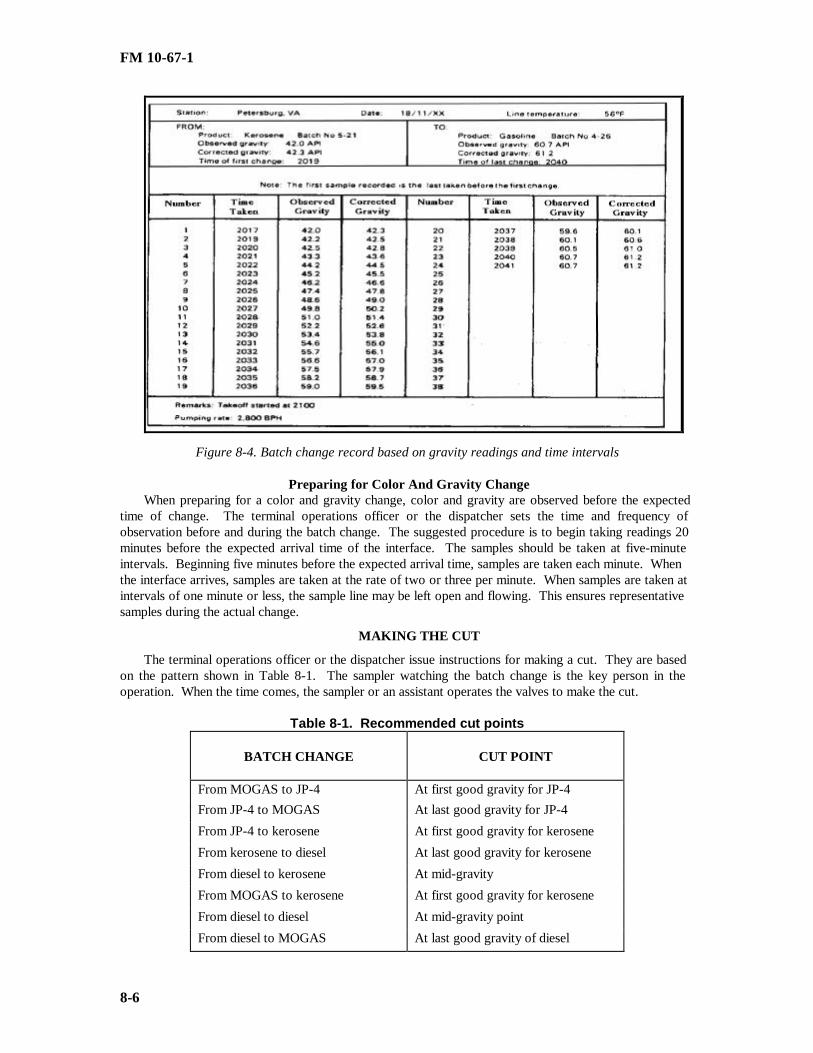
FM 10-67-1
8-6
Figure 8-4. Batch change record based on gravity readings and time intervals
Preparing for Color And Gravity ChangeWhen preparing for a color and gravity change, color and gravity are observed before the expected
time of change. The terminal operations officer or the dispatcher sets the time and frequency ofobservation before and during the batch change. The suggested procedure is to begin taking readings 20minutes before the expected arrival time of the interface. The samples should be taken at five-minuteintervals. Beginning five minutes before the expected arrival time, samples are taken each minute. Whenthe interface arrives, samples are taken at the rate of two or three per minute. When samples are taken atintervals of one minute or less, the sample line may be left open and flowing. This ensures representativesamples during the actual change.
MAKING THE CUT
The terminal operations officer or the dispatcher issue instructions for making a cut. They are basedon the pattern shown in Table 8-1. The sampler watching the batch change is the key person in theoperation. When the time comes, the sampler or an assistant operates the valves to make the cut.
Table 8-1. Recommended cut points
BATCH CHANGE CUT POINT
From MOGAS to JP-4 At first good gravity for JP-4From JP-4 to MOGAS At last good gravity for JP-4
From JP-4 to kerosene At first good gravity for kerosene
From kerosene to diesel At last good gravity for kerosene
From diesel to kerosene At mid-gravity
From MOGAS to kerosene At first good gravity for kerosene
From diesel to diesel At mid-gravity point
From diesel to MOGAS At last good gravity of diesel

FM 10-67-1
8-7
From MOGAS to diesel At first good gravity of diesel
BATCH CHANGE RECORDS
Observation of gravity changes for reporting passage of interfaces or for making delivery cuts is basedon displacement meter readings or time intervals and on hydrometer readings. The time of the first andlast gravity reading and the rate of flow should be reported to the dispatcher. This information fixes theexact time the interface passes. It also shows the length and volume of the interface. The format of thebatch change record is prescribed by the chief dispatcher. Suggested formats are shown in Figures 8-4,page 8-5, and 8-5, page 8-7. In both cases, the first reading recorded is the last reading taken before thefirst change is noted.
DISPLACEMENT METER AND HYDROMETER
Figure 8-5, page 8-7, is an example of a batch change record based on displacement meter andhydrometer (gravity) readings. The batch change is from gasoline (64 ° API or 0.7136 specific gravity) tokerosene (42° API or 0.8155 specific gravity). The purpose of the change is to make a heart cut deliverywhen the interface has passed the take-off point. The change covers a specific gravity range of .1019(.8155-.7136). Line temperature is 38°F. Gravity has been observed at 1-barrel intervals. Volume andcomposition of the interface are computed as follows:
• Specific gravity increased 10 points in the first 10-barrel increment (meter reading 371,590 barrels).Specific gravity 0.7136 represents pure gasoline, and specific gravity 0.8155 represents pure kerosene.Therefore, a 10-point increase represents 10/1,019 x 100 = 1.0 percent kerosene (0.10 barrel) in the firstincrement.
• Gravity increased 2 points in the second increment for a total increase of 36 points. Therefore, thesecond increment has 36/1,019 x 100 = 3.5 percent kerosene (0.35 barrel).
• The percent of total gravity increase and the corresponding amount of kerosene are computed in likemanner for each increment.
• Based on gravity alone, the nineteenth 10-barrel increment has 99.6 percent (or 9.96 barrels) ofkerosene and the last of the gasoline. The total of the barrel column shows 115.97 barrels of kerosene inan interface of 190 barrels. The interface has 61 percent tail product and 39 percent head product.
• The flash point tests show that even when good kerosene gravity has been reached, enough gasolinestays to lower the flash point of kerosene to a dangerous level. The 100 barrels added before the cut is asafety precaution that was taken to remove this hazard.
• Figure 8-6, page 8-8, is a graphic showing the same batch change. Point A is the beginning of theinterface at a meter reading of 371,580 barrels. Point B is the approximate end of the interface at a meterreading of 371,770 barrels. Point C is the cut point at a meter reading of 371,870 barrels. Area Drepresents the volume of gasoline in the interface. Area E represents the volume of kerosene asdetermined by gravity.

FM 10-67-1
8-8
Figure 8-5. Batch change record based on displacement meter and gravity readings

FM 10-67-1
8-9
Figure 8-6. Graphic showing a batch change
MID-GRAVITY POINT
Figure 8-5, page 8-7, shows a sample mid-gravity cut point. The mid-gravity cut point is reached inthe eighth 10-barrel increment at a meter reading of 371,660 barrels. While percentages vary, mid-gravity cuts divide interfaces into two unequal parts. The smaller part next to the head product consistsmainly of head product. The larger part next to the tail product consists mainly of tail product. Becausethe gravity of the tail part is heavier than the gravity of the head part, the tail product tends to penetratethe head product. The ninth 10-barrel increment has 53.2 percent (or 5.32 barrels) of tail product. Thebarrel column totals 17.10 barrels of tail product at this point. Therefore, the 80-barrel part of theinterface that would go to tail product tankage has 98.87 barrels of tail product and 11.13 barrels of headproduct. A mid-gravity cut is mentioned for gasoline and kerosene for illustration only. Such a cut wouldnot be made in practice. It would be necessary to protect the octane number and the vapor pressure of thegasoline and the flash point of the kerosene.
TIME INTERVAL AND HYDROMETERFigure 8-4, page 8-5, shows a batch change record based on observation of gravity for a fixed time
interval of one minute. The batch change shown is from kerosene (42.0 ° API) to gasoline (60.7° API).Readings could have been recorded the same way as in Figure 8-5, page 8-7, to compute the volume andcomposition of the interface. This record is adequate for recording the passage of an interface or for a cutwhen the interface has passed.
ANALYSIS OF BATCH CHANGE REPORTData recorded in Figure 8-4, page 8-5, can be made to show the same kind of information as that
shown in Figure 8-5, 8-7. The information in Table 8-2, page 8-9, has been computed as follows:
• The gravity differential is 61.2 - 42.3 = 18.9 o.
• The first gravity change is at 2019 and the final change is at 2040. This is a period of 21 minutes.At 2,800 barrels per hour, the interface has a volume of 980 barrels. This is about 46.7 barrels arrivingeach minute.
• Percentage and volume of gasoline are computed for each increment as in Figure 8-5, page 8-7.
• The total amount of gasoline in the interface is 560.85 barrels. This is 57.2 percent of the tailproduct as compared with 61 percent of the tail product in Figure 8 -5, page 8-7.

FM 10-67-1
8-10
Table 8-2. Analysis of batch change reportTimeTaken
CorrectedGravity
GravityIncrement
TotalIncrease
PercentGasoline Barrels
2017 42.3 0.0 0.0 0.0 0.002019 42.5 0.2 0.2 1.0 0.472020 42.8 0.3 0.5 2.6 1.212021 43.6 0.8 1.3 6.8 3.182022 44.5 0.9 2.2 11.1 5.182023 45.5 1.0 3.2 16.9 7.902024 46.6 1.1 4.3 22.7 10.702025 47.8 1.2 5.5 29.0 13.542026 49.0 1.2 6.7 35.5 16.582027 50.2 1.2 7.9 41.8 19.522028 51.4 1.2 9.1 48.1 22.462029 52.6 1.2 10.3 54.4 25.402030 53.8 1.2 11.5 60.8 28.392031 55.0 1.2 12.7 67.1 31.342032 56.1 1.1 13.8 73.0 34.092033 57.0 0.9 14.7 77.7 36.292034 57.9 0.9 15.6 82.5 38.532035 58.7 0.8 16.4 86.7 40.492036 59.5 0.8 17.2 91.0 43.602037 60.1 0.6 17.8 94.1 43.942038 60.6 0.5 18.3 96.7 45.152039 61.0 0.4 18.7 98.9 46.192040 61.2 0.2 18.9 100.0 46.70
Total gasoline in interface … … … … … … … … … … … … … … … … … … … … … … ..560.85 bbl

FM 10-67-1
9-1
CHAPTER 9
PIPELINE OPERATIONS
Section I. Duties of Personnel
CHIEF DISPATCHER
The chief dispatcher is usually the petroleum distribution officer in a petroleum pipeline and terminaloperating battalion or petroleum group. The dispatcher has operational control over the whole pipelinesystem. As a rule, the dispatcher’s office is normally located at the headquarters responsible for the co n-trol of the pipeline distribution system. The duties of the shift dispatchers are the same as those of thechief dispatcher. Shift dispatchers control operations in the name of the chief dispatcher.
Required Knowledge
The chief dispatcher must know--
• Knowledge and Skills, as required, by the Spill Prevention Control and Countermeasures (SPCC)Plan, for the particular installation and site over which the dispatcher has operational control.
• Capacity of storage tanks at each installation.
• Line fill and throughput for each section of pipeline.
• Hydraulics, including how to determine the normal working pressure for each section of line and themaximum discharge pressure that each pump station can develop.
• Number and location of pump stations.
• Line profile and the critical points in the line.
• Stock status and daily needs.
• Physical and chemical properties of each petroleum product pumped.
• Equipment controls and input and take-off rates.
• Safety features for protection of equipment and products pumped.
• Safety requirements for personnel and personal protective equipment (PPE) necessary for specificoperations.
• Procedures for blending in additives and interfaces.
Required Determinations
The chief dispatcher must determine--
• Type of product to be pumped.• Destination of each batch.• Amount of each product in each batch.• Estimated size of interfaces and estimated times of arrival of interfaces at pump stations and term i-
nals.• Starting and stopping times of all pumping operations.
• Type of cut to be made with each interface.
• Pipeline pump station pressures and flow rates.
FM 10-67-1
9-2
• Condition of the interior, corrosion inhibitors, and scraper program.
Required Actions
The chief dispatcher must--
• Coordinate the development of monthly and daily schedules.
• Relay daily pumping orders to district dispatchers.
• Keep necessary records based on hourly reports from pump stations, tank farms, dispensing stations,and other installations.
• Keep records of fuel received into the pipeline system, fuel delivered to installations along the line,fuel left in the system, and fuel lost.
• Report daily information to higher headquarters.
Chief Dispatcher’s Office
Personnel in the scheduling and dispatching sections of the office of the chief dispatcher have variousduties. These duties are described below:
Scheduling Section
Personnel in the scheduling section prepare the monthly pipeline schedules which are based on r e-quirements to maintain stock levels. They also prepare daily pumping schedules from the monthly sche d-ule. The daily schedules are usually prepared a week in advance.
Dispatching Section
Personnel in the dispatching section start, adjust, and stop all pumping operations. To do this, theyissue daily pumping orders to the district dispatchers. These orders are based on the daily and monthlyschedules and take into consideration any last minute changes or emergency requirements.
DISTRICT DISPATCHERSDistrict dispatchers are located at subcontrol headquarters in the pipeline system. Each controls
pumping operations in their district according to the instructions of the chief dispatcher. Hourly pumpingand delivery reports are sent to the chief dispatcher. The hourly reports include barrels pumped from orreceived into each storage location, corrected to 60°F. Also the report includes suction and dischargepressures and RPMs for operating pumps, batch changes, and flow rates. A district dispatcher has certainfreedom of action in emergencies. In the case of a line break, fire, or other interruption, the district di s-patcher--
• Isolates the affected section of the line.
• Diverts upstream pumping into empty storage tankage or orders the line shut down.
• Halts pumping in the broken section of the pipeline.
• Instructs the terminal station downstream from the break to begin drawing fuel from its tankage andto continue pumping or shut down.
• Informs the chief dispatcher at once of the shutdown.
• Identifies the shutdown section and reports the disposition and amount of flow to and from availabletankage.

FM 10-67-1
9-3
Section II. Pipeline Communications System
DESCRIPTION
An efficient communications system is a must for the operation and maintenance of military pip e-lines. The system must be separate, continuous, and dependable. The communications system must have-
• High-quality transmission to keep errors to a minimum.
• Enough channels or circuits to carry the traffic load.
• Prompt connections to avoid delays.
• Immediate alternate systems so there will be no interruptions in pipeline operations.
EQUIPMENT AND USE
Teletypewriters, telephones, and radio teletypes are the main items of equipment in the system. R a-dios provide communication between all dispatchers and between pump stations. Radio communication isalso used to maintain contact with maintenance support teams and mobile air and land patrols. Thecommunications system begins at the petroleum pipeline and terminal operating company. Each companyuses teletypewriters, radios, telephones, and radio teletypes to control operations. Telephones are used bycompany elements for administration purposes. They are also used for similar purposes by battalion andgroup headquarters. As a rule, all pump stations and tank farms have the same teletypewriter and tel e-phone capabil ities. Standby radio communications are provided between adjacent pump stations.
Teletypewriter Service
This is furnished on a party-line basis to all pump stations and tank farms in each district. Each endof the party line includes the subcontrol stations at either end of the district. The circuit at each pumpstation ends in a page-printing teletypewriter.
Party Line Telephone System.
This is provided to all pump stations and tank farms in the district. It is also provided to the subco n-trol station at each end of the district. Each station on the party line is given an identifying code ring.
SYSTEM EXPANSION AND CONTROL
The system is expanded when there are petroleum pipeline and terminal operating battalions and p e-troleum group headquarters. The system is controlled by the chief dispatcher. He uses the system to con-trol the flow of products through the pipeline.
SIGNAL OFFICER
A signal officer is assigned to petroleum battalion or group headquarters. One of his major functionsis to coordinate with appropriate signal agencies to ensure that they provide the required support. Thesignal officer has staff supervision over assigned and attached signal troop units. He supervises internalcommunication support activities for the headquarters. He also inspects subordinate units to ensureequipment is properly maintained and operated. The signal officer assigned to a petroleum group hea d-quarters takes part in the communications planning of the petroleum distribution system. This duty mayinclude--
• Preparation of signal plans and policies for the headquarters and its subordinate operating units.
• Acquisition and allocation of required circuits and frequencies.
• Preparation of plans for emergency communication.

FM 10-67-1
9-4
• Designation of alternate means of communications to be used when the existing systems are di s-rupted.
CHIEF DISPATCHER CONTROL STATION
The chief dispatcher is normally positioned away from the first district dispatcher. The first districtdispatcher is usually at the harbor end of the pipeline system. However, the chief dispatcher control st a-tion may be combined with the first district dispatcher subcontrol station if needed. The chief dispatcherhas a tape-printing and transmitting teletypewriter, a telephone, and radio facilities. As a rule, the tel e-typewriter is used as the main method of communication.
• The chief dispatcher has a direct teletypewriter channel to the district dispatcher at each subcontrolstation. This channel is on a party-line basis as long as there are no more than nine subcontrol stations inthe pipeline system. The chief dispatcher has a teletypewriter switchboard in which circuits to districtdispatchers end. The switchboard allows the chief dispatchers to contact any or all district dispatchersseparately or in any combination. It also allows district dispatchers to contact adjacent district dispatc h-ers.
• The chief dispatcher has a telephone that allows him to talk to subcontrol stations 1 and 2.
• The chief dispatcher also has mobile, high-frequency radio facilities. These facilities may be int e-grated into the common system at the chief dispatcher control station or any subcontrol station. The radiohas a radio-teletypewriter and voice capability. This gives the chief dispatcher another means of contac t-ing district dispatchers on a net operation basis. The radio system may be operated by remote controlfrom the office of the chief dispatcher and the dispatcher at each district.
• The chief dispatcher notifies all pump stations of an impending shipment by having the messagepunched on a teletypewriter tape. The message is sent to all district dispatchers at the same time. Onreceipt of the message, district dispatchers decide if it is intended for all pump stations. The district di s-patchers then transmit the message through their respective communication circuits. If a circuit to anydistrict station is out of order, the chief dispatcher uses the radio equipment for communication.
DISTRICT DISPATCHER SUBCONTROL STATIONS
All district dispatcher subcontrol stations have teletypewriters and telephones. As a rule, the tel e-typewriter is used as the main system of communications and the telephone as the secondary system. Thesystem is organized as described below.
• Each subcontrol station has a direct teletypewriter channel to the chief dispatcher. This channel isprovided on a private-line basis unless the chief dispatcher decides otherwise.
• Subcontrol stations 1 and 2 have direct telephone lines to the chief dispatcher.
• Each subcontrol station has a small telegraph and telephone switchboard. This switchboard term i-nates circuits coming into and within the district. This arrangement allows the operation to be flexible.Access to through circuits allows individual district dispatchers to function as the chief dispatcher in anemergency.
• All pump stations and tank farms in a district communicate through a party line telephone channelwith manual code ringing and a party line teletypewriter channel. These channels end in the subcontrolstations at either end of the district. The teletypewriter circuit at each district station ends in a teletyp e-writer that can receive and send both tape and page copy.
• Relay services are provided by the subcontrol stations. These services are mostly the relaying ofchief dispatcher channels to distant subcontrol stations. Services are provided to other stations on thepipeline system by request.

FM 10-67-1
9-5
• Each subcontrol station has mobile radio equipment. This equipment allows the subcontrol stationto contact the chief dispatcher and any other subcontrol station. The radio equipment may be used tocommunicate if the party line teletypewriter circuit is interrupted.
Section III. Schedules
Scheduling Factors
Scheduling is planning the movement of bulk petroleum products by pipeline from the base terminalto intermediate terminals and pipe head terminals. Before products can be scheduled for movement, thechief dispatcher must determine when and where specific products will be required and how much storagespace is available. He must also know how long it will take for the product to reach its destination after ithas been started through the pipeline. Past experience is the best way to determine daily requirementsthroughout the pipeline system. With the above factors in mind, the chief dispatcher prepares consum p-tion graphs. These graphs show projected consumption and deliveries. Under the supervision of the chiefdispatcher, the scheduling and distribution sections prepare a monthly pipeline schedule and a dailypumping schedule.
CONSUMPTION GRAPH
The chief dispatcher keeps a consumption graph for each product handled at each storage point.Each terminal keeps similar graphs for large volume users. The graphs are valuable for showing presentand future stocks and storage positions. They also show trends in consumption. Sudden increases or d e-creases in consumption are quickly recognized and can be reflected in scheduling. A consumption graphmust show the total barrels of any given product for each terminal or storage location. A separate graphshould not be prepared for each tank . Figure 9-1, page 9-6, is a consumption graph for diesel. Inform a-tion for this graph is given below.
• Storage capacity for the product in thousands of barrels (vertical axis) is plotted against time inmonthly intervals (horizontal axis). Days are figured from 0001 of one day to 0001 of the next.
• Allowance for vapor space is 5 percent of the total storage capacity. This is reflected at the top ofthe graph.
• Safety level is shown at the bottom. The safety level is normally determined (at theater level) basedon collective data.
• Calculated issues and receipts are shown by a broken line. Actual issues and receipts are shown by asolid line. All receipts are shown by a vertical line at the end of the day. Daily issues to local customersand pipeline issues are shown on the same graph.
• Allowances must be made for tank cleaning and repairs. The reduced storage capacity is subtractedfrom the total capacity.
• Differences in stock on hand from day to day show the rate of consumption. The average consum p-tion rate from past experiences is used to plan for future issues. Based on this projected consumption rate,the system must be replenished by pipeline.

FM 10-67-1
9-6

FM 10-67-1
9-7
Figure 9-1. Consumption graph
MONTHLY PIPELINE SCHEDULE
The monthly pipeline schedule as shown in Figure 9-2, page 9-8, shows the programmed movementof products through the pipeline. The products required for the 30-day period must be determined. Thena schedule can be prepared to compute the time it will take for a product to reach its destination after ithas started into the pipeline. This schedule is merely a graph which shows line capacity in barrels (di s-tance) plotted against time (hour). It is prepared on a sloping tabletop, which can be equipped with a full-length parallel rule. It is best to use an adjustable protractor with the parallel rule to ensure that the flowis plotted correctly. Information on this graph is given below.
• Before the graph is made, the number of hours a line is to be pumped each day must be determined.Time is shown from the beginning to the end of a given working day. The chart is drawn with the verticalaxis showing line fill.
• The horizontal axis is drawn to show the time period.
• Terminals are located on the chart by their respective line fill distance downstream from the baseterminal. The terminals are plotted vertically.
• Each batch is labeled by product and batch number. Each type of product is marked on the graphwith a different color.
• The distance in barrels divided by the pumping rate equals the number of hours it will take for agiven batch to reach a designated place.
• The slope of the throughput lines stays constant when there is no intermediate stripping and whenthe pumping rate stays the same. Stripping is when all or part of one or more batches is taken off themain pipeline at an intermediate terminal.
• When products are taken into a terminal and half of the pipeline is shut down, this is plotted on themonthly pipeline schedule. A dotted line on the horizontal time axis shows the time the pipeline is shutdown. A dotted line on the vertical axis shows the portion of the pipeline to be shut down. A second ve r-tical dotted line shows when the pipeline goes back on stream. It should be noted on the schedule that thisis a static condition.
• Stripping of product at a terminal is shown in the same manner as a static condition--with horizontaland vertical dotted lines. It is noted in the block formed by the dotted lines that a stripping action is ta k-ing place.
• The vertical lines represent terminals and stations. The points at which the sloping lines intersectthe vertical lines show scheduled arrival times.
• When all of the throughput lines have been drawn, the graph represents all scheduled pumping anddelivery operations for the month.

FM 10-67-1
9-8

FM 10-67-1
9-9
Figure 9-2. Monthly pipeline schedule
DAILY PUMPING SCHEDULE
The daily pumping schedule as shown in Figure 9-3 is used as a basis for preparing pumping orders.It is an abbreviated tabular form of the monthly schedule for each day concerned. This schedule showschanges and emergency needs. It is usually prepared a week in advance so that the dispatching sectioncan have a week’s supply. The dispatching section uses the daily pumping schedule to prepare thegraphic progress chart and the daily pumping order.
Figure 9-3. Daily pumping schedule

FM 10-67-1
9-10
Section IV. Line OperationsTESTING OPERATIONS
The chief dispatcher keeps a week’s supply of daily pumping schedules. He uses them to arrangewith the base terminal to test the products before pumping begins. They are tested according to MIL-HDBK-200. Test results are recorded on DA Form 2077 Arrangements are also made for line samplingand testing while the product is enroute. This is done to mark the progress and position of interfaces.Instructions for testing and disposing of interface are given to the terminals where they are to be taken off.
PUMPING OPERATIONS
The chief dispatcher decides the specific times batches are to be pumped into the line. All stationsalong the line are told of the starting time, amount of product, route, and destination. The input stationreports every hour on cumulative barrels pumped, temperatures, pressures, and batch numbers. Pumpstations along the line report every hour on line and atmospheric temperatures, pressures, product code,and batch number. This information is recorded on DA Form 4193 as shown in Figure 9-4, page 9-11and 9-12. The reports are sent to the district dispatchers who, in turn, send the reports to the chief di s-patcher. Pump stations are told of the expected arrival time of scrapers that may be in the line.
OPERATION REPORTSOperation reports cover hourly pumping and delivery data from the various pipeline pump stations.
These reports are sent to the appropriate district dispatcher. The reports provide a check on the operationof the line. The chief dispatcher decides the progress of batches and the position of interfaces by using thevarious operation reports. This information is recorded on the daily pumping record. Some of the info r-mation is used along with the graphic progress chart or with the stream tape. Discrepancies between ba r-rels pumped and barrels delivered must be investigated. The pipeline day begins at midnight. At thattime, the chief dispatcher sends a time signal to regulate all clocks in the system. The first report is madeat 0100. Station 1 reports first, and all others follow in order. The report from a branch line takeoff st a-tion follows that from the main line station where the branch begins. Reports from input stations, waystations, and takeoff stations will differ in content. Reports need be no more than a single teletype line.They are letter and figure-coded to save space and time. Data should be arranged in sequence. Then, theywill coincide with station logs and dispatcher’s pumping record. More station reports and information aregiven below.
Input Station ReportAn input station provides various data to the dispatcher. These data include--• Batch number and product code.• Tank number from which fuel is being pumped.• Line temperature.• Atmospheric temperature.• Suction pressure.• Station discharge pressure.• Any change in gravity.• Barrels pumped in last hour, corrected to 60°F.• Cumulative barrels pumped since midnight, corrected to 60 °F.
Pump Station ReportA pump station provides various data to the dispatcher. These data include--• Batch number.• Line temperature.• Atmospheric temperature.

FM 10-67-1
9-11
• Suction pressure.• Discharge pressure of each pump operating.
Figure 9-4. DA Form 4193 (Petroleum Products- Pump Station Hourly Operations Record)

FM 10-67-1
9-12
Figure 9-4. DA Form 4193 (Petroleum Products-Pump Station Hourly Operations Record) (continued)

FM 10-67-1
9-13
Takeoff Station Report
A takeoff station provides various data to the dispatcher. These data include--
• Batch number.
• Tank number into which fuel is being pumped.
• Product or grade (API gravity).
• Observed temperature.
• Sample number.
• Cumulative barrels received since midnight, corrected to 60 °F.
Additional Information
Other needed information will be sent hourly to the chief dispatcher from the district dispatchers.Data on rate of flow, position of interfaces, and inputs and takeoffs from the main line should be sent tothe chief dispatcher. He uses these to keep a current plot on the graphic progress chart.
Reporting Instructions
There are various instructions that stations use for reporting data to the dispatcher. These instru c-tions are given below.
• Station 1 puts its report on the teletype promptly on the hour.
• All other stations stand by to report in sequence.
• Any station not able to report in sequence must report after all other stations have reported.
• All information not pertinent to the report is excluded.
• The sequence of reports is interrupted only by emergencies.
• Any station not reporting is contacted by the chief dispatcher.
Section V. Dispatching Records And Controls
Daily Pumping Record
The daily pumping record as shown in Figure 9-5, page 9-14, is known also as the operation sheet ortrain sheet. The format may be changed locally to suit local needs or the requirements of higher hea d-quarters. Basically, the record details operations of the whole line in the same way the station log detailsstation operations. The chief dispatcher uses data in hourly operations reports to keep the daily pumpingrecord. The vertical axis shows a complete pipeline day beginning at 0000 and ending at 2400. The hor i-zontal axis is divided into separate sections for each pump station and terminal in the pipeline system.Station sections are labeled by station number or location. The first section is used for the base terminal.Other stations and terminals follow from left to right downstream. A suggested format is described below.

FM 10-67-1
9-14
Figure 9-5. Suggested format for daily pumping record

FM 10-67-1
9-15
Information Recorded
The tank column next to the left-hand time column is used to record the number of the tank fromwhich fuel is being pumped. Cumulative input is the hourly batch total of fuel pumped. The initial st a-tion suction pressure is that supplied by gravity or a feeder pump. Individual pump discharge pressuresand RPMs are recorded to show any problems. RPMs should be the same for all pumps operating pro p-erly. Suction pressure for pump 1 only is recorded. This is because the discharge pressure of pump 1 isthe suction pressure of the next pump. Cumulative takeoff at depots and terminals is the hourly total ofdeliveries from the line. Rate of flow beyond a takeoff terminal should be no more than the amountpumped into the pipeline minus the rate of takeoff. Therefore, rate of flow beyond a full-stream takeoffmust be zero. The tank column for delivery terminals is for the number of the tank receiving productfrom the line. Temperatures also help samplers to see gravity changes. A section for remarks can beplaced below each station section of the format. Batch numbers and changes, switching times, scraperlaunchings and arrivals, and other needed i nformation may be put in the remarks section.
Preparation and Posting
The daily pumping record is prepared by the dispatcher on duty at midnight and at 0700 or 0800.Postings for 2400 on the old sheet are carried over to 0000 on the new sheet. Properly arranged stationlogs help the dispatcher when he prepares and posts the daily pumping record. Batch changes, showingtime of first and final change (gravity or color) and rate of flow, are posted in the remarks section. Di s-charge pressures should be monitored closely. Any drop in discharge pressure could show a line tap orbreak. When a batch is completed at the terminal, the batch number and barrels pumped since midnightshould be shown under the respective section. The number of barrels short or over for each hour shouldbe entered in the end point block. The pipeline is over (black) when total deliveries exceed total pumping.The pipeline is short (red) when the total pumping exceed the total deliveries. A cumulative (over orshort) is carried for a complete day only. The cumulative total for each shift can be checked by subtrac t-ing the hourly deliveries from the hourly pumping since midnight.
GRAPHIC PROGRESS CHARTThe graphic progress chart as shown in Figure 9-6, page 9-16, shows the position of batches and their
progress through the pipeline. It is prepared one day in advance. The chart cover a 24-hour period.
PreparationThe chart is prepared on a sloping table using a full-length parallel rule, a flow rate scale, and a pr o-
tractor or adjustable triangle. Any scale can be used. The chart is prepared as follows:• Hours are shown on the vertical axis.• Line fill terminals and pump stations are shown on the horizontal axis. Line fill is shown to the
right of the midpoint, zero barrels. Scheduled input is shown to the left of the midpoint. The midpointrepresents the base terminal.
• Terminals, stations, and branch lines are shown on the vertical lines at the corresponding dow n-stream line fill distance from the input point or base terminal.
• To determine when a new product is to be started into the line, a horizontal line is drawn left fromthe entry point (base terminal). The line is drawn a distance equal to the number of barrels scheduled toenter. An adjustable triangle that has been preset for the desired rate of flow is used to draw a sloping,broken line from the end of the quantity line back to the base terminal time line. The point where thebroken line crossed the base terminal time line shows the time that the new product must be started.
• A solid sloping line is extended to the right from the base terminal time line at the same rate of flow.The degree of slope of this line shows the pumping rate of the throughput line. If the terminal is told tostrip product from the pipeline, the slope of the throughput line must be changed. The stripping action isshown by a broken vertical line.
• Shutdown of the line is shown by a broken horizontal line.• The points at which the sloping lines intersect the vertical lines (terminals and stations) show sche d-
uled arrival times.

FM 10-67-1
9-16
Figure 9-6. Graphic progress chart

FM 10-67-1
9-17
Use
The chart is put in use at midnight. The dispatcher transfers batch positions from the bottom of theprevious day’s chart to the top of the new chart. Actual positions of a given batch are determined byhourly deliveries at terminals and the reported passing of interfaces. When batches are moving ahead ofor behind schedule, the dispatcher can adjust the chart to show the change of the flow rate. He draws anew broken flow rate line to project delivery. As a rule, the desired action is to adjust the flow rate temp o-rarily to put the batch on schedule. Each hour, the dispatcher draws horizontal lines using the appropriatecolor for each batch to show the position of the different fuels in the line. When all the batch lines havebeen drawn, the chart represents all scheduled pumping and delivery operations for the day.
DAILY PUMPING ORDER
There is no set format for the daily pumping order. Table 9-1, page 9-18, shows a sample pumpingorder. General guidelines for preparing the order are as follows:
• Time is shown in chronological sequence. Definite times should be shown for specific actions.
• Locations are shown from the base terminal through intermediate terminals and pump stations to thehead terminal.
• Specific orders must be given for the respective terminals and stations. Orders should be statedbriefly and clearly.
• All product and batch numbers must be designated.
• Amounts of products to be handled and type of interface cuts must be specified.
STREAM TAPE OPERATION
Stream tape operation is another way to show the movement of fuels through the pipeline. It allowsthe dispatcher to determine instantly and accurately the location of any batch, buffer, dye, plug, or scraper.Arrival time at any terminal or branch line can be estimated easily. The operation and items needed aredescribed below.
Dispatching Board
This board is needed for the stream tape operation. It is a long worktable that parallels a pipelineprofile mounted on the wall above it. Components of the board include a system of markers to show st a-tions and terminals, the stream tape, and the guides or track in which the tape moves. There are separatetracks and tapes for each pipeline in the system.
Station Markers
The station markers may be movable metal or plastic pointers mounted on metal or plastic guides.The first marker at the left or upstream end of the board represents the base terminal or input points.Markers going to the right or downstream represent all other stations and terminals. The markers arespaced at distances and to the same scale as the pipeline profile on the wall above.
Stream Tape
The paper tape is 4 to 6 inches wide. It is supplied in rolls. The rolls are mounted under the left endof the dispatching board. The tape is fed through guides at the base terminal marker. The top edge of thetape has a printed scale. The scale shows the line fill at the proper number of barrels per inch. In co m-mercial use, the bottom edge may have one or two colored bands. The upper band stands for the shipper,and the lower band stands for the product. If there is only a single band, it stands for the product.

FM 10-67-1
9-18
Table 9-1. Sample format for daily pumping order
TIMES LOCATION DESIRED ACTION
0001 Base Terminal Pump DF, batch 3-17, 8,000 barrels at 1,000 barrelsper hour.
Pump Station 1 Pump 8,000 barrels of DF at 1,000 barrels per hour
Pump Station 2 Pump JP-4, batch 2-16
Intermediate Term inal No action
Pump Station 3 Pump DF, batch 3-14
Pump Station 4 Pump MOGAS, batch 1-13
Head Terminal Receive JP-4, batch 2-12, at 1,000 barrels per hour.
0800 Base Terminal Switch from DF, batch 1-17, to JP-4, batch 2-18, andpump 8,000 barrels.
Pump Station 7 Monitor the passage of interface, the end of batch 3-17, and the front of batch 2-18. Report.
Pump Station 2 Monitor the passage of interface, the end of batch 2-16, and the front of batch 3-17. Report.
Intermediate Terminal Prepare to receive JP-4, batch 2-16. Check passageof interface, end of batch 1-15, and front f batch 2-16.At API gravity of JP-4, open JP-4 tankage and strip500 barrels of JP-4 for 10 hours.
Pump Station 3 Monitor passage of interface, end of batch 1-15, andfront of batch 2-16. Report.
Pump Station 4 Continue to pump MOGAS, batch 1-13.
Head Terminal Switch from JP-4, batch 2-3, to receive MOGAS,batch 1-13. Receive 5,000 barrels for five hours.Interface will be taken into MOGAS tankage.
1600 Base Terminal Switch from JP-4, batch 2-18, to MOGAS, batch 1-19. Pump 8,000 barrels.
1800 Intermediate Terminal Close JP-4 tankage at good API gravity for JP-4.Monitor passage of interface, end of batch 2-16, andfront of batch 3-17.Report.Head Terminal Start receiving MOGAS, batch 1-13, at 1,000 barrelsper hour.
The number, width, and use of the posting spaces vary. Usually, the top half of the tape is used forpumping information. This includes hours, barrels pumped, batch numbers, gravities, batch totals, batchchanges, dates, and other data. The bottom half of the tape is used for delivery information. This i n-cludes hours, barrels delivered, total deliveries, station designations, and opening times. The 4-inch tapeis divided into four posting spaces, each three-fourths of an inch wide. The tape may be rerolled at thedownstream end of the board for storage. The steam tape can be used to record a variety of operations,including pumpings, batch changes, and deliveries. The tape can be used in the following ways.

FM 10-67-1
9-19
• Pumpings. The dispatcher performs a number of the operations starting at 0001 using the dailypumping order. A color-coded tape is selected. The free end is inserted in the track. Each hour, the inputpoint reports the number of barrels pumped. See Table 9-2, page 9-20. This information is first posted onthe daily pumping record and then on the stream tape. The dispatcher uses the printed scale to measure adistance from the batch head equal to the barrels pumped in the first hour. A vertical, broken pencil lineis then drawn from the proper graduation through the first posting space. The line coincides with the i n-put station marker and shows how far the batch advanced in the first hour. Thereafter, the tape is ad-vanced each hour by the number of barrels reported. Errors in increments will be avoided if the hourly,cumulative batch totals are scaled from the batch head. Hourly barrels and cumulative batch totals areposted in ink parallel with the vertical lines. Hours are posted on the first horizontal line. Batch numbersand gravities are posted in the space below. To estimate the arrival time of the batch head at any term i-nal, the dispatcher measures the distance in barrels from the batch head to the terminal marker. The di s-tance in barrels divided by the pumping rate per hour equals the number of hours and minutes from thetime of the last posting. When the first batch has been pumped, the tape is cut off at the total barrelspumped. A new tape is color coded for the next batch and trimmed to the tape. The old batch number,gravity, tank number, and total barrels are posted on the old tape. This is usually posted in the secondposting space next to the junction. The new batch number, gravity, and tank number are posted on thenew tape next to the junction and opposite the old data.
• Batch Changes. Batch changes are reported as the times, in minutes, of the first and final changein color or gravity. Barrels pumped during the hour of change divided by 60 equals the rate per minute.The number of minutes past the hour of the first and final changes multiplied by the rate per minuteequals the number of barrels past the hour to the head and tail of the interface. To plot these positions, thetape is advanced to the report hour. A mark is made on the scale opposite the reporting station marker.The two distances in barrels are scaled off from the index and marked. Vertical red pencil lines are thendrawn from the two graduations through the first and second posting spaces. The vertical lines should beon either side of the batch head shown by the cut tape. The distance between the red lines shows the pos i-tion and length of the interface. The station reporting the change and the date and time of first and finalchanges are posted in red pencil beside the plot.
• Deliveries. The spliced tape continues to be advanced until another new batch is started or a deli v-ery is to be made. When a delivery begins at some terminal, the proper batch is opposite the appropriateterminal marker on the board. The part of the tape that represents the batch is cut. The downstream endof the cut tape continues to advance in a stripping operation. It advances at a rate equal to the originalthroughput less the take-off rate. This is the new throughput. If a full-stream delivery is being made, thedownstream end does not advance. The upstream end of the tape is advanced and is lapped over thedownstream end by the number of barrels delivered. This is true for a stripping operation or a full-streamdelivery. Hourly deliveries are posted in the two bottom posting spaces. Barrels delivered each hour arescaled off from the cut, and vertical pencil lines are drawn through both spaces. If there is no printedscale at the bottom of the stream tape, cumulative hourly totals should be scaled from the cut. Barrelsdelivered each hour are posted in ink, parallel with the vertical lines. Deliveries at different terminalsfrom the same batch are scaled from the same cut. Alternate spaces are posted to show such deliveries. Ared pencil line is drawn to mark the last delivery total. The two ends of the tape are spliced in the lappedposition. When the tape is removed for storage, all laps are let out again. The tape is then replaced in itsoriginal length.

FM 10-67-1
9-20
Table 9.2. Sample tabulation of receipts and deliveriesDELIVERIES
TIME
RECEIVEDFROMINPUTPOINT
TOTERMINAL
Y
TOTERMINAL
Z TOTAL
OVEROR
SHORT
CUMULATIVEOVER
ORSHORT
0100 482 0 480 480 -2 -20200 486 0 482 482 -4 -60300 490 0 488 488 -2 -80400 502 0 500 500 -2 -100500 495 249 249 498 +3 -70600 505 248 254 502 -3 -100700 498 250 250 500 +2 -80800 510 251 261 512 +2 -6
(3,968) (998) (2,964) (3,962) (-6)0900 512 252 260 512 0 -61000 507 251 257 508 +1 -51100 504 250 252 502 -2 -71200 500 249 249 498 -2 -91300 498 248 252 500 +2 -71400 495 247 251 498 +3 -41500 490 248 240 488 -2 -61600 488 242 243 485 -3 -9
(7,962) (2,985) (4,968) (7,953) (-9)1700 492 0 494 494 +2 -71800 495 0 498 498 +3 -41900 498 0 500 500 +2 -22000 500 498 0 498 -2 -42100 505 503 0 503 -2 -62200 502 504 0 504 +2 -42300 500 249 252 501 +1 -32400 501 251 251 502 +1 -2
(11,955) (4,990) (6,963) (11,953) (-2)
Note: Receipts and deliveries are in barrels corrected to 60°F.
FM 10-67-1
10-1
CHAPTER 10
PETROLEUM INSTALLATION MAINTENANCE
Section I. Tank Farms and Pipeline Surroundings
MAINTENANCE OF SURROUNDINGS
The primary purpose of good maintenance practices at petroleum installations is to enhance safety and securityand to maximize service life. These practices also enhance work force performance and public relations. Workingpersonnel, military or civilian, perform better when high standards of safety, cleanliness, orderliness, and appea r-ance are maintained. This applies to all facilities, whether permanent, semipermanent, or temporary. Under anyconditions, fire prevention, integrity of firewalls, safety, security, and environmental protection stewardship mustbe considered in all petroleum installation maintenance procedures and policies.
GROUNDS
Constant attention should be paid to the installation grounds and the property around pipelines. All areasshould be attractive and free of fire hazards. To maintain the grounds, follow these steps.
• Mow grassy areas regularly.
• Use approved environmentally safe procedures for removal of unwanted plants from growing inside of fir e-walls, near fire hydrants, around tank openings, and in fuel handling areas of operation.
• Collect litter, trash, fallen leaves, and other combustible materials.
• Cut overgrown bushes and foliage around pipelines to permit patrolling and easy access to control valves.
• “No Smoking” and “Confined Space Entry Requirements” signs posted are in good condition and legible at adistance.
BUILDINGS AND SHELTERS
Buildings, pump station shelters, toolsheds, and all other similar structures should be kept in good conditionTo maintain them, follow these rules.
• Inspect all painted areas for flaking or blistered paint. Report areas that need repainting.
• Check the condition of roof gutters and downspouts. Report any needed repairs.
• Remove any items that could become fire or safety hazards. Follow general housekeeping procedures.
• Keep pump stations dry, clean, and well ventilated with approved adequate lighting devices.
FIREWALLS AND TANK MOUNDS
The firewalls which are built around aboveground tanks at permanent installations are usually made of co n-crete or some impervious material. These firewalls are subject to damage. The mounds of earth that cover unde r-ground tanks and the earthen firewalls (Figure 10-1, page 10-2) which are built around aboveground tanks in tact i-cal areas are subject to erosion. If left unchecked, erosion weakens firewalls so that they are not able to act as asecondary containment for a spill or prevention of a fire from spreading to another source. Also, the eroded soilcollects at the base of the firewalls. This destroys the grade inside the firewalls so that runoff water flows to thetank instead of from it. The water corrodes the tank bottom. It also washes away soil under the tank, causing thetank to settle. This settling puts stress on the tank structure and pipes. To maintain firewalls and tank mounds,follow these rules.

FM 10-67-1
10-2
• Check concrete firewalls regularly for cracks and other signs of damage. Report any deterioration.
• Fill in eroded areas in earthen mounds and firewalls as soon as possible.
• Regrade earthen firewalls so that water flows away from the tank.
• Seed the filled in areas of tank mounds and the outside slopes of firewalls with grass or vines, or with gravelor an asphalt like substance to hold soil in place.
• Dress the inside slopes frequently to replace eroded soil ; cover the inside slopes with gravel or perma prime.Another possibility is to arrange for the inside slopes to be with concrete. Another way to protect the ground is tocover the surface with rubberized or petroleum impervious sheets within the earthen berms.
Figure 10-1. Earthen firewall
PIPELINE SUPPORTS
Hangers and tiedowns as shown in Figure 10-2, page 10-3 are used to attach pipelines to bridges and trestles.Concrete embedded pipe anchors as shown in Figure 10-3, page 10-3, are used along pipelines to control mov e-ment and reduce vibrations. Other devices, such as wire ropes, cables, tower timbers, cross braces, and deadmananchors, are used to suspend pipelines across streams and ravines. To maintain pipeline supports, follow thesesteps:
• Inspect all devices monthly for warped and loose hardware, breaks, and corrosion. Repair, tighten, or replacethe hardware as needed.
• Allow enough space for the pipeline to expand in hot weather areas or to contract in cold weather areas whentightening fixtures.
• Inspect concrete foundations and the steel rods of pipe anchors for signs of damage or corrosion every 3months during the first year after construction and then every 6 months thereafter.

FM 10-67-1
10-3
Figure 10-2. Pipeline hangers and tie downs
Figure 10-3. Pipeline anchors

FM 10-67-1
10-4
WALKWAYS, RAILROAD TRACKS, AND CULVERTS
The roads, walkways, railroad tracks, and culverts required to operate a petroleum installation should be safe.To maintain them, follow these steps.
• Patch or repair potholes and cracks as soon as possible.
• Fill in washed-out areas beneath roads and walkways before more damage results.
• Ensure the railroad tracks in loading/unloading areas for tank cars are well maintained. Check the alignmentand condition of rails and ties. Look for loose spikes, worn or loose switches, or unserviceable grounding systems.
• Keep pipeline culverts under roads, railroad tracks, and water crossings clean. Inspect culverts after everyheavy storm. Check them frequently during rainy weather and in the spring after the snow melts and the groundthaws. Remove any debris and sediment that may have collected.
SECURITY FENCES
Fences are necessary around petroleum installations to prevent trespassing, theft and sabotage. To maintainthe security fences, follow these steps.
• Inspect the fencing, entrance gates, and fence posts regularly. Repair defective areas immediately.
• Promptly fill in gaps created by erosion or animals burrowing under the fences.
Section II. Waterfront Facilities
MAINTENANCE OF WATERFRONT FACILITIES
Waterfront facilities and tactical marine terminals are used to transfer fuel to and from tankers. Maintenanceon the waterfront is a constant effort to stop the potential threat to the environment caused by the sea, ships, andweather conditions A regular program of inspections and maintenance is necessary to prevent as much damage aspossible from the seawater, salt, air, marine organisms, sunlight, and dry rot. Furthermore, there are strict env i-ronmental regulations, permits and SPCC Plans which require that certain maintenance be done on a strict timeschedule. Every effort must be made to ensure these rules and time schedules are followed, both to the letter, andthe spirit of their intent. Emergency repairs are also necessary to mend the structural damage caused by movingvessels, ice, petroleum spills, and high waves. Ongoing maintenance is essential to keep waterfront facilities andmarine terminals operational.
RESPONSIBILITY FOR WATERFRONT MAINTENANCE
Repairs to structures such as piers and pilings cannot be done by organizational maintenance personnel. Ho w-ever, they are responsible for maintaining the pipelines, hoses, hose-handling equipment, grounding systems, andmooring devices at waterfront operations.
FUEL PIER AND JETTY PIPELINES
Pipelines on fuel piers and jetties as shown in Figure 10-4, page 10-5, are used in protected harbors to transferfuel. The piers and jetties are usually equipped with several pipelines to carry different fuels. The pipelines maybe supported on top of a pier or jetty, or they may be suspended below a pier with hangers (Figure 10-5, page 10-5).Pipelines under piers are especially subject to damage because they are alternately submerged and exposed by tides.To maintain the pipeline system--
• Inspect the pipelines, supports, and hangers frequently. Look for corrosion, chipped paint, and any signs thatthe protective coatings have failed.
• Sand the damaged areas to bare metal if necessary. Apply an protective coating material such as zinc chr o-mate, and then spot paint the pipeline, metal supports, and hangers.

FM 10-67-1
10-5
Figure 10-4. Multileg mooring facility
Figure 10-5. Pipelines under a fuel pier

FM 10-67-1
10-6
SUBMARINE PIPELINES
Submarine pipelines are welded pipe sections connected to storage tanks on shore and laid under water to shipmoorings. These pipelines are located at tactical marine terminals. They are also located in areas that are notnavigable by ships and in areas where there are no piers. Like the pipelines suspended under piers, submarinepipelines are especially prone to corrosion and damage from the ocean. The onshore sections should be inspectedfrequently and repaired as required. The underwater sections should be reported to support units. The markerbuoys for submarine pipelines and the chains used to lift the lines off the ocean floor should be serviced the sameas for the markers and chains of the mooring facilities.
HOSELINES
Wire-reinforced neoprene rubber hoses are flanged to the ends of submarine and pier pipelines. They provideflexible connections to tankers. Maintenance procedures of the hoselines include the following.
• Inspect the hoses for damage such as kinks, bulges, worn soft spots, and cuts that penetrate the wire rei n-forcement. Look inside the open ends for internal damage.
• Repair or replace hose sections, couplings, and gaskets as needed.
• Keep the hoses tightly capped when not in use.
• Test each hose to 1 1/2 times its normal working pressure every 3 months. See Table 10-1.
WARNING
Do not go over 125 PSI unless it can be determined that the hoses were designed by the manufacturer to takemore. During testing, look for leaks, bulges, and distortions in the hose. Stencil the date of the test on thehose in a subdued color (black or gray) and keep a written record of the tests.
Table 10-1. Hose test pressures.TYPE SIZE
(in)TEST
PRESSURE(PSI)
Hose assemblies, rubber, oil and gasolinedischarge, smooth-bore, lightweightbuoyant type (MIL-H-19001 (ships)) (lat-est revision)
Hose and hose assemblies, synthetic ru b-ber, reinforced, water- and oil resistant,nonmagnetic and regular service, high-pressure type (type C) (MIL-H-19606(ships)) (latest revision)
Hose and hose assemblies, rubber, oil-and gasoline discharge, smooth-bore,lightweight, buoyant type; reattachablecouplings and adapters (MIL-H-22240(ships)) (latest revision)
Hose, rubber, gasoline, with reusablecouplings, low temperature (MIL-H-6615, latest revision)
6
445
667
4
200
1,200 800*1,000
700300250
160
* TYPE D.

FM 10-67-1
10-7
HOSE-HANDLING EQUIPMENT
Hose-handling equipment consists of devices such as cranes, slings, hoists, winches, A-frames, and gin poles.This equipment is usually located at the end of piers. It is used to lift and suspend cargo hoses for fuel transfer. Itis rigged to allow movement of the ship during transfer operations. Maintenance requirements of hose-handlingequipment include the following.
• Lubricate all moving parts that are visible.
• Check for structural damage such as dents, buckling, cracks, and rust.
• Tighten all loose nuts on bolts and any other loose fixtures.
• Oil wire cables to keep them rust free.
• Test wire cables at least every 6 months.
MARINE LOADING ARMS
Marine loading arms (Chapter 4) are being used instead of hoses and hose-handling equipment at many w a-terfront facilities. Marine loading arms have a hydraulics system or a set of cables which moves the piping intoposition. Swivel joints provide a flexible connection between the piping and a tanker. Maintenance requirementsof marine loading arms include the following.
• Lubricate the ball bearings in the swivel joints.• Replace the packing, seals, and O-rings if a leak develops in the swivel joints. Follow the instructions in the
manufacturer’s manual.• Inspect the outside surface for rust. If necessary, scrape to bare metal and then spot paint with primer and
rust-inhibiting semigloss enamel.• Check the hydraulic fluid in the hydraulic arm. See the manufacturer’s manual for more information.
WARNING
Do Not adjust the cables in a cable-operated arm. This is not organizational level maintenance.
LINE-HANDLING EQUIPMENTBollards, bits, and capstans are hardware devices used to moor a ship to a pier or jetty. These devices are
made of cast iron or steel. They are fastened to the pier with anchor bolts. Line handling devices are subject tocorrosion. The anchor bolts are especially subject to corrosion where they come in contact with the castings.Maintenance requirements of line handling equipment include the following.
• Grout under the castings and coat the anchor bolts, nuts, and washers with asphalt enamel.• Inspect` the grouting and coatings often and repair them as needed.
MOORING FACILITIESA multileg mooring facility (Figure 10-4, page 10-5) is used to anchor a tanker in position offshore during a
fuel transfer. A mooring facility is located at the ocean end of submarine pipelines. Depending on the size of thetankers to be moored, the mooring facility can have three, five, or seven legs as shown in Figure 10-6, page 10-8.Each leg of a multileg mooring facility is made up of a marker buoy, sinker, anchor, and chain. The chains andbuoys are subject to much wear and tear from the ocean and moving vessels. Maintenance requirements of themooring facilities i nclude the following.
• Lift the chains and inspect them for corrosion and uneven wear at least once a year.• Clean and recoat the chains if necessary. Replace worn chains.• Make sure cotter keys and forelock pins are securely in place in mooring chains.• Inspect buoys frequently.• Lift, sandblast, and recoat buoys with anticorrosive primer and antifouling paint at least once a year to keep
them watertight and to prevent corrosion.

FM 10-67-1
10-8
Figure 10-6. Typical mooring
PIER GROUNDING SYSTEMS
All the metal structures and pipelines on piers should be grounded. Also, ships and tankers should begrounded and bonded with a flexible copper cable during fuel transfers. Maintenance requirements for the piergrounding systems include the following.
• Check all cables for positive connection before each transfer operation of fuels.
• Ensure all cables have a C-clamp or a device with sharp teeth or prongs to make contact with the metal underthe painted surface of the ship
• Test the system frequently. Replace broken wires and tighten loose connections as needed.

FM-10-67-1
11-1
CHAPTER 11
TANK CAR OPERATIONS
Section I. Tank Cars and Facilities
TANK CARSWhen rail facilities are available, tank cars may be used along with the pipeline to transport petroleum
products. Each tank car should be used to carry only one grade of product. If this is not possible, the tank car mustbe inspected and cleaned between loads to avoid product contamination. Tank cars vary in capacity and design.Those used for petroleum products usually have one compartment and range in capacity from 6,000 to 16,000gallons. Other tank cars have more than one tank compartment and carry more than one product at a time. Tankcars vary from those designed for narrow-gage foreign service to those designed for broad-gage foreign service andstandard-gage domestic service. Some tank cars have heaters to liquefy viscous products, but those without heatersare generally used. Figure 11-1 shows a typical petroleum tank car. The dome, safety valve, and bottom outlet oftank cars are described below.
Figure 11-1. Typical petroleum tank car
Dome
Each tank car compartment has a dome as shown in Figure 11-2, page 11-2, to allow space for the product toexpand as the temperature rises. The tank shell can be filled to the top. Each dome has a manhole through whichthe tank car may be loaded, unloaded, inspected, cleaned, and repaired. Dome covers may be hinged and bolted onor screwed on. Most domes have vents and safety valves to let out vapors.

FM-10-67-1
11-2
Figure 11-2. Tank car dome and bottom outlet
FM-10-67-1
11-3
Safety Valve
The safety valve used on most tank cars consists of a spring-loaded poppet valve which opens at a presetpressure. As pressure in the dome builds up to a point above the pressure setting of the valve, the valve is forcedoff the valve seat. This lets the excess vapors escape. The spring closes the valve automatically when the pressuredrops to a level equal to the valve setting.
Bottom Outlet
Each tank car has a bottom outlet and is usually loaded and unloaded through it. The outlet valve as shown inFigure 11-2, page 11-2, is controlled by a valve rod handle or valve rod handwheel. The outlets on tank cars usedin the United States are 5 inches in diameter. Outlets on tank cars used overseas are generally 4 inches indiameter. All outlets have male threads. A tank car elbow assembly is used to adapt a pump suction line to the 5-inch outlet. A 5- to 4-inch adapter must be installed between the elbow assembly and the tank car 5-inch outlet.
LOADING AND UNLOADING SITES AND FACILITIES
Engineer personnel construct standard loading and unloading facilities. The equipment at these facilitiesincludes pumps, manifolds, grounding items, and fire-fighting items. Portable pumping assemblies may be used inundeveloped theaters. This chapter deals mainly with the use of portable pumping assemblies for loading andunloading tank cars. However, the same procedures and safety precautions apply to all tank car operations.
SITECertain factors must be considered and provided for when choosing and preparing a site. Consider these
factors.
• The site should be at least 100 feet from any building.
• The site should have adequate drainage.
• If tank cars are to be unloaded by gravity, the site must be elevated enough to have the proper flow at thereceiving container
• If tank cars are to be loaded by gravity, the loading site must be below the supply container.
• A spur track or bypass should be provided for loading and unloading tank cars.
• The track at the site should be level so that product in all parts of the tank car remains level. This allows foraccurate gaging and keeps air and fuel from being trapped at one end of the car.
• If a tank truck is used to load or unload a tank car, it should be grounded to one or more ground rods to guardagainst static electricity or stray current.
• A grounding cable should be permanently bolted between the track rails.
• Derails, which are wedge-shaped devices of wood or metal, should be placed at the head of the car. Theyprevent other cars from backing into the tank car during transfer operations. Also, they are placed on the rails toprevent the tank car from rolling.
FACILITIESLoading and unloading facilities should be arranged so that several tank cars can be serviced at the same time.
Each servicing point at a facility should have bonding cables to bond the servicing point to the tank car shell and tothe track. There should be an emergency valve some distance from the loading and unloading point. This valve isused to cut off the flow through the line in case of fire. In some cases, product will flow by gravity to a loading andunloading facility from bulk storage tanks or pipelines. In other cases, fixed or portable pumping units must beused to transfer the product. Other equipment at the facility is described below.
• Distribution Manifold. A distribution manifold made of pipes and valves extends along a loading andunloading facility. It provides outlets for servicing several tank cars at one time. The manifold must be grounded.Cables must be available to bond the manifold to the track and to the tank car.

FM-10-67-1
11-4
• Car Mover.. There should be a standard car mover for spotting tank cars at each loading and unloadingfacility.
• Electrical Equipment. Electrical equipment includes lights, switches, and motors. They must be explosion-proof and in good working order.
• Outlet Plug. A wooden cone-shaped plug for the bottom of the tank car should be available in case ofemergency.
• Gossler Coupling . The Gossler coupling allows a tank car to be bottom loaded or unloaded at any NATOfacility. The coupling adjusts to fit any tank car bottom outlet or elbow and, with adapters, fits various hoses.Figure 11-3 shows the Gossler coupling.
Figure 11-3. Gossler coupling
PRECAUTIONARY MEASURES
Certain precautionary measures must be taken when a tank car is loaded or unloaded. Included among thesemeasures are the following:
• NO SMOKING signs must be placed so as to ensure that there is no smoking within 100 feet of the transferoperation.
• No welding, open flames, or lights, other than explosion-proof flashlights or lanterns, are allowed within 100feet of the transfer operation.
• The carrying of matches, lighters, or open lights is prohibited.
• All loading and unloading equipment must be bonded and grounded.

FM-10-67-1
11-5
Section II. Procedures for Loading Tank Cars
PRELIMINARY PROCEDURES
A number of procedures must be followed before tank cars are loaded. They are described below.
Sampling and Gaging
Take a sample of the product that is to be transferred to the tank car. Visually inspect it to make sure theproduct has no unusual appearance. If the identity or quality of the product is in question, test the product to makesure it meets specifications before the transfer operation is started. Also, gage the contents of the supply tank, andrecord the data. Take a water cut from the supply tank using water-indicating paste. Drain any water before theproduct is transferred.
Inspecting Loading Equipment
Inspect pumps, hose, pipelines, and manifolds to see that they are clean and in good operation condition.When possible, use equipment to handle only one product. If more than one product must be handled by the sameequipment, make sure all previous product is thoroughly drained before a new product is handled.
Spotting Tank Car
Spot a tank car by using the following procedures.
• Make sure the track rails are properly bonded and grounded. Ensure that cable connections are secure andmake bare metal-to-metal contact.
• Position the tank car so that there will be no unnecessary strain on the hose connections.
• Set the brakes and block the wheels of the tank car to keep it from moving during loading operations.
• Set and lock derails.
• Place STOP--TANK CAR CONNECTED signs between the rails at least 25 feet and preferably 50 feetahead of and behind the tank car or group of tank cars. Place the signs so that they can be seen by switch crews onthe main line next to the spur track. The signs should be at least 12 by 15 inches with black letters on a yellowbackground. The word STOP should be in 4-inch letters. The words TANK CAR CONNECTED should be in 2-inch letters.
• Place at least two fire extinguishers near the tank car where they will be in easy reach.
• If there is no permanent ground rod, drive a 4- to 5-foot iron rod into the ground beside the tank car.Attach a ground wire between the tank car and the rod. Soak the ground around the rod with water.
• If a tank car manifold is used, bond it to the tank car shell.
• When several rail cars are awaiting service, position cars with like products together (all MOGAS together,all JP-8 fuel together, and all aviation fuel together).
• Place NO SMOKING signs in the area where they can be easily seen.
Removing Dome Cover
Stand on the windward side of the dome when releasing internal pressure or when removing the dome cover.Remove the dome cover as follows.
• Clean all dirt from around the dome cover.
• Raise the safety valve on the dome to see if there is pressure in the tank. Reduce any pressure in the tankby keeping the safety valve open.
• Remove the padlock or seal that secures the dome cover.
• Loosen the dome cover slowly to permit any remaining pressure to escape through vents in the cover. Ifthe tank car has a screw cover, place a bar between the cover lug and the dome knob. Unscrew the cover two
FM-10-67-1
11-6
complete turns or until the vent openings are exposed. If the car has a hinge-and-bolt dome cover, loosen thenuts enough to release internal pressure.
• Remove the dome cover.
Inspecting Tank Car
Inspect the tank car to determine if it is suitable to receive the product. Follow these steps.
• Make sure that the product last carried in the tank is the same product that is to be transferred to the tank.If the product is not the same, follow the procedures in MIL-HDBK-200.
• Inspect the inside of the tank visually from the outside through the dome to make sure it is clean. If thereis rust, sand, scale, dirt, or residue, the tank must be cleaned before it is filled. Only authorized persons familiarwith procedures for cleaning tanks should enter the tank. See Chapter 12 for tank cleaning procedures.
• Look for any foreign objects, such as tools, bolts, or old tank car seals, that may have fallen into the tank.Such objects should be removed only by authorized persons. Some objects may not contaminate the product,inspect the tank for residual product. Any residual product must be removed before the tank is filled.
• Inspect the inside and outside of the tank visually from the outside to make sure there are no holes, cracks,leaks, or loose plates. See that the tank is properly mounted to the underframe and that the tank is safe androadworthy.
• Inspect the dome, dome cover, and safety valve to make sure they work and are in good condition. Makesure that the vent holes in the dome cover are open and clean.
• Make sure the bottom outlet chamber is in good condition.
• Ensure that the outlet valve seats and seals properly. Place a container under the bottom outlet chamber tocatch drainage. It should stay there until the transfer is complete. Open and close the outlet valve several timeswith the valve rod handle or handwheel located in the dome. If the valve does not seat properly, replace the valvegasket or repair the valve. In an emergency , load the tank car without repairing the outlet valve. However, reportit so that personnel at the installation receiving the tank car will unload it through the dome. The valve shouldthen be repaired as soon as possible. When the outlet valve is operating, close it.
• If necessary, tank cars may be flushed with a small amount of the product to be loaded. This will removetraces of previous product, rust, and scale from the outlet sump.
Removing Bottom Outlet Cap
Make sure the outlet valve is seated before removing the bottom outlet cap. Remove the bottom outlet cap asfollows:
• Remove the bottom outlet cap with the tank car wrench. If the cap does not unscrew easily, tap the caplightly in an upward direction with a wooden mallet or block. Let any product in the outlet chamber drain into thedrainage container.
• Open the outlet valve to allow any residual product to drain into the container. Close the outlet valve, butdo not replace the outlet cap until the car is completely loaded.
• Dispose of any product in the container, and place it back under the outlet valve.
BOTTOM OUTLET LOADING
Tank cars should always be loaded through the bottom outlet. This prevents vapor loss. It also reduces staticelectricity and the chance of product contamination. Precautions and procedures for loading a tank car through thebottom outlet are as follows:
• Place a pumping unit at least 50 feet from the tank car.
• Make sure the pumping unit is properly grounded.
• Make sure that the supply container is properly grounded and vented.
FM-10-67-1
11-7
• Make sure the hoseline connections are not laid on the ground without a dust cap or plug. It could result incontamination of product.
• Connect the pump suction line to the outlet of the supply container.
• Attach the tank car elbow or Gossler coupling to the tank car outlet. Connect the pump discharge hose toeither the elbow or the coupling. The tank car elbow is a part of the tank car loading facility and the FSSP.
• Station someone on the windward side of the dome to signal when the full mark is reached.
• Open the following valves before starting the pump:
••Outlet valve of the supply container.
••Pump valves necessary to permit flow through the pump.
••Tank car bottom outlet valve.
••Manifold valves, when a manifold is used.
• Start the pump following these precautions and steps.
••If spills occur while loading, stop the pump and cover the area with a blanket of foam from a foam fireextinguisher. If there is no foam fire extinguisher in the area, cover the spill with sand or dry earth. Removecontaminated earth and dispose of it according to current regulations.
••If sparks are seen while the car is being loaded, stop the pumps at once and check all bonding andgrounding connections. All connections should have bare metal-to-metal contact.
••If the bad connection cannot be found, check the power equipment in the area for stray current. Correctany faulty condition.
••In the event of enemy attack, electrical storm, or fire, stop the transfer operation. Disconnect the pumpdischarge hose and tank car elbow. Replace the bottom outlet cap. If time permits, move the car out of the dangerzone, set the brakes, and ground the car.
••In case of a fire at a hinged dome, stop loading and close the dome. In case of a fire at a screw dome,throw a wet tarpaulin or blanket over the dome or use a carbon dioxide or foam fire extinguisher.
••If the loading operation is stopped for any reason, disconnect the pump discharge hose.
••Check the contents of the tank often to avoid overfilling. However, never put your head in the dome.
••When the product level is near the full mark in the tank car, signal the pump operator to reduce pumpspeed and get ready to stop the pump. When a loading system that has a control valve is used, reduce the productflow by partially closing the valve. If the tank does not have a full mark, load the tank until the product reachesthe top of the shell. When the tank is full, stop the pump, close all the valves, and disconnect the pump dischargehose.
DOME LOADING
A tank car should be loaded through the dome only when bottom loading is not possible. If the tank car mustbe loaded through the dome, follow these steps.
• Place a pumping unit at least 50 feet from the tank car.
• Make sure the pumping unit is properly grounded.
• Make sure the supply container is properly grounded and vented.
• Make sure the hoseline connections are not laid on the ground without a dust cap or plug. This could resultin contamination of product.
• Connect the pump suction line to the outlet of the supply container.
• Put the end of the loading hose or drop tube through the dome of the tank until it almost touches the bottomof the tank. Bond the hose or drop tube to the tank. Make sure the end of the loading hose or drop tube remainssubmerged in the product in the tank during loading. If the hose or tube does not extend far enough into the tank,
FM-10-67-1
11-8
product will splash and vaporize. Splashing also causes static electricity. Make sure there is no strain on the hosethat would cause it to move or come out of the tank.
• Open the following valves before the pump is started:
••Outlet valve of the supply container.
••Pump valve to allow flow through the pump.
••Loading rack outlet valve when a loading rack is used.
••Manifold valves when a manifold is used.
• Make sure all the connections are secure, and start the pump following these precautions and step.
••Check for leaks at the bottom outlet when product starts to flow into the tank. If there are leaks, stop thepump and try to seat the bottom outlet valve by turning the valve rod handle clockwise. If the leak continues, stoploading, recover the product from the tank, and clean up any spills.
••If spills occur while loading, stop the pump and cover the area with a blanket of foam from a foam fireextinguisher. If there is no foam fire extinguisher in the area, cover the spill with sand or dry earth. Dispose ofcontaminated earth according to current regulations.
••Stop the pumps at once and check all bonding and grounding connections if sparks are seen while theproduct is being loaded. All connections should have bare metal-to-metal contact. If the bad connection cannot befound, check the power equipment in the area for stray current. Correct any faulty condition.
••Stop the transfer operation in the event of enemy attack, electrical storm, or fire. Then disconnect thepump discharge hose and tank car elbow, and replace the bottom outlet cap. If time permits, move the car out ofthe danger zone, set the brakes, and ground it.
••Stop loading and close the dome if there is a fire at a hinged dome. In case of a fire at a screw-type dome,throw a wet tarpaulin or blanket over the dome or use a carbon dioxide or a foam fire extinguisher.
••Remove the hose or drop tube from the tank if loading is stopped for any reason.
••Check the contents of the tank often to avoid overfilling. However, never put your head in the dome.
••Signal the pump operator to reduce pump speed, and get ready to stop the pump when the product level isnear the full mark in the tank car. When using a loading rack or other system that has a control valve, reduce theproduct flow by partially closing the valve. If the tank does not have a full mark, load the product until it reachesthe top of the tank shell. When the tank is full, stop the pump and close all the valves. Carefully remove theloading hose or drop tube from the tank to avoid spills.
FOLLOW-UP PROCEDURES
Certain follow-up procedures must be performed after a tank car is loaded. They are as follows:
• Allow the product to stand for at least 15 minutes so that suspended water or sediment can settle.
• Gage and sample the contents of the tank. Take the temperature of the product, volume correct the quantityaccording to DA Pamphlet 710-2-2, and record the data. Keep the sample for reference until the tank is delivered.
• Drain any water or sediment from the tank.
• Compare the amount of the product issued from storage tanks with the amount loaded on the tank cars afterthe daily closing gages are taken. Report excessive loss to the proper authority.
• Replace the bottom outlet cap. Close and lock the dome cover when the tank car is full of product.
• Place an approved identification seal on the dome cover. If the seal is in place, the receiver is assured that noone has tampered with the car. Record the seal marking on all the shipping papers.
• Remove the drainage tub from under the bottom outlet. Properly dispose of any product that is in the tub.
• Remove any DANGEROUS-EMPTY signs, and replace them with FLAMMABLE signs.
• Disconnect the grounding wire from the tank car. Remove the derails, if used, and remove the TANK CARCONNECTED signs.

FM-10-67-1
11-9
• Release the brakes, and move the car from the transfer area.
Section III. Procedures for Unloading Tank Cars
PRELIMINARY PROCEDURES
Certain procedures must be followed before tank cars are unloaded. The procedures to follow are given below:
Inspecting Receiving ContainersWhen inspecting receiving containers, you will need to follow certain procedures. These procedures are as
follows:
• If the product in the tank car is to be transferred to cans or drums, inspect the cans or drums to make surethey are cleaned in good condition.
• If the product in the tank car is to be transferred to a tank truck or semitrailer, inspect the vehicle tanks asyou would tank car tanks.
• If the product in the tank car is to be transferred to storage tanks, make sure the storage tanks are suitableto receive the assigned product.
• If a receiving tank already has product in it, gage and sample the tank contents. Make sure there is enoughoutage in the tank to receive the product. Visually inspect the sample to make sure the product in the receivingtank is the same as the product in the tank car. If there is any doubt, have tests made to verify the grade andquality of the product before mixing it with a new product. Gage the tank again, and record the data.
• Make sure that the receiving tank is grounded and vented.
Inspecting Unloading Equipment
Inspect pumps, hose, pipelines, and manifolds to see that they are clean and in good operating condition.When possible, use equipment to handle only one product. If more than one product must be handled by the sameequipment, make sure all previous product in it is thoroughly drained before new product is pumped.
Spotting Tank Car
A number of procedures are performed when spotting a tank car. These procedures are described in Section II.In addition, the following procedure apply to loading tank car.
• Checking Seals and Car Numbers. Make sure the tank car is in the right place by comparing the car andseal numbers with those on the shipping papers. Make sure the seals and locks are intact. Notify the properauthority if cars arrive with broken seals or locks. If there is an emergency and the tank car is needed immediately,unload the tank car but do not use the product until it has been tested.
• Removing Dome Cover. Pry the seals loose, and remove the dome cover. If the safety valve is notworking, high pressure may develop in the tank car in hot weather. If time permits, relieve the pressure by lettingthe car cool overnight. Relieving the pressure by venting allows product to vaporize. It also causes a fire hazard.
TANK CAR INSPECTION
A number of procedures must be followed when inspecting a tank car. Follow these steps.
• Inspect the tank car for leaks through the shell and the bottom outlet. If there are any signs the car is leaking,schedule it to be unloaded at once. Place containers to catch leaking product, and clean up any spills.
• Gage and sample the contents of the tank car, and check the sample for appearance and color. Take thetemperature of the product, volume correct the quantity according to DA Pamphlet 710-2-2, and record the data.Slowly drain any water in the tank through the bottom outlet. After the water is removed, gage the contents again,volume correct the quantity according to DA Pamphlet 710-2-2 and record the data. Fuel that is cloudy or off-color may be contaminated. Any questionable product should be thoroughly tested before it is unloaded.

FM-10-67-1
11-10
• Make sure the bottom outlet chamber is in good condition and the outlet valve is working properly (if it isused for unloading). In cold weather, water in the tank may freeze around the outlet valve and cause it not towork. To free the frozen valve, apply steam, hot water, or hot cloths to the outlet chamber. A hot air duct tentheater or a slave kit may be used by trained personnel, when authorized, to thaw the outlet. Let the valve thaw inthe warm part of the day, when possible.
SAFETY PRECAUTIONS
A tank car should be unloaded through the bottom outlet. The tank car may be unloaded through the domeonly when it is impossible to unload it through the bottom outlet. When unloading a tank car through either thebottom outlet or the dome, follow these safety precautions:
• If spills occur while unloading, stop the pump and cover the area with a blanket of foam from a foam fireextinguisher. If there is no foam fire extinguisher in the area, cover the spill with sand or dry earth. Dispose ofcontaminated earth according to current regulations.
• If sparks are seen while the car is being unloaded, stop the pumps immediately and check all bonding andgrounding connections. All connections should have bare metal-to-metal contact. If the bad connection cannot befound, check the power equipment in the area for stray current. Correct any faulty condition.
• In case of enemy attack, electrical storm, or fire, stop the transfer operation. Disconnect the pump suctionhose and tank car elbow, and replace the bottom outlet cap or remove the drop tube or hose. If time permits, movethe car out of the danger zone, set the brakes, and ground the car.
• In case of a fire at a hinged dome, stop unloading and close the dome. In case of a fire at a screw-type dome,throw a wet tarpaulin or blanket over the dome or use a carbon dioxide or a foam fire extinguisher.
• If loading is stopped for any reason, disconnect the pump suction hose or remove the hose or drop tube fromthe tank.
BOTTOM OUTLET PROCEDURES
Certain procedures must be followed to unload a tank car through the bottom outlet as shown in Figure 11-4,page 11-11. These procedures are as follows:
• Place the pump at least 50 feet from the tank car. Ground the pump.
• Measure the diameter of the bottom outlet of the tank to make sure the connection can be made with availableadapters.
• Turn the valve rod handle or handwheel clockwise to make sure the outlet valve is seated. Place a drain tubunder the bottom outlet, and leave it there until the operation is completed.
• Loosen the bottom outlet cap one or two turns. This permits product trapped in the outlet chamber to run intothe drain tub. If the cap does not unscrew easily, tap it lightly in an upward direction with a wooden mallet or ablock. Do not unscrew the cap completely. If flow from the outlet does not slow down after about 15 seconds, theoutlet valve is not seated properly. In such a case, tighten the outlet cap and try to seat the valve properly. Unloadthe tank car through the dome if the valve cannot be seated. When drainage from the outlet slows to a drip,remove the outlet cap.
• Attach the tank car elbow or Gossler coupling to the tank car outlet. Use the necessary adapters, and connectthe pump suction line to the tank car elbow or the coupling.
• Connect the pump discharge line to the inlet of the receiving container.
• Dispose of drainage collected in the drainage tub, and put the tub back in place.
• Place the dome cover over the manhole by propping it up with a block of wood under the edge. This allowsair to enter the tank as the product is unloaded.
• Open the bottom outlet valve when all connections are secure.
• Open the proper valves in the line, and start the pump.

FM-10-67-1
11-11
• Watch for leaks around all connections when the product starts to flow. If there are leaks, stop the pump andmake repairs before starting the pump again.
• Wait until all the product has been unloaded from the tank. Let the pump drain the suction line, and thenstop the pump. When the suction line is empty, the engine speed will increase noticeably.
• Close the inlet valve of the receiving container immediately after shutting down the pump so that product willnot drain back into the line.
Figure 11-4. Unloading tank car through bottom outlet
DOME UNLOADING
Certain procedures must be followed when unloading a tank car through the dome as shown in Figure 11-5,page 11-12. These procedures are as follows:
• Place the pump at least 50 feet from the tank car. Ground the pump.
• Place a drainage tub under the bottom outlet.
• Put the end of the unloading hose through the tank dome until it almost touches the bottom of the tank. Keepthe hose below the surface of the product until the tank is completely unloaded.
• Connect the pump discharge line to the inlet of the receiving container.
• Place the dome cover over the manhole so that it rests against the hose and allows enough space for venting.
• Open the proper valves in the line, and start the pump.
• Watch for leaks around all connections when the product starts to flow. If there are leaks, stop the pump andmake repairs before starting the pump again.
• Wait until all the product has been unloaded from the tank car. Let the pump drain the suction line, and thenstop the pump. When the suction line is empty, the engine speed will increase noticeably.
• Close the inlet valve of the receiving container immediately after shutting down the pump so that the productwill not drain back into the line.
• Remove the bottom outlet cap, if possible, and drain the product from the outlet chamber into the drainagetub.

FM-10-67-1
11-12
Figure 11-5. Unloading tank car through dome
FOLLOW-UP PROCEDURES
Certain follow-up procedures must be performed after a tank car is unloaded. These procedures are as follows:
• Make sure the tank car is completely empty.
• Gage and sample the product in the receiving tank, volume correct the quantity according to DA Pamphlet710-2-2, and record the data. Compare the amount of the product delivered to the receiving tank with the amountof the product taken from the tank car. Report excessive loss to the proper authority. Allow enough time for waterand particles to settle in the receiving tank. Drain the water from the receiving tank, gage the contents again, andrecord the data.
• Remove the unloading hose or drop tube from the tank car.
• Close and unlock the dome cover. Remove the drainage tub, and discard any product in the tub.
• If the tank car has FLAMMABLE signs, replace them with DANGEROUS EMPTY signs.
• Disconnect the ground wire from the tank car, and remove the derails, if used.
• Remove the TANK CAR CONNECTED signs.
• Release the brakes, and move the car from the transfer area.
• Notify the proper authority that the tank car is empty and that it is to be removed and reloaded.
• Report any defective car to the proper authority.

FM-10-67-1
12-1
CHAPTER 12
TANKS, TANKS CAR, AND TANK VEHICLESMAINTENANCE AND CLEANING
Section I. Storage Tanks and Tank Maintenance
USE OF STORAGE TANKS
Storage tanks are concrete, steel, and collapsible fabric containers used to store large amounts of fuel. Thesetanks must be large enough in size and number to hold fuel for current demands and reserve for future needs.Most storage tanks are located at tank farms. Tank farms are groups of storage tanks and pumps connected bypipelines and manifolds. These pipelines and manifolds move fuel into, out of, and between the tanks. Tank farmsare part of base terminals where tankers are loaded or unloaded, intermediate terminals where fuel is stored until itis needed elsewhere, and head terminals where fuel is issued.
CONCRETE TANKS
Concrete tanks are permanent underground tanks made of reinforced cement. They are covered with a 4-footmound of earth as shown in Figure 12-1. Most concrete tanks have manholes and ladders which provide access tothe inside. Pits containing pumps and other equipment may be located nearby. Most of these tanks are coated orlined on the inside to prevent leaks and to provide a barrier between the fuel and the concrete. These tanks aredifficult to clean and to repair if they develop cracks or leaks. All leaks should be reported for maintenance.
Figure 12-1. Earthen mound over concrete tank

FM-10-67-1
12-2
STEEL TANKS
Steel tanks are made of metal plates called staves. These staves are bolted or welded together. Bolted tanks asshown in Figure 12-2 come in 100-, 150-, 250-, 1,000-, 3,000-, and 10,000-barrel sizes. Neoprene rubber gasketsare used to seal the edges of the staves and to prevent leaks. Bolted tanks are used aboveground. They are semi-permanent because they can be taken down and reassembled at a new location. The bolted steel cone roof is usedextensively by the military. The tanks have free vents and have a high vapor loss. Welded tanks as shown in Fi g-ure 12-3, page 12-3, will hold volumes in excess of 10,000 barrels of fuel. They are built for permanent useaboveground or buried under a covering of cement or earth. Because of the construction it requires skilled perso n-nel. Many aboveground welded tanks have floating roofs as shown in Figure 12-4, page 12-3. These roofs moveup and down with the level of the fuel in the tank. This reduces the amount of vapor in the space above the fueland lessens the chance of a fire or explosion . The welded cone roof tank is better suited for the storage of highvolatile products than the bolted steel tank. In areas subject to bad weather conditions, floating roof tanks withpermanent covers or domes have been developed for use. Aboveground bolted and welded tanks should be built onlevel foundations that have adequate drainage. Concrete slab or concrete ring foundations are preferred. The ou t-side of the aboveground tanks should be painted a light color to protect them from corrosion and to reflect heat.Each tank should be surrounded by a firewall high enough to contain all the fuel in the tank in the event of a leak.As a safety measure, 1 foot should be added to the height of the firewall. There are three types of floating roofs:
• Pan. The pan type tank is a large, floating pan, slightly smaller in diameter than the tank shell. A system offlexible shoes closes the space between the edge of the roof and the tank shell.
• Pontoon. The pontoon type tank has a system of closed compartments or pontoons to increase floating stabil-ity and simplify the structure.
• Double Deck. The double deck type tank has two separate decks over the entire tank surface. It provides in-sulation from the sun’s rays and helps to cut down on loss of product from evaporation.
Figure 12-2. Bolted steel tank

FM-10-67-1
12-3
Figure 12-3. Welded steel tank
Figure 12-4. Cross section of tank with floating roof

FM-10-67-1
12-4
COLLAPSIBLE TANKS.
Collapsible fabric tanks as shown in Figure 12-5 are made of elastomeric-coated nylon. They are currentlyavailable in 3,000-, 10,000-, 50,000-, and 210,000-gallon sizes. They are used for the temporary storage of fuel atbeachheads, FSSPs, and tank farms. The major advantage of collapsible tanks is that they can be put into servicequickly. Most of the time involved is used to prepare a graded site that is su rrounded by a firewall.
Figure 12-5. Collapsible fabric tank
INSPECTION AND MAINTENANCE OF STEEL TANKS
When product characteristics of samples exceed deterioration limits, a physical inspection must be done on o p-erating tanks and bulk storage tank .. This inspection should take place whenever a tank’s condition shows ev i-dence of excessive interior rusting or liner deterioration and microbial problems, and the bottom sludge creates aproblem as to the ability of the tank to maintain the quality integrity of the product being stored or issued. Anynecessary maintenance should be performed as soon as possible. The results of the inspections and the maint e-nance performed on storage tanks should be recorded on DA Form 4177.
Steel Tank ExteriorCheck the outside of an aboveground steel tank every month for leaks. Be aware that seeping fuel discolors
paint. Repair leaks if possible. Do not try to repair a leak on the bottom of a storage tank. First determine howmuch fuel is being lost by checking the daily gage record and then report the leak to support maintenance.
Painted SurfaceCheck for rust and chipped paint on the sides of the tank every month. Check the paint on the roof every 6
months and spot paint if necessary. Do not paint the entire tank. Painting an entire tank is a support maintenancefunction. To spot paint areas of the tank, follow these steps.
• Clean the surface of the tank down to the bare metal with a wire brush.
• Paint the area with one coat of red lead primer (DOD-P-17545) and allow it to dry.
• Put two coats of rust-inhibiting semigloss enamel (Federal Specification TT-P-102) on the roof. If the tankhas been camouflaged, use lusterless enamel (Federal Specification TT-E-527) in black, brown, ye llow, and sand.

FM-10-67-1
12-5
Floating Roof
Check the seal on a floating roof tank frequently. Make sure it is in good condition and tightly sealed. Reportany damage to support maintenance. Check the roof daily during rainy, freezing, or snowy weather. If the seal hasfrozen to the tank surface, free the seal before raising or lowering the roof. Shovel snow over the side of the tankas soon as possible to prevent the collapse of the roof under the weight of the snow.
Swivel Joint Pipe Drain or Hose
Drain the water off the roof daily by opening the roof drain valve located on the tank shell at the bottom.Clean the swivel joint pipe drain or hose and the sump. Keep the pipe drain free of water during freezing weather.
Vents
Remove the screens every 6 months and clean them with dry-cleaning solvent. Check for corrosion and da m-age. Repair, repaint, or replace if necessary.
Pressure-Vacuum Breather Valve
Remove the valve as shown in Figure 12-6 every 6 months. Remove debris from the housing. Clean thescreens with dry-cleaning solvent or compressed air. Clean pallets, guides, and seats with dry-cleaning solvent ormild liquid metal polish. If metal polish is used, take care to remove the polish completely. Lubricate stems andguides. Regrind corroded seats and pallets by placing fine grinding compound between the two parts and lightlymoving the pallet back and forth on its seat. Then clean the parts as described above.
Figure 12-6. Pressure-vacuum breather valve

FM-10-67-1
12-6
Flame Arresters
Inspect the outside of flame arresters as shown in Figure 12-7 every 6 months. Clean and spot paint if nece s-sary. Flame arresters have box-shaped tube banks made of flat and corrugated metal sheets. Remove these tubebanks every 6 months and clean them with dry-cleaning solvent or compressed air. Do not remove any of themetal sheets from a tube bank. To prevent damage to the tank during freezing weather, remove the entire flamearrester from the tank before the tube banks become clogged with ice and prevent air from circulating.
Figure 12-7. Flame arrester and tube bank
Liquid-Level Gage
Follow the manufacturer’s instructions for maintenance. If necessary, place silica gel inside the gage to absorbmoisture and prevent condensation on the glass.
Gage-and-Thief Hatch
Check the hatch cover for damage once a year. To replace a damaged hatch cover, remove the pins and hatchcover, put a new cover in place, and replace the pins. Check the seal on the cover once a year for cracks and da m-age. Replace the seal if necessary.
Manhole Cover
Check the manhole cover and gasket regularly. To replace a damaged cover or gasket, remove the pins andwashers on the hinge, remove the damaged cover or gasket, put the new cover or gasket in place, and replace thepins and washers.
Water Drain Valves
Check the valves weekly for leaks. To repair a leak in a water drain valve that has a float control check valvedevice, unscrew the valve from the threaded flange, replace the D-ring, and screw the valve back into place. If thevalve does not have a float control check valve device, pump fuel out of the tank until the level of the fuel in thetank falls below the level of the valve. Then remove the valve and replace the D-ring. If replacing a D-ring doesnot stop a leak, replace the entire valve.

FM-10-67-1
12-7
Tank Stairways, Ladders, Handrails, Platforms, and Catwalks
Check these areas to make sure they are safe to use and that they are securely attached to the tank. Look forcorrosion and broken parts. Repair, repaint, or replace them as needed. Pay special attention to hollow handrailswhich may have corroded from the inside. Check the tread on stairways and ladders. If it has been worn smooth,it will be slippery when wet. Check platforms and catwalks where water can collect and cause corrosion. A smallhole may need to be drilled through the metal plate so that water will drain off the surface.
Tank Interior
Make a visual inspection of the inside of the tank at regular intervals (MIL-STD-457). A visual inspection ismade from the cleanout door or shell manhole. The tank should be drained and ventilated to the point that fuelvapors are no longer explosive. Although it is not necessary to enter a tank to make a visual inspection, respiratorsshould be worn during the inspection. Table 12-1 shows how often visual inspe ctions should be scheduled.
Table 12-1. Frequency of visual inspections.
Inside of Tank Coated Filter/Separator Used onIncoming Fuel
Frequency of Inspections
No No Every year
No Yes Every 2 years
Yes No Every 2 years
Yes Yes Every 3 years
REPAIR OF LEAKS IN WELDED STEEL TANKS
A leaking seam in a welded tank can be repaired by rewelding the seam. Such welding can be done by skilledwelders. See TM 9-237. The tank must first be drained, freed of vapor, and cleaned. After obtaining a permitfrom the safety officer to weld, follow these steps.
• Move fire-fighting equipment near the tank.
• Make sure the welders wear protective clothing and shoes.
• Remove paint from the surface of the repair area with a wire brush.
• Make sure the welders use the right size and type of electrodes.
• Repaint the repair area after the leak has been fixed.
REPAIR OF LEAKS IN BOLTED STEEL TANKS
The method used to repair a leak in a bolted steel tank is determined by the size and location of the leak. In anemergency, a leak caused by a small hole in a stave can be stopped by driving a wooden leak plug into the hole.Small holes can also be covered with patch bolts that are inserted from the outside and tightened with a wrench.Large leaks in the metal plate that require replacing one or more staves are beyond the scope of organizationalmaintenance. Leaks at vertical seams can sometimes be stopped by tightening the nuts at the leaks seam with awrench. Leaks at the chimes (horizontal edges) can usually be repaired by installing additional bolts or by repla c-ing the gasket material. To install additional bolts, drill holes between the bolts of the leaking chime. Then usenew washers, insert a bolt into each new hold, and securely tighten a nut on each bolt. To install new gasket mat e-rial, take out enough bolts in the leaking chime to remove the gasket material at and around the leak. Then cut outthe damaged section of gasket material, and chalk the area with putty. Using new gaskets and washers on thebolts, put the bolts back in and tighten the nuts.NOTE: Before many of the repairs can be made, the tank must be drained to a level below the leak. If repairsmust enter a tank to make or finish repairs, the tank must be completely drained. No one should enter the tankuntil the fuel vapor level is below the explosive limit. Small repairs which take a short time to complete, such as

FM-10-67-1
12-8
tightening a nut on a bolt, may then be made. Repairers must wear protective clothing and respirators. The tankshould be vapor freed for longer repairs.
INSPECTION AND MAINTENANCE OF COLLAPSIBLE TANKSCollapsible tanks should be inspected frequently, and any necessary maintenance performed as soon as poss i-
ble. Service to collapsible tanks should be recorded on DA Form 2404. TM 5-5430-210-12 has detailed instru c-tions on maintenance, troubleshooting, and repairs. See Figure 12-8, page 12-9, to locate parts of the tank.
Inspect and perform maint enance on the following:• Surrounding Area. Check the ground around the tank. Remove sticks, rocks, and sharp objects that could
damage the tank or cause a leaks.• Tank Exterior. Check the tank for tears, holes, loose handles, and leaks. Make the repairs if poss ible.• Fill and Discharge Parts. Check the fittings, elbows, and holes for damage and signs of a leak. If necessary,
clean the parts with dry-cleaning solvent. Replace worn gaskets and packing.• Vent Pipe. Check the coupling, dust cap, and vent pipe for damage. Look for signs of a leak. Replace worn
gaskets. Clean all parts with dry-cleaning solvent. Make sure the dust cap can operate freely to relieve pressure.• Drain. This fitting is located on the bottom of the tank at the lower end. Check the fitting and hose for leaks.
Replace worn packing and clean all parts with dry-cleaning solvent.• Control Valves. Check the fill and discharge valves. Also, check the drain control valve. Look for leaks.
To repair a leak, replace worn gaskets and packing. Clean all parts with dry-cleaning solvent. Look for bentstems. Repair or replace an entire valve if necessary.
• Tank Interior. Sludge can build up in the bottom of a collapsible tank. Remove this sludge and clean thetank periodically to prevent fuel contamination. Also clean the tank before using it to store a different fuel. Toclean the inside of a tank, follow these steps.
••Drain the fuel from the tank.
••Remove the access plate on the filler and discharge fitting.
WARNING
Do not inhale fuel vapors.
••Dispose of sludge in a way that is not harmful to the environment as given in paragraph on sludge di s-posal, page 12-25.
WARNING
Do not allow fuel or sludge to come in contact with the skin.
••Flush the tank with water.
••Replace the access plate.
••Open the drain and roll up the tank to remove as much water as possible.
••Unroll the tank and close the drain.
••Pump in a few gallons of fuel and roll up the tank again to wet the walls with fuel to prevent cracking.Use the new fuel if service is being changed from one fuel to another.
••Unroll the tank and put it back into use.

FM-10-67-1
12-9
Figure 12-8. Parts of a collapsible tank
REPAIR OF COLLAPSIBLE TANKS
The method used to repair a collapsible tank is determined by the size of the hole or tear in the tank. A sea l-ing plug is used to repair a hole up to 3/8 inch wide. A sealing clamp is used to repair holes larger than 3/8 inchand tears up to 7 inches. Type I repair kit as shown in Figure 12-9 contains sealing plugs. Type II repair kit asshown in Figure 12-10, page 12-10, contains sealing clamps and sealing plugs.
Figure 12-9. Type I repair kit

FM-10-67-1
12-10
Figure 12-10. Type II repair kit
Sealing Plug Repairs
To repair a tank with a sealing plug, follow these steps:
• Put on the protective hood and rubber gloves.
• Put a wooden plug into the hole to stop the leak until repair materials are ready to use.
• Remove the wooden plug and use a rotary cutter to cut a clean edge around the hole as shown in Figure 12-11, page 12-11.
• Push the cone-shaped end of the sealing plug through the hole.
• Pull the sealing plug up tight against the inside wall of the tank.
• Tighten the nut on the sealing plug with pliers and cut off the excess shank.
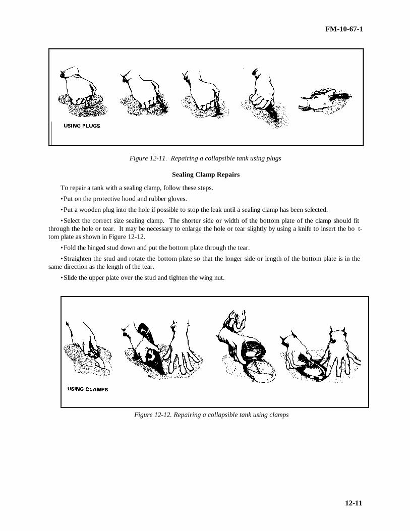
FM-10-67-1
12-11
Figure 12-11. Repairing a collapsible tank using plugs
Sealing Clamp Repairs
To repair a tank with a sealing clamp, follow these steps.
• Put on the protective hood and rubber gloves.
• Put a wooden plug into the hole if possible to stop the leak until a sealing clamp has been selected.
• Select the correct size sealing clamp. The shorter side or width of the bottom plate of the clamp should fitthrough the hole or tear. It may be necessary to enlarge the hole or tear slightly by using a knife to insert the bo t-tom plate as shown in Figure 12-12.
• Fold the hinged stud down and put the bottom plate through the tear.
• Straighten the stud and rotate the bottom plate so that the longer side or length of the bottom plate is in thesame direction as the length of the tear.
• Slide the upper plate over the stud and tighten the wing nut.
Figure 12-12. Repairing a collapsible tank using clamps

FM-10-67-1
12-12
Section II. Tank Cleaning Precautions and Equipment
NEED FOR PLANNING AND TRAINING BEFORE TANK CLEANING
During any fuel-handling operation, fuel vapors can accidentally ignite, causing a fire or an explosion. Thechance of this occurring during tank cleaning is especially high. There are other health and physical hazards i n-volved which make tank cleaning dangerous work. The job can be performed without death, injury, or propertydamage if the cleaning operation is carefully planned step by step and if members of the cleaning detail receiveextensive training. A working knowledge of the dangers involved and hands-on experience with the safety equi p-ment are essential. At least two members of the cleaning detail must be trained and tested in first aid. The trai n-ing must include cardiopulmonary resuscitation and treatment for vapor inhalation. In addition, the cleaning d e-tail supervisor must prepare a fire plan for the tank in the event fuel vapors are ignited.
WARNING
Prior to confined space entry, all requirements under the OSHA Confined Space Entry Programmust be met.
PREVENTION OF FIRE AND EXPLOSION
The danger of fire and explosion during tank cleaning operations comes from the possible ignition of fuel v a-pors. The best way to prevent a fire or explosion during tank cleaning, therefore, is to eliminate all sources of i g-nition and to reduce the concentration of vapors to a point where they will not ignite. Fuel vapors can be ignitedwhen they come in contact with a source of ignition. This is possible only when a certain amount of fuel vapor hasbeen combined with air. A mixture of 1 to 8 percent fuel vapor and air will ignite at once when it comes in contactwith a spark or flame. The mixture will burn if it is ignited in an open area where the hot gases produced haveroom to expand. The mixture will explode if it has ignited in a closed space where the heat and gases have noplace to go. A mixture with less than 1 percent fuel vapor is too lean to ignite. A mixture with more than 8 pe r-cent fuel vapor is too rich to ignite. Care must be taken when opening a tank with a mixture too rich to ignite.The too-rich mixture could quickly change to an ignitable mixture after opening the tank. The hydrogen sulfidevapors found in crude oil tanks are also combustible. They can ignite when the hydrogen sulfide content of thetank is between 4.3 percent and 46 percent. So that an explosion or fire does not occur during tank cleaning o p-erations, the concentration of fuel and hydrogen sulfide vapors must be reduced as quickly as possible to levels thatwill not ignite. The best way to reduce the concentration is to circulate air through the tank. The air weakens ordilutes the vapor concentration. Eventually the air displaces the vapors completely. Care must then be taken tomake sure the vapors are not allowed to collect in low areas outside the tank. These vapors could be ignited ou t-side the tank, and the fire could spread back to the tank. The other sources of ignition are covered in Chapter 2 ofthis manual.
HEALTH HAZARDS
The atmosphere inside a tank that has been removed from service is hazardous to health. The danger lies inseveral areas.
Presence of Fuel and Sludge
Physical contact with fuel and sludge can cause serious damage to the skin. Fuel and sludge remove naturaloils, leaving the skin chapped and cracked. These cracks are avenues for disease and infection to enter the body.Areas of skin wet with fuel or sludge must be washed at once with soap and water. The cleaning detail must wearwhite clothing so that fuel stains can be spotted easily. They must also wear rubber gloves and boots to protecttheir hands and feet.

FM-10-67-1
12-13
Presence of Fuel Vapors
Fuel vapors, especially gasoline and jet fuel vapors, are narcotic. Inhaling these vapors can slow the centralnervous system to the point that breathing stops. In addition, inhaling even small amounts of these vapors canirritate the lungs and respiratory system, causing pneumonia or leaving a person open to other respiratory diseases.The poisonous or toxic limit is 500 parts per million. The cleaning detail must wear respiratory equipment whileworking until testing the fuel vapors produces a reading at or below that limit. Workers may then work in the tankup to 8 hours without respiratory equipment. This does not apply to tanks that have been used to store leaded fuels.
Presence of Tetraethylead
Tetraethylead is a poisonous liquid. Contact with tetraethylead can result in lead poisoning. Therefore, greatcare must be taken when entering a tank that has been used to store leaded fuel. Inhaling the fuel vapors can befatal. Cleaning details must wear respiratory equipment when working in leaded fuel storage tanks. The equi p-ment must be used even after the tank has been tested and declared vapor free because inhaling dust particles fromscale on the walls can also result in death. Workers must also avoid direct contact with leaded sludge since lethalamounts of lead can easily be absorbed through the skin. This sludge is dangerous even after it has been removedfrom the tank, so great care must be taken with its disposal. The tank is not safe until it has been cleaned down tothe bare metal.
Presence of Hydrogen Sulfide
Exposure to hydrogen sulfide can cause death by paralyzing the respiratory system. Victims become unco n-scious and never regain consciousness. Mild exposure damages the eyes. Hydrogen sulfide, which is found incrude oils with a high sulfur content, can usually be detected by its rotten egg odor. Be cautious never to use thesense of smell to determine whether or not hydrogen sulfide is present in a tank. Use a piece of moist lead acetatepaper instead. If hydrogen sulfide is present in the tank, it will blacken the paper. The concentration of hydrogensulfide vapor can be measured by a hydrogen sulfide detector. The toxic level is 20 parts per million. It is not safeto work in a tank without respiratory equipment until rea dings are at or below that level.
Lack of Oxygen
Normal air contains 21 percent oxygen. A concentration of less than 7 percent is dangerous. Fuel vapors inaddition to being narcotic, displace oxygen in a tank. Respiratory equipment must be used during tank cleaninguntil a tank has been cleared of fuel vapors. Care must also be taken when entering a clean tank that has beenclosed for a long time. The metal surface inside may have rusted, using up the oxygen inside the tank. No oneshould enter such a tank until fresh air has been allowed to circulate inside the tank. For more on health hazards,see Chapter 2 of this manual.
PHYSICAL HAZARDS
In addition to fire and health hazards, there are physical hazards involved in tank cleaning. Members of thecleaning detail must take precautions to avoid the following:
• Collapse of ladders, scaffolds, and stairways. Make sure they are in good condition and securely attached tothe tank.
• Collapse of thin roof sections. Use wooden planks to distribute weight evenly when working on a roof.
• Accidental pumping of fuel into the tank. Make sure lines to the tank are blanked off with blind flanges orfigure eight blinds. Do not depend on closed valves.
• Tools and objects dropping from above. Handle tools carefully. Do not throw them and do not drop themthrough the roof manhole. Make sure fixtures inside the tank are securely attached to the tank and cannot beknocked down. Lower the swivel joint drain pipe to prevent accidental release during cleaning operations.
• Slipping on wet floors and tripping over hoses, pipes, and fittings. Use extreme caution when moving aroundinside the tank.

FM-10-67-1
12-14
• Colliding with other workers or tank supports in a poorly lighted tank. Make sure lighting is adequate.Workers must wear white so that they can be seen easily.
SAFETY EQUIPMENT SET
The safety equipment set as shown in Figure 12-13 contains nearly everything necessary to provide physicaland respiratory protection for two members of a cleaning detail. No one must enter a tank without having someexperience handling and operating the components of the set.
Figure 12-13. Safety equipment set
Respirators and Air Hoses
Two respirators and four rubber air hoses are in the set. Respirators are face masks which attach to air hoses.The respirators must be approved by the Bureau of Mines. When connected to a blower, respirators provide anindependent supply of fresh air to the wearer. They must be worn at all times inside tanks that were used to storeleaded fuel. They must be worn inside all other tanks until the tanks have been tested and found to be worn insideclean tanks that have been closed for a long time. The following precautions must be taken with respirators and airhoses:
• Inspect respirators before each use. Also inspect them before they are stored.
• Make necessary repairs at once to ensure that the respirators are ready for use at all times.
• Test respirators before each use. To test a respirator, cut off the air supply to the mask for a few seconds bycovering the end with the palm of the hand as shown in Figure 12-14, page 12-15. If there are no leaks and thestraps have been adjusted properly, the face piece will collapse against the face.

FM-10-67-1
12-15
• When attaching respirators to air hoses, make sure the connections are tight and that gaskets are being usedto provide an airtight seal. Replace worn gaskets if necessary.
• Never remove respirators while inside a tank. The tank may have been vapor free, but the face pieces couldstill be contaminated.
• When entering a tank, lift the air hoses over the edge of the manhole. Pad the edge of the manhole to preventdamage to the hoses.
• When a member of the cleaning detail enters a tank, someone must be assigned to tend the air hose and tokeep the worker under observation at all times. The attendant must be dressed and outfitted to enter the tank torescue an unconscious or injured worker.
• Do not yank, twist, or step on air hoses.• When inside a tank, do not wrap air hoses and lifelines around anything that could make an emergency exit
difficult.• Wash each face mask and air hose with soap and water at the end of each day and let them dry b efore storing.
Figure 12-14. Testing a respirator
Hand-Operated Blower The blower is mounted inside one of the two carrying cases for the set. The handle is detachable and mounts
on the outside of the case. The blower is operated with the lid closed. When the handle is turned, fresh air is fedthrough the air hoses to the respirators. The blower must be set up on the windward side of the tank to make surethe cleaning detail is receiving fresh air. The blower must be attended at all times while workers are wearing re s-pirators.
Leather Harnesses and Lifelines Two leather harnesses and lifelines are in the set. Workers wear harnesses into a tank when they wear resp i-
rators. The lifelines attach to the back of the harnesses. Lifelines are tended by the same workers tending the airhoses. Lifelines are used to trace workers inside a tank and to pull unconscious workers to safety. All harnessesand lif elines must be cleaned and allowed to dry before they are stored.
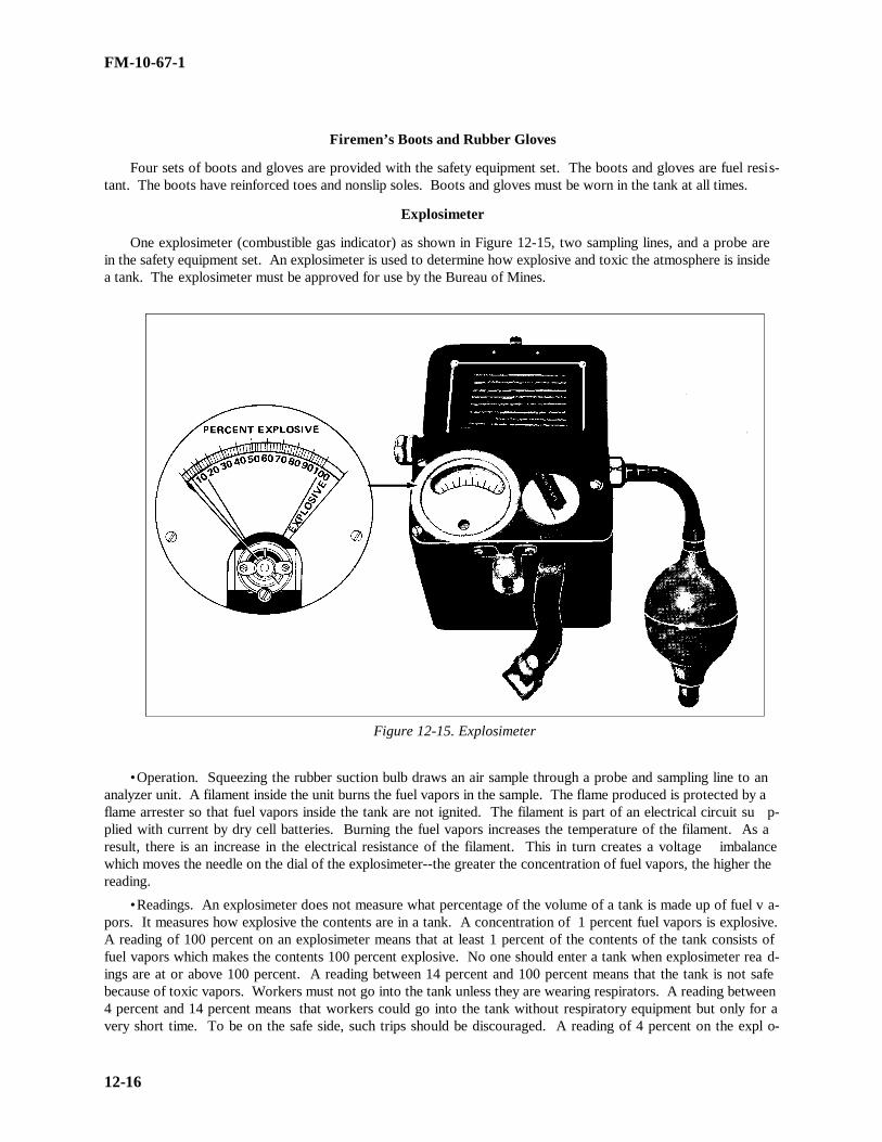
FM-10-67-1
12-16
Firemen’s Boots and Rubber Gloves
Four sets of boots and gloves are provided with the safety equipment set. The boots and gloves are fuel resi s-tant. The boots have reinforced toes and nonslip soles. Boots and gloves must be worn in the tank at all times.
Explosimeter
One explosimeter (combustible gas indicator) as shown in Figure 12-15, two sampling lines, and a probe arein the safety equipment set. An explosimeter is used to determine how explosive and toxic the atmosphere is insidea tank. The explosimeter must be approved for use by the Bureau of Mines.
Figure 12-15. Explosimeter
• Operation. Squeezing the rubber suction bulb draws an air sample through a probe and sampling line to ananalyzer unit. A filament inside the unit burns the fuel vapors in the sample. The flame produced is protected by aflame arrester so that fuel vapors inside the tank are not ignited. The filament is part of an electrical circuit su p-plied with current by dry cell batteries. Burning the fuel vapors increases the temperature of the filament. As aresult, there is an increase in the electrical resistance of the filament. This in turn creates a voltage imbalancewhich moves the needle on the dial of the explosimeter--the greater the concentration of fuel vapors, the higher thereading.
• Readings. An explosimeter does not measure what percentage of the volume of a tank is made up of fuel v a-pors. It measures how explosive the contents are in a tank. A concentration of 1 percent fuel vapors is explosive.A reading of 100 percent on an explosimeter means that at least 1 percent of the contents of the tank consists offuel vapors which makes the contents 100 percent explosive. No one should enter a tank when explosimeter rea d-ings are at or above 100 percent. A reading between 14 percent and 100 percent means that the tank is not safebecause of toxic vapors. Workers must not go into the tank unless they are wearing respirators. A reading between4 percent and 14 percent means that workers could go into the tank without respiratory equipment but only for avery short time. To be on the safe side, such trips should be discouraged. A reading of 4 percent on the expl o-

FM-10-67-1
12-17
simeter converts to approximately 500 parts per million, the toxic limit for fuel vapors. Members of the cleaningdetail can work in storage tanks for 8 hours at a time without respiratory equipment when the explosimeter readingis 4 percent or less.
NOTE: This does not apply to tanks that have been used to store leaded fuels.
• Directions for Use. To use an explosimeter, follow these steps.
••Obtain six fresh 1.5-volt dry cell batteries and put them in the explosimeter.
••Turn on the explosimeter in a vapor-free area outside the tank.
••Flush the explosimeter with fresh air by squeezing the bulb five times. Add two squeezes for every 10feet of line if a sampling line is being used.
••Move near the open manhole of the tank and take a sample of the air inside the tank by squeezing the bulbuntil the reading on the explosimeter remains steady. Wear the proper protective equipment.
••Note the reading. It shows the concentration of combustible vapors in the sample.
••Flush the explosimeter with fresh air after each use.
••Turn the explosimeter off and remove the batteries before storing the unit.
••Service the unit, if necessary, by following the directions in the manufacturer’s manual.
HYDROGEN SULFIDE DETECTOR
The cleaning detail must determine what kind of fuel was stored in a tank before they start any cleaning o p-eration. Tanks that were used to store crude oils must be tested for the presence of hydrogen sulfide. If the clea n-ing detail is unable to determine what kind of fuel was stored in a tank, the tank must be tested for hydrogen su l-fide to be on the safe side. Respiratory equipment must be worn during the test. A hydrogen sulfide detector asshown in Figure 12-16 consists of a suction bulb, a glass detector tube, and a frame with a scale. To use a hydr o-gen sulfide detector, break off the ends of the glass detector tube and insert the tube in the frame. Squeeze the bulb10 times to draw a sample into the tube. The reading on the scale is shown in percent. A content of 4.3 percent to46 percent hydrogen sulfide is explosive. The toxic limit is 20 parts per million or .002 percent. Members of thecleaning detail must not go into a tank until the percent of hydrogen sulfide is less than 4.3 percent. They must notremove respirators until the tank is vapor free.
Figure 12-16. Hydrogen Sulfide Detector

FM-10-67-1
12-18
FIRE EXTINGUISHERS
A fire caused by ignited vapors is a class B fire. Loaded stream, foam, carbon dioxide, or dry chemical fireextinguishers may be used on a class B fire. The extinguishers are available in hand and wheel units. Members ofthe cleaning detail should know how to operate these fire extinguishers. Fire extinguishers are effective only in thefirst stages of a fire, so the cleaning detail should be trained to act quickly. See Chapter 2 for more informationabout classes of fire and fire extinguishers.
PROTECTIVE CLOTHING AND EQUIPMENTMembers of the cleaning detail must wear clean, white cotton coveralls when they go inside a tank. White
must be used because it is easily seen inside a dim tank and it shows fuel stains easily. Cotton must be used b e-cause it cuts down on the generation of static electricity. All protective clothing must be laundered at the end ofeach workday. To protect the team from falling objects and debris, they must wear safety helmets when they goinside the tank. When respirators are no longer needed, they must wear goggles to protect their eyes from loosescale and cleaning solvents in the tank.
Section III. Storage Tank Cleaning
RESPONSIBILITYVapor freeing, decontaminating, and cleaning tanks are organizational maintenance activities with two exce p-
tions. Cleaning fixed tanks to apply rust proofing and coatings to the inside surface is the responsibility of the f a-cilities engineer. Cleaning fixed tanks that are a part of motor pools, service stations, and aircraft fueling systemsis also the responsibility of the facilities engineer. A tank should not be cleaned unless it is absolutely necessary.It is necessary to drain, vapor free, and clean a tank when the following actions take place.
InspectionsMIL-STD-457 states that a storage tank should be inspected periodically by physical entry. This means that
the inspectors must go inside the tank to do the inspection. The tank should be cleaned before such an inspectiontakes place. When these inspections are made depends on whether or not the inside of the tank is coated andwhether or not incoming fuel is pumped through a filter/separator. See Table 12-2 for more information.
Table 12-2. Frequency of physical entry inspections.Inside of
Tank CoatedFilter/Separator Used
on Incoming FuelFrequency of Inspections
No
No
Yes
Yes
No
Yes
No
Yes
Every 3 years
Every 4 years
Every 4 years
Every 6 years
RepairsA storage tank should be drained, vapor freed, and cleaned for any repairs to the tank, inside or outside, that r e-quire welding or the use of tools that could ignite vapors. The tank should also be cleaned whenever it is necessaryto enter the tank to make lengthy repairs.
Fuel ContaminationA storage tank should be cleaned as often as necessary to maintain fuel quality. MIL-STD-457 states that a
sample should be taken from an active tank at least every 30 days. A sample should be taken from a less activetank at least every 180 days. If laboratory tests show that the fuel is being contaminated by rust and dirt in the

FM-10-67-1
12-19
tank, the tank should be cleaned. If tests show that the fuel is being contaminated by bacteria, the tank and linesshould be flushed with fresh clean water. If bacteria reappears in later tests, the tank should then be cleaned.
Sludge Buildup
Dirt, gums, waxes, and resins settle out of fuel in a storage tank. This sludge collects on the bottom of thetank. When the sludge hardens, it forms a heel which cannot be pumped out. This heel remains in the tank whenthe tank is emptied and filled. The heavier or darker the fuel, the more sludge is left behind. Fuel pumped in ontop of this layer of sludge can become contaminated. When bottom samples show fuel contamination or whengagging reveals that too much sludge has built up, the tank should be cleaned.
Change of Product
A tank should be used to store only one kind of fuel so that quality can be maintained. If the service of a tankhas to be changed from one fuel to another, the tank should be cleaned before pumping in the new fuel. See MIL-HDBK-200, Table V, for guidelines.
NOTE: The service of a tank may be upgraded by gradually pumping in fuel of a higher quality than that prev i-ously pumped into the tank. Fuel contamination will always be a result of such an upgrade. This should be takeninto consideration before a decision is made to use this method to change service. This method should never beused to make radical changes. For example, the method should not be used to change tank service from diesel fuelto AVGAS.
Removal of Tank from Service
If a decision is made to take a storage tank out of service for longer than 4 months, the following actionsshould be taken:
• All concrete tanks should be cleaned.
• Steel tanks used to store fuel oil, diesel fuel, and lubricating oil should be cleaned. They should then becoated with the same product they contained. This will preserve the metal.
• Steel tanks used to store gasoline, jet fuel, and kerosene should be cleaned and then coated with ge neral-purpose lubricating oil (Federal Specification VV-L-800) to preserve the metal.
• Steel tanks to be dismantled should be cleaned and coated with general-purpose lubricating oil.
NOTE: It is not necessary to coat a tank that was taken down to move it to a new site for reassembly.
Reactivation of Tank
If a decision is made to put an inactive tank back into service, the following actions should be taken:
•Steel tanks that have stood empty for sometime should be cleaned to remove the rust which may have formedon the inside.
•Steel tanks that were coated with lubricating oil should be cleaned before they are used to store gasoline, jetfuel, or kerosene.
•Inactive tanks that were ballasted with water or fuel should be cleaned to remove rust and sludge.
FACILITIES ENGINEER DUTIES
When there is a reason to justify cleaning a tank, the facilities engineer is notified. The facilities engineershould--
• Determine the need to enter any tank that has been used to store leaded fuel.
• Determine the need to enter any other tank capable of holding 1,000 or more barrels of fuel.
• Make sure there is a safety equipment set available for use.

FM-10-67-1
12-20
• Obtain the services of a safety engineer experienced in tank cleaning safety. The safety engineer should bepresent when any tank containing leaded fuel is entered. The safety engineer should also be present when any tankcapable of holding 1,000 or more barrels of fuel is entered.
• Request medical advice from The Surgeon General (AR 200-1), if necessary.
• Obtain the services of a contractor to clean a tank if local demand for tank cleaning is so infrequent that thelocal work force cannot maintain a level of expertness (AR 420-49). The contractor should be instructed to provideall the equipment and take all the precautions necessary to protect life, health, and pro perty.
CLEANING DETAIL SUPERVISOR DUTIES
The cleaning detail supervisor oversees all cleaning operations. The cleaning supervisor should--
• Gather the following information:
••Kind of fuel stored in the tank.
••Reason for cleaning the tank.
••Condition of the tank and any repairs to be made.
••Amount of corrosion and sludge present in the tank.
••Last date the tank was cleaned and how well it was cleaned.
• Train the cleaning detail. This training must include instruction on the dangers involved in tank cleaning,the use of the safety equipment set, and the safety precautions that apply to tank cleaning.
• Prepare a fire plan for the tank. Everyone should know what is expected of him in the event of a fire or e x-plosion.
• Delegate various jobs to specific members of the cleaning detail.
• Make sure at least two members of the detail have recently been trained and tested in cardiopulmonary resu s-citation.
• Determine whether or not every member of the detail is in good physical condition and able to working in thetank. Workers who are tired or sick will develop more problems inside the tank.
• Inspect all safety equipment to make sure it is in good condition and ready for use.
• Make sure fire-fighting equipment is nearby.
• Arrange for the safe disposal of sludge. See AR 200-1.
• Contract, if necessary, for the use of a vacuum truck to remove sludge and haul it to a disposal area.
• Furnish the environmental engineer with information on the tank and sludge disposal to obtain a safety pe r-mit.
• Examine the area around the tank to make sure all sources of ignition have been removed.
• Make sure the tank is isolated before starting cleaning operations.
• Be present during cleaning operations to provide instruction and guidance.
• Make sure no one enters the tank until vapor readings are in the safe zone.
• Tell members of the cleaning detail to leave the tank if they smell fuel vapors.
TOOLS AND EQUIPMENT
In addition to the safety equipment and clothing already described, other tools and equipment are needed toclean a tank. Make sure the following items are on hand before starting cleaning operations:
• Blind flanges or Figure eight blinds to provide positive shutoff to the tank.
• Pump to move sludge from tank bottom to tank vehicle.
• Tank vehicle or vacuum truck to carry sludge to disposal site.
FM-10-67-1
12-21
• Air eductor or ejector to raw fuel vapors out of the tank.
• Blowers or fans to drive fuel vapors out of the tank.
• Shovels, scrapers, wire brushes, buckets, and wheelbarrows.
• Long-handled push brooms, scrub brushes, squeegees, and mops.
• Towels, washcloths, and bath soap for each member of the cleaning detail.
• Water hose and nozzle.
• Disinfectant for face masks.
• Clean rags and airtight metal cans to store oily rags until they can be destroyed.
• First aid kits.
• Wrenches and tools necessary to blank off the tank, enter the tank, and tighten loose tank access ories.
• Warning signs to post during tank cleaning.
• Sign-painting kit and yellow paint to stencil tank after cleaning.
• Ladders and scaffolding to reach upper areas of the tank shell.
• Detergents, cleaning solvents, and kerosene.
ISOLATING A TANK
Before vapor-freeing and cleaning operations can begin, a tank should be isolated. The tank should be co m-pletely cut off from the rest of the terminal and pipeline system. There should be no way to accidentally pump fuelinto the tank. There should also be no way for fuel vapors to drift back into the tank after it has been vapor freed.To isolate a tank, follow these steps.
• Use the lowest tank connection and pump or drain as much fuel as possible out of the tank. If necessary,pump in enough water to cover the tank bottom. What fuel is left and the sludge that had not hardened will floaton top of the water. Pump this liquid sludge to a tank vehicle and then draw off the water. Do not allow oily waterto spill on the ground. Be aware that some tanks, especially underground ones, may have permanently installedsump pumps for removing liquid sludge. Some may even have their own sludge disposal systems to pipe sludge toa disposal area.
NOTE: Never pump water into a concrete tank.
• Close the valves outside the firewall on all lines going to and from the tank. Attach a sign to each valve,warning workers not to open the valves.
• Drain and flush all the lines into the tank.
• Break all lines and remove the valves nearest to the tank. Replace the valves with either blind flanges or fi g-ure eight blinds as shown in Figure 12-17, page 12-22. Make sure the solid half of the figure eight blind is downin the line. If figure eight blind holders have already been permanently installed near the tank, it is not necessaryto remove the valves. Reverse the blinds so that the solid half closes off the line. All blank ends and blinds shouldbe strong enough to withstand any pressure that might be exerted in the line. Respirators should be worn whenblanking lines to tanks which were used to store leaded fuels and crude oils.

FM-10-67-1
12-22
Figure 12-17. Blanking off a tank with blind flanges or figure eight blinds
VAPOR FREEING A TANK
Vapor freeing is actually the complete replacement of fuel vapors in a tank with fresh air. A tank is usuallyconsidered vapor free when the concentration of fuel vapors is below the toxic and combustible levels. Vaporfreeing is a dangerous operation. Workers who open the manholes and cleanout doors of leaded fuel or crude oiltanks should wear respirators. No one should be in the area around the tank during vapor freeing except for thosewho approach the tank from time to time to conduct vapor tests. Several methods are used to vapor free tanks.Some methods are better than others. The method used depends on the kind of tank being cleaned and the situ a-tion.
Natural Ventilation
Natural ventilation, or airing, is the easiest method to use. Its main advantage is that it uses natural forces. Itrequire little or no equipment and no outside power source. However, there are several disadvantages to thismethod. First it takes longer than other methods. The concentration of vapors inside the tank is explosive andtoxic for a longer period of time. Vapors may collect at ground level outside the tank creating another hazard.Second, this method is not practical for underground tanks because of the lack of natural circulation. To ventilatea tank naturally-
• Remove the roof manhole cover.
• Remove the tank shell manhole cover or cleanout door.
• Allow air to circulate freely through the tank.
• Take vapor readings periodically. Do not start sludge removal until the tank is vapor free.
Forced Ventilation
Forced ventilation uses an outside force to direct the flow of air into the tank. This speeds the vapor freeingprocess. This is the most commonly used method. Two methods are used to force ventilate a tank.
• Blower or fan method. A blower or fan usually installed in the tank shell manhole or cleanout door is used toblow fresh air into the tank. Fuel vapors escape through the roof manhole. The blower or fan, may be steam-turbine, gasoline-engine, or electric-motor driven. Gasoline-powered units should be located away from the tankon the windward side. They should be equipped with spark arresters. Canvas ducts are used to carry the air to thetank. Electric-motor driven units should be explosion proof. To use a blower or fan--
••Open the tank shell manhole or cleanout door.
••Set up gasoline-engine powered units away from the tank and lay canvas ducts on the ground to the tankopening. Mount other units in the tank opening. When using this method to vapor free underground tanks, attachthe blowers to pipes leading to the tank bottom or to ducts or hoselines. These ducts or hoselines are fed throughroof openings to the tank bottom.

FM-10-67-1
12-23
••Remove the roof manhole cover.
••Start the blower and ventilate the tank until vapor readings are in the safe zone.
• Air ejector or eductor method. An air ejector, or eductor, is used to draw fuel vapors out of the top of thetank. The unit is installed in the roof manhole. Fresh air is allowed to enter through the tank shell manhole orcleanout door. To use an air ejector or eductor--
••Open the roof manhole and install the unit.
••Operate the unit to create a pressure differential between the inside and outside of the tank. Use the lowsetting at this point to avoid creating a vacuum.
••Once a pressure differential has been established, open the tank shell manhole or cleanout door. This a l-lows fresh air to be drawn into the tank. In underground tanks, open pipes leading into the bottom of the tank.
••Operate the unit at full speed until the tank is vapor free.
Steam Ventilation
This method uses steam to displace fuel vapors. Steam ventilation has many disadvantages. Its use is discou r-aged except in tanks where iron sulfide is known to be present. On large diameter tanks, steam is not effective;however, it is effective on tank trucks and rail cars. The disadvantages are--
• It generates static electricity which could ignite vapors.
• It is a slow method. Producing enough steam to displace fuel vapors in a large tank is difficult.
• The temperature must be at least 170° F to prevent condensation. This temperature is difficult to maintain incold weather.
• Steam damages the linings of coated tanks and causes cracks in concrete tanks. It should never be used tovapor free a concrete tank.
Water Displacement
This method uses water to take the place of fuel vapors in the tank. Fuel vapors exit as the tank is filled tooverflowing. The oily water produced by this process has to be treated before disposal. Water displacement ispractical for small tanks only. It should not be used in areas where water supplies are limited.
VAPOR TESTPeriodic vapor tests are made during vapor-freeing operations. They are made with an explosimeter and, if
necessary, a hydrogen sulfide detector. The tests are made to check on the progress of the vapor freeing. Vaportests are also conducted during tank-cleaning operations to make sure the tank is safe for members of the cleaningdetail. To conduct a vapor test--
• Read the manufacturer’s manuals and the paragraphs on explosimeter and hydrogen sulfide detector in thissection.
• Wear a respirator and approach an open cleanout door or tank shell manhole. Insert the probe through thedoor as shown in Figure 12-18, page 12-24. Take the first reading in the area where vapors are leaving the tank.Do not enter the tank at this time.
• Step inside the tank to take readings when the readings from the opening fall to 14 percent. Hold the probeabout 1 foot above the sludge. Turn off fans, blowers, and eductors while testing to get a true sample of the air inthe tank.
WARNING
If samples are also being taken with a hydrogen sulfide detector, do not enter the tank untilreadings from the door are at or below the 4.3 percent explosive limit for hydrogen sulfide.

FM-10-67-1
12-24
• Take samples often at various points inside the tank. Leave the tank between tests. Flush out the explosim e-ter with fresh air and reset at 0. Put a new glass tube in the hydrogen sulfide detector for each test.
• Repeat the tests until explosimeter readings are at or below the toxic limit of 4 percent. If samples are alsobeing taken with a hydrogen sulfide detector, repeat the tests with the detector until readings are at or below thetoxic limit of .002 percent.
• Continue to take samples after members of the cleaning detail have entered the tank to start sludge removaloperations. Additional fuel vapors may be trapped in the sludge. These vapors will be released when the sludge isdisturbed. If readings reach dangerous levels, members of the cleaning detail should leave the tank. They shouldnot reenter the tank until readings are again in the safe zone.
Figure 12-18. Vapor testing at cleanout door
CLEANING OPERATIONS
After a tank has been declared vapor free, members of the cleaning detail can usually enter the tank to begincleaning operations. Some underground steel tanks may not be entered. These tanks should be cleaned using themethod described in the paragraph on cleaning uncoated tank cars and tank vehicles, page 12-8 . To clean tanksthat do allow entry--
• Stencil a warning sign near the entrance to the tank if the tank was used to store leaded fuel. Wear respir a-tors in the tank and use forced ventilation until the tank has been cleaned down to the bare metal.
• Before starting to work, inspect the inside of the tank for loose fixtures and repair the tank if necessary.Lower the swivel joint drain pipe to the tank floor.
• Use a high-pressure water hose to dislodge sludge, loose rust, and scale.
• Continue to take vapor tests. Leave the tank if readings show toxic concentrations of fuel vapors. Since ittakes more time to leave an underground tank than an aboveground tank, an increase in the concentration of fuelvapors in an underground tank should be detected quickly.
• Lay a suction hose in the tank and use a pumping assembly to pump liquid sludge to a tank vehicle as shownin Figure 12-19. If a vacuum truck is being used, the pumping assembly is not necessary.

FM-10-67-1
12-25
• Brush, sweep, or scrap the remaining sludge into piles and shovel it into buckets or wheelbarrows.
• Use wire brushes and scrapers to remove rust and scale from the uncoated surface of tank walls and floor.Use scaffolds or ladders to get to out-of-reach areas.
• Dispose of the sludge and debris.
• Clean the tank, fixtures, and supports. If necessary, drill small holes at the bottom of hollow structures andsupports. Flush them from the top with water and allow to drain.
• Scrub the walls and floor with kerosene, cleaning solvent, or detergents, if necessary. Do not damage tankcoatings.
• Rinse the walls and floor with water. Mop up all water and wipe dry with lint-free rags.
Figure 12-19. Pumping sludge to tank vehicle
SLUDGE DISPOSAL
The cleaning detail supervisor should arrange for the disposal of the sludge. All activities should be coord i-nated with the environmental engineer whose job it is to consider the effect or impact the disposal of the sludgewill have on the environment. The method used to get rid of the sludge should not damage the environment orharm humans or animals (AR 200-1). For these reasons, sludge cannot be buried or carelessly dumped on theground.
Unleaded or Nonhydrogen Sulfide Sludge
Sludge that does not contain lead, hydrogen sulfide, or other harmful chemicals can be disposed of by farmingor weathering.

FM-10-67-1
12-26
• Farming. Sludge can be farmed at selected sites. These sites should be level, well drained, well ventilated,and sunny. The sludge should be hauled to the site, evenly distributed on the ground, and plowed in with the to p-soil. Later the land can be used to grow crops.
• Weathering. Sludge can be weathered at selected sites similar to those used for farming. An even layer ofsludge 3 inches deep should be spread on the ground with hoes, rakes, and shovels. The area should be roped offand warning signs put up. The sludge should be left undisturbed for 4 weeks (or longer if the temperature is belowfreezing). The rope and sign can be taken down after the weathering is complete. The sludge can then be leftthere, or it can be hauled away.
Leaded or Hydrogen Sulfide Sludge
Sludge that contains lead, hydrogen sulfide, or other harmful chemicals can be disposed of by controlledburning or by depositing it at specified sites.
• Controlled burning. Harmful sludge can be burned in high-intensity heat furnaces that do not give off emi s-sions.
• Depositing at specified site.
• Sludge can be taken to hazardous materials disposal sites. These sites are specially designated areas whichhave been set aside permanently for the disposal of dangerous substances such as nuclear wastes and toxic chem i-cals. The disposal sites must also be approved by EPA. All trucks used to transport sludge must be approved bystate and federal agencies and a certificate issued for each vehicle.
AFTER-CLEANING OPERATIONS
Certain tasks should be done when the cleaning detail finishes mopping up in the tank. The job is not co m-plete until these final tasks are done.
Tools and Equipment
Dispose of the rags and brooms used to clean leaded fuel and crude oil with the sludge from these tanks.Thoroughly clean all other tools and equipment with soap and water. You can use kerosene if necessary. Disinfectface masks. Allow all pieces in the safety equipment set to dry before storing them.
Pumping Assembly
To clean the pump assembly--
• Put the end of a suction hose into a barrel or drum of clean water. Attach the hose to a water faucet or couplethe hose to a water hose.
• Start the pump and if necessary, turn on the water. Run the pump until the pump and the hose have beenthoroughly flushed with water. Dispose of the water in a way that is not harmful to the environment.
• Put the end of the suction hose into a drum or container of solvent. Flush the pump and the hoses with 1 or 2gallons of solvent. Drain the solvent from the pump and hoses.
Stenciled Sign
Use yellow paint to stencil the cleaning date on the tank near the tank shell manhole or cleanout door.
Tank Ballast
Ballast or weight steel tanks that are being taken out of service in hurricane areas to prevent them from beingblown away. Ballast empty steel tanks in flood areas to prevent them from floating away.
NOTE: Ballasting is not a common practice. It should be done only if past experience has shown it to be nece s-sary. Light fuels or water with a rust inhibitor can be used for ballast. Water should not be used as ballast in areaswhere there is a chance it will freeze. Also, if other ballast is available, water should not be pumped into tankswhich will be used to store gasoline, jet fuel, or kerosene.

FM-10-67-1
12-27
Hygiene
At the end of each work day and at the end of the job, make sure all members of the cleaning detail bathe withsoap and water and change to clean clothes.
DA Form 4177
Complete DA Form 4177. Enter the cleaning date and any other important facts.
Section IV. Tank Car and Tank Vehicle Cleaning
RESPONSIBILITY FOR INSPECTING AND CLEANING
Tank cars and tank vehicles should be inspected before each use according to MIL-HDBK-200. The inside ofthe tank, including the dome, should be free of rust, scale, dirt, and sludge before new fuel is loaded. These in-spections should be made by those responsible for loading the fuel. Organizational maintenance personnel areresponsible for cleaning the inside of tank cars and tank vehicles, whenever necessary, to prevent fuel contamin a-tion. They are also responsible for cleaning tank cars and tank vehicles for a change in service or for repairs thatcould ignite vapors.
SAFETY PRECAUTIONS
The same dangers that are present during the cleaning of bulk storage tanks are present during the cleaning oftank cars and tank vehicles. Cleaning detail members should be familiar with the safety equipment and follow thesame safety precautions described in Section II of this Chapter.
CLEANING UNCOATED TANK CARS AND TANK VEHICLES
Some tank cars and all tank vehicles have uncoated steel interiors. These tank units should be vapor freed andcleaned using steam. Steam cleaning should also be used to clean underground steel tanks that do not allow entry.To clean a tank with steam--
• Move the tank car to a bypass or spur track. Move the tank vehicle to an open area outdoors. Set the brakes.Lock derails in place at each end of the tank car. Chock the wheels of the tank car or tank vehicle.
• Remove all sources of ignition in the area. Do not start the engine of a tank vehicle during cleaning oper a-tions.
• Put up signs warning of the danger of tank cleaning.
• Drain the tank car or tank vehicle of all fuel.
• Arrange for a supply of steam.
• Obtain or make a steam spray nozzle and cover plate as shown in Figure 12-20, page 12-28.
• Contact the environmental engineer and arrange for the disposal of sludge. See AR 200-1.
• Place a container under the tank car or tank vehicle to catch sludge. If necessary, have more containersavailable.
• Remove the dome or manhole cover.
• Bond the steam nozzle to the tank shell with a bare copper wire. Check the rails under the tank car for co r-rect bond and ground as shown in Figure 12-21, page 12-29. To ground the track vehicle-
••Drive a grounding rod about 3 feet into the ground. Soak the area around the rod with water to get a bet-ter ground.

FM-10-67-1
12-28
••Unwind the ground cable from the tank vehicle. Attach the cable clip to the grounding rod as shown inFigure 12-22, page 12-29.
• If the tank car or vehicle has only one compartment , steam the tank for an hour. Check the tank outlet. Ifthe steam of condensation and liquid sludge is still heavy, continue to steam until the flow of sludge stops. If thetank car has more than one compartment, steam clean each one until sludge no longer flows from the outlet. Allowthe tank to cool.
• Insert the pole of an explosimeter through the dome or manhole. Test for vapor concentration. Start stea m-ing operations again if the tank is not yet vapor free.
• Look inside the tank when it is vapor free to determine whether or not there is enough sludge left to justifyentering the tank to remove it. Use an explosion-proof light or flashlight.
• Wear protective clothing and respirators when entering the tank. Shovel the sludge into buckets and removethe buckets through the dome or manhole as shown in Figure 12-23, page 12-30. Lower a water hose inside anduse it to flush any remaining sludge through the tank outlet to a container.
• Climb out of the tank and replace the steam nozzle and cover plate. Turn the steam on and insert the siphonhose into a container of solvent. Place the solvent container under the tank outlet to recycle the solvent through thetank several times. Shift the nozzle to reach all sides of the tank. After the tank has been sprayed with solvent,move the siphon hose to a container of clean water to rinse the walls and floor. Remove the steam nozzle andcover plate. Allow the tank to cool before reentering.
• Flush all the lines on the tank vehicle. Clean the filter/separator and line strainer.
• Dry the inside of the tank with lint-free rags.
Figure 12-20. Steam spray nozzle and cover plate

FM-10-67-1
12-29
Figure 12-21. Grounding a tank car
Figure 12-22. Grounding a tank vehicle

FM-10-67-1
12-30
Figure 12-23. Removing sludge
CLEANING COATED TANK CARS
Some tank cars are coated on the inside to prevent rust. Never use steam to vapor free and clean a coated tankbecause steam can damage the coating badly. To vapor free and clean a coated tank car--
• Move the tank car to a bypass or spur track. Set the brakes. Lock derails in place at each end of the tank car.Chock the wheels as an added measure.
• Remove all sources of ignition. Check the rails under the car for correct bond and ground.• Post warning signs.• Drain all the fuel from the tank car.• Remove the dome cover.• Mount an air ejector or eductor in the dome to drain fuel vapors out of the car by suction. The air ejector may
be powered by steam or compressed air. Bond the unit to the tank before operating it.• Operate the air ejector until the tank is vapor free. Periodically, stop to test for fuel vapors with an expl o-
simeter.• Place a container under the tank car to catch sludge, solvents, and oily water after vapor-freeing operations
are finished.• Open the tank outlet.• Use a wooden scraper to loosen sludge and to put it in a bucket. Do not use metal tools. Lift the bucket out
through the dome and dispose of the sludge in a way that will not harm the environment.• Use a bristle scrub brush to clean the walls and bottom with solvent. Do not use steel wool, wire brushes, or
abrasive cleansers which could damage the tank coating.• Rinse the walls and floor down with warm water.
• Wipe the inside dry with lint-free rags.

PART THREE
AIRCRAFT REFULEING
This part provides guidance for Army aircraft refueling operations including doctrine forrefueling safety. It provides an overview of procedures to be used by aircrews, ground crews, andother refueling point personnel during aircraft refueling and defueling. Step-by-step procedures ofspecific tasks can be found in the appropriate MTP and STP. This part is oriented towardoperations at temporary and forward area refueling points. However, the chapters on qualitysurveillance and aircraft refueling and defueling concern all Army aircraft refueling operations.Chapters in this part describe the dangers associated with aviation fuels and refueling operations.Included in these chapters are the procedures that should be used to ensure the safety ofpersonnel, equipment, and the ecological environment and the guides for developing an effectivetraining program.
Note: In most small helicopters, the fill port is on the right and the pilot’s exit is to the right, soan accident at the nozzle could block the pilot’s escape route. The copilot’s exit is to the left;therefore, he usually operates the aircraft during refueling. Throughout these chapters, when thepilot is referred to, both the pilot and copilot are included.

FM 10-67-1
13-1
CHAPTER 13
AVIATION FUELS
Section I. Description of Fuels
JET OR TURBINE FUELS
Jet turbine fuels used in turbine-engine-powered Army aircraft have an API gravity range of 36° to 57°APIand a boiling range of approximately 100° to 600°F. The types of jet fuels used in Army aircraft are JP-4 (wide-cutgasoline type) and JP-5/JP-8 (kerosene type). JP-8 is mainly used in Army and Air Force aircraft. JP-5 is used bythe Navy. Commercial jet fuel procured locally under federal specification follow these guidelines. Navy activitiesare authorized to use JP-5 in Army turbine-engine-powered aircraft that they base on naval vessels if specified e n-gine adjustments are made.
JET FUEL ADDITIVES
DOD-procured JP-4/8 contains the additive FSII. It also contains an SDA and CI at concentration reco m-mended by vendor on QPL 25017. However, for application of lubricity improvement only, a concentration of 250PPM (1 quart/1000 gallons) will be used.
FSIIFSII prevents the water in fuel from freezing at normal water-freezing temperatures. Two types of FSII are a p-
proved for inhibiting turbine fuels. EGME is required for turbine fuels other than JP-5. DIEGME has been spec i-fied for use with JP-5 to protect the flash point. Frozen water particles that collect on the filter screens can causefuel starvation. This leads to engine failure. When using FSII as an additive to JP-4, the use limit is 0.08 percentminimum FSII by volume. When used for JP-5, the use limit is 0.10 percent minimum FSII by volume. This pe r-cent of FSII lowers the freezing point of any dissolved water in the fuel to the freezing point of the fuel itself. If theFSII content of the fuel decreases, the icing protection also decreases. If JP-4/8 contains less than 0.08 percent FSIIby volume or less than 0.10 for JP-5, blend it to use limits as soon as possible. This can be done by blending exis t-ing stocks, by locally injecting FSII during intraterminal transfer, or by resupply. If the mission prohibits the poss i-bility of blending or inhibiting low FSII stock, permission for limited use of stocks containing 0.08 to 0.20 percentFSII by volume can be obtained by contacting the United States Army Petroleum Center through appropriate co m-mand channels.
SDASDA increases the fuel's conductivity thereby permitting rapid depletion of any static charge generated during
movement. This additive is usually injected by personnel at the supporting DFSP located closest to the using acti v-ity. When properly injected, JP-4 will have a conductivity level between 150 and 600 CU. (This is also referred toas the pS/M. The accepted use limits permit issue of fuel with conductivity levels of 100 to 700 CU. A CU levelbelow 100 increases the hazard for explosion ; a CU level above 700 adversely affects fuel probes on board aircraft.Blending or injection may be necessary to obtain the required level.
CI
CI in fuel attaches itself to metal surfaces such as the interior of a pipeline. It reduces the effects of water andparticulate contamination from corroding the interior surface of the pipeline. CI is the most significant componentto JP-8 that provides lubricity to fuel wetted parts in reciprocating engines.

FM 10-67-1
13-2
WARNINGShould it become necessary to inject either FSII, SDA, or CI, exercise extreme caution. Both ofthese additives, in the neat form, are extremely dangerous and can cause serious health prob-lems, both near- and long-term.
AVGAS
Aviation gasolines are hydrocarbon mixtures with an API gravity range of 63° to 75° API and a boiling rangeof 80° to 340°F. Aviation gasolines are used to power reciprocating-engine aircraft. AVGAS is available in threegrades— 80/87, 100/130, and 115/145. AVGAS permits high compression, supercharged engines to developmaximum power without preignition (knocking). The Army requirements for AVGAS are decreasing and will beeliminated as reciprocating-engine aircraft are phased out of the Army inventory. Detailed guidance on specific a-tion requirements for AVGAS is included in Military Specification MIL-G-5572F.
Section II. Quality Surveillance
REQUIREMENTS
The quality and cleanliness of turbine fuel are vital to the safety of turbine-engine-powered aircraft. Turbineengines have more stringent fuel cleanliness requirements than do reciprocating engines. Because turbine engineshave high fuel consumption rates, contaminants accumulate in them rapidly. Fine sediment in the fuel may blockthe engine fuel supply system and erode critical parts in the engine and fuel control systems. Free water (water notdissolved in the fuel) may freeze at high altitudes and plug the fuel screens. This causes the engine to flame outand possible loss of aircraft. Saltwater is extremely dangerous because of its potential effect on certain aircraftinstruments. Turbine-engine-powered aircraft must have high-pressure, complex metering equipment to measurefuel precisely over a wide range of altitudes, speeds, and powers. Also, contaminants must be separated out of tu r-bine fuel before the fuel can be pumped into the aircraft. Turbine engine filters cannot remove fine sediment, e x-cessive amounts of sediment, or water from the fuel. Separating the contaminants from JP-5 and JP-8 is time co n-suming and further complicated by their high viscosity and specific gravity .
RESPONSIBILITY
Any unit or organization that has military owned aviation fuel in its physical possession is responsible for se t-ting up and maintaining an adequate quality surveillance program. Each person involved in aircraft refueling isresponsible for ensuring that the fuel pumped into an aircraft is clean, bright, and on specification and that it doesnot contain any free water or sediment.
AUTHORIZED PERSONNEL
Sampling and testing of petroleum products must be done by trained personnel. Personnel requirements aredescribed below.
• Sampling. No person must be permitted to draw an aviation fuel sample unless he is thoroughly familiarwith and can satisfactorily perform all required sampling as outlined in Chapter 3 . The importance of good sam-pling techniques cannot be overemphasized. If a sample submitted for testing does not truly represent the sampledproduct, the value of the test is lost.
• Testing. All petroleum testing must be done by trained personnel. Only trained personnel may teach oper a-tors to perform API gravity, Aqua-Glo, and particulate contaminates by color indicator method tests on fuel ownedby their units. (The color indicator test for particulate contamination is designed to be part of the preflight checksfor aviation fuels. This is not a substitute for monthly laboratory filter effectiveness testing.) Do not let untrainedpersonnel conduct these tests. Trained personnel are available to make liaison visits and to give technical help tounits they support. Units that handle aviation fuels should use this technical expertise and help.

FM 10-67-1
13-3
COMMON CONTAMINATION HAZARDS
Quality surveillance testing and sampling are used to find common contamination hazards. The hazards thataffect aircraft are sediment, water, microbiological growth, and commingled fuel.
Sediment
Sediment from tanks, pipes, hoses, pumps, people, and the air contaminates fuel. The most common sedimentsfound in aviation fuels are pieces of rust, paint, metal, rubber, dust, and sand. Sediment is classified by particlesize.
• Coarse sediment. Particles classified as coarse are 10 microns in size or larger (25,400 microns equal 1inch). Coarse sediment settles out of fuel easily, and it can also be removed by adequate filtering. Particles ofcoarse sediment clog nozzle screens, other fine screens throughout the aircraft fuel system, and most dangerously,the fuel orifices of aircraft engines. Particles of this size also become wedged in sliding valve clearances and valveshoulders where they cause excessive wear in the fuel controls and fuel injection equipment.
• Fine sediment . Particles classified as fine are smaller than 10 microns in size. Removing fine sediment bysettling or filtering is effective only to a limited degree. Fine sediment accumulates in fuel controls and forms adark, shellac-like surface on the sliding valves. It can also form a sludge like material that causes fuel injectionequipment to operate sluggishly. Particles of fine sediment are not visible to the naked eye, but they do scatterlight. This light-scattering property makes them show up as point flashes of light or as a slight haze in the fuel.
Water
Either fresh or saltwater may be in fuel. Water (fresh or salt) may be present as dissolved or free water.
• Free water. Free water can be removed from fuel by adequate filtering. It can be seen in the fuel as a cloud,emulsion, droplets, or in large amounts at the bottom of a tank, sample container, or filter/separator. Free watercan freeze in the aircraft fuel system, can make certain aircraft instruments malfunction, and can corrode the co m-ponents of the aircraft fuel system. Saltwater is more corrosive than fresh water. Ice in an aircraft fuel system canmake the engines fail.
• Dissolved water. Dissolved water is water that has been absorbed by the fuel. It cannot be seen and cannot beseparated out of the fuel by filtration or mechanical means. The danger of dissolved water is that it settles out asfree water when the fuel is cooled to a temperature lower than that at which the water is dissolved. Such a coolingof fuel is likely at high altitudes. Once freed, all the dangers of free water are present.
Microbiological Growth
If there is no water in the fuel, microbes cannot grow. Microbiological growth is brown, black, or gray andlooks stringy or fibrous. It causes problems because these organisms hold rust and water in suspension and act asstabilizing agents for water-fuel emulsions. These suspensions cling to glass and metal and can cause false fuelquantity readings. They also make fuel controls operate sluggishly and make fuel flow dividers stick. Microbiolog i-cal growth in aircraft fuel is a reliable indication that the fuel filters have failed, that the water has not been pro p-erly stripped from the fuel, or that the fuel storage tanks need to be cleaned more frequently. Addition of FSII toJP-4 has helped curb microbiological growth. However, it is still necessary to remove all water from aviation fueland aircraft fuel systems.
Commingled Fuel
Since each aircraft engine is designed to burn one particular type and grade of fuel, the consequences of usinga mixture of different fuels can range from small variations in engine performance to total loss of power and e n-gine failure. The consequences of commingling depend on the physical properties of the fuel.

FM 10-67-1
13-4
FILTER/SEPARATORS
Filter/separators help to keep fuel clean and free from water. When fuel is left in the dispensing hose at theend of the day's operation, it should be recirculated through the filter/separator before operations resume. Fi l-ter/separators must qualify under Military Specification MIL-F-8901E. The capacity of the unit must suit the c a-pacity of the pump. Follow the steps described below to keep filter/separators in good condition.
• Step 1. Check the filter/separator sumps each day, and drain any water. Sample any fuel-water mixture in aclean glass jar and check for water. Then dispose of the sample in an approved fuel container. Further dispositionshould be IAW local regulations.
• Step 2. Check the accuracy of the pressure differential indicator or gage annually. The appropriate interm e-diate DS, intermediate GS, unit maintenance, or directorate of logistics personnel must perform this check. Keep arecord of this check either by marking the indicator or gage or by keeping a logbook.
• Step 3. Keep a daily record of pressure differential readings. With new clean filter elements, the pressuredifferential is usually 2.5 PSI or less. It should increase slowly and gradually.
• Step 4. Inspect the elements immediately when there is a sudden drop in the pressure differential. An el e-ment may have ruptured. If there is no sign of rupture, submit a fuel sample to the laboratory to test the filter'seffectiveness.
• Step 5. Check new filter elements if there is no increase in the pressure differential after several months ofoperation. The elements may not be properly installed, or some may be ruptured.
• Step 6. Change the filter elements at once when the reading on the pressure differential indicator is red (35PSI and up). Change them at the end of the daily operation when the reading is in the yellow (20-35 PSI). Afterinstal ling new filter elements, they should be checked for effectiveness by the supporting petroleum laboratory.
• Step 7. Change the filter elements at least every 24 months or at the time interval specified by the manufa c-turer. Also change the elements when laboratory tests show excessive sediment or water.
• Step 8. Test all filter/separators for filter effectiveness every 30 days by having a product sample tested at acertified laboratory.
• Step 9. Change the elements immediately if the pressure differential exceeds the limits listed in the appropr i-ate TM for a refueling vehicle.
• Step 10. Mark the filter/separator housing with the date when the filter elements were first put into use orwhen the filter elements were last changed.
SAMPLING AND TESTING FREQUENCY
How often aviation fuels are sampled and tested depends on several factors. It depends upon whether the fuelis taken from a fuel source, a system or refueler, or an aircraft tank.
Fuel from Fuel Sources
Identify aviation fuels before they are used to fuel aircraft. Each fuel source must be sampled, identified by vi s-ual check of the color and appearance, and then classified by the API gravity test (Appendix I). Run Aqua-Glo andparticulate contaminant tests on the fuel during the filling of each aviation fuel source. Sampling and testing willbe performed by the supplying unit. Fuel used at a forward area refueling point must be sampled, tested, and cla s-sified. Plainly mark the aviation fuel source (collapsible drum, tank vehicle) before delivery to the forward area. Ifthe fuel for a forward area refueling point moves through the parent unit, the parent unit must classify it. If thefuel is deli vered directly by a CSS unit, the delivering unit must classify the fuel before delivering it.
Fuel in a System or Refueler
Sample and test the fuel in a system or refueler daily for water at the start of aircraft refueling operations andagain when changing the filter elements of the filter/separator on the system or refueler. Perform this test with theAqua-Glo kit. The Aqua-Glo test must be made on a moving stream of fuel. Test refuelers during the daily preo p-erational recirculation of fuel. Sample the fuel in a system when the pump is operating and at least one nozzle is

FM 10-67-1
13-5
open. This sampling and testing should be performed on FARE system by the parent unit before the FARE is d e-ployed to a forward area.
Fuel in Aircraft Tanks
A visual check of the fuel in aircraft tanks must be made by the flight crew before the first flight of eachworking day. The pilot or crew chief must draw a sample from each tank as part of preflight procedures. Thesample must be taken after the fuel tank sumps have been drained. The sample must be drawn in a clean, clearglass container. The size of the sample may vary between ½ and 1 pint depending on the condition of the fuel. Ifcontamination shows in the sample, more fuel should be drawn. If water, sediment, or any other suspicious matteris visible in the fuel after 1 quart or more is drawn, the supervisor should be consulted for instructions.
LABORATORY TESTING
Laboratory testing ensures that the fuel's quality meets specifications; that unknown products are identified ;that existing or potential contamination causes are identified. It also ensures that unfavorable field test results arecorroborated and that off-specification fuels are not used. Each using agency, installation, and unit submits petr o-leum samples to its supporting laboratory for testing by qualified technicians (Appendix C-14 of AR 710-2). Su b-mit these samples IAW MIL-HDBK-200 and as follows:
•When requested by petroleum offices.
•When fuel quality is questionable.
•When local classification is not possible or needs corroboration.
•When a filter/separator is first placed in service, after changing the filter elements,
and every month thereafter.
•After any aircraft crash in which the engine failed or engine failure is suspected.
PREFLIGHT SAMPLING AND TESTING
Certain minimum requirements for testing at the unit/organization level must be carried out before refuelingaircraft and before flight. The scope of the testing is restricted by the availability of testing equipment suitable foruse in field situations and by the short time frame in which test results must be obtained. This testing identifies themost common forms of aircraft fuel contamination. These are commingling, particulate matter, and water.
Testing Fuel From Fuel Source
Fuel supplies must be tested to confirm their identities (API gravity test) to detect water (Aqua-Glo test) and todetect particulate contaminates by color comparator ratings. The aviation fuel contamination test kit is designed toprovide a final check on aviation fuel just before fueling of an aircraft. It includes the API gravity test, the Aqua-Glo test, and the Millipore test (a test for particulate contaminates). The kit, used primarily by aviation companies,is operated by the fuel truck operator.
• Fuel classification (API gravity test ). Each type and grade of fuel has a particular API gravity range. TheAPI gravity test shows whether a fuel is actually what it is supposed to be. It is used hand in hand with visual e x-amination. A visual check differentiates fuels by color: JP-4, JP-5, and JP-8 are clear to amber; combat MOGAS isred; and AVGAS, grade 100/130, is green. The API gravity test confirms the color identification. This test is ne c-essary because the dyes used in fuels may lose color with age or when subjected to heat. The API gravity test is ameasure of the average specific gravity or weight of the hydrocarbons (molecules) present. Appendix I includes theAPI gravity ranges of common military fuels, an equipment list, and the procedures required to conduct the APIgravity test.
• Water detection (Aqua-Glo test). The presence of water in a fuel is tested with the automotive/aviation fuelwater detector kit, commonly called the Aqua-Glo kit. Aviation fuels may not be used if they contain more than 10PPM of water. The Aqua-Glo water detection test checks to see that the filter/separator is working properly. If areading is below the maximum allowable amount (10 PPM), the fuel is within the limits prescribed by militaryspecification. If the test shows more than 10 PPM of water in the sample, the fuel is off specification. This showsthat the filter/separator failed or that there is a malfunction in the system. The fuel and the system or refueler

FM 10-67-1
13-6
pumping it should be removed from service immediately for further examination. The fuel must be segregated andsampled. The sample is sent to the supporting laboratory for all tests called for by its specification. The equipmentmust be inspected to see if any source of water is present. The filter/separator must be opened and its filter el e-ments removed and replaced. Before the system or refueler may be placed back in service, it must be retested to besure that the water content of the fuel is below the maximum reading. Appendix E includes the equipment andprocedures required to conduct the Aqua-Glo test.
• Fibrous material . Samples of fuel that are to be dispensed to aircraft should contain no more than 10 fiberswhen a 1-quart sample is visually examined. When more than 10 fibers can be seen, the filter or filter/separatorelements are not functioning properly. Corrective action should be taken.
• Filter membrane color ratings. Filter membrane color ratings are used to determine the quality of aviationturbine fuels (its particulate contamination ). Appendix G discusses the use and procedures of this test. Anothermethod of determining particulate contaminant is ASTM D 2276.
Testing Fuel in Aircraft Tanks
Fuel in aircraft tanks must be checked by the aircraft crew before flight operations begin. Taking a preflightsample is the only way to ensure that the fuel on board does not contain water or other visible contaminants. (Thesample must be taken after the fuel tank sumps have been drained. Check for contamination by taking a samplefrom fuel sumps and filters IAW the operator's manual.) Although visual checks safeguard against and warn ofcontamination, they do not ensure that the checked product meets all requirements of its specification. When avisual check shows that the fuel may be contaminated, the aircraft should not be permitted to fly and the fuel sa m-ple should be sent to the supporting laboratory for testing. Any remaining fuel in storage should be isolated and notused until test reports are received. Any fuel that fails a visual check should be segregated and held until labor a-tory test results are received. To visually check a fuel, draw a sample in a clean sample bottle and look for the itemsdescribed below.
• Color. The color of an aviation fuel depends on its type and grade. Leaded fuels must be dyed, so AVGAS isdyed differently for different grades. Grade 100/130 is dyed green and grade 80/87 is dyed red. Jet fuels, becausethey are unleaded, are not dyed. They may be any color from water white to amber. Proper color shows freshnessand uniformity, but not necessarily quality. An off color or color of the wrong intensity does not always mean thatthe fuel is off specification; however, it does mean to look for contamination signs.
• Cleanliness and brightness. The fuel should be clean and bright. Cleanliness and brightness are distinct fromfuel color. Clean means without visible sediment, cloud, haze, emulsion, or free water. Bright means having thecharacteristic sparkle of clean, dry fuel in transmitted light.
• Cloud or haze. Ordinarily, a cloud or haze in fuel shows the presence of water, but cloudiness can be causedby large amounts of fine sediment. Cloudy fuel is not acceptable for use in aircraft. When a clean, bright fuel cools,a light cloud may form. Such a cloud shows that dissolved water has separated into a very small amount of freewater. Since free water is not acceptable in aviation fuels, the fuel should be rejected. If a cloud is present in a fuelafter it has been passed through a filter/separator system, the filter elements in the filter/separator should be r e-placed. Also, the source tank should be stripped of both water and emulsion. Cloudy fuel should be recirculatedthrough fresh filter elements. A precipitation cloud can be removed by a filter/separator that is working properly.
• Sediment . To be visible to the naked eye as specks, sediment particles must be larger than 40 microns. Vis i-ble sediment particles in a sample show that the filter/separator is not working properly; that there is a source ofcontamination downstream of the filter/separator; or that the sample container was not cleaned properly. In a sa m-ple of clean fuel, no sediment should be visible. However, even with the most efficient filter/separator and carefulfuel handling, occasionally there will be visible sediment particles in fuel. This sediment will normally be in theform of an extremely fine powder, rouge, or silt.
• Water. Entrained water may appear as a cloud or haze and it may settle out. Free water may be visible asdroplets or at the bottom of the sample container. If any free or entrained water is present, the fuel is unacceptable.
• Fibrous material . A quart sample of acceptable aviation fuel should not contain more than 10 fibers MIL-HDBK-200). The presence of more than 10 fibers per quart indicates that the filter/separator from the servicing
FM 10-67-1
13-7
vehicle is not working properly or that the filter elements are breaking down. The fibers can be detected visually,but a specific count can be determined only by laboratory testing.
SAMPLING AFTER AIRCRAFT ACCIDENTS/INCIDENTS
Fuel samples are taken after aircraft mishaps by an accident investigating team appointed by the properauthority. See DA Pamphlet 385-40. Investigation of Class A through E accidents/incidents is required as part ofthe aircraft accident prevention program. When an aircraft accident occurs in CONUS, the TAV representative atthe responsible petroleum field office should be informed. Combat losses are not considered accidents. Therefore,the sampling requirements described below do not apply to incidents classified as combat losses.
Sampling From Aircraft
Fuel and lubricant samples should be taken from the aircraft as soon as possible after the incident. Take thesamples as follows:
• Use the sampling kit assembled for this purpose.
• Draw a 4-ounce sample of fuel from the aircraft tank. If the aircraft has tanks that do not flow into eachother, take a sample from each tank. Check the sample for color, visible water, sediment, and contaminants.
• Draw a 2-gallon sample if the aircraft used jet fuel (clear to amber). If the aircraft used AVGAS (green orlight blue), draw a 5-gallon sample. Draw 1 gallon of lubricating oil from the aircraft.
• Close all sample containers tightly and tag each with a DA Form 1804. Fill in the sample tag to providecomplete identifying information including type of product, where the sample was taken, why the sample wastaken, name of person who took the sample, date the sample was taken, aircraft identification number, and anyother useful information. More details of sampling and tagging procedures are found in FM 10-67-2.
• Forward these samples to the appropriate petroleum laboratory (Appendix C-14 of AR 710-2).
Sampling From Fuel SourcesRetrace the fuel records of the aircraft. Obtain information and collect the samples as follows:• Record the date of the last refueling before the incident; the system or number of the refueler (tank vehicle);
and the name of the unit, organization, or supplier of the last refueling service. Check the results of the filter eff i-ciency and Aqua-Glo tests of the refueler. Also check the records of the daily filter pressure differential readings.
• Contact the organization that provided the last refueling. Record the date that the applicable refueler, tank,or drum was filled and the bulk storage system from which it was filled.
• Contact the organization responsible for the bulk storage system. Record the date the fuel was received intothe storage system and the supplier of the fuel. Check the bulk storage test results. If the fuel in storage has notbeen tested for 90 days, it should be retested. The storage tank records should show the daily water bottom checksand test results when products were received.
• Draw a sample (2 gallons of JP-4, JP-5, or JP-8; 5 gallons of AVGAS) from the refueler, tank, or drum thatwas used to refuel the aircraft. Draw a sample from the bulk storage system from which the refueler, tank, or drumwas filled.
• Close the samples tightly. Tag each with the required information, and forward all samples to the appropr i-ate petroleum laboratory for analysis.
Sampling Kit The sampling kit is needed to take fuel samples from downed aircraft. It should be kept in a suitable container
to protect it and to aid transport to and from the crash site. The kit includes the following:• Eight 1-gallon sample cans (packed two to a shipping container).• Sample tags, shipping tags, and labels.• Vacuum pump thief which is a local purchase item.• Two clear, 4-ounce sample bottles to use for visual checks.

FM 10-67-1
13-8
• Clean rags.• Sample stoppers.• One 10-foot, 1/8-inch-diameter bonding cable with connector clips.
• Other tools such as wrenches, screwdrivers. and a hammer.• Placard that has sampling and shipping instructions for samples taken.
Aviation Fuel Contamination Kit
The purpose of the aviation fuel contamination kit is to provide a capability to perform daily checks prior todispensing and monthly checks for filter effectiveness. It has the capability to perform type C testing, Aqua-Glotest, and matched weight monitors for particulate contamination. The kit can be operated by an aviation fuel ha n-dler, but the matched weight monitors must be sent to a petroleum laboratory.
SAMPLE FUEL DISPOSAL
Fuel samples should be disposed of in an approved fuel container. At permanent installations, the local defenseproperty disposal office disposes of contaminated fuels that are not suitable for use.
OFF-SPECIFICATION PRODUCTS
When a petroleum product is tested, it may be classified in one of three ways. The product may meet militaryspecification it may meet deterioration limits as specified in MIL-HDBK-200, or it may be off specification.
• Disposal. If a petroleum product does not meet the criteria established in its military specification or its det e-rioration limits, the supporting laboratory notifies the activity that it has the product. Also notify one of the fo l-lowing:
••USAPC Petroleum Field Office (East). The states east of the Mississippi River are served by the Chief,United States Army Petroleum Center , Petroleum Field Office East, ATTN: SATPC-QE, 54 M Avenue, Suite 9,New Cumberland Army Depot, New Cumberland, PA 17070-5008.
••USAPC Petroleum Field Office (West). The states west of the Mississippi River are served by the Chief,United States Army Petroleum Center, Petroleum Field Office West, ATTN: SATPC-QW, Building 247, D e-fense Depot Tracy, Tracy, CA 95371-5000.
••Defense Fuel Supply Center. Overseas, the appropriate DFSC regional office should be contacted throughcommand channels. DFSC areas of responsibility are in AR 710-2. A recommendation on the disposition orreclamation of the product should be included with the notification. The notification should be sent by thequickest and most efficient written means available, such as an immediate message. The holding unit marks thesegregated off-specification fuel and does not use it or transfer to DRMO until disposal instructions are receivedfrom the appropriate office.
Reclamation
Reclamation either restores the quality of a contaminated or off-specification product so that it will meet itsoriginal specification, or it changes the quality so that the product will meet the specification for a lower grade offuel. Proper reclamation results in purifying, dehydrating, downgrading, or blending the fuel. When USAPC d i-rects reclamation, the work is performed by the supporting petroleum unit which has the necessary equipment.Normally this work is closely supervised by personnel of the supporting petroleum laboratory.
Petroleum Recovery, Recycling, and Disposal
Policy and guidance for the recovery, recycling, and disposal of contaminated petroleum-based products areprovided in AR 710-2 .

FM 10-67-1
14-1
CHAPTER 14
AIRCRAFT REFUELING EQUIPMENT
FORWARD
In aircraft refueling operations, equipment and policy are interrelated. The two basic types of refueling sy s-tems, closed-circuit and open-port, are presented in this chapter, as is the policy for their use. Hose requirementsare also given. The 500 -gallon collapsible drum, which can be used with the FARE but is not an end-item comp o-nent, is also discussed. The type of nozzle used influences the safety of the operation and therefore refueling policy.Nozzles and hoses are equipment elements that are common to all refueling operations whether refueling service issupplied by a FARE system, a larger temporary system, or a refueler.
CLOSED-CIRCUIT REFUELINGClosed-circuit refueling is a system of refueling in which the nozzle mates with and locks into the fuel tank.
This eliminates spillage. Any closed system of aircraft refueling depends on two basic pieces of equipment- -a re-ceiver that is mounted in the aircraft and a nozzle. These two pieces of equipment are designed for each other.They mate or lock together before fuel can flow through them. The Army has two equipment systems. They arethe CCR system that is part of the FARE system and the D-1 pressure system (also called the centerpoint system).Its components, except for the receiver, are mounted on the M970 semitrailer. The CCR system is described b e-low.
CCR Fill PortThe CCR fill port as shown in Figure 14-1, page 14-2, is built into the aircraft. It includes a float-operated
valve that controls the flow of fuel into the aircraft tank or tanks. The valve is set to close at a certain level. Itshuts off the flow automatically if the rate of fuel flow exceeds the aircraft’s maximum safe flow rate. The devicein the receiver that mates to the CCR nozzle is recessed several inches inside the receiver. A bypass opening, co v-ered by a sliding panel, is positioned inside the receiver in the space between the outside dust plug and the matingdevice. When the sliding panel over this bypass is pushed aside, it is possible to refuel an aircraft that has a CCRreceiver with a conventional automotive-type nozzle. A variation is a CCR receiver mounted on a hinged panelthat swings inward when unlatched to allow access for open-port refueling. This procedure, though not desirable,is used during changeover from closed- to open-circuit refueling.
CCR NozzleThere are currently four models of CCR nozzles in the Aviation community. They are the Wiggins, Aeroquip,
Tube Alloy, and J.C. Carter. All four have a cam-lock coupler. A unisex coupler, model 125-0505, is available foruse with the HTARS. The CCR nozzle as shown in Figure 14-2, page 14-3, mates the fuel supply line to the CCRfill port as shown in Figure 14-3, page 14-3. When the nozzle drybreak coupling is coupled onto the port’s re-ceiving nipple, it locks the two parts together mechanically. The two parts stay latched together until they areopened by a pull on the latch release (a lanyard on the Wiggins model and a handle on the newer models). A valvein the CCR nozzle keeps the nozzle closed so that fuel cannot flow unless the nozzle is mated to the port, even ifthe flow control handle is accidentally moved into the FLOW position. The same valve will shut off the flow offuel if, for some reason, the nozzle is unlatched from the fill port before the flow control handle is moved to the NOFLOW position. The CCR nozzle can be operated at flow rates up to 150 GPM. Its pressure regulator limits thepressure, at the point of connection to the fill port, to 15 PSI. The nozzle has a strainer assembly (100-mesh, wirecloth strainer) set between the nozzle inlet and the nozzle coupling. These assemblies unscrew so that the strainercan be taken out to be cleaned. The nozzle is equipped with both a bonding plug and grounding clip.

FM 10-67-1
14-2
Figure 14-1. CCR fill port components

FM 10-67-1
14-3
Figure 14-2. CCR nozzle
Figure 14-3. CCR nozzle mated to CCR fill port

FM 10-67-1
14-4
Open-Port (Gravity-Fill) Nozzle Adapter
An open-port nozzle adapter as shown in Figure 14-4, changes the CCR nozzle making it possible to servicean aircraft using the open-port refueling method. The nozzle adapter is used when the aircraft is not adapted toCCR or when the CCR receptacle is damaged; the adapter is not used in closed-circuit refueling. The open-portnozzle adapter is like the conventional nozzle used to refuel vehicles. It has its own dust cap. It locks into the di s-charge end of the CCR nozzle as shown in Figure 14-5, so that the CCR system can be used to fuel aircraft withconventional fill ports. A squeeze-type, trigger grip opens and shuts the flow control valve of the adapter, but theflow control valve of the CCR nozzle itself must be open before fuel can flow. The adapter, like any conventionalnozzle, must not be modified with a device that locks the trigger open. If such a locking device has been added, itmust be removed. The adapter must be held and operated by hand during refueling. The nozzle adapter can beused if, in unusual circumstances, it is necessary to bypass the CCR system. Example: if a CCR receiver malfun c-tions, the CCR nozzle will not mate to it properly and it will not be possible to pump fuel through the CCR system.In such cases, the adapter can be mated to the CCR nozzle and used to pump fuel through the bypass in the r e-ceiver as shown in Figure 14-6, page 14-5.
Figure 14-4. CCR open-port (gravity-fill) nozzle adapter
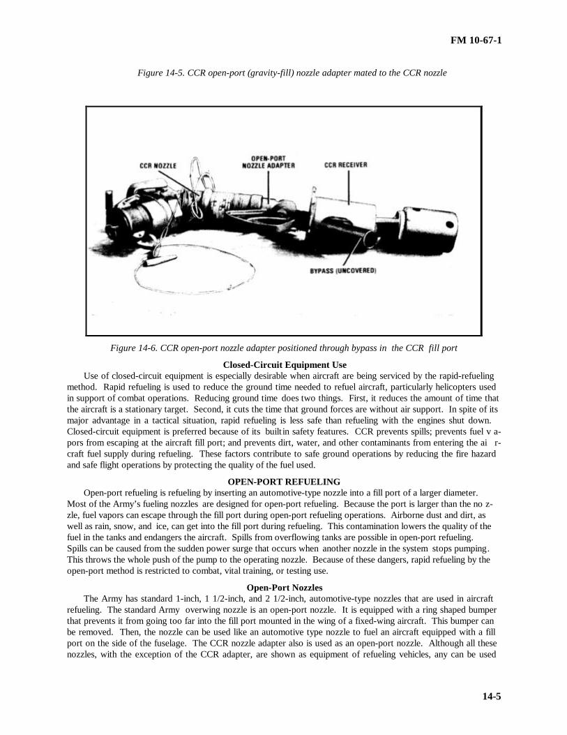
FM 10-67-1
14-5
Figure 14-5. CCR open-port (gravity-fill) nozzle adapter mated to the CCR nozzle
Figure 14-6. CCR open-port nozzle adapter positioned through bypass in the CCR fill port
Closed-Circuit Equipment UseUse of closed-circuit equipment is especially desirable when aircraft are being serviced by the rapid-refueling
method. Rapid refueling is used to reduce the ground time needed to refuel aircraft, particularly helicopters usedin support of combat operations. Reducing ground time does two things. First, it reduces the amount of time thatthe aircraft is a stationary target. Second, it cuts the time that ground forces are without air support. In spite of itsmajor advantage in a tactical situation, rapid refueling is less safe than refueling with the engines shut down.Closed-circuit equipment is preferred because of its builtin safety features. CCR prevents spills; prevents fuel v a-pors from escaping at the aircraft fill port; and prevents dirt, water, and other contaminants from entering the ai r-craft fuel supply during refueling. These factors contribute to safe ground operations by reducing the fire hazardand safe flight operations by protecting the quality of the fuel used.
OPEN-PORT REFUELINGOpen-port refueling is refueling by inserting an automotive-type nozzle into a fill port of a larger diameter.
Most of the Army’s fueling nozzles are designed for open-port refueling. Because the port is larger than the no z-zle, fuel vapors can escape through the fill port during open-port refueling operations. Airborne dust and dirt, aswell as rain, snow, and ice, can get into the fill port during refueling. This contamination lowers the quality of thefuel in the tanks and endangers the aircraft. Spills from overflowing tanks are possible in open-port refueling.Spills can be caused from the sudden power surge that occurs when another nozzle in the system stops pumping.This throws the whole push of the pump to the operating nozzle. Because of these dangers, rapid refueling by theopen-port method is restricted to combat, vital training, or testing use.
Open-Port NozzlesThe Army has standard 1-inch, 1 1/2-inch, and 2 1/2-inch, automotive-type nozzles that are used in aircraft
refueling. The standard Army overwing nozzle is an open-port nozzle. It is equipped with a ring shaped bumperthat prevents it from going too far into the fill port mounted in the wing of a fixed-wing aircraft. This bumper canbe removed. Then, the nozzle can be used like an automotive type nozzle to fuel an aircraft equipped with a fillport on the side of the fuselage. The CCR nozzle adapter also is used as an open-port nozzle. Although all thesenozzles, with the exception of the CCR adapter, are shown as equipment of refueling vehicles, any can be used
FM 10-67-1
14-6
with a hose, filter/separator, pumping assembly, and fuel source to form a small, temporary aircraft refueling sy s-tem.
Open-Port Nozzle UseNo Army, open-port nozzle may be equipped to stay open automatically. Open-port nozzles must be held open
by hand throughout their use in refueling. If any automatic device has been added to the nozzle to hold it open, thedevice must be removed.
REFUELING POLICYExcept as indicated below, an aircraft may not be refueled with its engines operating. The engines must be
shut down before refueling begins. The exceptions are described below.• Closed-Circuit Rapid Refueling. All Army aircraft may be refueled with engines running provided that
closed-circuit equipment is used.• Open-Port Rapid Refueling. In combat operations, the open-port method of rapid refueling may be used for
helicopters when, in the judgment of the aviation commander, the requirements of the tactical mission and thebenefits of reducing ground time outweigh the risks of this method of refueling. In noncombat situations, helico p-ters may be refueled by this method only when there are compelling reasons to do so. Example: Aviation co m-manders may decide that open-port rapid refueling must be done for purposes of training, field testing, or combattesting. When the FARE system is used for rapid refueling in a training situation, a berm should be built aroundthe 500-gallon drums whenever possible.
AIRCRAFT REFUELING HOSEHose used for aircraft refueling operations must be in good condition. Hose should be inspected before use. If
bulges, blisters, tears, or soft spots are noticed, replace the hose. If during normal operations the hose leaks orbulges, discontinue operations and replace the hose immediately. Hydrostatic testing of hose, other than sea hoseand cargo hose, is not required. However, testing can be performed on all hoses.
TestingTo perform hydrostatic test procedures, specialized equipment is needed. This equipment is normally found at
maintenance facilities. The maintenance facility can perform the test procedures when the hose is uncoupled fromthe vehicle. Operators are not expected to follow the procedures described below in a tactical or field situation:
• Use a liquid for the test that will not damage the hose or contaminate aviation fuel when the hose is returnedto service. Use a liquid such as water, mineral spirits, solvent, or a kerosene-type aviation fuel. Do not use JP-4 orblends of kerosene and gasoline. Whatever liquid used, handle it according to applicable handling proc edures.
• Connect one end of the hose to a cap equipped with an air bleeder valve that can produce enough pressurefor the test. Lay out the hose in a straight line, and remove all kinks and twist s. Make sure all connections aretight.
• Open the air bleeder valve, and pump liquid into the hose while holding the capped end up. Close thebleeder valve when the hose is full of liquid and all air is removed. All air is removed when a solid stream of li q-uid comes out of the bleeder valve.
Raise the pressure in the hose to the required level and maintain it for at least one minute. Check the hose forleaks. If a leak is located at a place other than a hose coupling juncture, release the pressure in the hose andtighten the coupling. Then bring the pressure back up to the required level, and hold it again for at least one mi n-ute. Replace or repair the hose if a coupling leaks, bulges, or has distortions in it.
Salvage and RecouplingHose that has been removed from service because it failed when tested or is damaged may be repaired and re-
turned to use after testing. If part of the hose is in good condition and is long enough, cut off the damaged part andreplace the coupling. Be sure that all the damaged portion is removed, including any part that shows signs of ca r-cass saturation. If the hose leaks at the coupling juncture, cut off at least the portion that is inserted into the co u-pling. Test the recoupled hose at its operating pressure. Lengths of suction hose that are in good condition but tooshort to justify recoupling may be saved and prepared for use in defueling.

FM 10-67-1
14-7
THE 500 GALLON COLLAPSIBLE DRUM
The 500-gallon collapsible drum as shown in Figure 14-7, page 14-8, is a durable, nonvented collapsiblecontainer. It may be used as a fuel source or for transporting and storage of fuel. When filled to its 500 galloncapacity, the drum is cylindrical in shape with rounded ends. The drum fabric is impregnated with fuel -resistantsynthetic rubber. The front and rear closure plate s are connected by three wire ropes providing interior support.The front closure plate has a threaded coupler valve assembly. Newer models have a threaded coupler valve onboth the front and rear closure plates. Procedures for filling, transporting, and storing the drum are described b e-low.
Filling the 500-Gallon Collapsible DrumUse the pressure control valve to fill the 500-gallon collapsible drum. The pressure control valve should be
used when drums are filled to prevent overfilling that could result in personal injury, equipment damage, and env i-ronmental damage. To fill drums with the pressure control valve, perform the following:
• Place empty drums in position for helicopter pickup.• Move a spill container to the drum being filled first.• Pull the tank vehicle within 50 feet of the drums.• Ground the tank vehicle.• Put a fire extinguisher within reach of the operation.• Unreel the hose and remove the nozzle if applicable.• Connect the hose to the inlet of the pressure control valve using necessary adapters.• Connect the outlet end of the 1 1/2-inch pressure control valve to one end of a length of discharge hose and
then couple the other end of the hose to the elbow coupler valve.• Hold the elbow coupler valve over the spill container, and open the valve enough to let air out. Push the
FILL button on the pressure control valve. As soon as the air is pushed out and the fuel flows, close the elbowvalve.
• Couple the elbow to the drum, and open the elbow valve.• Push the FILL button on the elbow valve, and fill the drum. The pressure control valve will shut off the flow
when the drum is full.• Close the elbow valve when the drum is full, and dis connect the elbow.• Move to the next drum. Repeat the previous three steps until all drums are filled.
Transporting the 500-Gallon Collapsible DrumThe drum can be transported by three primary methods using accessory items. It can be airlifted using sling
loading equipment. It can be transported by cargo vehicle using the tie -down kit. Also, it can be transported forshort distances over smooth terrain, at speeds not exceeding 10 mph, using the towing and lifting yoke.
Storing the Collapsible DrumDrums should be stored full of fuel. Too much collapsing and expanding of the drum takes its toll on the fa b-
ric. This is especially true during cold weather when the drum can become brittle and crack. In hot weather , fuelwill expand. Always drain a small amount of fuel from the drums before storage to keep pressure down in hotweather climates. If local fire regulations prevent the storage of drums full of fuel, they should be completelydrained. Never fill the drums with air. There is always some fuel left inside after the drums have been drained.Vapors inside the drums can cause an explosion.

FM 10-67-1
14-8
• Store the drums indoors if possible. Use a dark, cool, well ventilated area with a smooth surface. Store thedrums away from any source of heat that could damage the fabric or start a fire. Never stack the drums on top ofeach other or place equipment on top of them. That causes the fabric to wear and crack.
• If drums must be stored outdoors, keep them out of direct sunlight. The sun can cause the fabric to dry outand crack. Place the drums in a tent or under a tarp to block the sun and keep snow or ice off during cold weather.Keep the canvas propped up so air can circulate. If no shelter is available in hot climates, cover the drums withwet burlap or other cloth.
DRUM CELL
EXTERIOR CLOSURE RING
SWIVEL RING
ANCHOR SHACKLE
Figure 14-7. Filled 500-gallon drum

FM 10-67-1
15-1
CHAPTER 15
REFUELING FROM REFUELING SYSTEMS
Section I. Forward Area Refueling Equipment
UNIT-LEVEL REFUELING OPERATIONSUnit-level refueling operations in theaters of operation are usually carried out by individual aviation units. A
lightweight, air-transportable refueling system is used at the unit level. At present, the system authorized to mostunits that have the refueling aircraft mission in forward areas is the FARE system. This system can be set up byskilled personnel within 15 minutes of delivery to a site.
USEThe FARE system is designed for refueling helicopters in forward areas. It is lightweight and can be flown to
the refueling point by helicopter or fixed-wing aircraft. The bulk fuel for the system is usually flown to the site in500-gallon collapsible drums by utility or cargo helicopters. Chapter 14 describes how these tanks are filled. TheFARE system can also use collapsible tanks, tank vehicles, and semitrailers as fuel sources . To do so, the adapterswhich are included in the system are used.
EQUIPMENTThe FARE system (NSN 4930-00-133-3041) consists of a pumping assembly, filter/separator, hoses, nozzles,
grounding equipment, and valves and fittings. The components of the system, packed for transport, and the fireextinguishers that should be used with the system are shown in Figure 15-1, page 15-9, and TM 5-4930-229-12&P.
Pumping AssemblyThe pumping assembly includes a 100-GPM gasoline engine-driven centrifugal pump. The pump inlet co n-
nection is a 2-inch female fitting, and the outlet is a 2-inch male fitting. The pump-engine assembly and the e n-gine’s fuel tank are all housed in a tubular aluminum frame. Refer to TM 5-4320-256-14 for maintenance andoperation of the pumping assembly.
Filter/Separator The 100-GPM filter/separator is used to remove sediment and free water. For more information on the fi l-
ter/separator, see Chapter 21 or TM 5-4330-217-12.
Discharge Hose and FittingsThe FARE system has two sets of discharge hose, fittings, and nozzles. The T-Kit and Y-Kit are both
mounted in a tubular aluminum frame. The equipment in the two sets includes the following:• Four 50-foot lengths of 2-inch discharge hose.• Two 2-inch male couplings.• Two 2-inch butterfly valve assemblies.• Two 2-inch elbow coupler valves.• One T-fitting assembly.• One Y-fitting.• One 2-inch male to 4-inch female coupling.• One 2-inch male to 3-inch female coupling.• Two closed-circuit nozzle assemblies, each with an open-port nozzle adapter. (There are three models of
CCR nozzles that can be used with the FARE: 1. Wiggins Model CCN 101/14; 2. Aeroquip Model AE83206R;and 3. Model 125-1000.)
• Two 2-inch male-to-male adapters (NSN 4730-00-887-3824).

FM 10-67-1
15-2
• Water detector kit adapter.
Suction Hose and Fittings
Two canvas carrying cases hold the suction hose and their fittings. The equipment in the two sets include thefollowing:
• Twelve 5-foot lengths of 2-inch suction hose.
• Four 5-foot by 5/8-inch grounding rods, each with nozzle hanger and striker.
Other Required Items
Other items of equipment are needed to conduct aircraft refueling operations with a FARE system. These arefire extinguishers and a fuel source.
• Fire extinguishers. Extinguishers are not components of the FARE system. Providing fire extinguishers isa command responsibility. Three fire extinguishers are required for each FARE system used in aircraft refueling--one to be within reach of the pump operator and one for use at each nozzle. Fire extinguishers acceptable for useare 20-pound dry-powder (NSN 4210-00-257-5343) and the 15-pound CO2 (NSN 4210-00-202-7858).
• Fuel source. No fuel source is provided as a component of the FARE system. Generally, 500-gallon co l-lapsible drums are used because they can be airlifted full to the fuel point. But the FARE system can also beadapted to use larger fuel reservoirs or the ERFS tanks for aircraft to aircraft refueling. Collapsible drums andtanks are issued separately. The number of drums or tanks, as well as the type of fuel to be used, is determined bythe number and type of aircraft the FARE point is to support.
LOCATION
The operations and training officer (S3) of the aviation battalion or the operations officer of the aviation co m-pany plans the unit operations. As part of these plans, he chooses the general area for a refueling point and spec i-fies the amount and type of refueling support that will be needed. The specific site is selected either by the co m-pany operations officer, a pathfinder or a pathfinder team. If the operations officer selects the site, he shouldphysically check the area. He must choose a site that has enough open ground for the aircraft to land and lift offsafely. The site must be flat or have only a slight slope. He then informs the personnel who are to set up the sy s-tem where and when to establish the refueling point, how much of what type of fuel to take, and the type of setuprequired. If a pathfinder selects the specific sight, he enters the general area on foot or by vehicle, aircraft, or par a-chute to survey the possible locations. He has sufficient training to select a site that meets aviation requirements.He radios coordinates of the site to the units that will setup and use the site. He will also select the specific locationfor the refueling system. Operating personnel will choose the specific location at the site that is best for laying outthe equipment if a pathfinder does not select the site.
SITE LAYOUT
When the layout of a FARE system is being planned, five factors must be considered in addition to METT-T.These are described below.
Spacing Between Aircraft
Usually OH-6, OH-58, AH-1, UH-60, AH-64, or UH-1 helicopters are refueled at a forward refueling point.There must be 100 feet of space between these aircraft (rotor center to rotor center) (as shown in Figure 15-2, page15-10). In an emergency, a CH-47 or CH-54 may have to be refueled. Do it with the same layout but only if noother helicopter is at the site.
Wind Direction
Lay out the FARE system so that the helicopter can land, refuel, and take off into a direct head wind or a leftor right quartering head wind (Figure 15-2, page 15-10). If it is impossible to lay out the system this way, lay itout so that the aircraft will land, refuel, and take off in a crosswind. Avoid laying out the system so that helico p-ters will have to land or take off downwind. Such a maneuver is very dangerous because it is difficult to control ahelicopter when its tail is to the wind on landing or takeoff.

FM 10-67-1
15-3
Vapor Collection
By laying out the site at right angles to the wind for helicopter landing and takeoff, the wind will carry the fuelvapors away from the site. This is the best layout. Remember that fuel vapors are heavier than air and that theywill collect in a valley or hollow. If the site slopes, lay out the equipment on the higher ground.
Drainage
Do not lay out equipment in a place where a spill will drain into a stream, river, wetland, seashore, lake, orother environmentally sensitive area. A spill could contaminate the water and create an unsuspected fire hazarddownstream of the site. Choose a part of the site that is firm enough to support the weight of the aircraft and thefuel drums.
Camouflage
Camouflage is the only protection at a FARE point in a combat zone. Site features will be depended upon b e-cause airlifting in camouflage materials is not practical. When possible, put the pump, filter/separator, and fueldrums in woods or brush, along a hedgerow, or in positions where natural shadows will disguise the shadow pa t-terns of the equipment. It may be possible to conceal most of the hose in woods, with nozzles hung on hangers atthe edge of the tree line. Deep grass can be bent over the hoses to help conceal them. When spray paint is avai l-able, use earth and grass tones to dull and conceal couplings and fittings. Heaped dirt or large rocks can be usedalongside of the hoses (never on top) to break up the characteristic straight shadows. However, remember thatshadow patterns change during the day. Move equipment, if necessary, to use these changing patterns.
SITE PREPARATION
All sticks, stones, and debris should be cleared from the area. They can be sucked up and thrown out by rotorwash. Also clear the immediate refueling area, paths of approach, and hover lanes. To prevent fires, clear drygrass, leaves, and brush away from the pumping assembly. In some cases, engineer personnel prepare the site.This occurs when the site must be bulldozed (on a mountain) or if the site must be treated with dust suppressant (ina sandy desert). In such cases, the company or battalion operations officer must arrange for site preparation, inadvance, with the engineers.
EQUIPMENT LAYOUT
Lay out the FARE system in the way that is best for the specific situation. Tailor the layout to avoid obstacles,to take advantage of terrain features, to achieve maximum dispersion, and to operate within a restricted amount ofspace. The only mandatory feature of the FARE system layout is the spacing between aircraft. The layout dire c-tions that follow use all the hose. Figure 15-3, page 15-11, shows the FARE system laid out with all componenthose. Regardless of the layout that fits the situation, follow one basic rule when laying out equipment: Never takea dust cap or plug off until ready to couple the next piece of equipment. Follow the same rule, in reverse, whenuncoupling. Always position spill containers before uncoupling. Uncouple, drain, then cap or plug immediately.Couple removed caps and plugs together to keep them clean. Keep dirt out of the system. Use the butterfly valvesto shut off the flow from one or both drums, to switch from one to another, or to shut down the system. Thus, thebutterfly valves serve as an emergency shutoff, providing quick positive shutoff. Remember the lives of the ai r-crews and the troops they are supporting depend on the quality of the fuel pumped into the aircraft. Lay out theFARE system using the procedures described below.
• Position Pump and Filter/Separator . Place the pumping assembly on a cleared level spot. Have the inlet portfacing the place where the collapsible drums will be. (In this system, all inlet ports are female and all outlet portsare male.) Connect the female end of a 5-foot length of suction hose to the pump outlet. Connect another lengthof suction hose to the first suction hose. Connect the male end of the second hose length to the inlet port of thefilter/separator.
• Ground Pump and Filter/Separator . Drive one ground rod into the ground between the pump and fi l-ter/separator. For the depth required to ensure a proper ground, see Chapter 2. Attach the pump ground cableclip and the filter/separator grounding clip to the grounding rod.

FM 10-67-1
15-4
Connect to Two 500-Gallon Drum
To lay out the system as shown in Figures 15-2, page 15-10, and 15-3, page 15-11, do the following:
• Couple the male end of a 5-foot length of suction hose to the inlet port of the pump and couple a T-fittingto the female end of the suction hose.
• Couple a butterfly valve to each inlet of the T-fitting. The arrows on the valves should point in the dire c-tion of the fuel flow (toward the pump). The butterfly valves are used to shut off the flow from one or both drums,to switch from one to another, or to shut down the system. Thus, the butterfly valves serve as an emergency shu t-off, providing quick positive shutoff. A butterfly valve is open when its handle is parallel to the centerline of thevalve and closed when its handle is perpendicular to the centerline.
• Couple four 5-foot lengths of suction hose to each butterfly valve, and roll fuel drums into position nearthe ends of the suction hoses.
• Connect an elbow coupling to each drum’s outlet port.
• Use a male-to-male adapter fitting to connect the two female fittings at each drum. (There is a female endon the suction hose and a female end on the drum elbow coupler.)
Connect Other Supply Sources
If hooking the FARE system to a bulk fuel supply, such as a collapsible tank, put a butterfly valve in at theconnection to the suction line and use the 2- to 4-inch coupling adapter. The valve will control the flow of fuel tothe FARE system.
Assemble Discharge Hose
The discharge hose can be assembled in several different ways, but any arrangement must provide forenough distance between helicopters. A typical layout is shown in Figure 15-2, page 15-10. A schematic drawingof this layout is provided in Figure 15-3, page 15-11. To assemble the hose for this layout, connect the female co u-pling at the end of a 5-foot length of suction hose to the outlet port of the filter/separator and the male end to thefemale inlet of the Y-fitting. Connect two 50-foot lengths of discharge hose to one outlet of the Y-fitting and two50-foot lengths to the other outlet.
Assemble Dispensing PointsWhen the discharge hose is laid out, walk down it about 10 feet toward the Y-fitting. Drive a ground rod
into the ground. (For the depth required to ensure proper ground, refer to Chapter 2.) Go back to the end of thehose, attach the CCR nozzle, carry the nozzle back to the grounding rod, and hang the nozzle on the nozzlehanger. A ttach the clamp of the grounding cable to the ground rod. If aircraft that are not equipped for closed-circuit refueling are expected, hang the open-port nozzle adapter on the nozzle hanger too. Loop the last 10 feet ofhose back on itself as shown in Figure 15-2; page 15-10, no hose should lie beyond the nozzle hanger. Pace offthe distance from the ground rod to a point 10 feet from the outer end of the second 50-foot hose on the other armof the Y-fitting. If it is less than 100 feet, move the hose farther apart and set up the other dispensing point thesame way.
Position Fire ExtinguishersPlace one fire extinguisher at the pump and one by each combination ground rod/nozzle hanger. They must
be in place at all times. Finally, go back and check the whole system to make sure all the fittings and couplings arelocked tight. Make sure all four ground cables (from the pump, filter/separator, and one from each nozzle) aresecurely clipped to the three ground rods (one for the pump and filter/separator, and one for each nozzle). Thecompleted system should look like the system in Figures 15-2, page 15-10, and 15-3, page 15-11.
PREPARATION FOR OPERATION
Before starting up the system, fill the pump engine gas tank with fuel or run a supply line from a fuel source(tank, can, or drum) to the fuel selector valve on the pump frame. Check the oil level in the pump engine cran k-case. Then start up the system. If no aircraft are expected until a prearranged time, turn the system off after thisinitial startup and check. Follow procedures described below to ensure the equipment will be operational whenneeded.

FM 10-67-1
15-5
• Priming the Pump . The pump can be primed by gravity or manually. Always prime the pump with the sametype of fuel that will be pumped into the aircraft. Gravity prime and manual prime are described in the STP 10-77F15-SM-TG.
• Priming the Filter/Separator . If the fuel level in the supply source is above the filter/separator, the fi l-ter/separator will fill by gravity flow. If gravity flow primes the pump but does not fill the filter/separator, start thepump. Turn on the pump engine to idle speed. Close the filter/separator air vent as soon as fuel appears in thesight glass and let the pump fill the filter/separator. Check the pressure differential indicator of the filter/separatorto ensure that the filter elements are operating properly.
• Checking for Full Prime . The pump should obtain a full prime (maximum suction lift) in about four mi n-utes. If full flow is not reached in five minutes, stop the pump. Try to find the problem. Do not run the pumpmore than five minutes without a flow. This will cause the pump to overheat and damage the pump shaft seal. Ifthe pump has not obtained a full prime follow troubleshooting procedures outlined in the STP and TM 5-4320-256-14
• Inspecting Hose. Inspect all hose daily before use. Follow the steps described below.
••Check hose covering. If any part of a hose length shows signs of blistering, saturation, or nicks and cutsthat expose a significant amount of reinforcing material, remove that length of hose from service. Hose should notbe removed from service if nicks or cuts penetrate only the outer surface, unless the rubber in the immediate area ofthe nick or cut is loose. Usable parts of the hose should be salvaged and recoupled. If a length of discharge hose isremoved, remember that the layout must change to allow enough space between aircraft.
••Check the couplings . Look for coupling slippage. Coupling slippage usually appears first as a misalig n-ment of the hose and coupling or as a scored or freshly exposed part of the hose where the slippage has occurred.Look for signs of leakage at the coupling. If a coupling is slipping or leaking, remove that le ngth of hose fromservice. Salvage and recouple hose.
••Check the hose within 12 inches of the couplings . Check the hose closest to the coupling with particularcare because most hose failures occur in this area. Check all the way around the hose, pressing lightly and feelingfor soft spots. If weak or soft spots are found, remove the hose from service. Salvage and recouple hose.
••Test the hose. Test the hose at normal operating pressure by running the pump with the nozzle closed.Look for abnormal twisting or ballooning . Twisting and ballooning indicate that the hose carcass is weakening,so remove the hose from service immediately. Salvage and recouple.
••Check the nozzle screens . Remove the nozzle screens, and check their contents for particles of hose li n-ing. Particles of rubber left in new hose from the manufacturing process may appear during the first week of use.If such particles appear more than twice during the first week or appear thereafter, remove the length of hose fromservice immediately because it is deteriorating. Also check the screens for dirt and for other particles that mayshow that the filter/separator has failed. Report any such indications to your supervisor. Clean and replace thenozzle screens.
Sampling
As soon as the system is full of fuel, draw a sample from each nozzle. Check the samples visually for sed i-ment and with the Aqua-Glo test for water contamination. If dirt is visible in the samples, it may show that dirtgot in the couplings while the system was being laid out. Flush out the fuel in the discharge lines into a suitablecontainer. When moving to the refueling point, carry an extra drum to contain this fuel. After flushing the lines,take another sample from each nozzle. If the fuel does not pass the second check, do not use it. Notify your supe r-visor immed iately.
SEQUENCE OF OPERATIONS
The FARE system should be primed and ready for operations as soon as it is laid out and the fuel has beensampled. The pump should be started and idling before the first aircraft arrives. There should be at least threepeople, besides the air traffic controller or pathfinder, present during FARE point operations--one to tend the pumpand one to tend each of the two nozzles. (A member of the crew of the aircraft being refueled can operate the no z-zle fire extinguisher.) However, aircrew members must be properly trained and able to handle the refueling of

FM 10-67-1
15-6
their own aircraft if the need arises. All three of the personnel should hold MOS 77F. The sequence of actions inrefueling is vital to the safety of the operation. This sequence is described below.
Land Aircraft
The ground guide directs approaching aircraft and tells the pilot where to land. If necessary, guide the aircraft intofinal position. (Use the marshaling signals discussed in Chapter 2.) Check to see that armaments aboard the ai r-craft have been set on SAFE.
Deplane Crew and Passengers
Only the pilot may remain in the aircraft during refueling. Passengers should go to the passenger marshaling area.If required, a crew member may assist with the refueling by manning the fire extinguisher.
Position Fire Extinguisher
Carry the fire extinguisher from its position by the ground rod to the side of the aircraft by the fill port.
Turn Off Radios
All radios must be turned off for refueling except for the radio used to monitor air traffic control. The pilotmust not transmit while actual refueling is taking place.
Ground and Bond the Nozzle to the Aircraft
Either insert the nozzle bond plug into the bond plug receiver on the aircraft or attach the connector clip to abare metal part of the aircraft. Usually the clip is attached to the skid structure of helicopters; it should never beattached to the radio antenna or to a propeller. When the CCR nozzle is used, it is grounded to the ground rod.Connecting the bonding wire grounds the aircraft and bonds the nozzle to the aircraft.
Remove Dust Cap
After bonding the nozzle, remove the dust cap from the nozzle and then remove the plug from the aircraft fillport. Never put a dust cap on the ground. This could get dirt and dust in the fuel system.
Refuel
During refueling, the pump operator has one set of duties and the nozzle operator has another. These are d e-scribed below.
• Pump operator. Watch the refueling operation. Maintain visual contact with the nozzle operator. Whenaircraft are being refueled, run the pump engine at full throttle. When flow stops at both nozzles, cut the speedback to idle. If other aircraft are waiting for fuel or are in sight, let the engine idle. If not, shut down the engine.(The pump engine can idle for a long time without damage, but idling unnecessarily cuts down on the serviceablelife of both the pump and the engine.) Watch the 500-gallon drum that fuel is coming from so that a change canbe made when it is getting low.
•Nozzle operator. The nozzle operator has different duties depending on which type of refueling is takingplace. The duties are described below.
CAUTION
The nozzle operator must maintain physical contact with the nozzle at all times while refueling.
••Closed-Circuit Refueling. Insert the CCR nozzle into the receiver (fill port) mounted on the aircraft. Ifthe CCR nozzle and port will not mate, look for dirt in the fill port. Wipe out the port with a clean rag, wipe offthe nozzle, and lock the parts together. Pull back on the control handle latch, and then push the flow control ha n-dle up and toward the aircraft into the FLOW position. If the tank is to be filled completely, watch the back of thenozzle. When flow stops automatically, a red indicator will pop out on the back of the nozzle. If the tank is not

FM 10-67-1
15-7
going to be filled completely, watch for the pilot to signal when to stop flow. When he signals or the red indicatorpops out, pull the flow control handle back toward the hose into the NO-FLOW position.
••Open-port refueling. Take the dust caps off the front of the CCR nozzle and the back of the open-portnozzle adapter. Lock the adapter into the CCR nozzle before bonding the nozzle to the aircraft and removing thenozzle dust cap and the fill port cap or plug. Pull back on the control handle latch. Put the nozzle adapter deepinto the fill port. Push the CCR nozzle flow control handle up toward the aircraft into the FLOW position, andslowly squeeze the trigger of the open-port nozzle to let the flow start. Watch the pilot for a signal if the tank isnot going to be filled completely; watch the fill port if the tank is to be filled completely. When the tank gets closeto full, let up on the trigger and finish filling slowly. Release the trigger, and pull the CCR nozzle flow controlhandle back to the NO-FLOW position (back toward the hose). Drain remaining fuel out of the nozzle before ta k-ing it out of the fill port.
Replace Caps and Plugs
Replace the plug of the aircraft fill port. Then recap the nozzle.
Remove Nozzle Bond
Unplug the nozzle bonding plug or release the connector clip Carry the nozzle back to its hanger; do not lay iton the ground or drag it across the ground.
Remove Fire Extinguisher
Take the fire extinguisher back to its position by the ground rod.
Board Crew and Passengers
Have the members of the crew and passengers reboard the aircraft.
Direct Aircraft Lift-Off
On direction from the ground guide, have the aircraft lift off.
Turn Off Pump
If no other aircraft are in sight or expected shortly, turn off the pump. Although the pump can idle for longperiods, unnecessary idling cuts down on its serviceable life.
Change Fuel Drums
If 500-gallon drums are used as the fuel source, the drums may need to be changed frequently. If the suctionmanifold is used properly, a continuous flow of fuel can be kept while drums are changed. It is hard for even anexperienced soldier to tell when a 500-gallon collapsible drum is empty because the drum is a closed, unventedcontainer. When the drum begins to draw together and has sharp, folds (as shown in Figure 15-4, page 15-11),open the elbow coupling valve to the other full container. The pump engine’s speed will increase and will vibratewhen the flow from the first drum gets low. When this occurs, open the butterfly valve to the full drum. When thepump starts to draw fuel from the full drum and is pumping at full capacity, the engine speed will return to normaland vibration will stop. Close the elbow coupling valve to the empty drum. Allow enough time for the system tofill with fuel from the fresh drum. If the fuel was not tested before delivery, take a sample from each nozzle forinspection. If the fuel passes visual inspection, continue operations; if it fails the visual check, radio for instru c-tions. Do not use fuel that has not passed inspection. After doing the visual check, unlatch and remove the elbowvalve coupler from the empty drum and roll a full one into its place. Latch the suction manifold to the fresh drumby coupling the elbow valve coupler to the drum adapter.
DISASSEMBLING PROCEDURES
Three soldiers are needed to disassemble and move the FARE system. Before it can be moved, the fuel mustbe drained. The procedures for disassembling and moving the system are described below.
• Step 1. Stop the pump engine.
• Step 2. Close the elbow coupling.

FM 10-67-1
15-8
• Step 3. Place a suitable container under the connection at the outlet of the filter/separator. Disconnect theoutlet coupling and put the end of the discharge hose into the container.
• Step 4. Open the filter/separator air vent. Drain the fuel from the filter/separator into the container. Plugand cap the filter/separator inlet and outlet. Close the air vent and drain the valves.
• Step 5. Lift the nozzle and nozzle end of the hose. Disconnect the nozzle. Plug the nozzle inlet and set itaside. While another soldier holds the open end of the hose up, walk the fuel in the hose back toward the Y-fitting.(Lift the hose as you walk, or lay it over your shoulder, to force the fuel to drain into the container.) When the Y-fitting is reached, lift it. Holding the Y-fitting up, disconnect the drained hose. Cap the Y-outlet. Go back out thesame section of the hoseline, and disconnect the coupling between the two 50-foot lengths. Roll one length of hosewhile another soldier rolls the other. To roll the hose, cap the male (outer) end and use the capped end as a reel toroll the hose on as shown in Figure 15-5, page 15-12. When the hose length is rolled, plug the female end.
• Step 6. Repeat step 5, working from the other nozzle back to the Y-fitting.• Step 7. Lift the Y-fitting to drain the remaining fuel from it and from the 5-foot length of suction hose into
the container. Disconnect and plug the Y-inlet, and cap and plug the length of suction hose.• Step 8. Move the container of drained fuel over to the pump. Drain the pump casing and remaining lengths
of suction hose into the container. Cap and plug the pump inlet and outlet. Close the container of drained fuel.(This fuel may not be used to fuel aircraft until it has been sampled, tested, and found to be on specification.)
• Step 9. Stow each component in the space provided for it in a frame or canvas container. Place the fire e x-tinguishers for the nozzles and pump with the packaged components of the system. Remove the ground rods andplace them in the suction hose containers.
• Step 10. Move the system components, collapsible drums, and fire extinguishers to the next site. They maybe moved by helicopter or cargo vehicle.
ADVANCED AVIATION FORWARD AREA REFUELING SYSTEM
The AAFARS will eventually replace the FARE system. The development of the AAFARS results from aneed to decrease the refueling time for the aviation company and to field a more environmentally safe system. TheAAFARS is a four-point refueling system that provides a minimum of 55 GPM at each refueling point simultan e-ously. Each refueling point is separated by a distance of 100 feet. The system will be assembled using commercialcomponents including a pumping system, filtration system, lightweight hoses equipped with unisex dry-break co u-plings, and three types of refueling nozzles. The primary source of fuel supply will be the 500-gallon collapsibledrum, although the system will be compatible with other fuel sources as is the FARE. The key function of theAAFARS will be to simultaneously refuel four helicopters in tactical locations using the center point refueling (D-1), CCR, or open-port nozzles. The system will be able to interface with existing U.S. Army, Air Force, Navy,and Marine Corps aircraft and fuel sources as well as having interoperability with NATO and other allied nation’srefueling equipment.

FM 10-67-1
15-9
Figure 15-1. FARE system components packed for transport

FM 10-67-1
15-10
Figure 15-2. Typical layout of FARE system

FM 10-67-1
15-11
Figure 15-3. Schematic drawing of FARE system
Figure 15-4. Empty 500-gallon collapsible drum

FM 10-67-1
15-12
Figure 15-5. FARE discharge hose rolled for packing
Section II. Temporary and Semipermanent Refueling Systems
CHARACTERISTICS
When demand for refueling at a specific location exceeds the capabilities of the FARE system or when thereare not enough FARE systems to meet the demand, construction of a temporary or semipermanent system is nece s-sary. Such a system is assembled from components used in the fuel system supply point. A system of this type hasgreater tank capacity, pump capacity, and flow rates than a FARE system. These factors may justify the establis h-ment of the system on the basis of economy. A temporary system takes hours instead of minutes to set up and useslarger equipment. It is not as mobile as a FARE system. It covers a larger area, so it is more difficult to camo u-flage and is more vulnerable to enemy attack. Light construction equipment may be needed to level landing padsor prepare the berms around the collapsible tanks. Because all these characteristics make the system unsuitable forforward areas, this system type is usually not set up ahead of the division rear area. Use of this system forward ofthe brigade rear area is not recommended.
USE
A temporary refueling system is used to refuel aircraft in the field, usually in a rear area. The length of timethat a temporary refueling point is used depends on the tactical situation. The point may be used for a few days, afew months, or even years. It may be that the refueling point is temporary only in the sense that it is not a perm a-nent airfield with a built-in, underground refueling system.
FM 10-67-1
15-13
EQUIPMENT
Standard petroleum-handling equipment, the FSSP components, and the CCR nozzle with open-port adapterare used to assemble a temporary refueling system. The amount of equipment required depends on the planned useof the system--the type and number of aircraft to be serviced at the point. The basic equipment needed to set up atemporary refueling system to refuel aircraft are described below.
Fuel Reservoir
Ordinarily, a 3,000-, 10,000-, 20,000-, or 50,000-gallon collapsible tank is used to provide bulk fuel storage.Any of these tanks can be moved to a field site easily. One or more of these tanks may be used to meet the requiredoperating capability of the system.
Pumping Assembly
The 350-GPM pumping assembly is used for temporary refueling systems. It can be moved to the site by hel i-copter, fixed wing cargo aircraft, truck, or trailer. Although the assembly is trailer-mounted and it may be towedshort distances by a vehicle, it should not be towed across country or in convoy moves. The pumping assemblyincludes the valves, gages, and controls needed to operate it. It is equipped with a ground rod and cable. The maincomponents of the pumping assembly are the pump and pump engine. Chapter 20 gives more information onpumps.
• Pump. The self-priming, centrifugal pump is rated at 350 GPM at 80 PSI (275 feet of head rated onMOGAS). It has two inlet ports and two outlet ports. Gate valves control these ports. Suction and discharge pres-sure gages are mounted on the instrument panel.
• Engine . Two types of engines are used to power the pump-gasoline and diesel. The gasoline engine is a 4-cylinder, air-cooled engine. The diesel engine is a 3-cylinder, air-cooled engine. The engines have gages andstarter switches mounted on their instrument panels.
Filter\separator
The 350-GPM filter/separator is used with the 350-GPM pump. This filter/separator is designed for a flowrate of 350 GPM and a top working pressure of 150 PSI. See Chapter 21 for more information.
Other Components
The number and type of other components required to complete the refueling system (hoses, valves, reducers,nozzles, and fittings) and the way in which these components are assembled are determined by the desired size ofthe system and the type of aircraft to be serviced
LOCATION
The aviation commander who determines that a temporary refueling point is required also specifies its generallocation. He delegates selection of the specific site to subordinates. Because a large, temporary refueling point is avaluable target for the enemy and cannot be displaced as quickly as a small FARE point, a temporary system isusually set up in a secure area rather than in the forward combat zone. The selected area must provide enoughopen space to allow for safe landing and takeoff of aircraft; the land must be relatively level and well drained.
SITE LAYOUT
When planning the layout of a refueling point, your first consideration is to design the facility to accommodatethe number and type of aircraft that the refueling point will be required to handle. Other factors to consider are therequired spacing between aircraft, prevailing wind direction, vapor collection, drainage, camouflage, and choice ofa passenger marshaling area.
Spacing Between Aircraft
The spacing between aircraft depends on the type of aircraft. It depends on two features of the aircraft. Theseare the dimensions of the fuselage and the size of the circular pattern created by the rotor blades. The spacing r e-duces the possibility of collisions and prevents one helicopter from being overturned by another. Table 15-1, page15-14, shows the MINIMUM spacing to be used between aircraft during refueling.

FM 10-67-1
15-14
Table 15-1. Minimum spacing required between aircraft during refuelingAIRCRAFT POSITION MINIMUM
ROTOR-HUB TOROTOR-HUB
CH-47 SIDE BY SIDENOSE TO TAIL
180 FEET140 FEET
UH-60 100 FEETAH-64 100 FEETOH-6 100 FEETOH-58 100 FEETAH-1 100 FEETUH-1 100 FEET
• Small helicopters . Use the same layout to fuel all of the small Army helicopters. The fueling nozzlesmust be placed so that there is a 100-foot space between nozzles. Figure 15-6, page 15-17, shows a six-nozzle la y-out for small helicopters (OH-6, OH-58, AH-1, and UH-1). Layouts for five-, four-, three-, and two-nozzle systemsfor these aircraft are shown in Figure 15-7, page 15-18. These layouts provide 100 feet between nozzles which isadequate spacing for rapid refueling.
• CH-47. Setup a separate refueling point for CH-47 helicopters if they are refueled at the point. There aretwo reasons for this. First, enough space must be allowed between a CH-47 and any other helicopters so that therotor wash from the CH-47 will not turn the other helicopter over. Second, a CH-47 is refueled from both sides, soa separate refueling system lets both sides be refueled at the same time. This decreases ground time. The reco m-mended layout for a CH-47 refueling point is shown in Figure 15-8, page 15-15-20. Lay out the CH-47 point at aseparate site or on the same site as the refueling point for the small helicopters. If both points are laid out on onesite, allow 200 feet between the last nozzle of one system and the first nozzle of the other system. For CH-47 hel i-copters to land side by side, the recommended rotor hub spacing is 200 feet and the minimum is 180 feet. Whenlanding nose to tail, the recommended distance is 160 feet and the minimum is 140 feet. The recommended layoutprovides adequate spacing for CH-47 helicopters regardless of the direction of the landing. If in an emergency orunusual situation, a CH-47 must be refueled at a point laid out for the small helicopters. Have the CH-47 landsome distance from the refueling system and taxi in. Have the CH-47 taxi to the end nozzle. Do not allow anyother helicopters to use or approach the adjoining nozzle until the CH-47 lifts off. When refueling is complete,have the CH-47 taxi away from the refueling system and lift off from a designated point some distance away fromthe system. If a CH-47 is refueled at a two-nozzle point, have it land between the two nozzles and do not allowother aircraft to land at the point until the CH-47 has cleared the area. The CH-47C/D has a D-1, single-pointrefueling system. When the aircraft is equipped in this way, it is refueled in the same manner as the CH-54.
NOTE: The CH-54 poses the same rotor wash problems to small helicopters as the CH-47 does. The D-1 nozzle isuse for the CH-54 and CH-47C/D.
• UH-60. The UH-60 is equipped with CCR and D-1 receivers. When the D-1 nozzle is available, itshould be used. Otherwise, the CCR nozzle is used for refueling the UH-60. When neither CCR or D-1 nozzle isavailable, the local commander may authorize open-port refueling. When servicing UH-60 helicopters, positionthem so that the space from rotor hub to rotor hub is 125 feet (recommended). The minimum spacing for theseaircraft is 100 feet. See Table 15-1, page 15-14.
Wind Direction
In an area that has a prevailing wind pattern, lay out the refueling system across the wind (at a right angle tothe wind) so that helicopters can land, refuel, and take off into the wind. Because this arrangement is not alwayspossible, the recommended layout provides sufficient distance between nozzles to allow aircraft to land into thewind regardless of wind direction. Figure 15-9, page 15-21, shows how the recommended layout can be used u n-der various wind conditions. Similar approaches and landing directions apply to CH-47 helicopters.

FM 10-67-1
15-15
Vapor Collection
Another advantage of a crosswind layout is that the wind will carry fuel vapors away from, rather than across,the refueling point. Because fuel vapors are heavier than air, they will flow downhill. For this reason, lay out therefueling point out on the higher portion of a sloped site and not in a hollow or a valley.
Drainage
Position the refueling point on a part of the site that is firm. Do not lay out equipment in a place where a spillwill drain into a stream, river, wetland, seashore, lake, or other environmentally sensitive area. It must be firm andwell drained enough to support the weight of the aircraft and refueling equipment.
Camouflage
The extent and type of camouflage required depend on the tactical situation. If camouflage is intended pr i-marily to disguise the refueling point from enemy aircraft, the main concern should be the equipment shadow pa t-terns and straight lines of the hose manifold. When possible, place the pump, filter/separator, and fuel tanks inwoods or brush, along a hedgerow, or in positions where natural shadows will disguise the shadow patterns of theequipment. Use camouflage nets and support systems to distort shape and conceal the equipment. Ensure camo u-flage is staked down securely to prevent being torn loose by rotor wash. Use natural terrain contours and veget a-tion to help break up the straight lines of the hoses. Use camouflage nets to cover parts of the hoselines that arenot close to the nozzles or landing areas. One method of breaking up the straight lines of hoselines is to cutbranches, stick them into the earth under the hose that is not close to the nozzles, and weigh them down with thehose. Where grass or other vegetation is deep, bend it over the hoseline to conceal the hose from aerial observ a-tion.
Passenger Area
In laying out the site, set aside and mark off space for a passenger marshaling area. The passenger marshalingarea should be at least 50 feet from the nearest nozzle.
SITE PREPARATION
How much preparation is required will depend on the intended use of the temporary refueling point. Thecommander who decides to set up the temporary refueling point determines how much preparation is required. Ifengineer support is required for ground leveling, dust-suppressant treatment, berm construction, or other site d e-velopment, the same commander requests the support. The tactical situation, particularly air superiority and sitevulnerability, is a major factor in determining the amount of site preparation required at the site.
EQUIPMENT LAYOUTFigures 15-6 through 15-12, pages 15-17 through 15-24, are guides to laying out equipment systems. Figure
15-10, page 15-22, shows the layout for the refueling system assembly of a six-nozzle system designed to serviceOH-6, OH-58, AH-1, UH-60, AH-64, and UH-1 helicopters. Figure 15-8, page 15-20, shows a recommended lay-out for the refueling system of CH-47 helicopters. Figure 15-12, page 15-24, is a detailed drawing of the layout forthe six-nozzle system of CH-47 helicopters. It focuses on the principal valves and fitting assemblies. The CH-47system varies from the other system (Figure 15-11, page 15-23) in that the hose sections are arranged to provideincreased distance. Figure 15-13, page 15-25, shows the main valve and fitting assemblies of all recommendedtemporary refueling system equipment la youts.
NOTE: All final lengths of discharge hose in temporary systems should be positioned as shown for the hose at theextreme right of each drawing of the system (the other hoses are shown pulled out full length for refueling).The last 10 feet of dispensing hose should be looped back so that the nozzle can hang on the nozzle hanger that isattached to the ground rod. No hose should be lying forward of the ground rod when an aircraft lands at the no z-zle. In a tactical area, the proper layout of the collapsible tanks may have to be modified. The tactical situation,physical limitations of the site, and requirements for protection and camouflage must be weighed against the sta n-dards for proper layout. The following concerns must be weighed in specific tactical areas:
• Fuel supplies and tanks may need to be guarded.• Tanks may need to be shielded from enemy fire.• Tanks may need to be camouflaged.
FM 10-67-1
15-16
• Only limited areas of firm ground to support filled tanks in all types of weather may be available.
Grounding Equipment
In a temporary refueling system, ground the pump, the filter/separator, and each nozzle. For guidance onground rods and grounding procedures, see Chapter 2.
Positioning Collapsible Tanks
Prepare positions for 3,000-, 10,000-, 20,000-, or 50,000-gallon collapsible tanks. Clear and grade an area foreach tank. The grade of the area should not be steep because filled, collapsible tanks tend to creep or roll on a hil l-side. However, a slight slope toward the manifold end of the tank (not more than 6 inches per 20 feet for recta n-gular tanks or 3 inches per 20 feet for square tanks) helps drain the tanks when it must be moved. A berm must bebuilt around each tank and an impermeable liner must be added between layers of suitable fill, such that damage tothe tank and liner is reduced. The berm must be large enough to hold all the fuel in the tank and one foot of fre e-board. Before the walls are built, lay a drainpipe (sections of 4-inch suction hose will do) and close the end of thedrainpipe with a valve. Build up the berm over the drainpipe, and then make sure the drainpipe is not blocked orclosed. The valve should be kept closed to keep the fuel in the berm in case of a leak or tank rupture, but it may beopened when it is necessary to drain off rainwater. If drainage is a problem in the area, dig out a position for eachtank. This will also capture the fuel in case the tank ruptures. The berm dimensions are described below.
• The 3,000-gallon collapsible tank. Build the berm 3 feet high and 18 inches wide at the top. The inside d i-mensions of the berm should be 15 feet 6 inches by 15 feet 6 inches. Maintain a distance of 3 feet from the edge ofthe tank to the base of the berm.
• The 10,000-gallon collapsible tank. Build a berm that is 3 feet high and 18 inches wide at the top. Make theinside dimension of the berm 26 feet by 26 feet. Maintain a distance of 3 feet from the edge of the tank to the baseof the berm.
• The 20,000-gallon collapsible tank. Build a berm that is 4 feet high and 18 inches wide at the top. The i n-side dimensions of the firewall should be 35 feet long and 31 feet wide. Maintain a distance of 3 feet from the edgeof the tank to the base of the berm.
• The 50,000-gallon collapsible tank. Build a berm that is 4 feet high and 18 inches wide at the top. The i n-side dimensions of the firewall should be 73 feet long and 33 feet wide. Maintain a distance of 4 feet from the edgeof the tank to the base of the berm.
Positioning Fire Extinguishers
Position a fire extinguisher at each refueling nozzle and at the pump assembly. Place the fire extinguishers asshown in Figures 15-6, through 15-8, pages15-17 through 15-20 and 15-10 through 15-12, pages 15-22 through15-24. Twenty pound carbon dioxide (CO2) or equivalent capacity dry chemical fire extinguishers are reco m-mended.
PREPARATIONS FOR OPERATIONS
Be sure all safety precautions are taken. Be sure the danger control measures are being used. For example,ensure that no unnecessary vehicles or electrical equipment are within 50 feet of a nozzle. Have landing lights inplace, if appropriate. See that members of the ground crew have and are wearing all protective clothing andequipment necessary. Have required warning signs in place. Before daily operations begin, the fuel storage tanks,hoses, nozzles, pumps, filter/separators, bonding and grounding equipment, and fire extinguishers must bechecked. These procedures are described in the paragraph Preparation for Operations, on page 15-5.
SEQUENCE OF OPERATIONS
Following the sequence of actions in refueling is vital to the safety of operations. This sequence is described inthe paragraph Sequence of Operations, page 15-6.
EMERGENCY FIRE AND RESCUE PROCEDURES

FM 10-67-1
15-17
The best preparation for coping with an emergency is the fire-fighting and rescue training that all refuelingpersonnel should receive. The procedures and guidelines of what personnel should do in a fire or crash emergencyare found in Chapter 19.
Figure 15-6. Layout of six-nozzle temporary refueling system for OH-6, OH-58, AH-1,and UH-1 helicopters
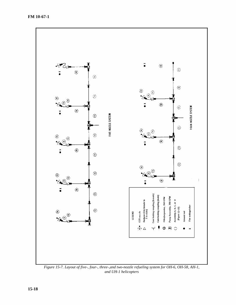
FM 10-67-1
15-18
Figure 15-7. Layout of five-, four-, three-,and two-nozzle refueling system for OH-6, OH-58, AH-1,and UH-1 helicopters

FM 10-67-1
15-19
Figure 15-7. Layout of five-,four-,three-, and two-nozzle refueling system for OH-6, OH-58, AH-1,and UH-1 helicopters (continued)

FM 10-67-1
15-20
Figure 15-8. Layout of temporary refueling system for CH-47 helicopters

FM 10-67-1
15-21
Figure 15-9. Temporary refueling systems under various wind conditions

FM 10-67-1
15-22
Figure 15-10. Suggested layout for six-nozzle refueling system for OH-6, OH-58, AH-1, UH-60,AH-64, and UH-1

FM 10-67-1
15-23
Figure 15-11. Suggested layout of refueling system for CH-47 helicopters
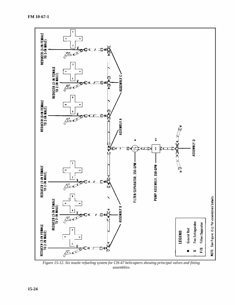
FM 10-67-1
15-24
Figure 15-12. Six nozzle refueling system for CH-47 helicopters showing principal valves and fittingassemblies
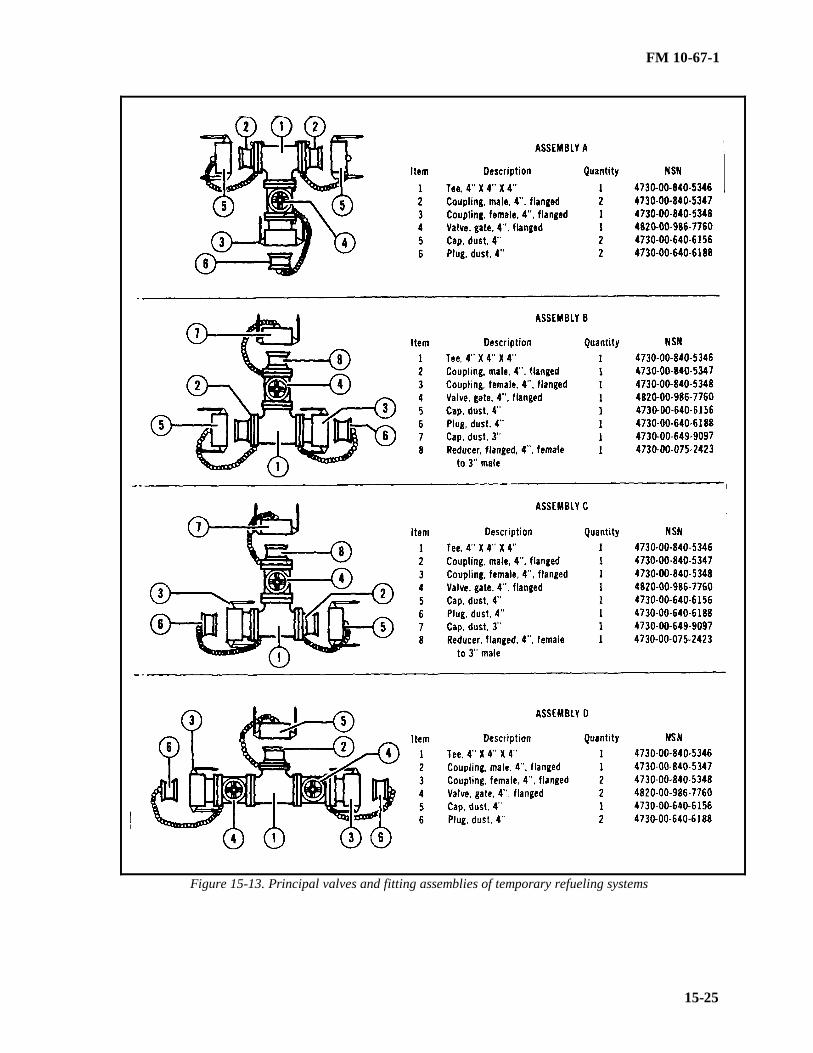
FM 10-67-1
15-25
Figure 15-13. Principal valves and fitting assemblies of temporary refueling systems

FM 10-67-1
15-26
Section III. HEMTT Tanker Aviation Refueling System
CHARACTERISTICS
The HTARS is a kit that consists of enough hoses, fittings, and nozzles to expand the HEMTT tankers cap a-bility to hot refuel up to four helicopters simultaneously using the on-board fuel-servicing pump. The equipment islightweight, has manually operated controls, and is equipped with valved and swivel adapters that allow conne c-tions between camlock and unisex type fittings. See Figure 15-14, for unisex connections. This equipment can beused in forward areas. It can be transported in the storage box of the HEMTT tanker.
Figure 15-14. Unisex connections
EQUIPMENT
The HTARS (NSN 4930-01-269-2273) consists of discharge hoses, valves and fittings, nozzles, and overpackspares. The components of the system are shown in Figure 15-15, page 15-27.
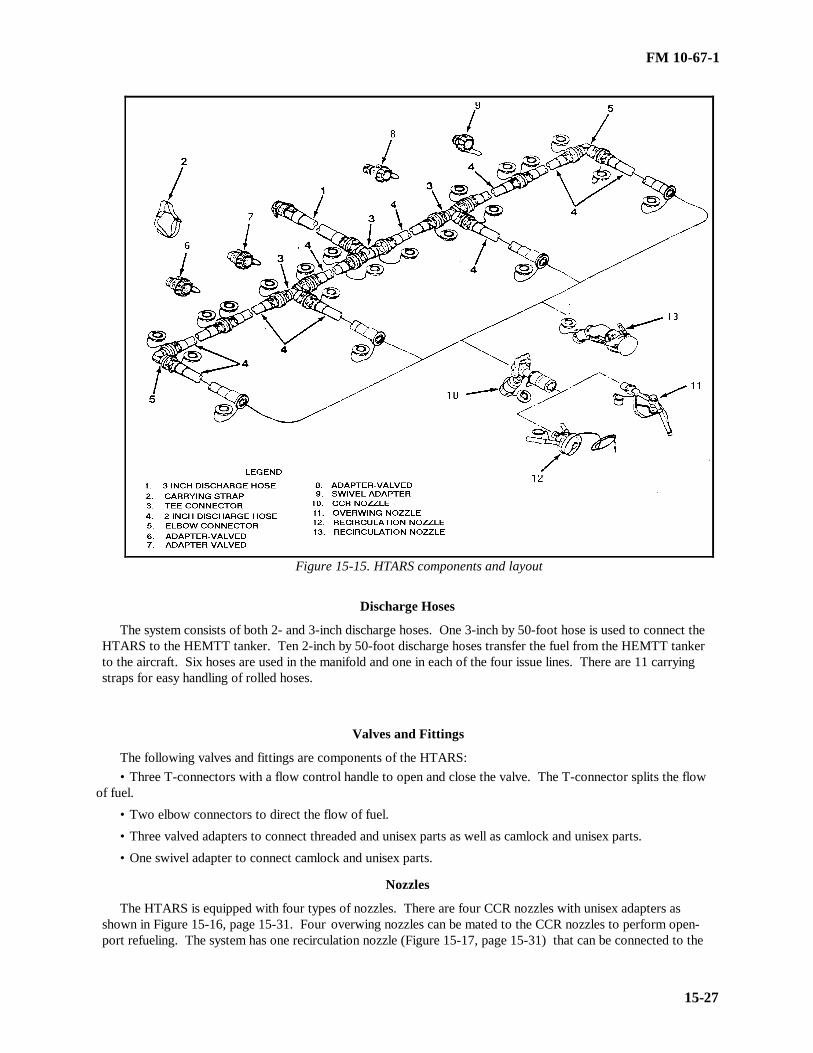
FM 10-67-1
15-27
Figure 15-15. HTARS components and layout
Discharge Hoses
The system consists of both 2- and 3-inch discharge hoses. One 3-inch by 50-foot hose is used to connect theHTARS to the HEMTT tanker. Ten 2-inch by 50-foot discharge hoses transfer the fuel from the HEMTT tankerto the aircraft. Six hoses are used in the manifold and one in each of the four issue lines. There are 11 carryingstraps for easy handling of rolled hoses.
Valves and Fittings
The following valves and fittings are components of the HTARS:• Three T-connectors with a flow control handle to open and close the valve. The T-connector splits the flow
of fuel.
• Two elbow connectors to direct the flow of fuel.
• Three valved adapters to connect threaded and unisex parts as well as camlock and unisex parts.
• One swivel adapter to connect camlock and unisex parts.
Nozzles
The HTARS is equipped with four types of nozzles. There are four CCR nozzles with unisex adapters asshown in Figure 15-16, page 15-31. Four overwing nozzles can be mated to the CCR nozzles to perform open-port refueling. The system has one recirculation nozzle (Figure 15-17, page 15-31) that can be connected to the

FM 10-67-1
15-28
HEMTT tanker to recirculate fuel in the system.. It is equipped with a fuel sample port to obtain a sample of fuel.The recirculation nozzle mates to the CCR nozzle. There are four D-1 nozzles to equip the system for center-point refueling (Figure 15-18, page 15-31).
Overpack Spares
Each system has one overpack spare with additional parts and accessories. The following parts are in theoverpack spares: one T-connector, one 2-inch by 50-foot discharge hose, one carrying strap for easier handling ofthe rolled hoses, 10 dust seals, two dust caps, and four grounding rods.
Other Required Items
Other items of equipment are required to conduct aircraft refueling operations with the HTARS. A minimumof five fire extinguishers are required--one to be within reach of the on-board pump and one at each refuelingpoint. The signs described in Chapter 2 will need to be posted at the refueling site. Also, water cans and spillcontainers will need to be available.
SITE LAYOUT
When planning the site layout for HTARS, you must consider the five factors in addition to METT-T. Thefactors to be considered are spacing between aircraft, wind direction, vapor collection, drainage, and camouflage.These factors are described in Section I, page 15-2 and 15-3.
SITE PREPARATION
The immediate refueling area, paths of approach, and hover lanes should be cleared before operations. Allsticks, stones, and debris should be cleared to prevent them from being sucked up or transformed into dangerousprojectiles by the rotor wash.
EQUIPMENT LAYOUT
Lay out the HTARS in a manner most practical for the situation. Avoid obstacles and take advantage of te r-rain features. When laying out the equipment, never remove a dust cap until ready to make a connection. Thiswill prevent dust or particulate matter from entering the system and causing fuel contamination. Likewise, whendisassembling, cap equipment immediately after uncoupling. When laying out the HTARS, follow the proceduresbelow.
Position Vehicle
Select the most level ground available to position the M978 HEMTT tanker. Avoid areas near bodies of waterto avoid contamination and use the highest ground available to prevent vapor accumulation. When positioning thevehicle, remember the system should be laid out so that helicopters can land and refuel into a headwind or cros s-wind. Make the most use of natural concealment. Position the vehicle to allow easy exit without blocking exits.After positioning vehicle, drive a ground rod at least 3 feet into the ground (specific depths for soil types are d e-scribed in Chapter 2), attach the vehicle ground cable to the ground rod, position fire extinguishers within easyreach, and post NO SMOKING signs.
Connect System Components
Connect the 3-inch by 50-foot discharge hose to the suction hose on the HEMTT tanker (the tanker suctionhose is connected to the bulk receptacle filtered on the HEMTT tanker). Connect the T-to the 3-inch dischargehose. Roll a 2-inch by 50-foot discharge hose from both sides of the T-and connect both discharge hoses to the tothe T. Connect another T to the end of each 2-inch discharge hose. Roll out and connect two 2-inch by 50-footdischarge hoses to each outer tee. At the end of both outer 2-inch discharge hoses, connect an elbow fitting. U n-roll and connect a 2-inch by 50-foot discharge hose to each of the two Ts and elbow fittings.. Put FLOW handlesin flow position after connections are made as shown in Figure 15-19, page 15-32.
NOTE: The unisex fittings will not connect if the FLOW handles are in the flow position.

FM 10-67-1
15-29
Connect Nozzles
Connect the type of nozzle to be used for the operation to the 2-inch discharge hose at each point. The CCRand D-1 nozzle connect to the 2-inch discharge hose. The overwing (open-port) and recirculation nozzle mate tothe outlet of the CCR nozzle. These nozzles are described in Chapter 14. Also, refer to TM 5-4930-235-13&P forinformation on nozzles.
Ground Equipment
Drive a grounding rod into the ground 10 feet back from the end of each dispensing hose (ground rod r e-quirements are described in Chapter 2). Loop the dispensing hose at each point back to the ground rod and hangthe nozzle on the ground rod hanger. Connect the clip of the nozzle grounding wire to the ground rod at eachpoint. At each point, place a CO 2 or dry chemical fire extinguisher. Also, place a spill container and a filled 5-gallon water can at each point.
Camouflage Equipment
Camouflage the truck and system to the extent required by the tactical situation. Natural concealment such aswoodlines, hedgerows, vegetation, and natural terrain contours should be used when possible. Straight lines of thehoseline can be broken up by breaking branches and placing them under the hoseline to hold them in place. Ca m-ouflage netting may be used for the vehicle and parts of the system that are not near the refuel points. Camouflagemust be staked down securely to keep it from being torn loose by rotor wash.
PREPARATION FOR OPERATION
Ensure all safety precautions have been taken. Verify that all safety and fire-fighting equipment is in placeand serviceable. Check landing lights if they are required. Perform daily and before operations checks on theHEMTT tanker IAW TM 9-2320-279-10-1 and on the HTARS IAW TM 5-4930-237-10. Inspect the dischargehoses, valves and fittings, nozzles, and grounding systems. Ensure that all refueling personnel have and arewearing the proper protective clothing (Chapter 2). As soon as the system is full of fuel and ready to operate eachday, draw a sample from each nozzle. If the fuel does not pass tests and inspections, do not use it. Isolate it, r e-sample it, send the sa mple to the supporting laboratory, and await the laboratory’s instructions on disposition.
SEQUENCE OF OPERATIONS
The HTARS has two primary modes of operation, refuel and recirculation. In the refueling mode, fuel ispumped from the HEMTT tanker through the system hoses to the refueling points (nozzles). In the recirculationmode, the refueling nozzle (CCR or D-1) is disconnected from the refueling point and the recirculation nozzle isconnected. The recirculation nozzle is connected to the HEMTT tanker and fuel circulates through the systemhoses and back to the tanker. The HTARS can operate in both modes at the same time.
Refueling Mode
To operate the HTARS in the refueling mode, follow these procedures:• Start and operate the HEMTT tanker IAW TM 9-2320-279-10-1.
• Ensure the soldier manning the nozzle guides the aircraft into position using the signals described in Cha p-ter 2 Check with the pilot to be sure that all armaments are on SAFE.
• Deplane the crew and passengers. Passengers must go to the designated passenger marshaling area. Me m-bers of the crew, except the pilot or copilot who may remain at the controls if necessary, should deplane and assistwith the refueling, or man fire extinguishers.
• Position a fire extinguisher at the HEMTT tanker and at each nozzle point. Carry the nozzle fire exti n-guisher out to the aircraft, and place it within reach of the aircraft fill port.
• Ensure the pilot notifies his commander that he will be off the air during refueling. He may monitor his r a-dios during refueling, but he should never transmit. The crew chief and pilot may talk by intercom during refue l-ing.

FM 10-67-1
15-30
NOTE: Ground the aircraft. Grounding of aircraft during refueling is no longer required by NFPA standards 77and 407. Grounding will not prevent sparking at the fuel surface. (See Chapter 2, Section III for more inform a-tion).
• Bond the nozzle to the aircraft in one of two ways. Either by inserting the bonding plug into the plug r e-ceiver or attaching the clip of the nozzle bonding cable to a bare metal part of the aircraft other than the antenna.
• After the nozzle is bonded to the aircraft, remove the dust cap from the nozzle and open the aircraft’s fillport.
• Verify that all valves between the HEMTT tanker and the fuel nozzle are open.
• Do not leave the nozzle at any time during refueling. Stop the flow of fuel if there is any emergency at therefueling point. Three types of nozzles can be used for aircraft refueling. Use of the center point (D-1), CCR, andoverwing (open-port) nozzle are described below.
••Center point refueling nozzle operation. Remove the dust cover from the end of the nozzle body. Graspthe handles and hold the nozzle in alignment with the aircraft refueling adapter. Press the nozzle body against theadapter and turn handles to the right until the end of the nozzle mates and locks to the aircraft refueling adapter.Rotate the control handle to the full OPEN position. The pilot will signal when the tank is full. To disconnect,rotate the control lever to the full CLOSED position. Grasp the handles and rotate the nozzle body to the left untilit disconnects from the aircraft adapter.
••CCR nozzle. Mate the CCR nozzle to the fill port. Pull back on the control handle latch, and then pushthe flow control handle up toward the aircraft into the FLOW position. If the aircraft is to be filled completely,watch the back of the nozzle. A red indicator will pop out of the back of the nozzle when the aircraft tank is full.Pull back on the flow control handle to move it into the NO FLOW position. Unlatch the nozzle.
••Overwing (open-port) nozzle. Rapid refueling (hot) using the open-port nozzle is restricted to combator vital training (Chapter 14). The decision to use the open-port nozzle must be made by the commander. Theopen-port nozzle is mated to the CCR nozzle. The end of the nozzle is placed in the aircraft fuel tank adapter. Setthe CCR nozzle to FLOW. Squeeze the control handle to dispense fuel. Watch the fill port when filling the tank.As the tank nears full, ease up on the trigger and finish filling more slowly. When the tank is full, release the tri g-ger. Move the flow control handle on the CCR nozzle to the NO FLOW position. Be sure that flow has stoppedcompletely before removing the nozzle from the fill port.
• Replace the cover of the aircraft fill port and put the dust cap back on the nozzle.
• Unplug the nozzle bonding plug or release the bonding clip. Carry the nozzle back to the hanger. Do notlay it or drag it across the ground.
• Release the grounding cable clip from the aircraft.
• Take the fire extinguisher back to a position near the nozzle hanger.
• Have the aircrew and passengers reboard the aircraft.
• Turn off the pump on the HEMTT tanker if no other aircraft is being refueled.
• After receiving clearance, the aircraft lifts off.
Recirculation Mode
One recirculation nozzle is supplied with the HTARS. To recirculate the entire system, the recirculation pr o-cedure must be performed for each refueling point. To perform recirculation, follow the procedures listed below.
• Connect the recirculation nozzle to the refueling point (CCR nozzle).
• Reposition hoses as required to reach the HEMTT tanker.
• Connect the recirculation nozzle to the HEMTT tanker bottom loading receptacle A. Press the nozzlebody against the A receptacle and turn the handles to the right until the nozzle body locks firmly to the receptacle.
• Start and operate the HEMTT tanker IAW TM 9-2320-279-10.
• Set the CCR nozzle to OPEN. Rotate the recirculation nozzle control lever to the full OPEN position.

FM 10-67-1
15-31
• If needed, fuel samples may be taken during the recirculation mode. The recirculation nozzle is equippedwith a hand-operated ball valve to allow sampling of the fuel entering the tanker. To take the fuel sample, placethe end of the tube in the sample container. Slowly move the control handle on the ball valve to the open position.When sampling is complete, set the control handle on the ball valve to the closed position.
• When recirculation is complete, set the recirculation nozzle control handle to the closed position. Set theCCR nozzle to the NO FLOW position.
• Shut down the HEMTT tanker IAW TM 9-2320-279-10-1.
• Disconnect the recirculation nozzle from the HEMTT tanker.
EMERGENCY FIRE AND RESCUE PROCEDURES
The best preparation for coping with an emergency is the fire-fighting and rescue training that all refuelingpersonnel should receive. The procedures and guidelines of what personnel should do in a fire or crash emergencyare found in Chapter 19.
Figure 15-16. Model 125-1000 CCR nozzle
Figure 15-17. Recirculation nozzle

FM 10-67-1
15-32
Figure 15-18. D-1 center-point refueling nozzle

FM 10-67-1
15-33
FLOW
NO FLOW
Figure 15-19. Discharge hose FLOW handles
Section IV. Fat Cow (CH-47) FARE

FM 10-67-1
15-34
PURPOSETo provide a continuous presence of aviation assets on the modern battlefield requires greater FARP mobility.
Logistical requirements may require a more rapid and mobile response for aviation fuels than can be met by tankvehicles or the sling loading of collapsible drums into an area of operation. Aircraft-to-aircraft refueling offers areduction in turnaround time at unit trains through rapid insertion, refueling of aircraft, and extraction of Class IIIassets. This refueling technique also reduces the time that supporting as well as supported aircraft are on theground and most vulnerable. Since it is possible to perform this operation closer to the FLOT, there is a reductionin the loss of lethal aviation assets due to refueling/rearming thus increasing force projection. Aircraft-to-aircraftrefueling systems and procedures for the Fat Cow are given below.
Fat CowThe CH-47 has capability to pump a maximum of 2320 gallons of fuel to other aircraft. Fuel is contained in
standard noncrashworthy 600-gallon ERFS tanks (crashworthy tanks are preferred) located in the cargo compar t-ment of the tanker aircraft. One to four tanks may be installed with enough refuel equipment to set up either tworefuel points per aircraft. In any configuration, the FARP can easily be set up and operational within 10 minutes oflanding. Also, the on board fuel can also be used to extend the range of the tanker aircraft.
EquipmentEquipment used in Fat Cow refueling operations consists of ERFS tanks, electric pump, filter/separator, hoses,
nozzles, grounding equipment and valves and fittings. There is currently no unique system for aircraft-to-aircraftrefueling. The system in use combines components of the ERFS, FARE, and HTARS. Major components are di s-cussed below.
• Tanks. The Fat Cow uses up to four ERFS tanks. They are metal, noncrashworthy, 600-gallon capacitytanks. Crashworthy tanks are preferred. The tanks can be filled to 580 gallons providing up to 2320 gallons forrefueling other aircraft. The tanks are secured to the aircraft using 5,000-and 10,000-pound cargo strap asse m-blies. Although noncrashworthy tanks are currently in use, they should be replaced with crashworthy tanks whenavailable.
• Pumping assembly. Electrically driven, explosion-proof, pumps are located aft of the rearmost tank, securedto the floor, and connected to the manifold. The pump receives AC and DC power from the aircraft’s electricalsystem and is connected to the utility receptacles in the cabin.
• Filter/separator. A 100-GPM filter/separator is secured to the aircraft floor. This is the same filter/separatorused with the FARE system. It contains five elements, each in a canister, that remove free water and particulatecontaminants. It has an air vent valve, a pressure differential indicator, a water sight glass, and a water drain valvethat is hand operated. For more information on the 100-GPM filter/separator, see Chapter 21.
• Hoses. The hoses used for the Fat Cow should be 2-inch in diameter. Use suction hoses on the suction sideof the pump and collapsible discharge hose on the dispensing side of the system. Use enough length of hose tomaintain required spacing between refueling points and between tanker aircraft and refueling points. The standardcamlocking hoses in the FARE system can be used. However, the unisex, dry-break couplings as used in theHTARS are recommended because of environmental considerations.
• Fittings, valves, and nozzles. Fittings, valves, and nozzles used for the Fat Cow are the same as those usedfor the FARE and HTARS described in Sections I and III. A Y-fitting is used between the discharge hose follo w-ing the filter/separator and the discharge hose to the refueling points. Butterfly valves may be inserted for quick,positive shutoff within the system when camlocking hoses are used. HTARS hoses have FLOW-NO-FLOW valvesat the dry break connections. The nozzles used are the same as those used on the FARE: CCR and D-1 nozzles.See Chapter 14 and the previous sections of this chapter for more information.
Site SelectionFollow the general guidelines for site selection covered in the previous sections. The landing zone should be
large enough to accommodate the tanker aircraft with minimum spacing between refueling points (see Table 15-1).For multitanker aircraft operations maintain a minimum of 300 feet separation between tanker aircraft. Ensure theground can support the aircraft and operation. Avoid wet, snow-covered or muddy ground and thick brush.
ADVANTAGES/DISADVANTAGES OF DEPLOYMENT

FM 10-67-1
15-35
Advantages
The advantages of the Fat Cow (CH-47) FARE are given below.• The CH-47 is an instant FARP. Once the CH-47 is on the ground, the system can be ready for refueling
within 10 minutes.
• The system can be displaced quickly. When refueling operations are completed, the FARP is packed up,the CH-47 takes off, and the site is cleared within minutes.
• The Fat Cow is useful for special operations.
DisadvantagesThe disadvantages of the Fat Cow are given below.• The ERFS tanks are airworthy when installed, operated, and maintained as described in TM 55-1560-307-
13&P. With this configuration, however, fuel can leak into the cabin and a catastrophic incident can occur in theevent of a hard landing or an accident. When the noncrashworthy ERFS tanks are installed, the potential for firesduring a crash increases.
• The armanents of the CH-47 provide limited protection. Therefore, advance planning is required when r e-connaissance and/or attack elements are used to escort the CH-47 with Fat Cow installed.
• The aircraft should be shut down and blades secured to prevent safety hazards. The rotor wash from the CH-47 presents a safety hazard to smaller aircraft.
• The CH-47 burns a tremendous amount of fuel; this must be planned for logistically.• The signature of the CH-47 makes it vulnerable to detection and attack.• Use of the Fat Cow diverts valuable aviation assets from other missions. It may be more advantageous to
perform the refuel mission with other refueling systems.
Section V. C-17 FARP USING THE HTARS
PURPOSE Another option for greater FARP mobility is the C-17 FARP using the HTARS, 100-GPM pump, and 100-GPMfilter/separator (for fuel post operations evacuation from system). The C-17 aircraft is able to deploy to forwardareas where only short runways and limited ramp spaces are available. The C-17 aircraft will land in a forwardarea to act as a ground tanker to provide fuel to receivers on the ground. The receivers can be aircraft, trucks,bladders, or other equipment. The C-17 can deliver fuel through either one or both of its single point receptacles.The C-17 booster pumps are used to defuel the aircraft using the HTARS and additional Army components. Defu-eling can be done up to a rate of 520-GPM, depending on the number of booster pumps used.
Site Considerations The site selected for C-17 FARP operations must be consistent with C-17 capabilities. The C-17 is can operatefrom small airfields with limited supporting infrastructure. The airfield runway must be 3,000 to 5,000 feet longand 90 feet wide. A paved runway is not required; it may be merely graded and compacted gravel or clay. A 500-by 200-foot area is required for the FARP site.
Equipment Required equipment includes: HTARS (see Section III for description), two 100-GPM filter/separators (seeChapter 21), five fire extinguishers, four water cans, and four spill containers. A 100-GPM pump (see Chapter 20)is required for post operations fuel evacuation of the system.
Layout Configure the HTARS and additional components as shown in Figure 15-20, page 15-37. Required minimumdistance between aircraft must be achieved. Lay out the system in the most practical manner taking advantage ofany terrain features. When laying out the equipment, never remove a dust cap until ready to make a connection.This will r educe the chance of dust or particulate entering the system.
Connection of System Components

FM 10-67-1
15-36
Starting at the supply aircraft, connect using a single point nozzle (D-1 type). After connecting the nozzle, pe r-form a locked nozzle check. Connect a 2-inch by 50-foot discharge hose to the nozzle using the sexless dry breakfitting. Install a T-fitting to the end of the discharge hose. Connect a 2-inch by 50-foot discharge hose to bothremaining ends of the T-fitting. After these lengths of hose, connect a 100-GPM filter/separator. Lay out the r e-mainder of the HTARS into a modified configuration resulting in two refueling points separated by at least 200 feetbetween points and 300 feet from the C-17. At each refueling point, connect the type nozzle to be used in refueling(CCR or D-1). After making all connections, make sure that all valves in the sexless fittings are in the open pos i-tion. After opening each valve, manually attempt to disconnect the drybreak connection. If the hardware is a s-sembled properly, the equipment will not di sconnect. If it does disconnect, replace the faulty connection.
Grounding and Other Equipment Drive a grounding rod into the ground 10 feet back from the end of each dispensing hose. Loop the dispensinghose back to the ground rod and hang the nozzle on the ground rod hanger. Connect the clip of the nozzlegrounding wire to the ground rod at each point. Place a fire extinguisher, a spill container, and a filled 5-gallonwater can at each point. Also place a grounding rod at the filter/separator and connect using the filter/separatorgrounding wire. Also place a fire extinguisher at the filter/separators.
Operation Operate the system in compliance with safety procedures in Chapter 2 and the following operation steps:
• The soldier operating the nozzle guides the aircraft into position using the signals described in Chapter 2.Check with the pilot to ensure that all armaments are on SAFE.
• Members of the crew, except the pilot or copilot who may remain at the controls if necessary, should d e-
plane and assist with refueling or man the fire extinguishers.
• Carry the fire extinguisher out to the aircraft and place it within reach of the aircraft fill point.
• The pilot should notify his commander that he will be off the air during refueling. He may monitor hisradios during refueling, but never transmit.
• Ground the aircraft.
• Bond the nozzle to the aircraft in one of two ways. Insert the bonding plug into the plug receiver on theaircraft or attach the clip of the nozzle bonding cable to a bare metal part of the aircraft other than the antenna.
• After the nozzle is bonded to the aircraft, remove the dust cap from the nozzle and open the aircraft’s fillport.
• Verify that all valves are open.
• Signal to the refueling supervisor using predefined hand signals that point is ready to provide fuel. Opennozzle and refuel. Do not leave the nozzle at any time during the refueling. Stop the flow of fuel if there is anyemergency at the refueling point.
• After the receiving aircraft is full, shut off the nozzle. Disconnect nozzle from the aircraft. Replace thecover of the aircraft fill port and put the dust cap back on the nozzle.
• Unplug the nozzle bonding plug and carry the nozzle back to the nozzle hanger.
• After receiving clearance, the aircraft is free to take off.

FM 10-67-1
15-37
• Evacuate fuel from the system using the FARE pump and recover the components using the followingprocedures:
•• Close D-1 nozzle.••Install the FARE pump 10-feet away from the SPR panel.••Reverse the flow direction of each filter/separator.••Start pump and run at idle.••Recover hoses, starting at the refueling point.••Stop pump and disconnect from the tanker aircraft.
ADVANTAGES/DISADVANTAGES
Advantages The advantages of the C-17 FARP are listed below.
• The C-17 can deliver bulk fuel to remote areas using small airfields with unimproved runways and littlesupporting infrastructure.
• The system can be set up and operational quickly.
• The C-17 FARP is useful for special operations.
Disadvantages The disadvantages of the C-17 FARP are listed below.
• The C-17 aircraft is diverted from other valuable missions to perform FARP operations. The use of otherFARP systems may be a more desirable allocation of resources.
• The C-17 requires a 3,000- by 90-foot minimum runway for landing.
• The operation may not be strategically advantageous in consideration of viable alternatives.
• The Army unit operating the FARP is responsible for transportation of personnel and equipment to theFARP site.

FM 10-67-1
15-38
Figure 15-20. HTARS configuration and additonal components for C-17 FARP
FM 10-67-1
16-1
CHAPTER 16
REFUELING FROM TANK VEHICLES
Section I. Refueling Vehicles
UsePetroleum tank vehicles serve two functions. They may be used for fuel servicing or bulk transport. The m a-
jor difference is that fuel servicing vehicles have a filter/separator and bulk transporters do not. Refueling vehiclesare used to refuel Army aircraft at a fixed or semifixed, airport type facility. However, refueling vehicles are notused exclusively to refuel fixed-wing aircraft. They are not normally used in rapid refueling. Although their usewith the HTARS or FARE components can aid in tactical situations where mobility is an asset. Refueling vehiclesare mainly used when it is more practical to take the fuel to the aircraft than to take the aircraft to the fuel.
VEHICLE REQUIREMENTSAll aviation fuel must pass through a filter/separator before it is loaded into a refueler. (A refueler is a tank
truck, tank semitrailer, or truck with a tank and pump unit.) It must be filtered again before it is pumped into anaircraft. All vehicles, except the M131A4, M131A5, and the M967, have filter/separators. (On the M49 andM131 series, the suffix “C” indicates a filter/separator.) Any of the refuelers described can be connected to theCCR system by substituting the CCR nozzle for the standard open-port (gravity-flow) nozzle. Tank vehicle fuelcompartments must carry only one grade or type of fuel.
FUEL-SERVICING TANK SEMITRAILERSThe fuel-servicing tank semitrailers are the M969, M970, M131A4C, and M131A5C. See the appropriate
technical manual for operation and maintenance information. These refuelers are described below. For more i n-formation see Chapter 24.
M969The M969 tank semitrailer is used mainly for automotive refueling. It has a four-cylinder diesel engine-
driven, 4-inch centrifugal, self-priming, low-head pump assembly. It has a stainless steel, single compartmenttank that holds 5,000 gallons, plus 3 percent capacity for expansion. It is equipped with a filter/separator and adual dispensing system. The filter/separator consists of 15 filter elements, 5 canisters, and 15 go/no-go fuses.Each dispensing system has a meter, a hose reel with electric rewind, 50 feet of 1 1/4-inch dispensing hose, and adispensing nozzle. The M969 semitrailer may be used for open-port refueling. Its nozzles cannot be used whenthe D-1 or the CCR nozzle is required. The fuel flows at a rate of 60 GPM through one nozzle only or throughboth nozzles at the same time. The M969A1 tank semitrailer is equipped with a hose trough cover, a control panelcover, a rear ladder, front and rear drains, and a tachometer and lead assembly that have been introduced for r e-pairing or upgrading the M969. More information on the M969 can be found in TM 9-2330-356-14 .
M970The M970, 5,000-gallon, fuel-dispensing tank semitrailer is designed for underwing and overwing refueling of
aircraft. The M970 has the same engine as the M969, but has a 3-inch, high-pressure, centrifugal pump. It also isequipped with the same 3-stage filter/separator as the M969, a recirculation system, and two refueling systems--onefor underwing and one for overwing. One meter is used with both refueling hoses. The M970A1 is equipped withthe same additional features as the M969A1 (described above).
• Underwing refueling system . The system consists of 50 feet of 2 1/2-inch hose, an electric-rewind reel, and adeadman control.
• Overwing refueling system . The overwing refueling system consists of 50 feet of 1 1/2-inch hose, an ove r-wing dispensing nozzle, an electric-rewind hose reel, and a closed-circuit dispensing nozzle. This nozzle is inte r-changeable with the overwing nozzle.

FM 10-67-1
16-2
• Recirculation system. This system allows fuel sampling and complete recirculation of fuel through the fi l-tering and dispensing system to remove condensation and contamination.
M131A4C The uses of the M131A4C are the same as the M131A5C. The main difference between this model and the
M131A5C is the tank configuration. This tank semitrailer has four tank compartments each of which holds 1,250gallons of fuel. There are slight differences in the pump, pump engines, hose reels, filter/separators, and otherequipment. They are also located differently. The M131A4C has three 15-foot sections of suction hose stored inhose tubes. It has a rear roadside equipment cabinet equipped with a reel of 2 1/2-inch hose (225-GPM dispen s-ing) and a 2 1/2-inch, automotive type nozzle. The forward roadside cabinet of the M131A4C has a 1 1/2-inchhose (0- to 55 GPM dispensing) on reel with the standard 1 1/2-inch, automotive-type nozzle.
M131A5CThe M131A5C tank semitrailer is one of the most commonly used fuel-servicing tank semitrailers in the
Army. It has a 5,000-gallon capacity and weighs 12 tons. The entire vehicle is about 31 feet long, 8 feet wide, and9 feet high. This semitrailer has a great deal of flexibility because it can be used in most fueling operations; thatis, it is capable of fuel transport, fuel transfer, and fuel servicing of containers, ground vehicles, and aircraft. It isused in open-port refueling of aircraft that have a maximum fuel acceptance rate of 225 GPM.
• Tank body. The tank is made of stainless steel. It has two fuel compartments. Each holds 2,500 gallons offuel. A slip-proof walkway of steel grating runs along the top of the tank body. Each compartment has a 20-inchmanhole cover with a filler cover and lock, an emergency dump valve, and a drainpipe. A load level indicator iswelded to the collar of each manhole.
• Side cabinets. The M131A5C has an equipment cabinet on each side of the tank body. The roadside cabinetis equipped with a reel of 1 1/2-inch, reinforced dispensing hose with 2 1/2-inch, automotive type nozzle equippedwith 100-mesh nozzle screen; the rate-of-flow selector dial; the engine control instruments; and the fi l-ter/separator pressure gages. The manifold valves and dump valve levers are also in this cabinet. The curbsidecabinet holds the pump, pump engine, and battery.
TANK TRUCKSThe tank trucks used for aircraft refueling are the M978 and the M49A2C. These tank trucks are described
below. See Chapter 29 for more information.
M978 The M978 tank truck, also called the HEMTT, is used to refuel aircraft, transport bulk fuels, and service co m-
bat vehicles. The M978 tank truck is able to transport bulk fuels in areas where other tank trucks cannot operate.It has a stainless steel 2,500-gallon tank with a single compartment shell. The fuel system of the truck includes apump and a filter/separator. Power for the 300-GPM centrifugal pump comes from the truck engine. The truckalso has an alternate fuel delivery pump. This 25-GPM pump is powered by 24 DC from the truck’s electrical sy s-tem. The filter/separator is located in the rear cabinet. It is a 300-GPM unit with a pressure differential indicator,15 filter and canister assemblies, and a manual drain valve. A sampling probe, for use with the Aqua-glo watertest kit, is located on the discharge side of the filter/separator. The tank truck has two hose reels in the rear cab i-net. Each hose reel has 50 feet of 1 1/2-inch dispensing hose. Each 1 1/2-inch hose has a 50-GPM capacity. Thehose ends have male, quick-disconnect fittings and bonding connections. Each hose reel has a fuel-servicing no z-zle. The HEMTT also has a 15-foot section of 3-inch suction hose. The HEMTT can also refuel aircraft with theHTARS. See Chapter 15 for more information.
M49A2CThe M49A2C tank truck is used in open-port refueling, in transporting fuel, and in servicing fuel containers
and ground vehicles. It has a stainless steel 1,200-gallon tank. The tank is evenly divided into two compartments.Power for the pump comes from the truck engine. A speed control linkage controls the speed of the truck engine,its power takeoff, and the fuel delivery pump. A 35-foot length of 1 1/2-inch reinforced hose (with a standard 11/2-inch, automotive-type nozzle equipped with 100-mesh nozzle screen) is mounted on the roadside of the tank.
TANK AND PUMP UNITThe tank and pump unit is also used in aircraft refueling. The tank and pump unit consists of a 50-GPM
pumping assembly, two 600-gallon aluminum tanks, and related equipment. The frame assembly makes it easier

FM 10-67-1
16-3
to take the pump off the truck for maintenance work or to use it as a pump unit for fuels that are stored in groundtanks. One electric model and several gasoline models of the tank and pump unit are currently in use . A newermodel tank and pump unit (Figure 24-3, page 24-5) consist of tank control levers at the rear of the unit, a bottomloading port, 500-gallon fuel tanks, and a bottom loading valve that opens automatically when fuel pressure is a p-plied and is closed automatically by the jet level sensor when the tank is full (when filled through bottom loadingport).
Section II. Refueling Operations
PERSONNEL TRAININGThe drivers (operators) of tank vehicles may not have received formal training in the specialized field of ai r-
craft refueling. The responsible unit commander should set up and maintain a safety training program for them.They should be thoroughly trained in the step-by-step procedures covered in this section. Emphasis should beplaced on the quality requirements for aviation fuels (Chapter 13), on fuel spills and fire-fighting techniques(Chapter 19), and petroleum safety (Chapter 2). Any accident involving fuel, an aircraft, or a tank vehicle mayresult in fire. Only drivers who have completed the safety training and have demonstrated their ability to refuelaircraft using the proper procedures should be assigned to aircraft refueling operations.
VEHICLE PREOPERATIONAL CHECKSThere are two types of preoperational checks on refueling vehicles. One type is the preoperational check on
the vehicle as a vehicle. For example, checking the inflation of the tires or the water level of the radiator is a veh i-cle check. Checks of this type are outlined in the equipment technical manual. The other type are the checks pe r-formed to ensure that the vehicle is ready to refuel aircraft.
DAILY PREOPERATIONAL CHECKS AND PROCEDURESEach day, before operations, the driver of the refueling vehicle should check the condition of the truck’s ele c-
trical system. This system is important since defective wiring can cause sparks. Also, it is a good safety practice toequip refueling vehicles with a hard-shell cab top as opposed to a canvas top. This is for the protection of vehicleoperators. In addition, before refueling an aircraft, personnel must perform the actions described below.
Recirculate Fuel Ground the refueler to a ground rod. Then, with the help of an assistant, assemble the hose to recirculate the
fuel that was in the hose overnight. Start the pump engine and pump (or the truck engine and pump). Recirculatethe fuel. Recirculation of the fuel does two things. Passing the fuel through the filter/separator removes any waterthat has settled overnight. The process allows the filter/separator pressure differential to be checked. The refuelermust be grounded while fuel is being recirculated because of the static charge that builds on aviation fuels in m o-tion.
Check Equipment Check the pressure differential of the filter/separator. Record it. Check the oil level in the pump engine. (or
truck engine if it powers the pump). Check the engine for oil leaks. Check the exhaust pipe and spark arrester forcracks and leaks.
Check for Leaks Check the tanks, pipes, pump, filter/separator, meter, hose reels, manhole cover, valves, and nozzles for leaks.
Inspect HosesInspect all hoses as described below. These checks are important to follow:
• Check hose cover. Extend all hose completely, and check the outside cover of the hose. If any part of thehose length shows signs of blistering, saturation, or nicks and cuts that expose reinforcing material, remove thatlength of hose from service. Focus particular attention within 12 inches of the couplings, as this is where mosthose failures occur. Usable parts of the hose should be salvaged and recoupled.
• Check couplings. Look for coupling slippage. Coupling slippage usually shows first as a misalignment ofthe hose and coupling or as a scored or freshly exposed part of the hose where the slippage has occurred. Look for

FM 10-67-1
16-4
signs of leakage at the coupling. If a coupling is slipping or leaking, remove that length of hose from service. Sa l-vage and recouple.
• Test hose. Test the hose at normal operating pressure. Run the pump with the nozzle closed. Look for a b-normal twisting or ballooning. Twisting or ballooning shows that the hose carcass is weakening, so remove thehose from service.
• Check nozzle screens. Remove the nozzle screens. Check their contents for particles of hose lining. Part i-cles of rubber left in new hose from the manufacturing process may appear during the first week of use. If particlesappear more than twice during the first week or appear thereafter, remove the length of hose from service becauseit is deteriorating. Also check the screens for dirt and for other particles that may show that the filter/separator hasfailed or that moving parts are wearing down. Report any such indications. Clean and replace the nozzle screens.The nozzle screens must be hand tightened only.
Check Bonding Check the nozzle bonding cable, bond plug, and bond clip. They must be in good condition to make the
positive bond required to prevent a spark.
Check GroundingCheck the grounding cable and its clips for defects. They must be in good condition to make a safe ground to
carry the static charge off the truck. Be sure the refueler is carrying a ground rod.
Check PlacementCheck to see that the fire extinguisher, spill container, dust plugs, and dust caps are in place.
Test FuelDraw a sample of fuel from the fuel probe coupling after recirculating the fuel and making other checks. Test
the fuel as discussed in Chapter 13. If the fuel does not pass the tests, notify the person in charge. Isolate the su s-pect fuel, resample it, send the sample to your supporting laboratory, and await the laboratory’s instructions ondisposition.
QUARTERLY PREOPERATIONAL CHECKSOnce a quarter, before operations, check the fueling system of the tank vehicle. Remove the pump strainer and
line strainers. Check them for dirt. Clean and replace them as necessary. Also check and clean the meter screens.Perform these maintenance checks immediately whenever a nozzle strainer or a lab report on a fuel sample showscontamination or whenever filter/separator elements are inspected or changed.
SEQUENCE OF OPERATIONSRefueling from a tank vehicle requires at least two people. If only the vehicle operator and his assistant are
present, the operator should attend the pump and the assistant should handle the nozzle. A fire extinguishershould be within reach of each. Where possible, the aircraft crew chief should be present to oversee the entire o p-eration and another member of the aircraft or ground crew should man the fire extinguisher at the nozzle. Afterthe aircraft parks, its engines are shut down, the rotor blades are secured, and armaments are set on SAFE, therefueling operation sequence can start. The procedures must be done in the sequence described below. If you arerapid refueling from the refueler, supplement the procedures with those in Chapter 15.
Check the AircraftCheck the interior of the aircraft. No one should be on board during refueling unless the pilot must be on
board to monitor the quantity of fuel to be loaded. Find out before starting the refueling sequence whether or notthere is a person in the aircraft. Check with the pilot to ensure that all armaments are on SAFE.
Position the RefuelerDrive the tank vehicle into position in front of the aircraft. Use the approach route shown in A, Figure 16-1,
page 16-5. Do not drive the refueler directly toward the aircraft because brake failure could cause a serious acc i-dent.
• Minimum distances. Keep a distance of at least 10 feet between the refueler and the aircraft. There must beat least 10 feet between the refueler and rotor blades of a helicopter. Keep a distance of at least 20 feet between theexhaust pipe of the pump engine (or truck engine) and the aircraft fill port and tank vent. See B, Figure 16-1 page16-5.

FM 10-67-1
16-5
• Refueler path. Park the refueler so that there is a clear open path to drive it away from the aircraft in anemergency. Do not detach a tank semitrailer from its tractor when refueling an aircraft. The tractor must be readyto pull the trailer away from the aircraft if the need arises.
• Ground guides. If the refueler can be driven into position without backing, do so. If the refueler must bebacked toward the aircraft, bring the truck to a full stop 20 to 25 feet away from the aircraft or its rotor blades.Have another soldier act as a ground guide. Follow his signals to guide the final backing approach until he stopsthe refueler at the proper distance from the aircraft and its fill port or vent. See C, Figure 16-1.
• Parking. Stop the refueler’s engine (unless it powers the pump), and set the brake. Chock the tires of therefueler and, if appropriate, the aircraft.
Figure 16-1. Positioning tank vehicle for refueling aircraft

FM 10-67-1
16-6
Check the Fuel Check the fuel in the tank to make sure it is the right type for the aircraft. Check the sight glass of the fi l-
ter/separator to make sure all water has been drained out.
Position Fire Extinguishers Place the truck fire extinguisher by the pump. Place a fire extinguisher by the aircraft fill port. Have members
of the ground crew or aircrew man these two fire extinguishers. If there are no personnel available to man the fireextinguishers, place them near the pump and nozzle operators. Position them where they will not be in the oper a-tor’s way and where they are not likely to be engulfed if a fire should start.
Ground the Refueler Unreel the ground cable, and attach it to an existing ground rod. If no ground rod exists at the location, drive
the refuelers ground rod into the earth to required depth and attach the clip to the rod. See Chapter 2.
Bond Nozzle to Aircraft Bond the nozzle to the aircraft before the dust cap is removed from the nozzle and the plug is removed from
the fill port. If the aircraft has a receiver for the bond plug, use the plug. If not, attach the bonding clip to a baremetal part of the aircraft.
Open Fill Port Open the fill port and remove the nozzle dust cap. If an open-port nozzle or the CCR nozzle adapter is being
used, put the nozzle well down into the fill port. Do not open the nozzle until it is inside the fill port. If the CCRnozzle is being used, mate the nozzle into the fill port. If they will not latch together, look for dirt in the fill portor on the nozzle. Wipe the fill port out and clean the nozzle; then mate the two together.
Refuel The procedures for refueling depend on the type of refueling. They are described below.• CCR. Pull back on the control handle latch, and then push the flow control handle up toward the aircraft and
into the FLOW position. If the tank will be filled completely, watch the back of the nozzle. A red indicator willpop up at the back of the nozzle when the tank is full. The flow shuts off automatically. If the tank will be filledonly partially, watch the pilot for a signal to stop the flow. Pull the flow control handle back toward the hose tomove it into the NO FLOW position. Unlatch the nozzle. Replace the fill port plug and the nozzle dust cap.
• Open-port refueling. Open the nozzle slowly to reduce splashing and to reduce the turbulence of the fuel a l-ready in the tank. Do not leave the nozzle at any time during the refueling operation. Do not block or wedge thenozzle lever open. If the nozzle handle has been notched, remove the notches so that the handle cannot stay openunless someone is holding it open. Slow the flow of fuel as the tank nears the fill level. Top off the tank so thatthe fuel will not overflow. Stop the flow completely before taking the nozzle out of the fill port.
• D-1 (underwing) refueling. Mate the D-1 (center-point) nozzle to the receiver mounted on the aircraft bygripping the two handgrip handles and turning them clockwise to lock the nozzle to the receiver. Turn the latchhandle counterclockwise, parallel to the hoseline, to allow fuel to flow. (The latch handle will not turn to theOPEN position unless the nozzle is locked to the receiver. If it will not turn, release the nozzle by turning thehandgrips counterclockwise. Begin again.) The M970 (5,000-gallon semitrailer) and the M978 HEMTT (2,500-gallon tank vehicle) are equipped with a fuel safety device (deadman control) and a D-1 nozzle. To start the flowof fuel to the nozzle, squeeze the deadman control. The flow is stopped by releasing the pressure on the deadmancontrol upon the pilot’s signal. Turn the latch handle clockwise, across the hoseline, and turn the handgrip ha n-dles counterclockwise to release the nozzle from the receiver. (The handgrip handles will not turn back to releasethe nozzle unless the latch handle has been turned back to the NO- FLOW position.)
Close Fill Port Replace the plug on the fill port. Replace the nozzle dust cap before disconnecting the nozzle bond.
Undo Nozzle Bond Remove the nozzle bond plug or undo the bonding clip. Reel up the hose and nozzle. Do not drag the nozzle
across the ground.

FM 10-67-1
16-7
Replace Fire Extinguisher Replace the fire extinguisher used at the nozzle.
Undo Refueler GroundRelease the clip on the ground rod, and reel up the grounding cable. Do not drag the cable clip across the
ground. Guide the cable back onto the reel to prevent damage to the grounding system. If the refueling operationis over and the refueler’s ground rod was used, pull the rod up and stow it in the refueler. Place the fire exti n-guisher in the refueler.
EMERGENCY FIRE AND RESCUE PROCEDURESThe best preparation for a fire emergency is knowing the dangers, particularly the rate of flame spread on
aviation fuels, knowing how to use a fire extinguisher, and preparing yourself to make an instant decision and takeinstant action. The basic actions that should be planned for and carried out quickly if a fire breaks out are d e-scribed in Chapter 19.
FM 10-67-1
17-1
CHAPTER 17
DEFUELING
MethodsFuel must be removed from an aircraft’s fuel tank when maintenance must be done on the fuel system, when
the fuel level gages are to be calibrated, and when work on the aircraft requires use of electrical equipment or otherequipment that might generate heat or sparks. The tank must also be defueled if the aircraft is to be shipped orstored. Defueling is more dangerous than fueling because, even though relatively small amounts of fuel are i n-volved, the procedure is more difficult and drainage provisions are usually inconvenient. All safety precautionsmust be observed. The general rule of defueling is that it must be done outdoors without damage to the aircraft orits fuel system, without fuel waste, and without safety violations. Aircraft fuel tanks must be defueled by power orby gravity. For speed and efficiency, power should be used to remove most of the fuel and only final drainingshould be done by gravity. These methods are described below.
Power DefuelingThe bulk of the fuel in an aircraft’s tanks should be removed by suction. A pump/engine assembly or the
pump of a refueler provides the power. The aircraft can be defueled either with a defueling tube or by using a pieceof salvaged suction hose.
• Defueling tube. A defueling tube is fitted onto the suction hose. The tube is inserted into the tank and mostof the fuel is pumped out.
• Suction hose. A piece of 1- or 1 1/2-inch salvaged suction hose may also be used to defuel an aircraft. Theend that will be inserted into the tank is cut at an angle so that the reinforcing wire is cut only once. The cut endof the reinforcing wire is also rounded to keep it from damaging the fuel tank. The hose is inserted into the tankand most of the fuel is pumped out.
Gravity DefuelingGravity defueling is the process of draining the tanks by opening the drain valves or petcocks of the aircraft
fuel system. It is a slow and dangerous process. Some suitable container must be placed under the valves to catchthe fuel. Except in an emergency, this method should be used only to complete the draining of the aircraft fuelsystem after the bulk of the fuel has been removed by a pump.
OUTDOOR DEFUELING PROCEDURESAircraft refueling must be done outdoors, except when the responsible commander directs indoor defueling.
When defueling is done outdoors, general safety precautions must be followed. Defueling may be into a tank veh i-cle or into a container.
General Safety PrecautionsThe general safety precautions for outdoor defueling are as follows:
• Aircraft fuel tank openings must be at least 50 feet from any hangar or building. They must be the properminimum distance from radar equipment.
• No aircraft, vehicle, electrical equipment, open-flame device, or any other spark generator must be allowed tooperate within 50 feet of the aircraft.
• No smoking is allowed within 50 feet of the aircraft.
• Aircraft engines and radios must be shut down.
• Only those personnel actually required to conduct the defueling operation and to operate the fire equipmentare allowed within 50 feet of the aircraft.

FM 10-67-1
17-2
• All defueling operations must be stopped if there is an electrical storm in the immediate area or if there is afire, fuel spill, crash, or accident at the refueling point or airfield.
• The fire chief or senior fire officer will decide when a defueling operation warrants a fire truck and personnelpresent. Fuel service personnel will man fire extinguishers for all defueling operations.
Tank Vehicle Defueling The procedures for defueling into a tank vehicle are as follows:
• Drive the tank vehicle into the same position as when refueling, but park it as far from the aircraft as thelength of the hose will permit. Park the tank vehicle so that there is a clear and open route to drive away from theaircraft in an emergency.
• Ground the tank vehicle by connecting one clip of the ground cable’s Y-cable to a ground rod. If there is noground rod in place at the site, drive the vehicle’s ground rod to the specified depth. See Chapter 2 for more i n-formation.
• Ground the aircraft by connecting the clip at the other end of the Y-cable to an unpainted surface of the ai r-craft other than the radio antenna or propeller.
• Bond the defueling tube to the aircraft with a bonding plug or clip. A length of suction hose may be used if adefueling tube is not available.
• Remove the plug from the aircraft fuel port, if appropriate, or slide the shield off the open port adapter ope n-ing of the CCR receiver.
• Insert the defueling tube or length of suction hose into the tank. If the aircraft has a drain port, attach thesuction hose to the aircraft’s drain port using the required adapters.
• Start the pump and pump the fuel out. As soon as the flow stops, shut down the pump.
• Remove the defueling tube or length of suction hose from the tank, and close the tank.
• Remove the bond and reel up the hose.
• Remove the ground connection to the aircraft, then the ground connection between the tank vehicle and theground rod. Reel up the grounding cable.
• Drive the tank vehicle away.
Container DefuelingGravity defueling is the procedure to place fuel into a container. It is a dangerous procedure. The fuel builds
considerable static charge as it falls into the container. It also splashes and agitates the fuel already in the co n-tainer. The soldier who opens the fuel system’s drain valves or petcocks is likely to get his arm and sleeve wetwith fuel. Fuel soaked clothing should be removed with care. Observe all safety precautions. Fuel should bewashed off the skin with soap and water. A fire truck (as required) or personnel with fire extinguishers must standby during the entire operation. The procedures for defueling into containers are as follows:
• Ground the container by attaching the grounding wire clip to the container on one end and a ground rod atthe other end.
• Ground the aircraft to the ground rod by connecting a cable to an unpainted surface of the aircraft, other thanthe radio antenna or propeller, and to a ground rod driven to the specified depth.
• Open the valves or petcocks, and drain the remaining fuel from the aircraft fuel system.
• Remove the ground to the aircraft after draining is complete, and then remove the ground to the container ofthe fuel.

FM 10-67-1
17-3
INDOOR DEFUELING PROCEDURESWhen an aircraft is scheduled for maintenance, the fuel system may have to be drained. Whenever possible,
the aircraft should be defueled outdoors before it is moved into a hangar or maintenance tent. However, duringroutine maintenance disassembly, an unexpected condition can be discovered that makes defueling necessary. Ifthe aircraft is either in a jig or on jacks when the discovery is made, moving the aircraft outdoors is probably i m-possible. In such a situation, the responsible commander must be notified immediately and all alternatives to i n-door defueling should be considered. If indoor defueling is to occur, follow the procedures described below.
Preparing to DefuelA number of procedures must be followed when preparing to defuel indoors. These are as follows:
• Move all aircraft that can be moved out of the hangar and park them at least 50 feet away from the hangar.
• Open the main doors of the hangar, and close any office or shop doors that open into a hangar. Opening themain doors provides maximum ventilation and will allow the force of an explosion to dissipate.
• Turn off all engines, electrical equipment, or other possible spark sources within 50 feet. Do not start orcontinue the operation if there is an electrical storm in the immediate area or a fuel spill, crash, fire, or any otheremergency at the airfield.
• Clear at least 50 feet of all personnel and equipment that are not required for defueling.
Grounding In a hangar, a water pipe or a buried grid usually provides the ground connection to an aircraft. In a tent, a
ground rod provides this ground connection.
DefuelingProcedures to defuel an aircraft indoors are the same as those for defueling into a tank vehicle or container
outdoors.
DRAINED FUEL DISPOSITIONDrained fuel should be disposed of properly. Dispose of all drained fuel according to AR 710-2. See Chapter
13 for more information.

FM 10-67-1
18-1
CHAPTER 18
OTHER WAYS OF TRANSPORTING PETROLEUM
Section I. External Loads
SLING-LOADING OPERATIONSPetroleum may be transported in 500-gallon collapsible fabric drums using the sling loading method. This
method enables obstacles to be overcome that hinder other modes of transportation. One or two drums can be slingloaded with a sling set of at least 10,000-pound capacity. Sling nets can be used to transport refueling systemcomponents. Refer to FM 55-450-4 for rigging instructions. For more detailed information on external load pr o-cedures, see FM 57-38.
LANDING POINTSAll sling-loading operations use 80- to 100-meter diameter landing points. Conditions of the area, such as
dusty surfaces or obstacles, may require increased spacing between loads, reducing the number of helicopters thatcan operate at the site at one time, and decreasing the overall speed of the operation. When selecting a site, youshould make sure the site is cleared of any loose materials or debris to prevent it from being blown into the groundcrew or rotor blades, or drawn into the helicopter engines. The landing site should provide maximum security andconcealment. Landing points used for supply or resupply should be located near supply points to reduce groundmovement of cargo after delivery.
UNIT RESPONSIBILITIESMost sling-load operations involve three elements: the supported unit whose equipment will be moved, the
supporting unit that will fly the loads, and the pathfinder element. Each element’s responsibilities are discussedbelow.
• Supported Unit. The supported unit must coordinate in advance with the supporting unit. The supportedunit will provide slings, straps, clevises, and any other equipment required for the move. They will perform theactual rigging of the aircraft. Ideally, the supported unit will provide the hook-up team. They will also ensure thatthe loads are properly rigged and do not exceed the allowable cargo load of the aircraft.
• Supporting Unit. The supporting unit provides advice and technical assistance to the supported unit asneeded. The unit will ensure that the load does not exceed the allowable cargo load of the aircraft transporting theload.
• Pathfinder Element. The pathfinder element provides advice and assistance to both the supported and su p-porting units. The pathfinder will supervise the rigging and inspection of all loads. It will also ensure that theload does not exceed the authorized load capacity of the aircraft. It will also provide ground guidance and air tra f-fic control during the sling load.
EQUIPMENTThe essential equipment used in external load operations are cargo nets and slings. The components are d e-
scribed below. Inspection, care, and storage of sling sets and nets are described in FM 55-450-1.
Sling SetsSling sets are used to externally transport 500-gallon collapsible drums. The primary sling sets used are the
10,000- and- 25,000-pound capacity. Both sling sets are similar except for a few minor differences. All parts areclearly marked. Do not mix up the sets. A sling with only one lifting leg is shown in Figure 18-1, page 18-2. O b-vious differences between the two sling sets are shown in Table 18-1.

FM 10-67-1
18-2
Figure 18-1. The 10,000-pound capacity sling set components
Table 18-1. Visible differences between the 10,000- and 25,000-pound capacity sling set
ITEM 10,000-POUND CAPACITY 25,000-POUND CAPACITY
SLING ROPE COLOR OLIVE DRAB BLACK
SLING ROPE DIAMETER 7/8-INCH 1 ¼-INCH
CLEVIS COLOR DULL GRAY ALUMINUM GOLD STEEL
NUMBER CHAIN LINKS 111 (APPROXIMATE) 88
WEIGHT 52 POUNDS 114 POUNDS
• Nylon rope assembly. The nylon rope assembly is made from double-braided nylon rope with an eye splice ateach end. The assembly is 12 feet long. However, the manufacturing process and shipment can result in shrin k-age. The shrinkage is normally temporary and is usually restored with use. To ensure proper load distribution, thevariation in lengths should not exceed 6 inches. The part number, NSN, and the capacity of the individual legs areembossed on the eye splice. The 2,500-pound nylon rope assembly is 7/8-inch in diameter. It is used with the10,000-pound sling set. The 6,250 pound nylon rope assembly is 1 1/4-inch in diameter. It is used with the25,000-pound sling set.NOTE: Each of the four legs will carry only one fourth of the total weight capacity of the sling sets.
• Apex fitting. The metal apex fitting attaches directly to the helicopter hook, except on the UH-1. A nylondonut must be used between the sling and the aircraft hook because of the shear pin design of the UH-1 hook.Each apex fitting consists of a clevis, pin, safety bolt, and locknut. The clevises for both capacity sling sets are thesame size but are made of different metals and have different pin sizes. The 10,000-pound capacity clevis is dullgray colored aluminum and uses a 1 1/8-inch diameter pin. The 25,000-pound capacity clevis is made of goldcolor alloy steel and uses a 1 1/2-inch pin.
• Grab hook assembly. The grab hook assembly is attached to the lower eye of the nylon rope. It is used to a t-tach the nylon rope assembly to the chain. It is also used to adjust the length of the chain. The chain is kept on thegrab hook by a spring-loaded keeper. The same type of grab hooks are used for both the 10,000- and 25,000-poundcapacity slings. However, they are not interchangeable. The 10,000-pound capacity is smaller. The part numberand capacity are embossed on the grab hook.

FM 10-67-1
18-3
• Chains. The chains for both size slings are welded steel alloy. The normal length of the chain is 8 feet, a l-lowing for adjustments from 0 to 4 feet. The chain is used as a loop. The 10,000-pound capacity set has about 111links and the 25,000-pound set has 88 links. The links in the 25,000-pound set are larger than the 10,000-poundset. Every tenth link on both sets is painted olive drab. The chain is attached to the grab hook so that the free endwill contain 10 links to the first painted link. When rigging a load, start counting the links from the free end.
Cargo NetsThere are two sizes of cargo nets. These are 5,000- and 10,000-pound capacity cargo nets. These nets are
used to externally transport general cargo. Maintenance, inspection and rigging instructions are described in FM55-450-3. The 5,000- and 10,000-pound nets are both used in the same manner. They are described below.
• The 5,000-pound capacity net. The 5,000-pound capacity net as shown in Figure 18-2 has a cubic capacity of125 cubic feet. The net is octagon shaped and measures 15 feet across the flat sides. The net is olive drab in colorand is made of nylon cord with webbing lifting loops. Each set of four lifting loops has a metal hook located at thetop center to provide an attachment point to hook the lifting legs to the apex fitting. The apex fitting is a metal,oval-shaped device attached to one of the four suspension straps. The four hooks are hooked to the apex. The apexfitting is then attached to the helicopter cargo hook.
• The 10,000-pound capacity net. The 10,000-pound capacity net as shown in Figure 18-3 is also made of n y-lon mesh cord with webbing lifting loops. The net has a maximum cubic capacity of 380 cubic feet, weighs 96pounds, and comes in a canvas cover. The net is black nylon, octagon shaped, and measures 18 feet across the flatsides. A yellow cord outlines the load area in the center of the net. There are four sets of lifting legs made from 13/4-inch wide nylon webbing attached to the outside of the net. Each leg is 11 feet in length with a hook to attachto the apex.
Figure 18-2. The 5,000-pound capacity cargo net
Figure 18-3. The 10,000-pound cargo net
FM 10-67-1
18-4
HOOKUP AND RELEASE PROCEDURESHookup of a load requires a team effort. The hook-up team requires a minimum of three personnel: the si g-
nalman, the hook-up man, and his assistant. The signalman must position the aircraft over the load so that thehook-up man and his assistant can discharge the static electricity and attach the load to the aircraft as quickly andsafely as possible. Release of the load is usually done by the air crew and only requires a signalman from theground crew.
Ground Crew Protective Measures and EquipmentGround crews working around hovering aircraft are exposed to a variety of hazards. To protect the crews the
following equipment is recommended or required. See Figure 18-4, page 18-5.• Helmet. The helmet provides protection against head injuries from flying debris and from being caught b e-
tween the aircraft and the load. Helmets must be securely fastened.• Eye protection. Goggles must be worn as a minimum to protect the eyes from airborne dust and debris
caused by rotor wash. A helmet with shield can also be used. A protective mask provides the best protection;however, it can cause a problem with depth perception and is not recommended for signalmen.
• Hearing protection. Prolonged exposure to high intensity noise experienced in sling load operations cancause hearing da mage. Earplugs or earmuffs must be worn.
• Hand protection. Leather gloves should be worn to protect the hands and fingers. If electrical gloves areavailable, they should be worn by the person manning the static wand for added protection from static dischargeburns.
• Static discharge wand. In flight a helicopter generates and stores a charge of static electricity. When thehelicopter lands, this charge is grounded out. While the helicopter is in flight, however, this charge remains storedunless a path is provided for it to be channeled into the earth. A ground crewman provides this path by contactingthe helicopter cargo hook with the apex fitting when the aircraft is hovering over the cargo hook-up point. A l-though this charge may not cause an electrical burn, it can cause a muscular reaction which may, if the individualconcerned is on an unsure footing, result in injury from a fall. An individual shocked by the electricity may alsosuffer a delayed discomfort from muscular cramps or spasms.
••To avoid the possibility of a static electric shock, ground crewmen use static discharge wands (field exp e-dient or manufactured) and grounding stakes to ground the cargo hook. Since the wand channels the electricityfrom the helicopter directly into the ground, the ground crewman will not be shocked when he connects the apexfitting to the cargo hook as shown in See Figure 18-5, page 18-6.
••Inspect the static discharge wand for serviceability. Select the grounding stake location, it should be onthe opposite side of the ground crew’s exit direction so that they will not trip over it as they depart. When opera t-ing on hard surfaces, position the load near the edge of the surface so the grounding stake can be driven into theground.
••Drive the stake into the ground until it is firmly seated--at least 6 to 8 inches in firm ground and 24 inchesin sandy or loose soil. Drive the stake in at a 45-degree angle away from the side of the load in case someone fallson it. Connect the cable clamp to the vertical shaft of the stake.
••Even though the helicopter has been grounded, the ground crew should not touch the cargo hook. Sincethe helicopter can recharge in less than 1 second, the wand operator must maintain continuous grounding contact.If contact is lost, all personnel must pull back from the cargo hook until contact is reestablished.
• Other equipment. Smoke grenades are used to mark the location of the landing point or to show wind dire c-tion. Flashlights with wands are used to give hand and arm signals during night oper ations.

FM 10-67-1
18-5
Figure 18-4. Ground crew safety equipment

FM 10-67-1
18-6
Figure 18-5. Grounding technique
Safety MeasuresIn addition to using the proper equipment, the following safety measures must also be followed:
• Wear long-sleeved shirts with the sleeves rolled down and fa stened. Button the shirt collar.
• Police the sling-load area thoroughly before conducting operations to reduce the amount of debris that can bethrown around by rotor wash.
• Remain alert during hookup and release operations. Be ready at all times to get clear of the load. Soldiershave been crushed between the aircraft and loads, have had loads dragged over them, or have taken an unwantedride because they have inadvertently become entangled with the load. Use extra caution if the load must bemounted to affect hookup. Slings under tension can crush a limb against the load.

FM 10-67-1
18-7
Ground Crew Duties
The ground crew will normally have one signalman and two hook-up men.
• Duties of the signalman.
••Before the arrival of the aircraft, the signalman directs the positioning of the load. He inspects the loadfor proper rigging and that it is ready to fly.
••As the helicopter approaches, the signalman positions himself 20 meters in front of the load maintainingeye contact with the crew and gives the hand and arm signal “assume guidance.” As the helicopter reaches theload, he gives hand and arm signals to position the aircraft directly over the load and close enough for the hook-upmen to place the apex fitting on the cargo hook. It is critical that the signalman positions himself where the pilotis able to see him.
••During the hookup, the signalman must observe the apex fitting and cargo hook. Once hookup has beendone, he must hold the aircraft at a hover until the hook-up men are clear of the area. When they are clear, thesignalman signals the aircraft upward slowly so that the sling legs gradually take up the load. This is to ensurethat the sling legs are not fouled. If they are fouled, the signalman motions the pilot downward and then instructshim to cut away the load. If the load has been successfully suspended, the signalman will give the signal to departand move quickly out of the way.
WARNING
At no time will the signalman allow a suspended load to pass over the head of any ground crew member.
• Duties of the hook-up men.
••One man handles the static discharge wand and the cargo hook while the other controls the apex fitting ofthe sling load. Hookup must be done quickly yet safely to reduce helicopter hover time and minimize exposuretime of the hook-up men under the helicopter.
••The hook-up men will be in position of the load when the helicopter arrives. As the helicopter hoversover the load, the hook-up men position themselves to perform the hookup quickly and not obscure the signalman’sobservation of the operation.
••When the helicopter is in correct position for hook-up, the static ground man grounds the aircraft by co n-tacting the static wand to the cargo hook as shown in Figure 18-5, page 18-6, and maintains continuous groundingcontact. The hook-up man then places the apex fitting on the cargo hook and ensures that the hook is properlyclosed.
••After the load is properly hooked to the aircraft, the hook-up team moves quickly aside to the predesi g-nated rendezvous area. If any of the legs become fouled and it is necessary to rehook the load, the signalman not i-fies the pilot.
Release ProceduresFor release operations, the hook-up team is referred to as the cargo release team. As the helicopter approaches
the site, it takes instructions from the signalman, who will guide them to the cargo release point. The cargo releaseteam stands by unless they are needed to manually release the load. The signalman directs the helicopter to set theload on the ground and then gives the release signal. At this time, the apex fitting should fall free of the cargohook. If it does not, the signalman signals the aircraft to hover and then directs the cargo release team to moveunder the helicopter to manually release the load from the hook. When the load is free of the hook and the releaseteam is no longer under the aircraft, the signalman directs the aircraft to depart and quickly moves out of the way.If the cargo release hook cannot be opened by activating it from within the helicopter or by the cargo release team,emergency release procedures will be required. The doughnut will have to be disassembled and the aerial deliveryslings passed through the hook. If an apex fitting or clevis is used at the attachment point, unscrew the nut andremove the pin. In extreme cases, it may be necessary to derig the load and have the helicopter set down to resolvethe situation.

FM 10-67-1
18-8
Section II. Aerial Bulk Fuel Delivery System
DESCRIPTIONThe ABFDS, shown in Figure 18-6, is designed to be installed as part of the C-130, C-141, or C-5A aircraft.
The most commonly used aircraft are the C-130 and C-141 . The system uses aerial pillow tanks mounted on amodular platform (2 on a C-130, 3 on a C-141, or 10 on a C-5A) to convert the aircraft quickly and safely into anaerial tanker with a 6,000-gallon capacity for C-130, 9,000-gallon capacity for a C-141, and 30,000-gallon capacityfor a C-5A. It has an off-load capacity of 1,200 GPM. Fuel can be off-loaded into trucks, bladders, other contai n-ers, and in extreme emergencies, other aircraft . The ABFDS consists of 3,000-gallon pillow tanks, a pallet and tie-down system, two pumping assemblies, two bidirectional flow meters, suction and delivery hoses (additional hoseis needed for C-141 installation), and auxiliary equipment and parts. When the system is equipped with a fi l-ter/separator it becomes the ADDS. An outside pumping source may be used to fill the tanks. The systems man i-fold permits both tanks to be emptied with only one pumping module. Air Force personnel are responsible for i n-stalling and operating the system, but Army petroleum personnel take part in the off-loading operation.
Figure 18-6. Aerial bulk fuel delivery system
Aerial Pillow TanksThe 3,000-gallon-capacity, rubber-coated pillow tanks are made with internal baffling. This baffling weakens
the forces created by the forward and backward surge of the fuel so that it will not affect the flight of fixed-wingaircraft. A special harness surrounds the tank to prevent forward movement of the tank during landing under crashconditions. Each tank has an automatic, vapor-elimination valve which is connected by hoses to an overboard ventport. This valve keeps vapors from collecting. Fuel is received and discharged through an elbow fitting mountedon each tank.
Pallet and Tie-Down SystemEach 3,000-gallon pillow tank is mounted on a 240-inch-long, 108-inch-wide aerial delivery platform. The
tanks are held on the platforms by a series of tie-down straps strong enough to withstand the force of a crash. Theplatforms fit on the aircraft conveyor system and are securely locked to the aircraft floor. The two pumping mo d-ules are mounted on a cargo pallet that is 108 inches long and 88 inches wide and held by straps. The pallet islocked to the aircraft ramp.

FM 10-67-1
18-9
Tank Armor SystemThe tank armor system is an optional item of equipment. It is a blanket in the form of a “sandwich” of plastic
reinforced with glass. The blanket wraps around the lower two-thirds of each pillow tank. The system has a glass-reinforced floor liner which protects the tank if the platform splinters from ballistics entering through the aircraftfloor. The tank armor system does not protect the pillow tanks from ballistics, but it does cut down on tearing andhelps control leaking.
Pumping ModulesOne 600-GPM pumping module is connected to each pillow tank. A valved crossover lets one pump fill or
discharge from both tanks. The two centrifugal pumps (one per module) are run by four-cylinder, 20-horsepower,gasoline-driven engines (Model 4A084-II). When a C-5A is used, it is equipped with four pumping modules . Adetailed description of the pumps is in TM 5-2805-213-14. Figure 18-7 shows the pumping modules. A vented,pressurized tank mounted in the module contains fuel for the engine. A 24-volt battery starts the engine. Eachengine has a flexible exhaust pipe long enough to reach overboard when the aircraft ramp is down and the enginesare running. Each pump has a manually operated drain valve located on the lower part of the pump housing. Adrain hose, long enough to reach beyond the aircraft ramp, is attached to this valve when the pump must bedrained.
Figure 18-7. Pumping modules
Bidirectional Flow MetersThe two turbine, bidirectional flow meters give readings on the flow of product through the 4-inch line in
which they are installed. Each meter is encased in a tubular frame and has a 4-inch, cam-locking male coupling atone end and a female cam-locking coupling at the other end. The meters are usually installed between the pumpoutlet and manifold inlets, but they may be installed along any point in the 4-inch line to monitor the product flow

FM 10-67-1
18-10
in either direction. The reading indicator is an odometer which shows the total in digits on two numerical dialcounters. Both counters may be reset to zero.
Suction and Discharge HosesThe AEBDS has enough suction and discharge hose to install it on the C-130 aircraft. More lengths of hose
are required when it is used on the C-141 aircraft. All hoses are 4 inches in diameter. They have cam-lockingcouplings, one male and one female, at e ither end. The following are the hoses in the system:
• A 28-foot suction hose to connect the forward tank to the pump module manifold.
• An 8-foot suction hose to connect the rear tank to the pump module manifold.
• Two 4-foot suction hoses, with elbow fittings at the male coupling end, to connect the pump outlet to themeter when the meter is installed at the manifold inlet.
• Two 20-inch suction hoses to replace the meters when they are not installed.
• A 50-foot suction hose to connect the system to an unpressurized, outside fuel supply.
• Four 25-foot delivery hoses to off-load fuel in the tanks. The hoses may be coupled in one 100-foot length ortwo 50-foot lengths. The system also has two D-1 nozzles for use with the discharge hose.
Auxiliary Equipment and PartsThe frame of the right-hand pumping module has a storage box for the auxiliary equipment and parts. The
auxiliary equipment and parts in the system include--
• Two 4-inch, female, back-to-back, cam-locking couplings
• Plugs and caps for sealing the cam-locking couplings during shipment
• Two caps for sealing the Victaulic coupling ends on the man ifold
• Two starter ropes for the auxiliary engine
• shims for tightening the cam-locking couplings
• A quick-disconnect plug and hose assembly for draining the engine crankcase
The system also has two devices for detecting volatile fumes.
ALTERNATE CAPABILITY EQUIPMENTThe ABFDS has been modified to include an ACE package by adding a filter/separator with a hose rack and a
35-PSI Center Point Receptacle nozzle. When the ACE package is added to the ABFDS, it becomes the ADDS asshown in See Figure 18-8, page 18-9.

FM 10-67-1
18-11
Figure 18-8. Aerial fuel delivery and dispensing system
Components and Functions of the ACE Package• Filter/separator module. The filter module is designed to fit between the pumping modules. It connects both
outlets by means of an interconnecting manifold, thus permitting operation of either pumping module. The fi l-ter/separator is rated at 350 GPM and uses a manual vent valve with sufficient hose to allow overboard ventingwhen required. The filter contains 18 elements and 18 canisters. The outlet of the filter is fitted with a dry breakadapter to allow disconnecting in the aircraft without the hazard of a fuel spill.
• Hose rack and hoses. A hose rack is mounted on top of the filter/separator frame. The rack is large enoughto store the hoses and nozzles required to operate the system. The rack is fitted with three strap assemblies to s e-cure the hoses during transportation. Hoses included in the ACE package are three 2 1/2-inch by 50-foot sectionsof delivery hose with camlocking couplings on either end.
• Fire extinguishers. Two hand-held, dry chemical, fire extinguishers with mounts are provided. One ismounted for access to the equipment operator and the other is mounted for access by the aircraft servicing perso n-nel.
• Static grounding reel. A manually operated static discharge reel is mounted on the filter/separator frame.The reel contains 165 inches of grounding cable to attach to the equipment being serviced.
• Fuel servicing nozzles. Two types of nozzles are used with the ADDS. The center point receptacle nozzlewill mate with the D-1 receptacle on the M969 and M970 fuel semitrailers as well as the M978 HEMTT. Thenozzle has a built-in pressure/flow regulator that limits the fuel delivery pressure to 35 PSI. It also includes a

FM 10-67-1
18-12
quick disconnect dry-break with an in-line strainer. The nozzle is fitted with a 2 1/2-inch camlocking end to a t-tach to the 2 1/2-inch delivery hose. A CCR nozzle is used for helicopter refueling cap ability .
USEThe ABFDS, installed in the C-130 aircraft, is used for aerial resupply of bulk petroleum. This resupply takes
a variety of forms. The system can be used for the initial movement of bulk petroleum into a theater of operations.It can be used to move bulk petroleum into forward areas. The system is valuable in situations where bulk petr o-leum is required in an area of operations where tank vehicles cannot go. The system is also capable of quick r e-sponse; it can move bulk petroleum over long distances over a short period of time. For off-loading, the systemcan be connected to any item of equipment that can be coupled to a 4-inch line, such as an FSSP, a tank vehicle, oran assault hoseline.
Section III. Wet- Wing Defueling
DESCRIPTIONWet-wing defueling is transferring fuel from fixed-wing aircraft fuel tanks to collapsible fabric tanks or tank
semitrailers. This method of bulk fuel resupply allows the aircraft to carry an internal load of dry cargo plus avi a-tion turbine fuel without requiring additional aircraft to provide fuel support. Wet-wing defueling can supplementother bulk fuel delivery systems. Aircraft used in wet-wing defueling operations include the C-5A, C-130, and C-141 cargo aircraft. Wet-wing defueling from the center point refueling port of these aircraft into Army collapsiblefabric tanks or tank semitrailers can be done with an acceptable degree of risk using the correct procedures. Fouraircrew members perform the operation.
EQUIPMENTIt is the Army’s responsibility to maintain and inspect fuel transfer equipment to ensure that the system is free
of leaks in the first 60 feet from the aircraft center point refueling port. Do not use the Army’s 350-GPM pump inwet-wing defueling because the excessive suction created could collapse the aircraft fuel manifold; fuel boosterpumps on board the aircraft must be used to transfer fuel. The Army will provide the equipment described belowto perform wet-wing defueling on Air Force cargo aircraft.
HoseOne 60-foot length of 3-inch collapsible defueling hose is required. The hose must be at least 60 feet in length
to make sure no cam-locking couplings are within the 50-foot safety cordon around the aircraft.
NozzleThe wet-wing defueling operation requires one nozzle. Use the D-1 (center point) refueling nozzle.
WARNINGRemove the dust cover and inspect the nozzle nose area for obvious damage and cleanliness before each use. Vis u-ally inspect the nozzle-locking mechanism before each fueling operation to determine that the mechanism is co m-plete and is functioning properly. No lubrication is required between overhauls.
CouplerOne 3-inch, dry-break coupler is needed. Use it to connect the D-1 nozzle to the hose.
Fire ExtinguisherAt least four potassium, stored pressure, dry chemical fire extinguishers are required. These extinguishers
must be rated by Underwriter’s Laboratory, incorporated at 80-B:C. Place and man the fire extinguishers as fo l-lows:
• One within 50 feet on the side of the operating aircraft engines (C-130 only), (APU, or GPU.• One within 30 feet of the side of the center point port being used.• One at the receiving tank or semitrailer.• One unmanned spare within 100 feet of the center point port being used.

FM 10-67-1
18-13
C-5A AIRCRAFTC-5A aircraft have an APU and two center point refueling ports on each side of the aircraft. The fuel flow rate
is 600 GPM from each port. The fuel booster pumps can be operated using a GPU or the aircraft APUs. When anAPU is used to power the pumps, place it on the opposite side of the aircraft from the center point port being used.Figure 18-9 shows the layout for wet-wing defueling of a C-5A aircraft.
Figure 18-9. Wetwing defueling of C-5A aircraft
C-130 AIRCRAFTThe C-130 aircraft can sustain a fuel flow rate of about 400 GPM when using all 10 fuel booster pumps. Only
four of the booster pumps can be used if the fuel is not carried in the external tanks. The four booster pumps pr o-duce a flow rate of about 150 GPM. The on-board booster pumps can be powered with a GPU or by number oneand two engines. Both engines must be running to power the electrical buses. Do not use the APU in this oper a-tion. Figure 18-10, page 18-14, shows the layout for wet wing defueling of C-130 aircraft.

FM 10-67-1
18-14
Figure 18-10. Wetwing defueling of C-130 aircraft
C-141 AIRCRAFTThe C-141 aircraft has two center point refueling ports that can be operated separately or together. The fuel
flow rate is 500 GPM through one center point refueling port and 600 GPM through both center point refuelingports. The fuel booster pumps can be powered by either a GPU or the APU. Figure 18-11, page 18-15, shows thelayout of wet-wing defueling of C-141 aircraft.
GROUNDING AND BONDING REQUIREMENTSGrounding and bonding requirements for Air Force aircraft must be followed during wet-wing defueling. Use
the best available ground in a fuel transfer operation. Because of the location of the operation, a proper groundcannot always be ensured. Therefore, bonding must be used to ensure equal electrostatic potentials are maintainedbetween aircraft and the fuel receiver.
FIRE SAFETYSources of vapor ignition peculiar to wet-wing defueling are the operation of APUs, GPUs, and aircraft en-
gines, particularly on the C-130. The most likely location for a fuel spill or fire during the defueling operation is atthe aircraft center point refueling port during connection or disconnection. Ignition here could result from vaporsreaching an APU or aircraft engine that is running or from a fuel splash or vapors reaching hot aircraft brakes.Static electricity could also be a source of ignition. Position the largest piece of fire-fighting equipment availableat the aircraft center point refueling port during the operation.

FM 10-67-1
18-15
Figure 18-11. Wetwing defueling of C-141 aircraft

FM 10-67-1
19-1
CHAPTER 19
AVIATION FIRE-FIGHTING AND RESCUE TRAINING
Section I. BasicFire-Fighting Training
RESPONSIBILITIESArmywide, fire-fighting and rescue training for these duties are engineer responsibilities. On a fixed airfield
where there is a fire department, the fire chief or marshal is responsible for training fire fighters and rescue crews.This includes auxiliary personnel. When there is no fire department or nearby engineer activity or when the nea r-est engineer activity is not staffed to provide training, the unit commander must ensure that adequate training isprovided. He usually delegates this duty to the training officer. The training officer, or other assigned soldier,should work closely with the nearest fire chief and unit safety officer. The training officer is also responsible forkeeping the motivation high. Endless variations can be used in training personnel. Actual use of assigned equi p-ment on test fires is also effective in keeping motivation high during the routine aspects of the training program.The training program should include a training plan or outline that provides continuous training for all personnel.The training plan details and evaluates the scope, depth, and effectiveness of the training program. A guide to thesubject matter and examples of practical exercises are described in the following sections.
BASICS OF FIRE-FIGHTINGTeach the basics of fire-fighting first. As new personnel come into the unit, repeat this training. In the tact i-
cal phase of training, review the basics and have the students practice with equipment. Teach personnel only aminimal amount of theory. Personnel, other than supervisors, need only enough theory to react intelligently to anemergency and for motivation. The subjects to be included in this phase of training are described below.
HazardsExplain fuel, static electricity, and other sources of ignition as possible causes of fires. Emphasize the rate at
which flames spread on aviation fuels . Also cover the ignition dangers of flammable, vapor-air mixtures. Teachaircraft safety including the hazard of rotor blades, the location and types of armaments carried on Army aircraft,the reaction of armaments in fires, and the dangers of approaching operating aircraft engines. Chapters 2 givesdetails.
Principles of Fire and Fire ExtinguishingInstruct personnel about the three elements required for fire, factors that contribute to the spread of fire, and
the principles of fire extinguishing. They should understand which approach is appropriate for which type of fireat a refueling point. Chapter 2 gives more information on this area. For more detailed information, see TM 5-315.Keep the information simple; relate it directly to practical fire situations that personnel are most likely to exper i-ence in their duties.
Principles and Types of Fire ExtinguishersDiscuss the different types of fire extinguishers that could be used in everyday operations. Explain the type or
class of fire for which each is intended, the active agent or agents in each type of extinguisher, and the principle onwhich its effectiveness depends. For concise information, see Chapter 2. For more detailed information seeTM 5-315. Include a brief review of extinguisher theory before actually using the extinguisher.
USE AND CARE OF EQUIPMENTThe common types of fire extinguishers used are dry chemical, CO 2, foam, and water. These are discussed in
detail in Chapter 2. Demonstrate, using the proper technique, these fire extinguishers.
FM 10-67-1
19-2
Demonstration and Practice OperationExplain and demonstrate the operation of each type of fire extinguisher. After the explanation and demo n-
stration, have personnel operate each type of extinguisher. Rotate personnel so that each will become thoroughlyfamiliar with the fire extinguishers.
Demonstration and Practice of Application TechniqueDemonstrate the proper technique for applying each available type of extinguisher agent to a fire. For each
type, emphasize the discharge time of the model. After the explanation and demonstration, have personnel pra c-tice the proper application technique. Then, have personnel extinguish a fire. Warn them that petroleum fires mayflare up when the extinguishing agent is first applied. Train personnel to work individually and as a team.
Practice of Extinguishing Class B FiresUsing staged fires, demonstrate the proper technique for extinguishing Class B fires. Have personnel practice
extinguishing the fires described below. To practice, the following materials will be needed:
•Aviation fuel in a safety can (off-specification fuels may be used).
•One or more metal pans, tubs, or cut portions of 55-gallon drums, at least 18 inches in diameter and 4 inchesdeep.
•Shredded paper.
•Cans of water or a water source.
•Dry chemical, CO2, or other appropriate extinguisher.
•Water extinguishers to be used by personnel being trained.
•One 15-pound CO2 or 20-pound dry chemical fire extinguisher, and one 2 1/2-gallon water extinguisher foremergency use only.
NOTE: If there is no paved area on which these fires can be built, provide sufficient water or water exti n-guishers to use in case grass or brush catches fire.
••Practical fire 1. In a safe outdoor location, pour gasoline in a narrow strip (4 or 5 inches wide) about 5feet long. Light one end using shredded paper. Then have personnel put out the fire.
••Practice fire 2. In a safe outdoor location, pour gasoline into a metal tub, pan, or drum; leave at least 1inch between the fuel level and the top of the container. To save fuel, partially fill the container with water andthen float gasoline on the water. If the fuel level in the container is too high, burning fuel could overflow duringthe training and cause a serious fire. Light the gasoline with shredded paper, and have personnel extinguish thefire.
••Practice fire 3. When water extinguishers are available, light shredded paper and a small amount of drygrass or brush on the ground in a safe outdoor location. Shield these materials from the wind, if necessary, to keepthem from blowing around and starting an unplanned fire. Light the materials and let them kindle thoroughly.Have the personnel use the CO2 or other Class B fire extinguisher until all visible flames are out. Usually, the firewill flare up again in a few moments. Then have personnel put it out with water extinguishers. This practice fireshows that an extinguisher for one class of fire is not necessarily effective on a fire of another class.
Practice of Extinguishing Class A FiresUsing staged fires, demonstrate the proper techniques for extinguishing Class A fires. Have personnel practice
extinguishing the fires. The following materials will be needed:•A metal wastebasket or similar metal container.•Shredded paper.•Dry grass or brush.•Gasoline in a safety can.•A metal pan, tub, or portion of a drum approximately 18 inches in diameter and 4 inches deep.•One or more water-type extinguishers for use by trainees.•One 2 1/2-gallon, water-based extinguisher and one 15-pound CO2 or 20-pound dry chemical extinguisher
for emergency use only.

FM 10-67-1
19-3
NOTE: If there is no paved area on which these fires can be built, provide sufficient water or water extinguishersto use in case grass or brush catches fire.
••Practice fire 1. In a safe outdoor location, place shredded paper, dry grass, and small pieces of dry brushin the metal waste basket. Light the material with shredded paper, and allow it to kindle thoroughly. Have pe r-sonnel put out the fire with the water-type extinguisher. See that they soak the material thoroughly and cool downthe container to prevent the fire from rekindling.
••In a safe outdoor location, pour gasoline in the metal tub or pan or float gasoline on water in the tub.Leave at least 1 inch between the top of the fuel level and the top of the container. Light the gasoline with shre d-ded paper and have personnel try to put the fire out with a water-type fire extinguisher. Usually they will not beable to extinguish the fire. Then have them try to put out the fire with a CO2 or other fire extinguishers. Thispractice fire shows the unsuitability of most water extinguishers for petroleum fires.
Care of EquipmentTeach personnel to inspect fire extinguishers each day on reporting for duty. They should ensure that the fire
extinguisher, or other equipment, is in place and that the pressure gage shows required pressure (on stored-pressure equipment). Periodic technical inspection, maintenance, and recharging or replacement are engineer r e-sponsibil ities.
KNOWLEDGE OF LAYOUTTrain personnel to be familiar with all features of the airfield or refueling point. Teach them how to get to any
specific location by the shortest route (in all kinds of weather and in darkness). Teach them where all fire andemergency equipment are located, where and how to shut off fuel flow, and where and how to give the alarm. Ifthere is a water system on the field or site, teach them where outlets are and how to open them if necessary.
FIRST AIDPersonnel who may be deployed at temporary forward area refueling or FARE system points should be given
priority for first aid training. The training officer should check with the nearest medical activity to arrange forperiodic first aid instruction to be given either by their medical personnel or a trained first aid instructor. If poss i-ble, a member of the unit involved in aircraft refueling should become qualified as a first aid instructor so that thetraining capability will exist within the unit. First aid procedures are in FM 21-11. Emphasize the first aid proc e-dures most likely to be needed during refueling. These might include burns, smoke inhalation, moving injuredpersonnel, and other fire-fighting and crash rescue first aid needs.
AIRCRAFT IDENTIFICATIONPersonnel must recognize the aircraft that may use the refueling point. They should be able to identify each
type of aircraft. Current Army aircraft are shown in Figure 19-1 thru 19-13. Explain to personnel that they mustbe thoroughly familiar with the various aircraft to fight a fire and rescue trapped personnel. In an emergencysituation, they may be working in smoke, fumes, or in darkness. Have personnel train with actual aircraft whe n-ever possible.
Figure 19-1. AH-1 (Cobra) attack helicopter

FM 10-67-1
19-4
Figure 19-2. AH-64 (Apache) attack helicopter
Figure 19-3.RAH-66 (Comanche) reconaissance attack helicopter
Figure 19-4. OH-6 (Cayuse) observation helicopter

FM 10-67-1
19-5
Figure 19-5. OH –58 (Kiowa ) observation helicopter
Figure 19-6. UH-1 (Iroquois or Huey) utility helicopter

FM 10-67-1
19-6
Figure 19-7. UH-60 (Blackhawk) utility helicopter
Figure 19-8. U-21 (Ute) operational aircraft
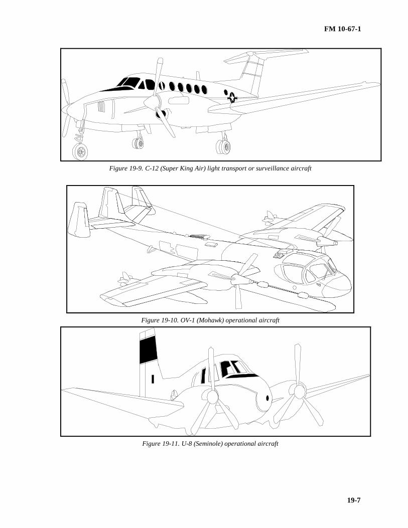
FM 10-67-1
19-7
Figure 19-9. C-12 (Super King Air) light transport or surveillance aircraft
Figure 19-10. OV-1 (Mohawk) operational aircraft
Figure 19-11. U-8 (Seminole) operational aircraft

FM 10-67-1
19-8
Figure 19-12. CH-47 (Chinook) cargo helicopter
Figure 19-13. CH-54 (Tarhe or Flying Crane) cargo helicopter
Section II. Basic Crash Rescue Training
APPROACH AND ENTRYNo one should assume that an aircraft accident has been fatal to the aircrew. Fire is often a delayed result of a
crash impact and, if the fire-fighting response is immediate, personnel in the aircraft may be rescued. Regardlessof the extent of the fire or limited fire-fighting capability, fire-fighting and crash rescue operations should startimmediately. Basic crash rescue training must be concerned with how to approach and get into the aircraft. Teachpersonnel about the principal hazards, including armaments and fuel, they will face when attempting an approachand entry. At semipermanent airfields, personnel should be familiar with fixed-wing aircraft as well as rotary-wing aircraft. They may need to know aircraft of other services also. At forward area refueling points, helicoptertraining should be emphasized.

FM 10-67-1
19-9
Approach
The route of approach of the aircraft is determined by the position of personnel in the aircraft, the position ofthe armaments board, and the location of the fire and the wind direction if the aircraft is on fire. Use crash rescuecharts (if available) to train personnel on the best method of approach to each type of aircraft. Use different fireand crash situations. When possible, train personnel using actual aircraft. Have personnel approach aircraft,identify location of personnel on board, and open exits.
Entry
Use crash rescue charts (if available), to teach personnel where the exits are and where personnel may be l o-cated in each type of aircraft. Familiarize them with every opening device both inside and outside the aircraft.Have personnel work the openings until they know them well enough to operate them effectively in darkness,smoke, or other conditions of low visibility. For detailed information on Army aircraft exits, see TM 5-315.
EVACUATION
Train personnel to decide whether the hazards of a situation are so great that the aircrews should be evacuatedfrom the aircraft instantly or whether the fire should be fought first until help arrives to assist in rescue. Som e-times wreckage or twisted controls make it difficult or impossible to rescue personnel without help. Extreme careshould be used in moving the injured. Train the personnel how to release the aircrew from safety belts, shoulderharnesses, parachutes, and ejection seats. Use the procedures described below.
Ejection Seats
Personnel must learn the correct release procedures for ejection seats. Use aircraft equipped with seats. A s e-rious accident can occur if personnel release an ejection seat instead of a soldier. For example, to release the MK-J5D (Martin-Baker) ejection seat in the OH-1 (Mohawk) aircraft, use the manual override handle. See Figure 19-13. Squeeze the trigger and hand grip and pull the handle up and aft (toward the rear of the plane). This frees thesoldier from the seat.

FM 10-67-1
19-10
Figure 19-14. MK-J5D (Martin-Baker) ejection
Parachutes
The two basic types of parachutes used in Army fixed-wing aircraft are back type and the attachable chest type.The parachute harness may have either three clip-type fasteners as shown in Figure 19-15, page 19-11, or onequick-release box as shown in Figure 19-14. The parachute harness may also have one or two parachute canopyreleases. Train personnel how to release any parachute harness equipment. When possible, have them release asoldier in an a ctual aircraft.

FM 10-67-1
19-11
Figure 19-15. Parachute harness with clip-type faseners

FM 10-67-1
19-12
Removal of Injured PersonnelThere is no substitute for actual experience in this phase of training. If you have an aircraft seat to use in
training, have a soldier act as an unconscious victim (limp deadweight) and have the other personnel practice r e-leasing and removing him from the seat. If possible, have a first aid instructor teach the best way of moving thevictim. Teach personnel that it is always easiest to remove a soldier through the normal route in and out of theaircraft. Only if the door or canopy is jammed and impossible to open should rescuers try to enter and remove vi c-tims by another route. Whenever possible, practice with an actual aircraft to give personnel a chance to becomefamiliar with the small space and limited approach and exit possibilities.
Section III. Tactical Fire-Fighting and Rescue Training
TACTICAL TRAININGAs soon as personnel have learned the basic fire-fighting and crash rescue procedures, they should be trained
in the tactics of attacking various fires. Fires at refueling points can involve aircraft and petroleum, petroleumalone, and grass or brush. During tactical training, hot drills are performed. Tactical training should be directedtoward developing speed, tactics of deployment, and the teamwork required to conduct successful fire-fighting andcrash rescue operations. It also helps to teach conservation of fire extinguishing agents.
AIRCRAFT FIRES AND CRASHESThe tactical aim in fighting aircraft fires is, first, to make rescue possible and, second, to try to save the ai r-
craft. The primary objective is to isolate the fuselage from the fire, cool it, and establish and maintain a fire-freeescape route until all personnel are evacuated. When possible, build a sample fire in a crashed fuselage or build amock-up to use so that personnel can practice with an actual fire. Described below are the basic procedures to fo l-low when fighting an aircraft fire.
Approach the SceneWhen mobile fire-fighting and rescue equipment is available, approach the fire or emergency by the fastest
route. Stress to personnel that the fastest route may not be the shortest route. They must also consider route sur-facing, weather conditions, and similar factors when determining the shortest route. Conduct timed runs to variouslocations on the airfield or refueling point to practice. Caution personnel in vehicles to be careful as they near theaccident scene to avoid hitting personnel escaping from the fire or crash or injured personnel lying on the ground.Stress special care when an aircraft fire or crash is approached in the dark or under conditions of low visibility.
Position EquipmentTeach personnel where to position fire-fighting and rescue equipment (mobile or hand-held). Teach them to
keep the following in mind:
• The equipment operator must be able to see the fire or wreck and its surroundings.
• The equipment must be positioned where it will not be engulfed in fire. On flat terrain, the best position isupwind. On a slope, the equipment must be placed up-slope from the fire or crash because both fuel and fuel v a-pors run downhill.
• No piece of equipment should block access to the fire or crash by other fire-fighting or rescue equipment.
• The equipment must be placed so that the fire can be fought effectively. If rescue is involved, the equipmentmust be positioned so that the flames can be kept away from trapped personnel and a safe escape route kept openuntil everyone is out of the aircraft.
Approach the AircraftTeach personnel that their approach to the aircraft and fire depends on their knowledge of the aircraft i n-
volved. This includes the location of exits, fuel tanks, armaments, and other flammable and explosives on board.Warn them that if the aircraft engine is operating that they must beware of rotor blades or propellers, turbine e n-gine air intake and exhaust vents, and the effect of rotor or prop wash on the stream of a fire extinguishing agent.

FM 10-67-1
19-13
Practice RescueHave personnel practice entering the aircraft and releasing and removing personnel.
Give First AidSimulate likely injuries and have personnel give first aid.
PETROLEUM FIRESTrain personnel in the tactics of approaching a petroleum fire that does not involve an aircraft. The principles
of approach to a site and the positioning of equipment are the same as for an aircraft fire. Reemphasize that bothfuel and fuel vapors flow downhill and that personnel must consider the danger of being engulfed by fire. Teachthem that if the fire involves flowing fuel, the first thing to do is shut off the flow. Be sure each person knowswhere cutoffs are and how to close fuel nozzles and valves that shut down pumps. If there are emergency cutoffs,see that personnel know where they are and how to operate them. If possible, float some fuel on water in an emptyberm and have personnel practice putting out the fire.
GRASS AND BRUSH FIRESIf fire extinguishers for Class A fires are available, train personnel how to fight grass and brush fires. Teach
them to expect aircraft or petroleum fires to lead to grass or brush fire. Wind usually determines the direction inwhich a grass fire moves, so the best approach is from upwind. Usually the approach should start at the upwindedge and work around the sides of the fire. However, at a refueling point, personnel must consider the position ofthe fuel supply and of the aircraft in relationship to the wind and fire. Teach them that depending on the locationof the fire and the speed of its advance it may be necessary to attack the fire from downwind or crosswind to cut itoff from the fuel supply and aircraft.

PART FOUR
PETROLEUM SUPPLY POINT OPERATIONS
This part describes petroleum handling equipment and its use as well as Class III supply pointoperations. It includes information on set up and management of a Class III supply point, assaulthoseline, and refuel on the move; receipt, issue and storage of bulk petroleum; and descriptionsand uses of petroleum handling equipment. This part is oriented toward tactical field operationsand deals with the responsibilities of both management and operator personnel.

FM 10-67-1
20-1
CHAPTER 20
PUMPS
This chapter describes pumps up to and including the 350-GPM. For information on largercapacity pumps, see Chapters 6 and 7.
Section I. Hand-Operated Pumps
THE 1-QUART-PER-STROKE DISPENSING PUMP
The 1-quart-per-stroke dispensing pump (NSN 4930-00-287-8293) is used chiefly to transferlubricating oil. The pump can be attached to a 55-gallon drum or a 600-gallon tank.
Description
This pump as shown in Figure 20-1, page 20-2, consists of a pump assembly, a suction pipe, and adischarge tube. It can be installed in a 1 ½- or 2-inch drum opening and on the 600-gallon, skid-mountedtank. The piston is raised and lowered by a gear-and-rack mechanism which is driven by a crank handle.Turning the handle to make one complete stroke of the piston delivers 1 quart of product. The handlemust then be returned to its original position before more product can be delivered. The pump has anadjustable stop so that it does not deliver too much or too little product. Product is delivered through anozzle which is positioned to connect with an adjustable swing arm return tube. The return tube letsexcess product drain back into the drum through a channel located in the pump base. If the work area isnot under cover, the pump suction pipe and the drum vent plug must be tightened securely and protectedwith a waterproof cover when the pump is not in use. This keeps water from seeping through the drumopenings and contaminating the product.
Use
This pump is used chiefly to transfer lubricating oil from 55-gallon drums to smaller containers.
THE 12-GPM DISPENSING PUMP
The 12-GPM dispensing pump (NSN 4930-00-263-9886) is used to transfer automotive gasoline,kerosene, fuel oil, and diesel fuel. The pump transfers these products from and to various containers.
Description
The 12-GPM pump as shown in Figure 20-2, page 20-2, consists of a pump assembly, a suction pipe,a discharge hose, and a valveless nozzle. The pump is designed to be installed in a 1 ½- or 2-inch drum ortank opening. Depending upon the manufacturer’s design, the pump may be one of three types: rotary,diaphragm, or piston. The pump discharges through an 8-foot length of 3/4-inch hose with nozzle. Whennot in use, the nozzle is placed in the nozzle bracket on the discharge fitting. The pump suction pipe mustbe tightened securely to the drum vent plug and protected with a waterproof cover when the pump is notin use.
Use
The 12-GPM pump is used to transfer automotive gasoline, kerosene, fuel oil, and diesel fuel from55-gallon drums; 600-gallon skid-mounted tanks; or other petroleum containers with a 1 ½- or 2-inchstandard treaded bung opening.

FM 10-67-1
20-2
Figure 20-1. The 1-quart-per-stroke dispensing pump mounted in a 55 gallon drum
Figure 20-2. The 12-GPM hand-driven dispensing pump installed in a 55-gallon drum

FM 10-67-1
20-3
THE 15-GPM DISPENSING PUMP
The 15-GPM dispensing pump (NSN 4930-00-276-0087) is used to transfer fuel from 55-gallondrums or 600-gallon, skid-mounted tanks. This fuel can be pumped directly to equipment fuel tanks.
Description
This unit as shown in Figure 20-3, 20-4, consists of a hand-driven, reciprocating pump; a suction stubassembly; a hose assembly; a nozzle; and a brace assembly. The pump body is mounted to the suctionstub assembly which fits into the 2-inch opening of the drum. The suction stub assembly includes atelescoping suction tube and a threaded bung adapter. The pump is operated by a push-pull action of thelever; the lever drives the piston within the pump, forcing fluid to the pump outlet. The pump dischargesthrough a 20-foot length of 1-inch hose and a standard nozzle with a 100-mesh, wire-cloth strainer. Agrounding wire equipment with alligator clamp and bonding plug is attached to the nozzle to permitelectrostatic bonding between the nozzle and other equipment. The brace assembly is attached to the topof the pump and to the chime of the drum to hold the pump securely during pumping operations. Thepump suction pipe of this pump must be tightened securely to the drum vent plug and protected with awaterproof cover when the pump is not in use.
Use
The 15-GPM pump is used to transfer fuels from 55-gallon drums or 600-gallon, skid-mounted tanksdirect to equipment fuel tanks. If no other aircraft refueling equipment is available, this pump may beused to refuel light aircraft if a 15-GPM filter/separator that qualified under Military Specification MIL-F-8901E is used with the pump.
Section II. Power-Driven Pumps
THE 50-GPM, GASOLINE-ENGINE-DRIVEN PUMPING ASSEMBLY FOR BULK TRANSFEROF FLAMMABLE LIQUIDS
The 50-GPM pumping assembly is used for bulk transfer of flammable liquids. If a 50-GPMfilter/separator is used, this pump can be used to refuel aircraft. A 50 -GPM electric pump used with thetank and pump unit is described in Chapter 2 4.
Description
The 50-GPM pumping assembly as shown in Figure 20-4, page 20-5, consists of a pump and engineassembly mounted on an oval aluminum base. The assembly has sections of suction and discharge hose,two 1½-inch dispensing nozzles, a drum-unloader suction suction stub, and two toolboxes containing toolsand accessories. The pumping assembly is equipped with a carrying handle . It fits into a rectangularaluminum box that can be used as a carrying case. The box has an oval inner compartment to hold themounting base of the pump and engine assembly. An outer compartment holds the coiled lengths of hose,the drum-unloader suction stub, the ground rod, and the muffler. The dispensing nozzles are stored inmounting brackets on the underside of the box lids. The pumping assembly must be bonded and groundedbefore operation. TMs 5-4320-237-15 and 10-4320-202-15 contain information on the operation andmaintenance of 50-GPM pumping assemblies.
• Pump. The pump is a self-priming, centrifugal pump. It is coupled to the engine by an intermediateadapter. The pump impeller is mounted directly on an extension of the engine crankshaft. Pump suctionand discharge ports have 1 ½- inch, cam-locking coupling adapters with dust caps.
• Engine. A one-cylinder , four-cycle, air-cooled gasoline engine is used to power the pump.
• Hose and fittings. Two 25-foot sections of 1½-inch, wire-reinforced suction hose and two 50- footsections of 1½-inch, collapsible discharge hose come with the pumping assembly. Each section of

FM 10-67-1
20-4
suction hose is fitted with a 1½-inch, female cam-locking coupling half on one end and a 1 ½-inch, malecam-locking coupling half on the other. The discharge hoses have 1 ½-inch, female cam-locking couplinghalves on both ends. All cam-locking coupling halves are fitted with dust caps or plugs.
• Hose and fitting kit. The hose and fitting kit is used to adapt the 50-GPM pumping assembly tofill 5-gallon fuel cans and dispense directly into vehicle fuel tanks. The basic kit consists of two Y-branches; four 25-foot, collapsible discharge hoses; and four 1-inch dispensing nozzles. Dust caps andplugs are also supplied. When the kit is used with the pumping assembly, the two 1 ½-inch nozzles arereplaced by the two Y-branches. Four 1-inch hoses, each fitted with a discharge nozzle, are then attachedto the Y-branches. The kit comes in a carrying case. The items in the case are four 1-inch dust caps; two1½-inch dust plugs; four 1-inch dust plugs; four collapsible discharge hose assemblies (each 1 inch indiameter by 25 feet long with a male and female cam-locking coupling half); four 1-inch, manually-operated, fuel- and oil-servicing nozzles; and two 1 ½-inch Y-branches.
Use
The 50-GPM, portable pumping assembly is used to transfer fuel from one bulk storage tank toanother and from storage tanks, tank cars, and tank vehicles to 55-gallon metal drums, 500-galloncollapsible drums, vehicles, and aircraft. When the aircraft or diesel vehicles are being refueled , the 50-GPM filter/separator must be used. With the suction stub attached to the suction hose, the pumpingassembly can be used to empty 55-gallon drums. When equipped with a hose and fitting kit, it can beused to fill 5-gallon fuel cans and refuel vehicles. The pumping assembly is also issued as part of the canand drum cleaning machine.
Figure 20-3. The 15-GPM, (mounted on a 55-gallon drum) and 15-GPM filter/separator connectedfor refueling hand-driven dispensing pump

FM 10-67-1
20-5
Figure 20-4. The 50-GPM pumping assembly
THE 100-GPM, GASOLINE-ENGINE-DRIVEN PUMPING ASSEMBLY FOR BULK TRANSFEROF FLAMMABLE LIQUIDS
The 100-GPM pumping assembly is used to transfer fuel from storage tanks, tank cars, and tankvehicles to smaller capacity containers. These containers include 5-gallon cans, 55-gallon drums, and500-gallon collapsible drums.
Description
The 100-GPM pumping assembly as shown in Figure 20-5, page 20-6, consists of a gasoline-engine-driven pump mounted on a frame, a rigid-wall suction hose, two discharge hoses, and two manuallyoperated hose nozzles. The unit must be grounded before operation. TM 5-4320-259-12 givesinformation on the operation and maintenance of the 100-GPM pumping assembly. Another 100-GPMpumping assembly is used as a component of the FARE system.
• Pump. The centrifugal pump is coupled directly to the engine. The pump impeller is mounted onthe threaded end of the engine crankshaft. After it is primed the first time, the pump is self-priming. Thepump, which has a 1 ½-inch suction port, discharges through a pipe cross. The two side ports of the pipecross are used for hose connections while the upper port is used for priming. All ports on the pump arefitted with caps to keep out dirt when the pump is not in use.
• Engine. An air-cooled, one-cylinder, gasoline-driven, four-cycle engine is used to power the pump.It develops 2½ horsepower at 3,600 RPM. Its speed is controlled by a mechanical governor whichcontrols the opening and closing of the carburetor throttle. The engine is splash-lubricated.
• Hoses and nozzles. The ½-inch suction and discharge hoses have cam-locking fittings so that theycan be easily attached to the related ports. The 10-foot section of suction hose is stored on top of the

FM 10-67-1
20-6
pumping assembly. The two 25-foot sections of discharge hose are stored in containers mounted on eachside of the pump. Two manually operated nozzles to control the flow of liquid are attached to the ends ofthe discharge hoses. The 1 ½-inch nozzles have cam-locking couplings.
Use
The 100-GPM pumping assembly is used to transfer fuel from storage tanks, tank cars, and tank vehiclesto 5-gallon cans, 55-gallon drums, and 500-gallon collapsible drums. It can also be used to refuel vehiclesand aircraft. When aircraft or diesel vehicles are being refueled, the 100-GPM filter/separator must beused.
Figure 20-5. The 100 GPM pumping assembly
THE 350-GPM PUMPING ASSEMBLY FOR BULK TRANSFER OF FLAMMABLE LIQUIDS
The 350-GPM pumping assembly is used mainly with the FSSP. It may also be used with the Army’scollapsible tanks and with the assault hose line.
Description
The 350-GPM pumping assembly as shown Figure 20-6, page 20-7, (gasoline- or diesel-enginedriven) is mounted on a two-wheel trailer. The assembly can be moved by a towing vehicle using theattached tow bar. However, it must be towed for only short distances at speeds not exceeding 20 mph onsurfaced roads. If the pumping assembly must be moved for a long distance, it should be loaded on acargo vehicle or flatbed using a lifting device with at least a 2,000-pound capacity. The assembly must bemoved on these vehicles. The gasoline-engine-driven pumping assembly is covered in TMs 5-4320-218-15, 5-4320-242-14, 5-4320-272-12, 5-4320-272-34, and 5-4320-273-14. The diesel-engine-drivenpumping assembly is covered in TM 5-4320-226-14.

FM 10-67-1
20-7
• Pump. The 4-inch, conventional-type, self-priming, centrifugal pump is designed to deliver 350GPM at approximately 275 feet of head. It has two female inlet (suction) ports and two male outlet(discharge) ports. Gate valves control all the ports.
• Gasoline engine. The four-cylinder gasoline engine is air-cooled. The starter switch is on theinstrument panel. Gages on the panel show engine vacuum, oil pressure, RPM, pump suction anddischarge pressures, and hours of operation.
NOTE: When 350-GPM pumping assemblies are used with the 4-inch hose line outfit, they are equippedwith a pressure regulator to control the flow of product through the hose line.
Use
The 350-GPM pumping assembly is used mainly with the FSSP. It moves fuel from the source of supplyto the tanks and from the tanks to the dispensing equipment. The pump may also be used with any of thecollapsible tanks now used by the Army and with the 4-inch hose line outfit (assault hose line).
Figure 20-6. The 350-GPM pumping assembly

FM 10-67-1
21-1
CHAPTER 21
FILTER/SEPARATORS
This chapter covers filter/separators up to and including 350-GPM. For information on larger filter/separators,see Chapters 6 and 7.
USE
Filter/separators remove solid contaminants and entrained water from liquid fuels. Those covered in thismanual range in capacity from 15 GPM to 350 GPM. All filter/separators discussed in this manual use identicalfilter elements and canisters meeting the requirements of Military Specification MIL-F-52308. Filter elements andcanisters are used in varying numbers depending on the flow rate of the specific filter/separator. Filter/separatorsmust be used in varying numbers depending on the flow rate of the specific filter/separator. Filter/separators mustbe used when automotive gasoline or diesel fuel is pumped to the user’s refueling vehicles or when vehicles arerefueled. They must also be used on all lines pumping aviation fuel directly to aircraft or to vehicles that refuelaircraft. In addition, all fuel loaded into aircraft refueling vehicles must be filtered again before it is pumped toaircraft.
MAINTENANCE
Filter/separators help you keep product clean and water-free at the Class III supply point. The steps youshould take to keep your filter/separators in good condition are outlined below:
• Test the accuracy of the pressure differential indicator once a year.
• Check the filter sumps each day, and remove any water you find.
• Keep a daily record of pressure differential readings. Pressure differential indicator readings should be keptin a daily log to determine when maintenance is needed. A suggested format for the daily log is shown in Figure21-1. The pressure differential will vary slightly in day-to-day operations because of different pumping rates anddifferences within products. The pressure differential with a clean, new element is usually 2.5 PSI or less. Itshould increase slowly and gradually with use.
• Inspect the filter elements immediately if there is a sudden, significant drop in the pressure differential. Itmay mean that a filter element has ruptured.
• Check the new filter elements if there is no increase in the pressure differential after several months of o p-eration. You may find that the elements are not properly installed or that some have ruptured.
• Change the filter elements at once when the reading on the pressure differential indicator is in the red (35PSI and up). Change them at the end of the daily operation when the reading is in the yellow (20-35 PSI). Whenchanging filter elements and canisters, always wear safety goggles and gloves to prevent fuel from contacting theeyes or skin.
• Change the filter elements at least every 24 months or when an inspection shows they are ruptured or notproperly installed. Stencil the month and year the filter elements are changed on the top of the filter/separator.
• Check the performance of all filter/separators, regardless of product in service, every 30 days by submittingsamples. Send the samples to a designated laboratory. Those not in use will be tested immediately before beingplaced in service and every 30 days thereafter while in use.
STANDARD FILTER ELEMENT AND CANISTER ASSEMBLY
The standard filter/separator consists of a filter element and a canister assembly. The direction of the flow offuel aids in the function of the filter/separator.
FM 10-67-1
21-2
Filter Element
The standard filter element (NSN 4330-00-983-0998) fits inside the canister. The element is a perforated tubesurrounded by a fiberglass filtering material, which in turn is wrapped with several layers of different materials.The fiberglass material filters solid particles from fuel. The outside of the element consists of layers of fiberglass,acetate, cotton knit, and fiberglass screen. This part coalesces (combines) fine particles of water in the fuel to formwater droplets, which settle because they are heavier than the fuel. The service life of the standard filter element is24 months.
Canister
The canister is a cylinder approximately 5 inches in diameter and 23 inches long. It consists of an outer andinner tube. The inner tube, made of perforated metal and a metal screen, supports the filter element. The outertube is made of perforated metal lined with a nonsticking, metallic-coated screen. An end seal plate at the top ofthe canister can be taken off to reach the filter element.
Fuel Flow
Raw fuel enters the center tube of the filter element through a fitting at the bottom of the canister. Solid co n-taminates are removed as the fuel flows outward from the perforated center tube through the fiberglass filteringmaterial. As the fuel passes through the outer layers of the element, fine particles of water in the fuel are coalescedinto droplets. The fuel containing the coalesced water passes through the inner tube of the canister into the spacebetween the inner and outer tubes. The metallic-coated screen of the outer tube does not allow water droplets topass through it, and they fall to the bottom chamber of the filter/separator. Only clean fuel passes through theouter canister tube into the filter/separator tank. Figure 21-2 shows the flow of fuel through a 100-GPM fi l-ter/separator.
THE 15-GPM FILTER/SEPARATOR
The 15-GPM filter/separator is used with the 15-GPM, hand-operated dispensing pump. It may also be usedto refuel light aircraft.
Description
The 15-GPM filter/separator as shown in Figure 21-3 is a vertical, portable unit consisting of an aluminumtank mounted on an aluminum skid. The tank has fuel inlet and outlet valves, a water drain valve, and a waterlevel sight gage. The fuel inlet and outlet valves are identical, 1-inch manually operated ball valves; they are a t-tached near the bottom of the tank. Cam-locking couplings for 1-inch hose are provided at the inlet and outletconnections. The water drain valve is a ½-inch manually operated ball valve; it is also mounted near the bottom ofthe filter/separator. The water level sight gage consists of a plastic sight and a ball float; it is mounted on the sideof the tank to show the water level in the base of the tank. This filter/separator contains a go/no-go fuse whichshuts off the flow of fuel if water gets past the canister. The cover, held in place by four bolts, has a manually o p-erated pressure vent valve to let air out of the unit. The filter/separator is 27½ inches high and weighs 20 poundswhen empty. Its top working pressure is 25 PSI. The filter/separator must be grounded before it is used. Detailedinformation on the 15-GPM filter/separator is in TM 5-4330-230-12.
Use
The 15-GPM filter/separator is used with the 15-GPM, hand-operated dispensing pump to pump fuel that mustbe free of solid contaminants and water. If no other aircraft refueling equipment is available, the 15-GPM pumpand filter/separator may be used to refuel light aircraft.
THE 50-GPM FILTER/SEPARATOR
The 50-GPM filter/separator is used with the 50-GPM pumping assembly. The type I model is intended foropen field use. The type II model is intended for use with the tank and pump unit.

FM 10-67-1
21-3
Description
The 50-GPM filter/separator as shown in Figure 21-4 consists of an aluminum tank with a removable cover,an inlet pipe with dust plug, an outlet pipe with dust cap, a manually operated water drain valve, an air vent valve,a pressure differential indicator, and a sight glass. Four filter element and canister assemblies are installed on amounting plate near the bottom of the tank. A float ball in the sight glass shows how much water is in the tank;the ball sinks in fuel and floats in water. The pressure differential indicator shows when the filter elements shouldbe changed. The unit is 36 inches high, 20½ inches long, and 16 inches wide; it weighs 85 pounds. It has a flowrate of 50 GPM. The filter/separator must be grounded before use. A grounding rod and cable come with the unit.TM 5-4330-232-12 gives more information on the use and upkeep of the 50-GPM filter/separator.
Use
The 50-GPM filter/separator is used with the 50-GPM pumping assembly in refueling systems at airfields andwith equipment for servicing ground vehicles. The type I filter/separator as shown in Figure 21-4 is frame-mounted; it is intended for open field use. The type II model has no frame and is intended for use with the tankand pump unit.
THE 100-GPM FILTER/SEPARATOR
The 100-GPM filter/separator is used with the 100-GPM pumping assembly. It is used mainly as part of theFARE system.
Description
The 100-GPM filter/separator as shown in Figure 21-5 has an aluminum tank with a removable cover. Its f e-male inlet has a dust plug, and its male outlet has a dust cap. Five filter elements, each in a canister, are set on amounting plate near the bottom of the tank. The filter/separator is mounted on a tubular aluminum frame. Thefilter/separator has an air vent valve, a pressure differential indicator, a sight glass, and a manually operated waterdrain valve. A float ball in the sight glass shows how much water is in the tank. The ball sinks in fuel but floats inwater. The pressure differential indicator shows when to change the filter elements. The flow rate of the fi l-ter/separator is 100 GPM, and its top working pressure is 75 PSI. The unit must be grounded before it is used.More information on the 100-GPM filter/separator is in TM 5-4330-217-12.
Use
The 100-GPM filter/separator is used mainly with the 100-GPM pumping assembly as part of the FARE sy s-tem. It is also issued as an individual item of equipment for use with various models of 100-GPM pumping asse m-blies.
THE 350-GPM FILTER/SEPARATOR
The 350-GPM filter/separator has several uses. It is used with the FSSP or separately.
Description
The 350-GPM filter/separator as shown in Figure 21-6 consists of an aluminum pressure tank with a remo v-able head. The tank is welded on a tubular aluminum frame for support and protection. It has an inlet pipethrough which unfiltered fuel enters, an outlet pipe through which the filtered fuel leaves, an internal inlet man i-fold, and risers for mounting 18 filter element and canister assemblies. The filter/separator also has an air ventvalve so that air can be let out of the tank, a sight glass to show the water level by means of a float ball, and amanually operated water drain valve to drain water from the tank. A pressure differential indicator shows whenthe filter elements need to be changed. The filter/separator is 40 inches high, 47 inches long, and 33 inches wide;it weighs 375 pounds. It is designed for a flow rate of 350 GPM and a top working pressure of 150 PSI. The unitmust be grounded before operation. TM 5-4330-211-12 has more information on the 350-GPM filter/separator.
FM 10-67-1
21-4
Use
The 350-GPM filter/separator is used in airfield refueling systems, motor fuel servicing equipment, and mil i-tary hose line systems.

FM 10-67-1
21-5
Figure 20-1. Suggested format for a filter/separator daily log

FM 10-67-1
21-6
Figure 21-2. Flow of fuel through the 100-GPM filter/separator
Figure 21-3. The 15-GPM filter/separator

FM 10-67-1
21-7
Figure 21-4. Frame-mounted (type1), 50-GPM filter/separator

FM 10-67-1
21-8
Figure 21-5. The 100-GPM filter/separator
Figure 21-6. The 350-GPM filter/separator

FM 10-67-1
22-1
CHAPTER 22
STORAGE CONTAINERS AND HANDLING EQUIPMENT
Section I. Packaged Petroleum Products and Fuels
DESCRIPTION
Packaged petroleum products are not the same as packaged petroleum fuels. Both are described below. Ap-pendix H provides standard reference data on various petroleum containers.
Products
Packaged petroleum products include lubricants, greases, hydraulic fluids, and other specialty products thathave been packaged at the procurement source. They are received directly from the vendor or issued through ge n-eral supply depots or supply points following MILSTRIP.
Fuels
Packaged petroleum fuels include fuel in reusable containers of 500 gallons or less. The containers used mostoften are 5-gallon cans, 55-gallon drums, and 500-gallon collapsible drums. Fuels are usually issued in bulk. Theneed to transfer bulk petroleum fuels to packaged containers depends on such operational factors as the quantitiesrequired for daily operations, the capabilities of the units to receive and store fuels, the existence of a bulk distrib u-tion system, and the tactical situation.
THE 5-GALLON FUEL CAN
This container is used to issue small quantities of fuel. A more complete discussion of its use is given below.
Description
The 5-gallon fuel can as shown in Figure 22-1, page 22-3 , is made of 20-gage sheet steel. The welded body isclinched to the bottom chime by a double seam. The head, welded to the top of the body, is fitted with three ca r-rying handles and a 2-inch threaded flange with closure assembly. A vent tube is welded to the underside of thehead and connected to a small vent hole in the flange. The vent makes the product flow freely when it is pouredfrom the can. The can is closed by a threaded plug which screws into the flange. The plug is attached to the canby a swivel wire, a swivel-wire hasp, a connector link, and a cotter pin. It is fitted with a synthetic-rubber, gas o-line-resistant gasket. The plug can be removed from the flange, and a flexible spout (inset of Figure 22-1, page 22-2) can be put in its place to help pour product from the can. A cap and screen can be screwed into the end of thespout to screen out gross sediment.
Use
The 5-gallon can is used to issue small quantities of fuel to using units. It is especially useful when conditionsare such that the container must be carried by hand.
Inspection
There are a number of checks you should make to see if 5-gallon cans are serviceable. These checks are di s-cussed below.
• Paint Condition . Check the condition of the paint on each can. Mark the can if it needs to be painted.
• Dents. Check the number and depth of dents on each can. If you count no more than six dents and each isless than one-half of an inch deep, you can use the can without repairing it. If you count no more than four dents

FM 10-67-1
22-2
and each is less than 1½-inch deep, you can use the can if the dents can be removed without weakening the metalor container construction. Reject a can as nonrepairable when dents over one-half of an inch long are presentalong the chime, when dents have caused the metal to rupture, or when dents exceed in number or depth the limitsset above.
• Contamination . Check the interior of each can for general cleanliness. Cans containing removable contam i-nates should be cleaned thoroughly before they are used. Label a can as nonrepairable if it contains a residue ofasphalt or tar or a similar substance that you cannot remove.
• Rust. Check the inside and outside of each can for rust. Cans with moderate exterior rusting are repairable ifyou can buff or sandblast the rust off without weakening the metal. Label the can nonrepairable if there is a greatdeal of rust on its outside. The inside of the can must be free of loose rust before it can be used. Label the can asnonrepairable if there is so much rust on the inside that you cannot remove it with solvent or caustic was hing.
• Holes. Check each can carefully for holes. A hole, rip, or rupture anywhere in the can (except the handle a s-sembly) makes it nonrepairable.
• Flange. Check the condition of the flange on each can. Ensure it is securely seated in the head and that theflange threads are in good condition. Cans with crossed, stripped, rusted, or worn flange threads are classified asnonrepairable.
• Filler Plug, Gasket, and Swivel Wire. Check each can for missing or defective filler plug, gasket, or swivelwire. Mark the can to show the repair it needs.
• Vent Tube. Check the condition of the vent tube in each can. Clean clogged vent tubes. Use cans with br o-ken or missing vent tubes only in an emergency.
• Handle Assembly . Check the condition of the handle assembly. You can use cans with holes, dents, or ripsin the handles if you can carry them without hurting your hands. If the handle needs repairing, mark where therepairs are needed. Classify cans with missing, broken, or badly smashed handles as nonrepairable.
Cleaning
The cans must be thoroughly inspected before and after cleaning. You can clean the cans by sloshing solventaround inside and allowing them to drain into a waste fuel container. This method removes most of the residualproduct, sand, and other foreign matter from the cans.
Filling
The 5-gallon cans as shown in Figure 22-2, page 22-4, must be filled to a level between one-fourth and three-fourths of an inch below the lowest point on the closure threads. The can holds approximately 5.14 gallons ofproduct when filled to the highest level (one-fourth of an inch below the lowest point of the closure threads).
Marking
All markings on 5-gallon cans should be in three-fourths of an inch letters. Place the marking on the can asshown in Figure 22-3, page 22-4.
THE 55-GALLON STEEL DRUM
The 55-gallon steel drum is used to issue fuels and lubricating oils to units. It cannot be hand carried like the5-gallon can.
Description
The 55-gallon drum as shown in Figure 22-4, page 22-5 , is made of either 16- or 18-gage, hot-rolled sheetsteel. It has rolling hoops and an enameled exterior finish. The drumheads are held to the cylindrical body bydouble-seamed chimes. Chimes of the 16-gage drum are reinforced by a strip of sheet steel (inset of Figure 22-4,page 22-5). Two flanged closures, a 2-inch plug, and a 3/4-inch plug (vent) are mounted in the top head of eachdrum. The 16-gage drum is more durable than the 18-gage drum and can be reused. The 16-gage drum can beidentified by the letter “O” embossed on the head of the drum. The 18-gage drum is primarily a disposable shi p-

FM 10-67-1
22-3
ping container. Product can be dispensed from the 55-gallon drum by a hand-driven pump mounted in the 2-inchclosure. A drum-unloader suction stub can be connected to the suction hose of a power-driven pumping assemblyto empty the drum. When the drum is in a horizontal position, a drum faucet can be installed in the 3/4-inch cl o-sure to draw off small quantities of product. The 55-gallon drum has an authorized capacity of 54 gallons for fuelswith flash points lower than 80 ° F and 55-gallons for fuels with flash points higher than 80°F. The closures co n-sist of a threaded flange pressed into the drumhead, a male threaded plug, and a synthetic-rubber gasket. Bothclosures on any one drum should be of the same type, either Rieke or Trisure. A Rieke plug can be screwed into aTrisure flange, or vice versa, but it will usually leak. The two designs are not the same, and part of one cannot beused with part of the other. The plug and gasket must match the flange as shown in Figure 22-5, page 22-5.
Use
The 55-gallon drum is used to issue fuel and lubricating oil to using units. It can also be used in most situ a-tions. However, it cannot be used when the terrain or tactical situation makes it necessary to deliver fuel in co n-tainers that can be hand carried.
InspectionThere are a number of specific checks you should make to see if 55-gallon drums can be used. These checks
are discussed below.
• Initial Inspection . The quickest and most economical way to inspect the drums is to check them for obviousmajor defects. Major defects which make drums nonrepairable are a great amount of rust inside or outside; a badlybent shape; damage to either flange, many holes or large holes; or residue of asphalt, tar, or similar substance thatyou cannot remove.
• Detailed Inspection . If you find no major defects during the initial inspection, give the drum a second, moredetailed inspection. Ensure each drum meets the minimum serviceability standards described in Table 22-1, page22-6.

FM 10-67-1
22-4
Figure 22-1. The 5-gallon fuel can
Figure 22-2. Fill level for 5-gallon can

FM 10-67-1
22-5
Figure 22-3. The 5-gallon can markings
Figure 22-4. Chimes on 55-gallon drum
Figure 22-5. Closures of 55-gallon drum

FM 10-67-1
22-6
Table 22.1. Minimum standards of serviceability for 55-gallon drumsPART GENERAL
REQUIREMENTDENTS
ALLOWEDHOLES
ALLOWEDCONDITION OF EXTERIORAND INTERIOR OF METALALLOWED
Body a. Numeroussmall dents areacceptable.b. Condition ofpaint of no im-portance.
a. Up to 3 inches indepth if not morethan six dents inbody.b. No restriction onlength.
a. None resultingfrom rust.b. Other up tothree-fourth inchin greatest dime n-sion are acceptableif not more thanfour holes in thebody.
Exterior: Must be free ofsevere pitting that wouldweaken drum structure.Interior: Must be free of pit-ting (If product residue pre-vents the determination,drum will be considered a c-ceptable until cleaned andreinspected.)
Chime Should be tight onboth types ofdrums. Reinforc-ing metal stripsshould be in placeon 16-gage drums.
16-gage. Nonegreater than one-fourth inch in depthwith no restrictionon length or num-ber.18-gage. Nonegreater than three-fourth inch in depthand 5 inches inlength with no morethan four dents perchimes
16-gage. No holesallowed and noruptures accept-able if they sepa-rate reinforcementfrom chime.18-gage. Nonegreater than three-fourths inch indepth and 5 inchesin length with nomore than fourdents per chime.
See information for body,above.
Flanage No defectivethreads, gasketseat, or weld.
None. None. Exterior: Moderate rusting ifgasket set and threads are notimpaired.Interior: See information forbody, above.
Head Must be restorableto approximateoriginal contour.
Up to 2 inches indepth if not morethan two dents perhead.
a. None resultingfrom rust.b. Up to three-fourths inch if notmore than onehole per head.c. None locatedwithin 2 inches offlange weld orchime.
See information for body,above.
Hoops Should be restor-able to approxi-mate originalshape.
None greater thanfive-eights inch indepth, no limitationin nu mber.
Up to three-fourths inch, notto exceed threeholes per hoop.
See information for body,above.
SideWeld
No indication ofcracking or dete-rioration
Up to 2 inches indepth, not to exceedthree dents per weld.
None. See information for body,above.

FM 10-67-1
22-7
Cleaning
The drums must be cleaned by the method described for cans. After cleaning a drum, inspect it with an exte n-sion light to ensure the inside is clean and free from rust. If you find sediment, clean the drum again as describedabove. If it is still not clean, classify it as unserviceable. When you are sure the drums are clean and free fromrust, put bung plugs, vent plugs, and gaskets back in place. Insert and tighten the plugs in the drums unless youare going to fill them immediately. If you store the drums temporarily, tighten the plugs by hand. If you storethem for a long time, tighten plugs with a wrench.
Filling
To make sure that there is enough vapor space in 55-gallon drums, only 54 gallons of light product or 55 ga l-lons of heavy product can be put into each drum. A light product is one which gives off flammable vapors at orbelow 80°F, and a heavy product is one which gives off flammable vapors above 80°F. If you have no meteringdevices, fill the drums to the level shown in Figure 22-6, page 22-8 . If you are going to put 54 gallons of productin a drum, fill it to a level 2 inches below the head. If you are going to put 55 gallons of product in a drum, fill itto a level 1½ inches below the head.
Marking
All markings on 55-gallon drums should be at least three-fourths of an inch. Mark the top head of the drumas shown in Figure 22-7, page 22-9.
THE 500-GALLON, LIQUID-FUEL COLLAPSIBLE FABRIC DRUMThe 500-gallon collapsible fabric drum can supply fuel to isolated ground troops. It can be towed short di s-
tances by trucks, carried by trucks, or carried by aircraft.
Description
The 500-gallon collapsible drum as shown in Figure 22-8, page 22-9, is a nonvented container made of fabricimpregnated with fuel-resistant, synthetic rubber. The cylindrical body is of four-ply fabric; the convex ends ofsix-ply fabric. The drum has a closure plate on each end. The plates are tied together inside the drum with su p-port cables so that they do not expand in length when the drum is filled. Each closure plate has a swivel ring withtwo anchor shackles. A lifting sling or towing and lifting yoke can be attached to these shackles. It can also beused to tie a drum to a vehicle. The drum is filled and emptied through an 1½-inch quick coupling elbow couplervalve and check valve adapter in the front closure plate. When the pressure control is used for the filling oper a-tion, the 1½-inch discharge hose of the control is attached to the elbow coupler valve. When the pressure control isnot used, the hose of the pumping assembly is attached directly to the elbow coupler valve. A filled drum is about5 feet 2 inches long and 4 feet 5 inches in diameter; it weighs about 4,000 pounds. It is designed for a regularworking pressure of 4 to 5 PSI and a top working pressure of 45 PSI. The collapsed drum can be moved by truck.Each drum is used for only one type of fuel. Repair kits for the 500-gallon collapsible drum can be used to maketemporary repairs.
• Pressure control. The pressure control is used to keep from pumping too much fuel into a nonvented co l-lapsible drum. Too much fuel could cause the drum to rupture. For information on filling collapsible drums usingthe pressure control, see Chapter 19. Figure 22-9, page 22-10 , shows the pressure control. Figure 22-10, page 22-10, shows it connected for filling a drum.
• Elbow coupler. The elbow coupler as shown in Figure 22-11, page 22-11 , has a 2-inch, cam-locking femalecoupling for connecting to the drum and a 1½-inch, cam-locking female for connecting to the hose. The FAREsystem includes an elbow coupler with a 2-inch fitting for connecting to the hose. The elbow coupler has a valve toshut off the flow of the fuel into and out of the drum.

FM 10-67-1
22-8
• Emergency repair kit. The emergency repair kit is used for temporary repairs only. For detailed informationsee, Chapter 12.

FM 10-67-1
22-9
Figure 22-6. Fill level for 55-gallon drum

FM 10-67-1
22-10
Figure 22-7. The 55 gallon drum markings
Figure 22-8. Filled 500-gallon collapsible drum

FM 10-67-1
22-11
Figure 22-9. Pressure control
Figure 22-10. Pressure control connected between a 50-GPM pumping assembly and a 500-gallon collapsibledrum for a filling operation
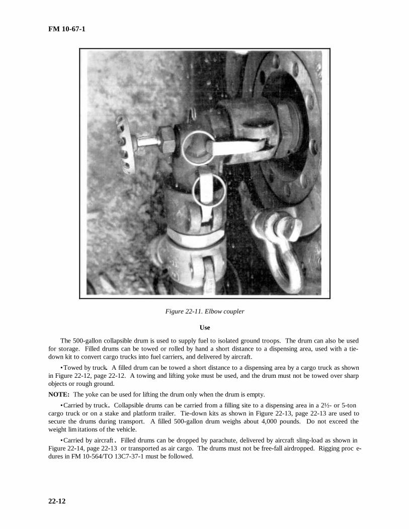
FM 10-67-1
22-12
Figure 22-11. Elbow coupler
Use
The 500-gallon collapsible drum is used to supply fuel to isolated ground troops. The drum can also be usedfor storage. Filled drums can be towed or rolled by hand a short distance to a dispensing area, used with a tie-down kit to convert cargo trucks into fuel carriers, and delivered by aircraft.
• Towed by truck. A filled drum can be towed a short distance to a dispensing area by a cargo truck as shownin Figure 22-12, page 22-12. A towing and lifting yoke must be used, and the drum must not be towed over sharpobjects or rough ground.
NOTE: The yoke can be used for lifting the drum only when the drum is empty.
• Carried by truck. Collapsible drums can be carried from a filling site to a dispensing area in a 2½- or 5-toncargo truck or on a stake and platform trailer. Tie-down kits as shown in Figure 22-13, page 22-13 are used tosecure the drums during transport. A filled 500-gallon drum weighs about 4,000 pounds. Do not exceed theweight lim itations of the vehicle.
• Carried by aircraft . Filled drums can be dropped by parachute, delivered by aircraft sling-load as shown inFigure 22-14, page 22-13 or transported as air cargo. The drums must not be free-fall airdropped. Rigging proc e-dures in FM 10-564/TO 13C7-37-1 must be followed.

FM 10-67-1
22-13
Inspect
The serviceability of 500-gallon collapsible drums can be determined by inspecting the items listed below. SeeTM 10-8110-201-14&P for more information.
• Body Fabric. Check the body fabric for holes, cuts, tears, deterioration, or leaks. The drum can be used ifthe rubber coating only is worn from the body fabric.
• Closures. Check the front and rear closure rings for cracks, leaks, or missing cap screws. Check the frontclosure plate for stripped threads or a missing pipe plug.
• Coupler Elbow Valve Assembly . Check the coupler elbow valve assembly for loose or missing gaskets or acorroded or stuck valve. Also check for cracked or missing parts.
• Pressure Control. Check the pressure control for body cracks. Also, check for loose or missing cap screwand nuts.
Cleaning
The 500-gallon collapsible drums are sent to the general support maintenance repair facility for cleaning.
Filling
For procedures for filling 500-gallon collapsible drums, see Chapter 14.
Marking
All markings on 500-gallon collapsible drums can vary between 2 to 5 inches. Mark both ends of the drum asshown in Figure 22-15, page 22-14. Put the filling date on the drum when you are using it for temporary storageof petroleum fuels.
Figure 22-12. Filled 500-gallon drum being towed by cargo vehicle
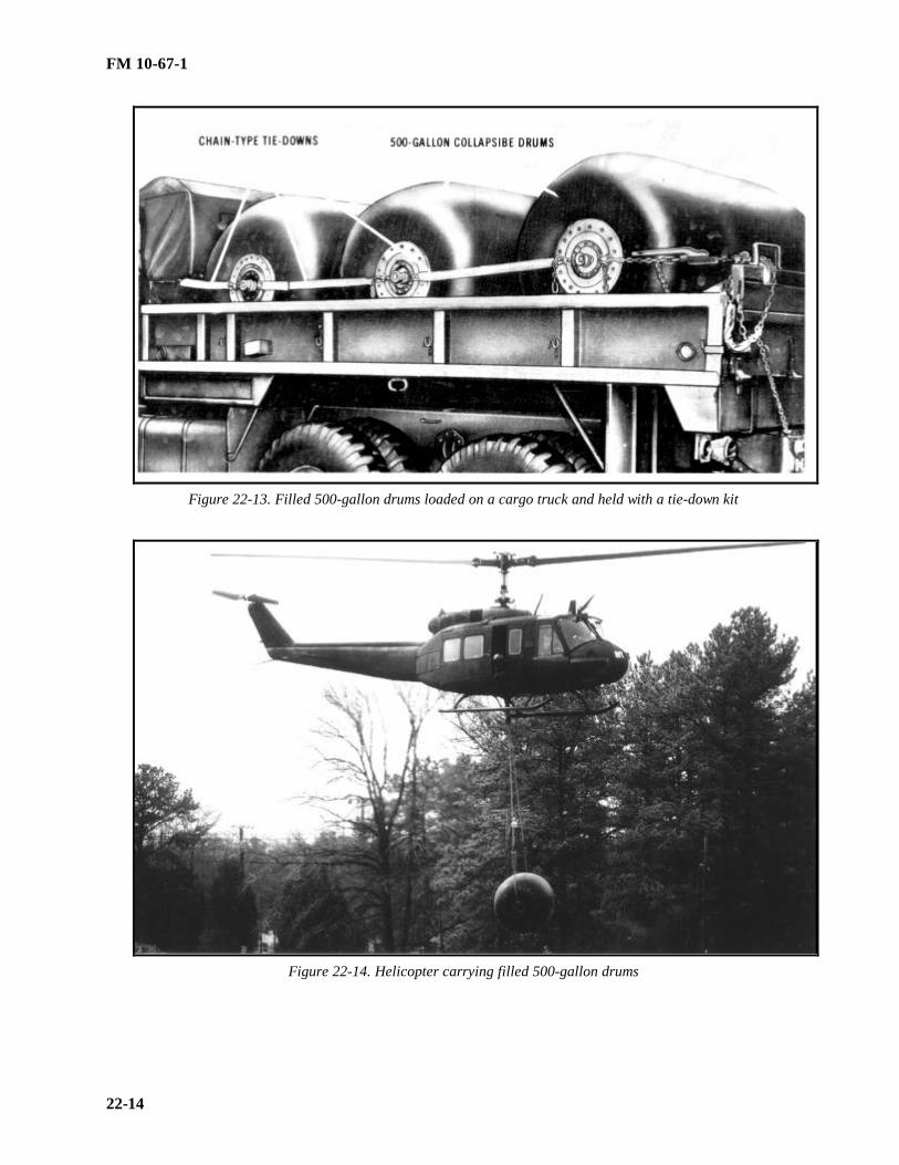
FM 10-67-1
22-14
Figure 22-13. Filled 500-gallon drums loaded on a cargo truck and held with a tie-down kit
Figure 22-14. Helicopter carrying filled 500-gallon drums

FM 10-67-1
22-15
Figure 22-15. The 500 gallon collasible drum markings
Section II. Bulk Petroleum Containers
BULK PETROLEUM PRODUCTS
Bulk petroleum products include those petroleum products transported in pipelines, tankers, tank cars, tankvehicles, and other bulk carriers. Containers discussed in this section are used to store and deliver bulk petroleumproducts in quantities over 500 gallons. For maintenance procedures see Chapter 13.
THE 3,000-GALLON COLLAPSIBLE FABRIC TANK
The 3,000-gallon collapsible fabric tank is made of single-ply, elastomeric-coated nylon. It has four carryinghandles, a filler/discharge assembly, and a vent fitting assembly. The tank is issued with a hose and gate valveassembly and emergency repair items. When filled, the tank is about 12 feet 6 inches square and 4 feet high.
Filler/discharge assembly
The filler/discharge assembly as shown in Figure 22-16, page 22-17 , is located on top of the tank. It consistsof an access door fitting, a 4-inch suction stub, an oval closure plate, a 4-inch flanged adapter coupled to a 4-inchelbow fitting, and a 4-inch dust cap.

FM 10-67-1
22-16
Vent fitting assembly
The vent fitting assembly as shown in Figure 22-17, page 22-18 , is located near the center of the top of thetank near the filler/discharge assembly. It consists of a vent flange attachment and a 2-inch, quick-disconnect,male coupling half connected to a 2-inch, quick-disconnect, female coupling half. It also consists of a 2-inch dustcap, a 2-inch vent pipe, a flame arrester, and a pressure relief cap with gasket. The pressure relief cap of the ventassembly opens automatically when the vapor pressure inside the tank reaches 10 PSI.
Hose and valve assembly
The 3,000-gallon collapsible tank comes with a hose and valve assembly to help transfer the product becausethis tank is issued as a separate item and not as part of a system. The assembly consists of 4- to 3-inch reducer; a3-inch, wire-reinforced hose assembly (4 feet long); and a 3-inch gate valve. The 4-inch female end of the reduceris connected to the 4-inch elbow fitting of the filler/discharge assembly on the tank. The 3-inch male end of thereducer is connected to the 3-inch hose assembly which, in turn, is coupled to the 3-inch gate valve.
Use
The 3,000-gallon collapsible tank is used for temporary storage of liquid fuels where larger collapsible tanksare not practical. With the hose and valve assembly attached, the tank can receive and dispense bulk petroleumfuels. The tanks is generally used in small bulk petroleum operations.
THE 10,000-GALLON COLLAPSIBLE FABRIC TANK
The 10,000-gallon collapsible fabric tank looks a lot like the 3,000-gallon collapsible tank, It consists of eitherone or two filler/discharge assemblies, a vent fitting assembly, a drain fitting assembly, and various hoses andvalves.
Description
The 10,000-gallon tank is made of single-ply, elastomeric-coated nylon with six carrying handles. The tankalso has emergency repair items. When filled, the tank is about 20 feet 6 inches square and 4 feet high.
• Filler/discharge assemblies. The filler/discharge assemblies as shown in Figure 22-16, page 22-17 , are ontop of the tank. They are similar to that of the 3,000-gallon collapsible tank.
• Vent fitting assembly . The vent fitting assembly as shown in Figure 22-17, page 22-18, is located on top ofthe tank. It is just like that of the 3,000-gallon collapsible tank. The pressure relief cap of the vent assembly onthe 10,000-gallon collapsible tank opens automatically when the vapor pressure inside the tank reaches 10 PSI.
• Drain fitting assembly . The drain fitting assembly is used to remove water. It is located on the bottom ofthe tank. It consists of a vent flange attachment, a drain fitting, and a plug and chain. The assembly has an 8-footlength of 3/4-inch, nonwire-reinforced hose assembly with male fittings on both ends and a ½-inch, rising-stemgate valve. These items are attached to the drain fitting assembly to help drain water from the tank.
Use
The 10,000-gallon collapsible storage tank is used to store petroleum products. It is usually a part of theFSSP, but it is also issued as a single item for additional bulk storage.
THE 20,000-GALLON COLLAPSIBLE FABRIC TANK
The 20,000-gallon collapsible fabric tank is primarily used in the FSSP. Its description and use are coveredbelow.

FM 10-67-1
22-17
Description
The 20,000-gallon collapsible tank as shown in Figure 22-18, page 22-19 , is made of elastomeric-coated ny-lon. It has 12 carrying handles, two filler/discharge assemblies with access doors, a vent fitting assembly, and adrain fitting assembly. When filled, the tank is about 28 feet long, 24 feet wide, and 5 feet high.
• Filler/discharge assemblies . The two 4-inch filler/discharge assemblies are identical to those on the 3,000-and 10,000-gallon collapsible tanks. They are located on top of the tank, 6 feet from each end and 4 feet from thecenterline. The assemblies are catercornered from each other.
• Vent fitting assembly . The vent fitting assembly is identical with those on the 3,000- and 10,000-gallon co l-lapsible tanks. It is located in the top center of the tank. The pressure relief cap of the assembly opens automat i-cally when the vapor pressure inside the tank reaches 10 PSI.
• Drain fitting assembly . The drain fitting assembly, located on the bottom of the tank, is used to remove w a-ter. The assembly is identical to those on the 3,000- and 10,000-gallon collapsible tanks.
Use
The 20,000-gallon collapsible tank is used to store bulk petroleum products. The primary use is in the FSSP.It is also issued as a single item for additional bulk storage.
THE 50,000-GALLON COLLAPSIBLE FABRIC TANK
The 50,000-gallon collapsible fabric tank is used for storing liquid fuels in large bulk petroleum operations. Ithas several uses.
Description
The 50,000-gallon collapsible fabric tank is made of single-ply, elastomeric-coated nylon. It has 18 carryinghandles, two filler/discharge assemblies with access doors, a vent fitting assembly, and a drain fitting assembly.The tank also has a hose and valve assembly and emergency repair items. When filled, the tank is about 65 feetlong, 25 feet wide, and 6 feet high.
• Filler/discharge assemblies . The two filler/discharge assemblies as shown in Figure 22-16, page 22-17 , arelocated on top of the tank. One is located at each end so that the tank can receive and discharge fuel from bothends.
• Vent fitting assembly . The vent fitting assembly are shown in Figure 22-17, page 22-18 , is centrally pos i-tioned on top of the tank. It is the same as that on the 3,000-gallon collapsible tank. The pressure relief cap of thevent assembly opens automatically when the vapor pressure inside the tank reaches 10 PSI.
• Hose and valve assembly . Because the 50,000-gallon collapsible tank is issued as a single item of equipmentand not as part of a system, it has a hose and valve assembly to help transfer product. The assembly consists of a4-inch, wire-reinforced hose assembly (10 feet long) and a 4-inch gate valve. The female end of the 4-inch hoseassembly is connected to the 4-inch elbow fitting of the filler/discharge assembly on the tank. The male end of thehose assembly is coupled to the 4-inch gate valve.
Use
The 50,000-gallon collapsible tank is use to store liquid fuels in large bulk petroleum operations. With thehose and valve assembly attached, the tank can receive and dispense fuels at temporary beachheads and at interm e-diate points along trunk hoseline and pipeline systems. The tank may also be used for temporary storage at supplyinstallations and airfields until permanent facilities can be built. The tanks are also used in tactical Class III su p-ply points to issue bulk petroleum to tank trucks and tank semitrailers. As part of the Class III supply point, thetanks provide maximum flexibility in the handling of various fuels (MOGAS and JP-8).

FM 10-67-1
22-18
THE 210,000-GALLON COLLAPSIBLE FABRIC TANK
The 210,000-gallon collapsible fabric tank is also called the BFTA. It stores bulk petroleum products.
Description
The BFTA is made of single-ply, elastomeric-coated nylon. The tank has a vent assembly, two filler/dischargeassemblies, and two drain assemblies. When filled, the tank is about 69 feet long, 69 feet wide, and 6 feet 9 incheshigh.
• Filler/discharge assemblies . The two 6-inch filler/discharge assemblies are located on top of the tank. Oneassembly is located at each end of the tank so that fuel can be received and dispensed at both ends.
• Vent fitting assembly . The vent fitting assembly is identical to those on other collapsible tanks. It is l o-cated in the center of the top of the tank. The relief valve opens when the internal tank vapor pressure reaches 10PSI.
• Drain fitting assemblies . The 2-inch drain fitting assemblies are located on the bottom of the tank, one ateach end. The assemblies are used to drain water from the tank.
Use
The 210,000-gallon collapsible tank is used to store liquid fuels in large bulk petroleum operations. The tanksare used primarily in the TPT and are issued as separate items of equipment.
EMERGENCY REPAIR ITEMS
Emergency repair items are issued with each collapsible tank. See Chapter 12 for a description of emergencyrepair items.

FM 10-67-1
22-19
Figure 22-16. Filler/discharge assembly (same on 3,000-, 10,000-, 20,000-, and 30,000-gallon
collapsible tanks)

FM 10-67-1
22-20
Figure 22-17. Vent fitting assembly (same for all collapsible tanks)
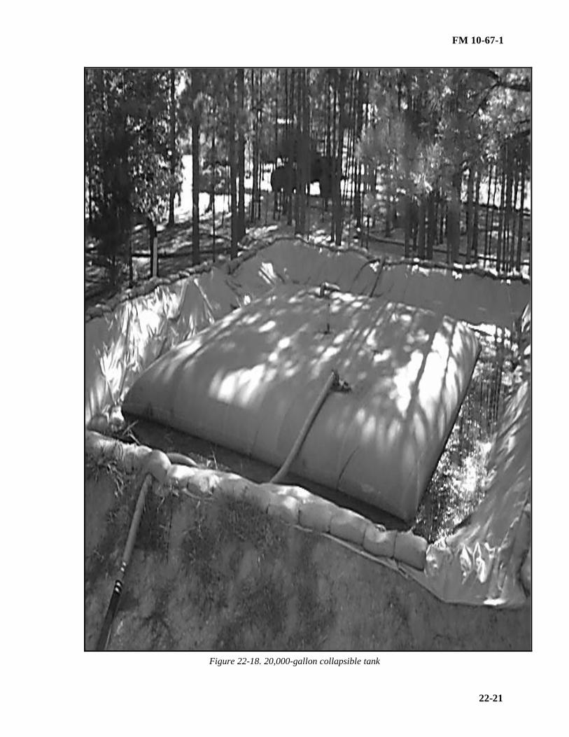
FM 10-67-1
22-21
Figure 22-18. 20,000-gallon collapsible tank

FM 10-67-1
23-1
CHAPTER 23
FUEL SYSTEM SUPPLY POINT
DESCRIPTIONThe FSSP is the Army’s primary means for the receipt and storage of bulk petroleum and for its issue to
combat forces under tactical conditions. The FSSP is not issued as a complete system. The major components areissued as separate items of equipment to add to the flexibility of the system. The number of major componentsdepends on the size and configuration of the system. An FSSP normally consists of two 350-GPM pumpingassemblies, two 350-GPM filter/separators, six 10,000-gallon collapsible tanks (An augmented FSSP increasestotal storage capacity by using larger collapsible tanks, six bottom loading points, two 500-gallon collapsible drumfilling points, and six refueling points. These components of the fuel system are connected by about 2,400 feet ofhose and 11 types of fittings. When an FSSP is requisitioned, you will only receive the hoses and fittings toconnect the above components. Figure 23-1, page 23-2, shows a typical layout. Table 23-1, page 23-3, lists thecomponents.
Receiving ManifoldThe receiving manifold consists of a Y- and T-assembly (reducing from 4 to 3 inches), lengths of 3-inch
suction hose, and 3-inch gate valves. With this manifold, the FSSP can receive product from more than onetransporter at a time. It also provides a way to switch from one supply source to another. Grounding equipmentmust be used whenever fuel is received through the manifold, because contact between the manifold and theground is not perfect. Chapter 28 gives information on receiving product into the FSSP.
Pumping Assemblies, Filter/Separators, and Collapsible Tanks
The FSSP uses specific pumping assemblies, filter/separators, and collapsible tanks. Each is described in thefollowing paragraphs. See Figure 23-1, page 23-2 , for these components.
• The 350-GPM pumping assemblies. The 350-GPM pumping assemblies are used as components of theFSSP. There are normally two per supply point.
• The 350-GPM filter/separators. Vertically mounted, 350-GPM filter/separators are used in each FSSP toremove entrained water and solid contaminants from the fuel before it is pumped into vehicles or container. Thereare normally two filter/separators per supply point.
• The 10,000-gallon collapsible tanks. The FSSP normally has six 10,000-gallon collapsible tanks. Onehoselines manifold assembly with two T-fittings and one assembly with one T-fitting are used with each tank. Themanifold as shown in Figure 23-2, page 23-4 , has two rising-stem, double-acting gate valves to control the flow offuel into and out of the collapsible tank.
Bottom Loading Points The fuel system has six 3-inch bottom loading points to load fuel into tank semi-trailers. Each bottom loading
points consists of a T-assembly (reducing from 4 to 3 inches) coupled to a 3-inch, cam-locking coupling valvefollowed by 25 feet of 3-inch discharge hose coupled to a 3-inch, cam-locking coupling valve.
The 500-Gallon Collapsible Drum Filling Points There are two 500-gallon collapsible drum filling points in the FSSP. Each point consists of a T assembly
(reducing from 3 to 1½ inches) coupled to a 1½-inch, cam-locking coupling valve followed by 25 feet of 1½-inchdischarge hose coupled to a 1½-inch, cam-locking coupling valve. The pressure control, not a component of theFSSP, is also used for the filling operation. The inlet of the pressure control is attached to the downstream end ofthe 1½-inch discharge hose, and the 5-foot length of pressure control discharge hose is connected from the controloutlet to the drum elbow coupler valve.

FM 10-67-1
23-2
Figure 23-1. Typical layout of the FSSP

FM 10-67-1
23-3
Table 23-1. Components of the FSSP
NO
ITEM DESCRIPTION REQD
1 Tank, 10,000-gallon, collapsible, petroleum 62. Valve, 3" gate, flanged, with M and F CL 33. Hose, suction, 3" x 12, M CL one end, F CL other 164. Y and T assembly, flanged, M CL 3" and 4" 15. Hose, suction, 4" x 10', M CL one end, F CL other 83*6. Pump, 350-GPM, 4", with M and F CL 27. Valve, gage, 4", flanged, with M and F CL 25*8. Manifold with two T fittings 00*9. Manifold with one T fitting 00*10. Hose, discharge, 4" x 50', with M and F CL 811. Y assembly, flanged, 4", with one F CL inlet and 2 M 112. Hose, discharge, 4" x 25', M and F CL 913/ Filter/separator, 350-GPM, 4", with M and F CL 214. Y assembly, flanged, 4", with two F CL inlets and one 115. T-assembly, flanged, 4" , with two M CL and one F 116. T assembly, flanged, 4" x 3", with one 4" M CL, one 617. Hose, discharge, 1½" x 25', M and F CL 518. Hose discharge, 3" x 25', M and F CL 419. Valve, quick-acting, 3", M and F CL 1220. Reducer, 4" F CL x 3" M CL 121 Hose, discharge, 3" x 50', M and F CL 222. T assembly, flanged, 3" x ½", with one 3" F CL, one 523. Valve, quick-acting, 1½" M CL 424 Hose, discharge, 1" x 25', M and F CL 625 Reducer, 3" F CL x 2" M CL 126. Valve, quick-acting, 2", M and F CL 127. Hose, discharge, 2" x 25', M and F CL 728. Tee, reducing, 2" F CL x 2" M CL x 1" M CL 629. Nozzle, 1", with adapter 630. Dust cap for 4" CL 231. Dust cap for 2" CL 132. Dust plug for 4" CL 1NOTE: *Each of the six storage tanks comes with a manifold consistingof eight lengths of hose, one double T, and one single T, and two 4-inch .gates valves.

FM 10-67-1
23-4
Figure 23-2. Manifold and hose assemblies
Can and Drum Filling and Vehicle Refueling Points There are six 5-gallon can and 55-gallon drum filling and vehicle refueling points in the FSSP. Each point
consists of a T-assembly (reducing from 2 to 1 inch) followed by 25 feet of 1-inch discharge hose coupled to a 1-inch aluminum nozzle.
Hose, Fittings, Accessories, and Tools The FSSP uses suction and discharge hoses, various types of fitting assemblies, and certain accessories and
tools. These components are described in the following paragraphs.
• Suction and discharge hoses. The two types of hose assemblies used in the FSSP are suction hose assembliesand discharge hose assemblies. Each hose assembly has a male coupling (with a dust cap) on one end and a femalecoupling (with a dust plug) on the other end. Figure 23-1, page 23-2, shows where the lengths of hoses are used.The dust caps and plugs must be used when the hose sections are not connected to the system.
• Fitting assemblies. Eleven types of fitting assemblies as shown in Figure 23-3, page 23-5, are used in theFSSP to connect hose sections, valves, and components. Dust caps and plugs must be kept on the assemblies whenthey are not in use. To prevent loss, dust caps and dust plugs are attached to the hose fittings with a chain. Ensurethat all fittings have gaskets. Chapter 28 shows the location of each fitting assembly.
• Accessories and tools. Accessories and tools come with the FSSP so that it can be connected to different fueltransporters, other pumping assemblies, or pipelines. They can also be used to connect the components of theFSSP in many combinations. The tools used to repair hose assemblies include a hose clamp locking tool, buckles,and bandings. Accessories include an adapter for connecting a tank car to a hose assembly, a pipe clamp coupling,a pipe coupling for connecting the FSSP to a pipeline, reducers for connecting different size hoses, coupling halves(flanged and threaded) to make a number of connections, gate valves, and Y-fittings.
USEThe FSSP is used at distribution points to provide storage facilities for transferring bulk fuel from one means
of transport to another and at dispensing facilities for bulk reduction or delivery of fuel to using vehicles. TheFSSP can receive product from tank trucks, railway cars, pipelines, hoselines, and aircraft. Since it can alsoreceive fuel from ocean tankers, it is able to support beached operations. It can store 60,000 gallons of bulkpetroleum. It can store even more if additional or larger collapsible tanks are added. However, this expansion
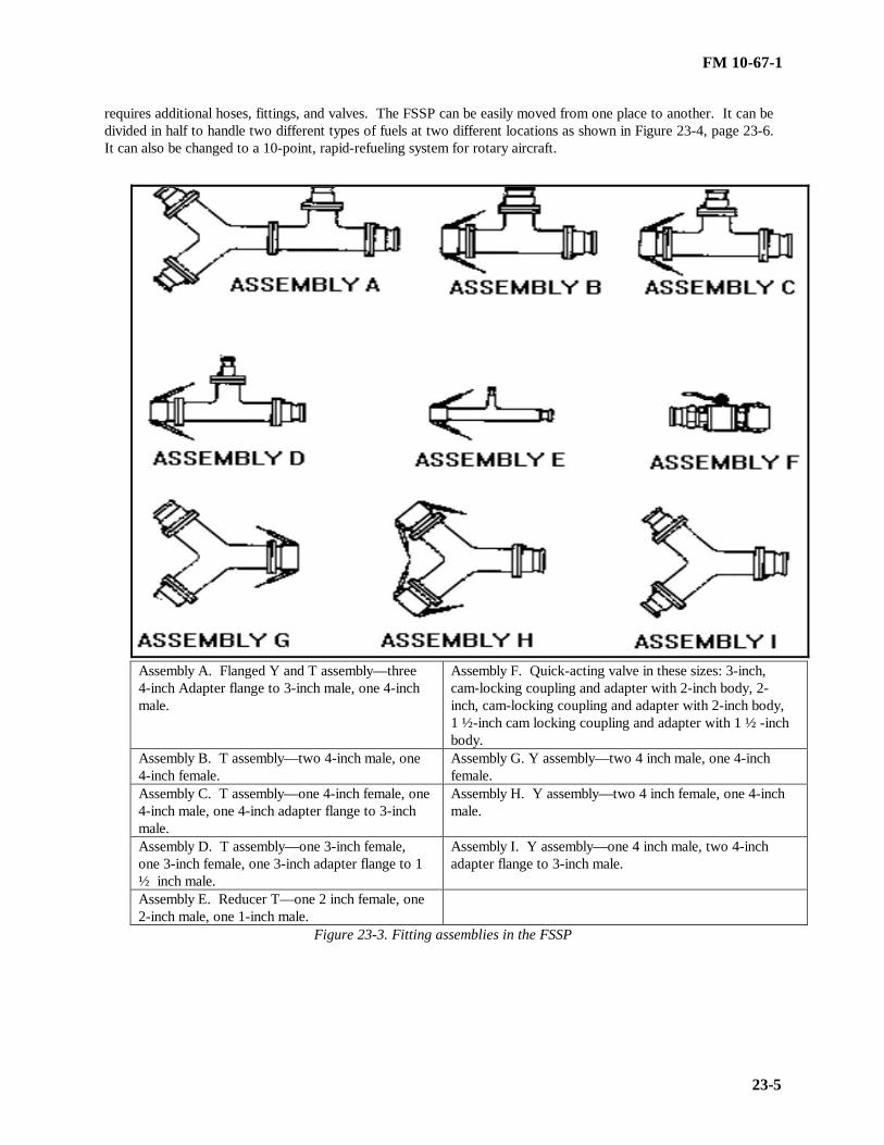
FM 10-67-1
23-5
requires additional hoses, fittings, and valves. The FSSP can be easily moved from one place to another. It can bedivided in half to handle two different types of fuels at two different locations as shown in Figure 23-4, page 23-6.It can also be changed to a 10-point, rapid-refueling system for rotary aircraft.
Assembly A. Flanged Y and T assembly— three4-inch Adapter flange to 3-inch male, one 4-inchmale.
Assembly F. Quick-acting valve in these sizes: 3-inch,cam-locking coupling and adapter with 2-inch body, 2-inch, cam-locking coupling and adapter with 2-inch body,1 ½-inch cam locking coupling and adapter with 1 ½ -inchbody.
Assembly B. T assembly— two 4-inch male, one4-inch female.
Assembly G. Y assembly— two 4 inch male, one 4-inchfemale.
Assembly C. T assembly— one 4-inch female, one4-inch male, one 4-inch adapter flange to 3-inchmale.
Assembly H. Y assembly— two 4 inch female, one 4-inchmale.
Assembly D. T assembly— one 3-inch female,one 3-inch female, one 3-inch adapter flange to 1½ inch male.
Assembly I. Y assembly— one 4 inch male, two 4-inchadapter flange to 3-inch male.
Assembly E. Reducer T— one 2 inch female, one2-inch male, one 1-inch male.
Figure 23-3. Fitting assemblies in the FSSP

FM 10-67-1
23-6
Figure 23-4. Suggested layout for fuel system divided for handling two different fuels or for moving

FM-10-67-1
24-1
CHAPTER 24
UNIT AND VEHICLES USED TO TRANSPORT BULK PETROLEUM
Section I. Tank and Pump Unit
DESCRIPTION
The tank and pump unit as shown in Figures 24-1, page 24-4 and 24-2, page 24-4, consists of a 50-GPMpumping assembly, two 600-gallon aluminum tanks, and related equipment. One electric model and several gas o-line models of the tank and pump unit are currently in use. However, the gasoline pump is being replaced by theelectric pump when requisitioned. The unit is designed to be transported on the 5-ton, 6X6, cargo truck. It is ne c-essary to transport the tank and pump unit on the 5-ton cargo truck because when the unit is filled with fuel it e x-ceeds the load limits of the 2½-ton cargo truck. The tank and pump unit can be used to refuel aircraft because thefilter/separator complies with Military Specification MIL-F-8901E. A newer model tank and pump unit as shownin Figure 24-3, page 24-5, consists of tank control levers at the rear of the unit, a bottom loading port, 500-gallonfuel tanks, and a bottom loading valve that opens automatically when fuel pressure is applied and is closed aut o-matically by the jet level sensor when the tank is full (when filled through bottom loading port ). A general de-scription of the components and installation procedures follows.
Pump Unit
The 50-GPM pumping assembly is used to issue bulk petroleum. The pumping assembly as shown in Figure24-4, page 24-6 includes a pump and engine assembly, a filter/separator, a manifold, hose reels, a ground reel,hose and fittings, and related equipment.
• Electric motor. The electric motor is powered by the vehicle electrical system. Electrical connection is pr o-vided by an intervehicle power cable attached to the NATO slave receptacle of the vehicle on one end and theelectric motor on the other. The electric motor is controlled by an ON-OFF toggle switch or an ON-OFF cableassembly connected to the junction box.
• Gasoline engine . The gasoline engine is a one-cylinder, four-cycle, air-cooled, hand-cranked engine. A r a-dio-shielded magneto supplies the ignition spark. A governor controls the engine speed by varying the throttleopening to suit the pump load. The engine has a 1-gallon fuel tank.
• Pump. The pump is a 50-GPM, self-priming, centrifugal pump. On the gasoline engine model tank andpump unit, the engine is connected to the pump by an intermediate coupler and the impeller is screwed on the e x-tension of the engine crankshaft. On the electric motor model, the impeller is mounted on the extended shaft of theelectric motor. On all models, the pump and engine or motor are mounted on a common base plate to aid removaland use in other pumping operations.
• Filter/separator . The filter/separator is a vertical, 50-GPM unit that is designed for a maximum operatingpressure of 25 PSI. It has four filter elements and canister assemblies, two pressure gages, a sight glass, and twodrains.
• Manifold . The manifold controls the flow of product to the suction side of the pump. Two cam-lockingcouplers provide connections or inlets for the tank suction lines. The product flows from either or both tanks to thesuction side of the pump through the manifold outlet and a section of hose. Some models are equipped with a di s-charge hose running from the filter/separator to the manifold. This permits discharging from the manifold outletwhen the three-way valve is positioned to close off the suction side. Other models use the manifold for suctiononly, and the three-way valve opens or closes the front and rear inlets on the manifold.

FM-10-67-1
24-2
• Hose reels. The dispensing hoses are stored on two reels, each with a recoil tension spring. A 40-footlength of 1½-inch, noncollapsible discharge hose is used on each reel. Product from the filter/separator entersthrough a pipe at the hub of the reel and is discharged through the hose.
• Ground reel. A ground reel is attached to the frame of the pumping assembly so that the tank and pumpunit can be grounded. One section of the ground wire must be clipped to a ground rod near the tank and pump unitbefore the other section is connected to the vehicle being refueled.
• Metering kit . The metering kit (NSN 4930-01-108-9568) consists of a meter, a hose assembly, couplers,cap screws, and washers. The meter is a volumetric, positive displacement meter. It has a five-digit reset counterand a nonsetback totalizer that registers 9,999,999 gallons. The metering kit can be used with all tank and pumpunits.
Related Items of Equipment
Other items issued with the pumping assembly are a drum suction stub for emptying 55-gallon drums, twodispensing nozzles, a starter rope, a carbon dioxide fire extinguisher, and tie-down assemblies as shown in Figure24-1, page 24-4. Nozzles must be fixed so that they must be held open by hand. All nozzles must be tended at alltimes.
The 600-Gallon Tanks
Two welded aluminum, skid-mounted tanks come with the tank and pump unit. The shell of each tank has amanhole assembly, a pump port drain plug, and a discharge valve assembly. Controls for the discharge valve areon top of the tank. The discharge valve outlet is at the bottom rear of the tank, and the drain plug is at the bottomfront. A baffle inside the shell reduces the surge of product during transport. Two lifting rings are attached to thetop of each end of the shell to make handling easier. Tie-downs are provided for securing the tanks in the vehiclebed.
USE
The tank and pump unit can be used to fill and empty 5-gallon cans, 55-gallon drums, and 500-gallon co l-lapsible drums. It can be used to temporarily store product, refuel ground vehicles, and replace or supplement sp e-cial-purpose vehicles. The unit may also be used to fuel aircraft if no other aircraft refueling equipment is avai l-able.
INSTALLATION
The tank and pump unit is designed to be transported in standard 5-ton cargo trucks. Blocking frames are notnecessary for stabilizing the unit in the truck bed. Wood blocking presents a fire hazard because the material iscombustible and will absorb fuel. To install the tank and pump unit on a cargo truck, do as follows:
• Lower the tailgate of the truck and remove the tarpaulin, bows, racks, and seats.
• Install the tank and pump unit.
NOTE: The NO SMOKING WITHIN 50 FEET signs painted on the sides of the 600-gallon tanks must not beobstructed.
• Released the ratchet of the tank tie-down assembly by pressing the release in the ratchet handle. Hold therelease, pull the handle down until the side cams engage, and push the static ratchet locks up from the ratchetdogs. This allows the center ratchet spool to rotate in either direction. To aid in unrolling the nylon strap, turn theratchet hook opening down on a flat surface. Press down in the center of the ratchet while pulling the strap awayfrom the ratchet.
• Place the tie-down straps over the tank ends. Attach the brackets to the sides of the truck, and attach thestrap end and ratchet to them.
• Move the ratchet handle up and down until the strap is tight. Push the ratchet handle to the LOCK position.

FM-10-67-1
24-3
• Hook the loose bracket of the pump tie-down assembly over the top of the reel frame (the long side with thehole out and down). Hook the bracket attached to the strap end beneath the rear of the truck 8 to 10 inches right ofcenter.
• Insert the strap end, rear to front, through the slot in the center of the ratchet spool. Pull the slack throughthe ratchet spool.
• Unlock the ratchet. Move the ratchet handle up and down until the strap is tight. Push the ratchet handle toits locked position.
• Raise the tailgate.
OPERATION
The tank and pump unit is used to dispense all types of automotive, aviation, diesel, and burner fuels. Onlyone type of fuel should be carried in and dispensed from the unit at one time. Dispensing with the tank and pumpunit may be done in various ways to meet different situations in the field. Even though differences exist betweenthe models, all the tank and pump units operate basically the same.
Preparing for Start of Tank and Pump Units
A number of steps and precautions must be followed before starting the tank and pump unit. These steps areas follows:
• Check the suction hose connections between the tanks and the pumping assembly to ensure that they areproperly locked into place.
• Connect the ground wires from the ground reel on the pumping assembly to the grounding rod driven intothe ground close to the vehicle being refueled.
• Maintain at least 25 feet between vehicles being refueled.
• Open only the fill port of the vehicle being refueled. Do not refuel two vehicles at one time unless thereare two people available to monitor both nozzles constantly.
• Open the hand valves on the filter/separator sight glass assembly, and allow the sight glass to fill. If theglass does not fill, open the petcock on the lower valve to release the air. Close the petcock when the sight glass iffull.
• Check the sight glass for the presence of water, and drain when necessary.
NOTE: Some models have a pipe plug drain instead of the petcock on the filter/separator. This pipe plug drainmust be removed to drain water.
• Attach the nozzle grounding cable to the vehicle being refueled.
WARNING
Normally the pump will automatically prime itself by gravity flow when the tanks are full. Do not removethe priming cap to check for pump prime. This will result in a fuel spill. Entrapped air will be releasedthrough the dispensing nozzle when it is first opened for dispensing.
Starting the Gasoline Engine
Several important steps must be followed to start the gasoline engine. These steps are as follows:
• Open the coupler angle valve assembly by turning the handwheel counterclockwise.
• Move the four-way valve handle to the required position.

FM-10-67-1
24-4
• Move the remote pump switch to the ON position.
• Stopping the Engine/Motor. To stop the gasoline engine, close the discharge valves on the tanks and allowthe engine to idle for three to five minutes. After the engine has cooled, shut off the ignition switch. To stop theelectric motor, turn the remote pump switch to the OFF position.
Figure 24-1. Tank and pump unit

FM-10-67-1
24-5
Figure 24-2. Mounted tank and pump unit
1. Bottom Loading Port2. Dispensing Reel3. Filter Separator4. 50 GPM Electrical Pump5. Quick Dry Disconnect Adapter6. Tank Control Levers7. Toolbox8. Static Discharge Reel

FM-10-67-1
24-6
Figure 24-3. New model tank and pump unit
Figure 24-4. Pumping Assembly

FM-10-67-1
24-7
Section II. Tank Trucks
M49A2C
The M49A2C tank truck is used mainly for transporting bulk petroleum and for general refueling. Its d e-scription and use are discussed in the following paragraphs.
Description
The M49A2C tank truck as shown in Figures 24-5, page 24-7, and Figure 24-6, page 24-7, is mounted on amodified M45A2 chassis. The truck has a multifuel engine and single front and dual rear tires. It is about 23 feetlong, 8 feet wide, and 7 2/3 feet high. TM 9-2320-209-34P gives details on this tank truck. The components ofthe vehicles are discussed below.
NOTE: This FM uses the terms curbside, roadside, left side, and right side. Curbside and roadside refer to theright and left sides, respectively, of a vehicle parked at the curb on the right side of the two-way street. The leftside of the vehicle is the driver’s side.
• Tank body and equipment . The tank body is a stainless steel, 1,200-gallon shell divided into two 600-galloncompartments. Each compartment has a manhole and filler cover assembly as shown in Figure 24-7, page 24-8.There is a walkway on each side of the tank body. A 5-pound carbon dioxide fire extinguisher is mounted on theleft rear and the right front of the tank body walkways. An equipment compartment or cabinet is located at therear of the tank body. This compartment houses the fuel delivery system of the tank truck. The components of thissystem and their location in the rear compartment are shown in Figure 24-8, page 24-8.
• Delivery pump . A rotary, positive-displacement pump, located in the rear equipment compartment (Figure24-8, page 24-8), pumps fuel from the tank truck. The pump is rated at 80 GPM at 700 RPM. The speed of thepump is governed by a speed control linkage assembly. The throttle control is located on the instrument panel inthe operator compartment.
• Filter/separator . There is an upright filter/separator in the rear equipment compartment (Figure 24-8, page24-8) of the M49A2C tank truck. It has three filter elements, three go/no-go fuses, a pressure gage, and an aut o-matic dump valve.
• Hose and nozzle assembly . A 35-foot length of 1½-inch reinforced hose with a standard 1½-inch nozzle ismounted on the left side of the tank body.

FM-10-67-1
24-8
Figure 24-5. Roadside view M49A2C
Figure 24-6. Curbside view of M49A2C tank
Figure 24-7. Manhole and filler covers of tank compartments on M49A2C tank truck

FM-10-67-1
24-9
Figure 24-8. Rear equipment compartment of M49A2C tank truck
Use
The M49A2C tank truck can carry bulk petroleum both on and off the road. However, it can carry only 600gallons when it travels off the road because the forward tank must be left empty. The truck can be used to fill andempty 500-gallon collapsible drums and 55-gallon drums and to refuel ground vehicles. The tank truck is usedalso in the open port refueling of aircraft. More information on the M49A2C can be obtained in the appropriateTM. Appendix K covers various conversion procedures that must be followed when changing products in tankcars and tank trucks.
M978 HEMTT
The M978 tank truck is used to haul and dispense bulk petroleum fuels. It is primarily used to refuel vehiclesand aircraft.
Description
The M978 tank truck as shown in Figure 24-9 is a 10-ton, 8X8 vehicle. It is on-the-road and off-the-road, allweather and all-terrain vehicle. The truck has an eight-cylinder, two-cycle, turbocharged, liquid-cooled, dieselengine. It can haul and dispense 2,500 gallons of bulk petroleum. The tank truck can ford water up to 48 inchesdeep. It is about 8½ feet tall and about 33 1/3 feet long. It has a highway cruising range of 300 miles. The co m-ponents of the vehicle are discussed below.
• Tank body and equipment . The tank is a stainless steel, 2,500-gallon, single compartment shell with onemanhole cover. A cabinet at the rear of the vehicle houses the vehicle’s fuel delivery manifold system, hose reels,ground cables, a deadman shutoff, and a filter/separator.

FM-10-67-1
24-10
• Delivery pump . Fuel is pumped from and into the vehicle by a 300-GPM centrifugal pump. The pump isdriven by a power takeoff from the vehicle’s engine. The vehicle also has an alternate fuel delivery pump. This25-GPM pump is powered by 24 volts DC from the vehicle electric system.
• Filter/separator . The filter/separator is located in the cabinet at the rear of the M978 tank truck. It is a 300-GPM unit with a pressure differential indicator, 15 filter and canister assemblies, and a manual drain valve. Thereis a sampling probe on the discharge side of the filter/separator for use with the Aqua- Glo water test kit.
• Discharge and suction hoses . The tank truck has two hose reels in the cabinet at the rear of the vehicle.Each hose reel has 50 feet of 1½-inch dispensing hose. Each hose has a 50-GPM capacity. The hose ends havemale cam-locking couplings and bonding connections. Each hose reel has a fuel-servicing nozzle. The HEMTTalso has a 15-foot section of 3-inch suction hose.
Figure 24-9. Roadside view of M978-tank truck
Use
The truck can travel on all types of terrain with a full payload. It is able to transport bulk fuels in areas whereother tank trucks cannot operate. The tank truck can service two vehicles at one time. Because it is equipped witha filter/separator, it may also be used to refuel aircraft.
Section III. Tank Semitrailers
M131A5C
The M131A5C tank semitrailer is used to carry and transfer fuel, service containers, and refuelground.vehicles. Its description and use are explained in the following paragraphs.
Description
This vehicle as shown in Figures 24-10, page 24-11 and 24-11, page 24-11 is a 12-ton, four-wheel, 5,000-gallon tank semitrailer. It is normally towed by a 5-ton, 6X6 tractor truck that has a fifth wheel. The semitrailer isabout 31 feet long, 8 feet wide, and 9 feet high. TM 9-2330-272-14&P has details on this tank semitrailer. Thecomponents of the vehicles are discussed below.
• Tank body and equipment . The tank body of the M131A5C is made of stainless steel. It is divided into two2,500-gallon compartments. Each compartment has a 20-inch manhole cover and a filler cover with a vent valveas shown as Figure 24-12, page 24-11. The top of the tank body has a steel grate so that personnel do not slipwhen they walk on the walkway. The walkway, reached by a ladder at the rear of the vehicle, gives access to the

FM-10-67-1
24-11
manhole covers. An equipment cabinet is mounted on each side of the tank vehicle. These cabinets hold thesemitrailer discharge and loading system. The components of this system located in the roadside equipment cab i-net are shown in Figure 24-13, page 24-12. Figure 24-14, page 24-13, shows the system components located inthe curbside equipment cabinet. A hose compartment is mounted on the tank body above the roadside equipmentcabinet as shown in Figure 24-10, page 24-11. The hose compartment is horizontally divided into three tubeswhich house three 15-foot lengths of suction hose and gage stick.
• Auxiliary engine and pump assembly . The auxiliary engine and pump assembly is located in the curbsidecabinet as shown in Figure 24-14, page 24-13. It is used to pump product into or out of the compartments. Theassembly has a two-cylinder, four-cycle, horizontally opposed, air-cooled engine and a self-priming, 225-GPMcentrifugal pump. The pump is connected directly to the engine through a shaft mounted on a bearing. The e n-gine and pump are separated by a fire wall.
• Filter/separator . A filter/separator is mounted on the right side of the tank body on the M131A5C tanksemitrailer. It has 15 elements and 5 canisters. The unit also has 15 go/no-go fuses mounted in the canister el e-ments. The filter/separator’s operating pressure is 75 PSI. Its capacity is 300 GPM.
• Dispensing hose and reels . The M131A5C tank semitrailer has 2½-inch and 1½-inch dispensing hose reels.Both reels are stored in the roadside equipment cabinet. The 2½-inch dispensing hose reel holds a 50-foot sectionof 2½-inch dispensing hose. This hose has a 2½-inch nozzle. Its discharge capacity is 225 GPM. The 1½-inchdispensing hose reel holds a 50-foot section of 1½-inch dispensing hose. This hose has a 1½-inch nozzle and isused for low-rate discharge (0 to 55 GPM).
Figure 24-10. Curbside view M131A5C
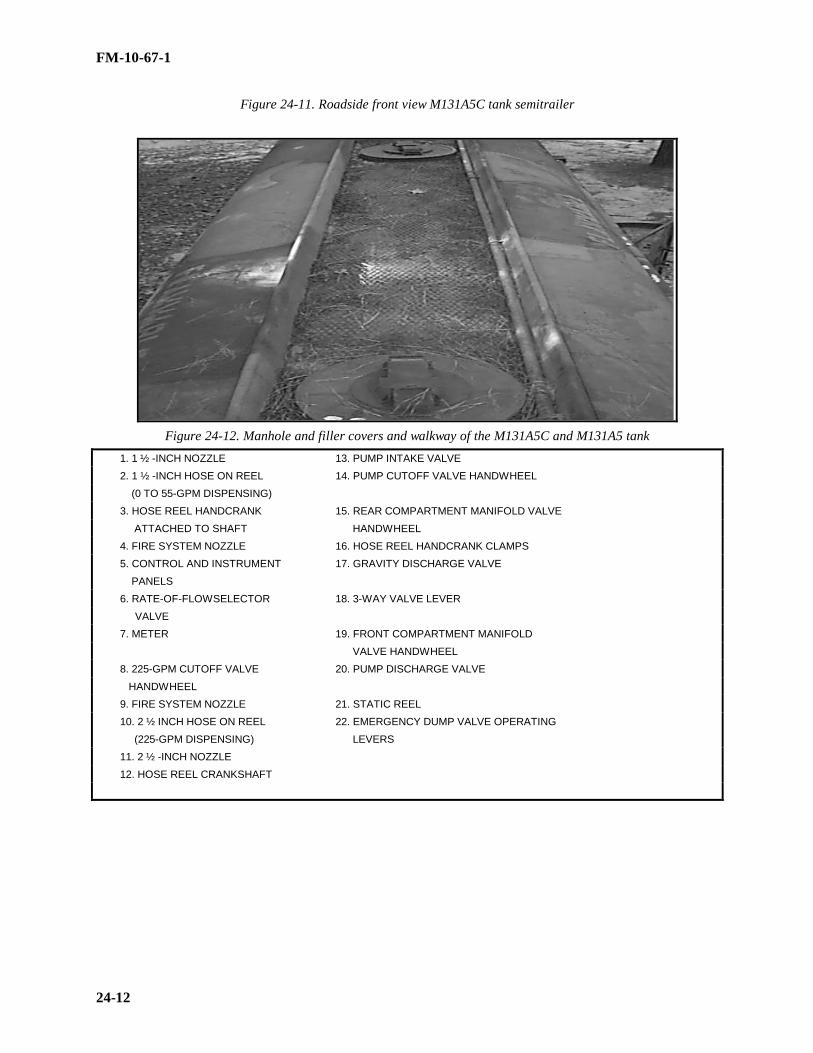
FM-10-67-1
24-12
Figure 24-11. Roadside front view M131A5C tank semitrailer
Figure 24-12. Manhole and filler covers and walkway of the M131A5C and M131A5 tank
1. 1 ½ -INCH NOZZLE 13. PUMP INTAKE VALVE
2. 1 ½ -INCH HOSE ON REEL 14. PUMP CUTOFF VALVE HANDWHEEL
(0 TO 55-GPM DISPENSING)
3. HOSE REEL HANDCRANK 15. REAR COMPARTMENT MANIFOLD VALVE
ATTACHED TO SHAFT HANDWHEEL
4. FIRE SYSTEM NOZZLE 16. HOSE REEL HANDCRANK CLAMPS
5. CONTROL AND INSTRUMENT 17. GRAVITY DISCHARGE VALVE
PANELS
6. RATE-OF-FLOWSELECTOR 18. 3-WAY VALVE LEVER
VALVE
7. METER 19. FRONT COMPARTMENT MANIFOLD
VALVE HANDWHEEL
8. 225-GPM CUTOFF VALVE 20. PUMP DISCHARGE VALVE
HANDWHEEL
9. FIRE SYSTEM NOZZLE 21. STATIC REEL
10. 2 ½ INCH HOSE ON REEL 22. EMERGENCY DUMP VALVE OPERATING
(225-GPM DISPENSING) LEVERS
11. 2 ½ -INCH NOZZLE
12. HOSE REEL CRANKSHAFT

FM-10-67-1
24-13
Figure 24-13. Roadside equipment cabinet of the M131A5C tank semitrailer
1. EXHAUST2. FIXED FIRE EXTINGUISHER NOZZLE3. CENTRIFUGAL PUMP4. PUMP DISCHARGE LINE5. PUMP SUCTION LINE6. FUEL TANK AND SEDIMENT BOWL7. BATTERY8. BATTERY LEAD9. FIRE WALL PANELS10. ENGINE11. SPARK PLUG CABLE12. BREATHER
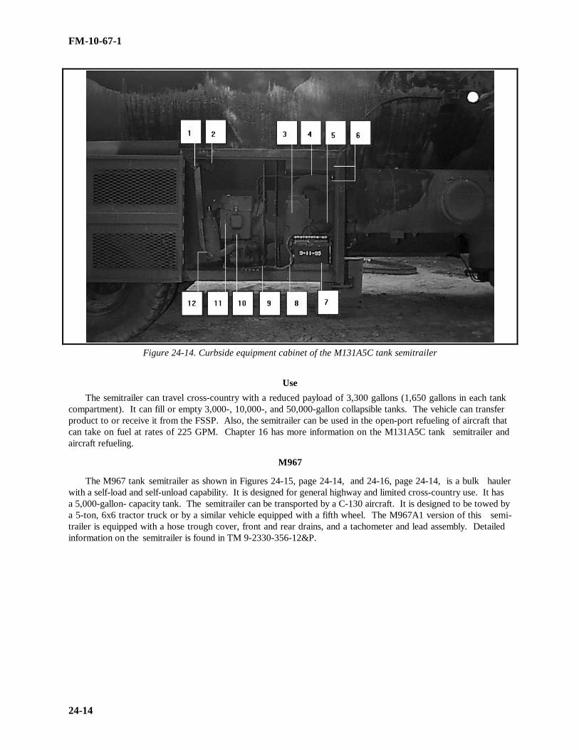
FM-10-67-1
24-14
Figure 24-14. Curbside equipment cabinet of the M131A5C tank semitrailer
UseThe semitrailer can travel cross-country with a reduced payload of 3,300 gallons (1,650 gallons in each tank
compartment). It can fill or empty 3,000-, 10,000-, and 50,000-gallon collapsible tanks. The vehicle can transferproduct to or receive it from the FSSP. Also, the semitrailer can be used in the open-port refueling of aircraft thatcan take on fuel at rates of 225 GPM. Chapter 16 has more information on the M131A5C tank semitrailer andaircraft refueling.
M967
The M967 tank semitrailer as shown in Figures 24-15, page 24-14, and 24-16, page 24-14, is a bulk haulerwith a self-load and self-unload capability. It is designed for general highway and limited cross-country use. It hasa 5,000-gallon- capacity tank. The semitrailer can be transported by a C-130 aircraft. It is designed to be towed bya 5-ton, 6x6 tractor truck or by a similar vehicle equipped with a fifth wheel. The M967A1 version of this semi-trailer is equipped with a hose trough cover, front and rear drains, and a tachometer and lead assembly. Detailedinformation on the semitrailer is found in TM 9-2330-356-12&P.

FM-10-67-1
24-15
Figure 24-15. Curbside view M967 tank semitrailer
Figure 24-16. Roadside view M967 tank semitrailer

FM-10-67-1
24-16
Description
The stainless steel body of the M967 consists of one 5,000-gallon fuel compartment. The compartment co n-tains pressure and vacuum vents and a manhole with locking device. The fuel delivery system is mounted on thesides of the vehicle. On the curbside of the vehicle are a pump and engine compartment, a pump engine fuel tank,a landing gear crank, a hose trough, and an emergency shutoff valve. On the roadside of the vehicle are a hosetrough, a ground board, a toolbox, a piping assembly, a control panel, and a portable grounding rod.
Use
The M967 semitrailer is used for bulk delivery of fuel. It does not have the dispensing capability of the M969or the M970. The four-cylinder, four-cycle auxiliary engine and pumping system can deliver bulk fuel at a rate ofup to 600 GPM and can self-load at a rate of up to 300 GPM.
M969
The M969 as shown in Figures 24-17 and 24-18, page 24-16, is a fuel-dispensing semitrailer. It has the samebulk delivery and self-load capabilities as the M967. It also has a 5,000-gallon-capacity tank and can be towed andtransported in the same way as the M967 tank semitrailer.
Figure 24-17. Curbside front view of M969 tank semitrailer

FM-10-67-1
24-17
Figure 24-18. Roadside view of M969 tank semitrailer
Description
The tank body and the auxiliary engine and pump assembly are identical to those of the M967. The M969A1version of this semitrailer is equipped with a hose trough cover, a control panel cover, a rear ladder, front and reardrains, and a tachometer and lead assembly. Additional differences found on the M969A1 model are an elasto-meric-type drive coupling between the fuel-dispensing pump and the engine assembly, a new axle, bogie, andbraking system . The vehicle components are discussed below.
• Tank body and equipment . The M969 has the same equipment that is included with the M967. It also hasthe equipment needed for automotive refueling and limited aircraft refueling. This equipment is mounted on thesides of the vehicle. The filter/separator, the pump and engine assembly as shown in Figure 24-19, page 24-17, theengine’s fuel tank, the landing gear crank, the emergency shutoff valve, a hose trough, and the battery compar t-ment for two batteries are located on the curbside of the M969. A hose trough, a portable grounding rod, a controlpanel, the manifold valving, and a hose reel cabinet as shown in Figure 24-20, page 24-18, are on the roadside ofthe vehicle.
• Filter/separator . The filter/separator is rated at 300 GPM and 15 PSI. It has three filtering stages. In thefirst stage, 15 filter elements remove solid particles and coalesce any water in the fuel. In the second stage, fivecanisters separate the water from the fuel and let it drain into the filter/separator sump. Finally, 15 go/no-go fusesact as safety devices to shut off the flow of fuel if the other two stages allow water to exceed a safe level. Three ofthese fuses are in each of the second-stage elements. Other parts of the filter/separator include an automatic drainvalve, a manual drain valve, and a pressure gage. When water in the filter sump reaches a certain level, the wateris removed by the automatic drain valve. This valve is operated by a float which rises in water and sinks in fuel.As water enters the filter sump, the float rises. When the float rises to a certain level, a valve opens in the drainvalve assembly allowing pump pressure to be applied to a diaphragm valve. The opening of the diaphragm valvecauses the automatic drain valve to open, allowing the water to drain. As the water is being drained, fuel flow iscontinued. If water enters the sump faster than the automatic drain valve can carry it away or if the filter elementsfail, the go/no-go fuses stop the flow of fuel. The pressure gage is located on the instrument panel in the roadsideequipment cabinet. It shows the amount of restriction in the filter/separator.
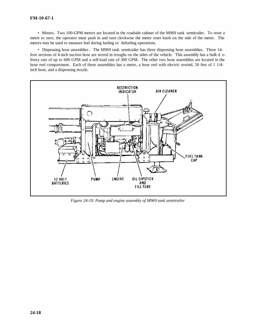
FM-10-67-1
24-18
• Meters. Two 100-GPM meters are located in the roadside cabinet of the M969 tank semitrailer. To reset ameter to zero, the operator must push in and turn clockwise the meter reset knob on the side of the meter. Themeters may be used to measure fuel during fueling or defueling operations.
• Dispensing hose assemblies . The M969 tank semitrailer has three dispensing hose assemblies. Three 14-foot sections of 4-inch suction hose are stored in troughs on the sides of the vehicle. This assembly has a bulk d e-livery rate of up to 600 GPM and a self-load rate of 300 GPM. The other two hose assemblies are located in thehose reel compartment. Each of these assemblies has a meter, a hose reel with electric rewind, 50 feet of 1 1/4-inch hose, and a dispensing nozzle.
Figure 24-19. Pump and engine assembly of M969 tank semitrailer
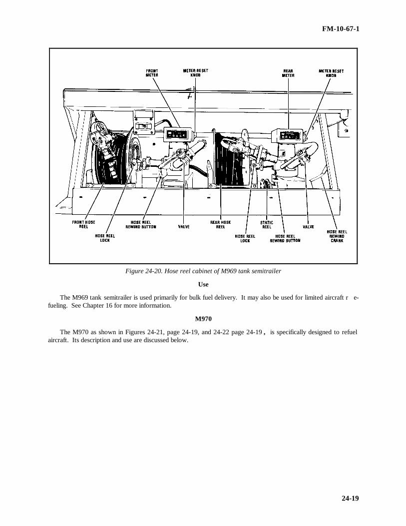
FM-10-67-1
24-19
Figure 24-20. Hose reel cabinet of M969 tank semitrailer
Use
The M969 tank semitrailer is used primarily for bulk fuel delivery. It may also be used for limited aircraft r e-fueling. See Chapter 16 for more information.
M970
The M970 as shown in Figures 24-21, page 24-19, and 24-22 page 24-19 , is specifically designed to refuelaircraft. Its description and use are discussed below.

FM-10-67-1
24-20
Figure 24-21. Curbside view M970- tank semitrailer
Figure 24-22. Roadside view M970 tank semitrailer

FM-10-67-1
24-21
Description
The M970 tank semitrailer has a 300-GPM bulk delivery capability and a self-load capability. It has the same5,000-gallon capacity as the M967 and M969. It can be towed and transported in the same way as the M967 andM969 semitrailers. The M970 has a 3-inch, high-pressure centrifugal pump and a recirculation system. TheM970A1 version of this semitrailer is equipped with a hose trough cover, a control panel cover, a rear ladder, afront and rear drain, and a tachometer and lead assembly.
• Tank body and equipment . In addition to the equipment on the M967, the M970 has special-purposeequipment required for overwing and underwing aircraft refueling. This equipment is mounted on the sides of thevehicle. A filter/separator, a pump and engine compartment, the engine’s fuel tank, a landing gear crank, anemergency shutoff valve, a hose trough, and a battery compartment for two batteries are on the curbside of the v e-hicle. A hose trough, a portable grounding rod, a ground board, a toolbox, a piping assembly, a control panel, themanifold valving, and a hose reel cabinet as shown in Figure 24-23, page 24-21, are on the roadside of the vehicle.
• Filter/separator . The M970 has the same filter/separator as the M969. It has a pressure differential gagethat is mounted on the control panel of the roadside equipment panel.
• Meter. The M970 tank semitrailer has one 300-GPM, full-metering meter located in the hose reel cabinet.The meter serves all three dispensing assemblies.
• Dispensing hose assemblies . There are three dispensing hose assemblies on the M970 tank semitrailer.One is made up of three 14-foot sections of 4-inch suction hose stored in hose troughs on the vehicle. The othertwo assemblies are located in the roadside equipment cabinet. One assembly is for underwing refueling. It i n-cludes 50 feet of 2½-inch hose with an electric rewind reel, a deadman control, and a D-1 nozzle. The overwingrefueling assembly has 50 feet of 1½-inch hose, an overwing dispensing nozzle, and a hose reel with electric r e-wind.

FM-10-67-1
24-22
Figure 24-23. Hose reel cabinet of M970 tank semitrailer

FM-10-67-1
24-23
Use
The M970 is used chiefly for underwing and overwing aircraft refueling. The recirculation system facilitatesfuel sampling and allows for complete recirculation of fuel to remove condensation and contamination.
M1062
The M1062 as shown in Figures 24-24 and 24-25, page 24-22, is a bulk fuel semitrailer designed and used toreceive transport and discharge bulk fuel on improved roads. Its description and use are discussed below.
Figure 24-24. Curbside view M1062 semitrailer
Figure 24-25. Roadside view M1062 tank semitrailer

FM-10-67-1
24-24
Description
The M1062 has a loading capability of 300 GPM using an external pump. It has a single compartment with acapacity of 7,500 gallons plus 3 percent expansion space and weighs 11, 566 pounds empty and about 65,556pounds full. Full weight will vary depending on product being hauled. The entire vehicle is about 34 foot long, 8feet wide, and 8 feet 9 inches high. It is designed to be towed by the M915/915A1 tractor equipped with a fifthwheel.
• Tank Body and Equipment. The stainless steel tank body of the M1062 tank semitrailer is constructed asone 7,500-gallon compartment with seven baffles. The fuel-handling equipment includes all the necessary piping,fitting, hose, and valves for handling the fuel from the curbside. Forward of the rear wheel is the spare tire carrier,landing gear, hose trough, and upper fifth wheel plate at the front
Use
The M1062 is a bulk fuel line hauler and can be loaded with an external 300 GPM pump. The semitrailer hasno on-board filter/separator or pump for retail issues.
VAPOR RECOVERY KIT.
The vapor recovery system as shown in Figure 24-26, page 24-24, can be installed on all models of tanksemitrailers and is required in certain ecological areas. The system allows a fuel depot to collect or recover thevapors and gases that are present during the loading operation. Vapors can also be recycled back to the semitrailerthrough the recovery system during loading operations. The system consists of a vaportight line running from thesealed hood on the emergency valve vent (directly behind the manhole cover) to the rear of the tank. The rolloverrail on the roadside of the semitrailer is used as part of the line. The adapter on the end of the line is compatiblewith the 4-inch quick disconnect vapor recovery connections at a majority of fuel depots.

FM-10-67-1
24-25
Figure 24-26. Typical vapor recovery system
Section IV. Other Considerations of Tank Vehicles
REFUELER MARKINGS
Specific markings are required on all vehicles transporting hazardous material. Vehicles that carry bulk fuelsmust be marked on both sides and the back of the tank body with the words FLAMMABLE and NO SMOKINGWITHIN 50 FEET. The word FLAMMABLE must be printed in block letters 6 inches high. The words NOSMOKING WITHIN 50 FEET must be printed in block letters and numbers 3 inches high. They must be placeddirectly under FLAMMABLE or to the right of it on the same line. On vehicles used in combat, these markingsare the same color as the registration markings, usually black on olive drab. On vehicles used on public highwaysin CONUS, the markings are in red letters on a white background. The capacity of each bulk tank must be marked(NUMBER) GALS below and to the right of each tank manhole cover. Refuelers must be marked, on each side ofthe tank, with the military symbol for the type of fuel the tank contains. The markings should be 6 inches high forsemitrailers, 4 inches high for trucks, and 3 inches high for two-wheel trailers. Refuelers must be placarded IAWAR 55-355 and applicable DOT regulations.

FM-10-67-1
24-26
CAMOUFLAGE
Concealing tank vehicles is important in a theater of operations because of their tactical importance. D e-stroying petroleum supplies and its transportation can effectively cripple a modern, highly mobile force and groundits aircraft. Dispersion is important because of the possibility of one explosion causing other explosions. FM 20-3and TM 5-200 provide detailed camouflage instructions. Nearby engineer units should be asked for advice andhelp in planning local camouflage measures; however, each unit is responsible for camouflaging the vehicles ituses.
factors described below can reveal the locations of tank vehicles. Preventive measures are also given.
Tracks
Any vehicle leaves tracks when off a paved surface. Vehicle tracks show up very clearly to aerial observers,especially in dew or snow. The best way to conceal tracks is to make them where they cannot be seen from the air.For example, turn off the road into a wooded area. If the refuelers must be driven in the open, drive parallel tohedges, fences, cultivated fields, or other terrain features that make the tracks less conspicuous. Tracks should becontinued past the refueling point (to the next road or to a farm) to give the appearance that they logically gosomewhere other than to the refueling area.
Shine
Shine is a giveaway to an unnatural object in a landscape. The windshield, headlights, and cab windows of atank vehicle are most likely to shine in sunlight, moonlight, or the light of flares. Shine is hard to counteract b e-cause light can be reflected through even the smallest gaps in cover. Dark cloth is an ideal cover. In the field,foliage or foliage attached to camouflage nets is usually all that is available. Camouflage paint should be used todull the body of the vehicle and any shiny part of the fittings or hose couplings.
Shadow
Fender shadows and the dark shadow under a vehicle reveal its presence. Each vehicle also casts a characte r-istic shadow pattern that can reveal its type. The best way to conceal the shadow is to use natural shadows. Alarge natural shadow is usually dark enough to hide a refueler parked within it. A refueling vehicle cannot safelybe parked within a shadow of a large building, so tree shadows are the only shadows likely to be large enough toconceal it. If a refueler must be parked in the open, it should be parked where its shadow will fall on an irregularsurface such as onto brush or into woods. Then the irregular surface will distort the characteristic shape of thevehicle shadow. Camouflage paint can also help conceal shadows. Dark blotches can break up fender patterns,and light paint interspersed with dark patches near the bottom of the tank vehicle can help break up the straightlines of the undercarriage.
VEHICLE PARK
Several factors are considered when laying out a parking area for vehicles. These are described below.
• Layout. Seven considerations determine the proper layout for a vehicle park. When a vehicle park is laidout properly, it will--
•• Leave enough space between refuelers so that they can be driven out quickly in an emergency.
•• Ground vehicles.
•• Let fire control personnel and equipment get to each refueler.
•• Keep fuel that leaks out of a tank vehicle from draining toward a nearby building.
•• Leave at least 25 feet between each refueler and the nearest building that has windows or doors on theside or sides that face the vehicle park.
•• Keep refuelers out of flight paths.
FM-10-67-1
24-27
•• Provide side protection, such as revetments, when needed.
Tactical and Other Concerns
In a tactical area, the proper layout of a vehicle park may have to be modified. The tactical situation, physicallimitations of the site, and requirements for protection and camouflage must be weighed against the standards for aproper layout. The following are among the concerns that must be weighed in a specific tactical area:
• Fuel supplies and tank vehicles may need to be guarded.
• Tank vehicles may have to be shielded from enemy fire.
• Vehicle park may have to be camouflaged.
• Paved areas or hardstands may be limited.
FM 10-67-1
25-1
CHAPTER 25
REFUEL ON THE MOVE
CONCEPT
The Army’s highly mobile force depends on fuel to sustain it on the battlefield more than it ever hasin the past. As in Operation Desert Storm, a mobile and maneuverable force needs large amounts of fuelin a timely fashion to maintain its offensive posture. Combat vehicles must be refueled efficiently, ra p-idly, and safely. For combat forces to remain maneuverable, fuel resupply must be flexible and innov a-tive. ROM is normally accomplished as far forward on the battlefield as the tactical situation permits,prior to the tactical assembly area. The doctrinal purpose of ROM is to extend the time that ground m a-neuver forces can spend on the objective, although ROM can be tailored to other situations as well. Whenvehicles enter a ROM site for refueling, they receive a predetermined amount of fuel (usually timed) andthey move out to return to their convoy or formation. This distinguishes it from routine convoy refuelingoperations.
WARNINGDue to safety considerations, normal vehicle refueling is done with the engine off. AR 385-55 states thatcommanders will apply all normal safety standards to their operations unless it is necessary to change todo the mission. In training situations, changes may be authorized only by the commander. Commanderswill evaluate the significance of the assumed risk versus the training benefit. In combat operations, co m-manders will make decisions based on METT-T and risk analysis.
CONSIDERATIONS
In planning a ROM operation, METT-T must be considered. Based on these considerations, identifyplan, and conduct the type of ROM operations that best support the commander’s scheme of m aneuver.
MissionThe mission drives the need for ROM operations. Since the ROM site is a vulnerable, high value target,consider other refueling options which will do the mission. ROM missions are most often used to supportextended moves to a tactical assembly area before an attack or before retrograde moves.
EnemyKnown or expected enemy activity in the area of operations and area of interest must be considered.
Clear and secure the ROM site before the fuel semitrailers arrive. Risk increases significantly as the ROMgets closer to the FLOT. Consider enemy artillery range when choosing the ROM sites and concealing itsoperations. Air defense assets should support the ROM site if there is any enemy air threat.
Terrain
A thorough terrain analysis is an essential part of a successful ROM operation. Examine the routes ofmarch, supporting road networks, cover and concealment, the locations of check points, and whether ornot the terrain can support loaded fuel semitrailers and high traffic flow. A movement using multipleroutes of march may require several ROM sites. Wet, swampy, or restrictive terrain will not support mostROM operations due to the weight of the fuel trailers and the high traffic flow.
TroopsThe status of combat vehicle crew and supporting unit soldiers must be analyzed. Do they have
enough crew members to operate the issue nozzle themselves and let the driver remain in the vehicle

FM 10-67-1
25-2
during refueling? Are the soldiers trained on ROM operations? Analyze the forces available to secure theROM site and perform traffic control.
Time
Time must be considered. Consider the time it will take to cover the distances vehicles will be mo v-ing; the amount of time available to coordinate, secure, establish, and camouflage the ROM site; the a c-ceptance rate of unit vehicles and the number of minutes of fuel they will receive. Also, determine howfar in advance of the main body the security force and fuel semitrailers can deploy while still concealingthe projected unit move. The ROM site personnel must ensure each vehicle receives the correct number ofminutes of fuel. If not, the following march units will back up.
VEHICLE HOLDING/ MARSHALING AREAS
Set up these areas at locations before and after the ROM site. Coordinate areas before to the start ofthe operation. Use the first area (prior to the ROM site) to organize the march column into serials of v e-hicles equal to the number of refueling points available. Call the vehicles forward out of the holding areaone serial at a time to move into position to receive the predetermined amount of fuel. When each serialhas received its allotted fuel, it moves to the second holding area (after the ROM site). In the secondholding area, organize the vehicles back into their convoy march elements or combat formations. Figure25-1 shows a recommended layout and marshaling areas for a ROM.
Figure 25-1. 8-Point ROM
PRIOR PLANNING
Plan a contingency for equipment failure. Make sure there is enough room in the site to moveequipment. Make the most use of natural cover and concealment. Include a signal system to coordinatethe operation. Use signals to start and stop refueling operations, and coordinate the vehicle serials to andfrom the holding areas. Use the arm and hand signals or flags during the day. Long distances may r e-

FM 10-67-1
25-3
quire radio communications. At night or in low visibility conditions, use chemical light or flashlights forsignals.
SAFETY PROCEDURES
• Enforce grounding and bonding procedures for fuel semitrailers, pumps, filter/separators and eachrefueling point.
• Make sure fuel handlers wear protective clothings (for example, standard combat uniform, hearingprotection, goggles, and gloves). With the exception of the standard uniform, other items are normallyprovided by the organization.
• Locate fire extinguishers at each refueling point and source of fuel (but not so close that they cannotbe reached in the event of a fire).
• Place fuel drip pans at each refueling point and fuel source. When draining drip pans, observe fire,safety, and environmental precautions.
• Ensure the fuel spills procedures and equipment should include, as a minimum, sorbents, shovels,and containers. An SOP should detail equipment and procedures for response in a field environment.Ensure that the SOP follows federal, state and local r equirements.
RESPONSIBILITIES
For the ROM operation to be expedient and personnel to be proficient on the battlefield, prior coord i-nation and planning must be conducted throughout the chain of command. Successful conduct of ROMoperations will require all units to work together. Planning must include both supporting and supportedunits. It must cover in detail the organization, sustainment, and protection of ROM site(s) and the o r-ganization and conduct of the overall operation.
Planning StaffsDetermine if you need more support requirements to conduct ROM operations and coordinate there
requirements with your higher headquarters. Coordinate with higher headquarters for operational andintelligence data. Analyze all factors involved, including the METT-T, to determine the type of refuelingoperation needed to support the mission. The recommendation is then forwarded to the commander. S e-lect the location for the ROM site based on the METT-T, the ROM configuration, and the establishedmarch route. Coordinate ROM security support before setting up the ROM site. Coordinate with themilitary police for traffic control support at the site. Receive and review estimated fuel requirements andcoordinate with the Class III section of the MMC. Review and coordinate the vehicle movements into therefueling area to prevent convoy backup.
ROM Site Personnel
Set up, perform PMCS, operate, and retrieve the equipment used in the operation. Ensure safety (forexample, grounding, bonding, fire extinguishers, no smoking signs, drip pans, spill equipment is in placeand personnel are familiar with procedures). Ensure personnel are familiar and equipped with operationalcontrol signals (flags, lights, radio) to be used. Man fuel nozzles to refuel vehicles when convoy perso n-nel (assistant driver or commander) are not available to refuel their own vehicles. Ensure vehicles safelyenter and move through the ROM site and receive the prescribed amount/time of fuel.
Refueling March Unit
March unit commanders are subordinate to the ROM site commanders during the refueling operation.Before entering the ROM site, vehicle operators close up vehicle intervals and reduce speeds per SOP.March units’ personnel follow instructions from ROM personnel. ROM site personnel regulate theamount of furling IAW the time limits set up. Vehicle passengers (assistant drivers or commander) refuel

FM 10-67-1
25-4
their vehicles. Vehicle drivers remain in their vehicles. Air guards will continue to observe assignedsectors during the refueling operations.
ROM EQUIPMENT CONFIGURATION
ROM is a concept that is equipment independent. As long as the concept is followed, any number ofcurrent equipment configurations can be used to do a ROM operation. ROM operations can be employedanywhere on the battlefield where there is a need to rapidly refuel combat vehicles.
ROM
The ROM kit consists of enough hoses, valves, and fittings to refuel up to eight combat vehicles at thesame time. The kit takes care of transporting the ROM. Any cargo vehicle with a payload capacitygreater than 1.5 tons can be used. The ROM weighs about 2,900 pounds. It cannot be loaded on the fuel-transporting semitrailer due to the weight limit of the semitrailer. The main fuel source is the 5,000-gallon fuel semitrailer (model 969s and M131A5C) using onboard pump and filter/separator. The ave r-age flow rate at each of the eight nozzles, using the fuel semitrailer, is 35 GPM. The area to set up andoperate the eight-point ROM kit is about 550 feet long by 150 feet wide. Multiple tankers can be co n-nected to the ROM kit by means of a Y- or T-fitting and valves. One tanker will be dispensing fuelthrough the ROM to refuel vehicles. The remaining tanker is backup and ready to replace the issuingtanker when it is empty.
NOTE: If conducting multiple tanker operations, fuel should not be received into and dispensed out ofthe same tanker at the same time. This would only be possible through top loading, which is a safety ha z-ard.
As a tanker is emptied, the fuel dispensing source is transferred to the backup tanker by the resetting ofthe values at the Y and/or T. This will allow fuel issues to continue to the combat vehicles. Fuel sem i-trailers can be shuttled to and from the ROM site to maintain a fueling tanker on-site.
Mini-ROM
Setting up several Mini-ROMs (four-point ROM), dispersed within the same general area, can reducethe vulnerability of the operation. More security personnel may be required to cover the larger operationalarea. More traffic control personnel may be required as a result of the multiple ROM sites. Set up a mainTCP along the route of march before the mini-ROM sites. Set up communications to coordinate trafficcontrol between the main TCP and the mini-ROM sites. When a march unit reaches the TCP, direct it tobreak down into subelements that equal the number of refueling points at each individual mini-ROM siteand proceed to a designated location. Figure 25-2 shows a recommended layout and marshaling areas fora mini-ROM.

FM 10-67-1
25-5
Figure 25-2. Mini-ROM
Collapsible Tank(s) With Pump and Filter/SeparatorCollapsible tankage (for example, 10,000- and 20,000-gallon bags) could be used as the fuel source in
ROM operations when the tactical situation does not dictate a highly mobile refueling system and largequantities of fuel are paramount. The ROM system using collapsible tanks as shown in Figure 25-3should be avoided in forward areas where vulnerability to enemy actions and lack of mobility expose o p-erations to high risk. Planning for ROM operations using collapsible tankage should take into account theadditional terrain requirements. The terrain must be level and free of debris. Additional area is requiredfor setting up the equipment (for example, collapsible tank(s), pumps, and filter/separators).

FM 10-67-1
25-6
Figure 25-3. Collapsible Tank ROM

FM 10-67-1
26-1
CHAPTER 26
CLASS III SUPPLY POINT
This chapter covers the movement, establishment, arrangement, and operation of tactical Class III supplypoints. All examples concerning the number of personnel and amount of equipment are based on the supply sec-tion of a petroleum supply company. Although the personnel and equipment may change when you consider, forexample, the quartermaster supply company, the principles and techniques will remain the same.
Section I. Movement
PLANNING
Before you begin to move, you must develop a plan. You will need to make sure you have all your personneland equipment on hand when you begin to move the supply point. Find out how much time you have in which toprepare your crew and equipment for the move. There are some tasks that should be taken care of before youmove. These include surveying the area to which you will be moving, coordinating with an engineer unit, and d e-veloping a flow plan. These tasks are described in the following paragraphs.
Take an Area Survey
Go over the area where the supply point will be located. Decide where to place the entire supply point.Choose an arrangement for the FSSP that fits the situation and the terrain. Also, decide where you want the truckparking, bulk storage (50,000-gallon collapsible tanks), and bulk reduction storage areas and other bulk reductionequipment.
Coordinate Engineer SupportWhen you go to look over an area for the first time, take a member of an engineer unit with you. After you
choose a site for each part of the supply point, you can give this information to the engineers. With this inform a-tion, the engineer unit can prepare individual tank sites, remove underbrush from bulk reduction areas, clear truckparking areas, and build an improved road through the site (if one is needed). If you do not have engineer support,your unit needs to prepare the site before you start setting up the equipment at the new site.
Develop a Flow PlanAfter you select the specific sites for the parts of the Class III supply point, develop a flow plan so that you do
not handle products and containers more than you have to. Figure 26-1, page 26-2, shows a suggested flow plan.The flow plan identifies steps which can be eliminated, combined, or changed to make the operation more efficient.It can also show unnecessary delays in handling and transporting. When developing the plan, consider the loc a-tion of bulk storage, packaged product storage, bulk reduction, and can and drum cleaning areas. Also considerthe flow of traffic through the supply point. Only one-way traffic should be permitted in the supply point. Studythe area, and make up a flow plan before the supply point moves to the new location.
PERSONNELMake sure that all personnel are on hand for the move to the new site. Table 26-1, page 26-2, shows perso n-
nel needed to operate a Class III supply point. The table shows the usual strength levels of a supply section in apetroleum supply company. In some situations, you will have to augment personnel. The usual strength consistsof a section chief, assistant section chief, and 31 crew members.
EQUIPMENTMake sure your Class III supply point equipment is on hand and ready for use. If any items are not working
properly, try to have them repaired or replaced before you move. Table 26-2, page 26-3, lists the major items ofequipment it takes to operate a Class III supply point. The equipment may vary according to the situation. Make

FM 10-67-1
26-2
sure you have the necessary vehicles needed to transport the equipment to the new site. Table 26-3, page 26-3, liststhe vehicles you need.
Figure 26-1. Flow plan for a suggested Class III supply point
Table 26-1. Personnel needed to operate a Class III supply point (based on the petroleumsupply section of a petroleum supply company)
POSITION TITLE GRADE MOS/ASI NUMBER
Section Chief E7 77F40 1Petroleum HeavyVehicle Operator
E5 77F20/H7 1
Petroleum InventoryControl
E5 77F20 1
Petroleum HeavyVehicle Operator
E4 77F10/H7 2
Petroleum SupplySpecialist
E4 77F10 5
Petroleum SupplySpecialist
E3 77F10 10
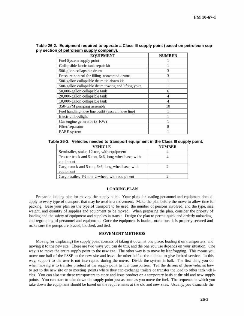
FM 10-67-1
26-3
Table 26-2. Equipment required to operate a Class III supply point (based on petroleum sup-ply section of petroleum supply company).
EQUIPMENT NUMBERFuel System supply point 1Collapsible fabric tank repair kit 1500-gllon collapsible drum 3Pressure control for filling nonvented drums 3500-gallon collapsible drum tie-down kit 1500-gallon collapsible drum towing and lifting yoke 150,000-gallon collapsible tank 620,000-gallon collapsible tank 410,000-gallon collapsible tank 4350-GPM pumping assembly 10Fuel handling hose line outfit (assault hose line) 1Electric floodlight 1Gas engine generator (3 KW) 1Filter/separator 8FARE system 1
Table 26-3. Vehicles needed to transport equipment in the Class III supply point.VEHICLE NUMBER
Semitrailer, stake, 12-ton, with equipment 4Tractor truck and 5-ton, 6x6, long wheelbase, withequipment
4
Cargo truck and 5-ton, 6x6, long wheelbase, withequipment
2
Cargo trailer, 1½ ton, 2-wheel, with equipment 2
LOADING PLAN
Prepare a loading plan for moving the supply point. Your plans for loading personnel and equipment shouldapply to every type of transport that may be used in a movement. Make the plan before the move to allow time forpacking. Base your plan on the type of transport to be used; the number of persons involved; and the type, size,weight, and quantity of supplies and equipment to be moved. When preparing the plan, consider the priority ofloading and the safety of equipment and supplies in transit. Design the plan to permit quick and orderly unloadingand regrouping of personnel and equipment. Once the equipment is loaded, make sure it is properly secured andmake sure the pumps are braced, blocked, and tied.
MOVEMENT METHODS
Moving (or displacing) the supply point consists of taking it down at one place, loading it on transporters, andmoving it to the new site. There are two ways you can do this, and the one you use depends on your situation. Oneway is to move the entire supply point to the new site. The other way is to move by leapfrogging. This means youmove one-half of the FSSP to the new site and leave the other half at the old site to give limited service. In thisway, support to the user is not interrupted during the move. Divide the system in half. The first thing you dowhen moving is to transfer product at the supply point to fuel transporters. Tell the drivers of these vehicles howto get to the new site or to meeting points where they can exchange trailers or transfer the load to other tank veh i-cles. You can also use these transporters to store and issue product on a temporary basis at the old and new supplypoints. You can start to take down the supply point just as soon as you move the fuel. The sequence in which youtake down the equipment should be based on the requirements at the old and new sites. Usually, you dismantle the

FM 10-67-1
26-4
FSSP first unless you are using the leapfrogging method. In any case, it is important that you work quickly oncethe order is given. Your main concern is to get to the new site as soon as possible and get set up.
EQUIPMENT MOVEMENT
You can take down most of the equipment without following procedural steps or guidelines. Do it as simplyand quickly as you can, but avoid spills and accidents. The three items which need your special attention are theFSSP, the 50,000-gallon collapsible tank, and the FARE system. Chapter 15 tells you how to move the FARE sy s-tem. Movement of the other two items is discussed below.
Fuel System Supply Point
First, drain the fuel from the collapsible tanks into the hose system. Close the valves at each tank so that thefuel does not flow back into the tanks. Then place a container under each tank drain port and drain the fuel that isleft in the tank. Stow the tanks in their carrying case. Now, starting at the receiving point, drain the fuel from thereceiving side of the system into the discharge side. Keep the discharge pump running for suction. Disconnect thehose assemblies and stow them in containers (when available). Be sure to install all dust caps and plugs on thehose assemblies as you dismantle them. Then disconnect the discharge pump and drain the fuel from the hose a s-semblies on the discharge side of the system. Disconnect the hose assemblies and place them in containers (whenavailable).
The 50,000-Gallon Collapsible TankFirst, drain the tank, Use a 350-GPM pumping assembly for suction. Then disconnect under the tank drain
port and drain the fuel left in the tank. Place a container under the tank drain port and drain the fuel left in thetank. Then drain the fuel from the hose assemblies, disconnect them, and place them in canvas bags.
Section II. Site Selection
GUIDELINES
Your next higher headquarters will assign you an area of operation, but you must choose your site within thatarea. You should make sure the Class III supply point is located as close to supported units as dispersion factors,sources of supply, and the tactical situation permit. Use vacated forward sites or existing facilities when you can.The site you choose should be reasonably level and well-drained to prevent water damage. Avoid low areas or fillthem in so that vapors do not collect. You may choose a site in low hills or rolling country, but never choose oneuphill or upstream from other installations which would be in the path of escaping fuel. Concealment is importantalso. Select a site that gives enough cover from enemy observation and attack. Your site should be large enough tomeet the needs of product supply and distribution plans, but not so large that handling operations become ineff i-cient. Provide for at least two storage areas with balanced stocks in each. The site should have easy access to roadnets, and at least one road should run through the supply point. However, do not choose a site that is near impo r-tant communications and population centers that may be enemy targets. There should be two large areas (one inthe front and one in the rear) which can be used for truck parking. Keep in mind that you may have to expand thesupply point. The site you choose should have enough space for you to add more collapsible tanks and truck par k-ing areas . Figure 26-2, page 26-5, shows an ideal site and sites that you should not use.
SELECTION CRITERIA FOR FSSP
When you select the FSSP site, consider cover and concealment, road nets, dispersion factors, terrain, and sitepreparation requirements. Make sure the site is suitable for the fuel system layout. Standard arrangements of theFSSP are shown in Section III.

FM 10-67-1
26-5
Figure 26-2. Site selection guidelines
Cover and Concealment
Select a site for the collapsible tanks, pumps, and filter/separators that is in the woods or in a tree line wherethe natural shadows disguise the telltale shapes. Use camouflage nets if you have them. When you lay hoseline,make use of natural terrain contours and vegetation to break up straight lines. One way to do this is to cutbranches, stick them in the earth under the hose, and then weigh them down with the hoseline. Where you havedeep grass or other vegetation to break up straight lines. Where you have deep grass or other vegetation, bend itover the hoseline to hide the hose so that it is not seen from the air.
Road Nets
Choose a site for the receiving, truck bottom loading, and vehicle refueling points that is next to a road in theClass III supply point. You can then load or unload trucks and refuel vehicles without leaving the road nets in thesupply point.

FM 10-67-1
26-6
Distance Between Items
You must consider the distance between items when you select the sites for the equipment in the FSSP. Inother words, how far apart should you put your components? Table 26-4 shows the usual distances between them.These distances are approximate, and they can vary with the terrain, natural cover, concealment, hose available,and road nets. However, you must put the 10,000-gallon collapsible tanks at least 40 feet apart.
Table 26-4. Usual distance between components of the FSSP
FROM TO
DISTANCE NEEDED(FEET)
Receiving Manifold Receiving pump 60
Receiving pump Manifold on first tank 60
10,000-gallon tank 10,000-gallon tank 40
Manifold on last tank Discharge pump 60
Discharge pump Filter/separators 40
Filter/separators First fuel-servicing nozzle 60
Fuel-servicing nozzle Fuel-servicing nozzle 25
Last fuel-servicing nozzle First 500-gallon drum filling point 75
500-gallon drum filling point 500-gallon drum filling point 50
Last 500-gallon drum filling point First bottom loading point 75
Bottom loading point Bottom loading point 75
Terrain
Select level terrain for the FSSP. Look for a tank site without slopes. A large slope may cause filled tanks toroll sideways, backwards, or forward. Put the pumps and filter/separators on level ground. Try to place the di s-charge pump at a lower level than the collapsible tanks so that there will be good suction to the pump.
Site Preparation
Deal with these three major items of equipment in the FSSP--the collapsible tanks, the pumps, and the fi l-ter/separators. Slope the tank sites gently toward the manifold end to help drain the tanks when they are removed.Slope the site for each tank no more than 3 to 6 inches in the direction of the tank’s fill port. Build a fire wallaround each tank. Make it large enough to hold the contents of the tank and 1 foot of freeboard. To do this, buildthe fire wall 3 feet high and 18 inches wide at the top. Make the inside dimensions of the fire wall 26 feet by 26feet. Maintain a distance of 3 feet from the edge of the tank to the base of the fire wall. If an engineer unit pr e-pares the site, give them this information. The pump and filter/separator sites must be cleared of dry grass, leaves,and trash.
SELECTION CRITERIA FOR EQUIPMENT
You must also select a site for other equipment in the Class III supply point. This equipment includes 20,000-gallon collapsible tanks, 50,000-gallon collapsible tanks, and 500-gallon collapsible drums. The FARE system siteis discussed in Chapter 15. Use the information in the following paragraphs to help you select a site for thisequipment.
The 20,000-Gallon Collapsible Tanks
The site you choose for the 20,000-gallon collapsible tanks should be similar to that for the 10,000-gallon co l-lapsible tanks. Choose a site that is nearly level with a gentle slope toward the manifold end of the tank. Space thetanks about 150 feet apart. Build a fire wall around each tank. Make it large enough to hold the contents of thetank and 1 foot of freeboard. To do this, build the fire wall 4 feet high and 18 inches wide at the top. Make the

FM 10-67-1
26-7
inside dimensions of the fire wall 35 feet long and 31 feet wide. Maintain a distance of 4 feet from the edge of thetank to the base of the fire wall. If an engineer unit prepares the site, give them these measurements. Place thedischarge pumps at a level lower than the tanks to aid pump suction.
The 50,000-Gallon Collapsible Tanks
Choose a site for the 50,000-gallon collapsible tanks that is similar to that for the 10,000- and 20,000-galloncollapsible tanks. Build the fire wall 4 feet high and 18 inches wide at the top. Make the inside dimensions of thefire wall 73 feet long and 33 feet wide. Place the discharge pumps at a level lower than the tanks to aid pump su c-tion.
THE 500-Gallon Collapsible Drums
Select a firm, level site near the source of supply. Select a site that allows drums to be easily lined up for fil l-ing and rolled away after filling.
SELECTION CRITERIA
Select a reasonably level site that can hold container stacks. Choose a site with good drainage so that waterdoes not damage the containers. Avoid low areas because dangerous vapors collect in them. Do not use an areawith a cinder base or marshland and wasteland overlaid with peat; they are usually damp. Use such areas only ifno other site is available. Be sure the site has natural cover and concealment and is large enough for future expa n-sion. Do not locate near other areas of operation. Stay at least 500 feet away for low-flash products and 200 feetfor high-flash products. Your site must be away from overhead electric lines so a broken wire cannot fall on thedrums. Clear the site of all underbrush that may get in the way or present a fire hazard. Spread sand, gravel, orsimilar material over areas where you store containers. They help drain the area and provide a more stable base forthe stocks. Do not use ashes or cinders because they are corrosive. Build a dike at least 18 inches high aroundeach major storage division in which low-flash products are stored. This dike must be able to hold all the liquid inthe drums stored in the area and have a freeboard of at least 6 inches. Choose a site for at least two clearing (i n-coming and outgoing) areas. These will be used to segregate incoming and outgoing mixed loads (railroad cars ortruckloads). Each area should have its own site. The sites should be located next to each other so that the samepersonnel can operate both areas.
Section III. Layout
SITE PREPARATION
Stop the convoy bringing the supply point equipment at an agreed on location which is close to the site andwell suited for off-loading of equipment. You can begin off-loading and layout operations at once if an engineerunit has already prepared the site. If your site is not prepared, you must prepare it. Your first concern as you beginthe layout is to be able to receive and issue bulk petroleum as soon as possible. For this reason, off-load and lay outthe FSSP first. Then turn your attention to bulk reduction operations. Set up the bulk reduction issue and storagearea. Place in this area the 50-GPM pumping assemblies, 500-gallon collapsible drums, 55-gallon drums, and 5-gallon cans. You can now begin to issue both bulk and packaged products. Next, set up the bulk storage area withits 50,000-gallon collapsible tanks and 350-GPM pumping assembly. Finally, set up the supply point safety andsecurity items.
STANDARD FSSP ARRANGEMENTS
Lay out the FSSP to take advantage of the terrain, natural cover, concealment, available hose, and road nets.If you must handle two types of fuel (for example, JP-8 and MOGAS), you may have to divide the fuel system (seeChapter 28). Some typical arrangements are shown in Figure 26-3, page 26-8. If none of these arrangements aresuitable, you may change them to fit your needs.

FM 10-67-1
26-8
Figure 26-3. Typical arrangements

FM 10-67-1
26-9
FSSP COMPONENTS
The best way to lay out the FSSP is to put the collapsible tanks in their prepared sites first. Then put thepumps and filter/separators in place and lay out all the fitting assemblies and hoses. Then make the connectionsand attach the fuel- and oil-servicing nozzles. Make sure you have placed the components to conform to the a r-rangement that you chose for the fuel system. Lay out the components of the fuel system as discussed below.
• Collapsible Tanks. Place the tanks at the prepared sites so that when you take them from their containers andunfold them, they are in position. Be careful not to step on the tanks as you unfold them. Then inspect the tankfabric for cuts, snags, or other damage. Also, make sure the tank filler and vent assemblies are in good workingorder.
• Pumps. After you put the 350-GPM pumping assemblies in place, lower the retractable support and chockthe wheels of each pump. Then drive a ground rod into the ground near each pump. Attach a ground cable to therod and to the pump frame.
• Filter/Separators. After you place the 350-GPM filter/separators in position, put shims under the skids tohelp level them. Drive a ground rod into the ground near each filter/separator, and attach a ground cable to the rodand to each unit. The last thing you do is to connect a hose or a pipe to the automatic water drain port to carrywater away from the unit.
• Fitting Assemblies and Hoses. Put all fitting assemblies and hoses in their proper places. Make sure all su c-tion hose is on the receiving side of the system and all discharge hose is on the dispensing side. Place 3-inch di s-charge hose at the tank truck bottom loading points. Place 1½-inch discharge hose at the 500-gallon collapsibledrum filling points and 1-inch discharge hose at the vehicle refueling points. Now, start at the collapsible tanksand connect all hose and fitting assemblies. Make sure all dust plugs and caps are left on the hoses and fittingsuntil they are connected into the system.
• Fuel- and Oil-Servicing Nozzles. Attach the six nozzles to the 1-inch discharge hose assemblies. Make surethe nozzle dust cap covers the spout of each nozzle. Make a support for the nozzles so that they do not lie on theground when not in use.
OTHER SUPPLY POINT EQUIPMENT
When setting up the layout of the Class III supply point, allow for the 50,000-gallon collapsible tanks, and theFARE system. These components are described in the following paragraphs.
The 50,000-Gallon Collapsible TanksThe 50,000-gallon collapsible tank is the largest container for storing bulk petroleum in the Class III supply
point. Each section of a petroleum supply company has four of these tanks. The site on which the tanks are set upis usually called the bulk storage area. For best results, use the four tanks separately. This way your Class III su p-ply point can handle the two most commonly used fuels: MOGAS and JP-8. For example, JP-8 may be placed inthe FSSP while MOGAS may be placed in the 50,000-gallon collapsible tanks (two tanks for each product). If youdo not need this much flexibility, you can manifold the four tanks together so that they will hold 200,000 gallons.The tanks are serviced by 350-GPM pumping assemblies. Set up the tanks the same way you set up the 10,000-gallon collapsible tanks. Then place the pumps and connect the fitting assemblies and hoses.
FARE SystemThe layout discussed here applies to the FARE system when it is used in gas-station-type operations for refuelingground vehicles. When you lay out the FARE system to refuel aircraft, you must consider many other factors thatthis chapter does not cover. See Part III. Lay out the FARE system in the way that best suits your needs. Use allor part of the hose provided. You can plan the layout to avoid obstacles, take advantage of terrain features, or op-erate in a limited space. However, you must have at least 25 feet between vehicles. A typical layout of the FAREsystem is shown in Figure 20-2, page 20-2.
BULK REDUCTION STORAGE AREA
Set up, in the bulk reduction storage area, a separate stocking area for each product and type of package. Ifyou have an area for each, you can inventory and control the stock more easily, and you are not as likely to identity

FM 10-67-1
26-10
the product incorrectly. Use a block system to separate large amounts of stored supplies so that the entire stock ofone product is not lost if there is an enemy attack or a fire. Plan the exact layout and size of the stacking area a c-cording to local conditions and safety requirements. Aisles between double rows of drums (units) are usually 9 to10 feet wide. You can reduce the width to 4 feet if this leaves you enough room to handle the product. Allow 15 to30 feet for aisles between sections of containers and 50 to 150 feet between blocks.
Layout for 5-Gallon Cans
A specific layout of a stacking area for 5-gallon cans is suggested. This layout is shown in Figure 26-4.
Figure 26-4. Suggested layout for 5-gallon cans
Layout for 55-Gallon Drums
Plan the layout of a stacking area for 55-gallon drums according to the type of product in the drums and the te r-rain. Petroleum products are classified as light or low flash (flash point at or below 80 °F) and heavy or high flash(flash point above 80°F). Some high-flash products are kerosene, diesel fuel, and lubricants. Some low-flashproducts are gasoline and jet fuels. Store low-flash and high-flash products in separate areas. A suggested layoutof a stacking area for 55-gallon drums of low-flash products is shown in Figure 26-5, page 26-11. Blocks are madeup of nine 70-foot-square sections, and each section is divided into five parallel units with 9-foot aisles betweenunits. The width of the aisles may be reduced to 4 feet if this leaves you enough handling room. Rows of drumscontaining low-flash products must be no more than 35 drums long and three tiers high. You may store a largerquantity of high-flash products in a block. The number of sections in the suggested layout is a guide only. Youcan lay out the drum stacking area any way that suits the terrain, but the rows of drums must be no more than 35drums long, and you must leave enough space between units, sections, and blocks.
Layout for 500-Gallon Collapsible Drums
There is no set method for laying out a storage area for 500-gallon collapsible drums. A suggested layout isshown in Figure 26-6, page 26-11. Make double rows, five drums long, with the fill ports facing outward. Leave 3feet between the butts of the drums and 9 or 10 feet between double rows. This gives vehicles and personnel easy

FM 10-67-1
26-11
access to the drums when they load or rig them for delivery. Use the section and block plan when you store a largenumber of drums. However, you should put only three double rows in a section and make three sections to a block.In each section, you have 300 drums; and in each block, you have 90 drums. Leave 30 feet between sections and150 feet between blocks.
Figure 26-5. Suggested layout for 55-gallon drums
Figure 26-6. Suggested layout for 500-gallon collapsible drums

FM 10-67-1
26-12
SAFETY AND SECURITY ITEMSOnce your supply point is set up, you must take steps to make sure it is safe and secure. To do this, follow the
steps listed below.• Checkpoints. Set up a checkpoint at the entrance and one at the exit of the operating area. Give personnel
coming to the area a safety briefing at entrance checkpoint. Fire prevention at the checkpoint is discussed inChapter 2. Use the checkpoints not only to control the vehicles going in and out, but also to account for the receiptand issue of petroleum in the supply point.
• Fire Plan. Develop a fire plan. See Chapter 2 for details.• Signs. You must set up many different types of signs in the area of operation. Place stock locator signs at
petroleum storage areas, including bulk reduction storage sites. Place signs identifying NO SMOKING areas anddangerous areas throughout the supply point. You must also set up speed control and traffic direction signs.
Section IV. Operation
FUEL FLOWBefore you can work at a Class III supply point, you must understand how petroleum flows through it. You
should know where it is received, which items of equipment transfer and store it, and where and how it is issued.Figure 26-7 is a flow plan for a suggested Class III supply point. A transporter brings the fuel to the Class III su p-ply point where it is routed to the FSSP and the four 50,000-gallon collapsible tanks. From the FSSP, the fuel caneither be issued or put into containers and stored in the bulk reduction storage area until it is issued. Fuel stored inthe 50,000-gallon collapsible tanks is issued as bulk petroleum. There are only a few steps in the flow of petroleumthrough the entire Class III supply point, but the process is not so simple when you look at the flow of petroleumthrough the FSSP and the 50,000-gallon collapsible tanks.
Figure 26-7. Flow plan for a suggested Class III supply point

FM 10-67-1
26-13
Flow Through the FSSP
The first step is to inspect the fuel when it arrives. The product then enters the system through the receivingmanifold. It usually moves under suction from one of the 350-GPM pumps used as a receiving pump. The productmay also move under positive pressure from a transporter, pipeline, or hoseline. When you have both fi l-ter/separators installed on the delivery side of the system, the receiving pump distributes the product directly to thetanks through the hoseline manifold. The other 350-GPM pump is used to draw fuel from the tanks and dischargeit through the two filter/separators into the hose header system. When you leave one filter/separator installed onthe receiving side of the system, the receiving pump distributes the product to the receiving filter/separator andthen to the collapsible tanks. After that, the flow of product is the same, except the fuel is drawn through only onefilter/separator on the discharge side of the system instead of two. You can also draw from the supply source d i-rectly to the discharge side of the system. This procedure bypasses the storage tanks. You need only one pumpand one filter/separator for this operation.
Flow Through the 50,000-Gallon Collapsible Tank
The first step is the inspection of the product. The fuel then enters from the transporter through a receiving man i-fold made up of a suction hose and gate valve. The product usually moves under suction from a 350-GPM pum p-ing assembly that distributes it into the 50,000-gallon collapsible tank. Another 350-GPM pumping assembly actsas a discharge pump and distributes the fuel from the tank to the discharge hose assembly. The discharge hoseassembly consists of a gate valve and discharge hose. From the discharge hose assembly the product moves into atransporter.
PERSONNEL
How you use your personnel is one of the most important parts of managing a Class III supply point. In otherwords, how many do you need for a specific operation? Where should you place them in relation to the equipment?What tasks should you give them to do? It is important that you assign specific tasks to your personnel at the ClassIII supply point, but you should also try to be flexible. The best way to use all of your personnel wisely is to let thejob determine the assignment. For example, if you have no issues scheduled for the FSSP, you can use the workersassigned there to improve the fire walls around the collapsible tanks. On the other hand, there may be a time whenthe supply point, or a section of it, is not busy. You may then use your workers to improve the camouflage andconcealment of the area, improve drainage ditches and roadways, make sure the safety equipment is serviceable,and do operator and organizational maintenance on the equipment in the supply point. Although the number ofpersons you assign to a specific task may vary greatly with your mission, it is still possible to obtain an averagenumber for each operation.
FSSP Operations
For a single shift, you need eight workers to operate the FSSP efficiently. Place them at certain strategicpoints in the operation as described below.
• Receiving Side. Assign two workers to the receiving manifold. Make them responsible for transferringbulk petroleum from the transporter to the fuel system. They operate all valves at the receiving point and make allnecessary hose connections.
• Pumps and Valves. Assign three workers to the pumps and control valves. Have one worker operate eachpump, and have the third worker control the valves on the discharge and receiving manifold of the collapsibletanks. Once the pumps are started, they can be monitored by one worker. This enables two workers to devote theirfull time to valve control and fuel flow problems.
• Dispensing Side . Assign three workers to the delivery side of the system (six 5-gallon can and 55-gallondrum filling points and two 500-gallon collapsible drum filling points). Make them responsible for dispensingpetroleum and controlling the fuel flow. They prepare the various filling points, operate the control valves, andmake all necessary hose connections. When tank vehicles are filled, have the truck driver help dispense the fuel.

FM 10-67-1
26-14
The 50,000-Gallon Collapsible Tank Operations
For a single shift, you need four workers to operate one 50-gallon collapsible tank. You generally have one50,000-gallon collapsible tank, two 350-GPM pumping assemblies (one receiving pump and one discharge pump),and one dispensing line. In the Class III supply point, you use the 50,000-gallon collapsible tank mainly for largevolume distribution of bulk petroleum. Place the workers as follows:
• Place one worker at the receiving point. Make this worker responsible for transferring bulk petroleumfrom the transporter to the tank. Have the worker operate the valves and make all necessary hose connections.
• Place one worker at each of the two 350-GPM pumping assemblies. Make each worker responsible for c o-ordinating the flow of petroleum.
• Place one worker at the dispensing line. Make this worker responsible for issuing bulk petroleum andcontrolling the fuel flow in the dispensing line.
The 500-Gallon Collapsible Drum Filling Operations You need only two workers to do this job efficiently. However, there are several methods of filling 500-gallon
collapsible drums. Two of the most commonly used methods are to fill the drums directly from the FSSP or to usethe 50-GPM pumping assembly. The positioning and the tasking of the crew vary with each of these methods.When drums are filled directly from the FSSP, assign one worker to the control valves of the filling point. Makethis worker responsible for controlling the flow of petroleum to the drums. Assign the other worker to the drums.Make this worker responsible for preparing the drums for filling, making all connections, and monitoring the fil l-ing operation. When the 50-GPM pumping assembly is used, you still need two workers for the filling operation.Have one worker operate the 50-GPM pumping assembly and control the flow of petroleum. Assign the other tothe drums with the same responsibility as in the method described before. For both methods, you need a vehicle toremove the filled drums to the bulk reduction storage area.
The 55-Gallon Drum Filling Operations
Although you usually fill 55-gallon drums directly from the FSSP, you can also use the 50-GPM pumping a s-sembly with the hose and fitting kit. When you use six fuel- and oil-servicing nozzles on the FSSP, you need 10workers at each nozzle. You also need two workers to bring empty drums to the filling points and two workers toremove filled drums to the bulk reduction storage area. Make the six workers at the servicing nozzles responsiblefor bonding the nozzles to the containers and filling the drums to the proper level. If you have a forklift, use it tomove the filled drums to the storage area.
The 5-Gallon Can Filling Operations
There are two methods of filling 5-gallon cans. You can use the fuel- and oil-servicing nozzles at the FSSP orthe 50-GPM pumping assembly with the hose and fitting kit. The number of workers you need to fill the cansvaries with the method you use. When the cans are filled directly from the FSSP, the operation is essentially thesame as for the 55-gallon drum. When the cans are filled using the 50-GPM pumping assembly with the hose andfitting kit, you need seven workers. Because this method is usually conducted near the bulk reduction storage area,you need only one worker to bring empty cans and one to remove the filled ones. Also, have one worker operatethe 50-GPM pumping assembly and control the flow of petroleum. Place one worker at each of the four dispensingnozzles of the hose and fitting kit. Have them bond the nozzles to the cans and fill them to their proper level.
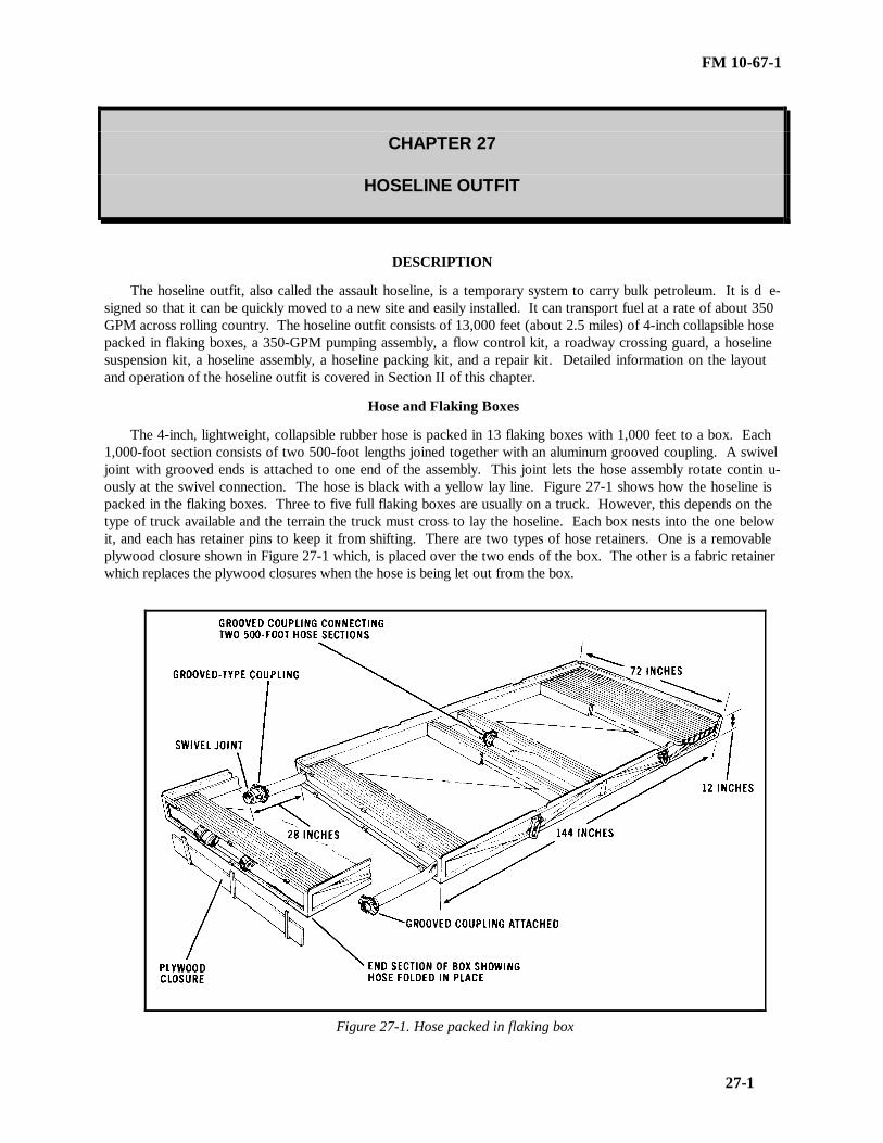
FM 10-67-1
27-1
CHAPTER 27
HOSELINE OUTFIT
DESCRIPTION
The hoseline outfit, also called the assault hoseline, is a temporary system to carry bulk petroleum. It is d e-signed so that it can be quickly moved to a new site and easily installed. It can transport fuel at a rate of about 350GPM across rolling country. The hoseline outfit consists of 13,000 feet (about 2.5 miles) of 4-inch collapsible hosepacked in flaking boxes, a 350-GPM pumping assembly, a flow control kit, a roadway crossing guard, a hoselinesuspension kit, a hoseline assembly, a hoseline packing kit, and a repair kit. Detailed information on the layoutand operation of the hoseline outfit is covered in Section II of this chapter.
Hose and Flaking Boxes
The 4-inch, lightweight, collapsible rubber hose is packed in 13 flaking boxes with 1,000 feet to a box. Each1,000-foot section consists of two 500-foot lengths joined together with an aluminum grooved coupling. A swiveljoint with grooved ends is attached to one end of the assembly. This joint lets the hose assembly rotate contin u-ously at the swivel connection. The hose is black with a yellow lay line. Figure 27-1 shows how the hoseline ispacked in the flaking boxes. Three to five full flaking boxes are usually on a truck. However, this depends on thetype of truck available and the terrain the truck must cross to lay the hoseline. Each box nests into the one belowit, and each has retainer pins to keep it from shifting. There are two types of hose retainers. One is a removableplywood closure shown in Figure 27-1 which, is placed over the two ends of the box. The other is a fabric retainerwhich replaces the plywood closures when the hose is being let out from the box.
Figure 27-1. Hose packed in flaking box
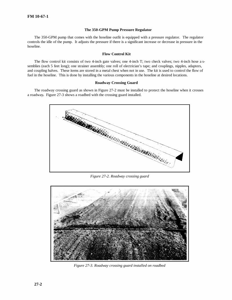
FM 10-67-1
27-2
The 350-GPM Pump Pressure Regulator
The 350-GPM pump that comes with the hoseline outfit is equipped with a pressure regulator. The regulatorcontrols the idle of the pump. It adjusts the pressure if there is a significant increase or decrease in pressure in thehoseline.
Flow Control Kit
The flow control kit consists of two 4-inch gate valves; one 4-inch T; two check valves; two 4-inch hose a s-semblies (each 5 feet long); one strainer assembly; one roll of electrician’s tape; and couplings, nipples, adapters,and coupling halves. These items are stored in a metal chest when not in use. The kit is used to control the flow offuel in the hoseline. This is done by installing the various components in the hoseline at desired locations.
Roadway Crossing Guard
The roadway crossing guard as shown in Figure 27-2 must be installed to protect the hoseline when it crossesa roadway. Figure 27-3 shows a roadbed with the crossing guard installed.
Figure 27-2. Roadway crossing guard
Figure 27-3. Roadway crossing guard installed on roadbed

FM 10-67-1
27-3
Hoseline Suspension Kit
The hoseline suspension kit consists of 350 feet of wire rope, 350 feet of manila rope, 25 wire-rope clips, 60shackles, 60 hose saddles, 14 steel pickets, 4 steel blocks, 4 turnbuckles, and 4 wire-rope thimbles. These items arestored in a metal chest when not in use. The kit is used to suspend segments of the hoseline system over streams oruneven areas as shown in Figure 27-4.
Figure 27-4. Suspension kit used with hose line system
Hoseline Displacement and Evacuation Kit.
The hoseline displacement and evacuation kit as shown in Figure 27-5 consists of a ball injector, a ball r e-ceiver, a displacement ball, an air eductor, 8 grooved couplings, and 16 pipe caps. It also has a metal storagechest. The kit is used to remove liquid fuel, vapors, and air from the hoseline system. It also flattens the hose sothat it can be easily packed into flaking boxes.
Figure 27-5. Hose line displacement and evacuation kit

FM 10-67-1
27-4
Sling AssemblyThe sling assembly as shown in as shown in Figure 27-6 is used to lift and handle flaking boxes. The four-leg
lifting sling is equipped with a spreader bar. The assembly can lift up to three full flaking boxes at a time, but itwill be damaged if it lifts more than three.
Figure 27-6. Sling assembly
Hoseline Packing Kit.The hoseline packing kit consists of a chain hoist, a hose puller, two hose clamps, and a metal storage chest.
The kit is used when packing sections of the hoseline system into the flaking boxes as shown in Figure 27-7. It isgenerally used when temperatures drop below 40°F. Below 40°F, the hose becomes less flexible and harder topack.
Figure 27-7. Hose line packing kit being used
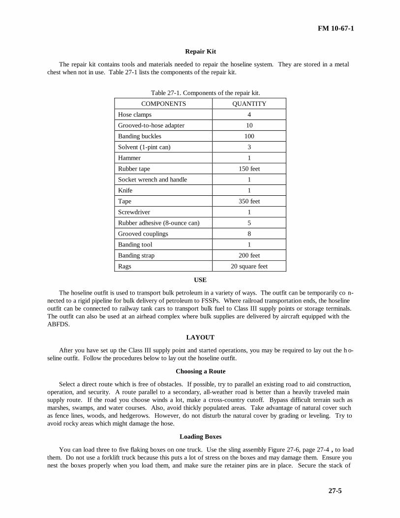
FM 10-67-1
27-5
Repair Kit
The repair kit contains tools and materials needed to repair the hoseline system. They are stored in a metalchest when not in use. Table 27-1 lists the components of the repair kit.
Table 27-1. Components of the repair kit.
COMPONENTS QUANTITY
Hose clamps 4
Grooved-to-hose adapter 10
Banding buckles 100
Solvent (1-pint can) 3
Hammer 1
Rubber tape 150 feet
Socket wrench and handle 1
Knife 1
Tape 350 feet
Screwdriver 1
Rubber adhesive (8-ounce can) 5
Grooved couplings 8
Banding tool 1
Banding strap 200 feet
Rags 20 square feet
USE
The hoseline outfit is used to transport bulk petroleum in a variety of ways. The outfit can be temporarily co n-nected to a rigid pipeline for bulk delivery of petroleum to FSSPs. Where railroad transportation ends, the hoselineoutfit can be connected to railway tank cars to transport bulk fuel to Class III supply points or storage terminals.The outfit can also be used at an airhead complex where bulk supplies are delivered by aircraft equipped with theABFDS.
LAYOUT
After you have set up the Class III supply point and started operations, you may be required to lay out the h o-seline outfit. Follow the procedures below to lay out the hoseline outfit.
Choosing a Route
Select a direct route which is free of obstacles. If possible, try to parallel an existing road to aid construction,operation, and security. A route parallel to a secondary, all-weather road is better than a heavily traveled mainsupply route. If the road you choose winds a lot, make a cross-country cutoff. Bypass difficult terrain such asmarshes, swamps, and water courses. Also, avoid thickly populated areas. Take advantage of natural cover suchas fence lines, woods, and hedgerows. However, do not disturb the natural cover by grading or leveling. Try toavoid rocky areas which might damage the hose.
Loading Boxes
You can load three to five flaking boxes on one truck. Use the sling assembly Figure 27-6, page 27-4 , to loadthem. Do not use a forklift truck because this puts a lot of stress on the boxes and may damage them. Ensure younest the boxes properly when you load them, and make sure the retainer pins are in place. Secure the stack of

FM 10-67-1
27-6
boxes on the truck to keep them from sliding. Leave the plywood closures as shown in Figure 27-8 in place duringloading and transporting. When you get to the distribution point, take the plywood closures off and replace themwith fabric retainers. These retainers automatically break away when the hose is pulled from the box. Keep themfor future use. Before you start distributing the hose from the flaking boxes, connect the tail coupling on the topbox to the lead coupling of the box below it. Do this until you have connected all the hose couplings on the truck.This lets you play out the whole truckload of hose without stopping to make connections.
Figure 27-8. Laying the assault hose line on a road
Distributing Hose
To start laying the hose, pull out the lead end of the hose from the top flaking box and hold it on the groundwhile the truck moves forward. When 100 feet are pulled from the truck, there is no longer any need for you tohold back the hose because its weight on the ground is enough to keep it from being dragged along by the truck.As the truck moves forward, the hose automatically comes out of the flaking boxes. You can play out the hose atspeeds up to 35 MPH; however, a speed of no more than 20 MPH is recommended. As you lay the hose, walkalong the line and straighten out kinks or binds and remove small obstructions which might damage the hoselineon a road Figure 27-8. Pick up the hose and move it to the road ditch or to a bank across the ditch. Never leavethe hose on the roadway.
Crossing Streams.
There are several ways you can lay the hoseline across a stream or watercourse. If there is a bridge, suspendthe hoseline on improvised brackets outside the bridge railing. If there is no bridge, you may lay the hoseline d i-rectly in the streambed if it is narrow and not apt to flood. Use the hoseline suspension kit, as shown in Figure 27-4, page 27-3, to cross a wide stream. Fabric saddles as shown in Figure 27-9, page 27-7 , with eyes for easy wireattachment come with the kit.

FM 10-67-1
27-7
Figure 27-9. Fabric saddle used in hose line suspension kit
Crossing Gaps
You should also use the hoseline suspension kit to span small gaps with steep sides. For a wide crossing, builda suspension bridge with a flat deck or floor to hold the hose. This eliminates the sags that occur when the suspe n-sion kit is used.
Crossing Roads
To cross a highway or railroad, run the hoseline under a bridge or through a culvert, if possible. You can pullthe hoseline through the culvert with a rope or push it through with a piece of lumber or a small-diameter pipe. Ifthere is no bridge, install the roadway crossing guard Figures 27-2, page 27-2, and 27-3, page 27-2 , to protect thehoseline. Never bury unprotected hoseline in a railroad. When crossing a railbed, you can either install a piece ofheavy wall pipe in a shallow ditch under the rails or suspend the hose over the railbed at a suitable height. As soonas possible, replace the hoseline at a railway crossing with welded pipeline because of the fire hazards caused bytrains.
PUMPING STATIONS
Assault hoseline pumping stations have one 350-GPM pumping assembly. If you are using only one hoselineoutfit, place the pumping assembly at the beginning of the hoseline system. Because this pump does not have apressure-regulating device, you must monitor it at all times for changes in hoseline pressure. You must set uppumping stations when you connect several hoseline outfits together. There is a formula you can use to locatepumping stations on level ground using motor gasoline in the hoseline. If you use a product other than motorgasoline, the distance between pumping stations (given by this formula) changes. For example, if you use a pro d-uct heavier than motor gasoline, the pumping stations should be closer together. If the product you use is lighterthan motor gasoline, the pumping stations should be farther apart. The distance between pumping stations (givenby this formula) also changes with the height of the terrain. For example, if you place the hoseline on an uphillslope, the pumping stations should be closer together. If you place the hoseline on downhill slope, the pumpingstations should be farther apart.

FM 10-67-1
27-8
PRESSURE-REDUCING STATIONS
When you place the hoseline on a steep downhill slope for some distance, there may be more pressure on thehoseline than it can take. If this occurs, install a pressure-reducing station in the line to relieve the pressure. Thestation consists of a regulating (receiving) storage tank.
CHECK VALVES
Install check valves as shown in Figure 27-10 (they are part of the flow control kit) in the hoseline system tokeep the fuel from flowing back when you stop the pumps. You usually have a backflow when your hoseline se c-tions are on an uphill slope. The check valve has a hinged disk which closes when the fuel flows in the wrong d i-rection and pushes against it. Put your check valves at the downstream end of the pump discharge manifold andnear the bottom end in hoselines on uphill slopes.
Figure 27-10. Check valve installed in the hose line
HOSELINE TESTING
Once you have set up the assault hoseline, fill it with fuel and run a pressure test to check for leaks. Start thepumps slowly, and raise the fluid pressure in the system gradually in increments of 50 PSI. Hold the pressure eachtime you raise it, and inspect the hoseline for leaks. Keep doing this up to and including 150 PSI. Even thoughthe design burst pressure of the hose is higher, your test should not exceed the rated safe working pressure of 150PSI. If the line pressure does not build up, stop the pumps because the line probably has a leak. You can usuallyfix leaks at couplings, fittings, or valves by tightening, adjusting, or replacing gaskets.
HOSE REPAIR
Leaking and broken hoses need to be repaired as soon as possible. Follow these steps to repair the hose:
Leaking Hose
Use the repair kit to fix seeping or fine spraying leaks which occur in the hose wall during testing or use. Fixthem at once so that they do not break the hose.
• Reduce the pressure in the hoseline. This cuts down on the fuel coming out of the leak.
• Clean an area about 6 inches wide on each side of the leak with solvent. If you do not have any solvent, wipethe area clean and dry.

FM 10-67-1
27-9
• Apply a thin coat of rubber adhesive to this area, and let it get tacky. This takes about five minutes.
• Cover the adhesive area with a spiral wrap of 2-inch-wide rubber tape. Overlap each wrap about 1 inch.
• Apply two spiral wraps of 2-inch vinyl-plastic tape to the area in the opposite direction. Wrap the tape astightly as you can without causing the hose to buckle.
• Keep some pressure on the hose so that it stays cylindrical. A tape patch is shown in Figure 27-11 .
Figure 27-11. Completed tape patch
Broken Hose
To repair breaks, splits, or punctures in the hose wall, cut out the defective area and join the cut ends with twocoupling sleeves and a coupling. You can repair only collapsible hose in this way because suction or hard wallhose has a wire wrap on the inside which makes cutting almost impossible.
• Shut down the system and ensure there is no pressure in the hoseline.
• Put a hose clamp (from the repair kit) on each side of the break as shown in Figure 27-12, page 27-10.
• Cut the hose about 6 inches from the edge of the break and check the inside for damage. If you find any, cutthe hose again to remove the damaged area.
• Wipe the end of the hose clean and dry.
• Put solvent on the inside of the hose, about 6 inches deep, and apply adhesive to the cut raw end. While thesolvent is drying, put a coat of adhesive on the outside of the coupling sleeve.
• Place the sleeve in the hose immediately so that the adhesive can act as a lubricant.
• Use the banding tool, which comes with the repair kit, to put banding straps on the hose as shown in Figure27-13, page 27-10.
• Bond the sleeve to the hose with three banding straps as shown in Figure 27-14, page 27-11.
• Apply the bands tightly, cut off the excess, and secure them with buckles. Stagger the buckles around thehose.
• Apply a coat of adhesive to the other cut end.
• Repeat the above steps on the other end of the hose.
• After you have completed both ends, connect the coupling sleeves with a grooved coupling, remove the hoseclamps, and start pumping.

FM 10-67-1
27-10
Figure 27-12. Clamp applied to hose
Figure 27-13. Coupling repair showing the use of the handing tool

FM 10-67-1
27-11
Figure 27-14. Completed coupling repair
HOSE EVACUATION
You cannot move the assault hoseline to a new location until you remove the fuel from the system and get allvapor and air out so that the hose is flat and ready to be packed. To do these things, use the displacement andevacuation kit.
Removing Fuel
Follow these steps to remove fuel from the system.
• Place a hose clamp on the section of hose just in front of the pump discharge manifold where the hoselinesystem starts.
• Disconnect the hose from the pump, and attach the ball injector, with the ball, to the end of the hose as shownin Figures 27-15, page 27-13 and 27-16, page 27-13.
• Move the pump to the other end of the assault hoseline, and connect it to the system.
• Put a second hose clamp on the end of the hose that connects to the pump suction manifold.
• Attach the ball receiver as shown in Figures 27-17, page 27-14 and 27-18, page 27-14. Connect the hose tothe pump.
• Attach an air compressor hose to the ball injector at the start of the system, and inject compressed air into thehose behind the ball.
• Remove both hose clamps from the system. You usually need 20 to 25 PSI of air pressure to move the dis-placement ball at a satisfactory rate.
• Start the pump and keep it running to move the fuel forward an d into storage.
You can also remove fuel from the hoseline by gravity if you have a tank truck to drain the filled lines. Do notuse water to displace fuel from the system.

FM 10-67-1
27-12
Removing Vapor and Air
After the displacement ball has moved through the line, you must still remove the vapor and air from the a s-sault hoseline. Follow these steps to remove vapor and air from the assault hoseline.
• Take the ball receiver off the end of the hoseline and put an airtight cap in its place. If you do not have a cap,you can seal the hose by bending it back on itself several times and tying it.
• Go to the beginning of the assault hoseline and disconnect the air compressor hose from the ball injector andattach the suction end of the air eductor as shown in Figure 27-19, page 27-15.
• Put the compressor hose on the inlet side of the eductor and turn on the air. This creates a vacuum and drawsthe vapor and air from the hoseline. You must operate the eductor about 10 minutes for each 1,000 feet of hose.
• When the hose flattens to a ribbon-like form, stop the air, fold back the end of the hose, and tie it.
Remove the ball inlet and air eductor. You are now ready to pack the hoseline into the flaking boxes.
DISPLACEMENT
The first thing you do when displacing the assault hoseline is to put all but one of the flaking boxes along theline at 1,000-foot intervals. Then, follow the procedures below.
• Keep one flaking box on the pickup vehicle.
• Back the vehicle over the hoseline as it lies on the ground.
• Have two crew members pick up the hose from the ground and pass it to two others on the vehicle.
• Start packing the hose into the flaking box by first placing the end of the hose, with the coupling attached, atthe left front of the box (Figure 27-1, page 27-1).
• Lay the hose along the length of the left side of the box.
• Run the hose around the back of the box, and then make successive folds, from left to right, until you reachthe front.
• Be sure to bend the hose so that it fills the entire width of the box.
• Ensure the folds are packed tightly together so that you can get 1,000 feet of hose in the plywood closures(Figure 27-1, page 27-1) and fabric retainers.
• If the temperature is below 40°F, you may have to use the hoseline packing kit to get the hose in the flakingbox.
• When using the kit, make about 15 folds in the box. Then lay a plank across the face of the hose, attach thehose puller, and compress the hose in the box. Put one clamp on each side of the box to keep the hose in place, andthen remove the plank and hose puller.
• Repeat this process about every 15 to 20 folds until the entire hose is packed in the flaking box.

FM 10-67-1
27-13
Figure 27-15. Unassembled ball injector
Figure 27-16. Assembled ball injector

FM 10-67-1
27-14
Figure 27-17. Unassembled ball receiver
Figure 27-18. Assembled ball receiver

FM 10-67-1
27-15
Figure 27-19. Air Eductor
FM-10-67-1
28-1
CHAPTER 28
RECEIPT, STORAGE, AND ISSUE Of BULK PETROLEUM
Section I. Bulk Petroleum Operations
HANDLING PROCEDURES
You usually receive bulk petroleum at the Class III supply point in 5,000- and 7,500-gallon tank semitrailers.You may also receive it in petroleum tank cars and through the assault hoseline. When bulk petroleum arrives atthe Class III supply point, you can store it in three types of containers: 10,000-gallon collapsible tanks, 20,000-gallon collapsible tanks, and 50,000-gallon collapsible tanks. From the supply point, you can issue bulk petroleumto tank vehicles and tank cars. This chapter covers step-by-step procedures for the receipt, storage, and issue ofbulk petroleum at the Class III supply point. The procedures and illustrations are based on the FSSP, but they alsoapply to the 50,000-gallon collapsible tank because of the similarity between the two operations. Environmentalguidance is in Chapter 1 of this publication and AR 200-1.
SAFETY PRECAUTIONS
There are a number of safety precautions that you must follow when you receive, store, and issue bulkpetroleum. These precautions are described below:
• HAZMAT materials for spill response must be present and available.
• Proper protective clothing and equipment must be worn by the handlers at all times during operations.
• Post NO SMOKING signs around the area of operation so that anyone working in the supply point or drivingthrough it can see the signs immediately. Do not let anyone carry matches and lighters in the operations area.Place fire extinguishers at all receipt, storage, and issue points.
• Keep at least 25 feet between tank vehicles during receipt and issue operations. Also, keep all tractorscoupled to tank semitrailers while product is being transferred so that the semitrailers can be moved quickly fromthe area in case of an emergency.
• Keep the canvas top and rear curtain of the tractor in place when the tank vehicle is carrying, loading, orunloading product. The curtains keep the tractor from being splashed with fuel from the vehicle catwalks.
• Keep a wooden, cone-shaped stopper handy to plug the bottom outlet of the tank car in an emergency whenyou load or unload a tank car. Also, ensure that all coal-burning locomotives in use near the transfer areas havesmokestack and firebox screens.
• Bond and ground all vehicles and equipment before you start to receive or issue fuel.
• Stop the pump and clean the area of a spill at once. If there is a possible source of ignition, cover the area ofthe spill at once with sand or dry earth. If you have no source of ignition, hose down the spill and cover it withsand or dry earth. All contaminated soil must be removed and disposed of according to local SOP and currentregulations.
• Stop the pump immediately and inspect all grounding and bonding connections if you see sparks. Ensure allgrounding and bonding connections are making a bare metal-to-metal contact. If you cannot find any faultyconnections, look at the power equipment in the area to find the cause of the stray current.
• Stop the transfer operation at once and close the cover of a tank vehicle or the hinged dome of a tank car. Ifa fire starts at a screw-type dome of a tank car, smother the flames by throwing a wet tarpaulin or blanket over thedome or by spraying the flames with a carbon dioxide or foam fire extinguisher.
FM-10-67-1
28-2
• Stop all transfer operations if there is an enemy attack, electrical storm, or fire in the area. Then cut off theflow of fuel to the tank vehicle or tank car, remove the hoses, and move the vehicle or tank car out of the dangerzone.
• Use your equipment for handling only one type of product to prevent product contamination. If you have touse the same equipment to handle several products, drain the equipment thoroughly of the product it just handled,and clean it if necessary. In addition, use tank vehicles and tank cars to carry only one type of product. If youmust use them for more than one fuel, inspect and clean them well between loads (Military Handbook 200).
• Ensure all electrical equipment you use in the area is explosion proof and in good operating condition.
• Do not permit welding, open flames, or lights (other than approved explosion proof flashlights or lanterns)within 100 feet of any receipt, storage, or issue operation.
• Place drip pans under all locations where leaks or spills may occur. Drip pans should be used when you areconnecting or disconnecting hoseline or pipeline couplings. They should also be placed under tank vehicle or tankcar loading connections.
SAFETY AND IDENTIFICATION MARKINGS
Mark the products you handle to identify them as shown in ARs 385-30 and 750-58 and MIL-STD-161. Youmust identify the type of product at each storage point with stenciled marks, decals, or placards. See Chapter 24for the safety markings required on tank vehicles.
TANK CAR LOADING AND UNLOADING SITE
A number of steps are required to select and prepare the tank car loading and unloading site. These steps aredescribed in Chapter 11.
Section II. Receipt
PRELIMINARY PROCEDURES
Some of the things you must do before you receive bulk petroleum are outlined below. They apply chiefly totank vehicles and tank cars. If you want to check yourself on tank vehicle and tank car procedures during theactual transfer operation, use the checklist shown in Appendix J. Some of the items on the list, however, do notapply to tactical Class III supply point operations but apply instead to terminal operations. See Chapter 6 forspecial information on terminals.
Prepare Delivery Schedule
Prepare a delivery schedule to avoid delays and interruptions at the Class III supply point. Before the productarrives, you should be notified of the type and amount of product and the approximate date and time it will arrive.This gives you time to plan for the receipt of the product.
Inspect Receiving Equipment
Inspect pumps, filter/separators, hose, manifolds, valves, and fittings to see that they are clean and in goodworking condition. Make sure your storage tanks are clean and free of contamination. If you need to clean orrepair storage tanks, tank vehicles, or tank cars, see Chapter 12 for details. Also, inspect the storage tanks to see ifthere is enough ullage in them to receive the incoming shipment. Do these things before the transporter gets to thesupply point.
Spot the Transporter
The first thing you do when the transporter arrives at your supply point is to position it so that hoseconnections can be made. When unloading a number of transporters at the same time, ensure they are at least 25feet apart. If you are dealing with a tank car, follow the procedures in Chapter 11.

FM-10-67-1
28-3
Check Seals and Numbers
After you have the transporter in place, compare the transporter and seal numbers with those on the shippingpapers to ensure you have received the right shipment. Look at the seals and locks carefully to see if there aresigns of tampering or pilfering. If you find a broken seal or lock, notify the proper authority, but do not use theproduct until it has been sampled and tested. If the transporter has no seals, you must carefully inspect the productto verify its quality and quantity.
Open Manhole and Dome Covers
When you open the manhole (tank vehicle) or dome cover (tank car), stand on the windward side of thetransporter. Clean all dirt and cinders from around the opening. Raise the safety valve or vent valve to see if thereis internal pressure in the tank. If there is pressure, reduce it by raising the safety valve or vent valve and keepingit open. Take the cover off slowly to let the remaining pressure escape. If you have a tank car that has a screwedon cover, place a bar between the cover lug and dome knob and unscrew the cover two complete turns or until thevent openings are exposed. If you have a tank car that has a hinge-and-bolt dome cover, loosen the nuts enough tolet out the pressure inside the tank.
Measure and Sample Products
After you open the cover, measure and sample the product in the transporter. Gage the tank, make an APIgravity test, and take the temperature of the product. Then correct the volume to 60°F according to DA Pam 710-2-2, and record the data. Take a sample, and examine it for color, brightness, and clarity. Look for a cloud, haze,emulsion, or droplets of water on the sides of the sample container. Also, check for accumulated water on thebottom of the container. Cloudy or hazy fuels contain some undissolved water. If you see sediment or suspendedforeign matter, you know the product is contaminated.
Inspect the Transporter
Inspect the transporter for leaks through the shell and bottom outlet. If the transporter is leaking, unload thefuel at once. Place a container under the leak, and clean up any spills. Also, ensure that the discharge outlet is ingood condition. The valve may stick in cold weather because water from the tank may freeze around it. To free afrozen valve, apply a steam jet, hot water, or hot cloths to the outlet chamber.
TANK VEHICLE UNLOADING
Use the appropriate TM for specific instructions on the operation of tank vehicles. Follow the steps belowwhen you receive bulk petroleum into your Class III supply point from a tank vehicle:
• Ensure the vehicle and the major components in the supply point are bonded and grounded. Place adrainage tub under the discharge manifold of the tank vehicle. Do not forget that you also need a fire extinguishernear the receiving point. Be sure to follow all the safety precautions.
• Connect the suction hose to the discharge port of the vehicle. Then assign someone to the top of the tankvehicle to watch the level of fuel as the product is discharged from the vehicle. Ensure that the manhole coversstay open during the receipt operation. Do this so that the tank shell does not collapse in case of a vent failure.
• Open the discharge valves on the tank vehicle and the suction valve on the 350-GPM pumping assembly inthe FSSP. Then start the pump and idle it for three to five minutes.
• Open the manifold valves of the collapsible tank that will receive the product. Ensure your tanks haveenough ullage to receive the shipment. Also, ensure all the other valves between the collapsible tank and the tankvehicle are open.
• Open the discharge valve on the pumping assembly, and increase the speed on the pump to operating speed.Continue this pump speed until you empty the tank vehicle. Figure 28-1, page 28-5, shows the product movingthrough the FSSP.

FM-10-67-1
28-4
• Idle the pump back for about three to five minutes before you shut it off. Close the discharge valve on thepump and the manifold valves of the storage tank. Then close the gravity discharge valve on the tank vehicle andthe suction valve on the pump.
• Uncouple the suction hose from the tank vehicle, close the manhole covers, and disconnect the bonding andgrounding equipment. Then move the tank vehicle from the receiving point, and get ready to unload the nextvehicle.
TANK CAR UNLOADING THROUGH THE BOTTOM OUTLET
Always unload a tank car through the bottom outlet. However, if the bottom outlet is broken or you do nothave the necessary adapter fittings, unload the tank car through the dome. No matter how you unload the car,always follow applicable safety precautions and the preliminary procedures discussed previously. Follow the stepslisted in Chapter 11 to unload tank cars through the bottom outlet.
TANK CAR UNLOADING THROUGH THE DOME
The procedures for unloading a tank car through the dome are almost the same as those for unloading throughthe bottom outlet. You pump the fuel the same way, and your preliminary, safety, and follow-up procedures are thesame. The only difference is that you place the suction hose through the dome instead of connecting it to thebottom outlet. When you put the suction hose through the dome, ensure it touches the bottom of the tank. Keepthe hose below the surface of the product until you finish unloading the tank. Be sure never to let air underpressure into a tank car when you are unloading by displacement. When the tank car is almost empty, move thehose around so that you draw all the product from the car. If possible, remove the bottom outlet cap and drain theproduct from the outlet chamber.
RECEIPT OF PRODUCT THROUGH THE ASSAULT HOSELINE
The assault hoseline is usually connected to the discharge hose of the 350-GPM pumping assembly on thereceiving side of the FSSP as shown in Figure 28-2, page 28-6. With this setup, the assault hoseline bypasses thereceiving pump. Also, you can connect the assault hoseline to a 50,000-gallon collapsible tank with this setup.See Chapter 27 for facts on how to set up, operate, and displace the assault hoseline. Follow the steps below toreceive bulk petroleum into the FSSP through the assault hoseline:
• Ensure you have good communications with the upstream pumping stations. You must keep in close touchduring hoseline operations to prevent accidents such as overfilled or ruptured tanks.
• Ensure you have enough ullage in your storage tanks to handle the incoming shipment after you receive apumping order. It tells you how much product will be delivered to the supply point. Then check your pumps,filter/separators, hose, manifolds, valves, and fittings to ensure they are clean and in good working condition.Also, ensure that the major items of equipment in the supply point are grounded and bonded.
• Open the manifold valves on the collapsible tank that will receive the product. Make sure all the othervalves between the collapsible tank and the hoseline are open. Then open the mainline valve on the assaulthoseline.
• Tell the upstream pumping station that you are ready to receive the product. Once the products start to flow,have some crew members walk the length of the hoseline to look for leaks in the hose, fittings, and valves.
• Transfer product to a number of storage tanks if you have a large shipment. To do this, first open themanifold valves on an empty storage tank and then close the manifold valves on the tank that has just been filled.Keep doing this until the entire shipment has arrived.
• Tell the upstream pumping station to reduce the flow rate when you have received almost all of the shipmentor when you are filling the last storage tank. Then gradually shut down the hoseline. You must keep in closetouch with the pumping station so as to keep from overfilling or rupturing a storage tank.
• Close all valves in the FSSP after the shipping order is complete. Then shut off the main valve on theassault hoseline.

FM-10-67-1
28-5

FM-10-67-1
28-6
Figure 28-1.Receiving product into the FSSP from tank vehicles
Figure 28-2. Receiving product into the FSSP through the assault hose line

FM-10-67-1
28-7
Section III. Storage
STORAGE CONSIDERATIONS
At the tactical Class III supply point, you should always store bulk petroleum in collapsible tanks. If you arein a supply section of a petroleum supply company, you can store up to 420,000 gallons of bulk petroleum (120,000gallons in the FSSP and 300,000 gallons in the six 50,000-gallon collapsible tanks). But storage is much morethan putting product in a tank. It involves such things as inspections, product circulation, tank repair, and eventhe disposal of excess product. The storage of bulk petroleum can be as dangerous as its receipt and issue, soalways follow applicable procedures.
STORAGE PRACTICES
There a number of practices you should always follow when storing bulk petroleum. These practices are listedbelow.
• Make sure you have a separate handling system for each type of petroleum product you store. Never mixvarious fuels together, and never mix leaded and unleaded gasoline.
• Install a filter/separator in the supply line between the storage tanks and the dispensing points.
• Do not store your hoses in a way that will bend them sharply over brackets. Do not leave hoses lying on theground where vehicles may run over them. In addition, put dust caps and plugs on all hoses when they are not inuse.
• Drain any water in your collapsible tanks through the drain fitting assembly.
• Clean line strainers and nozzle screens each day. When you remove the screen in a pressure nozzle, firstdisconnect the adapter. If you find any damaged strainers or screens, repair or replace them at once.
• If you find any particles of rubber or lint in a screen, it may show that the hose is deteriorating. Sediment,scale, or rust in the nozzle screen may show the failure of a filter element.
• Put dust caps on all nozzles when you are not using them. This keeps dust, dirt, and sediment from enteringthe nozzle spout and contaminating the fuel.
• Run a string across the top of your collapsible tanks so that you do not overfill them. Put the string 4 feet offthe ground for 3,000- and 10,000-gallon collapsible tanks. When the top of the tank reaches the string, it meansthe tank is full.
• Follow the first-in, first-out rule so that products do not deteriorate due to prolonged storage. Issue packagedproducts in damaged containers first, regardless of age.
• Inspect your facilities and operations regularly. Keep records of inspections, tests, checks, tank cleaning,and maintenance. Follow up on deficiencies to ensure they are corrected.
• Keep equipment records on the items in the supply point. Use DD Form 1970 to record and control the useof equipment when you do not use the equipment logbook for this purpose. Use DA Form 2404 to recordinspections and service before, during, and after use of equipment. DA Pamphlet 738-750 has more informationon the use and preparation of these records.
INSPECTIONS
Inspections are the key to finding out how well your Class III supply point is performing. They give youfirsthand information on how the equipment and products are maintained from day to day. Inspections let youmake on-the-spot corrections. They also give you information on the availability of required publications, accuracyof supply records and procedures, supply economy practices, care of tools and equipment, and status of authorizedstock levels of equipment and repair parts. Follow the steps below when inspecting your Class III supply point:
• Inspect the collapsible tanks and hoses in your supply point each day for signs of leaks, tears, punctures,unusual wear, and fabric deterioration.

FM-10-67-1
28-8
• Inspect the operating equipment in the supply point daily to evaluate operator maintenance and ensurethat the equipment is in good working order.
• Inspect fire-fighting equipment and drainage facilities weekly to see that they are in good condition.Make sure that the storage area is free of trash, weeds, or other combustible material.
• Survey the traffic control system often to ensure that traffic is routed efficiently. See that there is nounnecessary equipment in the area to hinder traffic movement or access to fire fighting-equipment.
FILTER/SEPARATORS
Filter/separators help you keep the product clean and water-free at the Class III supply point. The steps youshould take to keep your filter/separators in good condition are outlined in Chapter 21.
PRODUCT CONSOLIDATION AND CIRCULATION
When you consolidate or circulate product, you simply move it from one storage tank in the supply point toanother. You should consolidate your stock so that several storage tanks are filled with product and several areempty. This way you can be ready to receive and issue large quantities of bulk petroleum on short notice. You alsocut down on the number of tank switches you have to make during receipt and issue. Circulate the stock in yoursupply point so that the heavier portions of the product do not settle to the bottom of the tank and the light ends donot come to the top. Also, circulation ensures a good mixture of all the additives in the fuel. Step-by-stepprocedures for consolidating fuel at that FSSP are given below:
• Ensure the equipment in the FSSP is grounded. Then open the manifold valves on the collapsible tank fromwhich you are transferring product.
• Open the suction valve on the 350-GPM pumping assembly and the manifold valves on the collapsible tankthat will receive the product. Ensure all the other valves between the two collapsible tanks are open. Make yourdaily preventive maintenance checks on the pump. Then start the pump, and idle it for three to five minutes.
• Open the discharge valve on the pump, and increase the pump speed to the operating level. Continuepumping this way until you have finished the transfer. Figure 28-3, page 28-11, shows the product movingthrough the FSSP.
• Idle the pump back for three to five minutes before you shut it off. Close the discharge valve on the pumpand the manifold valves on the collapsible tanks while the pump is idling. Then close the suction valve on thepump.
EMERGENCY TANK REPAIR
If any of the collapsible tanks develop a leak, repair them at once with emergency repair items. Chapter 12covers tank repairs.
DISPOSAL OF EXCESS
If you are in CONUS or an overseas activity and you have an excess in bulk or packaged fuels of 500 gallonsor more per product grade, report the excess by sending a message to the Commander, USAPC. Include in yourmessage the quantity, location, type of product, NSN, and latest laboratory test results. If you are in an overseascommand, also report the excess to the appropriate DFSC field office or the JPO.
Section IV. Issue
ISSUE CONSIDERATIONS
Issuing bulk petroleum is perhaps the most important responsibility you have at the Class III supply point.The reason you are in the field is to get large quantities of petroleum to the units you support. In the theater ofoperations, you issue liquid petroleum in bulk as far forward as the tactical situation permits. Usually the unitsyou support pick up bulk petroleum from the supply point in their own vehicles. When you use the FSSP, make
FM-10-67-1
28-9
your bulk issues from the bottom loading points. Step-by-step procedures for issuing bulk petroleum to tankvehicles and tank cars are discussed in this section.
PRELIMINARY PROCEDURES
There are a number of preliminary steps you should take before issuing bulk petroleum from your Class IIIsupply point. These steps are discussed below.
Prepare Issue Schedule
Prepare an issue schedule before any transporter arrives at the supply point. Start by telling your customerhow much and what type of product you have on hand. Then tell him when he can pick up product at the supplypoint. If your transporters are delivering the product, tell the customer when it will arrive at his supply point. Tryto avoid delays and interruptions when you are scheduling issues. In other words, do not have more transporters atyour supply point than you can handle at one time. Also, ensure you have enough product on hand to fill all yourorders.
Inspect Equipment
Ensure that the discharging equipment in the supply point is in good working condition. Inspect your pumps,filter/separators, collapsible tanks, hose manifolds, valves, and fittings daily to see that they are free of leaks andcontaminations.
Spot the Transporter
When the transporter arrives at the supply point, check the customer’s issue request to ensure it is properlyauthorized. Then position the transporter at an issue point.
Inspect the Transporter
Open the manhole or dome cover to inspect the transporter. As part of your inspection, do the following:
• Check the inside and outside of the tank for holes, cracks, or loose plates. Ensure there are no leaks in thetank. See that the tank is properly mounted to the frame and safe for the road.
• Inspect the inside of the tank to see if it is clean. If you see a residue on the bottom of the tank such as rust,sand, or dirt, reject the transporter and have it cleaned according to directions in Chapter 13. Let only authorizedpersonnel, familiar with tank-cleaning procedures and safeguards, enter the tank.
• Check the interior of the tank for foreign objects such as tools, bolts, or old seals. Have authorized personnelremove objects from the tank. Some objects do not contaminate the product, but they may damage valves. Also,look for residual product in the tank. If you see any, remove it before you fill the tank.
• Inspect the fuel delivery system of the transporter for damage. On tank cars, check the dome, dome cover,bottom outlet chamber, and safety valve to ensure they are in good condition. See that the vent holes in the domecover are open and free of dirt.
• Ensure the tank car outlet valve seats and seals properly. To do this, first place a drainage tub under thebottom outlet chamber. Then open and close the outlet valve several times by working the valve rod handle orhandwheel located inside the dome. If the valve does not seat properly, reject the car and report the malfunction tothe local transportation officer who will schedule the repair. However, you may load the tank car in an emergencywithout repairing the valve, but report the broken valve to the unit receiving the tank car so that they can unload itthrough the dome. In any case, the tank car should be scheduled for repair as soon as possible. Ensure the outletvalve is closed after you have checked it.
• Ensure the product last carried in the tank is the same as the product you are going to put in it. If it is not,follow the procedures in MIL-HDBK-200. If you think it is necessary, flush the tank of the transporter with asmall amount of product to remove any traces of the last product as well as rust and scale. Then collect thisproduct and put it in a waste container. Appendix K has a conversion chart for procedures that should be followedwhen changing products in tank cars and tank trucks.

FM-10-67-1
28-10
TANK VEHICLE LOADING
Bulk petroleum can be issued to tank vehicles from your Class III supply point. Before you start, look over theapplicable safety precautions and the preliminary procedures previously described. See the appropriate TM fordetailed information on the operation of tank vehicles. Follow the steps below to issue bulk petroleum to tankvehicles from your Class III supply point:
• Ensure the vehicle and all issue equipment are bonded and grounded. Place a fire extinguisher at the issuepoint and a drainage tub under the receiving manifold of the tank vehicle.
• Connect the discharge hose to the receiving port of the tank vehicle. If the vehicle does not have anautomatic shutoff, assign someone to the top of the tank body to watch the product as it comes into the tank so thatyou do not overfill the vehicle.
• Make your preventive maintenance checks on the 350-GPM pump. Open the receiving valves on the tankvehicle and the manifold valves on the collapsible tank supplying the product. Ensure all the other valves betweenthe collapsible tank and the tank vehicle are open. Then open the suction valve on the 350-GPM pumpingassembly. Start the pump, and idle it for three to five minutes.
• Open the discharge valve on the pump, and increase its speed to operating speed. Pump at this rate until thetank vehicle is about three-fourths full. Then reduce the speed of the pump, and finish filling the tank at this rate.Figure 28-4, page 28-12, shows the product moving through the FSSP and into the tank vehicle.
• Idle the pump back for about three to five minutes when you have filled the tank and before you shut it off.
• Quickly turn off the system. Start by closing the pump discharge valve and the tank vehicle receiving valve.Then close the manifold valves on the collapsible tank and the suction valve on the pump. The last step is touncouple the discharge hose from the tank vehicle.
• Close the manhole cover, and move the vehicle to the designated area.
• Let the product stand for about 15 minutes so that suspended water or sediment can fall to the bottom of thetank. Then measure and sample the product in the transporter. Gage the tank, make an API gravity test, and takethe temperature of the product. Then correct the volume to 60°F, and record the data. Take a sample, andexamine it for color and appearance.
• Close the manhole covers, and remove the drainage tub. Then disconnect the bonding and groundingequipment.
TANK CAR LOADING THROUGH THE BOTTOM OUTLET
Always load a tank car through the bottom outlet unless the bottom outlet is broken or you do not have theadapter fittings you need. When this is the case, load the tank through the dome. Loading through the bottomoutlet is by far the better way because it prevents vapor loss, reduces static electricity, and protects the fuel againstcontamination from outside sources. Before you start loading, take the appropriate safety precautions and performthe necessary preliminary procedures. Then follow the steps in Chapter 12.
TANK CAR LOADING THROUGH THE DOME
Tank cars should be loaded through the dome only when bottom loading is not possible. Top loading must beapproved by the first commander in line. The procedures for loading a tank car through the dome are almost thesame as those for loading through the bottom outlet. You operate the pump in the same way and perform the samepreliminary, safety, and follow-up procedures. The only difference is that you place the discharge hose in the domeinstead of connecting it to the bottom outlet. Follow the steps in Chapter 12.

FM-10-67-1
28-11

FM-10-67-1
28-12
Figure 28-3. Consolidating or cirulating product in the FSSP

FM-10-67-1
28-13
Figure 28-4. Issuing product from an FSSP to a tank vehicle

APPENDIX A
ALLOWABLE OUTAGE FOR EXPANSION OFPETROLEUM PRODUCTS IN STORAGE TANKS
EXPANSION OF PRODUCTS
GROUPNUMBER
RANGE OFGROUP
(DEGREESAPI/60°F)
CORRE-SPONDING(DEGREESAPI/60°F)
COEFFICIENTOF
EXPANSIONPER
FAT 60°F
WITHINCREASE
OF10°F
(Percent)
WITHINCREASE
OF20°F
(Percent)
WITHINCREASE
OF30°F
(Percent)
WITHINCREASE
OF40°F
(Percent)
WITHINCREASE
OF50°F
(Percent)
WITHINCREASE
OF60°F
(Percent)0 Up to 14.9 6 .00035 .35 .70 1.05 1.40 1.75 2.10
1 15.0 to 34.9 22 .0004 .40 .80 1.20 1.60 2.00 2.40
2 35.0 to 50.9 44 .0005 .50 1.00 1.50 2.00 2.50 3.00
3 51.0 to 63.9 58 .0006 .60 1.20 1.80 2.40 3.00 3.60
4 64.0 to 78.9 72 .0007 .70 1.40 2.10 2.80 3.50 4.20
5 79.0 to 88.9 86 .0008 .80 1.60 2.40 3.20 4.00 4.80
6 89.0 to 93.9 91 .00085 .85 1.70 2.55 3.40 4.25 5.10
7 94.0 to 99.9 97 .0009 .95 1.90 2.85 3.80 4.75 5.70

FM 10-67-1
B-1
APPENDIX B
TANK STRAPPINGTerms
There are a number of terms used in describing tank strapping procedures. Some of these terms are definedbelow.
• Tank Height. Tank height is the distance from the top of the tank shell to the inside surface of the tankfloor.
• Oil (Product) Height. Oil (product) height is the highest fill point of the tank. This is not necessarily the topof the tank.
• Deadwood. Deadwood is any part of the interior of the tank that reduces or adds to the volume. Such itemsas ladders, supports, bolts, nuts, and channels are deadwood in the tank.
METHODS
As a rule, a strapping chart is prepared for each storage tank because tanks of the same size may vary incapacity. Storage tanks must be filled before they are strapped, because the walls expand slightly when the tanksare filled. Tank strapping methods are given below.
All-Rings
The all-rings method is very accurate. Its error rate is only one-fiftieth of 1 percent. This method requires thefollowing:
• Measurement of the outside circumference of each ring of the tank.
• Measurement of the height of each ring of the tank.
• Computation of the inside diameter of each ring of the tank.
• Computation of the volume of the tank.
Average Circumference
The average circumference method is less accurate than the all-rings method. This method results in anaverage of one-tenth of 1 percent error. The average circumference method requires the following:
• Measurement of the outside circumference of all rings of the tank and the average of these measurements.
• Computation of the diameter from the circumference averages.
• Computation of the inside diameter of the tank.
• Computation of the volume of the tank.
One-Ring
The one-ring method has an error rate of about one-fifth of 1 percent. This method requires the following:• Measurement of the diameter of the second or third ring of the tank.• Measurement of the total height of the tank.• Computation of the inside diameter of the tank.• Computation of the volume of the tank.

FM 10-67-1
B-2
Computation
This paragraph gives an example of a tank strapping computation on a single-ring tank as shown in Figure B-1, pageB-3. The information on tank measurements and deadwood that is needed in the strapping procedure isgiven inTable B-1, page B-4
• First, find the OD of the tank.
OD = circumferenceπ
OD = 40.53.1416
OD = 12.9 feet
• Then find the ID of the tank.
ID = OD - 2 x wall thickness
ID = 12.9 feet - 2 (.04 feet)
ID = 12.82 feet
• Now find the V of the tank, uncorrected for deadwood.
V = π ID2 height x 7.48 gallons per cubic foot4
V = 3.1416 (12.822) 20 x 7.484
V = 2580 x 7.48
V = 19300.5 gallons (uncorrected)
• Find the volume of the pipe connection and the cleanout door.
V pipe connection = π D H2 x 7.484
V pipe connection = 3.1416 (.672) 2 x 7.484
V pipe connection = 5.27 gallons
V cleanout door = length x height x depth x 7.48
V cleanout door = 3 x 5 x 1 x 7.48
V cleanout door = 112.2

FM 10-67-1
B-3
• Now find the volume of the deadwood. The only deadwood in this tank is the roof support.
V roof support = π D2 H x 7.484
V roof support = 3.1416 (.52) 20 x 7.48
4
V roof support = 29.32 gallons
• Find the total volume of the tank.
V uncorrected + V cleanout door + Vpipe connection = total volume
19,300.5 + 112.2 + 5.27= 10,417.97 gallons
• Now, subtract the deadwood from the total volume to get the total corrected volume of the tank.
19,417.97 - V roof support= total corrected volume19,417.97 - 29.32 = 19,388.65 gallons

FM 10-67-1
B-4
Figure B-1. Single ring tankTable B-1. Tank measurements and deadwood
TANK MEASUREMENTS
Outside circumferenceWall thicknessHeightPipe connectionCleanout door
DEADWOODRoof supportPipe connectionCleanout door
40 feet 6 inches1/2 inch20 feet2 feet long, 8 inches in diameter3 feet by 5 feet by 1 foot
MEASUREMENTS6 inches in diameter2 feet long, 8 inches in diameter3 feet by 5 feet by 1 foot

FM 10-67-1
C-1
APPENDIX C
FUNDAMENTALS OF PIPELINE HYDRAULICS
Section I. Physical Properties of Petroleum
TYPES OF PROPERTIES
Petroleum products have both chemical and physical properties or qualities. This manual is mainly concernedwith kerosene, automotive gasoline, jet fuel, and diesel fuel. Both physical and chemical properties are of concernto the scheduler and dispatcher. However, only physical properties as they affect product storage and movement inpipelines are covered in this appendix. They include density, gravity, viscosity, compressibility, effect of temper a-ture, and vapor pressure.
DensityAll substances have weight. Their weight depends on the number and arrangement of molecules of which they
are composed. Weight is a measure of the force of gravity. The weight of a definite mass of a substance variesslightly in different parts of the country because gravity varies. For this reason, weight and mass are not identical.Mass stays constant, but weight may not stay constant. The weight density or specific weight of a substance is itsweight per unit volume. The term specific refers to a unit quantity. In the metric system of measurement, the massof 1 cubic centimeter of water is 1 gram. Therefore, the density or specific weight of water is 1 gram per cubiccentimeter. In the English system of measurement, the density or specific weight of water is expressed as 62.3pounds per cubic foot. Specific volume is the space occupied by a unit quantity. In the metric system, 1 gram ofwater occupies 1 cubic centimeter. In the English system, 62.3 pounds of water occupies 1 cubic foot.
GravityGravity is the attraction between matter and the earth’s center. It is properly referred to as acceleration due to
gravity, which is the change in speed of a body falling freely toward the earth. This change in speed is 32.2 feetper second. This means that during each second of fall, the speed increases 32.2 feet per second. Gravity is mea s-ured by weight. Petroleum operations are concerned with specific gravity and API gravity. Specific gravity andAPI gravity and formulas for converting one to the other are described below.
• Specific Gravity. Specific gravity is a means of comparing weights of substances. This is independent of theactual numerical value of the pull of gravity in any locality. Specific gravity is the ratio between the weight of aquantity or volume of a substance and the weight of an equal quantity of water. It is a relative measure of weightdensity compared with water. Solids and liquids are usually compared with water at its maximum density at 4 °C.The specific gravity of water is 1. A substance of specific gravity 0.5 weighs half as much as water. A substanceof specific gravity 5.0 weighs five times as much as water. Petroleum products moved by pipeline are lighter thanwater. Therefore, their specific gravities are fractions in a narrow numerical range. Specific gravity is measuredwith a hydrometer.
• API Gravity. The petroleum industry uses the API gravity scale almost exclusively to designate gravities ofproducts. API gravities are based on reciprocals of specific gravities. They are whole numbers with a greater n u-merical spread. The API scale has a range of 0 ° to 100°. Water has a gravity of 10° API. This leaves a spread of90° API between the heaviest and lightest petroleum products. API gravity is inversely proportionate to specificgravity. In other words, the higher the specific gravity, the heavier the product and the lower the API gravity. Thelightest products have the highest API gravities.
• Formulas and Conversion Table. Formulas for converting specific gravity to API gravity and vice versa aregiven below. Table C-1 lists API gravity and corresponding specific gravity and weights at 60 °F.
Degrees API gravity = 141.5 -131.5specific gravity (60/60°F)
Specific gravity (60/60°F) = 141.5131.5 + degrees API

FM 10-67-1
C-2
Table C-1. API gravity equivalents at 60°FPOUNDS PER BARRELS PER
API SPECIFIC SPECIFICGRAVITY
USGALLON
IMPERIALGALLON
BARREL LONGTON
METRICTON
SHORTTON
1… … … … … … .. 1.0679 8.895 10.683 373.59 5.996 5.901 5.3532… … … … … … .. 1.0599 8.828 10.602 370.78 6.041 5.946 5.3943… … … … … .… . 1.0520 8/762 10.523 368.00 6.087 5.991 5.4354… … … … .… … . 1.0443 8.697 10.446 365.32 6.132 6.035 5.4755… … … .… … … . 1.0368 8.634 10.369 362.63 6.177 6.080 5.5166… … … .… … … . 1.0291 8.571 10.294 359.98 6.223 6.124 5.5567… … … .… … … . 1.0217 8.509 10.219 357.38 6.268 6.169 5.5968… … … .… … … . 1.0143 8.448 10.146 354.82 6.313 6.213 5.6379… … … .… … … . 1.0071 8.388 10.074 352.30 6.359 6.258 5.67710a… … ..… … … 1.0000 8.328 10.002 349.78 6.404 6.303 5.71811… … … ..… … .. 0.9930 8.270 9.932 347.34 6.449 6.347 5.79912… … … … ..… .. 0.9861 8.212 9.863 344.90 6.495 6.392 5.79913… … ..… … … .. 0.9792 8.155 9.794 342.51 6.540 6.437 5.83914… … ..… … … .. 0.9725 8.099 9.727 340.16 6.585 6.481 5.88015… … ..… … … .. 0.9659 8.044 9.661 337.85 6.630 6.525 5.92016… … ..… … … .. 0.9593 7.989 9.595 335.54 6.676 6.570 5.96117… ..… … … … .. 0.9529 7.935 9.530 333.27 6.721 6.615 6.00118… ..… … … … .. 0.9465 7.882 9.466 331.04 6.766 6.660 6.04219… ..… … … … .. 0.9402 7.830 9.404 328.86 6.812 6.704 6.08220… … ..… … … .. 0.9340 7.778 9.341 326.68 6.857 6.749 6.12221… … ..… … … .. 0.9279 7.727 9.280 324.53 6.902 6.793 6.16322… … … … ..… .. 0.9218 7.676 9.219 322.39 6.948 6.838 6.20423… … … … ..… .. 0.9159 7.627 9.160 320.33 6.993 6.882 6.24424… … … … ..… .. 0.9100 7.578 9.101 318.28 7.038 6.927 6.28425… ..… … … … .. 0.9042 7.529 9.042 316.22 7.084 6.972 6.32526… … ..… … … .. 0.8984 7.481 8.985 314.20 7.129 7.017 6.36527… … … … … … 0.8927 7.434 8.928 312.23 7.174 7.061 6.40628… … … … … … 0.8871 7.387 8.872 310.25 7.220 7.106 6.44629… … … … … … 0.8816 7.341 8.817 308.32 7.265 7.150 6.48730… … … … … … 0.8762 7.296 8.762 306.43 7.310 7.194 6.52731… … … … … … 0.8708 7.251 8.708 304.54 7.356 7.239 6.56832… … … … … … 0.8654 7.206 8.654 302.65 7.401 7.284 6.60333… … … … … … 0.8602 7.162 8.603 300.85 7.446 7.328 6.64834… … … … … … 0.8550 7.119 8.550 299.00 7.492 7.373 6.68935… … … … … … 0.8499 7.076 8.498 297.19 7.537 7.418 6.73036… … … … … … 0.8448 7.034 8.448 295.43 7.582 7.462 6.77037… … … … … … 0.8398 6.992 8.399 293.71 7.628 7.506 6.81038… … … … … … 0.8348 6.951 8.348 291.94 7.673 7.552 6.85139… … … … … … 0.8299 6.910 8.299 290.22 7.718 7.597 6.89140… … … … … … 0.8251 6.870 8.251 288.54 7.764 7.641 6.93141… … … … … … 0.8203 6.830 8.203 286.86 7.809 7.686 6.97242… … … … … … 0.8156 6.790 8.155 285.18 7.854 7.731 7.01343… … … … … … 0.8109 6.751 8.109 283.58 7.900 7.774 7.05344… … … … … … 0.8063 6.713 8.062 281.95 7.945 7.819 7.09345… … … … … … 0.0817 6.675 8.017 280.35 7.990 7.864 7.134

FM 10-67-1
C-3
Table C-1. API gravity equivalents at 60°F (continued)POUNDS PER BARRELS PER
API SPECIFICSPECIFICGRAVITY
USGALLON
IMPERIALGALLON BARREL
LONGTON
METRICTON
SHORTTON
46… … … … … … 0.7972 6.637 7.971 278.75 8.036 7.909 7.17547… … … … … … 0.7927 6.600 7.927 277.20 8.081 7.953 7.21548… … … … … … 0.7883 6.563 7.882 275.65 8.126 7.998 7.25649… … … … … … 0.7839 6.527 7.838 274.09 8.172 8.043 7.29750… … … … … … 0.7796 6.491 7.794 272.58 8.217 8.088 7.33751… … … … … … 0.7753 6.455 7.752 271.11 8.262 8.132 7.37752… … … … … … 0.7711 6.420 7.710 269.64 8.308 8.176 7.41753… … … … … … 0.7669 6.385 7.668 268.17 8.353 8.221 7.45854… … … … … … 0.7628 6.350 7.626 266.70 8.398 8.266 7.49955… … … … … … 0.7587 6.316 7.586 265.27 8.444 8.130 7.53956… … … … … … 0.7547 6.283 7.546 263.89 8.489 8.354 7.57957… … … … … … 0.7507 6.249 7.505 262.46 8.534 8.400 7.62058… … … … … … 0.7467 6.216 7.465 261.07 8.850 8.444 7.66159… … … … … … 0.7428 6.183 7.427 259.73 8.625 8.488 7.70060… … … … … … 0.7389 6.151 7.387 258.34 7.670 8.534 7.74261… … … … … … 0.7351 6.119 7.349 257.00 8.716 8.578 7.78262… … … … … … 0.7313 6.087 7.310 255.65 8.761 8.623 7.82363… … … … … … 0.7275 6.056 7.273 254.35 8.807 8.668 7.86364… … … … … … 0.7238 6.025 7.236 253.05 8.852 8.712 7.90465… … … … … … 0.7201 5.994 7.199 251.75 8.897 8.757 7.94466… … … … … … 0.7165 5.964 7.163 250.49 8.943 8.801 7.98467… … … … … … 0.7128 5.934 7.127 249.23 8.988 8.846 8.02568… … … … … … 0.7093 5.904 7.091 247.97 9.033 8.891 8.06569… … … … … … 0.7057 5.875 7.055 246.71 9.079 8.936 8.10770… … … … … … 0.7022 5.845 7.020 245.49 9.125 8.980 8.14771… … … … … … 0.6988 5.816 6.986 244.31 9.169 9.024 8.18772… … … … … … 0.6953 5.788 6.951 243.10 9.215 9.069 8.22773… … … … … … 0.6919 5.759 6.917 241.88 9.260 9.114 8.26974… … … … … … 0.6886 5.731 6.883 240.70 9.305 9.159 8.30975… … … … … … 0.6852 5.704 6.849 239.53 9.351 9.204 8.35076… … … … … … 0.6819 5.676 6.817 238.39 9.396 9.248 8.39077… … … … … … 0.6787 5.649 6.784 237.26 9.442 9.292 8.43078… … … … … … 0.6754 5.622 6.752 236.12 9.487 9.337 8.47079… … … … … … 0.6722 5.595 6.720 234.99 9.532 9.382 8.51180… … … … … … 0.6690 5.569 6.687 238.86 9.578 9.427 8.55281… … … … … … 0.6659 5.542 6.656 232.76 9.623 9.472 8.59382… … … … … … 0.6628 5.516 6.624 231.67 9.668 9.516 8.63383… … … … … … 0.6597 5.490 6.595 230.62 9.714 9.559 8.67284… … … … … … 0.6566 5.465 6.563 229.53 9.759 9.605 8.71385… … … … … … 0.6536 5.440 6.533 228.48 9.805 9.649 8.75486… … … … … … 0.6506 5.415 6.503 227.43 9.850 9.694 8.79487… … … … … … 0.7476 5.390 6.473 226.38 9.895 9.738 8.83588… … … … … … 0.6446 5.365 6.443 225.33 9.941 9.784 8.87689… … … … … … 0.6417 5.341 6.415 224.32 9.986 9.828 8.91690… … … … … … 0.6388 5.317 6.385 223.27 10.031 9.874 8.95791… … … … … … 0.6360 5.293 6.357 222.31 10.077 9.917 8.99692… … … … … … 0.6331 5.269 6.328 221.30 10.122 9.962 9.03893… … … … … … 0.6303 5.245 6.300 220.33 10.168 10.006 9.07794… … … … … … 0.6275 5.222 6.273 219.37 10.213 10.050 9.117aWater (H2O AT 60

FM 10-67-1
C-4
VISCOSITY
Viscosity is the internal resistance of a liquid to flow. A liquid is said to be viscous if it is sluggish or thick.Lubricating oil must be viscous enough to maintain a lubricating film under all operating conditions. However, itmust not be so viscous that it becomes a drag or causes a power loss. Absolute viscosity is a measure of the forcerequired to produce motion. The unit of force in the metric system is called the poise. One poise is equal to 100centipoises. Viscosity is measured by noting the time in seconds for a standard amount of product to flow througha viscosimeter. The Saybolt Universal instrument is the type of viscosimeter commonly used for such measur e-ments. A more accurate instrument for measuring viscosity is the Ubbelohde viscosimeter. Conversions fromkinematic to Saybolt viscosity can be taken from the ASTM table (Table C-2).
Table C-2. Kinematic viscosity converted to Saybolt Universal viscosity
KINEMATAICVISCOSITY
EQUIVALENT SAYBOLTUNIVERSAL VISCOSITY,
SECONDS KINEMATAICVISCOSITY
EQUIVALENT SAYBOLTUNIVERSAL VISCOSITY,
SECONDS
cSt AT 100°FBASIC VALUES
AT 210°F cSt AT 100°FBASIC VALUES
AT 210°F
2… … … … … … .. 32.6 32.9 27 128.1 129.02.5… … … … … .. 34.4 34.7 28 132.5 133.43… … … … … … .. 36.0 36.3 29 136.9 137.93.5… … … … … .. 37.6 37.9 30 141.3 142.34… … … … … … .. 39.1 39.4 31 145.7 146.84.5… … … … … .. 40.8 41.0 32 150.2 151.25… … … … … … .. 42.4 42.7 33 154.7 155.86… … … … … … . 45.6 45.9 34 159.2 160.37… … … … … … .. 48.8 49.1 35 163.7 164.98… … … … … … .. 52.1 52.5 36 168.2 169.49… … … … … … .. 55.5 55.9 37 172.7 173.910… … … … … … 58.9 59.3 38 177.3 178.511… … … … … …
.62.4 62.9 39 181.8 183.0
12… … … … … ….
66.0 66.5 40 186.3 187.6
13… … … … … ….
69.8 70.3 41 190.8 192.1
14… … … … … ….
73.6 74.1 42 195.3 196.7
15… … … … … ….
77.4 77.9 43 199.8 201.2
16… … … … … ….
81.3 81.9 44 204.4 205.9
17… … … … … ….
85.3 85.9 45 209.1 210.5
18… … … … … ….
89.4 90.1 46 213.7 215.2
19… … … … … ….
93.6 94.2 47 218.3 219.8
20… … … … … ….
97.8 98.5 48 222.9 224.5
21… … … … … ….
102.0 102.8 49 227.5 229.1
22… … … … … ….
106.4 107.1 50 232.1 233.8
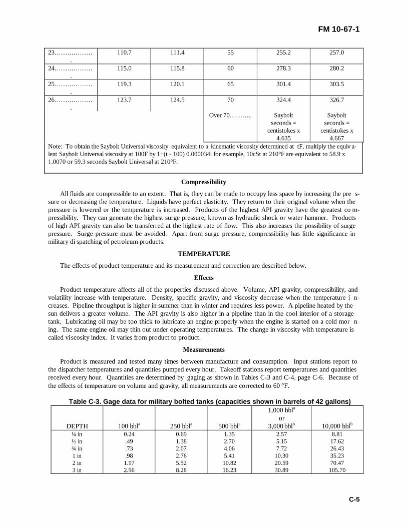
FM 10-67-1
C-5
23… … … … … ….
110.7 111.4 55 255.2 257.0
24… … … … … ….
115.0 115.8 60 278.3 280.2
25… … … … … ….
119.3 120.1 65 301.4 303.5
26… … … … … ….
123.7 124.5 70 324.4 326.7
Over 70… … … .. Sayboltseconds =
centistokes x4.635
Sayboltseconds =
centistokes x4.667
Note: To obtain the Saybolt Universal viscosity equivalent to a kinematic viscosity determined at tF, multiply the equiv a-lent Saybolt Universal viscosity at 100F by 1+(t - 100) 0.000034: for example, 10cSt at 210°F are equivalent to 58.9 x1.0070 or 59.3 seconds Saybolt Universal at 210°F.
Compressibility
All fluids are compressible to an extent. That is, they can be made to occupy less space by increasing the pre s-sure or decreasing the temperature. Liquids have perfect elasticity. They return to their original volume when thepressure is lowered or the temperature is increased. Products of the highest API gravity have the greatest co m-pressibility. They can generate the highest surge pressure, known as hydraulic shock or water hammer. Productsof high API gravity can also be transferred at the highest rate of flow. This also increases the possibility of surgepressure. Surge pressure must be avoided. Apart from surge pressure, compressibility has little significance inmilitary di spatching of petroleum products.
TEMPERATURE
The effects of product temperature and its measurement and correction are described below.
Effects
Product temperature affects all of the properties discussed above. Volume, API gravity, compressibility, andvolatility increase with temperature. Density, specific gravity, and viscosity decrease when the temperature i n-creases. Pipeline throughput is higher in summer than in winter and requires less power. A pipeline heated by thesun delivers a greater volume. The API gravity is also higher in a pipeline than in the cool interior of a storagetank. Lubricating oil may be too thick to lubricate an engine properly when the engine is started on a cold mor n-ing. The same engine oil may thin out under operating temperatures. The change in viscosity with temperature iscalled vi scosity index. It varies from product to product.
Measurements
Product is measured and tested many times between manufacture and consumption. Input stations report tothe dispatcher temperatures and quantities pumped every hour. Takeoff stations report temperatures and quantitiesreceived every hour. Quantities are determined by gaging as shown in Tables C-3 and C-4, page C-6. Because ofthe effects of temperature on volume and gravity, all measurements are corrected to 60 °F.
Table C-3. Gage data for military bolted tanks (capacities shown in barrels of 42 gallons)
DEPTH 100 bbla 250 bbla 500 bbla
1,000 bbla
or3,000 bblb 10,000 bblb
¼ in 0.24 0.69 1.35 2.57 8.81½ in .49 1.38 2.70 5.15 17.62¾ in .73 2.07 4.06 7.72 26.431 in .98 2.76 5.41 10.30 35.232 in 1.97 5.52 10.82 20.59 70.473 in 2.96 8.28 16.23 30.89 105.70

FM 10-67-1
C-6
4 in 3.95 11.04 21.64 41.18 140.945 in 4.94 13.80 27.05 51.48 176.176 in 5.93 16.56 32.46 61.77 211.417 in 6.92 19.32 37.87 72.07 246.648 in 7.91 22.07 43.28 82.36 281.889 in 8.90 24.83 46.68 92.66 317.11
10 in 9.89 27.59 54.09 102.96 352.3511 in 10.88 30.35 59.50 113.25 387.58
1 ft 0 in 11.87 33.11 64.91 123.56 422.822 ft 0 in 23.76 66.22 129.83 247.09 845.643 ft 0 in 35.66 99.34 194.74 370.64 1,268.464 ft 0 in 47.54 132.45 259.65 494.19 1,691.285 ft 0 in 59.43 165.56 324.56 617.74 2,114.096 ft 0 in 71.32 198.67 389.48 741.28 2,536.917 ft 0 in 83.21 231.79 454.39 864.38 2,959.738 ft 0 in 95.10 c264.90 c519.30 988.38 3,382.559 ft 0 in 106.99 c298.01 584.22 c1,111.93 3,805.37
Table C-3. Gage data for military bolted tanks (capacities shown in barrels of 42 gallons) Cont.10 ft 0 in 118.88 331.12 649.13 1,235.47 4,228.1911 ft 0 in 130.77 364.24 714.04 1,359.02 4,651.0112 ft 0 in 142.66 397.35 778.96 1,482.57 5,073.8313 ft 0 in 154.55 430.46 843,87 1,606.12 5,496.6414 ft 0 in 166.44 463.57 908.78 1,729.66 5,919.4615 ft 0 in 178.33 496.69 973.69 1,853.29 6,342.2816 ft 0 in 190.22 529.80 1,038.61 1,976.76 6,765.1017 ft 0 in … … … … . … … … … … … … … 2,100.30 7,187.9218 ft 0 in … … … … . … … … … … … … … 2,223.85 7,610.7419 ft 0 in … … … … . … … … … … … … … 2,347.40 8,033.5620 ft 0 in … … … … . … … … … … … … … 2,470.95 8,456.3821 ft 0 in … … … … . … … … … … … … … 2,594.49 8,879.1922 ft 0 in … … … … . … … … … … … … … 2,718.04 9,302.0123 ft 0 in … … … … . … … … … … … … … 2,841.59 9,724.8324 ft 0 in … … … … . … … … … … … … … 2,965.13 10,147.65
a One-ring tank.b More than n-ring tank.c Capacities greater than nominal size are produced by adding one additional ring. No more than one is permi t-ted.
Table C-4. Deadwood for military bolted tanks (capacities are in barrels of 42 gallons)
DEPTH 100 bbla 250 bbla 500 bbla
1,000 bbla
or3,000 bblb 10,000 bblb
1 ft 0 in 0.007 0.008 0.010 0.030 0.0552 ft 0 in .013 .016 .020 .060 .1103 ft 0 in .019 .024 .030 .089 .1644 ft 0 in .026 .032 .40 .119 .2175 ft 0 in .031 .039 .048 .145 .2796 ft 0 in .036 .046 .057 .169 .3407 ft 0 in .042 .053 .065 .195 .4058 ft 0 in .047 .058 .073 .219 .4679 ft 0 in .052 .066 .081 .243 .508
10 ft 0 in .058 .073 .089 .268 .54811 ft 0 in .063 .079 .098 .292 .58612 ft 0 in .069 .086 .105 .317 .62413 ft 0 in .074 .093 .113 .340 .66514 ft 0 in .079 .100 .122 .366 .700

FM 10-67-1
C-7
15 ft 0 in .084 .106 .129 .390 .74016 ft 0 in .090 .113 .137 .416 .77917 ft 0 in … … … … . … … … … … … … … .441 .81718 ft 0 in … … … … . … … … … … … … … .464 .85519 ft 0 in … … … … . … … … … … … … … .490 .89320 ft 0 in … … … … . … … … … … … … … .521 .93321 ft 0 in … … … … . … … … … … … … … .538 .97222 ft 0 in … … … … . … … … … … … … … .562 1.00623 ft 0 in … … … … . … … … … … … … … .586 1.10024 ft 0 in … … … … . … … … … … … … … .690 1.368
a One-ring tank.b More than one-ring tank.CCapacities greater than nominal size are produced by adding one additional ring. No more than one is permi t-ted.
Corrections
Volume correction to 60°F requires observation of both gravity and temperature. They should be taken asclose to the same time as possible. Combination hydrometers and thermometers make this easier. If specific gra v-ity is taken, it must be converted to API gravity. Gravity at the observed temperature is corrected to 60°F. Volumecorrection factors are based on true or corrected gravity. Corrections are made according to the API/ASTM-IPPetroleum Measurement Table (Tables 5B and 6B) and DA Pam 710-2-2. Table 5B gives factors for correctingobserved API gravity to true gravity at 60°F. Table 6B gives correction factors for each degree or half degree ofAPI gravity and each degree or half degree of temperature. Gravity must be corrected to 60°F to ensure that themultiplier is selected from the proper group. This is most important near the ends of the eight gravity ranges. Themultiplier is a ratio volume at 60 °F to volume at the observed temperature. If the observed temperature is higherthan 60°F, the multiplier is less than 1 and the corrected volume will be smaller. If observed temperature is lessthan 60°F, the mult iplier is less than 1 and the corrected volume will be larger.
Section II. Flow in Pipelines
HYDRAULICS
The principles of hydraulics govern flow in pipelines. Hydraulics is the branch of science that deals with thebehavior of liquids. It also deals with the equipment required to raise liquids to higher elevations and to transferthem from place to place. The broad subject includes the pressure and the equilibrium of liquids at rest ( hydroki-netics), as in an operating pipeline, and forces exerted on liquids by objects in motion (hydrodynamics), as inpumping equipment.
PRESSURE
Pressure is the main element in pipeline hydraulics. All forces producing pipeline flow and those opposing itcan be measured in terms of pressure or head. Coupled military pipelines are low-pressure systems that operate atpressures of not more than 600 PSI. The low pressure requires closer pump station spacing than in commercialpipeline. Pump stations are spaced about 12 to16 miles apart in military systems on level terrain. Welded linesconstructed for the military operate at higher pressures. The two types of pressure in a pipeline are static and d y-namic.
Static Pressure

FM 10-67-1
C-8
Static pressure is a measure of pressure in liquids at rest. At any level in any size or shape of container, staticpressure depends solely upon the vertical height of liquid above that level. Unit pressure at the bottom of all co n-tainers shown in Figure C-1, page C-8, is the same, 1 PSI. A column of water 1 inch square and about 27 incheshigh weighs 1 pound. The force of 1 pound acts on an area of 1 square inch in the first container. The secondcontainer holds 4 pounds of water distributed over 4 square inches. The third container holds 16 pounds distri b-uted over 16 square inches. The fourth holds 64 pounds distributed over 64 square inches. Total pressure varies atthe bottom of all containers in Figure C-1, page C-8, and Figure C-2, page C-8, but unit pressure is the same, 1PSI. The height of water in all the containers, 27 inches or 2.31 feet, is the head required to produce a pressure of1 PSI. Static pressure in any column of water is the head in feet divided by 2.31 or multiplied by 0.433 (Table C-5,page C-9). Static pressure is proportionally less in a petroleum product because of its lower specific gravity. Theformulas for converting head to pre ssure and vice versa are as follows:
Pressure (PSI) = head (in feet) x specific gravity2.31
or
Pressure (PSI) = 0.433 x head (in feet) x specific gravity
or
Head (in feet) = PSI0.433 x specific gravity
Figure C-1. Pressure in containers of different dimensions

FM 10-67-1
C-9
Figure C-2. Pressure in irregularly shaped containers
Table C-5. API gravity, corresponding specific gravity, weights, and pressure at 60°F
API GRAVITYSPECIFICGRAVITY
POUNDS PERCU FT FEET PER PSI PSI PER FOOT
10 1.0000 62.30 2.31 0.43315 .9659 60.17 2.39 .41820 .9340 58.18 2.48 .40425 .9042 56.32 2.56 .39126 .8984 55.96 2.57 .38927 .8927 55.61 2.59 .38628 .8871 55.26 2.61 .38429 .8816 54.92 2.62 .38130 .8762 54.58 2.64 .37931 .8708 54.24 2.66 .37732 .8654 53.90 2.67 .37433 .8602 53.58 2.69 .37234 .8550 53.25 2.70 .37035 .8498 52.93 2.72 .36836 .8448 52.62 2.74 .36537 .8398 52.31 2.75 .36338 .8348 52.00 2.77 .36139 .8299 51.69 2.79 .35940 .8251 51.39 2.80 .35741 .8203 51.09 2.82 .35542 .8155 50.79 2.84 .35343 .8109 50.51 2.85 .35144 .8063 50.22 2.87 .34945 .8017 49.93 2.88 .347

FM 10-67-1
C-10
46 .7972 49.65 2.90 .34547 .7927 49.37 2.92 .34348 .7883 49.10 2.93 .34149 .7839 48.82 2.95 .33950 .7796 48.55 2.97 .33751 .7753 48.29 2.98 .33552 .7711 48.02 3.00 .33453 .7669 47.76 3.02 .33254 .7628 47.50 3.03 .33055 .7587 47.25 3.05 .32856 .7547 47.00 3.06 .32657 .7507 46.75 3.08 .32558 .7467 46.50 3.10 .32359 .7428 46.26 3.11 .32160 .7389 46.01 3.13 .32061 .7351 45.77 3.15 .31862 .7313 45.53 3.16 .31663 .7275 45.30 3.18 .31564 .7238 45.07 3.19 .31365 .7201 44.84 3.21 .31166 .7165 44.61 3.22 .21067 .7128 44.39 3.24 .30868 .7093 44.16 3.26 .30769 .7057 43.94 3.27 .30570 .7022 43.72 3.29 .30471 ,6988 43.51 3.30 .30272 .6953 43.30 3.32 .30173 .6919 43.08 3.34 .29974 .6886 42.87 3.35 .29875 .6852 42.66 3.37 .296
Dynamic Pressure
Dynamic pressure or head is a measure of pressure in liquids in motion. Dynamic head is also a measure ofpotential energy or energy of position. Figure C-3, page C-10, shows the relationship between static head and d y-namic head. Static head at ground level behind the nozzle is measured by the vertical height of liquid in the tankabove the ground. When liquid starts to flow down the pipe, it loses static head, but it gains in dynamic head.Potential energy becomes kinetic energy or energy in motion. Dynamic head or velocity is greatest at ground levelwhere the stream changes direction and starts to rise. Dynamic head decreases after that until all velocity is lost.Meanwhile, the stream regains some portion of its initial static head and final static head is the head loss becauseof friction and change in direction. In other words, dynamic head is the static head required to accelerate thestream to its flowing velocity. It is the elevation to which a pump can push a co lumn of liquid.
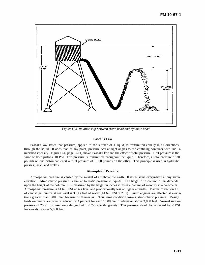
FM 10-67-1
C-11
Figure C-3. Relationship between static head and dynamic head
Pascal’s Law
Pascal’s law states that pressure, applied to the surface of a liquid, is transmitted equally in all directionsthrough the liquid. It adds that, at any point, pressure acts at right angles to the confining container with und i-minished intensity. Figure C-4, page C-11, shows Pascal’s law and the effect of total pressure. Unit pressure is thesame on both pistons, 10 PSI. This pressure is transmitted throughout the liquid. Therefore, a total pressure of 30pounds on one piston can exert a total pressure of 1,000 pounds on the other. This principle is used in hydraulicpresses, jacks, and brakes.
Atmospheric Pressure
Atmospheric pressure is caused by the weight of air above the earth. It is the same everywhere at any givenelevation. Atmospheric pressure is similar to static pressure in liquids. The height of a column of air dependsupon the height of the column. It is measured by the height in inches it raises a column of mercury in a barometer.Atmospheric pressure is 14.695 PSI at sea level and proportionally less at higher altitudes. Maximum suction liftof centrifugal pumps at sea level is 33(+) feet of water (14.695 PSI x 2.31). Pump engines are affected at elev a-tions greater than 3,000 feet because of thinner air. This same condition lowers atmospheric pressure. Designloads on pumps are usually reduced by 4 percent for each 1,000 feet of elevation above 3,000 feet. Normal suctionpressure of 20 PSI is based on a design fuel of 0.725 specific gravity. This pressure should be increased to 30 PSIfor elevations over 5,000 feet.

FM 10-67-1
C-12
Figure C-4. Illustration of Pascal’s law
Vacuum
A vacuum is created when pressure is reduced below atmospheric level. The theoretical limit of pressure r e-duction is absolute zero or perfect vacuum. Vacuums are measured as absolute pressure in inches of mercury.Pump suction reduces atmospheric pressure at the point of intake. This allows atmospheric pressure on the sourceof supply to push liquids into the pump. Figure C-5 shows the relationship between atmospheric pressure, gagepressure, vacuum, and absolute pressure.
Figure C-5. Interrelationship of atmospheric pressure, gage pressure, vacuum, and absolute pressure

FM 10-67-1
C-13
Vapor Pressure
All liquids, especially light petroleum products, tend to vaporize. This results from motion of the molecules ofwhich they are composed. Motion of molecules near the surface causes some to escape into the air. The tendencyto vaporize is called volatility. Volatility increases with temperature and decreases with pressure. Vapor pressureis formed when a vaporizing liquid is confined in a closed container like that used in the Reid vapor pressure test.The temperature at which vapor pressure is the boiling point of the liquid. For this reason, liquids boil at lowertemperatures at high elevations than at sea level. Vapor pressure reduces the effect of atmospheric pressure actingon the liquid. Maximum net suction lift is reduced accordingly. For this reason, pump suction pressure alwaysmust be greater than the vapor pressure of the product. Normal suction pressure of 20 PSI should be increased to30 PSI for operating temperatures over 100°F.
NATURE OF FLOW
The two types of flow are laminar and turbulent. They are covered in Chapter 9. Liquids flow in pipelines b e-cause of gravity or pump action. In both cases, they flow because of pressure. Pressure is supplied by weight of theliquid in gravity flow and by pump action in discharge flow. While pressure and head are almost synonymous,they are actually proportional to each other.
RESISTANCE OF FLOW
Flow in a pipeline continues until the head producing it has been lost. The loss of head or the difference b e-tween pressure at the source and at any point downstream is caused by factors that resist flow. The main factorsthat resist flow are friction of the pipe walls and viscosity of the liquid. Friction loss calculations are covered indetail in FM 5-482, Chapter 4. To calculate friction loss for JP-8, use Table C-6, page C-14, and Figure C-6, pageC-13. Less important factors in flow resistance include:
• Entrance to the pipe.
• Sudden changes in cross-sectional area or direction of flow.
• Resistance of valves and fittings.
• Passage through equipment, such as meters and traps.
• Corrosion or deposits in the line.
RATE OF FLOW
The rate of flow depends on pump pressure and differences in elevation. It also depends on gravity and vi s-cosity of the product, diameter and length of the pipe, and roughness of the pipe.
Pressure
There is friction between the liquid and the pipe walls. The pressure needed to overcome this resistance is e x-pressed as pressure drop or loss in pounds per square inch per mile of pipe as shown in Figure C-7, page C-15.The pressure needed to overcome the resistance of valves and fittings is similarly expressed in equivalent lengths ofpipe as shown in Figure C-8, page C-16, and Table C-6, page C-14. The total pressure needed to overcome allresistance in the line is pressure drop per mile times length of the line in miles. There is a direct relationship b e-tween pressure and rate of flow. This is shown by the fact that about double the pressure is needed to increasethroughput by one half as shown in Table C-8, page C-16.

FM 10-67-1
C-14
Figure C-6. Kinematic viscosities for common military fuels
Table C-6. Pipe lengths equivalent to lubricated plug valves

FM 10-67-1
C-15
125-POUND CAST IRONAND 150-POUND
NONFERROUS METAL
250-POUNDCAST IRON
150-POUND STEEL 300-POUND STEEL
NominalSize
(inches)
Regular(feet)
ShortPatternWedgeGate(feet)
Venturi(feet)
Regu-lar
(feet)
Venturi(feet)
Regular ShortPattern(feet)
Venturi(feet)
Regular(feet)
ShortPattern(feet)
Venturi(feet)
6 12 44 36 12 36 9.6 14.4 36 … … … 42 … … …8 18 54 54 18 54 12.0 48.0 54 9.6 54 54
10 24 60 60 24 60 … … .. 54.0 60 … … … 66 6012 30 72 78 … … … 78 … … … 72.0 84 … … … … … … 77
Table C-7. Relationship of pressure and quantity with length and diameter constantRELATIVEPRESSURE
INCREASEINPRESSURE(percent)
RELATIVEQUANTITY(percent)
INCREASEINQUANTITY(percent)
RELATIVEPRESSURE
DECREASEINPRESSURE(percent)
RELATIVEQUANTITY
DECREASEINQUANTITY(percent)
1.00 … … … … . 1.00 … … … … .. 1.00 … … … … .. 1.00 … … … … ..1.02 2 1.01 1 .98 2 .99 11.04 4 1.02 2 .96 4 .98 21.06 6 1.03 3 .94 6 .96 41.08 8 1.05 5 .92 8 .95 51.10 10 1.06 6 .90 10 .94 61.12 12 1.07 7 .88 12 .93 71.15 15 1.08 8 .85 15 .91 91.20 20 1.11 11 .80 20 .88 121.25 25 1.14 14 .75 25 .85 151.30 30 1.16 16 .70 30 .81 191.40 40 1.22 22 .60 40 .74 261.50 50 1.26 26 50 50 .67 331.75 75 1.38 38 .40 60 .58 422.00 100 1.49 49 .30 70 .49 51

FM 10-67-1
C-16
Figure C-7. Pressure loss due to friction in pipe

FM 10-67-1
C-17
Figure C-8. Pipe lengths equivalent to valves and fittings

FM 10-67-1
C-18
Elevation
Pressure needed to overcome friction is not the total pressure supplied if the product is to be pumped over ahill higher than the pump. The pressure equivalent of the difference in elevation in feet must be added to the pre s-sure needed to overcome friction. If the liquid is to flow downhill from the pump, the difference in elevation canbe subtracted. Otherwise, the liquid will flow proportionally farther at the same pump pressure. Elevation or staticpressure acts at all times on a filled line whether the liquid is flowing or not.
Gravity
Specific gravity of the product is important because the liquid being moved has weight. The greater the sp e-cific gravity, or the lower the API gravity, the greater must be the pump pressure to move it. As heavier productsare pumped in the line, pressure must be increased to keep the same flow rate. At the same pressure, flow rate fallsoff to suit the heaviest product being pumped. Observed gravity should be used in rate-of-flow computations i n-stead of true gravity. This is because the computation will be concerned with an actual, not theoretical, condition.Changing from 40 API gravity to 60 API gravity lessens pressure requirements 10 percent. At the same pressure,changing from 40 API gravity to 60 API gravity increases rate of flow about 7 percent.
Viscosity
Viscosity and specific gravity of product affect pump pressure in the same way. As more viscous products arepumped, pressure must be increased to keep the same rate of flow as shown in Table C-8. Both gravity and visco s-ity vary with temperature. Therefore, locations with temperature differences of about 50 °F require 10 to 20 percenthigher pumping pressures in winter.
Table C-8. Relationship of viscosity, quantity, and pressureRELATIVE QUANTITY WITHPRESSURE CONSTANT
RELATIVE PRESSURE WITHQUANTITY CONSTANT
VISCOSITYa Ab Bc VISCOSITYa Ab Bc
35 120 100 35 73 10040 110 91 40 85 11745 104 86 45 90 12850 100 83 50 100 13755 97 81 55 105 14460 95 79 60 109 15070 91 76 70 117 16180 89 74 80 123 16890 87 72 90 128 175
100 85 71 100 132 182125 82 68 125 142 194150 79 66 150 150 205200 75 63 200 162 222300 71 59 300 182 249
a Viscosity in Saybolt Universal seconds.b Quantity or pressure relative to 50 seconds.c Quantity or pressure relative to 35 seconds.
Diameter of Pipe
The pressure needed to pump at a given flow rate decreases rapidly as pipe diameter increases. It requiresabout 85 feet of pressure drop per mile to pump gasoline at the rate of 550 GPM through a 6.407-inch pipeline.Only about 22 feet of pressure drop are needed to pump at the same rate through 8.407-inch pipeline as shown in

FM 10-67-1
C-19
Figure C-6, page C-13. The decrease is about 74 percent. The same rate of flow requires about 600 feet of pres-sure drop for 4.344-inch pipeline. This is an increase of more than 500 percent. At any given pressure, throug h-put may be increased about threefold by increasing the pipe diameter 50 percent.
Length of pipe
Required pumping pressure increases directly with distance pumped. In other words, pressure drop per mile isproportional to distance pumped. If distance is doubled, pressure must be doubled. If pressure stays constant, rateof flow varies inversely as the approximate square root of length. For example, if station spacing is decreased byone half, flow rate will increase by about one half.
Roughness of pipe
Required pumping pressure increases directly with roughness of pipe For this reason, scrapers and corrosioninhibitors must be used to keep the pipeline in good operating condition.
Section III. Examples of Flow
HYDRAULIC GRADIENT
Figure C-9 shows what is meant by hydraulic gradient. The figure shows a tank with a pipeline of uniformsize and grade connected at point A and discharging into the atmosphere at point B. Vertical pipes that open tothe atmosphere have been connected at points X, Y, and Z. The tank is filled with product to a height of 10 feetabove A and B. The hydraulic gradient exists only under conditions of flow. It is assumed that the level of productin the tank stays the same when flow begins. Product rises in each of the vertical pipes to a height (D, E, and F)that represents the remaining feet of head at X, Y, and Z. The head that has been lost at each point is proportionalto the length of pipe through which product has flowed. Pressure head is lost uniformly from A to B. This un i-form loss of head is the hydraulic gradient. It is shown by the line co nnecting points C, D, E, F, and B.
Figure C-9. Hydraulic gradient

FM 10-67-1
C-20
DOWNHILL FLOW
Figure C-10, shows a situation in which the product flows downhill. Conditions are the same as in Figure C-8, page C-16, except that point B is 10 feet below the tank connection A. This change increases the head to 20feet. The new C to B line is the hydraulic gradient. This gradient is steeper than in Figure C-8, page C-16. Therate of flow or velocity is also greater.
Figure C-10. Downhill flow
UPHILL FLOW
Figure C-11, page C-20, shows a situation in which product flows uphill. The point of discharge B is 5 feetabove the tank outlet A. Effective head has been reduced to 5 feet. The hydraulic gradient is not as steep as that inFigure C-9, page C-18 . The rate of flow is also less. The tank could not be emptied by gravity below point D.
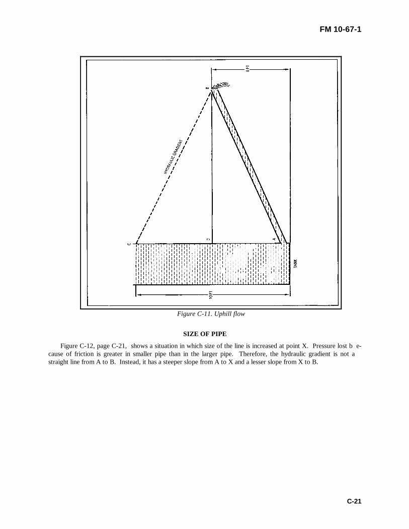
FM 10-67-1
C-21
Figure C-11. Uphill flow
SIZE OF PIPE
Figure C-12, page C-21, shows a situation in which size of the line is increased at point X. Pressure lost b e-cause of friction is greater in smaller pipe than in the larger pipe. Therefore, the hydraulic gradient is not astraight line from A to B. Instead, it has a steeper slope from A to X and a lesser slope from X to B.

FM 10-67-1
C-22
Figure C-12. Varying size of pipe

FM 10-67-1
D-1
APPENDIX D
PMCS CHECKLISTS
Use of FormsForms are prepared to schedule inspections and preventive maintenance and to record the results of inspections and the
need for repairs. They are also used to report preventive maintenance performed, to note repairs made, and to request servicesof support maintenance. In addition, forms are used to keep track of the time equipment is in use or out of service, and toprovide data for reports on the condition and status of equipment.
Responsibility for Record KeepingMost maintenance records are the responsibility of the TAMMS clerk. However, some forms should be filled out by
equipment operators and repairers Some forms require only one or two brief comments; others require many detailed entries.Some are filed in the appropriate equipment logbook. Others are turned over to the TAMMS clerk or maintenance supervisorfor further action. The maintenance forms that pipeline equipment operators and repairers should be familiar with are brieflydescribed in this appendix. DA Pamphlet 738-750 gives additional information on all these forms except DA Form 4177 andDA Form 10-242.
DD Form 314DD Form 314 is used to show when equipment is scheduled for periodic preventive maintenance and when maintenance
has been performed. The reverse side of DD Form 314 is used to record the time a piece of equipment was not missioncapable either because of maintenance or because repairers were waiting for parts from supply. Not all preventivemaintenance should be recorded on DD Form 314. Only preventive maintenance that is performed on a time or mileage basisshould be scheduled and recorded on DD Form 314. For example, DD Form 314 should be used to schedule and recordmaintenance that is done every 3 months, after 1,000 hours of operation, or every 5,000 miles.
DA Form 2404DA Form 2404 is used to report any faults or malfunctions discovered by an equipment operator. It is also used by
organizational maintenance personnel to record periodic maintenance services and spot check inspections. This form is atemporary record of needed and completed repairs. DA Form 2404 should be 75destroyed after all uncorrected faults havebeen recorded on DA Forms 2402 and 2407 or action has been taken to request repair parts. However, if the equipment is notcombat ready because of needed repairs, DA Form 2404 should be kept on file until the equipment has been repaired.
DA Form 2407DA Form 2407 is used by organizational maintenance personnel mainly to request support maintenance. It is used when
organizational maintenance personnel cannot repair a piece of equipment because of a lack of ability or proper tools. Allcopies of DA Form 2407 are sent with the faulty equipment to the support activity. The receipt copy is sent back to the owningorganization where it is kept on file until the equipment is returned. DA Form 2407 is also used to report maintenance oncertain sample items and to submit warranty claims. DA Form 2407-1 is used where there are not enough lines on DA Form2407. DA Form 2405 is used by the owning organization to keep a record of DA Forms 2407 sent to support maint enance.
DA Form 2409DA Form 2409 is used to keep a complete maintenance history on a piece of equipment. Its use is mandatory for some
pieces of equipment. See DA Pamphlet 738-750. DA Form 2409 should be maintained as a separate equipment log. Everyinspection or test specified in the appropriate TM should be noted on the front of DA Form 2409. Every corrective actiontaken by organizational personnel should be noted on the back of the form. The form is kept for 6 months after the lastinspection or corrective action noted.

FM 10-67-1
D-2
DA Form 4177DA Form 4177 is used to schedule inspections and preventive maintenance on a fixed utility or structure
such as storage tank. It is also used to record completed maintenance and repairs to tank. Additional info r-mation on scheduling inspections and performing required maintenance on storage tanks is in Chapter 12 ofthis manual. DA Form 4177 should be kept on file locally for the duration of the equipment. All lines on thereverse side of the form should be used. Instructions for preparing the format are given as follows.
Front of DA Form 4177The front of DA Form 4177 should be filled out as follows:
• Enter the location and identification number of the tank in the Equipment Number block.
• Briefly describe the tank in the Descri ption block. Include the capacity of the tank.
• Enter the name of the person who will perform the preventive maintenance on the tank in the PreventiveMaintenance To Be Done By block.
• Review the appropriate TMs and list the inspections to be performed and the maintenance actions to betaken in the Work To Be Done blocks.
• Number the work list consecutively in the Item Nr block.
• Enter the number of the TMs and the paragraph which describes the work to be performed in the Refe r-ence block.
• Enter how often the inspection or maintenance action should be performed in the Frequency block.
• Enter the day and the time the work should be performed in the Time block.
• Place a check in each block at the top of the form where the months are listed if inspections are made onsome items each month. Write SA in the appropriate blocks for semiannual maintenance and A in the appr o-priate block for annual maintenance.
Back of DA Form 4177
The back of DA Form 4177 should be filled out as given below.
• Enter the date the work was performed in the Date block.
• Enter the corresponding item number for the work performed in the Work Done block. These numbersare listed on the front of the form. Special maintenance and repairs performed on the storage tank, but notlisted on the front of the form, should be described briefly.
• Enter initials in the Initial block.
DA Form 10-5464-R
DA Form 10-5464-R is usually filled out by a pipeline patroller to report a pipeline leak. The completedform is turned over to the pipeline supervisor to be signed by the section chief and platoon leader. To fill outthis form--
• Enter the date and time in the blocks in the top right corner labeled Date and Time.
• Enter the name of the unit that the report goes to in the To block and the name of the unit the report isfrom in the From block.
• Enter name and grade in the Reported By block.
• Enter name of platoon and section in the Platoon And Se ction block.• Enter the number of the pump station nearest the leak and the number of the joint where the leak was
found in the Location Of Leak blocks.• Enter an estimate of the amount of leaked fuel in Fuel Lost block.• Enter the apparent cause of the leak in the A pparent Cause Of Leak blocks.• Enter a description of the kind of repair made in the Disp osition block.

FM 10-67-1
D-3
• Enter a description of any other actions taken to protect life and property in the Precautions Takenblock.

FM 10-67-1
E-1
APPENDIX E
WATER DETECTION (AQUA-GLO) TEST
EQUIPMENT
To test aviation fuels for undissolved (free) water, use the Aqua-Glo III ultraviolet detector kit as shown inFigures E-1A and E1B, page E-1 and page E-2. The standard test method for undissolved water is ASTM D 3240-86a. The following equipment is required to perform this test:
Aqua-Glow series III Free Water Detector Unit
The Aqua-Glo series III determines the degree of undissolved water content. The ultraviolet lamp assemblyhas a single, permanent fluorescing standard, positioned under a photographic-type iris diaphra gm that can beopened or closed to increase or decrease the amount of ultraviolet light. The water content is determined by a d-justing the diaphra gm lever arm until the fluorescing standard and the test pad shows equal brightness in the ultr a-violet light. The balance is reached when the zero-centering ammeter reads ZERO. The amount of water is readPPM on the diaphragm lever arm scale that has been precalibrated in the factory.
Test Pads
The fuel sample passes through a uranine dye-treated filter pad. Free water in the fuel reacts with the uraninedye. When the pad is illuminated by ultraviolet light, the dye contacted by the free water will fluoresce a brightyellow. The pad is packaged in a hermetically sealed packet. The test pads are packaged 50 to a box.
Test Pad Holder and Sample Line
A test pad holder and sample line are used to draw the fuel sample through the test pad. The test pad holder iscoupled to a sampling coupler mounted on the downstream side of the fi lter/separator.
Paper towels or blotters
Paper towels or blotters are used to remove excess fuel from the test pad before testing is conducted for freewater.
Tweezers
Tweezers are used at all times when the test pad is being handled .
Figure E-1A. Aqua-Glo Series III ultraviolet detector kit

FM 10-67-1
E-2
Figure E-1B. Aqua-Glo Series III ultraviolet detector kit
TEST PREPARATION
To ensure accurate free water detection, the Aqua-Glo III detector must be assembled for operation and cali-brated before each use and after every hour of use. These procedures are described below:
• Slide the meter assembly into the track on the ultra violet lamp assembly .
• Turn on the water detector, setting the indicator switch to the appropriate power source: set to AC (50 or 60Hz, 110-120v, using power cord), internal battery, or external battery (using external battery cord). See Figure E-2, page E-3. When using the internal battery, ensure the battery is charged if the battery is in a low or no batterypower condition. A low battery condition can be identified by sluggish response of the meter or failure of the de-tector to stay calibrated during two successive tests. Use of the detector in a low or no battery condition will pro-vide inaccurate test results.
• Remove the calibration pad stored in the kit. Always handle the pad with tweezers The pad is covered witha clear plastic shielding and has a coding standard written on one side. Note the “SET” code in the center of thepad, this is the calibration setting you will use for calibrating. The sample pad in Figure E-3, page E-3, has a cal i-bration set code of “5.3.” Ensure that the calibration and fluorescing standard are a matched set. The fluorescingstandard located under the hinged light shield has an alphanumeric code, and should match the code on the cal i-bration standard. Although the “SET” numbers on the standards may or may not be the same, the code for thestandards must be the same . You should label or mark the detector with the calibration/fluorescing code to ensurethe proper pad is used during calibration. Matched standard sets can be ordered under NSN 6630-01-245-5989.
• Using tweezers, insert the calibration pad in the test area window located on the bottom of the water detector.Lift the covers curved metal tab and place the pad (text facing you) in the depressed circular area in the center ofthe test area as shown in Figure E-4, page E-4. Close the test area cover and stand the water detector upright.
• Position the light-modulator lever, located on the side of the water detector, until the lever is directly abovethe number on the scale corresponding to the set number shown on the calibration pad as shown in Figure E-5,page E-4.
• Depress the switch button on the instrument pack and read the calibration meter. If the meter reads “0,” thewater detector is calibrated as shown in Figure E-6, page E-5. If the meter reads any increment other than “0,” youmust adjust the internal calibration screw until the water detector is “zeroed-out.”
• To adjust the internal calibration screw, remove the outer screw on the side of the calibration meter housingusing the jeweler’s screwdriver. Insert the jeweler’s screwdriver into the housing and turn the internal adjustment

FM 10-67-1
E-3
screw. Depress the switch button on the instrument pack as you turn the screw until the meter lever reads “0.”Replace the outer screw and the water detector is calibrated. See Figure E-7, page E-5.
• Remove the calibration pad from the test area, using tweezers, and place it back in the kit.
Figure E-2. AC/internal/external power settings
Figure E-3. Calibration pad and calibration set code

FM 10-67-1
E-4
Figure E-4. Placement of calibration pad in test area window
Figure E-5. Set the light-modulator lever

FM 10-67-1
E-5
Figure E-6. Calibration meter lever shaft reading “0”
Figure E-7. Zeroing-out the meter lever
FM 10-67-1
E-6
SAMPLING PROCEDURES
The sampling coupler must be permanently attached to a fuel probe mounted downstream from the fi l-ter/separator. For the test to be accurate, the sample must be taken from a moving stream of fuel. The sampleshould be drawn at a rate of 600 to 800 mL/minute. When sampling the fuel in a system, ensure the pump is ru n-ning and at least one nozzle is open. If sampling the fuel in a filter, take the sample while recirculating the fuelbefore operations. Take the sample using the procedures described below.
• Couple the detector pad holder assembly, with the toggle valve closed (parallel to the line), to the samplingcoupler. The detector pad holder assembly includes plastic tubing, the detector pad holder, toggle valve, and sa m-pling coupler.
• Flush the sampling line immediately before sampling. Put the end of the plastic tubing in a container thatwill hold approximately 1 gallon. (Note: The amount of free water in a sample is very sensitive to the temperatureof a sample. Using bottles or cans for a sample container could result in errors due to sample temperature or a d-sorption of water on container walls.) Open the toggle valve by turning the handle up (perpendicular to the line).Flush the detector pad assembly by displacing at least 1 liter of product . Shut the toggle valve and uncouple thedetector pad assembly.
• Unscrew the two halves of the detector pad holder. Using tweezers, take the detector pad out of its envelopeand put it, orange side up, in the recess in the outlet side of the holder . If the sample pad has any discoloration,unevenness in dye content, or a faded yellow appearance, select another sample pad. Screw the pad holder asse m-bly back together. When using a three-way valve, the assembly may be flushed with the pad in place. Do not r e-move the test pad from the hermetically sealed envelope until ready for use. The pad can absorb moisture from theair, rain, or sneezing. Exposing the test pad to the air on a humid day will ruin the pad in a matter of mi nutes.
• Couple the detector pad assembly back to the sampling coupler, with the toggle valve closed, and put the endof the plastic tubing into the neck of the plastic sample bottle. Open the toggle valve and allow 500 mL of productto pass through the sample pad. Normal sample volume is 500 mL, but if the reading is off scale, sample volumesas low as 100 mL may be used.
• Close the toggle valve and uncouple the detector pad holder from the sampling coupler. Unscrew the dete c-tor pad holder. Slip one prong into the notch in the pad holder , and lift the pad out. Press the test pad between drypaper towels or blotters to remove excess fuel.
TEST PROCEDURES
Test the fuel after the equipment has been prepared and the sample is drawn. For maximum accuracy, readthe test pad within three minutes after sampling is begun . Use the following procedures for testing.
• Using tweezers, put the pad in the test pad slot in the bottom of the ultraviolet lamp assembly. Ensure thatthe orange side faces the ultraviolet lamp. Turn on the lamp. Press the hooded button of the meter assembly whilemoving the light modulator lever as shown in Figure E-8, page E-7. Watch the meter scale while moving the lightmodulator lever until the meter pointer points to zero. Always move the modulator arm in the same direction toavoid backlash. Release pressure on the hooded button and shut the lamp switch off when the meter pointer hassettled on zero. The meter pointer should stabilize in about a minute.
• Take the reading from the scale below the lever at the point where the lever crosses the scale. Record thereading and sample volume. With a 500 mL sample, the scale reads directly in PPM of free water in the fuel. Ifyour reading is 10 PPM or below, the test is finished and the fuel may be used for Army or Air Force aircraft.Readings of 5.0 PPM or below are required for use in Navy and Marine Corps aircraft .
• If the reading is off the scale (on the high side), repeat sampling and testing procedures using a sample vo l-ume below 500 mL but no lower than 100 mL. Record the reading from the point where the lever crosses thescale, when the meter pointer points to zero, and perform the following calculation:
Free water, ppm = (meter reading, ppm) (500)/(sample volume, mL)
If the retest shows more than the 10 PPM of water, submit a sample to the supporting laboratory for inspection anddisposition instructions and take the fuel and refueler or fuel system out of service.

FM 10-67-1
E-7
CLEANING AND MAINTENANCE
Keep the kit and its components clean. Store the components in the kit and replace components when necessary.Proper maintenance is essential. Follow cleaning and maintenance instructions in TM 10-6640-221-13&P.
Figure E-8. Reading the undissolved water level
FM-10-67-1
F-1
APPENDIX F
PROCEDURES FOR TESTING RESISTANCE TO GROUND
TESTING AGAINST A KNOWN GROUND
When a ground rod is being tested against a known ground, the resistance of the known ground is so smallthat the total resistance in the test circuit is accepted as a measure of the ground rod’s resistance. Since the knownground may be some distance from the ground rod being tested, inspectors should carry with them up to 500-feet ofbuilding wire, type TW, number 14 AWG or larger, solid copper (or any other solid copper wire number 14 AWGor larger). To test against the known ground, connect a 24-volt aircraft battery, the ground rod being tested, amultimeter, and the known ground in series. Read the battery voltage and the milliamperes flowing through thecircuit. Use the following formula to find the resistance, E equals volts, and I equals milliamperes:
R = 1,000EI
Take a second set of readings with the polarity of the battery reversed (reverse the flow of current in the circuit).Use the same formula to find the resistances. The average will approximate the true resistance of the ground rod.
TESTING AGAINST TWO TEST STAKES
Use this method of testing the ground rod’s resistance when there is no known ground against which to test.Drive two test stakes (other ground rods) into the earth near the ground rod being tested. Use R1 to equal the re-sistance in ohms of rod 1, R2 to equal the resistance of rod 2, and R3 the resistance of rod 3. Test and compute theresistance between each pair of rods (rods 1 and 2, rods 1 and 3, and rods 2 and 3) using the method and formulaused to test against a known ground. Let A be the resistance between rod 1 and 2 (R1 + R2 =A). Let B be the re-sistance between rods 1 and 3 (R1 + R3=B), and C be the resistance between rods 2 and 3 (R2 + R3=C). Use thesefigures to solve the following equations for the resistance of the three rods:
R1 = A +B -C R2 = A + C - B
2 2
R3 = B + C -A
2
Not one of these resistances should be more than 10,000 ohms. If the resistance is higher, redrive and retest rodsuntil resistances are below 10,000 ohms. If after continued tests the resistance is not below 10,000 ohms, removethe rod or mark it as shown in Chapter 2.

FM 10-67-1
G-1
APPENDIX G
FILTER MEMBRANE COLOR RATINGSFOR PARTICULATE CONTAMINATION
IN AVIATION TURBINE FUELS
USE
The filter membrane color ratings are used to determine the quality of aviation turbine fuels. Another methodof determining particulate contamination is ASTM D 2276. These tests are not a substitute for required monthlytests that must be performed in a laboratory. When preflight or daily fuel samples pass the color test, use the fuel.If the fuel fails the color test, send a sample to the supporting laboratory. There are two types of field monitorsused to rate filter membrane color. The first has a single membrane filter (identified by blue and red protectiveplugs). Use this monitor for daily checks. The second type has a double membrane filter (identified by yellow andred protective plugs) and is used to submit the monthly samples to the laboratory. Do not use the fuel until the testreports are returned from the laboratory.
EQUIPMENT
The color rating when performed in the field requires the following equipment:
• Sample valve connection.
• Flexible pressure hose.
• Selector valve.
• Field monitor casing.
• Field monitor.
• Graduated receiver.
• Back pressure connection (for sampling from pipes or lines in which the pressure is too low to obtain aproper sample in a reasonable time).
SAMPLING PROCEDURES
Insert the sampling valve connection in the fuel line of the tank vehicle. Place this connection on the dow n-stream side of the filter/separator. After placing the sampling valve connection in the line, leave it there perm a-nently. See Figure G-1, page G-3. Follow the steps described below to take a sample for the color test.
• Step 1. Unscrew the top of the monitor casing on the sampling assembly. Remove the protective plug fromthe bottom (cobweb) side of the field monitor. Place the monitor, with the bottom side down, in the body of themonitor casing.
• Step 2. Remove the protective plug from the top of the field monitor. Put both plugs in a safe, clean place.
• Step 3. Replace the top of the monitor casing with the monitor in the monitor body. Screw the top in place.Hand tighten it only.
• Step 4. Attach one end of the bypass flushing hose to the selector valve and the other end to the downstreamside of the monitor casing.
• Step 5. Connect one end of the sampling line to the bottom of the monitor casing. Place the free end of theline in the sample receiver. If possible, use a graduated receiver that holds 5 liters.
• Step 6. Remove the dust caps from the sampling valve connection in the fuel line and from the flexible pre s-sure hose. Connect the sampling assembly to the sampling valve connection.
• Step 7. Place the selector valve in the FLUSH position.

FM 10-67-1
G-2
• Step 8. Flush the sampling assembly with approximately 1 gallon of fuel after reaching the proper fuel flowand line pressure. The pressure on the line must be at least 25 PSI. The fuel runs through the bypass flushing hoseand not through the field monitor.
• Step 9. Turn the selector valve to the SAMPLE position. Take a 1-gallon sample. When you have the r e-quired amount of fuel in the sample receiver, turn the selector valve to the OFF position.
• Step 10. Disconnect the sampling assembly from the sampling valve connection (allow one minute aftersample is complete before disconnecting as a precaution against electrostatic discharge ). Replace the two caps (oneon the sampling valve connection and the other on the flex ible pressure hose).
• Step 11. Remove the field monitor from the monitor casing, and replace the protective plugs. Handle thefield monitor carefully. Do not open it.
• Step 12. Connect the field monitor to the metal syringe. Use the syringe to remove any fuel product insidethe monitor. Pump the syringe two or three times to remove all of the fuel. When pumping the syringe, use slowstrokes to prevent damage to the filter.
COLOR COMPARISON
To use the color standards, match the color of the filter in the field monitor to the closest color sample in thecolor scale. Do this in a location shielded from direct sunlight to ensure an accurate match. Check color standardsin use frequently against a new, unused set of color standards to eliminate the possibility that sunlight or soilingdue to handling may have changed the colors. Use a set of color standards printed within two years for verific a-tion. Ratings between 0 to 3 can darken naturally by one number over time . When the filter has a color ratingabove 4 on any one of the color scales (A, B, or C), the fuel is unacceptable in its present state. Take another sa m-ple using the field monitor. If it also fails, send the fuel sample to the supporting laboratory for verification anddistribution instructions. Report the following information when forwarding the field monitor: date, monitor s e-rial number, sa mple location and volume of sample, and line pressure and flow rate.

FM 10-67-1
G-3
Figure G-1. Sampler assembly
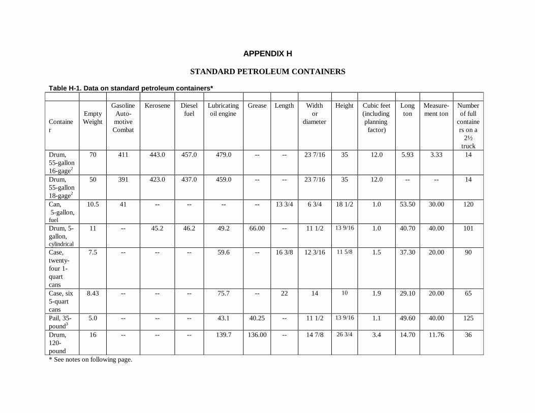
APPENDIX H
STANDARD PETROLEUM CONTAINERS
Table H-1. Data on standard petroleum containers*
Container
EmptyWeight
GasolineAuto-motiveCombat
Kerosene Dieselfuel
Lubricatingoil engine
Grease Length Widthor
diameter
Height Cubic feet(includingplanningfactor)
Longton
Measure-ment ton
Numberof full
containers on a
2½truck
Drum,55-gallon16-gage2
70 411 443.0 457.0 479.0 -- -- 23 7/16 35 12.0 5.93 3.33 14
Drum,55-gallon18-gage2
50 391 423.0 437.0 459.0 -- -- 23 7/16 35 12.0 -- -- 14
Can, 5-gallon,fuel
10.5 41 -- -- -- -- 13 3/4 6 3/4 18 1/2 1.0 53.50 30.00 120
Drum, 5-gallon,cylindrical
11 -- 45.2 46.2 49.2 66.00 -- 11 1/2 13 9/16 1.0 40.70 40.00 101
Case,twenty-four 1-quartcans
7.5 -- -- -- 59.6 -- 16 3/8 12 3/16 11 5/8 1.5 37.30 20.00 90
Case, six5-quartcans
8.43 -- -- -- 75.7 -- 22 14 10 1.9 29.10 20.00 65
Pail, 35-pound3
5.0 -- -- -- 43.1 40.25 -- 11 1/2 13 9/16 1.1 49.60 40.00 125
Drum,120-pound
16 -- -- -- 139.7 136.00 -- 14 7/8 26 3/4 3.4 14.70 11.76 36
* See notes on following page.

FM 10-67-1
NOTES:1. Data for 55-gallon drums and 5-gallon fuel cans are based on average weight of automotive combat gasoline;
data on 35-pound pails and 120-pound drums are based on average weight of grease; data on all othercontainers are based on average weight of engine lubricating oil. (Continued)
2. The standard 55-gallon drum (Military Specification PPP-D729E) has an authorized capacity of 54 gallons forproducts with flash point of less than 80 degrees Fahrenheit. For 55 gallons for products with flash point over80 degrees Fahrenheit. The specification shows maximum capacity of 57.75 gallons. The drum is identifiedby the letter “O” embossed on the head of the drum.
3. Data are based on the average empty weight of a Class 1 pail. The average empty weight of the Class 2 pail is5.75 pounds

FM 10-67-1
I-1
APPENDIX I
VOLUME CONVERSION
ASTM/API/IP TABLE 5A/B
ASTM/API/IP Table 5A/B gives the values of API gravities at 60 °F corresponding to API gravities observedwith a glass hydrometer at temperatures other than 60 °F. In converting an API gravity at the observed temperature(API hydrometer indication) to the corresponding API gravity at 60 °F, two corrections are necessary. The firstcorrection is the change in volume of the glass hydrometer by temperature. The second correction is the change involume of the oil. Both corrections have been applied to this table.
NOTE: This table must be used with API gravities (hydrometer indications) measured with a soft glass hydrometercalibrated at 60°F.
FUEL CLASSIFICATION BY API GRAVITY PROCEDURESThe first step in volume conversion is fuel classification.
• Taking the Readings. Described below are the procedures that must be followed during fuel classification.
• Step 1. Draw a 300-milliliter sample of fuel from the drum, nozzle, or other fuel source. Put it into a cleandry sample bottle, quart bottle with lid, or a sample can. Cover the sample container. Take the sample to a tent,building, or other sheltered place to conduct the test. Conduct the test promptly while the sample is fresh.
• Step 2. Agitate the contents of the sample container by shaking it thoroughly.
• Step 3. Slowly and carefully pour the sample down the inside of a clean, dry hydrometer cylinder, filling thecylinder a pproximately 3/4 full.
• Step 4. Allow any air bubbles that are deep in the liquid to rise to the surface. Hold the cylinder just belowthe rim with one hand, and tap the top of the cylinder sharply with the cupped palm of the other hand to removesurface air bubbles.
• Step 5. Set the cylinder on a level surface where it is pr otected from air currents.
• Step 6. Use the hydrometer with the range closest to the API gravity range of the fuel you think you aretesting. See Figure I-1, page I-2. For example, if you think the fuel is diesel and the API gravity range of diesel isbetween 30.0 and 42.0, use the third or fourth hydrometer from the equipment list.
• Step 7. Check the mercury column if the hydrometer being used has a built-in thermometer. If the mercuryhas separated, the hydrometer will not take acceptable temperature readings, and you should use another h y-drometer. If a hydrometer with an accurate thermometer is not available, you may use a calibrated tank the r-mometer to measure the temperature.
• Step 8. Lower the hydrometer gently into the sample.
NOTE: If the hydrometer sinks or floats with the scale out of the fuel, you have selected the wrong one for the typeof fuel you are testing. Try another hydrometer close to the same range. Keep trying until a hydrometer floats inthe sample.
• Step 9. Stir the sample gently by raising and lowering the hydrometer, and watch the movement of the me r-cury in the thermometer. (A fast registering thermometer should give an accurate reading in 30 to 45 seconds.)When the mercury stops moving, take a temperature reading and record it.
• Step 10. Allow the hydrometer to come to rest, but not touching the side of the cylinder. If it moves to theside, move it back to the center of the liquid and spin it gently.

FM 10-67-1
I-2
• Step 11. When the hydrometer is floating freely at rest, read it to the nearest scale division. Have your eyeslightly below the level of the liquid, and raise it slowly until the surface of the liquid appears to be a straight lineacross the hydrometer scale. Record the gravity reading to the nearest scale division as shown in Figure I-2,page I-3.
• Step 12. Stir the sample gently again by raising and lowering the hydrometer, and take a second temper a-ture reading. If the temperature of the fuel has not varied more than 1 °F from the previous reading, record thetemperature to the nearest 1°F. This is your test temperature reading. If the temperature of the sample haschanged more than 1 °F, repeat steps 9 through 12 until the te mperature is stable (within 1 °F).
Figure I-1. Typical API gravity ranges (corrected to 60 degrees)
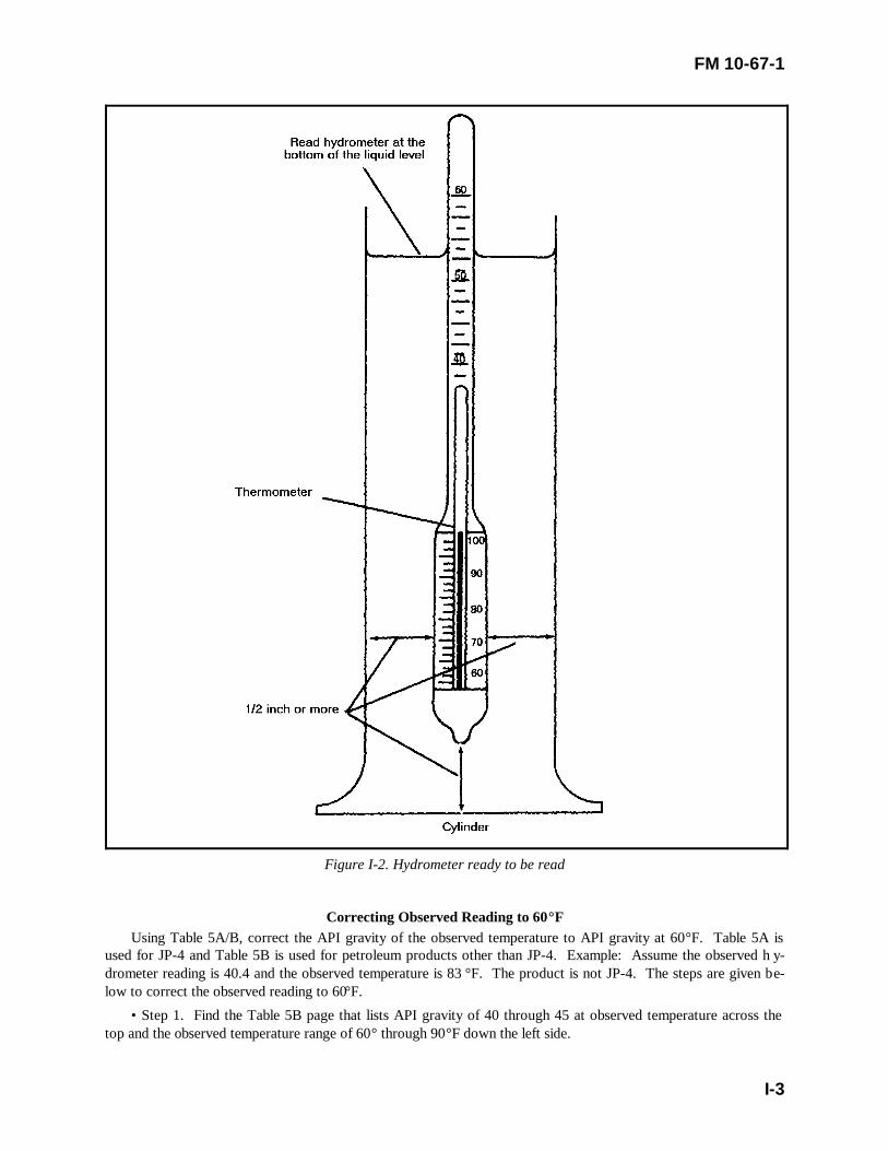
FM 10-67-1
I-3
Figure I-2. Hydrometer ready to be read
Correcting Observed Reading to 60°FUsing Table 5A/B, correct the API gravity of the observed temperature to API gravity at 60°F. Table 5A is
used for JP-4 and Table 5B is used for petroleum products other than JP-4. Example: Assume the observed h y-drometer reading is 40.4 and the observed temperature is 83 °F. The product is not JP-4. The steps are given be-low to correct the observed reading to 60°F.
• Step 1. Find the Table 5B page that lists API gravity of 40 through 45 at observed temperature across thetop and the observed temperature range of 60° through 90°F down the left side.
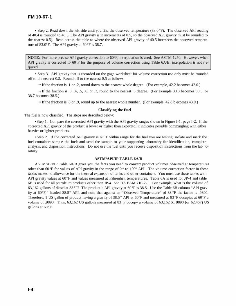
FM 10-67-1
I-4
• Step 2. Read down the left side until you find the observed temperature (83.0°F). The observed API readingof 40.4 is rounded to 40.5 (The API gravity is in increments of 0.5, so the observed API gravity must be rounded tothe nearest 0.5). Read across the table to where the observed API gravity of 40.5 intersects the observed tempera-ture of 83.0°F. The API gravity at 60°F is 38.7.
NOTE: For more precise API gravity correction to 60°F, interpolation is used. See ASTM 1250. However, whenAPI gravity is corrected to 60°F for the purpose of volume correction using Table 6A/B, interpolation is not r e-quired.
• Step 3. API gravity that is recorded on the gage worksheet for volume correction use only must be roundedoff to the nearest 0.5. Round off to the nearest 0.5 as follows:
••If the fraction is .1 or .2, round down to the nearest whole degree. (For example, 42.2 becomes 42.0.)
••If the fraction is .3, .4, .5, .6, or .7, round to the nearest .5 degree. (For example 38.3 becomes 38.5, or38.7 becomes 38.5.)
••If the fraction is .8 or .9, round up to the nearest whole number. (For example, 42.8 b ecomes 43.0.)
Classifying the FuelThe fuel is now classified. The steps are described below:
• Step 1. Compare the corrected API gravity with the API gravity ranges shown in Figure I-1, page I-2. If thecorrected API gravity of the product is lower or higher than expected, it indicates possible commingling with eitherheavier or lighter products.
• Step 2. If the corrected API gravity is NOT within range for the fuel you are testing, isolate and mark thefuel container; sample the fuel; and send the sample to your supporting laboratory for identification, completeanalysis, and disposition instructions. Do not use the fuel until you receive disposition instructions from the lab o-ratory.
ASTM/API/IP TABLE 6A/BASTM/API/IP Table 6A/B gives you the facts you need to convert product volumes observed at temperatures
other than 60°F for values of API gravity in the range of 0 ° to 100° API. The volume correction factor in thesetables makes no allowance for the thermal expansion of tanks and other containers. You must use these tables withAPI gravity values at 60°F and values measured at Fahrenheit temperatures. Table 6A is used for JP-4 and table6B is used for all petroleum products other than JP-4 See DA PAM 710-2-1. For example, what is the volume of63,162 gallons of diesel at 83°F? The product’s API gravity at 60°F is 38.5. Use the Table 6B column “API gra v-ity at 60°F,” headed 38.5° API, and note that against an “Observed Temperature” of 83 °F the factor is .9890.Therefore, 1 US gallon of product having a gravity of 38.5 ° API at 60°F and measured at 83°F occupies at 60°F avolume of .9890. Thus, 63,162 US gallons measured at 83 °F occupy a volume of 63,162 X. 9890 (or 62,467) USgallons at 60°F.

FM 10-67-1
J-1
APPENDIX J
CHECKLIST FOR DELIVERY AND UNLOADING
Preparing for Delivery
• Has gaging, sampling, and measuring equipment been cleaned and checked?
• Has receiving tank been gaged to determine if there is enough room to receive the scheduled quantity?
Prior to Unloading
• Have the vendor’s delivery documents been checked for completeness?
• Has the delivery conveyance been spotted at the correct location?
• Has adequate fire extinguishers and NO SMOKING signs been positioned?
• Has the delivery conveyance been properly bonded and grounded and inspected for leaks or otherdefects?
• Have the cargo hatch and valve seals been inspected for defects?
• Have the cargo hatches been opened to determine level of product?
• Is product clear and bright as viewed through a clean jar?
• Has the delivery tank been checked for eater using water-finding paste on the gage stick or tape?
• Has cargo temperature been determined a time of delivery?
• Has the cargo tank been gaged to determine quantity?
• Has the measured quantity been volume corrected to 60°F IAW DA Pamphlet 710-2-2?
• Have quantity surveillance samples been taken?
During Unloading Operations
• Are receiving personnel and the driver of the conveyance standing by?
• Is traffic being controlled to avoid the unloading area as much as possible?
• Are dispersing operations discontinued during unloading operations?
After Cargo is Unloaded
• Has the delivery conveyance been inspected to ensure the cargo tank is completed empty?
• Have the vehicle ground been disconnected and the discharge hoses secured?
• Have product spills been cleaned up IAW with current regulations?
• Has the receiving tank been gaged?

FM 10-67-1
K-1
APPENDIX K
CONVERSION CHARTS FOR TANK CARS, TANK TRUCKS ANDUS/NATO FUEL CODES AND PLACARD ID NUMBERS
Table K-1 can be used when converting tank cars and trucks to carry a different petroleum product. Whenlubricating oil is being carried, equipment must be free of loose rust, scale, and dirt. Explanations of the numericalsymbols are listed below the chart.
Table K-1. Conversion chart.Product to be loaded
Lastproductcarried
AVGASMIL-G-
5572
MOGASMIL-G-
3056
JP-4MIL-T-5624
JP-5MIL-G-
5624
JP-8MIL-T-83133
Petrlsolventor paintthinner
Kero-sene
MIL-P-25576
Dieselfuels
VV-F-800
Burnerfuel oilVV-F-815,
Gr 1 &2
Burnerfuel oilVV-F-815,
Gr 4, 5,& 6
Lubri-catingoils
AVGASMIL-G-5572
1 2 3 3 3 3 3 3 3 3 3
MOGASMIL-G-3056
3 1 3 3 3 3 3 3 3 3 3
JP-4 JetfuelMIL-T-5624
3 2 1 3 3 3 3 3 3 3 3
JP-5 JetfuelMIL-T-5624
3 2 2 1 3 3 2 2 2 2 3
JP-8 JetfuelMIL-T-83133
3 2 2 3 1 3 2 2 2 2 3
Petrlsolventor paintthinner
3 2 3 3 3 1 3 3 3 3 3
KeroseneMIL-P-25576
3 2 2 2 2 3 1 2 2 2 3
Diesel fuelsVV-F-800
4 3 4 4 4 5 5 1 2 2 3
Burner fueloil VV-F-815, Gr 1& 2
5 3 5 5 5 5 5 2 1 2 3
Burner fueloil VV-F-815, Gr 4,5, & 6
5 5 5 5 5 5 5 5 2 1 5
Lubri-cating oils
5 4 5 5 5 5 5 3 2 2 1
Number explanations:1-No conversion necessary because the same product is being loaded.2-Drain tank and manifold and empty filter/separator.3-Drain tank and manifold, empty filter/separator, and flush with product to be loaded.4-Steam clean, dry, and change filter elements. If the equipment has a coated interior, do not steam clean; wash tank and change filter elements.5-Do not load
TABLE K-2. US/NATO Fuel Codes and Placards ID Numbers
FM 10-67-1
K-2
US NATO FUEL CODES PLACARD ID NO.
MOGAS F-46, F-49, F-57 UN 1203
DF-1 F-75 NA 1993
DF-2 F-54 NA 1993
JP-4 F-40 UN 1863
JP-5 F-44 UN 1863
JP-8 F-34 UN 1863
AVN 115/145 F-22 UN 1203
DF MARINE F-76 NA 1993

APPENDIX L
Petroleum Product and Crude Oil Factors
Table L-1 provides data on petroleum products and crude oil.
Table L-1. Petroleum product and crude oil factors at 60°FDegrees API Gravity Pounds Barrels per Barrels per day required to equal
Item RangeFrom To
Average Specificgravity
USgallon
Imperialgallon
Perbarrel
Longton
Metricton
Shortton
One metric tonper year
One long tonper year
PETROLEUM PRODUCTSAviation Gasoline: Grade: 115/145 66.0 75.0 69.2 0.7050 5.868 P7.048 246.47 P9.088 P9.945 8.115 0.0272 0.0248Motor Gasoline: Combat Grade 55.1 61.4 58.4 0.7451 6.203 P7.330 260.74 P8.599 P9.410 7.678 0.0258 0.0236Jet Fuels: JP-4 48.1 56.5 53.5 0.7657 6.375 P7.650 267.58 P8.366 P8.234 7.469 0.0225 0.0229 JP-5 36.0 48.0 41.0 0.8203 6.830 P8.203 286.86 P7.809 P7.686 6.972 0.0211 0.0214 JP-6 46.0 50.0 48.7 0.7852 6.538 P7.846 274.39 P8.158 P8.029 7.284 0.0220 0.0223 Thermally Stable 46.7 48.0 47.3 0.7914 6.589 P7.907 276.75 P8.094 P7.966 7.227 0.0218 0.0222 JP-8 37.0 51.0 43.3 0.8095 6.7456 P8.100 283.31 P7.907 P7.782 7.060 0.0213 0.0193Napthas: Cleaning Solvent 45.0 55.0 48.0 0.7883 6.563 P7.882 275.65 P8.126 P7.998 7.256 0.0219 0.0223 Other Napthas 50.0 74.0 62.0 0.7313 6.087 P7.310 255.65 P8.761 P8.623 7.822 0.0236 0.0240Kerosene 39.0 46.0 42.0 0.8156 6.790 P8.155 285.18 P7.854 P7.730 7.013 0.0212 0.0215Diesel Fuels 34.0 37.0 36.0 0.8448 7.034 P8.448 295.43 P7.582 P7.462 6.770 0.0204 0.0208Residual Fuel Oils: Navy Special 12.1 21.4 18.0 0.9645 7.882 P9.466 331.04 P6.766 P6.660 6.041 0.0182 0.0185 All Others 3.0 25.0 12.0 0.9861 8.212 P9.863 344.90 P6.495 P6.392 5.799 0.0175 0.0178Lubricating Oils: Aviation (Recip) 26.6 28.4 27.7 0.8888 7.401 P8.888 310.84 P7.206 P7.092 6.434 0.0194 0.0197 Aviation (Jet-Petroleum) 29.6 29.6 29.6 0.8783 7.314 P8.784 307.19 P7.292 P7.177 6.511 0.0197 0.0200 Aviation (Jet-Synthetic) 8.6 25.7 22.0 0.9218 7.676 P9.219 322.39 P6.948 P6.838 6.204 0.0187 0.0190 Diesel Engine 24.3 27.4 26.3 0.8967 7.467 P8.968 313.61 P7.143 P7.030 6.377 0.0193 0.0196 Other Heavy Duty 23.0 31.0 27.0 0.8927 7.434 P8.928 312.23 P7.174 P7.061 6.406 0.0193 0.0197 All Others 26.0 29.0 27.0 0.8927 7.434 P8.928 312.23 P7.174 P7.061 6.406 0.0193 0.0197Insulating and Transformer Oils 29.5 31.5 30.0 0.8762 7.296 P8.765 306.43 P7.310 P7.194 6.527 0.0197 0.0200Fog Oil 34.0 37.0 36.0 0.8448 7.034 P8.448 295.43 P7.582 P7.462 6.770 0.0204 0.0208

Table L-1. Petroleum product and crude oil factors at 60°F (continued)Degrees API Gravity Pounds Barrels per Barrels per day required to equal
Item Range
From To
Average Specificgravity
USgallon
Imperialgallon
Perbarrel
Longton
Metricton
Shortton
One metric tonper year
One long tonper year
Liquified Petroleum Gases ....... ....... ....... ........... 4.450 P5.344 186.90 11.989 11.799 10.704 0.0323 0.0328Greases ....... ....... ....... 1.0002 8.330 10.004 349.86 P6.402 P6.301 5.716 0.0173 0.0175Asphalt and Road Oils ....... ....... ....... 1.0326 8.601 10.329 361.24 P6.201 P6.103 5.537 0.0167 0.0170Petroleum Coke ....... ....... ....... ........... ......... ........... 401.00 P5.589 P5.500 4.990 0.0151 0.0153TYPICAL CRUDE OILS:From: United States 10.0 48.0 35.0 0.8499 7.076 P8.499 297.19 P7.537 P7.418 6.729 0.0203 0.0206 Canada 5.0 48.0 35.0 0.8499 7.076 P8.499 297.19 P7.537 P7.418 6.729 0.0203 0.0206 Mexico 12.0 42.0 28.6 0.8838 7.360 P8.838 309.12 P7.247 P7.133 6.470 0.0195 0.0199 Columbia 21.1 46.8 25.7 0.9001 7.495 P9.001 314.79 P7.115 P7.003 6.353 0.0192 0.0195 Venezuela 10.3 48.0 26.1 0.8978 7.426 P8.978 313.99 P7.134 P7.021 6.369 0.0192 0.0195 Saudi Arabia 27.7 38.2 36.2 0.8438 7.026 P8.438 295.09 P7.591 P7.470 6.770 0.0205 0.0208 Kuwait 31.9 31.9 31.9 0.8660 7.211 P8.660 302.86 P7.396 P7.280 6.604 0.0199 0.0203 Iran 31.0 38.0 37.2 0.8388 6.984 P8.388 299.33 P7.637 P7.516 6.818 0.0206 0.0209 Iraq 32.1 41.7 35.0 0.8499 7.076 P8.499 297.19 P7.537 P7.418 6.729 0.0203 0.0206 Egypt 17.0 41.0 24.0 0.9100 7.578 P9.101 318.28 P7.038 P6.927 6.284 0.0190 0.0193 British Borneo 19.0 38.0 36.4 0.8428 7.017 P8.428 294.73 P7.600 P7.480 6.786 0.0205 0.0208 Indonesia 17.2 38.5 34.5 0.8524 7.098 P8.524 298.12 P7.514 P7.395 6.709 0.0203 0.0206
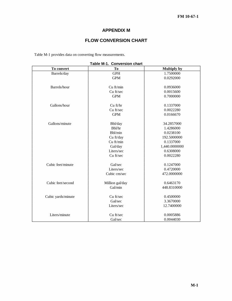
FM 10-67-1
M-1
APPENDIX M
FLOW CONVERSION CHART
Table M-1 provides data on converting flow measurements.
Table M-1. Conversion chartTo convert To Multiply byBarrels/day GPH 1.7500000
GPM 0.0292000
Barrels/hour Cu ft/min 0.0936000Cu ft/sec 0.0015600
GPM 0.7000000
Gallons/hour Cu ft/hr 0.1337000Cu ft/sec 0.0022280
GPM 0.0166670
Gallons/minute Bbl/day 34.2857000Bbl/hr 1.4286000
Bbl/min 0.0238100Cu ft/day 192.5000000Cu ft/min 0.1337000Gal/day 1,440.0000000
Liters/sec 0.6308000Cu ft/sec 0.0022280
Cubic feet/minute Gal/sec 0.1247000Liters/sec 0.4720000
Cubic cm/sec 472.0000000
Cubic feet/second Million gal/day 0.6463170Gal/min 448.8310000
Cubic yards/minute Cu ft/sec 0.4500000Gal/sec 3.3670000
Liters/sec 12.7400000
Liters/minute Cu ft/sec 0.0005886Gal/sec 0.0044030

N-1
APPENDIX N
MATERIAL SAFETY DATA SHEETS
MSD are published by the manufacturers of chemicals. They give a wealth of information on the particularproducts. These are particularly beneficial when a product contains a mixture of ingredients. The MSDS providesyou important information about the chemical substance, its hazards, and the procedures to follow to avoid injuryand illness. Ensure that all personnel assigned, attached, or working around, read and fully understand the MSDSbefore they handle any products. The MSDS contains the following general sections. See Figure N-1, pages N-1through N-6.
WARNINGCommanders at all levels must cooperate in community environmental action programs and must comply with therequirements of the Emergency Planning and Community Right to Know Act as best they can. This is a Federalrequirement.
• Hazardous Ingredients/Identity Information (Name and Product). Lists the substance’s hazardous comp o-nents, chemical identification, and common names. Workers exposure limits to the chemical are included.
• Physical/Chemical Characteristics. Includes boiling points, vapor pressure, vapor density, specific gravity,melting point, evaporation rate, water solubility, and appearance and odor under normal cond itions.
• Fire/Explosion Hazard Data. Lists ways to handle hazards such as fire-fighting equipment and pr ocedures.
• Reactivity Data. States whether the substance is stable and which substance and situation to avoid so it willnot react. Spill or Leak Procedures and Disposal. Addresses what to do if the substance spills or leaks, howto dispose of the substance, and what equipment and procedures are needed for cleaning up spills and leaks.
• Spill or Leak Procedures and Disposal. Addresses what to do if the substance spills or leaks, how to disposeof the substance, and what equipment and procedures are needed for cleaning up spills and leaks.
• Health Hazards Data. States how chemicals could enter the body, such as inhaling, penetrating the skin, andswallowing. Discusses the possible hazards that could come from exposure, and lists chemicals that may be ca r-cinogens.
• Special Protection Information. List ways to reduce harmful exposure as well as special work or hygienepractices that should be followed.
• Special Handling and Storage Precautions.
• Hazardous Ingredients.
• Other Information.
DoD Hazardous Materials Information SystemThis system produced by DoD, provides information on labeling requirements, chemical characteristics, phys i-
cal characteristics, health effects, safety precaution, handling procedures, fire fighting, and spill procedures forchemical in the DoD supply system. Hazardous Materials are listed in the HMIS in order of its NSN (the last ninedigits). If you only know the part number, trade name, FSCM, or specification number, sections at the back of theHMIS may give you a cross reference to the NSN. HMIS currently contains more than 40,000 product entries.The system is available through a microfiche set, magnetic tapes, and CD-ROM. HMIS is designed to suit thenormal informational needs Of DoD personnel involved in emergency response, safety, industrial hygiene, storage,handling, and transportation. A separate section of the HMIS which is now available is devoted to disposal co n-siderations. All data are republished in their e ntirety on an annual basis with updates each quarter.
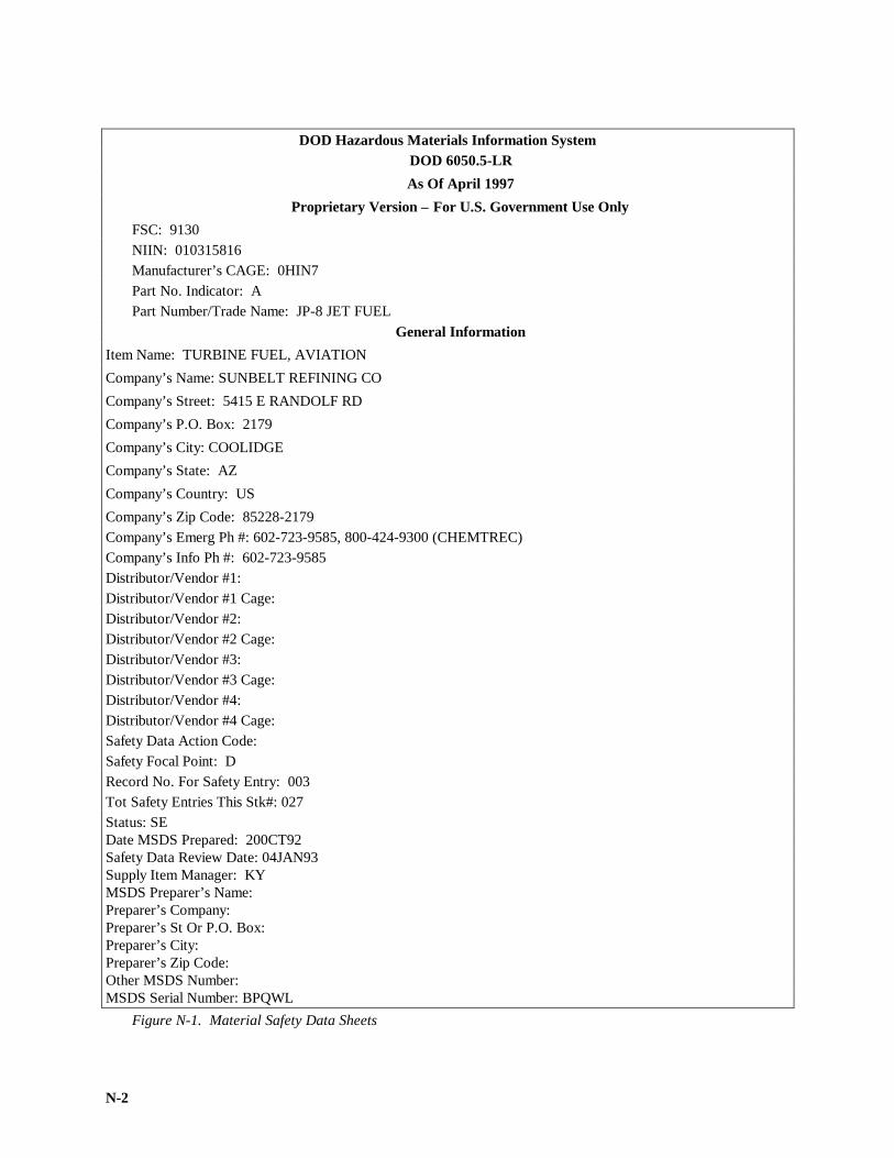
N-2
DOD Hazardous Materials Information SystemDOD 6050.5-LR
As Of April 1997
Proprietary Version – For U.S. Government Use OnlyFSC: 9130NIIN: 010315816Manufacturer’s CAGE: 0HIN7Part No. Indicator: APart Number/Trade Name: JP-8 JET FUEL
General InformationItem Name: TURBINE FUEL, AVIATION
Company’s Name: SUNBELT REFINING CO
Company’s Street: 5415 E RANDOLF RD
Company’s P.O. Box: 2179
Company’s City: COOLIDGE
Company’s State: AZ
Company’s Country: US
Company’s Zip Code: 85228-2179Company’s Emerg Ph #: 602-723-9585, 800-424-9300 (CHEMTREC)Company’s Info Ph #: 602-723-9585Distributor/Vendor #1:Distributor/Vendor #1 Cage:Distributor/Vendor #2:Distributor/Vendor #2 Cage:Distributor/Vendor #3:Distributor/Vendor #3 Cage:Distributor/Vendor #4:Distributor/Vendor #4 Cage:Safety Data Action Code:Safety Focal Point: DRecord No. For Safety Entry: 003Tot Safety Entries This Stk#: 027Status: SEDate MSDS Prepared: 200CT92Safety Data Review Date: 04JAN93Supply Item Manager: KYMSDS Preparer’s Name:Preparer’s Company:Preparer’s St Or P.O. Box:Preparer’s City:Preparer’s Zip Code:Other MSDS Number:MSDS Serial Number: BPQWL
Figure N-1. Material Safety Data Sheets

N-3
Report for NIIN: 010315816
Specification Number: MIL-T-83133Spec Type, Grade, Class: JP-8Hazard Characteristic Code: F4Unit Of Issue: GLUnit Of Issue Container QTY: BULKType Of Issue Container: BULKNet Unit Weight: BULK
Report for NIIN: 010315816
NRC/ State License Number: N/R
Net Explosive Weight:
Net Propellant Weight-Ammo: N/R
Coast Guard Ammunition Code:
Ingredients/Identity InformationProprietary: NO
Ingredient: KEROSENE
Ingredient Sequence Number: 01
Percent: 100%
Ingredient Action Code:
Ingredient Focal Point: D
NIOSH (RTECS) Number: 0A5500000
CAS Number: 8008-20-6
OSHA PEL: 100 PPM
ACGIH TLV: 100PPM 9091
Other Recommended Limit: 100 PPM (MFG)
Proprietary: NO
Ingredient: BENZENE (SARA III)
Ingredient Sequence Number: 02
Percent: <0.1%
Ingredient Action Code:
Ingredient Focal Point: D
NOISH (RTECS) Number: CY1400000
CAS Number: 71-43-2
OSHA PEL: 1 PPM/5STEL1910.1028
ACGIH TLV: 10 PPM; A2; 9293
Other Recommended Limit: NONE SPECIFIED
Figure N-1. Material Safety Data Sheets (Cont.)

N-4
Report for NIIN: 010315816
Physical/Chemical CharacteristicsAppearance And Odor: CLEAR LIQUID WITH PARAFFINIC ODOR.
Boiling Point: 300F, 149C
Report for NIIN: 010315816
Melting Point: UNKNOWN
Vapor Pressure (MM Hg/70 F): <10 MM
Vapor Density (Air=1): 4 (AIR=1)
Specific Gravity: 0.77-0.84
Decomposition Temperature: UNKNOWN
Evaporation Rate and Ref: UNKNOWN
Solubility In Water: NEGLIGIBLE
Percent Volatiles By Volume: N/K
Viscosity:
PH: N/K
Radioactivity:
Form (Radioactive Matl):
Magnetism (Milligauss): N/P
Corrosion Rate (IPY): UNKNOWN
Autoignition Temperature:
Fire and Explosion Hazard DataFlash Point: 100F, 38C
Flash Point Method: TCC
Lower Explosive Limit: 0.5
Upper Explosive Limit: 6.0
Extinguishing Media: FOAM, DRY CHEMICAL, CARBON DIOXIDE, WATER-FOG SPRAY.
DO NOT USE A DIRECT STREAM OF WATER.
Special Fire Fighting Proc: USE WATER SPRAY TO COOL FIRE-EXPOSED
CONTAINERS, STRUCTURES, AND PROTECT PERSONNEL. USE FOAM TO BLANKET LIQUID.
USE AIR-SUPPLIED RESPIRATOR EQUIMENT.
Unusual Fire And Expl Hazrds: VAPORS MAY FORM EXPLOSIVE MIXTURES WITH AIR.
VAPORS HEAVIER THAN AIR AND MAY TRAVEL CONSIDERABLE DISTANCE TO SOURCE OF
IGNITION AND FLASH BACK.
CONTACT MAY CAUSE IRRITATION, BURNING,DERMATITIS, IRRITATION OF NOSE AND THROAT, HEADACHES, DIZZINESS, AND LOSS OF CON-SCIOUSNESS. INGESTION: MAY CAUSE IRRITATION OF DIGESTIVE TRACT.
Figure N-1. Material Safety Data Sheets (Cont.)

N-5
Report for NIIN: 010315816
Carcinogenicity- NTP: NO
Carcinogenicity- IARC: NO
Carcinogenicity-OSHA: NO
Explanation Carcinogenicity:
Signs/Symptoms Of Overexp: EYES: IRRITATION, BURNING, REDNESS, TEARING.
SKIN: IRRITATION, BURNING, REDNESS, DERMATITIS. INHALATION: NOSE AND THROAT
IRRITATION, HEADACHE, LOSS OF COORDINATION, DIZZINESS, LOSS OF CONSCIOUSNESS. INGES-TION: IRRITATION OF DIGESTIVE TRACT.
Med Cond Aggravated By Exp: PERSON WITH PRE-EXISTING DISEASE INVOLVING EYES, SKIN, ORRESPIRATORY TRACT MAY BE AT INCREASED RISK FROM EXPOSURE. ALSO ALLERGIES, ASTHMA,HAY FEVER, SKIN CONDITIONS OR OPEN SORES MAY BE AGGRAVATED.
Emergency/First Aid Proc: EYES: FLUSH WITH LARGE AMOUNTS OF WATER. IF IRRITATION PERSISTS,GET MEDICAL ATTENTION. SKIN: REMOVE CONTAMINATED CLOTHING. WASH
AREA WITH SOAP AND WATER. INHALATION: MOVE TO FRESH AIR. IF NOT BREATHING GIVE CPR.IF BREATHING DIFFICULT GIVE OXYGEN. GET MEDICAL ATTENTION. INGESTION: DO NOT IN-DUCE VOMITING. GET MEDICAL ATTENTION.
Precautions for Safe Handling and Use
Steps If Matl Released/Spill: WEAR RESPIRATORY PROTECTION. STOP FLOW. ELIMINATE IGNITIONSOURCES. CONTAIN SPILL BY DIKING. KEEP PRODUCT OUT OF SEWERS AND
WATERWAYS. RECOVER LIQUID WITH VACUUM TRUCK. ABSORB RESIDUE WITH ABSORBENTAND PLACE WASTE IN PROPER CONTAINER FOR DISPOSAL.
Neutralizing Agent: NONE SPECIFIED BY MANUFACTURER.
Waste Disposal Method: DISPOSE OF WASTE MATERIAL IN ACCORDANCE WITH LOCAL,
STATE AND FEDERAL REGULATIONS. NOTIFY AUTHORITIES OF ANY SEWER, WATERWAY OR EX-TENSIVE LAND CONTAMINATION.
Precautions-Handling/Storing: STORE IN COOL, WELL VENTILATED AREA AWAY FROM HEAT,SPARKS, OPEN FLAMES AND STRONG OXIDANTS. KEEP CONTAINERS CLOSED AND PROTECTFROM PHYSICAL DAMAGE.
Other Precautions: REMOVE OIL-SOAKED CLOTHING PROMPTLY. IF MATERIAL IS ACCIDENTALLYRELEASED IN A CONFINED AREA, PROVIDE ADEQUATE VENTILATION.
Control MeasuresRespiratory Protection: USE NIOSH/MSHA APPROVED RESPIRATOR. USE SUPPLIED-AIR EQUIPMENT INCONFINED SPACES. USE ORGANIC VAPOR RESPIRATOR IN OPEN AREAS IF NECESSARY.
Ventilation: USE LOCAL EXHAUST VENTILATION IN CONFINED WORKING AREA.
EXPLOSION-PROOF MECHANICAL VENTILATION RECOMMENDED.
Protective Gloves: NITRIL OR PVC GLOVES.
Eye Protection: GOGGLES OR FACESHIELD IF SPLASHING.
Figure N-1. Material Safety Data Sheets (Cont.)
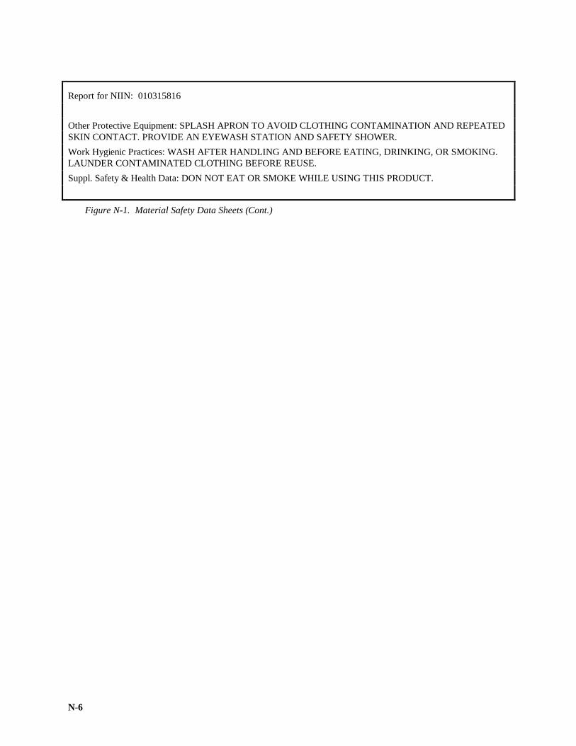
N-6
Report for NIIN: 010315816
Other Protective Equipment: SPLASH APRON TO AVOID CLOTHING CONTAMINATION AND REPEATEDSKIN CONTACT. PROVIDE AN EYEWASH STATION AND SAFETY SHOWER.
Work Hygienic Practices: WASH AFTER HANDLING AND BEFORE EATING, DRINKING, OR SMOKING.LAUNDER CONTAMINATED CLOTHING BEFORE REUSE.
Suppl. Safety & Health Data: DON NOT EAT OR SMOKE WHILE USING THIS PRODUCT.
Figure N-1. Material Safety Data Sheets (Cont.)

FM 10-67-1
O-1
APPENDIX O
FORCE PROVIDER
Force Provider is a modularized housing facility that supports a variety of missions such as soldier rest,housing for reconstituting units, an refugee housing. Force Provider provides such features as climate-controlled tents, kitchen facilities, modern morale and recreational facilities, and a variety of soldier welfareand support functions. Force Provider will bring a quality of life to soldiers as far forward as the division su p-port area that was not possible before.
Force Provider operations require significant fuel storage and distribution capabilities. These capabilitiessupport four functions: a bulk DF-2/JP-8 storage and distribution system, a 500-gallon drum DF-2/JP-8 dieselstorage system (capable of supporting generator operation at up to nine different sites), a bulk gasoline andfuel storage distribution system, and bulk DF-2/JP-8 storage for other prime power generating capabilities.Force Provider is equipped with systems already in the Army inventory to support these fun ctions.
Although Force Provider will be fielded as a company-level organization, the basic building block of thesystem is a module operated by a Force Provider platoon. A module can support 550 people and will be d e-ployed as far forward as the division support area. The following paragraphs will discuss the fuel storage anddistribution capabilities for a module. A Force Provider company can command and control up to six mo d-ules.
The bulk DF-2/JP-8 storage and distribution system consists of two FARE systems with 100-GPM pumpsand 100 filters/separators, two 10,000-gallon collapsible fabric tanks, four 500-gallon collapsible fabric drums,three berm liner assemblies, various adapters, associated hoses, and fuel spill control equi pment.
The 500-gallon drum storage system provides for two 500-gallon drums to support each of nine potentialgenerator locations. A camlock to hose adapter assembly and three straight tube-to-hose adapters are also pr o-vided for connecting the coupler elbow valve assembly and the ge nerator fuel line.
The bulk gasoline and fuel storage distribution system consists of a 50-GPM pumping assembly, a 50-GPM filter/separator, one 3,000-gallon collapsible tank, one berm liner assembly, various adapters, associatedhoses, and fuel spillage control equipment.
Two 10,000-gallon fabric tanks are provided for fuel storage should prime power generations units beused instead of the nine tactical generator sets. Adapters and 2-inch hose are provided to connect the bags tothe prime power unit generation set. These bags can be used as auxiliary storage if prime power generationunits are not used.
Each module also has a 5,000-gallon tanker and a TPU for fuel distribution and storage. This brings thetotal storage capacity for each module to approximately 65,000 gallons. This is anticipated to be a three-daysupply of fuel for a Force Provider modules without prime power generation support (for example, that useonly the small tactical generators) are anticipated to use about 7,000 gallons of DF-2/JP-8 and 1,000 gallons ofMOGAS a day. Operational tests of a “bare-bones” Force Provider module (soldier did not have vehicles,minimal laundry operations, minimal morale and welfare functions, good weather) showed that fuel consum p-tion was about 7 to 10 percent of this level. Each module’s equipment is operated by a 10-person petroleumdistribution section headed by a Sergeant First Class.
Force Provider’s fuel supply equipment should be among the first containers shipped to the Force Providersite. This enables the quick start of fuel support operations to support efficiently further site preparation a c-tivities and to allow time for fuel storage to be completely filled. An experienced POL handler should acco m-pany engineers as they lay out the Force Provider site to make sure they choose a suitable location for POLfacilities. Free bags that are 3,000 gallons larger should be at lest 300 feet from the main Force provider ca n-tonment, 15 feet from rods, and 250 feet from other fuel bags and large generators. The 500-gallon drumsshould be at least 15 feet from roads, 15 feet from generators, and at least 9 feet from any other areas whereForce Provider operations take place. Other considerations for POL site selection are the same as for any otherClass III site.

FM 10-67-1
Glossary-1
GLOSSARYSection I. Acronyms and Abbreviations
AAAFARS-Advance Aviation Forward Area Refueling SystemABFDS-Aerial Bulk Fuel Delivery SystemAC-alternating currentACE-alternate capability equipmentAFDDS-Aerial fuel Delivery and Dispensing SystemAFFF-aqueous film forming foamAH-attack helicopterANSI-American National Standards InstituteAPU-auxiliary power unitAR-Army regulationATC-air traffic controlAVGAS- aviation gasoline
Bbbl-barrelBFTA-bulk fuel tank assemblyBIU-beach interface unitBPH-barrels per hourBS&W-bottom sediment and waterBTU-beach termination unit
CC- CelsiusCCR-closed circuit refuelingCH-cargo helicopterCO2- carbon dioxideCONUS-continental United StatesCSS-combat service supportcSt-centistokesCU- conductivity unitscu-cubic
Dd-inside diameter of pipeDA- Department of the ArmyDA PAM-Department of the Army pamphletDIEGME- diethylene glycol monomethyl etherDFSC-Defense Fuel Supply CenterDFSP- Defense Fuel Support PointDLA- Defense Logistics AgencyDOD- Department of DefenseDOT-Department of TransportationDRMO-Defense Reutilization and Marketing OfficeDWT-deadweight tonnage
EECAS-Environmental Compliance Assessment SystemEGME- ethylene glycol monomethyl etherERFS-Extended Range Fuel System

FM 10-67-1
Glossary-2
EPA-Environmental Protection AgencyFFARE- forward area refueling equipmentFLOT- forward line of own troopsFM- field manualFSII- fuel system icing inhibitorft- feet; foot
Ggal(gl)- gallonsGPH-gallons per hourGPM-gallons per minuteGPU-ground power unit
HHAZCOM-hazardous communicationsHAZMAT-hazardous materialHEMTT-heavy expanded mobile tactical truckhd- headHM-hazardous materialHMIS-hazardous material information systemHP-horsepowerHTARS-HEMTT Tanker Aviation Refueling SystemHW-hazardous waste
IIAW-in accordance withID- inside diameterin- inchISCP-Installation Spill Contingency Plan
JJLOTS- joint logistics over the shoreJP-jet propulsionJPO-Joint Petroleum Office
Kk-viscosity in centistokesKW-kilowatt
Ll-literLARC-V-Lighter amphibious resupply cargo vehiclelb-poundsLIN-line item numberLRB-lay/repair barge
Mmax- maximumMETT-T- mission, equipment, tactics, troops-timemg- milligrammin- minimumml- milliliterMILSTRIP-military standard requisitioning and issue procedures

FM 10-67-1
Glossary-3
MIL HDBK-military handbookMOGAS- motor gasolineMOS-military occupation specialityMPH-miles per hourMSC-Military Sealift CommandMSDS-material safety data sheet
NNATO-North Atlantic Treaty OrganizationNEPA-National Environmental Policy ActNSN-national stock number
OOCONUS-outside Continental United StatesOD- outside diameterOH-observation helicopter
PPDC-Product Discharge ConferencePHIBCB-Navy Amphibious Construction BattalionPLL-prescribed load listPOL-petroleum, oils, and lubricantsPMCS-preventive maintenance checks and servicesPN-part numberPPM-parts per million; also p/mpS/M- Pico-Siemens/MeterPSI- pounds per square inchPSP-perforated steel plankingPSIG-pounds per square inch gaugePPM- parts per millionPQAR-petroleum quality assurance representative
QQM-Quartermaster
RRAH-reconnaissance attack helicopterRE-Reynolds numberROM-refuel on the moveRRF-ready reserve forceRPM-revolutions per minuteRRP-rapid refueling point
SSALM-single anchor leg mooringSAPO-subarea petroleum officeSEE-small emplacement excavatorSDA- static dissipating additiveSLWT-side loadable warping tugSOP-standard operating proceduresSPCCP-Spill control and countermeasure planspec-specificationsp gr-specific gravitySPM-single point mooring

FM 10-67-1
Glossary-4
STANAG- NATO Standardization AgreementSTP-soldier training publicationSWAPDOP-Southwest Asia Petroleum Distribution SystemTTAU-twin agent unitTAV- technical advisory visitTCP- traffic control pointTDA-table(s) of distribution and allowancesTM-technical manualTOE-table of organization and equipmentTPU-tank and pump unitTPT-tactical petroleum terminal
UUCT-underwater construction teamUH-utility helicopterULLS-unit level logistics systemUSAPC-United States Army Petroleum Center
Vv- volume
Wwt- weight

FM 10-67-1
Glossary-5
Section II. Terms
absolute pressure. Pressured measured with respect to, zero pressure, as distinct from pressure measured withrespect to some standard pressure, sure as atmospheric pressure Thirty pounds per square inch atmosphericpressure is equivalent to 44.7 pounds per square inch absolute pressure.
absolute viscosity. The force which will move 1 square centimeter of plane surface with a speed of 1 centimeterper second relative to another parallel plane surface from which it is separated by a layer of the liquid 1centimeter thick.
accelerated gum test. A test to determine the amount of gum and lead precipitate formed in aviation fuels as aresult of accelerated oxidation or aging. Potential gum is the amount of residue obtained by evaporating thefuel at the end of the specified aging period.
accountable officer. An individual, either civilian or military, required to ensure that accurate recording ofproperty transactions is accomplished and records pertaining thereto are maintained. (Accountability isconcerned primarily with records, while responsibility is concerned primarily with custody, care, andsafekeeping.) See Responsible officer.
acid. A chemical compound usually having a sour taste and capable of neutralize alkalis and turning blue litmuspaper red.
acidity. The amount of free acid in a substance.
acidizing. A method of increasing production from an oil well. Hydrochloric acid is pumped outward from thewell bore into the surrounding formation to dissolve limestone or sandstone. This action makes larger flowchannels.
acid treating. A process for removing undesirable elements in oil by contacting it with sulfuric acid. The acidsludge which is formed by the action of the acid on the oil separated from the oil. It takes with it coloringmatter, some sulfuric compounds, and unstable bodies. The remaining oil is finished by neutralizing,rerunning, or clay treating and becomes lighter in color and more stable.
adapter. A fitting used to change from one type of coupling to another type.
additive. An agent used for improving existing characteristics or for imparting new characteristics to certainpetroleum products.
aft. Near or at the stern (rear) of a vessel.
air-fuel ratio. The ratio of the volume of fuel to volume of air burned in an engine. The ratio in a gasoline engineis about 12 to 15 to 1.
air test. A method used to test a pipeline when a water test is not possible or desirable. The line is sectionalizedby block valves and tested in lengths that depend upon the capacity of available compressors. The air andvapor mixture could create a hazardous condition from flammable mixtures in lines that have been used forvolatile products.
alkylate. The product obtained in the alkylation process. Chemically, it is a complex molecule of the paraffinicseries, formed by the introduction of an alkyl radical into an organic compound.
alkylation. An important synthetic process for the manufacture of components aviation gasoline.
all-levels sample. A sample taken by lowering a closed sampler to the drawoff level of a tank, opening thesampler, and raising it at a uniform rate so that it is between 75 and 85 percent full when it emerges from theliquid.
American Petroleum Institute. The institute represents and is supported by the petroleum industry. Itstandardizes the tools and equipment used by the industry. It promotes the advancement of research in thepetroleum field.

FM 10-67-1
Glossary-6
American Society for Testing and Materials. A national scientific technical organization formed for thedevelopment of standards or characteristics and performance of materials, products, systems, and services andthe promotion of related knowledge.
amidship. An indefinite area of a ship midway between the bow (front) and the (rear).
anchor. A device used to control pipeline movement. An IPDS pipeline anchor is a 2½-inch square by 5 foot longsteel bar with a screw end. Anchors are in the 5-mile pipeline set and pipeline support assembly.
anchor clamp. A two-piece iron clamp that fits over an IPDS pipeline anchor to hold the pipe in place.
aneroid barometer. A barometer in which the action of the atmospheric pressure bending a metal surface is madeto move a pointer.
anhydrous. Free of water, especially water of crystallization.
anode. See electrode.
antieline. Folds of earth layers which are bent upward.
antifoam agent. An additive used in some lubricating oils to control foam.
antiknock. Resistance to detonation or pinging in spark-ignition engines.
antiknock agent. A chemical compound such as tetraethyllead which, when added in small amounts to the fuelcharge of an internal-combustion engine, tends to lessen knocking.
antioxidant. A chemical added to gasoline, lubricating oil, and certain other petroleum products to inhibitoxidation.
API gravity. See specific gravity. An arbitrary scale expressing the gravity or density of liquid petroleumproducts. The measuring scale is calibrated in terms of degrees API. The gravity of any petroleum product iscorrected to 60°F (16°C).
appearance. Refers to the visual examination of fuels. The terms used to describe appearance are clear andbright, hazy, and cloudy.
aromatic (noun). One of a broad class of unsaturated hydrocarbons that is characterized by the ring structure ofits molecules.
aromatic (adjective). Derived from, or characterized by, the benzene ring.
ash content. The percent by weight of residue left after combustion of a sample of fuel oil or other petroleum oil.
asphalt. Black to brown solid semisolid cement-like material which gradually liquefies when heated and whichhas bitumen as its main constituents. Asphalt occurs in nature is obtained as a residue from cracked stocks orfrom the distillation of certain crude oils
assault hoseline system. A petroleum hoseline system, composed of hose, collapsible storage containers, andportable pumps, which can be readily installed to supply fuel to rapidly advancing combat areas.
astern. Directly behind a vessel.
atmosphere. The mass of air surrounding the earth. The pressure of the air at sea level is used as a unit ofmeasure.
atmospheric pressure. a. The pressure of air, more specifically, the pressure of that sea level. b. As a standard,the pressure at which the mercury barometer stands at 760 millimeters or 29.92 inches (equivalent toapproximately 14.7 pounds per square inch).
atmospheric tank. A storage tank, either flat or cone-roofed, designed primarily for the storage of low vapor-pressure products. The tank, which may be of bolted, riveted, welded construction, is not intended towithstand appreciable pressure or vacuum.

FM 10-67-1
Glossary-7
atom. The smallest complete particle of an element which can be obtained that retains all physical and chemicalproperties of the element. According to present theory, the atom consists of a nucleus of protons and neutronspositively charged, surrounded by negatively charged particles called electrons.
autoignition. The spontaneous ignition and the resulting very rapid reaction portion of all the air-fuel mixture inan engine. The flame speed is many times great that which follows normal spark ignition. The noiseassociated with it is called knock.
automotive gasoline (MOGAS). A hydrocarbon fuel for use in internal-combustion engines and procured by themilitary under two specifications. The specification for leaded and unleaded gasoline is VV-G-001690.Specification MIL-G-3056 specifies combat grade type I and II.
average sample. A sample that consists of proportionate parts from all levels of the product. For example, anaverage sample from a horizontal, cylindrical tank or from spherical tank should contain more material fromthe middle of the tank where the diameter is the greatest.
aviation fuels (AVFUELS). Those refined petroleum products specifically formulated and blended for use inaircraft engines, both jet engines and piston (reciprocating) engines. AVGAS (below) is an aviation fuel.
aviation gasoline (AVGAS). A hydrocarbon fuel for use in reciprocating piston-type aircraft engines. AVGAS ischaracterized by high vapor pressure and distillation range and high tetraethyllead content. It is procured bythe military under specification MIL-G-5572.
bacon bomb. A thief-type sampler, also called a tank-car thief, consisting of a special metal cylinder tapered atboth ends and fitted internally with a plunger valve that opens automatically when the sampler strikes thebottom of the tank car. A trip cord may be attached to make it possible to open the cylinder at any desireddepth. The sampler is used in storage tanks and tank cars to take bottom samples of liquid products of 2 PSI,or less; Reid vapor pressure; and samples of semiliquid products.
ballast. Water, usually saltwater, carried in tanker cargo tanks when the tanks are empty of petroleum products toreduce buoyancy and improve stability and sea-keeping qualities. Ballast may be clean or black, depending onwhether it is contaminated with petroleum products.
ball valve. A quick-acting valve that has a rotating ball with a hole through it that lets fuel flow straight throughwhen the valve is open. Fuel flow shuts off when the ball rotates 90 degrees. Most ball valves open and closewith 1/4 turn of a valve handle.
barge. A flat-bottomed boat used to carry cargo on inland waters or in lighterage service. Barges are usuallytowed. A petroleum barge has internal tanks to transport liquid cargo.
barium-base grease. A water-resistant grease with high heat stability made by thickening a petroleum oil with abarium soap.
barometer. See aneroid barometer.
barrel (bbl). A common unit of measurement of liquids in the petroleum industry. It equals 42 US standardgallons.
base terminal. The initial pipeline facility for receiving, storing, and distributing petroleum products which areentering a theater of operations.
basket strainer. A steel mesh sieve that removes large particles from the fuel stream to protect pumps, meters,and gages.
batch. A specific quantity and type of product pumped into a pipeline.
batch change. Change or transition from one product to another in a pipeline, as evidenced by a change inproduct color or gravity or both.
batching. Determining the sequence in which two or more products are to be pumped and introducing thoseproducts into the pipeline in a sequence that results in the least formation of interfacial material.

FM 10-67-1
Glossary-8
beach interface assembly. A manifold with tanks and fittings that connects to the Beach Termination Unit. Usedto adapt the OPDS to the IPDS and to dispose of seawater and fuel interfaces.
beach termination unit. A manifold at the end of the OPDS flexible pipeline that connects the OPDS to theIPDS.
beaker. A cylindrical glass vessel with straight sides, a flaring rim, and pouring lip used in the laboratory.
bend. A curved length of pipe struck to a larger radius than a pipe elbow or ell. Pipe bends of 45°, 90°, or 180°are often specified as one-eighth, one-quarter, or one-half bends. A slight bend is often called a spring.
bending machine. A device for bending lengths of pipe to make horizontal or vertical changes in direction of thepipeline.
benzene. Colorless liquid hydrocarbon, with one ring of carbon atoms. Made from coal tar and by catalyticreforming of naphthenes, it is used in the manufacture of various products, as a solvent, and as a component ofhigh-octane gasoline.
benzol. The general term which refers to commercial or technical benzene.
bitumen. A mixture of hydrocarbons of natural or pyrogenous origin, or both, which are frequently accompaniedby their nonmetallic derivatives and which are completely soluble in carbon disulfide.
black cargoes (dirty cargoes). A general term used to refer to liquid cargoes of crude oil.
black oil. A general term applied to crude oil and the heavier and darker colored petroleum products such asresidual fuel oils.
bladder bird. A C-130 transport aircraft carrying petroleum to a forward unit or staging field in one or two3,000-gallon collapsible tanks equipped with a 4-inch hose system. The bladder bird can pump out 1,200 to6,000 gallons of fuel in 6 to 15 minutes of ground time.
blank. See figure-eight blank .
blank flange. A pipe-connecting flange supplied without bolt holes but otherwise ready for use. The fitting isintended to be drilled to suit the application. The blank flange is not the same as a blind flange.
bleeding. Separation of liquid lubricant from a lubricating grease.
blending. a. Mixing refinery products to suit market conditions. b. Mixing on-specification fuel with off-specification fuel to bring the latter to specification or use limits (a method of reclamation). c. Mixing aninterface with either or both adjacent products, or with a third product, without degrading any of them beyonduse limits.
blind flange. A flange used to close the end of a pipe or to close a pipeline to produce a dead end. It is used toensure that there will be no movement of product. The blind flange is not the same as a blank flange.
block valve. Any valve in the main line of a pipeline used to section a line.
boiling point. The temperature at which a substance boils or is converted into vapor by bubbles forming within theliquid. The temperature varies with atmospheric pressure.
boiling range. The range of temperature, usually determined at atmospheric pressure in standard laboratoryapparatus, over which the boiling or distillation of an oil commences, proceeds, and finishes.
bolted tank. A semipermanent, prefabricated storage tank. The plates of the tank shell are bolted together ratherthan welded or riveted. Military bolted tanks have capacities of 100; 250; 500; 1,000; 3,000; or 10,000barrels.
bonding. Electrically connecting units or containers before operations begin in order to equalize any staticpotential that might exist and to provide a continuous path for any static potential that might be generatedafter operations begin. See grounding .

FM 10-67-1
Glossary-9
booster station. A pump station used to boost the discharge from tanker pumps to base-terminal storage or usedalong the pipeline for added throughput.
bottled gas. Ordinarily, butane or propane, or butane-propane mixtures, liquefied and bottled under pressure. Seeliquefied petroleum gas.
bottoms. In a distilling operation, the portion of the charge remaining in the still or flask at the end of a run; inpipe stilling or distillation, the portion which does not vaporize.
bottom loading. Refers to the loading of a railway tank car or tank vehicle through the bottom outlet. Bottomloading reduces loss through vapor formation.
bottom sample. A sample taken with a Bacon bomb or thief sampler from material at the bottom of a tank. SeeBacon bomb.
bottom sediment and water. Amount of sediment and water measured in the bottom of a tank.
branch station. a. A pump station on a branch or lateral pipeline. b. The movement of gas (product vapors of air)in and out of the vent lines of storage tanks to alternate heating and cooling.
bright. See clear and bright.
bright stocks Pressure distillate bottoms which have had petrolatum wax removed and which have been filteredso that the stock has a low cold test and a good color (dark red by transmitted light and green by reflectedlight). Bright stock constitute the body of lubricants manufactured for internal-combustion engines.
british thermal unit (BTU). The quantity of heat required to raise by 1 degree Fahrenheit the temperature of 1pound of water at its maximum density (39°F or 4°C).
bulk petroleum products. Those petroleum products (fuels, lubricants) which are normally transported bypipeline, rail tank car, tank truck, barge, or tanker and stored in tanks or containers having a capacity of morethan 55 gallons, except fuels in 500-gallon collapsible containers, which are considered to be packaged. Seepackaged petroleum products.
bulk reduction. Packaging bulk petroleum products in cans, drums, and 500-gallon collapsible containers.
bunkering fuel A fuel oil carried by ships for their own use.
burner fuel oil. A fuel oil used under boilers and in furnaces to generate power or heat. Under FederalSpecification VV-F-815, it is produced in six grades: FS Number 1, FS Number 2, FS No 4, FS Number 5(Light) FS Number 5 (Heavy), and FS Number 6. Under specification MIL-F-859, one grade, Navy special, isproduced.
bushing. A hollow pipe fitting with both internal and external threads used to connect pipes or pipes and fittingsof different diameters.
butane. Either of two isomeric, flammable, gaseous hydrocarbons, of the paraffin series, n-butane or isobutane.Bottled butane is referred to as LPG and is used for domestic and laboratory purposes and for general brazing.
Butterworth. A commercially developed method of cleaning and gas-freeing cargo tanks of tankers by sprayinghot water from a special machine.
butt weld. A weld between two abutting ends or edges without overlapping.
bypass. A means of diverting flow of fluid in a system past some part of the system through which the fluidnormally flows, as in conducting the stream around a pump station.
cable toot drilling. A method of drilling in which a steel bit is alternately raised and lowered to strike theformation.
calcium-base grease. A grease composed of a mineral oil thickened with calcium (lime) soaps and suitable forslow-moving machine parts. It does not retain consistency at high temperatures.

FM 10-67-1
Glossary-10
calibration. a. The graduation of a measuring instrument. b. The determination of accuracy of graduation in ameasuring instrument.
calk. To seal the seams between adjacent plates or planks, generally by driving some expansive or imperviousmaterial between them.
calorie (cal). The amount of heat required to raise the temperature of 1 gram of water 1 degree centigrade, at ornear the temperature of maximum density. This unit is called a small calorie or gram calorie.
calorific value. The heat liberated by the combustion of a unit quantity of fuel.
calorimeter. An apparatus for measuring quantities of heat, such as the bomb calorimeter, which is used todetermine the heat of combustion or the thermal value of a fuel in calories or British thermal units.
cam-locking coupling A type of low-pressure, quick-disconnect hose fitting that opens and closes with two leverson the female coupling half. Hoses with cam-locking fittings are used in the terminals and the day tankassembly in the pipeline pump station.
capacity table. A table indicating capacity of bulk storage tanks.
carbon dioxide. A heavy, colorless gas, CO2, that will not support combustion (therefore, useful as a fire-extinguishing agent).
carbon monoxide. A colorless, odorless, and poisonous gas, CO, resulting from the incomplete combustion ofcarbon.
carbon residue. The carbonaceous residue formed after evaporation and pyrolysis of petroleum product. Theresidue is not entirely composed of carbon, but is a coke which can be further changed by pyrolysis (ASTMMethod D 189).
carbon tetrachloride. A colorless, nonflammable liquid, used as a solvent detergent, and drying agent forelectrical parts. It is no longer used as an extinguishing agent because of its toxic qualities.
cargo deadweight tons. The number of tons (2,240 pounds per ton) which remains after deducting the weights offuel, water, stores, and other such items.
casing head. A fitting at the top of the casing (or outer pipe) of an oil or gas well, which permits cleaning,pumping, and separating of oil or gas.
catalyst. A substance that promotes chemical action without the substance undergoing chemical change.
cathode. See electrode.
cathodic protection. An electrolytic method of protecting a buried pipeline or other metal structure againstcorrosion by surrounding it with an electrical field strong enough to overpower the currents seeking to leavethe metal to go into the soil. The method involves putting electrical current into the soil so that it flows to andinto the line or structure. The protective current may be obtained by the galvanic action between magnesiumanodes and the steel of the pipeline or structure or by a rectifier to convert alternating current to direct current.The current is put into the soil through a scrap metal graphite ground-bed.
cavitation. Formation of a cavity or partial vacuum around a fan, propeller, or impeller that is revolving above acertain critical speed causing a loss of efficiency.
centigrade scale. A thermometer scale on which the interval between the freezing point and boiling point of wateris divided into 100 parts or degrees centigrade, 0 °C corresponding to 32°F, and 100°C to 212°F. Also calledCelsius after Anders Celsius who first described it.
centistoke. A unit of kinematic viscosity; 0.01 stoke. See kineinatic viscosity.
centrifugal pump. An apparatus that builds up pressure head using centrifugal force as the principal means andangular velocity as the secondary means. See pump, centrifugal (volute type.

FM 10-67-1
Glossary-11
cetane number. The percentage by volume of normal cetane (100 cetane number), in a blend withheptamethylnonane (0 cetane number), which matches the ignition quality of the diesel fuel under test whencompared by the procedure specified in ASTM Method D 613. The determination of the cetane number ofdiesel fuel is similar to the determination of the octane number of gasoline.
change of product. Change of service; refers to transporting or storing a product in vessel, tank car or vehicle,storage tank, or other container after having transported or stored a different product in it. The differencebetween the two products governs the nature and extent of preparations (draining, flushing, cleaning) neededbefore the change can be made.
check valve. A one-way or nonreturn valve that permits fluids to pass in one direction only. The valve closeswhen the pressure causing flow stops
chime. Edge or rim of drum or stave of storage tank.
clamp, leak repair. A clamp supplied in one of three types of temporary repair of leaking pipe or couplings: a.Split leak clamp consisting of a saddle, stirrups, and a gasket to be fitted around the pipe at a split; b. Pit leakclamp used to stop a small hole caused by corrosion or other damage; c. An overcoupling clamp in two halves,used to enclose a leaking coupling.
Class III (POL). Petroleum fuels: lubricants, hydraulic and insulating oils, preservatives, liquid and compressedgases, chemical products, coolants, deicing and antifreeze compounds, together with components and additivesof such products and coal.
For Class III (POL), the following subclasses also apply:
• Air, Bulk Fuels (includes jet fuels and aviation gasolines, normally transported by pipeline, rail tank car,tank vehicle, barge and coastal or ocean-tankers and stored in a tank or container having a fill capacity greaterthan 500 gallons).
• Air, Packaged Bulk Fuels (includes fuels in subclass 1 which, because of operational necessity, aregenerally packaged and supplied in container 5- to 55-gallon capacity, except fuels in military collapsiblecontainers of 500 or less which also will be considered as packaged fuels).
• Air, Packaged Petroleum Products (includes aircraft unique petroleum and chemical products consistinggenerally of lubricating oils, greases, and specialty items normally packaged by the manufacturer andprocured, stored, transported, and issued in containers or packages of 55-gallon capacity or less).
• Ground, Bulk Fuels (includes MOGAS, diesel, kerosene, and heating oil normally transported by pipeline,rail tank car, tank truck, barge, and coastal ocean-going tankers and stored in a tank or container having a fillcapacity greater than 500 gallons).
• Ground, Packaged Bulk Fuels (includes ground bulk fuels which, because of operations necessity, aregenerally packaged and supplied in containers of 5- to 55-gallon capacity, except fuels in military collapsiblecontainers of 500 gallons or less which also will be considered as packaged fuels).
• Ground, Packaged Petroleum (includes petroleum and chemical products generally lubricating oils,greases, and specialty items normally packaged by the manufacturer and procured, stored, transported, andissued in containers of 55-gallon capacity or less).
Class III A (air). Petroleum and chemical products used in support of aircraft.
Class III W (ground) Petroleum and chemical products and solid fuels used in support of ground and marineequipment.
class of fires. Class A--fires of ordinary combustibles, such as paper, wood, textiles, or rubbish and extinguishedby water. Class B--fires of flammable liquids like gasoline, oil, or grease and extinguished by smothering. Class C--fires involving electrical equipment and extinguished by nonconducting agents. Class D--firesinvolving burning metal.
clean cargoes. Cargoes such as aviation and motor gasoline, diesel oils, jet fuel, kerosenes, and lubricating oils.
FM 10-67-1
Glossary-12
clean product. Products such as aviation and motor gasolines, jet fuel, diesel fuel, kerosene, and lubricating oil;contrasted with black oil.
clear and bright. Clear is the absence of visible solids, a cloud, a haze, an emulsion, or free water in the product.Bright is the sparkle of clean, dry product in transmitted light.
closed circuit refueling. A system of refueling in which the nozzle mates with a lock into the fuel tank,eliminating spillage.
closing gage. A volume measurement of product taken after a delivery or receipt of product and after at least a 30-minute settling time (and at close of business at terminals and supply points).
coalescing. a. Drawing together, combining, or uniting to form one body. b. A method of separating finely dividedor suspended water from a petroleum product by passing the product through filter media of a filter/separator.
collapsible fabric tank. A collapsible fabric container designed to store liquid fuels. The tank is made of singleply nylon cloth coated on both sides with an elastomer.
combustion. Burning or rapid oxidation caused by the union of oxygen and any material capable of being ignited.
commingling. The intentional or unintentional mixing of two or more products.
compatibility. Refers to the ability of additives or of lubricating oils of different composition or from differentsources to mix together without separation or reaction.
composite sample. A mixture of individual samples representing the bulk from which they were taken. Acomposite sample is not the same as a mixed sample.
compound. A substance formed by combining two or more ingredients in definite proportions by weight. Acompound possesses physical and chemical properties entirely different from those of the combiningingredients if used separately.
compounding. The addition of fatty oils and similar materials to lubricants to impart special properties.Lubricating oils to which such materials have been added are know as compounded oils.
compression ignition. Ignition in a diesel engine, in which the heat of compression ignites the fuel, in contrast tothe spark ignition in a gasoline engine.
compression ratio. The ratio of the volume enclosed in an engine cylinder at beginning of the compression stroketo the volume at the end of the compression stroke. The higher the compression ratio, the higher the efficiencyand output of the engine, the greater the tendency to knock, and the greater the need for high-octane fuel.
conduit. A duct for moving fluids. Synonymous with conduit, hoseline, as used with the OPDS.
consistency. The degree to which a material, such as a lubricating grease, resists deformation under theapplication of force. It is, therefore, a characteristic of plasticity, as viscosity is a characteristic of fluidity.Consistency is indicated by apparent viscosity; or as in the case of grease, is measured by the penetration of aspecial cone into the grease under prescribed conditions of temperature, load, and time, as described in ASTMMethod D 217.
contaminated fuel module. A 100,000-gallon storage set used to store off-specification fuel until it is blended orloaded into tanker trucks for disposal.
contaminant. A foreign substance in a product.
contaminated product. A product in which one or more grades or types of products have been inadvertentlymixed, or a product containing foreign matter, such as dust, dirt, rust water, or emulsions.
Contamination. The addition to a petroleum product of some material not normally present. Commoncontaminants are water, dirt, sand, rust, mill scale, and other petroleum products.
continuous sample. A sample taken from a flowing pipeline in such a manner that the sample is a representativeaverage of the stream during the period of sampling.

FM 10-67-1
Glossary-13
copper beaker. See weighted beaker.
copper strip corrosion. A qualitative method of determining the corrosiveness of a product by its effects on asmall strip of polished copper suspended or placed in the product (ASTM Method D 130).
corrosion. Rusting; a gradual eating away or oxidation such as the action of moist air on steel and the more rapidchemical action of acid on metal or steel.
cracking. A phenomenon by which large oil molecules are decomposed into smaller, lower boiling molecules. Atthe same time, certain of these molecules, which are reactive, combine with one another to give even largermolecules than those in the original stock The more stable molecules leave the system as cracked gasoline, butthe reactive ones polymerize, forming tar and even coke. Cracking may be either catalytic or thermal.
critical velocity. That zone of velocities between laminar flow and turbulent flow, where the exact nature of flowis unpredictable. Flow is considered laminar when the Reynolds number is less than 2,000, turbulent when theReynolds number is greater than 4,000, and critical or indeterminate in between those values.
crude. In a natural state; not altered, refined, or prepared for use by any process, as crude oil or crude petroleum.
crude oil (petroleum). See petroleum,
cup-case thermometer. An instrument, consisting of a thermometer attached to a hardwood or plastic back, withthe base of the thermometer enclosed by a metal cup, used to measure the temperature of products in storagetanks. The thermometer is lowered to the desired level, allowed to remain for a prescribed time, withdrawnimmediately, and read. The liquid-filled cup prevents a change in the height of the mercury before it can beread.
cut. a. A fraction obtained by a separation process. b. Product withdrawn from a pipeline and routed into tankage.Product withdrawn from the middle of a batch is referred to as a heart cut. c. In gaging bulk fuel, the markmade by a petroleum product in contact with the gaging instrument. The cut shows the level of the product.
datum plate. A level metal plate attached to the tank bottom directly under the reference point to provide asmooth surface on which the innage bob can rest.
deadweight pressure tester. A portable tester used to calibrate gages and verify settings on pressure relief valves.
deadweight tons. The carrying capacity of a tanker in tons of 2,240 pounds. To get deadweight tons, the lightdisplacement weight is subtracted from the loaded displacement weight. The difference is the weight indeadweight tons.
deadwood. Internal fittings and fixtures such as boltheads, channels, ladders, roof supports, and poles whichoccupy space within the tank and reduce storage capacity. Any tank feature projecting outside the tank thatadds to tank capacity, such as cleanout doors and pipe connections.
decanting. a. Transferring liquid from one container to another without disturbing the sediment. b. In militaryoperations, transferring bulk product to containers with capacities of 55 gallons or less (normally, 5-galloncans and 55-gallon drums).
Defense Fuel Supply Center (DFSC). An activity under the DLA with responsibility as the IMM for wholesalebulk petroleum products until their delivery to the point of sale. This responsibility includes contractadministration in oversea areas.
Defense Fuel Supply Center Contract Bulletin. A publication distributed by DFSC to disseminate informationconcerning all contracts awarded for direct support of installations. A separate contract bulletin is publishedfor each of several selected purchase programs; for example, East and West Coast Marine, Regions I through8, Alaska.
defense fuel supply point. Any military or commercial bulk fuel terminal storing product owned by DLA.
Defense General Supply Center (DGSC). An activity, under DLA, responsible for management of packagedpetroleum products, exclusive of packaged fuels. See packaged petroleum products.

FM 10-67-1
Glossary-14
Defense Logistics Agency (DLA). The agency, at the Department of Defense level, charged with providing themost effective and economical support of common supplies and services to the military departments and otherdesignated Department of Defense components. It is the agency under which the DFSC operates.
density. Specific weight or mass of a substance per unit volume (pounds per cubic foot or gallon or grams percubic centimeter). Specific gravity is the ratio of the mass of any volume of a substance to the mass of anequal volume of some standard substance (water in the case of liquids and hydrogen or air in the case of gases)at 40°C (104°F).
DOD activity address code (DODAAC). A distinctive six-position alphanumeric code assigned to identifyspecific units, activities, or organizations. This code is used for the first six positions of a MILSTRIPdocument number. The codes are published in DOD 4000.25-D, DOD Activity Address Directory.
design fuel. The heaviest fuel making up 24 percent or more of the total requirement. Fuels most likely to betransported by military pipeline are aviation fuels, motor gasoline, and diesel fuel.
detergency. The ability of a substance to clean and to wash away undesirable substances. Detergents may be eitheroil soluble or water soluble. Soap and synthetic detergents help to wet, disperse, and deflocculate solidparticles. Oil-soluble detergents are used in motor oils to disperse, loosen, and remove carbon, dirt, and otherundesirable materials from interior surfaces of internal-combustion engines.
detergent oil. A lubricating oil possessing special sludge-dispersing properties for use in internal-combustionengines. These properties are usually the result of the incorporation in the oil of special additives. Detergentoils hold sludge particles in suspension and thus promote engine cleanliness.
deterioration. Any undesirable chemical or physical change that takes place in a product during storage or use.Some of the more common forms of deterioration are weathering, gum formation, weakening of additives, andchange in color.
detonation. Sharp explosion. The term is used to describe the knock-producing type of combustion in spark-ignition, internal-combustion engines.
diesel engine. An internal-combustion engine in which air drawn in by the suction stroke is so highly compressedthat the heat generated ignites the fuel, which is automatically sprayed into the cylinder under high pressure.
diesel fuel. A hydrocarbon fuel used in diesel engines. Diesel fuels used by the Armed Forces are manufacturedunder two specifications: VV-F-800, which provides for three grades (DF-1, -2, and -A); and MIL-F-16884,which provides for one grade (Marine).
diesel fuel additive. Material added to diesel fuel to improve the ignition quality. Examples are amyl nitrate andethyl nitrate.
differential pressure. The difference between suction pressure and discharge pressure of a pump; increment ofpressure added by each pump operating in series in a pump station; pressure drop or loss between the inlet andoutlet of a filter, meter, or other accessory offering resistance to flow.
dike. An embankment or firewall erected around a storage tank to contain the product if tank leaks or ruptures.
discharge side. Downstream side of pump having the discharge pressure of the product.
dissolved water. See water, dissolved.
dispensing. Transfer of fuel into tanker trucks, rail tank cars and collapsible fuel drums from storage.
distillate. That portion of a liquid which is removed as a vapor and condensed during a distillation process.
distillate fuel oils. Fuel oils which are distillates derived directly or indirectly from crude petroleum (chiefly fromthe gas oil fraction).
distillation. a. Vaporization of a liquid and its subsequent condensation in a different chamber. In refining, itrefers to the separation of one group of petroleum constituents from another by means of volatilization in someform of closed apparatus, such as a still, by the aid of heat. b. ASTM distillation. Any distillation made

FM 10-67-1
Glossary-15
according to an ASTM distillation procedure, especially a distillation test made on such products as gasolines,jet or turbine fuels, and kerosene to determine the initial and final boiling points and the boiling range (ASTMMethod D 86).
dome innage. The height of liquid in the dome of a railway tank car, measured from the underside of the tank carshell at its highest point.
double groove fitting. A low-pressure fitting with two grooves. The lands of the double groove coupling lock intothe grooves.
downgrading. Assigning a lower grade to an off-specification product, provided it meets the requirements of thelower grade.
downstream. The direction of fuel flow in a pipeline. The discharge side of a pump station or terminal.
draft The depth to which the bow and stern are immersed. Draft marks are painted on both sides of the bow andstern of a tanker to show the depth to which the bow and stern are immersed. Used with an immersion scale,the draft marks show how many tons of cargo are required to immerse the tanker 1 inch at any draft accordingto the deadweight scale on the tanker's plan.
drain assembly. A pipe nipple with a 2-inch take-off and ball valve used to drain fuel from pipeline sections.
dry-break coupling. A coupling that locks into the receiver of a fuel tank. Also a type of low-pressure, quick-disconnect hose fitting. These couplings close automatically when the connection is broken. Dry-breakcouplings are used in closed circuit refueling operations to prevent fuel spills.
duel product swivel. The heart of the SALM in that it provides isolated, independent paths for products flow fromthe tanker through the mooring base regardless of orientation.
draw off valve. A connection on a tank shell (near bottom) or tank bottom through which water may flow or bedrawn from a tank or vessel or from a sump in the bottom of a tank or vessel.
drum. A 16- or 18-gage steel cylindrical container (generally , 55-gallon size) for petroleum products.
drum, collapsible. A 500-gallon collapsible fabric drum. (All other sizes of liquid fuel collapsible containers areconsidered tanks, not drums.)
drum thief. A metal or plastic tube, 1 1/2 inches in diameter and 30 inches long, used to withdraw samples fromdrums.
dynamic head. A measure of pressure in liquids in motion; a measure of potential energy or energy of position;the static head required to accelerate the stream to its flowing velocity; the elevation to which a pump can pusha column of liquid.
effluent. Outflowing or outflow; a term applied to a stream that has passed through a process or apparatus and hasbeen altered in some way; product flowing out of a filter/separator, for example, or past a device that adds aninhibitor.
elastomer. A rubber-like, synthetic long-chain ploymer used as the base for the UM/USA float/sink conduit.
elbow. An ell-shaped pipe fitting, struck to a smaller radius than a bend, used to form an angle between adjacentpipes. The angles are 11 1/4, 22 1/2, 45, and 90°.
electrode. The positive or negative terminal of an electric circuit. The positive electrode is called the anode ; thenegative electrode, the cathode.
electrolysis. Chemical decomposition by the action of an electric current. This process is both the cause ofexternal corrosion of buried pipelines and the basis for providing protection against such corrosion.
electromotive series. A listing of metals and alloys arranged in such order that any metal in the list is anodic to(corroded by) any metal following it and cathodic to (protected by) any metal preceding it.

FM 10-67-1
Glossary-16
end point. The point indicating the end of some operation or at which a certain definite change is observed. Intitration, this change is frequently a change in the color of an indicator which has been added to the solution orthe disappearance or excess of one of the reactants which is colored. In the distillation of liquids, such asgasoline, the end point is the maximum temperature which occurs during the test.
end protector. A plastic cap that fits over the ends of IPDS pipe joints, hoses, valves and fittings to protect thegrooves and keep dirt and trash out.
engine oil.. A term applied to oils used for the bearing lubrication of all types of engines, machines, and shaftingand for cylinder lubrication in other than steam engines.
entrained water. See water, entrained
ethylene glycol. A colorless, odorless, sweet-tasting dihydric alcohol, HOCH2 CH2 OH, used as an antifreeze.
evaporation. The conversion of a liquid into vapor, usually by means of heat.
evaporation loss. The loss of a liquid volume or weight due to the free evaporation of the liquid usually in astorage tank at atmospheric pressure. It varies with the temperature, the amount of liquid surface exposed, thetemperature of vaporization of the lightest components of the liquid, the velocity of air currents over thesurface exposed, and the degree of vapor tightness of the tank roof. Since petroleum products are nothomogeneous liquids, the rate of evaporation is not constant. The rate of’ evaporation is greatest at thebeginning when the largest percentage of light-volatile hydrocarbons are present and slowest whenevaporation has proceeded so far that only heavy residues are left.
existent gum test. See gum test.
expansion joint. A joint or coupling designed to permit an end wise movement of its parts to compensate forexpansion or contraction.
explosimeter. See gas detector.
explosive limits. The limits, in percentages, at which a mixture of gases and air will explode when the mixture isignited. The lower limit corresponds to the minimum amount of combustible gas and the upper limit refers tothe maximum amount of combustible gas that will make the mixture flammable. (Also referred to asflammable limits and explosive range.)
explosion-proof lights. See lights.
Fahrenheit scale. A thermometer scale on which the freezing point of water is 32 ° and the boiling point is 212 °(at sea level atmospheric pressure).
fault. A geological term for a structural closure caused by the fracturing of the crustal rocks during earthmovements.
feeder (flood) pumps. Pumps generally installed to supply the required suction pressure between tank farminstallations and mainline (trunk) pump stations or to feed fuel through short branch lines to dispensingtankage installations.
feet of head. The measure of pressure in terms of the height in feet of a column of a given fuel. Thismeasurement is convenient for use in hydraulic design of pipelines, since it can be applied directly to terrainelevations.
figure-eight blank. A pipe blank, or blind, in the form of a figure eight. One circle of the eight is solid to form ablank, and the other circle is open. It is used in locations where a line must be periodically blanked off and avisible indication is, required to show whether the line is blind or open.
fill stand. See loading rack.
filter (noun). A porous material on which solid particles are caught and retained when a mixture is passedthrough it.
FM 10-67-1
Glossary-17
filter (verb ). To remove mechanically the solids or free water from a petroleum product.
filter/separator. A device used to separate both solid contaminants and water from a petroleum fuel.
fire-suppression equipment. A standard set of fire-fighting and safety equipment that includes a trailer-mountedfire extinguisher, portable dry chemical fire extinguishers, fire-fighting suits and boots, and a supply of fire-fighting chemicals.
firewall. See dike.
five-mile pipeline set. A set that contains all the pipe, valves, couplings, pipeline anchors, and elbows needed toconstruct 5 miles of IPDS pipeline.
flacking. To pack hose by folding it and storing it horizontally.
flame arrester. An assembly of perforated plates or screens enclosed in a case and attached to the breather venton a petroleum storage tank. The device prevents a flame from entering the tank through the vent.
flammable. A term describing any combustible material which can be ignited easily and which will burn rapidly.Petroleum products which have flash points of 100 °F (37.8°C) or lower are classed as flammable.
flammable limits. See explosive limits.
flash point. The lowest temperature at which a liquid petroleum product gives off vapor in sufficient concentrationto ignite (that is, flash) on application of a flame under specified conditions.
flexible coupling. A coupler that connects the speed increaser on the engine to the drive shaft on the pump unit ofthe 800-GPM main line pumping assembly.
floating hose. The sections of hose that connect the submarine hose string to the tanker rail hose. Also calledfloated and floater hoses.
floating-roof tank. A tank with a roof that floats on the surface of the liquid contents. The roof, which has a tightseal of synthetic rubber around its perimeter, rises and falls with the changes in product level. When the rooffalls to a certain distance from the bottom, it comes to rest on supports. Because there is no vapor spacebetween the surface of the product and the roof, breathing and filling losses are practically eliminated.
flood pump. See feeder (flood) pumps.
flow rate. The amount of fuel passing through a point along a pipeline or hoseline over time. Flow rate is usuallystated in gallons per minute or gallons per hour.
flying crane. A CH-54A helicopter.
foaming. The formation of froth or foam on lubricating oils or other oils as a result of aeration or release of gasdissolved in the oil. Foaming characteristics of lubricating oils are determined by ASTM Method D 892.
fog oil. A petroleum oil used in smoke generators produced according to specification MIL-F-12070 in type SFG-1(for temperatures above 40°F (4°C)) and type SFG-2 (for temperatures of 40°F (4°C) or lower).
foot valve. Special-purpose check valve. See priming.
four-point mooring. The rigid mooring using four legs of chain or wire attached to anchors on the seafloor. Inthe case of OPDS, the tanker uses its two bower anchors and two quarter anchors for the four-point moor.
fractionation The separation of petroleum by distillation or crystallization into portions which have differentproperties.
freeboard. a. The distance measured downward at the side of a tanker, amidships, from the upper edge of thedeck line to the upper edge of the load line. b The height that a firewall exceeds the maximum fill from atank.
free water. See Water, free.

FM 10-67-1
Glossary-18
friction loss. Loss of pressure, in terms of feet of head per unit of pipe length, from internal resistance to flow inthe product itself (viscosity) and from resistance offered by pipe walls, pipe fittings, and reductions in pipediameter.
fuel-air ratio. See air-fuel ratio.
fuel oil Any liquid petroleum product burned for the generation of heat in a furnace or firebox or for thegeneration of power in an engine, exclusive of oils with a flash point below 100°F (38°C) (tag closed-cuptester) and oils burned in cotton- or wool-wick burners.
fuel system icing inhibitor. An agent to be used only as an anti-icing additive for jet turbine engine fuels.
gage (noun). An object used as a standard of measurement or comparison; that is, an instrument for measuring,indicating, or regulating the capacity, quantity, amount, or other properties.
gage (verb). To measure the contents or capacity, as of a tank. See innage and outage.
gage pressure. The pressure as shown by a pressure-registering instrument (gage).
gage sheet. A form used to record gage readings.
gage table. A table prepared to show the contents of a tank for each one-eighth or one-sixteenth inch of product inthe tank. After the tank has been gaged with a steel tape or pole and the height of the liquid determined, thecontents of the tank can be found by referring to this table. The table is compiled either through an ordinarycalibration of the tank or by a mathematical computation of the cylindrical volume for each inch of altitude,deducting the volume occupied by "deadwood." A table of temperature corrections is often made available foruse in reducing the measured contents of the tank to a standard volume at 60 °F (16°C). The volumecalculation and correction table is identified in ASTM Method D 1250.
gaging for water. Obtaining the depth of water bottom by taking a water cut. This is usually done by coating aplumb bob, tape, or gaging stick with water-finding paste.
gallon (gal). A unit of measure of volume. A US gallon contains 231 cubic inches or 3.785 liters; it is 0.83268times the imperial gallon. One US gallon of water weighs 8.3374 pounds at 60°F (16 °C).
gas detector. An instrument for determining the explosibility of a gas and air mixture (explosimeter).
gas oil. A term originally used to refer to an oil suitable for cracking to make illuminating gas. The term is nowused to designate an overhead product in between refined oils and low-viscosity lubricating oils, used primarilyas thermal or catalytic cracking feed stock, diesel fuel, furnace oil, and the like.
gasoline. See automotive gasoline and aviation gasoline .
gas turbine. An engine in which vapor (other than steam) is directed, under pressure, against a series of turbineblades. The energy contained in the rapidly expanding vapors is converted into rotary motion.
gate valve. An on-off valve used to start or stop fuel flow. The gate valve is closed by a flat face vertical disc orgate that slides down the valve to stop flow. Gate valves open and close with handwheels.
gravitometer. Permanently installed hydrometer that gives a continuous reading of the API or specific gravity ofthe product passing through the pipeline. See hydrometer.
gravity. See API gravity and specific gravity.
grease. A mixture of petroleum oil, soap (or other thickeners), and sometimes an additive used for lubricatingunder conditions where an oil cannot meet all requirements. (See specific greases under alphabetical listing.)
groove-type coupling. A coupling consisting of two segments, bolts for fastening the segments together, and aself-sealing gasket. Each segment engages a groove around the end of each pipe, and the gasket fits over theends of both pipes. When the bolts are tightened, the segments center and compress the gasket to form a tightjoint.

FM 10-67-1
Glossary-19
gross tank capacity. Tank capacity to maximum fill level; includes nonrecoverable tank bottoms. "Gross tankcapacity" is synonymous with "storage capacity."
gross tons. The entire internal cubic capacity of a tanker, expressed in units of 100 cubic feet to the ton, lesscertain exempted spaces such as tanks for water ballast.
gross weight. The total weight of a container, its cargo, and packing material. The gross weight is stated inpounds.
grounding. Connecting single or bonded units to a ground rod so that any static potential will be discharged intothe earth. If two or more units are bonded and one is grounded, the whole system is effectively grounded. (SeeBonding.)
ground products. Refined petroleum products normally intended for use in administrative, combat, and tacticalvehicles, materials-handling equipment, special-purpose vehicles, and stationary power and heatingequipment.
gum. Varnish-like, tacky, noncombustible insoluble deposits formed during the deterioration of petroleum and itsproducts, particularly gasoline. The amount of gummy material in gasoline is known as its gum content,which is determined by ASTM Methods D 381 and D 873. See gum test.
gum test. An analytical method for determining the amount of existing gum in gasoline by evaporating a samplefrom a glass dish on an elevated-temperature bath with the aid of circulating air.
handy-size tanker. A tanker with 225,000-barrel capacity designed to provide service to military terminals.
head. An expression of pressure, usually stated in terms of inches or feet. See Dynamic head, static pressure, andhydrostatic head.
head terminal. The last terminal in a pipeline system.
header. A common manifold in which a number of pipelines are united.
heart cut. a. A narrow-range cut, usually taken near the middle portion of the stock being distilled or treated. bA delivery of pure product from the middle of a batch at some intermediate point on the pipeline.
heavy product. A liquid in stored drums which gives off flammable vapors above the temperature of 80 °F (27°C).
high water mark. The point on the beach where the OPDS conduit and BTU terminate.
hogging. A condition in which the bow and stern are lower than the midship section. Usually caused by improperloading of the tanker or by overtrim.
hot spot. An area in the combustion of an engine which remains at a higher temperature than the surroundingmetal, which can cause detonation or preignition.
hydraulic drivehead. A hydraulic drill motor used to drive IPDS pipeline anchors into the ground. It is also usedto remove the anchors.
hydraulic fluid. A fluid of petroleum or nonpetroleum origin used in hydraulic systems. Low viscosity, low rateof change of viscosity with temperature, and low pour point are desirable characteristics.
hydraulic gradient. The progressive and continuous drop in pressure in a pipeline resulting from resistance toflow.
hydraulic gradient triangle. A right triangle so constructed that the slope of it hypotenuse represents the rate ofpressure loss due to friction of a given fluid flowing through the pipeline of a given size at a given initialpressure. Altitude of the triangle represents the initial pressure; base of the triangle represents the total lengthof pipe through which the fluid can be moved against friction alone by the initial pressure. When applied tothe profile of the pipeline route drawn to the same scale, this triangle locates the point where pressure lossesdue to both friction and elevation require the location of another pump station.

FM 10-67-1
Glossary-20
hydraulic profile. A schematic map of changes in elevation along a pipeline route. The hydraulic profile is usedto plot pump stations along the trace.
hydrocarbon. A compound containing only hydrogen and carbon. The simplest hydrocarbons are gases atordinary temperatures; with increasing molecular weight, they change to the liquid form and, finally to thesolid state. Hydrocarbons are the principal constituents of petroleum.
hydroforming. A special catalatic reforming process used to upgrade straight-run gasoline.
hydrometer. A graduated instrument for determining the gravity of liquids. It is usually made of hollow glassand weighted at one end so as to float upright. The depth to which the instrument sinks when immersed in aliquid is determined by the density of that liquid the lighter the liquid, the lower the instrument sinks. Somehydrometers are marked so that the percentage of each constituent of the product in them can be read.Hydrometers used to measure petroleum are usually marked with degrees API or specific gravity.
hydrostatic head. That portion of the indicated pressure at a point in a piping system or pipeline, which is due tothe superimposed height of the liquid head acting at that point.
icing. The solidification of particles of moisture in the fuel system, especially the carburetor, of an aircraft orground vehicle. The moisture may either be contained in the fuel or it may enter the system through the airintake. Icing may cause either partial or complete loss of power.
identification tests. Selected tests applied to a sample to identify quickly the type or grade of material representedor to determine that the quality has not been altered by time or handling.
ignition. See compression ignition.
ignition quality. The ability of a fuel to ignite upon injection into the engine cylinder.
impeller. A device which impels or pushes forward, such as the rotor of a centrifugal pump or air compressor.
intermediate terminal. Any fuel terminal connected to the pipeline and located between the base terminal and thehead terminal.
inhibitor. A substance added in small amounts to a petroleum product to prevent or retard undesirable chemicalchanges from taking place in the product or in the condition of the equipment in which the product is used.The essential function of inhibitors is to prevent or retard oxidation or corrosion.
Inland Petroleum Distribution System. A rapid-deployment, general support bulk fuel terminal and pipelinesystem. The IPDS is made up of tactical petroleum terminals, 5-mile pipeline sets and pipeline pump stations.
innage. The height or volume of liquid in a storage tank as measured or gaged from the bottom of the tank to thetop of the liquid.
innage tape and bob. A steel measuring tape connected by a harness snap to the eye of cone-tipped bob. Used tomeasure the distance from the bottom of the tank to the liquid level of product in a tank or gage pipe.
inorganic compound. A compound (such as clay or glass) containing no carbon, hence composed of matter otherthan animal or vegetable.
insulating oil. An oil used in circuit breakers, switches, transformers, and certain other electrical devices forinsulating, cooling, or both. In general, such oils are well-refined petroleum distillates of low volatility andhigh resistance to oxidation and sludging.
interface. A mixture, or commingling, between adjacent products in a multiproduct pipeline; interfacial mixture.
internal-combustion engine. An engine which operates by means of combustion of a fuel within its cylinders.
into-plane The requirement and procurement of fuel and lubricating oils for delivery into government-ownedaircraft normally at nonmilitary air facilities. Charges for this include the cost of fuel, lubricating oils, andrelated services.

FM 10-67-1
Glossary-21
inventory. Bulk tankage contents measured to current product level; includes tank bottoms and associated pipelinefill.
Jacob's ladder. A portable rope or wire ladder that is hung over the side of a tanker to permit boarding.
jet engine. An engine which converts air and fuel into a fast-moving stream of hot gases that propel the item onwhich it is mounted.
jet fuel. Fuel meeting the required properties for use in jet engines and aircraft turbine engines. Jet fuels areprocured for the Armed Forces in several grades. The most important grades are JP-4 (low vapor pressure) JP-5 (high flash point), and JP-8.
joint logistics over the shore. A LOTS operation involving operations support from two or more services.
Joint Petroleum Office (JPO). An office established by the Joint Chiefs of Staff with petroleum logisticsresponsibilities in a unified command in oversea areas.
kedging. Moving a ship along by means of anchors that have been hauled out the same distance from the ship by aboat.
kerosene. A refined petroleum distillate used in space heating units, in wick-fed lamps, bomb-type flares, forcleaning certain machinery and tools, and as a base for liquid insecticide sprays. A single multiple-use type isprocured under Federal Specification VV-K-211. A deodorized type, which is used as a base for insecticidesprays, is procured under Specification VV-K-220.
kinematic viscosity. The ratio of the absolute viscosity to the density at the temperature of the viscositymeasurement. The metric units of kinematic viscosity are the stoke and centistoke, which correspond to thepoise and centipoise of absolute viscosity.
knock. Noise, also called ping, associated with internal-combustion engines . After the spark ignites the charge,the charge burns smoothly until part of it is burned; then if either the fuel or engine operating conditions areunsuitable, the remaining portion burns suddenly, which makes a knock or ping.
knot. A unit of speed of 1 nautical mile an hour.
laminar flow. A smooth, streamline flow in which product in a pipeline is said to flow in concentric layers.When the velocity of flow increases beyond a certain point (critical velocity), the layers disintegrate and theflow becomes chaotic, or turbulent. See turbulent flow.
lead. A general term used to denote tetraethyllead or other organometallic lead antiknock compounds used asgasoline additives.
lead poisoning. Poisoning caused by tetraethyllead or another of the organometallic lead antiknock compoundsused as additives in gasoline. It may result from ingestion, absorption through the skin, or inhalation offumes.
light ends. a. The most volatile portions of a carbon and hydrogen mixture, the low boiling components that boiloff first in distillation. b . Opposite of heavy ends.
lighterage. The act of unloading all or part of a tanker's cargo by smaller tankers or barges to make the tankerlighter.
lighter, amphibious resupply cargo. A five-ton capacity vehicle, wheeled with propeller drive for water use.
light product. A light product is any liquid which gives off flammable vapors at or below 80 °F (27°C).
lights. Only explosionproof lights, motors, switches, or other electrical fixtures approved by the UnderwritersLaboratories for class 1, group D hazardous areas may be used where there are concentrations of flammablegases or vapors. Class 1, group D hazardous areas include those in which JP-4, gasoline, petroleum naphtha,alcohol, acetone, lacquer solvent, and natural gas are used.

FM 10-67-1
Glossary-22
lines of communication. All land, water and air routes that connect an operating military force with one or morebases of operations and along which supplies and reinforcements move.
liquefied petroleum gas. Light hydrocarbon material which exists as a gas under normal conditions but whichhas been converted to a liquid by pressure. Commercial liquefied gas consists of propane, butane, or a mixtureof the two.
liter (l). A metric unit of capacity equal to 0.9081 dry quart (US) or 1.0567 liquid quarts (US).
loaded displacement. The weight of a tanker, including cargo, passengers, fuel, water, and stores, which bringsthe tanker down to the load draft.
loading rack. a. A structure with one or more risers, loading valves, arms, and drop tubes built alongside railroadtracks for the purpose of loading railroad tank cars. b. A structure built in a tank vehicle loading area for thepurpose of transferring the product into tank vehicles. c. Fill stand. d. Loading stand.
load line. The line defining the maximum mean draft to which a tanker may be lawfully submerged. It is thelower limit of the freeboard for various conditions and seasons. The six load line used on tankers are theSummer load line; Winter load line; Winter, North Atlantic line; Tropical load line; Fresh water load line; andTropical fresh water load line.
looped line. a. A doubled pipeline constructed for the purpose of increasing capacity or reducing pressure losses.b. An alternate section of pipeline built around a break or a point of potential damage, such as at a rivercrossing, to restore or maintain operations during repairs.
lower sample. A sample with a bottle or beaker sampler from the middle of the bottom third of a tank's contents.
lubricant. A substance, especially oil, grease, and graphite, which may be interposed between moving surfaces toreduce friction and wear.
manhole (manhead). An access opening in a tank or other structure to allow someone to enter to inspect, clean, orrepair.
manifold. A piping arrangement which permits a stream of liquid or gas to be divided into two or more streams orwhich permits several streams to be collected into one. See header .
maximum working pressure. The highest pressure that equipment is designed to operate safely.
maximum fill level. The highest level to which a container may be filled.
meniscus. The curved surface of the top of a column of liquid in a narrow tube; the curve is concave when thecontaining walls are wet with the liquid and convex when they are not wet.
meter skid assembly. An 800-GPM skid-mounted fuel flow meter. Used to measure the amount of fuel flowingin and out of a fuel unit to or from the pipeline.
methane. a. A light, odorless, flammable gas, CH4. b . The first member of the paraffin series. It is the principalconstituent of natural gas.
micron. One micron is a thousandth part of 1 millimeter (approximately 25,400 microns equal 1 inch). Theaverage human hair is about 100 microns in diameter.
middle sample. A sample taken from the middle of a tank's contents.
mike. A term used to denote measurement of bulk petroleum products in thousands of gallons or barrels. Forexample, 10 mike barrels = 10,000 barrels.
Military Sealift Command. The US Navy command responsible for providing ocean transportation for themilitary services and for other governmental agencies and departments, as directed.
mill scale. A magnetic product formed on iron and some steel surfaces during the manufacturing process.

FM 10-67-1
Glossary-23
mixed sample. A sample taken by mixing or stirring the original sample and then drawing off the desired quantityfor testing.
molecule. Unit of matter; the smallest particle of an element or compound that retains chemical identity with thesubstance in mass.
motor fuel. See automotive gasoline, aviation gasoline, and jet fuel.
motor method. A test for determining the knock rating, in terms of ASTM motor octane numbers, of fuels for usein spark-ignition engines. The knocking tendency of the fuel under test is compared with knocking tendenciesof reference fuels of known octane number (ASTM Method D 2700).
multigrade oil. A multiviscosity number oil which acts as a high-viscosity oil in high temperatures but as a low-viscosity oil in low temperatures.
multistage pump. See pump, multistage.
naphtha. A general term applied to refined, partly refined, and unrefined petroleum products and liquid productsderiving from natural gas which distill between 347°F (175°C) and 460°F (238°C).
natural gas. Naturally occurring mixtures of hydrocarbon gases and vapors, the more important of which aremethane, ethane, propane, butane, pentane, and hexane.
net tonnage. The payload spaces remaining after space for the crew, power plant, fuel, and operation of the vesselare deducted from the gross tonnage. Each net ton represents a capacity of 100 cubic feet.
nonrecoverable tank bottom. That quantity of liquid that is below the suction manifold or drawoff line of astorage tank and is not available in normal day-to-day operations.
normal head capacity. The total head against which a pumping unit will pump at the most efficient operatingpoint.
normal pressure. Mean atmospheric pressure at sea level ; taken to be equal to that of a column of mercury 760millimeters high; about 14.7 pounds per square inch. See atmospheric pressure .
ocean terminal. A terminal capable of discharging and loading ocean-going tankers.
octane number. Term used to show numerically the relative antiknock value of automotive gasolines and ofaviation gasolines having a rating below 100. It is based on a comparison with the reference fuels, isooctane(100 octane number) and normal heptane (0 octane number). The octane number of an unknown fuel is thevolume percent of isooctane in a blend with normal heptane which matches the unknown fuel in knockingtendencies under a specified set of conditions. Above 100, the octane number of a fuel is based on the enginerating, defined in terms of milliliters of tetraethyllead in isooctane, which matches that of the unknown fuel.
officer-in-charge (OIC). The senior officer, or the officer designated, in charge of an operation in the militaryorganization.
off-line. A pipeline or terminal that is operating. Also, the process of stopping operations to go off-line.
Offshore Petroleum Discharge System (OPDS). The US Navy fleet of several special fuel tanker ships. Eachship carries a cargo of fuel, its own mooring buoy and 4 miles of flexible pipe. The mission of the system is todeliver fuel to the beach head in a theater of operations.
off-specification product. A product which fails to meet one or more of the physical, chemical, or performancerequirements of the specification.
olefin. One of a major series of hydrocarbons that appear chiefly in refinery operations. They have the generalformula of naphthenes and the chain structures of paraffins, but they are unsaturated. Molecular structure andnomenclature correspond to paraffins having the same amount of carbon. Ethylene, or ethene, is the lowest,member of the olefins, and the series is sometimes called the ethylene series.
opening gage. A gage of a product taken immediately before delivery or receipt of product.

FM 10-67-1
Glossary-24
outage. a. The volume of unoccupied space in a storage tank or other container, measured or gaged from areference point above the product to the surface of the product. b. The difference between rated capacity andactual contents. (Some space will always be left unoccupied for expansion of product.) See ullage.
outage tape and bob. A steel measuring tape connected by a harness snap to the eye of the rectangular bob. Theoutage tape and bob is used to measure the distance from a reference point above the product to the surface ofthe product in the tank.
overcoupling clamp. A type of repair clamp installed over a pipe coupling joint to stop leaks. Usually called anovercoupling.
oxidation. The process of combining with oxygen, a process which all hydrocarbons are capable of doing.
packaged petroleum products. Those petroleum products other than fuels (generally lubricants, greases, andspecialty items) that are stored, transported, and issued in containers with a capacity of 55 gallons or less. Seebulk petroleum products.
packed line. A petroleum pipeline filled with product under pressure.
packing. A general term for a yielding material used to make a tight joint or connection. Packing may be sheetrubber, asbestos, cork, or metal for gaskets or braided and graphited hemp or asbestos material in strips orrings for stuffing boxes.
paraffin. Any of the white, tasteless, odorless, and chemically inert waxy substances composed of saturatedhydrocarbons obtained from petroleum.
parallel connection. Pumps are said to be connected "in parallel" when they receive product directly from the linesimultaneously. This is in contrast to those connected "in series," in which the product goes through first oneunit and then the other. Pumps in parallel deliver the cumulative volume of all pumps at the pressure of onepump; pumps in series deliver the volume of one pump at the cumulative pressure of all pumps.
patrolling. Routine surveillance of the pipeline to detect leaks or potential leaks and breaks and to discouragepilferage and sabotage. Patrollers may travel on foot or ride in motor vehicles or aircraft.
penetrating oil. A thin, nonviscous oil used to loosen rusted or frozen metal parts such as nuts, screws, bolts, orpins. Penetrating oil is not intended for use as a lubricant. It is produced to specification VV-P-216.
performance number (PN). An indication of relative engine performance, the relative knock-free power or outputa supercharged aircraft engine can develop. For example, Avgrade 115/145 indicates a rating of 115 at leanmixture and a rating of 145 at rich mixture. The rating of 145 indicates that the engine can develop 145percent as much knock-free power with the fuel at rich mixture as it could under the same conditions with afuel having a performance number of 100.
petrochemical. Derived from the words petroleum and chemical and originally coined to designate chemicals ofpetroleum origin. At present, petrochemical covers a wide variety of products.
petroleum. Crude oil. Petroleum is a mixture of gaseous, liquid, and semisolid hydrocarbons varying widely ingravity and complexity. Petroleum can be removed as a liquid from underground reservoirs, and it can beseparated into various fractions by distillation and recovery. Petroleum is a general term that includes allpetroleum fuels, lubricants. and specialties.
petroleum measurement tables. ASTM-IP tables provided for the calculation of quantities of petroleum and itsproducts under the required conditions in any of three systems of measurements. Tables are provided for thereduction of gravity and volume to standard states over normal operating ranges, for calculation of weight-volume relationship, and for interconversion of a wide variety of commercially useful units (ASTM Method D1250).
POL. Petroleum, Oils, and Lubricants. Included are petroleum fuels, lubricants, hydraulic and insulating oils,temporary protectives, liquid and compressed gases, chemical products, liquid coolants, deicing and antifreezecompounds, together with components and additives of such products.

FM 10-67-1
Glossary-25
petroleum testing kit. A kit provided for limited quality surveillance testing under field conditions.
pigtail hose. The hose sections leading from the base of the SALM and connecting to the sea floor conduit. Alsocalled the jumper hose.
pinging. Detonation or knocking. Pinging is another term for the too rapid combustion of the air and vapormixture in an internal-combustion engine.
pipe cutting and beveling machine. Used for pipeline construction. A portable pipe cutting machine set that cancut either aluminum or steel pipe. It also cuts coupling grooves or bevels during the cutting operation.
pipehead. The downstream end of the pipeline with facilities for storing, distributing, or forwarding petroleumproducts.
pipeline. A line of pipe with pump stations, storage tanks, and accessory equipment to move petroleum products.
pipeline batch. See batch.
pipeline fill. The volume (quantity) of product required to fill a pipeline completely.
pipeline pump station. A standard set that contains all the equipment needed for an IPDS mainline pump station.It also contains most of the tools, supplies and repair parts needed to operate and maintain a pump station for18 months.
pipeline suspension bridge. A bridge used to breach wide, deep obstacles. There are 100-foot, 200-foot and 400-foot suspension bridges in the IPDS. They are constructed from sets of towers, cable, hangers, and guys.
pipeline tender. A quantity of product offered or designated for pipeline shipment. It may be moved in one ormore batches.
pipe wrapping. The process of cleaning, treating, and wrapping tile pipeline with a protective coating of treatedtape before burying it to keep it from corroding.
plasticizer. A substance added to a plastic or rubber material to maintain elasticity.
plug valve. A valve in which the part that closes the line is a revolving plug with an opening to permit liquid topass when the opening is aligned with the bore of the pipe. The valve is characterized by its rapid openingand closing capability, usually by turning a quarter turn with a removable handle. Some models have a controlwheel with a worm gear. Most models do not permit passage of scrapers.
polymerization. Changing a substance of a given molecular weight to another substance with chemicalingredients in the same proportions as in the first but with a new molecular weight that is a multiple of thefirst, depending upon how many molecules of the first have been combined. It is a method of changinghydrocarbon gases into high-octane gasoline.
port. a. A term for either a suction or discharge opening of petroleum-handling equipment or accessories. b . Theleft side of a vessel.
positive displacement pump. A pump that lifts or transfers fluid by positive or direct displacement without anytransformation of energy. This pump differs from the centrifugal pump, in which the rotating impeller firstcreates kinetic energy in the moving fluid and then transforms it into pressure.
post-discharge tests. Tests prescribed by MIL-HDBK-200 for product after it is received into storage tanks.These tests are the ones most likely to detect contamination that might have occurred during off-loading.
pour point. The lowest temperature at which an oil can be poured (ASTM Method D 97.)
predischarge tests. Tests MIL-HDBK-200 prescribes for samples of product from a ship. They are the tests mostlikely to show any contamination that might have occurred in transit.
preignition. Premature ignition of the air and fuel mixture in a spark-ignition engine by some means other thanthe spark. Preignition is often caused by overheated plugs or valves or by carbon deposits glowing with heat.

FM 10-67-1
Glossary-26
preissue tests. Tests prescribed by MIL-HDBK-200 before issue or shipment of products to ensure that satisfactoryquality has been maintained.
premium grade. Refers to automotive gasoline, specification VV-G- 1690, for use in motor vehicle and otherengines where the manufacturer specifies use of a fuel of higher octane rating than regular grade gasoline.
preservative. A petroleum product designed to prevent corrosion of ferrous and nonferrous metals. General-purpose lubricating oils produced to specifications VV-L-800, MIL-L-7870, and MIL-L-3150 havepreservative qualities.
pressure. A force or impulse. Pressure differential is incremental pressure, or the difference between suction anddischarge of a pump. Pressure gage is an instrument used to measure and indicate pressure in a fluid.
pressure conrol valve. A valve used to maintain positive discharge pressure at the fuel loading points in the fueldispensing assembly.
pressure drop. The decrease of pressure in pounds per square inch, or head in feet, of fluid flowing in a pipingsystem from one point to another point downstream from the first point. Pressure drop may be caused byfriction, increase of elevation, or increase of velocity.
priming. Displacement of air on the suction side of a centrifugal pump between the source of supply and the pointof intake in the pump. Pump can be primed by filling the pump casing with product to be pumped or byremoving the air with a vacuum pump. A foot valve or check valve can be installed on the suction line to holdproduct when pumping stops.
procurement quality assurance. That program by which the government determines if contractors have fulfilledtheir contract obligations for quality and quantity of products and related services.
profile. A vertical section through the route of a pipeline or other surveyed line on the earth's surface, showingdistances out from a starting point and elevations above or below a datum plane. A profile is used with thehydraulic gradient triangle in modular design of the pipeline.
prover tank. A volumetric tank used to prove or calibrate a flow meter. It may be the open type for measuring adelivery to another container or the closed type when control vapor losses are important. The tank may have anarrow neck with gage glass at top and bottom for added accuracy.
pump. An apparatus for lifting or transferring fluids. The following are principal types of pumps:
• Centrifugal (Volute Type). Consists of one or more impellers mounted on a rapidly rotating shaft. Theliquid enters the impeller at the center, or "eye," and is impelled outward from the center by centrifugal forceat high velocity into the volute of the pump casing. The function of the volute is to catch the impellerdischarge and convert peripheral (tangential) velocity head into pressure head while conducting the liquid at areducing rate of flow to the discharge nozzle of the pump casing.
• Duplex. A reciprocating pump which has two liquid cylinders. Duplex pumps have a more steadydischarge flow and pressure than do simplex pumps.
• Gear. A positive-displacement pump of the rotary type that moves liquid meshing gears rotating inopposite directions. Liquid enters on the suction side under atmospheric pressure and is carried to thedischarge side in the spaces between the gear teeth and the wall of the pump chamber.
• Multistage. A centrifugal pump which has two or more impellers mounted on the same shaft. Thedischarge from one impeller is conducted to the suction eye of the next impeller, and so forth. Petroleumproduct pumps with up to 14 stages and developing over 3,000 PSI discharge pressure are in use.
• Power. A reciprocating pump in which the liquid pistons are usually driven by a crankshaft driventhrough gears or a speed reducer by an automotive engine or electric motor, rather than by rods connected todirect acting steam pistons.
• Reciprocating. Consists of one or more cylinders into which liquid is sucked on the intake stroke of apiston and from which it is discharged on the discharge stroke. It is usually driven by a direct connected

FM 10-67-1
Glossary-27
steam piston, although belt, gear, or chain drive by steam turbine, diesel engine, or electric motor may be used.It may commonly be of simplex, duplex, or triplex (one-, two-, or three-pump cylinders) and be single acting(one working stroke per revolution using one side of piston) or double-acting (two working strokes perrevolution using both sides of piston). This is essentially a low-speed, low-capacity pump best suited to thehandling of small quantities of viscous liquids at high heads and variable discharge pressures.
• Rotary. A positive-displacement pump used mainly to pump liquids that are either too viscous or toovolatile to pick up readily from a lower level with a centrifugal pump. There are many types of rotary pumpdesigns. The types used most often are the gear-type and lobe-type, in which two gears or lobes mesh andtherefore rotate in opposite directions. The liquid is trapped between the gear teeth or lobes and the casingand is carried around the discharge side of the pump.
• Simplex. A reciprocating pump that has one liquid cylinder on a direct rod drive or a single crank orrocker arm.
• Single acting. A reciprocating pump that discharges when the piston is moving in one direction only;contrasted with a double acting pump in which liquid continuously enters and leaves the cylinder from one endor the other.
pump, booster. Used to add energy to fluid when the pressure of fluid flowing in a pipe is nearly expended andapproaches zero. The energy can be used to increase flow rate.
pump station. See booster station.
pup joints. Short pieces of pipe or nipples with grooved ends, which are shorter than standard lengths of pipe,used to close gaps in the line.
purple K. Potassium bicarbonate. A dry chemical used in the trailer-mounted fire extinguisher that puts out firesby smothering them.
qualified products list. A list prepared by the procuring service of civilian-type or off-the-shelf items that complywith specifications and have been found to be acceptable to the government.
quality surveillance. The measures taken to ensure that petroleum products which have been accepted by thegovernment as being of the required quality are still of the required quality when delivered to the user. Qualitysurveillance includes watching over and caring for products during all storage and handling operations,adhering to handling methods and procedures designed to protect quality, and examining and testing ofproducts in storage and on change of custody.
rack. See loading rack.
reaction. Chemical change that takes place when two or more substances are brought together. Reaction isaccompanied by exchange of molecules and formation of other substances.
ready reserve force. Cargo ships designated for rapid activation that serve the Strategic sealift program.
receiving tests. Tests prescribed by MIL-HDBK-200 to supply information quickly on the quality of productsreceived so their disposition can be planned.
reciprocating. Moving alternately back and forth. A reciprocating engine or pump (positive displacement) is onein which pistons move back and forth in cylinders.
reciprocating pump. See pump (reciprocating).
reclamation. Restoring or changing a contaminated or off-specification petroleum product so that it will eithermeet specifications or will be within use limits. See blending.
reducer. A coupling of a size larger on one end than on the other. It is used to connect pipe or pipe and otherfittings of different diameters.
reference depth. The distance from the reference point to the bottom of the tank (gaging height).

FM 10-67-1
Glossary-28
Reid vapor pressure (RVP). The measure of pressure exerted by a product on the interior of a special containerdue to its tendency to vaporize.
repeatability. The allowable difference between two results on the same sample by the same operator using thesame equipment.
reproducibility. The allowable difference between two results on the same sample by different operators indifferent locations.
residual fuel oils. Fuel oils which are either topped crude petroleum or viscous cracked residuum.
responsible officer. An individual, either civilian or military, responsible for the proper custody, care, andsafekeeping of property entrusted to him or under his supervision, to include pecuniary liability for any losswhich might occur because of failure to exercise this obligation. See also accountable officer.
Reynolds number (RE) A dimensionless value equal to velocity in feet per second times diameter in feet timeskinematic viscosity in square feet per second. The formula for obtaining the Reynolds number is:
Reynolds number = 3160Qdk
Where Q = gallons per minute,
d = inside diameter of pipe, in inches, and
k = viscosity, in centistokes.
rich mixture. An air and vapor mixture with enough air for good combustion.
ring. In a storage tank, the circular arrangement of staves to form the tank wall. Bolted military storage tankshave from one to three rings.
rising stem. Refers to one type of gate valve in which only the valve stem and disk rise together when the valve isopened. This contrasts with the nonrising stem valve on which the handwheel, valve stem, and disk risetogether when the valve is opened.
riveted construction. Refers to metal storage tanks with plates or sheets fastened together with rivets.
rotary drilling. The process of drilling by rotating a drill bit on the end of a string of pipe.
rotary pump See pump, rotary and pump, gear.
rust preventive. A preservative oil used to provide a waterproof film over iron or steel surfaces exposed tooxidation.
Society of Automotive Engineers (SAE) Numbers of Lubricants. A classification of lubricating oils forcrankcases and transmissions in terms of viscosity, standardized by SAE.
safe refueling rates. Maximum rates for safely refueling the different types of wheeled and tracked vehicles.
safety equipment set. A standard item provided for the safe cleaning of storage tanks, tank cars and trucks, andtank trailers. The set contains fresh air respirators, centrifugal air blower, rubber boots and gloves, and anexplosimeter or gas detector.
safety valve. Relief valve. An automatic valve used to release pressure above a given setting.
sagging. A condition in which the middle part of a ship's structure sinks below the bow and stern. It is usuallycaused by the improper distribution of the cargo.
salt dome. A geological formation resulting from intrusion of rock salt into overlying sedimentary beds.

FM 10-67-1
Glossary-29
sample. A quantity of product taken as prescribed in ASTM Method D 270 for examination and testing. Seespecific kind of sample.
sampler. A device used to obtain samples of various petroleum products. Another term for sampler is thief. SeeBacon bomb.
sand trap. An arrangement of piping between the incoming scraper station and the suction side of the first pump,intended to collect floating debris, dirt, scale, or sludge pumped through the line or dislodged by the scraper.
saturated hydrocarbon. A hydrocarbon of such composition that the valence, or combining power, of all carbonatoms present is fully satisfied. Such a hydrocarbon is a stable substance and does not oxidize readily. Thedegree of unsaturation is a measure of instability.
scale. A formation of oxide in a flaky film or in thin layers.
schedule. A monthly, weekly, or daily plan of dates product is required and sizes of batches to be delivered from apipeline at intermediate and pipehead terminals. Schedules must be translated into daily pumping orders forcontrol of pipeline operations.
scraper. A device propelled by the moving stream in a pipeline intended to scrape out or dislodge corrosion, wax,sediment, or other deposits that tend to increase friction loss, reduce throughput, or lead to contamination ofproduct. Scrapers are dispatched from and received in scraper traps. The outgoing barrel is on the dischargeside of a pump station, and the incoming barrel is on the suction side. The sand trap is intended to catch thematerial removed by the scraper. Other terms for scraper are pig or go-devil.
screen. A filter, sieve, or barrier made of meshed wire or perforated metal, intended to remove solid matter from aflowing stream or to segregate sizes of solid matter. The size of matter removed or segregated depends uponthe size of mesh or perforations.
scupper plugs. Plugs of various types, tightly fitted or cemented in all scupper holes on the weather deck oftankers, and used while loading, discharging, or shifting cargo in port. In the case of an oil spill, the plugsusually prevent harbor pollution by retaining the spill on deck.
secondary recovery. A method used in drilling to force oil to flow into the well bore after natural forces fail.Water, gas, or air is usually used.
sediment. Foreign matter other than water that settles to the bottom of a container.
sediment and water. Solids and aqueous solutions which may be present in an oil and which may be left to settleor which may be separated more rapidly by a centrifuge.
segregator. Filter/separator or water separator. A device for removing water from a stream of product.
series connection. Pumps are said to be connected "in series" when the product goes first through one unit andthen the next. Pumps in series deliver the volume of one pump at the cumulative pressure of all pumpsconnected, as in contrast with parallel connection in which all units connected receive product simultaneously.A pump manifolded for series operation might deliver 200 barrels per hour at 200 pounds per square inch,while the same unit manifold for parallel operation might deliver 400 barrels per hour at 100 pounds persquare inch. See stage .
settling time. The elapsed time that a product remains undisturbed or unagitated between receipt of product intoand discharge from storage.
shale. A sedimentary rock formed by the consolidation of mud or clay.
shale oil. Crude oil derived from shale.
shell. The tank of a railway tank car or tank truck. Shell capacity refers to the amount of product a tank car holdswhen the shell is full; that is, it is full when product just touches the underside of the top of the shell.Additional product in a tank car then becomes dome innage. Shell innage refers to the depth of product in atank car. Shell outage refers to the distance from the underside of the top of the shell to the level of product.

FM 10-67-1
Glossary-30
Dome innage and shell outage are not applied to tank trucks. The capacity of a tank truck refers to the amountof product in the vehicle when the level of product reaches one of two markers usually installed beneath thedome of each compartment. The higher marker is for highway travel, and the lower marker is for cross-country travel.
side loadable warping tug. A self-propelled pontoon barge section outfitted with winch, anchor and A-frame usedin the deployment of the OPDS.
simplex pump. See pump, simplex .
single acting pump. See pump, single acting.
single anchor leg mooring. The submersible barge carried by the host tanker, deployed, and used as a mooringand fuel node by the OPDS.
slack line. A pipeline that has been shut down under static pressure or static pressure in the product because ofdifferences in elevation along the profile.
slate. A report used by the military service for listing requirements of petroleum. The petroleum products writtenslate is a stock status and planned requirements report compiled monthly by a commander of an oversea areato requisition bulk petroleum products and certain packaged fuels. The petroleum products message slate is anadvanced requirements report submitted monthly by electrical transmission by Joint Petroleum Offices ( JPOs)and later confirmed by a written slate. The two types are as follows:
Overseas Bulk Petroleum Products Slate (OCONUS Slate). The planned 5-month delivery requirementsfor oversea ports or ocean terminals. It is submitted by the JPO via AUTODIN to DFSC.
CONUS Bulk Petroleum Products Slate (CONUS Slate). The planned four-month delivery requirements forCONUS tanker discharge ports or ocean terminals. It is prepared by DFSC field offices and is usuallydeveloped from data submitted by service activities within the area of responsibility of the individual fieldoffices.
slated items. High-usage petroleum products, either bulk products or packaged petroleum fuels, which are slated(requisitioned) for use in oversea areas only through JPO channels.
slop. Any liquid petroleum product known to be off specification. Storage tanks may be reserved for such productsuntil the products can be analyzed, reclaimed, or disposed of. Interfaces not disposed of in the adjacentproducts or not fit for such disposition should be taken off in slop tanks until they can be disposed of.
slop tanks. Tanks regularly containing products which are not up to quality, or products which are to be treated ordowngraded and transferred to selected tanks.
sludge. A heavy sedimentation or deposit on the bottom of storage tanks consisting of water, dirt, and othersettings; gunk. Crude oils and residuals form the heaviest sludges, and light products form lightest sludges.Engine sludge is a particular kind of sludge containing products of combustion deposited in internal-combustion engines.
soluble cutting oil. An industrial term used to describe a mineral oil containing an emulsifier, making it capableof mixing with water to form a coolant for metal-cutting tools.
solution. A uniform mixture of a solute in a solvent from which the solute can be separated by crystallization orother physical means. Called a physical solution when no chemical changes take place; otherwise called achemical solution.
sorbent. A material that absorbs fuel and oil but does not absorb water. Sorbent is used to soak up fuel spills inthe system.
sour crude. Crude oil which contains so much sulfur and sulfur compounds that they must be removed bychemical treatment. This oil has an objectionable odor.

FM 10-67-1
Glossary-31
Source Identification and Ordering Authorization Form (SIOATH). The SIOATH is a form used to advise thesupply source (contractor or terminal) of the activities authorized to order or requisition product from thatsource and the target quantity to be withdrawn by each. It also advises the ordering activities of all the supplydata necessary to schedule product and place a correct order.
spark ignition engine. An internal-combustion engine in which the air and vapor mixture is ignited by a timedspark from a spark plug. In contrast with compression ignition engine (diesel).
specific gravity (sp gr). The ratio of the weight of any quantity of matter, a petroleum product for example, to theweight of an equal quantity of water; usually determined by use of a hydrometer. See API gravity.
specification. Prescribed limits of control tests used to maintain uniformity of a specific product.
spectrometric oil analysis. The detection, by spectrometer, of wear metals in regularly taken samples of used oilsfrom oil-wetted mechanical systems. By examining the wear metals, the rate of friction wear of the variousmetal parts of the mechanical system can be determined. See wear metal.
split loading. Carrying more than one product in a compartmented tanker.
spontaneous combustion. Self-ignition of combustible materials caused by accumulation of heat through slowoxidation; cannot take place if the heat is dissipated as fast as it is generated.
spontaneous ignition temperature. The temperature of a metal bath just adequate enough to cause ignition of amixture of petroleum or similar vapor and air when tested in accordance with the provisions of ASTM MethodD 2155-66.
stage. Grade, level, or step, as in the case of liquid passing through an impeller of a pumping unit having morethan one impeller. Standard military pumping units are single-stage, two-stage, and four-stage. Four-stagepumping units can be operated with stages in series only; but two-stage pumping units can be operated withstages in parallel or in series.
standby. A term for equipment used only in emergencies or, as in the case of pumping units in a pump station,used on a rotational basis for uniformity of wear and for maintenance purposes.
standpipe. A high, vertical pipe used as a reservoir and as a means of maintaining a uniform pressure in a supplysystem.
starboard. The right side of a ship.
starting ease. Refers to the initial volatility of a gasoline; how readily it vaporizes and ignites for easy starting ofequipment or an engine.
static electricity. Electricity generated by friction between unlike substances and in the atmosphere; contrastedwith voltaic or current electricity.
static pressure. Hydrostatic pressure produced with a column of liquid because of weight alone; measured by feetof head.
still. An apparatus in which a substance is changed by heat, with or without chemical decomposition, into a vapor.The vapor is then liquefied in a condenser and collected in another part of the apparatus.
stoddard solvent. A petroleum distillate, water-white or not darker than 21, maximum end point of 410 °F(210°C) and minimum flash point 100 °F (38°C), used for dry cleaning (ASTM Method D 484).
storage capacity. Total of existing bulk tankage assigned for product storage. Capacity is measured to maximumfill level for each tank and includes nonrecoverable tank bottoms.
strainer. A screen, sieve, or filter.
strapping. Determining the volume of storage tanks at regular intervals of depth by carefully measuring it andallowing for lost volume from deadwood; the more accurate the strapping of a tank, the more accurate gagingcan be.
FM 10-67-1
Glossary-32
stratification. The condition that may occur in a tank in which batches of product of different gravities are stored.The heavier product settles to a layer on the bottom instead of mixing with the lighter product.
stripping. The process of drawing off a part of the total capacity of the pipeline into regulating tanks. Sometankers are equipped with a stripping system which is used for stripping the tanks dry of ballast.
Subarea Petroleum Office (SAPO). A suboffice of a JPO established by the JPO to fulfill petroleum logisticsresponsibilities in a section of the geographical area for which the JPO is responsible. See joint petroleumoffice.
suction pressure. Pressure on the suction side of the pump.
sump. A depression or low place on the floor of a storage tank or in a piece of equipment intended to aid removalof sediment and water.
supercharge method. A method for determining the knock-limited power, under supercharge rich-mixtureconditions, of fuels for use in spark-ignition aircraft engines.
surfactant. A surface active agent which enhances fuel and water emulsification and can interfere with removal ofentrained water from fuels.
suspension. Dispersion in a liquid or in a gas of small particles of a solid substance or of small droplets of aliquid. Smoke is a suspension of particles of carbon in gases of combustion. Fumes are a suspension of solidparticles in air. Fog is a dense suspension of water droplets in air. Mist is a less dense suspension of waterdroplets in air. An emulsion is a suspension of oil droplets in water or of water droplets in oil.
sweet crude. Crude oil that contains so little sulfur that chemical treatment to remove sulfur or sulfur compoundsis not needed.
switching manifold. A standard set of hoses, ball and gate valves, a pressure regulating valve, and flow metersand fittings used to direct fuel into and out of the pipeline from a terminal. It is also used to direct fuelbetween fuel units and from tanker truck receipt points.
switching tanks. Changing from one tank to another when pumping or receiving product.
synthetic detergent. The term synthetic is used to distinguish the newer chemical cleansers from the older ones,such as soaps.
synthetic fuels. The term commonly used to refer to fuels manufactured from sources other than crude petroleum,such as shale or coal.
tactical petroleum terminal. An IPDS general support fuel terminal made up of any number of fuel units. Canbe connected to a pipeline with a Pipeline Connection Assembly.
tag line. A rope tied to the bottom or sides of a suspended skid, box, or crate used to keep it from swinging andposition it for loading or grounding. Tag lines are used to safely spot sling-loaded equipment.
tank. A storage container for liquid products. Tankage refers to tanks collectively. Tank car is a cylindrical metaltank mounted on a frame and on railway freight car trucks. Tank bottoms are the contents below the suctionor draw offline. Tank or tank car heater is a stream coil on the tank bottom used to reduce viscosity for easyhandling of product. Tank farm is a group of storage tanks connected by pipe and manifold. Tank gaging ismeasurement of innage or outage and observation of temperature and specific gravity to determine volume ofcontents at 60°F. Tank truck (or semitrailer) is a tank shell mounted on a chassis for highway travel . Tankand pump unit is an assemblage of small tanks and a dispenser assembly suitable for mounting in a cargotruck. Also see Gross tank capacity, Innage, Inventory, Maximum fill level, nonrecoverable tank bottom,Outage, Shell (shell capacity), Storage capacity, Ullage, Usable inventory, Usable storage capacity, andVariable vapor space.)
tanker. A seagoing vessel for transporting liquids. Coastal tankers have less draft (depth of a ship below thewaterline) than oceangoing tankers.

FM 10-67-1
Glossary-33
tank farm. A general term for a fuel storage facility usually smaller and less equipped than a terminal.
tank farm assembly. An IPDS fuel storage set made up of two 5,000-barrel collapsible fuel tanks, a 600-GPMhoseline pump and valves, hoses and fittings. This assembly is the basic fuel storage set in the IPDS.
teletype. A form of telegraph using a teletypewriter (a device like a typewriter) to send messages. Often used as ameans of communication between the chief dispatcher and district dispatchers and pump stations.
tender. A quantity of product offered to a carrier for shipment. A tender may be moved in one or more batches.See batch.
terminal. A bulk facility for receipt, storage, transportation, and issue of petroleum products. The facility may bea base terminal for receipt and shipment of product by tanker, a pipehead terminal (head terminal) at thedownstream end of the pipeline, or an intermediate terminal on the pipeline. The terminal consists of a tankfarm or tank farm complex, tank farm manifold, and central pump station area.
tetraethylead (TEL). A volatile lead compound developed to improve octane rating of gasoline.
thermal jet engine. A power unit in which air is taken in from the atmosphere, heated by combustion of ahydrocarbon, and then exhausted at a velocity greater than that at which it was taken in. See turbojet engine.
thermal stability. Resistance of a petroleum product to breakdown of its properties as a result of heat.
thermocouple. An electrical device for measuring temperature. The device consists of two wires of differentmetals joined together. When the junction is heated, a current is generated and the amount is proportioned tothe temperature. A thermopile is the same kind of device, but it is more sensitive, consisting of severaldissimilar metals arranged alternately.
thermometer. A device for measuring temperature or degrees of heat or cold; may depend upon the expansion ofmercury or liquids or change in electrical conductivity. See ASTM Standard El and E77 for specifications.)
thermostat. An automatic device for regulating temperature.
thief. See bacon bomb and sampler.
thiefing. Taking a sample from a specified point in a container.
throttling valve. A valve used to regulate flow, to permit passage of any desired part of the full stream. A globeor needle valve is the most satisfactory type of throttling valve because there is no unbalanced pressure actingon the disk or needle point when either valve is open, hence no uneven wear or erosion. Needle valves areused for more delicate throttling than globe valves. A gate valve, intended to be fully closed or fully open, isunsatisfactory as a throttling valve because the face of the disk is exposed to uneven wear or erosion when thevalve is partly open.
throughput. Capacity; quantity transported per unit of time: barrels per day or gallons per minute.
tie-in. To connect two sections of pipeline. To connect a loop, bypass, or take-off to a pipeline or hoseline.
top sample. A sample taken about 6 inches below the surface of the tank contents.
topped crude. Crude oil from which some of the lighter parts have been removed by distillation.
trace An amount large enough to be detected but not to be measured.
Transfer Hoseline Assembly. A standard set of six-inch hoses and coupling sets used to move fuel between tanks,and the receipt and dispensing areas in a terminal.
transformer oil. See insulating oil.
transmission oil. Gear oil grade 75, 80, 90, and 140 made to specification MIL-L-2105 and gear oil made tospecification MIL-L-10324 for subzero use.
trim. The longitudinal deviation of a tanker from the designated waterline at a given draft. The captain of atanker trims it by arranging the weights so that the desired immersion at the bow and stern is obtained.

FM 10-67-1
Glossary-34
turbine oil. Lubricating oil for steam turbines, military symbol 2190TEP, made to specification MIL-L-17331.
turbojet engine. An engine in which air is compressed by a rotating compressor, heated by fuel combustion atcompressor pressure, released through a gas turbine which drives the compressor, and finally ejected at highvelocity through the rear exhaust nozzle.
turbulent flow. The state of flow in which the streamline or forward motion of fluid is broken up into eddies,swirls, and cross motions; the state in which flow can be described as chaotic; said to exist when the Reynoldsnumber is greater than 4,000.
turnaround. The length of time between arrival at a point and departure from that point. Turnaround refers tothe time required for a highway vehicle, railroad car, or waterborne vessel to load or discharge cargo. Theturnaround time or cycle includes time for loading; traveling to destination; unloading; reloading (if any);returning to home port, terminal, or installation; and unloading (if any).
ullage. The amount a tank, or container, lacks of being full. See outage .
U-loop. An expansion loop made up of three pipe joints and four 90 degree corners. The loop relieves expansionand contraction stresses in a pipeline section to keep the line from breaking at the coupling joints.
underwater construction team. A Navy unit specializing in offshore facilities installation and maintenance.
unsaturated hydrocarbon. An unsaturate; a hydrocarbon with a molecular structure containing one or moredouble or triple links between adjacent carbon members. Olefins and aromatics are the principal groups ofsuch substances. In addition to being unsaturated, these substances are also unstable and are more capable ofundergoing change than the saturates ( paraffins and naphthenes). Oxidation is an example of undesirablechange in a product.
upgrade. a. A grade that slopes upward in the direction of pipeline flow. b. To change service from a dark orheavy product to a light or volatile product; refers to the nature of a product stored in a tank or transported in atanker, tank car, or tank truck. c. To blend a higher grade gasoline interface into tankage containing a lowergrade gasoline.
upper sample. A sample taken from the middle of the upper third of the tank contents.
upstream. Opposite to the direction of pipeline flow; in contrast with downstream or the direction of pipelineflow.
usable inventory. Inventory contained between nonrecoverable tank bottom and current product level (excludingpipeline fill).
usable storage capacity. That part of storage capacity from fill level to, but not including nonrecoverable tankbottoms.
use limits. Tolerances established by MIL-HDBK-200 to permit use, under certain conditions, of products that donot fully meet specifications.
valve. A device used to control flow of fluids.
vapor. The gas-like form of a substance that is normally a solid or a liquid; any gaseous substance that can becondensed by cooling or compression. Vapor density is the relative weight of a gas or vapor compared withthe weight of an equal volume of a standard substance like air or hydrogen. Vapor lock is a condition in a fuelor pumping system, in which vaporized fuel or product is blocking or retarding flow of fuel to the carburetoror flow of product through the pump. Vapor pressure is the pressure in a closed vessel exerted by the vaporsreleased from any volatile product at a given temperature (ASTM Method D 323). Vapor space is the free areain a container above the level of the product. Vapor testing is a means of detecting the presence of flammablegas or vapor and measuring its concentration by means of a gas detector. Vaporization is the conversion of aliquid to vapor.
variable vapor space. Refers to the vapor space in tanks specially constructed for storage of volatile products.(These tanks usually have a balloon roof, a breather roof, or a lifter roof ( gasometer).) The vapor space is

FM 10-67-1
Glossary-35
described as variable because the tank roof moves up or down with the expansion or contraction of theconfined vapors.
velocity of flow. Rate of flow usually measured in feet per second equal to volume of flow in cubic feet per seconddivided by the cross-sectional area of the pipe in square feet. Velocity head is the head in feet equivalent to thevelocity in feet per second; equal to the square of the velocity divided by twice the acceleration of gravity infeet per second (64.3).
vent. An opening in a tank or other container that allows air to escape when pressure builds up or allows air tocome in when a partial vacuum develops.
viscosity. Internal resistance to flow; usually measured as time in seconds for a given quantity of sample to flowthrough a standard capillary tube. Viscosity index is a means of rating resistance to change in viscosity withchange in temperature. Oils of high viscosity index are more resistant to change; oils of low viscosity indexthicken quickly when chilled and thin too much when hot.
viscous. Heavy, thick-bodied, gluey, or slow in motion.
volatile. Tending to evaporate or vaporize readily; volatility is the extent to which a liquid vaporizes or the easewith which it turns to vapor.
volume correction. The correction of measured quantity of product, determined by gaging at observedtemperature and gravity and reference to a gage table, to net quantity of product at 60°F (16°C) after deductingbottom water and sediment.
water. An odorless, colorless, transparent liquid compound. Water in fuels is described as follows:
a. Dissolved. Percent can only be determined by a laboratory test such as the Aqua- Glo analysis. All fuel willcontain water in solution, but the amount will vary considerably as the temperature of the fuel varies. Thiswater cannot be separated from fuel by filtration or by mechanical means.
b. Entrained. Free water which is suspended throughout a fuel sample and has not settled to the bottom of thecontainer. This water can be removed by a filter/separator.
c. Free. All water present in the fuel which has not been dissolved by the fuel. This water should be separatedfrom fuel by normal settling.
water bottom. Water put in a tank bottom to keep product from leaking.
water contamination. Water present in a fuel in any form; includes dissolved water similar to moisture in the air,entrained water suspended in the form of minute droplets, and free water.
water drawoff. A sump and drain line or a drain line with valve used to draw off water from a tank withoutdisturbing the product.
water indicating paste. A preparation which changes color on contact with water and is applied to the innage bobor gaging tape. Helps measure quantity of water.
water separator. Segregator; a filtering device that separates or segregates water from a flowing stream bycoalescence.
water test. A method of testing a newly completed pipeline. The line should be blocked off in sections and clean,fresh water pumped until 1 1/2 times the working pressure is reached. Pressure is observed for a period of 24hours when possible.
wear metal. Traces of metals worn off metal mechanical parts by friction. See spectrometric oil analysis.
weathering. Loss of the most volatile components of crude oils and light products during storage and handlingand the formation of products of oxidation.
weekly tanker terminal status report. A message report which provides DFSC with pertinent data on presentand projected bulk POL terminal status.

FM 10-67-1
Glossary-36
weighted beaker (copper cylinder) (NSN 6640-00-946-3600). Consists of a copper bottle permanently attachedto a lead base. A drop cord is attached to the handle through a ring in the stopper so that a short, quick pullon the cord opens the beaker at any desired point beneath the surface of the liquid. This sampler is used totake upper, middle, lower, or all-level samples of liquid products of 16 PSI or less, Reid vapor pressure. It isused in tanker or barge compartments, shore tanks, tank cars, and tank trucks.
wet-wing. Technique for delivery of petroleum by air. The aircraft (usually a C-130) uses its fuel tanks ascontainers to move fuel to a forward area. At the forward area, all fuel in the aircraft's tanks, except thatrequired for the return trip, is pumped out into storage tanks.
white oils. A term applied to substantially colorless, tasteless, and odorless oils with various viscosities.
wick feed lubrication. Lubricating oil supplied to a bearing by feeding it through a wick of twisted fibers.Retention of siphoning power in an oil is determined by FTM No 2001.2.
WOG pipe fitting. A pipe fitting suitable for water, oil, or gas.
worked penetration. A test method of determining penetration (consistency) of lubricating grease aftermechanical working (FTM No 313.2).
Y-boat. A self-propelled, barge-type boat used to transport liquids. The large Y-boat (capacity: 11,079.8 USbarrels) has nine tanks for liquid cargo and one dry-cargo hatch; the small Y-boat (capacity: 6,711.3 USbarrels) has six tanks for liquid cargo and one dry-cargo hatch.
Z-offset. An expansion device made of one pipe joint with two 90-degree corners. It relieves expansion andcontraction stresses in a pipeline section to keep the line from breaking at the coupling joints. The Z-Offsetcan also be used to make changes of direction in the pipeline .

FM 10-67-1
References-1
REFERENCES
SOURCES USED
Theses are the sources quoted or paraphrased in this publication.
AR 200-1. Environmental Protection and Enhancement. 21 Feb 97AR 385-10. The Army Safety Program. 23 May 88AR 385-30. Safety Color Code Markings and Signs. 15 Sep 83.AR 710-2. Inventory Management Supply Policy Below the Wholesale Level (Reprinted W/Basic Incl C1). 31 Jan
92.AR 725-50. Requisition, Receipt, and Issue System. 15 Nov 95.AR 735-5. Policies and Procedures for Property Accountability (Reprinted W/Basic Incl C1). 28 Feb 94.AR 735-11. Accounting for Lost, Damaged, and Destroyed Property (Reprinted W/Basic Incl C1-3). 1 May 85.AR 750-58. Printing, Camouflage Painting, and Marking of Army Material (Reprinted W/Basic Incl C1). 25
Feb76
Code of Federal Regulations (CFR) 49.Available from:Superintendent of DocumentsUS Government Printing OfficeWashington, DC 20042
CTA 50-900. Clothing and Individual Equipment. 1 Sep 94.CTA 50-970. Expendable/Durable Items (Except: Medical, Class V Repair Parts and Heraldic Items). 21 Sep 90
DA Pam 25-30. Consolidated Index of Army Publications and Blank Forms. 1 Oct 96.DA Pam 310-35. Index of International Standardization Agreements. 15 Dec 78.DA Pam 710-2-1. Using Unit Supply System (Manual Procedures) (Reprinted W/Basic Incl C1-13). 1 Jan 82.DA Pam 710-2-2. Supply Support Activity Supply System: Manual Procedures (Reprinted W/Basic Incl C1-11). 1
Mar 84.DA Pam 738-750. Functional Users Manual for the Army Maintenance Management System (TAMMS). 1 Aug 94.
DOD 4140.25-M. DOD Management of Bulk Petroleum Products, Natural Gas and Coal, Vol I-IV. Jun 94.
FM 5-482. Military Petroleum Pipeline Systems. 26 Aug 94.FM 10-1. Quartermaster Principles. 11 Aug 94.FM 10-13. Supply and Service Reference Data. 21 Oct 86.FM 10-67. Petroleum Supply in Theaters of Operations (Reprinted W/Basic Incl C1). 16 Feb 83.FM 10-67-2. Petroleum Laboratory Testing and Operations. 2 Apr 97.FM 10-564/TO 13C7-37-1. Air Drop of Supplies and Equipment: Rigging Fuel Drums (Reprinted W/Basic Incl
C1-5). 16 Apr 79.FM 20-3. Camouflage. Nov 90.FM 21-60. Visual Signs. 30 Sep 87.FM 55-450-3. Multiservice Helicopter External Air Transport: Basic Operations and Equipment (Reprinted
W/Basic Incl C1). 11 Feb 91.FM 55-450-4. Multiservice Helicopter External Air Transport: Single-Point Rigging Procedures (Reprinted
W/Basic Incl C1). 11 Feb 91.FM 57-38. Pathfinder Operations. 9 Apr 93.
MIL-HDBK-200-G. Military Standardization Handbook: Quality Surveillance Handbook for Fuels, Lubricants,and Related Products. 1 Jul 87.
National Fire Protection Association Manual. Flammable and Combustible Liquids Code. Quincy, Massachusetts,1997.

FM 10-67-1
References-2
TB 43-0209. Color, Marking and Camouflage Painting of Material Vehicles, Construction Equipment, andMaterials Handling Equipment (Reprinted W/Basic Incl C1). 31 Oct 90.
TB 43-0212. Purging, Cleaning and Coating Interior Ferrous and Terne Sheet Vehicle Fuel Tanks. 1 Apr 77.
TC 5-400. Unit Leaders’ Handbook for Environmental Stewardship (reprinted W/Basic Incl C1). 29 Sep 94.
TM 5-2805-213-14. Operator, Organizational, Direct Support and General Support Maintenance Manual forEngine, Gasoline: 14 HP (Military Standard Model A042) (Reprinted W/Basic Incl C1). 18 Jul 69.
TM 10-4320-202-15. Operator’s, Organizational, Direct Support and General Support Maintenance Manual:Pumping Assembly, Flammable Liquid, Bulk Transfer, 50 GPM (Barnes Model 9117CA, Army ModelSPE-16) (Reprinted W/Basic Incl C3). 21 May 68.
TM 5-4320-218-15. Operator’s, Organizational, Direct Support, General Support, and Depot Maintenance Manualfor Pump, Centrifugal: Petroleum, Gasoline Driven, Trailer MTD, 4-inch, 350 GPM, 275-Ft Head(Gorman-Rupp Models 04A12B-MVG4D) (Reprinted W/Basic Incl C1-10). 2 Mar 61.
TM 5-4320-226-14. Operator’s Organizational, Direct Support, and General Support Maintenance Manual forPumping assembly, Diesel Engine Driven, Wheel MTD, 350 GPM, 275 Ft Head, Model13220E1070 (FuelUse Only) (Reprinted W/ Basic Incl C1-9). 15 Aug 84.
TM 5-4320-237-15. Operator, Organizational, Direct Support and General Support and Depot MaintenanceManual: Pump, Centrifugal: Gasoline Engine Driven, 50 GPM, 100-FT Head, Flammable Liquid, BulkTransfer (Barnes Model QM-2-28002) (Reprinted W/Basic Incl C6-8). 19 Apr 67.
TM 5-4320-242-14. Operator’s Organizational, Direct Support and General Support Maintenance Manual: PumpAssembly, Flammable Liquid, Bulk Transfer; Gasoline Engine Driven, 350 GPM Capacity at 190 FootHead, Wheel Mounted (Gorman-Rupp Model 84C15-4A084) (Reprinted W/Basic Incl C1-3). 2 Aug 72.
TM 5-4320-256-14. Operator’s, Organizational, Direct Support and General Support Maintenance Manual(Including Repair Parts and Special Tools List): Pump Assembly, Flammable Liquid, Centrifugal, Self-Priming, GED, 2-In, 100 GPM (Reprinted W/Basic Incl C1-6). 15 Nov 74.
TM 5-4320-259-12. Operator and Organizational Maintenance Manual: Pumping Assembly, Flammable, BulkTransfer, Lightweight, Centrifugal, 100 GPM Minimum; Gasoline Engine Driven (Barnes Model US6AGC)(Reprinted /Basic Incl C1-2). 28 Sep 71.
TM 5-4320-272-12. Operation and Organizational Maintenance Manual for Pumping Assembly, FlammableLiquid, Bulk Transfer, Gasoline Engine Driven; 350 GPM Capacity, 275 Ft Total Dynamic Head, WheelMtd (Peabody Barnes Inc.) (Reprinted W/Basic Incl C1-4). 14 Jan 74.
TM 5-4320-272-34. Direct Support and General Support Maintenance Manual for Pumping Assembly, FlammableLiquid, Bulk Transfer, Gasoline Engine Driven, 350 GPM Capacity, 275 Feet total Dynamic Head, WheelMtd (Peabody Barnes Inc.). 18 Feb 74.
TM 5-4320-273-14. Operator’s, Organizational, Direct Support, and General Support Maintenance Manual forPumping Assembly, Flammable Liquid, Bulk Transfer, GED, 350 GPM Capacity, 275-Ft Total Head,Wheel Mounted (Gorman-Rupp Model) (Reprinted W/ Basic Incl C1-4). 20 Oct 75.
TM 5-4330-211-12. Operator and Organizational Maintenance Manual (Including Repair Parts and Special ToolsList): Filter-Separator, 350 GPM Optimum Performance (Reprinted W/Basic Incl C1-10). 2 Oct 71.
TM 5-4330-217-12. Operator’s and Organizational Maintenance Manual (Including Repair Parts and SpecialTools List) for Filter Separator, Liquid Fuel, 100 GPM, Frame Mounted (Reprinted W/Basic Incl C1-6). 5Apr 73.
TM 5-4930-229-12&P. Operator’s and Organizational Maintenance Manual (Including Repair Parts and SpecialTools List) Forward Area Refueling Equipment (FARE) (Reprinted W/Basic Incl C1-10). 7 Jan 75.
TM 5-4330-230-12. Operator’s and Organizational Maintenance Manual (Including Repair Parts and SpecialTools List) For Filter/Separator, Liquid Fuel, 15 GPM, Aluminum, Skid Mtd (Reprinted W/Basic Incl C1-3). 26 Sep 70.
TM 5-4330-232-12. Operator’s and Organizational Maintenance Manual (Including Repair Parts and SpecialTools List): Filter/Separator, Liquid Fuel, 50 GPM, Frame Mtd (Reprinted W/Basic Incl C1-5). 19 Apr71.
TM 5-4930-235-13&P. Operator’s, Unit, and Intermediate Direct Support Maintenance Manual and Repair Partsand Special Tools List for Closed Circuit Refueling Nozzle Assembly (Reprinted W/Basic Incl C1-2). 16Aug 88.
TM 5-4930-237-10. Operator’s Manual for HEMTT Tanker Aviation Refueling System (HTARS) (ReprintedW/Basic Incl C1-3). 10 Mar 89.

FM 10-67-1
References-3
TM 5-5430-209-12. Operator’s and Organizational Maintenance Manual: Tank, Steel; Vertical, Bolted,Knockdown, Sealed Openings, Standard Bottom and Roof, Gasoline, Oil and Water (Reprinted W/BasicIncl C1-4). 15 May 74.
TM 5-5430-210-12. Operator’s and Organizational Maintenance Manual for Tank, Fabric; Collapsible, POL3,000 gallon (11,355 Liter) (NSN 5430-00-268-8187) 10,000 Gallon (37,850 Liter) (5430-00-052-3412)and (5430-00-641-8552) 20,000 Gallon (75,700 Liter) (5430-01-215-7525) and 50,000 Gallon (189,250Liter) (5430-00-182-8181) (Reprinted W/Basic Incl C1-11). 30 Nov 78.
TM 55-500. Watercraft Equipment Characteristics and Data. 30 Aug 96.TM 9-2320-209-34P. Direct Support and General Support Maintenance Repair Parts and Special Tools List
(Including Depot Maintenance Repair Parts and Special Tools) for 2 ½-ton, 6X6 truck (Reprinted W/BasicIncl C1-2). 1 Dec 76.
TM 9-2320-279-10-1. Operators Manual, Volume No. 1 for M977 Series 8X8 Heavy Expanded, Mobility TacticalTrucks (HEMTT) (Reprinted W/Basic Incl C1-4). 21 Nov 86.
TM 9-2330-208-15. Operator’s, Organizational, Field and Depot Maintenance Manual for Semitrailer, Tank: FuelServicing; 5,000 Gallon, 12- ton, 4-wheel, M131A3C (Reprinted W/Basic Incl C1-3). 11 Feb 60.
TM 9-2330-356-12&P. Direct Support and General Support Maintenance Manual Including Repair Parts andSpecial Tools List for Semitrailer, Tank: 5,000 Gallon, Bulk Haul, Self-Load/Unload, M967. (ReprintedW/Basic Incl C1). 20 Oct 80.
TM 9-2330-272-14&P. Operator’s, Organizational, Direct Support and General Support Maintenance ManualIncluding Repair Parts and Special Tools List for Semitrailer, for Tank; 5,000 Gallon M131A4 (ReprintedW/Basic Incl C1). 21 Jul 83.
TM 10-6640-221-13&P. Operator’s, Unit and Direct Support Maintenance Manual (Including Repair Parts andSpecial Tools List) for Aqua Glo Water Detector Model GTP-322. 28 Sep 90.
TM 10-8110-201-14&P. Operator, Organizational, Direct Support and General Support Maintenance Manual(Including Repair Parts and Special Tools List) for Drums, Fabric, Collapsible, Non-vented, 500 Gallon,Liquid Fuel (Reprinted W/Basic Incl C1-11). 10 Feb 83.
TM 9-2330-356-14. Operator’s, Unit, Direct Support, and General Support Maintenance Manual for Semitrailer,Tank: 5000 gallon, Bulk Haul, Self-Lod/Unload M967 (Reprinted W/Basic Incl C1-3). 26 Oct 90.
STP 110-77F15-SM-TG. Soldier’s Manual and Trainer’s Guide, MOS 77F, Petroleum Supply Specialist, SkillLevels 1, 2, 3, 4, and 5. 8 May 96
DOCUMENTS NEEDED
These documents must be available to the intended users of this publication.
DA Form 10-242. Petroleum Products-Pipeline Leakage Reports. Sep 57.DA Form 1296. Stock Accounting Record. Jan 82.DA Form 1804. Petroleum Sample. 1 Nov 67.DA Form 2064. Document Register for Supply Actions. Jan 82.DA Form 2402. Exchange Tag. Dec 85.DA Form 2404. Equipment Inspection and Maintenance Worksheet.DA Form 2405. Maintenance Request Register. 1 Apr 62.DA Form 2407. Maintenance Request. Jul 94.DA Form 2407-1. Maintenance Request Continuation Sheet. Jul 94.DA Form 2409. Equipment Maintenance Log (Consolidated). 1 Apr 62.DA Form 2765-1. Request for Issue or Turn-in. Apr 76.DA Form 2077. Petroleum Products Laboratory Analysis Report. Nov 67.DA Form 3643. Daily Issues of Petroleum Products. Apr 85.DA Form 3644. Monthly Abstract of Issues of Petroleum Products and Operating Supplies. Apr 85.DA Form 3853-1. Innage Gage Sheet (Using Innage Tape and Bob). 1 May 72.DA Form 3853-2. Outage Gage Sheet (Using Innage Tape and Bob). 1 May 72.DA Form 3853-3. Outage Gage Sheet (Using Outage Tape and Bob). 1 May 72.DA Form 4177. Utilities Inspection and Service Record. 1 Oct 73.DA Form 4193. Petroleum Products Pump Station Hourly Operation Record. 1 Jan 74.DA Form 4702-R. Monthly Bulk Petroleum Accounting Summary. Apr 85.

FM 10-67-1
References-4
DA Form 4697. Department of the Army Report of Survey. Sep 81.DA Form 4786. Petroleum Products – Tank Farm Intake Record. Apr 79.DA Form 5463-R. Petroleum Products - Tank Farm Outturn Record. Oct 85.DA Form 5467-R. Civilian Clearance Record. Oct 85.
DD Form 250. Material Inspection and Receiving Report. Jun 86.DD Form 250-1. Tanker/Barge Material Inspection and Receiving Report. Jun 86.DD Form 314. Preventive Maintenance Schedule and Record. 1 Dec 53.DD Form 1348-1. DOD Single Line Item Release/Receipt and Document. Jul 91.DD Form 1788. Bulk Petroleum Terminal Report. Oct 72.DD Form 1970. Motor Equipment Utilization Record. Apr 81
READINGS RECOMMENDED
These readings contain relevant supplemental information.
AR 11-27. Army Energy Program. 3 Feb 97AR 55-355. Defense Traffic Management Regulation. 31 Jul 86AR 385-55. Prevention of Motor Vehicle Accidents. 12 Mar 87.AR 420-49. Utility Services. 28 Apr 97.AR 420-90. Fire Protection. 25 Sep 92.
CTA 8-100. Army Medical Department Expendable/Durable Items. 31 Aug 94.
FM 5-36. Route Reconnaissance and Classification. 10 May 85.FM 10-426. Petroleum Supply Units. 12 Jun 97.FM 10-602. Headquarters and Headquarters Units, Petroleum and Water Distribution Organization. 12 Sep 96.FM 20-30. Battlefield Damage Assessment and Repair. 3 Sep 93.FM 21-11. First Aid for Soldiers (Reprinted W/Basic Incl C1-2). 27 Oct 88.FM 21-26. Map Reading and Land Navigation. 7 May 93.FM 55-9. Unit Air Movement Planning (Reprinted W/Basic Incl C1). 5 Apr 93.FM 55-65. Strategic Deployment. 3 Oct 95.FM 55-312. Military Convoy Operations in the Continental United States. 3 Apr 91.
SC 6680-90-N01. Sets, Kits, & Outfits Components List, Sampling and Gage Kit, Petroleum. Apr 93.
TB 55-9150-200-24. Engine and Transmission Oils, Fuels, and Additives for Army Aircraft (Reprinted W/BasicIncl C1-8). 30 Jul 76.
TM 5-200. Camouflage Materials. 19 Apr 68.TM 5-301-1. Army Facilities Components System— Planning (Temperate). 27 Jun 86.TM 5-301-2. Army Facilities Components System— Planning (Tropical). 27 Jun 86.TM 5-301-3. Army Facilities Components System— Planning (Frigid). 27 Jun 86.TM 5-301-4. Army Facilities Components System— Planning (Desert). 27 Jun 86.TM 5-315. Firefighting and Rescue Procedures in Theaters of Operations. 20 Apr 71.TM 5-330. Planning and Design of Roads, Airbases, and Heliports in the Theater of Operations (ReprintedW/Basic
Incl C1). 6 Sep 68.TM 5-803-4. Planning of Army Aviation Facilities. 15 Jul 83.

FM 10-67-12 April 1998
By order of the Secretary of the Army:
DENNIS J. REIMERGeneral, United States Army
Chief of Staff
Official:
Administrative Assistant to theSecretary of the Army
04394
DISTRIBUTION:
Active Army, National Guard, and U.S. Army Reserve: To be distributed in accordance with theinitial distribution number 115746, requirements for FM 10-67-1.

PIN: 076099-000
Related Documents