C5, FM 10-528/TO 13C7-26-71 AIRDROP OF SUPPLIES AND EQUIPMENT: RIGGING ROAD ROLLERS DISTRIBUTION RESTRICTION: Approved for public release; distribution is unlimited. HEADQUARTERS DEPARTMENT OF THE ARMY DEPARTMENT OF THE AIR FORCE

Welcome message from author
This document is posted to help you gain knowledge. Please leave a comment to let me know what you think about it! Share it to your friends and learn new things together.
Transcript
C5, FM 10-528/TO 13C7-26-71
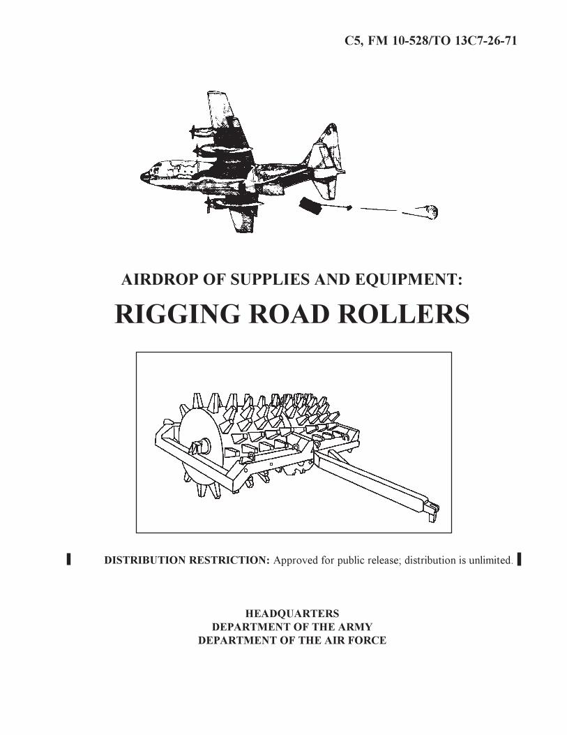
AIRDROP OF SUPPLIES AND EQUIPMENT:
RIGGING ROAD ROLLERS
DISTRIBUTION RESTRICTION: Approved for public release; distribution is unlimited.
HEADQUARTERSDEPARTMENT OF THE ARMY
DEPARTMENT OF THE AIR FORCE

C5, FM 10-528/TO 13C7-26-71
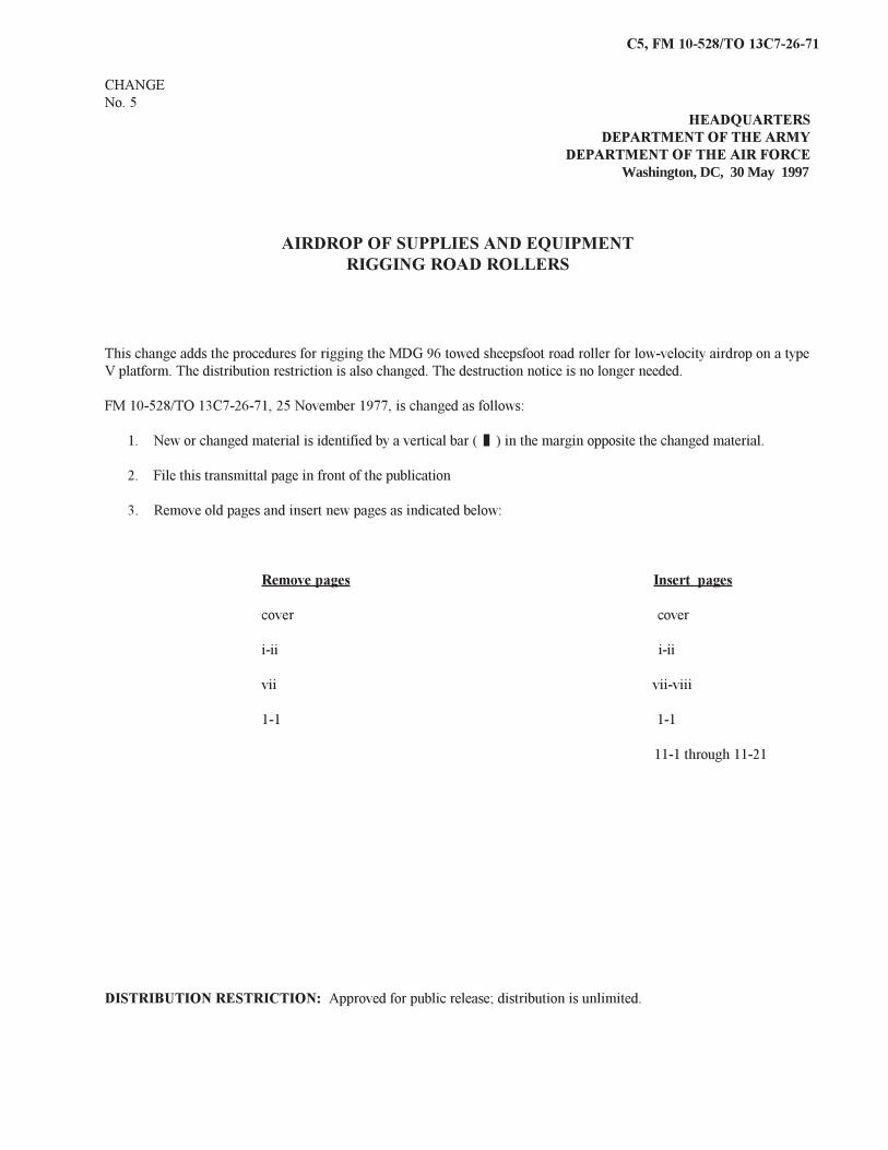
CHANGENo. 5
HEADQUARTERSDEPARTMENT OF THE ARMY
DEPARTMENT OF THE AIR FORCEWashington, DC, 30 May 1997
AIRDROP OF SUPPLIES AND EQUIPMENTRIGGING ROAD ROLLERS
This change adds the procedures for rigging the MDG 96 towed sheepsfoot road roller for low-velocity airdrop on a typeV platform. The distribution restriction is also changed. The destruction notice is no longer needed.
FM 10-528/TO 13C7-26-71, 25 November 1977, is changed as follows:
1. New or changed material is identified by a vertical bar ( ) in the margin opposite the changed material.
2. File this transmittal page in front of the publication
3. Remove old pages and insert new pages as indicated below:
Remove pages Insert pages
cover cover
i-ii i-ii
vii vii-viii
1-1 1-1
11-1 through 11-21
DISTRIBUTION RESTRICTION: Approved for public release; distribution is unlimited.
C5, FM 10-528/TO 13C7-26-71
DISTRIBUTION RESTRICTION: Approved for public release; distribution is unlimited.
HEADQUARTERSHEADQUARTERS
DEPARTMENT OF THE ARMYDEPARTMENT OF THE AIR FORCE
Washington, DC, 25 November 1977
Paragraph Page PREFACE ................................................................................................... viii
CHAPTER 1 INTRODUCTIONDescription of Items................................................................... 1-1 1-1Special Considerations............................................................... 1-2 1-1
CHAPTER 2 RIGGING 7-35-TON ROAD ROLLERDescription of Load................................................................... 2-1 2-1Preparing Platform..................................................................... 2-2 2-1Preparing and Positioning Honeycomb..................................... 2-3 2-2Preparing Road Roller............................................................... 2-4 2-3Installing Suspension Slings...................................................... 2-5 2-3Positioning Road Roller and Stowing Parking Stand................ 2-6 2-4Installing Lashings.................................................................... 2-7 2-4Stowing Cargo Parachutes......................................................... 2-8 2-4Installing Extraction System...................................................... 2-9 2-5Installing Release System.......................................................... 2-10 2-9Deleted....................................................................................... 2-11 2-9Positioning Extraction Parachute.............................................. 2-12 2-9Marking Rigged Load................................................................ 2-13 2-9Equipment Required.................................................................. 2-14 2-9
CHAPTER 3 RIGGING MODEL W-2 SHEEPSFOOT ROAD ROLLERSection I RIGGING ROLLER FOR LOW-VELOCITY AIRDROP
Description of Load................................................................... 3-1 3-1Preparing Platform.................................................................... 3-2 3-1
FIELD MANUALNo. 10-528TECHNICAL ORDERNo. 13C7-26-71
AIRDROP OF SUPPLIES AND EQUIPMENT:RIGGING ROAD ROLLERS
TABLE OF CONTENTS
i

C5, FM 10-528/TO 13C7-26-71Paragraph Page
Preparing and Positioning Honeycomb................................................ 3-3 3-1Preparing Road Roller.......................................................................... 3-4 3-1Installing Suspension Slings................................................................. 3-5 3-1Stowing Towing Tongue...................................................................... 3-6 3-4Positioning Road Roller........................................................................ 3-7 3-5Installing Lashings................................................................................ 3-8 3-5Installing Extraction Attaching Point Extension................................... 3-9 3-6Stowing Cargo Parachutes .................................................................... 3-10 3-7Installing Extraction System................................................................. 3-11 3-8Installing Release System..................................................................... 3-12 3-9Deleted.................................................................................................. 3-13 3-9Positioning Extraction Parachute.......................................................... 3-14 3-9Marking Rigged Load........................................................................... 3-15 3-9Equipment Required............................................................................. 3-16 3-9
Section II RIGGING W-2 ROLLER FOR LAPES
Description of Load.............................................................................. 3-17 3-11Special Considerations.......................................................................... 3-18 3-11Preparing Platform................................................................................ 3-19 3-11Preparing and Positioning Honeycomb................................................ 3-20 3-12Preparing Sheepsfoot Roller................................................................. 3-21 3-12Positioning Roller................................................................................. 3-22 3-12Installing Lashings................................................................................ 3-23 3-12Installing the Attitude Control Bar........................................................ 3-24 3-12Installing Extraction System................................................................. 3-25 3-12Marking Rigged Load........................................................................... 3-26 3-17Equipment Required............................................................................. 3-27 3-17
CHAPTER 4 RIGGING MODEL MDG 96 TOWED SHEEPSFOOT ROLLERSection I RIGGING ROLLER FOR LOW-ALTITUDE PARACHUTE
EXTRACTION SYSTEM (LAPES)Description of Load.............................................................................. 4-1 4-1Special Considerations.......................................................................... 4-2 4-1Preparing Platform................................................................................ 4-3 4-1Preparing and Positioning Honeycomb................................................ 4-4 4-1Preparing Sheepsfoot Roller................................................................. 4-5 4-2Positioning and Securing Tongue........................................................ 4-6 4-2Positioning Roller................................................................................. 4-7 4-3Installing Lashings................................................................................ 4-8 4-3Installing the Attitude Control Bar........................................................ 4-9 4-3Installing Extraction System................................................................. 4-10 4-4Marking Rigged Load........................................................................... 4-11 4-4Equipment Required............................................................................. 4-12 4-4
ii
C5, FM 10-528/TO 13C7-26-71
Paragraph Page
Placing Extraction Parachute................................................................ 10-13 10-15Marking Rigged Load........................................................................... 10-14 10-15Equipment Required............................................................................. 10-15 10-15
CHAPTER 11 RIGGING MODEL MDG 96 SHEEPSFOOT ROLLER ON A TYPE VPLATFORM FOR LOW-VELOCITY AIRDROP
Description of Load............................................................................... 11-1 11-1Preparing Platform................................................................................. 11-2 11-1Preparing and Positioning Honeycomb Stacks...................................... 11-3 11-3Preparing Roller and Positioning Parachute Stowage Platform............ 11-4 11-5Positioning and Securing Towing Tongue............................................ 11-5 11-8Lifting and Positioning Roller............................................................... 11-6 11-11Lashing Roller....................................................................................... 11-7 11-13Covering Roller and Installing Suspension Slings............................... 11-8 11-14Installing Cargo Parachutes.................................................................. 11-9 11-15Installing Parachute Release.................................................................. 11-10 11-16Installing Extraction System................................................................. 11-11 11-17Installing Provisions for Emergency Restraints.................................... 11-12 11-18Placing Extraction Parachute................................................................ 11-13 11-18Marking Rigged Load........................................................................... 11-14 11-18Equipment Required............................................................................. 11-15 11-18
GLOSSARY.........................................................................................................................................Glossary-1REFERENCES....................................................................................................................................References-1
vii
C5, FM 10-528/TO 13C7-26-71
PREFACE
SCOPE
This manual tells and shows how to prepare and rig the following towed road rollers for low-velocity airdrop on the type IIplatform from C-130 and C-141 aircraft: the 7- to 35-ton, W-2, MDG 96, vibrating, and 13-wheel. This manual also givesprocedures for rigging the W-2, MDG 96, vibrating and 13-wheel towed road rollers for LAPE airdrop on the metric platformfrom C-130 aircraft. Additionally, procedures are given for rigging the following towed road rollers for low-velocity airdrop onthe type V platform from C-130, C-141, C-17, and C-5 aircraft: 11-wheel, 13-wheel, Type I, M435, and MDG 96. This manualgives procedures for rigging the Type I and M435 towed road rollers for LAPE airdrop on the type V platform from C-130aircraft. It is designed for use by all parachute riggers.
USER INFORMATION
The proponent of this publication is HQ TRADOC. You are encouraged to report any errors or omissions and to suggest ways for making this a better manual. Army personnel, send your comments on DA Form 2028 directly to:
Aerial Delivery and Field Services DepartmentUSA Quartermaster Center and School1010 Shop RoadFort Lee, Virginia 23801-1502
Air Force personnel, send your reports on AFTO Form 22 through:HeadquartersAir Mobility Command (AMC/DOTX)402 Scott Drive, Unit 3AlScott AFB, Illinois 62225-5302
to:
Aerial Delivery and Field Services DepartmentUSA Quartermaster Center and School1010 Shop RoadFort Lee, Virginia 23801-1502
Also send information copy of AFTO Form 22 to:
SA-ALC/TILDP485 Quentin Roosevelt RoadKelly AFB, Texas 78241-6421
viii
C5, FM 10-528/TO 13C7-26-71
CHAPTER 1INTRODUCTION
1-1. Description of Items
The towed road rollers covered in this manualare listed below. Dimensions and weights aregiven in the description of items paragraph ineach chapter.
a. 7- to 35-ton ballast pneumatic tire rollerb. Model W-2 sheepsfoot rollerc. Model MDG 96 sheepsfoot rollerd. 13-wheel pneumatic tire rollere. 11-wheel pneumatic tire roller.f. M435 4- to 35-ton ballast pneumatic tire
rollerg. Type I, SM 54 vibrating smooth drum
rollerh. DED gas/VP4D diesel vibrating roller
1-2. Special ConsiderationsA copy of this manual should accompany therigged load to the aircraft. The loads coveredin this manual may include hazardous materi-als such as explosives, gasoline, or batteries.When included, these items must be packaged,marked, and labeled according to AFJMAN24-204/TM 38-250.
1-1
11-1
C5, FM 10-528/TO13C7-26-71
CHAPTER 11
RIGGING MODEL MDG 96 SHEEPSFOOT ROLLERON A TYPE V PLATFORM
FOR LOW-VELOCITY AIRDROP
11-1. Description of LoadThe MDG 96 towed sheepsfoot roller is riggedon a 12-foot type V airdrop platform. Theunrigged roller weighs 7,440 pounds. It is 140inches long, reducible to 77 inches; 54 incheshigh, and 119 inches wide.
11-2. Preparing Platform
a. Inspecting Platform. Inspect, or as-semble and inspect, the platform as outlined inTM 10-1670-268-20&P/TO 13C7-52-22.
b. Installing Tandem Links. Install tandemlinks on the front and rear of each rail asshown in Figure 11-1.
c. Installing and Numbering Clevises. Boltand number 22 clevis assemblies as shown inFigure 11-1.
11-2
C5, FM 10-528/TO13C7-26-71
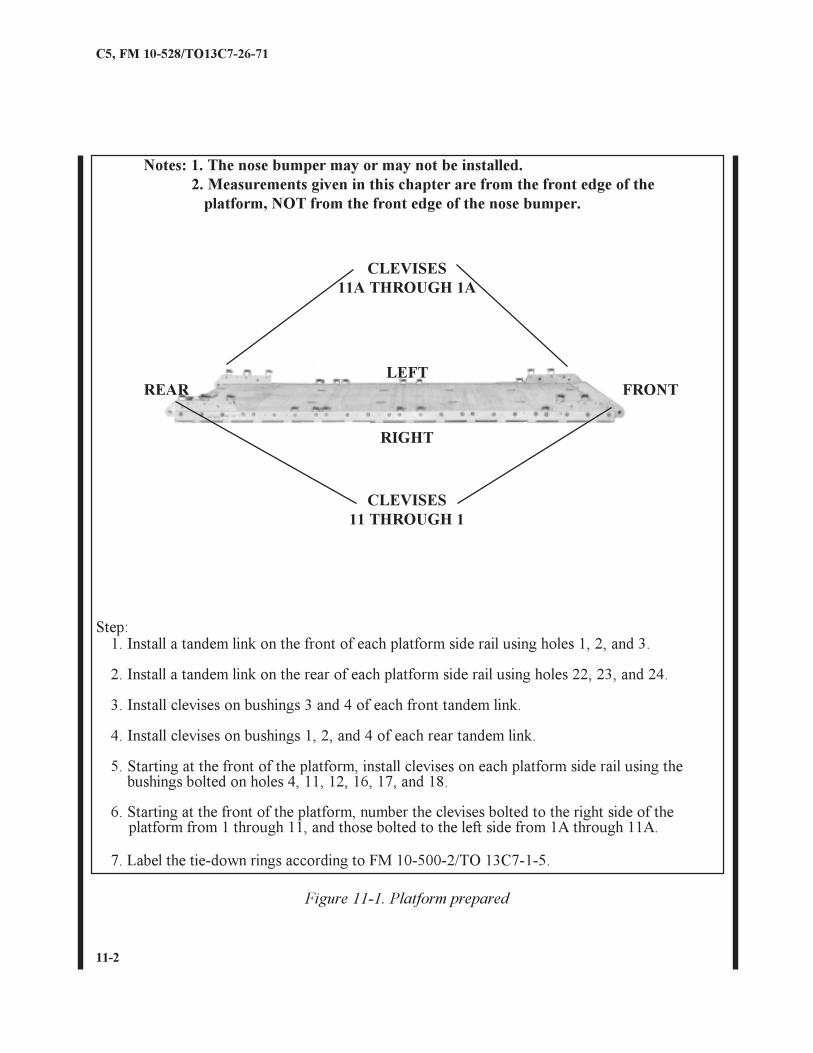
Notes: 1. The nose bumper may or may not be installed.2. Measurements given in this chapter are from the front edge of the platform, NOT from the front edge of the nose bumper.
CLEVISES11A THROUGH 1A
LEFT
RIGHT
CLEVISES11 THROUGH 1
REAR FRONT
Step:1. Install a tandem link on the front of each platform side rail using holes 1, 2, and 3.
2. Install a tandem link on the rear of each platform side rail using holes 22, 23, and 24.
3. Install clevises on bushings 3 and 4 of each front tandem link.
4. Install clevises on bushings 1, 2, and 4 of each rear tandem link.
5. Starting at the front of the platform, install clevises on each platform side rail using thebushings bolted on holes 4, 11, 12, 16, 17, and 18.
6. Starting at the front of the platform, number the clevises bolted to the right side of theplatform from 1 through 11, and those bolted to the left side from 1A through 11A.
7. Label the tie-down rings according to FM 10-500-2/TO 13C7-1-5.
Figure 11-1. Platform prepared
11-3
C5, FM 10-528/TO13C7-26-71
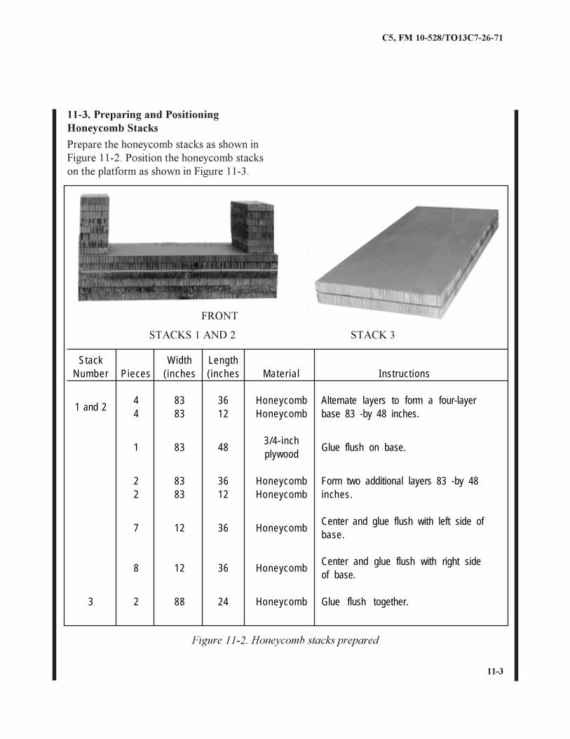
Figure 11-2. Honeycomb stacks prepared
STACKS 1 AND 2 STACK 3
FRONT
Prepare the honeycomb stacks as shown inFigure 11-2. Position the honeycomb stackson the platform as shown in Figure 11-3.
11-3. Preparing and PositioningHoneycomb Stacks
StackNumber Pieces
Width(inches
Length(inches Mater ial Instructions
1 and 244
8383
3612
HoneycombHoneycomb
Alternate layers to form a four-layerbase 83 -by 48 inches.
1 83 483/4-inchplywood
Glue flush on base.
22
8383
3612
HoneycombHoneycomb
Form two additional layers 83 -by 48inches.
7 12 36 HoneycombCenter and glue flush with left side ofbase.
8 12 36 HoneycombCenter and glue flush with right sideof base.
3 2 88 24 Honeycomb Glue flush together.
11-4
C5, FM 10-528/TO13C7-26-71
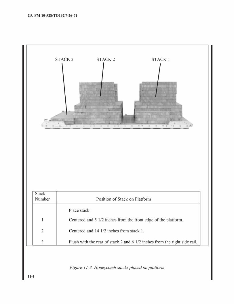
Place stack:
1 Centered and 5 1/2 inches from the front edge of the platform.
2 Centered and 14 1/2 inches from stack 1.
3 Flush with the rear of stack 2 and 6 1/2 inches from the right side rail.
StackNumber Position of Stack on Platform
STACK 3 STACK 2 STACK 1
Figure 11-3. Honeycomb stacks placed on platform
11-5
C5, FM 10-528/TO13C7-26-71
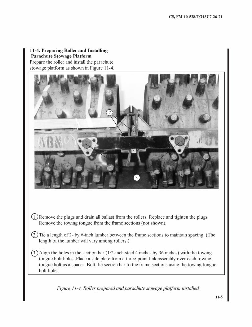
11-4. Preparing Roller and Installing
Figure 11-4. Roller prepared and parachute stowage platform installed
3
2
1 Remove the plugs and drain all ballast from the rollers. Replace and tighten the plugs.Remove the towing tongue from the frame sections (not shown).
2 Tie a length of 2- by 6-inch lumber between the frame sections to maintain spacing. (Thelength of the lumber will vary among rollers.)
3 Align the holes in the section bar (1/2-inch steel 4 inches by 36 inches) with the towingtongue bolt holes. Place a side plate from a three-point link assembly over each towingtongue bolt as a spacer. Bolt the section bar to the frame sections using the towing tonguebolt holes.
Parachute Stowage PlatformPrepare the roller and install the parachutestowage platform as shown in Figure 11-4.
11-6
C5, FM 10-528/TO13C7-26-71
5
4
6
6
7
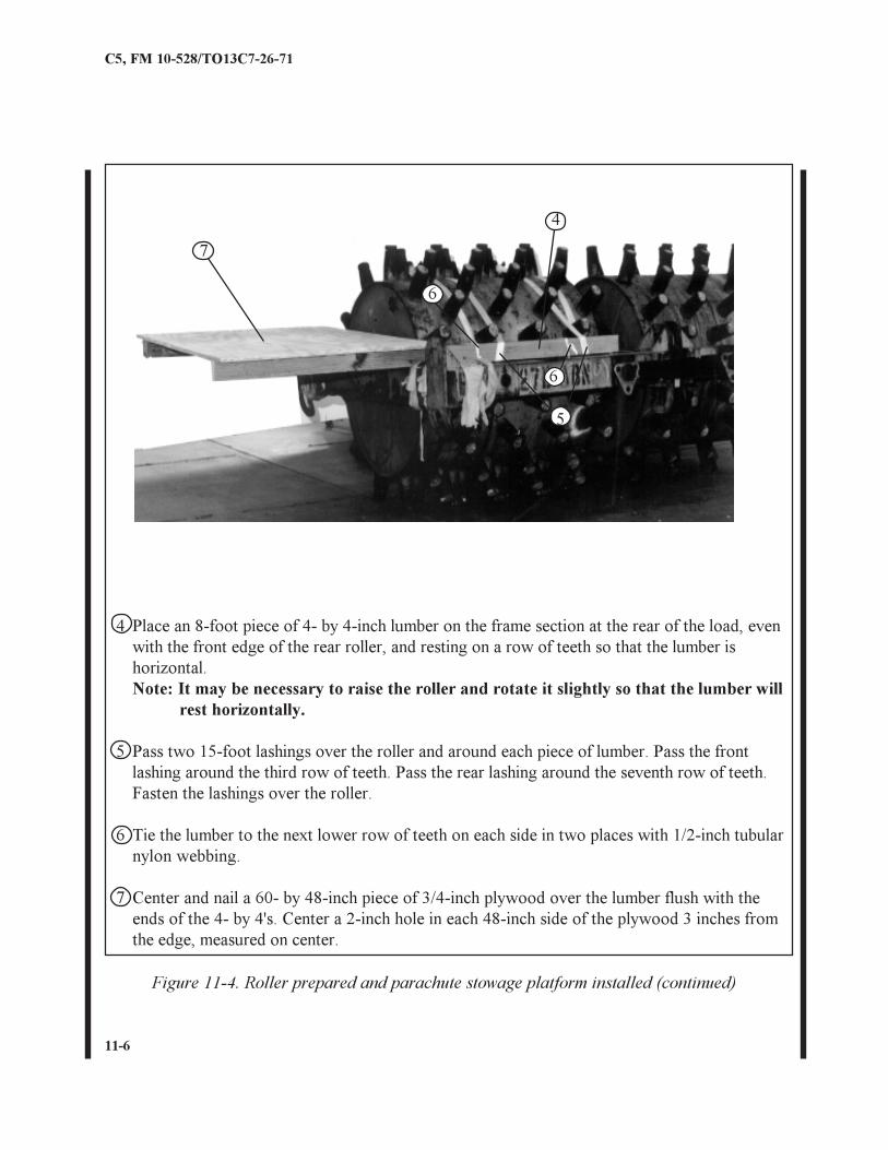
4 Place an 8-foot piece of 4- by 4-inch lumber on the frame section at the rear of the load, evenwith the front edge of the rear roller, and resting on a row of teeth so that the lumber ishorizontal.Note: It may be necessary to raise the roller and rotate it slightly so that the lumber will
rest horizontally.
5 Pass two 15-foot lashings over the roller and around each piece of lumber. Pass the frontlashing around the third row of teeth. Pass the rear lashing around the seventh row of teeth.Fasten the lashings over the roller.
6 Tie the lumber to the next lower row of teeth on each side in two places with 1/2-inch tubularnylon webbing.
7 Center and nail a 60- by 48-inch piece of 3/4-inch plywood over the lumber flush with theends of the 4- by 4's. Center a 2-inch hole in each 48-inch side of the plywood 3 inches fromthe edge, measured on center.
Figure 11-4. Roller prepared and parachute stowage platform installed (continued)
11-7
C5, FM 10-528/TO13C7-26-71
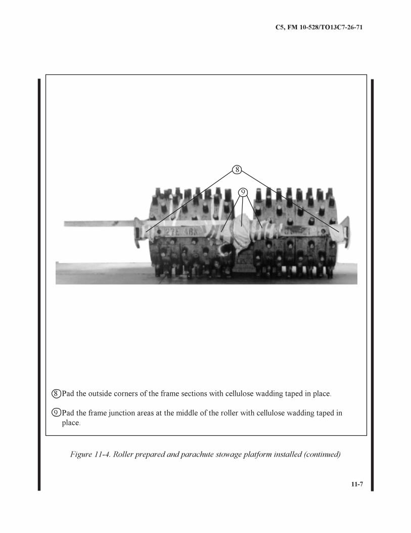
8 Pad the outside corners of the frame sections with cellulose wadding taped in place.
9 Pad the frame junction areas at the middle of the roller with cellulose wadding taped inplace.
Figure 11-4. Roller prepared and parachute stowage platform installed (continued)
8
9
11-8
C5, FM 10-528/TO13C7-26-71
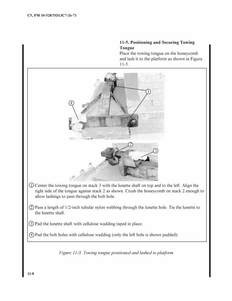
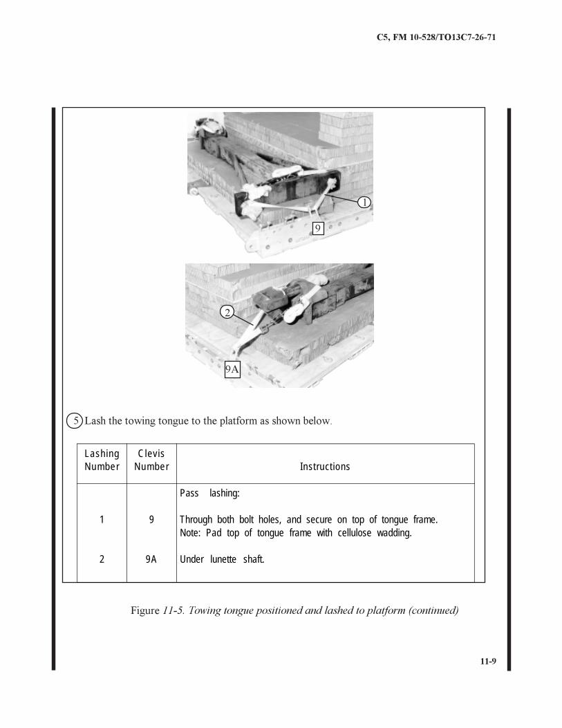
1 Center the towing tongue on stack 3 with the lunette shaft on top and to the left. Align theright side of the tongue against stack 2 as shown. Crush the honeycomb on stack 2 enough toallow lashings to pass through the bolt hole.
2 Pass a length of 1/2-inch tubular nylon webbing through the lunette hole. Tie the lunette tothe lunette shaft.
3 Pad the lunette shaft with cellulose wadding taped in place.
4 Pad the bolt holes with cellulose wadding (only the left hole is shown padded).
Figure 11-5. Towing tongue positioned and lashed to platform
11-5. Positioning and Securing TowingTonguePlace the towing tongue on the honeycomband lash it to the platform as shown in Figure11-5.
4
1
3
2
11-9
C5, FM 10-528/TO13C7-26-71
Figure 11-5. Towing tongue positioned and lashed to platform (continued)
9A
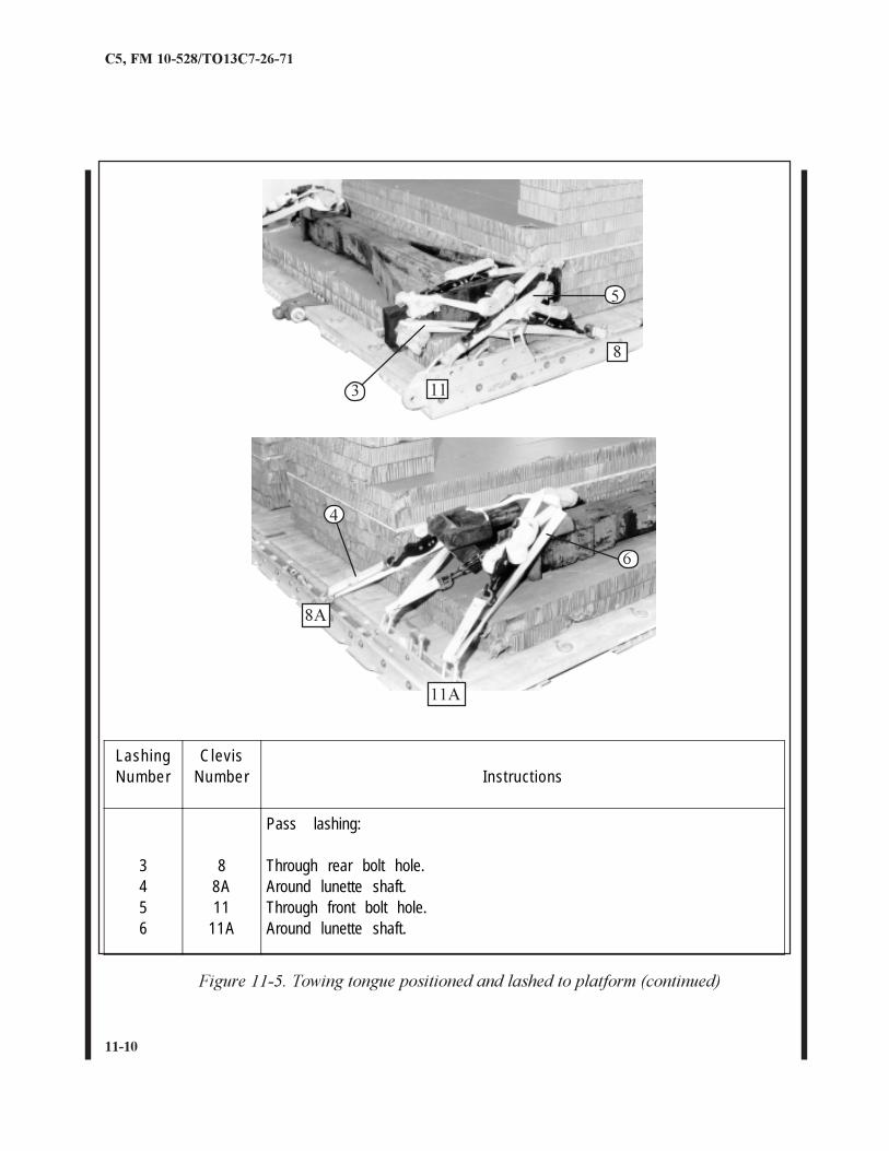
5 Lash the towing tongue to the platform as shown below.
1
2
9
LashingNumber
ClevisNumber Instructions
1
2
9
9A
Pass lashing:
Through both bolt holes, and secure on top of tongue frame.Note: Pad top of tongue frame with cellulose wadding.
Under lunette shaft.
11-10
C5, FM 10-528/TO13C7-26-71
Figure 11-5. Towing tongue positioned and lashed to platform (continued)
11
8
3
5
11A
6
4
8A
LashingNumber
ClevisNumber Instructions
3456
88A11
11A
Pass lashing:
Through rear bolt hole.Around lunette shaft.Through front bolt hole.Around lunette shaft.
11-11
C5, FM 10-528/TO13C7-26-71
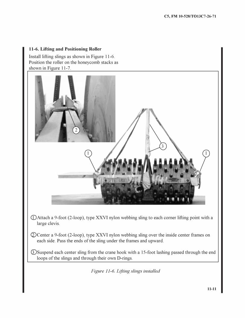
11-6. Lifting and Positioning Roller
Figure 11-6. Lifting slings installed
1 Attach a 9-foot (2-loop), type XXVI nylon webbing sling to each corner lifting point with alarge clevis.
2 Center a 9-foot (2-loop), type XXVI nylon webbing sling over the inside center frames oneach side. Pass the ends of the sling under the frames and upward.
3 Suspend each center sling from the crane hook with a 15-foot lashing passed through the endloops of the slings and through their own D-rings.
2
Install lifting slings as shown in Figure 11-6.Position the roller on the honeycomb stacks asshown in Figure 11-7.
11
3

11-12
C5, FM 10-528/TO13C7-26-71
Figure 11-7. Roller positioned on honeycomb stacks
1 Lift the roller slightly and tighten the center lifting slings if necessary to ensure the rollerremains level (not shown).
2 Set the roller on stacks 1 and 2 with the center of the roller frame midway between thestacks.
2
11-13
C5, FM 10-528/TO13C7-26-71
17
11
13
5
3
3
567 10 12
9
LashingNum ber
Clev isNum ber Inst ruct ions
123456789
10111213141516
11A2
2A3
3A4
4A5
5A6
6A7
7A10
10A
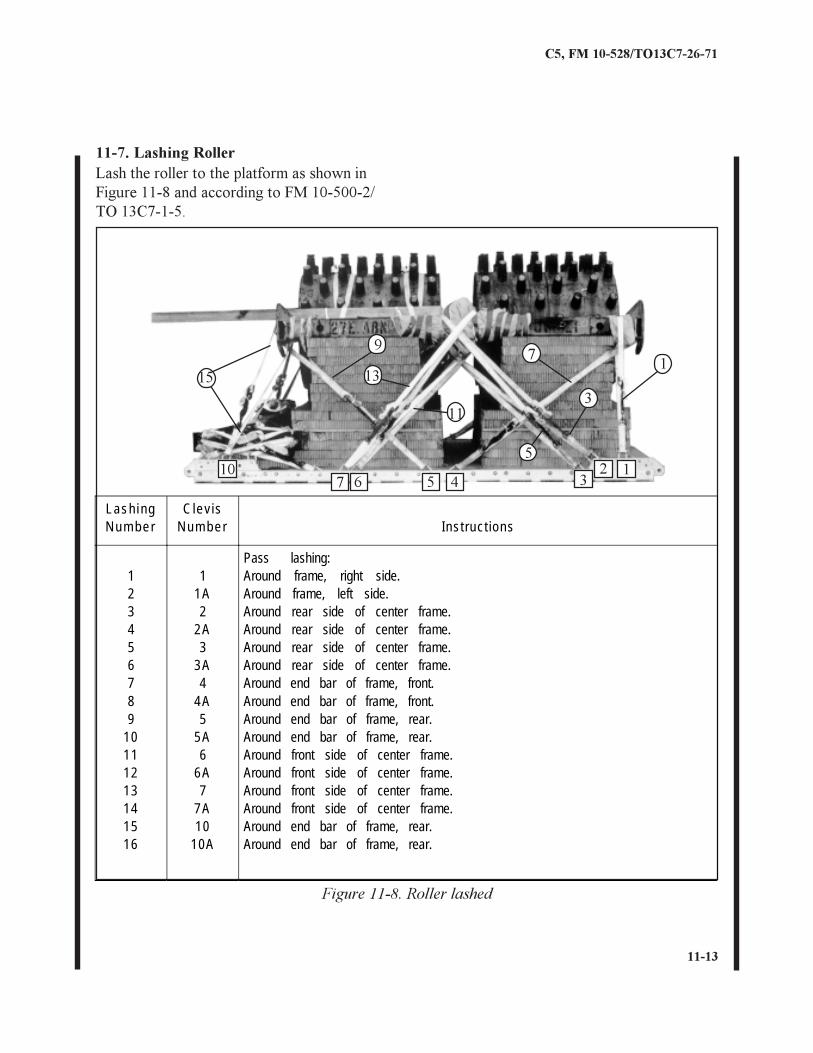
Pass lashing:Around frame, right side.Around frame, left side.Around rear side of center frame.Around rear side of center frame.Around rear side of center frame.Around rear side of center frame.Around end bar of frame, front.Around end bar of frame, front.Around end bar of frame, rear.Around end bar of frame, rear.Around front side of center frame.Around front side of center frame.Around front side of center frame.Around front side of center frame.Around end bar of frame, rear.Around end bar of frame, rear.
Figure 11-8. Roller lashed
Lash the roller to the platform as shown inFigure 11-8 and according to FM 10-500-2/TO 13C7-1-5.
11-7. Lashing Roller
15
4
11-14
C5, FM 10-528/TO13C7-26-71
1
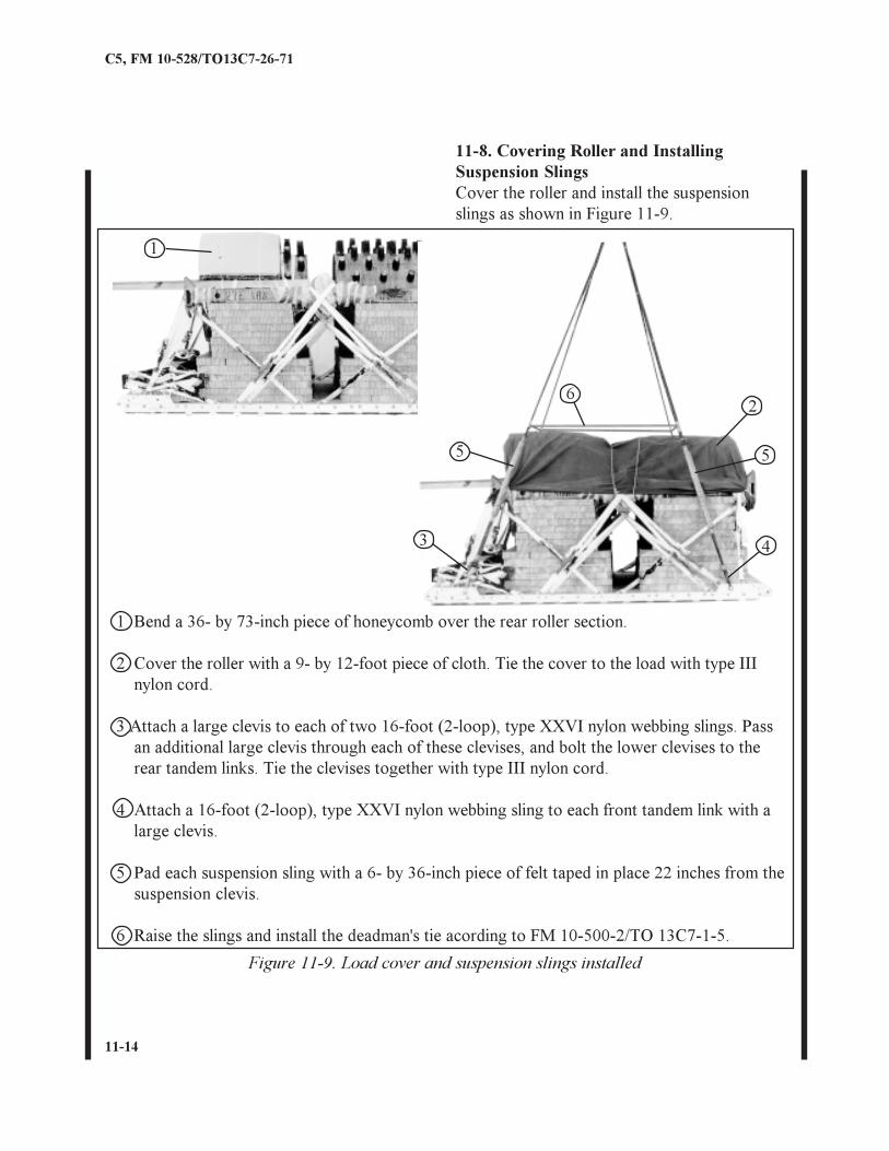
11-8. Covering Roller and InstallingSuspension SlingsCover the roller and install the suspensionslings as shown in Figure 11-9.
Figure 11-9. Load cover and suspension slings installed
1 Bend a 36- by 73-inch piece of honeycomb over the rear roller section.
2 Cover the roller with a 9- by 12-foot piece of cloth. Tie the cover to the load with type IIInylon cord.
3 Attach a large clevis to each of two 16-foot (2-loop), type XXVI nylon webbing slings. Passan additional large clevis through each of these clevises, and bolt the lower clevises to therear tandem links. Tie the clevises together with type III nylon cord.
4 Attach a 16-foot (2-loop), type XXVI nylon webbing sling to each front tandem link with alarge clevis.
5 Pad each suspension sling with a 6- by 36-inch piece of felt taped in place 22 inches from thesuspension clevis.
6 Raise the slings and install the deadman's tie acording to FM 10-500-2/TO 13C7-1-5.
5
62
4
5
3
11-15
C5, FM 10-528/TO13C7-26-71
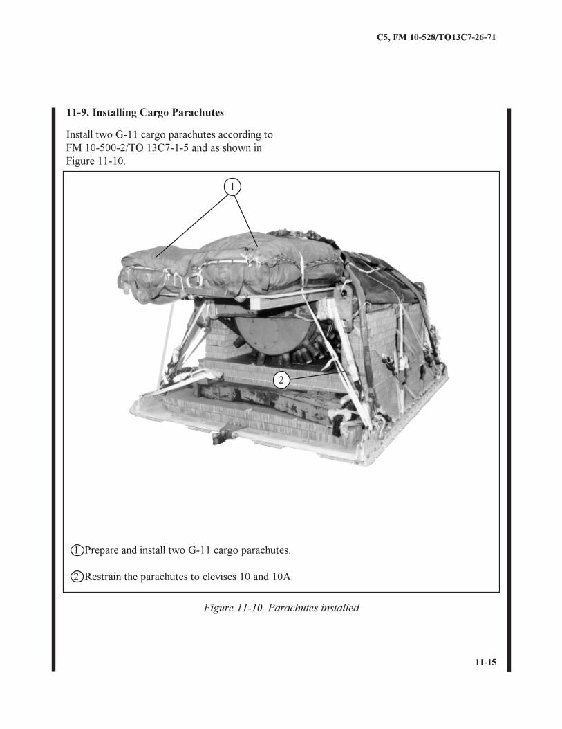
11-9. Installing Cargo Parachutes
Figure 11-10. Parachutes installed
1
2
Install two G-11 cargo parachutes according toFM 10-500-2/TO 13C7-1-5 and as shown inFigure 11-10.
1 Prepare and install two G-11 cargo parachutes.
2 Restrain the parachutes to clevises 10 and 10A.
11-16
C5, FM 10-528/TO13C7-26-71
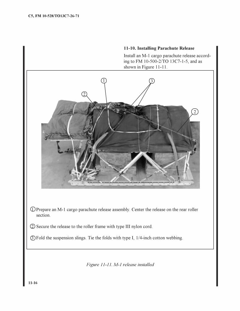
1 Prepare an M-1 cargo parachute release assembly. Center the release on the rear rollersection.
2 Secure the release to the roller frame with type III nylon cord.
3 Fold the suspension slings. Tie the folds with type I, 1/4-inch cotton webbing.
2
Figure 11-11. M-1 release installed
31
2
11-10. Installing Parachute Release
Install an M-1 cargo parachute release accord-ing to FM 10-500-2/TO 13C7-1-5, and asshown in Figure 11-11.
11-17
C5, FM 10-528/TO13C7-26-71
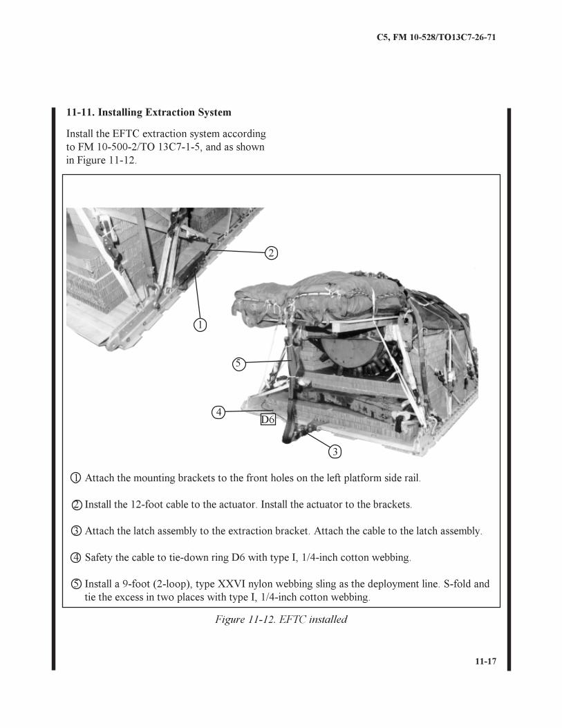
11-11. Installing Extraction System
Figure 11-12. EFTC installed
1 Attach the mounting brackets to the front holes on the left platform side rail.
2 Install the 12-foot cable to the actuator. Install the actuator to the brackets.
3 Attach the latch assembly to the extraction bracket. Attach the cable to the latch assembly.
4 Safety the cable to tie-down ring D6 with type I, 1/4-inch cotton webbing.
5 Install a 9-foot (2-loop), type XXVI nylon webbing sling as the deployment line. S-fold andtie the excess in two places with type I, 1/4-inch cotton webbing.
D6
3
4
5
2
1
Install the EFTC extraction system accordingto FM 10-500-2/TO 13C7-1-5, and as shownin Figure 11-12.
11-18
C5, FM 10-528/TO13C7-26-71
11-12. Installing Provisions for EmergencyRestraintsSelect and install provisions for emergencyrestraint according to the emergency aftrestraint requirements table in FM 10-500-2/TO 13C7-1-5.
11-13. Placing Extraction ParachuteSelect the extraction parachute and extractionline needed using the extraction line require-ments table in FM 10-500-2/TO 13C7-1-5.Place the extraction parachute and extractionline on the load for installation in the aircraft.
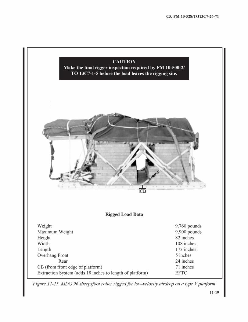
11-14. Marking Rigged LoadMark the rigged load according to FM 10-500-2/TO 13C7-1-5 and as shown in Figure 11-13.If the load varies from the one shown, theweight, height, CB, tip-off curve, and para-chute requirements must be recomputed.
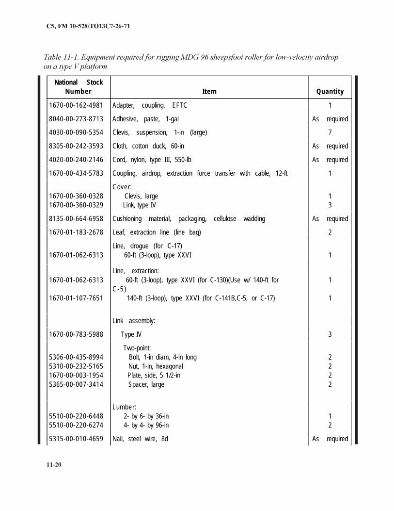
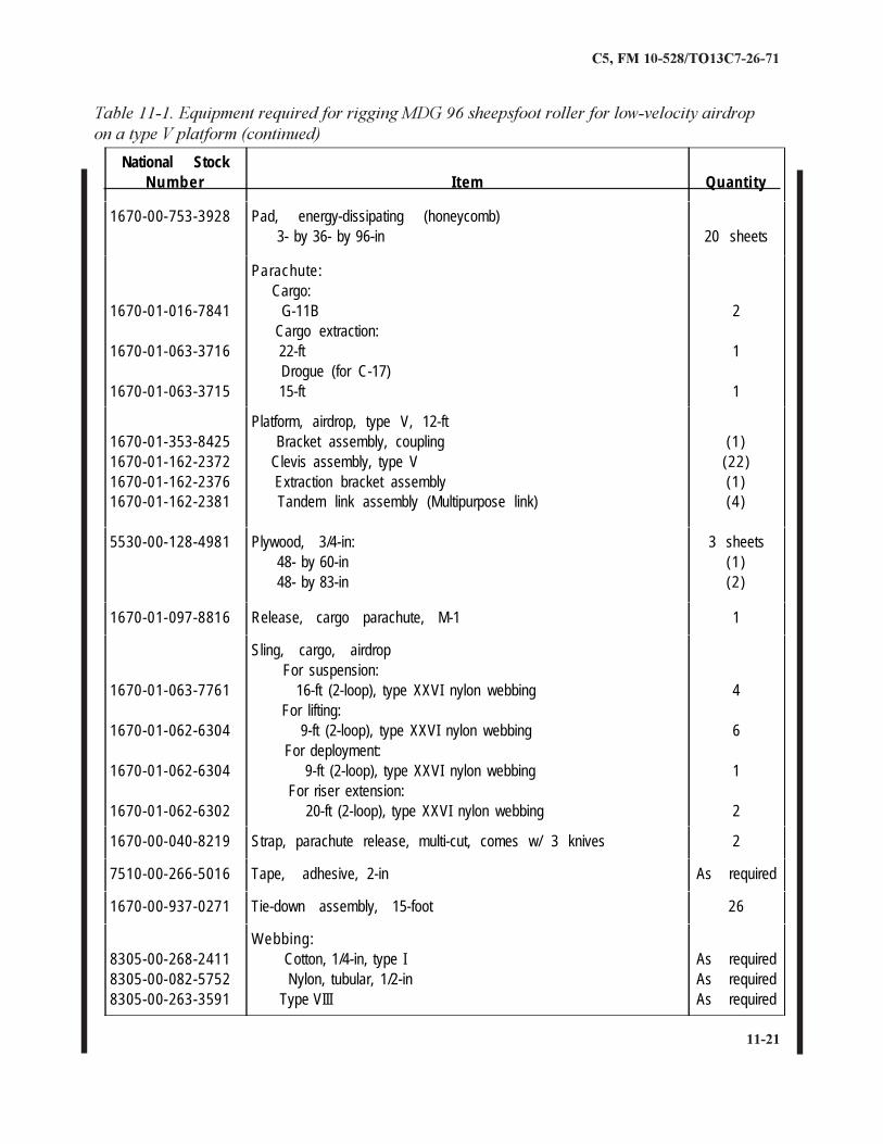
11-15. Equipment RequiredUse the equipment listed in Table 11-1 to rigthis load.
11-19
C5, FM 10-528/TO13C7-26-71
Figure 11-13. MDG 96 sheepsfoot roller rigged for low-velocity airdrop on a type V platform
CAUTIONMake the final rigger inspection required by FM 10-500-2/
TO 13C7-1-5 before the load leaves the rigging site.
Rigged Load Data
Weight 9,760 poundsMaximum Weight 9,900 poundsHeight 82 inchesWidth 108 inchesLength 173 inchesOverhang Front 5 inches
Rear 24 inchesCB (from front edge of platform) 71 inchesExtraction System (adds 18 inches to length of platform) EFTC
CB
11-20
C5, FM 10-528/TO13C7-26-71
Table 11-1. Equipment required for rigging MDG 96 sheepsfoot roller for low-velocity airdropon a type V platform
National StockNum ber Item Quantity
1670-00-162-4981 Adapter, coupling, EFTC 1
8040-00-273-8713 Adhesive, paste, 1-gal As required
4030-00-090-5354 Clevis, suspension, 1-in (large) 7
8305-00-242-3593 Cloth, cotton duck, 60-in As required
4020-00-240-2146 Cord, nylon, type III, 550-lb As required
1670-00-434-5783 Coupling, airdrop, extraction force transfer with cable, 12-ft 1
1670-00-360-03281670-00-360-0329
Cover: Clevis, large Link, type IV
13
8135-00-664-6958 Cushioning material, packaging, cellulose wadding As required
1670-01-183-2678 Leaf, extraction line (line bag) 2
1670-01-062-6313Line, drogue (for C-17) 60-ft (3-loop), type XXVI 1
1670-01-062-6313
1670-01-107-7651
Line, extraction: 60-ft (3-loop), type XXVI (for C-130)(Use w/ 140-ft forC-5 ) 140-ft (3-loop), type XXVI (for C-141B,C-5, or C-17)
1
1
Link assembly:
1670-00-783-5988 Type IV 3
5306-00-435-89945310-00-232-51651670-00-003-19545365-00-007-3414
Two-point: Bolt, 1-in diam, 4-in long Nut, 1-in, hexagonal Plate, side, 5 1/2-in Spacer, large
2222
5510-00-220-64485510-00-220-6274
Lumber: 2- by 6- by 36-in 4- by 4- by 96-in
12
5315-00-010-4659 Nail, steel wire, 8d As required
11-21
C5, FM 10-528/TO13C7-26-71
Table 11-1. Equipment required for rigging MDG 96 sheepsfoot roller for low-velocity airdropon a type V platform (continued)
National StockNumber Item Quantity
1670-00-753-3928 Pad, energy-dissipating (honeycomb) 3- by 36- by 96-in 20 sheets
1670-01-016-7841
1670-01-063-3716
1670-01-063-3715
Parachute: Cargo: G-11B Cargo extraction: 22-ft Drogue (for C-17) 15-ft
2
1
1
1670-01-353-84251670-01-162-23721670-01-162-23761670-01-162-2381
Platform, airdrop, type V, 12-ft Bracket assembly, coupling Clevis assembly, type V Extraction bracket assembly Tandem link assembly (Multipurpose link)
(1)(22)(1)(4)
5530-00-128-4981 Plywood, 3/4-in: 48- by 60-in 48- by 83-in
3 sheets(1)(2)
1670-01-097-8816 Release, cargo parachute, M-1 1
1670-01-063-7761
1670-01-062-6304
1670-01-062-6304
1670-01-062-6302
Sling, cargo, airdrop For suspension: 16-ft (2-loop), type XXVI nylon webbing For lifting: 9-ft (2-loop), type XXVI nylon webbing For deployment: 9-ft (2-loop), type XXVI nylon webbing For riser extension: 20-ft (2-loop), type XXVI nylon webbing
4
6
1
2
1670-00-040-8219 Strap, parachute release, multi-cut, comes w/ 3 knives 2
7510-00-266-5016 Tape, adhesive, 2-in As required
1670-00-937-0271 Tie-down assembly, 15-foot 26
8305-00-268-24118305-00-082-57528305-00-263-3591
Webbing: Cotton, 1/4-in, type I Nylon, tubular, 1/2-in Type VIII
As requiredAs requiredAs required
Related Documents