)0 0,/,7$5< 6<0%2/6 0$< DISTRIBUTION RESTRICTION: $SSURYHG IRU SXEOLF UHOHDVH GLVWULEXWLRQ LV XQOLPLWHG 7KLV SXEOLFDWLRQ VXSHUVHGHV )0 GDWHG 1RYHPEHU HEADQUARTERS, DEPARTMENT OF THE ARMY

Welcome message from author
This document is posted to help you gain knowledge. Please leave a comment to let me know what you think about it! Share it to your friends and learn new things together.
Transcript
DISTRIBUTION RESTRICTION:
HEADQUARTERS, DEPARTMENT OF THE ARMY
This publication is available at the Army Publishing Directorate site (http://armypubs.army.mil), and the Central Army Registry site
(https://atiam.train.army.mil/catalog/dashboard). To receive publishing updates, please subscribe at
(https://armypubs.army.mil/News/RssInstructions.aspx).

*FM 1-02.2
DISTRIBUTION RESTRICTION: This publication is approved for public release; distribution is unlimited.
*This publication supersedes 1-02.2, dated 10 November 2020.
FM 1-02.2 i
Field ManualNo. 1-02.2
Headquarters Department of the Army
Washington, D C ,
MILITARY SYMBOLS Contents
Page
PREFACE................................................................................................................... vii INTRODUCTION ......................................................................................................... ix
Chapter 1 MILITARY SYMBOL FUNDAMENTALS .................................................................. 1-1 Framed Symbols .......................................................................................................1-1 Amplifiers ...................................................................................................................1-5 Symbol Lettering........................................................................................................1-6 Unframed Symbols ....................................................................................................1-6 Control Measure Symbols .........................................................................................1-6 Military Symbol Construct Process............................................................................1-7
Chapter 2 MILITARY UNIT AND ORGANIZATIONAL SYMBOLS ........................................... 2-1 Unit and Organization Symbols .................................................................................2-1 Unit and Organization Frame Shapes .......................................................................2-1 Main and Modifier Icons and Amplifier Fields for Units .............................................2-1 Main Icons for Units.................................................................................................2-18
Chapter 3 ACTIVITY AND INSTALLATION SYMBOLS ........................................................... 3-1 Activity Frame Shapes...............................................................................................3-1 Installation Frame Shapes.........................................................................................3-4 Main Icons for Activities and Installations..................................................................3-8
Chapter 4 EQUIPMENT SYMBOLS .......................................................................................... 4-1 Framed and Unframed Equipment Symbols .............................................................4-1 Equipment Symbol Frame Shapes............................................................................4-1 Main and Modifier Icons and Amplifiers for Equipment.............................................4-2 Main Icons for Equipment........................................................................................4-10
Chapter 5 CONTROL MEASURES AND OPERATION SYMBOLS ......................................... 5-1 Fundamentals of Control Measure Symbols .............................................................5-1 Composition of Control Measure Symbols ................................................................5-1 Standard Identity Coloring Control Measures ...........................................................5-1 Control Measure Acronyms and Abbreviations Usage .............................................5-1 Operation Symbols ....................................................................................................5-2 Labeling Control Measures........................................................................................5-2 Main and Modifier Icons and Amplifiers ....................................................................5-2 Echelon Indicator (B) .................................................................................................5-4 Direction of Movement Indicator (Q) .........................................................................5-4 Offset Location Indicator (S2) ....................................................................................5-5
Contents
ii FM 1-02.2
Additional Information Amplifier (H) .......................................................................... 5-5 Boundaries ................................................................................................................ 5-6 Areas......................................................................................................................... 5-9 Points ...................................................................................................................... 5-19 Lines........................................................................................................................ 5-35 Movement and Maneuver Control Measure Symbols............................................. 5-41 Offensive and Defensive Operation Symbols ......................................................... 5-45 Observation Post Control Measures ....................................................................... 5-49 Military Deception Control Measures ...................................................................... 5-50 Airspace Control Measures..................................................................................... 5-52 Fire Support Coordination Control Measures ......................................................... 5-60 Target Control Measures ........................................................................................ 5-65 Target Acquisition Control Measures...................................................................... 5-70 Mobility and Countermobility Control Measures ..................................................... 5-76 CBRN Events Control Measures ............................................................................ 5-95 Route Control Measures ......................................................................................... 5-99 Convoy Control Measures .................................................................................... 5-101 Maritime Control Measures................................................................................... 5-102
Chapter 6 TACTICAL MISSION TASKS ................................................................................... 6-1 Tactical Mission Tasks Defined ................................................................................ 6-1 Symbols for Tactical Mission Tasks.......................................................................... 6-1
Chapter 7 COURSE OF ACTION SKETCH .............................................................................. 7-1 Purpose of Course of Action Sketch ......................................................................... 7-1 Makeup of Course of Action Sketch.......................................................................... 7-1 Task Organization Composition Symbols ................................................................. 7-1 GLOSSARY ................................................................................................ Glossary-1 REFERENCES........................................................................................ References-1 INDEX ............................................................................................................... Index-1
Figures
Figure 1-1. Example of full frame main icons ................................................................................ 1-5 Figure 2-1. Main and modifier icon and amplifier placement locations ......................................... 2-2 Figure 2-2. Template for an echelon amplifier ............................................................................... 2-5 Figure 2-3. Template for quantity amplifier .................................................................................... 2-8 Figure 2-4. Quantity amplifier usage example ............................................................................... 2-9 Figure 2-5. Template for task force or team amplifier.................................................................... 2-9 Figure 2-6. Template for attached and detached amplifier.......................................................... 2-10 Figure 2-7. Template for country code amplifier Field AS with Field F in use ............................. 2-11 Figure 2-8. Template for country code amplifier Field AS without Field F usage........................ 2-12 Figure 2-9. Template for command post using amplifier Field G................................................. 2-12 Figure 2-10. Template for additional information amplifier .......................................................... 2-14 Figure 2-11. Solidus usage example ........................................................................................... 2-14 Figure 2-12. Hyphen usage example........................................................................................... 2-15 Figure 2-13. Template for higher echelon amplifier ..................................................................... 2-15 Figure 2-14. Higher echelon amplifier usage example ................................................................ 2-15
Contents
FM 1-02.2 iii
Figure 2-15. Template for direction of movement amplifier .........................................................2-16 Figure 2-16. Direction of movement amplifier usage example.....................................................2-16 Figure 2-17. Template for combat effectiveness amplifier ...........................................................2-17 Figure 2-18. Headquarters staff location indicators .....................................................................2-17 Figure 2-19. Offset location indicators .........................................................................................2-18 Figure 3-1. Placement of activity main and modifier icons and amplifiers .....................................3-1 Figure 3-2. Evaluation rating amplifier usage construct .................................................................3-3 Figure 3-3. Activity direction of movement amplifier usage construct ............................................3-3 Figure 3-4. Activities offset location indicator amplifier usage construct........................................3-4 Figure 3-5. Placement of installation main and modifier icon and amplifiers .................................3-5 Figure 3-6. Template for operational condition amplifier................................................................3-7 Figure 4-1. Placement of land equipment symbols main and modifier icons and amplifiers .........4-3 Figure 4-2. Equipment direction of movement usage construct example of an armored high
mobility vehicle with medium gun system...................................................................4-5 Figure 4-3. Example of armored self-propelled (tracked) long-range surface to air missile launcher
engaging an enemy attack rotary aircraft ...................................................................4-7 Figure 4-4. Example of armored self-propelled howitzer moving by train......................................4-7 Figure 4-5. Speed usage construct example with direction of movement of an armored high
mobility vehicle with medium gun system...................................................................4-9 Figure 5-1. Composition of control measure symbol......................................................................5-1 Figure 5-2. Echelon indicator usage construct examples ..............................................................5-4 Figure 5-3. Direction of movement usage construct example........................................................5-5 Figure 5-4. Offset location indicator usage construct examples ....................................................5-5 Figure 5-5. Additional information usage construct example .........................................................5-6 Figure 5-6. Boundary composition template ..................................................................................5-6 Figure 5-7. Template for area control measure symbols .............................................................5-10 Figure 5-8. Template for points (left) and supply distribution points (right) control measure
symbols.....................................................................................................................5-20 Figure 5-9. Template for line control measure symbols ...............................................................5-35 Figure 7-1. Task organization main icon and amplifier fields .........................................................7-2 Figure 7-2. Battalion task force example........................................................................................7-6
Tables
Introductory table 1. New and modified military symbol changes ..................................................... x Table 1-1. Standard identities and physical domain frame shapes ...............................................1-2 Table 1-2. Friendly frame status examples in present, planned, or suspected .............................1-3 Table 1-3. Horizontal and vertical octagon placement diagram examples ....................................1-4 Table 1-4. Standard identity colors.................................................................................................1-5 Table 1-5. Construct process for framed symbols .........................................................................1-8 Table 1-6. Construct process for control measure symbol ............................................................1-9 Table 2-1. Unit and organization standard identity frame shapes..................................................2-1
Contents
iv FM 1-02.2
Table 2-2. Descriptions of main icon and amplifier fields for unit frames ...................................... 2-3 Table 2-3. Echelon and non-echelon amplifiers ............................................................................ 2-6 Table 2-4. Task organization indicator amplifier .......................................................................... 2-10 Table 2-5. Attached and detached amplifiers .............................................................................. 2-11 Table 2-6. Command post amplifier Field G usage examples..................................................... 2-13 Table 2-7. Main icons for units..................................................................................................... 2-19 Table 2-8. Main icons for named units......................................................................................... 2-35 Table 2-9. Sector 1 modifiers for units......................................................................................... 2-38 Table 2-10. Sector 2 modifiers for units....................................................................................... 2-58 Table 2-11. Unit symbol construct examples and translations .................................................... 2-72 Table 3-1. Activity standard identity frame shapes ........................................................................ 3-1 Table 3-2. Descriptions of main and modifier icons and amplifier fields for activity frames .......... 3-2 Table 3-3. Installation standard identity frame shapes .................................................................. 3-4 Table 3-4. Descriptions of main and modifier icon and amplifier fields for installation frames...... 3-5 Table 3-5. Operational condition amplifiers and construct examples ............................................ 3-7 Table 3-6. Main icons for activities and installations ..................................................................... 3-8 Table 3-7. Sector 1 modifiers for activities and installations........................................................ 3-20 Table 3-8. Sector 2 modifiers for individuals and organizations .................................................. 3-30 Table 4-1. Equipment standard identity frame shapes .................................................................. 4-2 Table 4-2. Descriptions of main and modifier icon and amplifier fields ......................................... 4-3 Table 4-3. Engagement bar designation colors ............................................................................. 4-6 Table 4-4. Equipment mobility (transportation) mode indicators (Field R) .................................... 4-8 Table 4-5. Operational condition amplifiers and construct examples .......................................... 4-10 Table 4-6. Main icons for equipment ........................................................................................... 4-11 Table 4-7. Sector 1 modifiers for equipment................................................................................ 4-34 Table 4-8. Sector 2 modifiers for equipment................................................................................ 4-39 Table 5-1. Present and planned status for control measure symbols ........................................... 5-2 Table 5-2. Main and modifier icon and amplifier descriptions for control measure symbols ......... 5-3 Table 5-3. Boundaries.................................................................................................................... 5-7 Table 5-4. Boundary control-line construct examples ................................................................... 5-9 Table 5-5. Area control measures main icons ............................................................................. 5-11 Table 5-6. Battle position and unique operation area templates with examples ......................... 5-16 Table 5-7. Point control measure main icon symbols .................................................................. 5-21 Table 5-8. Distinctive action point control measure functions, templates, and examples ........... 5-33 Table 5-9. Line control measure symbols.................................................................................... 5-36 Table 5-10. Forms of maneuver control measure symbols ......................................................... 5-42 Table 5-11. Movement to contact operation symbols .................................................................. 5-45 Table 5-12. Attack operation symbols ......................................................................................... 5-46 Table 5-13. Enabling operation symbols ..................................................................................... 5-47 Table 5-14. Retrograde operation symbols ................................................................................. 5-49 Table 5-15. Observation post control measure symbols ............................................................. 5-50

Contents
FM 1-02.2 v
Table 5-16. Military deception control measure symbols .............................................................5-51 Table 5-17. Airspace control measure symbols ...........................................................................5-53 Table 5-18. Fire support coordination control measure symbols .................................................5-61 Table 5-19. Target control measure symbols...............................................................................5-66 Table 5-20. Target acquisition control measure symbols ............................................................5-70 Table 5-21. Mobility control measure symbols.............................................................................5-77 Table 5-22. Countermobility symbols and control measure symbols...........................................5-80 Table 5-23. Land mine and minefield control measure symbols..................................................5-86 Table 5-24. Minefield sector 1 modifiers ......................................................................................5-90 Table 5-25. Field fortification control measures ...........................................................................5-94 Table 5-26. CBRN events control measures................................................................................5-96 Table 5-27. CBRN contaminated area control measures ............................................................5-98 Table 5-28. Route control measures..........................................................................................5-100 Table 5-29. Convoy control measures .......................................................................................5-102 Table 5-30. Maritime control measure symbols .........................................................................5-102 Table 6-1. Tactical mission task symbols.......................................................................................6-2 Table 7-1. Task organization icons ................................................................................................7-3 Table 7-2. Combat effectiveness icons ..........................................................................................7-5

This page intentionally left blank.

FM 1-02.2 vii
Preface
FM 1-02.2 constitutes approved Army military symbols for general use to depict land operations. The principal audience for FM 1-02.2 is all members of the profession of arms. Commanders and staffs of Army headquarters serving as a joint task force or multinational headquarters should also refer to applicable joint or multinational doctrine concerning the range of military operations and joint or multinational forces. Trainers and educators throughout the Army will also use this publication.
Commanders, staffs, and subordinates ensure their decisions and actions comply with applicable U.S.,international, and, in some cases host-nation laws and regulations. Commanders at all echelons ensure their Soldiers operate in accordance with the law of war and the rules of engagement. (See FM 6-27/MCTP 11-10D.)
This publication implements the following international agreements:
STANAG 1059 (ED. 8). Letter Codes for Geographical Entities. 1 April 2004.
STANAG 1241. (ED. 5). NATO Standard Identity Description Structure for Tactical Use. 6 April 2005.
STANAG 2019 (ED 7)/APP 6 (D). NATO Joint Military Symbology. 16 October 2017.
FM 1-02.2 applies to the Active Army, Army National Guard/Army National Guard of the United States and United States Army Reserve unless otherwise stated.
The proponent of FM 1-02.2 is the United States Army Combined Arms Center. The preparing agency is the Combined Arms Doctrine Directorate, United States Army Combined Arms Center. Send comments and recommendations on DA Form 2028 (Recommended Changes to Publications and Blank Forms) to Commander, United States Army Combined Arms Center and Fort Leavenworth, ATTN: ATZL-MCD (FM 1-02.2), 300 McPherson Avenue, Fort Leavenworth, KS 66027-2337; by e-mail to [email protected]; or submit an electronic DA Form 2028.

This page intentionally left blank.
FM 1-02.2 ix
Introduction
This publication compiles Department of Defense Military Standard (MIL-STD) 2525D approved military symbols applicable to land operations for use in U.S. Army doctrinal publications, situation maps, overlays, annotated aerial photographs for all types of military operation. MIL-STD 2525D is the single standard for developing and depicting computer-generated military symbols for use in command and control systems. FM 1-02.2 is the proponent for hand drawn alternate symbols, course of action sketch symbols applicable to U.S.Army doctrine, and approved for use military symbols that are not currently included in MIL-STD 2525Ddue to difference in revision timeline. Use this publication as the standard for properly constructing landoperations associated military symbols for communicating instructions to subordinate units, commanders,and staffs from company through corps echelons.
This publication is augmented by FM 1-02.1, Operational Terms, and Army Dictionary online. Changes to military symbols occur more frequently than traditional publication media can be updated. The terminology and military symbol database, known as the Army Dictionary, is updated monthly to reflect the latest editions of Army publications. (To access the database, go to https://jdeis.js.mil/jdeis/index.jsp?pindex=207, and log in with a common access card.) This database is an official DOD website, maintained by the Combined Arms Doctrine Directorate in collaboration with the Joint Staff Directorate for Joint Force Development. The site is part of the Joint Doctrine, Education, and Training Electronic Information System. It includes all Army doctrinal terms and all military symbols in MIL-STD 2525D, including air, land, maritime, space, activities, and control measures.
FM 1-02.2 is organized as follows:
Chapter 1 introduces military symbol fundamentals.
Chapters 2 through 4 provide icons for units, individuals, organizations, equipment, installations, and activities.
Chapter 5 introduces control measure symbols.
Chapter 6 discusses tactical mission tasks.
Chapter 7 discusses the course of action sketch.
These chapters provide detailed requirements for composing and constructing military symbols. The rules for building a set of military symbols allow enough flexibility for users to create any symbol to meet their operational needs. All military symbols construct standards are governed by MIL-STD 2525D, and this publication serves as the compendium of land related military symbols used in U.S. Army doctrine and training manuals.
FM 1-02.2 is now the proponent of military symbols that were included in ADP 1-02 as the preceding proponent.
The introductory table on page x provides a listing of new and modified military symbol changes published in this manual.

Introduction
x FM 1-02.2
Introductory table 1. New and modified military symbol changes
Symbol Status Symbol categoryAir defense Modified usage Approved for use as a sector 2
modifier for unitsAmplifier field “V” for specific unit equipment Added/correction Unit amplifier fields (figure 2-1 and
table 2-2)Command and control Modified usage Approved for use as a sector 1
modifier for facilities and equipmentCyberspace Modified usage Approved for use as main icon for
facilities, and sector 1 modifier for facilities and units
Cyber-server New Main icon for facilities and equipment
Continuity of operations New Sector 1 modifier for facilitiesData New Main icon and sector 2 modifier for
facilitiesDirected energy Modified usage Approved for use as a main icon for
unitsElectric generation Modified usage Approved for use as a sector 1
modifier for facilitiesInternet service provider New Main icon for facilitiesLaser (equipment main icon) Modified term Name change to directed energyMultidomain operations New Main icon and sector 1 modifier for
unitsNetwork Modified usage Approved for use as a sector 1
modifier for facilitiesOperations Modified usage Approved for use as a main icon
and sector 1 and 2 modifier for facilities
Robotic Modified usage Approved for use as a sector 1 modifier for units
Sector 1 and 2 modifiers for units and facilities
Modified usage All sector 1 and 2 modifiers can now offset to the right to avoid symbol overlapping. This excludes the following modifiers due to full frame linear design:
HeadquartersJammingSupply
Security Modified usage Now can be used as a main icon, sector 1 and sector 2 modifier for facilities
Short range air defense Added Main icon for unitsSupporting axis of advance Added/correction Control measureWater Modified usage Approved for use as a sector 1
modifier for facilitiesWired New Sector 1 modifier for facilitiesWireless New Sector 1 modifier for facilities
FM 1-02.2 1-1
Chapter 1
Military Symbol Fundamentals
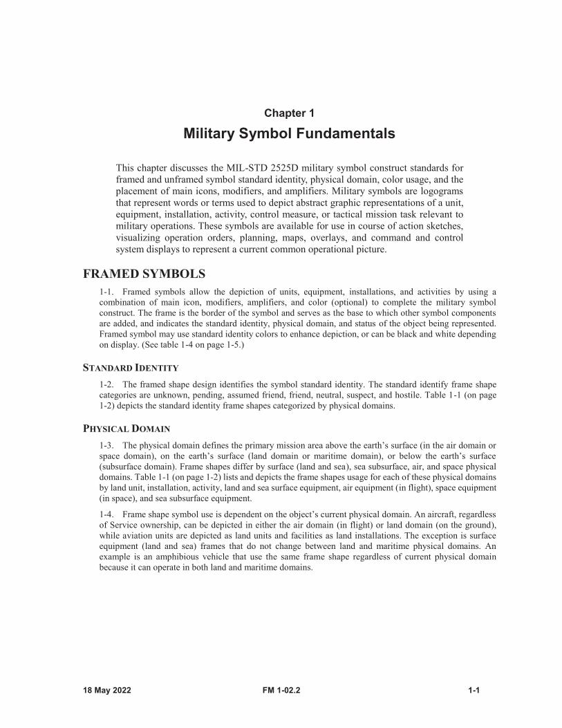
This chapter discusses the MIL-STD 2525D military symbol construct standards for framed and unframed symbol standard identity, physical domain, color usage, and the placement of main icons, modifiers, and amplifiers. Military symbols are logograms that represent words or terms used to depict abstract graphic representations of a unit, equipment, installation, activity, control measure, or tactical mission task relevant to military operations. These symbols are available for use in course of action sketches, visualizing operation orders, planning, maps, overlays, and command and control system displays to represent a current common operational picture.
FRAMED SYMBOLS1-1. Framed symbols allow the depiction of units, equipment, installations, and activities by using acombination of main icon, modifiers, amplifiers, and color (optional) to complete the military symbolconstruct. The frame is the border of the symbol and serves as the base to which other symbol componentsare added, and indicates the standard identity, physical domain, and status of the object being represented.Framed symbol may use standard identity colors to enhance depiction, or can be black and white dependingon display. (See table 1-4 on page 1-5.)
STANDARD IDENTITY
1-2. The framed shape design identifies the symbol standard identity. The standard identify frame shapecategories are unknown, pending, assumed friend, friend, neutral, suspect, and hostile. Table 1-1 (on page1-2) depicts the standard identity frame shapes categorized by physical domains.
PHYSICAL DOMAIN
1-3. The physical domain defines the primary mission area above the earth’s surface (in the air domain orspace domain), on the earth’s surface (land domain or maritime domain), or below the earth’s surface(subsurface domain). Frame shapes differ by surface (land and sea), sea subsurface, air, and space physicaldomains. Table 1-1 (on page 1-2) lists and depicts the frame shapes usage for each of these physical domainsby land unit, installation, activity, land and sea surface equipment, air equipment (in flight), space equipment(in space), and sea subsurface equipment.
1-4. Frame shape symbol use is dependent on the object’s current physical domain. An aircraft, regardlessof Service ownership, can be depicted in either the air domain (in flight) or land domain (on the ground),while aviation units are depicted as land units and facilities as land installations. The exception is surfaceequipment (land and sea) frames that do not change between land and maritime physical domains. Anexample is an amphibious vehicle that use the same frame shape regardless of current physical domainbecause it can operate in both land and maritime domains.

Chapter 1
1-2 FM 1-02.2
Table 1-1. Standard identities and physical domain frame shapes
Standard Identities and Physical Domains
Friendly Hostile Neutral UnknownAssumed Friend Pending
Land unit
Land and sea surface equipment
Air equipment (inflight)
Space equipment (in space)
Activity
Installation
Sea subsurface equipment
Military Symbol Fundamentals
FM 1-02.2 1-3
STATUS
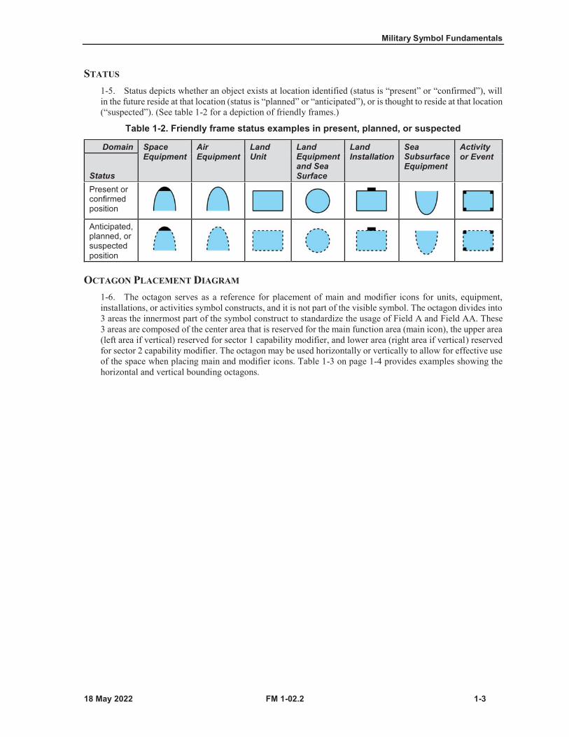
1-5. Status depicts whether an object exists at location identified (status is “present” or “confirmed”), willin the future reside at that location (status is “planned” or “anticipated”), or is thought to reside at that location(“suspected”). (See table 1-2 for a depiction of friendly frames.)
Table 1-2. Friendly frame status examples in present, planned, or suspected
Domain Space Equipment
AirEquipment
Land Unit
Land Equipment and Sea Surface
Land Installation
Sea Subsurface Equipment
Activity or Event
StatusPresent or confirmed position
Anticipated, planned, or suspected position
OCTAGON PLACEMENT DIAGRAM
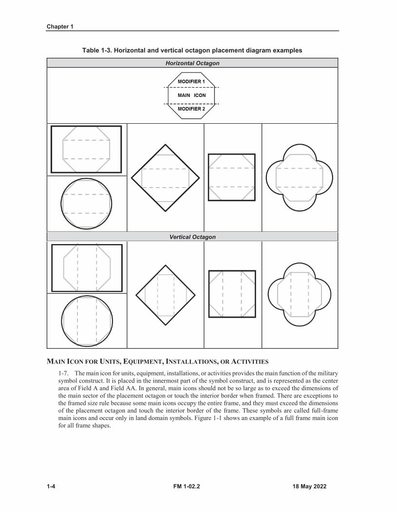
1-6. The octagon serves as a reference for placement of main and modifier icons for units, equipment,installations, or activities symbol constructs, and it is not part of the visible symbol. The octagon divides into3 areas the innermost part of the symbol construct to standardize the usage of Field A and Field AA. These3 areas are composed of the center area that is reserved for the main function area (main icon), the upper area(left area if vertical) reserved for sector 1 capability modifier, and lower area (right area if vertical) reservedfor sector 2 capability modifier. The octagon may be used horizontally or vertically to allow for effective useof the space when placing main and modifier icons. Table 1-3 on page 1-4 provides examples showing thehorizontal and vertical bounding octagons.
Chapter 1
1-4 FM 1-02.2
Table 1-3. Horizontal and vertical octagon placement diagram examples
Horizontal Octagon
Vertical Octagon
MAIN ICON FOR UNITS, EQUIPMENT, INSTALLATIONS, OR ACTIVITIES
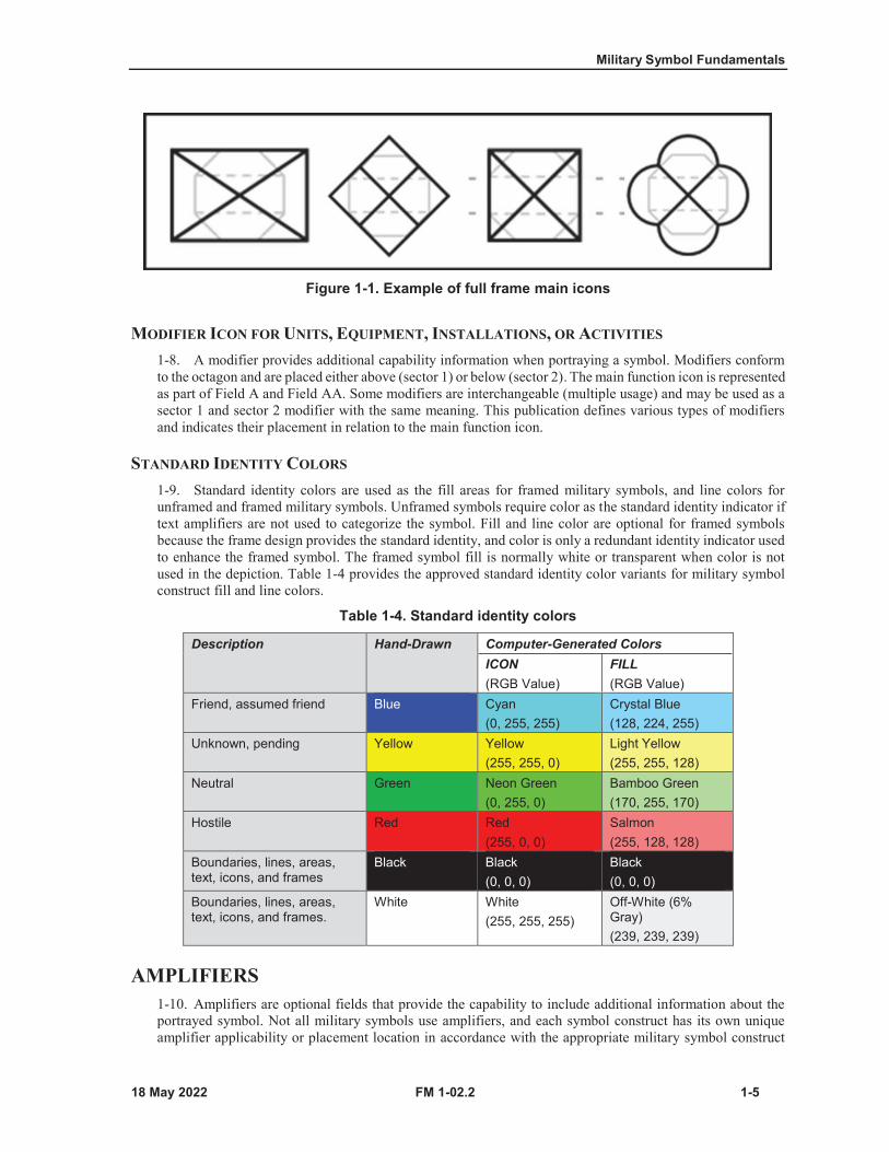
1-7. The main icon for units, equipment, installations, or activities provides the main function of the militarysymbol construct. It is placed in the innermost part of the symbol construct, and is represented as the centerarea of Field A and Field AA. In general, main icons should not be so large as to exceed the dimensions ofthe main sector of the placement octagon or touch the interior border when framed. There are exceptions tothe framed size rule because some main icons occupy the entire frame, and they must exceed the dimensionsof the placement octagon and touch the interior border of the frame. These symbols are called full-framemain icons and occur only in land domain symbols. Figure 1-1 shows an example of a full frame main iconfor all frame shapes.
Military Symbol Fundamentals
FM 1-02.2 1-5
Figure 1-1. Example of full frame main icons
MODIFIER ICON FOR UNITS, EQUIPMENT, INSTALLATIONS, OR ACTIVITIES
1-8. A modifier provides additional capability information when portraying a symbol. Modifiers conformto the octagon and are placed either above (sector 1) or below (sector 2). The main function icon is representedas part of Field A and Field AA. Some modifiers are interchangeable (multiple usage) and may be used as asector 1 and sector 2 modifier with the same meaning. This publication defines various types of modifiersand indicates their placement in relation to the main function icon.
STANDARD IDENTITY COLORS
1-9. Standard identity colors are used as the fill areas for framed military symbols, and line colors forunframed and framed military symbols. Unframed symbols require color as the standard identity indicator iftext amplifiers are not used to categorize the symbol. Fill and line color are optional for framed symbolsbecause the frame design provides the standard identity, and color is only a redundant identity indicator usedto enhance the framed symbol. The framed symbol fill is normally white or transparent when color is notused in the depiction. Table 1-4 provides the approved standard identity color variants for military symbolconstruct fill and line colors.
Table 1-4. Standard identity colors
Description Hand-Drawn Computer-Generated ColorsICON(RGB Value)
FILL(RGB Value)
Friend, assumed friend Blue Cyan(0, 255, 255)
Crystal Blue(128, 224, 255)
Unknown, pending Yellow Yellow(255, 255, 0)
Light Yellow(255, 255, 128)
Neutral Green Neon Green(0, 255, 0)
Bamboo Green(170, 255, 170)
Hostile Red Red(255, 0, 0)
Salmon(255, 128, 128)
Boundaries, lines, areas, text, icons, and frames
Black Black(0, 0, 0)
Black(0, 0, 0)
Boundaries, lines, areas, text, icons, and frames.
White White(255, 255, 255)
Off-White (6% Gray)(239, 239, 239)
AMPLIFIERS1-10. Amplifiers are optional fields that provide the capability to include additional information about theportrayed symbol. Not all military symbols use amplifiers, and each symbol construct has its own uniqueamplifier applicability or placement location in accordance with the appropriate military symbol construct
Chapter 1
1-6 FM 1-02.2
standard. Each respective chapter provides the applicable amplifier placement template and amplifier field listing for all military symbol constructs that have the option to use amplifiers.
SYMBOL LETTERING1-11. The lettering for all military symbols will always be uppercase, sans serif font, right aligned on the leftof side, left aligned on the right, and centered on top. In some cases the lettering may be tilted slightly tofollow the contour of a line, but must be oriented for left-to-right legibility and avoid tilting so much thatreaders must tilt their heads to read it.
UNFRAMED SYMBOLS1-12. Equipment symbols may be depicted with frame or unframed. Control measure symbols and missiontask symbols are unframed symbols that conform to special rules for their own elements.
UNFRAMED EQUIPMENT SYMBOLS
1-13. The military symbol construct standard permits the depiction of equipment symbols with or without aframe. Unframed equipment symbol constructs follow the same icon and amplifier placement rules as framedequipment symbols. The only difference is that the main icon of the symbol construct serves as the base foradding modifiers and amplifiers, and it must use standard identity colors (blue, red, green, or yellow) toeffectively depict and distinguish friendly or assumed friend, hostile or suspect, neutral, and unknown orpending units. Chapter 3 provides the equipment symbol icon and amplifier guidelines.
TACTICAL MISSION TASK SYMBOLS
1-14. Tactical mission task symbols are used in course of action sketches, synchronization matrices, andmaneuver sketches. Tactical mission task symbols are sized to accommodate the scale of the display or map,and they may be used with other framed and unframed symbols, but they do not use modifiers or amplifiers.Chapter 6 provides tactical mission task symbol listings and construct examples.
CONTROL MEASURE SYMBOLS1-15. A control measure is a means of regulating forces or warfighting functions. Control measure symbolshave different unique construct template patterns for each type of control measure, but they use similarstandard identity colors and amplifiers as other military symbols. They can be black or white, depending ontheir display background. Display backgrounds can be blue (for friendly), red (for hostile), green (forobstacles), or yellow (for a chemical, biological, radiological, and nuclear contaminated area fill). See chapter5 for description, placement, and further details of control measure symbols.
MAIN ICONS FOR CONTROL MEASURES
1-16. Similar to frame symbols, field A identifies the location for control measures main icon placement.The main icon provides the ability to depict the main or supporting function within the construct compositionof a control measure. Some control measures symbol constructs permit the use of Field A to embed acompleted framed symbol construct. Not all control measures have this placement field, and the controlmeasure templates in chapter 5 indicate if the construct composition provides the capability to add a mainicon to the symbol.
MODIFIERS FOR CONTROL MEASURES
1-17. Minefields and limited access areas have modifiers that can only be used within their unique militarysymbol construct. (See chapter 5 for appropriate modifier listing and usage construct.)
Military Symbol Fundamentals
FM 1-02.2 1-7
MILITARY SYMBOL CONSTRUCT PROCESS1-18. Military symbol construct is a logographic writing system similar to words in written language. Eachsymbol has a specific meaning that when combined with other symbols provides legible information that canbe used to quickly identify units, organizations, and capabilities and to understand current or future actions.The military symbol construct process can construct sentences and paragraphs or translate written words intomilitary symbols using MIL-STD 2525D symbol construct standard used by command and control systems.The symbols in this publication are adequate for depicting a variety of military symbol constructs, but if auser determines there is a gap in the symbol construct language, that user must inform the U.S. Armysymbologist so collaboration can begin on creating a required new military symbol.
CONSTRUCT PROCESS FOR FRAMED SYMBOLS
1-19. Chapters 2 through 4 provide icons and modifiers for building a wide variety of framed symbols. Table1-5 on page 1-8 provides a step-by-step framed symbol building process example for an infantry unit witharmored high mobility vehicle capability, echelon of command level, and its unit designation.

Chapter 1
1-8 FM 1-02.2
Table 1-5. Construct process for framed symbols
Steps Construct example and symbol translation
1 Choose appropriate frame shape from table 3-1 on page 3-1.Note. This example uses the friendly unit frame.
Friendly unit2 Choose appropriate main icon from chapters 2 through 5 and
combine it with frame.Note. This example selects the infantry main icon which is a full frame icon found in chapter 2.
Infantry
Friendly infantry unit3 Choose appropriate sector 1 modifier from chapters 2 through 5.
Note. This example uses the armored protected sector 1 modifier found in chapter 2. Armored
(protection)
Friendly infantry unit with armored (protection)
capability4 Choose appropriate sector 2 modifier from chapters 2 through 5.
Note. This example selects the wheeled high mobility sector 2 modifier found in chapter 2. Wheeled
highmobility
Friendly infantry unit with armored high mobility
vehicle capability5 Choose essential amplifier field from those listed in table 3-3 on
page 3-4.Note. This example uses Field B, H, M to add echelon and unit designator information to complete the desired military symbol. These specific amplifier symbols and construct usage can be found in chapter 2.
Infantry battalion with armored high mobility vehicle capability, 4th Battalion, 23rd Infantry Regiment, 2nd Brigade,
2nd Infantry Division
CONSTRUCT PROCESS FOR CONTROL MEASURES
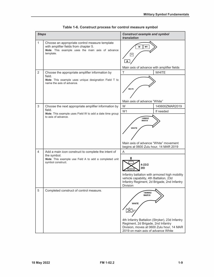
1-20. As part of the military symbol construct process, many control measure symbols can be combined withamplifiers and main icons to display operational information in one symbol. Table 1-6 depicts the steps inthe building process example for one of these types of control measures.
Military Symbol Fundamentals
FM 1-02.2 1-9
Table 1-6. Construct process for control measure symbol
Steps Construct example and symbol translation
1 Choose an appropriate control measure template with amplifier fields from chapter 5.Note. This example uses the main axis of advance template.
Main axis of advance with amplifier fields2 Choose the appropriate amplifier information by
field.Note. This example uses unique designation Field T to name the axis of advance.
T WHITE
Main axis of advance “White”3 Choose the next appropriate amplifier information by
field.Note. This example uses Field W to add a date time group to axis of advance.
W 140600ZMAR2019W1 If needed
Main axis of advance “White” movement begins at 0600 Zulu hour, 14 MAR 2019
4 Add a main icon construct to complete the intent of the symbol.Note. This example use Feld A to add a completed unit symbol construct.
A
Infantry battalion with armored high mobility vehicle capability, 4th Battalion, 23dInfantry Regiment, 2d Brigade, 2nd Infantry Division
5 Completed construct of control measure.
4th Infantry Battalion (Stryker), 23d Infantry Regiment, 2d Brigade, 2nd Infantry Division, moves at 0600 Zulu hour, 14 MAR 2019 on main axis of advance White

This page intentionally left blank.

FM 1-02.2 2-1
Chapter 2
Military Unit and Organizational Symbols
This chapter discusses symbols for units and organizations.
UNIT AND ORGANIZATION SYMBOLS2-1. A unit is any military element whose structure is prescribed by a competent authority (JP 3-33). Thissection includes the lists of amplifiers, main icons, and modifiers for constructing unit and organizationsymbols.
UNIT AND ORGANIZATION FRAME SHAPES2-2. Unit and organization frame shapes are used to identify friendly, enemy, neutral, or unknown affiliationunits in an area of interest or operation that may affect unified land operations. Table 2-1 provides thestandard identity frame shapes for units and organizations. The frame shape construct guidelines for mainand modifier icons and amplifier placement locations are provided in paragraph 2-3.
Table 2-1. Unit and organization standard identity frame shapes
Friendly Hostile Neutral Unknown
Assumed Friend Suspect Pending
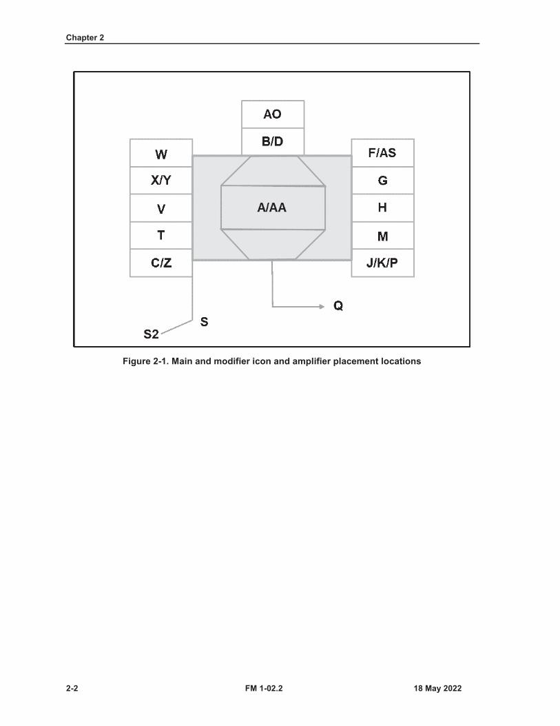
MAIN AND MODIFIER ICONS AND AMPLIFIER FIELDS FOR UNITS2-3. The main and modifier icons and amplifier fields standardize the display of alphanumericalinformation that graphically describes a unit, its capabilities, status, and location. The field placement is thesame for all unit standard identity frames (including friend and assumed friend, hostile and suspect, neutral,pending, and unknown). Figure 2-1 on page 2-2 shows the placement fields for land unit symbols using afriend symbol frame as an example. Table 2-2 on page 2-3 provides descriptions and formats for eachamplifier.
Chapter 2
2-2 FM 1-02.2
Figure 2-1. Main and modifier icon and amplifier placement locations
Military Unit and Organizational Symbols
FM 1-02.2 2-3
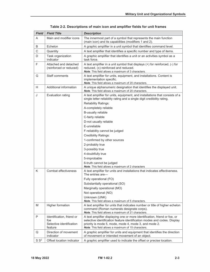
Table 2-2. Descriptions of main icon and amplifier fields for unit frames
Field Field Title DescriptionA Main and modifier icons The innermost part of a symbol that represents the main function
(main icon) and its capabilities (modifiers 1 and 2).B Echelon A graphic amplifier in a unit symbol that identifies command level.C Quantity A text amplifier that identifies a specific number and type of items.D Task organization
indicatorA graphic amplifier that identifies a unit or an activities symbol as a task force.
F Attached and detached (reinforced or reduced)
A text amplifier in a unit symbol that displays (+) for reinforced, (-) for reduced, (±) reinforced and reduced.Note. This field allows a maximum of 3 characters.
G Staff comments A text amplifier for units, equipment, and installations. Content is implementation specific.Note. This field allows a maximum of 20 characters.
H Additional information A unique alphanumeric designation that identifies the displayed unit.Note. This field allows a maximum of 20 characters.
J Evaluation rating A text amplifier for units, equipment, and installations that consists of a single letter reliability rating and a single digit credibility rating.Reliability Ratings:A-completely reliableB-usually reliableC-fairly reliableD-not usually reliableE-unreliableF-reliability cannot be judgedCredibility Ratings:1-confirmed by other sources2-probably true3-possibly true4-doubtfully true5-improbable6-truth cannot be judgedNote. This field allows a maximum of 2 characters
K Combat effectiveness A text amplifier for units and installations that indicates effectiveness. The entries are—Fully operational (FO)Substantially operational (SO)Marginally operational (MO)Not operational (NO)Unknown (UNK)Note. This field allows a maximum of 5 characters.
M Higher formation A text amplifier for units that indicates number or title of higher echelon command (Roman numerals designate corps).Note. This field allows a maximum of 21 characters.
P Identification, friend or foeSelective identification feature
A text amplifier displaying one or more identification, friend or foe, or selective identification feature identification modes and codes. Display priority is mode 5, mode, mode 4, mode 3, and mode 2.Note. This field allows a maximum of 15 characters.
Q Direction of movement indicator
A graphic amplifier for units and equipment that identifies the direction of movement or intended movement of an object.
S S2 Offset location indicator A graphic amplifier used to indicate the offset or precise location.
Chapter 2
2-4 FM 1-02.2
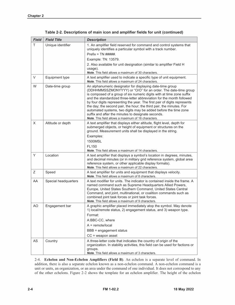
Table 2-2. Descriptions of main icon and amplifier fields for unit (continued)
Field Field Title DescriptionT Unique identifier 1. An amplifier field reserved for command and control systems that
uniquely identifies a particular symbol with a track number.Prefix = TN #####.Example: TN: 13579.2. Also available for unit designation (similar to amplifier Field Husage).Note. This field allows a maximum of 30 characters.
V Equipment type A text amplifier used to indicate a specific type of unit equipment.Note. This field allows a maximum of 24 characters.
W Date-time group An alphanumeric designator for displaying date-time group (DDHHMMSSZMONYYYY) or “O/O” for an order. The date-time group is composed of a group of six numeric digits with at time zone suffix and the standardized three-letter abbreviation for the month followed by four digits representing the year. The first pair of digits represents the day; the second pair, the hour; the third pair, the minutes. For automated systems, two digits may be added before the time zone suffix and after the minutes to designate seconds.Note. This field allows a maximum of 16 characters.
X Altitude or depth A text amplifier that displays either altitude, flight level, depth for submerged objects, or height of equipment or structures on the ground. Measurement units shall be displayed in the string.Examples:1500MSLFL150Note. This field allows a maximum of 14 characters.
Y Location A text amplifier that displays a symbol’s location in degrees, minutes, and decimal minutes (or in military grid reference system, global area reference system, or other applicable display formats).Note. This field allows a maximum of 22 characters.
Z Speed A text amplifier for units and equipment that displays velocity.Note. This field allows a maximum of 8 characters.
AA Special headquarters A text modifier for units. The indicator is contained inside the frame. A named command such as Supreme Headquarters Allied Powers, Europe, United States Southern Command, United States Central Command, and joint, multinational, or coalition commands such as combined joint task forces or joint task forces.Note. This field allows a maximum of 9 characters.
AO Engagement bar A graphic amplifier placed immediately atop the symbol. May denote 1) local/remote status, 2) engagement status, and 3) weapon type.Format:A:BBC-CC, whereA = remote/localBBB = engagement statusCC = weapon asset
AS Country A three-letter code that indicates the country of origin of the organization. In stability activities, this field can be used for factions or groups.Note. This field allows a maximum of 3 characters.
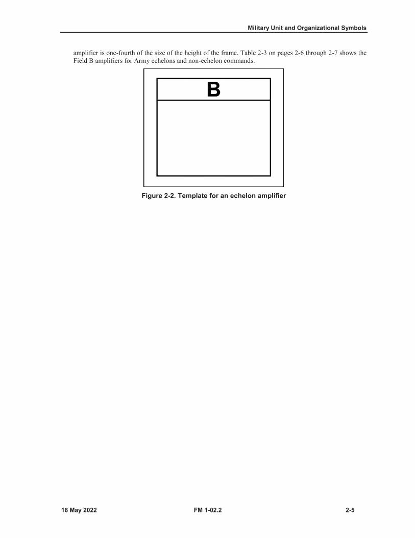
2-4. Echelon and Non-Echelon Amplifiers (Field B). An echelon is a separate level of command. Inaddition, there is also a separate echelon known as a non-echelon command. A non-echelon command is aunit or units, an organization, or an area under the command of one individual. It does not correspond to anyof the other echelons. Figure 2-2 shows the template for an echelon amplifier. The height of the echelon
Military Unit and Organizational Symbols
FM 1-02.2 2-5
amplifier is one-fourth of the size of the height of the frame. Table 2-3 on pages 2-6 through 2-7 shows the Field B amplifiers for Army echelons and non-echelon commands.
Figure 2-2. Template for an echelon amplifier
Chapter 2
2-6 FM 1-02.2
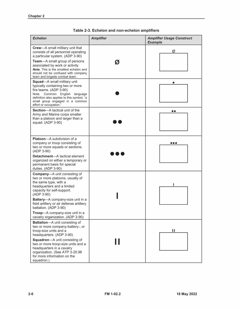
Table 2-3. Echelon and non-echelon amplifiers
Echelon Amplifier Amplifier Usage Construct Example
Crew—A small military unit that consists of all personnel operating a particular system. (ADP 3-90)Team—A small group of persons associated by work or activityNote. This is the smallest echelon and should not be confused with company team and brigade combat team.Squad—A small military unit typically containing two or more fire teams. (ADP 3-90)Note. Common English language definition also applies to this symbol, “a small group engaged in a common effort or occupation.”
Section—A tactical unit of the Army and Marine corps smaller than a platoon and larger than a squad. (ADP 3-90)
Platoon—A subdivision of a company or troop consisting of two or more squads or sections. (ADP 3-90)Detachment—A tactical element organized on either a temporary or permanent basis for special duties. (ADP 3-90)Company—A unit consisting of two or more platoons, usually of the same type, with a headquarters and a limited capacity for self-support. (ADP 3-90)Battery—A company-size unit in a field artillery or air defense artillery battalion. (ADP 3-90)Troop—A company-size unit in a cavalry organization. (ADP 3-90)Battalion—A unit consisting of two or more company-battery-, or troop-size units and a headquarters. (ADP 3-90)Squadron—A unit consisting of two or more troop-size units and a headquarters in a cavalry organization. (See ATP 3-20.96 for more information on the squadron.)
Military Unit and Organizational Symbols
FM 1-02.2 2-7
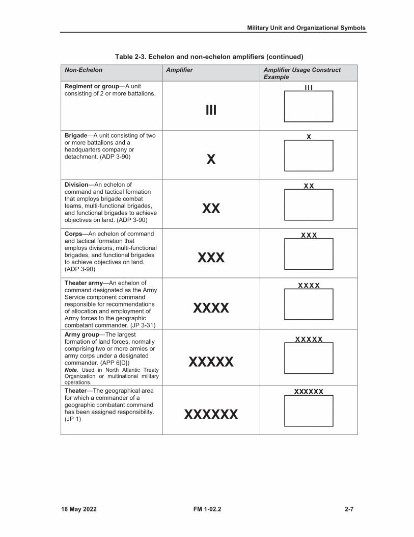
Table 2-3. Echelon and non-echelon amplifiers (continued)
Non-Echelon Amplifier Amplifier Usage Construct Example
Regiment or group—A unit consisting of 2 or more battalions.
IIIBrigade—A unit consisting of two or more battalions and a headquarters company or detachment. (ADP 3-90) XDivision—An echelon of command and tactical formation that employs brigade combat teams, multi-functional brigades, and functional brigades to achieve objectives on land. (ADP 3-90)
XXCorps—An echelon of command and tactical formation that employs divisions, multi-functional brigades, and functional brigades to achieve objectives on land. (ADP 3-90)
XXXTheater army—An echelon of command designated as the Army Service component command responsible for recommendations of allocation and employment of Army forces to the geographic combatant commander. (JP 3-31)
XXXXArmy group—The largest formation of land forces, normally comprising two or more armies or army corps under a designated commander. (APP 6[D])Note. Used in North Atlantic Treaty Organization or multinational military operations.
XXXXX
Theater—The geographical area for which a commander of a geographic combatant command has been assigned responsibility. (JP 1) XXXXXX
Chapter 2
2-8 FM 1-02.2
Table 2-3. Echelon and non-echelon amplifiers (continued)
Non-Echelon Amplifier Amplifier Usage Construct Example
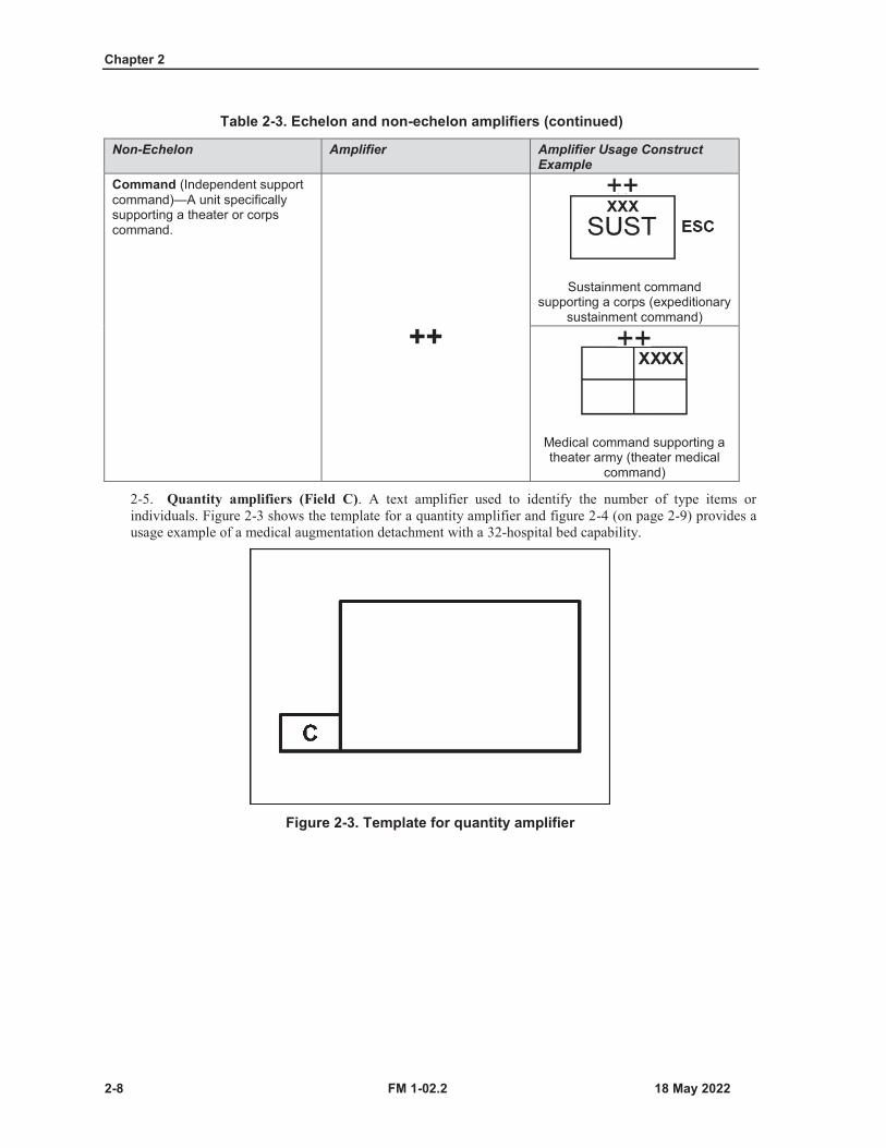
Command (Independent support command)—A unit specifically supporting a theater or corps command.
++
Sustainment command supporting a corps (expeditionary
sustainment command)
Medical command supporting a theater army (theater medical
command)
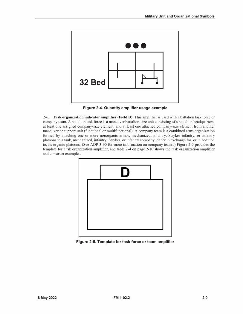
2-5. Quantity amplifiers (Field C). A text amplifier used to identify the number of type items orindividuals. Figure 2-3 shows the template for a quantity amplifier and figure 2-4 (on page 2-9) provides ausage example of a medical augmentation detachment with a 32-hospital bed capability.
Figure 2-3. Template for quantity amplifier
Military Unit and Organizational Symbols
FM 1-02.2 2-9
Figure 2-4. Quantity amplifier usage example
2-6. Task organization indicator amplifier (Field D). This amplifier is used with a battalion task force orcompany team. A battalion task force is a maneuver battalion-size unit consisting of a battalion headquarters,at least one assigned company-size element, and at least one attached company-size element from anothermaneuver or support unit (functional or multifunctional). A company team is a combined arms organizationformed by attaching one or more nonorganic armor, mechanized, infantry, Stryker infantry, or infantryplatoons to a tank, mechanized, infantry, Stryker, or infantry company, either in exchange for, or in additionto, its organic platoons. (See ADP 3-90 for more information on company teams.) Figure 2-5 provides thetemplate for a tsk organization amplifier, and table 2-4 on page 2-10 shows the task organization amplifierand construct examples.
Figure 2-5. Template for task force or team amplifier
Chapter 2
2-10 FM 1-02.2
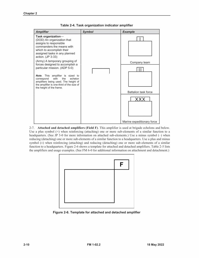
Table 2-4. Task organization indicator amplifier
Amplifier Symbol ExampleTask organization—(DOD) An organization that assigns to responsible commanders the means with which to accomplish their assigned tasks in any planned action. (JP 3-33)(Army) A temporary grouping of forces designed to accomplish a particular mission. (ADP 5-0)
Note. This amplifier is sized to correspond with the echelon amplifiers being used. The height of the amplifier is one-third of the size of the height of the frame.
Company team
Battalion task force
Marine expeditionary force
2-7. Attached and detached amplifiers (Field F). This amplifier is used at brigade echelons and below.Use a plus symbol (+) when reinforcing (attaching) one or more sub-elements of a similar function to aheadquarters. (See JP 3-0 for more information on attached sub-elements.) Use a minus symbol (–) whenreducing (detaching) one or more sub-elements of a similar function to a headquarters. Use a plus and minussymbol (±) when reinforcing (attaching) and reducing (detaching) one or more sub-elements of a similarfunction to a headquarters. Figure 2-6 shows a template for attached and detached amplifiers. Table 2-5 liststhe amplifiers and usage examples. (See FM 6-0 for additional information on attachment and detachment.)
Figure 2-6. Template for attached and detached amplifier
Military Unit and Organizational Symbols
FM 1-02.2 2-11
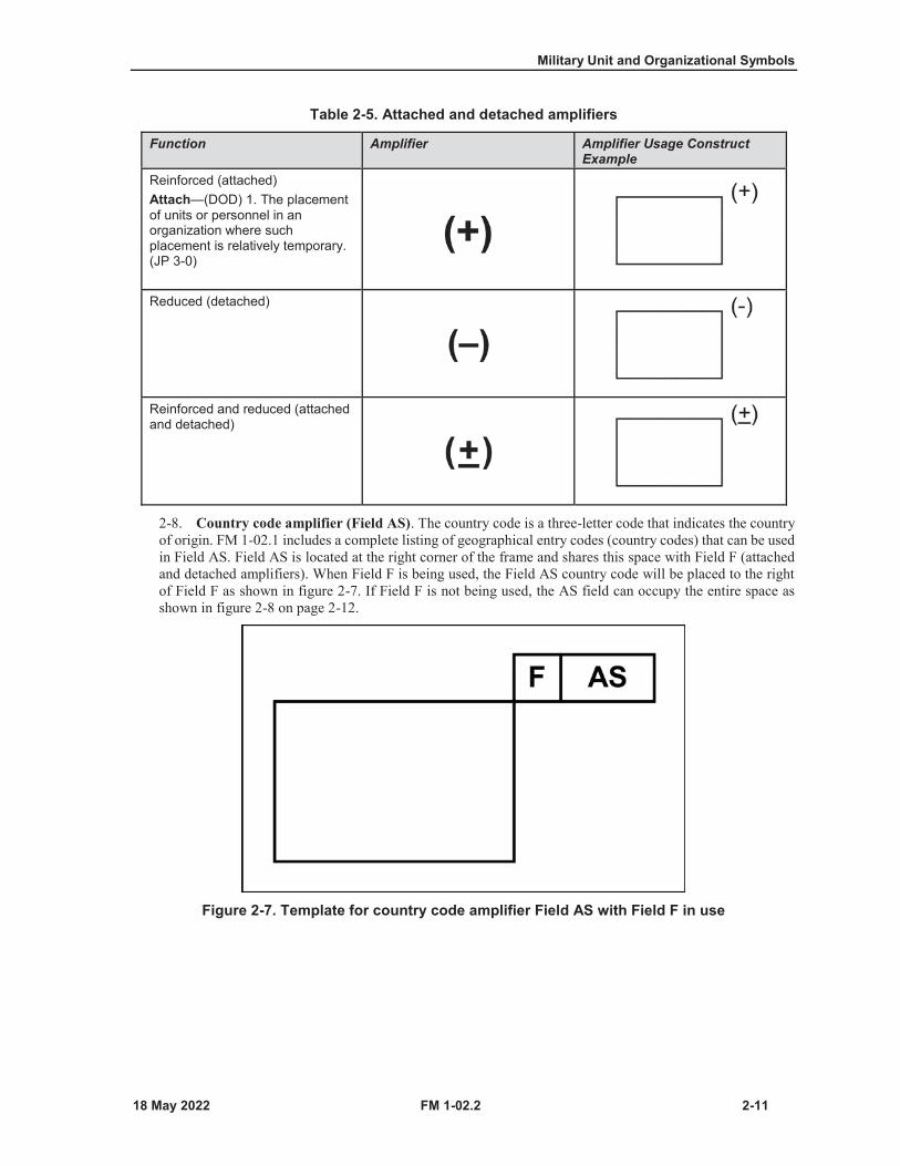
Table 2-5. Attached and detached amplifiers
Function Amplifier Amplifier Usage Construct Example
Reinforced (attached)Attach—(DOD) 1. The placement of units or personnel in an organization where such placement is relatively temporary. (JP 3-0)
Reduced (detached)
Reinforced and reduced (attached and detached)
2-8. Country code amplifier (Field AS). The country code is a three-letter code that indicates the countryof origin. FM 1-02.1 includes a complete listing of geographical entry codes (country codes) that can be usedin Field AS. Field AS is located at the right corner of the frame and shares this space with Field F (attachedand detached amplifiers). When Field F is being used, the Field AS country code will be placed to the rightof Field F as shown in figure 2-7. If Field F is not being used, the AS field can occupy the entire space asshown in figure 2-8 on page 2-12.
Figure 2-7. Template for country code amplifier Field AS with Field F in use

Chapter 2
2-12 FM 1-02.2
Figure 2-8. Template for country code amplifier Field AS without Field F usage
2-9. Command post using staff comments amplifier (Field G). A command post is a unit headquarterswhere the commander and staff perform their activities. The headquarters staff indicator (Field S) is alwaysused in conjunction with the command post and command group amplifiers. Figure 2-9 shows the templatefor the command post using amplifier Field G, and table 2-6 provides amplifier usage examples.
Figure 2-9. Template for command post using amplifier Field G

Military Unit and Organizational Symbols
FM 1-02.2 2-13
Table 2-6. Command post amplifier Field G usage examples
Description Amplifier Amplifier Usage ExampleCombat trains command post—controls and coordinates administrative and logistic support. (See ATP 6-0.5 for more information on combat trains.) CTCP
Early-entry command post—Alead element of a headquarters designed to control operations until the remaining portions of the headquarters are deployed and operational. (FM 6-0) EECP
Field trains command post—Afacility containing a personnel administration center, elements of the S-4 (battalion or brigade logistics staff officer) sustainment staff section, elements of company supply sections, and elements of the forward support company. (See ATP 6-0.5 for more information on field trains.)
FTCP
Main command post—A facility containing the majority of the staff designed to control current operations, conduct detailed analysis, and plan future operations. (FM 6-0) MAIN
Tactical command post—Afacility containing a tailored portion of a unit headquarters designed to control portions of an operation for a limited time. (FM 6-0) TAC
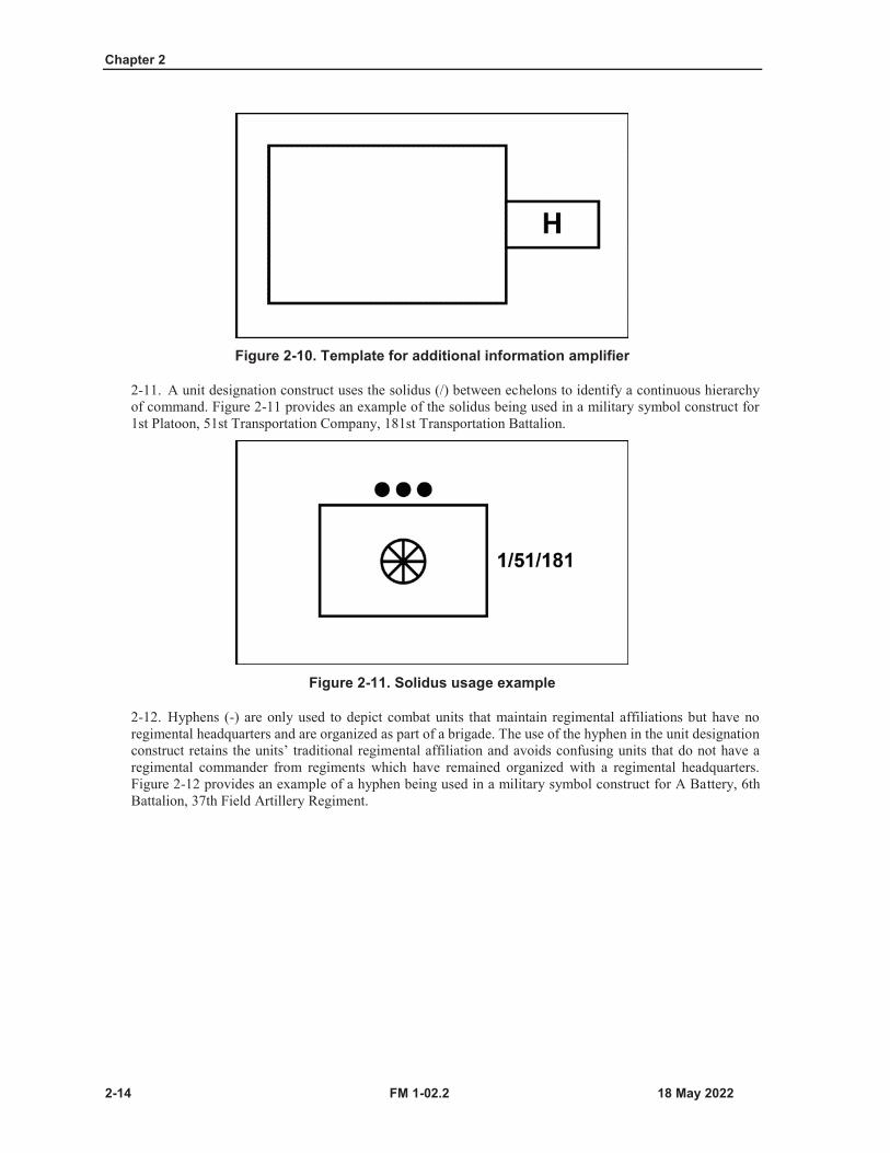
2-10. Alphanumeric unit designations using additional information amplifier (Field H). Thealphanumeric unit designation identifies the unit displayed, and it may consist of a number consistent withthe unit designation, function, and a higher echelon chain of command. The unit designation construct beginswith the unit’s own designation (number, or letter, or acronym), followed by a higher echelon commanddesignation. Figure 2-10 on page 2-14 shows the template.
Chapter 2
2-14 FM 1-02.2
Figure 2-10. Template for additional information amplifier
2-11. A unit designation construct uses the solidus (/) between echelons to identify a continuous hierarchyof command. Figure 2-11 provides an example of the solidus being used in a military symbol construct for1st Platoon, 51st Transportation Company, 181st Transportation Battalion.
Figure 2-11. Solidus usage example
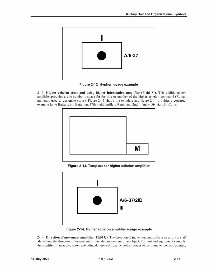
2-12. Hyphens (-) are only used to depict combat units that maintain regimental affiliations but have noregimental headquarters and are organized as part of a brigade. The use of the hyphen in the unit designationconstruct retains the units’ traditional regimental affiliation and avoids confusing units that do not have aregimental commander from regiments which have remained organized with a regimental headquarters.Figure 2-12 provides an example of a hyphen being used in a military symbol construct for A Battery, 6thBattalion, 37th Field Artillery Regiment.
Military Unit and Organizational Symbols
FM 1-02.2 2-15
Figure 2-12. Hyphen usage example
2-13. Higher echelon command using higher information amplifier (Field M). This additional textamplifier provides a unit symbol a space for the title or number of the higher echelon command (Romannumerals used to designate corps). Figure 2-13 shows the template and figure 2-14 provides a constructexample for A Battery, 6th Battalion, 37th Field Artillery Regiment, 2nd Infantry Division, III Corps.
Figure 2-13. Template for higher echelon amplifier
Figure 2-14. Higher echelon amplifier usage example
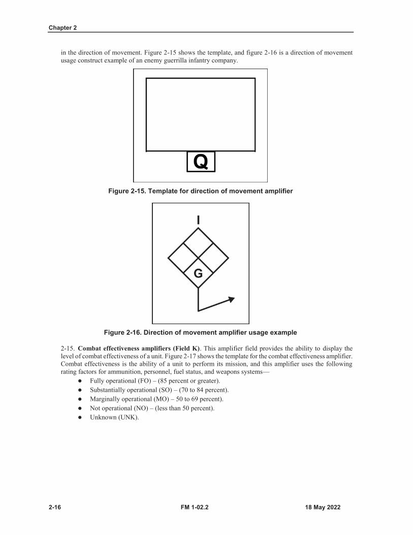
2-14. Direction of movement amplifier (Field Q). The direction of movement amplifier is an arrow or staffidentifying the direction of movement or intended movement of an object. For unit and equipment symbols,the amplifier is an angled arrow extending downward from the bottom center of the frame or icon and pointing
Chapter 2
2-16 FM 1-02.2
in the direction of movement. Figure 2-15 shows the template, and figure 2-16 is a direction of movement usage construct example of an enemy guerrilla infantry company.
Figure 2-15. Template for direction of movement amplifier
Figure 2-16. Direction of movement amplifier usage example
2-15. Combat effectiveness amplifiers (Field K). This amplifier field provides the ability to display thelevel of combat effectiveness of a unit. Figure 2-17 shows the template for the combat effectiveness amplifier.Combat effectiveness is the ability of a unit to perform its mission, and this amplifier uses the followingrating factors for ammunition, personnel, fuel status, and weapons systems—
Fully operational (FO) – (85 percent or greater).Substantially operational (SO) – (70 to 84 percent).Marginally operational (MO) – 50 to 69 percent).Not operational (NO) – (less than 50 percent).Unknown (UNK).
Military Unit and Organizational Symbols
FM 1-02.2 2-17
Figure 2-17. Template for combat effectiveness amplifier
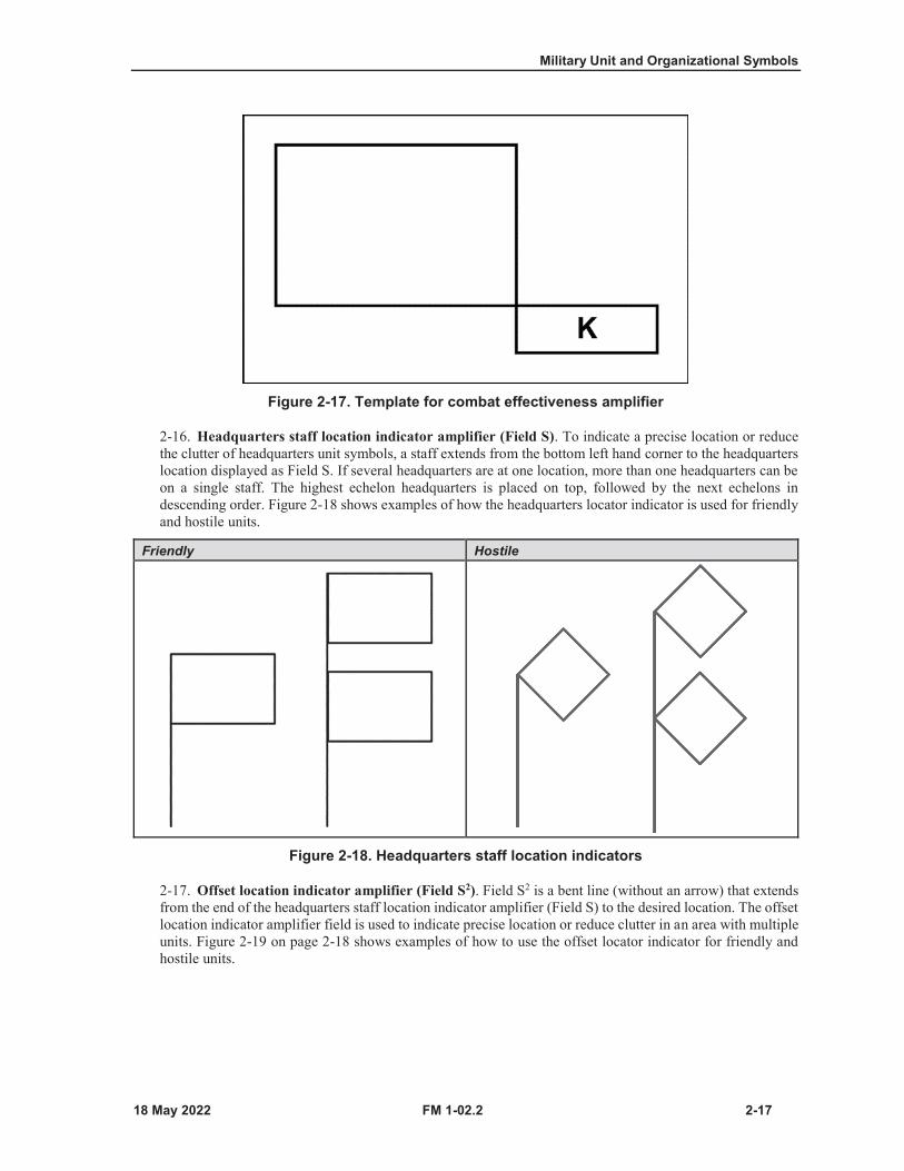
2-16. Headquarters staff location indicator amplifier (Field S). To indicate a precise location or reducethe clutter of headquarters unit symbols, a staff extends from the bottom left hand corner to the headquarterslocation displayed as Field S. If several headquarters are at one location, more than one headquarters can beon a single staff. The highest echelon headquarters is placed on top, followed by the next echelons indescending order. Figure 2-18 shows examples of how the headquarters locator indicator is used for friendlyand hostile units.
Friendly Hostile
Figure 2-18. Headquarters staff location indicators
2-17. Offset location indicator amplifier (Field S2). Field S2 is a bent line (without an arrow) that extendsfrom the end of the headquarters staff location indicator amplifier (Field S) to the desired location. The offsetlocation indicator amplifier field is used to indicate precise location or reduce clutter in an area with multipleunits. Figure 2-19 on page 2-18 shows examples of how to use the offset locator indicator for friendly andhostile units.

Chapter 2
2-18 FM 1-02.2
Friendly Hostile
Figure 2-19. Offset location indicators
MAIN ICONS FOR UNITS2-18. Most U.S. Army main icons for units were determined by table of organization and equipment andmodified table of organization and equipment descriptions in the Force Management System of the U.S.Army Force Management Support Agency. This section also includes a limited number of North AtlanticTreaty Organization (NATO) and civil authority main icons.
2-19. Main icon (Field A). The main icon is located in the center sector of the octagon and reflects the mainfunction of the symbol (see table 1-5 on page 1-8). Table 2-7 (on pages 2-19 through 2-34 shows the mainicons for units.

Military Unit and Organizational Symbols
FM 1-02.2 2-19
Table 2-7. Main icons for units
Function Icon Main Icon Usage Construct Example and Symbol Translation
Command and ControlCyberspace operations—The employment of cyberspace capabilities where the primary purpose is to achieve objectives in or through cyberspace. (JP 3-0)
CYBCyberspace brigade
Electronic warfare—Military action involving the use of electromagnetic and directed energy to control the electromagnetic spectrum or to attack the enemy. (See ADP 3-0for more information on electronic warfare).Note. EW stands for electromagnetic warfare.
EWElectromagnetic warfare company
Information operations—The integrated employment, during military operations, of information-related capabilities in concert with other lines of operation to influence, disrupt, corrupt, or usurp the decision-making of adversaries and potential adversaries while protecting our own. (JP 3-13)
IOInformation operations team
Interpreter or translator—The capability to translate orally for parties conversing in different languages, and turn documents into one’s own or other language.
Interpreter or translator teamIsolated personnel—United States military, Department of Defense civilians, and contractor personnel (and others designated by the Present or Secretary of Defense) who are separated from their unit (as an individual or a group) while participating in a United States sponsored military activity or mission and are, or may be, in a situation where they must survive, evade, resist, or escape. (JP 3-50)
Isolated squad
Chapter 2
2-20 FM 1-02.2
Table 2-7. Main icons for units (continued)
Function Icon Main Icon Usage Construct Example and Symbol Translation
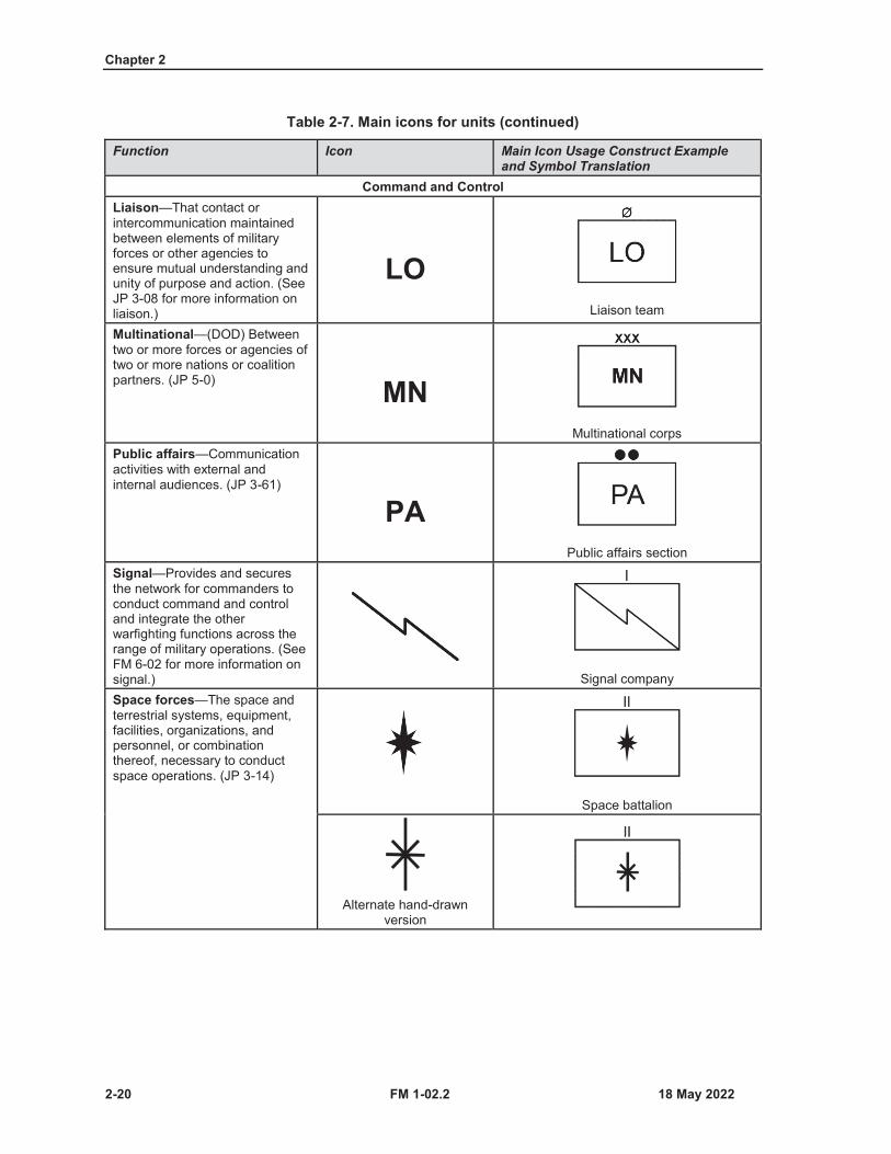
Command and ControlLiaison—That contact or intercommunication maintained between elements of military forces or other agencies to ensure mutual understanding and unity of purpose and action. (See JP 3-08 for more information on liaison.)
LOLiaison team
Multinational—(DOD) Between two or more forces or agencies of two or more nations or coalition partners. (JP 5-0) MN
Multinational corpsPublic affairs—Communication activities with external and internal audiences. (JP 3-61)
PAPublic affairs section
Signal—Provides and secures the network for commanders to conduct command and control and integrate the other warfighting functions across the range of military operations. (See FM 6-02 for more information on signal.) Signal companySpace forces—The space and terrestrial systems, equipment, facilities, organizations, and personnel, or combination thereof, necessary to conduct space operations. (JP 3-14)
Space battalion
Alternate hand-drawn version
Military Unit and Organizational Symbols
FM 1-02.2 2-21
Table 2-7. Main icons for units (continued)
Function Icon Main Icon Usage Construct Example and Symbol Translation
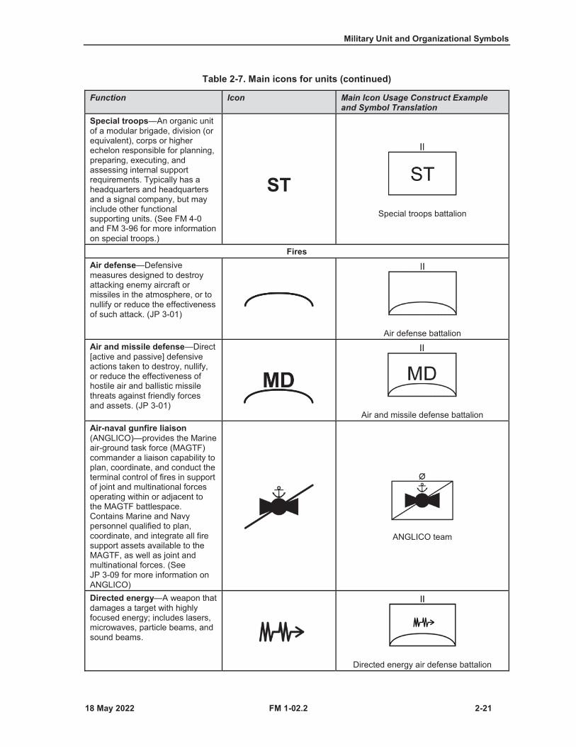
Special troops—An organic unit of a modular brigade, division (or equivalent), corps or higher echelon responsible for planning, preparing, executing, and assessing internal support requirements. Typically has a headquarters and headquarters and a signal company, but may include other functional supporting units. (See FM 4-0and FM 3-96 for more information on special troops.)
STSpecial troops battalion
FiresAir defense—Defensive measures designed to destroy attacking enemy aircraft or missiles in the atmosphere, or to nullify or reduce the effectiveness of such attack. (JP 3-01)
Air defense battalionAir and missile defense—Direct [active and passive] defensive actions taken to destroy, nullify, or reduce the effectiveness of hostile air and ballistic missile threats against friendly forces and assets. (JP 3-01)
Air and missile defense battalionAir-naval gunfire liaison (ANGLICO)—provides the Marine air-ground task force (MAGTF) commander a liaison capability to plan, coordinate, and conduct the terminal control of fires in support of joint and multinational forces operating within or adjacent to the MAGTF battlespace. Contains Marine and Navy personnel qualified to plan, coordinate, and integrate all fire support assets available to the MAGTF, as well as joint and multinational forces. (See JP 3-09 for more information on ANGLICO)
ANGLICO team
Directed energy—A weapon that damages a target with highly focused energy; includes lasers, microwaves, particle beams, and sound beams.
Directed energy air defense battalion
Chapter 2
2-22 FM 1-02.2
Table 2-7. Main icons for units (continued)
Function Icon Main Icon Usage Construct Example and Symbol Translation
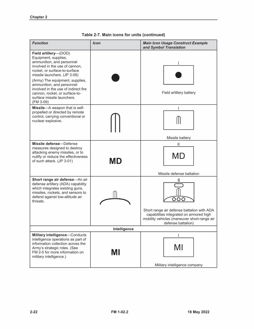
Field artillery—(DOD) Equipment, supplies, ammunition, and personnel involved in the use of cannon, rocket, or surface-to-surface missile launchers. (JP 3-09)(Army) The equipment, supplies, ammunition, and personnel involved in the use of indirect fire cannon, rocket, or surface-to-surface missile launchers. (FM 3-09)
Field artillery battery
Missile—A weapon that is self-propelled or directed by remote control, carrying conventional or nuclear explosive.
Missile batteryMissile defense—Defense measures designed to destroy attacking enemy missiles, or to nullify or reduce the effectiveness of such attack. (JP 3-01) MD
Missile defense battalionShort range air defense—An air defense artillery (ADA) capability which integrates existing guns, missiles, rockets, and sensors to defend against low-altitude air threats.
Short range air defense battalion with ADA capabilities integrated on armored high
mobility vehicles (maneuver short-range air defense battalion)
IntelligenceMilitary intelligence—Conducts intelligence operations as part of information collection across the Army’s strategic roles. (See FM 2-0 for more information on military intelligence.)
MIMilitary intelligence company
Military Unit and Organizational Symbols
FM 1-02.2 2-23
Table 2-7. Main icons for units (continued)
Function Icon Main Icon Usage Construct Example and Symbol Translation
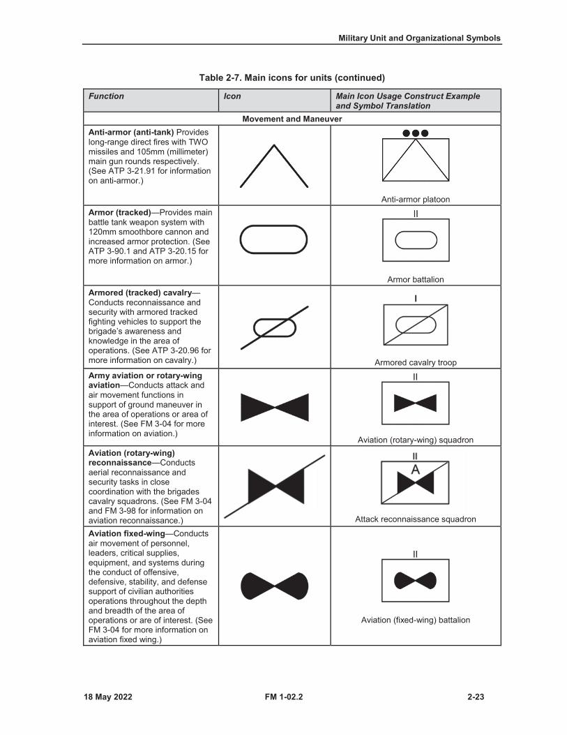
Movement and ManeuverAnti-armor (anti-tank) Provideslong-range direct fires with TWO missiles and 105mm (millimeter) main gun rounds respectively. (See ATP 3-21.91 for information on anti-armor.)
Anti-armor platoonArmor (tracked)—Provides main battle tank weapon system with 120mm smoothbore cannon and increased armor protection. (See ATP 3-90.1 and ATP 3-20.15 for more information on armor.)
Armor battalionArmored (tracked) cavalry—Conducts reconnaissance and security with armored tracked fighting vehicles to support the brigade’s awareness andknowledge in the area of operations. (See ATP 3-20.96 for more information on cavalry.) Armored cavalry troopArmy aviation or rotary-wing aviation—Conducts attack and air movement functions in support of ground maneuver in the area of operations or area of interest. (See FM 3-04 for more information on aviation.)
Aviation (rotary-wing) squadronAviation (rotary-wing) reconnaissance—Conducts aerial reconnaissance and security tasks in close coordination with the brigades cavalry squadrons. (See FM 3-04and FM 3-98 for information on aviation reconnaissance.) Attack reconnaissance squadron
Aviation fixed-wing—Conducts air movement of personnel, leaders, critical supplies, equipment, and systems during the conduct of offensive, defensive, stability, and defense support of civilian authorities operations throughout the depth and breadth of the area of operations or are of interest. (See FM 3-04 for more information on aviation fixed wing.)
Aviation (fixed-wing) battalion

Chapter 2
2-24 FM 1-02.2
Table 2-7. Main icons for units (continued)
Function Icon Main Icon Usage Construct Example and Symbol Translation
Cavalry (reconnaissance)—Conducts reconnaissance and security to support friendly forces awareness and knowledge in the area of operations. (See FM 3-98and ATP 3-20.96 for more information on cavalry reconnaissance.) Cavalry platoonCombined arms—Combines theefforts of armor units and mechanized infantry units to execute tactical missions as part of a combined arms operation. (See ATP 3-90.5 and ATP 3-90.1 for more information on combined arms.) Combined arms battalionInfantry—Provides Soldiers trained, armed, and equipped to fight dismounted by means of fire and movement in order to destroy, defeat, capture, or repel an enemy assault. (See ATP 3-21.20 for more information on infantry.) Infantry battalionMechanized armored (tracked) infantry—Provides armored tracked fighting vehicles to transport and support Soldiers trained, armed, and equipped to fight dismounted by means of fire and movement. (See ATP 3-90.5 and ATP 3-90.1 for more information on mechanized infantry.)
Mechanized armored infantry company
Mobile gun system—A Stryker brigade combat team asset that provides precise long-range direct fire in support of infantry and cavalry units. (See ATP 3-21.21 and ATP 3-21.91 for more information on mobile gun system.)Note. This main icon is placed about 1/8 from the left edge of the inside of the frame.
Mobile gun system platoon with armored high mobility vehicle capability
Mortar—Organic fire support to battalions, squadrons, companies, and troops, and are available to a commander when other indirect fire support is not available. (See ATP 3-21.90 for more information on mortars.)
Mortar section
Military Unit and Organizational Symbols
FM 1-02.2 2-25
Table 2-7. Main icons for units (continued)
Function Icon Main Icon Usage Construct Example and Symbol Translation
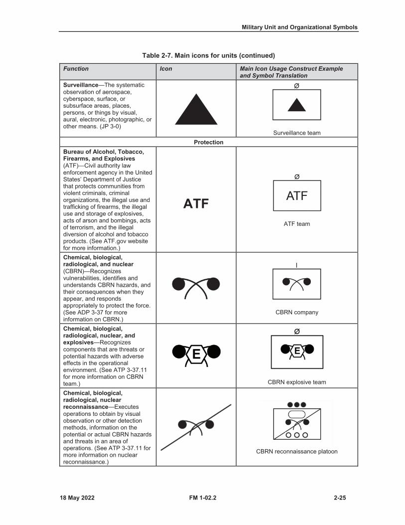
Surveillance—The systematic observation of aerospace, cyberspace, surface, or subsurface areas, places, persons, or things by visual, aural, electronic, photographic, or other means. (JP 3-0)
Surveillance teamProtection
Bureau of Alcohol, Tobacco, Firearms, and Explosives(ATF)—Civil authority law enforcement agency in the United States’ Department of Justice that protects communities from violent criminals, criminal organizations, the illegal use and trafficking of firearms, the illegal use and storage of explosives, acts of arson and bombings, acts of terrorism, and the illegal diversion of alcohol and tobacco products. (See ATF.gov website for more information.)
ATFATF team
Chemical, biological, radiological, and nuclear(CBRN)—Recognizes vulnerabilities, identifies and understands CBRN hazards, and their consequences when they appear, and responds appropriately to protect the force. (See ADP 3-37 for more information on CBRN.)
CBRN company
Chemical, biological, radiological, nuclear, and explosives—Recognizes components that are threats or potential hazards with adverse effects in the operational environment. (See ATP 3-37.11 for more information on CBRN team.) CBRN explosive team
Chemical, biological, radiological, nuclearreconnaissance—Executes operations to obtain by visual observation or other detection methods, information on the potential or actual CBRN hazards and threats in an area of operations. (See ATP 3-37.11 for more information on nuclear reconnaissance.)
CBRN reconnaissance platoon
Chapter 2
2-26 FM 1-02.2
Table 2-7. Main icons for units (continued)
Function Icon Main Icon Usage Construct Example and Symbol Translation
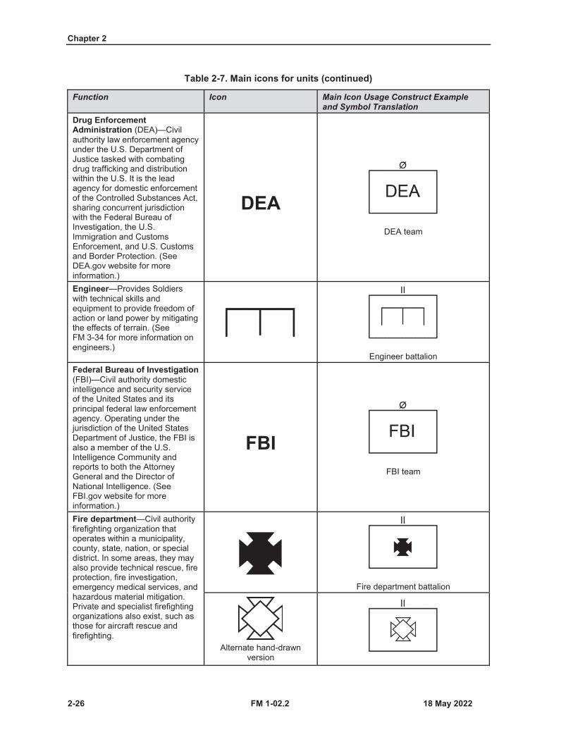
Drug Enforcement Administration (DEA)—Civil authority law enforcement agency under the U.S. Department of Justice tasked with combating drug trafficking and distribution within the U.S. It is the lead agency for domestic enforcement of the Controlled Substances Act, sharing concurrent jurisdiction with the Federal Bureau of Investigation, the U.S. Immigration and Customs Enforcement, and U.S. Customs and Border Protection. (See DEA.gov website for more information.)
DEADEA team
Engineer—Provides Soldiers with technical skills and equipment to provide freedom ofaction or land power by mitigating the effects of terrain. (See FM 3-34 for more information on engineers.)
Engineer battalionFederal Bureau of Investigation(FBI)—Civil authority domestic intelligence and security service of the United States and its principal federal law enforcement agency. Operating under the jurisdiction of the United States Department of Justice, the FBI is also a member of the U.S. Intelligence Community and reports to both the Attorney General and the Director of National Intelligence. (See FBI.gov website for more information.)
FBIFBI team
Fire department—Civil authority firefighting organization that operates within a municipality, county, state, nation, or special district. In some areas, they may also provide technical rescue, fire protection, fire investigation, emergency medical services, and hazardous material mitigation. Private and specialist firefighting organizations also exist, such as those for aircraft rescue and firefighting.
Fire department battalion
Alternate hand-drawn version
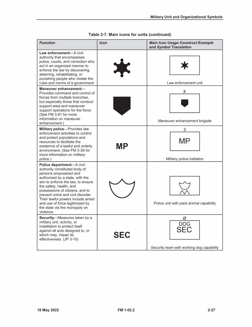
Military Unit and Organizational Symbols
FM 1-02.2 2-27
Table 2-7. Main icons for units (continued)
Function Icon Main Icon Usage Construct Example and Symbol Translation
Law enforcement—A civil authority that encompasses police, courts, and correction who act in an organized manner to enforce the law by discovering, deterring, rehabilitating, or punishing people who violate the rules and norms of a government. Law enforcement unitManeuver enhancement—Provides command and control of forces from multiple branches, but especially those that conduct support area and maneuver support operations for the force. (See FM 3-81 for more information on maneuver enhancement.) Maneuver enhancement brigade
Military police—Provides law enforcement activities to control and protect populations andresources to facilitate the existence of a lawful and orderly environment. (See FM 3-39 for more information on military police.)
MPMilitary police battalion
Police department—A civil authority constituted body of persons empowered and authorized by a state, with the aim to enforce the law, to ensure the safety, health, and possessions of citizens, and to prevent crime and civil disorder. Their lawful powers include arrest and use of force legitimized by the state via the monopoly on violence.
Police unit with pack animal capability
Security—Measures taken by a military unit, activity, or installation to protect itself against all acts designed to, or which may, impair its effectiveness. (JP 3-10)
SECSecurity team with working dog capability
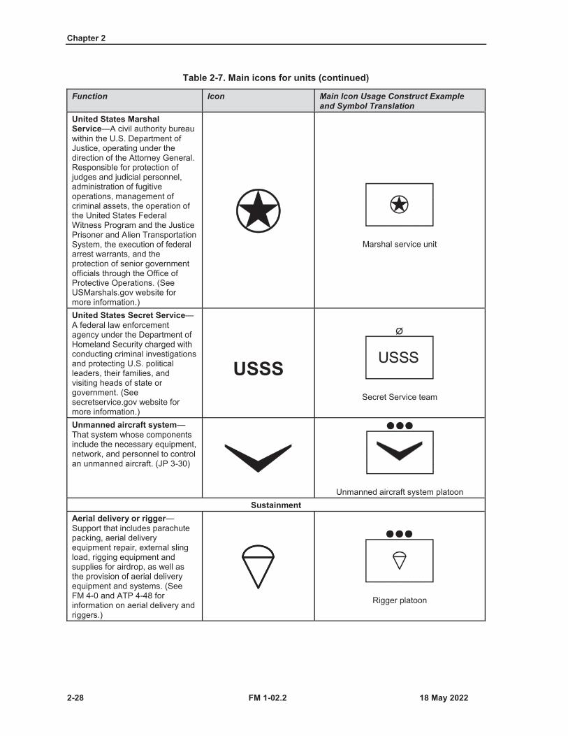
Chapter 2
2-28 FM 1-02.2
Table 2-7. Main icons for units (continued)
Function Icon Main Icon Usage Construct Example and Symbol Translation
United States Marshal Service—A civil authority bureau within the U.S. Department of Justice, operating under the direction of the Attorney General.Responsible for protection of judges and judicial personnel, administration of fugitive operations, management of criminal assets, the operation of the United States Federal Witness Program and the Justice Prisoner and Alien Transportation System, the execution of federal arrest warrants, and the protection of senior government officials through the Office ofProtective Operations. (See USMarshals.gov website for more information.)
Marshal service unit
United States Secret Service—A federal law enforcement agency under the Department of Homeland Security charged with conducting criminal investigations and protecting U.S. political leaders, their families, and visiting heads of state or government. (See secretservice.gov website for more information.)
USSSSecret Service team
Unmanned aircraft system—That system whose components include the necessary equipment, network, and personnel to control an unmanned aircraft. (JP 3-30)
Unmanned aircraft system platoonSustainment
Aerial delivery or rigger—Support that includes parachute packing, aerial delivery equipment repair, external sling load, rigging equipment and supplies for airdrop, as well as the provision of aerial delivery equipment and systems. (See FM 4-0 and ATP 4-48 for information on aerial delivery and riggers.)
Rigger platoon

Military Unit and Organizational Symbols
FM 1-02.2 2-29
Table 2-7. Main icons for units (continued)
Function Icon Main Icon Usage Construct Example and Symbol Translation
Army field support—Integrates and synchronizes delivery of U.S. Army Materiel Command strategic capabilities and enablers to the operational and tactical points of need in support of Army Service component commands and corps during large-scale combat operations. (See FM 4-0 for more information on Army field support.)
AFSArmy field support brigade
Ammunition—Provides effective and efficient handling, storing, securing, distributing, andaccounting for munitions while ensuring adequate explosives safety guidelines are met. (See FM 4-30 for more information on ammunition.) Ammunition platoonContracting support—Provides support contracting services, along with contracting advice and assistance, primarily to Army forces and to joint forces when directed, and is organized along functional lines. (See ATP 4-71for more information on contracting support.)
KSContracting support team
Explosive ordnance disposal—(DOD) The detection, identification, on-side evaluation, rendering safe, exploitation, recovery, and final disposal of explosive ordnance. (JP 3-34)(Army) The detection, identification, on-side evaluation, rendering safe, exploitation, recovery, and final disposal of explosive ordnance. (FM 4-30)
EODExplosive ordnance disposal (EOD) team
Finance—Provides timely commercial vendor services and contractual payments, various pay and disbursing services, and oversight and management of the Army’s banking program. (See FM 1-06 and FM 4-0 for more information on finance.) Finance platoon
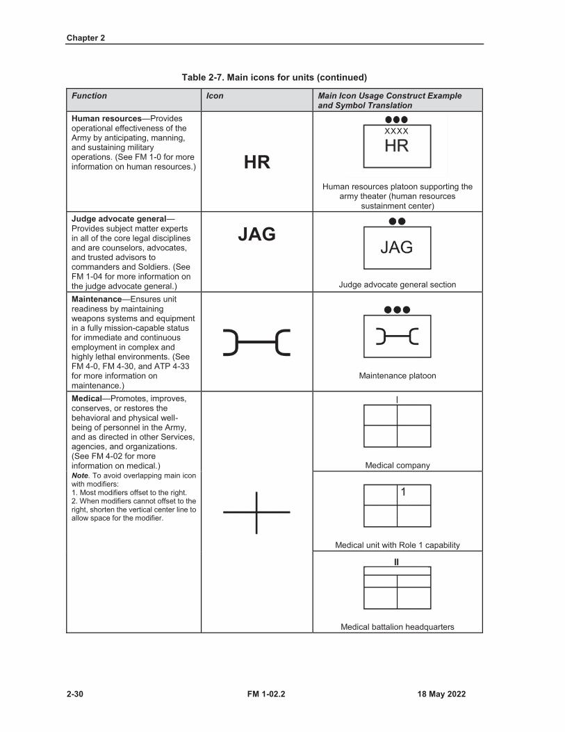
Chapter 2
2-30 FM 1-02.2
Table 2-7. Main icons for units (continued)
Function Icon Main Icon Usage Construct Example and Symbol Translation
Human resources—Provides operational effectiveness of the Army by anticipating, manning, and sustaining military operations. (See FM 1-0 for more information on human resources.) HR
Human resources platoon supporting the army theater (human resources
sustainment center)Judge advocate general—Provides subject matter experts in all of the core legal disciplines and are counselors, advocates, and trusted advisors to commanders and Soldiers. (See FM 1-04 for more information on the judge advocate general.)
JAG
Judge advocate general section
Maintenance—Ensures unit readiness by maintaining weapons systems and equipment in a fully mission-capable statusfor immediate and continuous employment in complex and highly lethal environments. (See FM 4-0, FM 4-30, and ATP 4-33 for more information on maintenance.)
Maintenance platoon
Medical—Promotes, improves, conserves, or restores the behavioral and physical well-being of personnel in the Army, and as directed in other Services, agencies, and organizations. (See FM 4-02 for more information on medical.)Note. To avoid overlapping main icon with modifiers:1. Most modifiers offset to the right.2. When modifiers cannot offset to theright, shorten the vertical center line toallow space for the modifier.
Medical company
Medical unit with Role 1 capability
Medical battalion headquarters

Military Unit and Organizational Symbols
FM 1-02.2 2-31
Table 2-7. Main icons for units (continued)
Function Icon Main Icon Usage Construct Example and Symbol Translation
Medical treatment facility—(joint) A facility established for the purpose of furnishing medical and/or dental care to eligible individuals. (JP 4-02)(Army) Any facility established for the purpose of providing medical treatment. This includes battalion aid stations, Role 2 facilities, dispensaries, clinics, and hospitals. (FM 4-02)Note. To avoid overlapping main icon with modifiers:1. Most modifiers offset to the right.2. When modifiers cannot offset to theright, shorten the vertical center line toallow space for the modifier.
Medical treatment facility company
Medical treatment facility platoon with Role 3 surgical capability
Mortuary affairs—Provides for the search, recovery, identification, preparation, and disposition of human remains of persons for whom the Services are responsible by status and executive order. (JP 4-0)
Mortuary affairs platoonBand—Serves as a combat multiplier and plays an integral part in the sustainment of forces engaged in unified land operations. (See ATP 1-19 for more information on the band.)
Band performance headquarters detachment
Alternate hand-drawn version
Ordnance—Provides munitions, maintenance, and explosive ordnance disposal support to generate and maintain combat power and to provide protection to Army, joint, intergovernmental, interagency, and multinational forces. (See FM 4-30 for more information on ordnance.) Ordnance company
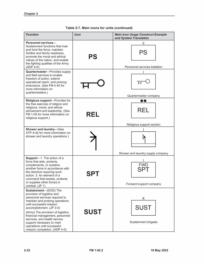
Chapter 2
2-32 FM 1-02.2
Table 2-7. Main icons for units (continued)
Function Icon Main Icon Usage Construct Example and Symbol Translation
Personnel services—Sustainment functions that man and fund the force, maintain Soldier and family readiness, promote the moral and ethical values of the nation, and enable the fighting qualities of the Army. (ADP 4-0)
PSPersonnel services battalion
Quartermaster—Provides supply and field services to enable freedom of action, extend operational reach, and prolong endurance. (See FM 4-40 for more information on quartermasters.)
Quartermaster companyReligious support—Provides for the free exercise of religion and religious, moral, and ethical advisement and leadership. (See FM 1-05 for more information on religious support.)
RELReligious support section
Shower and laundry—(See ATP 4-42 for more information on shower and laundry operations.)
Shower and laundry supply companySupport—1. The action of a force that aids, protects, complements, or sustains another force in accordance with the directive requiring such action. 3. An element of a command that assists, protects, or supplies other forces in combat. (JP 1)
SPTForward support company
Sustainment—(DOD) The provision of logistics and personnel services required to maintain and prolong operationsuntil successful mission accomplishment. (JP 3-0)(Army) The provision of logistics, financial management, personnel services, and health service support necessary to main operations until successful mission completion. (ADP 4-0)
SUSTSustainment brigade
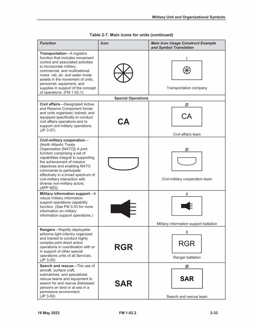
Military Unit and Organizational Symbols
FM 1-02.2 2-33
Table 2-7. Main icons for units (continued)
Function Icon Main Icon Usage Construct Example and Symbol Translation
Transportation—A logistics function that includes movement control and associated activities to incorporate military, commercial, and multinational motor, rail, air, and water mode assets in the movement of units, personnel, equipment, and supplies in support of the concept of operations. (FM 1-02.1)
Transportation company
Special OperationsCivil affairs—Designated Active and Reserve Component forces and units organized, trained, and equipped specifically to conduct civil affairs operations and to support civil-military operations. (JP 3-57)
CACivil affairs team
Civil-military cooperation—(North Atlantic Treaty Organization [NATO]) A joint function comprising a set of capabilities integral to supporting the achievement of mission objectives and enabling NATO commands to participate effectively in a broad spectrum of civil-military interaction with diverse non-military actors.(APP 6[D])
Civil-military cooperation team
Military information support—Arobust military information support operations capability function. (See FM 3-53 for more information on military information support operations.)
Military information support battalionRangers—Rapidly deployable airborne light infantry organized and trained to conduct highly complex joint direct action operations in coordination with or in support of other special operations units of all Services. (JP 3-05)
RGRRanger battalion
Search and rescue—The use of aircraft, surface craft, submarines, and specialized rescue teams and equipment to search for and rescue distressed persons on land or at sea in a permissive environment. (JP 3-50)
SARSearch and rescue team
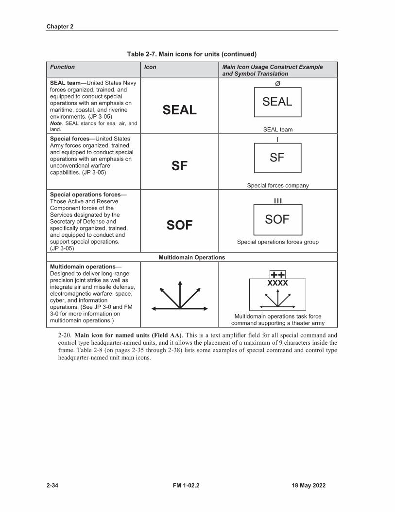
Chapter 2
2-34 FM 1-02.2
Table 2-7. Main icons for units (continued)
Function Icon Main Icon Usage Construct Example and Symbol Translation
SEAL team—United States Navy forces organized, trained, and equipped to conduct special operations with an emphasis on maritime, coastal, and riverine environments. (JP 3-05)Note. SEAL stands for sea, air, and land.
SEALSEAL team
Special forces—United States Army forces organized, trained, and equipped to conduct special operations with an emphasis on unconventional warfare capabilities. (JP 3-05)
SFSpecial forces company
Special operations forces—Those Active and Reserve Component forces of the Services designated by the Secretary of Defense and specifically organized, trained, and equipped to conduct and support special operations. (JP 3-05)
SOFSpecial operations forces group
Multidomain OperationsMultidomain operations—Designed to deliver long-range precision joint strike as well as integrate air and missile defense, electromagnetic warfare, space, cyber, and information operations. (See JP 3-0 and FM 3-0 for more information onmultidomain operations.)
Multidomain operations task force command supporting a theater army
2-20. Main icon for named units (Field AA). This is a text amplifier field for all special command andcontrol type headquarter-named units, and it allows the placement of a maximum of 9 characters inside theframe. Table 2-8 (on pages 2-35 through 2-38) lists some examples of special command and control typeheadquarter-named unit main icons.
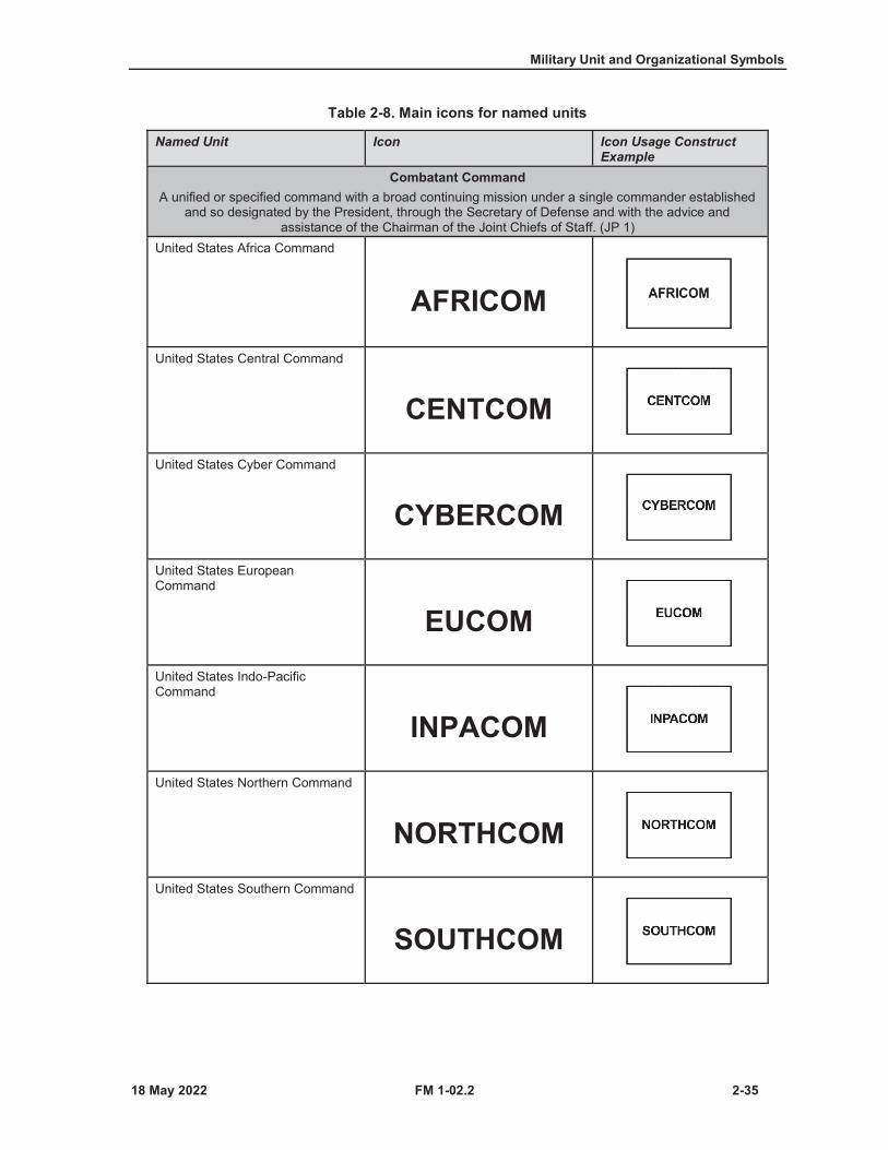
Military Unit and Organizational Symbols
FM 1-02.2 2-35
Table 2-8. Main icons for named units
Named Unit Icon Icon Usage Construct Example
Combatant CommandA unified or specified command with a broad continuing mission under a single commander established
and so designated by the President, through the Secretary of Defense and with the advice and assistance of the Chairman of the Joint Chiefs of Staff. (JP 1)
United States Africa Command
AFRICOMUnited States Central Command
CENTCOMUnited States Cyber Command
CYBERCOMUnited States European Command
EUCOMUnited States Indo-Pacific Command
INPACOMUnited States Northern Command
NORTHCOMUnited States Southern Command
SOUTHCOM
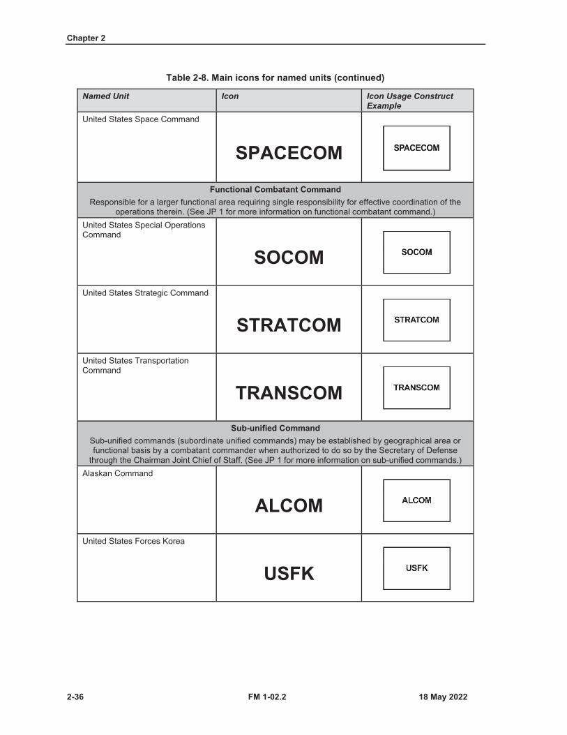
Chapter 2
2-36 FM 1-02.2
Table 2-8. Main icons for named units (continued)
Named Unit Icon Icon Usage Construct Example
United States Space Command
SPACECOMFunctional Combatant Command
Responsible for a larger functional area requiring single responsibility for effective coordination of the operations therein. (See JP 1 for more information on functional combatant command.)
United States Special Operations Command
SOCOMUnited States Strategic Command
STRATCOMUnited States Transportation Command
TRANSCOMSub-unified Command
Sub-unified commands (subordinate unified commands) may be established by geographical area or functional basis by a combatant commander when authorized to do so by the Secretary of Defense
through the Chairman Joint Chief of Staff. (See JP 1 for more information on sub-unified commands.) Alaskan Command
ALCOMUnited States Forces Korea
USFK

Military Unit and Organizational Symbols
FM 1-02.2 2-37
Table 2-8. Main icons for named units (continued)
Named Unit Icon Icon Usage Construct Example
United States Army, Africa Command
USARAFUnited States Army, Central Command
USARCENTUnited States Army, Cyber Command
ARCYBERUnited States Army, Military Surface Deployment and Distribution Command
SDDCUnited States Army, North
USANORTHUnited States Army, Pacific Command
USARPACUnited States Army, Southern Command
USARSO
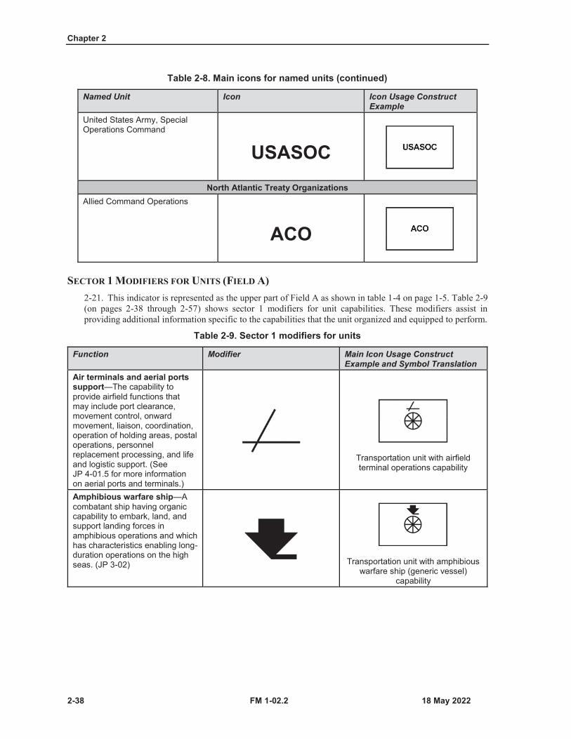
Chapter 2
2-38 FM 1-02.2
Table 2-8. Main icons for named units (continued)
Named Unit Icon Icon Usage Construct Example
United States Army, Special Operations Command
USASOCNorth Atlantic Treaty Organizations
Allied Command Operations
ACO
SECTOR 1 MODIFIERS FOR UNITS (FIELD A)2-21. This indicator is represented as the upper part of Field A as shown in table 1-4 on page 1-5. Table 2-9(on pages 2-38 through 2-57) shows sector 1 modifiers for unit capabilities. These modifiers assist inproviding additional information specific to the capabilities that the unit organized and equipped to perform.
Table 2-9. Sector 1 modifiers for units
Function Modifier Main Icon Usage Construct Example and Symbol Translation
Air terminals and aerial ports support—The capability to provide airfield functions that may include port clearance, movement control, onward movement, liaison, coordination, operation of holding areas, postal operations, personnel replacement processing, and life and logistic support. (See JP 4-01.5 for more information on aerial ports and terminals.)
Transportation unit with airfield terminal operations capability
Amphibious warfare ship—Acombatant ship having organic capability to embark, land, and support landing forces in amphibious operations and which has characteristics enabling long-duration operations on the high seas. (JP 3-02) Transportation unit with amphibious
warfare ship (generic vessel) capability
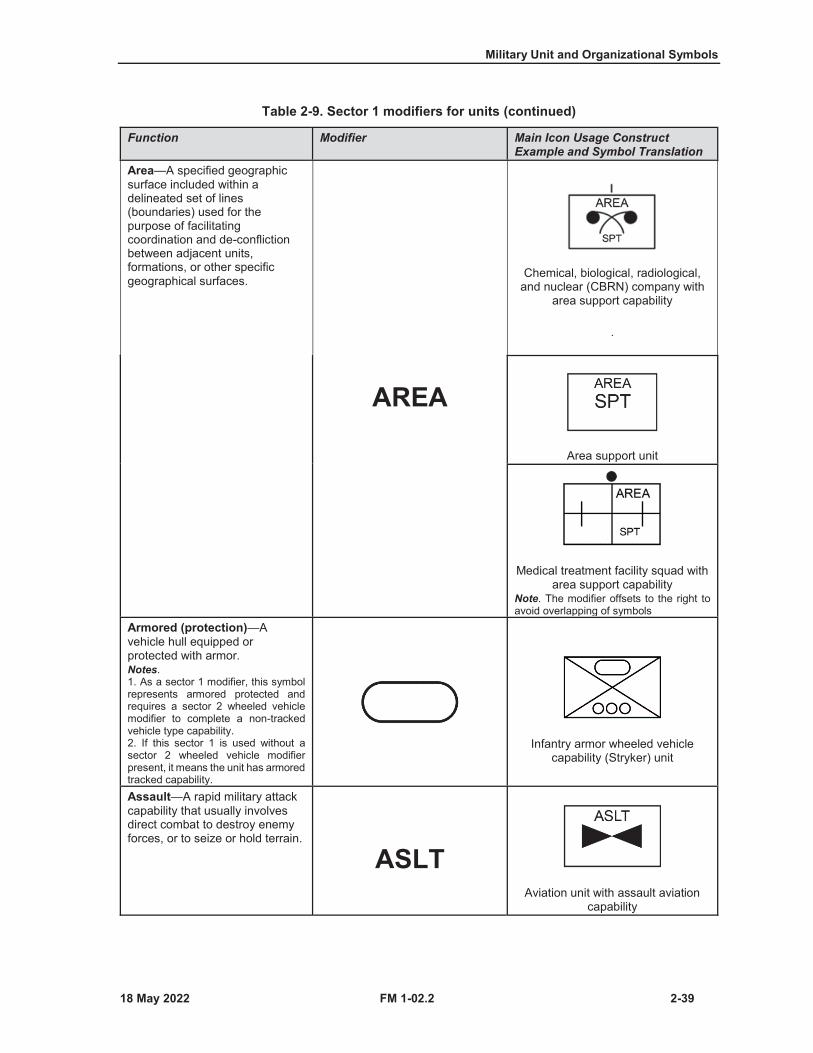
Military Unit and Organizational Symbols
FM 1-02.2 2-39
Table 2-9. Sector 1 modifiers for units (continued)
Function Modifier Main Icon Usage Construct Example and Symbol Translation
Area—A specified geographic surface included within a delineated set of lines (boundaries) used for the purpose of facilitating coordination and de-confliction between adjacent units, formations, or other specific geographical surfaces.
AREA
Chemical, biological, radiological, and nuclear (CBRN) company with
area support capability
.
Area support unit
Medical treatment facility squad with area support capability
Note. The modifier offsets to the right to avoid overlapping of symbols
Armored (protection)—Avehicle hull equipped or protected with armor.Notes.1. As a sector 1 modifier, this symbolrepresents armored protected andrequires a sector 2 wheeled vehiclemodifier to complete a non-trackedvehicle type capability.2. If this sector 1 is used without asector 2 wheeled vehicle modifierpresent, it means the unit has armoredtracked capability.
Infantry armor wheeled vehicle capability (Stryker) unit
Assault—A rapid military attack capability that usually involves direct combat to destroy enemy forces, or to seize or hold terrain.
ASLTAviation unit with assault aviation
capability

Chapter 2
2-40 FM 1-02.2
Table 2-9. Sector 1 modifiers for units (continued)
Function Modifier Main Icon Usage Construct Example and Symbol Translation
Attack—A type of offensive operation that destroys or defeats enemy forces, seizes and secures terrain, or both. (ADP 3-90) A
Aviation unit with attack helicopter capability
Army aviation or rotary-wing aviation—Conducts attack and air movement functions in support of ground maneuver in the area of operations or area of interest. (See FM 3-04 for more information on Army aviation.)
Maintenance platoon with aviation maintenance capability
Battalion (echelon of support)—Provides support to a battalion. (See ATP 3-96.1 for more information on battalion echelon of support.) II
Infantry security force assistance team supporting a battalion
Biological—Capability to detect biological warfare agent employment as a measure to provide medical treatment (See FM 3-11 for more information on biological.) A biological agent is a microorganism (or a toxin derived from it) that causes disease in personnel, plants, or animals or cause the deterioration of materiel. (JP 3-11)
BCBRN unit with biological capability
Bridging—Assets used to cross a gap; the two types of bridging are standard and nonstandard bridging. (See ATP 3-90.4 for more information on bridging.)
Engineer unit with bridging capability
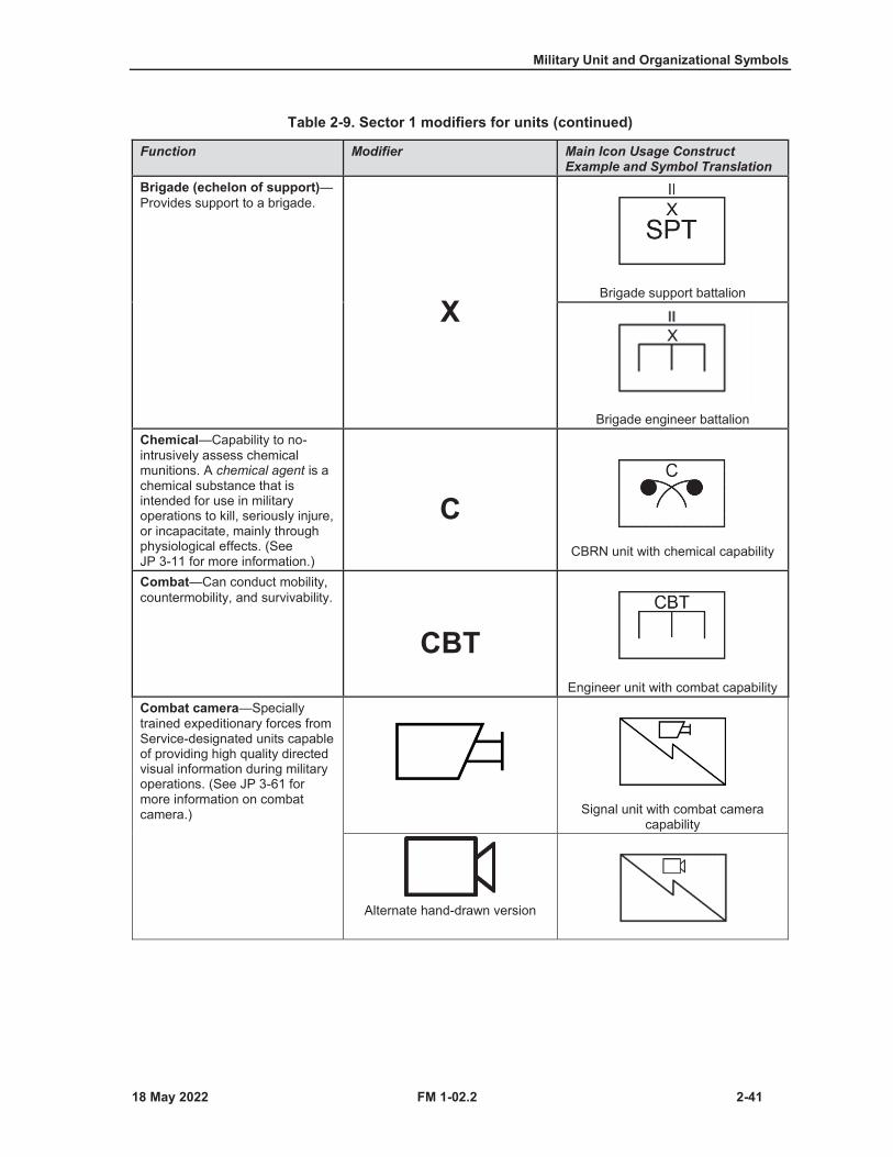
Military Unit and Organizational Symbols
FM 1-02.2 2-41
Table 2-9. Sector 1 modifiers for units (continued)
Function Modifier Main Icon Usage Construct Example and Symbol Translation
Brigade (echelon of support)—Provides support to a brigade.
XBrigade support battalion
Brigade engineer battalionChemical—Capability to no-intrusively assess chemical munitions. A chemical agent is a chemical substance that is intended for use in military operations to kill, seriously injure, or incapacitate, mainly through physiological effects. (See JP 3-11 for more information.)
CCBRN unit with chemical capability
Combat—Can conduct mobility, countermobility, and survivability.
CBTEngineer unit with combat capability
Combat camera—Specially trained expeditionary forces from Service-designated units capable of providing high quality directed visual information during military operations. (See JP 3-61 for more information on combat camera.) Signal unit with combat camera
capability
Alternate hand-drawn version
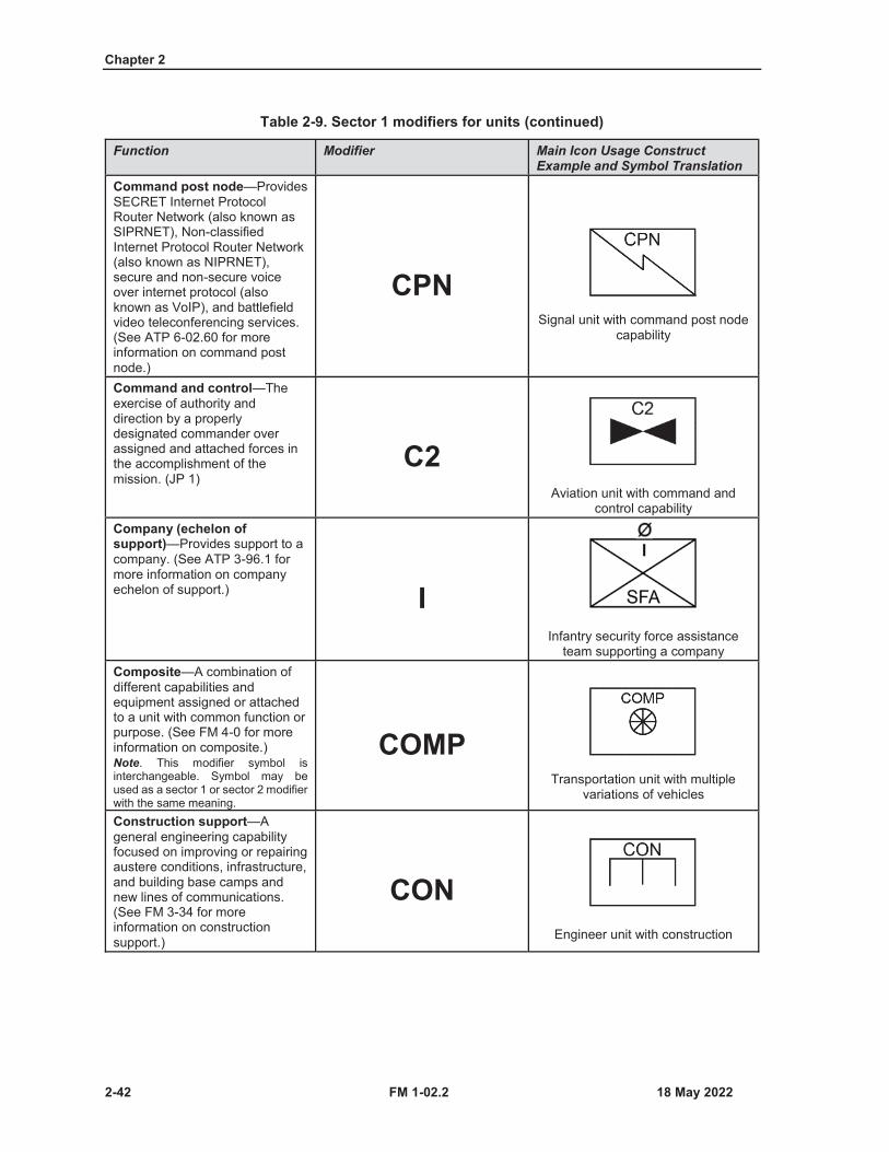
Chapter 2
2-42 FM 1-02.2
Table 2-9. Sector 1 modifiers for units (continued)
Function Modifier Main Icon Usage Construct Example and Symbol Translation
Command post node—Provides SECRET Internet Protocol Router Network (also known as SIPRNET), Non-classifiedInternet Protocol Router Network (also known as NIPRNET), secure and non-secure voice over internet protocol (also known as VoIP), and battlefield video teleconferencing services. (See ATP 6-02.60 for more information on command post node.)
CPNSignal unit with command post node
capability
Command and control—The exercise of authority and direction by a properly designated commander over assigned and attached forces in the accomplishment of the mission. (JP 1)
C2Aviation unit with command and
control capabilityCompany (echelon of support)—Provides support to a company. (See ATP 3-96.1 for more information on company echelon of support.) I
Infantry security force assistance team supporting a company
Composite—A combination of different capabilities and equipment assigned or attached to a unit with common function or purpose. (See FM 4-0 for more information on composite.) Note. This modifier symbol is interchangeable. Symbol may be used as a sector 1 or sector 2 modifier with the same meaning.
COMPTransportation unit with multiple
variations of vehicles
Construction support—Ageneral engineering capability focused on improving or repairing austere conditions, infrastructure, and building base camps andnew lines of communications. (See FM 3-34 for more information on construction support.)
CONEngineer unit with construction
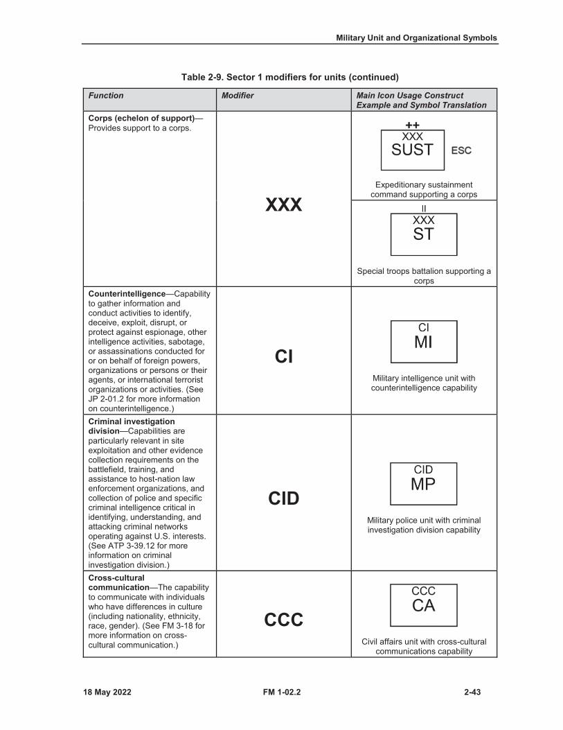
Military Unit and Organizational Symbols
FM 1-02.2 2-43
Table 2-9. Sector 1 modifiers for units (continued)
Function Modifier Main Icon Usage Construct Example and Symbol Translation
Corps (echelon of support)—Provides support to a corps.
XXXExpeditionary sustainment
command supporting a corps
Special troops battalion supporting a corps
Counterintelligence—Capability to gather information and conduct activities to identify, deceive, exploit, disrupt, or protect against espionage, other intelligence activities, sabotage, or assassinations conducted for or on behalf of foreign powers, organizations or persons or their agents, or international terrorist organizations or activities. (See JP 2-01.2 for more information on counterintelligence.)
CIMilitary intelligence unit with counterintelligence capability
Criminal investigation division—Capabilities are particularly relevant in site exploitation and other evidence collection requirements on the battlefield, training, and assistance to host-nation law enforcement organizations, and collection of police and specific criminal intelligence critical in identifying, understanding, and attacking criminal networks operating against U.S. interests. (See ATP 3-39.12 for more information on criminal investigation division.)
CIDMilitary police unit with criminal investigation division capability
Cross-cultural communication—The capability to communicate with individuals who have differences in culture (including nationality, ethnicity, race, gender). (See FM 3-18 for more information on cross-cultural communication.)
CCCCivil affairs unit with cross-cultural
communications capability
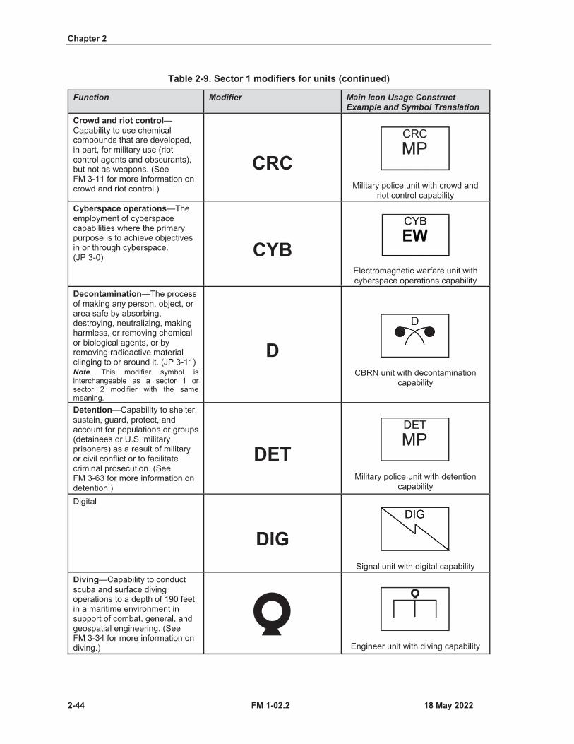
Chapter 2
2-44 FM 1-02.2
Table 2-9. Sector 1 modifiers for units (continued)
Function Modifier Main Icon Usage Construct Example and Symbol Translation
Crowd and riot control—Capability to use chemical compounds that are developed, in part, for military use (riot control agents and obscurants), but not as weapons. (See FM 3-11 for more information on crowd and riot control.)
CRCMilitary police unit with crowd and
riot control capabilityCyberspace operations—The employment of cyberspace capabilities where the primary purpose is to achieve objectives in or through cyberspace. (JP 3-0) CYB
Electromagnetic warfare unit with cyberspace operations capability
Decontamination—The process of making any person, object, or area safe by absorbing, destroying, neutralizing, making harmless, or removing chemical or biological agents, or by removing radioactive material clinging to or around it. (JP 3-11)Note. This modifier symbol is interchangeable as a sector 1 or sector 2 modifier with the same meaning.
DCBRN unit with decontamination
capability
Detention—Capability to shelter, sustain, guard, protect, and account for populations or groups (detainees or U.S. military prisoners) as a result of military or civil conflict or to facilitate criminal prosecution. (See FM 3-63 for more information on detention.)
DETMilitary police unit with detention
capability
Digital
DIGSignal unit with digital capability
Diving—Capability to conduct scuba and surface diving operations to a depth of 190 feet in a maritime environment in support of combat, general, and geospatial engineering. (See FM 3-34 for more information on diving.) Engineer unit with diving capability

Military Unit and Organizational Symbols
FM 1-02.2 2-45
Table 2-9. Sector 1 modifiers for units (continued)
Function Modifier Main Icon Usage Construct Example and Symbol Translation
Division (echelon of support)—Provides support to a division.
XXSustainment brigade supporting a
divisionDog (working dog)—A canine capability that enhances security, police operations, and force protection missions (including counter improvised explosive device operations and assured mobility). (See ATP 3-39.34 for more information on working dogs.)
DOGMilitary police unit with working dog
capability
Drilling—Capability to detect and assess water sources and drilling water wells. (See FM 3-34for more information on drilling.)
Engineer unit with drilling capabilityElectromagnetic warfare—Military action involving the use of electromagnetic and directed energy to control the electromagnetic spectrum or toattack the enemy. (See ADP 3-0for more information on electromagnetic warfare.)Note. EW stands for electromagnetic warfare.
EWCyberspace unit with
electromagnetic warfare capability
Electric power production—Capability to produce electrical power by converting fuels or other energy sources to electricity. (See ATP 3-34.45 for more information on electric power production.) Engineer platoon with electric
generation capabilityEnhanced—Provides network installation, troubleshooting, quality assurance testing, and handoff coordination to enable the transition from tactical to semi-permanent automation support. (See FM 6-02 for more information on enhanced.)
ENHSignal unit with enhanced capability
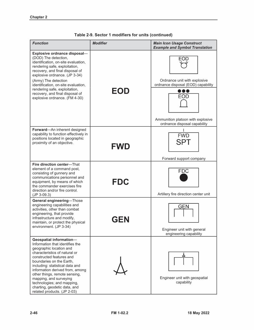
Chapter 2
2-46 FM 1-02.2
Table 2-9. Sector 1 modifiers for units (continued)
Function Modifier Main Icon Usage Construct Example and Symbol Translation
Explosive ordnance disposal—(DOD) The detection, identification, on-site evaluation, rendering safe, exploitation, recovery, and final disposal of explosive ordnance. (JP 3-34)(Army) The detection identification, on-site evaluation, rendering safe, exploitation, recovery, and final disposal of explosive ordnance. (FM 4-30)
EODOrdnance unit with explosive
ordnance disposal (EOD) capability
Ammunition platoon with explosive ordnance disposal capability
Forward—An inherent designed capability to function effectively in positions located in geographic proximity of an objective. FWD
Forward support companyFire direction center—That element of a command post, consisting of gunnery and communications personnel and equipment, by means of which the commander exercises fire direction and/or fire control. (JP 3-09.3)
FDCArtillery fire direction center unit
General engineering—Those engineering capabilities and activities, other than combat engineering, that provide infrastructure and modify, maintain, or protect the physical environment. (JP 3-34)
GENEngineer unit with general
engineering capabilityGeospatial information—Information that identifies the geographic location and characteristics of natural or constructed features and boundaries on the Earth, including: statistical data andinformation derived from, among other things, remote sensing, mapping, and surveying technologies; and mapping, charting, geodetic data, andrelated products. (JP 2-03)
Engineer unit with geospatial capability
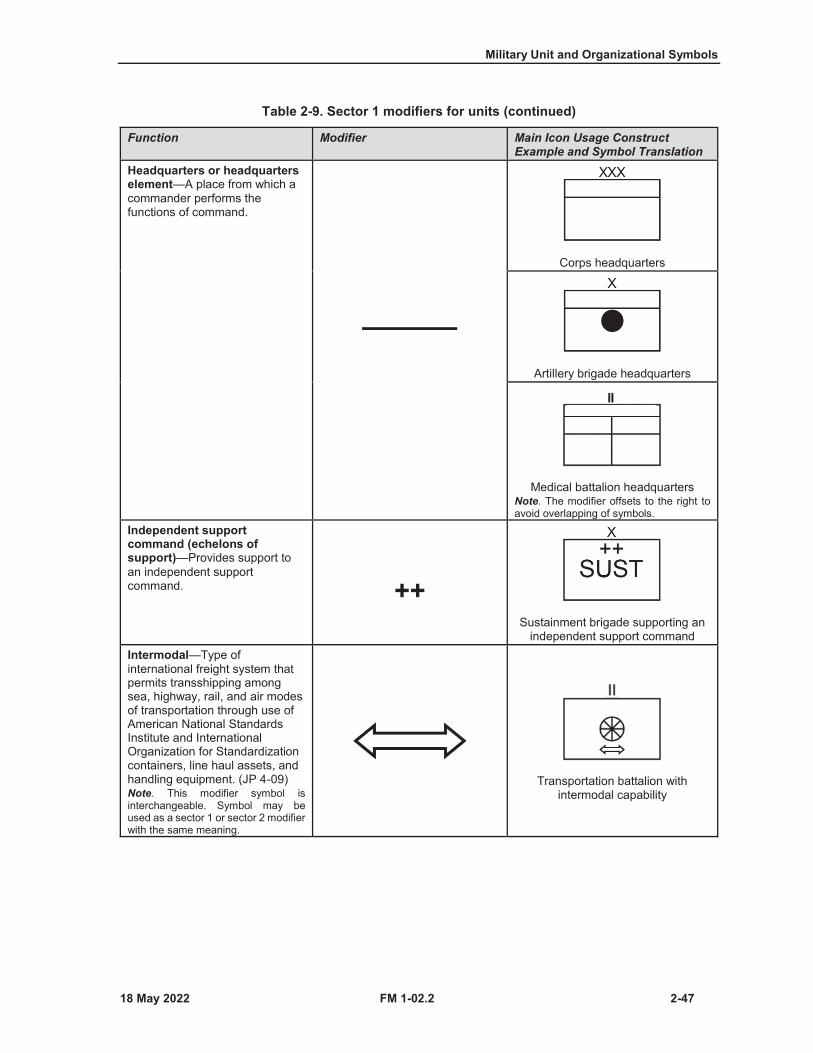
Military Unit and Organizational Symbols
FM 1-02.2 2-47
Table 2-9. Sector 1 modifiers for units (continued)
Function Modifier Main Icon Usage Construct Example and Symbol Translation
Headquarters or headquarters element—A place from which a commander performs the functions of command.
Corps headquarters
Artillery brigade headquarters
Medical battalion headquartersNote. The modifier offsets to the right to avoid overlapping of symbols.
Independent support command (echelons of support)—Provides support to an independent support command. ++
Sustainment brigade supporting an independent support command
Intermodal—Type of international freight system that permits transshipping among sea, highway, rail, and air modes of transportation through use of American National Standards Institute and International Organization for Standardization containers, line haul assets, and handling equipment. (JP 4-09)Note. This modifier symbol is interchangeable. Symbol may beused as a sector 1 or sector 2 modifier with the same meaning.
Transportation battalion with intermodal capability

Chapter 2
2-48 FM 1-02.2
Table 2-9. Sector 1 modifiers for units (continued)
Function Modifier Main Icon Usage Construct Example and Symbol Translation
Jamming—Capability to broadcast a signal tuned to frequencies with enough power to override signals at the receivers (spot jamming or barrage jamming). (See ATP 6-02.70 for more information on jamming.)Note. This modifier symbol is interchangeable as a sector 1 or sector 2 modifier with the same meaning.
Signal unit with jamming capabilityNote. To avoid overlapping of symbols, shorten the line of main icon to allow space for the modifiers.
Joint node network—Provides connection to the regional hub node, uses a dedicated frequency division multiple access satellite communications link, and shares bandwidth among command post nodes using network centric waveform satellite communications. (See ATP 6-02.60 for more information on the joint node network.)
JNNSignal unit with joint node network
capability
Maintenance—Ensures unit readiness by maintaining weapons systems and equipment in a fully mission-capable status for immediate and continuous employment in complex and highly lethal environments. (See FM 4-0 and ATP 4-33 for more information on maintenance.)Note. This modifier is interchangeable as a sector 1 or sector 2 modifier with the same meaning.
Aviation unit with organic maintenance capability
Medical evacuation—The timely and effective movement of the wounded, injured, or ill to and between medical treatment facilities on dedicated and properly marked medical platforms with en route care provided by medical personnel. (ATP 4-02.2)
Aviation unit with medical evacuation capability
Medical unit with wheeled high mobility vehicle medical evacuation
capabilityNote. The modifier offsets to the right to avoid overlapping of symbols.
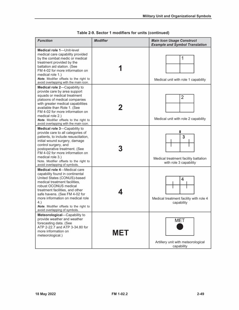
Military Unit and Organizational Symbols
FM 1-02.2 2-49
Table 2-9. Sector 1 modifiers for units (continued)
Function Modifier Main Icon Usage Construct Example and Symbol Translation
Medical role 1—Unit-level medical care capability provided by the combat medic or medical treatment provided by the battalion aid station. (See FM 4-02 for more information on medical role 1.)Note. Modifier offsets to the right to avoid overlapping with the main icon.
1Medical unit with role 1 capability
Medical role 2—Capability to provide care by area support squads or medical treatment platoons of medical companies with greater medical capabilities available than Role 1. (See FM 4-02 for more information on medical role 2.)Note. Modifier offsets to the right to avoid overlapping with the main icon.
2Medical unit with role 2 capability
Medical role 3—Capability to provide care to all categories of patients, to include resuscitation, initial wound surgery, damage control surgery, and postoperative treatment. (See FM 4-02 for more information on medical role 3.)Note. Modifier offsets to the right to avoid overlapping of symbols.
3Medical treatment facility battalion
with role 3 capability
Medical role 4—Medical care capability found in continental United States (CONUS)-based medical treatment facilities, robust OCONUS medical treatment facilities, and other safe havens. (See FM 4-02 for more information on medical role4.)Note. Modifier offsets to the right to avoid overlapping of symbols.
4Medical treatment facility with role 4
capability
Meteorological—Capability to provide weather and weather forecasting data. (See ATP 2-22.7 and ATP 3-34.80 for more information on meteorological.) MET
Artillery unit with meteorological capability

Chapter 2
2-50 FM 1-02.2
Table 2-9. Sector 1 modifiers for units (continued)
Function Modifier Main Icon Usage Construct Example and Symbol Translation
Multidomain operations—Designed to deliver long-range precision joint strike as well as integrate air and missile defense, electromagnetic warfare, space, cyber, and information operations. (See JP 3-0 and FM 3-0 for more information onmultidomain operations.)
Long-range artillery battery with multidomain capabilities
Watercraft (generic vessel)—Capability to conduct heavy lifting associated with water transport operational maneuver and intra-theater lift of units, equipment, and supplies. (See ATP 4-15 for more information on watercraft.)Note. This modifier symbol is interchangeable. Symbol may be used as a sector 1 or sector 2 modifierwith the same meaning.
Transportation unit with watercraft capability
Mobile advisor and support—Capability to support, breaching operations, clearing operations, gap-crossing operations, traffic control plan development, main and alternate supply route regulation and enforcement, passage of lines, straggler movement control. (See ATP 3-39.30 for more information on mobility support.)
Transportation rail unit with mobile advisor and support capability
Mobility support—Capability to support breaching operations, clearing operations, gap-crossing operations, traffic control plan development, main and alternate supply route regulation and enforcement, passage of lines, straggler movement control. (See ATP 3-39.30 for more information on mobility support.)
MSTransportation unit with mobility
support capability
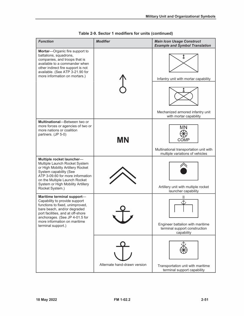
Military Unit and Organizational Symbols
FM 1-02.2 2-51
Table 2-9. Sector 1 modifiers for units (continued)
Function Modifier Main Icon Usage Construct Example and Symbol Translation
Mortar—Organic fire support to battalions, squadrons, companies, and troops that is available to a commander when other indirect fire support is not available. (See ATP 3-21.90 for more information on mortars.)
Infantry unit with mortar capability
Mechanized armored infantry unit with mortar capability
Multinational—Between two or more forces or agencies of two or more nations or coalition partners. (JP 5-0)
MNMultinational transportation unit with
multiple variations of vehiclesMultiple rocket launcher—Multiple Launch Rocket System or High Mobility Artillery Rocket System capability (See ATP 3-09.60 for more information on the Multiple Launch Rocket System or High Mobility Artillery Rocket System.) Artillery unit with multiple rocket
launcher capabilityMaritime terminal support—Capability to provide support functions to fixed, unimproved, bare beach, and/or degraded port facilities, and at off-shore anchorages. (See JP 4-01.5 for more information on maritime terminal support.) Engineer battalion with maritime
terminal support construction capability
Alternate hand-drawn version Transportation unit with maritime terminal support capability
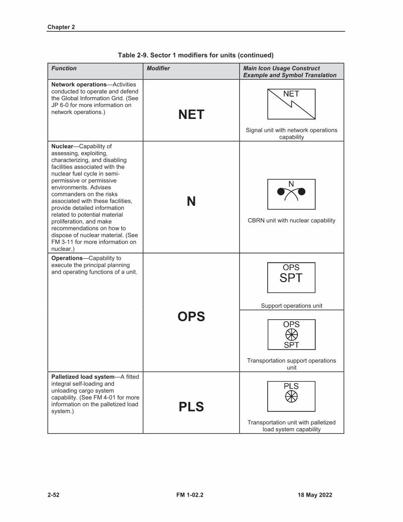
Chapter 2
2-52 FM 1-02.2
Table 2-9. Sector 1 modifiers for units (continued)
Function Modifier Main Icon Usage Construct Example and Symbol Translation
Network operations—Activities conducted to operate and defend the Global Information Grid. (See JP 6-0 for more information on network operations.) NET
Signal unit with network operations capability
Nuclear—Capability of assessing, exploiting, characterizing, and disabling facilities associated with the nuclear fuel cycle in semi-permissive or permissive environments. Advises commanders on the risks associated with these facilities, provide detailed information related to potential material proliferation, and make recommendations on how to dispose of nuclear material. (See FM 3-11 for more information on nuclear.)
NCBRN unit with nuclear capability
Operations—Capability to execute the principal planning and operating functions of a unit.
OPSSupport operations unit
Transportation support operations unit
Palletized load system—A fitted integral self-loading and unloading cargo system capability. (See FM 4-01 for more information on the palletized load system.) PLS
Transportation unit with palletized load system capability

Military Unit and Organizational Symbols
FM 1-02.2 2-53
Table 2-9. Sector 1 modifiers for units (continued)
Function Modifier Main Icon Usage Construct Example and Symbol Translation
Petroleum, oil, and lubricants (POL)—Capability to receive, stock, or distribute petroleum products. (See ATP 4-43 for more information on POL.)
Quartermaster unit with POL storage capability
Transportation unit with POL transport capability
Pipeline—A capability that consists of pipeline sets, pipeline pump stations, and pipeline support equipment. Its primary function is to transport fuel from one area to another. (See ATP 4-43 for more information on pipeline.) Quartermaster unit with pipeline
capabilityPostal service—Capability to operate as an extension of the United States Postal Service consistent with public law and federal regulations beyond the boundaries of U.S. sovereignty and provides postal services for all DOD personnel where there is no United States Postal Service available during normal and contingency operations. (See FM 1-0 and FM 4-0 for more information on postal service.)
Personnel services unit with postal service capability
Radar—A device or systemconsisting usually of a synchronized radio transmitter and receiver that emits radio waves and processes their reflections for display and is used especially for detaching and locating objects or surface features. (See ATP 3-09.12 and ATP 3-27.5 for more information on radar.)
Artillery unit with radar capability
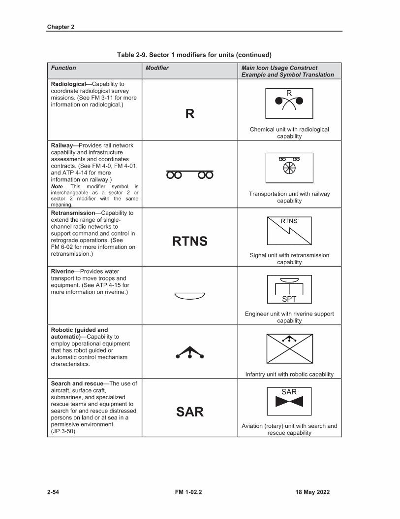
Chapter 2
2-54 FM 1-02.2
Table 2-9. Sector 1 modifiers for units (continued)
Function Modifier Main Icon Usage Construct Example and Symbol Translation
Radiological—Capability to coordinate radiological survey missions. (See FM 3-11 for more information on radiological.)
RChemical unit with radiological
capabilityRailway—Provides rail network capability and infrastructure assessments and coordinates contracts. (See FM 4-0, FM 4-01, and ATP 4-14 for more information on railway.)Note. This modifier symbol is interchangeable as a sector 2 or sector 2 modifier with the same meaning.
Transportation unit with railway capability
Retransmission—Capability to extend the range of single-channel radio networks to support command and control in retrograde operations. (See FM 6-02 for more information on retransmission.)
RTNSSignal unit with retransmission
capabilityRiverine—Provides water transport to move troops and equipment. (See ATP 4-15 for more information on riverine.)
Engineer unit with riverine support capability
Robotic (guided and automatic)—Capability to employ operational equipment that has robot guided or automatic control mechanism characteristics.
Infantry unit with robotic capabilitySearch and rescue—The use of aircraft, surface craft, submarines, and specialized rescue teams and equipment to search for and rescue distressed persons on land or at sea in a permissive environment. (JP 3-50)
SARAviation (rotary) unit with search and
rescue capability

Military Unit and Organizational Symbols
FM 1-02.2 2-55
Table 2-9. Sector 1 modifiers for units (continued)
Function Modifier Main Icon Usage Construct Example and Symbol Translation
Sensor—Capability to observe or receive a signal or observable from a person or object. (See FM 2-0 for more information on sensors.)
Electromagnetic warfare unit with sensor capability
Signals intelligence—Intelligence derived from communications, electronic, and foreign instrumentation signals. (JP 2-0)
Military intelligence unit with signals intelligence capability
Single rocket launcher (shoulder-launched munitions)—Unguided free-flight rocket and a launcher that contains all features and controls necessary to aim, fire, and engage targets. (See TM 3-23.25for more information on single rocket launchers.)
Artillery unit with single rocket launcher capability
Sniper—A specialized trained marksman with tactical skills and techniques who is highly capable at conducting detailed surveillance and shooting at exposed enemy’s forces from a concealed vantage point. (See TC 3-22.10 for more information on snipers.)
Infantry unit with sniper capability
Survey—Provides position and azimuth determining Global Positioning System capability. (See ATP 3-09.12 for more information on surveys.)

Chapter 2
2-56 FM 1-02.2
Table 2-9. Sector 1 modifiers for units (continued)
Function Modifier Main Icon Usage Construct Example and Symbol Translation
Tactical satellite communications—(See ATP 3-05.60 and ATP 6-02.54 for more information on tactical satellite communications.)
Signal unit with tactical satellite communications capability
Alternate hand-drawn version
Target acquisition—The detection, identification, and location of a target in sufficient detail to permit the effective employment of capabilities that create the required effects. (JP 3-60)
TAArtillery unit with target acquisition
capabilityTheater army (echelon of support)—Provides support to a theater army.
XXXXExpeditionary sustainment
command supporting a theater armyTheater of operations (echelon of support)—Provides support to a theater.
XXXXXXTheater sustainment command
supporting a theater of operations
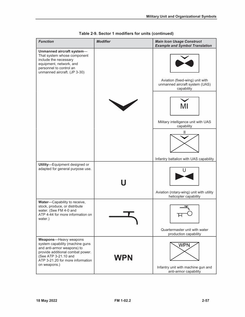
Military Unit and Organizational Symbols
FM 1-02.2 2-57
Table 2-9. Sector 1 modifiers for units (continued)
Function Modifier Main Icon Usage Construct Example and Symbol Translation
Unmanned aircraft system—That system whose component include the necessary equipment, network, and personnel to control an unmanned aircraft. (JP 3-30)
Aviation (fixed-wing) unit with unmanned aircraft system (UAS)
capability
Military intelligence unit with UAS capability
Infantry battalion with UAS capabilityUtility—Equipment designed or adapted for general purpose use.
UAviation (rotary-wing) unit with utility
helicopter capabilityWater—Capability to receive, stock, produce, or distribute water. (See FM 4-0 and ATP 4-44 for more information on water.)
Quartermaster unit with water production capability
Weapons—Heavy weapons system capability (machine guns and anti-armor weapons) to provide additional combat power.(See ATP 3-21.10 and ATP 3-21.20 for more information on weapons.)
WPNInfantry unit with machine gun and
anti-armor capability
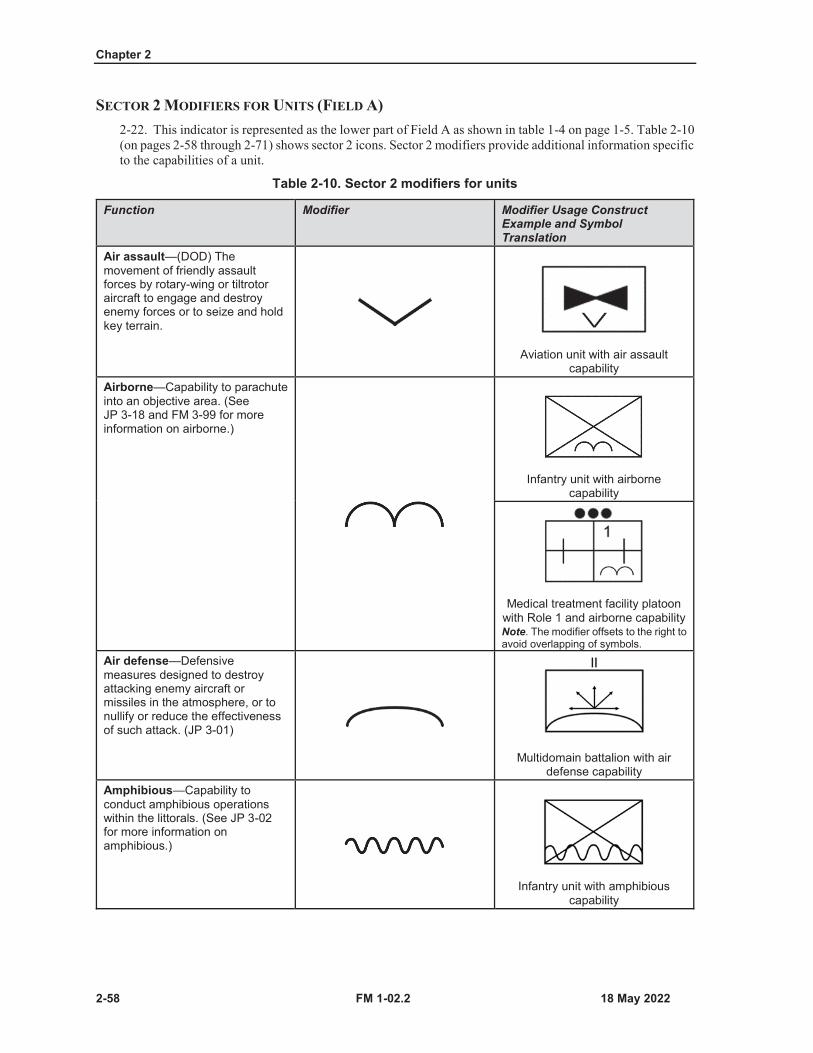
Chapter 2
2-58 FM 1-02.2
SECTOR 2 MODIFIERS FOR UNITS (FIELD A)2-22. This indicator is represented as the lower part of Field A as shown in table 1-4 on page 1-5. Table 2-10(on pages 2-58 through 2-71) shows sector 2 icons. Sector 2 modifiers provide additional information specificto the capabilities of a unit.
Table 2-10. Sector 2 modifiers for units
Function Modifier Modifier Usage Construct Example and Symbol Translation
Air assault—(DOD) The movement of friendly assault forces by rotary-wing or tiltrotor aircraft to engage and destroy enemy forces or to seize and hold key terrain.
Aviation unit with air assault capability
Airborne—Capability to parachute into an objective area. (See JP 3-18 and FM 3-99 for more information on airborne.)
Infantry unit with airborne capability
Medical treatment facility platoon with Role 1 and airborne capabilityNote. The modifier offsets to the right to avoid overlapping of symbols.
Air defense—Defensive measures designed to destroy attacking enemy aircraft or missiles in the atmosphere, or to nullify or reduce the effectiveness of such attack. (JP 3-01)
Multidomain battalion with airdefense capability
Amphibious—Capability to conduct amphibious operations within the littorals. (See JP 3-02 for more information on amphibious.)
Infantry unit with amphibious capability
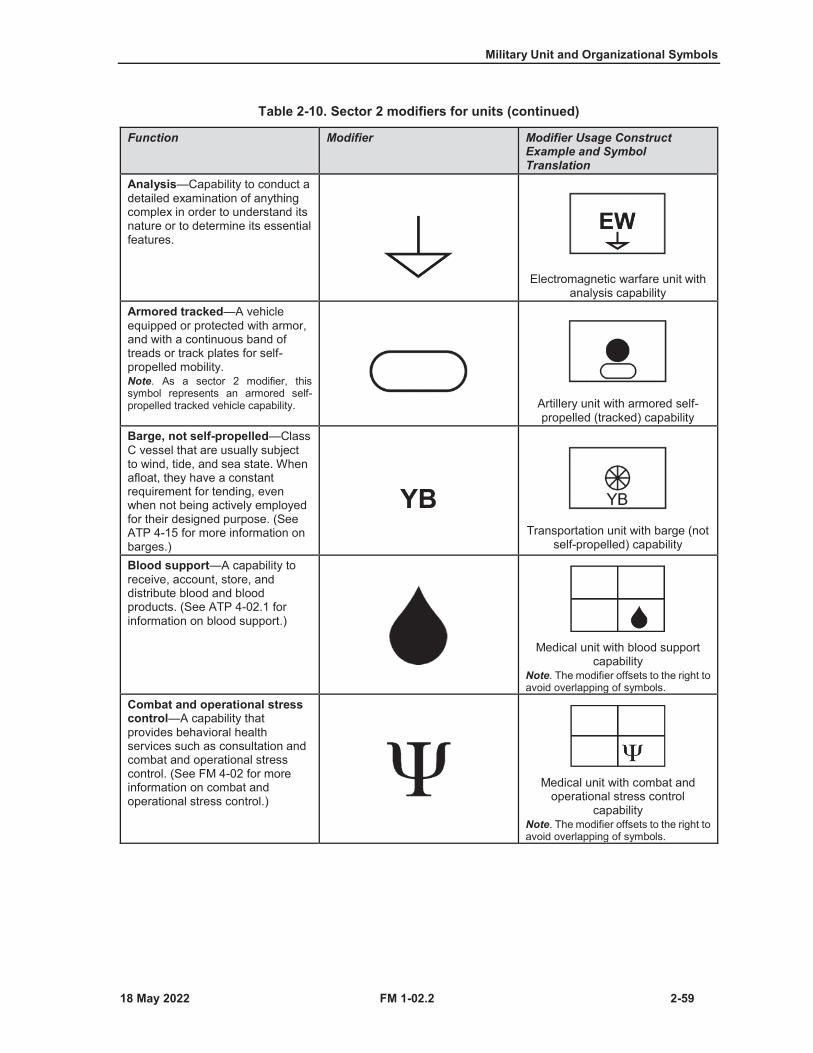
Military Unit and Organizational Symbols
FM 1-02.2 2-59
Table 2-10. Sector 2 modifiers for units (continued)
Function Modifier Modifier Usage Construct Example and Symbol Translation
Analysis—Capability to conduct a detailed examination of anything complex in order to understand its nature or to determine its essential features.
Electromagnetic warfare unit with analysis capability
Armored tracked—A vehicle equipped or protected with armor, and with a continuous band of treads or track plates for self-propelled mobility.Note. As a sector 2 modifier, this symbol represents an armored self-propelled tracked vehicle capability. Artillery unit with armored self-
propelled (tracked) capabilityBarge, not self-propelled—Class C vessel that are usually subject to wind, tide, and sea state. When afloat, they have a constant requirement for tending, even when not being actively employed for their designed purpose. (See ATP 4-15 for more information on barges.)
YBTransportation unit with barge (not
self-propelled) capability
Blood support—A capability to receive, account, store, and distribute blood and blood products. (See ATP 4-02.1 for information on blood support.)
Medical unit with blood support capability
Note. The modifier offsets to the right to avoid overlapping of symbols.
Combat and operational stress control—A capability that provides behavioral health services such as consultation and combat and operational stress control. (See FM 4-02 for more information on combat and operational stress control.)
Medical unit with combat and operational stress control
capabilityNote. The modifier offsets to the right to avoid overlapping of symbols.
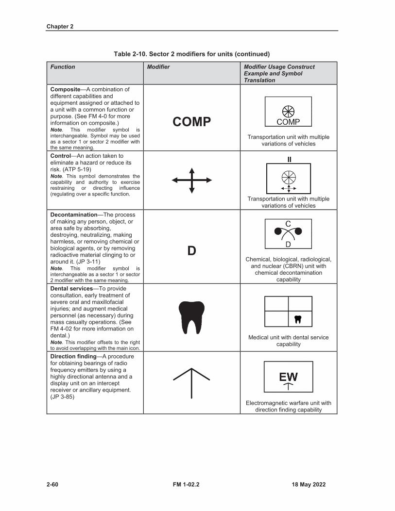
Chapter 2
2-60 FM 1-02.2
Table 2-10. Sector 2 modifiers for units (continued)
Function Modifier Modifier Usage Construct Example and Symbol Translation
Composite—A combination of different capabilities and equipment assigned or attached to a unit with a common function or purpose. (See FM 4-0 for more information on composite.)Note. This modifier symbol is interchangeable. Symbol may be used as a sector 1 or sector 2 modifier with the same meaning.
COMPTransportation unit with multiple
variations of vehicles
Control—An action taken to eliminate a hazard or reduce its risk. (ATP 5-19)Note. This symbol demonstrates the capability and authority to exercise restraining or directing influence (regulating over a specific function.
Transportation unit with multiple variations of vehicles
Decontamination—The process of making any person, object, or area safe by absorbing, destroying, neutralizing, making harmless, or removing chemical or biological agents, or by removing radioactive material clinging to or around it. (JP 3-11)Note. This modifier symbol is interchangeable as a sector 1 or sector 2 modifier with the same meaning.
DChemical, biological, radiological,
and nuclear (CBRN) unit with chemical decontamination
capabilityDental services—To provide consultation, early treatment of severe oral and maxillofacial injuries; and augment medical personnel (as necessary) during mass casualty operations. (See FM 4-02 for more information on dental.)Note. This modifier offsets to the right to avoid overlapping with the main icon.
Medical unit with dental service capability
Direction finding—A procedure for obtaining bearings of radio frequency emitters by using a highly directional antenna and a display unit on an intercept receiver or ancillary equipment. (JP 3-85)
Electromagnetic warfare unit with direction finding capability
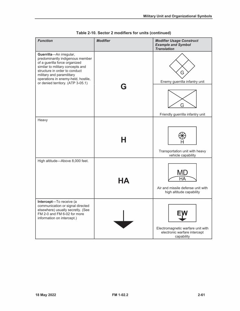
Military Unit and Organizational Symbols
FM 1-02.2 2-61
Table 2-10. Sector 2 modifiers for units (continued)
Function Modifier Modifier Usage Construct Example and Symbol Translation
Guerrilla—An irregular, predominantly indigenous member of a guerilla force organized similar to military concepts and structure in order to conduct military and paramilitary operations in enemy-held, hostile, or denied territory. (ATP 3-05.1) G
Enemy guerrilla infantry unit
Friendly guerrilla infantry unitHeavy
HTransportation unit with heavy
vehicle capabilityHigh altitude—Above 8,000 feet.
HAAir and missile defense unit with
high altitude capability
Intercept—To receive (a communication or signal directed elsewhere) usually secretly. (See FM 2-0 and FM 6-02 for more information on intercept.)
Electromagnetic warfare unit with electronic warfare intercept
capability

Chapter 2
2-62 FM 1-02.2
Table 2-10. Sector 2 modifiers for units (continued)
Function Modifier Modifier Usage Construct Example and Symbol Translation
Intermodal—Type of international freight system that permits transshipping among sea, highway, rail, and air modes of transportation through use of American National Standards Institute and International Organization for Standardization containers, line haul assets, and handling equipment. (JP 4-09)Note. This modifier symbol is interchangeable. Symbol may be used as a sector 1 or sector 2 modifier with the same meaning.
Transportation unit with intermodal capability
Jamming—Capability to broadcast a signal tuned to frequencies with enough power to override signals at the receivers (spot jamming or barrage jamming). (See ATP 6-02.70 for more information on jamming.)Note. This modifier symbol is interchangeable. Symbol may be used as a sector 1 or sector 2 modifier with the same meaning.
Electromagnetic warfare unit with jamming capability
Laboratory—A place equipped for experimental study in a science or for testing and analysis. (See FM 4-02 for more information on laboratories.)
LAB
CBRN unit with laboratory capability
Medical unit with laboratory capability
Note. The modifier offsets to the right to avoid overlapping of symbols.
Landing craft—Provides vessels (Landing Craft Utility 2000 or Landing Craft Mechanized-9) to increase access to austere points on the littorals that are unavailable to land forces, and to link ship and shore operations centers. (See ATP 4-15 for more information on landing craft.)
LCTransportation unit with landing
craft capability
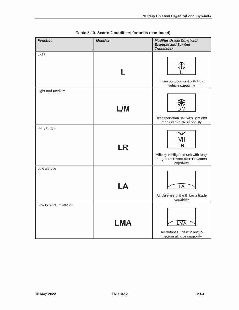
Military Unit and Organizational Symbols
FM 1-02.2 2-63
Table 2-10. Sector 2 modifiers for units (continued)
Function Modifier Modifier Usage Construct Example and Symbol Translation
Light
LTransportation unit with light
vehicle capabilityLight and medium
L/MTransportation unit with light and
medium vehicle capabilityLong range
LRMilitary intelligence unit with long-range unmanned aircraft system
capabilityLow altitude
LAAir defense unit with low altitude
capabilityLow to medium altitude
LMAAir defense unit with low to medium altitude capability
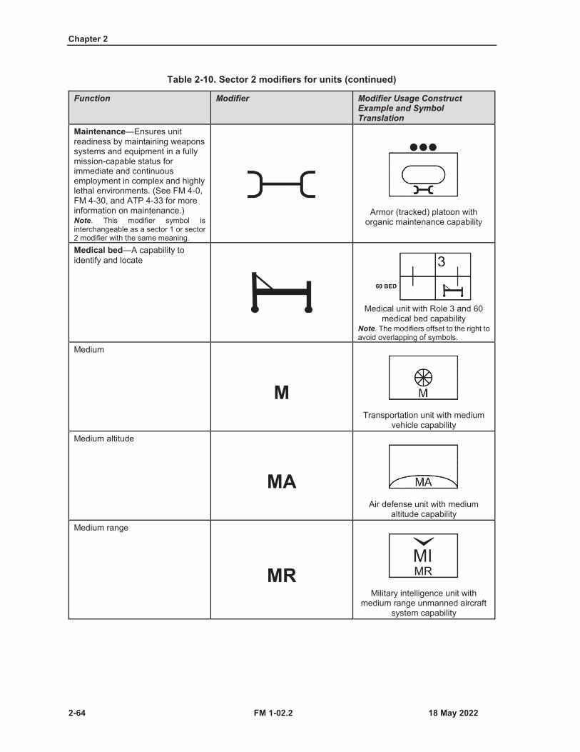
Chapter 2
2-64 FM 1-02.2
Table 2-10. Sector 2 modifiers for units (continued)
Function Modifier Modifier Usage Construct Example and Symbol Translation
Maintenance—Ensures unit readiness by maintaining weapons systems and equipment in a fully mission-capable status for immediate and continuous employment in complex and highly lethal environments. (See FM 4-0, FM 4-30, and ATP 4-33 for more information on maintenance.)Note. This modifier symbol is interchangeable as a sector 1 or sector 2 modifier with the same meaning.
Armor (tracked) platoon with organic maintenance capability
Medical bed—A capability to identify and locate
Medical unit with Role 3 and 60 medical bed capability
Note. The modifiers offset to the right to avoid overlapping of symbols.
Medium
MTransportation unit with medium
vehicle capabilityMedium altitude
MAAir defense unit with medium
altitude capabilityMedium range
MRMilitary intelligence unit with
medium range unmanned aircraft system capability
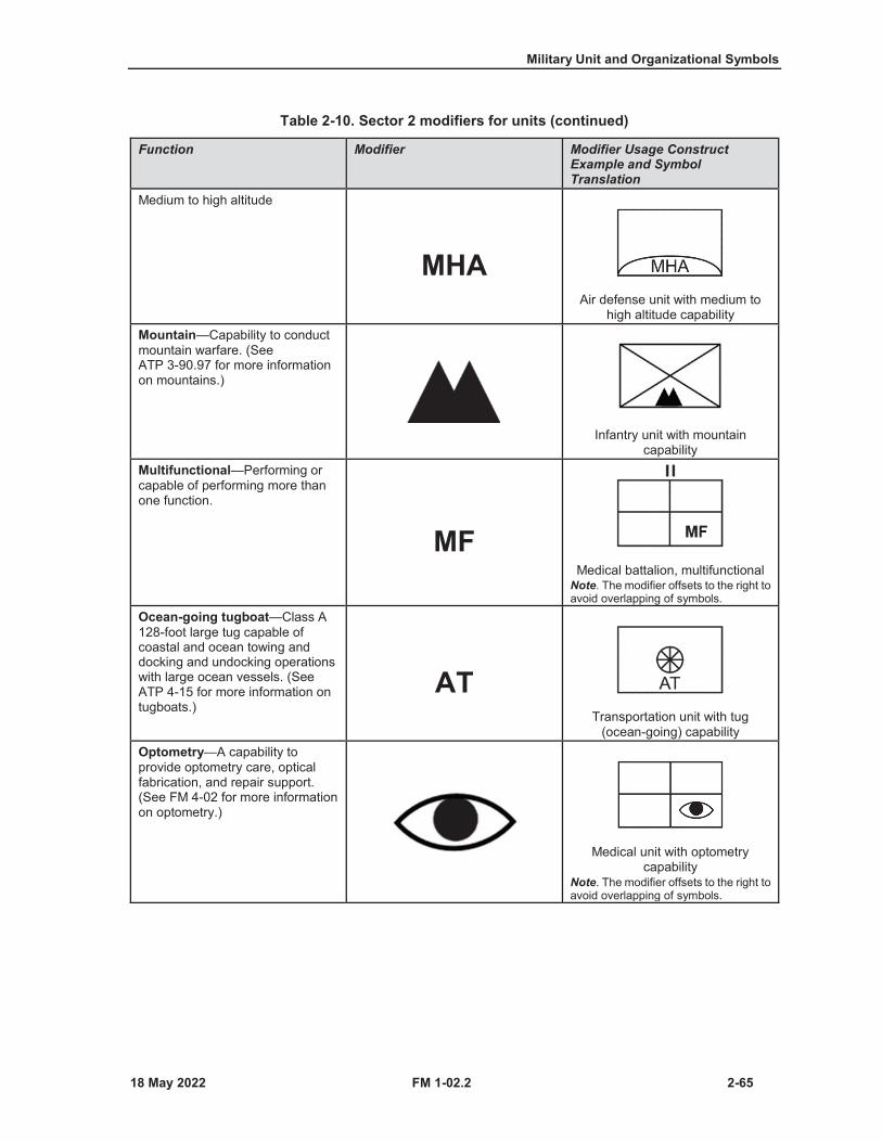
Military Unit and Organizational Symbols
FM 1-02.2 2-65
Table 2-10. Sector 2 modifiers for units (continued)
Function Modifier Modifier Usage Construct Example and Symbol Translation
Medium to high altitude
MHAAir defense unit with medium to
high altitude capabilityMountain—Capability to conduct mountain warfare. (See ATP 3-90.97 for more information on mountains.)
Infantry unit with mountain capability
Multifunctional—Performing or capable of performing more than one function.
MFMedical battalion, multifunctional
Note. The modifier offsets to the right to avoid overlapping of symbols.
Ocean-going tugboat—Class A 128-foot large tug capable ofcoastal and ocean towing anddocking and undocking operationswith large ocean vessels. (SeeATP 4-15 for more information ontugboats.)
ATTransportation unit with tug
(ocean-going) capabilityOptometry—A capability to provide optometry care, optical fabrication, and repair support. (See FM 4-02 for more information on optometry.)
Medical unit with optometry capability
Note. The modifier offsets to the right to avoid overlapping of symbols.
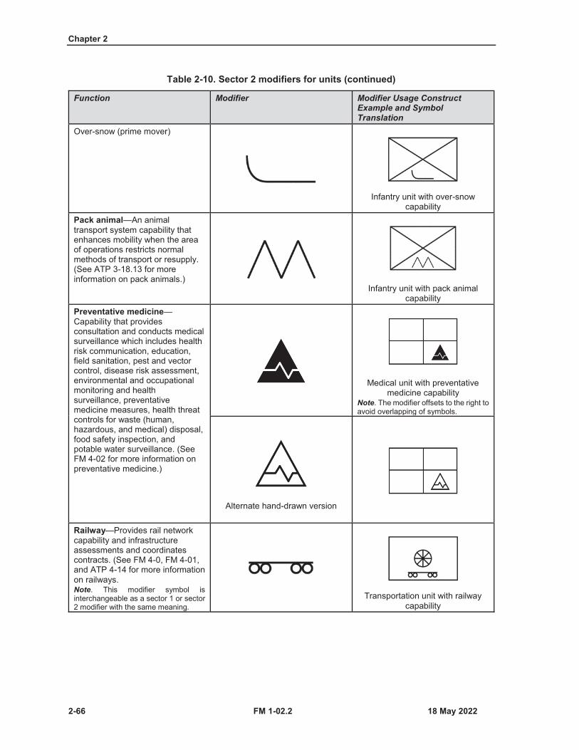
Chapter 2
2-66 FM 1-02.2
Table 2-10. Sector 2 modifiers for units (continued)
Function Modifier Modifier Usage Construct Example and Symbol Translation
Over-snow (prime mover)
Infantry unit with over-snow capability
Pack animal—An animal transport system capability that enhances mobility when the area of operations restricts normal methods of transport or resupply. (See ATP 3-18.13 for more information on pack animals.)
Infantry unit with pack animal capability
Preventative medicine—Capability that providesconsultation and conducts medical surveillance which includes health risk communication, education, field sanitation, pest and vector control, disease risk assessment, environmental and occupational monitoring and health surveillance, preventative medicine measures, health threat controls for waste (human, hazardous, and medical) disposal, food safety inspection, and potable water surveillance. (See FM 4-02 for more information on preventative medicine.)
Medical unit with preventative medicine capability
Note. The modifier offsets to the right to avoid overlapping of symbols.
Alternate hand-drawn version
Railway—Provides rail network capability and infrastructure assessments and coordinates contracts. (See FM 4-0, FM 4-01, and ATP 4-14 for more information on railways.Note. This modifier symbol is interchangeable as a sector 1 or sector 2 modifier with the same meaning.
Transportation unit with railway capability

Military Unit and Organizational Symbols
FM 1-02.2 2-67
Table 2-10. Sector 2 modifiers for units (continued)
Function Modifier Modifier Usage Construct Example and Symbol Translation
Recovery—Actions taken to extricate damaged or disabled equipment for return to friendly control or repair at another location. (JP 3-34)
Transportation unit with recovery capability
Riverine--Provides water transport to move troops and equipment. (See ATP 4-15 for more information on riverine.)
Engineer unit with riverine capability
Search—A systematic reconnaissance of a defined area, so that all parts of the area have passed within visibility.
Electromagnetic warfare unit with search capability
Security force assistance—(DOD) The Department of Defense activities that support the development of the capacity and capability of foreign security forces and their supporting institutions. (JP 3-22)(Army) The unified action to generate, employ, and sustain local, host nation, or regional security forces in support of legitimate authority. (FM 3-07)
SFAInfantry security force assistance
brigade
Surgical—Capability to provide life or limb saving operative treatment using specialized instruments to repair or stabilize a patient. (See FM 4-02 for more information on surgical.)Note. This modifier offsets to the right to avoid overlapping with the main icon. Medical unit with surgery
capability
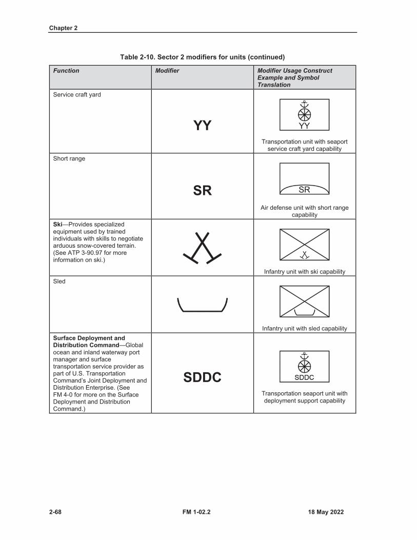
Chapter 2
2-68 FM 1-02.2
Table 2-10. Sector 2 modifiers for units (continued)
Function Modifier Modifier Usage Construct Example and Symbol Translation
Service craft yard
YYTransportation unit with seaport
service craft yard capabilityShort range
SRAir defense unit with short range
capabilitySki—Provides specialized equipment used by trained individuals with skills to negotiate arduous snow-covered terrain. (See ATP 3-90.97 for more information on ski.)
Infantry unit with ski capabilitySled
Infantry unit with sled capabilitySurface Deployment and Distribution Command—Global ocean and inland waterway port manager and surface transportation service provider as part of U.S. Transportation Command’s Joint Deployment and Distribution Enterprise. (See FM 4-0 for more on the Surface Deployment and Distribution Command.)
SDDCTransportation seaport unit with deployment support capability
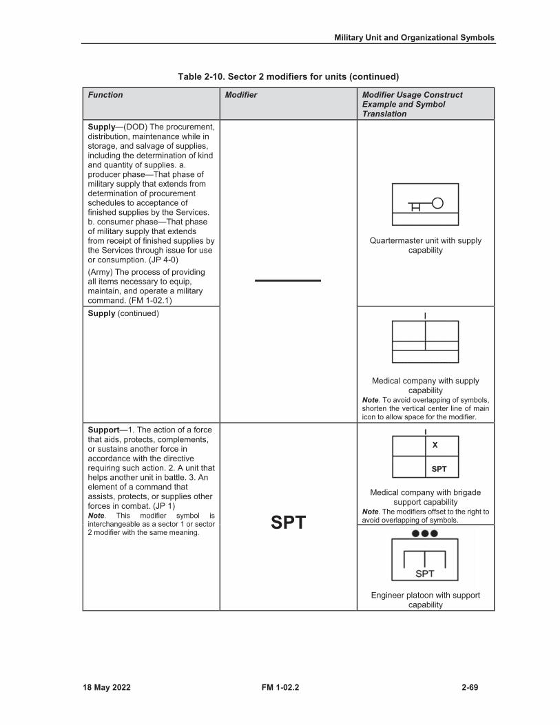
Military Unit and Organizational Symbols
FM 1-02.2 2-69
Table 2-10. Sector 2 modifiers for units (continued)
Function Modifier Modifier Usage Construct Example and Symbol Translation
Supply—(DOD) The procurement, distribution, maintenance while in storage, and salvage of supplies, including the determination of kind and quantity of supplies. a.producer phase—That phase of military supply that extends from determination of procurement schedules to acceptance of finished supplies by the Services. b. consumer phase—That phaseof military supply that extendsfrom receipt of finished supplies bythe Services through issue for useor consumption. (JP 4-0)(Army) The process of providing all items necessary to equip, maintain, and operate a military command. (FM 1-02.1)
Quartermaster unit with supply capability
Supply (continued)
Medical company with supply capability
Note. To avoid overlapping of symbols, shorten the vertical center line of main icon to allow space for the modifier.
Support—1. The action of a force that aids, protects, complements, or sustains another force in accordance with the directive requiring such action. 2. A unit that helps another unit in battle. 3. An element of a command that assists, protects, or supplies other forces in combat. (JP 1)Note. This modifier symbol is interchangeable as a sector 1 or sector 2 modifier with the same meaning.
SPT
Medical company with brigade support capability
Note. The modifiers offset to the right to avoid overlapping of symbols.
Engineer platoon with support capability

Chapter 2
2-70 FM 1-02.2
Table 2-10. Sector 2 modifiers for units (continued)
Function Modifier Modifier Usage Construct Example and Symbol Translation
Towed—Prime mover capability to pull a piece of equipment unable to move on its own.
Tug, harbor—Tug 900 Class B vessel that supports movement of barges and lighterage of various types in harbors, port areas, and during logistics over-the-shore anchorage. (See ATP 4-15 for more information on harbor tugs.)
YTTransportation unit with tug
(harbor) capabilityVertical take-off and landing—Capability to take off and land vertically.
VTOLFixed-wing unit with vertical take-
off and landing capabilityVery heavy—Cannon artillery larger than 210mm. (See FM 3-09for more information.)
VHArtillery unit with very heavy
artillery capabilityVeterinary service—A capability that provides consultation, animal care, food protection, and veterinary public health services. (See FM 4-02 for more information on veterinary service.)Note. This modifier offsets to the right to avoid overlapping with the main icon.
VMedical unit with veterinary
service capability
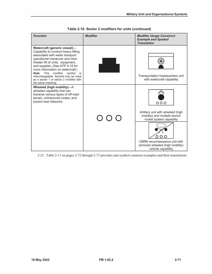
Military Unit and Organizational Symbols
FM 1-02.2 2-71
Table 2-10. Sector 2 modifiers for units (continued)
Function Modifier Modifier Usage Construct Example and Symbol Translation
Watercraft (generic vessel)—Capability to conduct heavy lifting associated with water transport operational maneuver and intra-theater lift of units, equipment, and supplies. (See ATP 4-15 for more information on watercraft.)Note. This modifier symbol is interchangeable. Symbol may be used as a sector 1 or sector 2 modifier with the same meaning.
Transportation headquarters unit with watercraft capability
Wheeled (high mobility)—Awheeled capability that can traverse various types of off-road terrain, unimproved routes, and paved road networks.
Artillery unit with wheeled (high mobility) and multiple launch
rocket system capability
CBRN reconnaissance unit with armored wheeled (high mobility)
vehicle capability
2-23. Table 2-11 on pages 2-72 through 2-73 provides unit symbol construct examples and their translations.
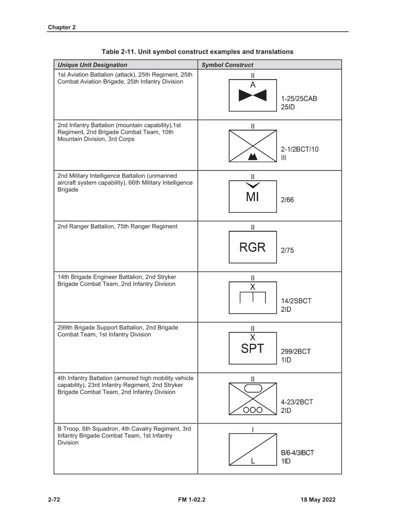
Chapter 2
2-72 FM 1-02.2
Table 2-11. Unit symbol construct examples and translations
Unique Unit Designation Symbol Construct1st Aviation Battalion (attack), 25th Regiment, 25thCombat Aviation Brigade, 25th Infantry Division
2nd Infantry Battalion (mountain capability),1stRegiment, 2nd Brigade Combat Team, 10th Mountain Division, 3rd Corps
2nd Military Intelligence Battalion (unmanned aircraft system capability), 66th Military Intelligence Brigade
2nd Ranger Battalion, 75th Ranger Regiment
14th Brigade Engineer Battalion, 2nd Stryker Brigade Combat Team, 2nd Infantry Division
299th Brigade Support Battalion, 2nd Brigade Combat Team, 1st Infantry Division
4th Infantry Battalion (armored high mobility vehicle capability), 23rd Infantry Regiment, 2nd Stryker Brigade Combat Team, 2nd Infantry Division
B Troop, 6th Squadron, 4th Cavalry Regiment, 3rd Infantry Brigade Combat Team, 1st Infantry Division

Military Unit and Organizational Symbols
FM 1-02.2 2-73
Table 2-11. Unit symbol construct examples and translations (continued)
Unique Unit Designation Symbol Construct6th Field Artillery Battalion (self-propelled multiple rocket launcher capability), 37th Field Artillery Regiment, 2nd Infantry Division
181 Transportation Battalion, 3rd Expeditionary Sustainment Command, 3rd Corps
67th Forward Support Company, 201st Brigade Support Battalion, 3rd Infantry Brigade Combat Team, 1st Infantry Division
C Field Artillery Battery (air assault capability), 3rd Battalion, 319 Field Artillery Regiment
F Company, 1st Battalion, 61st Infantry Regiment, 65th Infantry Brigade
Operational Detachment Alpha 595 (pack animal capability), C Company, 3rd Battalion, 5th Special Forces Group
III Marine Expeditionary Force

This page intentionally left blank.
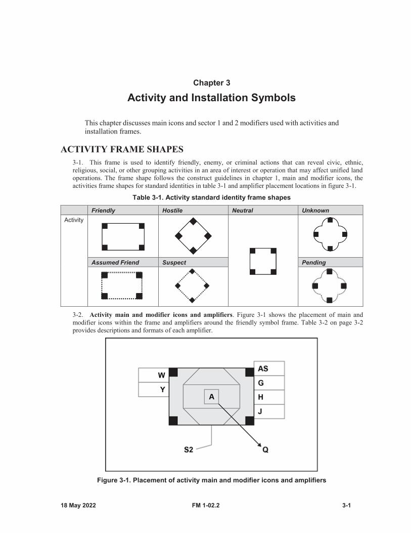
FM 1-02.2 3-1
Chapter 3
Activity and Installation Symbols
This chapter discusses main icons and sector 1 and 2 modifiers used with activities and installation frames.
ACTIVITY FRAME SHAPES3-1. This frame is used to identify friendly, enemy, or criminal actions that can reveal civic, ethnic,religious, social, or other grouping activities in an area of interest or operation that may affect unified landoperations. The frame shape follows the construct guidelines in chapter 1, main and modifier icons, theactivities frame shapes for standard identities in table 3-1 and amplifier placement locations in figure 3-1.
Table 3-1. Activity standard identity frame shapes
Friendly Hostile Neutral UnknownActivity
Assumed Friend Suspect Pending
3-2. Activity main and modifier icons and amplifiers. Figure 3-1 shows the placement of main andmodifier icons within the frame and amplifiers around the friendly symbol frame. Table 3-2 on page 3-2provides descriptions and formats of each amplifier.
Figure 3-1. Placement of activity main and modifier icons and amplifiers
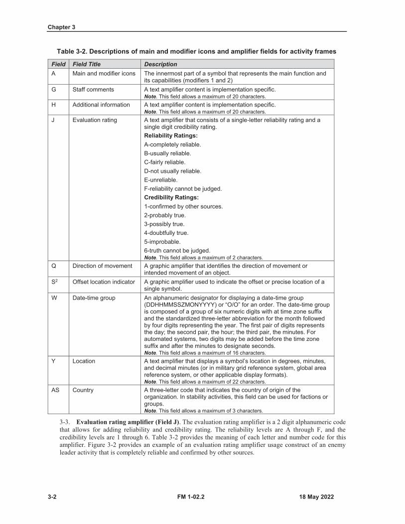
Chapter 3
3-2 FM 1-02.2
Table 3-2. Descriptions of main and modifier icons and amplifier fields for activity frames
Field Field Title DescriptionA Main and modifier icons The innermost part of a symbol that represents the main function and
its capabilities (modifiers 1 and 2)G Staff comments A text amplifier content is implementation specific.
Note. This field allows a maximum of 20 characters.H Additional information A text amplifier content is implementation specific.
Note. This field allows a maximum of 20 characters.J Evaluation rating A text amplifier that consists of a single-letter reliability rating and a
single digit credibility rating.Reliability Ratings:A-completely reliable.B-usually reliable.C-fairly reliable.D-not usually reliable.E-unreliable.F-reliability cannot be judged.Credibility Ratings:1-confirmed by other sources.2-probably true.3-possibly true.4-doubtfully true.5-improbable.6-truth cannot be judged.Note. This field allows a maximum of 2 characters.
Q Direction of movement A graphic amplifier that identifies the direction of movement or intended movement of an object.
S2 Offset location indicator A graphic amplifier used to indicate the offset or precise location of a single symbol.
W Date-time group An alphanumeric designator for displaying a date-time group (DDHHMMSSZMONYYYY) or “O/O” for an order. The date-time group is composed of a group of six numeric digits with at time zone suffix and the standardized three-letter abbreviation for the month followed by four digits representing the year. The first pair of digits represents the day; the second pair, the hour; the third pair, the minutes. For automated systems, two digits may be added before the time zone suffix and after the minutes to designate seconds.Note. This field allows a maximum of 16 characters.
Y Location A text amplifier that displays a symbol’s location in degrees, minutes, and decimal minutes (or in military grid reference system, global area reference system, or other applicable display formats).Note. This field allows a maximum of 22 characters.
AS Country A three-letter code that indicates the country of origin of the organization. In stability activities, this field can be used for factions or groups.Note. This field allows a maximum of 3 characters.
3-3. Evaluation rating amplifier (Field J). The evaluation rating amplifier is a 2 digit alphanumeric codethat allows for adding reliability and credibility rating. The reliability levels are A through F, and thecredibility levels are 1 through 6. Table 3-2 provides the meaning of each letter and number code for thisamplifier. Figure 3-2 provides an example of an evaluation rating amplifier usage construct of an enemyleader activity that is completely reliable and confirmed by other sources.
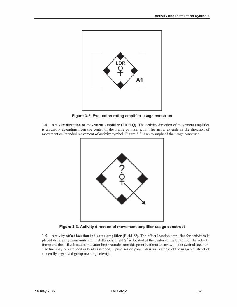
Activity and Installation Symbols
FM 1-02.2 3-3
Figure 3-2. Evaluation rating amplifier usage construct
3-4. Activity direction of movement amplifier (Field Q). The activity direction of movement amplifieris an arrow extending from the center of the frame or main icon. The arrow extends in the direction ofmovement or intended movement of activity symbol. Figure 3-3 is an example of the usage construct.
Figure 3-3. Activity direction of movement amplifier usage construct
3-5. Activity offset location indicator amplifier (Field S2). The offset location amplifier for activities isplaced differently from units and installations. Field S2 is located at the center of the bottom of the activityframe and the offset location indicator line protrude from this point (without an arrow) to the desired location.The line may be extended or bent as needed. Figure 3-4 on page 3-4 is an example of the usage construct ofa friendly organized group meeting activity.
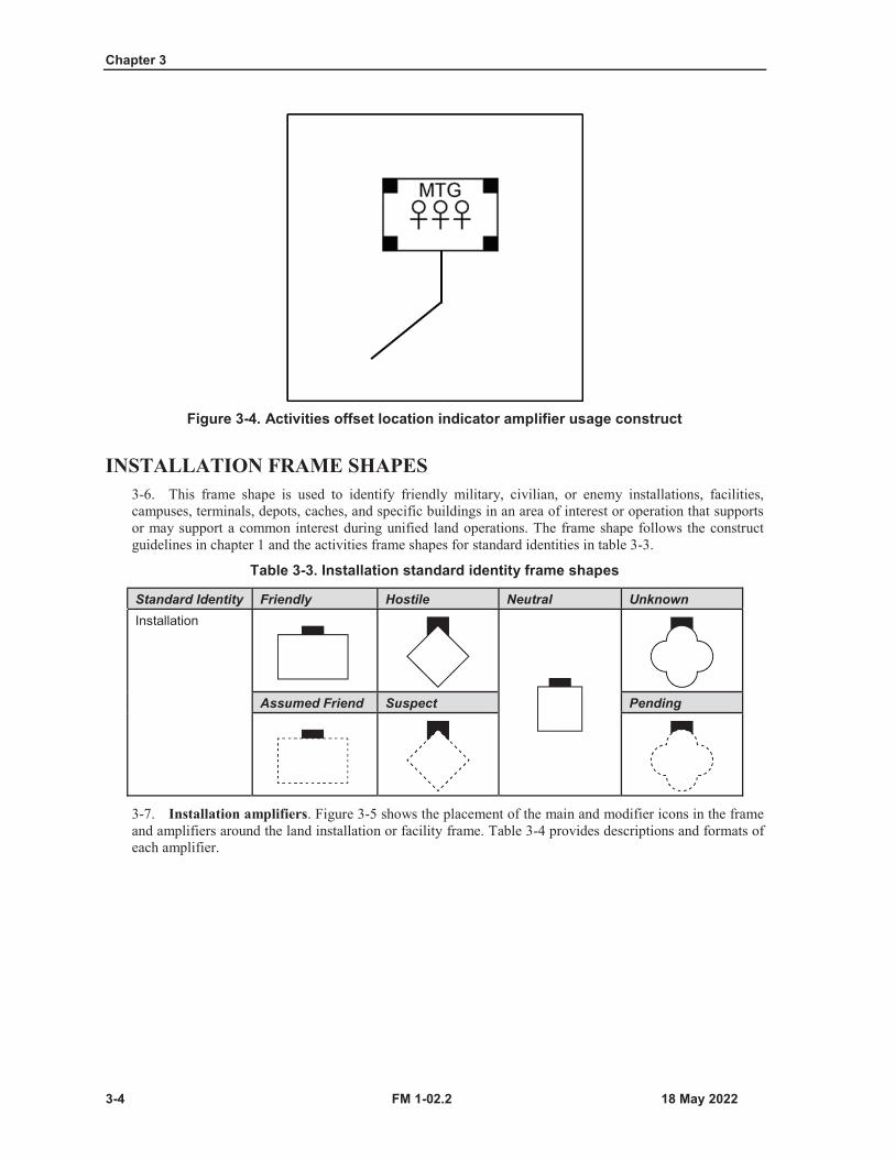
Chapter 3
3-4 FM 1-02.2
Figure 3-4. Activities offset location indicator amplifier usage construct
INSTALLATION FRAME SHAPES3-6. This frame shape is used to identify friendly military, civilian, or enemy installations, facilities,campuses, terminals, depots, caches, and specific buildings in an area of interest or operation that supportsor may support a common interest during unified land operations. The frame shape follows the constructguidelines in chapter 1 and the activities frame shapes for standard identities in table 3-3.
Table 3-3. Installation standard identity frame shapes
Standard Identity Friendly Hostile Neutral UnknownInstallation
Assumed Friend Suspect Pending
3-7. Installation amplifiers. Figure 3-5 shows the placement of the main and modifier icons in the frameand amplifiers around the land installation or facility frame. Table 3-4 provides descriptions and formats ofeach amplifier.

Activity and Installation Symbols
FM 1-02.2 3-5
Figure 3-5. Placement of installation main and modifier icon and amplifiers
Table 3-4. Descriptions of main and modifier icon and amplifier fields for installation frames
Field Field Title DescriptionA Main and modifier icons The innermost part of a symbol that represents the main function and
its capabilities (modifiers 1 and 2).G Staff comments A text amplifier content is implementation specific.
Note. This field allows a maximum of 20 characters.H Additional information A text amplifier content is implantation specific.
Note. This field allows a maximum of 20 characters.J Evaluation rating A text amplifier that consists of a single-letter reliability rating and a
single digit credibility rating.Reliability Ratings:A-completely reliable.B-usually reliable.C-fairly reliable.D-not usually reliable.E-unreliable.F-reliability cannot be judged.Credibility Ratings:1-confirmed by other sources.2-probably true.3-possibly true.4-doubtfully true.5-improbable.6-truth cannot be judged.Note. This field allows a maximum of 2 characters.
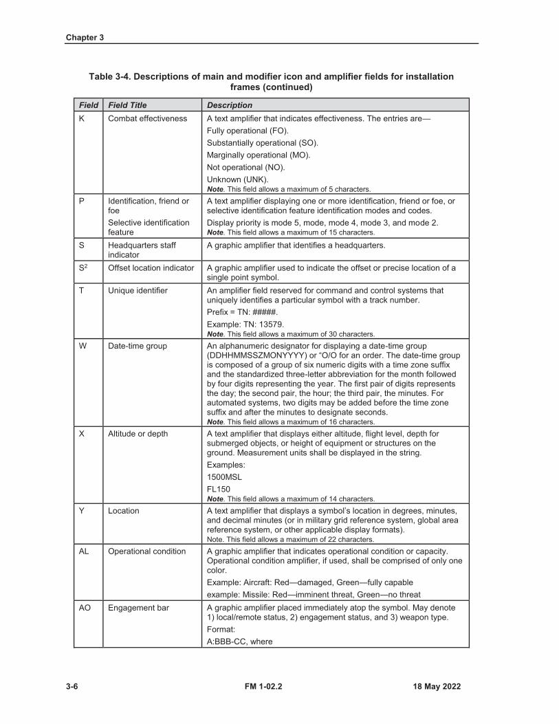
Chapter 3
3-6 FM 1-02.2
Table 3-4. Descriptions of main and modifier icon and amplifier fields for installation frames (continued)
Field Field Title DescriptionK Combat effectiveness A text amplifier that indicates effectiveness. The entries are—
Fully operational (FO).Substantially operational (SO).Marginally operational (MO).Not operational (NO).Unknown (UNK).Note. This field allows a maximum of 5 characters.
P Identification, friend or foeSelective identification feature
A text amplifier displaying one or more identification, friend or foe, or selective identification feature identification modes and codes.Display priority is mode 5, mode, mode 4, mode 3, and mode 2.Note. This field allows a maximum of 15 characters.
S Headquarters staff indicator
A graphic amplifier that identifies a headquarters.
S2 Offset location indicator A graphic amplifier used to indicate the offset or precise location of a single point symbol.
T Unique identifier An amplifier field reserved for command and control systems that uniquely identifies a particular symbol with a track number.Prefix = TN: #####.Example: TN: 13579.Note. This field allows a maximum of 30 characters.
W Date-time group An alphanumeric designator for displaying a date-time group (DDHHMMSSZMONYYYY) or “O/O for an order. The date-time group is composed of a group of six numeric digits with a time zone suffix and the standardized three-letter abbreviation for the month followed by four digits representing the year. The first pair of digits represents the day; the second pair, the hour; the third pair, the minutes. For automated systems, two digits may be added before the time zone suffix and after the minutes to designate seconds.Note. This field allows a maximum of 16 characters.
X Altitude or depth A text amplifier that displays either altitude, flight level, depth for submerged objects, or height of equipment or structures on the ground. Measurement units shall be displayed in the string.Examples:1500MSLFL150Note. This field allows a maximum of 14 characters.
Y Location A text amplifier that displays a symbol’s location in degrees, minutes, and decimal minutes (or in military grid reference system, global area reference system, or other applicable display formats).Note. This field allows a maximum of 22 characters.
AL Operational condition A graphic amplifier that indicates operational condition or capacity. Operational condition amplifier, if used, shall be comprised of only one color.Example: Aircraft: Red—damaged, Green—fully capableexample: Missile: Red—imminent threat, Green—no threat
AO Engagement bar A graphic amplifier placed immediately atop the symbol. May denote 1) local/remote status, 2) engagement status, and 3) weapon type.Format:A:BBB-CC, where
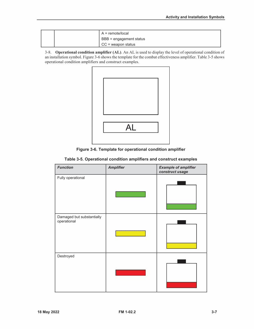
Activity and Installation Symbols
FM 1-02.2 3-7
A = remote/localBBB = engagement statusCC = weapon status
3-8. Operational condition amplifier (AL). An AL is used to display the level of operational condition ofan installation symbol. Figure 3-6 shows the template for the combat effectiveness amplifier. Table 3-5 showsoperational condition amplifiers and construct examples.
Figure 3-6. Template for operational condition amplifier
Table 3-5. Operational condition amplifiers and construct examples
Function Amplifier Example of amplifier construct usage
Fully operational
Damaged but substantially operational
Destroyed
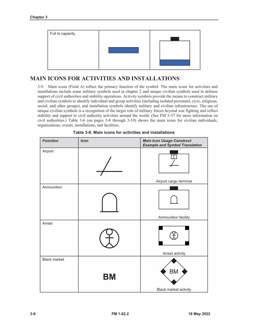
Chapter 3
3-8 FM 1-02.2
Full to capacity
MAIN ICONS FOR ACTIVITIES AND INSTALLATIONS3-9. Main icons (Field A) reflect the primary function of the symbol. The main icons for activities andinstallations include some military symbols used in chapter 2 and unique civilian symbols used in defensesupport of civil authorities and stability operations. Activity symbols provide the means to construct militaryand civilian symbols to identify individual and group activities (including isolated personnel, civic, religious,social, and other groups), and installation symbols identify military and civilian infrastructure. The use ofunique civilian symbols is a recognition of the larger role of military forces beyond war fighting and reflectstability and support to civil authority activities around the world. (See FM 3-57 for more information oncivil authorities.) Table 3-6 (on pages 3-8 through 3-19) shows the main icons for civilian individuals,organizations, events, installations, and facilities.
Table 3-6. Main icons for activities and installations
Function Icon Main Icon Usage Construct Example and Symbol Translation
Airport
Airport cargo terminalAmmunition
Ammunition facilityArrest
Arrest activityBlack market
BMBlack market activity
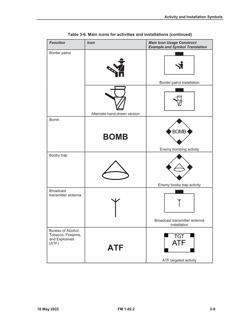
Activity and Installation Symbols
FM 1-02.2 3-9
Table 3-6. Main icons for activities and installations (continued)
Function Icon Main Icon Usage Construct Example and Symbol Translation
Border patrol
Border patrol installation
Alternate hand-drawn versionBomb
BOMBEnemy bombing activity
Booby trap
Enemy booby trap activityBroadcast transmitter antenna
Broadcast transmitter antenna installation
Bureau of Alcohol, Tobacco, Firearms, and Explosives (ATF) ATF
ATF targeted activity
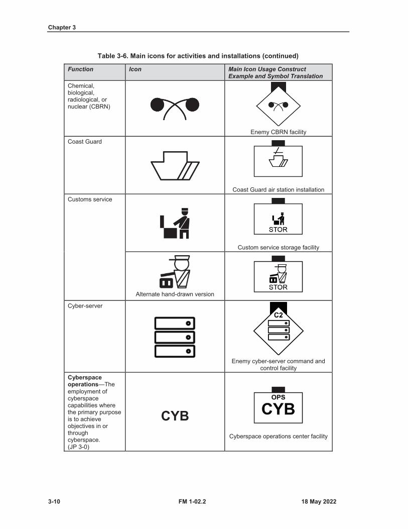
Chapter 3
3-10 FM 1-02.2
Table 3-6. Main icons for activities and installations (continued)
Function Icon Main Icon Usage Construct Example and Symbol Translation
Chemical, biological, radiological, or nuclear (CBRN)
Enemy CBRN facilityCoast Guard
Coast Guard air station installationCustoms service
Custom service storage facility
Alternate hand-drawn version
Cyber-server
Enemy cyber-server command and control facility
Cyberspace operations—The employment of cyberspace capabilities where the primary purpose is to achieve objectives in or through cyberspace. (JP 3-0)
CYBCyberspace operations center facility
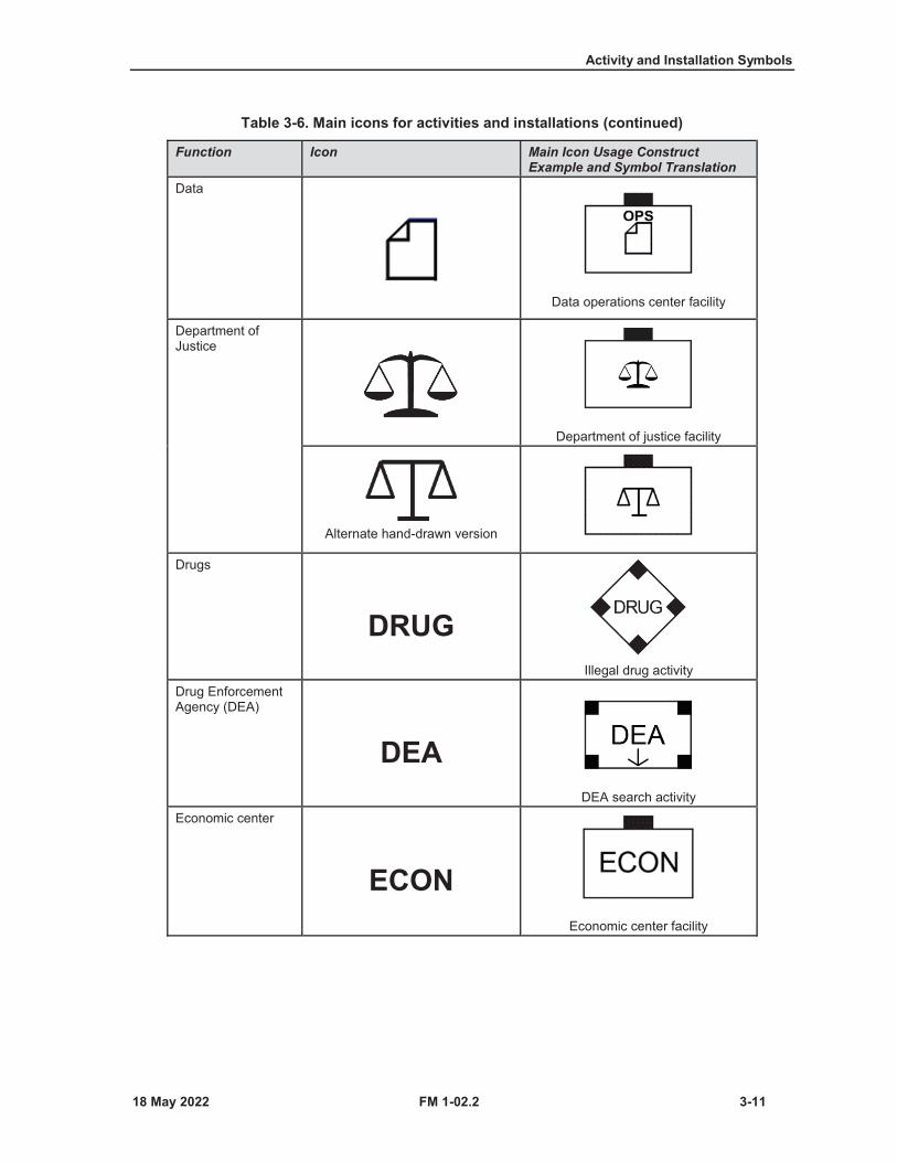
Activity and Installation Symbols
FM 1-02.2 3-11
Table 3-6. Main icons for activities and installations (continued)
Function Icon Main Icon Usage Construct Example and Symbol Translation
Data
Data operations center facility
Department of Justice
Department of justice facility
Alternate hand-drawn version
Drugs
DRUGIllegal drug activity
Drug Enforcement Agency (DEA)
DEADEA search activity
Economic center
ECONEconomic center facility
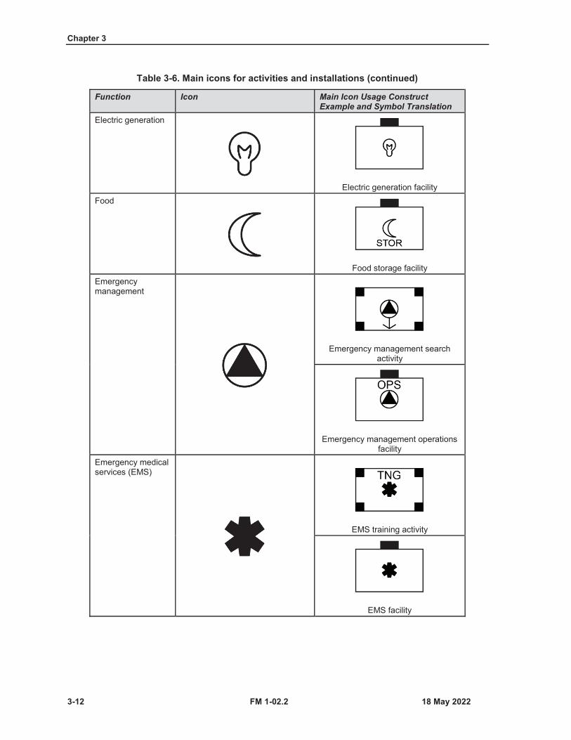
Chapter 3
3-12 FM 1-02.2
Table 3-6. Main icons for activities and installations (continued)
Function Icon Main Icon Usage Construct Example and Symbol Translation
Electric generation
Electric generation facilityFood
Food storage facilityEmergency management
Emergency management search activity
Emergency management operations facility
Emergency medical services (EMS)
EMS training activity
EMS facility
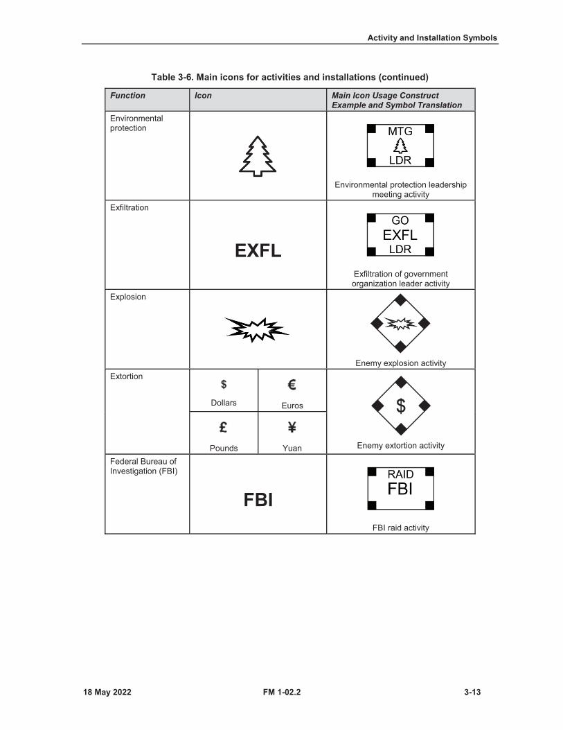
Activity and Installation Symbols
FM 1-02.2 3-13
Table 3-6. Main icons for activities and installations (continued)
Function Icon Main Icon Usage Construct Example and Symbol Translation
Environmental protection
Environmental protection leadership meeting activity
Exfiltration
EXFLExfiltration of government organization leader activity
Explosion
Enemy explosion activityExtortion
Dollars Euros
Enemy extortion activityPounds YuanFederal Bureau of Investigation (FBI)
FBIFBI raid activity

Chapter 3
3-14 FM 1-02.2
Table 3-6. Main icons for activities and installations (continued)
Function Icon Main Icon Usage Construct Example and Symbol Translation
Firefighter or firefighting
Firefighting activity
Alternate hand-drawn version Firefighter installationGovernmental organization
GOGovernmental organization facility
Graffiti
Enemy graffiti activityGrenade
Grenade cacheGroup (organized)
Group (organized) meeting activity

Activity and Installation Symbols
FM 1-02.2 3-15
Table 3-6. Main icons for activities and installations (continued)
Function Icon Main Icon Usage Construct Example and Symbol Translation
Group of victims—attempted criminal activity
Attempted criminal activity on a group of individuals
Group of victims—criminal activity
Friendly group of victims criminal activity
Improvised explosive device (IED)
IEDEnemy IED activity
Individual
Individual suspicious activityIndividual victim—attempted criminal activity
Attempted criminal activity on individual
Individual victim—criminal activity
Enemy individual victim criminal activity
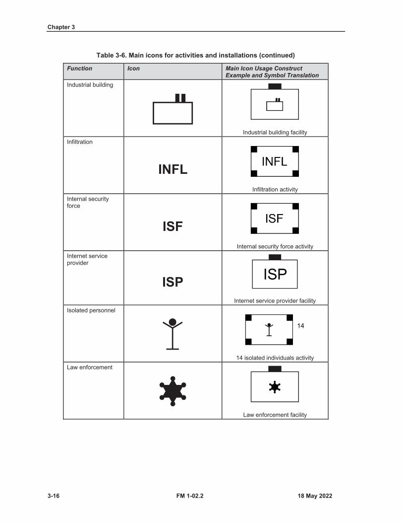
Chapter 3
3-16 FM 1-02.2
Table 3-6. Main icons for activities and installations (continued)
Function Icon Main Icon Usage Construct Example and Symbol Translation
Industrial building
Industrial building facilityInfiltration
INFLInfiltration activity
Internal security force
ISFInternal security force activity
Internet service provider
ISPInternet service provider facility
Isolated personnel
14 isolated individuals activityLaw enforcement
Law enforcement facility

Activity and Installation Symbols
FM 1-02.2 3-17
Table 3-6. Main icons for activities and installations (continued)
Function Icon Main Icon Usage Construct Example and Symbol Translation
Maritime terminal
Maritime terminal facility
Alternate hand-drawn version
Mass demonstration (protest)
MASSMass demonstration activity
Mass grave
Mass grave facilityMedical treatment
Medical treatment facility (hospital)Meeting
MTGMeeting activity
Military information support operations (MISO)
MISO activity
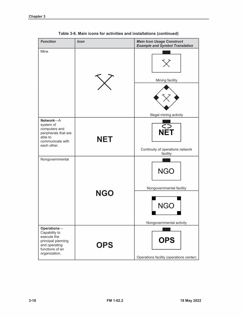
Chapter 3
3-18 FM 1-02.2
Table 3-6. Main icons for activities and installations (continued)
Function Icon Main Icon Usage Construct Example and Symbol Translation
Mine
Mining facility
Illegal mining activityNetwork—Asystem of computers and peripherals that are able to communicate with each other.
NETContinuity of operations network
facilityNongovernmental
NGONongovernmental facility
Nongovernmental activityOperations—Capability to execute the principal planning and operating functions of an organization.
OPSOperations facility (operations center)
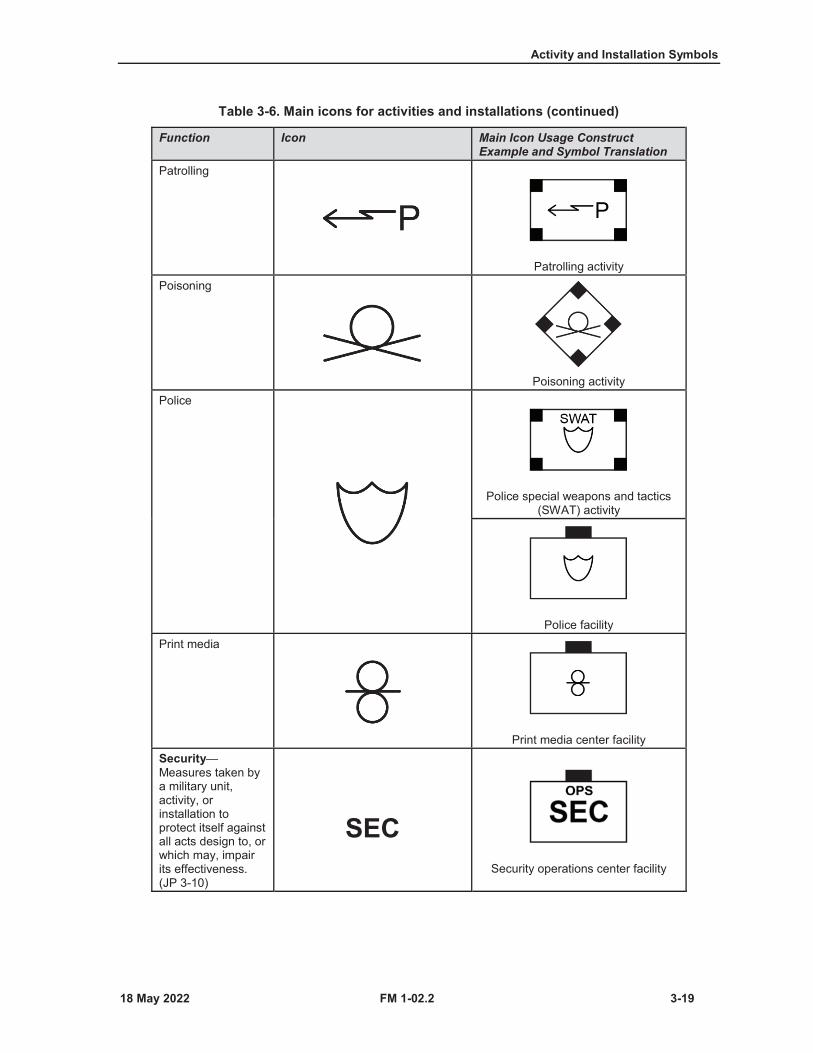
Activity and Installation Symbols
FM 1-02.2 3-19
Table 3-6. Main icons for activities and installations (continued)
Function Icon Main Icon Usage Construct Example and Symbol Translation
Patrolling
Patrolling activityPoisoning
Poisoning activityPolice
Police special weapons and tactics (SWAT) activity
Police facilityPrint media
Print media center facilitySecurity—Measures taken by a military unit, activity, or installation to protect itself against all acts design to, or which may, impair its effectiveness. (JP 3-10)
SECSecurity operations center facility

Chapter 3
3-20 FM 1-02.2
SECTOR 1 MODIFIERS FOR ACTIVITIES AND INSTALLATIONS
3-10. Table 3-7 (on pages 3-20 through 3-29) shows sector 1 modifiers (Field A). Sector 1 modifiers furtheridentify affiliation, capability, special characteristic, or specialty.
Table 3-7. Sector 1 modifiers for activities and installations
Function Modifier Modifier Icon Usage Construct Example and Symbol Translation
Assassinated
ASIndividual assassination victim
activityBiological
BBiological facility
Bomb
BOMBExplosion bomb activity
Chemical
CChemical, biological,
radiological, and nuclear (CBRN) chemical facility
Coal
COElectric generation coal powered
facility

Activity and Installation Symbols
FM 1-02.2 3-21
Table 3-7. Sector 1 modifiers for activities and installations (continued)
Function Modifier Modifier Icon Usage Construct Example and Symbol Translation
College or university
COL
College campusCommand and control
C2Enemy cyber-server command
and control facilityContinuity of operations—An effort within individual executive departments and agencies to ensure that primary mission essential functions continue to be performed during a wide range of emergencies, including localized acts of nature, accidents, and technological or attack-related emergencies.
Continuity of operations network facility
Displaced persons, refugees, or evacuees
DPREDisplaced persons, refugees, or evacuees tented camp facility
Electric generation
Electric generation network facility
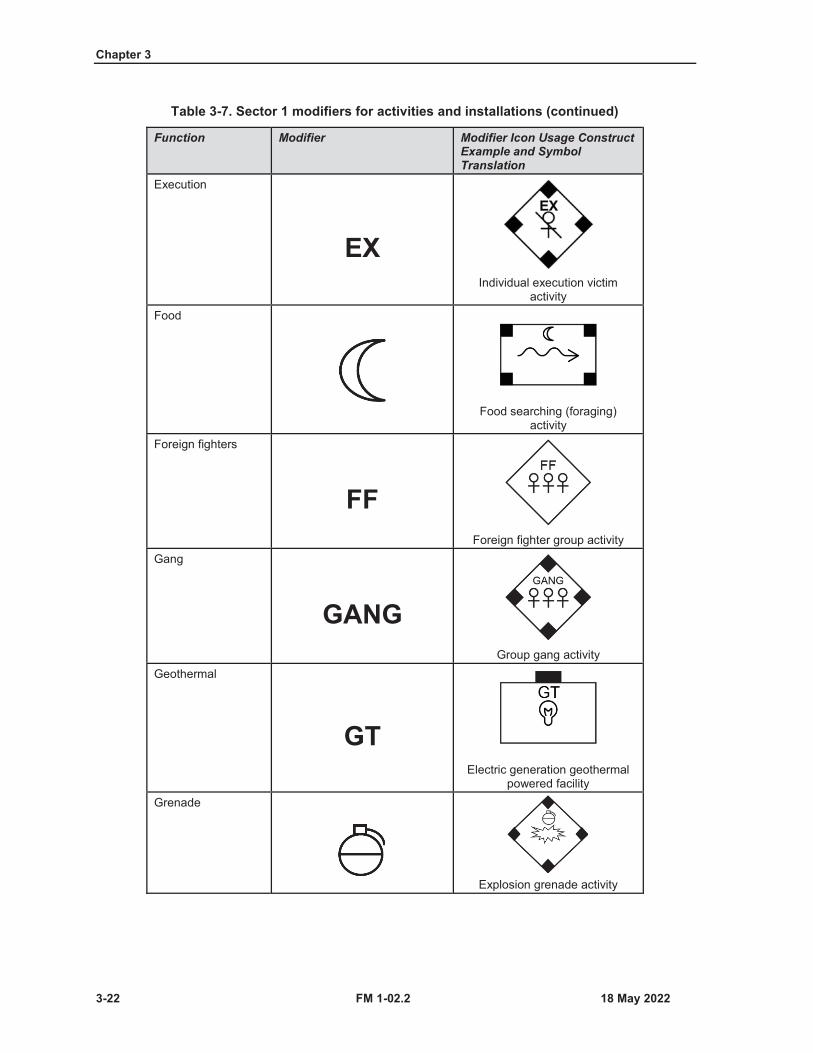
Chapter 3
3-22 FM 1-02.2
Table 3-7. Sector 1 modifiers for activities and installations (continued)
Function Modifier Modifier Icon Usage Construct Example and Symbol Translation
Execution
EXIndividual execution victim
activityFood
Food searching (foraging) activity
Foreign fighters
FFForeign fighter group activity
Gang
GANGGroup gang activity
Geothermal
GTElectric generation geothermal
powered facilityGrenade
Explosion grenade activity

Activity and Installation Symbols
FM 1-02.2 3-23
Table 3-7. Sector 1 modifiers for activities and installations (continued)
Function Modifier Modifier Icon Usage Construct Example and Symbol Translation
Hydroelectric
HYElectric generation hydroelectric
powered facilityImprovisedexplosive device
IEDExplosion improvised explosive
device activityIncendiary device
INExplosion incendiary device
activityKidnapping
KKidnapping activity
Laboratory
LABIllegal drug laboratory

Chapter 3
3-24 FM 1-02.2
Table 3-7. Sector 1 modifiers for activities and installations (continued)
Function Modifier Modifier Icon Usage Construct Example and Symbol Translation
LeaderNote. This modifier symbol is interchangeable. Symbol may be used as a sector 1 or sector 2 modifier with the same meaning.
LDRFriendly individual leader activity
Enemy individual leader activityMeeting
MTGGroup meeting activity
Mine
Explosion mine activityMortar
Explosion mortar activityMurdered
MUGroup murder victims activity
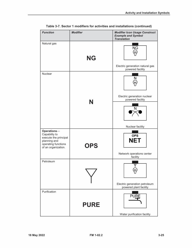
Activity and Installation Symbols
FM 1-02.2 3-25
Table 3-7. Sector 1 modifiers for activities and installations (continued)
Function Modifier Modifier Icon Usage Construct Example and Symbol Translation
Natural gas
NGElectric generation natural gas
powered facilityNuclear
NElectric generation nuclear
powered facility
Nuclear facilityOperations—Capability to execute the principal planning and operating functions of an organization. OPS
Network operations center facility
Petroleum
Electric generation petroleum powered plant facility
Purification
PUREWater purification facility
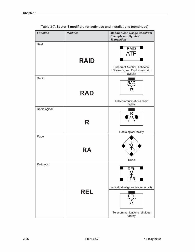
Chapter 3
3-26 FM 1-02.2
Table 3-7. Sector 1 modifiers for activities and installations (continued)
Function Modifier Modifier Icon Usage Construct Example and Symbol Translation
Raid
RAIDBureau of Alcohol, Tobacco,
Firearms, and Explosives raid activity
Radio
RADTelecommunications radio
facilityRadiological
RRadiological facility
Rape
RARape
Religious
RELIndividual religious leader activity
Telecommunications religious facility
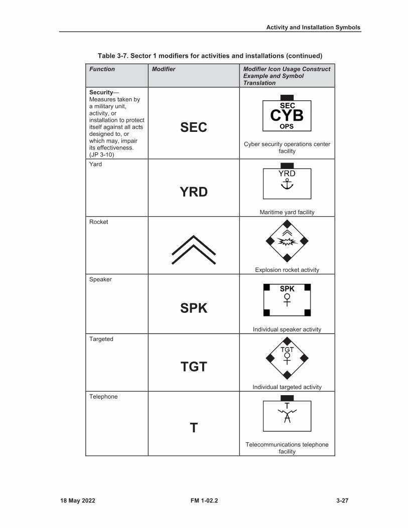
Activity and Installation Symbols
FM 1-02.2 3-27
Table 3-7. Sector 1 modifiers for activities and installations (continued)
Function Modifier Modifier Icon Usage Construct Example and Symbol Translation
Security—Measures taken by a military unit, activity, or installation to protect itself against all acts designed to, or which may, impair its effectiveness. (JP 3-10)
SECCyber security operations center
facility
Yard
YRDMaritime yard facility
Rocket
Explosion rocket activitySpeaker
SPKIndividual speaker activity
Targeted
TGTIndividual targeted activity
Telephone
TTelecommunications telephone
facility
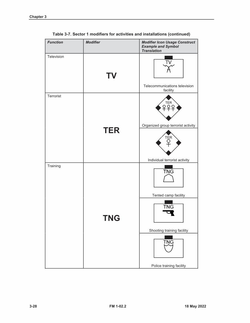
Chapter 3
3-28 FM 1-02.2
Table 3-7. Sector 1 modifiers for activities and installations (continued)
Function Modifier Modifier Icon Usage Construct Example and Symbol Translation
Television
TVTelecommunications television
facilityTerrorist
TEROrganized group terrorist activity
Individual terrorist activityTraining
TNG
Tented camp facility
Shooting training facility
Police training facility
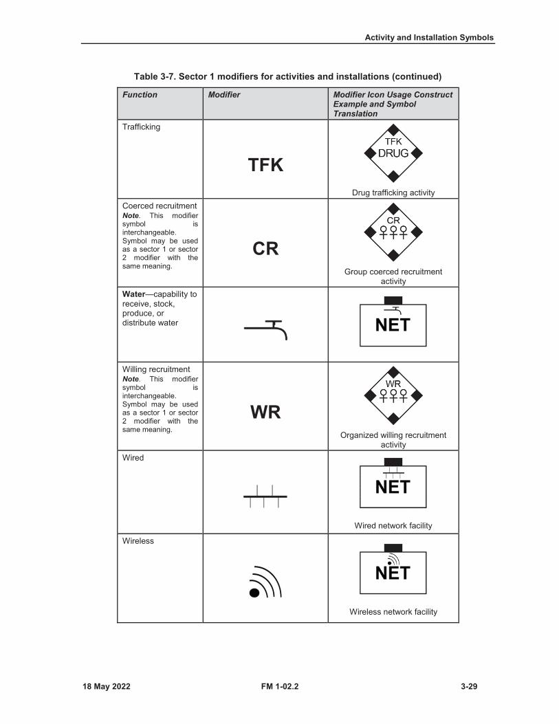
Activity and Installation Symbols
FM 1-02.2 3-29
Table 3-7. Sector 1 modifiers for activities and installations (continued)
Function Modifier Modifier Icon Usage Construct Example and Symbol Translation
Trafficking
TFKDrug trafficking activity
Coerced recruitmentNote. This modifier symbol is interchangeable. Symbol may be used as a sector 1 or sector 2 modifier with the same meaning.
CRGroup coerced recruitment
activityWater—capability to receive, stock, produce, or distribute water
Willing recruitmentNote. This modifier symbol is interchangeable. Symbol may be used as a sector 1 or sector 2 modifier with the same meaning.
WROrganized willing recruitment
activityWired
Wired network facility
Wireless
Wireless network facility

Chapter 3
3-30 FM 1-02.2
SECTOR 2 MODIFIERS FOR ACTIVITIES AND INSTALLATIONS
3-11. Table 3-8 (on pages 3-30 through 3-32) shows sector 2 modifiers (field A). Sector 2 modifiers furtheridentify affiliation, capability, special characteristic, or specialty.
Table 3-8. Sector 2 modifiers for individuals and organizations
Function Modifier Modifier Icon Usage Construct Example and Symbol Translation
Coerced recruitmentNote. This modifier symbol is interchangeable. Symbol may be used as a sector 1 or sector 2 modifier with the same meaning.
CROrganized coerced terrorist
recruitment activity
Border patrol coerced recruitment activity
Data
Network data security facilityLeaderNote. This modifier symbol is interchangeable. Symbol may be used as a sector 1 or sector 2 modifier with the same meaning. LDR
Friendly individual leader activityOperations—Capability to execute the principal planning and operating functions of an organization
OPSWireless network operations
facility
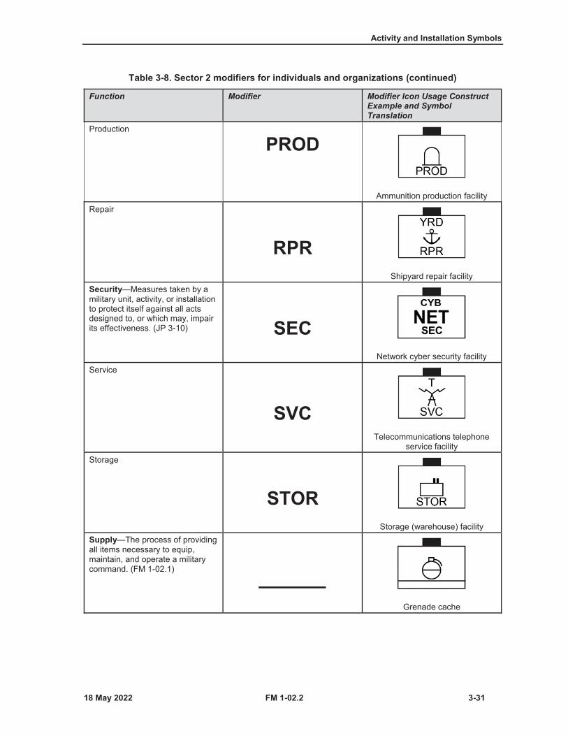
Activity and Installation Symbols
FM 1-02.2 3-31
Table 3-8. Sector 2 modifiers for individuals and organizations (continued)
Function Modifier Modifier Icon Usage Construct Example and Symbol Translation
Production
PROD
Ammunition production facilityRepair
RPRShipyard repair facility
Security—Measures taken by a military unit, activity, or installation to protect itself against all acts designed to, or which may, impair its effectiveness. (JP 3-10) SEC
Network cyber security facilityService
SVCTelecommunications telephone
service facilityStorage
STORStorage (warehouse) facility
Supply—The process of providing all items necessary to equip, maintain, and operate a military command. (FM 1-02.1)
Grenade cache
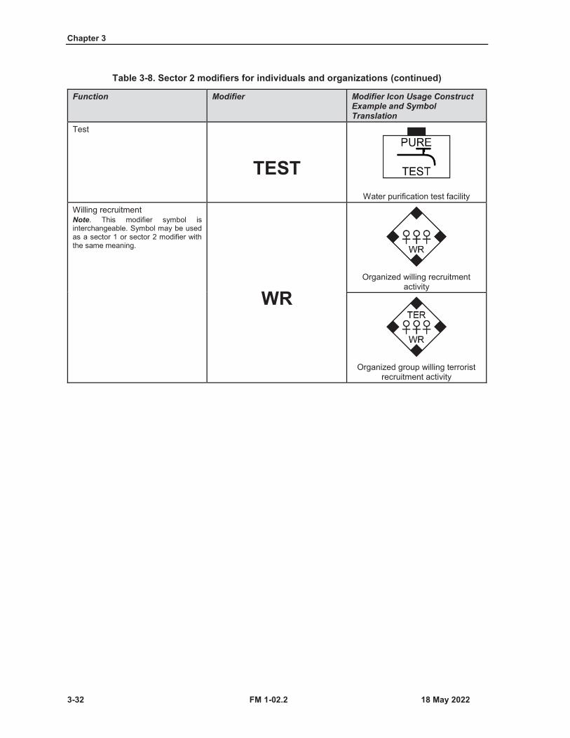
Chapter 3
3-32 FM 1-02.2
Table 3-8. Sector 2 modifiers for individuals and organizations (continued)
Function Modifier Modifier Icon Usage Construct Example and Symbol Translation
Test
TESTWater purification test facility
Willing recruitmentNote. This modifier symbol is interchangeable. Symbol may be used as a sector 1 or sector 2 modifier with the same meaning.
WROrganized willing recruitment
activity
Organized group willing terrorist recruitment activity
FM 1-02.2 4-1
Chapter 4
Equipment Symbols
This chapter discusses main icons, sector 1 modifiers, and mobility indicator amplifiers for equipment. Equipment is nonexpendable items needed to outfit or equip an individual or organization. This section includes the lists of main and modifier icons, and amplifiers for building land equipment symbols
FRAMED AND UNFRAMED EQUIPMENT SYMBOLS4-1. The equipment symbol construct standard permits the option to depict the symbol with frame orunframed. As discussed in chapter 1, the frame shape is what indicates the standard identity (friendly, enemy,neutral, and unknown) of a symbol. The unframed equipment symbol constructs must use colors (includingblue, red, green, and yellow) in order to indicate the standard identity depiction of friendly, enemy, neutral,or unknown items. (See paragraph 1-9 for more information on standard identity colors.)
EQUIPMENT SYMBOL FRAME SHAPES4-2. The symbol frame shape is used to identify friendly, enemy, neutral, and unknown equipmentaffiliation in or supporting an area of interest or operations. Table 4-1 on page 4-2 provides the standardidentity frame shapes for units and organizations. The frame shape construct guidelines for main and modifiericons and amplifier placement locations are provided in paragraph 4-4.

Chapter 4
4-2 FM 1-02.2
Table 4-1. Equipment standard identity frame shapes
Domain Friendly Hostile Neutral UnknownLand and sea surface
Assumed Friend Suspect Pending
Air (in flight)
Assumed Friend Suspect Unknown
Space (in space)
Assumed Friend Suspect Unknown
MAIN AND MODIFIER ICONS AND AMPLIFIERS FOR EQUIPMENT4-3. The purpose of main and modifier icons and amplifier fields is to standardize the display of optionalalphanumeric information that graphically describes the equipment and provides additional information oncapabilities, status, and location. Figure 4-1 shows the placement of land equipment symbol amplifiers aroundthe equipment symbol using a friendly frame example for the purpose of reference location. Table 4-2 onpages 4-3 through 4-5 provides the descriptions and formats of each amplifier.
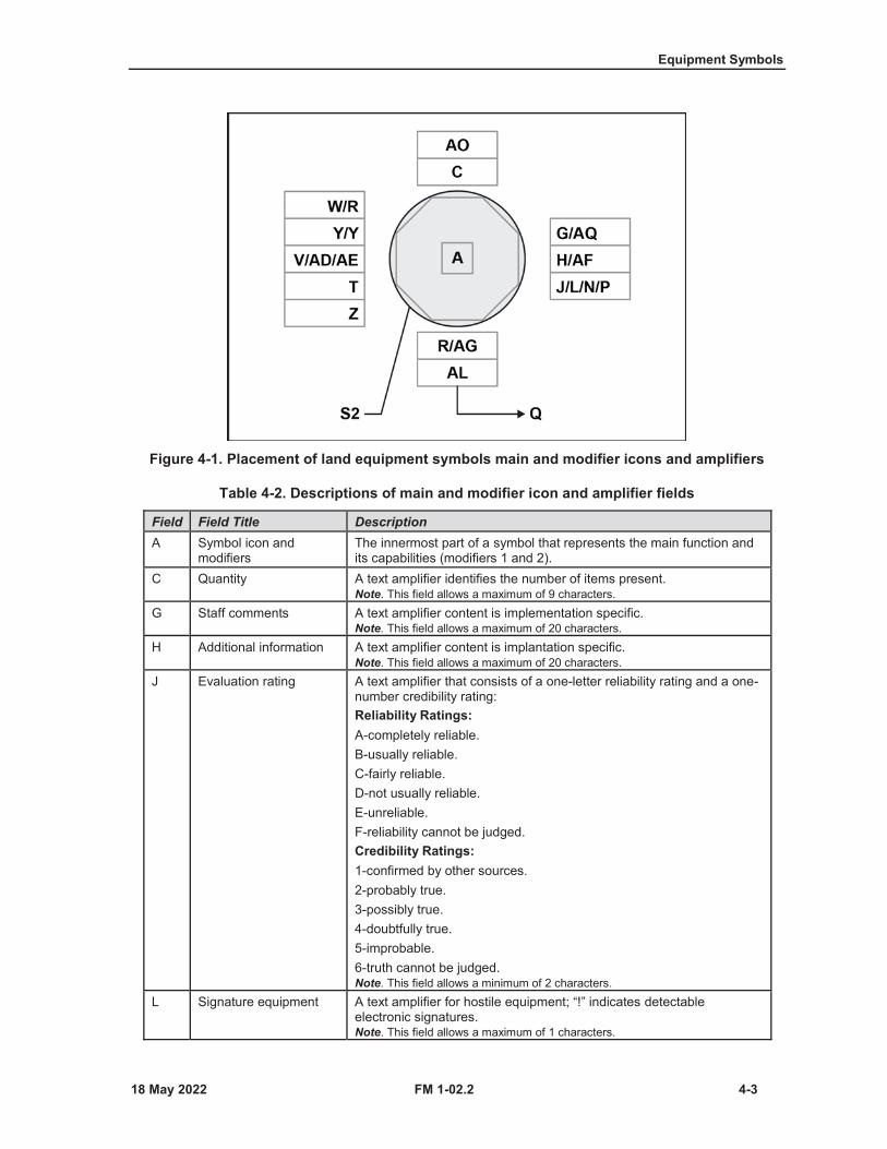
Equipment Symbols
FM 1-02.2 4-3
Figure 4-1. Placement of land equipment symbols main and modifier icons and amplifiers
Table 4-2. Descriptions of main and modifier icon and amplifier fields
Field Field Title DescriptionA Symbol icon and
modifiersThe innermost part of a symbol that represents the main function and its capabilities (modifiers 1 and 2).
C Quantity A text amplifier identifies the number of items present.Note. This field allows a maximum of 9 characters.
G Staff comments A text amplifier content is implementation specific.Note. This field allows a maximum of 20 characters.
H Additional information A text amplifier content is implantation specific.Note. This field allows a maximum of 20 characters.
J Evaluation rating A text amplifier that consists of a one-letter reliability rating and a one-number credibility rating:Reliability Ratings:A-completely reliable.B-usually reliable.C-fairly reliable.D-not usually reliable.E-unreliable.F-reliability cannot be judged.Credibility Ratings:1-confirmed by other sources.2-probably true.3-possibly true.4-doubtfully true.5-improbable.6-truth cannot be judged.Note. This field allows a minimum of 2 characters.
L Signature equipment A text amplifier for hostile equipment; “!” indicates detectable electronic signatures.Note. This field allows a maximum of 1 characters.

Chapter 4
4-4 FM 1-02.2
Table 4-2. Descriptions of main and modifier icon and amplifier fields (continued)
Field Field Title DescriptionN Hostile (enemy) A text amplifier for unframed equipment; letters “ENY” denote hostile
symbols.Note. This field allows a maximum of 3 characters.
P Identification, friend or foeSelective identification feature
A text amplifier displaying one or more identification, friend or foe or selective identification feature identification modes and codes.Display priority: Mode 5, Mode S,Mode 4, Mode 3, Mode 2.Note. This field allows a maximum of 15 characters.
Q Direction of movement indicator
A graphic amplifier that identifies the direction of movement or intended movement of an object.
R Mobility mode indicator A graphic amplifier that depicts the mobility mode of transportation of an object.
S2 Offset location indicator A graphic amplifier used to indicate the offset or precise location of a single point symbol.
T Unique identifier An amplifier field reserved for command and control systems that uniquely identifies a particular symbol with a track number.Prefix = TN: #####.Example: TN: 13579.Note. This field allows a maximum of 30 characters.
V Type A text amplifier for equipment that indicates types of equipment.Note. This field allows a maximum of 24 characters.
W Date-time group An alphanumeric designator for displaying a date-time group (DDHHMMSSZMONYYYY) or “O/O” for an order. The date-time group is composed of a group of six numeric digits with a time zone suffix and the standardized three-letter abbreviation for the month followed by four digits representing the year. The first pair of digits represents the day; the second pair, the hour; the third pair, the minutes. For automated systems, two digits may be added before the time zone suffix and after the minutes to designate seconds.Note. This field allows a maximum of 16 characters.
X Altitude or depth A text amplifier that displays either altitude, flight level, depth for submerged objects; or height of equipment or structures on the ground. Measurement units shall be displayed in the string.Examples:1500MSL.FL150.Note. This field allows a maximum of 14 characters.
Y Location A text amplifier that displays a symbol’s location in degrees, minutes, and decimal minutes (or in military grid reference system, global area reference system, or other applicable display formats).Examples:military grid reference system: 28SMB2649083145global area reference system: 3317.0921N 04412.6332ENote. This field allows a maximum of 22 characters.
Z Speed A text amplifier that displays velocity.Note. This field allows a maximum of 8 characters.
AD Platform type Electronic intelligence notation or communications intelligence notation.Note. This field allows a maximum of 6 characters.
AE Equipment teardown time
Equipment teardown time in minutes.Note. This field allows a maximum of 3 characters.
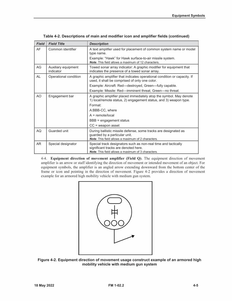
Equipment Symbols
FM 1-02.2 4-5
Table 4-2. Descriptions of main and modifier icon and amplifier fields (continued)
Field Field Title DescriptionAF Common identifier A text amplifier used for placement of common system name or model
type name.Example: “Hawk” for Hawk surface-to-air missile system.Note. This field allows a maximum of 12 characters.
AG Auxiliary equipment indicator
Towed sonar array indicator: A graphic modifier for equipment that indicates the presence of a towed sonar array.
AL Operational condition A graphic amplifier that indicates operational condition or capacity. If used, it shall be comprised of only one color.Example: Aircraft: Red—destroyed, Green—fully capable.Example: Missile: Red—imminent threat, Green—no threat.
AO Engagement bar A graphic amplifier placed immediately atop the symbol. May denote 1) local/remote status, 2) engagement status, and 3) weapon type.Format:A:BBB-CC, whereA = remote/localBBB = engagement statusCC = weapon asset
AQ Guarded unit During ballistic missile defense, some tracks are designated as guarded by a particular unit.Note. This field allows a maximum of 2 characters.
AR Special designator Special track designators such as non-real time and tactically significant tracks are denoted here.Note. This field allows a maximum of 3 characters.
4-4. Equipment direction of movement amplifier (Field Q). The equipment direction of movementamplifier is an arrow or staff identifying the direction of movement or intended movement of an object. Forequipment symbols, the amplifier is an angled arrow extending downward from the bottom center of theframe or icon and pointing in the direction of movement. Figure 4-2 provides a direction of movementexample for an armored high mobility vehicle with medium gun system.
Figure 4-2. Equipment direction of movement usage construct example of an armored high mobility vehicle with medium gun system
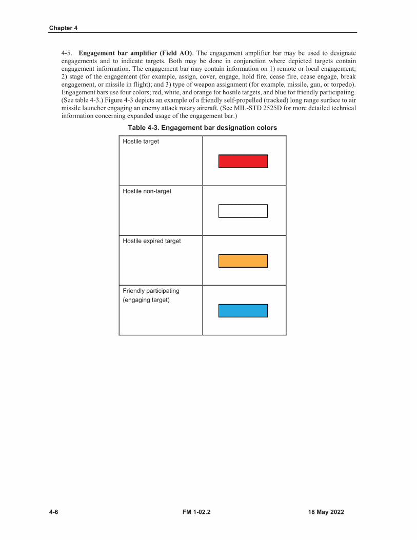
Chapter 4
4-6 FM 1-02.2
4-5. Engagement bar amplifier (Field AO). The engagement amplifier bar may be used to designateengagements and to indicate targets. Both may be done in conjunction where depicted targets containengagement information. The engagement bar may contain information on 1) remote or local engagement;2) stage of the engagement (for example, assign, cover, engage, hold fire, cease fire, cease engage, breakengagement, or missile in flight); and 3) type of weapon assignment (for example, missile, gun, or torpedo).Engagement bars use four colors; red, white, and orange for hostile targets, and blue for friendly participating.(See table 4-3.) Figure 4-3 depicts an example of a friendly self-propelled (tracked) long range surface to airmissile launcher engaging an enemy attack rotary aircraft. (See MIL-STD 2525D for more detailed technicalinformation concerning expanded usage of the engagement bar.)
Table 4-3. Engagement bar designation colors
Hostile target
Hostile non-target
Hostile expired target
Friendly participating(engaging target)
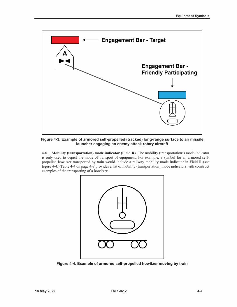
Equipment Symbols
FM 1-02.2 4-7
Figure 4-3. Example of armored self-propelled (tracked) long-range surface to air missile launcher engaging an enemy attack rotary aircraft
4-6. Mobility (transportation) mode indicator (Field R). The mobility (transportations) mode indicatoris only used to depict the mode of transport of equipment. For example, a symbol for an armored self-propelled howitzer transported by train would include a railway mobility mode indicator in Field R (seefigure 4-4.) Table 4-4 on page 4-8 provides a list of mobility (transportation) mode indicators with constructexamples of the transporting of a howitzer.
Figure 4-4. Example of armored self-propelled howitzer moving by train
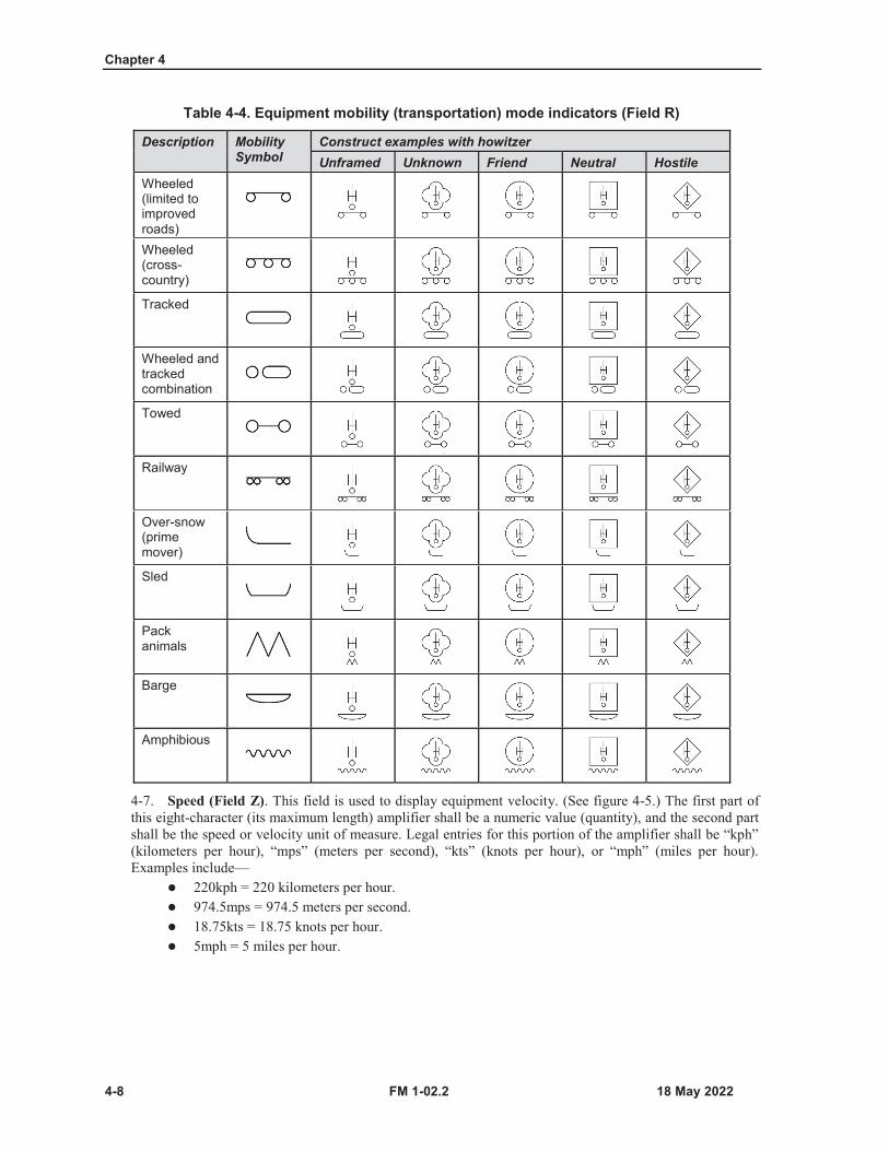
Chapter 4
4-8 FM 1-02.2
Table 4-4. Equipment mobility (transportation) mode indicators (Field R)
Description Mobility Symbol
Construct examples with howitzerUnframed Unknown Friend Neutral Hostile
Wheeled (limited to improved roads)Wheeled (cross-country)
Tracked
Wheeled and tracked combination
Towed
Railway
Over-snow (prime mover)
Sled
Pack animals
Barge
Amphibious
4-7. Speed (Field Z). This field is used to display equipment velocity. (See figure 4-5.) The first part ofthis eight-character (its maximum length) amplifier shall be a numeric value (quantity), and the second partshall be the speed or velocity unit of measure. Legal entries for this portion of the amplifier shall be “kph”(kilometers per hour), “mps” (meters per second), “kts” (knots per hour), or “mph” (miles per hour).Examples include—
220kph = 220 kilometers per hour.974.5mps = 974.5 meters per second.18.75kts = 18.75 knots per hour.5mph = 5 miles per hour.
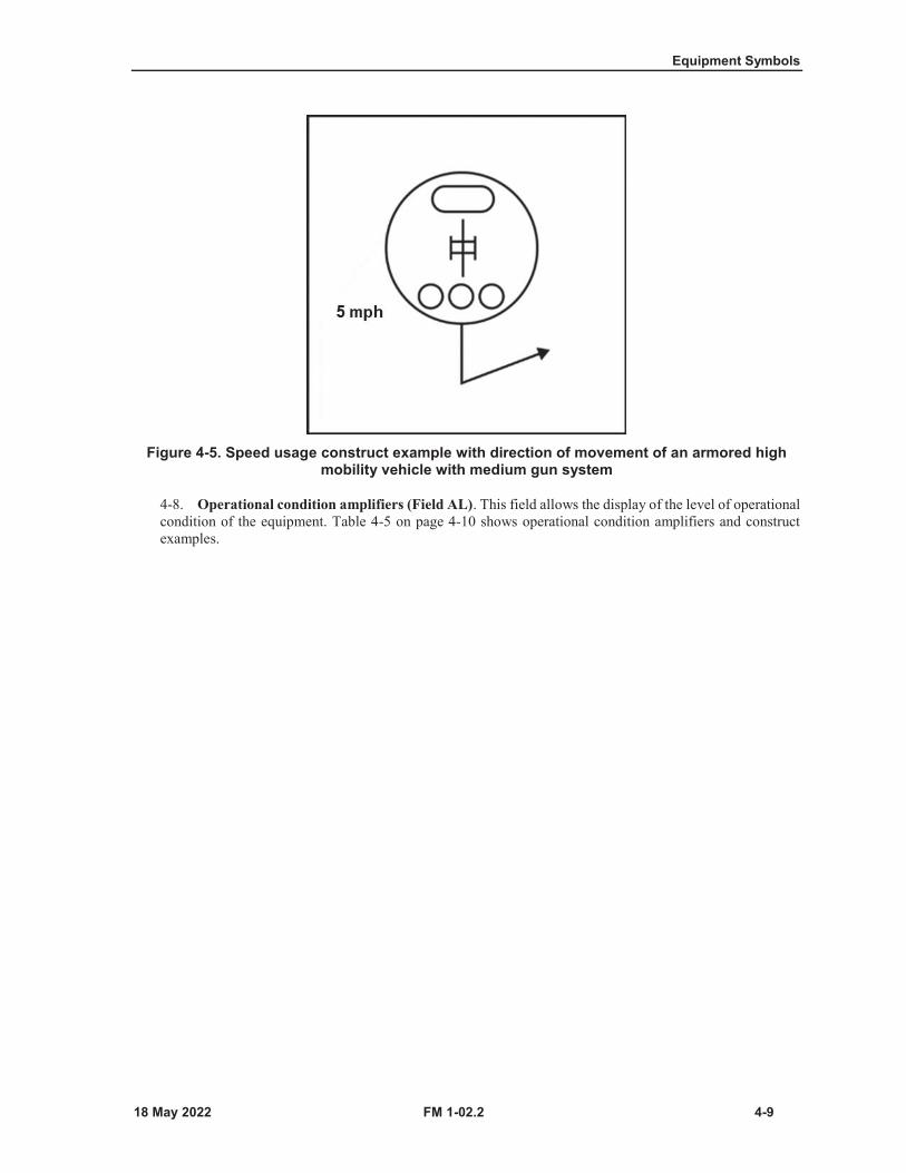
Equipment Symbols
FM 1-02.2 4-9
Figure 4-5. Speed usage construct example with direction of movement of an armored high mobility vehicle with medium gun system
4-8. Operational condition amplifiers (Field AL). This field allows the display of the level of operationalcondition of the equipment. Table 4-5 on page 4-10 shows operational condition amplifiers and constructexamples.
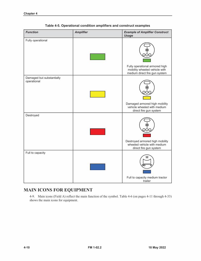
Chapter 4
4-10 FM 1-02.2
Table 4-5. Operational condition amplifiers and construct examples
Function Amplifier Example of Amplifier Construct Usage
Fully operational
Fully operational armored high mobility wheeled vehicle with medium direct fire gun system
Damaged but substantially operational
Damaged armored high mobility vehicle wheeled with medium
direct fire gun systemDestroyed
Destroyed armored high mobility wheeled vehicle with medium
direct fire gun systemFull to capacity
Full to capacity medium tractor trailer
MAIN ICONS FOR EQUIPMENT4-9. Main icons (Field A) reflect the main function of the symbol. Table 4-6 (on pages 4-11 through 4-33)shows the main icons for equipment.
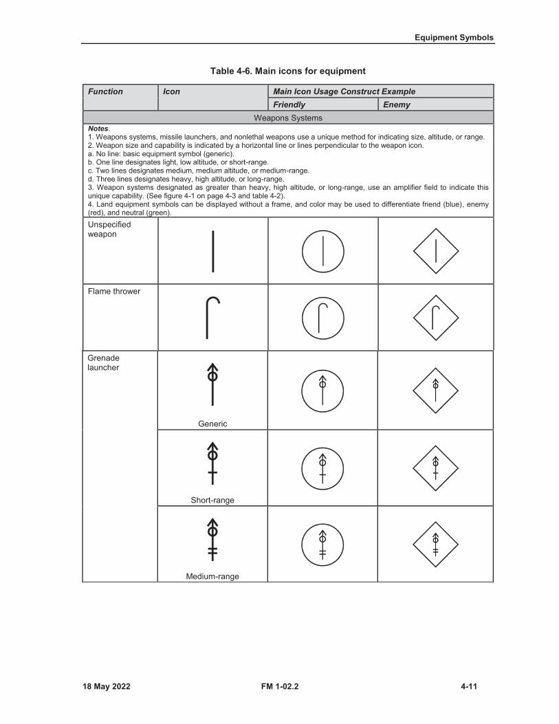
Equipment Symbols
FM 1-02.2 4-11
Table 4-6. Main icons for equipment
Function Icon Main Icon Usage Construct ExampleFriendly Enemy
Weapons SystemsNotes.1. Weapons systems, missile launchers, and nonlethal weapons use a unique method for indicating size, altitude, or range.2. Weapon size and capability is indicated by a horizontal line or lines perpendicular to the weapon icon.a. No line: basic equipment symbol (generic).b. One line designates light, low altitude, or short-range.c. Two lines designates medium, medium altitude, or medium-range.d. Three lines designates heavy, high altitude, or long-range.3. Weapon systems designated as greater than heavy, high altitude, or long-range, use an amplifier field to indicate thisunique capability. (See figure 4-1 on page 4-3 and table 4-2).4. Land equipment symbols can be displayed without a frame, and color may be used to differentiate friend (blue), enemy(red), and neutral (green).Unspecified weapon
Flame thrower
Grenade launcher
Generic
Short-range
Medium-range
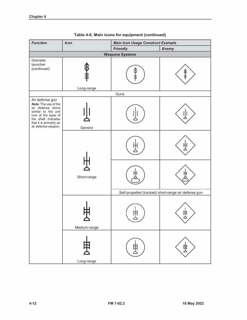
Chapter 4
4-12 FM 1-02.2
Table 4-6. Main icons for equipment (continued)
Function Icon Main Icon Usage Construct ExampleFriendly Enemy
Weapons SystemsGrenade launcher (continued)
Long-rangeGuns
Air defense gunNote. The use of the air defense dome similar to the unit icon at the base of the shaft indicates that it is primarily an air defense weapon. Generic
Short-range
Self-propelled (tracked) short-range air defense gun
Medium-range
Long-range

Equipment Symbols
FM 1-02.2 4-13
Table 4-6. Main icons for equipment (continued)
Function Icon Main Icon Usage Construct ExampleFriendly Enemy
Weapons SystemsAnti-tank gunNote. The use of the inverted V similar to the unit icon at the base of the shaft indicates that it is primarily an antitank weapon.
Generic
Armored high mobility wheeled vehicle with anti-tank gun
Light
Medium
HeavyDirect fire gun
Generic
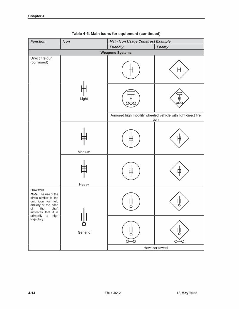
Chapter 4
4-14 FM 1-02.2
Table 4-6. Main icons for equipment (continued)
Function Icon Main Icon Usage Construct ExampleFriendly Enemy
Weapons SystemsDirect fire gun (continued)
Light
Armored high mobility wheeled vehicle with light direct fire gun
Medium
HeavyHowitzerNote. The use of the circle similar to the unit icon for field artillery at the base of the shaft indicates that it is primarily a high trajectory.
Generic
Howitzer towed

Equipment Symbols
FM 1-02.2 4-15
Table 4-6. Main icons for equipment (continued)
Function Icon Main Icon Usage Construct ExampleFriendly Enemy
Weapons SystemsHowitzer (continued)
120 millimeters or less
Greater than 120 millimeters but less than
160 millimeters
Greater than 160 millimeters but less than
210 millimeters
Howitzer armored self-propelled (tracked)Mortar
Generic
60 millimeters or less
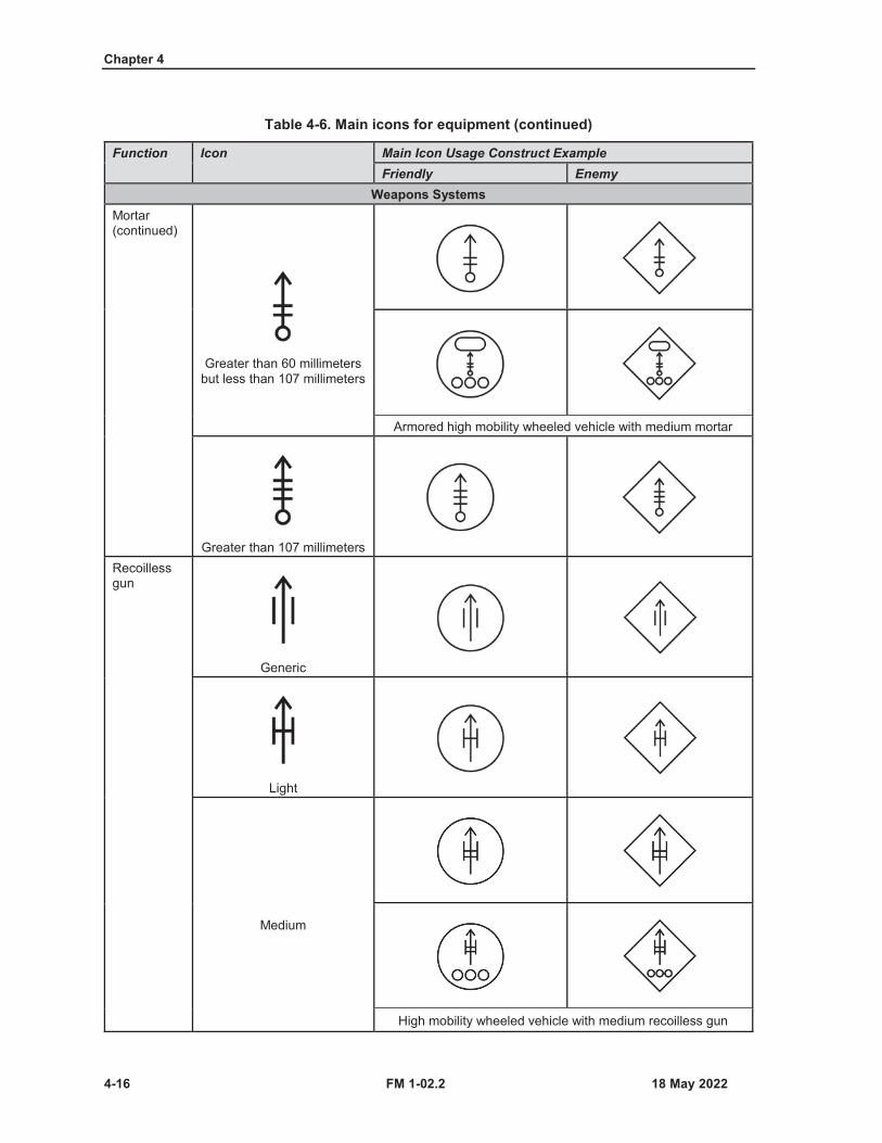
Chapter 4
4-16 FM 1-02.2
Table 4-6. Main icons for equipment (continued)
Function Icon Main Icon Usage Construct ExampleFriendly Enemy
Weapons SystemsMortar (continued)
Greater than 60 millimeters but less than 107 millimeters
Armored high mobility wheeled vehicle with medium mortar
Greater than 107 millimetersRecoilless gun
Generic
Light
Medium
High mobility wheeled vehicle with medium recoilless gun
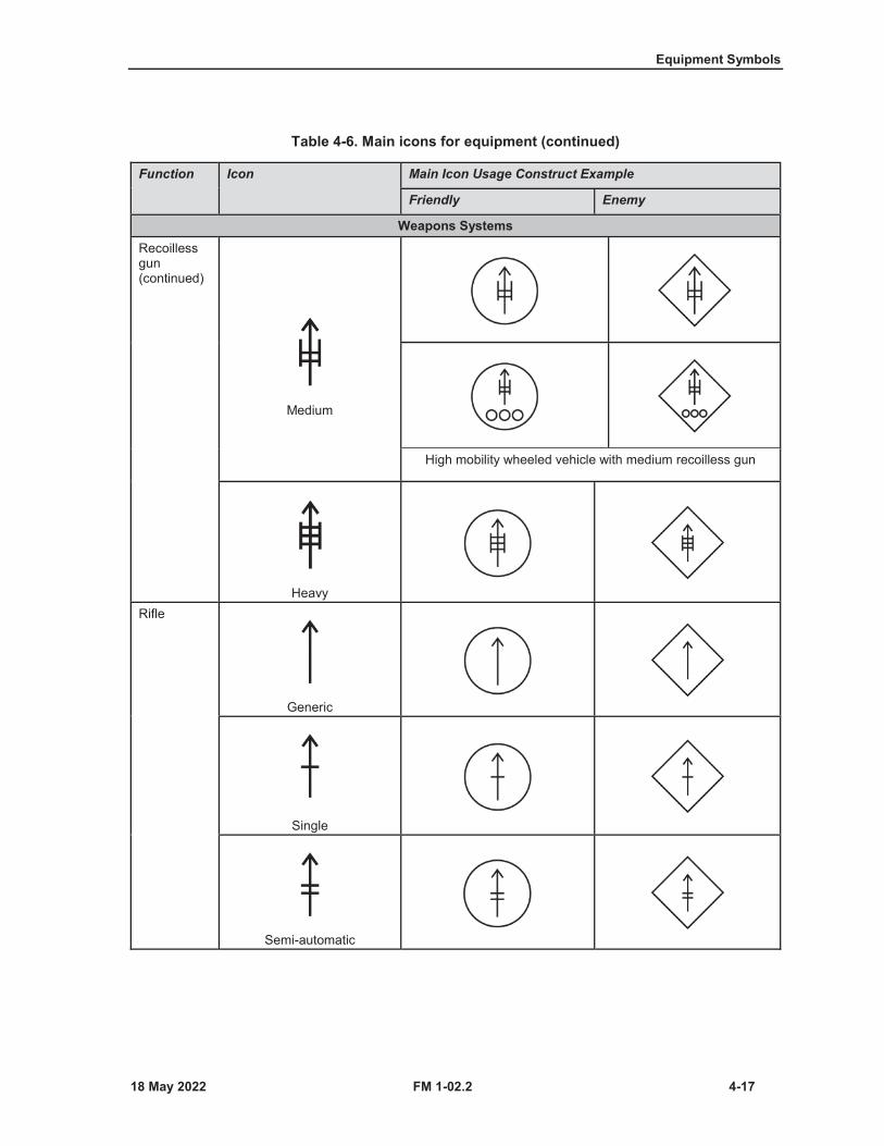
Equipment Symbols
FM 1-02.2 4-17
Table 4-6. Main icons for equipment (continued)
Function Icon Main Icon Usage Construct Example
Friendly Enemy
Weapons SystemsRecoilless gun(continued)
Medium
High mobility wheeled vehicle with medium recoilless gun
HeavyRifle
Generic
Single
Semi-automatic
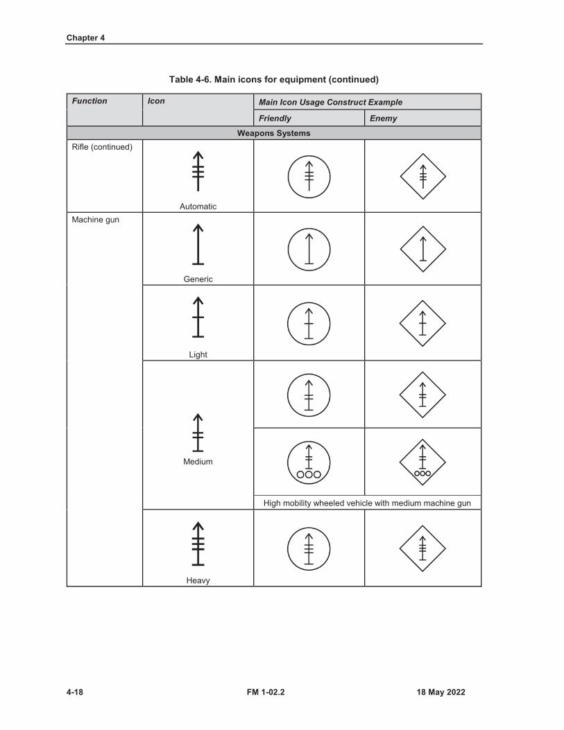
Chapter 4
4-18 FM 1-02.2
Table 4-6. Main icons for equipment (continued)
Function Icon Main Icon Usage Construct Example
Friendly Enemy
Weapons SystemsRifle (continued)
AutomaticMachine gun
Generic
Light
Medium
High mobility wheeled vehicle with medium machine gun
Heavy
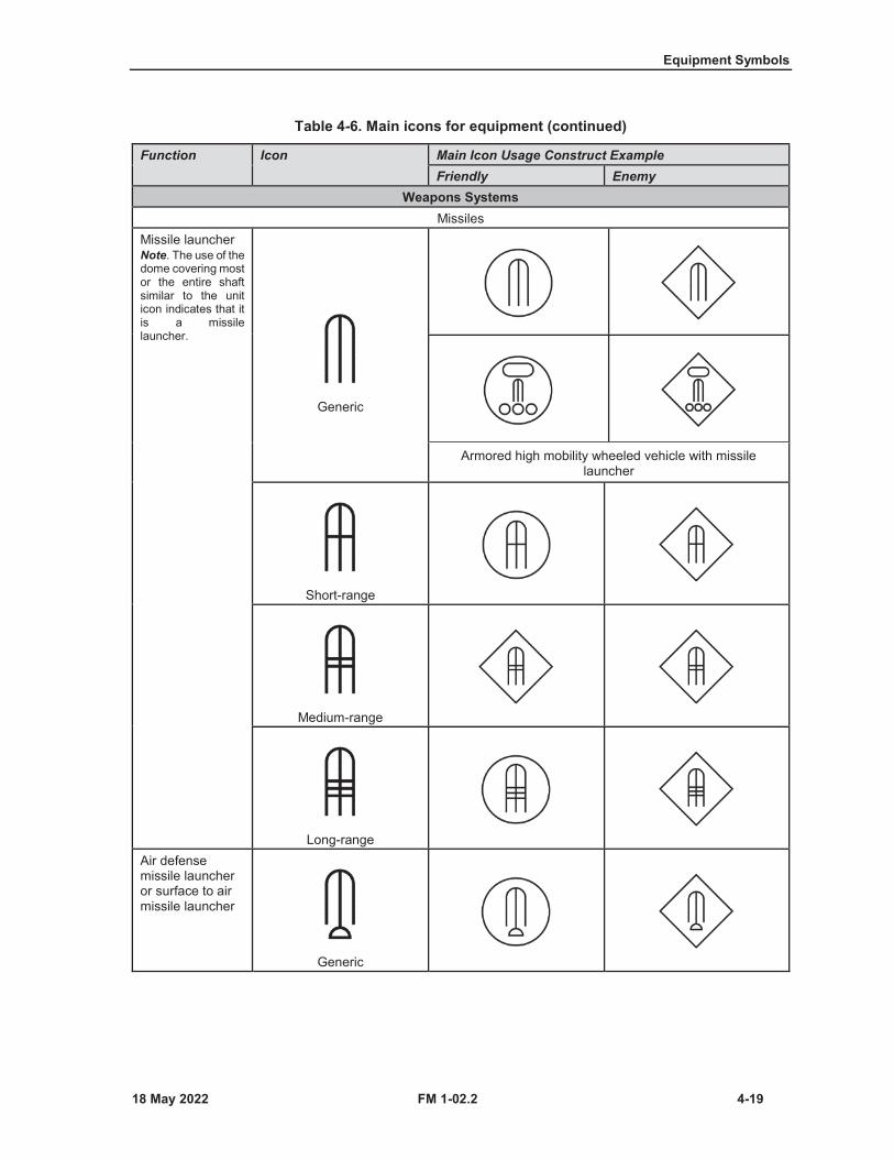
Equipment Symbols
FM 1-02.2 4-19
Table 4-6. Main icons for equipment (continued)
Function Icon Main Icon Usage Construct ExampleFriendly Enemy
Weapons SystemsMissiles
Missile launcher Note. The use of the dome covering most or the entire shaft similar to the unit icon indicates that it is a missile launcher.
Generic
Armored high mobility wheeled vehicle with missile launcher
Short-range
Medium-range
Long-rangeAir defense missile launcher or surface to air missile launcher
Generic

Chapter 4
4-20 FM 1-02.2
Table 4-6. Main icons for equipment (continued)
Function Icon Main Icon Usage Construct ExampleFriendly Enemy
Weapons SystemsAir defense missile launcher or surface to air missile launcher (continued)
Short-range
Armored high mobility wheeled vehicle with short-range air defense surface to air missile launcher
Medium-range
Long-range
Armored high mobility wheeled vehicle with missile launcher
Antitank missile launcher
Generic
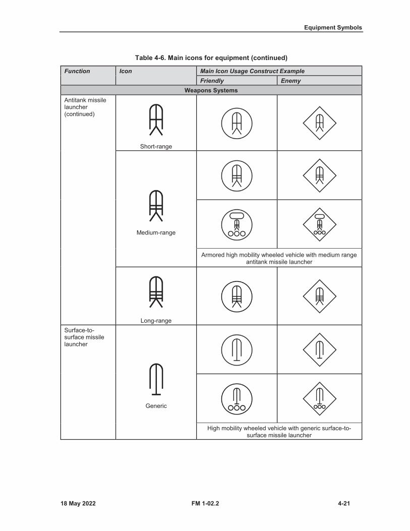
Equipment Symbols
FM 1-02.2 4-21
Table 4-6. Main icons for equipment (continued)
Function Icon Main Icon Usage Construct ExampleFriendly Enemy
Weapons SystemsAntitank missile launcher (continued)
Short-range
Medium-range
Armored high mobility wheeled vehicle with medium range antitank missile launcher
Long-rangeSurface-to-surface missile launcher
Generic
High mobility wheeled vehicle with generic surface-to-surface missile launcher
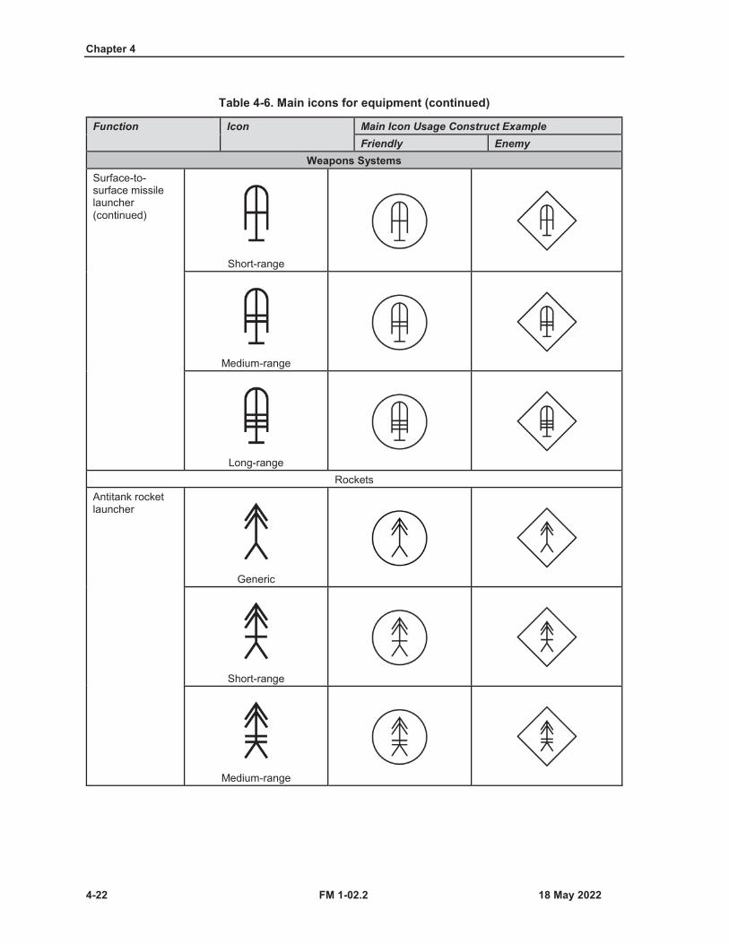
Chapter 4
4-22 FM 1-02.2
Table 4-6. Main icons for equipment (continued)
Function Icon Main Icon Usage Construct ExampleFriendly Enemy
Weapons SystemsSurface-to-surface missile launcher (continued)
Short-range
Medium-range
Long-rangeRockets
Antitank rocket launcher
Generic
Short-range
Medium-range

Equipment Symbols
FM 1-02.2 4-23
Table 4-6. Main icons for equipment (continued)
Function Icon Main Icon Usage Construct ExampleFriendly Enemy
Weapons SystemsAntitank rocket launcher (continued)
Medium-range (continued) Armored tracked vehicle with medium antitank rocket launcher
Long-rangeSingle rocket launcherNote. The use of the double inverted Vs similar to the multiple rocket launcher unit icon indicates that it is a rocket launcher.
Generic
Short-range
Medium-range
Long-range
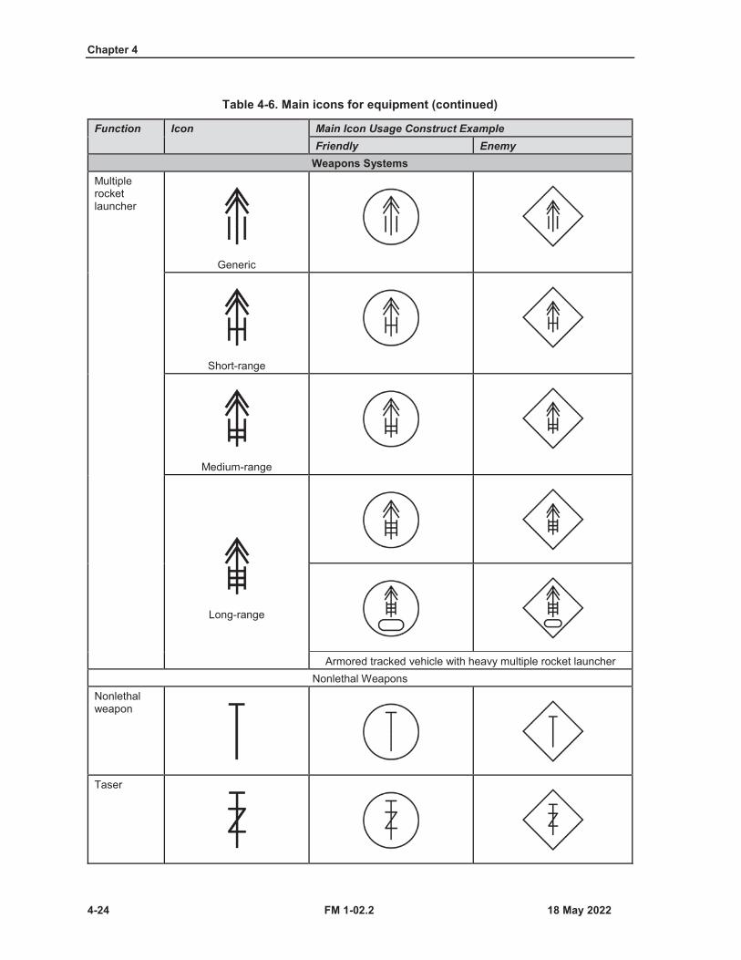
Chapter 4
4-24 FM 1-02.2
Table 4-6. Main icons for equipment (continued)
Function Icon Main Icon Usage Construct ExampleFriendly Enemy
Weapons SystemsMultiple rocket launcher
Generic
Short-range
Medium-range
Long-range
Armored tracked vehicle with heavy multiple rocket launcherNonlethal Weapons
Nonlethal weapon
Taser
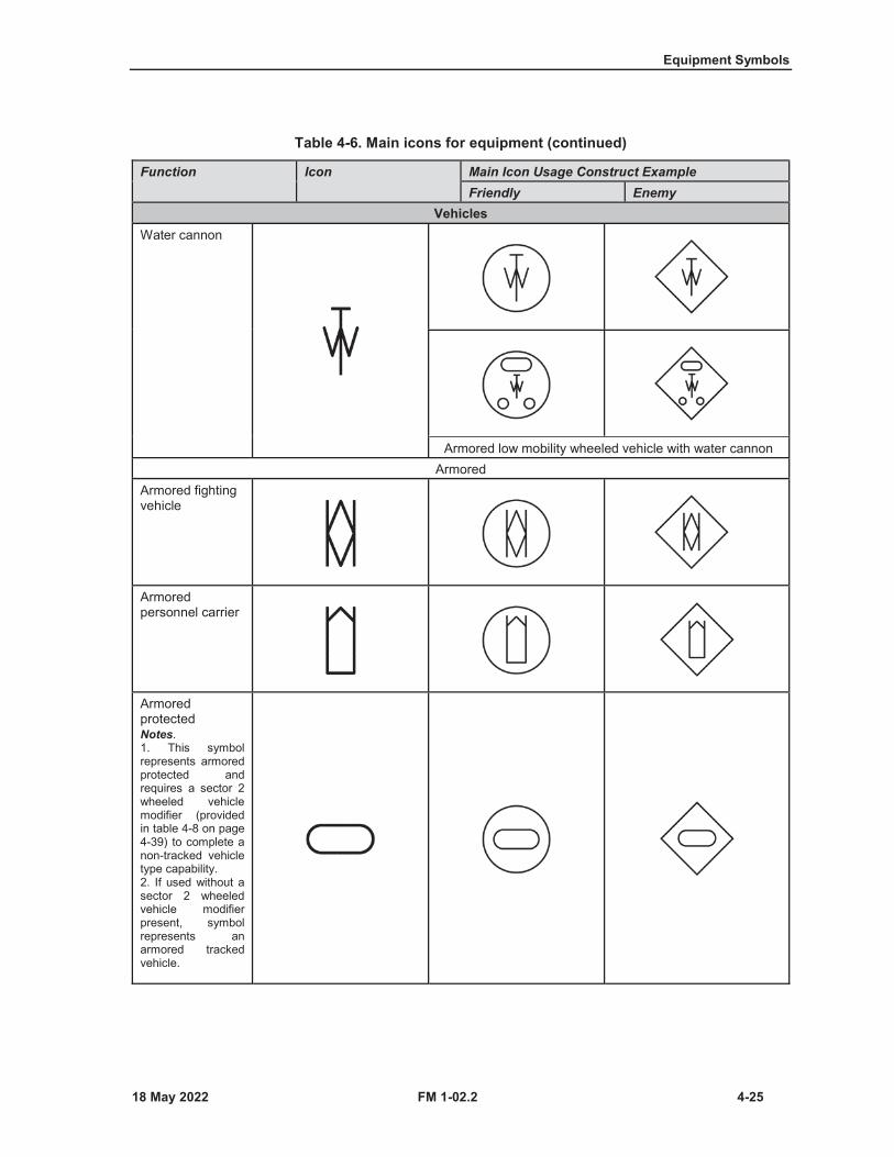
Equipment Symbols
FM 1-02.2 4-25
Table 4-6. Main icons for equipment (continued)
Function Icon Main Icon Usage Construct ExampleFriendly Enemy
VehiclesWater cannon
Armored low mobility wheeled vehicle with water cannonArmored
Armored fighting vehicle
Armored personnel carrier
Armored protectedNotes.1. This symbolrepresents armoredprotected andrequires a sector 2wheeled vehiclemodifier (providedin table 4-8 on page4-39) to complete anon-tracked vehicletype capability.2. If used without asector 2 wheeledvehicle modifier present, symbol represents an armored tracked vehicle.
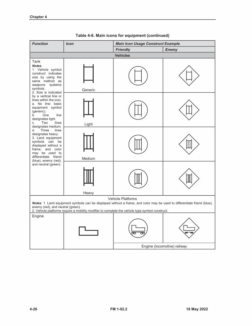
Chapter 4
4-26 FM 1-02.2
Table 4-6. Main icons for equipment (continued)
Function Icon Main Icon Usage Construct ExampleFriendly EnemyVehicles
TankNotes.1. Vehicle symbolconstruct indicatessize by using thesame method asweapons systemssymbols.2. Size is indicatedby a vertical line orlines within the icon.a. No line: basicequipment symbol(generic).b. One line designates light.c. Two linesdesignates medium.d. Three lines designates heavy.3. Land equipmentsymbols can bedisplayed without aframe, and colormay be used todifferentiate friend(blue), enemy (red),and neutral (green).
Generic
Light
Medium
HeavyVehicle Platforms
Notes. 1. Land equipment symbols can be displayed without a frame, and color may be used to differentiate friend (blue), enemy (red), and neutral (green).2. Vehicle platforms require a mobility modifier to complete the vehicle type symbol construct.Engine
Engine (locomotive) railway

Equipment Symbols
FM 1-02.2 4-27
Table 4-6. Main icons for equipment (continued)
Function Icon Main Icon Usage Construct ExampleFriendly EnemyVehicles
Flatbed
Flatbed railway car
Flatbed tractor trailerVehicle
Railway boxcar
High mobility wheeled petroleum, oils, and lubricants vehicle
Low mobility wheeled armored vehicle (armored car)
Medium tractor trailer

Chapter 4
4-28 FM 1-02.2
Table 4-6. Main icons for equipment (continued)
Function Icon Main Icon Usage Construct ExampleFriendly Enemy
Engineer EquipmentBridge
Rail bridgeFixed bridge
Folding girder bridge
Hollow deck bridge
Drill
Medium drill

Equipment Symbols
FM 1-02.2 4-29
Table 4-6. Main icons for equipment (continued)
Function Icon Main Icon Usage Construct ExampleFriendly Enemy
Mine clearing
Armored (tracked) robotic mine clearing vehicleMine laying
Tracked mine laying vehicleAircraft
Note. For all aircraft, an unframed icon denotes the equipment is in flight—in addition to the in flight construct provided.Fixed wing
Fixed-wing aircraft on ground
Fixed-wing aircraft in flight
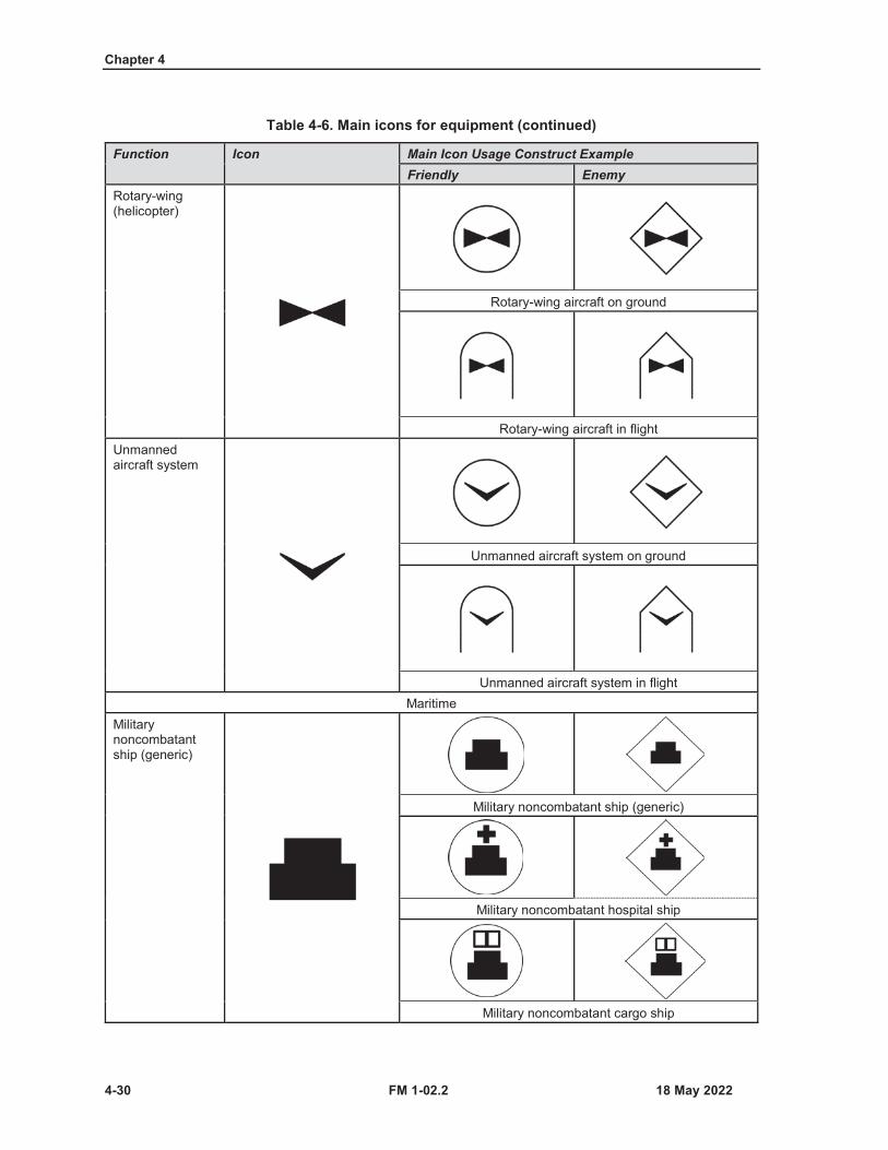
Chapter 4
4-30 FM 1-02.2
Table 4-6. Main icons for equipment (continued)
Function Icon Main Icon Usage Construct ExampleFriendly Enemy
Rotary-wing (helicopter)
Rotary-wing aircraft on ground
Rotary-wing aircraft in flightUnmanned aircraft system
Unmanned aircraft system on ground
Unmanned aircraft system in flightMaritime
Military noncombatant ship (generic)
Military noncombatant ship (generic)
Military noncombatant hospital ship
Military noncombatant cargo ship
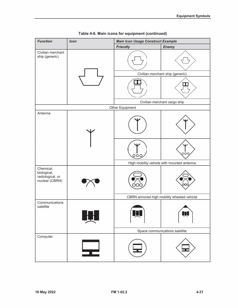
Equipment Symbols
FM 1-02.2 4-31
Table 4-6. Main icons for equipment (continued)
Function Icon Main Icon Usage Construct ExampleFriendly Enemy
Civilian merchant ship (generic)
Civilian merchant ship (generic)
Civilian merchant cargo shipOther Equipment
Antenna
High mobility vehicle with mounted antennaChemical, biological, radiological, or nuclear (CBRN)
CBRN armored high mobility wheeled vehicleCommunications satellite
Space communications satelliteComputer
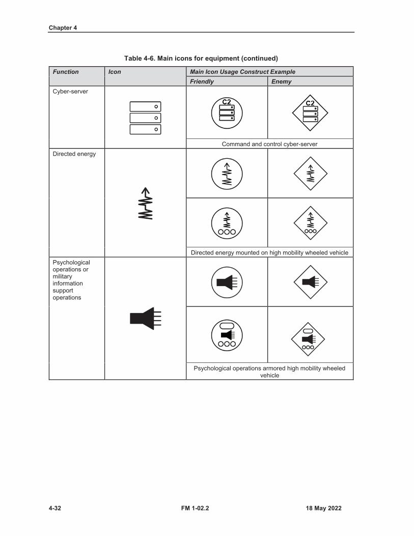
Chapter 4
4-32 FM 1-02.2
Table 4-6. Main icons for equipment (continued)
Function Icon Main Icon Usage Construct ExampleFriendly Enemy
Cyber-server
Command and control cyber-serverDirected energy
Directed energy mounted on high mobility wheeled vehiclePsychological operations or military information support operations
Psychological operations armored high mobility wheeled vehicle
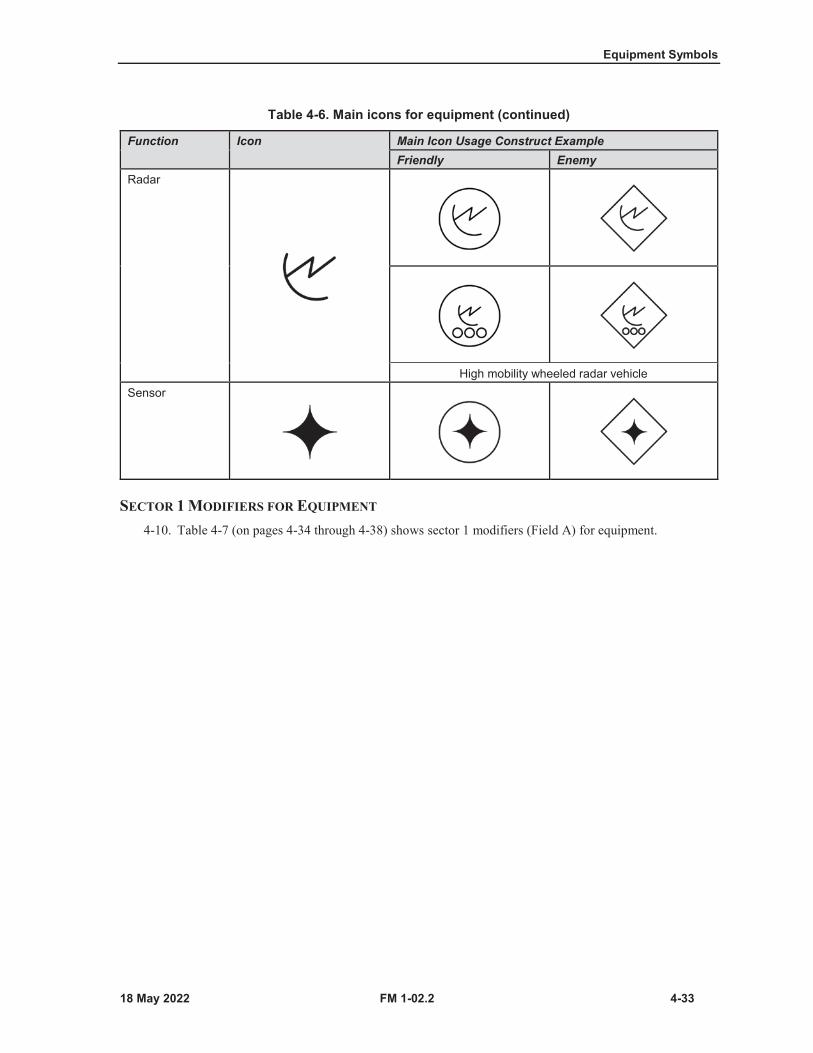
Equipment Symbols
FM 1-02.2 4-33
SECTOR 1 MODIFIERS FOR EQUIPMENT
4-10. Table 4-7 (on pages 4-34 through 4-38) shows sector 1 modifiers (Field A) for equipment.
Table 4-6. Main icons for equipment (continued)
Function Icon Main Icon Usage Construct ExampleFriendly Enemy
Radar
High mobility wheeled radar vehicleSensor
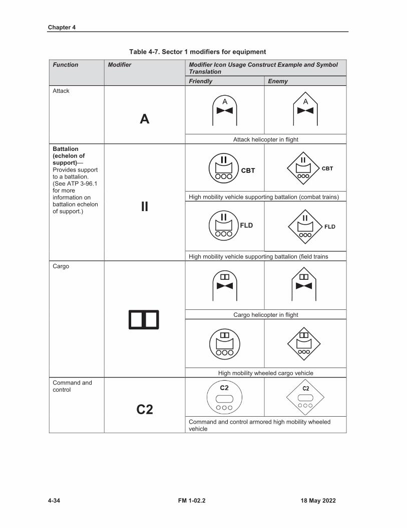
Chapter 4
4-34 FM 1-02.2
Table 4-7. Sector 1 modifiers for equipment
Function Modifier Modifier Icon Usage Construct Example and Symbol TranslationFriendly Enemy
Attack
AAttack helicopter in flight
Battalion (echelon of support)—Provides support to a battalion. (See ATP 3-96.1 for more information on battalion echelon of support.) II
High mobility vehicle supporting battalion (combat trains)
High mobility vehicle supporting battalion (field trainsCargo
Cargo helicopter in flight
High mobility wheeled cargo vehicleCommand and control
C2Command and control armored high mobility wheeled vehicle

Equipment Symbols
FM 1-02.2 4-35
Table 4-7. Sector 1 modifiers for equipment (continued)
Function Modifier Modifier Icon Usage Construct Example and Symbol TranslationFriendly Enemy
HeavyNote. This modifier symbol is interchangeable. Symbol may be used as a sector 1 or sector 2 modifier with the same meaning.
HHeavy helicopter in flight
LightNote. This modifier symbol is interchangeable. Symbol may be used as a sector 1 or sector 2 modifier with the same meaning.
LLight helicopter in flight
Light high mobility wheeled vehicleMediumNote. This modifier symbol is interchangeable. Symbol may be used as a sector 1 or sector 2 modifier with the same meaning.
MMedium helicopter in flight
Medium low mobility wheeled vehicle
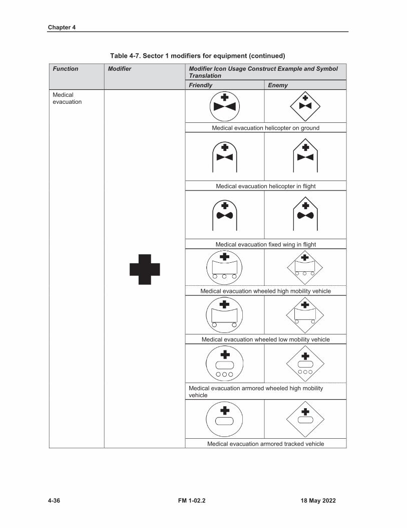
Chapter 4
4-36 FM 1-02.2
Table 4-7. Sector 1 modifiers for equipment (continued)
Function Modifier Modifier Icon Usage Construct Example and Symbol TranslationFriendly Enemy
Medical evacuation
Medical evacuation helicopter on ground
Medical evacuation helicopter in flight
Medical evacuation fixed wing in flight
Medical evacuation wheeled high mobility vehicle
Medical evacuation wheeled low mobility vehicle
Medical evacuation armored wheeled high mobility vehicle
Medical evacuation armored tracked vehicle
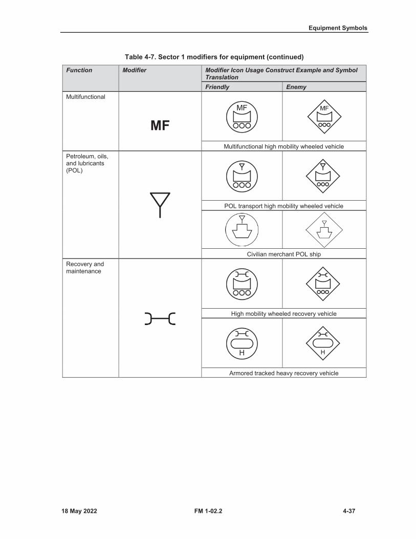
Equipment Symbols
FM 1-02.2 4-37
Table 4-7. Sector 1 modifiers for equipment (continued)
Function Modifier Modifier Icon Usage Construct Example and Symbol TranslationFriendly Enemy
Multifunctional
MFMultifunctional high mobility wheeled vehicle
Petroleum, oils, and lubricants (POL)
POL transport high mobility wheeled vehicle
Civilian merchant POL shipRecovery and maintenance
High mobility wheeled recovery vehicle
Armored tracked heavy recovery vehicle
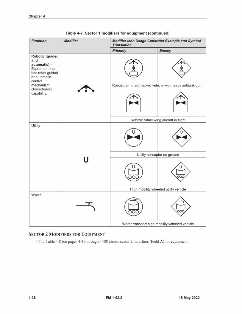
Chapter 4
4-38 FM 1-02.2
Table 4-7. Sector 1 modifiers for equipment (continued)
Function Modifier Modifier Icon Usage Construct Example and Symbol TranslationFriendly Enemy
Robotic (guided and automatic)—Equipment that has robot guided or automatic control mechanism characteristic capability.
Robotic armored tracked vehicle with heavy antitank gun
Robotic rotary wing aircraft in flightUtility
UUtility helicopter on ground
High mobility wheeled utility vehicleWater
Water transport high mobility wheeled vehicle
SECTOR 2 MODIFIERS FOR EQUIPMENT
4-11. Table 4-8 (on pages 4-39 through 4-40) shows sector 2 modifiers (Field A) for equipment.
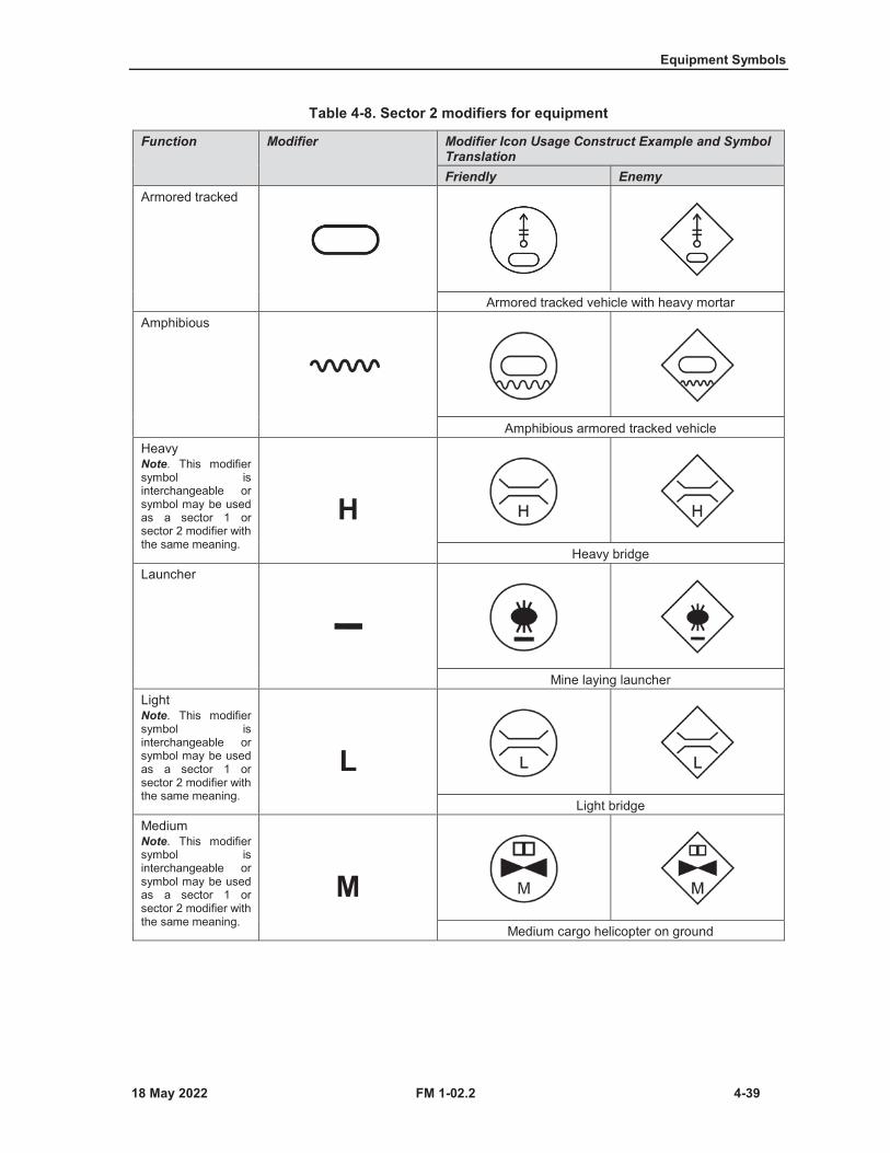
Equipment Symbols
FM 1-02.2 4-39
Table 4-8. Sector 2 modifiers for equipment
Function Modifier Modifier Icon Usage Construct Example and Symbol TranslationFriendly Enemy
Armored tracked
Armored tracked vehicle with heavy mortarAmphibious
Amphibious armored tracked vehicleHeavyNote. This modifier symbol is interchangeable or symbol may be used as a sector 1 or sector 2 modifier with the same meaning.
HHeavy bridge
Launcher
Mine laying launcherLightNote. This modifier symbol is interchangeable or symbol may be used as a sector 1 or sector 2 modifier with the same meaning.
LLight bridge
MediumNote. This modifier symbol is interchangeable or symbol may be used as a sector 1 or sector 2 modifier with the same meaning.
MMedium cargo helicopter on ground
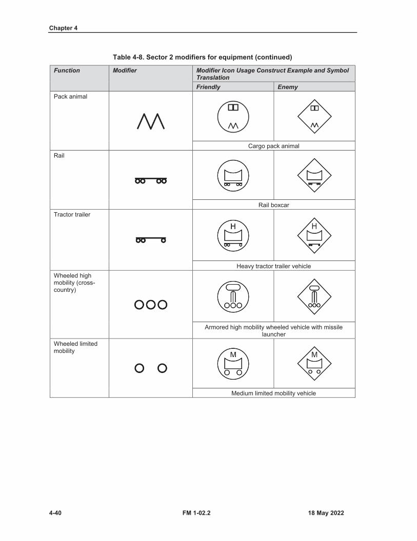
Chapter 4
4-40 FM 1-02.2
Table 4-8. Sector 2 modifiers for equipment (continued)
Function Modifier Modifier Icon Usage Construct Example and Symbol TranslationFriendly Enemy
Pack animal
Cargo pack animalRail
Rail boxcarTractor trailer
Heavy tractor trailer vehicleWheeled high mobility (cross-country)
Armored high mobility wheeled vehicle with missile launcher
Wheeled limitedmobility
Medium limited mobility vehicle
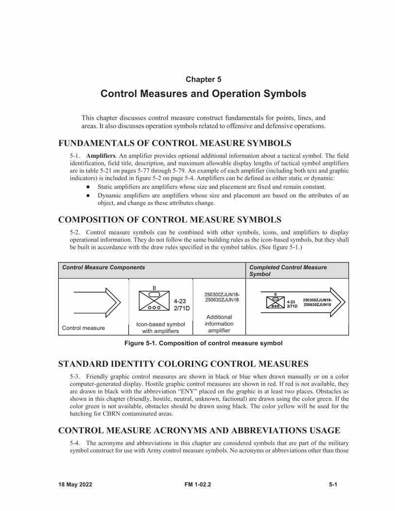
FM 1-02.2 5-1
Chapter 5
Control Measures and Operation Symbols
This chapter discusses control measure construct fundamentals for points, lines, and areas. It also discusses operation symbols related to offensive and defensive operations.
FUNDAMENTALS OF CONTROL MEASURE SYMBOLS5-1. Amplifiers. An amplifier provides optional additional information about a tactical symbol. The fieldidentification, field title, description, and maximum allowable display lengths of tactical symbol amplifiersare in table 5-21 on pages 5-77 through 5-79. An example of each amplifier (including both text and graphicindicators) is included in figure 5-2 on page 5-4. Amplifiers can be defined as either static or dynamic:
Static amplifiers are amplifiers whose size and placement are fixed and remain constant.Dynamic amplifiers are amplifiers whose size and placement are based on the attributes of anobject, and change as these attributes change.
COMPOSITION OF CONTROL MEASURE SYMBOLS5-2. Control measure symbols can be combined with other symbols, icons, and amplifiers to displayoperational information. They do not follow the same building rules as the icon-based symbols, but they shallbe built in accordance with the draw rules specified in the symbol tables. (See figure 5-1.)
Control Measure Components Completed Control Measure Symbol
Control measure Icon-based symbol with amplifiers
Additional information
amplifier
Figure 5-1. Composition of control measure symbol
STANDARD IDENTITY COLORING CONTROL MEASURES5-3. Friendly graphic control measures are shown in black or blue when drawn manually or on a colorcomputer-generated display. Hostile graphic control measures are shown in red. If red is not available, theyare drawn in black with the abbreviation “ENY” placed on the graphic in at least two places. Obstacles asshown in this chapter (friendly, hostile, neutral, unknown, factional) are drawn using the color green. If thecolor green is not available, obstacles should be drawn using black. The color yellow will be used for thehatching for CBRN contaminated areas.
CONTROL MEASURE ACRONYMS AND ABBREVIATIONS USAGE5-4. The acronyms and abbreviations in this chapter are considered symbols that are part of the militarysymbol construct for use with Army control measure symbols. No acronyms or abbreviations other than those
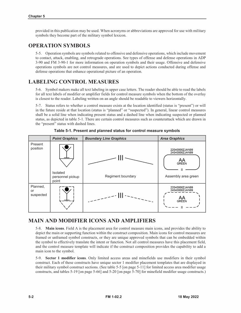
Chapter 5
5-2 FM 1-02.2
provided in this publication may be used. When acronyms or abbreviations are approved for use with military symbols they become part of the military symbol lexicon.
OPERATION SYMBOLS5-5. Operation symbols are symbols related to offensive and defensive operations, which include movementto contact, attack, enabling, and retrograde operations. See types of offense and defense operations in ADP3-90 and FM 3-90-1 for more information on operation symbols and their usage. Offensive and defensiveoperations symbols are not control measures, and are used to depict actions conducted during offense anddefense operations that enhance operational picture of an operation.
LABELING CONTROL MEASURES5-6. Symbol makers make all text labeling in upper case letters. The reader should be able to read the labelsfor all text labels of modifier or amplifier fields for control measure symbols when the bottom of the overlayis closest to the reader. Labeling written on an angle should be readable to viewers horizontally.
5-7. Status refers to whether a control measure exists at the location identified (status is “present”) or willin the future reside at that location (status is “planned” or “suspected”). In general, linear control measuresshall be a solid line when indicating present status and a dashed line when indicating suspected or plannedstatus, as depicted in table 5-1. There are certain control measures such as counterattack which are drawn inthe “present” status with dashed lines.
Table 5-1. Present and planned status for control measure symbols
Point Graphics Boundary Line Graphics Area GraphicsPresent position
Isolated personnel pickup point
Regiment boundary Assembly area green
Planned, or suspected
MAIN AND MODIFIER ICONS AND AMPLIFIERS5-8. Main icons. Field A is the placement area for control measure main icons, and provides the ability todepict the main or supporting function within the construct composition. Main icons for control measures areframed or unframed symbol constructs, or they are unique approved symbols that can be embedded withinthe symbol to effectively translate the intent or function. Not all control measures have this placement field,and the control measure template will indicate if the construct composition provides the capability to add amain icon to the symbol.
5-9. Sector 1 modifier icons. Only limited access areas and minefields use modifiers in their symbolconstruct. Each of these constructs have unique sector 1 modifier placement templates that are displayed intheir military symbol construct sections. (See table 5-5 [on page 5-11] for limited access area modifier usageconstructs, and tables 5-19 [on page 5-66] and 5-20 [on page 5-70] for minefield modifier usage constructs.)
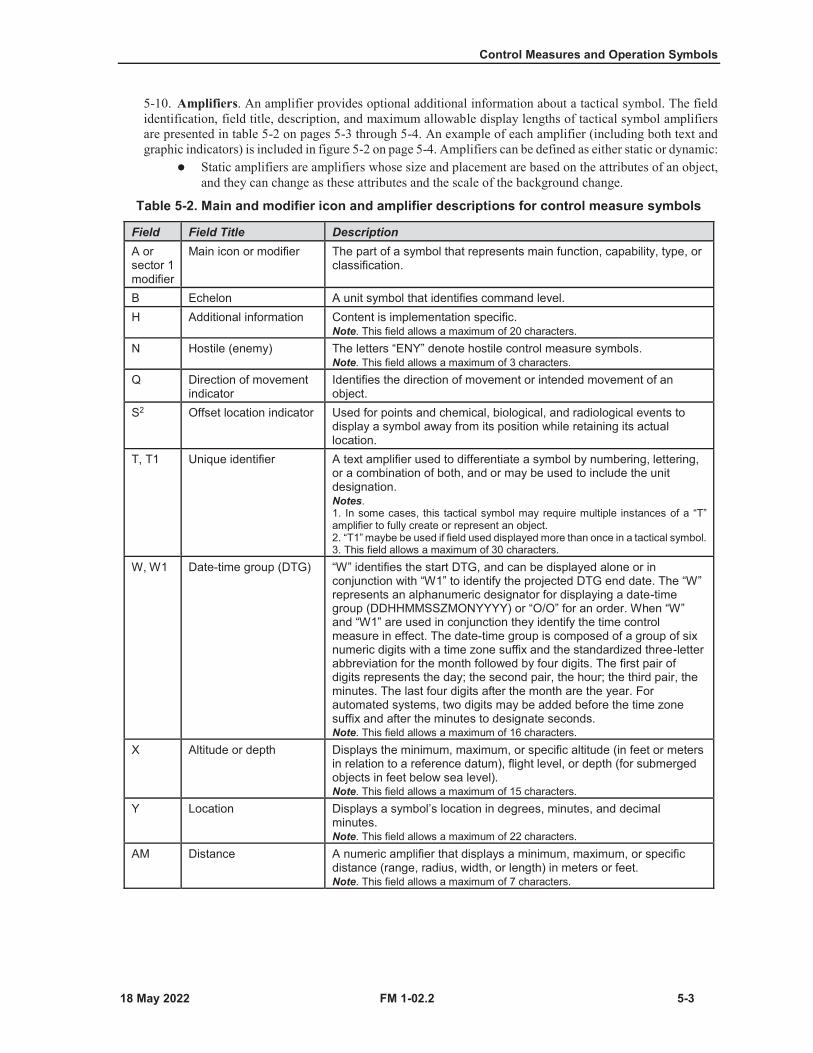
Control Measures and Operation Symbols
FM 1-02.2 5-3
5-10. Amplifiers. An amplifier provides optional additional information about a tactical symbol. The fieldidentification, field title, description, and maximum allowable display lengths of tactical symbol amplifiersare presented in table 5-2 on pages 5-3 through 5-4. An example of each amplifier (including both text andgraphic indicators) is included in figure 5-2 on page 5-4. Amplifiers can be defined as either static or dynamic:
Static amplifiers are amplifiers whose size and placement are based on the attributes of an object,and they can change as these attributes and the scale of the background change.
Table 5-2. Main and modifier icon and amplifier descriptions for control measure symbols
Field Field Title DescriptionA or sector 1 modifier
Main icon or modifier The part of a symbol that represents main function, capability, type, or classification.
B Echelon A unit symbol that identifies command level.H Additional information Content is implementation specific.
Note. This field allows a maximum of 20 characters.N Hostile (enemy) The letters “ENY” denote hostile control measure symbols.
Note. This field allows a maximum of 3 characters.Q Direction of movement
indicatorIdentifies the direction of movement or intended movement of an object.
S2 Offset location indicator Used for points and chemical, biological, and radiological events to display a symbol away from its position while retaining its actual location.
T, T1 Unique identifier A text amplifier used to differentiate a symbol by numbering, lettering, or a combination of both, and or may be used to include the unit designation.Notes.1. In some cases, this tactical symbol may require multiple instances of a “T”amplifier to fully create or represent an object.2. “T1” maybe be used if field used displayed more than once in a tactical symbol.3. This field allows a maximum of 30 characters.
W, W1 Date-time group (DTG) “W” identifies the start DTG, and can be displayed alone or in conjunction with “W1” to identify the projected DTG end date. The “W” represents an alphanumeric designator for displaying a date-time group (DDHHMMSSZMONYYYY) or “O/O” for an order. When “W” and “W1” are used in conjunction they identify the time control measure in effect. The date-time group is composed of a group of six numeric digits with a time zone suffix and the standardized three-letter abbreviation for the month followed by four digits. The first pair of digits represents the day; the second pair, the hour; the third pair, the minutes. The last four digits after the month are the year. For automated systems, two digits may be added before the time zone suffix and after the minutes to designate seconds.Note. This field allows a maximum of 16 characters.
X Altitude or depth Displays the minimum, maximum, or specific altitude (in feet or meters in relation to a reference datum), flight level, or depth (for submerged objects in feet below sea level).Note. This field allows a maximum of 15 characters.
Y Location Displays a symbol’s location in degrees, minutes, and decimal minutes.Note. This field allows a maximum of 22 characters.
AM Distance A numeric amplifier that displays a minimum, maximum, or specific distance (range, radius, width, or length) in meters or feet.Note. This field allows a maximum of 7 characters.
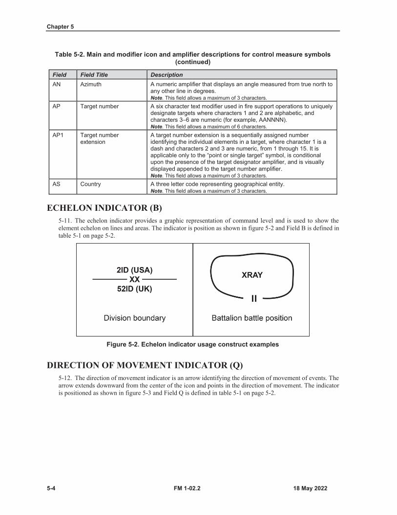
Chapter 5
5-4 FM 1-02.2
Table 5-2. Main and modifier icon and amplifier descriptions for control measure symbols (continued)
Field Field Title DescriptionAN Azimuth A numeric amplifier that displays an angle measured from true north to
any other line in degrees.Note. This field allows a maximum of 3 characters.
AP Target number A six character text modifier used in fire support operations to uniquely designate targets where characters 1 and 2 are alphabetic, and characters 3–6 are numeric (for example, AANNNN).Note. This field allows a maximum of 6 characters.
AP1 Target number extension
A target number extension is a sequentially assigned number identifying the individual elements in a target, where character 1 is a dash and characters 2 and 3 are numeric, from 1 through 15. It is applicable only to the “point or single target” symbol, is conditional upon the presence of the target designator amplifier, and is visually displayed appended to the target number amplifier.Note. This field allows a maximum of 3 characters.
AS Country A three letter code representing geographical entity.Note. This field allows a maximum of 3 characters.
ECHELON INDICATOR (B)5-11. The echelon indicator provides a graphic representation of command level and is used to show theelement echelon on lines and areas. The indicator is position as shown in figure 5-2 and Field B is defined intable 5-1 on page 5-2.
Figure 5-2. Echelon indicator usage construct examples
DIRECTION OF MOVEMENT INDICATOR (Q)5-12. The direction of movement indicator is an arrow identifying the direction of movement of events. Thearrow extends downward from the center of the icon and points in the direction of movement. The indicatoris positioned as shown in figure 5-3 and Field Q is defined in table 5-1 on page 5-2.
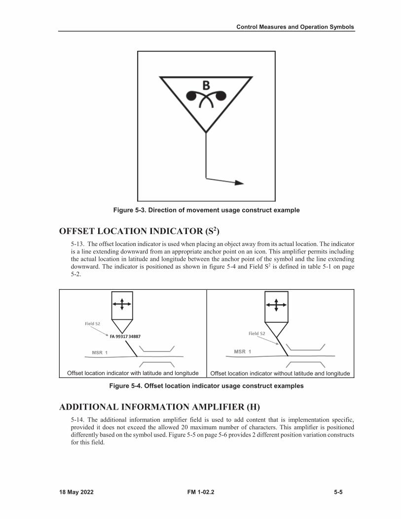
Control Measures and Operation Symbols
FM 1-02.2 5-5
Figure 5-3. Direction of movement usage construct example
OFFSET LOCATION INDICATOR (S2)5-13. The offset location indicator is used when placing an object away from its actual location. The indicatoris a line extending downward from an appropriate anchor point on an icon. This amplifier permits includingthe actual location in latitude and longitude between the anchor point of the symbol and the line extendingdownward. The indicator is positioned as shown in figure 5-4 and Field S2 is defined in table 5-1 on page5-2.
Offset location indicator with latitude and longitude Offset location indicator without latitude and longitude
Figure 5-4. Offset location indicator usage construct examples
ADDITIONAL INFORMATION AMPLIFIER (H)5-14. The additional information amplifier field is used to add content that is implementation specific,provided it does not exceed the allowed 20 maximum number of characters. This amplifier is positioneddifferently based on the symbol used. Figure 5-5 on page 5-6 provides 2 different position variation constructsfor this field.

Chapter 5
5-6 FM 1-02.2
14 individuals at isolated personnel pickup point Anthrax biological event
Figure 5-5. Additional information usage construct example
BOUNDARIES5-15. A boundary is a line that delineates surface areas for the purpose of facilitating coordination anddeconfliction of operations between adjacent units, formations, or areas (JP 3-0). Figure 5-6 provides aboundary composition template that includes orientation of optional field amplifier labels for horizontal(east—west) and vertical (north—south) boundaries. (See table 5-3 on pages 5-7 through 5-8 for depictionsof boundary control measures. The following are optional amplifiers that may be used with this controlmeasure construct:
Country code Field AS to identify the units’ three-letter geographical entity country code.Echelon indication Field B to identify the boundary echelon.Hostile (enemy) Field N to identify enemy boundaries.Unique identifier Field T to identify designations of adjacent units.
Horizontal (east-west)
Vertical (north-south)Boundary symbol amplifiersAS: Country code field identifies the units’ three-letter graphical entity country code.B: Echelon indication field identifies enemy boundaries.N: Hostile (enemy) field identifies designations of adjacent units.T: Unique identifier field identifies designation of adjacent units.
Figure 5-6. Boundary composition template

Control Measures and Operation Symbols
FM 1-02.2 5-7
Table 5-3. Boundaries
Function Template Construct ExampleEngineer work line—Acoordinated boundary line used to compartmentalize an area of operations to indicate where specific engineer units have primary responsibility for the engineer effort. (FM 3-34)Note. Letters “EWL” are an integral part of the symbol but they can rotate based on the direction of the line.
Friendly present boundary
Friendly planned, on order boundary
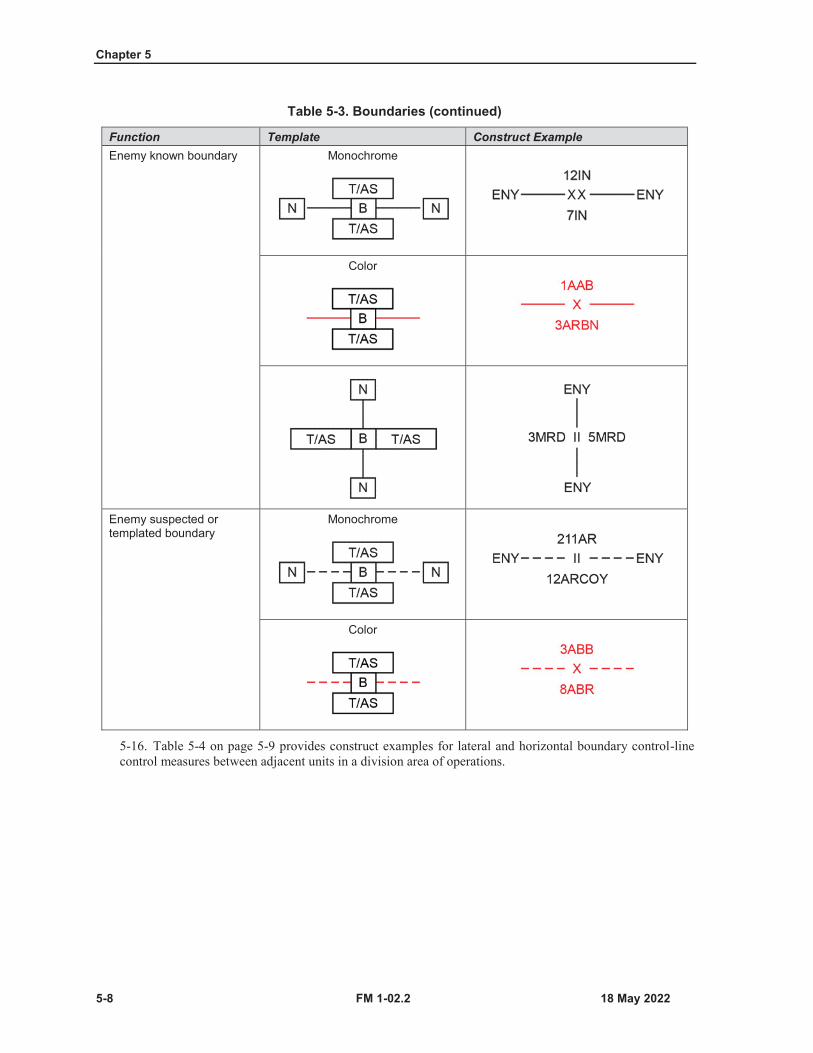
Chapter 5
5-8 FM 1-02.2
Table 5-3. Boundaries (continued)
Function Template Construct ExampleEnemy known boundary Monochrome
Color
Enemy suspected or templated boundary
Monochrome
Color
5-16. Table 5-4 on page 5-9 provides construct examples for lateral and horizontal boundary control-linecontrol measures between adjacent units in a division area of operations.
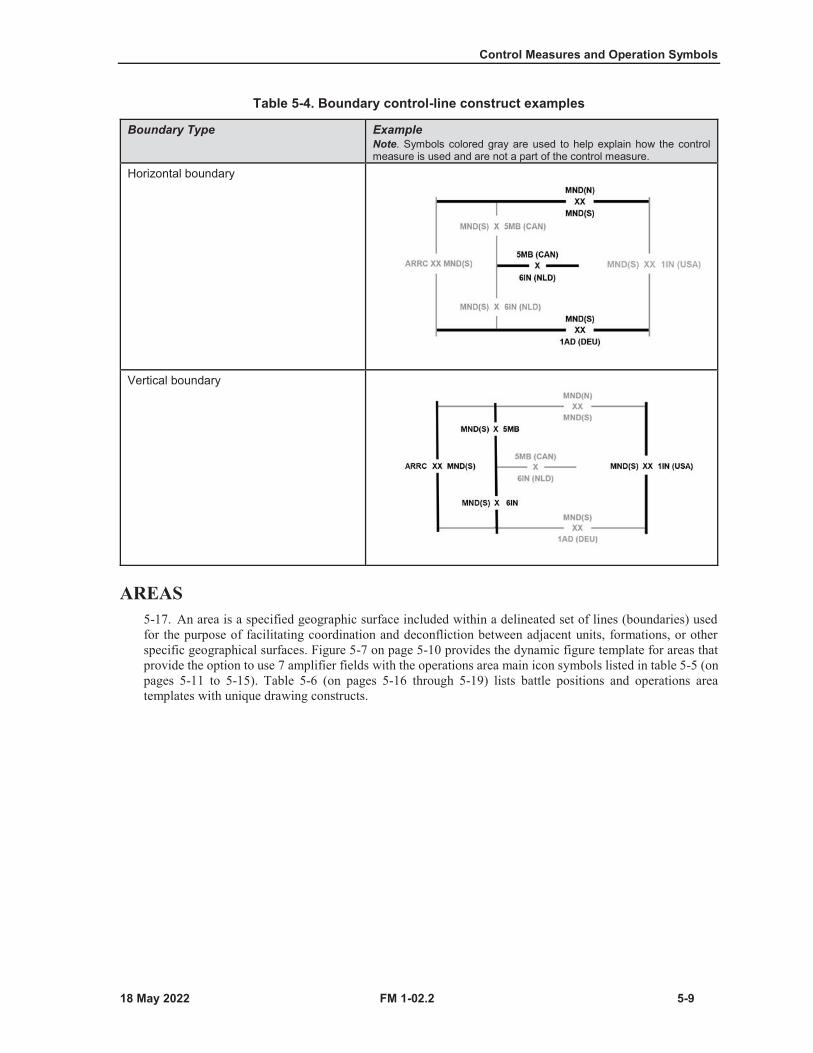
Control Measures and Operation Symbols
FM 1-02.2 5-9
Table 5-4. Boundary control-line construct examples
Boundary Type ExampleNote. Symbols colored gray are used to help explain how the control measure is used and are not a part of the control measure.
Horizontal boundary
Vertical boundary
AREAS5-17. An area is a specified geographic surface included within a delineated set of lines (boundaries) usedfor the purpose of facilitating coordination and deconfliction between adjacent units, formations, or otherspecific geographical surfaces. Figure 5-7 on page 5-10 provides the dynamic figure template for areas thatprovide the option to use 7 amplifier fields with the operations area main icon symbols listed in table 5-5 (onpages 5-11 to 5-15). Table 5-6 (on pages 5-16 through 5-19) lists battle positions and operations areatemplates with unique drawing constructs.

Chapter 5
5-10 FM 1-02.2
Area Template
A: Icon that identifies the main function.H: Additional information (content is implementation specific)N: Enemy: Letters “ENY” denote hostile. T: Identifies the unique text or numerical designation.W/W1: Identifies the date-time group associated with area.Notes.1. Not all fields are required for each area as some areas may use only one field, while others will use several.2. The information fields are moveable and scalable as a block in the area.3. The figure is dynamic.
Figure 5-7. Template for area control measure symbols
5-18. Table 5-5, on pages 5-11 through 5-15, lists area control measure main icon symbols that follow thespecific format as shown in figure 5-7.
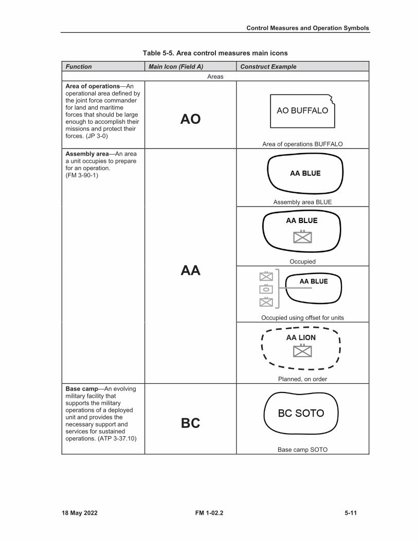
Control Measures and Operation Symbols
FM 1-02.2 5-11
Table 5-5. Area control measures main icons
Function Main Icon (Field A) Construct ExampleAreas
Area of operations—An operational area defined by the joint force commander for land and maritime forces that should be large enough to accomplish their missions and protect their forces. (JP 3-0)
AOArea of operations BUFFALO
Assembly area—An area a unit occupies to prepare for an operation. (FM 3-90-1)
AA
Assembly area BLUE
Occupied
Occupied using offset for units
Planned, on orderBase camp—An evolving military facility that supports the military operations of a deployed unit and provides the necessary support and services for sustained operations. (ATP 3-37.10)
BCBase camp SOTO
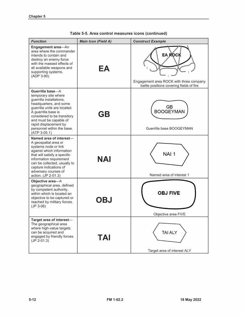
Chapter 5
5-12 FM 1-02.2
Table 5-5. Area control measures icons (continued)
Function Main Icon (Field A) Construct ExampleEngagement area—An area where the commander intends to contain and destroy an enemy force with the massed effects of all available weapons and supporting systems. (ADP 3-90)
EAEngagement area ROCK with three company
battle positions covering fields of fireGuerrilla base—Atemporary site where guerrilla installations, headquarters, and some guerrilla units are located. A guerrilla base is considered to be transitory and must be capable of rapid displacement by personnel within the base. (ATP 3-05.1)
GBGuerrilla base BOOGEYMAN
Named area of interest—A geospatial area or systems node or link against which information that will satisfy a specific information requirement can be collected, usually to capture indications of adversary courses of action. (JP 2-01.3)
NAINamed area of interest 1
Objective area—Ageographical area, defined by competent authority, within which is located an objective to be captured or reached by military forces. (JP 3-06)
OBJObjective area FIVE
Target area of interest—The geographical area where high-value targets can be acquired and engaged by friendly forces. (JP 2-01.3) TAI
Target area of interest ALY
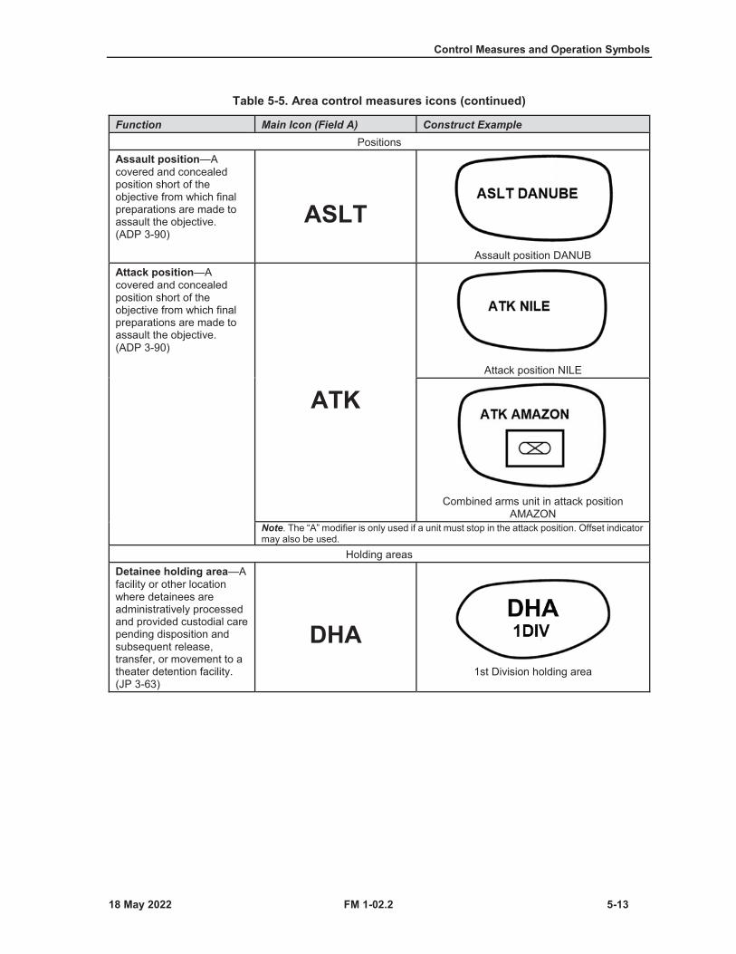
Control Measures and Operation Symbols
FM 1-02.2 5-13
Table 5-5. Area control measures icons (continued)
Function Main Icon (Field A) Construct ExamplePositions
Assault position—Acovered and concealed position short of the objective from which final preparations are made to assault the objective. (ADP 3-90)
ASLTAssault position DANUB
Attack position—Acovered and concealed position short of the objective from which final preparations are made to assault the objective. (ADP 3-90)
ATKAttack position NILE
Combined arms unit in attack position AMAZON
Note. The “A” modifier is only used if a unit must stop in the attack position. Offset indicator may also be used.
Holding areasDetainee holding area—Afacility or other location where detainees are administratively processed and provided custodial care pending disposition and subsequent release, transfer, or movement to a theater detention facility. (JP 3-63)
DHA1st Division holding area

Chapter 5
5-14 FM 1-02.2
Table 5-5. Area control measures icons (continued)
Function Main Icon (Field A) Construct ExampleRefugee holding areaNote. The use of “refugee holding area” acronym is permitted to conserve space.
REFUGEE HOLDING
AREA15th Military Police refugee holding area
Support areaThe portion of the commander’s area of interest that is designated to facilitate the positioning, employment,and protection of base sustainment assets required to sustain, enable, and control operations. (ADP 3-0)
Forward arming and refueling point—Atemporary facility, organized, equipped, and deployed, to provide fuel and ammunition necessary for the employment of aviation maneuver units in combat. (JP 3-09.3)
FARP2nd Aviation forward arming and refueling
pointBrigade support area—Adesignated area in which sustainment elements locate to provide support to a brigade. (ATP 4-90) BSA
Brigade support area CAPADivision support area—Adesignated area within the division commander’s area of operations that provides a location to base the division’s sustainment assets and provide sustainment to the division. (See ATP 3-91 for more information on the divisionsupport area.)
DSADivision support area CRUZ
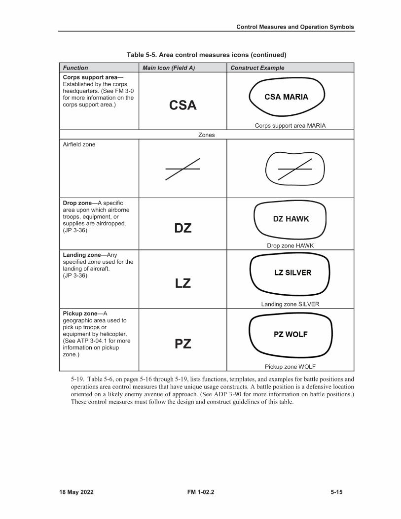
Control Measures and Operation Symbols
FM 1-02.2 5-15
Table 5-5. Area control measures icons (continued)
Function Main Icon (Field A) Construct ExampleCorps support area—Established by the corps headquarters. (See FM 3-0for more information on the corps support area.) CSA
Corps support area MARIAZones
Airfield zone
Drop zone—A specific area upon which airborne troops, equipment, or supplies are airdropped. (JP 3-36) DZ
Drop zone HAWKLanding zone—Any specified zone used for the landing of aircraft. (JP 3-36)
LZLanding zone SILVER
Pickup zone—Ageographic area used to pick up troops or equipment by helicopter. (See ATP 3-04.1 for more information on pickup zone.)
PZPickup zone WOLF
5-19. Table 5-6, on pages 5-16 through 5-19, lists functions, templates, and examples for battle positions andoperations area control measures that have unique usage constructs. A battle position is a defensive locationoriented on a likely enemy avenue of approach. (See ADP 3-90 for more information on battle positions.)These control measures must follow the design and construct guidelines of this table.
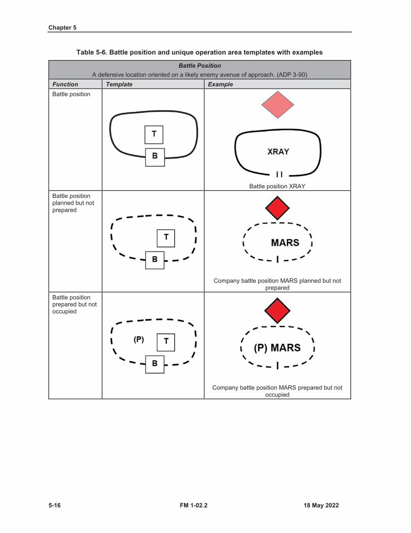
Chapter 5
5-16 FM 1-02.2
Table 5-6. Battle position and unique operation area templates with examples
Battle PositionA defensive location oriented on a likely enemy avenue of approach. (ADP 3-90)
Function Template ExampleBattle position
Battle position XRAYBattle position planned but not prepared
Company battle position MARS planned but not prepared
Battle position prepared but not occupied
Company battle position MARS prepared but not occupied
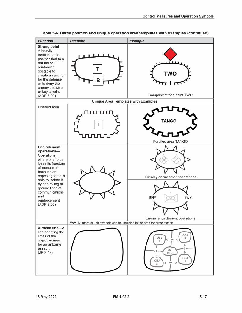
Control Measures and Operation Symbols
FM 1-02.2 5-17
Table 5-6. Battle position and unique operation area templates with examples (continued)
Function Template ExampleStrong point—A heavily fortified battle position tied to a natural or reinforcing obstacle to create an anchor for the defense or to deny the enemy decisive or key terrain. (ADP 3-90) Company strong point TWO
Unique Area Templates with ExamplesFortified area
Fortified area TANGOEncirclement operations—Operations where one force loses its freedom of maneuver because an opposing force is able to isolate it by controlling all ground lines of communications andreinforcement. (ADP 3-90)
Friendly encirclement operations
Enemy encirclement operationsNote. Numerous unit symbols can be included in the area for presentation.
Airhead line—Aline denoting the limits of the objective area for an airborne assault. (JP 3-18)
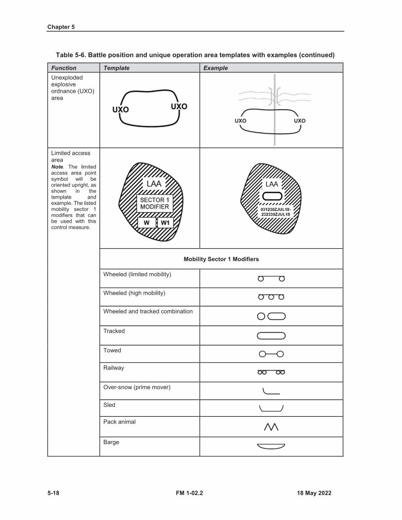
Chapter 5
5-18 FM 1-02.2
Table 5-6. Battle position and unique operation area templates with examples (continued)
Function Template ExampleUnexploded explosive ordnance (UXO) area
Limited access areaNote. The limited access area point symbol will be oriented upright, as shown in the template and example. The listed mobility sector 1 modifiers that can be used with this control measure.
Mobility Sector 1 Modifiers
Wheeled (limited mobility)
Wheeled (high mobility)
Wheeled and tracked combination
Tracked
Towed
Railway
Over-snow (prime mover)
Sled
Pack animal
Barge
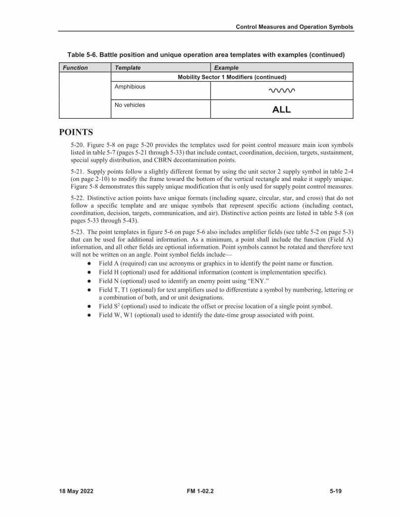
Control Measures and Operation Symbols
FM 1-02.2 5-19
Table 5-6. Battle position and unique operation area templates with examples (continued)
Function Template ExampleMobility Sector 1 Modifiers (continued)
Amphibious
No vehicles
POINTS5-20. Figure 5-8 on page 5-20 provides the templates used for point control measure main icon symbolslisted in table 5-7 (pages 5-21 through 5-33) that include contact, coordination, decision, targets, sustainment,special supply distribution, and CBRN decontamination points.
5-21. Supply points follow a slightly different format by using the unit sector 2 supply symbol in table 2-4(on page 2-10) to modify the frame toward the bottom of the vertical rectangle and make it supply unique.Figure 5-8 demonstrates this supply unique modification that is only used for supply point control measures.
5-22. Distinctive action points have unique formats (including square, circular, star, and cross) that do notfollow a specific template and are unique symbols that represent specific actions (including contact,coordination, decision, targets, communication, and air). Distinctive action points are listed in table 5-8 (onpages 5-33 through 5-43).
5-23. The point templates in figure 5-6 on page 5-6 also includes amplifier fields (see table 5-2 on page 5-3)that can be used for additional information. As a minimum, a point shall include the function (Field A)information, and all other fields are optional information. Point symbols cannot be rotated and therefore textwill not be written on an angle. Point symbol fields include—
Field A (required) can use acronyms or graphics in to identify the point name or function.Field H (optional) used for additional information (content is implementation specific).Field N (optional) used to identify an enemy point using “ENY.”Field T, T1 (optional) for text amplifiers used to differentiate a symbol by numbering, lettering ora combination of both, and or unit designations.Field S2 (optional) used to indicate the offset or precise location of a single point symbol.Field W, W1 (optional) used to identify the date-time group associated with point.

Chapter 5
5-20 FM 1-02.2
General purpose points Supply distribution pointsPoint symbol fieldsA (required) can use acronyms or graphics in to identify the point name or function.H (optional) used for additional information (content is implementation specific).N (optional) used to identify an enemy point using “ENY.”T, T1 (optional) for text amplifiers used to differentiate a symbol by numbering, lettering or a combination of both, and or unit designations.S2 (optional) used to indicate the offset or precise location of a single point symbol.W, W1 (optional) used to identify the date-time group associated with point.
Figure 5-8. Template for points (left) and supply distribution points (right) control measure symbols
5-24. The point control measure symbols are used in the exercise of authority and direction by a properlydesignated commander over assigned and attached forces in the accomplishment of the mission. Table 5-7on page 5-21 through 5-33 lists point control measure main icons that follow figure 5-8 template constructformats.

Control Measures and Operation Symbols
FM 1-02.2 5-21
Table 5-7. Point control measure main icon symbols
Function Main Icon (Field A) Construct Example and Symbol Translation
Movement and ManeuverCheckpoint—Apredetermined point on the ground used to control movement, tactical maneuver, and orientation. (See FM 3-90-1 for more information on checkpoints.) CP
Checkpoint 12 on main supply route 5, controlled by 100th Military Police
Detachment, operational from 0700 Zulu hour 14 MAR 2013 to 2200 Zulu hour 14
May 2013
CKPAlternate MIL-STD 2525D and
North Atlantic Treaty Organization (NATO) APP 6(D)
symbol usage
Control—An action taken to eliminate a hazard or reduce its risk. (ATP 5-19)Note. This symbol demonstrates the capability and authority to exercise restraining or directing influence (regulating) over a specific function.
Control point RED on main supply route 2, controlled by 615th Military Police Company, operational from 0700 Zulu hour 12 May 2013 to 0900 Zulu hour 12 May 2013
Engineer regulating point—Checkpoint to ensure that vehicles do not exceed the capacity of the crossing means and to give drivers final instructions on site-specific procedures and information, such as speed and vehicle interval.
ERPEngineer regulating point on main supply route 1, controlled by 2nd Engineer Battalion

Chapter 5
5-22 FM 1-02.2
Table 5-7. Point control measure main icon symbols (continued)
Function Main Icon (Field A) Construct Example and Symbol Translation
Linkup point—The point where two infiltrating elements in the same or different infiltration lanes are scheduled to meet to consolidate before proceeding on with their missions. (FM 3-90-1) LU
Night linkup point 1, controlled by 3rd Battalion, operational from 0900 Zulu hour
6 FEB 2008 to 0300 Zulu hour 10 FEB 2008
Passage point—Aspecifically designated place where the passing units will pass through the stationary unit. (FM 3-90-2)
PPPassage point RED, controlled by 3rd
Brigade, operational from 0700 Zulu hour6 FEB 2008 to 0900 Zulu hour 10 FEB
2008Rally point—An easily identifiable point on the ground at which units can reassemble and reorganize if they become dispersed. (ATP 3-21.20) RLY
Rally point 5, controlled by 1st Battalion, operational from 0700 Zulu hour 12 MAY
2013 to 0900 Zulu hour 13 May 2013Release point—A location on a route where marching elements are released from centralized control. (FM 3-90-2)
RPRelease point LIMA, controlled by 181st
Battalion, operational from 1230 Zulu hour 22 DEC 2012 to 1530 Zulu hour 22 DEC
2012

Control Measures and Operation Symbols
FM 1-02.2 5-23
Table 5-7. Point control measure main icon symbols (continued)
Function Main Icon (Field A) Construct Example and Symbol Translation
Start point—A location on a route where the march elements fall under the control of a designated march commander. (FM 3-90-2)
SPStart point, controlled by 2nd Troop, 3rd Cavalry Squadron, operational at 0630
Zulu hour 6 JUN 2013Point of departure—The point where the unit crosses the line of departure and begins moving along a direction of attack. (ADP 3-90)
PDPoint of departure 1.
Note. The offset indicator is used in the example to allow the viewer to better see the line of departure. It is not required.
ConsolidationAmnesty point
AMNUnited Nations weapons amnesty point, controlled by New Zealand, operational from 0700 Zulu hour 14 MAR 2013 to
0700 Zulu hour 12 MAY 2013Civilian collection point—Aspecific location where civilians are assembled to be transported to another location.
CIVHost nation only United States civilian
collection point, controlled by North Atlantic Treaty Organization, operational
from 0700 Zulu hour 21 AUG 2013 to 0800 Zulu hour 22 AUG 2013
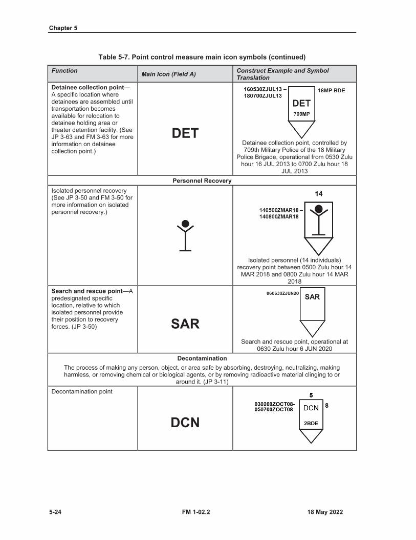
Chapter 5
5-24 FM 1-02.2
Table 5-7. Point control measure main icon symbols (continued)
Function Main Icon (Field A) Construct Example and Symbol Translation
Detainee collection point—A specific location where detainees are assembled until transportation becomes available for relocation to detainee holding area or theater detention facility. (See JP 3-63 and FM 3-63 for more information on detainee collection point.)
DETDetainee collection point, controlled by 709th Military Police of the 18 Military
Police Brigade, operational from 0530 Zulu hour 16 JUL 2013 to 0700 Zulu hour 18
JUL 2013Personnel Recovery
Isolated personnel recovery(See JP 3-50 and FM 3-50 for more information on isolated personnel recovery.)
Isolated personnel (14 individuals) recovery point between 0500 Zulu hour 14
MAR 2018 and 0800 Zulu hour 14 MAR 2018
Search and rescue point—Apredesignated specific location, relative to which isolated personnel provide their position to recovery forces. (JP 3-50) SAR
Search and rescue point, operational at 0630 Zulu hour 6 JUN 2020
DecontaminationThe process of making any person, object, or area safe by absorbing, destroying, neutralizing, making harmless, or removing chemical or biological agents, or by removing radioactive material clinging to or
around it. (JP 3-11)Decontamination point
DCN
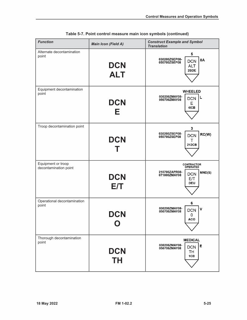
Control Measures and Operation Symbols
FM 1-02.2 5-25
Table 5-7. Point control measure main icon symbols (continued)
Function Main Icon (Field A) Construct Example and Symbol Translation
Alternate decontamination point
DCNALT
Equipment decontamination point
DCNE
Troop decontamination point
DCNT
Equipment or troop decontamination point
DCNE/T
Operational decontamination point
DCNO
Thorough decontamination point
DCNTH
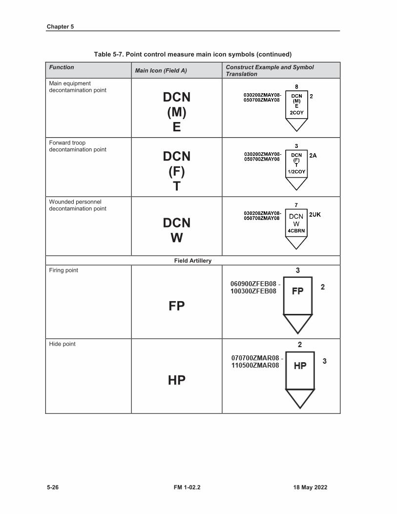
Chapter 5
5-26 FM 1-02.2
Table 5-7. Point control measure main icon symbols (continued)
Function Main Icon (Field A) Construct Example and Symbol Translation
Main equipment decontamination point
DCN(M)E
Forward troop decontamination point DCN
(F)T
Wounded personnel decontamination point
DCNW
Field ArtilleryFiring point
FP
Hide point
HP
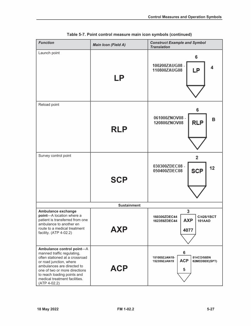
Control Measures and Operation Symbols
FM 1-02.2 5-27
Table 5-7. Point control measure main icon symbols (continued)
Function Main Icon (Field A) Construct Example and Symbol Translation
Launch point
LP
Reload point
RLP
Survey control point
SCP
SustainmentAmbulance exchange point—A location where a patient is transferred from one ambulance to another en route to a medical treatment facility. (ATP 4-02.2) AXP
Ambulance control point—Amanned traffic regulating, often stationed at a crossroad or road junction, where ambulances are directed to one of two or more directions to reach loading points and medical treatment facilities. (ATP 4-02.2)
ACP

Chapter 5
5-28 FM 1-02.2
Table 5-7. Point control measure main icon symbols (continued)
Function Main Icon (Field A) Construct Example and Symbol Translation
Ambulance loading point—This is the point in the shuttle system where one or more ambulances are stationed ready to receive patients for evacuation. (ATP 4-02.2)
ALP
Ambulance relay point—Apoint in the shuttle system where one or more empty ambulances are stationed to advance to a loading point or to the next relay post to replace departed ambulances. (ATP 4-02.2)
ARP
Ammunition supply point—An ammunition support activity operated by one or more modular ammunition platoons. (ATP 4-35)
ASP
Ammunition transfer holding point—A designated site operated by a brigade support battalion distribution company where ammunition is received, transferred, or temporarily stored to supported units within a brigade combat team. (ATP 4-35)
ATHP
Cannibalization point
CAN
Casualty collection point—A location that may or may not be staffed, where casualties are assembled for evacuation to a medical treatment facility. (ATP 4-02.2)
CCP
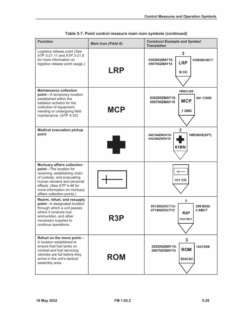
Control Measures and Operation Symbols
FM 1-02.2 5-29
Table 5-7. Point control measure main icon symbols (continued)
Function Main Icon (Field A) Construct Example and Symbol Translation
Logistics release point (See ATP 3-21.11 and ATP 3-21.8 for more information on logistics release point usage.)
LRP
Maintenance collectionpoint—A temporary location established within the battalion echelon for the collection of equipment needing or undergoing field maintenance. (ATP 4-33)
MCP
Medical evacuation pickup point
Mortuary affairs collection point—The location for receiving, establishing chain of custody, and evacuating human remains and personal effects. (See ATP 4-46 for more information on mortuary affairs collection points.)Rearm, refuel, and resupply point—A designated location through which a unit passes where it receives fuel, ammunition, and other necessary supplies to continue operations.
R3P
Refuel on the move point—A location established to ensure that fuel tanks on combat and fuel servicing vehicles are full before they arrive in the unit’s tactical assembly area.
ROM
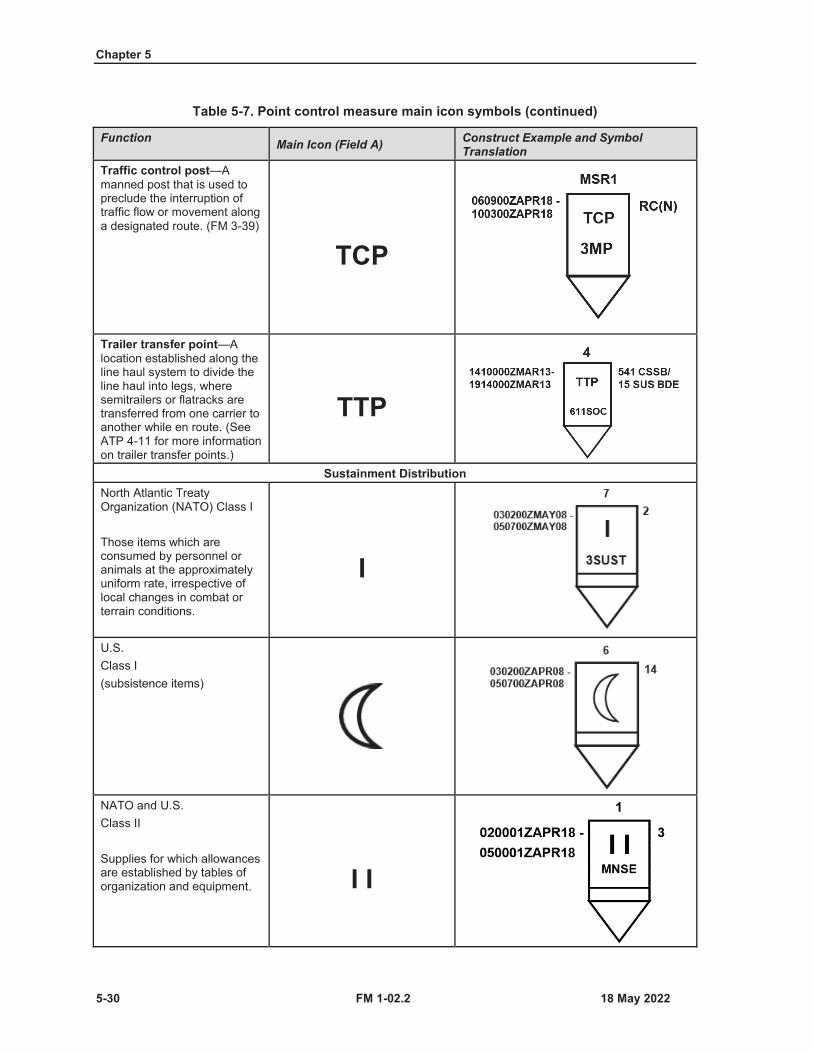
Chapter 5
5-30 FM 1-02.2
Table 5-7. Point control measure main icon symbols (continued)
Function Main Icon (Field A) Construct Example and Symbol Translation
Traffic control post—Amanned post that is used to preclude the interruption of traffic flow or movement along a designated route. (FM 3-39)
TCP
Trailer transfer point—Alocation established along the line haul system to divide theline haul into legs, where semitrailers or flatracks are transferred from one carrier to another while en route. (See ATP 4-11 for more information on trailer transfer points.)
TTP
Sustainment DistributionNorth Atlantic Treaty Organization (NATO) Class I
Those items which are consumed by personnel or animals at the approximately uniform rate, irrespective of local changes in combat or terrain conditions.
I
U.S.Class I(subsistence items)
NATO and U.S.Class II
Supplies for which allowances are established by tables of organization and equipment. I I
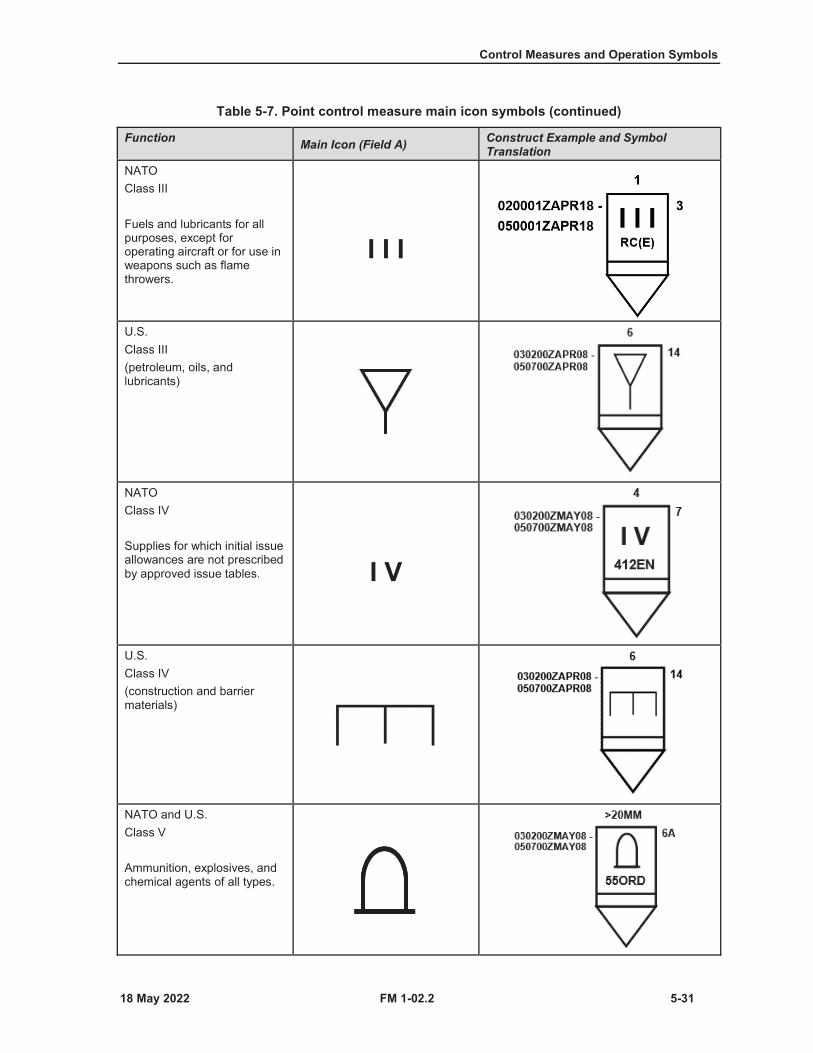
Control Measures and Operation Symbols
FM 1-02.2 5-31
Table 5-7. Point control measure main icon symbols (continued)
Function Main Icon (Field A) Construct Example and Symbol Translation
NATOClass III
Fuels and lubricants for all purposes, except for operating aircraft or for use in weapons such as flame throwers.
I I I
U.S.Class III(petroleum, oils, and lubricants)
NATOClass IV
Supplies for which initial issue allowances are not prescribed by approved issue tables. I V
U.S.Class IV(construction and barrier materials)
NATO and U.S.Class V
Ammunition, explosives, and chemical agents of all types.
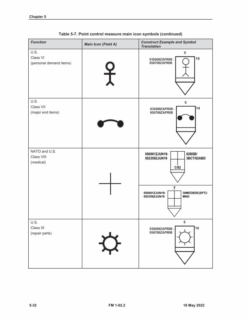
Chapter 5
5-32 FM 1-02.2
Table 5-7. Point control measure main icon symbols (continued)
Function Main Icon (Field A) Construct Example and Symbol Translation
U.S.Class VI(personal demand items)
U.S.Class VII(major end items)
NATO and U.S.Class VIII(medical)
U.S.Class IX(repair parts)
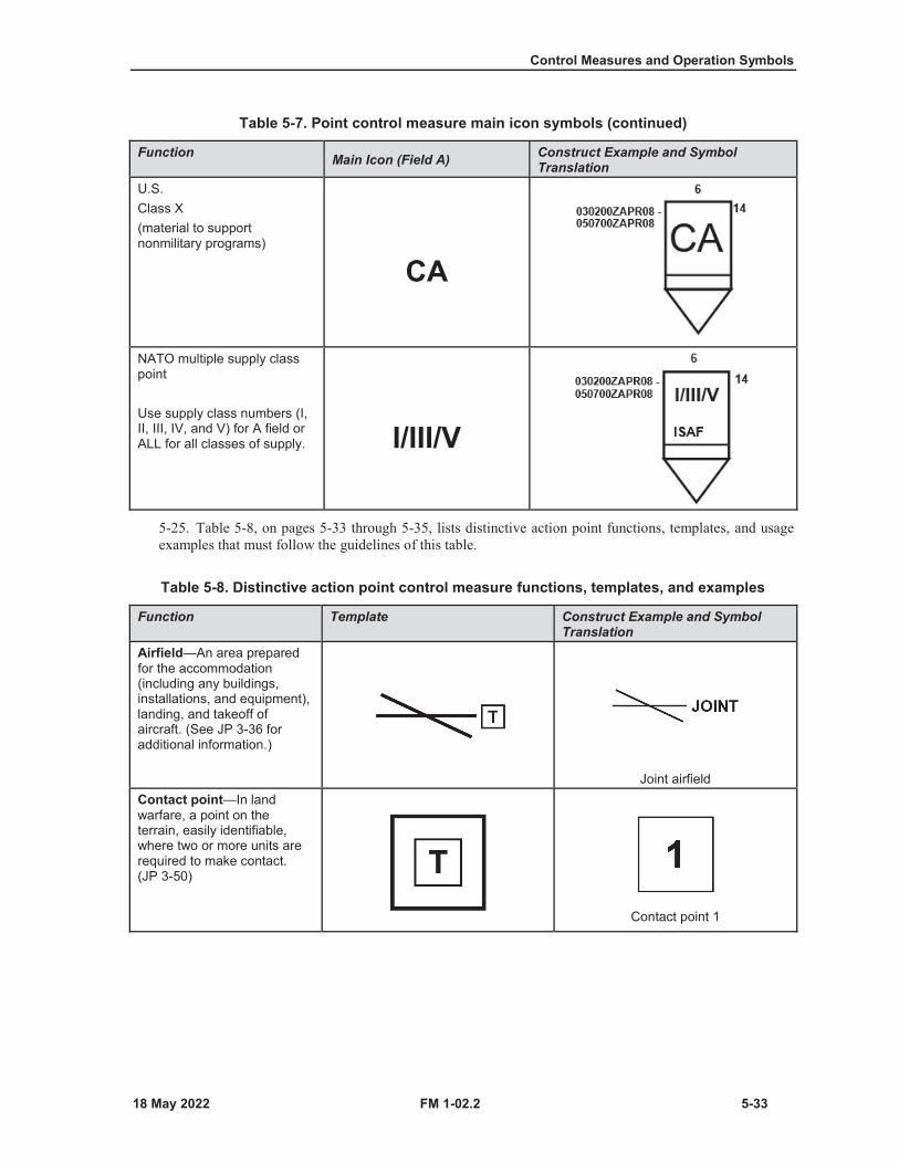
Control Measures and Operation Symbols
FM 1-02.2 5-33
Table 5-7. Point control measure main icon symbols (continued)
Function Main Icon (Field A) Construct Example and Symbol Translation
U.S.Class X(material to support nonmilitary programs)
CA
NATO multiple supply class point
Use supply class numbers (I, II, III, IV, and V) for A field or ALL for all classes of supply. I/III/V
5-25. Table 5-8, on pages 5-33 through 5-35, lists distinctive action point functions, templates, and usageexamples that must follow the guidelines of this table.
Table 5-8. Distinctive action point control measure functions, templates, and examples
Function Template Construct Example and Symbol Translation
Airfield—An area prepared for the accommodation (including any buildings, installations, and equipment), landing, and takeoff of aircraft. (See JP 3-36 for additional information.)
Joint airfieldContact point—In land warfare, a point on the terrain, easily identifiable, where two or more units are required to make contact.(JP 3-50)
Contact point 1
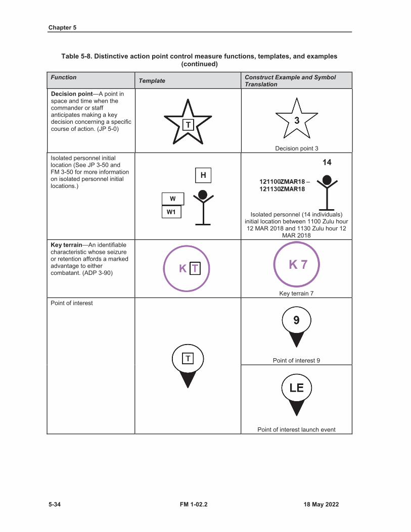
Chapter 5
5-34 FM 1-02.2
Table 5-8. Distinctive action point control measure functions, templates, and examples (continued)
Function Template Construct Example and Symbol Translation
Decision point—A point in space and time when the commander or staff anticipates making a key decision concerning a specific course of action. (JP 5-0)
Decision point 3Isolated personnel initial location (See JP 3-50 and FM 3-50 for more information on isolated personnel initial locations.)
Isolated personnel (14 individuals) initial location between 1100 Zulu hour 12 MAR 2018 and 1130 Zulu hour 12
MAR 2018Key terrain—An identifiable characteristic whose seizure or retention affords a marked advantage to either combatant. (ADP 3-90)
Key terrain 7Point of interest
Point of interest 9
Point of interest launch event
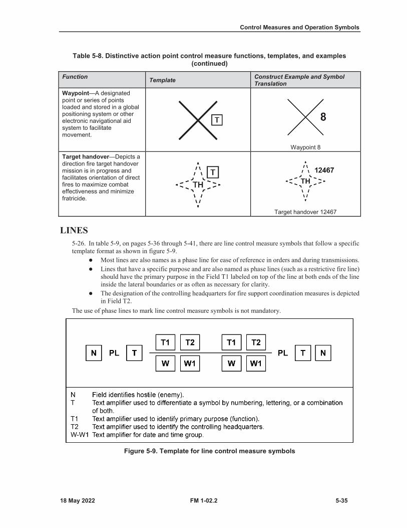
Control Measures and Operation Symbols
FM 1-02.2 5-35
Table 5-8. Distinctive action point control measure functions, templates, and examples (continued)
Function Template Construct Example and Symbol Translation
Waypoint—A designated point or series of points loaded and stored in a global positioning system or other electronic navigational aid system to facilitate movement.
Waypoint 8Target handover—Depicts a direction fire target handover mission is in progress and facilitates orientation of direct fires to maximize combat effectiveness and minimize fratricide.
Target handover 12467
LINES5-26. In table 5-9, on pages 5-36 through 5-41, there are line control measure symbols that follow a specifictemplate format as shown in figure 5-9.
Most lines are also names as a phase line for ease of reference in orders and during transmissions.Lines that have a specific purpose and are also named as phase lines (such as a restrictive fire line)should have the primary purpose in the Field T1 labeled on top of the line at both ends of the lineinside the lateral boundaries or as often as necessary for clarity.The designation of the controlling headquarters for fire support coordination measures is depictedin Field T2.
The use of phase lines to mark line control measure symbols is not mandatory.
Figure 5-9. Template for line control measure symbols

Chapter 5
5-36 FM 1-02.2
Table 5-9. Line control measure symbols
Function Template Construct ExampleNote. Symbols colored gray are used to help explain how the control measure is used and are not a part of the control measure.
LinesForward line of own troops—Aline which indicates the most forward position of friendly forces in any kind of military operation at a specific time. (JP 3-03)Note. The open side of the arc reflects the reported unit.
Friendly present
Friendly planned, or on order
Enemy suspected or templatedLine of contact—Ageneral trace delineating the locations where friendly and enemy forces are engaged. (ADP 3-0)The line of contact symbol is created when both the friendly and enemy forward line of troops symbols are displayed.Note. The open side of the art reflects the reported unit.

Control Measures and Operation Symbols
FM 1-02.2 5-37
Table 5-9. Line control measure symbols (continued)
FunctionTemplate
Construct ExampleNote. Symbols colored gray are used to help explain how the control measure is used and are not a part of the control measure.
Phase line—An easily identified feature in the operational area utilized for control and coordination of military operations. (JP 3-09)Forward edge of the battle area—The foremost limits of a series of areas in which ground combat units are deployed to coordinate fire support, the positioning of forces, or the maneuver of units, excluding areas in which covering or screening forces are operating. (JP 3-09.3)Release line—Phase line used in river crossing operations that delineates a change in the headquarters controlling movement. (See ATP 3-90.4 for more information on release line.)Bridgehead line—The limit of the objective area in the development of the bridgehead. (See ATP 3-90.4 for more information on bridgehead line.)
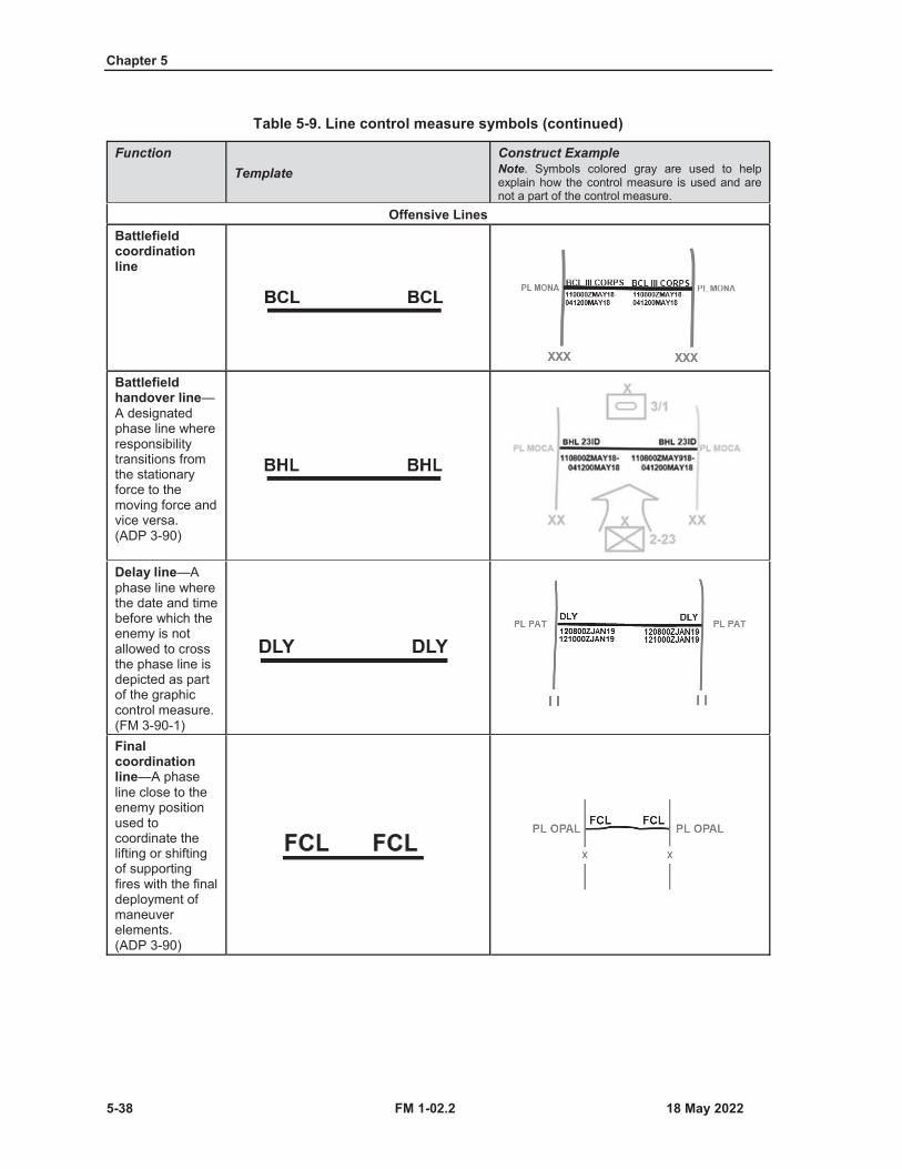
Chapter 5
5-38 FM 1-02.2
Table 5-9. Line control measure symbols (continued)
FunctionTemplate
Construct ExampleNote. Symbols colored gray are used to help explain how the control measure is used and are not a part of the control measure.
Offensive LinesBattlefield coordination line
Battlefield handover line—A designated phase line where responsibility transitions from the stationary force to the moving force and vice versa. (ADP 3-90)
Delay line—Aphase line where the date and time before which the enemy is not allowed to cross the phase line is depicted as part of the graphic control measure. (FM 3-90-1)Final coordination line—A phase line close to the enemy position used to coordinate the lifting or shifting of supporting fires with the final deployment of maneuver elements. (ADP 3-90)
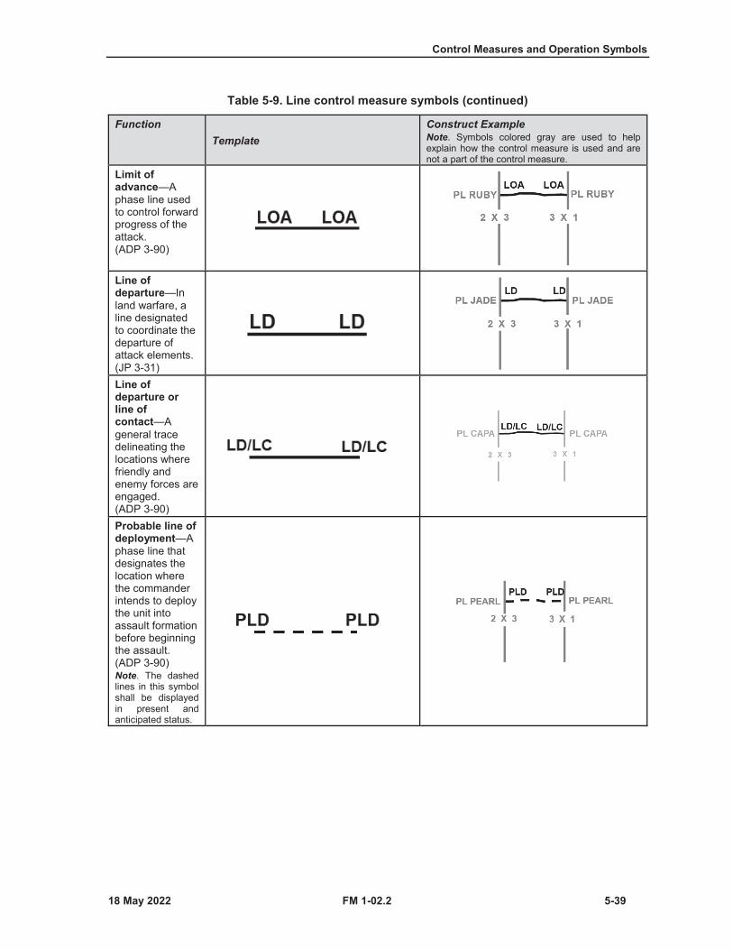
Control Measures and Operation Symbols
FM 1-02.2 5-39
Table 5-9. Line control measure symbols (continued)
FunctionTemplate
Construct ExampleNote. Symbols colored gray are used to help explain how the control measure is used and are not a part of the control measure.
Limit of advance—Aphase line used to control forward progress of the attack. (ADP 3-90)
Line of departure—In land warfare, a line designated to coordinate the departure of attack elements. (JP 3-31)Line of departure or line of contact—Ageneral trace delineating the locations where friendly and enemy forces are engaged. (ADP 3-90)Probable line of deployment—Aphase line that designates the location where the commander intends to deploy the unit into assault formation before beginning the assault. (ADP 3-90)Note. The dashed lines in this symbol shall be displayed in present and anticipated status.
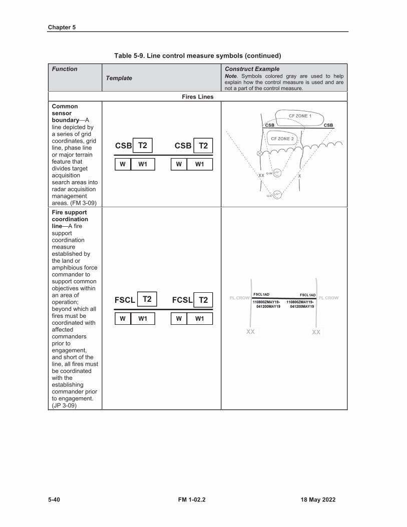
Chapter 5
5-40 FM 1-02.2
Table 5-9. Line control measure symbols (continued)
FunctionTemplate
Construct ExampleNote. Symbols colored gray are used to help explain how the control measure is used and are not a part of the control measure.
Fires LinesCommon sensor boundary—Aline depicted by a series of grid coordinates, grid line, phase line or major terrain feature that divides target acquisition search areas into radar acquisition management areas. (FM 3-09)Fire support coordination line—A fire support coordination measure established by the land or amphibious force commander to support common objectives within an area of operation; beyond which all fires must be coordinated with affected commanders prior to engagement, and short of the line, all fires must be coordinated with the establishing commander prior to engagement. (JP 3-09)
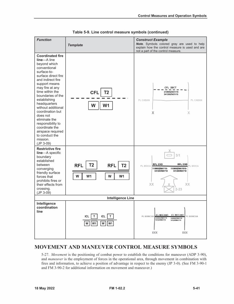
Control Measures and Operation Symbols
FM 1-02.2 5-41
Table 5-9. Line control measure symbols (continued)
FunctionTemplate
Construct ExampleNote. Symbols colored gray are used to help explain how the control measure is used and are not a part of the control measure.
Coordinated fire line—A line beyond which conventional surface-to-surface direct fire and indirect fire support means may fire at any time within the boundaries of the establishing headquarters without additional coordination but does not eliminate the responsibility to coordinate the airspace required to conduct the mission. (JP 3-09)Restrictive fire line—A specific boundary established between converging friendly surface forces that prohibits fires or their effects from crossing. (JP 3-09)
Intelligence LineIntelligence coordination line
MOVEMENT AND MANEUVER CONTROL MEASURE SYMBOLS5-27. Movement is the positioning of combat power to establish the conditions for maneuver (ADP 3-90),and maneuver is the employment of forces in the operational area, through movement in combination withfires and information, to achieve a position of advantage in respect to the enemy (JP 3-0). (See FM 3-90-1and FM 3-90-2 for additional information on movement and maneuver.)

Chapter 5
5-42 FM 1-02.2
5-28. Table 5-10, on pages 5-42 through 5-45 includes forms of maneuver control measures. Forms ofmaneuver are distinct tactical combinations of fire and movement with a unique set of doctrinalcharacteristics that differ primarily in the relationship between the maneuvering force and the enemy(ADP 3-90).
Table 5-10. Forms of maneuver control measure symbols
Control Measure Template Construct Example and Symbol Translation
Axis of AdvanceThe general area through which the bulk of a unit’s combat power must move. (ADP 3-90)
Airborne or aviation axis of advance
Airborne infantry unit moving on airborne axis of advance SWORD from 0400 Zulu
hour 8 October 2008 to 0300 Zulu hour 12 October 2008
Aviation unit moving on aviation axis of advance SNOW from 0400 Zulu hour 8
October 2008 to 0300 Zulu hour 12 October 2008
Attack helicopter axis of advance
Attack aviation unit moving on attack helicopter axis of advance MARK from 0400 Zulu hour 8 October 2008 to 0300
Zulu hour 12 October 2008
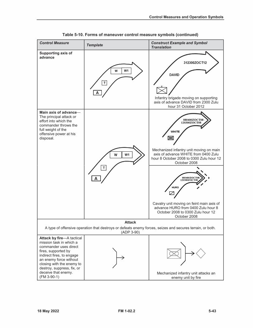
Control Measures and Operation Symbols
FM 1-02.2 5-43
Table 5-10. Forms of maneuver control measure symbols (continued)
Control Measure Template Construct Example and Symbol Translation
Supporting axis of advance
Infantry brigade moving on supporting axis of advance DAVID from 2300 Zulu
hour 31 October 2012Main axis of advance—The principal attack or effort into which the commander throws the full weight of the offensive power at his disposal.
Mechanized infantry unit moving on main axis of advance WHITE from 0400 Zulu
hour 8 October 2008 to 0300 Zulu hour 12 October 2008
Cavalry unit moving on feint main axis of advance HURO from 0400 Zulu hour 8
October 2008 to 0300 Zulu hour 12 October 2008
AttackA type of offensive operation that destroys or defeats enemy forces, seizes and secures terrain, or both.
(ADP 3-90)Attack by fire—A tactical mission task in which a commander uses direct fires, supported by indirect fires, to engage an enemy force without closing with the enemy to destroy, suppress, fix, or deceive that enemy. (FM 3-90-1)
Mechanized infantry unit attacks an enemy unit by fire

Chapter 5
5-44 FM 1-02.2
Table 5-10. Forms of maneuver control measure symbols (continued)
Control Measure Template Construct Example and Symbol Translation
Support by fire—Atactical mission task in which a maneuver force moves to a position where it can engage the enemy by direct fire in support of another maneuvering force. (FM 3-90-1)
Mechanized infantry battalion conducts support by fire
Direction of AttackA specific direction or assigned route a force uses and does not deviate from when attacking. (ADP 3-90)
Aviation direction of attack
Aviation unit aviation direction of attack from 0400 Zulu hour 8 October 2008 to
0300 Zulu hour 12 October 2008Direction of main attack
Combined arms unit direction of main attack from 0400 Zulu hour 8 October
2008 to 0300 Zulu hour 12 October 2008
Infantry unit feint direction of main attack from 0400 Zulu hour 8 October 2008 to
0300 Zulu hour 12 October 2008Direction of supporting attack
Mechanized armored unit planned direction of supporting attack ORNE from 0400 Zulu hour 8 October 2008 to 0300
Zulu hour 12 October 2008
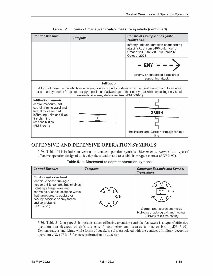
Control Measures and Operation Symbols
FM 1-02.2 5-45
Table 5-10. Forms of maneuver control measure symbols (continued)
Control Measure Template Construct Example and Symbol TranslationInfantry unit feint direction of supporting attack YALU from 0400 Zulu hour 8 October 2008 to 0300 Zulu hour 12 October 2008
Enemy or suspected direction of supporting attack
InfiltrationA form of maneuver in which an attacking force conducts undetected movement through or into an area
occupied by enemy forces to occupy a position of advantage in the enemy rear while exposing only small elements to enemy defensive fires. (FM 3-90-1)
Infiltration lane—Acontrol measure that coordinates forward and lateral movement of infiltrating units and fixes fire planning responsibilities. (FM 3-90-1)
Infiltration lane GREEN through fortified line
OFFENSIVE AND DEFENSIVE OPERATION SYMBOLS5-29. Table 5-11 includes movement to contact operation symbols. Movement to contact is a type ofoffensive operation designed to develop the situation and to establish or regain contact (ADP 3-90).
Table 5-11. Movement to contact operation symbols
Control Measure Template Construct Example and Symbol Translation
Cordon and search—Atechnique of conducting a movement to contact that involves isolating a target area and searching suspect locations within that target area to capture or destroy possible enemy forces and contraband. (FM 3-90-1)
Cordon and search chemical, biological, radiological, and nuclear
(CBRN) research facility
5-30. Table 5-12 on page 5-46 includes attack offensive operation symbols. An attack is a type of offensiveoperation that destroys or defeats enemy forces, seizes and secures terrain, or both (ADP 3-90).Demonstrations and feints, while forms of attack, are also associated with the conduct of military deceptionoperations. (See JP 3-13 for more information on attacks.)

Chapter 5
5-46 FM 1-02.2
Table 5-12. Attack operation symbols
Control Measure Template Construct Example and Symbol Translation
Ambush—An attack by fire or other destructive means from concealed positions on a moving or temporarily halted enemy. (FM 3-90-1)
Counterattack—Attack by part or all of a defending force against an enemy attacking force, for such specific purposes as regaining ground lost, or cutting off or destroying enemy advance units, and with the general objective of denying to the enemy the attainment of the enemy’s purpose in attacking. In sustained defensive operations, it is undertaken to restore the battle position and is directed at limited objectives. (FM 1-02.1)Note. The dashed lines in this graphic shall be displayed inpresent and anticipated status.Demonstration—In military deception, a show of force similar to a feint without actual contact with the adversary, in an area where a decision is not sought that is made to deceive an adversary. (JP 3-13.4)Feint—In military deception, an offensive action involving contact with the adversary conducted for the purpose of deceiving the adversary as to the location and/or time of the actual main offensive action. (JP 3-13.4)
5-31. Table 5-13, on pages 5-47 through 5-48 includes enabling operation symbols. Enabling operationsapply to all elements of decisive action, and related military symbols usage is described in ADP 3-90.Enabling operations include security, reconnaissance, relief in place, and passage of lines.
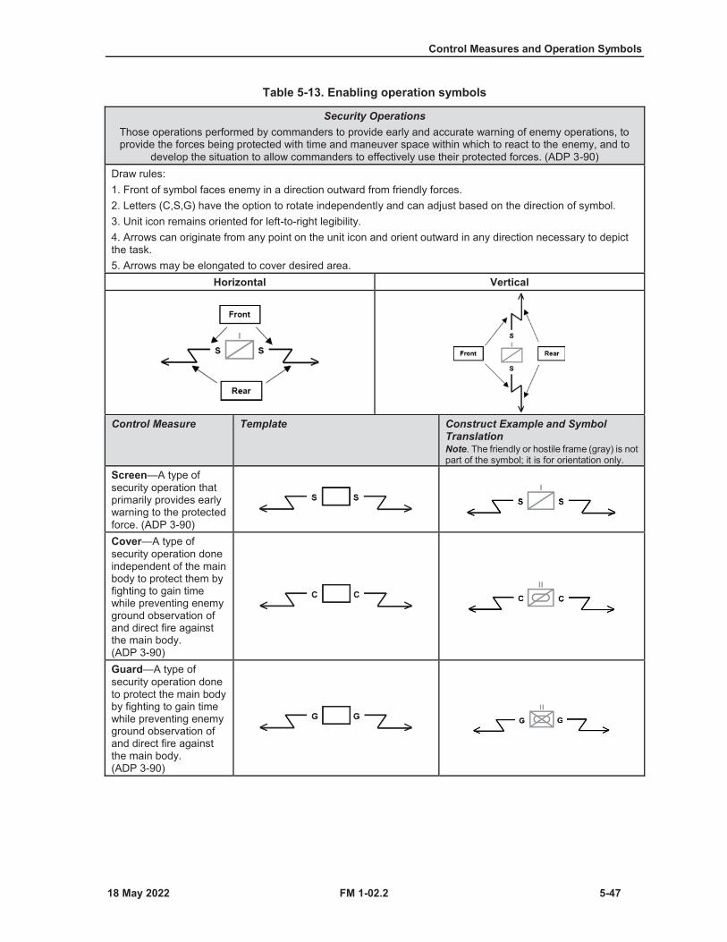
Control Measures and Operation Symbols
FM 1-02.2 5-47
Table 5-13. Enabling operation symbols
Security OperationsThose operations performed by commanders to provide early and accurate warning of enemy operations, to provide the forces being protected with time and maneuver space within which to react to the enemy, and to
develop the situation to allow commanders to effectively use their protected forces. (ADP 3-90)Draw rules:1. Front of symbol faces enemy in a direction outward from friendly forces.2. Letters (C,S,G) have the option to rotate independently and can adjust based on the direction of symbol.3. Unit icon remains oriented for left-to-right legibility.4. Arrows can originate from any point on the unit icon and orient outward in any direction necessary to depictthe task.5. Arrows may be elongated to cover desired area.
Horizontal Vertical
Control Measure Template Construct Example and Symbol TranslationNote. The friendly or hostile frame (gray) is not part of the symbol; it is for orientation only.
Screen—A type of security operation that primarily provides early warning to the protected force. (ADP 3-90)Cover—A type of security operation done independent of the main body to protect them by fighting to gain time while preventing enemy ground observation of and direct fire againstthe main body. (ADP 3-90)Guard—A type of security operation done to protect the main body by fighting to gain time while preventing enemy ground observation of and direct fire against the main body. (ADP 3-90)
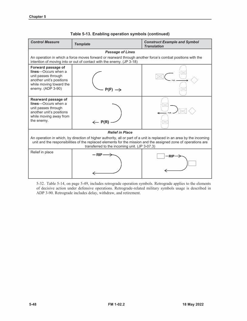
Chapter 5
5-48 FM 1-02.2
Table 5-13. Enabling operation symbols (continued)
Control Measure Template Construct Example and Symbol Translation
Passage of LinesAn operation in which a force moves forward or rearward through another force’s combat positions with the intention of moving into or out of contact with the enemy. (JP 3-18)Forward passage of lines—Occurs when a unit passes through another unit’s positions while moving toward the enemy. (ADP 3-90)
Rearward passage of lines—Occurs when a unit passes through another unit’s positions while moving away from the enemy.
Relief in PlaceAn operation in which, by direction of higher authority, all or part of a unit is replaced in an area by the incoming unit and the responsibilities of the replaced elements for the mission and the assigned zone of operations are
transferred to the incoming unit. (JP 3-07.3)Relief in place
5-32. Table 5-14, on page 5-49, includes retrograde operation symbols. Retrograde applies to the elementsof decisive action under defensive operations. Retrograde-related military symbols usage is described inADP 3-90. Retrograde includes delay, withdraw, and retirement.
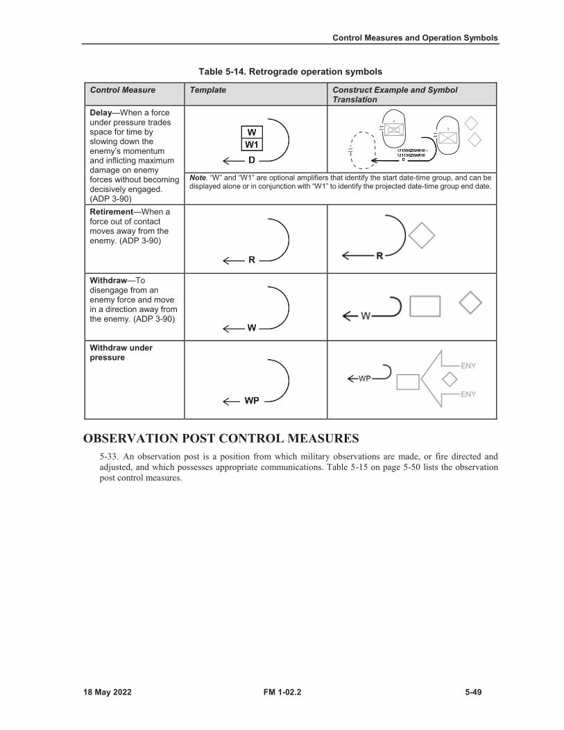
Control Measures and Operation Symbols
FM 1-02.2 5-49
Table 5-14. Retrograde operation symbols
Control Measure Template Construct Example and Symbol Translation
Delay—When a force under pressure trades space for time by slowing down the enemy’s momentum and inflicting maximum damage on enemy forces without becoming decisively engaged. (ADP 3-90)
Note. “W” and “W1” are optional amplifiers that identify the start date-time group, and can be displayed alone or in conjunction with “W1” to identify the projected date-time group end date.
Retirement—When a force out of contact moves away from the enemy. (ADP 3-90)
Withdraw—To disengage from an enemy force and move in a direction away from the enemy. (ADP 3-90)
Withdraw under pressure
OBSERVATION POST CONTROL MEASURES5-33. An observation post is a position from which military observations are made, or fire directed andadjusted, and which possesses appropriate communications. Table 5-15 on page 5-50 lists the observationpost control measures.

Chapter 5
5-50 FM 1-02.2
Table 5-15. Observation post control measure symbols
Function ConstructNote. Symbols without amplifier fields cannot be modified and must be used as depicted.
Observation post—A position from which military observations are made, or fire directed and adjusted, and which possess appropriate communications. While aerial observers and sensors systems are extremely useful, those systems do not constitute aerial observation posts. (FM 3-90-2)Reconnaissance observation post
Forward observer—An observer operating with front line troops and trained to adjust ground or naval gunfire and pass back battlefield information. (JP 3-09)
Chemical, biological, radiological, or nuclear(CBRN) observation post
Sensor observation post or listening pod
Combat outpost—A reinforced observation post capable of conducting limited combat operations. (FM 3-90-2)
MILITARY DECEPTION CONTROL MEASURES5-34. Military deception is actions executed to deliberately mislead adversary military, paramilitary, orviolent extremist organization decision makers, thereby causing the adversary to take specific actions (orinactions) that will contribute to the accomplishment of the friendly mission (JP 3-13.4). Military deceptioncontrol measures are designed to identify actions executed to mislead the enemy by manipulation, distortion,or falsification of evidence to induce the enemy to react in a manner prejudicial to the enemy’s interests.Table 5-16 on pages 5-51 and 5-52 demonstrates the military deception icon symbol usage construct.
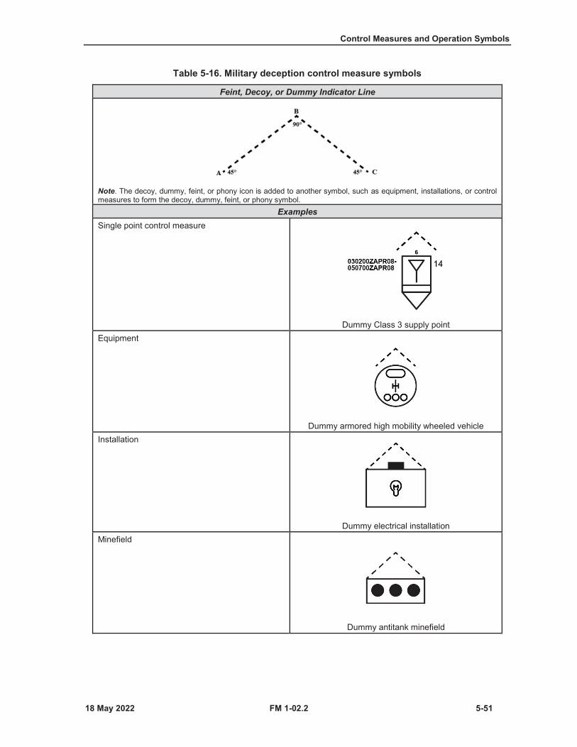
Control Measures and Operation Symbols
FM 1-02.2 5-51
Table 5-16. Military deception control measure symbols
Feint, Decoy, or Dummy Indicator Line
Note. The decoy, dummy, feint, or phony icon is added to another symbol, such as equipment, installations, or control measures to form the decoy, dummy, feint, or phony symbol.
ExamplesSingle point control measure
Dummy Class 3 supply pointEquipment
Dummy armored high mobility wheeled vehicleInstallation
Dummy electrical installationMinefield
Dummy antitank minefield
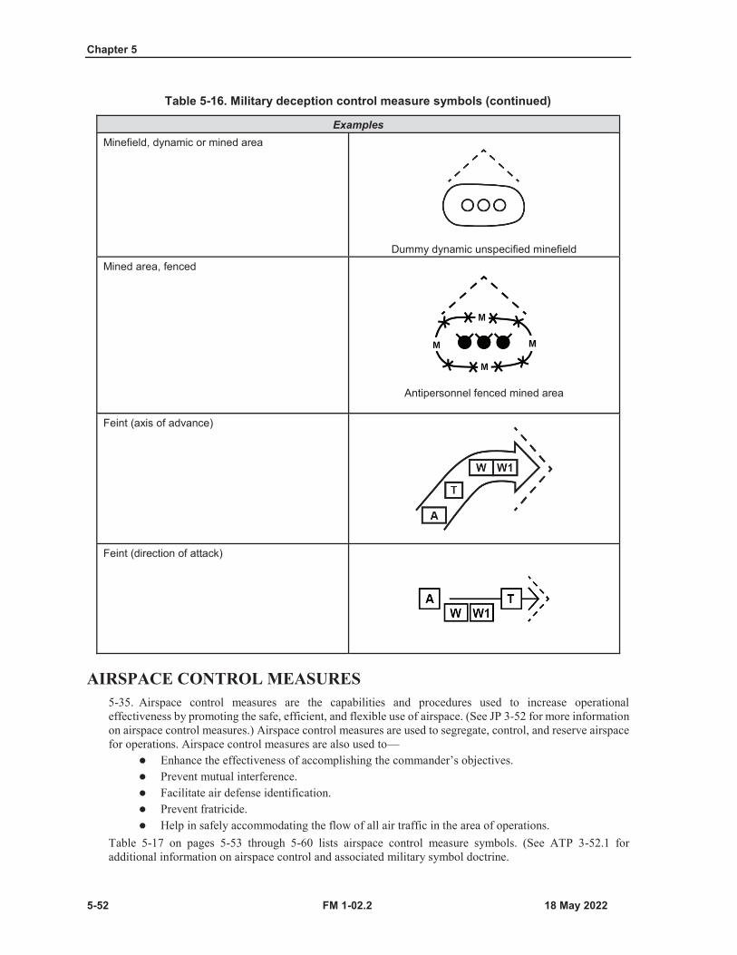
Chapter 5
5-52 FM 1-02.2
Table 5-16. Military deception control measure symbols (continued)
ExamplesMinefield, dynamic or mined area
Dummy dynamic unspecified minefieldMined area, fenced
Antipersonnel fenced mined area
Feint (axis of advance)
Feint (direction of attack)
AIRSPACE CONTROL MEASURES5-35. Airspace control measures are the capabilities and procedures used to increase operationaleffectiveness by promoting the safe, efficient, and flexible use of airspace. (See JP 3-52 for more informationon airspace control measures.) Airspace control measures are used to segregate, control, and reserve airspacefor operations. Airspace control measures are also used to—
Enhance the effectiveness of accomplishing the commander’s objectives.Prevent mutual interference.Facilitate air defense identification.Prevent fratricide.Help in safely accommodating the flow of all air traffic in the area of operations.
Table 5-17 on pages 5-53 through 5-60 lists airspace control measure symbols. (See ATP 3-52.1 for additional information on airspace control and associated military symbol doctrine.
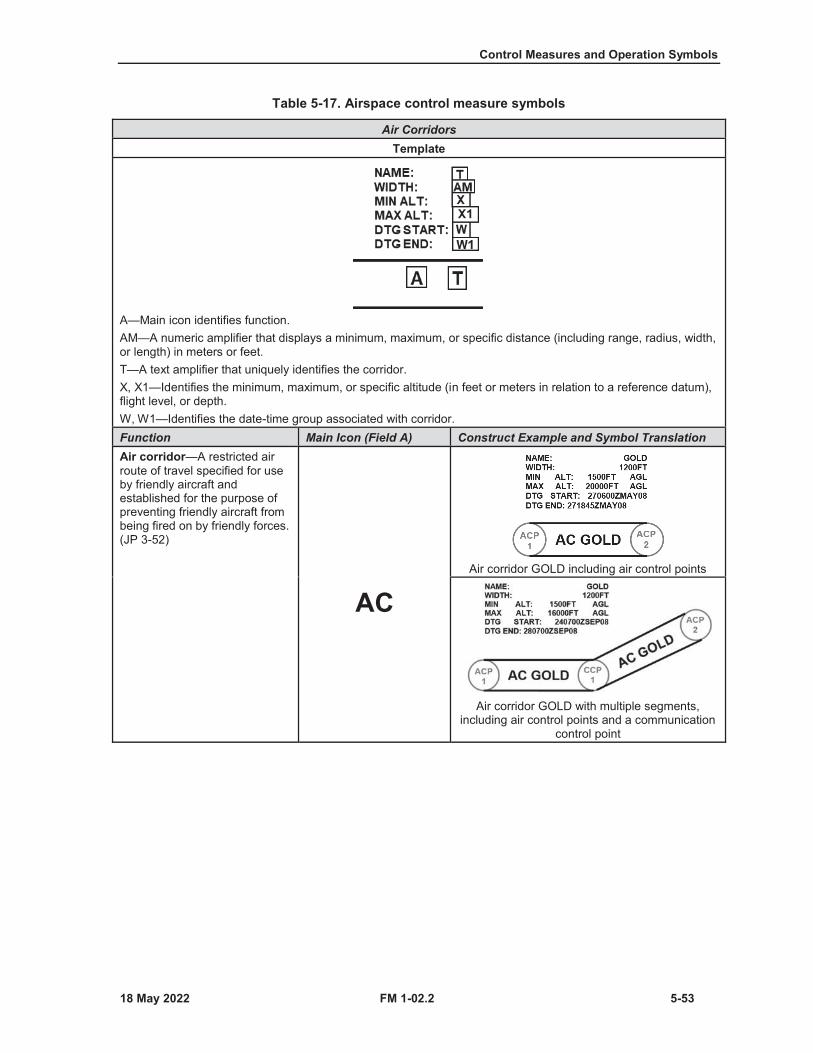
Control Measures and Operation Symbols
FM 1-02.2 5-53
Table 5-17. Airspace control measure symbols
Air CorridorsTemplate
A—Main icon identifies function.AM—A numeric amplifier that displays a minimum, maximum, or specific distance (including range, radius, width, or length) in meters or feet.T—A text amplifier that uniquely identifies the corridor.X, X1—Identifies the minimum, maximum, or specific altitude (in feet or meters in relation to a reference datum), flight level, or depth.W, W1—Identifies the date-time group associated with corridor.Function Main Icon (Field A) Construct Example and Symbol TranslationAir corridor—A restricted air route of travel specified for use by friendly aircraft and established for the purpose of preventing friendly aircraft from being fired on by friendly forces. (JP 3-52)
ACAir corridor GOLD including air control points
Air corridor GOLD with multiple segments, including air control points and a communication
control point
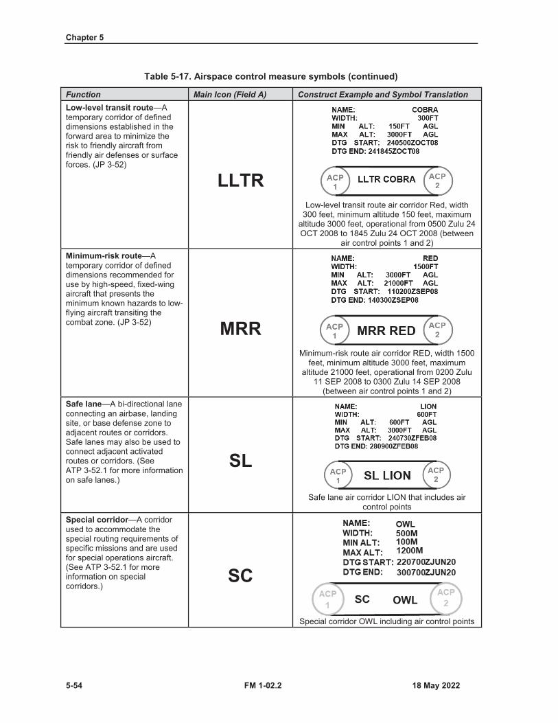
Chapter 5
5-54 FM 1-02.2
Table 5-17. Airspace control measure symbols (continued)
Function Main Icon (Field A) Construct Example and Symbol TranslationLow-level transit route—Atemporary corridor of defined dimensions established in the forward area to minimize the risk to friendly aircraft from friendly air defenses or surface forces. (JP 3-52)
LLTRLow-level transit route air corridor Red, width
300 feet, minimum altitude 150 feet, maximum altitude 3000 feet, operational from 0500 Zulu 24 OCT 2008 to 1845 Zulu 24 OCT 2008 (between
air control points 1 and 2)Minimum-risk route—Atemporary corridor of defined dimensions recommended for use by high-speed, fixed-wing aircraft that presents the minimum known hazards to low-flying aircraft transiting the combat zone. (JP 3-52) MRR
Minimum-risk route air corridor RED, width 1500 feet, minimum altitude 3000 feet, maximum
altitude 21000 feet, operational from 0200 Zulu 11 SEP 2008 to 0300 Zulu 14 SEP 2008
(between air control points 1 and 2)Safe lane—A bi-directional lane connecting an airbase, landing site, or base defense zone to adjacent routes or corridors. Safe lanes may also be used to connect adjacent activated routes or corridors. (See ATP 3-52.1 for more information on safe lanes.)
SL
Safe lane air corridor LION that includes air control points
Special corridor—A corridor used to accommodate the special routing requirements of specific missions and are used for special operations aircraft. (See ATP 3-52.1 for more information on special corridors.)
SC
Special corridor OWL including air control points
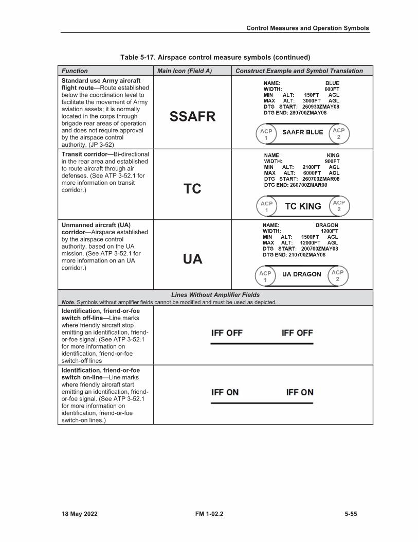
Control Measures and Operation Symbols
FM 1-02.2 5-55
Table 5-17. Airspace control measure symbols (continued)
Function Main Icon (Field A) Construct Example and Symbol TranslationStandard use Army aircraft flight route—Route established below the coordination level to facilitate the movement of Army aviation assets; it is normally located in the corps through brigade rear areas of operation and does not require approval by the airspace control authority. (JP 3-52)
SSAFR
Transit corridor—Bi-directional in the rear area and established to route aircraft through air defenses. (See ATP 3-52.1 for more information on transit corridor.) TC
Unmanned aircraft (UA) corridor—Airspace established by the airspace control authority, based on the UA mission. (See ATP 3-52.1 for more information on an UA corridor.)
UA
Lines Without Amplifier FieldsNote. Symbols without amplifier fields cannot be modified and must be used as depicted.Identification, friend-or-foe switch off-line—Line marks where friendly aircraft stop emitting an identification, friend-or-foe signal. (See ATP 3-52.1 for more information on identification, friend-or-foe switch-off linesIdentification, friend-or-foe switch on-line—Line marks where friendly aircraft start emitting an identification, friend-or-foe signal. (See ATP 3-52.1 for more information onidentification, friend-or-foe switch-on lines.)

Chapter 5
5-56 FM 1-02.2
Table 5-17. Airspace control measure symbols (continued)
ZonesFunction ExampleBase defense zone—An air defense zone established around an air base and limited to the engagement envelope of short-range air defense weapons systems defending that base. (JP 3-52)
Note. This zone symbol has no amplifier fields and cannot be modified.Zone Symbols with Amplifier Fields
Template
A—Main icon that identifies the function.T—Identifies the unique unit designation servicing the zone.X, X1—Identifies the minimum, maximum, and/or specific altitude (in feet or meters in relation to a reference datum), flight level, or depth.W, W1—Identifies the date-time group associated with zone.Function Main Icon (Field A) Example with Symbol TranslationHigh-density airspace control zone—Airspace designated in an airspace control plan or airspace control order in which there is a concentrated employment of numerous and varied weapons and airspace users. (JP 3-52) HIDACZ
High-density airspace control zone, established by 101st airborne control authority for a minimum altitude of 450000 feet above ground level and a maximum altitude of 1110000 feet above ground level, operational from 0700 Zulu hour 14 MAY
2013
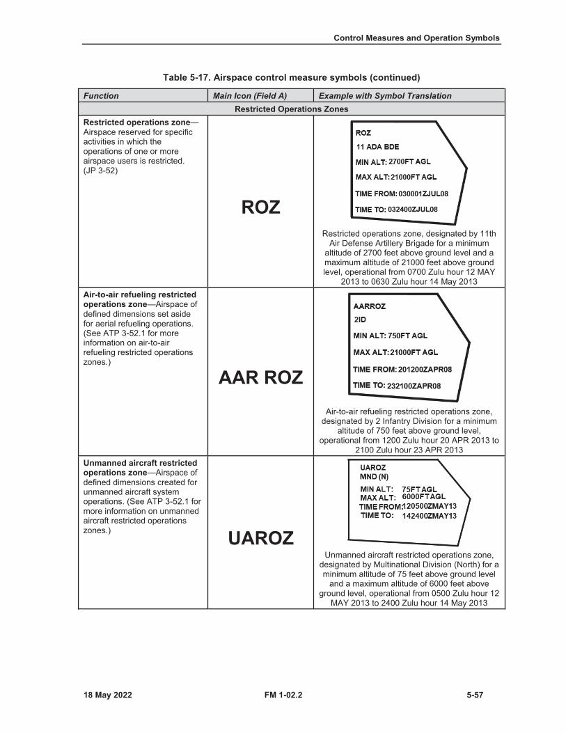
Control Measures and Operation Symbols
FM 1-02.2 5-57
Table 5-17. Airspace control measure symbols (continued)
Function Main Icon (Field A) Example with Symbol TranslationRestricted Operations Zones
Restricted operations zone—Airspace reserved for specific activities in which the operations of one or more airspace users is restricted. (JP 3-52)
ROZRestricted operations zone, designated by 11th
Air Defense Artillery Brigade for a minimum altitude of 2700 feet above ground level and a maximum altitude of 21000 feet above ground level, operational from 0700 Zulu hour 12 MAY
2013 to 0630 Zulu hour 14 May 2013Air-to-air refueling restricted operations zone—Airspace of defined dimensions set aside for aerial refueling operations. (See ATP 3-52.1 for more information on air-to-air refueling restricted operations zones.)
AAR ROZAir-to-air refueling restricted operations zone,
designated by 2 Infantry Division for a minimum altitude of 750 feet above ground level,
operational from 1200 Zulu hour 20 APR 2013 to 2100 Zulu hour 23 APR 2013
Unmanned aircraft restricted operations zone—Airspace of defined dimensions created for unmanned aircraft system operations. (See ATP 3-52.1 for more information on unmanned aircraft restricted operations zones.) UAROZ
Unmanned aircraft restricted operations zone, designated by Multinational Division (North) for a minimum altitude of 75 feet above ground level
and a maximum altitude of 6000 feet above ground level, operational from 0500 Zulu hour 12
MAY 2013 to 2400 Zulu hour 14 May 2013
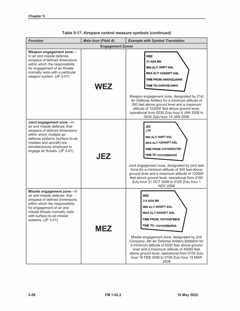
Chapter 5
5-58 FM 1-02.2
Table 5-17. Airspace control measure symbols (continued)
Function Main Icon (Field A) Example with Symbol TranslationEngagement Zones
Weapon engagement zone—In air and missile defense, airspace of defined dimensions within which the responsibility for engagement of air threats normally rests with a particular weapon system. (JP 3-01)
WEZWeapon engagement zone, designated by 21st Air Defense Artillery for a minimum altitude of 300 feet above ground level and a maximum altitude of 102000 feet above ground level,
operational from 0030 Zulu hour 4 JAN 2008 to 0630 Zulu hour 14 JAN 2008
Joint engagement zone—In air and missile defense, that airspace of defined dimensions within which multiple air defense systems (surface-to-air missiles and aircraft) are simultaneously employed to engage air threats. (JP 3-01)
JEZJoint engagement zone, designated by joint task force for a minimum altitude of 300 feet above
ground level and a maximum altitude of 120000 feet above ground level, operational from 0100
Zulu hour 31 OCT 2008 to 0100 Zulu hour 1 NOV 2008
Missile engagement zone—In air and missile defense, that airspace of defined dimensions within which the responsibility for engagement of air and missile threats normally rests with surface-to-air missile systems. (JP 3-01)
MEZMissile engagement zone, designated by 2nd
Company, 4th Air Defense Artillery Battalion for a minimum altitude of 6000 feet above ground
level and a maximum altitude of 45000 feet above ground level, operational from 0100 Zulu hour 16 FEB 2008 to 0100 Zulu hour 15 MAR
2008

Control Measures and Operation Symbols
FM 1-02.2 5-59
Table 5-17. Airspace control measure symbols (continued)
Function Main Icon (Field A) Example with Symbol TranslationLow-altitude missile engagement zone—In air and missile defense, that airspace of defined dimensions within which the responsibility for engagement of air and missile threats normally rests with low-to medium-altitude surface-to-air missiles. (JP 3-01) LOMEZ
Low (altitude) missile engagement zone, designated by anti-air coordination center, for aminimum altitude of 300 feet above ground level
and a maximum altitude of 6000 feet above ground level, operational from 0600 Zulu hour 7
AUG 2008 to 1600 Zulu hour 7 AUG 2008High-altitude missile engagement zone—In air and missile defense, that airspace of defined dimensions within which the responsibility for engagement of air and missile threats normally rests with high-altitude surface-to-air missiles. (JP 3-01) HIMEZ
High (altitude) missile engagement zone, designated by anti-air coordination center, for a
minimum altitude of 6000 feet above ground level and a maximum altitude of 150000 feet
above ground level, operational from 0600 Zulu hour 7 AUG 2008 to 1600 Zulu hour 7 AUG 2008
Short-range air defense engagement zone—In air and missile defense, that airspace of defined dimensions within which the responsibility for engagement of air and missile threats normally rests with short-range air defense weapons, and may be established within a low- or high-altitude missile engagement zone. (JP 3-01)
SHORADEZ
Short-range air defense engagement zone, designated by joint task force, for a minimum altitude of 300 feet above ground level and a
maximum altitude of 24000 feet above ground level, operational from 0600 Zulu hour 24 AUG
2008 to 2300 Zulu hour 24 AUG 2008

Chapter 5
5-60 FM 1-02.2
Table 5-17. Airspace control measure symbols (continued)
Function Main Icon (Field A) Example with Symbol TranslationWeapons free zone—An air defense zone established for the protection of key assets or facilities, other than air bases, where weapon systems may be fired at any target not positively recognized as friendly. (JP 3-01)
WFZWeapons free zone, designated by joint task
force, operational from 0805 Zulu 7 AUG 2013 to 0805 Zulu hour 21 AUG 2013
PointsFunction Template Construct Example and Symbol TranslationAir control point—A point easily defined and used for navigation, command and control, and communication. The point may be a terrain feature or an electronic navigational air. (See ATP 3-52.1 and ATP 3-04.1 for more information on air control points.)
Air corridor GOLD with air control points 1 and 2
FIRE SUPPORT COORDINATION CONTROL MEASURES5-36. Fire support coordination measures are employed by land or amphibious commanders to facilitate therapid engagement of targets and simultaneously provide safeguards for friendly forces. Fire supportcoordination control measures should be labeled with the abbreviation of the control measures, the controllingheadquarters (Field T), and the effective times (Fields W and W1). Lines should have this labeling on bothends of the line and repeated as often as necessary for clarity along any line that passes through boundaries.Table 5-18 on pages 5-61 through 5-65 lists fire support coordination control measure symbols. (See JP 3-0,FM 3-09, and ATP 3-52.1 for additional information on fire support coordination measures and associatedmilitary symbol doctrine.)

Control Measures and Operation Symbols
FM 1-02.2 5-61
Table 5-18. Fire support coordination control measure symbols
Function Template Construct ExampleAirspace coordination area
A three-dimensional block of airspace in a target area, established by the appropriate commander, in which friendly aircraft are reasonably safe from friendly surface fires. (JP 3-09.3
Airspace coordination area—irregular
A restricted area or route of travel specified for use by friendly aircraft and established for the purpose of preventing friendly aircraft from being fired on by friendly forces.
Airspace coordination area—rectangle
Airspace coordination area—circular

Chapter 5
5-62 FM 1-02.2
Table 5-18. Fire support coordination control measure symbols (continued)
Function Template Construct ExampleFree-fire area
A specific area into which any weapon system may fire without additional coordination with the establishing headquarters. (JP 3-09)
Free-fire area—irregular
Free-fire area—rectangle
Free-fire area—circular
No-fire areaAn area designated by the appropriate commander into which fires or their effects are prohibited. (JP 3-09.3)
No-fire area—irregular
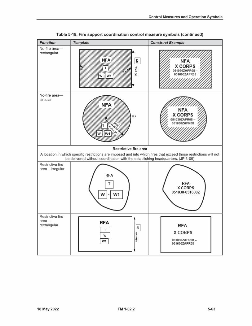
Control Measures and Operation Symbols
FM 1-02.2 5-63
Table 5-18. Fire support coordination control measure symbols (continued)
Function Template Construct ExampleNo-fire area—rectangular
No-fire area—circular
Restrictive fire areaA location in which specific restrictions are imposed and into which fires that exceed those restrictions will not
be delivered without coordination with the establishing headquarters. (JP 3-09)Restrictive fire area—irregular
Restrictive fire area—rectangular
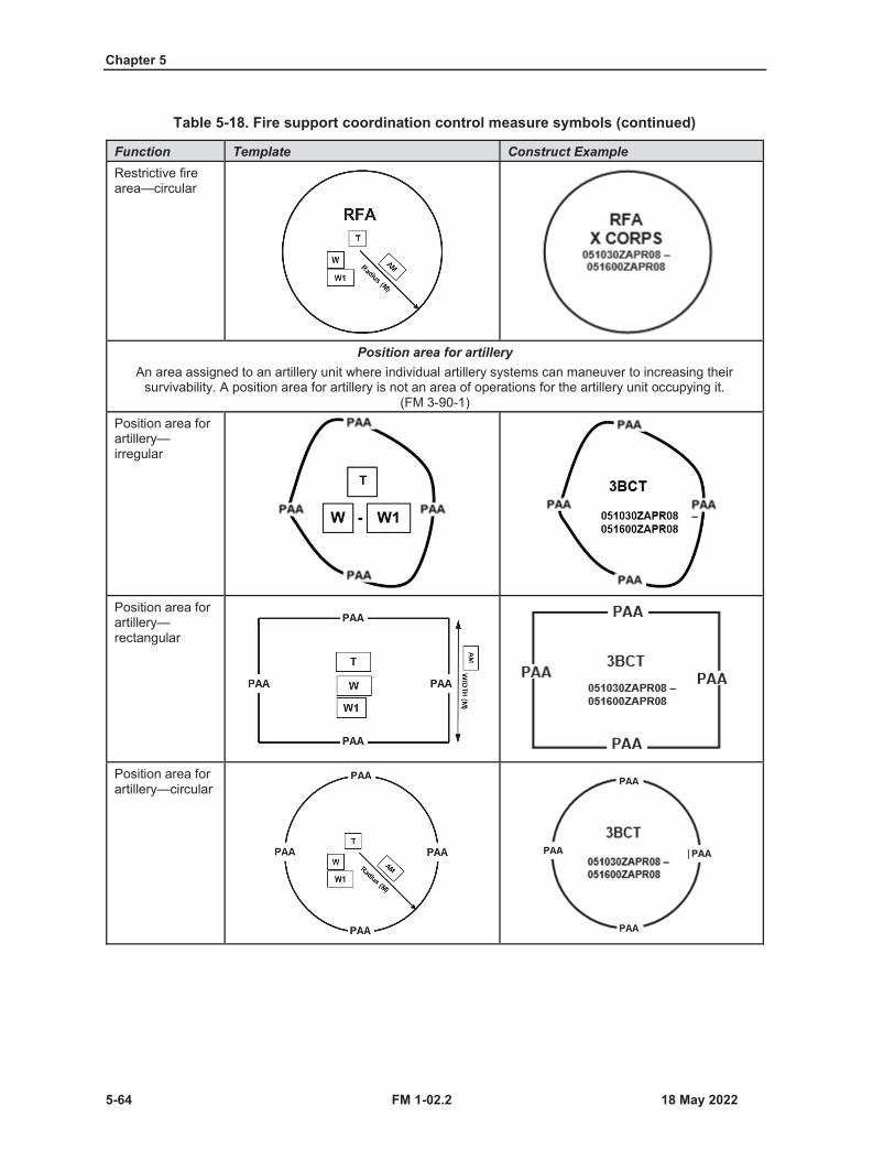
Chapter 5
5-64 FM 1-02.2
Table 5-18. Fire support coordination control measure symbols (continued)
Function Template Construct ExampleRestrictive fire area—circular
Position area for artilleryAn area assigned to an artillery unit where individual artillery systems can maneuver to increasing their
survivability. A position area for artillery is not an area of operations for the artillery unit occupying it. (FM 3-90-1)
Position area for artillery—irregular
Position area for artillery—rectangular
Position area for artillery—circular
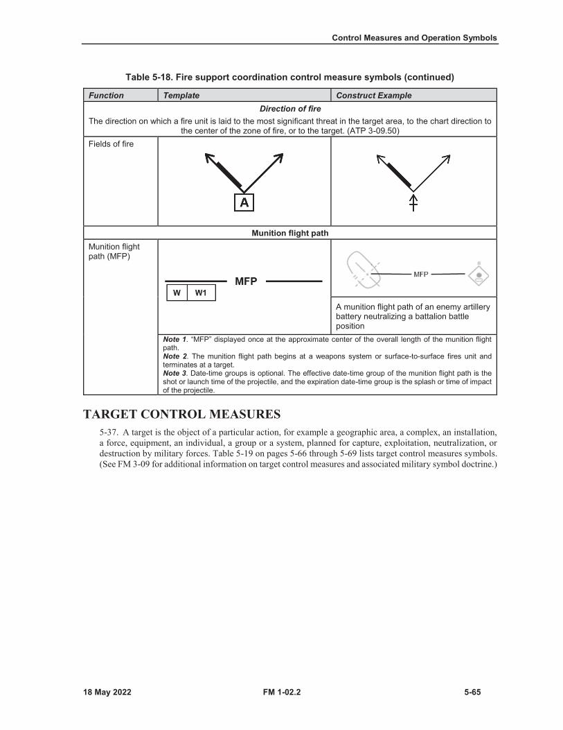
Control Measures and Operation Symbols
FM 1-02.2 5-65
Table 5-18. Fire support coordination control measure symbols (continued)
Function Template Construct ExampleDirection of fire
The direction on which a fire unit is laid to the most significant threat in the target area, to the chart direction to the center of the zone of fire, or to the target. (ATP 3-09.50)
Fields of fire
Munition flight pathMunition flight path (MFP)
A munition flight path of an enemy artillery battery neutralizing a battalion battle position
Note 1. “MFP” displayed once at the approximate center of the overall length of the munition flight path.Note 2. The munition flight path begins at a weapons system or surface-to-surface fires unit and terminates at a target.Note 3. Date-time groups is optional. The effective date-time group of the munition flight path is the shot or launch time of the projectile, and the expiration date-time group is the splash or time of impact of the projectile.
TARGET CONTROL MEASURES5-37. A target is the object of a particular action, for example a geographic area, a complex, an installation,a force, equipment, an individual, a group or a system, planned for capture, exploitation, neutralization, ordestruction by military forces. Table 5-19 on pages 5-66 through 5-69 lists target control measures symbols.(See FM 3-09 for additional information on target control measures and associated military symbol doctrine.)
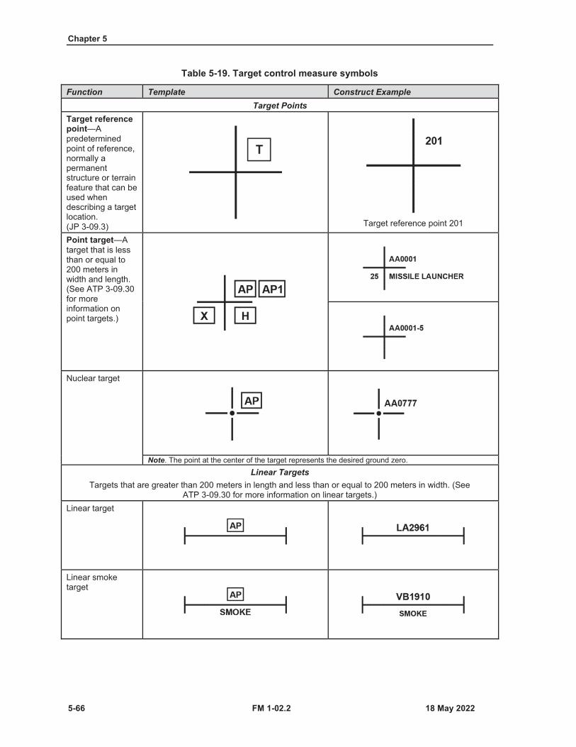
Chapter 5
5-66 FM 1-02.2
Table 5-19. Target control measure symbols
Function Template Construct ExampleTarget Points
Target reference point—Apredetermined point of reference, normally a permanent structure or terrain feature that can be used when describing a target location. (JP 3-09.3) Target reference point 201
Point target—Atarget that is less than or equal to200 meters in width and length. (See ATP 3-09.30 for more information on point targets.)
Nuclear target
Note. The point at the center of the target represents the desired ground zero.Linear Targets
Targets that are greater than 200 meters in length and less than or equal to 200 meters in width. (See ATP 3-09.30 for more information on linear targets.)
Linear target
Linear smoke target
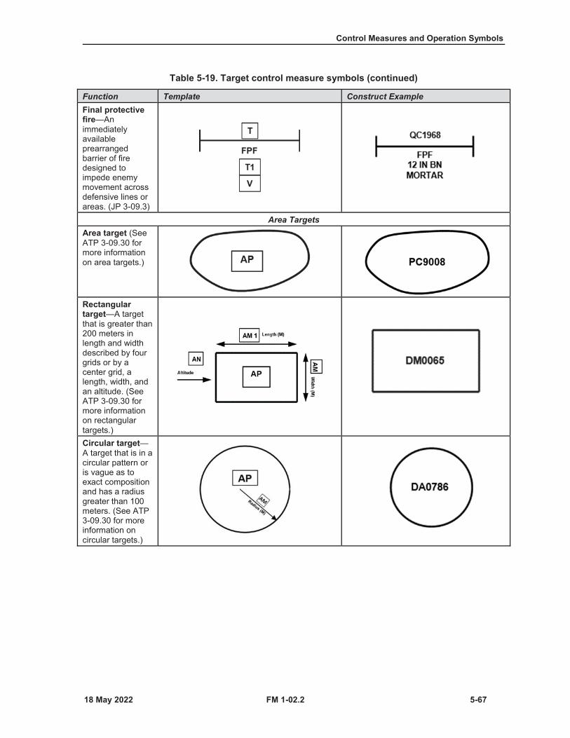
Control Measures and Operation Symbols
FM 1-02.2 5-67
Table 5-19. Target control measure symbols (continued)
Function Template Construct ExampleFinal protective fire—An immediately available prearranged barrier of fire designed to impede enemy movement across defensive lines or areas. (JP 3-09.3)
Area TargetsArea target (See ATP 3-09.30 for more information on area targets.)
Rectangular target—A target that is greater than 200 meters in length and width described by four grids or by a center grid, a length, width, and an altitude. (See ATP 3-09.30 for more information on rectangular targets.)Circular target—A target that is in a circular pattern or is vague as to exact composition and has a radius greater than 100 meters. (See ATP 3-09.30 for moreinformation oncircular targets.)
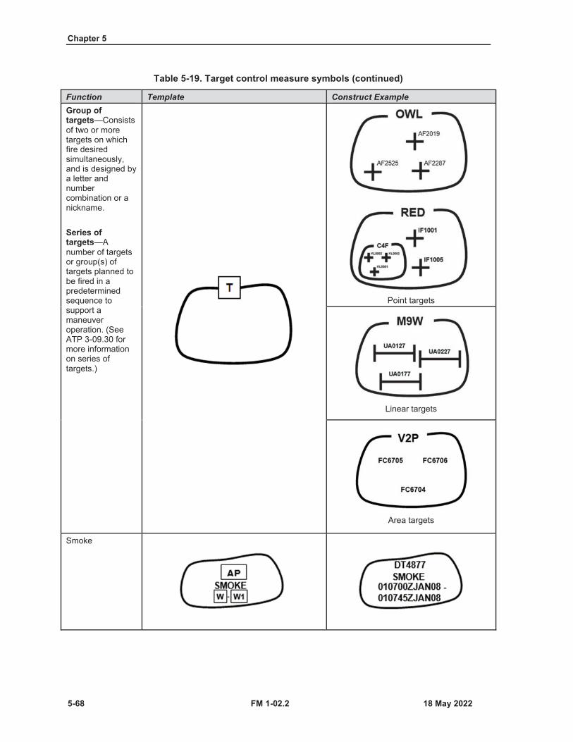
Chapter 5
5-68 FM 1-02.2
Table 5-19. Target control measure symbols (continued)
Function Template Construct ExampleGroup of targets—Consists of two or more targets on which fire desired simultaneously, and is designed by a letter and number combination or a nickname.
Series of targets—Anumber of targets or group(s) of targets planned to be fired in a predetermined sequence to support a maneuver operation. (See ATP 3-09.30 for more information on series of targets.)
Point targets
Linear targets
Area targets
Smoke

Control Measures and Operation Symbols
FM 1-02.2 5-69
Table 5-19. Target control measure symbols (continued)
Function Template Construct ExampleSmoke (continued)
PlannedBomb area
Naval GunfireFire support station—An exact location at sea within a fire support area from which a fire support ship delivers fire. (JP 3-02)
Fire Support AreaAn appropriate maneuver area assigned to fire support ships by the naval force commander from which they can
deliver gunfire support to an amphibious operation. (JP 3-09)Fire support area, irregular
Fire support area, rectangular
Fire support area, circular
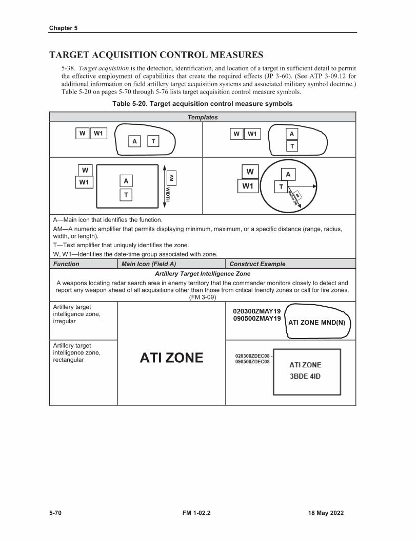
Chapter 5
5-70 FM 1-02.2
TARGET ACQUISITION CONTROL MEASURES5-38. Target acquisition is the detection, identification, and location of a target in sufficient detail to permitthe effective employment of capabilities that create the required effects (JP 3-60). (See ATP 3-09.12 foradditional information on field artillery target acquisition systems and associated military symbol doctrine.)Table 5-20 on pages 5-70 through 5-76 lists target acquisition control measure symbols.
Table 5-20. Target acquisition control measure symbols
Templates
A—Main icon that identifies the function.AM—A numeric amplifier that permits displaying minimum, maximum, or a specific distance (range, radius, width, or length).T—Text amplifier that uniquely identifies the zone.W, W1—Identifies the date-time group associated with zone.Function Main Icon (Field A) Construct Example
Artillery Target Intelligence ZoneA weapons locating radar search area in enemy territory that the commander monitors closely to detect and report any weapon ahead of all acquisitions other than those from critical friendly zones or call for fire zones.
(FM 3-09)Artillery target intelligence zone, irregular
ATI ZONEArtillery target intelligence zone, rectangular
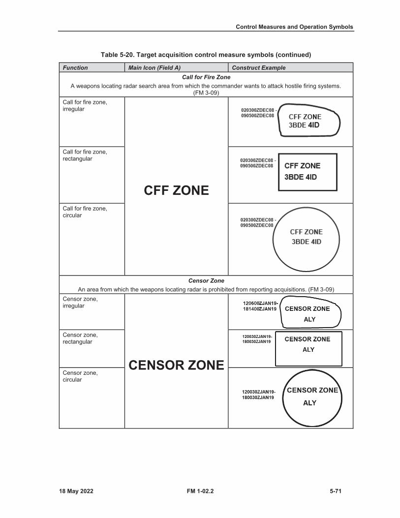
Control Measures and Operation Symbols
FM 1-02.2 5-71
Table 5-20. Target acquisition control measure symbols (continued)
Function Main Icon (Field A) Construct ExampleCall for Fire Zone
A weapons locating radar search area from which the commander wants to attack hostile firing systems. (FM 3-09)
Call for fire zone, irregular
CFF ZONE
Call for fire zone, rectangular
Call for fire zone, circular
Censor ZoneAn area from which the weapons locating radar is prohibited from reporting acquisitions. (FM 3-09)
Censor zone, irregular
CENSOR ZONE
Censor zone,rectangular
Censor zone,circular

Chapter 5
5-72 FM 1-02.2
Table 5-20. Target acquisition control measure symbols (continued)
Function Main Icon (Field A) Construct ExampleCritical Friendly Zone
A friendly area of coverage employed by weapons locating radar which the maneuver commander designates as critical to the protection of an asset whose loss would seriously jeopardize the mission. (FM 3-09)
Critical friendly zone, irregular
CZ ZONE
Critical friendly zone, rectangular
Critical friendly zone, circular
Dead Space AreaAn area where hostile weapons cannot be detected.
Dead space area, irregular
DA
Dead space area, rectangular
Dead space area, circular

Control Measures and Operation Symbols
FM 1-02.2 5-73
Table 5-20. Target acquisition control measure symbols (continued)
Function Main Icon (Field A) Construct ExampleTarget Build-Up Area
Target build-up area, irregular
TBA
Target build-up area, rectangular
Target build-up area, circular
Target Value AreaTarget value area, irregular
TVAR
Target value area, rectangular
Target value area, circular

Chapter 5
5-74 FM 1-02.2
Table 5-20. Target acquisition control measure symbols (continued)
Function Main Icon (Field A) Construct ExampleZone of Responsibility
Zone of responsibility, irregular
ZOR
Zone of responsibility, rectangular
Zone of responsibility, circular
Blue Kill BoxA fire support and airspace coordination measure that facilitates attacking surface targets with air-to-surface munitions without further coordination with the area of operations commanders’ headquarters. (ATP 3-09.34)
Blue kill box,irregular
BKB
Blue kill box,rectangular
Blue kill box,circular
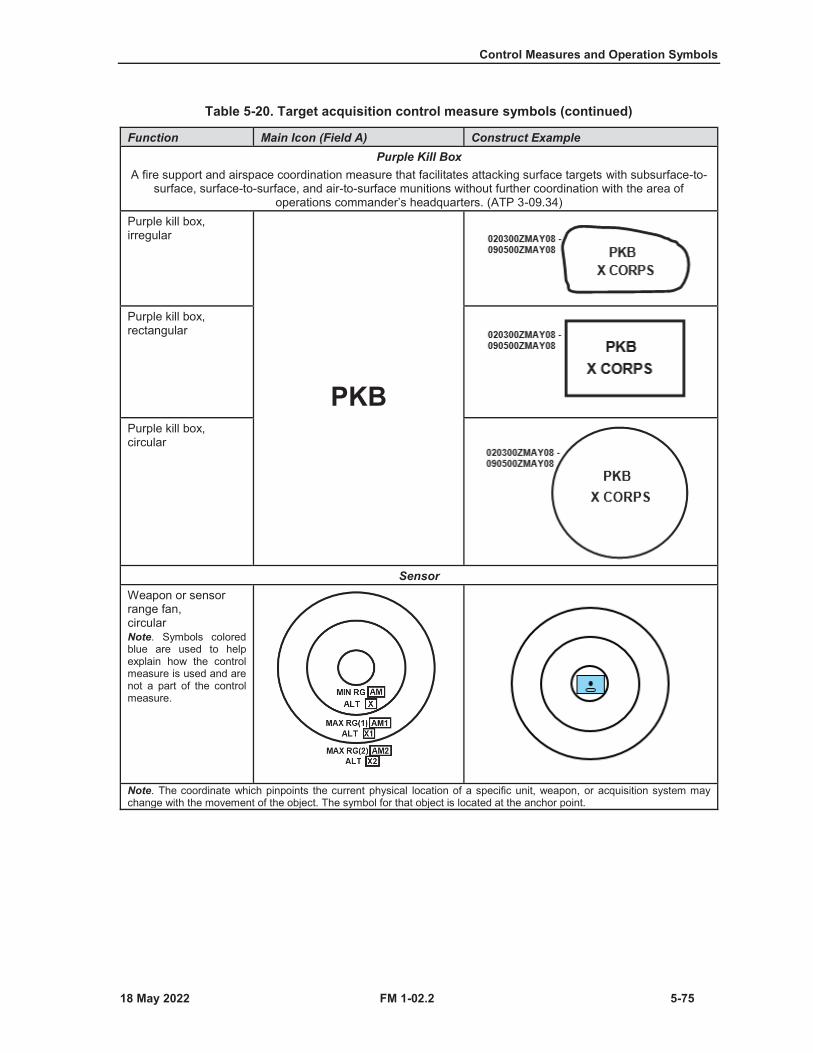
Control Measures and Operation Symbols
FM 1-02.2 5-75
Table 5-20. Target acquisition control measure symbols (continued)
Function Main Icon (Field A) Construct ExamplePurple Kill Box
A fire support and airspace coordination measure that facilitates attacking surface targets with subsurface-to-surface, surface-to-surface, and air-to-surface munitions without further coordination with the area of
operations commander’s headquarters. (ATP 3-09.34)Purple kill box,irregular
PKB
Purple kill box,rectangular
Purple kill box,circular
SensorWeapon or sensor range fan,circularNote. Symbols colored blue are used to help explain how the control measure is used and are not a part of the control measure.
Note. The coordinate which pinpoints the current physical location of a specific unit, weapon, or acquisition system may change with the movement of the object. The symbol for that object is located at the anchor point.
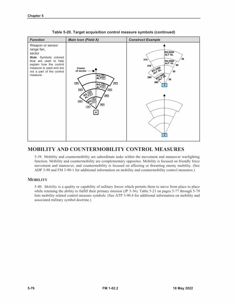
Chapter 5
5-76 FM 1-02.2
Table 5-20. Target acquisition control measure symbols (continued)
Function Main Icon (Field A) Construct ExampleWeapon or sensor range fan,sectorNote. Symbols colored blue are used to help explain how the control measure is used and are not a part of the control measure.
MOBILITY AND COUNTERMOBILITY CONTROL MEASURES5-39. Mobility and countermobility are subordinate tasks within the movement and maneuver warfightingfunction. Mobility and countermobility are complementary opposites. Mobility is focused on friendly forcemovement and maneuver, and countermobility is focused on affecting or thwarting enemy mobility. (SeeADP 3-90 and FM 3-90-1 for additional information on mobility and countermobility control measures.)
MOBILITY
5-40. Mobility is a quality or capability of military forces which permits them to move from place to placewhile retaining the ability to fulfill their primary mission (JP 3-36). Table 5-21 on pages 5-77 through 5-79lists mobility related control measure symbols. (See ATP 3-90.4 for additional information on mobility andassociated military symbol doctrine.)

Control Measures and Operation Symbols
FM 1-02.2 5-77
Table 5-21. Mobility control measure symbols
Function Template Construct ExampleNote. Symbols colored gray are used to help explain how the control measure is used and are not a part of the control measure.
Obstacle bypass,easy
Obstacle bypass,Difficult
Obstacle bypass,impossible
Gap—An area free of armed mines or obstacles whose width and direction allow a friendly force to pass through while dispersed in a tactical formation. (FM 1-02.1)
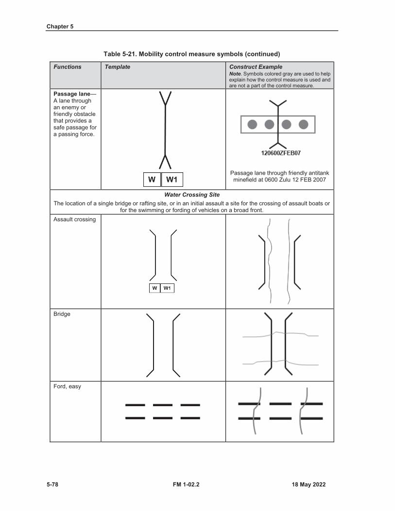
Chapter 5
5-78 FM 1-02.2
Table 5-21. Mobility control measure symbols (continued)
Functions Template Construct ExampleNote. Symbols colored gray are used to help explain how the control measure is used and are not a part of the control measure.
Passage lane—A lane through an enemy or friendly obstacle that provides a safe passage for a passing force.
Passage lane through friendly antitank minefield at 0600 Zulu 12 FEB 2007
Water Crossing SiteThe location of a single bridge or rafting site, or in an initial assault a site for the crossing of assault boats or
for the swimming or fording of vehicles on a broad front.Assault crossing
Bridge
Ford, easy
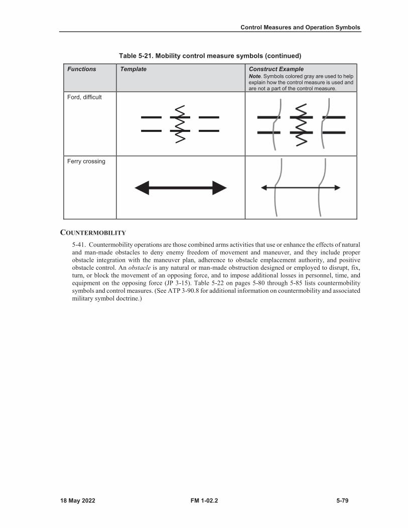
Control Measures and Operation Symbols
FM 1-02.2 5-79
Table 5-21. Mobility control measure symbols (continued)
Functions Template Construct ExampleNote. Symbols colored gray are used to help explain how the control measure is used and are not a part of the control measure.
Ford, difficult
Ferry crossing
COUNTERMOBILITY
5-41. Countermobility operations are those combined arms activities that use or enhance the effects of naturaland man-made obstacles to deny enemy freedom of movement and maneuver, and they include properobstacle integration with the maneuver plan, adherence to obstacle emplacement authority, and positiveobstacle control. An obstacle is any natural or man-made obstruction designed or employed to disrupt, fix,turn, or block the movement of an opposing force, and to impose additional losses in personnel, time, andequipment on the opposing force (JP 3-15). Table 5-22 on pages 5-80 through 5-85 lists countermobilitysymbols and control measures. (See ATP 3-90.8 for additional information on countermobility and associatedmilitary symbol doctrine.)
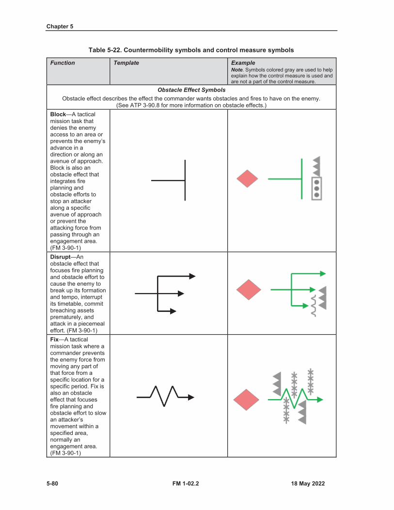
Chapter 5
5-80 FM 1-02.2
Table 5-22. Countermobility symbols and control measure symbols
Function Template ExampleNote. Symbols colored gray are used to help explain how the control measure is used and are not a part of the control measure.
Obstacle Effect SymbolsObstacle effect describes the effect the commander wants obstacles and fires to have on the enemy.
(See ATP 3-90.8 for more information on obstacle effects.)Block—A tactical mission task that denies the enemy access to an area or prevents the enemy’s advance in a direction or along an avenue of approach. Block is also an obstacle effect that integrates fire planning and obstacle efforts to stop an attacker along a specific avenue of approach or prevent the attacking force from passing through an engagement area. (FM 3-90-1)Disrupt—An obstacle effect that focuses fire planning and obstacle effort to cause the enemy to break up its formation and tempo, interruptits timetable, commit breaching assets prematurely, andattack in a piecemeal effort. (FM 3-90-1)Fix—A tactical mission task where a commander prevents the enemy force from moving any part of that force from a specific location for a specific period. Fix is also an obstacle effect that focuses fire planning and obstacle effort to slow an attacker’s movement within a specified area, normally an engagement area. (FM 3-90-1)
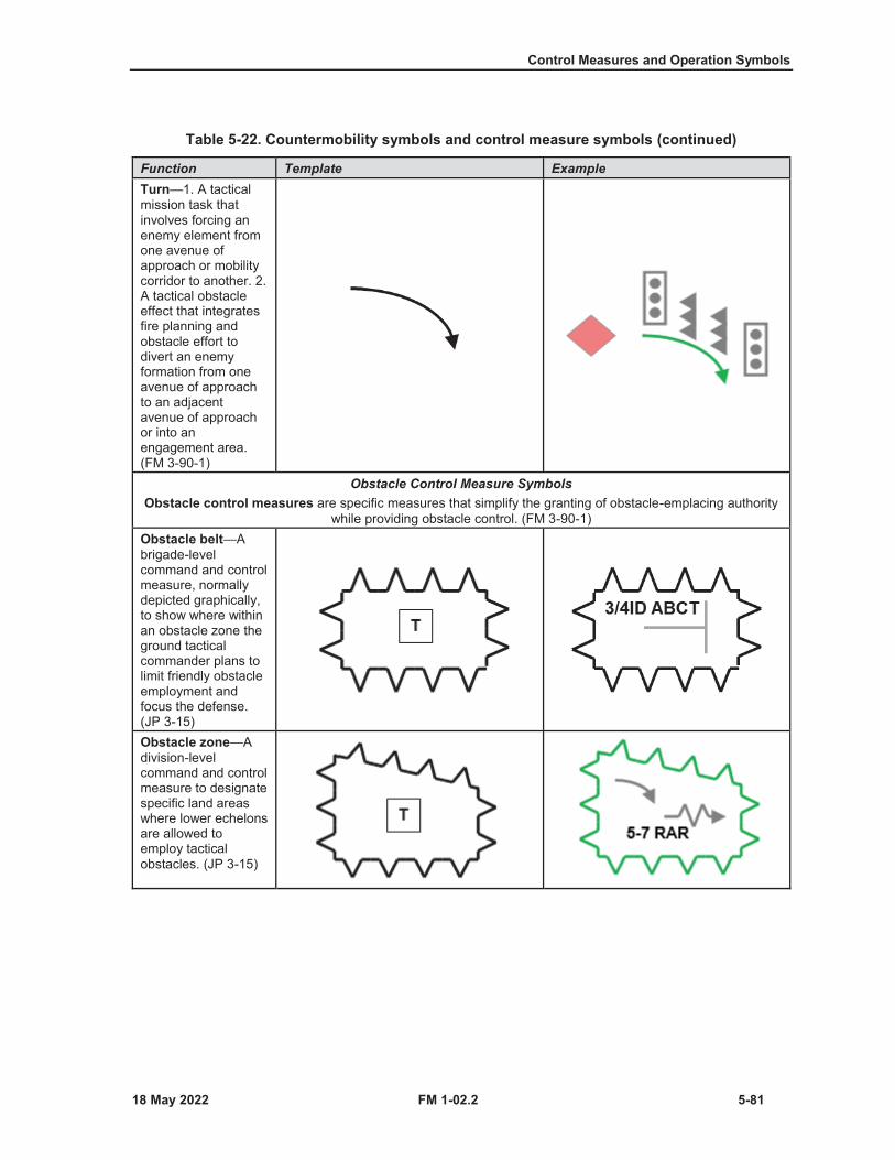
Control Measures and Operation Symbols
FM 1-02.2 5-81
Table 5-22. Countermobility symbols and control measure symbols (continued)
Function Template ExampleTurn—1. A tactical mission task that involves forcing an enemy element from one avenue of approach or mobility corridor to another. 2. A tactical obstacle effect that integrates fire planning and obstacle effort to divert an enemy formation from one avenue of approach to an adjacent avenue of approach or into an engagement area. (FM 3-90-1)
Obstacle Control Measure SymbolsObstacle control measures are specific measures that simplify the granting of obstacle-emplacing authority
while providing obstacle control. (FM 3-90-1)Obstacle belt—Abrigade-level command and control measure, normally depicted graphically, to show where within an obstacle zone the ground tactical commander plans to limit friendly obstacle employment and focus the defense. (JP 3-15)Obstacle zone—Adivision-level command and control measure to designate specific land areas where lower echelons are allowed to employ tacticalobstacles. (JP 3-15)
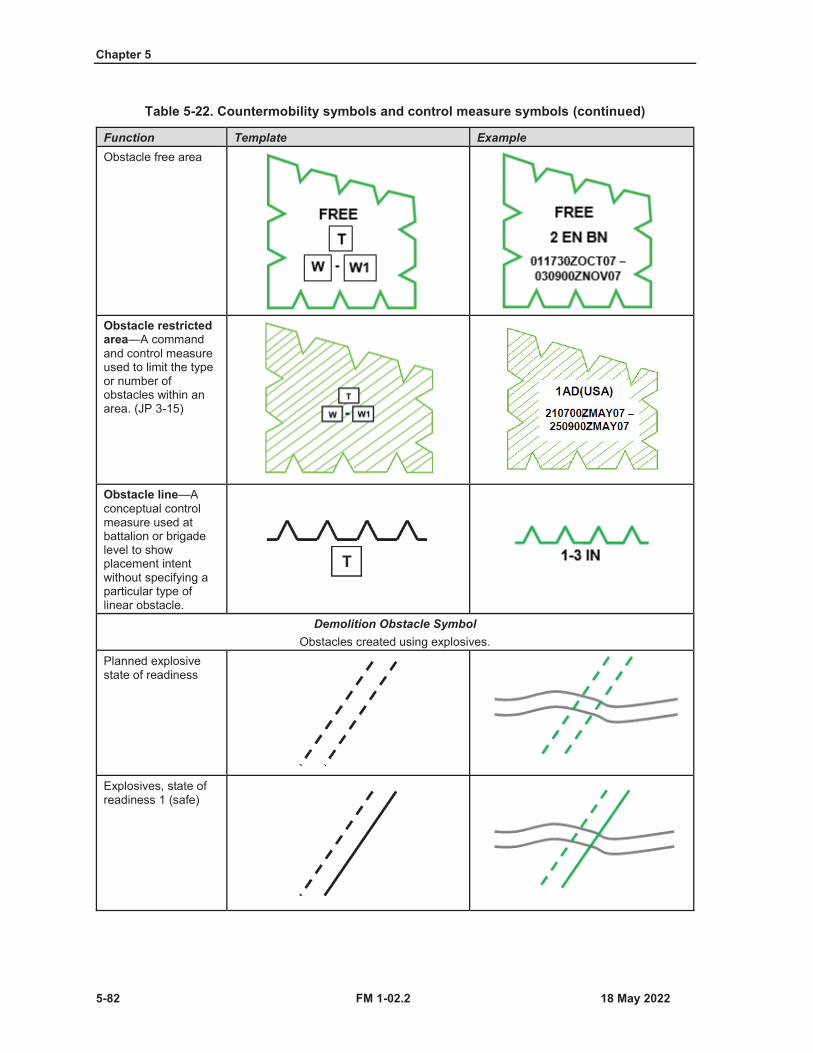
Chapter 5
5-82 FM 1-02.2
Table 5-22. Countermobility symbols and control measure symbols (continued)
Function Template ExampleObstacle free area
Obstacle restricted area—A command and control measure used to limit the type or number of obstacles within an area. (JP 3-15)
Obstacle line—Aconceptual control measure used at battalion or brigade level to show placement intent without specifying a particular type of linear obstacle.
Demolition Obstacle SymbolObstacles created using explosives.
Planned explosive state of readiness
Explosives, state of readiness 1 (safe)

Control Measures and Operation Symbols
FM 1-02.2 5-83
Table 5-22. Countermobility symbols and control measure symbols (continued)
Function Template ExampleExplosives, state of readiness 2 (armed but passable)
Roadblock complete (executed)
Abatis—An obstacle constructed by the felling and interlacing of trees across a route.
Constructed Obstacle SymbolsObstacles created with manual labor and or equipment. (See TM 3-34.85 for more information on constructed obstacle
symbols.)Wire
Unspecified
Single fence
Double fence
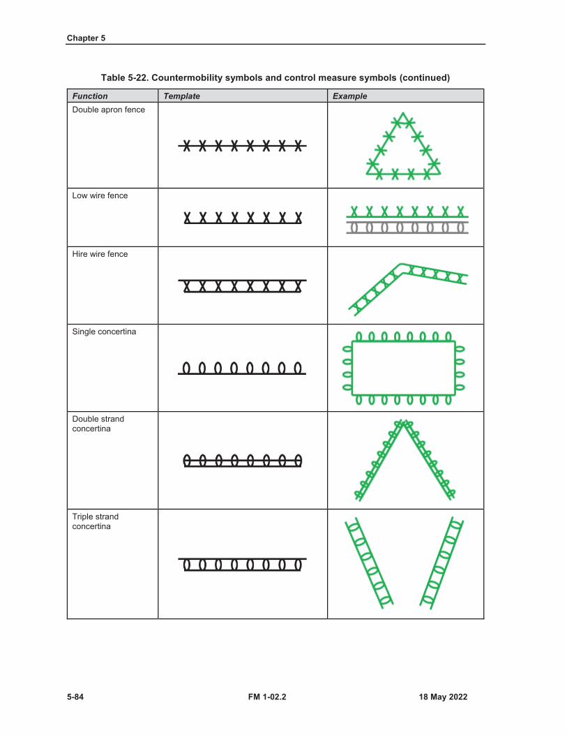
Chapter 5
5-84 FM 1-02.2
Table 5-22. Countermobility symbols and control measure symbols (continued)
Function Template ExampleDouble apron fence
Low wire fence
Hire wire fence
Single concertina
Double strand concertina
Triple strand concertina

Control Measures and Operation Symbols
FM 1-02.2 5-85
Table 5-22. Countermobility symbols and control measure symbols (continued)
Function Template ExampleAntivehicle Ditches and Walls
Antitank ditch—under construction
Antitank ditch—completed
Antitank ditch reinforced, with antitank mines.Note. The teeth typically point toward enemy forces.
Moveable antitank obstacle
Bridge blocked with movable antitank obstacle
Antitank wall
LAND MINE AND MINEFIELD CONTROL MEASURES
5-42. A land mine is a munition on or near the ground or other surface area that is designed to be explodedby the presence, proximity, or contact of a person or vehicle, and a minefield is an area which is dangerousbecause of the presence or suspected presence of land mines. (See JP 3-15 for more information on land
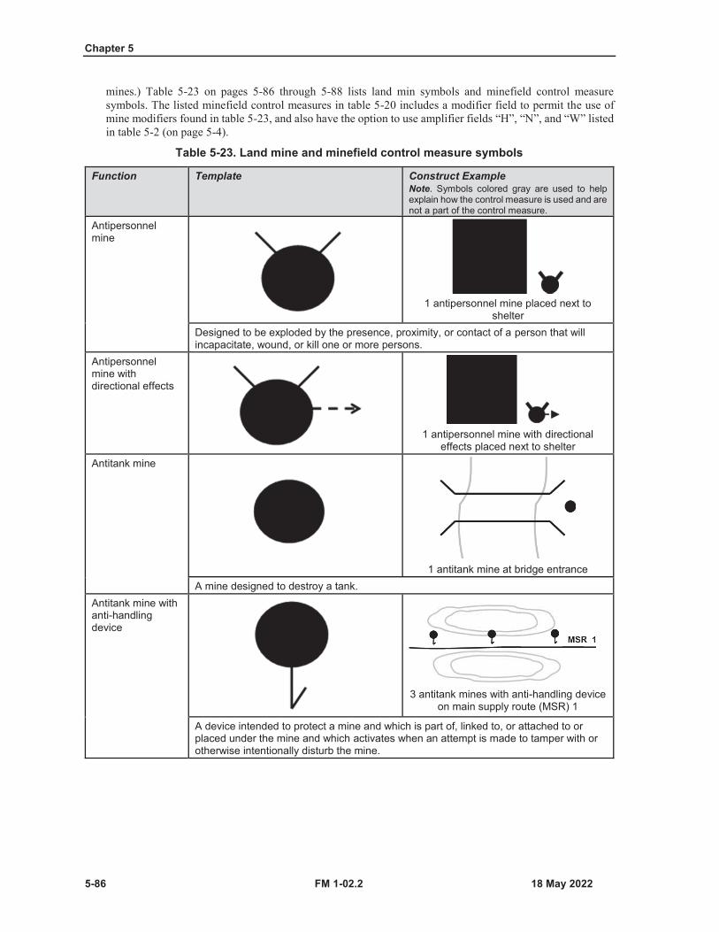
Chapter 5
5-86 FM 1-02.2
mines.) Table 5-23 on pages 5-86 through 5-88 lists land min symbols and minefield control measure symbols. The listed minefield control measures in table 5-20 includes a modifier field to permit the use of mine modifiers found in table 5-23, and also have the option to use amplifier fields “H”, “N”, and “W” listed in table 5-2 (on page 5-4).
Table 5-23. Land mine and minefield control measure symbols
Function Template Construct ExampleNote. Symbols colored gray are used to help explain how the control measure is used and are not a part of the control measure.
Antipersonnel mine
1 antipersonnel mine placed next to shelter
Designed to be exploded by the presence, proximity, or contact of a person that will incapacitate, wound, or kill one or more persons.
Antipersonnel mine with directional effects
1 antipersonnel mine with directional effects placed next to shelter
Antitank mine
1 antitank mine at bridge entranceA mine designed to destroy a tank.
Antitank mine with anti-handling device
3 antitank mines with anti-handling device on main supply route (MSR) 1
A device intended to protect a mine and which is part of, linked to, or attached to or placed under the mine and which activates when an attempt is made to tamper with or otherwise intentionally disturb the mine.
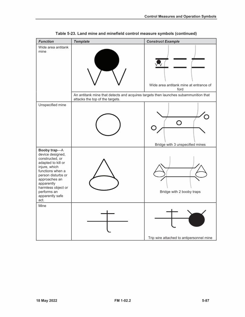
Control Measures and Operation Symbols
FM 1-02.2 5-87
Table 5-23. Land mine and minefield control measure symbols (continued)
Function Template Construct ExampleWide area antitank mine
Wide area antitank mine at entrance of ford
An antitank mine that detects and acquires targets then launches subammunition that attacks the top of the targets.
Unspecified mine
Bridge with 3 unspecified minesBooby trap—Adevice designed, constructed, or adapted to kill or injure, which functions when a person disturbs or approaches an apparently harmless object or performs an apparently safe act.
Bridge with 2 booby traps
Mine
Trip wire attached to antipersonnel mine

Chapter 5
5-88 FM 1-02.2
Table 5-23. Land mine and minefield control measure symbols (continued)
Function Template Construct ExampleMinefield
In land warfare, an area of ground containing mines emplaced with or without a pattern. (JP 3-15)Note. Minefield control measures use minefield sector 1 modifiers to identify type of minefield. (See table 5-23 on page 5-95for depictions of minefield sector 1 modifiers.)Static depiction minefield
Dynamic depiction minefield
Unspecified dynamic depicted minefieldMined area
Antipersonnel mined area
Mined area,fenced
Fenced antipersonnel mined area
Control Measures and Operation Symbols
FM 1-02.2 5-89
MINEFIELD SECTOR 1 MODIFIERS
5-43. Minefield sector 1 modifiers are used with minefield control measure symbols to identify type ofminefield. Table 5-24, on pages 5-90 through 5-93, provides minefield sector 1 modifiers that can be used inminefield control measure symbols in table 5-23.

Chapter 5
5-90 FM 1-02.2
Table 5-24. Minefield sector 1 modifiers
Description ModifierUnspecified
Antipersonnel mine
Antipersonnel mine with directional effects
Antitank mine
Antitank mine with antihandling device
Wide area antitank mine
Mine cluster
Antipersonnel mine and antipersonnel mine with directional effects
Antipersonnel mine and antitank mine
Antipersonnel mine and antitank mine with antihandling device
Antipersonnel mine and wide area antitank mine
Antipersonnel mine and mine cluster
Antipersonnel mine with directional effects and antitank mine
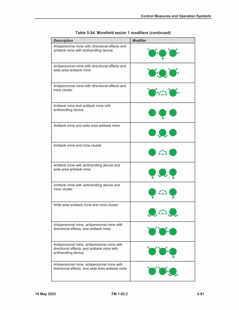
Control Measures and Operation Symbols
FM 1-02.2 5-91
Table 5-24. Minefield sector 1 modifiers (continued)
Description ModifierAntipersonnel mine with directional effects and antitank mine with antihandling device
Antipersonnel mine with directional effects and wide area antitank mine
Antipersonnel mine with directional effects and mine cluster
Antitank mine and antitank mine with antihandling device
Antitank mine and wide area antitank mine
Antitank mine and mine cluster
Antitank mine with antihandling device and wide area antitank mine
Antitank mine with antihandling device and mine cluster
Wide area antitank mine and mine cluster
Antipersonnel mine, antipersonnel mine with directional effects, and antitank mine
Antipersonnel mine, antipersonnel mine with directional effects, and antitank mine with antihandling device
Antipersonnel mine, antipersonnel mine with directional effects, and wide area antitank mine
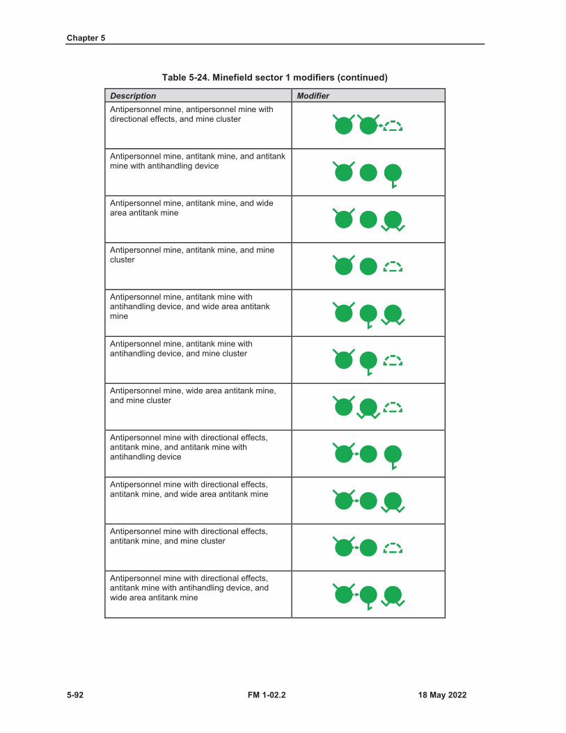
Chapter 5
5-92 FM 1-02.2
Table 5-24. Minefield sector 1 modifiers (continued)
Description ModifierAntipersonnel mine, antipersonnel mine with directional effects, and mine cluster
Antipersonnel mine, antitank mine, and antitank mine with antihandling device
Antipersonnel mine, antitank mine, and wide area antitank mine
Antipersonnel mine, antitank mine, and mine cluster
Antipersonnel mine, antitank mine withantihandling device, and wide area antitank mine
Antipersonnel mine, antitank mine with antihandling device, and mine cluster
Antipersonnel mine, wide area antitank mine, and mine cluster
Antipersonnel mine with directional effects, antitank mine, and antitank mine with antihandling device
Antipersonnel mine with directional effects, antitank mine, and wide area antitank mine
Antipersonnel mine with directional effects, antitank mine, and mine cluster
Antipersonnel mine with directional effects, antitank mine with antihandling device, and wide area antitank mine
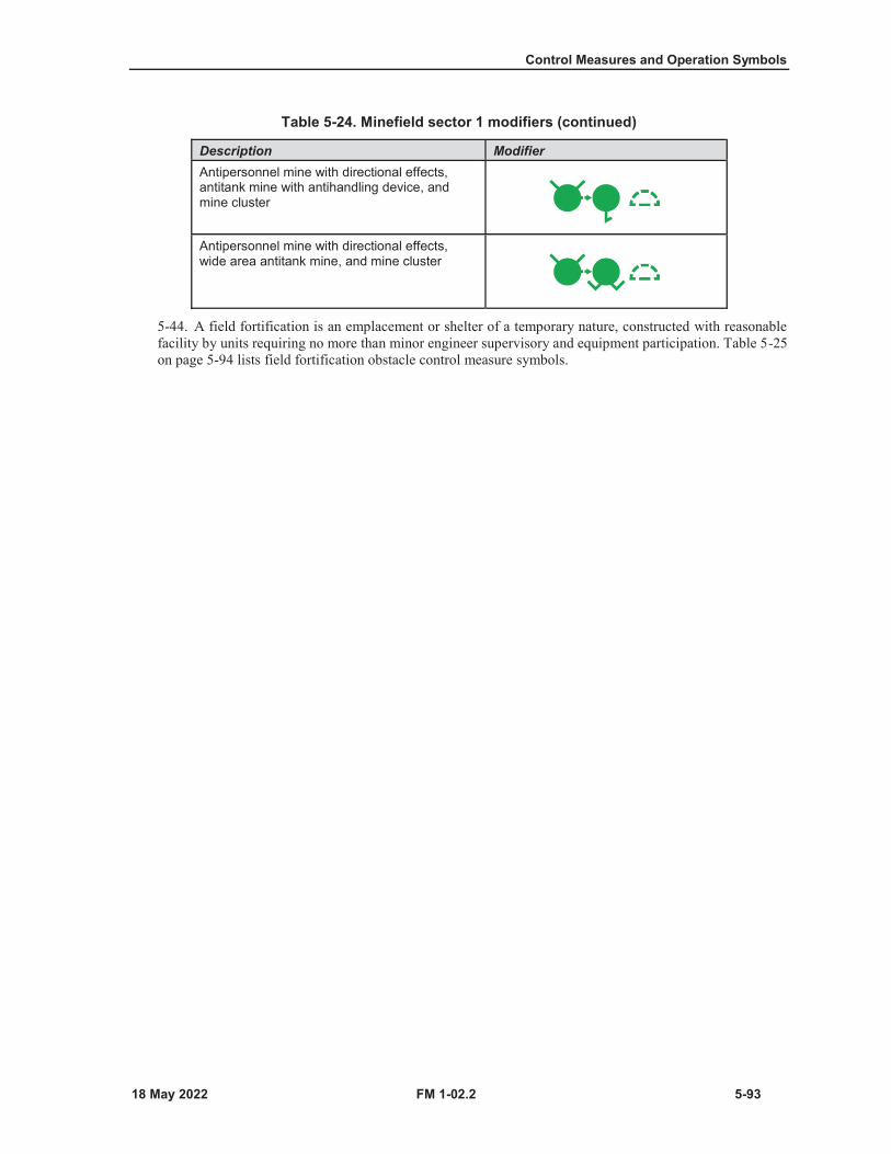
Control Measures and Operation Symbols
FM 1-02.2 5-93
Table 5-24. Minefield sector 1 modifiers (continued)
Description ModifierAntipersonnel mine with directional effects, antitank mine with antihandling device, and mine cluster
Antipersonnel mine with directional effects, wide area antitank mine, and mine cluster
5-44. A field fortification is an emplacement or shelter of a temporary nature, constructed with reasonablefacility by units requiring no more than minor engineer supervisory and equipment participation. Table 5-25on page 5-94 lists field fortification obstacle control measure symbols.
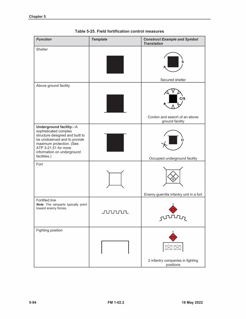
Chapter 5
5-94 FM 1-02.2
Table 5-25. Field fortification control measures
Function Template Construct Example and Symbol Translation
Shelter
Secured shelterAbove ground facility
Cordon and search of an above ground facility
Underground facility—Asophisticated complex structure designed and built to be unobserved and to provide maximum protection. (See ATP 3-21.51 for more information on underground facilities.) Occupied underground facilityFort
Enemy guerrilla infantry unit in a fortFortified lineNote. The ramparts typically point toward enemy forces.
Fighting position
2 infantry companies in fighting positions
Control Measures and Operation Symbols
FM 1-02.2 5-95
CBRN EVENTS CONTROL MEASURES5-45. CBRN events control measure symbols depict those conditions found in an area resulting fromimmediate or persisting effects of CBRN attacks or events. A warning system formats, processes, andbroadcasts CBRN event plumes symbols to provide common operational picture effects throughout theoperational environment. Table 5-26 on 5-96 through 5-97 depicts CBRN events control measure symbols.Table 5-27 on pages 5-98 and 5-99 depicts CBRN contaminated area control measures. (See ATP 3-11.36and ATP 3-11.37 for additional information on CBRN planning, reconnaissance, and associated militarysymbol doctrine.)
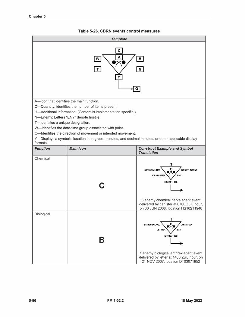
Chapter 5
5-96 FM 1-02.2
Table 5-26. CBRN events control measures
Template
A—Icon that identifies the main function.C—Quantity, identifies the number of items present.H—Additional information. (Content is implementation specific.)N—Enemy: Letters “ENY” denote hostile.T—Identifies a unique designation.W—Identifies the date-time group associated with point.Q—Identifies the direction of movement or intended movement.Y—Displays a symbol’s location in degrees, minutes, and decimal minutes, or other applicable display formats.Function Main Icon Construct Example and Symbol
TranslationChemical
C3 enemy chemical nerve agent event
delivered by canister at 0700 Zulu hour, on 30 JUN 2008, location HS10211948
Biological
B1 enemy biological anthrax agent event delivered by letter at 1400 Zulu hour, on
21 NOV 2007, location DT03071952
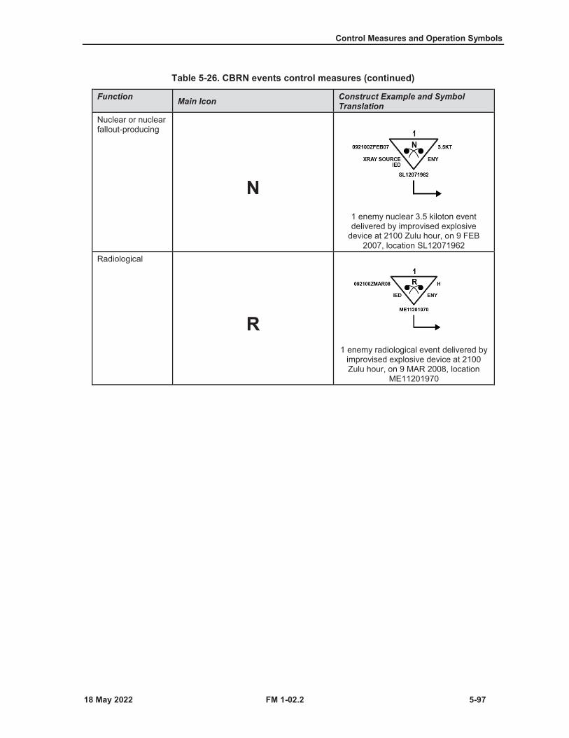
Control Measures and Operation Symbols
FM 1-02.2 5-97
Table 5-26. CBRN events control measures (continued)
Function Main Icon Construct Example and Symbol Translation
Nuclear or nuclear fallout-producing
N1 enemy nuclear 3.5 kiloton event delivered by improvised explosive
device at 2100 Zulu hour, on 9 FEB 2007, location SL12071962
Radiological
R1 enemy radiological event delivered by
improvised explosive device at 2100 Zulu hour, on 9 MAR 2008, location
ME11201970
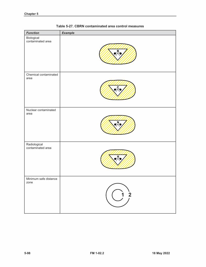
Chapter 5
5-98 FM 1-02.2
Table 5-27. CBRN contaminated area control measures
Function ExampleBiological contaminated area
Chemical contaminated area
Nuclear contaminated area
Radiological contaminated area
Minimum safe distance zone
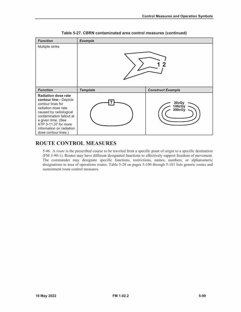
Control Measures and Operation Symbols
FM 1-02.2 5-99
Table 5-27. CBRN contaminated area control measures (continued)
Function ExampleMultiple strike
Function Template Construct ExampleRadiation dose rate contour line—Depicts contour lines for radiation dose rate caused by radiological contamination fallout at a given time. (See ATP 3-11.37 for more information on radiation dose contour lines.)
ROUTE CONTROL MEASURES5-46. A route is the prescribed course to be traveled from a specific point of origin to a specific destination(FM 3-90-1). Routes may have different designated functions to effectively support freedom of movement.The commander may designate specific functions, restrictions, names, numbers, or alphanumericdesignations to area of operations routes. Table 5-28 on pages 5-100 through 5-101 lists generic routes andsustainment route control measures.
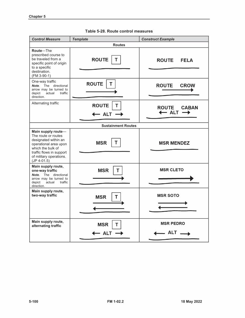
Chapter 5
5-100 FM 1-02.2
Table 5-28. Route control measures
Control Measure Template Construct ExampleRoutes
Route—The prescribed course to be traveled from a specific point of origin to a specific destination. (FM 3-90-1)One-way trafficNote. The directional arrow may be turned to depict actual traffic direction.
Alternating traffic
Sustainment RoutesMain supply route—The route or routes designated within an operational area upon which the bulk of traffic flows in support of military operations. (JP 4-01.5)Main supply route, one-way trafficNote. The directional arrow may be turned to depict actual traffic direction.Main supply route, two-way traffic
Main supply route, alternating traffic
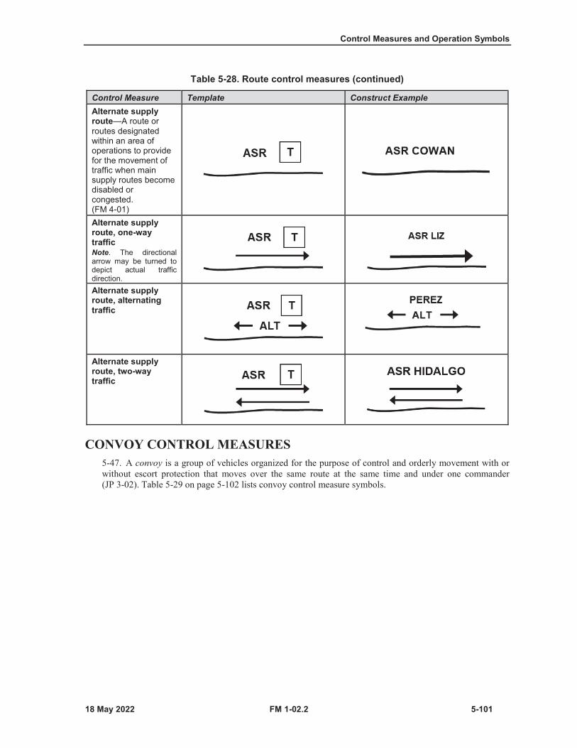
Control Measures and Operation Symbols
FM 1-02.2 5-101
Table 5-28. Route control measures (continued)
Control Measure Template Construct ExampleAlternate supply route—A route or routes designated within an area of operations to provide for the movement of traffic when main supply routes become disabled or congested. (FM 4-01)Alternate supply route, one-way trafficNote. The directional arrow may be turned to depict actual traffic direction.Alternate supply route, alternating traffic
Alternate supply route, two-way traffic
CONVOY CONTROL MEASURES5-47. A convoy is a group of vehicles organized for the purpose of control and orderly movement with orwithout escort protection that moves over the same route at the same time and under one commander(JP 3-02). Table 5-29 on page 5-102 lists convoy control measure symbols.

Chapter 5
5-102 FM 1-02.2
Table 5-29. Convoy control measures
Control Measure Template Construct ExampleNote. Symbols colored gray are used to help explain how the control measure is used and are not a part of the control measure.
Moving convoyNote. The arrow points in the direction the convoy is moving.
Halted convoy
MARITIME CONTROL MEASURES5-48. The U.S. Army has maritime sustainment vessels that use maritime control measures to direct actionsby establishing responsibilities, preventing ships, units, or aircraft from impeding one another, and imposingnecessary coordination. Table 5-30 includes the harbor entrance point maritime control measure symbolscurrently used in U.S. Army doctrine. (See MIL-STD 2525D for more joint maritime control measures.)
Table 5-30. Maritime control measure symbols
Function Template ExampleHarbor entrance point
Without the harbor control measure symbolPossible entries for H field are listed below:
ACode: 212901
OCode: 212902
With the harbor control measure symbol
XCode: 212903
YCode: 212904

FM 1-02.2 6-1
Chapter 6
Tactical Mission Tasks
This chapter provides symbols for tactical mission tasks.
TACTICAL MISSION TASKS DEFINED6-1. A task is a clearly defined and measurable activity accomplished by individuals or organizations. Atactical mission task is a specific activity performed by a unit while executing a form of tactical operation orform of maneuver. A tactical mission task may be expressed as either an action by a friendly force or aneffect on an enemy force (FM 3-90-1). The tactical mission tasks describe the results or effects commanderswant to achieve.
SYMBOLS FOR TACTICAL MISSION TASKS6-2. Table 6-1 on pages 6-2 through 6-7 shows the tactical mission tasks that have symbols. Not all tacticalmission tasks have symbols. Tactical mission task symbols can be used with unit symbols, but they do nothave modifiers. Tactical mission task symbols are used in course of action sketches, synchronizationmatrices, and maneuver sketches. They do not replace any part of the operation order. Tactical mission tasksymbols are sized to accommodate the scale of the display or map being used.
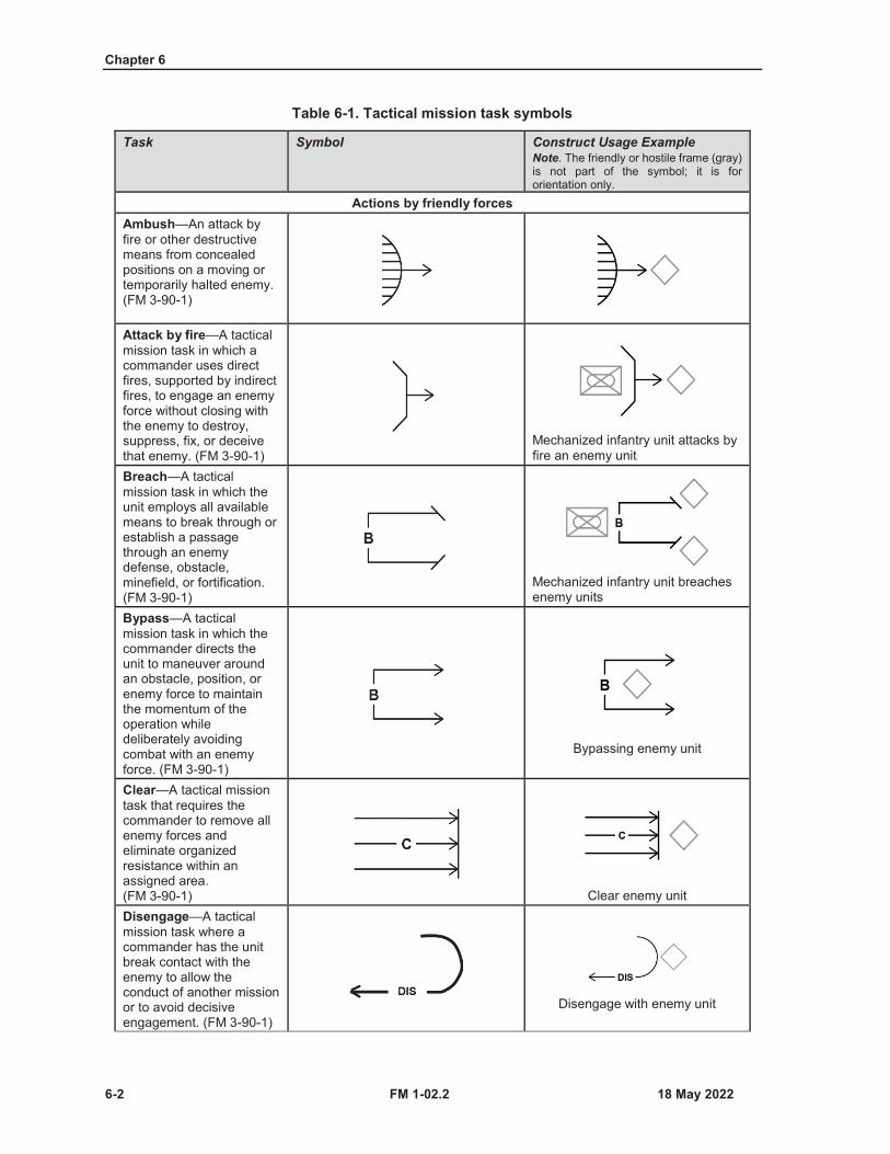
Chapter 6
6-2 FM 1-02.2
Table 6-1. Tactical mission task symbols
Task Symbol Construct Usage ExampleNote. The friendly or hostile frame (gray) is not part of the symbol; it is for orientation only.
Actions by friendly forcesAmbush—An attack by fire or other destructive means from concealed positions on a moving or temporarily halted enemy. (FM 3-90-1)
Attack by fire—A tactical mission task in which a commander uses direct fires, supported by indirect fires, to engage an enemy force without closing with the enemy to destroy, suppress, fix, or deceive that enemy. (FM 3-90-1)
Mechanized infantry unit attacks by fire an enemy unit
Breach—A tactical mission task in which the unit employs all available means to break through or establish a passage through an enemy defense, obstacle, minefield, or fortification. (FM 3-90-1)
Mechanized infantry unit breaches enemy units
Bypass—A tactical mission task in which the commander directs the unit to maneuver around an obstacle, position, or enemy force to maintain the momentum of the operation while deliberately avoiding combat with an enemy force. (FM 3-90-1)
Bypassing enemy unit
Clear—A tactical mission task that requires the commander to remove all enemy forces and eliminate organized resistance within an assigned area. (FM 3-90-1) Clear enemy unitDisengage—A tactical mission task where a commander has the unit break contact with the enemy to allow the conduct of another mission or to avoid decisive engagement. (FM 3-90-1)
Disengage with enemy unit
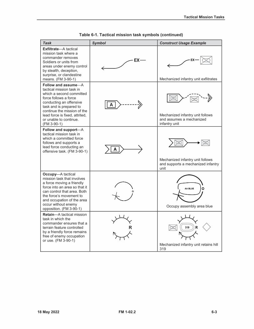
Tactical Mission Tasks
FM 1-02.2 6-3
Table 6-1. Tactical mission task symbols (continued)
Task Symbol Construct Usage ExampleExfiltrate—A tactical mission task where a commander removes Soldiers or units from areas under enemy control by stealth, deception, surprise, or clandestine means. (FM 3-90-1) Mechanized infantry unit exflitratesFollow and assume—Atactical mission task in which a second committed force follows a force conducting an offensive task and is prepared to continue the mission of the lead force is fixed, attrited, or unable to continue. (FM 3-90-1)
Mechanized infantry unit follows and assumes a mechanized infantry unit
Follow and support—Atactical mission task in which a committed force follows and supports a lead force conducting an offensive task. (FM 3-90-1)
Mechanized infantry unit follows and supports a mechanized infantry unit
Occupy—A tactical mission task that involves a force moving a friendly force into an area so that it can control that area. Both the force’s movement to and occupation of the area occur without enemy opposition. (FM 3-90-1) Occupy assembly area blue
Retain—A tactical mission task in which the commander ensures that a terrain feature controlled by a friendly force remains free of enemy occupation or use. (FM 3-90-1)
Mechanized infantry unit retains hill 319
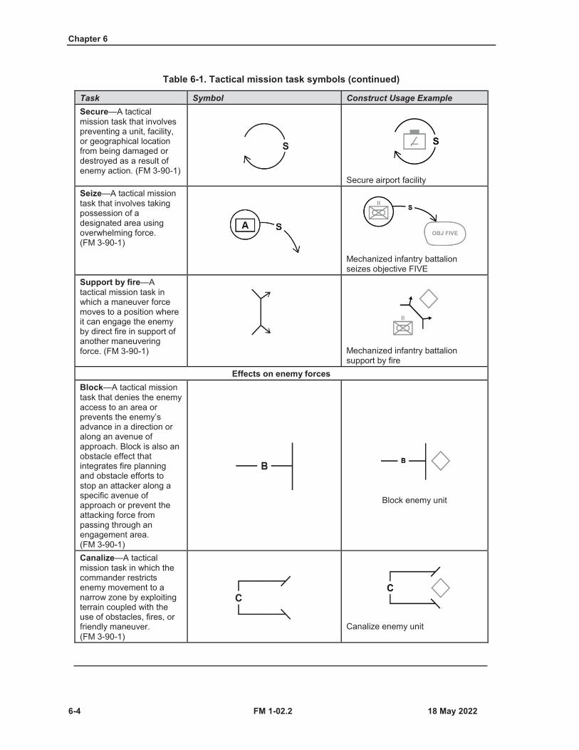
Chapter 6
6-4 FM 1-02.2
Table 6-1. Tactical mission task symbols (continued)
Task Symbol Construct Usage ExampleSecure—A tactical mission task that involves preventing a unit, facility, or geographical location from being damaged or destroyed as a result of enemy action. (FM 3-90-1)
Secure airport facilitySeize—A tactical mission task that involves taking possession of a designated area using overwhelming force. (FM 3-90-1)
Mechanized infantry battalion seizes objective FIVE
Support by fire—Atactical mission task in which a maneuver force moves to a position where it can engage the enemy by direct fire in support of another maneuvering force. (FM 3-90-1) Mechanized infantry battalion
support by fireEffects on enemy forces
Block—A tactical mission task that denies the enemy access to an area or prevents the enemy’s advance in a direction or along an avenue of approach. Block is also an obstacle effect that integrates fire planning and obstacle efforts to stop an attacker along a specific avenue of approach or prevent the attacking force from passing through an engagement area. (FM 3-90-1)
Block enemy unit
Canalize—A tactical mission task in which the commander restricts enemy movement to a narrow zone by exploiting terrain coupled with the use of obstacles, fires, or friendly maneuver. (FM 3-90-1)
Canalize enemy unit
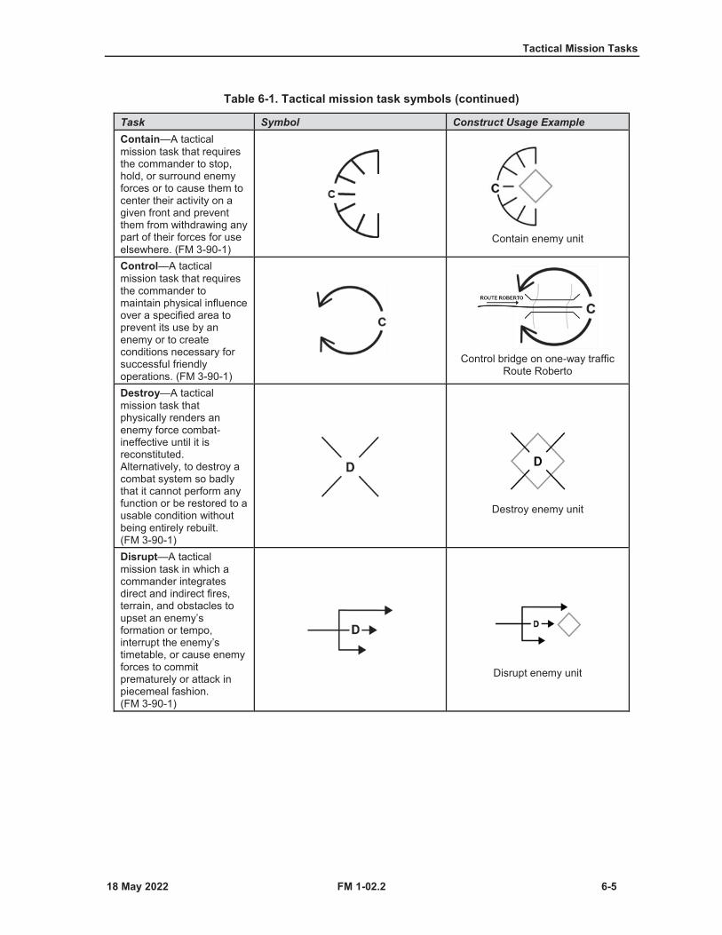
Tactical Mission Tasks
FM 1-02.2 6-5
Table 6-1. Tactical mission task symbols (continued)
Task Symbol Construct Usage ExampleContain—A tactical mission task that requires the commander to stop, hold, or surround enemy forces or to cause them to center their activity on a given front and prevent them from withdrawing any part of their forces for use elsewhere. (FM 3-90-1)
Contain enemy unit
Control—A tactical mission task that requires the commander to maintain physical influence over a specified area to prevent its use by an enemy or to create conditions necessary for successful friendly operations. (FM 3-90-1)
Control bridge on one-way traffic Route Roberto
Destroy—A tactical mission task that physically renders an enemy force combat-ineffective until it is reconstituted. Alternatively, to destroy a combat system so badly that it cannot perform any function or be restored to a usable condition without being entirely rebuilt.(FM 3-90-1)
Destroy enemy unit
Disrupt—A tactical mission task in which a commander integrates direct and indirect fires, terrain, and obstacles to upset an enemy’s formation or tempo, interrupt the enemy’s timetable, or cause enemy forces to commit prematurely or attack in piecemeal fashion.(FM 3-90-1)
Disrupt enemy unit
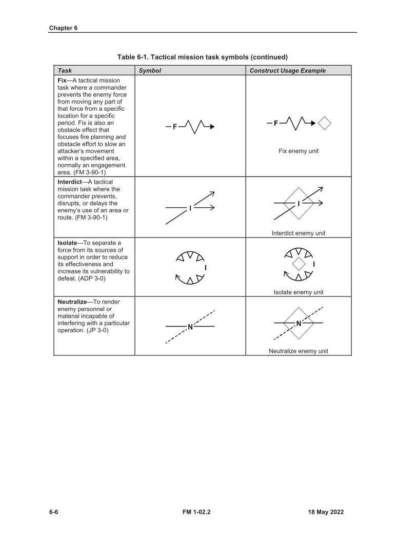
Chapter 6
6-6 FM 1-02.2
Table 6-1. Tactical mission task symbols (continued)
Task Symbol Construct Usage ExampleFix—A tactical mission task where a commander prevents the enemy force from moving any part of that force from a specific location for a specific period. Fix is also an obstacle effect that focuses fire planning and obstacle effort to slow an attacker’s movement within a specified area, normally an engagement area. (FM 3-90-1)
Fix enemy unit
Interdict—A tactical mission task where the commander prevents, disrupts, or delays the enemy’s use of an area or route. (FM 3-90-1)
Interdict enemy unitIsolate—To separate a force from its sources of support in order to reduce its effectiveness and increase its vulnerability to defeat. (ADP 3-0)
Isolate enemy unitNeutralize—To render enemy personnel or material incapable ofinterfering with a particular operation. (JP 3-0)
Neutralize enemy unit
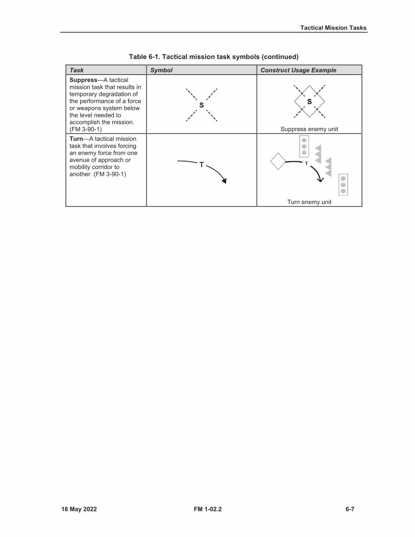
Tactical Mission Tasks
FM 1-02.2 6-7
Table 6-1. Tactical mission task symbols (continued)
Task Symbol Construct Usage ExampleSuppress—A tactical mission task that results in temporary degradation of the performance of a force or weapons system below the level needed to accomplish the mission. (FM 3-90-1) Suppress enemy unitTurn—A tactical mission task that involves forcing an enemy force from one avenue of approach or mobility corridor to another. (FM 3-90-1)
Turn enemy unit

This page intentionally left blank.
FM 1-02.2 7-1
Chapter 7
Course of Action Sketch
This chapter discusses the purpose and makeup of a course of action sketch.
PURPOSE OF COURSE OF ACTION SKETCH7-1. A course of action is a scheme developed to accomplish a mission (JP 5-0). Developing, analyzing,and deciding on a course of action for execution is central to planning. Part of course of action developmentis to produce a course of action statement and sketch. The staff prepares a course of action statement andsupporting sketch for each course of action under consideration. A Course of action statement clearlydescribes the array of forces and the sequence of tasks the unit will conduct to accomplish the mission. Thestatement should be a brief expression of how the combined arms concept will be conducted. The course ofaction sketch is the graphic portrayal of the course of action statement. The sketch provides a picture of themovement and maneuver aspects of the concept, including positioning of forces. (See FM 6-0 for a detaileddiscussion of the military decision-making process, including course of action development.)
MAKEUP OF COURSE OF ACTION SKETCH7-2. The course of action sketch provides a picture of the movement and maneuver aspects of the concept,including the positioning of forces. The course of action sketch becomes the basis for the operation overlay.At a minimum, the course of action sketch includes the array of generic forces and control measures,including—
Unit and subordinate unit boundaries.Unit movement formations (but not subordinate unit formations).Reconnaissance and security graphics.Ground and air axes of advance.Assembly areas, battle positions, strong points, engagement areas, and objectives.Obstacle control measures and tactical mission graphics.Fire support coordination and airspace control measures.Main effort.Location of command posts and critical communication nodes.Enemy locations, known or template.Population concentrations.
7-3. Most symbols for use on the course of action sketch are shown in chapters 2 through 7. However, theunit symbols do not provide decision makers with a quick and easy method of portraying detailed informationrelating to task organization, composition, or combat effectiveness. Task organization composition symbolsportray detailed information for course of action sketches.
TASK ORGANIZATION COMPOSITION SYMBOLS7-4. Part of course of action development includes determining relative combat power and arraying forcesto accomplish the primary tasks envisioned during action. After arraying forces, planners then group theseforces underneath a generic headquarters representing the initial task organization. The initial taskorganization for each generic unit is portrayed in a task organization composition symbol.
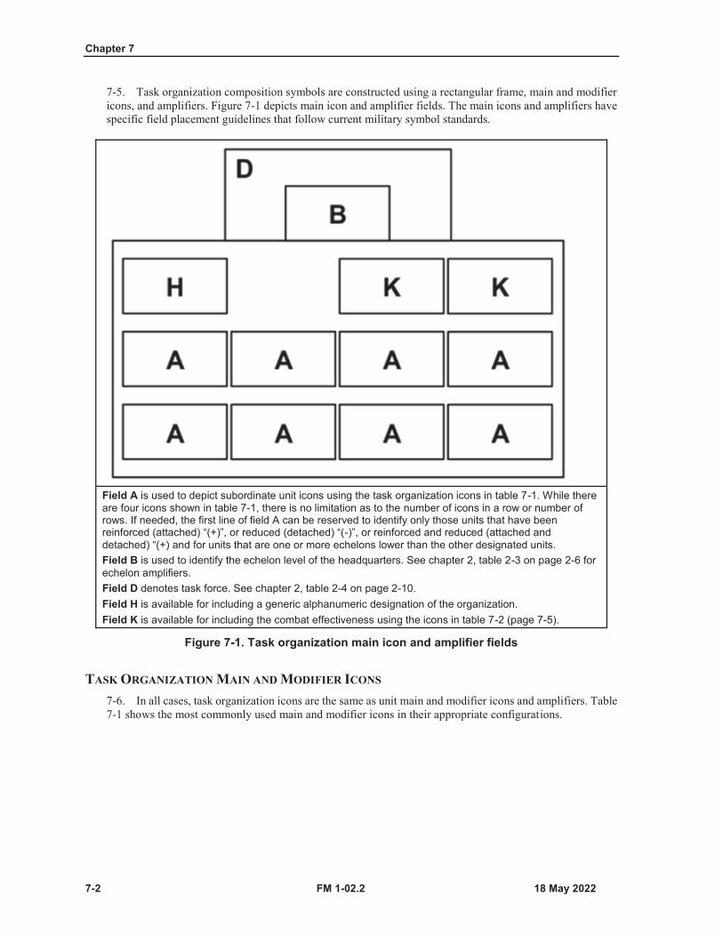
Chapter 7
7-2 FM 1-02.2
7-5. Task organization composition symbols are constructed using a rectangular frame, main and modifiericons, and amplifiers. Figure 7-1 depicts main icon and amplifier fields. The main icons and amplifiers havespecific field placement guidelines that follow current military symbol standards.
Field A is used to depict subordinate unit icons using the task organization icons in table 7-1. While there are four icons shown in table 7-1, there is no limitation as to the number of icons in a row or number of rows. If needed, the first line of field A can be reserved to identify only those units that have been reinforced (attached) “(+)”, or reduced (detached) “(-)”, or reinforced and reduced (attached and detached) “(+) and for units that are one or more echelons lower than the other designated units.Field B is used to identify the echelon level of the headquarters. See chapter 2, table 2-3 on page 2-6 for echelon amplifiers. Field D denotes task force. See chapter 2, table 2-4 on page 2-10.Field H is available for including a generic alphanumeric designation of the organization. Field K is available for including the combat effectiveness using the icons in table 7-2 (page 7-5).
Figure 7-1. Task organization main icon and amplifier fields
TASK ORGANIZATION MAIN AND MODIFIER ICONS
7-6. In all cases, task organization icons are the same as unit main and modifier icons and amplifiers. Table7-1 shows the most commonly used main and modifier icons in their appropriate configurations.

Course of Action Sketch
FM 1-02.2 7-3
Table 7-1. Task organization icons
Function SymbolAir assault infantry
Current usage construct
Alternate usage construct
Airborne infantry
Air defense
Air reconnaissance (cavalry)
Antitank
Armor tracked
Armored reconnaissance (cavalry)Note. Reconnaissance (cavalry) unity that has armored tracked vehicles.
Assault or lift helicopter
Current usage construct
Alternate usage construct
Attack helicopter
Combined arms
Engineer
Field artillery
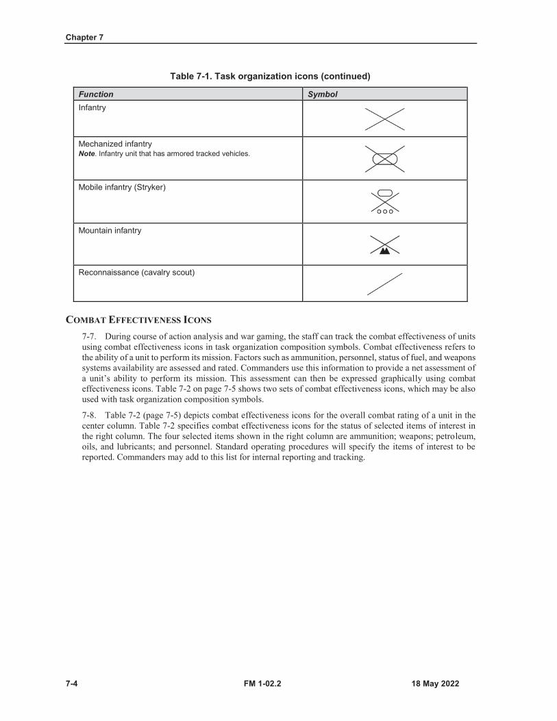
Chapter 7
7-4 FM 1-02.2
Table 7-1. Task organization icons (continued)
Function SymbolInfantry
Mechanized infantryNote. Infantry unit that has armored tracked vehicles.
Mobile infantry (Stryker)
Mountain infantry
Reconnaissance (cavalry scout)
COMBAT EFFECTIVENESS ICONS
7-7. During course of action analysis and war gaming, the staff can track the combat effectiveness of unitsusing combat effectiveness icons in task organization composition symbols. Combat effectiveness refers tothe ability of a unit to perform its mission. Factors such as ammunition, personnel, status of fuel, and weaponssystems availability are assessed and rated. Commanders use this information to provide a net assessment ofa unit’s ability to perform its mission. This assessment can then be expressed graphically using combateffectiveness icons. Table 7-2 on page 7-5 shows two sets of combat effectiveness icons, which may be alsoused with task organization composition symbols.
7-8. Table 7-2 (page 7-5) depicts combat effectiveness icons for the overall combat rating of a unit in thecenter column. Table 7-2 specifies combat effectiveness icons for the status of selected items of interest inthe right column. The four selected items shown in the right column are ammunition; weapons; petroleum,oils, and lubricants; and personnel. Standard operating procedures will specify the items of interest to bereported. Commanders may add to this list for internal reporting and tracking.

Course of Action Sketch
FM 1-02.2 7-5
Table 7-2. Combat effectiveness icons
Commander’s Assessment of Unit’s Ability to Perform Mission
Effectiveness Pie Charts Selected Status Pie Chart
No problems in any area
Some problems in personnel
Major problems in weapons systems
Cannot perform mission: personnel, ammunition, and weapons problems
POL petroleum, oils, and lubricants
EXAMPLE OF A TASK ORGANIZATION COMPOSITION SYMBOL
7-9. Figure 7-2 on page 7-6 depicts a generic example of a task force task organization composition symbolfor a battalion task force.

Chapter 7
7-6 FM 1-02.2
Figure 7-2. Battalion task force example
FM 1-02.2 Glossary-1
Glossary
The glossary lists acronyms and terms with Army and joint definitions. The proponent publication for terms is listed in parentheses after the definition.
SECTION I – ACRONYMS AND ABBREVIATIONS ADP Army doctrine publication
AFTTP Air Force tactics, techniques, and proceduresAPP Allied procedural publicationATP Army techniques publication
CBRN chemical, biological, radiological, and nuclearDA Department of the ArmyDD Department of Defense (forms)
DOD Department of DefenseED edition
ENY enemyFM field manualJP joint publication
kph kilometers per hourkts knots per hour
MCRP Marine Corps reference publicationMCTP Marine Corps training publication
MCWP Marine Corps warfighting publicationMIL-STD military standard
mph miles per hourmps meters per second
NATO North Atlantic Treaty OrganizationNTTP Navy tactics, techniques, and procedures
STANAG standardization agreementSBCT Stryker brigade combat team
TC training circularTM technical manualU.S. United States
SECTION II – TERMS air and missile defense
Direct [active and passive] defensive actions taken to destroy, nullify, or reduce the effectiveness of hostile air and ballistic missile threats against friendly forces and assets. (JP 3-01)
Glossary
Glossary-2 FM 1-02.2
air assaultThe movement of friendly assault forces by rotary-wing or tiltrotor aircraft to engage and destroy enemy forces or to seize and hold key terrain. (JP 3-18)
air corridorA restricted air route of travel specified for use by friendly aircraft and established for the purpose of preventing friendly aircraft from being fired on by friendly forces. (JP 3-52)
air defenseDefensive measures designed to destroy attacking enemy aircraft or aerodynamic missiles, or to nullify or reduce the effectiveness of such attack. (JP 3-01)
airfieldAn area prepared for the accommodation (including any buildings, installations, and equipment), landing, and takeoff of aircraft. (JP 3-36)
airhead lineA line denoting the limits of the objective area for an airborne assault. (JP 3-18)
airspace coordination areaA three-dimensional block of airspace in a target area, established by the appropriate commander, in which friendly aircraft are reasonably safe from friendly surface fires. (JP 3-09.3)
alternate supply routeA route or routes designated within an area of operations to provide for the movement of traffic when main supply routes become disabled or congested. (FM 4-01)
ambulance exchange pointA location where a patient is transferred from one ambulance to another en route to a medical treatment facility. (ATP 4-02.2)
ambulance loading pointThis is the point in the shuttle system where one or more ambulances are stationed ready to receive patients for evacuation. (ATP 4-02.2)
ambulance relay pointA point in the shuttle system where one or more empty ambulances are stationed to advance to a loading point or to the next relay post to replace departed ambulances. (ATP 4-02.2)
ambushAn attack by fire or other destructive means from concealed positions on a moving or temporarily halted enemy. (FM 3-90-1)
ammunition supply pointAn ammunition support activity operated by one or more modular ammunition platoons. (ATP 4-35)
ammunition transfer holding pointA designated site operated by a brigade support battalion distribution company where ammunition is received, transferred, or temporarily stored to supported units within a brigade combat team. (ATP 4-35)
amphibious warfare shipA combatant ship having organic capability to embark, land, and support landing forces in amphibious operations and which has characteristics enabling long-duration operations on the high seas. (JP 3-02)
area of operationsAn operational area defined by a commander for land and maritime forces that should be large enough to accomplish their missions and protect their forces. (JP 3-0)

Glossary
FM 1-02.2 Glossary-3
artillery target intelligence zoneA weapons locating radar search area in enemy territory that the commander monitors closely to detect and report any weapon ahead of all acquisitions other than those from critical friendly zones or call for fire zones.
assault positionA covered and concealed position short of the objective from which final preparations are made to assault the objective. (ADP 3-90)
assembly areaAn area a unit occupies to prepare for an operation.
attackA type of offensive operation that destroys or defeats enemy forces, seizes and secures terrain, or both. (ADP 3-90)
attack by fireDefinition.
attack position(Army) The last position an attacking force occupies or passes through before crossing the line of departure. (ADP 3-90)
axis of advanceThe general area through which the bulk of a unit’s combat power must move. (ADP 3-90
base campAn evolving military facility that supports the military operations of a deployed unit and provides the necessary support and services for sustained operations. (ATP 3-37.10)
base defense zoneAn air defense zone established around an air base and limited to the engagement envelope of short-range air defense weapons systems defending that base. (JP 3-52)
battalionA unit consisting of two or more company-, battery-, or troop-size units and a headquarters. (ADP 3-90)
batteryA company-size unit in a field artillery or air defense artillery battalion. (ADP 3-90)
battle handover lineA designated phase line where responsibility transitions from the stationary force to the moving force and vice versa. (ADP 3-90)
battle positionA defensive location oriented on a likely enemy avenue of approach. (ADP 3-90)
biological agentA microorganism (or a toxin derived from it) that cause disease in personnel, plants, or animals or causes the deterioration of materiel. (JP 3-11)
blockA tactical mission task that denies the enemy access to an area or prevents the enemy’s advance in a direction or along an avenue of approach. Block is also an obstacle effect that integrates fire planningand obstacle efforts to stop an attacker along a specific avenue of approach or prevent the attacking force from passing through an engagement area. (FM 3-90-1)
Glossary
Glossary-4 FM 1-02.2
blue kill boxA fire support and airspace coordination measure that facilitates attacking surface targets with air-to-surface munitions without further coordination with the area of operations commanders’ headquarters. (ATP 3-09.34)
boundaryA line that delineates surface areas for the purpose of facilitating coordination and deconfliction of operations between adjacent units, formations, or areas. (JP 3-0)
breachA tactical mission task in which the unit employs all available means to break through or establish a passage through an enemy defense, obstacle, minefield, or fortification. (FM 3-90-1)
brigadeA unit consisting of two or more battalions and a headquarters company or detachment. (ADP 3-90)
bypassA tactical mission task in which the commander directs the unit to maneuver around an obstacle, position, or enemy force to maintain the momentum of the operation while deliberately avoiding combat with an enemy force. (FM 3-90-1)
call for fire zoneA weapons locating radar search area from which the commander wants to attack hostile firing systems. (FM 3-09)
canalize(Army) A tactical mission task in which the commander restricts enemy movement to a narrow zone by exploiting terrain coupled with the use of obstacles, fires, or friendly maneuver. (FM 3-90-1)
casualty collection pointA location that may or may not be staffed, where casualties are assembled for evacuation to a medical treatment facility. (ATP 4-02.2)
censor zoneAn area from which the weapons locating radar is prohibited from reporting acquisitions. (FM 3-09)
chemical agentA chemical substance that is intended for use in military operations to kill, seriously injure, or incapacitate, mainly through physiological effects. (JP 3-11)
civil affairsDesignated Active and Reserve Component forces and units organized, trained, and equipped specifically to conduct civil affairs operations and to support civil-military operations. (JP 3-57)
civil-military cooperation(NATO) A joint function comprising a set of capabilities integral to supporting the achievement of mission objectives and enabling NATO commands to participate effectively in a broad spectrum of civil-military interaction with diverse non-military actors. (APP 6[D])
clearA tactical mission task that requires the commander to remove all enemy forces and eliminate organized resistance within an assigned area. (FM 3-90-1)
combatant commandA unified or specified command with a broad continuing mission under a single commander established and so designated by the President, through the Secretary of Defense and with the advice and assistance of the Chairman of the Joint Chiefs of Staff. (JP 1)
combat outpostA reinforced observation post capable of conducting limited combat operations. (FM 3-90-2)

Glossary
FM 1-02.2 Glossary-5
command and controlThe exercise of authority and direction by a properly designated commander over assigned and attached forces in the accomplishment of the mission. (JP 1)
common sensor boundaryA line depicted by a series of grid coordinates, grid line, phase line, or major terrain feature that divides target acquisition search areas into radar acquisition management areas. (FM 3-09)
companyA unit consisting of two or more platoons, usually of the same type, with a headquarters and a limited capacity for self-support. (ADP 3-90)
contact pointIn land warfare, a point on the terrain, easily identifiable, where two or more units are required to make contact. (JP 3-50)
contain(Army) A tactical mission task that requires the commander to stop, hold, or surround enemy forces or to cause them to center their activity on a given front and prevent them from withdrawing any part of their forces for use elsewhere. (FM 3-90-1)
control1. A tactical mission task that requires the commander to maintain physical influence over a specifiedarea to prevent its use by an enemy or to create conditions necessary for successful friendly operations.(FM 3-90-1) 2. An action taken to eliminate a hazard or reduce its risk. (ATP 5-19)
convoyA group of vehicles organized for the purpose of control and orderly movement with or without escort protection that moves over the same route at the same time and under one commander. (JP 3-02)
coordinated fire lineA line beyond which conventional surface-to-surface direct fire and indirect fire support means may fire at any time within the boundaries of the establishing headquarters without additional coordination but does not eliminate the responsibility to coordinate the airspace required to conduct the mission. (JP 3-09)
cordon and searchA technique of conducting a movement to contact that involves isolating a target area and searching suspect locations within that target area to capture or destroy possible enemy forces and contraband. (FM 3-90-1)
corpsAn echelon of command and tactical formation that employs divisions, multi-functional brigades, and functional brigades to achieve objectives on land. (ADP 3-90)
counterattackAttack by part or all of a defending force against an enemy attacking force, for such specific purposes as regaining ground lost, or cutting off or destroying an enemy advance units, and with the general objective of denying to the enemy the attainment of the enemy’s purpose in attacking. In sustained defensive operations, it is undertaken to restore the battle position and is directed at limited objectives. (FM 1-02.1)
course of actionA scheme developed to accomplish a mission. (JP 5-0)
cover(Army) A type of security operation done independent of the main body to protect them by fighting to gain time while preventing enemy ground observation of and direct fire against the main body. (ADP 3-90)
Glossary
Glossary-6 FM 1-02.2
crewA small military unit that consists of all personnel operating a particular system. (ADP 3-90)
critical friendly zoneA friendly area of coverage employed by weapons locating radar which the maneuver commander designates as critical to the protection of an asset whose loss would seriously jeopardize the mission. (FM 3-09)
cyberspace operationsThe employment of cyberspace capabilities where the primary purpose is to achieve objectives in or through cyberspace. (JP 3-0)
decision pointA point in space and time when the commander or staff anticipates making a key decision concerning a specific course of action. (JP 5-0)
decontaminationThe process of making any person, object, or area safe by destroying, neutralizing, making harmless, or absorbing and removing chemical or biological agents, or by removing radioactive material clinging to or around it. (JP 3-11)
delayWhen a force under pressure trades space for time by slowing down the enemy’s momentum and inflicting maximum damage on enemy forces without becoming decisively engaged. (ADP 3-90)
delay lineA phase line where the date and time before which the enemy is not allowed to cross the phase line is depicted as part of the graphic control measure. (FM 3-90-1)
demonstrationIn military deception, a show of force similar to a feint without actual contact with the adversary, in an area where a decision is not sought that is made to deceive an adversary. (JP 3-13.4)
destroyA tactical mission task that physically renders an enemy force combat ineffective until it is reconstituted. Alternatively, to destroy a combat system is to damage it so badly that it cannot perform any function or be restored to a usable condition without being entirely rebuilt. (FM 3-90-1)
detachmentA tactical element organized on either a temporary or permanent basis for special duties. (ADP 3-90)
detainee holding areaA facility or other location where detainees are administratively processed and provided custodial care pending disposition and subsequent release, transfer, or movement to a theater detention facility. (JP 3-63)
direction findingA procedure for obtaining bearings of radio frequency emitters by using a highly directional antenna and a display unit on an intercept receiver or ancillary equipment. (JP 3-85)
direction of attackA specific direction or assigned route a force uses and does not deviate from when attacking.(ADP 3-90)
direction of fireThe direction on which a fire unit is laid to the most significant threat in the target area, to the chart direction to the center of the zone of fire, or to the target. (ATP 3-09.50)
disengageA tactical mission task where a commander has the unit break contact with the enemy to allow the conduct of another mission or to avoid decisive engagement. (FM 3-90-1)

Glossary
FM 1-02.2 Glossary-7
disrupt1. A tactical mission task in which a commander integrates direct and indirect fires, terrain, andobstacles to upset an enemy’s formation or tempo, interrupt the enemy’s timetable, or cause enemyforces to commit prematurely or attack in a piecemeal fashion. 2. An obstacle effect that focuses fireplanning and obstacle effort to cause the enemy force to break up its formation and tempo, interrupt itstimetable, commit breaching assets prematurely, and attack in a piecemeal effort. (FM 3-90-1)
divisionAn echelon of command and tactical formation that employs brigade combat teams, multi-functional brigades, and functional brigades to achieve objectives on land. (ADP 3-90)
drop zoneA specific area upon which airborne troops, equipment, or supplies are airdropped. (JP 3-36)
encirclement operationsOperations where one force loses its freedom of maneuver because an opposing force is able to isolate it by controlling all ground lines of communications and reinforcement. (ADP 3-90)
engagement areaAn area where the commander intends to contain and destroy an enemy force with the massed effects of all available weapons and supporting systems. (ADP 3-90)
engineer work lineA coordinated boundary or phase line used to compartmentalize an area of operations to indicate where specific engineer units have primary responsibility for the engineer effort. (FM 3-34)
exfiltrateA tactical mission task where a commander removes Soldiers or units from areas under enemy control by stealth, deception, surprise or clandestine means. (FM 3-90-1)
explosive ordnance disposal(DOD) The detection, identification, on-side evaluation, rendering safe, recover, and final disposal of unexploded explosive ordnance. (JP 3-42)
feintIn military deception, an offensive action involving contact with the adversary conducted for the purpose of deceiving the adversary as to the location and/or time of the actual main offensive action. (JP 3-13.4)
field artilleryEquipment, supplies, ammunition, and personnel involved in the use of cannon, rocket, or surface-to-surface missile launchers. (JP 3-09)
final coordination lineA phase line close to the enemy position used to coordinate the lifting or shifting of supporting fires with the final deployment of maneuver elements. (ADP 3-90)
final protective firesAn immediately available prearranged barrier of fire designed to impede enemy movement across defensive lines or areas. (JP 3-09.3)
fire direction centerThat element of a command post, consisting of gunnery and communications personnel and equipment, by means of which the commander exercises fire direction and/or fire control. (JP 3-09.3)
fire support areaAn appropriate maneuver area assigned to fire support ships by the naval force commander from which they can deliver gunfire support to an amphibious operation. (JP 3-09)
Glossary
Glossary-8 FM 1-02.2
fire support coordination lineA fire support coordination measure established by the land or amphibious force commander to support common objectives within an area of operation; beyond which all fires must be coordinated with affected commanders prior to engagement, and short of the line, all fires must be coordinated with the establishing commander prior to engagement. (JP 3-09)
fire support stationAn exact location at sea within which a fire support ship delivers fire. (JP 3-02)
fixA tactical mission task where a commander prevents the enemy force from moving any part of that force from a specific location for a specific period. Fix is also an obstacle effect that focuses fire planning and obstacle effort to slow an attacker’s movement within a specified area, normally an engagement area. (FM 3-90-1)
follow and assumeA tactical mission task in which a second committed force follows a force conducting an offensive task and is prepared to continue the mission if the lead force is fixed, attrited, or unable to continue. (FM 3-90-1)
forms of maneuverDistinct tactical combinations of fire and movement within a unique set of doctrinal characteristics that differs primarily in the relationship between the maneuvering force and the enemy. (ADP 3-90)
forward arming and refueling pointA temporary facility, organized, equipped, and deployed to provide fuel and ammunition necessary for the employment of aviation maneuver units in combat. (JP 3-09.3)
forward edge of the battle areaThe foremost limits of a series of areas in which ground combat units are deployed to coordinate fire support, the positioning of forces, or the maneuver of units, excluding areas in which covering orscreening forces are operating. (JP 3-09.3)
forward line of own troopsA line which indicates the most forward positions of friendly forces in any kind of military operation at a specific time. (JP 3-03)
forward observerAn observer operating with front line troops and trained to adjust ground and naval gunfire and pass back battlefield information. (JP 3-09)
forward passage of linesOccurs when a unit passes through another unit’s positions while moving toward the enemy. (ADP 3-90)
free-fire areaA specific area into which any weapon system may fire without additional coordination with the establishing headquarters. (JP 3-09)
gapAn area free of armed mines or obstacles whose width and direction allow a friendly force to pass through while dispersed in a tactical formation. (FM 1-02.1)
general engineeringThose engineering capabilities and activities, other than combat engineering, that provide infrastructure and modify, maintain, or protect the physical environment. (JP 3-34)

Glossary
FM 1-02.2 Glossary-9
geospatial informationInformation that identifies the geographic location and characteristics of natural or constructed features and boundaries on the Earth, including: statistical data and information derived from, among other things, remote sensing, mapping, and surveying technologies; and mapping, charting, geodetic data and related products. (JP 2-03)
guardA type of security operation done to protect the main body by fighting to gain time while preventing enemy ground observation of and direct fire against the main body. (ADP 3-90)
guerrillaAn irregular, predominantly indigenous member of a guerrilla force organized similar to military concepts and structure in order to conduct military and paramilitary operations in enemy-held, hostile, or denied territory. (ATP 3-05.1)
high-altitude missile engagement zoneIn air and missile defense, that airspace of defined dimensions within which the responsibility for engagement of air and missile threats normally rests with high-altitude surface-to-air missiles. (JP 3-01)
high-density airspace control zoneAirspace designated in an airspace control plan or airspace control order in which there is a concentrated employment of numerous and varied weapons and airspace users. (JP 3-52)
infiltration(Army) A form of maneuver in which an attacking force conducts undetected movement through or into an area occupied by enemy forces to occupy a position of advantage in the enemy rear while exposing only small elements to enemy defensive fires. (FM 3-90-1)
infiltration laneA control measure that coordinates forward and lateral movement of infiltrating units and fixes fire planning responsibilities. (FM 3-90-1)
information operationsThe integrated employment, during military operations, of information related capabilities in concert with other lines of operation to influence, disrupt, corrupt, or usurp the decision making of adversaries and potential adversaries while protecting our own. (JP 3-13)
interdictA tactical mission task where the commander prevents, disrupts, or delays the enemy’s use of an area or route. (FM 3-90-1)
intermodalType of international freight system that permits transshipping among sea, highway, rail, and air modes of transportation through use of American National Standards Institute and International Organization for Standardization containers, line haul assets, and handling equipment. (JP 4-09)
isolateTo separate a force from its sources of support in order to reduce its effectiveness and increase its vulnerability to defeat. (ADP 3-0)
isolated personnelUnited States military, Department of Defense civilians and contractor personnel (and others designated by the President or Secretary of Defense) who are separated from their unit (as an individual or a group) while participating in a United States sponsored military activity or mission and are, or may be, in a situation where they must survive, evade, resist, or escape. (JP 3-50)
Glossary
Glossary-10 FM 1-02.2
joint engagement zoneIn air and missile defense, that airspace of defined dimensions within which multiple air defense systems (surface-to-air missiles and aircraft) are simultaneously employed to engage air threats. (JP 3-01)
key terrain(Army) An identifiable characteristic whose seizures or retention affords a marked advantage to either combatant. (ADP 3-90)
landing zoneAny specified zone used for the landing of aircraft. (JP 3-36)
limit of advanceA phase line used to control forward progress of the attack. (ADP 3-90)
line of contactA general trace delineating the locations where friendly and enemy forces are engaged. (ADP 3-90)
line of departureIn land warfare, a line designated to coordinate the departure of attack elements. (JP 3-31)
linkup pointThe point where two infiltrating elements in the same or different infiltration lanes are scheduled to meet to consolidate before proceeding on with their missions. (FM 3-90-1)
low-altitude missile engagement zoneIn air and missile defense, that airspace of defined dimensions within which the responsibility for engagement of air and missile threats normally rests with low- to medium-altitude surface-to-air missiles. (JP 3-01)
low-level transit routeA temporary corridor of defined dimensions established in the forward area to minimize the risk to friendly aircraft from friendly air defenses or surface forces. (JP 3-52)
main command postA facility containing the majority of the staff designated to control current operations, conduct detailed analysis, and plan future operations. (FM 6-0)
main supply routeThe route or routes designated within an operational area upon which the bulk of traffic flows in support of military operations. (JP 4-01.5)
maintenance collection pointA temporary location established within the battalion echelon for the collection of equipment needing or undergoing field maintenance. (ATP 4-33)
maneuverThe employment of forces in the operational area, through movement in combination with fires and information, to achieve a position of advantage in respect to the enemy. (JP 3-0)
medical evacuationThe timely and effective movement of the wounded, injured, or ill to and between medical treatment facilities on dedicated and properly marked medical platforms with en route care provided by medical personnel. (ATP 4-02.2)
medical treatment facilityA facility established for the purpose of furnishing medical and/or dental care to eligible individuals. (JP 4-02) (Army) Any facility established for the purpose of providing medical treatment. This includes battalion aid stations, Role 2 facilities, dispensaries, clinics, and hospitals. (FM 4-02)
Glossary
FM 1-02.2 Glossary-11
military deceptionActions executed to deliberately mislead adversary military, paramilitary, or violent extremist organization decision makers, thereby causing the adversary to take specific actions (or inactions) that will contribute to the accomplishment of the friendly mission. (JP 3-13.4)
minefieldIn land warfare, an area of ground containing mines emplaced with or without a pattern. (JP 3-15)
minimum-risk routeA temporary corridor of defined dimensions recommended for use by high speed, fixed-wing aircraft that presents the minimum known hazards to low-flying aircraft transiting the combat zone. (JP 3-52)
missile defenseDefense measures designed to destroy attacking enemy missiles, or to nullify or reduce the effectiveness of such attack. (JP 3-01)
missile engagement zoneIn air and missile defense, that airspace of defined dimensions within which the responsibility for engagement of air and missile threats normally rests with surface-to-air missile systems. (JP 3-01)
mobilityA quality or capability of military forces which permits them to move from place to place while retaining the ability to fulfill their primary mission. (JP 3-36)
mortuary affairsProvides for the search, recovery, identification, preparation, and disposition of human remains of persons for whom the Services are responsible by status and executive order. (JP 4-0)
movementThe positioning of combat power to establish the conditions for maneuver. (ADP 3-90)
movement to contact(Army) A type of offensive operation designed to develop the situation and to establish or regain contact. (ADP 3-90)
multinationalBetween two or more forces or agencies of two or more nations or coalition partners. (JP 5-0)
named area of interestThe geospatial area or systems node or link against which information that will satisfy a specific information requirement can be collected, usually to capture indications of adversary courses of action. (JP 2-01.3)
neutralizeTo render enemy personnel or material incapable of interfering with a particular operation. (JP 3-0)
no-fire areaAn area designated by the appropriate commander into which fires or their effects are prohibited. (JP 3-09.3)
objective areaA geographical area, defined by competent authority, within which is located an objective to be captured or reached by the military forces. (JP 3-06)
observation postA position from which military observations are made, or fire directed and adjusted, and which possesses appropriate communications. While aerial observers and sensor systems are extremely useful, those systems do not constitute aerial observation post. (FM 3-90-2)
Glossary
Glossary-12 FM 1-02.2
obstacle beltA brigade-level command and control measure, normally depicted graphically, to show where within an obstacle zone the ground tactical commander plans to limit friendly obstacle employment and focus the defense. (JP 3-15)
obstacle restricted areaA command and control measure used to limit the type or number of obstacles within an area. (JP 3-15)
obstacle zoneA division-level command and control measure to designate specific land areas where lower echelons are allowed to employ tactical obstacles. (JP 3-15)
occupyA tactical mission task that involves a force moving a friendly force into an area so that it can control that area. Both the force’s movement to and occupation of the area occur without enemy opposition. (FM 3-90-1)
passage laneA lane through an enemy or friendly obstacle that provides a safe passage for a passing force. (FM 3-90-2)
passage of linesAn operation in which a force moves forward or rearward through another force’s combat positions with the intention of moving into or out of contact with the enemy. (JP 3-18)
passage pointA specifically designated place where the passing units will pass through the stationary unit. (FM 3-90-2)
personnel servicesSustainment functions that man and fund the force, maintain Soldier and family readiness, promote the moral and ethical values of the nation, and enable the fighting qualities of the Army. (ADP 4-0)
phase lineAn easily identified feature in the operational area utilized for control and coordination of military operations. (JP 3-09)
platoonA subdivision of a company or troop consisting of two or more squads or sections. (ADP 3-90)
point of departureThe point where the unit crosses the line of departure and begins moving along a direction of attack.(ADP 3-90)
position area for artilleryAn area assigned to an artillery unit where individual artillery systems can maneuver to increase their survivability. A position area for artillery is not an area of operations for the artillery unit occupying it. (FM 3-90-1)
probable line of deploymentA phase line that designates the location where the commander intends to deploy the unit into assault formation before beginning the assault. (ADP 3-90)
public affairsCommunication activities with external and internal audiences. (JP 3-61)
purple kill boxA fire support and airspace coordination measure that facilitates attacking surface targets with subsurface-to-surface, surface-to-surface, and air-to-surface munitions without further coordination with the area of operation commander’s headquarters. (ATP 3-09.34)

Glossary
FM 1-02.2 Glossary-13
rally point(Army) An easily identifiable point on the ground at which units can reassemble and reorganize if they become dispersed. (ATP 3-21.20)
RangersRapidly deployable airborne light infantry organized and trained to conduct highly complex joint direct action operations in coordination with or in support of other special operations units of all Services. (JP 3-05)
rearward passage of linesOccurs when a unit passes through another unit’s positions while moving away from the enemy.(ADP 3-90)
recoveryActions taken to extricate damaged or disabled equipment for return to friendly control or repair at another location. (JP 3-34)
release pointA location on a route where marching elements are released from centralized control. (FM 3-90-2)
relief in placeAn operation in which, by direction of higher authority, all or part of a unit is replaced in an area by the incoming unit and the responsibilities of the replaced elements for the mission and the assigned zone of operations are transferred to the incoming unit. (JP 3-07.3)
restrictive fire areaA location in which specific restrictions are imposed and into which fires that exceed those restrictions will not be delivered without coordination with the establishing headquarters. (JP 3-09)
restrictive fire lineA specific boundary established between converging, friendly surface forces that prohibits fires or their effects from crossing. (JP 3-09)
restricted operations zoneAirspace reserved for specific activities in which the operations of one or more airspace users is restricted. (JP 3-52)
retainA tactical mission task in which the commander ensures that a terrain feature controlled by a friendly force remains free of enemy occupation or use. (FM 3-90-1)
retirementWhen a force out of contact moves away from the enemy. (ADP 3-90)
routeThe prescribed course to be traveled from a specific point of origin to a specific destination. (FM 3-90-1)
screenA type of security operation that primarily provides early warning to the protected force. (ADP 3-90)
SEAL teamUnited States Navy forces organized, trained, and equipped to conduct special operations with an emphasis on maritime, coastal, and riverine environments. (JP 3-05)
searchA systematic reconnaissance of a defined area, so that all parts of the area have passed within visibility. (JP 3-50)
Glossary
Glossary-14 FM 1-02.2
search and rescueThe use of aircraft, surface craft, submarines, and specialized rescue teams and equipment to search for and rescue distressed persons on land or at sea in a permissive environment. (JP 3-50)
search and rescue pointsA predesignated specific location, relative to which isolated personnel provide their position to recovery forces. (JP 3-50)
sectionA tactical unit of the Army and Marine Corps smaller than a platoon and larger than a squad. (ADP 3-90)
secureA tactical mission task that involves preventing a unit, facility, or geographical location from being damaged or destroyed as a result of enemy action. (FM 3-90-1)
securityMeasures taken by a military unit, activity, or installation to protect itself against all acts designed to,or which may, impair its effectiveness. (JP 3-10)
security force assistanceThe Department of Defense activities that support the development of the capacity and capability of foreign security forces and their supporting institutions. (JP 3-20)
security operationsThose operations performed by commanders to provide early and accurate warning of enemy operations, to provide the forces being protected with time and maneuver space within which to react to the enemy, and to develop the situation to allow commanders to effectively use their protected forces. (ADP 3-90)
seizeA tactical mission task that involves taking possession of a designated area using overwhelming force (FM 3-90-1)
short-range air defense engagement zoneIn air and missile defense, that airspace of defined dimensions within which the responsibility for engagement of air and missile threats normally rests with short-range air defense weapons, and may be established within a low- or high-altitude missile engagement zone. (JP 3-01)
signals intelligenceIntelligence derived from communications, electronic, and foreign instrumentation signals. (JP 2-0)
space forcesThe space and terrestrial systems, equipment, facilities, organizations, and personnel necessary to access, use and, if directed, control space for national security. (JP 3-14)
special forcesUnited States Army forces organized, trained, and equipped to conduct special operations with an emphasis on unconventional warfare capabilities. (JP 3-05)
special operations forcesThose Active and Reserve Component forces of the Military Service designated by the Secretary of Defense and specifically organized, trained, and equipped to conduct and support special operations. (JP 3-05)
squadA small military unit typically containing two or more fire teams. (ADP 3-90)
Glossary
FM 1-02.2 Glossary-15
standard use Army aircraft flight routeRoute established below the coordination level to facilitate the movement of Army aviation assets; it is normally located in the corps through brigade rear areas of operation and does not require approval by the airspace control authority. (JP 3-52)
start pointA location on a route where the march elements fall under the control of a designated march commander. (FM 3-90-2)
strong pointA heavily battle position tied to a natural or reinforcing obstacle to create an anchor for the defense or to deny the enemy decisive or key terrain. (ADP 3-90)
supply(Army) The process of providing all items necessary to equip, maintain, and operate a military command. (FM 1-02.1)
support1. The action of a force that aids, protects, complements, or sustains another force in accordance withthe directive requiring such action. 2. A unit that helps another unit in battle. 3. An element of acommand that assists, protects, or supplies other forces in combat. (JP 1)
support areaThe portion of the commander’s area of operations that is designated to facilitate the positioning employment, and protection of base sustainment assets required to sustain, enable, and control operations. (ADP 3-0)
support by fireA tactical mission task in which a maneuver force moves to a position where it can engage the enemy by direct fire in support of another maneuvering force. (FM 3-90-1)
suppressA tactical mission task that results in temporary degradation of the performance of a force or weapons system below the level needed to accomplish the mission. (FM 3-90-1)
surveillanceThe systematic observation of aerospace, cyberspace, surface or subsurface areas, places, persons, or things by visual, aural, electronic, photographic, or other means. (JP 3-0)
sustainment(joint) The provision of logistics and personnel services required to maintain and prolong operations until successful mission accomplishment. (JP 3-0) (Army) The provision of logistics, financial management, personnel services, and health service support necessary to maintain operations until successful mission completion. (ADP 4-0)
tactical command postA facility containing a tailored portion of a unit headquarters designed to control portions of an operation for a limited time. (FM 6-0)
tactical mission taskA specific activity performed by a unit while executing a form of tactical operation or form of maneuver. A tactical mission task may be expressed as either an action by a friendly force or an effect on an enemy force. (FM 3-90-1)
target acquisitionThe detection, identification, and location of a target in sufficient detail to permit the effective employment of capabilities that create the required effects. (JP 3-60)
target area of interestThe geographical area where high value targets can be acquired and engaged by friendly forces.(JP 2-01.3)

Glossary
Glossary-16 FM 1-02.2
target number extensionA sequentially assigned number identifying the individual elements in a target. (MIL-STD 6017)
target reference pointA predetermined point of reference, normally a permanent structure or terrain feature that can be used when describing a target location. (JP 3-09.3)
task organizationA temporary grouping of forces designed to accomplish a particular mission. (ADP 5-0)
theaterThe geographical area for which a commander of a geographic combatant command has been assigned responsibility. (JP 1)
theater armyAn echelon of command designated as the Army Service component command responsible for recommendations of allocations and employment of Army forces to the geographic combatant commander. (JP 3-31)
traffic control postA manned post that is used to preclude the interruption of traffic flow or movement along a designated route. (FM 3-39)
transportationA logistics function that includes movement control and associated activities to incorporate military, commercial, and multinational motor, rail, air, and water mode assets in the movement of units, personnel, equipment, and supplies in support of the concept of operations. (FM 1-02.1)
troopA company-size unit in a cavalry organization. (ADP 3-90)
turn1. A tactical mission task that involves forcing an enemy element from one avenue of approach ormobility corridor to another. 2. A tactical obstacle effect that integrates fire planning and obstacleeffort to divert an enemy formation from one avenue of approach to an adjacent avenue of approach orinto an engagement area. (FM 3-90-1)
unitAny military element whose structure is prescribed by a competent authority. (JP 3-33)
unmanned aircraft systemThat system whose components include the necessary equipment, network, and personnel to control an unmanned aircraft. (JP 3-30)
weapon engagement zoneIn air and missile defense, airspace of defined dimensions within which the responsibility for engagement of air threats normally rests with a particular weapon system. (JP 3-01)
weapons free zoneAn air defense zone established for the protection of key assets or facilities, other than air bases, where weapon systems may be fired at any target not positively recognized as friendly. (JP 3-01)
FM 1-02.2 References-1
References
All websites accessed on 7 March 2022.
REQUIRED PUBLICATIONSThese documents must be available to intended users of this publication.DOD Dictionary of Military and Associated Terms. March 2022.FM 1-02.1. Operational Terms. 9 March 2021.MIL-STD 2525D. Department of Defense Interface Standard Joint Military Symbology. 10 June 2014.
Available at www.jcs.mil/Portals/36/Documents/Doctrine/Other_Pubs/ms_2525d.pdf.
RELATED PUBLICATIONSThese documents contain relevant supplemental information.
DEPARTMENT OF DEFENSE AND JOINT PUBLICATIONSUnless otherwise indicated, most Department of Defense publications are available online at
http://www.dtic.mil/whs/directives/. Unless otherwise indicated, most joint publications are available online at http://www.jcs.mil/doctrine.
JP 1. Doctrine for the Armed Forces of the United States. 25 March 2013. JP 2-0. Joint Intelligence. 22 October 2013. JP 2-01.2. Counterintelligence and Human Intelligence in Joint Operations. 6 April 2016. (On
SIPRNET only.) JP 2-01.3. Joint Intelligence Preparation of the Operational Environment. 21 May 2014. JP 2-03. Geospatial Intelligence in Joint Operations. 5 July 2017. JP 3-0. Joint Operations. 17 January 2017. JP 3-01. Countering Air and Missile Threats. 21 April 2017. JP 3-02. Amphibious Operations. 4 January 2019. JP 3-03. Joint Interdiction. 9 September 2016. JP 3-05. Joint Doctrine for Special Operations. 22 September 2020. JP 3-06. Joint Urban Operations. 20 November 2013. JP 3-07.3. Peace Operations. 1 March 2018. JP 3-08. Interorganizational Cooperation. 12 October 2016. JP 3-09. Joint Fire Support. 10 April 2019. JP 3-09.3. Close Air Support. 10 June 2019. JP 3-10. Joint Security Operations in Theater. 25 July 2019. JP 3-11. Operations in Chemical, Biological, Radiological, and Nuclear Environments. 29 October
2018.JP 3-13. Information Operations. 27 November 2012. JP 3-13.4. Military Deception. 14 February 2017. JP 3-14. Space Operations. 10 April 2018. JP 3-15. Barriers, Obstacles, and Mine Warfare for Joint Operations. 6 September 2016. JP 3-18. Joint Forcible Entry Operations. 27 June 2018.
References
References-2 FM 1-02.2
JP 3-20. Security Cooperation. 23 May 2017.JP 3-22. Foreign Internal Defense. 17 August 2018.JP 3-30. Joint Air Operations. 25 July 2019.JP 3-31. Joint Land Operations. 3 October 2019.JP 3-33. Joint Task Force Headquarters. 31 January 2018.JP 3-34. Joint Engineer Operations. 6 January 2016.JP 3-36. Joint Air Mobility and Sealift Operations. 4 January 2021.JP 3-42. Joint Explosive Ordnance Disposal. 9 September 2016.JP 3-50. Personnel Recovery. 2 October 2015.JP 3-52. Joint Airspace Control. 13 November 2014.JP 3-57. Civil-Military Operations. 9 July 2018.JP 3-60. Joint Targeting. 28 September 2018.JP 3-61. Public Affairs. 17 November 2015.JP 3-63. Detainee Operations. 13 November 2014.JP 3-85. Joint Electromagnetic Spectrum Operations. 22 May 2020.JP 4-0. Joint Logistics. 4 February 2019.JP 4-01.5. Joint Terminal Operations. 2 November 2015.JP 4-02. Joint Health Services. 11 December 2017.JP 4-09. Distribution Operations (U//FOUO). 14 March 2019.JP 5-0. Joint Planning. 1 December 2020.JP 6-0. Joint Communications System. 10 June 2015.MIL-STD 6017. Variable Message Format (VMF). 22 January 2021.
ARMY PUBLICATIONSUnless otherwise indicated, most Army doctrinal publications are available online at
https://armypubs.army.mil/.ADP 3-0. Operations. 31 July 2019.ADP 3-37. Protection. 31 July 2019.ADP 3-90. Offense and Defense. 31 July 2019.ADP 4-0. Sustainment. 31 July 2019.ADP 5-0. The Operations Process. 31 July 2019.ATP 1-19. Army Bands. 28 July 2021.ATP 2-22.7. Geospatial Intelligence. 26 March 2015.ATP 3-04.1. Aviation Tactical Employment. 7 May 2020.ATP 3-05.1. Unconventional Warfare at the Combined Joint Special Operations Task Force Level. 9
April 2021. Common access card required.ATP 3-05.60. Special Operations Communications System. 30 November 2015.ATP 3-09.12. Field Artillery Counterfire and Weapons Locating Radar Operations. 26 October 2021.ATP 3-09.30. Observed Fires. 28 September 2017.ATP 3-09.34/MCRP 3-31.4 [3-25H]/NTTP 3-09.2.1/AFTTP 3-2.59. Kill Box: Multi-Service Tactics,
Techniques, and Procedures for Kill Box Planning and Employment. 18 June 2018.ATP 3-09.50. The Field Artillery Cannon Battery. 4 May 2016.ATP 3-09.60. Techniques for Multiple Launch Rocket System (MLRS) and High Mobility Artillery
Rocket System (HIMARS) Operations. 29 July 2020.
References
FM 1-02.2 References-3
ATP 3-11.36/MCRP 10-10E.1/NTTP 3-11.34/AFTTP 3-2.70. Multi-Service Tactics, Techniques, and Procedures for Chemical, Biological, Radiological, and Nuclear Planning. 24 September 2018.
ATP 3-11.37/MCRP 10-10E.7/NTTP 3-11.29/AFTTP 3-22.44). Multi-Service Tactics, Techniques, and Procedures for Chemical, Biological, Radiological, and Nuclear Reconnaissance and Surveillance. 31 March 2021.
ATP 3-18.13. Special Forces Use of Pack Animals. 30 October 2014.ATP 3-20.15/MCRP 3-10B.1. Tank Platoon. 3 July 2019.ATP 3-20.96. Cavalry Squadron. 12 May 2016.ATP 3-21.8. Infantry Platoon and Squad. 12 April 2016.ATP 3-21.10. Infantry Rifle Company. 14 May 2018.ATP 3-21.11. Stryker Brigade Combat Team Infantry Rifle Company. 25 November 2020.ATP 3-21.20. Infantry Battalion. 28 December 2017.ATP 3-21.21. SBCT Infantry Battalion. 18 March 2016.ATP 3-21.51. Subterranean Operations. 1 November 2019.ATP 3-21.90/MCTP 3-01D. Tactical Employment of Mortars. 9 October 2019.ATP 3-21.91. Stryker Brigade Combat Team Weapons Troop. 11 May 2017.ATP 3-27.5. AN/TPY-2 Forward Based Mode System Operations. 11 February 2022. Common access
card required.ATP 3-34.45/MCRP 3-40D.17. Electric Power Generation and Distribution. 6 July 2018.ATP 3-34.80. Geospatial Engineering. 22 February 2017.ATP 3-37.10/MCRP 3-40D.13. Base Camps. 27 January 2017.ATP 3-37.11. Chemical, Biological, Radiological, Nuclear, and Explosives Command. 28 August
2018.ATP 3-39.12. Law Enforcement Investigations. 19 August 2013.ATP 3-39.30. Security and Mobility Support. 21 May 2020.ATP 3-39.34. Military Working Dogs. 30 January 2015.ATP 3-52.1/MCRP 3-20F.4 [MCWP 3-25.13]/NTTP 3-56.4/AFTTP 3-2.78. Airspace Control: Multi-
Service Tactics, Techniques, and Procedures for Airspace Control. 14 February 2019.ATP 3-90.1. Armor and Mechanized Infantry Company Team. 27 January 2016.ATP 3-90.4/MCWP 3-17.8. Combined Arms Mobility. 8 March 2016.ATP 3-90.5. Combined Arms Battalion. 15 July 2021.ATP 3-90.8/MCTP 3-34B. Combined Arms Countermobility. 30 November 2021.ATP 3-90.97. Mountain Warfare and Cold Weather Operations. 29 April 2016.ATP 3-91. Division Operations. 17 October 2014.ATP 3-96.1. Security Force Assistance Brigade. 2 September 2020.ATP 4-02.1. Army Medical Logistics. 29 October 2015.ATP 4-02.2. Medical Evacuation. 12 July 2019.ATP 4-11. Army Motor Transport Operations. 14 August 2020.ATP 4-14. Expeditionary Railway Center Operations. 29 May 2014.ATP 4-15. Army Watercraft Operations. 3 April 2015.ATP 4-33. Maintenance Operations. 9 July 2019.ATP 4-35. Munitions Operations and Distribution Techniques. 5 September 2014ATP 4-42. Materiel Management, Supply, and Field Services Operations. 2 November 2020.ATP 4-43. Petroleum Supply Operations. 18 April 2022.ATP 4-44/MCRP 3-17.7Q. Water Support Operations. 2 October 2015.
References
References-4 FM 1-02.2
ATP 4-46. Contingency Fatality Operations. 17 December 2014.ATP 4-48. Aerial Delivery. 21 December 2016.ATP 4-71. Contracting Support Brigade. 4 June 2021.ATP 4-90. Brigade Support Battalion. 18 June 2020.ATP 5-19. Risk Management. 9 November 2021.ATP 6-0.5. Command Post Organization and Operations. 1 March 2017.ATP 6-02.54. Techniques for Satellite Communications. 5 November 2020.ATP 6-02.60. Tactical Network Techniques for Corps and Below. 9 August 2019.ATP 6-02.70. Techniques for Spectrum Management Operations. 16 October 2019.FM 1-0. Human Resources Support. 25 August 2021.FM 1-04. Legal Support to Operations. 8 June 2020.FM 1-05. Religious Support. 21 January 2019.FM 1-06. Financial Management Operations. 15 April 2014.FM 2-0. Intelligence. 6 July 2018.FM 3-0. Operations. 6 October 2017.FM 3-04. Army Aviation. 6 April 2020.FM 3-07. Stability. 2 June 2014.FM 3-09. Fire Support and Field Artillery Operations. 30 April 2020.FM 3-11. Chemical, Biological, Radiological, and Nuclear Operations. 23 May 2019.FM 3-18. Special Forces Operations. 28 May 2014.FM 3-34. Engineer Operations. 18 December 2020.FM 3-39. Military Police Operations. 9 April 2019.FM 3-50. Army Personnel Recovery. 2 September 2014.FM 3-53. Military Information Support Operations. 4 January 2013.FM 3-57. Civil Affairs Operations. 28 July 2021.FM 3-63. Detainee Operations. 2 January 2020.FM 3-81. Maneuver Enhancement Brigade. 9 November 2021.FM 3-90-1. Offense and Defense Volume 1. 22 March 2013.FM 3-90-2. Reconnaissance, Security, and Tactical Enabling Tasks, Volume 2. 22 March 2013.FM 3-96. Brigade Combat Team. 19 January 2021.FM 3-98. Reconnaissance and Security Operations. 1 July 2015.FM 3-99. Airborne and Air Assault Operations. 6 March 2015.FM 4-0. Sustainment Operations. 31 July 2019.FM 4-01. Army Transportation Operations. 3 April 2014.FM 4-02. Army Health System. 17 November 2020.FM 4-30. Ordnance Operations. 1 April 2014.FM 4-40. Quartermaster Operations. 22 October 2013.FM 6-0. Commander and Staff Organization and Operations. 5 May 2014.FM 6-02. Signal Support to Operations. 13 September 2019.FM 6-27/MCTP 11-10C. The Commander’s Handbook on the Law of Land Warfare. 7 August 2019.TC 3-22.10. Sniper. 7 December 2017.TM 3-23.25. Shoulder-Launched Munitions. 15 September 2010.TM 3-34.85/MCRP 3-17A. Engineer Field Data. 17 October 2013.
References
FM 1-02.2 References-5
INTERNATIONAL STANDARDIZATION AGREEMENTSMost Standardization Agreements are available on the NATO Standardization Office website (user
registration required): https://nso.nato.int/nso/.STANAG 1059 (ED. 8). Letter Codes for Geographical Entities. 1 April 2004.STANAG 1241 (ED. 5). NATO Standard Identity Description Structure for Tactical Use. 7 April 2005.STANAG 2019 (ED. 7)/APP 6(D). NATO Joint Military Symbology. 16 October 2017.
WEBSITESFederal Bureau of Investigation website. FBI.gov.U.S. Marshals Service website. https://www.usmarshals.gov/.
PRESCRIBED FORMSThis section contains no entries.
REFERENCED FORMSUnless otherwise indicated, DA forms are available on the Army Publishing Directorate (APD)
website at https://armypubs.army.mil/.DA Form 2028. Recommended Changes to Publications and Blank Forms.

This page intentionally left blank.
FM 1-02.2 Index-1
Index
Entries are by paragraph number.
A activity and installation symbols,
3-1–3-11activity direction of movement
amplifier, 3-4activity frame shapes, 3-1–3-5activity main and modifier icons
and amplifiers, 3-5activity offset location indicator
amplifier, 3-5additional information amplifier,
5-14additional information amplifier,
alphanumeric unit designations using, 2-10–2-12
airspace control measures, 5-35alphanumeric unit designations
using additional information amplifier, 2-10–2-12
amplifier, activity direction of movement, 3-4activity offset location indicator,
3-5command post using staff
comments, 2-9country code, 2-8direction of movement, 2-14evaluation rating, 3-3fields for units, 2-3headquarters staff location
indicator, 2-16offset location indicator, 2-17operational condition, 3-8
amplifiers, 1-10, 5-1, 5-10attached and detached, 2-7combat effectiveness, 2-15echelon and non-echelons, 2-4installation, 3-7operational condition, 4-8quantity, 2-5
areas, 5-17–5-19attached amplifiers, 2-7 attack, defined, 5-30
B boundaries, 5-15–5-16boundary, defined, 5-15
C CBRN events control measures,
5-45colors, standard identity, 1-9combat effectiveness, amplifiers,
2-15icons, 7-7–7-8
command post using staff comments amplifier, 2-9
composition of control measure symbols, 5-2
construct process, for control measures, 1-20military symbol, 1-18–1-20
control measure acronyms and abbreviations usage, 5-4
control measure symbols, 1-15, 5-1–5-48,composition of, 5-2fundamentals of, 5-1
control measures, construct process for, 1-20labeling, 5-6–5-7main icons for, 1-16modifiers for, 1-17standard identity coloring, 5-3
convoy, defined, 5-47control measures, 5-47
countermobility, 5-41country code amplifier, 2-8course of action, defined, 7-1course of action sketch, 7-1–7-9
makeup of, 7-2–7-3
D detached amplifiers, 2-7direction of movement, amplifier,
2-14indicator, 5-12
E echelon amplifiers (field B), 2-4echelon indicator, 5-11engagement bar amplifier, 4-5equipment direction of movement
amplifier, 4-4
equipment symbol frame shapes, 4-2
equipment symbols, 4-1–4-11equipment symbols, unframed, 1-
13evaluation rating amplifier, 3-3
F Field A, 2-19, 2-21, 2-22Field AA, 2-20Field AL, 4-8Field AO, 4-5Field AS, 2-8Field B, 2-4Field C, 2-5Field D, 2-6Field F, 2-7field fortification, 5-44Field G, 2-9Field H, 2-10–2-12Field J, 3-3Field K, 2-15Field M, 2-13Field Q, 2-14, 3-4, 4-4Field R, 4-6Field S, 2-16Field S2, 2-17, 3-5Field Z, 4-7fire support coordination control
measures, 5-36forms of maneuver, defined, 5-28framed and unframed equipment
symbols, 4-1framed symbols, 1-1fundamentals of control measure
symbols, 5-1
G-Hheadquarters staff location
indicator amplifier, 2-16higher echelon command using
higher information amplifier, 2-13

Index
Entries are by paragraph number.
References-2 FM 1-02.2
higher information amplifier, higher echelon command using, 2-13
I indicator, direction of movement,
5-12echelon, 5-11offset location, 5-13
indicator amplifier, task organization, 2-6
installation amplifiers, 3-7installation frame shapes, 3-6–3-8
J-K-Llabeling control measures, 5-6–
5-7land mine control measures, 5-42lettering, symbol, 1-11lines, 5-26
M main and modifier icons and
amplifiers, 5-8–5-10for equipment, 4-3
main and modifier icons for units, 2-3
main icon, 2-19, for named units, 2-20for units, equipment,
installations, or activities, 1-7
main icons, 5-8, for activities and installations, 3-9–3-11for control measures, 1-16for equipment, 4-9for units, 2-18-2–22
maneuver, defined, 5-28maritime control measures, 5-48military deception, defined, 5-34military deception control
measures, 5-34military symbol construct process,
1-18–1-20military symbol fundamentals,
1-1–1-20military unit and organizational
symbols, 2-1–2-23minefield control measures, 5-42
minefield sector 1 modifiers, 5-43mobility, defined, 5-40
(transportation) mode indicator, 4-6
mobility and countermobility control measures, 5-39–5-41
mode indicator, mobility, 4-6modifier icon for units, equipment,
installations, or activities, 1-8modifiers for control measures,
1-17movement, defined, 5-26movement and maneuver control
measure symbols, 5-26–5-31movement to contact, defined,
5-29
N non-echelon amplifiers, 2-4
O observation post control
measures, 5-33obstacle, defined, 5-41octagon placement diagram, 1-6offset location indicator, 5-13offset location indicator amplifier,
2-17operational condition amplifiers,
3-8, 4-8
P physical domain, 1-3points, 5-20–5-25
Q quantity amplifiers, 2-5
R route, defined, 5-46route control measures, 5-46
S sector 1 modifier icons, 5-9sector 1 modifiers, for activities
and installations, 3-10for equipment, 4-10for units, 2-21
sector 2 modifiers, for activities and installations, 3-11
for equipment, 4-11for units, 2-22
speed, 4-7standard identity, 1-2
coloring control measures, 5-3colors, 1-9
status, 1-5, 5-7symbol lettering, 1-11symbols for tactical mission tasks,
6-2
T tactical mission task, defined, 6-1tactical mission tasks, 6-1–6-2
symbols, 1-14target acquisition, defined, 5-38
control measures, 5-38target control measures, 5-37task organization composition
symbols, 7-4–7-5example of, 7-9
task organization indicator amplifier , 2-6
task organization main and modifier icons, 7-6
U-V-W-X-Y-Zunframed symbols, 1-12
equipment, 1-13unit, defined, 2-1unit and organization, frame
shapes, 2-2symbols, 2-1
unit symbol construct examples and their translations, 2-23
FM 1-02.2
By Order of the Secretary of the Army:
JAMES C. MCCONVILLE General, United States Army
Chief of Staff
Official:
MARK F. AVERILL Administrative Assistant
to the Secretary of the Army 2213100
DISTRIBUTION: Active Army, Army National Guard, and United States Army Reserve. To be distributed in accordance with the initial distribution number (IDN) 116180, requirements for FM 1-02.2.
18 May 2022

This page intentionally left blank.


207808-000
Related Documents