Fluid velocity fluctuations in a collision of a sphere with a wall J. Rafael Pacheco, 1,a) Angel Ruiz-Angulo, 2 Roberto Zenit, 2 and Roberto Verzicco 3 1 School of Mathematical and Statistical Sciences, Arizona State University, Tempe, Arizona 85287, USA and Environmental Fluid Dynamics Laboratories, Department of Civil Engineering and Geological Sciences, The University of Notre Dame, South Bend, Indiana 46556, USA 2 Instituto de Investigaciones en Materiales, Universidad Nacional Auto ´ noma de Me ´xico, Me ´xico D.F. 04510, Me ´xico 3 Dipartimento di Ingegneria Meccanica, Universita’ di Roma “Tor Vergata,” Via del Politecnico 1, 00133, Roma, Italy and PoF, University of Twente, 7500 AE Enschede, The Netherlands (Received 29 November 2010; accepted 18 May 2011; published online 23 June 2011) We report on the results of a combined experimental and numerical study on the fluid motion generated by the controlled approach and arrest of a solid sphere moving towards a solid wall at moderate Reynolds number. The experiments are performed in a small tank filled with water for a range of Reynolds numbers for which the flow remains axisymmetric. The fluid agitation of the fluid related to the kinetic energy is obtained as function of time in the experiment in a volume located around the impact point. The same quantities are obtained from the numerical simulations for the same volume of integration as in the experiments and also for the entire volume of the container. As shown in previous studies, this flow is characterized by a vortex ring, initially in the wake of the sphere, that spreads radially along the wall, generating secondary vorticity of opposite sign at the sphere surface and wall. It is also observed that before the impact, the kinetic energy increases sharply for a small period of time and then decreases gradually as the fluid motion dies out. The measure of the relative agitation of the collision is found to increase weakly with the Reynolds number Re. The close agreement between the numerics and experiments is indicative of the robustness of the results. These results may be useful in light of a potential modelling of particle-laden flows. Movies illustrating the spatio-temporal dynamics are provided with the online version of this paper. V C 2011 American Institute of Physics. [doi:10.1063/1.3598313] I. INTRODUCTION Particulate two-phase flows are prominent in industrial applications and natural phenomena, but despite its impor- tance, a thorough understanding is still deficient. Coal-based energy systems such as pulverized coal boilers and gasifiers are of current interest in industry due to the increase in energy demand. In nature, the movement of sediment bed- load due to flash-flooding on alluvial fans is also important because it may place many communities at high risk during intense and prolonged rainfall. Particulate two-phase flows have turbulent-like behavior at lower Reynolds numbers than those observed in single- phase turbulent flows. This characteristic makes two-phase flows very attractive in industrial applications. 1 Since the in- terstitial fluid must move around the inclusions that form the particulate phase, a velocity disturbance (agitation) naturally arises in the continuous phase. Integral measures (such as impulse, circulation, and kinetic energy) have been used as diagnostic tools to study vortical and turbulent flows. 2 How- ever, in the field of dispersed multiphase flows, integral measures have only been applied in a few instances (see Ref. 3 and references therein), and closure relations that can be used to predict fluctuations from first principles (without questionable assumptions) are scarce. There are notable exceptions, e.g., the case of bubbly liquids at high Reynolds and at low Weber numbers 4,5 and the case of low Reynolds number suspensions, for which models have been proposed to predict the hydrodynamic fluctuations for both sediment- ing particles 6 and simple shear flows. 7 Perhaps the simplest way to view the agitation phenom- enon is by relating it to the added mass, because the added mass determines the necessary work done to change the agi- tation associated with the fluid motion. 8–10 The agitation is important in situations of flows with non-dilute particle load- ing. 11 Transfer processes, such as dust resuspension (for par- ticles), heat transfer (by vapor bubbles), or interfacial gas transfer across a free surface (e.g., bubbles) predominately arise from the significant agitation afforded by the movement of discrete elements close to boundaries. 12–14 The kinematic blocking motion caused by a boundary (such as a rigid wall or free surface) inhibits the effects of external turbulence (for instance, by convection or the ambient flow) moving fluid near boundaries. Viscous effects further reduce these effects by creating boundary layers which are typically much larger than the discrete elements. The effect of discrete ele- ments striking or moving near to boundaries creates bound- ary layers, for instance by sand particles, which are much thinner and flows faster than those created by external motions. This is why sand particles enhance dust resuspen- sion 14–16 and vapor bubbles enhance heat transfer. 3,12,17 Practical engineering models of boundary transfer proc- esses (such as heat transfer, dust resuspension, or dilute gas fluidised beds) require closure relationships that relate the motion of elements close to boundaries with a degree of agi- tation of the fluid. Presently, most dispersed multiphase flow a) Electronic mail: [email protected]. 1070-6631/2011/23(6)/063301/9/$30.00 V C 2011 American Institute of Physics 23, 063301-1 PHYSICS OF FLUIDS 23, 063301 (2011) Downloaded 23 Jun 2011 to 129.219.247.33. Redistribution subject to AIP license or copyright; see http://pof.aip.org/about/rights_and_permissions

Welcome message from author
This document is posted to help you gain knowledge. Please leave a comment to let me know what you think about it! Share it to your friends and learn new things together.
Transcript
Fluid velocity fluctuations in a collision of a sphere with a wall
J. Rafael Pacheco,1,a) Angel Ruiz-Angulo,2 Roberto Zenit,2 and Roberto Verzicco3
1School of Mathematical and Statistical Sciences, Arizona State University, Tempe, Arizona 85287, USA andEnvironmental Fluid Dynamics Laboratories, Department of Civil Engineering and Geological Sciences,The University of Notre Dame, South Bend, Indiana 46556, USA2Instituto de Investigaciones en Materiales, Universidad Nacional Autonoma de Mexico,Mexico D.F. 04510, Mexico3Dipartimento di Ingegneria Meccanica, Universita’ di Roma “Tor Vergata,” Via del Politecnico 1,00133, Roma, Italy and PoF, University of Twente, 7500 AE Enschede, The Netherlands
(Received 29 November 2010; accepted 18 May 2011; published online 23 June 2011)
We report on the results of a combined experimental and numerical study on the fluid motion
generated by the controlled approach and arrest of a solid sphere moving towards a solid wall at
moderate Reynolds number. The experiments are performed in a small tank filled with water for a
range of Reynolds numbers for which the flow remains axisymmetric. The fluid agitation of the
fluid related to the kinetic energy is obtained as function of time in the experiment in a volume
located around the impact point. The same quantities are obtained from the numerical simulations
for the same volume of integration as in the experiments and also for the entire volume of the
container. As shown in previous studies, this flow is characterized by a vortex ring, initially in the
wake of the sphere, that spreads radially along the wall, generating secondary vorticity of opposite
sign at the sphere surface and wall. It is also observed that before the impact, the kinetic energy
increases sharply for a small period of time and then decreases gradually as the fluid motion dies
out. The measure of the relative agitation of the collision is found to increase weakly with the
Reynolds number Re. The close agreement between the numerics and experiments is indicative of
the robustness of the results. These results may be useful in light of a potential modelling of
particle-laden flows. Movies illustrating the spatio-temporal dynamics are provided with the online
version of this paper. VC 2011 American Institute of Physics. [doi:10.1063/1.3598313]
I. INTRODUCTION
Particulate two-phase flows are prominent in industrial
applications and natural phenomena, but despite its impor-
tance, a thorough understanding is still deficient. Coal-based
energy systems such as pulverized coal boilers and gasifiers
are of current interest in industry due to the increase in
energy demand. In nature, the movement of sediment bed-
load due to flash-flooding on alluvial fans is also important
because it may place many communities at high risk during
intense and prolonged rainfall.
Particulate two-phase flows have turbulent-like behavior
at lower Reynolds numbers than those observed in single-
phase turbulent flows. This characteristic makes two-phase
flows very attractive in industrial applications.1 Since the in-
terstitial fluid must move around the inclusions that form the
particulate phase, a velocity disturbance (agitation) naturally
arises in the continuous phase. Integral measures (such as
impulse, circulation, and kinetic energy) have been used as
diagnostic tools to study vortical and turbulent flows.2 How-
ever, in the field of dispersed multiphase flows, integral
measures have only been applied in a few instances (see Ref.
3 and references therein), and closure relations that can be
used to predict fluctuations from first principles (without
questionable assumptions) are scarce. There are notable
exceptions, e.g., the case of bubbly liquids at high Reynolds
and at low Weber numbers4,5 and the case of low Reynolds
number suspensions, for which models have been proposed
to predict the hydrodynamic fluctuations for both sediment-
ing particles6 and simple shear flows.7
Perhaps the simplest way to view the agitation phenom-
enon is by relating it to the added mass, because the added
mass determines the necessary work done to change the agi-
tation associated with the fluid motion.8–10 The agitation is
important in situations of flows with non-dilute particle load-
ing.11 Transfer processes, such as dust resuspension (for par-
ticles), heat transfer (by vapor bubbles), or interfacial gas
transfer across a free surface (e.g., bubbles) predominately
arise from the significant agitation afforded by the movement
of discrete elements close to boundaries.12–14 The kinematic
blocking motion caused by a boundary (such as a rigid wall
or free surface) inhibits the effects of external turbulence
(for instance, by convection or the ambient flow) moving
fluid near boundaries. Viscous effects further reduce these
effects by creating boundary layers which are typically much
larger than the discrete elements. The effect of discrete ele-
ments striking or moving near to boundaries creates bound-
ary layers, for instance by sand particles, which are much
thinner and flows faster than those created by external
motions. This is why sand particles enhance dust resuspen-
sion14–16 and vapor bubbles enhance heat transfer.3,12,17
Practical engineering models of boundary transfer proc-
esses (such as heat transfer, dust resuspension, or dilute gas
fluidised beds) require closure relationships that relate the
motion of elements close to boundaries with a degree of agi-tation of the fluid. Presently, most dispersed multiphase flowa)Electronic mail: [email protected].
1070-6631/2011/23(6)/063301/9/$30.00 VC 2011 American Institute of Physics23, 063301-1
PHYSICS OF FLUIDS 23, 063301 (2011)
Downloaded 23 Jun 2011 to 129.219.247.33. Redistribution subject to AIP license or copyright; see http://pof.aip.org/about/rights_and_permissions
models are based on the kinetic theory of the discrete and
continuous phases, in addition to Reynolds and phase aver-
aged momentum equations which are analogous to k � emodels of turbulence, techniques common in engineering.2
A practical closure relationship requires single (integral)
measures that can be incorporated into coupled two-phase ki-
netic models. There is a practical and well-established meth-
odology for interior flows, away from boundaries, but a
major pressing question is what conditions need to be
applied near boundaries. In this paper, we undertake detailed
calculations on the fluid motion around a sphere colliding
with a wall immersed in a viscous fluid and establish a new
methodology utilizing integral measures that in part permit
practical closure relationships near walls to be prescribed.
The problem combines many subjects of interest in fluid
mechanics: the detachment of a wake due to the unsteady
motion of an object,18 the interaction a vortex ring with a
sphere and a wall,19 and the rebound of a particle colliding
immersed in a liquid.15,16,20,21 The numerical methods and
experimental techniques used in this paper are summarized
in Sec. II, all of which have already been used in the analysis
of different but related problems,20–23 and only the salient
aspects are presented. The results from numerical simula-
tions and experiments are analyzed in Sec. III which includes
a definition of the fluid agitation. Summary and conclusions
are presented in Sec. IV.
II. NUMERICAL SCHEME AND THE EXPERIMENTALSETUP
Consider the flow in a completely filled cylinder of fluid
with kinematic viscosity � of radius R and height H. The
walls are stationary and the flow is driven by the motion of
the sphere, which is impulsively started from rest at constant
speed normal to the bottom wall and stops after traveling a
distance h. To non-dimensionalize the system, the diameter
of the sphere D is used as the length scale, the velocity scale
is the constant velocity of the sphere before impact Up, and
the time scale is the inertial time D=Up.
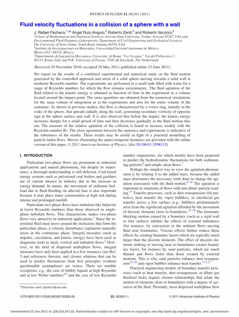
In cylindrical coordinates ðr; h; zÞ, the non-dimensional
velocity vector, pressure, and time are denoted by u ¼ðu; v;wÞ, p, and t, respectively. The system is governed by
four non-dimensional parameters, three geometric and one
dynamic: the radius of the container q ¼ R=D, the aspect
ratio C ¼ H=R, the traveling distance g ¼ h=D, and the
Reynolds number Re ¼ UpD=�. A schematic of the flow ge-
ometry, with an inset showing the azimuthal vorticity at
Re ¼ 400, q ¼ 10, C ¼ 1:5, and g ¼ 8, is given in Fig. 1.
The governing equations are the (non-dimensional)
incompressible Navier-Stokes equations
@u=@tþ ðu � rÞu ¼ �rpþ Re�1r2u; r � u ¼ 0: (1)
The boundary conditions for the velocity field are stress-free
at the top and no-slip on the side=bottom walls. On the
sphere, u and v are zero for all times and w ¼ �1 for t < 0
(prior to impact) and w ¼ 0 for t � 0 (perfect inelastic
collision).
Equation (1) is solved using a fractional-step scheme.
The discretization of both viscous and advective terms is per-
formed by second-order-accurate central finite-difference
approximations. The elliptic equation, necessary to enforce
incompressibility, is solved directly using trigonometric
expansions in the azimuthal direction and the tensor-product
method24 for the other two directions. Temporal evolution is
via a third-order Runge–Kutta scheme which calculates the
nonlinear terms explicitly and the viscous terms implicitly.
The stability limit due to the explicit treatment of the con-
vective terms is CFL <ffiffiffi3p
, where CFL is the Courant, Frie-
drichs and Lewy number.25 A useful feature of this scheme
is the possibility to advance in time by a variable time step,
without reducing the accuracy or introducing interpolations.
We have varied dt in all the simulations in this paper
such that the local CFL � 1:5, where CFL ¼ ðjuj=dr þ jvj=ðrdhÞ þ jwj=dzÞ dt, with the velocity components averaged at
the center of each computational cell. The smallest such
determined local dt is then used for time advancement (see
Ref. 26 for more details, including the treatment of the radial
axis).
The immersed boundary method (IB) is used in this
study to simulate the sphere. The main advantage of using the
IB consists in solving flows bounded by arbitrarily complex
geometries without resorting to body-conformal grids for
which the motion is prescribed, and, therefore, the solution
technique essentially has the same ease of use and efficiency
as that of simple geometries. The method is second-order in
space and this technique has already been implemented in
many different scenarios and grid layouts, e.g., laminar and
turbulent convection,27–29 turbulent flows and particle colli-
sion,30–33 biological devices,34 and bifurcations.35 The three-
dimensional simulations were conducted using the immersed
boundary method of Ref. 36.
Numerical simulations were conducted with different
grid sizes to verify the grid-independence results and to test
the adequacy of a coarser grid in resolving all the relevant
flow scales. We placed several probes in the neighborhood
FIG. 1. (Color online) Schematic of the flow apparatus. The inset shows the
initial position of the sphere and the vorticity contour of azimuthal vorticity
xh (from numerical simulations) for t > 0 after the sphere has touched the
wall at Re ¼ 400, q ¼ 10, C ¼ 1:5, and g ¼ 8.
063301-2 Pacheco et al. Phys. Fluids 23, 063301 (2011)
Downloaded 23 Jun 2011 to 129.219.247.33. Redistribution subject to AIP license or copyright; see http://pof.aip.org/about/rights_and_permissions
where the collision took place and measured the velocities at
different times. We then reduced the grid size using resolu-
tions of up to nh � nr � nz ¼ 96� 301� 601. We find that a
grid resolution of 64� 151� 251 results in a maximum dif-
ference in velocities at the probe locations of less than 1%
compared to the finer grid, and this resolution has been used
in most of the runs presented in this paper. To determine the
azimuthal symmetry of the flow, we have also performed
similar checks as in Refs. 37 and 38 who studied different
but related problems of baroclinic instabilities in the pres-
ence of rotation and stratification.
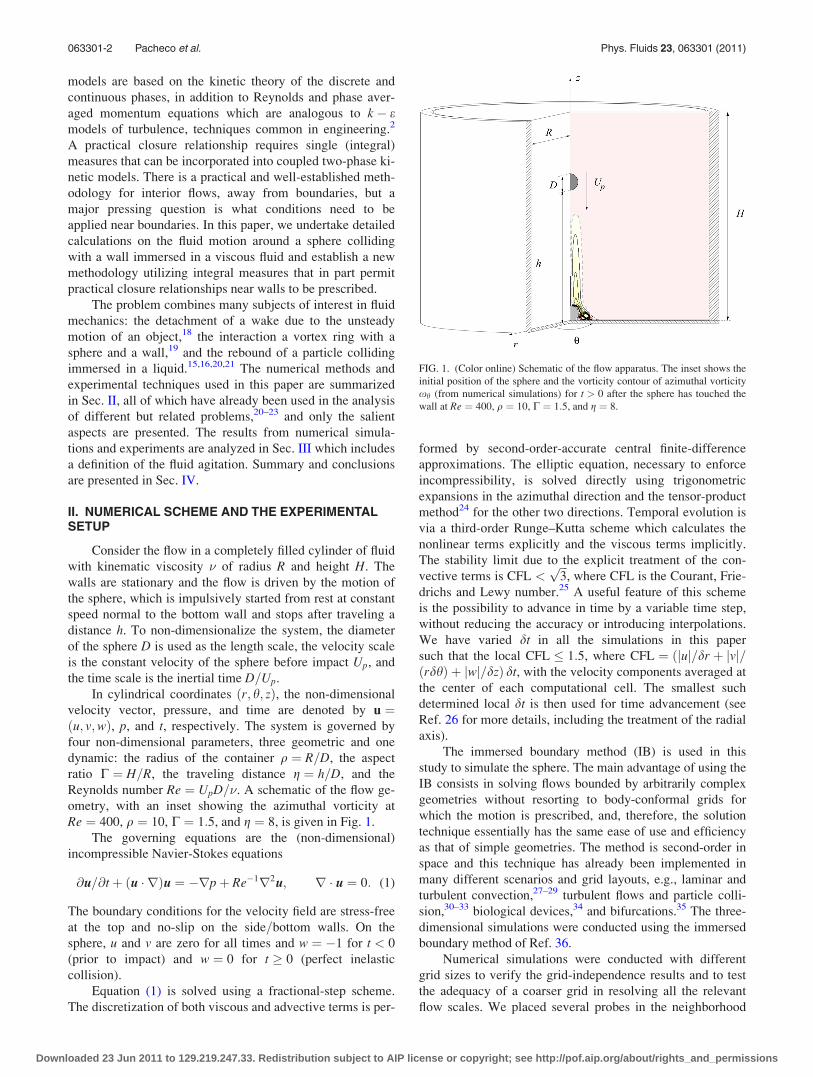
The experimental setup of the system used for this study
is shown in Fig. 2(a) and consists of a stainless steel sphere
of density 7.9 g=cm3 and diameter 25:4 mm in water at labo-
ratory conditions (�¼ 10.2 mm2 s�1) with an absolute uncer-
tainty of 60:1 mm2 s�1 confined in a rectangular glass
container of 2R� 2R� H ¼ 30� 30� 50 cm3 (� 12� 12
� 20 dimensionless units). The corresponding range of parti-
cle Reynolds number ranged between 50 and 400. A thick
glass plate was placed at the bottom of the container and the
particle release mechanism was placed at the top on the lid
of the container where two fine Nylon threads were glued to
the particle poles to inhibit rotation. The motion of the parti-
cle was controlled by slowly unwinding the threads from the
shaft of a computer-controlled DC motor, allowing the parti-
cle to touch the bottom wall without any noticeable bouncing
after impact.
To visualize and quantify the velocity field around the
sphere during the collision process, an ordinary 2-D particle
image velocimetry (PIV) system (Dantec Flowmap 1500
model) was used. The flow was illuminated with a pulsed
laser sheet of approximately 0.5 mm of thickness. The laser
sheet formed a small angle with the plane made by the two
strings attached to the sphere. Images of the laser illuminated
plane were obtained with a 1000� 1000 pixel digital camera.
The laser and the camera were synchronized by a control
unit that allowed the adjustment of the time between frames
as well as the time between pairs of frames. The typical time
between frames used to calculate the velocities was in the
order of 10 ms. The time between pairs of photographs was
160 ms, the highest allowed by the system. The field of view
of the camera was approximately 75� 85 mm2 (� 3� 3:3dimensionless units). An adaptive cross-correlation tech-
nique was used, with a final interrogation area of 32� 32
pixels and an overlap of 50% in both directions. Subse-
quently, a peak validation, moving average and spacial filter
routines were applied. The resolution of the optical array
was 12.5 pixel=mm. Using the uncertainty protocol of Ref.
39, the velocity uncertainty was calculated to be about 5.3%.
The experimental setup and a typical PIV image are shown
in Fig. 2, where the velocity field shown was superimposed
on the PIV image. For all cases, the area of the sphere was
masked and only half of the flow field was shown and proc-
essed, because the sphere blocked the laser light.
For a given experiment, the particle was placed origi-
nally at a distance of eight particle diameters from the bot-
tom plate (g ¼ 8), and the voltage was set to a constant value
before energizing the motor. After a very small transient, the
sphere began to descend at constant velocity. Since the parti-
cle Reynolds number was large, a deceleration of the particle
was not observed before it collided with the wall.20
III. RESULTS
The experimental measurements and most of the numer-
ical simulations were conducted for a range of particle Reyn-
olds numbers 100 � Re � 400 and g ¼ 8 to minimize the
possibility of a three-dimensional flow around the sphere.19
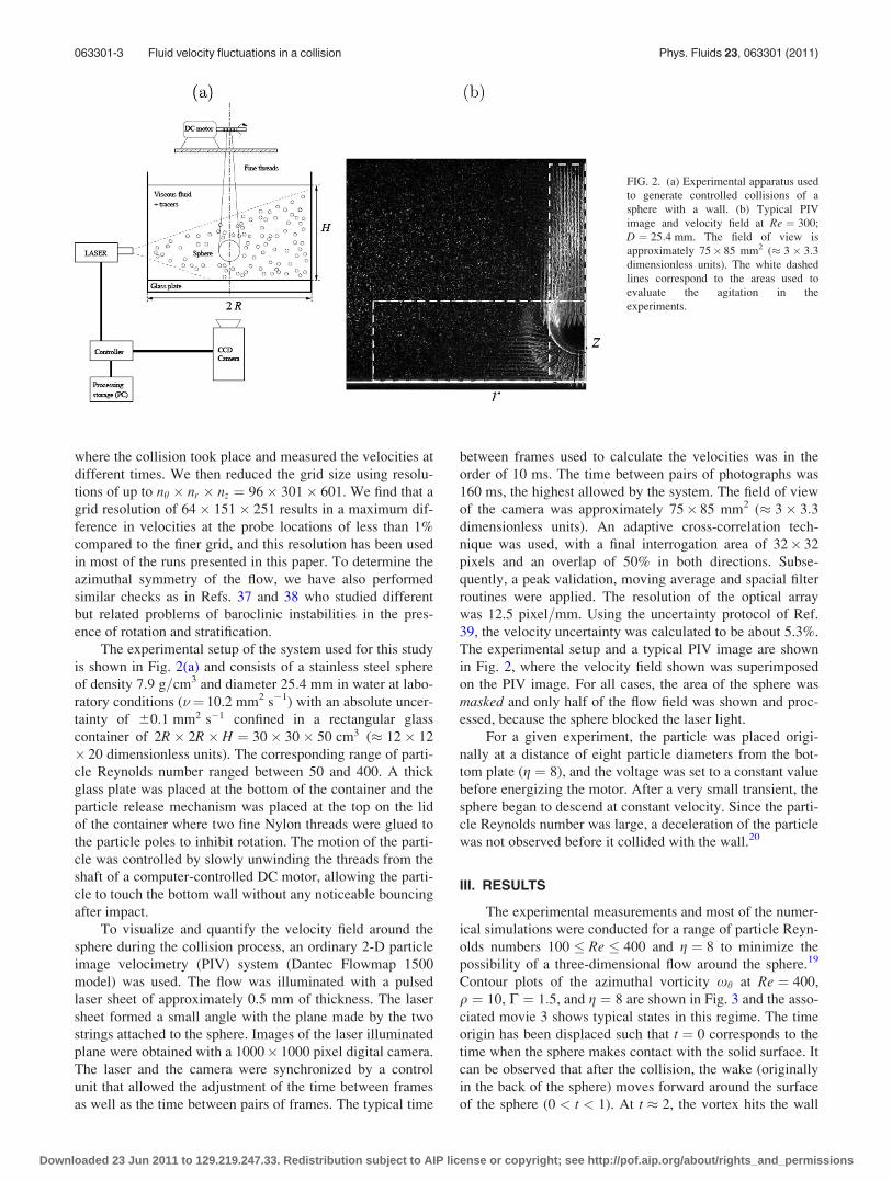
Contour plots of the azimuthal vorticity xh at Re ¼ 400,
q ¼ 10, C ¼ 1:5, and g ¼ 8 are shown in Fig. 3 and the asso-
ciated movie 3 shows typical states in this regime. The time
origin has been displaced such that t ¼ 0 corresponds to the
time when the sphere makes contact with the solid surface. It
can be observed that after the collision, the wake (originally
in the back of the sphere) moves forward around the surface
of the sphere (0 < t < 1). At t � 2, the vortex hits the wall
FIG. 2. (a) Experimental apparatus used
to generate controlled collisions of a
sphere with a wall. (b) Typical PIV
image and velocity field at Re ¼ 300;
D ¼ 25:4 mm. The field of view is
approximately 75� 85 mm2 (� 3� 3:3dimensionless units). The white dashed
lines correspond to the areas used to
evaluate the agitation in the
experiments.
063301-3 Fluid velocity fluctuations in a collision Phys. Fluids 23, 063301 (2011)
Downloaded 23 Jun 2011 to 129.219.247.33. Redistribution subject to AIP license or copyright; see http://pof.aip.org/about/rights_and_permissions
and begins to spread radially and at t � 4, the center of the
ring remains fixed in space and the fluid motion decreases
gradually due to the viscous dissipation. The nature of the
wake’s motion described above is qualitatively similar for
other values of Reynolds numbers and is in agreement with
other numerical and laboratory studies.16,40,41
A. Fluid agitation
We are interested in quantifying the fluid disturbance
caused by the collision of a single particle. A measure of the
fluid disturbance can be obtained from the velocity fields by
defining an agitation quantity (kinetic energy per unit mass)
within a volume of fluid that excludes the volume of the par-
ticle, as
AðtÞ ¼ð
V
ðu2 þ v2 þ w2Þ dV; (2)
where V is a control volume over which the agitation is
measured and ðu; v;wÞ are the vector components of fluid ve-
locity in the radial, azimuthal, and vertical directions,
respectively.
Ideally, the dimensions of the container should be as
large as possible, because far from the sphere, the velocity of
the fluid is negligible and the walls would have a negligible
influence in the flow dynamics. However, in any laboratory
experiment, there are limitations in the size of the measuring
area (in our case, the field of view of camera in the experi-
ments was approximately 3� 3:3 dimensionless units). We
have measured the agitation in the experiments for two dif-
ferent areas of field view and compared these results with
those from the Navier-Stokes solver for verification of the
correct implementation of the immersed boundary method.
Figure 4 shows the evolution of the agitation from Eq. (2) at
Re ¼ 400 and a comparison with the numerical results. The
region of integration to determine the agitation shown in Fig-
ure 4(a) is from r ¼ 0! 3 and z ¼ 0! 1 and that of Fig.
4(b) is from r ¼ 0! 0:5 and z ¼ 0! 3:3. The sharp
increase in the agitation after the sphere impact shown in
Figure 4(a) is due to the fluid motion in the wake of the parti-
cle before the collision that was excluded in the area of inte-
gration and not by the impact of the sphere. The rise in the
agitation shown in Fig. 4(b) is because the sphere enters the
domain of integration and accounts for a narrow region that
included the wake of the sphere.
In the original quiescent fluid, the flow is generated by
the sphere motion, thence the fluid is already agitated before
impact. Consequently, to quantify the agitation caused by
FIG. 3. (Color online) Contours of azi-
muthal vorticity xh from numerical sim-
ulations at Re ¼ 400, q ¼ 12, g ¼ 8,
C ¼ 1:25 and various t as indicated. The
region shown is �4:5 � r � 4:5 and
0 � z � 9. There are 20 positive (—–)
and negative (����) linearly spaced
contour levels in the ranges
xh 2 ½�1:5; 1:5�. The zero contour is the
grey line. The associated animation is
available online as movie 3 (enhanced
online). [URL: http://dx.doi.org/10.1063/
1.3598313.1].
063301-4 Pacheco et al. Phys. Fluids 23, 063301 (2011)
Downloaded 23 Jun 2011 to 129.219.247.33. Redistribution subject to AIP license or copyright; see http://pof.aip.org/about/rights_and_permissions
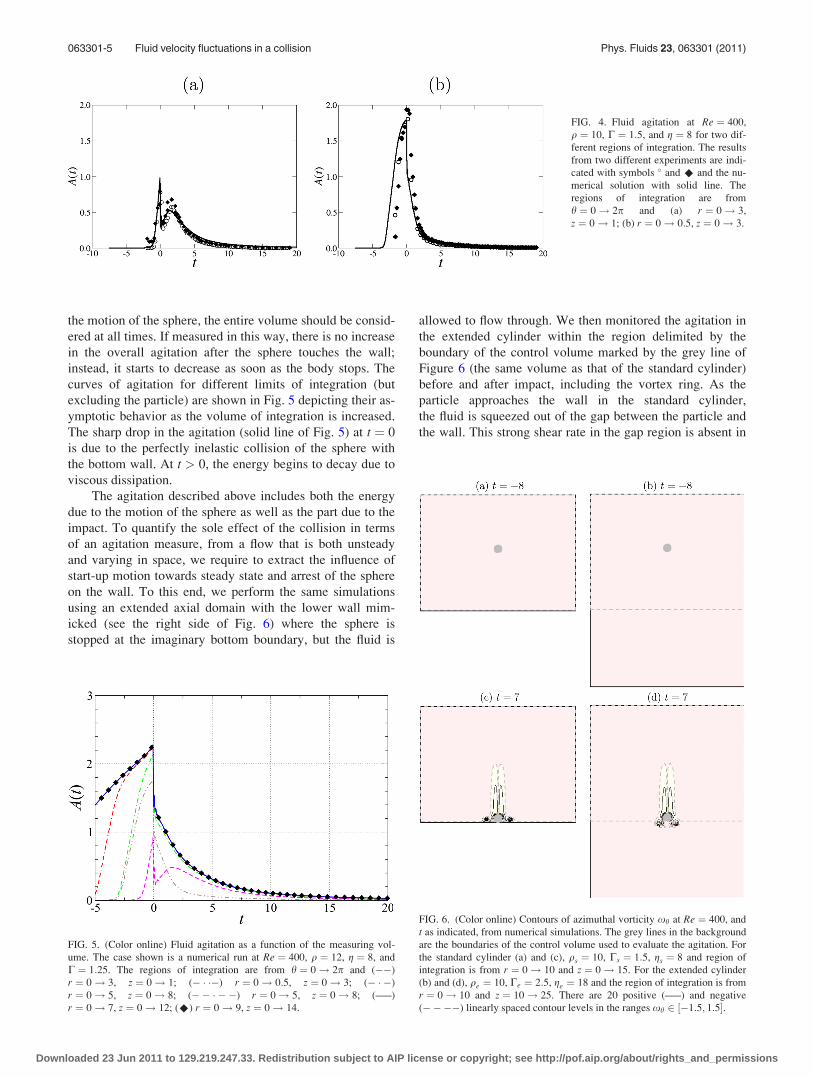
the motion of the sphere, the entire volume should be consid-
ered at all times. If measured in this way, there is no increase
in the overall agitation after the sphere touches the wall;
instead, it starts to decrease as soon as the body stops. The
curves of agitation for different limits of integration (but
excluding the particle) are shown in Fig. 5 depicting their as-
ymptotic behavior as the volume of integration is increased.
The sharp drop in the agitation (solid line of Fig. 5) at t ¼ 0
is due to the perfectly inelastic collision of the sphere with
the bottom wall. At t > 0, the energy begins to decay due to
viscous dissipation.
The agitation described above includes both the energy
due to the motion of the sphere as well as the part due to the
impact. To quantify the sole effect of the collision in terms
of an agitation measure, from a flow that is both unsteady
and varying in space, we require to extract the influence of
start-up motion towards steady state and arrest of the sphere
on the wall. To this end, we perform the same simulations
using an extended axial domain with the lower wall mim-
icked (see the right side of Fig. 6) where the sphere is
stopped at the imaginary bottom boundary, but the fluid is
allowed to flow through. We then monitored the agitation in
the extended cylinder within the region delimited by the
boundary of the control volume marked by the grey line of
Figure 6 (the same volume as that of the standard cylinder)
before and after impact, including the vortex ring. As the
particle approaches the wall in the standard cylinder,
the fluid is squeezed out of the gap between the particle and
the wall. This strong shear rate in the gap region is absent in
FIG. 4. Fluid agitation at Re ¼ 400,
q ¼ 10, C ¼ 1:5, and g ¼ 8 for two dif-
ferent regions of integration. The results
from two different experiments are indi-
cated with symbols and ^ and the nu-
merical solution with solid line. The
regions of integration are from
h ¼ 0! 2p and (a) r ¼ 0! 3,
z ¼ 0! 1; (b) r ¼ 0! 0:5, z ¼ 0! 3.
FIG. 5. (Color online) Fluid agitation as a function of the measuring vol-
ume. The case shown is a numerical run at Re ¼ 400, q ¼ 12, g ¼ 8, and
C ¼ 1:25. The regions of integration are from h ¼ 0! 2p and (��)
r ¼ 0! 3, z ¼ 0! 1; (� � ��) r ¼ 0! 0:5, z ¼ 0! 3; (� � �)
r ¼ 0! 5, z ¼ 0! 8; (�� � � �) r ¼ 0! 5, z ¼ 0! 8; (—–)
r ¼ 0! 7, z ¼ 0! 12; (^) r ¼ 0! 9, z ¼ 0! 14.
FIG. 6. (Color online) Contours of azimuthal vorticity xh at Re ¼ 400, and
t as indicated, from numerical simulations. The grey lines in the background
are the boundaries of the control volume used to evaluate the agitation. For
the standard cylinder (a) and (c), qs ¼ 10, Cs ¼ 1:5, gs ¼ 8 and region of
integration is from r ¼ 0! 10 and z ¼ 0! 15. For the extended cylinder
(b) and (d), qe ¼ 10, Ce ¼ 2:5, ge ¼ 18 and the region of integration is from
r ¼ 0! 10 and z ¼ 10! 25. There are 20 positive (—–) and negative
(����) linearly spaced contour levels in the ranges xh 2 ½�1:5; 1:5�.
063301-5 Fluid velocity fluctuations in a collision Phys. Fluids 23, 063301 (2011)
Downloaded 23 Jun 2011 to 129.219.247.33. Redistribution subject to AIP license or copyright; see http://pof.aip.org/about/rights_and_permissions
the extended cylinder and thus the sole effect of the collision
should be the difference between these evolutions.
If we let the subscripts s and e denote the standard and
extended cylinders, respectively, then a quantity with the
subscript c implies the difference between the corresponding
quantities calculated in the standard cylinder and the
extended cylinder, i.e., ð�Þc ¼ ð�Þs � ð�Þe. Thus, the agitation
due to the collision alone may be written as Ac ¼ As � Ae.
Notice that far away from the walls, the agitation produced
by the sphere in both the standard and extended cylinders
would be the same, but as the sphere approaches the solid-
mimicked wall, they would begin to differ.
Figure 6 shows contours of azimuthal vorticity, the
control volume, and the location of the spheres for the
two configurations at two different times (before and after
the sphere stops). The initial time of release of the sphere
was at t ¼ �8. At t ¼ 7, the vortex ring in the standard
cylinder has collided with the wall, whereas in the
extended cylinder, the vortex ring has already crossed the
imaginary lower boundary (dashed grey line correspond-
ing to the bottom wall of the standard cylinder). The
grids in the region of integration for both cylinders are
the same. However, for the extended cylinder, additional
grid points extend below the bottom wall compared to the
standard cylinder.
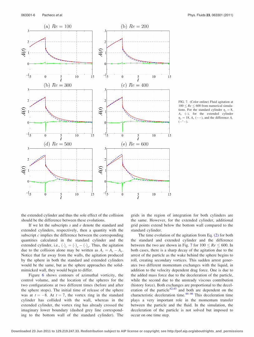
The time evolution of the agitation from Eq. (2) for both
the standard and extended cylinder and the difference
between the two are shown in Fig. 7 for 100 � Re � 600. In
both cases, there is a sharp decay of the agitation due to the
arrest of the particle as the wake behind the sphere begins to
roll, creating secondary vortices. This sudden arrest gener-
ates two different momentum exchanges with the liquid, in
addition to the velocity dependent drag force. One is due to
the added mass force due to the deceleration of the particle,
while the second due to the unsteady viscous contribution
(history force). Both exchanges are proportional to the decel-
eration of the particle42,43 and both are dependent on the
characteristic deceleration time.44–46 This deceleration time
plays a very important role in the momentum transfer
between the particle and the fluid. In the simulation, the
deceleration of the particle is not solved but imposed to
occur on one time step.
FIG. 7. (Color online) Fluid agitation at
100 � Re � 600 from numerical simula-
tions. For the standard cylinder gs ¼ 8,
As (–), for the extended cylinder
ge ¼ 18, Ae (��), and the difference Ac
(��).
063301-6 Pacheco et al. Phys. Fluids 23, 063301 (2011)
Downloaded 23 Jun 2011 to 129.219.247.33. Redistribution subject to AIP license or copyright; see http://pof.aip.org/about/rights_and_permissions
To analyze the forces acting on the sphere approaching a
solid wall through a thin layer would require measurements
of film thickness, impact velocity, and deceleration time,
where the lubrication theory applies. A detailed analysis of
these contributions is outside the scope of this work, but a
few remarks about the features associated with the momen-
tum transfer are appropriate here. We consider only the ways
to parameterize the agitation caused by the collision of the
sphere with the wall. These parametrizations either take the
form of an integral measure of the momentum exchange
(related to the force on the sphere and reaction by the wall) or
an integral measure of (kinetic) energy. And from this, there
are two ways to define the boundaries over which these inte-
gral measures are taken (either Eulerian or Lagrangian). An
integral measure of momentum is nontrivial to apply as mo-
mentum; as a concept, it is not well-defined (for unbounded
flows, see Refs. 47 and 48 and references therein) and it is
non-trivial to interpret (for bounded flows). Kinetic energy on
the other hand is a convergent quantity (in many cases). For
this reason, our approach has taken the route of assessing the
kinetic energy rather than the momentum exchange.
In order to quantify the agitation produced by a single
particle that can be used as boundary condition for kinetic
energy on the walls, it may be useful to define an average
agitation index (units of action per unit mass) as
hAi ¼ 1
Vp
ðT
to
AðtÞ dt; (3)
where Vpð¼ p=6Þ is the volume of the particle, to is the time
the sphere begins to move, and T is the time at which the
fluid motion has nearly ceased. The quantity hAi approaches
a constant value as T approaches infinity. The average agita-
tion index is loosely connected to the notion of “action”
from classical mechanics, which postulates that the path
actually followed by a physical system is that for which the
action is minimized.
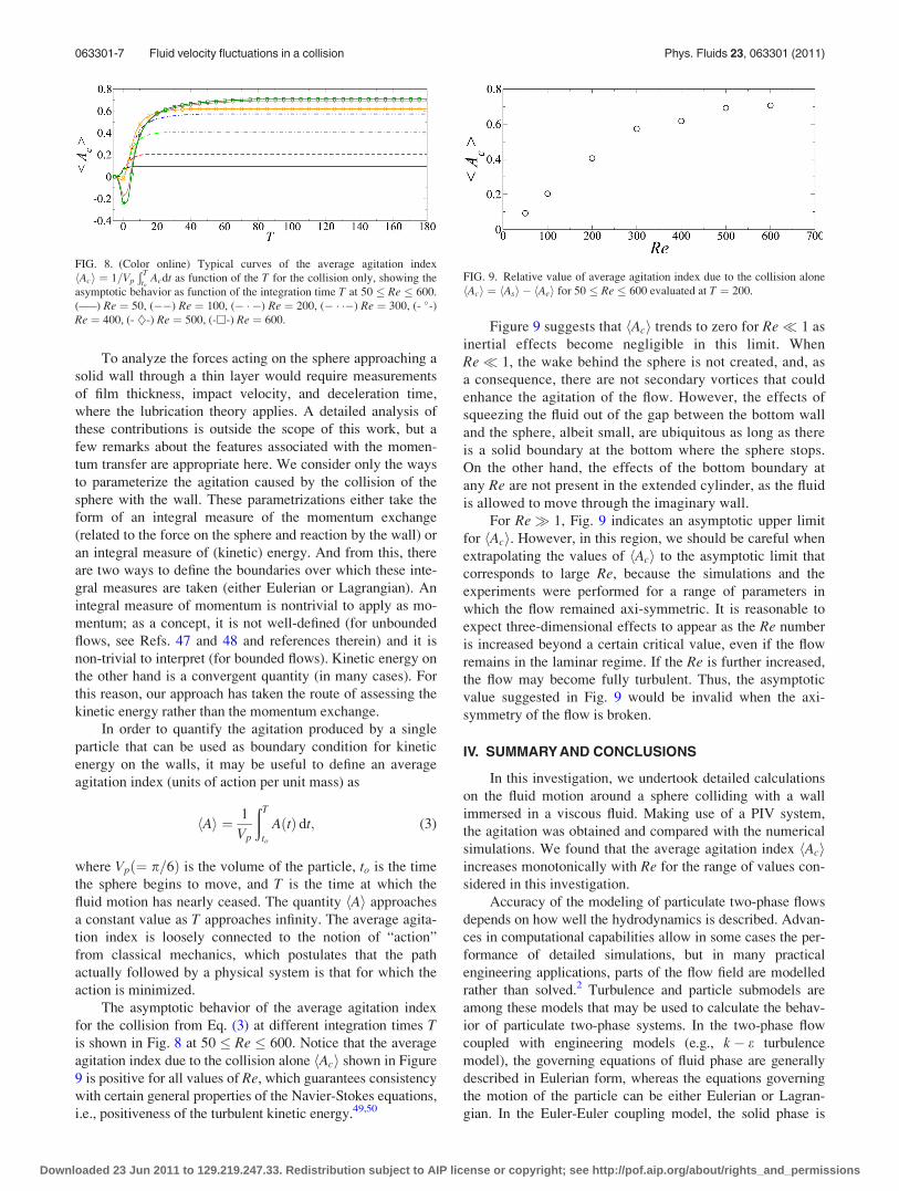
The asymptotic behavior of the average agitation index
for the collision from Eq. (3) at different integration times Tis shown in Fig. 8 at 50 � Re � 600. Notice that the average
agitation index due to the collision alone hAci shown in Figure
9 is positive for all values of Re, which guarantees consistency
with certain general properties of the Navier-Stokes equations,
i.e., positiveness of the turbulent kinetic energy.49,50
Figure 9 suggests that hAci trends to zero for Re 1 as
inertial effects become negligible in this limit. When
Re 1, the wake behind the sphere is not created, and, as
a consequence, there are not secondary vortices that could
enhance the agitation of the flow. However, the effects of
squeezing the fluid out of the gap between the bottom wall
and the sphere, albeit small, are ubiquitous as long as there
is a solid boundary at the bottom where the sphere stops.
On the other hand, the effects of the bottom boundary at
any Re are not present in the extended cylinder, as the fluid
is allowed to move through the imaginary wall.
For Re� 1, Fig. 9 indicates an asymptotic upper limit
for hAci. However, in this region, we should be careful when
extrapolating the values of hAci to the asymptotic limit that
corresponds to large Re, because the simulations and the
experiments were performed for a range of parameters in
which the flow remained axi-symmetric. It is reasonable to
expect three-dimensional effects to appear as the Re number
is increased beyond a certain critical value, even if the flow
remains in the laminar regime. If the Re is further increased,
the flow may become fully turbulent. Thus, the asymptotic
value suggested in Fig. 9 would be invalid when the axi-
symmetry of the flow is broken.
IV. SUMMARY AND CONCLUSIONS
In this investigation, we undertook detailed calculations
on the fluid motion around a sphere colliding with a wall
immersed in a viscous fluid. Making use of a PIV system,
the agitation was obtained and compared with the numerical
simulations. We found that the average agitation index hAciincreases monotonically with Re for the range of values con-
sidered in this investigation.
Accuracy of the modeling of particulate two-phase flows
depends on how well the hydrodynamics is described. Advan-
ces in computational capabilities allow in some cases the per-
formance of detailed simulations, but in many practical
engineering applications, parts of the flow field are modelled
rather than solved.2 Turbulence and particle submodels are
among these models that may be used to calculate the behav-
ior of particulate two-phase systems. In the two-phase flow
coupled with engineering models (e.g., k � e turbulence
model), the governing equations of fluid phase are generally
described in Eulerian form, whereas the equations governing
the motion of the particle can be either Eulerian or Lagran-
gian. In the Euler-Euler coupling model, the solid phase is
FIG. 8. (Color online) Typical curves of the average agitation index
hAci ¼ 1=Vp
Ð Tto
Acdt as function of the T for the collision only, showing the
asymptotic behavior as function of the integration time T at 50 � Re � 600.
(—–) Re ¼ 50, (��) Re ¼ 100, (� � �) Re ¼ 200, (� � ��) Re ¼ 300, (- -)Re ¼ 400, (- }-) Re ¼ 500, (-h-) Re ¼ 600.
FIG. 9. Relative value of average agitation index due to the collision alone
hAci ¼ hAsi � hAei for 50 � Re � 600 evaluated at T ¼ 200.
063301-7 Fluid velocity fluctuations in a collision Phys. Fluids 23, 063301 (2011)
Downloaded 23 Jun 2011 to 129.219.247.33. Redistribution subject to AIP license or copyright; see http://pof.aip.org/about/rights_and_permissions
treated as a continuum, with the disadvantage that the proba-
bilistic characteristic of particle motion is ignored.51 Never-
theless, in both Euler-Euler or Euler-Lagrange formulations,
the wall function is usually implemented as a boundary condi-
tions at the walls, where the turbulent kinetic energy k and
energy dissipation e are written in terms of the shear
velocity.52,53
Here, we proposed a new integral measure that in part
permits practical closure relationships near walls to be pre-
scribed. To incorporate these detailed calculations of sub-
grid scale processes into under-resolved models which do not
account explicitly for the particles (k � e models for exam-
ple), it might be useful to use the average agitation index as a
boundary condition for kinetic energy on the walls instead of
the commonly used wall-function. For example, by setting
k ¼ hAcif , where f is the a random frequency (with Gaussian
distribution) of particle collisions on the wall.
Finally, there are many aspects of integral measures
applied to disperse flows which require more exploration,
and this study provides the framework for further investiga-
tions. One of them is the implementation of the boundary
condition at the wall in a two-phase turbulent model as sug-
gested above and another is the motion of a sphere approach-
ing a solid wall through a thin layer with focus on the
momentum exchange due to inertia and viscous effects,
which will be addressed in forthcoming papers.
ACKNOWLEDGMENTS
The comments of the anonymous Referees have greatly
influenced the final version of this paper and are very much
appreciated. This work was partially supported by the
National Science Foundation Grant No. CBET-0608850 and
by National Autonomous University of Mexico through its
PAPIIT-DGAPA program (Grant No. IN 103900). A.R.-A.
acknowledges the PROBETEL and IIM-UNAM for their
scholarship program support. The authors acknowledge
Texas Advanced Computing Center (TACC) at the Univer-
sity of Texas at Austin and Ira A. Fulton High Performance
Computing Initiative at Arizona State University, both mem-
bers of the NSF-funded Teragrid, for providing HPC and vis-
ualization resources.
1S. Nagata, Mixing: Principles and Applications (Wiley, New York, USA,
1975).2J. C. R. Hunt, R. Delfos, I. Eames, and R. J. Perkins, “Vortices, complex
flows and inertial particles,” Flow, Turbul. Combust. 79, 207 (2007).3I. Eames, “Rapidly dissolving dense bodies in an inviscid fluid,” Proc. R.
Soc. London, Ser. A 464, 2985 (2008).4S.-Y. Kang, A. S. Sangani, H.-K. Tsao, and D. L. Koch, “Rheology of
dense bubble suspensions,” Phys. Fluids 9, 1540 (1997).5P. D. M. Spelt and A. S. Sangani, “Properties and averaged equations for
flows of bubbly liquids,” Appl. Sci. Res. 58, 337 (1998).6M. Brenner, “Screening mechanisms in sedimentation,” Phys. Fluids 11,
754 (2001).7G. Drazer, J. Koplik, and B. Khusid, “Microstructure and velocity fluctua-
tions in sheared suspensions,” J. Fluid Mech. 511, 237 (2004).8C. E. Brennen, “A review of added mass and fluid inertial forces,” Techni-
cal report, CR82.010, Nav. Civ. Eng. Lab., Dep. of the Navy, Port Hue-
neme, CA, (1982).9D. D. Joseph and J. Wang, “The dissipation approximation and viscous
potential flow,” J. Fluid Mech. 505, 365 (2004).
10J., Magnaudet and I. Eames, “The motion of high-Reynolds-number bub-
bles in inhomogeneous flows,” Annu. Rev. Fluid Mech. 32, 659 (2000).11G. Riboux, F. Risso, and D. Legendre, “Experimental characterization of
the agitation generated by bubbles rising at high Reynolds number,” J.
Fluid Mech. 643, 509 (2010).12I. Eames, “Momentum conservation and condensing vapor bubbles,” J.
Heat Transfer 132, 091501 (2010).13I. Eames and M. Gilbertson, “Mixing and drift in gas-fluidised beds,” Pow-
der Technol. 154, 185 (2005).14R. J. Munro, N. Bethke, and S. B. Dalziel, “Sediment resuspension and
erosion by vortex rings,” Phys. Fluids 21, 046601 (2009).15I. Eames and S. B. Dalziel, “Resuspension by an impacting sphere,” Phys.
Fluids 11, S11 (1999).16I. Eames and S. B. Dalziel, “Dust resuspension by the flow around an
impacting sphere,” J. Fluid Mech. 403, 305 (2000).17I. Eames, “Disappearing bodies and ghost vortices,” Philos. Trans. R. Soc.
London, Ser. A 366, 2219 (2008).18D. Rockwell, “Vortex-body interactions,” Annu. Rev. Fluid Mech. 30, 199
(1998).19J. D. A. Walker, C. R. Smith, A. W. Cerra, and T. L. Doligalski, “The
impact of a vortex ring on a wall,” J. Fluid Mech. 181, 99 (1987).20G. Joseph, R. Zenit, M. L. Hunt, and A. M. Rosenwinkel, “Particle-wall
collisions in a viscous fluid,” J. Fluid Mech. 433, 329 (2001).21P. Gondret, M. Lance, and L. Petit, “Bouncing motion of spherical par-
ticles in fluids,” Phys. Fluids 14, 643 (2002).22R. Zenit, M. L. Hunt, and C. E. Brennen, “Collisional particle pressure
measurements in solid-liquid flows,” J. Fluid Mech. 353, 261 (1997).23P. Orlandi and R. Verzicco, “Vortex rings impinging on walls:
Axisymmetric and three-dimensional simulations,” J. Fluid Mech. 256, 615
(1993).24R. E. Lynch, J. R. Rice, and D. H. Thomas, “Tensor product analysis of
partial difference equations,” Bull. Am. Math. Soc. 70, 378 (1964).25R. Courant, K. Friedrichs, and H. Lewy, “Uber die partiellen Differenzen-
gleichungen der mathematischen Physik,” Math. Ann. 100, 32 (1928).26R. Verzicco and P. Orlandi, “A finite-difference scheme for three-dimen-
sional incompressible flows in cylindrical coordinates,” J. Comput. Phys.
123, 402 (1996).27J. R. Pacheco, A. Pacheco-Vega, T. Rodic, and R. E. Peck, “Numerical
simulations of heat transfer and fluid flow problems using an immersed-
boundary finite-volume method on non-staggered grids,” Numer. Heat
Transfer, Part B 48, 1 (2005).28A. Pacheco-Vega, J. R. Pacheco, and T. Rodic, “A general scheme for the
boundary conditions in convective and diffusive heat transfer with
immersed boundary methods,” J. Heat Transfer 129, 1506 (2007).29G. Stringano, G. Pascazio, and R. Verzicco, “Turbulent thermal convec-
tion over grooved plates,” J. Fluid Mech. 557, 307 (2006).30S. Kang, G. Iaccarino, and F. Ham, “DNS of buoyancy-dominated turbu-
lent flows on a bluff body using the immersed boundary method,” J. Com-
put. Phys. 228, 3189 (2009).31J. Kim, D. Kim, and H. Choi, “An immersed-boundary finite-volume
method for simulations of flow in complex geometries,” J. Comput. Phys.
171, 132 (2001).32A. Cristallo and R. Verzicco, “Combined immersed boundary/large-eddy
simulations of incompressible three dimensional complex flows,” Flow
Turbul. Combust. 77, 3 (2006).33M. Uhlmann, “An immersed boundary method with direct forcing for the
simulation of particulate flows,” J. Comput. Phys. 209, 448 (2005).34M. D. de Tullio, A. Cristallo, E. Balaras, and R. Verzicco, “Direct numeri-
cal simulation of the pulsatile flow through an aortic bileaflet mechanical
heart valve,” J. Fluid Mech. 622, 259 (2009).35J. R. Pacheco, J. M. Lopez, and F. Marques, “Pinning of rotating waves
to defects in finite Taylor–Couette flow,” J. Fluid Mech. 666, 254
(2011).36E. A. Fadlun, R. Verzicco, P. Orlandi, and J. Mohd-Yusof, “Combined
immersed-boundary finite-difference methods for three-dimensional com-
plex flow simulations,” J. Comput. Phys. 161, 35 (2000).37R. Verzicco, F. Lalli, and E. Campana, “Dynamics of baroclinic vortices
in a rotating stratified fluid: A numerical study,” Phys. Fluids 9, 419
(1997).38S. A. Smirnov, J. R. Pacheco, and R. Verzicco, “Numerical simulations of
nonlinear thermally-stratified incremental spin-up in a circular cylinder,”
Phys. Fluids 22, 116602 (2010).39L. Lourenco and A. Krothapalli, “On the accuracy of velocity and vorticity
measurements with PIV,” Exp. Fluids 18, 421 (1995).
063301-8 Pacheco et al. Phys. Fluids 23, 063301 (2011)
Downloaded 23 Jun 2011 to 129.219.247.33. Redistribution subject to AIP license or copyright; see http://pof.aip.org/about/rights_and_permissions
40T. Leweke, M. C. Thompson, and K. Hourigan, “Touchdown of a sphere,”
Phys. Fluids 16, S5 (2004).41M. C. Thompson, T. Leweke, and K. Hourigan, “Sphere-wall collisions:
Vortex dynamics and stability,” J. Fluid Mech. 575, 121 (2007).42P. Gondret, E. Hallouin, M. Lance, and L. Petit, “Experiments on the
motion of a solid sphere toward a wall: From viscous dissipation to elasto-
hydrodynamic bouncing,” Phys. Fluids 11, 2803 (1999).43R. Mei and C. J. Lawrence, “The flow field due to a body in impulsive
motion,” J. Fluid Mech. 325, 79 (1996).44J. O. Marston, W. Yong, and S. T. Thoroddsen, “Direct verification of the
lubrication force on a sphere travelling through a viscous film upon
approach to a solid wall,” J. Fluid Mech. 655, 515 (2010).45A. Mongruel, C. Lamriben, S. Yahiaoui, and F. Feuillebois, “The approach of
a sphere to a wall at finite Reynolds number,” J. Fluid Mech. 661, 229 (2010).46M. A. T. van Hinsberg, J. ten Thije Boonkkamp, and H. J. H. Clercx, “An
efficient, second order method for the approximation of the Basset history
force,” J. Comput. Phys. 230, 1465 (2011).
47B. U. Felderhof, “Transient flow caused by a sudden impulse or twist
applied to a sphere immersed in a viscous incompressible fluid,” Phys.
Fluids 19, 073102 (2007).48I. Eames, “Disappearing bodies and ghost vortices,” Philos Trans. R. Soc.
London Ser. A 366, 2219 (2008).49C. G. Speziale, “On nonlinear K� l and K� e models of turbulence,” J.
Fluid Mech. 178, 459 (1987).50J. L. Lumley, “Computational modeling of turbulent flows,” Adv. Appl.
Mech. 18, 123 (1978).51P. Oresta, R. Verzicco, D. Lohse, and A. Prosperetti, “Heat transfer mech-
anisms in bubbly Rayleigh-Benard convection,” Phys. Rev. E 80, 026304
(2009).52Z. H. Zhao and H. J. S. Fernando, “Numerical simulation of scour around
pipelines using an Euler-Euler coupled two-phase model,” Environ. Fluid
Mech. 7, 121 (2007).53Z. H. Zhao and H. J. S. Fernando, “Numerical modeling of a sagging pipe-
line using an Eulerian two-phase model,” J. Turbul. 9, 1 (2008).
063301-9 Fluid velocity fluctuations in a collision Phys. Fluids 23, 063301 (2011)
Downloaded 23 Jun 2011 to 129.219.247.33. Redistribution subject to AIP license or copyright; see http://pof.aip.org/about/rights_and_permissions
Related Documents