This article appeared in a journal published by Elsevier. The attached copy is furnished to the author for internal non-commercial research and education use, including for instruction at the authors institution and sharing with colleagues. Other uses, including reproduction and distribution, or selling or licensing copies, or posting to personal, institutional or third party websites are prohibited. In most cases authors are permitted to post their version of the article (e.g. in Word or Tex form) to their personal website or institutional repository. Authors requiring further information regarding Elsevier’s archiving and manuscript policies are encouraged to visit: http://www.elsevier.com/copyright

Welcome message from author
This document is posted to help you gain knowledge. Please leave a comment to let me know what you think about it! Share it to your friends and learn new things together.
Transcript
This article appeared in a journal published by Elsevier. The attachedcopy is furnished to the author for internal non-commercial researchand education use, including for instruction at the authors institution
and sharing with colleagues.
Other uses, including reproduction and distribution, or selling orlicensing copies, or posting to personal, institutional or third party
websites are prohibited.
In most cases authors are permitted to post their version of thearticle (e.g. in Word or Tex form) to their personal website orinstitutional repository. Authors requiring further information
regarding Elsevier’s archiving and manuscript policies areencouraged to visit:
http://www.elsevier.com/copyright
Author's personal copy
Fluid–structure interaction of deformable aortic prostheses with a bileafletmechanical valve
M.D. de Tullio a,b, L. Afferrante a,b,�, G. Demelio a,b, G. Pascazio a,b, R. Verzicco c
a DIMeG, Politecnico di Bari, via Re David 200, 70125 Bari, Italyb CEMeC, Politecnico di Bari, via Re David 200, 70125 Bari, Italyc DIM, Universit�a di Roma Tor Vergata, Via del Politecnico 1, 00133 Roma, Italy
a r t i c l e i n f o
Article history:
Accepted 26 March 2011
Keywords:
Bentall procedure
Valsalva graft
Immersed boundary method
a b s t r a c t
Two different aortic prostheses can be used for performing the Bentall procedure: a standard straight
graft and the Valsalva graft that better reproduces the aortic root anatomy. The aim of the present work
is to study the effect of the graft geometry on the blood flow when a bileaflet mechanical heart valve is
used, as well as to evaluate the stress concentration near the suture line where the coronary arteries
are connected to graft. An accurate three-dimensional numerical method is proposed, based on the
immersed boundary technique. The method accounts for the interactions between the flow and the
motion of the rigid leaflets and of the deformable aortic root, under physiological pulsatile conditions.
The results show that the graft geometry only slightly influences the leaflets dynamics, while using the
Valsalva graft the stress level near the coronary-root anastomoses is about half that obtained using the
standard straight graft.
& 2011 Elsevier Ltd. All rights reserved.
1. Introduction
The aortic valve is located at the beginning of the aortic root,where three sinuses (sinuses of Valsalva) are present, from two ofwhom the coronary arteries originate. The Bentall procedure(Bentall and De Bono, 1968) that is a total root and ascendingroot replacement by means of a composite valved conduit, withits various modifications (Kouchoukos et al., 1991), is the stan-dard operation for patients who have lesions of the ascendingaorta associated with aortic valve disease. In this way, the naturalaortic root configuration is modified and this could influence theblood flow and leaflets motion. Moreover, the root looses anyextensibility at all levels (Weltert et al., 2009), because of thedifferent elastic characteristics of the composite material withrespect to the native aorta. A very delicate and important step ofthe procedure is the re-connection of the previously separatedcoronary arteries to the graft, as close as possible to their naturalposition. This procedure may have intra-operative (bleeding) andpost-operative (bleeding and late pseudo-aneurysm formation)complications due to the high stresses at the level of thecoronary-root anastomoses.
Computational methods could help surgeons in their practice,giving results that, even if requiring clinical confirmation in the
real case, would give an immediate insight and allow for com-parative studies between different types of prostheses. One of themajor issues is the correct modeling of the interaction betweenthe blood flow and the deforming vascular structures, consideringan accurate description of the flow field combined with a realisticcharacterization of the deforming structure’s material.
Several methods are usually adopted in literature to considerfluid–structure interaction (FSI) with deformable structures: thearbitrary Lagrangian–Eulerian formulation (Jianhai et al., 1996;Morsi et al., 2007; Carmody et al., 2006), the immersed boundary(IB) method (see Griffith et al. (2007) and references therein) andthe fictitious domain formulation (Baaijens, 2001; De Hart et al.,2003; Astorino et al., 2009). Recently a different approach (denotedas sequentially coupled arterial fluid–structure interaction) has beenproposed by Tezduyar et al. (2009), whereas in Weinberg andKaazempur-Mofrad (2007) a multiscale model has been developed.
In this study, we present an accurate numerical method basedon the immersed boundary technique able to handle complexmoving and deforming geometries. A direct numerical simulationapproach is used to correctly capture the physics of the transi-tional flow without introducing numerical viscosity or otherartificial dissipation mechanisms. A finite-element solver for thedeforming roots is coupled with the fluid solver in a segregatedweak approach, in order to reduce the computational cost and touse optimized solvers for both the fluid and structural problems.
Two different prostheses used in practice by surgeonsare considered, equipped with a bileaflet mechanical valve.Two cylindrical channels, reproducing the very early coronary
Contents lists available at ScienceDirect
journal homepage: www.elsevier.com/locate/jbiomechwww.JBiomech.com
Journal of Biomechanics
0021-9290/$ - see front matter & 2011 Elsevier Ltd. All rights reserved.
doi:10.1016/j.jbiomech.2011.03.036
� Corresponding author at: DIMeG, Politecnico di Bari, via Re David 200, 70125
Bari, Italy.
E-mail address: [email protected] (L. Afferrante).
Journal of Biomechanics 44 (2011) 1684–1690
Author's personal copy
vasculature, are connected to the grafts. Simulations of the flowinside the prostheses under physiological pulsatile inflow condi-tions are presented, considering several complete cardiac cycles.
2. Geometries and materials
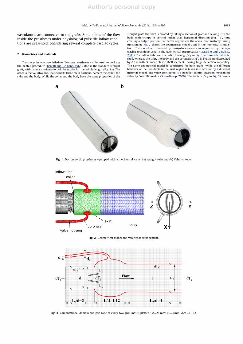
Two polyethylene terephthalate (Dacron) prostheses can be used to perform
the Bentall procedure (Bentall and De Bono, 1968). One is the standard straight
graft, with constant orientation of the textile for the whole length (Fig. 1a). The
other is the Valsalva one, that exhibits three main portions, namely the collar, the
skirt and the body. While the collar and the body have the same properties of the
straight graft, the skirt is created by taking a section of graft and sewing it to the
body with crimps in vertical rather than horizontal direction (Fig. 1b), thus
creating a bulged portion that better reproduces the aortic root anatomy during
functioning. Fig. 2 shows the geometrical model used in the numerical simula-
tions. The model is discretized by triangular elements, as requested by the ray-
tracing technique used in the geometrical preprocessor (Iaccarino and Verzicco,
2003). The inflow tube and the valve housing (@G1 in Fig. 3) are considered to be
rigid, whereas the skirt, the body and the coronaries (@G3 in Fig. 3) are discretized
by 0.3 mm-thick linear elastic shell elements having large deflection capability.
The same geometrical model is considered for both grafts, while the different
behavior of the two ducts in the skirt region is taken into account by a different
material model. The valve considered is a bileaflet 25 mm Bicarbon mechanical
valve by Sorin Biomedica (Sorin-Group, 2006). The leaflets (@G2 in Fig. 3) have a
Fig. 1. Dacron aortic prostheses equipped with a mechanical valve: (a) straight tube and (b) Valsalva tube.
Fig. 2. Geometrical model and valve/root arrangement.
Fig. 3. Computational domain and grid (one of every two grid lines is plotted): d¼25 mm; dc¼3 mm; do/d¼1.132.
M.D. de Tullio et al. / Journal of Biomechanics 44 (2011) 1684–1690 1685
Author's personal copy
curved profile and exhibit a rotation range equal to 601, with a fully open position
of 101 with respect to the streamwise direction. Fig. 2 shows the valve orientation
with respect to the two coronaries: this configuration is the most adopted in
surgery, and aims to maximize the coronary blood flow.
Dacron prostheses are characterized by orthotropic material properties in the
present work. As shown in Lee and Wilson (1986), the stress–strain relation for
the woven Dacron graft can be correctly modeled with a linear model both in
longitudinal and circumferential directions. Hence nine elastic constants (Young’s
moduli Ex, Ey, Ez, Poisson’s ratios nyz , nzx , nxy , and shear moduli Gyz, Gzx, Gxy) need to
be defined and for the compliance matrix to be positive definite the following
condition must be satisfied (z is the streamwise direction):
1�n2xy
Ey
Ex�n2
yz
Ez
Ey�n2
xz
Ez
Ex�2nxynyznxz
Ez
Ex40: ð1Þ
Since the Dacron graft can be considered as transversely isotropic (Ex¼Ey, nxz ¼ nyz ,
Gxz¼Gyz), the elastic constants are actually six. Numerical values of the material
constants are shown in Table 1. It is worth noting that for the Valsalva graft the
orthotropic directions of the material are inverted at the skirt region, in order to
take into account the different behavior of the prosthesis. A linear elastic material
with Young’s modulus equal to 2 MPa was used for the two coronaries. In terms of
displacement and strain results, this value gives a good match with respect to
more sophisticated models adopted in literature to model the natural aortic root,
that use non-linear material properties (Ranga et al., 2004). The leaflets are
considered to be rigid and made by pyrolytic carbon. Each leaflet has a moment of
inertia with respect to the pivot axis of Ii ¼ 7.94710�9 kg m2.
3. Numerical method and simulation details
In each point of the time-dependent fluid domain, the Navier–Stokes equations for an incompressible viscous Newtonian fluidare solved:
r � uf ¼ 0, ð2Þ
@uf
@tþr � ðuf uf Þ ¼�rpþ
1
Rer2uf þfþf 0, ð3Þ
where uf is the velocity vector, p is the pressure, f is the directforcing term of the immersed boundary method (Fadlun et al.,2000) and Re is the Reynolds number later specified. The fluidmodel is Newtonian since the blood in large arteries behavesaccordingly (Nichols and O’Rourke, 1990). The term f 0 modulatesin time the porosity of the material inside the two coronarychannels, so as to obtain a mainly diastolic coronary flow asdescribed by de Tullio et al. (2011). The two leaflets Bi can rotateabout their own pivots:
Iid2yi
dt2¼ Ti, for Bi with i¼ 1,2, ð4Þ
where yi are the angular displacements and Ti are the tiltingmoments about the pivots resulting from the viscous terms andpressure integrated over the leaflets surfaces. The Navier–Stokesequations are solved using a fractional-step approach where theviscous and convective terms are treated implicitly and explicitlyrespectively (Verzicco and Orlandi, 1996). A third-order Runge–Kutta scheme is used to advance the solution in time. A fixedCourant number equal to 0.25 has been used, thus having avariable time step, ranging from 3 to 250 ms during a cardiaccycle. A strong coupling scheme is employed for the solution ofthe system (2)–(4), the governing equations being integratedsimultaneously in the time-domain by an iterative procedure.Details on the method and several checks of the numerics can befound in de Tullio et al. (2009).
The Navier equation governs the dynamics of the solid region:
r � rs ¼ rs
@2xs
@t2, ð5Þ
where rs is the stress tensor, rs and xs are the density anddisplacements of the solid respectively. The constitutive andcompatibility relations are given by:
rs ¼ CEs, Es ¼1
2½rxsþðrxsÞ
TþðrxsÞ
Trxs�, ð6Þ
where C is the elasticity tensor and Es is the strain tensor. Thefinite-element commercial software ANSYSs MultiphysicsTM
(2008) is used to solve Eqs. (5) and (6). In this work, the unsteadyterms of Eq. (5) are not considered, thus neglecting inertial effectsof the deforming structure, according to a quasi-static approx-imation. A weak-coupling scheme is employed for the solution ofEqs. (2) and (5) which are solved in a successive manner with apartitioned (segregated) approach. This allows one to reduce thecomputational cost of the procedure and to use optimized solversfor both the fluid and the structural problem.
Both the strong and weak fluid–structure coupling are carriedout effectively in the context of an IB approach. In fact, for eachtime step, the body geometries (leaflets and root) are overlappedon the fixed cylindrical Cartesian grid, thus avoiding the need forremeshing or deforming the grid used to discretize the fluiddomain. This method is efficient and can handle large deforma-tions, since the fluid grid nodes are independent of the bodysurface position.
For each time step, the following procedure is employed,where n and nþ1 indicate the time levels, i¼1,2 indicates theleaflet, subscripts f and s indicate fluid and structure quantitiesrespectively:
1. the flow and leaflets equations are advanced in time using xsn
and usn as boundary conditions for the fluid domain, finding
ufnþ1, pf
nþ1, ynþ1i and _y
nþ1
i ;2. the loads exerted on the structures by the fluid Unþ1
f ¼
Unþ1f ðxn
s ,unþ1f ,pnþ1
f ,ynþ1i and _y
nþ1
i Þ are evaluated;
Table 1Numerical values of the material constants for the deformable graft.
Ex¼Ey Ez nxz ¼ nyz nxy Gxz¼Gyz Gxy
12 MPa 1.2 MPa 0.15 0.1 5.2 MPa 0.55 MPa
x/L
r/r0
0 0.5 10.975
0.98
0.985
0.99
0.995
1
Re=100
Re=200
Re=500
Fig. 4. Laminar flow inside a deformable pipe: dimensionless pipe radius r/r0
variation with dimensionless streamwise position x/L for different Reynolds
numbers (based on the undeformed pipe diameter 2r0 and inflow velocity).
Continuous lines indicate our calculations, while circles indicate analytical results
(Fung, 1984).
M.D. de Tullio et al. / Journal of Biomechanics 44 (2011) 1684–16901686
Author's personal copy
3. the root structural equations are solved with the com-puted loads, Unþ1
s ¼Unþ1f , to obtain the new values for xs
nþ1
and usnþ1, which are used as boundary conditions for the next
time step.
In this way, the solution of the structural solver is needed onlyonce per time step. Stability is ensured by the very small timesteps required by the flow solver to capture the time-history ofthe smallest turbulent scales.
time (ms)
aort
ic fl
ow ra
te (l
min
−1)
aort
ic p
ress
ure
(kPa
)
0 200 400 600 800−5
0
5
10
15
20
25
30
8
10
12
14
16
18
time (ms)
Λ
aort
ic fl
ow ra
te (l
min
−1)
0 200 400 600 800−0.2
0
0.2
0.4
0.6
0.8
1
1.2
−5
0
5
10
15
20
25
30
Valsalvastraight graft
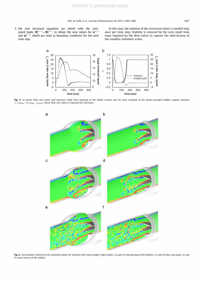
Fig. 5. (a) Aortic flow rate (dots) and pressure (solid line) imposed at the inflow section and (b) time variation of the phase-averaged leaflets angular position
L¼ ðaopen�aÞ=ðaopen�aclosedÞ. Aortic flow rate (dots) is reported for reference.
Fig. 6. Out of plane vorticity in the symmetry plane for Valsalva (left) and straight (right) grafts: (a) and (b) end opening of the leaflets; (c) and (d) flow rate peak; (e) and
(f) start closure of the leaflets.
M.D. de Tullio et al. / Journal of Biomechanics 44 (2011) 1684–1690 1687
Author's personal copy
The validation of the fully coupled approach of the flow solverwith the equations governing the dynamics of the rigid leaflets ispresented in de Tullio et al. (2009). Here, the coupling of the flowsolver with the deformable structure has been validated consid-ering a non-constrained pipe conveying a stationary flow, obtain-ing a satisfactory agreement between numerical and analyticalresults (Fung, 1984), as shown in Fig. 4.
4. Results and discussion
Five complete cardiac cycles are considered under typicalphysiological conditions for an adult male: the cycle duration isset at 866 ms, corresponding to about 70 beats/min. The mean flowrate is adjusted to about 5 l/min with a peak flow rate equal toabout 28 l/min. The blood kinematic viscosity and density are setto n¼ 3:0410�6 m2=s and rb ¼ 1060 kg=m3 respectively. The peakReynolds number, based upon the bulk velocity at the peak inflow,U¼0.95 m/s, and the inflow tube diameter, is about 7800. After agrid convergence study, a background cylindrical structured grid isused, having 217�165�250 nodes in the azimuthal, radial andaxial directions respectively. For the fluid domain inflow section(@G4 in Fig. 3), pressure and velocity profiles are imposed in orderto mimic the physiological flow rate and pressure produced by theheart in the left ventricle, as shown in Fig. 5. Regions @G5 and @G6
in Fig. 3 are treated as outflow sections.Concerning the deformable structure, it is fully constrained at
the lowest nodes (where the mechanical valve is fixed to theprosthesis). In real life, the distal part of the aorta is subject to an
axial extension that induces longitudinal stresses, as reported inHan and Fung (1995). The use of the prosthesis will influence thisextension, depending on its total axial stiffness, which will bedifferent for the straight and Valsalva graft. Due to the lack ofquantitative data concerning the two composite prostheses, weconsidered two opposite cases: (I) a longitudinal maximumdisplacement of about 5 mm (Han and Fung, 1995), modulatedin time by the pressure curve in Fig. 5a, is applied to the highestnodes of the graft model and (II) no axial displacement isimposed. During functioning, the straight graft, with a lower totalaxial stiffness, would have a behavior closer to case I, while theValsalva graft would be better described by case II. For complete-ness we simulate both cases for the two prostheses.
The phase-averaged angular displacements of the two leafletsduring the cardiac cycle are shown in Fig. 5b: very little sensitiv-ity to the aortic root geometry is observed. The leaflet dynamics isgreatly influenced by the pressure gradient through the valve, andthis is evident during the opening phase, where the flow isaccelerated. Small differences are noticeable during the closingphase, where the deceleration of the flow induces high turbulencelevels, and therefore the forces on the leaflets are influenced bythe fluctuations in time of the pressure and velocity fields. Theout-of-plane vorticity contours in the symmetry plane are shownin Fig. 6, at three significant instants. The typical configuration ofthe bileaflet valves, forming three jets, with strong shear layersshed from the valve housing and the tips of the leaflets, isnoticeable. At the peak flow rate, the shear layers becomeunstable and a strong small scale turbulence production isobserved in the wake and in the sinuses region. The Valsalvaprosthesis exhibits an axisymmetric recirculation region, due tothe sudden expansion flow past the valve, larger than thatoccurring for the case of the straight graft and more similar tothat occurring in the physiological situation. During the deceler-ating phase, the flow becomes turbulent with high production ofsmall scale structures downstream of the valve. The leaflets startclosing as soon as the pressure starts decreasing and quicklyreach a complete closure: the flow stops and viscosity dissipatesthe small scale structures until the beginning of the new cycle.The computed mean coronary flow is about 150 and 140 ml/minfor the Valsalva and straight graft respectively, being only slightlyinfluenced by the presence of the pseudo-sinuses, in agreementwith the in vivo observations of De Paulis et al. (2004).
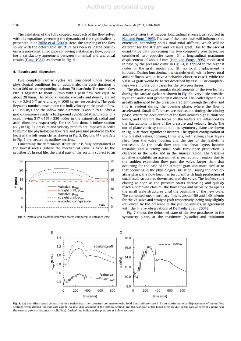
Fig. 7 shows the deformed state of the two prostheses in thesymmetry plane, at the maximum (systolic) and minimum
Y (m
m)
axis 00
55
1010
1515
2020
2525
straight graft, pmin
Valsalva, pmin
straight graft, pmax
Valsalva, pmax
unloaded configuration
Fig. 7. Systolic and diastolic deformed states compared to unloaded case.
time (ms)
σ eqv
(MPa
)
0.4
0.6
0.8
1.0
1.2
1.4
Valsalva
straightgraft
time (ms)
p (k
Pa)
08.0
10.0
12.0
14.0
16.0
18.0
inflow
200 400 600 800 0 200 400 600 800
Fig. 8. (a) Von Mises stress versus time in a region near the coronary-root anastomosis. Solid lines indicate case I (5 mm maximum axial displacement of the outflow
section), while dashed lines indicate case II (no axial displacement of the outflow section) and (b) evolution of the blood pressure during the cardiac cycle at a point near
the coronary-root anastomosis (solid line). Dashed line indicates the pressure at inflow section.
M.D. de Tullio et al. / Journal of Biomechanics 44 (2011) 1684–16901688
Author's personal copy
(diastolic) values of pressure, compared to the unloaded config-uration. The diameter variation is very small in the region wherethe crimps are horizontal, namely, for the straight tube and forthe body of the Valsalva prosthesis, whereas it is larger in the skirtregion, where the crimps are longitudinal.
Fig. 8a provides the time histories of the Von Mises stressesnear the coronary-root anastomoses for both the prostheses inthe two cases. The high frequency oscillations in the stress aremore marked in the Valsalva graft due to the reduced stiffness ofthe skirt region, combined with larger recirculation regions of theflow into the sinuses. The results clearly show that, in the regioncorresponding to the sinuses, and for both cases I and II, the stressvalues are smaller for the Valsalva prosthesis than for the straightone, for the entire cardiac cycle. In particular, the ratio between themaximum stress for the straight graft in case I and the maximumone for the Valsalva graft in case II is about two. Such value can beeven higher when considering that a small axial displacement ispresent also for the Valsalva graft. Notice that the pressure peak atvalve closure, as reported in Fig. 8b, is responsible of the stresspeak reported in Fig. 8a, while this effect is greatly reduced in thestraight graft because of its more rigid structure.
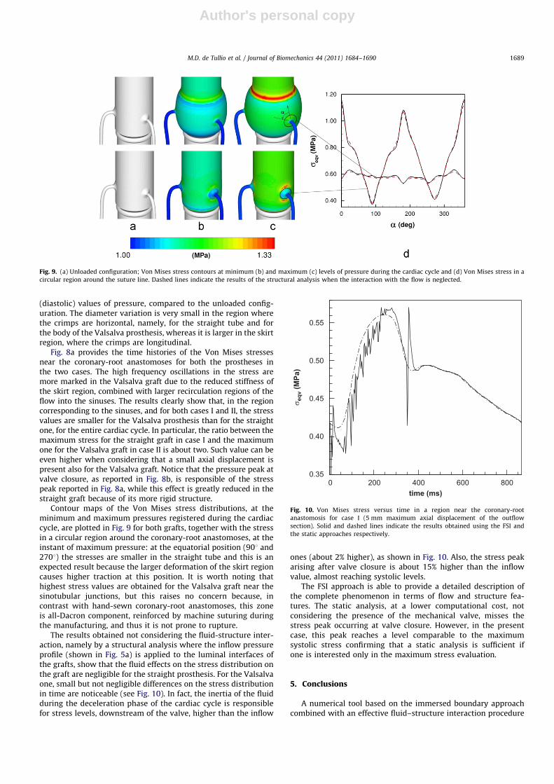
Contour maps of the Von Mises stress distributions, at theminimum and maximum pressures registered during the cardiaccycle, are plotted in Fig. 9 for both grafts, together with the stressin a circular region around the coronary-root anastomoses, at theinstant of maximum pressure: at the equatorial position (901 and2701) the stresses are smaller in the straight tube and this is anexpected result because the larger deformation of the skirt regioncauses higher traction at this position. It is worth noting thathighest stress values are obtained for the Valsalva graft near thesinotubular junctions, but this raises no concern because, incontrast with hand-sewn coronary-root anastomoses, this zoneis all-Dacron component, reinforced by machine suturing duringthe manufacturing, and thus it is not prone to rupture.
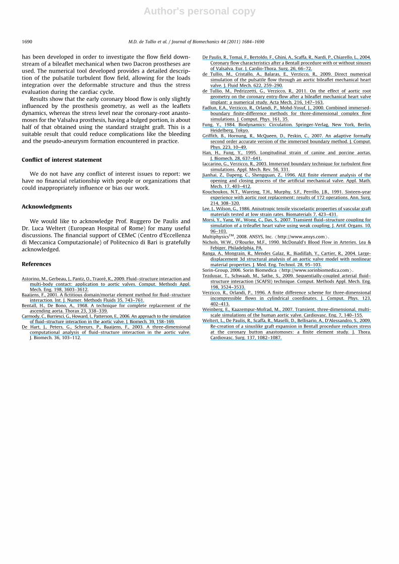
The results obtained not considering the fluid-structure inter-action, namely by a structural analysis where the inflow pressureprofile (shown in Fig. 5a) is applied to the luminal interfaces ofthe grafts, show that the fluid effects on the stress distribution onthe graft are negligible for the straight prosthesis. For the Valsalvaone, small but not negligible differences on the stress distributionin time are noticeable (see Fig. 10). In fact, the inertia of the fluidduring the deceleration phase of the cardiac cycle is responsiblefor stress levels, downstream of the valve, higher than the inflow
ones (about 2% higher), as shown in Fig. 10. Also, the stress peakarising after valve closure is about 15% higher than the inflowvalue, almost reaching systolic levels.
The FSI approach is able to provide a detailed description ofthe complete phenomenon in terms of flow and structure fea-tures. The static analysis, at a lower computational cost, notconsidering the presence of the mechanical valve, misses thestress peak occurring at valve closure. However, in the presentcase, this peak reaches a level comparable to the maximumsystolic stress confirming that a static analysis is sufficient ifone is interested only in the maximum stress evaluation.
5. Conclusions
A numerical tool based on the immersed boundary approachcombined with an effective fluid–structure interaction procedure
Fig. 9. (a) Unloaded configuration; Von Mises stress contours at minimum (b) and maximum (c) levels of pressure during the cardiac cycle and (d) Von Mises stress in a
circular region around the suture line. Dashed lines indicate the results of the structural analysis when the interaction with the flow is neglected.
time (ms)
σ eqv
(MPa
)
0.35
0.40
0.45
0.50
0.55
0 200 400 600 800
Fig. 10. Von Mises stress versus time in a region near the coronary-root
anastomosis for case I (5 mm maximum axial displacement of the outflow
section). Solid and dashed lines indicate the results obtained using the FSI and
the static approaches respectively.
M.D. de Tullio et al. / Journal of Biomechanics 44 (2011) 1684–1690 1689
Author's personal copy
has been developed in order to investigate the flow field down-stream of a bileaflet mechanical when two Dacron prostheses areused. The numerical tool developed provides a detailed descrip-tion of the pulsatile turbulent flow field, allowing for the loadsintegration over the deformable structure and thus the stressevaluation during the cardiac cycle.
Results show that the early coronary blood flow is only slightlyinfluenced by the prosthesis geometry, as well as the leafletsdynamics, whereas the stress level near the coronary-root anasto-moses for the Valsalva prosthesis, having a bulged portion, is abouthalf of that obtained using the standard straight graft. This is asuitable result that could reduce complications like the bleedingand the pseudo-aneurysm formation encountered in practice.
Conflict of interest statement
We do not have any conflict of interest issues to report: wehave no financial relationship with people or organizations thatcould inappropriately influence or bias our work.
Acknowledgments
We would like to acknowledge Prof. Ruggero De Paulis andDr. Luca Weltert (European Hospital of Rome) for many usefuldiscussions. The financial support of CEMeC (Centro d’Eccellenzadi Meccanica Computazionale) of Politecnico di Bari is gratefullyacknowledged.
References
Astorino, M., Gerbeau, J., Pantz, O., Traore, K., 2009. Fluid–structure interaction andmulti-body contact: application to aortic valves. Comput. Methods Appl.Mech. Eng. 198, 3603–3612.
Baaijens, F., 2001. A fictitious domain/mortar element method for fluid–structureinteraction. Int. J. Numer. Methods Fluids 35, 743–761.
Bentall, H., De Bono, A., 1968. A technique for complete replacement of theascending aorta. Thorax 23, 338–339.
Carmody, C., Burriesci, G., Howard, I., Patterson, E., 2006. An approach to the simulationof fluid–structure interaction in the aortic valve. J. Biomech. 39, 158–169.
De Hart, J., Peters, G., Schreurs, P., Baaijens, F., 2003. A three-dimensionalcomputational analysis of fluid–structure interaction in the aortic valve.J. Biomech. 36, 103–112.
De Paulis, R., Tomai, F., Bertoldo, F., Ghini, A., Scaffa, R., Nardi, P., Chiarello, L., 2004.Coronary flow characteristics after a Bentall procedure with or without sinusesof Valsalva. Eur. J. Cardio-Thora. Surg. 26, 66–72.
de Tullio, M., Cristallo, A., Balaras, E., Verzicco, R., 2009. Direct numericalsimulation of the pulsatile flow through an aortic bileaflet mechanical heartvalve. J. Fluid Mech. 622, 259–290.
de Tullio, M., Pedrizzetti, G., Verzicco, R., 2011. On the effect of aortic rootgeometry on the coronary entry-flow after a bileaflet mechanical heart valveimplant: a numerical study. Acta Mech. 216, 147–163.
Fadlun, E.A., Verzicco, R., Orlandi, P., Mohd-Yosuf, J., 2000. Combined immersed-boundary finite-difference methods for three-dimensional complex flowsimulations. J. Comput. Phys. 161, 35.
Fung, Y., 1984. Biodynamics: Circulation. Springer-Verlag, New York, Berlin,Heidelberg, Tokyo.
Griffith, B., Hornung, R., McQueen, D., Peskin, C., 2007. An adaptive formally
second order accurate version of the immersed boundary method. J. Comput.Phys. 223, 10–49.
Han, H., Fung, Y., 1995. Longitudinal strain of canine and porcine aortas.
J. Biomech. 28, 637–641.Iaccarino, G., Verzicco, R., 2003. Immersed boundary technique for turbulent flow
simulations. Appl. Mech. Rev. 56, 331.Jianhai, Z., Dapeng, C., Shengquan, Z., 1996. ALE finite element analysis of the
opening and closing process of the artificial mechanical valve. Appl. Math.Mech. 17, 403–412.
Kouchoukos, N.T., Wareing, T.H., Murphy, S.F., Perrillo, J.B., 1991. Sixteen-yearexperience with aortic root replacement: results of 172 operations. Ann. Surg.214, 308–320.
Lee, J., Wilson, G., 1986. Anisotropic tensile viscoelastic properties of vascular graftmaterials tested at low strain rates. Biomaterials 7, 423–431.
Morsi, Y., Yang, W., Wong, C., Das, S., 2007. Transient fluid–structure coupling for
simulation of a trileaflet heart valve using weak coupling. J. Artif. Organs. 10,96–103.
MultiphysicsTM, 2008. ANSYS, Inc. /http://www.ansys.comS.Nichols, W.W., O’Rourke, M.F., 1990. McDonald’s Blood Flow in Arteries. Lea &
Febiger, Philadelphia, PA.Ranga, A., Mongrain, R., Mendes Galaz, R., Biadillah, Y., Cartier, R., 2004. Large-
displacement 3d structural analysis of an aortic valve model with nonlinearmaterial properties. J. Med. Eng. Technol. 28, 95–103.
Sorin-Group, 2006. Sorin Biomedica /http://www.sorinbiomedica.comS.Tezduyar, T., Schwaab, M., Sathe, S., 2009. Sequentially-coupled arterial fluid–
structure interaction (SCAFSI) technique. Comput. Methods Appl. Mech. Eng.198, 3524–3533.
Verzicco, R., Orlandi, P., 1996. A finite difference scheme for three-dimensionalincompressible flows in cylindrical coordinates. J. Comput. Phys. 123,402–413.
Weinberg, E., Kaazempur-Mofrad, M., 2007. Transient, three-dimensional, multi-scale simulations of the human aortic valve. Cardiovasc. Eng. 7, 140–155.
Weltert, L., De Paulis, R., Scaffa, R., Maselli, D., Bellisario, A., D’Alessandro, S., 2009.
Re-creation of a sinuslike graft expansion in Bentall procedure reduces stressat the coronary button anastomoses: a finite element study. J. Thora.Cardiovasc. Surg. 137, 1082–1087.
M.D. de Tullio et al. / Journal of Biomechanics 44 (2011) 1684–16901690
Related Documents


![Vega: Nonlinear FEM Deformable Object Simulatorrun.usc.edu/vega/SinSchroederBarbic2012.pdf · Vega: Nonlinear FEM Deformable Object Simulator ... (CalculiX [DW]) deformable ... J.](https://static.cupdf.com/doc/110x72/5aecb8f27f8b9a3b2e8f8865/vega-nonlinear-fem-deformable-object-nonlinear-fem-deformable-object-simulator.jpg)


