Calhoun: The NPS Institutional Archive Faculty and Researcher Publications Faculty and Researcher Publications Collection 2001-12 Fluid Mechanics of Compressible Dynamic Stall Control Using Dynamically Deforming Airfoils Chandrasekhara, M.S. http://hdl.handle.net/10945/50221

Welcome message from author
This document is posted to help you gain knowledge. Please leave a comment to let me know what you think about it! Share it to your friends and learn new things together.
Transcript
Calhoun: The NPS Institutional Archive
Faculty and Researcher Publications Faculty and Researcher Publications Collection
2001-12
Fluid Mechanics of Compressible Dynamic
Stall Control Using Dynamically Deforming Airfoils
Chandrasekhara, M.S.
http://hdl.handle.net/10945/50221

REPORT DOCUMENTATION PAGE Form approved OMB NO. 0704-0188
Public reporting burden for this collection of information is estimated to average 1 hour per response, including the time for reviewing instructions, searching existing data sources, gathering and maintaining the data needed, and completing and reviewing the collection of information. Send comment regarding this burden estimates or any other aspect of this collection of information, including suggestions for reducing this burden, to Washington Headquarters Services, Directorate for Information Operations and Reports, 1215 Jefferson Davis Highway, Suite 1204, Arlington, VA 22202-4302, and to the Office of Management and Budget, Paperwork Reduction Project (0704-0188), Washington, DC 20503
1. AGENCY USE ONLY (Leave blank) 2. REPORT DATE
December 2001 3. REPORT TYPE AND DATES COVCERED
Final Report (1/1997 6/2001) Q\ A«?^ OQ-31 fKxsO T TITLE AND SUBTITLE Fluid Mechanics ot Compressible Dynamic Stall
Control Using Dynamically Deforming Airfoils
5. AUTHOR(S)
M.S. Chandrasekhara
5. FUNDING NUMBER^
MIPR7ENPSA£024 MPR8BNR8ÄR007 fi' MDPR9A^<PSAR005 MJT^ÖBNPGAR008 (^
»R0KNPGAS052
ft 7. PERFORMING ORGANIZATION NAME(S) AND ADDRESS(ES) Navy-NASA Joint Institute of Aeronautics, Dept. of Aeronautics & Astronautics, Code AA/CH Naval Postgraduate School, Monterey, CA 93943
8. PERFORMING ORGANIZATION REPORT NUMBER
9. SPONSORING/MONITORING AGENCY NAME(S) AND ADDRESSES
U.S. Army Research Office P.O. Box 12211 Research Triangle Park, NC 27709-2211 LI
EDWO JAN 1 7 2002
^
10. SPNSORING/ MONITORING AGENCY REPORT NUMBER
ARO-36477-EG • ID
11. SUPPLEMENTARY NOTES ßy- The views, opinions and/or findings contained in mis lepuiL,jbö*Öiuse,"ul' lilt: mthor(s) and should not be construed as an official Department of the Army position or decision, unless so designated by other documentation.
12a. DISTRIBUTION /AVAILABILITY STATEMENT
Approved for public release: distribution unlimited. 20020125 255 13.ABSTRACT (Maximum 200 words)
This report summarizes the key results from the two components of the study: (1) development of the knowledge and understanding of the fundamental fluid mechanics of the interactions of the unsteady flow occurring under the influence of the time scales of airfoil reduced frequency and dynamic leading edge adaptation at different flow conditions; (2) understanding of the role of the surface flow in compressible dynamic stall onset. For the former, a systematic investigation of the dynamic stall flow (or lack thereof) was carried out using a dynamically deforming leading edge airfoil, which allowed us to establish the fact there are some airfoil leading edge geometries that are indeed dynamic stall free. This offers the hope that rotor blade geometries can be adapted to avoid the destructive dynamic stall effects, while retaining its benefits. In the latter, 148 surface shear stress sensors were installed on an NACA 0012 airfoil and the flow behavior studied for various flow conditions, which showed the various stall onset mechanisms discovered earlier and also that the surface behavior becomes singular prior to stall onset.
14. SUBJECT TERMS
Flow control, adaptive airfoils, dynamic stall, unsteady surface shear stress 15. NUMBER OF PAGES
-40- 16. PRICE CODE
17. SECURITY CLASSIFICATION OF REPORT
UNCLASSIFIED
18. SECURITY CLASSIFICATION OF THIS PAGE
UNCLASSIFIED
19. SECURITY CLASSIFICATION OF ABSTRACT
UNCLASSIFIED
20. LIMITATION OF ABSTRACT
UL NSN 7540-01-280-5500 Enclosure 1 Standard Form 298 (Rev. 2-89)
Prescribed byANSI Std. 239-1
MASTER COPY: PLEASE KEEP THIS "MEMORANDUM OF TRANSMITTAL" BLANK FOR REPRODUCTION PURPOSES. WHEN REPORTS ARE GENERATED UNDER THE ARO SPONSORSHIP, FORWARD A COMPLETED COPY OF THIS FORM WITH EACH REPORT SHIPMENT TO THE ARO. THIS WILL ASSURE PROPER IDENTIFICATION. NOT TO BE USED FOR INTERIM PROGRESS REPORTS: CLICK HERE FOR INTERIM PROGRESS REPORT INSTRUCTIONS.
MEMORANDUM OF TRANSMITTAL
U.S. Army Research Office ATTN: AMXRO-ICA (Hall) P.O. Box 12211 Research Triangle Park, NC 27709-2211
_ Reprint (Orig + 2 copies) Technical Report (Orig + 2 copies)
Manuscript (1 copy) _X_ Final Progress Report (Orig + 2 copies)
Related materials, Abstracts, Thesis (1 copy)
CONTRACT/GRANT NUMBER: ARO-36477-EG
REPORT TITLE: Fluid Mechanics of Compressible Dynamic Stall Control Using Dynamically Deforming Airfoils
is forwarded for your information.
SUBMITTED FOR PUBLICATION TO (applicable only if report is manuscript):
Sincerely,
M.S.Chandrasekhara, 36477-EG
Department of Aeronautics & Astronautics
Naval Postgraduate School
Monterey, CA 93943
Enclosure 3
FLUID MECHANICS OF COMPRESSIBLE DYNAMIC STALL CONTROL USING DYNAMICALLY DEFORMING AIRFOILS
FINAL REPORT
M.S.CHANDRASEKHARA
DECEMBER 4, 2001
U.S. ARMY RESEARCH OFFICE
ARO CONTRACT NUMBER: 36477-EG
NAVY-NASA JOINT INSTITUTE OF AERONAUTICS DEPT. OF AERONAUTICS & ASTRONAUTICS, CODE AA/CH
NAVAL POSTGRADUATE SCHOOL MONTEREY, CA 93943
APPROVED FOR PUBLIC RELEASE: DISTRIBUTION UNLIMITED
THE VIEW, OPINIONS, AND/OR FINDINGS CONTAINED IN THIS REPORT ARE THOSE OF THE AUTHORS AND SHOULD NOT BE CONSTRUED AS AN OFFICIAL DEPARTMENT OF THE ARMY POSITION, POLOCY, OR DECISION, UNLESS SO DESIGNATED BY OTHER DOCUMENTATION

FINAL REPORT
Fluid Mechanics of Compressible Dynamic Stall Control
Using Dynamically Deforming Airfoils
FOREWORD
A three-year study was initiated to establish the fluid mechanics of compressible dynamic
stall control using the concept of dynamically deforming leading edge (DDLE) airfoils in
1997. It was extended by one year to document the surface details of the airfoil
compressible flow while experiencing dynamic stall. It was possible to achieve the goal
of controlling dynamic stall control through flow vorticity management. Dynamically
manipulating the airfoil leading edge curvature resulted in a dynamic stall free airfoil
because, the consequent potential flow changes caused a redistribution of the vorticity
such that it was below the critical level for coalescence. Surface hot-film gages showed
that the transition moved very rapidly from the x/c = 0.6 towards the leading edge in a
small angle of attack range, a fact crucial to computational flow modeling.
Funding support for this effort received through MEPR7ENPSAR024,
MIPR8BNPSAR007, MIPR9ANPSAR005, MIPR0BNPGAR008, MIPR0KNPGAS052
is gratefully acknowledged. The work was carried out in the Fluid Mechanics Laboratory
of NASA Ames Research Center. The support of Dr. S.S. Davis, Dr. J.C. Ross, Dr. R.D.
Mehta, the technical interactions with Dr. L.W. Carr, US Army AFDD/AMCOM and the
technical support of Mr. R.L. Miller are all sincerely appreciated. Dr. M.C. Wilder
participated in the experiments with support from NASA Ames Research Center. This
support is also acknowledged.
Fluid Mechanics of Compressible Dynamic Stall Control 1 FLUID MECHANICS OF COMPRESSIBLE DYNAMIC STALL CONTROL 2 FOREWORD 3 LIST OF FIGURES 5 L STATEMENT OF THE PROBLEM STUDIED 7
Nomenclature 8 2. DESCRIPTION OF THE EXPERIMENT 8
2.1 The Compressible Dynamic Stall Facility 8 2.2 The DDLE Airfoil 9 2.3 The Deformation Schedule 10 2.4 Phase Locking Instrumentation 11 2.5 Instrumentation and Techniques 12 2.6 Interferogram Image Processing 12 2.7 Experimental Conditions 13 2.8 Experimental Uncertainties 13
3. RESULTS AND DISCUSSION 14 3 .A. Characterization of Deforming Leading Edge Airfoil Flow Regimes; M =0.3.... 14 3.B. Characteristics of the DDLE Airfoil Flow at M = 0.4, Steady Flow 17 3.C. Flow Details Over Shape-8.5 Airfoil; M = 0.3, k = 0.05 17 3.D. PDI Images of Shape-6 Airfoil Flow; M = 0.4, k = 0.05 19 3.E. Airfoil Pressure and Vorticity Flux Distributions; M = 0.3, k = 0.05 20 3.F. Characteristics of the DDLE Airfoil Flow at M = 0.3, k = 0.05 23 3.G. Peak Suction Development 25 3.H. Vorticity Flux Distributions 27 3.1. Characteristics of the DDLE Airfoil Flow at M = 0.4, k = 0.05 28 3.J. Do Compressibility Effects on Attached Flow Envelope Negate Flow Control Efforts? 32 3.K. Surface Hot Film Gage Studies 32
4. CONCLUSIONS 37 5. LIST OF PUBLICATIONS AND TECHNICAL REPORTS 38 6. LIST OF ALL PARTICIPATING PERSONNEL 39 7. REPORT OF INVENTIONS 39 8. BIBLIOGRAPHY 39

LIST OF FIGURES
Fig. 1. Details of the DDLE airfoil model construction.
Fig. 2. Mounting arrangement of the DDLE drive system to the CDSF.
Fig. 3. DDLE airfoil shape and angle-of-attack history; M = 0.3, k = 0.05, (a) rapid
adaptation and (b) slow adaptation.
Fig. 4. Flow chart of phase-locking/data acquisition system; LEPI: Leading Edge
Position Interface; OAPI: Oscillating Airfoil Position Interface.
Fig. 5. Flow regimes over the DDLE airfoil: M = 0.3 and k = 0.
Fig. 6. Flow regimes over the DDLE airfoil; M = 0.4, and k = 0.
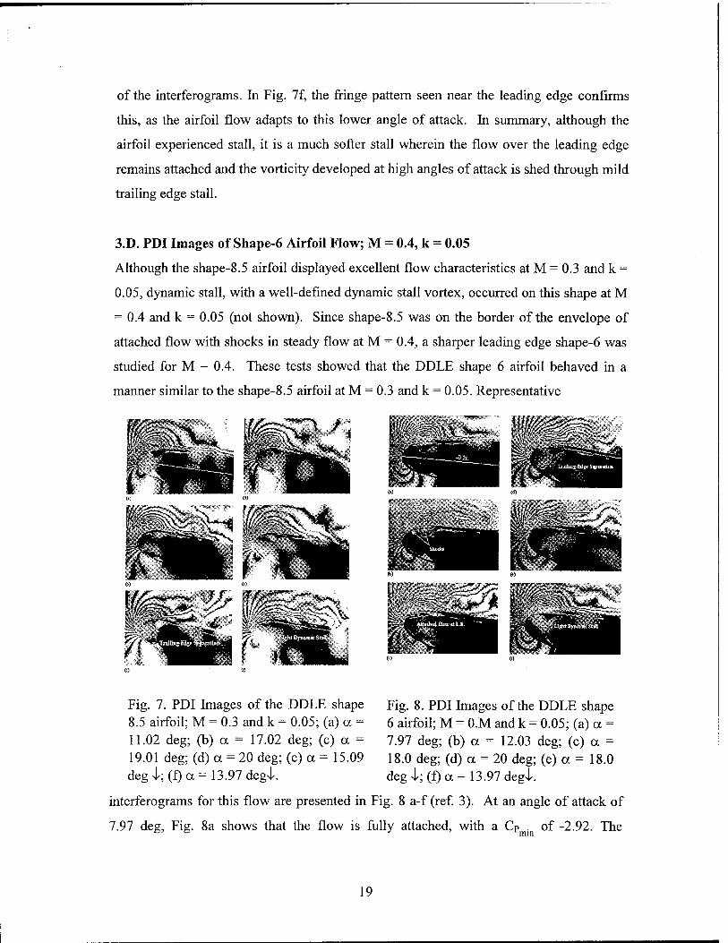
Fig. 7. PDI Images of the DDLE shape 8.5 airfoil; M = 0.3 and k = 0.05; (a) a = 11.02
deg; (b) a = 17.02 deg; (c) a = 19.01 deg; (d) a = 20 deg; (e) a = 15.09 deg I; (f) a =
13.97 deg^.
Fig. 8. PDI Images of the DDLE shape 6 airfoil; M = 0.M and k = 0.05; (a) a = 7.97
deg;(b) a = 12.03 deg; (c) a = 18.0 deg; (d) a = 20 deg; (e) a = 18.0 deg I; (f) a = 13.97
deg^.
Fig. 9. Vorticity flux distributions; M = 0.3 and k = 0.05. (a) DDLE shape 8.5 airfoil,
upstroke; (b) DDLE shape 8.5 airfoil, downstroke; and (c) NACA 0012 airfoil.
Fig. 10. PDI Images of flow over the shape adapting while pitching (SAP) airfoil; M =
0.3, k = 0.05 and rapid adaptation.
Fig. 11. Comparison of peak suction development over the SAP, shape 8.5 and NACA
0012 airfoils; M = 0.3 and k = 0.05.
Fig. 12. Vorticity flux development over the shape 8.5 and SAP airfoils; M = 0.3 and k =
0.05.
Fig. 13. Typical DDLE airfoil shape-change profile, M = 0.4 and k = 0.05.
Fig. 14. PDI Images of flow over the NACA 0012 airfoil, M = 0.4 and k = 0.05; (a) a =
10.0 deg, (b) a - 10.5 deg and (c) a = 12.5 deg.
Fig. 15. PDI Images of flow over the DDLE airfoil, M = 0.4 and k = 0.05; (a) a = 9.0
deg, shape 5.9; (b) a = 13.0 deg, shape 5.7; (c) a = 19.0 deg, shape 5.6; (d) a = 20.0 deg,
shape 5.6; (e) a = 18.1 deg -l, shape 4.7; and (f) a = 15.1 deg -i, shape 1.5.
Fig. 16. Development of suction peak on various airfoil configuration for M = 0.4 and k =
0.05.
Fig. 17. Attached flow envelopes for the DDLE airfoil for M = 0.3, 0.35 and 0.45.
Fig. 18. Heat flux gage outputs on the NACA 0012 airfoil upper surface, M = 0.3, k -
0.05 and upstroke.
Fig. 19. Heat flux gage outputs on the NACA 0012 airfoil upper surface, M = 0.3 and k =
0.05, upstroke, Surface map showing the rapid movement of transition point.
Fig. 20. Heat flux gage outputs on the NACA 0012 airfoil upper surface in the bubble
region, M = 0.3 and k = 0.05 and upstroke.
Fig. 21. Heat flux gage outputs on the NACA 0012 airfoil upper surface showing
reattachment, M = 0.3, k = 0.05 and downstroke.
Fig. 22. Heat flux gage outputs on the NACA 0012 airfoil upper surface showing shocks
and shock-induced dynamic stall onset, M = 0.45 and k = 0.05.

1. STATEMENT OF THE PROBLEM STUDIED
Prior ARO funded research established that compressible dynamic stall onset
mechanisms are very sensitive to leading edge flow over an airfoil and the phenomenon
is dominated by the generation of a large amount of coherent vorticity near the leading
edge. Thus, controlling dynamic stall requires "solutions" that can alter the leading edge
flow vorticity dynamics, generally not possible given the fixed geometry of an airfoil. It
is for this reason that the concept of the dynamically deforming leading edge(DDLE)
airfoil was developed. The DDLE airfoil can be continuously adapted to attain the "right"
shape for each instantaneous flow condition to prevent flow separation and the dynamic
stall vortex from forming. It is also of interest to identify the limits of such an approach to
prevent unintended consequences such as premature dynamic stall onset. Determination
of the appropriate shapes for which the solution is valid requires an extensive
understanding of the fundamental fluid mechanics of the interactions of the unsteady flow
occurring under the influence of the time scales of airfoil reduced frequency and dynamic
leading edge adaptation at different flow conditions. A major goal of the study was to
develop this knowledge.
Another important flow feature of interest is the behavior of transition in this flow. The
location of the transition point moves dramatically as the airfoil pitches up. Hence, it was
decided to study the surface flow using densely spaced hot film gages to identify the flow
events that govern the onset mechanisms. This information is also valuable in
computational modeling of the flow since all flow calculations have so far assumed either
fully laminar or turbulent flow, with a few exceptions that use a fixed transition location.
A conventional NACA 0012 airfoil was instrumented with 148 such gages with about 60
gages located on the upper surface in the first 25% of chord (40 sensors/in) for this
purpose and the flow over it was investigated.
This report summarizes the key results (drawn from the references listed in the
Bibliography, Sec. 8) from these two components of the study.

Nomenclature
Cp pressure coefficient
cp . peak suction pressure coefficient
C airfoil chord
f frequency of oscillation, Hz
k reduced frequency = n f c /U«,
M freestream Mach number
P static pressure
s, n coordinates along and normal to airfoil surface
x,y chordwise and vertical distance
a angle of attack
a0 mean angle of attack
Q spanwise component of vorticity
2. DESCRIPTION OF THE EXPERIMENT
2.1 The Compressible Dynamic Stall Facility
The experiments were carried out in the Compressible Dynamic Stall Facility (CDSF)
located in the Fluid Mechanics Laboratory(FML) of NASA Ames Research Center.
NASA and FML provided much of the instrumentation and material needed for the
research. The nonintrusive optical flow measurement technique of Point Diffraction
Interferometry (PDI) was used in the study. The details of the facility and the DDLE
airfoil have been discussed in Ref. 1 and hence, only a very brief description is given
below.
The CDSF is an in-draft wind tunnel driven by a 6MW, 240,000 CFM continuously
running evacuation compressor with a lOin x 14in test section and allows for a sinusoidal
variation of the airfoil angle of attack, as follows: 0 < ccm < 15°, 2° < a0< 10° and 0 < f <
lOOHz. A variable area downstream-throat is used to control the tunnel Mach number
over the range 0.1 < M < 0.5. Optical access from the stagnation point on the lower
surface to x/c = 0.4 on the upper surface is available with this model mounting
arrangement. Flow studies over a 6-inch chord NACA 0012 supported between optical
glass inserts in metal ports in the tunnel sidewalls are reported here.
2.2 The DDLE Airfoil
The philosophy used for the design of the DDLE airfoil was: relative to that of the fixed
geometry airfoil,
1. reduce the suction peak pressures at high angles of attack
2. reduce the strong adverse pressure gradient
3. distribute the suction pressure over a wider region of the upper surface in order to
improve the airfoil performance.
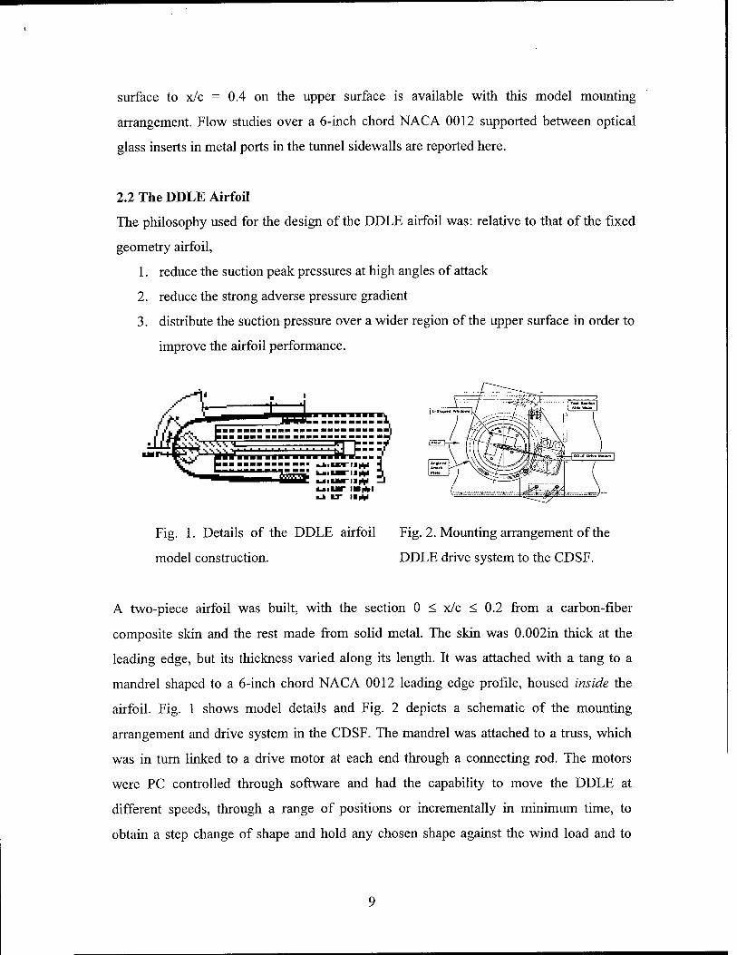
Fig. 1. Details of the DDLE airfoil Fig. 2. Mounting arrangement of the
model construction. DDLE drive system to the CDSF.
A two-piece airfoil was built, with the section 0 < x/c < 0.2 from a carbon-fiber
composite skin and the rest made from solid metal. The skin was 0.002in thick at the
leading edge, but its thickness varied along its length. It was attached with a tang to a
mandrel shaped to a 6-inch chord NACA 0012 leading edge profile, housed inside the
airfoil. Fig. 1 shows model details and Fig. 2 depicts a schematic of the mounting
arrangement and drive system in the CDSF. The mandrel was attached to a truss, which
was in turn linked to a drive motor at each end through a connecting rod. The motors
were PC controlled through software and had the capability to move the DDLE at
different speeds, through a range of positions or incrementally in minimum time, to
obtain a step change of shape and hold any chosen shape against the wind load and to
complete the required movements without jitter during movement or oscillations.
Additional details of DDLE design, fabrication and control system are described in ref. 1.
2.3 The Deformation Schedule
One of the major goals of the study was to establish the hitherto unknown fluid
mechanics of flow over such airfoils. With the particular design developed for this study,
it was possible to vary the airfoil leading edge curvature by as much as 320% (from
0.095in radius to 0.30in radius) through a maximum leading edge retraction of 0.08in to
produce dramatic flow changes around its leading edge and near the location of
compressible dynamic stall onset. In this report, the various DDLE airfoil shapes used
are identified by numbers, with shape 0 corresponding to that of NACA 0012. An integer
shape change occurs when the airfoil chord is changed by 0.003in.
30 -to tirn e(ms)
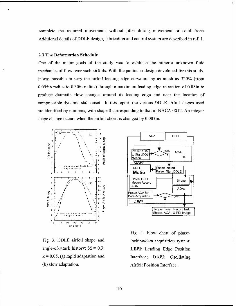
Fig. 3. DDLE airfoil shape and
angle-of-attack history; M = 0.3,
k = 0.05, (a) rapid adaptation and
(b) slow adaptation.
Trigger Laser, Record Inst. Shape, AOA2, & PDI Image
Fig. 4. Flow chart of phase-
locking/data acquisition system;
LEPI: Leading Edge Position
Interface; OAPI: Oscillating
Airfoil Position Interface.
10
A typical deformation schedule consists of rounding the nose from the original NACA
0012 shape by retracting the leading edge, holding the final shape for a dwell period, and
extending the leading edge back to the original shape. Steady flow studies were used to
identify stall free geometries which served as a basis to identify possible dynamic stall
vortex-free geometries, based on which oscillating airfoil shape change schedules that
offered the most potential for success were determined. Many different shape change
schedules were used during the study. Two shape-change schedules, one fast and the
other slow, along with the corresponding angle of attack variations, that were used for M
= 0.3, k = 0.05 are shown in Fig. 3. The oscillations in the output response of the
feedback system were minimized during the system tuning process for each condition to
maintain the DDLE airfoil shape to within a half-integer of the final round shape during
deformation.
2.4 Phase Locking Instrumentation
The deforming leading edge shape change is phase locked to the desired airfoil angle of
attack in its sinusoidal motion cycle as shown in the flow chart in Fig. 4. Special circuitry
was designed and built for this purpose. This is known as the Leading Edge Position
Interface (LEPI) and works in conjunction with an existing Oscillating Airfoil Position
Interface (OAPI) that was used to phase lock the airfoil angle of attack for PDI imaging.
The motion was initiated by triggering the DDLE servomotor controller through a signal
conditioner unit at a pre selected airfoil angle of attack. When a match occurred between
the selected and actual angles of attack, the trigger pulse issued by the OAPI activated the
DDLE motion controller unit, which was subsequently controlled by the pre-loaded (from
the PC) software as shown in Fig. 4. A slightly varying time delay (attributable to
ongoing real-time processing within the PID loop) exists in the controller leading to some
uncertainty (of the order of a few encoder counts) in phase locking. Since this problem
could not be eliminated, the simple solution of repeating the experiments was used
satisfactorily to acquire data sets within a narrow airfoil angle of attack window of its
deformation.
11
2.5 Instrumentation and Techniques
As stated earlier, PDI was used in the study to obtain quantitative flow field density
information. Its optical arrangement was similar to that of a standard Z-type schlieren
system, but the light source was a laser beam expanded (to 15 cm) to fill the field of view
of interest in the test section. The optics was aligned to minimize astigmatism. The knife-
edge was replaced by a pre-developed, but not fixed, (partially transmitting) photographic
plate (AGFA 8E75HD). This was necessary to burn an appropriate sized pinhole in it to
serve as the point diffractor and generate the reference beam. Imaging optics was set up
further downstream along the beam path for recording the flow. With no flow in the test
section, a pinhole was created in situ in the photographic plate. Light refracted by the
flow density changes (signal beam) focused to a slightly different spot overlapping the
point diffractor and passed through the partially transmitting photographic plate,
interfering with light passing through the pin-hole (which thus becomes the reference
beam) to produce interference fringes in real time, which were then recorded on Polaroid
film. Ref. 2 fully describes the technique and its implementation in the CDSF.
2.6 Interferogram Image Processing
Several hundred interferograms were obtained during the experiment. These were
scanned and processed manually using a software package developed in-house. Both
surface and global pressure fields have been derived from the interferograms.
In these PDI images, it must be noted that increasing positive fringe numbers represent
flow deceleration and vice versa. Hence, fringes from the freestream to the stagnation
point have positive values, with the freestream fringe having a value of 0. The
corresponding pressure along a fringe, up to the boundary layer edge, was derived using
isentropic flow relations as:
/ V 1 _p_ -1
\Po) p
2
For the specific case of the present experiments, p - pr= 0.009421s
12
or
ÜL = ^ + 0.00942 le Go 6o
Since p/po is a function of the freestream Mach number only, p/po can be determined by
knowing the fringe number. The pressure at the edge of the boundary layer was then used
as the surface pressure under the boundary layer assumptions.
2.7 Experimental Conditions
The experiments were conducted for a flow Mach number range from 0.2 < M < 0.45.
The corresponding Reynolds number ranged from 0.54xl06 - 1.6xl06. Three separate
studies were completed during the study: The first one involved PDI imaging of the flow
past airfoil of shapes from 0 - 22 at angles of attack of up to 20 deg, in steady flow over
the above Mach number range. This was used to develop the attached flow envelope to be
described later. Dynamic leading edge deformation at two rates was then used to identify
the effects of the deformation time scale on the flow behavior. Based on the steady flow
results, certain airfoils with fixed leading edge shapes were tested for their dynamic stall
behavior when the angle of attack was varied as a = 10°+10°sin©t. In particular, shape-2,
shape-4, shape-6, shape-8, shape-8.5 and shape-10 were tested. The oscillation frequency
was varied from 0-28 Hz, resulting in reduced frequencies from 0 - 0.1. Some shapes
such as shape-8.5, shape-6, etc were found to be dynamic stall free. Since in use, a rotor
has to have a sharp nose on the transonic advancing side and a rounded nose on the
slower retreating side of flight, it was essential to verify the validity of the dynamic
deforming leading edge approach in controlling dynamic stall when its angle of attack
was also varied, with two time scales dominating the flow. These tests were also carried
out. From the information generated, it was concluded that a shape change schedule from
0 - 8.5 for M = 0.3 and from 0 - 6 for M = 0.4 provided the best opportunity for
controlling dynamic stall, which were then tested.
2.8 Experimental Uncertainties
The estimated uncertainties in the data are as follows:
Mach number: ± 0.005
13
angle of attack: 0.05 deg
reduced frequency: 0.005
airfoil shape number: 0.05
airfoil displacement: 4 (am
Cp: ±0.1
CP . : mm
-5%
dCp/d(x/c) (vorticity flux): ±25
change in a during DDLE
movement: ± 0.25°
The uncertainty in Cp depends on the fringe number under consideration and is 1 fringe
for the flow in general with about 3 fringes possibly undetectable near the suction peak at
M = 0.3. Since correction for solid and wake blockage was less than 5% for Cp = -6.0 at
M = 0.3, a = 12°, only uncorrected PDI derived pressures are reported. The losses in the
tunnel screens causing a decrease in the stagnation pressure have been included in the
computation of the reference density in this otherwise atmospheric flow wind tunnel.
3. RESULTS AND DISCUSSION
3.A. Characterization of Deforming Leading Edge Airfoil Flow Regimes; M =0.3
The flow over the various airfoil shapes produced by deforming the airfoil leading edge
was mapped as a function of angle of attack and leading edge shape for both fixed and
dynamically changing airfoil shapes (see ref 3). In all cases the airfoil was brought to a
fixed angle of attack and held there while the leading-edge shape was varied. Each static-
shape was held for several seconds before the flow was imaged. For the unsteady cases
the leading edge was pulled back from shape-0 to shape-22 at different rates and the flow
was conditionally sampled during the leading-edge motion by phase-locking the PDI
system to one operator-selected shape per motion.
14
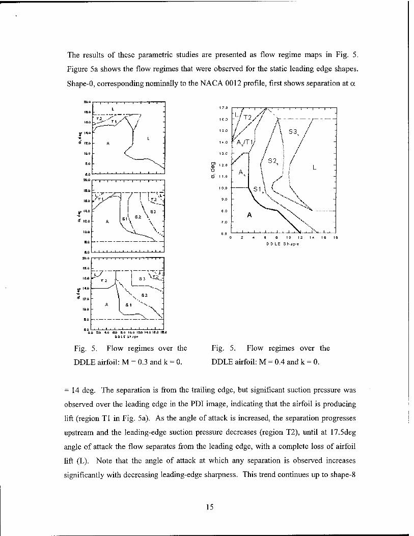
The results of these parametric studies are presented as flow regime maps in Fig. 5.
Figure 5a shows the flow regimes that were observed for the static leading edge shapes.
Shape-0, corresponding nominally to the NACA 0012 profile, first shows separation at a
IB.fi
lau
y. I4.fi -n
■ 1 ■ 1 ■ 1
A
"1 ■ l ■ l ■ 1 ■ 1 ■
! \ « -
■ ' ■ ■ i ■ i ■ i ■
>III -i-T r 1 I 1 I 1 '
\ A
. _x_ > ,1.1 .1.1.1.1.
Ü.Ü Eü 4.Ü Oil B.Ü iaü IEÜ 14.ü Idxl IH.Ü DDIC ih jp*
Fig. 5. Flow regimes over the
DDLE airfoil: M = 0.3 and k = 0.
i 1 1 1 r-
Fig. 5. Flow regimes over the
DDLE airfoil: M = 0.4 and k = 0.
= 14 deg. The separation is from the trailing edge, but significant suction pressure was
observed over the leading edge in the PDI image, indicating that the airfoil is producing
lift (region Tl in Fig. 5a). As the angle of attack is increased, the separation progresses
upstream and the leading-edge suction pressure decreases (region T2), until at 17.5deg
angle of attack the flow separates from the leading edge, with a complete loss of airfoil
lift (L). Note that the angle of attack at which any separation is observed increases
significantly with decreasing leading-edge sharpness. This trend continues up to shape-8
15

for which no separation is observed until a = 17 deg, while significant leading edge
suction remains until the airfoil reaches 18 deg angle of attack. This region of leading
edge suction at high angle of attack remains for shapes up to shape-12, although a high
frequency vortex-shedding phenomenon appears at these higher-number shapes.
Abrupt leading-edge stall occurs at higher leading edge displacements; in fact, stall
occurs at a as low as 10 deg for shape-8. It is clear form Fig. 5a that stall can be delayed
up to an angle of attack of 18 degrees for a range of airfoil shapes around shape-8. It can
also be seen that separated flow at high a on a sharp-nosed airfoil can be made to reattach
by rounding the leading edge.
Rapidly changing the leading edge shape at a fixed angle of attack results in the
development of a flow pattern very suggestive of the dynamic stall of an oscillating
airfoil. This pattern can be seen in the interferograms presented in Ref. (3). The flow
behavior at this deformation rate is not significantly different from that observed for fixed
shapes (Fig. 5a) for shapes up to shape-6. Beyond shape-6 a fringe pattern similar to
incipient dynamic stall vortex formation appears (denoted as SI in Fig. 5b). This
becomes an organized structure, which grows in size (regime S2), and moves
downstream along the airfoil surface (regime S3). Only at angles of attack greater than
15 deg and for shapes rounder than shape-16 was complete leading-edge stall observed.
The flow regimes observed while changing the leading edge shape at the highest rate
studied are shown in Fig. 5c. Again, as for the slow rate, a dynamic-stall-like vortex
develops for shapes above shape-6. However, the fully attached flow regime is limited to
angles below 14 deg; the static stall angle observed for the NACA 0012 profile. In
analyzing the parts of Fig. 5, it is clear that the attached flow envelope shrinks as the rate
of deformation is increased. Thus, unsteady shape change at the rates used here has
caused the flow vorticity and stall behavior to be unfavorably influenced. The fact that
the intermediate shapes encountered are inappropriate for the flow conditions at the
angles of attack of interest is responsible for this. Since any shape adaptation involves a
16
rate of change of leading edge curvature, the shrinkage of the attached-flow regime
suggests that a slower deformation rate is preferable at this freestream condition.
3.B. Characteristics of the DDLE Airfoil Flow at M = 0.4, Steady Flow
Figure 6 (ref 3) shows the flow regimes as a function of static airfoil leading edge
curvature and static angles of attack in steady flow at M = 0.4. Based on comparisons of
interferograms (not shown) the flow over the shape-0 airfoil is similar to that over the
NACA 0012 airfoil. Shocks develop in this flow at a « lOdeg and the airfoil experiences
leading edge stall at around 14 degrees (denoted as L in Fig. 6). As the nose radius is
increased at a = 6deg, the flow remains attached until shape-12 is reached. For angles of
up to 16 deg and shapes up to 4, shocks are present in the flow, but the flow does not
separate; this regime is labeled As in Fig. 6. A fringe counting shows that the Mach
number is as high as 1.2 at the foot of the shocks. Eventually, the shocks induce a small-
scale separation above 12 deg for shape-4 and beyond (Sis). Even with the shocks
present over the upper surface, the flow remains in that state until angles of attack of
about 17 deg when leading edge stall occurs. This stall angle is much higher than the 12
deg stall angle observed for the NACA 0012, showing the considerable alleviation of
separation that can be obtained by rounding the leading edge.
The small-scale separation grows progressively more severe for rounder leading edge
shapes (regimes S2s and S3s), and eventually complete separation from the leading edge
is observed.
3.C. Flow Details Over Shape-8.5 Airfoil; M = 0.3, k = 0.05
As discussed for Fig. 5a, there exists a range of airfoil shapes in flow at M - 0.3 in which
flow separation is delayed up to a = 18deg, for the steady conditions. Thus, it was
decided to investigate the behavior of an oscillating airfoil with a fixed nose shape within
this range as the next step in assessing the effectiveness of the DDLE airfoil concept for
achieving dynamic stall control. Several airfoils having leading edge shapes similar to
shape-8 were tested while executing sinusoidal pitching oscillations. In the tests, the
DDLE leading edge curvature was held fixed at a predetermined value. Flow images over
17
the shape-8.5 airfoil will be presented below since this shape provided the maximum
delay of unsteady separation, while noting that the flow over shapes-7.5 and 8 were
qualitatively similar.
The PDI image (ref. 3) in Fig. 7a for a = 11.02deg indicates that the flow is attached
everywhere because the fringes turn smoothly around the airfoil nose and return
gradually towards the surface and the boundary layer fringes run nearly parallel to the
surface; a pattern observed in prior tests during attached flow conditions. Since the
fringes represent constant density lines and the flow is attached, the image also presents
global and surface pressure information. A similar flow pattern is present even at a =
17.02deg, Fig. 7b (note that there is some separation downstream of the leading edge, but
the flow near the leading edge is attached). For comparison, deep dynamic stall was
found to occur (Ref. 4) by a = 16deg over an oscillating NACA 0012 airfoil at these
same flow conditions, with a corresponding loss in leading-edge suction, whereas in the
present case, the flow near the leading edge is still attached at 17 deg. At a = 19.01deg
(Fig. 7c), a larger region of separated flow can be seen towards the rear of the airfoil, but
even at this high angle of attack, the leading edge flow is fully attached. The separation
seen in the image is trailing edge flow reversal moving upstream. Figure 7d shows that
the leading edge flow is attached also at a = 20.0deg; this is a major improvement of the
flow behavior. An even more important result is the absence of the dynamic stall vortex
in the separated flow region in complete contrast to what is normally seen on oscillating
airfoils. Thus, for the DDLE shape-8.5 airfoil it has been possible to maintain a vortex-
free flow at all angles of attack during oscillation. This is a significant result because the
strong and detrimental pitching moment variations concomitant with a convecting vortex
have now been eliminated on this single element airfoil, even at high angles of attack.
The attached leading edge flow allows the airfoil to continuously produce lift throughout
the upstroke. During the downstroke, the flow reattaches towards the trailing edge, Fig.
7e a = 15.49deg) and 7f (a = 13.97deg). As the airfoil develops less lift at the lower
angles of attack, the leading edge vorticity must be shed, which seems to happen through
the occurrence of light dynamic stall over a small angle of attack range, based on analysis
18
of the interferograms. In Fig. 7f, the fringe pattern seen near the leading edge confirms
this, as the airfoil flow adapts to this lower angle of attack. In summary, although the
airfoil experienced stall, it is a much softer stall wherein the flow over the leading edge
remains attached and the vorticity developed at high angles of attack is shed through mild
trailing edge stall.
3.D. PDI Images of Shape-6 Airfoil Flow; M = 0.4, k = 0.05
Although the shape-8.5 airfoil displayed excellent flow characteristics at M = 0.3 and k =
0.05, dynamic stall, with a well-defined dynamic stall vortex, occurred on this shape at M
- 0.4 and k = 0.05 (not shown). Since shape-8.5 was on the border of the envelope of
attached flow with shocks in steady flow at M = 0.4, a sharper leading edge shape-6 was
studied for M = 0.4. These tests showed that the DDLE shape 6 airfoil behaved in a
manner similar to the shape-8.5 airfoil at M = 0.3 and k = 0.05. Representative
Sir W/^P^i
Fig. 7. PDI Images of the DDLE shape 8.5 airfoil; M = 0.3 and k = 0.05; (a) a = 11.02 deg; (b) a = 17.02 deg; (c) a = 19.01 deg; (d) a = 20 deg; (e) a = 15.09 deg^;(f)a= 13.97 degi.
Fig. 8. PDI Images of the DDLE shape 6 airfoil; M = 0.M and k = 0.05; (a) a = 7.97 deg; (b) a = 12.03 deg; (c) a = 18.0 deg; (d) a = 20 deg; (e) a = 18.0 deg 4; (f) a =13.97 deg!.
interferograms for this flow are presented in Fig. 8 a-f (ref. 3). At an angle of attack of
7.97 deg, Fig. 8a shows that the flow is fully attached, with a CP . of -2.92. The
19

interferograms showed a fringe pattern with two peaks by a = lOdeg (not shown). The
critical Cp . of-3.66 was also exceeded by this angle and shocks appeared at higher
angles. Figure 8b shows the multiple shocks which formed at a = 11.98 deg. Some flow
disturbances can be seen at the foot of the last shock in the figure; however, the fringes
indicate attached flow. This flow pattern continued until a = 16deg, when trailing edge
separation was seen (not shown). Figure 8c shows for a = 18deg that the leading edge
flow is still attached, although with fewer fringes, and shows some trailing edge
separation beyond x/c « 0.3. The decrease in the number fringes represents a
corresponding decrease in the local peak suction value, which is about -3.24 for this case.
It is believed that the increased wake width due to trailing edge separation has altered the
airfoil pressure distribution, and has caused the leading edge flow to become subsonic
again. Figure 8d for a = 20deg shows that the trailing edge separation has progressed to
x/c « 0.15, yet the leading edge flow remains attached at the top of the upstroke. During
the downstroke, the separated portion of the flow reattaches progressively toward the
trailing edge. Attached flow can be seen up to x/c « 0.25 in Fig. 8e for a = 18deg. At an
angle of attack of 13.97 deg, Fig. 8f, the flow appears to have fully reattached, but the
fringes near x/c «0.1-0.15 show an incipient vortex, like the light dynamic stall seen for
the shape 8.5 airfoil at M = 0.3 and k = 0.05 (Fig. 8f). It seems that shape-6 provides the
conditions to prevent the formation of a deep dynamic stall vortex and the corresponding
strong pitching moment variations. The formation of shocks in the flow implies that the
stall onset mechanisms for these conditions are significantly different from those at M =
0.3. That the DDLE airfoil did not experience abrupt dynamic stall even at this Mach
number confirms the applicability of the concept for a variety of flow conditions.
3.E. Airfoil Pressure and Vorticity Flux Distributions; M = 0.3, k = 0.05
As described by Reynolds and Carr 5, when no transpiration is present, the vorticity flux
in a flow with a moving surface is given in simplified form by
dQ. dU 1 dp v = - + -
ön dt Q 3s
20

An order or magnitude analysis (ref. 3) shows that the surface acceleration term in the
above equation is about 2 orders smaller and hence can be neglected initially. Thus, one
can obtain the vorticity fluxes from the pressure distributions by simply taking the
derivative with respect to distance along the airfoil surface.
Co as o.o
00 0.0
25 0 0
20 0.0
15 0.0
10 0.0
SO.O
0.0
- SO.O
10 0.0
1 1 ' 1
a 1 ' 1
- o
_ *• « IS .00° - ■J
Ä A 17 .0 2°
► ¥■ 19.0 2*
G —0 19 .5 9*
-
y-~ -*20 .00
S2i" /* , - ns^^ v^^- Ät^iT^
1 J 1/ I.I.I
-
(b)
u -a
<3 ©7.02
9
# Ä- - — A 10.00
i \ ►— *■ 1 .02 \ ■O— 0 2.98
X—- —- -X 3. *8
^äfcgte*-
Fig. 9. Vorticity flux distributions; M = 0.3 and k = 0.05. (a) DDLE shape 8.5 airfoil,
upstroke; (b) DDLE shape 8.5 airfoil, downstroke; and (c) NACA 0012 airfoil.
The vorticity fluxes calculated from the pressure distributions are plotted in Fig. 9a
and 9b for the shape-8.5 airfoil and Fig. 9c for the NACA 0012 airfoil. The distributions
21

in Fig. 9a for the airfoil upstroke show that generally there are two peaks in vorticity flux
for the higher angles shown; a larger amplitude narrow one at the suction peak location
and a smaller amplitude, wider one further downstream. For smaller angles the two peaks
are away from the leading edge region. The larger peaks shown have about twice the
amplitude of the smaller peaks, but the latter are several times wider. Since the area under
the curve gives the total vorticity production, the broader distributions provide a greater
contribution to this term. As the angle of attack increases, the second peak moves
progressively closer to the leading edge; for example it is at x/c = 0.08 for a = 11.02deg
and at x/c = 0.04 for a = 19deg. As the airfoil reaches the top of the cycle, there is a
reduction in the peak vorticity flux that is produced because the degree of unsteadiness
decreases to zero. Also, the data indicate a movement of the vorticity flux peaks toward
the trailing edge for a = 19.59deg and a = 20deg. The maximum value indicated in the
graph is about 230 for the first peak for a = 17deg, but generally the value for most
distributions in the second peak is around 100-125. The decrease in the first peak for a >
17deg may be attributable to the trailing edge separation that was discussed in Sec. C.
During the airfoil downstroke the peak values drop as the angle of attack is decreased and
the peak also moves towards the trailing edge. It should be noted that the vorticity has to
decrease due to the decreasing angle of attack and the excess vorticity has to be shed in
order for the Dflow to adjust to the rapidly changing conditions Din Fig. 9c the
distribution of vorticity flux for the NACA 0012 airfoil peaks with a magnitude of around
250. At a low angle of attack of 8deg this peak is centered near x/c = 0.04, but it moves
close to the leading edge and is around x/c = 0.025 for 13deg with a magnitude of about
350. The PDI images for the NACA 0012 airfoil show that dynamic stall ensued at a =
14deg for this Dcase. Also, no trailing edge separation could be identified in the PDI
images of the NACA 0012 Dfor this case; the trailing-edge separation appears to provide
a mechanism for shedding the vorticity at the high angles at which the DDLE airfoil was
tested. It is believed that for the vorticity to coalesce into a vortex, these sharp high peak
values are necessary. The vortex thus formed has to be convected by the flow.
Eventually, flow separation follows, causing unacceptably large hysteresis in the load and
moment loops. By carefully lowering the peak levels, and distributing the total vorticity
22

over a greater area on the airfoil upper surface, it becomes possible to keep the flow
attached and produce lift at low drag values until higher angles of attack.
3.F. Characteristics of the DDLE Airfoil Flow at M = 0.3, k = 0.05
In this section, the results for the case of the dynamically deforming leading edge airfoil
will be discussed. Whereas the previous two sections have shown the superior
performance of certain fixed shape airfoils, the need for a DDLE airfoil arises in the
helicopter case because the rotor blade has to fly through a large speed range. The
transonic advancing side requires a sharper nose compared to the lower speed retreating
side. Thus, dynamic adaptation becomes necessary. As a consequence, two time scales
ce= 12.03°, Shape* 2 a - 15.00°, Shape «»7.5 a= 17.01°, Shape»» 7
«= IS.O^l.ShapeW' a- 16.00°4, Shape* 6.5 a = 15.02°4, Shape* 5
Fig. 10. PDI Images of flow over the SAP airfoil; M = 0.3, k = 0.05 and
rapid adaptation
enter the flow physics and it becomes important to identify if this causes any fundamental
flow changes.
The PDI images of the flow at M = 0.3 and k = 0.05 over the DDLE airfoil adapted from
shape-0 (NACA 0012) to shape-8.5 are presented in Fig. 10 (ref. 6). These interferograms
were recorded at different angles of attack for the fast schedule used. It is clear from the
23

fringe pattern in Fig. 10 that the flow is fully attached at a = 12.03 deg, for shape 2.
Attached flow is also seen for a = 15 deg, for shape-7.5, although some disturbance is
noticeable in this figure near x/c «0.1. Results presented in ref. 3 show that the flow over
the fixed, shape-8.5, airfoil generally behaves similarly to that seen in Fig. 10 with slight
differences in the angle of attack of the events. It is noted here that on an NACA 0012
airfoil, dynamic stall onset occurs at a = 14 deg at M = 0.3. In contrast, on the DDLE
airfoil, the flow was fully attached (not shown) even at a = 16 deg, highlighting one
benefit of dynamic shape adaptation. Traces of trailing edge separation are present for a
= 17 deg over the shape-7 airfoil, which become more pronounced for a = 18 deg and
for a = 19 deg. A look at the leading edge image reveals the presence of a large number
of fringes in the flow, indicating the continued development of strong leading edge
suction, even when trailing edge separation has progressed up to x/c «0.1 on the upper
surface. At a = 20 deg, the maximum number of fringes has decreased and hence, the
peak suction pressure has dropped, but the leading edge flow remains attached. During
the downstroke, the flow at a = 19 deg and a = 18 deg (not shown) appears similar to
that seen on the upstroke at these angles, the only difference being that the maximum
number of leading edge fringes is fewer on the downstroke. As the return to the original
airfoil shape begins, light dynamic stall is induced at a = 16 deg, in much the same way
as was seen for the fixed shape-8.5 airfoil (ref. 3). This is because the flow has to adjust
to the more favorable conditions- in particular to the lower levels of vorticity flux
associated with these lower angles of attack - to prevent build up of vorticity. Most
interestingly, fully reattached flow develops at the high angle of attack of 15 deg on the
downstroke for the shape-5 airfoil, and the suction peak becomes well established again.
In contrast, at this angle of attack, light dynamic stall was present in the flow over the
fixed shape-8.5 airfoil as reported in ref. 1, leading to the conclusion that the DDLE
airfoil is better than a fixed shape-8.5 airfoil. Fig. 10 also shows that it is possible to
manipulate the flow field in order to keep the leading edge flow attached throughout the
oscillation cycle. Similar results were obtained for the slow schedule also.
24
The major difference between the NACA 0012 airfoil and the DDLE airfoil flow fields is
the absence of the dynamic stall vortex in the latter. Thus, it is clear that the vorticity
fields in the two cases are also different. The absence of the dynamic stall vortex leads to
the deduction that the pitching moment variations over the DDLE airfoil tend to be
milder, and the range of angles of attack over which the flow remains attached
considerably larger when compared to the NACA 0012 airfoil. Dynamic shape adaptation
has successfully altered the flow vorticity field, leading to changes in the airfoil stall
behavior from leading edge type to the trailing edge type. If the time scale of airfoil
oscillation and airfoil adaptation can be carefully matched to diffuse the excess vorticity
on the downstroke, then it may even be possible to avoid the light dynamic stall condition
encountered normally. This requires returning to the original shape very slowly.
However, since the airfoil oscillation frequency is derived from a rotor flow condition,
the airfoil adaptation rates are bounded. Hence, attempts to eliminate the light dynamic
stall state may be impractical in real use.
3.G. Peak Suction Development
In Fig. 11 (ref. 7), the development of the airfoil peak suction pressure coefficient Cp . is
compared for the NACA 0012, fixed shape-8.5, and the DDLE airfoil geometries at the
two deformation rates used. Within experimental uncertainty, the peak suction values for
the two deformation rates show nearly the same variation, even though the shape
adaptation was initiated at different angles of attack. The NACA 0012 airfoil generates
the highest value of Cp . (« -7.5), which indicates that the flow has become locally
supersonic (CPcrit« -7.0 at M = 0.3), however, no shocks are seen. In both the fixed shape
airfoil case and the DDLE airfoil case, CD . just reaches the critical value with the fixed
shape-8.5 airfoil showing a slightly more gradual fall of peak suction pressure. On the
upstroke, the values for the DDLE airfoil are slightly higher, suggesting that the suction
lift over it tends to be marginally higher. Of greater interest is the 30% smaller size of the
peak suction pressure loop for both the DDLE cases. This difference between the fixed
shape-8.5 and DDLE airfoil cases in both the upstroke and downstroke peak suction
25

7.0 11.0 15.0 19.0
Angle of attack a, deg
Fig. II. Comparison of peak suction
development over the SAP, shape 8.5
and NACA 0012 airfoils; M = 0.3
and k = 0.05.
Fig. 12. Vorticity flux development
over the shape 8.5 and SAP airfoils;
M = 0.3 and k = 0.05.
pressures is due to the different extents of trailing edge separation present over the
airfoils since there was no dynamic stall vortex in both flows. Because the flow
reattaches at a = 15 deg for the DDLE cases as opposed to at a « 12 deg for the fixed
shape-8.5 case, its loop is smaller. In contrast, for the NACA 0012 airfoil, the shedding
of the large dynamic stall vortex causes the flow to separate completely. Complete
reartachment does not occur until a « 8 deg on the downstroke (ref. 8). The large Act
between separation and reartachment results in a very large hysteresis loop in the moment
coefficient as well. If shape adaptation were ideal and complete, a difference in the Cp .
development between the upstroke and downstroke would not be present because the
flow vorticity would be diffused through the boundary layer at a rate consistent with its
production throughout the oscillation cycle. This should indeed be the goal of shape
adaptation. In reality, one can only expect to minimize the hysteresis loop so that the
airfoil can deliver a performance that is free from large-scale separation effects. The
results presented here confirm that satisfactory shape adaptation was achieved for this
experimental condition of M = 0.3 and k = 0.05.
26
It is noted here that the shape adaptation for the slow case was initiated at a « 3.8 deg
and for the rapid case at a « 8 deg, these angles being determined from the attached flow
envelope developed in Fig. 5. The primary factor that controls the shape change schedule
is the attached flow envelope for each Mach number. The requirement to satisfy, for
potential success, is that any instantaneous shape reached should be within this
envelope for the flow at any angle to remain attached. The delay in pressure field
development produced due the lag effects of unsteady flow provides some latitude in this
regard.
It was also observed in these studies that initiating the deformation at inappropriate
angles of attack induced premature dynamic stall. Thus, it is very important to determine
the attached flow envelope in steady flow first, before proceeding with dynamic stall flow
control. More details on this can be found in ref. 6.
3.H. Vorticity Flux Distributions
The vorticity fluxes calculated from the PDI derived pressure distributions (see ref. 3) for
the fixed shape-8.5 and the DDLE airfoils are compared in Fig. 12. The large changes in
the potential flow due to large real-time geometry modifications translate to a large effect
on the pressure distribution, which should be seen in the vorticity flux also. At a = 15
deg, the vorticity flux over the rapidly adapted DDLE airfoil is generally lower than that
over the fixed shape-8.5 airfoil. The location of the peak vorticity flux value over the
DDLE airfoil moves toward the trailing edge at x/c « 0.08 in Fig. 12a. No comparisons
can be made with the distributions for the NACA 0012 airfoil since dynamic stall occurs
at a = 14 deg and the flow separates completely by a - 16 deg. However, it was shown
in Sec. E that the vorticity flux distributions over the fixed shape-8.5 airfoil were
significantly superior to that over the NACA 0012 airfoil at the lower angles of attack,
because of its lower maximum value and downstream location of the peaks.
Figure 12 establishes that on the upstroke, the DDLE airfoil flow is generally better than
that of the fixed shape-8.5 airfoil. The peak vorticity flux for the DDLE airfoil moves
27

slightly upstream with increasing angle of attack (from x/c = 0.08 to x/c = 0.05, Fig. 12b-
d), but it is lower than that for the shape-8.5 airfoil. The large peak of 225 seen for the
fixed shape-8.5 airfoil close to the leading edge in Fig. 12b is not observed for the DDLE
airfoil, even though its instantaneous shape of 7.5 attained dynamically is very close to
the fixed shape-8.5. This can be attributed to the extreme sensitivity of the flow to the
dynamic change of leading edge curvature. At a = 20 deg, Fig. 12d, the peak vorticity in
the DDLE airfoil flow drops to about 50% ofthat seen in the fixed shape-8.5 airfoil flow,
occurring at x/c = 0.05. In this, the peak vorticity occurs away from the leading edge and
is significantly lower, when compared to the NACA 0012 airfoil prior to onset of
dynamic stall. This explains why no dynamic stall vortex was observed in the deforming
airfoil flow. On the downstroke at a = 19 deg, Fig. 12e, the DDLE airfoil flow vorticity
level is somewhat higher and leads the fixed shape-8.5 airfoil, a trend that can be traced
to the fact that the peak suction pressure is higher during the downstroke for the DDLE
airfoil. In Fig. 12f, the values for the fixed shape-8.5 airfoil are compared at a = 15.5 deg
with the DDLE airfoil at a = 15 deg. The higher vorticity flux levels suggest that a
somewhat improved lift performance can be expected from the DDLE airfoil because of
the increased circulation due to this vorticity.
3.1. Characteristics of the DDLE Airfoil Flow at M = 0.4, k = 0.05
The DDLE airfoil was adapted from shape-0 to shape-6 in this case based on the attached
flow envelope shown in Fig. 6 (ref. 3). The actual deformation schedule used is shown in
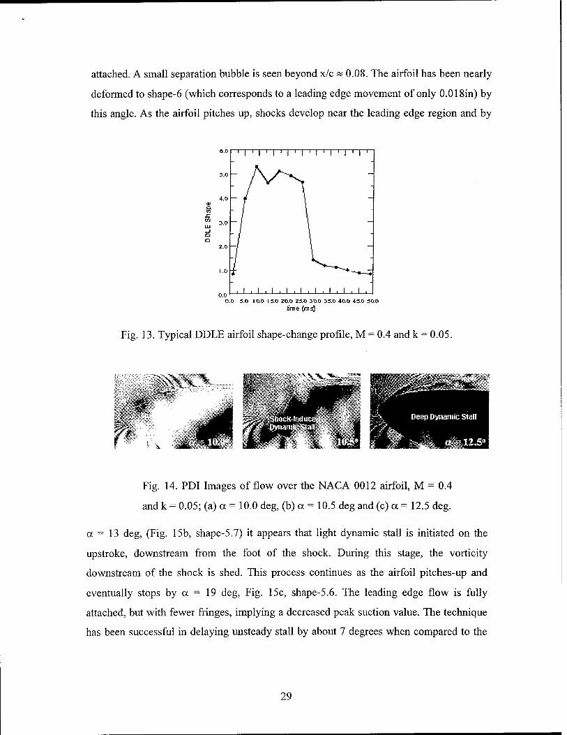
Fig. 13 (ref. 9). Figures 13 and 14 (ref. 9) show the flow development over the NACA
0012 and the DDLE airfoils, respectively. Shocks develop over the former by a = 10 deg
(Fig. 14a) and shock-induced dynamic stall ensues by a = 10.5 deg, (Fig. 14b) with deep
dynamic stall following at a = 12.5 deg as can be seen in Fig. 14c. The figures show that
the whole process occurs over a very small angle of attack range. The flow remains fully
stalled until a « 10 deg on the downstroke.
In contrast, the DDLE airfoil, whose shape is varied from shape-0 to shape-6 shows many
different flow features. At a = 9 deg Fig. 15a, the flow over the leading edge is fully
28
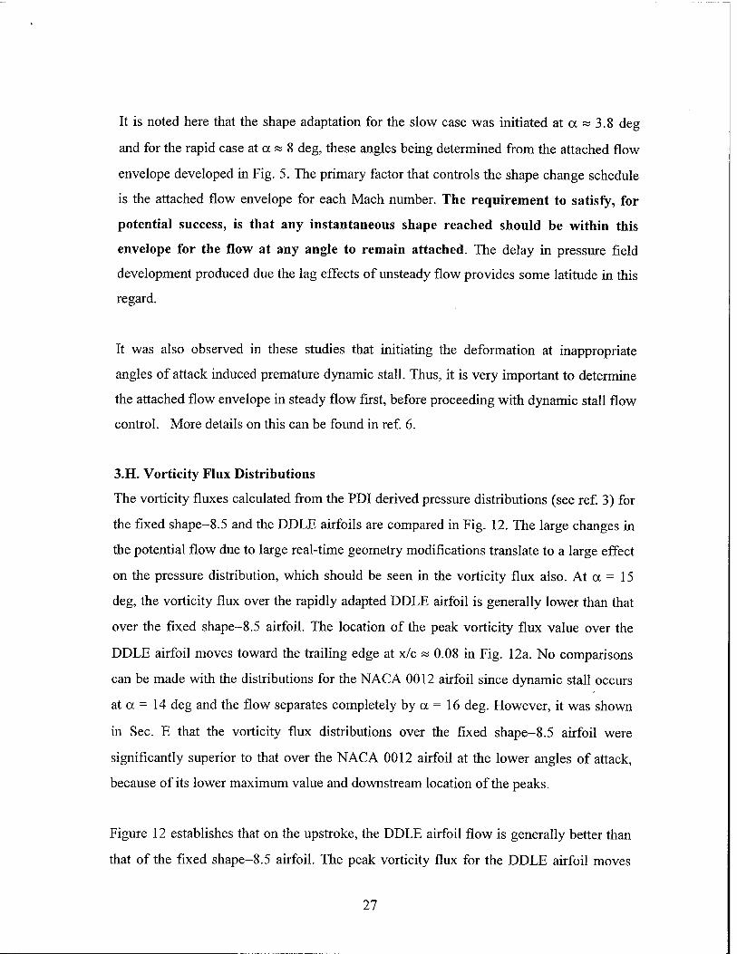
attached. A small separation bubble is seen beyond x/c « 0.08. The airfoil has been nearly
deformed to shape-6 (which corresponds to a leading edge movement of only 0.018in) by
this angle. As the airfoil pitches up, shocks develop near the leading edge region and by
4.0
1 I ' I ' I ' I ' I ' I ' I '
yV>
i . i . i . i . i . i . i . i . i 0.0 3.0 I O.0 I 3.0 20.0 25.0 30.0 310 40.0 430 30.0
time (ms)
Fig. 13. Typical DDLE airfoil shape-change profile, M = 0.4 and k = 0.05.
Fig. 14. PDI Images of flow over the NACA 0012 airfoil, M = 0.4
and k = 0.05; (a) a = 10.0 deg, (b) a = 10.5 deg and (c) a = 12.5 deg.
a = 13 deg, (Fig. 15b, shape-5.7) it appears that light dynamic stall is initiated on the
upstroke, downstream from the foot of the shock. During this stage, the vorticity
downstream of the shock is shed. This process continues as the airfoil pitches-up and
eventually stops by a = 19 deg, Fig. 15c, shape-5.6. The leading edge flow is fully
attached, but with fewer fringes, implying a decreased peak suction value. The technique
has been successful in delaying unsteady stall by about 7 degrees when compared to the
29
fixed NACA 0012 airfoil. Further increase in a results in a brief period of separation
''% Flow Attached aP Leading Edge
0°, Shape 5.6
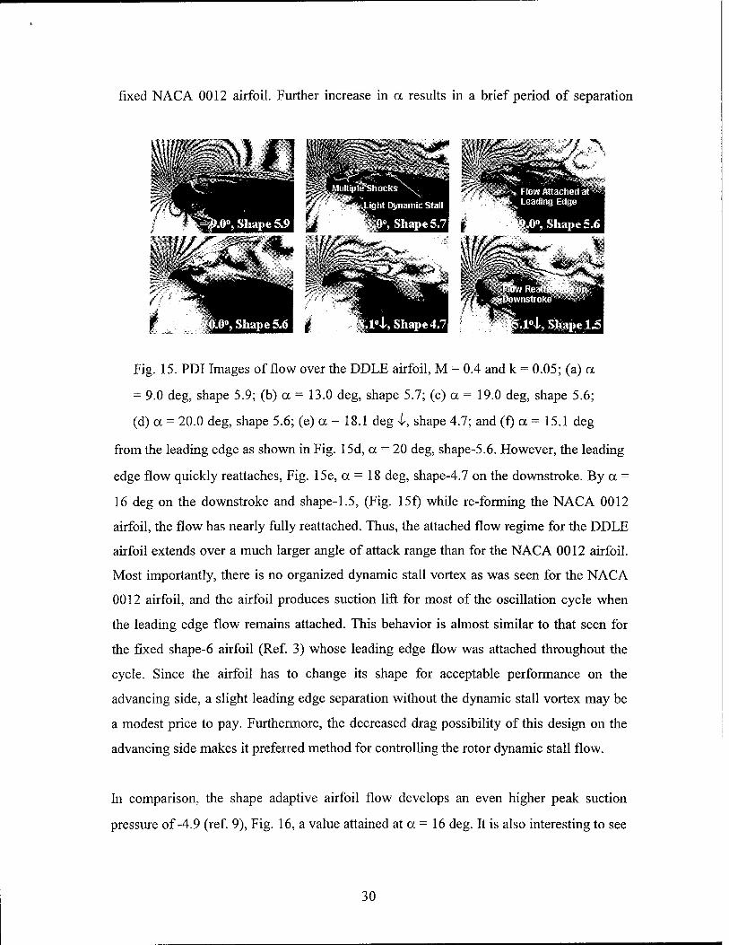
Fig. 15. PDI Images of flow over the DDLE airfoil, M = 0.4 and k = 0.05; (a) a
= 9.0 deg, shape 5.9; (b) a = 13.0 deg, shape 5.7; (c) a = 19.0 deg, shape 5.6;
(d) a = 20.0 deg, shape 5.6; (e) a = 18.1 deg 4, shape 4.7; and (f) a = 15.1 deg
from the leading edge as shown in Fig. 15d, a = 20 deg, shape-5.6. However, the leading
edge flow quickly reattaches, Fig. 15e, a = 18 deg, shape-4.7 on the downstroke. By a =
16 deg on the downstroke and shape-1.5, (Fig. 15f) while re-forming the NACA 0012
airfoil, the flow has nearly fully reattached. Thus, the attached flow regime for the DDLE
airfoil extends over a much larger angle of attack range than for the NACA 0012 airfoil.
Most importantly, there is no organized dynamic stall vortex as was seen for the NACA
0012 airfoil, and the airfoil produces suction lift for most of the oscillation cycle when
the leading edge flow remains attached. This behavior is almost similar to that seen for
the fixed shape-6 airfoil (Ref. 3) whose leading edge flow was attached throughout the
cycle. Since the airfoil has to change its shape for acceptable performance on the
advancing side, a slight leading edge separation without the dynamic stall vortex may be
a modest price to pay. Furthermore, the decreased drag possibility of this design on the
advancing side makes it preferred method for controlling the rotor dynamic stall flow.
In comparison, the shape adaptive airfoil flow develops an even higher peak suction
pressure of-4.9 (ref. 9), Fig. 16, a value attained at a = 16 deg. It is also interesting to see
30

that the CPmm plot appears like the natural extension of the NACA 0012 airfoil as its
shape is adapted. The loss of the suction peak occurs at a rate comparable to that
observed for the slatted airfoil, but as the flow visualization pictures discussed earlier
revealed, the recovery is also quicker and by a = 16 deg on the downstroke, the value is
fairly high at « -3.4. Despite the small amount of flow separation seen, it can be
concluded from Fig. 16 that acceptable shape adaptation can be achieved for this flow
condition.
--nutet ttii
--jLRClt|-**»>l6 Bihjp* i BDDIT
' OJJ 2J> 4J> S.fr 4Ä 10.0 12.fr 14J>> 16-& ia.O 2Ü-JJ
Fig. 16. Development of suction
peak on various airfoil
configuration for M = 0.4 and k =
0.05.
-1—■—i—■—i rrp ■—i ■—i ■—i—■ 1—■ r-
v=a.i « = 0.J4 V=OJ — — DDLE 5tiJp© "law
1i> 12 14 16 14 20
DDLE Shjpe
Fig. 17. Attached flow envelopes for the
DDLE airfoil for M = 0.3, 0.35 and 0.45.
CPmin values that were calculated from the maximum number of fringes seen in Fig. 14
and 15 show that the DDLE airfoil generally develops about 15-20% higher peak suction
values, which is clearly desirable. Thus, shape adaptation, which is necessary to satisfy
the geometry requirements on the advancing side is also beneficial. The reason for the
increased suction peak pressures appears to be the favorable interaction between the two
unsteady time scales present in the flow - namely, the airfoil reduced frequency and the
shape adaptation rate - both of which contribute to the unsteady term in the vorticity flux
equation. Together, these seem to induce a pronounced effect on the vorticity flux
manipulation.
31

3.J. Do Compressibility Effects on Attached Flow Envelope Negate Flow Control
Efforts?
The noticeable reduction of the size of the attached flow envelope for M = 0.4 compared
to M = 0.3 poses the question whether the concept can be indeed be useful in practical
applications, where a rotor blade starts pitching up from a high Mach number of 0.4-0.45.
Because compressibility promotes dynamic stall, its onset occurs at a very low angle of
attack (< 8-10 deg) at M = 0.45. Thus, for this flow to be controlled, the shape adaptation
should be initiated from a rotor azimuthal position where the Mach number is still high at
a low angle of attack. As the rotor retreats, its Mach number decreases and thus, a larger
range of airfoil shapes become available for flow control to progress because of the
expanded attached flow envelope at the lower Mach numbers, as seen in Fig. 17. Thus
flow control can continue well into the retreating side. A possible shape change schedule
is shown in Fig. 17. Since there is a lag in the development of the unsteady flow
development, it may be even possible to exceed the boundaries slightly from that shown.
This leads to the conclusion that the use of the DDLE concept provides significant
opportunity at achieving dynamic stall control.
3.K. Surface Hot Film Gage Studies
In an attempt to understand the events of dynamic stall, the surface shear stress was
qualitatively studied using a dense array of hot film gages. These were mounted on a
solid 6-inch chord NACA 0012 airfoil at a spacing of 40 gages/in from x/c = 0.1 on the
lower surface to x/c = 0.25 on the upper surface. Further downstream, a 4-gage set was
distributed at the same pitch in x/c increments of 0.05. This distribution resulted in a total
of 120 gages on the airfoil upper surface. For ease of reference, the gages are referred to
by their numbers, with gage no. 1 at x/c = 0.95 and gage no. 120 at the leading edge.
Gage number 60 was at x/c = 0.25 due to the high pitch used. These were operated using
TSI hot wire bridges Model 1750/1755 provided by the US Air Force Academy. Data
from 16 sensors was acquired at a time at rates of up to 40KHz per channel.
Since no calibration method exists for quantitative estimation of the skin friction, only a
qualitative analysis of the data was conducted. In the various plots presented here, the
32
ensemble averaged mean value over many cycles has been subtracted and only, the
deviations from this are plotted.
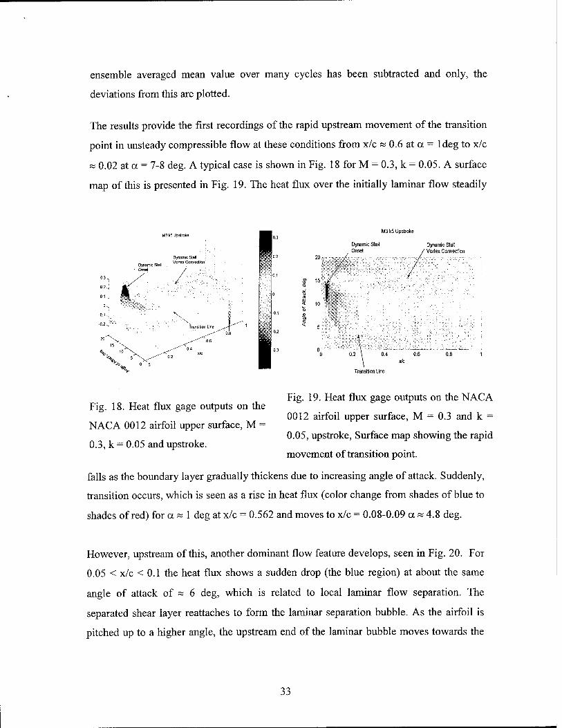
The results provide the first recordings of the rapid upstream movement of the transition
point in unsteady compressible flow at these conditions from x/c « 0.6 at a = ldeg to x/c
« 0.02 at a = 7-8 deg. A typical case is shown in Fig. 18 for M = 0.3, k = 0.05. A surface
map of this is presented in Fig. 19. The heat flux over the initially laminar flow steadily
15 "'
y
Dynamic Stal ~ « . Vörtex Convection: Dynamic SlaP : Onset /
*V
M3k5 Upstroke
Dynamic Stall Onset
< 10
0.2 \
\
Dynamic Stall / Vortex Convection
fc
0.4 0.6
X/c
Fig. 18. Heat flux gage outputs on the
NACA 0012 airfoil upper surface, M =
0.3, k = 0.05 and upstroke.
Fig. 19. Heat flux gage outputs on the NACA
0012 airfoil upper surface, M = 0.3 and k =
0.05, upstroke, Surface map showing the rapid
movement of transition point.
falls as the boundary layer gradually thickens due to increasing angle of attack. Suddenly,
transition occurs, which is seen as a rise in heat flux (color change from shades of blue to
shades of red) for a « 1 deg at x/c = 0.562 and moves to x/c = 0.08-0.09 a » 4.8 deg.
However, upstream of this, another dominant flow feature develops, seen in Fig. 20. For
0.05 < x/c < 0.1 the heat flux shows a sudden drop (the blue region) at about the same
angle of attack of « 6 deg, which is related to local laminar flow separation. The
separated shear layer reattaches to form the laminar separation bubble. As the airfoil is
pitched up to a higher angle, the upstream end of the laminar bubble moves towards the
33

leading edge. The downstream end of the bubble does not appear to move since the flow
downstream of it has already become fully turbulent.
It is interesting to see significant variations in the heat flux are present within the bubble
region (see indicated region in Fig. 20). Over the sensors near the leading edge the heat
flux keeps falling, indicating that the flow reversal is still ongoing at angles of attack
M3 k5 Upstroke
Dynamic Stall Vortex Conveclion
Transition Line
Fig. 20. Heat flux gage outputs on the
NACA 0012 airfoil upper surface in the
bubble region, M = 0.3 and k = 0.05
0.2 0.1
0 -0.1 -0.2
1 X
0 \
M3 k5, Downstroke
Relaminarization Line
Laminar Separation Bubble
/ ! , ■ 1 . " / . {
/ - ■':■.■■■■
\ \
■1 •■■■':■■ '
\ Tyrbylert X, Reältachrnenl Line'
''?'• Deep Dynamic Stall
Fig. 21. Heat flux gage outputs on the
NACA 0012 airfoil upper surface
showing reattachment, M = 0.3, k = 0.05
and downstroke.
slightly higher than the bubble formation angle. Then, there is a rapid rise in the heat flux
at the leading end of the bubble and a more gradual rise at its trailing end. It is believed
that part of this is due to the strong recirculation that is locally present. However, there is
an abrupt increase near the front end of the bubble, by an angle of attack of about 14.5-
15deg, which can be attributed to the bubble break-down. Out of this process arises the
dynamic stall vortex. Prior to the formation of the vortex, it is believed that there is
violent activity within the bubble. The turbulence associated with this enhances the heat
transfer, and the near identical angle of attack at which this rise is seen across several
sensors in Fig. 20 leads to the conclusion that it is an abrupt process and occurs as the
34
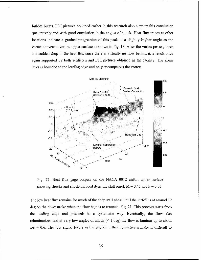
bubble bursts. PDI pictures obtained earlier in this research also support this conclusion
qualitatively and with good correlation in the angles of attack. Heat flux traces at other
locations indicate a gradual progression of this peak to a slightly higher angle as the
vortex convects over the upper surface as shown in Fig. 18. After the vortex passes, there
is a sudden drop in the heat flux since there is virtually no flow behind it, a result once
again supported by both schlieren and PDI pictures obtained in the facility. The shear
layer is bounded to the leading edge and only encompasses the vortex.
M45 k5 Upstroke
0.3.
0.2-
0.1-
0-
-0.1.
-0.2.
Shock: (8-10 deg)
Dynamic Stall Vortex Convection
,
mmmrn^
/
Transition Line
0.15
0 0
0.1
■0.1
0.2
-0.3
Fig. 22. Heat flux gage outputs on the NACA 0012 airfoil upper surface
showing shocks and shock-induced dynamic stall onset, M = 0.45 and k = 0.05.
The low heat flux remains for much of the deep stall phase until the airfoil is at around 12
deg on the downstroke when the flow begins to reattach, Fig. 21. This process starts from
the leading edge and proceeds in a systematic way. Eventually, the flow also
relaminarizes and at very low angles of attack (< 1 deg) the flow is laminar up to about
x/c = 0.6. The low signal levels in the region further downstream make it difficult to
35

discern the progress of the relaminarization. These details provide a clear documentation
of the large changes in the transition and the surface shear stress that occur in this
complex flow, a fact that needs to be included in the CFD modeling of the flow, that has
hitherto not been done. Considerably better agreement with experimental data can be
obtained if the appropriate physics such as described above is included in the models.
At M = 0.45, k = 0.05, the presence of shocks seen in the PDI pictures was also observed
here, Fig. 21. Since the static temperature rises across a shock wave, the heat transfer
from a heat flux gage at this location drops. Similarly, across an expansion wave, the heat
transfer rises. The boundary layer near the leading edge where the shock forms is very
thin, (« 100 um) and thus, the imprint of the shock can be picked up in the surface heat
flux traces. Interpretation of this requires some prior knowledge of the flow, since only a
rise or fall of heat transfer is measured. In this case, the PDI images from earlier
experiments provided ample proof of the presence of multiple shocks and thus, one can
infer the same in the heat flux gage experiments knowing the position of the sensors.
As angle of attack increases, more shocks form on the shear layer enveloping the bubble
that forms for this condition, even before the shocks forms. Ultimately it appears that, the
shear layer separates due to the pressure gradients imposed by the shocks. During this
event, once again, there is violent activity in the bubble and dynamic stall originates from
the separation. Its location is near the downstream end of the bubble unlike at M = 0.3,
where it was from its upstream end. This type of separation is different from the pure
bubble bursting induced event discussed for M = 0.3.
Due to the higher Reynolds number at M = 0.45, the transition point moves further
upstream compared to the M = 0.3, k = 0.05 condition. The movement of transition point
and the events of the shock and bubble interacting make this flow even more complex
than discussed above and once again, need to be properly modeled for a better CFD
analysis.
36

4. CONCLUSIONS
This study had two main foci: one was the establishment of the fluid mechanics of
compressible dynamic stall control and the other was the study of the fluid mechanics
processes of compressible dynamic stall.
For the first one, a dynamically deforming leading edge airfoil was tested in the CDSF.
The major contribution was establishing the fact that compressible dynamic stall can
indeed be controlled under helicopter retreating blade flow conditions. The establishment
of the attached flow envelope was key in identifying the airfoil leading edge shapes that
were needed during the process. The study also established that within this envelope, the
dynamic stall vorticity could be produced and diffused at rates that maintained its peak
level below the critical level for coalescence. This led to successful control of
compressible dynamic stall both at M = 0.3 and 0.4 at a reduced frequency of 0.05.
Another important result was that improper shape adaptation could promote dynamic stall
onset, even prematurely. Hence, it is imperative that the leading edge deformation
schedule be consistent with the vorticity balance requirements. In general slow rates of
adaptation were found to be better at achieving success. Since the time scale of
adaptation is not an independent quantity, but in fact is dependent upon the airfoil
reduced frequency, this result becomes important both in terms of practical utility and in
the fluid mechanics terms of vorticity management. The airfoil geometry was such that
the large leading edge curvature required for flow control could be produced with a very
small chordwise movement. In this study, less than 0.4% of chord, a maximum linear
chord length change of 0.025in was used. This small change appears within the realm of
present day smart materials and actuators, offering the hope that the technique could
become practical.
The heat flux gage studies documented the rapid movement of the transition onset point
as a function of angle of attack. They also showed that there is violent activity in the
bubble or under a separated shear layer at a higher Mach number of 0.45 prior to dynamic
37

stall onset, which lends support to the idea that the different dynamic stall onset processes
- identified by the author in previous ARO sponsored projects - are singular events.
5. LIST OF PUBLICATIONS AND TECHNICAL REPORTS
1. M.S.Chandrasekhara, M.C. Wilder and L.W.Carr, "Compressible Dynamic Stall
Control Using Dynamic Shape Adaptation", (AIAA Paper 99-0650), AIAA Journal,
Vol. 39, No. 10, pp. 2021-2024.
2. M.S.Chandrasekhara, M.C. Wilder and L.W.Carr, "Compressible Dynamic Stall
Control: Comparison of Two Approaches", (Invited AIAA Paper 99-3122), Journal
of Aircraft, Vol. 38, No. 3, pp. 448-453, May-Jun. 2001.
3. M.S.Chandrasekhara, M.C.Wilder, and L.W.Carr, "The Control of Compressible
Dynamic Stall Using Adaptive Airfoils", IUTAM Symposium on Mechanics of
Passive and Active Flow Control", Kluwer Academic Publishers, FMIA Vol. 53, pp.
75-80, Aug. 1999.
4. M.S.Chandrasekhara, M.C.Wilder, and L.W.Carr, "Unsteady Stall Control Using
Dynamically Deforming Airfoils", (AIAA Paper 97-2236), AIAA Journal, Vol. 36,
No. 10, Oct. 1998, pp. 1792-1800.
5. M.S.Chandrasekhara, M.C.Wilder, and L.W.Carr, "On the Competing Mechanisms
of Compressible Dynamic Stall", (AIAA Paper 96-1953), AIAA Journal, Vol. 36, No.
3, March 1998, pp. 387-393.
6. M.S.Chandrasekhara, L.W.Carr, M.C.Wilder, C.Hiel, C.D.Sticht, and G.N.Paulson,
"Design and Development of a Dynamically Deforming Leading Edge Airfoil for
Unsteady Flow Control", ICIASF'97 RECORD, IEEE Publication No. 97CH36121.
pp. 132-140.
7. M.S.Chandrasekhara, L.W.Carr, and M.C.Wilder, "Development of High Speed
Imaging and Analysis Techniques for Compressible Dynamic Stall", AGARD -CP -
522, May 1998, pp. 21.1-21.12.
8. M.Sahin, L.N.Sankar, M.S.Chandrasekhara and C.Tung, "Dynamic Stall Alleviation
Using a Deformable Leading Edge Concept - A Numerical Study", AIAA Paper 00-
0520, Reno, NV, Jan. 2000.
38
9. M.S.Chandrasekhara, "Review of Compressible Dynamic Stall and Its Control",
Invited Paper, Proc. of the 8th Asian Congress of Fluid Mechanics, International
Academic Publishers, Shenzhen, China, pp. 47-50.
10. W.Geissler, L.W.Carr, M.S.Chandrasekhara, M.C.Wilder and H.Sobieczky,
"Compressible Dynamic Stall Calculations Incorporating Transition Modeling for
Variable Geometry Airfoils", AIAA Paper 98-0705 . Reno, NV, Jan. 1998.
11. M.S.Chandrasekhara, M.C.Wilder, and L.W.Carr, "Fluid Mechanics of Wing
Adaptation for Separation Control", 7th Asian Congress of Fluid Mechanics, Madras,
India, Dec. 8-12, 1997.
12. W.Geissler, M.S.Chandrasekhara, M.F.Platzer and L.W.Carr, "The Effect of
Transition Modeling on the Prediction of Deep Dynamic Stall", 7th Asian Congress of
Fluid Mechanics, Madras, India, Dec. 8-12, 1997.
13. M.S.Chandrasekhara, M.C.Wilder and L.W.Carr, "Unsteady Stall Control Using
Dynamically Deforming Airfoils", AIAA Paper 97-2236. Atlanta, GA, Jun. 1997.
6. LIST OF ALL PARTICIPATING PERSONNEL
1. Professor M.S. Chandrasekhara, NPS, Monterey, CA
2. Dr. L.W. Carr, Cooperative Participant, US Army AFDD/AMCOM
3. Dr. M.C. Wilder, Eloret Institute, San Jose, CA
7. REPORT OF INVENTIONS
None.
8. BIBLIOGRAPHY
1. M.S.Chandrasekhara, L.W.Carr, M.C.Wilder, C.Hiel, C.D.Sticht, and
G.N.Paulson, "Design and Development of a Dynamically Deforming Leading
Edge Airfoil for Unsteady Flow Control", ICIASF'97 RECORD, IEEE
Publication No. 97CH3612L pp. 132-140.
39
2. N.J. Brock, M.S.Chandrasekhara, L.W.Carr, "A Real Time Interferometry System
for Unsteady Flow Measurements", ICIASF Publication No. 91CH3028-8. pp.
423-430.
3. M.S.Chandrasekhara, M.C.Wilder, and L.W.Carr, "Unsteady Stall Control Using
Dynamically Deforming Airfoils", (AIAA Paper 97-2236), AIAA Journal, Vol.
36, No. 10, Oct. 1998, pp. 1792-1800.
4. L.W.Carr and M.S.Chandrasekhara, "A Review of Compressibility Effects on
Dynamic Stall of Airfoils", AIAA Paper 95-0779, Invited Paper, Reno, NV, Jan.
1995.
5. W.C.Reynolds and L.W.Carr, "Review of Unsteady, Driven, Separated Flows",
AIAA Paper 85-0527, Mar. 1985.
6. M.S.Chandrasekhara, M.C.Wilder, and L.W.Carr, "Compressible Dynamic Stall
Control Using a Shape Adaptive Airfoil", AIAA Paper 99-0650 Reno. NV, Jan.
1999
7. M.S.Chandrasekhara, M.C. Wilder and L.W.Carr, "Compressible Dynamic Stall
Control Using Dynamic Shape Adaptation", (AIAA Paper 99-0650), AIAA
Journal, Vol. 39, No. 10, pp. 2021-2024.
8. S.Ahmed and M.S.Chandrasekhara, "Reattachment Studies of an Oscillating
Airfoil Dynamic Stall Flow Field", AIAA Paper No. 91-3225, Sep. 1991.
9. M.S.Chandrasekhara, M.C. Wilder and L.W.Carr, "Compressible Dynamic Stall
Control: Comparison of Two Approaches", (Invited AIAA Paper 99-3122),
Journal of Aircraft, Vol. 38, No. 3, pp. 448-453, May-Jun. 2001.
40
Related Documents


![14 Stall Parallel Operation [Kompatibilitätsmodus] · PDF filePiston Effect Axial Fans (none stall-free) Stall operation likely for none stall-free fans due to piston ... Stall &](https://static.cupdf.com/doc/110x72/5a9dccd97f8b9abd0a8d46cf/14-stall-parallel-operation-kompatibilittsmodus-effect-axial-fans-none-stall-free.jpg)