An image of hurricane Allen viewed via satellite: Although there is considerable motion and structure to a hurricane, the pressure variation in the vertical direction is approximated by the pressure-depth relationship for a static fluid. 1Visible and infrared image pair from a NOAA satellite using a technique developed at NASA/GSPC.2 1Photograph courtesy of A. F. Hasler [Ref. 7].2

Fluid Mechanics ll ( Chapter 2 )
Jan 19, 2015
Welcome message from author
This document is posted to help you gain knowledge. Please leave a comment to let me know what you think about it! Share it to your friends and learn new things together.
Transcript
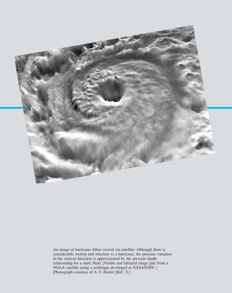
An image of hurricane Allen viewed via satellite: Although there isconsiderable motion and structure to a hurricane, the pressure variationin the vertical direction is approximated by the pressure-depthrelationship for a static fluid. 1Visible and infrared image pair from aNOAA satellite using a technique developed at NASA/GSPC.21Photograph courtesy of A. F. Hasler [Ref. 7].2
7708d_c02_40-99 8/31/01 12:33 PM Page 40 mac106 mac 106:1st_Shift:7708d:

In this chapter we will consider an important class of problems in which the fluid is eitherat rest or moving in such a manner that there is no relative motion between adjacent parti-cles. In both instances there will be no shearing stresses in the fluid, and the only forces thatdevelop on the surfaces of the particles will be due to the pressure. Thus, our principal con-cern is to investigate pressure and its variation throughout a fluid and the effect of pressureon submerged surfaces. The absence of shearing stresses greatly simplifies the analysis and,as we will see, allows us to obtain relatively simple solutions to many important practicalproblems.
41
2Fluid Statics
2.1 Pressure at a Point
As we briefly discussed in Chapter 1, the term pressure is used to indicate the normal forceper unit area at a given point acting on a given plane within the fluid mass of interest. Aquestion that immediately arises is how the pressure at a point varies with the orientation ofthe plane passing through the point. To answer this question, consider the free-body diagram,illustrated in Fig. 2.1, that was obtained by removing a small triangular wedge of fluid fromsome arbitrary location within a fluid mass. Since we are considering the situation in whichthere are no shearing stresses, the only external forces acting on the wedge are due to thepressure and the weight. For simplicity the forces in the x direction are not shown, and thez axis is taken as the vertical axis so the weight acts in the negative z direction. Although weare primarily interested in fluids at rest, to make the analysis as general as possible, we willallow the fluid element to have accelerated motion. The assumption of zero shearing stresseswill still be valid so long as the fluid element moves as a rigid body; that is, there is no rel-ative motion between adjacent elements.
There are no shear-ing stresses presentin a fluid at rest.
7708d_c02_40-99 8/31/01 12:33 PM Page 41 mac106 mac 106:1st_Shift:7708d:
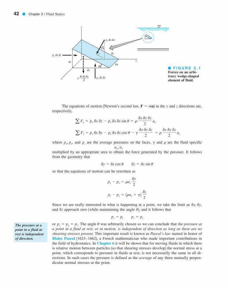
The equations of motion 1Newton’s second law, 2 in the y and z directions are,respectively,
where and are the average pressures on the faces, and are the fluid specific
multiplied by an appropriate area to obtain the force generated by the pressure. It followsfrom the geometry that
so that the equations of motion can be rewritten as
Since we are really interested in what is happening at a point, we take the limit as and approach zero 1while maintaining the angle 2, and it follows that
or The angle was arbitrarily chosen so we can conclude that the pressure ata point in a fluid at rest, or in motion, is independent of direction as long as there are noshearing stresses present. This important result is known as Pascal’s law named in honor ofBlaise Pascal 11623–16622, a French mathematician who made important contributions inthe field of hydrostatics. In Chapter 6 it will be shown that for moving fluids in which thereis relative motion between particles 1so that shearing stresses develop2 the normal stress at apoint, which corresponds to pressure in fluids at rest, is not necessarily the same in all di-rections. In such cases the pressure is defined as the average of any three mutually perpen-dicular normal stresses at the point.
ups � py � pz.
py � ps pz � ps
udzdx, dy,
pz � ps � 1raz � g2 dz
2
py � ps � ray dy
2
dy � ds cos u dz � ds sin u
ay, az
rgpzps, py,
a Fz � pz dx dy � ps dx ds cos u � g dx dy dz
2 � r
dx dy dz
2 az
a Fy � py dx dz � ps dx ds sin u � r dx dy dz
2 ay
F � ma
42 � Chapter 2 / Fluid Statics
δθ
θ
ps
y
z
________
2
δ y
δ x
δ s
δδ sx
pz δδ yx
py δδ zx
x
z
δx δyδzγ
� F I G U R E 2 . 1Forces on an arbi-trary wedge-shapedelement of fluid.
The pressure at apoint in a fluid atrest is independentof direction.
7708d_c02_042 8/2/01 1:10 PM Page 42
2.2 Basic Equation for Pressure Field
2.2 Basic Equation for Pressure Field � 43
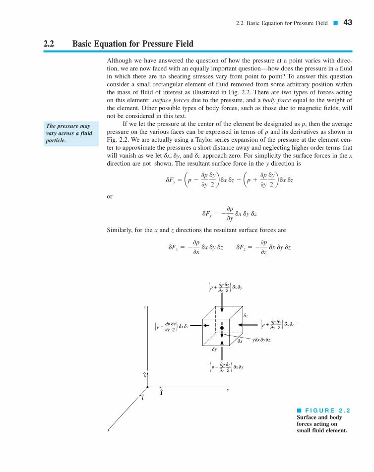
Although we have answered the question of how the pressure at a point varies with direc-tion, we are now faced with an equally important question—how does the pressure in a fluidin which there are no shearing stresses vary from point to point? To answer this questionconsider a small rectangular element of fluid removed from some arbitrary position withinthe mass of fluid of interest as illustrated in Fig. 2.2. There are two types of forces actingon this element: surface forces due to the pressure, and a body force equal to the weight ofthe element. Other possible types of body forces, such as those due to magnetic fields, willnot be considered in this text.
If we let the pressure at the center of the element be designated as p, then the averagepressure on the various faces can be expressed in terms of p and its derivatives as shown inFig. 2.2. We are actually using a Taylor series expansion of the pressure at the element cen-ter to approximate the pressures a short distance away and neglecting higher order terms thatwill vanish as we let and approach zero. For simplicity the surface forces in the xdirection are not shown. The resultant surface force in the y direction is
or
Similarly, for the x and z directions the resultant surface forces are
dFx � �0p
0x dx dy dz dFz � �
0p
0z dx dy dz
dFy � �0p
0y dx dy dz
dFy � ap �0p
0y dy
2b dx dz � ap �
0p
0y dy
2b dx dz
dzdx, dy,
The pressure mayvary across a fluidparticle.
k
ij
z
∂ δ δ δ
δ
xδ
yδ
∂
xγ δ yδ zδ
^
^
^
x
y
z
( ) x yp +zp
––– –––2z
∂ δ δ δ∂( ) x zp +
yp
––– –––2y
∂ δ δ δ∂( ) x yp –
zp
––– –––2z
∂ δ δ δ∂( ) x zp –
yp
––– –––2y
� F I G U R E 2 . 2Surface and bodyforces acting onsmall fluid element.
7708d_c02_043 8/2/01 1:10 PM Page 43

The resultant surface force acting on the element can be expressed in vector form as
or
(2.1)
where and are the unit vectors along the coordinate axes shown in Fig. 2.2. The groupof terms in parentheses in Eq. 2.1 represents in vector form the pressure gradient and canbe written as
where
and the symbol is the gradient or “del” vector operator. Thus, the resultant surface forceper unit volume can be expressed as
Since the z axis is vertical, the weight of the element is
where the negative sign indicates that the force due to the weight is downward 1in the neg-ative z direction2. Newton’s second law, applied to the fluid element, can be expressed as
where represents the resultant force acting on the element, a is the acceleration of theelement, and is the element mass, which can be written as It follows that
or
and, therefore,
(2.2)
Equation 2.2 is the general equation of motion for a fluid in which there are no shearingstresses. We will use this equation in Section 2.12 when we consider the pressure distributionin a moving fluid. For the present, however, we will restrict our attention to the special caseof a fluid at rest.
�§p � gk � ra
�§p dx dy dz � g dx dy dz k � r dx dy dz a
a dF � dFs � dwk � dm a
r dx dy dz.dm� dF
a dF � dm a
�dwk � �g dx dy dz k
dFs
dx dy dz� �§p
§
§ 1 2 �0 1 20x
i �0 1 20y
j �0 1 20z
k
0p
0x i �
0p
0y j �
0p
0z k � §p
ki, j,
dFs � �a 0p
0x i �
0p
0y j �
0p
0z kb dx dy dz
dFs � dFxi � dFy j � dFzk
44 � Chapter 2 / Fluid Statics
The resultant sur-face force acting ona small fluid ele-ment depends onlyon the pressuregradient if there areno shearing stressespresent.
7708d_c02_044 8/2/01 1:10 PM Page 44
2.3 Pressure Variation in a Fluid at Rest
2.3 Pressure Variation in a Fluid at Rest � 45
For a fluid at rest and Eq. 2.2 reduces to
or in component form
(2.3)
These equations show that the pressure does not depend on x or y. Thus, as we move frompoint to point in a horizontal plane 1any plane parallel to the x–y plane2, the pressure doesnot change. Since p depends only on z, the last of Eqs. 2.3 can be written as the ordinarydifferential equation
(2.4)
Equation 2.4 is the fundamental equation for fluids at rest and can be used to deter-mine how pressure changes with elevation. This equation indicates that the pressure gradi-ent in the vertical direction is negative; that is, the pressure decreases as we move upwardin a fluid at rest. There is no requirement that be a constant. Thus, it is valid for fluidswith constant specific weight, such as liquids, as well as fluids whose specific weight mayvary with elevation, such as air or other gases. However, to proceed with the integration ofEq. 2.4 it is necessary to stipulate how the specific weight varies with z.
2.3.1 Incompressible Fluid
Since the specific weight is equal to the product of fluid density and acceleration of gravitychanges in are caused either by a change in or g. For most engineering ap-
plications the variation in g is negligible, so our main concern is with the possible variationin the fluid density. For liquids the variation in density is usually negligible, even over largevertical distances, so that the assumption of constant specific weight when dealing with liq-uids is a good one. For this instance, Eq. 2.4 can be directly integrated
to yield
or
(2.5)
where are pressures at the vertical elevations as is illustrated in Fig. 2.3. Equation 2.5 can be written in the compact form
(2.6)
or
(2.7)p1 � gh � p2
p1 � p2 � gh
z1 and z2,p1 and p2
p1 � p2 � g1z2 � z12
p2 � p1 � �g1z2 � z12
�p2
p1
dp � �g�z2
z1
dz
rg1g � rg2,
g
dp
dz� �g
0p
0x� 0
0p
0y� 0
0p
0z� �g
§p � gk � 0
a � 0
For liquids or gasesat rest the pressuregradient in the ver-tical direction atany point in a fluiddepends only on thespecific weight ofthe fluid at thatpoint.
7708d_c02_045 8/2/01 1:11 PM Page 45
46 � Chapter 2 / Fluid Statics
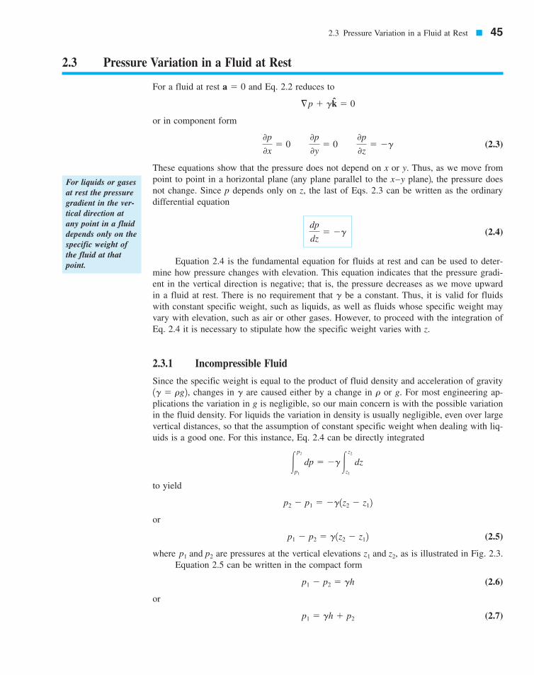
where h is the distance, which is the depth of fluid measured downward from thelocation of This type of pressure distribution is commonly called a hydrostatic distribu-tion, and Eq. 2.7 shows that in an incompressible fluid at rest the pressure varies linearlywith depth. The pressure must increase with depth to “hold up” the fluid above it.
It can also be observed from Eq. 2.6 that the pressure difference between two pointscan be specified by the distance h since
In this case h is called the pressure head and is interpreted as the height of a column of fluidof specific weight required to give a pressure difference For example, a pressuredifference of 10 psi can be specified in terms of pressure head as 23.1 ft of water
or 518 mm of Hg When one works with liquids there is often a free surface, as is illustrated in Fig. 2.3,
and it is convenient to use this surface as a reference plane. The reference pressure wouldcorrespond to the pressure acting on the free surface 1which would frequently be atmosphericpressure2, and thus if we let in Eq. 2.7 it follows that the pressure p at any depth hbelow the free surface is given by the equation:
(2.8)
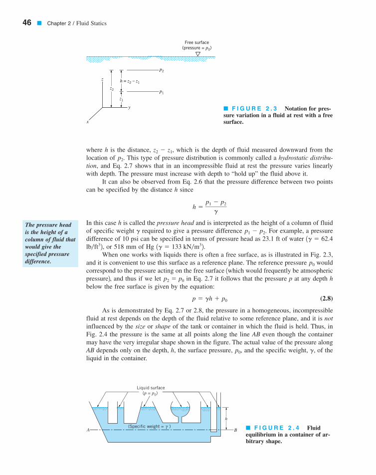
As is demonstrated by Eq. 2.7 or 2.8, the pressure in a homogeneous, incompressiblefluid at rest depends on the depth of the fluid relative to some reference plane, and it is notinfluenced by the size or shape of the tank or container in which the fluid is held. Thus, inFig. 2.4 the pressure is the same at all points along the line AB even though the containermay have the very irregular shape shown in the figure. The actual value of the pressure alongAB depends only on the depth, h, the surface pressure, and the specific weight, of theliquid in the container.
g,p0,
p � gh � p0
p2 � p0
p0
1g � 133 kN�m32.lb�ft32,1g � 62.4
p1 � p2.g
h �p1 � p2
g
p2.z2 � z1,
The pressure headis the height of acolumn of fluid thatwould give thespecified pressuredifference.
z
x
y
z1
z2 p1
p2
h = z2 – z1
Free surface(pressure = p0)
Liquid surface(p = p0)
A B
h
(Specific weight = )γ
� F I G U R E 2 . 3 Notation for pres-sure variation in a fluid at rest with a freesurface.
� F I G U R E 2 . 4 Fluidequilibrium in a container of ar-bitrary shape.
7708d_c02_046 8/2/01 1:11 PM Page 46
2.3 Pressure Variation in a Fluid at Rest � 47
EXAMPLE2.1
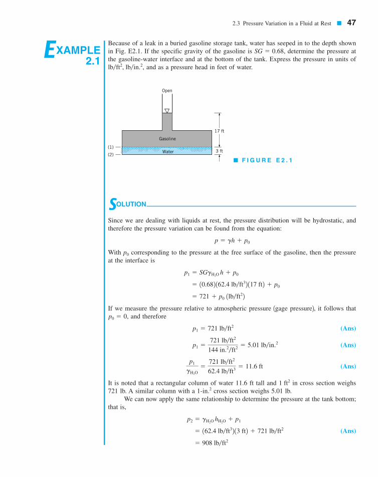
Because of a leak in a buried gasoline storage tank, water has seeped in to the depth shownin Fig. E2.1. If the specific gravity of the gasoline is determine the pressure atthe gasoline-water interface and at the bottom of the tank. Express the pressure in units of
and as a pressure head in feet of water.lb�ft2, lb�in.2,
SG � 0.68,
� F I G U R E E 2 . 1
SOLUTION
Since we are dealing with liquids at rest, the pressure distribution will be hydrostatic, andtherefore the pressure variation can be found from the equation:
With p0 corresponding to the pressure at the free surface of the gasoline, then the pressureat the interface is
If we measure the pressure relative to atmospheric pressure 1gage pressure2, it follows thatand therefore
(Ans)
(Ans)
(Ans)
It is noted that a rectangular column of water 11.6 ft tall and in cross section weighs721 lb. A similar column with a cross section weighs 5.01 lb.
We can now apply the same relationship to determine the pressure at the tank bottom;that is,
(Ans)
� 908 lb�ft2
� 162.4 lb�ft32 13 ft2 � 721 lb�ft2
p2 � gH2O hH2O � p1
1-in.21 ft2
p1
gH2O�
721 lb�ft2
62.4 lb�ft3 � 11.6 ft
p1 �721 lb�ft2
144 in.2�ft2 � 5.01 lb�in.2
p1 � 721 lb�ft2
p0 � 0,
� 721 � p0 1lb�ft22 � 10.682 162.4 lb�ft32 117 ft2 � p0
p1 � SGgH2O h � p0
p � gh � p0
(1)
(2)Water
Gasoline
Open
17 ft
3 ft
7708d_c02_40-99 8/31/01 12:35 PM Page 47 mac106 mac 106:1st_Shift:7708d:
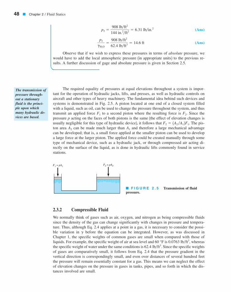
The required equality of pressures at equal elevations throughout a system is impor-tant for the operation of hydraulic jacks, lifts, and presses, as well as hydraulic controls onaircraft and other types of heavy machinery. The fundamental idea behind such devices andsystems is demonstrated in Fig. 2.5. A piston located at one end of a closed system filledwith a liquid, such as oil, can be used to change the pressure throughout the system, and thustransmit an applied force to a second piston where the resulting force is Since thepressure p acting on the faces of both pistons is the same 1the effect of elevation changes isusually negligible for this type of hydraulic device2, it follows that The pis-ton area can be made much larger than and therefore a large mechanical advantagecan be developed; that is, a small force applied at the smaller piston can be used to developa large force at the larger piston. The applied force could be created manually through sometype of mechanical device, such as a hydraulic jack, or through compressed air acting di-rectly on the surface of the liquid, as is done in hydraulic lifts commonly found in servicestations.
A1A2
F2 � 1A2 �A12F1.
F2.F1
48 � Chapter 2 / Fluid Statics
(Ans)
(Ans)
Observe that if we wish to express these pressures in terms of absolute pressure, wewould have to add the local atmospheric pressure 1in appropriate units2 to the previous re-sults. A further discussion of gage and absolute pressure is given in Section 2.5.
p2
gH2O�
908 lb�ft2
62.4 lb�ft3 � 14.6 ft
p2 �908 lb�ft2
144 in.2�ft2 � 6.31 lb�in.2
F1 = pA1F2 = pA2
� F I G U R E 2 . 5 Transmission of fluid pressure.
2.3.2 Compressible Fluid
We normally think of gases such as air, oxygen, and nitrogen as being compressible fluidssince the density of the gas can change significantly with changes in pressure and tempera-ture. Thus, although Eq. 2.4 applies at a point in a gas, it is necessary to consider the possi-ble variation in before the equation can be integrated. However, as was discussed inChapter 1, the specific weights of common gases are small when compared with those ofliquids. For example, the specific weight of air at sea level and is whereasthe specific weight of water under the same conditions is Since the specific weightsof gases are comparatively small, it follows from Eq. 2.4 that the pressure gradient in thevertical direction is correspondingly small, and even over distances of several hundred feetthe pressure will remain essentially constant for a gas. This means we can neglect the effectof elevation changes on the pressure in gases in tanks, pipes, and so forth in which the dis-tances involved are small.
62.4 lb�ft3.0.0763 lb�ft3,60 °F
g
The transmission ofpressure through-out a stationaryfluid is the princi-ple upon whichmany hydraulic de-vices are based.
7708d_c02_048 8/2/01 1:11 PM Page 48
For those situations in which the variations in heights are large, on the order of thou-sands of feet, attention must be given to the variation in the specific weight. As is describedin Chapter 1, the equation of state for an ideal 1or perfect2 gas is
where p is the absolute pressure, R is the gas constant, and T is the absolute temperature.This relationship can be combined with Eq. 2.4 to give
and by separating variables
(2.9)
where g and R are assumed to be constant over the elevation change from Althoughthe acceleration of gravity, g, does vary with elevation, the variation is very small 1see TablesC.1 and C.2 in Appendix C2, and g is usually assumed constant at some average value forthe range of elevation involved.
Before completing the integration, one must specify the nature of the variation of tem-perature with elevation. For example, if we assume that the temperature has a constant value
over the range 1isothermal conditions2, it then follows from Eq. 2.9 that
(2.10)
This equation provides the desired pressure-elevation relationship for an isothermal layer.For nonisothermal conditions a similar procedure can be followed if the temperature-elevationrelationship is known, as is discussed in the following section.
p2 � p1 exp c�g1z2 � z12RT0
dz1 to z2T0
z1 to z2.
�p2
p1
dp
p� ln
p2
p1� �
g
R �z2
z1
dz
T
dp
dz� �
gp
RT
p � rRT
2.3 Pressure Variation in a Fluid at Rest � 49
EXAMPLE2.2
If the specificweight of a fluidvaries significantlyas we move frompoint to point, thepressure will nolonger vary directlywith depth.
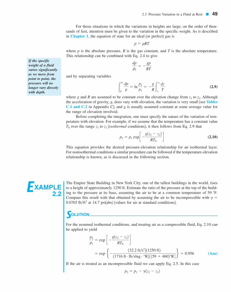
The Empire State Building in New York City, one of the tallest buildings in the world, risesto a height of approximately 1250 ft. Estimate the ratio of the pressure at the top of the build-ing to the pressure at its base, assuming the air to be at a common temperature of Compare this result with that obtained by assuming the air to be incompressible with
at 14.7 psi1abs2 1values for air at standard conditions2.
SOLUTION
For the assumed isothermal conditions, and treating air as a compressible fluid, Eq. 2.10 canbe applied to yield
(Ans)
If the air is treated as an incompressible fluid we can apply Eq. 2.5. In this case
p2 � p1 � g1z2 � z12
� exp e�132.2 ft�s22 11250 ft2
11716 ft # lb�slug # °R2 3 159 � 4602°R 4 f � 0.956
p2
p1� exp c�g1z2 � z12
RT0d
0.0765 lb�ft3g �
59 °F.
7708d_c02_049 8/2/01 1:19 PM Page 49

An important application of Eq. 2.9 relates to the variation in pressure in the earth’s atmos-phere. Ideally, we would like to have measurements of pressure versus altitude over the spe-cific range for the specific conditions 1temperature, reference pressure2 for which the pres-sure is to be determined. However, this type of information is usually not available. Thus, a“standard atmosphere” has been determined that can be used in the design of aircraft, mis-siles, and spacecraft, and in comparing their performance under standard conditions. Theconcept of a standard atmosphere was first developed in the 1920s, and since that time manynational and international committees and organizations have pursued the development ofsuch a standard. The currently accepted standard atmosphere is based on a report publishedin 1962 and updated in 1976 1see Refs. 1 and 22, defining the so-called U.S. standard at-mosphere, which is an idealized representation of middle-latitude, year-round mean condi-tions of the earth’s atmosphere. Several important properties for standard atmospheric con-ditions at sea level are listed in Table 2.1, and Fig. 2.6 shows the temperature profile for theU.S. standard atmosphere. As is shown in this figure the temperature decreases with altitude
50 � Chapter 2 / Fluid Statics
or
(Ans)
Note that there is little difference between the two results. Since the pressure difference be-tween the bottom and top of the building is small, it follows that the variation in fluid den-sity is small and, therefore, the compressible fluid and incompressible fluid analyses yieldessentially the same result.
We see that for both calculations the pressure decreases by less than 5% as we go fromground level to the top of this tall building. It does not require a very large pressure differ-ence to support a 1250-ft-tall column of fluid as light as air. This result supports the earlierstatement that the changes in pressures in air and other gases due to elevation changes arevery small, even for distances of hundreds of feet. Thus, the pressure differences betweenthe top and bottom of a horizontal pipe carrying a gas, or in a gas storage tank, are negligi-ble since the distances involved are very small.
� 1 �10.0765 lb�ft32 11250 ft2
114.7 lb�in.22 1144 in.2�ft22� 0.955
p2
p1� 1 �
g1z2 � z12
p1
2.4 Standard Atmosphere
� TA B L E 2 . 1Properties of U.S. Standard Atmosphere at Sea Levela
Property SI Units BG Units
Temperature, TPressure, p 101.33 kPa 1abs2
Density,Specific weight,Viscosity,
aAcceleration of gravity at sea level � 9.807 m�s2 � 32.174 ft�s2.
3.737 � 10�7 lb # s�ft21.789 � 10�5 N # s�m2m
0.07647 lb�ft312.014 N�m3g
0.002377 slugs�ft31.225 kg�m3r
314.696 lb�in.2 1abs2 42116.2 lb�ft2 1abs2518.67 °R 159.00 °F2288.15 K 115 °C2
The standard at-mosphere is an ide-alized representa-tion of meanconditions in theearth’s atmosphere.
7708d_c02_050 8/2/01 1:19 PM Page 50

in the region nearest the earth’s surface 1troposphere2, then becomes essentially constant inthe next layer 1stratosphere2, and subsequently starts to increase in the next layer.
Since the temperature variation is represented by a series of linear segments, it is pos-sible to integrate Eq. 2.9 to obtain the corresponding pressure variation. For example, in thetroposphere, which extends to an altitude of about 11 km the temperature vari-ation is of the form
(2.11)
where is the temperature at sea level and is the lapse rate 1the rate of changeof temperature with elevation2. For the standard atmosphere in the troposphere,
Equation 2.11 used with Eq. 2.9 yields
(2.12)
where is the absolute pressure at With and g obtained from Table 2.1, andwith the gas constant or the pressure variationthroughout the troposphere can be determined from Eq. 2.12. This calculation shows that atthe outer edge of the troposphere, where the temperature is the absolute pressureis about 23 kPa 13.3 psia2. It is to be noted that modern jetliners cruise at approximately thisaltitude. Pressures at other altitudes are shown in Fig. 2.6, and tabulated values for temper-ature, acceleration of gravity, pressure, density, and viscosity for the U.S. standard atmos-phere are given in Tables C.1 and C.2 in Appendix C.
�56.5 °C,
1716 ft # lb�slug # °R,R � 286.9 J�kg # Kpa, Ta,z � 0.pa
p � pa a1 �bz
Ta
bg �Rb
K�m or 0.00357 °R�ft.b � 0.00650
b1z � 02Ta
T � Ta � bz
1�36,000 ft2,
2.5 Measurement of Pressure � 51
2.5 Measurement of Pressure
Since pressure is a very important characteristic of a fluid field, it is not surprising that nu-merous devices and techniques are used in its measurement. As is noted briefly in Chapter 1,the pressure at a point within a fluid mass will be designated as either an absolute pressureor a gage pressure. Absolute pressure is measured relative to a perfect vacuum 1absolute zero
50
40
30
20
10
0-100 -80 -60 -40 -20 0 +20
Temperature, °C
Alt
itud
e z,
km
Stratosphere
Troposphere
-56
.5 °
C
-44
.5 °
C
-2.5
°C
32.2 km (p = 0.9 kPa)
20.1 km (p = 5.5 kPa)
11.0 km (p = 22.6 kPa)
p = 101.3 kPa (abs)15 °C
47.3 km(p = 0.1 kPa)
� F I G U R E 2 . 6 Vari-ation of temperature with al-titude in the U.S. standardatmosphere.
Pressure is desig-nated as either ab-solute pressure orgage pressure.
7708d_c02_051 8/2/01 1:20 PM Page 51

pressure2, whereas gage pressure is measured relative to the local atmospheric pressure. Thus,a gage pressure of zero corresponds to a pressure that is equal to the local atmospheric pres-sure. Absolute pressures are always positive, but gage pressures can be either positive or neg-ative depending on whether the pressure is above atmospheric pressure 1a positive value2 orbelow atmospheric pressure 1a negative value2. A negative gage pressure is also referred toas a suction or vacuum pressure. For example, 10 psi 1abs2 could be expressed as psi1gage2, if the local atmospheric pressure is 14.7 psi, or alternatively 4.7 psi suction or 4.7 psivacuum. The concept of gage and absolute pressure is illustrated graphically in Fig. 2.7 fortwo typical pressures located at points 1 and 2.
In addition to the reference used for the pressure measurement, the units used to ex-press the value are obviously of importance. As is described in Section 1.5, pressure is aforce per unit area, and the units in the BG system are or commonly abbrevi-ated psf or psi, respectively. In the SI system the units are this combination is calledthe pascal and written as Pa As noted earlier, pressure can also be ex-pressed as the height of a column of liquid. Then, the units will refer to the height of thecolumn 1in., ft, mm, m, etc.2, and in addition, the liquid in the column must be specified1 etc.2. For example, standard atmospheric pressure can be expressed as 760 mm Hg1abs2. In this text, pressures will be assumed to be gage pressures unless specifically desig-nated absolute. For example, 10 psi or 100 kPa would be gage pressures, whereas 10 psiaor 100 kPa 1abs2 would refer to absolute pressures. It is to be noted that pressure differencesare independent of the reference, so that no special notation is required in this case.
The measurement of atmospheric pressure is usually accomplished with a mercurybarometer, which in its simplest form consists of a glass tube closed at one end with theopen end immersed in a container of mercury as shown in Fig. 2.8. The tube is initially filledwith mercury 1inverted with its open end up2 and then turned upside down 1open end down2with the open end in the container of mercury. The column of mercury will come to an equi-librium position where its weight plus the force due to the vapor pressure 1which developsin the space above the column2 balances the force due to the atmospheric pressure. Thus,
(2.13)
where is the specific weight of mercury. For most practical purposes the contribution ofthe vapor pressure can be neglected since it is very small [for mercury,
1abs2 at a temperature of ] so that It is conventional to specify at-mospheric pressure in terms of the height, h, in millimeters or inches of mercury. Note thatif water were used instead of mercury, the height of the column would have to be approxi-mately 34 ft rather than 29.9 in. of mercury for an atmospheric pressure of 14.7 psia! Theconcept of the mercury barometer is an old one, with the invention of this device attributedto Evangelista Torricelli in about 1644.
patm � gh.68 °Flb�in.2pvapor � 0.000023
g
patm � gh � pvapor
H2O, Hg,
11 N�m2 � 1 Pa2.N�m2;
lb�in.2,lb�ft2
�4.7
52 � Chapter 2 / Fluid Statics
1
2
Absolute pressure@ 2
Absolute pressure@ 1
Gage pressure @ 1
Pre
ssur
e
Absolute zero reference
Local atmosphericpressure reference
Gage pressure @ 2(suction or vacuum)
� F I G U R E 2 . 7 Graphicalrepresentation of gage and absolutepressure.
A barometer is usedto measure atmos-pheric pressure.
7708d_c02_052 8/2/01 1:20 PM Page 52

2.6 Manometry
2.6 Manometry � 53
A standard technique for measuring pressure involves the use of liquid columns in verticalor inclined tubes. Pressure measuring devices based on this technique are called manome-ters. The mercury barometer is an example of one type of manometer, but there are manyother configurations possible, depending on the particular application. Three common typesof manometers include the piezometer tube, the U-tube manometer, and the inclined-tubemanometer.
Manometers usevertical or inclinedliquid columns tomeasure pressure.
EXAMPLE2.3
A mountain lake has an average temperature of and a maximum depth of 40 m. For abarometric pressure of 598 mm Hg, determine the absolute pressure 1in pascals2 at the deep-est part of the lake.
SOLUTION
The pressure in the lake at any depth, h, is given by the equation
where is the pressure at the surface. Since we want the absolute pressure, will be thelocal barometric pressure expressed in a consistent system of units; that is
and for
From Table B.2, at and therefore
(Ans)
This simple example illustrates the need for close attention to the units used in the calcula-tion of pressure; that is, be sure to use a consistent unit system, and be careful not to add apressure head 1m2 to a pressure 1Pa2.
� 392 kN�m2 � 79.5 kN�m2 � 472 kPa 1abs2
p � 19.804 kN�m32 140 m2 � 79.5 kN�m2
10 °CgH2 O � 9.804 kN�m3
p0 � 10.598 m2 1133 kN�m32 � 79.5 kN�m2
gHg � 133 kN�m3
pbarometric
gHg� 598 mm � 0.598 m
p0p0
p � gh � p0
10 °C
pvapor
A
h
patm
B
Mercury� F I G U R E 2 . 8 Mercury barometer.
7708d_c02_053 8/2/01 1:21 PM Page 53
2.6.1 Piezometer Tube
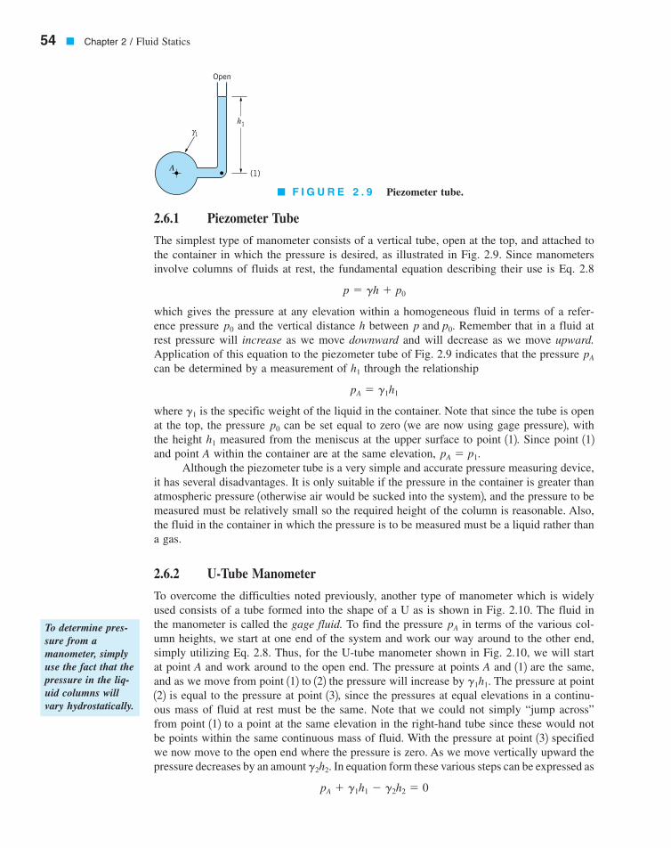
The simplest type of manometer consists of a vertical tube, open at the top, and attached tothe container in which the pressure is desired, as illustrated in Fig. 2.9. Since manometersinvolve columns of fluids at rest, the fundamental equation describing their use is Eq. 2.8
which gives the pressure at any elevation within a homogeneous fluid in terms of a refer-ence pressure and the vertical distance h between Remember that in a fluid atrest pressure will increase as we move downward and will decrease as we move upward.Application of this equation to the piezometer tube of Fig. 2.9 indicates that the pressure can be determined by a measurement of through the relationship
where is the specific weight of the liquid in the container. Note that since the tube is openat the top, the pressure can be set equal to zero 1we are now using gage pressure2, withthe height measured from the meniscus at the upper surface to point 112. Since point 112and point A within the container are at the same elevation,
Although the piezometer tube is a very simple and accurate pressure measuring device,it has several disadvantages. It is only suitable if the pressure in the container is greater thanatmospheric pressure 1otherwise air would be sucked into the system2, and the pressure to bemeasured must be relatively small so the required height of the column is reasonable. Also,the fluid in the container in which the pressure is to be measured must be a liquid rather thana gas.
2.6.2 U-Tube Manometer
To overcome the difficulties noted previously, another type of manometer which is widelyused consists of a tube formed into the shape of a U as is shown in Fig. 2.10. The fluid inthe manometer is called the gage fluid. To find the pressure in terms of the various col-umn heights, we start at one end of the system and work our way around to the other end,simply utilizing Eq. 2.8. Thus, for the U-tube manometer shown in Fig. 2.10, we will startat point A and work around to the open end. The pressure at points A and 112 are the same,and as we move from point 112 to 122 the pressure will increase by The pressure at point122 is equal to the pressure at point 132, since the pressures at equal elevations in a continu-ous mass of fluid at rest must be the same. Note that we could not simply “jump across”from point 112 to a point at the same elevation in the right-hand tube since these would notbe points within the same continuous mass of fluid. With the pressure at point 132 specifiedwe now move to the open end where the pressure is zero. As we move vertically upward thepressure decreases by an amount In equation form these various steps can be expressed as
pA � g1h1 � g2h2 � 0
g2h2.
g1h1.
pA
pA � p1.h1
p0
g1
pA � g1h1
h1
pA
p and p0.p0
p � gh � p0
54 � Chapter 2 / Fluid Statics
To determine pres-sure from amanometer, simplyuse the fact that thepressure in the liq-uid columns willvary hydrostatically.
Open
h1
1
(1)
γ
A
� F I G U R E 2 . 9 Piezometer tube.
7708d_c02_054 8/2/01 1:21 PM Page 54

and, therefore, the pressure can be written in terms of the column heights as
(2.14)
A major advantage of the U-tube manometer lies in the fact that the gage fluid can be dif-ferent from the fluid in the container in which the pressure is to be determined. For exam-ple, the fluid in A in Fig. 2.10 can be either a liquid or a gas. If A does contain a gas, thecontribution of the gas column, is almost always negligible so that and in thisinstance Eq. 2.14 becomes
Thus, for a given pressure the height, is governed by the specific weight, of the gagefluid used in the manometer. If the pressure is large, then a heavy gage fluid, such as mer-cury, can be used and a reasonable column height 1not too long2 can still be maintained. Al-ternatively, if the pressure is small, a lighter gage fluid, such as water, can be used so thata relatively large column height 1which is easily read2 can be achieved.
pA
pA
g2,h2,
pA � g2h2
pA � p2g1h1,
pA � g2h2 � g1h1
pA
2.6 Manometry � 55
EXAMPLE2.4
A closed tank contains compressed air and oil as is shown in Fig. E2.4. A U-tube manometer using mercury is connected to the tank as shown. For col-umn heights and determine the pressure reading 1in psi2of the gage.
h3 � 9 in.,h1 � 36 in., h2 � 6 in.,1SGHg � 13.62
1SGoil � 0.902
Pressuregage
Air
Oil
Open
Hg
(1) (2)
h1
h2
h3
� F I G U R E E 2 . 4
h1
h2
Open
(1)
(3)(2)
A
(gagefluid)
1γ
2γ
� F I G U R E 2 . 1 0 Simple U-tube manometer.
The contribution ofgas columns inmanometers is usu-ally negligible sincethe weight of thegas is so small.
V2.1 Blood pres-sure measurement
7708d_c02_055 8/2/01 1:21 PM Page 55

The U-tube manometer is also widely used to measure the difference in pressure be-tween two containers or two points in a given system. Consider a manometer connected be-tween containers A and B as is shown in Fig. 2.11. The difference in pressure between A andB can be found by again starting at one end of the system and working around to the otherend. For example, at A the pressure is which is equal to and as we move to point 122the pressure increases by The pressure at is equal to and as we move upward top3,p2g1h1.
p1,pA,
56 � Chapter 2 / Fluid Statics
SOLUTION
Following the general procedure of starting at one end of the manometer system and work-ing around to the other, we will start at the air–oil interface in the tank and proceed to theopen end where the pressure is zero. The pressure at level 112 is
This pressure is equal to the pressure at level 122, since these two points are at the same el-evation in a homogeneous fluid at rest. As we move from level 122 to the open end, the pres-sure must decrease by and at the open end the pressure is zero. Thus, the manometerequation can be expressed as
or
For the values given
so that
Since the specific weight of the air above the oil is much smaller than the specific weight ofthe oil, the gage should read the pressure we have calculated; that is,
(Ans)pgage �440 lb�ft2
144 in.2�ft2 � 3.06 psi
pair � 440 lb�ft2
pair � �10.92 162.4 lb�ft32 a36 � 6
12 ftb � 113.62 162.4 lb�ft32 a 9
12 ftb
pair � 1SGoil2 1gH2O2 1h1 � h22 � 1SGHg2 1gH2O2 h3 � 0
pair � goil1h1 � h22 � gHgh3 � 0
gHgh3,
p1 � pair � goil1h1 � h22
(1)
(2) (3)
(4)
(5)
A
B
h1
h2
h3
2γ
3γ
1γ
� F I G U R E 2 . 1 1 Differential U-tubemanometer.
Manometers are of-ten used to measurethe difference inpressure betweentwo points.
7708d_c02_056 8/2/01 1:22 PM Page 56
point 142 the pressure decreases by Similarly, as we continue to move upward from point142 to 152 the pressure decreases by Finally, since they are at equal elevations.Thus,
and the pressure difference is
When the time comes to substitute in numbers, be sure to use a consistent system of units!Capillarity due to surface tension at the various fluid interfaces in the manometer is
usually not considered, since for a simple U-tube with a meniscus in each leg, the capillaryeffects cancel 1assuming the surface tensions and tube diameters are the same at each menis-cus2, or we can make the capillary rise negligible by using relatively large bore tubes 1withdiameters of about 0.5 in. or larger2. Two common gage fluids are water and mercury. Bothgive a well-defined meniscus 1a very important characteristic for a gage fluid2 and have well-known properties. Of course, the gage fluid must be immiscible with respect to the other flu-ids in contact with it. For highly accurate measurements, special attention should be givento temperature since the various specific weights of the fluids in the manometer will varywith temperature.
pA � pB � g2h2 � g3h3 � g1h1
pA � g1h1 � g2h2 � g3h3 � pB
p5 � pB,g3h3.g2h2.
2.6 Manometry � 57
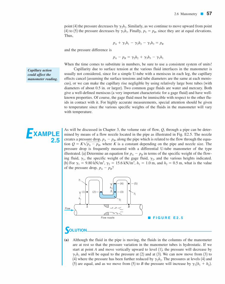
EXAMPLE2.5
As will be discussed in Chapter 3, the volume rate of flow, Q, through a pipe can be deter-mined by means of a flow nozzle located in the pipe as illustrated in Fig. E2.5. The nozzlecreates a pressure drop, along the pipe which is related to the flow through the equa-tion where K is a constant depending on the pipe and nozzle size. Thepressure drop is frequently measured with a differential U-tube manometer of the typeillustrated. 1a2 Determine an equation for in terms of the specific weight of the flow-ing fluid, the specific weight of the gage fluid, and the various heights indicated.1b2 For and what is the valueof the pressure drop, pA � pB?
h2 � 0.5 m,h1 � 1.0 m,g2 � 15.6 kN�m3,g1 � 9.80 kN�m3,g2,g1,
pA � pB
Q � K1pA � pB,pA � pB,
SOLUTION
(a) Although the fluid in the pipe is moving, the fluids in the columns of the manometerare at rest so that the pressure variation in the manometer tubes is hydrostatic. If westart at point A and move vertically upward to level 112, the pressure will decrease by
and will be equal to the pressure at 122 and at 132. We can now move from 132 to142 where the pressure has been further reduced by The pressures at levels 142 and152 are equal, and as we move from 152 to B the pressure will increase by g11h1 � h22.
g2h2.g1h1
A B
Flow nozzle
(1)
h1
(2) (3)
(4)h2
(5)
Flow
γ1
γ2
γ1
� F I G U R E E 2 . 5
Capillary actioncould affect themanometer reading.
7708d_c02_057 8/2/01 1:22 PM Page 57

58 � Chapter 2 / Fluid Statics
2.6.3 Inclined-Tube Manometer
To measure small pressure changes, a manometer of the type shown in Fig. 2.12 is frequentlyused. One leg of the manometer is inclined at an angle and the differential reading ismeasured along the inclined tube. The difference in pressure can be expressed as
or
(2.15)
where it is to be noted the pressure difference between points 112 and 122 is due to the verti-cal distance between the points, which can be expressed as Thus, for relatively smallangles the differential reading along the inclined tube can be made large even for small pres-sure differences. The inclined-tube manometer is often used to measure small differences ingas pressures so that if pipes A and B contain a gas then
or
(2.16)/2 �pA � pB
g2 sin u
pA � pB � g2/2 sin u
/2 sin u.
pA � pB � g2/2 sin u � g3 h3 � g1h1
pA � g1h1 � g2/2 sin u � g3 h3 � pB
pA � pB
/2u,
Thus, in equation form
or
(Ans)
It is to be noted that the only column height of importance is the differential reading,The differential manometer could be placed 0.5 or 5.0 m above the pipe 1
or 2 and the value of would remain the same. Relatively large values forthe differential reading can be obtained for small pressure differences, ifthe difference between and is small.
(b) The specific value of the pressure drop for the data given is
(Ans) � 2.90 kPa
pA � pB � 10.5 m2 115.6 kN�m3 � 9.80 kN�m32
g2g1
pA � pB,h2
h2h1 � 5.0 mh1 � 0.5 mh2.
pA � pB � h21g2 � g12
pA � g1h1 � g2h2 � g11h1 � h22 � pB
� F I G U R E 2 . 1 2 Inclined-tube manometer.
h1
h3
�2
(2)
γ3
γ2
γ1
A
B
θ(1)
Inclined-tubemanometers can beused to measuresmall pressure dif-ferences accurately.
7708d_c02_058 8/2/01 1:22 PM Page 58
where the contributions of the gas columns have been neglected. Equation 2.16shows that the differential reading 1for a given pressure difference2 of the inclined-tubemanometer can be increased over that obtained with a conventional U-tube manometer bythe factor Recall that as uS 0.sin uS 01�sin u.
/2
h1 and h3
2.7 Mechanical and Electronic Pressure Measuring Devices � 59
2.7 Mechanical and Electronic Pressure Measuring Devices
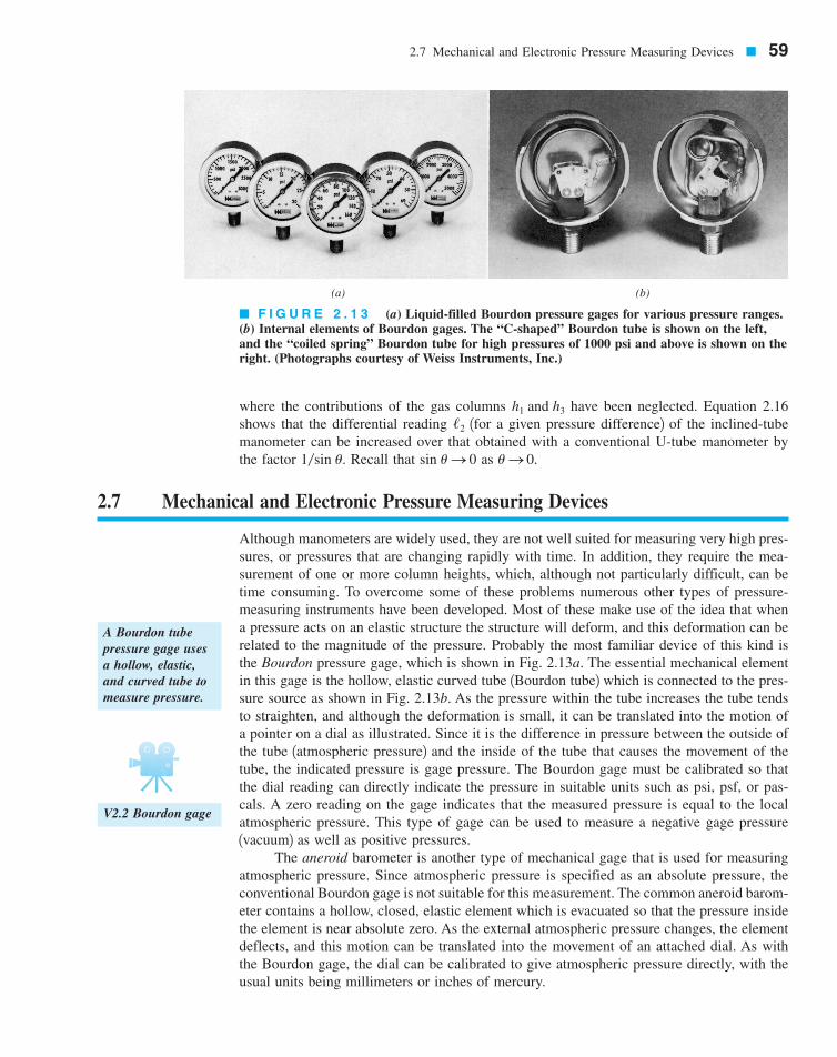
Although manometers are widely used, they are not well suited for measuring very high pres-sures, or pressures that are changing rapidly with time. In addition, they require the mea-surement of one or more column heights, which, although not particularly difficult, can betime consuming. To overcome some of these problems numerous other types of pressure-measuring instruments have been developed. Most of these make use of the idea that whena pressure acts on an elastic structure the structure will deform, and this deformation can berelated to the magnitude of the pressure. Probably the most familiar device of this kind isthe Bourdon pressure gage, which is shown in Fig. 2.13a. The essential mechanical elementin this gage is the hollow, elastic curved tube 1Bourdon tube2 which is connected to the pres-sure source as shown in Fig. 2.13b. As the pressure within the tube increases the tube tendsto straighten, and although the deformation is small, it can be translated into the motion ofa pointer on a dial as illustrated. Since it is the difference in pressure between the outside ofthe tube 1atmospheric pressure2 and the inside of the tube that causes the movement of thetube, the indicated pressure is gage pressure. The Bourdon gage must be calibrated so thatthe dial reading can directly indicate the pressure in suitable units such as psi, psf, or pas-cals. A zero reading on the gage indicates that the measured pressure is equal to the localatmospheric pressure. This type of gage can be used to measure a negative gage pressure1vacuum2 as well as positive pressures.
The aneroid barometer is another type of mechanical gage that is used for measuringatmospheric pressure. Since atmospheric pressure is specified as an absolute pressure, theconventional Bourdon gage is not suitable for this measurement. The common aneroid barom-eter contains a hollow, closed, elastic element which is evacuated so that the pressure insidethe element is near absolute zero. As the external atmospheric pressure changes, the elementdeflects, and this motion can be translated into the movement of an attached dial. As withthe Bourdon gage, the dial can be calibrated to give atmospheric pressure directly, with theusual units being millimeters or inches of mercury.
A Bourdon tubepressure gage usesa hollow, elastic,and curved tube tomeasure pressure.
� F I G U R E 2 . 1 3 (a) Liquid-filled Bourdon pressure gages for various pressure ranges.(b) Internal elements of Bourdon gages. The “C-shaped” Bourdon tube is shown on the left,and the “coiled spring” Bourdon tube for high pressures of 1000 psi and above is shown on theright. (Photographs courtesy of Weiss Instruments, Inc.)
(a) (b)
V2.2 Bourdon gage
7708d_c02_059 8/2/01 1:23 PM Page 59
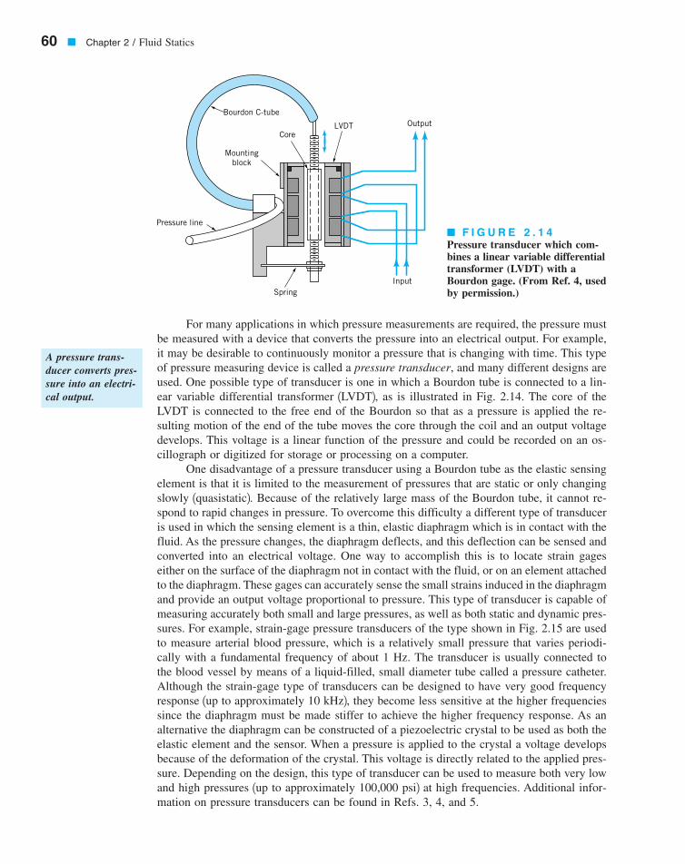
For many applications in which pressure measurements are required, the pressure mustbe measured with a device that converts the pressure into an electrical output. For example,it may be desirable to continuously monitor a pressure that is changing with time. This typeof pressure measuring device is called a pressure transducer, and many different designs areused. One possible type of transducer is one in which a Bourdon tube is connected to a lin-ear variable differential transformer 1LVDT2, as is illustrated in Fig. 2.14. The core of theLVDT is connected to the free end of the Bourdon so that as a pressure is applied the re-sulting motion of the end of the tube moves the core through the coil and an output voltagedevelops. This voltage is a linear function of the pressure and could be recorded on an os-cillograph or digitized for storage or processing on a computer.
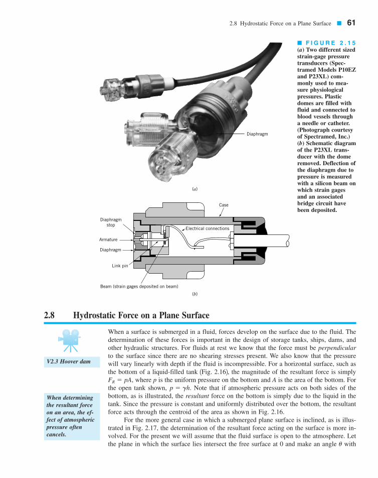
One disadvantage of a pressure transducer using a Bourdon tube as the elastic sensingelement is that it is limited to the measurement of pressures that are static or only changingslowly 1quasistatic2. Because of the relatively large mass of the Bourdon tube, it cannot re-spond to rapid changes in pressure. To overcome this difficulty a different type of transduceris used in which the sensing element is a thin, elastic diaphragm which is in contact with thefluid. As the pressure changes, the diaphragm deflects, and this deflection can be sensed andconverted into an electrical voltage. One way to accomplish this is to locate strain gageseither on the surface of the diaphragm not in contact with the fluid, or on an element attachedto the diaphragm. These gages can accurately sense the small strains induced in the diaphragmand provide an output voltage proportional to pressure. This type of transducer is capable ofmeasuring accurately both small and large pressures, as well as both static and dynamic pres-sures. For example, strain-gage pressure transducers of the type shown in Fig. 2.15 are usedto measure arterial blood pressure, which is a relatively small pressure that varies periodi-cally with a fundamental frequency of about 1 Hz. The transducer is usually connected tothe blood vessel by means of a liquid-filled, small diameter tube called a pressure catheter.Although the strain-gage type of transducers can be designed to have very good frequencyresponse 1up to approximately 10 kHz2, they become less sensitive at the higher frequenciessince the diaphragm must be made stiffer to achieve the higher frequency response. As analternative the diaphragm can be constructed of a piezoelectric crystal to be used as both theelastic element and the sensor. When a pressure is applied to the crystal a voltage developsbecause of the deformation of the crystal. This voltage is directly related to the applied pres-sure. Depending on the design, this type of transducer can be used to measure both very lowand high pressures 1up to approximately 100,000 psi2 at high frequencies. Additional infor-mation on pressure transducers can be found in Refs. 3, 4, and 5.
60 � Chapter 2 / Fluid Statics
A pressure trans-ducer converts pres-sure into an electri-cal output.
� F I G U R E 2 . 1 4Pressure transducer which com-bines a linear variable differentialtransformer (LVDT) with aBourdon gage. (From Ref. 4, usedby permission.)
Bourdon C-tube
CoreLVDT Output
InputSpring
Pressure line
Mountingblock
7708d_c02_060 8/2/01 1:23 PM Page 60
When a surface is submerged in a fluid, forces develop on the surface due to the fluid. Thedetermination of these forces is important in the design of storage tanks, ships, dams, andother hydraulic structures. For fluids at rest we know that the force must be perpendicularto the surface since there are no shearing stresses present. We also know that the pressurewill vary linearly with depth if the fluid is incompressible. For a horizontal surface, such asthe bottom of a liquid-filled tank 1Fig. 2.162, the magnitude of the resultant force is simply
where p is the uniform pressure on the bottom and A is the area of the bottom. Forthe open tank shown, Note that if atmospheric pressure acts on both sides of thebottom, as is illustrated, the resultant force on the bottom is simply due to the liquid in thetank. Since the pressure is constant and uniformly distributed over the bottom, the resultantforce acts through the centroid of the area as shown in Fig. 2.16.
For the more general case in which a submerged plane surface is inclined, as is illus-trated in Fig. 2.17, the determination of the resultant force acting on the surface is more in-volved. For the present we will assume that the fluid surface is open to the atmosphere. Letthe plane in which the surface lies intersect the free surface at 0 and make an angle withu
p � gh.FR � pA,
2.8 Hydrostatic Force on a Plane Surface � 61
When determiningthe resultant forceon an area, the ef-fect of atmosphericpressure oftencancels.
� F I G U R E 2 . 1 5(a) Two different sizedstrain-gage pressuretransducers (Spec-tramed Models P10EZand P23XL) com-monly used to mea-sure physiologicalpressures. Plasticdomes are filled withfluid and connected toblood vessels througha needle or catheter.(Photograph courtesyof Spectramed, Inc.)(b) Schematic diagramof the P23XL trans-ducer with the domeremoved. Deflection ofthe diaphragm due topressure is measuredwith a silicon beam onwhich strain gagesand an associatedbridge circuit havebeen deposited.
2.8 Hydrostatic Force on a Plane Surface
Case
Electrical connections
Beam (strain gages deposited on beam)
Link pin
Diaphragm
Diaphragm
Armature
Diaphragmstop
(b)
(a)
V2.3 Hoover dam
7708d_c02_061 8/2/01 1:24 PM Page 61

this surface as in Fig. 2.17. The x–y coordinate system is defined so that 0 is the origin andy is directed along the surface as shown. The area can have an arbitrary shape as shown. Wewish to determine the direction, location, and magnitude of the resultant force acting on oneside of this area due to the liquid in contact with the area. At any given depth, h, the forceacting on dA 1the differential area of Fig. 2.172 is and is perpendicular to thesurface. Thus, the magnitude of the resultant force can be found by summing these differ-ential forces over the entire surface. In equation form
where For constant and
(2.17)FR � g sin u�A
y dA
ugh � y sin u.
FR � �A
gh dA � �A
gy sin u dA
dF � gh dA
62 � Chapter 2 / Fluid Statics
Free surfacep = patm
Specific weight = γ
FRh
p = patm
p
y
ycyR
xR
xc
c
CP Centroid, c
Location ofresultant force
(center of pressure, CP)
dA
A
x
x
y
θ
0Free surface
hhc
FR
dF
� F I G U R E 2 . 1 6 Pressure and resultanthydrostatic force developed on the bottom of anopen tank.
� F I G U R E 2 . 1 7Notation for hydrosta-tic force on an in-clined plane surface ofarbitrary shape.
The resultant forceof a static fluid on aplane surface is dueto the hydrostaticpressure distributionon the surface.
7708d_c02_062 8/2/01 1:24 PM Page 62
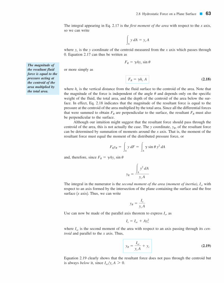
The integral appearing in Eq. 2.17 is the first moment of the area with respect to the x axis,so we can write
where is the y coordinate of the centroid measured from the x axis which passes through0. Equation 2.17 can thus be written as
or more simply as
(2.18)
where is the vertical distance from the fluid surface to the centroid of the area. Note thatthe magnitude of the force is independent of the angle and depends only on the specificweight of the fluid, the total area, and the depth of the centroid of the area below the sur-face. In effect, Eq. 2.18 indicates that the magnitude of the resultant force is equal to thepressure at the centroid of the area multiplied by the total area. Since all the differential forcesthat were summed to obtain are perpendicular to the surface, the resultant must alsobe perpendicular to the surface.
Although our intuition might suggest that the resultant force should pass through thecentroid of the area, this is not actually the case. The y coordinate, of the resultant forcecan be determined by summation of moments around the x axis. That is, the moment of theresultant force must equal the moment of the distributed pressure force, or
and, therefore, since
The integral in the numerator is the second moment of the area (moment of inertia), withrespect to an axis formed by the intersection of the plane containing the surface and the freesurface 1x axis2. Thus, we can write
Use can now be made of the parallel axis theorem to express as
where is the second moment of the area with respect to an axis passing through its cen-troid and parallel to the x axis. Thus,
(2.19)
Equation 2.19 clearly shows that the resultant force does not pass through the centroid butis always below it, since Ixc�yc A 7 0.
yR �Ixc
yc A� yc
Ixc
Ix � Ixc � Ay2c
Ix,
yR �Ix
yc A
Ix,
yR ��
A
y2 dA
yc A
FR � gAyc sin u
FR
yR � �A
y dF � �A
g sin u y2 dA
yR,
FRFR
u
hc
FR � ghc A
FR � gAyc sin u
yc
�A
y dA � yc A
2.8 Hydrostatic Force on a Plane Surface � 63
The magnitude ofthe resultant fluidforce is equal to thepressure acting atthe centroid of thearea multiplied bythe total area.
7708d_c02_063 8/2/01 1:24 PM Page 63
The x coordinate, for the resultant force can be determined in a similar manner bysumming moments about the y axis. Thus,
and, therefore,
where is the product of inertia with respect to the x and y axes. Again, using the parallelaxis theorem,1 we can write
(2.20)xR �Ixyc
yc A� xc
Ixy
xR ��
A
xy dA
yc A�
Ixy
yc A
FR xR � �A
g sin u xy dA
xR,
64 � Chapter 2 / Fluid Statics
The resultant fluidforce does not passthrough the cen-troid of the area.
1Recall that the parallel axis theorem for the product of inertia of an area states that the product of inertia with respect to an or-thogonal set of axes 1x–y coordinate system2 is equal to the product of inertia with respect to an orthogonal set of axes parallel tothe original set and passing through the centroid of the area, plus the product of the area and the x and y coordinates of the centroidof the area. Thus, Ixy � Ixyc � Axcyc.
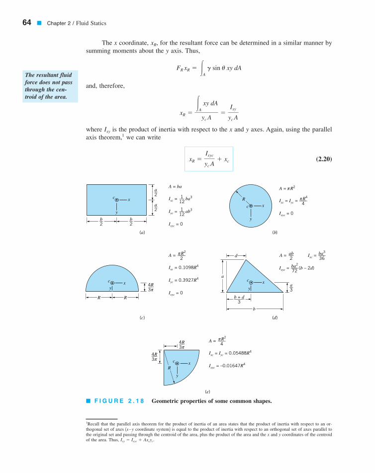
� F I G U R E 2 . 1 8 Geometric properties of some common shapes.
c
y
x
4R–––3π
4R–––3π
A = R2–––––4
π
Ixc = Iyc = 0.05488R4
Ixyc = –0.01647R4
A = R2–––––2
π
Ixc = 0.1098R4
Iyc = 0.3927R4
Ixyc = 0
A = ab–––2
Ixc =
Ixyc = (b – 2d)
ba3–––-–36
ba2–––––72
A = R2
R4–––––4
πIxc = Iyc =
Ixyc = 0
πA = ba
1–––12
Ixc = ba3
Iyc = ab3
Ixyc = 0
1–––12
c
yx
R R
4R–––3π
c
yx
b + d–––––––3
b
a––3
d
a
R
c
y
xRc
y
x
b––2
b––2
a––2
a––2
(a) (b)
(c) (d)
(e)
7708d_c02_064 8/2/01 1:25 PM Page 64
where is the product of inertia with respect to an orthogonal coordinate system passingthrough the centroid of the area and formed by a translation of the x-y coordinate system. Ifthe submerged area is symmetrical with respect to an axis passing through the centroid andparallel to either the x or y axes, the resultant force must lie along the line since is identically zero in this case. The point through which the resultant force acts is called thecenter of pressure. It is to be noted from Eqs. 2.19 and 2.20 that as increases the centerof pressure moves closer to the centroid of the area. Since the distance willincrease if the depth of submergence, increases, or, for a given depth, the area is rotatedso that the angle, decreases. Centroidal coordinates and moments of inertia for some com-mon areas are given in Fig. 2.18.
u,hc,
ycyc � hc �sin u,yc
Ixycx � xc,
Ixyc
2.8 Hydrostatic Force on a Plane Surface � 65
The point throughwhich the resultantfluid force acts iscalled the center ofpressure.
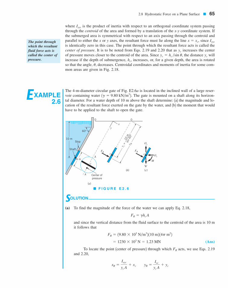
EXAMPLE2.6
The 4-m-diameter circular gate of Fig. E2.6a is located in the inclined wall of a large reser-voir containing water The gate is mounted on a shaft along its horizon-tal diameter. For a water depth of 10 m above the shaft determine: 1a2 the magnitude and lo-cation of the resultant force exerted on the gate by the water, and 1b2 the moment that wouldhave to be applied to the shaft to open the gate.
1g � 9.80 kN�m32.
SOLUTION
(a) To find the magnitude of the force of the water we can apply Eq. 2.18,
and since the vertical distance from the fluid surface to the centroid of the area is 10 mit follows that
(Ans)
To locate the point 1center of pressure2 through which acts, we use Eqs. 2.19and 2.20,
xR �Ixyc
yc A� xc yR �
Ixc
yc A� yc
FR
� 1230 � 103 N � 1.23 MN
FR � 19.80 � 103 N�m32 110 m2 14p m22
FR � ghc A
xy
c
A
A Center ofpressure
FR
�
M
Oy
Oxc
(a)
(c)(b)
4 m
Shaft
Stop10 m
60°
0 0
FRc
y R
y c =
10
m––
––––
–––
sin
60°
� F I G U R E E 2 . 6
7708d_c02_065 8/2/01 1:25 PM Page 65
66 � Chapter 2 / Fluid Statics
For the coordinate system shown, since the area is symmetrical, and the centerof pressure must lie along the diameter A-A. To obtain we have from Fig. 2.18
and is shown in Fig. E2.6b. Thus,
and the distance 1along the gate2 below the shaft to the center of pressure is
(Ans)
We can conclude from this analysis that the force on the gate due to the water has amagnitude of 1.23 MN and acts through a point along its diameter A-A at a distance of0.0866 m 1along the gate2 below the shaft. The force is perpendicular to the gate sur-face as shown.
(b) The moment required to open the gate can be obtained with the aid of the free-bodydiagram of Fig. E2.6c. In this diagram is the weight of the gate and and arethe horizontal and vertical reactions of the shaft on the gate. We can now sum momentsabout the shaft
and, therefore,
(Ans) � 1.07 � 105 N # m
� 11230 � 103 N2 10.0866 m2 M � FR 1yR � yc2
aMc � 0
OyOxw
yR � yc � 0.0866 m
� 0.0866 m � 11.55 m � 11.6 m
yR �1p�42 12 m24
110 m�sin 60°2 14p m22 �10 m
sin 60°
yc
Ixc �pR4
4
yR,xR � 0
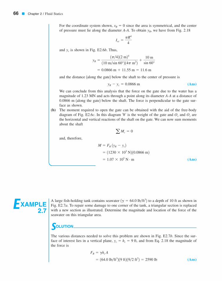
EXAMPLE2.7
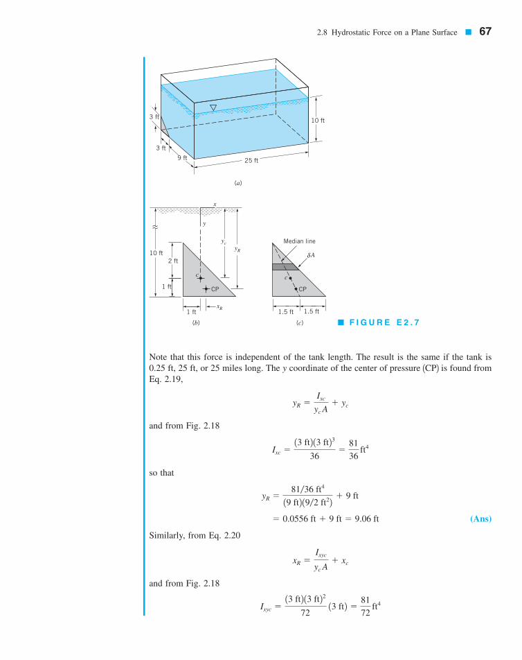
A large fish-holding tank contains seawater to a depth of 10 ft as shown inFig. E2.7a. To repair some damage to one corner of the tank, a triangular section is replacedwith a new section as illustrated. Determine the magnitude and location of the force of theseawater on this triangular area.
SOLUTION
The various distances needed to solve this problem are shown in Fig. E2.7b. Since the sur-face of interest lies in a vertical plane, and from Eq. 2.18 the magnitude ofthe force is
(Ans) � 164.0 lb�ft32 19 ft2 19�2 ft22 � 2590 lb
FR � ghc A
yc � hc � 9 ft,
1g � 64.0 lb�ft32
7708d_c02_40-99 8/31/01 12:38 PM Page 66 mac106 mac 106:1st_Shift:7708d:
2.8 Hydrostatic Force on a Plane Surface � 67
Note that this force is independent of the tank length. The result is the same if the tank is0.25 ft, 25 ft, or 25 miles long. The y coordinate of the center of pressure 1CP2 is found fromEq. 2.19,
and from Fig. 2.18
so that
(Ans)
Similarly, from Eq. 2.20
and from Fig. 2.18
Ixyc �13 ft2 13 ft22
72 13 ft2 �
81
72 ft4
xR �Ixyc
yc A� xc
� 0.0556 ft � 9 ft � 9.06 ft
yR �81�36 ft4
19 ft2 19�2 ft22 � 9 ft
Ixc �13 ft2 13 ft23
36�
81
36 ft4
yR �Ixc
yc A� yc
3 ft
3 ft
9 ft 25 ft
10 ft
(a)
(b) (c)
10 ft2 ft
1 ft
1 ft 1.5 ft 1.5 ft
Median line
δ AyR
xR
yc
y
x
c
CP
c
CP
� F I G U R E E 2 . 7
7708d_c02_40-99 8/31/01 12:38 PM Page 67 mac106 mac 106:1st_Shift:7708d:
2.9 Pressure Prism
68 � Chapter 2 / Fluid Statics
so that
(Ans)
Thus, we conclude that the center of pressure is 0.0278 ft to the right of and 0.0556 ftbelow the centroid of the area. If this point is plotted, we find that it lies on the median linefor the area as illustrated in Fig. E2.7c. Since we can think of the total area as consisting ofa number of small rectangular strips of area 1and the fluid force on each of these smallareas acts through its center2, it follows that the resultant of all these parallel forces must liealong the median.
dA
xR �81�72 ft4
19 ft2 19�2 ft22 � 0 � 0.0278 ft
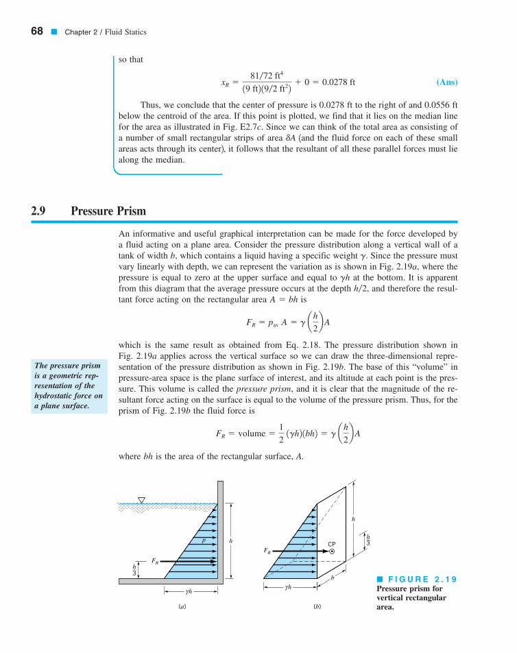
An informative and useful graphical interpretation can be made for the force developed bya fluid acting on a plane area. Consider the pressure distribution along a vertical wall of atank of width b, which contains a liquid having a specific weight Since the pressure mustvary linearly with depth, we can represent the variation as is shown in Fig. 2.19a, where thepressure is equal to zero at the upper surface and equal to at the bottom. It is apparentfrom this diagram that the average pressure occurs at the depth and therefore the resul-tant force acting on the rectangular area is
which is the same result as obtained from Eq. 2.18. The pressure distribution shown inFig. 2.19a applies across the vertical surface so we can draw the three-dimensional repre-sentation of the pressure distribution as shown in Fig. 2.19b. The base of this “volume” inpressure-area space is the plane surface of interest, and its altitude at each point is the pres-sure. This volume is called the pressure prism, and it is clear that the magnitude of the re-sultant force acting on the surface is equal to the volume of the pressure prism. Thus, for theprism of Fig. 2.19b the fluid force is
where bh is the area of the rectangular surface, A.
FR � volume �1
2 1gh2 1bh2 � g ah
2b A
FR � pav A � g ah
2b A
A � bhh�2,
gh
g.
� F I G U R E 2 . 1 9Pressure prism forvertical rectangulararea.
FR
γ h
h
h–3
(a) (b)
γ h
h
FR
h–3
b
CPp
The pressure prismis a geometric rep-resentation of thehydrostatic force ona plane surface.
7708d_c02_068 8/2/01 1:25 PM Page 68
The resultant force must pass through the centroid of the pressure prism. For the vol-ume under consideration the centroid is located along the vertical axis of symmetry of thesurface, and at a distance of above the base 1since the centroid of a triangle is located at
above its base2. This result can readily be shown to be consistent with that obtained fromEqs. 2.19 and 2.20.
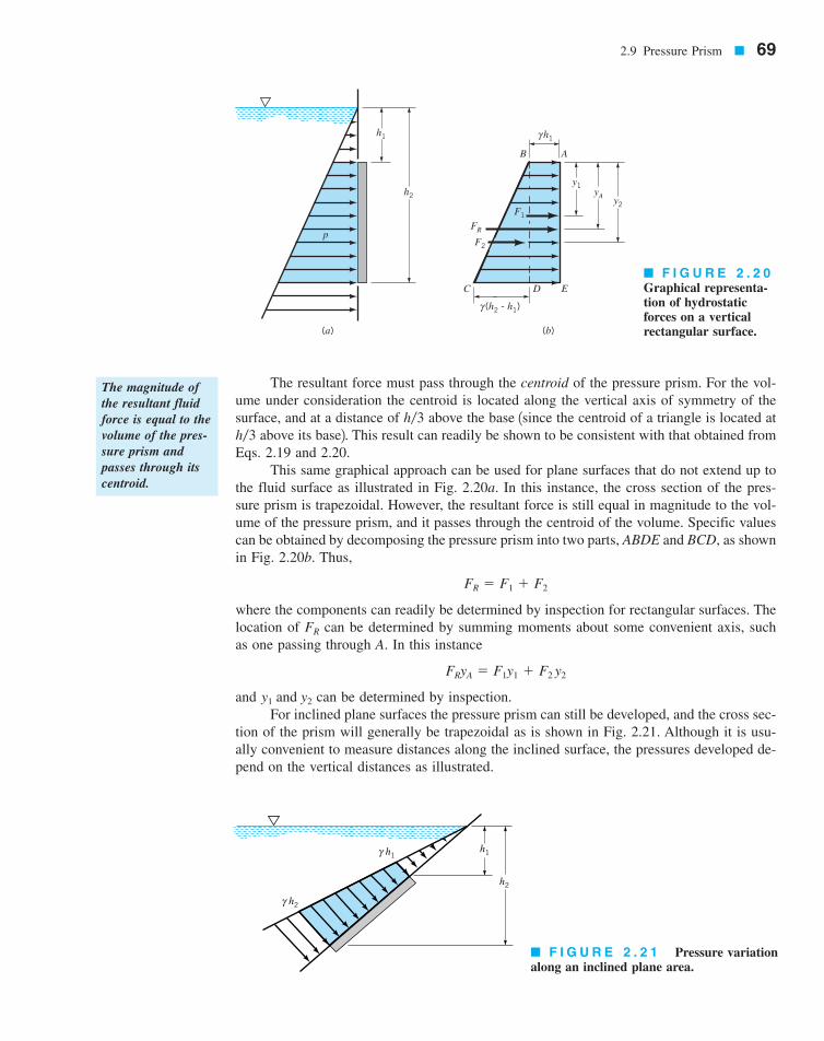
This same graphical approach can be used for plane surfaces that do not extend up tothe fluid surface as illustrated in Fig. 2.20a. In this instance, the cross section of the pres-sure prism is trapezoidal. However, the resultant force is still equal in magnitude to the vol-ume of the pressure prism, and it passes through the centroid of the volume. Specific valuescan be obtained by decomposing the pressure prism into two parts, ABDE and BCD, as shownin Fig. 2.20b. Thus,
where the components can readily be determined by inspection for rectangular surfaces. Thelocation of can be determined by summing moments about some convenient axis, suchas one passing through A. In this instance
and can be determined by inspection.For inclined plane surfaces the pressure prism can still be developed, and the cross sec-
tion of the prism will generally be trapezoidal as is shown in Fig. 2.21. Although it is usu-ally convenient to measure distances along the inclined surface, the pressures developed de-pend on the vertical distances as illustrated.
y1 and y2
FRyA � F1y1 � F2 y2
FR
FR � F1 � F2
h�3h�3
2.9 Pressure Prism � 69
γ h2
h2
γ h1h1
h1
h2
p
(a) (b)
C D E
AB
FR
F2
F1
y1yA
y2
(h2 - h1)γ
h1γ
� F I G U R E 2 . 2 0Graphical representa-tion of hydrostaticforces on a verticalrectangular surface.
The magnitude ofthe resultant fluidforce is equal to thevolume of the pres-sure prism andpasses through itscentroid.
� F I G U R E 2 . 2 1 Pressure variationalong an inclined plane area.
7708d_c02_069 8/2/01 1:26 PM Page 69
The use of pressure prisms for determining the force on submerged plane areas is con-venient if the area is rectangular so the volume and centroid can be easily determined. How-ever, for other nonrectangular shapes, integration would generally be needed to determinethe volume and centroid. In these circumstances it is more convenient to use the equationsdeveloped in the previous section, in which the necessary integrations have been made andthe results presented in a convenient and compact form that is applicable to submerged planeareas of any shape.
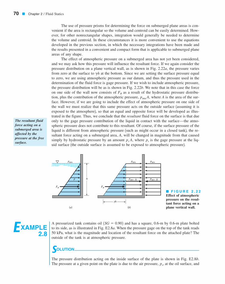
The effect of atmospheric pressure on a submerged area has not yet been considered,and we may ask how this pressure will influence the resultant force. If we again consider thepressure distribution on a plane vertical wall, as is shown in Fig. 2.22a, the pressure variesfrom zero at the surface to at the bottom. Since we are setting the surface pressure equalto zero, we are using atmospheric pressure as our datum, and thus the pressure used in thedetermination of the fluid force is gage pressure. If we wish to include atmospheric pressure,the pressure distribution will be as is shown in Fig. 2.22b. We note that in this case the forceon one side of the wall now consists of as a result of the hydrostatic pressure distribu-tion, plus the contribution of the atmospheric pressure, where A is the area of the sur-face. However, if we are going to include the effect of atmospheric pressure on one side ofthe wall we must realize that this same pressure acts on the outside surface 1assuming it isexposed to the atmosphere2, so that an equal and opposite force will be developed as illus-trated in the figure. Thus, we conclude that the resultant fluid force on the surface is that dueonly to the gage pressure contribution of the liquid in contact with the surface—the atmo-spheric pressure does not contribute to this resultant. Of course, if the surface pressure of theliquid is different from atmospheric pressure 1such as might occur in a closed tank2, the re-sultant force acting on a submerged area, A, will be changed in magnitude from that causedsimply by hydrostatic pressure by an amount where is the gage pressure at the liq-uid surface 1the outside surface is assumed to be exposed to atmospheric pressure2.
psps A,
patm A,FR
gh
70 � Chapter 2 / Fluid Statics
EXAMPLE2.8
A pressurized tank contains oil and has a square, 0.6-m by 0.6-m plate boltedto its side, as is illustrated in Fig. E2.8a. When the pressure gage on the top of the tank reads50 kPa, what is the magnitude and location of the resultant force on the attached plate? Theoutside of the tank is at atmospheric pressure.
SOLUTION
The pressure distribution acting on the inside surface of the plate is shown in Fig. E2.8b.The pressure at a given point on the plate is due to the air pressure, at the oil surface, andps,
1SG � 0.902
FR FR
patm patm
patmpatm A A
(a) (b)
h
h
γ
patm
p
� F I G U R E 2 . 2 2Effect of atmosphericpressure on the resul-tant force acting on aplane vertical wall.
The resultant fluidforce acting on asubmerged area isaffected by thepressure at the freesurface.
7708d_c02_070 8/2/01 1:26 PM Page 70

2.9 Pressure Prism � 71
the pressure due to the oil, which varies linearly with depth as is shown in the figure. Theresultant force on the plate 1having an area A2 is due to the components, with
and
The magnitude of the resultant force, is therefore
(Ans)
The vertical location of can be obtained by summing moments around an axisthrough point O so that
or
(Ans)
Thus, the force acts at a distance of 0.296 m above the bottom of the plate along the verti-cal axis of symmetry.
Note that the air pressure used in the calculation of the force was gage pressure. At-mospheric pressure does not affect the resultant force 1magnitude or location2, since it actson both sides of the plate, thereby canceling its effect.
yO � 0.296 m
125.4 � 103 N2 yO � 124.4 � 103 N2 10.3 m2 � 10.954 � 103 N2 10.2 m2
FRyO � F110.3 m2 � F210.2 m2FR
FR � F1 � F2 � 25.4 � 103 N � 25.4 kN
FR,
� 0.954 � 103 N
� 10.902 19.81 � 103 N�m32 a0.6 m
2b 10.36 m22
F2 � g ah2 � h1
2b A
� 24.4 � 103 N
� 350 � 103 N�m2 � 10.902 19.81 � 103 N�m32 12 m2 4 10.36 m22 F1 � 1 ps � gh12
A
F1 and F2,
p = 50 kPa
Air
2 m
0.6 m
(a)
F1
FR
PlateO
(h2 – h1)γ
0.2 m
F2
yO0.3 m
0.6 m
h2 = 2.6 mh1 = 2 m
h1γps Oil surface
(b)
Oil
� F I G U R E E 2 . 8
7708d_c02_40-99 8/31/01 1:16 PM Page 71 mac106 mac 106:1st_Shift:7708d:
2.10 Hydrostatic Force on a Curved Surface
72 � Chapter 2 / Fluid Statics
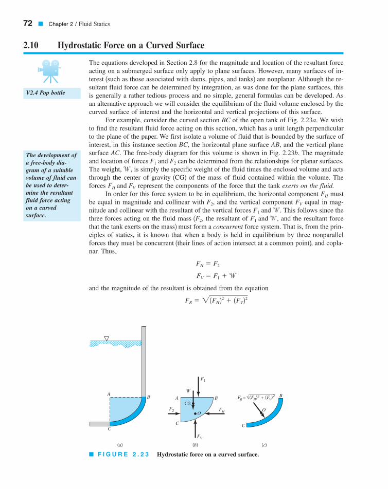
The equations developed in Section 2.8 for the magnitude and location of the resultant forceacting on a submerged surface only apply to plane surfaces. However, many surfaces of in-terest 1such as those associated with dams, pipes, and tanks2 are nonplanar. Although the re-sultant fluid force can be determined by integration, as was done for the plane surfaces, thisis generally a rather tedious process and no simple, general formulas can be developed. Asan alternative approach we will consider the equilibrium of the fluid volume enclosed by thecurved surface of interest and the horizontal and vertical projections of this surface.
For example, consider the curved section BC of the open tank of Fig. 2.23a. We wishto find the resultant fluid force acting on this section, which has a unit length perpendicularto the plane of the paper. We first isolate a volume of fluid that is bounded by the surface ofinterest, in this instance section BC, the horizontal plane surface AB, and the vertical planesurface AC. The free-body diagram for this volume is shown in Fig. 2.23b. The magnitudeand location of forces can be determined from the relationships for planar surfaces.The weight, is simply the specific weight of the fluid times the enclosed volume and actsthrough the center of gravity 1CG2 of the mass of fluid contained within the volume. Theforces represent the components of the force that the tank exerts on the fluid.
In order for this force system to be in equilibrium, the horizontal component mustbe equal in magnitude and collinear with and the vertical component equal in mag-nitude and collinear with the resultant of the vertical forces This follows since thethree forces acting on the fluid mass 1 the resultant of and the resultant forcethat the tank exerts on the mass2 must form a concurrent force system. That is, from the prin-ciples of statics, it is known that when a body is held in equilibrium by three nonparallelforces they must be concurrent 1their lines of action intersect at a common point2, and copla-nar. Thus,
and the magnitude of the resultant is obtained from the equation
FR � 21FH22 � 1FV2
2
FV � F1 �w
FH � F2
F1 and w,F2,F1 and w.
FVF2,FH
FH and FV
w,F1 and F2
CG
O
C
A B
FH
FV
F2
F1
�A
C
B
(a) (b) (c)
O
B
C
FR √(FH)2 + (FV)2=
� F I G U R E 2 . 2 3 Hydrostatic force on a curved surface.
The development ofa free-body dia-gram of a suitablevolume of fluid canbe used to deter-mine the resultantfluid force actingon a curvedsurface.
V2.4 Pop bottle
7708d_c02_072 8/2/01 1:26 PM Page 72
The resultant passes through the point O, which can be located by summing momentsabout an appropriate axis. The resultant force of the fluid acting on the curved surface BCis equal and opposite in direction to that obtained from the free-body diagram of Fig. 2.23b.The desired fluid force is shown in Fig. 2.23c.
FR
2.10 Hydrostatic Force on a Curved Surface � 73
EXAMPLE2.9
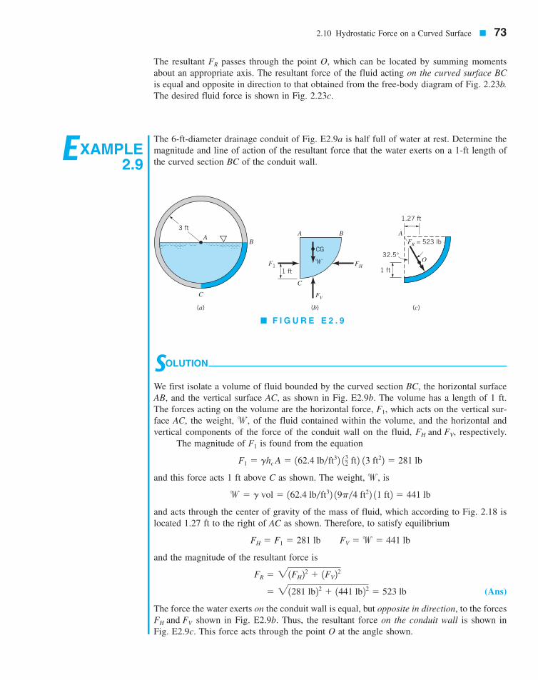
The 6-ft-diameter drainage conduit of Fig. E2.9a is half full of water at rest. Determine themagnitude and line of action of the resultant force that the water exerts on a 1-ft length ofthe curved section BC of the conduit wall.
SOLUTION
We first isolate a volume of fluid bounded by the curved section BC, the horizontal surfaceAB, and the vertical surface AC, as shown in Fig. E2.9b. The volume has a length of 1 ft.The forces acting on the volume are the horizontal force, which acts on the vertical sur-face AC, the weight, of the fluid contained within the volume, and the horizontal andvertical components of the force of the conduit wall on the fluid, respectively.
The magnitude of is found from the equation
and this force acts 1 ft above C as shown. The weight, is
and acts through the center of gravity of the mass of fluid, which according to Fig. 2.18 islocated 1.27 ft to the right of AC as shown. Therefore, to satisfy equilibrium
and the magnitude of the resultant force is
(Ans)
The force the water exerts on the conduit wall is equal, but opposite in direction, to the forcesshown in Fig. E2.9b. Thus, the resultant force on the conduit wall is shown in
Fig. E2.9c. This force acts through the point O at the angle shown.FH and FV
� 21281 lb22 � 1441 lb22 � 523 lb
FR � 21FH22 � 1FV22
FH � F1 � 281 lb FV �w � 441 lb
w � g vol � 162.4 lb�ft32 19p�4 ft22 11 ft2 � 441 lb
w,
F1 � ghc A � 162.4 lb�ft32 132 ft2 13 ft22 � 281 lb
F1
FH and FV,w,
F1,
B
C
(a)
A B
C
FV
FHF11 ft
�
CG
(b)
1 ft
A
1.27 ft
O
FR = 523 lb
32.5°
(c)
3 ftA
� F I G U R E E 2 . 9
7708d_c02_40-99 8/31/01 1:17 PM Page 73 mac106 mac 106:1st_Shift:7708d:
This same general approach can also be used for determining the force on curvedsurfaces of pressurized, closed tanks. If these tanks contain a gas, the weight of the gas isusually negligible in comparison with the forces developed by the pressure. Thus, the forces1such as in Fig. 2.23b2 on horizontal and vertical projections of the curved surfaceof interest can simply be expressed as the internal pressure times the appropriate projectedarea.
F1 and F2
74 � Chapter 2 / Fluid Statics
2.11 Buoyancy, Flotation, and Stability
An inspection of this result will show that the line of action of the resultant force passesthrough the center of the conduit. In retrospect, this is not a surprising result since at eachpoint on the curved surface of the conduit the elemental force due to the pressure is normalto the surface, and each line of action must pass through the center of the conduit. It there-fore follows that the resultant of this concurrent force system must also pass through the cen-ter of concurrence of the elemental forces that make up the system.
2.11.1 Archimedes’ Principle
When a stationary body is completely submerged in a fluid, or floating so that it is only par-tially submerged, the resultant fluid force acting on the body is called the buoyant force. Anet upward vertical force results because pressure increases with depth and the pressure forcesacting from below are larger than the pressure forces acting from above. This force can bedetermined through an approach similar to that used in the previous article for forces oncurved surfaces. Consider a body of arbitrary shape, having a volume that is immersedin a fluid as illustrated in Fig. 2.24a. We enclose the body in a parallelepiped and draw afree-body diagram of the parallelepiped with the body removed as shown in Fig. 2.24b. Notethat the forces and are simply the forces exerted on the plane surfaces of theparallelepiped 1for simplicity the forces in the x direction are not shown2, is the weight ofthe shaded fluid volume 1parallelepiped minus body2, and is the force the body is exert-ing on the fluid. The forces on the vertical surfaces, such as are all equal and can-cel, so the equilibrium equation of interest is in the z direction and can be expressed as
(2.21)
If the specific weight of the fluid is constant, then
where A is the horizontal area of the upper 1or lower2 surface of the parallelepiped, and Eq.2.21 can be written as
Simplifying, we arrive at the desired expression for the buoyant force
(2.22)
where is the specific weight of the fluid and is the volume of the body. The directionof the buoyant force, which is the force of the fluid on the body, is opposite to that shownon the free-body diagram. Therefore, the buoyant force has a magnitude equal to the weight
V�g
FB � gV�
FB � g1h2 � h12A � g 3 1h2 � h12A � V� 4
F2 � F1 � g1h2 � h12A
FB � F2 � F1 �w
F3 and F4,FB
wF4F1, F2, F3,
V�,
The resultant fluidforce acting on abody that is com-pletely submergedor floating in afluid is called thebuoyant force.
V2.5 CartesianDiver
7708d_c02_074 8/2/01 1:28 PM Page 74

of the fluid displaced by the body and is directed vertically upward. This result is commonlyreferred to as Archimedes’ principle in honor of Archimedes 1287–212 B.C.2, a Greekmechanician and mathematician who first enunciated the basic ideas associated withhydrostatics.
The location of the line of action of the buoyant force can be determined by summingmoments of the forces shown on the free-body diagram in Fig. 2.24b with respect to someconvenient axis. For example, summing moments about an axis perpendicular to the paperthrough point D we have
and on substitution for the various forces
(2.23)
where is the total volume The right-hand side of Eq. 2.23 is the first momentof the displaced volume with respect to the x-z plane so that is equal to the y coordinateof the centroid of the volume In a similar fashion it can be shown that the x coordinateof the buoyant force coincides with the x coordinate of the centroid. Thus, we conclude thatthe buoyant force passes through the centroid of the displaced volume as shown in Fig. 2.24c.The point through which the buoyant force acts is called the center of buoyancy.
These same results apply to floating bodies which are only partially submerged, as il-lustrated in Fig. 2.24d, if the specific weight of the fluid above the liquid surface is verysmall compared with the liquid in which the body floats. Since the fluid above the surfaceis usually air, for practical purposes this condition is satisfied.
In the derivations presented above, the fluid is assumed to have a constant specificweight, If a body is immersed in a fluid in which varies with depth, such as in a lay-ered fluid, the magnitude of the buoyant force remains equal to the weight of the displacedfluid. However, the buoyant force does not pass through the centroid of the displaced vol-ume, but rather, it passes through the center of gravity of the displaced volume.
gg.
V�.ycV�
1h2 � h12A.V�T
V�yc � V�Ty1 � 1V�T � V�2 y2
FByc � F2 y1 � F1y1 �wy2
2.11 Buoyancy, Flotation, and Stability � 75
h2
h1
A B
CD
A B
CD
(a)
(b)
(c)
(d)
x
y
z
y1
y2
ycF3 F4FB
FB
FB
c
F2
F1
�
Centroid
Centroidof displaced
volume
c
� F I G U R E 2 . 2 4Buoyant force on sub-merged and floatingbodies.
Archimedes’ princi-ple states that thebuoyant force has amagnitude equal tothe weight of thefluid displaced bythe body and isdirected verticallyupward.
V2.6 Hydrometer
7708d_c02_075 8/2/01 1:28 PM Page 75
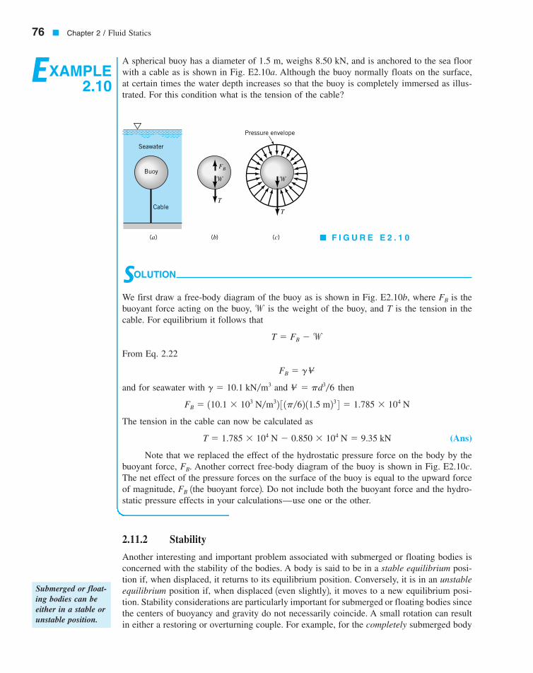
2.11.2 Stability
Another interesting and important problem associated with submerged or floating bodies isconcerned with the stability of the bodies. A body is said to be in a stable equilibrium posi-tion if, when displaced, it returns to its equilibrium position. Conversely, it is in an unstableequilibrium position if, when displaced 1even slightly2, it moves to a new equilibrium posi-tion. Stability considerations are particularly important for submerged or floating bodies sincethe centers of buoyancy and gravity do not necessarily coincide. A small rotation can resultin either a restoring or overturning couple. For example, for the completely submerged body
76 � Chapter 2 / Fluid Statics
EXAMPLE2.10
A spherical buoy has a diameter of 1.5 m, weighs 8.50 kN, and is anchored to the sea floorwith a cable as is shown in Fig. E2.10a. Although the buoy normally floats on the surface,at certain times the water depth increases so that the buoy is completely immersed as illus-trated. For this condition what is the tension of the cable?
Submerged or float-ing bodies can beeither in a stable orunstable position.
SOLUTION
We first draw a free-body diagram of the buoy as is shown in Fig. E2.10b, where is thebuoyant force acting on the buoy, is the weight of the buoy, and T is the tension in thecable. For equilibrium it follows that
From Eq. 2.22
and for seawater with and then
The tension in the cable can now be calculated as
(Ans)
Note that we replaced the effect of the hydrostatic pressure force on the body by thebuoyant force, Another correct free-body diagram of the buoy is shown in Fig. E2.10c.The net effect of the pressure forces on the surface of the buoy is equal to the upward forceof magnitude, 1the buoyant force2. Do not include both the buoyant force and the hydro-static pressure effects in your calculations—use one or the other.
FB
FB.
T � 1.785 � 104 N � 0.850 � 104 N � 9.35 kN
FB � 110.1 � 103 N�m32 3 1p�62 11.5 m23 4 � 1.785 � 104 N
V� � pd3�6g � 10.1 kN�m3
FB � gV�
T � FB �w
wFB
Buoy
Seawater
Cable
�
FB
T
T
Pressure envelope
(a) (b) (c)
�
� F I G U R E E 2 . 1 0
7708d_c02_076 8/2/01 1:28 PM Page 76
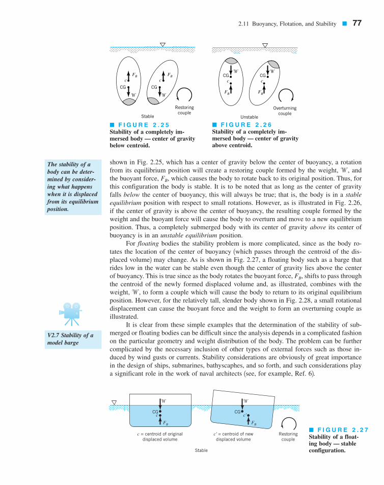
shown in Fig. 2.25, which has a center of gravity below the center of buoyancy, a rotationfrom its equilibrium position will create a restoring couple formed by the weight, andthe buoyant force, which causes the body to rotate back to its original position. Thus, forthis configuration the body is stable. It is to be noted that as long as the center of gravityfalls below the center of buoyancy, this will always be true; that is, the body is in a stableequilibrium position with respect to small rotations. However, as is illustrated in Fig. 2.26,if the center of gravity is above the center of buoyancy, the resulting couple formed by theweight and the buoyant force will cause the body to overturn and move to a new equilibriumposition. Thus, a completely submerged body with its center of gravity above its center ofbuoyancy is in an unstable equilibrium position.
For floating bodies the stability problem is more complicated, since as the body ro-tates the location of the center of buoyancy 1which passes through the centroid of the dis-placed volume2 may change. As is shown in Fig. 2.27, a floating body such as a barge thatrides low in the water can be stable even though the center of gravity lies above the centerof buoyancy. This is true since as the body rotates the buoyant force, shifts to pass throughthe centroid of the newly formed displaced volume and, as illustrated, combines with theweight, to form a couple which will cause the body to return to its original equilibriumposition. However, for the relatively tall, slender body shown in Fig. 2.28, a small rotationaldisplacement can cause the buoyant force and the weight to form an overturning couple asillustrated.
It is clear from these simple examples that the determination of the stability of sub-merged or floating bodies can be difficult since the analysis depends in a complicated fashionon the particular geometry and weight distribution of the body. The problem can be furthercomplicated by the necessary inclusion of other types of external forces such as those in-duced by wind gusts or currents. Stability considerations are obviously of great importancein the design of ships, submarines, bathyscaphes, and so forth, and such considerations playa significant role in the work of naval architects 1see, for example, Ref. 62.
w,
FB,
FB,w,
2.11 Buoyancy, Flotation, and Stability � 77
FB FBc c
CG CG
� �
Restoringcouple
Stable
FB FB
c cCG CG
� �
Overturningcouple
Unstable
�
FB
cCG
Restoringcouple
c' = centroid of newdisplaced volume
c = centroid of originaldisplaced volume
Stable
�
FB
c'CG
� F I G U R E 2 . 2 5Stability of a completely im-mersed body — center of gravitybelow centroid.
� F I G U R E 2 . 2 6Stability of a completely im-mersed body — center of gravityabove centroid.
� F I G U R E 2 . 2 7Stability of a float-ing body — stable configuration.
The stability of abody can be deter-mined by consider-ing what happenswhen it is displacedfrom its equilibriumposition.
V2.7 Stability of amodel barge
7708d_c02_077 8/2/01 1:29 PM Page 77
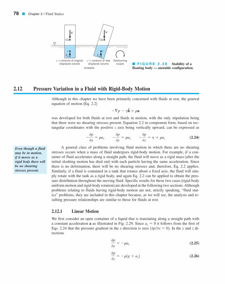
78 � Chapter 2 / Fluid Statics
2.12 Pressure Variation in a Fluid with Rigid-Body Motion
Although in this chapter we have been primarily concerned with fluids at rest, the generalequation of motion 1Eq. 2.22
was developed for both fluids at rest and fluids in motion, with the only stipulation beingthat there were no shearing stresses present. Equation 2.2 in component form, based on rec-tangular coordinates with the positive z axis being vertically upward, can be expressed as
(2.24)
A general class of problems involving fluid motion in which there are no shearingstresses occurs when a mass of fluid undergoes rigid-body motion. For example, if a con-tainer of fluid accelerates along a straight path, the fluid will move as a rigid mass 1after theinitial sloshing motion has died out2 with each particle having the same acceleration. Sincethere is no deformation, there will be no shearing stresses and, therefore, Eq. 2.2 applies.Similarly, if a fluid is contained in a tank that rotates about a fixed axis, the fluid will sim-ply rotate with the tank as a rigid body, and again Eq. 2.2 can be applied to obtain the pres-sure distribution throughout the moving fluid. Specific results for these two cases 1rigid-bodyuniform motion and rigid-body rotation2 are developed in the following two sections. Althoughproblems relating to fluids having rigid-body motion are not, strictly speaking, “fluid stat-ics” problems, they are included in this chapter because, as we will see, the analysis and re-sulting pressure relationships are similar to those for fluids at rest.
2.12.1 Linear Motion
We first consider an open container of a liquid that is translating along a straight path witha constant acceleration a as illustrated in Fig. 2.29. Since it follows from the first ofEqs. 2.24 that the pressure gradient in the x direction is zero In the y and z di-rections
(2.25)
(2.26) 0p
0z� �r1g � az2
0p
0y� �ray
10p�0x � 02.ax � 0
�0p
0x� rax �
0p
0y� ray �
0p
0z� g � raz
�§p � gk � ra
Even though a fluidmay be in motion,if it moves as arigid body there willbe no shearingstresses present.
� F I G U R E 2 . 2 8 Stability of afloating body — unstable configuration.
� �
CGCG
c c'
FB FB
Overturningcouple
c' = centroid of newdisplaced volume
c = centroid of originaldisplaced volume
Unstable
7708d_c02_078 8/2/01 1:29 PM Page 78
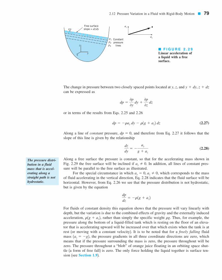
The change in pressure between two closely spaced points located at y, z, and can be expressed as
or in terms of the results from Eqs. 2.25 and 2.26
(2.27)
Along a line of constant pressure, and therefore from Eq. 2.27 it follows that theslope of this line is given by the relationship
(2.28)
Along a free surface the pressure is constant, so that for the accelerating mass shown inFig. 2.29 the free surface will be inclined if In addition, all lines of constant pres-sure will be parallel to the free surface as illustrated.
For the special circumstance in which which corresponds to the massof fluid accelerating in the vertical direction, Eq. 2.28 indicates that the fluid surface will behorizontal. However, from Eq. 2.26 we see that the pressure distribution is not hydrostatic,but is given by the equation
For fluids of constant density this equation shows that the pressure will vary linearly withdepth, but the variation is due to the combined effects of gravity and the externally inducedacceleration, rather than simply the specific weight Thus, for example, thepressure along the bottom of a liquid-filled tank which is resting on the floor of an eleva-tor that is accelerating upward will be increased over that which exists when the tank is atrest 1or moving with a constant velocity2. It is to be noted that for a freely falling fluidmass the pressure gradients in all three coordinate directions are zero, whichmeans that if the pressure surrounding the mass is zero, the pressure throughout will bezero. The pressure throughout a “blob” of orange juice floating in an orbiting space shut-tle 1a form of free fall2 is zero. The only force holding the liquid together is surface ten-sion 1see Section 1.92.
1az � �g2,
rg.r1g � az2,
dp
dz� �r 1g � az2
ay � 0, az � 0,
ay � 0.
dz
dy� �
ay
g � az
dp � 0,
dp � �ray dy � r1g � az2 dz
dp �0p
0y dy �
0p
0z dz
y � dy, z � dz
2.12 Pressure Variation in a Fluid with Rigid-Body Motion � 79
Free surfaceslope = dz/dy
p1p2p3
az
ay
y
z
x
Constantpressure
lines
a
� F I G U R E 2 . 2 9Linear acceleration ofa liquid with a freesurface.
The pressure distri-bution in a fluidmass that is accel-erating along astraight path is nothydrostatic.
7708d_c02_079 8/2/01 1:29 PM Page 79
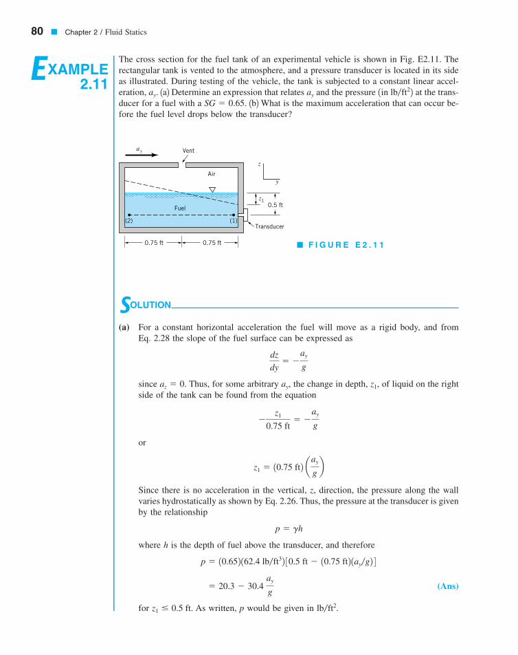
80 � Chapter 2 / Fluid Statics
EXAMPLE2.11
The cross section for the fuel tank of an experimental vehicle is shown in Fig. E2.11. Therectangular tank is vented to the atmosphere, and a pressure transducer is located in its sideas illustrated. During testing of the vehicle, the tank is subjected to a constant linear accel-eration, 1a2 Determine an expression that relates and the pressure at the trans-ducer for a fuel with a 1b2What is the maximum acceleration that can occur be-fore the fuel level drops below the transducer?
SG � 0.65.1in lb�ft22ayay.
SOLUTION
(a) For a constant horizontal acceleration the fuel will move as a rigid body, and fromEq. 2.28 the slope of the fuel surface can be expressed as
since Thus, for some arbitrary the change in depth, of liquid on the rightside of the tank can be found from the equation
or
Since there is no acceleration in the vertical, z, direction, the pressure along the wallvaries hydrostatically as shown by Eq. 2.26. Thus, the pressure at the transducer is givenby the relationship
where h is the depth of fuel above the transducer, and therefore
(Ans)
for As written, p would be given in lb�ft2.z1 0.5 ft.
� 20.3 � 30.4 ay
g
p � 10.652 162.4 lb�ft32 30.5 ft � 10.75 ft2 1ay�g2 4
p � gh
z1 � 10.75 ft2 aay
gb
�z1
0.75 ft� �
ay
g
z1,ay,az � 0.
dz
dy� �
ay
g
ay Vent
Air
Fuel
(1)(2)
0.75 ft 0.75 ft
Transducer
0.5 ftz1
y
z
� F I G U R E E 2 . 1 1
7708d_c02_40-99 8/31/01 1:18 PM Page 80 mac106 mac 106:1st_Shift:7708d:

2.12.2 Rigid-Body Rotation
After an initial “start-up” transient, a fluid contained in a tank that rotates with a constantangular velocity about an axis as is shown in Fig. 2.30 will rotate with the tank as a rigidbody. It is known from elementary particle dynamics that the acceleration of a fluid particlelocated at a distance r from the axis of rotation is equal in magnitude to and the directionof the acceleration is toward the axis of rotation as is illustrated in the figure. Since the pathsof the fluid particles are circular, it is convenient to use cylindrical polar coordinates r,and z, defined in the insert in Fig. 2.30. It will be shown in Chapter 6 that in terms of cylin-drical coordinates the pressure gradient can be expressed as
(2.29)
Thus, in terms of this coordinate system
and from Eq. 2.2
(2.30)0p
0r� rrv2
0p
0u� 0
0p
0z� �g
ar � �rv2 êr au � 0 az � 0
§p �0p
0r êr �
1r 0p
0u êu �
0p
0z êz
§p
u,
rv2,
v
2.12 Pressure Variation in a Fluid with Rigid-Body Motion � 81
(b) The limiting value for 1when the fuel level reaches the transducer2 can be found fromthe equation
or
and for standard acceleration of gravity
(Ans)
Note that the pressure in horizontal layers is not constant in this example sinceThus, for example, p1 � p2.0p�0y � �ray � 0.
1ay2max � 23 132.2 ft�s22 � 21.5 ft�s2
1ay2max �2g
3
0.5 ft � 10.75 ft2 c 1ay2max
gd
A fluid contained ina tank that is rotat-ing with a constantangular velocityabout an axis willrotate as a rigidbody.
� F I G U R E 2 . 3 0Rigid-body rotation of a liquid in a tank.
θθ
r
x
y
z
er
ez
e
ar = r 2ω
ω
r
Axis ofrotation
7708d_c02_081 8/2/01 1:30 PM Page 81

These results show that for this type of rigid-body rotation, the pressure is a function of twovariables r and z, and therefore the differential pressure is
or
(2.31)
Along a surface of constant pressure, such as the free surface, so that from Eq. 2.311using 2
and, therefore, the equation for surfaces of constant pressure is
(2.32)
This equation reveals that these surfaces of constant pressure are parabolic as illustrated inFig. 2.31.
Integration of Eq. 2.31 yields
or
(2.33)
where the constant of integration can be expressed in terms of a specified pressure at somearbitrary point This result shows that the pressure varies with the distance from theaxis of rotation, but at a fixed radius, the pressure varies hydrostatically in the vertical di-rection as shown in Fig. 2.31.
r0, z0.
p �rv2r 2
2� gz � constant
� dp � rv2 � r dr � g � dz
z �v2r 2
2g� constant
dz
dr�
rv2
g
g � rgdp � 0,
dp � rrv2 dr � g dz
dp �0p
0r dr �
0p
0z dz
82 � Chapter 2 / Fluid Statics
� F I G U R E 2 . 3 1 Pressuredistribution in a rotating liquid.
The free surface ina rotating liquid iscurved rather thanflat.
Constantpressure
lines
p1
p2
p3
p4
p1
p2
p3p4
2r2____2g
ω
r
y
x
z
7708d_c02_082 8/2/01 1:30 PM Page 82

2.12 Pressure Variation in a Fluid with Rigid-Body Motion � 83
EXAMPLE2.12
It has been suggested that the angular velocity, of a rotating body or shaft can be mea-sured by attaching an open cylinder of liquid, as shown in Fig. E2.12a, and measuring withsome type of depth gage the change in the fluid level, caused by the rotation of thefluid. Determine the relationship between this change in fluid level and the angular velocity.
H � h0,
v,
SOLUTION
The height, h, of the free surface above the tank bottom can be determined from Eq. 2.32,and it follows that
The initial volume of fluid in the tank, is equal to
The volume of the fluid with the rotating tank can be found with the aid of the differentialelement shown in Fig. E2.12b. This cylindrical shell is taken at some arbitrary radius, r, andits volume is
The total volume is, therefore
Since the volume of the fluid in the tank must remain constant 1assuming that none spillsover the top2, it follows that
or
(Ans)
This is the relationship we were looking for. It shows that the change in depth could indeedbe used to determine the rotational speed, although the relationship between the change indepth and speed is not a linear one.
H � h0 �v2R2
4g
pR 2H �pv2R 4
4g� pR2h0
V� � 2p�R
0 r av2r 2
2g� h0b dr �
pv2R 4
4g� pR2h0
dV� � 2prh dr
V�i � pR2H
V�i,
h �v2r 2
2g� h0
r
hH
R
r
h0h
dr
(b)(a)
ω
0
z
Depthgage
Initialdepth
� F I G U R E E 2 . 1 2
7708d_c02_40-99 8/31/01 1:19 PM Page 83 mac106 mac 106:1st_Shift:7708d:
84 � Chapter 2 / Fluid Statics
In the E-book, click on any key wordor topic to go to that subject.Absolute pressureArchimedes’ principleBarometerBourdon pressure gageBuoyant forceCenter of buoyancyCenter of pressureCentroidCompressible fluid pressuredistribution
Force on a curved surfaceForce on a plane surfaceGage fluidGage pressureHydrostatic pressuredistribution
Inclined-tube manometerManometerMoment of inertiaPascal’s lawPiezometer tubePressure at a point
Pressure headPressure prismPressure transducerPressure-depth relationshipRigid-body motionStability of floating bodiesStandard atmosphereU-Tube manometerVacuum pressure
Key Words and Topics
1. The U.S. Standard Atmosphere, 1962, U.S. GovernmentPrinting Office, Washington, D.C., 1962.2. The U.S. Standard Atmosphere, 1976, U.S. GovernmentPrinting Office, Washington, D.C., 1976.3. Benedict, R. P., Fundamentals of Temperature, Pressure, andFlow Measurements, 3rd Ed., Wiley, New York, 1984.4. Dally, J. W., Riley, W. F., and McConnell, K. G., Instru-mentation for Engineering Measurements, 2nd Ed., Wiley, NewYork, 1993.
5. Holman, J. P., Experimental Methods for Engineers, 4th Ed.,McGraw-Hill, New York, 1983.6. Comstock, J. P., ed., Principles of Naval Architecture, So-ciety of Naval Architects and Marine Engineers, New York,1967.7. Hasler, A. F., Pierce, H., Morris, K. R., and Dodge, J., “Me-teorological Data Fields ‘In Perspective’,” Bulletin of the Amer-ican Meteorological Society, Vol. 66, No. 7, July 1985.
References
In the E-book, click here to go to a set of review problems com-plete with answers and detailed solutions.
Review Problems
Note: Unless otherwise indicated use the values of fluid prop-erties found in the tables on the inside of the front cover. Prob-lems designated with an 1*2 are intended to be solved with theaid of a programmable calculator or a computer. Problems des-ignated with a 1 2 are “open-ended” problems and require crit-ical thinking in that to work them one must make various as-sumptions and provide the necessary data. There is not a uniqueanswer to these problems.
In the E-book, answers to the even-numbered problemscan be obtained by clicking on the problem number. In the E-book, access to the videos that accompany problems canbe obtained by clicking on the “video” segment (i.e., Video2.3) of the problem statement. The lab-type problems can be
accessed by clicking on the “click here” segment of the prob-lem statement.
2.1 The water level in an open standpipe is 80 ft above theground. What is the static pressure at a fire hydrant that is con-nected to the standpipe and located at ground level? Expressyour answer in psi.
2.2 Blood pressure is usually given as a ratio of the maxi-mum pressure 1systolic pressure2 to the minimum pressure 1di-astolic pressure2. As shown in Video V2.1, such pressures arecommonly measured with a mercury manometer. A typicalvalue for this ratio for a human would be where thepressures are in mm Hg. (a) What would these pressures be in
120�70,
†
Problems
7708d_c02_40-99 8/30/01 6:55 AM Page 84 mac45 Mac 45:1st Shift:
A

Problems � 85
pascals? (b) If your car tire was inflated to 120 mm Hg, wouldit be sufficient for normal driving?
2.3 What pressure, expressed in pascals, will a skin diverbe subjected to at a depth of 40 m in seawater?
2.4 The two open tanks shown in Fig. P2.4 have the samebottom area, A, but different shapes. When the depth, h, of aliquid in the two tanks is the same, the pressure on the bottomof the two tanks will be the same in accordance with Eq. 2.7.However, the weight of the liquid in each of the tanks is dif-ferent. How do you account for this apparent paradox?
2.5 Bourdon gages (see Video V2.2 and Fig. 2.13) are com-monly used to measure pressure. When such a gage is attachedto the closed water tank of Fig. P2.5 the gage reads 5 psi. Whatis the absolute air pressure in the tank? Assume standard at-mospheric pressure of 14.7 psi.
2.6 Bathyscaphes are capable of submerging to great depthsin the ocean. What is the pressure at a depth of 5 km, assum-ing that seawater has a constant specific weight of Express your answer in pascals and psi.
2.7 For the great depths that may be encountered in theocean the compressibility of seawater may become an impor-tant consideration. (a) Assume that the bulk modulus for sea-water is constant and derive a relationship between pressure anddepth which takes into account the change in fluid density withdepth. (b) Make use of part 1a2 to determine the pressure at adepth of 6 km assuming seawater has a bulk modulus of
and a density of at the surface. Com-pare this result with that obtained by assuming a constant den-sity of
2.8 Blood pressure is commonly measured with a cuffplaced around the arm, with the cuff pressure (which is a mea-sure of the arterial blood pressure) indicated with a mercurymanometer (see Video 2.1). A typical value for the maximumvalue of blood pressure (systolic pressure) is 120 mm Hg. Whywouldn’t it be simpler, and cheaper, to use water in the manome-ter rather than mercury? Explain and support your answer withthe necessary calculations.
2.9 Two hemispherical shells are bolted together as shownin Fig. P2.9. The resulting spherical container, which weighs400 lb, is filled with mercury and supported by a cable as shown.The container is vented at the top. If eight bolts are symmetri-cally located around the circumference, what is the verticalforce that each bolt must carry?
2.10 Develop an expression for the pressure variation in aliquid in which the specific weight increases with depth, h, as
where K is a constant and is the specificweight at the free surface.
*2.11 In a certain liquid at rest, measurements of the spe-cific weight at various depths show the following variation:
g0g � Kh � g0,
1030 kg�m3.
1030 kg�m32.3 � 109 Pa
10.1 kN�m3?
h
Area = A Area = A
� F I G U R E P 2 . 4
Sphere diameter = 3 ftVent
Cable
� F I G U R E P 2 . 9
Air
Water15 20
25
30
35
10
5
0
12 in.
Bourdon gage
6 in.
� F I G U R E P 2 . 5
7708d_c02_40-99 8/31/01 1:19 PM Page 85 mac106 mac 106:1st_Shift:7708d:

86 � Chapter 2 / Fluid Statics
The depth corresponds to a free surface at atmosphericpressure. Determine, through numerical integration of Eq. 2.4,the corresponding variation in pressure and show the results ona plot of pressure 1in psf2 versus depth 1in feet2.2.12 The basic elements of a hydraulic press are shown inFig. P2.12. The plunger has an area of , and a force,can be applied to the plunger through a lever mechanism hav-ing a mechanical advantage of 8 to 1. If the large piston has anarea of , what load, can be raised by a force of 30 lbapplied to the lever? Neglect the hydrostatic pressure variation.
2.13 A 0.3-m-diameter pipe is connected to a 0.02-m-diameter pipe and both are rigidly held in place. Both pipes arehorizontal with pistons at each end. If the space between thepistons is filled with water, what force will have to be appliedto the larger piston to balance a force of 80 N applied to thesmaller piston? Neglect friction.
2.14 Because of elevation differences, the water pres-sure in the second floor of your house is lower than it is in thefirst floor. For tall buildings this pressure difference can becomeunacceptable. Discuss possible ways to design the water distri-bution system in very tall buildings so that the hydrostatic pres-sure difference is within acceptable limits.
2.15 What would be the barometric pressure reading, in mmHg, at an elevation of 4 km in the U.S. standard atmosphere?1Refer to Table C.2 in Appendix C.22.16 An absolute pressure of 7 psia corresponds to whatgage pressure for standard atmospheric pressure of 14.7 psia?
*2.17 A Bourdon gage (see Fig. 2.13 and Video V2.2) isoften used to measure pressure. One way to calibrate this typeof gage is to use the arangement shown in Fig. P2.17a. Thecontainer is filled with a liquid and a weight, �, placed on oneside with the gage on the other side. The weight acting on theliquid through a 0.4-in.-diameter opening creates a pressure thatis transmitted to the gage. This arrangement, with a series ofweights, can be used to determine what a change in the dialmovement, in Fig. P2.17b, corresponds to in terms of achange in pressure. For a particular gage, some data are givenbelow. Based on a plot of these data, determine the relationshipbetween � and the pressure, p, where p is measured in psi?
� (lb) 0 1.04 2.00 3.23 4.05 5.24 6.31(deg.) 0 20 40 60 80 100 120
2.18 For an atmospheric pressure of 101 kPa 1abs2 deter-mine the heights of the fluid columns in barometers containingone of the following liquids: (a) mercury, (b) water, and (c)ethyl alcohol. Calculate the heights including the effect of va-por pressure, and compare the results with those obtained ne-glecting vapor pressure. Do these results support the widespreaduse of mercury for barometers? Why?
2.19 Aneroid barometers can be used to measure changesin altitude. If a barometer reads 30.1 in. Hg at one elevation,what has been the change in altitude in meters when the barom-eter reading is 28.3 in. Hg? Assume a standard atmosphere andthat Eq. 2.12 is applicable over the range of altitudes of inter-est.
2.20 Pikes Peak near Denver, Colorado, has an elevation of14,110 ft. (a) Determine the pressure at this elevation, based onEq. 2.12. (b) If the air is assumed to have a constant specificweight of what would the pressure be at this al-titude? (c) If the air is assumed to have a constant temperatureof what would the pressure be at this elevation? For allthree cases assume standard atmospheric conditions at sea level1see Table 2.12.2.21 Equation 2.12 provides the relationship between pres-sure and elevation in the atmosphere for those regions in whichthe temperature varies linearly with elevation. Derive this equa-tion and verify the value of the pressure given in Table C.2 inAppendix C for an elevation of 5 km.
2.22 As shown in Fig. 2.6 for the U.S. standard atmosphere,the troposphere extends to an altitude of 11 km where the pres-
59 °F,
0.07647 lb�ft3,
u
u,
†
F2,150 in.2
F1,1 in.2
h � 0
h (ft) ( )
0 7010 7620 8430 9140 9750 10260 10770 11080 11290 114
100 115
lb�ft3G
F1
F2
Plunger
Hydraulic fluid
� F I G U R E P 2 . 1 2
Bourdon Gage
(b) (a)
�
Liquid
0.4-in.-diameter
θ
� F I G U R E P 2 . 1 7
7708d_c02_40-99 8/31/01 1:19 PM Page 86 mac106 mac 106:1st_Shift:7708d:
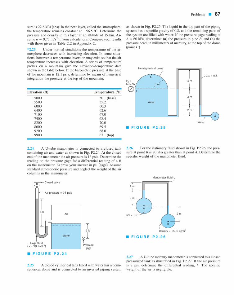
Problems � 87
sure is 22.6 kPa 1abs2. In the next layer, called the stratosphere,the temperature remains constant at Determine thepressure and density in this layer at an altitude of 15 km. As-sume in your calculations. Compare your resultswith those given in Table C.2 in Appendix C.
*2.23 Under normal conditions the temperature of the at-mosphere decreases with increasing elevation. In some situa-tions, however, a temperature inversion may exist so that the airtemperature increases with elevation. A series of temperatureprobes on a mountain give the elevation–temperature datashown in the table below. If the barometric pressure at the baseof the mountain is 12.1 psia, determine by means of numericalintegration the pressure at the top of the mountain.
2.24 A U-tube manometer is connected to a closed tankcontaining air and water as shown in Fig. P2.24. At the closedend of the manometer the air pressure is 16 psia. Determine thereading on the pressure gage for a differential reading of 4 fton the manometer. Express your answer in psi 1gage2. Assumestandard atmospheric pressure and neglect the weight of the aircolumns in the manometer.
2.25 A closed cylindrical tank filled with water has a hemi-spherical dome and is connected to an inverted piping system
as shown in Fig. P2.25. The liquid in the top part of the pipingsystem has a specific gravity of 0.8, and the remaining parts ofthe system are filled with water. If the pressure gage reading atA is 60 kPa, determine: (a) the pressure in pipe B, and (b) thepressure head, in millimeters of mercury, at the top of the dome1point C 2.
2.26 For the stationary fluid shown in Fig. P2.26, the pres-sure at point B is 20 kPa greater than at point A. Determine thespecific weight of the manometer fluid.
2.27 A U-tube mercury manometer is connected to a closedpressurized tank as illustrated in Fig. P2.27. If the air pressureis 2 psi, determine the differential reading, h. The specificweight of the air is negligible.
g � 9.77 m�s2
�56.5 °C.
Elevation (ft) Temperature ( )
5000 50.1 1base25500 55.26000 60.36400 62.67100 67.07400 68.48200 70.08600 69.59200 68.09900 67.1 1top2
�F
Pressuregage
Air
Water
Air pressure = 16 psia
Gage fluid( = 90 lb/ft3)γ
Closed valve
4 ft
2 ft
� F I G U R E P 2 . 2 4
pA =60 kPa
Water
B
2 m
4 m
3 m
3 m
SG = 0.8
Water
Hemispherical dome
C
A
� F I G U R E P 2 . 2 5
Manometer fluid
A
B
1 m
2 m
2 m
Density = 1500 kg/m3
SG = 1.2
� F I G U R E P 2 . 2 6
7708d_c02_40-99 8/31/01 1:19 PM Page 87 mac106 mac 106:1st_Shift:7708d:

88 � Chapter 2 / Fluid Statics
2.28 A suction cup is used to support a plate of weight as shown in Fig. P2.28. For the conditions shown, determine�.
2.29 A piston having a cross-sectional area of and neg-ligible weight is located in a cylinder containing oil as shown in Fig. P2.29. The cylinder is connected to a pres-surized tank containing water and oil. A force, P, holds the pis-ton in place. (a) Determine the required value of the force, P.(b) Determine the pressure head, expressed in feet of water, act-ing on the tank bottom.
2.30 Although it is difficult to compress water, the den-sity of water at the bottom of the ocean is greater than that atthe surface because of the higher pressure at depth. Estimatehow much higher the ocean’s surface would be if the densityof seawater were instantly changed to a uniform density equalto that at the surface.
2.31 The mercury manometer of Fig. P2.31 indicates adifferential reading of 0.30 m when the pressure in pipe A is30-mm Hg vacuum. Determine the pressure in pipe B.
2.32 For the inclined-tube manometer of Fig. P2.32 thepressure in pipe A is 0.6 psi. The fluid in both pipes A and Bis water, and the gage fluid in the manometer has a specificgravity of 2.6. What is the pressure in pipe B corresponding tothe differential reading shown?
†
1SG � 0.923 ft2
w
Air
pair = 2 psi
Water
2 ft
Mercury (SG = 13.6)
h
2 ft
2 ft
� F I G U R E P 2 . 2 7
Water
Open
0.5-ft radius
2-ft-diameter
0.4 ft
Suction cupPlate
1.6 ftSG = 8
� F I G U R E P 2 . 2 8
Air pressure = 5 psi
Oil (SG = 0.9)
Water
Tank bottom
4-in.diamter
Cylinder
Piston
3 ft
2 ft
2 ft
3 ft
P
� F I G U R E P 2 . 2 9
AB
OilWater
Mercury 0.30 m
0.15 m
0.50 m
� F I G U R E P 2 . 3 1
Water
Water
8 in.
30°3 in.
3 in.
A
B
SG = 2.6
� F I G U R E P 2 . 3 2
7708d_c02_40-99 8/30/01 6:51 AM Page 88 mac45 Mac 45:1st Shift:
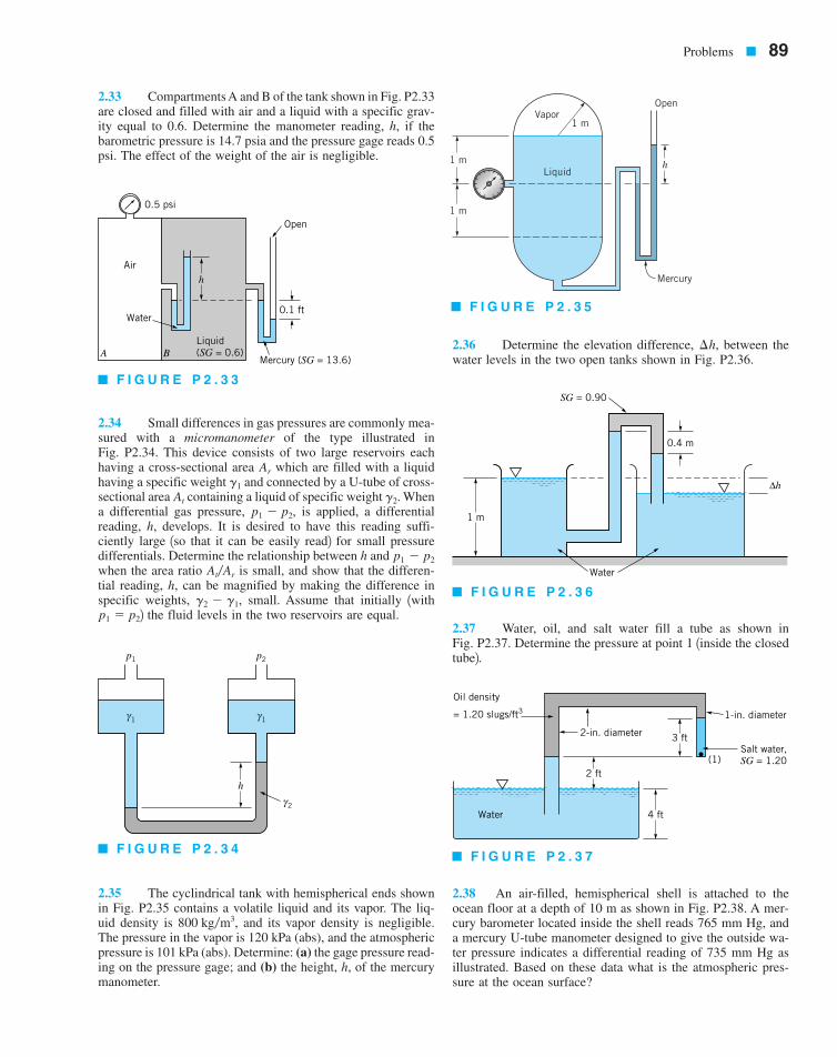
Problems � 89
2.33 Compartments A and B of the tank shown in Fig. P2.33are closed and filled with air and a liquid with a specific grav-ity equal to 0.6. Determine the manometer reading, h, if thebarometric pressure is 14.7 psia and the pressure gage reads 0.5psi. The effect of the weight of the air is negligible.
2.34 Small differences in gas pressures are commonly mea-sured with a micromanometer of the type illustrated inFig. P2.34. This device consists of two large reservoirs eachhaving a cross-sectional area which are filled with a liquidhaving a specific weight and connected by a U-tube of cross-sectional area containing a liquid of specific weight Whena differential gas pressure, is applied, a differentialreading, h, develops. It is desired to have this reading suffi-ciently large 1so that it can be easily read2 for small pressuredifferentials. Determine the relationship between h and when the area ratio is small, and show that the differen-tial reading, h, can be magnified by making the difference inspecific weights, small. Assume that initially 1with2 the fluid levels in the two reservoirs are equal.
2.35 The cyclindrical tank with hemispherical ends shownin Fig. P2.35 contains a volatile liquid and its vapor. The liq-uid density is and its vapor density is negligible.The pressure in the vapor is 120 kPa (abs), and the atmosphericpressure is 101 kPa (abs). Determine: (a) the gage pressure read-ing on the pressure gage; and (b) the height, h, of the mercurymanometer.
2.36 Determine the elevation difference, between thewater levels in the two open tanks shown in Fig. P2.36.
2.37 Water, oil, and salt water fill a tube as shown inFig. P2.37. Determine the pressure at point 1 1inside the closedtube2.
2.38 An air-filled, hemispherical shell is attached to theocean floor at a depth of 10 m as shown in Fig. P2.38. A mer-cury barometer located inside the shell reads 765 mm Hg, anda mercury U-tube manometer designed to give the outside wa-ter pressure indicates a differential reading of 735 mm Hg asillustrated. Based on these data what is the atmospheric pres-sure at the ocean surface?
¢h,
800 kg�m3,
p1 � p2
g2 � g1,
At�Ar
p1 � p2
p1 � p2,g2.At
g1
Ar
Mercury (SG = 13.6)
Water
Air
0.5 psi
Open
0.1 ft
h
Liquid(SG = 0.6)BA
� F I G U R E P 2 . 3 3
h
p1 p2
2γ
1γ1γ
� F I G U R E P 2 . 3 4
Liquid
Vapor1 m
Open
Mercury
1 m
1 m
h
� F I G U R E P 2 . 3 5
1 m
0.4 m
∆h
SG = 0.90
Water
� F I G U R E P 2 . 3 6
Salt water,SG = 1.20
1-in. diameter
2-in. diameter
2 ft
3 ft
(1)
4 ftWater
Oil density
= 1.20 slugs/ft3
� F I G U R E P 2 . 3 7
7708d_c02_40-99 8/31/01 1:19 PM Page 89 mac106 mac 106:1st_Shift:7708d:
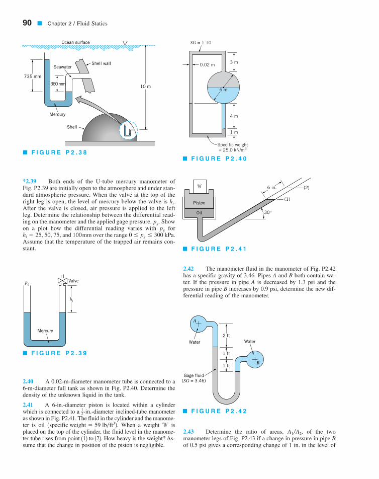
90 � Chapter 2 / Fluid Statics
*2.39 Both ends of the U-tube mercury manometer ofFig. P2.39 are initially open to the atmosphere and under stan-dard atmospheric pressure. When the valve at the top of theright leg is open, the level of mercury below the valve is After the valve is closed, air pressure is applied to the leftleg. Determine the relationship between the differential read-ing on the manometer and the applied gage pressure, Showon a plot how the differential reading varies with for
50, 75, and 100mm over the range Assume that the temperature of the trapped air remains con-stant.
2.40 A 0.02-m-diameter manometer tube is connected to a6-m-diameter full tank as shown in Fig. P2.40. Determine thedensity of the unknown liquid in the tank.
2.41 A 6-in.-diameter piston is located within a cylinderwhich is connected to a -diameter inclined-tube manometeras shown in Fig. P2.41. The fluid in the cylinder and the manome-ter is oil When a weight isplaced on the top of the cylinder, the fluid level in the manome-ter tube rises from point 112 to 122. How heavy is the weight? As-sume that the change in position of the piston is negligible.
2.42 The manometer fluid in the manometer of Fig. P2.42has a specific gravity of 3.46. Pipes A and B both contain wa-ter. If the pressure in pipe A is decreased by 1.3 psi and thepressure in pipe B increases by 0.9 psi, determine the new dif-ferential reading of the manometer.
2.43 Determine the ratio of areas, of the twomanometer legs of Fig. P2.43 if a change in pressure in pipe Bof 0.5 psi gives a corresponding change of 1 in. in the level of
A1�A2,w1specific weight � 59 lb�ft32.
12-in.
0 pg 300 kPa.hi � 25,pg
pg.
hi.
Mercury
Shell
SeawaterShell wall
Ocean surface
735 mm
360 mm 10 m
� F I G U R E P 2 . 3 8
Mercury
hi
pgValve
� F I G U R E P 2 . 3 9
�
Piston
Oil
(1)
(2)
30°
6 in.
� F I G U R E P 2 . 4 1
Water Water
Gage fluid(SG = 3.46)
1 ft
1 ft
2 ft
A
B
� F I G U R E P 2 . 4 2
SG = 1.10
6 m
1 m
4 m
Specific weight= 25.0 kN/m3
3 m0.02 m
� F I G U R E P 2 . 4 0
7708d_c02_40-99 8/31/01 1:19 PM Page 90 mac106 mac 106:1st_Shift:7708d:

Problems � 91
the mercury in the right leg. The pressure in pipe A does notchange.
2.44 The inclined differential manometer of Fig. P2.44 con-tains carbon tetrachloride. Initially the pressure differential be-tween pipes A and B, which contain a brine is zeroas illustrated in the figure. It is desired that the manometer givea differential reading of 12 in. 1measured along the inclinedtube2 for a pressure differential of 0.1 psi. Determine the re-quired angle of inclination,
2.45 Determine the new differential reading along the in-clined leg of the mercury manometer of Fig. P2.45, if the pres-sure in pipe A is decreased 10 kPa and the pressure in pipe Bremains unchanged. The fluid in A has a specific gravity of 0.9and the fluid in B is water.
2.46 Determine the change in the elevation of the mercuryin the left leg of the manometer of Fig. P2.46 as a result of anincrease in pressure of 5 psi in pipe A while the pressure in pipeB remains constant.
*2.47 Water initially fills the funnel and its connecting tubeas shown in Fig. P2.47. Oil is poured into the fun-nel until it reaches a level as indicated. Determine andplot the value of the rise in the water level in the tube, as afunction of h for with and
2.48 Concrete is poured into the forms as shown in Fig.P2.48 to produce a set of steps. Determine the weight of thesandbag needed to keep the bottomless forms from lifting offthe ground. The weight of the forms is 85 lb, and the specificweight of the concrete is
2.49 A square gate is located in the slop-ing side of a dam. Some measurements indicate that the resul-tant force of the water on the gate is 500 kN. (a) Determine thepressure at the bottom of the gate. (b) Show on a sketch wherethis force acts.
45°3 m � 3 m
150 lb�ft3.
d � 0.1 ft.H � D � 2 ftH�2 h H,
/,h 7 H�21SG � 0.852
u.
1SG � 1.12,
Area = A1Area = A2
Oil(SG = 0.8)
Water
Mercury
A B
� F I G U R E P 2 . 4 3
Brine
Brine
Carbontetrachloride
A
B
θ
� F I G U R E P 2 . 4 4
100 mm
50 mm
Mercury
WaterSG = 0.9
30°
A
B
80 mm
� F I G U R E P 2 . 4 5
Water
Mercury
in. diameter30°
Oil (SG = 0.9)
18 in.6 in.
1_4
in.
diameter
1_2
12 in.
A
B
� F I G U R E P 2 . 4 6
h = H––2
D d
H
Water
Initial Final
Oil
h
�
� F I G U R E P 2 . 4 7
8 in. risers
10 in. tread
3 ft
Open bottom
Open top
Sand
� F I G U R E P 2 . 4 8
7708d_c02_40-99 8/31/01 1:19 PM Page 91 mac106 mac 106:1st_Shift:7708d:
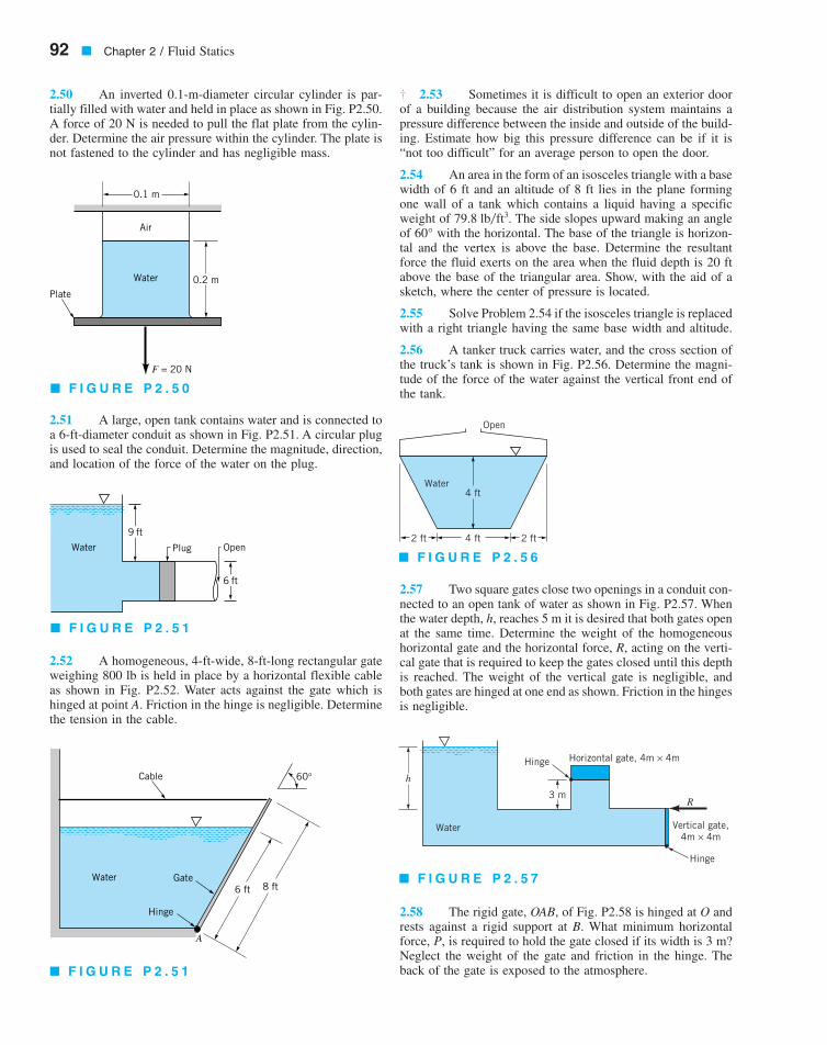
92 � Chapter 2 / Fluid Statics
2.50 An inverted 0.1-m-diameter circular cylinder is par-tially filled with water and held in place as shown in Fig. P2.50.A force of 20 N is needed to pull the flat plate from the cylin-der. Determine the air pressure within the cylinder. The plate isnot fastened to the cylinder and has negligible mass.
2.51 A large, open tank contains water and is connected toa 6-ft-diameter conduit as shown in Fig. P2.51. A circular plugis used to seal the conduit. Determine the magnitude, direction,and location of the force of the water on the plug.
2.52 A homogeneous, 4-ft-wide, 8-ft-long rectangular gateweighing 800 lb is held in place by a horizontal flexible cableas shown in Fig. P2.52. Water acts against the gate which ishinged at point A. Friction in the hinge is negligible. Determinethe tension in the cable.
2.53 Sometimes it is difficult to open an exterior doorof a building because the air distribution system maintains apressure difference between the inside and outside of the build-ing. Estimate how big this pressure difference can be if it is“not too difficult” for an average person to open the door.
2.54 An area in the form of an isosceles triangle with a basewidth of 6 ft and an altitude of 8 ft lies in the plane formingone wall of a tank which contains a liquid having a specificweight of The side slopes upward making an angleof with the horizontal. The base of the triangle is horizon-tal and the vertex is above the base. Determine the resultantforce the fluid exerts on the area when the fluid depth is 20 ftabove the base of the triangular area. Show, with the aid of asketch, where the center of pressure is located.
2.55 Solve Problem 2.54 if the isosceles triangle is replacedwith a right triangle having the same base width and altitude.
2.56 A tanker truck carries water, and the cross section ofthe truck’s tank is shown in Fig. P2.56. Determine the magni-tude of the force of the water against the vertical front end ofthe tank.
2.57 Two square gates close two openings in a conduit con-nected to an open tank of water as shown in Fig. P2.57. Whenthe water depth, h, reaches 5 m it is desired that both gates openat the same time. Determine the weight of the homogeneoushorizontal gate and the horizontal force, R, acting on the verti-cal gate that is required to keep the gates closed until this depthis reached. The weight of the vertical gate is negligible, andboth gates are hinged at one end as shown. Friction in the hingesis negligible.
2.58 The rigid gate, OAB, of Fig. P2.58 is hinged at O andrests against a rigid support at B. What minimum horizontalforce, P, is required to hold the gate closed if its width is 3 m?Neglect the weight of the gate and friction in the hinge. Theback of the gate is exposed to the atmosphere.
60°79.8 lb�ft3.
†
Water
Air
Plate0.2 m
0.1 m
F = 20 N
� F I G U R E P 2 . 5 0
Plug OpenWater
9 ft
6 ft
� F I G U R E P 2 . 5 1
Water
Open
4 ft
4 ft 2 ft2 ft
� F I G U R E P 2 . 5 6
h
3 m
Hinge
Water
Hinge
Horizontal gate, 4m × 4m
Vertical gate,4m × 4m
R
� F I G U R E P 2 . 5 7
Cable
Gate
Hinge
Water6 ft 8 ft
A
60°
� F I G U R E P 2 . 5 1
7708d_c02_40-99 8/31/01 1:19 PM Page 92 mac106 mac 106:1st_Shift:7708d:
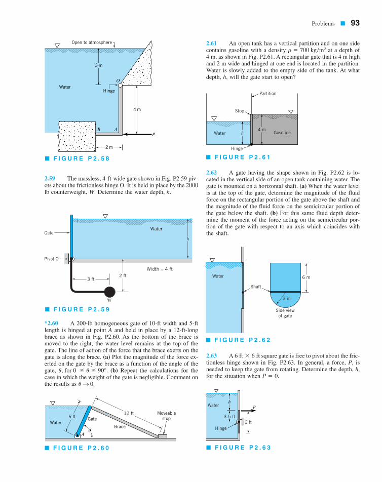
Problems � 93
2.59 The massless, 4-ft-wide gate shown in Fig. P2.59 piv-ots about the frictionless hinge O. It is held in place by the 2000lb counterweight, W. Determine the water depth, h.
*2.60 A 200-lb homogeneous gate of 10-ft width and 5-ftlength is hinged at point A and held in place by a 12-ft-longbrace as shown in Fig. P2.60. As the bottom of the brace ismoved to the right, the water level remains at the top of thegate. The line of action of the force that the brace exerts on thegate is along the brace. (a) Plot the magnitude of the force ex-erted on the gate by the brace as a function of the angle of thegate, (b) Repeat the calculations for thecase in which the weight of the gate is negligible. Comment onthe results as
2.61 An open tank has a vertical partition and on one sidecontains gasoline with a density at a depth of4 m, as shown in Fig. P2.61. A rectangular gate that is 4 m highand 2 m wide and hinged at one end is located in the partition.Water is slowly added to the empty side of the tank. At whatdepth, h, will the gate start to open?
2.62 A gate having the shape shown in Fig. P2.62 is lo-cated in the vertical side of an open tank containing water. Thegate is mounted on a horizontal shaft. (a) When the water levelis at the top of the gate, determine the magnitude of the fluidforce on the rectangular portion of the gate above the shaft andthe magnitude of the fluid force on the semicircular portion ofthe gate below the shaft. (b) For this same fluid depth deter-mine the moment of the force acting on the semicircular por-tion of the gate with respect to an axis which coincides withthe shaft.
2.63 A square gate is free to pivot about the fric-tionless hinge shown in Fig. P2.63. In general, a force, P, isneeded to keep the gate from rotating. Determine the depth, h,for the situation when P � 0.
6 ft � 6 ft
r � 700 kg�m3
uS 0.
u, for 0 u 90°.
12 ft
Brace
Gate5 ftWater
Aθ
Moveablestop
� F I G U R E P 2 . 6 0
B A
Hinge
O
P
Water
Open to atmosphere
3 m
2 m
4 m
� F I G U R E P 2 . 5 8
Pivot O
Gate
2 ft
h
3 ft
Width = 4 ft
Water
�
� F I G U R E P 2 . 5 9
6 m
3 m
Side viewof gate
Shaft
Water
� F I G U R E P 2 . 6 2
Water
3.5 ft6 ft
Hinge
Ph
� F I G U R E P 2 . 6 3
Stop
Partition
Hinge
Water Gasoline4 m
h
� F I G U R E P 2 . 6 1
7708d_c02_40-99 8/31/01 1:19 PM Page 93 mac106 mac 106:1st_Shift:7708d:

2.64 A thin 4-ft-wide, right-angle gate with negligible massis free to pivot about a frictionless hinge at point O, as shownin Fig. P2.64. The horizontal portion of the gate covers a 1-ft-diameter drain pipe which contains air at atmospheric pressure.Determine the minimum water depth, h, at which the gate willpivot to allow water to flow into the pipe.
2.65 The specific weight, of the static liquid layer shownin Fig. P2.65 increases linearly with depth. At the free surface
and at the bottom of the layer Make use of Eq. 2.4 to determine the pressure at the bottom ofthe layer.
*2.66 An open rectangular settling tank contains a liquidsuspension that at a given time has a specific weight that variesapproximately with depth according to the following data:
The depth corresponds to the free surface. Determine, bymeans of numerical integration, the magnitude and location ofthe resultant force that the liquid suspension exerts on a verti-cal wall of the tank that is 6 m wide. The depth of fluid in thetank is 3.6 m.
2.67 The inclined face AD of the tank of Fig. P2.67 is aplane surface containing a gate ABC, which is hinged along lineBC. The shape of the gate is shown in the plan view. If the tankcontains water, determine the magnitude of the force that thewater exerts on the gate.
2.68 Dams can vary from very large structures with curvedfaces holding back water to great depths, as shown in VideoV2.3, to relatively small structures with plane faces as shownin Fig. P2.68. Assume that the concrete dam shown in Fig. P2.68weighs and rests on a solid foundation. Determinethe minimum coefficient of friction between the dam and thefoundation required to keep the dam from sliding at the waterdepth shown. You do not need to consider possible uplift alongthe base. Base your analysis on a unit length of the dam.
*2.69 Water backs up behind a concrete dam as shown inFig. P2.69. Leakage under the foundation gives a pressure dis-tribution under the dam as indicated. If the water depth, h, istoo great, the dam will topple over about its toe 1point A2. Forthe dimensions given, determine the maximum water depth forthe following widths of the dam:Base your analysis on a unit length of the dam. The specificweight of the concrete is 150 lb�ft3.
/ � 20, 30, 40, 50, and 60 ft.
23.6 kN�m3
h � 0
g � 95 lb�ft3.g � 70 lb�ft3,
g,
94 � Chapter 2 / Fluid Statics
h (m) ( )
0 10.00.4 10.10.8 10.21.2 10.61.6 11.32.0 12.32.4 12.72.8 12.93.2 13.03.6 13.1
N�m3G
Water
Hinge
Right-angle gate
Width = 4 ft
1-ft-diameter pipe
O
h
3 ft
� F I G U R E P 2 . 6 4
Water
Stop
Hinge
A
A
B
C
B, C
D
y'
x'
4 ft30°
2 ft
y' = 4(x')2
Plan ofgate
� F I G U R E P 2 . 6 7
5 m
2 m
4 m
Water
6 m
� F I G U R E P 2 . 6 8
2 ft
z
= 95 lb/ft3
z = 0γ
= 70 lb/ft3γ
� F I G U R E P 2 . 6 5
7708d_c02_40-99 8/31/01 1:20 PM Page 94 mac106 mac 106:1st_Shift:7708d:

2.70 A 4-m-long curved gate is located in the side of areservoir containing water as shown in Fig. P2.70. Determinethe magnitude of the horizontal and vertical components of theforce of the water on the gate. Will this force pass through pointA? Explain.
2.71 The air pressure in the top of the two liter pop bottleshown in Video V2.4 and Fig. P2.71 is 40 psi, and the pop depthis 10 in. The bottom of the bottle has an irregular shape with adiameter of 4.3 in. (a) If the bottle cap has a diameter of 1 in.what is magnitude of the axial force required to hold the capin place? (b) Determine the force needed to secure the bottom2 inches of the bottle to its cylindrical sides. For this calcula-tion assume the effect of the weight of the pop is negligible. (c)By how much does the weight of the pop increase the pressure2 inches above the bottom? Assume the pop has the same spe-cific weight as that of water.
2.72 Hoover Dam (see Video 2.3) is the highest arch-gravity type of dam in the United States. A cross section of thedam is shown in Fig. P2.72(a). The walls of the canyon inwhich the dam is located are sloped, and just upstream of thedam the vertical plane shown in Figure P2.72(b) approximatelyrepresents the cross section of the water acting on the dam.Use this vertical cross section to estimate the resultant hori-zontal force of the water on the dam, and show here this forceacts.
2.73 A plug in the bottom of a pressurized tank is conicalin shape as shown in Fig. P2.73. The air pressure is 50 kPa andthe liquid in the tank has a specific weight of De-termine the magnitude, direction, and line of action of the forceexerted on the curved surface of the cone within the tank dueto the 50-kPa pressure and the liquid.
2.74 A 12-in.-diameter pipe contains a gas under a pres-sure of 140 psi. If the pipe wall thickness is -in., what is theaverage circumferential stress developed in the pipe wall?
2.75 The concrete seawall ofFig. P2.75 has a curved surface and restrains seawater at a depthof 24 ft. The trace of the surface is a parabola as illustrated.Determine the moment of the fluid force 1per unit length2 withrespect to an axis through the toe 1point A).
1specific weight � 150 lb�ft32
14
27 kN�m3.
Problems � 95
pB = hγ
pA = hTγ
ABWater
Water
h
hT = 10 ft
80 ft
�
� F I G U R E P 2 . 6 9
45 ft
727 ft
660 ft
(a) (b)
290 ft
880 ft
715 ft
� F I G U R E P 2 . 7 2
3 m
Water
9 m
A
Gate
� F I G U R E P 2 . 7 0
Air
Liquid
50 kPa
3 m
1 m
60°
� F I G U R E P 2 . 7 3
12 in.10 in.
1 in. diameter
4.3 in. diameter
pair = 40 psi
� F I G U R E P 2 . 7 1
7708d_c02_40-99 8/31/01 1:20 PM Page 95 mac106 mac 106:1st_Shift:7708d:
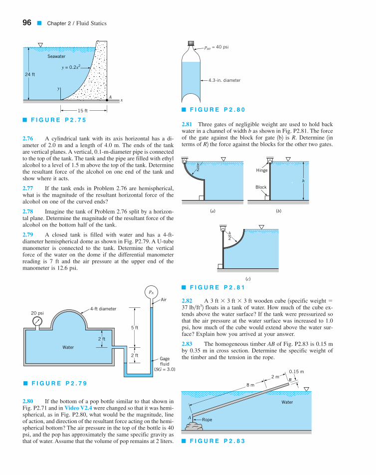
2.76 A cylindrical tank with its axis horizontal has a di-ameter of 2.0 m and a length of 4.0 m. The ends of the tankare vertical planes. A vertical, 0.1-m-diameter pipe is connectedto the top of the tank. The tank and the pipe are filled with ethylalcohol to a level of 1.5 m above the top of the tank. Determinethe resultant force of the alcohol on one end of the tank andshow where it acts.
2.77 If the tank ends in Problem 2.76 are hemispherical,what is the magnitude of the resultant horizontal force of thealcohol on one of the curved ends?
2.78 Imagine the tank of Problem 2.76 split by a horizon-tal plane. Determine the magnitude of the resultant force of thealcohol on the bottom half of the tank.
2.79 A closed tank is filled with water and has a 4-ft-diameter hemispherical dome as shown in Fig. P2.79. A U-tubemanometer is connected to the tank. Determine the verticalforce of the water on the dome if the differential manometerreading is 7 ft and the air pressure at the upper end of themanometer is 12.6 psi.
2.80 If the bottom of a pop bottle similar to that shown inFig. P2.71 and in Video V2.4 were changed so that it was hemi-spherical, as in Fig. P2.80, what would be the magnitude, lineof action, and direction of the resultant force acting on the hemi-spherical bottom? The air pressure in the top of the bottle is 40psi, and the pop has approximately the same specific gravity asthat of water. Assume that the volume of pop remains at 2 liters.
2.81 Three gates of negligible weight are used to hold backwater in a channel of width b as shown in Fig. P2.81. The forceof the gate against the block for gate 1b2 is R. Determine 1interms of R2 the force against the blocks for the other two gates.
2.82 A wooden cube 1specific 2 floats in a tank of water. How much of the cube ex-tends above the water surface? If the tank were pressurized sothat the air pressure at the water surface was increased to 1.0psi, how much of the cube would extend above the water sur-face? Explain how you arrived at your answer.
2.83 The homogeneous timber AB of Fig. P2.83 is 0.15 mby 0.35 m in cross section. Determine the specific weight ofthe timber and the tension in the rope.
37 lb�ft3weight �3 ft � 3 ft � 3 ft
96 � Chapter 2 / Fluid Statics
y
Seawater
24 ft
Ax
y = 0.2x2
15 ft
� F I G U R E P 2 . 7 5
4.3-in. diameter
pair = 40 psi
� F I G U R E P 2 . 8 0
(a) (b)
Hinge
Block
(c)
h
2h
2h
� F I G U R E P 2 . 8 1
20 psi4-ft diameter
Air
Gagefluid
(SG = 3.0)
Water
2 ft
2 ft
5 ft
pA
� F I G U R E P 2 . 7 9 8 m
2 mB
0.15 m
Water
RopeA
� F I G U R E P 2 . 8 3
7708d_c02_40-99 8/31/01 1:20 PM Page 96 mac106 mac 106:1st_Shift:7708d:

2.84 When the Tucurui dam was constructed in northernBrazil, the lake that was created covered a large forest of valu-able hardwood trees. It was found that even after 15 years un-derwater the trees were perfectly preserved and underwater log-ging was started. During the logging process a tree is selected,trimmed, and anchored with ropes to prevent it from shootingto the surface like a missile when cut. Assume that a typicallarge tree can be approximated as a truncated cone with a basediameter of 8 ft, a top diameter of 2 ft, and a height of 100 ft.Determine the resultant vertical force that the ropes must resistwhen the completely submerged tree is cut. The specific grav-ity of the wood is approximately 0.6.
2.85 Estimate the minimum water depth needed to floata canoe carrying two people and their camping gear. List all as-sumptions and show all calculations.
2.86 An inverted test tube partially filled with air floats ina plastic water-filled soft drink bottle as shown in Video V2.5and Fig. P2.86. The amount of air in the tube has been adjustedso that it just floats. The bottle cap is securely fastened. A slightsqueezing of the plastic bottle will cause the test tube to sinkto the bottom of the bottle. Explain this phenomenon.
2.87 The hydrometer shown in Video V2.6 and Fig. P2.87has a mass of 0.045 kg and the cross-sectional area of its stemis Determine the distance between graduations 1onthe stem2 for specific gravities of 1.00 and 0.90.
2.88 An L-shaped rigid gate is hinged at one end and is lo-cated between partitions in an open tank containing water as
shown in Fig. P2.88. A block of concrete is tobe hung from the horizontal portion of the gate. Determine therequired volume of the block so that the reaction of the gate onthe partition at A is zero when the water depth is 2 ft above thehinge. The gate is 2 ft wide with a negligible weight, and thehinge is smooth.
2.89 When a hydrometer (see Fig. P2.87 and Video V2.6)having a stem diameter of 0.30 in. is placed in water, the stemprotrudes 3.15 in. above the water surface. If the water is re-placed with a liquid having a specific gravity of 1.10, how muchof the stem would protrude above the liquid surface? The hy-drometer weighs 0.042 lb.
2.90 The thin-walled, 1-m-diameter tank of Fig. P2.90 isclosed at one end and has a mass of 90 kg. The open end ofthe tank is lowered into the water and held in the position shownby a steel block having a density of Assume thatthe air that is trapped in the tank is compressed at a constanttemperature. Determine: (a) the reading on the pressure gage atthe top of the tank, and (b) the volume of the steel block.
*2.91 An inverted hollow cone is pushed into the water asis shown in Fig. P2.91. Determine the distance, that the wa-ter rises in the cone as a function of the depth, d, of the loweredge of the cone. Plot the results for when H isequal to 1 m. Assume the temperature of the air within the coneremains constant.
0 � d � H,
/,
7840 kg�m3.
1g � 150 lb�ft32
290 mm2.
†
Problems � 97
Air
Plastic bottleWater
Test tube
� F I G U R E P 2 . 8 6
FluidsurfaceHydrometer
� F I G U R E P 2 . 8 7
Water
Air
Concrete blockGate
A
Hinge
1 ft 1 ft
2 ft
2 ft
� F I G U R E P 2 . 8 8
Air
Water
Open end Cable
Steelblock
0.6 m
3.0 m
Tank
� F I G U R E P 2 . 9 0
7708d_c02_40-99 8/30/01 6:51 AM Page 97 mac45 Mac 45:1st Shift:

2.92 An open container of oil rests on the flatbed of a truckthat is traveling along a horizontal road at As the truckslows uniformly to a complete stop in 5 s, what will be the slopeof the oil surface during the period of constant deceleration?
2.93 A 5-gal, cylindrical open container with a bottom areaof is filled with glycerin and rests on the floor of anelevator. (a) Determine the fluid pressure at the bottom of thecontainer when the elevator has an upward acceleration of
(b) What resultant force does the container exert on thefloor of the elevator during this acceleration? The weight of thecontainer is negligible. 1Note: 22.94 An open rectangular tank 1 m wide and 2 m long con-tains gasoline to a depth of 1 m. If the height of the tank sidesis 1.5 m, what is the maximum horizontal acceleration 1alongthe long axis of the tank2 that can develop before the gasolinewould begin to spill?
2.95 If the tank of Problem 2.94 slides down a frictionlessplane that is inclined at with the horizontal, determine theangle the free surface makes with the horizontal.
2.96 A closed cylindrical tank that is 8 ft in diameter and24 ft long is completely filled with gasoline. The tank, with itslong axis horizontal, is pulled by a truck along a horizontal sur-face. Determine the pressure difference between the ends 1alongthe long axis of the tank2 when the truck undergoes an accel-eration of
2.97 The open U-tube of Fig. P2.97 is partially filled witha liquid. When this device is accelerated with a horizontal ac-celeration a, a differential reading h develops between themanometer legs which are spaced a distance apart. Determinethe relationship between a, and h.
2.98 An open 1-m-diameter tank contains water at a depthof 0.7 m when at rest. As the tank is rotated about its verticalaxis the center of the fluid surface is depressed. At what angu-lar velocity will the bottom of the tank first be exposed? Nowater is spilled from the tank.
2.99 The U-tube of Fig. P2.99 is partially filled with waterand rotates around the axis a–a. Determine the angular veloc-ity that will cause the water to start to vaporize at the bottomof the tube 1point A2.
2.100 The U-tube of Fig. P2.100 contains mercury and ro-tates about the off-center axis a–a. At rest, the depth of mer-cury in each leg is 150 mm as illustrated. Determine the angu-lar velocity for which the difference in heights between the twolegs is 75 mm.
2.101 A closed, 0.4-m-diameter cylindrical tank is com-pletely filled with oil and rotates about its verticallongitudinal axis with an angular velocity of Deter-mine the difference in pressure just under the vessel cover be-tween a point on the circumference and a point on the axis.
2.102 This problem involves the force needed to open agate that covers an opening in the side of a water-filled tank.To proceed with this problem, click here in the E-book.
40 rad�s.1SG � 0.92
/,/
5 ft�s2.
30°
1 gal � 231 in.3
3 ft�s2.
120 in.2
55 mi�hr.
98 � Chapter 2 / Fluid Statics
�d
R
HCone
Water
Open end
� F I G U R E P 2 . 9 1
ah
�
� F I G U R E P 2 . 9 7
ω
Aa
a
12 in.
4 in. 4 in.
� F I G U R E P 2 . 9 9
150 mm
220 mm
Mercury
90 mm
ω
a
a
� F I G U R E P 2 . 1 0 0
7708d_c02_40-99 8/31/01 1:20 PM Page 98 mac106 mac 106:1st_Shift:7708d:

2.103 This problem involves the use of a cleverly designedapparatus to investigate the hydrostatic pressure force on a sub-merged rectangle. To proceed with this problem, click here inthe E-book.
2.104 This problem involves determining the weightneeded to hold down an open-bottom box that has slanted sides
when the box is filled with water. To proceed with this prob-lem, click here in the E-book.
2.105 This problem involves the use of a pressurized airpad to provide the vertical force to support a given load. To pro-ceed with this problem, click here in the E-book.
Problems � 99
7708d_c02_40-99 8/31/01 1:20 PM Page 99 mac106 mac 106:1st_Shift:7708d:
Related Documents