Chennai Institute of Technology Staff Name: T. Sudhakar Dept : Mechanical Engineering 1 1. Calibration Test Rig For Venturimeter. USER MANUAL Calibration test rig for Venturimeters INTRODUCTION: To control Industrial processes, it is essential to know the amount of material entering and leaving the process. Many different types of meters are used industrially. A few types of flow meters measure the mass flow rate directly, but the majority measures the volumetric flow rate or the average fluid velocity from which the volumetric flow rate can be calculated. Venturimeter is an apparatus for finding out the discharge of a liquid flowing in a pipe. A Venturimeter in it simplest form consists of the following three parts. a. Convergent Cone. b. Throat and c. Divergent Cone. The principle of the orifice meter is identical with that of the Venturimeter. However the Venturimeter has certain practical disadvantages for ordinary plant practice. It is expensive, it occupies considerable space its ratio of throat Diameter to pipe cannot be changed. For a given meter and definite Manometer system, the maximum measurable flow rate is fixed. So if the flow range is changed, the throat diameter may be too large to give an accurate reading or too small to accommodate the maximum flow rate. Description: The apparatus consisting of Venturimeters of two different Sizes fitted separately on pipeline with flow control valves. Pressure tapping from Venturimeters are connected to a multiport manifold and to Manometer. The whole unit is mounted on a sturdy iron stand. A collecting tank with gauge glass, scale fitting and a drain valve. A sump tank with a monoblock pumping unit is provided. Aim : To determine the co-efficient of discharge of the Venturimeter. Procedure: 1. Measure the length and breadth of the collecting tank. L = m. B = m. 2. Open the respective valve in a pipeline and close all other valves. Adjust the flow suitably 3. Note the left limb reading (h 1 ) m and right limb reading (h 2 ) m of the manometer. 4. Close the drain valve of the collecting tank. 5. Find the time taken for 10 cm (0.1 m) ( R ) rise of water level in the collecting tank.

Welcome message from author
This document is posted to help you gain knowledge. Please leave a comment to let me know what you think about it! Share it to your friends and learn new things together.
Transcript
Chennai Institute of Technology
Staff Name: T. Sudhakar Dept : Mechanical Engineering 1
1. Calibration Test Rig
For
Venturimeter.
USER MANUAL
Calibration test rig for Venturimeters
INTRODUCTION:
To control Industrial processes, it is essential to know the amount of material entering and leaving the process. Many different
types of meters are used industrially. A few types of flow meters measure the mass flow rate directly, but the majority measures
the volumetric flow rate or the average fluid velocity from which the volumetric flow rate can be calculated.
Venturimeter is an apparatus for finding out the discharge of a liquid flowing in a pipe.
A Venturimeter in it simplest form consists of the following three parts.
a. Convergent Cone. b. Throat and c. Divergent Cone.
The principle of the orifice meter is identical with that of the Venturimeter. However the Venturimeter has certain practical
disadvantages for ordinary plant practice. It is expensive, it occupies considerable space its ratio of throat Diameter to pipe
cannot be changed.
For a given meter and definite Manometer system, the maximum measurable flow rate is fixed. So if the flow range is
changed, the throat diameter may be too large to give an accurate reading or too small to accommodate the maximum
flow rate.
Description:
The apparatus consisting of Venturimeters of two different Sizes fitted separately on pipeline with flow control valves.
Pressure tapping from Venturimeters are connected to a multiport manifold and to Manometer. The whole unit is mounted on a
sturdy iron stand. A collecting tank with gauge glass, scale fitting and a drain valve.
A sump tank with a monoblock pumping unit is provided.
Aim : To determine the co-efficient of discharge of the Venturimeter.
Procedure:
1. Measure the length and breadth of the collecting tank.
L = m.
B = m.
2. Open the respective valve in a pipeline and close all other valves. Adjust the
flow suitably
3. Note the left limb reading (h1) m and right limb reading (h2) m of the manometer.
4. Close the drain valve of the collecting tank.
5. Find the time taken for 10 cm (0.1 m) ( R ) rise of water level in the collecting tank.
Chennai Institute of Technology
Staff Name: T. Sudhakar Dept : Mechanical Engineering 2
6. Repeat the experiment for different flow rates and through different flow
Meters.
Calculations:
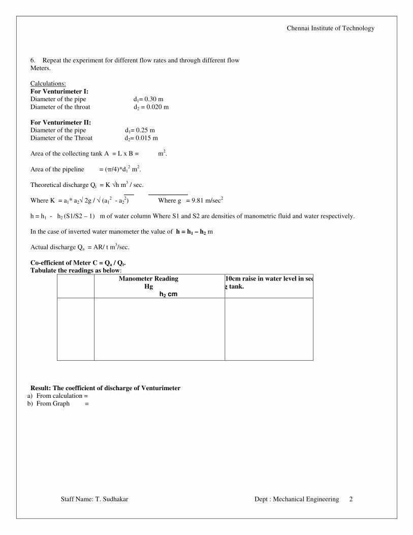
For Venturimeter I:
Diameter of the pipe d1= 0.30 m
Diameter of the throat d2 = 0.020 m
For Venturimeter II:
Diameter of the pipe d1= 0.25 m
Diameter of the Throat d2= 0.015 m
Area of the collecting tank A = L x B = m2.
Area of the pipeline = (π/4)*d12 m
2.
Theoretical discharge Qt = K √h m3 / sec.
Where K = a1* a2√ 2g / √ (a12 - a2
2) Where g = 9.81 m/sec
2
h = h1 - h2 (S1/S2 – 1) m of water column Where S1 and S2 are densities of manometric fluid and water respectively.
In the case of inverted water manometer the value of h = h1 – h2 m
Actual discharge Qa = AR/ t m3/sec.
Co-efficient of Meter C = Qa / Qt.
Tabulate the readings as below:
Manometer Reading
Hg
h2 cm
Time for 10cm raise in water level in sec.
Collecting tank.
Result: The coefficient of discharge of Venturimeter
a) From calculation =
b) From Graph =
Chennai Institute of Technology
Staff Name: T. Sudhakar Dept : Mechanical Engineering 3
2. Calibration Test Rig
For
Orifice meter
USER MANUAL
Calibration test rig for Orifice Meter
INTRODUCTION:
To control Industrial processes, it is essential to know the amount of material entering and leaving the process. Many different
types of meters are used industrially. A few types of flow meters measures the mass flow rate directly, but the majority measure
the volumetric flow rate or the average fluid velocity from which the volumetric flow rate can be calculated.
Venturimeter is an apparatus for finding out the discharge of a liquid flowing in a pipe.
A Venturimeter in it simplest form consists of the following three parts.
b. Convergent Cone. b. Throat and c. Divergent Cone.
The principle of the orifice meter is identical with that of the Venturimeter. However the Venturimeter has certain
practical disadvantages for ordinary plant practice. It is expensive, it occupies considerable space its ratio of throat
Diameter to pipe cannot be changed. For a given meter and definite Manometer system, the maximum measurable flow
rate is fixed. So if the flow range is changed, the throat diameter may be too large to give an accurate reading or too small
to accommodate the maximum flow rate.
The orifice meter meets these objections to the Venturimeter but at the price of large power consumption. (i.e. the pressure
recovery in an orifice meter is poor.)
An orifice meter in its simple form consists of a plate having a sharp circular hole. This plate is fixed in a pipeline with flanges
for measuring the discharge of flowing liquid.
Description:
The apparatus consisting of orificemeter fitted separately on pipeline with flow control valves.
Pressure tapping from Orifice meters is connected to a multi port manifold and to Manometer. The whole unit is mounted on a
sturdy iron stand. A collecting tank with gauge glass, scale fitting and a drain valve.
A sump tank with a mono block pumping unit is provided.
Aim: To determine the co-efficient of discharge of the orificemeter.
Chennai Institute of Technology
Staff Name: T. Sudhakar Dept : Mechanical Engineering 4
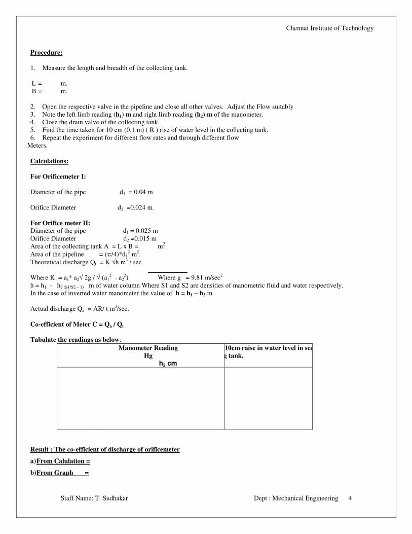
Procedure:
1. Measure the length and breadth of the collecting tank.
L = m.
B = m.
2. Open the respective valve in the pipeline and close all other valves. Adjust the Flow suitably
3. Note the left limb reading (h1) m and right limb reading (h2) m of the manometer.
4. Close the drain valve of the collecting tank.
5. Find the time taken for 10 cm (0.1 m) ( R ) rise of water level in the collecting tank.
6. Repeat the experiment for different flow rates and through different flow
Meters.
Calculations:
For Orificemeter I:
Diameter of the pipe d1 = 0.04 m
Orifice Diameter d2 =0.024 m.
For Orifice meter II:
Diameter of the pipe d1 = 0.025 m
Orifice Diameter d2 =0.015 m
Area of the collecting tank A = L x B = m2.
Area of the pipeline = (π/4)*d12 m
2.
Theoretical discharge Qt = K √h m3 / sec.
Where K = a1* a2√ 2g / √ (a12 - a2
2) Where g = 9.81 m/sec
2
h = h1 - h2 (S1/S2 – 1) m of water column Where S1 and S2 are densities of manometric fluid and water respectively.
In the case of inverted water manometer the value of h = h1 – h2 m
Actual discharge Qa = AR/ t m3/sec.
Co-efficient of Meter C = Qa / Qt
Tabulate the readings as below:
Manometer Reading
Hg
h2 cm
Time for 10cm raise in water level in sec.
Collecting tank.
Result : The co-efficient of discharge of orificemeter
a) From Calulation =
b) From Graph =
Chennai Institute of Technology
Staff Name: T. Sudhakar Dept : Mechanical Engineering 5
3. LOSSES IN PIPE LINE FITTINGS
USER MANUAL
LOSSES IN PIPE LINE FITTINGS
INTRODUCTION:
Whenever the velocity of a fluid is changed, either in direction or magnitude, by a change in the direction or size of the
conduct friction is generated in addition to the skin friction from flow through the straight pipe. However such friction
includes form friction resulting from vortices that develop when the normal streamlines disturbed and when boundary –
layer separation occurs. However these effects cannot be calculated precisely.
The object of this experiment is to find the loss co-efficient at different joints of interest, and to estimate the total loss of head by
friction.
DESCRIPTION:
The apparatus consisting of piping system with 2 GI pipelines of sizes 25 and 15mm with sudden expansion, sudden
contraction, bend and Elbow. A multipoint manifold connects the pressure tappings to a manometer.
A collecting tank with gauge glass, scale fittings and a drain valve provided.
Aim : To study flow in pipes and determine the losses due to pipe fittings – minor losses.
Procedure:
1) Measure the length and breadth of the collecting tank and find the area A m2
2) Open the respective cocks in the manifold where the head loss due to friction is to be measured close all other valves and
pressure cocks. Adjust the flow rate suitably.
3) Note the left limb reading (h1) m and right limb reading (h2) m of the Manometer.
4) Close the drain valve of the collecting tank.
5) Find the time taken t for 10 cm (0.1 m)rise ( R ) of water in the collecting tank t = sec.
6) Repeat the experiment for different flow rates and flow through different Fittings.
Calculation:
Diameter of the pipe d = m
Loss of head due to friction for that particular joint h = h1 - h2 ((S1/S2) –1))m. Where S1 & S2 are densities of manometric
fluid and water respectively.
In the case of inverted water manometer the value of h = h1 – h2 m
For contraction h = K * v22/2g , where v2 is the velocity in the smaller pipe on the down stream side and K is the Loss coefficient.
The velocity v2 may be calculated knowing the area of the pipe and the total discharge.
Area of the pipe on the downstream side (a) =(ππππ d2)/4 = m
2
Quantity of water collected Qa = AR/t m3 / sec
For expansion h = K(v1 – v2)2 / 2g
Where v1 and v2 are the velocities of water in the smaller pipe and in the bigger diameter pipe respectively. The velocity may be
calculated as detailed above.
Chennai Institute of Technology
Staff Name: T. Sudhakar Dept : Mechanical Engineering 6
For elbow and bend h = K v2 / 2g
Area of the pipe (a) =(ππππ d2)/4 = m
2
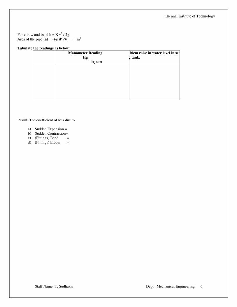
Tabulate the readings as below:
Manometer Reading
Hg
h2 cm
Time for 10cm raise in water level in sec.
Collecting tank.
Result: The coefficient of loss due to
a) Sudden Expansion =
b) Sudden Contraction=
c) (Fittings) Bend =
d) (Fittings) Elbow =
Chennai Institute of Technology
Staff Name: T. Sudhakar Dept : Mechanical Engineering 7
4. PELTON WHEEL TURBINE TEST RIG
USER MANUAL
INTRODUCTION.
The Pelton wheel turbine test rig is supplied as a complete set to conduct experiment on model Pelton wheel turbine in
Engineering College and technical Institutions. It has been specially designed to conduct experiments in METRIC UNITS.
The test rig consists essentially of
(1) Pelton wheel Turbine
(2) A Supply water to the above Pelton turbine
(3) A flow measuring unit consisting of Orificemeter and pressure gauge
(4) Piping system.
GENERAL DESCRIPTION
The Pelton wheel turbine consists of casing overhung bearings housing and rotor assembly, shaft, brake drum and brake
arrangement all mounted on suitable MS base. A transparent section made of clear acrylic sheet provided at the runner side of the
turbine makes it possible to have visual observation of flow in the buckets. The casing safeguards the runner against accident and
also prevents the splashing of water. The horizontal shaft rotates in roller bearing supports the overhung buckets. The runner is
fixed to the horizontal shaft. On the periphery of the runner bucket are fixed uniformly by means of steel bolts. This facilities
replacing of worn out bucket (which may occur after longer periods of usage) in case any of the buckets wears out. The Nozzle
assembly is bolted to the casing in such a way that the inlet pipe is kept vertically upwards. The spear inside the nozzle can be
moved radically towards the runner thereby regulating the quantity of water flowing through the nozzle. The water in the form of
jet strikes the buckets thus causing it to rotate.
A belt brake arrangement is provided to load the turbine. The output of the turbine can be controlled by regulating the jet of water
striking he runner buckets. The net supply head on the turbine is measured means of a Pressure gauge and the speed of the turbine
may be measured using a hand tachometer.
CONSTRUCTIONAL FEATURES
CASING: Casing is fabricated from MS Plates with integral base and the loading frame.
RUNNER: Runner is made of steel and machined precisely and fixed to the horizontal shaft. The bucket resembles a
hemispherical cup with a dividing wall in its center in the radial direction of the runner. The buckets are arranged uniformly on
the periphery of the runner. The complete assembly is Nickel plated to prevent corrosion and also to have a smooth finish.
NOZZLE ASSEMBLY: Nozzle Assembly consists essentially of a spear, a control rod, a hand wheel and the input pipe. The
water from the supply pump is made to pass through the nozzle before it enters the turbine. Shaft is made of s.steel rod and carries
the runner and the brake drum.
Chennai Institute of Technology
Staff Name: T. Sudhakar Dept : Mechanical Engineering 8
BEARING: Bearings are of high quality to ensure smooth operation for longer periods with provision for grease lubrication.
BRAKE ARRANGEMENT: Brake arrangement consists of machined and polished brake drum, cooling water pipes internal
water scoop, discharge pipe spring balances, belt arrangement, supporting stand , etc. for loading of the turbine.
BASE FRAME:Base frame is made of MS Channel for sturdy construction and it is an integral part of the casting.
COMMISSIONING
NOTE THE FOLLOWING
1.Operation of the bearing, temperature rise, noise etc.
2.Vibration of the unit.
3. Steady constant speed and speed fluctuations if any.
If the operation of the above parts is normal then load the turbine slowly and take readings.
Open the water inlet valve and allow some cooling water through the brake drum when the turbine runs under load so
that the heat generated by brake drum is carried by the cooling water. Do not load the turbine suddenly. Load the turbine
gradually.
TO SHUT DOWN:
Before switching off the supply pump, first remove the all load, and close the drum cooling inlet water gate valve. Then close the
main valve and switch off supply pump set. Never SWITICH OFF THE SUPPLY PUMPSET WHEN THE TURBINE IS
WORKING UNDER LOAD, Should the electric line trips the off when the turbine is working, first release the load from the
turbine.
MAINTENANCE:
The units are built very sturdy and they do not require any routine a regular maintenance. However we recommend the following
to be done once in a year to increase the life of element. Lubricate all the working parts where provision for lubrication is made.
Remove the grease and apply fresh grease. Then run the machine for a few minutes to eject the excess grease in bearing housing.
Over greasing results in excessive heat generation due to pumping action of the bearing and it is as harmful as under greasing.
Never run pump without water in it. Never try throttling the suction side of the pump to control discharge as it would seriously
affect the performance of the pump.
TECHNICAL SPECIFICATIONS:
Pelton Pelton Pelton Pelton TURBINE
1. Rated supply head - 30 m
2. Discharge - 450 1pm
Chennai Institute of Technology
Staff Name: T. Sudhakar Dept : Mechanical Engineering 9
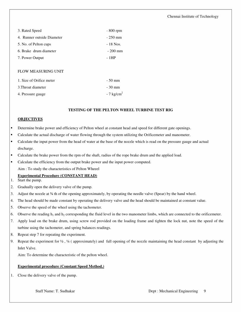
3. Rated Speed - 800 rpm
4. Runner outside Diameter - 250 mm
5. No. of Pelton cups - 18 Nos.
6. Brake drum diameter - 200 mm
7. Power Output - 1HP
FLOW MEASURING UNIT
1. Size of Orifice meter - 50 mm
3.Throat diameter - 30 mm
4. Pressure gauge - 7 kg/cm2
TESTING OF THE PELTON WHEEL TURBINE TEST RIG
OBJECTIVES
� Determine brake power and efficiency of Pelton wheel at constant head and speed for different gate openings.
� Calculate the actual discharge of water flowing through the system utilizing the Orificemeter and manometer.
� Calculate the input power from the head of water at the base of the nozzle which is read on the pressure gauge and actual
discharge.
� Calculate the brake power from the rpm of the shaft, radius of the rope brake drum and the applied load.
� Calculate the efficiency from the output brake power and the input power computed.
Aim : To study the characteristics of Pelton Wheeel
Experimental Procedure (CONSTANT HEAD)
1. Start the pump.
2. Gradually open the delivery valve of the pump.
3. Adjust the nozzle at ¾ th of the opening approximately, by operating the needle valve (Spear) by the hand wheel.
4. The head should be made constant by operating the delivery valve and the head should be maintained at constant value.
5. Observe the speed of the wheel using the tachometer.
6. Observe the reading h1 and h2 corresponding the fluid level in the two manometer limbs, which are connected to the orificemeter.
7. Apply load on the brake drum, using screw rod provided on the loading frame and tighten the lock nut, note the speed of the
turbine using the tachometer, and spring balances readings.
8. Repeat step 7 for repeating the experiment.
9. Repeat the experiment for ½ , ¼ ( approximately) and full opening of the nozzle maintaining the head constant by adjusting the
Inlet Valve.
Aim: To determine the characteristic of the pelton wheel.
Experimental procedure (Constant Speed Method.)
1. Close the delivery valve of the pump.
Chennai Institute of Technology
Staff Name: T. Sudhakar Dept : Mechanical Engineering 10
2. Start the Pump.
3. Gradually open the delivery valve of the pump and adjust the nozzle at ¼ of the opening.
4. Read the pressure gauge and note down the value
5. Apply the load on the brake drum so that the speed shown by the tachometer comes to the rated speed and note this rated speed.
Note down the spring balances reading attached to the brake drum.
6. Observe and note the reading of the manometer limbs.
7. Manipulate the discharge through the valve and control the speed at the rated value and note the spring balances readings.
8. Observe and note down the manometer readings h1 &h2
9. Repeat the experiment for different loads.
10. Repeat the experiment for different and full opening of the nozzle.
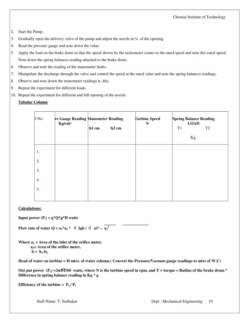
Tabular Column
Sl No:
Pressure Gauge Reading
Kg/cm²
Manometer Reading
h1 cm h2 cm
Turbine Speed
N
Spring Balance Reading
LOAD
T1 T2
Kg.
1.
2.
3.
4.
5.
Calculations:
Input power (Pi) = g*Q*ρρρρ *H watts
Flow rate of water Q = a1*a2 * √√√√ 2gh / √√√√ a1² – a22
Where a1 = Area of the inlet of the orifice meter.
a2= Area of the orifice meter.
h = h1-h2
Head of water on turbine = H mtrs. of water column.( Convert the Pressure/Vacuum gauge readings to mtrs of W.C)
Out put power (Po) =2ππππΝΤΝΤΝΤΝΤ/60 watts, where N is the turbine speed in rpm, and T = torque = Radius of the brake drum *
Difference in spring balance reading in Kg * g
Efficiency of the turbine = Po / Pi
Chennai Institute of Technology
Staff Name: T. Sudhakar Dept : Mechanical Engineering 11
Graphs: The following graphs are drawn taking speed on x-axis:
a) Speed (N) vs I/P power
b) Speed (N) vs %efficiency
c) Speed (N) Vs Discharge.
Result: 1. Efficiency of the pelton wheel. =
2. Corresponding Discharge =
3. Corresponding Pi =
4. Corresponding N =
5. Corresponding Sp. Speed =
Chennai Institute of Technology
Staff Name: T. Sudhakar Dept : Mechanical Engineering 12
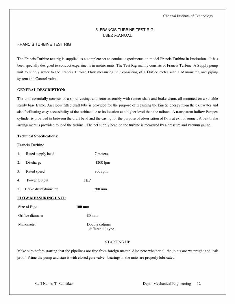
5. FRANCIS TURBINE TEST RIG
USER MANUAL
FRANCIS TURBINE TEST RIG
The Francis Turbine test rig is supplied as a complete set to conduct experiments on model Francis Turbine in Institutions. It has
been specially designed to conduct experiments in metric units. The Test Rig mainly consists of Francis Turbine, A Supply pump
unit to supply water to the Francis Turbine Flow measuring unit consisting of a Orifice meter with a Manometer, and piping
system and Control valve.
GENERAL DESCRIPTION:
The unit essentially consists of a spiral casing, and rotor assembly with runner shaft and brake drum, all mounted on a suitable
sturdy base frame. An elbow fitted draft tube is provided for the purpose of regaining the kinetic energy from the exit water and
also facilitating easy accessibility of the turbine due to its location at a higher level than the tailrace. A transparent hollow Perspex
cylinder is provided in between the draft bend and the casing for the purpose of observation of flow at exit of runner. A belt brake
arrangement is provided to load the turbine. The net supply head on the turbine is measured by a pressure and vacuum gauge.
Technical Specifications:
Francis Turbine
1. Rated supply head 7 meters.
2. Discharge 1200 lpm
3. Rated speed 800 rpm.
4. Power Output 1HP
5. Brake drum diameter 200 mm.
FLOW MEASURING UNIT:
Size of Pipe 100 mm
Orifice diameter 80 mm
Manometer Double column
differential type
STARTING UP
Make sure before starting that the pipelines are free from foreign matter. Also note whether all the joints are watertight and leak
proof. Prime the pump and start it with closed gate valve. bearings in the units are properly lubricated.
Chennai Institute of Technology
Staff Name: T. Sudhakar Dept : Mechanical Engineering 13
Then slowly open the gate valve situated above the turbine and open the cock fitted to the pressure gauge and see that the
pump develops the rated head. If the pump develops the required head, Run the turbine at the normal speed (1200 rpm)
for about one hour and carefully note the following:
1. Operation of the bearings, temperature rise, noise etc.
2. Vibration of the unit.
3 Steady constant speed and speed fluctuations if any.
In addition to this on the pump side, note the operation of the stuffing box (The stuffing box should show an occasional
drip of water. If the gland is over tightened the leakage stops but the packing will heat up, burn and damage the shaft).
If the operation of the above parts are normal, load the turbine slowly and take readings. Open the water inlet valve and allow
some cooling water through the brake drum when the turbine runs under load, so that the heat generated by the brake drum is
carried away by the cooling water. Do not suddenly load the turbine. Load the turbine gradually and at the same time open the
guide vanes to run the turbine at the normal speed
TO SHUT DOWN
Before switching off the supply pump, first remove all the load on the turbine. Close the cooling inlet water gate valve. Slowly
close the guide vanes to its full closed position. Then close the gate valve just above the turbine. Manometer cocks and Orifice
meter cocks should also be closed, in order to isolate the Manometer. Then switch off the supply pump. Never switch off the
supply pump when the turbine is working under load. Should the electric line trips off when the turbine is working, first unload
turbine, close all the valves and cocks. Start the electric motor again, when the line gets the power and then operate the turbine by
opening the valves in the order said above.
TESTING
Water turbines are tested in the hydraulic laboratory to demonstrate how tests on small water turbine are carried out, to study their
construction, and to give the students a clear knowledge about the different types of turbines and their characteristics.
Apply load slowly by adjusting the screw rod connected to the belt, for loading the brake drum and tighten the lock nut. The
speed gets reduced, Open the Gate valve to an extent the speed is 900 rpm again.
Note the spring balance reading, Pressure gauge reading and manometer reading.
Plot graphs BP Vs efficiency The experiment may also be repeated at constant net supply head. by varying the load, speed and
guide vane settings.
However the net supply head on the turbine may be reduced and the turbine tested in which case the power developed by the
turbine and the best efficiency speed will also is reduced. Though the turbines can also be tested at higher net supply heads, the
supply pump cannot develop the higher head at the same time maintaining higher rate of flow.
Chennai Institute of Technology
Staff Name: T. Sudhakar Dept : Mechanical Engineering 14
The output power from the turbine is calculated from the readings taken on the brake and the speed of the shaft. The input power
supplied to the turbine is calculated from the net supply head on the turbine and discharge through the turbine. Efficiency of the
turbine being the ratio between the output and input and can be determined from these two readings.
The discharge is measured by the Orifice meter and the Manometer fitted with the calibrated Scale. Supply head is
measured with the help of the pressure gauge. (Any calibration error of the gauges, the difference in levels of the pressure
and vacuum gauge should also be taken into account). The speed of the turbine is measured with a hand tachometer.
It is suggested that the turbines shall be tested at normal speed, 3 speeds below normal speed, 3 speeds above normal speed. After
starting and running the turbine at normal speed for some time, load the turbine and take readings. Note the following:
1. Net supply head pressure and vacuum gauge readings plus (height of pressure gauge over vacuum gauge).
2. Discharge (Manometer readings)
3. Turbine shaft speed.
4. Spring balance reading.
For any particular setting of the guide vanes first run the turbine at light load and then gradually load it. The net supply
head on the turbine shall be maintained constant at the rated value, and adjusting the gate valve fitted just above the
turbine can do this.
Calculations:
Input power (Pi) = g*Q*ρρρρ *H watts
Flow rate of water Q = a1*a2 * √√√√ 2gh / √√√√ a1² – a22
Where a1 = Area of the inlet of the orifice meter.
a2= Area of the orifice meter.
h = h1-h2
Head of water on turbine = H mtrs. of water column.( Convert the Pressure/Vacuum gauge readings to mtrs of W.C)
Out put power (Po) =2πΝΤπΝΤπΝΤπΝΤ/60 watts, where N is the turbine speed in rpm, and T = torque = Radius of the brake drum *
Difference in spring balance reading in Kg * g
Efficiency of the turbine = Po / Pi
Chennai Institute of Technology
Staff Name: T. Sudhakar Dept : Mechanical Engineering 15
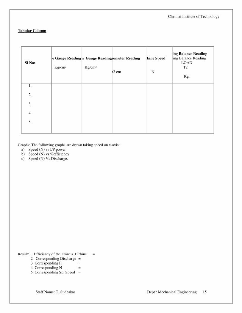
Tabular Column
Sl No:
Pressure Gauge Reading
Kg/cm²
Vacuum Gauge Reading
Kg/cm²
Manometer Reading
h1 cm h2 cm
Turbine Speed
N
Spring Balance Reading
Spring Balance Reading
LOAD
T1 T2
Kg.
1.
2.
3.
4.
5.
Graphs: The following graphs are drawn taking speed on x-axis:
a) Speed (N) vs I/P power
b) Speed (N) vs %efficiency
c) Speed (N) Vs Discharge.
Result: 1. Efficiency of the Francis Turbine =
2. Corresponding Discharge =
3. Corresponding Pi =
4. Corresponding N =
5. Corresponding Sp. Speed =
Chennai Institute of Technology
Staff Name: T. Sudhakar Dept : Mechanical Engineering 16
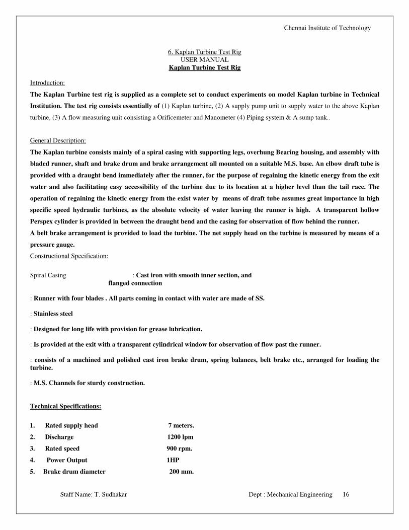
6. Kaplan Turbine Test Rig
USER MANUAL
KKaappllaann TTuurrbbiinnee TTeesstt RRiigg
Introduction:
The Kaplan Turbine test rig is supplied as a complete set to conduct experiments on model Kaplan turbine in Technical
Institution. The test rig consists essentially of (1) Kaplan turbine, (2) A supply pump unit to supply water to the above Kaplan
turbine, (3) A flow measuring unit consisting a Orificemeter and Manometer (4) Piping system & A sump tank..
General Description:
The Kaplan turbine consists mainly of a spiral casing with supporting legs, overhung Bearing housing, and assembly with
bladed runner, shaft and brake drum and brake arrangement all mounted on a suitable M.S. base. An elbow draft tube is
provided with a draught bend immediately after the runner, for the purpose of regaining the kinetic energy from the exit
water and also facilitating easy accessibility of the turbine due to its location at a higher level than the tail race. The
operation of regaining the kinetic energy from the exist water by means of draft tube assumes great importance in high
specific speed hydraulic turbines, as the absolute velocity of water leaving the runner is high. A transparent hollow
Perspex cylinder is provided in between the draught bend and the casing for observation of flow behind the runner.
A belt brake arrangement is provided to load the turbine. The net supply head on the turbine is measured by means of a
pressure gauge.
Constructional Specification:
Spiral Casing : Cast iron with smooth inner section, and
flanged connection
: Runner with four blades . All parts coming in contact with water are made of SS.
: Stainless steel
: Designed for long life with provision for grease lubrication.
: Is provided at the exit with a transparent cylindrical window for observation of flow past the runner.
: consists of a machined and polished cast iron brake drum, spring balances, belt brake etc., arranged for loading the
turbine.
: M.S. Channels for sturdy construction.
Technical Specifications:
1. Rated supply head 7 meters.
2. Discharge 1200 lpm
3. Rated speed 900 rpm.
4. Power Output 1HP
5. Brake drum diameter 200 mm.
Chennai Institute of Technology
Staff Name: T. Sudhakar Dept : Mechanical Engineering 17
FLOW MEASURING UNIT:
Size of Pipe 125 mm
Orifice diameter 75 mm
Manometer Double column
differential type
The turbine is placed on a Channel base situated at a suitable height from the floor level. The supply pump draws water
from the sump tank and supplies it to the turbine. The Orifice meter and Manometer arrangement are provided to
measure the rate of flow.
A valve is provided after the outlet of the pump to regulate the discharge and supply head on the turbine
Make sure before starting that the pipelines are free from foreign matter. Also note whether all the joints are watertight
and leak proof. While starting, the valve near the pump should be closed. This precaution is necessary because pumps
requires high power while starting. See that all the bearings in the units are properly lubricated. Then slowly open the
valve near the pump and see that the pump develops the rated head the turbine attains the normal rated speed of 900 rpm.
Run the turbine at the rated speed for about one hour and carefully note the following.
� Operation of the bearings, temperature rise, noise etc.,
� Vibration of the unit.
� Steady constant speed and speed fluctuations, if any.
In addition to this, on the pump side note the operation of the stuffing box. (The Stuffing box should show an occasionally
drip of water. If the gland is over tightened, the leakage stops, but the packing will heat up, burn and damage the Shaft).
If the operation of the above parts are normal load the turbine slowly and take readings. Open the water inlet valve and
allow some cooling water through brake drum when the turbine runs under load, so that the heat generated by the brake
drum is carried away by the cooling water. Do not suddenly load the turbine. Load the turbine gradually and at the same
time open the guide vanes to run the turbine at the normal speed.
To Shut Down:
Before switching off the supply pump set, first remove the entire load, Manometer cocks should also be closed in order to
isolate the manometer. Then close the main valve, and switch off the supply pump set.
NEVER SWITCH OFF THE SUPPLY PUMPSET WHEN THE TURBINE IS WORKING UNDER LOAD.
Chennai Institute of Technology
Staff Name: T. Sudhakar Dept : Mechanical Engineering 18
Should the electric line trips off when the turbine is working, first unload the turbine, close all the valves and cocks.. Start
the electric motor again when the line gets the power and then operate the turbine by opening the valves in the order said
above.
Testing:
Water turbines are tested in the hydraulic laboratory to demonstrate how tests on small water turbines are carried out, to
study their construction, and to give the students a clear knowledge about the different types of turbines and their
characteristics.
Turbines shall be first tested at constant net supply head (at the rated a value of 7m) by varying the load, speed, However,
the net supply head on the turbine may be reduced and the turbine tested in which case the power developed by the
turbine and the best efficiency speed will also be reduced. Though the turbine can also be tested at higher net supply
heads, the supply pump set cannot provide the higher head at the same time maintaining higher rate of flow.
The output power from the turbine is calculated from the reading taken on the brake and the speed of the shaft. The
input power supplied to the turbine is calculated from the net supply head on the turbine and discharge through the
Turbine. Efficiency of the turbine being the ratio between the output and input can be determined from these readings.
The discharge is measured by the Orifice meter and with the manometer. Supply head is measured with the help of the
pressure gauge and vacuum gauge. The speed of the turbine may be measured with a hand tachometer.
After starting and running the turbine at normal speed for some time load the turbine and take readings
Note the following:
• Net supply head (The differential of the readings on pressure & vacuum gauges.
• Discharge (Manometer reading).
• Turbine shaft speed
• Spring balance reading.
For any particular setting of the guide vane and runner blades first run the turbine at light load and then gradually load
it.. The net supply head on the turbine shall be maintained constant at the rated value, and this can be done by adjusting
the valve fitted just after the pump.
Maintenance:
As these units are built very sturdily, they do not require any routine or regular maintenance. However, we recommend
the following to be done
Lubricate all the working parts where provision for lubrication is made.
Never run the pump without water in it, as this would cause damage to stuffing box, bush bearing etc.
Never try to throttle the suction side of the pump to control discharge as it would
Chennai Institute of Technology
Staff Name: T. Sudhakar Dept : Mechanical Engineering 19
Seriously affect the performance of the pump.
Regularly run the Turbine at least 3 days in a week at the rated speed.
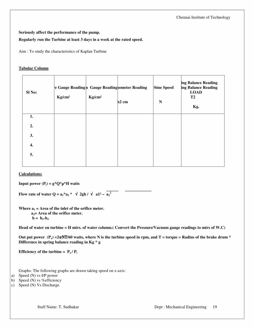
Aim : To study the characteristics of Kaplan Turbine
Tabular Column
Sl No:
Pressure Gauge Reading
Kg/cm²
Vacuum Gauge Reading
Kg/cm²
Manometer Reading
h1 cm h2 cm
Turbine Speed
N
Spring Balance Reading
Spring Balance Reading
LOAD
T1 T2
Kg.
1.
2.
3.
4.
5.
Calculations:
Input power (Pi) = g*Q*ρρρρ *H watts
Flow rate of water Q = a1*a2 * √√√√ 2gh / √√√√ a1² – a22
Where a1 = Area of the inlet of the orifice meter.
a2= Area of the orifice meter.
h = h1-h2
Head of water on turbine = H mtrs. of water column.( Convert the Pressure/Vacuum gauge readings to mtrs of W.C)
Out put power (Po) =2πΝΤπΝΤπΝΤπΝΤ/60 watts, where N is the turbine speed in rpm, and T = torque = Radius of the brake drum *
Difference in spring balance reading in Kg * g
Efficiency of the turbine = Po / Pi
Graphs: The following graphs are drawn taking speed on x-axis:
a) Speed (N) vs I/P power
b) Speed (N) vs %efficiency
c) Speed (N) Vs Discharge.
Chennai Institute of Technology
Staff Name: T. Sudhakar Dept : Mechanical Engineering 20
Result : 1. Efficiency of the Kaplan Turbine =
2. Corresponding Discharge =
3. Corresponding Pi =
4. Corresponding N =
5. Corresponding Sp. Speed =
Chennai Institute of Technology
Staff Name: T. Sudhakar Dept : Mechanical Engineering 21
7. Rotometer Test Rig
USER MANUAL
Rotometer Test Rig
Introduction
In the orifice, nozzle or venturi, the variations of flow rate through a constant area generate a variable pressure drop, which is
related to the flow rate. Another class of meters, called area meters, consists of devices in which the pressure drop is constant or
nearly so, and the area through which the fluid flows varies with flow rate.
Description
The most important area meter is a Rotometer. It consists essentially of a gradually tapered glass tube mounted vertically
in a frame with the large end up. The fluid flows upward through the tapered tube and suspends freely a float (Which does not
actually float but is completely submerged in the fluid). The float is the indicating element and the greater the flow rate, the
higher the float rides in the tube. The entire fluid stream must flow through the annular space between the float and the tube well.
The tube is marked in divisions, and the reading of the meter is obtained from the scale reading at the reading edge of the float,
which is taken at the largest cross section of the float. Rotometers can be used for either liquid- or gas –flow measurement.
The bore of a Rotometer tube is either an accurately formed plain conical taper parallel with the axis of the tube. The
tube shown in Fig. is a tapered tube. In the Rotometers angled notches in the top of the float made it rotate, but the float does not
rotate in most current designs. For opaque liquids, for high temperatures or pressures, or for other conditions where glass is
impracticable, metal tubes are used. Metal tubes are plain tapered. Since in a metal tube the float is invisible, means must be
provided for either indicating or transmitting the meter reading. This is accomplished by attaching a rod, called an extension, to
the top or bottom of the float and using the extension as an armature.
The extension is enclosed in a fluid – tight tube mounted on one of the fittings. Since the inside of this tube
communicates directly with the interior of the Rotometer, no stuffing box for the extension is needed. The tube is surrounded by
external induction coils the length of the extension exposed to the coils varies with the position of the float. This is turn change
the inductance of the coil, and the variation of the inductance is measured electrically to operate a control valve or to give a
reading on a recorder. Also, a magnetic follower, mounted outside the extension tube and adjacent to a vertical scale, can be used
as a visual indicator for the top edge of the extension. By such modifications the Rotometer has developed from a simple visual
indicating instrument using only glass tubes into a versatile recording and controlling device.
Chennai Institute of Technology
Staff Name: T. Sudhakar Dept : Mechanical Engineering 22
Floats may be constructed of metals of various densities from lead to aluminium or from glass or plastic. Stainless steel floats are
common. Float shapes and proportions are also varied for different applications.
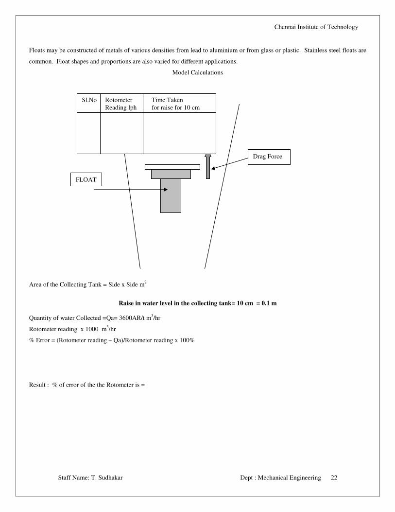
Model Calculations
Area of the Collecting Tank = Side x Side m2
Raise in water level in the collecting tank= 10 cm = 0.1 m
Quantity of water Collected =Qa= 3600AR/t m3/hr
Rotometer reading x 1000 m3/hr
% Error = (Rotometer reading – Qa)/Rotometer reading x 100%
Result : % of error of the the Rotometer is =
Drag Force
FLOAT
Sl.No Rotometer Time Taken
Reading lph for raise for 10 cm
Chennai Institute of Technology
Staff Name: T. Sudhakar Dept : Mechanical Engineering 23
8. SUBMERSIBLE PUMP TEST RIG
USER MANUAL
SUBMERSIBLE PUMP TEST RIG
INTRODUCTION:
Submersible pump is a multistage pump with a difference the pump and motor are submerged in water. Since there is a limitation
on the suction head of a ordinary pumps this pump is used where the suction head is large.
The submersible pump test rig consisting of multistage mixed flow impellers arranged on a single shaft with a submersible motor
of 3 hp capacity. The suction housing of the pump is arranged between the pump and the motor and is guarded by a perforated
strainer.
The pump is used to provide high discharge with medium total head.
The outlet of the pump is connected to a 1½” delivery pipe with a pressure gauge to indicate the total head developed and a flow
control valve.
A Orifice meter of inlet Diameter 40 mm and throat Diameter 24 mm is connected to the delivery pipe with a manometer to
measure discharge.
Panel with switch, starter and energy meter provided to note the input energy for the pump
PROCEDURE:
���� Adjust the delivery valve and maintain required delivery head. Note the reading
���� Note the manometer reading.
���� For different delivery head repeat the experiment.
���� For every set of reading note the time taken for 10 Rev. energy meter.
CALCULATION:
The total effective head H in meters of W.C. = Hd
Since the delivery pressure is in Kg/cm2 the total head developed by the pump to be converted in mtrs. of water column.
Where Hd = Delivery head
Discharge Q = a1 a2 √2ghw / √a12 – a2
2 m
3/sec.
Where
a1 = Inlet area of Orifice meter.
a2 = Throat area of Orifice meter
hw = (h1 – h2 ) x ℓm /
ℓ w
Chennai Institute of Technology
Staff Name: T. Sudhakar Dept : Mechanical Engineering 24
Where h1 and h2 are manometer reading and
M = density of mercury.
W = density of water.
The work done by the pump is given by
Po = (ρρρρ * g * Q * H)/1000 KW.
The Input power Pi = 3600/t x 10/t KW.
The efficiency of the pump = Po / Pi x 100 %
Graph:
Plot graphs Discharge Vs power.
Discharge Vs Head.
Discharge Vs Efficiency.
Result : 1. Efficiency of the Submersible =
2. Corresponding Discharge =
3. Corresponding Pi =
4. Corresponding N =
5. Corresponding Sp. Speed =
Chennai Institute of Technology
Staff Name: T. Sudhakar Dept : Mechanical Engineering 25
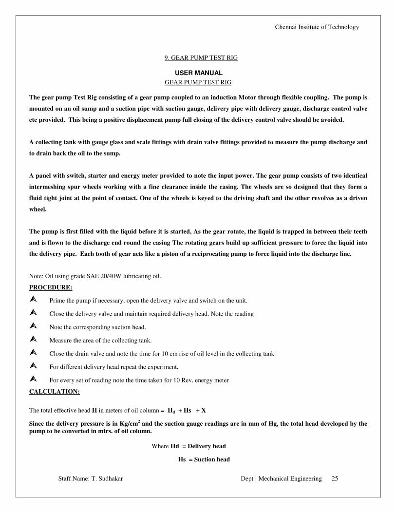
9. GEAR PUMP TEST RIG
USER MANUAL
GEAR PUMP TEST RIG
The gear pump Test Rig consisting of a gear pump coupled to an induction Motor through flexible coupling. The pump is
mounted on an oil sump and a suction pipe with suction gauge, delivery pipe with delivery gauge, discharge control valve
etc provided. This being a positive displacement pump full closing of the delivery control valve should be avoided.
A collecting tank with gauge glass and scale fittings with drain valve fittings provided to measure the pump discharge and
to drain back the oil to the sump.
A panel with switch, starter and energy meter provided to note the input power. The gear pump consists of two identical
intermeshing spur wheels working with a fine clearance inside the casing. The wheels are so designed that they form a
fluid tight joint at the point of contact. One of the wheels is keyed to the driving shaft and the other revolves as a driven
wheel.
The pump is first filled with the liquid before it is started, As the gear rotate, the liquid is trapped in between their teeth
and is flown to the discharge end round the casing The rotating gears build up sufficient pressure to force the liquid into
the delivery pipe. Each tooth of gear acts like a piston of a reciprocating pump to force liquid into the discharge line.
Note: Oil using grade SAE 20/40W lubricating oil.
PROCEDURE:
���� Prime the pump if necessary, open the delivery valve and switch on the unit.
���� Close the delivery valve and maintain required delivery head. Note the reading
���� Note the corresponding suction head.
���� Measure the area of the collecting tank.
���� Close the drain valve and note the time for 10 cm rise of oil level in the collecting tank
���� For different delivery head repeat the experiment.
���� For every set of reading note the time taken for 10 Rev. energy meter
CALCULATION:
The total effective head H in meters of oil column = Hd + Hs + X
Since the delivery pressure is in Kg/cm2 and the suction gauge readings are in mm of Hg, the total head developed by the
pump to be converted in mtrs. of oil column.
Where Hd = Delivery head
Hs = Suction head
Chennai Institute of Technology
Staff Name: T. Sudhakar Dept : Mechanical Engineering 26
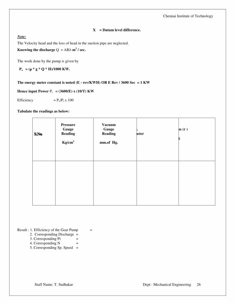
X = Datum level difference.
Note:
The Velocity head and the loss of head in the suction pipe are neglected.
Knowing the discharge Q = AR/t m3 / sec.
The work done by the pump is given by
Po = (ρρρρ * g * Q * H)/1000 KW.
The energy meter constant is noted (E - rev/KWH) OR E Rev / 3600 Sec = 1 KW
Hence input Power Pi = (3600/E) x (10/T) KW
Efficiency = Po/Pi x 100
Tabulate the readings as below:
SSS...NNNooo
Pressure
Gauge
Reading
Kg/cm2
Vacuum
Gauge
Reading
mm.of Hg.
For 5 call.
Energy meter
For 10 cms (r )
Collecting
Tank (t )
Result : 1. Efficiency of the Gear Pump =
2. Corresponding Discharge =
3. Corresponding Pi =
4. Corresponding N =
5. Corresponding Sp. Speed =
Chennai Institute of Technology
Staff Name: T. Sudhakar Dept : Mechanical Engineering 27
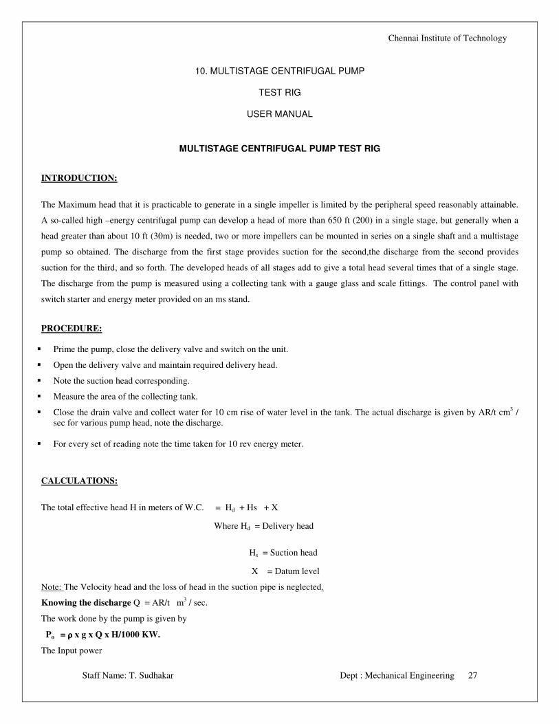
10. MULTISTAGE CENTRIFUGAL PUMP
TEST RIG
USER MANUAL
MULTISTAGE CENTRIFUGAL PUMP TEST RIG
INTRODUCTION:
The Maximum head that it is practicable to generate in a single impeller is limited by the peripheral speed reasonably attainable.
A so-called high –energy centrifugal pump can develop a head of more than 650 ft (200) in a single stage, but generally when a
head greater than about 10 ft (30m) is needed, two or more impellers can be mounted in series on a single shaft and a multistage
pump so obtained. The discharge from the first stage provides suction for the second,the discharge from the second provides
suction for the third, and so forth. The developed heads of all stages add to give a total head several times that of a single stage.
The discharge from the pump is measured using a collecting tank with a gauge glass and scale fittings. The control panel with
switch starter and energy meter provided on an ms stand.
PROCEDURE:
� Prime the pump, close the delivery valve and switch on the unit.
� Open the delivery valve and maintain required delivery head.
� Note the suction head corresponding.
� Measure the area of the collecting tank.
� Close the drain valve and collect water for 10 cm rise of water level in the tank. The actual discharge is given by AR/t cm3 /
sec for various pump head, note the discharge.
� For every set of reading note the time taken for 10 rev energy meter.
CALCULATIONS:
The total effective head H in meters of W.C. = Hd + Hs + X
Where Hd = Delivery head
Hs = Suction head
X = Datum level
Note: The Velocity head and the loss of head in the suction pipe is neglected.
Knowing the discharge Q = AR/t m3 / sec.
The work done by the pump is given by
Po = ρρρρ x g x Q x H/1000 KW.
The Input power
Chennai Institute of Technology
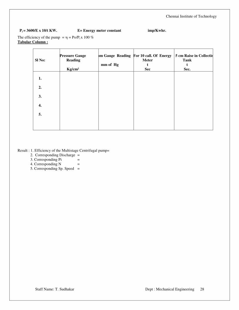
Staff Name: T. Sudhakar Dept : Mechanical Engineering 28
Pi = 3600/E x 10/t KW. E= Energy meter constant imp/Kwhr.
The efficiency of the pump = η = Po/Pi x 100 %
Tabular Column :
Sl No:
Pressure Gauge
Reading
Kg/cm²
Vacuum Gauge Reading
mm of Hg
Time For 10 call. Of Energy
Meter
t
Sec
Time For 5 cm Raise in Collecting
Tank
t
Sec.
1.
2.
3.
4.
5.
Result : 1. Efficiency of the Multistage Centrifugal pump=
2. Corresponding Discharge =
3. Corresponding Pi =
4. Corresponding N =
5. Corresponding Sp. Speed =
Chennai Institute of Technology
Staff Name: T. Sudhakar Dept : Mechanical Engineering 29
11. SINGLE STAGE CENTRIFUGAL PUMP TEST RIG
USER MANUAL
SINGLE STAGE CENTRIFUGAL PUMP TEST RIG
INTRODUCTION:
The pump which raises water from a lower level to a higher level by the action of Centrifugal force is known as centrifugal pump.
The pump lifts water because of atmospheric pressure acting on the surface of water. The pump reduces the pressure in the casing
to such an extent that the atmospheric pressure forces up water in the suction pipe
DESCRIPTION:
The centrifugal pump with motor mounted on a sturdy iron base plate. The suction pipe is provided with a suction gauge, and a
foot valve. The delivery pipe with a priming valve, delivery control valve, and a pressure gauge. The discharge from the pump is
measured using a collecting tank with a gauge glass. Panel with switch starter and energy meter provided.
PROCEDURE:
���� Prime the pump, close the delivery valve and switch on the unit.
���� Open the delivery valve and maintain required delivery head. Note the reading
���� Note the corresponding suction head.
���� Measure the area of the collecting tank, A.
���� Close the drain valve and note the time for 10 cm ( 0.1 m ), R rise of water level in the collecting tank
���� For different delivery head repeat the experiment.
���� For every set of reading note the time taken for 10 Rev. energy meter.
CALCULATION:
The total effective head H in meters of W.C. = Hd + Hs + X
Since the delivery pressure is in Kg/cm2 and the suction gauge readings are in mm of Hg, the total head developed by the
pump to be converted in mtrs. of water column.
Where HD = Delivery head
HS = Suction head
X = Datum level difference.
Note:
The Velocity head and the loss of head in the suction pipe are neglected.
Knowing the discharge Q = AR/t m3 / sec.
The work done by the pump is given by
Chennai Institute of Technology
Staff Name: T. Sudhakar Dept : Mechanical Engineering 30
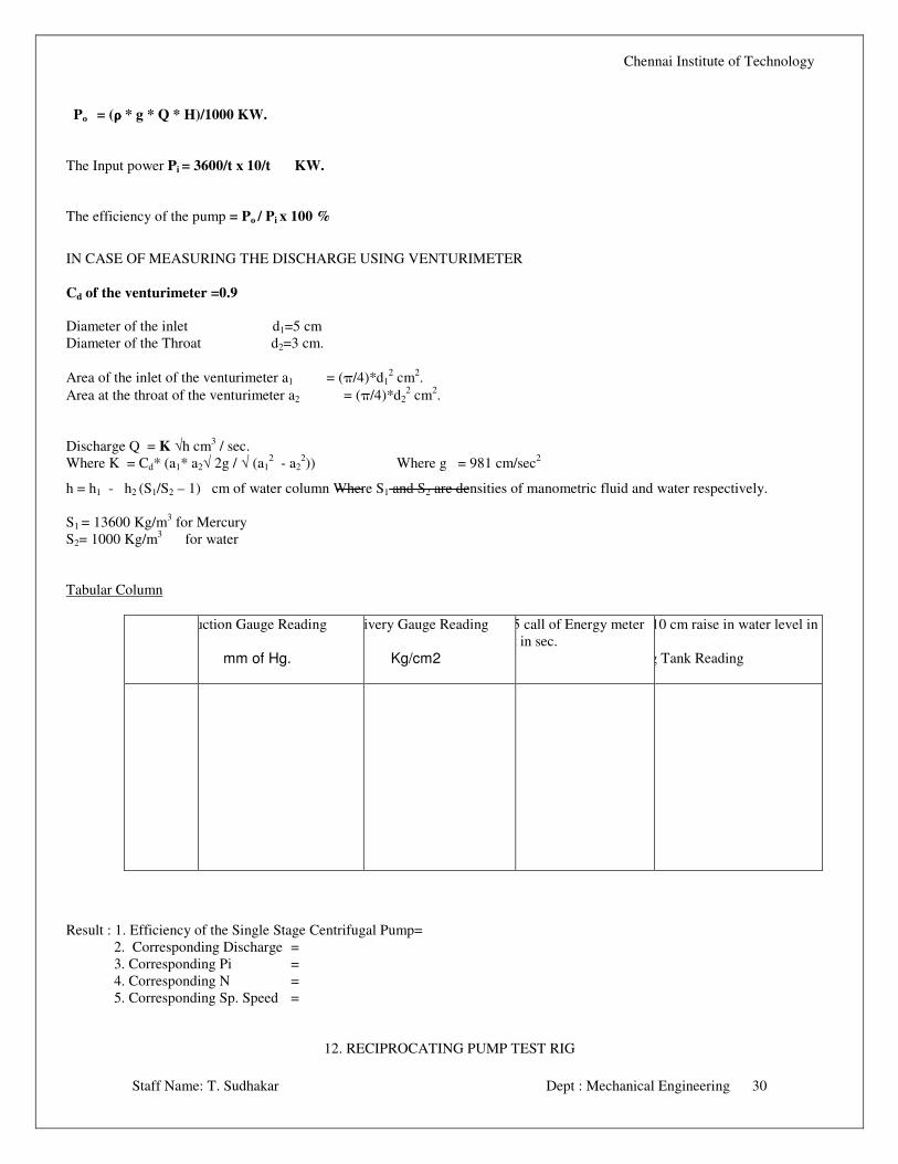
Po = (ρρρρ * g * Q * H)/1000 KW.
The Input power Pi = 3600/t x 10/t KW.
The efficiency of the pump = Po / Pi x 100 %
IN CASE OF MEASURING THE DISCHARGE USING VENTURIMETER
Cd of the venturimeter =0.9
Diameter of the inlet d1=5 cm
Diameter of the Throat d2=3 cm.
Area of the inlet of the venturimeter a1 = (π/4)*d12 cm
2.
Area at the throat of the venturimeter a2 = (π/4)*d22 cm
2.
Discharge Q = K √h cm3 / sec.
Where K = Cd* (a1* a2√ 2g / √ (a12 - a2
2)) Where g = 981 cm/sec
2
h = h1 - h2 (S1/S2 – 1) cm of water column Where S1 and S2 are densities of manometric fluid and water respectively.
S1 = 13600 Kg/m3 for Mercury
S2= 1000 Kg/m3 for water
Tabular Column
Suction Gauge Reading
mm of Hg.
Delivery Gauge Reading
Kg/cm2
Time for 5 call of Energy meter
reading t in sec.
Time for 10 cm raise in water level in
Collecting Tank Reading
Result : 1. Efficiency of the Single Stage Centrifugal Pump=
2. Corresponding Discharge =
3. Corresponding Pi =
4. Corresponding N =
5. Corresponding Sp. Speed =
12. RECIPROCATING PUMP TEST RIG
Chennai Institute of Technology
Staff Name: T. Sudhakar Dept : Mechanical Engineering 31
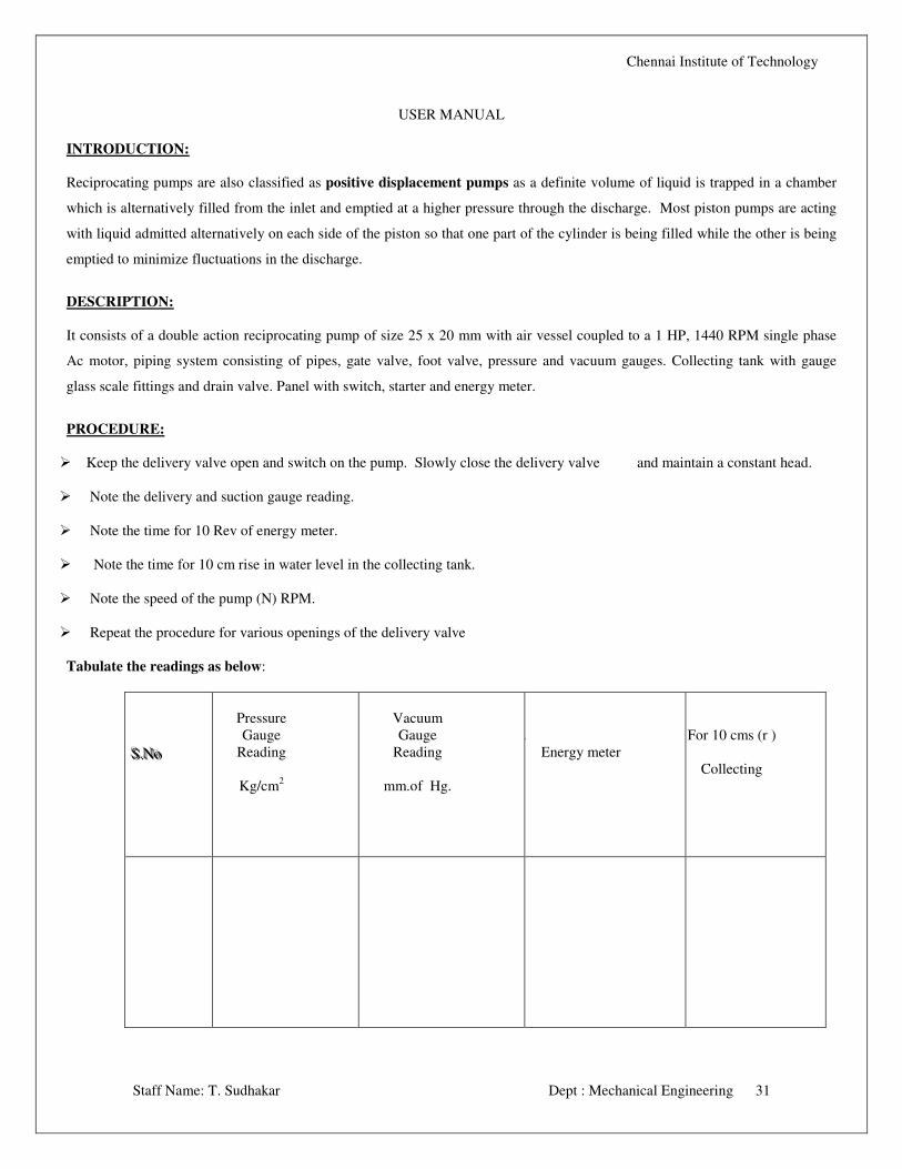
USER MANUAL
INTRODUCTION:
Reciprocating pumps are also classified as positive displacement pumps as a definite volume of liquid is trapped in a chamber
which is alternatively filled from the inlet and emptied at a higher pressure through the discharge. Most piston pumps are acting
with liquid admitted alternatively on each side of the piston so that one part of the cylinder is being filled while the other is being
emptied to minimize fluctuations in the discharge.
DESCRIPTION:
It consists of a double action reciprocating pump of size 25 x 20 mm with air vessel coupled to a 1 HP, 1440 RPM single phase
Ac motor, piping system consisting of pipes, gate valve, foot valve, pressure and vacuum gauges. Collecting tank with gauge
glass scale fittings and drain valve. Panel with switch, starter and energy meter.
PROCEDURE:
� Keep the delivery valve open and switch on the pump. Slowly close the delivery valve and maintain a constant head.
� Note the delivery and suction gauge reading.
� Note the time for 10 Rev of energy meter.
� Note the time for 10 cm rise in water level in the collecting tank.
� Note the speed of the pump (N) RPM.
� Repeat the procedure for various openings of the delivery valve
Tabulate the readings as below:
SSS...NNNooo
Pressure
Gauge
Reading
Kg/cm2
Vacuum
Gauge
Reading
mm.of Hg.
For 5 call.
Energy meter
For 10 cms (r )
Collecting
Chennai Institute of Technology
Staff Name: T. Sudhakar Dept : Mechanical Engineering 32
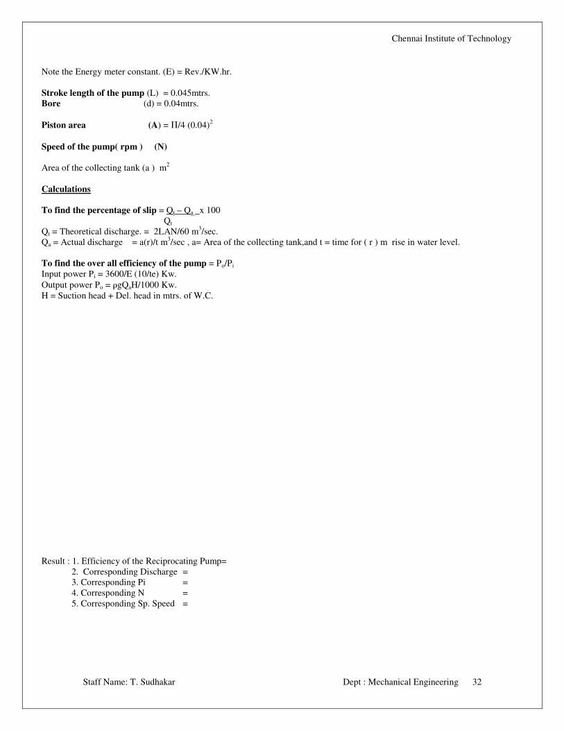
Note the Energy meter constant. (E) = Rev./KW.hr.
Stroke length of the pump (L) = 0.045mtrs.
Bore (d) = 0.04mtrs.
Piston area (A) = Π/4 (0.04)2
Speed of the pump( rpm ) (N)
Area of the collecting tank (a ) m2
Calculations
To find the percentage of slip = Qt – Qa x 100
Qt
Qt = Theoretical discharge. = 2LAN/60 m3/sec.
Qa = Actual discharge = a(r)/t m3/sec , a= Area of the collecting tank,and t = time for ( r ) m rise in water level.
To find the over all efficiency of the pump = Po/Pi
Input power Pi = 3600/E (10/te) Kw.
Output power Po = ρgQaH/1000 Kw.
H = Suction head + Del. head in mtrs. of W.C.
Result : 1. Efficiency of the Reciprocating Pump=
2. Corresponding Discharge =
3. Corresponding Pi =
4. Corresponding N =
5. Corresponding Sp. Speed =

Chennai Institute of Technology
Staff Name: T. Sudhakar Dept : Mechanical Engineering 33
Related Documents