University of Hail Faculty of Engineering DEPARTMENT OF MECHANICAL ENGINEERING ME 311 - Fluid Mechanics Lecture notes Chapter 5 Part2 Control volume analysis Newton’s Second Law—The Linear Momentum Equation Prepared by : Dr. N. Ait Messaoudene Based on: “Fundamentals of Fluid Mechanics” Munson; Young; Okiishi; Huebsch, 6 th Edition, John Willey and Sons, 2010. 1 st semester 2011-2012

Welcome message from author
This document is posted to help you gain knowledge. Please leave a comment to let me know what you think about it! Share it to your friends and learn new things together.
Transcript
University of HailFaculty of Engineering
DEPARTMENT OF MECHANICAL ENGINEERING
ME 311 - Fluid MechanicsLecture notes
Chapter 5Part2
Control volume analysisNewton’s Second Law—The Linear Momentum Equation
Prepared by : Dr. N. Ait Messaoudene
Based on:
“Fundamentals of Fluid Mechanics”Munson; Young; Okiishi; Huebsch, 6th Edition, John Willey and Sons, 2010.
1st semester 2011-2012
Derivation of the Linear Momentum Equation
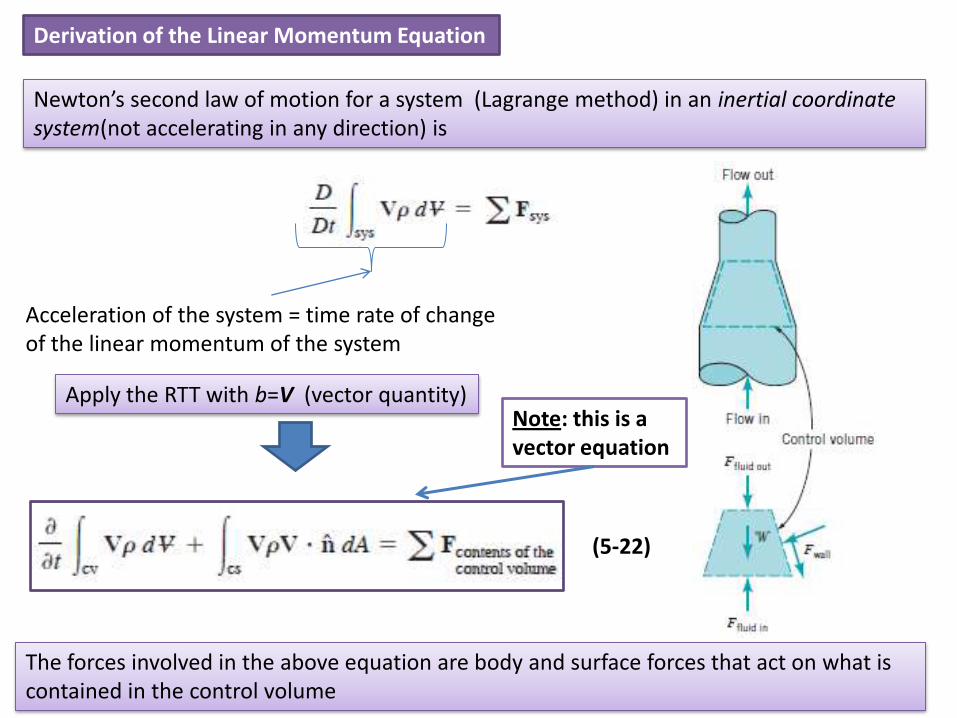
Newton’s second law of motion for a system (Lagrange method) in an inertial coordinate system(not accelerating in any direction) is
Acceleration of the system = time rate of change of the linear momentum of the system
Apply the RTT with b=V (vector quantity)
The forces involved in the above equation are body and surface forces that act on what is contained in the control volume
(5-22)
Note: this is a vector equation

The only body force we consider in this chapter is the one associated with the action of gravity. We experience this body force as weight, W
The surface forces are basically exerted on the contents of the control volume by material just outside the control volume in contact with material just inside the control volume.
For example:
•A wall in contact with fluid can exert a reaction surface force on the fluid it bounds. •Fluid just outside the control volume can push on fluid just inside the control volume at a common interface, usually an opening in the control surface through which fluid flow occurs. •An immersed object can resist fluid motion with surface forces.
General considerations about the linear momentum equation:
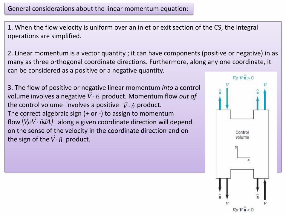
1. When the flow velocity is uniform over an inlet or exit section of the CS, the integral operations are simplified.
2. Linear momentum is a vector quantity ; it can have components (positive or negative) in as many as three orthogonal coordinate directions. Furthermore, along any one coordinate, it can be considered as a positive or a negative quantity.
3. The flow of positive or negative linear momentum into a control volume involves a negative product. Momentum flow out of the control volume involves a positive product. The correct algebraic sign (+ or -) to assign to momentum flow along a given coordinate direction will depend on the sense of the velocity in the coordinate direction and on the sign of the product.
nV ˆ
nV ˆ
dAnVV ˆ
nV ˆ
4. is zero for steady flow.
5. If the CS is selected so that it is perpendicular to the flow where fluid enters or leaves the CV, the surface force exerted at these locations by fluid outside the CV on fluid inside will be due to pressure. Furthermore, when subsonic flow exits from a control volume into the atmosphere, atmospheric pressure prevails at the exit cross section.
6. In general, forces due to atmospheric pressure acting on a CS cancel each other and gage pressure may be used in computations. Nevertheless, the forces due to atmospheric pressure acting on the CS may need consideration ion some cases and carefull attention should be given to the proper choice of the CS (see example 5.11).
7. The external forces have an algebraic sign, positive if the force is in the assigned positive coordinate direction and negative otherwise.
8. Only external forces acting on the contents of the CV are considered in the linear momentum equation (Eq. 5.22). If the fluid alone is included in a control volume, reaction forces between the fluid and the surface or surfaces in contact with the fluid will need to be in Eq. 5.22. If the fluid and the wetted surface or surfaces are within the CV, the anchoring force that holds the wetted surface(s) in place is an external force and must therefore be in Eq. 5.22.
9. The force required to anchor (hold in place) an object will generally exist in response to surface pressure and /or shear forces acting on the CS, to a change in linear momentum flow through the CV containing the object, and to the weight of the object and the fluid contained in the CV.
Application of the Linear Momentum Equation
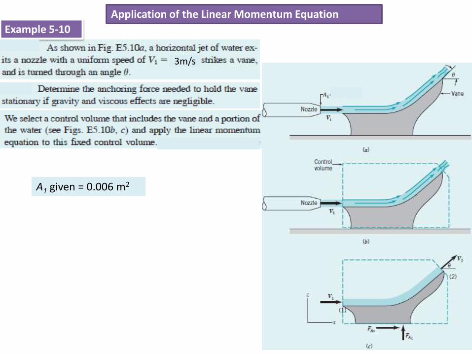
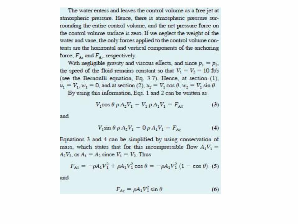
Example 5-10
3m/s
A1 given = 0.006 m2

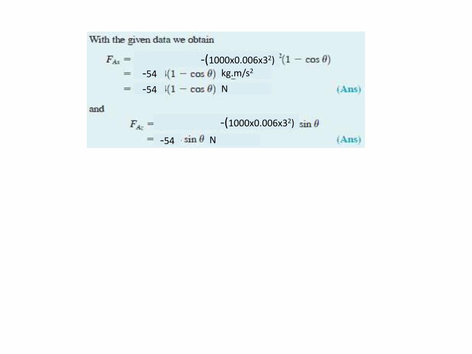
-(1000x0.006x32)
-54 kg.m/s2
N-54
-(1000x0.006x32)
-54 N
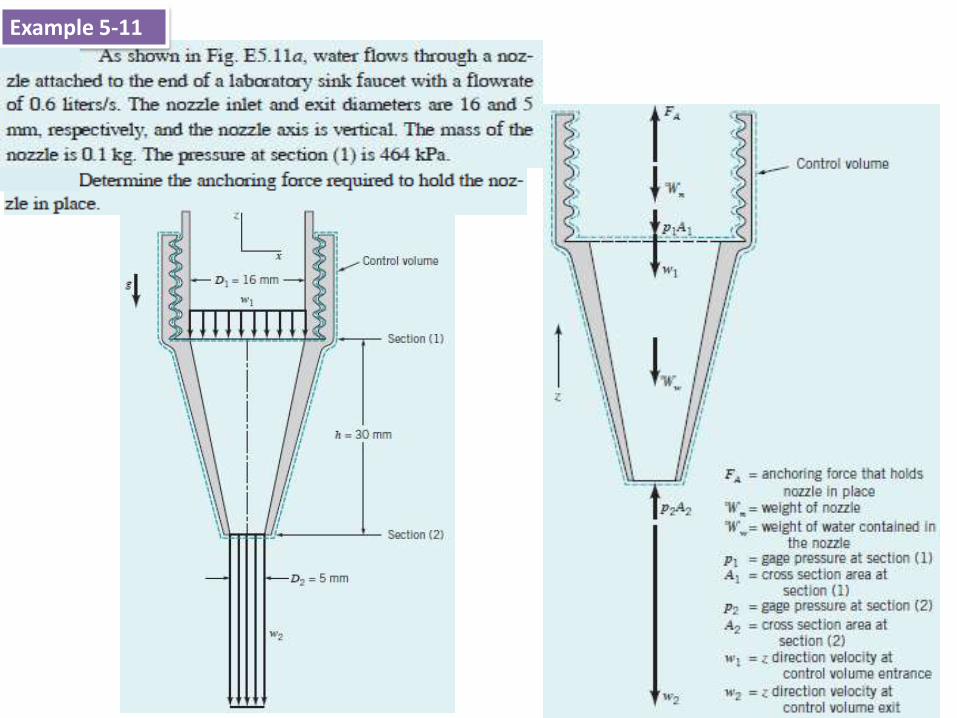
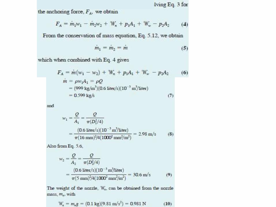
Example 5-11
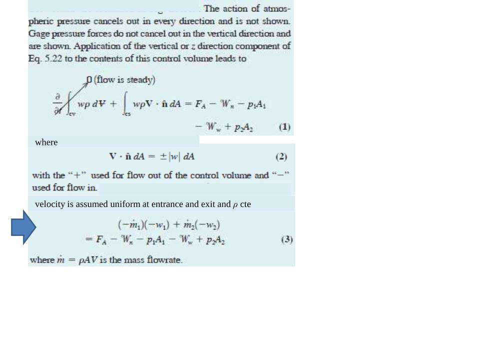
where
velocity is assumed uniform at entrance and exit and ρ cte
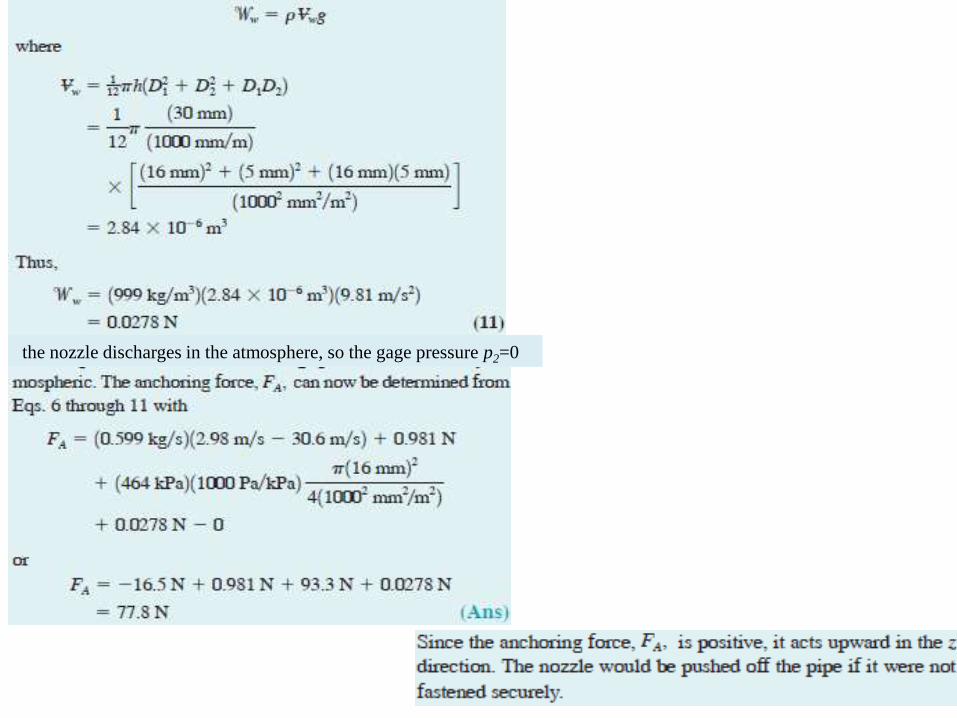
the nozzle discharges in the atmosphere, so the gage pressure p2=0
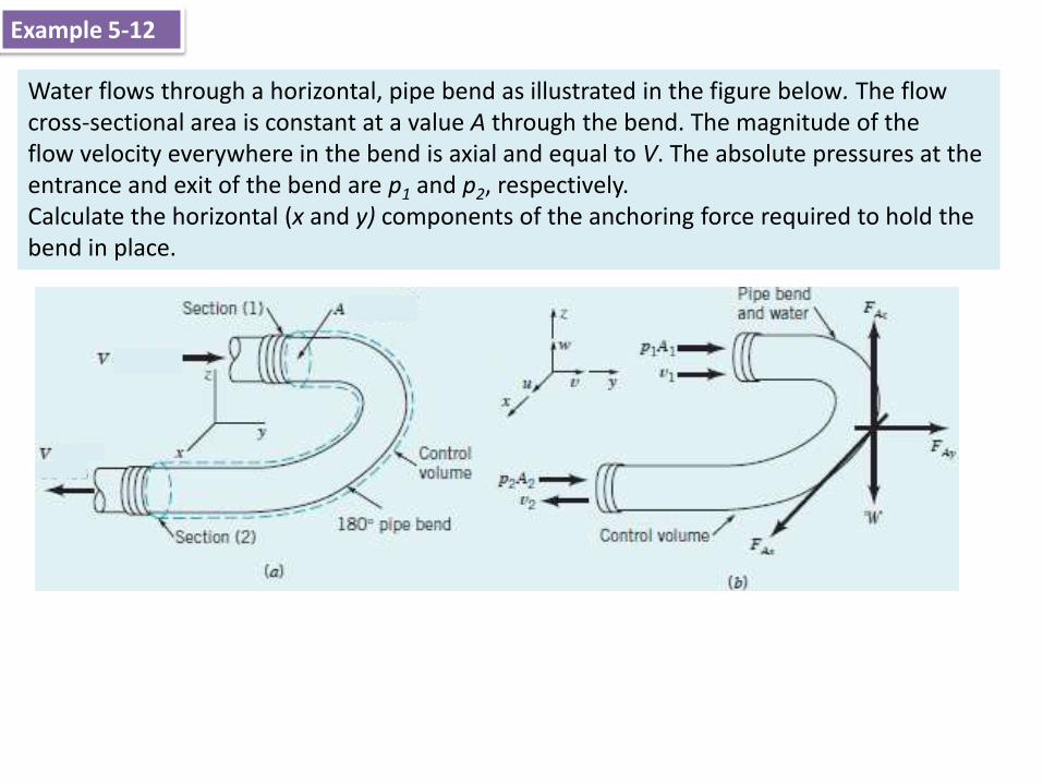
Water flows through a horizontal, pipe bend as illustrated in the figure below. The flow cross-sectional area is constant at a value A through the bend. The magnitude of theflow velocity everywhere in the bend is axial and equal to V. The absolute pressures at the entrance and exit of the bend are p1 and p2, respectively.Calculate the horizontal (x and y) components of the anchoring force required to hold the bend in place.
Example 5-12
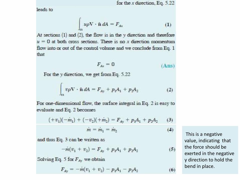
This is a negative value, indicating that the force should be exerted in the negative y direction to hold the bend in place.
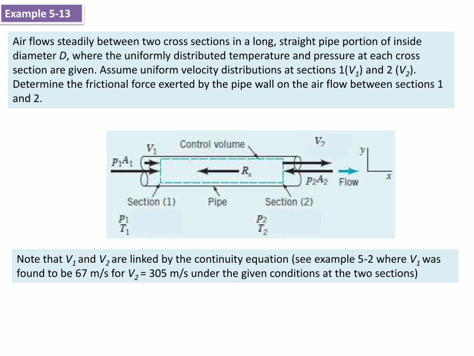
Air flows steadily between two cross sections in a long, straight pipe portion of inside diameter D, where the uniformly distributed temperature and pressure at each cross section are given. Assume uniform velocity distributions at sections 1(V1) and 2 (V2).Determine the frictional force exerted by the pipe wall on the air flow between sections 1 and 2.
Example 5-13
Note that V1 and V2 are linked by the continuity equation (see example 5-2 where V1 was found to be 67 m/s for V2 = 305 m/s under the given conditions at the two sections)
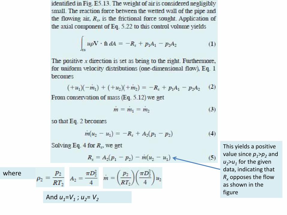
where
And u1=V1 ; u2= V2
This yields a positive value since p1>p2 and u2>u1 for the given data, indicating that Rx opposes the flow as shown in the figure

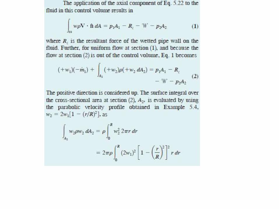
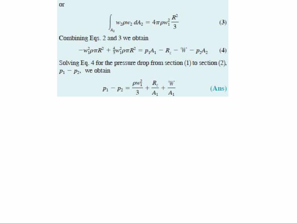
Consider the flow of Example 5.4 to be vertically upward.Develop an expression for the fluid pressure drop that occurs between sections 1 and 2.
Example 5-14
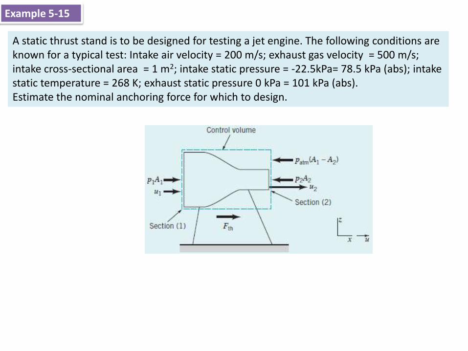
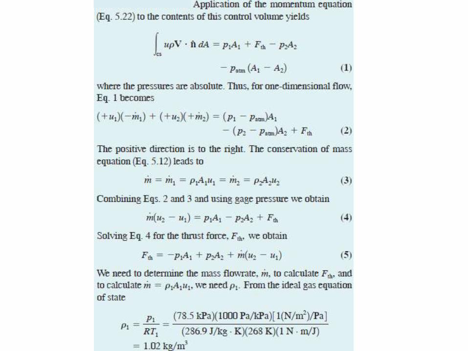
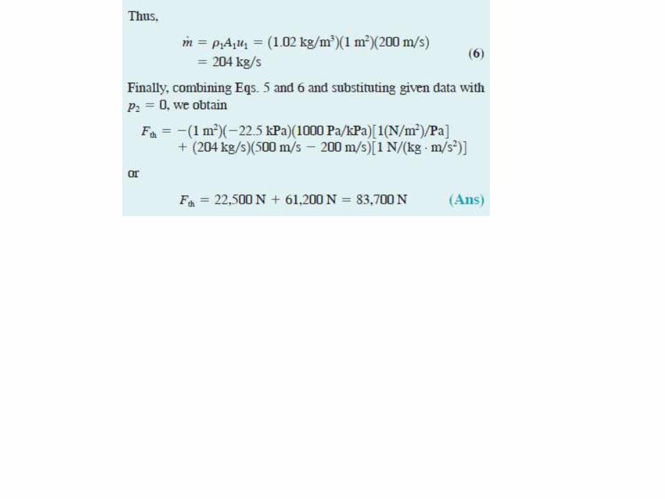
A static thrust stand is to be designed for testing a jet engine. The following conditions areknown for a typical test: Intake air velocity = 200 m/s; exhaust gas velocity = 500 m/s; intake cross-sectional area = 1 m2; intake static pressure = -22.5kPa= 78.5 kPa (abs); intake static temperature = 268 K; exhaust static pressure 0 kPa = 101 kPa (abs).Estimate the nominal anchoring force for which to design.
Example 5-15

For an inertial, moving, nondeforming control volume the Reynolds transport theorem leads to
Moving control volume
Where:The relative velocity, W, is the fluid velocity seen by an observer moving with the control volume. The control volume velocity VCV, is the velocity of the control volume as seen from a fixed coordinate system.The absolute velocity, V, is the fluid velocity seen by a stationary observer in a fixed coordinate system.
(5-24)
These velocities are related to each other by the vector equation
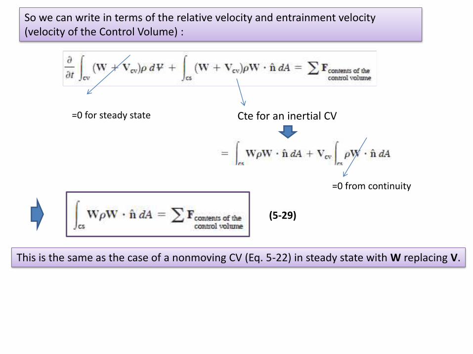
So we can write in terms of the relative velocity and entrainment velocity (velocity of the Control Volume) :
=0 for steady state Cte for an inertial CV
=0 from continuity
(5-29)
This is the same as the case of a nonmoving CV (Eq. 5-22) in steady state with W replacing V.
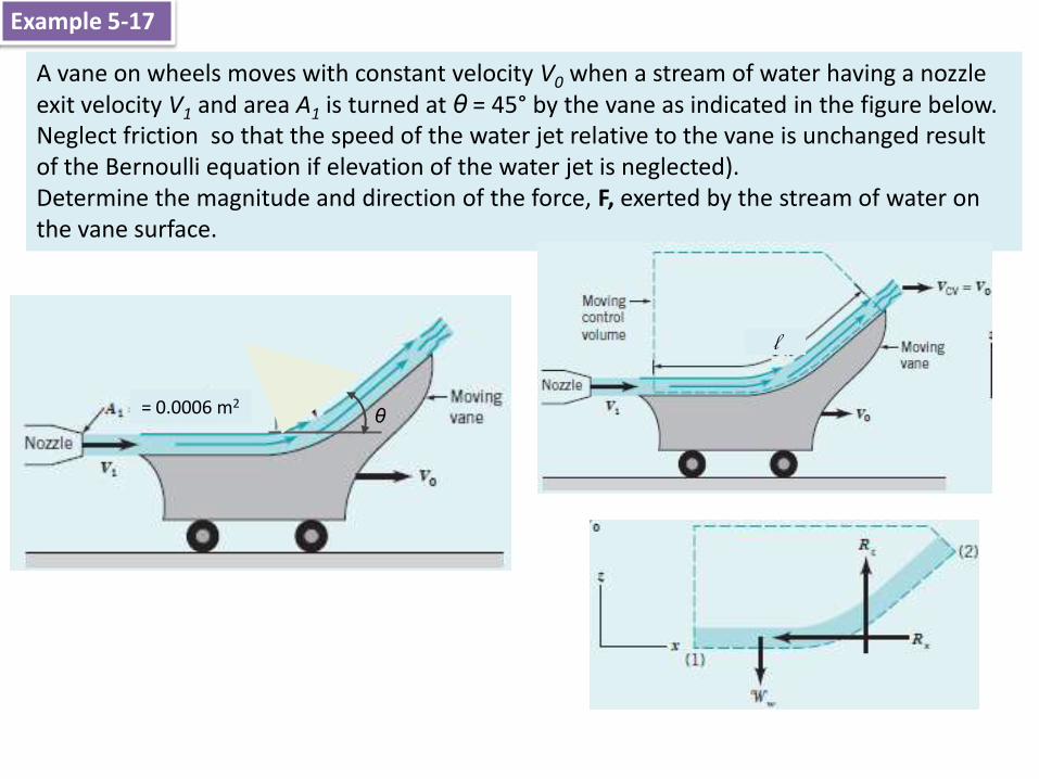
A vane on wheels moves with constant velocity V0 when a stream of water having a nozzle exit velocity V1 and area A1 is turned at θ = 45° by the vane as indicated in the figure below. Neglect friction so that the speed of the water jet relative to the vane is unchanged result of the Bernoulli equation if elevation of the water jet is neglected).Determine the magnitude and direction of the force, F, exerted by the stream of water on the vane surface.
Example 5-17
= 0.0006 m2
l
θ

Relative water speed is unchanged along the vane , so we have:
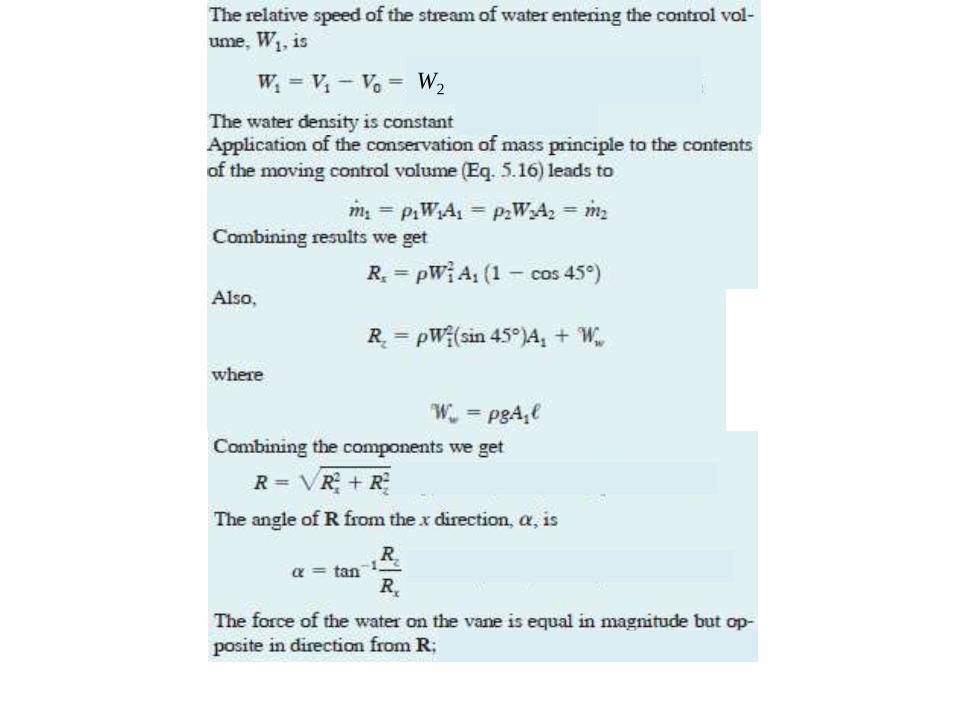
W2
Related Documents