JOURNAL OF THERMOPHYSICS AND HEAT TRANSFER Vol. 19, No. 2, April–June 2005 Fluid Flow Around and Heat Transfer from Elliptical Cylinders: Analytical Approach W. A. Khan, ∗ J. R. Culham, † and M. M. Yovanovich ‡ University of Waterloo, Waterloo, Ontario N2L 3G1, Canada An integral method of boundary-layer analysis is employed to derive closed-form expressions for the calculation of total drag and average heat transfer for flow across an elliptical cylinder under isothermal and isoflux thermal boundary conditions. The Von K´ arm´ an–Pohlhausen integral method is used to solve the momentum and energy equations for both thermal boundary conditions. A fourth-order velocity profile in the hydrodynamic boundary layer and a third-order temperature profile in the thermal boundary layer are used. The present results are in good agreement with existing experimental/numerical data and, in the limiting cases, can be used for circular cylinders and finite plates. Nomenclature a = semimajor axis of elliptical cylinder, m b = semiminor axis of elliptical cylinder, m C D = total drag coefficient C D f = friction drag coefficient C Dp = pressure drag coefficient C f = skin friction coefficient, ≡ 2τ w /ρU 2 app C p = pressure coefficient, ≡ 2p/ρU 2 app c = dimensional focal distance, m c p = fluid specific heat, kJ/kg K D = diameter of circular cylinder, m E (e) = complete elliptic integral of second kind e = eccentricity, ≡ √ (1 − 2 ) g 11 , g 22 = metric coefficients ¯ h = average heat-transfer coefficient, W/m 2 K k = thermal conductivity, W/m K L = length of finite plate, m L = characteristic length ≡ 2a,m Nu L = Nusselt number based on characteristic length ≡ L ¯ h/ k f P = pressure, N/m 2 Pr = Prandtl number ≡ ν/α q = heat flux, W/m 2 Re L = Reynolds number based on characteristic length ≡ LU app /ν r = radius of curvature of surface, m s = distance along curved surface of elliptical cylinder measured from forward stagnation point, m T = temperature, ◦ C U app = approach velocity, m/s U (s ) = velocity in inviscid region just outside boundary layer, m/s u = s -component of velocity in boundary layer, m/s v = η-component of velocity in boundary layer, m/s x , y = Cartesian coordinates Received 28 April 2004; presented as Paper 2004-2272 at the AIAA 37th Thermophysics Conference, Portland, OR, 28 June–1 July 2004; revision received 5 July 2004; accepted for publication 8 July 2004. Copyright c 2004 by the American Institute of Aeronautics and Astronautics, Inc. All rights reserved. Copies of this paper may be made for personal or internal use, on condition that the copier pay the $10.00 per-copy fee to the Copyright Clearance Center, Inc., 222 Rosewood Drive, Danvers, MA 01923; include the code 0887-8722/05 $10.00 in correspondence with the CCC. ∗ Postdoctoral Fellow, Department of Mechanical Engineering. Member AIAA. † Associate Professor and Director, Microelectronics Heat Transfer Lab- oratory, Department of Mechanical Engineering. ‡ Distinguished Professor Emeritus, Department of Mechanical Engineer- ing. Fellow AIAA. δ = hydrodynamic boundary-layer thickness, m δ 1 = displacement thickness, m δ 2 = momentum thickness, m δ T = thermal boundary layer thickness, m = axis ratio ≡ b/a η = distance normal to and measured from surface of elliptical cylinder, m θ = angle measured from stagnation point, radians λ = pressure gradient parameter µ = absolute viscosity of fluid, kg/ms ν = kinematic viscosity of fluid, m 2 /s ξ , θ = modified polar coordinates ρ = fluid density, kg/m 3 τ = shear stress, N/m 2 Subscripts a = ambient f = fluid p = pressure s = separation T = thermal w = wall Introduction M ANY industrial applications, where heat loads are substantial and space is limited, require the use of tubular heat exchang- ers for the cooling of electronic equipment. In these applications, el- liptical geometries outperform circular geometries. Elliptical cylin- ders offer less flow resistance and higher heat-transfer rates than circular cylinders. They provide more general geometrical configu- rations than circular cylinders. In the limiting cases, they represent a finite-length plate when the axis ratio → 0 and a circular cylinder when the axis ratio → 1. Thus, a systematic analytical investi- gation of elliptical geometries can provide flow and heat-transfer characteristics not only from elliptical cylinders of different axis ratios but also from circular cylinders and finite-length flat plates. Because of space limitations, existing literature is reviewed for the elliptical cylinders only. There have been few experimental/numerical studies of fluid flow and heat transfer from elliptical cylinders. Schubauer 1,2 con- ducted experiments to determine velocity distributions in the lam- inar boundary layer on the surface of an elliptic cylinder with axis ratio 1:3. He found that the velocity distributions in the boundary layer, its thickness, and its tendency to separate from the surface of the body are governed almost entirely by the velocity distribu- tion in the region of potential flow outside the boundary layer. He got good agreement with the approximate method, developed by Pohlhausen, 3 for the forward part of the cylinder. The same ap- proximate method was used by Schlichting and Ulrich 4 to calculate 178

Welcome message from author
This document is posted to help you gain knowledge. Please leave a comment to let me know what you think about it! Share it to your friends and learn new things together.
Transcript
JOURNAL OF THERMOPHYSICS AND HEAT TRANSFER
Vol. 19, No. 2, April–June 2005
Fluid Flow Around and Heat Transfer from Elliptical Cylinders:Analytical Approach
W. A. Khan,∗ J. R. Culham,† and M. M. Yovanovich‡
University of Waterloo, Waterloo, Ontario N2L 3G1, Canada
An integral method of boundary-layer analysis is employed to derive closed-form expressions for the calculationof total drag and average heat transfer for flow across an elliptical cylinder under isothermal and isoflux thermalboundary conditions. The Von Karman–Pohlhausen integral method is used to solve the momentum and energyequations for both thermal boundary conditions. A fourth-order velocity profile in the hydrodynamic boundarylayer and a third-order temperature profile in the thermal boundary layer are used. The present results are in goodagreement with existing experimental/numerical data and, in the limiting cases, can be used for circular cylindersand finite plates.
Nomenclaturea = semimajor axis of elliptical cylinder, mb = semiminor axis of elliptical cylinder, mCD = total drag coefficientCD f = friction drag coefficientCDp = pressure drag coefficientC f = skin friction coefficient, ≡ 2τw/ρU 2
appCp = pressure coefficient, ≡ 2�p/ρU 2
appc = dimensional focal distance, mcp = fluid specific heat, kJ/kg KD = diameter of circular cylinder, mE(e) = complete elliptic integral of second kinde = eccentricity, ≡ √
(1 − ε2)g11, g22 = metric coefficientsh = average heat-transfer coefficient, W/m2 Kk = thermal conductivity, W/m KL = length of finite plate, mL = characteristic length ≡ 2a, mNuL = Nusselt number based on characteristic length
≡ Lh/k f
P = pressure, N/m2
Pr = Prandtl number ≡ ν/αq = heat flux, W/m2
ReL = Reynolds number based on characteristic length≡ LUapp/ν
r = radius of curvature of surface, ms = distance along curved surface of elliptical cylinder
measured from forward stagnation point, mT = temperature, ◦CUapp = approach velocity, m/sU (s) = velocity in inviscid region just outside
boundary layer, m/su = s-component of velocity in boundary layer, m/sv = η-component of velocity in boundary layer, m/sx , y = Cartesian coordinates
Received 28 April 2004; presented as Paper 2004-2272 at the AIAA 37thThermophysics Conference, Portland, OR, 28 June–1 July 2004; revisionreceived 5 July 2004; accepted for publication 8 July 2004. Copyright c©2004 by the American Institute of Aeronautics and Astronautics, Inc. Allrights reserved. Copies of this paper may be made for personal or internaluse, on condition that the copier pay the $10.00 per-copy fee to the CopyrightClearance Center, Inc., 222 Rosewood Drive, Danvers, MA 01923; includethe code 0887-8722/05 $10.00 in correspondence with the CCC.
∗Postdoctoral Fellow, Department of Mechanical Engineering. MemberAIAA.
†Associate Professor and Director, Microelectronics Heat Transfer Lab-oratory, Department of Mechanical Engineering.
‡Distinguished Professor Emeritus, Department of Mechanical Engineer-ing. Fellow AIAA.
δ = hydrodynamic boundary-layer thickness, mδ1 = displacement thickness, mδ2 = momentum thickness, mδT = thermal boundary layer thickness, mε = axis ratio ≡ b/aη = distance normal to and measured from surface
of elliptical cylinder, mθ = angle measured from stagnation point, radiansλ = pressure gradient parameterµ = absolute viscosity of fluid, kg/msν = kinematic viscosity of fluid, m2/sξ , θ = modified polar coordinatesρ = fluid density, kg/m3
τ = shear stress, N/m2
Subscripts
a = ambientf = fluidp = pressures = separationT = thermalw = wall
Introduction
M ANY industrial applications, where heat loads are substantialand space is limited, require the use of tubular heat exchang-
ers for the cooling of electronic equipment. In these applications, el-liptical geometries outperform circular geometries. Elliptical cylin-ders offer less flow resistance and higher heat-transfer rates thancircular cylinders. They provide more general geometrical configu-rations than circular cylinders. In the limiting cases, they represent afinite-length plate when the axis ratio ε → 0 and a circular cylinderwhen the axis ratio ε → 1. Thus, a systematic analytical investi-gation of elliptical geometries can provide flow and heat-transfercharacteristics not only from elliptical cylinders of different axisratios but also from circular cylinders and finite-length flat plates.Because of space limitations, existing literature is reviewed for theelliptical cylinders only.
There have been few experimental/numerical studies of fluidflow and heat transfer from elliptical cylinders. Schubauer1,2 con-ducted experiments to determine velocity distributions in the lam-inar boundary layer on the surface of an elliptic cylinder with axisratio 1:3. He found that the velocity distributions in the boundarylayer, its thickness, and its tendency to separate from the surfaceof the body are governed almost entirely by the velocity distribu-tion in the region of potential flow outside the boundary layer. Hegot good agreement with the approximate method, developed byPohlhausen,3 for the forward part of the cylinder. The same ap-proximate method was used by Schlichting and Ulrich4 to calculate
178
KHAN, CULHAM, AND YOVANOVICH 179
boundary-layer parameters for elliptical cylinders of different axisratios, mentioned by Schlichting.5
Ota et al.6,7 experimentally studied heat transfer and flow aroundelliptical cylinders of axis ratios 1:2 and 1:3. Their results show thatthe heat-transfer coefficient of an elliptical cylinder is higher thanthat of a circular one with equal circumference and the pressuredrag coefficients of the former are much lower than those of thelater. Zukauskas and Z iugzda8 experimentally studied fluid flowand heat transfer from an elliptical cylinder with 1:2 ratio betweenminor and major axes and with air flow parallel to either axis. Theyfound higher heat-transfer coefficients for elliptical cylinders.
Modi et al.9 studied experimentally the aerodynamics of a setof two-dimensional, stationary elliptic cylinders with different axisratios in the subcritical–Reynolds number range 3 × 10³–105. Theypresented extensive results on static pressure distribution, Strouhalnumber, and near-wake geometry as functions of the angle of attackand Reynolds number. They also determined the separation pointsusing the analytical Gortler series solution approach.
Kondjoyan and Daudin10 measured experimentally the effect offreestream turbulence intensity on heat and mass transfer at thesurfaces of a circular cylinder and an elliptical cylinder with axisratio 1:4. They found that the effect of turbulence intensity appearedto be as important as the influence of velocity and seemed to beindependent of the pressure gradient and of the degree of turbulenceisotropy.
Jackson,11 D’Allessio and Dennis,12,13 and D’Allessio14 numeri-cally studied the flow of a viscous incompressible fluid past an in-clined elliptic cylinder. They obtained solutions for Reynolds num-bers up to 100 and for various inclinations. Good agreement wasfound with the existing results. Li et al.15 experimentally showedthat the heat-transfer rate with elliptical pin fins is higher than thatwith circular pin fins, whereas the flow resistance of the former ismuch lower than that of the latter in the Reynolds-number rangefrom 103 to 104.
The results of these studies are applicable only over a fixed rangeof conditions. Furthermore, no analytical studies exist that provideclosed-form solutions for fluid flow and heat transfer from ellipticalcylinders for a wide range of axis ratio and Reynolds and Prandtlnumbers. The following study will be used to derive closed-formexpressions for the drag and heat-transfer coefficients from ellip-tical cylinders of arbitrary axis ratio. For the limiting cases, theseexpressions will be used for circular cylinders and finite plates. Thebasic parameters involved in this problem are the minor–major axisratio, ε = b/a, and the Reynolds and Prandtl numbers.
AnalysisConsider uniform flow of a Newtonian fluid past a fixed elliptical
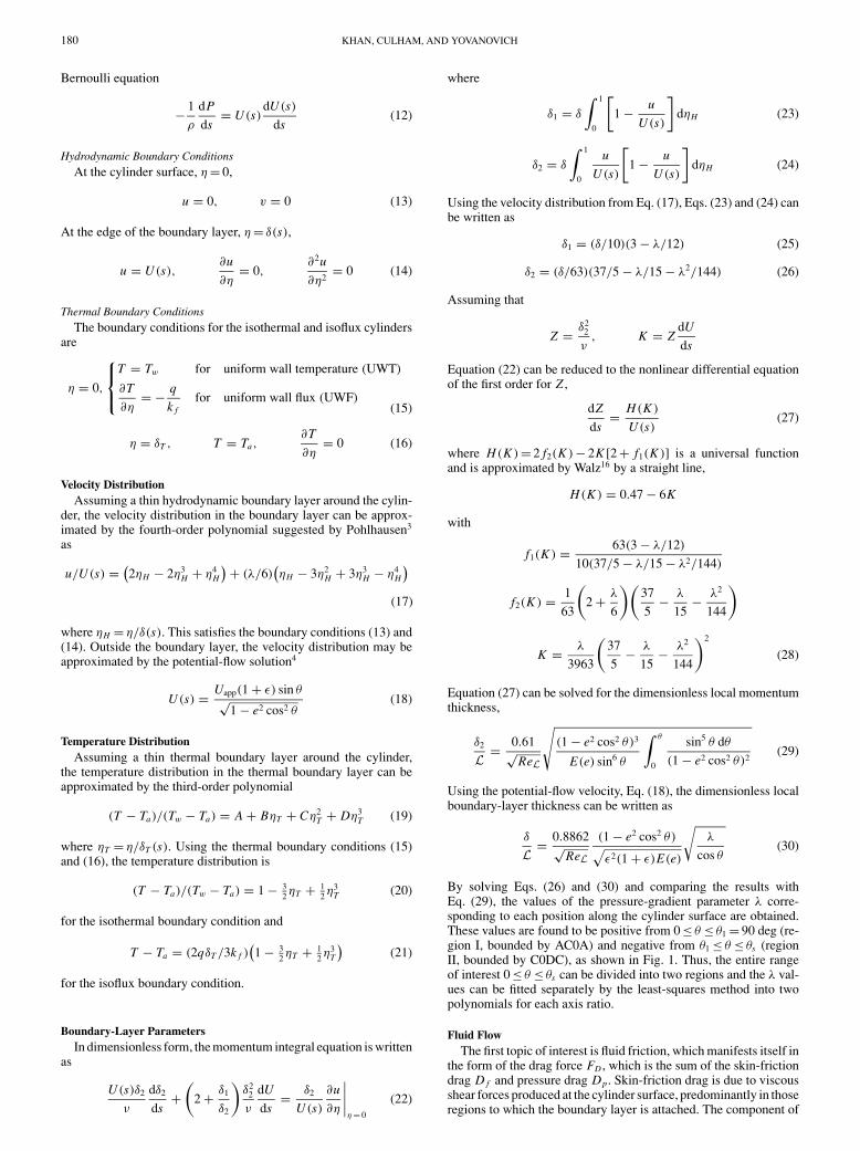
cylinder with major axis 2a and minor axis 2b. The cylinder isoriented so that the major axis is parallel to the direction of the netflow in the main stream, thus making one end of the major axis apoint of stagnation A (Fig. 1). The flow is assumed to be laminar,steady, and two-dimensional. The approach velocity of the air is Uapp
and the ambient temperature of the air is Ta . The surface temperatureof the wall is Tw in the isothermal case and the heat flux is q for theisoflux case. The radius of curvature of the surface is r .
Fig. 1 Laminar flow over an elliptical cylinder.
For a comparison of total drag and heat transfer from an ellipti-cal cylinder with those from a circular cylinder and a flat plate, acharacteristic length is used in both the Reynolds and the Nusseltnumbers. This characteristic length L is the equivalent diameter of acircular cylinder whose perimeter is the same as that of the ellipticalcylinder and that of the flat plate. In this case, the distance traversedby the flow will be the same along the surfaces of the three objects.This length is
L = 4aE(e)/π (1)
where E(e) is the complete elliptic integral of the second kind. Inthe limiting cases, when ε → 1, this characteristic length gives thediameter D of a circular cylinder, and when ε → 0, it represents thelength L of a flat plate.
Coordinate System and Governing EquationsFollowing D’Allessio,14 the mapping between Cartesian (x, y)
and modified polar (ξ, θ ) coordinates is
x = c cosh ξ cos θ, y = c sinh ξ sin θ (2)
where c is the dimensional focal distance
c = a√
1 − ε2 with ε = b/a
The surface of an ellipse is defined by ξ = ξ0, so that
tanh ξ0 = ε (3)
The elliptic coordinate system gives the metric coefficients
g11 = g22 = c√
sinh2 ξ + sin2 θ (4)
The equations of continuity, momentum, and energy for steady-stateforced convection of a Newtonian constant-property fluid with noheat generation can be expressed as
∇ · V = 0 (5)
V · ∇V = −(1/ρ)∇ P + ν∇2V (6)
V · ∇T = α∇2T (7)
where V is the velocity vector of the flowfield, ∇ P is the pressuregradient for forced convection, and T is the temperature. For ana-lyzing fluid flow around and heat transfer from an elliptical cylinder,it is convenient to use a curvilinear system of coordinates in whichs denotes distance along the curved surface of the elliptical cylindermeasured from the forward stagnation point and η is the distancenormal to and measured from the surface (Fig. 1). In this system ofcoordinates, the velocity components in the local s- and η-directionsare denoted by u and v. The potential flow velocity just outside theboundary layer is denoted by U (s). Using an order-of-magnitudeanalysis, one can obtain the following simplified boundary layerequations corresponding to Eqs. (5–7):
Continuity
∂u
∂s+ ∂v
∂η= 0 (8)
s-Momentum
u∂u
∂s+ v
∂u
∂η= − 1
ρ
dP
ds+ ν
∂2u
∂η2(9)
η-Momentum
dP
dη= 0 (10)
Energy
u∂T
∂s+ v
∂T
∂η= α
∂2T
∂η2(11)
180 KHAN, CULHAM, AND YOVANOVICH
Bernoulli equation
− 1
ρ
dP
ds= U (s)
dU (s)
ds(12)
Hydrodynamic Boundary ConditionsAt the cylinder surface, η = 0,
u = 0, v = 0 (13)
At the edge of the boundary layer, η = δ(s),
u = U (s),∂u
∂η= 0,
∂2u
∂η2= 0 (14)
Thermal Boundary ConditionsThe boundary conditions for the isothermal and isoflux cylinders
are
η = 0,
T = Tw for uniform wall temperature (UWT)
∂T
∂η= − q
k ffor uniform wall flux (UWF)
(15)
η = δT , T = Ta,∂T
∂η= 0 (16)
Velocity DistributionAssuming a thin hydrodynamic boundary layer around the cylin-
der, the velocity distribution in the boundary layer can be approx-imated by the fourth-order polynomial suggested by Pohlhausen3
as
u/U (s) = (2ηH − 2η3
H + η4H
) + (λ/6)(ηH − 3η2
H + 3η3H − η4
H
)
(17)
where ηH = η/δ(s). This satisfies the boundary conditions (13) and(14). Outside the boundary layer, the velocity distribution may beapproximated by the potential-flow solution4
U (s) = Uapp(1 + ε) sin θ√1 − e2 cos2 θ
(18)
Temperature DistributionAssuming a thin thermal boundary layer around the cylinder,
the temperature distribution in the thermal boundary layer can beapproximated by the third-order polynomial
(T − Ta)/(Tw − Ta) = A + BηT + Cη2T + Dη3
T (19)
where ηT = η/δT (s). Using the thermal boundary conditions (15)and (16), the temperature distribution is
(T − Ta)/(Tw − Ta) = 1 − 32 ηT + 1
2 η3T (20)
for the isothermal boundary condition and
T − Ta = (2qδT /3k f )(1 − 3
2 ηT + 12 η3
T
)(21)
for the isoflux boundary condition.
Boundary-Layer ParametersIn dimensionless form, the momentum integral equation is written
as
U (s)δ2
ν
dδ2
ds+
(2 + δ1
δ2
)δ2
2
ν
dU
ds= δ2
U (s)
∂u
∂η
∣∣∣∣η = 0
(22)
where
δ1 = δ
∫ 1
0
[1 − u
U (s)
]dηH (23)
δ2 = δ
∫ 1
0
u
U (s)
[1 − u
U (s)
]dηH (24)
Using the velocity distribution from Eq. (17), Eqs. (23) and (24) canbe written as
δ1 = (δ/10)(3 − λ/12) (25)
δ2 = (δ/63)(37/5 − λ/15 − λ2/144) (26)
Assuming that
Z = δ22
ν, K = Z
dU
ds
Equation (22) can be reduced to the nonlinear differential equationof the first order for Z ,
dZ
ds= H(K )
U (s)(27)
where H(K ) = 2 f2(K ) − 2K [2 + f1(K )] is a universal functionand is approximated by Walz16 by a straight line,
H(K ) = 0.47 − 6K
with
f1(K ) = 63(3 − λ/12)
10(37/5 − λ/15 − λ2/144)
f2(K ) = 1
63
(2 + λ
6
)(37
5− λ
15− λ2
144
)
K = λ
3963
(37
5− λ
15− λ2
144
)2
(28)
Equation (27) can be solved for the dimensionless local momentumthickness,
δ2
L = 0.61√ReL
√(1 − e2 cos2 θ)3
E(e) sin6 θ
∫ θ
0
sin5 θ dθ
(1 − e2 cos2 θ)2(29)
Using the potential-flow velocity, Eq. (18), the dimensionless localboundary-layer thickness can be written as
δ
L = 0.8862√ReL
(1 − e2 cos2 θ)√
ε2(1 + ε)E(e)
√λ
cos θ(30)
By solving Eqs. (26) and (30) and comparing the results withEq. (29), the values of the pressure-gradient parameter λ corre-sponding to each position along the cylinder surface are obtained.These values are found to be positive from 0 ≤ θ ≤ θ1 = 90 deg (re-gion I, bounded by AC0A) and negative from θ1 ≤ θ ≤ θs (regionII, bounded by C0DC), as shown in Fig. 1. Thus, the entire rangeof interest 0 ≤ θ ≤ θs can be divided into two regions and the λ val-ues can be fitted separately by the least-squares method into twopolynomials for each axis ratio.
Fluid FlowThe first topic of interest is fluid friction, which manifests itself in
the form of the drag force FD , which is the sum of the skin-frictiondrag D f and pressure drag Dp . Skin-friction drag is due to viscousshear forces produced at the cylinder surface, predominantly in thoseregions to which the boundary layer is attached. The component of
KHAN, CULHAM, AND YOVANOVICH 181
shear force in the flow direction is given by
D f =∫
s
τw sin θ dAs (31)
where dAs = ds per unit length of cylinder. In the case of the ellip-tical geometry, the radial distance r to a point on the ellipse surfaceξ = ξ0 is
r = a√
1 − e2 cos2 θ (32)
Therefore, the length ds is
ds = a√
1 − e2 cos2 θ dθ (33)
The shear stress on the cylinder wall τw can be obtained fromNewton’s law of viscosity. In dimensionless form, it can be written as
C f = 0.38√
ε2(1 + ε)3 E(e)√ReL
(λ + 12) sin θ
(1 − e2 cos2 θ)32
√cos θ
λ(34)
The friction drag coefficient is defined as
CD f =∫ π
0
C f sin θ dθ =∫ θs
0
C f sin θ dθ +∫ π
θs
C f sin θ dθ
(35)Because no shear stress acts on the cylinder surface after theboundary-layer separation, the second integral will be zero and thefriction drag coefficient is written as
CD f =∫ θs
0
C f sin θ dθ (36)
The analytical definition for the boundary-layer separation showsthat the separation point is characterized by zero transverse velocitygradient at the wall. The angle of separation θs calculated in thisstudy depends upon the velocity distribution, Eq. (17), chosen in-side the boundary layer. The angle of separation, for different axisratios, is given in Table 1. It is important to note that these resultsfollow the trend of Schlichting and Ulrich4 and Schubauer1 but donot confirm the Modi et al.9 trend. The friction-drag coefficientsare calculated for different axis ratios and a general correlation isdeduced in terms of arbitrary axis ratio and Reynolds number:
CD f = 1.353 + 4.43ε1.35
√ReL
(37)
In the limiting cases when ε → 1, this gives 5.783/√
ReD for a cir-cular cylinder, and when ε → 0, it gives 1.353/
√ReL for a finite
flat plate.The pressure drag is due to the unbalanced pressures that exist
between the relatively high pressures on the upstream surfaces andthe lower pressures on the downstream surfaces. The component ofpressure drag in the flow direction is given by
Dp =∫
s
�P cos θ dAs (38)
Table 1 Angle of separation for differentaxis ratios of elliptical cylinder
ε θs
1 1.880.9 1.910.8 1.950.6 2.050.5 2.120.4 2.210.3 2.310.2 2.450.1 2.650.01 2.99
which can be rewritten in terms of the pressure-drag coefficient as
CDp =∫ π
0
Cp cos θ√
1 − e2 cos2 θ dθ (39)
The unbalanced pressure, �P = P1 − P2, between upstreamand downstream surfaces can be obtained by integrating theθ -component of Eq. (6) from P1 to P2. Using an order-of-magnitudeanalysis, the simplified θ -component of Eq. (6) in elliptic cylindercoordinates (ξ, θ ) can be written as
uξ
g11
∂uθ
∂ξ+ uθ
g11
∂uθ
∂θ= − 1
g11ρ
∂ P
∂θ+ ν
g211
{∂2uθ
∂θ2
}(40)
where g11 are the metric coefficients and are given by Eq. (4), uξ
and uθ are the velocity components in the ξ - and θ -directions andare given by
uξ = − 1
g11
∂φ
∂ξ, uθ = − 1
g11
∂φ
∂θ(41)
where φ is the potential function for a steady flow past an ellipticalcylinder and is obtained from the complex potential
φ = Uappa√
(1 + ε)/(1 − ε) cosh ξ cos θ(1 − ε tanh ξ) (42)
Calculating the velocity components and their derivatives on thesurface of the elliptic cylinder, one can find, from Eq. (38), thepressure coefficients for different axis ratios. These coefficients arethen used, in Eq. (39), to determine the pressure-drag coefficients fordifferent axis ratios. Using these coefficients, a general correlationin terms of the axis ratio and Reynolds number is found to be
CDp = (1.1526 + 1.26/ReL)ε0.95 (43)
The total drag coefficient CD can be written as the sum of both dragcoefficients,
CD = 1.353 + 4.43ε1.35
√ReL
+(
1.1526 + 1.26
ReL
)ε0.95 (44)
In the limiting cases when ε → 1
CD = 5.786/√
ReD + 1.152 + 1.260/ReD (45)
for a circular cylinder and, when ε → 0, it gives
CD = 1.353/√
ReL (46)
for a finite flat plate.
Heat TransferFor the isothermal boundary condition, the energy integral equa-
tion can be written as
d
ds
∫ δT
0
(T − Ta)u dη = −α∂T
∂η
∣∣∣∣η = 0
(47)
Using the velocity and temperature profiles, and assuming thatζ = δT /δ < 1, Eq. (47) can be simplified to
δTd
ds[U (s)δT ζ(λ + 12)] = 90α (48)
This equation can be rewritten separately as
δTd
ds[U (s)δT ζ(λ1 + 12)] = 90α (49)
for region I and
δTd
ds[U (s)δT ζ(λ2 + 12)] = 90α (50)
182 KHAN, CULHAM, AND YOVANOVICH
for region II. Multiplying both equations by U (s)ζ and integratingseparately in the two regions, one can solve these two equations forthe local thermal boundary-layer thicknesses to find(
δT (θ)
L
)· Re
12L Pr
13 =
√2.236
(1 + ε)E(e)
×
3
√(1 − e2 cos2 θ)2 f3(θ)
ε(λ1 + 12)2 sin2 θ
√λ1
cos θfor region I
3
√(1 − e2 cos2 θ)2 f5(θ)
ε sin2 θ
√λ2
cos θfor region II (51)
where
f3(θ) =∫ θ
0
sin θ(λ1 + 12) dθ (52)
f5(θ) = f3(θ)
λ1 + 12+ f4(θ)
λ2 + 12(53)
with
f4(θ) =∫ θs
θ1
sin θ(λ2 + 12) dθ (54)
For the isothermal boundary condition, the local heat-transfer coef-ficient is
h(θ) = −k f∂T
∂η
∣∣∣∣η = 0
/(Tw − Ta) = 3k f
2δT(55)
Thus, the local Nusselt numbers for both regions can be written as
NuL(θ)|isothermal
Re12L Pr
13
=√
(1 + ε)E(e)
3.33
×
3
√ε(λ1 + 12)2 sin2 θ
(1 − e2 cos2 θ)2 f3(θ)
√cos θ
λ1for region I
3
√ε sin2 θ
(1 − e2 cos2 θ)2 f4(θ)
√cos θ
λ2for region II (56)
The average heat-transfer coefficient is defined as
h = 1
π
∫ π
0
h(θ) dθ = 1
π
[∫ θs
0
h(θ) dθ +∫ π
θs
h(θ) dθ
](57)
It has been observed experimentally by many researchers that, at lowReynolds numbers, there is no appreciable increase in the local heattransfer after the separation point. However, at high Reynolds num-bers, the local heat transfer increases from the separation point to therear stagnation point. Hence, the average heat transfer coefficient is
h = 1
π
∫ θs
0
h(θ) dθ = 1
π
[∫ θ1
0
h1(θ) dθ +∫ θs
θ1
h2(θ) dθ
](58)
Using Eqs. (51–54), Eq. (58) can be solved for the average heat-transfer coefficient, which gives the average Nusselt number for anisothermal elliptical cylinder of arbitrary axis ratio ε as
NuD|isothermal
Re12L Pr
13
= 0.75 − 0.16 exp
(−0.018
ε3.1
)(59)
For the isoflux boundary condition, the energy integral equation canbe written as
d
dx
∫ δT
0
(T − Ta)u dη = q
ρcp(60)
For constant heat flux and thermophysical properties, Eq. (60) canbe simplified to
d
ds
[U (s)δ2
T ζ(λ + 12)] = 90
ν
Pr(61)
Rewriting Eq. (61) for the two regions in the same way as Eq. (48),one can obtain the local thermal boundary layer thicknesses δT1 andδT2 under isoflux boundary condition. The local surface temperaturesfor the two regions can then be obtained from Eq. (21) as
�T1(θ) = 2qδT1
/3k f (62)
�T2(θ) = 2qδT2
/3k f (63)
The local heat transfer coefficient can now be obtained from itsdefinition as
h1(θ) = q/�T1(θ), h2(θ) = q/�T2(θ) (64)
Following the same procedure for the average heat-transfer coef-ficient, one can obtain the average Nusselt number for an isofluxcylinder as
NuL|isoflux
Re12L Pr
13
= 0.91 − 0.31 exp
(−0.09
ε1.79
)(65)
This Nusselt number is 6% greater than the average Nusselt numberfor an isothermal circular cylinder. Combining the results for boththermal boundary conditions, we have
NuL
Re12L Pr
13
=
0.75 − 0.16 exp
(−0.018
ε3.1
)UWT
0.91 − 0.31 exp
(−0.09
ε1.79
)UWF (66)
which gives the dimensionless Nusselt numbers for elliptical cylin-ders of arbitrary axis ratio under isothermal or isoflux boundaryconditions. In the limiting cases, when ε = 1, it represents the aver-age Nusselt numbers for a circular cylinder,
NuD
Re12D Pr
13
={
0.5930 UWT
0.6321 UWF (67)
And, when ε = 0, it represents the average Nusselt number for afinite flat plate as
NuL
Re12L Pr
13
={
0.750 UWT
0.912 UWF (68)
where L is the length of the plate.
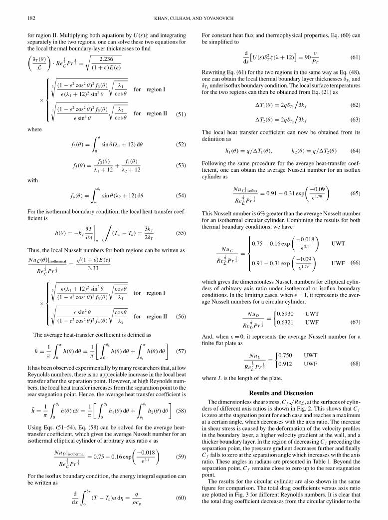
Results and DiscussionThe dimensionless shear stress, C f
√ReL, at the surfaces of cylin-
ders of different axis ratios is shown in Fig. 2. This shows that C f
is zero at the stagnation point for each case and reaches a maximumat a certain angle, which decreases with the axis ratio. The increasein shear stress is caused by the deformation of the velocity profilesin the boundary layer, a higher velocity gradient at the wall, and athicker boundary layer. In the region of decreasing C f preceding theseparation point, the pressure gradient decreases further and finallyC f falls to zero at the separation angle which increases with the axisratio. These angles in radians are presented in Table 1. Beyond theseparation point, C f remains close to zero up to the rear stagnationpoint.
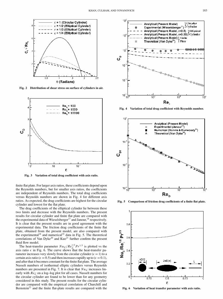
The results for the circular cylinder are also shown in the samefigure for comparison. The total drag coefficients versus axis ratioare plotted in Fig. 3 for different Reynolds numbers. It is clear thatthe total drag coefficient decreases from the circular cylinder to the
KHAN, CULHAM, AND YOVANOVICH 183
Fig. 2 Distribution of shear stress on surface of cylinders in air.
Fig. 3 Variation of total drag coefficient with axis ratio.
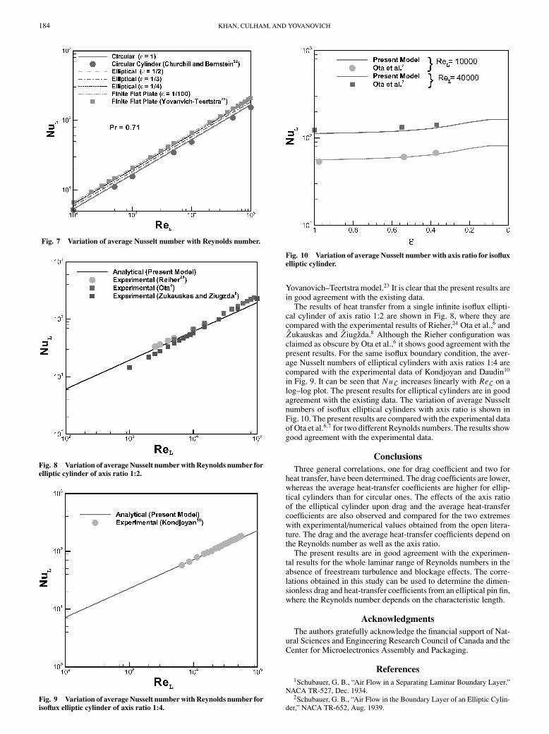
finite flat plate. For larger axis ratios, these coefficients depend uponthe Reynolds numbers, but for smaller axis ratios, the coefficientsare independent of Reynolds numbers. The total drag coefficientsversus Reynolds numbers are shown in Fig. 4 for different axisratios. As expected, the drag coefficients are highest for the circularcylinder and lowest for the flat plate.
The drag coefficients of the elliptical cylinder lie between thesetwo limits and decrease with the Reynolds numbers. The presentresults for circular cylinder and finite flat plate are compared withthe experimental data of Wieselsberger17 and Janour,18 respectively.It is clear that the present results are in good agreement with theexperimental data. The friction drag coefficients of the finite flatplate, obtained from the present model, are also compared withthe experimental18 and numerical19 data in Fig. 5. The theoreticalcorrelations of Van Dyke20 and Kuo21 further confirm the presentfluid flow model.
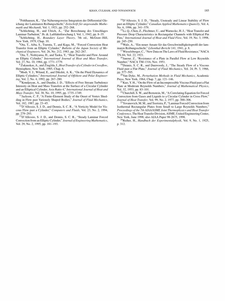
The heat-transfer parameter NuL/Re1/2L Pr 1/3 is plotted vs the
axis ratio ε in Fig. 6. The curve shows that the heat-transfer pa-rameter increases very slowly from the circular cylinder (ε = 1) to acertain axis ratio (ε = 0.5) and then increases rapidly up to (ε = 0.1),and after that it becomes constant for the finite flat plate. The averageNusselt numbers of isothermal elliptic cylinders versus Reynoldsnumbers are presented in Fig. 7. It is clear that NuL increases lin-early with ReL on a log–log plot for all cases. Nusselt numbers forthe circular cylinder are found to be lower than for any geometryconsidered in this study. The present results for the circular cylin-der are compared with the empirical correlation of Churchill andBernstein22 and the finite flat-plate results are compared with the
Fig. 4 Variation of total drag coefficient with Reynolds number.
Fig. 5 Comparison of friction drag coefficients of a finite flat plate.
Fig. 6 Variation of heat transfer parameter with axis ratio.
184 KHAN, CULHAM, AND YOVANOVICH
Fig. 7 Variation of average Nusselt number with Reynolds number.
Fig. 8 Variation of average Nusselt number with Reynolds number forelliptic cylinder of axis ratio 1:2.
Fig. 9 Variation of average Nusselt number with Reynolds number forisoflux elliptic cylinder of axis ratio 1:4.
Fig. 10 Variation of average Nusselt number with axis ratio for isofluxelliptic cylinder.
Yovanovich–Teertstra model.23 It is clear that the present results arein good agreement with the existing data.
The results of heat transfer from a single infinite isoflux ellipti-cal cylinder of axis ratio 1:2 are shown in Fig. 8, where they arecompared with the experimental results of Rieher,24 Ota et al.,6 andZukauskas and Z iugzda.8 Although the Rieher configuration wasclaimed as obscure by Ota et al.,6 it shows good agreement with thepresent results. For the same isoflux boundary condition, the aver-age Nusselt numbers of elliptical cylinders with axis ratios 1:4 arecompared with the experimental data of Kondjoyan and Daudin10
in Fig. 9. It can be seen that NuL increases linearly with ReL on alog–log plot. The present results for elliptical cylinders are in goodagreement with the existing data. The variation of average Nusseltnumbers of isoflux elliptical cylinders with axis ratio is shown inFig. 10. The present results are compared with the experimental dataof Ota et al.6,7 for two different Reynolds numbers. The results showgood agreement with the experimental data.
ConclusionsThree general correlations, one for drag coefficient and two for
heat transfer, have been determined. The drag coefficients are lower,whereas the average heat-transfer coefficients are higher for ellip-tical cylinders than for circular ones. The effects of the axis ratioof the elliptical cylinder upon drag and the average heat-transfercoefficients are also observed and compared for the two extremeswith experimental/numerical values obtained from the open litera-ture. The drag and the average heat-transfer coefficients depend onthe Reynolds number as well as the axis ratio.
The present results are in good agreement with the experimen-tal results for the whole laminar range of Reynolds numbers in theabsence of freestream turbulence and blockage effects. The corre-lations obtained in this study can be used to determine the dimen-sionless drag and heat-transfer coefficients from an elliptical pin fin,where the Reynolds number depends on the characteristic length.
AcknowledgmentsThe authors gratefully acknowledge the financial support of Nat-
ural Sciences and Engineering Research Council of Canada and theCenter for Microelectronics Assembly and Packaging.
References1Schubauer, G. B., “Air Flow in a Separating Laminar Boundary Layer,”
NACA TR-527, Dec. 1934.2Schubauer, G. B., “Air Flow in the Boundary Layer of an Elliptic Cylin-
der,” NACA TR-652, Aug. 1939.
KHAN, CULHAM, AND YOVANOVICH 185
3Pohlhausen, K., “Zur Naherungsweise Integration der Differential Gle-ichung der Laminaren Reibungschicht,” Zeitschrift fur angewandte Mathe-matik und Mechanik, Vol. 1, 1921, pp. 252–268.
4Schlichting, H., and Ulrich, A., “Zur Berechnung des UmschlagesLaminar-Turbulent,” Jb. dt. Luftfahrtforschung I, Vol. 1, 1942, pp. 8–35.
5Schlichting, H., Boundary Layer Theory, 7th ed., McGraw–Hill,New York, 1979, Chap. 10.
6Ota, T., Aiba, S., Tsuruta, T., and Kaga, M., “Forced Convection HeatTransfer from an Elliptic Cylinder,” Bulletin of the Japan Society of Me-chanical Engineers, Vol. 26, No. 212, 1983, pp. 262–267.
7Ota, T., Nishiyama, H., and Taoka, Y., “Heat Transfer and Flow Aroundan Elliptic Cylinder,” International Journal of Heat and Mass Transfer,Vol. 27, No. 10, 1984, pp. 1771–1779.
8 Zukauskas, A., and Z iugzda, J., Heat Transfer of a Cylinder in Crossflow,Hemisphere, New York, 1985, Chap. 6.
9Modi, V. J., Wiland, E., and Dikshit, A. K., “On the Fluid Dynamics ofElliptic Cylinders,” International Journal of Offshore and Polar Engineer-ing, Vol. 2, No. 4, 1992, pp. 267–280.
10Kondjoyan, A., and Daudin, J. D., “Effects of Free Stream TurbulenceIntensity on Heat and Mass Transfers at the Surface of a Circular Cylinderand an Elliptical Cylinder, Axis Ratio 4,” International Journal of Heat andMass Transfer, Vol. 38, No. 10, 1995, pp. 1735–1749.
11Jackson, C. P., “A Finite-Element Study of the Onset of Vortex Shed-ding in Flow past Variously Shaped Bodies,” Journal of Fluid Mechanics,Vol. 182, 1987, pp. 23–45.
12D’Allessio, S. J. D., and Dennis, S. C. R., “A Vorticity Model for Vis-cous Flow past a Cylinder,” Computers and Fluids, Vol. 23, No. 2, 1994,pp. 279–293.
13D’Allessio, S. J. D., and Dennis, S. C. R., “Steady Laminar ForcedConvection from an Elliptic Cylinder,” Journal of Engineering Mathematics,Vol. 29, No. 2, 1995, pp. 181–193.
14D’Allessio, S. J. D., “Steady, Unsteady and Linear Stability of Flowpast an Elliptic Cylinder,” Canadian Applied Mathematics Quaterly, Vol. 4,No. 6, 1996, pp. 341–379.
15Li, Q., Chen, Z., Flechtner, U., and Warnecke, H. J., “Heat Transfer andPressure Drop Characteristics in Rectangular Channels with Elliptical PinFins,” International Journal of Heat and Fluid Flow, Vol. 19, No. 3, 1998,pp. 245–250.
16Walz, A., “Ein neuer Ansatz fur das Greschwindligkeitsprofil der lam-inaren Reibungsschicht,” Lilienthal-Bericht 141, 1941, p. 8.
17Wieselsberger, C., “New Data on The Laws of Fluid Resistance,” NACATN-84, Vol. 22, 1921.
18Janour, Z., “Resistance of a Plate in Parallel Flow at Low ReynoldsNumber,” NACA TM-1316, Nov. 1951.
19Dennis, S. C. R., and Dunwoody, J., “The Steady Flow of a ViscousFluid past a Flat Plate,” Journal of Fluid Mechanics, Vol. 24, Pt. 3, 1966,pp. 577–595.
20Van Dyke, M., Perturbation Methods in Fluid Mechanics, AcademicPress, New York, 1964, Chap. 7, pp. 121–146.
21Kuo, Y. H., “On the Flow of an Incompressible Viscous Fluid past a FlatPlate at Moderate Reynolds Numbers,” Journal of Mathematical Physics,Vol. 32, 1953, pp. 83–101.
22Churchill, S. W., and Bernstein, M., “A Correlating Equation for ForcedConvection from Gases and Liquids to a Circular Cylinder in Cross Flow,”Journal of Heat Transfer, Vol. 99, No. 2, 1977, pp. 300–306.
23Yovanovich, M. M., and Teertstra, P., “Laminar Forced Convection fromIsothermal Rectangular Plates from Small to Large Reynolds Numbers,”Proceedings of the 7th AIAA/ASME Joint Thermophysics and Heat TransferConference, The Heat Transfer Division, ASME, United Engineering Center,New York, June 1998; also AIAA Paper 98-2675, 1998.
24Reiher, H., Handbuch der Experimentalphysik, Vol. 9, No. 1, 1925,p. 312.
Related Documents