OCA 64 FLUID COOLING | Industrial & Mobile OCA Series AIR COOLED OCA FEATURES Young Radiator – OCS Model Interchange American Industrial – AOCS Interchange Hydraulic Circuits Machine Tool Cooling Gear Oil Cooling Lube Oil Cooling Process Cooling Torque Converters Marine Transmissions Aerodynamically Designed Fan Brazed Aluminum Core Enclosed Fan Cooled Standard – TEFC Materials Fan Blade Composite with cast aluminum hub Cabinet Steel with baked enamel finish Connections Aluminum – Female SAE Motor Support Steel Shroud Steel Core Brazed Aluminum Motor TEFC & Hydraulic motor Ratings Max Operating Pressure - 250 psi Max Operating Temperature - 350° F Dimension Range OCA-2000 OCA-2500 OCA-3100 This New Line Features High efficient, light weight, low fouling extruded core design Rugged construction with a patented T-Bar brazed aluminum core captured in steel framing Both mobile and industrial applications High flow capacity; with a flow range from 20-500 GPM Ability to handle high viscosity fluids i.e. gear oil cooling Available in 7 sizes with electric or hydraulic motor options Standard sizes available with short, lean lead time CORE INSIDE

FLUID COOLING | Industrial & Mobile OCA Series · OCA 64 [email protected] 262.554.8330 FLUID COOLING | Industrial & Mobile OCA Series AIR COOLED OCA FEATURES N Young Radiator
Aug 28, 2018
Welcome message from author
This document is posted to help you gain knowledge. Please leave a comment to let me know what you think about it! Share it to your friends and learn new things together.
Transcript

OC
A
[email protected] 262.554.8330 www.thermaltransfer.com64
FLUID COOLING | Industrial & Mobile OCA Series
AIR
CO
OL
ED
OCA
FEATURES Young Radiator – OCS Model Interchange
American Industrial – AOCS Interchange
Hydraulic Circuits
Machine Tool Cooling
Gear Oil Cooling
Lube Oil Cooling
Process Cooling
Torque Converters
Marine Transmissions
Aerodynamically Designed Fan
Brazed Aluminum Core
Enclosed Fan Cooled Standard – TEFC
Materials
Fan Blade Composite with cast aluminum hub
Cabinet Steel with baked enamel finish
Connections Aluminum – Female SAE
Motor Support Steel
Shroud Steel
Core Brazed Aluminum
Motor TEFC & Hydraulic motor
Ratings
Max Operating Pressure - 250 psi
Max Operating Temperature - 350° F
Dimension Range
OCA-2000
OCA-2500OCA-3100
This New Line Features High efficient, light weight, low fouling
extruded core design Rugged construction with a patented
T-Bar brazed aluminum core captured in steel framing
Both mobile and industrial applications High flow capacity; with a flow range from
20-500 GPM Ability to handle high viscosity fluids i.e. gear
oil cooling Available in 7 sizes with electric
or hydraulic motor options Standard sizes available with short,
lean lead time
CORE INSIDE
OC
A
www.thermaltransfer.com [email protected] 262.554.8330 65
AIR
CO
OL
ED
OCA
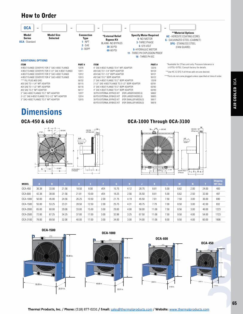
How to Order
ModelSeries
OCA - Standard
Model SizeSelected
– – –OCA
ConnectionType
1 - NPT2 - SAE3 - BSPP
Dimensions OCA-450 & 600 OCA-1000 Through OCA-3100
Shipping MODEL A B C D E F G H J K L M N T WT (lbs)
OCA-450 36.38 33.00 21.56 18.50 8.00 #24 15.75 4.12 28.75 8.81 5.00 6.62 2.00 24.00 400
OCA-600 42.38 38.00 21.56 21.81 10.00 #24 18.25 2.56 35.50 8.81 5.00 6.62 2.50 32.00 497
OCA-1000 50.00 45.00 24.56 26.25 10.50 2.00 21.75 4.19 45.50 7.81 7.50 7.50 3.00 36.00 690
OCA-1500 55.00 53.25 23.31 28.50 12.50 2.00 25.75 4.31 49.75 7.79 7.00 8.50 3.00 42.00 832
OCA-2000 65.00 60.00 29.06 33.00 15.00 3.00 29.00 4.00 58.00 11.06 7.50 8.56 3.00 48.00 1223
OCA-2500 72.00 67.25 34.25 37.00 17.00 3.00 32.88 3.25 67.50 11.06 7.50 9.50 4.00 54.00 1723
OCA-3100 78.00 69.50 32.06 40.00 17.00 3.00 34.00 3.00 74.00 11.06 9.00 9.50 4.00 60.00 1806
OCA-450OCA-600
OCA-1000OCA-1500
*External ReliefBypass Kit
BLANK- NO BYPASS30-30 PSI60-60 PSI
–
Specify Motor Required0 -NO-MOTOR
3 -THREE PHASE6 -575 VOLT
9 -HYDRAULIC MOTOR11 - THREE PH EXPLOSION PROOF
18 - THREE PH IEC
–**Material Options
HC - HERESITE COATING (CORE)G - GALVANIZED STEEL (CABINET)
SFG - STAINLESS STEEL (FAN GUARD)
ITEM PART #4-BOLT FLANGE COVER PLT FOR 2” SAE 4-BOLT FLANGE 120764-BOLT FLANGE COVER PLT FOR 2-1/2” SAE 4-BOLT FLANGE 120114-BOLT FLANGE COVER PLT FOR 3” SAE 4-BOLT FLANGE 120124-BOLT FLANGE COVER PLT FOR 4” SAE 4-BOLT FLANGE 12013*** FILL PLUG (#20 SAE) 50732#20 SAE TO 1-1/4” NPT ADAPTER 50115#24 SAE TO 1-1/2” NPT ADAPTER 50116#32 SAE TO 2” NPT ADAPTER 501172” SAE 4-BOLT FLANGE TO 2” NPT ADAPTER 120772-1/2” SAE 4-BOLT FLANGE TO 2-1/2” NPT ADAPTER 120143” SAE 4-BOLT FLANGE TO 3” NPT ADAPTER 12015
ITEM PART #4” SAE 4-BOLT FLANGE TO 4” NPT ADAPTER 12016#20 SAE TO 1-1/4” BSPP ADAPTER 50120#24 SAE TO 1-1/2” BSPP ADAPTER 50121#32 SAE TO 2” BSPP ADAPTER 501222” SAE 4-BOLT FLANGE TO 2” BSPP ADAPTER 120782-1/2” SAE 4-BOLT FLANGE TO 2-1/2” BSPP ADAPTER 637813” SAE 4-BOLT FLANGE TO 3” BSPP ADAPTER 637824” SAE 4-BOLT FLANGE TO 4” BSPP ADAPTER 6378330 PSI EXTERNAL BYPASS KIT (FOR LARGER MODELS) 5060260 PSI EXTERNAL BYBASS KIT (FOR LARGER MODELS) 5060330 PSI EXTERNAL BYPASS KIT (FOR SMALLER MODELS) 5061760 PSI EXTERNAL BYBASS KIT (FOR SMALLER MODELS) 50618
*** Available for 2 Pass unit only. Pressure tolerance is (+5 PSI/-0 PSI). Consult factory for details.
***Use HC-G-SFG if all three add-ons are desired.
*** Ports do not come plugged unless specified at time of order.
ADDITIONAL OPTIONS
OC
A
[email protected] 262.554.8330 www.thermaltransfer.com66
AIR
CO
OL
ED
OCA
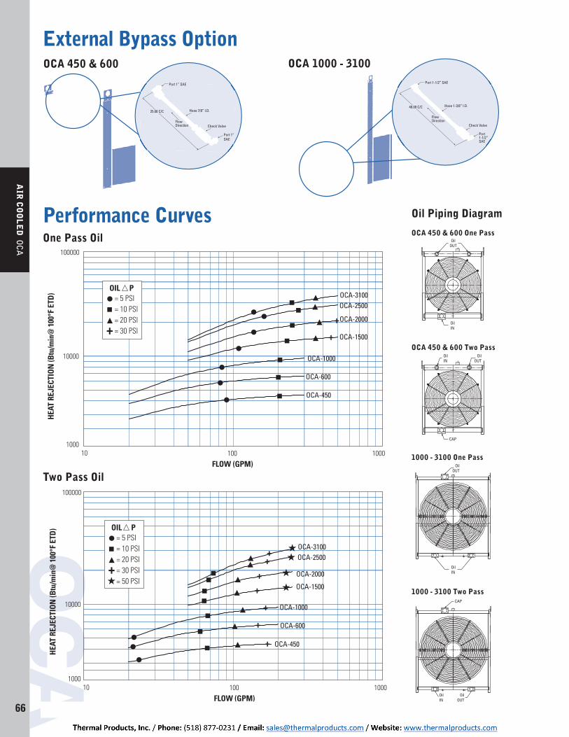
OCA 450 & 600 OCA 1000 - 3100
Port 1” SAE
Hose 7/8” I.D.
Check Valve
Port 1” SAE
FlowDirection Check Valve
FlowDirection
Port 1-1/2” SAE
Hose 1-3/8” I.D.
Port 1-1/2” SAE
40.00 C/C25.00 C/C
Performance Curves
Two Pass Oil
+
+
+
+
+
+
+
OCA-3100OCA-2500
OCA-2000
OCA-1500
OCA-1000
OCA-600
OCA-450
1000 100 10
10000
100000
FLOW (GPM)
HEAT
REJ
ECTI
ON (B
tu/m
in@
100
°F E
TD)
1000
= 5 PSI = 10 PSI = 20 PSI = 30 PSI = 50 PSI
OIL P
+
One Pass Oil
+
+
OCA-3100OCA-2500
OCA-2000
OCA-1500
OCA-1000
OCA-600
OCA-450
1000 100 10
10000
100000
FLOW (GPM)
HEAT
REJ
ECTI
ON (B
tu/m
in@
100
°F E
TD)
1000
= 5 PSI = 10 PSI = 20 PSI = 30 PSI
OIL P
+
Oil Piping Diagram
1000 - 3100 One Pass
1000 - 3100 Two Pass
OCA 450 & 600 One Pass
OCA 450 & 600 Two Pass
External Bypass Option
OC
A
www.thermaltransfer.com [email protected] 262.554.8330 67
AIR
CO
OL
ED
OCA
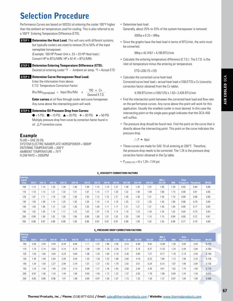
Selection ProcedurePerformance Curves are based on 50SSU oil entering the cooler 100°F higher than the ambient air temperature used for cooling. This is also referred to as a 100°F Entering Temperature Difference (ETD).
STEP 1 Determine the Heat Load. This will vary with different systems, but typically coolers are sized to remove 25 to 50% of the input nameplate horsepower. (Example: 100 HP Power Unit x .33 = 33 HP Heat load.) Convert HP to BTU/MIN: HP x 42.41 = BTU/MIN
STEP 2 Determine Entering Temperature Difference (ETD). Desired oil entering cooler °F – Ambient air temp. °F = Actual ETD
STEP 3 Determine Curve Horsepower Heat Load. Enter the information from above: E.T.D. Temperature Correction Factor:
Btu/Mincorrected = Input Btu/Min x 100 x Cv Desired E.T.D. STEP 4 Enter curves at oil flow through cooler and curve horsepower. Any curve above the intersecting point will work.
STEP 5 Determine Oil Pressure Drop from Curves: = 5 PSI; = 10 PSI; = 20 PSI; = 30 PSI; = 50 PSI.
Multiply pressure drop from curve by correction factor found in oil P correction curve.
ExampleFLUID = SAE 20 OIL SYSTEM ELECTRIC NAMEPLATE HORSEPOWER = 300HP ENTERING TEMPERATURE = 200°F AMBIENT TEMPERATURE = 75°F FLOW RATE = 200GPM
100 2.04 2.44 4.44 6.44 8.84 1.11 1.57 1.86 2.58 4.23 6.48 9.42 13.60 1.30 3.04 3.54 0.770
110 1.74 2.14 3.64 5.14 6.74 1.08 1.49 1.76 2.39 3.77 5.74 8.37 11.67 1.24 2.44 2.94 0.760
120 1.54 1.84 3.04 4.24 5.64 1.06 1.42 1.64 2.19 3.30 5.95 7.27 9.77 1.18 2.14 2.54 0.749
130 1.44 1.64 2.64 3.44 4.54 1.03 1.34 1.53 1.98 2.84 4.18 6.23 7.84 1.12 1.94 2.24 0.738
140 1.34 1.54 2.27 2.94 3.74 1.01 1.27 1.42 1.79 2.42 3.51 5.24 6.15 1.07 1.94 2.04 0.726
150 1.24 1.34 1.94 2.54 3.14 0.99 1.21 1.34 1.65 2.08 2.94 4.39 4.81 1.02 1.74 1.94 0.716
200 0.97 1.00 1.24 1.44 1.64 0.93 1.03 1.12 1.22 1.37 2.63 1.78 1.99 0.94 1.24 1.34 0.675
250 0.85 0.86 0.96 1.01 1.09 0.89 0.97 1.00 1.07 1.15 1.25 1.26 1.27 0.87 1.04 1.09 0.596
MIL-L Ester SAE 5 SAE 10 SAE 20 SAE 30 SAE 40 ISO 22 ISO 32 ISO 46 ISO 68 ISO 100 ISO 150 ISO 220 ISO 320 7808 Polyglycol Phosphate 50%EG
Entering Liquid Temp
CP PRESSURE DROP CORRECTION FACTORS
100 1.12 1.16 1.26 1.39 1.46 1.09 1.15 1.19 1.27 1.38 1.44 1.57 1.85 1.20 0.93 0.84 0.86
110 1.10 1.13 1.21 1.33 1.41 1.07 1.14 1.17 1.26 1.32 1.40 1.49 1.68 1.15 0.90 0.81 0.85
120 1.07 1.11 1.18 1.28 1.36 1.05 1.12 1.15 1.21 1.28 1.36 1.41 1.54 1.10 0.89 0.80 0.85
130 1.05 1.09 1.14 1.25 1.30 1.04 1.10 1.14 1.18 1.25 1.31 1.35 1.45 1.06 0.86 0.78 0.84
140 1.04 1.06 1.12 1.20 1.26 1.03 1.09 1.11 1.17 1.21 1.27 1.31 1.40 1.04 0.85 0.77 0.83
150 1.02 1.05 1.10 1.17 1.23 1.03 1.07 1.10 1.14 1.18 1.23 1.28 1.34 1.02 0.84 0.75 0.83
200 0.99 1.00 1.02 1.05 1.08 0.99 1.00 1.01 1.02 1.03 1.09 1.10 1.15 0.99 0.80 0.72 0.81
250 0.96 0.97 0.98 0.99 1.00 0.96 0.97 0.97 0.97 0.98 1.00 1.02 1.03 0.98 0.77 0.70 0.80
MIL-L Ester SAE 5 SAE 10 SAE 20 SAE 30 SAE 40 ISO 22 ISO 32 ISO 46 ISO 68 ISO 100 ISO 150 ISO 220 ISO 320 7808 Polyglycol Phosphate 50%EG
Entering Liquid Temp
CV VISCOSITY CORRECTION FACTORS
Determine heat load. Generally, about 25% to 33% of the system horsepower is removed.
300hp x 0.33 = 99hp
Since the graphs have the heat load in terms of BTU/min, the units must be converted.
99hp x 42.4167 = 4,199 BTU/min
Calculate the entering temperature difference (E.T.D.). The E.T.D. is the inlet oil temperature minus the entering air temperature.
ETD=200-75 =125
Calculate the corrected curve heat load. Corrected curve heat load = actual heat load x (100/ETD) x Cv (viscosity correction factor obtained from the Cv table).
4,199 BTU/min x (100/125) x 1.02= 3,426 BTU/min
Find the intersection point between the corrected heat load and flow rate on the performance curves. Any curve above this point will work for this application. Usually the smallest cooler is most desired. In this case the intersecting point on the single pass graph indicates that the OCA-450 will suffice.
The pressure drop should be found next. Find the point on the curve that is directly above the intersecting point. This point on the curve indicates the pressure drop.
P ≈ 6psi
These curves are made for SAE 10 oil entering at 200°F. Therefore, the pressure drop needs to be corrected. The 1.24 is the pressure drop correction factor obtained in the Cp table.
PCORRECTED = 6 x 1.24= 7.44 psi

OC
A
[email protected] 262.554.8330 www.thermaltransfer.com68
AIR
CO
OL
ED
OCA
SpecificationsElectric Motor Data
Model Motor HP Phase HZ Voltage RPM Nema Frame Full Load Amps Net Weight
OCA-450 3 3 60 230/460 1750 182T 9.6/4.8 134
OCA-600 3 3 60 230/460 1160 213T 9.6/4.8 147
OCA-1000 5 3 60 230/460 1160 215T 16.2/8.1 161
OCA-1500 5 3 60 230/460 1160 215T 16.2/8.1 161
OCA-2000 10 3 60 230/460 1175 256T 28.8/14.4 357
OCA-2500 15 3 60 230/460 1170 284T 39/19.5 436
OCA-3100 20 3 60 230/460 1175 286T 51/25.5 522
(3 Phase Explosion Proof Class I Group D & Class II Group F&G)
Model Motor HP Phase HZ Voltage RPM Nema Frame Full Load Amps Net Weight
OCA-450 3 3 60 208-230/460 1725 182T 9.5-8.6/4.3 68
OCA-600 3 3 60 230/460 1160 213T 10/5 125
OCA-1000 5 3 60 230/460 1160 215T 16/8 138
OCA-1500 5 3 60 230/460 1160 215T 16/8 138
OCA-2000 10 3 60 230/460 1175 256T 28.8/14.4 269
OCA-2500 15 3 60 230/460 1175 284T 39.4/19.7 361
OCA-3100 20 3 60 230/460 1175 286T 52/26 368
(3 Phase TEFC)
Model Motor HP Phase HZ Voltage RPM Nema Frame Full Load Amps Net Weight
OCA-450 3 3 60 575 1750 182T 3.4 68
OCA-600 3 3 60 575 1160 213T 4.1 111
OCA-1000 5 3 60 575 1160 215T 6.0 122
OCA-1500 5 3 60 575 1160 215T 6.0 122
OCA-2000 10 3 60 575 1180 256T 11.5 286
OCA-2500 15 3 60 575 1180 284T 15.0 425
OCA-3100 20 3 60 575 1175 286T 20.0 452
(3 Phase 575V TEFC)
Model Motor KW/HP Phase HZ Voltage RPM IEC Frame Full Load Amps Net Weight
OCA-450 2.2/3 3 60 208-230/460 1750 100 8.5-8.2/4.1 68
OCA-600 2.2/3 3 60 230/460 1160 112 9.6/4 110
OCA-1000 3.7/5 3 60 230/460 1160 132 17.6/8.8 123
OCA-1500 3.7/5 3 60 230/460 1160 132 17.6/8.8 123
OCA-2000 7.5/10 3 60 230/460 1180 160 28.4/14.2 247
OCA-2500 11/15 3 60 230/460 1180 180 42/21 361
OCA-3100 15/20 3 60 230/460 1175 180 52/26 368
(3 Phase Metric/IEC)
MODEL HP PRESSURE (PSI) FLOW (GPM) RPM DISPLACEMENT (CUIN/REV)
OCA-450 3 870 11.1 1750 1.37
OCA-600 3 1305 8.0 1160 1.37
OCA-1000 5 2030 8.0 1160 1.37
OCA-1500 5 2030 8.0 1160 1.37
OCA-2000 10 2900 8.2 1175 1.37
OCA-2500 15 2900 8.2 1175 1.71
OCA-3100 20 2320 13.3 1175 2.2
HYDRAULIC MOTORS
Hydraulic Motor Data

www.thermaltransfer.com [email protected] 262.554.8330 69
AIR
CO
OL
ED
OCA
THE OCA ADVANTAGE
AdvantagesT-BAR provides advantages and value far beyond typical aluminum core designs. Superior performance
Aluminum has up to 25 percent higher heat transfer capacity in comparison to a traditional copper/brass cooling package.
Rugged Structure Resistant to Fouling Resistant to Salt Spray and Salt Air Compact Flexible Mounting and Port Configuration Great Dollar Value Per BTU
LOW-CLOGGINGHIGH-PERFORMANCE
T-BAR is a flexible design, high performing, and a cost-effective aluminum solution. Tubular Micro Channel Extrusion (T-BAR™) T-BAR is manufactured with Alloy 1100 aluminum micro channel and bars in our patented in-house tube-to-bar brazing process using a Nocolok CAB (Controlled Atmosphere Brazing) brazing technology furnace. Because our tubes are a solid extrusion, T-BAR is very robust — with no tube seams to fail and leak.
WELDING STATION
8: WELD TANK, PORTS & BRACKETRY TO CORE
COOL-DOWN UNIT
7: COOL
FLUX STATION
4:FLUX CORE UNIT TO PREPARE FOR BRAZING
STACKING STATION
3: STACK ASSEMBLE TUBE & BARS TO FORM CORE UNIT
CUTTING STATIONS
1: CUT EXTRUDED 2:CUT SPACER BARSALUMINUM TUBING
FURNACE
5:PRE-HEAT 6: BRAZE 1200˚ F
T-Bar Manufacturing Process
T-BAR CORE IN OCA ASSEMBLY
CORE INSIDE
Related Documents