Tutorial Flowol Primary/Secondary © Keep I.T. Easy 2005 Flowol Page 1 3 A Control Program for Windows PC Authors: Anthony and Rod Bowker (K.I.T.E.) Programming: Anthony Bowker (K.I.T.E.) Tutorial: Rod Bowker (K.I.T.E.) Copyright: Program – Keep I.T. Easy (K.I.T.E.) 2005 Copyright: Tutorial – Keep I.T. Easy (K.I.T.E.) 2005 http://www.flowol.com Document Flowol 3 version 1 TM

Welcome message from author
This document is posted to help you gain knowledge. Please leave a comment to let me know what you think about it! Share it to your friends and learn new things together.
Transcript
Tutorial Flowol Primary/Secondary
© Keep I.T. Easy 2005 Flowol Page 1
3
A Control Program for
Windows PC
Authors: Anthony and Rod Bowker (K.I.T.E.)
Programming: Anthony Bowker (K.I.T.E.)
Tutorial: Rod Bowker (K.I.T.E.)
Copyright: Program – Keep I.T. Easy (K.I.T.E.) 2005
Copyright: Tutorial – Keep I.T. Easy (K.I.T.E.) 2005
http://www.flowol.com
Document Flowol 3 version 1
TM
Flowol Tutorial Primary/Secondary
Page 2 © Keep I.T. Easy 2005 Flowol
Contents Setup Instructions Page
System Requirements and Installing Flowol - - - - - - - - - - - - - - - - - - - - - - - - 3 Getting Started - - - - - - - - - - - - - - - - - - - - - - - - - - - - - - - - - - - - - - - - - - - - - 4
Setting up Flowol for your interface - - - - - - - - - - - - - - - - - - - - - - - - - - - - - - 5
Tutorial Introduction - - - - - - - - - - - - - - - - - - - - - - - - - - - - - - - - - - - - - - - - - - - - - - 6
The Screen [Workspace, Toolbar, Mimic, Graph] - - - - - - - - - - - - - - - - - - - - - 7
The Symbols on the toolbar - - - - - - - - - - - - - - - - - - - - - - - - - - - - - - - - - - - - 8
Zebra crossing - - - - - - - - - - - - - - - - - - - - - - - - - - - - - - - - - - - - - - - - - - - - - 9
Using the „prompts‟ to create a simple program - - - - - - - - - - - - - - - - 9
Displaying a „mimic‟ - - - - - - - - - - - - - - - - - - - - - - - - - - - - - - - - - - 9 Saving a program - - - - - - - - - - - - - - - - - - - - - - - - - - - - - - - - - - - - - 9
Editing a flowchart: deleting and adding symbols - - - - - - - - - - - - - - - 10
Text, labelling a flowchart - - - - - - - - - - - - - - - - - - - - - - - - - - - - - - 10
Traffic Lights - - - - - - - - - - - - - - - - - - - - - - - - - - - - - - - - - - - - - - - - - - - - - 11
Using the „monitor‟ bars - - - - - - - - - - - - - - - - - - - - - - - - - - - - - - - - 11
Multiple outputs in a symbol - - - - - - - - - - - - - - - - - - - - - - - - - - - - - 11
Moving the prompt box - - - - - - - - - - - - - - - - - - - - - - - - - - - - - - - - - 11
Editing instructions in a symbol - - - - - - - - - - - - - - - - - - - - - - - - - - - 11
Printing the flowchart - - - - - - - - - - - - - - - - - - - - - - - - - - - - - - - - - - 11
Undo and Redo - - - - - - - - - - - - - - - - - - - - - - - - - - - - - - - - - - - - - - 12
Changing the size [Re-scale, Zoom] of the flowchart- - - - - - - - - - - - - 12 Changing the speed of the flowchart - - - - - - - - - - - - - - - - - - - - - - - - 12
Stepping through the flowchart - - - - - - - - - - - - - - - - - - - - - - - - - - - -12
The Lighthouse - - - - - - - - - - - - - - - - - - - - - - - - - - - - - - - - - - - - - - - - - - - - 13
Moving and Copying a flowchart - - - - - - - - - - - - - - - - - - - - - - - - - - 13
Changing the colours - - - - - - - - - - - - - - - - - - - - - - - - - - - - - - - - - - 13
Using an INPUT- - - - - - - - - - - - - - - - - - - - - - - - - - - - - - - - - - - - - - 14
Subroutines- - - - - - - - - - - - - - - - - - - - - - - - - - - - - - - - - - - - - - - - - 15
Run What? - - - - - - - - - - - - - - - - - - - - - - - - - - - - - - - - - - - - - - - - - 15
Using Sound on PC Flowol - - - - - - - - - - - - - - - - - - - - - - - - - - - - - - - - - - - - 16
Recording sound and using sound in a flowchart - - - - - - - - - - - - - - - - 16
Copy and Paste - - - - - - - - - - - - - - - - - - - - - - - - - - - - - - - - - - - - - - - - - - - - 17
Copy a flowchart back into Flowol or into Word - - - - - - - - - - - - - - - - 17 Copy a mimic into Word - - - - - - - - - - - - - - - - - - - - - - - - - - - - - - - - 17
Controlling Electric Motors [The 3D „Mobile‟ mimic]- - - - - - - - - - - - - - - - - 18
Controlling a motor in a program and changing the motor speed- - - - - -18
Using Analogue Values [Vals] with an interactive Cot Mobile- - - - - - - - - - - - - 19
The 3D Big Wheel mimic- - - - - - - - - - - - - - - - - - - - - - - - - - - - - - - - - - - - - 20
Explaining „Active Inputs‟ - - - - - - - - - - - - - - - - - - - - - - - - - - - - - - 20
Using Speech - - - - - - - - - - - - - - - - - - - - - - - - - - - - - - - - - - - - - - - 20
Variables - - - - - - - - - - - - - - - - - - - - - - - - - - - - - - - - - - - - - - - - - - 21
Using Active inputs - - - - - - - - - - - - - - - - - - - - - - - - - - - - - - - - - - - 21
Changing the speed of a motor with variables - - - - - - - - - - - - - - - - - - 22
„Stop All‟- - - - - - - - - - - - - - - - - - - - - - - - - - - - - - - - - - - - - - - - - - 22 Controlling a Motorised Barrier - - - - - - - - - - - - - - - - - - - - - - - - - - - - - - - - - 23
Using a „feedback‟ switch - - - - - - - - - - - - - - - - - - - - - - - - - - - - - - -23
Using Analogue Values [Vals]. Controlling the Autohome - - - - - - - - - - - - - - - 24
Printing the flowchart; Changing workspace dimensions - - - - - - - - - - - - - - - - 25
Using keyboard shortcuts „Hot Keys‟ - - - - - - - - - - - - - - - - - - - - - - - - - - - - - 25
Monitoring the System and Data Logging - - - - - - - - - - - - - - - - - - - - - - - - - - 26
Calibrating analogue sensors; Showing a Graph window - - - - - - - - - - 26
Setting up the Graph windows - - - - - - - - - - - - - - - - - - - - - - - - - - - - 27
Multiple graph windows - - - - - - - - - - - - - - - - - - - - - - - - - - - - - - - - 28
Scanning the values on a graph - - - - - - - - - - - - - - - - - - - - - - - - - - - -28
Transferring Graph Data and Printing Graphs - - - - - - - - - - - - - - - - - - - - - - - 29
Other Situations using variables [Counting; Repeating; Interrupting etc]- - - - - - 30 Solar water heater - - - - - - - - - - - - - - - - - - - - - - - - - - - - - - - - - - - - - - - - - - 31
The „Buggy‟ project - - - - - - - - - - - - - - - - - - - - - - - - - - - - - - - - - - - - - - - - - 32
Installing Flowol on RM Networks - - - - - - - - - - - - - - - - - - - - - - - - - - - - - - - - - - - - 33
Index & Glossary - - - - - - - - - - - - - - - - - - - - - - - - - - - - - - - - - - - - - - - - - - 36
Tutorial Flowol Primary/Secondary
© Keep I.T. Easy 2005 Flowol Page 3
System Requirements – PC Windows 20 Mb of free Hard Disk Space
Microsoft Windows 2000, XP, Server 2003 or Vista (32 or 64 bit)
We recommend that all the latest critical updates are installed
from: http://windowsupdates.microsoft.com
Note: The five mimics accompanying Flowol 3 will also be installed. The „Big Wheel‟ and
„Cot Mobile‟ are new F3D mimics which have 3D animations. The speed of the animation
will depend on the graphics capability of your computer. One way to speed up slow animation, at the expense of image quality, is to remove the tick from the „Use anti-aliasing‟
option in the Mimic tab of the Options dialog from the Settings menu.
USB Users: Ensure that the interface is NOT connected when the Flowol software is
installed. If you have installed the FlowGo/Solo drivers with a previous version of Flowol, uninstall them first by going to the Add or Remove programs control panel and remove the
„FlowGo/Solo USB Drivers (Flowol 2.91)‟ program.
Installing Flowol - PC Windows
Note: Close any open programs before the installation as your system will need to
be restarted for configuration changes to take effect.
Log on with a user account with Administrative privileges.
Insert the Flowol 3 CD ROM into the CD Drive.
This is an auto play CD ROM, which means that Windows should detect the
presence of the CD and automatically start up the Auto run program.
Follow the on-screen instructions to complete the installation of the Flowol and
its associated files onto the hard disc.
When installation is complete, eject the CD ROM and store safely.
Restart your system. Note: If the Auto run program fails to start, use Windows Explorer to navigate the CD ROM
contents and double click on the file Setup.exe.
[See p.33 for installation onto RM networks]
Important Notes:
1. Flowol3 can be installed alongside Flowol2.
2. Flowchart programs created in Flowol2 can be opened in Flowol3 but those
saved by Flowol3 cannot be opened back into Flowol2.
3. After Flowol3 has been installed it can point to the 2D mimics already on your
machine and use them by default. Your version of Flowol2 however, may no
longer be able to access these 2D mimics.
You should not need to use Flowol2 once you have Flowol3, but if you do
continue to use Flowol2 and need to access the mimics:
Use the „Set Mimic Directory..‟ in the file menu of Flowol2 [available only
on later versions of Flowol2]
If your mimics were installed from CD, then un-install these 2D mimics and
re-install them again from your CD after Flowol3 has been installed.
If your mimics were installed from floppy discs then the content of the
original mimic folder on your machine must be manually transferred to the
mimic folder in the Flowol3 folder.
4. When using the Mimic Creator after installing Flowol3, you will need to use the
„Set Mimic Directory..‟ in the file menu each time you need to access the 2D
mimics. Or transfer the mimics as explained above if you need to access them by
default.
Flowol Tutorial Primary/Secondary
Page 4 © Keep I.T. Easy 2005 Flowol
Getting Started To start the Flowol software once it has been installed:
PC Windows:
Click on the Start button on the taskbar.
Within Programs, select Flowol 3 and click on the Flowol 3 icon.
Configuring Flowol
Flowol can operate with or without an interface attached. If the „No Interface‟
option is selected, Flowol will automatically be in simulation mode with the
maximum number of inputs and outputs available. If an Interface has been selected
from the list then Flowol can operate either:
Without the interface connected, open (in simulation mode), so that the
correct number of outputs, inputs and commands are available for that
interface.
Or: with the interface connected, closed (interface in operation).
The following interfaces can be supported:
Data Harvest: Contact Controller Plus
Contact Controller
FlowGo [Serial/USB]
Solo
Fischertechnik: Intelligent Interface [Serial]
Deltronics: Serial Interface
Serial Interface +
Junior Interface
Extra Sense [Serial Interface] to operate the Control IT Buffer Box.
Digital Serial Adapter: to operate the Control IT Buffer Box.
Control and Data Capture Interface [USB]
Commotion: Serial Interface
Junior Interface
Commotion CoCo [USB]
LEGO DACTA: (Control Lab) Interface B
Other interfaces may be added in the future and available for download from the
web site. http://www.flowol.com/flowol3/interfaces.aspx
Tutorial Flowol Primary/Secondary
© Keep I.T. Easy 2005 Flowol Page 5
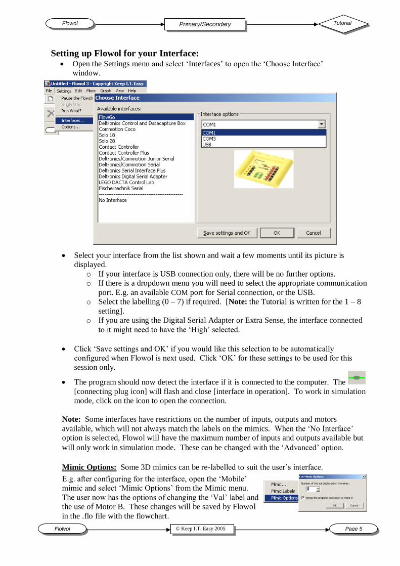
Setting up Flowol for your Interface: Open the Settings menu and select „Interfaces‟ to open the „Choose Interface‟
window.
Select your interface from the list shown and wait a few moments until its picture is
displayed.
o If your interface is USB connection only, there will be no further options.
o If there is a dropdown menu you will need to select the appropriate communication
port. E.g. an available COM port for Serial connection, or the USB.
o Select the labelling (0 – 7) if required. [Note: the Tutorial is written for the 1 – 8
setting].
o If you are using the Digital Serial Adapter or Extra Sense, the interface connected
to it might need to have the „High‟ selected.
Click „Save settings and OK‟ if you would like this selection to be automatically
configured when Flowol is next used. Click „OK‟ for these settings to be used for this
session only.
The program should now detect the interface if it is connected to the computer. The
[connecting plug icon] will flash and close [interface in operation]. To work in simulation
mode, click on the icon to open the connection.
Note: Some interfaces have restrictions on the number of inputs, outputs and motors
available, which will not always match the labels on the mimics. When the „No Interface‟
option is selected, Flowol will have the maximum number of inputs and outputs available but
will only work in simulation mode. These can be changed with the „Advanced‟ option.
E.g. after configuring for the interface, open the „Mobile‟
mimic and select „Mimic Options‟ from the Mimic menu.
The user now has the options of changing the „Val‟ label and
the use of Motor B. These changes will be saved by Flowol
in the .flo file with the flowchart.
.
Mimic Options: Some 3D mimics can be re-labelled to suit the user‟s interface.
Flowol Tutorial Primary/Secondary
Page 6 © Keep I.T. Easy 2005 Flowol
The Tutorial
This tutorial introduces Flowol software and the flowchart method of creating a control program.
It is a hands-on approach which puts the reader through a series of problem solving exercises.
Each exercise uses a control program to explore different elements of control, starting with
simple ideas and progressing to more complex examples. The features of Flowol are introduced
gradually at each stage.
[The tutorial, also on the Flowol CD, will be installed automatically so it can be accessed from the „Help‟ menu].
Pages 7 to 20 are an appropriate introduction for all students. Since the examples are progressive,
you can decide how far your students should go. Each theme in the tutorial gives direction to
possible solutions and several of the pages can also be used as worksheets. Ideas should be
transferred from one section to another and extended to provide a complete solution.
It might also be useful to refer to the Student‟s Activities available on the web site. These
activities are a pupil based text to support parts of the Flowol tutorial and also the extra Primary
and Secondary Mimic Discs. The controllable tasks are progressive, similar to those in the
tutorial, but focus more on the problem solving aspects of the examples rather than acquiring the
skills to use the software.
Extra mimic packs are available, check http://www.flowol.com for details.
Flowol is normally set to operate in simulation mode. This allows all students on a computer to
actively create, test and refine their control solutions. The mimics are controllable pictures which
respond in a realistic way and the visual activity of the flowchart allows the logic to be easily
followed and amended.
When models are connected and operated through a control interface, the mimics still respond.
Readings from analogue sensors can also be logged and used to control events. The computer
screen then also becomes an important monitoring tool. Industrial processes, security systems etc
are often monitored in a similar way.
Introduction.
Using the Tutorial.
Why Flowol?
Copyright: all rights reserved. This tutorial may be copied for use within the premises of the licensee on the
condition that it is not loaned or sold.
Keep I.T. Easy acknowledge that there may be error or omission in this publication for which responsibility cannot be assumed. No liability will be accepted for loss or damage resulting from the use of information contained in this
tutorial or from uses as described.
Tutorial Flowol Primary/Secondary
© Keep I.T. Easy 2005 Flowol Page 7
‘Flowol Control and Data Logging’
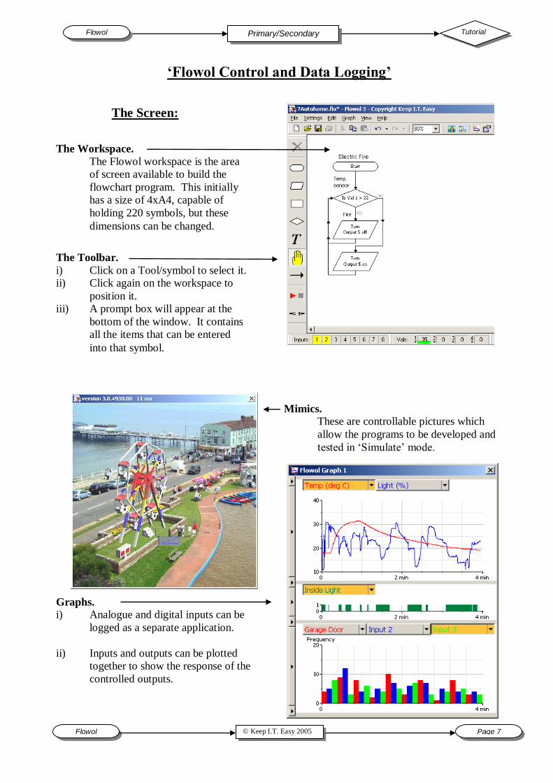
The Screen:
The Toolbar.
i) Click on a Tool/symbol to select it.
ii) Click again on the workspace to
position it.
iii) A prompt box will appear at the
bottom of the window. It contains
all the items that can be entered
into that symbol.
The Workspace.
The Flowol workspace is the area
of screen available to build the
flowchart program. This initially
has a size of 4xA4, capable of
holding 220 symbols, but these
dimensions can be changed.
Mimics.
These are controllable pictures which
allow the programs to be developed and
tested in „Simulate‟ mode.
Graphs. i) Analogue and digital inputs can be
logged as a separate application.
ii) Inputs and outputs can be plotted
together to show the response of the
controlled outputs.
Flowol Tutorial Primary/Secondary
Page 8 © Keep I.T. Easy 2005 Flowol
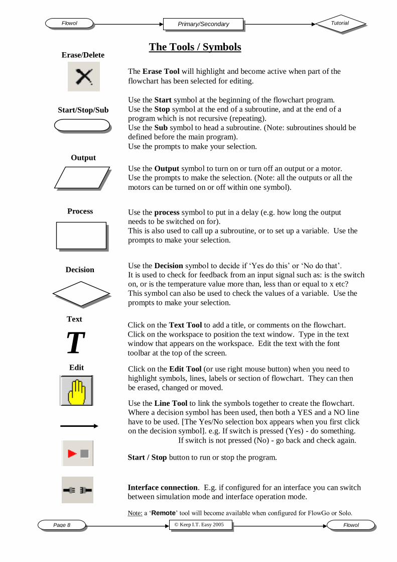
The Tools / Symbols
The Erase Tool will highlight and become active when part of the
flowchart has been selected for editing.
Start/Stop/Sub
Use the Start symbol at the beginning of the flowchart program.
Use the Stop symbol at the end of a subroutine, and at the end of a
program which is not recursive (repeating).
Use the Sub symbol to head a subroutine. (Note: subroutines should be
defined before the main program).
Use the prompts to make your selection.
Output
Use the Output symbol to turn on or turn off an output or a motor.
Use the prompts to make the selection. (Note: all the outputs or all the
motors can be turned on or off within one symbol).
Process Use the process symbol to put in a delay (e.g. how long the output
needs to be switched on for).
This is also used to call up a subroutine, or to set up a variable. Use the
prompts to make your selection.
Decision Use the Decision symbol to decide if „Yes do this‟ or „No do that‟.
It is used to check for feedback from an input signal such as: is the switch
on, or is the temperature value more than, less than or equal to x etc?
This symbol can also be used to check the values of a variable. Use the
prompts to make your selection.
Click on the Text Tool to add a title, or comments on the flowchart.
Click on the workspace to position the text window. Type in the text
window that appears on the workspace. Edit the text with the font
toolbar at the top of the screen.
Text
T
Edit Click on the Edit Tool (or use right mouse button) when you need to
highlight symbols, lines, labels or section of flowchart. They can then
be erased, changed or moved.
Use the Line Tool to link the symbols together to create the flowchart.
Where a decision symbol has been used, then both a YES and a NO line
have to be used. [The Yes/No selection box appears when you first click
on the decision symbol]. e.g. If switch is pressed (Yes) - do something.
If switch is not pressed (No) - go back and check again.
Start / Stop button to run or stop the program.
Interface connection. E.g. if configured for an interface you can switch
between simulation mode and interface operation mode.
Note: a „Remote‟ tool will become available when configured for FlowGo or Solo.
Erase/Delete
Tutorial Flowol Primary/Secondary
© Keep I.T. Easy 2005 Flowol Page 9
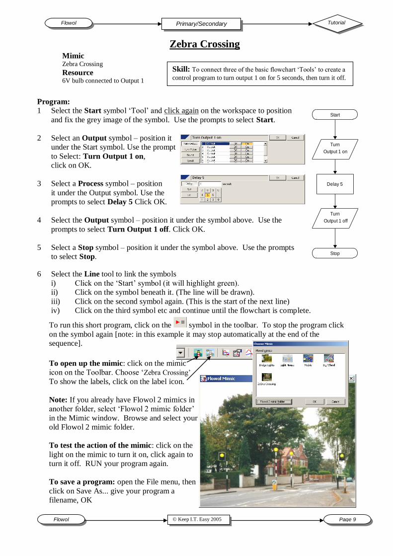
Program:
1 Select the Start symbol „Tool‟ and click again on the workspace to position
and fix the grey image of the symbol. Use the prompts to select Start.
2 Select an Output symbol – position it
under the Start symbol. Use the prompt
to Select: Turn Output 1 on,
click on OK.
3 Select a Process symbol – position
it under the Output symbol. Use the
prompts to select Delay 5 Click OK.
4 Select the Output symbol – position it under the symbol above. Use the
prompts to select Turn Output 1 off. Click OK.
5 Select a Stop symbol – position it under the symbol above. Use the prompts
to select Stop.
Mimic Zebra Crossing
Resource 6V bulb connected to Output 1
Zebra Crossing
Skill: To connect three of the basic flowchart „Tools‟ to create a
control program to turn output 1 on for 5 seconds, then turn it off.
To open up the mimic: click on the mimic
icon on the Toolbar. Choose „Zebra Crossing‟
To show the labels, click on the label icon.
Note: If you already have Flowol 2 mimics in
another folder, select „Flowol 2 mimic folder‟
in the Mimic window. Browse and select your
old Flowol 2 mimic folder.
To test the action of the mimic: click on the
light on the mimic to turn it on, click again to
turn it off. RUN your program again.
To save a program: open the File menu, then
click on Save As... give your program a
filename, OK
6 Select the Line tool to link the symbols
i) Click on the „Start‟ symbol (it will highlight green).
ii) Click on the symbol beneath it. (The line will be drawn).
iii) Click on the second symbol again. (This is the start of the next line)
iv) Click on the third symbol etc and continue until the flowchart is complete.
Start
Turn
Output 1 on
Delay 5
Turn
Output 1 off
Stop
To run this short program, click on the symbol in the toolbar. To stop the program click
on the symbol again [note: in this example it may stop automatically at the end of the
sequence].
Flowol Tutorial Primary/Secondary
Page 10 © Keep I.T. Easy 2005 Flowol
Start
Turn
Output 1 on
Delay 2
Turn
Output 1 off
Stop
Delay 2
Start
Turn
Output 1 on
Delay 2
Turn
Output 1 off
Stop
Start
Turn
Output 1 on
Delay 2
Turn
Output 1 off
Stop
Erase this stop & draw new line
Change delay
Insert extra process
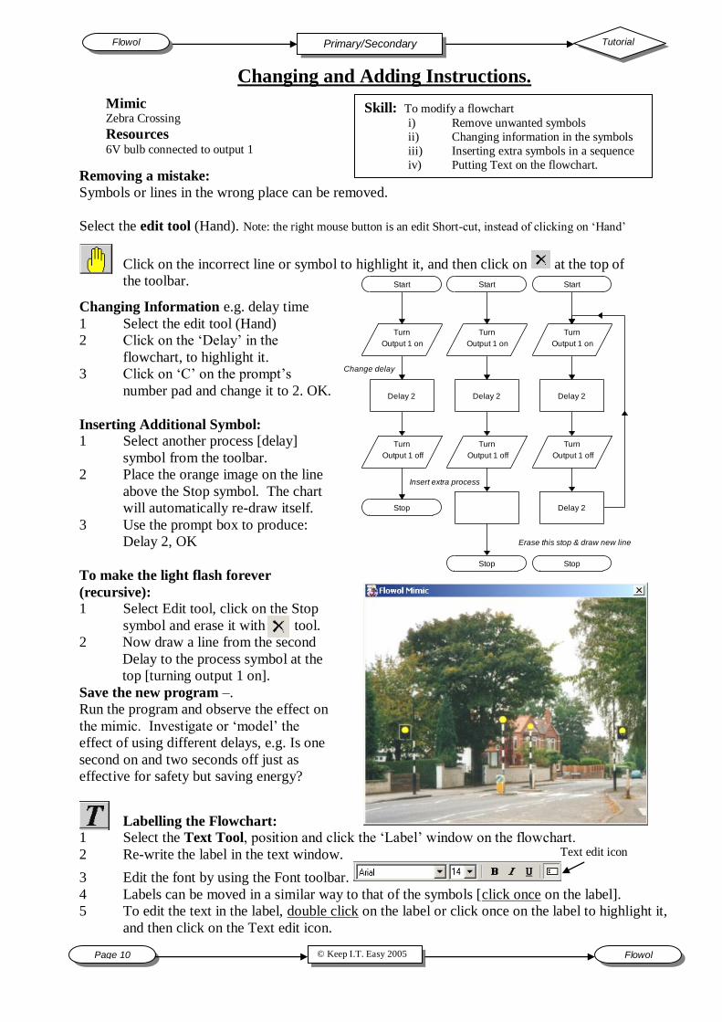
Changing and Adding Instructions.
Skill: To modify a flowchart
i) Remove unwanted symbols
ii) Changing information in the symbols
iii) Inserting extra symbols in a sequence
iv) Putting Text on the flowchart.
Mimic Zebra Crossing
Resources 6V bulb connected to output 1
Removing a mistake:
Symbols or lines in the wrong place can be removed.
Select the edit tool (Hand). Note: the right mouse button is an edit Short-cut, instead of clicking on „Hand‟
Click on the incorrect line or symbol to highlight it, and then click on at the top of
the toolbar.
Changing Information e.g. delay time
1 Select the edit tool (Hand)
2 Click on the „Delay‟ in the
flowchart, to highlight it.
3 Click on „C‟ on the prompt‟s
number pad and change it to 2. OK.
Inserting Additional Symbol: 1 Select another process [delay]
symbol from the toolbar.
2 Place the orange image on the line
above the Stop symbol. The chart
will automatically re-draw itself.
3 Use the prompt box to produce:
Delay 2, OK
To make the light flash forever
(recursive):
1 Select Edit tool, click on the Stop
symbol and erase it with tool.
2 Now draw a line from the second
Delay to the process symbol at the
top [turning output 1 on].
Save the new program –.
Run the program and observe the effect on
the mimic. Investigate or „model‟ the
effect of using different delays, e.g. Is one
second on and two seconds off just as
effective for safety but saving energy?
Labelling the Flowchart:
1 Select the Text Tool, position and click the „Label‟ window on the flowchart.
2 Re-write the label in the text window.
3 Edit the font by using the Font toolbar.
4 Labels can be moved in a similar way to that of the symbols [click once on the label].
5 To edit the text in the label, double click on the label or click once on the label to highlight it,
and then click on the Text edit icon.
Text edit icon
Tutorial Flowol Primary/Secondary
© Keep I.T. Easy 2005 Flowol Page 11
Traffic Lights box (symbol) can
control 2 motors.
The power control has
to be the same for both
motors in the same
box. Note: if power is
50%Data Logging
and Control.
The „cause and effect‟ is easily demonstrated by
using Flowol Graphs:
The pump motor A
responds to the temp.
difference.
The „Sun seeker‟
motor responds to the
light differential.
Note: The light graph has
been left as %.
The temperature sensors
have been calibrated and
then the temperature range
(limits) changed.
Save your Program
in one sub., then it
stays at that value
until it is re-
defined.
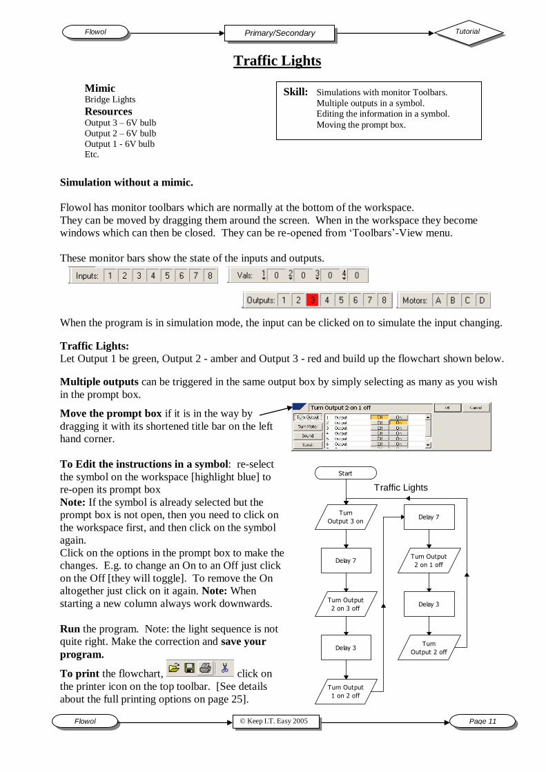
Mimic Bridge Lights
Resources Output 3 – 6V bulb
Output 2 – 6V bulb
Output 1 - 6V bulb Etc.
Skill: Simulations with monitor Toolbars.
Multiple outputs in a symbol.
Editing the information in a symbol.
Moving the prompt box.
Simulation without a mimic.
Flowol has monitor toolbars which are normally at the bottom of the workspace.
They can be moved by dragging them around the screen. When in the workspace they become
windows which can then be closed. They can be re-opened from „Toolbars‟-View menu.
These monitor bars show the state of the inputs and outputs.
When the program is in simulation mode, the input can be clicked on to simulate the input changing.
Traffic Lights:
Let Output 1 be green, Output 2 - amber and Output 3 - red and build up the flowchart shown below.
Multiple outputs can be triggered in the same output box by simply selecting as many as you wish
in the prompt box.
Move the prompt box if it is in the way by
dragging it with its shortened title bar on the left
hand corner.
To Edit the instructions in a symbol: re-select
the symbol on the workspace [highlight blue] to
re-open its prompt box
Note: If the symbol is already selected but the
prompt box is not open, then you need to click on
the workspace first, and then click on the symbol
again.
Click on the options in the prompt box to make the
changes. E.g. to change an On to an Off just click
on the Off [they will toggle]. To remove the On
altogether just click on it again. Note: When
starting a new column always work downwards.
Run the program. Note: the light sequence is not
quite right. Make the correction and save your
program.
To print the flowchart, click on
the printer icon on the top toolbar. [See details
about the full printing options on page 25].
Start
Turn
Output 3 on
Delay 7
Turn Output
2 on 3 off
Delay 3
Turn Output
1 on 2 off
Delay 7
Turn Output
2 on 1 off
Delay 3
Turn
Output 2 off
Traffic Lights
Flowol Tutorial Primary/Secondary
Page 12 © Keep I.T. Easy 2005 Flowol
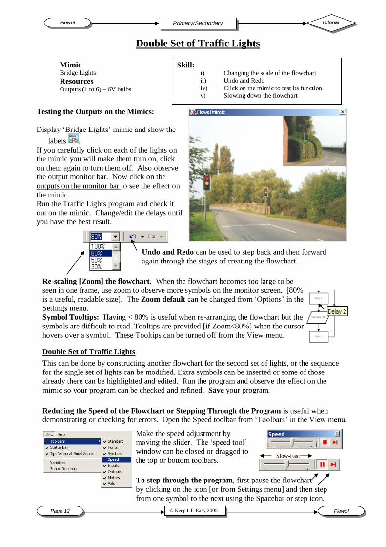
Double Set of Traffic Lights
Skill: i) Changing the scale of the flowchart
ii) Undo and Redo
iv) Click on the mimic to test its function.
v) Slowing down the flowchart
Mimic Bridge Lights
Resources Outputs (1 to 6) – 6V bulbs
Testing the Outputs on the Mimics:
Display „Bridge Lights‟ mimic and show the
labels .
If you carefully click on each of the lights on
the mimic you will make them turn on, click
on them again to turn them off. Also observe
the output monitor bar. Now click on the
outputs on the monitor bar to see the effect on
the mimic.
Run the Traffic Lights program and check it
out on the mimic. Change/edit the delays until
you have the best result.
Double Set of Traffic Lights
This can be done by constructing another flowchart for the second set of lights, or the sequence
for the single set of lights can be modified. Extra symbols can be inserted or some of those
already there can be highlighted and edited. Run the program and observe the effect on the
mimic so your program can be checked and refined. Save your program.
Re-scaling [Zoom] the flowchart. When the flowchart becomes too large to be
seen in one frame, use zoom to observe more symbols on the monitor screen. [80%
is a useful, readable size]. The Zoom default can be changed from „Options‟ in the
Settings menu.
Symbol Tooltips: Having < 80% is useful when re-arranging the flowchart but the
symbols are difficult to read. Tooltips are provided [if Zoom<80%] when the cursor
hovers over a symbol. These Tooltips can be turned off from the View menu.
Undo and Redo can be used to step back and then forward
again through the stages of creating the flowchart.
Reducing the Speed of the Flowchart or Stepping Through the Program is useful when
demonstrating or checking for errors. Open the Speed toolbar from „Toolbars‟ in the View menu.
Make the speed adjustment by
moving the slider. The „speed tool‟
window can be closed or dragged to
the top or bottom toolbars.
Slow-Fast
To step through the program, first pause the flowchart
by clicking on the icon [or from Settings menu] and then step
from one symbol to the next using the Spacebar or step icon.
Tutorial Flowol Primary/Secondary
© Keep I.T. Easy 2005 Flowol Page 13
The Lighthouse
Skill: To use multiple flowcharts:
i) Move sections of flowchart.
ii) Copy a flowchart.
iii) Changing the colour of the flowchart.
iv) Controlling a model through a control box.
Mimic Light House
Resources
Output 2 - buzzer
Outputs 1 & 3 – 6V bulbs
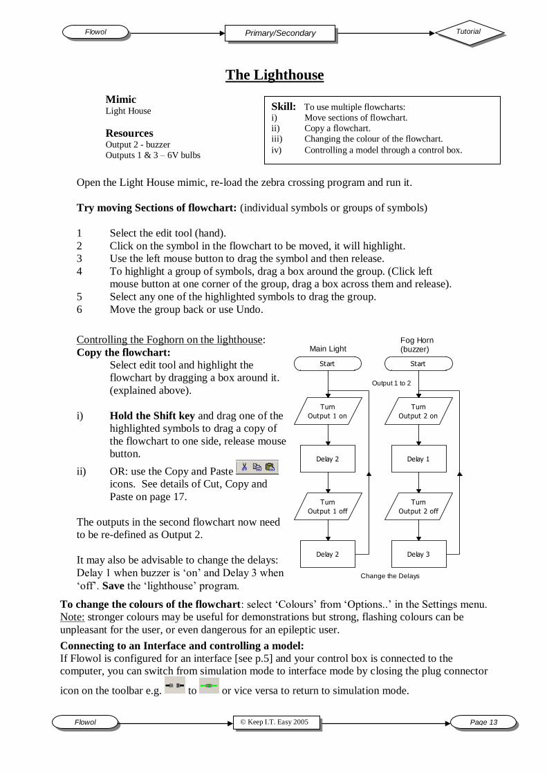
Open the Light House mimic, re-load the zebra crossing program and run it.
Try moving Sections of flowchart: (individual symbols or groups of symbols)
1 Select the edit tool (hand).
2 Click on the symbol in the flowchart to be moved, it will highlight.
3 Use the left mouse button to drag the symbol and then release.
4 To highlight a group of symbols, drag a box around the group. (Click left
mouse button at one corner of the group, drag a box across them and release).
5 Select any one of the highlighted symbols to drag the group.
6 Move the group back or use Undo.
Controlling the Foghorn on the lighthouse:
Copy the flowchart:
Select edit tool and highlight the
flowchart by dragging a box around it.
(explained above).
i) Hold the Shift key and drag one of the
highlighted symbols to drag a copy of
the flowchart to one side, release mouse
button.
ii) OR: use the Copy and Paste
icons. See details of Cut, Copy and
Paste on page 17.
The outputs in the second flowchart now need
to be re-defined as Output 2.
It may also be advisable to change the delays:
Delay 1 when buzzer is „on‟ and Delay 3 when
„off‟. Save the „lighthouse‟ program.
Connecting to an Interface and controlling a model:
If Flowol is configured for an interface [see p.5] and your control box is connected to the
computer, you can switch from simulation mode to interface mode by closing the plug connector
icon on the toolbar e.g. to or vice versa to return to simulation mode.
To change the colours of the flowchart: select „Colours‟ from „Options..‟ in the Settings menu.
Note: stronger colours may be useful for demonstrations but strong, flashing colours can be
unpleasant for the user, or even dangerous for an epileptic user.
Start
Turn
Output 1 on
Delay 2
Turn
Output 1 off
Delay 2
Start
Turn
Output 2 on
Delay 1
Turn
Output 2 off
Delay 3
Main LightFog Horn(buzzer)
Output 1 to 2
Change the Delays
Flowol Tutorial Primary/Secondary
Page 14 © Keep I.T. Easy 2005 Flowol
Lighthouse with a switch
Skill: Using an Input (Decision) symbol.
Mimic Light House
Resources Output 3 – 6V bulb
Output 2 – Buzzer
Output 1 – 6V bulb
Input 1 – switch or LDR
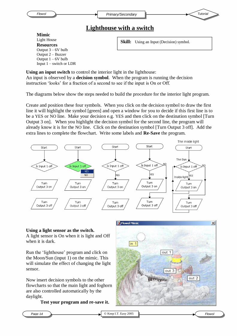
Using an input switch to control the interior light in the lighthouse:
An input is observed by a decision symbol. When the program is running the decision
instruction „looks‟ for a fraction of a second to see if the input is On or Off.
The diagrams below show the steps needed to build the procedure for the interior light program.
Create and position these four symbols. When you click on the decision symbol to draw the first
line it will highlight the symbol [green] and open a window for you to decide if this first line is to
be a YES or NO line. Make your decision e.g. YES and then click on the destination symbol [Turn
Output 3 on]. When you highlight the decision symbol for the second line, the program will
already know it is for the NO line. Click on the destination symbol [Turn Output 3 off]. Add the
extra lines to complete the flowchart. Write some labels and Re-Save the program.
Using a light sensor as the switch.
A light sensor is On when it is light and Off
when it is dark.
Run the „lighthouse‟ program and click on
the Moon/Sun (input 1) on the mimic. This
will simulate the effect of changing the light
sensor.
Now insert decision symbols to the other
flowcharts so that the main light and foghorn
are also controlled automatically by the
daylight.
Test your program and re-save it.
Start
Is Input 1 off
Turn
Output 3 on
Turn
Output 3 off
YES
NO
Tutorial Flowol Primary/Secondary
© Keep I.T. Easy 2005 Flowol Page 15
Lighthouse with Subroutines
and Sound Subroutines
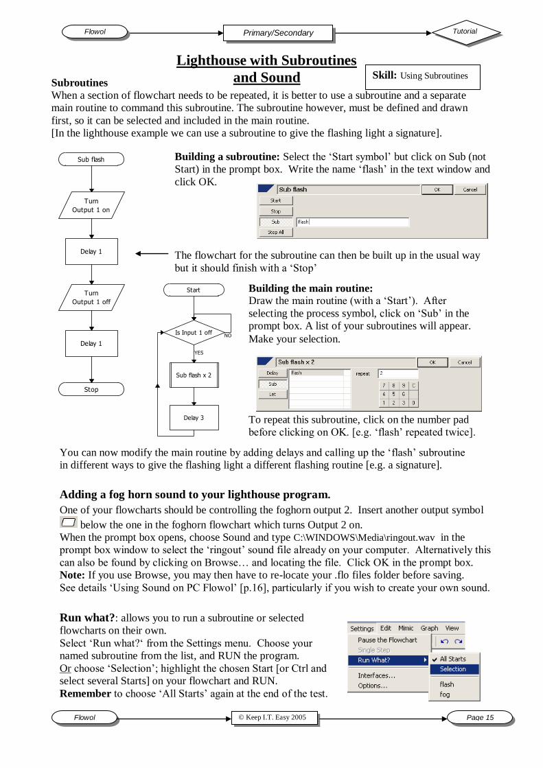
When a section of flowchart needs to be repeated, it is better to use a subroutine and a separate
main routine to command this subroutine. The subroutine however, must be defined and drawn
first, so it can be selected and included in the main routine.
[In the lighthouse example we can use a subroutine to give the flashing light a signature].
Building a subroutine: Select the „Start symbol‟ but click on Sub (not
Start) in the prompt box. Write the name „flash‟ in the text window and
click OK.
Turn
Output 1 on
Delay 1
Turn
Output 1 off
Delay 1
Sub flash
Stop
The flowchart for the subroutine can then be built up in the usual way
but it should finish with a „Stop‟
Start
Is Input 1 off
Sub flash x 2
Delay 3
YES
NO
Building the main routine:
Draw the main routine (with a „Start‟). After
selecting the process symbol, click on „Sub‟ in the
prompt box. A list of your subroutines will appear.
Make your selection.
To repeat this subroutine, click on the number pad
before clicking on OK. [e.g. „flash‟ repeated twice].
You can now modify the main routine by adding delays and calling up the „flash‟ subroutine
in different ways to give the flashing light a different flashing routine [e.g. a signature].
Adding a fog horn sound to your lighthouse program.
One of your flowcharts should be controlling the foghorn output 2. Insert another output symbol
below the one in the foghorn flowchart which turns Output 2 on.
When the prompt box opens, choose Sound and type C:\WINDOWS\Media\ringout.wav in the
prompt box window to select the „ringout‟ sound file already on your computer. Alternatively this
can also be found by clicking on Browse… and locating the file. Click OK in the prompt box.
Note: If you use Browse, you may then have to re-locate your .flo files folder before saving.
See details „Using Sound on PC Flowol‟ [p.16], particularly if you wish to create your own sound.
Run what?: allows you to run a subroutine or selected
flowcharts on their own.
Select „Run what?„ from the Settings menu. Choose your
named subroutine from the list, and RUN the program.
Or choose „Selection‟; highlight the chosen Start [or Ctrl and
select several Starts] on your flowchart and RUN.
Remember to choose „All Starts‟ again at the end of the test.
Skill: Using Subroutines
Flowol Tutorial Primary/Secondary
Page 16 © Keep I.T. Easy 2005 Flowol
Play Stop Recording your own sounds:
Attach a microphone and speaker to the sound card.
Open the Flowol program.
Launch Microsoft‟s Sound Recorder by clicking on the icon [Note: This „Sound
Recorder‟ can then be re-accessed from the lower taskbar].
Click on the Record button to start a recording. Make your sound into the microphone.
Click on the Stop button when the recording is complete.
Only edit the sound if you need to. E.g. you might need to delete a bit of recording just
before or after the section of sound you need. To do this, move the slider on the Recorder
window to identify the beginning and end of the sound and use the Edit menu on the
Recorder to delete the unwanted sections of recording.
Select Save As from the Sound Recorder‟s File menu. Save as a .WAV file type in the
destination of your choice but it may be best to save it in the same area that stores your
flowchart .flo files.
To use the sound in your flowchart program insert an output symbol . Select
Sound from the prompt box and Browse.. for your .wav file and click OK. In the foghorn
example above we wanted the sound to run with the visual fog horn on the mimic,
therefore did not tick the „Wait for sound to finish…‟ in the prompt box.
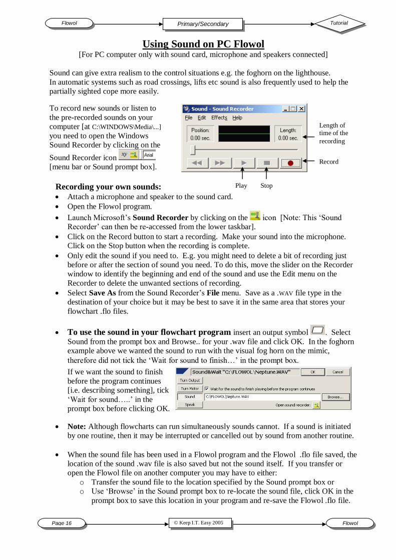
Using Sound on PC Flowol [For PC computer only with sound card, microphone and speakers connected]
Sound can give extra realism to the control situations e.g. the foghorn on the lighthouse.
In automatic systems such as road crossings, lifts etc sound is also frequently used to help the
partially sighted cope more easily.
To record new sounds or listen to
the pre-recorded sounds on your
computer [at C:\WINDOWS\Media\...]
you need to open the Windows
Sound Recorder by clicking on the
Sound Recorder icon
[menu bar or Sound prompt box].
Length of
time of the
recording
Record
Note: Although flowcharts can run simultaneously sounds cannot. If a sound is initiated
by one routine, then it may be interrupted or cancelled out by sound from another routine.
When the sound file has been used in a Flowol program and the Flowol .flo file saved, the
location of the sound .wav file is also saved but not the sound itself. If you transfer or
open the Flowol file on another computer you may have to either:
o Transfer the sound file to the location specified by the Sound prompt box or
o Use „Browse‟ in the Sound prompt box to re-locate the sound file, click OK in the
prompt box to save this location in your program and re-save the Flowol .flo file.
If we want the sound to finish
before the program continues
[i.e. describing something], tick
„Wait for sound…..‟ in the
prompt box before clicking OK.
Tutorial Flowol Primary/Secondary
© Keep I.T. Easy 2005 Flowol Page 17
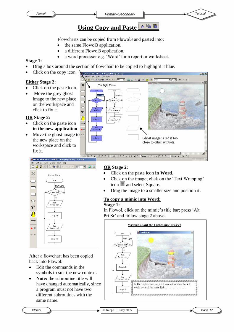
Using Copy and Paste
Flowcharts can be copied from Flowol3 and pasted into:
the same Flowol3 application.
a different Flowol3 application.
a word processor e.g. „Word‟ for a report or worksheet.
Stage 1:
Drag a box around the section of flowchart to be copied to highlight it blue.
Click on the copy icon.
Either Stage 2:
Click on the paste icon.
Move the grey ghost
image to the new place
on the workspace and
click to fix it.
OR Stage 2:
Click on the paste icon
in the new application.
Move the ghost image to
the new place on the
workspace and click to
fix it.
OR Stage 2:
Click on the paste icon in Word.
Click on the image; click on the „Text Wrapping‟
icon and select Square.
Drag the image to a smaller size and position it. To copy a mimic into Word:
Stage 1:
In Flowol, click on the mimic‟s title bar; press „Alt
Prt Sr‟ and follow stage 2 above.
After a flowchart has been copied
back into Flowol:
Edit the commands in the
symbols to suit the new context.
Note: the subroutine title will
have changed automatically, since
a program must not have two
different subroutines with the
same name.
Ghost image is red if too
close to other symbols.

Flowol Tutorial Primary/Secondary
Page 18 © Keep I.T. Easy 2005 Flowol
Controlling Electric Motors
Skill:
Using a Motor output on a mimic.
Changing the speed of a motor.
Mimic: Mobile
Note: Different options are
available with this mimic. See p.5
Electric motors produce movement. This can be the continuous
rotation of a cot mobile or the forwards and backwards
movement of a barrier.
Open the mimic folder and select the
Mobile mimic.
Use the left mouse button and click on the
letters on the motor monitor bar
and observe the effect on
the mimic. When letter A goes green, motor
A should go forward. Click again to stop it.
Use the right mouse button to turn the letter
A red. This should make the motor reverse.
On the mobile mimic, motor A rotates the
whole mobile but what do motors B and C
do? You might like to have the labels on .
Controlling a motor in a program:
Choose an output symbol to open
the prompt box and select Turn
Motor.. [Note the 3D mimics have
written prompt names to remind you
what the motors do].
Select: A (Mobile) Fd [to make motor A rotate forwards] and click OK,.
Turn
Motor A fd
Start
Is Input 1 onTurn
Motor A off
YES
NO
Activity 1: Build up this program which uses input 1 to
control the mobile‟s movement.
Activity 2: Now build a program using another input button
to control another moving feature [try forward and reverse].
Note: More than one motor can be controlled by the same output symbol.
Motor Speed or Power Control.
Real motors on models and those on 3D mimics often rotate too quickly. To slow them down we
need to give the motors a „%‟ speed setting. To do this, select the „Turn Motor A fd‟ symbol to
re-open its prompt box. Tick the „Set motor power‟ check box and choose a % speed setting e.g.
50%, before clicking OK.
Note: Set motor power back to 100% when needed.
Activity 3: Edit your program to
change some of your motor speeds.
Add extra output symbols and delays
to make the mobile go fast, then slow
and then fast again.
Tutorial Flowol Primary/Secondary
© Keep I.T. Easy 2005 Flowol Page 19
Using Analogue Values [Vals] with the Cot Mobile
Mimic
Explore the outputs on the mobile by clicking on the output monitor bar. [You will need to look
closely at the mimic since some of the lights on the mobile‟s models are quite small].
Activity 4: We will now make the light in the hot air balloon act as a „Night-light‟. E.g. the
balloon will light up automatically only when it is dark. For this activity we will assume that
Val 1 is the value from a light sensor on the end of the mobile arm. A light sensor gives a high
Activity 5: To occupy the baby create a program to automatically flash the car brake light and
aeroplane wing tip lights, if the room light level falls below 60 units.
Activity 6: The Automatic Mobile. For this activity assume that the analogue value is from a
sound detector which gives a high reading when it is noisy. Now create a program which brings the
mobile to „life‟ if the Baby wakes up during the night and cries. Remember you can control the
lights, the movements and even produce your own sound file if you wish. Perhaps the mobile
should be more active the greater the noise, and then gradually become less active as time passes.
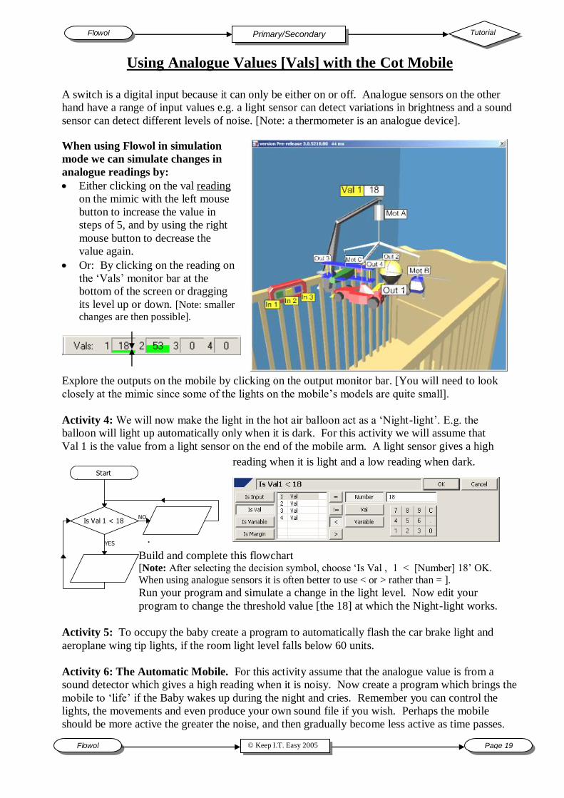
A switch is a digital input because it can only be either on or off. Analogue sensors on the other
hand have a range of input values e.g. a light sensor can detect variations in brightness and a sound
sensor can detect different levels of noise. [Note: a thermometer is an analogue device].
When using Flowol in simulation
mode we can simulate changes in
analogue readings by:
Either clicking on the val reading
on the mimic with the left mouse
button to increase the value in
steps of 5, and by using the right
mouse button to decrease the
value again.
Or: By clicking on the reading on
the „Vals‟ monitor bar at the
bottom of the screen or dragging
its level up or down. [Note: smaller
changes are then possible].
.
Start
Is Val 1 < 18
YES
NO
Build and complete this flowchart [Note: After selecting the decision symbol, choose „Is Val , 1 < [Number] 18‟ OK.
When using analogue sensors it is often better to use < or > rather than = ].
Run your program and simulate a change in the light level. Now edit your
program to change the threshold value [the 18] at which the Night-light works.
reading when it is light and a low reading when dark.
Flowol Tutorial Primary/Secondary
Page 20 © Keep I.T. Easy 2005 Flowol
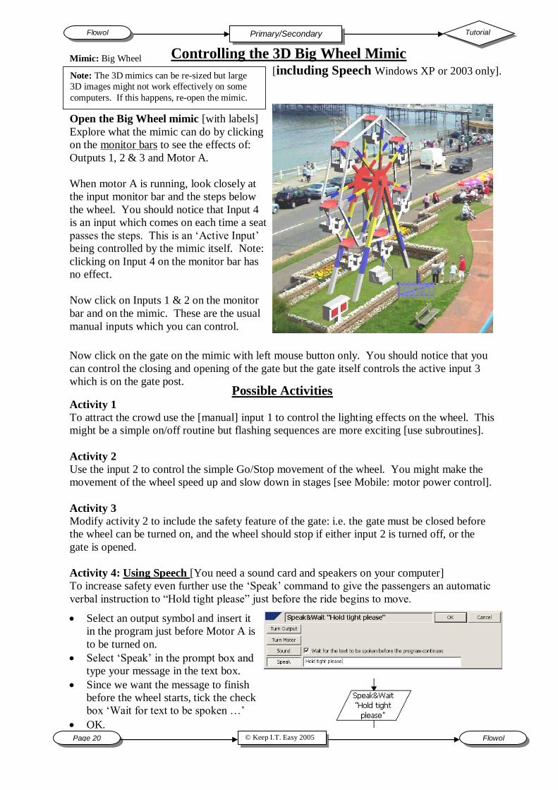
Controlling the 3D Big Wheel Mimic [including Speech Windows XP or 2003 only].
Open the Big Wheel mimic [with labels]
Explore what the mimic can do by clicking
on the monitor bars to see the effects of:
Outputs 1, 2 & 3 and Motor A.
When motor A is running, look closely at
the input monitor bar and the steps below
the wheel. You should notice that Input 4
is an input which comes on each time a seat
passes the steps. This is an „Active Input‟
being controlled by the mimic itself. Note:
clicking on Input 4 on the monitor bar has
no effect.
Now click on Inputs 1 & 2 on the monitor
bar and on the mimic. These are the usual
manual inputs which you can control.
Now click on the gate on the mimic with left mouse button only. You should notice that you
can control the closing and opening of the gate but the gate itself controls the active input 3
which is on the gate post. Possible Activities Activity 1
To attract the crowd use the [manual] input 1 to control the lighting effects on the wheel. This
might be a simple on/off routine but flashing sequences are more exciting [use subroutines].
Activity 2
Use the input 2 to control the simple Go/Stop movement of the wheel. You might make the
movement of the wheel speed up and slow down in stages [see Mobile: motor power control].
Activity 3
Modify activity 2 to include the safety feature of the gate: i.e. the gate must be closed before
the wheel can be turned on, and the wheel should stop if either input 2 is turned off, or the
gate is opened.
Activity 4: Using Speech [You need a sound card and speakers on your computer]
To increase safety even further use the „Speak‟ command to give the passengers an automatic
verbal instruction to “Hold tight please” just before the ride begins to move.
Select an output symbol and insert it
in the program just before Motor A is
to be turned on.
Select „Speak‟ in the prompt box and
type your message in the text box.
Since we want the message to finish
before the wheel starts, tick the check
box „Wait for text to be spoken …‟
OK.
Note: The 3D mimics can be re-sized but large
3D images might not work effectively on some
computers. If this happens, re-open the mimic.
Mimic: Big Wheel
© Keep I.T. Easy 2005 Flowol Page 21
Tutorial Flowol Secondary
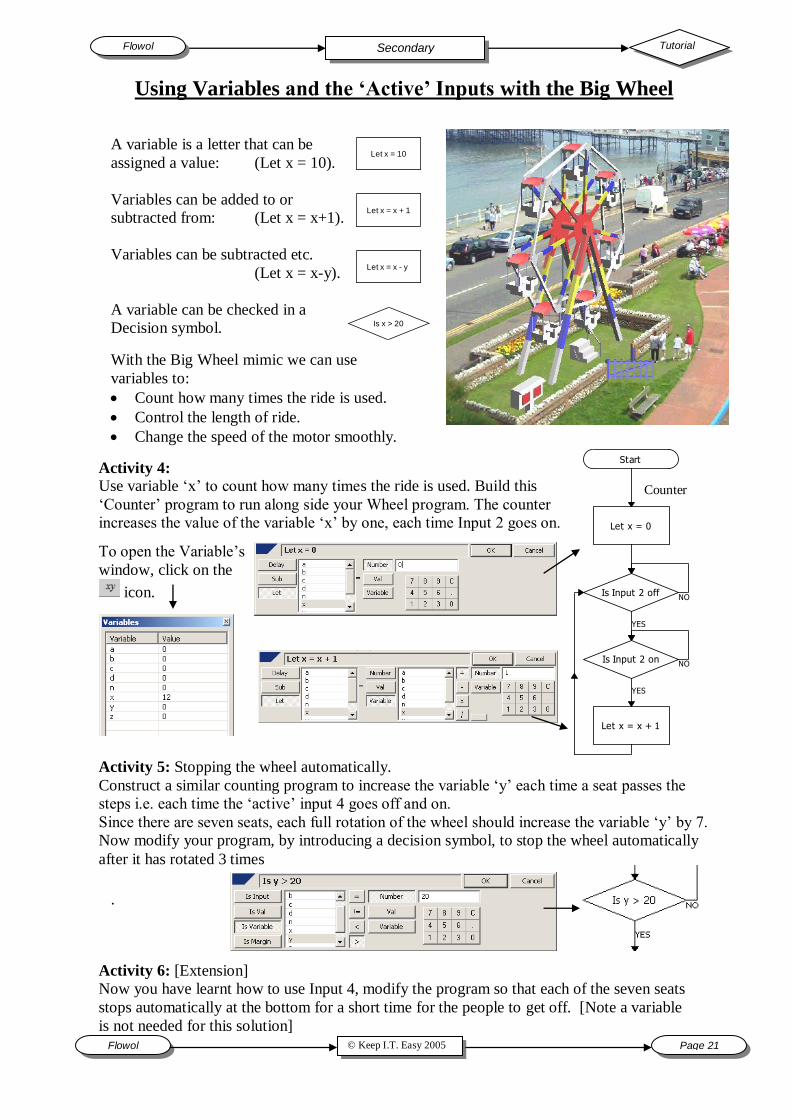
Activity 4:
Use variable „x‟ to count how many times the ride is used. Build this
„Counter‟ program to run along side your Wheel program. The counter
increases the value of the variable „x‟ by one, each time Input 2 goes on.
Start
Is Input 2 off
Is Input 2 on
Let x = x + 1
Let x = 0
YES
NO
YES
NO
To open the Variable‟s
window, click on the
icon.
Counter
Using Variables and the ‘Active’ Inputs with the Big Wheel
A variable is a letter that can be
assigned a value: (Let x = 10).
Variables can be added to or
subtracted from: (Let x = x+1).
Variables can be subtracted etc.
(Let x = x-y).
A variable can be checked in a
Decision symbol.
Let x = 10
Let x = x + 1
Let x = x - y
Is x > 20
With the Big Wheel mimic we can use
variables to:
Count how many times the ride is used.
Control the length of ride.
Change the speed of the motor smoothly.
.
Activity 5: Stopping the wheel automatically.
Construct a similar counting program to increase the variable „y‟ each time a seat passes the
steps i.e. each time the „active‟ input 4 goes off and on.
Since there are seven seats, each full rotation of the wheel should increase the variable „y‟ by 7.
Now modify your program, by introducing a decision symbol, to stop the wheel automatically
after it has rotated 3 times
Activity 6: [Extension]
Now you have learnt how to use Input 4, modify the program so that each of the seven seats
stops automatically at the bottom for a short time for the people to get off. [Note a variable
is not needed for this solution]
Page 22 © Keep I.T. Easy 2005 Flowol
Flowol Tutorial Secondary
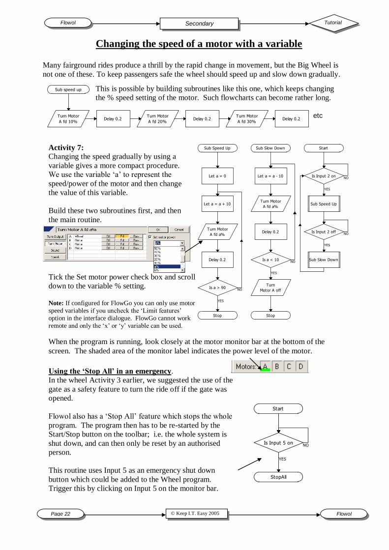
Activity 7:
Changing the speed gradually by using a
variable gives a more compact procedure.
We use the variable „a‟ to represent the
speed/power of the motor and then change
the value of this variable.
Build these two subroutines first, and then
the main routine.
Changing the speed of a motor with a variable
This is possible by building subroutines like this one, which keeps changing
the % speed setting of the motor. Such flowcharts can become rather long.
Many fairground rides produce a thrill by the rapid change in movement, but the Big Wheel is
not one of these. To keep passengers safe the wheel should speed up and slow down gradually.
Sub speed up
Turn Motor
A fd 10%Delay 0.2
Turn Motor
A fd 20%Delay 0.2
Turn Motor
A fd 30%Delay 0.2
etc
Sub Speed Up
Turn Motor
A fd a%
Let a = 0
Let a = a + 10
Is a > 90
Stop
Delay 0.2
Sub Slow Down
Turn Motor
A fd a%
Let a = a - 10
Is a < 10
Stop
Delay 0.2
Turn
Motor A off
Start
Is Input 2 on
Sub Speed Up
Is Input 2 off
Sub Slow Down
YES
NO
YES
NO
YES
NO
YES
NO
Tick the Set motor power check box and scroll
down to the variable % setting.
Note: If configured for FlowGo you can only use motor
speed variables if you uncheck the „Limit features‟
option in the interface dialogue. FlowGo cannot work
remote and only the „x‟ or „y‟ variable can be used.
When the program is running, look closely at the motor monitor bar at the bottom of the
screen. The shaded area of the monitor label indicates the power level of the motor.
Using the ‘Stop All’ in an emergency.
In the wheel Activity 3 earlier, we suggested the use of the
gate as a safety feature to turn the ride off if the gate was
opened.
Flowol also has a „Stop All‟ feature which stops the whole
program. The program then has to be re-started by the
Start/Stop button on the toolbar; i.e. the whole system is
shut down, and can then only be reset by an authorised
person.
This routine uses Input 5 as an emergency shut down
button which could be added to the Wheel program.
Trigger this by clicking on Input 5 on the monitor bar.
Start
Is Input 5 on
StopAll
YES
NO
© Keep I.T. Easy 2005 Flowol Page 23
Tutorial Flowol Secondary
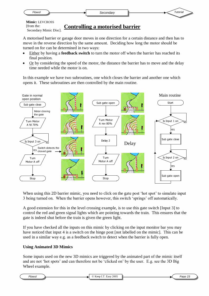
A motorised barrier or garage door moves in one direction for a certain distance and then has to
move in the reverse direction by the same amount. Deciding how long the motor should be
turned on for can be determined in two ways:
Either by having a feedback switch to turn the motor off when the barrier has reached its
final position.
Or by considering the speed of the motor, the distance the barrier has to move and the delay
time needed while the motor is on.
In this example we have two subroutines, one which closes the barrier and another one which
opens it. These subroutines are then controlled by the main routine.
Controlling a motorised barrier
Sub gate open
Turn Motor
A rev 80%
Delay 2
Turn
Motor A off
Stop
Start
Is Input 1 on
Sub gate close
Is Input 2 on
Sub gate open
YES
NO
YES
NO
Delay
Sub gate close
Turn Motor
A fd 70%
Turn
Motor A off
Stop
Is Input 3 on
YES
NO
Gate in normal open position
Motor closing
the gate
Switch detects the
closed gate
Main routine
When using this 2D barrier mimic, you need to click on the gate post „hot spot‟ to simulate input
3 being turned on. When the barrier opens however, this switch „springs‟ off automatically.
A good extension for this in the level crossing example, is to use this gate switch [Input 3] to
control the red and green signal lights which are pointing towards the train. This ensures that the
gate is indeed shut before the train is given the green light.
If you have checked all the inputs on this mimic by clicking on the input monitor bar you may
have noticed that input 4 is a switch on the hinge post [not labelled on the mimic]. This can be
used in a similar way e.g. as a feedback switch to detect when the barrier is fully open.
Using Animated 3D Mimics
Some inputs used on the new 3D mimics are triggered by the animated part of the mimic itself
and are not „hot spots‟ and can therefore not be „clicked on‟ by the user. E.g. see the 3D Big
Wheel example.
Mimic: LEVCROSS
[from the:
Secondary Mimic Disc].
Page 24 © Keep I.T. Easy 2005 Flowol
Flowol Tutorial Secondary
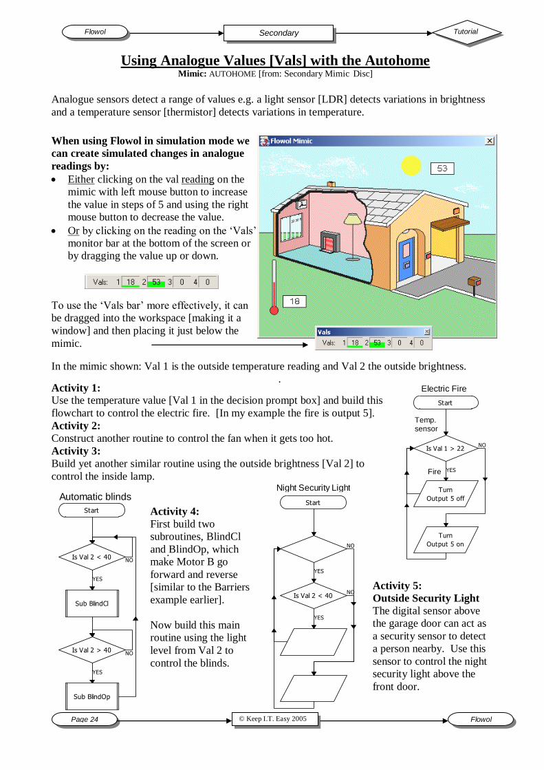
In the mimic shown: Val 1 is the outside temperature reading and Val 2 the outside brightness.
.
Activity 5:
Outside Security Light
The digital sensor above
the garage door can act as
a security sensor to detect
a person nearby. Use this
sensor to control the night
security light above the
front door.
.
.
Analogue sensors detect a range of values e.g. a light sensor [LDR] detects variations in brightness
and a temperature sensor [thermistor] detects variations in temperature.
Using Analogue Values [Vals] with the Autohome Mimic: AUTOHOME [from: Secondary Mimic Disc]
When using Flowol in simulation mode we
can create simulated changes in analogue
readings by:
Either clicking on the val reading on the
mimic with left mouse button to increase
the value in steps of 5 and using the right
mouse button to decrease the value.
Or by clicking on the reading on the „Vals‟
monitor bar at the bottom of the screen or
by dragging the value up or down.
To use the „Vals bar‟ more effectively, it can
be dragged into the workspace [making it a
window] and then placing it just below the
mimic.
Activity 1:
Use the temperature value [Val 1 in the decision prompt box] and build this
flowchart to control the electric fire. [In my example the fire is output 5].
Activity 2:
Construct another routine to control the fan when it gets too hot.
Activity 3:
Build yet another similar routine using the outside brightness [Val 2] to
control the inside lamp.
Activity 4:
First build two
subroutines, BlindCl
and BlindOp, which
make Motor B go
forward and reverse
[similar to the Barriers
example earlier].
Now build this main
routine using the light
level from Val 2 to
control the blinds.
Is Val 2 > 40
Is Val 2 < 40
Sub BlindOp
Sub BlindCl
Start
YES
NO
YES
NO
Automatic blinds
Is Val 1 > 22
Turn
Output 5 off
Turn
Output 5 on
Start
YES
NO
Temp. sensor
Fire
Electric Fire
Start
Is Val 2 < 40
YES
NO
YES
NO
Night Security Light
© Keep I.T. Easy 2005 Flowol Page 25
Tutorial Flowol Secondary
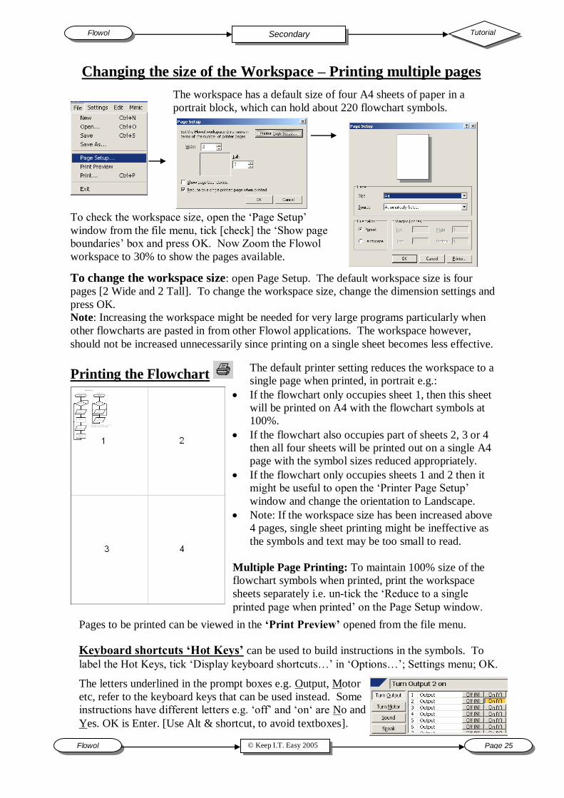
Changing the size of the Workspace – Printing multiple pages
The workspace has a default size of four A4 sheets of paper in a
portrait block, which can hold about 220 flowchart symbols.
To check the workspace size, open the „Page Setup‟
window from the file menu, tick [check] the „Show page
boundaries‟ box and press OK. Now Zoom the Flowol
workspace to 30% to show the pages available.
Printing the Flowchart
The default printer setting reduces the workspace to a
single page when printed, in portrait e.g.:
If the flowchart only occupies sheet 1, then this sheet
will be printed on A4 with the flowchart symbols at
100%.
If the flowchart also occupies part of sheets 2, 3 or 4
then all four sheets will be printed out on a single A4
page with the symbol sizes reduced appropriately.
If the flowchart only occupies sheets 1 and 2 then it
might be useful to open the „Printer Page Setup‟
window and change the orientation to Landscape.
Note: If the workspace size has been increased above
4 pages, single sheet printing might be ineffective as
the symbols and text may be too small to read.
Multiple Page Printing: To maintain 100% size of the
flowchart symbols when printed, print the workspace
sheets separately i.e. un-tick the „Reduce to a single
printed page when printed‟ on the Page Setup window.
To change the workspace size: open Page Setup. The default workspace size is four
pages [2 Wide and 2 Tall]. To change the workspace size, change the dimension settings and
press OK.
Note: Increasing the workspace might be needed for very large programs particularly when
other flowcharts are pasted in from other Flowol applications. The workspace however,
should not be increased unnecessarily since printing on a single sheet becomes less effective.
Pages to be printed can be viewed in the ‘Print Preview’ opened from the file menu.
Keyboard shortcuts ‘Hot Keys’ can be used to build instructions in the symbols. To
label the Hot Keys, tick „Display keyboard shortcuts…‟ in „Options…‟; Settings menu; OK.
The letters underlined in the prompt boxes e.g. Output, Motor
etc, refer to the keyboard keys that can be used instead. Some
instructions have different letters e.g. „off‟ and „on„ are No and
Yes. OK is Enter. [Use Alt & shortcut, to avoid textboxes].
Page 26 © Keep I.T. Easy 2005 Flowol
Flowol Tutorial Secondary
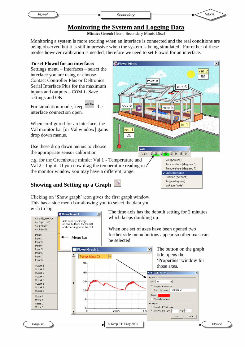
Monitoring the System and Logging Data Mimic: Greenh [from: Secondary Mimic Disc]
Monitoring a system is more exciting when an interface is connected and the real conditions are
being observed but it is still impressive when the system is being simulated. For either of these
modes however calibration is needed, therefore we need to set Flowol for an interface.
To set Flowol for an interface:
Settings menu – Interfaces – select the
interface you are using or choose
Contact Controller Plus or Deltronics
Serial Interface Plus for the maximum
inputs and outputs – COM 1- Save
settings and OK.
For simulation mode, keep the
interface connection open.
When configured for an interface, the
Val monitor bar [or Val window] gains
drop down menus.
Use these drop down menus to choose
the appropriate sensor calibration
e.g. for the Greenhouse mimic: Val 1 - Temperature and
Val 2 - Light. If you now drag the temperature reading in
the monitor window you may have a different range.
Showing and Setting up a Graph
Clicking on „Show graph‟ icon gives the first graph window.
This has a side menu bar allowing you to select the data you
wish to log. The time axis has the default setting for 2 minutes
which keeps doubling up.
When one set of axes have been opened two
further side menu buttons appear so other axes can
be selected.
The button on the graph
title opens the
„Properties‟ window for
those axes.
Menu bar
© Keep I.T. Easy 2005 Flowol Page 27
Tutorial Flowol Secondary
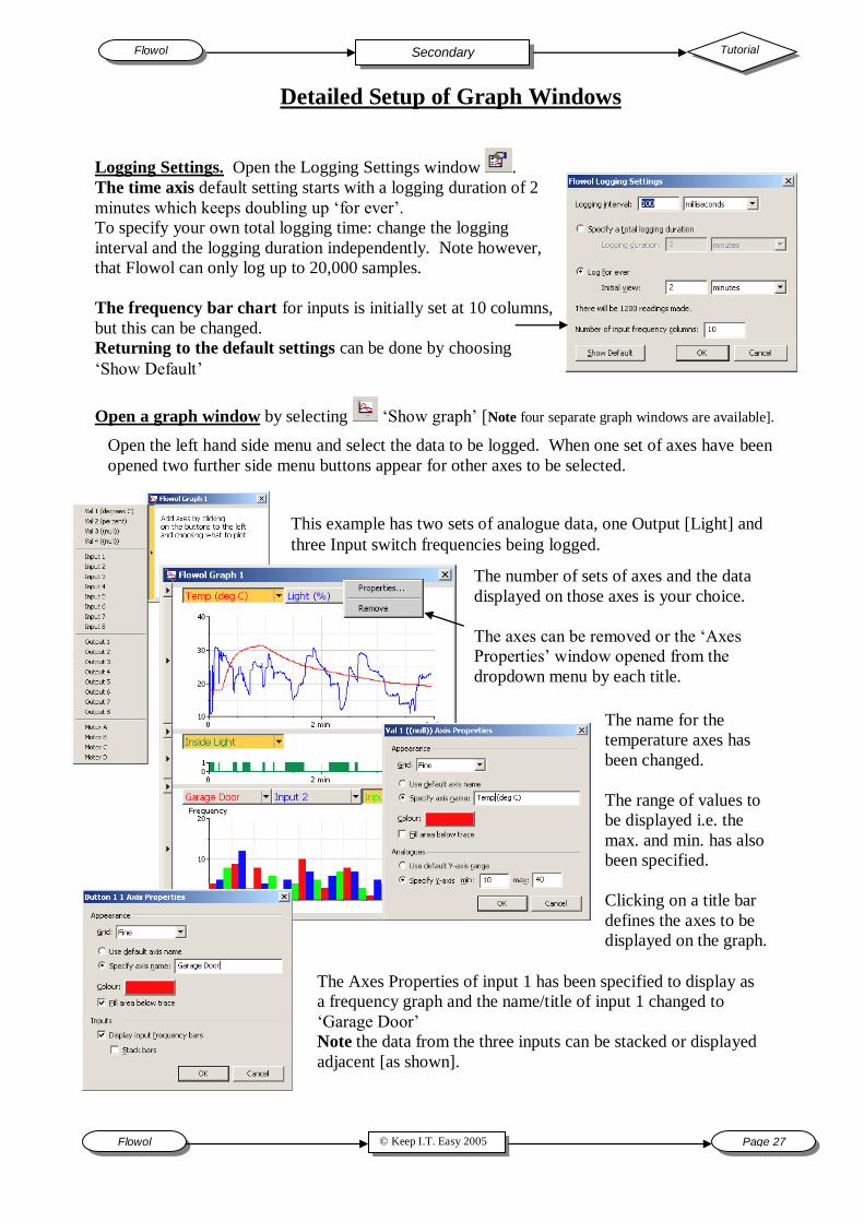
Detailed Setup of Graph Windows
Logging Settings. Open the Logging Settings window .
The time axis default setting starts with a logging duration of 2
minutes which keeps doubling up „for ever‟.
To specify your own total logging time: change the logging
interval and the logging duration independently. Note however,
that Flowol can only log up to 20,000 samples.
The frequency bar chart for inputs is initially set at 10 columns,
but this can be changed.
Returning to the default settings can be done by choosing
„Show Default‟
Open a graph window by selecting „Show graph‟ [Note four separate graph windows are available].
Open the left hand side menu and select the data to be logged. When one set of axes have been
opened two further side menu buttons appear for other axes to be selected.
The number of sets of axes and the data
displayed on those axes is your choice.
The axes can be removed or the „Axes
Properties‟ window opened from the
dropdown menu by each title.
This example has two sets of analogue data, one Output [Light] and
three Input switch frequencies being logged.
The name for the
temperature axes has
been changed.
The range of values to
be displayed i.e. the
max. and min. has also
been specified.
Clicking on a title bar
defines the axes to be
displayed on the graph.
The Axes Properties of input 1 has been specified to display as
a frequency graph and the name/title of input 1 changed to
„Garage Door‟
Note the data from the three inputs can be stacked or displayed
adjacent [as shown].
Page 28 © Keep I.T. Easy 2005 Flowol
Flowol Tutorial Secondary
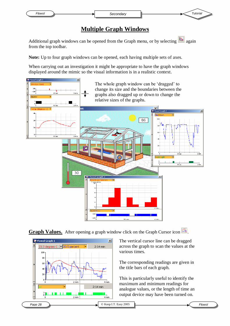
Additional graph windows can be opened from the Graph menu, or by selecting again
from the top toolbar.
Note: Up to four graph windows can be opened, each having multiple sets of axes.
When carrying out an investigation it might be appropriate to have the graph windows
displayed around the mimic so the visual information is in a realistic context.
The whole graph window can be „dragged‟ to
change its size and the boundaries between the
graphs also dragged up or down to change the
relative sizes of the graphs.
Multiple Graph Windows
Graph Values. After opening a graph window click on the Graph Cursor icon .
The vertical cursor line can be dragged
across the graph to scan the values at the
various times.
The corresponding readings are given in
the title bars of each graph.
This is particularly useful to identify the
maximum and minimum readings for
analogue values, or the length of time an
output device may have been turned on.

© Keep I.T. Easy 2005 Flowol Page 29
Tutorial Flowol Secondary
Saving and Opening Graph Data from Flowol and then back into Flowol
uses a Flowol graph data [*.flogdata] file.
Note: It is advisable to always save graph data even if you then wish to
export it.
Transferring Graph Data and the Graph Windows
Choose „Copy Graph‟ from the Graph menu. Select which
graph window you wish to copy.
Open the second application e.g. Word, and paste the graph
window.
To re-position the graph window:
Click on the image; click on the „Text Wrapping‟ icon
from the Picture toolbar and select Square.
Drag the image to the required size and position it.
Exporting Graph Data for other applications can be saved as either *.csv, *.tsv or *.sid files.
CSV - (Comma Separated Values) – This is the best format to import the data into a spreadsheet
or database.
TSV - (Tab Separated Values) – This is useful to import the data into a word processor as a table.
SID - This type of file can be used to export the data to other graphing applications e.g. Insight 2.
Open the „Graph‟ menu.
Note: „Log on Run‟ will normally be ticked so that graphical data is logged by default. Un-ticking this will
mean that no data is logged.
Copy Graph: to copy the graph window into another application.
Choose „Print Graph‟ from the Graph menu and select the graph
window you wish to print.
If the graph window only has a single set of axes, it will
print on the top half of an A4 sheet of paper in portrait.
If the graph window has multiple axes, it will print over the
whole sheet of A4 paper in portrait.
To print graphs in landscape choose Properties… on the
Print dialogue that opens when using the Print graph option. [Note: this will also change the page size and orientation of the flowchart
printing since Flowol only communicates with one instant of the printer
driver].
Note: It is often more flexible to copy and paste the graph
window into „Word‟ [as above] and print the graph from that
application.
Print Graph: to print the graph window directly.
Page 30 © Keep I.T. Easy 2005 Flowol
Flowol Tutorial Secondary
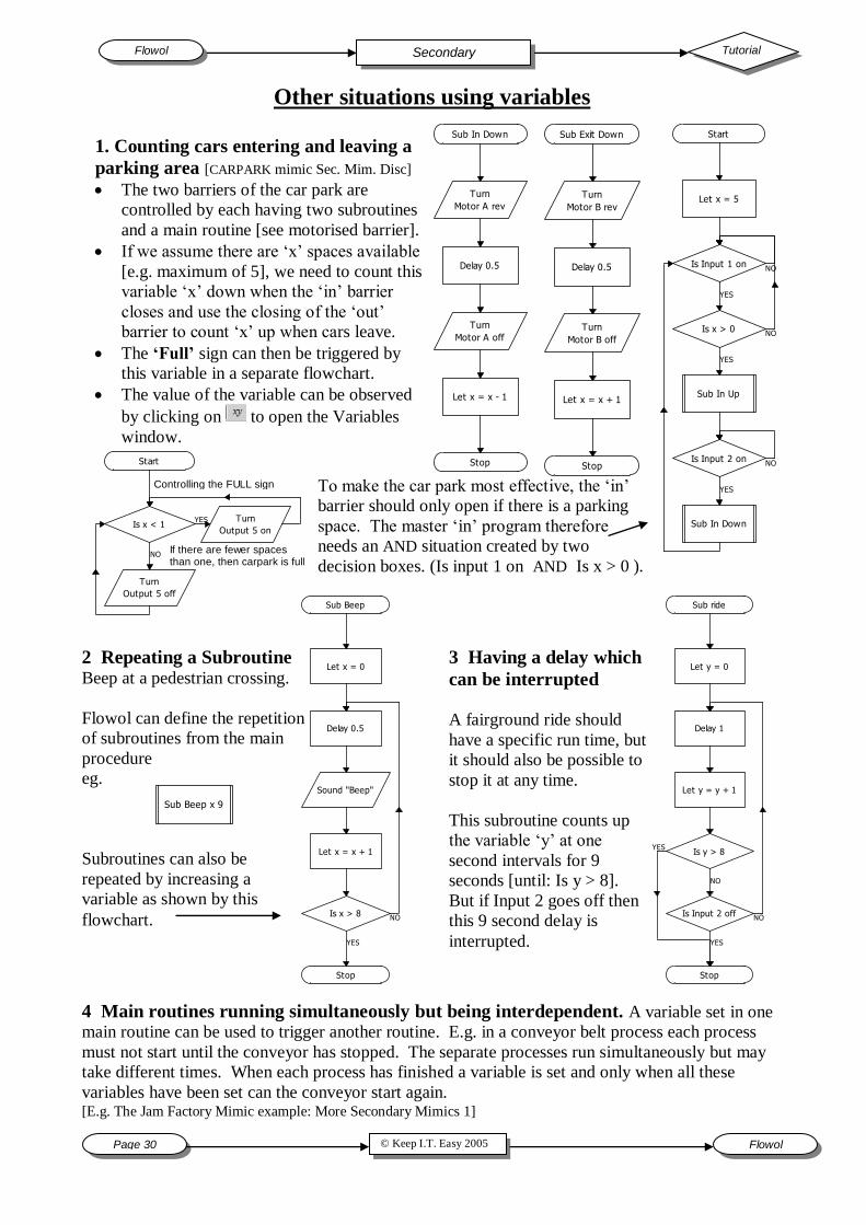
To make the car park most effective, the „in‟
barrier should only open if there is a parking
space. The master „in‟ program therefore
needs an AND situation created by two
decision boxes. (Is input 1 on AND Is x > 0 ).
Other situations using variables
2 Repeating a Subroutine Beep at a pedestrian crossing.
Flowol can define the repetition
of subroutines from the main
procedure
eg.
Subroutines can also be
repeated by increasing a
variable as shown by this
flowchart.
Sub Beep
Let x = 0
Sound "Beep"
Delay 0.5
Is x > 8
Stop
Let x = x + 1
YES
NO
Sub Beep x 9
4 Main routines running simultaneously but being interdependent. A variable set in one
main routine can be used to trigger another routine. E.g. in a conveyor belt process each process
must not start until the conveyor has stopped. The separate processes run simultaneously but may
take different times. When each process has finished a variable is set and only when all these
variables have been set can the conveyor start again. [E.g. The Jam Factory Mimic example: More Secondary Mimics 1]
Sub In Down
Turn
Motor A rev
Delay 0.5
Turn
Motor A off
Stop
Let x = x - 1
Sub Exit Down
Turn
Motor B rev
Delay 0.5
Turn
Motor B off
Stop
Let x = x + 1
Start
Is Input 1 on
Sub In Up
Is Input 2 on
Sub In Down
Let x = 5
Is x > 0
YES
NO
YES
NO
YES
NO
Start
Is x < 1Turn
Output 5 on
Turn
Output 5 off
YES
NOIf there are fewer spacesthan one, then carpark is full
Controlling the FULL sign
Sub ride
Let y = 0
Delay 1
Let y = y + 1
Is Input 2 off
Stop
Is y > 8
YES
NO
YES
NO
3 Having a delay which
can be interrupted
A fairground ride should
have a specific run time, but
it should also be possible to
stop it at any time.
This subroutine counts up
the variable „y‟ at one
second intervals for 9
seconds [until: Is y > 8].
But if Input 2 goes off then
this 9 second delay is
interrupted.
1. Counting cars entering and leaving a
parking area [CARPARK mimic Sec. Mim. Disc]
The two barriers of the car park are
controlled by each having two subroutines
and a main routine [see motorised barrier].
If we assume there are „x‟ spaces available
[e.g. maximum of 5], we need to count this
variable „x‟ down when the „in‟ barrier
closes and use the closing of the „out‟
barrier to count „x‟ up when cars leave.
The ‘Full’ sign can then be triggered by
this variable in a separate flowchart.
The value of the variable can be observed
by clicking on to open the Variables
window.
© Keep I.T. Easy 2005 Flowol Page 31
Tutorial Flowol Secondary
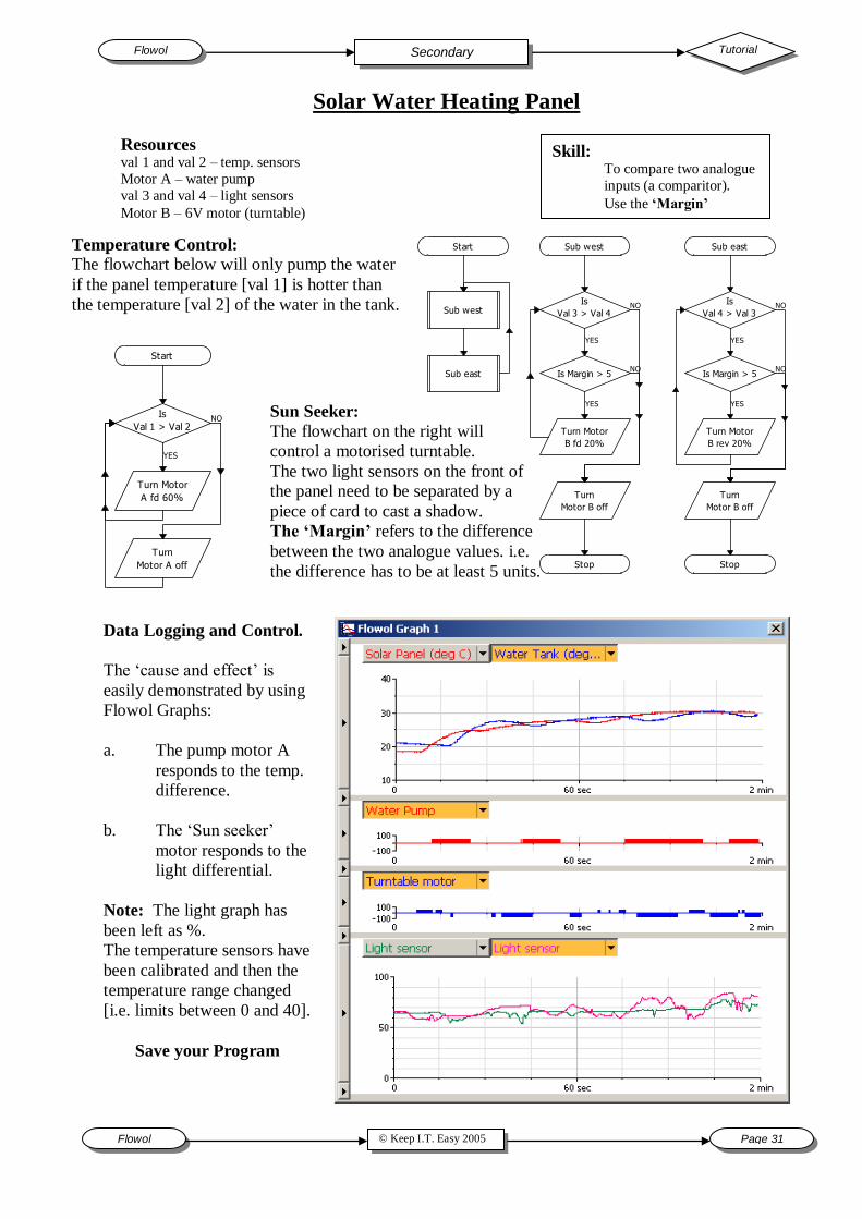
Solar Water Heating Panel
Skill: To compare two analogue
inputs (a comparitor).
Use the ‘Margin’
Resources val 1 and val 2 – temp. sensors
Motor A – water pump
val 3 and val 4 – light sensors
Motor B – 6V motor (turntable)
Temperature Control:
The flowchart below will only pump the water
if the panel temperature [val 1] is hotter than
the temperature [val 2] of the water in the tank.
Sun Seeker:
The flowchart on the right will
control a motorised turntable.
The two light sensors on the front of
the panel need to be separated by a
piece of card to cast a shadow.
The ‘Margin’ refers to the difference
between the two analogue values. i.e.
the difference has to be at least 5 units.
Data Logging and Control.
The „cause and effect‟ is
easily demonstrated by using
Flowol Graphs:
a. The pump motor A
responds to the temp.
difference.
b. The „Sun seeker‟
motor responds to the
light differential.
Note: The light graph has
been left as %.
The temperature sensors have
been calibrated and then the
temperature range changed
[i.e. limits between 0 and 40].
Save your Program
Sub west
Is
Val 3 > Val 4
Is Margin > 5
Turn Motor
B fd 20%
Turn
Motor B off
Stop
Sub east
Is
Val 4 > Val 3
Is Margin > 5
Turn Motor
B rev 20%
Turn
Motor B off
Stop
Sub west
Sub east
Start
YES
NO
YES
NO
YES
NO
YES
NO
Is
Val 1 > Val 2
Turn Motor
A fd 60%
Turn
Motor A off
Start
YES
NO
Page 32 © Keep I.T. Easy 2005 Flowol
Flowol Tutorial Secondary
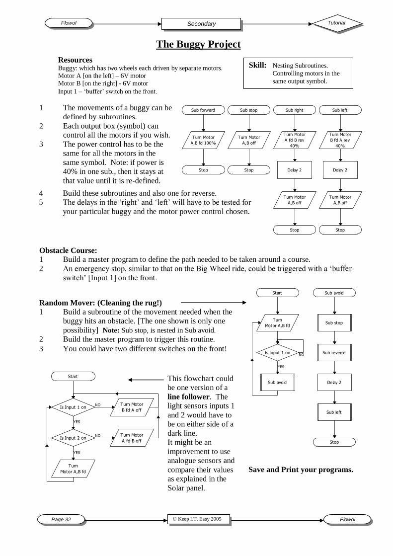
Skill: Nesting Subroutines. Controlling motors in the
same output symbol.
Resources Buggy: which has two wheels each driven by separate motors.
Motor A [on the left] – 6V motor
Motor B [on the right] - 6V motor
Input 1 – „buffer‟ switch on the front.
1 The movements of a buggy can be
defined by subroutines.
2 Each output box (symbol) can
control all the motors if you wish.
3 The power control has to be the
same for all the motors in the
same symbol. Note: if power is
40% in one sub., then it stays at
that value until it is re-defined.
4 Build these subroutines and also one for reverse.
5 The delays in the „right‟ and „left‟ will have to be tested for
your particular buggy and the motor power control chosen.
Obstacle Course: 1 Build a master program to define the path needed to be taken around a course.
2 An emergency stop, similar to that on the Big Wheel ride, could be triggered with a „buffer
switch‟ [Input 1] on the front.
Random Mover: (Cleaning the rug!)
1 Build a subroutine of the movement needed when the
buggy hits an obstacle. [The one shown is only one
possibility] Note: Sub stop, is nested in Sub avoid.
2 Build the master program to trigger this routine.
3 You could have two different switches on the front!
This flowchart could
be one version of a
line follower. The
light sensors inputs 1
and 2 would have to
be on either side of a
dark line.
It might be an
improvement to use
analogue sensors and
compare their values
as explained in the
Solar panel.
Save and Print your programs.
Sub forward
Turn Motor
A,B fd 100%
Stop
Sub stop
Turn Motor
A,B off
Stop
Sub right
Delay 2
Turn Motor
A,B off
Stop
Sub left
Turn Motor
B fd A rev
40%
Delay 2
Turn Motor
A,B off
Stop
Turn Motor
A fd B rev
40%
The Buggy Project
Start
Is Input 1 on
Is Input 2 on
Turn
Motor A,B fd
Turn Motor
B fd A off
Turn Motor
A fd B off
YES
NO
YES
NO
Sub avoid
Sub stop
Sub reverse
Delay 2
Sub left
Stop
Is Input 1 on
Sub avoid
Turn
Motor A,B fd
Start
YES
NO
© Keep I.T. Easy 2005 Flowol Page 33
Tutorial Flowol Network Administrator
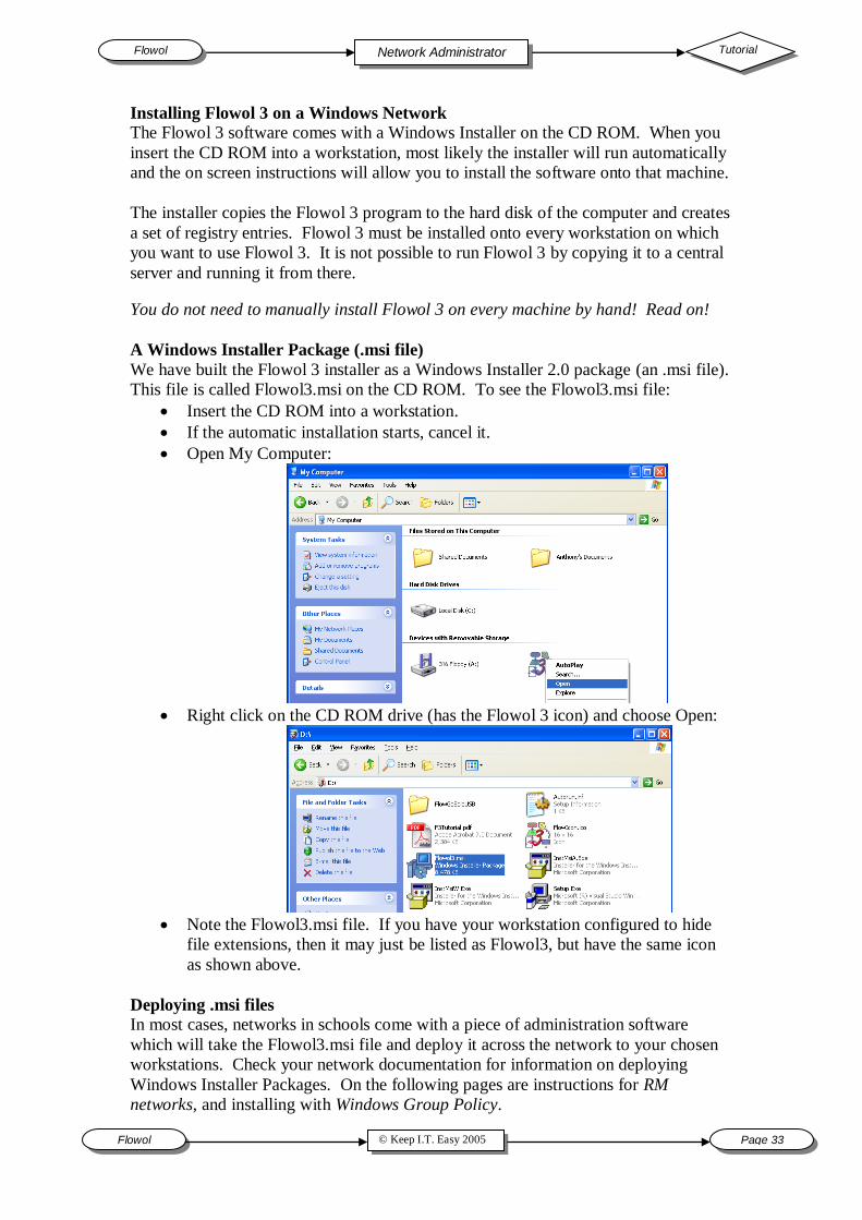
Installing Flowol 3 on a Windows Network
The Flowol 3 software comes with a Windows Installer on the CD ROM. When you
insert the CD ROM into a workstation, most likely the installer will run automatically
and the on screen instructions will allow you to install the software onto that machine.
The installer copies the Flowol 3 program to the hard disk of the computer and creates
a set of registry entries. Flowol 3 must be installed onto every workstation on which
you want to use Flowol 3. It is not possible to run Flowol 3 by copying it to a central
server and running it from there.
You do not need to manually install Flowol 3 on every machine by hand! Read on!
A Windows Installer Package (.msi file)
We have built the Flowol 3 installer as a Windows Installer 2.0 package (an .msi file).
This file is called Flowol3.msi on the CD ROM. To see the Flowol3.msi file:
Insert the CD ROM into a workstation.
If the automatic installation starts, cancel it.
Open My Computer:
Right click on the CD ROM drive (has the Flowol 3 icon) and choose Open:
Note the Flowol3.msi file. If you have your workstation configured to hide
file extensions, then it may just be listed as Flowol3, but have the same icon
as shown above.
Deploying .msi files
In most cases, networks in schools come with a piece of administration software
which will take the Flowol3.msi file and deploy it across the network to your chosen
workstations. Check your network documentation for information on deploying
Windows Installer Packages. On the following pages are instructions for RM
networks, and installing with Windows Group Policy.
Page 34 © Keep I.T. Easy 2005 Flowol
Flowol Tutorial Secondary
Installing Flowol3 onto the RM Community Connect 3 network system
Only the site licence version of Flowol 3 should be installed onto a network.
For updates and corrections to the information given here, look on the web at
http://www.flowol.com/Flowol3/RMConnect3.aspx
[You can follow along in the Community Connect 3 Reference Manual, Chapter 7,
section entitled ‘Deploying a Non-Curriculum Choice Windows Installer Package’,
page 101]
[Creating the folder structure on the server]
1. At a workstation, log on as a system administrator.
2. Browse to Q:\Applications. In the Applications folder, create a new folder and
name it Flowol3.
3. In the newly-created Flowol3 folder, create another folder called Shortcuts. In
the newly-created Shortcuts folder, create another folder also called Flowol3.
Thus you have created the folder structure
Q:\Applications\Flowol3\Shortcuts\Flowol3.
[Copying the Windows Installer package to the server, page 102]
4. Copy all of the files from the Flowol3 program CD Rom into the first Flowol3
folder you created, i.e. into Q:\Applications\Flowol3.
5. In the RM Management Console, select the Workstations option, right-click
Main Site and then choose Update Package List.
6. Right-click on Workstation and choose Properties.
7. Select the Packages tab at the top of the dialog box.
8. In the list of Available Packages, choose Flowol3.
9. Click Allocate and then click on OK.
10. Restart the workstation to install Flowol3 onto it.
[Copying shortcuts to the server]
11. Log on again to the same workstation as system administrator.
12. Locate the Flowol 3 shortcut by browsing to C:\Documents and Settings\All
Users\Start Menu\Programs\Flowol 3.
13. Copy the Flowol 3 shortcut to the folder you created at
Q:\Applications\Flowol3\Shortcuts\Flowol3
14. In the RM Management Console, Resources, Program Sets option double-click
on Data Logging & Control.
15. Select the Shortcuts tab at the top of the dialog box.
16. In the Source list, choose Flowol3.
17. In the Available Shortcuts list, choose Flowol 3.
18. Click „>‟ button and then click on OK.
You can now deploy the Flowol3 package to different workstations on your network.
If you are going to use the FlowGo or SOLO interface via the USB port, when you
plug the FlowGo/SOLO into the USB port on the workstation, follow these steps:
1. When asked for the Administrator password, make sure you provide the
correct domain. E.g. RMTRAINING\SystemAdmin
2. Wait for the Found New Hardware dialog
3. Choose the default option, Install Software Automatically.
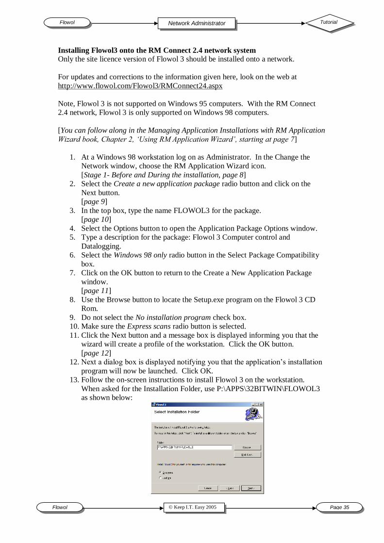
© Keep I.T. Easy 2005 Flowol Page 35
Tutorial Flowol Network Administrator
Installing Flowol3 onto the RM Connect 2.4 network system
Only the site licence version of Flowol 3 should be installed onto a network.
For updates and corrections to the information given here, look on the web at
http://www.flowol.com/Flowol3/RMConnect24.aspx
Note, Flowol 3 is not supported on Windows 95 computers. With the RM Connect
2.4 network, Flowol 3 is only supported on Windows 98 computers.
[You can follow along in the Managing Application Installations with RM Application
Wizard book, Chapter 2, ‘Using RM Application Wizard’, starting at page 7]
1. At a Windows 98 workstation log on as Administrator. In the Change the
Network window, choose the RM Application Wizard icon.
[Stage 1- Before and During the installation, page 8]
2. Select the Create a new application package radio button and click on the
Next button.
[page 9]
3. In the top box, type the name FLOWOL3 for the package.
[page 10]
4. Select the Options button to open the Application Package Options window.
5. Type a description for the package: Flowol 3 Computer control and
Datalogging.
6. Select the Windows 98 only radio button in the Select Package Compatibility
box.
7. Click on the OK button to return to the Create a New Application Package
window.
[page 11]
8. Use the Browse button to locate the Setup.exe program on the Flowol 3 CD
Rom.
9. Do not select the No installation program check box.
10. Make sure the Express scans radio button is selected.
11. Click the Next button and a message box is displayed informing you that the
wizard will create a profile of the workstation. Click the OK button.
[page 12]
12. Next a dialog box is displayed notifying you that the application‟s installation
program will now be launched. Click OK.
13. Follow the on-screen instructions to install Flowol 3 on the workstation.
When asked for the Installation Folder, use P:\APPS\32BITWIN\FLOWOL3
as shown below:

Page 36 © Keep I.T. Easy 2005 Flowol
Flowol Tutorial Network Administrator
14. When the Flowol 3 setup has finished, it will prompt you to Restart the
computer. Click Yes.
15. Once the computer has restarted, log on as Administrator.
[page 15]
16. Now we need to create a shortcut for Flowol3. Navigate using My Computer
to P:\APPS\32BITWIN\FLOWOL3
17. Right-click on Flowol3.exe, choose Send To -> Desktop As Shortcut.
18. Close the My Computer window.
19. Note the new shortcut on the Windows Desktop. Right-click it and choose
Properties.
20. Set the Start in to N:\MyWork
21. OK the Properties window.
22. Double-click the shortcut to load Flowol 3.
23. Optionally, if you want to set a default interface, open the Flowol 3 Interface
dialog and choose the interface you want all computers to use.
24. Close Flowol 3 by choosing Exit from the File menu.
[Stage 2-After the Installation, page 17]
25. Start the RM Application Wizard.
26. Choose the Continue building FLOWOL3 radio button.
27. Click the Next button.
28. Follow the on-screen instructions to continue. The Wizard carries out the
post-installation system scan, compares this with the pre-installation scan, and
builds the application package.
[page 18]
29. When the wizard has completed, click the Allocate button to allocate Flowol 3
to the different workstations. [page 22 onwards]
If you are going to use the FlowGo or SOLO interface via the USB port, then the
easiest way to install the USB drivers is individually at each workstation:
1. Log on to each workstation as Administrator.
2. Turn File Protector off.
3. Connect the FlowGo or SOLO to the USB port.
4. When asked for a driver, direct Windows to the FlowGoSoloUSB folder on
the Flowol CD Rom. E.g. D:\FlowGoSoloUSB if D:\ is the letter for the CD
Rom drive.
5. Follow the on-screen instructions.
6. Turn File Protector back on.
If you have many workstations and wish to build the FlowGo/Solo USB driver into
the application package, then install the drivers as described in the 6 steps above
during the package creation, after step 21. It is recommended that you build the
package containing the USB driver on a very clean machine.

© Keep I.T. Easy 2005 Flowol Page 37
Tutorial Flowol Network Administrator
Windows 2000 or 2003 Server Network via Active Directory/Group Policy
Microsoft provides automatic deployment via Group Policy. For information on
Group Policy see http://www.microsoft.com/windowsserver2003/gpmc/default.mspx
To install Flowol 3:
1. Logon to the Windows 2000, or 2003 server machine as an Administrator.
2. Create a network share on the server and copy the Flowol3.msi from the CD.
Then (without the Group Policy Management Console):
3. Click Start, Programs, Administrative Tools, Active Directory Users
and Computers.
4. Right-click the organizational unit to which you want to apply the
package, and then click Properties.
5. Click the Group Policy tab.
6. If you have an existing group policy, skip to step 7. If you need to create a
group policy, click New, type a descriptive name for the group policy, and
then press ENTER.
7. Click the group policy, and then click Edit.
Or (with the Group Policy Management Console):
3. Click Start, Programs, Administrative Tools, Group Policy
Management.
4. Expand the Forest and Domains tree nodes to show the domain node of
your domain.
5. Click on the domain.
6. If you have an existing group policy, skip to step 7. If you need to create a
group policy, right click the domain and choose Create and Link a GPO
Here…, type a descriptive name for the group policy object, and then
press ENTER.
7. In the right hand pane, right click the group policy object and choose Edit.
And finally:
8. To deploy with a computer-based policy, double-click the Computer
Configuration branch to expand it, double-click Software Settings, right-
click Software installation, point to New, and then click Package…
9. Browse to the network share that contains the Flowol3.msi package, choose
the Flowol3.msi package, and then click Open.
10. When asked which deployment method to use, choose Assigned and then OK.
Installation using the msiexec.exe command line [Advanced users only]
If you‟re familiar with logon scripts and batch files, you can call the Flowol 3 installer
from the command line using msiexec.exe. Command line arguments for msiexec.exe
can be found at http://msdn.microsoft.com/library/default.asp?url=/library/en-
us/msi/setup/command_line_options.asp
To run the setup with the user interface call Msiexec.exe /i D:\flowol3.msi
To run the setup silently, call Msiexec.exe /i D:\flowol3.msi /qn
(Note this will result in the restart happening automatically)
Page 38 © Keep I.T. Easy 2005 Flowol
Flowol Tutorial Primary/Secondary
Flowol 3 Index and Glossary
Calibrating: The program needs information about the type of sensors being used on
the analogue inputs so that appropriate readings can be displayed. If Flowol has been
set/configured for an interface, click on the down menus on the „Val‟ monitor bar and
choose the appropriate sensor [p.26].
Colours: The colours of the flowchart symbols and lines can be changed to suit the
user. To do this, select the Settings menu - Options… - Colours (Note: strong colours
may be useful for demonstrations but strong flashing colours can be hazardous) [p.13]
Com: The value of the Com needs to be selected when using the Serial port, so that
the computer can communicate with the interface [p.5].
Configure: Flowol is normally set/configured assuming it is not connected to an
interface. When you wish to use an interface you need to re-configure Flowol [p.4].
Copy Flowchart: Highlight the appropriate section of flowchart and click on the
copy icon on the top toolbar. To paste the flowchart back into the same application or
another Flowol application, click on the paste icon, move the ghost image to the new
position on the workspace and place. To paste into a word processor, position the
cursor and select the paste icon [p.17].
Copy Graph: Choose „Copy Graph‟ from the Graph menu. Paste.. etc [p.29].
Data Logging: Information from sensors can be displayed on graphs, saved and re-
opened or exported to other applications [p.26 – 29].
Decision symbol refers to information, and decides if „Yes do this‟ or „No do that‟.
The information might be a switch turning on or off, or the light or temperature levels
changing, or a variable reaching a specified value i.e. „Is Input 2 on‟ or „Is Val 1 > 25‟
[p.14].
Digital inputs can only be off or on e.g. switches, pressure pads etc [p.14].
Edit (hand) tool is needed to highlight a symbol, line, label or section of flowchart so
it can then be erased, changed or moved. (Note: Using the right mouse button is a
shortcut to the edit tool) [p.10].
Erase tool, allows a highlighted symbol, line or section of flowchart to be removed
[p.10].
Exporting: Graph data can be exported as SID, CSV or TSV files for other
applications [p.29].
Feedback occurs when some change in the controlled system is detected by the
inputs, which then alters the behaviour of the system. E.g. when a moving barrier hits
a switch which then stops the movement [p.23] or a temperature sensor controlling a
heater, turns the heater off when it gets too hot [p.24].
Flogdata file is the Flowol graph data file for graphs which can be re-opened back
into Flowol [p.29].
Flowchart is the group of instruction symbols connected in the right order to create
the Flowol program [p.9].
Graphs: Digital and analogue data from inputs can be logged and displayed as bar
charts [p.27] or line graphs [p.26-28] respectively. The response of the outputs and
motors can also be displayed on the graphs. The information can be exported as SID,
CSV or TSV files [p.29] for other applications or a flogdata file to re-open back into
Flowol. The graph window can be opened by selecting the „Show graph‟ icon [p.26].
Graph values: A vertical cursor can be scanned across the graphs to display the
values at particular times [p.28].
Grid (from Properties.. on graphs window) allows the number of grid lines to be
changed on the graph [p.26].
© Keep I.T. Easy 2005 Flowol Page 39
Tutorial Flowol Primary/Secondary
Hot Keys: Some letters in the prompt boxes are underlined e.g. Output, Motor etc,
which refer to the keyboard shortcuts which can be used instead of using the
prompt box. Some instructions have different letters e.g. „on‟ and „off „are Yes and
No. OK is Enter or Return. [p. 25].
Inserting symbols: Another symbol can be inserted automatically in a vertical
flowchart. Place the new symbol on the flowchart line in the correct place [p.10].
Installation is needed to get the Flowol program from the CD on to your computer
[p.3] or [p.33].
Interface: These are the control boxes which transfer the instructions from the
Flowol program on the computer to the real devices being controlled. Several
different Serial and USB interfaces can be used. The interface window can be opened
by choosing the Setting menu and Interfaces… [p.5].
Labels: Select the Text Tool „T‟, position and click the „window‟ on the flowchart.
Write the label in the text window. Use the font toolbar to vary the style [p.10].
LDR is a Light Dependent Resistor and is the usual type of light sensor [p.14].
Lines are used to link the symbols together to create the flowchart. Select the line
from the toolbar. Click on the symbol you want it to start from, and then click on the
symbol you want it to go to [p.9]. When a decision symbol is being connected, then
both a YES or NO decision has to be made [p.14].
Log on run (in Graph menu) will normally be ticked so that graphical data is logged
by default. Un-ticking this will mean that no data is logged [p.29].
Margin refers to the difference in reading between two analogue sensors e.g. „Is Val3
> Val4‟ and „Is margin > 5‟ [p.31].
Mimics: These are controllable pictures which allow the control solution to be tested
in simulation mode. Parts of the mimic will animate to show the response of the
outputs and sensitive areas can be clicked on, to simulate the inputs. Use the „Open a
mimic‟ icon on the top toolbar to select the mimic and the „Show mimic labels‟ icon
to display the labels [p.9].
Monitor bars show (monitor) the state of the inputs and outputs. These are normally
displayed at the bottom of the workspace [p.11].
Motors: These outputs control motors which can go forward and in reverse. Power
control of the motor is also possible [p.18].
Move individual symbols, labels or a group by selecting the Edit tool (hand). Click
on the symbol in the flowchart to be moved, it will highlight. Use the left mouse
button to drag the symbol and then release. To highlight a group of symbols, drag a
box around the group. (Click left mouse button at one corner of the group, drag a box
across them and release). Select any one of the highlighted symbols to drag the
group [p.13].
New: Icon on the top toolbar will clear the workspace ready for a new flowchart.
Open: Icon on the top toolbar will open a .flo file folder.
Open Graph data (from Graph menu) will allow data, in the form of a flogdata file,
to be loaded back into the Flowol graph window [p.29].
Output symbol is used to turn an output [p.9] or motor [p.18] on or off, or call up a
previously recorded sound [p.16]. Note: if needed, all the outputs can be turned on or
off in one symbol and all the motors can be turned on or off in the one symbol.
Paste allows copied sections of flowchart to be pasted back into Flowol or a word
processor [p.17].
Print Graph (from Graph menu) allows the whole graph to be printed [p.29].
Print Icon allows the whole flowchart to be printed directly [p.11].
Print Preview (from File menu) allows the flowchart pages to be observed [p.25].
Page 40 © Keep I.T. Easy 2005 Flowol
Flowol Tutorial Primary/Secondary
Printer Setup (File menu) can change the workspace dimensions, alter portrait to
landscape and allow you to select single sheet printing [p.25].
Process symbol is most frequently used for a delay [p.9] but is also needed to call up
the subroutines [p.15] or set up variables [p.21] e.g. „Delay 5‟ or „Sub flash x 5‟ or
„Let y = x + 1‟ respectively.
Prompt boxes: When a flowchart symbol is placed on the workspace an appropriate
„prompt box‟ appears at the bottom of the screen. The instructions for that symbol are
achieved by clicking on the options made available in the prompt box [p.9].
Recursive: This is when a section of flowchart keeps repeating a process e.g. a
flashing light [p.10].
Redo allows you to step forward again in the flowchart construction if you have used
Undo [p.12].
Remote: If a remote interface is being used e.g. FlowGo, Solo etc then the „Remote‟
button transfers the program to that device.
Repeating Subroutines: When calling up a subroutine from the main program, the
number of repeats can be defined directly [p.15] or controlled with variables [p.30].
Run What? allows a subroutine or selected flowcharts to run on their own [p.15].
Save: Use the Save (disc) icon to save the flowchart with its current filename.
Save As… (in File menu) will allow the flowchart to be saved as a .flo file with a new
filename. [p.9]
Save Graph data: (in the Graph menu) allows the information to be saved as flogdata
file [p.29].
Sensors: Digital inputs are either off or on, and can be produced by switches, pressure
pads etc. Analogue sensors produce a range of input values, e.g. light intensity,
temperature, noise level etc. If the program has been configured for an interface, the
drop down menus on the val monitor bar allows you to calibrate the sensors [p. 26].
Scale View: To change the size of the flowchart, change the „Zoom‟ value on the top
icon bar [p.12].
Serial: The Serial port allows the computer to be connected to some interfaces [p.5].
Show graph: Use the icon on the top toolbar to open the graph window [p.26-28].
Simulate: [when the connection plug is open on the left hand toolbar] The mimics
can then be „clicked on‟ to simulate the effect of the inputs being changed. Click on
the actual item (switch, Sun etc) on the mimic, not on the label [p.14]. To simulate
the change in analogue value from a light or temperature sensor: click on the
displayed number on the mimic with the left mouse button to increase the reading in
steps of 5, and right mouse button to decrease it [p.19]. The analogue input can also
be changed by dragging or clicking on the val reading in the val monitor bar at the
bottom of the workspace [p.24]. To operate an interface which is connected, click on
the connecting icon, to close it.
Sound: Pre-recorded sound files or those recorded on the Windows „Sound
Recorder‟ (opened with the Sound Recorder icon on top toolbar) can be called up like
an output in the flowchart [p.16].
Speech can be called up like an output. Type the speech in the window [p.20].
Speed of Program: Reducing the speed of the flowchart is sometimes useful when
demonstrating or checking for errors. Select the „Speed‟ from „Toolbars‟ in the View
menu and adjust the slider [p.12].
Start symbol is needed at the beginning of a flowchart program. Many separate
flowcharts can be created (each with their own „Start‟ symbol). This number of Starts
available may be less when configured for some interfaces e.g. FlowGo & Solo [p.9].
© Keep I.T. Easy 2005 Flowol Page 41
Tutorial Flowol Primary/Secondary
Stepping through the program: Select the „Speed‟ bar, from „Toolbars‟ in the View
menu. Pause the flowchart by clicking on the icon on the Speed toolbar, then step
from one symbol to the next using the Spacebar or step icon [p.12].
Stop symbol is needed at the end of a subroutine, and at the end of a program that is
not recursive (repeating) [p.9].
Stop all (in the Start/Stop prompt box) allows all the routines to be turned off from
within the control procedure [p.22].
Subroutine is a piece of program (a flowchart) which can be called up by a main
routine. Note: Subroutines must be defined before the main program [p.15].
Symbols represent the different types of commands which can be used to build up the
flowchart program [p.8]. To use a symbol, click on the symbol to select it; click again
on the workspace to position it [p.9].
Testing the mimic: Click on the input or output number or motor letter in the monitor
bars [p.18]. For motor, use left mouse button for forward and right button for reverse
[p.18]. With some mimics you can click on the actual item (not the label) on the
mimic [p.12]. To test the change in an analogue reading from a sensor: click on the
displayed value on the mimic with the left mouse button to increase in steps of 5, and
right mouse button to decrease the value [p.19].
Testing the interface: Configure the program for an interface („Interface..‟ in the
Settings menu) [p.5]. Check that the connecting plug icon on the left hand toolbar is
closed. Click on the outputs on the monitor bars or mimic to change the state of the
outputs. The output on the interface should also change. Change the inputs on the
interface and the input monitor bars should also respond.
Text ‘T’ symbol allows headings or comments to be added to the flowchart [p.10].
Time interval and logging options of graph axes can be changed by selecting the
„Logging Options‟ icon on the top toolbar. The time axis has a default setting of 2
minutes which keeps doubling up indefinitely. This setting can be changed [p.27].
Toolbars on the left-hand side and top of the workspace allow you to select the
symbols/tools or icons to help you build and process the program [p.8].
Tooltips are provided next to the flowchart symbols, so you can read them more
easily when Zoom<80% [p.12].
Tutorial: As you progress through the tutorial, examples of control are introduced
progressively. The features of Flowol are introduced and explained at each stage to
achieve the control solutions [p.6].
Undo allows you to go back to an earlier stage of your flowchart construction [p.12]
USB: The USB (Universal Serial Bus) can be used to connect the computer to some
types of interfaces [p.5].
Vals are the values of the reading from analogue sensors [p.19 & p.24-27].
Variables are letters that can be assigned a value (Let n = 10). These variables can
then be mathematically manipulated. These are useful when counting, repeating
subroutines and linking separate flowcharts. The variable window can be opened by
choosing the „xy‟ icon on the toolbar [p.21-22 & p.30].
Workspace is the area on the screen where the flowchart can be built up [p.7].
Zoom: When the flowchart becomes too large to be seen in one frame, use the zoom
(Scale view) to observe more symbols on the monitor screen [p.12].
Page 42 © Keep I.T. Easy 2005 Flowol
Flowol Tutorial Primary/Secondary
Notes:
Related Documents