FLOWMASTER 250DL PORTABLE FLOW & PRESSURE TEST INSTRUMENT WITH DATA LOGGER Easy and simple to use everywhere www.tsi.ie Unit 1, Portlaoise Enterprise Centre, Clonminam Industrial Estate, Portlaoise, Co. Laois, Ireland t: +353 (0)87 235 2107 | f: +353 (0)57 866 3852 | e: [email protected] THE FLOWMASTER 250DL MEASURES THE FLOW RATE AND THE PRESSURE AT EVERY WATER DRAWING OFF POINT AND PRODUCES VERIFIABLE REPORTS OPERATION MANUAL AND MAINTENANCE MANUAL MODEL Flowmaster 250DL

Welcome message from author
This document is posted to help you gain knowledge. Please leave a comment to let me know what you think about it! Share it to your friends and learn new things together.
Transcript
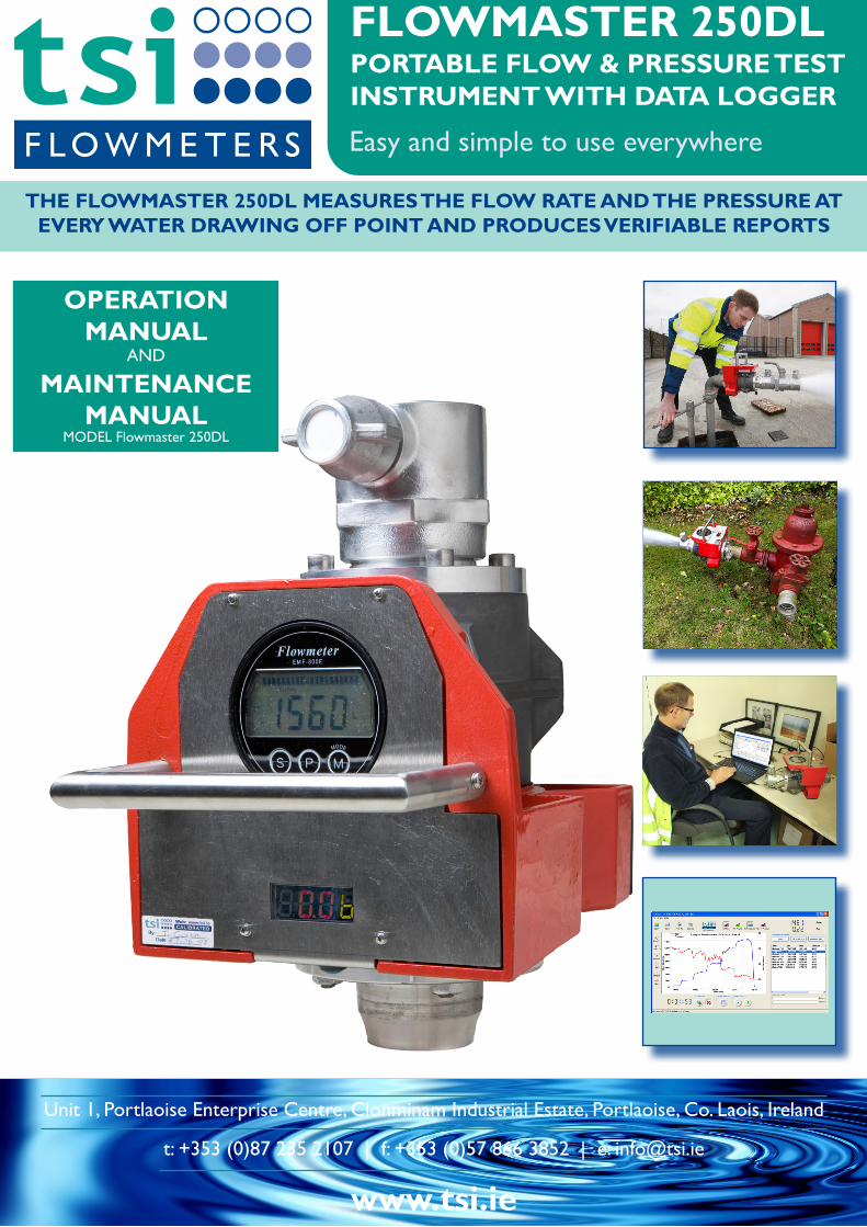
FLOWMASTER 250DLPORTABLE FLOW & PRESSURE TEST INSTRUMENT WITH DATA LOGGER
Easy and simple to use everywhere
www.tsi.ie
Unit 1, Portlaoise Enterprise Centre, Clonminam Industrial Estate, Portlaoise, Co. Laois, Ireland
t: +353 (0)87 235 2107 | f: +353 (0)57 866 3852 | e: [email protected]
THE FLOWMASTER 250DL MEASURES THE FLOW RATE AND THE PRESSURE AT EvERy WATER DRAWING OFF POINT AND PRODUCES vERIFIABLE REPORTS
OPERATION MANUAL
AND
MAINTENANCE MANUAL
MODEL Flowmaster 250DL
www.tsi.ie
Unit 1, Portlaoise Enterprise Centre, Clonminam Industrial Estate, Portlaoise, Co. Laois, Ireland
t: +353 (0)87 235 2107 | f: +353 (0)57 866 3852 | e: [email protected]
Version 2.0February 2012
OPERATION MANUAL AND
MAINTENANCE MANUAL MODEL Flowmaster 250DL
Digital Pressure and integrated Data Logger
CONTENTS
Version 2.0 (February 2012) TSI Flowmeters Ltd.3
1 GETTING TO KNOW yOUR FLOWMASTER
1.2 FOUR SIMPLE STEPS TO FAST FLOW ANALYSIS
1.1 INTRODUCTION
2 SPECIFICATION
2.2 FLOWMETER
2.1 GENERAL
2.4 DATA LOGGER
2.3 PRESSURE TRANSDUCER AND DISPLAY
3 FLOWMASTER OPERATION
3.2 TOTALISER FUNCTION
3.1 FLOWMETER POWER ON SEQUENCE
4 USING yOUR FLOWMASTER
4.2 FLOW & RESIDUAL PRESSURE MEASUREMENT
4.1 PRECAUTIONS
5 MAINTENANCE & TROUBLE-SHOOTING
5.2 FLOWMASTER MAINTENANCE
5.1 BATTERY MAINTENANCE
5.3 TROUBLE-SHOOTING
6 GENERAL INSTRUCTION: CM RANGE 3 STAGE BATTERy CHARGERS
6.2 FEATURES
6.1 OVERVIEW
6.3 OPERATION
7 ACCESSORIES
7.2 TRANSPORT & STORAGE CASE
7.1 BALL VALVE WITH BS INST. M/F FITTINGS
7.4 REPLACEMENT BATTERY / MAINS CHARGER
7.3 ADAPTORS
8 LIMITED WARRANTy
4.3 STATIC PRESSURE MEASUREMENT
1.4 EXPLANATION OF USER PANEL
1.3 APPLICATIONS5.4 CALIBRATION OF YOUR FLOWMASTER
2.7 MANUALS
9 CE DECLARATION OF CONFORMITy
4.4 FLUSHING
4
4
5
5
6
6
6
6
6
7
8
4
6
7
9
10
10
11
11
16
15
15
17
18
21
21
21
21
22
22
22
22
22
23
24
2.5 BATTERY PACK 6
3.3 PRESSURE READOUT POWER ON SEQUENCE 8
4.5 USING THE DATA LOGGER 12
10 CALIBRATION CERTIFICATE 25
5.5 RESETTING THE CALIBRATION DUE DATE IN DATA LOGGER MEMORY
19
3.4 DATA LOGGER 8
2.6 SOFTWARE 6

The model Flowmaster 250DL portable flow and pressure tester measures the available pressure and flow at the service point while recording the measurement points in the internal data logger for the creation of verifiable reports. There are no moving parts in the sensors, leading to high reliability. The Flowmaster 250DL measures static pressure, residual pressure, instantaneous flow, and total flow.The integrated data logger records flow and pressure readings at one second intervals and stores these in internal memory. The log files are uploaded to your PC through the USB port where the powerful graphing software greatly simplifies report writing.The Flowmaster is now used by most UK and Irish fire services and has been exported to 50 countries. The Flowmaster meets the requirements of the JOIFF standard, ‘Guideline for the testing of fire hydrants’.
GETTING TO KNOW yOUR FLOWMASTER1
1.1 INTRODUCTION
Internal Battery Pack
Connection socket for battery charger
Power On/Off Switch
USB Connector
Supporting Feet
Handle
Outlet BS Inst. Female
Digital Display Flow Rate
Digital Display Pressure
Intake BS Inst. Male
1.2 FOUR SIMPLE STEPS TO FAST FLOW ANALySIS
Data Log On/Off Switch
The main features of the TSI Flowmaster are:• Measures static pressure, residual pressure,
instantaneous flow, total flow• Automatically stores your test results• Creates verifiable test reports• Easy to use - simply attach to the fire hydrant outlet• Accurate and reliable electromagnetic sensor• Easy to read digital displays• Convenient carrying handle• Portable, rechargeable and connectable anywhere• Robust and durable – no moving parts
1) Measure and record pressure and flow rate.
2) Upload results to PC.
3) Label data for reports.
4) Sample report format.
Version 2.0 (February 2012) TSI Flowmeters Ltd.4
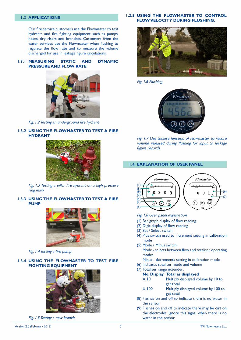
Fig. 1.8 User panel explanation(1) Bar graph display of flow reading(2) Digit display of flow reading(3) Set / Select switch(4) Plus switch used to increment setting in calibration
mode(5) Mode / Minus switch: Mode - selects between flow and totaliser operating
modes Minus - decrements setting in calibration mode(6) Indicates totaliser mode and volume(7) Totaliser range extender: No. Display Total as displayed X 10 Multiply displayed volume by 10 to
get total X 100 Multiply displayed volume by 100 to
get total(8) Flashes on and off to indicate there is no water in
the sensor(9) Flashes on and off to indicate there may be dirt on
the electrodes. Ignore this signal when there is no water in the sensor
(1)(8)(9)(2)
(3)
(5)
(6)
(4)(7)
Fig. 1.3 Testing a pillar fire hydrant on a high pressure ring main
Fig. 1.4 Testing a fire pump
Fig. 1.5 Testing a new branch
Fig. 1.2 Testing an underground fire hydrant
MEASURING STATIC AND DyNAMIC PRESSURE AND FLOW RATE
USING THE FLOWMASTER TO TEST A FIRE HyDRANT
USING THE FLOWMASTER TO TEST A FIRE PUMP
1.3.2
1.3.1
1.3.3
USING THE FLOWMASTER TO TEST FIRE FIGHTING EQUIPMENT
1.3.4
Fig. 1.6 Flushing
USING THE FLOWMASTER TO CONTROL FLOW vELOCITy DURING FLUSHING.
1.3.5
Fig. 1.7 Use totalise function of Flowmaster to record volume released during flushing for input to leakage figure records
FLOW TOTAL
1.4 EXPLANATION OF USER PANEL
1.3 APPLICATIONS
Our fire service customers use the Flowmaster to test hydrants and fire fighting equipment such as pumps, hoses, dry risers and branches. Customers from the water services use the Flowmaster when flushing to regulate the flow rate and to measure the volume discharged for use in leakage figure calculations.
Version 2.0 (February 2012) TSI Flowmeters Ltd.5
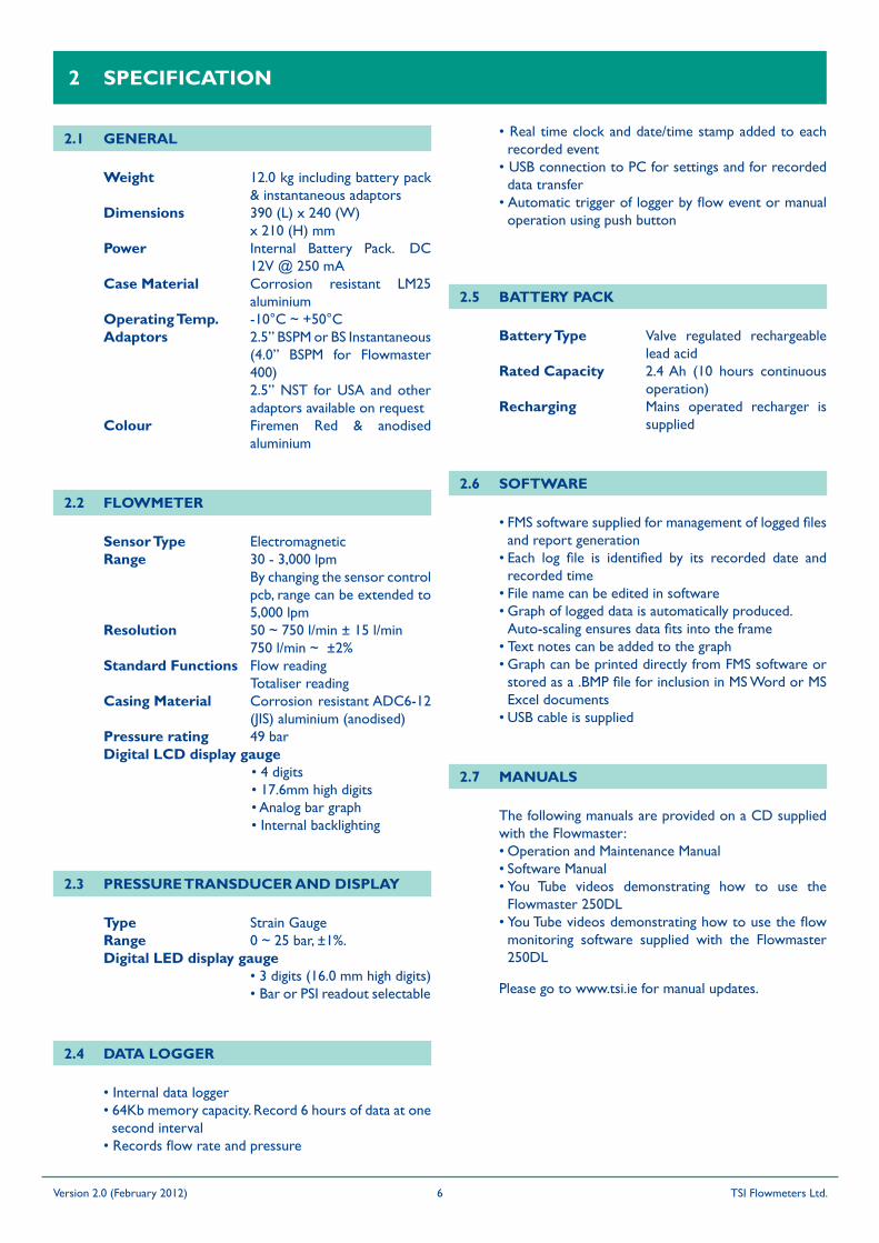
GENERAL2.1
Weight 12.0 kg including battery pack & instantaneous adaptors
Dimensions 390 (L) x 240 (W) x 210 (H) mmPower Internal Battery Pack. DC
12V @ 250 mACase Material Corrosion resistant LM25
aluminiumOperating Temp. -10°C ~ +50°CAdaptors 2.5” BSPM or BS Instantaneous
(4.0” BSPM for Flowmaster 400)
2.5” NST for USA and other adaptors available on request
Colour Firemen Red & anodised aluminium
Sensor Type ElectromagneticRange 30 - 3,000 lpm By changing the sensor control
pcb, range can be extended to 5,000 lpm
Resolution 50 ~ 750 l/min ± 15 l/min 750 l/min ~ ±2%Standard Functions Flow reading Totaliser readingCasing Material Corrosion resistant ADC6-12
(JIS) aluminium (anodised)Pressure rating 49 barDigital LCD display gauge • 4 digits • 17.6mm high digits • Analog bar graph • Internal backlighting
Type Strain GaugeRange 0 ~ 25 bar, ±1%. Digital LED display gauge • 3 digits (16.0 mm high digits) • Bar or PSI readout selectable
• Internal data logger• 64Kb memory capacity. Record 6 hours of data at one
second interval• Records flow rate and pressure
SPECIFICATION2
FLOWMETER2.2
PRESSURE TRANSDUCER AND DISPLAy2.3
DATA LOGGER2.4
Battery Type Valve regulated rechargeable lead acid
Rated Capacity 2.4 Ah (10 hours continuous operation)
Recharging Mains operated recharger is supplied
BATTERy PACK2.5
• Real time clock and date/time stamp added to each recorded event
• USB connection to PC for settings and for recorded data transfer
• Automatic trigger of logger by flow event or manual operation using push button
• FMS software supplied for management of logged files and report generation
• Each log file is identified by its recorded date and recorded time
• File name can be edited in software• Graph of logged data is automatically produced.
Auto-scaling ensures data fits into the frame• Text notes can be added to the graph• Graph can be printed directly from FMS software or
stored as a .BMP file for inclusion in MS Word or MS Excel documents
• USB cable is supplied
SOFTWARE2.6
MANUALS2.7
The following manuals are provided on a CD supplied with the Flowmaster:• Operation and Maintenance Manual• Software Manual• You Tube videos demonstrating how to use the
Flowmaster 250DL• You Tube videos demonstrating how to use the flow
monitoring software supplied with the Flowmaster 250DL
Please go to www.tsi.ie for manual updates.
Version 2.0 (February 2012) TSI Flowmeters Ltd.6

Fig. 3.3 Flow meter display when ready for flow measurement and there is no water in the pipe. Note the flashing symbols on the left side of the flowmeter gauge
Fig. 3.2 Flow meter display when ready for flow measurement, water is filling the pipe and is flowing
Fig. 3.1 Flow meter display when ready for flow measurement, water is filling the pipe but is not flowing
The Flowmaster is now ready to make both flow and pressure measurements.
The Flow meter backlight LEDs will turn on. After a few moments, the self-test mode will commence and the display sequence will be as shown below.
The final display in the sequence indicates that the self-test is complete and the Flow meter is in flow measurement mode.
3 FLOWMASTER OPERATION
3.1 FLOWMETER POWER ON SEQUENCEThe Flowmaster is ready to measure flow and pressure as soon as battery power is applied. Turn on the Flowmaster by pressing the ON/OFF switch to “1” position.
Following power_on, the flow meter begins a self test sequence lasting approximately 5 seconds and then automatically enters flow measurement mode. The typical flow meter display in flow measurement mode is as shown in Fig. 3.1.The pressure meter and data logger self test lasts approximately 3 seconds. The readouts are as shown in Fig. 3.4 and Fig. 3.5.
Version 2.0 (February 2012) TSI Flowmeters Ltd.7
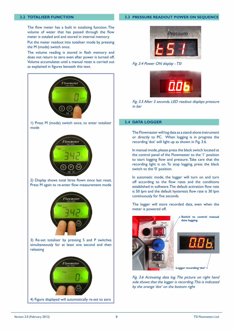
1) Press M (mode) switch once, to enter totaliser mode
2) Display shows total litres flown since last reset. Press M again to re-enter flow measurement mode
3) Re-set totaliser by pressing S and P switches simultaneously for at least one second and then releasing
4) Figure displayed will automatically re-set to zero
The flow meter has a built in totalising function. The volume of water that has passed through the flow meter is totaled and and stored in internal memory.Put the meter readout into totaliser mode by pressing the M (mode) switch once.The volume reading is stored in flash memory and does not return to zero even after power is turned off. Volume accumulates until a manual reset is carried out as explained in figures beneath this text.
Fig. 3.4 Power ON display - TSI
PRESSURE READOUT POWER ON SEQUENCE3.3TOTALISER FUNCTION3.2
Fig. 3.5 After 3 seconds, LED readout displays pressure in bar
DATA LOGGER3.4
The logger will store recorded data, even when the meter is powered off.
The Flowmaster will log data as a stand-alone instrument or directly to PC. When logging is in progress the recording ‘dot’ will light up as shown in Fig. 3.6.
In manual mode, please press the black switch located at the control panel of the Flowmaster to the ‘1’ position to start logging flow and pressure. Take care that the recording light is on. To stop logging, press the black switch to the ‘0’ position.
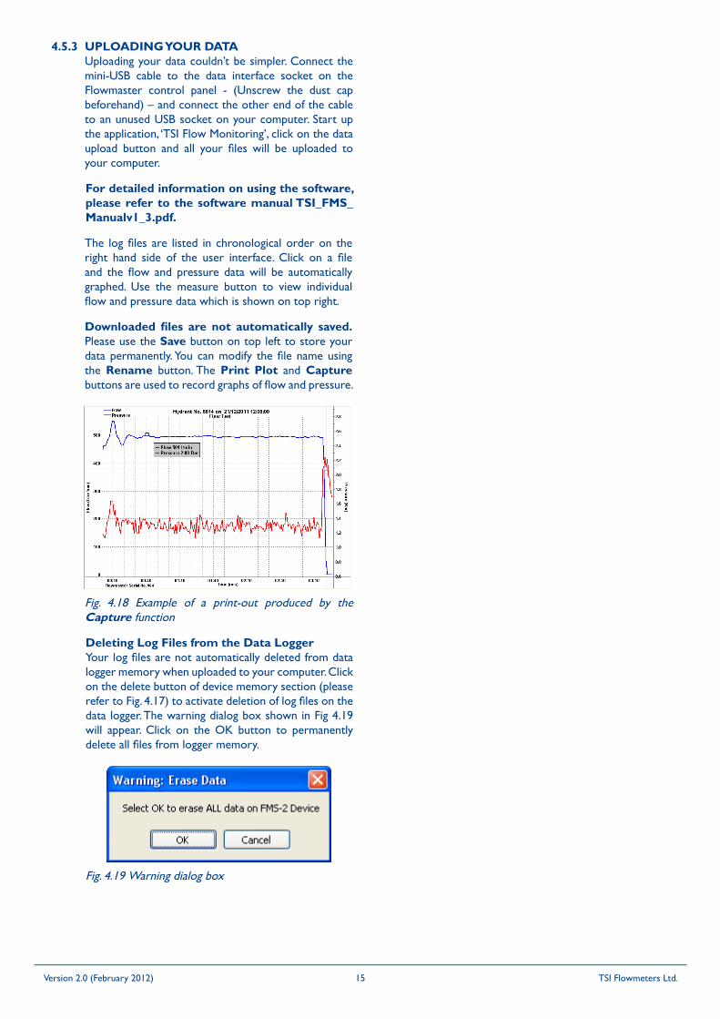
In automatic mode, the logger will turn on and turn off according to the flow rates and the conditions established in software. The default activation flow rate is 50 lpm and the default hysteresis flow rate is 30 lpm continuously for five seconds.
Fig. 3.6 Activating data log. The picture on right hand side shows that the logger is recording. This is indicated by the orange ‘dot’ on the bottom right
Switch to control manual data logging
Logger recording ‘dot’
Version 2.0 (February 2012) TSI Flowmeters Ltd.8
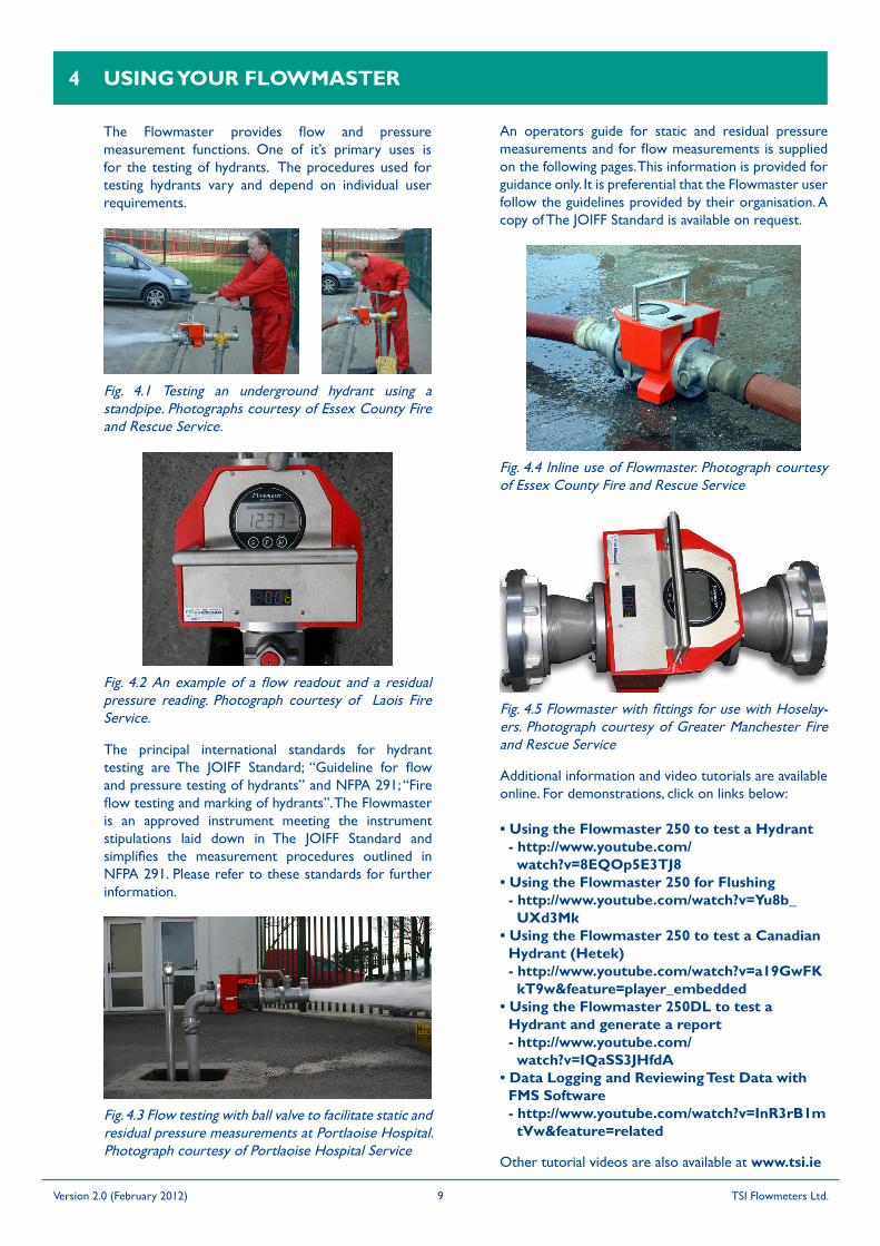
The Flowmaster provides flow and pressure measurement functions. One of it’s primary uses is for the testing of hydrants. The procedures used for testing hydrants vary and depend on individual user requirements.
Fig. 4.1 Testing an underground hydrant using a standpipe. Photographs courtesy of Essex County Fire and Rescue Service.
Fig. 4.2 An example of a flow readout and a residual pressure reading. Photograph courtesy of Laois Fire Service.
The principal international standards for hydrant testing are The JOIFF Standard; “Guideline for flow and pressure testing of hydrants” and NFPA 291; “Fire flow testing and marking of hydrants”. The Flowmaster is an approved instrument meeting the instrument stipulations laid down in The JOIFF Standard and simplifies the measurement procedures outlined in NFPA 291. Please refer to these standards for further information.
An operators guide for static and residual pressure measurements and for flow measurements is supplied on the following pages. This information is provided for guidance only. It is preferential that the Flowmaster user follow the guidelines provided by their organisation. A copy of The JOIFF Standard is available on request.
Fig. 4.3 Flow testing with ball valve to facilitate static and residual pressure measurements at Portlaoise Hospital. Photograph courtesy of Portlaoise Hospital Service
Fig. 4.4 Inline use of Flowmaster. Photograph courtesy of Essex County Fire and Rescue Service
Fig. 4.5 Flowmaster with fittings for use with Hoselay-ers. Photograph courtesy of Greater Manchester Fire and Rescue Service
Other tutorial videos are also available at www.tsi.ie
USING yOUR FLOWMASTER4
Additional information and video tutorials are available online. For demonstrations, click on links below:
• Using the Flowmaster 250 to test a Hydrant- http://www.youtube.com/
watch?v=8EQOp5E3TJ8• Using the Flowmaster 250 for Flushing
- http://www.youtube.com/watch?v=yu8b_UXd3Mk
• Using the Flowmaster 250 to test a Canadian Hydrant (Hetek)- http://www.youtube.com/watch?v=a19GwFK
kT9w&feature=player_embedded• Using the Flowmaster 250DL to test a
Hydrant and generate a report- http://www.youtube.com/
watch?v=IQaSS3JHfdA• Data Logging and Reviewing Test Data with
FMS Software- http://www.youtube.com/watch?v=InR3rB1m
tvw&feature=related
Version 2.0 (February 2012) TSI Flowmeters Ltd.9
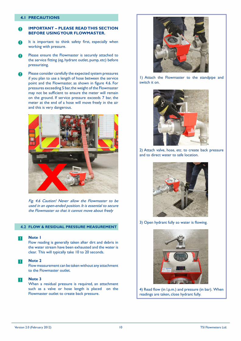
IMPORTANT – PLEASE READ THIS SECTION BEFORE USING yOUR FLOWMASTER.
4.1 PRECAUTIONS
It is important to think safety first, especially when working with pressure.
Please ensure the Flowmaster is securely attached to the service fitting (eg, hydrant outlet, pump, etc) before pressurizing.
Please consider carefully the expected system pressures if you plan to use a length of hose between the service point and the Flowmaster, as shown in figure 4.6. For pressures exceeding 5 bar, the weight of the Flowmaster may not be sufficient to ensure the meter will remain on the ground. If service pressure exceeds 7 bar, the meter at the end of a hose will move freely in the air and this is very dangerous.
Fig. 4.6 Caution! Never allow the Flowmaster to be used in an open-ended position. It is essential to secure the Flowmaster so that it cannot move about freely
4.2 FLOW & RESIDUAL PRESSURE MEASUREMENT
Note 1Flow reading is generally taken after dirt and debris in the water stream have been exhausted and the water is clear. This will typically take 10 to 20 seconds.
Note 2Flow measurement can be taken without any attachment to the Flowmaster outlet.
Note 3When a residual pressure is required, an attachment such as a valve or hose length is placed on the Flowmaster outlet to create back pressure.
1) Attach the Flowmaster to the standpipe and switch it on.
2) Attach valve, hose, etc. to create back pressure and to direct water to safe location.
3) Open hydrant fully so water is flowing.
4) Read flow (in l.p.m.) and pressure (in bar). When readings are taken, close hydrant fully.
!
!
!
!
4.1
!
!
!
Version 2.0 (February 2012) TSI Flowmeters Ltd.10

4.3 STATIC PRESSURE MEASUREMENT
1) Attach Flowmaster to standpipe.
2) Attach blank plug. Ensure bleed valve is open.
3) Crack open the hydrant slowly. All air will be expelled from the standpipe when water begins to drain from the bleed valve. Close the bleed valve.
5) When reading is taken, close hydrant fully.
4) Read static pressure (in bar).
6) Open the bleed valve to exhaust pressure from the meter and standpipe. Remove the blanking plug and progress to flow test.
4.4 FLUSHING
1) Equipment required for flushing.
2) Flowmaster connected to standpipe (through hose length).
3) Adjust valve position to achieve desired flow rate.
4) Record volume discharged for inclusion in leakage figures.
Version 2.0 (February 2012) TSI Flowmeters Ltd.11
!
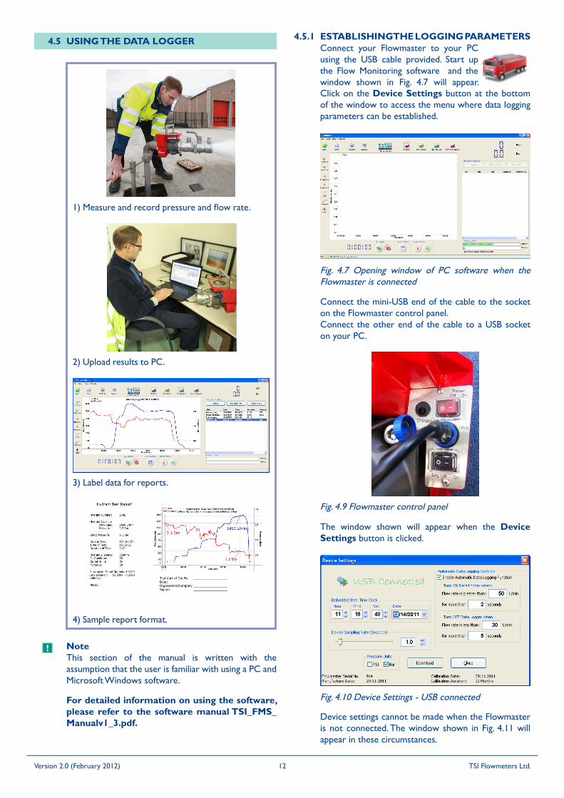
4.5 USING THE DATA LOGGER
NoteThis section of the manual is written with the assumption that the user is familiar with using a PC and Microsoft Windows software.
For detailed information on using the software, please refer to the software manual TSI_FMS_Manualv1_3.pdf.
ESTABLISHING THE LOGGING PARAMETERS4.5.1
Fig. 4.7 Opening window of PC software when the Flowmaster is connected
Connect the mini-USB end of the cable to the socket on the Flowmaster control panel.Connect the other end of the cable to a USB socket on your PC.
The window shown will appear when the Device Settings button is clicked.
Fig. 4.9 Flowmaster control panel
1) Measure and record pressure and flow rate.
2) Upload results to PC.
3) Label data for reports.
4) Sample report format.
Connect your Flowmaster to your PC using the USB cable provided. Start up the Flow Monitoring software and the window shown in Fig. 4.7 will appear. Click on the Device Settings button at the bottom of the window to access the menu where data logging parameters can be established.
Device settings cannot be made when the Flowmaster is not connected. The window shown in Fig. 4.11 will appear in these circumstances.
Fig. 4.10 Device Settings - USB connected
Version 2.0 (February 2012) TSI Flowmeters Ltd.12
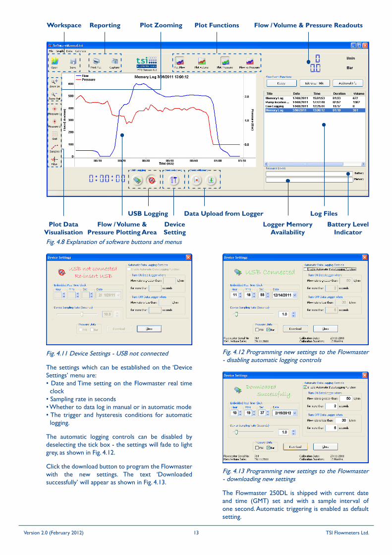
Click the download button to program the Flowmaster with the new settings. The text ‘Downloaded successfully’ will appear as shown in Fig. 4.13.
Fig. 4.12 Programming new settings to the Flowmaster - disabling automatic logging controls
The Flowmaster 250DL is shipped with current date and time (GMT) set and with a sample interval of one second. Automatic triggering is enabled as default setting.
Fig. 4.13 Programming new settings to the Flowmaster - downloading new settings
The automatic logging controls can be disabled by deselecting the tick box - the settings will fade to light grey, as shown in Fig. 4.12.
Fig. 4.11 Device Settings - USB not connected
The settings which can be established on the ‘Device Settings’ menu are:• Date and Time setting on the Flowmaster real time
clock• Sampling rate in seconds • Whether to data log in manual or in automatic mode• The trigger and hysteresis conditions for automatic
logging.
EXPLANATION OF SOFTWARE DISPLAY
Plot Zooming
Plot Data Visualisation
Workspace Reporting Plot Functions
USB Logging Data Upload from Logger
Device Setting
Battery Level Indicator
Log Files
Flow / Volume & Pressure Readouts
Flow / Volume & Pressure Plotting Area
TSI Flowmeters Ltd.4Version 1.3 (February 2012)
Logger Memory Availability
Fig. 4.8 Explanation of software buttons and menus
Version 2.0 (February 2012) TSI Flowmeters Ltd.13
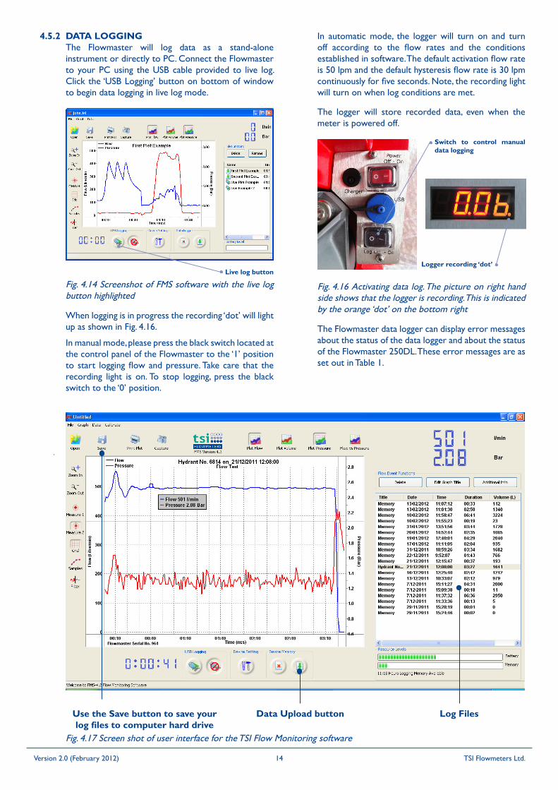
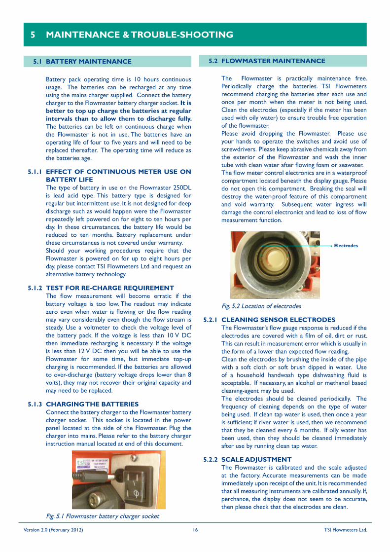
Fig. 4.17 Screen shot of user interface for the TSI Flow Monitoring software
Fig. 4.16 Activating data log. The picture on right hand side shows that the logger is recording. This is indicated by the orange ‘dot’ on the bottom right
Switch to control manual data logging
Logger recording ‘dot’
The Flowmaster data logger can display error messages about the status of the data logger and about the status of the Flowmaster 250DL. These error messages are as set out in Table 1.
Log FilesUse the Save button to save your log files to computer hard drive
Data Upload button
DATA LOGGINGThe Flowmaster will log data as a stand-alone instrument or directly to PC. Connect the Flowmaster to your PC using the USB cable provided to live log. Click the ‘USB Logging’ button on bottom of window to begin data logging in live log mode.
4.5.2
When logging is in progress the recording ‘dot’ will light up as shown in Fig. 4.16.
In manual mode, please press the black switch located at the control panel of the Flowmaster to the ‘1’ position to start logging flow and pressure. Take care that the recording light is on. To stop logging, press the black switch to the ‘0’ position.
In automatic mode, the logger will turn on and turn off according to the flow rates and the conditions established in software. The default activation flow rate is 50 lpm and the default hysteresis flow rate is 30 lpm continuously for five seconds. Note, the recording light will turn on when log conditions are met.
Fig. 4.14 Screenshot of FMS software with the live log button highlighted
Live log button
The logger will store recorded data, even when the meter is powered off.
Version 2.0 (February 2012) TSI Flowmeters Ltd.14
Deleting Log Files from the Data LoggerYour log files are not automatically deleted from data logger memory when uploaded to your computer. Click on the delete button of device memory section (please refer to Fig. 4.17) to activate deletion of log files on the data logger. The warning dialog box shown in Fig 4.19 will appear. Click on the OK button to permanently delete all files from logger memory.
Fig. 4.19 Warning dialog box
Downloaded files are not automatically saved. Please use the Save button on top left to store your data permanently. You can modify the file name using the Rename button. The Print Plot and Capture buttons are used to record graphs of flow and pressure.
Fig. 4.18 Example of a print-out produced by the Capture function
UPLOADING yOUR DATAUploading your data couldn’t be simpler. Connect the mini-USB cable to the data interface socket on the Flowmaster control panel - (Unscrew the dust cap beforehand) – and connect the other end of the cable to an unused USB socket on your computer. Start up the application, ‘TSI Flow Monitoring’, click on the data upload button and all your files will be uploaded to your computer.
4.5.3
The log files are listed in chronological order on the right hand side of the user interface. Click on a file and the flow and pressure data will be automatically graphed. Use the measure button to view individual flow and pressure data which is shown on top right.
For detailed information on using the software, please refer to the software manual TSI_FMS_Manualv1_3.pdf.
Version 2.0 (February 2012) TSI Flowmeters Ltd.15
5 MAINTENANCE & TROUBLE-SHOOTING
5.1 BATTERy MAINTENANCE
Battery pack operating time is 10 hours continuous usage. The batteries can be recharged at any time using the mains charger supplied. Connect the battery charger to the Flowmaster battery charger socket. It is better to top up charge the batteries at regular intervals than to allow them to discharge fully. The batteries can be left on continuous charge when the Flowmaster is not in use. The batteries have an operating life of four to five years and will need to be replaced thereafter. The operating time will reduce as the batteries age.
EFFECT OF CONTINUOUS METER USE ON BATTERy LIFEThe type of battery in use on the Flowmaster 250DL is lead acid type. This battery type is designed for regular but intermittent use. It is not designed for deep discharge such as would happen were the Flowmaster repeatedly left powered on for eight to ten hours per day. In these circumstances, the battery life would be reduced to ten months. Battery replacement under these circumstances is not covered under warranty.Should your working procedures require that the Flowmaster is powered on for up to eight hours per day, please contact TSI Flowmeters Ltd and request an alternative battery technology.
TEST FOR RE-CHARGE REQUIREMENTThe flow measurement will become erratic if the battery voltage is too low. The readout may indicate zero even when water is flowing or the flow reading may vary considerably even though the flow stream is steady. Use a voltmeter to check the voltage level of the battery pack. If the voltage is less than 10 V DC then immediate recharging is necessary. If the voltage is less than 12 V DC then you will be able to use the Flowmaster for some time, but immediate top-up charging is recommended. If the batteries are allowed to over-discharge (battery voltage drops lower than 8 volts), they may not recover their original capacity and may need to be replaced.
CHARGING THE BATTERIESConnect the battery charger to the Flowmaster battery charger socket. This socket is located in the power panel located at the side of the Flowmaster. Plug the charger into mains. Please refer to the battery charger instruction manual located at end of this document.
5.1.1
5.1.2
5.1.3
The Flowmaster is practically maintenance free. Periodically charge the batteries. TSI Flowmeters recommend charging the batteries after each use and once per month when the meter is not being used. Clean the electrodes (especially if the meter has been used with oily water) to ensure trouble free operation of the flowmaster.Please avoid dropping the Flowmaster. Please use your hands to operate the switches and avoid use of screwdrivers. Please keep abrasive chemicals away from the exterior of the Flowmaster and wash the inner tube with clean water after flowing foam or seawater.The flow meter control electronics are in a waterproof compartment located beneath the display gauge. Please do not open this compartment. Breaking the seal will destroy the water-proof feature of this compartment and void warranty. Subsequent water ingress will damage the control electronics and lead to loss of flow measurement function.
5.2 FLOWMASTER MAINTENANCE
CLEANING SENSOR ELECTRODESThe Flowmaster’s flow gauge response is reduced if the electrodes are covered with a film of oil, dirt or rust. This can result in measurement error which is usually in the form of a lower than expected flow reading.Clean the electrodes by brushing the inside of the pipe with a soft cloth or soft brush dipped in water. Use of a household handwash type dishwashing fluid is acceptable. If necessary, an alcohol or methanol based cleaning-agent may be used.The electrodes should be cleaned periodically. The frequency of cleaning depends on the type of water being used. If clean tap water is used, then once a year is sufficient; if river water is used, then we recommend that they be cleaned every 6 months. If oily water has been used, then they should be cleaned immediately after use by running clean tap water.
5.2.1
SCALE ADJUSTMENTThe Flowmaster is calibrated and the scale adjusted at the factory. Accurate measurements can be made immediately upon receipt of the unit. It is recommended that all measuring instruments are calibrated annually. If, perchance, the display does not seem to be accurate, then please check that the electrodes are clean.
5.2.2
Fig. 5.1 Flowmaster battery charger socket
Fig. 5.2 Location of electrodes
Electrodes
Version 2.0 (February 2012) TSI Flowmeters Ltd.16

Display does not reach this display of the Self-Test Sequence -
Possible Cause:The Sensor part of the device and the Display part of the device are not in contact.
Action:Check all cables are secure. If still not connected – please contact your local representative* This condition may indicate that water ingress to the electronics compartment has damaged the control electronics. Please contact your local representative.
ERRATIC DISPLAy5.3.2
Possible Cause:The battery voltage is too low.
Action:Charge the batteries.
READING NOT DISPLAyINGThe power-on Self-test Sequence is okay, but there is no reading when water is flowing.
5.3.3
Possible Cause:1) Batteries voltage is too low2) No earth wire to battery3) Unit is faulty
Action:1) Charge or replace batteries2) Replace earth wire between battery negative
terminal and red casting3) Return unit to Manufacturer
RECHARGING ISSUESThe unit will not charge or there are humming noises while trying to recharge.
5.3.4
Possible Cause:Faulty battery charger or batteries are over-discharged and cannot recover.
Action:Contact local representative for replacement charger or batteries. Generally speaking, if battery voltage falls below 6 volts DC, it will not recover.
5.3 TROUBLE-SHOOTING
INCOMPLETE SELF-TEST SEQUENCEDisplay goes through the Self-Test Sequence until this display -
5.3.1
DATA LOGGER MESSAGESThe Flowmaster data logger can display error and reminder messages about the status of the data logger and about the status of the Flowmaster 250DL. These messages are as set out in Table 1 below.
The messages are displayed on the LED readout for two second duration every ten seconds. An example of how the messages appear on the LED readout is shown below.
Fig. 5.3 This is how No SNS (flow sensor not connected) is displayed on the LED readout
5.3.5
Message on LED Problem Description Problem Solution
SET DATE Date has not been set on the data logger real time clock
Connect the Flowmaster to the FMS software and set the date.
DATA FULL Data logger memory is full – no more data can be stored
Connect the Flowmaster to the FMS software. Upload the files and save to PC hard drive. After saving to PC hard drive, delete files from data logger memory.
DATA LO Data logger memory is 80% full – there is memory available for some data to be stored
Connect the Flowmaster to the FMS software. Upload the files and save to PC hard drive. After saving to PC hard drive, delete files from data logger memory.
BAT LO Flowmaster battery is low Recharge the Flowmaster battery
NO SNS Flow sensor is not taking flow measurements See troubleshooting section
CAL OUT The meter calibration has expired. Contact TSI Flowmeters to have your meter calibrated
CAL DUE The meter calibration will expire soon Contact TSI Flowmeters to have your meter calibrated
Table 1 Error and reminder messages that are displayed on the LED readout
Version 2.0 (February 2012) TSI Flowmeters Ltd.17
ALL LOG FILE DATES ARE yEAR 2000The data logger has a rechargeable battery to power flash memory within the data logger. If this battery has no charge, the date will revert to the default date of the year 2000.
5.3.6
Possible Cause 1:Battery not charged.
Action:Connect the Flowmaster to the computer via the USB cable and start up the FMS software. Power on the Flowmaster. Leave like this for at least three hours. To verify, power off the meter and disconnect from your computer. Reconnect and set the date and time. Power off and disconnect again. Reconnect and verify the set date and time have been retained in data logger memory.
Possible Cause 2:Battery fault.
Action:The battery may have developed a fault or may have dislodged from it’s holder in the data logger. Try charging the data logger battery as described above. If this fails, return your meter to TSI for repair.
5.4 CALIBRATION OF yOUR FLOWMASTER
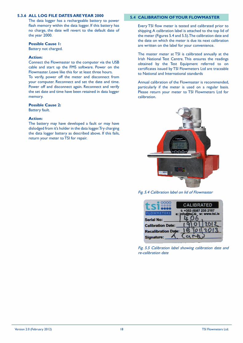
Every TSI flow meter is tested and calibrated prior to shipping. A calibration label is attached to the top lid of the meter (Figures 5.4 and 5.5). The calibration date and the date on which the meter is due its next calibration are written on the label for your convenience.
Fig. 5.4 Calibration label on lid of Flowmaster
Fig. 5.5 Calibration label showing calibration date and re-calibration date
The master meter at TSI is calibrated annually at the Irish National Test Centre. This ensures the readings obtained by the Test Equipment referred to on certificates issued by TSI Flowmeters Ltd are traceable to National and International standards
Annual calibration of the Flowmaster is recommended, particularly if the meter is used on a regular basis. Please return your meter to TSI Flowmeters Ltd for calibration.
Version 2.0 (February 2012) TSI Flowmeters Ltd.18
The procedure for resetting the calibration date is as follows (Note, the Flowmaster must be connected to your computer via the USB cable):• Determine the code for your meter from the ‘Get
Software ID’ on the calibrate tab. Please refer to Fig. 5.10 and Fig. 5.11.
• Send this code and the serial number of your Flowmaster to TSI Flowmeters Ltd. Inform them of the number of months for which the new calibration certificate is to remain valid
• TSI will send a new code to you which, when applied to your Flowmaster, will update the calibration date and stop the reminder messages from appearing on the LED readout.
• To program your Flowmaster with the new code, select that ‘Apply Code’ option from the calibrate menu. Please refer to Fig. 5.12 to Fig. 5.15. Insert the new code in the dialog box that will appear and click
Fig. 5.7 ‘Calibrate’ drop down menu
5.5 RESETTING THE CALIBRATION DUE DATE IN DATA LOGGER MEMORy
A procedure for controlling the timing of appearance of the messages on the LED readout is provided with the FMS software. This is found on the ‘calibration’ tab on the menu bar. Please refer to Fig. 5.7. The first item on the calibrate tab is a dialog box containing a description of the procedure. Please refer to Fig. 5.8. and Fig. 5.9.
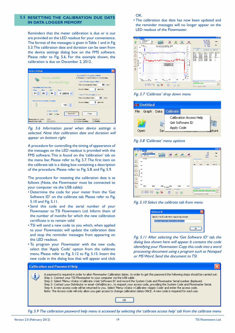
Reminders that the meter calibration is due or is out are provided on the LED readout for your convenience. The format of the messages is given in Table 1 and in Fig 5.3. The calibration date and duration can be seen from the device settings dialog box on the FMS software. Please refer to Fig. 5.6. For the example shown, the calibration is due on December 2, 2012.
Fig. 5.8 ‘Calibrate’ menu options
Fig. 5.6 Information panel when device settings is selected. Note that calibration date and duration will appear on bottom right
Fig. 5.9 The calibration password help menu is accessed by selecting the ‘calibrate access help’ tab from the calibrate menu
OK.• The calibration due date has now been updated and
the reminder messages will no longer appear on the LED readout of the Flowmaster.
Fig. 5.10 Select the calibrate tab from menu
Fig. 5.11 After selecting the ‘Get Software ID’ tab, the dialog box shown here will appear. It contains the code identifying your Flowmaster. Copy this code into a word processing document using a program such as Notepad or MS Word. Send the document to TSI.
Version 2.0 (February 2012) TSI Flowmeters Ltd.19
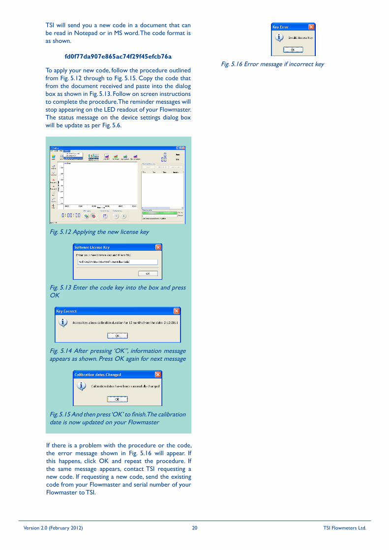
TSI will send you a new code in a document that can be read in Notepad or in MS word. The code format is as shown.
fd0f77da907e865ac74f29f45efcb76aFig. 5.16 Error message if incorrect key
If there is a problem with the procedure or the code, the error message shown in Fig. 5.16 will appear. If this happens, click OK and repeat the procedure. If the same message appears, contact TSI requesting a new code. If requesting a new code, send the existing code from your Flowmaster and serial number of your Flowmaster to TSI.
To apply your new code, follow the procedure outlined from Fig. 5.12 through to Fig. 5.15. Copy the code that from the document received and paste into the dialog box as shown in Fig. 5.13. Follow on screen instructions to complete the procedure. The reminder messages will stop appearing on the LED readout of your Flowmaster. The status message on the device settings dialog box will be update as per Fig. 5.6.
Fig. 5.12 Applying the new license key
Fig. 5.13 Enter the code key into the box and press OK
Fig. 5.14 After pressing ‘OK”, information message appears as shown. Press OK again for next message
Fig. 5.15 And then press ‘OK’ to finish. The calibration date is now updated on your Flowmaster
Version 2.0 (February 2012) TSI Flowmeters Ltd.20

!
This new range of battery chargers utilises the latest computer controlled technology designed to give greater charging control of Lead Acid batteries, with increased product reliability.
What follows is the procedure for the correct operation of the battery charger:1) Make sure the charger is unplugged.2) Connect the battery as shown in Fig. 5.1.3) Plug the charger in and switch ON.4) During start up the charger will determine battery
status and depending on the result will switch to either bulk charge mode (red indicator ON) or float charge mode (green indicator ON). Note, when the charger enters float charge mode the battery is 100% fully charged.
5) If neither of the indicators illuminate then unplug the charger, check the fuse in the plug, replace if necessary, plug back in and switch ON.
Charger Status LED StatusBulk charge mode Red - static ONFloat charge mode(charge complete) Green - static ON
Battery reversal detected Red - flashing
High temperature detected Red + Green flashingsimultaneously
Short circuit Red + Green flashingalternately
Open circuit Red + Green staticsimultaneously
6 GENERAL INSTRUCTION: CM RANGE 3 STAGE BATTERy CHARGERS
6.1 OvERvIEW
6.2 FEATURES
6.3 OPERATION
Short Circuit Protection – Prevents damage to the charger if the dc output is short circuited, visual indication is by alternate flashing red and green indicators.
Reverse Polarity Protection – Prevents damage to the charger if the battery is accidentally connected in reverse, visual indication is by a continuous flashing red indicator.
High Temperature Protection – If the internal case temperature rises above a pre-determined level the system is designed to automatically shut down the charging current, thus reducing the case temperature. As the temperature reduces the charger will automatically turn up to the maximum charging current available. Simultaneous flashing of the red and green indicators will visually indicate high case temperatures.
Soft Start – On power up the system will enter a “soft start” mode. This facility checks for possible faults i.e. reverse battery connection, short circuit, etc. before offering maximum charge current.
Constant Current Bulk Charge and 3 Stage Charging – Provides the fastest possible way to recharge a SLA battery without overcharging.Constant voltage Float – Compensates for self discharge, holding the battery at peak charge, ready for use. The battery can be left on charge until required without fear of overcharging.
Proportional Charging – Automatically, proportionally adjusts the second (constant voltage) stage length of charge based on the time taken to carry out the first (constant current) stage. This facility allows optimal charging by eliminating overcharging and compromise of the fixed charge timers.
First Stage – constant current (CC) mode. Visual indication: Red LED ON, Green LED off.Second Stage – constant voltage (CV) mode. Visual indication: As above.Third Stage – float charge mode. The battery will be maintained 100% charged. Visual indication: Green LED ON, Red LED off.
Note: On power up the charger will appear to be in “float” mode for a short period of time. This is to complete all checks as described in feature “soft start”.
Fig. 6.1 LED Protocol Table
Version 2.0 (February 2012) TSI Flowmeters Ltd.21
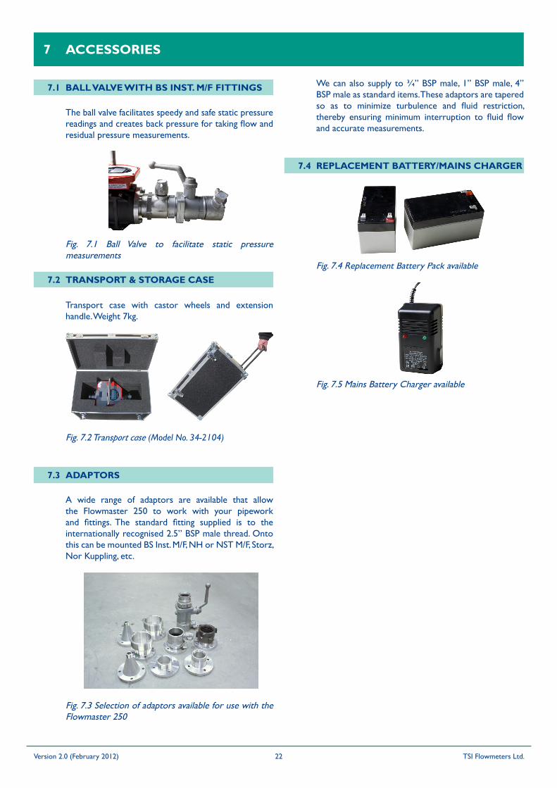
A wide range of adaptors are available that allow the Flowmaster 250 to work with your pipework and fittings. The standard fitting supplied is to the internationally recognised 2.5” BSP male thread. Onto this can be mounted BS Inst. M/F, NH or NST M/F, Storz, Nor Kuppling, etc.
7 ACCESSORIES
7.1 BALL vALvE WITH BS INST. M/F FITTINGS
The ball valve facilitates speedy and safe static pressure readings and creates back pressure for taking flow and residual pressure measurements.
7.2 TRANSPORT & STORAGE CASE
Transport case with castor wheels and extension handle. Weight 7kg.
Fig. 7.2 Transport case (Model No. 34-2104)
7.3 ADAPTORS
Fig. 7.3 Selection of adaptors available for use with the Flowmaster 250
We can also supply to ¾” BSP male, 1” BSP male, 4” BSP male as standard items. These adaptors are tapered so as to minimize turbulence and fluid restriction, thereby ensuring minimum interruption to fluid flow and accurate measurements.
7.4 REPLACEMENT BATTERy/MAINS CHARGER
Fig. 7.4 Replacement Battery Pack available
Fig. 7.1 Ball Valve to facilitate static pressure measurements
Fig. 7.5 Mains Battery Charger available
Version 2.0 (February 2012) TSI Flowmeters Ltd.22
TSI Flowmeters Ltd., of 24 Rockdale, Mountrath Road, Portlaoise, Co. Laois, Ireland (Warrantor), warrants to the original purchaser of the new fire protection equipment manufactured by Warrantor and to any person to whom such equipment is transferred, that such equipment shall be free from defects in materials and workmanship during the one (1) year period commencing upon the receipt of such equipment by the original purchaser thereof (“warranty period”).
Warrantor’s obligation under this warranty is specifically limited to replacing or repairing its fire protection equipment or parts thereof, which are shown by Warrantor’s examination to be in a defective condition attributable hereunder to Warrantor. To qualify for this Warranty, alleged defective equipment MUST be returned to Warrantor at its above address, transportation charges prepaid, within a reasonable time after discovery of an alleged defect, and in no event later than thirty (30) days after the expiration of the warranty period. If, as a result of Warrantor’s examination of returned equipment, Warrantor concludes that a product defect attributable hereunder to Warrantor exists, Warrantor shall cure such defect within a reasonable time, not to exceed forty-five (45) days after such examination. All expenses in curing such defect, except for transportation charges and shipping expenses incurred in delivering such equipment to Warrantor, shall be paid by Warrantor.
In the event that such equipment is found to be attributable hereunder to Warrantor and Warrantor is unable to provide replacement, or repair is not commercially practicable or cannot be timely made, Warrantor may elect to refund to claimant the purchase price of such equipment actually received by Warrantor, less reasonable depreciation, in complete discharge of its obligations hereunder. If Warrantor elects to comply with this warranty by means of such refund, as a condition precedent to such compliance, the claimant shall return such equipment to Warrantor free and clear of liens and other encumbrances.
THE ORIGINAL PURCHASER OF SUCH EQUIPMENT, AND PERSON TO WHOM SUCH EQUIPMENT IS TRANSFERRED, AND ANY PERSON WHO IS AN INTENDED OR UNINTENDED BENEFICIARY OF SUCH EQUIPMENT, SHALL NOT BE ENTITLED TO RECOVER FROM WARRANTOR ANY CONSEQUENTIAL OR INCIDENTAL DAMAGES FOR INJURY TO PERSON AND/OR PROPERTY RESULTING FROM ANY DEFECTIVE EQUIPMENT MANUFACTURED BY WARRANTOR.
Misuse or neglect (including failure to provide reasonable maintenance) of, or accident or unauthorised repairs or alterations to, such equipment, shall release and discharge Warrantor from any obligations under this
8 LIMITED WARRANTy
warranty or otherwise.
WARRANTOR EXPRESSLY LIMITS WITH RESPECT TO SUCH EQUIPMENT ALL IMPLIED WARRANTIES OF MERCHANTABILITY AND ALL IMPLIED WARRANTIES OF FITNESS FOR A PARTICULAR PURPOSE TO THE WARRANTY PERIOD. AFTER EXPIRATION OF THE WARRANTY PERIOD, WARRANTOR EXPRESSLY DISCLAIMS WITH RESPECT TO SUCH EQUIPMENT ALL IMPLIED WARRANTIES OF MERCHANTABILITY AND ALL IMPLIED WARRANTIES OF FITNESS FOR A PARTICULAR PURPOSE. THERE IS NO WARRANTY OF ANY NATURE MADE BY WARRANTOR BEYOND THAT WHICH IS CONTAINED HEREIN.
Should Warrantor fail to meet with its obligations under this warranty, a claimant may sue Warrantor to secure its compliance with this warranty. No action to enforce this warranty or to otherwise secure recovery from Warrantor for any damages arising out of the fire protection equipment manufactured by Warrantor shall be commenced later than two (2) months from and after the date of the receipt of such equipment by the original purchaser thereof.
NO PERSON HAS AUTHORITY TO ENLARGE, AMEND, OR MODIFY THIS WARRANTY.
Warrantor reserves the right to change the parts or design of its products from time to time without notice, and with no obligation to maintain spare parts or to make corresponding changes in the products previously manufactured.
Version 2.0 (February 2012) TSI Flowmeters Ltd.23
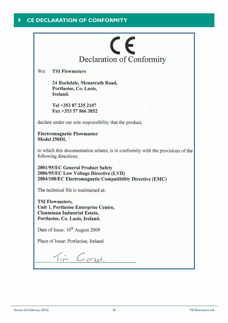
9 CE DECLARATION OF CONFORMITy
Version 2.0 (February 2012) TSI Flowmeters Ltd.24
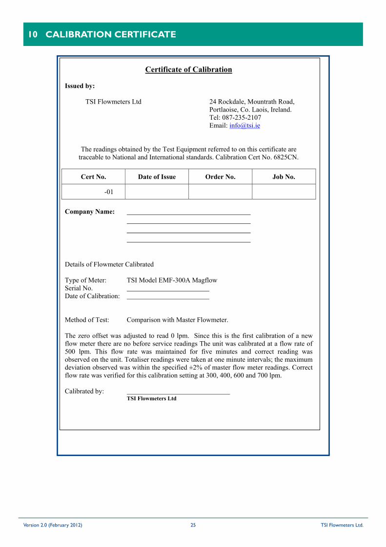
10 CALIBRATION CERTIFICATE
Certificate of Calibration
Issued by:
TSI Flowmeters Ltd 24 Rockdale, Mountrath Road, Portlaoise, Co. Laois, Ireland. Tel: 087-235-2107 Email: [email protected]
The readings obtained by the Test Equipment referred to on this certificate are traceable to National and International standards. Calibration Cert No. 6825CN.
Cert No. Date of Issue Order No. Job No.
-01
Company Name:
Details of Flowmeter Calibrated
Type of Meter: TSI Model EMF-300A Magflow Serial No. Date of Calibration:
Method of Test: Comparison with Master Flowmeter.
The zero offset was adjusted to read 0 lpm. Since this is the first calibration of a new flow meter there are no before service readings The unit was calibrated at a flow rate of 500 lpm. This flow rate was maintained for five minutes and correct reading was observed on the unit. Totaliser readings were taken at one minute intervals; the maximum deviation observed was within the specified ±2% of master flow meter readings. Correct flow rate was verified for this calibration setting at 300, 400, 600 and 700 lpm.
Calibrated by: TSI Flowmeters Ltd
Version 2.0 (February 2012) TSI Flowmeters Ltd.25
Related Documents