KEY FEATURES: • High capacity single slot linear diffuser available in five slot widths, offers an attractive alternative to traditional multi-slot designs. Available slot widths are 1" (25), 1 1/2" (38), 2" (51), 2 1/2" (64) and 3" (76). A two slot option is also available. • Comprehensive selection of frame/border styles and mounting hardware to suit any installation. • Choice of FLH Series Horizontal or FLV Series Vertical Pattern Controllers. May be combined within a single system. • Custom curving availability to meet specific design requirements, provides architectural appeal. • Heavy wall extruded aluminum construction permits support and full integration with ceiling system. • Mitered end borders are available which maximize aesthetic appeal. • Available in single sections up to 12 ft. (3658) in length. Longer lengths are supplied in multiple sections with alignment strips for field assembly. • High performance design is ideally suited to VAV systems, both heating and cooling. • Custom colors and anodized finishes are available. FLH SERIES: Designed primarily for continuous linear slot ceiling applications requiring horizontal air patterns. Tight, high induction air pattern maximizes coanda effect under a wide range of airflow volumes for maximum occupant comfort. Typical applications would include open office perimeter zones, entrance foyers and lobbies, mall and office entrance atriums and conference meeting rooms. FLV SERIES: Designed primarily for continuous linear slot ceiling applications requiring an adjustable extended throw vertical air pattern. Typical applications would include perimeter glass curtain walls and high bays for heated and/or cooled air, which may be directed downwards, terminating at the floor at a comfortable velocity. Also suitable for interior zones with high ceilings, such as entrance foyers and lobbies, mall and office entrance atriums, convention center and theaters. This model may also be used in high sidewall applications with long throw requirements. FLP (I) SERIES: Nailor offers factory built supply air plenum boots in various lengths to suit the application in both uninsulated and insulated versions. Nailor engineered plenums save on costly field labor and ensure a sure-fit trouble free installation. FT SERIES: The FlowLine ™ Series is available in modular lengths for lay-in T-Bar applications, utilizing either the horizontal high throw or vertical jet throw pattern controllers. Units are supplied with factory installed engineered plenums in uninsulated or insulated versions. FM SERIES: The FM Series is an architecturally pleasing modular square ceiling diffuser primarily for lay-in T-Bar applications. Designed to compliment the FlowLine ™ Linear Diffuser System, the FM Series features a single slot at the perimeter of a 2 ft. x 2 ft. (600 x 600) ceiling module and accommodates a center acoustic ceiling tile. FLOWLINE™ LINEAR DIFFUSERS A5 FLOWLINE™ LINEAR DIFFUSERS A Adjustable Dual Pattern Controllers Horizontal High Throw Series: Pattern controllers provide 180 O directional control; left or right horizontal throw, angular discharge, volume control and shut-off capability. Adjustable 4 piece Pattern Controllers Vertical Jet Throw Series: Versatile pattern controllers provide for an adjustable perpendicular discharge.

Welcome message from author
This document is posted to help you gain knowledge. Please leave a comment to let me know what you think about it! Share it to your friends and learn new things together.
Transcript
Key FeATureS:• High capacity single slot linear diffuser available in five slotwidths, offers an attractive alternative to traditional multi-slotdesigns. Available slot widths are 1" (25), 1 1/2" (38), 2" (51),2 1/2" (64) and 3" (76). A two slot option is also available.
• Comprehensive selection of frame/border styles andmounting hardware to suit any installation.
• Choice of FLH Series Horizontal or FLV Series VerticalPattern Controllers. May be combined within a singlesystem.
• Custom curving availability to meet specific designrequirements, provides architectural appeal.
• Heavy wall extruded aluminum construction permits supportand full integration with ceiling system.
• Mitered end borders are available which maximize aestheticappeal.
• Available in single sections up to 12 ft. (3658) in length.Longer lengths are supplied in multiple sections withalignment strips for field assembly.
• High performance design is ideally suited to VAV systems,both heating and cooling.
• Custom colors and anodized finishes are available.
FLH SerieS:Designed primarily for continuous linear slot ceilingapplications requiring horizontal air patterns. Tight, highinduction air pattern maximizes coanda effect under a widerange of airflow volumes for maximum occupant comfort.Typical applications would include open office perimeterzones, entrance foyers and lobbies, mall and office entranceatriums and conference meeting rooms.
FLV SerieS:Designed primarily for continuous linear slot ceilingapplications requiring an adjustable extended throw vertical airpattern. Typical applications would include perimeter glasscurtain walls and high bays for heated and/or cooled air, whichmay be directed downwards, terminating at the floor at acomfortable velocity. Also suitable for interior zones with highceilings, such as entrance foyers and lobbies, mall and officeentrance atriums, convention center and theaters.This model may also be used in high sidewall applications withlong throw requirements.
FLP(i) SerieS:Nailor offers factory built supply air plenum boots in variouslengths to suit the application in both uninsulated and insulatedversions. Nailor engineered plenums save on costly field laborand ensure a sure-fit trouble free installation.
FT SerieS:The FlowLine™ Series is available in modular lengths for lay-inT-Bar applications, utilizing either the horizontal high throw orvertical jet throw pattern controllers. Units are supplied withfactory installed engineered plenums in uninsulated orinsulated versions.
FM SerieS:The FM Series is an architecturally pleasing modular squareceiling diffuser primarily for lay-in T-Bar applications. Designedto compliment the FlowLine™ Linear Diffuser System, the FMSeries features a single slot at the perimeter of a 2 ft. x 2 ft.(600 x 600) ceiling module and accommodates a centeracoustic ceiling tile.
FLOWLINE™ LINEAR DIFFUSERS
A5
FLOW
LINE™
LINEA
R D
IFFUSER
S
A
Adjustable DualPattern Controllers
Horizontal High Throw Series:Pattern controllers provide 180O directional control; left or righthorizontal throw, angular discharge, volume control and shut-offcapability.
Adjustable 4 piecePattern Controllers
Vertical Jet Throw Series: Versatile pattern controllers provide for an adjustable perpendicular discharge.

CONTINUOUS FLOWLINE™ LINEAR
A6
FLO
WLI
NE™
LIN
EAR D
IFFU
SERS
A FLH SerieS• HOriZONTAL HiGH THrOw PATTerN CONTrOLLerS• CONTiNuOuS CuSTOM LiNeAr DiFFuSer
STANDArD FeATureS:• Heavy wall extruded aluminumconstruction with galvanized steelpattern controllers.
• Sliding pattern controller designprovides easy adjustment for horizontalor vertical directional control as well asa volume control or shut-off capability.
• Dual blade pattern controllers areconstructed on 24" (610) centers asstandard for maximum flexibility.
• Five slot widths in a one or two slotconfiguration provide a high air volumecapability.
• Single section lengths up to 12 ft.(3658) reduce the number of joints incontinuous runs.
• Multiple section assemblies are dividedinto equal length single sections andare provided with alignment strips.
• Mitered end borders on standard
frame Type AA provide a superiorarchitectural finish.
• FlowLine™ can be custom curved inany plane - concave, convex or flatradius.
FrAMe/BOrDer STyLeS:• FlowLine™ FLH Series is designed forcontinuous length installation in bothhard drywall or acoustical suspension(T-Bar) ceiling systems. Optionalmounting hardware is available to suitthe installation method.
• Available in two standard and variousspecial frame/border designs to suitany installation requirement.
• Various end border options areavailable to suit installation.
• Mitered corner and transition sectionsare available.
SuPPLy Air PLeNuMS:• Model Series FLP(I) factory engineeredplenum boots are available, whichensure both a trouble free installationand that catalog performance is met.
FiNiSH:• Standard finish is AW Appliance Whiteon exposed frame surfaces. Patterncontrollers and interior surfaces areblack.
• Custom color and anodized finishes are available to suit architecturalrequirements.
The FlowLine™ FLH Series continuous slot diffuser is designed primarily for ceiling applications. The adjustable pattern controllers,which are easily adjusted from the face, allow the discharge air to be directed to the left or right as well as downward. When positionedfor horizontal discharge, a tight horizontal air pattern is produced that makes full use of the ceiling (coanda) effect, even at reducedair volumes. High induction characteristics maximize room air movement and mixing, making FlowLine™ FLH Series eminentlysuitable for variable air volume systems.
AngularHorizontal Left Horizontal Right Vertical Fully Dampered
One Way Horizontal Left Opposed Horizontal Horizontal and Vertical
FLH Series Pattern Controller Adjustment
Models:FLH10 1" (25) SlotFLH15 1 1/2" (38) SlotFLH20 2" (51) SlotFLH25 2 1/2" (64) SlotFLH30 3" (76) Slot

CONTINUOUS FLOWLINE™ LINEAR
A7
FLOW
LINE™
LINEA
R D
IFFUSER
S
A
The FlowLine™ FLV Series continuous slot diffuser is designed for both ceiling and high sidewall applications and provides total airpattern control flexibility. Similar in appearance to the FLH Series, the FLV Series features adjustable pattern controllers that directthe airstream perpendicular to the face, providing a strong vertical projection when installed in a ceiling and horizontally when installedin a sidewall application. The pattern controllers permit angular discharge, allowing the airstream to be directed left or right in a ceilingapplication and up or down in a sidewall application. The pattern controllers also provide a variable aperture capability to adjustperformance to specific applications.
Models:FLV10 1" (25) SlotFLV15 1 1/2" (38) SlotFLV20 2" (51) SlotFLV25 2 1/2" (64) SlotFLV30 3" (76) Slot
STANDArD FeATureS:• Heavy wall extruded aluminumconstruction with galvanized steelpattern controllers.
• Sliding pattern controller designprovides easy adjustment for verticaldirectional control as well as a volumecontrol capability.
• Dual blade pattern controllers areconstructed on 24" (610) centers asstandard for maximum flexibility.
• Five slot widths in a one or two slotconfiguration provide a high air volumecapability.
• Single section lengths up to 12 ft.(3658) reduce the number of joints incontinuous runs.
• Multiple section assemblies are dividedinto equal length single sections andare provided with alignment strips.
• Mitered end borders on standard frame Type AA provide a superiorarchitectural finish.
• FlowLine™ can be custom curved inany plane - concave, convex or flatradius.
FrAMe/BOrDer STyLeS:• FlowLine™ FLV Series is designed forcontinuous length installation in bothhard drywall or acoustical suspension(T-Bar) ceiling systems. Optionalmounting hardware is available to suitthe installation method.
• Available in two standard and variousspecial frame/border designs to suitany installation requirement.
• Various end border options areavailable to suit installation.
• Mitered corner and transition sectionsare available.
SuPPLy Air PLeNuMS:• Model Series FLP(I) factory engineeredplenum boots are available, whichensure both a trouble free installationand that catalog performance is met.
FiNiSH:• Standard finish is AW Appliance Whiteon exposed frame surfaces. Patterncontrollers and interior surfaces areblack.
• Custom color and anodized finishes are available to suit architecturalrequirements.
Angular Horizontal Left Horizontal RightVertical 50% Vertical
Vertical Vertical and Horizontal
FLV Series Pattern Controller Adjustment
FLV SerieS• VerTiCAL JeT THrOw PATTerN CONTrOLLerS• CONTiNuOuS CuSTOM LiNeAr DiFFuSer
CONTINUOUS FLOWLINE™ LINEAR
A8
FLO
WLI
NE™
LIN
EAR D
IFFU
SERS
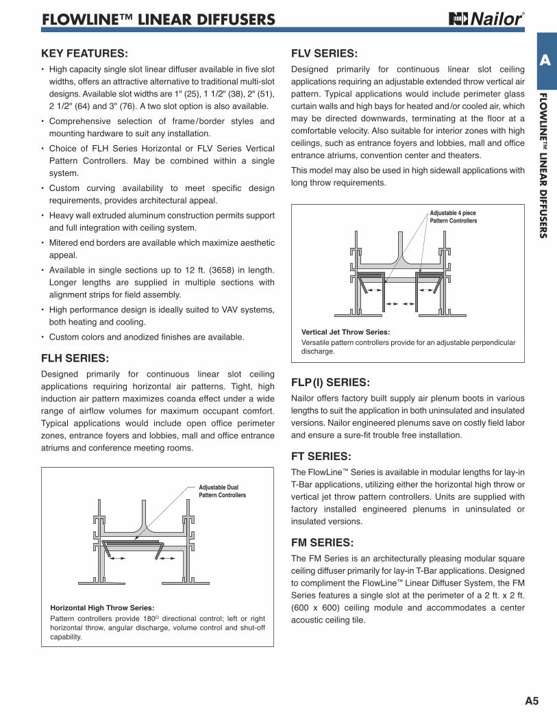
A STANDArD FrAMe/BOrDer STyLeS(TyPe H HOriZONTAL PATTerN CONTrOLLerS iLLuSTrATeD. ALSO AVAiLABLe wiTH TyPe V VerTiCAL).These frame/border styles require installation of the FlowLine™ diffuser prior to installation of the drywall. The ceiling opening shouldbe framed and the diffuser attached with optional mounting clips or suspended from the building structure with hanger wire using theintegral hanger brackets supplied with the diffuser.
H
WW + 1/4" (6)
S AOW
13/32"(10)
A
H
WW + 1/4" (6)
S COW
13/16"(21)
C S
H
W + 1/4" (6)W
T S COW
13/16"(21)
C
Dimensional Data - imperial (Metric) units
Type AA exposed Flange Frame • Drywall (ceiling, wall), T-Bar
One Slot
Type CC Concealed Tapered Frame • Drywall (ceiling, wall) • Tape and Spackle
Type CC Concealed Tapered Side Frame • Drywall (ceiling, wall) • Tape and Spackle
Model SSlot Width
1 Slot 2 Slot ABorder Width
HHeight
T2 SlotW OW W OW
FL(H or V)10FL(H or V)15FL(H or V)20FL(H or V)25FL(H or V)30
1 (25)1 1/2 (38)2 (51)2 1/2 (64)3 (76)
2 1/2 (64)3 1/2 (89)4 1/2 (114)5 1/2 (140)6 1/2 (165)
3 9/16 (90)4 9/16 (116)5 9/16 (141)6 9/16 (167)7 9/16 (192)
4 15/16 (125)6 15/16 (176)8 15/16 (227)10 15/16 (278)12 15/16 (329)
6 (152)8 (203)10 (254)12 (305)14 (356)
1 9/32 (33)1 17/32 (39)1 25/32 (45)2 1/32 (52)2 9/32 (58)
2 3/8 (60)2 5/8 (67)2 7/8 (73)3 1/8 (79)3 3/8 (86)
1 7/16 (37)1 15/16 (49)2 7/16 (62)2 15/16 (75)3 7/16 (87)
Dimensional Data - imperial (Metric) units
S
H
W + 1/4" (6)W
T S AOW
13/32"(10)
A
Two Slot
Type AA exposed Flange Frame • Drywall (ceiling, wall), T-Bar
Two Slot
One Slot
Model SSlot Width
1 Slot 2 Slot CBorder Width
HHeight
T2 SlotW OW W OW
FLH10FLH15FLH20FLH25FLH30
1 (25)1 1/2 (38)2 (51)2 1/2 (64)3 (76)
2 1/2 (64)3 1/2 (89)4 1/2 (114)5 1/2 (140)6 1/2 (165)
4 3/8 (111)5 3/8 (137)6 3/8 (162)7 3/8 (187)8 3/8 (213)
4 15/16 (125)6 15/16 (176)8 15/16 (227)10 15/16 (278)12 15/16 (329)
6 13/16 (173)8 13/16 (224)10 13/16 (275)12 13/16 (325)14 13/16 (376)
1 11/16 (43)1 15/16 (49)2 3/16 (56)2 7/16 (62)2 11/16 (68)
2 3/8 (60)2 5/8 (67)2 7/8 (73)3 1/8 (79)3 3/8 (86)
1 7/16 (37)1 15/16 (49)2 7/16 (62)2 15/16 (75)3 7/16 (87)
CONTINUOUS FLOWLINE™ LINEAR
A9
FLOW
LINE™
LINEA
R D
IFFUSER
S
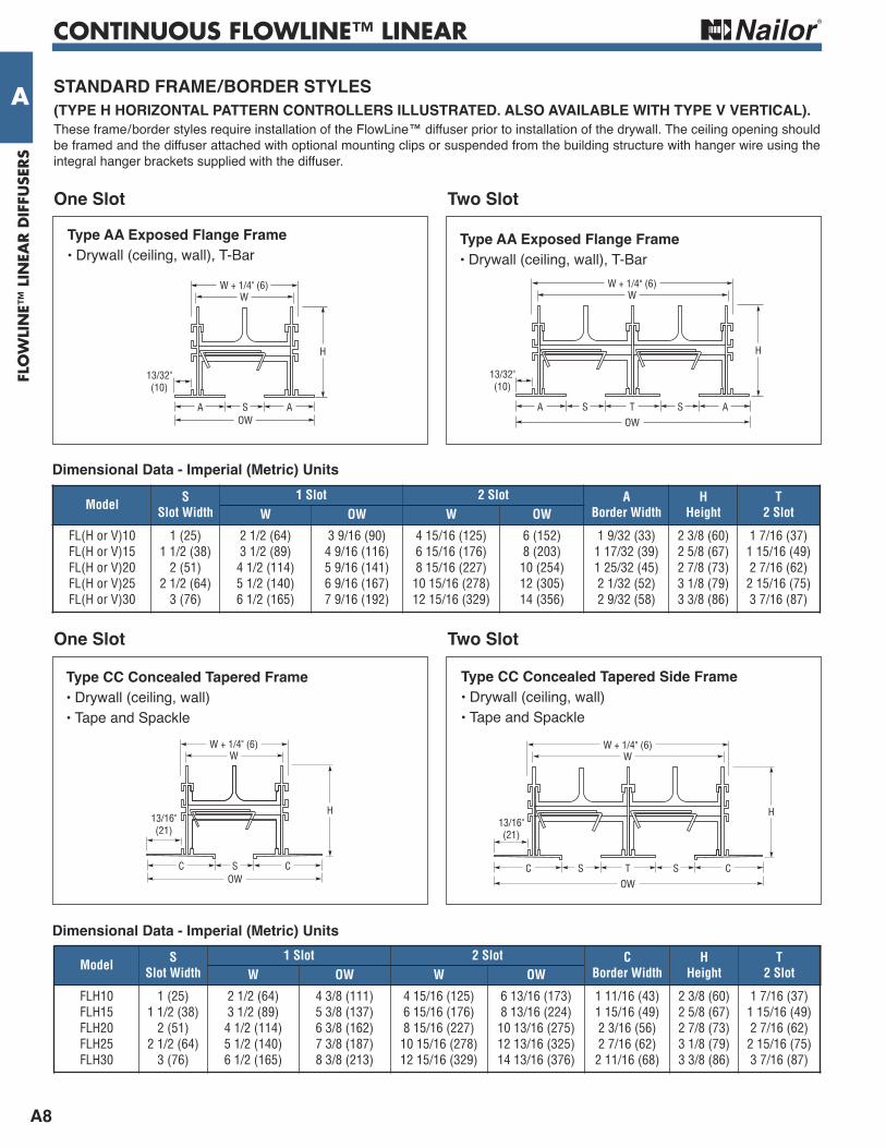
ASTANDArD FrAMe/BOrDer STyLeS wiTH CONCeALeD MOuNTiNG BrACKeT(TyPe H HOriZONTAL PATTerN CONTrOLLerS iLLuSTrATeD. ALSO AVAiLABLe wiTH TyPe V VerTiCAL).The concealed mounting bracket option permits surface mounting of the FlowLine™ diffuser after the ceiling installation. Diffuser simplypushes up into the ceiling opening until the legs of the factory supplied mounting brackets locate into a hemmed duct plenum or ontothe topside of the drywall. Factory supplied levelling screws then draw the diffuser up until it is tight and snug with the ceiling.
A AS
13/32"(10)
D
OW = D+1/16" (2)
H
Type AAC exposed Flange Frame • Drywall (ceiling)
One Slot
Dimensional Data - imperial (Metric) units
D
H
A TS AS
13/32"(10)
OW = D
Two Slot
Type AAC exposed Flange Frame • Drywall (ceiling)
Two Slot
One Slot
Model SSlot Width
D Duct Width Ceiling Opening Width ABorder Width
HHeight
T2 Slot1 Slot 2 Slot 1 Slot 2 Slot
FLH10FLH15FLH20FLH25FLH30
1 (25)1 1/2 (38)2 (51)2 1/2 (64)3 (76)
3 1/2 (89)4 1/2 (114)5 1/2 (140)6 1/2 (165)7 1/2 (191)
6 (152)8 (203)10 (254)12 (305)14 (356)
3 (76)4 (102)5 (127)6 (152)7 (178)
5 1/2 (140)7 1/2 (191)9 1/2 (241)11 1/2 (292)13 1/2 (343)
1 9/32 (33)1 17/32 (39)1 25/32 (45)2 1/32 (52)2 9/32 (58)
2 3/8 (60)2 5/8 (67)2 7/8 (73)3 1/8 (79)3 3/8 (86)
1 7/16 (37)1 15/16 (49)2 7/16 (62)2 15/16 (75)3 7/16 (87)
H
D
S COW = D + 7/8" (22)
13/16"(21)
C
Type CCC Concealed Tapered Frame with Concealed Mounting Brackets
S
H
D
T S COW = D + 13/16" (21)
13/16"(21)
C
Type CCC Concealed Tapered Side Frame with Concealed Mounting Brackets
Dimensional Data - imperial (Metric) units
Model SSlot Width
D Duct Width CBorder Width
HHeight
T2 Slot
Ceiling Opening Width1 Slot 2 Slot 1 Slot 2 Slot
FLH10FLH15FLH20FLH25FLH30
1 (25)1 1/2 (38)2 (51)2 1/2 (64)3 (76)
3 1/2 (89)4 1/2 (114)5 1/2 (140)6 1/2 (165)7 1/2 (191)
6 (152)8 (203)10 (254)12 (305)14 (356)
1 11/16 (43)1 15/16 (49)2 3/16 (56)2 7/16 (62)2 11/16 (68)
2 3/8 (60)2 5/8 (67)2 7/8 (73)3 1/8 (79)3 3/8 (86)
1 7/16 (37)1 15/16 (49)2 7/16 (62)2 15/16 (75)3 7/16 (87)
3 (76)4 (102)5 (127)6 (152)7 (178)
5 1/2 (140)7 1/2 (191)9 1/2 (241)11 1/2 (292)13 1/2 (343)

CONTINUOUS FLOWLINE™ LINEAR
A10
FLO
WLI
NE™
LIN
EAR D
IFFU
SERS
A STANDArD FrAMe/BOrDer STyLeS(TyPe H HOriZONTAL PATTerN CONTrOLLerS iLLuSTrATeD. ALSO AVAiLABLe wiTH TyPe V VerTiCAL).These frame/border styles require installation of the FlowLine™ diffuser prior to installation of the drywall. The ceiling opening shouldbe framed and the diffuser attached with optional mounting clips or suspended from the building structure with hanger wire using theintegral hanger brackets supplied with the diffuser.
H
WW + 1/4" (6)
S COW
13/16"(21)
C S
H
W + 1/4" (6)W
T S COW
13/16"(21)
C
Dimensional Data - imperial (Metric) units
One Slot
Type CCA Concealed Tapered Frame with Countersunk Screw Holes
Type CCA Concealed Tapered Side Frame with Countersunk Screw Holes
Dimensional Data - imperial (Metric) units
Two Slot
Two Slot
One Slot
H
D
S COW = D + 7/8" (22)
13/16"(21)
C S
H
D
T S COW = D + 13/16" (21)
13/16"(21)
C
Type CCCA Concealed Tapered Frame with Concealed Mounting Brackets & Countersunk Screw Holes
Type CCCA Concealed Tapered Side Frame with Concealed Mounting Brackets & Countersunk Screw Holes
Model SSlot Width
1 Slot 2 Slot CBorder Width
HHeight
T2 SlotW OW W OW
FLH10FLH15FLH20FLH25FLH30
1 (25)1 1/2 (38)2 (51)2 1/2 (64)3 (76)
2 1/2 (64)3 1/2 (89)4 1/2 (114)5 1/2 (140)6 1/2 (165)
4 3/8 (111)5 3/8 (137)6 3/8 (162)7 3/8 (187)8 3/8 (213)
4 15/16 (125)6 15/16 (176)8 15/16 (227)10 15/16 (278)12 15/16 (329)
6 13/16 (173)8 13/16 (224)10 13/16 (275)12 13/16 (325)14 13/16 (376)
1 11/16 (43)1 15/16 (49)2 3/16 (56)2 7/16 (62)2 11/16 (68)
2 3/8 (60)2 5/8 (67)2 7/8 (73)3 1/8 (79)3 3/8 (86)
1 7/16 (37)1 15/16 (49)2 7/16 (62)2 15/16 (75)3 7/16 (87)
Model SSlot Width
D Duct Width CBorder Width
HHeight
T2 Slot
Ceiling Opening Width
1 Slot 2 Slot 1 Slot 2 Slot
FLH10FLH15FLH20FLH25FLH30
1 (25)1 1/2 (38)2 (51)2 1/2 (64)3 (76)
3 1/2 (89)4 1/2 (114)5 1/2 (140)6 1/2 (165)7 1/2 (191)
6 (152)8 (203)10 (254)12 (305)14 (356)
1 11/16 (43)1 15/16 (49)2 3/16 (56)2 7/16 (62)2 11/16 (68)
2 3/8 (60)2 5/8 (67)2 7/8 (73)3 1/8 (79)3 3/8 (86)
1 7/16 (37)1 15/16 (49)2 7/16 (62)2 15/16 (75)3 7/16 (87)
3 (76)4 (102)5 (127)6 (152)7 (178)
5 1/2 (140)7 1/2 (191)9 1/2 (241)11 1/2 (292)13 1/2 (343)
CONTINUOUS FLOWLINE™ LINEAR
A11
FLOW
LINE™
LINEA
R D
IFFUSER
S
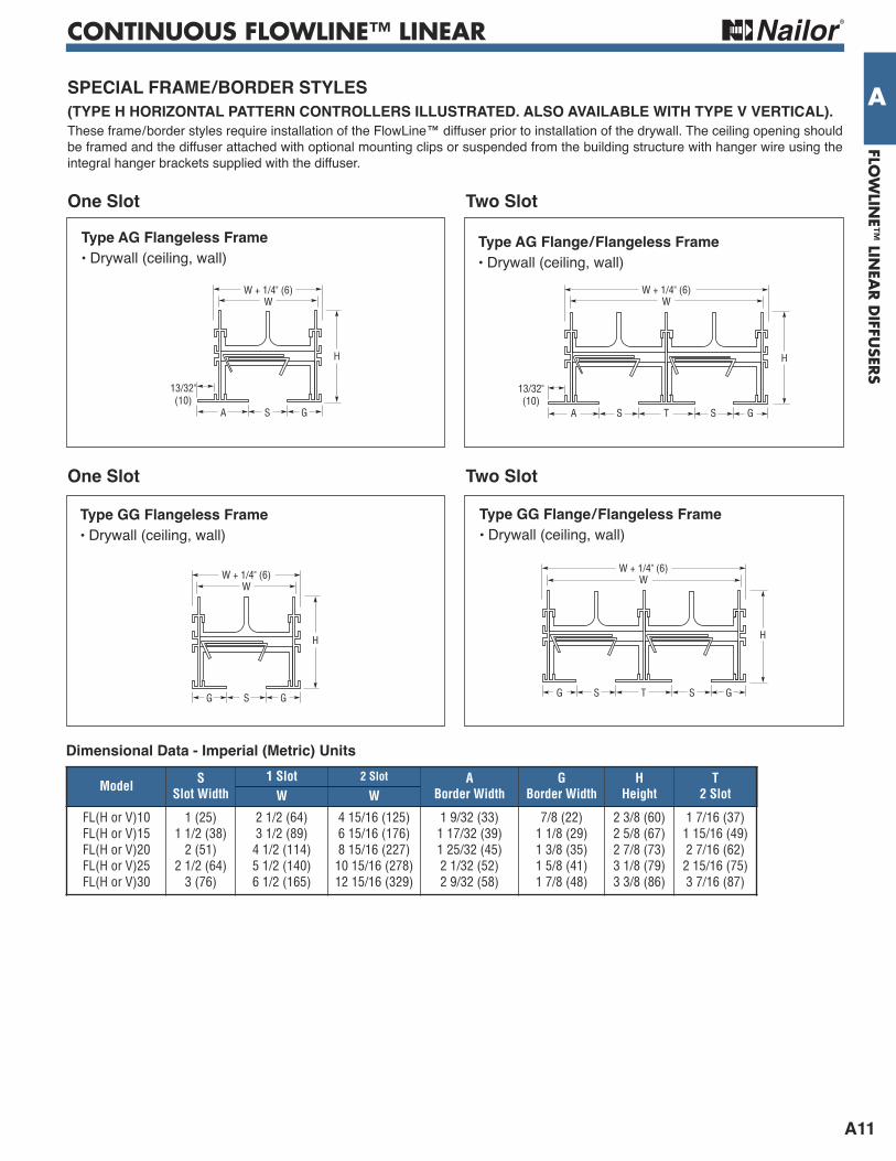
ASPeCiAL FrAMe/BOrDer STyLeS(TyPe H HOriZONTAL PATTerN CONTrOLLerS iLLuSTrATeD. ALSO AVAiLABLe wiTH TyPe V VerTiCAL).These frame/border styles require installation of the FlowLine™ diffuser prior to installation of the drywall. The ceiling opening shouldbe framed and the diffuser attached with optional mounting clips or suspended from the building structure with hanger wire using theintegral hanger brackets supplied with the diffuser.
H
W
SA G
W + 1/4" (6)
13/32"(10)
H
W
S G
W + 1/4" (6)
G
H
W
STS G
W + 1/4" (6)
G
Type AG Flangeless Frame • Drywall (ceiling, wall)
One Slot
Type GG Flangeless Frame • Drywall (ceiling, wall)
Type GG Flange/Flangeless Frame • Drywall (ceiling, wall)
Model SSlot Width
1 Slot 2 Slot ABorder Width
GBorder Width
HHeight
T2 SlotW W
FL(H or V)10FL(H or V)15FL(H or V)20FL(H or V)25FL(H or V)30
1 (25)1 1/2 (38)2 (51)2 1/2 (64)3 (76)
2 1/2 (64)3 1/2 (89)4 1/2 (114)5 1/2 (140)6 1/2 (165)
4 15/16 (125)6 15/16 (176)8 15/16 (227)10 15/16 (278)12 15/16 (329)
1 9/32 (33)1 17/32 (39)1 25/32 (45)2 1/32 (52)2 9/32 (58)
7/8 (22)1 1/8 (29)1 3/8 (35)1 5/8 (41)1 7/8 (48)
2 3/8 (60)2 5/8 (67)2 7/8 (73)3 1/8 (79)3 3/8 (86)
1 7/16 (37)1 15/16 (49)2 7/16 (62)2 15/16 (75)3 7/16 (87)
Dimensional Data - imperial (Metric) units
H
W
STS G
W + 1/4" (6)
A
13/32"(10)
Two Slot
Type AG Flange/Flangeless Frame • Drywall (ceiling, wall)
Two Slot
One Slot
CONTINUOUS FLOWLINE™ LINEAR
A12
FLO
WLI
NE™
LIN
EAR D
IFFU
SERS
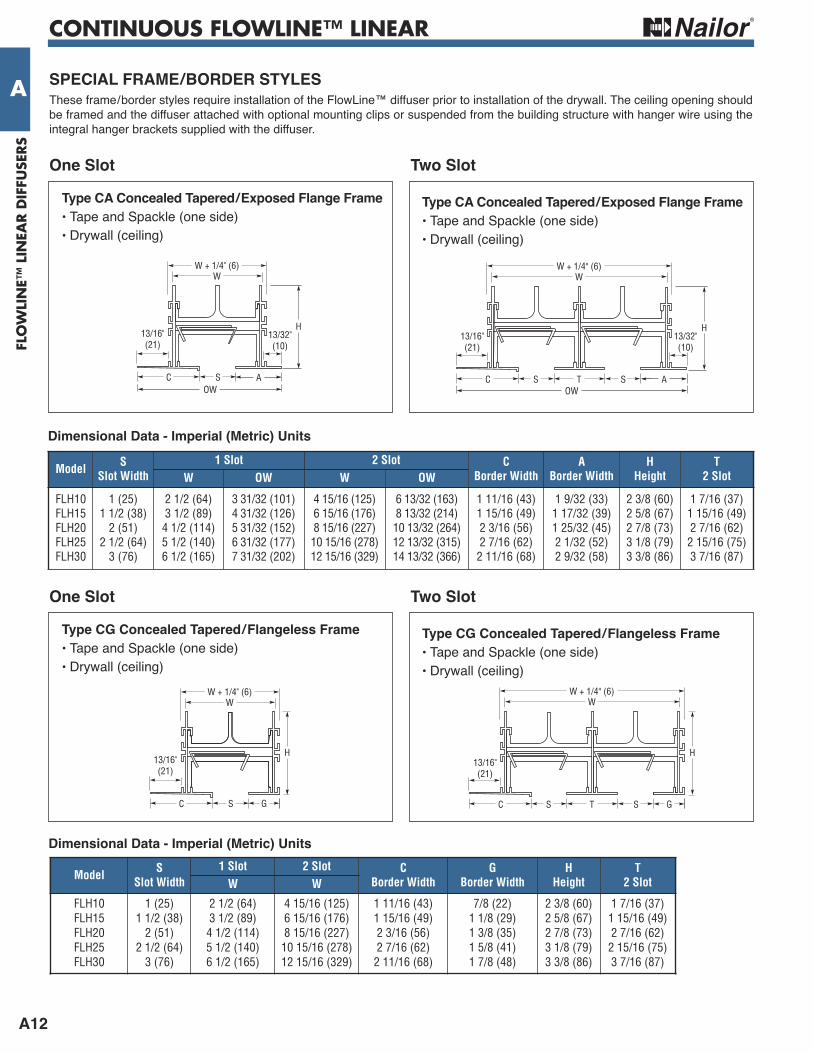
A SPeCiAL FrAMe/BOrDer STyLeSThese frame/border styles require installation of the FlowLine™ diffuser prior to installation of the drywall. The ceiling opening shouldbe framed and the diffuser attached with optional mounting clips or suspended from the building structure with hanger wire using theintegral hanger brackets supplied with the diffuser.
Type CA Concealed Tapered/exposed Flange Frame • Tape and Spackle (one side) • Drywall (ceiling)
Two Slot
Type CA Concealed Tapered/exposed Flange Frame • Tape and Spackle (one side) • Drywall (ceiling)
One Slot
Type CG Concealed Tapered/Flangeless Frame • Tape and Spackle (one side) • Drywall (ceiling)
Two Slot
Type CG Concealed Tapered/Flangeless Frame • Tape and Spackle (one side) • Drywall (ceiling)
One Slot
Dimensional Data - imperial (Metric) units
Model SSlot Width
1 Slot 2 Slot CBorder Width
GBorder Width
HHeight
T2 SlotW W
FLH10FLH15FLH20FLH25FLH30
1 (25)1 1/2 (38)2 (51)2 1/2 (64)3 (76)
2 1/2 (64)3 1/2 (89)4 1/2 (114)5 1/2 (140)6 1/2 (165)
4 15/16 (125)6 15/16 (176)8 15/16 (227)10 15/16 (278)12 15/16 (329)
1 11/16 (43)1 15/16 (49)2 3/16 (56)2 7/16 (62)2 11/16 (68)
7/8 (22)1 1/8 (29)1 3/8 (35)1 5/8 (41)1 7/8 (48)
2 3/8 (60)2 5/8 (67)2 7/8 (73)3 1/8 (79)3 3/8 (86)
1 7/16 (37)1 15/16 (49)2 7/16 (62)2 15/16 (75)3 7/16 (87)
G
H
S
W + 1/4" (6)W
T S
13/16"(21)
CG
H
WW + 1/4" (6)
S
13/16"(21)
C
A
H
OWS
W + 1/4" (6)W
T S
13/16"(21)
13/32"(10)
C
H13/32"(10)
AOW
WW + 1/4" (6)
S
13/16"(21)
C
Model SSlot Width
1 Slot 2 Slot CBorder Width
ABorder Width
HHeight
T2 SlotW OW W OW
FLH10FLH15FLH20FLH25FLH30
1 (25)1 1/2 (38)2 (51)2 1/2 (64)3 (76)
2 1/2 (64)3 1/2 (89)4 1/2 (114)5 1/2 (140)6 1/2 (165)
3 31/32 (101)4 31/32 (126)5 31/32 (152)6 31/32 (177)7 31/32 (202)
4 15/16 (125)6 15/16 (176)8 15/16 (227)10 15/16 (278)12 15/16 (329)
6 13/32 (163)8 13/32 (214)10 13/32 (264)12 13/32 (315)14 13/32 (366)
1 11/16 (43)1 15/16 (49)2 3/16 (56)2 7/16 (62)2 11/16 (68)
1 9/32 (33)1 17/32 (39)1 25/32 (45)2 1/32 (52)2 9/32 (58)
2 3/8 (60)2 5/8 (67)2 7/8 (73)3 1/8 (79)3 3/8 (86)
1 7/16 (37)1 15/16 (49)2 7/16 (62)2 15/16 (75)3 7/16 (87)
Dimensional Data - imperial (Metric) units
CONTINUOUS FLOWLINE™ LINEAR
A13
FLOW
LINE™
LINEA
R D
IFFUSER
S
A
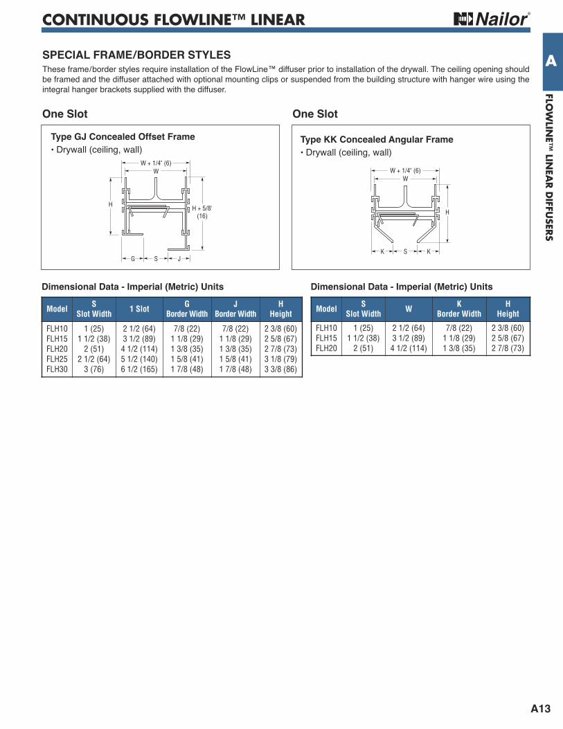
H + 5/8"(16)
W
SG J
W + 1/4" (6)
H
Type GJ Concealed Offset Frame • Drywall (ceiling, wall)
Model SSlot Width W K
Border WidthH
Height
FLH10FLH15FLH20
1 (25)1 1/2 (38)2 (51)
2 1/2 (64)3 1/2 (89)4 1/2 (114)
7/8 (22)1 1/8 (29)1 3/8 (35)
2 3/8 (60)2 5/8 (67)2 7/8 (73)
Dimensional Data - imperial (Metric) units
W
SK K
W + 1/4" (6)
H
One Slot
Type KK Concealed Angular Frame • Drywall (ceiling, wall)
One Slot
Model SSlot Width 1 Slot G
Border WidthJ
Border WidthH
Height
FLH10FLH15FLH20FLH25FLH30
1 (25)1 1/2 (38)2 (51)2 1/2 (64)3 (76)
2 1/2 (64)3 1/2 (89)4 1/2 (114)5 1/2 (140)6 1/2 (165)
7/8 (22)1 1/8 (29)1 3/8 (35)1 5/8 (41)1 7/8 (48)
7/8 (22)1 1/8 (29)1 3/8 (35)1 5/8 (41)1 7/8 (48)
2 3/8 (60)2 5/8 (67)2 7/8 (73)3 1/8 (79)3 3/8 (86)
Dimensional Data - imperial (Metric) units
SPeCiAL FrAMe/BOrDer STyLeSThese frame/border styles require installation of the FlowLine™ diffuser prior to installation of the drywall. The ceiling opening shouldbe framed and the diffuser attached with optional mounting clips or suspended from the building structure with hanger wire using theintegral hanger brackets supplied with the diffuser.

CONTINUOUS FLOWLINE™ LINEAR
A14
FLO
WLI
NE™
LIN
EAR D
IFFU
SERS
A
Frame Type C C F F F O F C e L e L e L e L AA, AAC D - 1/8 (3) D - 1/8 (3) D - 1/4 (6) D +1 5/8 (41) D - 1/8 (3) D + 13/16 (21) D - 1/16 (2) D + 7/8 (22)
CC, CCA, CCC, CCCA D - 1/8 (3) D - 1/8 (3) N/A N/A N/A N/A N/A N/A
GG, AG D - 1/8 (3) D - 1/8 (3) D - 1/4 (6) D +1 5/8 (41) D - 1/8 (3) D + 13/16 (21) D - 1/16 (2) D + 7/8 (22)
CA, CG, GJ, KK D - 1/8 (3) D - 1/8 (3) N/A N/A N/A N/A N/A N/A
eND BOrDer CONFiGurATiONS FOr VAriOuS MOuNTiNGS
DE
1" (25)
L
DE
L
M Mitered end Border F Flanged end Cap
DE
LL
DE
O Open end C Flat end Cap
Frame Type M M M O M C O O O C e L e L e L e L e L AA, AAC D - 1/4 (6) D + 9/16 (14) D - 1/8 (3) D + 9/32 (7) D - 1/16 (2) D + 11/32 (9) D D D - 1/16 (2) D - 1/16 (2)
CC, CCA, CCC, CCCA D - 1/4 (6) D + 1 3/8 (35) D - 1/8 (3) D + 11/16 (17) D - 1/16 (2) D + 3/4 (19) D D D - 1/16 (2) D - 1/16 (2)
GG, AG N/A N/A N/A N/A N/A N/A D D D - 1/16 (2) D - 1/16 (2)
CA, CG, GJ, KK N/A N/A N/A N/A N/A N/A D D D - 1/16 (2) D - 1/16 (2)
Overall Length Dimensions and end Cap PositionD = Duct Length e = end Cap Position L = Overall Length
• Architecturallysuperior look forType A Frame/Border withExposed Flange.
• Factory mounted.
• Removable forfield end trim orstocking.
• Removable forfield end trim orstocking.

CONTINUOUS FLOWLINE™ LINEAR
A15
FLOW
LINE™
LINEA
R D
IFFUSER
S
AOPTiONS AND ACCeSSOrieS
Mitered Corners FLMC10 • 1 " (25) Slot FLMC15 • 1 1/2" (38) Slot FLMC20 • 2" (51) Slot FLMC25 • 2 1/2" (64) Slot FLMC30 • 3" (76) Slot The standard mitered corners are 90° and 135°. Units are factory welded with precision to match and align with the associated straight leg.Units are supplied with factoryinstalled blank-offs in the slot(painted black) and are inactive.Other angles are available.
Special Mitered Corners *Available from 45 – 179° as SPL. (A detailed sketch is required for co-ordination with installing contractors).
TransitionsType C Cross
FLC10 • 1 " (25) Slot FLC15 • 1 1/2" (38) Slot FLC20 • 2" (51) Slot FLC25 • 2 1/2" (64) Slot FLC30 • 3" (76) Slot
Type T Tee FLT10 • 1 " (25) Slot FLT15 • 1 1/2" (38) Slot FLT20 • 2" (51) Slot FLT25 • 2 1/2" (64) Slot FLT30 • 3" (76) SlotTransitions are inactive. Blank-offsinstalled at factory. Not available in2 slot version.
Blank-Offs FLBO10 • 1 " (25) Slot FLBO15 • 1 1/2" (38) Slot FLBO20 • 2" (51) Slot FLBO25 • 2 1/2" (64) Slot FLBO30 • 3" (76) Slot
Corrosion resistant steel, paintedflat black. Fit in neck of diffuser.Provided in 48 " (1219) lengths.Field cut to length.
No. ofSlots
SlotWidth
Border AA, CC Border GG
L1 L2 L1 L2
1
1 (25)1 1/2 (38)2 (51)
9 9/16 (243)10 9/16 (268)11 9/16 (294)
7 15/32 (190)7 7/8 (200)8 5/16 (211)
8 11/16 (221)9 11/16 (246)10 11/16 (271)
7 1/8 (181)7 17/32 (191)7 15/16 (202)
2 1/2 (64)3 (76)
12 9/16 (319)13 9/16 (344)
8 23/32 (221)9 1/8 (232)
11 11/16 (297)12 11/16 (322)
8 11/32 (212)8 3/4 (222)
2
1 (25)1 1/2 (38)2 (51)
11 31/32 (304)13 31/32 (355)15 31/32 (406)
8 15/32 (215)9 5/16 (237)10 1/8 (257)
11 3/32 (282)13 3/32 (333)15 3/32 (383)
8 3/32 (206)8 29/32 (226)9 3/4 (248)
2 1/2 (64)3 (76)
17 31/32 (456)19 31/32 (507)
10 31/32 (279)11 25/32 (299)
17 3/32 (434)19 3/32 (485)
10 9/16 (268)11 13/32 (290)
L1
6"(152)
90°
OW
L2
6"(152)
135°
6"(152)
L
OW
6"(152)
6"(152)
L
OW
No. ofSlots
SlotWidth
Border AA, CC Border GG
OW L OW L
1
1 (25)1 1/2 (38)2 (51)
3 9/16 (90)4 9/16 (116)5 9/16 (141)
15 9/16 (395)16 9/16 (421)17 9/16 (446)
2 3/4 (70)3 3/4 (95)4 3/4 (121)
14 11/16 (373)15 11/16 (398)16 11/16 (424)
2 1/2 (64)3 (76)
6 9/16 (167)7 9/16 (192)
18 9/16 (471)19 9/16 (497)
5 3/4 (146)6 3/4 (171)
17 11/16 (449)18 11/16 (475)
CONTINUOUS FLOWLINE™ LINEAR
A16
FLO
WLI
NE™
LIN
EAR D
IFFU
SERS
A OPTiONS AND ACCeSSOrieS
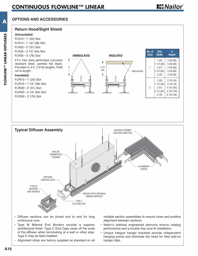
return Hood/Sight Shielduninsulated:
FLR10 • 1 " (25) Slot FLR15 • 1 1/2" (38) Slot FLR20 • 2" (51) Slot FLR25 • 2 1/2" (64) Slot FLR30 • 3" (76) Slot51% free area perforated corrosionresistant steel, painted flat black.Provided in 4 ft. (1219) lengths. Fieldcut to length.insulated:
FLRI10 • 1 " (25) Slot FLRI15 • 1 1/2" (38) Slot FLRI20 • 2" (51) Slot FLRI25 • 2 1/2" (64) Slot FLRI30 • 3" (76) Slot
No. ofSlots
SlotWidth
HHeight
1
1 (25)1 1/2 (38)2 (51)2 1/2 (64)3 (76)
3 3/8 (86)3 3/8 (86)3 3/8 (86)3 3/8 (86)3 3/8 (86)
2
1 (25)1 1/2 (38)2 (51)2 1/2 (64)3 (76)
2 1/8 (54)3 1/8 (79)4 1/8 (105)5 1/8 (130)6 1/8 (156)
INSULATION
H
INSULATEDUNINSULATED
2 1/2"(64)
Typical Diffuser Assembly
• Diffuser sections can be joined end to end for longcontinuous runs.
• Type M Mitered End Borders provide a superiorarchitectural finish. Type C End Caps close off the endsof the diffuser when terminating at a wall or other stop.Type C may be field installed.
• Alignment strips are factory supplied as standard on all
multiple section assemblies to ensure close and positivealignment between sections.
• Nailor’s optional engineered plenums ensure catalogperformance and a trouble free sure fit installation.
• Unique integral hanger brackets provide independenthanging points and eliminate the need for field add-onhanger clips.
ALIGNMENTSTRIPS
TYPE CFLAT END CAP
SPACER WITH INTEGRALHANGER BRACKET
PATTERNCONTROLLERS
TYPE MMITERED
END BORDER
NAILORENGINEERED
PLENUM
MITERED CORNERSECTION (INACTIVE)
CONTINUOUS FLOWLINE™ LINEAR • TECHZONE™
A17
FLOW
LINE™
LINEA
R D
IFFUSER
S
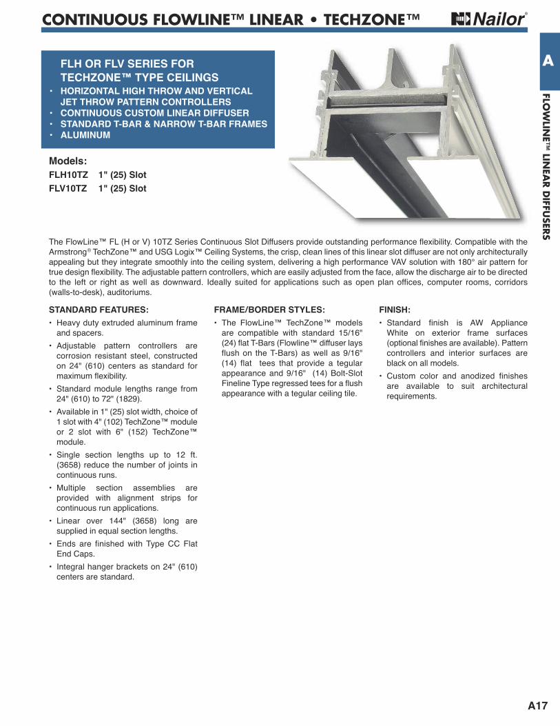
A FLH Or FLV SerieS FOr TeCHZONe™ TyPe CeiLiNGS• HOriZONTAL HiGH THrOw AND VerTiCAL JeT THrOw PATTerN CONTrOLLerS• CONTiNuOuS CuSTOM LiNeAr DiFFuSer• STANDArD T-BAr & NArrOw T-BAr FrAMeS• ALuMiNuM
The FlowLine™ FL (H or V) 10TZ Series Continuous Slot Diffusers provide outstanding performance flexibility. Compatible with theArmstrong® TechZone™ and USG Logix™ Ceiling Systems, the crisp, clean lines of this linear slot diffuser are not only architecturallyappealing but they integrate smoothly into the ceiling system, delivering a high performance VAV solution with 180° air pattern fortrue design flexibility. The adjustable pattern controllers, which are easily adjusted from the face, allow the discharge air to be directedto the left or right as well as downward. Ideally suited for applications such as open plan offices, computer rooms, corridors(walls-to-desk), auditoriums.
Models:FLH10TZ 1" (25) SlotFLV10TZ 1" (25) Slot
STANDArD FeATureS:• Heavy duty extruded aluminum frameand spacers.
• Adjustable pattern controllers arecorrosion resistant steel, constructedon 24" (610) centers as standard formaximum flexibility.
• Standard module lengths range from24" (610) to 72" (1829).
• Available in 1" (25) slot width, choice of1 slot with 4" (102) TechZone™ moduleor 2 slot with 6" (152) TechZone™module.
• Single section lengths up to 12 ft.(3658) reduce the number of joints incontinuous runs.
• Multiple section assemblies areprovided with alignment strips forcontinuous run applications.
• Linear over 144" (3658) long aresupplied in equal section lengths.
• Ends are finished with Type CC FlatEnd Caps.
• Integral hanger brackets on 24" (610)centers are standard.
FrAMe/BOrDer STyLeS:• The FlowLine™ TechZone™ modelsare compatible with standard 15/16"(24) flat T-Bars (Flowline™ diffuser laysflush on the T-Bars) as well as 9/16"(14) flat tees that provide a tegularappearance and 9/16" (14) Bolt-SlotFineline Type regressed tees for a flushappearance with a tegular ceiling tile.
FiNiSH:• Standard finish is AW Appliance White on exterior frame surfaces(optional finishes are available). Patterncontrollers and interior surfaces areblack on all models.
• Custom color and anodized finishes are available to suit architecturalrequirements.
CONTINUOUS FLOWLINE™ LINEAR • TECHZONE™
A18
FLO
WLI
NE™
LIN
EAR D
IFFU
SERS
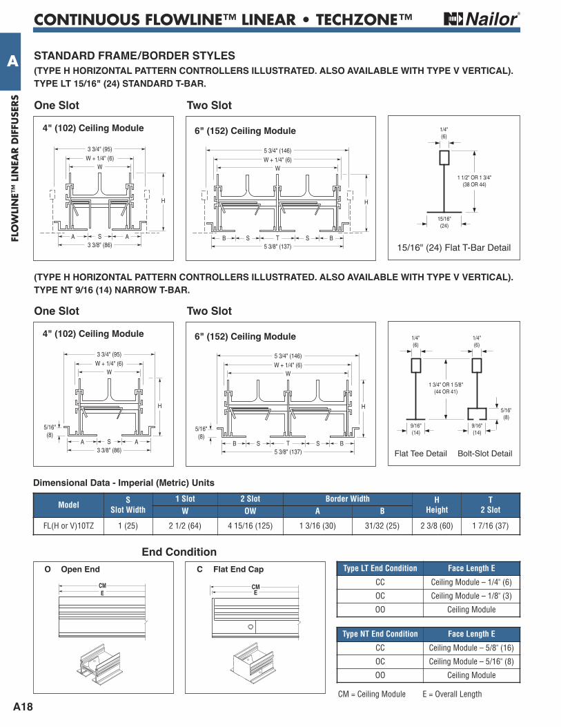
A STANDArD FrAMe/BOrDer STyLeS(TyPe H HOriZONTAL PATTerN CONTrOLLerS iLLuSTrATeD. ALSO AVAiLABLe wiTH TyPe V VerTiCAL).TyPe LT 15/16" (24) STANDArD T-BAr.
4" (102) Ceiling Module
Model SSlot Width
1 Slot 2 Slot Border Width HHeight
T2 SlotW OW A B
FL(H or V)10TZ 1 (25) 2 1/2 (64) 4 15/16 (125) 1 3/16 (30) 31/32 (25) 2 3/8 (60) 1 7/16 (37)
Dimensional Data - imperial (Metric) units
Two Slot
6" (152) Ceiling Module
One Slot
15/16" (24) Flat T-Bar Detail
H
3 3/4" (95)W + 1/4" (6)
3 3/8" (86)S AA
W
5 3/4" (146)W + 1/4" (6)
5 3/8" (137)T S BSB
W
H
1 1/2" OR 1 3/4"(38 OR 44)
1/4"(6)
15/16"(24)
Type LT End Condition Face Length E
CC Ceiling Module – 1/4" (6)
OC Ceiling Module – 1/8" (3)
OO Ceiling Module
CM = Ceiling Module E = Overall Length
CME
end Condition O Open end
CME
C Flat end Cap
4" (102) Ceiling Module
Two Slot
6" (152) Ceiling Module
One Slot
H
3 3/4" (95)W + 1/4" (6)
3 3/8" (86)S AA
W
5/16"(8)
5 3/4" (146)W + 1/4" (6)
5 3/8" (137)T S BSB
W
5/16"(8)
H
1 3/4" OR 1 5/8" (44 OR 41)
5/16" (8)
1/4" (6)
9/16" (14)
1/4" (6)
9/16" (14)
Flat Tee Detail Bolt-Slot Detail
(TyPe H HOriZONTAL PATTerN CONTrOLLerS iLLuSTrATeD. ALSO AVAiLABLe wiTH TyPe V VerTiCAL).TyPe NT 9/16 (14) NArrOw T-BAr.
Type NT End Condition Face Length E
CC Ceiling Module – 5/8" (16)
OC Ceiling Module – 5/16" (8)
OO Ceiling Module
CONTINUOUS FLOWLINE™ LINEAR
A19
FLOW
LINE™
LINEA
R D
IFFUSER
S
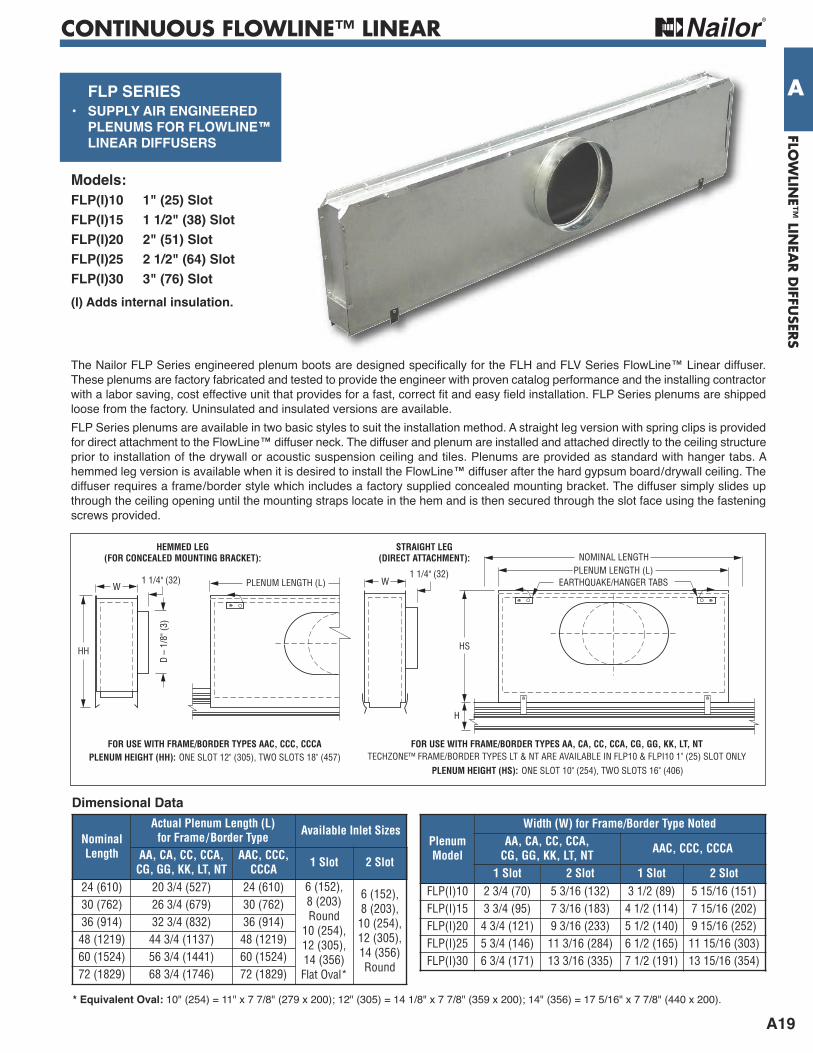
A FLP SerieS• SuPPLy Air eNGiNeereD PLeNuMS FOr FLOwLiNe™ LiNeAr DiFFuSerS
The Nailor FLP Series engineered plenum boots are designed specifically for the FLH and FLV Series FlowLine™ Linear diffuser.These plenums are factory fabricated and tested to provide the engineer with proven catalog performance and the installing contractorwith a labor saving, cost effective unit that provides for a fast, correct fit and easy field installation. FLP Series plenums are shippedloose from the factory. Uninsulated and insulated versions are available.FLP Series plenums are available in two basic styles to suit the installation method. A straight leg version with spring clips is providedfor direct attachment to the FlowLine™ diffuser neck. The diffuser and plenum are installed and attached directly to the ceiling structureprior to installation of the drywall or acoustic suspension ceiling and tiles. Plenums are provided as standard with hanger tabs. Ahemmed leg version is available when it is desired to install the FlowLine™ diffuser after the hard gypsum board/drywall ceiling. Thediffuser requires a frame/border style which includes a factory supplied concealed mounting bracket. The diffuser simply slides upthrough the ceiling opening until the mounting straps locate in the hem and is then secured through the slot face using the fasteningscrews provided.
Models:FLP(i)10 1" (25) SlotFLP(i)15 1 1/2" (38) SlotFLP(i)20 2" (51) SlotFLP(i)25 2 1/2" (64) SlotFLP(i)30 3" (76) Slot(i) Adds internal insulation.
HSHH
1 1/4" (32) WW PLENUM LENGTH (L)
PLENUM LENGTH (L)EARTHQUAKE/HANGER TABS
NOMINAL LENGTH
D –
1/8"
(3)
STRAIGHT LEG(DIRECT ATTACHMENT):
HEMMED LEG(FOR CONCEALED MOUNTING BRACKET):
ONE SLOT 10" (254), TWO SLOTS 16" (406)PLENUM HEIGHT (HS):ONE SLOT 12" (305), TWO SLOTS 18" (457)PLENUM HEIGHT (HH):
FOR USE WITH FRAME/BORDER TYPES AAC, CCC, CCCA FOR USE WITH FRAME/BORDER TYPES AA, CA, CC, CCA, CG, GG, KK, LT, NTTECHZONE™ FRAME/BORDER TYPES LT & NT ARE AVAILABLE IN FLP10 & FLPI10 1" (25) SLOT ONLY
H
1 1/4" (32)
* equivalent Oval: 10" (254) = 11" x 7 7/8" (279 x 200); 12" (305) = 14 1/8" x 7 7/8" (359 x 200); 14" (356) = 17 5/16" x 7 7/8" (440 x 200).
Dimensional Data
NominalLength
Actual Plenum Length (L)for Frame/Border Type Available Inlet Sizes
AA, CA, CC, CCA,CG, GG, KK, LT, NT
AAC, CCC,CCCA 1 Slot 2 Slot
24 (610) 20 3/4 (527) 24 (610) 6 (152),8 (203)Round10 (254),12 (305),14 (356)Flat Oval*
6 (152),8 (203),10 (254),12 (305),14 (356)Round
30 (762) 26 3/4 (679) 30 (762)36 (914) 32 3/4 (832) 36 (914)48 (1219) 44 3/4 (1137) 48 (1219)60 (1524) 56 3/4 (1441) 60 (1524)72 (1829) 68 3/4 (1746) 72 (1829)
PlenumModel
Width (W) for Frame/Border Type NotedAA, CA, CC, CCA,CG, GG, KK, LT, NT AAC, CCC, CCCA
1 Slot 2 Slot 1 Slot 2 SlotFLP(I)10 2 3/4 (70) 5 3/16 (132) 3 1/2 (89) 5 15/16 (151)FLP(I)15 3 3/4 (95) 7 3/16 (183) 4 1/2 (114) 7 15/16 (202)FLP(I)20 4 3/4 (121) 9 3/16 (233) 5 1/2 (140) 9 15/16 (252)FLP(I)25 5 3/4 (146) 11 3/16 (284) 6 1/2 (165) 11 15/16 (303)FLP(I)30 6 3/4 (171) 13 3/16 (335) 7 1/2 (191) 13 15/16 (354)

CONTINUOUS FLOWLINE™ LINEAR
A20
FLO
WLI
NE™
LIN
EAR D
IFFU
SERS
AThe Nailor FLP Series engineered plenum boots with IDCO option (Cable Operated inlet damper) are designed specifically for the FLHand FLV Series FlowLine™ Linear diffuser. These plenums are factory fabricated and tested to provide the engineer with proven catalogperformance and the installing contractor with a labor saving, cost effective unit that provides for a fast, correct fit and easy fieldinstallation. FLP Series plenums are shipped loose from the factory. Uninsulated and insulated versions are available.The round inlet damper is Nailor’s 4250 radial sliding blade design factory mounted on the inlet. A flexible rotary cable connects thedamper to a Phillips head screw operator mounted inside the plenum that permits air balancing at the diffuser face.FLP Series plenums are available in two basic styles to suit the installation method. A straight leg version with spring clips is providedfor direct attachment to the FlowLine™ diffuser neck. The diffuser and plenum are installed and attached directly to the ceiling structureprior to installation of the drywall or acoustic suspension ceiling and tiles. Plenums are provided as standard with hanger tabs. A hemmedleg version is available when it is desired to install the FlowLine™ diffuser after the hard gypsum board/drywall ceiling. The diffuserrequires a frame/border style which includes a factory supplied concealed mounting bracket. The diffuser simply slides up through theceiling opening until the mounting straps locate in the hem and is then secured through the slot face using the fastening screws provided.
HSHHD
– 1/
8" (3
)
D –
1/8"
(3)
2 3/4"(70)
2 3/4"(70)
WW PLENUM LENGTH (L)PLENUM LENGTH (L)
EARTHQUAKE/HANGER TABS
NOMINAL LENGTHSTRAIGHT LEG
(DIRECT ATTACHMENT):HEMMED LEG
(FOR CONCEALED MOUNTING BRACKET):
FOR USE WITH FRAME/BORDER TYPES AAC, CCC, CCCA FOR USE WITH FRAME/BORDER TYPES AA, CA, CC, CCA, CG, GG, KK, LT, NT
H
TECHZONE™ FRAME/BORDER TYPES LT & NT ARE AVAILABLE IN FLP10 & FLPI10 1" (25) SLOT ONLY
Dimensional Data
NominalLength
Actual Plenum Length (L)for Frame/Border Type
AA, CA, CC, CCA,CG, GG, KK, LT, NT
AAC, CCC,CCCA
24 (610) 20 3/4 (527) 24 (610)30 (762) 26 3/4 (679) 30 (762)36 (914) 32 3/4 (832) 36 (914)48 (1219) 44 3/4 (1137) 48 (1219)60 (1524) 56 3/4 (1441) 60 (1524)72 (1829) 68 3/4 (1746) 72 (1829)
PlenumModel
Width (W) for Frame/Border Type NotedAA, CA, CC, CCA, CG, GG, KK, LT, NT AAC, CCC, CCCA
1 Slot 2 Slot 1 Slot 2 SlotFLP(I)10 2 3/4 (70) 5 3/16 (132) 3 1/2 (89) 5 15/16 (151)FLP(I)15 3 3/4 (95) 7 3/16 (183) 4 1/2 (114) 7 15/16 (202)FLP(I)20 4 3/4 (121) 9 3/16 (233) 5 1/2 (140) 9 15/16 (252)FLP(I)25 5 3/4 (146) 11 3/16 (284) 6 1/2 (165) 11 15/16 (303)FLP(I)30 6 3/4 (171) 13 3/16 (335) 7 1/2 (191) 13 15/16 (354)
FLP PLeNuMS wiTH iDCO OPTiON (CABLe OPerATeD iNLeT DAMPer)
Straight Leg (Direct Attachment)For use w/Frame/Border Types AA, CA, CC, CCA, CG, GG, KK, LT, NT
Hemmed Leg (For concealed mounting bracket)For use w/Frame/Border Types AAC, CCC, CCCA
Inlet Size D(Round)
Plenum Height HH1 Slot 2 Slot
6 (152), 8 (203)10 (254)12 (305)14 (356)
12 (305)13 (330)15 (381)17 (432)
18 (457)18 (457)18 (457)18 (457)
Inlet Size D(Round)
Plenum Height HS1 Slot 2 Slot
6 (152), 8 (203)10 (254)12 (305)14 (356)
10 (254)13 (330)15 (381)17 (432)
16 (406)16 (406)16 (406)17 (432)

CONTINUOUS FLOWLINE™ LINEAR
A21
FLOW
LINE™
LINEA
R D
IFFUSER
S
A
1"(25)
A
1 1/2"(38)
2"(51)
HC1 Hard Ceiling Clip 5/8" (16)HC5 Hard Ceiling Clip 1/2" (13)
HARDCEILING
CLIPS
24" (610) MAXIMUMCENTERS
FRAMEOPENINGWIDTH FW
MOUNTINGSCREWS
CEILINGFRAMINGMEMBERS
ALIGNMENTSTRIPS
Typical installation
DRYWALL
FRAMINGMEMBER
FLAT HEADSCREW
HC1/HC5HARD
CEILING CLIP
exposed Flange Frame Type AA
DRYWALL
FRAMINGMEMBER
FLAT HEADSCREW
HC1/HC5HARD
CEILING CLIP
TAPE AND SPACKLE
Concealed Tapered Frame Type CC
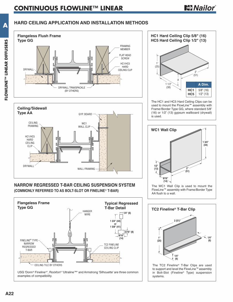
HArD CeiLiNG APPLiCATiON AND iNSTALLATiON MeTHODS
The HC1 and HC5 Hard Ceiling Clips can beused to mount the FlowLine™ assembly withFrame/Border Types AA, CC or GG, where5/8" (16) or 1/2" (13) gypsum wallboard(drywall) is used.
A Dim.HC1HC5
5/8" (16)1/2" (13)
ModelFrame Opening Width FW1 Slot 2 Slot
FL(H or V)10FL(H or V)15FL(H or V)20FL(H or V)25FL(H or V)30
3 1/4 (83)4 1/4 (108)5 1/4 (133)6 1/4 (159)7 1/4 (184)
5 3/4 (146)7 3/4 (197)9 3/4 (248)11 3/4 (298)13 3/4 (349)
CONTINUOUS FLOWLINE™ LINEAR
A22
FLO
WLI
NE™
LIN
EAR D
IFFU
SERS
A
1"(25)
A
1 1/2"(38)
2"(51)
The HC1 and HC5 Hard Ceiling Clips can beused to mount the FlowLine™ assembly withFrame/Border Type GG, where standard 5/8"(16) or 1/2" (13) gypsum wallboard (drywall)is used.
HC1 Hard Ceiling Clip 5/8" (16)HC5 Hard Ceiling Clip 1/2" (13)
HArD CeiLiNG APPLiCATiON AND iNSTALLATiON MeTHODS
FRAMINGMEMBER
FLAT HEADSCREW
HC1/HC5HARD
CEILING CLIP
DRYWALL TRIM/SPACKLE(BY OTHERS)
DRYWALL
Flangeless Flush Frame Type GG
CEILINGFRAMING
GYP. BOARD
HC1/HC5HARD
CEILINGCLIP
DRYWALLWALL FRAMING
WC1WALL CLIP
Ceiling/Sidewall Type AA
1 3/4"(44)
9/16"(14)
2"(51)
1/2"(13)
wC1 wall Clip
NArrOw reGreSSeD T-BAr CeiLiNG SuSPeNSiON SySTeM(COMMONLy reFerreD TO AS BOLT-SLOT Or FiNeLiNe® T-BAr)
The WC1 Wall Clip is used to mount theFlowLine™ assembly with Frame/Border TypeAA flush to a wall.
HANGERWIRE
TC2 FINELINECEILING CLIP
FINELINE® TYPENARROW
REGRESSEDT-BAR
CEILING TILE BY OTHERS
Flangeless Frame Type GG
1"(25)
2 (51)"
1/4"(6)
1/4"(6)
TC2 Fineline® T-Bar Clip1/4" (6)
1 3/4" (44)or
1 5/8" (41)
5/16" (8)9/16"(14)
Typical regressedT-Bar Detail
USG 'Donn® Fineline®', Rockfon® 'Ultraline™' and Armstrong 'Silhouette' are three commonexamples of compatibility.
The TC2 Fineline® T-Bar Clips are used to support and level the FlowLine™assemblyin Bolt-Slot (Fineline® Type) suspensionsystems.
A Dim.HC1HC5
5/8" (16)1/2" (13)

CONTINUOUS FLOWLINE™ LINEAR
A23
FLOW
LINE™
LINEA
R D
IFFUSER
S
AHArD CeiLiNG APPLiCATiON AND iNSTALLATiON MeTHODS
DRYWALL
CONCEALEDMOUNTING BRACKET
exposed Flange Frame Type AAC
FLCMB Concealed MountingBracket
Concealed Tapered Frame with Concealed Mounting Brackets Type CCC
Supplied as standard with Frame/BorderTypes AAC, CCC and CCCA.
CONCEALEDMOUNTINGBRACKET
TAPE AND SPACKLE
DRYWALL
CONTINUOUS FLOWLINE™ LINEAR
A24
FLO
WLI
NE™
LIN
EAR D
IFFU
SERS
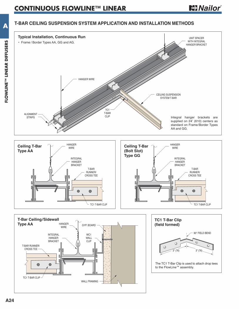
A T-BAr CeiLiNG SuSPeNSiON SySTeM APPLiCATiON AND iNSTALLATiON MeTHODS
HANGERWIRE
TC1 T-BAR CLIP
INTEGRALHANGERBRACKET
T-BARRUNNER/
CROSS TEE
Ceiling T-Bar Type AA
3" (76)3" (76)
90° FIELD BEND
TC1 T-Bar Clip(field formed)
INTEGRALHANGERBRACKET
HANGERWIRE
T-BAR RUNNER/CROSS TEE
WALL FRAMINGTC1 T-BAR CLIP
WC1WALLCLIP
GYP. BOARD
T-Bar Ceiling/Sidewall Type AA
CEILING SUSPENSIONSYSTEM T-BAR
HANGER WIRE
UNIT SPACERWITH INTEGRAL
HANGER BRACKET
ALIGNMENTSTRIPS
TC1T-BARCLIP
Typical installation, Continuous run• Frame / Border Types AA, GG and AG.
Integral hanger brackets aresupplied on 24" (610) centers asstandard on Frame/Border TypesAA and GG.
The TC1 T-Bar Clip is used to attach drop teesto the FlowLine™ assembly.
HANGERWIRE
TC1 T-BAR CLIP
INTEGRALHANGERBRACKET
T-BARRUNNER/
CROSS TEE
Ceiling T-Bar (Bolt Slot) Type GG
CONTINUOUS FLOWLINE™ LINEAR
A25
FLOW
LINE™
LINEA
R D
IFFUSER
S
A
FLAT HEADSCREW
HC1/HC5 HARDCEILING CLIP
FRAMINGMEMBER
5/8" (16)DRYWALL
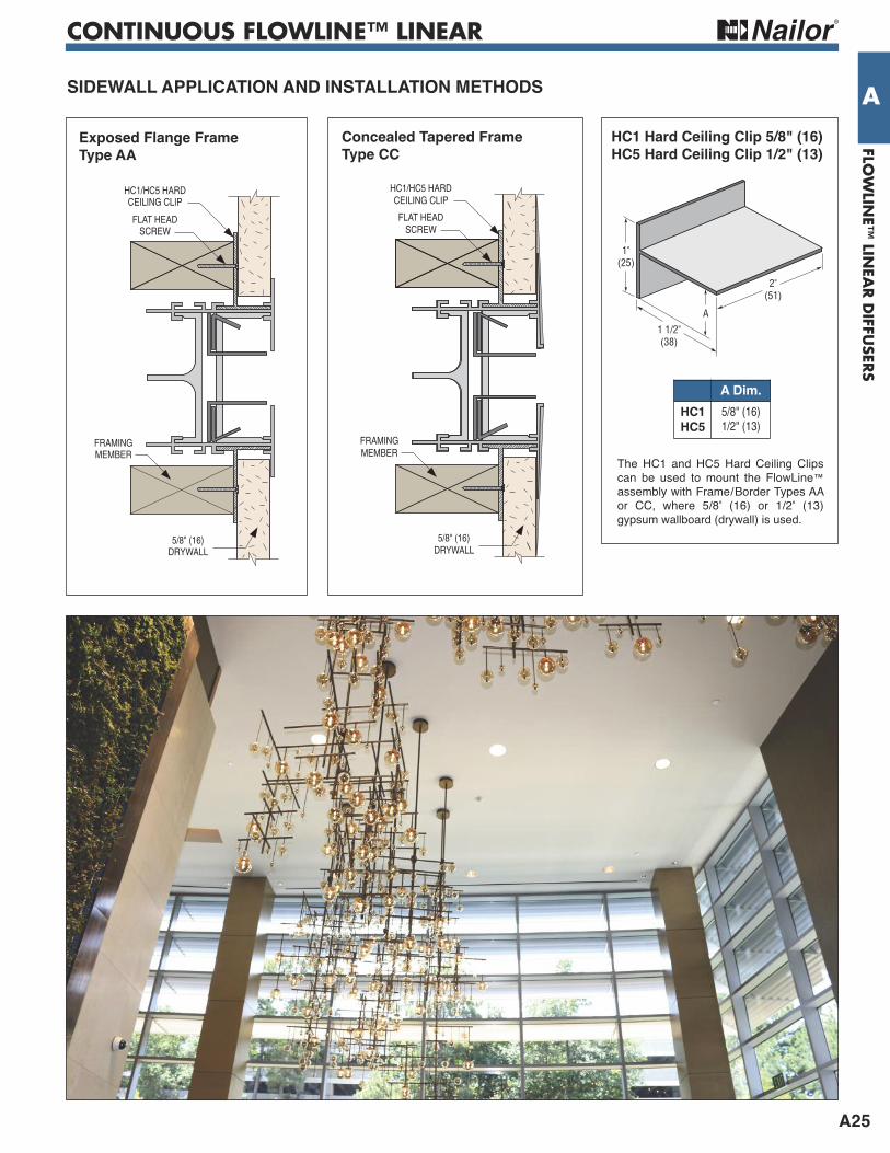
SiDewALL APPLiCATiON AND iNSTALLATiON MeTHODS
exposed Flange Frame Type AA
FLAT HEADSCREW
HC1/HC5 HARDCEILING CLIP
FRAMINGMEMBER
5/8" (16)DRYWALL
Concealed Tapered Frame Type CC
1"(25)
A
1 1/2"(38)
2"(51)
HC1 Hard Ceiling Clip 5/8" (16)HC5 Hard Ceiling Clip 1/2" (13)
The HC1 and HC5 Hard Ceiling Clipscan be used to mount the FlowLine™assembly with Frame/Border Types AAor CC, where 5/8" (16) or 1/2" (13)gypsum wallboard (drywall) is used.
A Dim.HC1HC5
5/8" (16)1/2" (13)

CONTINUOUS FLOWLINE™ LINEAR
A26
FLO
WLI
NE™
LIN
EAR D
IFFU
SERS
A SiDewALL APPLiCATiON AND iNSTALLATiON MeTHODS
Mounting Clips HC2 Hard Ceiling Clip
A
DETAIL A
HC2 HARDCEILING CLIP
CEILINGFRAMING
FLAT HEADSCREW
5/8" (16)DRYWALL
1/2" (13)DRYWALL
5/8" (16)DRYWALL
WALLFRAMING
HC2 HARDCEILING CLIP
1"(25)
2"(51)
1"(25)
11/16"(17)
Flowline Part No. A Dim. B Dim.FLH10 HC3-10 13/16 (21) 3/16 (5)
FLH15 HC3-15 1 1/16 (27) 7/16 (11)
FLH20 HC3-20 1 5/16 (33) 11/16 (17)
Flangeless Concealed FrameType GJ
The WC2 Wall Clip can be used tomount the FlowLineTM assembly withframe/border types G or J, flush to awall.
The HC2 Hard Ceiling Clip can be usedto mount the FlowLineTM assembly withframe/border type G, where standard5/8" (16) gypsum wallboard (drywall) isinstalled below the frame face.
The HC3 Hard Ceiling Clip can be usedto mount the FlowLineTM assembly withframe/border type K, where standard 5/8"(16) gypsum wallboard (drywall) is used.
5/16"(8)
15/16"(24)
13/16" (21)
1"(25)
2"(51)
2"(51) 1 1/2"
(38)
A
CROSS-SECTION
3/8"(10)
11/16"(17)
1/8"(3)
1"(25)
1"(25)
1/16"(2)
CROSS-SECTION
3/16" (5) 3/16" (5)
3/16"(5)
15/16"(24)
13/16" (21)
B
DETAIL B
WC2 WALL CLIP
WC2 WALL CLIPCEILINGFRAMING
FLAT HEADSCREW
5/8" (16)DRYWALL1/2" (13)DRYWALL
5/8" (16)DRYWALL
WALLFRAMING
CROSS-SECTION
1 1/2"(38)
1/8"(3)
10/16" (16)A
B
C
DETAIL C
HC3 HARDCEILNG CLIP
HC3 HARDCEILNG CLIP
HC3 HARDCEILNG CLIP
TAPE AND SPACKLETAPE AND SPACKLE
FRAMINGMEMBER
FRAMINGMEMBER
FLAT HEADSCREW
FLAT HEADSCREW
5/8" (16)DRYWALL
5/8" (16)DRYWALL
Mounting Clips wC2 wall Clip
Flangeless Concealed FrameType GJ
Mounting Clips HC3 Hard Ceiling Clip for Type K Border
Flangeless Concealed FrameType KK
PERFORMANCE DATA • FLH SERIES
A31
FLOW
LINE™
LINEA
R D
IFFUSER
S
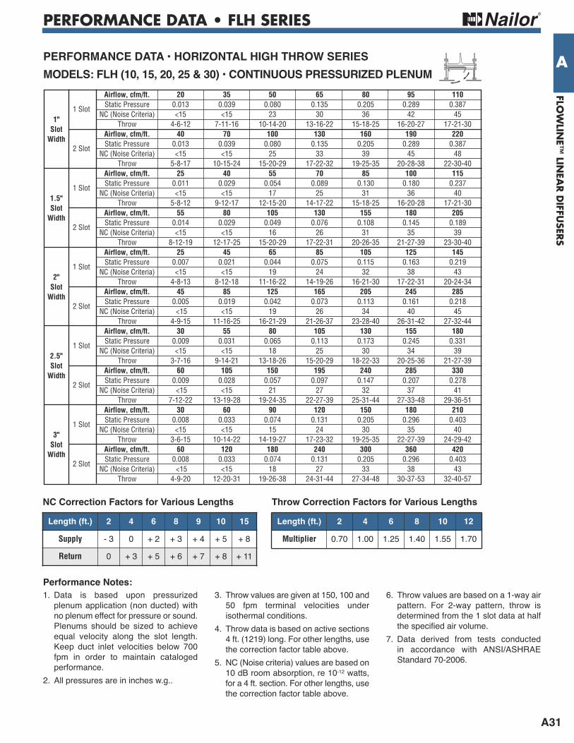
APerFOrMANCe DATA • HOriZONTAL HiGH THrOw SerieSMODeLS: FLH (10, 15, 20, 25 & 30) • CONTiNuOuS PreSSuriZeD PLeNuM
1. Data is based upon pressurizedplenum application (non ducted) withno plenum effect for pressure or sound.Plenums should be sized to achieveequal velocity along the slot length.Keep duct inlet velocities below 700fpm in order to maintain catalogedperformance.
2. All pressures are in inches w.g..
3. Throw values are given at 150, 100 and50 fpm terminal velocities underisothermal conditions.
4. Throw data is based on active sections4 ft. (1219) long. For other lengths, usethe correction factor table above.
5. NC (Noise criteria) values are based on10 dB room absorption, re 10-12 watts,for a 4 ft. section. For other lengths, usethe correction factor table above.
6. Throw values are based on a 1-way airpattern. For 2-way pattern, throw isdetermined from the 1 slot data at halfthe specified air volume.
7. Data derived from tests conducted in accordance with ANSI/ASHRAEStandard 70-2006.
Performance Notes:
Airflow, cfm/ft. 20 35 50 65 80 95 110
1 Slot Static Pressure 0.013 0.039 0.080 0.135 0.205 0.289 0.387
NC (Noise Criteria) <15 <15 23 30 36 42 45
1" Throw 4-6-12 7-11-16 10-14-20 13-16-22 15-18-25 16-20-27 17-21-30
Slot
Airflow, cfm/ft. 40 70 100 130 160 190 220
Width 2 Slot
Static Pressure 0.013 0.039 0.080 0.135 0.205 0.289 0.387 NC (Noise Criteria) <15 <15 25 33 39 45 48 Throw 5-8-17 10-15-24 15-20-29 17-22-32 19-25-35 20-28-38 22-30-40 Airflow, cfm/ft. 25 40 55 70 85 100 115
1 Slot Static Pressure 0.011 0.029 0.054 0.089 0.130 0.180 0.237
NC (Noise Criteria) <15 <15 17 25 31 36 40
1.5" Throw 5-8-12 9-12-17 12-15-20 14-17-22 15-18-25 16-20-28 17-21-30
Slot
Airflow, cfm/ft. 55 80 105 130 155 180 205
Width 2 Slot
Static Pressure 0.014 0.029 0.049 0.076 0.108 0.145 0.189 NC (Noise Criteria) <15 <15 16 26 31 35 39 Throw 8-12-19 12-17-25 15-20-29 17-22-31 20-26-35 21-27-39 23-30-40 Airflow, cfm/ft. 25 45 65 85 105 125 145
1 Slot Static Pressure 0.007 0.021 0.044 0.075 0.115 0.163 0.219
NC (Noise Criteria) <15 <15 19 24 32 38 43
2" Throw 4-8-13 8-12-18 11-16-22 14-19-26 16-21-30 17-22-31 20-24-34
Slot Airflow, cfm/ft. 45 85 125 165 205 245 285
Width
2 Slot
Static Pressure 0.005 0.019 0.042 0.073 0.113 0.161 0.218 NC (Noise Criteria) <15 <15 19 26 34 40 45 Throw 4-9-15 11-16-25 16-21-29 21-26-37 23-28-40 26-31-42 27-32-44 Airflow, cfm/ft. 30 55 80 105 130 155 180
1 Slot Static Pressure 0.009 0.031 0.065 0.113 0.173 0.245 0.331
NC (Noise Criteria) <15 <15 18 25 30 34 39
2.5" Throw 3-7-16 9-14-21 13-18-26 15-20-29 18-22-33 20-25-36 21-27-39
Slot Airflow, cfm/ft. 60 105 150 195 240 285 330
Width
2 Slot
Static Pressure 0.009 0.028 0.057 0.097 0.147 0.207 0.278 NC (Noise Criteria) <15 <15 21 27 32 37 41 Throw 7-12-22 13-19-28 19-24-35 22-27-39 25-31-44 27-33-48 29-36-51 Airflow, cfm/ft. 30 60 90 120 150 180 210
1 Slot Static Pressure 0.008 0.033 0.074 0.131 0.205 0.296 0.403
NC (Noise Criteria) <15 <15 15 24 30 35 40
3" Throw 3-6-15 10-14-22 14-19-27 17-23-32 19-25-35 22-27-39 24-29-42
Slot Airflow, cfm/ft. 60 120 180 240 300 360 420
Width
2 Slot
Static Pressure 0.008 0.033 0.074 0.131 0.205 0.296 0.403 NC (Noise Criteria) <15 <15 18 27 33 38 43 Throw 4-9-20 12-20-31 19-26-38 24-31-44 27-34-48 30-37-53 32-40-57
Length (ft.) 2 4 6 8 9 10 15
Supply - 3 0 + 2 + 3 + 4 + 5 + 8
Return 0 + 3 + 5 + 6 + 7 + 8 + 11
NC Correction Factors for Various LengthsLength (ft.) 2 4 6 8 10 12
Multiplier 0.70 1.00 1.25 1.40 1.55 1.70
Throw Correction Factors for Various Lengths
PERFORMANCE DATA • FLH SERIES
A32
FLO
WLI
NE™
LIN
EAR D
IFFU
SERS
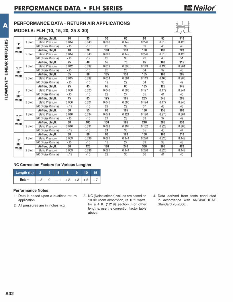
A PerFOrMANCe DATA • reTurN Air APPLiCATiONS MODeLS: FLH (10, 15, 20, 25 & 30)
1. Data is based upon a ductless returnapplication.
2. All pressures are in inches w.g..
3. NC (Noise criteria) values are based on10 dB room absorption, re 10-12 watts,for a 4 ft. (1219) section. For otherlengths, use the correction factor tableabove.
4. Data derived from tests conducted in accordance with ANSI/ASHRAEStandard 70-2006.
Performance Notes:
Airflow, cfm/ft. 20 35 50 65 80 95 110
1" 1 Slot Static Pressure 0.014 0.043 0.088 0.149 0.226 0.318 0.426
Slot
NC (Noise Criteria) <15 <18 26 33 39 45 48
Width Airflow, cfm/ft. 40 70 100 130 160 190 220
2 Slot Static Pressure 0.014 0.043 0.088 0.149 0.226 0.318 0.426 NC (Noise Criteria) <15 <19 28 36 42 48 51 Airflow, cfm/ft. 25 40 55 70 85 100 115
1.5" 1 Slot Static Pressure 0.012 0.032 0.059 0.098 0.143 0.198 0.261
Slot
NC (Noise Criteria) <15 <15 20 28 34 39 43
Width Airflow, cfm/ft. 55 80 105 130 155 180 205
2 Slot Static Pressure 0.015 0.032 0.054 0.084 0.119 0.160 0.208 NC (Noise Criteria) <15 <15 19 29 34 38 42 Airflow, cfm/ft. 25 45 65 85 105 125 145
2" 1 Slot Static Pressure 0.008 0.023 0.048 0.083 0.127 0.179 0.241
Slot
NC (Noise Criteria) <15 <15 22 27 35 41 46
Width Airflow, cfm/ft. 45 85 125 165 205 245 285
2 Slot Static Pressure 0.006 0.021 0.046 0.080 0.124 0.177 0.240 NC (Noise Criteria) <15 <15 22 29 37 43 48 Airflow, cfm/ft. 30 55 80 105 130 155 180
2.5" 1 Slot Static Pressure 0.010 0.034 0.074 0.124 0.190 0.270 0.364
Slot
NC (Noise Criteria) <15 <15 21 28 33 37 42
Width Airflow, cfm/ft. 60 105 150 195 240 285 330
2 Slot Static Pressure 0.010 0.031 0.063 0.107 0.162 0.228 0.306 NC (Noise Criteria) <15 <15 24 30 35 40 44 Airflow, cfm/ft. 30 60 90 120 150 180 210
3" 1 Slot Static Pressure 0.009 0.036 0.081 0.144 0.226 0.326 0.443
Slot
NC (Noise Criteria) <15 <15 18 27 33 38 43
Width Airflow, cfm/ft. 60 120 180 240 300 360 420
2 Slot Static Pressure 0.009 0.036 0.081 0.144 0.226 0.326 0.443 NC (Noise Criteria) <15 <15 22 30 36 41 46
Length (ft.) 2 4 6 8 9 10 15
Return - 3 0 + 1 + 2 + 3 + 5 + 7
NC Correction Factors for Various Lengths

PERFORMANCE DATA • FLH & FTH SERIES
A33
FLOW
LINE™
LINEA
R D
IFFUSER
S
A Airflow, cfm 25 50 75 100 125 150 175 Total Pressure 0.008 0.034 0.075 0.132 0.206 0.297 0.040 2 Ft. Static Pressure 0.007 0.030 0.065 0.115 0.180 0.260 0.350 NC (Noise Criteria) <15 <15 <15 20 29 36 40 Throw 1-2-5 3-6-9 5-9-12 7-10-13 8-10-14 9-11-16 10-12-18
Airflow, cfm 40 80 120 160 200 240 280 1" Total Pressure 0.009 0.031 0.066 0.117 0.180 0.264 0.352 Slot 4 Ft. Static Pressure 0.006 0.020 0.042 0.075 0.115 0.170 0.225 Width NC (Noise Criteria) <15 <15 <15 17 25 32 38 Throw 1-2-5 3-6-12 5-9-15 8-12-17 10-12-18 12-15-20 13-16-22
Airflow, cfm 50 100 150 200 250 300 350 Total Pressure 0.009 0.036 0.079 0.140 0.217 0.316 0.424 5 Ft. Static Pressure 0.005 0.020 0.042 0.075 0.115 0.170 0.225 NC (Noise Criteria) <15 <15 <15 18 26 33 38 Throw 1-2-7 3-7-13 8-10-17 10-13-19 12-15-20 14-16-22 15-17-24
1 Slot 6" D
ia. Inlet
Airflow, cfm 50 75 100 125 150 175 200 Total Pressure 0.029 0.068 0.119 0.188 0.272 0.358 0.471 2 Ft. Static Pressure 0.028 0.065 0.114 0.180 0.260 0.342 0.450 NC (Noise Criteria) <15 <15 20 28 35 41 44 Throw 2-5-9 5-9-11 7-10-14 8-11-15 9-12-18 10-12-19 11-13-20
Airflow, cfm 70 110 150 190 230 270 310 1" Total Pressure 0.016 0.040 0.075 0.120 0.176 0.242 0.319 Slot 4 Ft. Static Pressure 0.014 0.034 0.063 0.101 0.149 0.205 0.270 Width NC (Noise Criteria) <15 <15 <15 23 30 36 41 Throw 2-4-10 6-8-14 7-11-17 9-13-19 10-15-22 13-16-24 15-18-26
Airflow, cfm 80 130 180 230 280 330 380 Total Pressure 0.007 0.025 0.056 0.093 0.142 0.206 0.283 5 Ft. Static Pressure 0.006 0.020 0.044 0.072 0.110 0.160 0.220 NC (Noise Criteria) <15 <15 <15 23 29 35 40 Throw 2-5-11 6-9-15 8-12-18 9-14-20 11-15-22 13-17-24 14-18-26
1 Slot 8" D
ia. Inlet
Airflow, cfm 30 60 90 120 150 180 210 Total Pressure 0.002 0.038 0.088 0.148 0.246 0.367 0.471 2 Ft. Static Pressure 0.001 0.032 0.075 0.125 0.210 0.315 0.400 NC (Noise Criteria) <15 <15 <15 22 31 39 44 Throw 1-4-7 4-7-11 6-9-13 8-10-15 10-13-17 11-14-19 12-15-20
Airflow, cfm 70 110 150 190 230 270 310 1.5" Total Pressure 0.021 0.045 0.089 0.148 0.206 0.288 0.376 Slot 4 Ft. Static Pressure 0.013 0.025 0.052 0.089 0.120 0.170 0.220 Width NC (Noise Criteria) <15 <15 <15 20 24 30 36 Throw 2-5-11 5-8-15 8-12-17 10-13-19 12-15-20 13-16-21 14-17-23
Airflow, cfm 85 135 185 235 285 335 385 Total Pressure 0.013 0.055 0.101 0.165 0.247 0.342 0.440 5 Ft. Static Pressure 0.001 0.025 0.045 0.075 0.115 0.160 0.200 NC (Noise Criteria) <15 <15 <15 20 26 31 37 Throw 2-5-11 5-19-15 8-13-18 11-15-21 12-17-23 14-18-25 15-20-27
1 Slot 6" D
ia. Inlet
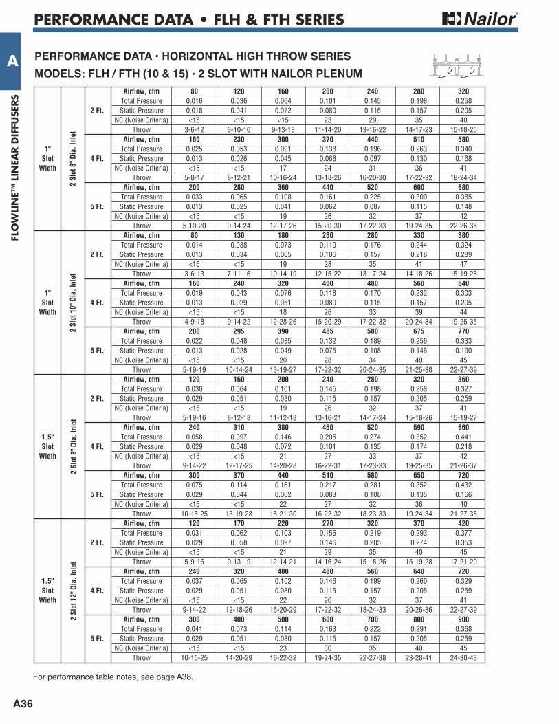
PerFOrMANCe DATA • HOriZONTAL HiGH THrOw SerieS MODeLS: FLH / FTH (10 &15) • 1 SLOT wiTH NAiLOr PLeNuM
Airflow, cfm 30 60 90 120 150 180 210 Total Pressure 0.002 0.032 0.076 0.128 0.222 0.317 0.428 2 Ft. Static Pressure 0.001 0.030 0.072 0.120 0.210 0.300 0.405 NC (Noise Criteria) <15 <15 <15 23 31 40 44 Throw 1-4-7 4-7-11 7-9-13 8-12-15 10-13-17 11-14-18 12-15-19
Airflow, cfm 70 120 170 220 270 320 370 1.5" Total Pressure 0.015 0.035 0.075 0.125 0.207 0.272 0.380 Slot 4 Ft. Static Pressure 0.012 0.027 0.060 0.100 0.170 0.220 0.310 Width NC (Noise Criteria) <15 <15 <15 22 30 36 44 Throw 2-5-11 6-9-15 9-13-18 12-15-21 14-17-23 15-19-25 16-20-26
Airflow, cfm 85 145 205 265 325 385 445 Total Pressure 0.016 0.041 0.084 0.131 0.204 0.276 0.401 5 Ft. Static Pressure 0.012 0.030 0.062 0.095 0.150 0.200 0.300 NC (Noise Criteria) <15 <15 <15 23 30 36 43 Throw 2-5-11 6-10-16 9-13-20 12-17-23 15-19-25 16-20-27 17-21-29
1 Slot 8" D
ia. Inlet
For performance table notes, see page A35.

PERFORMANCE DATA • FLH & FTH SERIES
A34
FLO
WLI
NE™
LIN
EAR D
IFFU
SERS
A Airflow, cfm 40 80 120 160 200 240 280 Total Pressure 0.007 0.028 0.065 0.115 0.180 0.259 0.352 2 Ft. Static Pressure 0.006 0.025 0.057 0.102 0.159 0.229 0.312 NC (Noise Criteria) <15 <15 <15 17 26 31 38 Throw 1-3-8 5-8-13 7-10-15 10-13-17 11-14-19 12-15-22 13-16-23
Airflow, cfm 100 150 200 250 300 350 400 2" Total Pressure 0.015 0.034 0.040 0.094 0.136 0.185 0.241 Slot 4 Ft. Static Pressure 0.010 0.022 0.040 0.062 0.089 0.122 0.159 Width NC (Noise Criteria) <15 <15 <15 15 22 30 37 Throw 3-4-11 6-9-14 8-12-17 9-13-19 12-14-23 14-25-27 15-17-28
Airflow, cfm 125 180 235 290 345 400 455 Total Pressure 0.180 0.037 0.064 0.097 0.137 0.184 0.238 5 Ft. Static Pressure 0.010 0.021 0.035 0.535 0.076 0.102 0.132 NC (Noise Criteria) <15 <15 <15 22 29 34 39 Throw 3-6-12 8-12-17 9-13-19 12-14-23 14-13-26 16-18-28 17-21-30
1 Slot 8" D
ia. Inlet
Airflow, cfm 50 100 150 200 250 300 350 Total Pressure 0.007 0.028 0.064 0.113 0.177 0.254 0.346 2 Ft. Static Pressure 0.007 0.027 0.060 0.108 0.168 0.242 0.329 NC (Noise Criteria) <15 <15 <15 17 24 29 37 Throw 2-5-10 5-8-12 6-10-14 8-12-17 9-13-19 10-14-22 13-16-25
Airflow, cfm 100 170 240 310 380 450 520 2" Total Pressure 0.008 0.023 0.045 0.076 0.114 0.169 0.213 Slot 4 Ft. Static Pressure 0.065 0.019 0.038 0.063 0.094 0.132 0.176 Width NC (Noise Criteria) <15 <15 <15 20 27 33 39 Throw 3-6-12 7-11-15 9-13-19 11-15-23 14-17-27 15-19-30 16-21-34
Airflow, cfm 125 205 285 365 445 525 605 Total Pressure 0.009 0.023 0.045 0.074 0.109 0.152 0.202 5 Ft. Static Pressure 0.007 0.018 0.034 0.056 0.083 0.115 0.153 NC (Noise Criteria) <15 <15 <15 23 31 36 41 Throw 3-7-15 7-11-19 10-14-24 13-16-25 15-19-30 16-21-32 21-25-34
1 Slot 12" Oval Inlet
Airflow, cfm 100 145 190 235 280 325 370 Total Pressure 0.024 0.050 0.085 0.131 0.186 0.250 0.324 2 Ft. Static Pressure 0.045 0.045 0.077 0.117 0.167 0.224 0.291 NC (Noise Criteria) <15 <15 <15 22 29 35 40 Throw 4-9-11 6-19-13 8-12-17 10-14-18 12-16-22 13-17-24 14-18-26
Airflow, cfm 140 220 300 380 460 540 620 2.5" Total Pressure 0.015 0.037 0.069 0.111 0.163 0.225 0.296 Slot 4 Ft. Static Pressure 0.010 0.026 0.048 0.077 0.112 0.155 0.204 Width NC (Noise Criteria) <15 <15 <15 25 33 40 45 Throw 5-8-17 10-14-22 12-16-25 14-17-28 16-19-31 19-22-33 21-24-35
Airflow, cfm 150 240 330 420 510 600 690 Total Pressure 0.013 0.034 0.063 0.103 0.151 0.209 0.277 5 Ft. Static Pressure 0.002 0.020 0.037 0.060 0.088 0.122 0.162 NC (Noise Criteria) <15 <15 <15 23 31 38 43 Throw 3-8-16 8-12-21 12-15-25 15-18-29 17-21-32 19-23-35 21-27-38
1 Slot 10" Oval Inlet
PerFOrMANCe DATA • HOriZONTAL HiGH THrOw SerieSMODeLS: FLH / FTH (20 & 25) • 1 SLOT wiTH NAiLOr PLeNuM
Airflow, cfm 100 145 190 235 280 325 370 Total Pressure 0.021 0.043 0.074 0.114 0.161 0.217 0.282 2 Ft. Static Pressure 0.019 0.041 0.070 0.106 0.151 0.204 0.264 NC (Noise Criteria) <15 <15 <15 20 27 33 38 Throw 4-9-11 6-19-13 8-12-17 10-14-18 12-16-22 13-17-24 14-18-26
Airflow, cfm 140 225 310 395 480 565 650 2.5" Total Pressure 0.012 0.031 0.059 0.096 0.142 0.197 0.261 Slot 4 Ft. Static Pressure 0.009 0.024 0.046 0.075 0.111 0.154 0.204 Width NC (Noise Criteria) <15 <15 15 23 31 38 43 Throw 5-8-17 10-14-22 12-16-25 14-17-29 17-20-32 20-23-34 22-26-37
Airflow, cfm 150 250 350 450 550 650 750 Total Pressure 0.010 0.028 0.054 0.090 0.134 0.188 0.250 5 Ft. Static Pressure 0.007 0.019 0.038 0.063 0.094 0.131 0.174 NC (Noise Criteria) <15 <15 16 26 34 40 46 Throw 3-8-16 8-12-21 13-16-26 16-19-31 18-22-33 20-25-37 22-28-39
1 Slot 12" Oval Inlet
For performance table notes, see page A35.

PERFORMANCE DATA • FLH & FTH SERIES
A35
FLOW
LINE™
LINEA
R D
IFFUSER
S
A Airflow, cfm 125 170 215 260 305 350 395 Total Pressure 0.030 0.056 0.894 0.131 0.180 0.237 0.302 2 Ft. Static Pressure 0.027 0.049 0.078 0.115 0.158 0.208 0.265 NC (Noise Criteria) <15 <15 <15 24 29 35 40 Throw 7-11-16 9-13-19 11-15-21 13-17-23 15-18-25 16-19-28 17-20-31
Airflow, cfm 200 275 350 425 500 575 650 3" Total Pressure 0.027 0.050 0.081 0.120 0.166 0.220 0.281 Slot 4 Ft. Static Pressure 0.017 0.032 0.052 0.076 0.106 0.140 0.179 Width NC (Noise Criteria) <15 <15 18 22 28 34 40 Throw 8-13-20 10-15-24 15-19-27 17-21-30 18-23-32 20-24-35 21-26-37
Airflow, cfm 220 310 400 490 580 670 760 Total Pressure 0.025 0.040 0.082 0.123 0.172 0.230 0.296 5 Ft. Static Pressure 0.013 0.026 0.043 0.065 0.091 0.122 0.157 NC (Noise Criteria) <15 <15 16 24 32 39 45 Throw 8-12-21 12-17-25 15-20-29 18-23-32 20-24-35 21-26-37 23-28-40
1 Slot 10" Oval Inlet
Airflow, cfm 125 170 215 260 305 350 395 Total Pressure 0.029 0.053 0.085 0.124 0.170 0.224 0.286 2 Ft. Static Pressure 0.026 0.049 0.078 0.115 0.158 0.208 0.265 NC (Noise Criteria) <15 <15 <15 18 25 31 36 Throw 7-11-16 9-13-19 11-15-21 13-17-23 15-18-25 16-19-28 17-20-31
Airflow, cfm 200 290 380 470 560 650 740 3" Total Pressure 0.022 0.047 0.081 0.123 0.175 0.236 0.306 Slot 4 Ft. Static Pressure 0.017 0.036 0.061 0.094 0.133 0.179 0.232 Width NC (Noise Criteria) <15 <15 <15 22 29 36 41 Throw 8-13-20 11-16-24 15-20-28 17-22-31 20-24-34 21-26-37 23-28-40
Airflow, cfm 220 330 440 550 660 770 880 Total Pressure 0.020 0.044 0.079 0.123 0.177 0.241 0.315 5 Ft. Static Pressure 0.013 0.030 0.053 0.082 0.118 0.161 0.210 NC (Noise Criteria) <15 <15 19 26 32 39 43 Throw 8-12-21 11-14-26 14-16-30 17-20-34 20-25-37 22-27-39 24-29-42
1 Slot 12" Oval Inlet
1. Data is based upon FlowLine™with Nailor engineered plenum(uninsulated) as a completeassembly.
2. All pressures are in inches w.g..
3. Throw values are given at 150,100 and 50 fpm terminal velocitiesunder isothermal conditions.
4. NC (Noise criteria) values arebased on 10 dB room absorption,re 10-12 watts.
5. Throw values are based on a1-way air pattern. For 2-waypattern, throw is determined fromthe 1 slot data at half the specifiedair volume.
6. Data derived from tests conducted in accordance with ANSI/ASHRAEStandard 70-2006.
Performance Notes:
PerFOrMANCe DATA • HOriZONTAL HiGH THrOw SerieS MODeLS: FLH30 AND FTH30 • 1 SLOT wiTH NAiLOr PLeNuM
PERFORMANCE DATA • FLH & FTH SERIES
A36
FLO
WLI
NE™
LIN
EAR D
IFFU
SERS
A Airflow, cfm 80 120 160 200 240 280 320 Total Pressure 0.016 0.036 0.064 0.101 0.145 0.198 0.258 2 Ft. Static Pressure 0.018 0.041 0.072 0.080 0.115 0.157 0.205 NC (Noise Criteria) <15 <15 <15 23 29 35 40 Throw 3-6-12 6-10-16 9-13-18 11-14-20 13-16-22 14-17-23 15-18-25
Airflow, cfm 160 230 300 370 440 510 580 1" Total Pressure 0.025 0.053 0.091 0.138 0.196 0.263 0.340 Slot 4 Ft. Static Pressure 0.013 0.026 0.045 0.068 0.097 0.130 0.168 Width NC (Noise Criteria) <15 <15 17 24 31 36 41 Throw 5-8-17 8-12-21 10-16-24 13-18-26 16-20-30 17-22-32 18-24-34
Airflow, cfm 200 280 360 440 520 600 680 Total Pressure 0.033 0.065 0.108 0.161 0.225 0.300 0.385 5 Ft. Static Pressure 0.013 0.025 0.041 0.062 0.087 0.115 0.148 NC (Noise Criteria) <15 <15 19 26 32 37 42 Throw 5-10-20 9-14-24 12-17-26 15-20-30 17-22-33 19-24-35 22-26-38 Airflow, cfm 80 130 180 230 280 330 380 Total Pressure 0.014 0.038 0.073 0.119 0.176 0.244 0.324 2 Ft. Static Pressure 0.013 0.034 0.065 0.106 0.157 0.218 0.289 NC (Noise Criteria) <15 <15 19 28 35 41 47 Throw 3-6-13 7-11-16 10-14-19 12-15-22 13-17-24 14-18-26 15-19-28
Airflow, cfm 160 240 320 400 480 560 640 1" Total Pressure 0.019 0.043 0.076 0.118 0.170 0.232 0.303 Slot 4 Ft. Static Pressure 0.013 0.029 0.051 0.080 0.115 0.157 0.205 Width NC (Noise Criteria) <15 <15 18 26 33 39 44 Throw 4-9-18 9-14-22 12-28-26 15-20-29 17-22-32 20-24-34 19-25-35
Airflow, cfm 200 295 390 485 580 675 770 Total Pressure 0.022 0.048 0.085 0.132 0.189 0.256 0.333 5 Ft. Static Pressure 0.013 0.028 0.049 0.075 0.108 0.146 0.190 NC (Noise Criteria) <15 <15 20 28 34 40 45 Throw 5-19-19 10-14-24 13-19-27 17-22-32 20-24-35 21-25-38 22-27-39 Airflow, cfm 120 160 200 240 280 320 360 Total Pressure 0.036 0.064 0.101 0.145 0.198 0.258 0.327 2 Ft. Static Pressure 0.029 0.051 0.080 0.115 0.157 0.205 0.259 NC (Noise Criteria) <15 <15 19 26 32 37 41 Throw 5-19-16 8-12-18 11-12-18 13-16-21 14-17-24 15-18-26 15-19-27
Airflow, cfm 240 310 380 450 520 590 660 1.5" Total Pressure 0.058 0.097 0.146 0.205 0.274 0.352 0.441 Slot 4 Ft. Static Pressure 0.029 0.048 0.072 0.101 0.135 0.174 0.218 Width NC (Noise Criteria) <15 <15 21 27 33 37 42 Throw 9-14-22 12-17-25 14-20-28 16-22-31 17-23-33 19-25-35 21-26-37
Airflow, cfm 300 370 440 510 580 650 720 Total Pressure 0.075 0.114 0.161 0.217 0.281 0.352 0.432 5 Ft. Static Pressure 0.029 0.044 0.062 0.083 0.108 0.135 0.166 NC (Noise Criteria) <15 <15 22 27 32 36 40 Throw 10-15-25 13-19-28 15-21-30 16-22-32 18-23-33 19-24-34 21-27-38 Airflow, cfm 120 170 220 270 320 370 420 Total Pressure 0.031 0.062 0.103 0.156 0.219 0.293 0.377 2 Ft. Static Pressure 0.029 0.058 0.097 0.146 0.205 0.274 0.353 NC (Noise Criteria) <15 <15 21 29 35 40 45 Throw 5-9-16 9-13-19 12-14-21 14-16-24 15-18-26 15-19-28 17-21-29
Airflow, cfm 240 320 400 480 560 640 720 1.5" Total Pressure 0.037 0.065 0.102 0.146 0.199 0.260 0.329 Slot 4 Ft. Static Pressure 0.029 0.051 0.080 0.115 0.157 0.205 0.259 Width NC (Noise Criteria) <15 <15 22 26 32 37 41 Throw 9-14-22 12-18-26 15-20-29 17-22-32 18-24-33 20-26-36 22-27-39
Airflow, cfm 300 400 500 600 700 800 900 Total Pressure 0.041 0.073 0.114 0.163 0.222 0.291 0.368 5 Ft. Static Pressure 0.029 0.051 0.080 0.115 0.157 0.205 0.259 NC (Noise Criteria) <15 <15 23 30 35 40 45 Throw 10-15-25 14-20-29 16-22-32 19-24-35 22-27-38 23-28-41 24-30-43
2 Slot 8" D
ia. Inlet
2 Slot 10" Dia. Inlet
2 Slot 8" D
ia. Inlet
PerFOrMANCe DATA • HOriZONTAL HiGH THrOw SerieS MODeLS: FLH / FTH (10 & 15) • 2 SLOT wiTH NAiLOr PLeNuM
2 Slot 12" Dia. Inlet
For performance table notes, see page A38.

PERFORMANCE DATA • FLH & FTH SERIES
A37
FLOW
LINE™
LINEA
R D
IFFUSER
S
A Airflow, cfm 120 165 210 255 300 345 390 Total Pressure 0.023 0.043 0.069 0.101 0.141 0.186 0.238 2 Ft. Static Pressure 0.015 0.029 0.047 0.068 0.095 0.125 0.160 NC (Noise Criteria) <15 <15 16 24 29 34 38 Throw 5-8-14 7-11-16 9-14-19 11-14-21 13-16-23 14-17-24 14-18-25
Airflow, cfm 240 300 360 420 480 540 600 2" Total Pressure 0.051 0.079 0.114 0.156 0.204 0.258 0.318 Slot 4 Ft. Static Pressure 0.021 0.034 0.048 0.066 0.086 0.108 0.134 Width NC (Noise Criteria) <15 17 23 29 34 39 43 Throw 6-11-20 9-14-23 11-16-24 13-19-26 14-20-29 16-22-30 18-23-32
Airflow, cfm 260 325 390 455 520 585 650 Total Pressure 0.053 0.082 0.118 0.161 0.211 0.267 0.329 5 Ft. Static Pressure 0.018 0.028 0.040 0.055 0.072 0.092 0.113 NC (Noise Criteria) <15 16 22 29 34 38 42 Throw 5-11-21 8-14-23 11-16-25 13-18-28 14-21-30 16-23-32 17-23-33 Airflow, cfm 120 195 270 345 420 495 570 Total Pressure 0.009 0.024 0.046 0.075 0.111 0.155 0.205 2 Ft. Static Pressure 0.007 0.020 0.039 0.063 0.094 0.130 0.172 NC (Noise Criteria) <15 <15 <15 22 28 35 41 Throw 5-8-14 8-13-18 12-15-22 14-17-24 15-19-26 16-21-29 18-20-31
Airflow, cfm 240 330 420 510 600 690 780 2" Total Pressure 0.019 0.037 0.060 0.088 0.122 0.161 0.206 Slot 4 Ft. Static Pressure 0.013 0.026 0.042 0.062 0.086 0.113 0.145 Width NC (Noise Criteria) <15 <15 17 24 30 35 41 Throw 6-11-20 10-15-23 13-19-26 15-21-29 18-23-32 20-24-34 21-25-36
Airflow, cfm 280 380 480 580 680 780 880 Total Pressure 0.022 0.040 0.065 0.094 0.130 0.172 0.218 5 Ft. Static Pressure 0.014 0.026 0.041 0.060 0.083 0.110 0.140 NC (Noise Criteria) <15 <15 18 25 31 36 41 Throw 5-12-22 10-15-25 13-20-29 15-22-32 18-24-34 21-25-36 23-27-39 Airflow, cfm 80 160 240 320 400 480 560 Total Pressure 0.005 0.019 0.043 0.078 0.122 0.175 0.238 2 Ft. Static Pressure 0.003 0.014 0.032 0.057 0.088 0.127 0.173 NC (Noise Criteria) <15 <15 <15 18 27 35 41 Throw 2-4-10 6-10-16 10-14-20 13-16-23 15-18-26 16-20-29 18-22-31
Airflow, cfm 160 280 400 520 640 760 880 2.5" Total Pressure 0.011 0.034 0.070 0.118 0.178 0.251 0.336 Slot 4 Ft. Static Pressure 0.005 0.018 0.036 0.061 0.092 0.130 0.174 Width NC (Noise Criteria) <15 <15 <15 22 31 38 44 Throw 3-15-14 7-12-22 12-17-26 15-21-30 18-23-32 21-25-36 23-27-39
Airflow, cfm 200 335 470 605 740 875 1010 Total Pressure 0.014 0.040 0.079 0.130 0.194 0.271 0.361 5 Ft. Static Pressure 0.005 0.016 0.032 0.054 0.079 0.110 0.147 NC (Noise Criteria) <15 <15 <15 23 31 38 44 Throw 3-5-15 7-13-23 12-18-28 15-23-32 19-25-35 23-27-29 23-29-41 Airflow, cfm 80 170 260 350 440 530 620 Total Pressure 0.003 0.015 0.034 0.061 0.097 0.140 0.192 2 Ft. Static Pressure 0.002 0.012 0.027 0.049 0.077 0.112 0.153 NC (Noise Criteria) <15 <15 <15 17 27 34 41 Throw 2-4-10 7-10-17 11-14-21 14-17-24 15-19-27 17-21-31 19-23-32
Airflow, cfm 160 295 430 595 700 835 970 2.5" Total Pressure 0.007 0.024 0.051 0.088 0.136 0.193 0.260 Slot 4 Ft. Static Pressure 0.004 0.016 0.033 0.056 0.086 0.122 0.165 Width NC (Noise Criteria) <15 <15 <15 21 29 37 43 Throw 3-5-14 8-13-23 13-19-27 16-22-31 20-24-34 22-26-38 23-29-41
Airflow, cfm 200 350 500 650 800 950 1100 Total Pressure 0.010 0.029 0.059 0.100 0.151 0.212 0.284 5 Ft. Static Pressure 0.005 0.017 0.033 0.057 0.086 0.121 0.162 NC (Noise Criteria) <15 <15 <15 21 29 37 43 Throw 3-5-15 8-14-24 13-19-29 17-23-33 21-26-37 23-28-40 25-31-43
2 Slot 8" D
ia. Inlet
2 Slot 12" Dia. Inlet
2 Slot 10" Dia. Inlet
PerFOrMANCe DATA • HOriZONTAL HiGH THrOw SerieS MODeLS: FLH / FTH (20 & 25) • 2 SLOT wiTH NAiLOr PLeNuM
2 Slot 12" Dia. Inlet
For performance table notes, see page A38.

PERFORMANCE DATA • FLH & FTH SERIES
A38
FLO
WLI
NE™
LIN
EAR D
IFFU
SERS
A Airflow, cfm 80 180 280 380 480 580 680 Total Pressure 0.004 0.022 0.053 0.097 0.155 0.226 0.311 2 Ft. Static Pressure 0.003 0.015 0.036 0.067 0.106 0.156 0.214 NC (Noise Criteria) <15 <15 <15 17 28 36 43 Throw 1-3-9 6-10-17 11-15-22 14-18-25 16-20-29 18-22-32 20-24-34
Airflow, cfm 150 300 450 600 750 900 1050 3" Total Pressure 0.009 0.035 0.080 0.143 0.222 0.321 0.436 Slot 4 Ft. Static Pressure 0.004 0.016 0.038 0.067 0.104 0.151 0.205 Width NC (Noise Criteria) <15 <15 <15 19 29 38 45 Throw 2-4-12 6-12-23 12-18-28 16-23-32 20-25-35 23-28-39 24-30-42
Airflow, cfm 180 350 520 690 860 1030 1200 Total Pressure 0.011 0.042 0.092 0.162 0.251 0.360 0.489 5 Ft. Static Pressure 0.004 0.016 0.035 0.062 0.096 0.138 0.186 NC (Noise Criteria) <15 <15 <15 19 29 38 45 Throw 2-4-13 6-13-24 13-19-30 16-24-34 21-27-38 24-30-41 26-32-45
PerFOrMANCe DATA • HOriZONTAL HiGH THrOw SerieSMODeLS: FLH30 AND FTH30 • 2 SLOT wiTH NAiLOr PLeNuM
2 Slot 10" Dia. Inlet
Airflow, cfm 80 180 280 380 480 580 680 Total Pressure 0.004 0.017 0.042 0.077 0.124 0.180 0.248 2 Ft. Static Pressure 0.003 0.014 0.034 0.063 0.100 0.146 0.201 NC (Noise Criteria) <15 <15 <15 <15 23 32 39 Throw 1-3-9 6-10-17 11-15-22 14-18-25 16-20-29 18-22-32 20-24-34
Airflow, cfm 150 310 470 630 790 950 1110 3" Total Pressure 0.006 0.024 0.056 0.100 0.156 0.226 0.309 Slot 4 Ft. Static Pressure 0.003 0.014 0.033 0.059 0.093 0.135 0.184 Width NC (Noise Criteria) <15 <15 <15 23 29 35 42 Throw 2-4-12 7-13-23 13-19-28 17-23-32 21-26-36 23-28-40 25-31-43
Airflow, cfm 180 360 540 720 900 1080 1260 Total Pressure 0.007 0.027 0.060 0.108 0.169 0.244 0.331 5 Ft. Static Pressure 0.003 0.014 0.031 0.056 0.087 0.126 0.170 NC (Noise Criteria) <15 <15 16 24 30 35 42 Throw 2-4-13 6-13-24 13-19-30 17-24-35 22-28-39 24-30-42 26-32-46
2 Slot 12" Dia. Inlet
1. Data is based upon FlowLine™with Nailor engineered plenum(uninsulated) as a completeassembly.
2. All pressures are in inches w.g..
3. Throw values are given at 150, 100and 50 fpm terminal velocities underisothermal conditions.
4. NC (Noise criteria) values are basedon 10 dB room absorption, re 10-12watts.
5. Throw values are based on a1-way air pattern. For 2-way pattern,throw is determined from the 1 slotdata at half the specified air volume.
6. Data derived from tests conducted in accordance with ANSI/ASHRAEStandard 70-2006.
Performance Notes:
PERFORMANCE DATA • FLV SERIES
A39
FLOW
LINE™
LINEA
R D
IFFUSER
S
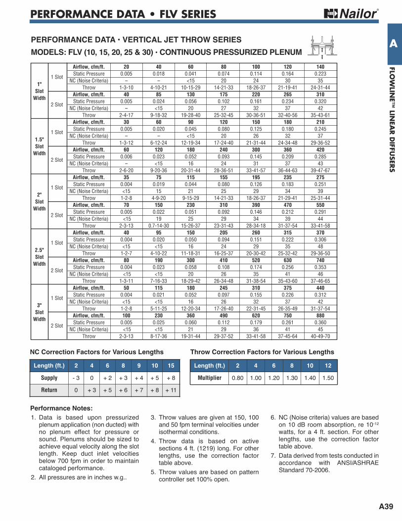
APerFOrMANCe DATA • VerTiCAL JeT THrOw SerieSMODeLS: FLV (10, 15, 20, 25 & 30) • CONTiNuOuS PreSSuriZeD PLeNuM
Airflow, cfm/ft. 20 40 60 80 100 120 140
1 Slot Static Pressure 0.005 0.018 0.041 0.074 0.114 0.164 0.223
NC (Noise Criteria) -- -- <15 20 24 30 35
1" Throw 1-3-10 4-10-21 10-15-29 14-21-33 18-26-37 21-19-41 24-31-44
Slot
Airflow, cfm/ft. 40 85 130 175 220 265 310
Width 2 Slot
Static Pressure 0.005 0.024 0.056 0.102 0.161 0.234 0.320 NC (Noise Criteria) -- <15 20 27 32 37 42 Throw 2-4-17 9-18-32 19-28-40 25-32-45 30-36-51 32-40-56 35-43-61 Airflow, cfm/ft. 30 60 90 120 150 180 210
1 Slot Static Pressure 0.005 0.020 0.045 0.080 0.125 0.180 0.245
NC (Noise Criteria) -- -- <15 20 26 32 37
1.5" Throw 1-3-12 6-12-24 12-19-34 17-24-40 21-31-44 24-34-48 29-36-52
Slot
Airflow, cfm/ft. 60 120 180 240 300 360 420
Width 2 Slot
Static Pressure 0.006 0.023 0.052 0.093 0.145 0.209 0.285 NC (Noise Criteria) -- <15 16 24 31 37 43 Throw 2-6-20 9-20-36 20-31-44 28-36-51 33-41-57 36-44-63 39-47-67 Airflow, cfm/ft. 35 75 115 155 195 235 275
1 Slot Static Pressure 0.004 0.019 0.044 0.080 0.126 0.183 0.251
NC (Noise Criteria) <15 15 21 25 29 34 39
2" Throw 1-2-8 4-9-20 9-15-29 14-21-33 18-26-37 21-29-41 25-31-44
Slot Airflow, cfm/ft. 70 150 230 310 390 470 550
Width
2 Slot
Static Pressure 0.005 0.022 0.051 0.092 0.146 0.212 0.291 NC (Noise Criteria) <15 19 25 29 34 39 44 Throw 2-3-13 0.7-14-30 15-26-37 23-31-43 28-34-18 31-37-54 33-41-58 Airflow, cfm/ft. 40 95 150 205 260 315 370
1 Slot Static Pressure 0.004 0.020 0.050 0.094 0.151 0.222 0.306
NC (Noise Criteria) <15 <15 16 24 29 35 48
2.5" Throw 1-2-7 4-10-22 11-18-31 16-25-37 20-30-42 25-32-42 29-36-50
Slot Airflow, cfm/ft. 80 190 300 410 520 630 740
Width
2 Slot
Static Pressure 0.004 0.023 0.058 0.108 0.174 0.256 0.353 NC (Noise Criteria) <15 <15 20 26 35 41 46 Throw 1-3-11 7-16-33 18-29-42 26-34-48 31-38-54 35-43-60 37-46-65 Airflow, cfm/ft. 50 115 180 245 310 375 440
1 Slot Static Pressure 0.004 0.021 0.052 0.097 0.155 0.226 0.312
NC (Noise Criteria) <15 <15 16 26 32 37 42
3" Throw 1-2-8 5-11-25 12-20-34 17-26-40 22-31-45 26-35-49 31-37-54
Slot Airflow, cfm/ft. 100 230 360 490 620 750 880
Width
2 Slot
Static Pressure 0.005 0.025 0.060 0.112 0.179 0.261 0.360 NC (Noise Criteria) <15 <15 21 29 36 41 45 Throw 2-3-13 8-17-36 19-31-44 29-37-52 33-41-58 37-45-64 40-49-70
1. Data is based upon pressurizedplenum application (non ducted) withno plenum effect for pressure orsound. Plenums should be sized toachieve equal velocity along the slotlength. Keep duct inlet velocitiesbelow 700 fpm in order to maintaincataloged performance.
2. All pressures are in inches w.g..
3. Throw values are given at 150, 100and 50 fpm terminal velocities underisothermal conditions.
4. Throw data is based on activesections 4 ft. (1219) long. For otherlengths, use the correction factortable above.
5. Throw values are based on patterncontroller set 100% open.
6. NC (Noise criteria) values are basedon 10 dB room absorption, re 10-12watts, for a 4 ft. section. For otherlengths, use the correction factortable above.
7. Data derived from tests conducted inaccordance with ANSI/ASHRAEStandard 70-2006.
Performance Notes:
Length (ft.) 2 4 6 8 9 10 15
Supply - 3 0 + 2 + 3 + 4 + 5 + 8
Return 0 + 3 + 5 + 6 + 7 + 8 + 11
NC Correction Factors for Various LengthsLength (ft.) 2 4 6 8 10 12
Multiplier 0.80 1.00 1.20 1.30 1.40 1.50
Throw Correction Factors for Various Lengths

PERFORMANCE DATA • FLV & FTV SERIES
A40
FLO
WLI
NE™
LIN
EAR D
IFFU
SERS
A Airflow, cfm 50 95 140 185 230 275 320 Total Pressure 0.010 0.033 0.073 0.127 0.197 0.281 0.381 2 Ft. Static Pressure 0.007 0.029 0.062 0.109 0.168 0.241 0.325 NC (Noise Criteria) <15 <15 17 26 33 39 44 Throw 2-3-10 7-9-19 9-14-24 12-19-28 15-22-31 18-24-34 21-26-36
Airflow, cfm 100 175 250 325 400 475 550 1" Total Pressure 0.018 0.056 0.113 0.190 0.289 0.408 0.547 Slot 4 Ft. Static Pressure 0.013 0.039 0.079 0.133 0.201 0.285 0.381 Width NC (Noise Criteria) <15 <15 20 29 35 41 46 Throw 2-4-13 6-11-23 11-17-30 14-21-34 18-26-37 21-29-41 24-31-44
Airflow, cfm 110 195 280 365 450 535 620 Total Pressure 0.019 0.060 0.124 0.212 0.322 0.455 0.611 5 Ft. Static Pressure 0.013 0.040 0.081 0.139 0.211 0.297 0.400 NC (Noise Criteria) <15 <15 21 30 36 42 47 Throw 1-3-12 6-11-22 10-17-31 14-21-35 18-25-39 21-30-42 23-32-45
1 Slot8" Dia. Inlet
Airflow, cfm 50 95 140 185 230 275 320 Total Pressure 0.006 0.022 0.049 0.087 0.134 0.192 0.259 2 Ft. Static Pressure 0.005 0.020 0.045 0.079 0.122 0.174 0.236 NC (Noise Criteria) <15 <15 15 23 30 35 40 Throw 2-3-10 7-9-19 9-14-24 12-19-28 15-22-31 18-24-34 21-26-36
Airflow, cfm 100 180 260 340 420 500 580 1" Total Pressure 0.011 0.036 0.075 0.128 0.196 0.278 0.373 Slot 4 Ft. Static Pressure 0.009 0.029 0.060 0.103 0.156 0.221 0.299 Width NC (Noise Criteria) <15 <15 17 24 31 37 42 Throw 2-4-13 7-12-23 11-17-30 14-22-34 18-28-39 22-30-42 25-32-45
Airflow, cfm 110 210 310 410 510 610 710 Total Pressure 0.011 0.040 0.087 0.152 0.235 0.337 0.456 5 Ft. Static Pressure 0.009 0.030 0.065 0.114 0.177 0.256 0.342 NC (Noise Criteria) <15 <15 17 26 33 39 44 Throw 1-3-12 6-12-24 12-18-32 15-23-37 20-29-41 23-32-45 28-34-48
1 Slot 10" Oval Inlet
Airflow, cfm 50 95 140 185 230 275 320 Total Pressure 0.004 0.017 0.037 0.064 0.100 0.142 0.194 2 Ft. Static Pressure 0.004 0.016 0.035 0.061 0.094 0.135 0.182 NC (Noise Criteria) <15 <15 <15 20 27 32 37 Throw 2-3-10 7-9-19 9-14-24 12-19-28 15-22-31 18-24-34 21-26-36
Airflow, cfm 100 190 280 370 460 550 640 1" Total Pressure 0.009 0.032 0.068 0.120 0.185 0.264 0.358 Slot 4 Ft. Static Pressure 0.007 0.028 0.060 0.105 0.163 0.232 0.315 Width NC (Noise Criteria) <15 <15 18 26 33 38 43 Throw 2-4-13 7-12-24 12-18-31 17-24-36 20-29-41 24-31-44 28-33-47
Airflow, cfm 110 220 330 440 550 660 770 Total Pressure 0.007 0.016 0.035 0.061 0.094 0.135 0.182 5 Ft. Static Pressure 0.006 0.026 0.057 0.101 0.157 0.227 0.308 NC (Noise Criteria) <15 <15 17 24 31 37 42 Throw 1-3-12 7-12-25 12-19-33 17-25-39 21-31-43 25-33-47 30-36-51
1 Slot 12" Oval Inlet
PerFOrMANCe DATA • VerTiCAL JeT THrOw SerieSMODeLS: FLV / FTV (10 & 15) • 1 SLOT wiTH NAiLOr PLeNuM
Airflow, cfm 60 110 160 210 260 310 360 Total Pressure 0.009 0.029 0.060 0.104 0.159 0.226 0.305 2 Ft. Static Pressure 0.006 0.021 0.046 0.079 0.122 0.173 0.234 NC (Noise Criteria) <15 <15 <15 20 27 33 38 Throw 1-2-9 4-9-18 9-12-24 11-17-29 13-20-32 17-24-34 19-26-37
Airflow, cfm 120 200 280 360 440 520 600 1.5" Total Pressure 0.020 0.057 0.111 0.184 0.276 0.385 0.513 Slot 4 Ft. Static Pressure 0.013 0.035 0.068 0.113 0.170 0.236 0.316 Width NC (Noise Criteria) <15 <15 19 27 33 39 43 Throw 1-3-12 3-9-21 8-14-29 12-19-34 15-23-37 18-26-41 21-31-44
Airflow, cfm 140 220 300 380 460 540 620 Total Pressure 0.026 0.062 0.116 0.186 0.272 0.376 0.494 5 Ft. Static Pressure 0.015 0.035 0.066 0.107 0.156 0.215 0.285 NC (Noise Criteria) <15 <15 19 26 32 38 42 Throw 1-3-12 3-8-20 6-13-28 10-18-34 14-21-37 17-24-11 19-29-43
1 Slot 8" D
ia. Inlet
For performance table notes, see page A42.
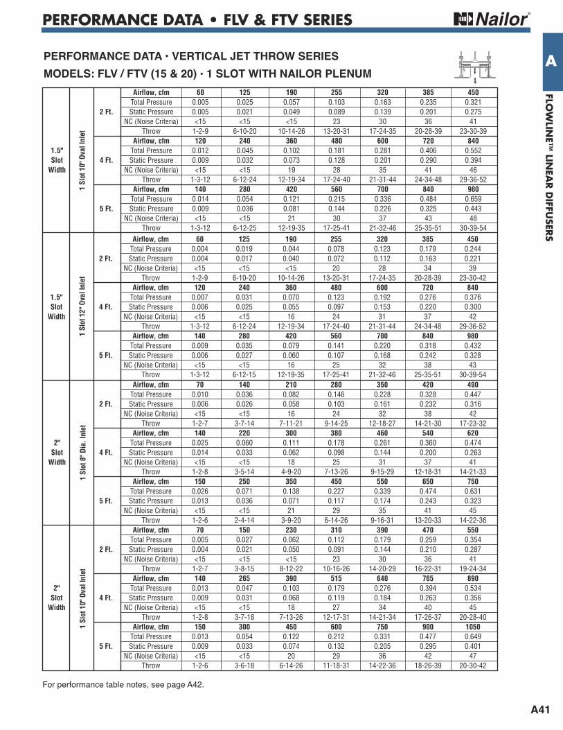
PERFORMANCE DATA • FLV & FTV SERIES
A41
FLOW
LINE™
LINEA
R D
IFFUSER
S
A Airflow, cfm 60 125 190 255 320 385 450 Total Pressure 0.005 0.025 0.057 0.103 0.163 0.235 0.321 2 Ft. Static Pressure 0.005 0.021 0.049 0.089 0.139 0.201 0.275 NC (Noise Criteria) <15 <15 <15 23 30 36 41 Throw 1-2-9 6-10-20 10-14-26 13-20-31 17-24-35 20-28-39 23-30-39
Airflow, cfm 120 240 360 480 600 720 840 1.5" Total Pressure 0.012 0.045 0.102 0.181 0.281 0.406 0.552 Slot 4 Ft. Static Pressure 0.009 0.032 0.073 0.128 0.201 0.290 0.394 Width NC (Noise Criteria) <15 <15 19 28 35 41 46 Throw 1-3-12 6-12-24 12-19-34 17-24-40 21-31-44 24-34-48 29-36-52
Airflow, cfm 140 280 420 560 700 840 980 Total Pressure 0.014 0.054 0.121 0.215 0.336 0.484 0.659 5 Ft. Static Pressure 0.009 0.036 0.081 0.144 0.226 0.325 0.443 NC (Noise Criteria) <15 <15 21 30 37 43 48 Throw 1-3-12 6-12-25 12-19-35 17-25-41 21-32-46 25-35-51 30-39-54
1 Slot 10" Oval Inlet
Airflow, cfm 60 125 190 255 320 385 450 Total Pressure 0.004 0.019 0.044 0.078 0.123 0.179 0.244 2 Ft. Static Pressure 0.004 0.017 0.040 0.072 0.112 0.163 0.221 NC (Noise Criteria) <15 <15 <15 20 28 34 39 Throw 1-2-9 6-10-20 10-14-26 13-20-31 17-24-35 20-28-39 23-30-42
Airflow, cfm 120 240 360 480 600 720 840 1.5" Total Pressure 0.007 0.031 0.070 0.123 0.192 0.276 0.376 Slot 4 Ft. Static Pressure 0.006 0.025 0.055 0.097 0.153 0.220 0.300 Width NC (Noise Criteria) <15 <15 16 24 31 37 42 Throw 1-3-12 6-12-24 12-19-34 17-24-40 21-31-44 24-34-48 29-36-52
Airflow, cfm 140 280 420 560 700 840 980 Total Pressure 0.009 0.035 0.079 0.141 0.220 0.318 0.432 5 Ft. Static Pressure 0.006 0.027 0.060 0.107 0.168 0.242 0.328 NC (Noise Criteria) <15 <15 16 25 32 38 43 Throw 1-3-12 6-12-15 12-19-35 17-25-41 21-32-46 25-35-51 30-39-54
1 Slot 12" Oval Inlet
Airflow, cfm 70 140 210 280 350 420 490 Total Pressure 0.010 0.036 0.082 0.146 0.228 0.328 0.447 2 Ft. Static Pressure 0.006 0.026 0.058 0.103 0.161 0.232 0.316 NC (Noise Criteria) <15 <15 16 24 32 38 42 Throw 1-2-7 3-7-14 7-11-21 9-14-25 12-18-27 14-21-30 17-23-32
Airflow, cfm 140 220 300 380 460 540 620 2" Total Pressure 0.025 0.060 0.111 0.178 0.261 0.360 0.474 Slot 4 Ft. Static Pressure 0.014 0.033 0.062 0.098 0.144 0.200 0.263 Width NC (Noise Criteria) <15 <15 18 25 31 37 41 Throw 1-2-8 3-5-14 4-9-20 7-13-26 9-15-29 12-18-31 14-21-33
Airflow, cfm 150 250 350 450 550 650 750 Total Pressure 0.026 0.071 0.138 0.227 0.339 0.474 0.631 5 Ft. Static Pressure 0.013 0.036 0.071 0.117 0.174 0.243 0.323 NC (Noise Criteria) <15 <15 21 29 35 41 45 Throw 1-2-6 2-4-14 3-9-20 6-14-26 9-16-31 13-20-33 14-22-36
1 Slot 8" D
ia. Inlet
PerFOrMANCe DATA • VerTiCAL JeT THrOw SerieSMODeLS: FLV / FTV (15 & 20) • 1 SLOT wiTH NAiLOr PLeNuM
Airflow, cfm 70 150 230 310 390 470 550 Total Pressure 0.005 0.027 0.062 0.112 0.179 0.259 0.354 2 Ft. Static Pressure 0.004 0.021 0.050 0.091 0.144 0.210 0.287 NC (Noise Criteria) <15 <15 <15 23 30 36 41 Throw 1-2-7 3-8-15 8-12-22 10-16-26 14-20-29 16-22-31 19-24-34
Airflow, cfm 140 265 390 515 640 765 890 2" Total Pressure 0.013 0.047 0.103 0.179 0.276 0.394 0.534 Slot 4 Ft. Static Pressure 0.009 0.031 0.068 0.119 0.184 0.263 0.356 Width NC (Noise Criteria) <15 <15 18 27 34 40 45 Throw 1-2-8 3-7-18 7-13-26 12-17-31 14-21-34 17-26-37 20-28-40
Airflow, cfm 150 300 450 600 750 900 1050 Total Pressure 0.013 0.054 0.122 0.212 0.331 0.477 0.649 5 Ft. Static Pressure 0.009 0.033 0.074 0.132 0.205 0.295 0.401 NC (Noise Criteria) <15 <15 20 29 36 42 47 Throw 1-2-6 3-6-18 6-14-26 11-18-31 14-22-36 18-26-39 20-30-42
1 Slot 10" Oval Inlet
For performance table notes, see page A42.
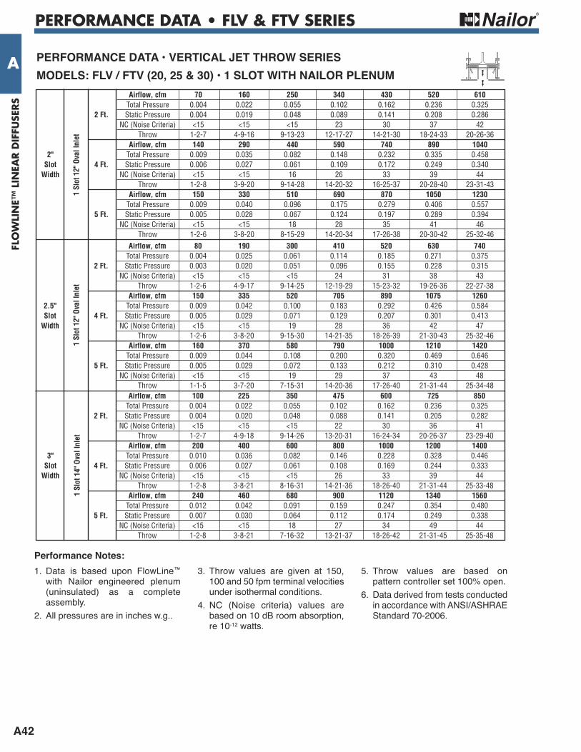
PERFORMANCE DATA • FLV & FTV SERIES
A42
FLO
WLI
NE™
LIN
EAR D
IFFU
SERS
A Airflow, cfm 70 160 250 340 430 520 610 Total Pressure 0.004 0.022 0.055 0.102 0.162 0.236 0.325 2 Ft. Static Pressure 0.004 0.019 0.048 0.089 0.141 0.208 0.286 NC (Noise Criteria) <15 <15 <15 23 30 37 42 Throw 1-2-7 4-9-16 9-13-23 12-17-27 14-21-30 18-24-33 20-26-36
Airflow, cfm 140 290 440 590 740 890 1040 2" Total Pressure 0.009 0.035 0.082 0.148 0.232 0.335 0.458 Slot 4 Ft. Static Pressure 0.006 0.027 0.061 0.109 0.172 0.249 0.340 Width NC (Noise Criteria) <15 <15 16 26 33 39 44 Throw 1-2-8 3-9-20 9-14-28 14-20-32 16-25-37 20-28-40 23-31-43
Airflow, cfm 150 330 510 690 870 1050 1230 Total Pressure 0.009 0.040 0.096 0.175 0.279 0.406 0.557 5 Ft. Static Pressure 0.005 0.028 0.067 0.124 0.197 0.289 0.394 NC (Noise Criteria) <15 <15 18 28 35 41 46 Throw 1-2-6 3-8-20 8-15-29 14-20-34 17-26-38 20-30-42 25-32-46
1 Slot 12" Oval Inlet
Airflow, cfm 80 190 300 410 520 630 740 Total Pressure 0.004 0.025 0.061 0.114 0.185 0.271 0.375 2 Ft. Static Pressure 0.003 0.020 0.051 0.096 0.155 0.228 0.315 NC (Noise Criteria) <15 <15 <15 24 31 38 43 Throw 1-2-6 4-9-17 9-14-25 12-19-29 15-23-32 19-26-36 22-27-38
Airflow, cfm 150 335 520 705 890 1075 1260 2.5" Total Pressure 0.009 0.042 0.100 0.183 0.292 0.426 0.584 Slot 4 Ft. Static Pressure 0.005 0.029 0.071 0.129 0.207 0.301 0.413 Width NC (Noise Criteria) <15 <15 19 28 36 42 47 Throw 1-2-6 3-8-20 9-15-30 14-21-35 18-26-39 21-30-43 25-32-46
Airflow, cfm 160 370 580 790 1000 1210 1420 Total Pressure 0.009 0.044 0.108 0.200 0.320 0.469 0.646 5 Ft. Static Pressure 0.005 0.029 0.072 0.133 0.212 0.310 0.428 NC (Noise Criteria) <15 <15 19 29 37 43 48 Throw 1-1-5 3-7-20 7-15-31 14-20-36 17-26-40 21-31-44 25-34-48
1 Slot 12" Oval Inlet
Airflow, cfm 100 225 350 475 600 725 850 Total Pressure 0.004 0.022 0.055 0.102 0.162 0.236 0.325 2 Ft. Static Pressure 0.004 0.020 0.048 0.088 0.141 0.205 0.282 NC (Noise Criteria) <15 <15 <15 22 30 36 41 Throw 1-2-7 4-9-18 9-14-26 13-20-31 16-24-34 20-26-37 23-29-40
Airflow, cfm 200 400 600 800 1000 1200 1400 3" Total Pressure 0.010 0.036 0.082 0.146 0.228 0.328 0.446 Slot 4 Ft. Static Pressure 0.006 0.027 0.061 0.108 0.169 0.244 0.333 Width NC (Noise Criteria) <15 <15 <15 26 33 39 44 Throw 1-2-8 3-8-21 8-16-31 14-21-36 18-26-40 21-31-44 25-33-48
Airflow, cfm 240 460 680 900 1120 1340 1560 Total Pressure 0.012 0.042 0.091 0.159 0.247 0.354 0.480 5 Ft. Static Pressure 0.007 0.030 0.064 0.112 0.174 0.249 0.338 NC (Noise Criteria) <15 <15 18 27 34 49 44 Throw 1-2-8 3-8-21 7-16-32 13-21-37 18-26-42 21-31-45 25-35-48
1 Slot 14" Oval Inlet
PerFOrMANCe DATA • VerTiCAL JeT THrOw SerieSMODeLS: FLV / FTV (20, 25 & 30) • 1 SLOT wiTH NAiLOr PLeNuM
1. Data is based upon FlowLine™with Nailor engineered plenum(uninsulated) as a completeassembly.
2. All pressures are in inches w.g..
3. Throw values are given at 150,100 and 50 fpm terminal velocitiesunder isothermal conditions.
4. NC (Noise criteria) values arebased on 10 dB room absorption,re 10-12 watts.
5. Throw values are based onpattern controller set 100% open.
6. Data derived from tests conducted in accordance with ANSI/ASHRAEStandard 70-2006.
Performance Notes:

PERFORMANCE DATA • FLV & FTV SERIES
A43
FLOW
LINE™
LINEA
R D
IFFUSER
S
A Airflow, cfm 80 155 230 305 380 455 530 Total Pressure 0.012 0.045 0.098 0.173 0.269 0.385 0.523 2 Ft. Static Pressure 0.009 0.032 0.070 0.122 0.189 0.272 0.369 NC (Noise Criteria) <15 <15 18 27 34 40 45 Throw 2-4-13 7-12-23 12-19-29 12-23-33 21-26-36 23-29-40 25-31-43
Airflow, cfm 160 260 360 460 560 660 760 1" Total Pressure 0.031 0.083 0.159 0.261 0.386 0.537 0.712 Slot 4 Ft. Static Pressure 0.017 0.046 0.089 0.144 0.215 0.299 0.396 Width NC (Noise Criteria) <15 <15 24 31 38 43 48 Throw 2-4-17 6-12-28 10-29-33 17-24-37 20-29-41 23-31-44 26-34-47
Airflow, cfm 200 300 400 500 600 700 800 Total Pressure 0.045 0.101 0.180 0.280 0.404 0.550 0.718 5 Ft. Static Pressure 0.022 0.051 0.092 0.143 0.207 0.281 0.368 NC (Noise Criteria) <15 <15 25 32 38 43 47 Throw 2-4-19 4-11-19 9-19-34 13-23-37 19-29-41 22-32-44 25-34-47
2 Slot 8" D
ia. Inlet
Airflow, cfm 80 165 250 335 420 505 590 Total Pressure 0.006 0.029 0.067 0.121 0.190 0.275 0.376 2 Ft. Static Pressure 0.005 0.024 0.054 0.096 0.151 0.217 0.297 NC (Noise Criteria) <15 <15 <15 23 31 37 42 Throw 2-4-13 8-13-24 13-20-30 18-24-34 22-28-39 24-30-42 26-32-46
Airflow, cfm 160 300 440 580 720 860 1000 1" Total Pressure 0.016 0.057 0.122 0.212 0.326 0.464 0.628 Slot 4 Ft. Static Pressure 0.011 0.036 0.078 0.136 0.210 0.299 0.404 Width NC (Noise Criteria) <15 <15 20 29 36 42 47 Throw 2-4-17 7-15-30 15-23-36 21-30-42 25-33-46 30-35-51 32-39-55
Airflow, cfm 200 350 500 650 800 950 1100 Total Pressure 0.022 0.068 0.140 0.238 0.360 0.506 0.679 5 Ft. Static Pressure 0.014 0.042 0.085 0.142 0.215 0.304 0.408 NC (Noise Criteria) <15 <15 22 31 37 43 47 Throw 2-4-19 7-14-32 13-23-37 20-31-43 25-43-47 30-36-52 32-40-56
2 Slot 10" Dia. Inlet
Airflow, cfm 80 170 260 350 440 530 620 Total Pressure 0.004 0.021 0.049 0.090 0.142 0.207 0.282 2 Ft. Static Pressure 0.004 0.018 0.043 0.077 0.122 0.177 0.242 NC (Noise Criteria) <15 <15 <15 21 28 34 39 Throw 2-4-13 8-13-24 14-21-31 19-25-35 23-28-40 25-31-43 28-33-47
Airflow, cfm 160 320 480 640 800 960 1120 1" Total Pressure 0.010 0.036 0.082 0.147 0.229 0.330 0.448 Slot 4 Ft. Static Pressure 0.006 0.026 0.058 0.102 0.159 0.229 0.312 Width NC (Noise Criteria) <15 <15 <15 24 32 37 42 Throw 2-4-17 8-17-31 17-25-37 23-31-44 29-34-48 31-37-54 33-41-57
Airflow, cfm 200 375 550 725 900 1075 1250 Total Pressure 0.013 0.044 0.095 0.165 0.255 0.363 0.490 5 Ft. Static Pressure 0.009 0.029 0.062 0.108 0.167 0.238 0.321 NC (Noise Criteria) <15 <15 17 26 33 38 43 Throw 2-4-19 8-17-33 17-25-40 23-32-45 29-35-51 32-39-55 34-42-59
2 Slot 12" Dia. Inlet
PerFOrMANCe DATA • VerTiCAL JeT THrOw SerieSMODeLS: FLV / FTV (10 & 15) • 2 SLOT wiTH NAiLOr PLeNuM
Airflow, cfm 120 210 300 390 480 570 660 Total Pressure 0.011 0.033 0.068 0.116 0.175 0.248 0.333 2 Ft. Static Pressure 0.007 0.024 0.048 0.082 0.124 0.175 0.234 NC (Noise Criteria) <15 <15 <15 21 27 33 38 Throw 2-4-15 6-13-26 12-19-31 17-25-35 21-28-40 24-31-43 26-33-46
Airflow, cfm 240 340 440 540 640 740 840 1.5" Total Pressure 0.029 0.059 0.097 0.148 0.207 0.276 0.356 Slot 4 Ft. Static Pressure 0.016 0.032 0.055 0.082 0.114 0.154 0.198 Width NC (Noise Criteria) <15 <15 <15 22 28 32 37 Throw 2-6-20 4-10-29 8-17-34 11-23-39 15-26-42 21-31-45 23-34-47
Airflow, cfm 260 365 470 575 680 785 890 Total Pressure 0.031 0.061 0.102 0.152 0.213 0.284 0.365 5 Ft. Static Pressure 0.016 0.031 0.052 0.078 0.109 0.146 0.187 NC (Noise Criteria) <15 <15 <15 22 28 32 36 Throw 2-4-17 3-8-28 6-13-35 9-20-39 12-25-42 17-30-45 21-33-47
2 Slot 10" Dia. Inlet
For performance table notes, see page A45.
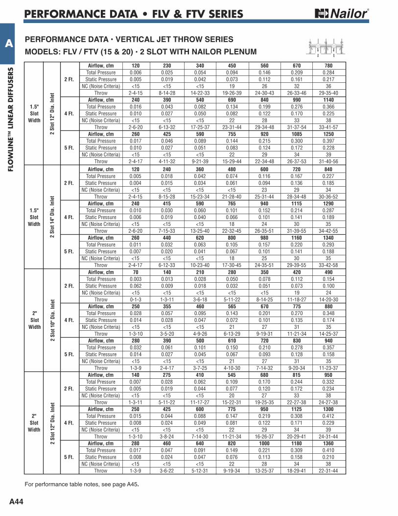
PERFORMANCE DATA • FLV & FTV SERIES
A44
FLO
WLI
NE™
LIN
EAR D
IFFU
SERS
A Airflow, cfm 120 230 340 450 560 670 780 Total Pressure 0.006 0.025 0.054 0.094 0.146 0.209 0.284 2 Ft. Static Pressure 0.005 0.019 0.042 0.073 0.112 0.161 0.217 NC (Noise Criteria) <15 <15 <15 19 26 32 36 Throw 2-4-15 8-14-28 14-22-33 19-26-39 24-30-43 26-33-46 29-35-40
Airflow, cfm 240 390 540 690 840 990 1140 1.5" Total Pressure 0.016 0.043 0.082 0.134 0.199 0.276 0.366 Slot 4 Ft. Static Pressure 0.010 0.027 0.050 0.082 0.122 0.170 0.225 Width NC (Noise Criteria) <15 <15 <15 22 28 33 38 Throw 2-6-20 6-13-32 17-25-37 23-31-44 29-34-48 31-37-54 33-41-57
Airflow, cfm 260 425 590 755 920 1085 1250 Total Pressure 0.017 0.046 0.089 0.144 0.215 0.300 0.397 5 Ft. Static Pressure 0.010 0.027 0.051 0.083 0.124 0.172 0.228 NC (Noise Criteria) <15 <15 <15 22 29 34 39 Throw 2-4-17 4-11-32 9-21-39 15-29-44 22-34-48 26-37-53 31-40-56
2 Slot 12" Dia. Inlet
Airflow, cfm 120 240 360 480 600 720 840 Total Pressure 0.005 0.018 0.042 0.074 0.116 0.167 0.227 2 Ft. Static Pressure 0.004 0.015 0.034 0.061 0.094 0.136 0.185 NC (Noise Criteria) <15 <15 <15 <15 23 29 34 Throw 2-4-15 8-15-28 15-23-34 21-28-40 25-31-44 28-34-48 30-36-52
Airflow, cfm 240 415 590 765 940 1115 1290 1.5" Total Pressure 0.010 0.030 0.060 0.101 0.152 0.214 0.287 Slot 4 Ft. Static Pressure 0.006 0.019 0.040 0.066 0.101 0.141 0.189 Width NC (Noise Criteria) <15 <15 <15 18 24 30 35 Throw 2-6-20 7-15-33 13-25-40 22-32-45 26-35-51 31-39-55 34-42-55
Airflow, cfm 260 440 620 800 980 1160 1340 Total Pressure 0.011 0.032 0.063 0.105 0.157 0.220 0.293 5 Ft. Static Pressure 0.007 0.020 0.041 0.067 0.101 0.141 0.188 NC (Noise Criteria) <15 <15 <15 18 25 30 35 Throw 2-4-17 6-12-33 10-23-40 17-30-45 24-35-51 29-39-55 33-42-58
2 Slot 14" Dia. Inlet
Airflow, cfm 70 140 210 280 350 420 490 Total Pressure 0.003 0.013 0.028 0.050 0.078 0.112 0.154 2 Ft. Static Pressure 0.062 0.009 0.018 0.032 0.051 0.073 0.100 NC (Noise Criteria) <15 <15 <15 <15 <15 19 24 Throw 0-1-3 1-3-11 3-6-18 5-11-22 8-14-25 11-18-27 14-20-30
Airflow, cfm 250 355 460 565 670 775 880 2" Total Pressure 0.028 0.057 0.095 0.143 0.201 0.270 0.348 Slot 4 Ft. Static Pressure 0.014 0.028 0.047 0.072 0.101 0.135 0.174 Width NC (Noise Criteria) <15 <15 <15 21 27 31 35 Throw 1-3-10 3-5-20 4-9-26 6-13-29 9-19-31 11-21-34 14-25-37
Airflow, cfm 280 390 500 610 720 830 940 Total Pressure 0.032 0.061 0.101 0.150 0.210 0.278 0.357 5 Ft. Static Pressure 0.014 0.027 0.045 0.067 0.093 0.128 0.158 NC (Noise Criteria) <15 <15 <15 21 27 31 35 Throw 1-3-9 2-4-17 3-7-25 4-10-30 7-14-32 9-20-34 11-23-37
2 Slot 10" Dia. Inlet
PerFOrMANCe DATA • VerTiCAL JeT THrOw SerieSMODeLS: FLV / FTV (15 & 20) • 2 SLOT wiTH NAiLOr PLeNuM
Airflow, cfm 140 275 410 545 680 815 950 Total Pressure 0.007 0.028 0.062 0.109 0.170 0.244 0.332 2 Ft. Static Pressure 0.005 0.019 0.044 0.077 0.120 0.172 0.234 NC (Noise Criteria) <15 <15 <15 20 27 33 38 Throw 1-3-11 5-11-22 11-17-27 15-22-31 19-25-35 22-27-38 24-27-38
Airflow, cfm 250 425 600 775 950 1125 1300 2" Total Pressure 0.015 0.044 0.088 0.147 0.219 0.308 0.412 Slot 4 Ft. Static Pressure 0.008 0.024 0.049 0.081 0.122 0.171 0.229 Width NC (Noise Criteria) <15 <15 <15 22 29 34 39 Throw 1-3-10 3-8-24 7-14-30 11-21-34 16-26-37 20-29-41 24-31-44
Airflow, cfm 280 460 640 820 1000 1180 1360 Total Pressure 0.017 0.047 0.091 0.149 0.221 0.309 0.410 5 Ft. Static Pressure 0.008 0.024 0.047 0.076 0.113 0.158 0.210 NC (Noise Criteria) <15 <15 <15 22 28 34 38 Throw 1-3-9 3-6-22 5-12-31 9-19-34 13-25-37 18-29-41 22-31-44
2 Slot 12" Dia. Inlet
For performance table notes, see page A45.
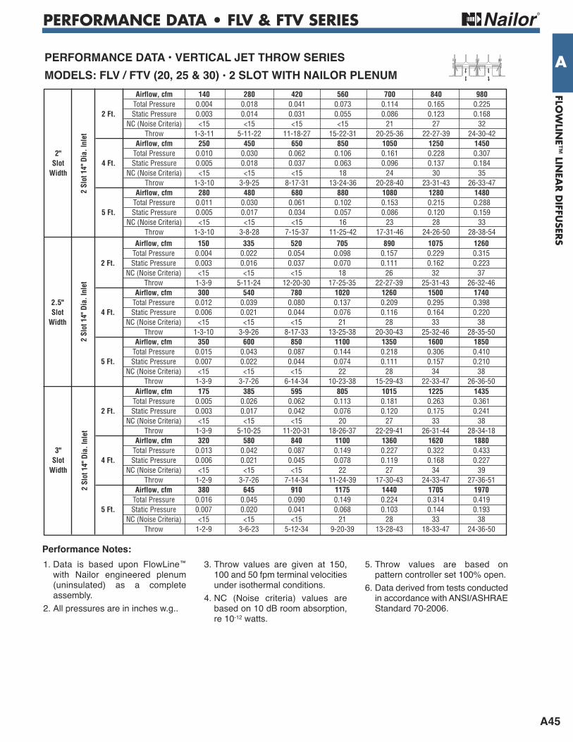
PERFORMANCE DATA • FLV & FTV SERIES
A45
FLOW
LINE™
LINEA
R D
IFFUSER
S
A Airflow, cfm 140 280 420 560 700 840 980 Total Pressure 0.004 0.018 0.041 0.073 0.114 0.165 0.225 2 Ft. Static Pressure 0.003 0.014 0.031 0.055 0.086 0.123 0.168 NC (Noise Criteria) <15 <15 <15 <15 21 27 32 Throw 1-3-11 5-11-22 11-18-27 15-22-31 20-25-36 22-27-39 24-30-42
Airflow, cfm 250 450 650 850 1050 1250 1450 2" Total Pressure 0.010 0.030 0.062 0.106 0.161 0.228 0.307 Slot 4 Ft. Static Pressure 0.005 0.018 0.037 0.063 0.096 0.137 0.184 Width NC (Noise Criteria) <15 <15 <15 18 24 30 35 Throw 1-3-10 3-9-25 8-17-31 13-24-36 20-28-40 23-31-43 26-33-47
Airflow, cfm 280 480 680 880 1080 1280 1480 Total Pressure 0.011 0.030 0.061 0.102 0.153 0.215 0.288 5 Ft. Static Pressure 0.005 0.017 0.034 0.057 0.086 0.120 0.159 NC (Noise Criteria) <15 <15 <15 16 23 28 33 Throw 1-3-10 3-8-28 7-15-37 11-25-42 17-31-46 24-26-50 28-38-54
2 Slot 14" Dia. Inlet
Airflow, cfm 150 335 520 705 890 1075 1260 Total Pressure 0.004 0.022 0.054 0.098 0.157 0.229 0.315 2 Ft. Static Pressure 0.003 0.016 0.037 0.070 0.111 0.162 0.223 NC (Noise Criteria) <15 <15 <15 18 26 32 37 Throw 1-3-9 5-11-24 12-20-30 17-25-35 22-27-39 25-31-43 26-32-46
Airflow, cfm 300 540 780 1020 1260 1500 1740 2.5" Total Pressure 0.012 0.039 0.080 0.137 0.209 0.295 0.398 Slot 4 Ft. Static Pressure 0.006 0.021 0.044 0.076 0.116 0.164 0.220 Width NC (Noise Criteria) <15 <15 <15 21 28 33 38 Throw 1-3-10 3-9-26 8-17-33 13-25-38 20-30-43 25-32-46 28-35-50
Airflow, cfm 350 600 850 1100 1350 1600 1850 Total Pressure 0.015 0.043 0.087 0.144 0.218 0.306 0.410 5 Ft. Static Pressure 0.007 0.022 0.044 0.074 0.111 0.157 0.210 NC (Noise Criteria) <15 <15 <15 22 28 34 38 Throw 1-3-9 3-7-26 6-14-34 10-23-38 15-29-43 22-33-47 26-36-50
2 Slot 14" Dia. Inlet
Airflow, cfm 175 385 595 805 1015 1225 1435 Total Pressure 0.005 0.026 0.062 0.113 0.181 0.263 0.361 2 Ft. Static Pressure 0.003 0.017 0.042 0.076 0.120 0.175 0.241 NC (Noise Criteria) <15 <15 <15 20 27 33 38 Throw 1-3-9 5-10-25 11-20-31 18-26-37 22-29-41 26-31-44 28-34-18
Airflow, cfm 320 580 840 1100 1360 1620 1880 3" Total Pressure 0.013 0.042 0.087 0.149 0.227 0.322 0.433 Slot 4 Ft. Static Pressure 0.006 0.021 0.045 0.078 0.119 0.168 0.227 Width NC (Noise Criteria) <15 <15 <15 22 27 34 39 Throw 1-2-9 3-7-26 7-14-34 11-24-39 17-30-43 24-33-47 27-36-51
Airflow, cfm 380 645 910 1175 1440 1705 1970 Total Pressure 0.016 0.045 0.090 0.149 0.224 0.314 0.419 5 Ft. Static Pressure 0.007 0.020 0.041 0.068 0.103 0.144 0.193 NC (Noise Criteria) <15 <15 <15 21 28 33 38 Throw 1-2-9 3-6-23 5-12-34 9-20-39 13-28-43 18-33-47 24-36-50
2 Slot 14" Dia. Inlet
PerFOrMANCe DATA • VerTiCAL JeT THrOw SerieSMODeLS: FLV / FTV (20, 25 & 30) • 2 SLOT wiTH NAiLOr PLeNuM
1. Data is based upon FlowLine™with Nailor engineered plenum(uninsulated) as a completeassembly.
2. All pressures are in inches w.g..
3. Throw values are given at 150,100 and 50 fpm terminal velocitiesunder isothermal conditions.
4. NC (Noise criteria) values arebased on 10 dB room absorption,re 10-12 watts.
5. Throw values are based onpattern controller set 100% open.
6. Data derived from tests conducted in accordance with ANSI/ASHRAEStandard 70-2006.
Performance Notes:
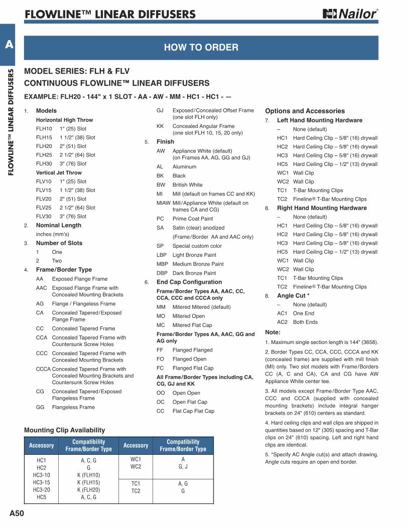
FLOWLINE™ LINEAR DIFFUSERS
A50
FLO
WLI
NE™
LIN
EAR D
IFFU
SERS
A HOw TO OrDer Or TO SPeCiFyHOw TO OrDer
MODeL SerieS: FLH & FLVCONTiNuOuS FLOwLiNe™ LiNeAr DiFFuSerSeXAMPLe: FLH20 - 144" x 1 SLOT - AA - Aw - MM - HC1 - HC1 - —
1. Models Horizontal High Throw FLH10 1" (25) Slot FLH15 1 1/2" (38) Slot FLH20 2" (51) Slot FLH25 2 1/2" (64) Slot FLH30 3" (76) Slot Vertical Jet Throw FLV10 1" (25) Slot FLV15 1 1/2" (38) Slot FLV20 2" (51) Slot FLV25 2 1/2" (64) Slot FLV30 3" (76) Slot2. Nominal Length inches (mm’s)3. Number of Slots 1 One 2 Two4. Frame/Border Type AA Exposed Flange Frame AAC Exposed Flange Frame with Concealed Mounting Brackets AG Flange / Flangeless Frame CA Concealed Tapered/Exposed Flange Frame CC Concealed Tapered Frame CCA Concealed Tapered Frame with Countersunk Screw Holes CCC Concealed Tapered Frame with Concealed Mounting Brackets CCCA Concealed Tapered Frame with Concealed Mounting Brackets and Countersunk Screw Holes CG Concealed Tapered/Exposed Flangeless Frame GG Flangeless Frame
GJ Exposed/Concealed Offset Frame (one slot FLH only) KK Concealed Angular Frame (one slot FLH 10, 15, 20 only)5. Finish AW Appliance White (default) (on Frames AA, AG, GG and GJ) AL Aluminum BK Black BW British White MI Mill (default on frames CC and KK) MIAW Mill /Appliance White (default on frames CA and CG) PC Prime Coat Paint SA Satin (clear) anodized (Frame/Border AA and AAC only) SP Special custom color LBP Light Bronze Paint MBP Medium Bronze Paint DBP Dark Bronze Paint6. end Cap Configuration
Frame/Border Types AA, AAC, CC, CCA, CCC and CCCA only MM Mitered Mitered (default) MO Mitered Open MC Mitered Flat Cap
Frame/Border Types AA, AAC, GG and AG only FF Flanged Flanged FO Flanged Open FC Flanged Flat Cap All Frame/Border Types including CA, CG, GJ and KK OO Open Open OC Open Flat Cap CC Flat Cap Flat Cap
Options and Accessories7. Left Hand Mounting Hardware – None (default) HC1 Hard Ceiling Clip – 5/8" (16) drywall HC2 Hard Ceiling Clip – 5/8" (16) drywall HC3 Hard Ceiling Clip – 5/8" (16) drywall HC5 Hard Ceiling Clip – 1/2" (13) drywall WC1 Wall Clip WC2 Wall Clip TC1 T-Bar Mounting Clips TC2 Fineline® T-Bar Mounting Clips8. right Hand Mounting Hardware – None (default) HC1 Hard Ceiling Clip – 5/8" (16) drywall HC2 Hard Ceiling Clip – 5/8" (16) drywall HC3 Hard Ceiling Clip – 5/8" (16) drywall HC5 Hard Ceiling Clip – 1/2" (13) drywall WC1 Wall Clip WC2 Wall Clip TC1 T-Bar Mounting Clips TC2 Fineline® T-Bar Mounting Clips8. Angle Cut * – None (default) AC1 One End AC2 Both EndsNote:1. Maximum single section length is 144" (3658).2. Border Types CC, CCA, CCC, CCCA and KK(concealed frame) are supplied with mill finish(MI) only. Two slot models with Frame/BordersCC (A, C and CA), CA and CG have AWAppliance White center tee.3. All models except Frame/Border Type AAC,CCC and CCCA (supplied with concealedmounting brackets) include integral hangerbrackets on 24" (610) centers as standard.4. Hard ceiling clips and wall clips are shipped inquantities based on 12" (305) spacing and T-Barclips on 24" (610) spacing. Left and right handclips are identical.5. *Specify AC Angle cut(s) and attach drawing.Angle cuts require an open end border.
Accessory CompatibilityFrame/Border Type Accessory Compatibility
Frame/Border Type
HC1HC2HC3-10HC3-15HC3-20HC5
A, C, GG
K (FLH10)K (FLH15)K (FLH20)A, C, G
WC1WC2
AG, J
TC1TC2
A, GG
Mounting Clip Availability
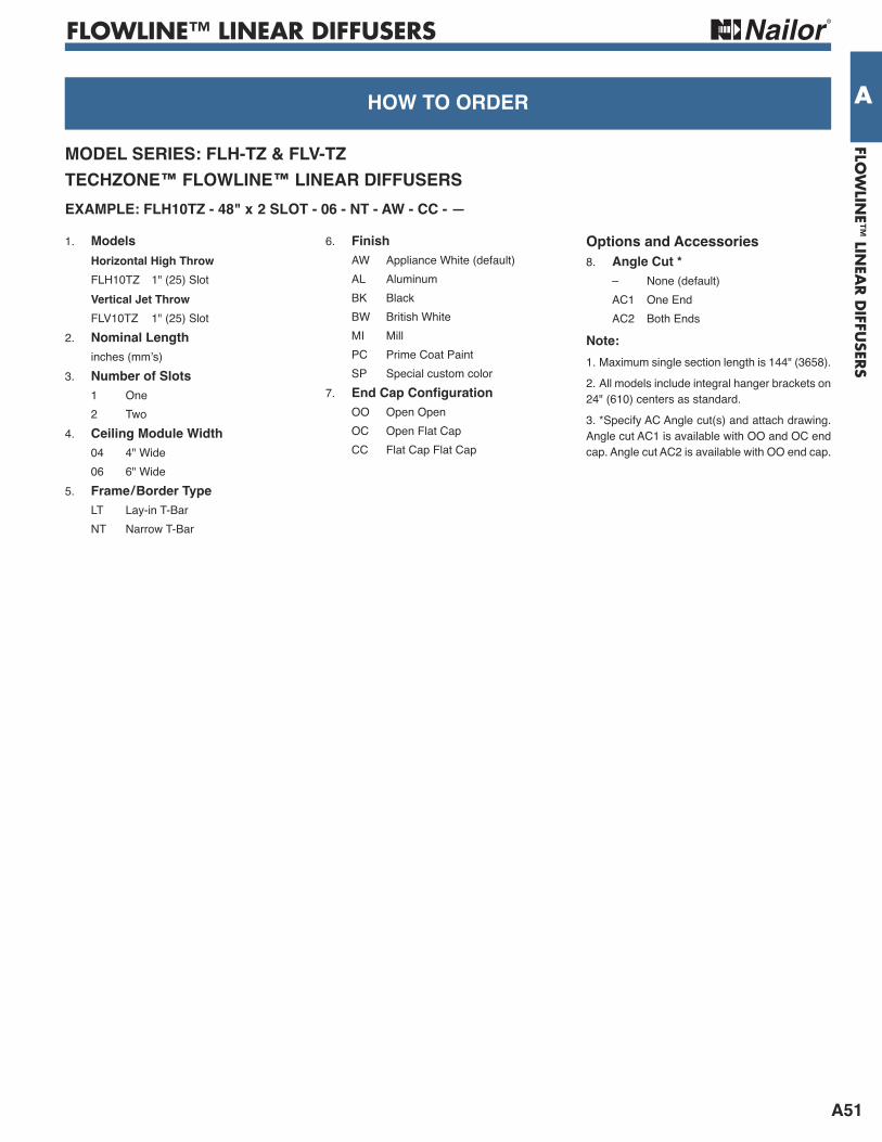
FLOWLINE™ LINEAR DIFFUSERS
A51
FLOW
LINE™
LINEA
R D
IFFUSER
S
AHOw TO OrDer Or TO SPeCiFyHOw TO OrDer
MODeL SerieS: FLH-TZ & FLV-TZTeCHZONe™ FLOwLiNe™ LiNeAr DiFFuSerSeXAMPLe: FLH10TZ - 48" x 2 SLOT - 06 - NT - Aw - CC - —
1. Models Horizontal High Throw FLH10TZ 1" (25) Slot Vertical Jet Throw FLV10TZ 1" (25) Slot2. Nominal Length inches (mm’s)3. Number of Slots 1 One 2 Two4. Ceiling Module width 04 4" Wide 06 6" Wide5. Frame/Border Type LT Lay-in T-Bar NT Narrow T-Bar
6. Finish AW Appliance White (default) AL Aluminum BK Black BW British White MI Mill PC Prime Coat Paint SP Special custom color7. end Cap Configuration OO Open Open OC Open Flat Cap CC Flat Cap Flat Cap
Options and Accessories8. Angle Cut * – None (default) AC1 One End AC2 Both EndsNote:1. Maximum single section length is 144" (3658).2. All models include integral hanger brackets on 24" (610) centers as standard.3. *Specify AC Angle cut(s) and attach drawing.Angle cut AC1 is available with OO and OC endcap. Angle cut AC2 is available with OO end cap.
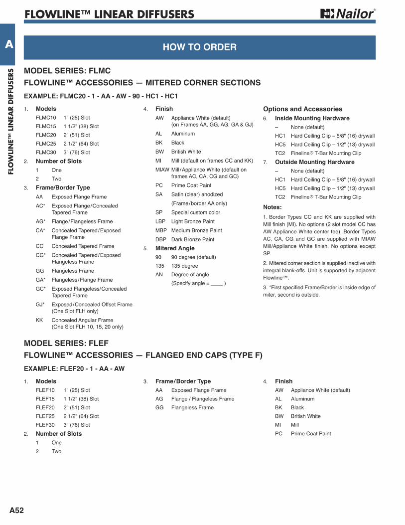
FLOWLINE™ LINEAR DIFFUSERS
A52
FLO
WLI
NE™
LIN
EAR D
IFFU
SERS
A HOw TO OrDer Or TO SPeCiFyHOw TO OrDer
MODeL SerieS: FLMCFLOwLiNe™ ACCeSSOrieS — MiTereD COrNer SeCTiONSeXAMPLe: FLMC20 - 1 - AA - Aw - 90 - HC1 - HC11. Models FLMC10 1" (25) Slot FLMC15 1 1/2" (38) Slot FLMC20 2" (51) Slot FLMC25 2 1/2" (64) Slot FLMC30 3" (76) Slot2. Number of Slots 1 One 2 Two3. Frame/Border Type AA Exposed Flange Frame AC* Exposed Flange/Concealed Tapered Frame AG* Flange/Flangeless Frame CA* Concealed Tapered/Exposed Flange Frame CC Concealed Tapered Frame CG* Concealed Tapered/Exposed Flangeless Frame GG Flangeless Frame GA* Flangeless/Flange Frame GC* Exposed Flangeless/Concealed Tapered Frame GJ* Exposed/Concealed Offset Frame (One Slot FLH only) KK Concealed Angular Frame (One Slot FLH 10, 15, 20 only)
4. Finish AW Appliance White (default) (on Frames AA, GG, AG, GA & GJ) AL Aluminum BK Black BW British White MI Mill (default on frames CC and KK) MIAW Mill /Appliance White (default on frames AC, CA, CG and GC) PC Prime Coat Paint SA Satin (clear) anodized (Frame/border AA only) SP Special custom color LBP Light Bronze Paint MBP Medium Bronze Paint DBP Dark Bronze Paint5. Mitered Angle 90 90 degree (default) 135 135 degree AN Degree of angle (Specify angle = ____ )
Options and Accessories6. inside Mounting Hardware – None (default) HC1 Hard Ceiling Clip – 5/8" (16) drywall HC5 Hard Ceiling Clip – 1/2" (13) drywall TC2 Fineline® T-Bar Mounting Clip7. Outside Mounting Hardware – None (default) HC1 Hard Ceiling Clip – 5/8" (16) drywall HC5 Hard Ceiling Clip – 1/2" (13) drywall TC2 Fineline® T-Bar Mounting ClipNotes:1. Border Types CC and KK are supplied with Mill finish (MI). No options (2 slot model CC hasAW Appliance White center tee). Border TypesAC, CA, CG and GC are supplied with MIAWMill/Appliance White finish. No options exceptSP. 2. Mitered corner section is supplied inactive withintegral blank-offs. Unit is supported by adjacentFlowline™.3. *First specified Frame/Border is inside edge ofmiter, second is outside.
MODeL SerieS: FLeFFLOwLiNe™ ACCeSSOrieS — FLANGeD eND CAPS (TyPe F)eXAMPLe: FLeF20 - 1 - AA - Aw1. Models FLEF10 1" (25) Slot FLEF15 1 1/2" (38) Slot FLEF20 2" (51) Slot FLEF25 2 1/2" (64) Slot FLEF30 3" (76) Slot2. Number of Slots 1 One 2 Two
3. Frame/Border Type AA Exposed Flange Frame AG Flange / Flangeless Frame GG Flangeless Frame
4. Finish AW Appliance White (default) AL Aluminum BK Black BW British White MI Mill PC Prime Coat Paint

FLOWLINE™ LINEAR DIFFUSERS
A54
FLO
WLI
NE™
LIN
EAR D
IFFU
SERS
A HOw TO OrDer Or TO SPeCiFyHOw TO OrDer
MODeL SerieS: FLPFLOwLiNe™ LiNeAr DiFFuSer PLeNuMSeXAMPLe: FLP10 - 48" x 1 SLOT - HSTD - 08 - AA - iD - — 1. Models uninsulated Plenum FLP10 1" (25) Slot FLP15 1 1/2" (38) Slot FLP20 2" (51) Slot FLP25 2 1/2" (64) Slot FLP30 3" (76) Slot insulated Plenum (internal) FLPI10 1" (25) Slot FLPI15 1 1/2" (38) Slot FLPI20 2" (51) Slot FLPI25 2 1/2" (64) Slot FLPI30 3" (76) Slot2. Nominal Length imperial Sizes inches (mm’s) 24, 30, 36, 48, 60, 72 (610, 762, 914, 1219, 1524, 1829) Metric Sizes (mm’s) (600, 750, 900, 1200, 1500, 1800)3. Number of Slots 1 One 2 Two4. Plenum Height HSTD Standard (default) One Slot Option (for round inlets) H13 13" (330) H15 15" (381) H17 17" (432)5. inlet Size One Slot 06 6" (152) Round 08 8" (203) Round 10 10" (254) Flat Oval 10R 10" (254) Round 12 12" (305) Flat Oval 12R 12" (305) Round 14 14" (356) Flat Oval 14R 14" (356) Round
Two Slot 06 6" (152) Round 08 8" (203) Round 10R 10" (254) Round 12R 12" (305) Round 14R 14" (356) Round6. Frame/Border Type (Diffuser) AA Exposed Flange Frame AAC Exposed Flange Frame with Concealed Mounting Brackets AG Flange/Flangeless Frame CA Concealed Tapered/Exposed Flange Frame CC Concealed Tapered Frame CCA Concealed Tapered Frame with Countersunk Screw Holes CCC Concealed Tapered Frame with Concealed Mounting Brackets CCCA Concealed Tapered Frame with Concealed Mounting Brackets and Countersunk Screw Holes CG Concealed Tapered/Exposed Flangeless Frame GG Flangeless Frame GJ Exposed/Concealed Offset Frame (One Slot FLH only) KK Concealed Angular Frame LT Lay-in T-Bar (TechZone™) NT Narrow T-Bar (TechZone™)
Options and Accessories:7. inlet Damper – None (default) ID Inlet Damper with HLQ IDCO Cable Operated Damper8a. external insulation (FLP models only) – None (default) EX External Foil Back (installed)8b. internal insulation (FLPI models only) FGI 1/4" (6.35) Coated fiberglass (default) FFI 3/8" (9.53) Fiber-free foamNotes:1. Plenums are shipped loose as standard forfield installation.2. Plenums for Frame/Border Types AA, AG, CA,CC, CG, CCA, GG, GJ, KK, LT and NT are fordifferent attachment to diffuser neck. TechZone™Frame Border Type LT and NT are available inFLP10 and FLPI10 1" (25) slot only. 3. Plenums for Frame Types AAC, CCC andCCCA are hemmed for field attachment by useof concealed mounting brackets. 4. Standard internal insulation ("I" suffix models)is 1/4" (6.35) coated fiberglass.
Plenum Inlet Type/Size
Code Height Round Oval
HSTDH13H15H17
Standard *13 (330)15 (381)17 (432)
06, 0806, 08, 10R
06, 08, 10R, 12R06, 08, 10R – 14R
10 – 1412 – 1414—
Available inlet Sizes – One Slot Plenum
* 10" (254) for Type AA, CA, CC, CCA, AG, CG, GG, GJ, KK, LT and NT (straight leg).12" (305) for Type AAC, CCC and CCCA (hemmed leg).
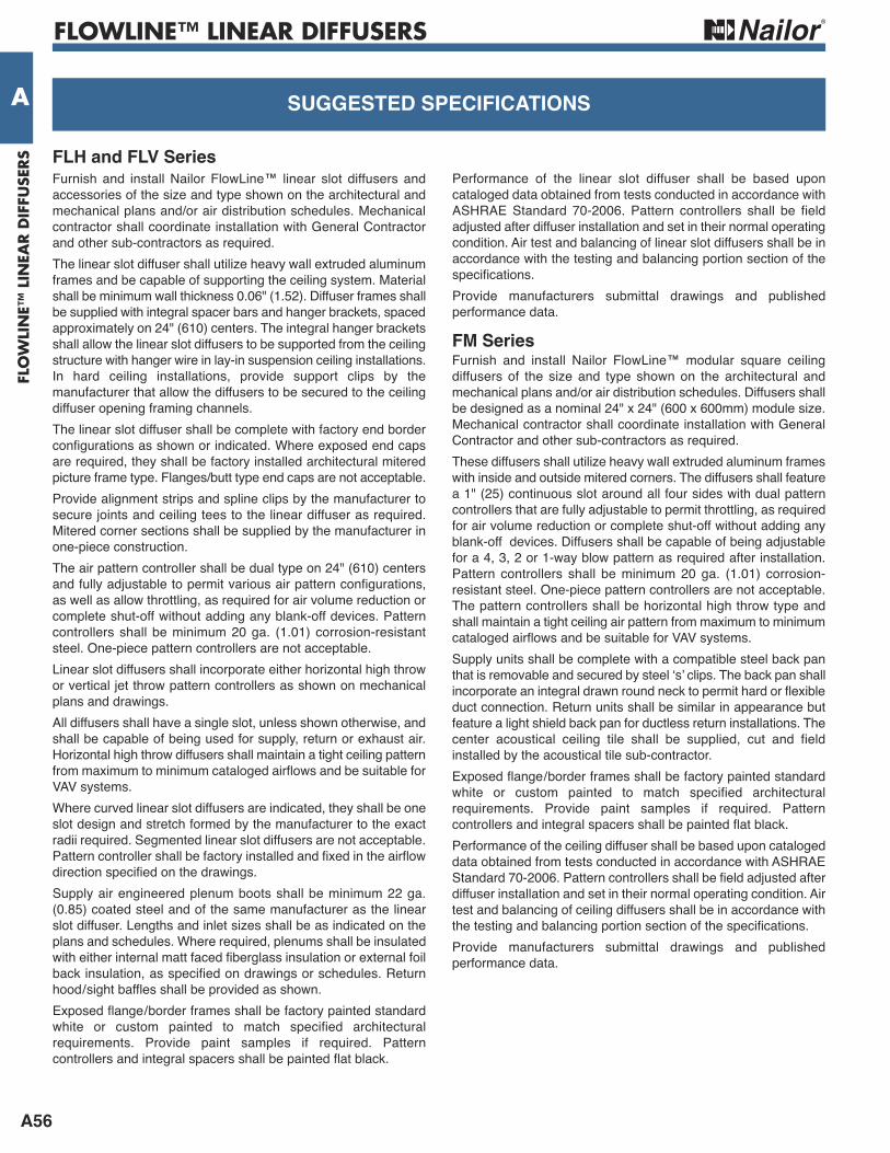
FLOWLINE™ LINEAR DIFFUSERS
A56
FLO
WLI
NE™
LIN
EAR D
IFFU
SERS
A HOw TO OrDer Or TO SPeCiFySuGGeSTeD SPeCiFiCATiONS
FLH and FLV SeriesFurnish and install Nailor FlowLine™ linear slot diffusers andaccessories of the size and type shown on the architectural andmechanical plans and/or air distribution schedules. Mechanicalcontractor shall coordinate installation with General Contractorand other sub-contractors as required.The linear slot diffuser shall utilize heavy wall extruded aluminumframes and be capable of supporting the ceiling system. Materialshall be minimum wall thickness 0.06" (1.52). Diffuser frames shallbe supplied with integral spacer bars and hanger brackets, spacedapproximately on 24" (610) centers. The integral hanger bracketsshall allow the linear slot diffusers to be supported from the ceilingstructure with hanger wire in lay-in suspension ceiling installations.In hard ceiling installations, provide support clips by themanufacturer that allow the diffusers to be secured to the ceilingdiffuser opening framing channels.The linear slot diffuser shall be complete with factory end borderconfigurations as shown or indicated. Where exposed end capsare required, they shall be factory installed architectural miteredpicture frame type. Flanges/butt type end caps are not acceptable. Provide alignment strips and spline clips by the manufacturer tosecure joints and ceiling tees to the linear diffuser as required.Mitered corner sections shall be supplied by the manufacturer inone-piece construction.The air pattern controller shall be dual type on 24" (610) centersand fully adjustable to permit various air pattern configurations,as well as allow throttling, as required for air volume reduction orcomplete shut-off without adding any blank-off devices. Patterncontrollers shall be minimum 20 ga. (1.01) corrosion-resistantsteel. One-piece pattern controllers are not acceptable.Linear slot diffusers shall incorporate either horizontal high throwor vertical jet throw pattern controllers as shown on mechanicalplans and drawings.All diffusers shall have a single slot, unless shown otherwise, andshall be capable of being used for supply, return or exhaust air.Horizontal high throw diffusers shall maintain a tight ceiling patternfrom maximum to minimum cataloged airflows and be suitable forVAV systems.Where curved linear slot diffusers are indicated, they shall be oneslot design and stretch formed by the manufacturer to the exactradii required. Segmented linear slot diffusers are not acceptable.Pattern controller shall be factory installed and fixed in the airflowdirection specified on the drawings.Supply air engineered plenum boots shall be minimum 22 ga.(0.85) coated steel and of the same manufacturer as the linearslot diffuser. Lengths and inlet sizes shall be as indicated on theplans and schedules. Where required, plenums shall be insulatedwith either internal matt faced fiberglass insulation or external foilback insulation, as specified on drawings or schedules. Returnhood/sight baffles shall be provided as shown.Exposed flange/border frames shall be factory painted standardwhite or custom painted to match specified architecturalrequirements. Provide paint samples if required. Patterncontrollers and integral spacers shall be painted flat black.
Performance of the linear slot diffuser shall be based uponcataloged data obtained from tests conducted in accordance withASHRAE Standard 70-2006. Pattern controllers shall be fieldadjusted after diffuser installation and set in their normal operatingcondition. Air test and balancing of linear slot diffusers shall be inaccordance with the testing and balancing portion section of thespecifications.Provide manufacturers submittal drawings and publishedperformance data.
FM SeriesFurnish and install Nailor FlowLine™ modular square ceilingdiffusers of the size and type shown on the architectural andmechanical plans and/or air distribution schedules. Diffusers shallbe designed as a nominal 24" x 24" (600 x 600mm) module size.Mechanical contractor shall coordinate installation with GeneralContractor and other sub-contractors as required.These diffusers shall utilize heavy wall extruded aluminum frameswith inside and outside mitered corners. The diffusers shall featurea 1" (25) continuous slot around all four sides with dual patterncontrollers that are fully adjustable to permit throttling, as requiredfor air volume reduction or complete shut-off without adding anyblank-off devices. Diffusers shall be capable of being adjustablefor a 4, 3, 2 or 1-way blow pattern as required after installation.Pattern controllers shall be minimum 20 ga. (1.01) corrosion-resistant steel. One-piece pattern controllers are not acceptable.The pattern controllers shall be horizontal high throw type andshall maintain a tight ceiling air pattern from maximum to minimumcataloged airflows and be suitable for VAV systems.Supply units shall be complete with a compatible steel back panthat is removable and secured by steel ‘s’ clips. The back pan shallincorporate an integral drawn round neck to permit hard or flexibleduct connection. Return units shall be similar in appearance butfeature a light shield back pan for ductless return installations. Thecenter acoustical ceiling tile shall be supplied, cut and fieldinstalled by the acoustical tile sub-contractor.Exposed flange/border frames shall be factory painted standardwhite or custom painted to match specified architecturalrequirements. Provide paint samples if required. Patterncontrollers and integral spacers shall be painted flat black.Performance of the ceiling diffuser shall be based upon catalogeddata obtained from tests conducted in accordance with ASHRAEStandard 70-2006. Pattern controllers shall be field adjusted afterdiffuser installation and set in their normal operating condition. Airtest and balancing of ceiling diffusers shall be in accordance withthe testing and balancing portion section of the specifications.Provide manufacturers submittal drawings and publishedperformance data.
Related Documents