J Neurosurg: Pediatrics / Volume 9 / February 2012 191 C EREBROSPINAL fluid shunting is required when en- dogenous pathways of circulation and reabsorp- tion of CSF are disrupted. Cerebrospinal fluid shunt system failure is a significant cause of morbidity in patients with hydrocephalus. Shunt system malfunctions can occur due to catheter breakage or disconnection, ob- struction of either the ventricular or distal catheter, ob- struction of the shunt valve, or malpositioning. As biome- chanical devices, CSF shunt systems are inherently prone to failure and infection. In the 1st year after implantation alone, the average failure rate of a CSF shunt is 30%, and reports show that up to 50% of CSF shunt systems fail over time. 6,16 The flow of CSF within a shunt system depends on intraventricular pressure, the diameter and length of the catheter, and the resistance of the shunt sys- tem, including the internal resistance in the shunt tubing and the distal pressure at the site of CSF drainage. Distal catheter malfunction is well documented in the literature. Infection, bowel or bladder perforation, pseu- docyst formation, volvulus, abdominal wall or diaphragm penetration, umbilical or inguinal hernia formation, scro- tal extrusion, and unexplained failure are all described. Late shunt malfunction secondary to smoldering infec- tions, embolization of choroid plexus and leptomeninges, or cellular invasion may contribute to late-term shunt malfunction and changes in resistance to CSF flow. 10 J Neurosurg Pediatrics 9:191–197, 2012 Flow characteristics of cerebrospinal fluid shunt tubing Laboratory investigation JOSEPH T. CHEATLE, M.D., ALEXIS N. BOWDER, B.S., B.A., SANDEEP K. AGRAWAL, PH.D., MICHAEL D. SATHER, M.D., AND LESLIE C. HELLBUSCH, M.D. Division of Neurosurgery, Department of Surgery, University of Nebraska Medical Center, Omaha, Nebraska Object. Cerebrospinal fluid shunt systems malfunction for a multitude of reasons, including malpostitioning, obstruction of the ventricular or distal catheter, obstruction of the shunt valve, and catheter disruptions or disconnec- tions. The goal of this study was to examine the hydrodynamic resistance and flow in new and explanted catheters and also in catheters with 1 or 2 straight connectors. Methods. Explanted catheters of multiple lengths, 2-piece catheters, 3-piece catheters, and new catheters were attached to a proximal and distal manometer. A flask with artificial CSF attached to the proximal end provided flow. The flow was allowed to stabilize over 1 hour; then the change in pressure between the proximal and distal end of the catheter was measured. Results. The resistance to flow was calculated for new, never-implanted catheters and compared with the resis- tance of explanted distal shunt catheters. The resistance of the new catheters was examined after the addition of 1 and 2 straight connectors. Explanted catheters exhibited a slight increase in the resistance to flow of artificial CSF com- pared with new catheters. Two-piece and 3-piece catheters had a significant increase in resistance to flow compared with new catheters. For all catheters, resistance to flow increased as length increased (new, p = 0.01; explanted, p = 0.009; 1 connector, p = 0.01; 2 connectors, p = 0.03). In this paper, effective diameter is defined as the available cross- sectional area of catheter contacted by the artificial CSF. For new and explanted catheters, a decrease in the effective diameter of the catheter was associated with an increase in the resistance to flow of artificial CSF (new, p = 0.1083; explanted, p = 0.0091). However, after the addition of 1 or 2 connectors, an inverse trend was observed: resistance to flow increased with effective diameter. Conclusions. There appears to be some increase in resistance of CSF shunt catheters as they age, altering flow dynamics. In addition, the use of straight connectors within a CSF shunt system increases the resistance to flow of artificial CSF within the shunt system. The increase in resistance appears to be related to the duration of implantation and the length of the catheter and inversely related to the diameter of the catheter. This increase in resistance may be related to sterile shunt malfunction. The addition of straight connectors is associated with a significant increase in resistance in comparison with catheters without connectors (p = 0.005). (http://thejns.org/doi/abs/10.3171/2011.11.PEDS11255) KEY WORDS • cerebrospinal fluid shunt • shunt malfunction • cerebrospinal fluid dynamics • hydrocephalus 191 This article contains some figures that are displayed in color online but in black and white in the print edition.

Welcome message from author
This document is posted to help you gain knowledge. Please leave a comment to let me know what you think about it! Share it to your friends and learn new things together.
Transcript
J Neurosurg Pediatrics Volume 9 February 2012
J Neurosurg Pediatrics 9000ndash000 2012
191
Cerebrospinal fluid shunting is required when en-dogenous pathways of circulation and reabsorp-tion of CSF are disrupted Cerebrospinal fluid
shunt system failure is a significant cause of morbidity in patients with hydrocephalus Shunt system malfunctions can occur due to catheter breakage or disconnection ob-struction of either the ventricular or distal catheter ob-struction of the shunt valve or malpositioning As biome-chanical devices CSF shunt systems are inherently prone to failure and infection In the 1st year after implantation alone the average failure rate of a CSF shunt is 30 and reports show that up to 50 of CSF shunt systems fail over time616 The flow of CSF within a shunt system depends on intraventricular pressure the diameter and length of the catheter and the resistance of the shunt sys-
tem including the internal resistance in the shunt tubing and the distal pressure at the site of CSF drainage
Distal catheter malfunction is well documented in the literature Infection bowel or bladder perforation pseu-docyst formation volvulus abdominal wall or diaphragm penetration umbilical or inguinal hernia formation scro-tal extrusion and unexplained failure are all described Late shunt malfunction secondary to smoldering infec-tions embolization of choroid plexus and leptomeninges or cellular invasion may contribute to late-term shunt malfunction and changes in resistance to CSF flow10
J Neurosurg Pediatrics 9191ndash197 2012
Flow characteristics of cerebrospinal fluid shunt tubing
Laboratory investigation
Joseph T CheaTle MD alexis N BowDer Bs Ba saNDeep K agrawal phD MiChael D saTher MD aND leslie C hellBusCh MDDivision of Neurosurgery Department of Surgery University of Nebraska Medical Center Omaha Nebraska
Object Cerebrospinal fluid shunt systems malfunction for a multitude of reasons including malpostitioning obstruction of the ventricular or distal catheter obstruction of the shunt valve and catheter disruptions or disconnec-tions The goal of this study was to examine the hydrodynamic resistance and flow in new and explanted catheters and also in catheters with 1 or 2 straight connectors
Methods Explanted catheters of multiple lengths 2-piece catheters 3-piece catheters and new catheters were attached to a proximal and distal manometer A flask with artificial CSF attached to the proximal end provided flow The flow was allowed to stabilize over 1 hour then the change in pressure between the proximal and distal end of the catheter was measured
Results The resistance to flow was calculated for new never-implanted catheters and compared with the resis-tance of explanted distal shunt catheters The resistance of the new catheters was examined after the addition of 1 and 2 straight connectors Explanted catheters exhibited a slight increase in the resistance to flow of artificial CSF com-pared with new catheters Two-piece and 3-piece catheters had a significant increase in resistance to flow compared with new catheters For all catheters resistance to flow increased as length increased (new p = 001 explanted p = 0009 1 connector p = 001 2 connectors p = 003) In this paper effective diameter is defined as the available cross-sectional area of catheter contacted by the artificial CSF For new and explanted catheters a decrease in the effective diameter of the catheter was associated with an increase in the resistance to flow of artificial CSF (new p = 01083 explanted p = 00091) However after the addition of 1 or 2 connectors an inverse trend was observed resistance to flow increased with effective diameter
Conclusions There appears to be some increase in resistance of CSF shunt catheters as they age altering flow dynamics In addition the use of straight connectors within a CSF shunt system increases the resistance to flow of artificial CSF within the shunt system The increase in resistance appears to be related to the duration of implantation and the length of the catheter and inversely related to the diameter of the catheter This increase in resistance may be related to sterile shunt malfunction The addition of straight connectors is associated with a significant increase in resistance in comparison with catheters without connectors (p = 0005)(httpthejnsorgdoiabs103171201111PEDS11255)
Key worDsensp ensp ensp bullensp ensp ensp cerebrospinalenspfluidenspshuntensp ensp ensp bullensp ensp ensp shuntenspmalfunctionensp ensp ensp bullensp ensp ensp cerebrospinalenspfluidenspdynamicsensp ensp ensp bullensp ensp ensp hydrocephalus
191
This article contains some figures that are displayed in color on line but in black and white in the print edition
J T Cheatle et al
192 J Neurosurg Pediatrics Volume 9 February 2012
Sterile shunt malfunction is a known cause of shunt failure Previous studies outline reaction to silicone within the body via a delayed hypersensitivity reaction2311 Upon electron microscopy examination shunts with sterile malfunction have been found to have increased protein-aceous and cellular debris10 This reaction may change the resistance to flow of CSF and result in less than optimal shunt function or outright failure Calcification of the ex-ternal surface of catheters and microstructure alteration of silicone catheters has been demonstrated in in vitro samples of explanted silicone catheters5
The resistance of different shunt valves alone and in series with their catheters has been well documented in the literature7 Valves have low intrinsic hydrodynamic resistance A valve in series with a catheter increases the resistance in the system by 100ndash20010 but little is known about how the addition of straight connectors to the distal catheter can change the resistance to flow of the CSF shunt system
To date no formal studies have been performed on explanted shunt catheters to determine if the resistance changes over the duration of implantation The distal cath-eter is responsible for a significant portion of the total resis-tance and a significant increase in resistance over the life of a shunt can alter the function of the CSF shunt system In this study we compare the hydrodynamic resistance prop-erties of explanted distal shunt catheters to identical new distal shunt catheters In addition we examine the effects of straight connectors on CSF shunt systems in vitro
MethodsNew Tubing and Straight Connectors
New CSF shunt tubing and straight connectors were donated by Codman All of the tubing was suitable for implantation without having any defects or being past the expiration date The shunt tubing from Codman had an inner diameter of 10 mm and outer diameter of 22 mm and was originally 120 cm in length The Codman straight connectors with beveled tips were 111 mm in length and had an inner diameter of 10 mm and outer diameter of 19 mmUsed Tubing
Under the approval of the institutional review board distal CSF shunt tubing was obtained from patients in the course of noninfected CSF shunt revision surgery The tubing was used to study the flow and resistance of used tubing The manufacturer and model number of the re-trieved shunt tubing were identified by visual inspection and confirmed by reviewing operative reports Subse-quent chart review allowed us to determine the length of time the shunt tubing was implanted as well as the origi-nal diagnosis necessitating placement of a CSF shunt sys-tem If an infection was known or suspected at the time of surgery the shunt tubing was excluded from the study Retrieved shunt specimens were tested while this study was active between 2004 and 2009Artificial CSF
Artificial CSF was made to closely resemble natural
CSF17 100-ml aliquots of distilled water were mixed with 126 mM sodium chloride 3 mM potassium chloride and 125 mM monosodium phosphate until dissolved 2 mM magnesium chloride and 2 mM of calcium chloride were subsequently added and allowed to dissolve and 26 mM sodium bicarbonate and 10 mM of dextrose were added last and allowed to dissolve The artificial CSF was al-lowed to equilibrate to the temperature of the water bath to closely resemble in vivo conditions
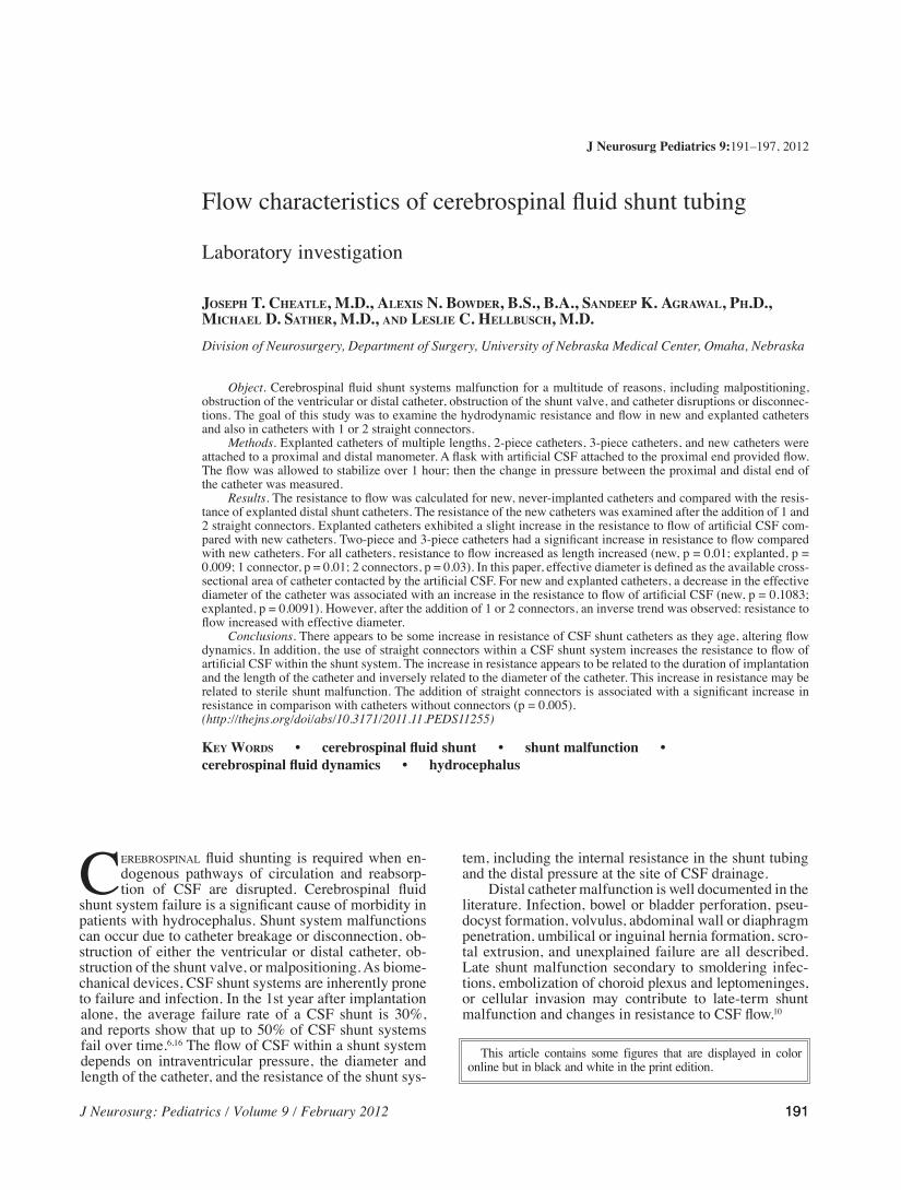
Measurement of CSF Shunt Tubing ResistanceA water bath system as pictured in Fig 1 was main-
tained at 37deg plusmn 2degC Manometers were placed at each end of the water bath with a constant height plusmn 2 mm A flask with a redundant catheter containing 350 ml of artificial CSF was connected to the proximal CSF drainage cath-eter and placed in the water bath The flask and catheter were constant in all experiments The catheter was of ad-equate length to ensure that the artificial CSF was equili-brated to the temperature of the water bath The proximal end of the catheter was attached to the proximal manom-eter The distal end of the catheter was then attached to the distal manometer All air was purged from the sys-tem The pump was set to provide flow of 15 ml per hour After 1 hour the water column heights of the proximal and distal manometer were read and recorded as was the total volume of artificial CSF remaining in the beaker
To examine the effects of straight connectors in vitro the new distal catheter tubing was cut to lengths of 18 35 52 857 93 96 and 98 cm These specific lengths were chosen to match lengths of explanted catheters For each length the resistance was measured using the above procedure for a control catheter (with no connector) a catheter with 1 connector (2-piece catheter) and a cath-eter with 2 connectors (3-piece catheter) Resistance was measured 5 times for condition (control 1 connector and 2 connectors) with catheters that were 18 35 52 857 93 96 and 98 cm in length Therefore for each length 15 tri-als were performed
Determination of Resistance to FlowThe following variables were recorded during the
measurement of resistance starting volume of artificial CSF ending volume of artificial CSF total volume of ar-tificial CSF used height of the water column in proximal
Fig 1ensp Schematicensp ofensp shuntensp flowensp systemenspwithinensp aenspwaterensp bathenspmain-tained at 370deg plusmnensp20degCenspaCSFensp=enspartificialenspCSF
J Neurosurg Pediatrics Volume 9 February 2012
Flow characteristics of CSF shunt tubing
193
manometer and height of water column in distal manom-eter
The Poiseuille law states that the volume flow of an incompressible fluid through a circular tube is equal to p8 times the pressure differences between the ends of the tube times the fourth power of the tubersquos radius di-vided by the product of the tubersquos length and the dynamic viscosity of the fluid9 Using the data obtained and the Poiseuille law shown in Equation 1 the resistance to flow was calculated for each trial
Equation 1 Using the Poiseuille equation assuming a constant velocity the resistance to flow for CSF (a New-tonian fluid) through the CSF shunt system was calcu-lated where r = radius of the catheter l = length of distal catheter and h = viscosity of the fluid A predetermined viscosity of CSF at 079 mPasec4 was used for the viscos-ity in each resistance to flow calculation
Q = (Pproximal minusenspPdistal) π r 4 8lη Eq 1Effective diameter was calculated by solving the Poi-
seuille equation for effective diameter and the resulting equation (Equation 2) was used to calculate the effective diameter for each trial
Equation 2 The following equation was derived from the Poiseuille equation and used to calculate effective di-ameter (D) in each catheter where l = length of tube h = viscosity of the fluid in mPasec and Q = resistance to flow of CSF in Pasec
D = 2( η 8lQπ)14 Eq 2Finally for each trial the Reynolds number was
calculated (Equation 3) and the flow through the shunt system was characterized as either laminar or turbulent Averages for resistance to flow effective diameter and Reynolds numbers and their corresponding standard de-viations were calculated for each condition
Equation 3 The following equation was used to calculate the Reynolds number for each trial where h = viscosity (in centistokes) Q = resistance to flow of CSF (in gallonsminute) and D = effective diameter (in mil-limeters)9
Re = (3160Q)(ηD) Eq 3
ResultsNew Versus Explanted Shunts
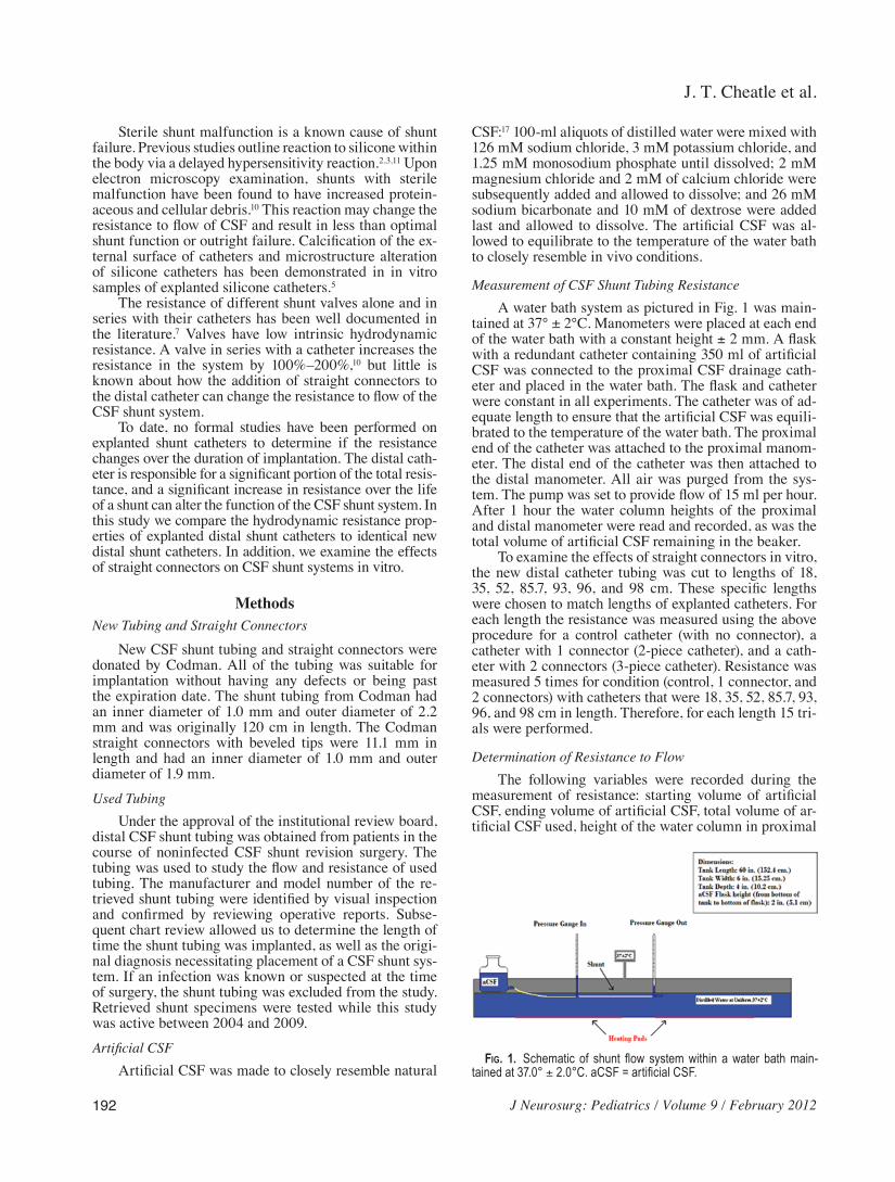
Seven different lengths of shunt tubing were exam-ined in the laboratory (Table 1) The mean resistances of these catheters are illustrated in Fig 2 The increasing length of catheters is associated with an arithmetic in-crease in the resistance (p = 0028) seen in Fig 2 lower Another factor regarding resistance is the diameter of the tubing as seen in Fig 2 upper (p = 0028) Here the resis-tance of the catheter is inversely related to the diameter of the shunt tubing
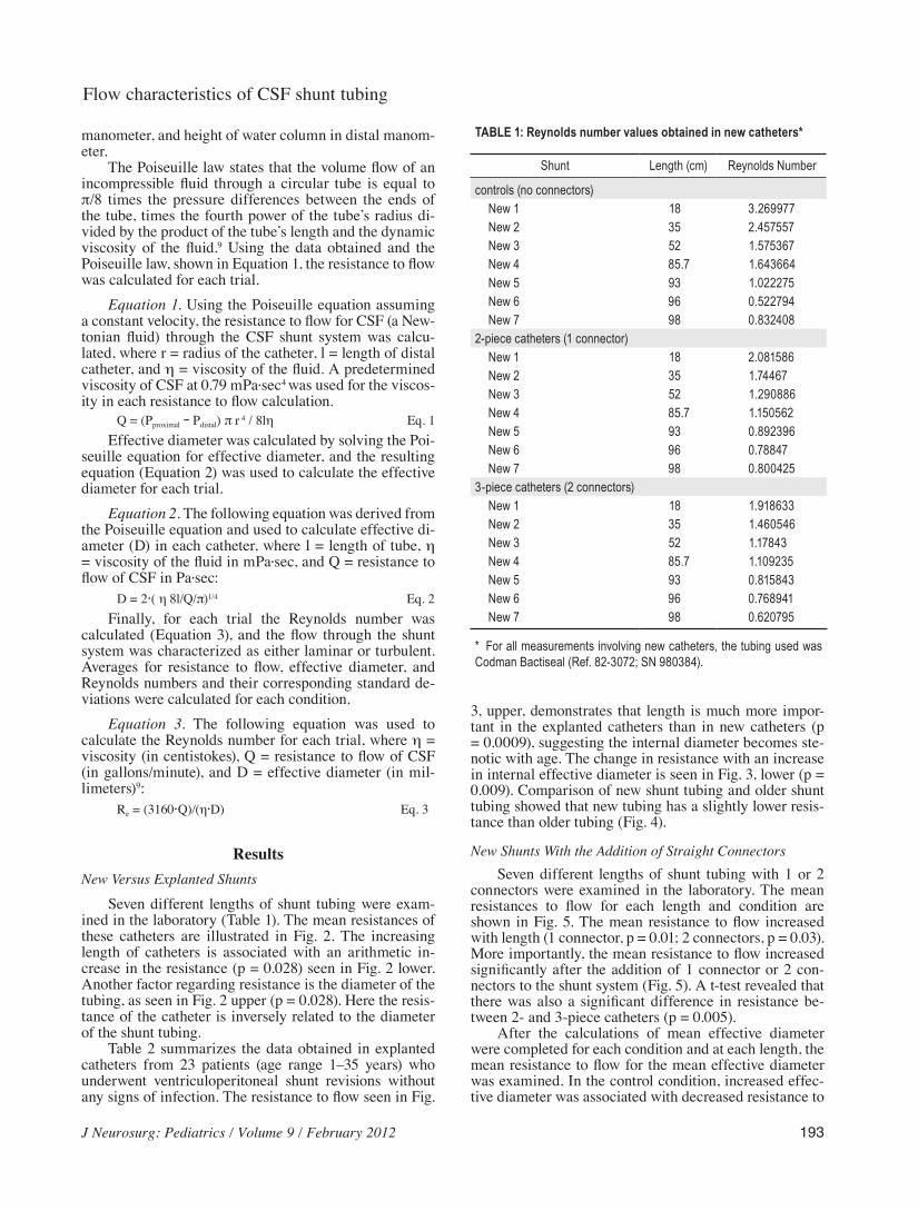
Table 2 summarizes the data obtained in explanted catheters from 23 patients (age range 1ndash35 years) who underwent ventriculoperitoneal shunt revisions without any signs of infection The resistance to flow seen in Fig
3 upper demonstrates that length is much more impor-tant in the explanted catheters than in new catheters (p = 00009) suggesting the internal diameter becomes ste-notic with age The change in resistance with an increase in internal effective diameter is seen in Fig 3 lower (p = 0009) Comparison of new shunt tubing and older shunt tubing showed that new tubing has a slightly lower resis-tance than older tubing (Fig 4)
New Shunts With the Addition of Straight ConnectorsSeven different lengths of shunt tubing with 1 or 2
connectors were examined in the laboratory The mean resistances to flow for each length and condition are shown in Fig 5 The mean resistance to flow increased with length (1 connector p = 001 2 connectors p = 003) More importantly the mean resistance to flow increased significantly after the addition of 1 connector or 2 con-nectors to the shunt system (Fig 5) A t-test revealed that there was also a significant difference in resistance be-tween 2- and 3-piece catheters (p = 0005)
After the calculations of mean effective diameter were completed for each condition and at each length the mean resistance to flow for the mean effective diameter was examined In the control condition increased effec-tive diameter was associated with decreased resistance to
TABLE 1 Reynolds number values obtained in new catheters
Shunt Length (cm) ReynoldsenspNumber
controlsensp(noenspconnectors)ensp ensp Newensp1 18ensp 3269977ensp ensp Newensp2 35 2457557ensp ensp Newensp3 52 1575367ensp ensp Newensp4 857 1643664ensp ensp Newensp5 93 1022275ensp ensp Newensp6 96 0522794ensp ensp Newensp7 98 08324082-pieceenspcathetersensp(1enspconnector)ensp ensp Newensp1 18ensp 2081586ensp ensp Newensp2 35 174467ensp ensp Newensp3 52 1290886ensp ensp Newensp4 857 1150562ensp ensp Newensp5 93 0892396ensp ensp Newensp6 96 078847ensp ensp Newensp7 98 08004253-pieceenspcathetersensp(2enspconnectors)ensp ensp Newensp1 18ensp 1918633ensp ensp Newensp2 35 1460546ensp ensp Newensp3 52 117843ensp ensp Newensp4 857 1109235ensp ensp Newensp5 93 0815843ensp ensp Newensp6 96 0768941ensp ensp Newensp7 98 0620795
ensp ForenspallenspmeasurementsenspinvolvingenspnewenspcathetersensptheensptubingenspusedenspwasenspCodmanenspBactisealensp(Refensp82-3072enspSNensp980384)
J T Cheatle et al
194 J Neurosurg Pediatrics Volume 9 February 2012
flow as shown in Fig 3 In contrast when effective diame-ter increased in catheters containing either 1 or 2 straight connectors resistance to flow increased as well (Fig 6)
To characterize the flow through shunts Reynolds numbers were used to determine whether flow was lami-nar or turbulent Laminar flow indicates smooth constant flow of a fluid through a system and correlates to Reyn-olds number values less than 2300 The calculations of Reynolds numbers were completed for each condition at each length and the results are displayed in Fig 7 and Table 1 For all 3 conditions the Reynolds number indi-cated laminar flow with values that were well below the cutoff for turbulent flow In addition the Reynolds num-bers appeared to decrease as the length of the catheters increased
DiscussionCerebrospinal fluid shunts are the mainstay of hy-
drocephalus treatment However dysfunction of CSF shunt systems continues to be a common problem1 As with all mechanical implanted devices shunts are prone to failure infection and infiltration by host tissue Little is known about the changes in resistance associated with aging of shunts or the effect of such changes on shunt function although it appears that shunt tubing predictably becomes more resistive to flow possibly contributing to shunt failure In this study we examined new shunt tubing
and compared this to explanted tubing removed because of CSF shunt malfunction Explanted shunt tubing has a slight increase in resistance to flow compared with new tubing This gradual increase in resistance is of unknown physiological significance but it may contribute to ster-ile shunt malfunction It is possible that during shunt re-placements the shunt tubing may be stretched or damaged upon removal Such damage could possibly have altered the resistance to flow in the explanted shunts that we used in our study although we very carefully examined the entire visible surface of the shunts before testing Never-theless in situ studies of resistance to flow would not be practical because it would be difficult to obtain multiple trials for each patient and would potentially increase the risk of shunt revision surgery
For incompressible flow within a viscid fluid the ki-
Fig 2ensp Lineenspgraphsenspdemonstratingensphowenspaverageenspresistanceenspperensptrialensp(averageensp ofensp 5ensp trials)ensp isensp affectedensp byensp theensp effectiveensp diameterensp andensp lengthenspofenspnewenspcatheters UpperenspTheenspaverageenspresistanceensptoenspflowenspplottedenspasenspaenspfunctionenspofenspeffectiveenspdiameterensp Inenspnewenspcathetersenspasensp lengthensp increasesenspandensp effectiveensp diameterensp decreasesensp resistanceensp toensp flowensp increasesensp Theenspaverageensp resistanceensp toensp flowensp measuredensp inensp Pa∙secm3ensp isensp displayedensp onensptheenspy-axisenspwhereenspE+10enspdenotesenspscientificenspnotationensp(100E+10ensp=ensp100ensptimesensp1010) Lowerensp Theensp averageensp resistanceensp toensp flowensp plottedensp asensp aensp functionenspofensplength
Fig 3ensp Lineenspgraphsenspdemonstratingensphowenspaverageenspresistanceensp forensp theensp23enspexplantedenspcathetersenspisenspaffectedenspbyensptheenspeffectiveenspdiameterenspandensplengthenspofenspeachenspcatheter UpperenspTheenspaverageenspresistanceensptoenspflowenspplottedenspasenspaenspfunctionenspofensplength LowerenspTheenspaverageenspresistanceensptoenspflowenspplottedenspasenspaenspfunctionenspofenspeffectiveenspdiameterenspAsenspseenenspwithensptheenspnewenspcathetersenspinenspFigensp2enspanenspincreaseenspinensptheensplengthenspofenspexplantedenspcathetersenspcorrespondsensptoenspanenspincreaseenspinenspresistanceensptoenspflowenspInenspadditionenspsmallerenspeffectiveenspdiametersenspleadensptoenspanenspincreaseenspinenspresistanceensptoenspflowenspinenspexplantedenspcatheters
Fig 4ensp Barensp graphensp comparingensp theensp changeensp inensp averageensp resistanceensp toenspflowenspbetweenenspnewenspandenspexplantedenspcatheters
J Neurosurg Pediatrics Volume 9 February 2012
Flow characteristics of CSF shunt tubing
195
netic and potential energy of a fluid must remain constant Therefore when a fluid moves from a region of low pres-sure to a region of higher pressure the speed at which it flows must decrease Cerebrospinal fluid is a Newtonian fluid and its viscosity is nearly that of watermdashranging from 07 to 1 mPasec at 37degC The viscosity of our artifi-cial CSF was found to be 079 mPasec412 In nonimplant-ed CSF shunts CSF flow is laminar The Reynolds num-
ber for each of the explanted catheters remains low well below the threshold of turbulent or even transitional flow and therefore the characteristic nature of the flow remains laminar The change in the resistance to flow although significant does not cause turbulent flow This suggests that a relatively uniform stenosis along the length of the tube occurs rather than a stenotic area with a relatively spared diameter in other areas as occurs in blood vessels in vivo13
The standard shunt system consists of tubing with fixed resistance and a 1-way differential pressure valve1516 The flow of fluid through this system is reliant on both the differential pressure across the shunt and the resistance of the shunt itself This resistance can be reproducibly set by the manufacturers of the shunt tubing However within a shunt system there exists a series of resistors the open-ing of the ventricular catheter (Rc) the valve (Rv) any shunt accessories (Ra) and finally the distal tubing (Rt) Therefore the total resistance of a shunt system can be represented in the following equation15 Rs = Rc + Rv + Ra + Rt
In some shunts the values of Rv and Ra are designed to change with position14 The changes in resistance to flow after the addition of various shunt valves has been well documented A valve in series with a catheter in-creases the resistance in the system by 100ndash20010 In
TABLE 2 Resistance and effective diameter in explanted catheters
Shunt MeanenspResistanceensp(Pa∙secm3) SD MeanenspEffectiveenspDiameterensp(mm) SD
Explantedensp1 188E+10 190E+09 194 465Eminus02Explantedensp2 729E+10 165E+10 139 747Eminus02Explantedensp3 568E+10 476E+09 150 323Eminus02Explantedensp4 249E+10 125E+10 149 793Eminus02Explantedensp5 156E+10 775E+09 187 264Eminus01Explantedensp6 184E+10 247E+09 190 646Eminus02Explantedensp7 280E+10 480E+09 154 635Eminus02Explantedensp8 406E+10 375E+10 163 316Eminus01Explantedensp9 230E+10 176E+10 134 183Eminus01Explantedensp10 416E+10 191E+10 166 192Eminus01Explantedensp11 198E+10 584E+09 155 101Eminus01Explantedensp12 188E+10 121E+10 181 281Eminus01Explantedensp13 262E+10 750E+09 157 121Eminus01Explantedensp14 363E+10 116E+10 176 125Eminus01Explantedensp15 201E+10 173E+10 150 284Eminus01Explantedensp16 182E+10 458E+09 176 106Eminus01Explantedensp17 506E+10 174E+10 167 129Eminus01Explantedensp18 254E+10 318E+09 166 498Eminus02Explantedensp19 576E+10 152E+10 147 940Eminus02Explantedensp20 298E+10 505E+09 165 680Eminus02Explantedensp21 111E+10 607E+09 157 212Eminus01Explantedensp22 418E+10 704E+10 181 462Eminus01Explantedensp23 879E+10 444E+10 119 219Eminus01
ensp ValuesenspareensppresentedenspinenspscientificenspEenspnotationensp100E+10ensp=ensp100ensptimesensp1010ensp100Eminus01ensp=ensp100ensptimesensp10minus1
Fig 5ensp Barensp graphensp depictingensp theensp averageensp resistanceensp toensp flowensp forensp theenspcontrolensp 2-pieceensp andensp 3-pieceensp cathetersensp atensp 7ensp differentensp lengthsensp NoneensponeenspandensptwoenspreferensptoensptheenspnumberenspofenspconnectorsenspSignificantenspincreaseenspinenspaverageenspresistanceensptoenspflowensp(pensp=ensp005)ensp
J T Cheatle et al
196 J Neurosurg Pediatrics Volume 9 February 2012
addition a study examining the effect of the use of Luer connector devices in arterial and ventricular catheters showed that these devices exerted an increased resistance to flow within the catheter system8 Therefore our find-ings that the resistance to flow within CSF shunt systems increases with the addition of 1 or 2 straight connectors is consistent with previous research If the resistance of the connectors (Rsc1 and Rsc2) were added to the above equation one would expect the resistance to flow to be significantly different between shunts of similar length containing either 1 or 2 connectors This assumption is supported by our findings Rc + Rv + Ra + Rt + Rsc1 ne Rc + Rv + Ra + Rt + Rsc1 + Rsc2
Connectors are added to a shunt system for 2 reasons to repair a break and to lengthen the shunt as the patient grows15 Not only must shunts sometimes be lengthened using connectors but shunt valves must also be adjust-ed for each patient based on activity level resistance to flow within their system and their production of CSF An increased resistance to flow may contribute to shunt malfunction by causing a slower flow through the entire system A higher resistance to flow could also result in mildly increased intracranial pressure in shunt-treated patients Knowing that the addition of connectors to a shunt system results in a significant increase in resistance to flow within a CSF shunt system will enable physicians to consider adjusting the CSF shunt valves accordingly
It should be noted that all of the new shunts and straight connectors used in this experiment were from Codman
The different trends between the control conditions and connector conditions in respect to the effect of diam-eter on resistance to flow support the conclusion that the connectors create additional resistance within the shunt system As diameter increases within a viscous fluid sys-tem the resistance to flow naturally decreases because there is more area through which the fluid can flow9 This trend was exhibited in the control group
When connectors were added to the CSF shunt sys-tem we saw an inverse trend As effective diameter in-creased resistance to flow increased as well This in-crease in resistance is due to the presence of a connector within the shunt system Resistance to flow increased as the viscous CSF fluid was forced through the opening of the straight connectors within the CSF shunt systems
As expected the Reynolds numbers for all runs were well under the thresholds of turbulent or even transitional flow and therefore the characteristic nature of the flow remained laminar Therefore the change in resistance to flow with the addition of connectors although significant does not cause turbulent flow
The changes in the resistance to flow observed in this study represent a preliminary look at the dynamics of a CSF shunt system In addition it might be worthwhile to include histological examination using electron micros-copy of the explanted shunt tubing to see if proteinaceous debris or other components are contributing to stenosis over time
ConclusionsAn increase in resistance within a CSF shunt system
appears to be directly related to the length of the catheter and inversely related to the effective diameter of the cath-eter This increase in resistance may be related to sterile shunt malfunction The addition of straight connectors shows a significant increase in resistance in comparison with catheters without connectors (p = 0005) There is also a significant difference between resistances to flow in catheters containing 1 connector versus the resistance to flow in catheters containing 2 connectors (p = 0005)
Fig 6ensp Lineenspgraphsenspshowingensphowenspeffectiveenspdiameterenspaffectsensptheenspaver-ageenspresistanceensptoenspflowenspinensp2-enspandensp3-pieceenspcatheters UpperenspTheenspaver-ageenspresistanceenspforensp2-pieceenspcathetersenspplottedenspasenspaenspfunctionenspofenspeffectiveenspdiameterensp ensp Lower Theensp averageensp resistanceensp toensp flowensp forensp 3-pieceensp cath-etersenspplottedenspasenspaenspfunctionenspofenspeffectiveenspdiameterenspInenspcontrastensptoensptheensptrendsenspdisplayedenspbyensptheenspcontrolensporenspnewenspcathetersenspinenspFigensp3enspasenspinternalenspdiameterenspincreasedenspresistanceensptoenspflowenspalsoenspincreasedenspThisenspsuggestsenspthatensptheenspcon-nectorsenspthemselvesenspcreateenspanenspadditionalenspsourceenspofenspresistanceenspwithinenspaenspCSFenspshuntenspsystemensp
Fig 7ensp BarenspgraphenspdepictingensptheenspReynoldsenspnumberenspforenspcontrolensp2-enspandensp3-pieceenspcathetersenspatensp7enspdifferentensplengthsenspofenspcatheterenspAsenspexpectedenspallensptrialsensphadenspReynoldsenspnumbersensp indicatingensp laminarenspflowenspwithenspvaluesenspwellenspbelowensptheenspthresholdenspforenspturbulentenspflowenspofensp2300enspSignificantenspdifferenceenspinenspReyn-oldsenspnumbersensp(pensp=ensp005)
J Neurosurg Pediatrics Volume 9 February 2012
Flow characteristics of CSF shunt tubing
197
Disclosure
New shunt tubing and connectors for this study were donated by Codman
Author contributions to the study and manuscript preparation include the following Conception and design Bowder Agrawal Sather Hellbusch Acquisition of data Bowder Agrawal Satire Analysis and interpretation of data all authors Drafting the article Bowder Cheatle Agrawal Hellbusch Critically revising the article all authors Reviewed submitted version of manuscript all authors Approved the final version of the manuscript on behalf of all authors Bowder Statistical analysis Bowder Cheatle Administrativetechnicalmaterial support Agrawal Hellbusch Study supervision Agrawal Hellbusch
References
1 Aschoff A Kremer P Hashemi B Kunze S The scientific history of hydrocephalus and its treatment Neurosurg Rev 2267ndash95 1999
2 Baldwin CM Jr Kaplan EN Silicone-induced human adjuvant disease AnnenspPlastenspSurg 10270ndash273 1983
3 Bass SJ Gastwirth CM Green R Knights EM Weinstock RE Phagocytosis of silastic material following silastic great toe implant JenspFootenspSurg 1770ndash72 1978
4 Bloomfield IG Johnston IH Bilston LE Effects of proteins blood cells and glucose on the viscosity of cerebrospinal fluid Pediatr Neurosurg 28246ndash251 1998
5 Boch AL Hermelin E Sainte-Rose C Sgouros S Mechanical dysfunction of ventriculoperitoneal shunts caused by calcifi-cation of the silicone rubber catheter J Neurosurg 88975ndash982 1998
6 Borgbjerg BM Gjerris F Albeck MJ Hauerberg J Boslashrgesen SE Frequency and causes of shunt revisions in different cere-brospinal fluid shunt types ActaenspNeurochirensp(Wien) 136189ndash194 1995
7 Czosnyka Z Czosnyka M Richards H Pickard JD Hydrody-namic properties of hydrocephalus shunts ActaenspNeurochirenspSupplensp71334ndash339 1998
8 Eloot S De Vos JY Hombrouckx R Verdonck P How much is catheter flow influenced by the use of closed luer lock ac-cess devices NephrolenspDialenspTransplant 223061ndash3064 2007
9 Fox RW Pritchard PJ McDonald AT IntroductionensptoenspFluidenspMechanicsenspedensp7 Hoboken JN John Wiley and Sons 2005 p 348
10 Gower DJ Lewis JC Kelly DL Jr Sterile shunt malfunction A scanning electron microscopic perspective J Neurosurg 61 1079ndash1084 1984
11 Heggers JP Kossovsky N Parsons RW Robson MC Pelley RP Raine TJ Biocompatibility of silicone implants AnnenspPlastenspSurg 1138ndash45 1983
12 Howden L Giddings D Power H Aroussi A Vloeberghs M Garnett M et al Three-dimensional cerebrospinal flow with-in the human ventricular system ComputenspMethods BiomechenspBiomedenspEnginensp11123ndash133 2008
13 Ku DN Blood flow in arteries AnnuenspRevenspFluidenspMech 29 399ndash434 1997
14 Magram G Cerebrospinal fluid shunt management Part 1 Neurologist 2274ndash287 1996
15 Magram G Liakos AM Cerebrospinal fluid flow through an implanted shunt NeurolenspRes 2243ndash50 2000
16 Malm J Lundkvist B Eklund A Koskinen LO Kristensen B CSF outflow resistance as predictor of shunt function A long-term study ActaenspNeurolenspScand 110154ndash160 2004
17 Sendelbeck L Recipe for preparation of artificial CSF SpecialenspDelivery 84 1987
Manuscript submitted June 29 2011Accepted November 7 2011Please include this information when citing this paper DOI
103171201111PEDS11255Address correspondence to Alexis Bowder BS BA Depart-
ment of Surgery Division of Neurosurgery Nebraska Medical Cen-ter Omaha Nebraska 68198-6250 email alexisbowderunmc edu
J T Cheatle et al
192 J Neurosurg Pediatrics Volume 9 February 2012
Sterile shunt malfunction is a known cause of shunt failure Previous studies outline reaction to silicone within the body via a delayed hypersensitivity reaction2311 Upon electron microscopy examination shunts with sterile malfunction have been found to have increased protein-aceous and cellular debris10 This reaction may change the resistance to flow of CSF and result in less than optimal shunt function or outright failure Calcification of the ex-ternal surface of catheters and microstructure alteration of silicone catheters has been demonstrated in in vitro samples of explanted silicone catheters5
The resistance of different shunt valves alone and in series with their catheters has been well documented in the literature7 Valves have low intrinsic hydrodynamic resistance A valve in series with a catheter increases the resistance in the system by 100ndash20010 but little is known about how the addition of straight connectors to the distal catheter can change the resistance to flow of the CSF shunt system
To date no formal studies have been performed on explanted shunt catheters to determine if the resistance changes over the duration of implantation The distal cath-eter is responsible for a significant portion of the total resis-tance and a significant increase in resistance over the life of a shunt can alter the function of the CSF shunt system In this study we compare the hydrodynamic resistance prop-erties of explanted distal shunt catheters to identical new distal shunt catheters In addition we examine the effects of straight connectors on CSF shunt systems in vitro
MethodsNew Tubing and Straight Connectors
New CSF shunt tubing and straight connectors were donated by Codman All of the tubing was suitable for implantation without having any defects or being past the expiration date The shunt tubing from Codman had an inner diameter of 10 mm and outer diameter of 22 mm and was originally 120 cm in length The Codman straight connectors with beveled tips were 111 mm in length and had an inner diameter of 10 mm and outer diameter of 19 mmUsed Tubing
Under the approval of the institutional review board distal CSF shunt tubing was obtained from patients in the course of noninfected CSF shunt revision surgery The tubing was used to study the flow and resistance of used tubing The manufacturer and model number of the re-trieved shunt tubing were identified by visual inspection and confirmed by reviewing operative reports Subse-quent chart review allowed us to determine the length of time the shunt tubing was implanted as well as the origi-nal diagnosis necessitating placement of a CSF shunt sys-tem If an infection was known or suspected at the time of surgery the shunt tubing was excluded from the study Retrieved shunt specimens were tested while this study was active between 2004 and 2009Artificial CSF
Artificial CSF was made to closely resemble natural
CSF17 100-ml aliquots of distilled water were mixed with 126 mM sodium chloride 3 mM potassium chloride and 125 mM monosodium phosphate until dissolved 2 mM magnesium chloride and 2 mM of calcium chloride were subsequently added and allowed to dissolve and 26 mM sodium bicarbonate and 10 mM of dextrose were added last and allowed to dissolve The artificial CSF was al-lowed to equilibrate to the temperature of the water bath to closely resemble in vivo conditions
Measurement of CSF Shunt Tubing ResistanceA water bath system as pictured in Fig 1 was main-
tained at 37deg plusmn 2degC Manometers were placed at each end of the water bath with a constant height plusmn 2 mm A flask with a redundant catheter containing 350 ml of artificial CSF was connected to the proximal CSF drainage cath-eter and placed in the water bath The flask and catheter were constant in all experiments The catheter was of ad-equate length to ensure that the artificial CSF was equili-brated to the temperature of the water bath The proximal end of the catheter was attached to the proximal manom-eter The distal end of the catheter was then attached to the distal manometer All air was purged from the sys-tem The pump was set to provide flow of 15 ml per hour After 1 hour the water column heights of the proximal and distal manometer were read and recorded as was the total volume of artificial CSF remaining in the beaker
To examine the effects of straight connectors in vitro the new distal catheter tubing was cut to lengths of 18 35 52 857 93 96 and 98 cm These specific lengths were chosen to match lengths of explanted catheters For each length the resistance was measured using the above procedure for a control catheter (with no connector) a catheter with 1 connector (2-piece catheter) and a cath-eter with 2 connectors (3-piece catheter) Resistance was measured 5 times for condition (control 1 connector and 2 connectors) with catheters that were 18 35 52 857 93 96 and 98 cm in length Therefore for each length 15 tri-als were performed
Determination of Resistance to FlowThe following variables were recorded during the
measurement of resistance starting volume of artificial CSF ending volume of artificial CSF total volume of ar-tificial CSF used height of the water column in proximal
Fig 1ensp Schematicensp ofensp shuntensp flowensp systemenspwithinensp aenspwaterensp bathenspmain-tained at 370deg plusmnensp20degCenspaCSFensp=enspartificialenspCSF
J Neurosurg Pediatrics Volume 9 February 2012
Flow characteristics of CSF shunt tubing
193
manometer and height of water column in distal manom-eter
The Poiseuille law states that the volume flow of an incompressible fluid through a circular tube is equal to p8 times the pressure differences between the ends of the tube times the fourth power of the tubersquos radius di-vided by the product of the tubersquos length and the dynamic viscosity of the fluid9 Using the data obtained and the Poiseuille law shown in Equation 1 the resistance to flow was calculated for each trial
Equation 1 Using the Poiseuille equation assuming a constant velocity the resistance to flow for CSF (a New-tonian fluid) through the CSF shunt system was calcu-lated where r = radius of the catheter l = length of distal catheter and h = viscosity of the fluid A predetermined viscosity of CSF at 079 mPasec4 was used for the viscos-ity in each resistance to flow calculation
Q = (Pproximal minusenspPdistal) π r 4 8lη Eq 1Effective diameter was calculated by solving the Poi-
seuille equation for effective diameter and the resulting equation (Equation 2) was used to calculate the effective diameter for each trial
Equation 2 The following equation was derived from the Poiseuille equation and used to calculate effective di-ameter (D) in each catheter where l = length of tube h = viscosity of the fluid in mPasec and Q = resistance to flow of CSF in Pasec
D = 2( η 8lQπ)14 Eq 2Finally for each trial the Reynolds number was
calculated (Equation 3) and the flow through the shunt system was characterized as either laminar or turbulent Averages for resistance to flow effective diameter and Reynolds numbers and their corresponding standard de-viations were calculated for each condition
Equation 3 The following equation was used to calculate the Reynolds number for each trial where h = viscosity (in centistokes) Q = resistance to flow of CSF (in gallonsminute) and D = effective diameter (in mil-limeters)9
Re = (3160Q)(ηD) Eq 3
ResultsNew Versus Explanted Shunts
Seven different lengths of shunt tubing were exam-ined in the laboratory (Table 1) The mean resistances of these catheters are illustrated in Fig 2 The increasing length of catheters is associated with an arithmetic in-crease in the resistance (p = 0028) seen in Fig 2 lower Another factor regarding resistance is the diameter of the tubing as seen in Fig 2 upper (p = 0028) Here the resis-tance of the catheter is inversely related to the diameter of the shunt tubing
Table 2 summarizes the data obtained in explanted catheters from 23 patients (age range 1ndash35 years) who underwent ventriculoperitoneal shunt revisions without any signs of infection The resistance to flow seen in Fig
3 upper demonstrates that length is much more impor-tant in the explanted catheters than in new catheters (p = 00009) suggesting the internal diameter becomes ste-notic with age The change in resistance with an increase in internal effective diameter is seen in Fig 3 lower (p = 0009) Comparison of new shunt tubing and older shunt tubing showed that new tubing has a slightly lower resis-tance than older tubing (Fig 4)
New Shunts With the Addition of Straight ConnectorsSeven different lengths of shunt tubing with 1 or 2
connectors were examined in the laboratory The mean resistances to flow for each length and condition are shown in Fig 5 The mean resistance to flow increased with length (1 connector p = 001 2 connectors p = 003) More importantly the mean resistance to flow increased significantly after the addition of 1 connector or 2 con-nectors to the shunt system (Fig 5) A t-test revealed that there was also a significant difference in resistance be-tween 2- and 3-piece catheters (p = 0005)
After the calculations of mean effective diameter were completed for each condition and at each length the mean resistance to flow for the mean effective diameter was examined In the control condition increased effec-tive diameter was associated with decreased resistance to
TABLE 1 Reynolds number values obtained in new catheters
Shunt Length (cm) ReynoldsenspNumber
controlsensp(noenspconnectors)ensp ensp Newensp1 18ensp 3269977ensp ensp Newensp2 35 2457557ensp ensp Newensp3 52 1575367ensp ensp Newensp4 857 1643664ensp ensp Newensp5 93 1022275ensp ensp Newensp6 96 0522794ensp ensp Newensp7 98 08324082-pieceenspcathetersensp(1enspconnector)ensp ensp Newensp1 18ensp 2081586ensp ensp Newensp2 35 174467ensp ensp Newensp3 52 1290886ensp ensp Newensp4 857 1150562ensp ensp Newensp5 93 0892396ensp ensp Newensp6 96 078847ensp ensp Newensp7 98 08004253-pieceenspcathetersensp(2enspconnectors)ensp ensp Newensp1 18ensp 1918633ensp ensp Newensp2 35 1460546ensp ensp Newensp3 52 117843ensp ensp Newensp4 857 1109235ensp ensp Newensp5 93 0815843ensp ensp Newensp6 96 0768941ensp ensp Newensp7 98 0620795
ensp ForenspallenspmeasurementsenspinvolvingenspnewenspcathetersensptheensptubingenspusedenspwasenspCodmanenspBactisealensp(Refensp82-3072enspSNensp980384)
J T Cheatle et al
194 J Neurosurg Pediatrics Volume 9 February 2012
flow as shown in Fig 3 In contrast when effective diame-ter increased in catheters containing either 1 or 2 straight connectors resistance to flow increased as well (Fig 6)
To characterize the flow through shunts Reynolds numbers were used to determine whether flow was lami-nar or turbulent Laminar flow indicates smooth constant flow of a fluid through a system and correlates to Reyn-olds number values less than 2300 The calculations of Reynolds numbers were completed for each condition at each length and the results are displayed in Fig 7 and Table 1 For all 3 conditions the Reynolds number indi-cated laminar flow with values that were well below the cutoff for turbulent flow In addition the Reynolds num-bers appeared to decrease as the length of the catheters increased
DiscussionCerebrospinal fluid shunts are the mainstay of hy-
drocephalus treatment However dysfunction of CSF shunt systems continues to be a common problem1 As with all mechanical implanted devices shunts are prone to failure infection and infiltration by host tissue Little is known about the changes in resistance associated with aging of shunts or the effect of such changes on shunt function although it appears that shunt tubing predictably becomes more resistive to flow possibly contributing to shunt failure In this study we examined new shunt tubing
and compared this to explanted tubing removed because of CSF shunt malfunction Explanted shunt tubing has a slight increase in resistance to flow compared with new tubing This gradual increase in resistance is of unknown physiological significance but it may contribute to ster-ile shunt malfunction It is possible that during shunt re-placements the shunt tubing may be stretched or damaged upon removal Such damage could possibly have altered the resistance to flow in the explanted shunts that we used in our study although we very carefully examined the entire visible surface of the shunts before testing Never-theless in situ studies of resistance to flow would not be practical because it would be difficult to obtain multiple trials for each patient and would potentially increase the risk of shunt revision surgery
For incompressible flow within a viscid fluid the ki-
Fig 2ensp Lineenspgraphsenspdemonstratingensphowenspaverageenspresistanceenspperensptrialensp(averageensp ofensp 5ensp trials)ensp isensp affectedensp byensp theensp effectiveensp diameterensp andensp lengthenspofenspnewenspcatheters UpperenspTheenspaverageenspresistanceensptoenspflowenspplottedenspasenspaenspfunctionenspofenspeffectiveenspdiameterensp Inenspnewenspcathetersenspasensp lengthensp increasesenspandensp effectiveensp diameterensp decreasesensp resistanceensp toensp flowensp increasesensp Theenspaverageensp resistanceensp toensp flowensp measuredensp inensp Pa∙secm3ensp isensp displayedensp onensptheenspy-axisenspwhereenspE+10enspdenotesenspscientificenspnotationensp(100E+10ensp=ensp100ensptimesensp1010) Lowerensp Theensp averageensp resistanceensp toensp flowensp plottedensp asensp aensp functionenspofensplength
Fig 3ensp Lineenspgraphsenspdemonstratingensphowenspaverageenspresistanceensp forensp theensp23enspexplantedenspcathetersenspisenspaffectedenspbyensptheenspeffectiveenspdiameterenspandensplengthenspofenspeachenspcatheter UpperenspTheenspaverageenspresistanceensptoenspflowenspplottedenspasenspaenspfunctionenspofensplength LowerenspTheenspaverageenspresistanceensptoenspflowenspplottedenspasenspaenspfunctionenspofenspeffectiveenspdiameterenspAsenspseenenspwithensptheenspnewenspcathetersenspinenspFigensp2enspanenspincreaseenspinensptheensplengthenspofenspexplantedenspcathetersenspcorrespondsensptoenspanenspincreaseenspinenspresistanceensptoenspflowenspInenspadditionenspsmallerenspeffectiveenspdiametersenspleadensptoenspanenspincreaseenspinenspresistanceensptoenspflowenspinenspexplantedenspcatheters
Fig 4ensp Barensp graphensp comparingensp theensp changeensp inensp averageensp resistanceensp toenspflowenspbetweenenspnewenspandenspexplantedenspcatheters
J Neurosurg Pediatrics Volume 9 February 2012
Flow characteristics of CSF shunt tubing
195
netic and potential energy of a fluid must remain constant Therefore when a fluid moves from a region of low pres-sure to a region of higher pressure the speed at which it flows must decrease Cerebrospinal fluid is a Newtonian fluid and its viscosity is nearly that of watermdashranging from 07 to 1 mPasec at 37degC The viscosity of our artifi-cial CSF was found to be 079 mPasec412 In nonimplant-ed CSF shunts CSF flow is laminar The Reynolds num-
ber for each of the explanted catheters remains low well below the threshold of turbulent or even transitional flow and therefore the characteristic nature of the flow remains laminar The change in the resistance to flow although significant does not cause turbulent flow This suggests that a relatively uniform stenosis along the length of the tube occurs rather than a stenotic area with a relatively spared diameter in other areas as occurs in blood vessels in vivo13
The standard shunt system consists of tubing with fixed resistance and a 1-way differential pressure valve1516 The flow of fluid through this system is reliant on both the differential pressure across the shunt and the resistance of the shunt itself This resistance can be reproducibly set by the manufacturers of the shunt tubing However within a shunt system there exists a series of resistors the open-ing of the ventricular catheter (Rc) the valve (Rv) any shunt accessories (Ra) and finally the distal tubing (Rt) Therefore the total resistance of a shunt system can be represented in the following equation15 Rs = Rc + Rv + Ra + Rt
In some shunts the values of Rv and Ra are designed to change with position14 The changes in resistance to flow after the addition of various shunt valves has been well documented A valve in series with a catheter in-creases the resistance in the system by 100ndash20010 In
TABLE 2 Resistance and effective diameter in explanted catheters
Shunt MeanenspResistanceensp(Pa∙secm3) SD MeanenspEffectiveenspDiameterensp(mm) SD
Explantedensp1 188E+10 190E+09 194 465Eminus02Explantedensp2 729E+10 165E+10 139 747Eminus02Explantedensp3 568E+10 476E+09 150 323Eminus02Explantedensp4 249E+10 125E+10 149 793Eminus02Explantedensp5 156E+10 775E+09 187 264Eminus01Explantedensp6 184E+10 247E+09 190 646Eminus02Explantedensp7 280E+10 480E+09 154 635Eminus02Explantedensp8 406E+10 375E+10 163 316Eminus01Explantedensp9 230E+10 176E+10 134 183Eminus01Explantedensp10 416E+10 191E+10 166 192Eminus01Explantedensp11 198E+10 584E+09 155 101Eminus01Explantedensp12 188E+10 121E+10 181 281Eminus01Explantedensp13 262E+10 750E+09 157 121Eminus01Explantedensp14 363E+10 116E+10 176 125Eminus01Explantedensp15 201E+10 173E+10 150 284Eminus01Explantedensp16 182E+10 458E+09 176 106Eminus01Explantedensp17 506E+10 174E+10 167 129Eminus01Explantedensp18 254E+10 318E+09 166 498Eminus02Explantedensp19 576E+10 152E+10 147 940Eminus02Explantedensp20 298E+10 505E+09 165 680Eminus02Explantedensp21 111E+10 607E+09 157 212Eminus01Explantedensp22 418E+10 704E+10 181 462Eminus01Explantedensp23 879E+10 444E+10 119 219Eminus01
ensp ValuesenspareensppresentedenspinenspscientificenspEenspnotationensp100E+10ensp=ensp100ensptimesensp1010ensp100Eminus01ensp=ensp100ensptimesensp10minus1
Fig 5ensp Barensp graphensp depictingensp theensp averageensp resistanceensp toensp flowensp forensp theenspcontrolensp 2-pieceensp andensp 3-pieceensp cathetersensp atensp 7ensp differentensp lengthsensp NoneensponeenspandensptwoenspreferensptoensptheenspnumberenspofenspconnectorsenspSignificantenspincreaseenspinenspaverageenspresistanceensptoenspflowensp(pensp=ensp005)ensp
J T Cheatle et al
196 J Neurosurg Pediatrics Volume 9 February 2012
addition a study examining the effect of the use of Luer connector devices in arterial and ventricular catheters showed that these devices exerted an increased resistance to flow within the catheter system8 Therefore our find-ings that the resistance to flow within CSF shunt systems increases with the addition of 1 or 2 straight connectors is consistent with previous research If the resistance of the connectors (Rsc1 and Rsc2) were added to the above equation one would expect the resistance to flow to be significantly different between shunts of similar length containing either 1 or 2 connectors This assumption is supported by our findings Rc + Rv + Ra + Rt + Rsc1 ne Rc + Rv + Ra + Rt + Rsc1 + Rsc2
Connectors are added to a shunt system for 2 reasons to repair a break and to lengthen the shunt as the patient grows15 Not only must shunts sometimes be lengthened using connectors but shunt valves must also be adjust-ed for each patient based on activity level resistance to flow within their system and their production of CSF An increased resistance to flow may contribute to shunt malfunction by causing a slower flow through the entire system A higher resistance to flow could also result in mildly increased intracranial pressure in shunt-treated patients Knowing that the addition of connectors to a shunt system results in a significant increase in resistance to flow within a CSF shunt system will enable physicians to consider adjusting the CSF shunt valves accordingly
It should be noted that all of the new shunts and straight connectors used in this experiment were from Codman
The different trends between the control conditions and connector conditions in respect to the effect of diam-eter on resistance to flow support the conclusion that the connectors create additional resistance within the shunt system As diameter increases within a viscous fluid sys-tem the resistance to flow naturally decreases because there is more area through which the fluid can flow9 This trend was exhibited in the control group
When connectors were added to the CSF shunt sys-tem we saw an inverse trend As effective diameter in-creased resistance to flow increased as well This in-crease in resistance is due to the presence of a connector within the shunt system Resistance to flow increased as the viscous CSF fluid was forced through the opening of the straight connectors within the CSF shunt systems
As expected the Reynolds numbers for all runs were well under the thresholds of turbulent or even transitional flow and therefore the characteristic nature of the flow remained laminar Therefore the change in resistance to flow with the addition of connectors although significant does not cause turbulent flow
The changes in the resistance to flow observed in this study represent a preliminary look at the dynamics of a CSF shunt system In addition it might be worthwhile to include histological examination using electron micros-copy of the explanted shunt tubing to see if proteinaceous debris or other components are contributing to stenosis over time
ConclusionsAn increase in resistance within a CSF shunt system
appears to be directly related to the length of the catheter and inversely related to the effective diameter of the cath-eter This increase in resistance may be related to sterile shunt malfunction The addition of straight connectors shows a significant increase in resistance in comparison with catheters without connectors (p = 0005) There is also a significant difference between resistances to flow in catheters containing 1 connector versus the resistance to flow in catheters containing 2 connectors (p = 0005)
Fig 6ensp Lineenspgraphsenspshowingensphowenspeffectiveenspdiameterenspaffectsensptheenspaver-ageenspresistanceensptoenspflowenspinensp2-enspandensp3-pieceenspcatheters UpperenspTheenspaver-ageenspresistanceenspforensp2-pieceenspcathetersenspplottedenspasenspaenspfunctionenspofenspeffectiveenspdiameterensp ensp Lower Theensp averageensp resistanceensp toensp flowensp forensp 3-pieceensp cath-etersenspplottedenspasenspaenspfunctionenspofenspeffectiveenspdiameterenspInenspcontrastensptoensptheensptrendsenspdisplayedenspbyensptheenspcontrolensporenspnewenspcathetersenspinenspFigensp3enspasenspinternalenspdiameterenspincreasedenspresistanceensptoenspflowenspalsoenspincreasedenspThisenspsuggestsenspthatensptheenspcon-nectorsenspthemselvesenspcreateenspanenspadditionalenspsourceenspofenspresistanceenspwithinenspaenspCSFenspshuntenspsystemensp
Fig 7ensp BarenspgraphenspdepictingensptheenspReynoldsenspnumberenspforenspcontrolensp2-enspandensp3-pieceenspcathetersenspatensp7enspdifferentensplengthsenspofenspcatheterenspAsenspexpectedenspallensptrialsensphadenspReynoldsenspnumbersensp indicatingensp laminarenspflowenspwithenspvaluesenspwellenspbelowensptheenspthresholdenspforenspturbulentenspflowenspofensp2300enspSignificantenspdifferenceenspinenspReyn-oldsenspnumbersensp(pensp=ensp005)
J Neurosurg Pediatrics Volume 9 February 2012
Flow characteristics of CSF shunt tubing
197
Disclosure
New shunt tubing and connectors for this study were donated by Codman
Author contributions to the study and manuscript preparation include the following Conception and design Bowder Agrawal Sather Hellbusch Acquisition of data Bowder Agrawal Satire Analysis and interpretation of data all authors Drafting the article Bowder Cheatle Agrawal Hellbusch Critically revising the article all authors Reviewed submitted version of manuscript all authors Approved the final version of the manuscript on behalf of all authors Bowder Statistical analysis Bowder Cheatle Administrativetechnicalmaterial support Agrawal Hellbusch Study supervision Agrawal Hellbusch
References
1 Aschoff A Kremer P Hashemi B Kunze S The scientific history of hydrocephalus and its treatment Neurosurg Rev 2267ndash95 1999
2 Baldwin CM Jr Kaplan EN Silicone-induced human adjuvant disease AnnenspPlastenspSurg 10270ndash273 1983
3 Bass SJ Gastwirth CM Green R Knights EM Weinstock RE Phagocytosis of silastic material following silastic great toe implant JenspFootenspSurg 1770ndash72 1978
4 Bloomfield IG Johnston IH Bilston LE Effects of proteins blood cells and glucose on the viscosity of cerebrospinal fluid Pediatr Neurosurg 28246ndash251 1998
5 Boch AL Hermelin E Sainte-Rose C Sgouros S Mechanical dysfunction of ventriculoperitoneal shunts caused by calcifi-cation of the silicone rubber catheter J Neurosurg 88975ndash982 1998
6 Borgbjerg BM Gjerris F Albeck MJ Hauerberg J Boslashrgesen SE Frequency and causes of shunt revisions in different cere-brospinal fluid shunt types ActaenspNeurochirensp(Wien) 136189ndash194 1995
7 Czosnyka Z Czosnyka M Richards H Pickard JD Hydrody-namic properties of hydrocephalus shunts ActaenspNeurochirenspSupplensp71334ndash339 1998
8 Eloot S De Vos JY Hombrouckx R Verdonck P How much is catheter flow influenced by the use of closed luer lock ac-cess devices NephrolenspDialenspTransplant 223061ndash3064 2007
9 Fox RW Pritchard PJ McDonald AT IntroductionensptoenspFluidenspMechanicsenspedensp7 Hoboken JN John Wiley and Sons 2005 p 348
10 Gower DJ Lewis JC Kelly DL Jr Sterile shunt malfunction A scanning electron microscopic perspective J Neurosurg 61 1079ndash1084 1984
11 Heggers JP Kossovsky N Parsons RW Robson MC Pelley RP Raine TJ Biocompatibility of silicone implants AnnenspPlastenspSurg 1138ndash45 1983
12 Howden L Giddings D Power H Aroussi A Vloeberghs M Garnett M et al Three-dimensional cerebrospinal flow with-in the human ventricular system ComputenspMethods BiomechenspBiomedenspEnginensp11123ndash133 2008
13 Ku DN Blood flow in arteries AnnuenspRevenspFluidenspMech 29 399ndash434 1997
14 Magram G Cerebrospinal fluid shunt management Part 1 Neurologist 2274ndash287 1996
15 Magram G Liakos AM Cerebrospinal fluid flow through an implanted shunt NeurolenspRes 2243ndash50 2000
16 Malm J Lundkvist B Eklund A Koskinen LO Kristensen B CSF outflow resistance as predictor of shunt function A long-term study ActaenspNeurolenspScand 110154ndash160 2004
17 Sendelbeck L Recipe for preparation of artificial CSF SpecialenspDelivery 84 1987
Manuscript submitted June 29 2011Accepted November 7 2011Please include this information when citing this paper DOI
103171201111PEDS11255Address correspondence to Alexis Bowder BS BA Depart-
ment of Surgery Division of Neurosurgery Nebraska Medical Cen-ter Omaha Nebraska 68198-6250 email alexisbowderunmc edu
J Neurosurg Pediatrics Volume 9 February 2012
Flow characteristics of CSF shunt tubing
193
manometer and height of water column in distal manom-eter
The Poiseuille law states that the volume flow of an incompressible fluid through a circular tube is equal to p8 times the pressure differences between the ends of the tube times the fourth power of the tubersquos radius di-vided by the product of the tubersquos length and the dynamic viscosity of the fluid9 Using the data obtained and the Poiseuille law shown in Equation 1 the resistance to flow was calculated for each trial
Equation 1 Using the Poiseuille equation assuming a constant velocity the resistance to flow for CSF (a New-tonian fluid) through the CSF shunt system was calcu-lated where r = radius of the catheter l = length of distal catheter and h = viscosity of the fluid A predetermined viscosity of CSF at 079 mPasec4 was used for the viscos-ity in each resistance to flow calculation
Q = (Pproximal minusenspPdistal) π r 4 8lη Eq 1Effective diameter was calculated by solving the Poi-
seuille equation for effective diameter and the resulting equation (Equation 2) was used to calculate the effective diameter for each trial
Equation 2 The following equation was derived from the Poiseuille equation and used to calculate effective di-ameter (D) in each catheter where l = length of tube h = viscosity of the fluid in mPasec and Q = resistance to flow of CSF in Pasec
D = 2( η 8lQπ)14 Eq 2Finally for each trial the Reynolds number was
calculated (Equation 3) and the flow through the shunt system was characterized as either laminar or turbulent Averages for resistance to flow effective diameter and Reynolds numbers and their corresponding standard de-viations were calculated for each condition
Equation 3 The following equation was used to calculate the Reynolds number for each trial where h = viscosity (in centistokes) Q = resistance to flow of CSF (in gallonsminute) and D = effective diameter (in mil-limeters)9
Re = (3160Q)(ηD) Eq 3
ResultsNew Versus Explanted Shunts
Seven different lengths of shunt tubing were exam-ined in the laboratory (Table 1) The mean resistances of these catheters are illustrated in Fig 2 The increasing length of catheters is associated with an arithmetic in-crease in the resistance (p = 0028) seen in Fig 2 lower Another factor regarding resistance is the diameter of the tubing as seen in Fig 2 upper (p = 0028) Here the resis-tance of the catheter is inversely related to the diameter of the shunt tubing
Table 2 summarizes the data obtained in explanted catheters from 23 patients (age range 1ndash35 years) who underwent ventriculoperitoneal shunt revisions without any signs of infection The resistance to flow seen in Fig
3 upper demonstrates that length is much more impor-tant in the explanted catheters than in new catheters (p = 00009) suggesting the internal diameter becomes ste-notic with age The change in resistance with an increase in internal effective diameter is seen in Fig 3 lower (p = 0009) Comparison of new shunt tubing and older shunt tubing showed that new tubing has a slightly lower resis-tance than older tubing (Fig 4)
New Shunts With the Addition of Straight ConnectorsSeven different lengths of shunt tubing with 1 or 2
connectors were examined in the laboratory The mean resistances to flow for each length and condition are shown in Fig 5 The mean resistance to flow increased with length (1 connector p = 001 2 connectors p = 003) More importantly the mean resistance to flow increased significantly after the addition of 1 connector or 2 con-nectors to the shunt system (Fig 5) A t-test revealed that there was also a significant difference in resistance be-tween 2- and 3-piece catheters (p = 0005)
After the calculations of mean effective diameter were completed for each condition and at each length the mean resistance to flow for the mean effective diameter was examined In the control condition increased effec-tive diameter was associated with decreased resistance to
TABLE 1 Reynolds number values obtained in new catheters
Shunt Length (cm) ReynoldsenspNumber
controlsensp(noenspconnectors)ensp ensp Newensp1 18ensp 3269977ensp ensp Newensp2 35 2457557ensp ensp Newensp3 52 1575367ensp ensp Newensp4 857 1643664ensp ensp Newensp5 93 1022275ensp ensp Newensp6 96 0522794ensp ensp Newensp7 98 08324082-pieceenspcathetersensp(1enspconnector)ensp ensp Newensp1 18ensp 2081586ensp ensp Newensp2 35 174467ensp ensp Newensp3 52 1290886ensp ensp Newensp4 857 1150562ensp ensp Newensp5 93 0892396ensp ensp Newensp6 96 078847ensp ensp Newensp7 98 08004253-pieceenspcathetersensp(2enspconnectors)ensp ensp Newensp1 18ensp 1918633ensp ensp Newensp2 35 1460546ensp ensp Newensp3 52 117843ensp ensp Newensp4 857 1109235ensp ensp Newensp5 93 0815843ensp ensp Newensp6 96 0768941ensp ensp Newensp7 98 0620795
ensp ForenspallenspmeasurementsenspinvolvingenspnewenspcathetersensptheensptubingenspusedenspwasenspCodmanenspBactisealensp(Refensp82-3072enspSNensp980384)
J T Cheatle et al
194 J Neurosurg Pediatrics Volume 9 February 2012
flow as shown in Fig 3 In contrast when effective diame-ter increased in catheters containing either 1 or 2 straight connectors resistance to flow increased as well (Fig 6)
To characterize the flow through shunts Reynolds numbers were used to determine whether flow was lami-nar or turbulent Laminar flow indicates smooth constant flow of a fluid through a system and correlates to Reyn-olds number values less than 2300 The calculations of Reynolds numbers were completed for each condition at each length and the results are displayed in Fig 7 and Table 1 For all 3 conditions the Reynolds number indi-cated laminar flow with values that were well below the cutoff for turbulent flow In addition the Reynolds num-bers appeared to decrease as the length of the catheters increased
DiscussionCerebrospinal fluid shunts are the mainstay of hy-
drocephalus treatment However dysfunction of CSF shunt systems continues to be a common problem1 As with all mechanical implanted devices shunts are prone to failure infection and infiltration by host tissue Little is known about the changes in resistance associated with aging of shunts or the effect of such changes on shunt function although it appears that shunt tubing predictably becomes more resistive to flow possibly contributing to shunt failure In this study we examined new shunt tubing
and compared this to explanted tubing removed because of CSF shunt malfunction Explanted shunt tubing has a slight increase in resistance to flow compared with new tubing This gradual increase in resistance is of unknown physiological significance but it may contribute to ster-ile shunt malfunction It is possible that during shunt re-placements the shunt tubing may be stretched or damaged upon removal Such damage could possibly have altered the resistance to flow in the explanted shunts that we used in our study although we very carefully examined the entire visible surface of the shunts before testing Never-theless in situ studies of resistance to flow would not be practical because it would be difficult to obtain multiple trials for each patient and would potentially increase the risk of shunt revision surgery
For incompressible flow within a viscid fluid the ki-
Fig 2ensp Lineenspgraphsenspdemonstratingensphowenspaverageenspresistanceenspperensptrialensp(averageensp ofensp 5ensp trials)ensp isensp affectedensp byensp theensp effectiveensp diameterensp andensp lengthenspofenspnewenspcatheters UpperenspTheenspaverageenspresistanceensptoenspflowenspplottedenspasenspaenspfunctionenspofenspeffectiveenspdiameterensp Inenspnewenspcathetersenspasensp lengthensp increasesenspandensp effectiveensp diameterensp decreasesensp resistanceensp toensp flowensp increasesensp Theenspaverageensp resistanceensp toensp flowensp measuredensp inensp Pa∙secm3ensp isensp displayedensp onensptheenspy-axisenspwhereenspE+10enspdenotesenspscientificenspnotationensp(100E+10ensp=ensp100ensptimesensp1010) Lowerensp Theensp averageensp resistanceensp toensp flowensp plottedensp asensp aensp functionenspofensplength
Fig 3ensp Lineenspgraphsenspdemonstratingensphowenspaverageenspresistanceensp forensp theensp23enspexplantedenspcathetersenspisenspaffectedenspbyensptheenspeffectiveenspdiameterenspandensplengthenspofenspeachenspcatheter UpperenspTheenspaverageenspresistanceensptoenspflowenspplottedenspasenspaenspfunctionenspofensplength LowerenspTheenspaverageenspresistanceensptoenspflowenspplottedenspasenspaenspfunctionenspofenspeffectiveenspdiameterenspAsenspseenenspwithensptheenspnewenspcathetersenspinenspFigensp2enspanenspincreaseenspinensptheensplengthenspofenspexplantedenspcathetersenspcorrespondsensptoenspanenspincreaseenspinenspresistanceensptoenspflowenspInenspadditionenspsmallerenspeffectiveenspdiametersenspleadensptoenspanenspincreaseenspinenspresistanceensptoenspflowenspinenspexplantedenspcatheters
Fig 4ensp Barensp graphensp comparingensp theensp changeensp inensp averageensp resistanceensp toenspflowenspbetweenenspnewenspandenspexplantedenspcatheters
J Neurosurg Pediatrics Volume 9 February 2012
Flow characteristics of CSF shunt tubing
195
netic and potential energy of a fluid must remain constant Therefore when a fluid moves from a region of low pres-sure to a region of higher pressure the speed at which it flows must decrease Cerebrospinal fluid is a Newtonian fluid and its viscosity is nearly that of watermdashranging from 07 to 1 mPasec at 37degC The viscosity of our artifi-cial CSF was found to be 079 mPasec412 In nonimplant-ed CSF shunts CSF flow is laminar The Reynolds num-
ber for each of the explanted catheters remains low well below the threshold of turbulent or even transitional flow and therefore the characteristic nature of the flow remains laminar The change in the resistance to flow although significant does not cause turbulent flow This suggests that a relatively uniform stenosis along the length of the tube occurs rather than a stenotic area with a relatively spared diameter in other areas as occurs in blood vessels in vivo13
The standard shunt system consists of tubing with fixed resistance and a 1-way differential pressure valve1516 The flow of fluid through this system is reliant on both the differential pressure across the shunt and the resistance of the shunt itself This resistance can be reproducibly set by the manufacturers of the shunt tubing However within a shunt system there exists a series of resistors the open-ing of the ventricular catheter (Rc) the valve (Rv) any shunt accessories (Ra) and finally the distal tubing (Rt) Therefore the total resistance of a shunt system can be represented in the following equation15 Rs = Rc + Rv + Ra + Rt
In some shunts the values of Rv and Ra are designed to change with position14 The changes in resistance to flow after the addition of various shunt valves has been well documented A valve in series with a catheter in-creases the resistance in the system by 100ndash20010 In
TABLE 2 Resistance and effective diameter in explanted catheters
Shunt MeanenspResistanceensp(Pa∙secm3) SD MeanenspEffectiveenspDiameterensp(mm) SD
Explantedensp1 188E+10 190E+09 194 465Eminus02Explantedensp2 729E+10 165E+10 139 747Eminus02Explantedensp3 568E+10 476E+09 150 323Eminus02Explantedensp4 249E+10 125E+10 149 793Eminus02Explantedensp5 156E+10 775E+09 187 264Eminus01Explantedensp6 184E+10 247E+09 190 646Eminus02Explantedensp7 280E+10 480E+09 154 635Eminus02Explantedensp8 406E+10 375E+10 163 316Eminus01Explantedensp9 230E+10 176E+10 134 183Eminus01Explantedensp10 416E+10 191E+10 166 192Eminus01Explantedensp11 198E+10 584E+09 155 101Eminus01Explantedensp12 188E+10 121E+10 181 281Eminus01Explantedensp13 262E+10 750E+09 157 121Eminus01Explantedensp14 363E+10 116E+10 176 125Eminus01Explantedensp15 201E+10 173E+10 150 284Eminus01Explantedensp16 182E+10 458E+09 176 106Eminus01Explantedensp17 506E+10 174E+10 167 129Eminus01Explantedensp18 254E+10 318E+09 166 498Eminus02Explantedensp19 576E+10 152E+10 147 940Eminus02Explantedensp20 298E+10 505E+09 165 680Eminus02Explantedensp21 111E+10 607E+09 157 212Eminus01Explantedensp22 418E+10 704E+10 181 462Eminus01Explantedensp23 879E+10 444E+10 119 219Eminus01
ensp ValuesenspareensppresentedenspinenspscientificenspEenspnotationensp100E+10ensp=ensp100ensptimesensp1010ensp100Eminus01ensp=ensp100ensptimesensp10minus1
Fig 5ensp Barensp graphensp depictingensp theensp averageensp resistanceensp toensp flowensp forensp theenspcontrolensp 2-pieceensp andensp 3-pieceensp cathetersensp atensp 7ensp differentensp lengthsensp NoneensponeenspandensptwoenspreferensptoensptheenspnumberenspofenspconnectorsenspSignificantenspincreaseenspinenspaverageenspresistanceensptoenspflowensp(pensp=ensp005)ensp
J T Cheatle et al
196 J Neurosurg Pediatrics Volume 9 February 2012
addition a study examining the effect of the use of Luer connector devices in arterial and ventricular catheters showed that these devices exerted an increased resistance to flow within the catheter system8 Therefore our find-ings that the resistance to flow within CSF shunt systems increases with the addition of 1 or 2 straight connectors is consistent with previous research If the resistance of the connectors (Rsc1 and Rsc2) were added to the above equation one would expect the resistance to flow to be significantly different between shunts of similar length containing either 1 or 2 connectors This assumption is supported by our findings Rc + Rv + Ra + Rt + Rsc1 ne Rc + Rv + Ra + Rt + Rsc1 + Rsc2
Connectors are added to a shunt system for 2 reasons to repair a break and to lengthen the shunt as the patient grows15 Not only must shunts sometimes be lengthened using connectors but shunt valves must also be adjust-ed for each patient based on activity level resistance to flow within their system and their production of CSF An increased resistance to flow may contribute to shunt malfunction by causing a slower flow through the entire system A higher resistance to flow could also result in mildly increased intracranial pressure in shunt-treated patients Knowing that the addition of connectors to a shunt system results in a significant increase in resistance to flow within a CSF shunt system will enable physicians to consider adjusting the CSF shunt valves accordingly
It should be noted that all of the new shunts and straight connectors used in this experiment were from Codman
The different trends between the control conditions and connector conditions in respect to the effect of diam-eter on resistance to flow support the conclusion that the connectors create additional resistance within the shunt system As diameter increases within a viscous fluid sys-tem the resistance to flow naturally decreases because there is more area through which the fluid can flow9 This trend was exhibited in the control group
When connectors were added to the CSF shunt sys-tem we saw an inverse trend As effective diameter in-creased resistance to flow increased as well This in-crease in resistance is due to the presence of a connector within the shunt system Resistance to flow increased as the viscous CSF fluid was forced through the opening of the straight connectors within the CSF shunt systems
As expected the Reynolds numbers for all runs were well under the thresholds of turbulent or even transitional flow and therefore the characteristic nature of the flow remained laminar Therefore the change in resistance to flow with the addition of connectors although significant does not cause turbulent flow
The changes in the resistance to flow observed in this study represent a preliminary look at the dynamics of a CSF shunt system In addition it might be worthwhile to include histological examination using electron micros-copy of the explanted shunt tubing to see if proteinaceous debris or other components are contributing to stenosis over time
ConclusionsAn increase in resistance within a CSF shunt system
appears to be directly related to the length of the catheter and inversely related to the effective diameter of the cath-eter This increase in resistance may be related to sterile shunt malfunction The addition of straight connectors shows a significant increase in resistance in comparison with catheters without connectors (p = 0005) There is also a significant difference between resistances to flow in catheters containing 1 connector versus the resistance to flow in catheters containing 2 connectors (p = 0005)
Fig 6ensp Lineenspgraphsenspshowingensphowenspeffectiveenspdiameterenspaffectsensptheenspaver-ageenspresistanceensptoenspflowenspinensp2-enspandensp3-pieceenspcatheters UpperenspTheenspaver-ageenspresistanceenspforensp2-pieceenspcathetersenspplottedenspasenspaenspfunctionenspofenspeffectiveenspdiameterensp ensp Lower Theensp averageensp resistanceensp toensp flowensp forensp 3-pieceensp cath-etersenspplottedenspasenspaenspfunctionenspofenspeffectiveenspdiameterenspInenspcontrastensptoensptheensptrendsenspdisplayedenspbyensptheenspcontrolensporenspnewenspcathetersenspinenspFigensp3enspasenspinternalenspdiameterenspincreasedenspresistanceensptoenspflowenspalsoenspincreasedenspThisenspsuggestsenspthatensptheenspcon-nectorsenspthemselvesenspcreateenspanenspadditionalenspsourceenspofenspresistanceenspwithinenspaenspCSFenspshuntenspsystemensp
Fig 7ensp BarenspgraphenspdepictingensptheenspReynoldsenspnumberenspforenspcontrolensp2-enspandensp3-pieceenspcathetersenspatensp7enspdifferentensplengthsenspofenspcatheterenspAsenspexpectedenspallensptrialsensphadenspReynoldsenspnumbersensp indicatingensp laminarenspflowenspwithenspvaluesenspwellenspbelowensptheenspthresholdenspforenspturbulentenspflowenspofensp2300enspSignificantenspdifferenceenspinenspReyn-oldsenspnumbersensp(pensp=ensp005)
J Neurosurg Pediatrics Volume 9 February 2012
Flow characteristics of CSF shunt tubing
197
Disclosure
New shunt tubing and connectors for this study were donated by Codman
Author contributions to the study and manuscript preparation include the following Conception and design Bowder Agrawal Sather Hellbusch Acquisition of data Bowder Agrawal Satire Analysis and interpretation of data all authors Drafting the article Bowder Cheatle Agrawal Hellbusch Critically revising the article all authors Reviewed submitted version of manuscript all authors Approved the final version of the manuscript on behalf of all authors Bowder Statistical analysis Bowder Cheatle Administrativetechnicalmaterial support Agrawal Hellbusch Study supervision Agrawal Hellbusch
References
1 Aschoff A Kremer P Hashemi B Kunze S The scientific history of hydrocephalus and its treatment Neurosurg Rev 2267ndash95 1999
2 Baldwin CM Jr Kaplan EN Silicone-induced human adjuvant disease AnnenspPlastenspSurg 10270ndash273 1983
3 Bass SJ Gastwirth CM Green R Knights EM Weinstock RE Phagocytosis of silastic material following silastic great toe implant JenspFootenspSurg 1770ndash72 1978
4 Bloomfield IG Johnston IH Bilston LE Effects of proteins blood cells and glucose on the viscosity of cerebrospinal fluid Pediatr Neurosurg 28246ndash251 1998
5 Boch AL Hermelin E Sainte-Rose C Sgouros S Mechanical dysfunction of ventriculoperitoneal shunts caused by calcifi-cation of the silicone rubber catheter J Neurosurg 88975ndash982 1998
6 Borgbjerg BM Gjerris F Albeck MJ Hauerberg J Boslashrgesen SE Frequency and causes of shunt revisions in different cere-brospinal fluid shunt types ActaenspNeurochirensp(Wien) 136189ndash194 1995
7 Czosnyka Z Czosnyka M Richards H Pickard JD Hydrody-namic properties of hydrocephalus shunts ActaenspNeurochirenspSupplensp71334ndash339 1998
8 Eloot S De Vos JY Hombrouckx R Verdonck P How much is catheter flow influenced by the use of closed luer lock ac-cess devices NephrolenspDialenspTransplant 223061ndash3064 2007
9 Fox RW Pritchard PJ McDonald AT IntroductionensptoenspFluidenspMechanicsenspedensp7 Hoboken JN John Wiley and Sons 2005 p 348
10 Gower DJ Lewis JC Kelly DL Jr Sterile shunt malfunction A scanning electron microscopic perspective J Neurosurg 61 1079ndash1084 1984
11 Heggers JP Kossovsky N Parsons RW Robson MC Pelley RP Raine TJ Biocompatibility of silicone implants AnnenspPlastenspSurg 1138ndash45 1983
12 Howden L Giddings D Power H Aroussi A Vloeberghs M Garnett M et al Three-dimensional cerebrospinal flow with-in the human ventricular system ComputenspMethods BiomechenspBiomedenspEnginensp11123ndash133 2008
13 Ku DN Blood flow in arteries AnnuenspRevenspFluidenspMech 29 399ndash434 1997
14 Magram G Cerebrospinal fluid shunt management Part 1 Neurologist 2274ndash287 1996
15 Magram G Liakos AM Cerebrospinal fluid flow through an implanted shunt NeurolenspRes 2243ndash50 2000
16 Malm J Lundkvist B Eklund A Koskinen LO Kristensen B CSF outflow resistance as predictor of shunt function A long-term study ActaenspNeurolenspScand 110154ndash160 2004
17 Sendelbeck L Recipe for preparation of artificial CSF SpecialenspDelivery 84 1987
Manuscript submitted June 29 2011Accepted November 7 2011Please include this information when citing this paper DOI
103171201111PEDS11255Address correspondence to Alexis Bowder BS BA Depart-
ment of Surgery Division of Neurosurgery Nebraska Medical Cen-ter Omaha Nebraska 68198-6250 email alexisbowderunmc edu
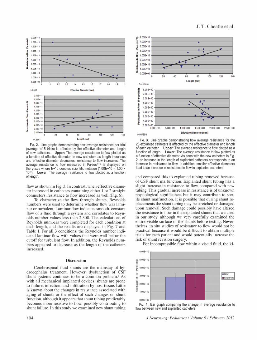
J T Cheatle et al
194 J Neurosurg Pediatrics Volume 9 February 2012
flow as shown in Fig 3 In contrast when effective diame-ter increased in catheters containing either 1 or 2 straight connectors resistance to flow increased as well (Fig 6)
To characterize the flow through shunts Reynolds numbers were used to determine whether flow was lami-nar or turbulent Laminar flow indicates smooth constant flow of a fluid through a system and correlates to Reyn-olds number values less than 2300 The calculations of Reynolds numbers were completed for each condition at each length and the results are displayed in Fig 7 and Table 1 For all 3 conditions the Reynolds number indi-cated laminar flow with values that were well below the cutoff for turbulent flow In addition the Reynolds num-bers appeared to decrease as the length of the catheters increased
DiscussionCerebrospinal fluid shunts are the mainstay of hy-
drocephalus treatment However dysfunction of CSF shunt systems continues to be a common problem1 As with all mechanical implanted devices shunts are prone to failure infection and infiltration by host tissue Little is known about the changes in resistance associated with aging of shunts or the effect of such changes on shunt function although it appears that shunt tubing predictably becomes more resistive to flow possibly contributing to shunt failure In this study we examined new shunt tubing
and compared this to explanted tubing removed because of CSF shunt malfunction Explanted shunt tubing has a slight increase in resistance to flow compared with new tubing This gradual increase in resistance is of unknown physiological significance but it may contribute to ster-ile shunt malfunction It is possible that during shunt re-placements the shunt tubing may be stretched or damaged upon removal Such damage could possibly have altered the resistance to flow in the explanted shunts that we used in our study although we very carefully examined the entire visible surface of the shunts before testing Never-theless in situ studies of resistance to flow would not be practical because it would be difficult to obtain multiple trials for each patient and would potentially increase the risk of shunt revision surgery
For incompressible flow within a viscid fluid the ki-
Fig 2ensp Lineenspgraphsenspdemonstratingensphowenspaverageenspresistanceenspperensptrialensp(averageensp ofensp 5ensp trials)ensp isensp affectedensp byensp theensp effectiveensp diameterensp andensp lengthenspofenspnewenspcatheters UpperenspTheenspaverageenspresistanceensptoenspflowenspplottedenspasenspaenspfunctionenspofenspeffectiveenspdiameterensp Inenspnewenspcathetersenspasensp lengthensp increasesenspandensp effectiveensp diameterensp decreasesensp resistanceensp toensp flowensp increasesensp Theenspaverageensp resistanceensp toensp flowensp measuredensp inensp Pa∙secm3ensp isensp displayedensp onensptheenspy-axisenspwhereenspE+10enspdenotesenspscientificenspnotationensp(100E+10ensp=ensp100ensptimesensp1010) Lowerensp Theensp averageensp resistanceensp toensp flowensp plottedensp asensp aensp functionenspofensplength
Fig 3ensp Lineenspgraphsenspdemonstratingensphowenspaverageenspresistanceensp forensp theensp23enspexplantedenspcathetersenspisenspaffectedenspbyensptheenspeffectiveenspdiameterenspandensplengthenspofenspeachenspcatheter UpperenspTheenspaverageenspresistanceensptoenspflowenspplottedenspasenspaenspfunctionenspofensplength LowerenspTheenspaverageenspresistanceensptoenspflowenspplottedenspasenspaenspfunctionenspofenspeffectiveenspdiameterenspAsenspseenenspwithensptheenspnewenspcathetersenspinenspFigensp2enspanenspincreaseenspinensptheensplengthenspofenspexplantedenspcathetersenspcorrespondsensptoenspanenspincreaseenspinenspresistanceensptoenspflowenspInenspadditionenspsmallerenspeffectiveenspdiametersenspleadensptoenspanenspincreaseenspinenspresistanceensptoenspflowenspinenspexplantedenspcatheters
Fig 4ensp Barensp graphensp comparingensp theensp changeensp inensp averageensp resistanceensp toenspflowenspbetweenenspnewenspandenspexplantedenspcatheters
J Neurosurg Pediatrics Volume 9 February 2012
Flow characteristics of CSF shunt tubing
195
netic and potential energy of a fluid must remain constant Therefore when a fluid moves from a region of low pres-sure to a region of higher pressure the speed at which it flows must decrease Cerebrospinal fluid is a Newtonian fluid and its viscosity is nearly that of watermdashranging from 07 to 1 mPasec at 37degC The viscosity of our artifi-cial CSF was found to be 079 mPasec412 In nonimplant-ed CSF shunts CSF flow is laminar The Reynolds num-
ber for each of the explanted catheters remains low well below the threshold of turbulent or even transitional flow and therefore the characteristic nature of the flow remains laminar The change in the resistance to flow although significant does not cause turbulent flow This suggests that a relatively uniform stenosis along the length of the tube occurs rather than a stenotic area with a relatively spared diameter in other areas as occurs in blood vessels in vivo13
The standard shunt system consists of tubing with fixed resistance and a 1-way differential pressure valve1516 The flow of fluid through this system is reliant on both the differential pressure across the shunt and the resistance of the shunt itself This resistance can be reproducibly set by the manufacturers of the shunt tubing However within a shunt system there exists a series of resistors the open-ing of the ventricular catheter (Rc) the valve (Rv) any shunt accessories (Ra) and finally the distal tubing (Rt) Therefore the total resistance of a shunt system can be represented in the following equation15 Rs = Rc + Rv + Ra + Rt
In some shunts the values of Rv and Ra are designed to change with position14 The changes in resistance to flow after the addition of various shunt valves has been well documented A valve in series with a catheter in-creases the resistance in the system by 100ndash20010 In
TABLE 2 Resistance and effective diameter in explanted catheters
Shunt MeanenspResistanceensp(Pa∙secm3) SD MeanenspEffectiveenspDiameterensp(mm) SD
Explantedensp1 188E+10 190E+09 194 465Eminus02Explantedensp2 729E+10 165E+10 139 747Eminus02Explantedensp3 568E+10 476E+09 150 323Eminus02Explantedensp4 249E+10 125E+10 149 793Eminus02Explantedensp5 156E+10 775E+09 187 264Eminus01Explantedensp6 184E+10 247E+09 190 646Eminus02Explantedensp7 280E+10 480E+09 154 635Eminus02Explantedensp8 406E+10 375E+10 163 316Eminus01Explantedensp9 230E+10 176E+10 134 183Eminus01Explantedensp10 416E+10 191E+10 166 192Eminus01Explantedensp11 198E+10 584E+09 155 101Eminus01Explantedensp12 188E+10 121E+10 181 281Eminus01Explantedensp13 262E+10 750E+09 157 121Eminus01Explantedensp14 363E+10 116E+10 176 125Eminus01Explantedensp15 201E+10 173E+10 150 284Eminus01Explantedensp16 182E+10 458E+09 176 106Eminus01Explantedensp17 506E+10 174E+10 167 129Eminus01Explantedensp18 254E+10 318E+09 166 498Eminus02Explantedensp19 576E+10 152E+10 147 940Eminus02Explantedensp20 298E+10 505E+09 165 680Eminus02Explantedensp21 111E+10 607E+09 157 212Eminus01Explantedensp22 418E+10 704E+10 181 462Eminus01Explantedensp23 879E+10 444E+10 119 219Eminus01
ensp ValuesenspareensppresentedenspinenspscientificenspEenspnotationensp100E+10ensp=ensp100ensptimesensp1010ensp100Eminus01ensp=ensp100ensptimesensp10minus1
Fig 5ensp Barensp graphensp depictingensp theensp averageensp resistanceensp toensp flowensp forensp theenspcontrolensp 2-pieceensp andensp 3-pieceensp cathetersensp atensp 7ensp differentensp lengthsensp NoneensponeenspandensptwoenspreferensptoensptheenspnumberenspofenspconnectorsenspSignificantenspincreaseenspinenspaverageenspresistanceensptoenspflowensp(pensp=ensp005)ensp
J T Cheatle et al
196 J Neurosurg Pediatrics Volume 9 February 2012
addition a study examining the effect of the use of Luer connector devices in arterial and ventricular catheters showed that these devices exerted an increased resistance to flow within the catheter system8 Therefore our find-ings that the resistance to flow within CSF shunt systems increases with the addition of 1 or 2 straight connectors is consistent with previous research If the resistance of the connectors (Rsc1 and Rsc2) were added to the above equation one would expect the resistance to flow to be significantly different between shunts of similar length containing either 1 or 2 connectors This assumption is supported by our findings Rc + Rv + Ra + Rt + Rsc1 ne Rc + Rv + Ra + Rt + Rsc1 + Rsc2
Connectors are added to a shunt system for 2 reasons to repair a break and to lengthen the shunt as the patient grows15 Not only must shunts sometimes be lengthened using connectors but shunt valves must also be adjust-ed for each patient based on activity level resistance to flow within their system and their production of CSF An increased resistance to flow may contribute to shunt malfunction by causing a slower flow through the entire system A higher resistance to flow could also result in mildly increased intracranial pressure in shunt-treated patients Knowing that the addition of connectors to a shunt system results in a significant increase in resistance to flow within a CSF shunt system will enable physicians to consider adjusting the CSF shunt valves accordingly
It should be noted that all of the new shunts and straight connectors used in this experiment were from Codman
The different trends between the control conditions and connector conditions in respect to the effect of diam-eter on resistance to flow support the conclusion that the connectors create additional resistance within the shunt system As diameter increases within a viscous fluid sys-tem the resistance to flow naturally decreases because there is more area through which the fluid can flow9 This trend was exhibited in the control group
When connectors were added to the CSF shunt sys-tem we saw an inverse trend As effective diameter in-creased resistance to flow increased as well This in-crease in resistance is due to the presence of a connector within the shunt system Resistance to flow increased as the viscous CSF fluid was forced through the opening of the straight connectors within the CSF shunt systems
As expected the Reynolds numbers for all runs were well under the thresholds of turbulent or even transitional flow and therefore the characteristic nature of the flow remained laminar Therefore the change in resistance to flow with the addition of connectors although significant does not cause turbulent flow
The changes in the resistance to flow observed in this study represent a preliminary look at the dynamics of a CSF shunt system In addition it might be worthwhile to include histological examination using electron micros-copy of the explanted shunt tubing to see if proteinaceous debris or other components are contributing to stenosis over time
ConclusionsAn increase in resistance within a CSF shunt system
appears to be directly related to the length of the catheter and inversely related to the effective diameter of the cath-eter This increase in resistance may be related to sterile shunt malfunction The addition of straight connectors shows a significant increase in resistance in comparison with catheters without connectors (p = 0005) There is also a significant difference between resistances to flow in catheters containing 1 connector versus the resistance to flow in catheters containing 2 connectors (p = 0005)
Fig 6ensp Lineenspgraphsenspshowingensphowenspeffectiveenspdiameterenspaffectsensptheenspaver-ageenspresistanceensptoenspflowenspinensp2-enspandensp3-pieceenspcatheters UpperenspTheenspaver-ageenspresistanceenspforensp2-pieceenspcathetersenspplottedenspasenspaenspfunctionenspofenspeffectiveenspdiameterensp ensp Lower Theensp averageensp resistanceensp toensp flowensp forensp 3-pieceensp cath-etersenspplottedenspasenspaenspfunctionenspofenspeffectiveenspdiameterenspInenspcontrastensptoensptheensptrendsenspdisplayedenspbyensptheenspcontrolensporenspnewenspcathetersenspinenspFigensp3enspasenspinternalenspdiameterenspincreasedenspresistanceensptoenspflowenspalsoenspincreasedenspThisenspsuggestsenspthatensptheenspcon-nectorsenspthemselvesenspcreateenspanenspadditionalenspsourceenspofenspresistanceenspwithinenspaenspCSFenspshuntenspsystemensp
Fig 7ensp BarenspgraphenspdepictingensptheenspReynoldsenspnumberenspforenspcontrolensp2-enspandensp3-pieceenspcathetersenspatensp7enspdifferentensplengthsenspofenspcatheterenspAsenspexpectedenspallensptrialsensphadenspReynoldsenspnumbersensp indicatingensp laminarenspflowenspwithenspvaluesenspwellenspbelowensptheenspthresholdenspforenspturbulentenspflowenspofensp2300enspSignificantenspdifferenceenspinenspReyn-oldsenspnumbersensp(pensp=ensp005)
J Neurosurg Pediatrics Volume 9 February 2012
Flow characteristics of CSF shunt tubing
197
Disclosure
New shunt tubing and connectors for this study were donated by Codman
Author contributions to the study and manuscript preparation include the following Conception and design Bowder Agrawal Sather Hellbusch Acquisition of data Bowder Agrawal Satire Analysis and interpretation of data all authors Drafting the article Bowder Cheatle Agrawal Hellbusch Critically revising the article all authors Reviewed submitted version of manuscript all authors Approved the final version of the manuscript on behalf of all authors Bowder Statistical analysis Bowder Cheatle Administrativetechnicalmaterial support Agrawal Hellbusch Study supervision Agrawal Hellbusch
References
1 Aschoff A Kremer P Hashemi B Kunze S The scientific history of hydrocephalus and its treatment Neurosurg Rev 2267ndash95 1999
2 Baldwin CM Jr Kaplan EN Silicone-induced human adjuvant disease AnnenspPlastenspSurg 10270ndash273 1983
3 Bass SJ Gastwirth CM Green R Knights EM Weinstock RE Phagocytosis of silastic material following silastic great toe implant JenspFootenspSurg 1770ndash72 1978
4 Bloomfield IG Johnston IH Bilston LE Effects of proteins blood cells and glucose on the viscosity of cerebrospinal fluid Pediatr Neurosurg 28246ndash251 1998
5 Boch AL Hermelin E Sainte-Rose C Sgouros S Mechanical dysfunction of ventriculoperitoneal shunts caused by calcifi-cation of the silicone rubber catheter J Neurosurg 88975ndash982 1998
6 Borgbjerg BM Gjerris F Albeck MJ Hauerberg J Boslashrgesen SE Frequency and causes of shunt revisions in different cere-brospinal fluid shunt types ActaenspNeurochirensp(Wien) 136189ndash194 1995
7 Czosnyka Z Czosnyka M Richards H Pickard JD Hydrody-namic properties of hydrocephalus shunts ActaenspNeurochirenspSupplensp71334ndash339 1998
8 Eloot S De Vos JY Hombrouckx R Verdonck P How much is catheter flow influenced by the use of closed luer lock ac-cess devices NephrolenspDialenspTransplant 223061ndash3064 2007
9 Fox RW Pritchard PJ McDonald AT IntroductionensptoenspFluidenspMechanicsenspedensp7 Hoboken JN John Wiley and Sons 2005 p 348
10 Gower DJ Lewis JC Kelly DL Jr Sterile shunt malfunction A scanning electron microscopic perspective J Neurosurg 61 1079ndash1084 1984
11 Heggers JP Kossovsky N Parsons RW Robson MC Pelley RP Raine TJ Biocompatibility of silicone implants AnnenspPlastenspSurg 1138ndash45 1983
12 Howden L Giddings D Power H Aroussi A Vloeberghs M Garnett M et al Three-dimensional cerebrospinal flow with-in the human ventricular system ComputenspMethods BiomechenspBiomedenspEnginensp11123ndash133 2008
13 Ku DN Blood flow in arteries AnnuenspRevenspFluidenspMech 29 399ndash434 1997
14 Magram G Cerebrospinal fluid shunt management Part 1 Neurologist 2274ndash287 1996
15 Magram G Liakos AM Cerebrospinal fluid flow through an implanted shunt NeurolenspRes 2243ndash50 2000
16 Malm J Lundkvist B Eklund A Koskinen LO Kristensen B CSF outflow resistance as predictor of shunt function A long-term study ActaenspNeurolenspScand 110154ndash160 2004
17 Sendelbeck L Recipe for preparation of artificial CSF SpecialenspDelivery 84 1987
Manuscript submitted June 29 2011Accepted November 7 2011Please include this information when citing this paper DOI
103171201111PEDS11255Address correspondence to Alexis Bowder BS BA Depart-
ment of Surgery Division of Neurosurgery Nebraska Medical Cen-ter Omaha Nebraska 68198-6250 email alexisbowderunmc edu
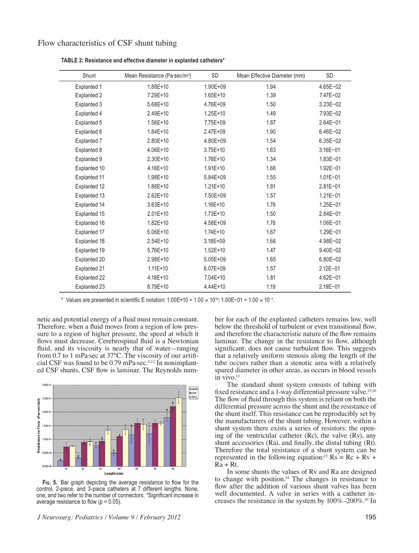
J Neurosurg Pediatrics Volume 9 February 2012
Flow characteristics of CSF shunt tubing
195
netic and potential energy of a fluid must remain constant Therefore when a fluid moves from a region of low pres-sure to a region of higher pressure the speed at which it flows must decrease Cerebrospinal fluid is a Newtonian fluid and its viscosity is nearly that of watermdashranging from 07 to 1 mPasec at 37degC The viscosity of our artifi-cial CSF was found to be 079 mPasec412 In nonimplant-ed CSF shunts CSF flow is laminar The Reynolds num-
ber for each of the explanted catheters remains low well below the threshold of turbulent or even transitional flow and therefore the characteristic nature of the flow remains laminar The change in the resistance to flow although significant does not cause turbulent flow This suggests that a relatively uniform stenosis along the length of the tube occurs rather than a stenotic area with a relatively spared diameter in other areas as occurs in blood vessels in vivo13
The standard shunt system consists of tubing with fixed resistance and a 1-way differential pressure valve1516 The flow of fluid through this system is reliant on both the differential pressure across the shunt and the resistance of the shunt itself This resistance can be reproducibly set by the manufacturers of the shunt tubing However within a shunt system there exists a series of resistors the open-ing of the ventricular catheter (Rc) the valve (Rv) any shunt accessories (Ra) and finally the distal tubing (Rt) Therefore the total resistance of a shunt system can be represented in the following equation15 Rs = Rc + Rv + Ra + Rt
In some shunts the values of Rv and Ra are designed to change with position14 The changes in resistance to flow after the addition of various shunt valves has been well documented A valve in series with a catheter in-creases the resistance in the system by 100ndash20010 In
TABLE 2 Resistance and effective diameter in explanted catheters
Shunt MeanenspResistanceensp(Pa∙secm3) SD MeanenspEffectiveenspDiameterensp(mm) SD
Explantedensp1 188E+10 190E+09 194 465Eminus02Explantedensp2 729E+10 165E+10 139 747Eminus02Explantedensp3 568E+10 476E+09 150 323Eminus02Explantedensp4 249E+10 125E+10 149 793Eminus02Explantedensp5 156E+10 775E+09 187 264Eminus01Explantedensp6 184E+10 247E+09 190 646Eminus02Explantedensp7 280E+10 480E+09 154 635Eminus02Explantedensp8 406E+10 375E+10 163 316Eminus01Explantedensp9 230E+10 176E+10 134 183Eminus01Explantedensp10 416E+10 191E+10 166 192Eminus01Explantedensp11 198E+10 584E+09 155 101Eminus01Explantedensp12 188E+10 121E+10 181 281Eminus01Explantedensp13 262E+10 750E+09 157 121Eminus01Explantedensp14 363E+10 116E+10 176 125Eminus01Explantedensp15 201E+10 173E+10 150 284Eminus01Explantedensp16 182E+10 458E+09 176 106Eminus01Explantedensp17 506E+10 174E+10 167 129Eminus01Explantedensp18 254E+10 318E+09 166 498Eminus02Explantedensp19 576E+10 152E+10 147 940Eminus02Explantedensp20 298E+10 505E+09 165 680Eminus02Explantedensp21 111E+10 607E+09 157 212Eminus01Explantedensp22 418E+10 704E+10 181 462Eminus01Explantedensp23 879E+10 444E+10 119 219Eminus01
ensp ValuesenspareensppresentedenspinenspscientificenspEenspnotationensp100E+10ensp=ensp100ensptimesensp1010ensp100Eminus01ensp=ensp100ensptimesensp10minus1
Fig 5ensp Barensp graphensp depictingensp theensp averageensp resistanceensp toensp flowensp forensp theenspcontrolensp 2-pieceensp andensp 3-pieceensp cathetersensp atensp 7ensp differentensp lengthsensp NoneensponeenspandensptwoenspreferensptoensptheenspnumberenspofenspconnectorsenspSignificantenspincreaseenspinenspaverageenspresistanceensptoenspflowensp(pensp=ensp005)ensp
J T Cheatle et al
196 J Neurosurg Pediatrics Volume 9 February 2012
addition a study examining the effect of the use of Luer connector devices in arterial and ventricular catheters showed that these devices exerted an increased resistance to flow within the catheter system8 Therefore our find-ings that the resistance to flow within CSF shunt systems increases with the addition of 1 or 2 straight connectors is consistent with previous research If the resistance of the connectors (Rsc1 and Rsc2) were added to the above equation one would expect the resistance to flow to be significantly different between shunts of similar length containing either 1 or 2 connectors This assumption is supported by our findings Rc + Rv + Ra + Rt + Rsc1 ne Rc + Rv + Ra + Rt + Rsc1 + Rsc2
Connectors are added to a shunt system for 2 reasons to repair a break and to lengthen the shunt as the patient grows15 Not only must shunts sometimes be lengthened using connectors but shunt valves must also be adjust-ed for each patient based on activity level resistance to flow within their system and their production of CSF An increased resistance to flow may contribute to shunt malfunction by causing a slower flow through the entire system A higher resistance to flow could also result in mildly increased intracranial pressure in shunt-treated patients Knowing that the addition of connectors to a shunt system results in a significant increase in resistance to flow within a CSF shunt system will enable physicians to consider adjusting the CSF shunt valves accordingly
It should be noted that all of the new shunts and straight connectors used in this experiment were from Codman
The different trends between the control conditions and connector conditions in respect to the effect of diam-eter on resistance to flow support the conclusion that the connectors create additional resistance within the shunt system As diameter increases within a viscous fluid sys-tem the resistance to flow naturally decreases because there is more area through which the fluid can flow9 This trend was exhibited in the control group
When connectors were added to the CSF shunt sys-tem we saw an inverse trend As effective diameter in-creased resistance to flow increased as well This in-crease in resistance is due to the presence of a connector within the shunt system Resistance to flow increased as the viscous CSF fluid was forced through the opening of the straight connectors within the CSF shunt systems
As expected the Reynolds numbers for all runs were well under the thresholds of turbulent or even transitional flow and therefore the characteristic nature of the flow remained laminar Therefore the change in resistance to flow with the addition of connectors although significant does not cause turbulent flow
The changes in the resistance to flow observed in this study represent a preliminary look at the dynamics of a CSF shunt system In addition it might be worthwhile to include histological examination using electron micros-copy of the explanted shunt tubing to see if proteinaceous debris or other components are contributing to stenosis over time
ConclusionsAn increase in resistance within a CSF shunt system
appears to be directly related to the length of the catheter and inversely related to the effective diameter of the cath-eter This increase in resistance may be related to sterile shunt malfunction The addition of straight connectors shows a significant increase in resistance in comparison with catheters without connectors (p = 0005) There is also a significant difference between resistances to flow in catheters containing 1 connector versus the resistance to flow in catheters containing 2 connectors (p = 0005)
Fig 6ensp Lineenspgraphsenspshowingensphowenspeffectiveenspdiameterenspaffectsensptheenspaver-ageenspresistanceensptoenspflowenspinensp2-enspandensp3-pieceenspcatheters UpperenspTheenspaver-ageenspresistanceenspforensp2-pieceenspcathetersenspplottedenspasenspaenspfunctionenspofenspeffectiveenspdiameterensp ensp Lower Theensp averageensp resistanceensp toensp flowensp forensp 3-pieceensp cath-etersenspplottedenspasenspaenspfunctionenspofenspeffectiveenspdiameterenspInenspcontrastensptoensptheensptrendsenspdisplayedenspbyensptheenspcontrolensporenspnewenspcathetersenspinenspFigensp3enspasenspinternalenspdiameterenspincreasedenspresistanceensptoenspflowenspalsoenspincreasedenspThisenspsuggestsenspthatensptheenspcon-nectorsenspthemselvesenspcreateenspanenspadditionalenspsourceenspofenspresistanceenspwithinenspaenspCSFenspshuntenspsystemensp
Fig 7ensp BarenspgraphenspdepictingensptheenspReynoldsenspnumberenspforenspcontrolensp2-enspandensp3-pieceenspcathetersenspatensp7enspdifferentensplengthsenspofenspcatheterenspAsenspexpectedenspallensptrialsensphadenspReynoldsenspnumbersensp indicatingensp laminarenspflowenspwithenspvaluesenspwellenspbelowensptheenspthresholdenspforenspturbulentenspflowenspofensp2300enspSignificantenspdifferenceenspinenspReyn-oldsenspnumbersensp(pensp=ensp005)
J Neurosurg Pediatrics Volume 9 February 2012
Flow characteristics of CSF shunt tubing
197
Disclosure
New shunt tubing and connectors for this study were donated by Codman
Author contributions to the study and manuscript preparation include the following Conception and design Bowder Agrawal Sather Hellbusch Acquisition of data Bowder Agrawal Satire Analysis and interpretation of data all authors Drafting the article Bowder Cheatle Agrawal Hellbusch Critically revising the article all authors Reviewed submitted version of manuscript all authors Approved the final version of the manuscript on behalf of all authors Bowder Statistical analysis Bowder Cheatle Administrativetechnicalmaterial support Agrawal Hellbusch Study supervision Agrawal Hellbusch
References
1 Aschoff A Kremer P Hashemi B Kunze S The scientific history of hydrocephalus and its treatment Neurosurg Rev 2267ndash95 1999
2 Baldwin CM Jr Kaplan EN Silicone-induced human adjuvant disease AnnenspPlastenspSurg 10270ndash273 1983
3 Bass SJ Gastwirth CM Green R Knights EM Weinstock RE Phagocytosis of silastic material following silastic great toe implant JenspFootenspSurg 1770ndash72 1978
4 Bloomfield IG Johnston IH Bilston LE Effects of proteins blood cells and glucose on the viscosity of cerebrospinal fluid Pediatr Neurosurg 28246ndash251 1998
5 Boch AL Hermelin E Sainte-Rose C Sgouros S Mechanical dysfunction of ventriculoperitoneal shunts caused by calcifi-cation of the silicone rubber catheter J Neurosurg 88975ndash982 1998
6 Borgbjerg BM Gjerris F Albeck MJ Hauerberg J Boslashrgesen SE Frequency and causes of shunt revisions in different cere-brospinal fluid shunt types ActaenspNeurochirensp(Wien) 136189ndash194 1995
7 Czosnyka Z Czosnyka M Richards H Pickard JD Hydrody-namic properties of hydrocephalus shunts ActaenspNeurochirenspSupplensp71334ndash339 1998
8 Eloot S De Vos JY Hombrouckx R Verdonck P How much is catheter flow influenced by the use of closed luer lock ac-cess devices NephrolenspDialenspTransplant 223061ndash3064 2007
9 Fox RW Pritchard PJ McDonald AT IntroductionensptoenspFluidenspMechanicsenspedensp7 Hoboken JN John Wiley and Sons 2005 p 348
10 Gower DJ Lewis JC Kelly DL Jr Sterile shunt malfunction A scanning electron microscopic perspective J Neurosurg 61 1079ndash1084 1984
11 Heggers JP Kossovsky N Parsons RW Robson MC Pelley RP Raine TJ Biocompatibility of silicone implants AnnenspPlastenspSurg 1138ndash45 1983
12 Howden L Giddings D Power H Aroussi A Vloeberghs M Garnett M et al Three-dimensional cerebrospinal flow with-in the human ventricular system ComputenspMethods BiomechenspBiomedenspEnginensp11123ndash133 2008
13 Ku DN Blood flow in arteries AnnuenspRevenspFluidenspMech 29 399ndash434 1997
14 Magram G Cerebrospinal fluid shunt management Part 1 Neurologist 2274ndash287 1996
15 Magram G Liakos AM Cerebrospinal fluid flow through an implanted shunt NeurolenspRes 2243ndash50 2000
16 Malm J Lundkvist B Eklund A Koskinen LO Kristensen B CSF outflow resistance as predictor of shunt function A long-term study ActaenspNeurolenspScand 110154ndash160 2004
17 Sendelbeck L Recipe for preparation of artificial CSF SpecialenspDelivery 84 1987
Manuscript submitted June 29 2011Accepted November 7 2011Please include this information when citing this paper DOI
103171201111PEDS11255Address correspondence to Alexis Bowder BS BA Depart-
ment of Surgery Division of Neurosurgery Nebraska Medical Cen-ter Omaha Nebraska 68198-6250 email alexisbowderunmc edu
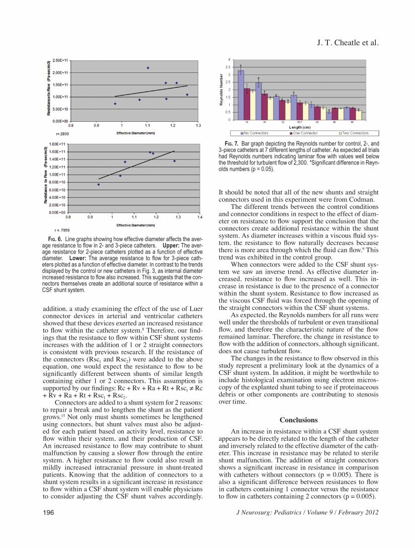
Related Documents