Journal of Advanced Research in Fluid Mechanics and Thermal Sciences ISSN (online): 2289-7879 | Vol. 14, No. 1. Pages 8-23, 2015 8 Penerbit Akademia Baru Flow Analysis of Cooling Water in the Gas Turbine Fin Fan Cooler at Utilities Plant A. M. S. Zuan *,1,a , S. S. Hidayah 1,b , S. Syahrullail 1,c , M. N. Musa 1,d , and E. A. Rahim 2,e Faculty of Mechanical Engineering, Universiti Teknologi Malaysia, 81310 Skudai, Johor, Malaysia. Fakulti Kejuruteraan Mekanikal dan Pembuatan, Jabatan Kejuruteraan Pembuatan dan Industri (JKPI), Universiti Tun Hussein Onn Malaysia, 83000, Parit Raja, Johor, Malaysia. a,* [email protected], b [email protected], c [email protected], d [email protected], e [email protected] Abstract – The main purpose of this project is to study the flow analysis of cooling water in gas turbine fin fan cooler in utilities plant in Gebeng, Pahang. The focus of this project is to study the flow analysis over the implementation of the new design of the fin fan cooler, with enhancement from the aspect of geometrical dimension and fin material selection. There are two design that have been analysed which are the former old design of the fin fan cooler who later will be replaced and the new and improved design of fin fan which will be commissioned. The flow patterns are studied by using the section of the finned tube within the domain of both different design of new and old. The Ansys Fluent R15.0 is utilized to stimulate the related boundary condition such forced convection and conduction for the fin section within the domain. The model of finned tube are drawn and represented geometrically by using Solidworks 2013. Finally, the result accumulated from the flow simulation of each design have been analysed and explained in precise manner to provide the future researchers to make further and more concise study regarding the flow analysis of gas turbine fin fan cooler in utilities plant. Copyright © 2015 Penerbit Akademia Baru - All rights reserved. Keywords: Flow Analysis, Fin Fan Cooler, Cooling Water, Ansys Fluent, Gas Turbine 1.0 INTRODUCTION Utilities plant is the heart of industrial operation which mostly involved the utilization of heavy machinery and tremendous production capacity which rely on private utilities consumption. As for Utilities Gebeng, Kuantan under Petronas Gas Berhad, they were obligated to supply adequate amount of energy especially electricity to surrounding customer such as Petronas Dehydrogenation (PDH), BASF Petronas Chemical (BPC), Kaneka, and also Polyplastic. Fulfilling the daily demand has been a challenge since the operation of the plant need to be monitored 24-hours and even slight glitch of running requirement impacting customers’ operation which leads to loss of production and costs. Utilities Gebeng consists of four major plants producing essential commodities such as electricity, steam, nitrogen liquid and gas also demineralized water. The most important plant is cogeneration (COGEN) plant mainly focused on the steam and electricity production. This COGEN plant formed by few significantly conventional components mainly focus on gas

Welcome message from author
This document is posted to help you gain knowledge. Please leave a comment to let me know what you think about it! Share it to your friends and learn new things together.
Transcript
Journal of Advanced Research in Fluid Mechanics and Thermal Sciences
ISSN (online): 2289-7879 | Vol. 14, No. 1. Pages 8-23, 2015
8
Penerbit
Akademia Baru
Flow Analysis of Cooling Water in the Gas
Turbine Fin Fan Cooler at Utilities Plant
A. M. S. Zuan*,1,a, S. S. Hidayah1,b, S. Syahrullail1,c, M. N. Musa1,d, and E. A. Rahim2,e
Faculty of Mechanical Engineering, Universiti Teknologi Malaysia, 81310 Skudai, Johor,
Malaysia.
Fakulti Kejuruteraan Mekanikal dan Pembuatan, Jabatan Kejuruteraan Pembuatan dan
Industri (JKPI), Universiti Tun Hussein Onn Malaysia, 83000, Parit Raja, Johor, Malaysia. a,*[email protected], [email protected], [email protected], [email protected],
Abstract – The main purpose of this project is to study the flow analysis of cooling water in gas turbine
fin fan cooler in utilities plant in Gebeng, Pahang. The focus of this project is to study the flow analysis
over the implementation of the new design of the fin fan cooler, with enhancement from the aspect of
geometrical dimension and fin material selection. There are two design that have been analysed which
are the former old design of the fin fan cooler who later will be replaced and the new and improved
design of fin fan which will be commissioned. The flow patterns are studied by using the section of the
finned tube within the domain of both different design of new and old. The Ansys Fluent R15.0 is utilized
to stimulate the related boundary condition such forced convection and conduction for the fin section
within the domain. The model of finned tube are drawn and represented geometrically by using
Solidworks 2013. Finally, the result accumulated from the flow simulation of each design have been
analysed and explained in precise manner to provide the future researchers to make further and more
concise study regarding the flow analysis of gas turbine fin fan cooler in utilities plant. Copyright ©
2015 Penerbit Akademia Baru - All rights reserved.
Keywords: Flow Analysis, Fin Fan Cooler, Cooling Water, Ansys Fluent, Gas Turbine
1.0 INTRODUCTION
Utilities plant is the heart of industrial operation which mostly involved the utilization of heavy
machinery and tremendous production capacity which rely on private utilities consumption. As
for Utilities Gebeng, Kuantan under Petronas Gas Berhad, they were obligated to supply
adequate amount of energy especially electricity to surrounding customer such as Petronas
Dehydrogenation (PDH), BASF Petronas Chemical (BPC), Kaneka, and also Polyplastic.
Fulfilling the daily demand has been a challenge since the operation of the plant need to be
monitored 24-hours and even slight glitch of running requirement impacting customers’
operation which leads to loss of production and costs.
Utilities Gebeng consists of four major plants producing essential commodities such as
electricity, steam, nitrogen liquid and gas also demineralized water. The most important plant
is cogeneration (COGEN) plant mainly focused on the steam and electricity production. This
COGEN plant formed by few significantly conventional components mainly focus on gas
Journal of Advanced Research in Fluid Mechanics and Thermal Sciences
ISSN (online): 2289-7879 | Vol. 14, No. 1. Pages 8-23, 2015
9
Penerbit
Akademia Baru
turbine, heat recovery steam generator (HRSG), boilers and diesel engine conclude by
combination of power generation system and steam generation system.
Gas turbine stressed out as main mechanism of electricity generation driven by set of internal
combustion engine powered by diesel connected to upstream rotating compressor coupled to a
downstream turbine with combustion chamber in between. To highlight the gas turbine
practical functions, this component equipped with standalone cooling system just to maintain
the temperature of lubricating system. Inconsistency in lubrication oil temperature is a serious
issue due to the correlation in between the rate of cooling and bearing trip temperature. High
bearing temperature eventually wage in the journal and thrust bearing dysfunctions due to
particular factors and ultimately damaging the bearings by radial or axial rubbing of the rotor.
The cooling water undergo minimization of heat capacity within the fluid by the flow of the
liquid into a set of air cooled heat exchanger or gas turbine fin fan (GT FiFa) cooler built with
fins to optimize the rate of heat transfer to surrounding. Due to the deteriorating condition of
current GT FiFa, the management of Utilities Gebeng has decided to install new GT FiFa with
upgrades from the perspective of fins material and tube bundles design standard. The typical
design uses a fin-fan cooler to cool combustion turbine extraction air, with no attempt to regain
any heat lost to the atmosphere [1]. New materials that will be used for tubes are carbon steel
and aluminium for the fins. The design is compatible with current structure including fans,
motor and piping which expected to deliver as per current design flow, pressure and
temperature. Many research and methods has been done to study the fin fan cooler usage [2]
[3-6]. Changes of the design has been evaluated, reviewed, and verified prior to their
implementation.
Behaviour of the new GT FiFa is under the impression that this new equipment will behave
better than the current one. The related parameters will be identified and the utilization of
Computation Fluid Dynamics (CFD) specifically ANSYS ICEM allow the simulation of the
fluid flow within the finned tube bundles inside the GT FiFa. The utilization of this software
purposely defines the air flow pattern. Analysis of the air flow pattern enables us to study the
air distribution within tube bundles and determine the effectiveness of new GT FiFa design
upon the standard operational requirement. The enhancement of the new GT FiFa can be
evaluated by comparing the collected performance data to the previous GT FiFa performance.
2.0 METHODOLOGY
The flow analysis of the finned tube bundles in the gas turbine fin fan cooler can be done
analytically by using Computational Fluid Dynamics (CFD) software developed by ANSYS,
well known as Ansys Fluent. This software is notoriously recognized as a tool to multiple
models such as fluid flow and heat transfer, turbulence, volumetric reactions, multiphase flow
and few others. This chapter significantly highlights procedures and the flow of work from
development of three dimensional drawing up until the boundary condition identification for
the flow simulation which focus on the correlation between the variables to achieve our main
objectives of the study.
The procedures of utilizing Ansys Fluent programming obtained from user manual of the
software. Referring to user manual can act as a guide for user to use the software especially
when any trouble emerges from the utilization of the meshing and simulation of the model.
This also can spare the right path for the user in performing the simulation.
Journal of Advanced Research in Fluid Mechanics and Thermal Sciences
ISSN (online): 2289-7879 | Vol. 14, No. 1. Pages 8-23, 2015
10
Penerbit
Akademia Baru
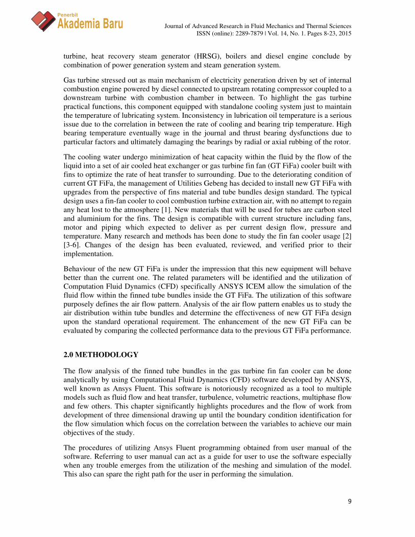
Figure 1: Flow chart of finned tube section simulation procedures
Simulation of flow in Ansys Fluent requires the identification of boundary for the theoretical
fluid to swift represented by the three dimensional model drawing of the finned tube geometry
with their surrounding domain. As starter, the models of the finned tube were drawn
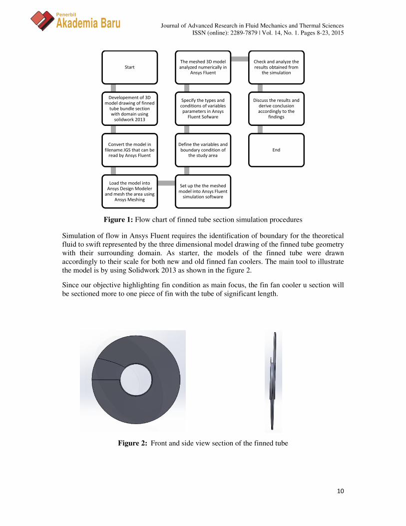
accordingly to their scale for both new and old finned fan coolers. The main tool to illustrate
the model is by using Solidwork 2013 as shown in the figure 2.
Since our objective highlighting fin condition as main focus, the fin fan cooler u section will
be sectioned more to one piece of fin with the tube of significant length.
Start
Developement of 3D
model drawing of finned
tube bundle section
with domain using
solidwork 2013
Convert the model in
filename.IGS that can be
read by Ansys Fluent
Load the model into
Ansys Design Modeler
and mesh the area using
Ansys Meshing
Set up the the meshed
model into Ansys Fluent
simulation software
Define the variables and
boundary condition of
the study area
Specify the types and
conditions of variables
parameters in Ansys
Fluent Sofware
The meshed 3D model
analyzed numerically in
Ansys Fluent
Check and analyze the
results obtained from
the simulation
Discuss the results and
derive conclusion
accordingly to the
findings
End
Figure 2: Front and side view section of the finned tube
Journal of Advanced Research in Fluid Mechanics and Thermal Sciences
ISSN (online): 2289-7879 | Vol. 14, No. 1. Pages 8-23, 2015
11
Penerbit
Akademia Baru
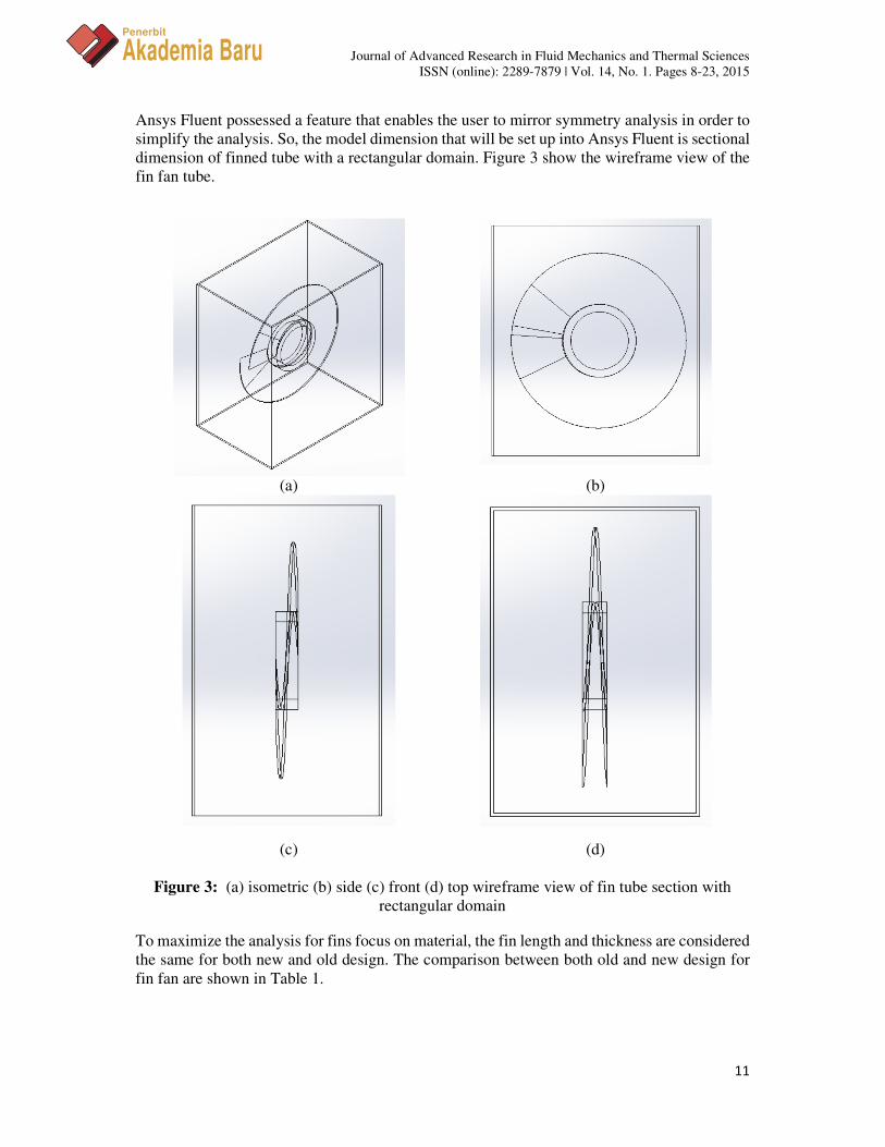
Ansys Fluent possessed a feature that enables the user to mirror symmetry analysis in order to
simplify the analysis. So, the model dimension that will be set up into Ansys Fluent is sectional
dimension of finned tube with a rectangular domain. Figure 3 show the wireframe view of the
fin fan tube.
(a) (b)
(c) (d)
Figure 3: (a) isometric (b) side (c) front (d) top wireframe view of fin tube section with
rectangular domain
To maximize the analysis for fins focus on material, the fin length and thickness are considered
the same for both new and old design. The comparison between both old and new design for
fin fan are shown in Table 1.

Journal of Advanced Research in Fluid Mechanics and Thermal Sciences
ISSN (online): 2289-7879 | Vol. 14, No. 1. Pages 8-23, 2015
12
Penerbit
Akademia Baru
Table 1: Data Comparison between old design and new design
The Ansys Fluent 15.0 was being utilized in this project to stimulate the airflow pattern
aftermath in the gas turbine fin fan cooler tube finned tube section after the meshing and
boundary identification by using ansys meshing application. First, it is compulsory to set the
simulation into 3D version because the model has been drawn in three dimensional models.
There are several requirements that need to be dispensed before the software can simulate our
case study.
The mesh file will be read, check and scale in the Ansys Fluent and by calculating the Reynolds
number of the air flow, we can determine the type of flow to be decided in the vicious model.
Since the value of the Reynolds number of the airflow exceeding 2,300, the type of flow for
this airflow is turbulent. The velocity of the inlet will be defined as well in the boundary
condition.
3.0 RESULTS AND DISCUSSION
Based on the outcome from the simulation by using Ansys Fluent 15.0, it basically appears as
both different design exhibits diverse result which distinguished the results. This enables the
comparison between the effectiveness of the modification to be made from the former design
to the new design of fin fan tube.
The results from simulation illustrated that the vector of the air flow from the fan behaves
differently according to their speed and the fin plate region it flow through. This discrepancy
in results leads by the enhancement in the context of the materials of the fins, geometrical
dimensions, pressure and temperature gradient, also the fan velocity variation for each design.
But, putting the study within a perspective, our main purpose of this study inclination is to
analyze the air flow pattern in the domain over the fin plate only.
The factors that govern the patterns of the air flow denote by the velocity of the inlet blower
and the geometrical representation by the finned plate, upon the air flow travelling distance
within the domain. In this analysis, there are three types of differences illustrated during the
simulation which are the differences in velocity inlet of the blower, geometry dimensions and
fin materials. Figure 4 below describe the similar pattern that happened over the finned plate
within the enclosure.
Old Design New Design
Tube
Length (mm) 120.97 124.94
Diameter (mm) 12.7 13.35 14.224 15.875
Thickness (mm) 0.325 0.8255
Fin Length (mm) 11.112 11.125
Thickness (mm) 0.4 0.4
Domain
Length (mm) 25 25
Wide (mm) 5 5
Height (mm) 50 50
Cooling Water Inlet Temperature
( ̊C ) 49.3 49.3
Fin/Tube Material Pure Copper/Pure
Copper
Aluminium/
Pure Copper
Driven Fan Air Velocity (ms-1) 8,182 10.87
Journal of Advanced Research in Fluid Mechanics and Thermal Sciences
ISSN (online): 2289-7879 | Vol. 14, No. 1. Pages 8-23, 2015
13
Penerbit
Akademia Baru
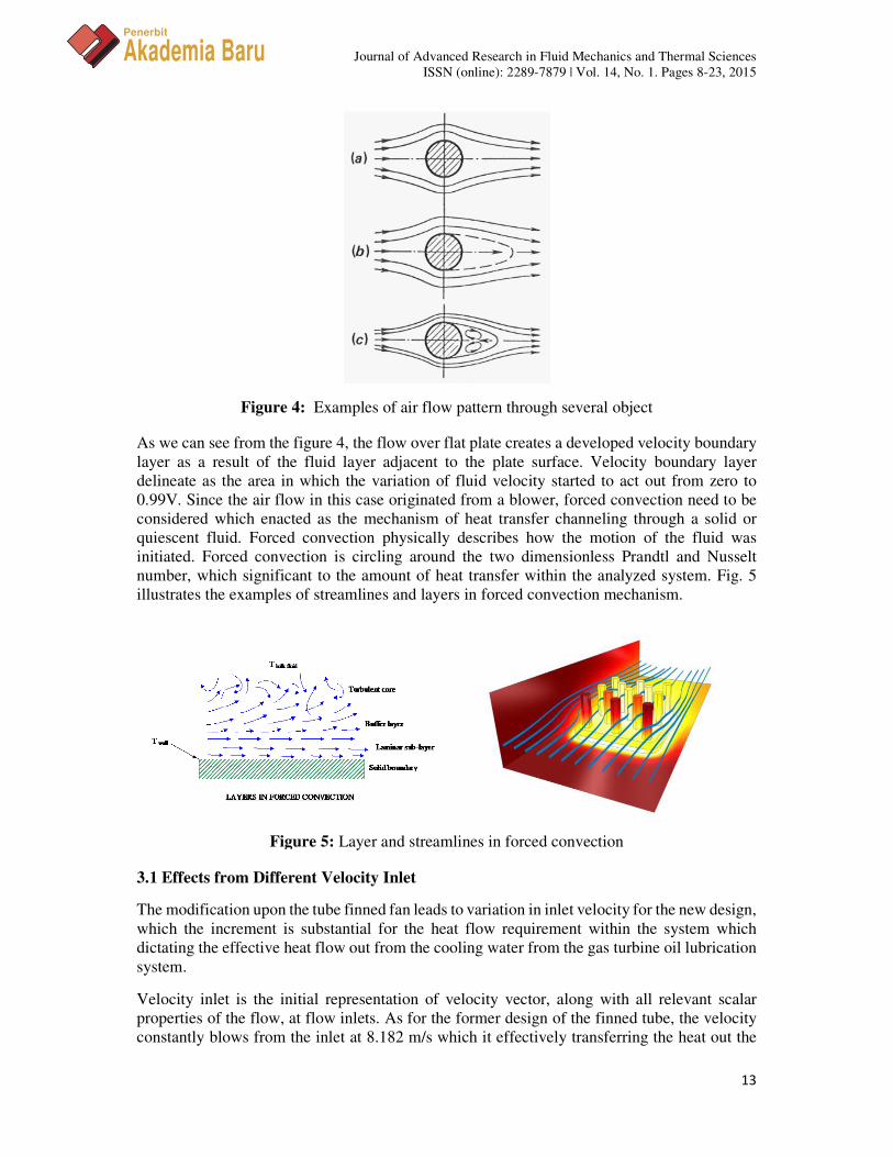
Figure 4: Examples of air flow pattern through several object
As we can see from the figure 4, the flow over flat plate creates a developed velocity boundary
layer as a result of the fluid layer adjacent to the plate surface. Velocity boundary layer
delineate as the area in which the variation of fluid velocity started to act out from zero to
0.99V. Since the air flow in this case originated from a blower, forced convection need to be
considered which enacted as the mechanism of heat transfer channeling through a solid or
quiescent fluid. Forced convection physically describes how the motion of the fluid was
initiated. Forced convection is circling around the two dimensionless Prandtl and Nusselt
number, which significant to the amount of heat transfer within the analyzed system. Fig. 5
illustrates the examples of streamlines and layers in forced convection mechanism.
3.1 Effects from Different Velocity Inlet
The modification upon the tube finned fan leads to variation in inlet velocity for the new design,
which the increment is substantial for the heat flow requirement within the system which
dictating the effective heat flow out from the cooling water from the gas turbine oil lubrication
system.
Velocity inlet is the initial representation of velocity vector, along with all relevant scalar
properties of the flow, at flow inlets. As for the former design of the finned tube, the velocity
constantly blows from the inlet at 8.182 m/s which it effectively transferring the heat out the
Figure 5: Layer and streamlines in forced convection
Journal of Advanced Research in Fluid Mechanics and Thermal Sciences
ISSN (online): 2289-7879 | Vol. 14, No. 1. Pages 8-23, 2015
14
Penerbit
Akademia Baru
system for certain reliable period of time. As the lifespan of the finned tube grew longer, the
air flow inside the finned tube somehow influenced not only the external circumstances but
also internal limitations which constrained the heat exchange in between cooling water and air
flow. Under these conditions, by revamping the current geometry of finned tube with
designated velocity inlet, the heat exchange in between two fluids medium are expected to rise
and outgrow the former finned tube. Figures below illustrating the result of velocity vector
from the simulation based on velocity magnitude for both old and new design of finned tube
along with the comparison in between both outlines.
3.1.1 Old Design of Finned Tube
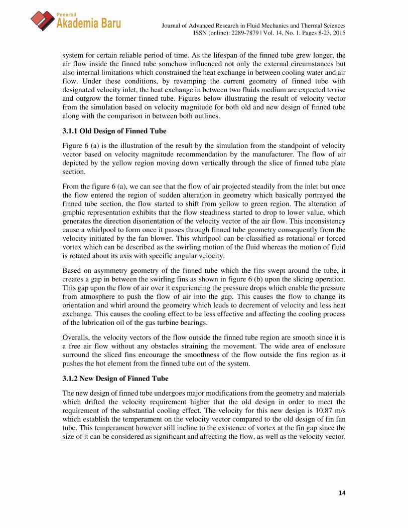
Figure 6 (a) is the illustration of the result by the simulation from the standpoint of velocity
vector based on velocity magnitude recommendation by the manufacturer. The flow of air
depicted by the yellow region moving down vertically through the slice of finned tube plate
section.
From the figure 6 (a), we can see that the flow of air projected steadily from the inlet but once
the flow entered the region of sudden alteration in geometry which basically portrayed the
finned tube section, the flow started to shift from yellow to green region. The alteration of
graphic representation exhibits that the flow steadiness started to drop to lower value, which
generates the direction disorientation of the velocity vector of the air flow. This inconsistency
cause a whirlpool to form once it passes through finned tube geometry consequently from the
velocity initiated by the fan blower. This whirlpool can be classified as rotational or forced
vortex which can be described as the swirling motion of the fluid whereas the motion of fluid
is rotated about its axis with specific angular velocity.
Based on asymmetry geometry of the finned tube which the fins swept around the tube, it
creates a gap in between the swirling fins as shown in figure 6 (b) upon the slicing operation.
This gap upon the flow of air over it experiencing the pressure drops which enable the pressure
from atmosphere to push the flow of air into the gap. This causes the flow to change its
orientation and whirl around the geometry which leads to decrement of velocity and less heat
exchange. This causes the cooling effect to be less effective and affecting the cooling process
of the lubrication oil of the gas turbine bearings.
Overalls, the velocity vectors of the flow outside the finned tube region are smooth since it is
a free air flow without any obstacles straining the movement. The wide area of enclosure
surround the sliced fins encourage the smoothness of the flow outside the fins region as it
pushes the hot element from the finned tube out of the system.
3.1.2 New Design of Finned Tube
The new design of finned tube undergoes major modifications from the geometry and materials
which drifted the velocity requirement higher that the old design in order to meet the
requirement of the substantial cooling effect. The velocity for this new design is 10.87 m/s
which establish the temperament on the velocity vector compared to the old design of fin fan
tube. This temperament however still incline to the existence of vortex at the fin gap since the
size of it can be considered as significant and affecting the flow, as well as the velocity vector.
Journal of Advanced Research in Fluid Mechanics and Thermal Sciences
ISSN (online): 2289-7879 | Vol. 14, No. 1. Pages 8-23, 2015
15
Penerbit
Akademia Baru
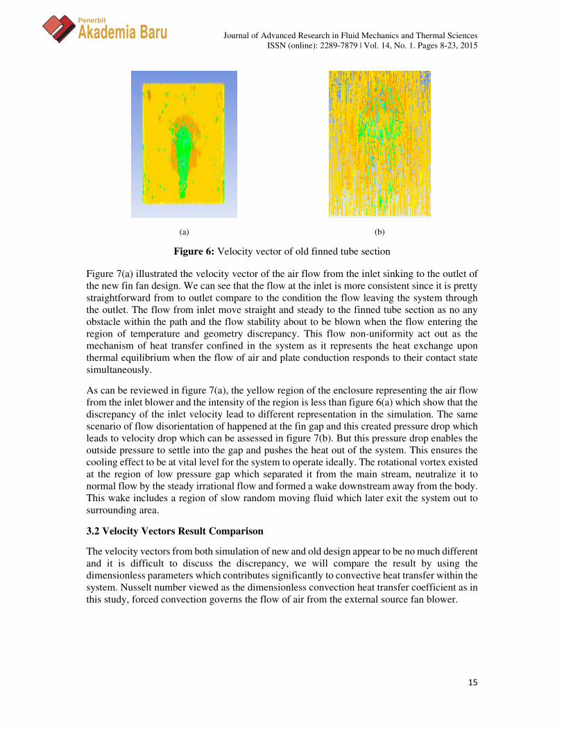
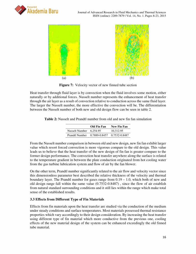
Figure 7(a) illustrated the velocity vector of the air flow from the inlet sinking to the outlet of
the new fin fan design. We can see that the flow at the inlet is more consistent since it is pretty
straightforward from to outlet compare to the condition the flow leaving the system through
the outlet. The flow from inlet move straight and steady to the finned tube section as no any
obstacle within the path and the flow stability about to be blown when the flow entering the
region of temperature and geometry discrepancy. This flow non-uniformity act out as the
mechanism of heat transfer confined in the system as it represents the heat exchange upon
thermal equilibrium when the flow of air and plate conduction responds to their contact state
simultaneously.
As can be reviewed in figure 7(a), the yellow region of the enclosure representing the air flow
from the inlet blower and the intensity of the region is less than figure 6(a) which show that the
discrepancy of the inlet velocity lead to different representation in the simulation. The same
scenario of flow disorientation of happened at the fin gap and this created pressure drop which
leads to velocity drop which can be assessed in figure 7(b). But this pressure drop enables the
outside pressure to settle into the gap and pushes the heat out of the system. This ensures the
cooling effect to be at vital level for the system to operate ideally. The rotational vortex existed
at the region of low pressure gap which separated it from the main stream, neutralize it to
normal flow by the steady irrational flow and formed a wake downstream away from the body.
This wake includes a region of slow random moving fluid which later exit the system out to
surrounding area.
3.2 Velocity Vectors Result Comparison
The velocity vectors from both simulation of new and old design appear to be no much different
and it is difficult to discuss the discrepancy, we will compare the result by using the
dimensionless parameters which contributes significantly to convective heat transfer within the
system. Nusselt number viewed as the dimensionless convection heat transfer coefficient as in
this study, forced convection governs the flow of air from the external source fan blower.
(a) (b)
Figure 6: Velocity vector of old finned tube section
Journal of Advanced Research in Fluid Mechanics and Thermal Sciences
ISSN (online): 2289-7879 | Vol. 14, No. 1. Pages 8-23, 2015
16
Penerbit
Akademia Baru
Heat transfer through fluid layer is by convection when the fluid involves some motion, either
naturally or by additional forces. Nusselt number represents the enhancement of heat transfer
through the air layer as a result of convection relative to conduction across the same fluid layer.
The larger the Nusselt number, the more effective the convection will be. The differentiation
between the Nusselt number of both new and old design flow can be seen in table 2.
Table 2: Nusselt and Prandtl number from old and new fin fan simulation
Old Fin Fan New Fin Fan
Nusselt Number 6,254.95 10,312.95
Prandtl Number 0.7889-0.8457 0.7532-0.8487
From the Nusselt number comparison in between old and new design, new fin fan exhibit larger
value which resort forced convection is more vigorous compare to the old design. This value
leads us to believe that the heat transfer of the new design of fin fan is greater compare to the
former design performance. The convection heat transfer anywhere along the surface is related
to the temperature gradient in between the plate conduction originated from hot cooling water
from the gas turbine lubrication system and flow of air by the fan blower.
On the other term, Prandtl number significantly related to the air flow and velocity vector since
this dimensionless parameter best described the relative thickness of the velocity and thermal
boundary layer. The Prandtl number for gases range from 0.19 – 1.0, which both of new and
old design range fall within the same value (0.7532-0.8487) , since the flow of air establish
from natural standard surrounding conditions and it still lies within the range which make total
sense of the established results.
3.3 Effects from Different Type of Fin Materials
Effects from fin materials upon the heat transfer are studied via the conduction of the medium
under steady conditions and surface temperatures. Most materials possessed thermal resistance
properties which vary accordingly to their design consideration. By increasing the heat transfer
using different type of fin material which more conductive from the previous one, cooling
effects of the new material design of the system can be enhanced exceedingly the old finned
tube material.
(a) (b)
Figure 7: Velocity vector of new finned tube section

Journal of Advanced Research in Fluid Mechanics and Thermal Sciences
ISSN (online): 2289-7879 | Vol. 14, No. 1. Pages 8-23, 2015
17
Penerbit
Akademia Baru
3.3.1 Old Design of Finned Tube
The old design of the copper tube increases their surface area by attaching the tube with
extended fins surface from the same material as the tube. These fins surfaces are manufactured
either by extruding, welding or wrapping thin metal sheet onto the curve surfaces of the copper
tube. These fins enhance the heat transfer from a surface by exposing a larger surface area to
mechanism of heat transfer, as for this case forced convection driven by the fan blower.
The copper tube conditioned to undergo conduction as a result from flowing hot cooling water
leaving the heat exchange system in between the cooling water and high temperature of
lubrication oil. The cooling water acts as a working fluid where it transfers the heat out from
bearing of the gas turbine to ensure the friction and heat of the system does not influence the
performance of the gas turbine and eventually lead to worst case scenario such gas turbine
shutdown or bearing replacement.
The heat transfer via conduction for this finned tube can be scrutinized from the static
temperature contours generated from the simulation software. The temperature distributions of
the old finned tube section portrayed by figure 8(a), where the distribution depicted by the color
variation of the contours. It can be seen in the figure that the exploitation of copper as fins
material for this former design is really effective from the perspective heat transfer since copper
possessed 352 – 401 W/m.K which can be considered high thermal conductivity and very
practical as an extension for transferring heat out under given circumstances. The heat
conduction through the copper fins assumed to be constant and uniform over entire surface for
the convenience in this analysis.
The amount of heat transfer usually much lower at the fin base compare to the tip area since
the fluid is surrounded by solid surfaces near the wall. This manifestation can be spotted in
figure 8(a), the area of copper tube thickness at boundary condition is set to 49.3oC and the
temperature which has been set as wall in the boundary condition conducted through the wall
where the air flow from outside at 25oC flow over the heated finned tube section. The area
turning lighter blue after the simulation indicated that the heat has been transferred out of the
region by the flow of cooler air. Meanwhile, the tip of the fin started to heat up since the heat
has been conducted uniformly to the edge of the fins.
The area where undergo velocity inlet flow first hand also experience more heat transfer which
underlined by the blue area of the half section of fin compared to other half which in yellow
and green contours. The temperature of the surface for the fin is 318 K or 44.85oC in average
which lies within the range of copper tube and air flow, which 49.3oC and 25oC respectively.
The small reduce in temperature is less effective to supply the system with cooling effect
necessary to maintain the sufficient heat transfer, as keeping the temperature of bearing in gas
turbine at par with ideal values. This leads to the decision of replacing this old design to the
new one with the expectation of the heat transfer and cooling effects will be higher and
effective.
3.3.2 New Design of Finned Tube
The new design of finned tube subjected to few changes as the refinement of the model aims
to increase the practical requirement and effectiveness of the system as a whole. This is
important since the systems connected to each other as whole gas turbine operation supported
by other small units which very cardinal to the whole plant performance.
Journal of Advanced Research in Fluid Mechanics and Thermal Sciences
ISSN (online): 2289-7879 | Vol. 14, No. 1. Pages 8-23, 2015
18
Penerbit
Akademia Baru
The revamped new design material has been changed from copper to aluminum. Theoretically,
aluminum thermal conductivity is less compared to copper but practically, aluminum is more
in favors from the aspect of material cost and physical properties. Aluminum is well known as
it appears as material with lower cost of procurement and undemanding process of handling
since it physically lighter than copper. To bounce this disadvantage of low thermal conductivity
of aluminum, the copper tube has been designed specifically in definite size and length so that
the gap for heat transfer will be more open for the heat flow to leave the system. This
geometrical enhancement will be discussed in details in section 4.3.
The same mechanism of heat transfer by heat conductivity occurred in the new design followed
by cross flow of forced convection of the air flow. This direct contact heat exchange with built-
in aluminum fins enables the system to operate at a lower temperature difference and reduce
the weight of the equipment. There are few advantages of this type fin and plate heat
exchangers are larger transfer area, five times lighter if compared to shell and tube heat
exchanger and it can withstand high pressure constraints. The disadvantages of this heat
exchanger that could be underlined are clogging cooling water pathways and aluminum is
susceptible to brittle failure after certain period of time.
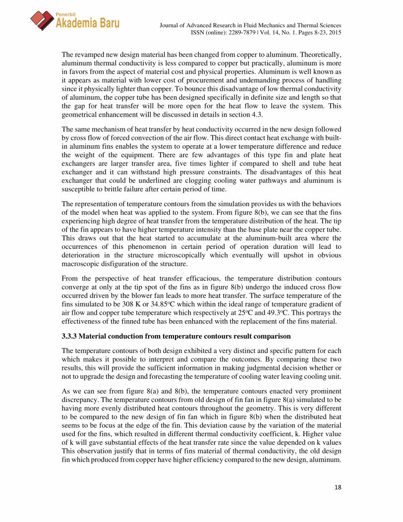
The representation of temperature contours from the simulation provides us with the behaviors
of the model when heat was applied to the system. From figure 8(b), we can see that the fins
experiencing high degree of heat transfer from the temperature distribution of the heat. The tip
of the fin appears to have higher temperature intensity than the base plate near the copper tube.
This draws out that the heat started to accumulate at the aluminum-built area where the
occurrences of this phenomenon in certain period of operation duration will lead to
deterioration in the structure microscopically which eventually will upshot in obvious
macroscopic disfiguration of the structure.
From the perspective of heat transfer efficacious, the temperature distribution contours
converge at only at the tip spot of the fins as in figure 8(b) undergo the induced cross flow
occurred driven by the blower fan leads to more heat transfer. The surface temperature of the
fins simulated to be 308 K or 34.85oC which within the ideal range of temperature gradient of
air flow and copper tube temperature which respectively at 25oC and 49.3oC. This portrays the
effectiveness of the finned tube has been enhanced with the replacement of the fins material.
3.3.3 Material conduction from temperature contours result comparison
The temperature contours of both design exhibited a very distinct and specific pattern for each
which makes it possible to interpret and compare the outcomes. By comparing these two
results, this will provide the sufficient information in making judgmental decision whether or
not to upgrade the design and forecasting the temperature of cooling water leaving cooling unit.
As we can see from figure 8(a) and 8(b), the temperature contours enacted very prominent
discrepancy. The temperature contours from old design of fin fan in figure 8(a) simulated to be
having more evenly distributed heat contours throughout the geometry. This is very different
to be compared to the new design of fin fan which in figure 8(b) when the distributed heat
seems to be focus at the edge of the fin. This deviation cause by the variation of the material
used for the fins, which resulted in different thermal conductivity coefficient, k. Higher value
of k will gave substantial effects of the heat transfer rate since the value depended on k values
This observation justify that in terms of fins material of thermal conductivity, the old design
fin which produced from copper have higher efficiency compared to the new design, aluminum.

Journal of Advanced Research in Fluid Mechanics and Thermal Sciences
ISSN (online): 2289-7879 | Vol. 14, No. 1. Pages 8-23, 2015
19
Penerbit
Akademia Baru
As a whole system, the finned tube will be cross flow with air from the surrounding which will
be force convection by fan blower. In order to counter the effect of low heat transfer in the new
aluminum finned tube design, the velocity inlet for the new design is set to higher value
compared to the old one. The setup results in more lower surface temperature in new design of
finned tube compared to the old one despite their values of thermal conductivity coefficient, k.
The surface temperature and velocity of the design are tabulated in the table below.
Table 3: Air velocity and surface temperature data
Old Fin Fan New Fin Fan
Air Velocity (m/s) 8.182 10.87
Surface temperature (oC) 47.85 34.85
The new design of the fin fan acted out more effective than the old design due to the surface
temperature reading. This proven that the new design of fin fan enhances the performance of
the system as a whole from the perspective of heat transfer, cost effectiveness and structure
reliability.
3.4 EFFECTS FROM DIFFERENT GEOMETRY DIMENSION
The last enhancement that we will discuss in this chapter is the alteration of tube geometry.
The alteration has been made at the thickness of the copper tube. This thickness alteration
initiated by the modification of tube inner and outer diameter. Different dimension of model
geometry most likely to create different streamlines of the flow which can be a way of
evaluating the efficiency of the designs. As for this analysis, the new design of fin fan appears
to have augmentation for their dimension to be compared to the old design
3.4.1 Old Design of Finned Tube
The old design of the fin fan has the inner diameter, Di and outer diameter, Do of 12.7 mm and
13.35 mm respectively. This measurement sums up the thickness of the tube as 0.325 mm as it
(a) (b)
Figure 8: Temperature distributions of finned tube

Journal of Advanced Research in Fluid Mechanics and Thermal Sciences
ISSN (online): 2289-7879 | Vol. 14, No. 1. Pages 8-23, 2015
20
Penerbit
Akademia Baru
acts as a channel to supply the cooling water into and out the lubrication system. Streamlines
are the lines that tangential to the velocity vector throughout the flow field. Streamlines
depends on the boundary conditions and dimensionless parameters assigned and obtained from
the simulation. The streamlines are kept at constant by structure stability which by means
majorly defined reciprocates by convective instability. Convective stability occurred when
adiabatic cooling or heating take place which basically cover the basis of rising and descending
of the air.
The streamlines of the flow in old design finned tube when viewed from y-axis seems to
establish pattern consistency which basically originated from the geometry of the model itself.
The presence of the specific copper tube create a boundary for the streamlines to get through
and this leads to air flow vertical displacement. This is more likely to happen especially when
the convective instability commonly appears to be occurred in turbulent flow and convective
activity. The streamlines obviously to have symmetry pattern if viewed from velocity inlet
flow.
3.4.2 New Design of Finned Tube
The new design of finned tube has been modified to have larger values compared to the old fin
fan by having the inner diameter, Di and outer diameter, Do of 14.224 mm and 15.875 mm
respectively. This alteration leads to the thickness of 0.8255 mm of the copper tube. The
magnification of the tube size leads to bigger area of finned surface which increases the area
of heat dissipation in the system. This finned surface are extended to different length as in this
new model, the fins are made from aluminum.
In the analysis of fins, the fins are considered to be in steady state operation and no heat
generated within the fin, as their thermal conductivity, k remained constant. The convective
heat transfer coefficient, h also recognized to be inconsistent along the fins according to the
length of the circumference. Other than that, the value of the it also represented as a influential
function of the fluid motion at the corresponding point.
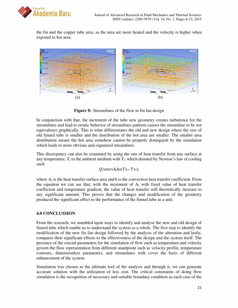
From figure 9(b), the streamlines of the flow in new fin fan design graphically represented as
asymmetry, which completely contrast the streamlines of the old design represented in figure
9(a). This contrast is basically denoted by the difference in tube geometry when the conduction
in between the tube and fins happened. As the conduction creep on the model, it is theoretically
given that the tip of the fin is usually hotter compared to the base of the fin or the copper tube.
The area with higher temperature has higher velocity as the air flow over the fine, so the higher
velocity have the tendency formed more tangled streamlines once it flow over the plate, causing
the streamlines to behave erratically. This difference is an upshot from the modification of the
tube geometry, which we really need to consider in the analysis.
3.4.3 Flow Streamlines within Geometry Result Comparison
As we can see and compare graphically from both figure 9(a) and 9(b), the streamlines of both
old and new design exhibit significant variance in their patterns. This might be caused by area
of surface exposed to the forced convection.
As stated in boundary condition, the copper tube inside fin area opted to undergo wall
conduction as the temperature set to 49.3oC and subjected to conduct throughout the fin. The
heat mostly conducted up until to the tip of fin so the heat can be extended as far as it can from
the heated base. So, the streamlines of the new finned tube section mostly pivoted at the tip of
Journal of Advanced Research in Fluid Mechanics and Thermal Sciences
ISSN (online): 2289-7879 | Vol. 14, No. 1. Pages 8-23, 2015
21
Penerbit
Akademia Baru
the fin and the copper tube area, as the area are more heated and the velocity is higher when
exposed to hot area.
In conjunction with that, the increment of the tube new geometry creates turbulence for the
streamlines and lead to erratic behavior of streamlines patterns causes the streamline to be not
equivalence graphically. This is what differentiates the old and new design where the size of
old finned tube is smaller and the distribution of the hot area are smaller. The smaller area
distribution means the hot area somehow cannot be properly distinguish by the simulation
which leads to more obvious and organized streamlines.
This discrepancy can also be examined by using the rate of heat transfer from any surface at
any temperature, Ts to the ambient medium with T∞ which denoted by Newton’s law of cooling
such
� ̇����=ℎ��(�− ∞);
where As is the heat transfer surface area and h is the convection heat transfer coefficient. From
the equation we can see that, with the increment of As with fixed value of heat transfer
coefficient and temperature gradient, the value of heat transfer will theoretically increase to
any significant amount. This proves that the changes and modification of the geometry
produced the significant effect to the performance of the finned tube as a unit.
4.0 CONCLUSSION
From the research, we stumbled upon ways to identify and analyse the new and old design of
finned tube which enable us to understand the system as a whole. The first step to identify the
modification of the new fin fan design followed by the analysis of the alteration and lastly,
compares their significant effects to the effectiveness of the design and the system itself. The
presence of the crucial parameters for the simulation of flow such as temperature and velocity
govern the flow representation from different standpoint such as velocity profile, temperature
contours, dimensionless parameters, and streamlines with cover the basis of different
enhancement of the system.
Simulation was chosen as the ultimate tool of the analysis and through it, we can generate
accurate solution with the utilization of less cost. The critical constraints of doing flow
simulation is the recognition of necessary and suitable boundary condition as each case of the
(a) (b)
Figure 9: Streamlines of the flow in fin fan design
Journal of Advanced Research in Fluid Mechanics and Thermal Sciences
ISSN (online): 2289-7879 | Vol. 14, No. 1. Pages 8-23, 2015
22
Penerbit
Akademia Baru
analysis requires specific set and values of the constraints. This reliable boundary condition is
really important to visualize our case into simulation that resembles the pragmatic and accurate
real condition. Instead of this long and elaborated explanation about simulation, this flow
analysis also can be analysed by using calculation or experiments which respond accordingly
to our scope of study and method of selection.
Besides that, within this study, we might find few inconsistency in analysis especially in the
replacement of fin material from copper to aluminium as the changes can be misunderstand as
the downgrading the material efficiency but the external factors such the material cost and
structure durability appears to be the limitation that need to be included in the analysis and
discussion. The inconsistency has been bounced by the adjustment of the related boundary
condition such as increased velocity and appropriate material selection.
Furthermore, the boundary conditions and changes of the model influenced the several of
temperature contours, velocity profile and streamlines obtained. We can spot various results
regarding the responds of the systems to the boundary condition. Some changes can be smooth
and organized and some other can be erratic and unstable, which lead to the formation of low
pressure stagnation point and whirlpool. This inconsistency in system responds lead us to
believe that the modification of the design, material selection for the fins and velocity inlet
variety influence the flow pattern inside the finned tube section within the domain, as well as
the analysis of the flow.
As a conclusion, this project successfully achieved the objectives proposed in the beginning of
the study. The objectives are achieved steps by steps with structured solution, analysis and
recommendation for the system to behave more independently and effective. But, the main
objective which to study the flow of cooling water in gas turbine fin fan cooler in utilities plant
is fulfilled and finally came out with several recommendations that can be suggested after
analysing the results from the simulation.
ACKNOWLEDGMENT
The authors wish to thank the Faculty of Mechanical Engineering at the Universiti Teknologi
Malaysia for their support and cooperation during this study. The authors also wish to thank
Research Management Centre (RMC) for the Research University Grant (02G34, 02G35,
09H64) from the Universiti Teknologi Malaysia and Fundamental Research Grant Scheme
(4F610) from the Ministry of Higher Education for their financial support.
REFERENCES
[1] M. Colleen, Design of a combustion turbine heat recovery rotor air cooling system,
Society of Mechanical Engineers (1992).
[2] G.N. Xie, Q.Y. Chen, M. Zeng, Q.W. Wang, Thermal design of heat exchanger with fins
inside and outside tubes, Proceedings of the ASME Turbo Expo (2006).
[3] Y.J. Kim, M. Kim, M.Y. Ha, J.K. Min, Numerical study on surface air-oil heat exchanger
for aero gas-turbine engine using one-dimensional flow and thermal network model.
Transactions of the Korean Society of Mechanical Engineers 38 (2014) 915-924.
Journal of Advanced Research in Fluid Mechanics and Thermal Sciences
ISSN (online): 2289-7879 | Vol. 14, No. 1. Pages 8-23, 2015
23
Penerbit
Akademia Baru
[4] A.D. Al Dakhil, J.A. Al Sudairy, I.A. Al Buraiki, Failure analysis at steam condenser fin
fan cooler tubes, Ras Tanura Refinery, American Society of Mechanical Engineers.
Pressure Vessels and Piping Division 3 (2012) 483-488.
[5] M. De Paepe, A. Willems, A. Zenner, Experimental determination of the heat transfer
coefficient of a plate-fin heat exchanger, Heat Transfer Engineering 26 (2005) 29-35.
[6] G. Lozza, U. Merlo, An experimental investigation of heat transfer and friction losses of
interrupted and wavy fins for fin-and-tube heat exchangers. International Journal of
Refrigeration 24 (2001) 409-416.
Related Documents