Planning, Execution and Upkeep of Release 2002 Forschungsgesellschaft Landschaftsentwicklung Landschaftsbau e.V. Green-roof sites Guidelines for the

Welcome message from author
This document is posted to help you gain knowledge. Please leave a comment to let me know what you think about it! Share it to your friends and learn new things together.
Transcript
Planning, Execution
and Upkeep of
Release 2002
Forschungsgese l lschaf tLandschaf tsentw ick lungLandschaf tsbau e.V.
Green-roof sites
Guidelines for the
FORSCHUNGSGESELLSCHAFT LANDSCHAFTSENTWICKLUNG LANDSCHAFTSBAU E. V. – FLL
THE LANDSCAPING AND LANDSCAPE DEVELOPMENT RESEARCH SOCIETY E.V. – FLL
Guideline for the Planning, Execution and Upkeep of Green-Roof Sites
– Roof-Greening Guideline –
January 2002 edition
with
Methods to be employed when investigating vegetation substrates and aggregate-type drainage materials used at roof-greening sites
1995 edition
with supplements dated January 2002
and Procedure for investigating resistance to root penetration at green-roof
sites
1999 edition with editorial changes dated January 2002
Notes for the user
The technical rules issued by FLL may be freely used by anybody interested. An obligation to apply these guidelines may derive from any legal or administrative regulation, contract or from any other legal basis. FLL guidelines are the result of voluntary and unpaid technical and scientific work and cooperation. Due to the principles and rules applied when establishing these guidelines they can be considered to be the outcome of professional expert work. FLL guidelines are an important source of expertise for professional behaviour in standard working situations. They can, however, not include all types of special cases for which additional or restrictive measures may be required. Nonethe-less, they present a yardstick for precise and faultless technical behaviour. This standard is also significant in the context of the law. FLL guidelines intend to be “recognised rules of technique”. The use of FLL guidelines does, however, not reduce the user’s responsibility for individual behaviour. Every user of these guidelines acts at his own risk. At the same time, all users who identify any mistake or ambiguity in this set of guidelines which may lead to any wrong application are requested to report immediately to FLL in order to eliminate possible defects.
This download edition is your personal version of the FLL-guidelines.Dissemination only by the publisher. All rights reserved. Unauthorized
forwarding of this data to other persons will be pursued with all legal meansof regress.
Guideline for the Planning, Execution and Upkeep of Green-Roof Sites – Roof-Greening Guideline –
Published by: Forschungsgesellschaft Landschaftsentwicklung Landschaftsbau e. V. – FLL Colmantstr. 32, 53115 Bonn Telephone: 0228/690028, Telefax: 0228/690029 mailto: [email protected], Homepage: www.fll.de
Editorial team: The Roof-Greening Working Group
Lösken, G., Prof., Hannover (Chairman)
Adam, H.-J., Hannover Appl, R., Nürtingen Bohlen, R., Ladbergen Fischer, P., Prof. Dr., Freising-Weihenstephan Hämmerle, F., Ditzingen Henneberg, M., Krauchenwies Henseleit, R., Dr., Frankfurt Hofmann, H.-U., Stuttgart Kist, R., Stuttgart König, P., Kretz Krupka, B., Bad Pyrmont Liesecke, H.-J., Prof. Dr., Hannover Marrett-Foßen, M., Dr., Tornesch Michels, K., Köln Neumann, K., Prof. Dr., Berlin Nott, D., Düsseldorf, Münster Raisch, W., Ostfildern Roth-Kleyer, S., Prof. Dr., Geisenheim Ruttensperger, S., Stuttgart Schade, C., Groß Ippener Schenk, D., Unterensingen Schuhmann, V., Bad Honnef Siegert, P., Tornesch Tebart, W., München Wittke, K., München
Coordinator of the editorial team: Büttner, T., FLL, Bonn Rohrbach, J., FLL, Bonn Schulze-Ardey, C., FLL, Bonn
All rights of reprint or reproduction reserved.
1st edition, 5000 copies, Bonn, January 2002 (german version) 1st edition, 400 copies, Bonn, August 2004 (english version) download edition, Bonn, January 2006
Replacement for the 1995 edition Previous editions: Principles for Roof-Greening Sites 1982, 1984
Guideline for Roof-Greening Sites 1990, 1992, 1995
ISBN 3-934484-81-6
This download edition is your personal version of the FLL-guidelines.Dissemination only by the publisher. All rights reserved. Unauthorized
forwarding of this data to other persons will be pursued with all legal meansof regress.
3
Preface to the 2002 edition
Upon its first publication the “Guidelines for the Planning, Execution and Upkeep of Green-Roof Sites – Roof Greening Guidelines” issued by FLL have found wide distribution and acceptance even beyond the borders of the Federal Republic of Germany. Their significance is mirrored also by the fact that reference is made to them repeatedly in the DIN standards.
As a continuation of the 1995 edition the present 2002 edition includes new developments and findings especially in the complex field of roof drainage. Beside statements related to drainage systems using pressurized drainage this revised edition also comes to conclusions based on new findings in regard to the working mechanism of corrosion affecting drainage systems: the carbon-ate content of materials is no longer listed among valid evaluation criteria.
In regard to the coefficient of discharge a differentiation is made between the run-off reference value for drainage according to DIN EN 12056 and DIN 1986 and the annual total retention of rain water seen from an ecological perspective. In addition, criteria for acceptance processes have been specified, recommendations relating to the duration of warranty periods made, and care and maintenance activities revised and enlarged.
In the context of changes concerning granulometric distribution for single-course substrates and drainage course materials as well as nutrients and the proportion of organic substances in sub-strates it seems appropriate to take note of the close relationship between RAL quality assurance and the FLL Roof-Greening Guidelines. The RAL quality assurance, issued by RAL in 1999, takes up criteria of the guidelines and includes regular monitoring of substrates and aggregate-type drainage materials in relation to their compliance with the defined parameters. In this context, the revised version of the FLL Roof-Greening Guidelines will also imply an adjustment of the quality and testing regulations by the RAL quality assurance.
No revision has been effected in regard to investigation methods and the procedure for investigat-ing resistance to root penetration which are part of the appendix of these guidelines. As far as in-vestigation methods are concerned a procedure to determine the coefficient of discharge was added. In respect of resistance to root penetration only editorial changes were made.
The present edition replaces the 1995 edition. It is in line with state-of-the-art technology and sci-entific research and takes account of practical experience so that it can be seen as a set of “recog-nised rules of technique” in the sense of the Standard Building Contract Terms.
We would like to express our thanks and gratitude to all members of the FLL Working Party “Roof-Greening” as well as to all experts who have contributed to the revision of these guidelines for their work and commitment in the development of roof-greening.
Bonn, January 2002
Prof. Albert Schmidt Prof. Gilbert Lösken President FLL Chairman AK Roof-greening
This download edition is your personal version of the FLL-guidelines.Dissemination only by the publisher. All rights reserved. Unauthorized
forwarding of this data to other persons will be pursued with all legal meansof regress.

4
Contents
1 Area of Validity, Purpose.................................................................................................. 8 1.1 Area of validity .................................................................................................................. 8 1.2 Purpose.............................................................................................................................. 8 1.3 Other Standards, Guidelines and Codes of Practice..................................................... 8
2 Types of Greening and Forms of Cultivation ............................................................... 12 2.1 Types of greening ........................................................................................................... 12 2.1.1 General information........................................................................................................... 12 2.1.2 Intensive greening............................................................................................................. 12 2.1.3 Simple intensive greening................................................................................................. 12 2.1.4 Extensive greening ........................................................................................................... 12 2.2 Different forms of cultivation......................................................................................... 13 2.2.1 General information........................................................................................................... 13 2.2.2 Different forms of cultivation - intensive greening ............................................................. 13 2.2.3 Different forms of cultivation - simple intensive greening.................................................. 13 2.2.4 Different forms of cultivation - extensive greening ............................................................ 13 2.3 Identifying site conditions for vegetation..................................................................... 14 2.3.1 General information........................................................................................................... 14 2.3.2 Climate- and weather-dependant factors .......................................................................... 14 2.3.3 Structure-dependant factors.............................................................................................. 14 2.3.4 Plant-dependant factors.................................................................................................... 14
3 Functions and Effects..................................................................................................... 15 3.1 General information........................................................Fehler! Textmarke nicht definiert. 3.2 Functions and effects of town planning and planning for open-air amenities ......... 15 3.3 Ecological functions and effects ................................................................................... 15 3.4 Protective and economic functions and effects .......................................................... 16 4 Requirements related to Construction and Materials.................................................. 17 4.1 Planning requirements ................................................................................................... 17 4.2 Form of use / suitability for use..................................................................................... 17 4.3 Roof slope........................................................................................................................ 17 4.4 Roof designs and suitability for greening .................................................................... 18 4.4.1 Roofs with damp-proof linings........................................................................................... 18 4.4.2 Roofs made from non water-permeable concrete............................................................. 19 4.4.3 Roofs with coverings ......................................................................................................... 19 4.5 Diffusion of moisture ...................................................................................................... 19 4.6 Design loads.................................................................................................................... 19 4.7 Protection against falls................................................................................................... 20 4.8 Draining ...........................................................................Fehler! Textmarke nicht definiert. 4.9 Watering........................................................................................................................... 20 4.10 Compatibility of materials .............................................................................................. 21 4.11 Environmental compatibility ..........................................Fehler! Textmarke nicht definiert. 4.12 Plant compatibility / absence of any risk of phytotoxicity .......................................... 21 5 Technical Requirements (Construction)....................................................................... 22 5.1 General information........................................................................................................ 22 5.2 Protection against root penetration .............................................................................. 22 5.2.1 Materials ........................................................................................................................... 22 5.2.2 Requirements.................................................................................................................... 22 5.2.3 Execution .......................................................................................................................... 23
This download edition is your personal version of the FLL-guidelines.Dissemination only by the publisher. All rights reserved. Unauthorized
forwarding of this data to other persons will be pursued with all legal meansof regress.
5
5.3 Protection against mechanical damage........................................................................ 23 5.3.1 Materials ........................................................................................................................... 23 5.3.2 Requirements.................................................................................................................... 24 5.3.3 Execution .......................................................................................................................... 24 5.4 Protection against corrosion ......................................................................................... 25 5.5 Drainage facilities ........................................................................................................... 25 5.5.1 Materials ........................................................................................................................... 25 5.5.2 Requirements.................................................................................................................... 25 5.5.3 Execution .......................................................................................................................... 26 5.6 Joints and borders.......................................................................................................... 26 5.6.1 Types ................................................................................................................................ 26 5.6.2 Requirements.................................................................................................................... 26 5.6.3 Execution .......................................................................................................................... 27 5.7 Protection against emissions ........................................................................................ 28 5.8 Wind loads....................................................................................................................... 28 5.9 Fire prevention ................................................................................................................ 29 5.10 Protection against slipping and shearing..................................................................... 29 5.10.1 Types ................................................................................................................................ 29 5.10.2 Requirements.................................................................................................................... 29 5.10.3 Execution .......................................................................................................................... 29 5.11 Surrounds........................................................................................................................ 30 5.11.1 Types ................................................................................................................................ 30 5.11.2 Requirements.................................................................................................................... 30 5.11.3 Execution .......................................................................................................................... 30 5.12 Trafficable paved surfaces............................................................................................. 30 5.12.1 Types ................................................................................................................................ 30 5.12.2 Requirements.................................................................................................................... 31 5.12.3 Execution .......................................................................................................................... 31 5.13 Furnishings...................................................................................................................... 31 5.13.1 Types ................................................................................................................................ 31 5.13.2 Requirements.................................................................................................................... 31 5.13.3 Installation......................................................................................................................... 31
6 Construction of Vegetation Areas / Requirements ...................................................... 33 6.1 Working courses and definitions .................................................................................. 33 6.1.1 Working courses ............................................................................................................... 33 6.1.2 Definitions ......................................................................................................................... 33 6.2 Construction techniques................................................................................................ 34 6.2.1 Construction depths .......................................................................................................... 34 6.3 Water retention................................................................................................................ 35 6.3.1 General information........................................................................................................... 35 6.3.2 Maximum water capacity................................................................................................... 35 6.3.3 Water permeability ............................................................................................................ 36 6.3.4 Coefficient of discharge..................................................................................................... 36 6.3.5 Water retention and annual coefficient of discharge ......................................................... 36 6.4 Water storage and additional watering......................................................................... 38 6.4.1 Water storage.................................................................................................................... 38 6.4.2 Additional watering............................................................................................................ 38
7 Drainage Course ............................................................................................................. 40 7.1 Material groups and types.............................................................................................. 40 7.2 Requirements .................................................................................................................. 41 7.2.1 Granulometric distribution ................................................................................................. 41 7.2.2 Frost resistance................................................................................................................. 41 7.2.3 Structural and bedding stability ......................................................................................... 41
This download edition is your personal version of the FLL-guidelines.Dissemination only by the publisher. All rights reserved. Unauthorized
forwarding of this data to other persons will be pursued with all legal meansof regress.

6
7.2.4 Behaviour under compression .......................................................................................... 42 7.2.5 Water permeability ............................................................................................................ 42 7.2.6 Water-storage capacity ..................................................................................................... 42 7.2.7 pH value............................................................................................................................ 43 7.2.8 Carbonate content ............................................................................................................ 43 7.2.9 Salt content ....................................................................................................................... 43 7.3 Construction.................................................................................................................... 43 8 Filter Course.................................................................................................................... 44 8.1 Material groups and types.............................................................................................. 44 8.2 Requirements .................................................................................................................. 44 8.2.1 Weight per unit of surface area......................................................................................... 44 8.2.2 Cut-through resistance...................................................................................................... 44 8.2.3 Effectiveness of mechanical filtration / aperture width ...................................................... 44 8.2.4 Susceptibility to root penetration ....................................................................................... 45 8.2.5 Resistance to weathering.................................................................................................. 45 8.2.6 Resistance to soil-borne solutions and micro-organisms.................................................. 45 8.2.7 Tensile strength, flexibility and coefficient of friction ......................................................... 45 8.3 Construction.................................................................................................................... 45 9 Vegetation Support Course............................................................................................ 46 9.1 Materials groups and types............................................................................................ 46 9.2 Requirements .................................................................................................................. 47 9.2.1 Granulometric distribution ................................................................................................. 47 9.2.2 Organic content................................................................................................................. 49 9.2.3 Frost resistance................................................................................................................. 49 9.2.4 Structural and bedding stability of soil and aggregate mixtures........................................ 49 9.2.5 Behaviour of substrate boards under compression........................................................... 50 9.2.6 Water permeability ............................................................................................................ 50 9.2.7 Water-storage capacity ..................................................................................................... 50 9.2.8 Air content ......................................................................................................................... 50 9.2.9 pH value............................................................................................................................ 50 9.2.10 Carbonate content ............................................................................................................ 51 9.2.11 Salt content ....................................................................................................................... 51 9.2.12 Nutrient content................................................................................................................. 51 9.2.13 Adsorptive capacity ........................................................................................................... 51 9.2.14 Content in respect of seeds capable of germination and of plant parts capable of regeneration ........................................................................................... 52 9.2.15 Foreign substances........................................................................................................... 52 9.3 Construction.................................................................................................................... 52 10 Requirements in respect of Sowing Seed, Plants and Vegetation............................. 53 10.1 Plant breed and commercial groups............................................................................. 53 10.2 Requirements .................................................................................................................. 53 10.2.1 Sowing seed ..................................................................................................................... 53 10.2.2 Shoot parts........................................................................................................................ 53 10.2.3 Shrubs............................................................................................................................... 53 10.2.4 Bulbous plants .................................................................................................................. 54 10.2.5 Coppices ........................................................................................................................... 54 10.2.6 Lawn turf ........................................................................................................................... 54 10.2.7 Vegetation matting ............................................................................................................ 54
11 Greening, Protection against Erosion, Cultivation and Maintenance........................ 56 11.1 Greening .......................................................................................................................... 56 11.2 Execution......................................................................................................................... 56 11.3 Ensuring the stability of coppices................................................................................. 57 11.3.1 Requirements.................................................................................................................... 57
This download edition is your personal version of the FLL-guidelines.Dissemination only by the publisher. All rights reserved. Unauthorized
forwarding of this data to other persons will be pursued with all legal meansof regress.
7
11.3.2 Bracing.............................................................................................................................. 57 11.3.3 Anchorage to supporting trestles ...................................................................................... 57 11.4 Prevention of erosion ..................................................................................................... 57 11.5 Final care ......................................................................................................................... 58 11.6 Readiness for handover ................................................................................................. 59 11.7 Care during maturation and subsequent upkeep, maintenance work....................... 60 11.7.1 General information........................................................................................................... 60 11.7.2 Care during maturation and subsequent upkeep for extensive greening sites ................. 60 11.7.3 Maintenance work............................................................................................................. 61 11.8 Warranty, periods of limitation ...................................................................................... 61 12 Testing ............................................................................................................................. 62
13 Reference Values for design Loads .............................................................................. 68 13.1 Materials for use in drainage courses........................................................................... 68 13.2 Materials for vegetation support courses..................................................................... 69 13.3 Vegetation........................................................................................................................ 70 Methods to be employed when investigating plant substrates and aggregate-type drainage materials used at roof-greening sites .............................................. 71 Procedure for investigating resistance to root penetration at green-roof sites ..................... 82
This download edition is your personal version of the FLL-guidelines.Dissemination only by the publisher. All rights reserved. Unauthorized
forwarding of this data to other persons will be pursued with all legal meansof regress.

8
1 Area of Validity, Purpose
1.1 Area of validity The “Guidelines for the Planning, Execution and Upkeep of Green-Roof Sites – Roof-Greening Guidelines” apply to the greening of roofs, roof terraces, underground car parks and other building covers with, as a rule, ca 2 m covering.
1.2 Purpose Over the past few years, increasing prominence has been given to greening in connection with building projects, as a means of enhancing the environment in the places where we live and work and of improving the way they work and look. A great deal of development work has been under-taken, involving both ‘intensive’ and, in particular, ‘simple intensive’ and ‘extensive’ greening, whilst at the same time embracing construction methods and materials, also the use of plants.
The area covered by these guidelines extends to the greening of roofs, terraces and façades at a variety of levels in buildings as well as to other structures where greening is not necessarily carried out at ground level.
For the evaluation of green-roof sites cf. “Evaluation of green-roof sites; recommendation related to evaluating construction planning, approval procedures and acceptance”, FLL 1998.
The purpose of the guidelines is to set out the basic principles and requirements which apply in general terms to the planning, execution and maintenance of such schemes, taking full account of current knowledge and the most advanced technology. They deal with additional basic principles relating to the planning and construction of properties, and the emphasis is on technical require-ments in respect of construction and vegetation. These guidelines are intended for the use of pro-fessionals and craftsmen working in all relevant sectors and trades.
1.3 Other Standards, Guidelines and Codes of Practice Standards and Guidelines lay down general standards and requirements and provide the basis for agreement between clients, planners and contractors.
Since, for the most part, existing Standards and Guidelines do not apply directly to roof-greening, a check needs to be made in each instance to see how applicable they are generally, whether or not they can be used in a modified form. Particular attention needs to be paid to the individual Stan-dards and Guidelines listed below, each of which will be valid in its most recent version.
Reference needs to be made at this point to the validity and statutory significance of the specific handling instructions issued by manufacturers and processors in respect of various materials, also to the comprehensive associated set of materials standards.
Construction Industry Contracting Procedure – VOB – Parts A, B and C VOB/A – DIN 1960 General Terms governing the Award of Contracts for Building Works
VOB/B – DIN 1961 General Contractual Conditions governing the Execution of Building Works
VOB/C General Contractual Conditions (Technical) governing Building Works – ATV DIN 18299 General Regulations governing Construction Work of all Types DIN 18320 Landscaping Work DIN 18336 Damp-proofing DIN 18338 Covering and damp-proofing or roots DIN 18354 Mastic asphalt work
This download edition is your personal version of the FLL-guidelines.Dissemination only by the publisher. All rights reserved. Unauthorized
forwarding of this data to other persons will be pursued with all legal meansof regress.
9
Standards DIN 1055 Structural design loads.
–1: Bedding materials, construction materials and structural components, intrinsic loads and friction angles
–3: Live loads –4: Live loads: wind loads in structures which are not susceptible to vibration –5: Live loads: snow and ice loads
DIN 1986 Drainage facilities for buildings and properties –1: Technical conditions (construction) –2: Establishment of nominal widths for drainage and ventilation facilities
(Note: DIN 1986–1 and –2 have been partly replaced by DIN EN 12056, edition 01/2001 and were both in force up until June 30, 2001. After this date the standards DIN EN 12056–1 to –3 jointly with DIN 1986–100 have been in force)
–30: Maintenance –100: Drainage Installations for Buildings and Plots of Land
(Note: Additional regulations in connection with DIN EN 12056, draft version 01/2001, upon its adoption this version shall replace DIN 1986-1+2 in combination with DIN EN 12056–1 to –3)
DIN 1988 Technical Rules governing Drinking Water Installations DIN 4045 Sewage Technology – Basic Principles DIN 4095 Building Sites; Drainage for the protection of the construction plant: Planning,
Determination of Requirements and Execution DIN 4102 Behaviour of construction materials and components under fire
–1: Construction materials: terminology, requirements and tests –4: Composition and use of classified construction materials and structural
components, also of special structural components –7: Roofing; terminology, requirements and tests
(Note: in conjunction with decrees adopted by the various federal States on the basis of the ARGEBAU (ed.): specimen decree “Behaviour of green-roof sites under fire: adopted by the Fachkommission Bauaufsicht [Building Inspectorate Commission]” dated 22./23.06.1989)
DIN 4108 Thermal insulation in buildings DIN 4109 Sound insulation in buildings DIN 18035 –4: Playing fields; grassed areas DIN 18195 Damp-proofing of buildings
–1: Principles, definitions, allocation of different types of damp-proofing –2: Materials –3: Requirements related to the use of materials –5: Damp-proofing – moisture protection –6: Protection against external groundwater –8: Damp-proofing over settlement joints –10: Protective layers and protective action
DIN 18531 Damp-proofing of roofs. Terminology, requirements, planning principles DIN 18915 Vegetation technology in landscaping: groundwork DIN 18916 Vegetation technology in landscaping; plants and working with plants DIN 19917 Vegetation technology in landscaping; lawns and seeding DIN 18919 Vegetation technology in landscaping; care of green areas during maturation
and subsequent maintenance. DIN EN 12056 Gravity force drainage installations within buildings – 1: General requirements related to execution – 3: Roof drainage, planning and calculation (Note: in conjunction with DIN 1986–100, at present: draft version 01/2001)
This download edition is your personal version of the FLL-guidelines.Dissemination only by the publisher. All rights reserved. Unauthorized
forwarding of this data to other persons will be pursued with all legal meansof regress.

10
Guidelines and Codes of Practice THE ASPHALT-USERS’ ADVISORY CENTRE (ED.):
– Information concerning mastic asphalt. Vol. 23 Mastic asphalt as a damp-proof course un-derneath green sites
DUD BUSINESS UNIT ROOF AND DAMP-PROOFING SHEETING IN IVK (ED.):
– lnformation related to the laying of damp-proofing materials for buildings – Materials specification sheets for roof sheeting – Materials specification sheets for damp-proof lining
THE FEDERAL BRANDS AGENCY (ED.):
– Descriptive list of brands for lawn grasses THE FEDERAL MINISTER FOR THE ENVIRONMENT, PROTECTION OF NATUR AND SECURITY OF POWER STATIONS:
– Regulation governing Sewage Sludge AbfKlärV THE GERMAN INSTITUTE FOR QUALITY ASSURANCE AND CODING E.V. RAL (ED.):
Federal Agency for Compost e.V.: – Compost, quality certificate RAL-GZ 251
Agency for Plastic, Roof and Damp-proofing Sheeting Contractors e.V.: – Laying of plastic sheeting for roofs and plastic damp-proofing lining,
quality certificate RAL-RG 718 Agency for Substrates for Planting e.V.: – Quality and testing regulations bark for planting, quality certificate RAL-GZ 250 – Quality and testing regulations roof substrates, quality certificate RAL-GZ 253 – Quality and testing regulations basic materials for substrates,
quality certificate RAL-GZ 254 THE HIGHWAYS AND TRAFFIC RESEARCH SOCIETY (ED.):
– Conditions governing the supply of geotextiles and lattice-type materials for use in road building (TL Geotex E–StB 95)
THE LANDSCAPING AND LANDSCAPE DEVELOPMENT RESEARCH SOCIETY E.V. – FLL (ED.): – Recommendation related to percolation and water retention – Descriptive list of fertilizers for landscaping and the construction of playing fields – Evaluation of green-roof sites; recommendation related to evaluating construction planning,
approval procedures and acceptance – Quality assessment in tree nursery plants – Quality assessment in shrubs – Quality requirements for organic mulch materials and composts for landscaping purposes
and recommendations regarding the use of same – Standard seed mixtures lawn – RSM – Guideline for the planning, execution and care related to façade greening with climbers – Procedure for investigating resistance to root penetration at green-roof sites
PROFESSIONAL ASSOCIATION GREEN-ROOFING FBB (ED.):
– Sheeting and coating resistant to root penetration, testing in accordance with the FLL pro-cedure
THE PROFESSIONAL GARDEN LANDSCAPERS’ ASSOCIATION (ED.):
– Accident prevention instructions in respect of garden, orchard and park development work, UW 4.2
– Horticultural work on construction sites
This download edition is your personal version of the FLL-guidelines.Dissemination only by the publisher. All rights reserved. Unauthorized
forwarding of this data to other persons will be pursued with all legal meansof regress.
11
VDD–BITUMINOUS ROOF AND DAMP-PROOF SHEETING INDUSTRIAL ASSOCIATION E.V. (ED.):
– The abc of bituminous sheeting – technical rules VDI ASSOCIATION OF GERMAN ENGINEERS (ED.):
– Roof drainage with pressurised drainage systems, VDI 3806 WDK THE GERMAN RUBBER INDUSTRY ASSOCIATION E.V. WDK (ED.):
– WdK–Flat Roofing Manual or rubber sheeting for roofs and flat rooftops ZDB THE GERMAN CENTRAL BUILDING TRADE ASSOCIATION E.V. (ZDB), ASSOCIATION OF GERMAN TILING EXPERTS (ED.):
– Code of Practice governing the laying of floor tiles and slabs outside buildings
THE GERMAN CENTRAL ROOFING TRADE ASSOCIATION – ASSOCIATION OF ROOFING, WALLING AND DAMP-PROOFING EXPERTS E.V. AND CHIEF GERMAN CONSTRUCTION INDUSTRY ASSOCIATION E.V. FEDERAL DEPARTMENT FOR STRUCTURAL DAMP-PROOFING (ED.):
– Guidelines for roofs with damp-proofing – flat roof guidelines Also any further guidelines, codes of practice and official rulings such as may affect green-roof sites.
Contractual obligations DIN GERMAN STANDARDISATION INSTITUTE (ED.):
– StLB – Standard contractual terms for the construction industry – STLB – Subsidiary contractual terms for open-air amenities – StLB – Temporary work contracts
THE LANDSCAPING AND LANDSCAPE DEVELOPMENT RESEARCH SOCIETY E.V. – FLL (ED.): – Special terms, additional terms and industrial customs and practices in conjunction with
landscaping standards DIN 18915–18920 – MLV–open-air amenities – specimen list of contractual terms governing open-air amenities – MLV–roof and façade greening sites – specimen contractual terms governing roof- and fa-
çade-greening
This download edition is your personal version of the FLL-guidelines.Dissemination only by the publisher. All rights reserved. Unauthorized
forwarding of this data to other persons will be pursued with all legal meansof regress.

12
2 Types of Greening and Forms of Cultivation
2.1 Types of greening
2.1.1 General information Roof-greening is divided into three different types, depending on use, factors affecting construction and the method used to carry out the work, and this distinction will play a critical part in determining both the plant types which are selected and how the vegetation will look. As far as the planning and execution of work is concerned, a distinction is made between
– intensive greening – simple intensive greening, and – extensive greening
Each of these types covers a variety of forms of cultivation, with seamless transition and site-specific differentiation. Having due regard for all the information which has been derived from the use of plants and vegetation science, the following criteria may be used to differentiate between the three types of greening.
2.1.2 Intensive greening The term ‘intensive greening‘ covers the planting of shrubs and coppices, as well as grassed ar-eas, even an occasional tree. These may be laid out either on the same level, at different heights or in individual plantings spread about the site. The wide range of options available for designs and uses means that sites can be fitted out in such a manner as to create an amenity comparable to park facilities at ground level. The plants which are used make heavy demands on the layered su-perstructure.
Regular attention is needed to maintain sites of this type in good order, in particular regular water-ing and feeding is required.
2.1.3 Simple intensive greening As a rule, simple intensive greening involves the use of grass, shrubs and coppices as ground cover, but the range of options available to the user and the architect is not as wide as that which intensive greening has to offer. The plants which are used make few demands on the layered su-perstructure and need little watering and feeding, which reduces the amount of attention required.
An simple intensive greening site is less costly to construct than is an intensive greening site.
2.1.4 Extensive greening Extensive greening involves cultivation of vegetation in forms which create a ‘virtual Nature’ land-scape and requires hardly any external input for either maintenance or propagation.
The plants which are used will be particularly well suited to coping with the full range of conditions which they are likely to encounter at the locations in which they will be planted, and they will be capable of self-propagation. These plants should be of Central European flora stock, but local flora should be considered.
Vegetation stocks, the bulk of which will be enclosed and flat, will consist of mosses, succulents, herbaceous plants and grasses. The vegetation stock will undergo a natural process of change, including new types of plants which enlarge the flora stock in the course of time.
This download edition is your personal version of the FLL-guidelines.Dissemination only by the publisher. All rights reserved. Unauthorized
forwarding of this data to other persons will be pursued with all legal meansof regress.

13
As a rule, extensive greening is the least costly to implement and maintain. Depending on the greening objective, any regional climatic conditions and the type of construction certain selected care activities, such as nutrient supply, may be required.
2.2 Different forms of cultivation
2.2.1 General information The use of plants covers virtually the entire range of species from horticultural plant varieties in-cluding aesthetic and functional aspects at intensive greening sites to wild plant stock mirroring natural plant species at extensive greening sites. The objective for extensive greening is to initiate vegetation development in a shortened period of time as opposed to spontaneous self-greening processes and to establish lasting stocks with the help of natural vegetation dynamics.
The distinction between different vegetation forms can only be exemplary given the wide range of option and is based on stock-forming groups of plants. In individual cases on part-surfaces differ-ent vegetation aspects may form due to varying site conditions.
The desired target vegetation needs to be clearly defined and described.
2.2.2 Different forms of cultivation - intensive greening Intensive greening covers virtually the entire range of plants and landscaping options available when planning open-air amenities, giving an unlimited choice of forms. Limitations as to the use of trees and large bush-type coppices will depend on the property in question. Where there are spe-cial planting conditions, the range of options can be extended to other types or groups of vegeta-tion.
2.2.3 Different forms of cultivation – simple intensive greening Simple intensive greening which fits in between intensive and extensive greening can involve culti-vation in any of the following forms:
– grass and herbaceous plants – wild shrubs and coppices – coppices and shrubs or – coppices
2.2.4 Different forms of cultivation – extensive greening In extensive greening the following forms of cultivation can be defined:
– moss and members of the Sedum family – members of the Sedum family, moss and herbaceous plants – members of the Sedum family, grass and herbaceous plants – grass and herbaceous plants
This download edition is your personal version of the FLL-guidelines.Dissemination only by the publisher. All rights reserved. Unauthorized
forwarding of this data to other persons will be pursued with all legal meansof regress.
14
2.3 Identifying site conditions for vegetation
2.3.1 General information If roof-greening is to be a lasting success, it is absolutely essential that site conditions are identified to see if they are suitable for vegetation.
The factors which determine the quality of any given site may be listed under the following head-ings:
– climate- and weather-dependant factors – structure-dependant factors and – plant-dependant factors
2.3.2 Climate- and weather dependant factors The following factors will need to be taken into account:
– the regional climate – the local microclimate – the pattern and volume of annual precipitation – average exposure to sunshine – any incidence of periods of drought – any incidence of periods of frost, with or without snow cover – the direction of the prevailing wind.
2.3.3 Structure-dependant factors The following factors will need to be taken into account:
– areas exposed to the sun, shaded areas and areas where sunshine and shade alternate – deflection of precipitation by the structure – the effect of flue gas emissions – wind-flow conditions – exposure of the roof surfaces – stress due to reflecting façades – additional water load from adjoining structural elements – the gradient or slope of the roof surfaces – design loads and the depth derived therefrom for the layered superstructure
2.3.4 Planning-dependant factors For intensive greening, attention needs to be paid to the following factors:
– certain individual varieties, particularly evergreens, are not completely hardy under winter con-ditions and where the plant cover is of limited density
– shrubs and coppices in exposed positions must be able to withstand the wind – certain types of plants are sensitive to reflected light and thermal build-up
all vegetation is sensitive to airborne chemical and exhaust contamination, also to warm and cold air emissions
For extensive greening, attention needs to be paid to the following factors:
– the effect of wind and of the intensity of solar radiation on water stocks – the demands made by plants at dry locations upon air resources in the layered superstructure – these forms of vegetation are also sensitive to airborne chemical contamination, also to warm
and cold air emissions – the transformation towards forms of vegetation at alternately damp or permanently damp loca-
tions in shady conditions or in wet areas, e.g. at zero-gradient-roofs.
This download edition is your personal version of the FLL-guidelines.Dissemination only by the publisher. All rights reserved. Unauthorized
forwarding of this data to other persons will be pursued with all legal meansof regress.
15
3 Functions and Effects
3.1 General information There are a number of inter-related functions and effects of various kinds associated with roof-greening, once it has been carried out. They fall under three main headings:
− town planning and planning of open-air amenities − ecology and − the economy and environmental protection.
The way in which these functions and effects are classified under the above headings and the weighting which they carry will vary from one situation to the next. This being the case, a measure of overlap is inevitable in any classification based on the most essential features and any example is, at best, illustrative and the sequence in which they are listed has no implications in terms of their respective values.
Functions and effects are used to evaluate construction work in the context of testing for environ-mental compatibility and environmental impact regulations, a process in which the procedures fol-lowed and the weighting accorded to different factors will vary from one local or regional authority to the next. In order to ensure that the required functions and effects are achieved it is recom-mended that, with appropriate targets, minimum standards be laid down in terms of the composi-tion and density of construction, depth and the form of vegetation (see also “Evaluation of roof-greening”).
3.2 Functions and effects of town planning and planning for open-air amenities – More green and open-air amenities are provided on a given property, without additional land
acquisition costs – Green areas and open-air amenities are maintained or reclaimed as compensatory action at
sites which have been placed under a strain or over-utilised by buildings or some other form of surface cover
– The appearance of urban and rural areas is improved by bringing in additional plants, greenery and green spaces, all of which are planning features with a natural look, designed to empha-sise the creation of a sense of structure and spaciousness
– By allocating both private and open spaces which people can experience and use in the im-mediate vicinity of the places where they live and work, planners can create a better environ-ment for these activities
– Plants, greenery and green spaces give overlooked flat rooftops in the vicinity a more natural look than that created by weathered or gravel-covered roofs
3.3 Ecological functions and effects – Planners can cater for the demands imposed by green planning, care of the countryside and
the protection of Nature in both built-up and rural areas – Special conservation areas can be provided for threatened flora and fauna in built-up areas – Rainwater runoff can be held in check and water can be retained; it can also be returned to the
natural moisture cycle by evaporation and transpiration – The micro-climate can be improved by taking the extremes out of temperature fluctuations,
reducing the strength of reflection onto adjoining areas, increasing atmospheric moisture lev-els and by fixing dust particles better than weathered or gravel-covered roofs are able to do
This download edition is your personal version of the FLL-guidelines.Dissemination only by the publisher. All rights reserved. Unauthorized
forwarding of this data to other persons will be pursued with all legal meansof regress.

16
3.4 Protective and economic functions and effects – The amount of water which runs off into the property drainage system will be reduced by re-
tention, thereby reducing the burden on the urban drainage system – The demands placed upon the roof structure in terms of physical, chemical and biological
stress will be reduced, whilst the effectiveness of damp-proof linings will be enhanced by nar-rowing of the range over which the temperature fluctuates, by keeping UV radiation and emis-sions off the roof, also by preventing blistering or incrustation
– The risk of damage to the damp-proof lining on the roof due to the action of external mechani-cal forces will be reduced, as will the negative pressure effect created by the wind
– Improved protection against flying sparks and radiated heat – There will be improved insulation against the sound of footsteps or airborne noise – Thermal insulation will be improved during the winter and, in particular, during the summer – Reduction of the coefficient of discharge in terms of estate drainage – Retention of water caused by precipitation – More economic use of the urban sewage system – Increase in value of the real estate through attractive greening of the building – Image gain for the owner due to visibly sustainable and responsible action when constructing
the building
This download edition is your personal version of the FLL-guidelines.Dissemination only by the publisher. All rights reserved. Unauthorized
forwarding of this data to other persons will be pursued with all legal meansof regress.
17
4 Requirements related to Construction and Materials
4.1 Planning requirements In the context of the planning process all characteristics of the building related to structural and vegetation-technical aspects have to be put down and evaluated. This analysis may lead to addi-tional specific requirements necessary for the construction of the building or the way the roof-greening is planned.
In particular in case of larger course depths checks need to made as to what extent principles re-lated to earthwork have to be applied.
4.2 Form of use / suitability for use When considering use, a distinction needs to be made between the structural features of the roof and the suitability of the same for use by people. Structural aspects of use are laid down in the “Flat-roof Guidelines”, DIN 18195 and DIN 1055.
Basically, the use by people of roofs which have been subjected to greening is restricted to paved walkways and terraces intended specifically to act as rest areas and surfaced accordingly. Full access to a roof which has been subjected to greening is only possible where turf has been laid for just that purpose. Note has to be taken of guidelines related to construction requirements for build-ings which have to be adapted to the needs of disabled persons.
Planted areas at intensive greening sites, along with areas of vegetation at extensive greening sites laid out with a ‘virtual Nature’ look, are not meant to be used, and access is normally re-stricted to people who care for and maintain the site.
4.3 Roof slope With reference to structural and vegetation requirements in respect of roof-greening methods, the angles at which roofs slope have to be taken into account.
Roofs with a slope of less than 2 % are special structures and they will, therefore, require special measures. This also applies to individual roof areas, such as valleys.
Where a green-roof site of the intensive type is to be watered from an integral reservoir, the roofing will either have to be constructed without any gradient or reservoir boards will have to be provided.
For extensive and simple intensive greening, roofs with a gradient of at least 2 % should be con-sidered the norm, in accordance with the “Flat-roof Guidelines”. In extensive greening, controlled drainage will meet the basic needs of the vegetation.
Where extensive greening is being applied to roofs in which the gradient is less than 2 %, a drain-age course of suitable dimensions will be needed to cope with water run-off and avoid waterlog-ging in the vegetation support course. Single-course structures will need to be free from waterlog-ging in the standard structure depth. The total depth of the structure has to be increased accordingly, if necessary.
This download edition is your personal version of the FLL-guidelines.Dissemination only by the publisher. All rights reserved. Unauthorized
forwarding of this data to other persons will be pursued with all legal meansof regress.

18
Tab.1: Examples for comparing the values of percent in roof slope and degree in gradient
Roof slope in percent corresponds to gradient
in degree
Roof slope in percent corresponds to gradient
in degree 1% ~ 0,6o 1o ~ 1,7% 2% ~ 1,1o 2o ~ 3,5% 3% ~ 1,7o 3o ~ 5,2% 5% ~ 2,9o 5o ~ 8,8% 7% ~ 4,0o 7o ~ 12,3% 9% ~ 5,1o 9o ~ 15,8%
10% ~ 5,7o 10o ~ 17,6% 15% ~ 8,5o 15o ~ 26,8% 20% ~ 11,3o 20o ~ 36,4% 30% ~ 16,7o 25o ~ 46,6% 40% ~ 21,8o 30o ~ 57,7% 60% ~ 31,0o 35o ~ 70,0% 80% ~ 38,7o 40o ~ 83,9%
100% ~ 45,0o 45o ~ 100,0%
As the gradient increases, so does the rate at which water runs off the roof. A layered superstruc-ture with a fairly high water-storage capacity and poor drainage, or vegetation which does not re-quire a great deal of water, will compensate for gradients of 5 % or more.
As the angle at which the roof slope increases, special action is required to protect the structure against shear and slide (see 5.10). In view of the structural and vegetation problems which roofs with a gradient in excess of 45° pose, greening should not be considered in such cases.
4.4 Roof designs and suitability for greening A variety of conditions needs to be considered at green-roof sites, involving both the way in which the site is constructed and the physical conditions on-site. These conditions relate to the suitability of all the courses and materials used in roof construction and to the ways in which they work. For further details, the reader is referred to the “Flat-roof Guidelines”.
4.4.1 Roofs with damp-proof linings Non-ventilated roof with no thermal insulation Any type of greening and any form of vegetation may be used, notably those with high design loads. In the case of structures in which the underside of the roofing is exposed to sub-zero tem-peratures, the risk of frost damage to plants cannot be excluded.
Non-ventilated roof with thermal insulation Any type of greening and any form of vegetation may be used, notably those with high design loads. The pressure loading capability of the heat insulator needs to be adapted to the loads of the greening structure including the vegetation load.
Non-ventilated roof with thermal insulation on lightweight structures Generally-speaking, only arrangements with low design loads may be used for greening. Some-times, the safety margin in the roof load-bearing capacity is so low as to preclude greening.
This download edition is your personal version of the FLL-guidelines.Dissemination only by the publisher. All rights reserved. Unauthorized
forwarding of this data to other persons will be pursued with all legal meansof regress.
19
Ventilated roof with thermal insulation Note should be taken of the fact that the top layer usually has only a poor load-bearing capacity. The cooling effect of roof-greening can affect physical processes involved in construction work, and this is a risk which needs to be assessed on a site-by-site basis.
U-shaped roofs Where greening is carried out on U-shaped roofs, or other roofs with special shapes, fitted with thermal insulation above the damp-proof lining, attention needs to be paid to moisture diffusion. Each site will have to be assessed to see whether or not a levelling or intermediate course is needed. Attention will have to be paid to the special conditions which apply where redevelopment work is involved.
4.4.2 Roof made from non water-permeable concrete Roof made from non water-permeable concrete with or without a thermal insulation under-lay Any type of greening and any forms of vegetation may be used. Generally-speaking, additional surface treatment for the concrete is not needed in order to prevent root penetration.
Roof made from non water-permeable concrete with thermal insulation overlay Greening is possible as for U-shaped roofs.
4.4.3 Roofs with coverings The building methods and materials currently used for roofs with coverings are not, generally-speaking, intended for greening, but where structural conditions permit, there is also the option for greening these roofs. In some cases special measures may be required.
4.5 Diffusion of moisture The physical characteristics of roof structures which are to be subjected to greening must be checked. This applies both to roofs which are to be constructed and, in particular, to existing roof-ing. Here, attention needs to be paid to moisture diffusion as a function of spatial use.
4.6 Design loads The critical factor in deciding what type of greening to use and how to cultivate the site will be mat-ters relating to statics - i.e. design loads. DIN 1055 also requires that a distinction has to be made between constant and live loading.
When deciding into which category the superstructure fits, all the courses must be considered, at maximum water capacity and including the surface load generated by the vegetation, as a compo-nent in the surface load. The load generated by any water stored in an integral reservoir will also need to be added into the figures. Spot loadings generated by large-scale bushes, trees and struc-tural components, such as pergolas, water pools and peripheral items, will need to be calculated separately (see also paragraph 13).
Where greening is being carried out and spot loads are being positioned, it is particularly important to ensure that the thermal insulation and the damp-proof lining on the roof have adequate com-pressive strength.
Where a layered superstructure is being constructed, care must be taken to ensure that any sub-stances used as intermediate layers do not push the load above the design limit.
If the course of the vegetation is to serve as a protection against negative pressure effects created by wind affecting the underlying roof structure, paragraph 5.8 needs to be taken into account.
This download edition is your personal version of the FLL-guidelines.Dissemination only by the publisher. All rights reserved. Unauthorized
forwarding of this data to other persons will be pursued with all legal meansof regress.

20
4.7 Protection against falls The requirements laid down by the Professional Garden Landscapers’ Association referring to pro-tection devices preventing falls during execution, care and maintenance activities on buildings (e.g. barriers, options for securing workers with ropes) have to be taken into account already during the planning process and in invitations to tender.
4.8 Draining Arrangements for water drainage shall comply with the requirements laid down in DIN EN 12056–3 and DIN 1986–100 (for the time being available only as a draft version). Care must be taken right at the beginning of planning for roof-greening sites to ensure that there are proper facilities avail-able for draining water from all areas, whether or not they have been subjected to greening. Sepa-rate account needs to be taken of water draining off façades.
Drainage must be available through the layered superstructure and off the surface of same. There are three different arrangements which may be used to drain excess water off the roof quickly:
– drainage within the vegetation area – drainage outside the vegetation area – separate drainage facilities for areas which have undergone greening and those which have no vegetation
Regardless of the size of the roof surface, roofs with drainage facilities located within the vegeta-tion area have to have at least one run-off facility and at least one emergency overflow. Run-off facility and emergency overflow are to be designed in accordance with DIN EN 12056–3.
When designing the size of drainage facilities in accordance with DIN EN 12056–3 and 1986–100 the run-off reference values / coefficients of discharge listed in paragraph 6.3.4 shall be used.
In addition, for roof drainage facilities with pressurized drainage VDI guideline 3806 has to be taken into account. In connection with roof greening the following aspects are important:
– at small-scale green-roof sites it is to be checked whether the rain water volume is sufficient to ensure the self-cleaning power of the pressure discharge system (see also VDI 3806, para-graph 3.2)
– in any pressure discharge system a combination of roof surfaces with different discharge de-lay, such as e.g. intensive greening, extensive greening, gravel and non-gravel roofs, is to be avoided
– greening with a large surface water reservoir in the drainage course should be drained by means of a separate open channel system, since the run-off behaviour is difficult to foresee and currently no clear statements can be made in regard to the effects on roof drainage with pressure systems
– ensure regular maintenance of the drainage system in accordance with DIN 1986–30
4.9 Watering The number of mains pipes and junction points required for watering, along with the sizes used, will depend upon local conditions and on the structure involved. These factors will also be deter-mined by the size and layout of the property. During the planning stage, mains demand will need to be established having regard to local conditions and to the form of cultivation to be used for the vegetation, close attention being paid to the provisions laid down in DIN 1988.
This download edition is your personal version of the FLL-guidelines.Dissemination only by the publisher. All rights reserved. Unauthorized
forwarding of this data to other persons will be pursued with all legal meansof regress.
21
4.10 Compatibility of materials All materials used for the roof and vegetation layered superstructure have to be selected in a way to ensure mutual chemical compatibility. In general, the material manufacturers provide information relating to any limitation of use due to incompatibility.
If any material is found to be incompatible, either the selection must be revised or an additional barrier layer will have to be provided.
Damp-proof linings and root-penetration barriers must be checked to ensure that they are resistant to hydrolysis. The materials will also have to be checked to ensure that they are suited to constant exposure to water as a result of greening applied over the top of them. Where necessary, evidence may be needed to show that this is the case.
There must be no risk that these functions may be compromised by changes brought about due to the biological action of micro-organisms or by substances dissolved in water.
4.11 Environmental compatibility The materials which are used must not be allowed to generate atmospheric pollution due to proc-esses such as leaching or the release of gaseous substances. Attention must be paid to federal and regional laws and regulations governing pollution and environmental compatibility, also to local regulations which apply in these areas. Subsequent disposal requirements should always be taken into account when selecting materials.
4.12 Plant compatibility / absence of any risk of phytotoxicity Materials must not contain any components which are harmful to plant life and which are capable, over a given period, of finding their way out into the environment. Attention must be paid to federal and regional laws and regulations concerning the protection of plants. If phytotoxicity is suspected, testing will have to be carried out for plant germination and / or for gaseous phytotoxic substances.
This download edition is your personal version of the FLL-guidelines.Dissemination only by the publisher. All rights reserved. Unauthorized
forwarding of this data to other persons will be pursued with all legal meansof regress.
22
5 Technical Requirements (Construction)
5.1 General information Structural requirements in relation to roof greening mainly refer to:
– protection against falls (see 4.7) – protection against root penetration (see 5.2) – protection against mechanical damage (see 5.3) – protection against corrosion (see 5.4) – drainage facilities (see 5.5) – joints and borders (see 5.6) – protection against emissions (see 5.7) – wind loads (see 5.8) – fire prevention (see 5.9) – protection against slipping and shearing (see 5.10) – surrounds (see 5.11) – trafficable paved surfaces (see 5.12) – furnishings (see 5.13) – ensuring the stability of coppices (see 11.3)
5.2 Protection against root penetration 5.2.1 Materials Protection against root penetration may be provided by means of:
– protective sheeting – full surface treatment / liquid coating
Due to their construction floors made of non water-permeable concrete and welded metal vats are resistant to root penetration. Settlement joints in floors made of non water-permeable concrete have to be equipped with a special treatment against root penetration.
An additional course may be laid on the roof on top of the damp-proof lining to prevent root pene-tration, although the latter can, itself, take on this function if an appropriate combination of materi-als is used, provided that the requirements laid down in 5.2.2 are met.
5.2.2 Requirements Modern engineering requires that both intensive and extensive green-roof sites have to be pro-vided with constant suitable and lasting protection against root ingress or penetration which would damage the damp-proof lining.
Where grasses with strong rhizome growth are used, such as bamboo and varieties of Chinese reeds, the structure will need more protection than just a root-penetration barrier. Special arrange-ments will also have to be made for upkeep.
Resistance to root penetration will need to be proven in the manner prescribed in the “Procedure for investigating resistance to root penetration at green-roof sites, FLL 1999”.
This download edition is your personal version of the FLL-guidelines.Dissemination only by the publisher. All rights reserved. Unauthorized
forwarding of this data to other persons will be pursued with all legal meansof regress.
23
5.2.3 Execution From a damp-proofing and protection perspective the sealing of a roof surface which is divided into various sub-areas should be effected in its totality. Protection measures against root penetration should not be limited to those areas where vegetation has been planted.
Any joints, borders, places where there are features which pass through the roof and structural joints will need to be treated to prevent penetration by roots.
Where sheeting is used to prevent root penetration, it will only be effective if appropriate sealant materials are used on seams. The properties of some materials are such that additional treatment is needed along seams, as specified by the manufacturer, to seal off any capillaries which may be present, as is the case, for instance, where woven fabric-reinforced sheeting is concerned.
Where additional sheeting is being laid on top of a damp-proof lining with a rough surface to pre-vent root penetration, a barrier layer will need to be incorporated in order to prevent mechanical damage to it. Any damp-proof lining / root-penetration barrier which is not UV-resistant will need to be treated. Where there is a break in construction work, temporary protection will be required, as prescribed in DIN 18195, Part 10.
Work on joints and borders shall be carried out in accordance with the “Flat-roof guidelines” and DIN 18195. This also applies to additional root-penetration barrier sheeting or courses laid as a damp-proof lining. Any root-penetration barrier sheeting or courses laid in separate confined areas must be affixed firmly and permanently, by mechanical means, along the top border of the sealed area and protection must be provided.
Greening must not be applied to expansion joints, to which unrestricted access must be available at all times.
In cases of large surface water reservoirs (see 6.4) and a roof damp-proof lining which is not resis-tant to root penetration the protection against root penetration to be applied may at the same time form the vat for water retention. In case of roof damp-proof lining which is resistant to root penetra-tion a water retention reservoir should be planned and provided as a separate unit.
5.3 Protection against mechanical damage 5.3.1 Materials Damp-proof linings and root-penetration barriers on roofs can be protected against mechanical damage by:
– protective non-woven fabrics – protective boards – protective sheeting – full surface treatment, or – drainage courses
The method used to protect the site against mechanical damage will depend on subsequent levels of stress in the damp-proof lining/root-penetration barrier used on the roof. In some cases, courses of concrete or screed may be needed to provide protection against mechanical damage (see 5.4).
This download edition is your personal version of the FLL-guidelines.Dissemination only by the publisher. All rights reserved. Unauthorized
forwarding of this data to other persons will be pursued with all legal meansof regress.
24
5.3.2 Requirements DIN 18195 part 1 states that a distinction needs to be made between protective courses, protective linings and protective action.
According to DIN 18195, part 10, “Protective courses must provide damp-proof linings in structures with permanent protection against the harmful effects of static, dynamic and thermal stress. In some cases, they may act as wearing surfaces in the structure.” This requirement also applies to the root-penetration barrier. Where a green-roof site is classified as a wearing surface, it can also act as a protective course.
According to DIN 18195, part 1, “A protective lining provides additional protection for damp-proof linings made up of sheet-type materials, but is not a substitute for a protective course....”
Depending on the materials used, a protective lining may be needed on top of the damp-proof lin-ing/root-penetration barrier on a roof, forming part of the layered superstructure at the green-roof site (see 6.1.1 and 6.1.2.4).
According to DIN 18195, Part 1, “Protective action consists of measures taken by contractors dur-ing construction to provide temporary protection for damp-proofing.” At green-roof sites, the damp-proof lining/root-penetration barrier will need to be protected against mechanical damage during construction. As a rule, where a protective layer or course of appropriate dimensions is applied immediately upon completion of the damp-proof lining/root-penetration barrier, there will be no need for additional protection.
Protective linings and courses must not be susceptible to functional impairment due to the action of any extraneous materials which cause mechanical damage.
5.3.3 Execution Where stress levels are moderate, as is the case where there is a thin superstructure, a suitable protective nonwoven fabric weighing at least 300g/m² may be used (see also “Guidelines for flat roofs”).
Where stress levels are fairly high, provision must be made for the installation of protective sheet-ing, panels or matting, each of which needs to be fitted in the appropriate manner. The dimensions used will need to be tailored to the level of stress.
When using protective layers made from concrete and screed at green-roof sites the additional loads which are imposed need to be taken into account. If the materials are not installed in a pro-fessional way there is the risk of carbonate release and of corrosion in the drainage facilities (see 5.4). Where mastic asphalt is used to create protective courses, attention needs to be paid to thermal tolerance and the compatibility of materials, as well as to additional loads. Protective courses of this type can become necessary at green-roof sites where vehicular access is required. They will need to be formed in the manner prescribed in DIN 18195, Part 10.
Drainage courses laid immediately after the damp-proof lining/root-penetration barrier has been applied to the roof must be protected against mechanical damage.
This download edition is your personal version of the FLL-guidelines.Dissemination only by the publisher. All rights reserved. Unauthorized
forwarding of this data to other persons will be pursued with all legal meansof regress.
25
5.4 Protection against corrosion Investigations have confirmed that past cases of damage at green-roof sites due to corrosion in drainage facilities were not attributable to the layered superstructure. Generally-speaking, the prob-lem arose due to the release of carbonates from protective concrete or screed courses, also, in certain cases, from the mortar or lean concrete bedding used in surrounds, paving or furnishings.
In the meantime, these findings have been proven by testing and have been supplemented by the following aspect: even the use of highly calcareous vegetation support courses, e.g. consisting of substrates containing a certain proportion of recycled brick clay with mortar, travertine, dolomite or limy composts has not led to any incident of corrosion affecting drainage facilities. Based on these test results carbonates are no longer taken into account as evaluation criteria for drainage and vegetation support courses.
Where concrete or screed protective courses are laid, the surface must be formed or treated in such a manner as to ensure that it is sufficiently compact to prevent the release of any carbonates.
In the cases of surrounds (see 5.11), paved walkways (see 5.12) and furnishings (see 5.13) set in mortar or fine chippings, care must be taken to treat the surface of the mortar in a way to ensure that no carbonates in larger quantities can be dissolved.
If, in individual cases, the standard installation of concrete, cement floor or mortar is not possible the surface has to be protected against dissolution of carbonates through water ingress by means of a top coating and/or covering or inclusion with plastic sheeting.
5.5 Drainage facilities 5.5.1 Materials Drainage of facilities consists of:
– roof outlets – interior guttering – guttering – downpipes, and – emergency overflows
5.5.2 Requirements Drainage facilities must be capable of collecting both overflow from the drainage course and sur-face water from the vegetation support course and of conveying it away. Water from adjoining fa-çades has to be drained off in such a manner that the functions of the vegetation course and struc-ture are not impeded.
Where pressurised drainage is used, checks must be made on a site-by-site basis to see how ef-fective it is when operating under the conditions found at a green-roof site (see 4.8).
As a matter of basic principle, roof outlets at green-roof sites must not be allowed to become cov-ered with greenery or loose gravel and they must be constructed in such a manner as to render them permanently accessible. Plants must not be allowed to grow into guttering, thereby prevent-ing them from working properly.
This download edition is your personal version of the FLL-guidelines.Dissemination only by the publisher. All rights reserved. Unauthorized
forwarding of this data to other persons will be pursued with all legal meansof regress.

26
5.5.3 Execution 5.5.3.1 Roof outlets in areas with vegetation Where roof outlets are located within vegetation areas, an inspection shaft will need to be installed, to allow inspections to be carried out, to prevent contamination and to stop plants from growing over the outlet.
Where a reservoir is created in the drainage course, inspection shafts must be installed with valves to protect the roof outlet. Inspection shafts must not be on obstacle to drainage.
5.5.3.2 Roof outlets in areas without vegetation As a rule, roof outlets located away from vegetation areas are left lying loose in a strip of gravel or, if they are in a paved area with open access, they have a frame, the cover on which lies flush with the upper edge of the paving.
5.5.3.3 Removal of water from sloping roofs Water is drained from sloping roofs by means of strips of gravel, either with our without drainpipes embedded in them, or by means of either rainwater guttering at the edge of the roof or downpipes. A distinction needs to be made between drainage via eaves guttering and drainage via valley gut-tering.
Where the roof slopes at a fairly steep angle, it must be assumed that greater volumes of rainwater will run off at the eaves and allowance must be made for this factor when decisions are being taken concerning dimensions for the drainage system and the construction of the eaves. The use of over-hanging vegetation which grows vigorously should be avoided in the area surrounding the eaves.
Very careful attention needs to be paid to the setting of dimensions where rainwater runs off the roof via valley guttering, since the valley will need to cope with water running off two roof surfaces.
5.6 Joints and borders 5.6.1 Types Joints and borders are divided up into:
– joints with façades and other vertical structural components – joints where the roof is penetrated, and – borders at roof edges
5.6.2 Requirements In any building project, joints and borders can always be tailored to suit the property, detailed con-ditions at individual sites and the characteristics specific to the materials used. Detailed recom-mendations for dealing with this problem will be found in the “Flat-roof guidelines” and in other regulatory documents dealing with damp-proofing.
At joints and borders, damp-proof linings/root-penetration barriers must be brought up to the top, as prescribed in the “Flat-roof guidelines”, DIN 18195, Part 9, and in DIN 18531. They must then be kept permanently in this position and must be protected against damage.
Since these requirements are so important in the context of roof-greening at sites where elevations vary, it is worth reproducing them here:
This download edition is your personal version of the FLL-guidelines.Dissemination only by the publisher. All rights reserved. Unauthorized
forwarding of this data to other persons will be pursued with all legal meansof regress.

27
At joints, damp-proof lining/root-penetration barriers on roofs must be brought up to the following heights:
– 15 cm high for a roof slope of up to 5º, and – 10 cm high for a roof slope of over 5º.
The minimum height for borders is
– 10 cm for a roof slope of up to 5º – 5 cm for a roof slope of over 5º.
As a rule, a strip made up of slabs or gravel must be provided to separate vegetation areas from the structural component in question. If carried out as required this strip will provide protection against negative pressures generated by the wind (see 5.8) and, in case of extensive greening, assume the function of a preventive fire break (see 5.9).
5.6.3 Execution 5.6.3.1 Joints with façades At joints with façades, the gravel strip acts as a safety margin and splash lap, and it must offer open access for inspection, maintenance and upkeep. The safety margin prevents plant develop-ment from being hindered by water running off the façade or by drops of water. If the strip has to be used to clean a façade, it will have to be constructed with a correspondingly greater width.
It must be noted that, in accordance with the requirements laid down in 5.5.2, damp-proof lin-ings/root-penetration barriers on roofs are to brought above the surface of gravel strips, vegetation areas and paved areas with open access. This applies, similarly, to other vertical structural com-ponents and to items which penetrate the roof, such as ventilation inlets and air vents, aerial ducts and domelights. Where the layered superstructure incorporates a filter layer, the nonwoven fabric used for this purpose must be brought up flush with the top of the vegetation course.
Where vegetation areas are to be created which are separated from the façade, there are different options available:
– continuous drainage course beneath the vegetation area and the gravel strips – separation of the vegetation support layer and gravel strips by means of a surround or of a
strip on nonwoven fabric – separation of the vegetation support layer and gravel strips, with separate arrangements for
water removal – installation of drainage guttering in place of the strip of gravel
5.6.3.2 Joints at places where the roof is penetrated The principles which apply at joints with places where the roof is penetrated are the same as those which apply to façade joints. Once damp-proof linings/root-penetration barriers are in place on a flat roof, the latter must not subsequently be penetrated in order to anchor any structural compo-nent connected with the use of the roof space. Where there is no provision in the plans for anchor-age in the foundations, structural components and furnishings, such as pergolas, trellises, light fittings and seats will need to be secured to slab or grid-type bases laid on the roof which are able to spread the load.
5.6.3.3 Joints at roof edges As a rule, a vegetation-free strip lined with either slabs or gravel, should be laid along the roof edges. This strip will act as a safety barrier and will allow maintenance and cultivation work to be carried out.
Where parapets are high enough, the junction between the greening superstructure and the edge of the roof should be executed in the manner used for façade joints.
This download edition is your personal version of the FLL-guidelines.Dissemination only by the publisher. All rights reserved. Unauthorized
forwarding of this data to other persons will be pursued with all legal meansof regress.

28
Where the parapets are on the small side and where the layered superstructure for the green-roof site is fairly deep, a surround will have to be constructed to enclose the vegetation area.
5.7 Protection against emissions Wherever ventilation and air-conditioning plant is installed, the generation of warm and cold air and currents can cause frost and drought damage to plants. Exhaust gases such as SO2 issuing from chimneys and exhausts can do direct damage to vegetation, particularly to evergreen and winter-green species. This means that areas affected by warm air, air currents and exhaust gases need to be checked with special care to see whether or not they are suitable for planting and, if they are, to see what type of vegetation is best suited to them.
5.8 Wind loads Wind can generate positive and negative pressure forces, as well as friction, which act on struc-tures. The strength of these forces is a direct function of wind strength and direction and of the shape and height of the building in question. In the surrounding area, wind load can damage any-thing built on top of the roof, either during construction or after work has been completed. Action needs, therefore, to be taken at the planning stage to prevent damp-proof linings and anything else which is laid on top of the roof from being lifted off by the wind.
DIN 1055, Part 4, breaks roof spaces down into three areas, each of which is subject to different levels of stress and requires appropriate action to protect it:
– corners, where stress levels are very high – edges, where stress levels are high, and – the central area, where stress levels are low.
These areas have to be secured by taking appropriate action.
Where damp-proof linings/root-penetration barriers are not affixed rigidly, the layered superstruc-ture at the green-roof site must be used to prevent them from being lifted up by the wind. At edges and corners, gravel fill needs to be laid, slabs being used where stress levels are on the high side. Temporary safety measures will be needed whilst construction work is in hand.
At green-roof sites, every effort is usually made to ensure that loads and the depth of the layered superstructure are kept to an absolute minimum, but there are situations in which this depth needs to be increased or heavier materials have to be used in order to secure borders and corner areas which are particularly at risk. The critical factor here is the load generated by the layered super-structure when it is dry. In certain cases, gravel fill and slabs may have to be used together to se-cure the roof borders and corners.
The vertical load required for securing purposes needs to be established in the manner prescribed in DIN 1055, Part 4, which prescribes a figure 1.5 times the positive or negative wind pressure.
This requirement in respect of gravel or concrete slabs, which relates solely to the vertical load, takes no account of the fact that the following factors also apply at green-roof sites:
– coarseness of the vegetation stock – the load generated by residual moisture in the soil superstructure – the load generated by the vegetation stock, which has to be taken into account even though it
is low – compared with the way in which chips settle individually in a gravel bed, roots spread through-
out the topsoil and bond an entire area together – wind permeability in the vegetation support layer, which evens out the pressure differential
between the top and the underside of the vegetation layer, thereby reducing the load.
This download edition is your personal version of the FLL-guidelines.Dissemination only by the publisher. All rights reserved. Unauthorized
forwarding of this data to other persons will be pursued with all legal meansof regress.

29
The listed criteria will reduce the load and will need to be taken into account when providing evi-dence of the transfer of wind load.
5.9 Fire prevention DIN 4102-4 contains no specific instructions with regard to green-roof sites, and it is for this reason that the ARGEBAU has now brought out fire-protection instructions for roofs which have under-gone greening. The regional authorities in the German Länder are incorporating these by means of technical instructions or an order as a standard for their buildings inspectorate.
In this context, intensive greening is to be deemed to be “hard roofing”.
Extensive greening may be deemed to have sufficient resistance if:
– the vegetation support layer is of a specific mineral composition and no less than 3 cm deep – the forms of vegetation used constitute a low fire load, and – if there is a space of at least 50 cm between the vegetation area and any item which pene-
trates the roof or any structural component which rises from it.
Full particulars will be found in the appropriate regional buildings inspectorate order for the Federal Land in question.
5.10 Protection against slipping and shearing 5.10.1 Types When considering a protection against slipping and shearing, a distinction needs to be drawn be-tween:
– action affecting the structure, and – action relating to the vegetation.
5.10.2 Requirements Where vegetation on a roof which slopes at an angle of 20° or less (36 % gradient) is planted in such a manner as to create stable conditions, there is usually no need for any costly measures to prevent the structure from shearing, provided that the properties of the materials which make up the underlying layers remain unaffected.
Where a roof slopes at an angle in excess of 20° (36 % gradient), structural anti-shear protection will normally be needed. Once the angle exceeds 30° (58 % gradient), the problems associated with the vegetation increase and a separate set of statics calculations will be needed. Care must be taken to ensure that the action taken to prevent shearing does not create tension at the point of contact with the damp-proof lining and the root-penetration barrier.
5.10.3 Execution Special woven matting, anti-shear plates and profiles, studded anti-shear plates and anti-shear fabrics, lined on the underside with geotextiles designed to deal with static loads, may be built into the design of the structure to prevent slipping.
Where geotextiles or geotextile compound materials are used, they must have sufficient tensile strength to cope with the anticipated static loads. In the case of roofs which slope on one side only, they will need to be affixed along the upper edge in a permanent and satisfactory manner.
In order enable the vegetation to protect against sliding, the vegetation support course will have to be cultivated in such a way as to ensure that structural soundness is not affected by water. This
This download edition is your personal version of the FLL-guidelines.Dissemination only by the publisher. All rights reserved. Unauthorized
forwarding of this data to other persons will be pursued with all legal meansof regress.
30
may be achieved through the use of fine- to medium-sized gravel chippings with shapes which mesh together when laid. It can also be achieved by limiting the amount of material which can be washed out, so as to avoid changes in consistency, and by encouraging root penetration at the fastest possible rate, thereby promoting bonding.
When determining the dimensions for the drainage system, allowance will have to be made for the increased volumes of excess water which accumulate at the lower levels and need to be removed.
5.11 Surrounds 5.11.1 Types Surrounds may consist of: – vertical components arising from the main structure
– structural components made on site from materials such as concrete, clinker or timber, or – prefabricated units, manufactured from materials such as fibre cement, stoneware, timber,
concrete or lightweight concrete.
5.11.2 Requirements Surrounds must be sturdy and they must not generate pressure at the edges on damp-proof lin-ings/root-penetration barriers. Where there are spot loads, attention must be paid to distribution, also to the compressive strength of the material used for thermal insulation.
5.11.3 Execution Structural components made on site or assembled from prefabricated parts may be laid either on a protective/anti-bonding layer placed directly onto the damp-proof lining/root- penetration barrier, or onto the filter course over the top of a continuous drainage course. In the event of chemical incom-patibility, there may even be a need for a separate spacer layer if the protective/anti-bonding layer does not already cater for this function.
In order to prevent scour, prefabricated structural units must be laid in mortar containing polymer modifiers or in fine chippings (see 5.4). Depending on the outlet layout on the roof and where there is combined drainage serving the vegetation and paved areas, drainage outlets must be provided at the foot of the surrounds unless there are separate arrangements for drainage in the individual areas on the roof.
5.12 Trafficable paved surfaces 5.12.1 Types Trafficable areas may be surfaced with paving:
– made up of materials such as stoneware, clinker, natural stone or special concrete slabs laid in mortar
– which is raised, e.g. slabs or timber lattice frames – such as slabs made of concrete or natural stone, or paving made from clinker, concrete or
natural stone, laid in fine chippings
Paved areas may be drained by means of:
– setting the paving at a slope to allow water to run off to roof outlets – seepage through joints into a continuous drainage course – run-off along troughs between raised paved areas
This download edition is your personal version of the FLL-guidelines.Dissemination only by the publisher. All rights reserved. Unauthorized
forwarding of this data to other persons will be pursued with all legal meansof regress.
31
5.12.2 Requirements Paving must be sturdy and laid in such a manner as to avoid generating stresses. If the edges do apply pressure, this must not be allowed to interfere with the workings of the damp-proof lin-ing/root-penetration barrier. Spot loads will need to be adjusted to suit the base where raised pav-ing is used.
Where paving is laid in mortar, it must, as a matter of principle, be laid with an adequate slope at the surface. Due to the risk of blistering, cracking, frost damages and corrosion trafficable surface paving laid in mortar should be an exception.
5.12.3 Execution Paving in fine chippings must be laid on the filter course over the top of a continuous drainage course or directly into materials which are capable of draining.
Depending upon the arrangement used for the elevated bearings, an additional course will be re-quired to distribute pressure. Water from drainage courses in vegetation areas may run off into the space under the elevated bearings or through it.
An anti-bonding level will be required underneath paving laid in mortar on top of damp-proof lin-ings/root-penetration barriers. In order to prevent stress levels from building up in the paving, ex-pansion joints appropriate to the materials concerned will need to be provided.
Where the vegetation area is watered from an integral reservoir in the superstructure and where there are large paved areas, separation will be needed. Any drainage course made out of aggre-gates and used to support loose paving must be no less than 6 cm thick.
5.13 Furnishings 5.13.1 Types Furnishings include items such as:
– trellises – pergolas – lighting – ponds, etc.
The layout for such items and the way in which they are installed are matters which need to be tailored to individual sites, where they will need to be considered separately, both structurally and in terms of static loading.
5.13.2 Requirements Furnishings must be sturdy and they need to be set up and secured in such a manner as to spread their weight. It is particularly important to ensure that no stress is generated when such items are laid on their base. Allowance must be made, in accordance with DIN 1055, for spot and/or surface loads and for wind loads.
5.13.3 Installation Furnishings may be installed by means of:
– a system which anchors them to the roof and distributes the load, using mountings incorpo-rated into the design of the roof, or
– flat or truss-type foundation (see also 5.4)
This download edition is your personal version of the FLL-guidelines.Dissemination only by the publisher. All rights reserved. Unauthorized
forwarding of this data to other persons will be pursued with all legal meansof regress.
32
Provision for furnishings can be incorporated into the structural design by means of mountings which protrude above the damp-proof lining. Here, attention must be paid not only to the require-ments in respect of static loadings, but also to the instructions relating to the creation of breaks in the continuity of the roof surface (see 5.6).
Installation of furnishings which do not form part of the original roof design should only be under-taken in exceptional circumstances. Where this does happen, care must be taken to ensure that the continuity of the damp-proof lining/root- penetration barrier, also of the thermal insulation layer and vapour seal, is not disturbed.
Where flat or truss-type foundations are used, anti-bonding and protective courses will have to be installed over the top of the underlying courses in the roof superstructure. The dimensions which are used here will depend directly upon the types of furnishings to be installed and upon the effect which they have.
This download edition is your personal version of the FLL-guidelines.Dissemination only by the publisher. All rights reserved. Unauthorized
forwarding of this data to other persons will be pursued with all legal meansof regress.
33
6 Construction of Vegetation Areas / Requirements
6.1 Working courses and definitions 6.1.1 Working courses A differentiation is made between the following working courses:
– vegetation support course – filter course – drainage course – protective layer – root-penetration barrier – separation layer – anti-bonding layer
6.1.2 Definitions 6.1.2.1 Vegetation support course The vegetation support course is capable of accommodating a dense root stock, having all the requisite basic physical, chemical and biological properties needed for plant growth. It needs to be stable, to be able to absorb water seepage for the benefit of plants and to allow only excess water to percolate through to the drainage course. It must be capable of containing an adequate volume of air for the type of vegetation planted in it, even when it has reached the maximum water content.
6.1.2.2 Filter course The filter course is designed to prevent fine soil and substrate components from being washed out of the vegetation support course into the drainage course in a slurry, thereby adversely affecting water permeability therein.
6.1.2.3 Drainage course The drainage course contains sufficient spaces to take up any excess water, which it then chan-nels to the roof outlets. Provided that suitable materials are used, this course can also act as a water reservoir and it can both increase the space available for root growth and protect the under-lying structure.
6.1.2.4 Protective layer According to DIN 18195, Parts 1 and 5, a protective layer provides additional protection for the damp-proof lining/root-penetration barrier on the roof (see also 5.2.3 and 5.3.2). Provided that suitable materials are used, it can also be used as a separation layer.
6.1.2.5 Root-penetration barrier The root-penetration barrier must provide constant protection for the damp-proof lining on the roof by preventing plant roots from growing into or through it (see 5.2).
6.1.2.6 Separation layer A separation layer is installed in order to keep chemically incompatible materials apart.
6.1.2.7 Anti-bonding layer An anti-bonding layer prevents unwanted bonding between different materials and/or reduces shear stress levels between any pair of courses.
This download edition is your personal version of the FLL-guidelines.Dissemination only by the publisher. All rights reserved. Unauthorized
forwarding of this data to other persons will be pursued with all legal meansof regress.
34
6.2 Construction techniques As a rule the construction of vegetation areas consists of several functional layers/courses with material- and construction-type-specific differences which are combined in a way to achieve full functionality and the best possible effect.
In dependence of their material form individual courses may take over several functions.
A distinction has to be made between the following construction types:
– multi-course construction, consisting of separate drainage, filter and vegetation support course or of a drainage and vegetation support course by which, due to their material composition, the filter function is performed as well
– single-course construction, consisting of a vegetation support course including drainage and filter function
For all types of construction a root penetration barrier and a sufficient protection course are re-quired.
6.2.1 Construction depths The depth of the layered superstructure will depend upon:
– the way in which the roof is constructed – the type of vegetation planned for the site – the materials used in the individual courses
Tab. 2 lists the various courses depths of different greening types. Regional climatic conditions and site-specific aspects, sometimes differing largely, require a lower or higher calculation of the course depths to be installed within the range of options presented.
The following factors need to be taken into account when determining the sizes of the vegetation support and drainage courses:
– the needs of the vegetation – the properties of the materials used – the angle at which the roof slopes – exposure of the roof surface – regional climatic conditions – local conditions on site – specific surface loadings for the materials used – water retention which shall be achieved
In addition, when planning the functional courses the following aspects have to be taken into ac-count:
– with increasing depth of the vegetation support course a differentiation has to be made in re-gard to the organic content (see 9.1)
– single-course constructions consisting of aggregate-type materials should have a minimum depth of 6 cm
– in case of larger course depths, beside drainage demands, the planning of the drainage course should be calculated on the basis of the desired effect, in terms of vegetation growth, to enlarge the volume of the course where roots can grow and to achieve a high air manage-ment volume
– when planning the drainage course, even unfavourable drainage conditions, such as e.g. a roof slope which is insufficient, counter-slope, uneven spots on the roof surface and too large distances between the roof outlets, have to be taken into account
– special types of construction have to meet structural and vegetation-dependant requirements
This download edition is your personal version of the FLL-guidelines.Dissemination only by the publisher. All rights reserved. Unauthorized
forwarding of this data to other persons will be pursued with all legal meansof regress.
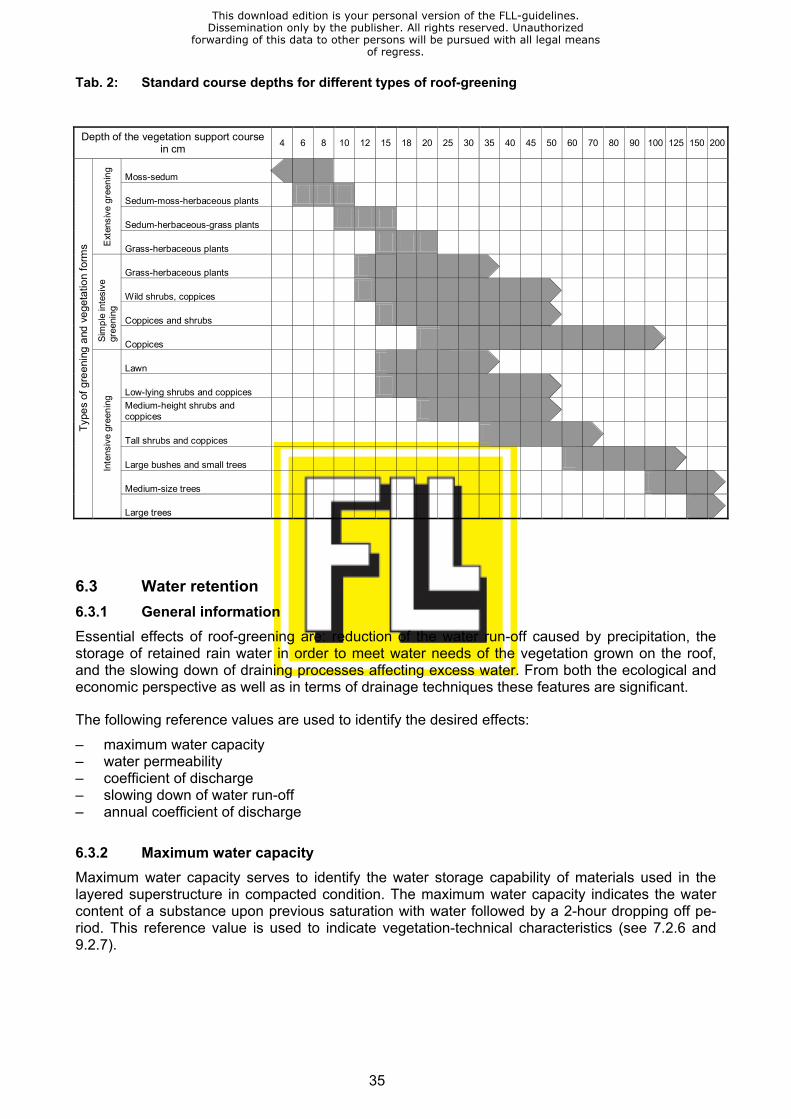
35
Tab. 2: Standard course depths for different types of roof-greening
6.3 Water retention 6.3.1 General information Essential effects of roof-greening are: reduction of the water run-off caused by precipitation, the storage of retained rain water in order to meet water needs of the vegetation grown on the roof, and the slowing down of draining processes affecting excess water. From both the ecological and economic perspective as well as in terms of drainage techniques these features are significant.
The following reference values are used to identify the desired effects:
– maximum water capacity – water permeability – coefficient of discharge – slowing down of water run-off – annual coefficient of discharge
6.3.2 Maximum water capacity Maximum water capacity serves to identify the water storage capability of materials used in the layered superstructure in compacted condition. The maximum water capacity indicates the water content of a substance upon previous saturation with water followed by a 2-hour dropping off pe-riod. This reference value is used to indicate vegetation-technical characteristics (see 7.2.6 and 9.2.7).
Depth of the vegetation support course
in cm 4 6 8 10 12 15 18 20 25 30 35 40 45 50 60 70 80 90 100 125 150 200
Moss-sedum
Sedum-moss-herbaceous plants
Sedum-herbaceous-grass plants
Ext
ensi
ve g
reen
ing
Grass-herbaceous plants
Grass-herbaceous plants
Wild shrubs, coppices
Coppices and shrubs
Sim
ple
inte
sive
gr
eeni
ng
Coppices
Lawn
Low-lying shrubs and coppices Medium-height shrubs and coppices
Tall shrubs and coppices
Large bushes and small trees
Medium-size trees
Type
s of
gre
enin
g an
d ve
geta
tion
form
s
Inte
nsiv
e gr
eeni
ng
Large trees
This download edition is your personal version of the FLL-guidelines.Dissemination only by the publisher. All rights reserved. Unauthorized
forwarding of this data to other persons will be pursued with all legal meansof regress.
36
6.3.3 Water permeability Water permeability Kf mod. of materials used in the layered superstructure, a term which indicates the flowing-through of water in a unit of length and time in compacted and water-saturated condi-tion, is used to indicate vegetation-technical characteristics (see 7.2.5 and 9.2.6).
6.3.4 Coefficient of discharge The coefficient of discharge/run-off reference value C according to DIN EN 12056–3 and draft ver-sion DIN 1986–100 (in the past, based on DIN 1986–2, indicated as coefficient of discharge ψ) is included into the calculation of rain water discharge (l/s) as a dimensionless parameter.
When calculating drainage needs for roof-greening the coefficient of discharge is based on the ratio between rain drainage volume and rain fall during a block rain (see 4.8).
For roof-greening the following run-off reference values/coefficients of discharge C (ψ) depending on the depth of the course and the roof gradient are applicable:
Roof gradient up to 15° Roof gradient larger 15° – at > 50 cm course depth C = 0,1 ––– – at > 25 – 50 cm course depth C = 0,2 ––– – at > 15 – 25 cm course depth C = 0,3 ––– – at > 10 – 15 cm course depth C = 0,4 C = 0,5 – at > 6 – 10 cm course depth C = 0,5 C = 0,6 – at > 4 – 6 cm course depth C = 0,6 C = 0,7 – at > 2 – 4 cm course depth C = 0,7 C = 0,8
These run-off reference values are valid for the layered superstructure with a reference rain of r(15) = 300 l/(s x ha) upon previous saturation with water and a 24-hour dropping off period.
By testing (see “Investigation methods” – appendix section 5) on a site-to-site basis location- and product-specific values may be obtained. Depending on local rain fall higher or lower coefficients of discharge may be resulting from the test outcome.
A coefficient of discharge for gravel areas of 0,5 was listed in DIN 1986–2 and turned out to be too low. In the draft version of DIN 1986–100 the value is at 1,0, and is too high. Based on recent studies it can be recommended to use a coefficient of 0,8 for gravel areas.
6.3.5 Water retention and annual coefficient of discharge The percentage water retention as actual retention is determined by calculating the difference be-tween the volume of precipitation measured and the run-off water volume on an annual average. This leads to the annual coefficient of discharge ψa based on DIN 4045, as the ratio between the annual rain water run-off sum and the annual rain volume. In differentiated sewage/rain water drainage regulations this coefficient is also shown as the sealing coefficient.
6.3.5.1 Volume of water retention The annual water retention depends less on the type of construction and functional courses as rather on the course depth. However, substance-specific water retention capability and water per-meability have to be taken into account. Differences between courses of different depth can be found more distinctly in summer; in cool seasons they balance more and more down to almost equal levels in winter. Although during the summer a higher proportion of annual precipitation is measured, here water retention is substantially higher, whereas in winter and with lower precipita-tion values, but also less evaporation of the layered superstructure and the lowest levels of transpi-ration of plants water run-off is at maximum levels.
This download edition is your personal version of the FLL-guidelines.Dissemination only by the publisher. All rights reserved. Unauthorized
forwarding of this data to other persons will be pursued with all legal meansof regress.

37
Tab. 3 sets out reference values for percentage water retention. In regard to differentiated sew-age/rain water drainage regulations also the annual coefficient of discharge/sealing coefficient is shown.
Tab. 3: Reference values showing percentage annual water retention on green-roof sites in de-pendence on course depth
Type of green-
ing
Course depth
in cm
Form of vegetation
Water reten-tion - annual average in
in %
Annual coeffi-cient of dis-charge ψa /
sealing coeffi-cient
Extensive greening
2 – 4 > 4 – 6 > 6 – 10 > 10 – 15 > 15 – 20
Moss–sedum greening Sedum–moss greening Sedum–moss–herbaceous plants Sedum–herbaceous-grass plants Grass–herbaceous plants
40 45 50 55 60
0,60 0,55 0,50 0,45 0,40
Intensive greening
15 – 25 > 25 – 50 > 50
Lawn, shrubs, coppices Lawn, shrubs, coppices Lawn, shrubs, coppices, trees
60 70 > 90
0,40 0,30 0,10
All figures relate to locations with annual precipitation values of 650 – 800 mm where monitoring has been performed over a period of several years. In regions with lower annual precipitation values water retention is higher, in regions with higher annual precipitation it is lower.
This download edition is your personal version of the FLL-guidelines.Dissemination only by the publisher. All rights reserved. Unauthorized
forwarding of this data to other persons will be pursued with all legal meansof regress.
38
6.4 Water storage and additional watering 6.4.1 Water storage At any green-roof site, the main limiting factor and the one which will determine the way in which the vegetation develops, will be the water supply. The volume of water available for storage will be reduced considerably by virtue of the fact that the demands of physics and the budget require that design loads and roof superstructure depths be kept to an absolute minimum.
Water can be stored in various courses and in a number of different ways and forms which, de-pending on the way in which the individual courses are constructed and the order in which they are laid, may be divided up under the headings set out below:
– storage in the vegetation support course through the use of substances which retain water for vegetation substrates or prefabricated substrate boards
– storage in the vegetation support course and, additionally, in the drainage course, through the use either of open-pore type aggregate materials in graded granular sizes or of prefabricated draining substrate boards
– storage in the vegetation support course and, additionally, in the drainage course, by allowing a water supply to build up in the aggregate over the entire area or by using pre-formed drain-age boards with partial retention characteristics.
Water may be stored simultaneously in the vegetation support and drainage courses, whatever type of greening is used. There is scope for intensive root development throughout the layered superstructure, all of which is available for water storage.
Current knowledge indicates that in the context of intensive greening schemes, the form of water storage which offers the most reliable long-term performance and which caters most even-handedly for all economic and ecological needs is a combined system in which water is stored in the vegetation support course and held in a reservoir formed in the drainage course.
In the case of thin-course simple intensive greening, it only makes sense to form a reservoir in the drainage course if additional watering is carried out during periods of low precipitation.
In contrast, reservoir-type watering arrangements at extensive greening sites are associated with various drawbacks linked to plant physiology.
6.4.2 Additional watering Green-roof sites are designed to depend chiefly on precipitation for their water supply, this being readily available without cost. This minimises the need for supplementary watering and helps to return precipitation to the natural water cycle immediately. Where necessary, additional watering will have to be carried out regularly at intensive greening sites; this is also the case during the con-struction phase at extensive greening sites.
Additional watering may be provided by using:
– a hose – hose and sprinkler – spray-type hoses – drip-type hoses – an overhead irrigation system – automated watering systems where there is an in-built reservoir
Where sprinklers, spray-type watering via a hose or drip-type watering is used, the system can either be operated manually or controlled by means of a timer. A hand-held hose will have to be used to water any areas which are tucked away in corners or which lie along edges which do not receive adequate watering, due to their being roofed over or to deflection of the water jet by the wind or for some other reason.
This download edition is your personal version of the FLL-guidelines.Dissemination only by the publisher. All rights reserved. Unauthorized
forwarding of this data to other persons will be pursued with all legal meansof regress.

39
Overhead irrigation systems, installed above or beneath the ground, may be operated manually or by a timer, or they may be completely automatic. The piping must be corrosion-proof, and there must be a facility for ensuring that the pipe system can be drained completely, so as to eliminate the risk of frost damage.
A reservoir-based watering system may be fitted with an automatic or semi-automatic water feed. Here, the drainage course acts as a reservoir which stores precipitation, the capacity of which will depend on the type and depth of the drainage course involved. A minimum clearance needs to be maintained between the peak level in the reservoir and the filter course, in order to prevent the vegetation support course from becoming waterlogged. During the autumn and winter season, when plant life is dormant, the artificial water table needs to be lowered by adjusting the valves in the roof outlets. Alternatively, the water may be drained off completely.
This download edition is your personal version of the FLL-guidelines.Dissemination only by the publisher. All rights reserved. Unauthorized
forwarding of this data to other persons will be pursued with all legal meansof regress.
40
7 Drainage Course
7.1 Materials groups and types When the drainage course is being formed, a distinction is made between the following groups and types of materials:
Aggregate-type materials – gravel and fine chippings – lava and pumice – expanded clay and slate, unbroken – expanded clay and slate, broken
Recycling aggregate-type materials – brick hardcore – slag – foamed glass
Drainage matting – textured nonwoven matting – studded plastic matting – fibre-type woven matting – flock-type foam matting
Drainage boards – boards made from foam pellets – studded rubber boards – shaped rigid plastic boards – shaped plastic foam boards
Drainage and substrate boards – boards made from modified foam
Course materials and dimensions will depend upon construction requirements and objectives for vegetation. If certain products, such as e.g. drainage boards, show a characteristic value for ther-mal strength, due to a general approval scheme by the Construction Inspectorate, green-roof sites may be constructed with countable heat insulation effect.
Construction requirements relate to: – the drainage function – design loads and – the protective function.
Objectives for the vegetation relate to: – the prevention of waterlogging – water supply either through retention or from a reservoir – increasing the depth of the course available for root penetration – the type and form of vegetation sought
This download edition is your personal version of the FLL-guidelines.Dissemination only by the publisher. All rights reserved. Unauthorized
forwarding of this data to other persons will be pursued with all legal meansof regress.
41
7.2 Requirements Where drainage courses are concerned, some or all of the following properties will need to be taken into account, depending on the group of materials in use:
– compatibility of materials (see 4.10) – environmental compatibility (see 4.11) – plant compatibility / absence of any risk of phytotoxicity (see 4.12) – behaviour under fire (see 5.9) – granulometric composition (see 7.2.1) – frost-resistance (see 7.2.2) – structural and bedding stability (see 7.2.3) – behaviour under compressive loads (see 7.2.4) – water-permeability (see 7.2.5) – water-storage capacity / maximum water capacity (see 7.2.6) – pH–value (see 7.2.7) – salt content (see 7.2.9)
Generally-speaking, the requirements in respect of the aggregate-type materials and mixtures used for drainage courses apply to the material after it has been compacted to the defined labora-tory standard.
Details of the type and scope of standard suitability and inspection tests are set out in Section 12.
The different properties associated with the materials need to be assessed against the conditions which apply in the position and at the site where they are to be used, in order to ensure that they are suitable.
7.2.1 Granulometric distribution No more than 7% by mass of aggregate-type materials shall have a diameter of d < 0,063 mm.
Granular distribution depends on course depth and shall be as follows:
– at course depth of 4 – 10 cm between 2/8 mm and 2/12 mm – at course depth of > 10 – 20 cm between 4/8 mm and 8/16 mm – at course depth of > 20 cm between 4/8 mm and 16/32 mm
7.2.2 Frost resistance Attention must be paid to frost resistance in materials. The frost resistance requirements in respect of admixtures for concrete or of building materials in natural stone are based on materials and structural components subjected to high levels of static and/or dynamic stress. There is only limited scope for including these requirements in an appraisal of roof greening materials in terms of the vegetation used.
7.2.3 Structural and bedding stability Materials must have sufficient intrinsic strength, also the ability to retain their shape, in addition to which they must be stable once laid during and after construction work. They must not settle to any significant extent under the weight of the overlying structure, under the action of water or under the load generated during upkeep.
In aggregate-type materials, granular shape plays a critical role in the stability of the material once it has been laid. In drainage courses, the use of broken grit is, therefore, to be prescribed for depths of 4-10 cm and strongly recommended for depths of over 10 cm.
This download edition is your personal version of the FLL-guidelines.Dissemination only by the publisher. All rights reserved. Unauthorized
forwarding of this data to other persons will be pursued with all legal meansof regress.
42
7.2.4 Behaviour under compression Any compressive forces applied by overlying loads to drainage matting and boards made from plastic once they are in situ shall not be permitted to interfere with the way in which they work (see 7.2.5). For details of compressive forces acting on substrate boards made from modified foam, refer to section 9.2.5.
7.2.5 Water permeability Materials shall be highly permeable, so as to ensure that any surplus water is drained off promptly into the roof outlets.
For drainage courses, the target for vertical water run-off, which is found by calculating the water infiltration rate, using the method prescribed under “Investigation methods”, is mod. Kf ≥ 0.3 cm/s Λ 180 mm/min.
As a rule, the drainage matting, boards and mineral aggregates currently in use are adequate for areas of up to 400 m² or thereabouts per roof outlet and ca. 15 m outlet length where the water runs off a roof at a gradient of no less than 2 %.
In the case of green-roof sites with a shallow layered superstructure, it needs to be borne in mind that some of the precipitation which falls during rare periods of heavy rainfall is drained off the sur-face.
If, for a given site, the amount of surface drainage is to be minimised, the volume per metre of width which has to be handled by the drainage course [q’ in l/(s x m)] may be found in the follow-ing manner:
A x C x q q´ = b in l/(s x m)
where q´ = the volume in l/(s x m) cleared via the drainage course A = the surface area to be drained, in m2 C = the run-off reference value/coefficient of discharge (see 6.3.4) q = maximum rainfall, as defined in DIN EN 12056–3, DIN 1986–100 in l/(s x m2), or local re-
quirement b = arithmetical run-off width in m; here b = 1 m
The efficiency of the materials used in the drainage course, as a function of the gradient and course depth, is to be proven by the manufacturer in the form of a run-off rate in l/(s x m).
In the case of ductile drainage courses, evidence of the amount of water which runs off shall be based upon the depth and the coefficient of permeability found for a 50-year load-bearing life, hav-ing regard to the long-term performance of the material under stress. These figures are to be quoted as a function of applied pressure. In the case of mineral aggregate materials, allowance must be made for the fact that there will be a reduction in granular sizes due to the action of me-chanical, physical or chemical factors.
7.2.6 Water-storage capacity For horticultural reasons, open-pore and water-absorbent mineral materials need to be used for aggregate-type drainage courses required to have a fairly high water-storage capacity.
Where a reservoir is to be created, aggregate materials or components which maintain a rigid shape and which have cavities offering a high capacity for water absorption must be used. The engineering and the materials used must ensure that the artificial water table can rise. In order to
This download edition is your personal version of the FLL-guidelines.Dissemination only by the publisher. All rights reserved. Unauthorized
forwarding of this data to other persons will be pursued with all legal meansof regress.
43
prevent the vegetation support course from becoming waterlogged and to ensure that excess wa-ter can be drained away without any difficulty, sufficient dry space must be left above the ceiling level for said artificial water table.
7.2.7 pH-value Where drainage courses are constructed using aggregate materials, account needs to be taken of the pH, in conjunction with the needs of the vegetation and of the properties of the support course. Therefore, the objective should be to achieve a similar ph-value for the drainage course as for the vegetation support course (see 9.2.9).
As a rule the ph-values for the drainage course should be set as follows: – Intensive greening pH 5,5 – 8,0 – Extensive greening
– multiple-course structure pH 6,5 – 8,0
Special forms of vegetation, such as special humus rooting plants, may need a low pH value.
7.2.8 Carbonate content Based on recent findings carbonates are no longer listed among the evaluation criteria for drainage and vegetation support courses (see 5.4).
The use of concrete recycling for drainage courses is to be avoided.
7.2.9 Salt content In the interests of plant physiology, the soluble salt content in aggregate-type materials and in drainage and substrate boards, may not exceed
– 2,5 g/litre at intensive greening sites, and – 3,5 g/litre at extensive sites
In the event that the soluble salt content in extracted water exceeds the prescribed limit, an addi-tional test shall be carried out to determine the salt content in the extract with saturated gypsum solution, the result of which shall then be used to make an assessment.
With reference to the potential risk of environmental pollution due to the leaching of salts, the aim should be to achieve a content of 1,0 g per litre, regardless of the type of greening which is being carried out.
7.3 Construction Materials are to be laid with an even surface, having regard to the roof gradient, any irregularity which may be present on the roof, also any specific structural requirements with regard to the sur-face layer. A tolerance of ± 1 cm from level is permitted over a measured length of 4 m. The mini-mum course depth must be respected throughout. Addition of further courses shall not be allowed to interfere with the drainage function.
Where drainage matting and boards are used, the evenness of the surface will match that of the roof in both type and extent. Where the roof gradient is < 2 %, appropriate action shall be taken to smooth out any unevenness.
Where aggregate-type materials with sharp edges or pointed shapes are used, or where the use of rigid plastic drainage components is involved, resulting in the generation of pressure at the edges, there is the risk that fairly high levels of mechanical stress will be applied to the damp-proof lin-ing/root-penetration barrier and a protective lining may be required (see 5.3).
This download edition is your personal version of the FLL-guidelines.Dissemination only by the publisher. All rights reserved. Unauthorized
forwarding of this data to other persons will be pursued with all legal meansof regress.
44
8 Filter Course
8.1 Materials groups and types Current practice, reflecting the most recent developments, calls for the use of geotextiles in the form of nonwoven fabrics as filter courses. Either the latter is laid on top of the drainage course in a separate operation or it forms an integral part of ready-made drainage matting.
Nonwoven fabrics consist of aligned or randomly laid fibres of any length. These fibres may be bonded using a mechanical, chemical or thermal process, or a combination of the three.
Where nonwoven fabrics are affixed mechanically with pins, they must be detector-proofed.
8.2 Requirements In accordance with the “Code of Practice governing the use of geotextiles in earthworks” (TL Geo-tex E–StB 95), note must be taken of the following characteristics:
– Environmental compatibility (see 4.11) – Plant compatibility / absence of any risk of phytotoxicity (see 4.12) – Behaviour under fire (see 5.9) – Weight per unit of surface area (see 8.2.1) – Cut-through resistance (see 8.2.2) – Effectiveness of mechanical filtration / aperture width (see 8.2.3) – Susceptibility to root penetration (see 8.2.4) – Resistance to weathering (see 8.2.5) – Resistance to soil-borne solutions and micro-organisms (see 8.2.6) – Tensile strength, flexibility, coefficient of friction (see 8.2.7)
8.2.1 Weight per unit of surface area The minimum recommended weight is 100 g/m² and will, as a rule, be between 100 and 200 g/m² for vegetation support courses up to 25 cm deep. For deeper courses and in the case of steeply angled green-roof sites, this may need to be increased in order to meet requirements in respect of cut-through resistance, tensile strength and flexibility, which will be determined by the materials used and by the type of structure involved.
8.2.2 Cut-through strength Nonwoven fabrics must come up to Class 1 for strength, with a cut-through force of ≥ 0,5 kN, pro-vided that no major mechanical stresses are anticipated during construction work or when vertical loads are subsequently applied.
8.2.3 Effectiveness of mechanical filtration / aperture width In accordance with the “Code of Practice governing the use of geotextiles in earthworks” (TL Geo-tex E–StB 95), the effectiveness of a nonwoven fabric in terms of mechanical filtration is character-ised by the effective aperture width: the effective aperture width O90,w denotes the diameter of the screening fraction of a standard test soil at which the geotextile retains 90 % of the soil and allows 10 % to pass through.”
For roof-greening purposes, the depth and composition of the vegetation support course (see 9.2.1) dictate that filter courses with an effective aperture width O90,w < 0,2 mm are adequate.
This download edition is your personal version of the FLL-guidelines.Dissemination only by the publisher. All rights reserved. Unauthorized
forwarding of this data to other persons will be pursued with all legal meansof regress.
45
8.2.4 Susceptibility to root penetration The nonwoven fabric must permit root penetration, which must not be impeded in the drainage course, particularly at extensive greening sites.
8.2.5 Resistance to weathering In accordance with the “Code of Practice governing the use of geotextiles in earthworks” (TL Geo-tex E–StB 95), nonwoven fabrics are not permanently weather-proof outdoors, and this is a factor which needs to be noted whilst the drainage course is being installed.
8.2.6 Resistance to soil-borne solutions and micro-organisms In accordance with the “Code of Practice governing the use of geotextiles in earthworks” (TL Geo-tex E–StB 95), the hitherto widely-used materials listed therein must have sufficient resistance to the effects of soil-borne chemicals and micro-organisms.
8.2.7 Tensile strength, flexibility and coefficient of friction Where necessary, any requirements in respect of the above will need to be prescribed to suit the site concerned, e.g. to cater for roofs which slope fairly steeply, and evidence will be required to demonstrate compliance therewith.
8.3 Construction Sheets of nonwoven fabrics laid as filter courses must overlap by a minimum of 10 cm and they must be brought up at the edges to beneath the surface of the vegetation support course.
Nonwoven fabrics must be covered over within one week of installation. Until this has been done, they must be protected against wind-generated negative pressures.
Drainage matting lined with nonwoven fabrics which are brought upwards at roof edges or which abut onto vertical structures must be provided with permanent weather-proofing.
Where a reservoir-type watering system is to be installed, care must be taken to ensure that con-struction work does not result in a reduction at any point in the volume of the dry space. The filter course must not be permitted to come into contact with the surface of the water when the artificial water table is at the maximum height.
This download edition is your personal version of the FLL-guidelines.Dissemination only by the publisher. All rights reserved. Unauthorized
forwarding of this data to other persons will be pursued with all legal meansof regress.
46
9 Vegetation Support Course
9.1 Materials groups and types When the vegetation support course is being cultivated, a distinction shall be made between the following groups and types of materials for vegetation substrates, depending on the materials and type of construction used. Types of greening and different forms of cultivation are also factors which are to be taken into consideration:
– soil mixtures – improved top and underlying soil
– aggregate mixtures – mineral aggregate mixtures with a high organic content – mineral aggregate mixtures with a low organic content – mineral aggregate mixtures with an open-pore granular structure with no organic content
– substrate boards – made from modified foam materials – made from mineral fibres
– vegetation matting – with mineral/organic aggregate mixtures
In regard to requirement relating to the proportions of organic content the following differentiation is made:
– substrates with an apparent density of ≤ 0,8, and – substrates with an apparent density of > 0,8 both in dry condition.
The materials and dimensions chosen for this course will be determined by local construction re-quirements and by objectives for the vegetation.
Construction requirements relate to:
– the drainage function – design load – the protective function
Objectives for the vegetation relate to:
– the demands imposed by the desired type and shape of the vegetation – the need to ensure that all functions are assured on a permanent basis – limiting upkeep costs whilst the site is maturing and once it has become established
In a layered superstructure where the depth of the vegetation support course is 35 cm, or there-abouts, or greater, a distinction needs to be made during cultivation between an upper substrate and an entirely non-organic lower substrate.
Where extremely thin courses are used, vegetation matting can also act as the vegetation support course. When laid on a substrate course, this arrangement is classified as a type of greening (see 11.1).
Substrates for vegetation matting shall be consistent with the group of mineral aggregate mixtures with a low organic content. In terms of composition and granulometric distribution, they differ from the mixtures installed as a course.
This download edition is your personal version of the FLL-guidelines.Dissemination only by the publisher. All rights reserved. Unauthorized
forwarding of this data to other persons will be pursued with all legal meansof regress.
47
9.2 Requirements Attention shall be paid to the following properties, depending upon the type of greening which is being undertaken, in respect of vegetation support courses:
– Environmental compatibility (see 4.11) – Plant compatibility (see 4.12) – Behaviour under fire (see 5.9) – Granulometric distribution (see 9.2.1) – Mineral content by volume (see 9.2.2) – Frost-resistance (see 9.2.3) – Structural and bedding stability of aggregate-type materials (see 9.2.4) – Behaviour of matting under compression (see 9.2.5) – Water permeability (see 9.2.6) – Maximum water capacity (see 9.2.7) – Air content (see 9.2.8) – pH value (see 9.2.9) – Salt content (see 9.2.11) – Nutrient content (see 9.2.12) – Adsorptive capacity (see 9.2.13) – Seeds capable of germination / plant parts (see 9.2.14) – Proportion of foreign substances (see 9.2.15)
Total pore volume is not one of the reference values, but it is used to determine the air content at maximum water capacity and at pF 1.8.
An approximate idea as to the volume of water available to the plants may be derived from the maximum water capacity minus a quantity of approximately 10 - 15 % to cater for the water held in the fine pores at pF > 4.2.
As a rule, requirements in respect of vegetation substrates relate to the condition after it has been compacted to the defined laboratory standard.
Details of the type and scope of standard suitability and inspection tests are set out in Section 12.
9.2.1 Granulometric distribution The combined clay and silt content (d < 0,063 mm) in vegetation courses should not exceed the following figures:
– at intensive greening sites 20 % by mass – at extensive greening sites
– multiple-course construction 15 % by mass – single-course construction 7 % by mass
In vegetation substrates for intensive greening the clay and silt content should not exceed the fol-lowing figures:
– clay (d < 0,002 mm) 3 – 10 % by mass – silt (d = 0,002 up to < 0,063 mm) 10 – 17 % by mass
The largest grain size at flat green-roof sites should show the following figures depending on the depth of the vegetation support course:
– up to 10 cm d = 10 – 12 mm – more than 10 cm d = up to 16 mm
This download edition is your personal version of the FLL-guidelines.Dissemination only by the publisher. All rights reserved. Unauthorized
forwarding of this data to other persons will be pursued with all legal meansof regress.
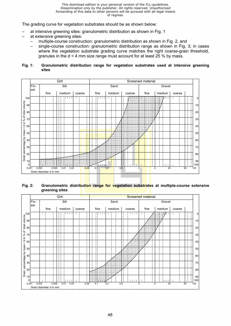
48
The grading curve for vegetation substrates should be as shown below:
– at intensive greening sites: granulometric distribution as shown in Fig. 1 – at extensive greening sites:
– multiple-course construction: granulometric distribution as shown in Fig. 2, and – single-course construction: granulometric distribution range as shown in Fig. 3; in cases
where the vegetation substrate grading curve matches the right coarse-grain threshold, granules in the d < 4 mm size range must account for at least 25 % by mass.
Fig. 1: Granulometric distribution range for vegetation substrates used at intensive greening sites
Grit Screened material
Fin-est
Silt Sand Gravel fine medium coarse fine medium coarse fine medium coarse
100 | | | | | | | | | | | | | | | | | | | | | 0
90 10
80 20
70 30
60 40
50 50
40 60
30 70
20 80
10 900
|
| | | | |
| | | | | | | | | | | | | |
100
0,001 0,002 0,006 0,01 0,02 0,06 0,1 0,2 0,6 2 6 20 60 100 Grain diameter d in mm
Fig. 2: Granulometric distribution range for vegetation substrates at multiple-course extensive
greening sites
Grit Screened material
Fin-est
Silt Sand Gravel fine medium coarse fine medium coarse fine medium coarse
100 | | | | | | | | | | | | | | | | | | | | | 0
90 10
80 20
70 30
60 40
50 50
40 60
30 70
20 80
10 900
|
| | | | |
| | | | | | | | | | | | | |
100
0,001 0,002 0,006 0,01 0,02 0,06 0,1 0,2 0,6 2 6 20 60 100 Grain diameter d in mm
Gra
in p
erce
ntag
e by
mas
s <
d in
% o
f tot
al v
olum
e G
rain
per
cent
age
by m
ass
< d
in %
of
tota
l vol
ume
This download edition is your personal version of the FLL-guidelines.Dissemination only by the publisher. All rights reserved. Unauthorized
forwarding of this data to other persons will be pursued with all legal meansof regress.
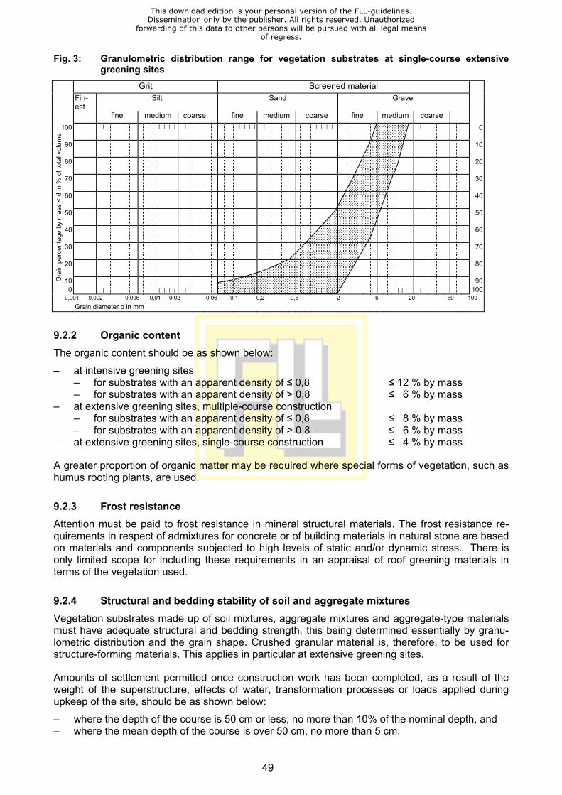
49
Fig. 3: Granulometric distribution range for vegetation substrates at single-course extensive greening sites
Grit Screened material
Fin-est
Silt Sand Gravel fine medium coarse fine medium coarse fine medium coarse
100 | | | | | | | | | | | | | | | | | | | | | 0
90 10
80 20
70 30
60 40
50 50
40 60
30 70
20 80
10 900
|
| | | | |
| | | | | | | | | | | | | |
100
0,001 0,002 0,006 0,01 0,02 0,06 0,1 0,2 0,6 2 6 20 60 100 Grain diameter d in mm
9.2.2 Organic content The organic content should be as shown below:
– at intensive greening sites – for substrates with an apparent density of ≤ 0,8 ≤ 12 % by mass – for substrates with an apparent density of > 0,8 ≤ 6 % by mass
– at extensive greening sites, multiple-course construction – for substrates with an apparent density of ≤ 0,8 ≤ 8 % by mass – for substrates with an apparent density of > 0,8 ≤ 6 % by mass
– at extensive greening sites, single-course construction ≤ 4 % by mass
A greater proportion of organic matter may be required where special forms of vegetation, such as humus rooting plants, are used.
9.2.3 Frost resistance Attention must be paid to frost resistance in mineral structural materials. The frost resistance re-quirements in respect of admixtures for concrete or of building materials in natural stone are based on materials and components subjected to high levels of static and/or dynamic stress. There is only limited scope for including these requirements in an appraisal of roof greening materials in terms of the vegetation used.
9.2.4 Structural and bedding stability of soil and aggregate mixtures Vegetation substrates made up of soil mixtures, aggregate mixtures and aggregate-type materials must have adequate structural and bedding strength, this being determined essentially by granu-lometric distribution and the grain shape. Crushed granular material is, therefore, to be used for structure-forming materials. This applies in particular at extensive greening sites.
Amounts of settlement permitted once construction work has been completed, as a result of the weight of the superstructure, effects of water, transformation processes or loads applied during upkeep of the site, should be as shown below:
– where the depth of the course is 50 cm or less, no more than 10% of the nominal depth, and – where the mean depth of the course is over 50 cm, no more than 5 cm.
Gra
in p
erce
ntag
e by
mas
s <
d in
% o
f tot
al v
olum
e
This download edition is your personal version of the FLL-guidelines.Dissemination only by the publisher. All rights reserved. Unauthorized
forwarding of this data to other persons will be pursued with all legal meansof regress.

50
9.2.5 Behaviour of substrate boards under compression Long-term compression of substrate boards, once they have been fitted, by vertical loads is permit-ted within the following limits
– 20% of the nominal depth in boards which are 30 – 50 mm thick, and – not more than 10 mm with a depth of the course which is > 50 mm.
9.2.6 Water permeability Water permeability in vegetation substrates shall be adjusted to suit the type of construction planned for the drainage course.
It is found as the water filtration rate mod. Kf and the figures should be as shown below for aggre-gate mixtures and aggregate-type materials once they have been compacted and for substrate boards once they have been installed
– at intensive greening sites ≥ 0,0005 cm/s or ≥ 0,3 mm/min – at extensive greening sites
– multiple-course construction ≥ 0,001 cm/s or ≥ 0,6 mm/min – single-course construction ≥ 0,1 cm/s or ≥ 60 mm/min
9.2.7 Water-storage capacity The maximum water capacity of vegetation substrates in their compacted or installed state, as a reference value for water storage capacity, shall be as shown below:
– at intensive greening sites ≥ 45% by volume – at extensive greening sites
– multiple-course construction ≥ 35% by volume – single-course construction ≥ 20% by volume
The maximum water capacity should not exceed 65% by volume in order to avoid waterlogging.
9.2.8 Air content When the water content of vegetation substrates is at full capacity, the amount of air present shall be no less than 10 % by volume.
If the figure which is found is lower than that shown, the air content at pF 1.8 shall also be used in making an assessment.
At pF 1.8, it should be (proportion of wide coarse pores)
– at intensive greening sites ≥ 20% by volume – at extensive greening sites ≥ 25% by volume
9.2.9 pH value In the vegetation support course the pH value has to be adjusted to the needs of the vegetation. In vegetation substrates the following pH values should be kept:
– at intensive greening sites pH 5,5 – 8,0 – at extensive greening sites
– multiple-course construction pH 6,5 – 8,0 – single-course construction pH 6,5 – 9,5
For single-course constructions pH values of above 8 – 9,5 as short-term admissible tolerances at the time of the installation do not present any risk to the site.
This download edition is your personal version of the FLL-guidelines.Dissemination only by the publisher. All rights reserved. Unauthorized
forwarding of this data to other persons will be pursued with all legal meansof regress.
51
Having regard to the demands of the vegetation any drop of the pH value in the substrate below the admissible range after the installation is to be avoided.
Special forms of vegetation, such as special humus rooting plants, may need a fairly low pH value of ca. 5,5.
9.2.10 Carbonate content Based on recent findings carbonate values no longer figure amongst the evaluation criteria for vegetation support and drainage courses (see 5.4).
9.2.11 Salt content In vegetation substrates the content of soluble salts shall not exceed the figures shown below:
– 2,5 g/litre for intensive greening, and – 3,5 g/litre for extensive greening.
In the event that the soluble salt content in a water extract exceeds the prescribed limit, an addi-tional test shall be carried out to determine the salt content in the extract with saturated gypsum solution, the result of which shall then be used to make an assessment.
With reference to the potential risk of environmental pollution due to the leaching of salts, the aim should be to achieve a salt content which is as low as possible.
Where plants, such as special humus rooting species, which are sensitive to salt are used at inten-sive greening sites, the salt content shall not exceed 1.0 g per litre.
9.2.12 Nutrient content The nutrient content in vegetation substrates needs to be set at a level appropriate to the type of greening and the form of construction, within the ranges shown in Table 4 above. Large reserves of nutrients should not be left in the ground, given the comparatively low adsorptive capacity of the vegetation substrates and in view of the possibility of pollution if they leach out.
Tab. 4: Nutrient content in vegetation substrates
Nutrients in mg/litre N P2O5 K2O Mg (CaCl2) (CAL) (CAL) (CaCl2) Intensive greening sites < 80 < 200 < 700 < 160 Extensive greening sites Any possibly necessary additional nutrient supply by means of fertilizing should only be carried out after greening or during final care with suitable fertilizing agents (see 11.5). In the context of matu-ration and follow-up care further nutrients may be added, if required.
9.2.13 Adsorptive capacity No value is set for the adsorptive capacity of vegetation substrates. A value can be declared by indication the type of analysis method used.
This download edition is your personal version of the FLL-guidelines.Dissemination only by the publisher. All rights reserved. Unauthorized
forwarding of this data to other persons will be pursued with all legal meansof regress.
52
9.2.14 Content in respect of seeds capable of germination and of plant parts capable of regeneration
The materials used initially to assemble the vegetation substrate should contain no living plants, nor any plant parts which are capable of regeneration, particularly rooting weeds. Where soils are used in vegetation substrates, it makes sense to use under-soil rather than topsoil in order to avoid, as far as possible, the risk of importing seeds which are capable of germinating. The basic materials which go into the preparation of vegetation substrates need to be protected against the inclusion of seeds right from the time when they are collected and prepared. In addi-tion, vegetation substrates need similar protection whilst they are being manufactured or in stor-age.
9.2.15 Foreign substances The proportion of identifiable foreign substances of diameters larger than 2 mm, such as e.g. non-woven fabrics, glass, ceramics, plastic materials or timber, must not exceed 0,5 % by weight.
9.3 Construction Unless soil modelling is planned, the vegetation support course will, as a rule, be installed parallel to the underlying courses. The prescribed minimum depth must be respected throughout.
Vegetation support courses made from soil mixtures, aggregate mixtures and aggregate-type ma-terials shall be moistened to ground humidity levels.
Where soil or aggregate mixtures are used, the specific required depth for the material in question after laying shall be achieved by compacting. Allowance needs to be made for the possibility of slumping when setting the dimensions for the course. Hereby ATV DIN 18320 must be respected which stipulates that vegetation support courses have to be determined in settled condition at the time of the acceptance and on all contract locations.
Substrate boards shall be protected against wetting through and laying shall be performed in dry condition.
A permanent watering arrangement may be used, if necessary, to keep the vegetation support course damp, so as to stop the surface from drying out and to prevent wind erosion. If there is a lengthy interval between installation and greening, additional preventive measures may be needed to prevent erosion. Areas planted with shrubs and coppices may be mulched with suitable materi-als after planting to protect them.
All values defined for granulometric distribution (see 9.2.1) do not only apply in terms of substrate suitability tests but also in installed condition. If substrates are blown onto the roof by means of a silo vehicle, changes in the granulometric distribution may occur depending on the source material. To a limited extent this effect can be counteracted by adding higher proportions of larger grain sizes already in the substrate manufacturing process.
This download edition is your personal version of the FLL-guidelines.Dissemination only by the publisher. All rights reserved. Unauthorized
forwarding of this data to other persons will be pursued with all legal meansof regress.
53
10 Requirements in respect of Sowing Seed, Plants and Vegetation
10.1 Plant-breed and commercial groups With regard to requirements in respect of sowing seed, plants and vegetation, a distinction is made between the following plant- breed and commercial groups, each of which is subject to the relevant quality conditions, where such exist:
– Sowing seed – Shoot parts – Shrubs – Bulbous plants – Coppices – Lawn turf – Vegetation matting
10.2 Requirements 10.2.1 Sowing seed Sowing seed must comply with DIN 18917. Depending on the type of greening which is being car-ried out and upon the form of vegetation used, certified, standard, commercial or standby sowing seed may be used.
At intensive greening sites, the most suitable standard seed mixture (SSM), in the most up-to-date form, must be used for grassing. In the case of simple intensive greening sites, it may be neces-sary to use seed mixtures which fall outside these norms. The “Descriptive Catalogue for Lawn Grasses” issued by the German Federal Plant-Breeds Agency will have to be consulted when se-lecting special breeds.
For extensive greening sites involving the use of grass and herbaceous plants, the standard seed mixture RSM 6.1 may be used. Where different forms of cultivation are to be used for the vegeta-tion, blends tailored to the planting location and the site will have to be prescribed for sowing or topping up plant density.
10.2.2 Shoot parts Shoot parts from plants of the genus Sedum are subject to the requirements laid down in the “Quality Specifications in respect of Shrubs”.
10.2.3 Shrubs Shrubs are subject to DIN 18916 and must therefore comply with the “Quality Specifications in re-spect of Shrubs”.
At roof-greening sites, care must also be taken to ensure that the clump height is in keeping with the depth of the vegetation support course. Shrubs grown on cohesive soils are not suitable for use at green-roof sites.
Plants grown for extensive greening sites need to be brought on robustly, being fertilised with only moderate amounts of nitrogen, and they must be hardened off adequately. They must not come straight from a nursery greenhouse.
Before wild varieties are used at extensive greening sites, evidence must be provided to show that they have come from a nursery and not from the wild.
This download edition is your personal version of the FLL-guidelines.Dissemination only by the publisher. All rights reserved. Unauthorized
forwarding of this data to other persons will be pursued with all legal meansof regress.

54
10.2.4 Bulbous plants The usual trade classifications apply where bulbous flowering plants are used at intensive greening sites.
Where bulbous plants are used at extensive greening sites, evidence will be required to show that they have come from a nursery and not from the wild.
In the case of bulbous plants for extensive greening sites which have been grown as merchandise, varieties with small or flat clumps are preferable. The plants themselves should be grown in sub-strates consisting mainly of mineral substances.
10.2.5 Coppices Coppices must comply with DIN 18916 and thus with the “Quality Conditions governing Tree Nurs-ery Plants”.
It is also recommended, where roof-greening is concerned, that only non-grafted coppices be used. Where the vegetation support course is relatively shallow, plants with flat clumps must be prescribed. The substrate in which pot, container and flat-clump plants are grown should consist mainly of mineral substances. The exceptions here are substrates used for special humus rooting plants. As a rule, solitary plants grown on cohesive soil are not suitable for use at green-roof sites.
Clumps must be free of any alien vegetation, particularly of those species which generate rhizomes and runners.
As a rule, only young plants can be used at extensive greening sites.
At green-roof sites, it is recommended that nursery contracts be used, specifying substrate types, clump heights and cultivation arrangements.
10.2.6 Lawn turf Lawn turf is subject to the requirements laid down in DIN 18917.
Where simple intensive greening is being carried out at a site where there is a risk of drought con-ditions or where extensive greening is being carried out with an adequate course depth, landscap-ing turf types of an appropriate SSM quality may be used. Additional herbaceous plant seed may be added, to SSM standards, provided that this does not include any leguminous varieties. No clo-ver species may be used in lawn turf.
Lawn turf for roof-greening must be laid on a sandy soil containing light to moderate amounts of humus.
10.2.7 Vegetation matting For the purposes of cultivation, transport, laying and use, vegetation matting needs to be made up of suitable support linings. At locations where the vegetation matting will be subjected to traction, the support linings must satisfy the requirements in respect of geotextiles. Nonwoven fabric under-lay materials must allow root penetration. In regard to substrates for filling vegetation matting see 9.1.
Vegetation matting must be of a uniform depth and must be of a design which ensures that no cavities are left when it is laid.
Action must be taken during cultivation to harden vegetation off. Vegetation matting must not be brought straight from a nursery greenhouse. The presence or absence of shoot parts which have
This download edition is your personal version of the FLL-guidelines.Dissemination only by the publisher. All rights reserved. Unauthorized
forwarding of this data to other persons will be pursued with all legal meansof regress.
55
developed in an appropriate manner for the variety of plant concerned, also of short spaces be-tween leaf nodes, will indicate whether or not plants have been hardened off.
The stock of varieties to be used for a given form of vegetation (see 2.2.4) will need to be speci-fied, with details of the quantities of mosses, succulents, grasses, herbs and bulbous plants re-quired.
Plans for the site should allow for no less than 75 % total ground cover, with no more than 20 % of the total available space being left for some other form of cover.
The amount of substrate filling material lost during collection, transport and laying must not exceed 3 % of the total surface area. In addition, the size of any area without substrate filling material must not exceed 30 cm² and there must be no more than 10 such areas for every m² of vegetation mat-ting. A greater number of spaces may be left, provided that they are of fairly small proportions, but the combined area of these spaces must not exceed 3 % of the total covered area.
This download edition is your personal version of the FLL-guidelines.Dissemination only by the publisher. All rights reserved. Unauthorized
forwarding of this data to other persons will be pursued with all legal meansof regress.
56
11 Greening, Protection against Erosion, Cultivation and Mainte-nance
11.1 Greening Greening procedures must be appropriate to the biological characteristics of
– individual plant varieties – the different forms of vegetation, and – the objective, in terms of greening quality.
These procedures can be modified and, to some extent, combined.
The following option are available for establishing vegetation:
– dry seeding – without the use of adhesives for fixation – using adhesives for fixation
– wet seeding – without shoot parts – with shoot parts
– spreading plant parts – shoots – rosettes
– covering pre-cultivated vegetation matting with – biodegradable support linings – durable support linings – durable statically-active linings
– laying turf – without reinforcement – with reinforcement
– planting – individual plants – pre-cultivated plant elements.
11.2 Execution Depending on the type of greening procedure execution has to be in compliance with DIN 18916, DIN 18917 or DIN 18918.
Recommended are the following volumes per m² for:
– dry seeding 3000 – 5000 grains/m² – wet seeding
– without shoot parts 3000 – 5000 grains/m² – with shoot parts 1500 – 3000 grains/m² as well as – 30 g/ at least 50 pieces of shoots of at least 4 types
– spreading shoots 60 g/ at least 100 pieces of shoots of at least 4 types – planting at least 16 pieces for a pot content of 50 cm3. For smaller pots the
number has to be increased adequately.
This download edition is your personal version of the FLL-guidelines.Dissemination only by the publisher. All rights reserved. Unauthorized
forwarding of this data to other persons will be pursued with all legal meansof regress.
57
11.3 Ensuring the stability of coppices 11.3.1 Requirements The stability of fairly sizeable coppices may be ensured by means of
– bracing and – anchoring.
Bracing and anchoring give coppices temporary stability, assuming that the courses have at least the minimum prescribed depths and that there is an adequate volume of soil in which the roots can take hold.
Whilst anchoring and bracing is in use, it needs to be checked at regular intervals for signs of con-traction, compression or shearing.
11.3.2 Bracing The best means of bracing is a corrosion-proof wire or cable brace attached directly to the building by means of a detachable screw-type fastening which fits onto threaded anchors made from high-grade corrosion-proof steel, these being fitted above the damp-proof lining. The individual wire and cable braces will need to be fitted with tensioning devices. Where conditions are suitable in terms of the construction and of static loads, braces may be attached to structural components such as border surrounds, walls and large paving slabs. Alternatively, they may be attached to isolated anchor points, such as paving slabs set into the layered superstructure, but care must be exercised in such cases to ensure that, in doing so, the limits for load-bearing structural components and/or the thermal insulation and damp-proof lining on the roof are not exceeded. The angle between braces attached to isolated anchor points and the surface of the roof ought not to exceed 60°.
11.3.3 Anchorage to supporting trestles Rectangular or triangular supporting trestles are suitable for anchoring trees. They are manufac-tured in steel tubing, with surfaces treated to protect them against corrosion. Individual trestles must have broad base boards.
11.4 Prevention of erosion Vertical load-bearing strength must be adequate, but it is also important to note that there is a risk of attack by wind and water during construction and that individual courses in the superstructure need to be prevented from lifting or from being eroded. The risk period can be reduced by putting the greening in place at a time of the year when growth conditions are best for the vegetation.
Until such time as the roots from the vegetation stock have worked their way into the layered su-perstructure, the vegetation support course, plants and sowing seeds are at risk from the effects of water and wind. The following preventive measures need to be put in place to counteract the risk of damage
– appropriate specifications in respect of the layered superstructure – temporary measures, and – special measures for places subject to extreme conditions.
There is some scope for combining these measures.
The specifications mentioned above in respect of the layered superstructure relate to:
– the use of stable vegetation substrates capable of withstanding high loads, even when dry – application of additional hard stone chippings, acting as a mulch course, on top of finely-
structured vegetation substrates, and – ensuring that plant varieties and forms of vegetation and plant-breeding are selected appropri-
ately for the positions which they occupy, offering fast and lasting ground cover.
This download edition is your personal version of the FLL-guidelines.Dissemination only by the publisher. All rights reserved. Unauthorized
forwarding of this data to other persons will be pursued with all legal meansof regress.

58
The following temporary action may be taken:
– keep the vegetation substrate permanently moist as part of the care of the site during prepara-tion, and
– run a compactor over the site to ensure that sowing seeds, shoots and the surface of the sub-strate are firmly in place. This may have to be repeated.
Special action is required at sites which are particularly exposed to the wind and on roofs which slope at a steep angle:
– use wet seed, or – cover the area to be treated with ready-grown vegetation matting.
The degree of risk of substrate erosion by the wind should not be assessed on the basis of wind speeds but on specific drift rates for individual materials.
Where substrates are at risk from erosion, greening at roof edges and in places which are particu-larly susceptible to drifting needs to be carried out with vegetation mats or honeycomb reinforce-ment blocks.
11.5 Final care Care during site preparation is defined in DIN 18916 and DIN 18917 and the requirements and specifications may be transferred to intensive greening sites, although some differentiation will be needed for extensive greening and, to some extent, simple intensive greening sites. The following is a general list of the tasks which need to be carried out, but this will need to be tailored to individ-ual sites, to suit the climatic conditions encountered there and to fit the way in which the vegetation is intended to develop:
– initial watering – watering at sowing time – intermittent watering until the site is handed over – initial fertilisation – repeat fertilisation – removal of alien growth – grass-cutting – rolling where frost has caused ground lift – re-treatment of joints in areas where vegetation matting is used – pruning of coppices – subsequent seeding – subsequent planting – pest control – keep technical installations free from vegetation – keep safety areas and floor covering free from dead leaves and any vegetation which is a risk
to trouble-free functioning of the devices
The contract will need to include detailed descriptions of:
– the objectives for upkeep – individual jobs for which payment is to be made, specifying the type of job, the scope, the total
duration and the season, as well as – the condition which the desired from of vegetation needs to attain before it is ready to be
handed over.
This download edition is your personal version of the FLL-guidelines.Dissemination only by the publisher. All rights reserved. Unauthorized
forwarding of this data to other persons will be pursued with all legal meansof regress.
59
Additional fertilisation should be carried out on the basis of the amount of nutrient in the substrate and of the greening objectives. During initial and subsequent fertilisation, it is recommended that nutrients be administered by means of coated NPK slow-release fertiliser capsules, at the rates shown below
– Intensive greening sites 8 g N/m2 (pure nitrogen) – Extensive greening sites 5 g N/m2 (pure nitrogen)
Where alien vegetation is present in excessive amounts and/or where it poses a threat, deep cut-ting and removal of the material which is cut out can keep the problem in check.
Herbicide products may not be used.
11.6 Readiness for handover The acceptance criteria in respect of extensive greening sites differ from those set out in DIN 18916 und DIN 18917:
– before a site is handed over, the seeded or planted vegetation should have gone through a dormant phase and, where weather conditions permit, a period of drought or frost. Generally-speaking, it will take between 12 and 15 months for a site to be ready to be handed over.
– Greening sites created through seeding and planting of shoots from varieties of the genus Sedum should form as uniform a plant stock as possible, which should aim to provide at least 60 % ground cover in an uncut state. At least 60 % of the plant stock must consist of varieties contained in the seed mixture. Seasonal variations in the condition of the different varieties need to be taken into account when identifying the extent of ground cover. Fostered and alien vegetation cannot be considered as qualifying as part of the required ground cover. If plants in these categories account for more than 20 % of the ground cover, the site shall not be deemed to be ready for handover
– The population of shoots from plants of the genus Sedum must be no less than 75 % of the specified figure and these must have taken root
– Turf and vegetation matting must have taken root firmly and must be incapable of being lifted. All the different varieties required must be present, giving the prescribed proportional cover. The total amount of cover with turf and with vegetation matting must extend to 95 % and 75 % respectively. The variety-specific seasonal condition of the plant shall be taken into account when determining the proportional cover. The percentage of visible joints shall not exceed 10 % of the total joint share
– Clump-type plants must be present in the quantities set out in the invitation to tender and must be of sufficient vitality to maintain the stock. When counting area plantings with potted plants or potting boards losses of up to 5 % of the total piece number are not taken into consideration if, despite the loss of individual plants, the visual impression is such that the area is fully cov-ered
– If an invitation to tender includes greening with mini clump-type plants and the ready-for-handover condition is to be determined by means of the proportional cover, the latter is to be defined on a site-to-site basis and should also be set at a level of 60 %. It is important to take note of the dependence between proportional cover, duration of the final care and piece num-ber of mini clump-type plants planted per square meter
– Plant growth shall be consistent with that which is typical for the variety and the plants must have taken root in the substrate of the vegetation course
– Vegetation which has become rampant and thus weakened as a result of excessive watering and fertilisation is not fit to be handed over
If the client abstains from placing a final care order to the contractor, acceptance is performed im-mediately after planting and/or seeding or spreading of the shoot parts.
Partial acceptance according to § 12 No. 2 VOB/B should be effected:
This download edition is your personal version of the FLL-guidelines.Dissemination only by the publisher. All rights reserved. Unauthorized
forwarding of this data to other persons will be pursued with all legal meansof regress.

60
– upon termination of all damp-proofing works, as far as the order contains both roof damp-proofing and roof greening
– upon termination of the construction of the vegetation course, if planting and sowing activities cannot be carried out immediately afterwards
In addition to and/or opposed to what is laid down in ATV 18320 gaps of less than 2,5 m² individual surface are not deducted from the total surface of sowing or spreading of shoot parts.
11.7 Care during maturation and subsequent upkeep, maintenance work 11.7.1 General information DIN 18919 describes the care of sites during maturation and subsequent upkeep, specifying item-ised action for ground-level greening sites. These principles may also be applied, in essence, to intensive greening sites.
Where extensive greening is being carried out, the care objectives and the individual tasks which will need to be performed will be tailored on a site-by-site basis to the process used for greening and to the form of vegetation used. This also applies, to some extent, to simple intensive greening sites. The foregoing does not, in any way, affect damp-proofing checks which have to be carried out.
For both intensive and extensive greening sites, it is strongly recommended that contractual ar-rangements, stretching beyond the guarantee period, be made by the garden and landscape archi-tects who plan and supervise the work, and/or by the contractor. These will cover maintenance under expert supervision and will set out long-term aims and objectives.
During all works on roofs with a fall height of more than 3 m protection against falling is required and the corresponding regulations governing the accident prevention have to be respected (see 4.7).
Where façade cleaning is required, the vegetation and layered superstructure will need to be pro-tected against harmful substances before work starts.
11.7.2 Care during maturation and subsequent upkeep for extensive greening sites Upon termination of the final care and acceptance a natural development dynamics in the forma-tion of vegetation sets in on extensive greening sites. This process may be influenced only to a limited extent by care measures, e.g. cutting of plants or eliminating of individual plants. Immigrat-ing, high-growing species which risk to replace the desired varieties, e.g. some leguminoses (fa-baceae) should be removed at an early stage.
Care of the scheme during maturation, after handover upon completion of the preparation period, will continue for a limited time, until roughly 90 % ground cover has been achieved. At extensive greening sites, this period may last for up to two years, depending on the process used for green-ing and on how far development of the site has advanced. Feeding will form part of the work car-ried out during this period, particularly in the case of vegetation substrates at single-course sites.
As a rule, maintenance at extensive greening sites consists of nothing more than one or two in-spections per annum.
The list of individual tasks to be carried out as part of care during and after maturation at extensive greening sites includes:
– feeding with nutrients – removal of alien coppice material and other unwanted vegetation – pruning / thinning – infill seeding to deal with sizeable bare patches
This download edition is your personal version of the FLL-guidelines.Dissemination only by the publisher. All rights reserved. Unauthorized
forwarding of this data to other persons will be pursued with all legal meansof regress.
61
– additional planting where there are sizeable bare patches – substrate infill to compensate for erosion – preventing technical installations from becoming overgrown – removing dead leaves from gravel strips and paving and clearing away any overgrowth which
may interfere with trouble-free functioning of the devices
In the case of extensive greening, additional feeding should only be carried out during the fixed-term period of cultivation during maturation, for which purpose it is recommended that a slow-release fertiliser capsule be used to give an annual dose of 5 g N/m².
In case of construction forms which are poor in nutrition, e.g. single-course and thin-layered con-structions, it may be necessary to carry out follow-up feeding in intervals of several years in order to achieve the desired vegetation and blooming aspect.
11.7.3 Maintenance work Maintenance of equipment installed at the site should be combined with care of the vegetation, with particular attention to the following: – check to ensure that roof outlets and drainage/watering equipment located inside inspection
manholes are in good working order – removal of dirt and deposits from inspection manholes, overhead sprinklers and roof outlets – checks to ensure that surrounds are firmly in place, along with surface fastenings and other
structural components
Any deposits which form in gravel strips at joints and borders, also in gravel chippings laid on equipment, interfering with the way in which they work will have to be removed at intervals which can run to several years.
11.8 Warranty, periods of limitation It is recommended to stipulate the following contractual agreements regarding periods of limitation for warranty:
– for the construction of the superstructure and all technical installations 2 years – for tasks related to vegetation, if the contractor, who has been in charge of
the roof-greening contract, will also be in charge of all subsequent care activities 2 years.
If after this period of limitation for contractual warranty any defects are identified (e.g. loss of plants) the client is entitled to claim warranty only if the defects are due to faulty services provided by the contractor.
This download edition is your personal version of the FLL-guidelines.Dissemination only by the publisher. All rights reserved. Unauthorized
forwarding of this data to other persons will be pursued with all legal meansof regress.

62
12 Testing
There are two different forms of testing:
– testing for suitability, and – inspection tests.
As a rule, materials are checked to ensure that they have the requisite properties and this involves the suitability and inspection tests listed in the following tables:
– Tab. 5 for drainage courses, and – Tab. 6 for vegetation support courses. This has no bearing whatsoever on the need for in-house supervision by manufacturers.
Test and investigation reports on the outcome of suitability and inspection tests carried out on ag-gregate materials for drainage courses and on vegetation substrates shall compare actual figures with reference values, in the form shown in Tables 7, 8. 9 and 10 and shall include an assessment. In doing so, allowance needs to be made for pre-determined site-specific departures from standard values. All reports have to include the materials composition.
Tab. 5: Evidence related to the properties of materials used in drainage courses in the context of suitability and inspection testing
Mineral aggregate-type Synthetic
materials matting or boards Properties suitability inspection suitability inspection testing testing testing testing Granulometric distribution N N – – Frost resistance Z – – – Structural and bedding stability Z – – – Behaviour under compression – – N – Water permeability N – N – Capacity to store water/ Maximum capacity N – N –
pH value N N – – Salt content N N N*) – Plant compatibility/ Absence of any risk of phytotoxicity Z/N*) – Z/N*) –
Environmental compatibility Z/N*) – Z/N*) – Behaviour under fire – – N*) – Compatibility of materials – – N*) –
N = Proof required Z = Assurance required on the basis of several years’ experience and/or of in-house supervision *) = May need to be verified by means of testing in accordance with standards and guidelines currently in force
This download edition is your personal version of the FLL-guidelines.Dissemination only by the publisher. All rights reserved. Unauthorized
forwarding of this data to other persons will be pursued with all legal meansof regress.

63
Tab. 6: Evidence related to the properties of vegetation substrates in the context of suitability and inspection testing
Intensive greening Extensive greening Extensive greening
multi-course single-course Properties Suitability inspec-tion
suitability inspec-tion
suitability inspec- tion
testing testing testing testing testing testing
Mineral content by volume Z – Z – – – Granulometric distribution N N N N N N Organic content N N N N N*) N*) Frost-resistance Z – Z – Z – Structural and bedding stability in aggregates Z – Z – Z –
Behaviour of matting and boards under compression Z – Z – Z –
Water permeability N N*) N N*) N – Ability to store water / maximum water capacity N N*) N N*) N –
Air content N – N – N – pH value N N N N N N Salt content N N N N N N Nutrient content N N*) N N*) – – Seeds/plant parts capable of germina-tion
Z – Z – Z –
Plant compatibility Z/N*) – Z/N*) – Z/N*) – Environmental compatibility Z/N*) – Z/N*) – Z/N*) – Behaviour under fire – – N*) – – – Foreign substances Z N*) Z N*) Z N*)
N = Proof required Z = Assurance required on the basis of several years’ experience and/or of in-house supervision *) = May need to be verified by means of testing in accordance with standards and guidelines currently in force
This download edition is your personal version of the FLL-guidelines.Dissemination only by the publisher. All rights reserved. Unauthorized
forwarding of this data to other persons will be pursued with all legal meansof regress.

64
Tab. 7: Requirements in respect of vegetation characteristics in aggregate-type materials used for drainage courses (All figures relate to the condition of the materials after compaction to the de-fined laboratory standard)
Requirements Finding Properties Unit Reference value
Granulometric distribution – proportion of slurry-forming components mass % ≤ 7 (d < 0,063mm)
Apparent density (volume weight) 1) – when dry g/cm3 – – at maximum water capacity g/cm3 –
Water and air management – total pore volume 2) Vol.–% – – maximum water capacity Vol.–% – – water permeability mod. Kf cm/s > 0,3 mm/min > 180 – maximum run-off 2) l/(s x m) –
pH value, salt content – pH value (in CaCl2) – at intensive greening sites 5,5 – 8,0 – at extensive greening sites, multi-course 6,5 – 8,0 – salt content (gypsum extract) 3) – at extensive greening sites g/l < 3,5 – at intensive greening sites g/l < 2,5 – salt content (gypsum extract) 4) – at extensive greening sites g/l < 2,5 – at intensive greening sites g/l < 1,5
1) No requirement 2) Separate evidence where necessary 3) The value should be as low as possible 4) Where needed
This download edition is your personal version of the FLL-guidelines.Dissemination only by the publisher. All rights reserved. Unauthorized
forwarding of this data to other persons will be pursued with all legal meansof regress.
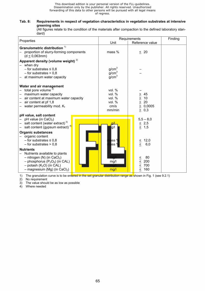
65
Tab. 8: Requirements in respect of vegetation characteristics in vegetation substrates at intensive greening sites
(All figures relate to the condition of the materials after compaction to the defined laboratory stan-dard)
Requirements Finding Properties Unit Reference value
Granulometric distribution 1) – proportion of slurry-forming components mass % < 20 (d < 0,063mm)
Apparent density (volume weight) 2) – when dry – for substrates ≤ 0,8 g/cm3 – – for substrates > 0,8 g/cm3 – – at maximum water capacity g/cm3
Water and air management – total pore volume 2) vol. % – – maximum water capacity vol. % > 45 – air content at maximum water capacity vol. % > 10 – air content at pf 1,8 vol. % > 20 – water permeability mod. Kf cm/s > 0,0005 mm/min > 0,3
pH value, salt content – pH value (in CaCl2) 5,5 – 8,0 – salt content (water extract) 3) g/l < 2,5 – salt content (gypsum extract) 4) g/l < 1,5
Organic substances – organic content – for substrates ≤ 0,8 mass % < 12,0 – for substrates > 0,8 mass % < 6,0
Nutrients – Nutrients available to plants – nitrogen (N) (in CaCl2) mg/l < 80 – phosphorus (P2O5) (in CAL) mg/l < 200 – potash (K2O) (in CAL) mg/l < 700 – magnesium (Mg) (in CaCl2) mg/l < 160
1) The granulation curve is to be entered in the set granular distribution range as shown in Fig. 1 (see 9.2.1) 2) No requirement 3) The value should be as low as possible 4) Where needed
This download edition is your personal version of the FLL-guidelines.Dissemination only by the publisher. All rights reserved. Unauthorized
forwarding of this data to other persons will be pursued with all legal meansof regress.
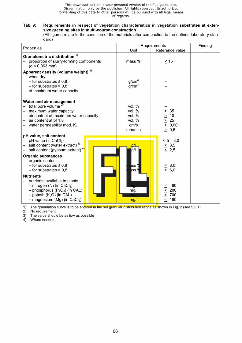
66
Tab. 9: Requirements in respect of vegetation characteristics in vegetation substrates at exten-sive greening sites in multi-course construction
(All figures relate to the condition of the materials after compaction to the defined laboratory stan-dard)
Requirements Finding Properties Unit Reference value
Granulometric distribution 1) – proportion of slurry-forming components mass % < 15 (d < 0,063 mm)
Apparent density (volume weight) 2) – when dry – for substrates ≤ 0,8 g/cm3 – – for substrates > 0,8 g/cm3 – – at maximum water capacity
Water and air management – total pore volume 2) vol. % – – maximum water capacity vol. % > 35 – air content at maximum water capacity vol. % > 10 – air content at pf 1,8 vol. % > 25 – water permeability mod. Kf cm/s > 0,001 mm/min > 0,6
pH value, salt content – pH value (in CaCl2) 6,5 – 8,0 – salt content (water extract) 3) g/l < 3,5 – salt content (gypsum extract) 4) g/l < 2,5
Organic substances – organic content
– for substrates ≤ 0,8 – for substrates > 0,8
mass % mass %
<<
8,0 6,0
Nutrients – nutrients available to plants – nitrogen (N) (in CaCl2) mg/l < 80 – phosphorus (P2O5) (in CAL) mg/l < 200 – potash (K2O) (in CAL) mg/l > 700 – magnesium (Mg) (in CaCl2) mg/l < 160
1) The granulation curve is to be entered in the set granular distribution range as shown in Fig. 2 (see 9.2.1) 2) No requirement 3) The value should be as low as possible 4) Where needed
This download edition is your personal version of the FLL-guidelines.Dissemination only by the publisher. All rights reserved. Unauthorized
forwarding of this data to other persons will be pursued with all legal meansof regress.
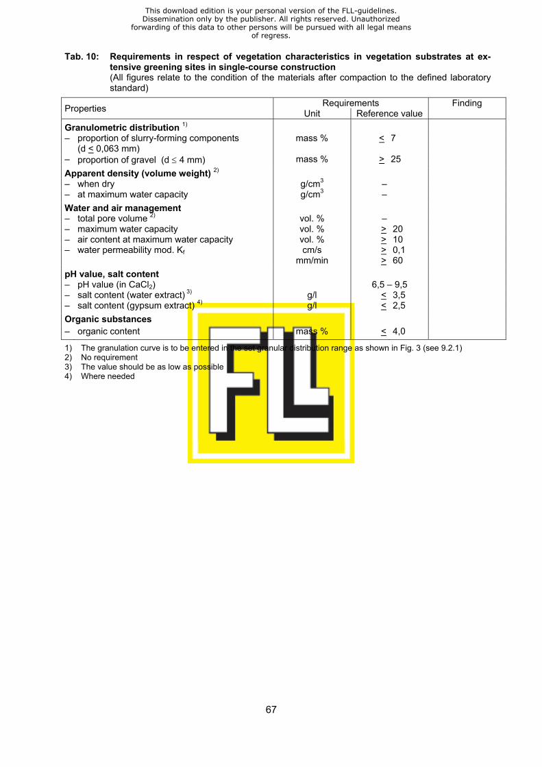
67
Tab. 10: Requirements in respect of vegetation characteristics in vegetation substrates at ex-tensive greening sites in single-course construction
(All figures relate to the condition of the materials after compaction to the defined laboratory standard)
Requirements Finding Properties Unit Reference value
Granulometric distribution 1) – proportion of slurry-forming components mass % < 7 (d < 0,063 mm) – proportion of gravel (d ≤ 4 mm) mass % > 25
Apparent density (volume weight) 2) – when dry g/cm3 – – at maximum water capacity g/cm3 –
Water and air management – total pore volume 2) vol. % – – maximum water capacity vol. % > 20 – air content at maximum water capacity vol. % > 10 – water permeability mod. Kf cm/s > 0,1 mm/min > 60
pH value, salt content – pH value (in CaCl2) 6,5 – 9,5 – salt content (water extract) 3) g/l < 3,5 – salt content (gypsum extract) 4) g/l < 2,5
Organic substances – organic content mass % < 4,0
1) The granulation curve is to be entered in the set granular distribution range as shown in Fig. 3 (see 9.2.1) 2) No requirement 3) The value should be as low as possible 4) Where needed
This download edition is your personal version of the FLL-guidelines.Dissemination only by the publisher. All rights reserved. Unauthorized
forwarding of this data to other persons will be pursued with all legal meansof regress.

68
13 Reference values for design loads
13.1 Materials for use in drainage courses Tab. 11: Design loads at maximum water capacity for materials, matting and boards
Material group Grain size Surface load per cm course depth Material type in mm kg/m2 kN/m2 Mineral aggregates Gravel 4/8 – 8/16 16 – 18 0,16 – 0,18 Lava 2/8 – 8/16 11 – 14 0,11 – 0,14 Pumice 2/8 – 4/12 11 – 12 0,11 – 0,12 Expanded clay, uncrushed 4/8 – 8/16 5 – 6 0,05 – 0,06 Expanded slate, uncrushed 4/8 – 8/16 6 – 7 0,06 – 0,07 Expanded clay, crushed 2/8 – 4/ 8 6 – 8 0,06 – 0,08 Expanded slate, crushed 2/8 – 4/11 6 – 8 0,06 – 0,08 Recycling aggregates Brick hardcore 4/8 – 8/16 10 – 13 0,10 – 0,13 Slag n. b. n. b. n. b. Foamed glass 10/25 2,5 – 3 0,025 – 0,03 Course depth Surface load for the entire course in cm kg/m2 kN/m2 Drainage matting Textured nonwoven fabrics 1,0 5,6 – 7,5 0,056 – 0,075 Studded plastic matting 1,2 2,1 – 2,3 0,021 – 0,023 Fibre-type woven matting 1,0 2,2 – 2,3 0,022 – 0,023 Fibre-type woven matting 2,2 2,2 – 2,3 0,022 – 0,023 Flock-type foam matting 3,5 5,6 – 5,9 0,056 – 0,059 Drainage boards Studded rubber boards 2,0 11,0 – 13,0 0,110 – 0,130 Foam-type drainage boards (NR) 5,0 1,8 – 2,5 0,018 – 0,025 Foam-type drainage boards (NR) 6,5 2,0 – 2,8 0,020 – 0,028 Shaped hard plastic boards (R)1) 4,0 19,0 – 21,0 0,190 – 0,210 Shaped hard plastic boards (R)1) 6,0 24,0 – 26,0 0,240 – 0,260 Shaped foam-type drainage boards (R)1)
6,0 16,0 – 18,0 0,160 – 0,180
Shaped foam-type drainage boards (R).1)
8,0 24,0 – 27,0 0,240 – 0,270
Shaped foam-type drainage boards (R).1)
10,0 33,0 – 36,0 0,330 – 0,360
Shaped foam-type drainage boards (R)1)
12,0 44,0 – 46,0 0,440 – 0,460
Drainage and substrate boards Modified foam-type boards 3,0 22,0 – 26,0 0,220 – 0,260
1) Filled to the top of the component with 4/8 lava o. A. = no reservoir m. A. = with reservoir n. b. = not found
This download edition is your personal version of the FLL-guidelines.Dissemination only by the publisher. All rights reserved. Unauthorized
forwarding of this data to other persons will be pursued with all legal meansof regress.
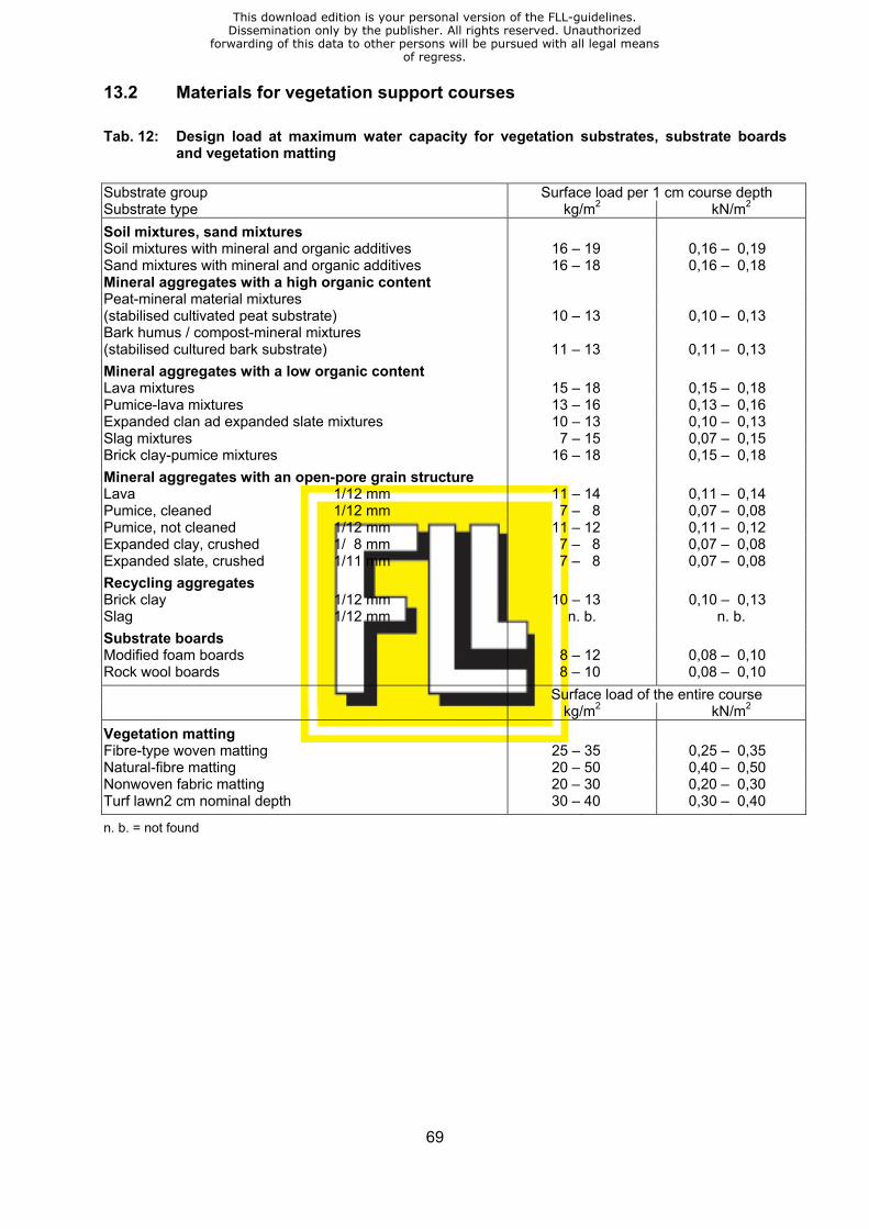
69
13.2 Materials for vegetation support courses Tab. 12: Design load at maximum water capacity for vegetation substrates, substrate boards
and vegetation matting
Substrate group Surface load per 1 cm course depth Substrate type kg/m2 kN/m2
Soil mixtures, sand mixtures Soil mixtures with mineral and organic additives 16 – 19 0,16 – 0,19 Sand mixtures with mineral and organic additives 16 – 18 0,16 – 0,18 Mineral aggregates with a high organic content Peat-mineral material mixtures (stabilised cultivated peat substrate) 10 – 13 0,10 – 0,13 Bark humus / compost-mineral mixtures (stabilised cultured bark substrate) 11 – 13 0,11 – 0,13
Mineral aggregates with a low organic content Lava mixtures 15 – 18 0,15 – 0,18 Pumice-lava mixtures 13 – 16 0,13 – 0,16 Expanded clan ad expanded slate mixtures 10 – 13 0,10 – 0,13 Slag mixtures 7 – 15 0,07 – 0,15 Brick clay-pumice mixtures 16 – 18 0,15 – 0,18
Mineral aggregates with an open-pore grain structure Lava 1/12 mm 11 – 14 0,11 – 0,14 Pumice, cleaned 1/12 mm 7 – 8 0,07 – 0,08 Pumice, not cleaned 1/12 mm 11 – 12 0,11 – 0,12 Expanded clay, crushed 1/ 8 mm 7 – 8 0,07 – 0,08 Expanded slate, crushed 1/11 mm 7 – 8 0,07 – 0,08
Recycling aggregates Brick clay 1/12 mm 10 – 13 0,10 – 0,13 Slag 1/12 mm n. b. n. b.
Substrate boards Modified foam boards 8 – 12 0,08 – 0,10 Rock wool boards 8 – 10 0,08 – 0,10
Surface load of the entire course kg/m2 kN/m2
Vegetation matting Fibre-type woven matting 25 – 35 0,25 – 0,35 Natural-fibre matting 20 – 50 0,40 – 0,50 Nonwoven fabric matting 20 – 30 0,20 – 0,30 Turf lawn2 cm nominal depth 30 – 40 0,30 – 0,40
n. b. = not found
This download edition is your personal version of the FLL-guidelines.Dissemination only by the publisher. All rights reserved. Unauthorized
forwarding of this data to other persons will be pursued with all legal meansof regress.

70
13.3 Vegetation
Tab. 13: Surface loads generated by various forms of vegetation
Design load Form of vegetation kg/m2 kN/m2
Extensive greening sites Greening with moss – Sedum 10 0,10 Greening with Sedum – moss – herbaceous plants 10 0,10 Greening with Sedum – grass – herbaceous plants 10 0,10 Greening with grass – herbaceous plants (dry lawn) 10 0,10 Simple intensive greening sites Greening with grass – herbaceous plants (grass roof, rough-grassed area)
15 0,15
Greening with wild bushes - coppices 10 0,10 Greening with coppices - shrubs 15 0,15 Greening with coppices (up to 150 cm tall) 20 0,20 Intensive greening sites Lawn 5 0,05 Low bushes and coppices 10 0,10 Shrubs and bushes up to 150 cm tall 20 0,20 Bushes up to 3 m tall 30 0,30 Large bushes up to 6 m tall 40 0,40 Small trees up to 10 m tall 60 0,60 Trees up to 15 m tall 150 1,50
This download edition is your personal version of the FLL-guidelines.Dissemination only by the publisher. All rights reserved. Unauthorized
forwarding of this data to other persons will be pursued with all legal meansof regress.
71
Methods to be employed when investigating plant substrate and aggregate-type drainage materials used
at roof-greening sites1
1995 issue with supplements dated January 2002
The methods to be used in determining properties/reference values are those described in the list set out herein below, in their agreed (VDLUFA), standardised (DIN) or modified forms. In those isolated cases where the methods employed vary from those shown, this must be indi-cated clearly in investigation reports and an explanation must be given as to how this is likely to alter the way in which comparisons are made. It is recommended that the following layout be adopted when preparing investigation reports: 1. Execution Give details of: the client and/or the contractor who carried out the work; the type of sample taken and the quantity of material involved; delivery and inspection dates, along with manufac-turer’s material specifications for the materials used and as identified by visual or manual in-spection. 2. Methods Give brief details of the methods used during the inspection. 3. Findings Set out mean figures in tabular format. 4. Evaluation Give a verbal opinion, using the requirements set out in tables 7-10 as a framework and using the granulometric distribution ranges shown in Figs. 1-3 in the “Roof-greening guidelines, edi-tion 2002”. Except where shown in the appendix, method descriptions are to be taken from the following publications: – VDLUFA Methodenbuch [The VDLUFA Methods Handbook], Vol. 1. Soil investigations. 4th
edition (1991) with appropriate addenda. – DIN Standards (latest version). – ÖNORM Standards (latest version). – HARTGE, K.H. u. R. HORN: die physikalische Untersuchung von Böden [Physical exami-
nation of soils]. 2nd edition (1989).
1 FLL “Roof-greening“ Working Party, “Investigation methods“ working group: Prof. H.-J. Liesecke, Hano-ver (Chairman); Prof. Dr. P. Fischer, Freising; Prof. Dipl.-Ing. G. Lösken, Hanover; Dr. L. Nätscher, Freis-ing; Dipl.-Ing. P. Siegert, Tornesch.
This download edition is your personal version of the FLL-guidelines.Dissemination only by the publisher. All rights reserved. Unauthorized
forwarding of this data to other persons will be pursued with all legal meansof regress.

72
Property Reference value
Description of the method Comments / notes
Granulometric distribu-tion
DIN 19683
Soil investigations in agricultural water The d > 2 mm fraction needs to be engineering checked for particles of clay – Granular fraction Part 1 Physical laboratory investigation: If such are present, soak the sample, d > 2 mm Determination of granulometric compo- flush out the clay sition by means of screening and add the < 2 mm fraction. – Granular fraction Part 2 Physical laboratory investigation: d < 2 mm Determination of granulometric compo- sition by means of pre-treatment with [Mass %] sodium pyrophosphate
Apparent density Appendix, item 2 Following on from DIN 18127 sub-soil; (volume weight) Determination in compacted 15 cm Ø Test and testing equipment: – cool damp Sf cylindrical test samples measuring Proctor compaction test and from the – dry St approximately 10 cm in length. determination of water permeability as – at maximum defined in DIN 18035 Playing fields: – water capacity Sw Part 4 Grassed areas: in the earlier October 1974 issue. [g/cm3 and g/litre] Water content VDLUFA A 2.1.1 [Mass % and vol. %] Determination by drying at 105°C DIN 19683 A procedure for carrying out soil in- vestigations for water engineering pur- poses in agriculture. Part 4: Physics laboratory investigations: Determina- tion of the water content in soil Maximum Appendix, item 3 see above water capacity Determination in compacted 15 cm Ø WKmax cylindrical test samples measuring app. 10 cm in length [Vol. %] Water permeability Appendix, item 4 see above mod. Kf Determination in compacted 15 cm Ø cylindrical test samples measuring app. 10 cm in length and at maximum [cm/s or water capacity mm/min] Total pore volume VDLUFA Bulletin 6/1970 This procedure cannot be used for GPV Pages 126–128, with correction
6/1971, substrates which contain organic-synthetic foam type materials.
Page149 Simplified determination of pore [Vol. %] volume using the FEIGE method
This download edition is your personal version of the FLL-guidelines.Dissemination only by the publisher. All rights reserved. Unauthorized
forwarding of this data to other persons will be pursued with all legal meansof regress.
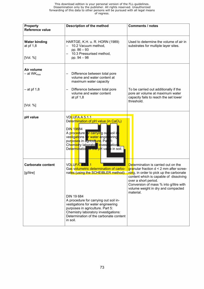
73
Property Reference value
Description of the method Comments / notes
Water binding HARTGE, K.H. u. R. HORN (1989) Used to determine the volume of air in at pf 1,8 – 10.2 Vacuum method, substrates for multiple layer sites. pp. 86 – 93 – 10.3 Pressurised method, [Vol. %] pp. 94 – 98 Air volume
– at WKmax – Difference between total pore volume and water content at maximum water capacity – at pf 1,8 – Difference between total pore To be carried out additionally if the volume and water content pore air volume at maximum water at pf 1,8 capacity fails to reach the set lower threshold. [Vol. %] pH value VDLUFA A 5.1.1 Determination of pH value (in CaCl2) DIN 19684 A procedure for carrying out soil in- vestigations for water engineering purposes in agriculture. Part 1: Chemistry laboratory investigations: Determination of the pH value in soil. Carbonate content VDLUFA A 5.3.1 Determination is carried out on the Gas volumetric determination of carbo- granular fraction d < 2 mm after scree- [g/litre] nates (using the SCHEIBLER method) ning, in order to pick up the carbonate content which is capable of dissolving over a short period. Conversion of mass % into g/litre with volume weight in dry and compacted material. DIN 19 684 A procedure for carrying out soil in- vestigations for water engineering purposes in agriculture. Part 5: Chemistry laboratory investigations: Determination of the carbonate content in soil.
This download edition is your personal version of the FLL-guidelines.Dissemination only by the publisher. All rights reserved. Unauthorized
forwarding of this data to other persons will be pursued with all legal meansof regress.
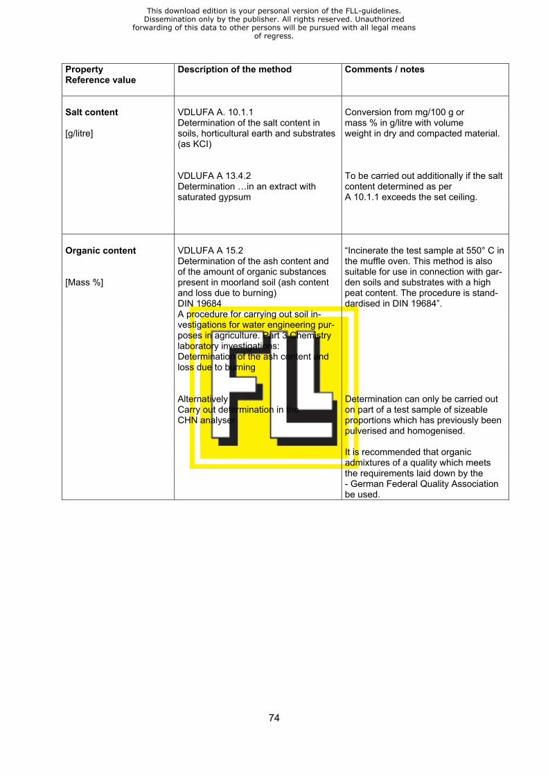
74
Property Reference value
Description of the method Comments / notes
Salt content VDLUFA A. 10.1.1 Conversion from mg/100 g or Determination of the salt content in mass % in g/litre with volume [g/litre] soils, horticultural earth and substrates weight in dry and compacted material. (as KCI) VDLUFA A 13.4.2 To be carried out additionally if the salt Determination …in an extract with content determined as per saturated gypsum A 10.1.1 exceeds the set ceiling. Organic content VDLUFA A 15.2 “Incinerate the test sample at 550° C in Determination of the ash content and the muffle oven. This method is also of the amount of organic substances suitable for use in connection with gar- [Mass %] present in moorland soil (ash content den soils and substrates with a high and loss due to burning) peat content. The procedure is stand- DIN 19684 dardised in DIN 19684”. A procedure for carrying out soil in- vestigations for water engineering pur- poses in agriculture. Part 3 Chemistry
laboratory investigations:
Determination of the ash content and loss due to burning Alternatively Determination can only be carried out Carry out determination in the on part of a test sample of sizeable CHN analyser proportions which has previously been pulverised and homogenised. It is recommended that organic admixtures of a quality which meets the requirements laid down by the - German Federal Quality Association be used.
This download edition is your personal version of the FLL-guidelines.Dissemination only by the publisher. All rights reserved. Unauthorized
forwarding of this data to other persons will be pursued with all legal meansof regress.
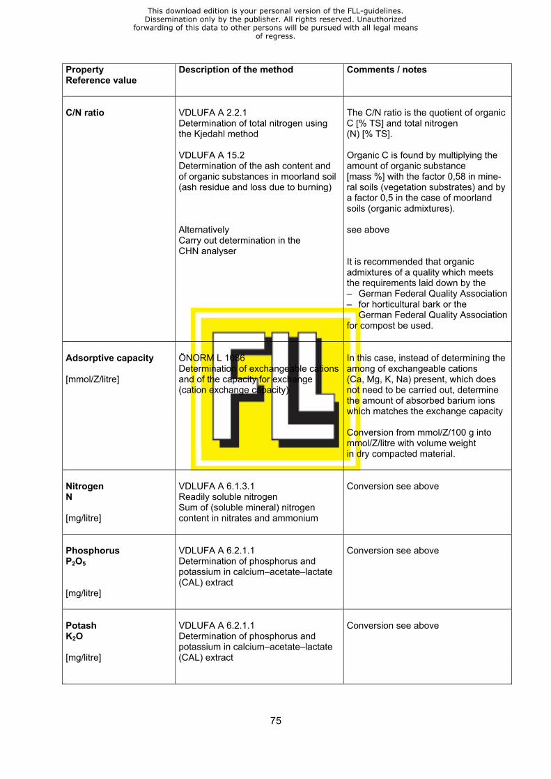
75
Property Reference value
Description of the method Comments / notes
C/N ratio VDLUFA A 2.2.1 The C/N ratio is the quotient of organic Determination of total nitrogen using C [% TS] and total nitrogen the Kjedahl method (N) [% TS]. VDLUFA A 15.2 Organic C is found by multiplying the Determination of the ash content and amount of organic substance of organic substances in moorland soil [mass %] with the factor 0,58 in mine- (ash residue and loss due to burning) ral soils (vegetation substrates) and by a factor 0,5 in the case of moorland soils (organic admixtures).
Alternatively see above Carry out determination in the CHN analyser It is recommended that organic admixtures of a quality which meets the requirements laid down by the – German Federal Quality Association – for horticultural bark or the German Federal Quality Association for compost be used. Adsorptive capacity ÖNORM L 1086 In this case, instead of determining the Determination of exchangeable cations among of exchangeable cations [mmol/Z/litre] and of the capacity for exchange (Ca, Mg, K, Na) present, which does (cation exchange capacity) not need to be carried out, determine the amount of absorbed barium ions which matches the exchange capacity Conversion from mmol/Z/100 g into mmol/Z/litre with volume weight in dry compacted material. Nitrogen VDLUFA A 6.1.3.1 Conversion see above N Readily soluble nitrogen Sum of (soluble mineral) nitrogen [mg/litre] content in nitrates and ammonium Phosphorus VDLUFA A 6.2.1.1 Conversion see above P2O5 Determination of phosphorus and potassium in calcium–acetate–lactate (CAL) extract [mg/litre] Potash VDLUFA A 6.2.1.1 Conversion see above K2O Determination of phosphorus and potassium in calcium–acetate–lactate [mg/litre] (CAL) extract
This download edition is your personal version of the FLL-guidelines.Dissemination only by the publisher. All rights reserved. Unauthorized
forwarding of this data to other persons will be pursued with all legal meansof regress.
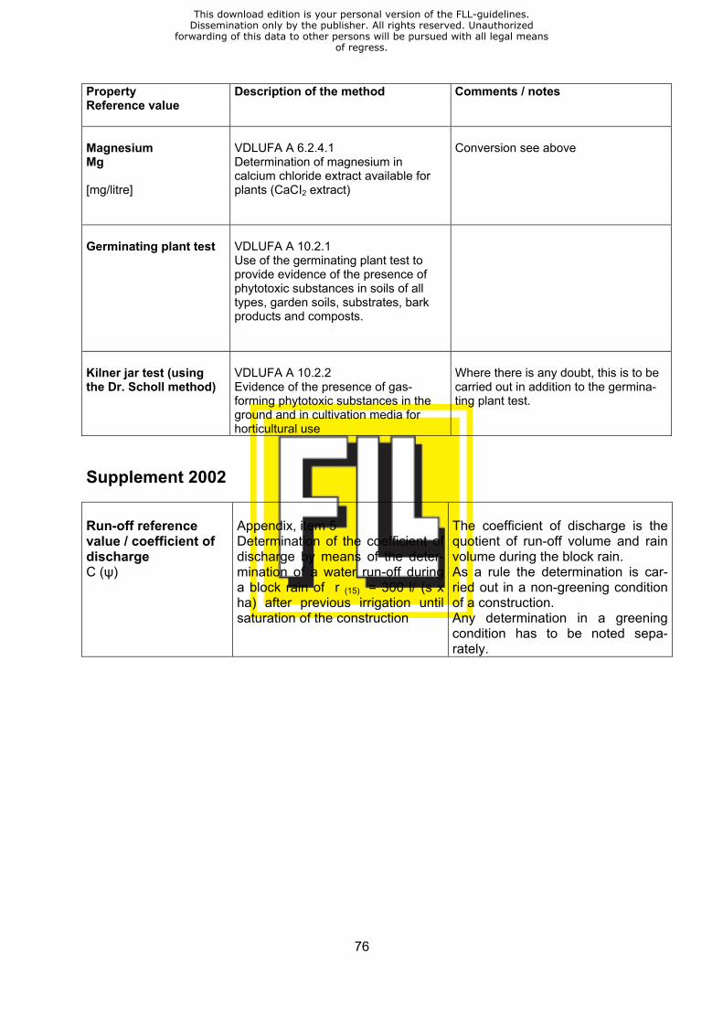
76
Property Reference value
Description of the method Comments / notes
Magnesium VDLUFA A 6.2.4.1 Conversion see above Mg Determination of magnesium in calcium chloride extract available for [mg/litre] plants (CaCI2 extract) Germinating plant test VDLUFA A 10.2.1 Use of the germinating plant test to provide evidence of the presence of phytotoxic substances in soils of all types, garden soils, substrates, bark products and composts. Kilner jar test (using VDLUFA A 10.2.2 Where there is any doubt, this is to be the Dr. Scholl method) Evidence of the presence of gas- carried out in addition to the germina- forming phytotoxic substances in the ting plant test. ground and in cultivation media for horticultural use Supplement 2002
Run-off reference value / coefficient of discharge C (ψ)
Appendix, item 5 Determination of the coefficient of discharge by means of the deter-mination of a water run-off during a block rain of r (15) = 300 l/ (s x ha) after previous irrigation until saturation of the construction
The coefficient of discharge is the quotient of run-off volume and rain volume during the block rain. As a rule the determination is car-ried out in a non-greening condition of a construction. Any determination in a greening condition has to be noted sepa-rately.
This download edition is your personal version of the FLL-guidelines.Dissemination only by the publisher. All rights reserved. Unauthorized
forwarding of this data to other persons will be pursued with all legal meansof regress.
77
Appendix
Determination of apparent density (volume weight), maximum water capacity, water permeability and run-
off reference value / coefficient of discharge 1 Purpose and area of application Substrates with a high mineral content and mineral aggregate-type materials for vegetation support and drainage courses at green-roof sites, ready for use and having grain sizes which are normally up to d = 16 mm or, exceptionally, to d = 32 mm. 2 Determination of apparent density (volume weight) 2.1 Principle Cool/moist material with a loose volume of between 2100 and 2500 ml is compacted in the standardised manner in defined cylindrical containers. Calculate apparent density from the vol-ume of the compacted sample and apparent density under moist conditions, at maximum water capacity and under dry conditions, after the sample has been dried at 105°C. 2.2 Apparatus – cylindrical plastic containers with an inside diameter of 150 mm and a height of 165 mm,
with a base perforated in the manner defined below: Radius interval 15° Perforation perimeter spacing 10 mm Perforation diameter 5 mm Number of perforations: centre 1 x 1 = 1
90° intervals 4 x 7 = 28 30°/60° intervals 8 x 6 = 48 15°/45°/75° intervals 12 x 4 = 48
125 – screening: 0,6 mm mesh wire, diameter 148 mm – 7 mm steel plate, diameter 148 mm (proctor compaction test as per DIN 18127) – proctor hammer, 4,5 kg drop weight, 450 mm drop height (proctor compaction test as per
DIN 18127) – plastic dry dishes heat-resistant to 150° C, with a diameter of app. 30 cm – drying cabinet – scales, accurate to within 0,1 g 2.3 Determination Estimate visually/manually how cool/moist the test material is (it must not be wet), determine the water content and identify this as the test water content. Where water is added, the sample must be left for at least 3 hours under air-tight conditions before any further work is done with it, in order to ensure even moistening throughout the sample. Weigh the cylindrical container with the wire mesh inserted in it, then, with the perforated base covered over with the wire mesh, fill to a depth of between 120 mm and 140 mm with a quantity of the material under examination, which must be cool / moist. The container is filled to a level which will ultimately leave a depth of 100 mm or thereabouts after compaction. Place the steel plate over the top of the material with which the container is filled and then strike 6 times with the Proctor hammer to compact it. Find the depth of the sample in its compacted state by mak-ing four cross-wise measurements from the upper rim of the cylinder to the surface of the sam-ple and then subtracting the result from the internal height the cylinder. The sample volume may then be calculated using the formula π x r² x h . Find the weight of the container plus the sam-
This download edition is your personal version of the FLL-guidelines.Dissemination only by the publisher. All rights reserved. Unauthorized
forwarding of this data to other persons will be pursued with all legal meansof regress.

78
ple, from which the weight of the container plus the fitted wire mesh is then subtracted to give the weight of the sample. Apparent density at maximum water capacity is to be determined immediately after said maxi-mum water capacity has been found (see 3.). Check the height of the sample so as to take ac-count of any swelling which may take place. Find the volume and weight of the sample, as de-scribed above. In order to determine apparent density in a dry condition, once apparent density at maximum water capacity has been determined, along with water permeability, place the sample in dry dishes of known weight and dry at 105°C. Find the weight of the sample plus the dish, then subtract the weight of the dish from the resulting figure to give the dry weight for the sample. 2.4 Calculation Calculate apparent density under moist conditions (Sf) using:
mvf Sf = V [g/cm3]
mvf = mass (weight) in g in moist condition
V = volume in cm3 in compacted condition
Calculate apparent density at maximum water capacity (Swk) using the formula:
mwk Swk= V or Vwk [g/cm3]
mwk = mass (weight) in g at maximum water capacity Vwk = corrected volume where there is swelling Calculate apparent density under dry conditions (St) using the formula:
mf St = V [g/cm3]
mt = mass (weight) in g in dry condition Testing is to be carried out in three parallel tests on the same samples and in the sequence shown above. The result is to be expressed as a mean figure in each instance. 3 Determination of maximum water capacity 3.1 Principle The amount of water taken up by compacted materials inside cylindrical vessels (see 2.) after total immersion for 24 hours in water which is then left to drip away over a 2-hour period. 3.2 Apparatus – see 2.2 – plastic channels with a depth of at least 200 mm for immersion – spacers, roughly 10 mm deep, to allow water ingress through a perforated base – 148 mm diameter nonwoven fabric filters to cover the top of the sample – 0,6 mm gauge 148 mm diameter wire mesh to cover the top of the sample – 100 x 100 mm concrete sett as a weight to rest of top of the sample – plastic bowls to allow the water to drip away, with drainage channels on top of them, made
from spherical pieces of bonded foam and measuring at least 50 mm in depth.
This download edition is your personal version of the FLL-guidelines.Dissemination only by the publisher. All rights reserved. Unauthorized
forwarding of this data to other persons will be pursued with all legal meansof regress.
79
3.3 Determination Place the fabric filter and wire mesh on top of the materials inside the cylindrical vessels (see 2.3) and then weight these down with pieces of sett so as to prevent the contents from rising. Place the vessels in plastic bowls and fill slowly with water until the level reaches approximately 10mm below the top of the test sample. Dampen the surface of the test sample thoroughly and then add more water until the level is 10 mm above the top of the test sample. Add more water, if necessary, in order to maintain the latter level. After the test sample has been totally im-mersed for 24 hours, remove the vessels and place them on top of the draining boards posi-tioned over the plastic basins, where they are to be left for two hours whilst the water drips out. At the end of this period, dry the vessels thoroughly, remove the cover from the top of the test sample and find the combined weight of the vessel plus the test sample, subtracting the known weight of the cylinder (see 2.3) to work out the weight of the test sample. Check the volume of the test sample (see 2.3), then, having determined water permeability (see 4.) in the manner described in 2.3, dry the test sample at 105°C and find the weight. The water content in g / cm³ of the compacted test sample will be found from the difference between the mass (weight) at maximum water capacity and the corresponding figure with the test sample in a dry condition. 3.4 Calculation Calculate maximum water capacity (WKmax) using the following formula:
(mwk – mf) x 100 WKmax = V or Vwk [Vol.–%]
mwk = mass (weight) in g (^ cm3) at maximum water capacity mf = mass (weight) in g in dry condition The result is to be expressed as the mean from the 3 parallel tests. 4 Determination of water permeability 4.1 Principle The coefficient of absorption (mod. Kf) (water) for the materials in compacted condition inside cylindrical vessels (see 2.) at maximum water capacity is found by measuring the fall over a given period in the level of the water in which the materials are totally immersed. 4.2 Apparatus – see 2.2 and 3.2 – annular test prods: wire ring, diameter approximately 40 mm, with tow test prods attached vertically to it, these being 45 mm and 35 mm in length. 4.3 Determination As soon as the maximum water capacity has been determined, cover the surface of the test sample with wire mesh, place the annular test prod on top and then fill the cylinder carefully from the top until the surface of the water is between 10 and 20 mm above the top of the test sample. Add water continuously as the water level drops, in such a manner as to maintain the total immersion depth. Measurement actually commences as soon as water begins to flow evenly out of the perforated base. Fill with water until the surface is above the tip of the upper test prod. Observe the water as the level drops and note the time taken for it to drop from tip of the upper test prod to that of the lower one, in other words, from 45 mm to 35 mm. Determination can be carried out in 3 parallel tests, as described in section 2 above; the measurement is to be repeated 3 times in each case.
This download edition is your personal version of the FLL-guidelines.Dissemination only by the publisher. All rights reserved. Unauthorized
forwarding of this data to other persons will be pursued with all legal meansof regress.
80
4.4 Calculation Calculate water permeability (mod. Kf) using the following formula:
1 h mod. Kf = t x h + 4,0 [cm/s]
h = the depth in cm of the compacted test material (see 2.3) t = the time in s taken for the water level to drop from 45 mm to 35 mm The result is to be expressed as the mean for all measurements. Supplement 20022 5 Determination of the run-off reference value/coefficient of discharge C (ψ) 5.1 Principle Determination of the run-off reference value/coefficient of discharge by means of determination of the water run-off from a course construction of a roof-greening with 2 % drainage gradient during a 15-minutes block rain of r = 300 l / (s x ha) ^ 27 l/m² after previous irrigation which saturates the course and which is then left to drip away over a 24-hour period. 5.2 Apparatus – wind and rain protected testing hall to mount the test equipment – testing table of 1 m width, with side barriers according to the construction depth of the roof-
greening system to be tested, screening grids with a ca. 3 mm wire mesh at the end of the run-off, variable gradients, water-permeable sealing, drip channel or outlet funnel at the end of the gradient with outlet connection piece
Optional flow lengths of: – 10 m with correction factor 1,0 – 5 m with correction factor 0,72 – 2,50 m with correction factor 0,65 – irrigation facility consisting of a nozzle tube with constant and uniform distribution of the block rain, if possible, to be mounted 60 – 80 cm above the layered superstructure to be exam-ined, all-side foil protection in order to prevent drop drift, pressure reducer inside the supply tube for the fine-tuning of the rain volume, water-meter precision instrument to monitor the rain volume in dependence on time by means of a stopwatch or electronically – measuring device to measure the run-off water volume in dependence on time: – visually
– via collecting receptacle with water exchange indicator, or – via a calibrated collecting receptacle, or – via water-meter precision instruments and monitoring of time by means of a stopwatch – electronically – by means of weighing, or – via a water-meter precision instrument and monitoring of volume and time by means of a data logger
2 Working Party “Determination of coefficient of discharge”: Prof. Dr. H.–J. Liesecke, Hanover (Chairman); Dr. W. Kolb, Veitshöchheim; Prof. Dipl.–Ing. G. Lösken, Hanover; Dr. M. Marrett–Foßen, Tornesch; Prof. Dr. St. Roth–Kleyer, Geisenheim; Dipl.–Ing. Chr. Schade, Groß–Ippener
This download edition is your personal version of the FLL-guidelines.Dissemination only by the publisher. All rights reserved. Unauthorized
forwarding of this data to other persons will be pursued with all legal meansof regress.
81
5.3 Determination Set a gradient of 2 % at the testing equipment. Installation of the roof-greening course construc-tion to be tested in damp condition. Apply irrigation to saturate the course until a constant outlet water flow is kept over a period of 10 minutes. Check that there is no drift of the irrigation. Leave to drip away over a period of 24 hours in order to reach an approximate condition of maximum water capacity. Apply block rain of 27 l/m² in 15 minutes, as constant as possible regarding its intensity. Monitor the outlet water flow during the irrigation period in dependence on time. The measurement is to be repeated 3 times in 24-hour intervals.
5.4 Calculation
Calculate the run-off reference value/coefficient of discharge C (ψ) using the following formula: outlet water volume in litres in 15 minutes C = x correction factor to take account of the rain volume in litres in 15 minutes flow length The result is to be expressed as the mean from the three repeated measurements.
This download edition is your personal version of the FLL-guidelines.Dissemination only by the publisher. All rights reserved. Unauthorized
forwarding of this data to other persons will be pursued with all legal meansof regress.
82
Procedure for investigating resistance to root penetra-tion at green-roof sites3
1999 edition
with editorial changes dated January 2002
Introduction In order to exclude vegetation-dependant structural damage due to roof-greening, in 1984 a “Procedure for investigating resistance to root penetration” was elaborated by a working group team of The Landscaping and Landscape Development Research Society e.V. (FLL) which fo-cused on the stress exerted on root protection barriers due to plant roots. The procedure is mainly based on experience and findings gathered in tests carried out over a period of several years with different damp-proof sheets and various plant varieties. All tests were executed be-tween 1975 and 1980 at the Institute for Pedology and Plant Nutrition, Technical College (FH). The FLL procedure was revised in 1992 and, for the last time so far, in 1995. The procedure is highly acknowledged among manufacturer, planners and executing contrac-tors which is also documented by the large number of already completed and still ongoing in-vestigations. In 1993 the FLL decided to re-examine the existing procedure with a test period of 4 years with the aim to reduce the test period to 2 years without watering down the desired particularly strict standards of the current tests. After a series of tests at the Institute for Pedology and Plant Nutrition, Technical College Wei-henstephan agreement was reached regarding the following requirements: the 2-year-test takes place in a climate-controlled greenhouse in which the plant varieties put to the test will find a test climate with temperature and light conditions which allow them to grow over the entire year. Thus, an effective growth period of 24 months can be achieved, a similar duration as for the 4-year test, when taking the yearly, several-months lasting dormant phase of vegetation in out-door conditions into account. Both tests are considered to be equal and have been described in the present new edition of the procedure. In the course of changes regarding its content this edition has also been subject to editorial changes in format in order to facilitate comprehension and to make it easier for the testing insti-tutions to evaluate the test results obtained.
3 FLL Work Party “Roof-Greening“, team “Root-penetration barrier“: Prof. Dr. P. Fischer, Freising–Weihenstephan (Chairman); Dipl.–Ing. R. Bohlen, Ladbergen; R. Klein, Wächtersbach–Neudorf; Prof. Dr. H.–J. Liesecke, Hanover; Prof. G. Lösken, Hannover; Dipl.–Ing. P. Siegert, Tornesch; Dipl.–Ing. W. Te-bart, München; Dipl.–Ing. R. Walter, Stuttgart
This download edition is your personal version of the FLL-guidelines.Dissemination only by the publisher. All rights reserved. Unauthorized
forwarding of this data to other persons will be pursued with all legal meansof regress.
83
1 Area of validity This procedure covers investigations into resistance to root penetration of roots and rhizomes of different test plants in – root protection barrier sheeting – roof and damp-proof lining sheets, and – liquid surface treatment materials for all types of roof-greening (intensive greening, simple intensive greening, extensive green-ing). This procedure includes testing of products including all jointing techniques linked to them. Therefore, it is admissible only for testing purposes related to individual sheeting and/or surface coating. No examination of an entire roof protection system, i.e. of a protection course consist-ing of several layers for roof protection purposes, can be effected. For reasons related to the testing procedure it may be necessary to apply a separate course underneath the surface treatment in order to test coating products using liquid surface treatment materials. This method is admissible as long as the manufacturer clearly guarantees that resis-tance to root penetration is effected only by means of the top coating applied to the construc-tion. Any lamination, i.e. a separate layer on top of a sheeting and/or coating to be tested, has to be excluded. The findings for any sheeting and/or coating which has been tested cannot be transferred to resistance to root penetration in relation to plants with strong rhizome growth (e.g. bamboo or Chinese reeds varieties). When using these types of plants on top of a regular root penetration barrier additional structural measures have to be taken and special care activities to be pro-vided. This procedure does not extend to investigations into environmental compatibility of any product tested. 2 Definitions For the application of this procedure the following definitions shall be applied: 2.1 Trial containers Containers which have been specially equipped for the examination with minimum dimensions. The containers are equipped with the sheeting or coating to be tested (trial containers) and re-spectively with a nonwoven fabric (control container). 2.2 Moisture course The moisture course consists of coarse mineral aggregate laid underneath the sheeting and/or coating to be tested. It is kept constantly humid and therefore allows for continuous growth of roots and rhizomes penetrating the protective sheeting and/or coating down to the transparent bottom of the container. Thus any penetration can be early detected. 2.3 Protective course Nonwoven fabric which is compatible (material) with the sheeting/coating and which is laid di-rectly underneath the material to be tested onto the moisture course in order to reach an equal distribution of compression.
This download edition is your personal version of the FLL-guidelines.Dissemination only by the publisher. All rights reserved. Unauthorized
forwarding of this data to other persons will be pursued with all legal meansof regress.

84
2.4 Vegetation support course Standard cultivation substrate (materials mixture) readily available, or which can be made up, in a consistent form at any investigation site. The structure of this course shall be stabilised and shall offer good water and air management properties. It shall be given light basic fertilisation and therefore favours an optimum root development of the test plants. The vegetation support course is in direct contact with the sheeting to be tested. 2.5 Test plant varieties 2.5.1 For the 2-year test – Pyracantha coccinea ‘Orange Charmer’, ornamental coppice which under greenhouse
conditions shows an all year round root growth suitable for the test, and – Agropyron repens, couch grass, an indigenous grass with slow-growing rhizomes the set-
tling of which can hardly be avoided on green-roofs and which also grows sufficiently all year through under the given testing conditions
2.5.2 For the 4-year test – Alnus incana, grey alder, a wild coppice which shows a root growth suitable for the test un-
der the given outdoor conditions during the vegetation period, and – Agropyron repens, couch grass 2.6 Sufficient growth performance of the test plants The coppices (‘Orange Charmer’ and alder) in the trial containers have to show an average growth performance of at least 80 % (height, diameter of the stem) of the plants in the control containers during the entire duration of the investigation. Hereby, if necessary, any impairment which may have a harmful effect onto the test plants and which may be caused by any sub-stance emit by the sheeting and/or surface coating harming the plants can be detected. The spreading of the couch grass at the substrate surface will be evaluated visually (in a valu-ated way, see 2.7). Hereby, the plants in the trial containers have to show at least a medium stock density (see 7.2). 2.7 Valuation of the couch grass stock For the visual valuation of the stock density of the couch grass growth the following figures are assigned. The classification is as follows: 1 = hardly any couch grass present (about 0 – 20 % of the surface covered) 2 = thin stock (about 20 – 40 % of the surface covered) 3 = medium stock (about 40 – 60 % of the surface covered) 4 = dense stock (about 60 – 80 % of the surface covered) 5 = very dense couch grass stock (about 80 – 100 % of the surface covered) 2.8 Equivalent joining techniques In the investigation it is admissible to combine different joining techniques as far as they aim exclusively at producing material-homogenous seam joints (e.g. solvent bonding – with a sol-vent which evaporates – and hot gas welding). Such types of seam bonding are considered to be equivalent. In contrast to this combinations of bonding-free joints and joints with bonding glue or joints using 2 different types of glues are not considered to be equivalent.
This download edition is your personal version of the FLL-guidelines.Dissemination only by the publisher. All rights reserved. Unauthorized
forwarding of this data to other persons will be pursued with all legal meansof regress.
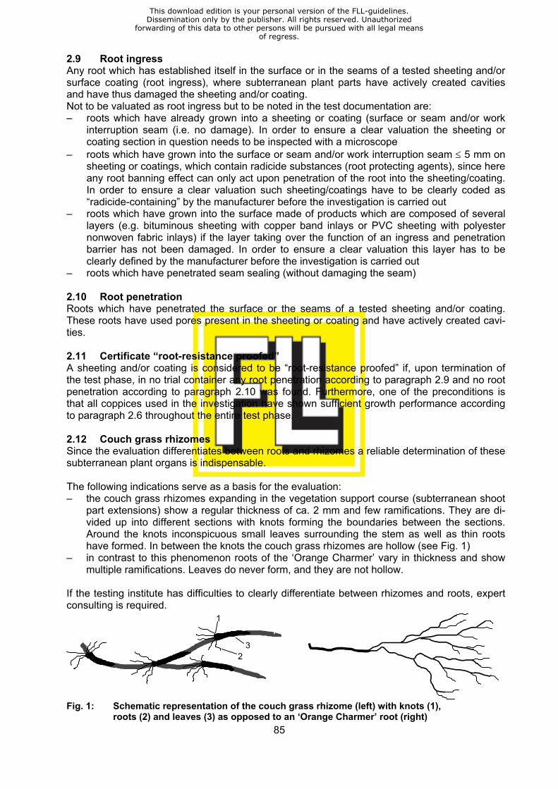
85
2.9 Root ingress Any root which has established itself in the surface or in the seams of a tested sheeting and/or surface coating (root ingress), where subterranean plant parts have actively created cavities and have thus damaged the sheeting and/or coating. Not to be valuated as root ingress but to be noted in the test documentation are: – roots which have already grown into a sheeting or coating (surface or seam and/or work
interruption seam (i.e. no damage). In order to ensure a clear valuation the sheeting or coating section in question needs to be inspected with a microscope
– roots which have grown into the surface or seam and/or work interruption seam ≤ 5 mm on sheeting or coatings, which contain radicide substances (root protecting agents), since here any root banning effect can only act upon penetration of the root into the sheeting/coating. In order to ensure a clear valuation such sheeting/coatings have to be clearly coded as “radicide-containing” by the manufacturer before the investigation is carried out
– roots which have grown into the surface made of products which are composed of several layers (e.g. bituminous sheeting with copper band inlays or PVC sheeting with polyester nonwoven fabric inlays) if the layer taking over the function of an ingress and penetration barrier has not been damaged. In order to ensure a clear valuation this layer has to be clearly defined by the manufacturer before the investigation is carried out
– roots which have penetrated seam sealing (without damaging the seam) 2.10 Root penetration Roots which have penetrated the surface or the seams of a tested sheeting and/or coating. These roots have used pores present in the sheeting or coating and have actively created cavi-ties. 2.11 Certificate “root-resistance proofed” A sheeting and/or coating is considered to be “root-resistance proofed” if, upon termination of the test phase, in no trial container any root penetration according to paragraph 2.9 and no root penetration according to paragraph 2.10 was found. Furthermore, one of the preconditions is that all coppices used in the investigation have shown sufficient growth performance according to paragraph 2.6 throughout the entire test phase. 2.12 Couch grass rhizomes Since the evaluation differentiates between roots and rhizomes a reliable determination of these subterranean plant organs is indispensable. The following indications serve as a basis for the evaluation: – the couch grass rhizomes expanding in the vegetation support course (subterranean shoot
part extensions) show a regular thickness of ca. 2 mm and few ramifications. They are di-vided up into different sections with knots forming the boundaries between the sections. Around the knots inconspicuous small leaves surrounding the stem as well as thin roots have formed. In between the knots the couch grass rhizomes are hollow (see Fig. 1)
– in contrast to this phenomenon roots of the ‘Orange Charmer’ vary in thickness and show multiple ramifications. Leaves do never form, and they are not hollow.
If the testing institute has difficulties to clearly differentiate between rhizomes and roots, expert consulting is required.
1
23
Fig. 1: Schematic representation of the couch grass rhizome (left) with knots (1),
roots (2) and leaves (3) as opposed to an ‘Orange Charmer’ root (right)
This download edition is your personal version of the FLL-guidelines.Dissemination only by the publisher. All rights reserved. Unauthorized
forwarding of this data to other persons will be pursued with all legal meansof regress.
86
2.13 Evaluation of couch grass rhizomes Couch grass rhizome root ingress and penetration into the sheeting and/or coating (surface or seams) are detected and noted in the test report, but not evaluated in regard to resistance to root penetration. If no damage of the product due to rhizomes is found, an explicit statement stressing this fact is to be included into the test report (see 2.14). 2.14 Certificate “rhizome-resistant against couch grass” A sheeting and/or coating is considered to be “rhizome-resistant against couch grass” if, upon termination of the test phase, - in analogy to root ingress (see 2.9) and root penetration (see 2.10) - in no trial container neither rhizome ingress nor rhizome penetration is found. Furthermore, one of the preconditions is that all couch grasses used in the investigation have shown sufficient growth performance throughout the entire test phase (see 2.6). 2.15 Incidents leading to a premature test stop If in the course of the evaluations during the test visible penetrations of roots or rhizomes into the sheeting and/or coating to be tested are identified (see 7.1) the client who has commis-sioned the investigation needs to be informed. The test is stopped if the penetrations are caused by roots. If any rhizomes have penetrated the test material the investigation may be continued upon mutual agreement with the client. If during the test phase more than 25 % of the coppices are lost, the investigation has to be started anew, i.e. new planting needs to be carried out. At the same time, the vegetation sup-port course needs to be replaced by a new aggregate mixture. A new date has to be assigned to the beginning of the test phase. The same procedure shall be applied if during the test phase no sufficient root growth of the test plants can be achieved (see 2.6). 3 Brief description of the procedure In a trial container under standardised conditions the resistance to root penetration of root-penetration sheeting as well as roof and damp-proof linings and/or surface coating vis-à-vis any roots and rhizomes of test plant varieties affecting them is examined. During a 4-year test the examination is carried out in outdoor conditions where alders and couch grasses are used as test plants. The 2-year test is carried out in a climate-controlled greenhouse by testing ‘Orange Charmer’ and couch grass. The sheeting and/or coating which needs to show several seams/joints and/or one work inter-ruption joint is installed in 8 trial containers. 3 more receptacles without any sheeting or coating are included into the test. They serve as control receptacles for plant growth. A thin vegetation support course is laid into the pre-treated containers. With dense planting, moderate fertilizing and modest watering the desired high root pressure will be obtained. Towards the end of the investigation the vegetation support course is taken out of the recepta-cle and an examination of the sheeting and/or coating is effected focussed on the detection of any root and/or rhizome ingress or penetration. Control samples of any sheeting and/or coating tested are stored at the test institute.
This download edition is your personal version of the FLL-guidelines.Dissemination only by the publisher. All rights reserved. Unauthorized
forwarding of this data to other persons will be pursued with all legal meansof regress.

87
4 Test facilities and material 4.1 Location of the testing 4.1.1 For the 4-year investigation A hall needs to be provided equipped with a transparent roof cover, but open on its four sides. Hereby, conditions similar to outdoor conditions are created. At the same time, any precipitation which may lead to waterlogging in the run-off-free receptacles is shielded off. Admissible as locations are also non-heated greenhouses as far as they provide sufficient ventilation facilities and frost can take effect. 4.1.2 For the 2-year investigation Provide a greenhouse equipped with heating and ventilation facilities. The heating system is to be set in a way that during the day a temperature of (18±3)°C and during the night a tempera-ture of (16±3)°C is achieved. As of an indoor temperature of (22±3)°C and more the greenhouse shall be ventilated. Avoid a constant indoor temperature of > 35 °C. The natural light conditions in central-European regions ensure a favourable growth of the test plants at the set temperatures throughout the entire year. Any shading of the plants in summer or artificial lighting in winter is not required. The space demand per receptacle (800 x 800 mm), respecting the required minimum distance according to paragraph 6.1, amounts to ca. 1,5 to 2 m², depending on the arrangement of the containers. 4.2 Trial containers The internal dimensions of the containers used in the trial shall not be less than 800 x 800 x 250 mm, but larger containers may be needed if the circumstances under which they are to be installed so require. Trial containers are to be fitted with transparent bases (e.g. acrylic glass) so that root penetra-tion can be detected even during the test phase without interfering with the vegetation support course. The base of the container shall be darkened (e.g. by means of a foil which is impervious to light), in order to avoid the growth of algae in the moisture course. Ideally, the transparent container base will be a tray with a 20 mm raised rim to maintain a constant supply of water in the moisture course. The water supply into the moisture course is effected by means of a filling pipe. This pipes shall have a diameter of 35 mm and is mounted on the outside of the container, pointing upwards and abutting onto the raised rim of the base tray (see Fig. 2).
35
70
250
800
*1
Fig. 2: Construction design of the trial containers (minimum dimensions, all figures in mm, *1 = transparent base with raised rim)
For each sheeting and/or coating to be tested 8 trial containers are required. In addition, per experimental run – regardless of the number of sheets/coating to be tested – 3 control contain-ers (without any sheeting/coating) shall be provided.
This download edition is your personal version of the FLL-guidelines.Dissemination only by the publisher. All rights reserved. Unauthorized
forwarding of this data to other persons will be pursued with all legal meansof regress.
88
4.3 Moisture course This course consists of expanded slate or expanded clay (grain size 8 – 16 mm) which has to meet the quality requirements indicated in Tab. 1. In order to avoid any in-house analysis effort it is useful to only use products which are subject to a permanent quality control in regard to the defined guidelines. Thus, the manufacturer will guarantee the required properties. For the required course depth of (50±5) mm (see 6.1) the material demand comes to 32 l per trial container (800 x 800 mm). 4.4 Protective nonwoven fabric Use a nonwoven fabric made of synthetic fibres with a weight of ca. 200 g/m2. The material compatibility of the nonwoven fabric with the sheet/coating to be tested needs to be ensured. The material demand comes to 0,64 m² per trial container (800 x 800 mm). 4.5 Sheeting and/or coating to be tested The sheeting/coating has to be laid and/or applied according to paragraph 6.1. The surface to be treated (minus the 50 mm depth of the moisture course) amounts to a calculated figure of about 1,3 m² (without overlapping) per container presenting the indicated minimum dimension (800 x 800 x 250 mm). 4.6 Vegetation substrate The substrate consists of: – 70 vol. % slightly decomposed North German moorland peat, and – 30 vol. % expanded clay or slate (grain size 8 – 16 mm) of the quality indicated in Tab. 1.
As described in paragraph 4.3 it is useful to apply only products which have undergone quality testing.
Add calcium carbonate to bring the pH value to figures between 5,5 and 6,5 (see 4.7). The basic fertilization defined in paragraph 4.8 is mixed with the vegetation support course in a homogenous way before filling the container. In a 4-year investigation the substrate need comes to about 96 l per trial container (800 x 800 mm) with a required course depth of (150±10) mm, for the 2-year investigation to about 88 l per receptacle (taking into account a substrate supply via plant earth-clumps). Tab. 1: Required quality of expanded clay/slate. Determination with water extracted from the
ground material with demineralised water in a 1:10 (weight/vol.) ratio Soluble salts (calculated as KCl) < 0,25 g/100 g CaO < 120 mg/100 g Na2O < 15 mg/100 g Mg < 15 mg/100 g Cl – < 10 mg/100 g F – < 1,2 mg/100 g
4.7 pH settings For the vegetation support course different quantities of calcium carbonate may be necessary in order to set the desired pH value to 5,5 – 6,5. The required quantity can be determined by using the following procedure: – take 5 samples of 1 l each from the well-mixed vegetation support course – moisten the samples with tap water – mix the samples with different quantities (4, 5, 6, 7 or 8 g) of calcium carbonate
This download edition is your personal version of the FLL-guidelines.Dissemination only by the publisher. All rights reserved. Unauthorized
forwarding of this data to other persons will be pursued with all legal meansof regress.
89
– put the samples into a plastic bag, close them and label them – store the samples in the bag for about 3 days at room temperature – send the samples to a laboratory which works on the basis of the regulations of the
VDLUFA Association and ask them for a pH analysis in CaCl2 – extrapolate the quantity of calcium carbonate which has led to the desired pH value in the 1
l-sample to the entire volume of the vegetation support course 4.8 Fertilizer As a basic fertilization a multiple-nutrient fertilizer with ca. 15% N, 10% P2O5, 15% K2O, 2 % MgO and less than 0,5 % Cl as well as a fertilizer containing nutrient trace elements with Fe, Cu, Mo, Mn, B and Zn shall be provided. Per container (800 x 800 mm) 30 g of a multiple-nutrient fertilizer are applied. The fertilizer containing nutrient trace elements is used in the quantity recommended for substrates by the manufacturer. Use slow-release fertilizer capsules with ca. 15 % N, 10 % P2O5, 15 % K2O and a duration of action of 6 – 8 months for the repeat fertilizing. The demand in fertilizers comes to 30 g/container (800 x 800 mm) per fertilization unit. 4.9 Tensiometer In order to monitor watering of the vegetation support course per container a tensiometer with a measuring range of 0 – 600 hPa has to be used. 4.10 Test plants For the 4-year investigation the following 2 plant varieties meeting the defined quality require-ments shall be used: – Alnus incana – grey alder, 2-year seedling, height60 – 100 cm, and – Agropyron repens – couch grass, seeds For the 2-year investigation the following 2 plant varieties meeting the defined quality require-ments shall to be used: – Pyracantha coccinea ‘Orange Charmer’ – in a 2-litre container, height 60 – 80 cm – Agropyron repens – couch grass, seeds Per trial container with dimensions of 800 x 800 mm 4 coppices (alder, ‘Orange Charmer’) as well as 2 g of couch grass seeds have to be set/applied. This leads to a calculated plant density of 6,25 coppices/m² and 3,13 g seeds/m². If larger trial containers are in use, plant density has to reach at least the figures indicated above by increasing the number of plants and the quantity of seeds. When buying test plants make sure that plant quality does not vary. 4.11 Watering The water used for watering shall meet the minimum quality requirements listed in Tab. 2. Please enquire details about the local water quality at the waterworks responsible for the supply of the facility. If any of the values laid down in Tab. 2 is exceeded the water for watering needs to be blended with fully desalinated water or with rain water. Tab. 2: Minimum quality requirements for water used for watering purposes Conductivity < 1000 µS/cm Sum total alkaline earths < 5,4 mmol/l Acid capacity (up to pH 4,3) < 7,2 mmol/l Chloride < 150 mg Cl/l Sodium < 150 mg Na/l Nitrate ≤ 50 mg NO3/l
This download edition is your personal version of the FLL-guidelines.Dissemination only by the publisher. All rights reserved. Unauthorized
forwarding of this data to other persons will be pursued with all legal meansof regress.
90
5 Samples and information provided by the manufacturer Samples from the sheeting/coating under investigation are to be taken by the test institute for retention before the investigation starts and at the end of the same. The material taken as a sample has to include at least one bonding seam per jointing technique and/or one work inter-ruption joint and shall have a size of at least 0,5 m². Retention samples are to be stored in the dark and in dry condition at a temperature above 5 °C and not exceeding 25 °C. The duration of retention has to be equal or exceed the period of validity of the test report (see 8). Care must be taken during storage to ensure that they are not kept with any incompatible material. In order to ensure a clear identification of the tested product the following information needs to be provided by the manufacturer before the test is started: product name, area of application, material description, material standards, thickness (without lamination), finish/structure, form of delivery, manufacturing technique, test certificates, year of manufacture, mounting/laying tech-nique at the location of the investigation (overlapping, jointing techniques, jointing agents, type of seam sealing, covering strips over seams, special corner and angle joints), admixture of bio-cides (e.g. root inhibitors) with details regarding the concentration of the substance. In addition, a product data sheet of the sheeting/coating to be tested has to be handed in for retention at the test institute. Moreover, for products consisting of several layers (e.g. bituminous sheeting with copper band inlays or PVC sheeting with polyester nonwoven fabric inlays) the manufacturer has to define in an unambiguous way before the start of the investigation which layer is meant to take over the function of an ingress and penetration barrier. 6 Testing conditions 6.1 Preparation and installation of the 8 trial containers The trial containers shall be prepared with the following layered superstructure (from bottom to top): moisture course, protective lining, sheet and/or coating to be tested, vegetation support course, planting. Directly above the transparent base of the receptacle as bottom layer the moisture course is laid with a depth of (50±5) mm. The protective lining is cut to size based on the base area of the container and laid directly onto the moisture course. On top of the protective lining the sheet/coating is applied as described in paragraphs 6.1.1 and 6.1.2. After the installation of the sheets/coating to be tested the vegetation substrate is filled in in a compacted form and a course depth of (150±10) mm. This corresponds to a substrate volume of 96 l (4–year test) respectively 88 l (2–year test) (see 4.6) for a receptacle of 800 x 800 mm. Per trial container of 800 x 800 mm and for a 4-year investigation 4 pieces of Alnus incana (grey alder), for a 2-year test 4 pieces of Pyracantha coccinea shall be planted equally spread over the entire surface (see Fig. 3). Furthermore, for both investigation types and per receptacle 2 g of seeds of Agropyron repens (couch grass) are equally sawn onto the vegetation support course. If larger trial containers are necessary, the number of plants and the quantity of seeds needs to be increased so that at least the same plant density is reached (see 4.10). Place the ceramic cell of the tensiometers into the vegetation support course directly on top of the sheet/coating. Thus measurements can be carried out in the lowest part of the root area. The tensiometer shall be placed in a symmetrical distance with the plants (see Fig. 3).
This download edition is your personal version of the FLL-guidelines.Dissemination only by the publisher. All rights reserved. Unauthorized
forwarding of this data to other persons will be pursued with all legal meansof regress.
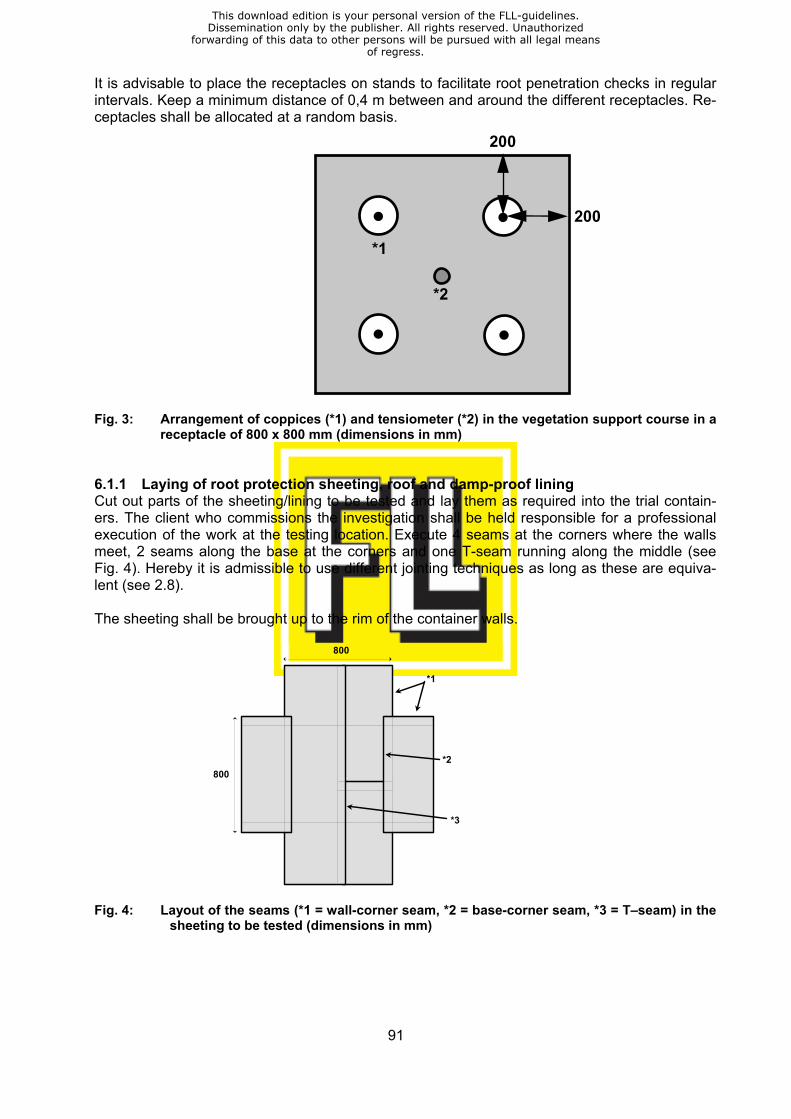
91
It is advisable to place the receptacles on stands to facilitate root penetration checks in regular intervals. Keep a minimum distance of 0,4 m between and around the different receptacles. Re-ceptacles shall be allocated at a random basis.
200
*2
*1
200
Fig. 3: Arrangement of coppices (*1) and tensiometer (*2) in the vegetation support course in a
receptacle of 800 x 800 mm (dimensions in mm) 6.1.1 Laying of root protection sheeting, roof and damp-proof lining Cut out parts of the sheeting/lining to be tested and lay them as required into the trial contain-ers. The client who commissions the investigation shall be held responsible for a professional execution of the work at the testing location. Execute 4 seams at the corners where the walls meet, 2 seams along the base at the corners and one T-seam running along the middle (see Fig. 4). Hereby it is admissible to use different jointing techniques as long as these are equiva-lent (see 2.8). The sheeting shall be brought up to the rim of the container walls.
800
800
*1
*2
*3
Fig. 4: Layout of the seams (*1 = wall-corner seam, *2 = base-corner seam, *3 = T–seam) in the
sheeting to be tested (dimensions in mm)
This download edition is your personal version of the FLL-guidelines.Dissemination only by the publisher. All rights reserved. Unauthorized
forwarding of this data to other persons will be pursued with all legal meansof regress.
92
6.1.2 Installation of surface coating under investigation – liquid surface treatment Just like the sheeting the liquid surface coating is applied as required at the testing location un-der the responsibility of the client who commissions the investigation. The coating shall be ap-plied in 2 work steps. In the centre of the receptacle there shall be a work interruption joint going all the way through the material under testing. The time interval between both stages of work shall be at least 24 hours. The coating shall be brought up to the rims of the container walls. 6.2 Preparation and installation of the 3 control receptacles Preparation and installation of the control receptacles is effected as described in paragraph 6.1. However, no sheeting/coating to be tested is installed, i.e. the vegetation support course is laid immediately on top of the protective lining. 6.3 Care of the plants during the growth period The substrate moisture content is to be set according to the needs of the plants by means of top watering onto the vegetation support course. The moisture (soil moisture tension) shall be checked by means of a tensiometer. In order to ensure a good germination of the seeds and/or good taking roots of the coppices in the first 8 weeks after the greening process irrigation is carried out as soon as the soil moisture tension drops below a value of –100 hPa. In the further course of the investigation watering is applied only if the soil moisture tension falls below values between –300 and –400 hPa. The irrigation volumes shall be dimensioned for achieving a soil moisture tension in the substrate of nearly 0 hPa. Make sure that the entire vegetation support course (including peripheral areas) is equally humidified. Avoid any lasting water excess (waterlogging) in the lower areas of the vegetation support course. In order not to damage the tensiometers the devices need to be taken out of the containers at the beginning of the first frost season (for the 4-year investiga-tion). Irrigation during the dormant phase of the vegetation shall be adapted to the low water demands of the plants. After the last frosts in spring the tensiometer devices shall be placed back at the same position. Irrigation is continued as described above. The moisture course shall be kept constantly humid by watering via the infeed pipe which is mounted to the receptacle. Any repeat fertilization for a 2-year investigation shall be carried out in semi-annual intervals with a fertilizing agent and in the quantities listed in paragraph 4.8. The first unit shall be applied 3 months after planting. In the 4-year investigation repeat fertilization is given once a year in March or April. Any alien growth and any plant parts which have died back and fallen onto the surface of the vegetation support course are to be removed. Any coppices which have died (‘Orange Charmer’ and/or alder) shall be replaced. In order not to interfere with root growth of the remaining plants replacement planting is admissible only dur-ing the first 3 months in the 2-year investigation and during the first 6 months in the 4-year in-vestigation. If during the course of the investigation the losses in terms of coppices account for more than 25 % of the total plant number the test shall be repeated (see 2.15). If the coppice plants (‘Orange Charmer’ and/or alder) need to be pruned, a growth height of at least (150±10) cm shall be kept. Any pruning shall be effected on the same day on plants in both trial and control containers. In the area of walkways between the containers side shoots may be pruned if they are an ob-stacle to using the walkways.
This download edition is your personal version of the FLL-guidelines.Dissemination only by the publisher. All rights reserved. Unauthorized
forwarding of this data to other persons will be pursued with all legal meansof regress.

93
Any insufficient couch grass stock (< 40 % of the surface is covered) shall be improved by up to 2 units of repeat seeding in the first 3 (2-year investigation) or 6 months (4-year investigation) of the test. To avoid a storage of couch grass all blades of grass shall be cut back to a height of 5 cm once they have reached a growth height of ca. 20 cm. In case of strong pest attacks and/or any plant diseases threatening the survival of the plants under testing appropriate plant protection measures shall be carried out. 7 Evaluations 7.1 Evaluations during the testing In the 2-year investigation as well as in the 4-year investigation the transparent base of all 8 trial containers shall be examined in intervals of 6 months in order to detect visible roots and rhi-zomes (i.e. successful root penetration). If visible root penetration is discovered in the trial containers the client who has commissioned the investigation shall be informed. The trial may be discontinued (see 2.15). Apart from this notification no interim results in writing shall be disseminated during the duration of the trial. In semi-annual intervals (2–year investigation) or annually (4–year investigation) growth per-formance of the coppice plants (‘Orange Charmer and alder) shall be monitored by measuring the height and diameter of the trunk at a height of 20 cm. In the same way the propagation of the couch grass on the substrate surface is valuated (see 2.7). The average growth perform-ance of the plants in the trial containers shall be determined and compared with the result of the control containers. If no sufficient growth is achieved in accordance with paragraph 2.6, the test shall be re-started (see 2.15). Any plant damages, such as e.g. deformations of the leaves or changes of leave colour, shall be noted separately. 7.2 Evaluation at the end of the trial The client of the investigation shall be notified of the date and time of the planned final evalua-tion to enable him to personally assist the session. The evaluation commences with a final monitoring of the growth performance of the plants as described in paragraph 7.1. At the end of the trial the vegetation support course is taken out of all trial containers in order to examine the sheeting/surface coating on root and rhizome ingress and/or penetration. Accord-ing to paragraphs 2.9, 2.10 and 2.12 roots and/or rhizome ingress and penetration into the sheeting/coating shall be recorded in absolute figures. This examination shall be done separately for the following areas – for root protection sheeting, roof and damp-proof lining:
– the surface and – the seams
– for liquid surface coating: – the surface and, if possible – the work interruption joint, if the latter is visible If more than 50 roots and/or rhizomes per container are found which have penetrated the sheet-ing/coating, the evaluation on ingress/penetration – as opposed to the above described – shall
This download edition is your personal version of the FLL-guidelines.Dissemination only by the publisher. All rights reserved. Unauthorized
forwarding of this data to other persons will be pursued with all legal meansof regress.
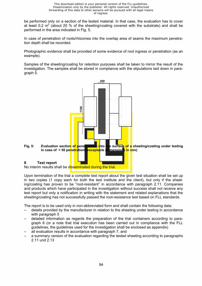
94
be performed only on a section of the tested material. In that case, the evaluation has to cover at least 0,2 m2 (about 20 % of the sheeting/coating covered with the substrate) and shall be performed in the area indicated in Fig. 5. In case of penetration of roots/rhizomes into the overlap area of seams the maximum penetra-tion depth shall be recorded. Photographic evidence shall be provided of some evidence of root ingress or penetration (as an example). Samples of the sheeting/coating for retention purposes shall be taken to mirror the result of the investigation. The samples shall be stored in compliance with the stipulations laid down in para-graph 5.
20011
00
Fig. 5: Evaluation section of penetrations into the surface of a sheeting/coating under testing
in case of > 50 penetrations/receptacle (dimensions in mm) 8 Test report No interim results shall be disseminated during the trial. Upon termination of the trial a complete test report about the given test situation shall be set up in two copies (1 copy each for both the test institute and the client), but only if the sheet-ing/coating has proven to be “root-resistant” in accordance with paragraph 2.11. Companies and products which have participated in the investigation without success shall not receive any test report but only a notification in writing with the statement and related explanations that the sheeting/coating has not successfully passed the root-resistance test based on FLL standards. The report is to be used only in non-abbreviated form and shall contain the following data: – details provided by the manufacturer in relation to the sheeting under testing in accordance
with paragraph 5 – detailed information as regards the preparation of the trial containers according to para-
graph 6 (or a note that trial execution has been carried out in compliance with the FLL guidelines, the guidelines used for the investigation shall be enclosed as appendix)
– all evaluation results in accordance with paragraph 7, and – a summary version of the evaluation regarding the tested sheeting according to paragraphs
2.11 und 2.13
This download edition is your personal version of the FLL-guidelines.Dissemination only by the publisher. All rights reserved. Unauthorized
forwarding of this data to other persons will be pursued with all legal meansof regress.
95
Furthermore, the report shall incorporate the following statements: – “The test report encompasses ..... pages and shall be used only in a non-abbreviated ver-
sion” – “The findings of the investigation are closely related to all reference data and material prop-
erties of the tested sheeting listed in the test report in compliance with the requirements, as well as to the jointing techniques which have been used or which are considered to be equivalent”
– “Retention samples of the tested sheeting/surface coating will be kept at the test institute” – “The test report was compiled on (date) ........ and has a general period of validity of 10
years. After confirmation by the test institute the period of validity may be extended in inter-vals of 5 years, but only if
– no major changes have been made to the investigation principles and rules, and – the tested product is still in compliance with the delivery programme of the client” Please contact the FLL to be provided with a specimen test report. 9 Competence The client who commissions the investigation is competent for: – procurement and installation of the protective lining (see 2.3 and 6.1) and the sheeting
and/or coating to be tested (see 6.1) – provision of a material sample (see 5), and – details in relation to the tested sheeting and/or coating (see 5) The test institute commits itself to providing the following services: – provision of a suitable space to carry out the investigation (see 4.1) – taking and storage of a material sample (see 5) – procurement and/or composition and installation of the moisture course and the vegetation
support course (see 4.3, 4.6, 6.1 and 6.2) – procurement and installation of the tensiometer devices (see 4.9, 6.1 and 6.2) – procurement of the test plants and/or the seeds, as well as for the greening of the recepta-
cles (see 4.10, 6.1 and 6.2) – care of the plants during the growth period (see 6.3) – all evaluation processes (see 7), and – setting up a final test report (see 8) The trial containers (see 4.2) may be provided by either the client or the test institute. All com-petences are subject to contractual agreements between the client who commissions the inves-tigation and the test institute. These contractual agreements also determine the expenses in-curred for the investigation which shall be borne by the client. Please contact the FLL to be provided with a specimen contract.
This download edition is your personal version of the FLL-guidelines.Dissemination only by the publisher. All rights reserved. Unauthorized
forwarding of this data to other persons will be pursued with all legal meansof regress.

ISBN 3-934484-81-6
Related Documents