AERONAUTICAL ENGINEERING –MRCET (UGC- AUTONOMOUS) III –II Sem- FVD (R15A2116) Page 1 FLIGHT VEHICLE DESIGN (R15A2116) COURSE FILE III B. Tech II Semester (2017-2018) Prepared By Ms. D.SMITHA, Assoc .Prof Department of Aeronautical Engineering MALLA REDDY COLLEGE OF ENGINEERING & TECHNOLOGY (Autonomous Institution – UGC, Govt. of India) Affiliated to JNTU, Hyderabad, Approved by AICTE - Accredited by NBA & NAAC – ‘A’ Grade - ISO 9001:2015 Certified) Maisammaguda, Dhulapally (Post Via. Kompally), Secunderabad – 500100, Telangana State, India.

Welcome message from author
This document is posted to help you gain knowledge. Please leave a comment to let me know what you think about it! Share it to your friends and learn new things together.
Transcript

AERONAUTICAL ENGINEERING –MRCET (UGC- AUTONOMOUS)
III –II Sem- FVD (R15A2116) Page 1
FLIGHT VEHICLE DESIGN (R15A2116)
COURSE FILE
III B. Tech II Semester
(2017-2018) Prepared By
Ms. D.SMITHA, Assoc .Prof
Department of Aeronautical Engineering
MALLA REDDY COLLEGE OF ENGINEERING &
TECHNOLOGY
(Autonomous Institution – UGC, Govt. of India)
Affiliated to JNTU, Hyderabad, Approved by AICTE - Accredited by NBA & NAAC – ‘A’ Grade - ISO 9001:2015 Certified)
Maisammaguda, Dhulapally (Post Via. Kompally), Secunderabad – 500100, Telangana State, India.
AERONAUTICAL ENGINEERING –MRCET (UGC- AUTONOMOUS)
III –II Sem- FVD (R15A2116) Page 2
MRCET VISION
▪ To become a model institution in the fields of Engineering, Technology and
Management.
▪ To have a perfect synchronization of the ideologies of MRCET with challenging
demands of International Pioneering Organizations.
MRCET MISSION
▪ To establish a pedestal for the integral innovation, team spirit, originality and
competence in the students, expose them to face the global challenges and become pioneers of Indian vision of modern society
MRCET QUALITY POLICY.
▪ To pursue continual improvement of teaching learning process of Undergraduate and
Post Graduate programs in Engineering & Management vigorously.
▪ To provide state of art infrastructure and expertise to impart the quality education
AERONAUTICAL ENGINEERING –MRCET (UGC- AUTONOMOUS)
III –II Sem- FVD (R15A2116) Page 3
PROGRAM OUTCOMES (PO’s)
Engineering Graduates will be able to:
1. Engineering knowledge: Apply the knowledge of mathematics, science, engineering
fundamentals, and an engineering specialization to the solution of complex engineering problems.
2. Problem analysis: Identify, formulate, review research literature, and analyze complex engineering problems reaching substantiated conclusions using first principles of mathematics, natural sciences, and engineering sciences.
3. Design / development of solutions: Design solutions for complex engineering problems and design system components or processes that meet the specified needs with appropriate consideration for the public health and safety, and the cultural, societal, and environmental considerations.
4. Conduct investigations of complex problems: Use research-based knowledge and research
methods including design of experiments, analysis and interpretation of data, and synthesis of the information to provide valid conclusions.
5. Modern tool usage: Create, select, and apply appropriate techniques, resources, and modern engineering and IT tools including prediction and modeling to complex engineering activities with an understanding of the limitations.
6. The engineer and society: Apply reasoning informed by the contextual knowledge to assess societal, health, safety, legal and cultural issues and the consequent responsibilities relevant to the professional engineering practice.
7. Environment and sustainability: Understand the impact of the professional engineering solutions in societal and environmental contexts, and demonstrate the knowledge of, and need for sustainable development.
8. Ethics: Apply ethical principles and commit to professional ethics and responsibilities and norms of the engineering practice.
9. Individual and team work: Function effectively as an individual, and as a member or leader in diverse teams, and in multidisciplinary settings.
10. Communication: Communicate effectively on complex engineering activities with the engineering community and with society at large, such as, being able to comprehend and write effective reports and design documentation, make effective presentations, and give and receive clear instructions.
11. Project management and finance: Demonstrate knowledge and understanding of the
engineering and management principles and apply these to one’s own work, as a member and leader in a team, to manage projects and in multi disciplinary environments.
12. Life- long learning: Recognize the need for, and have the preparation and ability to engage
in independent and life-long learning in the broadest context of technological change.

AERONAUTICAL ENGINEERING –MRCET (UGC- AUTONOMOUS)
III –II Sem- FVD (R15A2116) Page 4
DEPARTMENT OF AERONAUTICAL ENGINEERING
VISION
Department of Aeronautical Engineering aims to be indispensable source in Aeronautical Engineering which has a zeal to provide the value driven platform for the students to acquire
knowledge and empower themselves to shoulder higher responsibility in building a strong nation.
MISSION
The primary mission of the department is to promote engineering education and research. To
strive consistently to provide quality education, keeping in pace with time and technology.
Department passions to integrate the intellectual, spiritual, ethical and social development of
the students for shaping them into dynamic engineers.
QUALITY POLICY STATEMENT
Impart up-to-date knowledge to the students in Aeronautical area to make them quality
engineers. Make the students experience the applications on quality equipment and tools.
Provide systems, resources and training opportunities to achieve continuous improvement.
Maintain global standards in education, training and services.
AERONAUTICAL ENGINEERING –MRCET (UGC- AUTONOMOUS)
III –II Sem- FVD (R15A2116) Page 5
PROGRAM EDUCATIONAL OBJECTIVES – Aeronautical Engineering
1. PEO1 (PROFESSIONALISM & CITIZENSHIP): To create and sustain a community of learning in which students acquire knowledge and learn to apply it professionally with due consideration for ethical, ecological and economic issues.
2. PEO2 (TECHNICAL ACCOMPLISHMENTS): To provide knowledge based services to satisfy the needs of society and the industry by providing hands on experience in various technologies in core field.
3. PEO3 (INVENTION, INNOVATION AND CREATIVITY): To make the students to design, experiment, analyze, and interpret in the core field with the help of other multi disciplinary concepts wherever applicable.
4. PEO4 (PROFESSIONAL DEVELOPMENT): To educate the students to disseminate research findings with good soft skills and become a successful entrepreneur.
5. PEO5 (HUMAN RESOURCE DEVELOPMENT): To graduate the students in building national capabilities in technology, education and research
PROGRAM SPECIFIC OUTCOMES – Aeronautical Engineering
1. To mould students to become a professional with all necessary skills, personality and sound knowledge in basic and advance technological areas.
2. To promote understanding of concepts and develop ability in design manufacture and
maintenance of aircraft, aerospace vehicles and associated equipment and develop application capability of the concepts sciences to engineering design and processes.
3. Understanding the current scenario in the field of aeronautics and acquire ability to apply
knowledge of engineering, science and mathematics to design and conduct experiments in the field of Aeronautical Engineering.
4. To develop leadership skills in our students necessary to shape the social, intellectual,
business and technical worlds.
AERONAUTICAL ENGINEERING –MRCET (UGC- AUTONOMOUS)
III –II Sem- FVD (R15A2116) Page 6
MALLA REDDY COLLEGE OF ENGINEERING & TECHNOLOGY
III Year B. Tech, ANE-II Sem
(R15A2116) FLIGHT VEHICLE DESIGN Objectives:
• Students can acquire knowledge of designing a model of aircraft
• Sizing of different components of aircraft can be done
• Performance of different flights can be estimated
UNIT I DESIGN PROCESS OVERVIEW AIRFOIL AND GEOMETRY ELECTION,THRUST TO WEIGHT RATIO,WING LOADING Phases of aircraft design. Aircraft conceptual design process, project brief / request for proposal, problem definition information retrieval, aircraft requirements, configuration options Integrated product development and aircraft design. empty weight estimation –historical trends, fuel fraction estimation, mission profiles, mission segment weight fractions. Airfoil selection, airfoil design, design lift coefficient, stall, airfoil thickness ratio airfoil considerations. Wing geometry and wing vertical location, wing tip shapes Tail geometry and arrangements. Thrust to weight ratio - statistical estimation, thrust matching. Wing loading UNIT II INITIAL SIZING & CONFIGURATION LAYOUT Sizing with fixed engine and with rubber engine. Geometry sizing of fuselage, wing, tail, control surfaces. Development of configuration lay out from conceptual sketch. The inboard profile drawing, wetted area, volume distribution and fuel volume plots Lofting- definition, significance and methods, flat wrap lofting. Special consideration in configuration lay out. Isobar tailoring Sears-Haack volume distribution, structural load paths. Radar, IR, visual detect ability, aural signature. UNIT III CREW STATION,PASSENGERS &PAYLOAD, LANDING GEAR &SUBSYSTEMS AERODYNAMIC &PROPULSION, STRUCTURES &WEIGHT & BALANCE Fuselage design- crew station, passenger compartment, cargo provisions, weapons carriage, gun installation Landing gear arrangements, guidelines for lay out. Shock absorbers – types, sizing, stroke determination, gear load factors. Gear retraction geometry. Aircraft subsystems, significance to configuration lay out. The baseline design layout and report of initial specifications Airworthiness requirements - loads, safety margins, material properties, methods of estimation- construction, operation, maintenance, training- procedures Aircraft materials- mechanical properties- design data-
L T/P/D C
4 0 4
AERONAUTICAL ENGINEERING –MRCET (UGC- AUTONOMOUS)
III –II Sem- FVD (R15A2116) Page 7
allowable, allowable bases. Failure theory. Flight loads- atmospheric, maneuver- construction of flight envelope. Wing loads, Empennage loads, Fuselage loads. UNIT IV PERFORMANCE AND CONSTRAINT ANALYSIS REFINED SIZING & TRADE STUDIES The aircraft operating envelope. Take off analysis, balanced field length Landing analysis. Fighter performance measures of merit. Effects of wind on aircraft performance. Initial technical report of baseline design analysis and evaluation. Refined baseline design and report of specifications. Elements of life cycle cost, cost estimating method, RDT&E and production costs, operation and maintenance costs, fuel and oil costs, crew salaries Refined conceptual sizing methods. Sizing matrix plot and carpet plot. Trade studies - design trades, requirement trades, growth sensitivities. Multivariable design optimization methods. Measures of merit Determination of final baseline design configuration, preparation of type specification report UNIT V Design of the DC – 1, DC – 2, DC- 3 aircraft, Boeing B-47 and 707, General Dynamics F-16, SR-71 Black bird Northrop-Grumman B-2 Stealth Bomber. A survey of the Indian aircraft design effort Design of VTOL aircraft, helicopters, hypersonic vehicles, delta and double delta wings, forward swept wings, uninhabited air vehicles. Outcomes:
• Students can estimate all the design parameters of an aircraft.
• Ability to model the aircraft structural components
• Ideology of load estimations basing on the formulae can be performed by students Text books
1. Raymer ,D.P., Aircraft Design : A Conceptual Approach, 3rd edn., AIAA Education series, AIAA, 1999,ISBN: 1-56347-281-0
2. Howe, D., Aircraft Conceptual Design Synthesis, Professional Engineering Publishing,London,2000,ISBN:1-86058-301-6

AERONAUTICAL ENGINEERING –MRCET (UGC- AUTONOMOUS)
III –II Sem- FVD (R15A2116) Page 8
MALLAREDDY COLLEGE OF ENGINEERING AND TECHNOLOGY (UGC- AUTONOMOUS –Govt. OF INDIA)
III B.TECH II SEMESTER – AERONAUTICAL ENGINEERING
(R15A2116) FLIGHT VEHICLE DESIGN
MODEL PAPER – I MAXIMUM MARKS: 75
PART A Max Marks: 25
i. All questions in this section are compulsory
ii. Answer in TWO to FOUR sentences.
1) Explain about the design wheel with sketch (3M)
2) Define take-off weight build up (3M)
3) What is rubber engine sizing (3M)
4) Define conic lofting (2M)
5) Define “tip back angle” (3M)
6) Explain about the selection of materials for an aircraft ( 2 M)
7) Explain about trade studies ( 2 M)
8) Define balanced field length ( 3 M)
9) Explain VTOL terminology (2M)
10) Define the phases of aircraft design using flow diagram (2M)
PART B Max Marks: 50
i. Answer only one question among the two questions in choice.
ii. Each question answer (irrespective of the bits) carries 10M.
11) Explain Thrust Matching & also explain about the Thrust –To Weight Ratio and Wing Loading
OR 12) Explain tail geometry and arrangements in detail with requires sketches
13) Write the equation for rubber engine sizing
OR 14) What is Radar Detect ability explain in detail with fig
AERONAUTICAL ENGINEERING –MRCET (UGC- AUTONOMOUS)
III –II Sem- FVD (R15A2116) Page 9
15) Explain in detail about the shock absorbers
OR 16) Explain aircraft subsystems in detail with neat sketches
17) Explain aircraft operating envelope
OR 18) What do you understand by RDT&E and production costs explain
19) Explain about VTOL Aircraft design
OR 20) Explain in detail about the design of the DC- 1
AERONAUTICAL ENGINEERING –MRCET (UGC- AUTONOMOUS)
III –II Sem- FVD (R15A2116) Page 10
MALLAREDDY COLLEGE OF ENGINEERING AND TECHNOLOGY (UGC- AUTONOMOUS –Govt. OF INDIA)
III B.TECH II SEMESTER – AERONAUTICAL ENGINEERING
(R15A2116) FLIGHT VEHICLE DESIGN
MODEL PAPER – II MAXIMUM MARKS: 75
PART A Max Marks: 25
i. All questions in this section are compulsory
ii. Answer in TWO to FOUR sentences.
1) Explain specific fuel consumption (2M)
2) Define range (2M)
3) Explain geometry sizing (3M)
4) Explain about flat-wrap fuselage lofting (3M)
5) Define wing loads (3M)
6) Define oleo pneumatic shock strut (3M)
7) Define RDT&E (3M)
8) Define ground roll in landing analysis (2M)
9) Define delta wing with neat sketch (2M)
10) Draw neat sketches of suck down and fountain lift (2M)
PART B Max Marks: 50 i. Answer only one question among the two questions in choice.
ii. Each question answer (irrespective of the bits) carries 10M.
11) Explain in detail the conceptual design phase in aircraft design
OR 12) Explain mission profiles with a neat sketch and also explain mission segment weight
fractions for simple cruise
13) Explain in detail about the airfoil geometry with req sketches
OR 14) How wetted area and volume determination is estimated
AERONAUTICAL ENGINEERING –MRCET (UGC- AUTONOMOUS)
III –II Sem- FVD (R15A2116) Page 11
15) Explain in detail about the structural considerations in special considerations in configuration
layout with neat figures
OR 16) Explain about the design configuration of crew station, passenger compartment, and cargo
provisions
17) Explain landing analysis in detail with a neat sketches and equations
OR 18) Explain elements of lift – cycle cost and cost – estimating methods
19) Explain in detail about design of the DC- 2 aircraft
OR 20) Explain about VTOL jet – propulsion options
AERONAUTICAL ENGINEERING –MRCET (UGC- AUTONOMOUS)
III –II Sem- FVD (R15A2116) Page 12
MALLAREDDY COLLEGE OF ENGINEERING AND TECHNOLOGY (UGC- AUTONOMOUS –Govt. OF INDIA)
III B.TECH II SEMESTER – AERONAUTICAL ENGINEERING
(R15A2116) FLIGHT VEHICLE DESIGN
MODEL PAPER – III MAXIMUM MARKS: 75
PART A Max Marks: 25 i. All questions in this section are compulsory
ii. Answer in TWO to FOUR sentences.
1) Define drag polar (2M)
2) Write about the subsonic lift-curve slope with sketch (2M)
3) Define leakage and protuberance drag (3M)
4) Define Oswald span efficiency factor (3M)
5) Define young’s modulus (2M)
6) Explain about the trim condition (2M)
7) Define level flight (2M)
8) Define total take –off distance (3M)
9) Explain uninhabited air vehicles (3M)
10) Define cut-off forward swept (3M)
PART B Max Marks: 50
i. Answer only one question among the two questions in choice.
ii. Each question answer (irrespective of the bits) carries 10M.
11) Explain about the overview of the design process and phases of aircraft design
OR 12) Explain about the airfoil & geometry selection
13) Explain in detail about conic lofting
OR
AERONAUTICAL ENGINEERING –MRCET (UGC- AUTONOMOUS)
III –II Sem- FVD (R15A2116) Page 13
14) Explain about vulnerability considerations , crashworthiness considerations and producibility
considerations
15) Explain about the air loads due to maneuver loads ,gust loads, air loads due to control deflection
OR
16) Compare the drag polar of a symmetric airfoils and a cambered airfoils
17) Explain refined baseline design and report of specifications
OR 18) Explain about effects of wind on aircraft performance
19) Explain about the hypersonic vehicles
OR 20) Explain about SR -71 Black bird Northrop – Grumman
AERONAUTICAL ENGINEERING –MRCET (UGC- AUTONOMOUS)
III –II Sem- FVD (R15A2116) Page 14
MALLAREDDY COLLEGE OF ENGINEERING AND TECHNOLOGY (UGC- AUTONOMOUS –Govt. OF INDIA)
III B.TECH II SEMESTER – AERONAUTICAL ENGINEERING
(R15A2116) FLIGHT VEHICLE DESIGN
MODEL PAPER – IV MAXIMUM MARKS: 75
PART A Max Marks: 25 i. All questions in this section are compulsory
ii. Answer in TWO to FOUR sentences.
1) Explain what is RDT&E and production costs (3M)
2) Define stability (2M)
3) Define static lateral directional stability and trim (3M)
4) Explain in short about the carpet plot (3M)
5) Define load factor (2M)
6) Define aerodynamic center (2M)
7) Define propulsion efficiency (3M)
8) Explain in short about gross thrust and net thrust (2M)
9) Explain in short about the aerodynamic forces (3M)
10) Briefly explain about aerodynamic coefficients with fig (2M)
PART B Max Marks: 50 i. Answer only one question among the two questions in choice.
ii. Each question answer (irrespective of the bits) carries 10M.
11) Explain what is Design and Design Wheel?
OR
12) Derive the relationship between the thrust – to – weight ratio and wing loading of an aircraft
in climb
13) Explain about conic shape parameter
OR
14) What are the factors involved in deciding the location of the wing with respect to the
fuselage? Explain in detail

AERONAUTICAL ENGINEERING –MRCET (UGC- AUTONOMOUS)
III –II Sem- FVD (R15A2116) Page 15
15) What are the functions of a landing gear system?
OR
16) Describe the maneuver loads acting on an aircraft?
17) Write short notes on (a) Elements of life cycle cost, (b) cost analysis
OR 18) Explain in detail about the Measures of merit?
19) Explain about Boeing B-47 aircraft.
OR
20) Explain in detail about VTOL propulsion considerations
AERONAUTICAL ENGINEERING –MRCET (UGC- AUTONOMOUS)
III –II Sem- FVD (R15A2116) Page 16
MALLAREDDY COLLEGE OF ENGINEERING AND TECHNOLOGY (UGC- AUTONOMOUS –Govt. OF INDIA)
III B.TECH II SEMESTER – AERONAUTICAL ENGINEERING
(R15A2116) FLIGHT VEHICLE DESIGN
MODEL PAPER – V MAXIMUM MARKS: 75
PART A Max Marks: 25
i. All questions in this section are compulsory
ii. Answer in TWO to FOUR sentences.
1) Explain the difference between the jet engine locations at chin and side with neat fig
(3M) 2) Draw the neat figures of typical mission profiles for sizing (3M)
3) Define design take –off gross weight (3M)
4) Explain about airfoil geometry with a neat fig (3M)
5) Define wing dihedral, wing incidence angle ,taper ratio (3M)
6) Explain about maneuver (2M)
7) Explain fuel & oil costs (2M)
8) Write a short notes on cost estimating method (2M)
9) Write a short notes on Boeing B- 47 (2M)
10) Write about hypersonic vehicles ` (2M)
PART B Max Marks: 50 i. Answer only one question among the two questions in choice.
ii. Each question answer (irrespective of the bits) carries 10M.
11) (a)Explain about take off – weight calculation (b)aircraft conceptual design process
OR 12) Explain about wing geometry and wing vertical location with neat sketches
13) Explain in detail about s( a ) ears – Haack volume distribution ( b ) infrared detect ability
OR 14) Explain in detail about control surface sizing
15) Explain about landing gear arrangements
OR
AERONAUTICAL ENGINEERING –MRCET (UGC- AUTONOMOUS)
III –II Sem- FVD (R15A2116) Page 17
16) Explain in detail about aerodynamic considerations in configuration layout and crashworthiness
considerations
17) Explain takeoff and landing analysis with neat sketches
OR 18) Explain about improved conceptual sizing methods and sizing matrix and carpet plots
19) Explain in detail about DC – 3 aircraft
OR
20) Explain hypersonic vehicles , delta and double delta wings
AERONAUTICAL ENGINEERING –MRCET (UGC- AUTONOMOUS)
III –II Sem- FVD (R15A2116) Page 18
UNIT – I DESIGN PROCESS OVERVIEW AIRFOL & GEOMETRY SELECTION, THRUST TO WEIGHT
RATIO, WING LOADING
1.1- WHAT IS DESIGN ▪ Aircraft design is a separate discipline of aeronautical engineering different from the analytical
disciplines such as aerodynamics, structures, controls, and propulsion. An aircraft designer needs to be well versed in these and many other specialties, but will actually spend little time performing such analysis in all but the smallest companies. Instead, the designer's time is spent doing something called "design," creating the geometric description of a thing to be built.
▪ To the uninitiated, "design" looks a lot like "drafting" (or in the modern world, "computer-aided
drafting"). The designer's product is a drawing, and the designer spends the day hunched over a drafting table or computer terminal.
▪ A good aircraft design seems to miraculously glide through subsequent evaluations by specialists
without major changes being required. Somehow, the landing gear fits, the fuel tanks are near the centre of gravity, the structural members are simple and lightweight, the overall arrangement provides good aerodynamics, the engines install in a simple and clean fashion, and a host of similar detail seems to fall into place.
▪ Design is not just the actual layout, but also the analytical processes used to determine what
should be designed and how the design should be modified to better meet the requirements. In a small company, this may be done by the same individuals who do the layout design. In the larger companies, aircraft analysis is done by the sizing and performance specialists with the assistance of experts in aerodynamics, weights, propulsion, stability, and other technical specialties.
1.2- OVERVIEW OF THE DESIGN PROCESS ▪ Those involved in design can never quite agree as to just where the design process begins. The
designer thinks it starts with a new airplane concept. The sizing specialist knows that nothing can begin until an initial estimate of the weight is made. The customer, civilian or military, feels that the design begins with requirements.
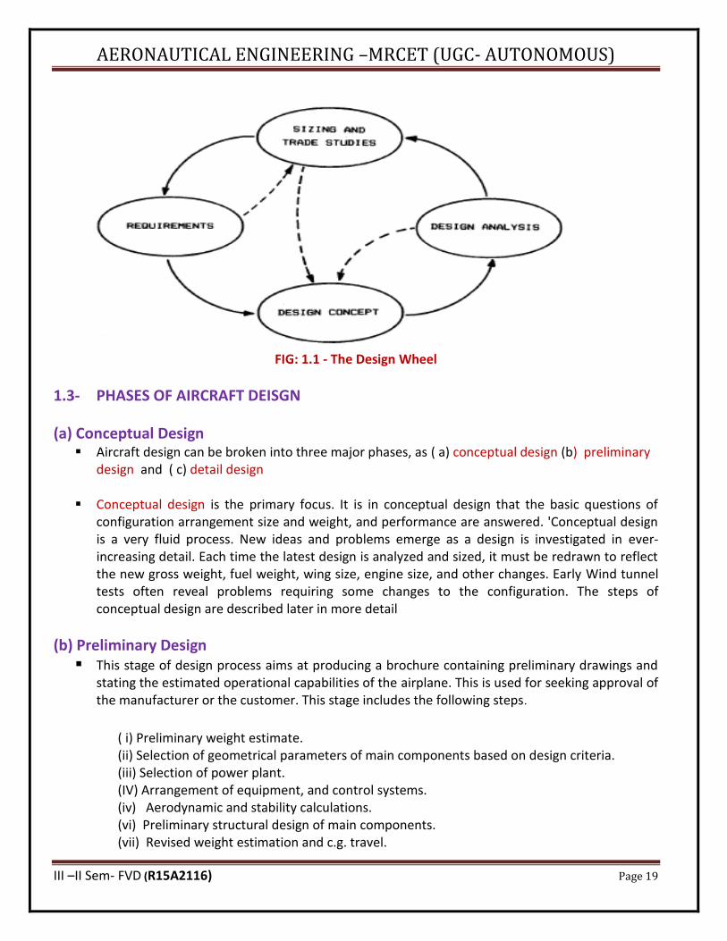
▪ Design is an iterative effort, as shown in the "Design Wheel" of Fig. 1.1. Requirements are set by
prior design trade studies. Concepts are developed to meet requirements. Design analysis frequently points toward new concepts and technologies, which can initiate a whole new design effort. However a particular design is begun, all of these activities are equally important in producing a good aircraft concept.
AERONAUTICAL ENGINEERING –MRCET (UGC- AUTONOMOUS)
III –II Sem- FVD (R15A2116) Page 19
FIG: 1.1 - The Design Wheel
1.3- PHASES OF AIRCRAFT DEISGN
(a) Conceptual Design ▪ Aircraft design can be broken into three major phases, as ( a) conceptual design (b) preliminary
design and ( c) detail design
▪ Conceptual design is the primary focus. It is in conceptual design that the basic questions of configuration arrangement size and weight, and performance are answered. 'Conceptual design is a very fluid process. New ideas and problems emerge as a design is investigated in ever-increasing detail. Each time the latest design is analyzed and sized, it must be redrawn to reflect the new gross weight, fuel weight, wing size, engine size, and other changes. Early Wind tunnel tests often reveal problems requiring some changes to the configuration. The steps of conceptual design are described later in more detail
(b) Preliminary Design ▪ This stage of design process aims at producing a brochure containing preliminary drawings and
stating the estimated operational capabilities of the airplane. This is used for seeking approval of the manufacturer or the customer. This stage includes the following steps.
( i) Preliminary weight estimate. (ii) Selection of geometrical parameters of main components based on design criteria. (iii) Selection of power plant. (IV) Arrangement of equipment, and control systems. (iv) Aerodynamic and stability calculations. (vi) Preliminary structural design of main components. (vii) Revised weight estimation and c.g. travel.
AERONAUTICAL ENGINEERING –MRCET (UGC- AUTONOMOUS)
III –II Sem- FVD (R15A2116) Page 20
(viii) Preparation of 3-view drawing. (ix) Performance estimation. (x) Preparation of brochure.
▪ After the preliminary design has been approved by the manufacturer / customer. The detailed design studies are carried out. These include the following stages (a) Wind tunnel and structural testing on models of airplane configuration arrived after preliminary design stage. These tests serve as a check on the correctness of the estimated characteristics and assessment of the new concepts proposed in the design.
(b) Mock-up: This is a full scale model of the airplane or its important sections. This helps in (a) efficient lay-out of structural components and equipments,
(b) Checking the clearances, firing angles of guns, visibility etc. Currently this stage is avoided by the use of CAD (Computer Aided Design) packages which provide detailed drawings of various components and subassemblies.
(c) Complete wind tunnel testing of the approved configuration. Currently CFD (Computational Fluid Dynamics) plays an important role in reducing the number of tests to be carried-out. In CFD, the equations governing the fluid flow are solved numerically. The results provide flow patterns, drag coefficient, lift coefficient, moment coefficient, pressure distribution etc. Through the results may not be very accurate at high angles of attack, they are generally accurate near the design point. Further, they provide information on the effects of small changes in the geometric parameters, on the flow field and permit parametric studies. (d) Preparation of detailed drawings. (e) Final selection of power plant. (f) Calculations of (a) c.g. shift (b) performance and (c) stability (g) Fabrication of prototypes. These are the first batch of full scale airplane. Generally six prototypes are constructed. Some of them are used for verifying structural integrity and functioning of various systems. Others are used for flight testing to evaluate performance and stability.
(c) Detail Design ▪ Assuming a favourable decision for entering full-scale development, the detail design phase
begins in which the actual pieces to be fabricated are designed. For example, during conceptual and preliminary design the wing box will be designed and analyzed as a whole. During detail design, that whole will be broken down into individual ribs, spars, and skins, each of which must be separately designed and analyzed.
▪ Another important part of detail design is called production design. Specialists determine how
the airplane will be fabricated, starting with the smallest and simplest subassemblies and building up to the final assembly process. Production designers frequently wish to modify the design for ease of manufacture; that can have a major impact on performance or weight. Compromises are inevitable, but the design must still meet the original requirements.
▪ During detail design, the testing effort intensifies. Actual structure of the aircraft is fabricated
and tested. Control laws for the flight control system are tested on an "iron-bird" simulator, a
AERONAUTICAL ENGINEERING –MRCET (UGC- AUTONOMOUS)
III –II Sem- FVD (R15A2116) Page 21
detailed working model of the actuators and flight control surfaces. Flight simulators are developed and flown by both company and customer test-pilots.
▪ Detail design ends with fabrication of the aircraft. Frequently the fabrication begins on part of
the aircraft before the entire detail-design effort is completed. Hopefully, changes to already-fabricated pieces can be avoided.
1.4- AIRCRAFT CONCEPTUAL DESIGN PROCESS ▪ Conceptual design will usually begin with either a specific set of design requirements established
by the prospective customer or a company-generated guess as to what future customers may need. Design requirements include parameters such as the aircraft range and payload, takeoff and landing distances, and manoeuvrability and speed requirements.
▪ The design requirements also include a vast set of civil or military design specifications which
must be met. These include landing sink-speed, stall speed, structural design limits, pilots' outside vision angles, reserve fuel, and many others. Sometimes a design will begin as an innovative idea rather than as a response to a given requirement
▪ Before a design can be started, a decision must be made as to what technologies will be
incorporated. If a design is to be built in the near future, it must use only currently-available technologies as well as existing engines and avionics. If it is being designed to be built in the more distant future, then an estimate of the technological state of the art must be made to determine which emerging technologies will be ready for use at that time.
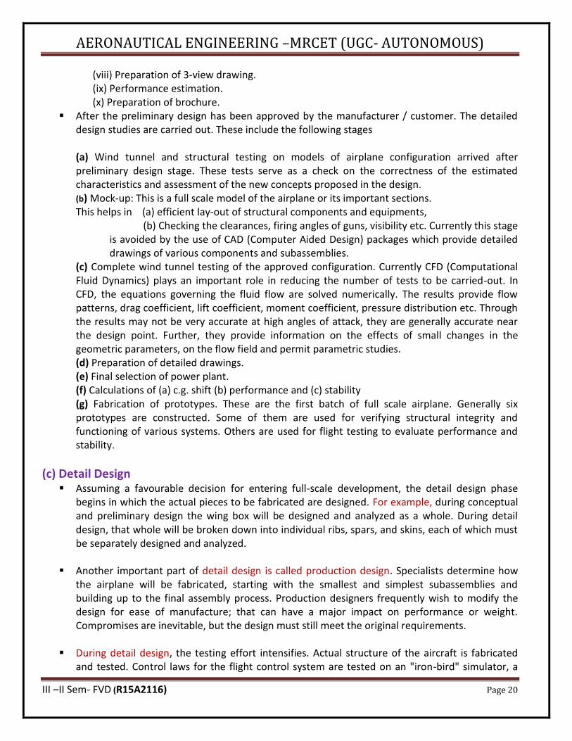
▪ An optimistic estimate of the technology availability will yield a lighter, cheaper aircraft to
perform a given mission, but will also result in a higher development risk. The actual design effort usually begins with a conceptual sketch
FIG: 1.2- Initial Sketch
AERONAUTICAL ENGINEERING –MRCET (UGC- AUTONOMOUS)
III –II Sem- FVD (R15A2116) Page 22
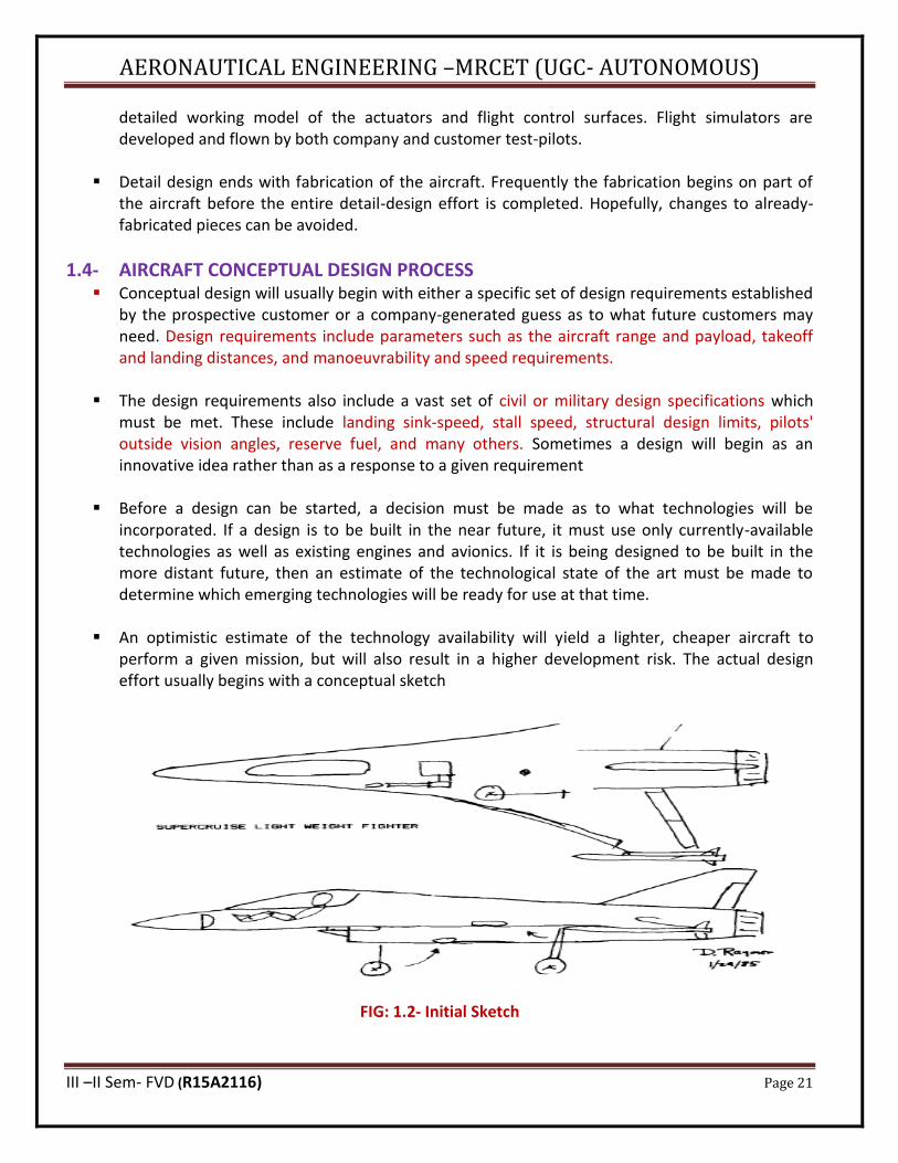
▪ This is the "back of a napkin" drawing of aerospace legend, and gives a rough indication of what the design may look like. A good conceptual sketch will include the approximate wing and tail geometries, the fuselage shape, and the internal locations of the major components such as the engine, cockpit, payload/passenger compartment, landing gear, and perhaps the fuel tanks. The conceptual sketch can be used to estimate aerodynamics and weight fractions by comparison to previous designs. These estimates are used to make a first estimate of the required total weight and fuel weight to perform the design mission, by a process called "sizing."
▪ The conceptual sketch may not be needed for initial sizing if the design resembles previous ones.
The "first-order" sizing provides the information needed to develop an initial design layout
FIG – 1.3- Configuration Layout
▪ This is a three-view drawing complete with the more important internal arrangement details, including typically the landing gear, payload or passenger compartment, engines and inlet ducts, fuel tanks, cockpit, major avionics, and any other internal components which are large enough to affect the overall shaping of the aircraft. Enough cross-sections are shown to verify that everything fits.
▪ On a drafting table, the three-view layout is done in some convenient scale such as 1/10, 1/20, 1/40, or 1/100 (depending upon the size of the airplane and the available paper). On a computer-aided design system, the design work is usually done in full scale (numerically).
▪ This initial layout is analyzed to determine if it really will perform the mission as indicated by the first-order sizing. Actual aerodynamics, weights, and installed propulsion characteristics are analyzed and subsequently used to do a detailed sizing calculation. Furthermore, the performance capabilities of the design are calculated and compared to the requirements mentioned above. Optimization techniques are used to find the lightest or lowest-cost aircraft that will both perform the design mission and meet all performance requirements.
▪ The results of this optimization include a better estimate of the required total weight and fuel weight to meet the mission. The results also include required revisions to the engine and wing sizes. This frequently requires a new or revised design layout, in which the designer incorporates
AERONAUTICAL ENGINEERING –MRCET (UGC- AUTONOMOUS)
III –II Sem- FVD (R15A2116) Page 23
these changes and any others suggested by the effort to date. The revised drawing, after some number of iterations, is then examined in detail by an ever-expanding group of specialists, each of whom insures that the design meets the requirements of that specialty
▪ The end product of all this will be an aircraft design that can be confidently passed to the
preliminary design phase, as previously discussed. While further changes should be expected during preliminary design, major revisions will not occur if the conceptual design effort has been successful.
1.5- SIZING FROM A CONCEPTUAL SKETCH ▪ There are many levels of design procedure. The simplest level just adopts past history. For
example, if you need an immediate estimate of the takeoff weight of an airplane to replace the Air Force F-15 fighter, use 44,500 lb. That is what the F-15 weighs, and is probably a good number to start with.
▪ To get the "right" answer takes several years, many people, and lots of money. Actual design
requirements must be evaluated against a number of candidate designs, each of which must be designed, analyzed, sized, optimized, and redesigned any number of times. Analysis techniques include all manner of computer code as well as correlations to wind-tunnel and other tests. Even with this extreme level of design sophistication, the actual airplane when flown will never exactly match predictions.
▪ The simplified sizing method presented in this section can only be used for missions which do
not include any combat or payload drops. While admittedly crude, this method introduces all of the essential features of the most sophisticated design by the major aerospace manufacturers.
1.6- TAKE OFF WEIGHT BUILD UP ▪ "Design takeoff gross weight" is the total weight of the aircraft as it begins the mission for which
it was designed. This is not necessarily the same as the "maximum takeoff weight." Many military aircraft can be overloaded beyond design weight but will suffer a reduced manoeuvrability. Unless specifically mentioned, takeoff gross weight, or "W0 ," is assumed to be the design weight. Design takeoff gross weight can be broken into crew weight, payload (or passenger) weight, fuel weight, and the remaining (or "empty") weight. The empty weight includes the structure, engines, landing gear, fixed equipment, avionics, and anything else not considered a part of crew, payload, or fuel.
▪ Equation (1.1) summarizes the takeoff-weight build-up.
____________ (1.1)
▪ The crew and payload weights are both known since they are given in the design requirements. The only unknowns are the fuel weight and empty weight. However, they are both dependent on the total aircraft weight.

AERONAUTICAL ENGINEERING –MRCET (UGC- AUTONOMOUS)
III –II Sem- FVD (R15A2116) Page 24
▪ Thus an iterative process must be used for aircraft sizing.
▪ To simplify the calculation, both fuel and empty weights can be expressed as fractions of the
total takeoff weight, i.e., (Wj!Wo) and (We!Wo)
▪ Thus equation (1.1) becomes
-____________ (1.2)
This can be solved for W0 as follows:
-____________ (1.3)
______________ (1.4)
Now Wo can be determined if (Wf/Wo) and (We/Wo) can be estimated. These are described below.
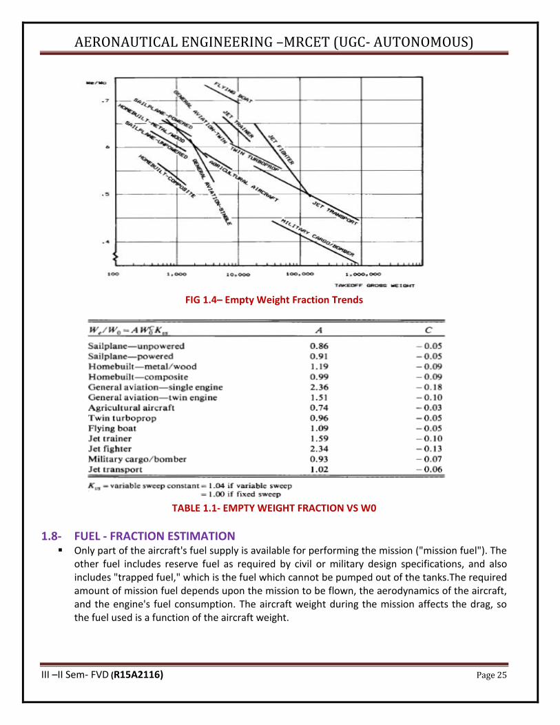
1.7- EMPTY WEIGHT FRACTION ▪ The empty-weight fraction (We/ Wo) can be estimated statistically from historical trends as
shown in Fig1.4,. Empty-weight fractions vary from about 0.3 to 0.7, and diminish with increasing total aircraft weight. As can be seen, the type of aircraft also has a strong effect, with flying boats having the highest empty-weight fractions and long-range military aircraft having the lowest. Flying boats are heavy because they need to carry extra weight for what amounts to a boat hull. Notice also that different types of aircraft exhibit different slopes to the trend lines of empty-weight Fraction vs. takeoff weight.
▪ Table 1.1 presents statistical curve-fit equations for the trends shown in fig 1.4. Note that these
are all exponential equations based upon takeoff gross weight. The exponents are small negative numbers, which indicates that the empty weight fractions decrease with increasing takeoff weight, as shown by the trend lines in fig 1.4. The differences in exponents for different types of aircraft reflect the different slopes to the trend lines, and imply that some types of aircraft are more sensitive in sizing than others.
▪ A variable-sweep wing is heavier than a fixed wing, and is accounted for at this initial stage of
design by multiplying the empty-weight fraction as determined from the equations in Table 1.1 by about 1.04.
AERONAUTICAL ENGINEERING –MRCET (UGC- AUTONOMOUS)
III –II Sem- FVD (R15A2116) Page 25
FIG 1.4– Empty Weight Fraction Trends
TABLE 1.1- EMPTY WEIGHT FRACTION VS W0
1.8- FUEL - FRACTION ESTIMATION ▪ Only part of the aircraft's fuel supply is available for performing the mission ("mission fuel"). The
other fuel includes reserve fuel as required by civil or military design specifications, and also includes "trapped fuel," which is the fuel which cannot be pumped out of the tanks.The required amount of mission fuel depends upon the mission to be flown, the aerodynamics of the aircraft, and the engine's fuel consumption. The aircraft weight during the mission affects the drag, so the fuel used is a function of the aircraft weight.
AERONAUTICAL ENGINEERING –MRCET (UGC- AUTONOMOUS)
III –II Sem- FVD (R15A2116) Page 26
▪ As a first approximation, the fuel used can be considered to be proportional to the aircraft weight, so the fuel fraction ( Wf! Wo) is approximately independent of aircraft weight. Fuel fraction can be estimated based on the mission to be flown using approximations of the fuel consumption and aerodynamics.
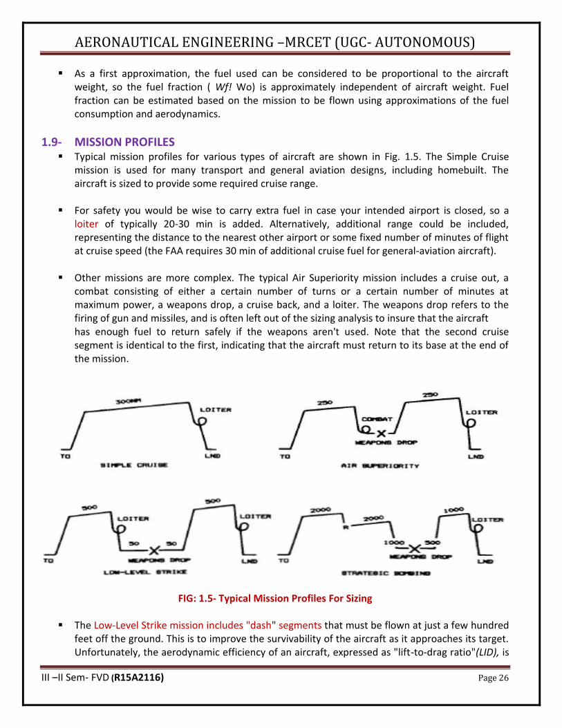
1.9- MISSION PROFILES ▪ Typical mission profiles for various types of aircraft are shown in Fig. 1.5. The Simple Cruise
mission is used for many transport and general aviation designs, including homebuilt. The aircraft is sized to provide some required cruise range.
▪ For safety you would be wise to carry extra fuel in case your intended airport is closed, so a
loiter of typically 20-30 min is added. Alternatively, additional range could be included, representing the distance to the nearest other airport or some fixed number of minutes of flight at cruise speed (the FAA requires 30 min of additional cruise fuel for general-aviation aircraft).
▪ Other missions are more complex. The typical Air Superiority mission includes a cruise out, a
combat consisting of either a certain number of turns or a certain number of minutes at maximum power, a weapons drop, a cruise back, and a loiter. The weapons drop refers to the firing of gun and missiles, and is often left out of the sizing analysis to insure that the aircraft has enough fuel to return safely if the weapons aren't used. Note that the second cruise segment is identical to the first, indicating that the aircraft must return to its base at the end of the mission.
FIG: 1.5- Typical Mission Profiles For Sizing
▪ The Low-Level Strike mission includes "dash" segments that must be flown at just a few hundred feet off the ground. This is to improve the survivability of the aircraft as it approaches its target. Unfortunately, the aerodynamic efficiency of an aircraft, expressed as "lift-to-drag ratio"(LID), is
AERONAUTICAL ENGINEERING –MRCET (UGC- AUTONOMOUS)
III –II Sem- FVD (R15A2116) Page 27
greatly reduced during low-level, high-speed flight, as is the engine efficiency. The aircraft may burn almost as much fuel during the low-level dash segment as it burns in the much-longer cruise segment.
▪ The Strategic Bombing mission introduces another twist. After the initial cruise, a refuelling
segment occurs, as indicated by an "R." Here the aircraft meets up with a tanker aircraft such as an Air Force KC-135 and receives some quantity of fuel. This enables the bomber to achieve far more range, but adds to the overall operating cost because a fleet of tanker aircraft must be dedicated to supporting the bombers.
▪ Another difference in this strategic mission is the fact that the return cruise range is far shorter
than the outbound range. This is necessary because of the extreme range required. If the aircraft were sized to return to its original base, it would probably weigh several million pounds. Instead, it is assumed that strategic bombers will land on bases in friendly countries for refuelling after completion of their mission.
1.10- MISSION SEGMENT WEIGHT FRACTIONS ▪ For analysis, the various mission segments, or "legs," are numbered, with zero denoting the start
of the mission. Mission leg "one" is usually engine warm-up and takeoff for first-order sizing estimation. The remaining legs are sequentially numbered.
For example, in the simple cruise mission the legs could be numbered as
(1) Warm-up and takeoff, (2) climb, (3) cruise, (4) loiter, and (5) land
▪ In a similar fashion, the aircraft weight at each part of the mission can be numbered. Thus, Wo is the beginning weight ("takeoff gross weight").
▪ For the simple cruise mission, W1 would be the weight at the end of the first mission segment,
which is the warm-up and takeoff. W2 would be the aircraft weight at the end of the climb. W3 would be the weight after cruise, and W4 after loiter. Finally, W5 would be the weight at the end of the landing segment, which is also the end of the total mission.
▪ During each mission segment, the aircraft loses weight by burning fuel (remember that our simple sizing method doesn't permit missions involving a payload drop). The aircraft weight at the end of a mission segment divided by its weight at the beginning of that segment is called the "mission segment weight fraction." This will be the basis for estimating the required fuel fraction for initial sizing.
▪ For any mission segment '' i,'' the mission segment weight fraction can be expressed as (Wi/W; _
1). If these weight fractions can be estimated for all of the mission legs, they can be multiplied together to find the ratio of the aircraft weight at the end of the total mission, Wx (assuming "x" segments altogether) divided by the initial weight, W0• This ratio, WxlW0, can then be used to calculate the total fuel fraction required.
AERONAUTICAL ENGINEERING –MRCET (UGC- AUTONOMOUS)
III –II Sem- FVD (R15A2116) Page 28
▪ These mission segment weight fractions can be estimated by a variety of methods. For our
simplified form of initial sizing, the types of mission leg will be limited to warm-up and takeoff, climb, cruise, loiter, and land. As previously mentioned, mission legs involving combat, payload drop, and refuel are not permitted in this simplified sizing method but will be discussed in a later sections.
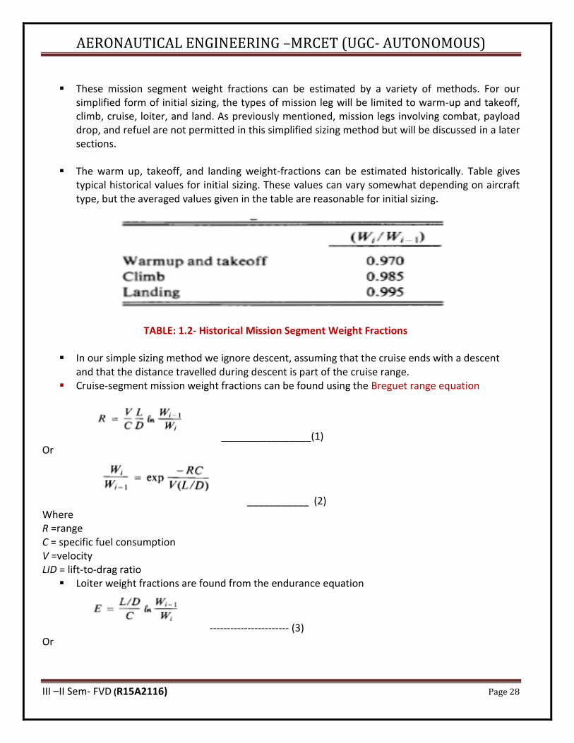
▪ The warm up, takeoff, and landing weight-fractions can be estimated historically. Table gives
typical historical values for initial sizing. These values can vary somewhat depending on aircraft type, but the averaged values given in the table are reasonable for initial sizing.
TABLE: 1.2- Historical Mission Segment Weight Fractions
▪ In our simple sizing method we ignore descent, assuming that the cruise ends with a descent and that the distance travelled during descent is part of the cruise range.
▪ Cruise-segment mission weight fractions can be found using the Breguet range equation
________________(1) Or
___________ (2) Where R =range C = specific fuel consumption V =velocity LID = lift-to-drag ratio
▪ Loiter weight fractions are found from the endurance equation
----------------------- (3) Or
AERONAUTICAL ENGINEERING –MRCET (UGC- AUTONOMOUS)
III –II Sem- FVD (R15A2116) Page 29
----------------------- (4) Where E = endurance or loiter time.
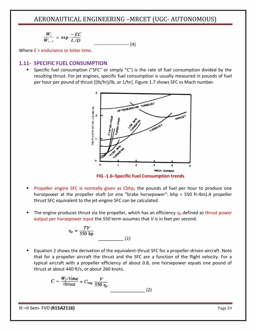
1.11- SPECIFIC FUEL CONSUMPTION ▪ Specific fuel consumption ("SFC" or simply "C") is the rate of fuel consumption divided by the
resulting thrust. For jet engines, specific fuel consumption is usually measured in pounds of fuel per hour per pound of thrust [(lb/hr)/lb, or 1/hr]. Figure 1.7 shows SFC vs Mach number.
FIG -1.6–Specific Fuel Consumption trends
▪ Propeller engine SFC is normally given as Cbhp, the pounds of fuel per hour to produce one
horsepower at the propeller shaft (or one "brake horsepower": bhp = 550 ft-Ibis).A propeller thrust SFC equivalent to the jet-engine SFC can be calculated.
▪ The engine produces thrust via the propeller, which has an efficiency ηp defined as thrust power
output per horsepower input the 550 term assumes that V is in feet per second.
__________ (1)
▪ Equation 2 shows the derivation of the equivalent-thrust SFC for a propeller-driven aircraft. Note that for a propeller aircraft the thrust and the SFC are a function of the flight velocity. For a typical aircraft with a propeller efficiency of about 0.8, one horsepower equals one pound of thrust at about 440 ft/s, or about 260 knots.
______________ (2)
AERONAUTICAL ENGINEERING –MRCET (UGC- AUTONOMOUS)
III –II Sem- FVD (R15A2116) Page 30
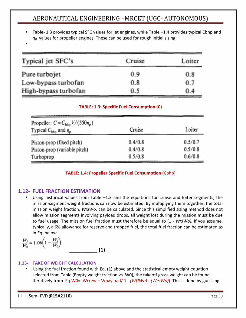
▪ Table- 1.3 provides typical SFC values for jet engines, while Table –1.4 provides typical Cbhp and ηp values for propeller engines. These can be used for rough initial sizing.
▪
TABLE: 1.3: Specific Fuel Consumption (C)
TABLE: 1.4: Propeller Specific Fuel Consumption (Cbhp)
1.12- FUEL FRACTION ESTIMATION ▪ Using historical values from Table –1.3 and the equations for cruise and loiter segments, the
mission-segment weight fractions can now be estimated. By multiplying them together, the total mission weight fraction, WxlWo, can be calculated. Since this simplified sizing method does not allow mission segments involving payload drops, all weight lost during the mission must be due to fuel usage. The mission fuel fraction must therefore be equal to (1 - WxlWo). If you assume, typically, a 6% allowance for reserve and trapped fuel, the total fuel fraction can be estimated as in Eq. below
__________ (1) 1.13- TAKE OF WEIGHT CALCULATION
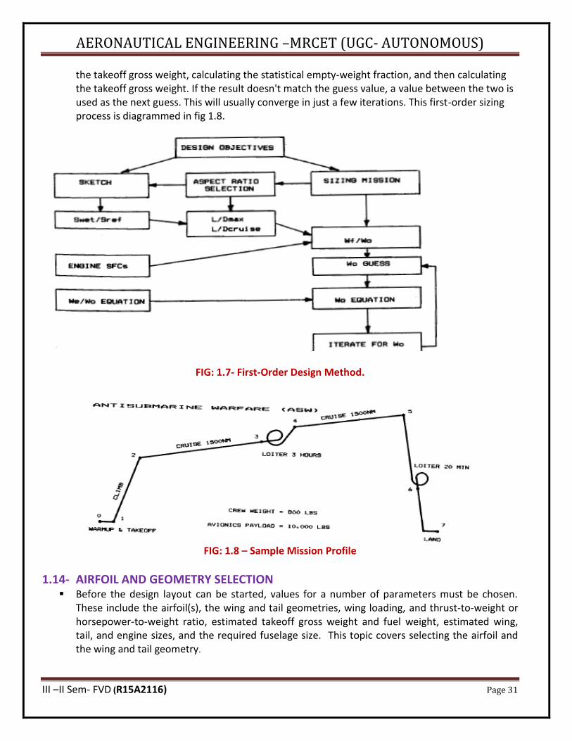
▪ Using the fuel fraction found with Eq. (1) above and the statistical empty weight equation selected from Table (Empty weight fraction vs. W0), the takeoff gross weight can be found iteratively from Eq.W0= Wcrew + Wpayload/ 1 - (Wf!Wo) - (We!Wo)). This is done by guessing
AERONAUTICAL ENGINEERING –MRCET (UGC- AUTONOMOUS)
III –II Sem- FVD (R15A2116) Page 31
the takeoff gross weight, calculating the statistical empty-weight fraction, and then calculating the takeoff gross weight. If the result doesn't match the guess value, a value between the two is used as the next guess. This will usually converge in just a few iterations. This first-order sizing process is diagrammed in fig 1.8.
FIG: 1.7- First-Order Design Method.
FIG: 1.8 – Sample Mission Profile
1.14- AIRFOIL AND GEOMETRY SELECTION ▪ Before the design layout can be started, values for a number of parameters must be chosen.
These include the airfoil(s), the wing and tail geometries, wing loading, and thrust-to-weight or horsepower-to-weight ratio, estimated takeoff gross weight and fuel weight, estimated wing, tail, and engine sizes, and the required fuselage size. This topic covers selecting the airfoil and the wing and tail geometry.
AERONAUTICAL ENGINEERING –MRCET (UGC- AUTONOMOUS)
III –II Sem- FVD (R15A2116) Page 32
(a) Airfoil Selection ▪ The airfoil, in many respects, is the heart of the airplane. The airfoil affects the cruise speed,
takeoff and landing distances, stall speed, handling qualities (especially near the stall), and overall aerodynamic efficiency during all phases of flight.
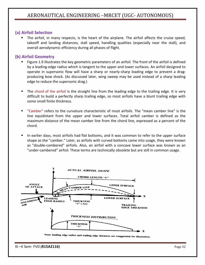
(b) Airfoil Geometry ▪ Figure 1.9 illustrates the key geometric parameters of an airfoil. The front of the airfoil is defined
by a leading-edge radius which is tangent to the upper and lower surfaces. An airfoil designed to operate in supersonic flow will have a sharp or nearly-sharp leading edge to prevent a drag-producing bow shock. (As discussed later, wing sweep may be used instead of a sharp leading edge to reduce the supersonic drag.)
▪ The chord of the airfoil is the straight line from the leading edge to the trailing edge. It is very
difficult to build a perfectly sharp trailing edge, so most airfoils have a blunt trailing edge with some small finite thickness.
▪ "Camber" refers to the curvature characteristic of most airfoils. The "mean camber line" is the line equidistant from the upper and lower surfaces. Total airfoil camber is defined as the maximum distance of the mean camber line from the chord line, expressed as a percent of the chord.
▪ In earlier days, most airfoils had flat bottoms, and it was common to refer to the upper surface
shape as the "camber." Later, as airfoils with curved bottoms came into usage, they were known as "double-cambered" airfoils. Also, an airfoil with a concave lower surface was known as an "under-cambered" airfoil. These terms are technically obsolete but are still in common usage.
AERONAUTICAL ENGINEERING –MRCET (UGC- AUTONOMOUS)
III –II Sem- FVD (R15A2116) Page 33
FIG: 1.9- Airfoil Geometry
▪ The thickness distribution of the airfoil is the distance from the upper surface to the lower surface, measured perpendicular to the mean camber line, and is a function of the distance from the leading edge. The "airfoil thickness ratio" (tic) refers to the maximum thickness of the airfoil divided by its chord.
▪ When an airfoil is scaled in thickness, the camber line must remain unchanged, so the scaled
thickness distribution is added to the original camber line to produce the new, scaled airfoil. In a similar fashion, an airfoil which is to have its camber changed is broken into its camber line and thickness distribution. The camber line is scaled to produce the desired maximum camber; then the original thickness distribution is added to obtain the new airfoil. In this fashion, the airfoil can be reshaped to - change either the profile drag or lift characteristics, without greatly affecting the other.
(c) Airfoil Lift and Drag
▪ An airfoil generates lift by changing the velocity of the air passing over and under itself. The airfoil angle of attack and/or camber causes the air over the top of the wing to travel faster than the air beneath the wing.
▪ Bernoulli's equation shows that higher velocities produce lower pressures, so the upper surface
of the airfoil tends to be pulled upward by lower-than-ambient pressures while the lower surface of the a1rfoil tends to be pushed upward by higher-than-ambient pressures. The integrated differences in pressure between the top and bottom of the a1rfoil generate the net lifting force.
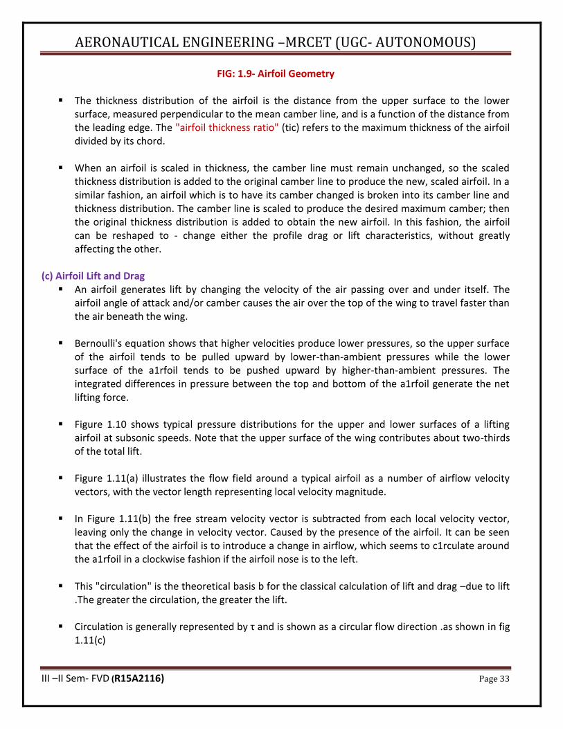
▪ Figure 1.10 shows typical pressure distributions for the upper and lower surfaces of a lifting
airfoil at subsonic speeds. Note that the upper surface of the wing contributes about two-thirds of the total lift.
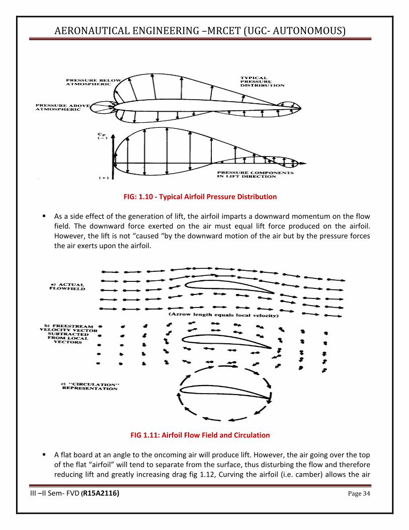
▪ Figure 1.11(a) illustrates the flow field around a typical airfoil as a number of airflow velocity
vectors, with the vector length representing local velocity magnitude.
▪ In Figure 1.11(b) the free stream velocity vector is subtracted from each local velocity vector, leaving only the change in velocity vector. Caused by the presence of the airfoil. It can be seen that the effect of the airfoil is to introduce a change in airflow, which seems to c1rculate around the a1rfoil in a clockwise fashion if the airfoil nose is to the left.
▪ This "circulation" is the theoretical basis b for the classical calculation of lift and drag –due to lift .The greater the circulation, the greater the lift.
▪ Circulation is generally represented by τ and is shown as a circular flow direction .as shown in fig 1.11(c)
AERONAUTICAL ENGINEERING –MRCET (UGC- AUTONOMOUS)
III –II Sem- FVD (R15A2116) Page 34
FIG: 1.10 - Typical Airfoil Pressure Distribution
▪ As a side effect of the generation of lift, the airfoil imparts a downward momentum on the flow field. The downward force exerted on the air must equal lift force produced on the airfoil. However, the lift is not “caused “by the downward motion of the air but by the pressure forces the air exerts upon the airfoil.
FIG 1.11: Airfoil Flow Field and Circulation
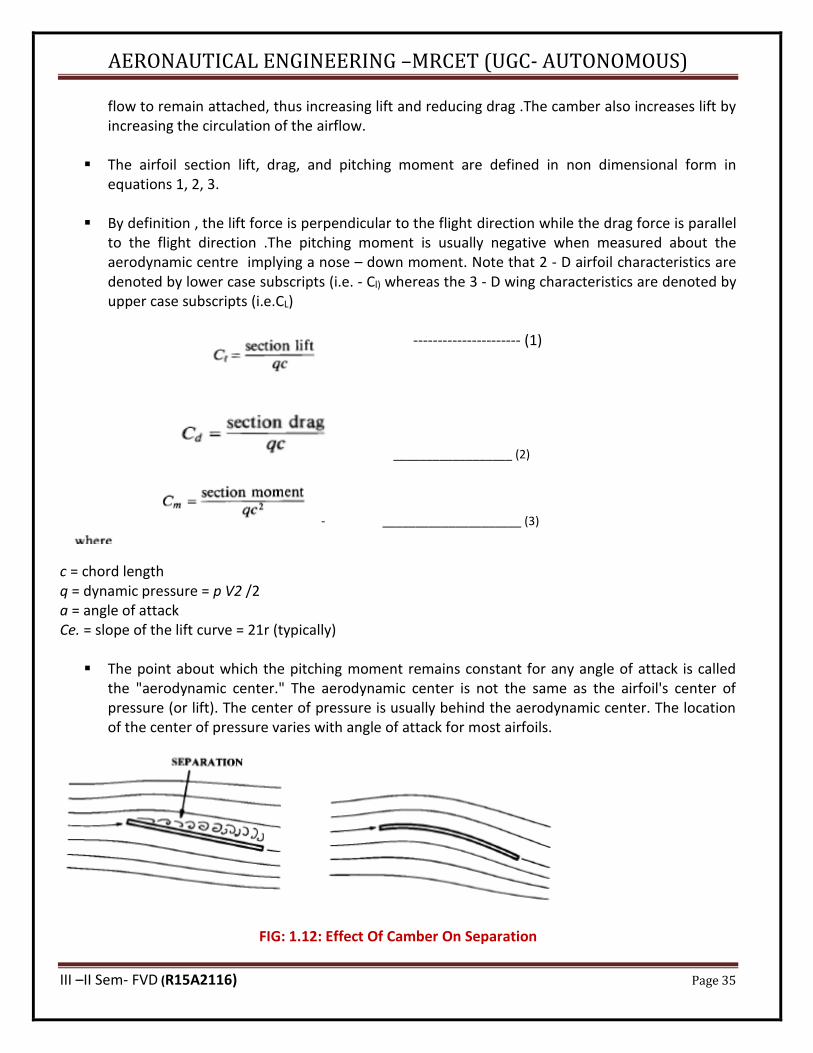
▪ A flat board at an angle to the oncoming air will produce lift. However, the air going over the top of the flat “airfoil” will tend to separate from the surface, thus disturbing the flow and therefore reducing lift and greatly increasing drag fig 1.12, Curving the airfoil (i.e. camber) allows the air
AERONAUTICAL ENGINEERING –MRCET (UGC- AUTONOMOUS)
III –II Sem- FVD (R15A2116) Page 35
flow to remain attached, thus increasing lift and reducing drag .The camber also increases lift by increasing the circulation of the airflow.
▪ The airfoil section lift, drag, and pitching moment are defined in non dimensional form in
equations 1, 2, 3.
▪ By definition , the lift force is perpendicular to the flight direction while the drag force is parallel to the flight direction .The pitching moment is usually negative when measured about the aerodynamic centre implying a nose – down moment. Note that 2 - D airfoil characteristics are denoted by lower case subscripts (i.e. - Cl) whereas the 3 - D wing characteristics are denoted by upper case subscripts (i.e.CL)
---------------------- (1)
__________________ (2)
- _____________________ (3)
c = chord length q = dynamic pressure = p V2 /2 a = angle of attack Ce. = slope of the lift curve = 21r (typically)
▪ The point about which the pitching moment remains constant for any angle of attack is called the "aerodynamic center." The aerodynamic center is not the same as the airfoil's center of pressure (or lift). The center of pressure is usually behind the aerodynamic center. The location of the center of pressure varies with angle of attack for most airfoils.
FIG: 1.12: Effect Of Camber On Separation
AERONAUTICAL ENGINEERING –MRCET (UGC- AUTONOMOUS)
III –II Sem- FVD (R15A2116) Page 36
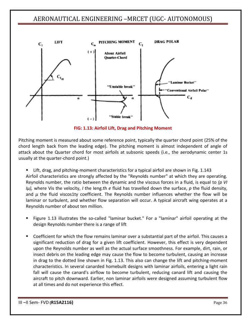
FIG: 1.13: Airfoil Lift, Drag and Pitching Moment
Pitching moment is measured about some reference point, typically the quarter chord point (25% of the chord length back from the leading edge). The pitching moment is almost independent of angle of attack about the Quarter chord for most airfoils at subsonic speeds (i.e., the aerodynamic center 1s usually at the quarter-chord point.)
▪ Lift, drag, and pitching-moment characteristics for a typical airfoil are shown in Fig. 1.143 Airfoil characteristics are strongly affected by the "Reynolds number" at which they are operating. Reynolds number, the ratio between the dynamic and the viscous forces in a fluid, is equal to (p VI Iμ), where Vis the velocity, I the Ieng.th e fluid has travelled down the surface, p the fluid density, and μ the fluid viscos1ty coefficient. The Reynolds number influences whether the flow will be laminar or turbulent, and whether flow separation will occur. A typical aircraft wing operates at a Reynolds number of about ten million.
▪ Figure 1.13 illustrates the so-called "laminar bucket." For a "laminar" airfoil operating at the
design Reynolds number there is a range of lift
▪ Coefficient for which the flow remains laminar over a substantial part of the airfoil. This causes a significant reduction of drag for a given lift coefficient. However, this effect is very dependent upon the Reynolds number as well as the actual surface smoothness. For example, dirt, rain, or insect debris on the leading edge may cause the flow to become turbulent, causing an increase in drag to the dotted line shown in Fig. 1.13. This also can change the lift and pitching-moment characteristics. In several canarded homebuilt designs with laminar airfoils, entering a light rain fall will cause the canard's airflow to become turbulent, reducing canard lift and causing the aircraft to pitch downward. Earlier, non laminar airfoils were designed assuming turbulent flow at all times and do not experience this effect.
AERONAUTICAL ENGINEERING –MRCET (UGC- AUTONOMOUS)
III –II Sem- FVD (R15A2116) Page 37
FIG: 1.14: Typical Airfoils
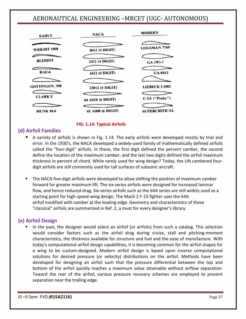
(d) Airfoil Families ▪ A variety of airfoils is shown in Fig. 1.14. The early airfoils were developed mostly by trial and
error. In the 1930's, the NACA developed a widely-used family of mathematically defined airfoils called the "four-digit" airfoils. In these, the first digit defined the percent camber, the second define the location of the maximum camber, and the last two digits defined the airfoil maximum thickness in percent of chord. While rarely used for wing design? Today, the UN cambered four-digit airfoils are still commonly used for tall surfaces of subsonic aircraft.
▪ The NACA five-digit airfoils were developed to allow shifting the position of maximum camber
forward for greater maximum lift. The six-series airfoils were designed for increased laminar flow, and hence reduced drag. Six-series airfoils such as the 64A series are still widely used as a starting point for high-speed-wing design. The Mach 2 F-15 fighter uses the 64A airfoil modified with camber at the leading edge. Geometry and characteristics of these "classical" airfoils are summarized in Ref. 2, a must for every designer's library.
(e) Airfoil Design ▪ In the past, the designer would select an airfoil (or airfoils) from such a catalog. This selection
would consider factors such as the airfoil drag during cruise, stall and pitching-moment characteristics, the thickness available for structure and fuel and the ease of manufacture. With today's computational airfoil design capabilities, it is becoming common for the airfoil shapes for a wing to be custom-designed. Modern airfoil design is based upon inverse computational solutions for desired pressure (or velocity) distributions on the airfoil. Methods have been developed for designing an airfoil such that the pressure differential between the top and bottom of the airfoil quickly reaches a maximum value attainable without airflow separation. Toward the rear of the airfoil, various pressure recovery schemes are employed to prevent separation near the trailing edge.
AERONAUTICAL ENGINEERING –MRCET (UGC- AUTONOMOUS)
III –II Sem- FVD (R15A2116) Page 38
▪ These airfoil optimization techniques result in airfoils with substantial pressure differentials (lift) over a much greater percent of chord than a classical airfoil. This permits a reduced wing area (and wetted area) for a required amount of lift.
▪ Another consideration in modern airfoil design is the desire to maintain laminar flow over the
greatest possible part of the airfoil. Laminar flow can be maintained by providing a negative pressure gradient, i.e., by having the pressure continuously drop from the leading edge to a position close to the trailing edge. This tends to "suck" the flow rearward, promoting laminar flow.
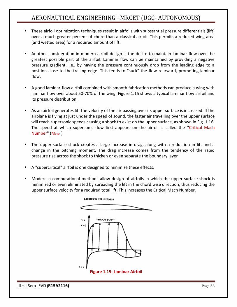
▪ A good laminar-flow airfoil combined with smooth fabrication methods can produce a wing with
laminar flow over about 50-70% of the wing. Figure 1.15 shows a typical laminar flow airfoil and its pressure distribution.
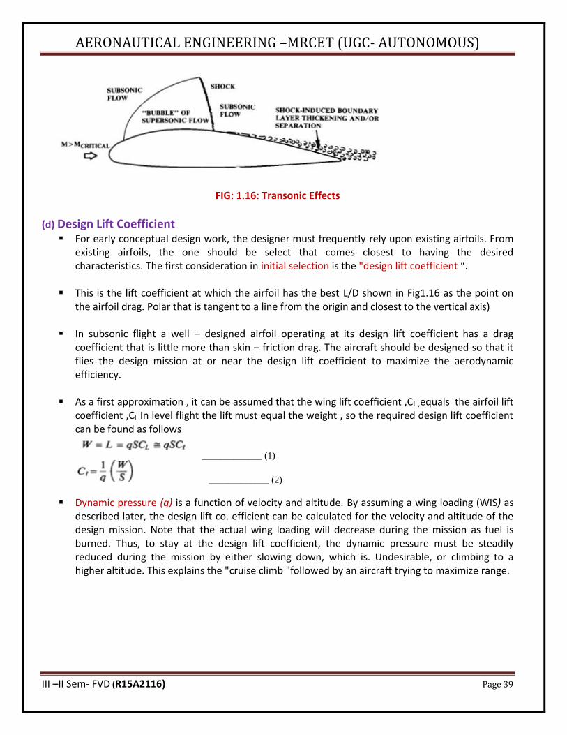
▪ As an airfoil generates lift the velocity of the air passing over its upper surface is increased. If the
airplane is flying at just under the speed of sound, the faster air travelling over the upper surface will reach supersonic speeds causing a shock to exist on the upper surface, as shown in Fig. 1.16. The speed at which supersonic flow first appears on the airfoil is called the "Critical Mach Number" (MCrit )
▪ The upper-surface shock creates a large increase in drag, along with a reduction in lift and a
change in the pitching moment. The drag increase comes from the tendency of the rapid pressure rise across the shock to thicken or even separate the boundary layer
▪ A "supercritical" airfoil is one designed to minimize these effects.
▪ Modern n computational methods allow design of airfoils in which the upper-surface shock is
minimized or even eliminated by spreading the lift in the chord wise direction, thus reducing the upper surface velocity for a required total lift. This increases the Critical Mach Number.
Figure 1.15: Laminar Airfoil
AERONAUTICAL ENGINEERING –MRCET (UGC- AUTONOMOUS)
III –II Sem- FVD (R15A2116) Page 39
FIG: 1.16: Transonic Effects
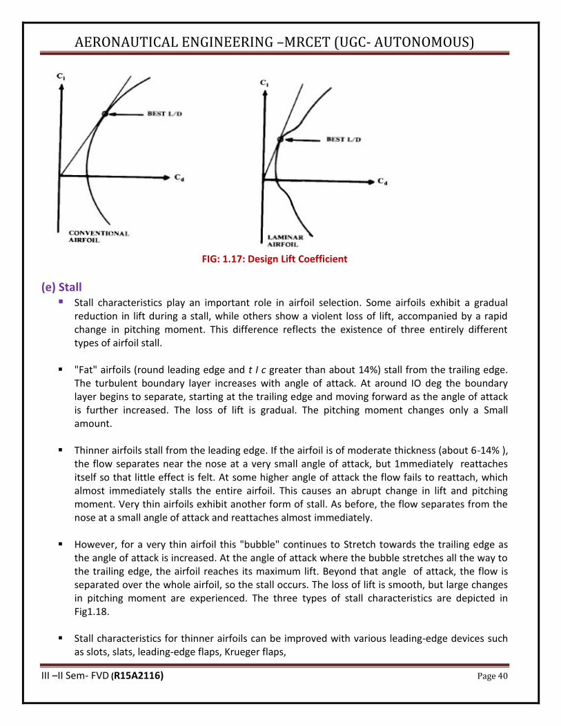
(d) Design Lift Coefficient ▪ For early conceptual design work, the designer must frequently rely upon existing airfoils. From
existing airfoils, the one should be select that comes closest to having the desired characteristics. The first consideration in initial selection is the "design lift coefficient “.
▪ This is the lift coefficient at which the airfoil has the best L/D shown in Fig1.16 as the point on
the airfoil drag. Polar that is tangent to a line from the origin and closest to the vertical axis)
▪ In subsonic flight a well – designed airfoil operating at its design lift coefficient has a drag coefficient that is little more than skin – friction drag. The aircraft should be designed so that it flies the design mission at or near the design lift coefficient to maximize the aerodynamic efficiency.
▪ As a first approximation , it can be assumed that the wing lift coefficient ,CL ,equals the airfoil lift
coefficient ,Cl .In level flight the lift must equal the weight , so the required design lift coefficient can be found as follows
_____________ (1)
_____________ (2)
▪ Dynamic pressure (q) is a function of velocity and altitude. By assuming a wing loading (WIS) as described later, the design lift co. efficient can be calculated for the velocity and altitude of the design mission. Note that the actual wing loading will decrease during the mission as fuel is burned. Thus, to stay at the design lift coefficient, the dynamic pressure must be steadily reduced during the mission by either slowing down, which is. Undesirable, or climbing to a higher altitude. This explains the "cruise climb "followed by an aircraft trying to maximize range.
AERONAUTICAL ENGINEERING –MRCET (UGC- AUTONOMOUS)
III –II Sem- FVD (R15A2116) Page 40
FIG: 1.17: Design Lift Coefficient
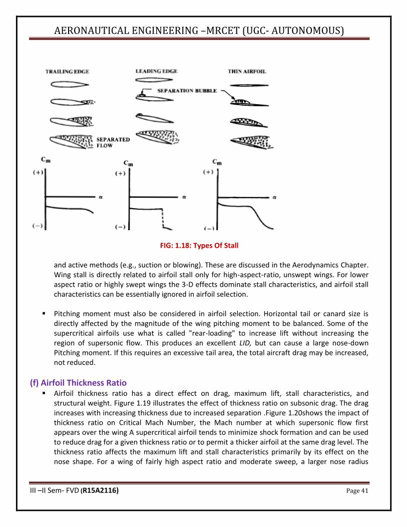
(e) Stall ▪ Stall characteristics play an important role in airfoil selection. Some airfoils exhibit a gradual
reduction in lift during a stall, while others show a violent loss of lift, accompanied by a rapid change in pitching moment. This difference reflects the existence of three entirely different types of airfoil stall.
▪ "Fat" airfoils (round leading edge and t I c greater than about 14%) stall from the trailing edge.
The turbulent boundary layer increases with angle of attack. At around IO deg the boundary layer begins to separate, starting at the trailing edge and moving forward as the angle of attack is further increased. The loss of lift is gradual. The pitching moment changes only a Small amount.
▪ Thinner airfoils stall from the leading edge. If the airfoil is of moderate thickness (about 6-14% ),
the flow separates near the nose at a very small angle of attack, but 1mmediately reattaches itself so that little effect is felt. At some higher angle of attack the flow fails to reattach, which almost immediately stalls the entire airfoil. This causes an abrupt change in lift and pitching moment. Very thin airfoils exhibit another form of stall. As before, the flow separates from the nose at a small angle of attack and reattaches almost immediately.
▪ However, for a very thin airfoil this "bubble" continues to Stretch towards the trailing edge as the angle of attack is increased. At the angle of attack where the bubble stretches all the way to the trailing edge, the airfoil reaches its maximum lift. Beyond that angle of attack, the flow is separated over the whole airfoil, so the stall occurs. The loss of lift is smooth, but large changes in pitching moment are experienced. The three types of stall characteristics are depicted in Fig1.18.
▪ Stall characteristics for thinner airfoils can be improved with various leading-edge devices such
as slots, slats, leading-edge flaps, Krueger flaps,
AERONAUTICAL ENGINEERING –MRCET (UGC- AUTONOMOUS)
III –II Sem- FVD (R15A2116) Page 41
FIG: 1.18: Types Of Stall
and active methods (e.g., suction or blowing). These are discussed in the Aerodynamics Chapter. Wing stall is directly related to airfoil stall only for high-aspect-ratio, unswept wings. For lower aspect ratio or highly swept wings the 3-D effects dominate stall characteristics, and airfoil stall characteristics can be essentially ignored in airfoil selection.
▪ Pitching moment must also be considered in airfoil selection. Horizontal tail or canard size is
directly affected by the magnitude of the wing pitching moment to be balanced. Some of the supercritical airfoils use what is called "rear-loading" to increase lift without increasing the region of supersonic flow. This produces an excellent LID, but can cause a large nose-down Pitching moment. If this requires an excessive tail area, the total aircraft drag may be increased, not reduced.
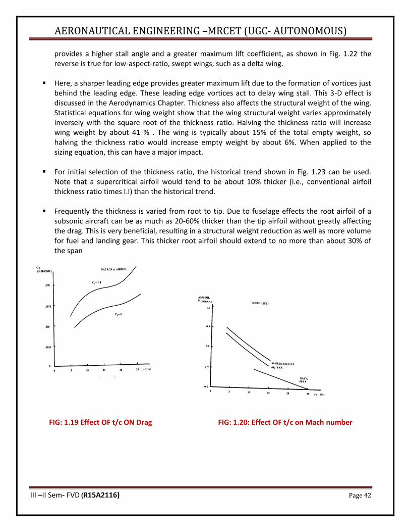
(f) Airfoil Thickness Ratio ▪ Airfoil thickness ratio has a direct effect on drag, maximum lift, stall characteristics, and
structural weight. Figure 1.19 illustrates the effect of thickness ratio on subsonic drag. The drag increases with increasing thickness due to increased separation .Figure 1.20shows the impact of thickness ratio on Critical Mach Number, the Mach number at which supersonic flow first appears over the wing A supercritical airfoil tends to minimize shock formation and can be used to reduce drag for a given thickness ratio or to permit a thicker airfoil at the same drag level. The thickness ratio affects the maximum lift and stall characteristics primarily by its effect on the nose shape. For a wing of fairly high aspect ratio and moderate sweep, a larger nose radius
AERONAUTICAL ENGINEERING –MRCET (UGC- AUTONOMOUS)
III –II Sem- FVD (R15A2116) Page 42
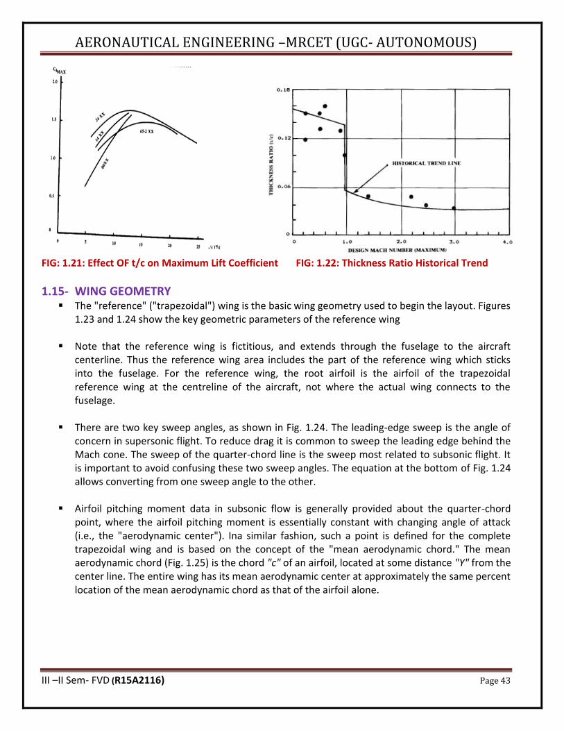
provides a higher stall angle and a greater maximum lift coefficient, as shown in Fig. 1.22 the reverse is true for low-aspect-ratio, swept wings, such as a delta wing.
▪ Here, a sharper leading edge provides greater maximum lift due to the formation of vortices just
behind the leading edge. These leading edge vortices act to delay wing stall. This 3-D effect is discussed in the Aerodynamics Chapter. Thickness also affects the structural weight of the wing. Statistical equations for wing weight show that the wing structural weight varies approximately inversely with the square root of the thickness ratio. Halving the thickness ratio will increase wing weight by about 41 % . The wing is typically about 15% of the total empty weight, so halving the thickness ratio would increase empty weight by about 6%. When applied to the sizing equation, this can have a major impact.
▪ For initial selection of the thickness ratio, the historical trend shown in Fig. 1.23 can be used.
Note that a supercritical airfoil would tend to be about 10% thicker (i.e., conventional airfoil thickness ratio times I.I) than the historical trend.
▪ Frequently the thickness is varied from root to tip. Due to fuselage effects the root airfoil of a
subsonic aircraft can be as much as 20-60% thicker than the tip airfoil without greatly affecting the drag. This is very beneficial, resulting in a structural weight reduction as well as more volume for fuel and landing gear. This thicker root airfoil should extend to no more than about 30% of the span
FIG: 1.19 Effect OF t/c ON Drag FIG: 1.20: Effect OF t/c on Mach number
AERONAUTICAL ENGINEERING –MRCET (UGC- AUTONOMOUS)
III –II Sem- FVD (R15A2116) Page 43
FIG: 1.21: Effect OF t/c on Maximum Lift Coefficient FIG: 1.22: Thickness Ratio Historical Trend
1.15- WING GEOMETRY ▪ The "reference" ("trapezoidal") wing is the basic wing geometry used to begin the layout. Figures
1.23 and 1.24 show the key geometric parameters of the reference wing
▪ Note that the reference wing is fictitious, and extends through the fuselage to the aircraft centerline. Thus the reference wing area includes the part of the reference wing which sticks into the fuselage. For the reference wing, the root airfoil is the airfoil of the trapezoidal reference wing at the centreline of the aircraft, not where the actual wing connects to the fuselage.
▪ There are two key sweep angles, as shown in Fig. 1.24. The leading-edge sweep is the angle of
concern in supersonic flight. To reduce drag it is common to sweep the leading edge behind the Mach cone. The sweep of the quarter-chord line is the sweep most related to subsonic flight. It is important to avoid confusing these two sweep angles. The equation at the bottom of Fig. 1.24 allows converting from one sweep angle to the other.
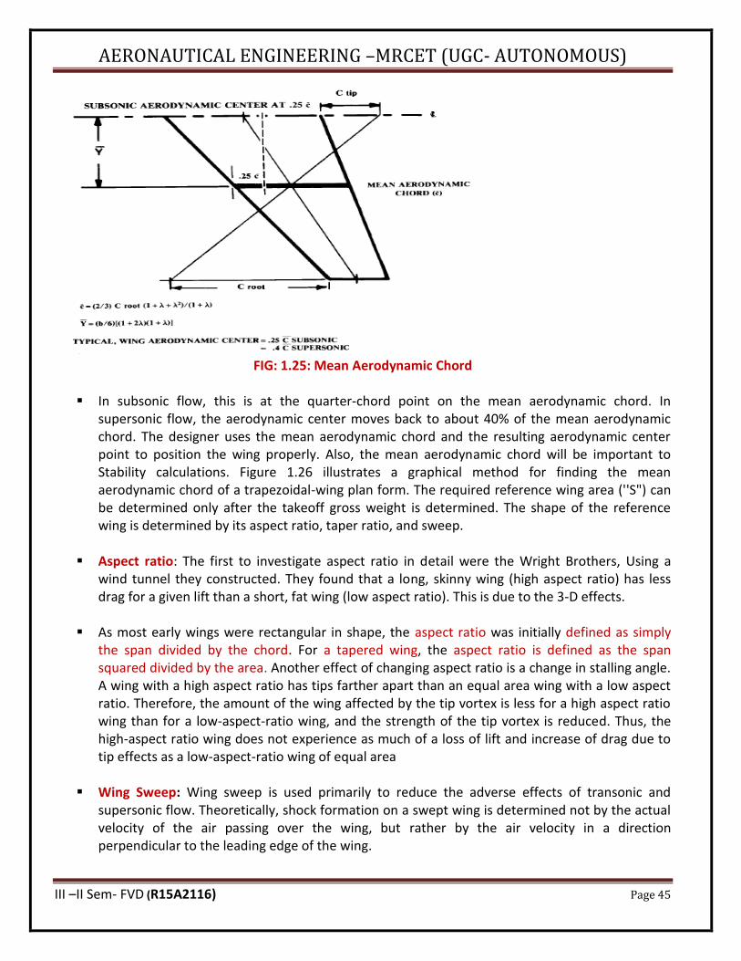
▪ Airfoil pitching moment data in subsonic flow is generally provided about the quarter-chord point, where the airfoil pitching moment is essentially constant with changing angle of attack (i.e., the "aerodynamic center"). Ina similar fashion, such a point is defined for the complete trapezoidal wing and is based on the concept of the "mean aerodynamic chord." The mean aerodynamic chord (Fig. 1.25) is the chord "c" of an airfoil, located at some distance "Y" from the center line. The entire wing has its mean aerodynamic center at approximately the same percent location of the mean aerodynamic chord as that of the airfoil alone.

AERONAUTICAL ENGINEERING –MRCET (UGC- AUTONOMOUS)
III –II Sem- FVD (R15A2116) Page 44
FIG: 1.23: Wing Geometry
FIG: 1.24: Wing Sweep A.
AERONAUTICAL ENGINEERING –MRCET (UGC- AUTONOMOUS)
III –II Sem- FVD (R15A2116) Page 45
FIG: 1.25: Mean Aerodynamic Chord
▪ In subsonic flow, this is at the quarter-chord point on the mean aerodynamic chord. In supersonic flow, the aerodynamic center moves back to about 40% of the mean aerodynamic chord. The designer uses the mean aerodynamic chord and the resulting aerodynamic center point to position the wing properly. Also, the mean aerodynamic chord will be important to Stability calculations. Figure 1.26 illustrates a graphical method for finding the mean aerodynamic chord of a trapezoidal-wing plan form. The required reference wing area (''S") can be determined only after the takeoff gross weight is determined. The shape of the reference wing is determined by its aspect ratio, taper ratio, and sweep.
▪ Aspect ratio: The first to investigate aspect ratio in detail were the Wright Brothers, Using a wind tunnel they constructed. They found that a long, skinny wing (high aspect ratio) has less drag for a given lift than a short, fat wing (low aspect ratio). This is due to the 3-D effects.
▪ As most early wings were rectangular in shape, the aspect ratio was initially defined as simply the span divided by the chord. For a tapered wing, the aspect ratio is defined as the span squared divided by the area. Another effect of changing aspect ratio is a change in stalling angle. A wing with a high aspect ratio has tips farther apart than an equal area wing with a low aspect ratio. Therefore, the amount of the wing affected by the tip vortex is less for a high aspect ratio wing than for a low-aspect-ratio wing, and the strength of the tip vortex is reduced. Thus, the high-aspect ratio wing does not experience as much of a loss of lift and increase of drag due to tip effects as a low-aspect-ratio wing of equal area
▪ Wing Sweep: Wing sweep is used primarily to reduce the adverse effects of transonic and supersonic flow. Theoretically, shock formation on a swept wing is determined not by the actual velocity of the air passing over the wing, but rather by the air velocity in a direction perpendicular to the leading edge of the wing.
AERONAUTICAL ENGINEERING –MRCET (UGC- AUTONOMOUS)
III –II Sem- FVD (R15A2116) Page 46
▪ Taper Ratio: Wing taper ratio, λ is the ratio between the tip chord and the centerline root chord. Most wings of low sweep have a taper ratio of about 0.4-0.5. Most swept wings have a taper ratio of about 0.2-0.3.
(a) Wing Vertical Location ▪ The wing vertical location with respect to the fuselage is generally set by the real-world
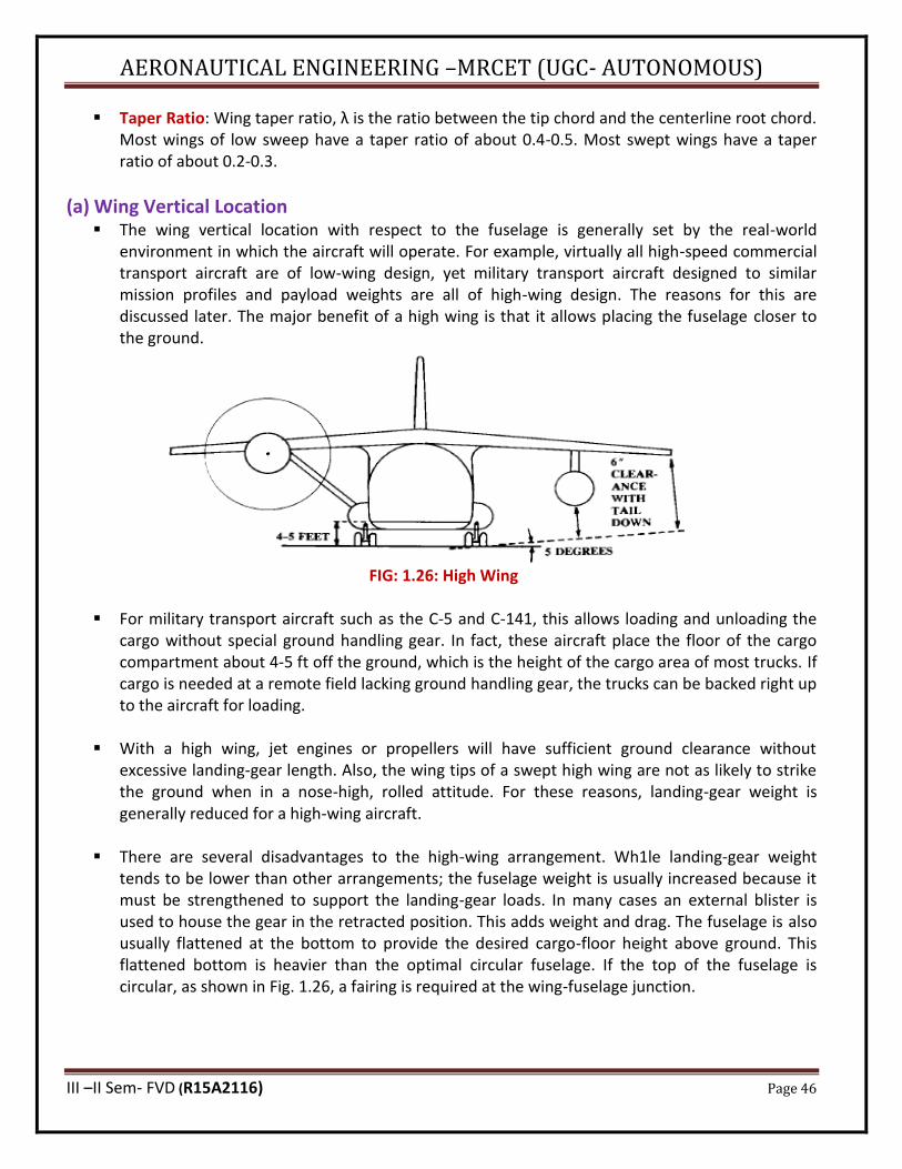
environment in which the aircraft will operate. For example, virtually all high-speed commercial transport aircraft are of low-wing design, yet military transport aircraft designed to similar mission profiles and payload weights are all of high-wing design. The reasons for this are discussed later. The major benefit of a high wing is that it allows placing the fuselage closer to the ground.
FIG: 1.26: High Wing
▪ For military transport aircraft such as the C-5 and C-141, this allows loading and unloading the
cargo without special ground handling gear. In fact, these aircraft place the floor of the cargo compartment about 4-5 ft off the ground, which is the height of the cargo area of most trucks. If cargo is needed at a remote field lacking ground handling gear, the trucks can be backed right up to the aircraft for loading.
▪ With a high wing, jet engines or propellers will have sufficient ground clearance without
excessive landing-gear length. Also, the wing tips of a swept high wing are not as likely to strike the ground when in a nose-high, rolled attitude. For these reasons, landing-gear weight is generally reduced for a high-wing aircraft.
▪ There are several disadvantages to the high-wing arrangement. Wh1le landing-gear weight
tends to be lower than other arrangements; the fuselage weight is usually increased because it must be strengthened to support the landing-gear loads. In many cases an external blister is used to house the gear in the retracted position. This adds weight and drag. The fuselage is also usually flattened at the bottom to provide the desired cargo-floor height above ground. This flattened bottom is heavier than the optimal circular fuselage. If the top of the fuselage is circular, as shown in Fig. 1.26, a fairing is required at the wing-fuselage junction.
AERONAUTICAL ENGINEERING –MRCET (UGC- AUTONOMOUS)
III –II Sem- FVD (R15A2116) Page 47
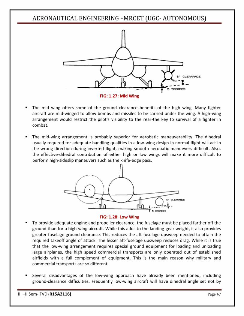
FIG: 1.27: Mid Wing
▪ The mid wing offers some of the ground clearance benefits of the high wing. Many fighter aircraft are mid-winged to allow bombs and missiles to be carried under the wing. A high-wing arrangement would restrict the pilot's visibility to the rear-the key to survival of a fighter in combat.
▪ The mid-wing arrangement is probably superior for aerobatic maneuverability. The dihedral
usually required for adequate handling qualities in a low-wing design in normal flight will act in the wrong direction during inverted flight, making smooth aerobatic manuevers difficult. Also, the effective-dihedral contribution of either high or low wings will make it more difficult to perform high-sideslip maneuvers such as the knife-edge pass.
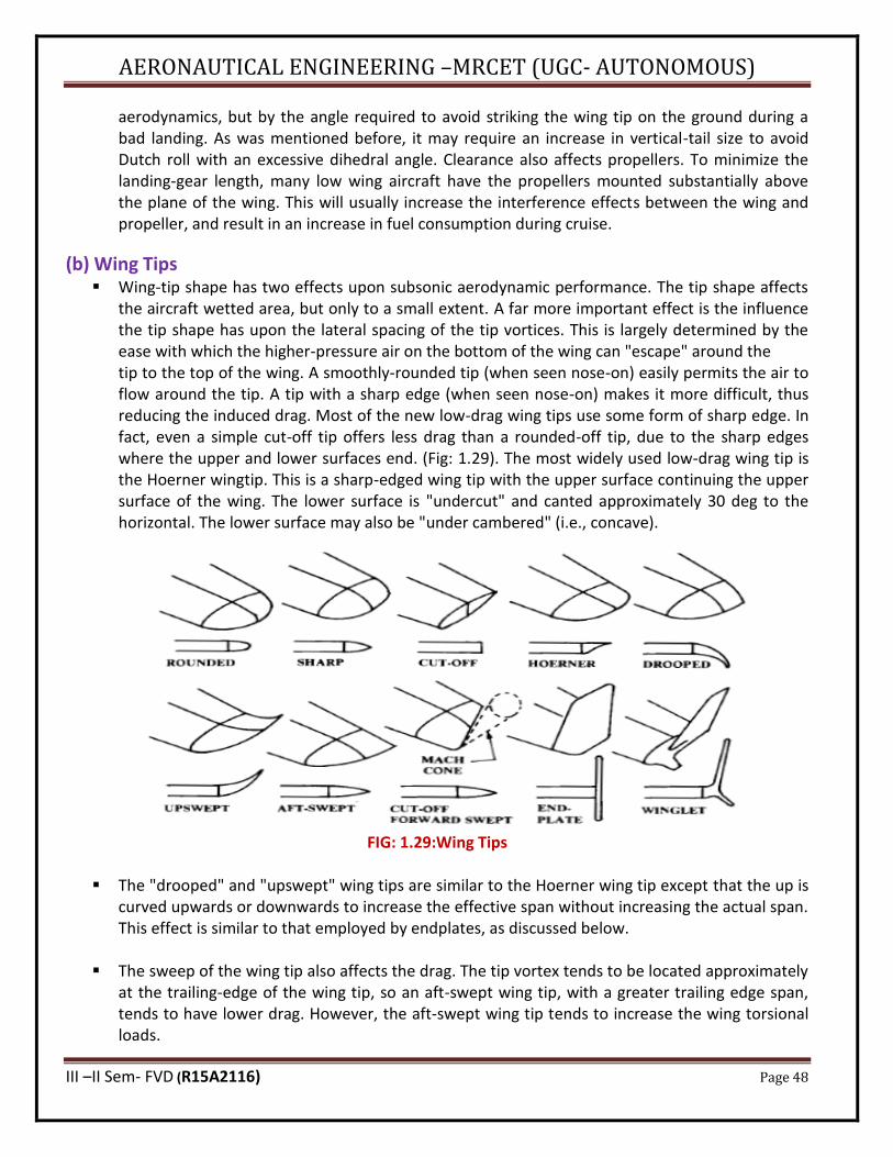
FIG: 1.28: Low Wing ▪ To provide adequate engine and propeller clearance, the fuselage must be placed farther off the
ground than for a high-wing aircraft. While this adds to the landing-gear weight, it also provides greater fuselage ground clearance. This reduces the aft-fuselage upsweep needed to attain the required takeoff angle of attack. The lesser aft-fuselage upsweep reduces drag. While it is true that the low-wing arrangement requires special ground equipment for loading and unloading large airplanes, the high speed commercial transports are only operated out of established airfields with a full complement of equipment. This is the main reason why military and commercial transports are so different.
▪ Several disadvantages of the low-wing approach have already been mentioned, including
ground-clearance difficulties. Frequently low-wing aircraft will have dihedral angle set not by
AERONAUTICAL ENGINEERING –MRCET (UGC- AUTONOMOUS)
III –II Sem- FVD (R15A2116) Page 48
aerodynamics, but by the angle required to avoid striking the wing tip on the ground during a bad landing. As was mentioned before, it may require an increase in vertical-tail size to avoid Dutch roll with an excessive dihedral angle. Clearance also affects propellers. To minimize the landing-gear length, many low wing aircraft have the propellers mounted substantially above the plane of the wing. This will usually increase the interference effects between the wing and propeller, and result in an increase in fuel consumption during cruise.
(b) Wing Tips ▪ Wing-tip shape has two effects upon subsonic aerodynamic performance. The tip shape affects
the aircraft wetted area, but only to a small extent. A far more important effect is the influence the tip shape has upon the lateral spacing of the tip vortices. This is largely determined by the ease with which the higher-pressure air on the bottom of the wing can "escape" around the tip to the top of the wing. A smoothly-rounded tip (when seen nose-on) easily permits the air to flow around the tip. A tip with a sharp edge (when seen nose-on) makes it more difficult, thus reducing the induced drag. Most of the new low-drag wing tips use some form of sharp edge. In fact, even a simple cut-off tip offers less drag than a rounded-off tip, due to the sharp edges where the upper and lower surfaces end. (Fig: 1.29). The most widely used low-drag wing tip is the Hoerner wingtip. This is a sharp-edged wing tip with the upper surface continuing the upper surface of the wing. The lower surface is "undercut" and canted approximately 30 deg to the horizontal. The lower surface may also be "under cambered" (i.e., concave).
FIG: 1.29:Wing Tips
▪ The "drooped" and "upswept" wing tips are similar to the Hoerner wing tip except that the up is curved upwards or downwards to increase the effective span without increasing the actual span. This effect is similar to that employed by endplates, as discussed below.
▪ The sweep of the wing tip also affects the drag. The tip vortex tends to be located approximately
at the trailing-edge of the wing tip, so an aft-swept wing tip, with a greater trailing edge span, tends to have lower drag. However, the aft-swept wing tip tends to increase the wing torsional loads.
AERONAUTICAL ENGINEERING –MRCET (UGC- AUTONOMOUS)
III –II Sem- FVD (R15A2116) Page 49
▪ A cut-off, forward-swept wing tip is sometimes used for supersonic aircraft. The tip is cut off at
an angle equal to the supersonic Mach-cone angle, because the area of the wing within the shock cone formed at the wing tip will contribute little to the lift. Also, this tip shape will reduce the torsional loads applied to the wing. The F-15 fighter uses such a cut-off tip for both Wings and horizontal tails.
▪ Induced drag is caused by the higher-pressure air at the bottom of the wing escaping around the
wing tip to the top of the wing. An obvious way to prevent this would be to mount a vertical plate at the wing tip.
▪ The endplate effect has been known almost since the dawn of flight, but has been seen rarely.
The wetted area of the endplate itself creates drag. Also, an end plated wing has an effective span increase of only about 80% of the actual span increase caused by adding the endplates' height to the wing span. However, endplates can be useful when span must be limited.
▪ An advanced version of the endplate can offer lower drag than an equal area increase in wing
span. The "winglet," designed by NASA's R. Whit- comb, gets an additional drag reduction by using the energy available in the tip vortex. The winglet is cambered and twisted so that the rotating vortex flow at the wing tip creates a lift force on the winglet that has a forward component. This forward lift component acts as a "negative" drag, reducing the total wing drag.
1.16- TAIL GEOMETRY AND ARRANGEMENT Tail functions
▪ Tails are little wings. Much of the previous discussion concerning wings can also be applied to tail surfaces. The major difference between a wing and a tail is that, while the wing is designed routinely to carry a substantial amount of lift, a tail is designed to operate normally at only a fraction of its lift potential. Any time in flight that a tail comes close to its maximum lift potential, and hence its stall angle, something is very wrong!
▪ Tails provide for trim, stability, and control. Trim refers to the generation of a lift force that, by
acting through some tail moment arm about the center of gravity, balances some other moment produced by the aircraft.
▪ For the horizontal tail, trim primarily refers to the balancing of the moment created by the wing.
An aft horizontal tail typically has a negative incidence angle of about 2-3 deg to balance the wing pitching moment. As the wing pitching moment varies under different flight conditions, the horizontal tail incidence is usually adjustable through a range of about 3 deg up and down.
▪ The tails are also a key element of stability, acting much like the fins on an arrow. While it is
possible to design a stable aircraft without tails, such a design is usually penalized in some other area, such as a compromised airfoil shape, excessive wing area or sweep, or narrow center-of-gravity range.

AERONAUTICAL ENGINEERING –MRCET (UGC- AUTONOMOUS)
III –II Sem- FVD (R15A2116) Page 50
▪ The other major function of the tail is control. The tail must be sized to provide adequate control
power at all critical conditions. These critical conditions for the horizontal tail or canard typically include nose wheel liftoff, low-speed flight with flaps down, and transonic manoeuvring. For the vertical tail, critical conditions typically include engine-out flight at low speeds, maximum roll rate, and spin recovery.
▪ Note that control power depends upon the size and type of the movable surface as well as the
overall size of the tail itself. For example, several airliners use double-hinged rudders to provide more engine-out control power without increasing the size of the vertical tail beyond what is required for Dutch-roll damping. Several fighters, including the YF-12 and the F-107, have used all-moving vertical tails instead of separate rudders to increase control power.
(a) Tail Arrangement ▪ Figure 1.31 illustrates some of the possible variations in aft-tail arrangement. ▪ The first shown has become "conventional" for the simple reason that it works. For most aircraft
designs, the conventional tail will usually provide adequate stability and control at the lightest weight. Probably 70% or more of the aircraft in service have such a tail arrangement. However, there are many reasons for considering others.
▪ The "T-tail" is also widely used. A T-tail is inherently heavier than a conventional tail because the
vertical tail must be strengthened to support the horizontal tail, but the T-tail provides compensating advantages in many cases.
FIG: 1.30: Aft Tail Variations

AERONAUTICAL ENGINEERING –MRCET (UGC- AUTONOMOUS)
III –II Sem- FVD (R15A2116) Page 51
▪ The cruciform tail, a compromise between the conventional and T-tail arrangements, lifts the
horizontal tail to avoid proximity to a jet exhaust (as on the B-lB), or to expose the lower part of the rudder to undisturbed air during high angle-of-attack conditions and spins. These goals can be accomplished with a T-tail, but the cruciform tail will impose less of a weight Penalty. However, the cruciform tail will not provide a tail-area reduction due to endplate effect as will a T-tail.
▪ The "H-tail" is used primarily to position the vertical tails in undisturbed air during high angle-of-
attack conditions (as on the T-46) or to position the rudders in the propwash on a multiengine aircraft to enhance engine-out control. The H-tail is heavier than the conventional tail, but its endplate effect allows smaller horizontal tail.
▪ The "V-tail" is intended to reduce wetted area. With a V-tail, the horizontal and vertical tail
forces are the result of horizontal and vertical projections of the force exerted upon the "V" surfaces. For some required horizontal and vertical tail area, the required V surface area would theoretically be found from the Pythagorian theorem, and the tail dihedral angle would be found as the arctangent of the ratio of required vertical and horizontal areas. The resulting wetted area of the V surfaces would clearly be less than for separate horizontal and vertical surfaces.
▪ The inverted V-tail shown in fig above avoids this problem, and instead produces a desirable
"proverse roll-yaw coupling." The inverted V-tail is also said to reduce spiraling tendencies. This tail arrangement can cause difficulties in providing adequate ground clearance.
▪ The "Y-tail" is similar to the V-tail, except that the dihedral angle is reduced and a third surface is
mounted vertically beneath the V. This third surface contains the rudder, whereas the V surfaces provide only pitch control. This tail arrangement avoids the complexity of the ruddervators while reducing interference drag when compared to a conventional tail. An inverted Y-tail is used on the F-4, primarily to keep the horizontal surfaces out of the wing wake at high angles of attack.
▪ Twin tails on the fuselage can position the rudders away from the aircraft centerline, which may become blanketed by the wing or forward fuselage at high angles of attack. Also, twin tails have been used simply to reduce the height required with a single tail. Twin tails are usually heavier than an equal-area centerline-mounted single tail, but are often more effective. Twin tails are seen on most large modern fighters such as the F-14, F-15, F-18, and MiG-25.
▪ Boom-mounted tails have been used to allow pusher propellers or to allow location of a heavy
jet engine near the center of gravity. Tailbooms are typically heavier than a conventional fuselage construction, but can be desirable in some applications
▪ The "ring-tail" concept attempts to provide all tail contributions via an airfoil-sectioned ring attached to the aft fuselage, usually doubling as a propeller shroud. While conceptually
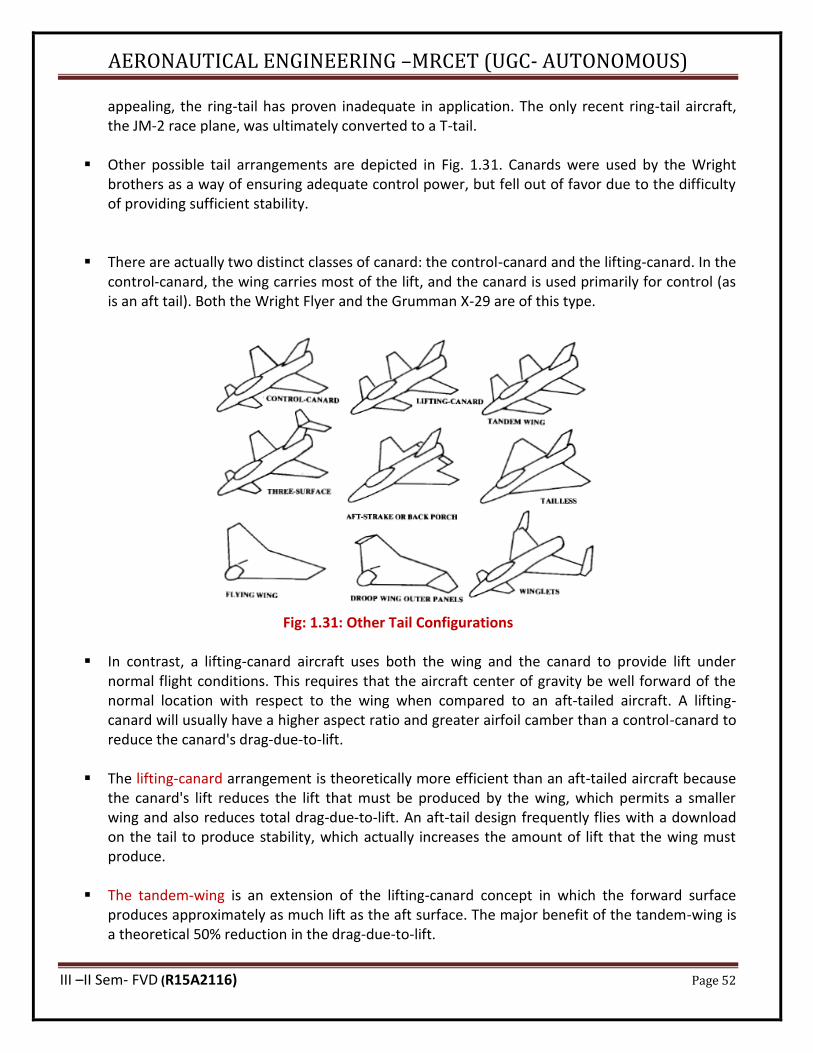
AERONAUTICAL ENGINEERING –MRCET (UGC- AUTONOMOUS)
III –II Sem- FVD (R15A2116) Page 52
appealing, the ring-tail has proven inadequate in application. The only recent ring-tail aircraft, the JM-2 race plane, was ultimately converted to a T-tail.
▪ Other possible tail arrangements are depicted in Fig. 1.31. Canards were used by the Wright
brothers as a way of ensuring adequate control power, but fell out of favor due to the difficulty of providing sufficient stability.
▪ There are actually two distinct classes of canard: the control-canard and the lifting-canard. In the control-canard, the wing carries most of the lift, and the canard is used primarily for control (as is an aft tail). Both the Wright Flyer and the Grumman X-29 are of this type.
Fig: 1.31: Other Tail Configurations
▪ In contrast, a lifting-canard aircraft uses both the wing and the canard to provide lift under normal flight conditions. This requires that the aircraft center of gravity be well forward of the normal location with respect to the wing when compared to an aft-tailed aircraft. A lifting-canard will usually have a higher aspect ratio and greater airfoil camber than a control-canard to reduce the canard's drag-due-to-lift.
▪ The lifting-canard arrangement is theoretically more efficient than an aft-tailed aircraft because
the canard's lift reduces the lift that must be produced by the wing, which permits a smaller wing and also reduces total drag-due-to-lift. An aft-tail design frequently flies with a download on the tail to produce stability, which actually increases the amount of lift that the wing must produce.
▪ The tandem-wing is an extension of the lifting-canard concept in which the forward surface
produces approximately as much lift as the aft surface. The major benefit of the tandem-wing is a theoretical 50% reduction in the drag-due-to-lift.
AERONAUTICAL ENGINEERING –MRCET (UGC- AUTONOMOUS)
III –II Sem- FVD (R15A2116) Page 53
▪ A three-surface arrangement provides both aft-tail and lifting-canard surfaces. This allows the
use of the lifting-canard for reduction of wing drag-due-to-lift without the difficulty of incorporating wing flaps as seen on a canard-only configuration.
▪ The "back-porch" or "aft-strake" is a horizontal control surface that is incorporated into a faired extension of the wing or fuselage. This device, seen on the X-29, is mostly used to prevent pitch up but can also serve as a primary pitch control surface in some cases.
▪ The tailless configuration offers the lowest weight and drag of any tail configuration, if it can be made to work. For a stable aircraft, the wing of a tailless aircraft must be reflexed or twisted to provide natural stability. This reduces the efficiency of the wing.
▪ Winglets or endplates mounted at the wing tips can be used in place of a vertical tail. This may provide the required vertical tail surface for free, since the effective increase in wing aspect ratio may more than compensate for the wetted area of the tail. To place these tip surfaces far enough aft to act like vertical tails requires either extreme wing sweep or a canard arrangement, or both
(b) Tail Geometry ▪ The surface areas required for all types of tails are directly proportional to the aircraft's wing
area, so the tail areas cannot be selected until the initial estimate of aircraft takeoff gross weight has been made. The initial estimation of tail area is made using the "tail volume coefficient" method,
▪ Other geometric parameters for the tails can be selected at this time. Tail aspect ratio and taper
ratio show little variation over a wide range of aircraft types. Table below provides guidance for selection of tail aspect ratio and taper ratio. Note that T-tail aircraft have lower vertical-tail aspect ratios to reduce the weight impact of the horizontal tail's location on top of the Vertical tall. Also, some general-aviation aircraft use un tapered horizontal tails (λ= 1.0) to reduce manufacturing costs.
▪ Leading-edge sweep of the horizontal tail is usually set to about 5 deg more than the wing
sweep. This tends to make the tail stall after the wing, and also provides the tail with a higher Critical Mach Number than the wing, which avoids loss of elevator effectiveness due to shock formation. For low-speed aircraft, the horizontal tail sweep is frequently set to provide a straight hinge line for the elevator, which usually has the left and right sides connected to reduce flutter tendencies. Vertical-tail sweep varies between about 35 and 55 deg. For a low-speed aircraft, there 1s little reason for vertical-tail sweep beyond about 20 deg other than asthetics. For a high-speed aircraft, vertical-tail sweep is used primarily to insure that the tail's Critical Mach Number is higher than the wing’s.
▪ The exact plan form of the tail surfaces is actually not very critical in the early stages of the
design process. The tail geometries are revised during later analytical and wind-tunnel studies. For conceptual design, it is usually acceptable simply to draw tail surfaces that "look right," based upon prior experience and similar designs.

AERONAUTICAL ENGINEERING –MRCET (UGC- AUTONOMOUS)
III –II Sem- FVD (R15A2116) Page 54
▪ Tail thickness ratio is usually similar to the wing thickness ratio, as determined by the historical guidelines provided in the wing-geometry section. For a high-speed aircraft, the horizontal tail is frequently about lO% thinner than the wing to ensure that the tail has a higher Critical Mach Number.
Note that a lifting canard or tandem wing should be designed using the guidelines and procedures given for initial wing design, instead of the tail design guidelines described above.
THRUST TO WEIGHT RATIO AND WING LOADING The thrust-to-weight ratio (TIW) and the
wing loading (WIS) are the two most important parameters affecting aircraft performance. Optimization of these parameters forms a major part of the analytical design activities conducted after an initial design layout.
▪ However, it is essential that a credible estimate of the wing loading and thrust-to-weight ratio be made before the initial design layout is begun. Otherwise, the optimized aircraft may be so unlike the as-drawn aircraft that the design must be completely redone
▪ Wing loading and thrust-to-weight ratio are interconnected for a number of performance
calculations, such as takeoff distance, which is frequently a critical design driver. A requirement for short takeoff can be met by using a large wing (low WIS) with a relatively small engine (low TIW). While the small engine will cause the aircraft to accelerate slowly, it only needs to reach a moderate speed to lift off the ground.
▪ On the other hand, the same takeoff distance could be met with a small wing (high WIS)
provided that a large engine (high TIW) is also used. In this case, the aircraft must reach a high speed to lift off, but the large engine can rapidly accelerate the aircraft to that speed.
1.17- THRUST TO WEIGHT RATIO THRUST TO WEIGHT DEFINITIONS
▪ T/W directly affects the performance of the aircraft. An aircraft with a higher T!W will accelerate more quickly, climb more rapidly, reach a higher maximum speed, and sustain higher turn rates. On the other hand, the larger engines will consume more fuel throughout the mission, which will drive up the aircraft's takeoff gross weight to perform the design mission.
▪ TI W is not a constant. The weight of the aircraft varies during flight as fuel is burned. Also, the
engine's thrust varies with altitude and velocity (as does the horsepower and propeller efficiency, ηP) .
▪ When designers speak of an aircraft's thrust-to-weight ratio they generally refer to the TIW
during sea-level static (zero-velocity), standard-day conditions at design takeoff weight and maximum throttle setting. Another commonly referred-to T/W concerns combat conditions.
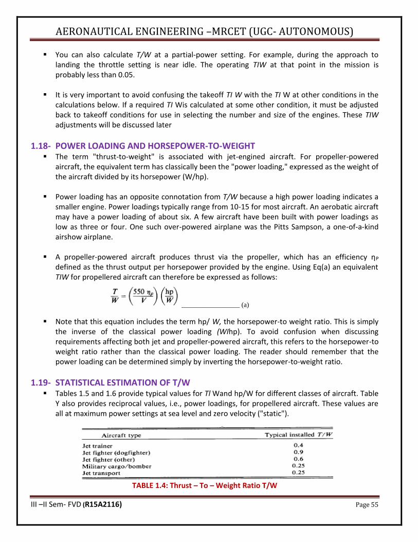
AERONAUTICAL ENGINEERING –MRCET (UGC- AUTONOMOUS)
III –II Sem- FVD (R15A2116) Page 55
▪ You can also calculate T/W at a partial-power setting. For example, during the approach to landing the throttle setting is near idle. The operating TIW at that point in the mission is probably less than 0.05.
▪ It is very important to avoid confusing the takeoff TI W with the TI W at other conditions in the
calculations below. If a required TI Wis calculated at some other condition, it must be adjusted back to takeoff conditions for use in selecting the number and size of the engines. These TIW adjustments will be discussed later
1.18- POWER LOADING AND HORSEPOWER-TO-WEIGHT ▪ The term "thrust-to-weight" is associated with jet-engined aircraft. For propeller-powered
aircraft, the equivalent term has classically been the "power loading," expressed as the weight of the aircraft divided by its horsepower (W/hp).
▪ Power loading has an opposite connotation from T/W because a high power loading indicates a
smaller engine. Power loadings typically range from 10-15 for most aircraft. An aerobatic aircraft may have a power loading of about six. A few aircraft have been built with power loadings as low as three or four. One such over-powered airplane was the Pitts Sampson, a one-of-a-kind airshow airplane.
▪ A propeller-powered aircraft produces thrust via the propeller, which has an efficiency ηP
defined as the thrust output per horsepower provided by the engine. Using Eq(a) an equivalent TIW for propellered aircraft can therefore be expressed as follows:
_________________ (a)
▪ Note that this equation includes the term hp/ W, the horsepower-to weight ratio. This is simply the inverse of the classical power loading (WIhp). To avoid confusion when discussing requirements affecting both jet and propeller-powered aircraft, this refers to the horsepower-to weight ratio rather than the classical power loading. The reader should remember that the power loading can be determined simply by inverting the horsepower-to-weight ratio.
1.19- STATISTICAL ESTIMATION OF T/W ▪ Tables 1.5 and 1.6 provide typical values for Tl Wand hp/W for different classes of aircraft. Table
Y also provides reciprocal values, i.e., power loadings, for propellered aircraft. These values are all at maximum power settings at sea level and zero velocity ("static").
TABLE 1.4: Thrust – To – Weight Ratio T/W
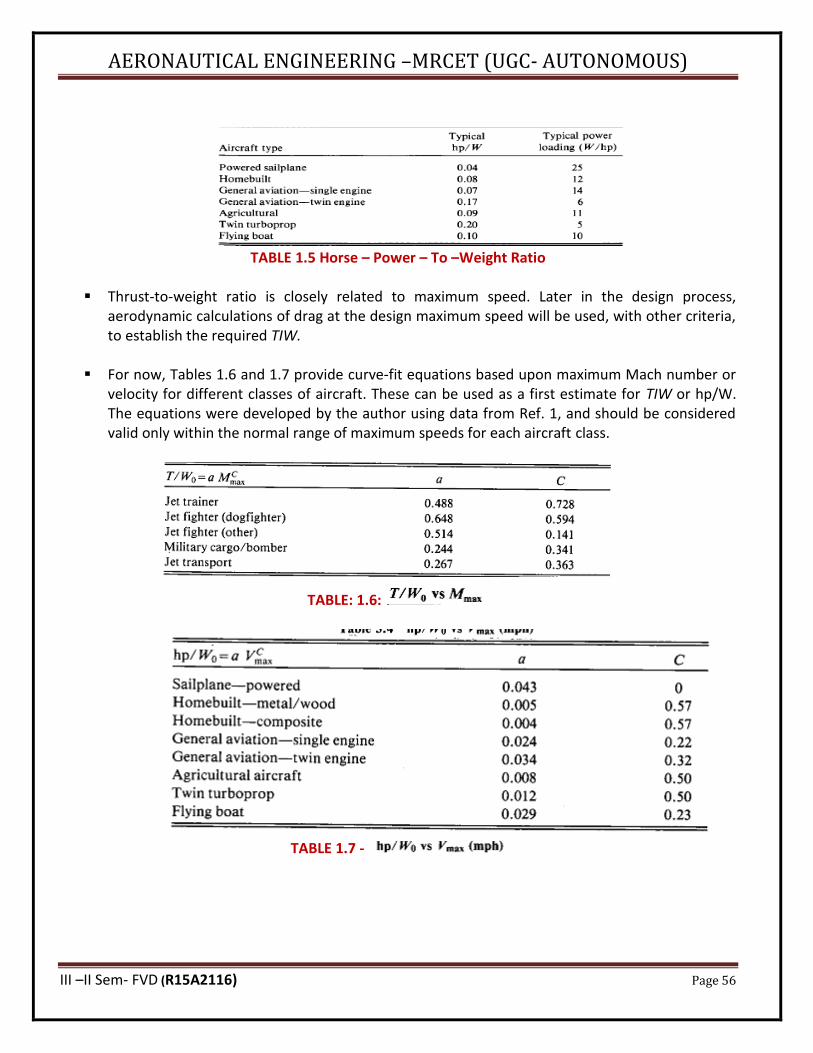
AERONAUTICAL ENGINEERING –MRCET (UGC- AUTONOMOUS)
III –II Sem- FVD (R15A2116) Page 56
TABLE 1.5 Horse – Power – To –Weight Ratio
▪ Thrust-to-weight ratio is closely related to maximum speed. Later in the design process, aerodynamic calculations of drag at the design maximum speed will be used, with other criteria, to establish the required TIW.
▪ For now, Tables 1.6 and 1.7 provide curve-fit equations based upon maximum Mach number or
velocity for different classes of aircraft. These can be used as a first estimate for TIW or hp/W. The equations were developed by the author using data from Ref. 1, and should be considered valid only within the normal range of maximum speeds for each aircraft class.
TABLE: 1.6:
TABLE 1.7 -
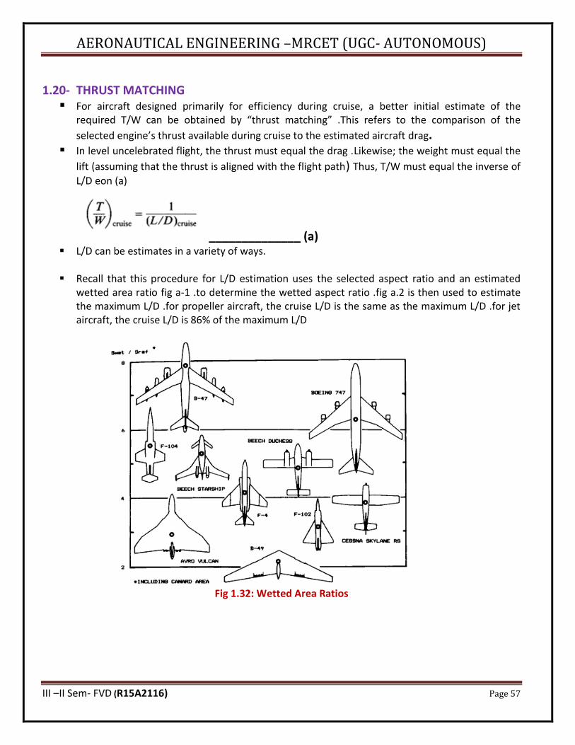
AERONAUTICAL ENGINEERING –MRCET (UGC- AUTONOMOUS)
III –II Sem- FVD (R15A2116) Page 57
1.20- THRUST MATCHING ▪ For aircraft designed primarily for efficiency during cruise, a better initial estimate of the
required T/W can be obtained by “thrust matching” .This refers to the comparison of the
selected engine’s thrust available during cruise to the estimated aircraft drag. ▪ In level uncelebrated flight, the thrust must equal the drag .Likewise; the weight must equal the
lift (assuming that the thrust is aligned with the flight path) Thus, T/W must equal the inverse of
L/D eon (a)
______________ (a) ▪ L/D can be estimates in a variety of ways.
▪ Recall that this procedure for L/D estimation uses the selected aspect ratio and an estimated
wetted area ratio fig a-1 .to determine the wetted aspect ratio .fig a.2 is then used to estimate the maximum L/D .for propeller aircraft, the cruise L/D is the same as the maximum L/D .for jet aircraft, the cruise L/D is 86% of the maximum L/D
Fig 1.32: Wetted Area Ratios
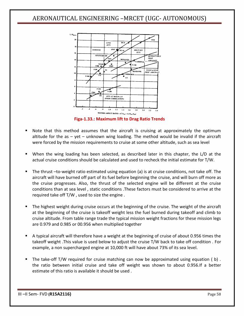
AERONAUTICAL ENGINEERING –MRCET (UGC- AUTONOMOUS)
III –II Sem- FVD (R15A2116) Page 58
Figa-1.33.: Maximum lift to Drag Ratio Trends
▪ Note that this method assumes that the aircraft is cruising at approximately the optimum altitude for the as – yet – unknown wing loading. The method would be invalid if the aircraft were forced by the mission requirements to cruise at some other altitude, such as sea level
▪ When the wing loading has been selected, as described later in this chapter, the L/D at the
actual cruise conditions should be calculated and used to recheck the initial estimate for T/W.
▪ The thrust –to-weight ratio estimated using equation (a) is at cruise conditions, not take off. The aircraft will have burned off part of its fuel before beginning the cruise, and will burn off more as the cruise progresses. Also, the thrust of the selected engine will be different at the cruise conditions than at sea level , static conditions .These factors must be considered to arrive at the required take off T/W , used to size the engine .
▪ The highest weight during cruise occurs at the beginning of the cruise. The weight of the aircraft
at the beginning of the cruise is takeoff weight less the fuel burned during takeoff and climb to cruise altitude. From table range trade the typical mission weight fractions for these mission legs are 0.979 and 0.985 or 00.956 when multiplied together
▪ A typical aircraft will therefore have a weight at the beginning of cruise of about 0.956 times the
takeoff weight .This value is used below to adjust the cruise T/W back to take off condition . For example, a non supercharged engine at 10,000 ft will have about 73% of its sea level.
▪ The take-off T/W required for cruise matching can now be approximated using equation ( b) . the ratio between initial cruise and take off weight was shown to about 0.956.If a better estimate of this ratio is available it should be used .
AERONAUTICAL ENGINEERING –MRCET (UGC- AUTONOMOUS)
III –II Sem- FVD (R15A2116) Page 59
_____________ (b)
▪ The thrust ratio between take off and cruise conditions should be obtained from actual engine data if possible.
▪ For a propeller aircraft , the required take – off hp/W can be found by combining equations 1
and 2 from below mentioned
---------- ( 1) And
-------- (2)
--------- ( 3 )
▪ After an initial layout has been completed, actual aerodynamic calculations are made to
compare the drag during cruise with the thrust available.
▪ There are many other criteria which can set the thrust – to – weight ratio such as climb rate , take off distances , and turning performance .These other criteria also involve the wing loading and are described in sub sections.
1.21- WING LOADING ▪ The wing loading is the weight of the aircraft divided by the area of the reference wing. As with
the thrust – to – weight ratio, the term wing loading” normally refers to the take off wing loading , but can also refer to combat and other flight conditions
▪ Wing loading affects stall speed, climb rate, take off and landing distances , and turn
performance .The wing loading determines the design lift coefficient, and impacts drag through its effect upon wetted area and wing span.
▪ Wing loading has a strong effect upon sized aircraft take off gross weight.
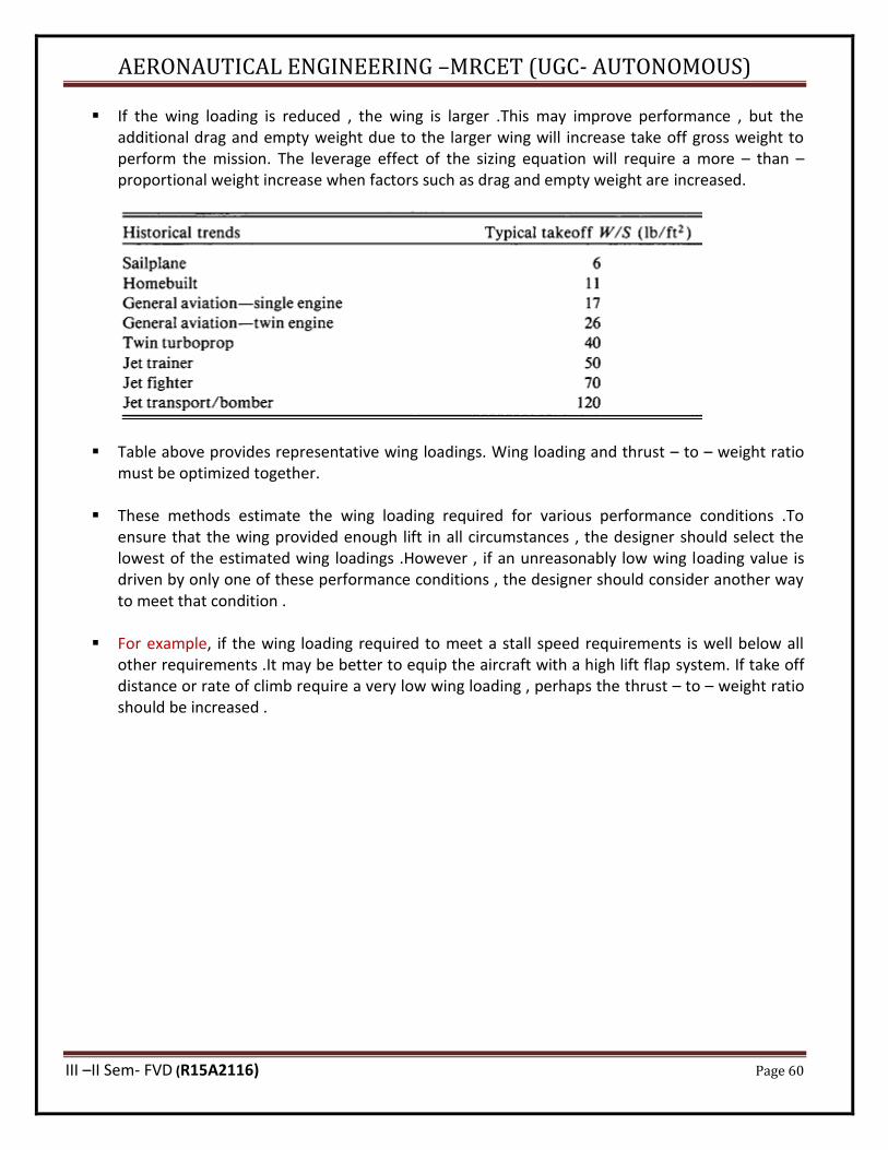
AERONAUTICAL ENGINEERING –MRCET (UGC- AUTONOMOUS)
III –II Sem- FVD (R15A2116) Page 60
▪ If the wing loading is reduced , the wing is larger .This may improve performance , but the additional drag and empty weight due to the larger wing will increase take off gross weight to perform the mission. The leverage effect of the sizing equation will require a more – than – proportional weight increase when factors such as drag and empty weight are increased.
▪ Table above provides representative wing loadings. Wing loading and thrust – to – weight ratio must be optimized together.
▪ These methods estimate the wing loading required for various performance conditions .To ensure that the wing provided enough lift in all circumstances , the designer should select the lowest of the estimated wing loadings .However , if an unreasonably low wing loading value is driven by only one of these performance conditions , the designer should consider another way to meet that condition .
▪ For example, if the wing loading required to meet a stall speed requirements is well below all
other requirements .It may be better to equip the aircraft with a high lift flap system. If take off distance or rate of climb require a very low wing loading , perhaps the thrust – to – weight ratio should be increased .
AERONAUTICAL ENGINEERING –MRCET (UGC- AUTONOMOUS)
III –II Sem- FVD (R15A2116) Page 61
UNIT – II INITIAL SIZING AND CONFIGURATION LAYOUT
2.1- INITIAL SIZING- INTRODUCTION ▪ Aircraft sizing is the process of determining the takeoff gross weight and fuel weight required for
an aircraft concept to perform its design mission. That sizing method was limited to fairly simple design missions.
▪ This chapter presents a more refined method capable of dealing with most types of aircraft-
sizing problems.
▪ An aircraft can be sized using some existing engine or a new design engine. The existing engine is fixed in size and thrust, and is referred to as a "fixed engine"("fixed" refers to engine size).
▪ The new design engine can be built in any size and thrust required, and is called a "rubber
engine" because it can be “stretched" during the sizing process to provide any required amount of thrust.
▪ Rubber-engine sizing is used during the early stages of an aircraft development program that is
sufficiently important to warrant the development of an all-new engine. This is generally the case for a major military fighter or bomber program, and is sometimes the case for a transport-aircraft project such as the SST.
▪ In these cases, the designer will use a rubber engine in the early stages of design, and then, with
the customer, tell the engine company what characteristics the new engine should have. When the engine company finalizes the design for the new engine, it becomes fixed in size and thrust. The aircraft concept will then be finalized around this now-fixed engine
▪ Developing a new jet engine costs on the order of a billion dollars. Developing and certifying a
new piston engine is also very expensive. Most aircraft projects do not rate development of a new engine, and so must rely on selecting the best of the existing engines. However, even projects which must use an existing engine may begin with a rubber-engine design study to determine what characteristics to look for in the selection of an existing engine
▪ The rubber engine can be scaled to any thrust so the thrust-to-weight ratio can be held to some desired value even as the aircraft weight is varied. The rubber-engine sizing approach allows the designer to size the aircraft to meet both performance and range goals, by solving for takeoff gross weight while holding the thrust-to-weight ratio required to meet the performance objectives. As the weight varies, the rubber-engine is scaled up or down as required.
▪ This is not possible for fixed-engine aircraft sizing. When a fixed size engine is used, either the
mission range or the performance of the aircraft must become a fallout parameter.
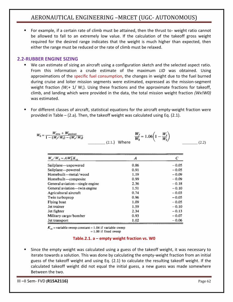
AERONAUTICAL ENGINEERING –MRCET (UGC- AUTONOMOUS)
III –II Sem- FVD (R15A2116) Page 62
▪ For example, if a certain rate of climb must be attained, then the thrust to- weight ratio cannot be allowed to fall to an extremely low value. If the calculation of the takeoff gross weight required for the desired range indicates that the weight is much higher than expected, then either the range must be reduced or the rate of climb must be relaxed.
2.2-RUBBER ENGINE SIZING ▪ We can estimate of sizing an aircraft using a configuration sketch and the selected aspect ratio.
From this information a crude estimate of the maximum LID was obtained. Using approximations of the specific fuel consumption, the changes in weight due to the fuel burned during cruise and loiter mission segments were estimated, expressed as the mission-segment weight fraction (W;+ 1/ W;). Using these fractions and the approximate fractions for takeoff, climb, and landing which were provided in the data, the total mission weight fraction (Wx!W0) was estimated.
▪ For different classes of aircraft, statistical equations for the aircraft empty-weight fraction were
provided in Table – (2.a). Then, the takeoff weight was calculated using Eq. (2.1).
_________ (2.1.) Where ________ (2.2)
Table.2.1. a – empty weight fraction vs. W0
▪ Since the empty weight was calculated using a guess of the takeoff weight, it was necessary to iterate towards a solution. This was done by calculating the empty-weight fraction from an initial guess of the takeoff weight and using Eq. (2.1) to calculate the resulting takeoff weight. If the calculated takeoff weight did not equal the initial guess, a new guess was made somewhere Between the two.
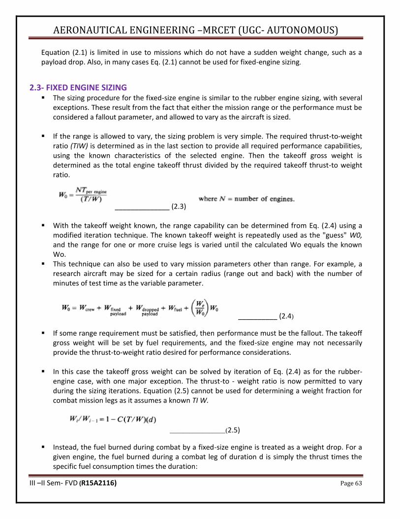
AERONAUTICAL ENGINEERING –MRCET (UGC- AUTONOMOUS)
III –II Sem- FVD (R15A2116) Page 63
Equation (2.1) is limited in use to missions which do not have a sudden weight change, such as a payload drop. Also, in many cases Eq. (2.1) cannot be used for fixed-engine sizing.
2.3- FIXED ENGINE SIZING ▪ The sizing procedure for the fixed-size engine is similar to the rubber engine sizing, with several
exceptions. These result from the fact that either the mission range or the performance must be considered a fallout parameter, and allowed to vary as the aircraft is sized.
▪ If the range is allowed to vary, the sizing problem is very simple. The required thrust-to-weight
ratio (TIW) is determined as in the last section to provide all required performance capabilities, using the known characteristics of the selected engine. Then the takeoff gross weight is determined as the total engine takeoff thrust divided by the required takeoff thrust-to weight ratio.
______________ (2.3)
▪ With the takeoff weight known, the range capability can be determined from Eq. (2.4) using a
modified iteration technique. The known takeoff weight is repeatedly used as the "guess" W0, and the range for one or more cruise legs is varied until the calculated Wo equals the known Wo.
▪ This technique can also be used to vary mission parameters other than range. For example, a research aircraft may be sized for a certain radius (range out and back) with the number of minutes of test time as the variable parameter.
__________ (2.4)
▪ If some range requirement must be satisfied, then performance must be the fallout. The takeoff gross weight will be set by fuel requirements, and the fixed-size engine may not necessarily provide the thrust-to-weight ratio desired for performance considerations.
▪ In this case the takeoff gross weight can be solved by iteration of Eq. (2.4) as for the rubber-
engine case, with one major exception. The thrust-to - weight ratio is now permitted to vary during the sizing iterations. Equation (2.5) cannot be used for determining a weight fraction for combat mission legs as it assumes a known TI W.
_________________(2.5)
▪ Instead, the fuel burned during combat by a fixed-size engine is treated as a weight drop. For a given engine, the fuel burned during a combat leg of duration d is simply the thrust times the specific fuel consumption times the duration:
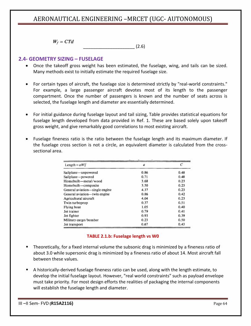
AERONAUTICAL ENGINEERING –MRCET (UGC- AUTONOMOUS)
III –II Sem- FVD (R15A2116) Page 64
_____________________ (2.6)
2.4- GEOMETRY SIZING – FUSELAGE • Once the takeoff gross weight has been estimated, the fuselage, wing, and tails can be sized.
Many methods exist to initially estimate the required fuselage size.
• For certain types of aircraft, the fuselage size is determined strictly by "real-world constraints." For example, a large passenger aircraft devotes most of its length to the passenger compartment. Once the number of passengers is known and the number of seats across is selected, the fuselage length and diameter are essentially determined.
• For initial guidance during fuselage layout and tail sizing, Table provides statistical equations for fuselage length developed from data provided in Ref. 1. These are based solely upon takeoff gross weight, and give remarkably good correlations to most existing aircraft.
• Fuselage fineness ratio is the ratio between the fuselage length and its maximum diameter. If the fuselage cross section is not a circle, an equivalent diameter is calculated from the cross-sectional area.
TABLE 2.1.b: Fuselage length vs W0
▪ Theoretically, for a fixed internal volume the subsonic drag is minimized by a fineness ratio of about 3.0 while supersonic drag is minimized by a fineness ratio of about 14. Most aircraft fall between these values.
▪ A historically-derived fuselage fineness ratio can be used, along with the length estimate, to develop the initial fuselage layout. However, "real world constraints" such as payload envelope must take priority. For most design efforts the realities of packaging the internal components will establish the fuselage length and diameter.
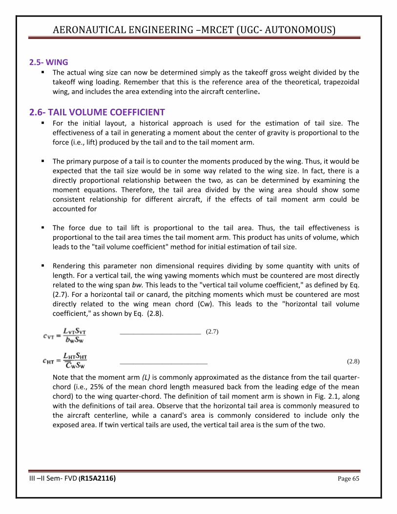
AERONAUTICAL ENGINEERING –MRCET (UGC- AUTONOMOUS)
III –II Sem- FVD (R15A2116) Page 65
2.5- WING ▪ The actual wing size can now be determined simply as the takeoff gross weight divided by the
takeoff wing loading. Remember that this is the reference area of the theoretical, trapezoidal wing, and includes the area extending into the aircraft centerline.
2.6- TAIL VOLUME COEFFICIENT ▪ For the initial layout, a historical approach is used for the estimation of tail size. The
effectiveness of a tail in generating a moment about the center of gravity is proportional to the force (i.e., lift) produced by the tail and to the tail moment arm.
▪ The primary purpose of a tail is to counter the moments produced by the wing. Thus, it would be
expected that the tail size would be in some way related to the wing size. In fact, there is a directly proportional relationship between the two, as can be determined by examining the moment equations. Therefore, the tail area divided by the wing area should show some consistent relationship for different aircraft, if the effects of tail moment arm could be accounted for
▪ The force due to tail lift is proportional to the tail area. Thus, the tail effectiveness is
proportional to the tail area times the tail moment arm. This product has units of volume, which leads to the "tail volume coefficient" method for initial estimation of tail size.
▪ Rendering this parameter non dimensional requires dividing by some quantity with units of
length. For a vertical tail, the wing yawing moments which must be countered are most directly related to the wing span bw. This leads to the "vertical tail volume coefficient," as defined by Eq. (2.7). For a horizontal tail or canard, the pitching moments which must be countered are most directly related to the wing mean chord (Cw). This leads to the "horizontal tail volume coefficient," as shown by Eq. (2.8).
_________________________ (2.7)
___________________________ (2.8)
Note that the moment arm (L) is commonly approximated as the distance from the tail quarter-chord (i.e., 25% of the mean chord length measured back from the leading edge of the mean chord) to the wing quarter-chord. The definition of tail moment arm is shown in Fig. 2.1, along with the definitions of tail area. Observe that the horizontal tail area is commonly measured to the aircraft centerline, while a canard's area is commonly considered to include only the exposed area. If twin vertical tails are used, the vertical tail area is the sum of the two.
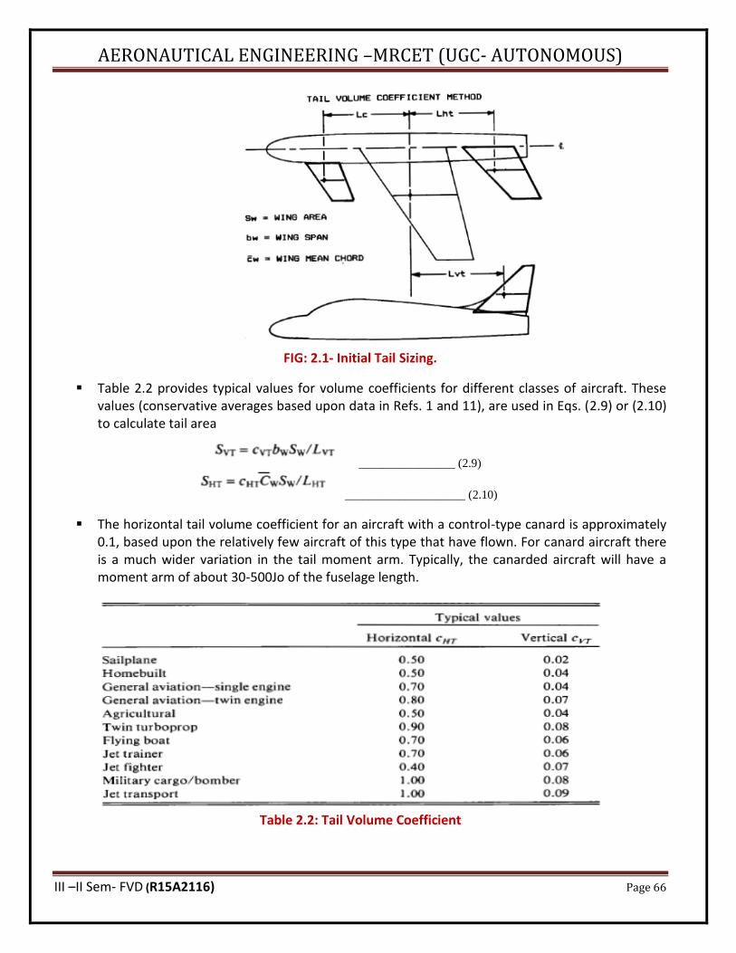
AERONAUTICAL ENGINEERING –MRCET (UGC- AUTONOMOUS)
III –II Sem- FVD (R15A2116) Page 66
FIG: 2.1- Initial Tail Sizing.
▪ Table 2.2 provides typical values for volume coefficients for different classes of aircraft. These values (conservative averages based upon data in Refs. 1 and 11), are used in Eqs. (2.9) or (2.10) to calculate tail area
________________ (2.9)
____________________ (2.10)
▪ The horizontal tail volume coefficient for an aircraft with a control-type canard is approximately 0.1, based upon the relatively few aircraft of this type that have flown. For canard aircraft there is a much wider variation in the tail moment arm. Typically, the canarded aircraft will have a moment arm of about 30-500Jo of the fuselage length.
Table 2.2: Tail Volume Coefficient

AERONAUTICAL ENGINEERING –MRCET (UGC- AUTONOMOUS)
III –II Sem- FVD (R15A2116) Page 67
2.7- CONTROL SURFACE SIZING ▪ The primary control surfaces are the ailerons (roll), elevator (pitch), and rudder (yaw). Final
sizing of these surfaces is based upon dynamic analysis of control effectiveness, including structural bending and control-system effects. For initial design, the following guidelines are offered.
▪ The required aileron area can be estimated from Fig. 2.2, an updated version of a figure from
Ref. 12. In span, the ailerons typically extend from about 50% to about 90% of the span. In some aircraft, the ailerons extend all the way out to the wing tips. This extra10% provides little control effectiveness due to the vortex flow at the wingtips, but can provide a location for an aileron mass balance (see below).
▪ Wing flaps occupy the part of the wing span inboard of the ailerons. If a large maximum lift coefficient is required, the flap span should be as large as possible. One way of accomplishing this is through the use of spoilers rather than ailerons. Spoilers are plates located forward of the flaps on the top of the wing, typically aft of the maximum thickness point. Spoilers are deflected upward into the slipstream to reduce the wing's lift. Deploying the spoiler on one wing will cause a large rolling moment.
▪ Spoilers are commonly used on jet transports to augment roll control at low speed, and can also be used to reduce lift and add drag during the landing roll out. However, because spoilers have very nonlinear response characteristics they are difficult to implement for roll control when using a manual flight control system.
▪ High-speed aircraft can experience phenomena known as "aileron reversal “in which the air loads placed upon a deflected aileron are so great that the wing itself is twisted. At some speed, the wing may twist so much that the rolling moment produced by the twist will exceed the rolling moment produced by the aileron, causing the aircraft to roll the wrong way. To avoid this, many transport jets use an auxiliary, inboard aileron for high-speed roll control. Spoilers can also be used for this purpose. Several military fighters rely upon "rolling tails" (horizontal tails capable of being deflected non symmetrically) to achieve the same result.
▪ Control surfaces are usually tapered in chord by the same ratio as the wing or tail surface so that the control surface maintains a constant percent chord (Fig2.2). This allows spars to be straight-tapered rather than curved. Ailerons and flaps are typically about 15-250Jo of the wing chord. Rudders and elevators are typically about 25-50% of the tail chord.
▪ Control-surface "flutter," a rapid oscillation of the surface caused by the air loads, can tear off the control surface or even the whole wing. Flutter tendencies are minimized by using mass balancing and aerodynamic balancing.
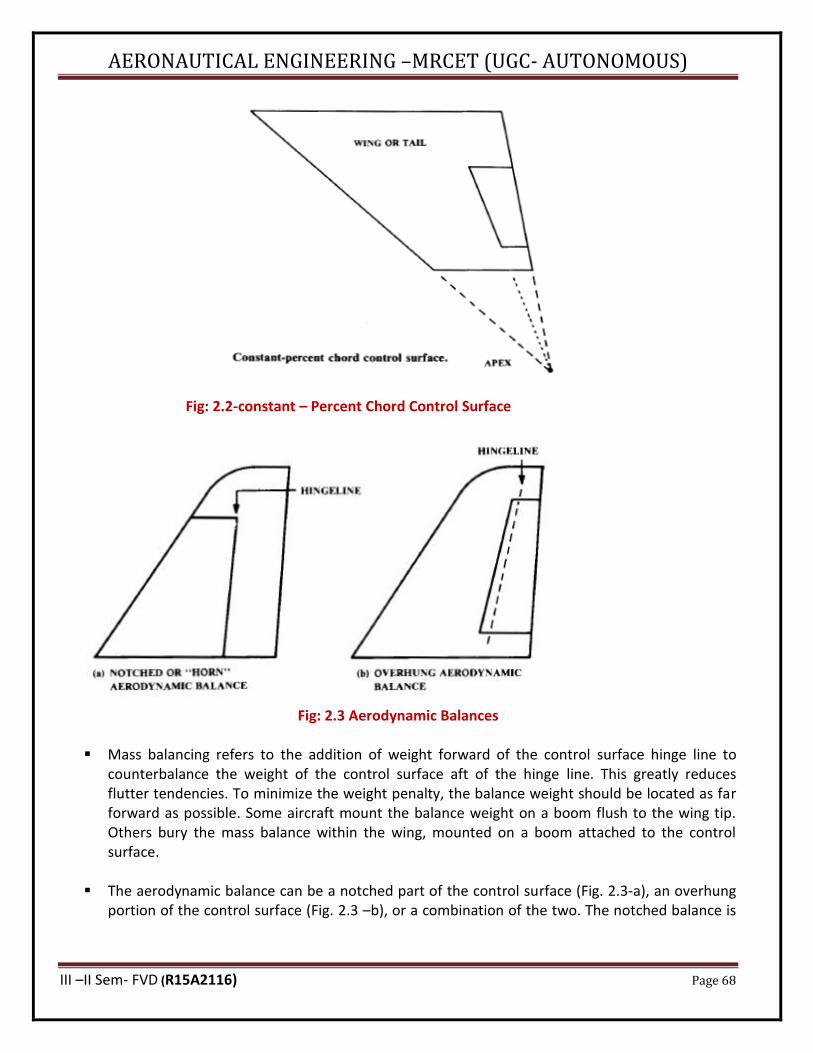
AERONAUTICAL ENGINEERING –MRCET (UGC- AUTONOMOUS)
III –II Sem- FVD (R15A2116) Page 68
Fig: 2.2-constant – Percent Chord Control Surface
Fig: 2.3 Aerodynamic Balances
▪ Mass balancing refers to the addition of weight forward of the control surface hinge line to
counterbalance the weight of the control surface aft of the hinge line. This greatly reduces flutter tendencies. To minimize the weight penalty, the balance weight should be located as far forward as possible. Some aircraft mount the balance weight on a boom flush to the wing tip. Others bury the mass balance within the wing, mounted on a boom attached to the control surface.
▪ The aerodynamic balance can be a notched part of the control surface (Fig. 2.3-a), an overhung
portion of the control surface (Fig. 2.3 –b), or a combination of the two. The notched balance is
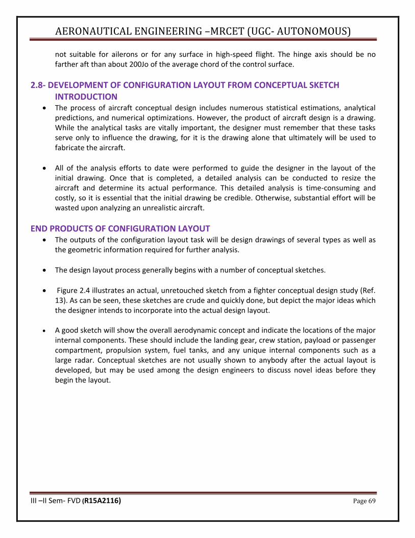
AERONAUTICAL ENGINEERING –MRCET (UGC- AUTONOMOUS)
III –II Sem- FVD (R15A2116) Page 69
not suitable for ailerons or for any surface in high-speed flight. The hinge axis should be no farther aft than about 200Jo of the average chord of the control surface.
2.8- DEVELOPMENT OF CONFIGURATION LAYOUT FROM CONCEPTUAL SKETCH INTRODUCTION
• The process of aircraft conceptual design includes numerous statistical estimations, analytical predictions, and numerical optimizations. However, the product of aircraft design is a drawing. While the analytical tasks are vitally important, the designer must remember that these tasks serve only to influence the drawing, for it is the drawing alone that ultimately will be used to fabricate the aircraft.
• All of the analysis efforts to date were performed to guide the designer in the layout of the initial drawing. Once that is completed, a detailed analysis can be conducted to resize the aircraft and determine its actual performance. This detailed analysis is time-consuming and costly, so it is essential that the initial drawing be credible. Otherwise, substantial effort will be wasted upon analyzing an unrealistic aircraft.
END PRODUCTS OF CONFIGURATION LAYOUT • The outputs of the configuration layout task will be design drawings of several types as well as
the geometric information required for further analysis.
• The design layout process generally begins with a number of conceptual sketches.
• Figure 2.4 illustrates an actual, unretouched sketch from a fighter conceptual design study (Ref. 13). As can be seen, these sketches are crude and quickly done, but depict the major ideas which the designer intends to incorporate into the actual design layout.
• A good sketch will show the overall aerodynamic concept and indicate the locations of the major internal components. These should include the landing gear, crew station, payload or passenger compartment, propulsion system, fuel tanks, and any unique internal components such as a large radar. Conceptual sketches are not usually shown to anybody after the actual layout is developed, but may be used among the design engineers to discuss novel ideas before they begin the layout.
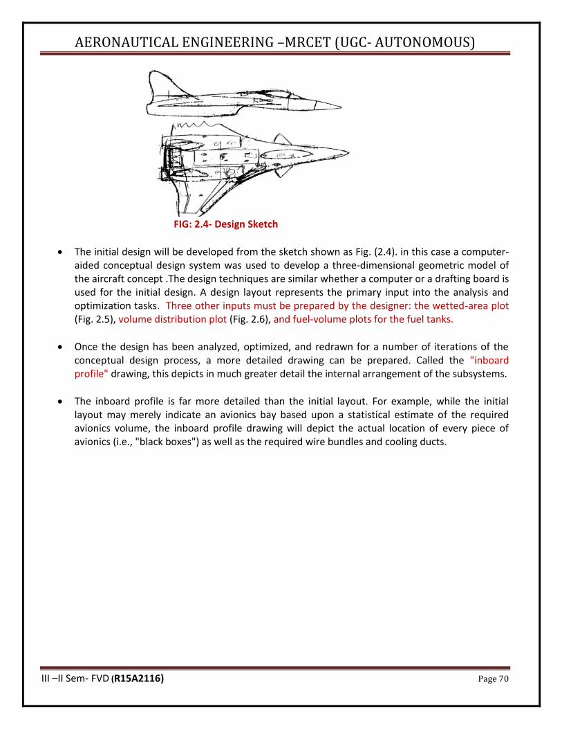
AERONAUTICAL ENGINEERING –MRCET (UGC- AUTONOMOUS)
III –II Sem- FVD (R15A2116) Page 70
FIG: 2.4- Design Sketch
• The initial design will be developed from the sketch shown as Fig. (2.4). in this case a computer-aided conceptual design system was used to develop a three-dimensional geometric model of the aircraft concept .The design techniques are similar whether a computer or a drafting board is used for the initial design. A design layout represents the primary input into the analysis and optimization tasks. Three other inputs must be prepared by the designer: the wetted-area plot (Fig. 2.5), volume distribution plot (Fig. 2.6), and fuel-volume plots for the fuel tanks.
• Once the design has been analyzed, optimized, and redrawn for a number of iterations of the conceptual design process, a more detailed drawing can be prepared. Called the "inboard profile" drawing, this depicts in much greater detail the internal arrangement of the subsystems.
• The inboard profile is far more detailed than the initial layout. For example, while the initial layout may merely indicate an avionics bay based upon a statistical estimate of the required avionics volume, the inboard profile drawing will depict the actual location of every piece of avionics (i.e., "black boxes") as well as the required wire bundles and cooling ducts.
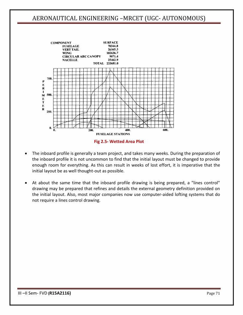
AERONAUTICAL ENGINEERING –MRCET (UGC- AUTONOMOUS)
III –II Sem- FVD (R15A2116) Page 71
Fig 2.5- Wetted Area Plot
• The inboard profile is generally a team project, and takes many weeks. During the preparation of the inboard profile it is not uncommon to find that the initial layout must be changed to provide enough room for everything. As this can result in weeks of lost effort, it is imperative that the initial layout be as well thought-out as possible.
• At about the same time that the inboard profile drawing is being prepared, a "lines control" drawing may be prepared that refines and details the external geometry definition provided on the initial layout. Also, most major companies now use computer-aided lofting systems that do not require a lines control drawing.
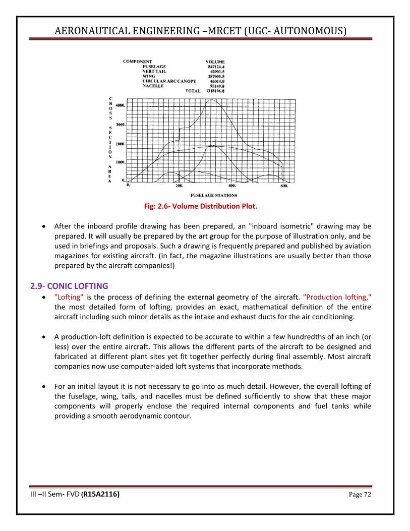
AERONAUTICAL ENGINEERING –MRCET (UGC- AUTONOMOUS)
III –II Sem- FVD (R15A2116) Page 72
Fig: 2.6- Volume Distribution Plot.
• After the inboard profile drawing has been prepared, an "inboard isometric" drawing may be prepared. It will usually be prepared by the art group for the purpose of illustration only, and be used in briefings and proposals. Such a drawing is frequently prepared and published by aviation magazines for existing aircraft. (In fact, the magazine illustrations are usually better than those prepared by the aircraft companies!)
2.9- CONIC LOFTING • "Lofting" is the process of defining the external geometry of the aircraft. "Production lofting,"
the most detailed form of lofting, provides an exact, mathematical definition of the entire aircraft including such minor details as the intake and exhaust ducts for the air conditioning.
• A production-loft definition is expected to be accurate to within a few hundredths of an inch (or less) over the entire aircraft. This allows the different parts of the aircraft to be designed and fabricated at different plant sites yet fit together perfectly during final assembly. Most aircraft companies now use computer-aided loft systems that incorporate methods.
• For an initial layout it is not necessary to go into as much detail. However, the overall lofting of the fuselage, wing, tails, and nacelles must be defined sufficiently to show that these major components will properly enclose the required internal components and fuel tanks while providing a smooth aerodynamic contour.
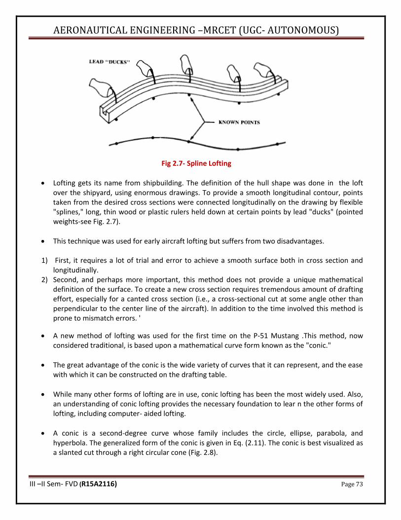
AERONAUTICAL ENGINEERING –MRCET (UGC- AUTONOMOUS)
III –II Sem- FVD (R15A2116) Page 73
Fig 2.7- Spline Lofting
• Lofting gets its name from shipbuilding. The definition of the hull shape was done in the loft over the shipyard, using enormous drawings. To provide a smooth longitudinal contour, points taken from the desired cross sections were connected longitudinally on the drawing by flexible "splines," long, thin wood or plastic rulers held down at certain points by lead "ducks" (pointed weights-see Fig. 2.7).
• This technique was used for early aircraft lofting but suffers from two disadvantages.
1) First, it requires a lot of trial and error to achieve a smooth surface both in cross section and longitudinally.
2) Second, and perhaps more important, this method does not provide a unique mathematical definition of the surface. To create a new cross section requires tremendous amount of drafting effort, especially for a canted cross section (i.e., a cross-sectional cut at some angle other than perpendicular to the center line of the aircraft). In addition to the time involved this method is prone to mismatch errors. '
• A new method of lofting was used for the first time on the P-51 Mustang .This method, now considered traditional, is based upon a mathematical curve form known as the "conic."
• The great advantage of the conic is the wide variety of curves that it can represent, and the ease with which it can be constructed on the drafting table.
• While many other forms of lofting are in use, conic lofting has been the most widely used. Also, an understanding of conic lofting provides the necessary foundation to lear n the other forms of lofting, including computer- aided lofting.
• A conic is a second-degree curve whose family includes the circle, ellipse, parabola, and hyperbola. The generalized form of the conic is given in Eq. (2.11). The conic is best visualized as a slanted cut through a right circular cone (Fig. 2.8).
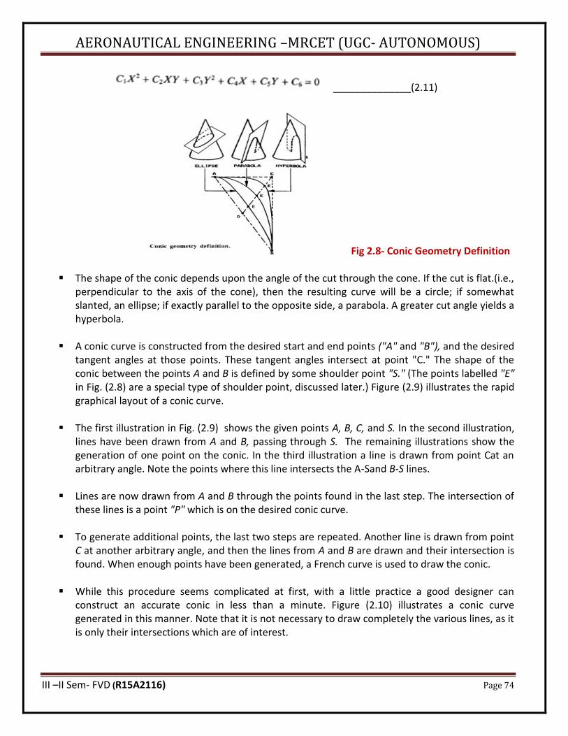
AERONAUTICAL ENGINEERING –MRCET (UGC- AUTONOMOUS)
III –II Sem- FVD (R15A2116) Page 74
______________(2.11)
Fig 2.8- Conic Geometry Definition
▪ The shape of the conic depends upon the angle of the cut through the cone. If the cut is flat.(i.e., perpendicular to the axis of the cone), then the resulting curve will be a circle; if somewhat slanted, an ellipse; if exactly parallel to the opposite side, a parabola. A greater cut angle yields a hyperbola.
▪ A conic curve is constructed from the desired start and end points ("A" and "B"), and the desired tangent angles at those points. These tangent angles intersect at point "C." The shape of the conic between the points A and B is defined by some shoulder point "S." (The points labelled "E" in Fig. (2.8) are a special type of shoulder point, discussed later.) Figure (2.9) illustrates the rapid graphical layout of a conic curve.
▪ The first illustration in Fig. (2.9) shows the given points A, B, C, and S. In the second illustration, lines have been drawn from A and B, passing through S. The remaining illustrations show the generation of one point on the conic. In the third illustration a line is drawn from point Cat an arbitrary angle. Note the points where this line intersects the A-Sand B-S lines.
▪ Lines are now drawn from A and B through the points found in the last step. The intersection of these lines is a point "P" which is on the desired conic curve.
▪ To generate additional points, the last two steps are repeated. Another line is drawn from point C at another arbitrary angle, and then the lines from A and B are drawn and their intersection is found. When enough points have been generated, a French curve is used to draw the conic.
▪ While this procedure seems complicated at first, with a little practice a good designer can construct an accurate conic in less than a minute. Figure (2.10) illustrates a conic curve generated in this manner. Note that it is not necessary to draw completely the various lines, as it is only their intersections which are of interest.
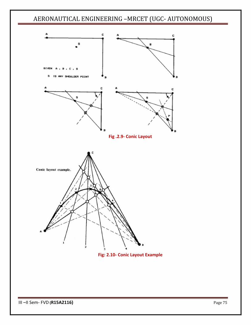
AERONAUTICAL ENGINEERING –MRCET (UGC- AUTONOMOUS)
III –II Sem- FVD (R15A2116) Page 75
Fig .2.9- Conic Layout
Fig: 2.10- Conic Layout Example
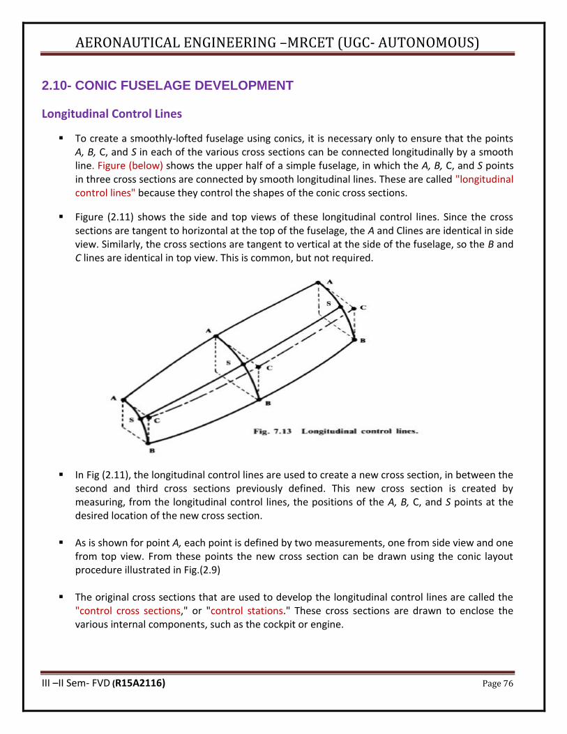
AERONAUTICAL ENGINEERING –MRCET (UGC- AUTONOMOUS)
III –II Sem- FVD (R15A2116) Page 76
2.10- CONIC FUSELAGE DEVELOPMENT
Longitudinal Control Lines
▪ To create a smoothly-lofted fuselage using conics, it is necessary only to ensure that the points A, B, C, and S in each of the various cross sections can be connected longitudinally by a smooth line. Figure (below) shows the upper half of a simple fuselage, in which the A, B, C, and S points in three cross sections are connected by smooth longitudinal lines. These are called "longitudinal control lines" because they control the shapes of the conic cross sections.
▪ Figure (2.11) shows the side and top views of these longitudinal control lines. Since the cross sections are tangent to horizontal at the top of the fuselage, the A and Clines are identical in side view. Similarly, the cross sections are tangent to vertical at the side of the fuselage, so the B and C lines are identical in top view. This is common, but not required.
▪ In Fig (2.11), the longitudinal control lines are used to create a new cross section, in between the second and third cross sections previously defined. This new cross section is created by measuring, from the longitudinal control lines, the positions of the A, B, C, and S points at the desired location of the new cross section.
▪ As is shown for point A, each point is defined by two measurements, one from side view and one from top view. From these points the new cross section can be drawn using the conic layout procedure illustrated in Fig.(2.9)
▪ The original cross sections that are used to develop the longitudinal control lines are called the "control cross sections," or "control stations." These cross sections are drawn to enclose the various internal components, such as the cockpit or engine.
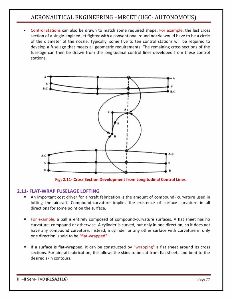
AERONAUTICAL ENGINEERING –MRCET (UGC- AUTONOMOUS)
III –II Sem- FVD (R15A2116) Page 77
▪ Control stations can also be drawn to match some required shape. For example, the last cross section of a single-engined jet fighter with a conventional round nozzle would have to be a circle of the diameter of the nozzle. Typically, some five to ten control stations will be required to develop a fuselage that meets all geometric requirements. The remaining cross sections of the fuselage can then be drawn from the longitudinal control lines developed from these control stations.
Fig: 2.11- Cross Section Development from Longitudinal Control Lines
2.11- FLAT-WRAP FUSELAGE LOFTING ▪ An important cost driver for aircraft fabrication is the amount of compound- curvature used in
lofting the aircraft. Compound-curvature implies the existence of surface curvature in all directions for some point on the surface.
▪ For example, a ball is entirely composed of compound-curvature surfaces. A flat sheet has no curvature, compound or otherwise. A cylinder is curved, but only in one direction, so it does not have any compound curvature. Instead, a cylinder or any other surface with curvature in only one direction is said to be "flat-wrapped".
▪ If a surface is flat-wrapped, it can be constructed by "wrapping" a flat sheet around its cross sections. For aircraft fabrication, this allows the skins to be cut from flat sheets and bent to the desired skin contours.
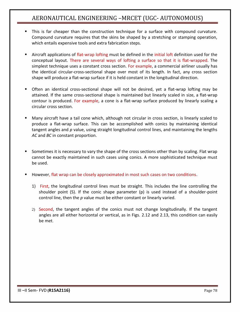
AERONAUTICAL ENGINEERING –MRCET (UGC- AUTONOMOUS)
III –II Sem- FVD (R15A2116) Page 78
▪ This is far cheaper than the construction technique for a surface with compound curvature. Compound curvature requires that the skins be shaped by a stretching or stamping operation, which entails expensive tools and extra fabrication steps.
▪ Aircraft applications of flat-wrap lofting must be defined in the initial loft definition used for the conceptual layout. There are several ways of lofting a surface so that it is flat-wrapped. The simplest technique uses a constant cross section. For example, a commercial airliner usually has the identical circular-cross-sectional shape over most of its length. In fact, any cross section shape will produce a flat-wrap surface if it is held constant in the longitudinal direction.
▪ Often an identical cross-sectional shape will not be desired, yet a flat-wrap lofting may be attained. If the same cross-sectional shape is maintained but linearly scaled in size, a flat-wrap contour is produced. For example, a cone is a flat-wrap surface produced by linearly scaling a circular cross section.
▪ Many aircraft have a tail cone which, although not circular in cross section, is linearly scaled to produce a flat-wrap surface. This can be accomplished with conics by maintaining identical tangent angles and p value, using straight longitudinal control lines, and maintaining the lengths AC and BC in constant proportion.
▪ Sometimes it is necessary to vary the shape of the cross sections other than by scaling. Flat wrap
cannot be exactly maintained in such cases using conics. A more sophisticated technique must be used.
▪ However, flat wrap can be closely approximated in most such cases on two conditions. 1) First, the longitudinal control lines must be straight. This includes the line controlling the
shoulder point (S). If the conic shape parameter (p) is used instead of a shoulder-point control line, then the p value must be either constant or linearly varied.
2) Second, the tangent angles of the conics must not change longitudinally. If the tangent angles are all either horizontal or vertical, as in Figs. 2.12 and 2.13, this condition can easily be met.
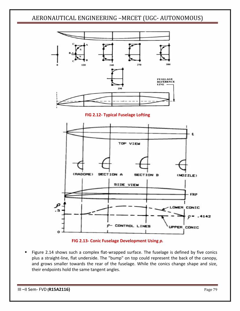
AERONAUTICAL ENGINEERING –MRCET (UGC- AUTONOMOUS)
III –II Sem- FVD (R15A2116) Page 79
FIG 2.12- Typical Fuselage Lofting
FIG 2.13- Conic Fuselage Development Using p.
▪ Figure 2.14 shows such a complex flat-wrapped surface. The fuselage is defined by five conics plus a straight-line, flat underside. The "bump" on top could represent the back of the canopy, and grows smaller towards the rear of the fuselage. While the conics change shape and size, their endpoints hold the same tangent angles.
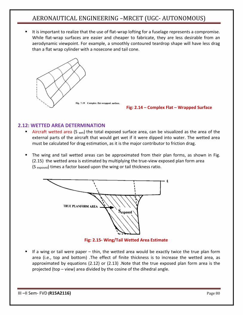
AERONAUTICAL ENGINEERING –MRCET (UGC- AUTONOMOUS)
III –II Sem- FVD (R15A2116) Page 80
▪ It is important to realize that the use of flat-wrap lofting for a fuselage represents a compromise. While flat-wrap surfaces are easier and cheaper to fabricate, they are less desirable from an aerodynamic viewpoint. For example, a smoothly contoured teardrop shape will have less drag than a flat wrap cylinder with a nosecone and tail cone.
Fig: 2.14 – Complex Flat – Wrapped Surface
2.12: WETTED AREA DETERMINATION ▪ Aircraft wetted area (S wet) the total exposed surface area, can be visualized as the area of the
external parts of the aircraft that would get wet if it were dipped into water. The wetted area must be calculated for drag estimation, as it is the major contributor to friction drag.
▪ The wing and tail wetted areas can be approximated from their plan forms, as shown in Fig. (2.15) the wetted area is estimated by multiplying the true-view exposed plan form area (S exposed) times a factor based upon the wing or tail thickness ratio.
Fig: 2.15- Wing/Tail Wetted Area Estimate
▪ If a wing or tail were paper – thin, the wetted area would be exactly twice the true plan form
area (i.e., top and bottom) .The effect of finite thickness is to increase the wetted area, as approximated by equations (2.12) or (2.13) .Note that the true exposed plan form area is the projected (top – view) area divided by the cosine of the dihedral angle.
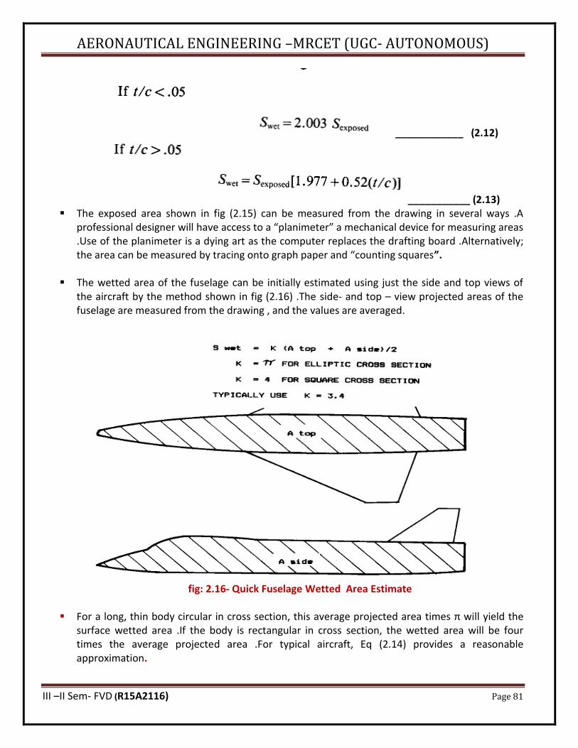
AERONAUTICAL ENGINEERING –MRCET (UGC- AUTONOMOUS)
III –II Sem- FVD (R15A2116) Page 81
____________ (2.12)
___________ (2.13) ▪ The exposed area shown in fig (2.15) can be measured from the drawing in several ways .A
professional designer will have access to a “planimeter” a mechanical device for measuring areas .Use of the planimeter is a dying art as the computer replaces the drafting board .Alternatively; the area can be measured by tracing onto graph paper and “counting squares”.
▪ The wetted area of the fuselage can be initially estimated using just the side and top views of the aircraft by the method shown in fig (2.16) .The side- and top – view projected areas of the fuselage are measured from the drawing , and the values are averaged.
fig: 2.16- Quick Fuselage Wetted Area Estimate
▪ For a long, thin body circular in cross section, this average projected area times π will yield the
surface wetted area .If the body is rectangular in cross section, the wetted area will be four times the average projected area .For typical aircraft, Eq (2.14) provides a reasonable approximation.
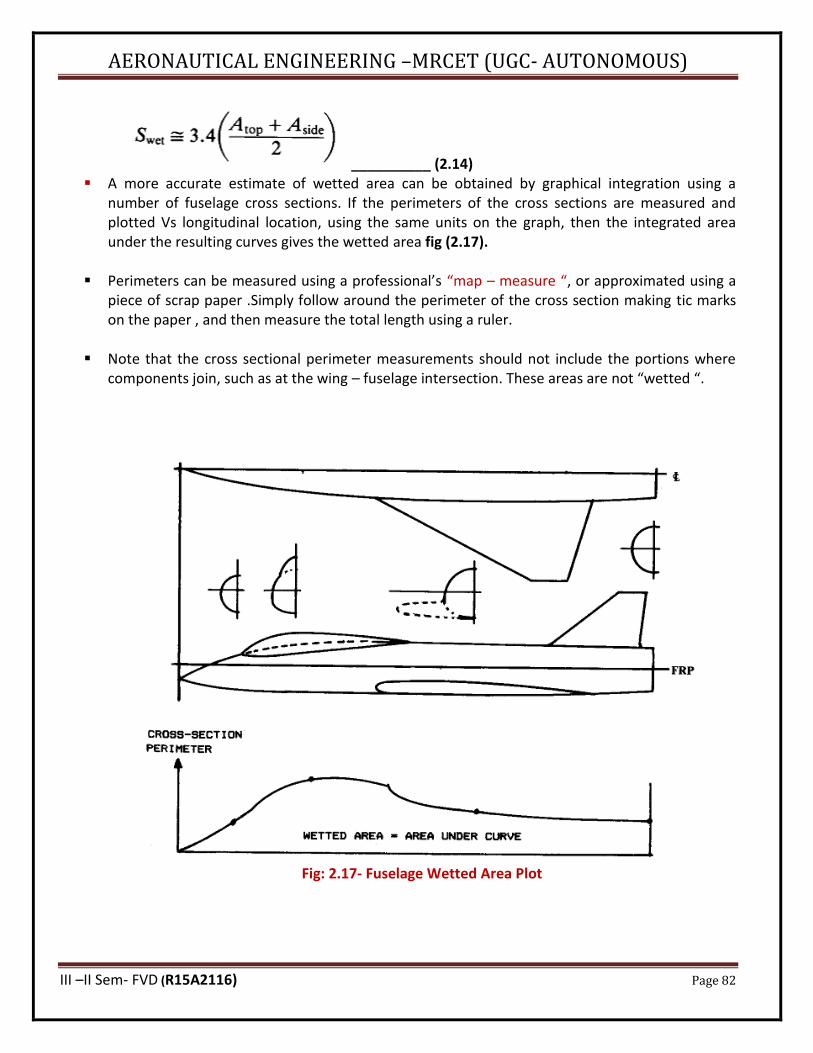
AERONAUTICAL ENGINEERING –MRCET (UGC- AUTONOMOUS)
III –II Sem- FVD (R15A2116) Page 82
__________ (2.14) ▪ A more accurate estimate of wetted area can be obtained by graphical integration using a
number of fuselage cross sections. If the perimeters of the cross sections are measured and plotted Vs longitudinal location, using the same units on the graph, then the integrated area under the resulting curves gives the wetted area fig (2.17).
▪ Perimeters can be measured using a professional’s “map – measure “, or approximated using a piece of scrap paper .Simply follow around the perimeter of the cross section making tic marks on the paper , and then measure the total length using a ruler.
▪ Note that the cross sectional perimeter measurements should not include the portions where components join, such as at the wing – fuselage intersection. These areas are not “wetted “.
Fig: 2.17- Fuselage Wetted Area Plot
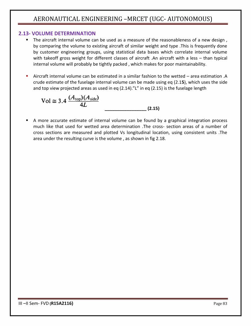
AERONAUTICAL ENGINEERING –MRCET (UGC- AUTONOMOUS)
III –II Sem- FVD (R15A2116) Page 83
2.13- VOLUME DETERMINATION ▪ The aircraft internal volume can be used as a measure of the reasonableness of a new design ,
by comparing the volume to existing aircraft of similar weight and type .This is frequently done by customer engineering groups, using statistical data bases which correlate internal volume with takeoff gross weight for different classes of aircraft .An aircraft with a less – than typical internal volume will probably be tightly packed , which makes for poor maintainability.
▪ Aircraft internal volume can be estimated in a similar fashion to the wetted – area estimation .A
crude estimate of the fuselage internal volume can be made using eq (2.15), which uses the side and top view projected areas as used in eq (2.14).”L” in eq (2.15) is the fuselage length
_________________ (2.15)
▪ A more accurate estimate of internal volume can be found by a graphical integration process much like that used for wetted area determination .The cross- section areas of a number of cross sections are measured and plotted Vs longitudinal location, using consistent units .The area under the resulting curve is the volume , as shown in fig 2.18.
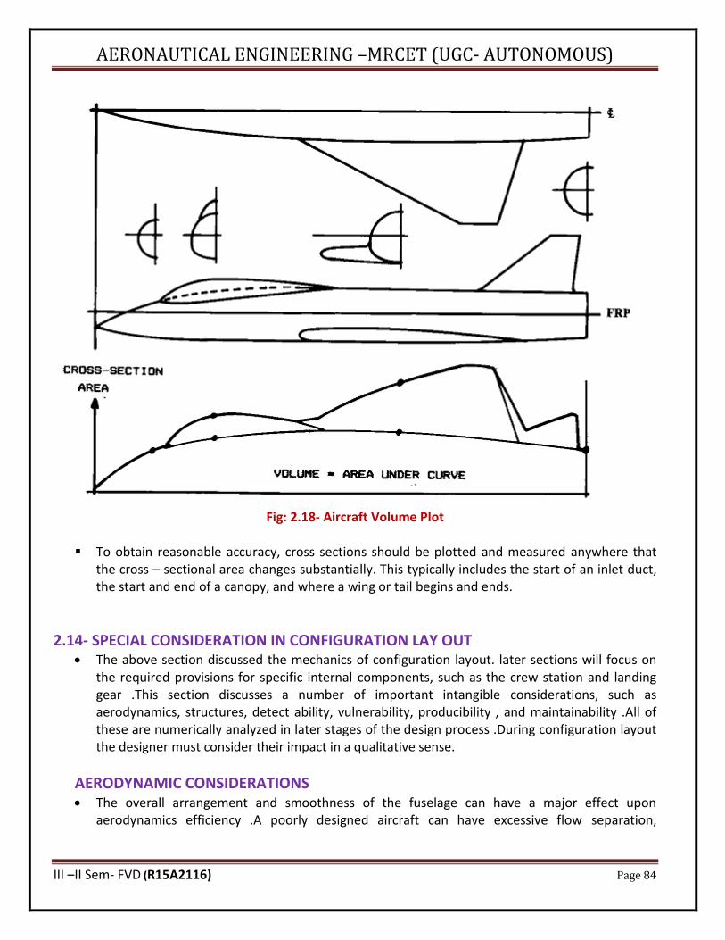
AERONAUTICAL ENGINEERING –MRCET (UGC- AUTONOMOUS)
III –II Sem- FVD (R15A2116) Page 84
Fig: 2.18- Aircraft Volume Plot
▪ To obtain reasonable accuracy, cross sections should be plotted and measured anywhere that
the cross – sectional area changes substantially. This typically includes the start of an inlet duct, the start and end of a canopy, and where a wing or tail begins and ends.
2.14- SPECIAL CONSIDERATION IN CONFIGURATION LAY OUT • The above section discussed the mechanics of configuration layout. later sections will focus on
the required provisions for specific internal components, such as the crew station and landing gear .This section discusses a number of important intangible considerations, such as aerodynamics, structures, detect ability, vulnerability, producibility , and maintainability .All of these are numerically analyzed in later stages of the design process .During configuration layout the designer must consider their impact in a qualitative sense.
AERODYNAMIC CONSIDERATIONS • The overall arrangement and smoothness of the fuselage can have a major effect upon
aerodynamics efficiency .A poorly designed aircraft can have excessive flow separation,

AERONAUTICAL ENGINEERING –MRCET (UGC- AUTONOMOUS)
III –II Sem- FVD (R15A2116) Page 85
transonic drag rise, and supersonic wave drag .Also, poor wing – fuselage arrangement can cause lift losses or disruption of the desired elliptical lift distribution.
• Aerodynamic analysis will be discussed in further sections and a variety of first – order estimation methods will be presented. During concept layout, the designer must consider the requirements for aerodynamic based upon experience and a “good eye”.
• Minimization of wetted area is the most powerful aerodynamic consideration for virtually all aircraft .Wetted area directly affects the friction drag. Fuselage wetted area is minimized by tight internal packaging and a low fineness ratio (i.e, a short , fat fuselage ) .However , excessively tight packaging should be avoided for maintainability considerations .Also , a short , fat fuselage will have a short tail moment arm which increases the required tail areas .The short , fat fuselage will also have high supersonic wave drag.
• Another major driver for good aerodynamic design during fuselage layout is the maintenance of smooth longitudinal contours. These can be provided by the use of smooth longitudinal control lines. Generally, longitudinal breaks in contour should follow a radius at least equal to the fuselage diameter at that point.
• To prevent separation of the airflow, the aft – fuselage deviation from the free stream direction should not exceed 10-12 deg fig2.19. However, the air inflow induced by a pusher – propeller will prevent separation despite contour angles of up to 30 deg or more.
• The aerodynamic interaction between diffeenrt components should be visualized in desinging
the aircraft. For example , a canard should not be located such that its wake might enter the engine inlets at any possible angle of attack.wake ingestion can stall or even destroy a jet engine.
Fig: 2.19- longitudinal contour guidelines
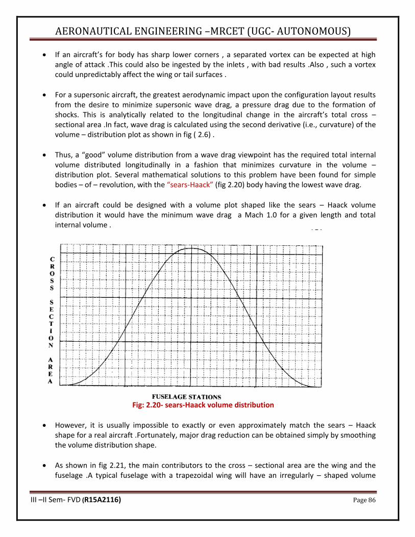
AERONAUTICAL ENGINEERING –MRCET (UGC- AUTONOMOUS)
III –II Sem- FVD (R15A2116) Page 86
• If an aircraft’s for body has sharp lower corners , a separated vortex can be expected at high angle of attack .This could also be ingested by the inlets , with bad results .Also , such a vortex could unpredictably affect the wing or tail surfaces .
• For a supersonic aircraft, the greatest aerodynamic impact upon the configuration layout results from the desire to minimize supersonic wave drag, a pressure drag due to the formation of shocks. This is analytically related to the longitudinal change in the aircraft’s total cross – sectional area .In fact, wave drag is calculated using the second derivative (i.e., curvature) of the volume – distribution plot as shown in fig ( 2.6) .
• Thus, a “good” volume distribution from a wave drag viewpoint has the required total internal volume distributed longitudinally in a fashion that minimizes curvature in the volume – distribution plot. Several mathematical solutions to this problem have been found for simple bodies – of – revolution, with the “sears-Haack” (fig 2.20) body having the lowest wave drag.
• If an aircraft could be designed with a volume plot shaped like the sears – Haack volume distribution it would have the minimum wave drag a Mach 1.0 for a given length and total internal volume .
Fig: 2.20- sears-Haack volume distribution
• However, it is usually impossible to exactly or even approximately match the sears – Haack shape for a real aircraft .Fortunately, major drag reduction can be obtained simply by smoothing the volume distribution shape.
• As shown in fig 2.21, the main contributors to the cross – sectional area are the wing and the fuselage .A typical fuselage with a trapezoidal wing will have an irregularly – shaped volume

AERONAUTICAL ENGINEERING –MRCET (UGC- AUTONOMOUS)
III –II Sem- FVD (R15A2116) Page 87
distribution with the maximum cross sectional area located near the center of the wing .By “squeezing “the fuselage at that point, the volume – distribution shape can be smoothed and the maximum cross – sectional area reduced.
• This design technique, developed by R. Whitcomb of the NACA, is referred to as “ area – ruling “ or “coke – bottling” and can reduce the wave drag by as much as 50% .Note that the volume removed at the center of the fuselage must be provided elsewhere , either by lengthening the fuselage or by increasing its cross – sectional area in other places .
• While area- ruling was developed for minimization of supersonic drag, there is reason to believe that even low – speed aircraft can benefit from it to some extent .The airflow over the wing tends to separate toward the trailing edge. If an aircraft is designed such that the fuselage is increasing in cross – sectional area towards the wing trailing edge , this may “push “ air onto the wing , thus reducing the tendency to separate .The Witt man Tailwind, which is remarkably efficient , uses this approach .
Fig: 2.21- Design for Low Wave Drag
2.15- STRUCTURAL CONSIDERATIONS ▪ Primary concern in the design process is to obtain an airplane with low structural weight. This is
achieved by provision of efficient load path i.e. structural elements by which the opposing forces are connected.
▪ It may be recalled that the structural members are of the following types. a) Struts which take tension b) Columns which take compressive load c) Beams which transfer normal loads d) Shafts which transmit torsion e) Levers which transfer the load along with change of direction.
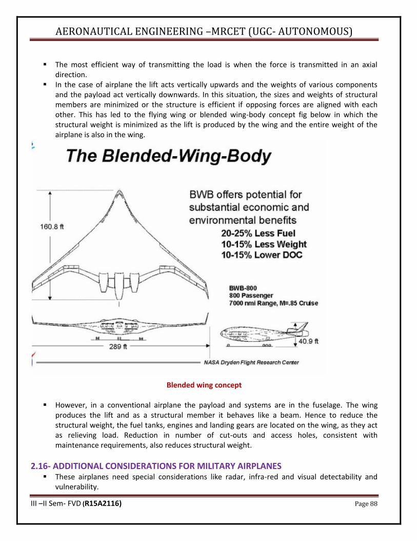
AERONAUTICAL ENGINEERING –MRCET (UGC- AUTONOMOUS)
III –II Sem- FVD (R15A2116) Page 88
▪ The most efficient way of transmitting the load is when the force is transmitted in an axial
direction. ▪ In the case of airplane the lift acts vertically upwards and the weights of various components
and the payload act vertically downwards. In this situation, the sizes and weights of structural members are minimized or the structure is efficient if opposing forces are aligned with each other. This has led to the flying wing or blended wing-body concept fig below in which the structural weight is minimized as the lift is produced by the wing and the entire weight of the airplane is also in the wing.
Blended wing concept
▪ However, in a conventional airplane the payload and systems are in the fuselage. The wing
produces the lift and as a structural member it behaves like a beam. Hence to reduce the structural weight, the fuel tanks, engines and landing gears are located on the wing, as they act as relieving load. Reduction in number of cut-outs and access holes, consistent with maintenance requirements, also reduces structural weight.
2.16- ADDITIONAL CONSIDERATIONS FOR MILITARY AIRPLANES ▪ These airplanes need special considerations like radar, infra-red and visual detectability and
vulnerability.
AERONAUTICAL ENGINEERING –MRCET (UGC- AUTONOMOUS)
III –II Sem- FVD (R15A2116) Page 89
(a) Radar Detectability
▪ A radar installation consists of a transmitter antenna that sends a directed beam of electromagnetic wave and receiver antenna which picks up the faint radio waves that bounce off the object. The extent to which an object returns electromagnetic energy is a measure of its “Radar cross section (RCS)”.
▪ Following remarks are made in this context. ▪ Radar signal strength is inversely proportional to the 4th power of distance of the target. ▪ RCS depends on “look angle” i.e. the direction from threat radar. ▪ Following factors contribute to RCS. (a) Flat surfaces perpendicular to incoming radar beams for example flat sides of fuselage. (b) Leading edges. (c) Inlet and exhaust cavities of engine. (d) Discontinuities in surface. ▪ Stealth technology The ways to reduce RCS are referred to as stealth technology. This requires proper shaping of the airplane - buried engines (no nacelles), flying wing, intakes on top of the airplane, exhaust with 2 – D nozzles. Use of radar beam absorbing materials like composites and special paints also reduces RCS.
(b) Infra Red Detectability ▪ Guidance of air-to-air and ground-to-air missiles is many times based on seeking source of infra-
red (IR) radiation.
▪ Following are the sources of IR. ▪ Engine exhaust ▪ (ii) Hot parts of airplane. Heating being caused by aerodynamic heating, at high speeds. ▪ (iii) Solar IR radiation reflected by skin and cockpit.
▪ The Radiation from engine exhaust can be reduced in the following manner.
(a) Having a bypass engine as power plant. (b) Increased mixing and lower temperature by using 2-D nozzle.
(C) Visual Detectability ▪ Visual detection depends on the size of the airplane and color. Aircraft can also be detected in
night by glow of engine exhaust. Camouflage schemes are used to avoid detection.
▪ Visual detection depends upon the size of aircraft and its color and intensity contrast with the background. In simulated combat, pilots of the small F-5 can frequently spot the much-larger F-15s well before the F-5s are seen. However, aircraft size is determined by the mission requirements and cannot be arbitrarily reduced.
▪ At night, aircraft are visually detected mostly by engine and exhaust glow and by glint off the transparencies. These can be reduced by techniques previously discussed for IR and glint suppression.
AERONAUTICAL ENGINEERING –MRCET (UGC- AUTONOMOUS)
III –II Sem- FVD (R15A2116) Page 90
(D) Aural Signature ▪ Aural signature (noise) is important for civilian as well as military aircraft. Commercial airports
frequently have anti noise ordinances that restrict some aircraft. Aircraft noise is largely caused by airflow shear layers, primarily due to the engine exhaust.
▪ Noise during the arrival and departure of the airplane affects the community around the airport. In 1994, ICAO (International Civil Aviation Organization) and later FAR (Federal Aviation Regulation) prescribed limits on noise level at three different points near the airport .
▪ The noise is generated by: a) The engines b) Parts of the airframe like control surfaces and high lift devices which Significantly change the airflow direction. c) Projections in airflow like landing gear and spoilers.
▪ Considerable research has been carried out to reduce the engine noise. High by-pass ratio
engines with lobed nozzle have significantly lowered the noise level.
▪ Noise level inside the cabin has to be minimal. This is achieved by suitable noise insulation. Further, the clearance between cabin and the propeller should not be less than the half of the radius of the propeller.
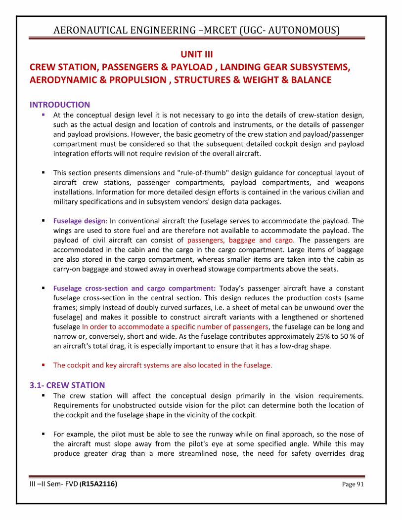
AERONAUTICAL ENGINEERING –MRCET (UGC- AUTONOMOUS)
III –II Sem- FVD (R15A2116) Page 91
UNIT III CREW STATION, PASSENGERS & PAYLOAD , LANDING GEAR SUBSYSTEMS, AERODYNAMIC & PROPULSION , STRUCTURES & WEIGHT & BALANCE INTRODUCTION
▪ At the conceptual design level it is not necessary to go into the details of crew-station design, such as the actual design and location of controls and instruments, or the details of passenger and payload provisions. However, the basic geometry of the crew station and payload/passenger compartment must be considered so that the subsequent detailed cockpit design and payload integration efforts will not require revision of the overall aircraft.
▪ This section presents dimensions and "rule-of-thumb" design guidance for conceptual layout of aircraft crew stations, passenger compartments, payload compartments, and weapons installations. Information for more detailed design efforts is contained in the various civilian and military specifications and in subsystem vendors' design data packages.
▪ Fuselage design: In conventional aircraft the fuselage serves to accommodate the payload. The wings are used to store fuel and are therefore not available to accommodate the payload. The payload of civil aircraft can consist of passengers, baggage and cargo. The passengers are accommodated in the cabin and the cargo in the cargo compartment. Large items of baggage are also stored in the cargo compartment, whereas smaller items are taken into the cabin as carry-on baggage and stowed away in overhead stowage compartments above the seats.
▪ Fuselage cross-section and cargo compartment: Today’s passenger aircraft have a constant fuselage cross-section in the central section. This design reduces the production costs (same frames; simply instead of doubly curved surfaces, i.e. a sheet of metal can be unwound over the fuselage) and makes it possible to construct aircraft variants with a lengthened or shortened fuselage In order to accommodate a specific number of passengers, the fuselage can be long and narrow or, conversely, short and wide. As the fuselage contributes approximately 25% to 50 % of an aircraft's total drag, it is especially important to ensure that it has a low-drag shape.
▪ The cockpit and key aircraft systems are also located in the fuselage.
3.1- CREW STATION ▪ The crew station will affect the conceptual design primarily in the vision requirements.
Requirements for unobstructed outside vision for the pilot can determine both the location of the cockpit and the fuselage shape in the vicinity of the cockpit.
▪ For example, the pilot must be able to see the runway while on final approach, so the nose of the aircraft must slope away from the pilot's eye at some specified angle. While this may produce greater drag than a more streamlined nose, the need for safety overrides drag
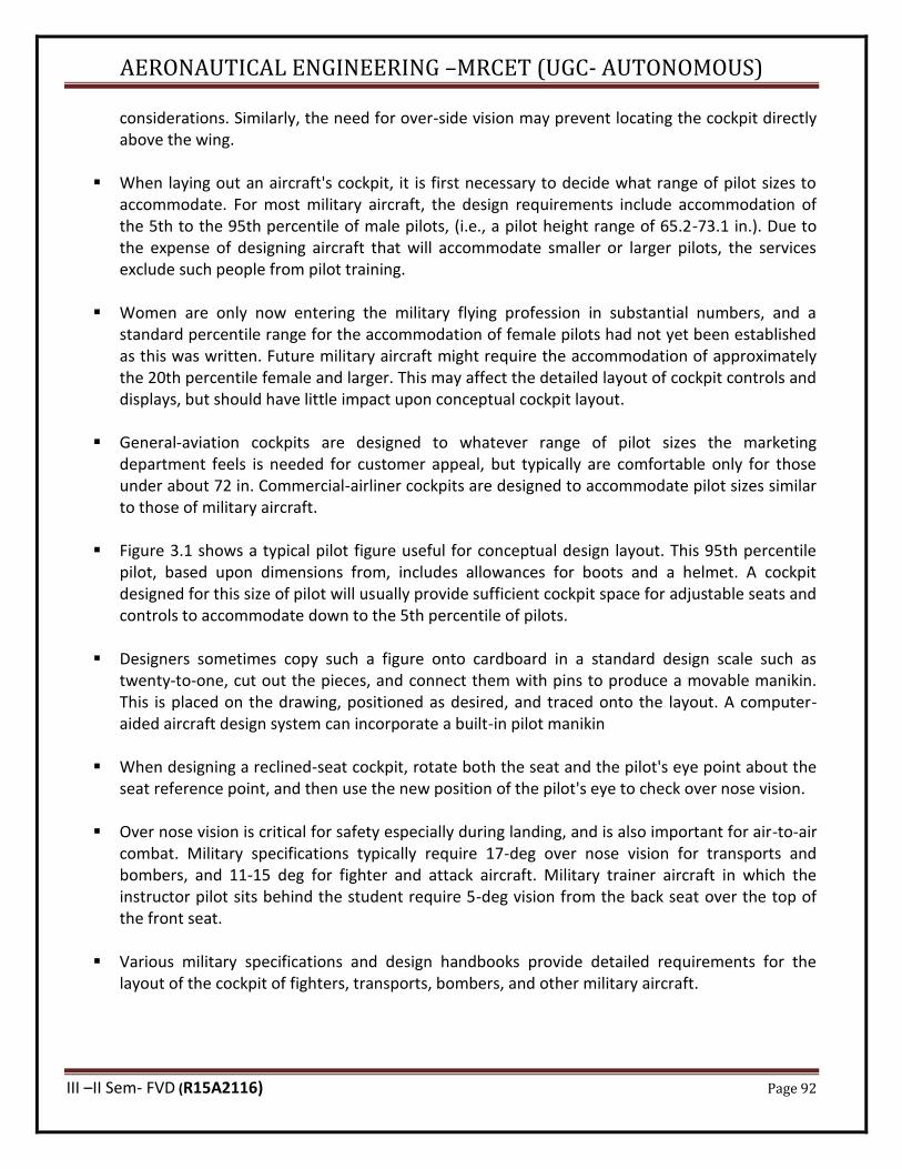
AERONAUTICAL ENGINEERING –MRCET (UGC- AUTONOMOUS)
III –II Sem- FVD (R15A2116) Page 92
considerations. Similarly, the need for over-side vision may prevent locating the cockpit directly above the wing.
▪ When laying out an aircraft's cockpit, it is first necessary to decide what range of pilot sizes to accommodate. For most military aircraft, the design requirements include accommodation of the 5th to the 95th percentile of male pilots, (i.e., a pilot height range of 65.2-73.1 in.). Due to the expense of designing aircraft that will accommodate smaller or larger pilots, the services exclude such people from pilot training.
▪ Women are only now entering the military flying profession in substantial numbers, and a standard percentile range for the accommodation of female pilots had not yet been established as this was written. Future military aircraft might require the accommodation of approximately the 20th percentile female and larger. This may affect the detailed layout of cockpit controls and displays, but should have little impact upon conceptual cockpit layout.
▪ General-aviation cockpits are designed to whatever range of pilot sizes the marketing department feels is needed for customer appeal, but typically are comfortable only for those under about 72 in. Commercial-airliner cockpits are designed to accommodate pilot sizes similar to those of military aircraft.
▪ Figure 3.1 shows a typical pilot figure useful for conceptual design layout. This 95th percentile pilot, based upon dimensions from, includes allowances for boots and a helmet. A cockpit designed for this size of pilot will usually provide sufficient cockpit space for adjustable seats and controls to accommodate down to the 5th percentile of pilots.
▪ Designers sometimes copy such a figure onto cardboard in a standard design scale such as twenty-to-one, cut out the pieces, and connect them with pins to produce a movable manikin. This is placed on the drawing, positioned as desired, and traced onto the layout. A computer-aided aircraft design system can incorporate a built-in pilot manikin
▪ When designing a reclined-seat cockpit, rotate both the seat and the pilot's eye point about the seat reference point, and then use the new position of the pilot's eye to check over nose vision.
▪ Over nose vision is critical for safety especially during landing, and is also important for air-to-air combat. Military specifications typically require 17-deg over nose vision for transports and bombers, and 11-15 deg for fighter and attack aircraft. Military trainer aircraft in which the instructor pilot sits behind the student require 5-deg vision from the back seat over the top of the front seat.
▪ Various military specifications and design handbooks provide detailed requirements for the layout of the cockpit of fighters, transports, bombers, and other military aircraft.
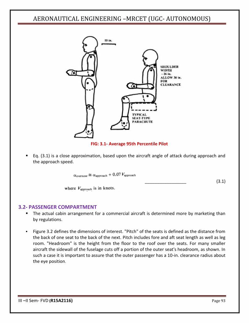
AERONAUTICAL ENGINEERING –MRCET (UGC- AUTONOMOUS)
III –II Sem- FVD (R15A2116) Page 93
FIG: 3.1- Average 95th Percentile Pilot
▪ Eq. (3.1) is a close approximation, based upon the aircraft angle of attack during approach and the approach speed.
_________________ (3.1)
3.2- PASSENGER COMPARTMENT ▪ The actual cabin arrangement for a commercial aircraft is determined more by marketing than
by regulations.
▪ Figure 3.2 defines the dimensions of interest. "Pitch" of the seats is defined as the distance from the back of one seat to the back of the next. Pitch includes fore and aft seat length as well as leg room. "Headroom" is the height from the floor to the roof over the seats. For many smaller aircraft the sidewall of the fuselage cuts off a portion of the outer seat's headroom, as shown. In such a case it is important to assure that the outer passenger has a 10-in. clearance radius about the eye position.
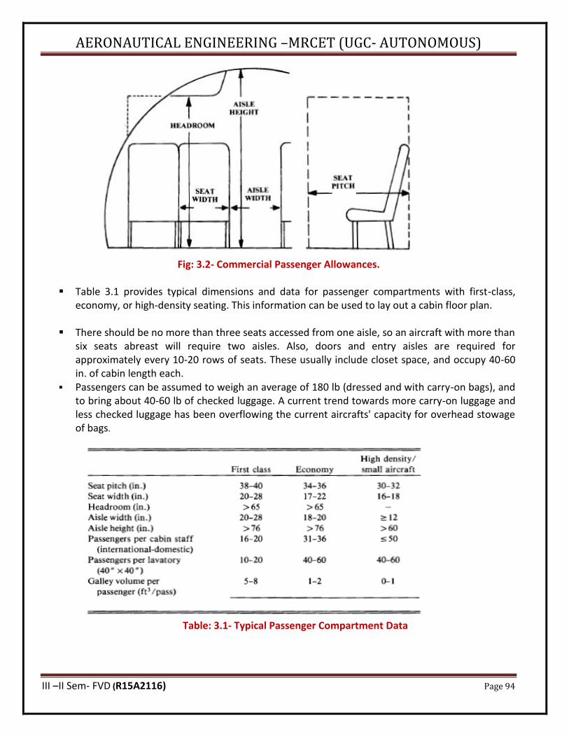
AERONAUTICAL ENGINEERING –MRCET (UGC- AUTONOMOUS)
III –II Sem- FVD (R15A2116) Page 94
Fig: 3.2- Commercial Passenger Allowances.
▪ Table 3.1 provides typical dimensions and data for passenger compartments with first-class, economy, or high-density seating. This information can be used to lay out a cabin floor plan.
▪ There should be no more than three seats accessed from one aisle, so an aircraft with more than six seats abreast will require two aisles. Also, doors and entry aisles are required for approximately every 10-20 rows of seats. These usually include closet space, and occupy 40-60 in. of cabin length each.
▪ Passengers can be assumed to weigh an average of 180 lb (dressed and with carry-on bags), and to bring about 40-60 lb of checked luggage. A current trend towards more carry-on luggage and less checked luggage has been overflowing the current aircrafts' capacity for overhead stowage of bags.
Table: 3.1- Typical Passenger Compartment Data
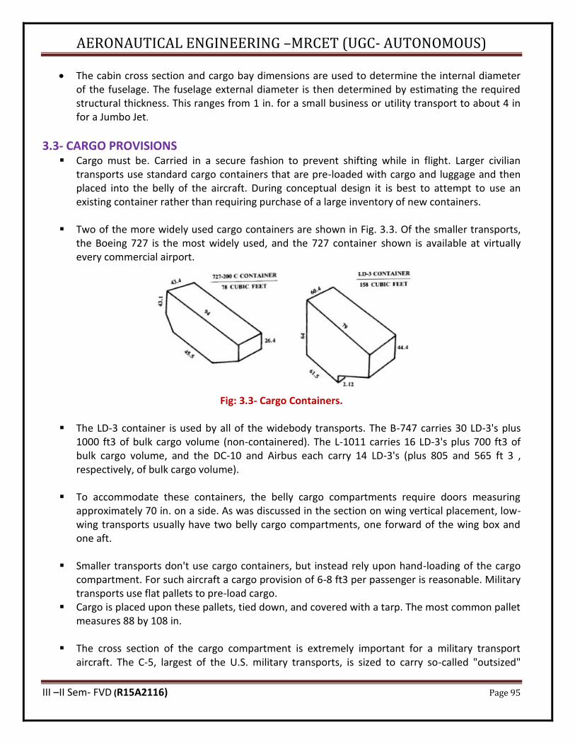
AERONAUTICAL ENGINEERING –MRCET (UGC- AUTONOMOUS)
III –II Sem- FVD (R15A2116) Page 95
• The cabin cross section and cargo bay dimensions are used to determine the internal diameter of the fuselage. The fuselage external diameter is then determined by estimating the required structural thickness. This ranges from 1 in. for a small business or utility transport to about 4 in for a Jumbo Jet.
3.3- CARGO PROVISIONS ▪ Cargo must be. Carried in a secure fashion to prevent shifting while in flight. Larger civilian
transports use standard cargo containers that are pre-loaded with cargo and luggage and then placed into the belly of the aircraft. During conceptual design it is best to attempt to use an existing container rather than requiring purchase of a large inventory of new containers.
▪ Two of the more widely used cargo containers are shown in Fig. 3.3. Of the smaller transports, the Boeing 727 is the most widely used, and the 727 container shown is available at virtually every commercial airport.
Fig: 3.3- Cargo Containers.
▪ The LD-3 container is used by all of the widebody transports. The B-747 carries 30 LD-3's plus 1000 ft3 of bulk cargo volume (non-containered). The L-1011 carries 16 LD-3's plus 700 ft3 of bulk cargo volume, and the DC-10 and Airbus each carry 14 LD-3's (plus 805 and 565 ft 3 , respectively, of bulk cargo volume).
▪ To accommodate these containers, the belly cargo compartments require doors measuring approximately 70 in. on a side. As was discussed in the section on wing vertical placement, low-wing transports usually have two belly cargo compartments, one forward of the wing box and one aft.
▪ Smaller transports don't use cargo containers, but instead rely upon hand-loading of the cargo compartment. For such aircraft a cargo provision of 6-8 ft3 per passenger is reasonable. Military transports use flat pallets to pre-load cargo.
▪ Cargo is placed upon these pallets, tied down, and covered with a tarp. The most common pallet measures 88 by 108 in.
▪ The cross section of the cargo compartment is extremely important for a military transport aircraft. The C-5, largest of the U.S. military transports, is sized to carry so-called "outsized"
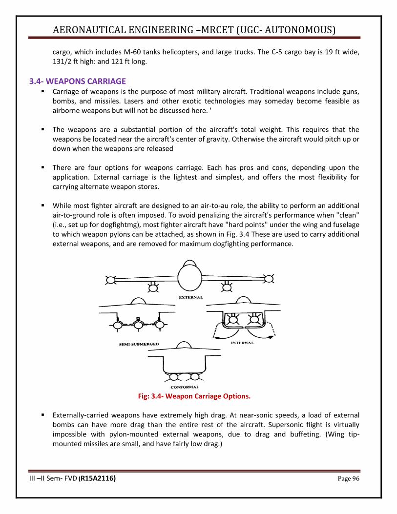
AERONAUTICAL ENGINEERING –MRCET (UGC- AUTONOMOUS)
III –II Sem- FVD (R15A2116) Page 96
cargo, which includes M-60 tanks helicopters, and large trucks. The C-5 cargo bay is 19 ft wide, 131/2 ft high: and 121 ft long.
3.4- WEAPONS CARRIAGE ▪ Carriage of weapons is the purpose of most military aircraft. Traditional weapons include guns,
bombs, and missiles. Lasers and other exotic technologies may someday become feasible as airborne weapons but will not be discussed here. '
▪ The weapons are a substantial portion of the aircraft's total weight. This requires that the weapons be located near the aircraft's center of gravity. Otherwise the aircraft would pitch up or down when the weapons are released
▪ There are four options for weapons carriage. Each has pros and cons, depending upon the
application. External carriage is the lightest and simplest, and offers the most flexibility for carrying alternate weapon stores.
▪ While most fighter aircraft are designed to an air-to-au role, the ability to perform an additional air-to-ground role is often imposed. To avoid penalizing the aircraft's performance when "clean" (i.e., set up for dogfightmg), most fighter aircraft have "hard points" under the wing and fuselage to which weapon pylons can be attached, as shown in Fig. 3.4 These are used to carry additional external weapons, and are removed for maximum dogfighting performance.
Fig: 3.4- Weapon Carriage Options.
▪ Externally-carried weapons have extremely high drag. At near-sonic speeds, a load of external bombs can have more drag than the entire rest of the aircraft. Supersonic flight is virtually impossible with pylon-mounted external weapons, due to drag and buffeting. (Wing tip-mounted missiles are small, and have fairly low drag.)

AERONAUTICAL ENGINEERING –MRCET (UGC- AUTONOMOUS)
III –II Sem- FVD (R15A2116) Page 97
▪ Semi submerged carriage offers a substantial reduction in drag, but reduces flexibility for carrying different weapons. Also, the indentations produce _structural weigh! Penalty on the airplane. Conformal carriage doesn’t‘t intrude into the aircraft structure, but has slightly higher drag than the semi submerged carriage.
▪ The lowest-drag option for weapons carriage is internal. An internal weapons bay has been a standard feature of bombers for over fifty years, but has been seen on only a few fighters and fighter-bombers, such as the F- 106 and FB-111.
▪ Conformal weapons mount flush to the bottom of the wing or fuselage. Semi submerged weapons are half-submerged in an indentation on the aircraft. This is seen on the F-4 for air-to-air missiles
3.5- GUN INSTALLATION ▪ The gun has been the primary weapon of the air-to-air fighter since the first World War I scout
pilot took a shot at an opposing scout pilot with a handgun. For a time during the 1950's it was felt that the then-new air-to air missiles would replace the gun, and in fact several fighters such as the F-4 and F-104 were originally designed without guns. History proved that missiles cannot be solely relied upon, and all new fighters are being designed with guns.
3.6- LANDING GEAR ARRANGEMENTS ▪ Of the many internal components that must be defined in an. Aircraft layout, the landing gear
will usually cause the most trouble .Landing gear must be placed in the correct down position for landing, and must somehow retract into the aircraft without chopping up the structure, obliterating the fuel tanks, or bulging out into the slipstream. This chapter covers landing gear design as well as installation of other subsystems.
LANDING GEAR ARRANGEMENTS ▪ The common options for landing-gear arrangement are shown in Fig. 3.5. The single main gear is
used for many sailplanes because of its simplicity. The wheel can be forward of the center of gravity (c.g.), as shown here, or can be aft of the c.g. with a skid under the cockpit. .
▪ "Bicycle" gear has two main wheels, fore and aft of the e.g.: with small "outrigger" wheels on the wings to prevent the aircraft from tipping sideways. The bicycle landing gear has the aft wheel so far behind the c.g. that the aircraft must take off and land in a flat attitude, which limits this type of gear to aircraft with high lift at low angles of attack (i.e., high-aspect-ratio wings with large camber and/or flaps). Bicycle gear has been used mainly on aircraft with narrow fuselage and wide wing span such as the B-47.
▪ The "tail dragger" landing gear has two main wheels forward of the e.g. and an auxiliary wheel at the tail. Tail dragger gear is also called "conventional" landing gear, because it was the most widely used Arrangement during the first 40 years of aviation. Tail dragger gear provides more propeller clearance, has less drag and weight, and allows the wing to generate more lift for rough-field operation than does tricycle gear.
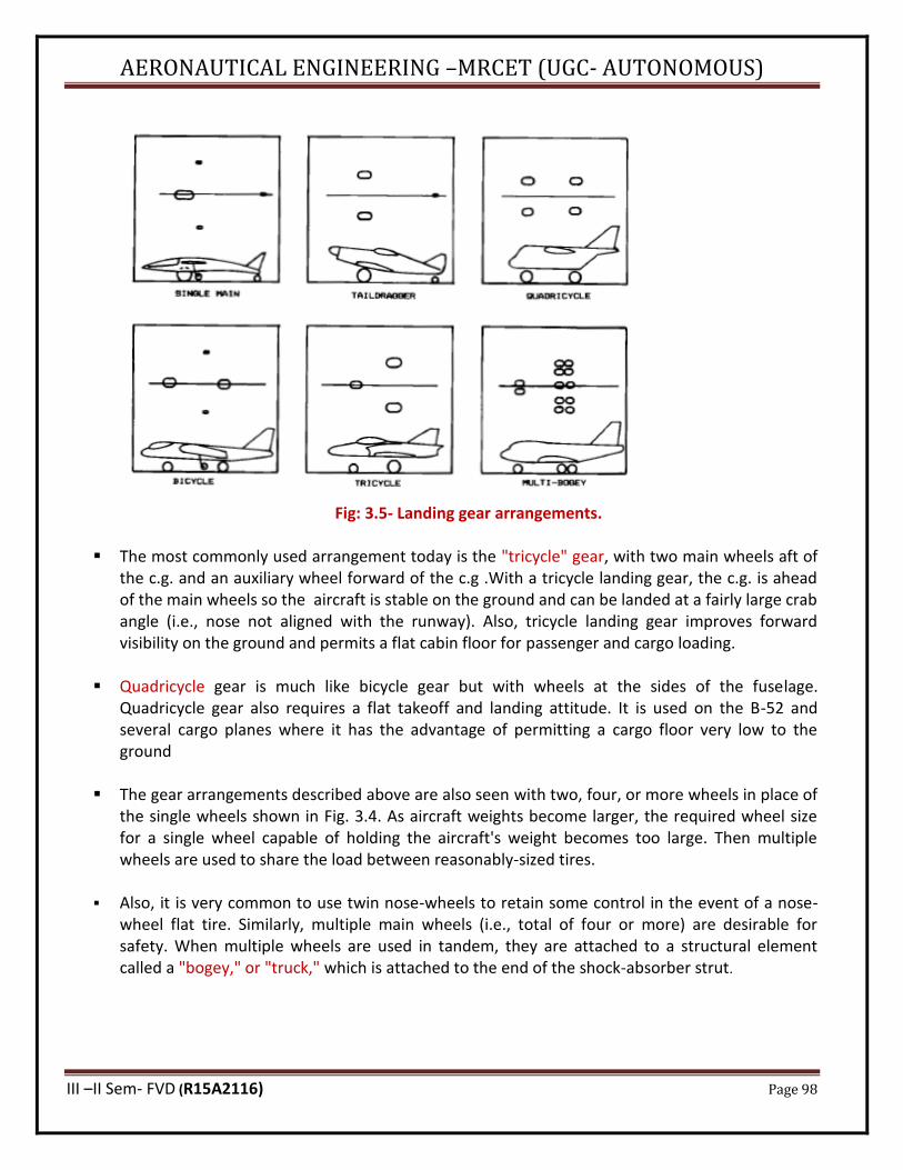
AERONAUTICAL ENGINEERING –MRCET (UGC- AUTONOMOUS)
III –II Sem- FVD (R15A2116) Page 98
Fig: 3.5- Landing gear arrangements.
▪ The most commonly used arrangement today is the "tricycle" gear, with two main wheels aft of the c.g. and an auxiliary wheel forward of the c.g .With a tricycle landing gear, the c.g. is ahead of the main wheels so the aircraft is stable on the ground and can be landed at a fairly large crab angle (i.e., nose not aligned with the runway). Also, tricycle landing gear improves forward visibility on the ground and permits a flat cabin floor for passenger and cargo loading.
▪ Quadricycle gear is much like bicycle gear but with wheels at the sides of the fuselage. Quadricycle gear also requires a flat takeoff and landing attitude. It is used on the B-52 and several cargo planes where it has the advantage of permitting a cargo floor very low to the ground
▪ The gear arrangements described above are also seen with two, four, or more wheels in place of
the single wheels shown in Fig. 3.4. As aircraft weights become larger, the required wheel size for a single wheel capable of holding the aircraft's weight becomes too large. Then multiple wheels are used to share the load between reasonably-sized tires.
▪ Also, it is very common to use twin nose-wheels to retain some control in the event of a nose-wheel flat tire. Similarly, multiple main wheels (i.e., total of four or more) are desirable for safety. When multiple wheels are used in tandem, they are attached to a structural element called a "bogey," or "truck," which is attached to the end of the shock-absorber strut.
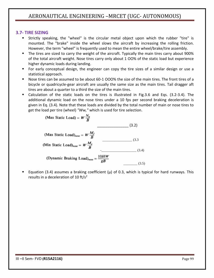
AERONAUTICAL ENGINEERING –MRCET (UGC- AUTONOMOUS)
III –II Sem- FVD (R15A2116) Page 99
3.7- TIRE SIZING ▪ Strictly speaking, the "wheel" is the circular metal object upon which the rubber "tire" is
mounted. The "brake" inside the wheel slows the aircraft by increasing the rolling friction. However, the term "wheel" is frequently used to mean the entire wheel/brake/tire assembly.
▪ The tires are sized to carry the weight of the aircraft. Typically the main tires carry about 900% of the total aircraft weight. Nose tires carry only about 1 OO% of the static load but experience higher dynamic loads during landing.
▪ For early conceptual design, the engineer can copy the tire sizes of a similar design or use a statistical approach.
▪ Nose tires can be assumed to be about 60-1 OOO% the size of the main tires. The front tires of a bicycle or quadricycle-gear aircraft are usually the same size as the main tires. Tail dragger aft tires are about a quarter to a third the size of the main tires.
▪ Calculation of the static loads on the tires is illustrated in Fig.3.6 and Eqs. (3.2-3.4). The additional dynamic load on the nose tires under a 10 fps per second braking deceleration is given in Eq. (3.4). Note that these loads are divided by the total number of main or nose tires to get the load per tire (wheel) "Ww," which is used for tire selection.
_______________ (3.2)
_________________ (3.3
-____________________ (3.4)
________ (3.5)
▪ Equation (3.4) assumes a braking coefficient (μ) of 0.3, which is typical for hard runways. This results in a deceleration of 10 ft/s2
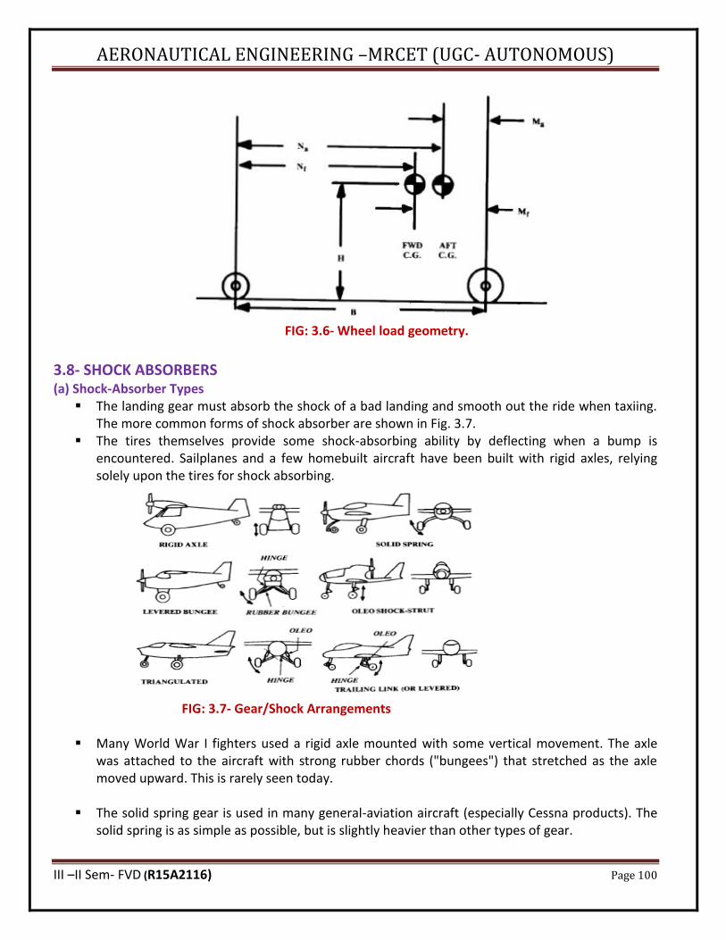
AERONAUTICAL ENGINEERING –MRCET (UGC- AUTONOMOUS)
III –II Sem- FVD (R15A2116) Page 100
FIG: 3.6- Wheel load geometry.
3.8- SHOCK ABSORBERS (a) Shock-Absorber Types
▪ The landing gear must absorb the shock of a bad landing and smooth out the ride when taxiing. The more common forms of shock absorber are shown in Fig. 3.7.
▪ The tires themselves provide some shock-absorbing ability by deflecting when a bump is encountered. Sailplanes and a few homebuilt aircraft have been built with rigid axles, relying solely upon the tires for shock absorbing.
FIG: 3.7- Gear/Shock Arrangements
▪ Many World War I fighters used a rigid axle mounted with some vertical movement. The axle was attached to the aircraft with strong rubber chords ("bungees") that stretched as the axle moved upward. This is rarely seen today.
▪ The solid spring gear is used in many general-aviation aircraft (especially Cessna products). The solid spring is as simple as possible, but is slightly heavier than other types of gear.

AERONAUTICAL ENGINEERING –MRCET (UGC- AUTONOMOUS)
III –II Sem- FVD (R15A2116) Page 101
▪ The levered. Bungee-chord gear was very common in early light aircraft such as the Piper Cub.
The gear leg is pivoted at the fuselage. Rubber bungee chords underneath the gear are stretched as the gear deflects upward and outwards. This gear is light in weight but is high in drag. This gear also causes lateral scrubbing of the tires.
▪ The oleo pneumatic shock strut, or "oleo," is the most common type of shock-absorbing gear m
use today (Fig. 3.8). The oleo concept was patented in 1915 as a recoil device for large cannons. The oleo combines a spring effect using compressed air with a damping effect using a piston which forces 0il through a small hole (orifice). For maximum efficiency, many oleos have a mechanism for varying the size of the orifice as the oleo compresses ("metered orifice").
▪ Fig: 3.8- Oleo Shock Absorber (most simple type).
3.9- STROKE DETERMINATION ▪ The required deflection of the shock-absorbing system (the "stroke") depends upon the vertical
velocity at touchdown, the shock-absorbing material and the amount of wing lift still available after touchdown. As a rough rule-of-thumb, the stroke in inches approximately equals the vertical velocity at touchdown in (ft/s).
▪ The vertical energy of the aircraft, which must be absorbed during the landing, is defined in Eq. (3.6). This kinetic energy is absorbed by the work of deflecting the shock absorber and tire.
___________________ (3.6)
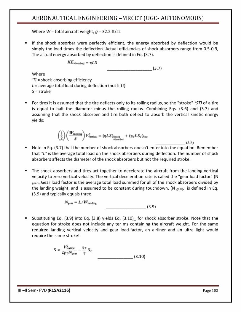
AERONAUTICAL ENGINEERING –MRCET (UGC- AUTONOMOUS)
III –II Sem- FVD (R15A2116) Page 102
Where W = total aircraft weight, g = 32.2 ft/s2
▪ If the shock absorber were perfectly efficient, the energy absorbed by deflection would be simply the load times the deflection. Actual efficiencies of shock absorbers range from 0.5-0.9, The actual energy absorbed by deflection is defined in Eq. (3.7).
___________________ (3.7) Where 'Tl = shock-absorbing efficiency L = average total load during deflection (not lift!) S = stroke
▪ For tires it is assumed that the tire deflects only to its rolling radius, so the "stroke" (ST) of a tire
is equal to half the diameter minus the rolling radius. Combining Eqs. (3.6) and (3.7) and assuming that the shock absorber and tire both deflect to absorb the vertical kinetic energy yields:
_______________ (3.8)
▪ Note in Eq. (3.7) that the number of shock absorbers doesn't enter into the equation. Remember that "L" is the average total load on the shock absorbers during deflection. The number of shock absorbers affects the diameter of the shock absorbers but not the required stroke.
▪ The shock absorbers and tires act together to decelerate the aircraft from the landing vertical velocity to zero vertical velocity. The vertical deceleration rate is called the "gear load factor" (N
gear). Gear load factor is the average total load summed for all of the shock absorbers divided by the landing weight, and is assumed to be constant during touchdown. (N gear). is defined in Eq. (3.9) and typically equals three.
_________________ (3.9)
▪ Substituting Eq. (3.9) into Eq. (3.8) yields Eq. (3.10)_ for shock absorber stroke. Note that the equation for stroke does not include any ter ms containing the aircraft weight. For the same required landing vertical velocity and gear load-factor, an airliner and an ultra light would require the same stroke!
_______________ (3.10)
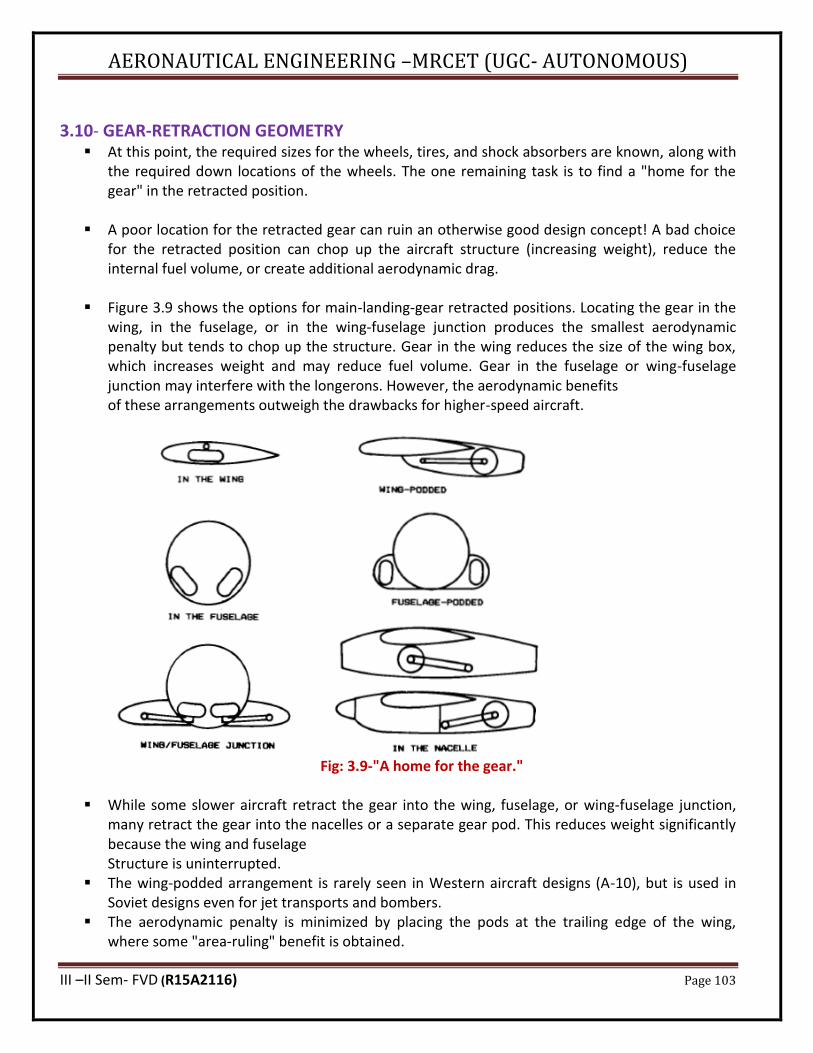
AERONAUTICAL ENGINEERING –MRCET (UGC- AUTONOMOUS)
III –II Sem- FVD (R15A2116) Page 103
3.10- GEAR-RETRACTION GEOMETRY
▪ At this point, the required sizes for the wheels, tires, and shock absorbers are known, along with the required down locations of the wheels. The one remaining task is to find a "home for the gear" in the retracted position.
▪ A poor location for the retracted gear can ruin an otherwise good design concept! A bad choice for the retracted position can chop up the aircraft structure (increasing weight), reduce the internal fuel volume, or create additional aerodynamic drag.
▪ Figure 3.9 shows the options for main-landing-gear retracted positions. Locating the gear in the wing, in the fuselage, or in the wing-fuselage junction produces the smallest aerodynamic penalty but tends to chop up the structure. Gear in the wing reduces the size of the wing box, which increases weight and may reduce fuel volume. Gear in the fuselage or wing-fuselage junction may interfere with the longerons. However, the aerodynamic benefits of these arrangements outweigh the drawbacks for higher-speed aircraft.
Fig: 3.9-"A home for the gear."
▪ While some slower aircraft retract the gear into the wing, fuselage, or wing-fuselage junction, many retract the gear into the nacelles or a separate gear pod. This reduces weight significantly because the wing and fuselage Structure is uninterrupted.
▪ The wing-podded arrangement is rarely seen in Western aircraft designs (A-10), but is used in Soviet designs even for jet transports and bombers.
▪ The aerodynamic penalty is minimized by placing the pods at the trailing edge of the wing, where some "area-ruling" benefit is obtained.
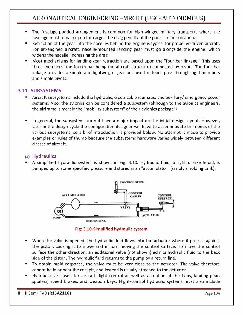
AERONAUTICAL ENGINEERING –MRCET (UGC- AUTONOMOUS)
III –II Sem- FVD (R15A2116) Page 104
▪ The fuselage-podded arrangement is common for high-winged military transports where the fuselage must remain open for cargo. The drag penalty of the pods can be substantial.
▪ Retraction of the gear into the nacelles behind the engine is typical for propeller-driven aircraft. For jet-engined aircraft, nacelle-mounted landing gear must go alongside the engine, which widens the nacelle, increasing the drag.
▪ Most mechanisms for landing-gear retraction are based upon the "four bar linkage." This uses three members (the fourth bar being the aircraft structure) connected by pivots. The four-bar linkage provides a simple and lightweight gear because the loads pass through rigid members and simple pivots.
3.11- SUBSYSTEMS ▪ Aircraft subsystems include the hydraulic, electrical, pneumatic, and auxiliary/ emergency power
systems. Also, the avionics can be considered a subsystem (although to the avionics engineers, the airframe is merely the "mobility subsystem" of their avionics package!)
▪ In general, the subsystems do not have a major impact on the initial design layout. However, later in the design cycle the configuration designer will have to accommodate the needs of the various subsystems, so a brief introduction is provided below. No attempt is made to provide examples or rules of thumb because the subsystems hardware varies widely between different classes of aircraft.
(a) Hydraulics ▪ A simplified hydraulic system is shown in Fig. 3.10. Hydraulic fluid, a light oil-like liquid, is
pumped up to some specified pressure and stored in an "accumulator" (simply a holding tank).
Fig: 3.10-Simplified hydraulic system
▪ When the valve is opened, the hydraulic fluid flows into the actuator where it presses against the piston, causing it to move and in turn moving the control surface. To move the control surface the other direction, an additional valve (not shown) admits hydraulic fluid to the back side of the piston. The hydraulic fluid returns to the pump by a return line.
▪ To obtain rapid response, the valve must be very close to the actuator. The valve therefore cannot be in or near the cockpit, and instead is usually attached to the actuator.
▪ Hydraulics are used for aircraft flight control as well as actuation of the flaps, landing gear, spoilers, speed brakes, and weapon bays. Flight-control hydraulic systems must also include
AERONAUTICAL ENGINEERING –MRCET (UGC- AUTONOMOUS)
III –II Sem- FVD (R15A2116) Page 105
some means of providing the proper control "feel" to the pilot. For example, the controls should become stiffer at higher speeds, and should become heavier in a tight, high-g tur n. Such "feel" is provided by a combination of springs, bob weights, and air bellows.
(b) Electrical System • An aircraft electrical system provides electrical power to the avionics, hydraulics, environmental-
control, lighting, and other subsystems.. '!he electrical system consists of batteries, generators, transformer-rectifiers ("TR's"), electrical controls, circuit breakers,. and cables . Aircraft generators usually produce alternating (AC) and are located on or near the engines. TR's are used to convert the alternating g current to direct current (DC). Aircraft batteries can be large and heavy if they are used as the only power source for starting.
(c) Pneumatic System • The pneumatic system provides compressed air for pressurization, environmental control, anti-
icing, and in some cases engine starting. Typically the pneumatic system uses pressurized air bled from the engine compressor
• The pneumatic system uses pressurized air bled from the engine compressor. This compressed air is cooled through a heat exchanger using outside air. This cooling air is taken from a flush inlet inside the inlet duct (i.e., inlet secondary airflow) or from a separate inlet usually located on the fuselage or at the front of the inlet boundary-layer diverter.
• The cooled compressor air is then used for cockpit pressurization and avionics cooling. For anti-icing, the compressor bleed air goes un cooled through ducts to the wing leading edge, inlet cowls, and windshield.
• Compressed air is sometimes used for starting other engines after one engine has been started by battery. Also, some military aircraft use a ground power cart that provides compressed air through a hose to start the engine.
3.12: LOAD CATEGORIES • When one thinks of aircraft loads the air loads due to high-g manoeuvring comes immediately to
mind while important, manoeuvring loads are only a part of the total loads that must be withstood by the aircraft structure.
• The largest load the aircraft is actually expected to encounter is called the "limit," or "applied," load. For the fighter of Fig. 3.11, the limit load on the wing occurs during an 8-g manoeuvre.

AERONAUTICAL ENGINEERING –MRCET (UGC- AUTONOMOUS)
III –II Sem- FVD (R15A2116) Page 106
Fig: .3.11- Typical fighter limit loads
• To provide a margin of safety, the aircraft structure is always designed to withstand a higher load than the limit load. The highest load the structure is designed to withstand without breaking is the "design," or "ultimate," load.
• The "factor of safety" is the multiplier used on limit load to determine the design load.
3.13- AIR LOADS (a) Manoeuvre Loads
• The greatest air loads on an aircraft usually come from the generation of lift during high-g maneuvers. Even the fuselage is almost always structurally sized by the lift of the wing rather than by the air pressures produced directly on the fuselage.
• Aircraft load factor (n) expresses the maneuvering of an aircraft as a multiple of the standard acceleration due to gravity (g = 32.2 ft/s-s). At lower speeds the highest load factor an aircraft may experience is limited by the maximum lift available.
• At higher speeds the maximum load factor is limited to some arbitrary value based upon the expected use of the aircraft.
• The V-n diagram depicts the aircraft limit load factor as a function of airspeed. The V-n diagram of Fig. 3.12 is typical for a general aviation aircraft. Note that the maximum lift load factor equals 1.0 at level-flight stall speed, as would be expected. The aircraft can be stalled at a higher speed by trying to exceed the available load factor, such as in a steep turn.
• The point labelled "high A.O.A." (Angle of attack) is the slowest speed at which the maximum load factor can be reached without stalling. This part of the flight envelope is important because the load on the wing is approximately perpendicular to the flight direction, not the body-axis vertical direction.
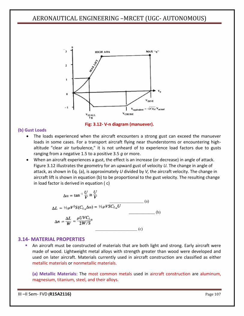
AERONAUTICAL ENGINEERING –MRCET (UGC- AUTONOMOUS)
III –II Sem- FVD (R15A2116) Page 107
Fig: 3.12- V-n diagram (manuever). (b) Gust Loads
• The loads experienced when the aircraft encounters a strong gust can exceed the manuever loads in some cases. For a transport aircraft flying near thunderstorms or encountering high-altitude "clear air turbulence," it is not unheard of to experience load factors due to gusts ranging from a negative 1.5 to a positive 3.5 g or more.
• When an aircraft experiences a gust, the effect is an increase (or decrease) in angle of attack. Figure 3.12 illustrates the geometry for an upward gust of velocity U. The change in angle of attack, as shown in Eq. (a), is approximately U divided by V, the aircraft velocity. The change in aircraft lift is shown in equation (b) to be proportional to the gust velocity. The resulting change in load factor is derived in equation ( c)
_________________ (a)
_____________ (b)
_____________________ (c)
3.14- MATERIAL PROPERTIES ▪ An aircraft must be constructed of materials that are both light and strong. Early aircraft were
made of wood. Lightweight metal alloys with strength greater than wood were developed and used on later aircraft. Materials currently used in aircraft construction are classified as either metallic materials or nonmetallic materials.
(a) Metallic Materials: The most common metals used in aircraft construction are aluminum, magnesium, titanium, steel, and their alloys.

AERONAUTICAL ENGINEERING –MRCET (UGC- AUTONOMOUS)
III –II Sem- FVD (R15A2116) Page 108
▪ Alloys: An alloy is composed of two or more metals. The metal present in the alloy in the largest
amount is called the base metal. All other metals added to the base metal are called alloying elements. Adding the alloying elements may result in a change in the properties of the base metal. For example, pure aluminum is relatively soft and weak. However, adding small amounts or copper, manganese, and magnesium will increase aluminum's strength many times. Heat treatment can increase or decrease an alloy's strength and hardness. Alloys are important to the aircraft industry. They provide materials with properties that pure metals do not possess.
▪ Aluminum: 1. Aluminum alloys are widely used in modern aircraft construction. Aluminum alloys are
valuable because they have a high strength-to-weight ratio. 2. Aluminum alloys are corrosion resistant and comparatively easy to fabricate. 3. The outstanding characteristic of aluminum is its lightweight. 4. The strength and stiffness properties of aluminium are affected by the form (sheet, plate,
bar, extrusion, or forging) and by heat treatment and tempering. In general, the stronger the aluminium, the more brittle it is.
▪ Magnesium 1. Magnesium is the world's lightest structural metal. 2. It is a silvery-white material that weighs two-thirds as much as aluminum. 3. Magnesium is used to make helicopters. 4. Magnesium's low resistance to corrosion has limited its use in conventional aircraft 5. Magnesium has a good strength-to-weight ratio, tolerates high temperatures, and is
easily formed, especially by casting, forging, and machining. It has been used for engine mounts, wheels, control hinges, brackets, stiffeners, fuel tanks, and even wings.
▪ Titanium 1. Titanium is a lightweight, strong, corrosion resistant metal. Recent developments make
titanium ideal for applications where aluminum alloys are too weak and stainless steel is too heavy.
2. Additionally, titanium is unaffected by long exposure to seawater and marine atmosphere.
3. Titanium would seem to be the ideal aerospace material. It has a better strength-to-weight ratio and stiffness than aluminium, and is capable of temperatures almost as high as steel. Titanium is also corrosion-resistant.
▪ Steel Alloys 1. Alloy steels used in aircraft construction have great strength, more so than other fields of
engineering would require. 2. These materials must withstand the forces that occur on today's modern aircraft. 3. These steels contain small percentages of carbon, nickel, chromium, vanadium, and
molybdenum. High-tensile steels will stand stress of 50 to 150 tons per square inch without failing. Such steels are made into tubes, rods, and wires.
4. Another type of steel used extensively is stainless steel. Stainless steel resists corrosion and is particularly valuable for use in or near water.
AERONAUTICAL ENGINEERING –MRCET (UGC- AUTONOMOUS)
III –II Sem- FVD (R15A2116) Page 109
(b) Nonmetallic Materials
▪ In addition to metals, various types of plastic materials are found in aircraft construction. Some of these plastics include transparent plastic, reinforced plastic, composite, and carbon-fiber materials.
▪ Transparent Plastic
Transparent plastic is used in canopies, windshields, and other transparent enclosures. You need to handle transparent plastic surfaces carefully because they are relatively soft and scratch easily. At approximately 225°F, transparent plastic becomes soft and pliable.
▪ Reinforced Plastic Reinforced plastic is used in the construction of radomes, wingtips, stabilizer tips, antenna covers, and flight controls. Reinforced plastic has a high strength-to-weight ratio and is resistant to mildew and rot. Because it is easy to fabricate, it is equally suitable for other parts of the aircraft.
▪ Composite and Carbon Fiber Materials
High-performance aircraft require an extra high strength-to-weight ratio material. Fabrication of composite materials satisfies this special requirement. Composite materials are constructed by using several layers of bonding materials
▪ These materials are mechanically fastened to conventional substructures. Another type of composite construction consists of thin graphite epoxy skins bonded to an aluminum honeycomb core. Carbon fiber is extremely strong, thin fiber made by heating synthetic fibers, such as rayon, until charred, and then layering in cross sections.
3.15- WING LOADS ▪ The loads on the wing are the sum of the aerodynamic lift and drag forces, as well as
concentrated and distributed weight of wing mounted engines, fuel stored and structural elements. The resulting load factor will vary within the aero plane’s flight envelope already discussed.
3.16- FUSELAGE LOADS The fuselage is a particularly critical part of the aero plane and it is also the part in which all the loads are acting. Indeed, the fuselage loads include: • Landing gear loads; • Wing loads; • Empennage loads; • Fuselage aerodynamic loads; • Pressurization loads; • Inertial loads.

AERONAUTICAL ENGINEERING –MRCET (UGC- AUTONOMOUS)
III –II Sem- FVD (R15A2116) Page 110
3.17- LANDING GEARS, WING AND EMPENNAGE LOADS
▪ The landing gear's main purpose is to reduce the landing loads to a level that can be withstood by the aircraft.
▪ To analyze fully all the possible gear loads, a number of landing scenarios must be examined. These include a level landing, a tail-down landing, a one-wheel landing, and a crabbed landing. For certification the aircraft maybe subjected to drop tests, in which an actual aircraft is dropped from a height of somewhere between 9.2-18. 7 in. The required drop distance typically will be 3 .6 times the square root of the wing loading.
▪ Once all these loads have already been discussed, they only have to be transmitted to the fuselage in the attachments between these structures and the fuselage structure.
3. 18- INERTIAL LOADS ▪ Inertial loads reflect the resistance of mass to acceleration (F = ma). The various accelerations
due to maneuver and gust, described above, establish the stresses for the aerodynamic surfaces.
▪ Every object in the aircraft experiences a force equal to the object's weight times the aircraft load factor. This creates additional stresses throughout the aircraft, which must be determined. Note that the weight of the wing structure will produce torsional loads on the wing in addition to the aerodynamic torsional loads.
▪ Inertial loads due to rotation must also be considered. For example, the tip tanks of a fighter rolling at a high rate will experience an outward centrifugal force. This force produces an outward load factor equal to the distance from the aircraft e.g. times the square of the rotation rate, divided by g.
Related Documents