The best adhesive installs in the worst conditions. (800) 999-5099 strongtie.com New! SET-3G High-Strength Anchoring Adhesive

Welcome message from author
This document is posted to help you gain knowledge. Please leave a comment to let me know what you think about it! Share it to your friends and learn new things together.
Transcript
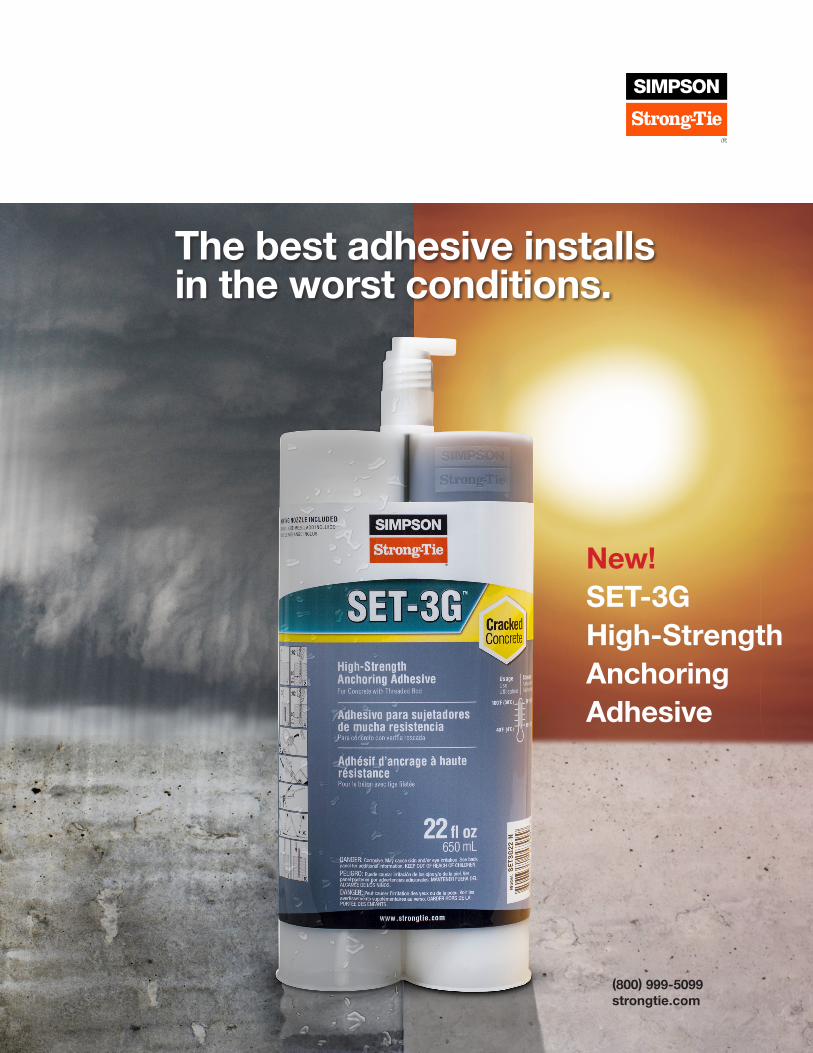
The best adhesive installs in the worst conditions.
(800) 999-5099strongtie.com
New!SET-3G High-Strength Anchoring Adhesive

2
© 2
017
Sim
pson
Str
ong-
Tie
Com
pany
Inc.
F-A
-SE
T3G
17
SET-3G™ High-Strength Epoxy Adhesive
SET-3G is the latest innovation in epoxy anchoring adhesives from Simpson Strong-Tie. Formulated to provide superior performance in cracked and uncracked concrete at elevated temperatures, SET-3G installs and performs in a variety of environmental conditions and temperature extremes. The exceptional bond strength of SET-3G results in high design strengths.
Features
• Exceptional performance — superior bond-strength values at long-term elevated temperature of 110°F (43°C) using optimized drill bit diameters
• Tested and assessed in accordance with ICC-ES AC308 and ACI 355.4 for use in cracked and uncracked normal-weight and lightweight concrete
• Design flexibility — can be specified for dry or water-saturated conditions when temperatures range from -40°F (-40°C) to 176°F (80°C)
• Jobsite versatility — can be installed in dry, water-saturated or water-filled holes in base materials with temperatures between 40°F (4°C) and 100°F (38°C)
• Maximized production and safety — qualified for installation using the Speed Clean™ DXS dust extraction drilling system as an alternative to the conventional blow-brush-blow hole-cleaning method
• Wire brush hole-cleaning system for conventional blow-brush-blow cleaning method
• Available in three cartridge configurations for maximum versatility — 8.5 oz. coaxial, 22 oz. side-by-side or 56 oz. side-by-side cartridges dispensed using manual, battery or pneumatic dispensing tools
Product Descriptions
• 1:1 ratio, two-component, high-strength, epoxy-based anchoring adhesive formula
• Two-year shelf life for unopened cartridges stored between 45°F (7°C) and 90°F (32°C)
• Low-odor formulation
• When properly mixed, SET-3G will be a uniform gray color
• Volatile organic compound (VOC) — 1.9 g/L
• Manufactured in the USA using global materials
Applications
• Threaded rod anchor and rebar dowel installations in cracked and uncracked concrete under a wide variety of environmental installation and use conditions
• Installation in downward, horizontal and upwardly inclined (including overhead) orientations
• Qualified for use in structures assigned to Seismic Design Categories A through F
Codes
• ICC-ES (concrete) — evaluation report pending; City of L.A. (concrete) — evaluation report pending; AASHTO M235 and ASTM C881, Types I and IV, Grade 3, Class C; NSF/ANSI Standard 61 (300 in.2 / 1,000 gal.)
Chemical Resistance
• Contact Simpson Strong-Tie for information
Installation and Application Instructions
• Surfaces to receive epoxy must be clean.
• Base-material temperatures must be 40°F (4°C) or above at the time of installation. For best results, adhesive should be conditioned to a temperature between 70°F (21°C) and 80°F (37°C) at the time of installation.
• To warm cold adhesive, store cartridges in a warm, uniformly heated area or storage container.
• Mixed material can harden in the dispensing nozzle within 30 minutes at 70°F (21°C).
Note: For full installation instructions, see product packaging or visit strongtie.com/set3g.
CrackedConcrete CODE LISTED
3
© 2
017
Sim
pson
Str
ong-
Tie
Com
pany
Inc.
F-A
-SE
T3G
17
SET-3G™ High-Strength Epoxy Adhesive
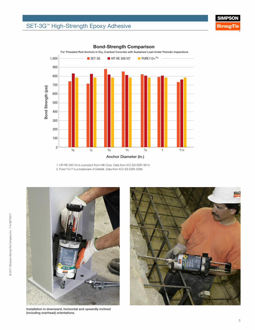
Installation in downward, horizontal and upwardly inclined (including overhead) orientations.
SET-3G HIT-RE 500 V3¹ PURE110+®²
900
1,000
800
700
600
500
400
300
200
100
0⅜ ½ ⅝
Anchor Diameter (in.)
Bond-Strength Comparison For Threaded Rod Anchors in Dry, Cracked Concrete with Sustained Load Under Periodic Inspections
Bo
nd S
tren
gth
(psi
)
¾ ⅞ 1 1¼
1. HIT-RE 500 V3 is a product from Hilti Corp. Data from ICC-ES ESR-3814.2. Pure110+® is a trademark of DeWalt. Data from ICC-ES ESR-3298.

4
© 2
017
Sim
pson
Str
ong-
Tie
Com
pany
Inc.
F-A
-SE
T3G
17
SET-3G™ High-Strength Epoxy Adhesive
Hole Cleaning Accessories: Wire Brush Heads / T-Handle Extensions Specifically designed for use with SET-3G to permit proper hole cleaning with fewer brush strokes at embedments up to 20 times the anchor diameter.
Note: When installing in holes drilled using the Simpson Strong-Tie® Speed Clean™ system with the appropriate HEPA vacuum equipped with an automatic filter cleaning system, wire brushes are not used.
SET-3G Wire Brush AccessoriesModel No. Description Hole
DiameterAnchor
DiameterRebar Size
Package Qty.
Carton Qty.
ETB43S 7/16" brush head 7/16" 3/8" 1 25
ETB50S 1/2" brush head 1/2" #3 1 25
ETB56S 9/16" brush head 9/16" 1/2" 1 25
ETB62S 5/8" brush head 5/8" #4 1 25
ETB68S 11/16" brush head 11/16" 5/8" 1 25
ETB75S 3/4" brush head 3/4" #5 1 25
ETB87S 7/8" brush head 7/8" 3/4" #6 1 25
ETB100S 1" brush head 1" 7/8" #7 1 25
ETB112S 1 1/8" brush head 1 1/8" 1" #8 1 25
ETB137S 1 3/8" brush head 1 3/8" 1 1/4" #10 1 25
SET-3G T-Handle AccessoriesModel No. Description Package
Qty.Carton
Qty.ETBS-TH T-handle to clean holes up to 13 1/2" deep 1 25
ETBS-EXT 12" extension for ETBS-TH (T-handle) 1 25
SET-3G Adhesive Cartridge System
Model No. Capacity(oz.)
Cartridge Type
Carton Quantity
Dispensing Tool(s)
Mixing Nozzle
SET3G102 8.5 Coaxial 12 CDT10S EMN22i
SET3G22-N1 22 Side-by-side 10 EDT22S, EDTA22P, EDTA22CKT EMN22i
SET3G56 56 Side-by-side 6 EDTA56P EMN22i (not included)
1. One EMN21i mixing nozzle and one extension are supplied with each cartridge. 2. Two EMN22i mixing nozzles and two nozzle extensions are supplied with each cartridge.3. Cartridge estimation guidelines are available at strongtie.com/apps.4. Use only Simpson Strong-Tie® mixing nozzles in accordance with Simpson Strong-Tie
instructions. Modification or improper use of mixing nozzle may impair SET-3G adhesive performance.
SET-3G Cure Schedule1, 2
Concrete Temperature Gel Time Cure Time
(°F) (°C) (min.) (hr.)
40 5 120 192
60 16 50 48
70 21 35 24
90 32 25 24
100 38 15 24
1. For water-saturated concrete and water-filled holes, the cure times should be doubled.
2. For installation of anchors in concrete where the temperature is below 70°F (21°C), the adhesive must be conditioned to a minimum temperature of 70°F (21°C).
Test Criteria
Anchors installed with SET-3G adhesive have been tested in accordance with ICC-ES Acceptance Criteria for Adhesive Anchors in Concrete Elements (AC308).
Property Test Method Result*
Consistency ASTM C881 Passed, non sag
Heat deflection ASTM D648 147°F
Bond strength (moist cure) ASTM C882 3,306 psi at 2 days
Water absorption ASTM D570 0.13%
Compressive yield strength ASTM D695 15,390 psi
Compressive modulus ASTM D695 991,830 psi
Shore D durometer ASTM D2240 84
Gel time ASTM C881 52 minutes
Volatile organic compound (VOC) — 1.9 g/L
*Material and curing conditions: 73 ± 2°F, unless otherwise noted.

5
© 2
017
Sim
pson
Str
ong-
Tie
Com
pany
Inc.
F-A
-SE
T3G
17
SET-3G™ High-Strength Epoxy Adhesive
OSHA Silica Dust Compliance RegulationsSET-3G is code listed to work with the Speed Clean™ DXS dust extraction system. This cleaning system cuts out the dusty, time-consuming “blow-brush-blow” hole-cleaning process.
Automating dust removal also reduces the reliance on the installer to perform the cleaning process, thereby increasing the likelihood that anchors will be installed correctly.
• Faster: One worker can drill faster and “clean” holes at the same time rather than having two people on the task.
• Safer: No more airborne dust shooting out of holes from cleaning with compressed air.
For information on the OSHA Silica Dust Requirement, go to strongtie.com/oshasilica.
Adhesive Piston Plug Delivery SystemFor consistent dispensing of anchoring adhesives in any installation orientation, the Simpson Strong-Tie® Adhesive Piston Plug Delivery System offers you an easy-to-use, more reliable and less time-consuming means to dispense adhesive into drilled holes for threaded rod and rebar dowel installations at overhead, upwardly inclined and horizontal orientations.
The matched tolerance design between the piston plug and drilled hole virtually eliminates the formation of voids and air pockets during adhesive dispensing.
√
!
√
!
½ to ⅔
embedment⅓ to½
SD
SET-3G Installation Information and Additional Data for Threaded Rod and Rebar in Normal-Weight Concrete1
Characteristic Symbol UnitsNominal Anchor Diameter da (in.) / Rebar Size
3/8 / #3 1/2 / #4 5/8 / #5 3/4 / #6 7/8 / #7 1 / #8 1 1/4 / #10
Installation Information
Drill Bit Diameter for Threaded Rod dhole in. 7/16 9/16 11/16 7/8 1 1 1/8 1 3/8
Drill Bit Diameter for Rebar dhole in. 1/2 5/8 3/4 7/8 1 1 1/8 1 3/8
Maximum Tightening Torque Tinst ft.-lb. 15 30 60 100 125 150 200
Minimum Embedment Depth hef, min in. 2 3/8 2 3/4 3 1/8 3 1/2 3 3/4 4 5
Maximum Embedment Depth hef, max in. 7 1/2 10 12 1/2 15 17 1/2 20 25
Minimum Concrete Thickness hmin in. hef + 1 1/4 hef + 2dhole
Critical Edge Distance cac in. See footnote 2
Minimum Edge Distance cmin in. 1 3/4 2 3/4
Minimum Anchor Spacing smin in. 3 6
1. The information presented in this table is to be used in conjunction with the design criteria of ACI 318-14 and ACI 318-11. 2. cac = hef (τk,uncr /1,160)0.4 x [3.1 – 0.7(h/hef)], where:
[h/hef] ≤ 2.4τk,uncr = the characteristic bond strength in uncracked concrete, given in the tables that follow ≤ kuncr ((hef x f 'c)0.5/(π x da))h = the member thickness (inches)hef = the embedment depth (inches)
*IBC
DXS Drill Bit
Piston Plug Delivery SystemAdhesive Piston Plug Family
6
© 2
017
Sim
pson
Str
ong-
Tie
Com
pany
Inc.
F-A
-SE
T3G
17
SET-3G™ High-Strength Epoxy Adhesive
SD
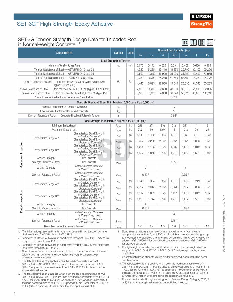
IBC *SET-3G Tension Strength Design Data for Threaded Rod in Normal-Weight Concrete1, 8
Characteristic Symbol UnitsNominal Rod Diameter (in.)
3/8 1/2 5/8 3/4 7/8 1 1 1/4
Steel Strength in Tension
Minimum Tensile Stress Area Ase in.2 0.078 0.142 0.226 0.334 0.462 0.606 0.969Tension Resistance of Steel — ASTM F1554, Grade 36
Nsa lb.
4,525 8,235 13,110 19,370 26,795 35,150 56,200Tension Resistance of Steel — ASTM F1554, Grade 55 5,850 10,650 16,950 25,050 34,650 45,450 72,675Tension Resistance of Steel — ASTM A193, Grade B7 9,750 17,750 28,250 41,750 57,750 75,750 121,125
Tension Resistance of Steel — Stainless Steel ASTM A193, Grade B8 and B8M (Types 304 and 316) 4,445 8,095 12,880 19,040 26,335 34,540 55,235
Tension Resistance of Steel — Stainless Steel ASTM F593 CW (Types 304 and 316) 7,800 14,200 22,600 28,390 39,270 51,510 82,365Tension Resistance of Steel — Stainless Steel ASTM A193, Grade B6 (Type 410) 8,580 15,620 24,860 36,740 50,820 66,660 106,590
Strength Reduction Factor for Tension — Steel Failure φ 0.755
Concrete Breakout Strength in Tension (2,500 psi ≤ f'c ≤ 8,000 psi)
Effectiveness Factor for Cracked Concrete kc,cr 17
Effectiveness Factor for Uncracked Concrete kc,cr 24
Strength Reduction Factor — Concrete Breakout Failure in Tension φ 0.656
Bond Strength in Tension (2,500 psi ≤ f’c ≤ 8,000 psi)7
Minimum Embedment hef,min in. 2 3/8 2 3/4 3 1/8 3 1/2 3 3/4 4 5 Maximum Embedment hef,max in. 7 1/2 10 12 1/2 15 17 1/2 20 25
Temperature Range A2,4
Characteristic Bond Strength in Cracked Concrete9 τk,cr psi 1,448 1,402 1,356 1,310 1265 1219 1,128
Characteristic Bond Strength in Uncracked Concrete9 τk,uncr psi 2,357 2,260 2,162 2,064 1967 1,868 1,672
Temperature Range B3,4
Characteristic Bond Strength in Cracked Concrete9 τk,cr psi 1,201 1,163 1,125 1,087 1,050 1,012 936
Characteristic Bond Strength in Uncracked Concrete9 τk,uncr psi 1,957 1,876 1,795 1,713 1,632 1,551 1,388
Anchor Category Dry Concrete 1Strength Reduction Factor Dry Concrete φdry,ci 0.6510
Anchor Category Water-Saturated Concrete, or Water-Filled Hole 3 2
Strength Reduction Factor Water-Saturated Concrete, or Water-Filled Hole φwet,ci 0.4510 0.5510
Temperature Range A2,4
Characteristic Bond Strength in Cracked Concrete9 τk,cr psi 1,346 1,304 1,356 1,310 1,265 1,219 1,128
Characteristic Bond Strength in Uncracked Concrete9 τk,uncr psi 2,192 2102 2,162 2,064 1,967 1,868 1,672
Temperature Range B3,4
Characteristic Bond Strength in Cracked Concrete9 τk,cr psi 1,117 1,082 1,125 1087 1,050 1,012 936
Characteristic Bond Strength in Uncracked Concrete9 τk,uncr psi 1,820 1,744 1,795 1,713 1,632 1,551 1,388
Anchor Category Dry Concrete 2 1Strength Reduction Factor Dry Concrete φdry,pi 0.5510 0.6510
Anchor Category Water-Saturated Concrete, or Water-Filled Hole 3
Strength Reduction Factor Water-Saturated Concrete, or Water-Filled Hole φwet,pi 0.4510
Reduction Factor for Seismic Tension αN,seis11 1.0 0.9 1.0 1.0 1.0 1.0 1.0
Cont
inuo
us In
spec
tion
Perio
dic
Insp
ectio
n
1. The information presented in this table is to be used in conjunction with the design criteria of ACI 318-14 and ACI 318-11.
2. Temperature Range A: Maximum short-term temperature = 160°F, maximum long-term temperature = 110°F.
3. Temperature Range B: Maximum short-term temperature = 176°F, maximum long-term temperature = 110°F.
4. Short-term concrete temperatures are those that occur over short intervals (diurnal cycling). Long-term temperatures are roughly constant over significant periods of time.
5. The tabulated value of ϕ applies when the load combinations of ACI 318-14 5.3 or ACI 318-11 9.2 are used. If the load combinations of ACI 318-11 Appendix C are used, refer to ACI 318-11 D.4.4 to determine the appropriate value of ϕ.
6. The tabulated value of Φ applies when both the load combinations of ACI 318-14 5.3, or ACI 318-11 9.2 are used and the requirements of ACI 318-14 17.3.3 (c) or ACI 318-11 D.4.3 (c), as applicable, for Condition B are met. If the load combinations of ACI 318-11 Appendix C are used, refer to ACI 318 D.4.4 (c) for Condition B to determine the appropriate value of ϕ.
7. Bond strength values shown are for normal-weight concrete having a compressive strength of f'c = 2,500 psi. For higher compressive strengths up to 8,000 psi, the tabulated characteristic bond strength may be increased by a factor of (f'c/2,500)0.34 for uncracked concrete and a factor of (f'c/2,500)0.24 for cracked concrete.
8. For lightweight concrete, the modification factor for bond strength shall be as given in ACI 318-14 17.2.6 or ACI 318-11 D.3.6, as applicable, where applicable.
9. Characteristic bond strength values are for sustained loads, including dead and live loads.
10. The tabulated value of ϕ applies when both the load combinations of ACI 318-14 5.3, or ACI 318-11 9.2 are used and the requirements of ACI 318-14 17.3.3 (c) or ACI 318-11 D.4.3 (c), as applicable, for Condition B are met. If the load combinations of ACI 318-11 Appendix C are used, refer to ACI 318 D.4.4(c) for Condition B to determine the appropriate value of ϕ.
11. For anchors installed in regions assigned to Seismic Design Category C, D, E or F, the bond strength values must be multiplied by αN,seis.
7
© 2
017
Sim
pson
Str
ong-
Tie
Com
pany
Inc.
F-A
-SE
T3G
17
SET-3G™ High-Strength Epoxy Adhesive
SD
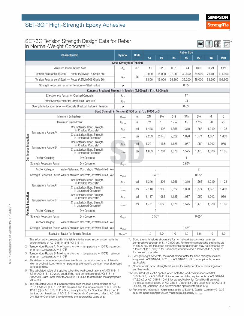
IBC *SET-3G Tension Strength Design Data for Rebar in Normal-Weight Concrete1,8
Characteristic Symbol UnitsRebar Size
#3 #4 #5 #6 #7 #8 #10
Steel Strength in Tension
Minimum Tensile Stress Area Ase in.2 0.11 0.20 0.31 0.44 0.60 0.79 1.27
Tension Resistance of Steel — Rebar (ASTM A615 Grade 60)Nsa lb.
9,900 18,000 27,900 39,600 54,000 71,100 114,300
Tension Resistance of Steel — Rebar (ASTM A706 Grade 60) 8,800 16,000 24,800 35,200 48,000 63,200 101,600
Strength Reduction Factor for Tension — Steel Failure φ 0.755
Concrete Breakout Strength in Tension (2,500 psi ≤ f'c ≤ 8,000 psi)
Effectiveness Factor for Cracked Concrete kc,cr 17
Effectiveness Factor for Uncracked Concrete kc,cr 24
Strength Reduction Factor — Concrete Breakout Failure in Tension φ 0.656
Bond Strength in Tension (2,500 psi ≤ f'c ≤ 8,000 psi)7
Minimum Embedment hef,min in. 2 3/8 2 3/4 3 1/8 3 1/2 3 3/4 4 5
Maximum Embedment hef,max in. 7 1/2 10 12 1/2 15 17 1/2 20 25
Temperature Range A2,4
Characteristic Bond Strength in Cracked Concrete9 τk,cr psi 1,448 1,402 1,356 1,310 1,265 1,219 1,128
Characteristic Bond Strength in Uncracked Concrete9 τk,uncr psi 2,269 2,145 2,022 1,898 1,774 1,651 1,403
Temperature Range B3,4
Characteristic Bond Strength in Cracked Concrete9 τk,cr psi 1,201 1,163 1,125 1,087 1,050 1,012 936
Characteristic Bond Strength in Uncracked Concrete9 τk,uncr psi 1,883 1,781 1,678 1,575 1,473 1,370 1,165
Anchor Category Dry Concrete 1
Strength Reduction Factor Dry Concrete φdry,ci 0.6510
Anchor Category Water-Saturated Concrete, or Water-Filled Hole 3 2
Strength Reduction Factor Water-Saturated Concrete, or Water-Filled Hole φwet,ci 0.4510 0.5510
Temperature Range A2,4
Characteristic Bond Strength in Cracked Concrete9 τk,cr psi 1,346 1,304 1,356 1,310 1,265 1,219 1,128
Characteristic Bond Strength in Uncracked Concrete9 τk,uncr psi 2,110 1,995 2,022 1,898 1,774 1,651 1,403
Temperature Range B3,4
Characteristic Bond Strength in Cracked Concrete9 τk,cr psi 1,117 1,082 1,125 1,087 1,050 1,012 936
Characteristic Bond Strength in Uncracked Concrete9 τk,uncr psi 1,751 1,656 1,678 1,575 1,473 1,370 1,165
Anchor Category Dry Concrete 2 1
Strength Reduction Factor Dry Concrete φdry,pi 0.5510 0.6510
Anchor Category Water-Saturated Concrete, or Water-Filled Hole 3
Strength Reduction Factor Water-Saturated Concrete, or Water-Filled Hole φwet,pi 0.4510
Reduction Factor for Seismic Tension αN,seis11 1.0 1.0 1.0 1.0 1.0 1.0 1.0
1. The information presented in this table is to be used in conjunction with the design criteria of ACI 318-14 and ACI 318-11.
2. Temperature Range A: Maximum short-term temperature = 160°F, maximum long-term temperature = 110°F.
3. Temperature Range B: Maximum short-term temperature = 176°F, maximum long-term temperature = 110°F.
4. Short-term concrete temperatures are those that occur over short intervals (diurnal cycling). Long-term temperatures are roughly constant over significant periods of time.
5. The tabulated value of ϕ applies when the load combinations of ACI 318-14 5.3 or ACI 318-11 9.2 are used. If the load combinations of ACI 318-11 Appendix C are used, refer to ACI 318-11 D.4.4 to determine the appropriate value of ϕ.
6. The tabulated value of Φ applies when both the load combinations of ACI 318-14 5.3, or ACI 318-11 9.2 are used and the requirements of ACI 318-14 17.3.3 (c) or ACI 318-11 D.4.3 (c), as applicable, for Condition B are met. If the load combinations of ACI 318-11 Appendix C are used, refer to ACI 318 D.4.4(c) for Condition B to determine the appropriate value of ϕ.
7. Bond strength values shown are for normal-weight concrete having a compressive strength of f'c = 2,500 psi. For higher compressive strengths up to 8,000 psi, the tabulated characteristic bond strength may be increased by a factor of (f'c /2,500)0.34 for uncracked concrete and a factor of (f'c /2,500)0.24 for cracked concrete.
8. For lightweight concrete, the modification factor for bond strength shall be as given in ACI 318-14 17.2.6 or ACI 318-11 D.3.6, as applicable, where applicable.
9. Characteristic bond strength values are for sustained loads, including dead and live loads.
The tabulated value of ϕ applies when both the load combinations of ACI 318-14 5.3, or ACI 318-11 9.2 are used and the requirements of ACI 318-14 17.3.3 (c) or ACI 318-11 D.4.3 (c), as applicable, for Condition B are met. If the load combinations of ACI 318-11 Appendix C are used, refer to ACI 318 D.4.4(c) for Condition B to determine the appropriate value of ϕ.
10. For anchors installed in regions assigned to Seismic Design Category C, D, E or F, the bond strength values must be multiplied by αN,seis.
Cont
inuo
us In
spec
tion
Perio
dic
Insp
ectio
n
This flier is effective until December 31, 2019, and reflects information available as of December 1, 2017. This information is updated periodically and should not be relied upon after December 31, 2019. Contact Simpson Strong‑Tie for current information and limited warranty or see strongtie.com.
© 2017 Simpson Strong‑Tie Company Inc. • P.O. Box 10789, Pleasanton, CA 94588 F-A-SET3G17 12/17 exp. 12/19
(800) 999-5099strongtie.com
SET-3G™ High-Strength Epoxy Adhesive
SD
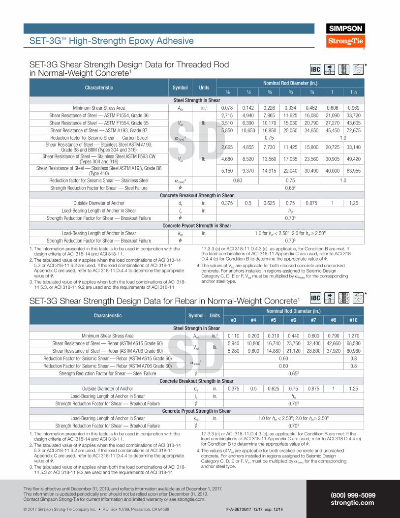
SET-3G Shear Strength Design Data for Threaded Rod in Normal-Weight Concrete1
Characteristic Symbol UnitsNominal Rod Diameter (in.)
3/8 1/2 5/8 3/4 7/8 1 1 1/4
Steel Strength in ShearMinimum Shear Stress Area Ase in.2 0.078 0.142 0.226 0.334 0.462 0.606 0.969
Shear Resistance of Steel — ASTM F1554, Grade 36
Vsa lb.
2,715 4,940 7,865 11,625 16,080 21,090 33,720
Shear Resistance of Steel — ASTM F1554, Grade 55 3,510 6,390 10,170 15,030 20,790 27,270 43,605
Shear Resistance of Steel — ASTM A193, Grade B7 5,850 10,650 16,950 25,050 34,650 45,450 72,675Reduction factor for Seismic Shear — Carbon Streel αV,seis
4 0.75 1.0Shear Resistance of Steel — Stainless Steel ASTM A193,
Grade B8 and B8M (Types 304 and 316)
Vsa lb.
2,665 4,855 7,730 11,425 15,800 20,725 33,140
Shear Resistance of Steel — Stainless Steel ASTM F593 CW (Types 304 and 316) 4,680 8,520 13,560 17,035 23,560 30,905 49,420
Shear Resistance of Steel — Stainless Steel ASTM A193, Grade B6 (Type 410) 5,150 9,370 14,915 22,040 30,490 40,000 63,955
Reduction factor for Seismic Shear — Stainless Steel αV,seis4 0.80 0.75 1.0
Strength Reduction Factor for Shear — Steel Failure φ 0.652
Concrete Breakout Strength in ShearOutside Diameter of Anchor da in. 0.375 0.5 0.625 0.75 0.875 1 1.25
Load-Bearing Length of Anchor in Shear le in. hef
Strength Reduction Factor for Shear — Breakout Failure φ 0.703
Concrete Pryout Strength in ShearLoad-Bearing Length of Anchor in Shear kcp in. 1.0 for hef < 2.50"; 2.0 for hef ≥ 2.50"
Strength Reduction Factor for Shear — Breakout Failure φ 0.703
1. The information presented in this table is to be used in conjunction with the design criteria of ACI 318-14 and ACI 318-11.
2. The tabulated value of φ applies when the load combinations of ACI 318-14 5.3 or ACI 318-11 9.2 are used. If the load combinations of ACI 318-11 Appendix C are used, refer to ACI 318-11 D.4.4 to determine the appropriate value of φ.
3. The tabulated value of φ applies when both the load combinations of ACI 318-14 5.3, or ACI 318-11 9.2 are used and the requirements of ACI 318-14
17.3.3 (c) or ACI 318-11 D.4.3 (c), as applicable, for Condition B are met. If the load combinations of ACI 318-11 Appendix C are used, refer to ACI 318 D.4.4 (c) for Condition B to determine the appropriate value of φ.
4. The values of Vsa are applicable for both cracked concrete and uncracked concrete. For anchors installed in regions assigned to Seismic Design Category C, D, E or F, Vsa must be multiplied by αVseis for the corresponding anchor steel type.
SDSET-3G Shear Strength Design Data for Rebar in Normal-Weight Concrete1
Characteristic Symbol UnitsNominal Rod Diameter (in.)
#3 #4 #5 #6 #7 #8 #10
Steel Strength in ShearMinimum Shear Stress Area Ase in.2 0.110 0.200 0.310 0.440 0.600 0.790 1.270
Shear Resistance of Steel — Rebar (ASTM A615 Grade 60)Vsa lb.
5,940 10,800 16,740 23,760 32,400 42,660 68,580
Shear Resistance of Steel — Rebar (ASTM A706 Grade 60) 5,280 9,600 14,880 21,120 28,800 37,920 60,960
Reduction Factor for Seismic Shear — Rebar (ASTM A615 Grade 60)αV,seis
40.60 0.8
Reduction Factor for Seismic Shear — Rebar (ASTM A706 Grade 60) 0.60 0.8
Strength Reduction Factor for Shear — Steel Failure φ 0.652
Concrete Breakout Strength in ShearOutside Diameter of Anchor da in. 0.375 0.5 0.625 0.75 0.875 1 1.25
Load-Bearing Length of Anchor in Shear le in. hef
Strength Reduction Factor for Shear — Breakout Failure φ 0.703
Concrete Pryout Strength in ShearLoad-Bearing Length of Anchor in Shear kcp in. 1.0 for hef < 2.50"; 2.0 for hef ≥ 2.50"
Strength Reduction Factor for Shear — Breakout Failure φ 0.703
1. The information presented in this table is to be used in conjunction with the design criteria of ACI 318-14 and ACI 318-11.
2. The tabulated value of φ applies when the load combinations of ACI 318-14 5.3 or ACI 318-11 9.2 are used. If the load combinations of ACI 318-11 Appendix C are used, refer to ACI 318-11 D.4.4 to determine the appropriate value of φ.
3. The tabulated value of φ applies when both the load combinations of ACI 318-14 5.3 or ACI 318-11 9.2 are used and the requirements of ACI 318-14
17.3.3 (c) or ACI 318-11 D.4.3 (c), as applicable, for Condition B are met. If the load combinations of ACI 318-11 Appendix C are used, refer to ACI 318 D.4.4 (c) for Condition B to determine the appropriate value of φ.
4. The values of Vsa are applicable for both cracked concrete and uncracked concrete. For anchors installed in regions assigned to Seismic Design Category C, D, E or F, Vsa must be multiplied by αVseis for the corresponding anchor steel type.
IBC *
IBC *
Related Documents