FlexPod Solutions FlexPod NetApp April 13, 2022 This PDF was generated from https://docs.netapp.com/us-en/flexpod/index.html on April 13, 2022. Always check docs.netapp.com for the latest.

Welcome message from author
This document is posted to help you gain knowledge. Please leave a comment to let me know what you think about it! Share it to your friends and learn new things together.
Transcript

FlexPod Solutions
FlexPodNetAppApril 13, 2022
This PDF was generated from https://docs.netapp.com/us-en/flexpod/index.html on April 13, 2022.Always check docs.netapp.com for the latest.
Table of Contents
FlexPod Solutions . . . . . . . . . . . . . . . . . . . . . . . . . . . . . . . . . . . . . . . . . . . . . . . . . . . . . . . . . . . . . . . . . . . . . . . . 1
FlexPod Definition . . . . . . . . . . . . . . . . . . . . . . . . . . . . . . . . . . . . . . . . . . . . . . . . . . . . . . . . . . . . . . . . . . . . . . . . 2
FlexPod Express Technical Specifications. . . . . . . . . . . . . . . . . . . . . . . . . . . . . . . . . . . . . . . . . . . . . . . . . . . . 2
FlexPod Datacenter Technical Specifications . . . . . . . . . . . . . . . . . . . . . . . . . . . . . . . . . . . . . . . . . . . . . . . . 26
FlexPod Datacenter . . . . . . . . . . . . . . . . . . . . . . . . . . . . . . . . . . . . . . . . . . . . . . . . . . . . . . . . . . . . . . . . . . . . . . 61
FlexPod DataCenter with NetApp SnapMirror Business Continuity and ONTAP 9.10. . . . . . . . . . . . . . . . . . 61
Hybrid Cloud. . . . . . . . . . . . . . . . . . . . . . . . . . . . . . . . . . . . . . . . . . . . . . . . . . . . . . . . . . . . . . . . . . . . . . . . . . . 119
NetApp Cloud Insights for FlexPod . . . . . . . . . . . . . . . . . . . . . . . . . . . . . . . . . . . . . . . . . . . . . . . . . . . . . . . 119
FlexPod with FabricPool - Inactive Data Tiering to Amazon AWS S3 . . . . . . . . . . . . . . . . . . . . . . . . . . . . . 143
Enterprise Databases. . . . . . . . . . . . . . . . . . . . . . . . . . . . . . . . . . . . . . . . . . . . . . . . . . . . . . . . . . . . . . . . . . . . 165
SAP . . . . . . . . . . . . . . . . . . . . . . . . . . . . . . . . . . . . . . . . . . . . . . . . . . . . . . . . . . . . . . . . . . . . . . . . . . . . . . . 165
Oracle. . . . . . . . . . . . . . . . . . . . . . . . . . . . . . . . . . . . . . . . . . . . . . . . . . . . . . . . . . . . . . . . . . . . . . . . . . . . . . 165
Microsoft SQL Server . . . . . . . . . . . . . . . . . . . . . . . . . . . . . . . . . . . . . . . . . . . . . . . . . . . . . . . . . . . . . . . . . . 165
Healthcare . . . . . . . . . . . . . . . . . . . . . . . . . . . . . . . . . . . . . . . . . . . . . . . . . . . . . . . . . . . . . . . . . . . . . . . . . . . . 166
FlexPod for Genomics . . . . . . . . . . . . . . . . . . . . . . . . . . . . . . . . . . . . . . . . . . . . . . . . . . . . . . . . . . . . . . . . . 166
FlexPod Datacenter for Epic Directional Sizing Guide. . . . . . . . . . . . . . . . . . . . . . . . . . . . . . . . . . . . . . . . . 206
FlexPod Datacenter for Epic EHR Deployment Guide. . . . . . . . . . . . . . . . . . . . . . . . . . . . . . . . . . . . . . . . . 221
FlexPod for Epic Performance Testing. . . . . . . . . . . . . . . . . . . . . . . . . . . . . . . . . . . . . . . . . . . . . . . . . . . . . 258
FlexPod for MEDITECH Directional Sizing Guide . . . . . . . . . . . . . . . . . . . . . . . . . . . . . . . . . . . . . . . . . . . . 275
FlexPod Datacenter for MEDITECH Deployment Guide . . . . . . . . . . . . . . . . . . . . . . . . . . . . . . . . . . . . . . . 286
FlexPod for Medical Imaging . . . . . . . . . . . . . . . . . . . . . . . . . . . . . . . . . . . . . . . . . . . . . . . . . . . . . . . . . . . . 316
Virtual Desktop Infrastructure. . . . . . . . . . . . . . . . . . . . . . . . . . . . . . . . . . . . . . . . . . . . . . . . . . . . . . . . . . . . . . 349
Modern Apps . . . . . . . . . . . . . . . . . . . . . . . . . . . . . . . . . . . . . . . . . . . . . . . . . . . . . . . . . . . . . . . . . . . . . . . . . . 350
Microsoft Apps . . . . . . . . . . . . . . . . . . . . . . . . . . . . . . . . . . . . . . . . . . . . . . . . . . . . . . . . . . . . . . . . . . . . . . . . . 351
FlexPod Express . . . . . . . . . . . . . . . . . . . . . . . . . . . . . . . . . . . . . . . . . . . . . . . . . . . . . . . . . . . . . . . . . . . . . . . 352
FlexPod Express with Cisco UCS C-Series and NetApp AFF C190 Series Design Guide . . . . . . . . . . . . . 352
FlexPod Express with Cisco UCS C-Series and NetApp AFF C190 Series Deployment Guide . . . . . . . . . 363
FlexPod Express with Cisco UCS C-Series and AFF A220 Series Design Guide . . . . . . . . . . . . . . . . . . . . 457
FlexPod Express with Cisco UCS C-Series and AFF A220 Series Deployment Guide . . . . . . . . . . . . . . . . 467
FlexPod Express with VMware vSphere 6.7U1 and NetApp AFF A220 with Direct-Attached IP-Based
Storage Design Guide . . . . . . . . . . . . . . . . . . . . . . . . . . . . . . . . . . . . . . . . . . . . . . . . . . . . . . . . . . . . . . . . . 547
FlexPod Express with VMware vSphere 6.7U1 and NetApp AFF A220 with Direct-Attached IP-Based
Storage. . . . . . . . . . . . . . . . . . . . . . . . . . . . . . . . . . . . . . . . . . . . . . . . . . . . . . . . . . . . . . . . . . . . . . . . . . . . . 558
FlexPod and Security . . . . . . . . . . . . . . . . . . . . . . . . . . . . . . . . . . . . . . . . . . . . . . . . . . . . . . . . . . . . . . . . . . . . 667
FlexPod, The Solution to Ransomware . . . . . . . . . . . . . . . . . . . . . . . . . . . . . . . . . . . . . . . . . . . . . . . . . . . . 667
FIPS 140-2 security-compliant FlexPod solution for healthcare . . . . . . . . . . . . . . . . . . . . . . . . . . . . . . . . . 686
Cisco Intersight with NetApp ONTAP storage quick start guide . . . . . . . . . . . . . . . . . . . . . . . . . . . . . . . . . . . . 711
Cisco Intersight with NetApp ONTAP storage: quick start guide . . . . . . . . . . . . . . . . . . . . . . . . . . . . . . . . . 711
What’s new . . . . . . . . . . . . . . . . . . . . . . . . . . . . . . . . . . . . . . . . . . . . . . . . . . . . . . . . . . . . . . . . . . . . . . . . . . 711
Requirements. . . . . . . . . . . . . . . . . . . . . . . . . . . . . . . . . . . . . . . . . . . . . . . . . . . . . . . . . . . . . . . . . . . . . . . . 712
Before you begin . . . . . . . . . . . . . . . . . . . . . . . . . . . . . . . . . . . . . . . . . . . . . . . . . . . . . . . . . . . . . . . . . . . . . 713
Claim targets . . . . . . . . . . . . . . . . . . . . . . . . . . . . . . . . . . . . . . . . . . . . . . . . . . . . . . . . . . . . . . . . . . . . . . . . 719
Monitor NetApp storage from Cisco Intersight . . . . . . . . . . . . . . . . . . . . . . . . . . . . . . . . . . . . . . . . . . . . . . . 720

Use cases. . . . . . . . . . . . . . . . . . . . . . . . . . . . . . . . . . . . . . . . . . . . . . . . . . . . . . . . . . . . . . . . . . . . . . . . . . . 723
References. . . . . . . . . . . . . . . . . . . . . . . . . . . . . . . . . . . . . . . . . . . . . . . . . . . . . . . . . . . . . . . . . . . . . . . . . . 725
Infrastructure . . . . . . . . . . . . . . . . . . . . . . . . . . . . . . . . . . . . . . . . . . . . . . . . . . . . . . . . . . . . . . . . . . . . . . . . . . 726
End-to-End NVMe for FlexPod with Cisco UCSM, VMware vSphere 7.0, and NetApp ONTAP 9. . . . . . . . 726

FlexPod Solutions
1

FlexPod Definition
FlexPod Express Technical Specifications
TR-4293: FlexPod Express Technical Specifications
Karthick Radhakrishnan, Arvind Ramakrishnan, Lindsey Street, Savita Kumari, NetApp
FlexPod Express is a predesigned, best practice architecture that is built on the Cisco Unified ComputingSystem (Cisco UCS) and the Cisco Nexus family of switches, and the storage layer is built by using the NetAppFAS or the NetApp E-Series storage. FlexPod Express is a suitable platform for running various virtualizationhypervisors and bare metal operating systems (OSs) and enterprise workloads.
FlexPod Express delivers not only a baseline configuration, but also the flexibility to be sized and optimized toaccommodate many different use cases and requirements. This document categorizes the FlexPod Expressconfigurations based on the storage system used, FlexPod Express with NetApp FAS and FlexPod Expresswith E-Series.
FlexPod platforms
There are three FlexPod platforms:
• FlexPod Datacenter. This platform is a massively scalable virtual data center infrastructure suited forworkload enterprise applications, virtualization, VDI, and public and private cloud. FlexPod Datacenter hasits own specifications, which are documented in TR-4036: FlexPod Datacenter Technical Specifications.
• FlexPod Express. This platform is a compact converged infrastructure that is targeted for remote officeand edge use cases.
• FlexPod Select. This platform is a purpose-built architecture for high-performance applications, such asFlexPod Select for High-Performance Oracle RAC.
This document provides the technical specifications for the FlexPod Express platform.
FlexPod Rules
The FlexPod design allows a flexible infrastructure that encompasses many different components and softwareversions.
Use the rule sets as a guide for building or assembling a valid FlexPod configuration. The numbers and ruleslisted in this document are the minimum requirements for FlexPod; they can be expanded in the includedproduct families as required for different environments and use cases.
Supported versus validated FlexPod configurations
The FlexPod architecture is defined by the set of rules described in this document. The hardware componentsand software configurations must be supported by the Cisco Hardware Compatibility List (HCL) and theNetApp Interoperability Matrix Tool (IMT).
Each Cisco Validated Design (CVD) or NetApp Verified Architecture (NVA) is a possible FlexPod configuration.Cisco and NetApp document these configuration combinations and validate them with extensive end-to-endtesting. The FlexPod deployments that deviate from these configurations are fully supported if they follow theguidelines in this document and all the components are listed as compatible in the Cisco HCL and NetApp IMT.
2
For example, adding additional storage controllers or Cisco UCS servers and upgrading software to newerversions is fully supported if the software, hardware, and configurations meet the guidelines defined in thisdocument.
Storage Software
FlexPod Express supports storage systems that run NetApp ONTAP or SANtricity operating systems.
NetApp ONTAP
The NetApp ONTAP software is the operating system that runs on AFF and FAS storage systems. ONTAPprovides a highly scalable storage architecture that enables nondisruptive operations, nondisruptive upgrades,and an agile data infrastructure.
For more information about ONTAP, see the ONTAP product page.
E-Series SANtricity software
E-Series SANtricity software is the operating system that runs on E-Series storage systems. SANtricityprovides a highly flexible system that meets varying application needs and offers built-in high availability and awide variety of data protection features.
For more information, see the SANtricity product page.
Minimum hardware requirements
This section describes the minimum hardware requirements for the different versions of FlexPod Express.
FlexPod Express with NetApp FAS
The hardware requirements for FlexPod Express solutions that use NetApp FAS controllers for underlyingstorage include the configurations describe in this section.
CIMC-based configuration (standalone rack servers)
The Cisco Integrated Management Controller (CIMC) configuration includes the following hardwarecomponents:
• Two 10Gbps standard Ethernet switches in a redundant configuration (Cisco Nexus 0808 is recommended,with Cisco Nexus 3000 and 9000 models supported)
• Cisco UCS C-Series standalone rack servers
• Two AFF C190, AFF A250, FAS2600, or FAS 2700 series controllers in a high-availability (HA) pairconfiguration deployed as a two-node cluster
Cisco UCS-managed configuration
The Cisco UCS-managed confirmation includes the following hardware components:
• Two 10Gbps standard Ethernet switches in a redundant configuration (Cisco Nexus 3524 is recommended)
• One Cisco UCS 5108 alternating current (AC) blade server chassis
• Two Cisco UCS 6324 fabric interconnects
• Cisco UCS B-Series servers (at least four Cisco UCS B200 M5 blade servers)
3
• Two AFF C190, AFF A250, FAS2750, or FAS2720 controllers in an HA pair configuration (requires twoavailable unified target adapter 2 [UTA2] ports per controller)
FlexPod Express with E-Series
The hardware requirements for the FlexPod Express with E-Series starter configuration include:
• Two Cisco UCS 6324 fabric interconnects
• One Cisco UCS Mini chassis 5108 AC2 or DC2 (the Cisco UCS 6324 fabric interconnects are onlysupported in the AC2 and DC2 chassis)
• Cisco UCS B-Series servers (at least two Cisco UCS B200 M4 blade servers)
• One HA pair configuration of an E-Series E2824 storage system loaded with minimum 12 disk drives
• Two 10Gbps standard Ethernet switches in a redundant configuration (existing switches in the data centercan be used)
These hardware components are required to build a starter configuration of the solution; additional bladeservers and disk drives can be added as needed. The E-Series E2824 storage system can be replaced with ahigher platform and can also be run as an all-flash system.
Minimum Software Requirements
This section describes the minimum software requirements for the different versions of FlexPod Express.
Software requirements for FlexPod Express with NetApp AFF or FAS
The software requirements for the FlexPod Express with NetApp FAS include:
• ONTAP 9.1 or later
• Cisco NX-OS version 7.0(3)I6(1) or later
• In the Cisco UCS- managed configuration, Cisco UCS Manager UCS 4.0(1b)
All software must be listed and supported in the NetApp IMT. Certain software features might require morerecent versions of code than the minimums listed in previous architectures.
Software requirements for FlexPod Express with E-Series
The software requirements for the FlexPod Express with E-Series include:
• E-Series SANtricity software 11.30 or higher
• Cisco UCS Manager 4.0(1b).
All software must be listed and supported in the NetApp IMT.
Connectivity requirements
This section describes the connectivity requirements for the different versions of FlexPod Express.
Connectivity requirements for FlexPod Express with NetApp FAS
The connectivity requirements for FlexPod Express with NetApp FAS include:
4

• NetApp FAS storage controllers must be directly connected to the Cisco Nexus switches, except in theCisco UCS-managed configuration, where storage controllers are connected to the fabric interconnects.
• No additional equipment can be placed inline between the core FlexPod components.
• Virtual port channels (vPCs) are required to connect the Cisco Nexus 3000/9000 series switches to theNetApp storage controllers.
• Although it is not required, enabling jumbo frame support is recommended throughout the environment.
Connectivity requirements for FlexPod Express with NetApp E-Series
The connectivity requirements for FlexPod Express with E-Series include:
• The E-Series storage controllers must be directly connected to the fabric interconnects.
• No additional equipment should be placed inline between the core FlexPod components.
• vPCs are required between the fabric interconnects and the Ethernet switches.
Connectivity requirements for FlexPod Express with NetApp AFF
The connectivity requirements for FlexPod Express with NetApp AFF include:
• NetApp AFF storage controllers must be directly connected to the Cisco Nexus switches, except in theCisco UCS–managed configuration, where storage controllers are connected to the fabric. interconnects.
• No additional equipment can be placed inline between the core FlexPod components.
• Virtual port channels (vPCs) are required to connect the Cisco Nexus 3000/9000 series switches to theNetApp storage controllers.
• Although it is not required, enabling jumbo frame support is recommended throughout the environment.
Other requirements
Additional requirements for FlexPod Express include the following:
• Valid support contracts are required for all equipment, including:
◦ SMARTnet support for Cisco equipment
◦ SupportEdge Advisor or SupportEdge Premium support for NetApp equipment
• All software components must be listed and supported in the NetApp IMT.
• All NetApp hardware components must be listed and supported on NetApp Hardware Universe.
• All Cisco hardware components must be listed and supported on Cisco HCL.
Optional Features
This section describes the optional features for FlexPod Express.
iSCSI boot option
The FlexPod Express architecture uses iSCSI boot. The minimum requirements for the iSCSI boot optioninclude:
• An iSCSI license/feature activated on the NetApp storage controller
5
• A two-port 10Gbps Ethernet adapter on each node in the NetApp storage controller HA pair
• An adapter in the Cisco UCS server that is capable of iSCSI boot
Configuration options
This section provides more information about the configuration required and validated in the FlexPod Expressarchitecture.
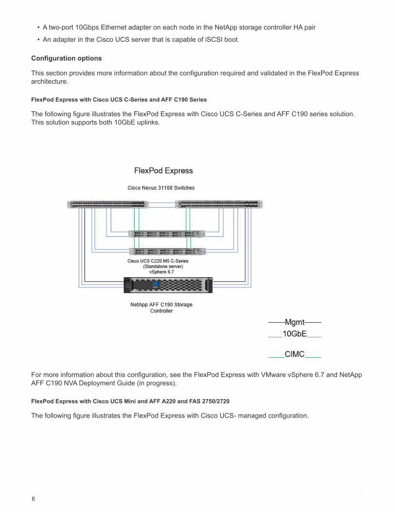
FlexPod Express with Cisco UCS C-Series and AFF C190 Series
The following figure illustrates the FlexPod Express with Cisco UCS C-Series and AFF C190 series solution.This solution supports both 10GbE uplinks.
For more information about this configuration, see the FlexPod Express with VMware vSphere 6.7 and NetAppAFF C190 NVA Deployment Guide (in progress).
FlexPod Express with Cisco UCS Mini and AFF A220 and FAS 2750/2720
The following figure illustrates the FlexPod Express with Cisco UCS- managed configuration.
6
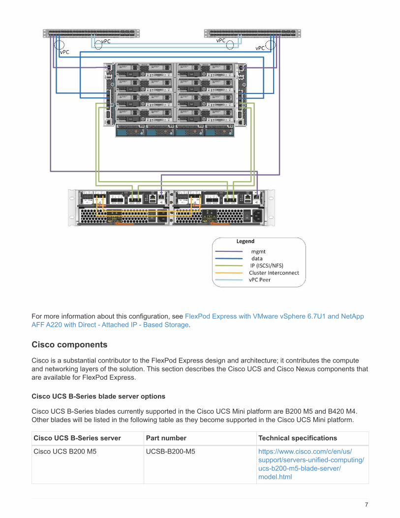
For more information about this configuration, see FlexPod Express with VMware vSphere 6.7U1 and NetAppAFF A220 with Direct - Attached IP - Based Storage.
Cisco components
Cisco is a substantial contributor to the FlexPod Express design and architecture; it contributes the computeand networking layers of the solution. This section describes the Cisco UCS and Cisco Nexus components thatare available for FlexPod Express.
Cisco UCS B-Series blade server options
Cisco UCS B-Series blades currently supported in the Cisco UCS Mini platform are B200 M5 and B420 M4.Other blades will be listed in the following table as they become supported in the Cisco UCS Mini platform.
Cisco UCS B-Series server Part number Technical specifications
Cisco UCS B200 M5 UCSB-B200-M5 https://www.cisco.com/c/en/us/support/servers-unified-computing/ucs-b200-m5-blade-server/model.html
7

Cisco UCS B-Series server Part number Technical specifications
Cisco UCS B200 M4 UCSB-B200-M4 http://www.cisco.com/c/dam/en/us/products/collateral/servers-unified-computing/ucs-b-series-blade-servers/b200m4-specsheet.pdf
Cisco UCS B420 M4 UCSB-B420-M4 http://www.cisco.com/c/dam/en/us/products/collateral/servers-unified-computing/ucs-b-series-blade-servers/b420m4-spec-sheet.pdf
Cisco UCS C-Series rack server options
Cisco UCS C-Series blades are available in one-rack and two-rack unit (RU) varieties, with various CPU,memory, and I/O options. The part numbers listed in the following table are for the base server; they do notinclude CPUs, memory, disk drives, PCIe cards, or the Cisco FEX. Multiple configuration options are availableand supported in FlexPod.
Cisco UCS C-Series rack server Part number Technical specifications
Cisco UCS C220 M4 UCSC-C220-M4S http://www.cisco.com/c/dam/en/us/products/collateral/servers-unified-computing/ucs-c-series-rack-servers/c220m4-sff-spec-sheet.pdf
Cisco UCS C240 M4 UCSC-C240-M4S http://www.cisco.com/c/dam/en/us/products/collateral/servers-unified-computing/ucs-c-series-rack-servers/c240m4-sff-spec-sheet.pdf
Cisco UCS C460 M4 UCSC-C460-M4 http://www.cisco.com/c/dam/en/us/products/collateral/servers-unified-computing/ucs-c-series-rack-servers/c460m4_specsheet.pdf
Cisco Nexus switches
Redundant switches are required for all FlexPod Express architectures.
The FlexPod Express with NetApp AFF or FAS architecture is built with the Cisco Nexus 31108 switch.FlexPod Express with the Cisco UCS Mini (Cisco UCS- managed) architecture is validated by using the CiscoNexus 3524 switch. This configuration can also be deployed with a standard switch.
The FlexPod Express with E-Series can be deployed with a standard switch.
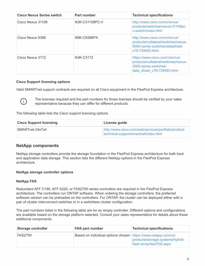
The following table lists the part numbers for the Cisco Nexus series chassis; they do not include additionalSFP or add-on modules.
Cisco Nexus Series switch Part number Technical specifications
Cisco Nexus 3048 N3K-C3048TP-1GE http://www.cisco.com/c/en/us/products/collateral/switches/nexus-3000-series-switches/data_sheet_c78-685363.html
8
Cisco Nexus Series switch Part number Technical specifications
Cisco Nexus 31108 N3K-C31108PC-V http://www.cisco.com/c/en/us/products/switches/nexus-31108pc-v-switch/index.html
Cisco Nexus 9396 N9K-C9396PX http://www.cisco.com/c/en/us/products/collateral/switches/nexus-9000-series-switches/datasheet-c78-729405.html
Cisco Nexus 3172 N3K-C3172 https://www.cisco.com/c/en/us/products/collateral/switches/nexus-3000-series-switches/data_sheet_c78-729483.html
Cisco Support licensing options
Valid SMARTnet support contracts are required on all Cisco equipment in the FlexPod Express architecture.
The licenses required and the part numbers for those licenses should be verified by your salesrepresentative because they can differ for different products.
The following table lists the Cisco support licensing options.
Cisco Support licensing License guide
SMARTnet 24x7x4 http://www.cisco.com/web/services/portfolio/product-technical-support/smartnet/index.html
NetApp components
NetApp storage controllers provide the storage foundation in the FlexPod Express architecture for both bootand application data storage. This section lists the different NetApp options in the FlexPod Expressarchitecture.
NetApp storage controller options
NetApp FAS
Redundant AFF C190, AFF A220, or FAS2750 series controllers are required in the FlexPod Expressarchitecture. The controllers run ONTAP software. When ordering the storage controllers, the preferredsoftware version can be preloaded on the controllers. For ONTAP, the cluster can be deployed either with apair of cluster interconnect switches or in a switchless cluster configuration.
The part numbers listed in the following table are for an empty controller. Different options and configurationsare available based on the storage platform selected. Consult your sales representative for details about theseadditional components.
Storage controller FAS part number Technical specifications
FAS2750 Based on individual options chosen https://www.netapp.com/us/products/storage-systems/hybrid-flash-array/fas2700.aspx
9
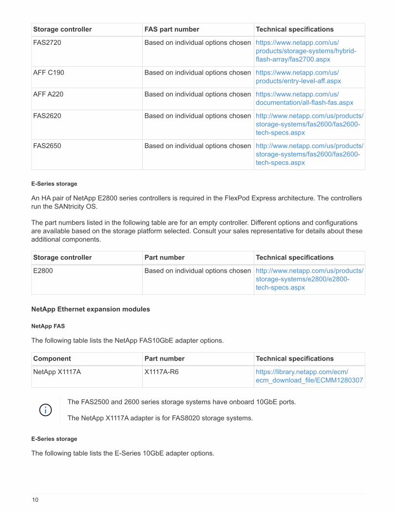
Storage controller FAS part number Technical specifications
FAS2720 Based on individual options chosen https://www.netapp.com/us/products/storage-systems/hybrid-flash-array/fas2700.aspx
AFF C190 Based on individual options chosen https://www.netapp.com/us/products/entry-level-aff.aspx
AFF A220 Based on individual options chosen https://www.netapp.com/us/documentation/all-flash-fas.aspx
FAS2620 Based on individual options chosen http://www.netapp.com/us/products/storage-systems/fas2600/fas2600-tech-specs.aspx
FAS2650 Based on individual options chosen http://www.netapp.com/us/products/storage-systems/fas2600/fas2600-tech-specs.aspx
E-Series storage
An HA pair of NetApp E2800 series controllers is required in the FlexPod Express architecture. The controllersrun the SANtricity OS.
The part numbers listed in the following table are for an empty controller. Different options and configurationsare available based on the storage platform selected. Consult your sales representative for details about theseadditional components.
Storage controller Part number Technical specifications
E2800 Based on individual options chosen http://www.netapp.com/us/products/storage-systems/e2800/e2800-tech-specs.aspx
NetApp Ethernet expansion modules
NetApp FAS
The following table lists the NetApp FAS10GbE adapter options.
Component Part number Technical specifications
NetApp X1117A X1117A-R6 https://library.netapp.com/ecm/ecm_download_file/ECMM1280307
The FAS2500 and 2600 series storage systems have onboard 10GbE ports.
The NetApp X1117A adapter is for FAS8020 storage systems.
E-Series storage
The following table lists the E-Series 10GbE adapter options.
10

Component Part number
10GbE iSCSI/16Gb FC 4-port X-56025-00-0E-C
10GbE iSCSI/16Gb FC 2-port X-56024-00-0E-C
The E2824 series storage systems have onboard 10GbE ports.
The 10GbE iSCSI/16Gb FC 4-port host interface card (HIC) can be used for additional portdensity.
The onboard ports and the HIC can function as iSCSI adapters or FC adapters depending on the featureactivated in SANtricity OS.
For more information about supported adapter options, see the Adapter section of NetApp Hardware Universe.
NetApp disk shelves and disks
NetApp FAS
A minimum of one NetApp disk shelf is required for storage controllers. The NetApp shelf type selecteddetermines which drive types are available within that shelf.
The FAS2700 and FAS2600 series of controllers are offered as a configuration that includes dual storagecontrollers plus disks housed within the same chassis. This configuration is offered with SATA or SAS drives;therefore, additional external disk shelves are not needed unless performance or capacity requirements dictatemore spindles.
All disk shelf part numbers are for the empty shelf with two AC PSUs. Consult your salesrepresentative for additional part numbers.
Disk drive part numbers vary according to the size and form factor of the disk you intend topurchase. Consult your sales representative for additional part numbers.
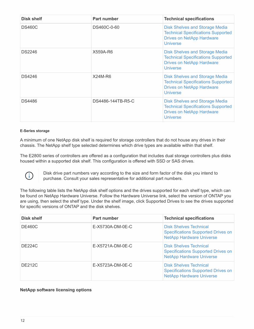
The following table lists the NetApp disk shelf options, along with the drives supported for each shelf type,which can be found on NetApp Hardware Universe. Follow the Hardware Universe link, select the version ofONTAP you are using, then select the shelf type. Under the shelf image, click Supported Drives to see thedrives supported for specific versions of ONTAP and the disk shelves.
Disk shelf Part number Technical specifications
DS212C DS212C-0-12 Disk Shelves and Storage MediaTechnical SpecificationsSupported Drives on NetAppHardware Universe
DS224C DS224C-0-24 Disk Shelves and Storage MediaTechnical SpecificationsSupported Drives on NetAppHardware Universe
11
Disk shelf Part number Technical specifications
DS460C DS460C-0-60 Disk Shelves and Storage MediaTechnical Specifications SupportedDrives on NetApp HardwareUniverse
DS2246 X559A-R6 Disk Shelves and Storage MediaTechnical Specifications SupportedDrives on NetApp HardwareUniverse
DS4246 X24M-R6 Disk Shelves and Storage MediaTechnical Specifications SupportedDrives on NetApp HardwareUniverse
DS4486 DS4486-144TB-R5-C Disk Shelves and Storage MediaTechnical Specifications SupportedDrives on NetApp HardwareUniverse
E-Series storage
A minimum of one NetApp disk shelf is required for storage controllers that do not house any drives in theirchassis. The NetApp shelf type selected determines which drive types are available within that shelf.
The E2800 series of controllers are offered as a configuration that includes dual storage controllers plus diskshoused within a supported disk shelf. This configuration is offered with SSD or SAS drives.
Disk drive part numbers vary according to the size and form factor of the disk you intend topurchase. Consult your sales representative for additional part numbers.
The following table lists the NetApp disk shelf options and the drives supported for each shelf type, which canbe found on NetApp Hardware Universe. Follow the Hardware Universe link, select the version of ONTAP youare using, then select the shelf type. Under the shelf image, click Supported Drives to see the drives supportedfor specific versions of ONTAP and the disk shelves.
Disk shelf Part number Technical specifications
DE460C E-X5730A-DM-0E-C Disk Shelves TechnicalSpecifications Supported Drives onNetApp Hardware Universe
DE224C E-X5721A-DM-0E-C Disk Shelves TechnicalSpecifications Supported Drives onNetApp Hardware Universe
DE212C E-X5723A-DM-0E-C Disk Shelves TechnicalSpecifications Supported Drives onNetApp Hardware Universe
NetApp software licensing options
12
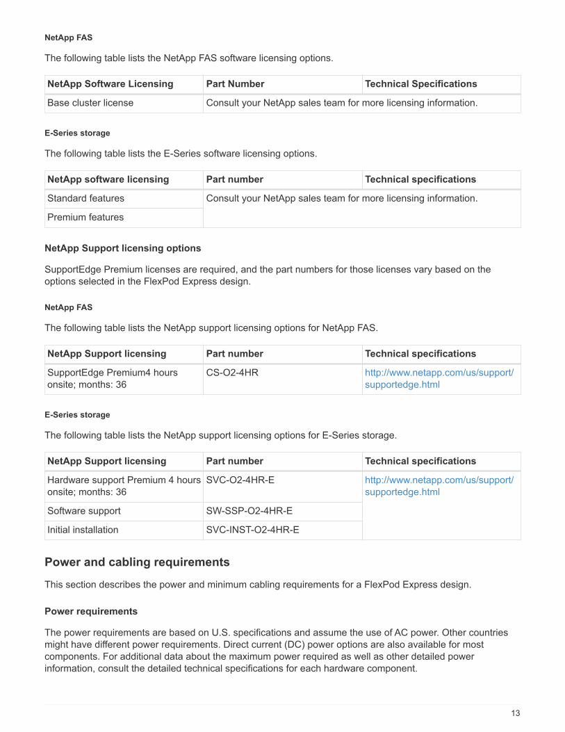
NetApp FAS
The following table lists the NetApp FAS software licensing options.
NetApp Software Licensing Part Number Technical Specifications
Base cluster license Consult your NetApp sales team for more licensing information.
E-Series storage
The following table lists the E-Series software licensing options.
NetApp software licensing Part number Technical specifications
Standard features Consult your NetApp sales team for more licensing information.
Premium features
NetApp Support licensing options
SupportEdge Premium licenses are required, and the part numbers for those licenses vary based on theoptions selected in the FlexPod Express design.
NetApp FAS
The following table lists the NetApp support licensing options for NetApp FAS.
NetApp Support licensing Part number Technical specifications
SupportEdge Premium4 hoursonsite; months: 36
CS-O2-4HR http://www.netapp.com/us/support/supportedge.html
E-Series storage
The following table lists the NetApp support licensing options for E-Series storage.
NetApp Support licensing Part number Technical specifications
Hardware support Premium 4 hoursonsite; months: 36
SVC-O2-4HR-E http://www.netapp.com/us/support/supportedge.html
Software support SW-SSP-O2-4HR-E
Initial installation SVC-INST-O2-4HR-E
Power and cabling requirements
This section describes the power and minimum cabling requirements for a FlexPod Express design.
Power requirements
The power requirements are based on U.S. specifications and assume the use of AC power. Other countriesmight have different power requirements. Direct current (DC) power options are also available for mostcomponents. For additional data about the maximum power required as well as other detailed powerinformation, consult the detailed technical specifications for each hardware component.
13

For detailed Cisco UCS power data, see the Cisco UCS Power Calculator.
The following table lists the power ports required per device.
Cisco Nexus switches Power cables required
Cisco Nexus 3048 2x C13/C14 power cables for each Cisco Nexus 3000series switch
Cisco Nexus 3524 2x C13/C14 power cables for each Cisco Nexus 3000series switch
Cisco Nexus 9396 2x C13/C14 power cables for each Cisco Nexus 9000series switch
Cisco UCS chassis Power cables required
Cisco UCS 5108 2 CAB-US515P-C19-US/CAB-US520-C19-US foreach Cisco UCS chassis
Cisco UCS B-Series servers Power cables required
Cisco UCS B200 M4 N/A; blade server is powered by chassis
Cisco UCS B420 M4 N/A; blade server is powered by chassis
Cisco UCS B200 M5 N/A; blade server is powered by chassis
Cisco UCS B480 M5 N/A; blade server is powered by chassis
Cisco UCS C-Series servers Power ports required
Cisco UCS C220 M4 2 x C13/C14 power cables for each Cisco UCS server
Cisco UCS C240 M4
Cisco UCS C460 M4Cisco UCS C220 M5Cisco UCS C240 M5Cisco UCS C480 M5
NetApp FAS controllers Power ports required (per HA pair)
FAS2554 2 x C13/C14
FAS2552 2 x C13/C14
FAS2520 2 x C13/C14
FAS8020 2 x C13/C14
E-Series controllers Power ports required (per HA pair)
E2824 2 x C14/C20
NetApp FAS disk shelves Power ports required
DS212C 2 x C13/C14
14

NetApp FAS disk shelves Power ports required
DS224C 2 x C13/C14
DS460C 2 x C13/C14
DS2246 2 x C13/C14
DS4246 4 x C13/C14
E-Series disk shelves Power ports required
DE460C 2 x C14/C20
DE224C 2 x C14/C20
DE212C 2 x C14/C20
Minimum cable requirements
This section describes the minimum cable requirements for a FlexPod Express design. Most FlexPodimplementations require additional cables, but the number varies based on the deployment size and scope.
The following table lists the minimum number of cables required for each device.
Cisco Nexus 3000 Series switches Cables required
Cisco Nexus 31108 At least two 10GbE fiber or Twinax cables per switch
Cisco Nexus 3172PQ
Cisco Nexus 3048
Cisco Nexus 3524
Cisco Nexus 9396
DS212C
DS2246 Number of SAS cables depends on specificconfiguration of disk shelves
DS460C
DS224C
DS4246
E2800 • At least one Gigabit Ethernet (1GbE) cable formanagement per controller
• At least two 10GbE cables per controller (foriSCSI) or two FC cables matching speedrequirements
DE460C 2 x mini-SAS HD cables per disk shelf
DE224C 2 x mini-SAS HD cables per disk shelf
DE212C 2 x mini-SAS HD cables per disk shelf
15

Technical Specifications and References
This section describes additional important technical specifications for each of the FlexPod Expresscomponents.
Cisco UCS B-Series blade servers
The following table lists the Cisco UCS B-Series blade server options.
Component Cisco UCS B200 M4 Cisco UCS B420 M4 Cisco UCS B200 M5
Processor support Intel Xeon E5-2600 Intel Xeon E5-4600 Intel XeonScalable processors
Maximum memorycapacity
24 DIMMs for a maximumof 768GB
48 DIMMs for a maximumof 3TB
24 DIMMs for a maximumof 3072GB
Memory size and speed 32GB DDR4; 2133MHz 64GB DDR4; 2400MHz 16GB, 32GB, 64GB, and128GB DDR4; 2666MHz
SAN boot support Yes Yes Yes
Mezzanine I/O adapterslots
2 3 2, front and rear, includingGPU support
I/O maximum throughput 80Gbps 160Gbps 80Gbps
Cisco UCS C-Series rack servers
The following table lists Cisco UCS C-Series rack server options.
Component Cisco UCS C220
M4
Cisco UCS C240
M4
Cisco UCS C460
M4
Cisco UCS C220
M5
Processor support 1 or 2 Intel E5-2600series
1 or 2 Intel Xeon E5-2600 series
2 or 4 Intel Xeon E7-4800/8800 series
Intel Xeon Scalableprocessors (1 or 2)
Maximum memorycapacity
1.5GB 1.5TB 6TB 3072GB
PCIe slots 2 6 10 2
Form factor 1RU 2RU 4RU 1 RU
The following table lists the datasheets for the Cisco UCS C-Series rack server options.
Component Cisco UCS datasheet
Cisco UCS C220 M4 http://www.cisco.com/c/dam/en/us/products/collateral/servers-unified-computing/ucs-c-series-rack-servers/c220m4-sff-spec-sheet.pdf
Cisco UCS C240 M4 http://www.cisco.com/c/en/us/products/collateral/servers-unified-computing/ucs-c240-m4-rack-server/datasheet-c78-732455.html
16
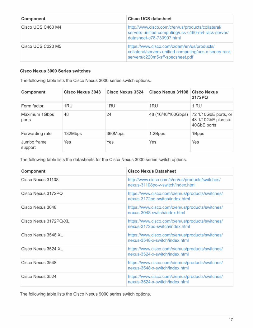
Component Cisco UCS datasheet
Cisco UCS C460 M4 http://www.cisco.com/c/en/us/products/collateral/servers-unified-computing/ucs-c460-m4-rack-server/datasheet-c78-730907.html
Cisco UCS C220 M5 https://www.cisco.com/c/dam/en/us/products/collateral/servers-unified-computing/ucs-c-series-rack-servers/c220m5-sff-specsheet.pdf
Cisco Nexus 3000 Series switches
The following table lists the Cisco Nexus 3000 series switch options.
Component Cisco Nexus 3048 Cisco Nexus 3524 Cisco Nexus 31108 Cisco Nexus
3172PQ
Form factor 1RU 1RU 1RU 1 RU
Maximum 1Gbpsports
48 24 48 (10/40/100Gbps) 72 1/10GbE ports, or48 1/10GbE plus six40GbE ports
Forwarding rate 132Mbps 360Mbps 1.2Bpps 1Bpps
Jumbo framesupport
Yes Yes Yes Yes
The following table lists the datasheets for the Cisco Nexus 3000 series switch options.
Component Cisco Nexus Datasheet
Cisco Nexus 31108 http://www.cisco.com/c/en/us/products/switches/nexus-31108pc-v-switch/index.html
Cisco Nexus 3172PQ https://www.cisco.com/c/en/us/products/switches/nexus-3172pq-switch/index.html
Cisco Nexus 3048 https://www.cisco.com/c/en/us/products/switches/nexus-3048-switch/index.html
Cisco Nexus 3172PQ-XL https://www.cisco.com/c/en/us/products/switches/nexus-3172pq-switch/index.html
Cisco Nexus 3548 XL https://www.cisco.com/c/en/us/products/switches/nexus-3548-x-switch/index.html
Cisco Nexus 3524 XL https://www.cisco.com/c/en/us/products/switches/nexus-3524-x-switch/index.html
Cisco Nexus 3548 https://www.cisco.com/c/en/us/products/switches/nexus-3548-x-switch/index.html
Cisco Nexus 3524 https://www.cisco.com/c/en/us/products/switches/nexus-3524-x-switch/index.html
The following table lists the Cisco Nexus 9000 series switch options.
17
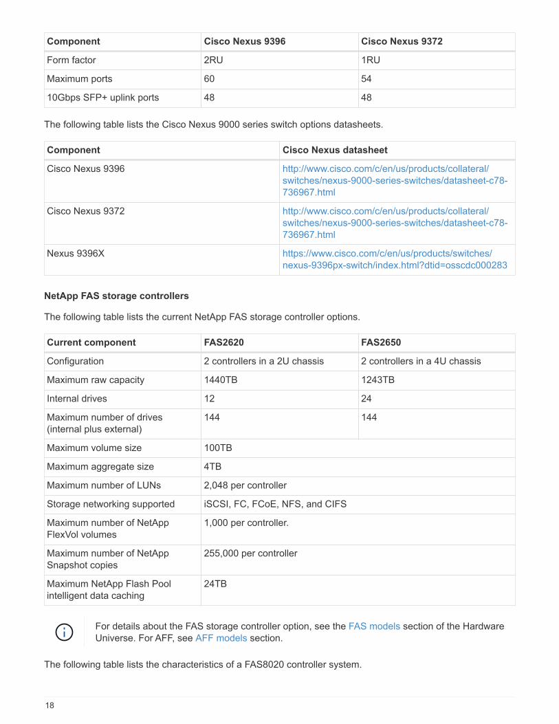
Component Cisco Nexus 9396 Cisco Nexus 9372
Form factor 2RU 1RU
Maximum ports 60 54
10Gbps SFP+ uplink ports 48 48
The following table lists the Cisco Nexus 9000 series switch options datasheets.
Component Cisco Nexus datasheet
Cisco Nexus 9396 http://www.cisco.com/c/en/us/products/collateral/switches/nexus-9000-series-switches/datasheet-c78-736967.html
Cisco Nexus 9372 http://www.cisco.com/c/en/us/products/collateral/switches/nexus-9000-series-switches/datasheet-c78-736967.html
Nexus 9396X https://www.cisco.com/c/en/us/products/switches/nexus-9396px-switch/index.html?dtid=osscdc000283
NetApp FAS storage controllers
The following table lists the current NetApp FAS storage controller options.
Current component FAS2620 FAS2650
Configuration 2 controllers in a 2U chassis 2 controllers in a 4U chassis
Maximum raw capacity 1440TB 1243TB
Internal drives 12 24
Maximum number of drives(internal plus external)
144 144
Maximum volume size 100TB
Maximum aggregate size 4TB
Maximum number of LUNs 2,048 per controller
Storage networking supported iSCSI, FC, FCoE, NFS, and CIFS
Maximum number of NetAppFlexVol volumes
1,000 per controller.
Maximum number of NetAppSnapshot copies
255,000 per controller
Maximum NetApp Flash Poolintelligent data caching
24TB
For details about the FAS storage controller option, see the FAS models section of the HardwareUniverse. For AFF, see AFF models section.
The following table lists the characteristics of a FAS8020 controller system.
18
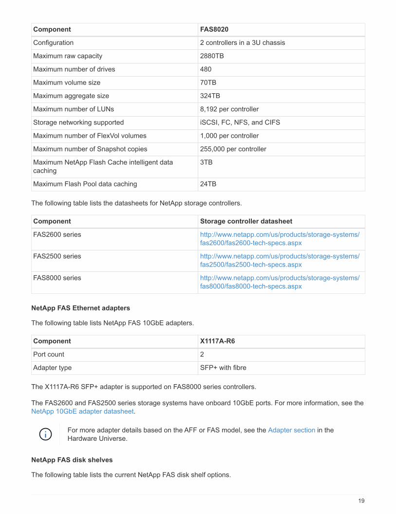
Component FAS8020
Configuration 2 controllers in a 3U chassis
Maximum raw capacity 2880TB
Maximum number of drives 480
Maximum volume size 70TB
Maximum aggregate size 324TB
Maximum number of LUNs 8,192 per controller
Storage networking supported iSCSI, FC, NFS, and CIFS
Maximum number of FlexVol volumes 1,000 per controller
Maximum number of Snapshot copies 255,000 per controller
Maximum NetApp Flash Cache intelligent datacaching
3TB
Maximum Flash Pool data caching 24TB
The following table lists the datasheets for NetApp storage controllers.
Component Storage controller datasheet
FAS2600 series http://www.netapp.com/us/products/storage-systems/fas2600/fas2600-tech-specs.aspx
FAS2500 series http://www.netapp.com/us/products/storage-systems/fas2500/fas2500-tech-specs.aspx
FAS8000 series http://www.netapp.com/us/products/storage-systems/fas8000/fas8000-tech-specs.aspx
NetApp FAS Ethernet adapters
The following table lists NetApp FAS 10GbE adapters.
Component X1117A-R6
Port count 2
Adapter type SFP+ with fibre
The X1117A-R6 SFP+ adapter is supported on FAS8000 series controllers.
The FAS2600 and FAS2500 series storage systems have onboard 10GbE ports. For more information, see theNetApp 10GbE adapter datasheet.
For more adapter details based on the AFF or FAS model, see the Adapter section in theHardware Universe.
NetApp FAS disk shelves
The following table lists the current NetApp FAS disk shelf options.
19

Component DS460C DS224C DS212C DS2246 DS4246
Form factor 4RU 2RU 2RU 2RU 4RU
Drives perenclosure
60 24 12 24 24
Drive form factor 3.5" large formfactor
2.5" small formfactor
3.5" large formfactor
2.5" small formfactor
3.5" large formfactor
Shelf I/Omodules
Dual IOM12modules
Dual IOM12modules
Dual IOM12modules
Dual IOM6modules
Dual IOM6modules
For more information, see the NetApp disk shelves datasheet.
For more information about the disk shelves, see the NetApp Hardware Universe Disk Shelvessection.
NetApp FAS disk drives
The technical specifications for the NetApp disks include form factor size, disk capacity, disk RPM, supportingcontrollers, and Data ONTAP version requirements and are located in the Drives section on NetApp HardwareUniverse.
E-Series storage controllers
The following table lists the current E-Series storage controller options.
Current Component E2812 E2824 E2860
Configuration 2 controllers in a 2Uchassis
2 controllers in a 2Uchassis
2 controllers in a 4Uchassis
Maximum raw capacity 1800TB 1756.8TB 1800TB
Internal drives 12 24 60
Maximum number ofdrives (internal plusexternal)
180
Maximum SSD 120
Maximum volume size fordisk pool volume
1024TB
Maximum disk pools 20
Storage networkingsupported
iSCSI and FC
Maximum number ofvolumes
512
The following table lists the datasheets for the current E-Series storage controller.
20
Component Storage controller datasheet
E2800 http://www.netapp.com/us/media/ds-3805.pdf
E-Series adapters
The following table lists the E-Series adapters.
Component X-56023-00-0E-
C
X-56025-00-0E-
C
X-56027-00-0E-
C
X-56024-00-0E-
C
X-56026-00-0E-
C
Port count 2 4 4 2 2
Adapter type 10Gb Base-T 16G FC and10GbE iSCSI
SAS 16G FC and10GbE iSCSI
SAS
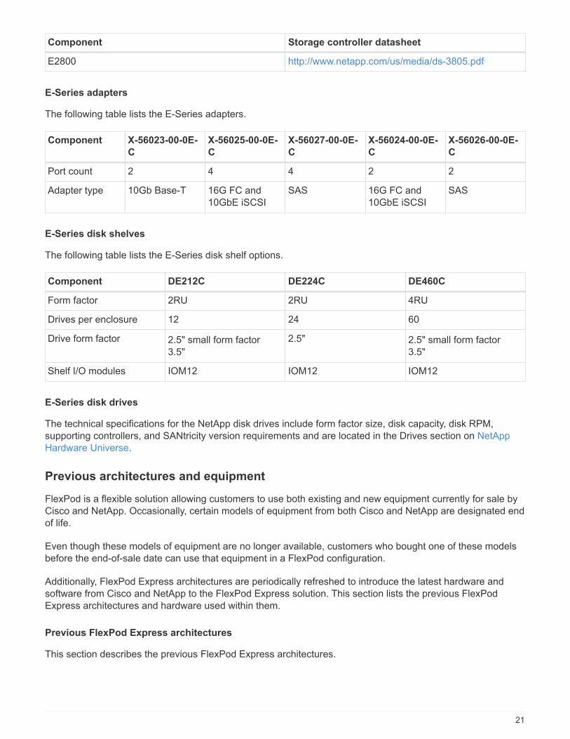
E-Series disk shelves
The following table lists the E-Series disk shelf options.
Component DE212C DE224C DE460C
Form factor 2RU 2RU 4RU
Drives per enclosure 12 24 60
Drive form factor 2.5" small form factor3.5"
2.5" 2.5" small form factor3.5"
Shelf I/O modules IOM12 IOM12 IOM12
E-Series disk drives
The technical specifications for the NetApp disk drives include form factor size, disk capacity, disk RPM,supporting controllers, and SANtricity version requirements and are located in the Drives section on NetAppHardware Universe.
Previous architectures and equipment
FlexPod is a flexible solution allowing customers to use both existing and new equipment currently for sale byCisco and NetApp. Occasionally, certain models of equipment from both Cisco and NetApp are designated endof life.
Even though these models of equipment are no longer available, customers who bought one of these modelsbefore the end-of-sale date can use that equipment in a FlexPod configuration.
Additionally, FlexPod Express architectures are periodically refreshed to introduce the latest hardware andsoftware from Cisco and NetApp to the FlexPod Express solution. This section lists the previous FlexPodExpress architectures and hardware used within them.
Previous FlexPod Express architectures
This section describes the previous FlexPod Express architectures.
21
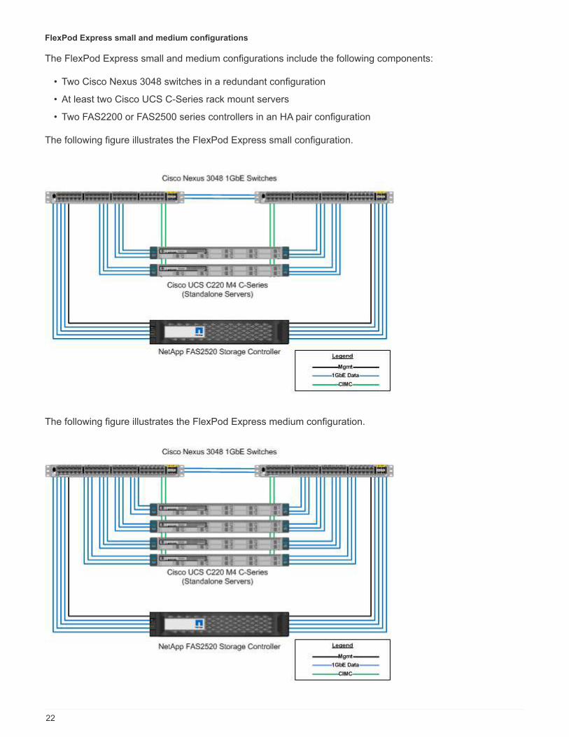
FlexPod Express small and medium configurations
The FlexPod Express small and medium configurations include the following components:
• Two Cisco Nexus 3048 switches in a redundant configuration
• At least two Cisco UCS C-Series rack mount servers
• Two FAS2200 or FAS2500 series controllers in an HA pair configuration
The following figure illustrates the FlexPod Express small configuration.
The following figure illustrates the FlexPod Express medium configuration.
22

FlexPod Express large configuration
The FlexPod Express large configuration includes the following components:
• Two Cisco Nexus 3500 series or Cisco Nexus 9300 series switches in a redundant configuration
• At least two Cisco UCS C-Series rack mount servers
• Two FAS2552, FAS2554, or FAS8020 controllers in an HA pair configuration (requires two 10GbE ports percontroller)
• One NetApp disk shelf with any supported disk type (when the FAS8020 is used)
The following figure illustrates the FlexPod Express large configuration.
Previous FlexPod Express verified architectures
Previous FlexPod Express verified architectures are still supported. The architecture and deploymentdocuments include:
• FlexPod Express with Cisco UCS C-Series and NetApp FAS2500 Series
• FlexPod Express with VMware vSphere 6.0: Small and Medium Configurations
• FlexPod Express with VMware vSphere 6.0: Large Configuration
• FlexPod Express with Microsoft Windows Server 2012 R2 Hyper-V: Small and Medium Configurations
• FlexPod Express with Microsoft Windows Server 2012 R2 Hyper-V: Large Configuration
Previous hardware
The following table lists the hardware used in previous FlexPod Express architectures.
23
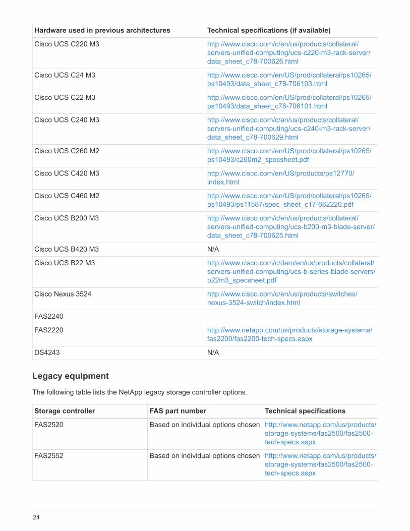
Hardware used in previous architectures Technical specifications (if available)
Cisco UCS C220 M3 http://www.cisco.com/c/en/us/products/collateral/servers-unified-computing/ucs-c220-m3-rack-server/data_sheet_c78-700626.html
Cisco UCS C24 M3 http://www.cisco.com/en/US/prod/collateral/ps10265/ps10493/data_sheet_c78-706103.html
Cisco UCS C22 M3 http://www.cisco.com/en/US/prod/collateral/ps10265/ps10493/data_sheet_c78-706101.html
Cisco UCS C240 M3 http://www.cisco.com/c/en/us/products/collateral/servers-unified-computing/ucs-c240-m3-rack-server/data_sheet_c78-700629.html
Cisco UCS C260 M2 http://www.cisco.com/en/US/prod/collateral/ps10265/ps10493/c260m2_specsheet.pdf
Cisco UCS C420 M3 http://www.cisco.com/en/US/products/ps12770/index.html
Cisco UCS C460 M2 http://www.cisco.com/en/US/prod/collateral/ps10265/ps10493/ps11587/spec_sheet_c17-662220.pdf
Cisco UCS B200 M3 http://www.cisco.com/c/en/us/products/collateral/servers-unified-computing/ucs-b200-m3-blade-server/data_sheet_c78-700625.html
Cisco UCS B420 M3 N/A
Cisco UCS B22 M3 http://www.cisco.com/c/dam/en/us/products/collateral/servers-unified-computing/ucs-b-series-blade-servers/b22m3_specsheet.pdf
Cisco Nexus 3524 http://www.cisco.com/c/en/us/products/switches/nexus-3524-switch/index.html
FAS2240
FAS2220 http://www.netapp.com/us/products/storage-systems/fas2200/fas2200-tech-specs.aspx
DS4243 N/A
Legacy equipment
The following table lists the NetApp legacy storage controller options.
Storage controller FAS part number Technical specifications
FAS2520 Based on individual options chosen http://www.netapp.com/us/products/storage-systems/fas2500/fas2500-tech-specs.aspx
FAS2552 Based on individual options chosen http://www.netapp.com/us/products/storage-systems/fas2500/fas2500-tech-specs.aspx
24

Storage controller FAS part number Technical specifications
FAS2554 Based on individual options chosen http://www.netapp.com/us/products/storage-systems/fas2500/fas2500-tech-specs.aspx
FAS8020 Based on individual options chosen http://www.netapp.com/us/products/storage-systems/fas8000/fas8000-tech-specs.aspx
The following table lists the NetApp legacy disk shelf options for NetApp FAS.
Disk shelf Part number Technical specifications
DE1600 E-X5682A-DM-0E-R6-C Disk Shelves TechnicalSpecifications Supported Drives onNetApp Hardware Universe
DE5600 E-X4041A-12-R6 Disk Shelves TechnicalSpecifications Supported Drives onNetApp Hardware Universe
DE6600 X-48564-00-R6 Disk Shelves TechnicalSpecifications Supported Drives onNetApp Hardware Universe
NetApp legacy FAS controllers
The following table lists the legacy NetApp FAS controller options.
Current component FAS2554 FAS2552 FAS2520
Configuration 2 controllers in a 4Uchassis
2 controllers in a 2Uchassis
2 controllers in a 2Uchassis
Maximum raw capacity 576TB 509TB 336TB
Internal drives 24 24 12
Maximum number ofdrives (internal plusexternal)
144 144 84
Maximum volume size 60TB
Maximum aggregate size 120TB
Maximum number ofLUNs
2,048 per controller
Storage networkingsupported
iSCSI, FC, FCoE, NFS, and CIFS iSCSI, NFS, and CIFS
Maximum number ofNetApp FlexVol volumes
1,000 per controller
Maximum number ofNetApp Snapshot copies
255,000 per controller
25

For more NetApp FAS models, see the FAS models section in the Hardware Universe.
Additional Information
To learn more about the information that is described in this document, see the following documents andwebsites:
• AFF and FAS System Documentation Center
https://docs.netapp.com/platstor/index.jsp
• AFF Documentation Resources page
https://www.netapp.com/us/documentation/all-flash-fas.aspx
• FAS Storage Systems Documentation Resources page
https://www.netapp.com/us/documentation/fas-storage-systems.aspx
• FlexPod
https://flexpod.com/
• NetApp documentation
https://docs.netapp.com
FlexPod Datacenter Technical Specifications
TR-4036: FlexPod Datacenter Technical Specifications
Arvind Ramakrishnan, and Jyh-shing Chen, NetApp
The FlexPod platform is a predesigned, best practice data center architecture that is built on the Cisco UnifiedComputing System (Cisco UCS), the Cisco Nexus family of switches, and NetApp storage controllers (AFF,ASA, or FAS systems).
FlexPod is a suitable platform for running a variety of virtualization hypervisors as well as bare-metal operatingsystems and enterprise workloads. FlexPod delivers not only a baseline configuration, but also the flexibility tobe sized and optimized to accommodate many different use cases and requirements.
Before you order a complete FlexPod configuration, see the FlexPod Converged Infrastructurepage on netapp.com for the latest version of these technical specifications.
Next: FlexPod platforms.
FlexPod platforms
There are two FlexPod platforms:
• FlexPod Datacenter. This platform is a massively scalable virtual data center infrastructure that is suitedfor workload enterprise applications; virtualization; virtual desktop infrastructure (VDI); and public, private,
26
and hybrid cloud workloads.
• FlexPod Express. This platform is a compact converged infrastructure that is targeted to remote office andedge use cases. FlexPod Express has its own specifications that are documented in the FlexPod ExpressTechnical Specifications.
This document provides the technical specifications for the FlexPod Datacenter platform.
FlexPod rules
The FlexPod design enables a flexible infrastructure that encompasses many different components andsoftware versions.
Use the rule sets as a guide for building or assembling a valid FlexPod configuration. The numbers and rulesthat are listed in this document are the minimum requirements for a FlexPod configuration. They can beexpanded in the included product families as required for different environments and use cases.
Supported versus validated FlexPod configurations
The FlexPod architecture is defined by the set of rules that are described in this document. The hardwarecomponents and software configurations must be supported by the Cisco UCS Hardware and SoftwareCompatibility List and the NetApp Interoperability Matrix Tool (IMT).
Each Cisco Validated Design (CVD) or NetApp Verified Architecture (NVA) is a possible FlexPod configuration.Cisco and NetApp document these configuration combinations and validate them with extensive end-to-endtesting. The FlexPod deployments that deviate from these configurations are fully supported if they follow theguidelines in this document and if all the components are listed as compatible in the Cisco UCS Hardware andSoftware Compatibility List and the NetApp IMT.
For example, adding more storage controllers or Cisco UCS Servers and upgrading software to newer versionsare fully supported if the software, hardware, and configurations meet the guidelines that are defined in thisdocument.
NetApp ONTAP
NetApp ONTAP software is installed on all NetApp FAS, AFF, and AFF All SAN Array (ASA) systems. FlexPodis validated with ONTAP software, providing a highly scalable storage architecture that enables nondisruptiveoperations, nondisruptive upgrades, and an agile data infrastructure.
For more information about ONTAP, see the ONTAP Data Management Software product page.
Cisco Nexus switching modes of operation
A variety of Cisco Nexus products can be used as the switching component of a given FlexPod deployment.Most of these options leverage the traditional Cisco Nexus OS or NX-OS software. The Cisco Nexus family ofswitches offers varying capabilities within its product lines. These capabilities are detailed later in thisdocument.
Cisco’s offering in the software-defined networking space is called Application Centric Infrastructure (ACI). TheCisco Nexus product line that supports the ACI mode, also called fabric mode, is the Cisco Nexus 9300 series.These switches can also be deployed in NX-OS or standalone mode.
Cisco ACI is targeted at data center deployments that focus on the requirements of a specific application.Applications are instantiated through a series of profiles and contracts that allow connectivity from the host orvirtual machine (VM) all the way through the network to the storage.
27
FlexPod is validated with both modes of operation of the Cisco Nexus switches. For more information aboutthe ACI and the NX-OS modes, see the following Cisco pages:
• Cisco Application Centric Infrastructure
• Cisco NX-OS Software
Minimum hardware requirements
A FlexPod Datacenter configuration has minimum hardware requirements, including, but not limited to,switches, fabric interconnects, servers, and NetApp storage controllers.
You must use Cisco UCS Servers. Both C-Series and B-Series Servers have been used in the validateddesigns. Cisco Nexus Fabric Extenders (FEXs) are optional with C-Series Servers.
A FlexPod configuration has the following minimum hardware requirements:
• Two Cisco Nexus switches in a redundant configuration. This configuration can consist of two redundantswitches from the Cisco Nexus 5000, 7000, or 9000 Series. The two switches should be of the same modeland should be configured in the same mode of operation.
If you are deploying an ACI architecture, you must observe the following additional requirements:
◦ Deploy the Cisco Nexus 9000 Series Switches in a leaf-spine topology.
◦ Use three Cisco Application Policy Infrastructure Controllers (APICs).
• Two Cisco UCS 6200, 6300, or 6400 Series Fabric Interconnects in a redundant configuration.
• Cisco UCS Servers:
◦ If the solution uses B-Series Servers, one Cisco UCS 5108 B-Series Blade Server Chassis plus twoCisco UCS B-Series Blade Servers plus two 2104, 2204/8, 2408, or 2304 I/O modules (IOMs).
◦ If the solution uses C-Series Servers, two Cisco UCS C-Series Rack Servers.
For larger deployments of Cisco UCS C-Series Rack Servers, you can choose a pair of 2232PP FEXmodules. However, the 2232PP is not a hardware requirement.
• Two NetApp storage controllers in a high-availability (HA) pair configuration:
This configuration can consist of any supported NetApp FAS, AFF, or ASA-series storage controllers. Seethe NetApp Hardware Universe application for a current list of supported FAS, AFF, and ASA controllermodels.
◦ The HA configuration requires two redundant interfaces per controller for data access; the interfacescan be FCoE, FC, or 10/25/100Gb Ethernet (GbE).
◦ If the solution uses NetApp ONTAP, a cluster interconnect topology that is approved by NetApp isrequired. For more information, see the Switches tab of the NetApp Hardware Universe.
◦ If the solution uses ONTAP, at least two additional 10/25/100GbE ports per controller are required fordata access.
◦ For ONTAP clusters with two nodes, you can configure a two-node switchless cluster.
◦ For ONTAP clusters with more than two nodes, a pair of cluster interconnect switches are required.
• One NetApp disk shelf with any supported disk type. See the Shelves tab of the NetApp HardwareUniverse for a current list of supported disk shelf models.
28
Minimum software requirements
A FlexPod configuration has the following minimum software requirements:
• NetApp ONTAP:
◦ ONTAP software version requires ONTAP 9.1 or later
• Cisco UCS Manager releases:
◦ Cisco UCS 6200 Series Fabric Interconnect—2.2(8a)
◦ Cisco UCS 6300 Series Fabric Interconnect—3.1(1e)
◦ Cisco UCS 6400 Series Fabric Interconnect—4.0(1)
• Cisco Intersight Managed Mode:
◦ Cisco UCS 6400 Series Fabric Interconnect – 4.1(2)
• For Cisco Nexus 5000 Series Switches, Cisco NX-OS software release 5.0(3)N1(1c) or later, including NX-OS 5.1.x
• For Cisco Nexus 7000 Series Switches:
◦ The 4-slot chassis requires Cisco NX-OS software release 6.1(2) or later
◦ The 9-slot chassis requires Cisco NX-OS software release 5.2 or later
◦ The 10-slot chassis requires Cisco NX-OS software release 4.0 or later
◦ The 18-slot chassis requires Cisco NX-OS software release 4.1 or later
• For Cisco Nexus 9000 Series Switches, Cisco NX-OS software release 6.1(2) or later
The software that is used in a FlexPod configuration must be listed and supported in the NetAppIMT. Some features might require more recent releases of the software than the ones that arelisted.
Connectivity requirements
A FlexPod configuration has the following connectivity requirements:
• A separate 100Mbps Ethernet/1Gb Ethernet out-of-band management network is required for allcomponents.
• NetApp recommends that you enable jumbo frame support throughout the environment, but it is notrequired.
• The Cisco UCS Fabric Interconnect appliance ports are recommended only for iSCSI and NASconnections.
• No additional equipment can be placed in line between the core FlexPod components.
Uplink connections:
• The ports on the NetApp storage controllers must be connected to the Cisco Nexus 5000, 7000, or 9000Series Switches to enable support for virtual port channels (vPCs).
• vPCs are required from the Cisco Nexus 5000, 7000, or 9000 Series Switches to the NetApp storagecontrollers.
• vPCs are required from the Cisco Nexus 5000, 7000, or 9000 Series Switches to the fabric interconnects.
29

• A minimum two connections are required for a vPC. The number of connections within a vPC can beincreased based on the application load and performance requirements.
Direct connections:
• NetApp storage controller ports that are directly connected to the fabric interconnects can be grouped toenable a port channel. vPC is not supported for this configuration.
• FCoE port channels are recommended for end-to-end FCoE designs.
SAN boot:
• FlexPod solutions are designed around a SAN-boot architecture using iSCSI, FC, or FCoE protocols. Usingboot-from-SAN technologies provides the most flexible configuration for the data center infrastructure andenables the rich features available within each infrastructure component. Although booting from SAN is themost efficient configuration, booting from local server storage is a valid and supported configuration.
• SAN boot over FC-NVME is not supported.
Other requirements
A FlexPod architecture has the following additional interoperability and support-related requirements:
• All hardware and software components must be listed and supported on the NetApp IMT, the Cisco UCSHardware and Software Compatibility List, and the Cisco UCS Hardware and Software InteroperabilityMatrix Tool.
• Valid support contracts are required for all equipment, including:
◦ Smart Net Total Care (SmartNet) support for Cisco equipment
◦ SupportEdge Advisor or SupportEdge Premium support for NetApp equipment
For more information, see the NetApp IMT.
Optional features
NetApp supports several optional components to further enhance FlexPod Datacenter architectures. Optionalcomponents are outlined in the following subsections.
MetroCluster
FlexPod supports both variants of the NetApp MetroCluster software for continuous availability, in either two- orfour-node cluster configurations. MetroCluster provides synchronous replication for critical workloads. Itrequires a dual-site configuration that is connected with Cisco switching. The maximum supported distancebetween the sites is approximately 186 miles (300km) for MetroCluster FC and increases to approximately 435miles (700km) for MetroCluster IP. The following figures illustrate a FlexPod Datacenter with NetAppMetroCluster architecture and FlexPod Datacenter with NetApp MetroCluster IP architecture, respectively.
The following figure depicts FlexPod Datacenter with NetApp MetroCluster architecture.
30

The following figure depicts the FlexPod Datacenter with NetApp MetroCluster IP architecture.
31

Starting with ONTAP 9.8, ONTAP Mediator can be deployed at a third site to monitor the MetroCluster IPsolution and to facilitate automated unplanned switchover when a site disaster occurs.
For a FlexPod MetroCluster IP solution deployment with extended layer-2 site-to-site connectivity, you canachieve cost savings by sharing ISL and using FlexPod switches as compliant MetroCluster IP switches if thenetwork bandwidth and switches meet the requirements as illustrated in the following figure, which depicts theFlexPod MetroCluster IP solution with ISL sharing and compliant switches.
The following two figures depict the VXLAN Multi-Site fabric and the MetroCluster IP storage fabric for aFlexPod MetroCluster IP solution with VXLAN Multi-Site fabric deployment.
• VXLAN Multi-Site fabric for FlexPod MetroCluster IP solution
32

• MetroCluster IP storage fabric for FlexPod MetroCluster IP solution
End-to-end FC-NVMe
An end-to-end FC-NVMe seamlessly extends a customer’s existing SAN infrastructure for real-timeapplications while simultaneously delivering improved IOPS and throughput with reduced latency.
An existing 32G FC SAN transport can be used to simultaneously transport both NVMe and SCSI workloads.
33
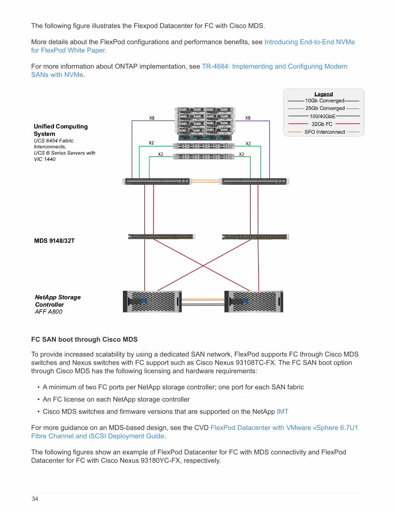
The following figure illustrates the Flexpod Datacenter for FC with Cisco MDS.
More details about the FlexPod configurations and performance benefits, see Introducing End-to-End NVMefor FlexPod White Paper.
For more information about ONTAP implementation, see TR-4684: Implementing and Configuring ModernSANs with NVMe.
FC SAN boot through Cisco MDS
To provide increased scalability by using a dedicated SAN network, FlexPod supports FC through Cisco MDSswitches and Nexus switches with FC support such as Cisco Nexus 93108TC-FX. The FC SAN boot optionthrough Cisco MDS has the following licensing and hardware requirements:
• A minimum of two FC ports per NetApp storage controller; one port for each SAN fabric
• An FC license on each NetApp storage controller
• Cisco MDS switches and firmware versions that are supported on the NetApp IMT
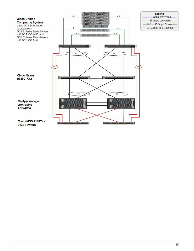
For more guidance on an MDS-based design, see the CVD FlexPod Datacenter with VMware vSphere 6.7U1Fibre Channel and iSCSI Deployment Guide.
The following figures show an example of FlexPod Datacenter for FC with MDS connectivity and FlexPodDatacenter for FC with Cisco Nexus 93180YC-FX, respectively.
34
35
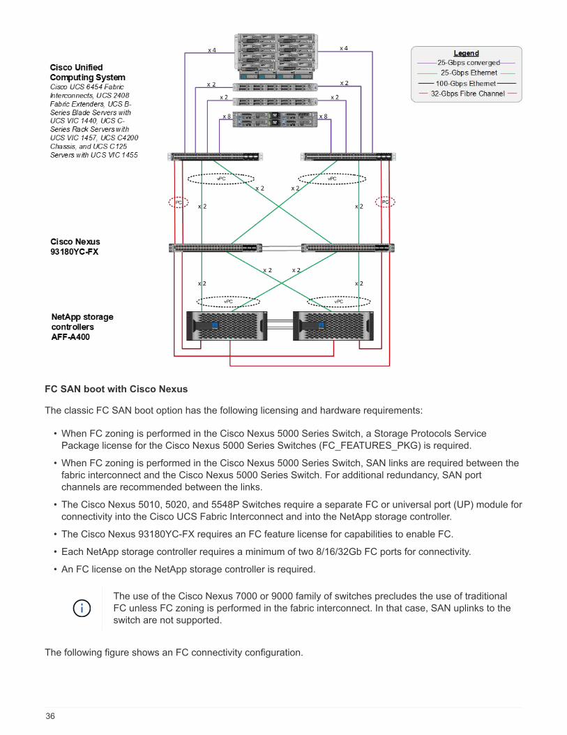
FC SAN boot with Cisco Nexus
The classic FC SAN boot option has the following licensing and hardware requirements:
• When FC zoning is performed in the Cisco Nexus 5000 Series Switch, a Storage Protocols ServicePackage license for the Cisco Nexus 5000 Series Switches (FC_FEATURES_PKG) is required.
• When FC zoning is performed in the Cisco Nexus 5000 Series Switch, SAN links are required between thefabric interconnect and the Cisco Nexus 5000 Series Switch. For additional redundancy, SAN portchannels are recommended between the links.
• The Cisco Nexus 5010, 5020, and 5548P Switches require a separate FC or universal port (UP) module forconnectivity into the Cisco UCS Fabric Interconnect and into the NetApp storage controller.
• The Cisco Nexus 93180YC-FX requires an FC feature license for capabilities to enable FC.
• Each NetApp storage controller requires a minimum of two 8/16/32Gb FC ports for connectivity.
• An FC license on the NetApp storage controller is required.
The use of the Cisco Nexus 7000 or 9000 family of switches precludes the use of traditionalFC unless FC zoning is performed in the fabric interconnect. In that case, SAN uplinks to theswitch are not supported.
The following figure shows an FC connectivity configuration.
36
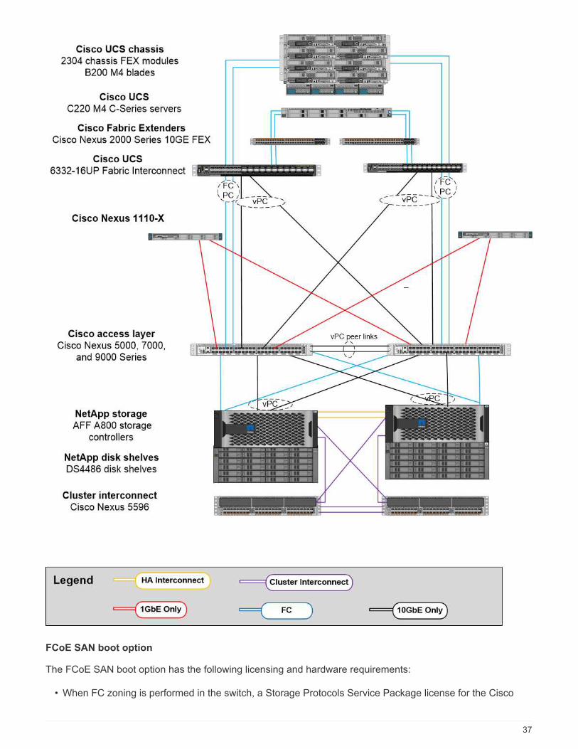
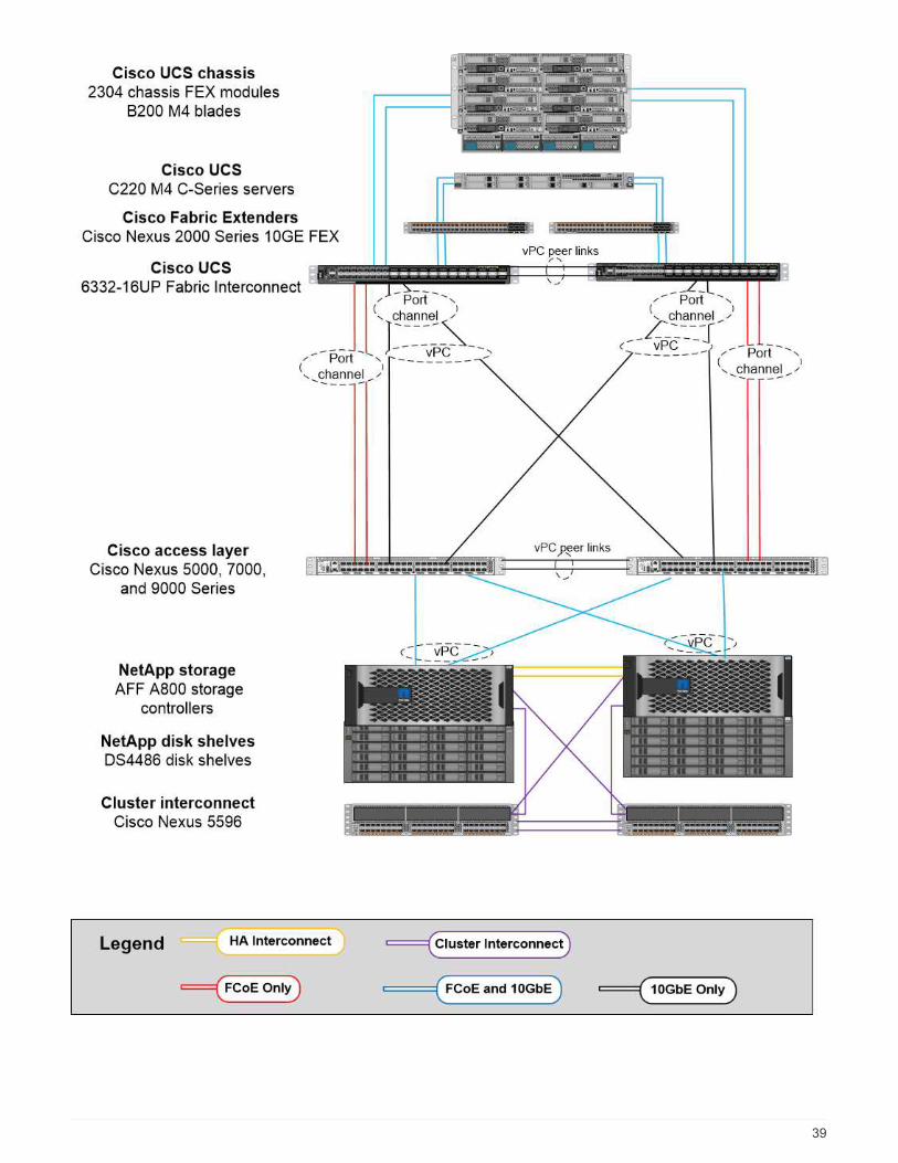
FCoE SAN boot option
The FCoE SAN boot option has the following licensing and hardware requirements:
• When FC zoning is performed in the switch, a Storage Protocols Service Package license for the Cisco
37

Nexus 5000 or 7000 Series Switches (FC_FEATURES_PKG) is required.
• When FC zoning is performed in the switch, FCoE uplinks are required between the fabric interconnect andthe Cisco Nexus 5000 or 7000 Series Switches. For additional redundancy, FCoE port channels are alsorecommended between the links.
• Each NetApp storage controller requires at least one dual-port unified target adapter (UTA) add-on card forFCoE connectivity unless onboard unified target adapter 2 (UTA2) ports are present.
• This option requires an FC license on the NetApp storage controller.
• If you use the Cisco Nexus 7000 Series Switches and FC zoning is performed in the switch, a line card thatis capable of supporting FCoE is required.
The use of the Cisco Nexus 9000 Series Switches precludes the use of FCoE unless FCzoning is performed in the fabric interconnect and storage is connected to the fabricinterconnects with appliance ports. In that case, FCoE uplinks to the switch are notsupported.
The following figure shows an FCoE boot scenario.
38
39

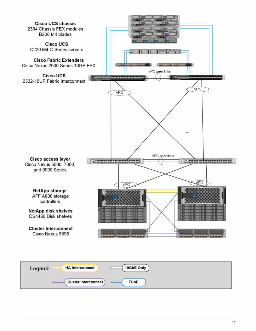
iSCSI boot option
The iSCSI boot option has the following licensing and hardware requirements:
• An iSCSI license on the NetApp storage controller is required.
• An adapter in the Cisco UCS Server that is capable of iSCSI boot is required.
• A two-port 10Gbps Ethernet adapter on the NetApp storage controller is required.
The following figure shows an Ethernet-only configuration that is booted by using iSCSI.
40
41
Cisco UCS direct connect with NetApp storage
NetApp AFF and FAS controllers can be directly connected to the Cisco UCS fabric interconnects without anyupstream SAN switch.
Four Cisco UCS port types can be used to directly connect to NetApp storage:
• Storage FC port. Directly connect this port to an FC port on NetApp storage.
• Storage FCoE port. Directly connect this port to an FCoE port on NetApp storage.
• Appliance port. Directly connect this port to a 10GbE port on NetApp storage.
• Unified storage port. Directly connect this port to a NetApp UTA.
The licensing and hardware requirements are as follows:
• A protocol license on the NetApp storage controller is required.
• A Cisco UCS adapter (initiator) is required on the server. For a list of supported Cisco UCS adapters, seethe NetApp IMT.
• A target adapter on the NetApp storage controller is required.
The following figure shows an FC direct-connect configuration.
42
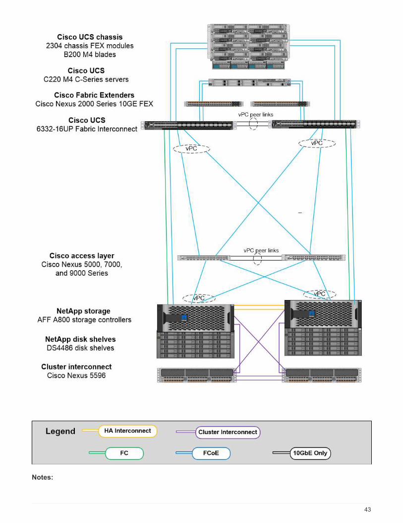
Notes:
43
• Cisco UCS is configured in FC switching mode.
• FCoE ports from the target to fabric interconnects are configured as FCoE storage ports.
• FC ports from the target to fabric interconnects are configured as FC storage ports.
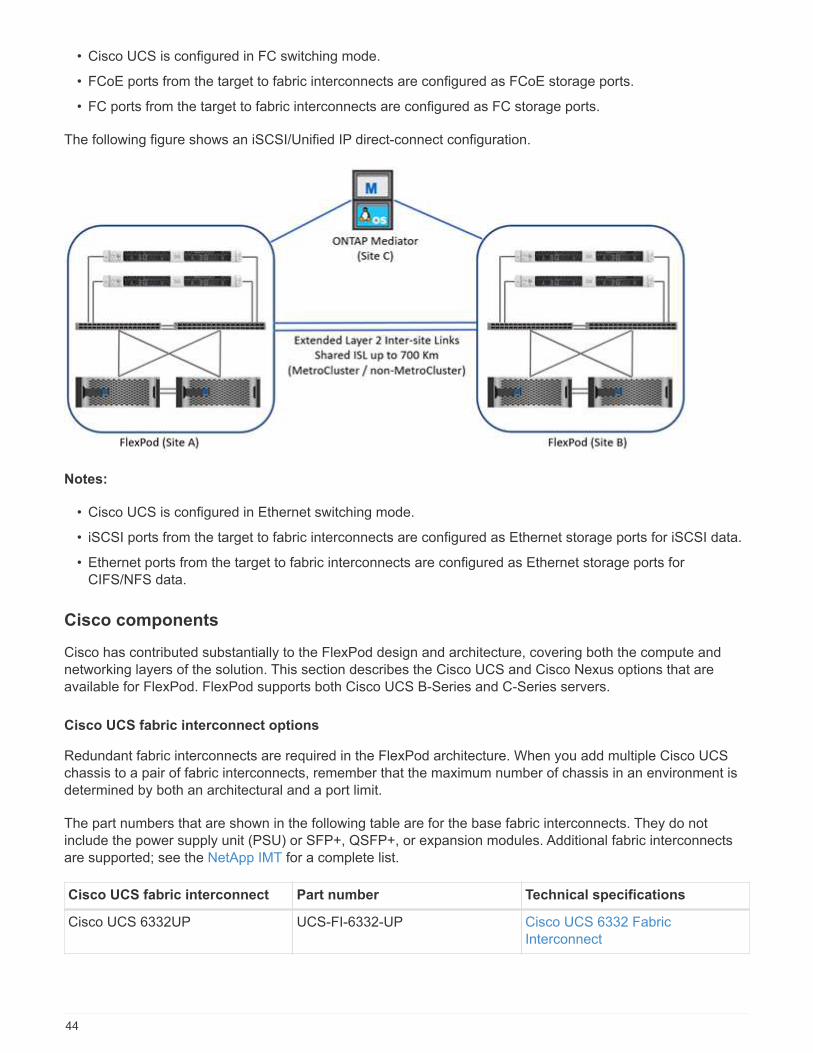
The following figure shows an iSCSI/Unified IP direct-connect configuration.
Notes:
• Cisco UCS is configured in Ethernet switching mode.
• iSCSI ports from the target to fabric interconnects are configured as Ethernet storage ports for iSCSI data.
• Ethernet ports from the target to fabric interconnects are configured as Ethernet storage ports forCIFS/NFS data.
Cisco components
Cisco has contributed substantially to the FlexPod design and architecture, covering both the compute andnetworking layers of the solution. This section describes the Cisco UCS and Cisco Nexus options that areavailable for FlexPod. FlexPod supports both Cisco UCS B-Series and C-Series servers.
Cisco UCS fabric interconnect options
Redundant fabric interconnects are required in the FlexPod architecture. When you add multiple Cisco UCSchassis to a pair of fabric interconnects, remember that the maximum number of chassis in an environment isdetermined by both an architectural and a port limit.
The part numbers that are shown in the following table are for the base fabric interconnects. They do notinclude the power supply unit (PSU) or SFP+, QSFP+, or expansion modules. Additional fabric interconnectsare supported; see the NetApp IMT for a complete list.
Cisco UCS fabric interconnect Part number Technical specifications
Cisco UCS 6332UP UCS-FI-6332-UP Cisco UCS 6332 FabricInterconnect
44
Cisco UCS fabric interconnect Part number Technical specifications
Cisco UCS 6454 UCS-FI-6454-U Cisco UCS 6454 FabricInterconnect
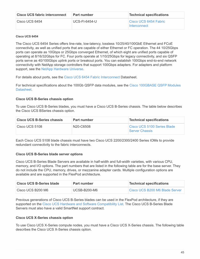
Cisco UCS 6454
The Cisco UCS 6454 Series offers line-rate, low-latency, lossless 10/25/40/100GbE Ethernet and FCoEconnectivity, as well as unified ports that are capable of either Ethernet or FC operation. The 44 10/25Gbpsports can operate as 10Gbps or 25Gbps converged Ethernet, of which eight are unified ports capable ofoperating at 8/16/32Gbps for FC. Four ports operate at 1/10/25Gbps for legacy connectivity, and six QSFPports serve as 40/100Gbps uplink ports or breakout ports. You can establish 100Gbps end-to-end networkconnectivity with NetApp storage controllers that support 100Gbps adapters. For adapters and platformsupport, see the NetApp Hardware Universe.
For details about ports, see the Cisco UCS 6454 Fabric Interconnect Datasheet.
For technical specifications about the 100Gb QSFP data modules, see the Cisco 100GBASE QSFP ModulesDatasheet.
Cisco UCS B-Series chassis option
To use Cisco UCS B-Series blades, you must have a Cisco UCS B-Series chassis. The table below describesthe Cisco UCS BSeries chassis option.
Cisco UCS B-Series chassis Part number Technical specifications
Cisco UCS 5108 N20-C6508 Cisco UCS 5100 Series BladeServer Chassis
Each Cisco UCS 5108 blade chassis must have two Cisco UCS 2200/2300/2400 Series IOMs to provideredundant connectivity to the fabric interconnects.
Cisco UCS B-Series blade server options
Cisco UCS B-Series Blade Servers are available in half-width and full-width varieties, with various CPU,memory, and I/O options. The part numbers that are listed in the following table are for the base server. Theydo not include the CPU, memory, drives, or mezzanine adapter cards. Multiple configuration options areavailable and are supported in the FlexPod architecture.
Cisco UCS B-Series blade Part number Technical specifications
Cisco UCS B200 M6 UCSB-B200-M6 Cisco UCS B200 M6 Blade Server
Previous generations of Cisco UCS B-Series blades can be used in the FlexPod architecture, if they aresupported on the Cisco UCS Hardware and Software Compatibility List. The Cisco UCS B-Series BladeServers must also have a valid SmartNet support contract.
Cisco UCS X-Series chassis option
To use Cisco UCS X-Series compute nodes, you must have a Cisco UCS X-Series chassis. The following tabledescribes the Cisco UCS X-Series chassis option.
45
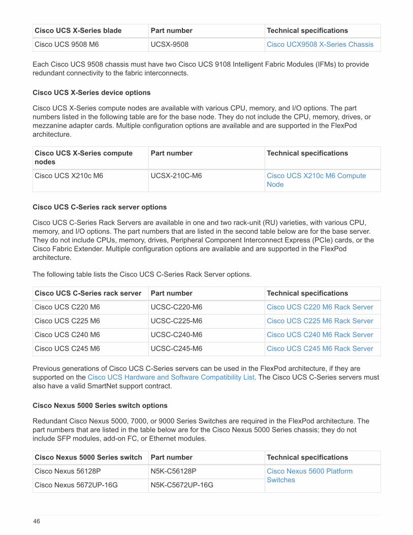
Cisco UCS X-Series blade Part number Technical specifications
Cisco UCS 9508 M6 UCSX-9508 Cisco UCX9508 X-Series Chassis
Each Cisco UCS 9508 chassis must have two Cisco UCS 9108 Intelligent Fabric Modules (IFMs) to provideredundant connectivity to the fabric interconnects.
Cisco UCS X-Series device options
Cisco UCS X-Series compute nodes are available with various CPU, memory, and I/O options. The partnumbers listed in the following table are for the base node. They do not include the CPU, memory, drives, ormezzanine adapter cards. Multiple configuration options are available and are supported in the FlexPodarchitecture.
Cisco UCS X-Series compute
nodes
Part number Technical specifications
Cisco UCS X210c M6 UCSX-210C-M6 Cisco UCS X210c M6 ComputeNode
Cisco UCS C-Series rack server options
Cisco UCS C-Series Rack Servers are available in one and two rack-unit (RU) varieties, with various CPU,memory, and I/O options. The part numbers that are listed in the second table below are for the base server.They do not include CPUs, memory, drives, Peripheral Component Interconnect Express (PCIe) cards, or theCisco Fabric Extender. Multiple configuration options are available and are supported in the FlexPodarchitecture.
The following table lists the Cisco UCS C-Series Rack Server options.
Cisco UCS C-Series rack server Part number Technical specifications
Cisco UCS C220 M6 UCSC-C220-M6 Cisco UCS C220 M6 Rack Server
Cisco UCS C225 M6 UCSC-C225-M6 Cisco UCS C225 M6 Rack Server
Cisco UCS C240 M6 UCSC-C240-M6 Cisco UCS C240 M6 Rack Server
Cisco UCS C245 M6 UCSC-C245-M6 Cisco UCS C245 M6 Rack Server
Previous generations of Cisco UCS C-Series servers can be used in the FlexPod architecture, if they aresupported on the Cisco UCS Hardware and Software Compatibility List. The Cisco UCS C-Series servers mustalso have a valid SmartNet support contract.
Cisco Nexus 5000 Series switch options
Redundant Cisco Nexus 5000, 7000, or 9000 Series Switches are required in the FlexPod architecture. Thepart numbers that are listed in the table below are for the Cisco Nexus 5000 Series chassis; they do notinclude SFP modules, add-on FC, or Ethernet modules.
Cisco Nexus 5000 Series switch Part number Technical specifications
Cisco Nexus 56128P N5K-C56128P Cisco Nexus 5600 PlatformSwitches
Cisco Nexus 5672UP-16G N5K-C5672UP-16G
46
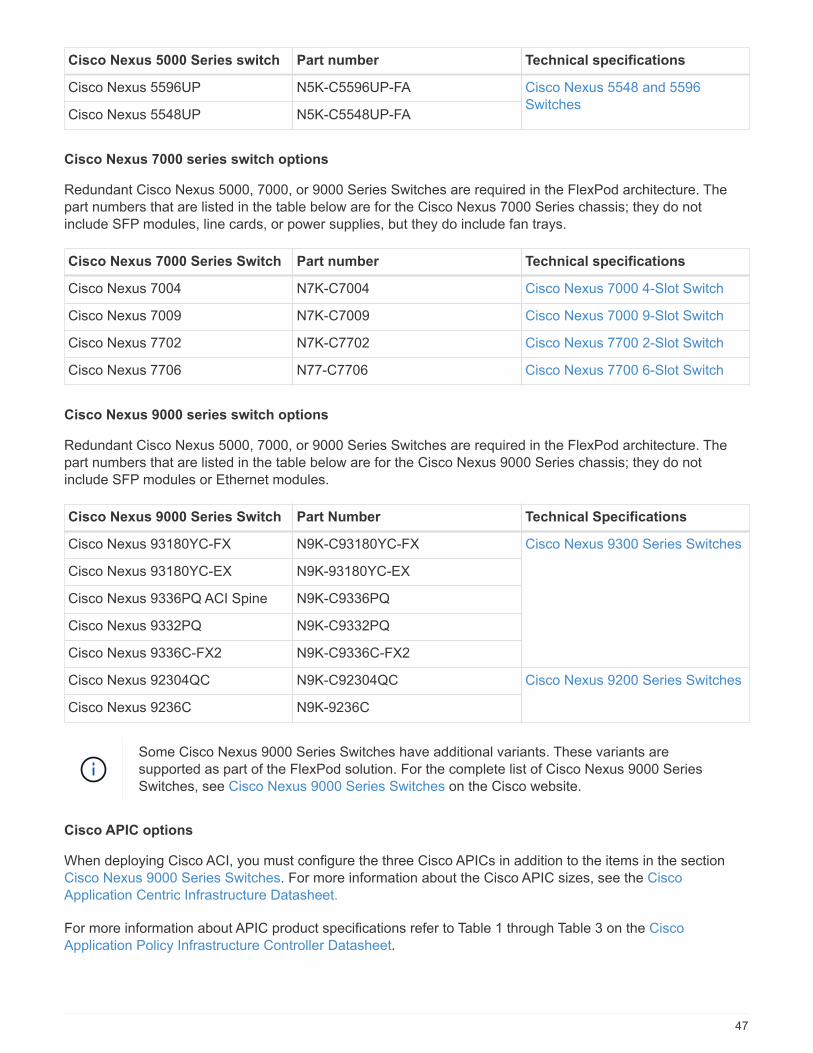
Cisco Nexus 5000 Series switch Part number Technical specifications
Cisco Nexus 5596UP N5K-C5596UP-FA Cisco Nexus 5548 and 5596Switches
Cisco Nexus 5548UP N5K-C5548UP-FA
Cisco Nexus 7000 series switch options
Redundant Cisco Nexus 5000, 7000, or 9000 Series Switches are required in the FlexPod architecture. Thepart numbers that are listed in the table below are for the Cisco Nexus 7000 Series chassis; they do notinclude SFP modules, line cards, or power supplies, but they do include fan trays.
Cisco Nexus 7000 Series Switch Part number Technical specifications
Cisco Nexus 7004 N7K-C7004 Cisco Nexus 7000 4-Slot Switch
Cisco Nexus 7009 N7K-C7009 Cisco Nexus 7000 9-Slot Switch
Cisco Nexus 7702 N7K-C7702 Cisco Nexus 7700 2-Slot Switch
Cisco Nexus 7706 N77-C7706 Cisco Nexus 7700 6-Slot Switch
Cisco Nexus 9000 series switch options
Redundant Cisco Nexus 5000, 7000, or 9000 Series Switches are required in the FlexPod architecture. Thepart numbers that are listed in the table below are for the Cisco Nexus 9000 Series chassis; they do notinclude SFP modules or Ethernet modules.
Cisco Nexus 9000 Series Switch Part Number Technical Specifications
Cisco Nexus 93180YC-FX N9K-C93180YC-FX Cisco Nexus 9300 Series Switches
Cisco Nexus 93180YC-EX N9K-93180YC-EX
Cisco Nexus 9336PQ ACI Spine N9K-C9336PQ
Cisco Nexus 9332PQ N9K-C9332PQ
Cisco Nexus 9336C-FX2 N9K-C9336C-FX2
Cisco Nexus 92304QC N9K-C92304QC Cisco Nexus 9200 Series Switches
Cisco Nexus 9236C N9K-9236C
Some Cisco Nexus 9000 Series Switches have additional variants. These variants aresupported as part of the FlexPod solution. For the complete list of Cisco Nexus 9000 SeriesSwitches, see Cisco Nexus 9000 Series Switches on the Cisco website.
Cisco APIC options
When deploying Cisco ACI, you must configure the three Cisco APICs in addition to the items in the sectionCisco Nexus 9000 Series Switches. For more information about the Cisco APIC sizes, see the CiscoApplication Centric Infrastructure Datasheet.
For more information about APIC product specifications refer to Table 1 through Table 3 on the CiscoApplication Policy Infrastructure Controller Datasheet.
47

Cisco Nexus fabric extender options
Redundant Cisco Nexus 2000 Series rack-mount FEXs are recommended for large FlexPod architectures thatuse C-Series servers. The table below describes a few Cisco Nexus FEX options. Alternate FEX models arealso supported. For more information, see the Cisco UCS Hardware and Software Compatibility List.
Cisco Nexus rack-mount FEX Part number Technical specifications
Cisco Nexus 2232PP N2K-C2232PP Cisco Nexus 2000 Series FabricExtenders
Cisco Nexus 2232TM-E N2K-C2232TM-E
Cisco Nexus 2348UPQ N2K-C2348UPQ Cisco Nexus 2300 Platform FabricExtenders
Cisco Nexus 2348TQCisco Nexus2348TQ-E
N2K-C2348TQN2K-C2348TQ-E
Cisco MDS options
Cisco MDS switches are an optional component in the FlexPod architecture. Redundant SAN switch fabricsare required when you implement the Cisco MDS switch for FC SAN. The table below lists the part numbersand details for a subset of the supported Cisco MDS switches. See the NetApp IMT and Cisco Hardware andSoftware Compatibility List for a complete list of supported SAN switches.
Cisco MDS 9000 series switch Part number Description
Cisco MDS 9148T DS-C9148T-24IK Cisco MDS 9100 Series Switches
Cisco MDS 9132T DS-C9132T-MEK9
Cisco MDS 9396S DS-C9396S-K9 Cisco MDS 9300 Series Switches
Cisco software licensing options
Licenses are required to enable storage protocols on the Cisco Nexus switches. The Cisco Nexus 5000 and7000 Series of switches all require a storage services license to enable the FC or FCoE protocol for SAN bootimplementations. The Cisco Nexus 9000 Series Switches currently do not support FC or FCoE.
The required licenses and the part numbers for those licenses vary depending on the options that you selectfor each component of the FlexPod solution. For example, software license part numbers vary depending onthe number of ports and which Cisco Nexus 5000 or 7000 Series Switches you choose. Consult your salesrepresentative for the exact part numbers. The table below lists the Cisco software licensing options.
48
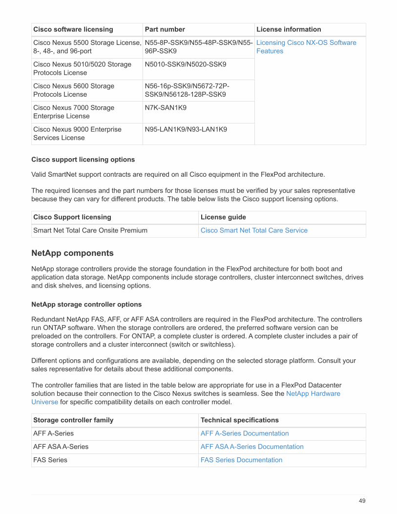
Cisco software licensing Part number License information
Cisco Nexus 5500 Storage License,8-, 48-, and 96-port
N55-8P-SSK9/N55-48P-SSK9/N55-96P-SSK9
Licensing Cisco NX-OS SoftwareFeatures
Cisco Nexus 5010/5020 StorageProtocols License
N5010-SSK9/N5020-SSK9
Cisco Nexus 5600 StorageProtocols License
N56-16p-SSK9/N5672-72P-SSK9/N56128-128P-SSK9
Cisco Nexus 7000 StorageEnterprise License
N7K-SAN1K9
Cisco Nexus 9000 EnterpriseServices License
N95-LAN1K9/N93-LAN1K9
Cisco support licensing options
Valid SmartNet support contracts are required on all Cisco equipment in the FlexPod architecture.
The required licenses and the part numbers for those licenses must be verified by your sales representativebecause they can vary for different products. The table below lists the Cisco support licensing options.
Cisco Support licensing License guide
Smart Net Total Care Onsite Premium Cisco Smart Net Total Care Service
NetApp components
NetApp storage controllers provide the storage foundation in the FlexPod architecture for both boot andapplication data storage. NetApp components include storage controllers, cluster interconnect switches, drivesand disk shelves, and licensing options.
NetApp storage controller options
Redundant NetApp FAS, AFF, or AFF ASA controllers are required in the FlexPod architecture. The controllersrun ONTAP software. When the storage controllers are ordered, the preferred software version can bepreloaded on the controllers. For ONTAP, a complete cluster is ordered. A complete cluster includes a pair ofstorage controllers and a cluster interconnect (switch or switchless).
Different options and configurations are available, depending on the selected storage platform. Consult yoursales representative for details about these additional components.
The controller families that are listed in the table below are appropriate for use in a FlexPod Datacentersolution because their connection to the Cisco Nexus switches is seamless. See the NetApp HardwareUniverse for specific compatibility details on each controller model.
Storage controller family Technical specifications
AFF A-Series AFF A-Series Documentation
AFF ASA A-Series AFF ASA A-Series Documentation
FAS Series FAS Series Documentation
49
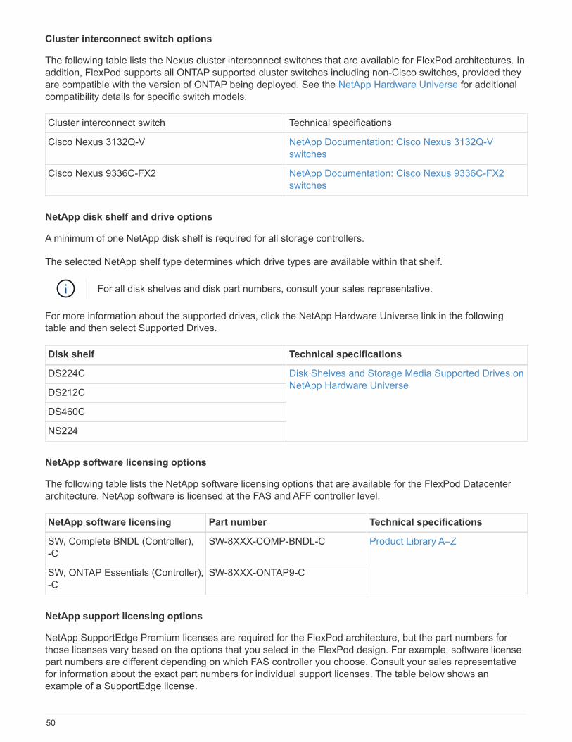
Cluster interconnect switch options
The following table lists the Nexus cluster interconnect switches that are available for FlexPod architectures. Inaddition, FlexPod supports all ONTAP supported cluster switches including non-Cisco switches, provided theyare compatible with the version of ONTAP being deployed. See the NetApp Hardware Universe for additionalcompatibility details for specific switch models.
Cluster interconnect switch Technical specifications
Cisco Nexus 3132Q-V NetApp Documentation: Cisco Nexus 3132Q-Vswitches
Cisco Nexus 9336C-FX2 NetApp Documentation: Cisco Nexus 9336C-FX2switches
NetApp disk shelf and drive options
A minimum of one NetApp disk shelf is required for all storage controllers.
The selected NetApp shelf type determines which drive types are available within that shelf.
For all disk shelves and disk part numbers, consult your sales representative.
For more information about the supported drives, click the NetApp Hardware Universe link in the followingtable and then select Supported Drives.
Disk shelf Technical specifications
DS224C Disk Shelves and Storage Media Supported Drives onNetApp Hardware Universe
DS212C
DS460C
NS224
NetApp software licensing options
The following table lists the NetApp software licensing options that are available for the FlexPod Datacenterarchitecture. NetApp software is licensed at the FAS and AFF controller level.
NetApp software licensing Part number Technical specifications
SW, Complete BNDL (Controller),-C
SW-8XXX-COMP-BNDL-C Product Library A–Z
SW, ONTAP Essentials (Controller),-C
SW-8XXX-ONTAP9-C
NetApp support licensing options
NetApp SupportEdge Premium licenses are required for the FlexPod architecture, but the part numbers forthose licenses vary based on the options that you select in the FlexPod design. For example, software licensepart numbers are different depending on which FAS controller you choose. Consult your sales representativefor information about the exact part numbers for individual support licenses. The table below shows anexample of a SupportEdge license.
50
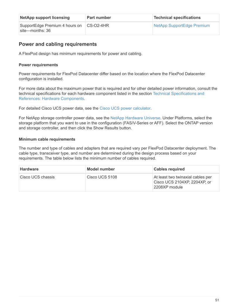
NetApp support licensing Part number Technical specifications
SupportEdge Premium 4 hours onsite—months: 36
CS-O2-4HR NetApp SupportEdge Premium
Power and cabling requirements
A FlexPod design has minimum requirements for power and cabling.
Power requirements
Power requirements for FlexPod Datacenter differ based on the location where the FlexPod Datacenterconfiguration is installed.
For more data about the maximum power that is required and for other detailed power information, consult thetechnical specifications for each hardware component listed in the section Technical Specifications andReferences: Hardware Components.
For detailed Cisco UCS power data, see the Cisco UCS power calculator.
For NetApp storage controller power data, see the NetApp Hardware Universe. Under Platforms, select thestorage platform that you want to use in the configuration (FAS/V-Series or AFF). Select the ONTAP versionand storage controller, and then click the Show Results button.
Minimum cable requirements
The number and type of cables and adapters that are required vary per FlexPod Datacenter deployment. Thecable type, transceiver type, and number are determined during the design process based on yourrequirements. The table below lists the minimum number of cables required.
Hardware Model number Cables required
Cisco UCS chassis Cisco UCS 5108 At least two twinaxial cables perCisco UCS 2104XP, 2204XP, or2208XP module
51

Hardware Model number Cables required
Cisco UCS Fabric Interconnects Cisco UCS 6248UP • Two Cat5e cables formanagement ports
• Two Cat5e cables for the L1,L2 interconnects, per pair offabric interconnects
• At least four twinaxial cablesper fabric interconnect
• At least four FC cables perfabric interconnect
Cisco UCS 6296UP
Cisco UCS 6332-16UP
Cisco UCS 6454
Cisco UCS 6332 • Two Cat5e cables formanagement ports
• Two Cat5e cables for the L1,L2 interconnects, per pair offabric interconnects
• At least four twinaxial cablesper fabric interconnect
Cisco UCS 6324 • Two 10/100/1000Mbpsmanagement ports
• At least two twinaxial cablesper fabric interconnect
Cisco Nexus 5000 and 7000 SeriesSwitches
Cisco Nexus 5000 Series • At least two 10GbE fiber ortwinaxial cables per switch
• At least two FC cables perswitch (if FC/FCoE connectivityis required)
Cisco Nexus 7000 Series
Cisco Nexus 9000 Series Switches Cisco Nexus 9000 Series At least two 10GbE cables perswitch
NetApp FAS controllers AFF A-Series • A pair of SAS or SATA cablesper storage controller
• At least two FC cables percontroller, if using legacy FC
• At least two 10GbE cables percontroller
• At least one GbE cable formanagement per controller
• For ONTAP, eight shorttwinaxial cables are requiredper pair of cluster interconnectswitches
FAS Series
52
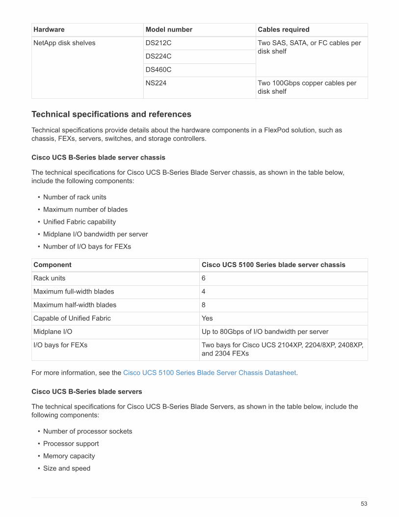
Hardware Model number Cables required
NetApp disk shelves DS212C Two SAS, SATA, or FC cables perdisk shelf
DS224C
DS460C
NS224 Two 100Gbps copper cables perdisk shelf
Technical specifications and references
Technical specifications provide details about the hardware components in a FlexPod solution, such aschassis, FEXs, servers, switches, and storage controllers.
Cisco UCS B-Series blade server chassis
The technical specifications for Cisco UCS B-Series Blade Server chassis, as shown in the table below,include the following components:
• Number of rack units
• Maximum number of blades
• Unified Fabric capability
• Midplane I/O bandwidth per server
• Number of I/O bays for FEXs
Component Cisco UCS 5100 Series blade server chassis
Rack units 6
Maximum full-width blades 4
Maximum half-width blades 8
Capable of Unified Fabric Yes
Midplane I/O Up to 80Gbps of I/O bandwidth per server
I/O bays for FEXs Two bays for Cisco UCS 2104XP, 2204/8XP, 2408XP,and 2304 FEXs
For more information, see the Cisco UCS 5100 Series Blade Server Chassis Datasheet.
Cisco UCS B-Series blade servers
The technical specifications for Cisco UCS B-Series Blade Servers, as shown in the table below, include thefollowing components:
• Number of processor sockets
• Processor support
• Memory capacity
• Size and speed
53

• SAN boot support
• Number of mezzanine adapter slots
• I/O maximum throughput
• Form factor
• Maximum number of servers per chassis
Component Cisco UCS datasheet
Cisco UCS B200 M6 Cisco UCS B200 M6 Blade Server
Cisco UCS C-Series rack servers
The technical specifications for the Cisco UCS C-Series rack servers include processor support, maximummemory capacity, the number of PCIe slots, and the size of the form factor. For additional details on compatibleUCS server models, see the Cisco Hardware Compatibility list. The following tables illustrate the C-SeriesRack Server datasheets and Cisco UCS C-Series chassis option, respectively.
Component Cisco UCS datasheet
Cisco UCS C220 M6 Cisco UCS C220 M6 Rack Server
Cisco UCS C225 M6 Cisco UCS C225 M6 Rack Server
Cisco UCS C240 M6 Cisco UCS C240 M6 Rack Server
Cisco UCS C245 M6 Cisco UCS C245 M6 Rack Server
Cisco UCS X-Series chassis
The technical specifications for Cisco UCS X-Series chassis, as shown in the table below, include the followingcomponents:
• Number of rack units
• Maximum number of nodes
• Unified Fabric capability
• Number of I/O bays for IFMs
Component Cisco UCS 9508 X-Series compute node chassis
Rack units 7
Maximum number of nodes 8
Capable of Unified Fabric Yes
I/O bays for IFMs Two bays for Cisco UCS 9108 Intelligent FabricModules (IFMs)
For more information, see the Cisco UCS X9508 X-Series Chassis Datasheet.
Cisco UCS X-Series compute node
The technical specifications for Cisco UCS X-Series compute node, as shown in the following table below,
54
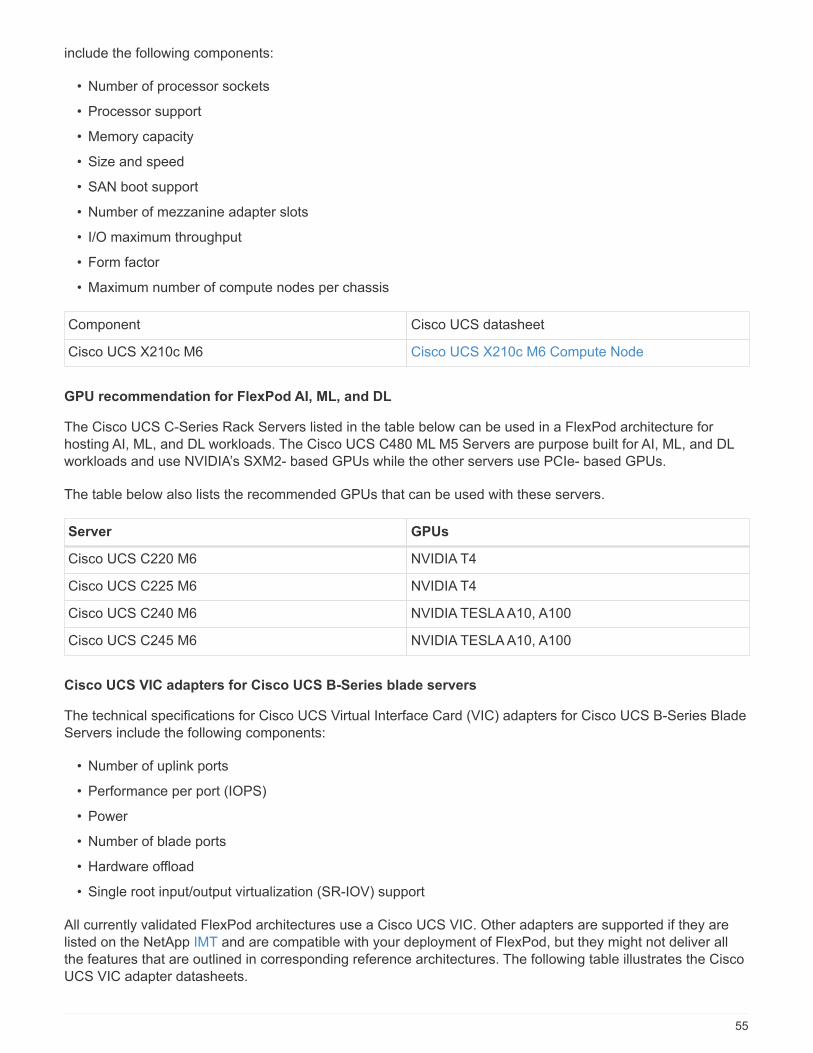
include the following components:
• Number of processor sockets
• Processor support
• Memory capacity
• Size and speed
• SAN boot support
• Number of mezzanine adapter slots
• I/O maximum throughput
• Form factor
• Maximum number of compute nodes per chassis
Component Cisco UCS datasheet
Cisco UCS X210c M6 Cisco UCS X210c M6 Compute Node
GPU recommendation for FlexPod AI, ML, and DL
The Cisco UCS C-Series Rack Servers listed in the table below can be used in a FlexPod architecture forhosting AI, ML, and DL workloads. The Cisco UCS C480 ML M5 Servers are purpose built for AI, ML, and DLworkloads and use NVIDIA’s SXM2- based GPUs while the other servers use PCIe- based GPUs.
The table below also lists the recommended GPUs that can be used with these servers.
Server GPUs
Cisco UCS C220 M6 NVIDIA T4
Cisco UCS C225 M6 NVIDIA T4
Cisco UCS C240 M6 NVIDIA TESLA A10, A100
Cisco UCS C245 M6 NVIDIA TESLA A10, A100
Cisco UCS VIC adapters for Cisco UCS B-Series blade servers
The technical specifications for Cisco UCS Virtual Interface Card (VIC) adapters for Cisco UCS B-Series BladeServers include the following components:
• Number of uplink ports
• Performance per port (IOPS)
• Power
• Number of blade ports
• Hardware offload
• Single root input/output virtualization (SR-IOV) support
All currently validated FlexPod architectures use a Cisco UCS VIC. Other adapters are supported if they arelisted on the NetApp IMT and are compatible with your deployment of FlexPod, but they might not deliver allthe features that are outlined in corresponding reference architectures. The following table illustrates the CiscoUCS VIC adapter datasheets.
55
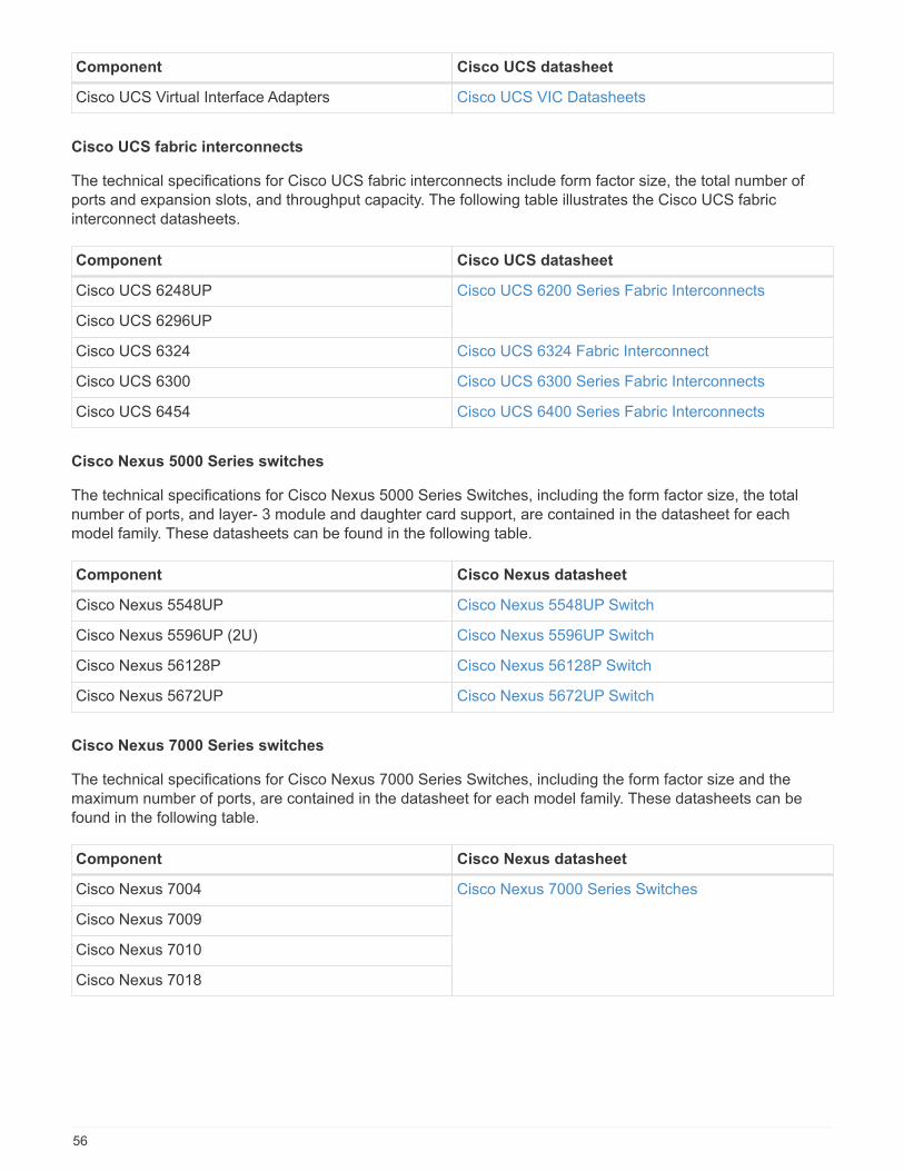
Component Cisco UCS datasheet
Cisco UCS Virtual Interface Adapters Cisco UCS VIC Datasheets
Cisco UCS fabric interconnects
The technical specifications for Cisco UCS fabric interconnects include form factor size, the total number ofports and expansion slots, and throughput capacity. The following table illustrates the Cisco UCS fabricinterconnect datasheets.
Component Cisco UCS datasheet
Cisco UCS 6248UP Cisco UCS 6200 Series Fabric Interconnects
Cisco UCS 6296UP
Cisco UCS 6324 Cisco UCS 6324 Fabric Interconnect
Cisco UCS 6300 Cisco UCS 6300 Series Fabric Interconnects
Cisco UCS 6454 Cisco UCS 6400 Series Fabric Interconnects
Cisco Nexus 5000 Series switches
The technical specifications for Cisco Nexus 5000 Series Switches, including the form factor size, the totalnumber of ports, and layer- 3 module and daughter card support, are contained in the datasheet for eachmodel family. These datasheets can be found in the following table.
Component Cisco Nexus datasheet
Cisco Nexus 5548UP Cisco Nexus 5548UP Switch
Cisco Nexus 5596UP (2U) Cisco Nexus 5596UP Switch
Cisco Nexus 56128P Cisco Nexus 56128P Switch
Cisco Nexus 5672UP Cisco Nexus 5672UP Switch
Cisco Nexus 7000 Series switches
The technical specifications for Cisco Nexus 7000 Series Switches, including the form factor size and themaximum number of ports, are contained in the datasheet for each model family. These datasheets can befound in the following table.
Component Cisco Nexus datasheet
Cisco Nexus 7004 Cisco Nexus 7000 Series Switches
Cisco Nexus 7009
Cisco Nexus 7010
Cisco Nexus 7018
56
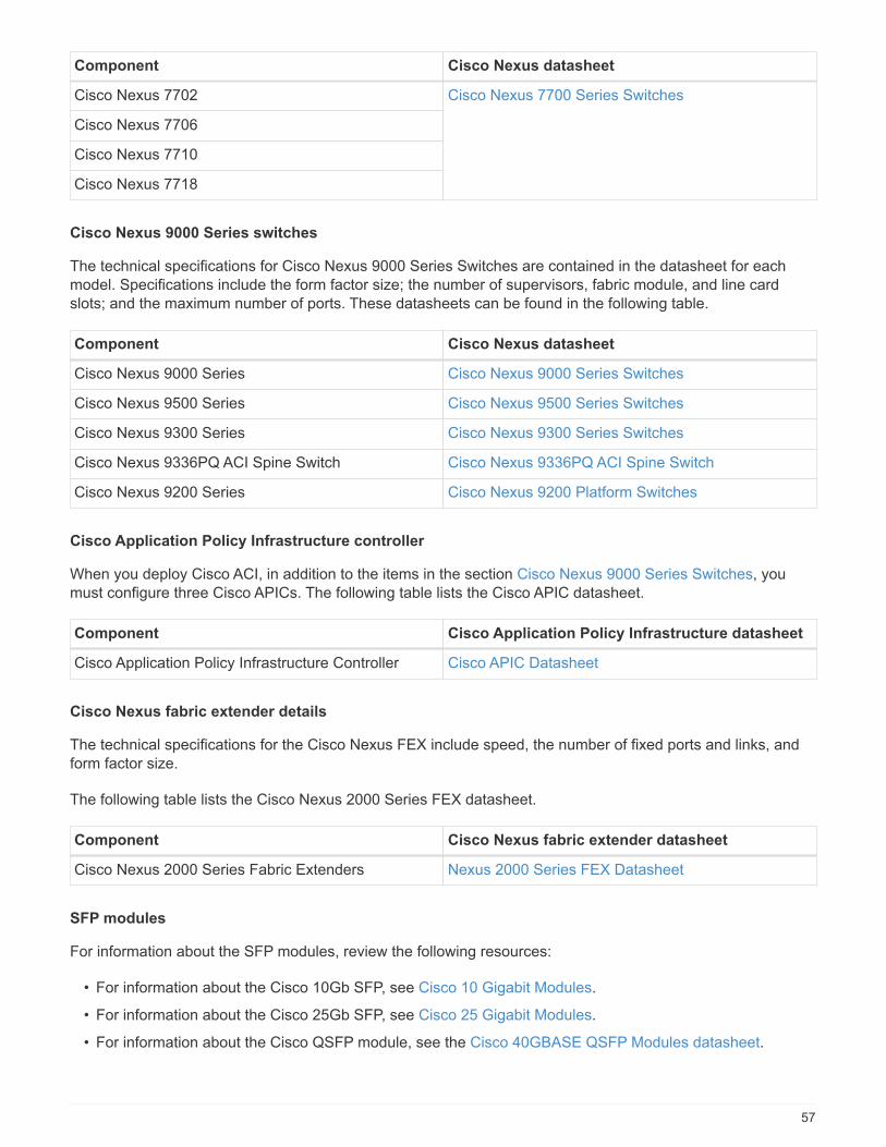
Component Cisco Nexus datasheet
Cisco Nexus 7702 Cisco Nexus 7700 Series Switches
Cisco Nexus 7706
Cisco Nexus 7710
Cisco Nexus 7718
Cisco Nexus 9000 Series switches
The technical specifications for Cisco Nexus 9000 Series Switches are contained in the datasheet for eachmodel. Specifications include the form factor size; the number of supervisors, fabric module, and line cardslots; and the maximum number of ports. These datasheets can be found in the following table.
Component Cisco Nexus datasheet
Cisco Nexus 9000 Series Cisco Nexus 9000 Series Switches
Cisco Nexus 9500 Series Cisco Nexus 9500 Series Switches
Cisco Nexus 9300 Series Cisco Nexus 9300 Series Switches
Cisco Nexus 9336PQ ACI Spine Switch Cisco Nexus 9336PQ ACI Spine Switch
Cisco Nexus 9200 Series Cisco Nexus 9200 Platform Switches
Cisco Application Policy Infrastructure controller
When you deploy Cisco ACI, in addition to the items in the section Cisco Nexus 9000 Series Switches, youmust configure three Cisco APICs. The following table lists the Cisco APIC datasheet.
Component Cisco Application Policy Infrastructure datasheet
Cisco Application Policy Infrastructure Controller Cisco APIC Datasheet
Cisco Nexus fabric extender details
The technical specifications for the Cisco Nexus FEX include speed, the number of fixed ports and links, andform factor size.
The following table lists the Cisco Nexus 2000 Series FEX datasheet.
Component Cisco Nexus fabric extender datasheet
Cisco Nexus 2000 Series Fabric Extenders Nexus 2000 Series FEX Datasheet
SFP modules
For information about the SFP modules, review the following resources:
• For information about the Cisco 10Gb SFP, see Cisco 10 Gigabit Modules.
• For information about the Cisco 25Gb SFP, see Cisco 25 Gigabit Modules.
• For information about the Cisco QSFP module, see the Cisco 40GBASE QSFP Modules datasheet.
57

• For information about the Cisco 100Gb SFP, see Cisco 100 Gigabit Modules.
• For information about the Cisco FC SFP module, see the Cisco MDS 9000 Family Pluggable Transceiversdatasheet.
• For information about all supported Cisco SFP and transceiver modules, see Cisco SFP and SFP+Transceiver Module Installation Notes and Cisco Transceiver Modules.
NetApp storage controllers
The technical specifications for NetApp storage controllers include the following components:
• Chassis configuration
• Number of rack units
• Amount of memory
• NetApp FlashCache caching
• Aggregate size
• Volume size
• Number of LUNs
• Supported network storage
• Maximum number of NetApp FlexVol volumes
• Maximum number of supported SAN hosts
• Maximum number of Snapshot copies
FAS Series
All available models of FAS storage controllers are supported for use in a FlexPod Datacenter. Detailedspecifications for all FAS series storage controllers are available in the NetApp Hardware Universe. See theplatform-specific documentation listed in the following table for detailed information about a specific FASmodel.
Component FAS Series controller platform documentation
FAS9000 Series FAS9000 Series Datasheet
FAS8700 Series FAS8700 Series Datasheet
FAS8300 Series FAS8300 Series Datasheet
FAS500f Series FAS500f Series Datasheet
FAS2700 Series FAS2700 Series Datasheet
AFF A-Series
All current models of NetApp AFF A-Series storage controllers are supported for use in FlexPod. Additionalinformation can be found in the AFF Technical Specifications datasheet and in the NetApp Hardware Universe.See the platform- specific documentation listed in the following table for detailed information about a specificAFF Model.
58

Component AFF A-Series controller platform documentation
NetApp AFF A800 AFF A800 Platform Documentation
NetApp AFF A700 AFF A700 Platform Documentation
NetApp AFF A700s AFF A700s Platform Documentation
NetApp AFF A400 AFF A400 Platform Documentation
NetApp AFF A250 AFF A250 Platform Documentation
AFF ASA A-Series
All current models of NetApp AFF ASA A-Series storage controllers are supported for use in FlexPod.Additional information can be found in the All SAN Array documentation resources, ONTAP AFF All SAN ArraySystem technical report, and in the NetApp Hardware Universe. See the platform-specific documentation listedin the following table for detailed information about a specific AFF Model.
Component AFF A-Series controller platform documentation
NetApp AFF ASA A800 AFF ASA A800 Platform Documentation
NetApp AFF ASA A700 AFF ASA A700 Platform Documentation
NetApp AFF ASA A400 AFF ASA A400 Platform Documentation
NetApp AFF ASA A250 AFF ASA A250 Platform Documentation
NetApp AFF ASA A220 AFF ASA A220 Platform Documentation
NetApp disk shelves
The technical specifications for NetApp disk shelves include the form factor size, the number of drives perenclosure, and the shelf I/O modules; this documentation can be found in the following table. For moreinformation, see the NetApp Disk Shelves and Storage Media Technical Specifications and the NetAppHardware Universe.
Component NetApp FAS/AFF disk shelf documentation
NetApp DS212C Disk Shelf DS212C Disk Shelf Documentation
NetApp DS224C Disk Shelf DS224C Disk Shelf Documentation
NetApp DS460C Disk Shelf DS460C Disk Shelf Documentation
NetApp NS224 NVMe-SSD Disk Shelf NS224 Disk Shelf Documentation
NetApp drives
The technical specifications for NetApp drives include the form factor size, disk capacity, disk RPM, supportingcontrollers, and ONTAP version requirements. These specifications can be found in the Drives section of theNetApp Hardware Universe.
Legacy equipment
FlexPod is a flexible solution that enables you to use your existing equipment and new equipment that iscurrently for sale by Cisco and NetApp. Occasionally, certain models of equipment from both Cisco andNetApp are designated as end of life (EOL).
59
Even though these equipment models are no longer available, if you purchased one of these models beforethe end-of-availability (EOA) date, you can use that equipment in a FlexPod configuration. A complete list ofthe legacy equipment models that are supported in FlexPod that are no longer for sale can be referenced onthe NetApp Service and Support Product Programs End of Availability Index.
For more information on legacy Cisco equipment, see the Cisco EOL and EOA notices for Cisco UCS C-SeriesRack Servers, Cisco UCS B-Series Blade Servers, and Nexus switches.
Legacy FC Fabric support includes the following:
• 2Gb Fabric
• 4Gb Fabric
Legacy software includes the following:
• NetApp Data ONTAP operating in 7-Mode, 7.3.5 and later
• ONTAP 8.1.x through 9.0.x
• Cisco UCS Manager 1.3 and later
• Cisco UCS Manager 2.1 through 2.2.7
Where to find additional Information
To learn more about the information that is described in this document, review the following documents andwebsites:
• NetApp Product Documentation
https://docs.netapp.com/
• NetApp Support Communications
https://mysupport.netapp.com/info/communications/index.html
• NetApp Interoperability Matrix Tool (IMT)
https://mysupport.netapp.com/matrix/#welcome
• NetApp Hardware Universe
https://hwu.netapp.com/
• NetApp Support
https://mysupport.netapp.com/
60
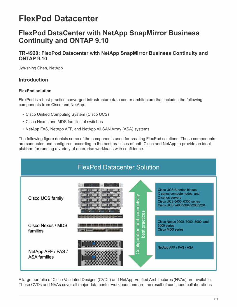
FlexPod Datacenter
FlexPod DataCenter with NetApp SnapMirror BusinessContinuity and ONTAP 9.10
TR-4920: FlexPod Datacenter with NetApp SnapMirror Business Continuity andONTAP 9.10
Jyh-shing Chen, NetApp
Introduction
FlexPod solution
FlexPod is a best-practice converged-infrastructure data center architecture that includes the followingcomponents from Cisco and NetApp:
• Cisco Unified Computing System (Cisco UCS)
• Cisco Nexus and MDS families of switches
• NetApp FAS, NetApp AFF, and NetApp All SAN Array (ASA) systems
The following figure depicts some of the components used for creating FlexPod solutions. These componentsare connected and configured according to the best practices of both Cisco and NetApp to provide an idealplatform for running a variety of enterprise workloads with confidence.
A large portfolio of Cisco Validated Designs (CVDs) and NetApp Verified Architectures (NVAs) are available.These CVDs and NVAs cover all major data center workloads and are the result of continued collaborations
61

and innovations between NetApp and Cisco on FlexPod solutions.
Incorporating extensive testing and validations in their creation process, FlexPod CVDs and NVAs providereference solution architecture designs and step-by-step deployment guides to help partners and customersdeploy and adopt FlexPod solutions. By using these CVDs and NVAs as guides for design and implementation,businesses can reduce risks; reduce solution downtime; and increase the availability, scalability, flexibility, andsecurity of the FlexPod solutions they deploy.
Each of the FlexPod component families shown (Cisco UCS, Cisco Nexus/MDS switches, and NetAppstorage) offers platform and resource options to scale the infrastructure up or down, while supporting thefeatures and functionality that are required under the configuration and connectivity best practices of FlexPod.FlexPod can also scale out for environments that require multiple consistent deployments by rolling outadditional FlexPod stacks.
Disaster recovery and business continuity
There are various methods that companies can adopt to make sure that they can quickly recover theirapplication and data services from disasters. Having a disaster recovery (DR) and business continuity (BC)plan, implementing a solution which meets the business objectives, and performing regular testing of thedisaster scenarios enables companies to recover from a disaster and continue critical business services after adisaster situation occurs.
Companies might have different DR and BC requirements for different types of application and data services.Some applications and data might not be needed during an emergency or disaster situation, while others mightneed to be continuously available to support business requirements.
For mission- critical application and data services that could disrupt your business when they are not available,a careful evaluation is needed to answer questions such as what kind of maintenance and disaster scenariosthe business needs to consider, how much data the business can afford to lose in case of a disaster, and howquickly the recovery can and should take place.
For businesses that rely on data services for revenue generation, the data services might need to be protectedby a solution that can withstand not only various single-point-of-failure scenarios but also a site outage disasterscenario to provide continuous business operations.
Recovery point objective and recovery time objective
The recovery point objective (RPO) measures how much data, in terms of time, you can afford to lose, or thepoint up to which you can recover your data. With a daily backup plan, a company might lose a day’s worth ofdata because the changes made to the data since the last backup could be lost in a disaster. For business-critical and mission-critical data services, you might require a zero RPO and an associated plan andinfrastructures to protect data without any data loss.
The recovery time objective (RTO) measures how much time you can afford to not have the data available, orhow quickly data services must be brought back up. For example, a company might have a backup andrecovery implementation that uses traditional tapes for certain data sets due to its size. As a result, to restorethe data from the backup tapes, it might take several hours, or even days if there is an infrastructure failure.Time considerations must also include time to bring the infrastructure back up in addition to restoring data. Formission-critical data services, you might require a very low RTO and thus can only tolerate a failover time ofseconds or minutes to quickly bring the data services back online for business continuity.
SM-BC
Beginning with ONTAP 9.8, you can protect SAN workloads for transparent application failover with NetAppSM-BC. You can create consistency group relationships between two AFF clusters or two ASA clusters for data
62
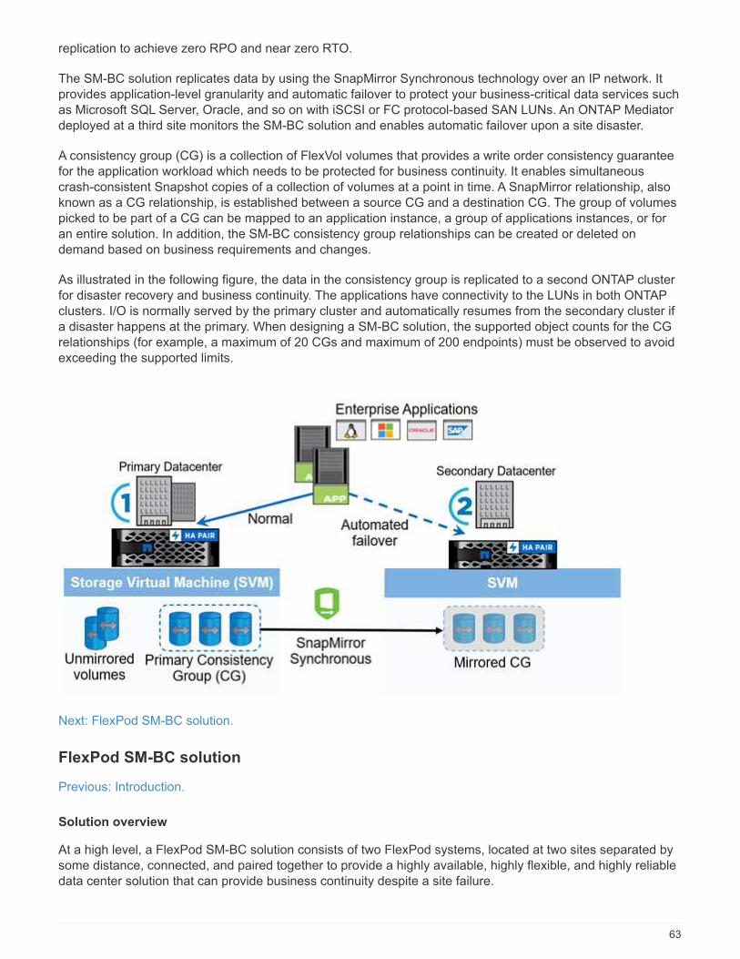
replication to achieve zero RPO and near zero RTO.
The SM-BC solution replicates data by using the SnapMirror Synchronous technology over an IP network. Itprovides application-level granularity and automatic failover to protect your business-critical data services suchas Microsoft SQL Server, Oracle, and so on with iSCSI or FC protocol-based SAN LUNs. An ONTAP Mediatordeployed at a third site monitors the SM-BC solution and enables automatic failover upon a site disaster.
A consistency group (CG) is a collection of FlexVol volumes that provides a write order consistency guaranteefor the application workload which needs to be protected for business continuity. It enables simultaneouscrash-consistent Snapshot copies of a collection of volumes at a point in time. A SnapMirror relationship, alsoknown as a CG relationship, is established between a source CG and a destination CG. The group of volumespicked to be part of a CG can be mapped to an application instance, a group of applications instances, or foran entire solution. In addition, the SM-BC consistency group relationships can be created or deleted ondemand based on business requirements and changes.
As illustrated in the following figure, the data in the consistency group is replicated to a second ONTAP clusterfor disaster recovery and business continuity. The applications have connectivity to the LUNs in both ONTAPclusters. I/O is normally served by the primary cluster and automatically resumes from the secondary cluster ifa disaster happens at the primary. When designing a SM-BC solution, the supported object counts for the CGrelationships (for example, a maximum of 20 CGs and maximum of 200 endpoints) must be observed to avoidexceeding the supported limits.
Next: FlexPod SM-BC solution.
FlexPod SM-BC solution
Previous: Introduction.
Solution overview
At a high level, a FlexPod SM-BC solution consists of two FlexPod systems, located at two sites separated bysome distance, connected, and paired together to provide a highly available, highly flexible, and highly reliabledata center solution that can provide business continuity despite a site failure.
63

In addition to deploying two new FlexPod infrastructures to create a FlexPod SM-BC solution, the solution canalso be implemented on two existing FlexPod infrastructures that are compatible with SM-BC or by adding anew FlexPod to peer with an existing FlexPod.
The two FlexPod systems in a FlexPod SM-BC solution do not need to be identical in configurations. However,the two ONTAP clusters need to be of the same storage families, either two AFF or two ASA systems, but notnecessarily the same hardware model. The SM-BC solution does not support FAS systems.
The two FlexPod sites require network connectivity which meets the solution bandwidth and quality-of-servicerequirements and has less than 10 milliseconds (10ms) round-trip latency between sites as required by theONTAP SM-BC solution. For this FlexPod SM-BC solution validation, the two FlexPod sites are interconnectedvia extended layer-2 network in the same lab.
The NetApp ONTAP SM-BC solution provides synchronous replication between the two NetApp storageclusters for high availability and disaster recovery in a campus or metropolitan area. The ONTAP Mediatordeployed at a third site monitors the solution and enables automated failover in case of a site disaster. Thefollowing figure provides a high-level view of the solution components.
With the FlexPod SM-BC solution, you can deploy a VMware vSphere-based private cloud on a distributed andyet integrated infrastructure. The integrated solution enables multiple sites to be coordinated as a singlesolution infrastructure to protect data services from a variety of single-point-of-failure scenarios and a completesite failure.
This technical report highlights some of the end-to-end design considerations of the FlexPod SM-BC solution.The practitioners are encouraged to reference information available in the various FlexPod CVDs and NVAs foradditional FlexPod solution implementation details.
Although the solution was validated by deploying two FlexPod systems based on FlexPod best practices asdocumented in CVDs, it takes into accounts the requirements for the SM-BC solution. The deployed FlexPodSM-BC solution discussed in this report has been validated for resiliency and fault tolerance during variousfailure scenarios as well as a simulated site failure scenario.
Solution requirements
The FlexPod SM-BC solution is designed to address the following key requirements:
64

• Business continuity for business-critical applications and data services in the event of a complete datacenter (site) failure
• Flexible, distributed workload placement with workload mobility across data centers
• Site affinity where virtual machine data is accessed locally, from the same data center site, during normaloperations
• Quick recovery with zero data loss when a site failure occurs
Solution components
Cisco compute components
The Cisco UCS is an integrated computing infrastructure to provide unified computing resources, unified fabric,and unified management. It enables companies to automate and accelerate deployment of applications,including virtualization and bare-metal workloads. The Cisco UCS supports a wide range of deployment usecases including remote and branch locations, data centers, and hybrid cloud use cases. Depending on thespecific solution requirements, the FlexPod Cisco compute implementation can utilize a variety of componentsat different scales. The following subsections provide additional information on some of the UCS components.
UCS server and compute node
The following figure shows some examples of the UCS server components, including UCS C- Series rackservers, UCS 5108 chassis with B-Series blade servers, and the new UCS X9508 chassis with X-Seriescompute nodes. The Cisco UCS C-Series rack servers are available in one and two rack-unit (RU) form factor,Intel and AMD CPU based models, and with various CPU speeds and cores, memory, and I/O options. TheCisco UCS B-Series blade servers and the new X-Series compute nodes are also available with various CPU,memory, and I/O options, and they are all supported in the FlexPod architecture to meet the diverse businessrequirements.
In addition to the latest generation C220/C225/C240/C245 M6 rack servers, B200 M6 blade servers, andX210c compute nodes shown in this figure, prior generations of rack and blade servers can also be used ifthey are still supported.
65

I/O Module and Intelligent Fabric Module
The I/O Module (IOM)/Fabric Extender and Intelligent Fabric Module (IFM) provide unified fabric connectivityfor the Cisco UCS 5108 blade server chassis and the Cisco UCS X9508 X-Series chassis, respectively.
The fourth generation UCS IOM 2408 has eight 25-G unified Ethernet ports for connecting the UCS 5108chassis with Fabric Interconnect (FI). Each 2408 has four 10-G backplane Ethernet connectivity through themidplane to each blade server in the chassis.
The UCSX 9108 25G IFM has eight 25-G unified Ethernet ports for connecting the blade servers in the UCSX9508 chassis with fabric interconnects. Each 9108 has four 25-G connections towards each UCS X210ccompute node in the X9108 chassis. The 9108 IFM also works in concert with the fabric interconnect tomanage the chassis environment.
The following figure depicts the UCS 2408 and earlier IOM generations for the UCS 5108 chassis and the 9108IFM for the X9508 chassis.
UCS Fabric Interconnects
The Cisco UCS Fabric Interconnects (FIs) provide connectivity and management for the entire Cisco UCS.Typically deployed as an active/active pair, the system’s FIs integrate all components into a single, highlyavailable management domain controlled by the Cisco UCS Manager or Cisco Intersight. Cisco UCS FIsprovide a single unified fabric for the system with low-latency and lossless, cut-through switching that supportsLAN, SAN, and management traffic using a single set of cables.
There are two variants for the fourth-generation Cisco UCS FIs: UCS FI 6454 and 64108. They include supportfor 10/25 Gbps Ethernet ports, 1/10/25-Gbps Ethernet ports, 40/100-Gbps Ethernet up-link ports, and unifiedports that can support 10/25 Gigabit Ethernet or 8/16/32-Gbps Fibre Channel. The following figure shows thefourth-generation Cisco UCS FIs along with the third-generation models that are also supported.
66
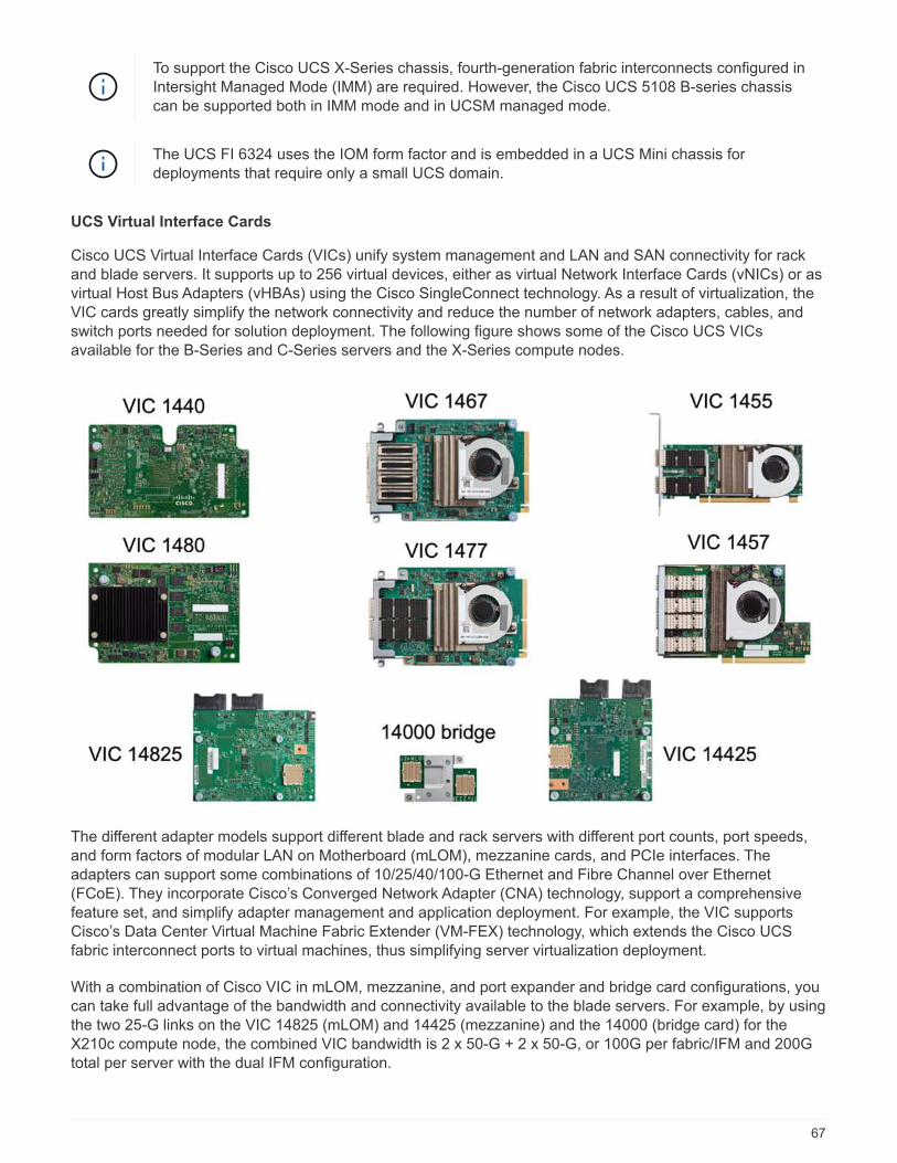
To support the Cisco UCS X-Series chassis, fourth-generation fabric interconnects configured inIntersight Managed Mode (IMM) are required. However, the Cisco UCS 5108 B-series chassiscan be supported both in IMM mode and in UCSM managed mode.
The UCS FI 6324 uses the IOM form factor and is embedded in a UCS Mini chassis fordeployments that require only a small UCS domain.
UCS Virtual Interface Cards
Cisco UCS Virtual Interface Cards (VICs) unify system management and LAN and SAN connectivity for rackand blade servers. It supports up to 256 virtual devices, either as virtual Network Interface Cards (vNICs) or asvirtual Host Bus Adapters (vHBAs) using the Cisco SingleConnect technology. As a result of virtualization, theVIC cards greatly simplify the network connectivity and reduce the number of network adapters, cables, andswitch ports needed for solution deployment. The following figure shows some of the Cisco UCS VICsavailable for the B-Series and C-Series servers and the X-Series compute nodes.
The different adapter models support different blade and rack servers with different port counts, port speeds,and form factors of modular LAN on Motherboard (mLOM), mezzanine cards, and PCIe interfaces. Theadapters can support some combinations of 10/25/40/100-G Ethernet and Fibre Channel over Ethernet(FCoE). They incorporate Cisco’s Converged Network Adapter (CNA) technology, support a comprehensivefeature set, and simplify adapter management and application deployment. For example, the VIC supportsCisco’s Data Center Virtual Machine Fabric Extender (VM-FEX) technology, which extends the Cisco UCSfabric interconnect ports to virtual machines, thus simplifying server virtualization deployment.
With a combination of Cisco VIC in mLOM, mezzanine, and port expander and bridge card configurations, youcan take full advantage of the bandwidth and connectivity available to the blade servers. For example, by usingthe two 25-G links on the VIC 14825 (mLOM) and 14425 (mezzanine) and the 14000 (bridge card) for theX210c compute node, the combined VIC bandwidth is 2 x 50-G + 2 x 50-G, or 100G per fabric/IFM and 200Gtotal per server with the dual IFM configuration.
67

For details on the Cisco UCS product families, technical specifications, and documentations, see the CiscoUCS web site for information.
Cisco switching components
Nexus switches
FlexPod uses Cisco Nexus Series switches to provide Ethernet switching fabric for communications betweenCisco UCS and NetApp storage controllers. All currently supported Cisco Nexus switch models, including theCisco Nexus 3000, 5000, 7000, and 9000 Series, are supported for FlexPod deployment.
When selecting a switch model for FlexPod deployment, there are many factors to consider, such asperformance, port speed, port density, switching latency, and protocols such as ACI and VXLAN support, foryour design objectives as well as the switches’ support timespan.
The validation for many recent FlexPod CVDs uses Cisco Nexus 9000 series switches such as the Nexus9336C-FX2 and the Nexus 93180YC-FX3, which deliver high performance 40/100G and 10//25G ports, lowlatency, and exceptional power efficiency in a compact 1U form factor. Additional speeds are supported viauplink ports and breakout cables. The following figure shows a few Cisco Nexus 9k and 3k switches, includingthe Nexus 9336C-FX2 and the Nexus 3232C used for this validation.
See Cisco Data Center Switches for more information on the available Nexus switches and their specificationsand documentations.
MDS switches
The Cisco MDS 9100/9200/9300 Series Fabric switches are an optional component in the FlexPodarchitecture. These switches are highly reliable, highly flexible, secure, and can provide visibility into the trafficflow in the fabric. The following figure shows some example MDS switches that can be used to build redundantFC SAN fabrics for a FlexPod solution to meet application and business requirements.
68

Cisco MDS 9132T/9148T/9396T high performance 32G Multilayer Fabric Switches are cost effective and arehighly reliable, flexible, and scalable. The advanced storage networking features and functions come with easeof management and are compatible with the entire Cisco MDS 9000 family portfolio for a reliable SANimplementation.
State-of-the-art SAN analytics and telemetry capabilities are built into this next-generation hardware platform.The telemetry data extracted from the inspection of the frame headers can be streamed to an analytics-visualization platform, including the Cisco Data Center Network Manager. The MDS switches supporting 16GFC, such as the MDS 9148S, are also supported in FlexPod. In addition, Multiservice MDS switches, such asMDS 9250i, which supports FCoE and FCIP protocols in addition to FC protocol, are also part of the FlexPodsolution portfolio.
On semi-modular MDS switches such as 9132T and 9396T, additional port expansion module and portlicenses can be added to support additional device connectivity. On the fixed switches such as 9148T,additional port licenses can be added as needed. This pay-as-you-grow flexibility provides an operationalexpenses component to help reduce the capital expenses for the implementation and operation of MDS switch-based SAN infrastructure.
See Cisco MDS Fabric Switches for more information on the available MDS Fabric switches and see theNetApp IMT and Cisco Hardware and Software Compatibility List for a complete list of supported SANswitches.
NetApp components
Redundant NetApp AFF or ASA controllers running ONTAP software 9.8, or later releases are required tocreate a FlexPod SM-BC solution. The latest ONTAP release, currently 9.10.1, is recommended for SM-BCdeployment to take advantage of continued ONTAP innovations, performance, and quality improvements andthe increased maximum object count for SM-BC support.
NetApp AFF and ASA controllers with industry-leading performance and innovations provide enterprise dataprotection and feature-rich data management capabilities. The AFF and ASA systems support end-to-endNVMe technologies, including NVMe-attached SSDs and NVMe over Fibre Channel (NVMe/FC) front-end hostconnectivity. You can improve your workload throughput and reduce I/O latency by adopting NVMe/FC-basedSAN infrastructure. However, NVMe/FC-based datastores can currently only be used for workloads notprotected by SM-BC, because SM-BC solution currently supports only iSCSI and FC protocols.
NetApp AFF and ASA storage controllers also provide a hybrid-cloud foundation for customers to takeadvantages of the seamless data mobility enabled by NetApp Data Fabric. With Data Fabric, you can easilyget data from the edge where it is generated to the core where it is used and to the cloud to take advantage ofthe on-demand elastic compute and AI and ML capabilities to gain actionable business insights.
69

As shown in the following figure, NetApp offers a variety of storage controllers and disk shelves to meet yourperformance and capacity requirements. See the following table for links to product pages for informationabout the NetApp AFF and ASA controller capabilities and specifications.
Product family Technical specifications
AFF series AFF series documentation
ASA series ASA series documentation
Consult the NetApp disk shelves and storage media documentation and NetApp Hardware Universe for detailson the disk shelves and the supported disk shelves for each storage controller model.
Solution topologies
FlexPod solutions are flexible in topology and can be scaled up or scaled out to meet different solutionrequirements. A solution that requires business continuity protection and only minimum compute and storageresources can use a simple solution topology, as illustrated in the following figure. This simple topology usesthe UCS C-Series rack servers and AFF/ASA controllers with SSDs in the controller without additional diskshelves.
70

The redundant compute, network, and storage components are interconnected with redundant connectivitybetween the components. This highly available design provides solution resiliency and enables it to withstandsingle-point-of-failure scenarios. The multi-site design and ONTAP SM-BC synchronous data replicationrelationships provide business-critical data services despite the potential for single-site storage failure.
An asymmetric deployment topology that could be used by companies between a data center and a branchoffice in a metropolitan area might look like the following figure. For this asymmetric design, the data centerrequires a higher performance FlexPod with more compute and storage resources. However, the branch officerequirement is less and can be met by a much smaller FlexPod.
For companies with greater compute and storage resource requirements and multiple sites, a VXLAN-basedmulti-site fabric allows the multiple sites to have a seamless network fabric to facilitate application mobility so
71

an application can be served from any site.
There might be an existing FlexPod solution using the Cisco UCS 5108 chassis and B-Series blade serversthat must be protected by a new FlexPod instance. The new FlexPod instance can use the latest UCS X9508chassis with X210c compute nodes managed by Cisco Intersight, as shown in the following figure. In this case,the FlexPod systems at each site are connected to a larger data center fabric, and the sites are connectedthrough an interconnect network to form a VXLAN multi-site fabric.
For companies that have a datacenter and several branch offices in a metro area that all need to be protectedto provide business continuity, the FlexPod SM-BC deployment topology shown in the following figure can beimplemented to protect critical application and data services to achieve zero RPO and near zero RTOobjectives for all branch sites.
72

For this deployment model, each branch office establishes the SM-BC relationships and consistency groups itrequires with the datacenter. You must take into account the supported SM-BC object limits, so the overallconsistency group relationships and endpoint counts do not exceed the supported maximums at thedatacenter.
Next: Solution validation overview.
Solution validation
Solution validation - Overview
Previous: FlexPod SM-BC solution.
The FlexPod SM-BC solution design and implementation details depend on the specific FlexPod situationconfiguration and solution objectives. After the general business continuity requirements are defined, theFlexPod SM-BC solution can be created by implementing a completely new solution with two new FlexPodsystems, adding a new FlexPod at another site to pair with an existing FlexPod, or by pairing two existingFlexPod systems together.
Since FlexPod solutions are flexible in nature in its configurations, all supported FlexPod configurations andcomponents can potentially be used. The remainder of this section provides information for the implementationvalidations performed for a VMware-based virtual infrastructure solution. Except for the SM-BC relatedaspects, the implementation follows the standard FlexPod deployment processes. Please see the availableFlexPod CVDs and NVAs appropriate for your specific configurations for general FlexPod implementationdetails.
Validation topology
For validation of the FlexPod SM-BC solution, supported technology components from NetApp, Cisco, andVMware are used. The solution features NetApp AFF A250 HA pairs running ONTAP 9.10.1, dual Cisco Nexus
73
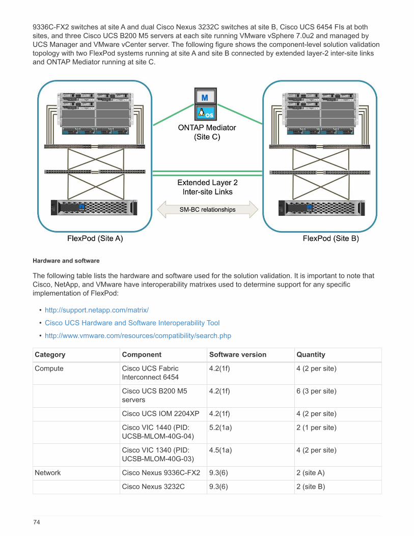
9336C-FX2 switches at site A and dual Cisco Nexus 3232C switches at site B, Cisco UCS 6454 FIs at bothsites, and three Cisco UCS B200 M5 servers at each site running VMware vSphere 7.0u2 and managed byUCS Manager and VMware vCenter server. The following figure shows the component-level solution validationtopology with two FlexPod systems running at site A and site B connected by extended layer-2 inter-site linksand ONTAP Mediator running at site C.
Hardware and software
The following table lists the hardware and software used for the solution validation. It is important to note thatCisco, NetApp, and VMware have interoperability matrixes used to determine support for any specificimplementation of FlexPod:
• http://support.netapp.com/matrix/
• Cisco UCS Hardware and Software Interoperability Tool
• http://www.vmware.com/resources/compatibility/search.php
Category Component Software version Quantity
Compute Cisco UCS FabricInterconnect 6454
4.2(1f) 4 (2 per site)
Cisco UCS B200 M5servers
4.2(1f) 6 (3 per site)
Cisco UCS IOM 2204XP 4.2(1f) 4 (2 per site)
Cisco VIC 1440 (PID:UCSB-MLOM-40G-04)
5.2(1a) 2 (1 per site)
Cisco VIC 1340 (PID:UCSB-MLOM-40G-03)
4.5(1a) 4 (2 per site)
Network Cisco Nexus 9336C-FX2 9.3(6) 2 (site A)
Cisco Nexus 3232C 9.3(6) 2 (site B)
74
Category Component Software version Quantity
Storage NetApp AFF A250 9.10.1 4 (2 per site)
NetApp System Manager 9.10.1 2 (1 per site)
NetApp Active IQ UnifiedManager
9.10 1
NetApp ONTAP Tools forVMware vSphere
9.10 1
NetApp SnapCenterPlugin for VMwarevSphere
4.6 1
NetApp ONTAP Mediator 1.3 1
NAbox 3.0.2 1
NetApp Harvest 21.11.1-1 1
Virtualization VMware ESXi 7.0U2 6 (3 per site)
VMware ESXi nenicEthernet Driver
1.0.35.0 6 (3 per site)
VMware vCenter 7.0U2 1
NetApp NFS Plug-in forVMware VAAI
2.0 6 (3 per site)
Testing Microsoft Windows 2022 1
Microsoft SQL Server 2019 1
Microsoft SQL ServerManagement Studio
18.10 1
HammerDB 4.3 1
Microsoft Windows 10 6 (3 per site)
IOMeter 1.1.0 6 (3 per site)
Next: Solution validation - Compute.
Solution validation - Compute
Preivous: Solution validation - Overview.
The compute configuration for the FlexPod SM-BC solution follows typical FlexPod solution best practices. Thefollowing sections highlight some of the connectivity and configurations used for the validation. Some of theSM-BC-related considerations are also highlighted to provide implementation references and guidance.
Connectivity
The connectivity between the UCS B200 blade servers and the IOMs are provided by the UCS VIC cardthrough the UCS 5108 chassis backplane connections. The UCS 2204XP Fabric Extenders used for thevalidation has sixteen 10G ports each to connect to the eight half-width blade servers, for example, two foreach server. To increase server connectivity bandwidth, an additional mezzanine-based VIC can be added to
75
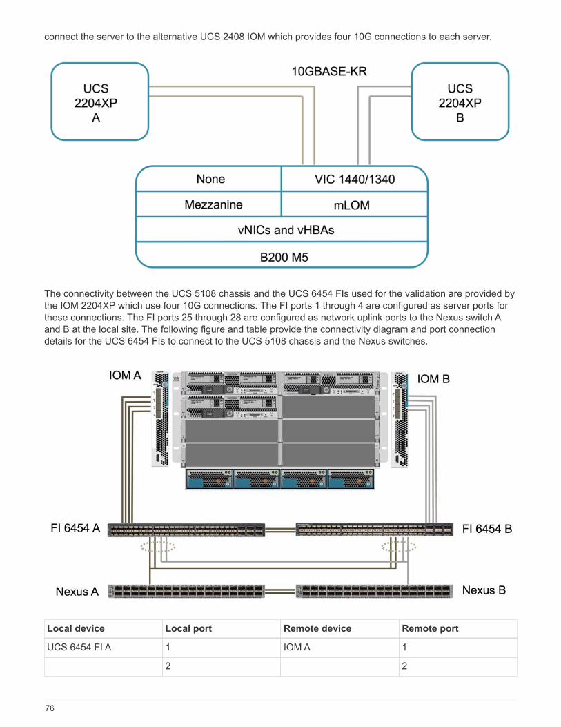
connect the server to the alternative UCS 2408 IOM which provides four 10G connections to each server.
The connectivity between the UCS 5108 chassis and the UCS 6454 FIs used for the validation are provided bythe IOM 2204XP which use four 10G connections. The FI ports 1 through 4 are configured as server ports forthese connections. The FI ports 25 through 28 are configured as network uplink ports to the Nexus switch Aand B at the local site. The following figure and table provide the connectivity diagram and port connectiondetails for the UCS 6454 FIs to connect to the UCS 5108 chassis and the Nexus switches.
Local device Local port Remote device Remote port
UCS 6454 FI A 1 IOM A 1
2 2
76
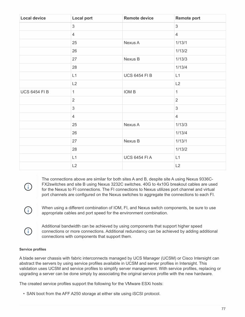
Local device Local port Remote device Remote port
3 3
4 4
25 Nexus A 1/13/1
26 1/13/2
27 Nexus B 1/13/3
28 1/13/4
L1 UCS 6454 FI B L1
L2 L2
UCS 6454 FI B 1 IOM B 1
2 2
3 3
4 4
25 Nexus A 1/13/3
26 1/13/4
27 Nexus B 1/13/1
28 1/13/2
L1 UCS 6454 FI A L1
L2 L2
The connections above are similar for both sites A and B, despite site A using Nexus 9336C-FX2switches and site B using Nexus 3232C switches. 40G to 4x10G breakout cables are usedfor the Nexus to FI connections. The FI connections to Nexus utilizes port channel and virtualport channels are configured on the Nexus switches to aggregate the connections to each FI.
When using a different combination of IOM, FI, and Nexus switch components, be sure to useappropriate cables and port speed for the environment combination.
Additional bandwidth can be achieved by using components that support higher speedconnections or more connections. Additional redundancy can be achieved by adding additionalconnections with components that support them.
Service profiles
A blade server chassis with fabric interconnects managed by UCS Manager (UCSM) or Cisco Intersight canabstract the servers by using service profiles available in UCSM and server profiles in Intersight. Thisvalidation uses UCSM and service profiles to simplify server management. With service profiles, replacing orupgrading a server can be done simply by associating the original service profile with the new hardware.
The created service profiles support the following for the VMware ESXi hosts:
• SAN boot from the AFF A250 storage at either site using iSCSI protocol.
77
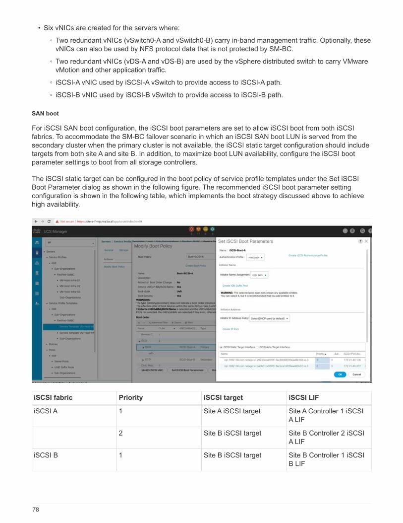
• Six vNICs are created for the servers where:
◦ Two redundant vNICs (vSwitch0-A and vSwitch0-B) carry in-band management traffic. Optionally, thesevNICs can also be used by NFS protocol data that is not protected by SM-BC.
◦ Two redundant vNICs (vDS-A and vDS-B) are used by the vSphere distributed switch to carry VMwarevMotion and other application traffic.
◦ iSCSI-A vNIC used by iSCSI-A vSwitch to provide access to iSCSI-A path.
◦ iSCSI-B vNIC used by iSCSI-B vSwitch to provide access to iSCSI-B path.
SAN boot
For iSCSI SAN boot configuration, the iSCSI boot parameters are set to allow iSCSI boot from both iSCSIfabrics. To accommodate the SM-BC failover scenario in which an iSCSI SAN boot LUN is served from thesecondary cluster when the primary cluster is not available, the iSCSI static target configuration should includetargets from both site A and site B. In addition, to maximize boot LUN availability, configure the iSCSI bootparameter settings to boot from all storage controllers.
The iSCSI static target can be configured in the boot policy of service profile templates under the Set iSCSIBoot Parameter dialog as shown in the following figure. The recommended iSCSI boot parameter settingconfiguration is shown in the following table, which implements the boot strategy discussed above to achievehigh availability.
iSCSI fabric Priority iSCSI target iSCSI LIF
iSCSI A 1 Site A iSCSI target Site A Controller 1 iSCSIA LIF
2 Site B iSCSI target Site B Controller 2 iSCSIA LIF
iSCSI B 1 Site B iSCSI target Site B Controller 1 iSCSIB LIF
78
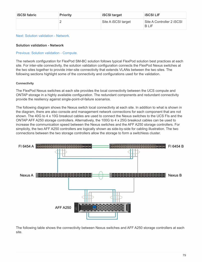
iSCSI fabric Priority iSCSI target iSCSI LIF
2 Site A iSCSI target Site A Controller 2 iSCSIB LIF
Next: Solution validation - Network.
Solution validation - Network
Previous: Solution validation - Compute.
The network configuration for FlexPod SM-BC solution follows typical FlexPod solution best practices at eachsite. For inter-site connectivity, the solution validation configuration connects the FlexPod Nexus switches atthe two sites together to provide inter-site connectivity that extends VLANs between the two sites. Thefollowing sections highlight some of the connectivity and configurations used for the validation.
Connectivity
The FlexPod Nexus switches at each site provides the local connectivity between the UCS compute andONTAP storage in a highly available configuration. The redundant components and redundant connectivityprovide the resiliency against single-point-of-failure scenarios.
The following diagram shows the Nexus switch local connectivity at each site. In addition to what is shown inthe diagram, there are also console and management network connections for each component that are notshown. The 40G to 4 x 10G breakout cables are used to connect the Nexus switches to the UCS FIs and theONTAP AFF A250 storage controllers. Alternatively, the 100G to 4 x 25G breakout cables can be used toincrease the communication speed between the Nexus switches and the AFF A250 storage controllers. Forsimplicity, the two AFF A250 controllers are logically shown as side-by-side for cabling illustration. The twoconnections between the two storage controllers allow the storage to form a switchless cluster.
The following table shows the connectivity between Nexus switches and AFF A250 storage controllers at eachsite.
79

Local device Local port Remote device Remote port
Nexus A 1/10/1 AFF A250 A e1a
1/10/2 e1b
1/10/3 AFF A250 B e1a
1/10/4 e1b
Nexus B 1/10/1 AFF A250 A e1c
1/10/2 e1d
1/10/3 AFF A250 B e1c
1/10/4 e1d
The connectivity between the FlexPod switches at site A and site B is shown in the following figure with cablingdetails listed in the accompanying table. The connections between the two switches at each site are for thevPC peer links. On the other hand, the connections between the switches across sites provide the inter-sitelinks. The links extend the VLANs across sites for intercluster communication, SM-BC data replication, in-bandmanagement, and data access for the remote site resources.
Local device Local port Remote device Remote port
Site A switch A 33 Site B switch A 31
34 32
25 Site A switch B 25
26 26
Site A switch B 33 Site B switch B 31
34 32
25 Site A switch A 25
26 26
Site B switch A 31 Site A switch A 33
32 34
25 Site B switch B 25
80
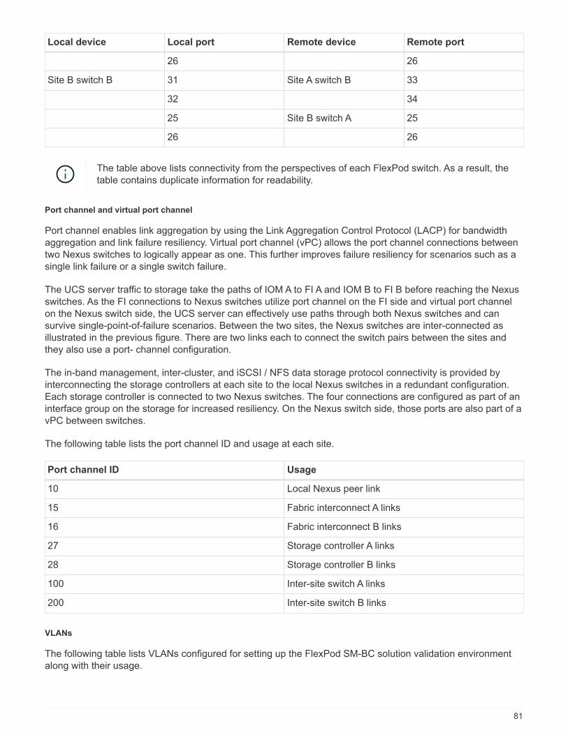
Local device Local port Remote device Remote port
26 26
Site B switch B 31 Site A switch B 33
32 34
25 Site B switch A 25
26 26
The table above lists connectivity from the perspectives of each FlexPod switch. As a result, thetable contains duplicate information for readability.
Port channel and virtual port channel
Port channel enables link aggregation by using the Link Aggregation Control Protocol (LACP) for bandwidthaggregation and link failure resiliency. Virtual port channel (vPC) allows the port channel connections betweentwo Nexus switches to logically appear as one. This further improves failure resiliency for scenarios such as asingle link failure or a single switch failure.
The UCS server traffic to storage take the paths of IOM A to FI A and IOM B to FI B before reaching the Nexusswitches. As the FI connections to Nexus switches utilize port channel on the FI side and virtual port channelon the Nexus switch side, the UCS server can effectively use paths through both Nexus switches and cansurvive single-point-of-failure scenarios. Between the two sites, the Nexus switches are inter-connected asillustrated in the previous figure. There are two links each to connect the switch pairs between the sites andthey also use a port- channel configuration.
The in-band management, inter-cluster, and iSCSI / NFS data storage protocol connectivity is provided byinterconnecting the storage controllers at each site to the local Nexus switches in a redundant configuration.Each storage controller is connected to two Nexus switches. The four connections are configured as part of aninterface group on the storage for increased resiliency. On the Nexus switch side, those ports are also part of avPC between switches.
The following table lists the port channel ID and usage at each site.
Port channel ID Usage
10 Local Nexus peer link
15 Fabric interconnect A links
16 Fabric interconnect B links
27 Storage controller A links
28 Storage controller B links
100 Inter-site switch A links
200 Inter-site switch B links
VLANs
The following table lists VLANs configured for setting up the FlexPod SM-BC solution validation environmentalong with their usage.
81
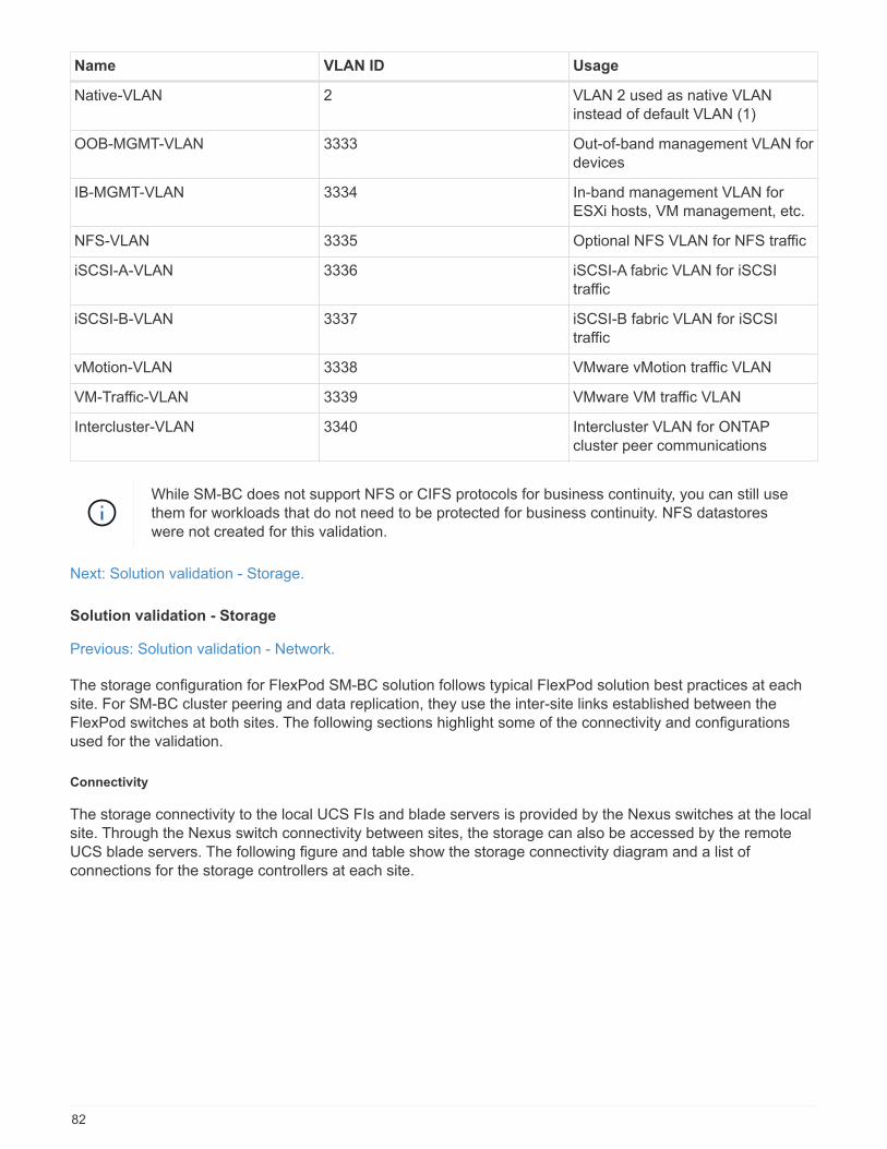
Name VLAN ID Usage
Native-VLAN 2 VLAN 2 used as native VLANinstead of default VLAN (1)
OOB-MGMT-VLAN 3333 Out-of-band management VLAN fordevices
IB-MGMT-VLAN 3334 In-band management VLAN forESXi hosts, VM management, etc.
NFS-VLAN 3335 Optional NFS VLAN for NFS traffic
iSCSI-A-VLAN 3336 iSCSI-A fabric VLAN for iSCSItraffic
iSCSI-B-VLAN 3337 iSCSI-B fabric VLAN for iSCSItraffic
vMotion-VLAN 3338 VMware vMotion traffic VLAN
VM-Traffic-VLAN 3339 VMware VM traffic VLAN
Intercluster-VLAN 3340 Intercluster VLAN for ONTAPcluster peer communications
While SM-BC does not support NFS or CIFS protocols for business continuity, you can still usethem for workloads that do not need to be protected for business continuity. NFS datastoreswere not created for this validation.
Next: Solution validation - Storage.
Solution validation - Storage
Previous: Solution validation - Network.
The storage configuration for FlexPod SM-BC solution follows typical FlexPod solution best practices at eachsite. For SM-BC cluster peering and data replication, they use the inter-site links established between theFlexPod switches at both sites. The following sections highlight some of the connectivity and configurationsused for the validation.
Connectivity
The storage connectivity to the local UCS FIs and blade servers is provided by the Nexus switches at the localsite. Through the Nexus switch connectivity between sites, the storage can also be accessed by the remoteUCS blade servers. The following figure and table show the storage connectivity diagram and a list ofconnections for the storage controllers at each site.
82
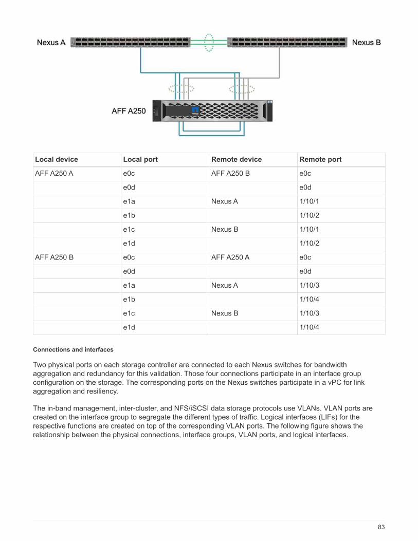
Local device Local port Remote device Remote port
AFF A250 A e0c AFF A250 B e0c
e0d e0d
e1a Nexus A 1/10/1
e1b 1/10/2
e1c Nexus B 1/10/1
e1d 1/10/2
AFF A250 B e0c AFF A250 A e0c
e0d e0d
e1a Nexus A 1/10/3
e1b 1/10/4
e1c Nexus B 1/10/3
e1d 1/10/4
Connections and interfaces
Two physical ports on each storage controller are connected to each Nexus switches for bandwidthaggregation and redundancy for this validation. Those four connections participate in an interface groupconfiguration on the storage. The corresponding ports on the Nexus switches participate in a vPC for linkaggregation and resiliency.
The in-band management, inter-cluster, and NFS/iSCSI data storage protocols use VLANs. VLAN ports arecreated on the interface group to segregate the different types of traffic. Logical interfaces (LIFs) for therespective functions are created on top of the corresponding VLAN ports. The following figure shows therelationship between the physical connections, interface groups, VLAN ports, and logical interfaces.
83

SAN boot
NetApp recommends implementing SAN boot for the Cisco UCS servers in the FlexPod solution. ImplementingSAN boot enables you to safely secure the operating system within the NetApp storage system, providingbetter performance and flexibility. For this solution, iSCSI SAN boot was validated.
The following figure depicts the connectivity for iSCSI SAN boot of Cisco UCS server from NetApp Storage. IniSCSI SAN boot, each Cisco UCS server is assigned two iSCSI vNICs (one for each SAN fabric) that provideredundant connectivity from the server all the way to the storage. The 10/25-G Ethernet storage ports that areconnected to the Nexus switches (in this example e1a, e1b, e1c, and e1d) are grouped together to form oneinterface group (ifgrp) (in this example, a0a). The iSCSI VLAN ports are created on the ifgrp and the iSCSILIFs are created on the iSCSI VLAN ports.
Each iSCSI boot LUN is mapped to the server that boots from it through the iSCSI LIFs by associating the bootLUN with the server’s iSCSI Qualified Names (IQNs) in its boot igroup. The server’s boot igroup contains twoIQNs, one for each vNIC / SAN fabric. This feature enables only the authorized server to have access to theboot LUN created specifically for that server.
84
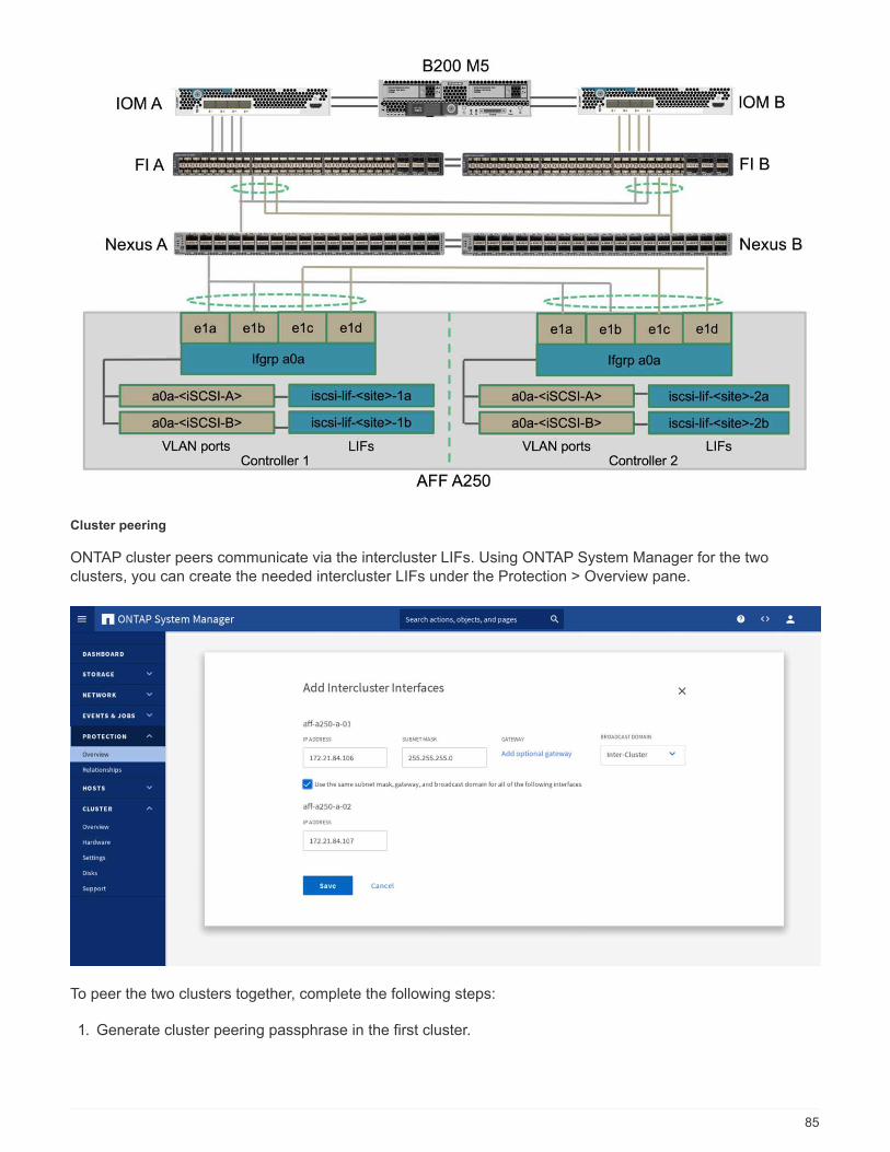
Cluster peering
ONTAP cluster peers communicate via the intercluster LIFs. Using ONTAP System Manager for the twoclusters, you can create the needed intercluster LIFs under the Protection > Overview pane.
To peer the two clusters together, complete the following steps:
1. Generate cluster peering passphrase in the first cluster.
85
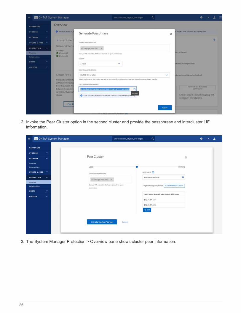
2. Invoke the Peer Cluster option in the second cluster and provide the passphrase and intercluster LIFinformation.
3. The System Manager Protection > Overview pane shows cluster peer information.
86
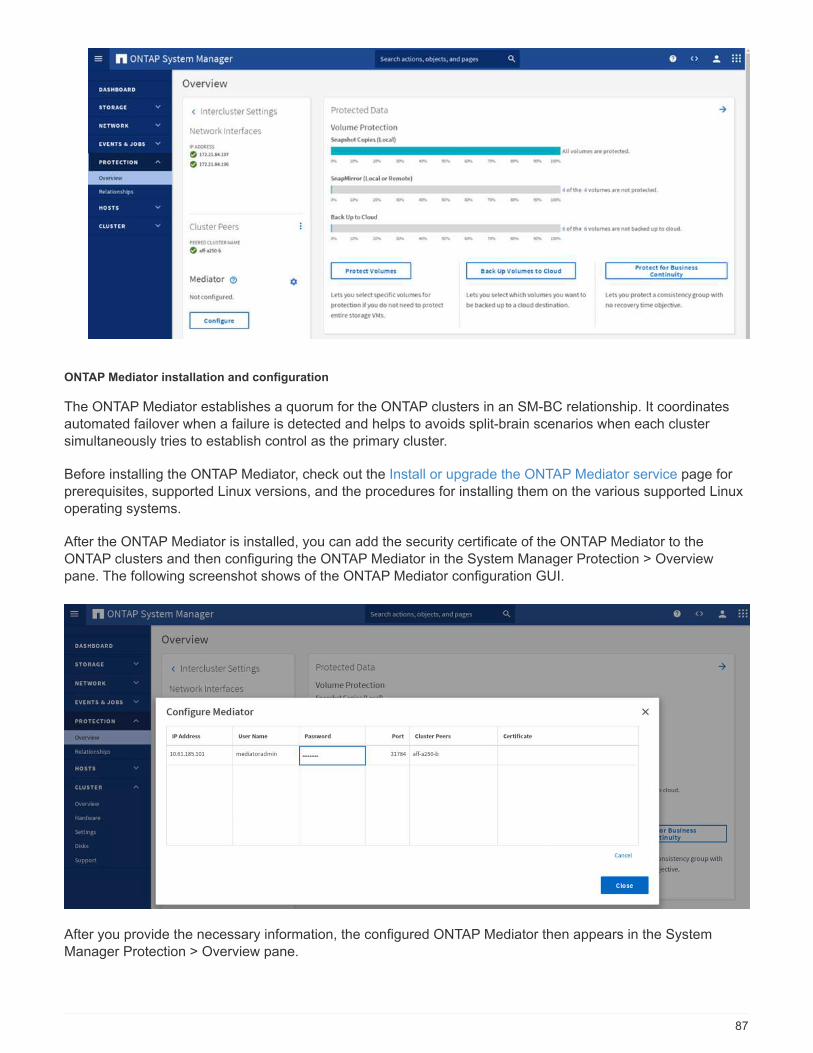
ONTAP Mediator installation and configuration
The ONTAP Mediator establishes a quorum for the ONTAP clusters in an SM-BC relationship. It coordinatesautomated failover when a failure is detected and helps to avoids split-brain scenarios when each clustersimultaneously tries to establish control as the primary cluster.
Before installing the ONTAP Mediator, check out the Install or upgrade the ONTAP Mediator service page forprerequisites, supported Linux versions, and the procedures for installing them on the various supported Linuxoperating systems.
After the ONTAP Mediator is installed, you can add the security certificate of the ONTAP Mediator to theONTAP clusters and then configuring the ONTAP Mediator in the System Manager Protection > Overviewpane. The following screenshot shows of the ONTAP Mediator configuration GUI.
After you provide the necessary information, the configured ONTAP Mediator then appears in the SystemManager Protection > Overview pane.
87
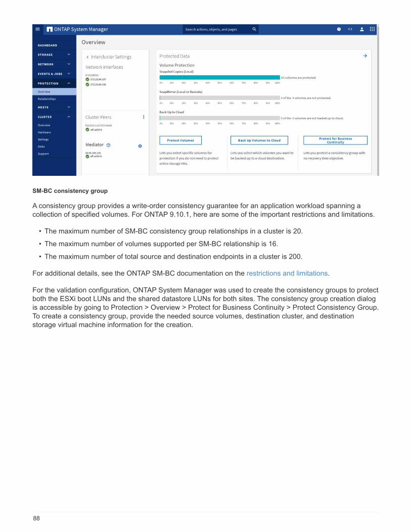
SM-BC consistency group
A consistency group provides a write-order consistency guarantee for an application workload spanning acollection of specified volumes. For ONTAP 9.10.1, here are some of the important restrictions and limitations.
• The maximum number of SM-BC consistency group relationships in a cluster is 20.
• The maximum number of volumes supported per SM-BC relationship is 16.
• The maximum number of total source and destination endpoints in a cluster is 200.
For additional details, see the ONTAP SM-BC documentation on the restrictions and limitations.
For the validation configuration, ONTAP System Manager was used to create the consistency groups to protectboth the ESXi boot LUNs and the shared datastore LUNs for both sites. The consistency group creation dialogis accessible by going to Protection > Overview > Protect for Business Continuity > Protect Consistency Group.To create a consistency group, provide the needed source volumes, destination cluster, and destinationstorage virtual machine information for the creation.
88

The following table lists the four consistency groups that are created and the volumes that are included in eachconsistency group for the validation testing.
System Manager Consistency group Volumes
Site A cg_esxi_a esxi_a
Site A cg_infra_datastore_a infra_datastore_a_01infra_datastore_a_02
Site B cg_esxi_b esxi_b
Site B cg_infra_datastore_b infra_datastore_b_01infra_datastore_b_02
After the consistency groups are created, they show up under the respective protection relationships in site Aand site B.
This screenshot shows the consistency group relationships at site A.
89
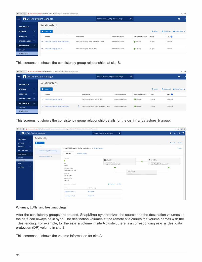
This screenshot shows the consistency group relationships at site B.
This screenshot shows the consistency group relationship details for the cg_infra_datastore_b group.
Volumes, LUNs, and host mappings
After the consistency groups are created, SnapMirror synchronizes the source and the destination volumes sothe data can always be in sync. The destination volumes at the remote site carries the volume names with the_dest ending. For example, for the esxi_a volume in site A cluster, there is a corresponding esxi_a_dest dataprotection (DP) volume in site B.
This screenshot shows the volume information for site A.
90

This screenshot shows the volume information for site B.
To facilitate transparent application failover, the mirrored SM-BC LUNs also need to be mapped to the hostsfrom the destination cluster. This allows the hosts to properly see paths to the LUNs from both the source and
destination clusters. The igroup show and lun show outputs for both site A and site B are captured in thefollowing two screenshots. With the created mappings, each ESXi host in the cluster sees its own SAN bootLUN as ID 0 and all the four shared iSCSI datastore LUNs.
This screenshot shows the host igroups and LUN mapping for site A cluster.
91
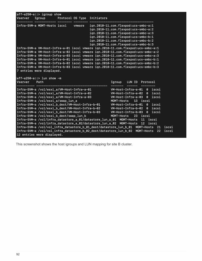
This screenshot shows the host igroups and LUN mapping for site B cluster.
92
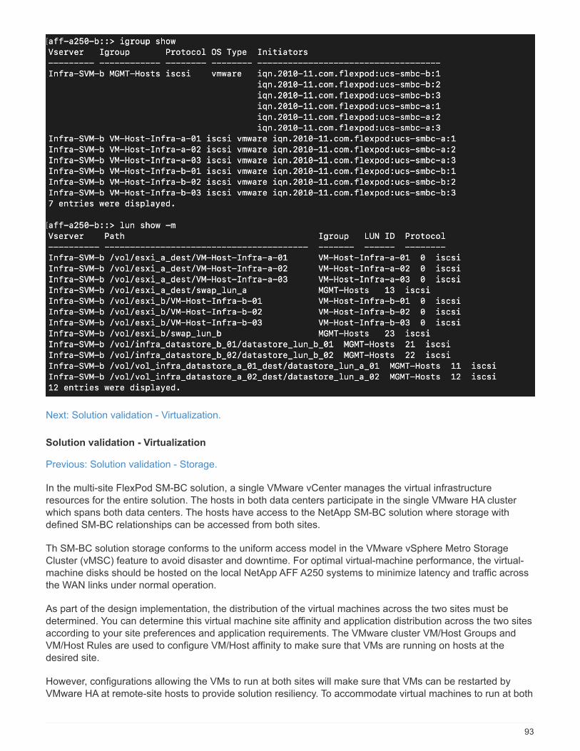
Next: Solution validation - Virtualization.
Solution validation - Virtualization
Previous: Solution validation - Storage.
In the multi-site FlexPod SM-BC solution, a single VMware vCenter manages the virtual infrastructureresources for the entire solution. The hosts in both data centers participate in the single VMware HA clusterwhich spans both data centers. The hosts have access to the NetApp SM-BC solution where storage withdefined SM-BC relationships can be accessed from both sites.
Th SM-BC solution storage conforms to the uniform access model in the VMware vSphere Metro StorageCluster (vMSC) feature to avoid disaster and downtime. For optimal virtual-machine performance, the virtual-machine disks should be hosted on the local NetApp AFF A250 systems to minimize latency and traffic acrossthe WAN links under normal operation.
As part of the design implementation, the distribution of the virtual machines across the two sites must bedetermined. You can determine this virtual machine site affinity and application distribution across the two sitesaccording to your site preferences and application requirements. The VMware cluster VM/Host Groups andVM/Host Rules are used to configure VM/Host affinity to make sure that VMs are running on hosts at thedesired site.
However, configurations allowing the VMs to run at both sites will make sure that VMs can be restarted byVMware HA at remote-site hosts to provide solution resiliency. To accommodate virtual machines to run at both
93
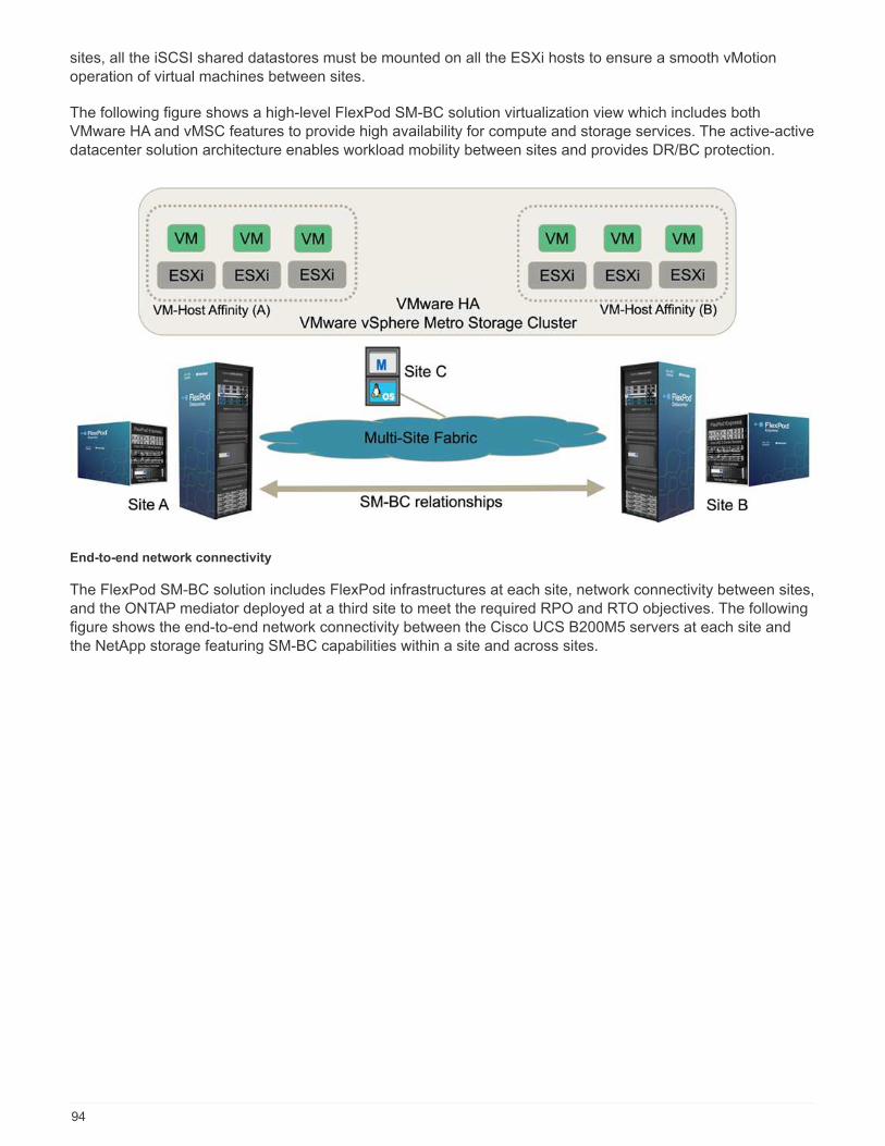
sites, all the iSCSI shared datastores must be mounted on all the ESXi hosts to ensure a smooth vMotionoperation of virtual machines between sites.
The following figure shows a high-level FlexPod SM-BC solution virtualization view which includes bothVMware HA and vMSC features to provide high availability for compute and storage services. The active-activedatacenter solution architecture enables workload mobility between sites and provides DR/BC protection.
End-to-end network connectivity
The FlexPod SM-BC solution includes FlexPod infrastructures at each site, network connectivity between sites,and the ONTAP mediator deployed at a third site to meet the required RPO and RTO objectives. The followingfigure shows the end-to-end network connectivity between the Cisco UCS B200M5 servers at each site andthe NetApp storage featuring SM-BC capabilities within a site and across sites.
94
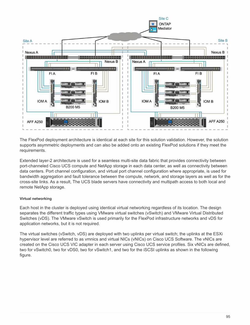
The FlexPod deployment architecture is identical at each site for this solution validation. However, the solutionsupports asymmetric deployments and can also be added onto an existing FlexPod solutions if they meet therequirements.
Extended layer-2 architecture is used for a seamless multi-site data fabric that provides connectivity betweenport-channeled Cisco UCS compute and NetApp storage in each data center, as well as connectivity betweendata centers. Port channel configuration, and virtual port channel configuration where appropriate, is used forbandwidth aggregation and fault tolerance between the compute, network, and storage layers as well as for thecross-site links. As a result, The UCS blade servers have connectivity and multipath access to both local andremote NetApp storage.
Virtual networking
Each host in the cluster is deployed using identical virtual networking regardless of its location. The designseparates the different traffic types using VMware virtual switches (vSwitch) and VMware Virtual DistributedSwitches (vDS). The VMware vSwitch is used primarily for the FlexPod infrastructure networks and vDS forapplication networks, but it is not required.
The virtual switches (vSwitch, vDS) are deployed with two uplinks per virtual switch; the uplinks at the ESXihypervisor level are referred to as vmnics and virtual NICs (vNICs) on Cisco UCS Software. The vNICs arecreated on the Cisco UCS VIC adapter in each server using Cisco UCS service profiles. Six vNICs are defined,two for vSwitch0, two for vDS0, two for vSwitch1, and two for the iSCSI uplinks as shown in the followingfigure.
95

vSwitch0 is defined during VMware ESXi host configuration, and it contains the FlexPod infrastructuremanagement VLAN and the ESXi host VMkernel (VMK) ports for management. An infrastructure managementvirtual machine port group is also placed on vSwitch0 for any critical infrastructure management virtualmachines that are needed.
It is important to place such management infrastructure virtual machines on vSwitch0 instead of the vDSbecause if the FlexPod infrastructure is shut down or power cycled and you attempt to activate thatmanagement virtual machine on a host other than the host on which it was originally running, it boots up fineon the network on vSwitch0. This process is particularly important if VMware vCenter is the managementvirtual machine. If vCenter were on the vDS and moved to another host and then booted, it would not beconnected to the network after booting up.
Two iSCSI boot vSwitches are used in this design. Cisco UCS iSCSI boot requires separate vNICs for iSCSIboot. These vNICs use iSCSI VLAN of the appropriate fabric as the native VLAN and are attached to theappropriate iSCSI boot vSwitch. Optionally, you could also deploy iSCSI networks on vDS by deploying a newvDS or using an existing one.
VM-Host affinity groups and rules
To enable virtual machines to run on any ESXi host at both SM-BC sites, all ESXi hosts must mount the iSCSIdatastores from both sites. If the datastores from both sites are properly mounted by all ESXi hosts, you canmigrate a virtual machine between any hosts with vMotion and the VM still maintains access to all its virtualdisks created from those datastores.
For a virtual machine that uses local datastores, its access to virtual disks becomes remote if it is migrated to ahost at the remote site and thus increasing read operation latency due to the physical distance between thesites. Therefore, it is a best practice to keep virtual machines on the local hosts and utilize local storage at thesite.
By using a VM/host affinity mechanism, you can use VM/Host Groups to create a VM group and a host groupfor virtual machines and hosts located at a particular site. Using VM/Host Rules, you can specify the policy forthe VMs and hosts to follow. To allow virtual-machine migration across sites during a site maintenance ordisaster scenario, use the “Should run on hosts in group” policy specification for that flexibility.
The following screenshot shows that two host groups and two VM groups are created for site A and site Bhosts and VMs
96
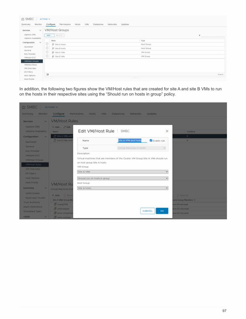
In addition, the following two figures show the VM/Host rules that are created for site A and site B VMs to runon the hosts in their respective sites using the “Should run on hosts in group” policy.
97

vSphere HA heartbeat
VMware vSphere HA has a heartbeat mechanism for host state validation. The primary heartbeat mechanismis through networking, and the secondary heartbeat mechanism is through the datastore. If heartbeats are notreceived, it then decides if it is isolated from the network by pinging the default gateway or the manuallyconfigured isolation addresses. For the datastore heartbeat, VMware recommends increasing the heartbeatdatastores from the minimum of two to four for a stretched cluster.
For the solution validation, the two ONTAP cluster management IP addresses are used as the isolation
address. In addition, the recommended vSphere HA advanced option ds.heartbeatDsPerHost with a valueof 4 was added as shown in the following figure.
For the heartbeat datastore, specify the four shared datastores from the cluster and complement automatically,as shown in the following figure.
98

For additional best practices and configurations for VMware HA Cluster and VMware vSphere Metro storagecluster, see Creating and Using vSphere HA Clusters, VMware vSphere Metro Storage Cluster (vMSC) and theVMWare KB for NetApp ONTAP with NetApp SnapMirror Business Continuity (SM-BC) and VMware vSphereMetro Storage Cluster (vMSC).
Next: Solution validation - Validated scenarios.
Solution validation - Validated scenarios
Previous: Solution validation - Virtualization.
The FlexPod Datacenter SM-BC solution protects data services for a variety of single-point-of-failure scenariosas well as for a site disaster. The redundant design implemented at each site provides high availability, and theSM-BC implementation with synchronous data replication across sites protects data services from a sitewidedisaster of one site. The deployed solution is validated for its desired solution functions and various failurescenarios for which the solution is designed to protect.
99

Solution functions validation
A variety of test cases are used to verify solution functions and simulate partial and complete site failurescenarios. To minimize duplication with the tests already performed in the existing FlexPod Datacentersolutions under Cisco Validated Design Program, the focus of this report is on the SM-BC related aspects ofthe solution. Some general FlexPod validations are included for practitioners to go through for theirimplementation validations.
For the solution validation, one Windows 10 virtual machine per ESXi host was created on all ESXi hosts atboth sites. The IOMeter tool was installed and used to generate I/O to two virtual data disks that are mappedfrom the shared local iSCSI datastores. The IOMeter workload parameters configured were 8-KB I/O, 75%read, and 50% random, with 8 outstanding I/O commands for each data disk. For most of the test scenariosperformed, the continuation of IOMeter I/O serves as an indication that the scenario did not cause a dataservice outage.
Since SM-BC is critical for business applications such as database servers, the Microsoft SQL server 2019instance on a Windows server 2022 virtual machine was also included as part of the testing to confirm that theapplication continues to run when storage at its local site is not available and data service is resumed at theremote site storage without application disruptions.
ESXi Host iSCSI SAN boot test
The ESXi hosts in the solution are configured to boot from iSCSI SAN. Using SAN boot simplifies servermanagement when replacing a server because the service profile of the server can be associated with a newserver for it to boot up without making any additional configuration changes.
In addition to booting an ESXi host located at a site from its local iSCSI boot LUN, testing was also performedto boot the ESXi host when its local storage controller is in a takeover state or when its local storage cluster iscompletely unavailable. These validation scenarios make sure that the ESXi hosts are properly configured perdesign and can boot up during a storage maintenance or disaster scenario for disaster-recovery to providebusiness continuity.
Before the SM-BC consistency group relationship is configured, an iSCSI LUN hosted by a storage controllerHA pair has four paths, two through each iSCSI fabric, based on the implementation of best practices. A hostcan get to the LUN through the two iSCSI VLANs/fabrics to the LUN hosting controller as well as through thehigh-availability partner of the controller.
After the SM-BC consistency group relationship is configured and the mirrored LUNs are properly mapped tothe initiators, the path count for the LUN doubles. For this implementation, it goes from having twoactive/optimized paths and two active/non-optimized paths to having two active/optimized paths and sixactive/non-optimized paths.
The following figure illustrates the paths an ESXi host can take to access a LUN, for example, LUN 0. As theLUN is attached to the site A controller 01, only the two paths directly accessing the LUN via that controller areactive/optimized and all the remaining six paths are active/nonoptimized.
100
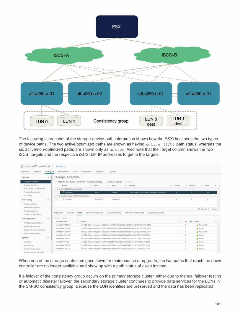
The following screenshot of the storage-device-path information shows how the ESXi host sees the two types
of device paths. The two active/optimized paths are shown as having active (I/O) path status, whereas the
six active/non-optimized paths are shown only as active. Also note that the Target column shows the twoiSCSI targets and the respective iSCSI LIF IP addresses to get to the targets.
When one of the storage controllers goes down for maintenance or upgrade, the two paths that reach the down
controller are no longer available and show up with a path status of dead instead.
If a failover of the consistency group occurs on the primary storage cluster, either due to manual failover testingor automatic disaster failover, the secondary storage cluster continues to provide data services for the LUNs inthe SM-BC consistency group. Because the LUN identities are preserved and the data has been replicated
101
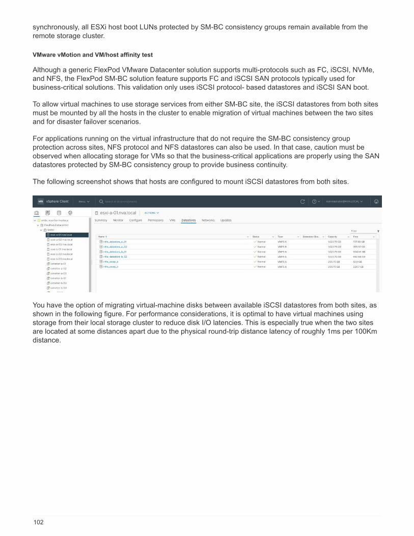
synchronously, all ESXi host boot LUNs protected by SM-BC consistency groups remain available from theremote storage cluster.
VMware vMotion and VM/host affinity test
Although a generic FlexPod VMware Datacenter solution supports multi-protocols such as FC, iSCSI, NVMe,and NFS, the FlexPod SM-BC solution feature supports FC and iSCSI SAN protocols typically used forbusiness-critical solutions. This validation only uses iSCSI protocol- based datastores and iSCSI SAN boot.
To allow virtual machines to use storage services from either SM-BC site, the iSCSI datastores from both sitesmust be mounted by all the hosts in the cluster to enable migration of virtual machines between the two sitesand for disaster failover scenarios.
For applications running on the virtual infrastructure that do not require the SM-BC consistency groupprotection across sites, NFS protocol and NFS datastores can also be used. In that case, caution must beobserved when allocating storage for VMs so that the business-critical applications are properly using the SANdatastores protected by SM-BC consistency group to provide business continuity.
The following screenshot shows that hosts are configured to mount iSCSI datastores from both sites.
You have the option of migrating virtual-machine disks between available iSCSI datastores from both sites, asshown in the following figure. For performance considerations, it is optimal to have virtual machines usingstorage from their local storage cluster to reduce disk I/O latencies. This is especially true when the two sitesare located at some distances apart due to the physical round-trip distance latency of roughly 1ms per 100Kmdistance.
102
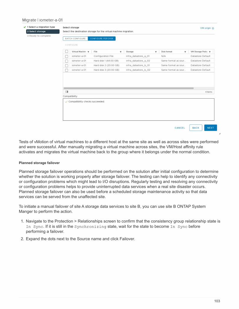
Tests of vMotion of virtual machines to a different host at the same site as well as across sites were performedand were successful. After manually migrating a virtual machine across sites, the VM/Host affinity ruleactivates and migrates the virtual machine back to the group where it belongs under the normal condition.
Planned storage failover
Planned storage failover operations should be performed on the solution after initial configuration to determinewhether the solution is working properly after storage failover. The testing can help to identify any connectivityor configuration problems which might lead to I/O disruptions. Regularly testing and resolving any connectivityor configuration problems helps to provide uninterrupted data services when a real site disaster occurs.Planned storage failover can also be used before a scheduled storage maintenance activity so that dataservices can be served from the unaffected site.
To initiate a manual failover of site A storage data services to site B, you can use site B ONTAP SystemManger to perform the action.
1. Navigate to the Protection > Relationships screen to confirm that the consistency group relationship state is
In Sync. If it is still in the Synchronizing state, wait for the state to become In Sync beforeperforming a failover.
2. Expand the dots next to the Source name and click Failover.
103
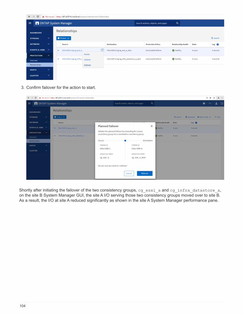
3. Confirm failover for the action to start.
Shortly after initiating the failover of the two consistency groups, cg_esxi_a and cg_infra_datastore_a,on the site B System Manager GUI, the site A I/O serving those two consistency groups moved over to site B.As a result, the I/O at site A reduced significantly as shown in the site A System Manager performance pane.
104
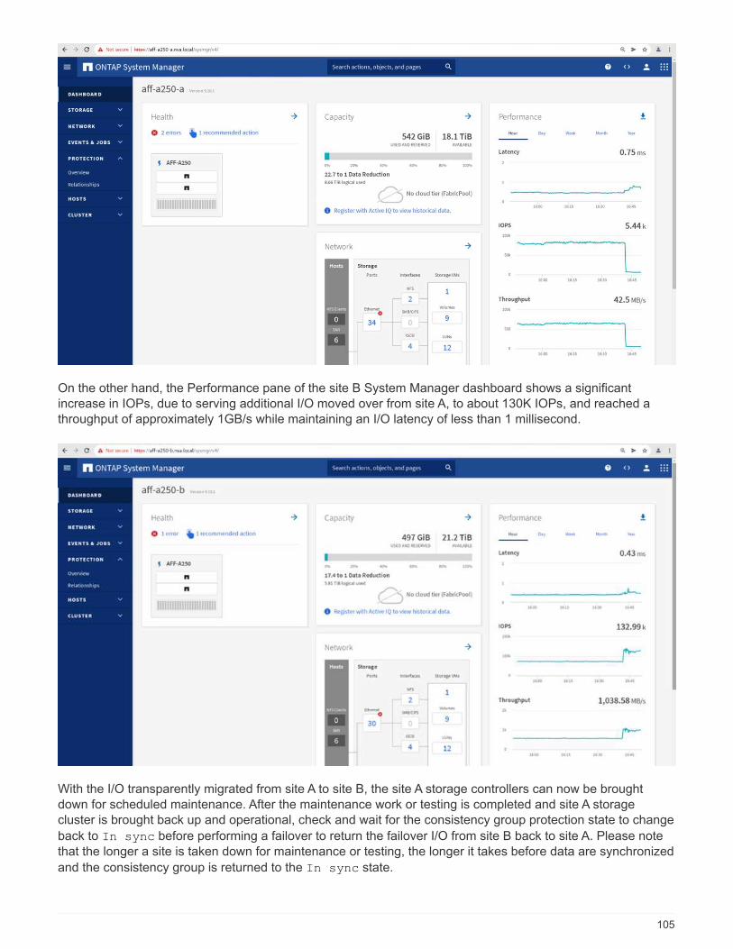
On the other hand, the Performance pane of the site B System Manager dashboard shows a significantincrease in IOPs, due to serving additional I/O moved over from site A, to about 130K IOPs, and reached athroughput of approximately 1GB/s while maintaining an I/O latency of less than 1 millisecond.
With the I/O transparently migrated from site A to site B, the site A storage controllers can now be broughtdown for scheduled maintenance. After the maintenance work or testing is completed and site A storagecluster is brought back up and operational, check and wait for the consistency group protection state to change
back to In sync before performing a failover to return the failover I/O from site B back to site A. Please notethat the longer a site is taken down for maintenance or testing, the longer it takes before data are synchronized
and the consistency group is returned to the In sync state.
105

Unplanned storage failover
An unplanned storage failover can occur when a real disaster happens or during a disaster simulation. Forexample, see the following figure in which the storage system at site A experiences a power outage, anunplanned storage failover is triggered, and the data services for site A LUNs, which are protected by the SM-BC relationships, continue from site B.
To simulate a storage disaster at site A, both storage controllers at site A can be powered off by physicallyturning off the power switch to discontinue the supply of power to the controllers, or by using the storagecontroller service processors’ system power management command to power off the controllers.
When the storage cluster at site A losses power, there is a sudden stop of the data services provided by thesite A storage cluster. Then, the ONTAP Mediator, which monitors the SM-BC solution from a third site, detectsthe site A storage failure condition and enables the SM-BC solution to perform an automated unplannedfailover. This allows site B storage controllers to continue data services for the LUNs configured in the SM-BCconsistency group relationships with site A.
From the application perspective, the data services pause briefly while the operating system checks the pathstatus for the LUNs and then resume I/O on the available paths to the surviving site B storage controllers.
106

During the validation testing, the IOMeter tool on the VMs at both sites generates I/O to their local datastores.After the site A cluster was powered off, I/O paused briefly and then resumed afterwards. See the following twofigures for the dashboards of the storage cluster at site A and site B respectively before the disaster whichshow roughly 80k IOPS and 600 MB/s throughput at each site.
After powering off the storage controllers at site A, we can visually validate that site B storage controller I/Oincreased sharply to provide additional data services on behalf of site A (see the following figure). In addition,the GUI of the IOMeter VMs also showed that I/O continued despite site A storage cluster outage. Please notethat if there are additional datastores backed by LUNs not protected by SM-BC relationships, those datastoreswill no longer be accessible when the storage disaster occurs. Therefore, it is important to evaluate thebusiness needs of the various application data and properly place them in datastores protected by SM-BCrelationships to provide business continuity.
107
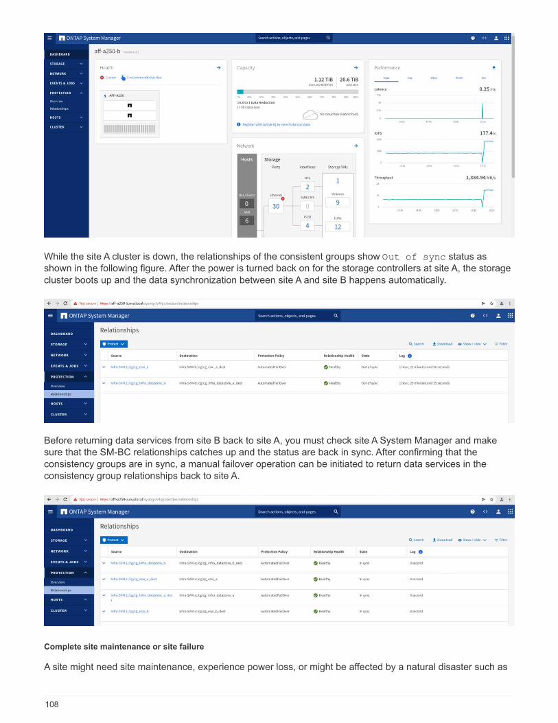
While the site A cluster is down, the relationships of the consistent groups show Out of sync status asshown in the following figure. After the power is turned back on for the storage controllers at site A, the storagecluster boots up and the data synchronization between site A and site B happens automatically.
Before returning data services from site B back to site A, you must check site A System Manager and makesure that the SM-BC relationships catches up and the status are back in sync. After confirming that theconsistency groups are in sync, a manual failover operation can be initiated to return data services in theconsistency group relationships back to site A.
Complete site maintenance or site failure
A site might need site maintenance, experience power loss, or might be affected by a natural disaster such as
108

a hurricane or an earthquake. Therefore, it is crucial that you exercise planned and unplanned site failurescenarios to help ensure that your FlexPod SM-BC solution is properly configured to survive such failures forall your business-critical applications and data services. The following site-related scenarios were validated.
• Planned site maintenance scenario by migrating virtual machines and critical data services to the other site
• Unplanned site outage scenario by powering off servers and storage controllers for disaster simulation
To get a site ready for planned site maintenance, a combination of migrating affected virtual machines off thesite with vMotion and a manual failover of the SM-BC consistency group relationships are needed to migratevirtual machines and critical data services to the alternative site. Testing was performed in two different orders:vMotion first followed by SM-BC failover and SM-BC failover first followed by vMotion, to confirm that virtualmachines continue to run and data services are not interrupted.
Before performing the planned migration, update the VM/Host affinity rule so the VMs that are currently runningon the site are automatically migrated off the site that is undergoing maintenance. The following screenshotshows an example of modifying the site A VM/Host affinity rule for the VMs to migrate from site A to site Bautomatically. Instead of specifying that the VMs now need to run on site B, you can also choose to disable theaffinity rule temporarily so the VMs can be migrated manually.
After virtual machines and storage services have been migrated, you can power off servers, storagecontrollers, disk shelves, and switches and perform the needed site maintenance activities. When sitemaintenance is completed and the FlexPod instance is brought back up, you can change the host group affinityfor the VMs to return to their original site. Afterwards, you should change the “Must run on hosts in group”VM/Host site affinity rule back to “Should run on hosts in group” so virtual machines are allowed to run on hostsat the other site should a disaster happens. For the validation testing, all virtual machines were successfullymigrated to the other site and the data services continued without problems after performing a failover for the
109
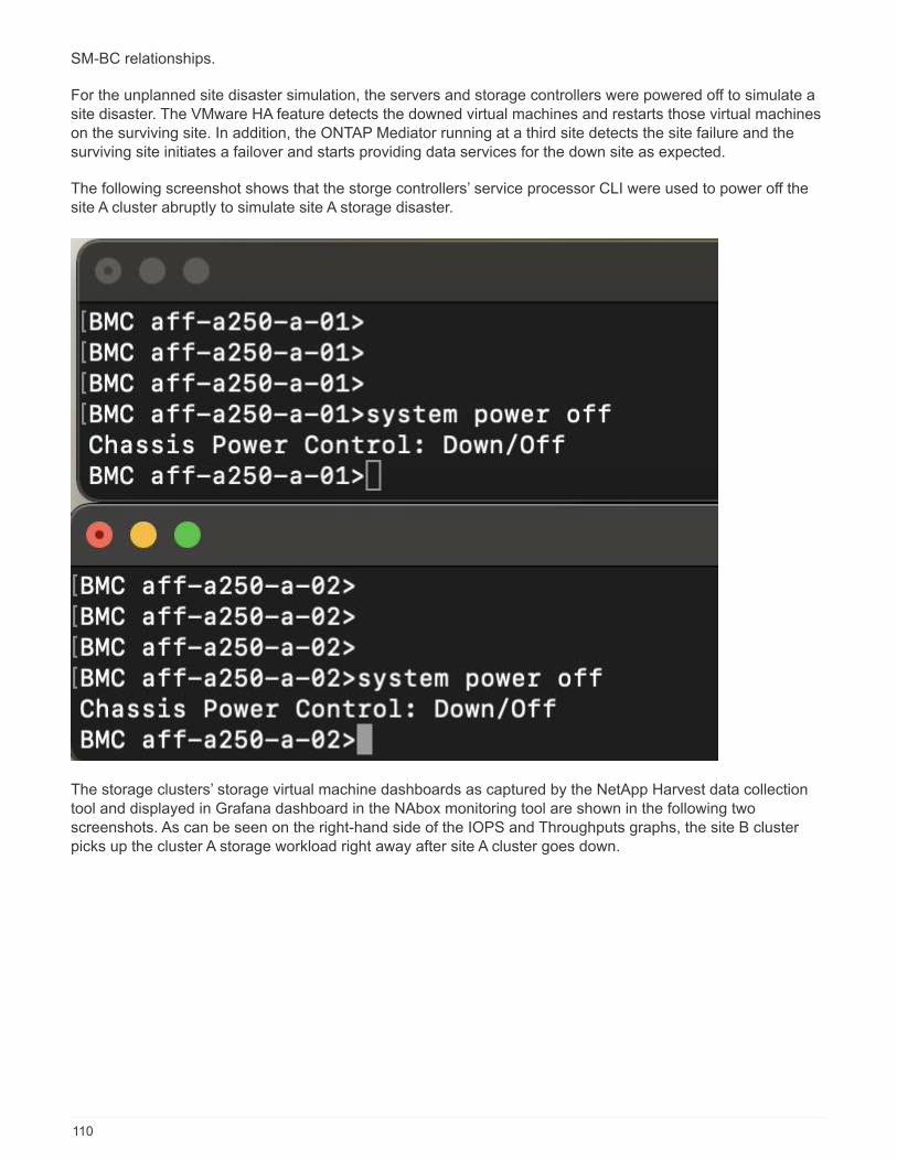
SM-BC relationships.
For the unplanned site disaster simulation, the servers and storage controllers were powered off to simulate asite disaster. The VMware HA feature detects the downed virtual machines and restarts those virtual machineson the surviving site. In addition, the ONTAP Mediator running at a third site detects the site failure and thesurviving site initiates a failover and starts providing data services for the down site as expected.
The following screenshot shows that the storge controllers’ service processor CLI were used to power off thesite A cluster abruptly to simulate site A storage disaster.
The storage clusters’ storage virtual machine dashboards as captured by the NetApp Harvest data collectiontool and displayed in Grafana dashboard in the NAbox monitoring tool are shown in the following twoscreenshots. As can be seen on the right-hand side of the IOPS and Throughputs graphs, the site B clusterpicks up the cluster A storage workload right away after site A cluster goes down.
110
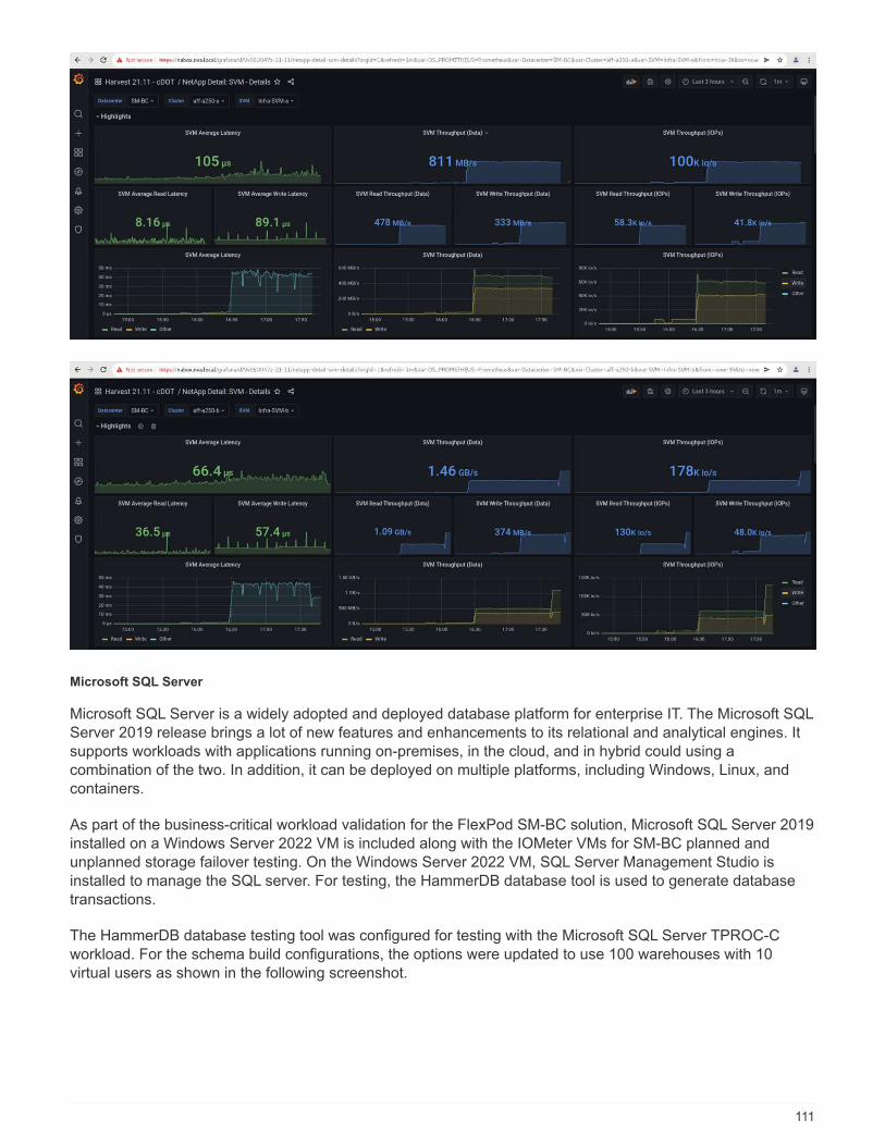
Microsoft SQL Server
Microsoft SQL Server is a widely adopted and deployed database platform for enterprise IT. The Microsoft SQLServer 2019 release brings a lot of new features and enhancements to its relational and analytical engines. Itsupports workloads with applications running on-premises, in the cloud, and in hybrid could using acombination of the two. In addition, it can be deployed on multiple platforms, including Windows, Linux, andcontainers.
As part of the business-critical workload validation for the FlexPod SM-BC solution, Microsoft SQL Server 2019installed on a Windows Server 2022 VM is included along with the IOMeter VMs for SM-BC planned andunplanned storage failover testing. On the Windows Server 2022 VM, SQL Server Management Studio isinstalled to manage the SQL server. For testing, the HammerDB database tool is used to generate databasetransactions.
The HammerDB database testing tool was configured for testing with the Microsoft SQL Server TPROC-Cworkload. For the schema build configurations, the options were updated to use 100 warehouses with 10virtual users as shown in the following screenshot.
111

After the schema build options were updated, the schema build process was started. A few minutes later, anunplanned simulated site B storage cluster failure was introduced by powering off both nodes of the two nodeAFF A250 storage cluster at about the same time using system processor CLI commands.
After a brief pause of database transactions, the automated failover for the disaster remediation kicked in andthe transactions resumed. The following screenshot shows the HammerDB Transaction Counter screenshotaround that time. As the database for the Microsoft SQL Server normally resides on the site B storage cluster,the transaction paused briefly when storage at site B went down and then resumed after the automated failoverhappened.
112
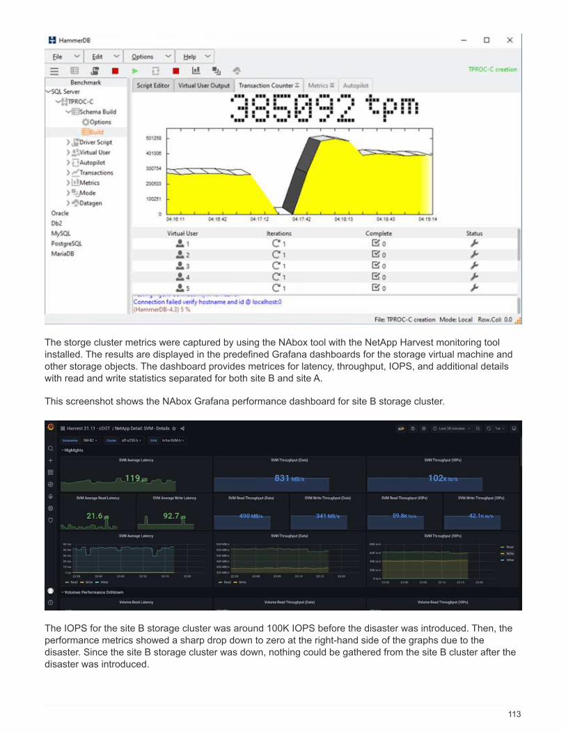
The storge cluster metrics were captured by using the NAbox tool with the NetApp Harvest monitoring toolinstalled. The results are displayed in the predefined Grafana dashboards for the storage virtual machine andother storage objects. The dashboard provides metrices for latency, throughput, IOPS, and additional detailswith read and write statistics separated for both site B and site A.
This screenshot shows the NAbox Grafana performance dashboard for site B storage cluster.
The IOPS for the site B storage cluster was around 100K IOPS before the disaster was introduced. Then, theperformance metrics showed a sharp drop down to zero at the right-hand side of the graphs due to thedisaster. Since the site B storage cluster was down, nothing could be gathered from the site B cluster after thedisaster was introduced.
113
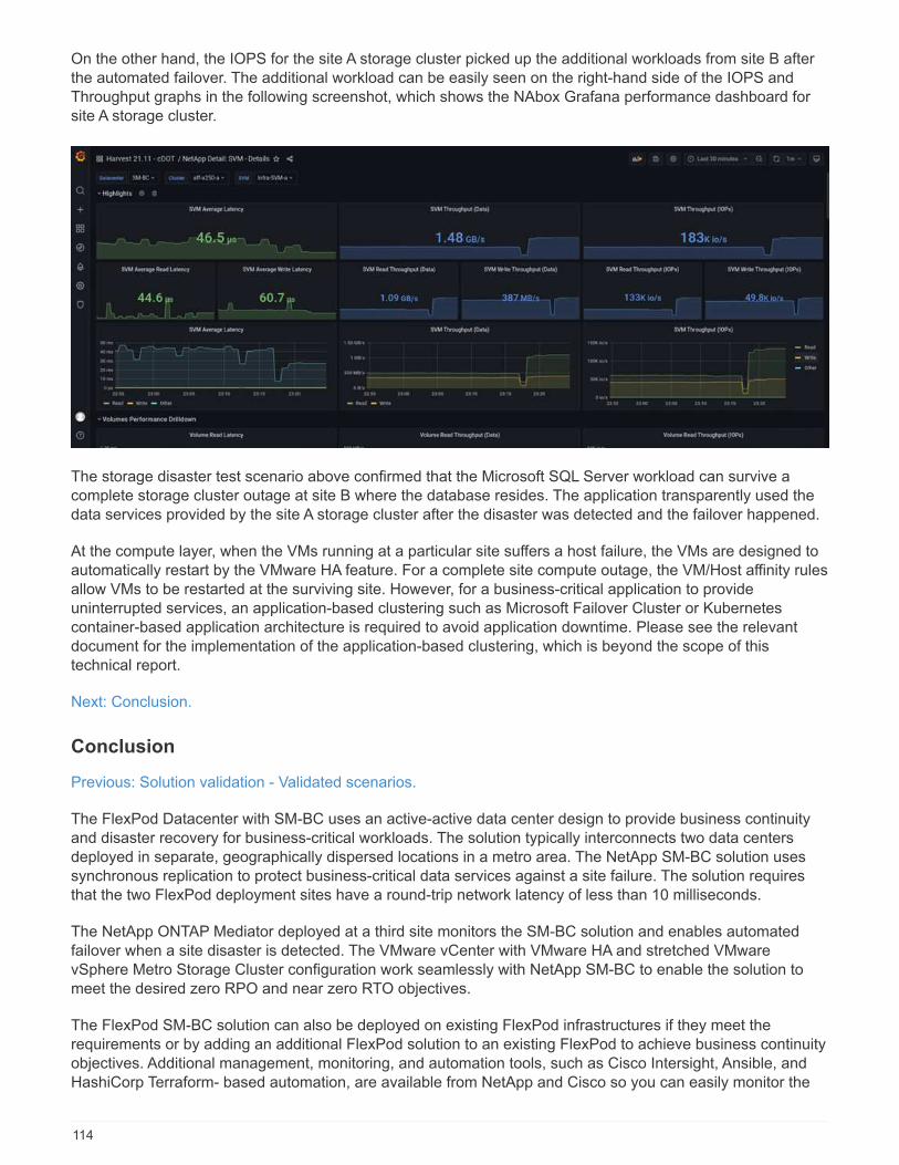
On the other hand, the IOPS for the site A storage cluster picked up the additional workloads from site B afterthe automated failover. The additional workload can be easily seen on the right-hand side of the IOPS andThroughput graphs in the following screenshot, which shows the NAbox Grafana performance dashboard forsite A storage cluster.
The storage disaster test scenario above confirmed that the Microsoft SQL Server workload can survive acomplete storage cluster outage at site B where the database resides. The application transparently used thedata services provided by the site A storage cluster after the disaster was detected and the failover happened.
At the compute layer, when the VMs running at a particular site suffers a host failure, the VMs are designed toautomatically restart by the VMware HA feature. For a complete site compute outage, the VM/Host affinity rulesallow VMs to be restarted at the surviving site. However, for a business-critical application to provideuninterrupted services, an application-based clustering such as Microsoft Failover Cluster or Kubernetescontainer-based application architecture is required to avoid application downtime. Please see the relevantdocument for the implementation of the application-based clustering, which is beyond the scope of thistechnical report.
Next: Conclusion.
Conclusion
Previous: Solution validation - Validated scenarios.
The FlexPod Datacenter with SM-BC uses an active-active data center design to provide business continuityand disaster recovery for business-critical workloads. The solution typically interconnects two data centersdeployed in separate, geographically dispersed locations in a metro area. The NetApp SM-BC solution usessynchronous replication to protect business-critical data services against a site failure. The solution requiresthat the two FlexPod deployment sites have a round-trip network latency of less than 10 milliseconds.
The NetApp ONTAP Mediator deployed at a third site monitors the SM-BC solution and enables automatedfailover when a site disaster is detected. The VMware vCenter with VMware HA and stretched VMwarevSphere Metro Storage Cluster configuration work seamlessly with NetApp SM-BC to enable the solution tomeet the desired zero RPO and near zero RTO objectives.
The FlexPod SM-BC solution can also be deployed on existing FlexPod infrastructures if they meet therequirements or by adding an additional FlexPod solution to an existing FlexPod to achieve business continuityobjectives. Additional management, monitoring, and automation tools, such as Cisco Intersight, Ansible, andHashiCorp Terraform- based automation, are available from NetApp and Cisco so you can easily monitor the
114
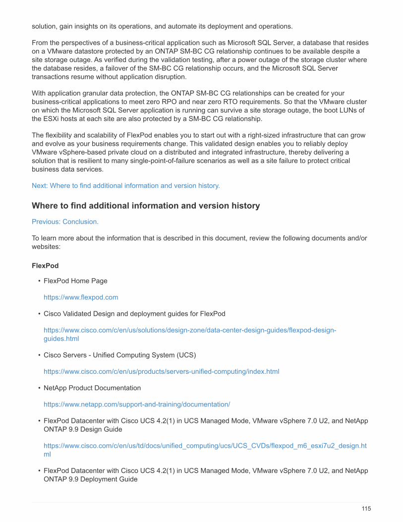
solution, gain insights on its operations, and automate its deployment and operations.
From the perspectives of a business-critical application such as Microsoft SQL Server, a database that resideson a VMware datastore protected by an ONTAP SM-BC CG relationship continues to be available despite asite storage outage. As verified during the validation testing, after a power outage of the storage cluster wherethe database resides, a failover of the SM-BC CG relationship occurs, and the Microsoft SQL Servertransactions resume without application disruption.
With application granular data protection, the ONTAP SM-BC CG relationships can be created for yourbusiness-critical applications to meet zero RPO and near zero RTO requirements. So that the VMware clusteron which the Microsoft SQL Server application is running can survive a site storage outage, the boot LUNs ofthe ESXi hosts at each site are also protected by a SM-BC CG relationship.
The flexibility and scalability of FlexPod enables you to start out with a right-sized infrastructure that can growand evolve as your business requirements change. This validated design enables you to reliably deployVMware vSphere-based private cloud on a distributed and integrated infrastructure, thereby delivering asolution that is resilient to many single-point-of-failure scenarios as well as a site failure to protect criticalbusiness data services.
Next: Where to find additional information and version history.
Where to find additional information and version history
Previous: Conclusion.
To learn more about the information that is described in this document, review the following documents and/orwebsites:
FlexPod
• FlexPod Home Page
https://www.flexpod.com
• Cisco Validated Design and deployment guides for FlexPod
https://www.cisco.com/c/en/us/solutions/design-zone/data-center-design-guides/flexpod-design-guides.html
• Cisco Servers - Unified Computing System (UCS)
https://www.cisco.com/c/en/us/products/servers-unified-computing/index.html
• NetApp Product Documentation
https://www.netapp.com/support-and-training/documentation/
• FlexPod Datacenter with Cisco UCS 4.2(1) in UCS Managed Mode, VMware vSphere 7.0 U2, and NetAppONTAP 9.9 Design Guide
https://www.cisco.com/c/en/us/td/docs/unified_computing/ucs/UCS_CVDs/flexpod_m6_esxi7u2_design.html
• FlexPod Datacenter with Cisco UCS 4.2(1) in UCS Managed Mode, VMware vSphere 7.0 U2, and NetAppONTAP 9.9 Deployment Guide
115
https://www.cisco.com/c/en/us/td/docs/unified_computing/ucs/UCS_CVDs/flexpod_m6_esxi7u2.html
• FlexPod Datacenter with Cisco UCS X-Series, VMware 7.0 U2, and NetApp ONTAP 9.9 Design Guide
https://www.cisco.com/c/en/us/td/docs/unified_computing/ucs/UCS_CVDs/flexpod_xseries_esxi7u2_design.html
• FlexPod Datacenter with Cisco UCS X-Series, VMware 7.0 U2, and NetApp ONTAP 9.9 Deployment Guide
https://www.cisco.com/c/en/us/td/docs/unified_computing/ucs/UCS_CVDs/flexpod_xseries_vmware_7u2.html
• FlexPod Express for VMware vSphere 7.0 with Cisco UCS Mini and NetApp AFF/FAS NVA Design Guide
https://www.netapp.com/pdf.html?item=/media/22621-nva-1154-DESIGN.pdf
• FlexPod Express for VMware vSphere 7.0 with Cisco UCS Mini and NetApp AFF/FAS NVA DeploymentGuide
https://www.netapp.com/pdf.html?item=/media/21938-nva-1154-DEPLOY.pdf
• FlexPod MetroCluster IP with VXLAN Multi-Site Frontend Fabric
https://www.cisco.com/c/dam/en/us/products/collateral/servers-unified-computing/flexpod-metrocluster-ip-vxlan-multi-site-wp.pdf
• NAbox
https://nabox.org
• NetApp Harvest
https://github.com/NetApp/harvest/releases
SM-BC
• SM-BC
https://docs.netapp.com/us-en/ontap/smbc/index.html
• TR-4878: SnapMirror Business Continuity (SM-BC) ONTAP 9.8
https://www.netapp.com/pdf.html?item=/media/21888-tr-4878.pdf
• How to correctly delete a SnapMirror relationship ONTAP 9
https://kb.netapp.com/Advice_and_Troubleshooting/Data_Protection_and_Security/SnapMirror/How_to_correctly_delete_a_SnapMirror_relationship_ONTAP_9
• SnapMirror Synchronous disaster recovery basics
https://docs.netapp.com/us-en/ontap/data-protection/snapmirror-synchronous-disaster-recovery-basics-concept.html
• Asynchronous SnapMirror disaster recovery basics
116
https://www.cisco.com/c/en/us/td/docs/unified_computing/ucs/UCS_CVDs/flexpod_xseries_vmware_7u2.html
https://docs.netapp.com/us-en/ontap/data-protection/snapmirror-disaster-recovery-concept.html#data-protection-relationships
• Data protection and disaster recovery
https://docs.netapp.com/us-en/ontap/data-protection-disaster-recovery/index.html
• Install or upgrade the ONTAP Mediator service
https://docs.netapp.com/us-en/ontap/mediator/index.html
VMware vSphere HA and vSphere Metro Storage Cluster
• Creating and Using vSphere HA Clusters
https://docs.vmware.com/en/VMware-vSphere/7.0/com.vmware.vsphere.avail.doc/GUID-5432CA24-14F1-44E3-87FB-61D937831CF6.html
• VMware vSphere Metro Storage Cluster (vMSC)
https://core.vmware.com/resource/vmware-vsphere-metro-storage-cluster-vmsc
• VMware vSphere Metro Storage Cluster Recommended Practices
https://core.vmware.com/resource/vmware-vsphere-metro-storage-cluster-recommended-practices
• NetApp ONTAP with NetApp SnapMirror Business Continuity (SM-BC) with VMware vSphere MetroStorage Cluster (vMSC). (83370)
https://kb.vmware.com/s/article/83370
• Protect tier-1 applications and databases with VMware vSphere Metro Storage Cluster and ONTAP
https://community.netapp.com/t5/Tech-ONTAP-Blogs/Protect-tier-1-applications-and-databases-with-VMware-vSphere-Metro-Storage/ba-p/171636
Microsoft SQL and HammerDB
• Microsoft SQL Server 2019
https://www.microsoft.com/en-us/sql-server/sql-server-2019
• Architecting Microsoft SQL Server on VMware vSphere Best Practices Guide
https://www.vmware.com/content/dam/digitalmarketing/vmware/en/pdf/solutions/sql-server-on-vmware-best-practices-guide.pdf
• HammerDB website
https://www.hammerdb.com
Compatibility Matrix
• Cisco UCS Hardware Compatibility Matrix
117

https://ucshcltool.cloudapps.cisco.com/public/
• NetApp Interoperability Matrix Tool
https://support.netapp.com/matrix/
• NetApp Hardware Universe
https://hwu.netapp.com
• VMware Compatibility Guide
http://www.vmware.com/resources/compatibility/search.php
Version history
Version Date Document version history
Version 1.0 April 2022 Initial release.
118

Hybrid Cloud
NetApp Cloud Insights for FlexPod
TR-4868: NetApp Cloud Insights for FlexPod
Alan Cowles, NetApp
In partnership with:
The solution detailed in this technical report is the configuration of the NetApp Cloud Insights service to monitorthe NetApp AFF A800 storage system running NetApp ONTAP, which is deployed as a part of a FlexPodDatacenter solution.
Customer value
The solution detailed here provides value to customers who are interested in a fully-featured monitoringsolution for their hybrid cloud environments, where ONTAP is deployed as the primary storage system. Thisincludes FlexPod environments that use NetApp AFF and FAS storage systems.
Use cases
This solution applies to the following use cases:
• Organizations that want to monitor various resources and utilization in their ONTAP storage systemdeployed as part of a FlexPod solution.
• Organizations that want to troubleshoot issues and shorten resolution time for incidents that occur in theirFlexPod solution with their AFF or FAS systems.
• Organizations interested in cost optimization projections, including customized dashboards to providedetailed information about wasted resources, and where cost savings can be realized in their FlexPodenvironment, including ONTAP.
Target audience
The target audience for the solution includes the following groups:
• IT executives and those concerned with cost optimization and business continuity.
• Solutions architects with an interest in data center or hybrid cloud design and management.
• Technical support engineers responsible for troubleshooting and incident resolution.
You can configure Cloud Insights to provide several useful types of data that you can use to assist withplanning, troubleshooting, maintenance, and ensuring business continuity. By monitoring the FlexPodDatacenter solution with Cloud Insights and presenting the aggregated data in easily digestible customizeddashboards; it is not only possible to predict when resources in a deployment might need to be scaled to meetdemands, but also to identify specific applications or storage volumes that are causing problems within thesystem. This helps to ensure that the infrastructure being monitored is predictable and performs according to
119

expectations, allowing an organization to deliver on defined SLA’s and to scale infrastructure as needed,eliminating waste and additional costs.
Architecture
In this section, we review the architecture of a FlexPod Datacenter converged infrastructure, including aNetApp AFF A800 system that is monitored by Cloud Insights.
Solution technology
A FlexPod Datacenter solution consists of the following minimum components to provide a highly available,easily scalable, validated, and supported converged infrastructure environment.
• Two NetApp ONTAP storage nodes (one HA pair)
• Two Cisco Nexus data center network switches
• Two Cisco MDS fabric switches (optional for FC deployments)
• Two Cisco UCS fabric interconnects
• One Cisco UCS blade chassis with two Cisco UCS B-series blade servers
Or
• Two Cisco UCS C-Series rackmount servers
For Cloud Insights to collect data, an organization must deploy an Acquisition Unit as a virtual or physicalmachine either within their FlexPod Datacenter environment, or in a location where it can contact thecomponents from which it is collecting data. You can install the Acquisition Unit software on a system runningseveral supported Windows or Linux operating systems. The following table lists solution components for thissoftware.
Operating system Version
Microsoft Windows 10
Microsoft Windows Server 2012, 2012 R2, 2016, 2019
Red Hat Enterprise Linux 7.2 – 7.6
CentOS 7.2 – 7.6
Oracle Enterprise Linux 7.5
Debian 9
Ubuntu 18.04 LTS
Architectural diagram
The following figure shows the solution architecture.
120

Hardware requirements
The following table lists the hardware components that are required to implement the solution. The hardwarecomponents that are used in any particular implementation of the solution might vary based on customerrequirements.
Hardware Quantity
Cisco Nexus 9336C-FX2 2
Cisco UCS 6454 Fabric Interconnect 2
Cisco UCS 5108 Blade Chassis 1
Cisco UCS 2408 Fabric Extenders 2
Cisco UCS B200 M5 Blades 2
NetApp AFF A800 2
Software requirements
The following table lists the software components that are required to implement the solution. The softwarecomponents that are used in any particular implementation of the solution might vary based on customerrequirements.
121
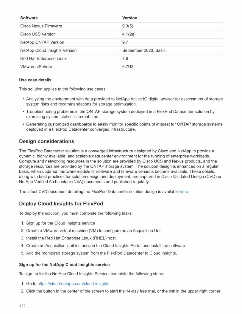
Software Version
Cisco Nexus Firmware 9.3(5)
Cisco UCS Version 4.1(2a)
NetApp ONTAP Version 9.7
NetApp Cloud Insights Version September 2020, Basic
Red Hat Enterprise Linux 7.6
VMware vSphere 6.7U3
Use case details
This solution applies to the following use cases:
• Analyzing the environment with data provided to NetApp Active IQ digital advisor for assessment of storagesystem risks and recommendations for storage optimization.
• Troubleshooting problems in the ONTAP storage system deployed in a FlexPod Datacenter solution byexamining system statistics in real-time.
• Generating customized dashboards to easily monitor specific points of interest for ONTAP storage systemsdeployed in a FlexPod Datacenter converged infrastructure.
Design considerations
The FlexPod Datacenter solution is a converged infrastructure designed by Cisco and NetApp to provide adynamic, highly available, and scalable data center environment for the running of enterprise workloads.Compute and networking resources in the solution are provided by Cisco UCS and Nexus products, and thestorage resources are provided by the ONTAP storage system. The solution design is enhanced on a regularbasis, when updated hardware models or software and firmware versions become available. These details,along with best practices for solution design and deployment, are captured in Cisco Validated Design (CVD) orNetApp Verified Architecture (NVA) documents and published regularly.
The latest CVD document detailing the FlexPod Datacenter solution design is available here.
Deploy Cloud Insights for FlexPod
To deploy the solution, you must complete the following tasks:
1. Sign up for the Cloud Insights service
2. Create a VMware virtual machine (VM) to configure as an Acquisition Unit
3. Install the Red Hat Enterprise Linux (RHEL) host
4. Create an Acquisition Unit instance in the Cloud Insights Portal and install the software
5. Add the monitored storage system from the FlexPod Datacenter to Cloud Insights.
Sign up for the NetApp Cloud Insights service
To sign up for the NetApp Cloud Insights Service, complete the following steps:
1. Go to https://cloud.netapp.com/cloud-insights
2. Click the button in the center of the screen to start the 14-day free trial, or the link in the upper right corner
122
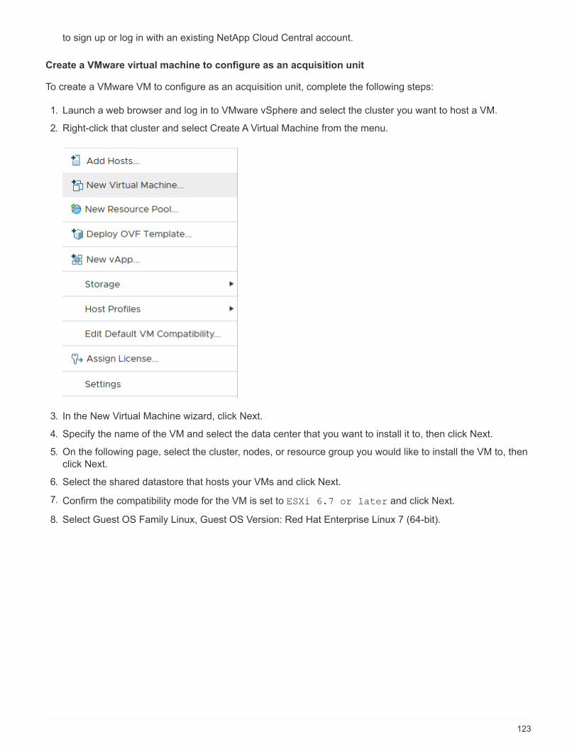
to sign up or log in with an existing NetApp Cloud Central account.
Create a VMware virtual machine to configure as an acquisition unit
To create a VMware VM to configure as an acquisition unit, complete the following steps:
1. Launch a web browser and log in to VMware vSphere and select the cluster you want to host a VM.
2. Right-click that cluster and select Create A Virtual Machine from the menu.
3. In the New Virtual Machine wizard, click Next.
4. Specify the name of the VM and select the data center that you want to install it to, then click Next.
5. On the following page, select the cluster, nodes, or resource group you would like to install the VM to, thenclick Next.
6. Select the shared datastore that hosts your VMs and click Next.
7. Confirm the compatibility mode for the VM is set to ESXi 6.7 or later and click Next.
8. Select Guest OS Family Linux, Guest OS Version: Red Hat Enterprise Linux 7 (64-bit).
123

9. The next page allows for the customization of hardware resources on the VM. The Cloud InsightsAcquisition Unit requires the following resources. After the resources are selected, click Next:
a. Two CPUs
b. 8GB of RAM
c. 100GB of hard disk space
d. A network that can reach resources in the FlexPod Datacenter and the Cloud Insights server throughan SSL connection on port 443.
e. An ISO image of the chosen Linux distribution (Red Hat Enterprise Linux) to boot from.
124

10. To create the VM, on the Ready to Complete page, review the settings and click Finish.
Install Red Hat Enterprise Linux
To install Red Hat Enterprise Linux, complete the following steps:
1. Power on the VM, click the window to launch the virtual console, and then select the option to Install RedHat Enterprise Linux 7.6.
125
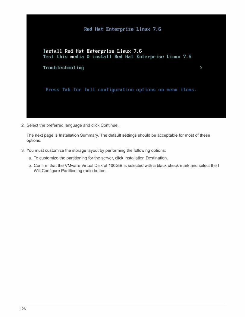
2. Select the preferred language and click Continue.
The next page is Installation Summary. The default settings should be acceptable for most of theseoptions.
3. You must customize the storage layout by performing the following options:
a. To customize the partitioning for the server, click Installation Destination.
b. Confirm that the VMware Virtual Disk of 100GiB is selected with a black check mark and select the IWill Configure Partitioning radio button.
126

c. Click Done.
A new menu displays enabling you to customize the partition table. Dedicate 25 GB each to
/opt/netapp and /var/log/netapp. You can automatically allocate the rest of the storage to thesystem.
127
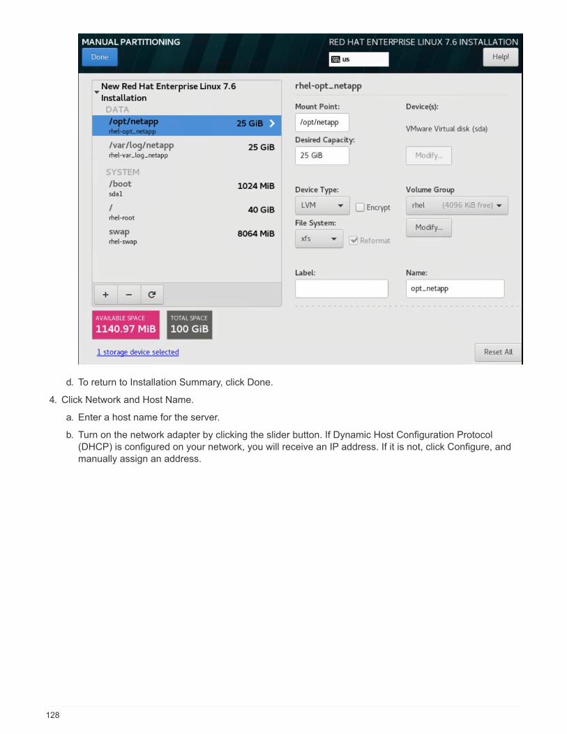
d. To return to Installation Summary, click Done.
4. Click Network and Host Name.
a. Enter a host name for the server.
b. Turn on the network adapter by clicking the slider button. If Dynamic Host Configuration Protocol(DHCP) is configured on your network, you will receive an IP address. If it is not, click Configure, andmanually assign an address.
128

c. . Click Done to return to Installation Summary.
5. On the Installation Summary page, click Begin Installation.
6. On the Installation Progress page, you can set the root password or create a local user account. When theinstallation finishes, click Reboot to restart the server.
129
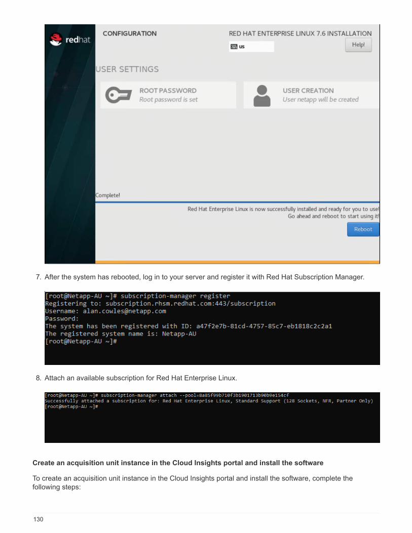
7. After the system has rebooted, log in to your server and register it with Red Hat Subscription Manager.
8. Attach an available subscription for Red Hat Enterprise Linux.
Create an acquisition unit instance in the Cloud Insights portal and install the software
To create an acquisition unit instance in the Cloud Insights portal and install the software, complete thefollowing steps:
130

1. From the home page of Cloud Insights, hover over the Admin entry in the main menu to the left and selectData Collectors from the menu.
2. In the top center of the Data Collectors page, click the link for Acquisition Units.
3. To create a new Acquisition Unit, click the button on the right.
4. Select the operating system that you want to use to host your Acquisition Unit and follow the steps to copythe installation script from the web page.
In this example, it is a Linux server, which provides a snippet and a token to paste into the CLI on our host.The web page waits for the Acquisition Unit to connect.
131
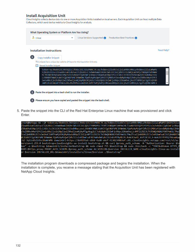
5. Paste the snippet into the CLI of the Red Hat Enterprise Linux machine that was provisioned and clickEnter.
The installation program downloads a compressed package and begins the installation. When theinstallation is complete, you receive a message stating that the Acquisition Unit has been registered withNetApp Cloud Insights.
132

Add the monitored storage system from the FlexPod Datacenter to Cloud Insights
To add the ONTAP storage system from a FlexPod deployment, complete the following steps:
1. Return to the Acquisition Units page on Cloud Insights portal and find the listed newly registered unit. Todisplay a summary of the unit, click the unit.
2. To start a wizard to add the storage system, on the Summary page, click the button for creating a datacollector. The first page displays all the systems from which data can be collected. Use the search bar tosearch for ONTAP.
133
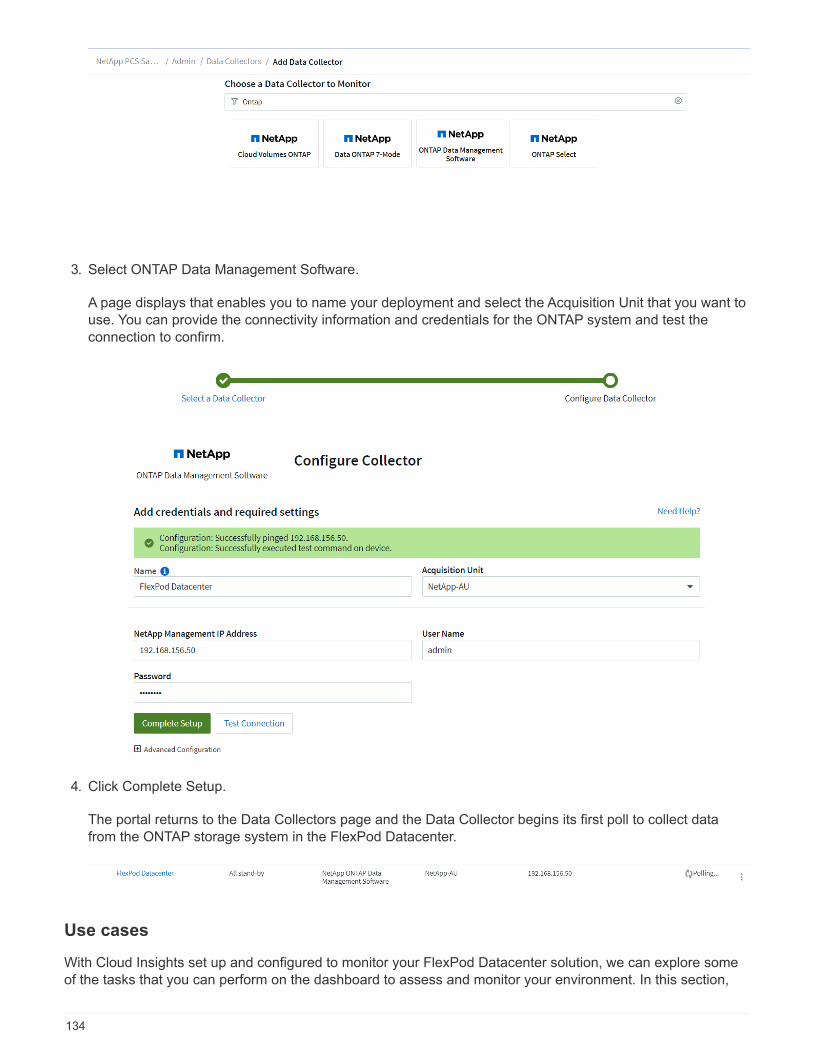
3. Select ONTAP Data Management Software.
A page displays that enables you to name your deployment and select the Acquisition Unit that you want touse. You can provide the connectivity information and credentials for the ONTAP system and test theconnection to confirm.
4. Click Complete Setup.
The portal returns to the Data Collectors page and the Data Collector begins its first poll to collect datafrom the ONTAP storage system in the FlexPod Datacenter.
Use cases
With Cloud Insights set up and configured to monitor your FlexPod Datacenter solution, we can explore someof the tasks that you can perform on the dashboard to assess and monitor your environment. In this section,
134
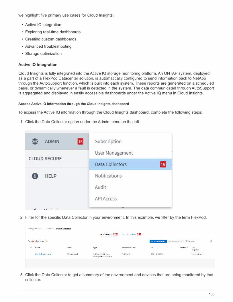
we highlight five primary use cases for Cloud Insights:
• Active IQ integration
• Exploring real-time dashboards
• Creating custom dashboards
• Advanced troubleshooting
• Storage optimization
Active IQ integration
Cloud Insights is fully integrated into the Active IQ storage monitoring platform. An ONTAP system, deployedas a part of a FlexPod Datacenter solution, is automatically configured to send information back to NetAppthrough the AutoSupport function, which is built into each system. These reports are generated on a scheduledbasis, or dynamically whenever a fault is detected in the system. The data communicated through AutoSupportis aggregated and displayed in easily accessible dashboards under the Active IQ menu in Cloud Insights.
Access Active IQ information through the Cloud Insights dashboard
To access the Active IQ information through the Cloud Insights dashboard, complete the following steps:
1. Click the Data Collector option under the Admin menu on the left.
2. Filter for the specific Data Collector in your environment. In this example, we filter by the term FlexPod.
3. Click the Data Collector to get a summary of the environment and devices that are being monitored by thatcollector.
135
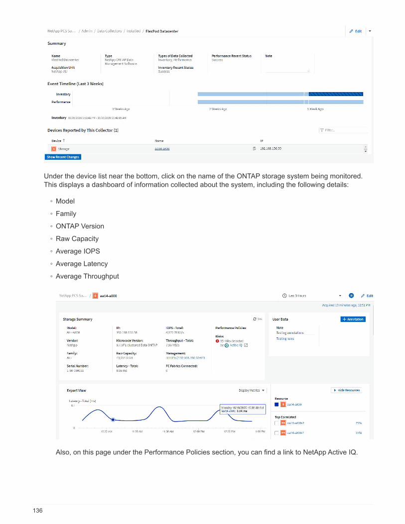
Under the device list near the bottom, click on the name of the ONTAP storage system being monitored.This displays a dashboard of information collected about the system, including the following details:
◦ Model
◦ Family
◦ ONTAP Version
◦ Raw Capacity
◦ Average IOPS
◦ Average Latency
◦ Average Throughput
Also, on this page under the Performance Policies section, you can find a link to NetApp Active IQ.
136
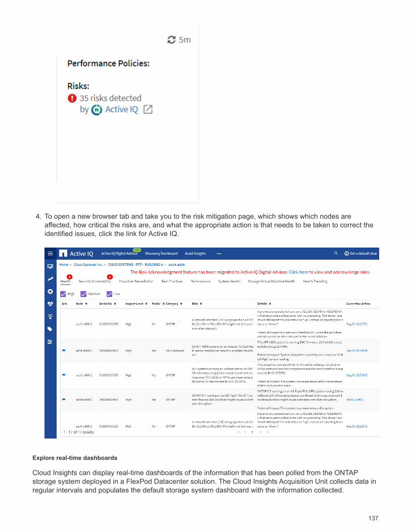
4. To open a new browser tab and take you to the risk mitigation page, which shows which nodes areaffected, how critical the risks are, and what the appropriate action is that needs to be taken to correct theidentified issues, click the link for Active IQ.
Explore real-time dashboards
Cloud Insights can display real-time dashboards of the information that has been polled from the ONTAPstorage system deployed in a FlexPod Datacenter solution. The Cloud Insights Acquisition Unit collects data inregular intervals and populates the default storage system dashboard with the information collected.
137
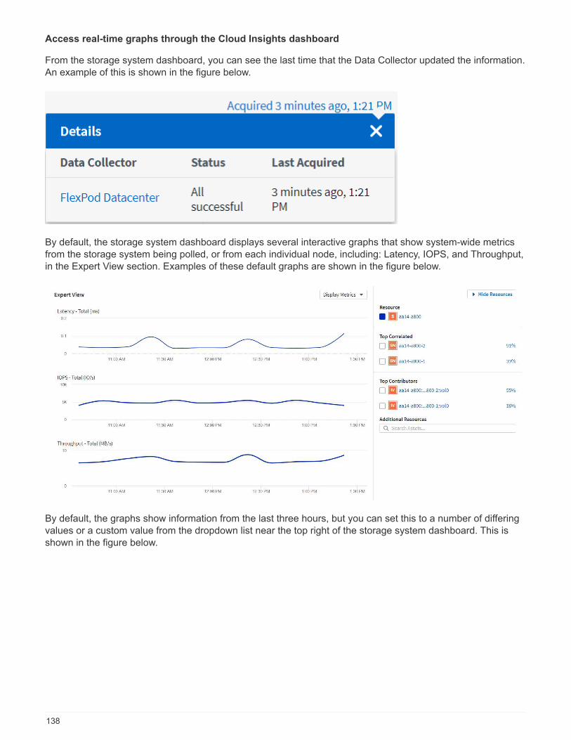
Access real-time graphs through the Cloud Insights dashboard
From the storage system dashboard, you can see the last time that the Data Collector updated the information.An example of this is shown in the figure below.
By default, the storage system dashboard displays several interactive graphs that show system-wide metricsfrom the storage system being polled, or from each individual node, including: Latency, IOPS, and Throughput,in the Expert View section. Examples of these default graphs are shown in the figure below.
By default, the graphs show information from the last three hours, but you can set this to a number of differingvalues or a custom value from the dropdown list near the top right of the storage system dashboard. This isshown in the figure below.
138

Create custom dashboards
In addition to making use of the default dashboards that display system-wide information, you can use CloudInsights to create fully customized dashboards that enable you to focus on resource use for specific storagevolumes in the FlexPod Datacenter solution, and thus the applications deployed in the converged infrastructurethat depend on those volumes to run effectively. Doing so can help you to create a better visualization ofspecific applications and the resources they consume in the data center environment.
Create a customized dashboard to assess storage resources
To create a customized dashboard to assess storage resources, complete the following steps:
1. To create a customized dashboard, hover over Dashboards on the Cloud Insights main menu and click +New Dashboard in the dropdown list.
139
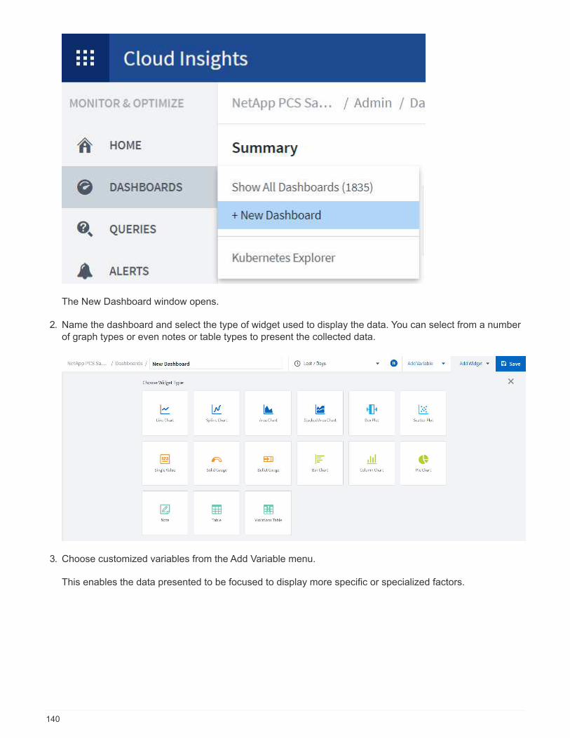
The New Dashboard window opens.
2. Name the dashboard and select the type of widget used to display the data. You can select from a numberof graph types or even notes or table types to present the collected data.
3. Choose customized variables from the Add Variable menu.
This enables the data presented to be focused to display more specific or specialized factors.
140
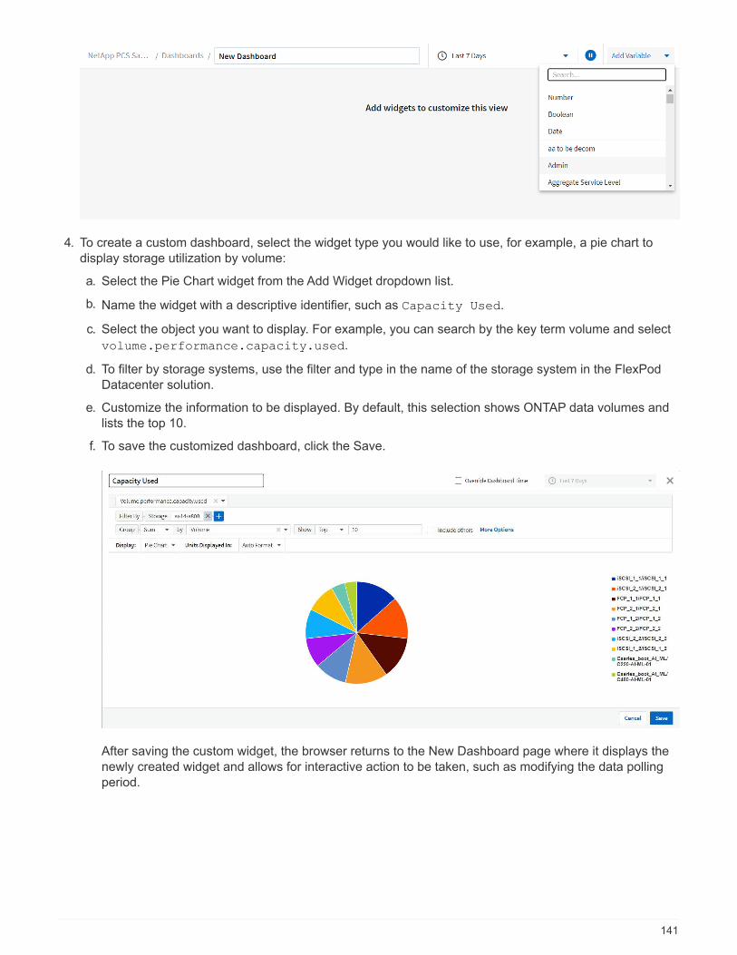
4. To create a custom dashboard, select the widget type you would like to use, for example, a pie chart todisplay storage utilization by volume:
a. Select the Pie Chart widget from the Add Widget dropdown list.
b. Name the widget with a descriptive identifier, such as Capacity Used.
c. Select the object you want to display. For example, you can search by the key term volume and select
volume.performance.capacity.used.
d. To filter by storage systems, use the filter and type in the name of the storage system in the FlexPodDatacenter solution.
e. Customize the information to be displayed. By default, this selection shows ONTAP data volumes andlists the top 10.
f. To save the customized dashboard, click the Save.
After saving the custom widget, the browser returns to the New Dashboard page where it displays thenewly created widget and allows for interactive action to be taken, such as modifying the data pollingperiod.
141

Advanced troubleshooting
Cloud Insights enables advanced troubleshooting methods to be applied to any storage environment in aFlexPod Datacenter converged infrastructure. Using components of each of the features mentioned above:Active IQ integration, default dashboards with real-time statistics, and customized dashboards, issues thatmight arise are detected early and solved rapidly. Using the list of risks in Active IQ, a customer can findreported configuration errors that could lead to issue or discover bugs that have been reported and patchedversions of code that can remedy them. Observing the real-time dashboards on the Cloud Insights home pagecan help to discover patterns in system performance that could be an early indicator of a problem on the riseand help to resolve it expediently. Lastly, being able to create customized dashboards enables customers tofocus on the most important assets in their infrastructure and monitor those directly to ensure that they canmeet their business continuity objectives.
Storage optimization
In addition to troubleshooting, it is possible to use the data collected by Cloud Insights to optimize the ONTAPstorage system deployed in a FlexPod Datacenter converged infrastructure solution. If a volume shows a highlatency, perhaps because several VMs with high performance demands are sharing the same datastore, thatinformation is displayed on the Cloud Insights dashboard. With this information, a storage administrator canchoose to migrate one or more VMs either to other volumes, migrate storage volumes between tiers ofaggregates, or between nodes in the ONTAP storage system, resulting in a performance optimizedenvironment. The information gleaned from the Active IQ integration with Cloud Insights can highlightconfiguration issues that lead to poorer than expected performance, and provide the recommended correctiveaction that if implemented, can remediate any issues, and ensure an optimally tuned storage system.
Videos and demos
You can see a video demonstration of using NetApp Cloud Insights to assess the resources in an on-premisesenvironment here.
You can see a video demonstration of using NetApp Cloud Insights to monitor infrastructure and set alertthresholds for infrastructure here.
You can see a video demonstration of using NetApp Cloud Insights to asses individual applications in theenvironment here.
Additional information
To learn more about the information that is described in this document, review the following websites:
• Cisco Product Documentation
142
https://www.cisco.com/c/en/us/support/index.html
• FlexPod Datacenter
https://www.flexpod.com
• NetApp Cloud Insights
https://cloud.netapp.com/cloud-insights
• NetApp Product Documentation
https://docs.netapp.com
FlexPod with FabricPool - Inactive Data Tiering to AmazonAWS S3
TR-4801: FlexPod with FabricPool - Inactive Data Tiering to Amazon AWS S3
Scott Kovacs, NetApp
Flash storage prices continue to fall, making it available to workloads and applications that were not previouslyconsidered candidates for flash storage. However, making the most efficient use of the storage investment isstill critically important for IT managers. IT departments continue to be pressed to deliver higher-performingservices with little or no budget increase. To help address these needs, NetApp FabricPool allows you toleverage cloud economics by moving infrequently used data off of expensive on-premises flash storage to amore cost-effective storage tier in the public cloud. Moving infrequently accessed data to the cloud frees upvaluable flash storage space on AFF or FAS systems to deliver more capacity for business-critical workloads tothe high-performance flash tier.
This technical report reviews the FabricPool data- tiering feature of NetApp ONTAP in the context of a FlexPodconverged infrastructure architecture from NetApp and Cisco. You should be familiar with the FlexPodDatacenter converged infrastructure architecture and the ONTAP storage software to fully benefit from theconcepts discussed in this technical report. Building on familiarity with FlexPod and ONTAP, we discussFabricPool, how it works, and how it can be used to achieve more efficient use of on-premises flash storage.Much of the content in this report is covered in greater detail in TR-4598 FabricPool Best Practices and otherONTAP product documentation. The content has been condensed for a FlexPod infrastructure and does notcompletely cover all use cases for FabricPool. All features and concepts examined are available in ONTAP 9.6.
Additional information about FlexPod is available in TR-4036 FlexPod Datacenter Technical Specifications.
FlexPod overview and architecture
FlexPod overview
FlexPod is a defined set of hardware and software that forms an integrated foundation for both virtualized andnonvirtualized solutions. FlexPod includes NetApp AFF storage, Cisco Nexus networking, Cisco MDS storagenetworking, the Cisco Unified Computing System (Cisco UCS), and VMware vSphere software in a singlepackage. The design is flexible enough that the networking, computing, and storage can fit into one data centerrack, or it can be deployed according to a customer’s data center design. Port density allows the networkingcomponents to accommodate multiple configurations.
One benefit of the FlexPod architecture is the ability to customize, or flex, the environment to suit a customer’s
143
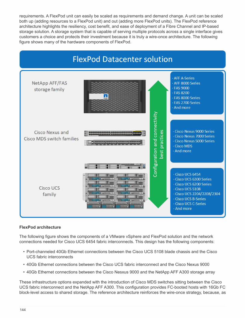
requirements. A FlexPod unit can easily be scaled as requirements and demand change. A unit can be scaledboth up (adding resources to a FlexPod unit) and out (adding more FlexPod units). The FlexPod referencearchitecture highlights the resiliency, cost benefit, and ease of deployment of a Fibre Channel and IP-basedstorage solution. A storage system that is capable of serving multiple protocols across a single interface givescustomers a choice and protects their investment because it is truly a wire-once architecture. The followingfigure shows many of the hardware components of FlexPod.
FlexPod architecture
The following figure shows the components of a VMware vSphere and FlexPod solution and the networkconnections needed for Cisco UCS 6454 fabric interconnects. This design has the following components:
• Port-channeled 40Gb Ethernet connections between the Cisco UCS 5108 blade chassis and the CiscoUCS fabric interconnects
• 40Gb Ethernet connections between the Cisco UCS fabric interconnect and the Cisco Nexus 9000
• 40Gb Ethernet connections between the Cisco Nesxus 9000 and the NetApp AFF A300 storage array
These infrastructure options expanded with the introduction of Cisco MDS switches sitting between the CiscoUCS fabric interconnect and the NetApp AFF A300. This configuration provides FC-booted hosts with 16Gb FCblock-level access to shared storage. The reference architecture reinforces the wire-once strategy, because, as
144
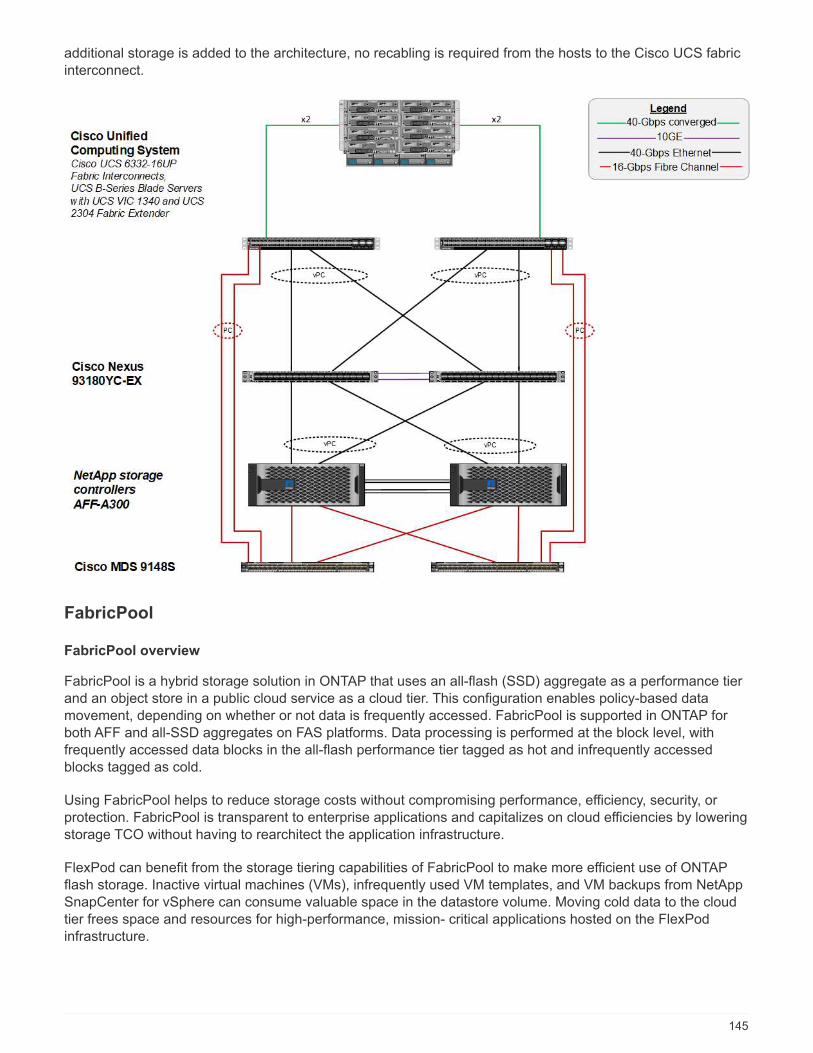
additional storage is added to the architecture, no recabling is required from the hosts to the Cisco UCS fabricinterconnect.
FabricPool
FabricPool overview
FabricPool is a hybrid storage solution in ONTAP that uses an all-flash (SSD) aggregate as a performance tierand an object store in a public cloud service as a cloud tier. This configuration enables policy-based datamovement, depending on whether or not data is frequently accessed. FabricPool is supported in ONTAP forboth AFF and all-SSD aggregates on FAS platforms. Data processing is performed at the block level, withfrequently accessed data blocks in the all-flash performance tier tagged as hot and infrequently accessedblocks tagged as cold.
Using FabricPool helps to reduce storage costs without compromising performance, efficiency, security, orprotection. FabricPool is transparent to enterprise applications and capitalizes on cloud efficiencies by loweringstorage TCO without having to rearchitect the application infrastructure.
FlexPod can benefit from the storage tiering capabilities of FabricPool to make more efficient use of ONTAPflash storage. Inactive virtual machines (VMs), infrequently used VM templates, and VM backups from NetAppSnapCenter for vSphere can consume valuable space in the datastore volume. Moving cold data to the cloudtier frees space and resources for high-performance, mission- critical applications hosted on the FlexPodinfrastructure.
145

Fibre Channel and iSCSI protocols generally take longer before experiencing a timeout (60 to120 seconds), but they do not retry to establish a connection in the same way that NASprotocols do. If a SAN protocol times out, the application must be restarted. Even a shortdisruption could be disastrous to production applications using SAN protocols because there isno way to guarantee connectivity to public clouds. To avoid this issue, NetApp recommendsusing private clouds when tiering data that is accessed by SAN protocols.
In ONTAP 9.6, FabricPool integrates with all the major public cloud providers: Alibaba Cloud Object StorageService, Amazon AWS S3, Google Cloud Storage, IBM Cloud Object Storage, and Microsoft Azure BlobStorage. This report focuses on Amazon AWS S3 storage as the cloud object tier of choice.
The composite aggregate
A FabricPool instance is created by associating an ONTAP flash aggregate with a cloud object store, such asan AWS S3 bucket, to create a composite aggregate. When volumes are created inside the compositeaggregate, they can take advantage of the tiering capabilities of FabricPool. When data is written to thevolume, ONTAP assigns a temperature to each of the data blocks. When the block is first written, it is assigneda temperature of hot. As time passes, if the data is not accessed, it undergoes a cooling process until it isfinally assigned a cold status. These infrequently accessed data blocks are then tiered off the performanceSSD aggregate and into the cloud object store.
The period of time between when a block is designated as cold and when it is moved to cloud object storage ismodified by the volume tiering policy in ONTAP. Further granularity is achieved by modifying ONTAP settingsthat control the number of days required for a block to become cold. Candidates for data tiering are traditionalvolume snapshots, SnapCenter for vSphere VM backups and other NetApp Snapshot- based backups, andany infrequently used blocks in a vSphere datastore, such as VM templates and infrequently accessed VMdata.
Inactive data reporting
Inactive data reporting (IDR) is available in ONTAP to help evaluate the amount of cold data that can be tieredfrom an aggregate. IDR is enabled by default in ONTAP 9.6 and uses a default 31-day cooling policy todetermine which data in the volume is inactive.
The amount of cold data that is tiered depends on the tiering policies set on the volume. Thisamount may be different than the amount of cold data detected by IDR using the default 31-daycooling period.
Object creation and data movement
FabricPool works at the NetApp WAFL block level, cooling blocks, concatenating them into storage objects,and migrating those objects to a cloud tier. Each FabricPool object is 4MB and is composed of 1,024 4KBblocks. The object size is fixed at 4MB based on performance recommendations from leading cloud providersand cannot be changed. If cold blocks are read and made hot, only the requested blocks in the 4MB object arefetched and moved back to the performance tier. Neither the entire object nor the entire file is migrated back.Only the necessary blocks are migrated.
If ONTAP detects an opportunity for sequential readaheads, it requests blocks from the cloudtier before they are read to improve performance.
By default, data is moved to the cloud tier only when the performance aggregate is greater than 50% utilized.This threshold can be set to a lower percentage to allow a smaller amount of data storage on the performanceflash tier to be moved to the cloud. This might be useful if the tiering strategy is to move cold data only when
146
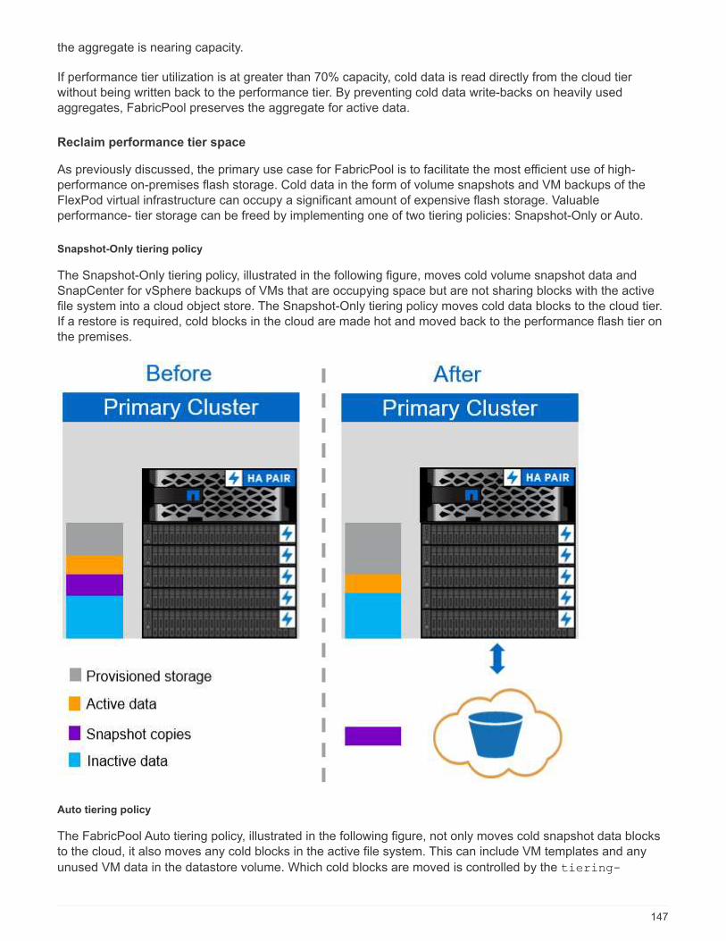
the aggregate is nearing capacity.
If performance tier utilization is at greater than 70% capacity, cold data is read directly from the cloud tierwithout being written back to the performance tier. By preventing cold data write-backs on heavily usedaggregates, FabricPool preserves the aggregate for active data.
Reclaim performance tier space
As previously discussed, the primary use case for FabricPool is to facilitate the most efficient use of high-performance on-premises flash storage. Cold data in the form of volume snapshots and VM backups of theFlexPod virtual infrastructure can occupy a significant amount of expensive flash storage. Valuableperformance- tier storage can be freed by implementing one of two tiering policies: Snapshot-Only or Auto.
Snapshot-Only tiering policy
The Snapshot-Only tiering policy, illustrated in the following figure, moves cold volume snapshot data andSnapCenter for vSphere backups of VMs that are occupying space but are not sharing blocks with the activefile system into a cloud object store. The Snapshot-Only tiering policy moves cold data blocks to the cloud tier.If a restore is required, cold blocks in the cloud are made hot and moved back to the performance flash tier onthe premises.
Auto tiering policy
The FabricPool Auto tiering policy, illustrated in the following figure, not only moves cold snapshot data blocksto the cloud, it also moves any cold blocks in the active file system. This can include VM templates and any
unused VM data in the datastore volume. Which cold blocks are moved is controlled by the tiering-
147
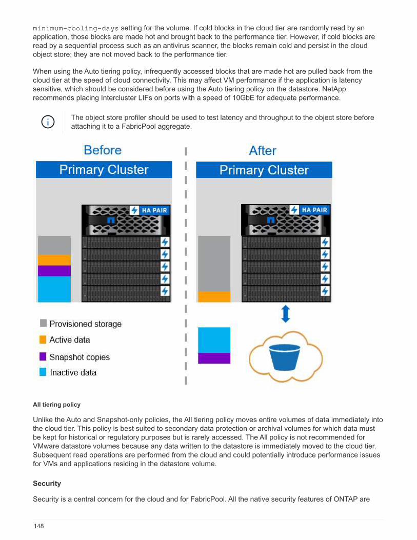
minimum-cooling-days setting for the volume. If cold blocks in the cloud tier are randomly read by anapplication, those blocks are made hot and brought back to the performance tier. However, if cold blocks areread by a sequential process such as an antivirus scanner, the blocks remain cold and persist in the cloudobject store; they are not moved back to the performance tier.
When using the Auto tiering policy, infrequently accessed blocks that are made hot are pulled back from thecloud tier at the speed of cloud connectivity. This may affect VM performance if the application is latencysensitive, which should be considered before using the Auto tiering policy on the datastore. NetApprecommends placing Intercluster LIFs on ports with a speed of 10GbE for adequate performance.
The object store profiler should be used to test latency and throughput to the object store beforeattaching it to a FabricPool aggregate.
All tiering policy
Unlike the Auto and Snapshot-only policies, the All tiering policy moves entire volumes of data immediately intothe cloud tier. This policy is best suited to secondary data protection or archival volumes for which data mustbe kept for historical or regulatory purposes but is rarely accessed. The All policy is not recommended forVMware datastore volumes because any data written to the datastore is immediately moved to the cloud tier.Subsequent read operations are performed from the cloud and could potentially introduce performance issuesfor VMs and applications residing in the datastore volume.
Security
Security is a central concern for the cloud and for FabricPool. All the native security features of ONTAP are
148
supported in the performance tier, and the movement of data is secured as it is transferred to the cloud tier.FabricPool uses the AES-256-GCM encryption algorithm on the performance tier and maintains this encryptionend to end into the cloud tier. Data blocks that are moved to the cloud object store are secured with transportlayer security (TLS) v1.2 to maintain data confidentiality and integrity between storage tiers.
Communicating with the cloud object store over an unencrypted connection is supported but notrecommended by NetApp.
Data encryption
Data encryption is vital to the protection of intellectual property, trade information, and personally identifiablecustomer information. FabricPool fully supports both NetApp Volume Encryption (NVE) and NetApp StorageEncryption (NSE) to maintain existing data protection strategies. All encrypted data on the performance tierremains encrypted when moved to the cloud tier. Client-side encryption keys are owned by ONTAP and theserver-side object store encryption keys are owned by the respective cloud object store. Any data notencrypted with NVE is encrypted with the AES-256-GCM algorithm. No other AES-256 ciphers are supported.
The use of NSE or NVE is optional and not required to use FabricPool.
FabricPool requirements
FabricPool requires ONTAP 9.2 or later and the use of SSD aggregates on any of the platforms listed in thissection. Additional FabricPool requirements depend on the cloud tier being attached. For entry-level AFFplatforms that have a fixed, relatively small capacity such as the NetApp AFF C190, FabricPool can be highlyeffective for moving inactive data to the cloud tier.
Platforms
FabricPool is supported on the following platforms:
• NetApp AFF
◦ A800
◦ A700S, A700
◦ A320, A300
◦ A220, A200
◦ C190
◦ AFF8080, AFF8060, and AFF8040
• NetApp FAS
◦ FAS9000
◦ FAS8200
◦ FAS8080, FAS8060, and FAS8040
◦ FAS2750, FAS2720
◦ FAS2650, FAS2620
Only SSD aggregates on FAS platforms can use FabricPool.
• Cloud tiers
149

◦ Alibaba Cloud Object Storage Service (Standard, Infrequent Access)
◦ Amazon S3 (Standard, Standard-IA, One Zone-IA, Intelligent-Tiering)
◦ Amazon Commercial Cloud Services (C2S)
◦ Google Cloud Storage (Multi-Regional, Regional, Nearline, Coldline)
◦ IBM Cloud Object Storage (Standard, Vault, Cold Vault, Flex)
◦ Microsoft Azure Blob Storage (Hot and Cool)
Intercluster LIFs
Cluster high-availability (HA) pairs that use FabricPool require two intercluster logical interfaces (LIFs) tocommunicate with the cloud tier. NetApp recommends creating an intercluster LIF on additional HA pairs toseamlessly attach cloud tiers to aggregates on those nodes as well.
The LIF that ONTAP uses to connect with the AWS S3 object store must be on a 10Gbps port.
If more than one Intercluser LIF is used on a node with different routing, NetApp recommends placing them indifferent IPspaces. During configuration, FabricPool can select from multiple IPspaces, but it is not able toselect specific intercluster LIFs within an IPspace.
Disabling or deleting an intercluster LIF interrupts communication to the cloud tier.
Connectivity
FabricPool read latency is a function of connectivity to the cloud tier. Intercluster LIFs using 10Gbps ports,illustrated in the following figure, provide adequate performance. NetApp recommends validating the latencyand throughput of the specific network environment to determine the effect it has on FabricPool performance.
When using FabricPool in low-performance environments, minimum performance requirementsfor client applications must continue to be met, and recovery time objectives should be adjustedaccordingly.
150
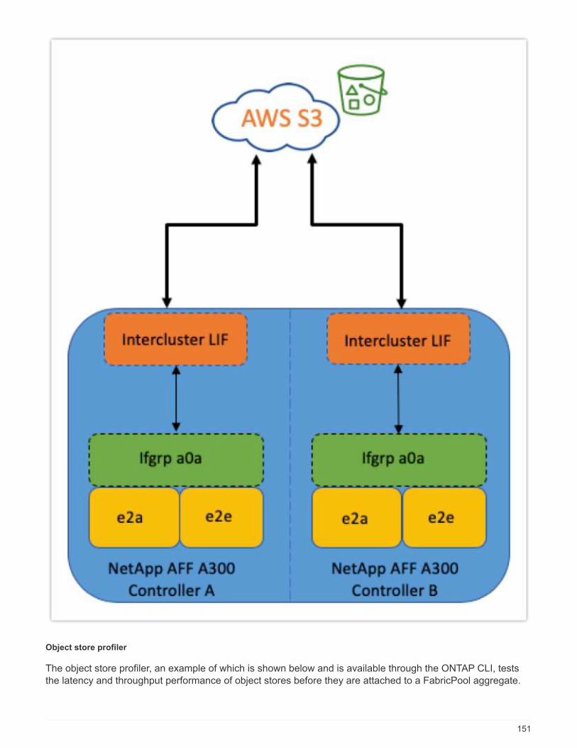
Object store profiler
The object store profiler, an example of which is shown below and is available through the ONTAP CLI, teststhe latency and throughput performance of object stores before they are attached to a FabricPool aggregate.
151
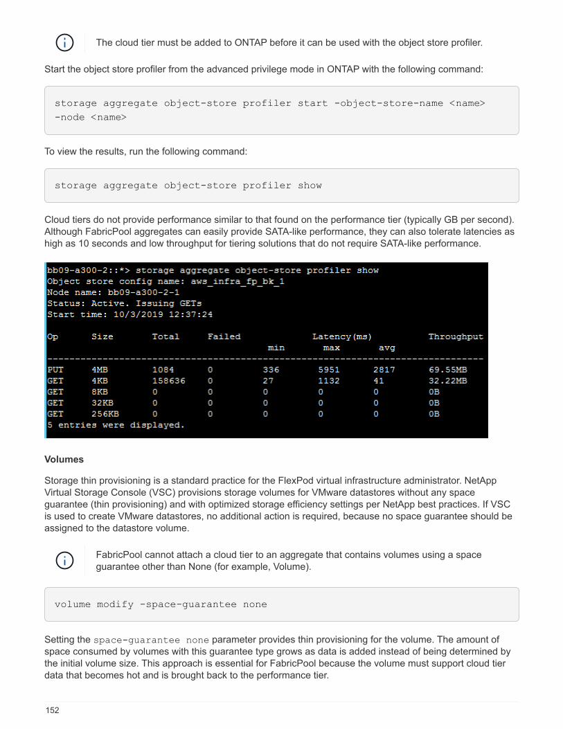
The cloud tier must be added to ONTAP before it can be used with the object store profiler.
Start the object store profiler from the advanced privilege mode in ONTAP with the following command:
storage aggregate object-store profiler start -object-store-name <name>
-node <name>
To view the results, run the following command:
storage aggregate object-store profiler show
Cloud tiers do not provide performance similar to that found on the performance tier (typically GB per second).Although FabricPool aggregates can easily provide SATA-like performance, they can also tolerate latencies ashigh as 10 seconds and low throughput for tiering solutions that do not require SATA-like performance.
Volumes
Storage thin provisioning is a standard practice for the FlexPod virtual infrastructure administrator. NetAppVirtual Storage Console (VSC) provisions storage volumes for VMware datastores without any spaceguarantee (thin provisioning) and with optimized storage efficiency settings per NetApp best practices. If VSCis used to create VMware datastores, no additional action is required, because no space guarantee should beassigned to the datastore volume.
FabricPool cannot attach a cloud tier to an aggregate that contains volumes using a spaceguarantee other than None (for example, Volume).
volume modify -space-guarantee none
Setting the space-guarantee none parameter provides thin provisioning for the volume. The amount ofspace consumed by volumes with this guarantee type grows as data is added instead of being determined bythe initial volume size. This approach is essential for FabricPool because the volume must support cloud tierdata that becomes hot and is brought back to the performance tier.
152

Licensing
FabricPool requires a capacity-based license when attaching third-party object storage providers (such asAmazon S3) as cloud tiers for AFF and FAS hybrid flash systems.
FabricPool licenses are available in perpetual or term-based (1-year or 3-year) format.
Tiering to the cloud tier stops when the amount of data (used capacity) stored on the cloud tier reaches thelicensed capacity. Additional data, including SnapMirror copies to volumes using the All tiering policy, cannotbe tiered until the license capacity is increased. Although tiering stops, data is still accessible from the cloudtier. Additional cold data remains on SSDs until the licensed capacity is increased.
A free 10TB capacity, term-based FabricPool license comes with the purchase of any new ONTAP 9.5 or latercluster, although additional support costs might apply. FabricPool licenses (including additional capacity forexisting licenses) can be purchased in 1TB increments.
A FabricPool license can only be deleted from a cluster that contains no FabricPool aggregates.
FabricPool licenses are clusterwide. You should have the UUID available when purchasing a
license (cluster identify show). For additional licensing information, refer to the NetAppKnowledgebase.
Configuration
Software revisions
The following table illustrates validated hardware and software versions.
Layer Device Image Comments
Storage NetApp AFF A300 ONTAP 9.6P2
Compute Cisco UCS B200 M5blade servers with CiscoUCS VIC 1340
Release 4.0(4b)
Network Cisco Nexus 6332-16UPfabric interconnect
Release 4.0(4b)
Cisco Nexus 93180YC-EXswitch in NX-OSstandalone mode
Release 7.0(3)I7(6)
Storage network Cisco MDS 9148S Release 8.3(2)
Hypervisor VMware vSphere ESXi6.7U2
ESXi 6.7.0,13006603
VMware vCenter Server vCenter server6.7.0.30000 Build13639309
Cloud provider Amazon AWS S3 Standard S3 bucket withdefault options
The basic requirements for FabricPool are outlined in FabricPool Requirements. After all the basicrequirements have been met, complete the following steps to configure FabricPool:
153

1. Install a FabricPool license.
2. Create an AWS S3 object store bucket.
3. Add a cloud tier to ONTAP.
4. Attach the cloud tier to an aggregate.
5. Set the volume tiering policy.
Next: Install FabricPool license.
Install FabricPool license
After you acquire a NetApp license file, you can install it with OnCommand System Manager. To install thelicense file, complete the following steps:
1. Click Configurations.
2. Click Cluster.
3. Click Licenses.
4. Click Add.
5. Click Choose Files to browse and select a file.
6. Click Add.
154
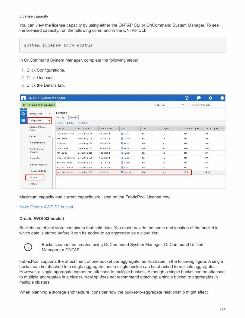
License capacity
You can view the license capacity by using either the ONTAP CLI or OnCommand System Manager. To seethe licensed capacity, run the following command in the ONTAP CLI:
system license show-status
In OnCommand System Manager, complete the following steps:
1. Click Configurations.
2. Click Licenses.
3. Click the Details tab.
Maximum capacity and current capacity are listed on the FabricPool License row.
Next: Create AWS S3 bucket.
Create AWS S3 bucket
Buckets are object store containers that hold data. You must provide the name and location of the bucket inwhich data is stored before it can be added to an aggregate as a cloud tier.
Buckets cannot be created using OnCommand System Manager, OnCommand UnifiedManager, or ONTAP.
FabricPool supports the attachment of one bucket per aggregate, as illustrated in the following figure. A singlebucket can be attached to a single aggregate, and a single bucket can be attached to multiple aggregates.However, a single aggregate cannot be attached to multiple buckets. Although a single bucket can be attachedto multiple aggregates in a cluster, NetApp does not recommend attaching a single bucket to aggregates inmultiple clusters.
When planning a storage architecture, consider how the bucket-to-aggregate relationship might affect
155
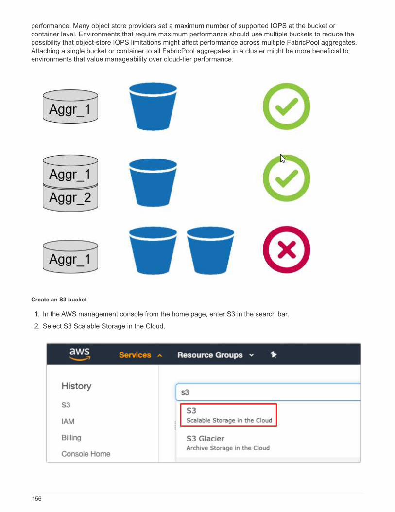
performance. Many object store providers set a maximum number of supported IOPS at the bucket orcontainer level. Environments that require maximum performance should use multiple buckets to reduce thepossibility that object-store IOPS limitations might affect performance across multiple FabricPool aggregates.Attaching a single bucket or container to all FabricPool aggregates in a cluster might be more beneficial toenvironments that value manageability over cloud-tier performance.
Create an S3 bucket
1. In the AWS management console from the home page, enter S3 in the search bar.
2. Select S3 Scalable Storage in the Cloud.
156
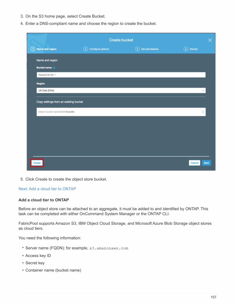
3. On the S3 home page, select Create Bucket.
4. Enter a DNS-compliant name and choose the region to create the bucket.
5. Click Create to create the object store bucket.
Next: Add a cloud tier to ONTAP
Add a cloud tier to ONTAP
Before an object store can be attached to an aggregate, it must be added to and identified by ONTAP. Thistask can be completed with either OnCommand System Manager or the ONTAP CLI.
FabricPool supports Amazon S3, IBM Object Cloud Storage, and Microsoft Azure Blob Storage object storesas cloud tiers.
You need the following information:
• Server name (FQDN); for example, s3.amazonaws.com
• Access key ID
• Secret key
• Container name (bucket name)
157

OnCommand System Manager
To add a cloud tier with OnCommand System Manager, complete the following steps:
1. Launch OnCommand System Manager.
2. Click Storage.
3. Click Aggregates & Disks.
4. Click Cloud Tiers.
5. Select an object store provider.
6. Complete the text fields as required for the object store provider.
In the Container Name field, enter the object store’s bucket or container name.
7. Click Save and Attach Aggregates.
ONTAP CLI
To add a cloud tier with the ONTAP CLI, enter the following commands:
158
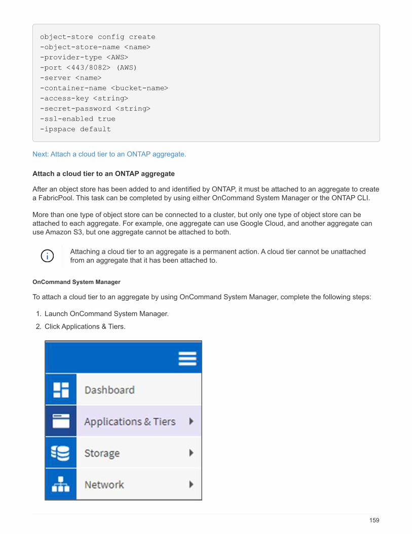
object-store config create
-object-store-name <name>
-provider-type <AWS>
-port <443/8082> (AWS)
-server <name>
-container-name <bucket-name>
-access-key <string>
-secret-password <string>
-ssl-enabled true
-ipspace default
Next: Attach a cloud tier to an ONTAP aggregate.
Attach a cloud tier to an ONTAP aggregate
After an object store has been added to and identified by ONTAP, it must be attached to an aggregate to createa FabricPool. This task can be completed by using either OnCommand System Manager or the ONTAP CLI.
More than one type of object store can be connected to a cluster, but only one type of object store can beattached to each aggregate. For example, one aggregate can use Google Cloud, and another aggregate canuse Amazon S3, but one aggregate cannot be attached to both.
Attaching a cloud tier to an aggregate is a permanent action. A cloud tier cannot be unattachedfrom an aggregate that it has been attached to.
OnCommand System Manager
To attach a cloud tier to an aggregate by using OnCommand System Manager, complete the following steps:
1. Launch OnCommand System Manager.
2. Click Applications & Tiers.
159
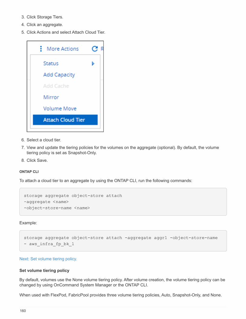
3. Click Storage Tiers.
4. Click an aggregate.
5. Click Actions and select Attach Cloud Tier.
6. Select a cloud tier.
7. View and update the tiering policies for the volumes on the aggregate (optional). By default, the volumetiering policy is set as Snapshot-Only.
8. Click Save.
ONTAP CLI
To attach a cloud tier to an aggregate by using the ONTAP CLI, run the following commands:
storage aggregate object-store attach
-aggregate <name>
-object-store-name <name>
Example:
storage aggregate object-store attach -aggregate aggr1 -object-store-name
- aws_infra_fp_bk_1
Next: Set volume tiering policy.
Set volume tiering policy
By default, volumes use the None volume tiering policy. After volume creation, the volume tiering policy can bechanged by using OnCommand System Manager or the ONTAP CLI.
When used with FlexPod, FabricPool provides three volume tiering policies, Auto, Snapshot-Only, and None.
160

• Auto
◦ All cold blocks in the volume are moved to the cloud tier. Assuming that the aggregate is more than50% utilized, it takes approximately 31 days for inactive blocks to become cold. The Auto cooling
period is adjustable between 2 days and 63 days by using the tiering-minimum-cooling-dayssetting.
◦ When cold blocks in a volume with a tiering policy set to Auto are read randomly, they are made hotand written to the performance tier.
◦ When cold blocks in a volume with a tiering policy set to Auto are read sequentially, they stay cold andremain on the cloud tier. They are not written to the performance tier.
• Snapshot-Only
◦ Cold snapshot blocks in the volume that are not shared with the active file system are moved to thecloud tier. Assuming that the aggregate is more than 50% utilized, it takes approximately 2 days forinactive snapshot blocks to become cold. The Snapshot-Only cooling period is adjustable from 2 to 63
days by using the tiering-minimum-cooling-days setting.
◦ When cold blocks in a volume with a tiering policy set to Snapshot-Only are read, they are made hotand written to the performance tier.
• None (Default)
◦ Volumes set to use None as their tiering policy do not tier cold data to the cloud tier.
◦ Setting the tiering policy to None prevents new tiering.
◦ Volume data that has previously been moved to the cloud tier remains in the cloud tier until it becomeshot and is automatically moved back to the performance tier.
OnCommand System Manager
To change a volume’s tiering policy by using OnCommand System Manager, complete the following steps:
1. Launch OnCommand System Manager.
2. Select a volume.
3. Click More Actions and select Change Tiering Policy.
4. Select the tiering policy to apply to the volume.
5. Click Save.
161
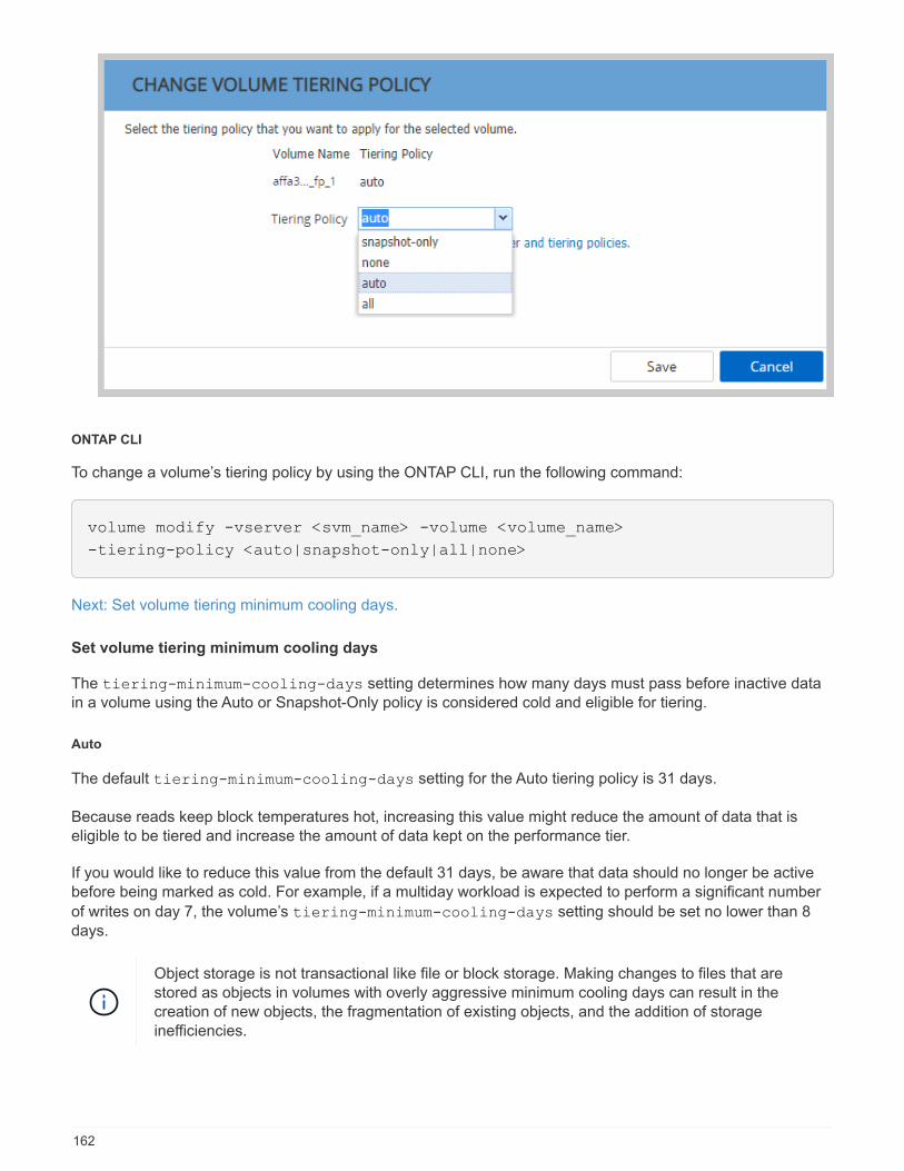
ONTAP CLI
To change a volume’s tiering policy by using the ONTAP CLI, run the following command:
volume modify -vserver <svm_name> -volume <volume_name>
-tiering-policy <auto|snapshot-only|all|none>
Next: Set volume tiering minimum cooling days.
Set volume tiering minimum cooling days
The tiering-minimum-cooling-days setting determines how many days must pass before inactive datain a volume using the Auto or Snapshot-Only policy is considered cold and eligible for tiering.
Auto
The default tiering-minimum-cooling-days setting for the Auto tiering policy is 31 days.
Because reads keep block temperatures hot, increasing this value might reduce the amount of data that iseligible to be tiered and increase the amount of data kept on the performance tier.
If you would like to reduce this value from the default 31 days, be aware that data should no longer be activebefore being marked as cold. For example, if a multiday workload is expected to perform a significant number
of writes on day 7, the volume’s tiering-minimum-cooling-days setting should be set no lower than 8days.
Object storage is not transactional like file or block storage. Making changes to files that arestored as objects in volumes with overly aggressive minimum cooling days can result in thecreation of new objects, the fragmentation of existing objects, and the addition of storageinefficiencies.
162
Snapshot-Only
The default tiering-minimum-cooling-days setting for the Snapshot-Only tiering policy is 2 days. A 2-day minimum gives additional time for background processes to provide maximum storage efficiency andprevents daily data-protection processes from having to read data from the cloud tier.
ONTAP CLI
To change a volume’s tiering-minimum-cooling-days setting by using the ONTAP CLI, run the followingcommand:
volume modify -vserver <svm_name> -volume <volume_name> -tiering-minimum
-cooling-days <2-63>
The advanced privilege level is required.
Changing the tiering policy between Auto and Snapshot-Only (or vice versa) resets the inactivityperiod of blocks on the performance tier. For example, a volume using the Auto volume tieringpolicy with data on the performance tier that has been inactive for 20 days will have theperformance tier data inactivity reset to 0 days if the tiering policy is set to Snapshot-Only.
Performance considerations
Size the performance tier
When considering sizing, keep in mind that the performance tier should be capable of the following tasks:
• Supporting hot data
• Supporting cold data until the tiering scan moves the data to the cloud tier
• Supporting cloud tier data that becomes hot and is written back to the performance tier
• Supporting WAFL metadata associated with the attached cloud tier
For most environments, a 1:10 performance-to-capacity ratio on FabricPool aggregates is extremelyconservative, while providing significant storage savings. For example, if the intent is to tier 200TB to the cloudtier, then the performance tier aggregate should be 20TB at a minimum.
Writes from the cloud tier to the performance tier are disabled if performance tier capacity isgreater than 70%. If this occurs, blocks are read directly from the cloud tier.
Size the cloud tier
When considering sizing, the object store acting as the cloud tier should be capable of the following tasks:
• Supporting reads of existing cold data
• Supporting writes of new cold data
• Supporting object deletion and defragmentation
163
Cost of ownership
The FabricPool Economic Calculator is available through the independent IT analyst firm Evaluator Group tohelp project the cost savings between on premises and the cloud for cold data storage. The calculator providesa simple interface to determine the cost of storing infrequently accessed data on a performance tier versussending it to a cloud tier for the remainder of the data lifecycle. Based on a 5-year calculation, the four keyfactors—source capacity, data growth, snapshot capacity, and the percentage of cold data—are used todetermine storage costs over the time period.
Conclusion
The journey to the cloud varies between organizations, between business units, and even between businessunits within organizations. Some choose a fast adoption, while others take a more conservative approach.FabricPool fits into the cloud strategy of organizations no matter their size and regardless of their cloudadoption speed, further demonstrating the efficiency and scalability benefits of a FlexPod infrastructure.
Where to find additional information
To learn more about the information that is described in this document, review the following documents and/orwebsites:
• FabricPool Best Practices
www.netapp.com/us/media/tr-4598.pdf
• NetApp Product Documentation
https://docs.netapp.com
• TR-4036: FlexPod Datacenter Technical Specification
https://www.netapp.com/us/media/tr-4036.pdf
164
Enterprise Databases
SAP
Introduction to SAP on FlexPod
The FlexPod platform is a predesigned, best practice data center architecture that is built on the Cisco UnifiedComputing System (Cisco UCS), the Cisco Nexus family of switches, and NetApp storage controllers.
FlexPod is a suitable platform for running SAP applications, and the solutions provided here allows you toquickly and reliably deploy SAP HANA with a model of tailored datacenter integration. FlexPod delivers notonly a baseline configuration, but also the flexibility to be sized and optimized to accommodate many differentuse cases and requirements.
Oracle
Microsoft SQL Server
165

Healthcare
FlexPod for Genomics
TR-4911: FlexPod Genomics
JayaKishore Esanakula, NetApp
There are few fields of medicine that are more important than genomics for healthcare and the life sciences,and genomics are fast becoming a key clinical tool for doctors and nurses. Genomics, when combined withmedical imaging and digital pathology, help us understand how a patient’s genes might be affected bytreatment protocols. The success of genomics in healthcare increasingly depends on data interoperability atscale. The end goal is to make sense of the enormous volumes of genetic data and identify clinically relevantcorrelations and variants that improve diagnosis and make precision medicine a reality. Genomics help usunderstand the origin of disease outbreaks, how diseases evolve, and which treatments and strategies mightbe effective. Clearly, genomics has many benefits that span prevention, diagnosis, and treatment. Healthcareorganizations are grappling with several challenges, including the following:
• Improved care quality
• Value-based care
• Data explosion
• Precision medicine
• Pandemics
• Wearables, remote monitoring, and care
• Cyber security
Standardized clinical pathways and clinical protocols are one of the critical components of modern medicine.One of the key aspects of standardization is interoperability between care providers, not just for medicalrecords but also for genomic data. The big question is will healthcare organizations relinquish ownership ofgenomic data in lieu of patient ownership of their personal genomics data and related medical records?
Interoperable patient data is key for enabling precision medicine, one of the driving forces behind the recentexplosion of data growth. The objective for precision medicine is to make health maintenance, diseaseprevention, diagnoses, and treatment solutions more effective and precise.
The rate of data growth has been exponential. In early February 2021, US laboratories sequencedapproximately 8,000 COVID-19 strains per week. The number of genomes sequenced had increased to 29,000per week by April 2021. Each fully sequenced human genome is around 125GB in size. Therefore, at a rate of29,000 genomes sequenced per week, total genome storage at rest would be more than 180 petabytes peryear. Various countries have committed resources to genomic epidemiology to improve genomic surveillanceand prepare for the next wave of global health challenges.
The reduced cost of genomic research is driving genetic testing and research at an unprecedented rate. Thethree Ps are at an inflection point: computer power, privacy of data, and personalization of medicine. By 2025researchers estimate that 100 million to as many as 2 billion human genomes will be sequenced. For genomicsto be effective and a valuable proposition, genomics capabilities must be a seamless part of care workflows; itshould be easy to access and be actionable during a patient’s visit. It is also equally important that patientelectronic medical-record data be integrated with patient genomics data. With the advent of state-of-the-artconverged infrastructure like FlexPod, organizations can bring their genomics capabilities into the everydayworkflows of physicians, nurses, and clinic managers. For the latest FlexPod platform information, see this
166
FlexPod Datacenter with Cisco UCS X-Series White Paper.
For a physician, the true value of genomics includes precision medicine and personalized treatment plansbased on the genomic data of a patient. There has never been such synergy between clinicians and datascientists in the past, and genomics is benefiting from the technological innovations in the recent past, and alsoreal partnerships between healthcare organizations and technology leaders in the industry.
Academic medical centers and other healthcare and life science organizations are well on their way toestablishing center of excellence (COE) in genome science. According to Dr. Charlie Gersbach, Dr. GregCrawford, and Dr. Tim E Reddy from Duke University, “We know that genes aren’t turned on or off by a simplebinary switch, but instead it’s a result of multiple gene regulatory switches that work together. ” They have alsodetermined that “none of these parts of the genome work in isolation. The genome is a very complicated webthat evolution has woven” ( ref).
NetApp and Cisco have been hard at work implementing incremental improvements into the FlexPod platformfor over 10 years. All customer feedback is heard, evaluated, and tied into the value streams and feature setsin FlexPod. It is this continuous loop of feedback, collaboration, improvement, and celebration that setsFlexPod apart as a trusted converged infrastructure platform the world over. It has been simplified anddesigned from the ground up to be the most reliable, robust, versatile, and agile platform for healthcareorganizations.
Scope
The FlexPod converged infrastructure platform enables a healthcare organization to host one or moregenomics workloads, along with other clinical and nonclinical healthcare applications. This technical reportuses an open-source, industry-standard genomics tool called GATK during FlexPod platform validation.However, a deeper discussion of genomics or GATK is outside the scope of this document.
Audience
This document is intended for technical leaders in the healthcare industry and for Cisco and NetApp partnersolutions engineers and professional services personnel. NetApp assumes that the reader has a goodunderstanding of compute and storage sizing concepts as well as a technical familiarity with healthcare threats,healthcare security, healthcare IT systems, Cisco UCS, and NetApp storage systems.
Hospital capabilities deployed on FlexPod
A typical hospital has a diversified set of IT systems. The majority of such systems are purchased from avendor, whereas very few are built by the hospital system in house. Therefore, the hospital system mustmanage a diverse infrastructure environment in their data centers. When hospitals unify their systems into aconverged infrastructure platform like FlexPod, organizations can standardize their data center operations.With FlexPod, healthcare organizations can implement clinical and non-clinical systems on the same platform,thereby unifying data center operations.
167
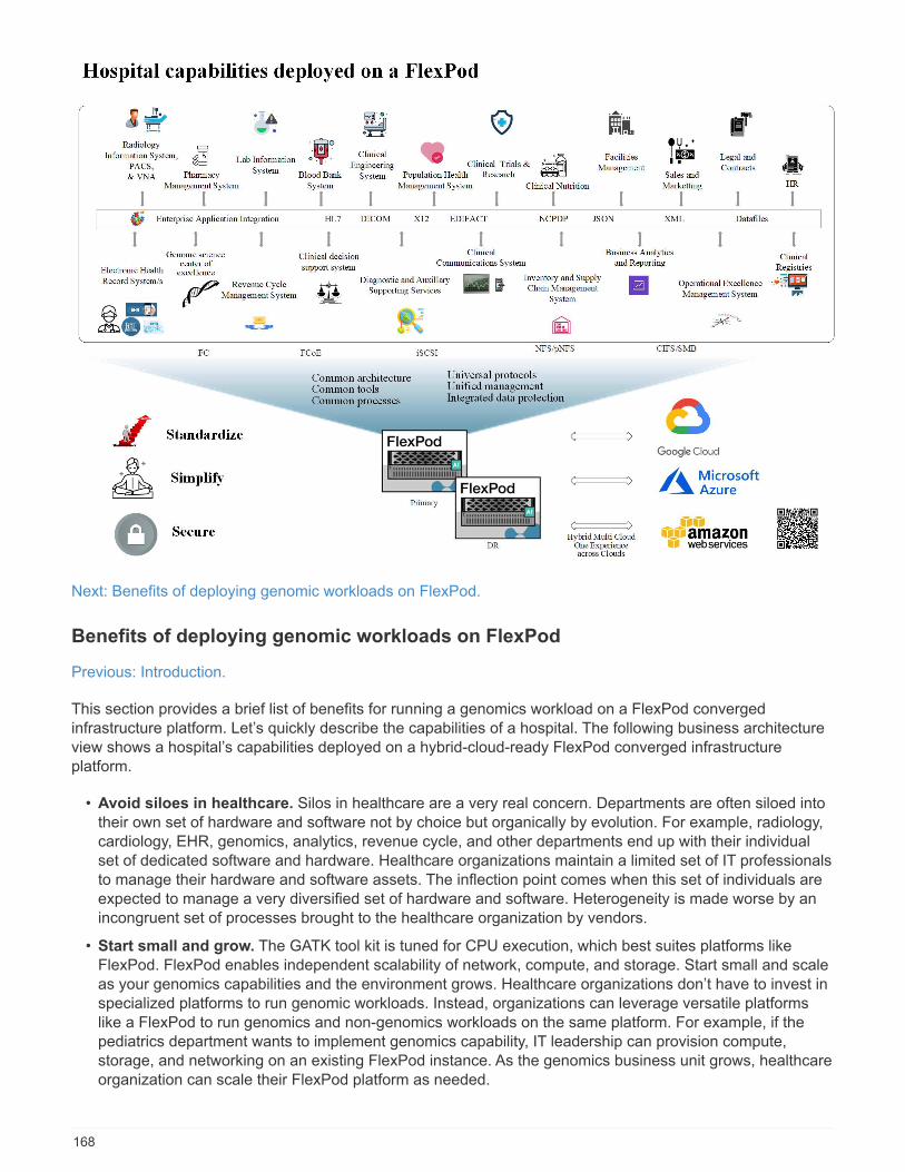
Next: Benefits of deploying genomic workloads on FlexPod.
Benefits of deploying genomic workloads on FlexPod
Previous: Introduction.
This section provides a brief list of benefits for running a genomics workload on a FlexPod convergedinfrastructure platform. Let’s quickly describe the capabilities of a hospital. The following business architectureview shows a hospital’s capabilities deployed on a hybrid-cloud-ready FlexPod converged infrastructureplatform.
• Avoid siloes in healthcare. Silos in healthcare are a very real concern. Departments are often siloed intotheir own set of hardware and software not by choice but organically by evolution. For example, radiology,cardiology, EHR, genomics, analytics, revenue cycle, and other departments end up with their individualset of dedicated software and hardware. Healthcare organizations maintain a limited set of IT professionalsto manage their hardware and software assets. The inflection point comes when this set of individuals areexpected to manage a very diversified set of hardware and software. Heterogeneity is made worse by anincongruent set of processes brought to the healthcare organization by vendors.
• Start small and grow. The GATK tool kit is tuned for CPU execution, which best suites platforms likeFlexPod. FlexPod enables independent scalability of network, compute, and storage. Start small and scaleas your genomics capabilities and the environment grows. Healthcare organizations don’t have to invest inspecialized platforms to run genomic workloads. Instead, organizations can leverage versatile platformslike a FlexPod to run genomics and non-genomics workloads on the same platform. For example, if thepediatrics department wants to implement genomics capability, IT leadership can provision compute,storage, and networking on an existing FlexPod instance. As the genomics business unit grows, healthcareorganization can scale their FlexPod platform as needed.
168
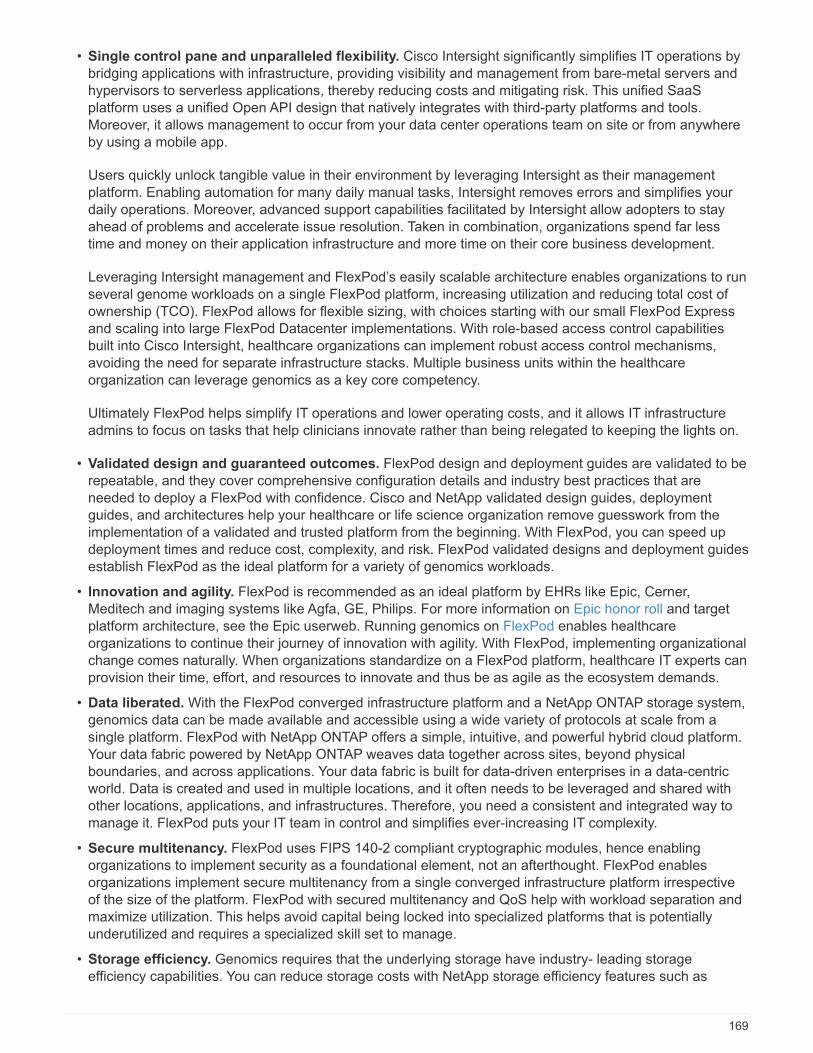
• Single control pane and unparalleled flexibility. Cisco Intersight significantly simplifies IT operations bybridging applications with infrastructure, providing visibility and management from bare-metal servers andhypervisors to serverless applications, thereby reducing costs and mitigating risk. This unified SaaSplatform uses a unified Open API design that natively integrates with third-party platforms and tools.Moreover, it allows management to occur from your data center operations team on site or from anywhereby using a mobile app.
Users quickly unlock tangible value in their environment by leveraging Intersight as their managementplatform. Enabling automation for many daily manual tasks, Intersight removes errors and simplifies yourdaily operations. Moreover, advanced support capabilities facilitated by Intersight allow adopters to stayahead of problems and accelerate issue resolution. Taken in combination, organizations spend far lesstime and money on their application infrastructure and more time on their core business development.
Leveraging Intersight management and FlexPod’s easily scalable architecture enables organizations to runseveral genome workloads on a single FlexPod platform, increasing utilization and reducing total cost ofownership (TCO). FlexPod allows for flexible sizing, with choices starting with our small FlexPod Expressand scaling into large FlexPod Datacenter implementations. With role-based access control capabilitiesbuilt into Cisco Intersight, healthcare organizations can implement robust access control mechanisms,avoiding the need for separate infrastructure stacks. Multiple business units within the healthcareorganization can leverage genomics as a key core competency.
Ultimately FlexPod helps simplify IT operations and lower operating costs, and it allows IT infrastructureadmins to focus on tasks that help clinicians innovate rather than being relegated to keeping the lights on.
• Validated design and guaranteed outcomes. FlexPod design and deployment guides are validated to berepeatable, and they cover comprehensive configuration details and industry best practices that areneeded to deploy a FlexPod with confidence. Cisco and NetApp validated design guides, deploymentguides, and architectures help your healthcare or life science organization remove guesswork from theimplementation of a validated and trusted platform from the beginning. With FlexPod, you can speed updeployment times and reduce cost, complexity, and risk. FlexPod validated designs and deployment guidesestablish FlexPod as the ideal platform for a variety of genomics workloads.
• Innovation and agility. FlexPod is recommended as an ideal platform by EHRs like Epic, Cerner,Meditech and imaging systems like Agfa, GE, Philips. For more information on Epic honor roll and targetplatform architecture, see the Epic userweb. Running genomics on FlexPod enables healthcareorganizations to continue their journey of innovation with agility. With FlexPod, implementing organizationalchange comes naturally. When organizations standardize on a FlexPod platform, healthcare IT experts canprovision their time, effort, and resources to innovate and thus be as agile as the ecosystem demands.
• Data liberated. With the FlexPod converged infrastructure platform and a NetApp ONTAP storage system,genomics data can be made available and accessible using a wide variety of protocols at scale from asingle platform. FlexPod with NetApp ONTAP offers a simple, intuitive, and powerful hybrid cloud platform.Your data fabric powered by NetApp ONTAP weaves data together across sites, beyond physicalboundaries, and across applications. Your data fabric is built for data-driven enterprises in a data-centricworld. Data is created and used in multiple locations, and it often needs to be leveraged and shared withother locations, applications, and infrastructures. Therefore, you need a consistent and integrated way tomanage it. FlexPod puts your IT team in control and simplifies ever-increasing IT complexity.
• Secure multitenancy. FlexPod uses FIPS 140-2 compliant cryptographic modules, hence enablingorganizations to implement security as a foundational element, not an afterthought. FlexPod enablesorganizations implement secure multitenancy from a single converged infrastructure platform irrespectiveof the size of the platform. FlexPod with secured multitenancy and QoS help with workload separation andmaximize utilization. This helps avoid capital being locked into specialized platforms that is potentiallyunderutilized and requires a specialized skill set to manage.
• Storage efficiency. Genomics requires that the underlying storage have industry- leading storageefficiency capabilities. You can reduce storage costs with NetApp storage efficiency features such as
169
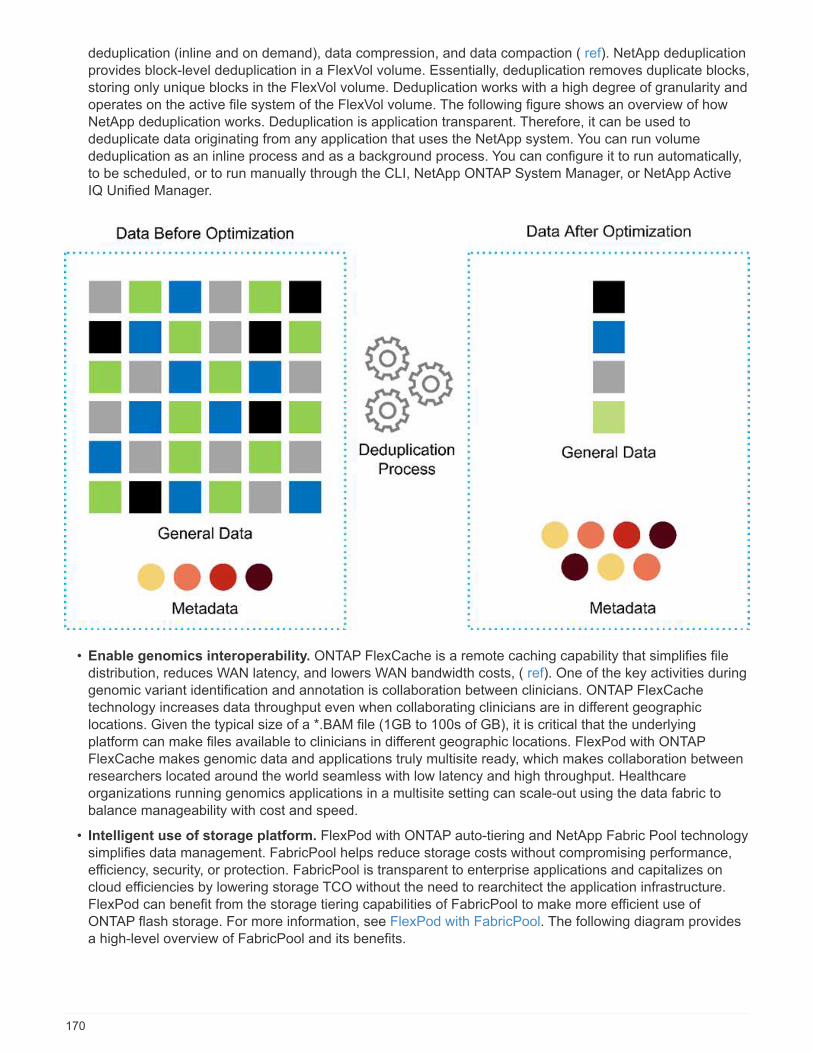
deduplication (inline and on demand), data compression, and data compaction ( ref). NetApp deduplicationprovides block-level deduplication in a FlexVol volume. Essentially, deduplication removes duplicate blocks,storing only unique blocks in the FlexVol volume. Deduplication works with a high degree of granularity andoperates on the active file system of the FlexVol volume. The following figure shows an overview of howNetApp deduplication works. Deduplication is application transparent. Therefore, it can be used todeduplicate data originating from any application that uses the NetApp system. You can run volumededuplication as an inline process and as a background process. You can configure it to run automatically,to be scheduled, or to run manually through the CLI, NetApp ONTAP System Manager, or NetApp ActiveIQ Unified Manager.
• Enable genomics interoperability. ONTAP FlexCache is a remote caching capability that simplifies filedistribution, reduces WAN latency, and lowers WAN bandwidth costs, ( ref). One of the key activities duringgenomic variant identification and annotation is collaboration between clinicians. ONTAP FlexCachetechnology increases data throughput even when collaborating clinicians are in different geographiclocations. Given the typical size of a *.BAM file (1GB to 100s of GB), it is critical that the underlyingplatform can make files available to clinicians in different geographic locations. FlexPod with ONTAPFlexCache makes genomic data and applications truly multisite ready, which makes collaboration betweenresearchers located around the world seamless with low latency and high throughput. Healthcareorganizations running genomics applications in a multisite setting can scale-out using the data fabric tobalance manageability with cost and speed.
• Intelligent use of storage platform. FlexPod with ONTAP auto-tiering and NetApp Fabric Pool technologysimplifies data management. FabricPool helps reduce storage costs without compromising performance,efficiency, security, or protection. FabricPool is transparent to enterprise applications and capitalizes oncloud efficiencies by lowering storage TCO without the need to rearchitect the application infrastructure.FlexPod can benefit from the storage tiering capabilities of FabricPool to make more efficient use ofONTAP flash storage. For more information, see FlexPod with FabricPool. The following diagram providesa high-level overview of FabricPool and its benefits.
170
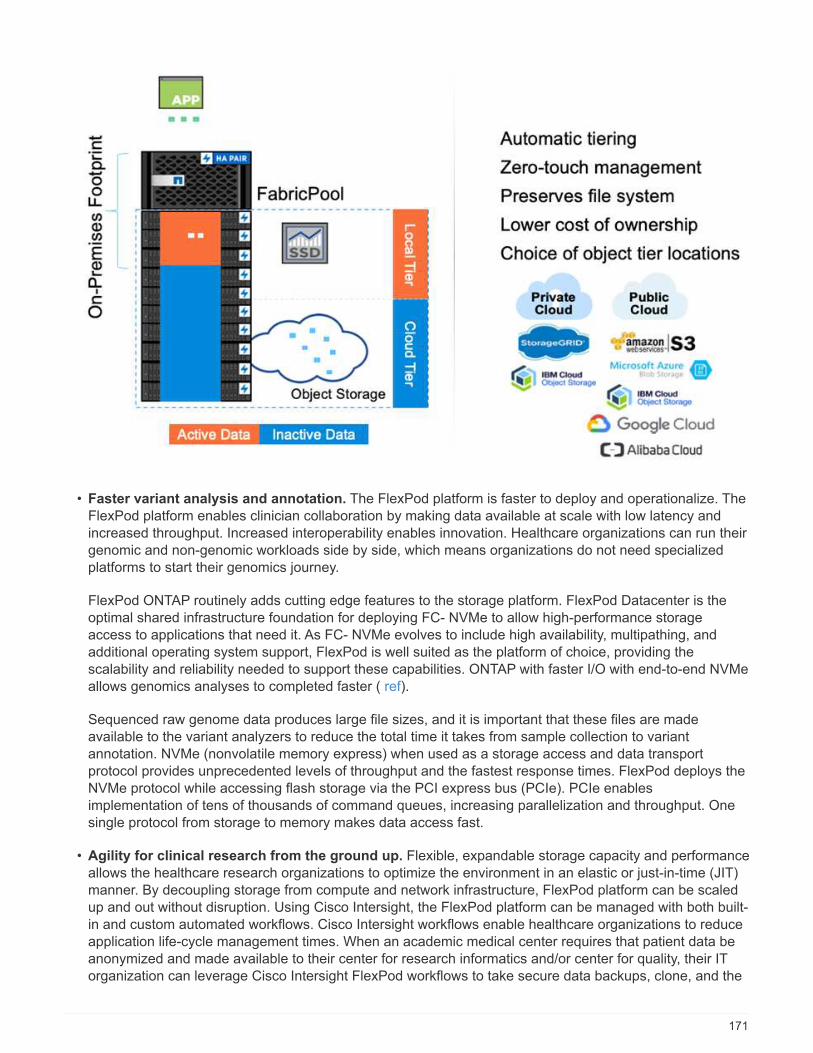
• Faster variant analysis and annotation. The FlexPod platform is faster to deploy and operationalize. TheFlexPod platform enables clinician collaboration by making data available at scale with low latency andincreased throughput. Increased interoperability enables innovation. Healthcare organizations can run theirgenomic and non-genomic workloads side by side, which means organizations do not need specializedplatforms to start their genomics journey.
FlexPod ONTAP routinely adds cutting edge features to the storage platform. FlexPod Datacenter is theoptimal shared infrastructure foundation for deploying FC- NVMe to allow high-performance storageaccess to applications that need it. As FC- NVMe evolves to include high availability, multipathing, andadditional operating system support, FlexPod is well suited as the platform of choice, providing thescalability and reliability needed to support these capabilities. ONTAP with faster I/O with end-to-end NVMeallows genomics analyses to completed faster ( ref).
Sequenced raw genome data produces large file sizes, and it is important that these files are madeavailable to the variant analyzers to reduce the total time it takes from sample collection to variantannotation. NVMe (nonvolatile memory express) when used as a storage access and data transportprotocol provides unprecedented levels of throughput and the fastest response times. FlexPod deploys theNVMe protocol while accessing flash storage via the PCI express bus (PCIe). PCIe enablesimplementation of tens of thousands of command queues, increasing parallelization and throughput. Onesingle protocol from storage to memory makes data access fast.
• Agility for clinical research from the ground up. Flexible, expandable storage capacity and performanceallows the healthcare research organizations to optimize the environment in an elastic or just-in-time (JIT)manner. By decoupling storage from compute and network infrastructure, FlexPod platform can be scaledup and out without disruption. Using Cisco Intersight, the FlexPod platform can be managed with both built-in and custom automated workflows. Cisco Intersight workflows enable healthcare organizations to reduceapplication life-cycle management times. When an academic medical center requires that patient data beanonymized and made available to their center for research informatics and/or center for quality, their ITorganization can leverage Cisco Intersight FlexPod workflows to take secure data backups, clone, and the
171
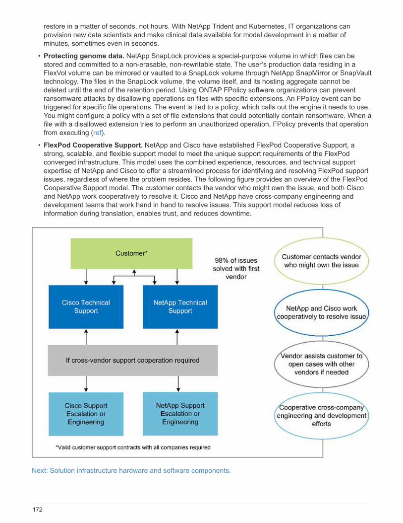
restore in a matter of seconds, not hours. With NetApp Trident and Kubernetes, IT organizations canprovision new data scientists and make clinical data available for model development in a matter ofminutes, sometimes even in seconds.
• Protecting genome data. NetApp SnapLock provides a special-purpose volume in which files can bestored and committed to a non-erasable, non-rewritable state. The user’s production data residing in aFlexVol volume can be mirrored or vaulted to a SnapLock volume through NetApp SnapMirror or SnapVaulttechnology. The files in the SnapLock volume, the volume itself, and its hosting aggregate cannot bedeleted until the end of the retention period. Using ONTAP FPolicy software organizations can preventransomware attacks by disallowing operations on files with specific extensions. An FPolicy event can betriggered for specific file operations. The event is tied to a policy, which calls out the engine it needs to use.You might configure a policy with a set of file extensions that could potentially contain ransomware. When afile with a disallowed extension tries to perform an unauthorized operation, FPolicy prevents that operationfrom executing (ref).
• FlexPod Cooperative Support. NetApp and Cisco have established FlexPod Cooperative Support, astrong, scalable, and flexible support model to meet the unique support requirements of the FlexPodconverged infrastructure. This model uses the combined experience, resources, and technical supportexpertise of NetApp and Cisco to offer a streamlined process for identifying and resolving FlexPod supportissues, regardless of where the problem resides. The following figure provides an overview of the FlexPodCooperative Support model. The customer contacts the vendor who might own the issue, and both Ciscoand NetApp work cooperatively to resolve it. Cisco and NetApp have cross-company engineering anddevelopment teams that work hand in hand to resolve issues. This support model reduces loss ofinformation during translation, enables trust, and reduces downtime.
Next: Solution infrastructure hardware and software components.
172
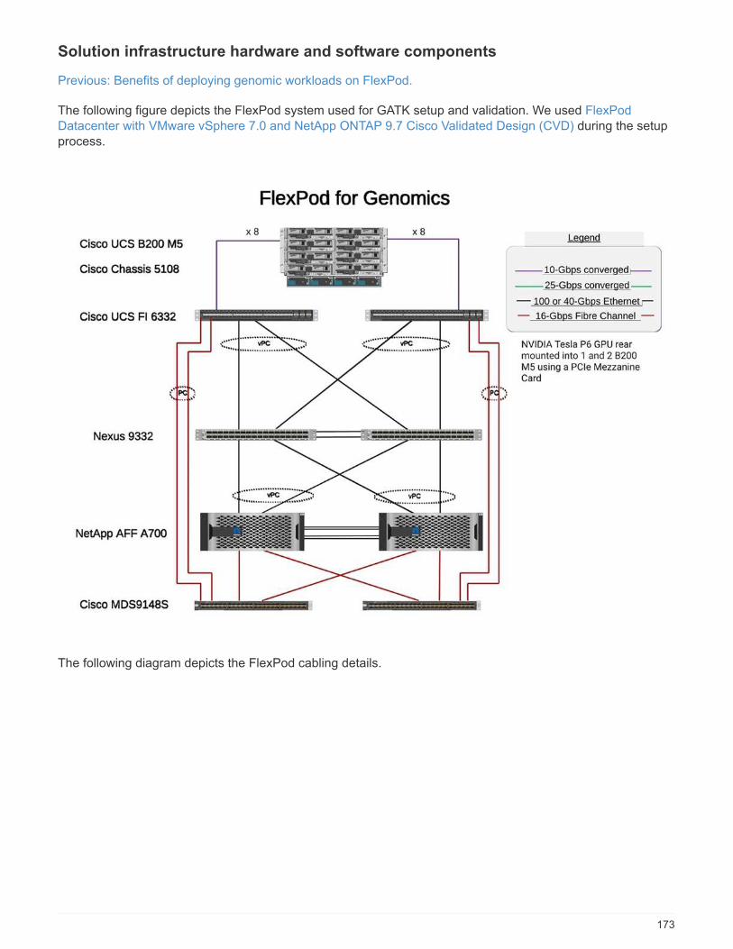
Solution infrastructure hardware and software components
Previous: Benefits of deploying genomic workloads on FlexPod.
The following figure depicts the FlexPod system used for GATK setup and validation. We used FlexPodDatacenter with VMware vSphere 7.0 and NetApp ONTAP 9.7 Cisco Validated Design (CVD) during the setupprocess.
The following diagram depicts the FlexPod cabling details.
173

The following table lists the hardware components used during the GATK testing enabling on a FlexPod. Hereis the NetApp Interoperability Matrix Tool (IMT) and Cisco Hardware Compatibility List (HCL).
Layer Product family Quantity and model Details
Compute Cisco UCS 5108 chassis 1 or 2
Cisco UCS blade servers 6 B200 M5 Each with 2x 20 or morecores, 2.7GHz, and 128-384GB RAM
174
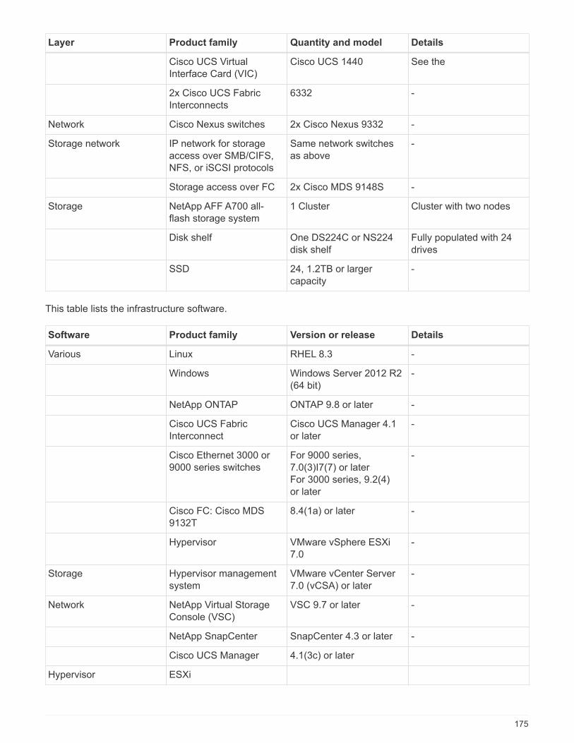
Layer Product family Quantity and model Details
Cisco UCS VirtualInterface Card (VIC)
Cisco UCS 1440 See the
2x Cisco UCS FabricInterconnects
6332 -
Network Cisco Nexus switches 2x Cisco Nexus 9332 -
Storage network IP network for storageaccess over SMB/CIFS,NFS, or iSCSI protocols
Same network switchesas above
-
Storage access over FC 2x Cisco MDS 9148S -
Storage NetApp AFF A700 all-flash storage system
1 Cluster Cluster with two nodes
Disk shelf One DS224C or NS224disk shelf
Fully populated with 24drives
SSD 24, 1.2TB or largercapacity
-
This table lists the infrastructure software.
Software Product family Version or release Details
Various Linux RHEL 8.3 -
Windows Windows Server 2012 R2(64 bit)
-
NetApp ONTAP ONTAP 9.8 or later -
Cisco UCS FabricInterconnect
Cisco UCS Manager 4.1or later
-
Cisco Ethernet 3000 or9000 series switches
For 9000 series,7.0(3)I7(7) or laterFor 3000 series, 9.2(4)or later
-
Cisco FC: Cisco MDS9132T
8.4(1a) or later -
Hypervisor VMware vSphere ESXi7.0
-
Storage Hypervisor managementsystem
VMware vCenter Server7.0 (vCSA) or later
-
Network NetApp Virtual StorageConsole (VSC)
VSC 9.7 or later -
NetApp SnapCenter SnapCenter 4.3 or later -
Cisco UCS Manager 4.1(3c) or later
Hypervisor ESXi
175
Software Product family Version or release Details
Management Hypervisor managementsystemVMware vCenterServer 7.0 (vCSA) or later
NetApp Virtual StorageConsole (VSC)
VSC 9.7 or later
NetApp SnapCenter SnapCenter 4.3 or later
Cisco UCS Manager 4.1(3c) or later
Next: Genomics - GATK setup and execution.
Genomics - GATK setup and execution
Previous: Solution infrastructure hardware and software components.
According to the National Human Genome Research Institute ( NHGRI), “Genomics is the study of all of aperson’s genes (the genome), including interactions of these genes with each other and with a person’senvironment. ”
According to the NHGRI, “Deoxyribonucleic acid (DNA) is the chemical compound that contains theinstructions needed to develop and direct the activities of nearly all living organisms. DNA molecules are madeof two twisting, paired strands, often referred to as a double helix.” “An organism’s complete set of DNA iscalled its genome.”
Sequencing is the process of determining the exact order of the bases in a strand of DNA. One of the mostcommon types of sequencing used today is called sequencing by synthesis. This technique uses the emissionof fluorescent signals to order the bases. Researchers can use DNA sequencing to search for geneticvariations and any mutations that might play a role in the development or progression of a disease while aperson is still in the embryonic stage.
From sample to variant identification, annotation, and prediction
At a high level, genomics can be classified into the following steps. This is not an exhaustive list:
1. Sample collection.
2. Genome sequencing using a sequencer to generate the raw data.
3. Preprocessing. For example, deduplication using Picard.
4. Genomic analysis.
a. Mapping to a reference genome.
b. Variant identification and annotation typically performed using GATK and similar tools.
5. Integration into the electronic health record (EHR) system.
6. Population stratification and identification of genetic variation across geographical location and ethnicbackground.
7. Predictive models using significant single- nucleotide polymorphism.
8. Validation.
The following figure shows the process from sampling to variant identification, annotation, and prediction.
176
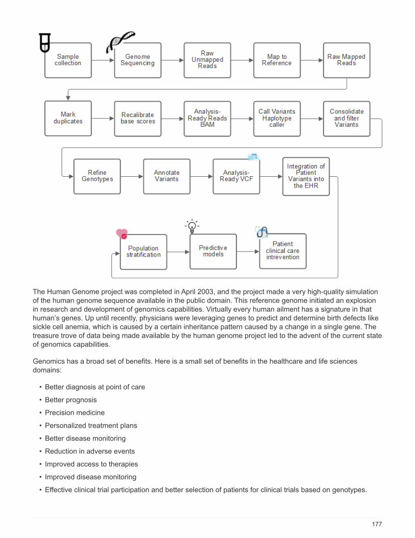
The Human Genome project was completed in April 2003, and the project made a very high-quality simulationof the human genome sequence available in the public domain. This reference genome initiated an explosionin research and development of genomics capabilities. Virtually every human ailment has a signature in thathuman’s genes. Up until recently, physicians were leveraging genes to predict and determine birth defects likesickle cell anemia, which is caused by a certain inheritance pattern caused by a change in a single gene. Thetreasure trove of data being made available by the human genome project led to the advent of the current stateof genomics capabilities.
Genomics has a broad set of benefits. Here is a small set of benefits in the healthcare and life sciencesdomains:
• Better diagnosis at point of care
• Better prognosis
• Precision medicine
• Personalized treatment plans
• Better disease monitoring
• Reduction in adverse events
• Improved access to therapies
• Improved disease monitoring
• Effective clinical trial participation and better selection of patients for clinical trials based on genotypes.
177
Genomics is a "four-headed beast," because of the computational demands across the lifecycle of a dataset:acquisition, storage, distribution, and analysis.
Genome Analysis Toolkit (GATK)
GATK was developed as a data science platform at the Broad Institute. GATK is a set of open-source tools thatenable genome analysis, specifically variant discovery, identification, annotation, and genotyping. One of thebenefits of GATK is that the set of tools and or commands can be chained to form a complete workflow. Theprimary challenges that Broad institute tackles are the following:
• Understand the root causes and biological mechanisms of diseases.
• Identify therapeutic interventions that act at the fundamental cause of a disease.
• Understand the line of sight from variants to function in human physiology.
• Create standards and policy frameworks for genome data representation, storage, analysis, security, andso on.
• Standardize and socialize interoperable genome aggregation databases (gnomAD).
• Genome-based monitoring, diagnosis, and treatment of patients with greater precision.
• Help implement tools that predict diseases well before symptoms appear.
• Create and empower a community of cross-disciplinary collaborators to help tackle the toughest and mostimportant problems in biomedicine.
According to GATK and the Broad institute, genome sequencing should be treated as a protocol in a pathologylab; every task is well documented, optimized, reproducible, and consistent across samples and experiments.The following is a set of steps recommended by the Broad Institute, for more information, see the GATKwebsite.
FlexPod setup
Genomics workload validation includes a from-scratch setup of a FlexPod infrastructure platform. The FlexPodplatform is highly available and can be independently scaled; for example, network, storage and compute canbe scaled independently. We used the following Cisco validated design guide as the reference architecturedocument to set up the FlexPod environment: FlexPod Datacenter with VMware vSphere 7.0 and NetAppONTAP 9.7. See the following FlexPod platform set up highlights:
To perform FlexPod lab setup, complete the following steps:
1. FlexPod lab setup and validation uses the following IP4 reservations and VLANs.
178
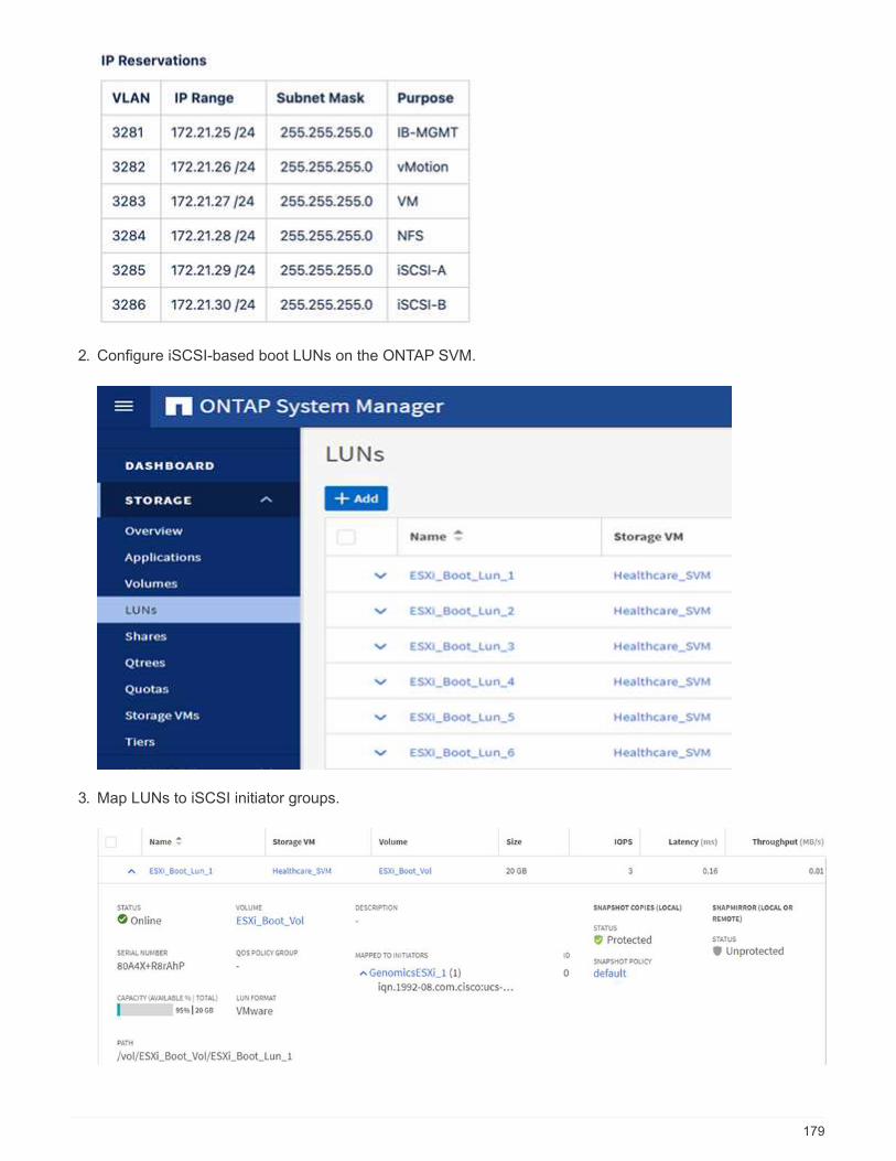
2. Configure iSCSI-based boot LUNs on the ONTAP SVM.
3. Map LUNs to iSCSI initiator groups.
179
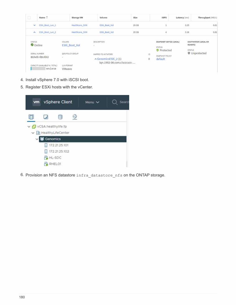
4. Install vSphere 7.0 with iSCSI boot.
5. Register ESXi hosts with the vCenter.
6. Provision an NFS datastore infra_datastore_nfs on the ONTAP storage.
180
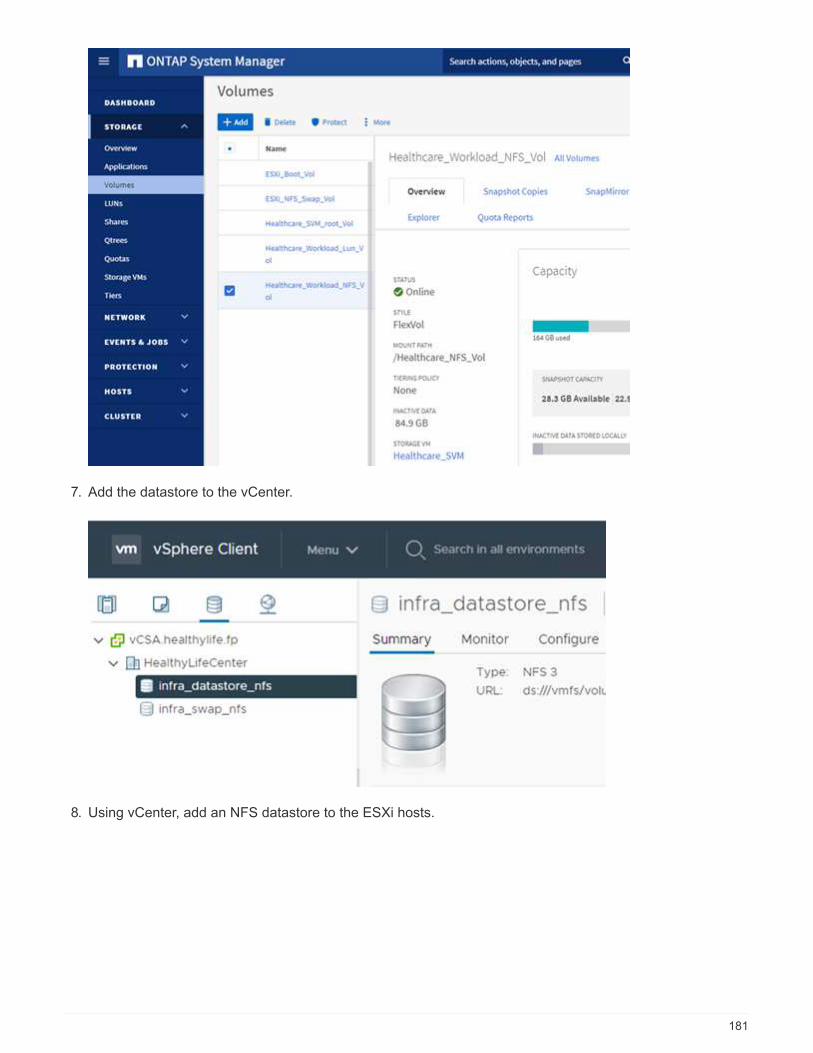
7. Add the datastore to the vCenter.
8. Using vCenter, add an NFS datastore to the ESXi hosts.
181

9. Using the vCenter, create a Red Hat Enterprise Linux (RHEL) 8.3 VM to run GATK.
10. An NFS datastore is presented to the VM and mounted at /mnt/genomics, which is used to store GATKexecutables, scripts, Binary Alignment Map (BAM) files, reference files, index files, dictionary files, and outfiles for variant calling.
GATK setup and execution
Install the following prerequisites on the RedHat Enterprise 8.3 Linux VM:
• Java 8 or SDK 1.8 or later
• Download GATK 4.2.0.0 from the Broad Institute GitHub site. Genome sequence data is generally stored inthe form of a series of tab-delimited ASCII columns. However, ASCII takes too much space to store.Therefore, a new standard evolved called a BAM (*.bam) file. A BAM file stores the sequence data in acompressed, indexed, and binary form. We downloaded a set of publicly available BAM files for GATKexecution from the public domain. We also downloaded index files (\*.bai), dictionary files (*. dict), andreference data files (*. fasta) from the same public domain.
After downloading, the GATK tool kit has a jar file and a set of support scripts.
• gatk-package-4.2.0.0-local.jar executable
• gatk script file.
We downloaded the BAM files and the corresponding index, dictionary, and reference genome files for a familythat consisted of father, mother, and son *.bam files.
Cromwell engine
Cromwell is an open-source engine geared towards scientific workflows that enables workflow management.The Cromwell engine can be run in two modes, Server mode or a single- workflow Run mode. The behavior ofthe Cromwell engine can be controlled using the Cromwell engine configuration file.
• Server mode. Enables RESTful execution of workflows in Cromwell engine.
• Run mode. Run mode is best suited for executing single workflows in Cromwell, ref for a complete set ofavailable options in Run mode.
We use the Cromwell engine to execute the workflows and pipelines at scale. The Cromwell engine uses auser-friendly workflow description language (WDL)-based scripting language. Cromwell also supports a second
182
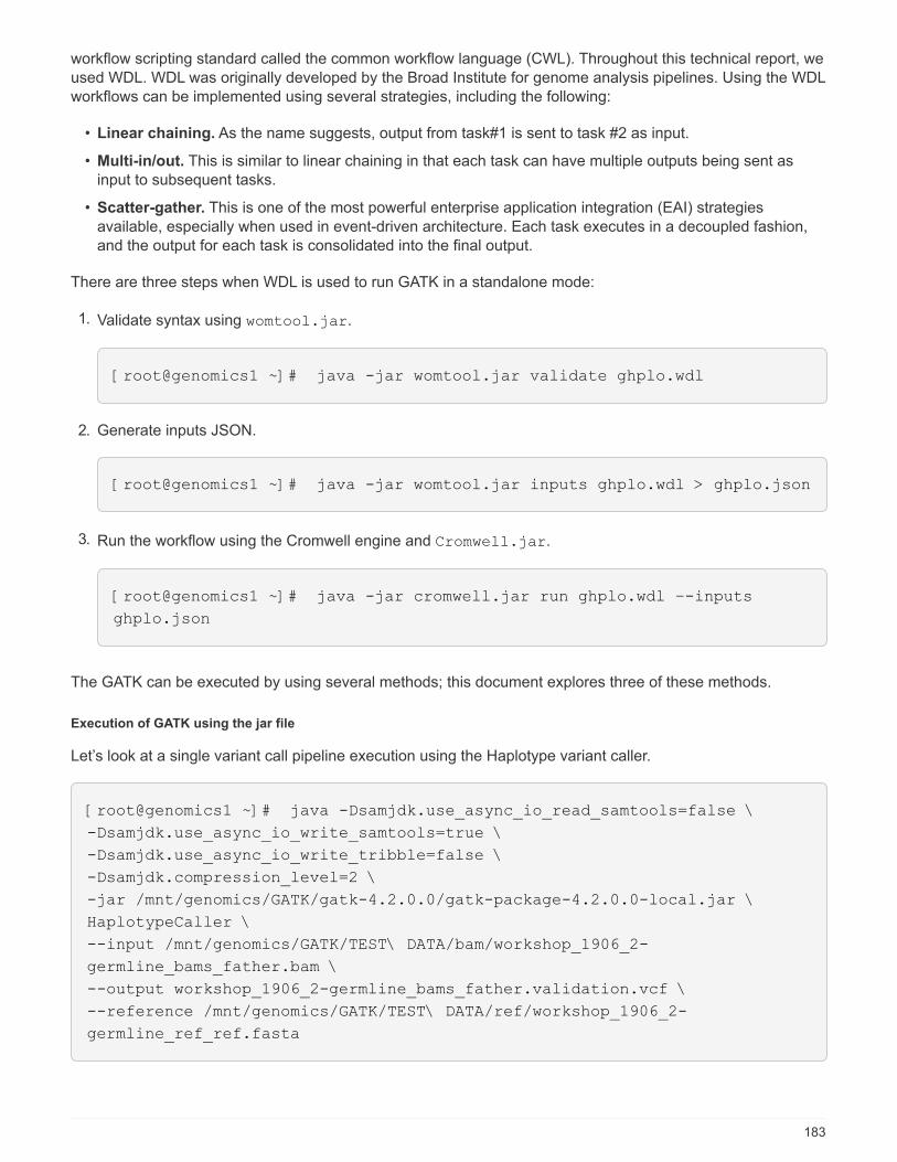
workflow scripting standard called the common workflow language (CWL). Throughout this technical report, weused WDL. WDL was originally developed by the Broad Institute for genome analysis pipelines. Using the WDLworkflows can be implemented using several strategies, including the following:
• Linear chaining. As the name suggests, output from task#1 is sent to task #2 as input.
• Multi-in/out. This is similar to linear chaining in that each task can have multiple outputs being sent asinput to subsequent tasks.
• Scatter-gather. This is one of the most powerful enterprise application integration (EAI) strategiesavailable, especially when used in event-driven architecture. Each task executes in a decoupled fashion,and the output for each task is consolidated into the final output.
There are three steps when WDL is used to run GATK in a standalone mode:
1. Validate syntax using womtool.jar.
[root@genomics1 ~]# java -jar womtool.jar validate ghplo.wdl
2. Generate inputs JSON.
[root@genomics1 ~]# java -jar womtool.jar inputs ghplo.wdl > ghplo.json
3. Run the workflow using the Cromwell engine and Cromwell.jar.
[root@genomics1 ~]# java -jar cromwell.jar run ghplo.wdl –-inputs
ghplo.json
The GATK can be executed by using several methods; this document explores three of these methods.
Execution of GATK using the jar file
Let’s look at a single variant call pipeline execution using the Haplotype variant caller.
[root@genomics1 ~]# java -Dsamjdk.use_async_io_read_samtools=false \
-Dsamjdk.use_async_io_write_samtools=true \
-Dsamjdk.use_async_io_write_tribble=false \
-Dsamjdk.compression_level=2 \
-jar /mnt/genomics/GATK/gatk-4.2.0.0/gatk-package-4.2.0.0-local.jar \
HaplotypeCaller \
--input /mnt/genomics/GATK/TEST\ DATA/bam/workshop_1906_2-
germline_bams_father.bam \
--output workshop_1906_2-germline_bams_father.validation.vcf \
--reference /mnt/genomics/GATK/TEST\ DATA/ref/workshop_1906_2-
germline_ref_ref.fasta
183

In this method of execution, we use the GATK local execution jar file, we use a single java command to invokethe jar file, and we pass several parameters to the command.
1. This parameter indicates that we are invoking the HaplotypeCaller variant caller pipeline.
2. -- input specifies the input BAM file.
3. --output specifies the variant output file in variant call format (*.vcf) (ref).
4. With the --reference parameter, we are passing a reference genome.
Once executed, output details can be found in the section "Output for execution of GATK using the jar file."
Execution of GATK using ./gatk script
GATK tool kit can be executed using the ./gatk script. Let’s examine the following command:
[root@genomics1 execution]# ./gatk \
--java-options "-Xmx4G" \
HaplotypeCaller \
-I /mnt/genomics/GATK/TEST\ DATA/bam/workshop_1906_2-
germline_bams_father.bam \
-R /mnt/genomics/GATK/TEST\ DATA/ref/workshop_1906_2-
germline_ref_ref.fasta \
-O /mnt/genomics/GATK/TEST\ DATA/variants.vcf
We pass several parameters to the command.
• This parameter indicates that we are invoking the HaplotypeCaller variant caller pipeline.
• -I specifies the input BAM file.
• -O specifies the variant output file in variant call format (*.vcf) (ref).
• With the -R parameter, we are passing a reference genome.
Once executed, output details can be found in the section "Output for execution of GATK using the ./gatkscript."
Execution of GATK using Cromwell engine
We use the Cromwell engine to manage GATK execution. Let’s examine the command line and it’sparameters.
[root@genomics1 genomics]# java -jar cromwell-65.jar \
run /mnt/genomics/GATK/seq/ghplo.wdl \
--inputs /mnt/genomics/GATK/seq/ghplo.json
Here, we invoke the Java command by passing the -jar parameter to indicate that we intend to execute a jar
file, for example, Cromwell-65.jar. The next parameter passed (run) indicates that the Cromwell engine is
running in Run mode, the other possible option is Server mode. The next parameter is *.wdl that the Run
184
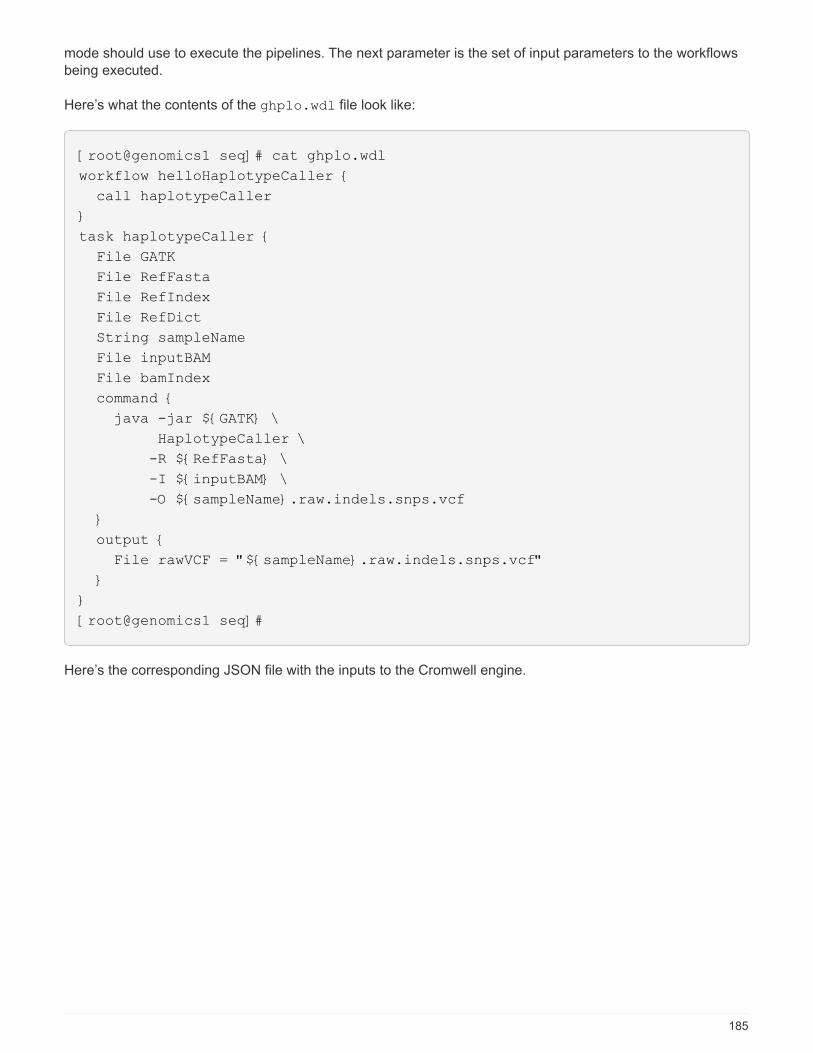
mode should use to execute the pipelines. The next parameter is the set of input parameters to the workflowsbeing executed.
Here’s what the contents of the ghplo.wdl file look like:
[root@genomics1 seq]# cat ghplo.wdl
workflow helloHaplotypeCaller {
call haplotypeCaller
}
task haplotypeCaller {
File GATK
File RefFasta
File RefIndex
File RefDict
String sampleName
File inputBAM
File bamIndex
command {
java -jar ${GATK} \
HaplotypeCaller \
-R ${RefFasta} \
-I ${inputBAM} \
-O ${sampleName}.raw.indels.snps.vcf
}
output {
File rawVCF = "${sampleName}.raw.indels.snps.vcf"
}
}
[root@genomics1 seq]#
Here’s the corresponding JSON file with the inputs to the Cromwell engine.
185
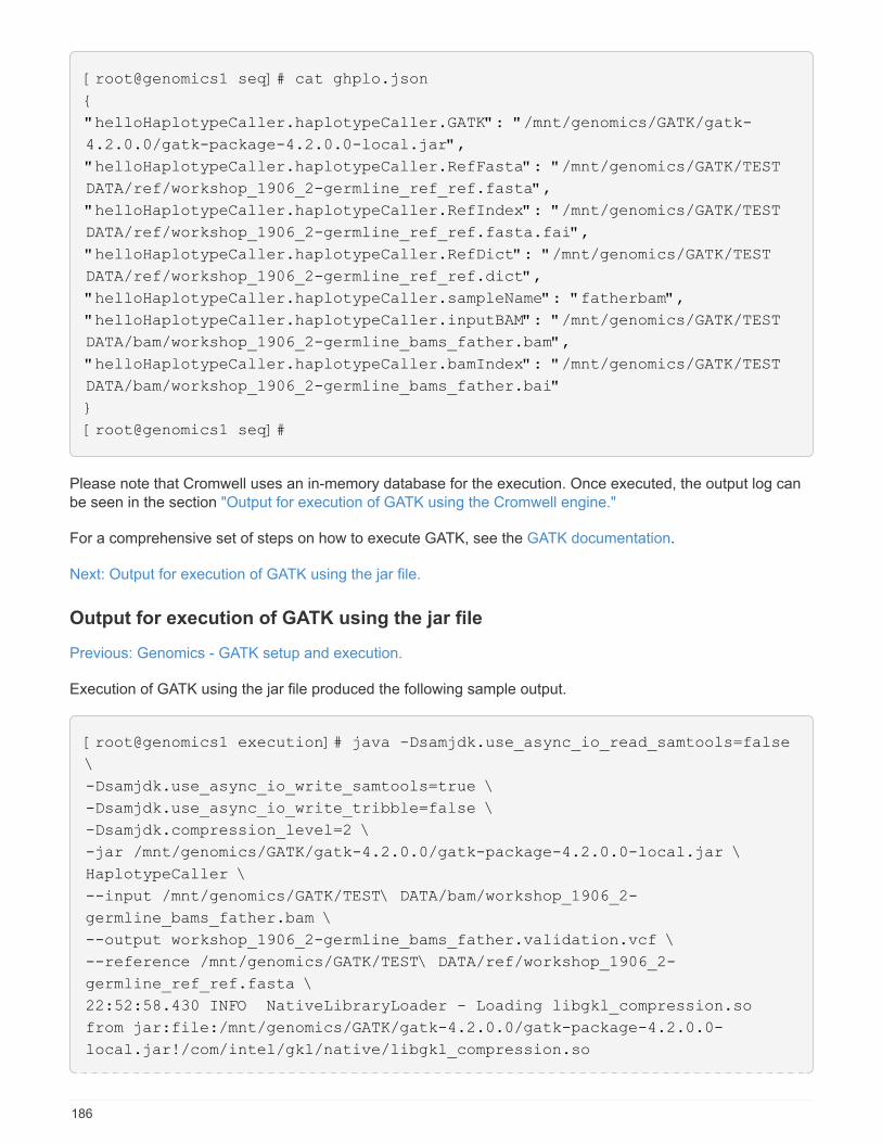
[root@genomics1 seq]# cat ghplo.json
{
"helloHaplotypeCaller.haplotypeCaller.GATK": "/mnt/genomics/GATK/gatk-
4.2.0.0/gatk-package-4.2.0.0-local.jar",
"helloHaplotypeCaller.haplotypeCaller.RefFasta": "/mnt/genomics/GATK/TEST
DATA/ref/workshop_1906_2-germline_ref_ref.fasta",
"helloHaplotypeCaller.haplotypeCaller.RefIndex": "/mnt/genomics/GATK/TEST
DATA/ref/workshop_1906_2-germline_ref_ref.fasta.fai",
"helloHaplotypeCaller.haplotypeCaller.RefDict": "/mnt/genomics/GATK/TEST
DATA/ref/workshop_1906_2-germline_ref_ref.dict",
"helloHaplotypeCaller.haplotypeCaller.sampleName": "fatherbam",
"helloHaplotypeCaller.haplotypeCaller.inputBAM": "/mnt/genomics/GATK/TEST
DATA/bam/workshop_1906_2-germline_bams_father.bam",
"helloHaplotypeCaller.haplotypeCaller.bamIndex": "/mnt/genomics/GATK/TEST
DATA/bam/workshop_1906_2-germline_bams_father.bai"
}
[root@genomics1 seq]#
Please note that Cromwell uses an in-memory database for the execution. Once executed, the output log canbe seen in the section "Output for execution of GATK using the Cromwell engine."
For a comprehensive set of steps on how to execute GATK, see the GATK documentation.
Next: Output for execution of GATK using the jar file.
Output for execution of GATK using the jar file
Previous: Genomics - GATK setup and execution.
Execution of GATK using the jar file produced the following sample output.
[root@genomics1 execution]# java -Dsamjdk.use_async_io_read_samtools=false
\
-Dsamjdk.use_async_io_write_samtools=true \
-Dsamjdk.use_async_io_write_tribble=false \
-Dsamjdk.compression_level=2 \
-jar /mnt/genomics/GATK/gatk-4.2.0.0/gatk-package-4.2.0.0-local.jar \
HaplotypeCaller \
--input /mnt/genomics/GATK/TEST\ DATA/bam/workshop_1906_2-
germline_bams_father.bam \
--output workshop_1906_2-germline_bams_father.validation.vcf \
--reference /mnt/genomics/GATK/TEST\ DATA/ref/workshop_1906_2-
germline_ref_ref.fasta \
22:52:58.430 INFO NativeLibraryLoader - Loading libgkl_compression.so
from jar:file:/mnt/genomics/GATK/gatk-4.2.0.0/gatk-package-4.2.0.0-
local.jar!/com/intel/gkl/native/libgkl_compression.so
186

Aug 17, 2021 10:52:58 PM
shaded.cloud_nio.com.google.auth.oauth2.ComputeEngineCredentials
runningOnComputeEngine
INFO: Failed to detect whether we are running on Google Compute Engine.
22:52:58.541 INFO HaplotypeCaller -
------------------------------------------------------------
22:52:58.542 INFO HaplotypeCaller - The Genome Analysis Toolkit (GATK)
v4.2.0.0
22:52:58.542 INFO HaplotypeCaller - For support and documentation go to
https://software.broadinstitute.org/gatk/
22:52:58.542 INFO HaplotypeCaller - Executing as
[email protected] on Linux v4.18.0-305.3.1.el8_4.x86_64 amd64
22:52:58.542 INFO HaplotypeCaller - Java runtime: OpenJDK 64-Bit Server
VM v1.8.0_302-b08
22:52:58.542 INFO HaplotypeCaller - Start Date/Time: August 17, 2021
10:52:58 PM EDT
22:52:58.542 INFO HaplotypeCaller -
------------------------------------------------------------
22:52:58.542 INFO HaplotypeCaller -
------------------------------------------------------------
22:52:58.542 INFO HaplotypeCaller - HTSJDK Version: 2.24.0
22:52:58.542 INFO HaplotypeCaller - Picard Version: 2.25.0
22:52:58.542 INFO HaplotypeCaller - Built for Spark Version: 2.4.5
22:52:58.542 INFO HaplotypeCaller - HTSJDK Defaults.COMPRESSION_LEVEL : 2
22:52:58.543 INFO HaplotypeCaller - HTSJDK
Defaults.USE_ASYNC_IO_READ_FOR_SAMTOOLS : false
22:52:58.543 INFO HaplotypeCaller - HTSJDK
Defaults.USE_ASYNC_IO_WRITE_FOR_SAMTOOLS : true
22:52:58.543 INFO HaplotypeCaller - HTSJDK
Defaults.USE_ASYNC_IO_WRITE_FOR_TRIBBLE : false
22:52:58.543 INFO HaplotypeCaller - Deflater: IntelDeflater
22:52:58.543 INFO HaplotypeCaller - Inflater: IntelInflater
22:52:58.543 INFO HaplotypeCaller - GCS max retries/reopens: 20
22:52:58.543 INFO HaplotypeCaller - Requester pays: disabled
22:52:58.543 INFO HaplotypeCaller - Initializing engine
22:52:58.804 INFO HaplotypeCaller - Done initializing engine
22:52:58.809 INFO HaplotypeCallerEngine - Disabling physical phasing,
which is supported only for reference-model confidence output
22:52:58.820 INFO NativeLibraryLoader - Loading libgkl_utils.so from
jar:file:/mnt/genomics/GATK/gatk-4.2.0.0/gatk-package-4.2.0.0-
local.jar!/com/intel/gkl/native/libgkl_utils.so
22:52:58.821 INFO NativeLibraryLoader - Loading libgkl_pairhmm_omp.so
from jar:file:/mnt/genomics/GATK/gatk-4.2.0.0/gatk-package-4.2.0.0-
local.jar!/com/intel/gkl/native/libgkl_pairhmm_omp.so
22:52:58.854 INFO IntelPairHmm - Using CPU-supported AVX-512 instructions
22:52:58.854 INFO IntelPairHmm - Flush-to-zero (FTZ) is enabled when
187
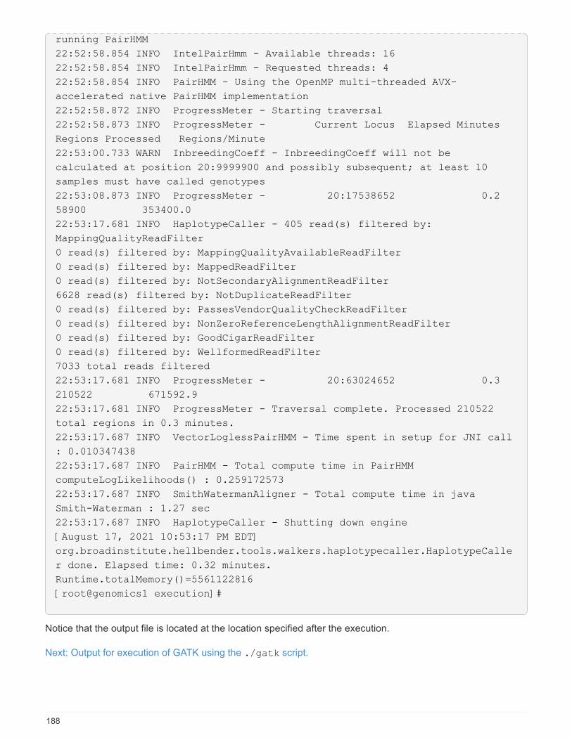
running PairHMM
22:52:58.854 INFO IntelPairHmm - Available threads: 16
22:52:58.854 INFO IntelPairHmm - Requested threads: 4
22:52:58.854 INFO PairHMM - Using the OpenMP multi-threaded AVX-
accelerated native PairHMM implementation
22:52:58.872 INFO ProgressMeter - Starting traversal
22:52:58.873 INFO ProgressMeter - Current Locus Elapsed Minutes
Regions Processed Regions/Minute
22:53:00.733 WARN InbreedingCoeff - InbreedingCoeff will not be
calculated at position 20:9999900 and possibly subsequent; at least 10
samples must have called genotypes
22:53:08.873 INFO ProgressMeter - 20:17538652 0.2
58900 353400.0
22:53:17.681 INFO HaplotypeCaller - 405 read(s) filtered by:
MappingQualityReadFilter
0 read(s) filtered by: MappingQualityAvailableReadFilter
0 read(s) filtered by: MappedReadFilter
0 read(s) filtered by: NotSecondaryAlignmentReadFilter
6628 read(s) filtered by: NotDuplicateReadFilter
0 read(s) filtered by: PassesVendorQualityCheckReadFilter
0 read(s) filtered by: NonZeroReferenceLengthAlignmentReadFilter
0 read(s) filtered by: GoodCigarReadFilter
0 read(s) filtered by: WellformedReadFilter
7033 total reads filtered
22:53:17.681 INFO ProgressMeter - 20:63024652 0.3
210522 671592.9
22:53:17.681 INFO ProgressMeter - Traversal complete. Processed 210522
total regions in 0.3 minutes.
22:53:17.687 INFO VectorLoglessPairHMM - Time spent in setup for JNI call
: 0.010347438
22:53:17.687 INFO PairHMM - Total compute time in PairHMM
computeLogLikelihoods() : 0.259172573
22:53:17.687 INFO SmithWatermanAligner - Total compute time in java
Smith-Waterman : 1.27 sec
22:53:17.687 INFO HaplotypeCaller - Shutting down engine
[August 17, 2021 10:53:17 PM EDT]
org.broadinstitute.hellbender.tools.walkers.haplotypecaller.HaplotypeCalle
r done. Elapsed time: 0.32 minutes.
Runtime.totalMemory()=5561122816
[root@genomics1 execution]#
Notice that the output file is located at the location specified after the execution.
Next: Output for execution of GATK using the ./gatk script.
188

Output for execution of GATK using the ./gatk script
Previous: Output for execution of GATK using the jar file.
The execution of GATK using the ./gatk script produced the following sample output.
[root@genomics1 gatk-4.2.0.0]# ./gatk --java-options "-Xmx4G" \
HaplotypeCaller \
-I /mnt/genomics/GATK/TEST\ DATA/bam/workshop_1906_2-
germline_bams_father.bam \
-R /mnt/genomics/GATK/TEST\ DATA/ref/workshop_1906_2-
germline_ref_ref.fasta \
-O /mnt/genomics/GATK/TEST\ DATA/variants.vcf
Using GATK jar /mnt/genomics/GATK/gatk-4.2.0.0/gatk-package-4.2.0.0-
local.jar
Running:
java -Dsamjdk.use_async_io_read_samtools=false
-Dsamjdk.use_async_io_write_samtools=true
-Dsamjdk.use_async_io_write_tribble=false -Dsamjdk.compression_level=2
-Xmx4G -jar /mnt/genomics/GATK/gatk-4.2.0.0/gatk-package-4.2.0.0-local.jar
HaplotypeCaller -I /mnt/genomics/GATK/TEST DATA/bam/workshop_1906_2-
germline_bams_father.bam -R /mnt/genomics/GATK/TEST
DATA/ref/workshop_1906_2-germline_ref_ref.fasta -O /mnt/genomics/GATK/TEST
DATA/variants.vcf
23:29:45.553 INFO NativeLibraryLoader - Loading libgkl_compression.so
from jar:file:/mnt/genomics/GATK/gatk-4.2.0.0/gatk-package-4.2.0.0-
local.jar!/com/intel/gkl/native/libgkl_compression.so
Aug 17, 2021 11:29:45 PM
shaded.cloud_nio.com.google.auth.oauth2.ComputeEngineCredentials
runningOnComputeEngine
INFO: Failed to detect whether we are running on Google Compute Engine.
23:29:45.686 INFO HaplotypeCaller -
------------------------------------------------------------
23:29:45.686 INFO HaplotypeCaller - The Genome Analysis Toolkit (GATK)
v4.2.0.0
23:29:45.686 INFO HaplotypeCaller - For support and documentation go to
https://software.broadinstitute.org/gatk/
23:29:45.687 INFO HaplotypeCaller - Executing as
[email protected] on Linux v4.18.0-305.3.1.el8_4.x86_64 amd64
23:29:45.687 INFO HaplotypeCaller - Java runtime: OpenJDK 64-Bit Server
VM v11.0.12+7-LTS
23:29:45.687 INFO HaplotypeCaller - Start Date/Time: August 17, 2021 at
11:29:45 PM EDT
23:29:45.687 INFO HaplotypeCaller -
------------------------------------------------------------
23:29:45.687 INFO HaplotypeCaller -
189
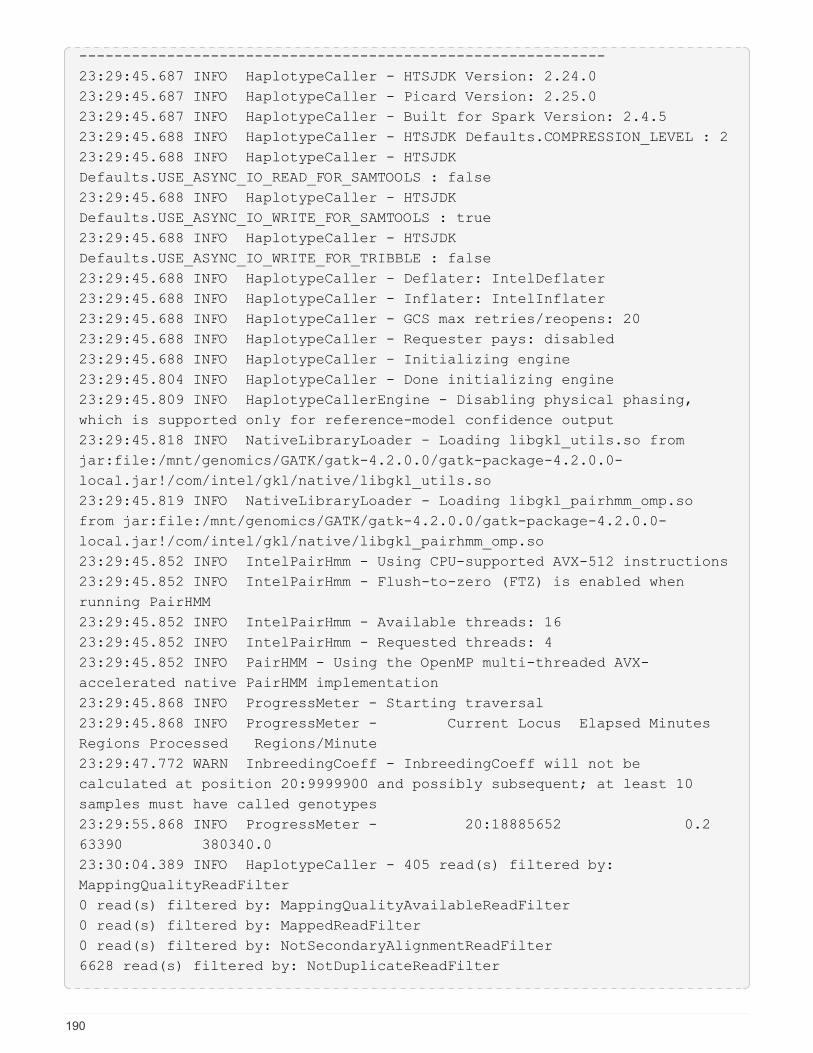
------------------------------------------------------------
23:29:45.687 INFO HaplotypeCaller - HTSJDK Version: 2.24.0
23:29:45.687 INFO HaplotypeCaller - Picard Version: 2.25.0
23:29:45.687 INFO HaplotypeCaller - Built for Spark Version: 2.4.5
23:29:45.688 INFO HaplotypeCaller - HTSJDK Defaults.COMPRESSION_LEVEL : 2
23:29:45.688 INFO HaplotypeCaller - HTSJDK
Defaults.USE_ASYNC_IO_READ_FOR_SAMTOOLS : false
23:29:45.688 INFO HaplotypeCaller - HTSJDK
Defaults.USE_ASYNC_IO_WRITE_FOR_SAMTOOLS : true
23:29:45.688 INFO HaplotypeCaller - HTSJDK
Defaults.USE_ASYNC_IO_WRITE_FOR_TRIBBLE : false
23:29:45.688 INFO HaplotypeCaller - Deflater: IntelDeflater
23:29:45.688 INFO HaplotypeCaller - Inflater: IntelInflater
23:29:45.688 INFO HaplotypeCaller - GCS max retries/reopens: 20
23:29:45.688 INFO HaplotypeCaller - Requester pays: disabled
23:29:45.688 INFO HaplotypeCaller - Initializing engine
23:29:45.804 INFO HaplotypeCaller - Done initializing engine
23:29:45.809 INFO HaplotypeCallerEngine - Disabling physical phasing,
which is supported only for reference-model confidence output
23:29:45.818 INFO NativeLibraryLoader - Loading libgkl_utils.so from
jar:file:/mnt/genomics/GATK/gatk-4.2.0.0/gatk-package-4.2.0.0-
local.jar!/com/intel/gkl/native/libgkl_utils.so
23:29:45.819 INFO NativeLibraryLoader - Loading libgkl_pairhmm_omp.so
from jar:file:/mnt/genomics/GATK/gatk-4.2.0.0/gatk-package-4.2.0.0-
local.jar!/com/intel/gkl/native/libgkl_pairhmm_omp.so
23:29:45.852 INFO IntelPairHmm - Using CPU-supported AVX-512 instructions
23:29:45.852 INFO IntelPairHmm - Flush-to-zero (FTZ) is enabled when
running PairHMM
23:29:45.852 INFO IntelPairHmm - Available threads: 16
23:29:45.852 INFO IntelPairHmm - Requested threads: 4
23:29:45.852 INFO PairHMM - Using the OpenMP multi-threaded AVX-
accelerated native PairHMM implementation
23:29:45.868 INFO ProgressMeter - Starting traversal
23:29:45.868 INFO ProgressMeter - Current Locus Elapsed Minutes
Regions Processed Regions/Minute
23:29:47.772 WARN InbreedingCoeff - InbreedingCoeff will not be
calculated at position 20:9999900 and possibly subsequent; at least 10
samples must have called genotypes
23:29:55.868 INFO ProgressMeter - 20:18885652 0.2
63390 380340.0
23:30:04.389 INFO HaplotypeCaller - 405 read(s) filtered by:
MappingQualityReadFilter
0 read(s) filtered by: MappingQualityAvailableReadFilter
0 read(s) filtered by: MappedReadFilter
0 read(s) filtered by: NotSecondaryAlignmentReadFilter
6628 read(s) filtered by: NotDuplicateReadFilter
190
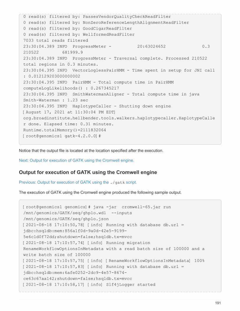
0 read(s) filtered by: PassesVendorQualityCheckReadFilter
0 read(s) filtered by: NonZeroReferenceLengthAlignmentReadFilter
0 read(s) filtered by: GoodCigarReadFilter
0 read(s) filtered by: WellformedReadFilter
7033 total reads filtered
23:30:04.389 INFO ProgressMeter - 20:63024652 0.3
210522 681999.9
23:30:04.389 INFO ProgressMeter - Traversal complete. Processed 210522
total regions in 0.3 minutes.
23:30:04.395 INFO VectorLoglessPairHMM - Time spent in setup for JNI call
: 0.012129203000000002
23:30:04.395 INFO PairHMM - Total compute time in PairHMM
computeLogLikelihoods() : 0.267345217
23:30:04.395 INFO SmithWatermanAligner - Total compute time in java
Smith-Waterman : 1.23 sec
23:30:04.395 INFO HaplotypeCaller - Shutting down engine
[August 17, 2021 at 11:30:04 PM EDT]
org.broadinstitute.hellbender.tools.walkers.haplotypecaller.HaplotypeCalle
r done. Elapsed time: 0.31 minutes.
Runtime.totalMemory()=2111832064
[root@genomics1 gatk-4.2.0.0]#
Notice that the output file is located at the location specified after the execution.
Next: Output for execution of GATK using the Cromwell engine.
Output for execution of GATK using the Cromwell engine
Previous: Output for execution of GATK using the ./gatk script.
The execution of GATK using the Cromwell engine produced the following sample output.
[root@genomics1 genomics]# java -jar cromwell-65.jar run
/mnt/genomics/GATK/seq/ghplo.wdl --inputs
/mnt/genomics/GATK/seq/ghplo.json
[2021-08-18 17:10:50,78] [info] Running with database db.url =
jdbc:hsqldb:mem:856a1f0d-9a0d-42e5-9199-
5e6c1d0f72dd;shutdown=false;hsqldb.tx=mvcc
[2021-08-18 17:10:57,74] [info] Running migration
RenameWorkflowOptionsInMetadata with a read batch size of 100000 and a
write batch size of 100000
[2021-08-18 17:10:57,75] [info] [RenameWorkflowOptionsInMetadata] 100%
[2021-08-18 17:10:57,83] [info] Running with database db.url =
jdbc:hsqldb:mem:6afe0252-2dc9-4e57-8674-
ce63c67aa142;shutdown=false;hsqldb.tx=mvcc
[2021-08-18 17:10:58,17] [info] Slf4jLogger started
191

[2021-08-18 17:10:58,33] [info] Workflow heartbeat configuration:
{
"cromwellId" : "cromid-41b7e30",
"heartbeatInterval" : "2 minutes",
"ttl" : "10 minutes",
"failureShutdownDuration" : "5 minutes",
"writeBatchSize" : 10000,
"writeThreshold" : 10000
}
[2021-08-18 17:10:58,38] [info] Metadata summary refreshing every 1
second.
[2021-08-18 17:10:58,38] [info] No metadata archiver defined in config
[2021-08-18 17:10:58,38] [info] No metadata deleter defined in config
[2021-08-18 17:10:58,40] [info] KvWriteActor configured to flush with
batch size 200 and process rate 5 seconds.
[2021-08-18 17:10:58,40] [info] WriteMetadataActor configured to flush
with batch size 200 and process rate 5 seconds.
[2021-08-18 17:10:58,44] [info] CallCacheWriteActor configured to flush
with batch size 100 and process rate 3 seconds.
[2021-08-18 17:10:58,44] [warn] 'docker.hash-lookup.gcr-api-queries-per-
100-seconds' is being deprecated, use 'docker.hash-lookup.gcr.throttle'
instead (see reference.conf)
[2021-08-18 17:10:58,54] [info] JobExecutionTokenDispenser - Distribution
rate: 50 per 1 seconds.
[2021-08-18 17:10:58,58] [info] SingleWorkflowRunnerActor: Version 65
[2021-08-18 17:10:58,58] [info] SingleWorkflowRunnerActor: Submitting
workflow
[2021-08-18 17:10:58,64] [info] Unspecified type (Unspecified version)
workflow 3e246147-b1a9-41dc-8679-319f81b7701e submitted
[2021-08-18 17:10:58,66] [info] SingleWorkflowRunnerActor: Workflow
submitted 3e246147-b1a9-41dc-8679-319f81b7701e
[2021-08-18 17:10:58,66] [info] 1 new workflows fetched by cromid-41b7e30:
3e246147-b1a9-41dc-8679-319f81b7701e
[2021-08-18 17:10:58,67] [info] WorkflowManagerActor: Starting workflow
3e246147-b1a9-41dc-8679-319f81b7701e
[2021-08-18 17:10:58,68] [info] WorkflowManagerActor: Successfully started
WorkflowActor-3e246147-b1a9-41dc-8679-319f81b7701e
[2021-08-18 17:10:58,68] [info] Retrieved 1 workflows from the
WorkflowStoreActor
[2021-08-18 17:10:58,70] [info] WorkflowStoreHeartbeatWriteActor
configured to flush with batch size 10000 and process rate 2 minutes.
[2021-08-18 17:10:58,76] [info] MaterializeWorkflowDescriptorActor
[3e246147]: Parsing workflow as WDL draft-2
[2021-08-18 17:10:59,34] [info] MaterializeWorkflowDescriptorActor
[3e246147]: Call-to-Backend assignments:
helloHaplotypeCaller.haplotypeCaller -> Local
192
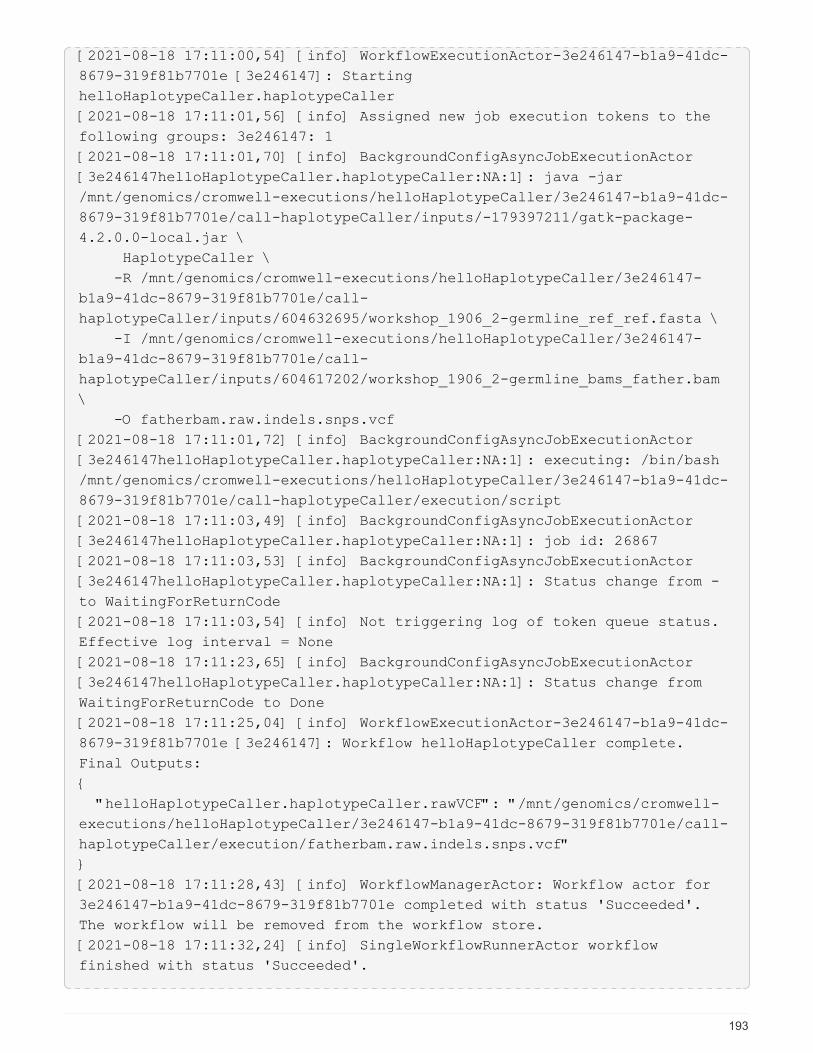
[2021-08-18 17:11:00,54] [info] WorkflowExecutionActor-3e246147-b1a9-41dc-
8679-319f81b7701e [3e246147]: Starting
helloHaplotypeCaller.haplotypeCaller
[2021-08-18 17:11:01,56] [info] Assigned new job execution tokens to the
following groups: 3e246147: 1
[2021-08-18 17:11:01,70] [info] BackgroundConfigAsyncJobExecutionActor
[3e246147helloHaplotypeCaller.haplotypeCaller:NA:1]: java -jar
/mnt/genomics/cromwell-executions/helloHaplotypeCaller/3e246147-b1a9-41dc-
8679-319f81b7701e/call-haplotypeCaller/inputs/-179397211/gatk-package-
4.2.0.0-local.jar \
HaplotypeCaller \
-R /mnt/genomics/cromwell-executions/helloHaplotypeCaller/3e246147-
b1a9-41dc-8679-319f81b7701e/call-
haplotypeCaller/inputs/604632695/workshop_1906_2-germline_ref_ref.fasta \
-I /mnt/genomics/cromwell-executions/helloHaplotypeCaller/3e246147-
b1a9-41dc-8679-319f81b7701e/call-
haplotypeCaller/inputs/604617202/workshop_1906_2-germline_bams_father.bam
\
-O fatherbam.raw.indels.snps.vcf
[2021-08-18 17:11:01,72] [info] BackgroundConfigAsyncJobExecutionActor
[3e246147helloHaplotypeCaller.haplotypeCaller:NA:1]: executing: /bin/bash
/mnt/genomics/cromwell-executions/helloHaplotypeCaller/3e246147-b1a9-41dc-
8679-319f81b7701e/call-haplotypeCaller/execution/script
[2021-08-18 17:11:03,49] [info] BackgroundConfigAsyncJobExecutionActor
[3e246147helloHaplotypeCaller.haplotypeCaller:NA:1]: job id: 26867
[2021-08-18 17:11:03,53] [info] BackgroundConfigAsyncJobExecutionActor
[3e246147helloHaplotypeCaller.haplotypeCaller:NA:1]: Status change from -
to WaitingForReturnCode
[2021-08-18 17:11:03,54] [info] Not triggering log of token queue status.
Effective log interval = None
[2021-08-18 17:11:23,65] [info] BackgroundConfigAsyncJobExecutionActor
[3e246147helloHaplotypeCaller.haplotypeCaller:NA:1]: Status change from
WaitingForReturnCode to Done
[2021-08-18 17:11:25,04] [info] WorkflowExecutionActor-3e246147-b1a9-41dc-
8679-319f81b7701e [3e246147]: Workflow helloHaplotypeCaller complete.
Final Outputs:
{
"helloHaplotypeCaller.haplotypeCaller.rawVCF": "/mnt/genomics/cromwell-
executions/helloHaplotypeCaller/3e246147-b1a9-41dc-8679-319f81b7701e/call-
haplotypeCaller/execution/fatherbam.raw.indels.snps.vcf"
}
[2021-08-18 17:11:28,43] [info] WorkflowManagerActor: Workflow actor for
3e246147-b1a9-41dc-8679-319f81b7701e completed with status 'Succeeded'.
The workflow will be removed from the workflow store.
[2021-08-18 17:11:32,24] [info] SingleWorkflowRunnerActor workflow
finished with status 'Succeeded'.
193
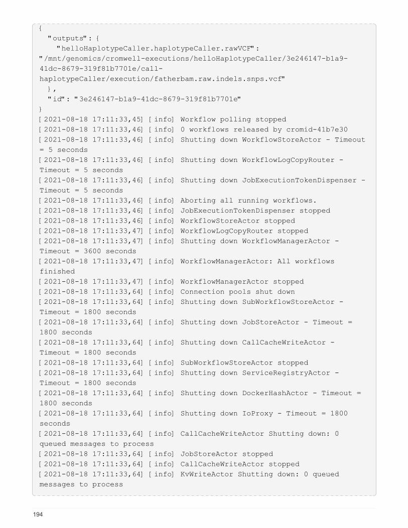
{
"outputs": {
"helloHaplotypeCaller.haplotypeCaller.rawVCF":
"/mnt/genomics/cromwell-executions/helloHaplotypeCaller/3e246147-b1a9-
41dc-8679-319f81b7701e/call-
haplotypeCaller/execution/fatherbam.raw.indels.snps.vcf"
},
"id": "3e246147-b1a9-41dc-8679-319f81b7701e"
}
[2021-08-18 17:11:33,45] [info] Workflow polling stopped
[2021-08-18 17:11:33,46] [info] 0 workflows released by cromid-41b7e30
[2021-08-18 17:11:33,46] [info] Shutting down WorkflowStoreActor - Timeout
= 5 seconds
[2021-08-18 17:11:33,46] [info] Shutting down WorkflowLogCopyRouter -
Timeout = 5 seconds
[2021-08-18 17:11:33,46] [info] Shutting down JobExecutionTokenDispenser -
Timeout = 5 seconds
[2021-08-18 17:11:33,46] [info] Aborting all running workflows.
[2021-08-18 17:11:33,46] [info] JobExecutionTokenDispenser stopped
[2021-08-18 17:11:33,46] [info] WorkflowStoreActor stopped
[2021-08-18 17:11:33,47] [info] WorkflowLogCopyRouter stopped
[2021-08-18 17:11:33,47] [info] Shutting down WorkflowManagerActor -
Timeout = 3600 seconds
[2021-08-18 17:11:33,47] [info] WorkflowManagerActor: All workflows
finished
[2021-08-18 17:11:33,47] [info] WorkflowManagerActor stopped
[2021-08-18 17:11:33,64] [info] Connection pools shut down
[2021-08-18 17:11:33,64] [info] Shutting down SubWorkflowStoreActor -
Timeout = 1800 seconds
[2021-08-18 17:11:33,64] [info] Shutting down JobStoreActor - Timeout =
1800 seconds
[2021-08-18 17:11:33,64] [info] Shutting down CallCacheWriteActor -
Timeout = 1800 seconds
[2021-08-18 17:11:33,64] [info] SubWorkflowStoreActor stopped
[2021-08-18 17:11:33,64] [info] Shutting down ServiceRegistryActor -
Timeout = 1800 seconds
[2021-08-18 17:11:33,64] [info] Shutting down DockerHashActor - Timeout =
1800 seconds
[2021-08-18 17:11:33,64] [info] Shutting down IoProxy - Timeout = 1800
seconds
[2021-08-18 17:11:33,64] [info] CallCacheWriteActor Shutting down: 0
queued messages to process
[2021-08-18 17:11:33,64] [info] JobStoreActor stopped
[2021-08-18 17:11:33,64] [info] CallCacheWriteActor stopped
[2021-08-18 17:11:33,64] [info] KvWriteActor Shutting down: 0 queued
messages to process
194
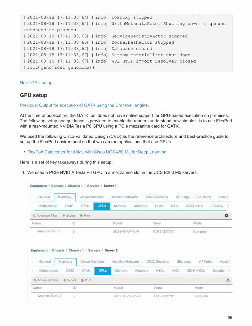
[2021-08-18 17:11:33,64] [info] IoProxy stopped
[2021-08-18 17:11:33,64] [info] WriteMetadataActor Shutting down: 0 queued
messages to process
[2021-08-18 17:11:33,65] [info] ServiceRegistryActor stopped
[2021-08-18 17:11:33,65] [info] DockerHashActor stopped
[2021-08-18 17:11:33,67] [info] Database closed
[2021-08-18 17:11:33,67] [info] Stream materializer shut down
[2021-08-18 17:11:33,67] [info] WDL HTTP import resolver closed
[root@genomics1 genomics]#
Next: GPU setup.
GPU setup
Previous: Output for execution of GATK using the Cromwell engine.
At the time of publication, the GATK tool does not have native support for GPU-based execution on premises.The following setup and guidance is provided to enable the readers understand how simple it is to use FlexPodwith a rear-mounted NVIDIA Tesla P6 GPU using a PCIe mezzanine card for GATK.
We used the following Cisco-Validated Design (CVD) as the reference architecture and best-practice guide toset up the FlexPod environment so that we can run applications that use GPUs.
• FlexPod Datacenter for AI/ML with Cisco UCS 480 ML for Deep Learning
Here is a set of key takeaways during this setup:
1. We used a PCIe NVIDIA Tesla P6 GPU in a mezzanine slot in the UCS B200 M5 servers.
195
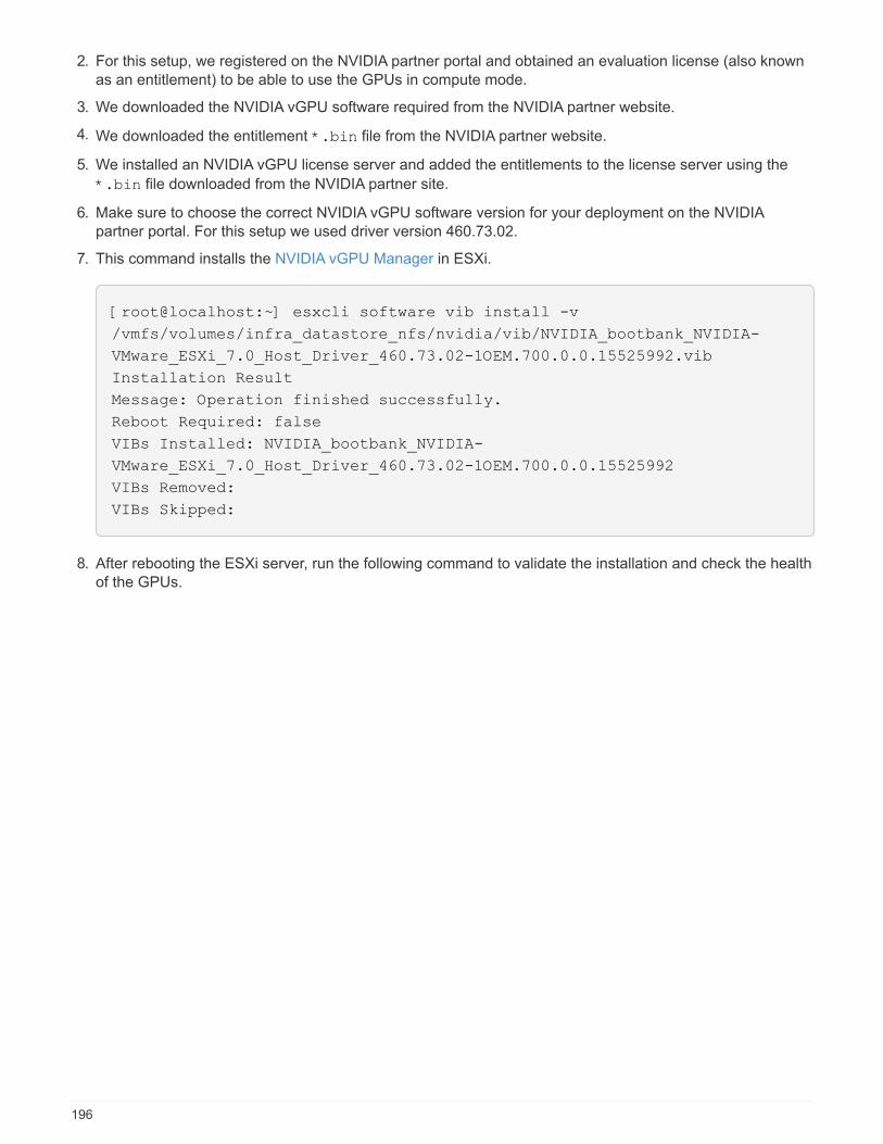
2. For this setup, we registered on the NVIDIA partner portal and obtained an evaluation license (also knownas an entitlement) to be able to use the GPUs in compute mode.
3. We downloaded the NVIDIA vGPU software required from the NVIDIA partner website.
4. We downloaded the entitlement *.bin file from the NVIDIA partner website.
5. We installed an NVIDIA vGPU license server and added the entitlements to the license server using the
*.bin file downloaded from the NVIDIA partner site.
6. Make sure to choose the correct NVIDIA vGPU software version for your deployment on the NVIDIApartner portal. For this setup we used driver version 460.73.02.
7. This command installs the NVIDIA vGPU Manager in ESXi.
[root@localhost:~] esxcli software vib install -v
/vmfs/volumes/infra_datastore_nfs/nvidia/vib/NVIDIA_bootbank_NVIDIA-
VMware_ESXi_7.0_Host_Driver_460.73.02-1OEM.700.0.0.15525992.vib
Installation Result
Message: Operation finished successfully.
Reboot Required: false
VIBs Installed: NVIDIA_bootbank_NVIDIA-
VMware_ESXi_7.0_Host_Driver_460.73.02-1OEM.700.0.0.15525992
VIBs Removed:
VIBs Skipped:
8. After rebooting the ESXi server, run the following command to validate the installation and check the healthof the GPUs.
196
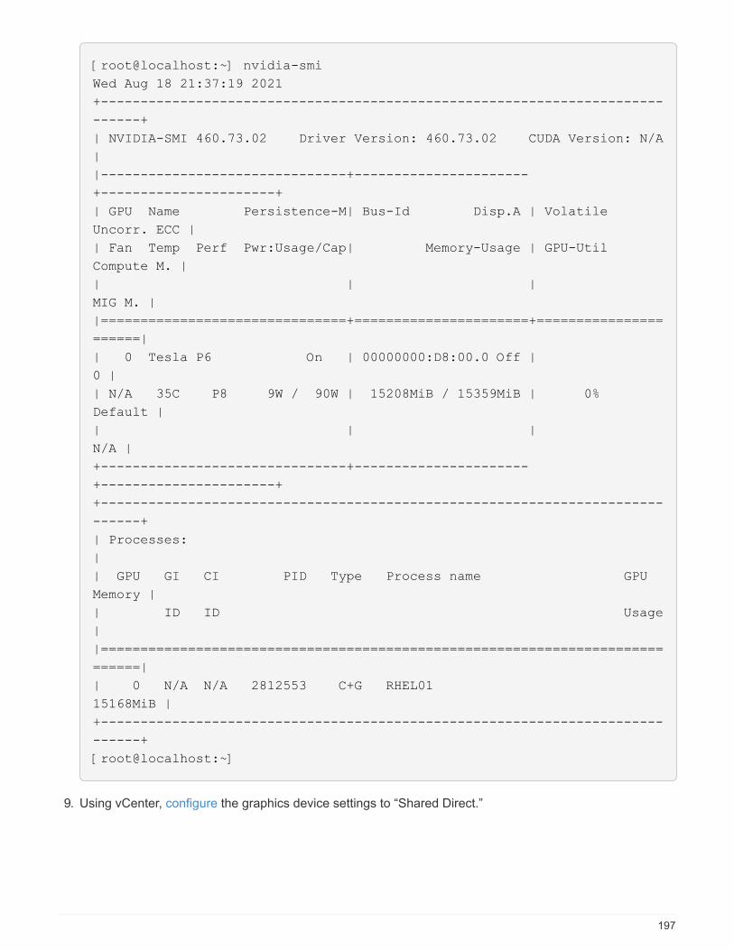
[root@localhost:~] nvidia-smi
Wed Aug 18 21:37:19 2021
+-----------------------------------------------------------------------
------+
| NVIDIA-SMI 460.73.02 Driver Version: 460.73.02 CUDA Version: N/A
|
|-------------------------------+----------------------
+----------------------+
| GPU Name Persistence-M| Bus-Id Disp.A | Volatile
Uncorr. ECC |
| Fan Temp Perf Pwr:Usage/Cap| Memory-Usage | GPU-Util
Compute M. |
| | |
MIG M. |
|===============================+======================+================
======|
| 0 Tesla P6 On | 00000000:D8:00.0 Off |
0 |
| N/A 35C P8 9W / 90W | 15208MiB / 15359MiB | 0%
Default |
| | |
N/A |
+-------------------------------+----------------------
+----------------------+
+-----------------------------------------------------------------------
------+
| Processes:
|
| GPU GI CI PID Type Process name GPU
Memory |
| ID ID Usage
|
|=======================================================================
======|
| 0 N/A N/A 2812553 C+G RHEL01
15168MiB |
+-----------------------------------------------------------------------
------+
[root@localhost:~]
9. Using vCenter, configure the graphics device settings to “Shared Direct.”
197

10. Make sure that secure boot is disabled for the RedHat VM.
11. Make sure that the VM Boot Options firmware is set to EFI ( ref).
198
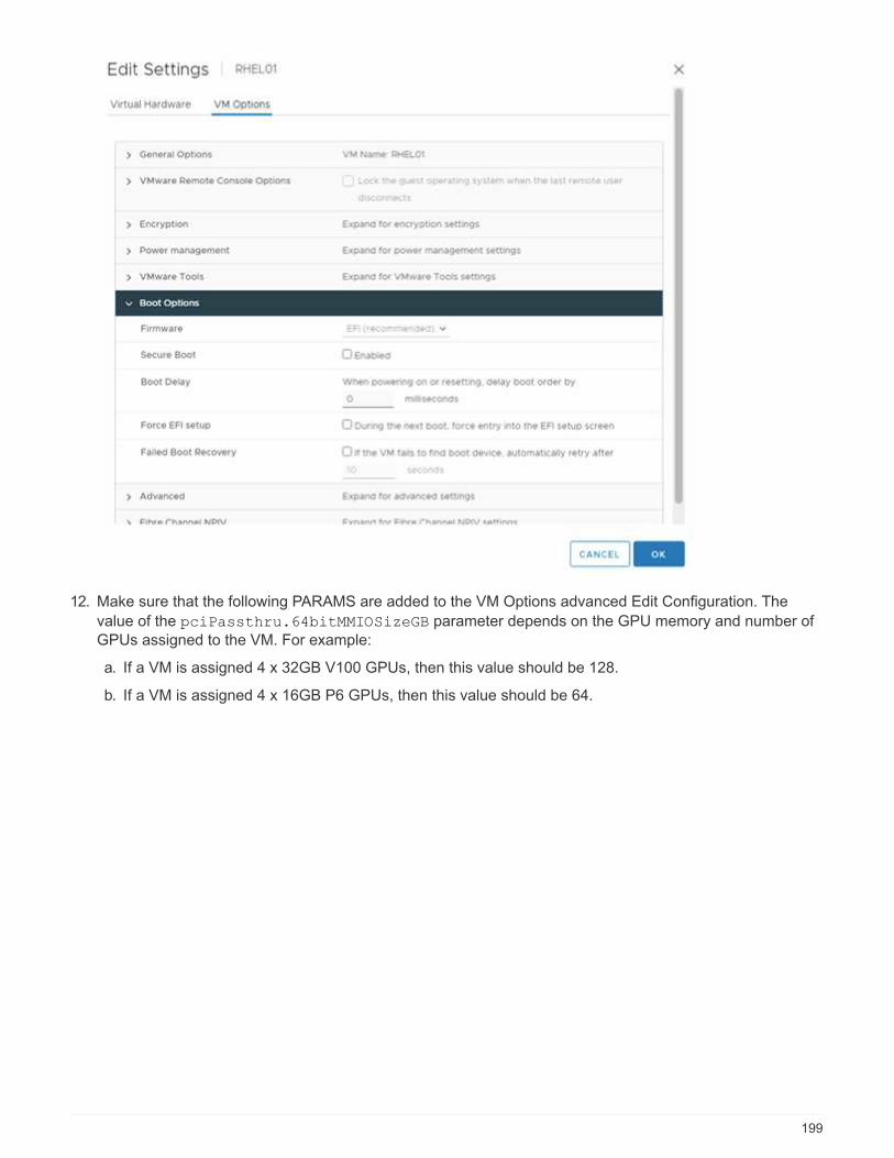
12. Make sure that the following PARAMS are added to the VM Options advanced Edit Configuration. The
value of the pciPassthru.64bitMMIOSizeGB parameter depends on the GPU memory and number ofGPUs assigned to the VM. For example:
a. If a VM is assigned 4 x 32GB V100 GPUs, then this value should be 128.
b. If a VM is assigned 4 x 16GB P6 GPUs, then this value should be 64.
199
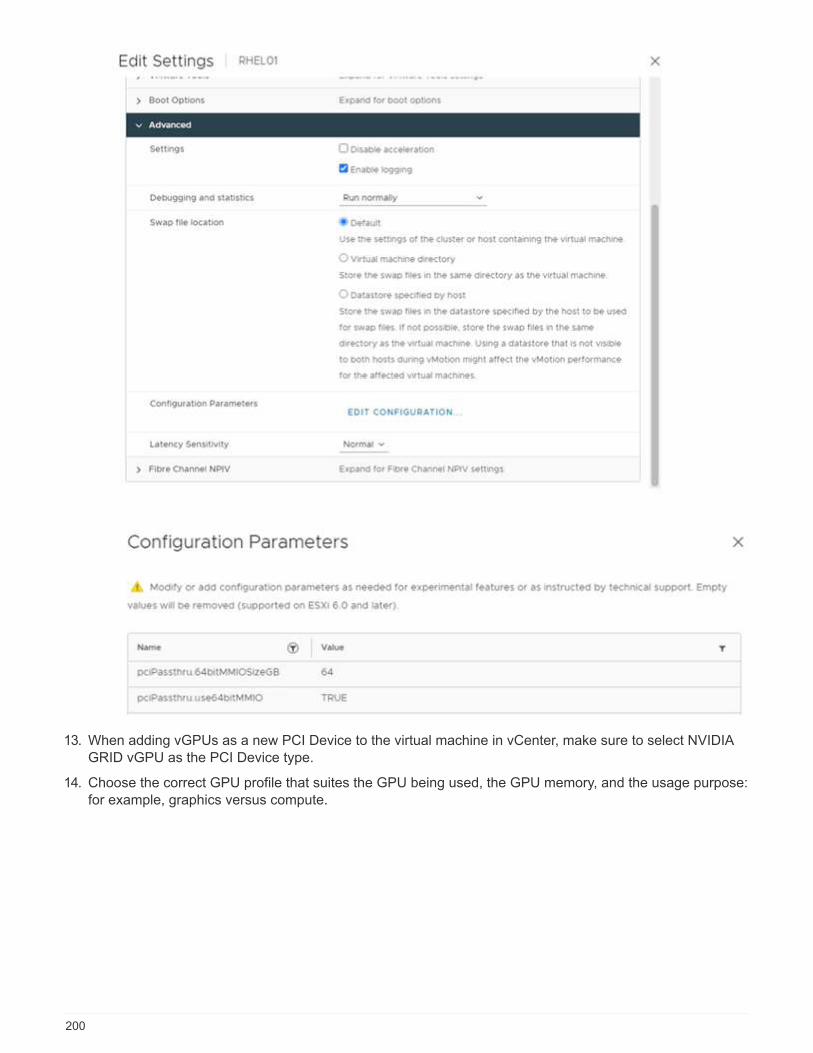
13. When adding vGPUs as a new PCI Device to the virtual machine in vCenter, make sure to select NVIDIAGRID vGPU as the PCI Device type.
14. Choose the correct GPU profile that suites the GPU being used, the GPU memory, and the usage purpose:for example, graphics versus compute.
200
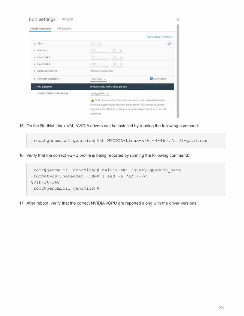
15. On the RedHat Linux VM, NVIDIA drivers can be installed by running the following command:
[root@genomics1 genomics]#sh NVIDIA-Linux-x86_64-460.73.01-grid.run
16. Verify that the correct vGPU profile is being reported by running the following command:
[root@genomics1 genomics]# nvidia-smi –query-gpu=gpu_name
–format=csv,noheader –id=0 | sed -e ‘s/ /-/g’
GRID-P6-16C
[root@genomics1 genomics]#
17. After reboot, verify that the correct NVIDIA vGPU are reported along with the driver versions.
201

[root@genomics1 genomics]# nvidia-smi
Wed Aug 18 20:30:56 2021
+-----------------------------------------------------------------------
------+
| NVIDIA-SMI 460.73.01 Driver Version: 460.73.01 CUDA Version:
11.2 |
|-------------------------------+----------------------
+----------------------+
| GPU Name Persistence-M| Bus-Id Disp.A | Volatile
Uncorr. ECC |
| Fan Temp Perf Pwr:Usage/Cap| Memory-Usage | GPU-Util
Compute M. |
| | |
MIG M. |
|===============================+======================+================
======|
| 0 GRID P6-16C On | 00000000:02:02.0 Off |
N/A |
| N/A N/A P8 N/A / N/A | 2205MiB / 16384MiB | 0%
Default |
| | |
N/A |
+-------------------------------+----------------------
+----------------------+
+-----------------------------------------------------------------------
------+
| Processes:
|
| GPU GI CI PID Type Process name GPU
Memory |
| ID ID Usage
|
|=======================================================================
======|
| 0 N/A N/A 8604 G /usr/libexec/Xorg
13MiB |
+-----------------------------------------------------------------------
------+
[root@genomics1 genomics]#
18. Make sure that the license server IP is configured on the VM in the vGPU grid configuration file.
a. Copy the template.
202
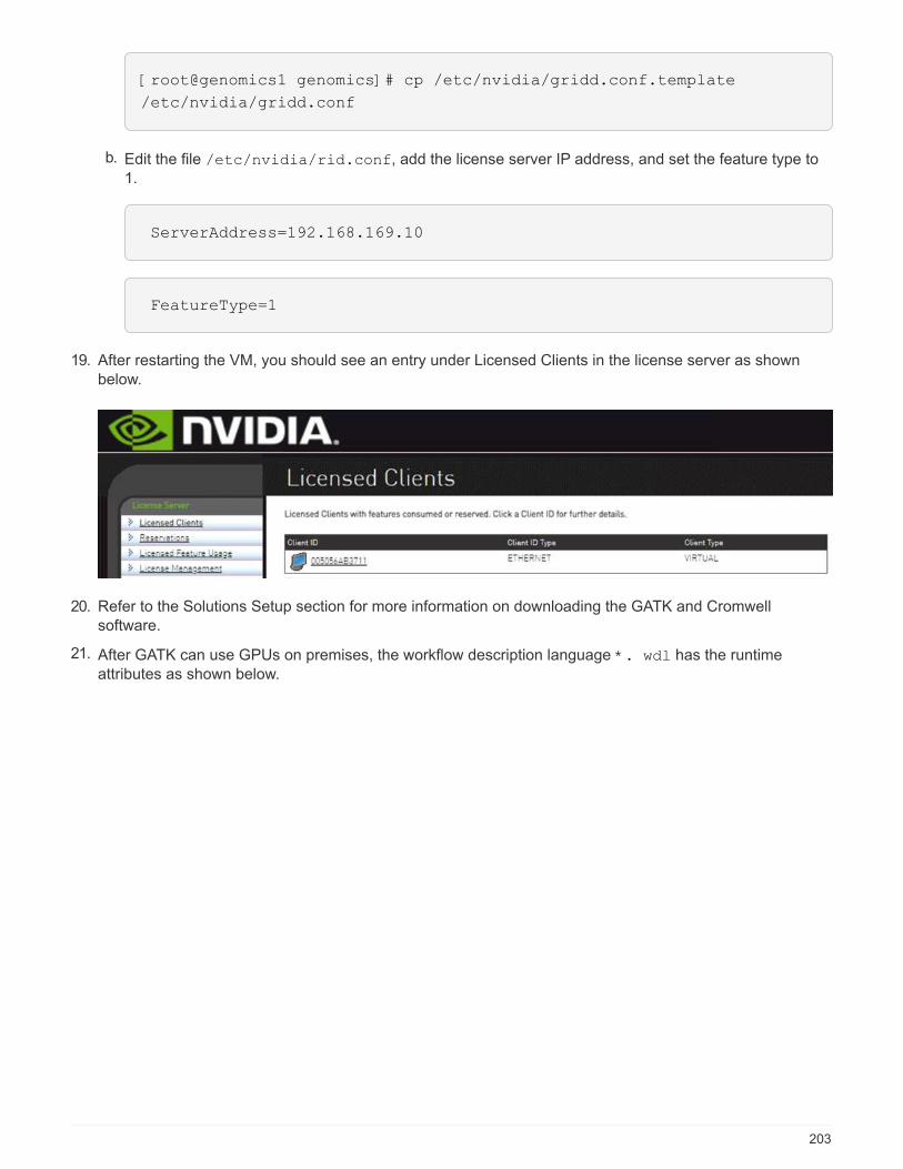
[root@genomics1 genomics]# cp /etc/nvidia/gridd.conf.template
/etc/nvidia/gridd.conf
b. Edit the file /etc/nvidia/rid.conf, add the license server IP address, and set the feature type to1.
ServerAddress=192.168.169.10
FeatureType=1
19. After restarting the VM, you should see an entry under Licensed Clients in the license server as shownbelow.
20. Refer to the Solutions Setup section for more information on downloading the GATK and Cromwellsoftware.
21. After GATK can use GPUs on premises, the workflow description language *. wdl has the runtimeattributes as shown below.
203
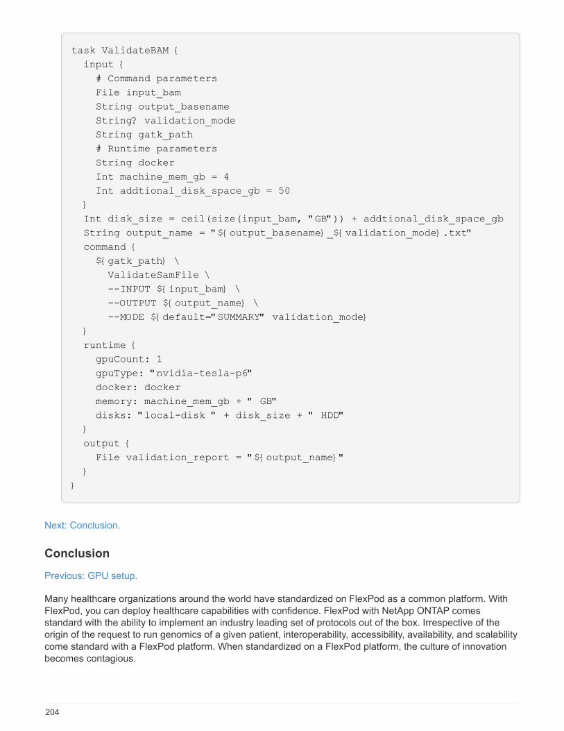
task ValidateBAM {
input {
# Command parameters
File input_bam
String output_basename
String? validation_mode
String gatk_path
# Runtime parameters
String docker
Int machine_mem_gb = 4
Int addtional_disk_space_gb = 50
}
Int disk_size = ceil(size(input_bam, "GB")) + addtional_disk_space_gb
String output_name = "${output_basename}_${validation_mode}.txt"
command {
${gatk_path} \
ValidateSamFile \
--INPUT ${input_bam} \
--OUTPUT ${output_name} \
--MODE ${default="SUMMARY" validation_mode}
}
runtime {
gpuCount: 1
gpuType: "nvidia-tesla-p6"
docker: docker
memory: machine_mem_gb + " GB"
disks: "local-disk " + disk_size + " HDD"
}
output {
File validation_report = "${output_name}"
}
}
Next: Conclusion.
Conclusion
Previous: GPU setup.
Many healthcare organizations around the world have standardized on FlexPod as a common platform. WithFlexPod, you can deploy healthcare capabilities with confidence. FlexPod with NetApp ONTAP comesstandard with the ability to implement an industry leading set of protocols out of the box. Irrespective of theorigin of the request to run genomics of a given patient, interoperability, accessibility, availability, and scalabilitycome standard with a FlexPod platform. When standardized on a FlexPod platform, the culture of innovationbecomes contagious.
204

Where to find additional information
To learn more about the information that is described in this document, review the following documents andwebsites:
• FlexPod Datacenter for AI/ML with Cisco UCS 480 ML for Deep Learning
https://www.cisco.com/c/en/us/td/docs/unified_computing/ucs/UCS_CVDs/flexpod_480ml_aiml_deployment.pdf
• FlexPod Datacenter with VMware vSphere 7.0 and NetApp ONTAP 9.7
https://www.cisco.com/c/en/us/td/docs/unified_computing/ucs/UCS_CVDs/fp_vmware_vsphere_7_0_ontap_9_7.html
• ONTAP 9 Documentation Center
http://docs.netapp.com
• Epic honor roll
https://www.netapp.com/blog/achieving-epic-honor-roll/
• Agile and efficient—how FlexPod drives data center modernization
https://www.flexpod.com/idc-white-paper/
• AI in healthcare
https://www.netapp.com/us/media/na-369.pdf
• FlexPod for healthcare Ease Your Transformation
https://flexpod.com/solutions/verticals/healthcare/
• FlexPod from Cisco and NetApp
https://flexpod.com/
• AI and Analytics for healthcare (NetApp)
https://www.netapp.com/us/artificial-intelligence/healthcare-ai-analytics/index.aspx
• AI in healthcare Smart infrastructure Choices Increase Success
https://www.netapp.com/pdf.html?item=/media/7410-wp-7314.pdf
• FlexPod Datacenter with ONTAP 9.8, ONTAP Storage Connector for Cisco Intersight, and Cisco IntersightManaged Mode.
https://www.netapp.com/pdf.html?item=/media/25001-tr-4883.pdf
• FlexPod Datacenter with Red Hat Enterprise Linux OpenStack Platform
https://www.cisco.com/c/en/us/td/docs/unified_computing/ucs/UCS_CVDs/flexpod_openstack_osp6.html
205
Version history
Version Date Document version history
Version 1.0 November 2021 Initial release.
FlexPod Datacenter for Epic Directional Sizing Guide
FlexPod for Epic Directional Sizing Guide
Brian O’Mahony, Ganesh Kamath, Atul Bhalodia, NetAppMike Brennan, Jon Ebmeier, Cisco
In partnership with:
Purpose
This technical report provides guidance for sizing FlexPod (NetApp storage and Cisco Unified ComputingSystem) for an Epic Electronic Health Record (EHR) application software environment.
FlexPod systems that host Epic Hyperspace, InterSystems Caché database, Cogito Clarity analytics andreporting suite, and services servers hosting the Epic application layer provide an integrated platform for adependable, high-performance infrastructure that can be deployed rapidly. The FlexPod integrated platform isdeployed by skilled FlexPod channel partners and is supported by Cisco and NetApp technical assistancecenters.
The sizing exercise described in this document covers users, global reference counts, availability, and disasterrecovery (DR) requirements. The goal is to determine the optimal size of compute, network, and storageinfrastructure components.
This document is outlined into the following main sections:
• Reference Architecture, which describes the small, medium, and large compute storage architectures thatcan be used to host the Epic production database workload.
• Technical Specifications, which details a sample bill of materials for the storage architectures. Theconfigurations that are described are only for general guidance. Always size the systems according to yourworkload and tune the configurations as necessary.
Overall solution benefits
By running an Epic environment on the FlexPod architectural foundation, healthcare organizations can expectto see improved staff productivity and decreased capital and operating expenses. FlexPod, a prevalidated,rigorously tested converged infrastructure from the strategic partnership of Cisco and NetApp, is engineeredand designed specifically to deliver predictable low-latency system performance and high availability. Thisapproach results in high comfort levels and the best response time for users of the Epic EHR system.
The FlexPod solution from Cisco and NetApp meets Epic system requirements with a high-performing,modular, prevalidated, converged, virtualized, efficient, scalable, and cost-effective platform. FlexPodDatacenter with Epic delivers the following benefits specific to the healthcare industry:
206
• Modular architecture. FlexPod addresses the varied needs of the Epic modular architecture with purpose-configured FlexPod platforms for each specific workload. All components are connected through aclustered server and storage management fabric and a cohesive management toolset.
• Accelerated application deployment. The prevalidated architecture reduces implementation integrationtime and risk to expedite Epic project plans. NetApp OnCommand Workforce Automation (WFA) workflowsfor Epic automate Epic backup and refresh and remove the need for custom unsupported scripts. Whetherthe solution is used for an initial rollout of Epic, a hardware refresh, or expansion, more resources can beshifted to the business value of the project.
• Simplified operations and lowered costs. Eliminate the expense and complexity of legacy proprietaryRISC and UNIX platforms by replacing them with a more efficient and scalable shared resource capable ofsupporting clinicians wherever they are. This solution delivers higher resource utilization for greater ROI.
• Quicker deployment of infrastructure. Whether it’s in an existing data center or a remote location, theintegrated and tested design of FlexPod Datacenter with Epic enables customers to have the newinfrastructure up and running in less time with less effort.
• Scale-out architecture. Scale SAN and NAS from terabytes to tens of petabytes without reconfiguringrunning applications.
• Nondisruptive operations. Perform storage maintenance, hardware lifecycle operations, and softwareupgrades without interrupting the business.
• Secure multitenancy. Supports the increased needs of virtualized server and storage sharedinfrastructure, enabling secure multitenancy of facility-specific information, especially when hosting multipleinstances of databases and software.
• Pooled resource optimization. Help reduce physical server and storage controller counts, load balanceworkload demands, and boost utilization while improving performance.
• Quality of service (QoS). FlexPod offers QoS on the entire stack. Industry-leading QoS storage policiesenable differentiated service levels in a shared environment. These policies enable optimal performance forworkloads and help in isolating and controlling runaway applications.
• Storage efficiency. Reduce storage costs with the NetApp 7:1 storage efficiency guarantee.
• Agility. The industry-leading workflow automation, orchestration, and management tools offered byFlexPod systems allow IT to be far more responsive to business requests. These requests can range fromEpic backup and provisioning of additional test and training environments to analytics database replicationsfor population health-management initiatives.
• Productivity. Quickly deploy and scale this solution for optimal clinician end-user experience.
• Data Fabric. The NetApp Data Fabric architecture weaves data together across sites, beyond physicalboundaries, and across applications. The Data Fabric is built for data-driven enterprises in a data-centricworld. Data is created and used in multiple locations, and it often needs to be leveraged and shared withother locations, applications, and infrastructures. Customers want a way to manage data that is consistentand integrated. The Data Fabric offers a way to manage data that puts IT in control and simplifies ever-increasing IT complexity.
Scope
This document covers environments that use Cisco Unified Computing System (Cisco UCS) and NetAppONTAP based storage. It provides sample reference architectures for hosting Epic.
It does not cover:
• Detailed sizing guidance for using NetApp System Performance Modeler (SPM) or other NetApp sizingtools
207
• Sizing for nonproduction workloads
Audience
This document is for NetApp and partner systems engineers and professional services personnel. The readeris assumed to have a good understanding of compute and storage sizing concepts, as well as technicalfamiliarity with Cisco UCS and NetApp storage systems.
Related documents
The following technical reports are relevant to this technical report. Together they make up a complete set ofdocuments required for sizing, designing, and deploying Epic on FlexPod infrastructure:
• TR-4693: FlexPod Datacenter for Epic EHR Deployment Guide
• TR-3930i: NetApp Sizing Guidelines for Epic (requires Field Portal access)
• TR-3928: NetApp Best Practices for Epic
Reference architecture
NetApp storage reference architectures for Epic
An appropriate storage architecture can be determined by the overall database size and the total IOPS.Performance alone is not the only factor, and you might decide to use a larger node count based on additionalcustomer requirements.
Given the storage requirements for Epic software environments, NetApp has three reference architecturesbased on the size of the environment. Epic requires the use of NetApp sizing methods to properly size aNetApp storage system for use in Epic environments. For quantitative performance requirements and sizingguidance, see NetApp TR-3930i: NetApp Sizing Guidelines for Epic. NetApp Field Portal access is required toview this document.
The architectures listed here are a starting point for the design. The workloads must be validated in the SPMtool for the number of disks and controller utilization. Work with the NetApp Epic team to validate all designs.
All Epic production is deployed on all-flash arrays. In this report, the disk pools required for spinning disk havebeen consolidated to three disk pools for all-flash arrays. Before reading this section, you should review theEpic All-Flash Reference Architecture Strategy Handbook for the Epic storage layout requirements.
The three storage reference architectures are as follows:
• Small. Four-node architecture with two nodes in production and two nodes in DR (fewer than 5M globalreferences)
• Medium. Six-node architecture with four nodes in production and two nodes in DR (more than 5M globalreferences)
• Large. Twelve-or-more node architecture with six to ten nodes in production (5M-10M global references)
Global references = (Read IOPS + (Write Operations per 80-Second Write Burst / 45)) * 225.These numbers are taken from the customer-specific Epic Hardware Configuration Guide.
Storage layout and LUN configuration
The first step in satisfying Epic’s high-availability (HA_ and redundancy requirements is to design the storage
208

layout specifically for the Epic software environment. The design considerations should include isolating diskpool 1 from disk pool 2 on dedicated high-performance storage. See the Epic All-Flash Reference ArchitectureStrategy Handbook for information about what workloads are in each disk pool.
Placing each disk pool on a separate node creates the fault domains required for the isolation of Epic’sproduction and nonproduction workloads. Using one aggregate per node maximizes disk utilization andaggregate affinity to provide better performance. This design also maximizes storage efficiency with aggregate-level deduplication.
Because Epic allows storage resources to be shared for nonproduction needs, a storage system can oftenservice both the Clarity server and production services storage needs, such as virtual desktop infrastructure(VDI), CIFS, and other enterprise functions.
The Epic Database Storage Layout Recommendations document provides recommendations for the size andnumber of LUNs for each database. These recommendations might need to be adjusted according to yourenvironment. It is important to review these recommendations with Epic support and finalize the number ofLUNs and LUN sizes.
NetApp recommends starting with larger size LUNs because the size of the LUNs themselveshave no cost to storage. For ease of operation, make sure that the number of LUNs and initialsize can grow well beyond expected requirements after 3 years. Growing LUNs is much easierto manage than adding LUNs while scaling. With thin-provisioned LUNs and volumes, thestorage- used space shows up in the aggregate.
Epic requires database, journal, and application or system storage to be presented to databaseservers as LUNs through FC.
Use one LUN per volume for Epic production and for Clarity. For larger deployments, NetApp recommends 24to 32 LUNs for the Epic database. Factors that determine the number of LUNs to use are:
• Overall size of the Epic DB after 3 years. For larger DBs, determine the maximum size of the LUN for thatoperating system (OS) and make sure that you have enough LUNs to scale. For example, if you need a60TB Epic database and the OS LUNs have a 4TB maximum, you need 24 to 32 LUNs to provide scaleand head room.
Regardless of whether the architecture is small, medium, or large:
• ONTAP allows easy nondisruptive scale up and scale out. Disks and nodes can be upgraded, added, orremoved by using ONTAP nondisruptive operations. Customers can start with four nodes and move to sixnodes or upgrade to larger controllers nondisruptively.
• NetApp OnCommand Workflow Automation workflows can back up and refresh Epic full-copy testenvironments. This solution simplifies the architecture and saves on storage capacity with integratedefficiencies.
• The DR shadow database server is part of a customer’s business continuity strategy (used to support SROfunctionality and potentially configured to be an SRW instance). Therefore, the placement and sizing of thethird storage system are usually the same as in the production database storage system.
• Database consistency requires some consideration. If NetApp SnapMirror backup copies are used inrelation to business continuity, see the Epic document Business Continuity Technical Solutions Guide. Forinformation about the use of SnapMirror technologies, see TR-3446: SnapMirror Async Overview and BestPractices Guide.
• Isolation of production from potential bully workloads is a key design objective of Epic. A storage pool is afault domain in which workload performance must be isolated and protected. Each node in an ONTAPcluster is a fault domain and can be considered as a pool of storage.
209

All platforms in the ONTAP family can run the full host of feature sets for Epic workloads.
Small configuration: four-node reference architecture for fewer than 5M global references (up to ~22K total IOPS)
The small reference architecture is a four-node architecture with two nodes in production and two nodes in DR,with fewer than 5M global references. This architecture can be used by customers with fewer than 5M globalreferences. At this size, the separation of Report and Clarity is not required.
With unique multiprotocol support from NetApp, QoS, and the ability to create fault domains in the samecluster, you can run all the production workload for disk pool1 and disk pool2 on a single HA pair and meet allof NetApp best practices and Epic’s High Comfort rating requirements. All of disk pool1 would run on node1and all of disk pool 2 would run on pool2.
With the ability of ONTAP to segregate workloads in the same cluster, and ONTAP multiprotocol support, allthe production Epic workloads (Production, Report, Clarity, VMware, Citrix, CIFS, and Epic- related workloads)can be run on a single HA pair in a single cluster. This capability enables you to meet all of Epic’s requirements(documented in the Epic All-Flash Reference Architecture Strategy Handbook) and all the NetApp bestpractices. Basically, pool1 runs on node prod-01 and pool2 runs on prod-02, as shown in the figure below. TheNAS 1 workload can be placed on node 2 with NetApp multiprotocol NAS and SAN capabilities.
For disaster recovery, Epic DR pool 3 is split between the two nodes in the HA pair. Epic DR runs on node dr-01 and DR services run on dr-02.
NetApp SnapMirror or SnapVault replication can be set up as needed for workloads.
From a storage design and layout perspective, the following figure shows a high-level storage layout for theproduction database and the other constructs that comprise the Epic workload.
210
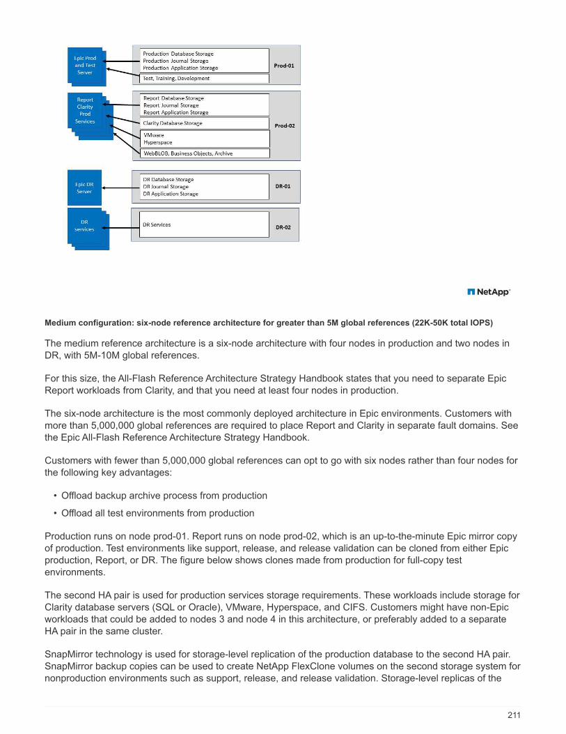
Medium configuration: six-node reference architecture for greater than 5M global references (22K-50K total IOPS)
The medium reference architecture is a six-node architecture with four nodes in production and two nodes inDR, with 5M-10M global references.
For this size, the All-Flash Reference Architecture Strategy Handbook states that you need to separate EpicReport workloads from Clarity, and that you need at least four nodes in production.
The six-node architecture is the most commonly deployed architecture in Epic environments. Customers withmore than 5,000,000 global references are required to place Report and Clarity in separate fault domains. Seethe Epic All-Flash Reference Architecture Strategy Handbook.
Customers with fewer than 5,000,000 global references can opt to go with six nodes rather than four nodes forthe following key advantages:
• Offload backup archive process from production
• Offload all test environments from production
Production runs on node prod-01. Report runs on node prod-02, which is an up-to-the-minute Epic mirror copyof production. Test environments like support, release, and release validation can be cloned from either Epicproduction, Report, or DR. The figure below shows clones made from production for full-copy testenvironments.
The second HA pair is used for production services storage requirements. These workloads include storage forClarity database servers (SQL or Oracle), VMware, Hyperspace, and CIFS. Customers might have non-Epicworkloads that could be added to nodes 3 and node 4 in this architecture, or preferably added to a separateHA pair in the same cluster.
SnapMirror technology is used for storage-level replication of the production database to the second HA pair.SnapMirror backup copies can be used to create NetApp FlexClone volumes on the second storage system fornonproduction environments such as support, release, and release validation. Storage-level replicas of the
211
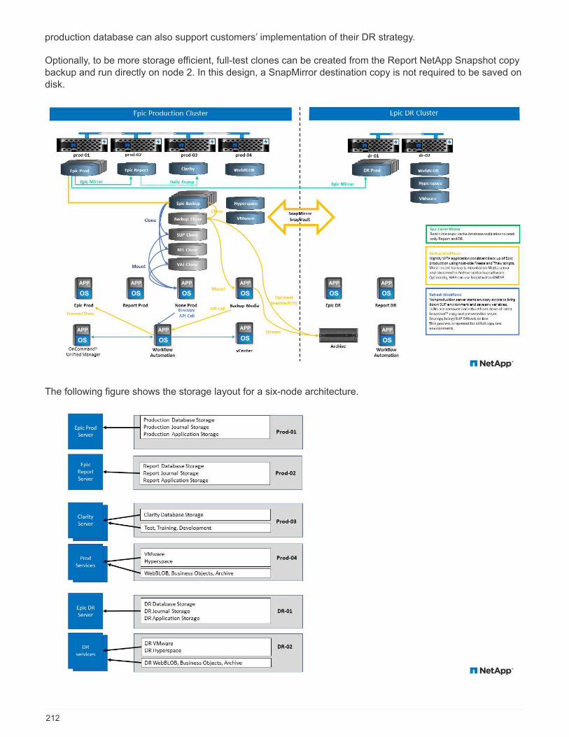
production database can also support customers’ implementation of their DR strategy.
Optionally, to be more storage efficient, full-test clones can be created from the Report NetApp Snapshot copybackup and run directly on node 2. In this design, a SnapMirror destination copy is not required to be saved ondisk.
The following figure shows the storage layout for a six-node architecture.
212

Large configuration: reference architecture for greater than 10M global references (more than 50K IOPS)
The large architecture is typically a twelve-or-more-node architecture with six to ten nodes in production, withmore than 10M global references. For large Epic deployments, Epic Production, Epic Report, and Clarity canbe placed on a dedicated HA pair with storage evenly balanced among the nodes, as shown in the figurebelow.
Larger customers have two options:
• Retain the six-node architecture and use AFF A700 controllers.
• Run Epic production, report, and DR on a dedicated AFF A300 HA pair.
You must use the SPM to compare controller utilization. Also, consider rack space and power when selectingcontrollers.
The following figure shows the storage layout for a large reference architecture.
213

Cisco UCS reference architecture for Epic
The architecture for Epic on FlexPod is based both on guidance from Epic, Cisco, and NetApp, and frompartner experience in working with Epic customers of all sizes. The architecture is adaptable and applies bestpractices for Epic, depending on the customer’s data center strategy—whether small or large, and whethercentralized, distributed, or multitenant.
When it comes to deploying Epic, Cisco has designed Cisco UCS reference architectures that align directlywith Epic’s best practices. Cisco UCS delivers a tightly integrated solution for high performance, highavailability, reliability, and scalability to support physician practices and hospital systems with several thousandbeds.
Basic design for smaller implementations
A basic design for Epic on Cisco UCS is less extensive than an expanded design. An example of a basicdesign use case might be a physician’s practice with outpatient clinics. Such an organization might have fewusers of the Epic applications, or it might not need all components of Epic. For example, a physician’s practicegroup might not require the Epic Willow Pharmacy application or Epic Monitor for in-patient monitoring. A basicdesign requires fewer virtual hosts and fewer physical servers. It is also likely to have fewer SAN requirements,and the WAN connections to the secondary data center might be handled with basic routing and TCP/IP.
The following figure illustrates an example of a basic small Epic configuration.
214

Expanded design for larger implementations
An expanded design for Epic on Cisco UCS follows the same best practices as a basic design. The primarydifference is in the scale of the expanded design. With larger scale there is usually a need for higherperformance in the core switching, SAN, and processor requirements for Caché databases. Largerimplementations typically have more Hyperspace users and need more XenApp for Hyperspace or other virtualapplication servers. Also, with requirements for more processing power, Cisco UCS quad-socket servers withIntel Skylake processors are used for the Chronicles Caché database and the related Production, Reporting,and Disaster Recovery Caché servers.
The following figure illustrates an example of an expanded Epic design.
215
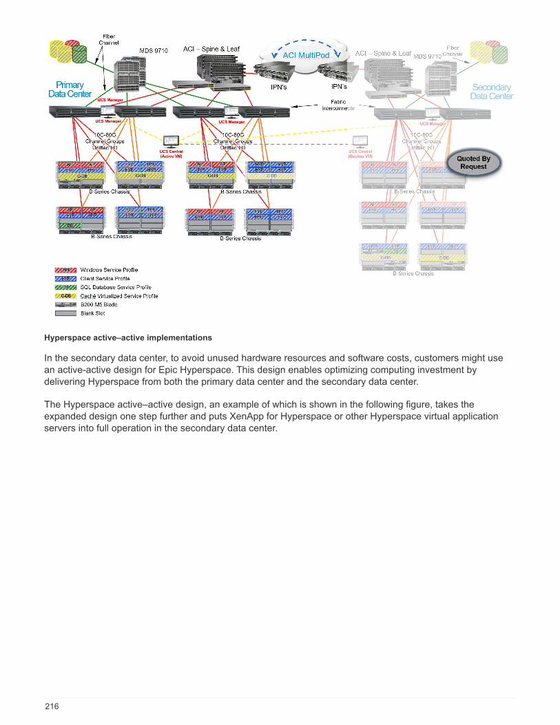
Hyperspace active–active implementations
In the secondary data center, to avoid unused hardware resources and software costs, customers might usean active-active design for Epic Hyperspace. This design enables optimizing computing investment bydelivering Hyperspace from both the primary data center and the secondary data center.
The Hyperspace active–active design, an example of which is shown in the following figure, takes theexpanded design one step further and puts XenApp for Hyperspace or other Hyperspace virtual applicationservers into full operation in the secondary data center.
216
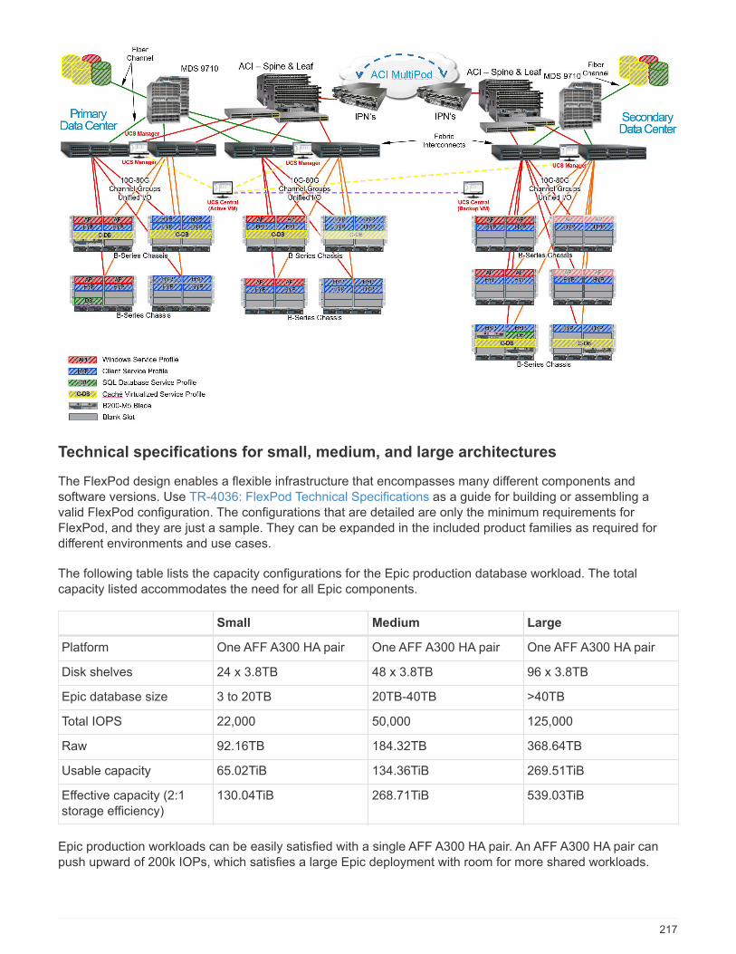
Technical specifications for small, medium, and large architectures
The FlexPod design enables a flexible infrastructure that encompasses many different components andsoftware versions. Use TR-4036: FlexPod Technical Specifications as a guide for building or assembling avalid FlexPod configuration. The configurations that are detailed are only the minimum requirements forFlexPod, and they are just a sample. They can be expanded in the included product families as required fordifferent environments and use cases.
The following table lists the capacity configurations for the Epic production database workload. The totalcapacity listed accommodates the need for all Epic components.
Small Medium Large
Platform One AFF A300 HA pair One AFF A300 HA pair One AFF A300 HA pair
Disk shelves 24 x 3.8TB 48 x 3.8TB 96 x 3.8TB
Epic database size 3 to 20TB 20TB-40TB >40TB
Total IOPS 22,000 50,000 125,000
Raw 92.16TB 184.32TB 368.64TB
Usable capacity 65.02TiB 134.36TiB 269.51TiB
Effective capacity (2:1storage efficiency)
130.04TiB 268.71TiB 539.03TiB
Epic production workloads can be easily satisfied with a single AFF A300 HA pair. An AFF A300 HA pair canpush upward of 200k IOPs, which satisfies a large Epic deployment with room for more shared workloads.
217
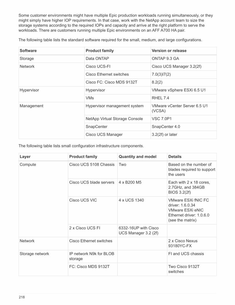
Some customer environments might have multiple Epic production workloads running simultaneously, or theymight simply have higher IOP requirements. In that case, work with the NetApp account team to size thestorage systems according to the required IOPs and capacity and arrive at the right platform to serve theworkloads. There are customers running multiple Epic environments on an AFF A700 HA pair.
The following table lists the standard software required for the small, medium, and large configurations.
Software Product family Version or release
Storage Data ONTAP ONTAP 9.3 GA
Network Cisco UCS-FI Cisco UCS Manager 3.2(2f)
Cisco Ethernet switches 7.0(3)I7(2)
Cisco FC: Cisco MDS 9132T 8.2(2)
Hypervisor Hypervisor VMware vSphere ESXi 6.5 U1
VMs RHEL 7.4
Management Hypervisor management system VMware vCenter Server 6.5 U1(VCSA)
NetApp Virtual Storage Console VSC 7.0P1
SnapCenter SnapCenter 4.0
Cisco UCS Manager 3.2(2f) or later
The following table lists small configuration infrastructure components.
Layer Product family Quantity and model Details
Compute Cisco UCS 5108 Chassis Two Based on the number ofblades required to supportthe users
Cisco UCS blade servers 4 x B200 M5 Each with 2 x 18 cores,2.7GHz, and 384GBBIOS 3.2(2f)
Cisco UCS VIC 4 x UCS 1340 VMware ESXi fNIC FCdriver: 1.6.0.34VMware ESXi eNICEthernet driver: 1.0.6.0(see the matrix)
2 x Cisco UCS FI 6332-16UP with CiscoUCS Manager 3.2 (2f)
Network Cisco Ethernet switches 2 x Cisco Nexus93180YC-FX
Storage network IP network N9k for BLOBstorage
FI and UCS chassis
FC: Cisco MDS 9132T Two Cisco 9132Tswitches
218
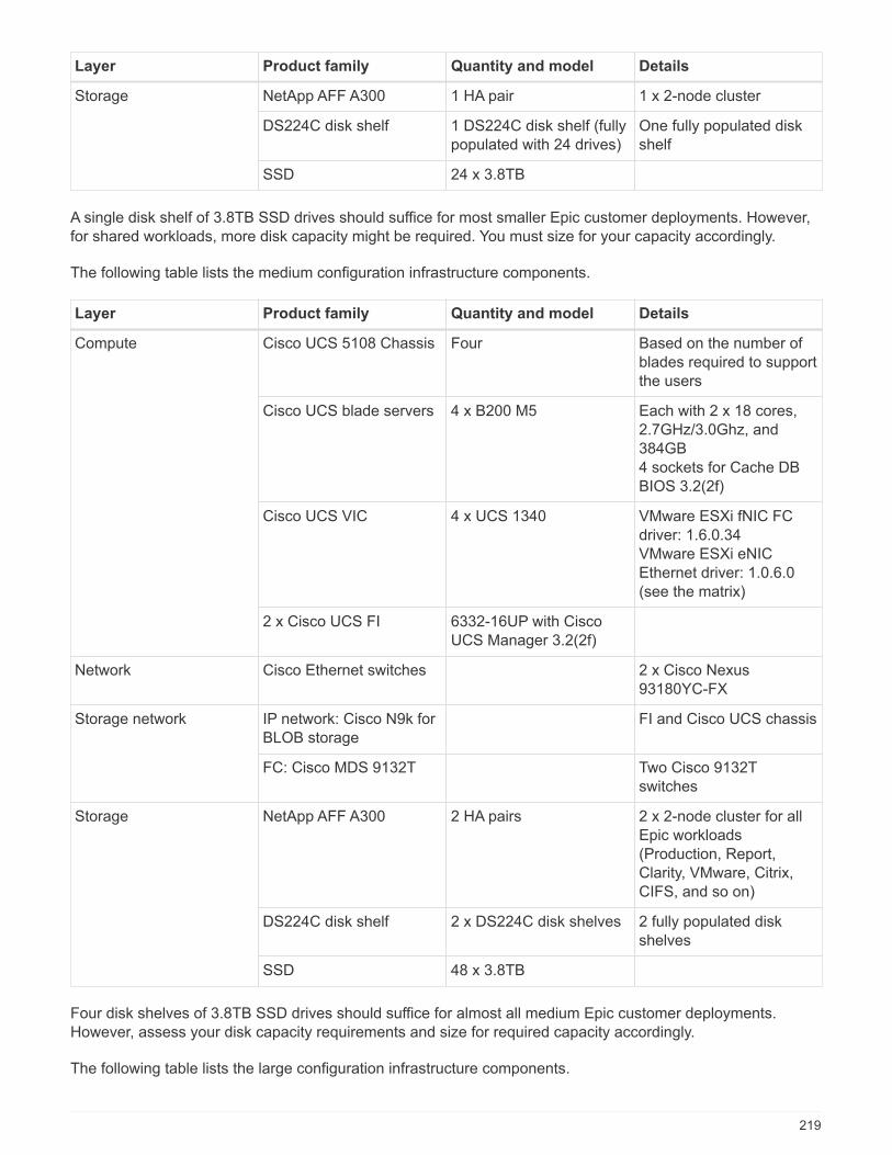
Layer Product family Quantity and model Details
Storage NetApp AFF A300 1 HA pair 1 x 2-node cluster
DS224C disk shelf 1 DS224C disk shelf (fullypopulated with 24 drives)
One fully populated diskshelf
SSD 24 x 3.8TB
A single disk shelf of 3.8TB SSD drives should suffice for most smaller Epic customer deployments. However,for shared workloads, more disk capacity might be required. You must size for your capacity accordingly.
The following table lists the medium configuration infrastructure components.
Layer Product family Quantity and model Details
Compute Cisco UCS 5108 Chassis Four Based on the number ofblades required to supportthe users
Cisco UCS blade servers 4 x B200 M5 Each with 2 x 18 cores,2.7GHz/3.0Ghz, and384GB4 sockets for Cache DBBIOS 3.2(2f)
Cisco UCS VIC 4 x UCS 1340 VMware ESXi fNIC FCdriver: 1.6.0.34VMware ESXi eNICEthernet driver: 1.0.6.0(see the matrix)
2 x Cisco UCS FI 6332-16UP with CiscoUCS Manager 3.2(2f)
Network Cisco Ethernet switches 2 x Cisco Nexus93180YC-FX
Storage network IP network: Cisco N9k forBLOB storage
FI and Cisco UCS chassis
FC: Cisco MDS 9132T Two Cisco 9132Tswitches
Storage NetApp AFF A300 2 HA pairs 2 x 2-node cluster for allEpic workloads(Production, Report,Clarity, VMware, Citrix,CIFS, and so on)
DS224C disk shelf 2 x DS224C disk shelves 2 fully populated diskshelves
SSD 48 x 3.8TB
Four disk shelves of 3.8TB SSD drives should suffice for almost all medium Epic customer deployments.However, assess your disk capacity requirements and size for required capacity accordingly.
The following table lists the large configuration infrastructure components.
219
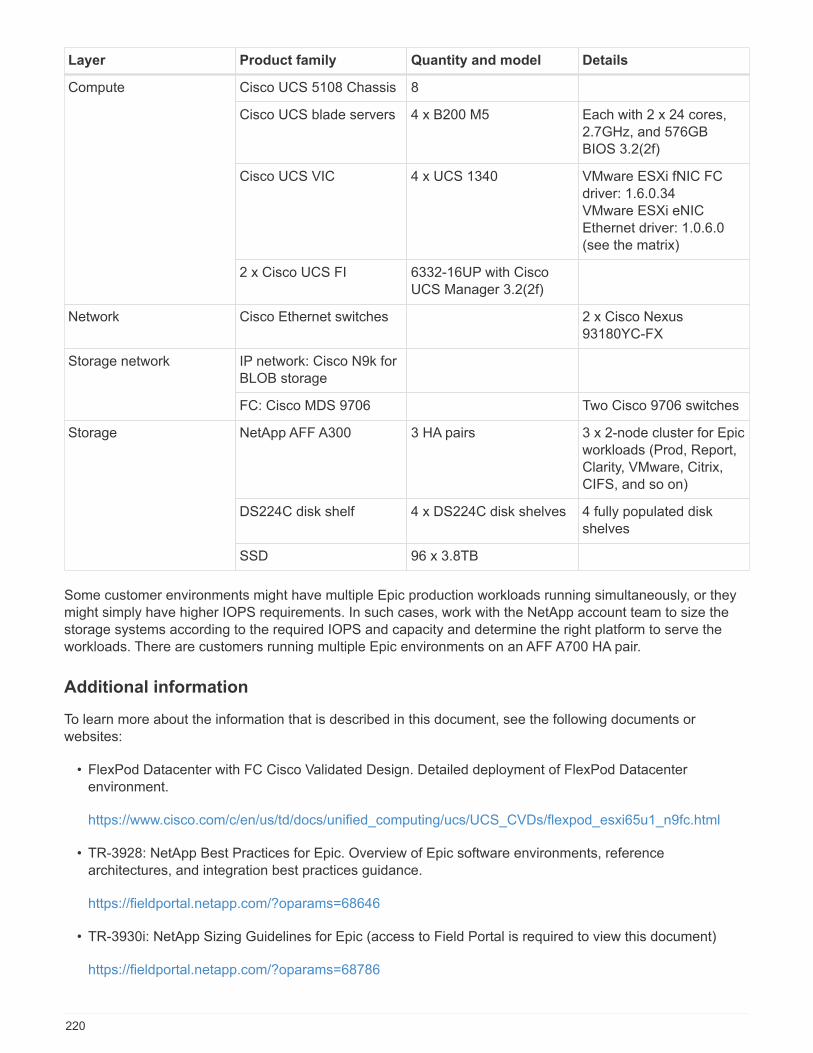
Layer Product family Quantity and model Details
Compute Cisco UCS 5108 Chassis 8
Cisco UCS blade servers 4 x B200 M5 Each with 2 x 24 cores,2.7GHz, and 576GBBIOS 3.2(2f)
Cisco UCS VIC 4 x UCS 1340 VMware ESXi fNIC FCdriver: 1.6.0.34VMware ESXi eNICEthernet driver: 1.0.6.0(see the matrix)
2 x Cisco UCS FI 6332-16UP with CiscoUCS Manager 3.2(2f)
Network Cisco Ethernet switches 2 x Cisco Nexus93180YC-FX
Storage network IP network: Cisco N9k forBLOB storage
FC: Cisco MDS 9706 Two Cisco 9706 switches
Storage NetApp AFF A300 3 HA pairs 3 x 2-node cluster for Epicworkloads (Prod, Report,Clarity, VMware, Citrix,CIFS, and so on)
DS224C disk shelf 4 x DS224C disk shelves 4 fully populated diskshelves
SSD 96 x 3.8TB
Some customer environments might have multiple Epic production workloads running simultaneously, or theymight simply have higher IOPS requirements. In such cases, work with the NetApp account team to size thestorage systems according to the required IOPS and capacity and determine the right platform to serve theworkloads. There are customers running multiple Epic environments on an AFF A700 HA pair.
Additional information
To learn more about the information that is described in this document, see the following documents orwebsites:
• FlexPod Datacenter with FC Cisco Validated Design. Detailed deployment of FlexPod Datacenterenvironment.
https://www.cisco.com/c/en/us/td/docs/unified_computing/ucs/UCS_CVDs/flexpod_esxi65u1_n9fc.html
• TR-3928: NetApp Best Practices for Epic. Overview of Epic software environments, referencearchitectures, and integration best practices guidance.
https://fieldportal.netapp.com/?oparams=68646
• TR-3930i: NetApp Sizing Guidelines for Epic (access to Field Portal is required to view this document)
https://fieldportal.netapp.com/?oparams=68786
220

• Epic_on_Cisco_UCS_tech_brief. Cisco Best practices with Epic on Cisco UCS.
https://www.cisco.com/c/dam/en_us/solutions/industries/healthcare/Epic_on_UCS_tech_brief_FNL.pdf
• NetApp FlexPod Design Zone
https://www.cisco.com/c/en/us/solutions/design-zone/data-center-design-guides/flexpod-design-guides.html
• FlexPod DC with Fibre Channel Storage (MDS Switches) Using NetApp AFF, vSphere 6.5U1, and CiscoUCS Manager
https://www.cisco.com/c/en/us/td/docs/unified_computing/ucs/UCS_CVDs/flexpod_esxi65u1_n9fc.html
• TR-4693: FlexPod Datacenter for Epic EHR Deployment Guide
https://www.netapp.com/us/media/tr-4693.pdf
• NetApp Product Documentation
https://www.netapp.com/us/documentation/index.aspx
Acknowledgements
The following people contributed to the writing of this guide.
• Ganesh Kamath, Technical Marketing Engineer, NetApp
• Atul Bhalodia, Technical Marketing Engineer, NetApp
• Ketan Mota, Product Manager, NetApp
• Jon Ebmeier, Cisco Systems, Inc.
• Mike Brennan, Cisco Systems, Inc.
FlexPod Datacenter for Epic EHR Deployment Guide
TR-4693: FlexPod Datacenter for Epic EHR Deployment Guide
Brian O’Mahony, NetAppGanesh Kamath, NetAppMike Brennan, Cisco
In partnership with:
This technical report is for customers who plan to deploy Epic on FlexPod systems. It provides a brief overviewof the FlexPod architecture for Epic and covers the setup and installation of FlexPod to deploy Epic forhealthcare.
FlexPod systems deployed to host Epic HyperSpace, InterSystems Caché database, Cogito Clarity analytics
221
and reporting suite, and services servers hosting the Epic application layer provide an integrated platform for adependable, high-performance infrastructure that can be deployed rapidly. The FlexPod integrated platform isdeployed by skilled FlexPod channel partners and is supported by Cisco and NetApp technical assistancecenters.
Overall solution benefits
By running an Epic environment on the FlexPod architectural foundation, healthcare organizations can expectto see an improvement in staff productivity and a decrease in capital and operating expenses. FlexPodDatacenter with Epic delivers several benefits specific to the healthcare industry:
• Simplified operations and lowered costs. Eliminate the expense and complexity of legacy proprietaryRISC/UNIX platforms by replacing them with a more efficient and scalable shared resource capable ofsupporting clinicians wherever they are. This solution delivers higher resource utilization for greater ROI.
• Quicker deployment of infrastructure. Whether it’s in an existing data center or a remote location, theintegrated and tested design of FlexPod Datacenter with Epic enables customers to have the newinfrastructure up and running in less time with less effort.
• Scale-out architecture. Scale SAN and NAS from terabytes to tens of petabytes without reconfiguringrunning applications.
• Nondisruptive operations. Perform storage maintenance, hardware lifecycle operations, and softwareupgrades without interrupting the business.
• Secure multitenancy. This benefit supports the increased needs of virtualized server and storage sharedinfrastructure, enabling secure multitenancy of facility-specific information, particularly if hosting multipleinstances of databases and software.
• Pooled resource optimization. This benefit can help reduce physical server and storage controllercounts, load balance workload demands, and boost utilization while improving performance.
• Quality of service (QoS). FlexPod offers QoS on the entire stack. Industry-leading QoS storage policiesenable differentiated service levels in a shared environment. These policies enable optimal performance forworkloads and help in isolating and controlling runaway applications.
• Storage efficiency. Reduce storage costs with the NetApp 7: 1 storage efficiency guarantee.
• Agility. The industry-leading workflow automation, orchestration, and management tools offered byFlexPod systems allow IT to be far more responsive to business requests. These business requests canrange from Epic backup and provisioning of additional test and training environments to analytics databasereplications for population health management initiatives.
• Productivity. Quickly deploy and scale this solution for optimal clinician end- user experiences.
• Data Fabric. The NetApp Data Fabric architecture weaves data together across sites, beyond physicalboundaries, and across applications. The NetApp Data Fabric is built for data-driven enterprises in a data-centric world. Data is created and used in multiple locations, and it often needs to be leveraged and sharedwith other locations, applications, and infrastructures. Customers want a way to manage data that isconsistent and integrated. It provides a way to manage data that puts IT in control and simplifies ever-increasing IT complexity.
FlexPod
A New approach for infrastructure for Epic EHR
Healthcare provider organizations remain under pressure to maximize the benefits of their substantialinvestments in industry-leading Epic electronic health records (EHRs). For mission-critical applications, whencustomers design their data centers for Epic solutions, they often identify the following goals for their datacenter architecture:
222

• High availability of the Epic applications
• High performance
• Ease of implementing Epic in the data center
• Agility and scalability to enable growth with new Epic releases or applications
• Cost effectiveness
• Alignment with Epic guidance and target platforms
• Manageability, stability, and ease of support
• Robust data protection, backup, recovery, and business continuance
As Epic users evolve their organizations to become accountable care organizations and adjust to tightened,bundled reimbursement models, the challenge becomes delivering the required Epic infrastructure in a moreefficient and agile IT delivery model.
Over the past decade, the Epic infrastructure customarily consisted of proprietary RISC processor- basedservers running proprietary versions of UNIX and traditional SAN storage arrays. These server and storageplatforms offer little by way of virtualization and can result in prohibitive capital and operating costs, givenincreasing IT budget constraints.
Epic now supports a production target platform consisting of a Cisco Unified Computing System (Cisco UCS)with Intel Xeon processors, virtualized with VMware ESXi, running Red Hat Enterprise Linux (RHEL). Thisplatform coupled with Epic’s High Comfort Level ranking for NetApp storage running ONTAP, a new era of Epicdata center optimization has begun.
Value of prevalidated converged infrastructure
Epic is prescriptive as to its customers’ hardware requirements because of an overarching requirement fordelivering predictable low-latency system performance and high availability.
FlexPod, a prevalidated, rigorously tested converged infrastructure from the strategic partnership of Cisco andNetApp, is engineered and designed specifically for delivering predictable low-latency system performance andhigh availability. This approach results in Epic high comfort levels and ultimately the best response time forusers of the Epic EHR system.
The FlexPod solution from Cisco and NetApp meets Epic system requirements with a high performing,modular, prevalidated, converged, virtualized, efficient, scalable, and cost-effective platform. It provides:
• Modular architecture. FlexPod addresses the varied needs of the Epic modular architecture with purpose-configured FlexPod platforms for each specific workload. All components are connected through aclustered server and storage management fabric and a cohesive management toolset.
• Accelerated application deployment. The prevalidated architecture reduces implementation integrationtime and risk to expedite Epic project plans. NetApp OnCommand Workforce Automation (OnCommandWFA) workflows for Epic automate Epic backup and refresh and remove the need for custom unsupportedscripts. Whether the solution is used for an initial rollout of Epic, a hardware refresh, or expansion, moreresources can be shifted to the business value of the project.
• Industry-leading technology at each level of the converged stack. Cisco, NetApp, VMware, and RedHat are all ranked as number 1 or number 2 by industry analysts in their respective categories of servers,networking, storage, and open systems Linux.
• Investment protection with standardized, flexible IT. The FlexPod reference architecture anticipatesnew product versions and updates, with rigorous ongoing interoperability testing to accommodate futuretechnologies as they become available.
223

• Proven deployment across a broad range of environments. Pretested and jointly validated with popularhypervisors, operating systems, applications, and infrastructure software, FlexPod has been installed insome of Epic’s largest customer organizations.
Proven FlexPod architecture and cooperative support
FlexPod is a proven data center solution, offering a flexible, shared infrastructure that easily scales to supportgrowing workload demands without affecting performance. By leveraging the FlexPod architecture, this solutiondelivers the full benefits of FlexPod, including:
• Performance to meet the Epic workload requirements. Depending on the reference workloadrequirements (small, medium, large), different ONTAP platforms can be deployed to meet the required I/Oprofile.
• Scalability to easily accommodate clinical data growth. Dynamically scale virtual machines (VMs),servers, and storage capacity on demand, without traditional limits.
• Enhanced efficiency. Reduce both administration time and TCO with a converged virtualizedinfrastructure, which is easier to manage and stores data more efficiently while driving more performancefrom Epic software. NetApp OnCommand WFA automation simplifies the solution to reduce testenvironment refresh time from hours or days to minutes.
• Reduced risk. Minimize business disruption with a prevalidated platform built on a defined architecturethat eliminates deployment guesswork and accommodates ongoing workload optimization.
• FlexPod Cooperative Support. NetApp and Cisco have established Cooperative Support, a strong,scalable, and flexible support model to address the unique support requirements of the FlexPod convergedinfrastructure. This model uses the combined experience, resources, and technical support expertise ofNetApp and Cisco to provide a streamlined process for identifying and resolving a customer’s FlexPodsupport issue, regardless of where the problem resides. The FlexPod Cooperative Support model helps tomake sure that your FlexPod system operates efficiently and benefits from the most up-to-date technology,while providing an experienced team to help resolve integration issues.
FlexPod Cooperative Support is especially valuable to healthcare organizations running business-criticalapplications such as Epic on the FlexPod converged infrastructure.
The following figure illustrates the FlexPod cooperative support model.
224

In addition to these benefits, each component of the FlexPod Datacenter stack with Epic solution deliversspecific benefits for Epic EHR workflows.
Cisco Unified Computing System
A self-integrating, self-aware system, Cisco UCS consists of a single management domain interconnected witha unified I/O infrastructure. Cisco UCS for Epic environments has been aligned with Epic infrastructurerecommendations and best practices to help ensure that the infrastructure can deliver critical patientinformation with maximum availability.
The foundation of Epic on Cisco UCS architecture is Cisco UCS technology, with its integrated systemsmanagement, Intel Xeon processors, and server virtualization. These integrated technologies solve data centerchallenges and enable customers to meet their goals for data center design for Epic. Cisco UCS unifies LAN,SAN, and systems management into one simplified link for rack servers, blade servers, and VMs. Cisco UCS isan end-to-end I/O architecture that incorporates Cisco unified fabric and Cisco fabric extender (FEX)technology to connect every component in Cisco UCS with a single network fabric and a single network layer.
The system is designed as a single virtual blade chassis that incorporates and scales across multiple bladechassis, rack servers, and racks. The system implements a radically simplified architecture that eliminates themultiple redundant devices that populate traditional blade server chassis and result in layers of complexity:Ethernet and FC switches and chassis management modules. Cisco UCS consists of a redundant pair of Ciscofabric interconnects (FIs) that provide a single point of management, and a single point of control, for all I/Otraffic.
Cisco UCS uses service profiles to help ensure that virtual servers in the Cisco UCS infrastructure areconfigured correctly. Service profiles include critical server information about the server identity such as LANand SAN addressing, I/O configurations, firmware versions, boot order, network VLAN, physical port, and QoS
225
policies. Service profiles can be dynamically created and associated with any physical server in the system inminutes rather than hours or days. The association of service profiles with physical servers is performed as asimple, single operation and enables migration of identities between servers in the environment withoutrequiring any physical configuration changes. It facilitates rapid bare-metal provisioning of replacements forfailed servers.
Using service profiles helps to make sure that servers are configured consistently throughout the enterprise.When using multiple Cisco UCS management domains, Cisco UCS Central can use global service profiles tosynchronize configuration and policy information across domains. If maintenance needs to be performed in onedomain, the virtual infrastructure can be migrated to another domain. This approach helps to ensure that evenwhen a single domain is offline, applications continue to run with high availability.
Cisco UCS has been extensively tested with Epic over a multi- year period to demonstrate that it meets theserver configuration requirements. Cisco UCS is a supported server platform, as listed in customers’ “EpicHardware Configuration Guide.”
Cisco Nexus
Cisco Nexus switches and MDS multilayer directors provide enterprise-class connectivity and SANconsolidation. Cisco multiprotocol storage networking reduces business risk by providing flexibility and options:FC, Fibre Connection (FICON), FC over Ethernet (FCoE), SCSI over IP (iSCSI), and FC over IP (FCIP).
Cisco Nexus switches offer one of the most comprehensive data center network feature sets in a singleplatform. They deliver high performance and density for both data center and campus core. They also offer afull feature set for data center aggregation, end-of-row, and data center interconnect deployments in a highlyresilient modular platform.
Cisco UCS integrates computing resources with Cisco Nexus switches and a unified I/O fabric that identifiesand handles different types of network traffic, including storage I/O, streamed desktop traffic, management,and access to clinical and business applications:
• Infrastructure scalability. Virtualization, efficient power and cooling, cloud scale with automation, highdensity, and performance all support efficient data center growth.
• Operational continuity. The design integrates hardware, NX-OS software features, and management tosupport zero-downtime environments.
• Transport flexibility. Incrementally adopt new networking technologies with a cost-effective solution.
Together, Cisco UCS with Cisco Nexus switches and MDS multilayer directors provide a compute, networking,and SAN connectivity solution for Epic.
NetApp ONTAP
NetApp storage running ONTAP software reduces overall storage costs while delivering the low-latency readand write response times and IOPS required for Epic workloads. ONTAP supports both all-flash and hybridstorage configurations to create an optimal storage platform to meet Epic requirements. NetApp flash-accelerated systems received the Epic High Comfort Level rating, providing Epic customers with theperformance and responsiveness key to latency- sensitive Epic operations. NetApp can also isolate productionfrom nonproduction by creating multiple fault domains in a single cluster. NetApp reduces performance issuesby guaranteeing a minimum performance level for workloads with ONTAP minimum QoS.
The scale-out architecture of the ONTAP software can flexibly adapt to various I/O workloads. To deliver thenecessary throughput and low latency required for clinical applications while providing a modular scale-outarchitecture, all-flash configurations are typically used in ONTAP architectures. All- flash arrays will be requiredby Epic by year 2020 and are required by Epic today for customers with more than 5 million global references.
226
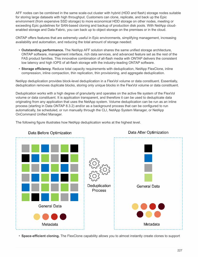
AFF nodes can be combined in the same scale-out cluster with hybrid (HDD and flash) storage nodes suitablefor storing large datasets with high throughput. Customers can clone, replicate, and back up the Epicenvironment (from expensive SSD storage) to more economical HDD storage on other nodes, meeting orexceeding Epic guidelines for SAN-based cloning and backup of production disk pools. With NetApp cloud-enabled storage and Data Fabric, you can back up to object storage on the premises or in the cloud.
ONTAP offers features that are extremely useful in Epic environments, simplifying management, increasingavailability and automation, and reducing the total amount of storage needed:
• Outstanding performance. The NetApp AFF solution shares the same unified storage architecture,ONTAP software, management interface, rich data services, and advanced feature set as the rest of theFAS product families. This innovative combination of all-flash media with ONTAP delivers the consistentlow latency and high IOPS of all-flash storage with the industry-leading ONTAP software.
• Storage efficiency. Reduce total capacity requirements with deduplication, NetApp FlexClone, inlinecompression, inline compaction, thin replication, thin provisioning, and aggregate deduplication.
NetApp deduplication provides block-level deduplication in a FlexVol volume or data constituent. Essentially,deduplication removes duplicate blocks, storing only unique blocks in the FlexVol volume or data constituent.
Deduplication works with a high degree of granularity and operates on the active file system of the FlexVolvolume or data constituent. It is application transparent, and therefore it can be used to deduplicate dataoriginating from any application that uses the NetApp system. Volume deduplication can be run as an inlineprocess (starting in Data ONTAP 8.3.2) and/or as a background process that can be configured to runautomatically, be scheduled, or run manually through the CLI, NetApp System Manager, or NetAppOnCommand Unified Manager.
The following figure illustrates how NetApp deduplication works at the highest level.
• Space-efficient cloning. The FlexClone capability allows you to almost instantly create clones to support
227

backup and test environment refresh. These clones consume additional storage only as changes aremade.
• Integrated data protection. Full data protection and disaster recovery features help customers protectcritical data assets and provide disaster recovery.
• Nondisruptive operations. Upgrading and maintenance can be performed without taking data offline.
• Epic workflow automation. NetApp has designed OnCommand WFA workflows to automate and simplifythe Epic backup solution and refresh of test environments such as SUP, REL, and REL VAL. This approacheliminates the need for any custom unsupported scripts, reducing deployment time, operations hours, anddisk capacity required for NetApp and Epic best practices.
• QoS. Storage QoS allows you to limit potential bully workloads. More importantly, QoS can guaranteeminimum performance for critical workloads such as Epic production. NetApp QoS can reduceperformance-related issues by limiting contention.
• OnCommand Insight Epic dashboard. The Epic Pulse tool can identify an application issue and its effecton the end user. The OnCommand Insight Epic dashboard can help identify the root cause of the issue andgives full visibility into the complete infrastructure stack.
• Data Fabric. NetApp Data Fabric simplifies and integrates data management across cloud and on-premises to accelerate digital transformation. It delivers consistent and integrated data managementservices and applications for data visibility and insights, data access and control, and data protection andsecurity. NetApp is integrated with AWS, Azure, Google Public Cloud, and IBM Cloud clouds, givingcustomers a wide breadth of choice.
The following figure illustrates FlexPod for Epic workloads.
228
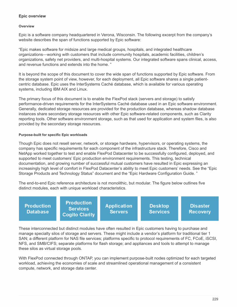
Epic overview
Overview
Epic is a software company headquartered in Verona, Wisconsin. The following excerpt from the company’swebsite describes the span of functions supported by Epic software:
“Epic makes software for midsize and large medical groups, hospitals, and integrated healthcareorganizations—working with customers that include community hospitals, academic facilities, children’sorganizations, safety net providers, and multi-hospital systems. Our integrated software spans clinical, access,and revenue functions and extends into the home. ”
It is beyond the scope of this document to cover the wide span of functions supported by Epic software. Fromthe storage system point of view, however, for each deployment, all Epic software shares a single patient-centric database. Epic uses the InterSystems Caché database, which is available for various operatingsystems, including IBM AIX and Linux.
The primary focus of this document is to enable the FlexPod stack (servers and storage) to satisfyperformance-driven requirements for the InterSystems Caché database used in an Epic software environment.Generally, dedicated storage resources are provided for the production database, whereas shadow databaseinstances share secondary storage resources with other Epic software-related components, such as Clarityreporting tools. Other software environment storage, such as that used for application and system files, is alsoprovided by the secondary storage resources.
Purpose-built for specific Epic workloads
Though Epic does not resell server, network, or storage hardware, hypervisors, or operating systems, thecompany has specific requirements for each component of the infrastructure stack. Therefore, Cisco andNetApp worked together to test and enable FlexPod Datacenter to be successfully configured, deployed, andsupported to meet customers’ Epic production environment requirements. This testing, technicaldocumentation, and growing number of successful mutual customers have resulted in Epic expressing anincreasingly high level of comfort in FlexPod Datacenter’s ability to meet Epic customers’ needs. See the “EpicStorage Products and Technology Status” document and the “Epic Hardware Configuration Guide. ”
The end-to-end Epic reference architecture is not monolithic, but modular. The figure below outlines fivedistinct modules, each with unique workload characteristics.
These interconnected but distinct modules have often resulted in Epic customers having to purchase andmanage specialty silos of storage and servers. These might include a vendor’s platform for traditional tier 1SAN; a different platform for NAS file services; platforms specific to protocol requirements of FC, FCoE, iSCSI,NFS, and SMB/CIFS; separate platforms for flash storage; and appliances and tools to attempt to managethese silos as virtual storage pools.
With FlexPod connected through ONTAP, you can implement purpose-built nodes optimized for each targetedworkload, achieving the economies of scale and streamlined operational management of a consistentcompute, network, and storage data center.
229
Caché production database
Caché, manufactured by InterSystems, is the database system on which Epic is built. All patient data in Epic isstored in a Caché database.
In an InterSystems Caché database, the data server is the access point for persistently stored data. Theapplication server services database queries and makes data requests to the data server. For most Epicsoftware environments, the use of the symmetric multiprocessor architecture in a single database serversuffices to service the Epic applications’ database requests. In large deployments, using InterSystems’Enterprise Caché Protocol can support a distributed database model.
By using failover-enabled clustered hardware, a standby data server can access the same disks (that is,storage) as the primary data server and take over the processing responsibilities in the event of a hardwarefailure.
InterSystems also provides technologies to satisfy shadow, disaster recovery, and high-availability (HA)requirements. InterSystems’ shadow technology can be used to asynchronously replicate a Caché databasefrom a primary data server to one or more secondary data servers.
Cogito Clarity
Cogito Clarity is Epic’s integrated analytics and reporting suite. Starting as a copy of the production Cachédatabase, Cogito Clarity delivers information that can help improve patient care, analyze clinical performance,manage revenue, and measure compliance. As an OLAP environment, Cogito Clarity utilizes either MicrosoftSQL Server or Oracle RDBMS. Because this environment is distinct from the Caché production databaseenvironment, it is important to architect a FlexPod platform that supports the Cogito Clarity requirementsfollowing Cisco and NetApp published validated design guides for SQL Server and Oracle environments.
Epic Hyperspace Desktop Services
Hyperspace is the presentation component of the Epic suite. It reads and writes data from the Caché databaseand presents it to the user. Most hospital and clinic staff members interact with Epic using the Hyperspaceapplication.
Although Hyperspace can be installed directly on client workstations, many healthcare organizations useapplication virtualization through a Citrix XenApp farm or a virtual desktop infrastructure (VDI) to deliverapplications to users. Virtualizing XenApp server farms using ESXi is supported. See the validated designs forFlexPod for ESXi in the “References” section for configuration and implementation guidelines.
For customers interested in deploying full VDI Citrix XenDesktop or VMware Horizon View systems, carefulattention must be paid for an optimal clinical workflow experience. A foundational step for obtaining preciseconfigurations is to clearly understand and document the scope of the project, including detailed mapping ofuser profiles. Many user profiles include access to applications beyond Epic. Variables in profiles include:
• Authentication, especially Imprivata or similar tap- and-go single sign-on (SSO), for nomadic clinician users
• PACS Image Viewer
• Dictation software and devices such as Dragon NaturallySpeaking
• Document management such as Hyland OnBase or Perceptive Software integration
• Departmental applications such as health information management coding from 3M Health Care orOptumHealth
• Pre-Epic legacy EMR or revenue cycle apps, which the customer might still use
• Video conferencing capabilities that could require use of video acceleration cards in the servers
230

Your certified FlexPod reseller, with specific certifications in VMware Horizon View or Citrix XenDesktop, willwork with your Cisco and NetApp Epic solutions architect and professional services provider to scope andarchitect the solution for your specific VDI requirements.
Disaster recovery and shadow copies
Evolving to active-active dual data centers
In Epic software environments, a single patient-centric database is deployed. Epic’s hardware requirementsrefer to the physical server hosting the primary Caché data server as the production database server. Thisserver requires dedicated, high-performance storage for files belonging to the primary database instance. ForHA, Epic supports the use of a failover database server that has access to the same files.
A reporting shadow database server is typically deployed to provide read-only access to production data. Ithosts a Caché data server configured as a backup shadow of the production Caché data server. This databaseserver has the same storage capacity requirements as the production database server. This storage is sizeddifferently from a performance perspective because reporting workload characteristics are different.
A shadow database server can also be deployed to support Epic’s read-only (SRO) functionality, in whichaccess is provided to a copy of production in read-only mode. This type of database server can be switched toread-write mode for business continuity reasons.
To meet business continuity and disaster recovery (DR) objectives, a DR shadow database server is commonlydeployed at a site geographically separate from the production and/or reporting shadow database servers. ADR shadow database server also hosts a Caché data server configured as a backup shadow of the productionCaché data server. It can be configured to act as a shadow read-write instance if the production site isunavailable for an extended time. Like the reporting shadow database server, the storage for its database fileshas the same capacity requirements as the production database server. In contrast, this storage is sized thesame as production from a performance perspective, for business continuity reasons.
For healthcare organizations that need continuous uptime for Epic and have multiple data centers, FlexPodcan be used to build an active-active design for Epic deployment. In an active-active scenario, FlexPodhardware is installed into a second data center and is used to provide continuous availability and quick failoveror disaster recovery solutions for Epic. The “Epic Hardware Configuration Guide” provided to customers shouldbe shared with Cisco and NetApp to facilitate the design of an active-active architecture that meets Epic’sguidelines.
Licensing Caché
NetApp and Cisco are experienced in migrating legacy Epic installations to FlexPod systems following Epic’sbest practices for platform migration. They can work through any details if a platform migration is required.
One consideration for new customers moving to Epic or existing customers evaluating a hardware andsoftware refresh is the licensing of the Caché database. InterSystems Caché can be purchased with either aplatform-specific license (limited to a single hardware OS architecture) or a platform-independent license. Aplatform-independent license allows the Caché database to be migrated from one architecture to another, but itcosts more than a platform-specific license.
Customers with platform-specific licensing might need to budget for additional licensing costs toswitch platforms.
Epic storage considerations
RAID performance and protection
231

Epic recognizes the value of NetApp RAID DP, RAID-TEC, and WAFL technologies in achieving levels of dataprotection and performance that meet Epic-defined requirements. Furthermore, with NetApp efficiencytechnologies, NetApp storage systems can deliver the overall read performance required for Epicenvironments while using fewer disk drives.
Epic requires the use of NetApp sizing methods to properly size a NetApp storage system for use in Epicenvironments. For more information, see TR-3930i: NetApp Sizing Guidelines for Epic. NetApp Field Portalaccess is required to view this document.
Isolation of production disk groups
See the Epic All-Flash Reference Architecture Strategy Handbook for details about the storage layout on anall-flash array. In summary, disk pool 1 (production) must be stored on a separate storage fault domain fromdisk pool 2. An ONTAP node in the same cluster is a fault domain.
Epic recommends the use of flash for all full-size operational databases, not just the production operationaldatabases. At present this approach is only a recommendation; however, by calendar year 2020 it will be arequirement for all customers.
For very large sites, where the production OLTP database is expected to exceed 5 million global referencesper second, the Cogito workloads should be placed on a third array to minimize the impact to the performanceof the production OLTP database. The test bed configuration used in this document is an all-flash array.
High availability and redundancy
Epic recommends the use of HA storage systems to mitigate hardware component failure. Thisrecommendation extends from basic hardware, such as redundant power supplies, to networking, such asmultipath networking.
At the storage node level, Epic highlights the use of redundancy to enable nondisruptive upgrades andnondisruptive storage expansion.
Pool 1 storage must reside on separate disks from the pool 2 storage for the performance isolation reasonspreviously stated, both of which NetApp storage arrays provide by default out of the box. This separation alsoprovides data-level redundancy for disk-level failures.
Storage monitoring
Epic recommends the use of effective monitoring tools to identify or predict any storage system bottlenecks.
NetApp OnCommand Unified Manager, bundled with ONTAP, can be used to monitor capacity, performance,and headroom. For customers with OnCommand Insight, an Insight dashboard has been developed for Epicthat gives complete visibility into storage, network, and compute beyond what the Epic Pulse monitoring toolprovides. Although Pulse can detect an issue, Insight can identify the issue early, before it has an impact.
Snapshot technology
Epic recognizes that storage node-based NetApp Snapshot technology can minimize performance impacts onproduction workloads compared to traditional file-based backups. When Snapshot backups are intended foruse as a recovery source for the production database, the backup method must be implemented with databaseconsistency in mind.
Storage expansion
Epic cautions against expanding storage without considering storage hotspots. For example, if storage isfrequently added in small increments, storage hotspots can develop where data is not evenly spread across
232
disks.
Comprehensive management tools and automation capabilities
Cisco Unified Computing System with Cisco UCS Manager
Cisco focuses on three key elements to deliver the best data center infrastructure: simplification, security, andscalability. The Cisco UCS Manager software combined with platform modularity provides a simplified, secure,and scalable desktop virtualization platform.
• Simplified. Cisco UCS provides a radical new approach to industry-standard computing and provides thecore of the data center infrastructure for all workloads. Among the many features and benefits of CiscoUCS are the reduction in the number of servers needed, the reduction in the number of cables used perserver, and the capability to rapidly deploy or re- provision servers through Cisco UCS service profiles.With fewer servers and cables to manage and with streamlined server and application workloadprovisioning, operations are significantly simplified. Scores of blade and rack servers can be provisioned inminutes with Cisco UCS Manager service profiles. Cisco UCS service profiles eliminate server integrationrun books and eliminate configuration drift. This approach accelerates the time to productivity for endusers, improves business agility, and allows IT resources to be allocated to other tasks.
Cisco UCS Manager (UCSM) automates many mundane, error-prone data center operations such asconfiguration and provisioning of server, network, and storage access infrastructure. In addition, Cisco UCSB-Series blade servers and C-Series rack servers with large memory footprints enable high applicationuser density, which helps reduce server infrastructure requirements.
Simplification leads to faster, more successful Epic infrastructure deployment. Cisco and its technologypartners such as VMware and Citrix and storage partners IBM, NetApp, and Pure Storage have developedintegrated, validated architectures, including predefined converged architecture infrastructure packagessuch as FlexPod. Cisco virtualization solutions have been tested with VMware vSphere, Linux, CitrixXenDesktop, and XenApp.
• Secure. Although VMs are inherently more secure than their physical predecessors, they introduce newsecurity challenges. Mission-critical web and application servers using a common infrastructure such asvirtual desktops are now at a higher risk for security threats. Inter–virtual machine traffic now poses animportant security consideration that IT managers need to address, especially in dynamic environments inwhich VMs, using VMware vMotion, move across the server infrastructure.
Virtualization, therefore, significantly increases the need for virtual machine–level awareness of policy andsecurity, especially given the dynamic and fluid nature of virtual machine mobility across an extendedcomputing infrastructure. The ease with which new virtual desktops can proliferate magnifies theimportance of a virtualization-aware network and security infrastructure. Cisco data center infrastructure(Cisco UCS, Cisco MDS, and Cisco Nexus family solutions) for desktop virtualization provides strong datacenter, network, and desktop security, with comprehensive security from the desktop to the hypervisor.Security is enhanced with segmentation of virtual desktops, virtual machine–aware policies andadministration, and network security across the LAN and WAN infrastructure.
• Scalable. Growth of virtualization solutions is all but inevitable, so a solution must be able to scale, andscale predictably, with that growth. The Cisco virtualization solutions support high virtual machine density(VMs per server), and additional servers scale with near-linear performance. Cisco data centerinfrastructure provides a flexible platform for growth and improves business agility. Cisco UCS Managerservice profiles allow on-demand host provisioning and make it just as easy to deploy dozens of hosts as itis to deploy hundreds.
Cisco UCS servers provide near-linear performance and scale. Cisco UCS implements the patented CiscoExtended Memory Technology to offer large memory footprints with fewer sockets (with scalability to up to
233
1TB of memory with 2- and 4-socket servers). Using unified fabric technology as a building block, CiscoUCS server aggregate bandwidth can scale to up to 80Gbps per server, and the northbound Cisco UCSfabric interconnect can output 2Tbps at line rate, helping prevent desktop virtualization I/O and memorybottlenecks. Cisco UCS, with its high-performance, low-latency unified fabric-based networkingarchitecture, supports high volumes of virtual desktop traffic, including high-resolution video andcommunications traffic. In addition, Cisco storage partner NetApp helps to maintain data availability andoptimal performance during boot and login storms as part of the Cisco virtualization solutions.
Cisco UCS, Cisco MDS, and Cisco Nexus data center infrastructure designs provide an excellent platform forgrowth, with transparent scaling of server, network, and storage resources to support desktop virtualization,data center applications, and cloud computing.
VMware vCenter Server
VMware vCenter Server provides a centralized platform for managing Epic environments so healthcareorganizations can automate and deliver a virtual infrastructure with confidence:
• Simple deployment. Quickly and easily deploy vCenter Server using a virtual appliance.
• Centralized control and visibility. Administer the entire vSphere infrastructure from a single location.
• Proactive optimization. Allocate and optimize resources for maximum efficiency.
• Management. Use powerful plug-ins and tools to simplify management and extend control.
Virtual Storage Console for VMware vSphere
Virtual Storage Console (VSC), VASA Provider, and Storage Replication Adapter (SRA) for VMware vSpherefrom NetApp are a virtual appliance. This product suite includes capabilities of VSC, VASA Provider, and SRA.The product suite includes SRA and VASA Provider as plug-ins to vCenter Server, which provides end-to-endlifecycle management for VMs in VMware environments using NetApp storage systems.
The virtual appliance for VSC, VASA Provider, and SRA integrates smoothly with the VMware vSphere WebClient and enables you to use SSO services. In an environment with multiple vCenter Server instances, eachvCenter Server instance that you want to manage must have its own registered instance of VSC. The VSCdashboard page enables you to quickly check the overall status of your datastores and VMs.
By deploying the virtual appliance for VSC, VASA Provider, and SRA, you can perform the following tasks:
• Using VSC to deploy and manage storage and configure the ESXi host. You can use VSC to addcredentials, remove credentials, assign credentials, and set up permissions for storage controllers in yourVMware environment. In addition, you can manage ESXi servers that are connected to NetApp storagesystems. You can set recommended best practice values for host timeouts, NAS, and multipathing for allthe hosts with a couple of clicks. You can also view storage details and collect diagnostic information.
• Using VASA Provider to create storage capability profiles and set alarms. VASA Provider for ONTAPis registered with VSC as soon as you enable the VASA Provider extension. You can create and usestorage capability profiles and virtual datastores. You can also set alarms to alert you when the thresholdsfor volumes and aggregates are almost full. You can monitor the performance of virtual machine disks(VMDKs) and the VMs that are created on virtual datastores.
• Using SRA for disaster recovery. You can use SRA to configure protected and recovery sites in yourenvironment for disaster recovery during failures.
NetApp OnCommand Insight and ONTAP
NetApp OnCommand Insight integrates infrastructure management into the Epic service delivery chain. This
234

approach provides healthcare organizations with better control, automation, and analysis of the storage,network, and compute infrastructure. IT can optimize the current infrastructure for maximum benefit whilesimplifying the process of determining what and when to buy. It also mitigates the risks associated withcomplex technology migrations. Because it requires no agents, installation is straightforward andnondisruptive. Installed storage and SAN devices are continually discovered, and detailed information iscollected for full visibility of your entire storage environment. You can quickly identify misused, misaligned,underused, or orphaned assets and reclaim them to fuel future expansion:
• Optimize existing resources. Identify misused, underused, or orphaned assets using established bestpractices to avoid problems and meet service levels.
• Make better decisions. Real-time data helps resolve capacity problems more quickly to accurately planfuture purchases, avoid overspending, and defer capital expenditures.
• Accelerate IT initiatives. Better understand virtual environments to manage risks, minimize downtime,and speed cloud deployment.
• OnCommand Insight dashboard. This Epic dashboard was developed by NetApp for Epic and provides acomprehensive view of the complete infrastructure stack and goes beyond Pulse monitoring. OnCommandInsight can proactively identify contention issues in compute, network, and storage.
NetApp OnCommand workflow automation
OnCommand WFA is a free software solution that helps to automate storage management tasks, such asprovisioning, migration, decommissioning, data protection configurations, and cloning storage. You can useOnCommand WFA to build workflows to complete tasks that are specified by your processes.
A workflow is a repetitive and procedural task that consists of steps, including the following types of tasks:
• Provisioning, migrating, or decommissioning storage for databases or file systems
• Setting up a new virtualization environment, including storage switches and datastores
• Setting up storage for an application as part of an end-to-end orchestration process
Workflows can be built to quickly set up and configure NetApp storage as per recommended best practices forEpic workloads. OnCommand WFA workflows for Epic replace all customer unsupported scripting required forEpic workflows to automate backup and test environment refresh.
NetApp SnapCenter
SnapCenter is a unified, scalable platform for data protection. SnapCenter provides centralized control andoversight, allowing users to manage application-consistent, database-consistent Snapshots copies.SnapCenter enables the backup, restore, clone, and backup, verification of virtual machine (VMs) from bothprimary and secondary destinations (SnapMirror and SnapVault). With SnapCenter, database, storage, andvirtualization administrators have a single tool to manage backup, restore, and clone operations for variousapplications, databases, and VMs.
SnapCenter enables centralized application resource management and easy data protection job execution byusing resource groups and policy management (including scheduling and retention settings). SnapCenterprovides unified reporting by using a dashboard, multiple reporting options, job monitoring, and log and eventviewers.
SnapCenter can back up VMware, RHEL, SQL, Oracle, and CIFS. Combined with Epic WFA backup workflowintegration, NetApp provides a backup solution for any Epic environment.
235

Design
The architecture of FlexPod for Epic is based both on guidance from Epic, Cisco, and NetApp and from partnerexperience in working with Epic customers of all sizes. The architecture is adaptable and applies best practicesfor Epic, depending on the customer’s data center strategy, whether small or large and whether centralized,distributed, or multitenant.
The correct storage architecture can be determined by the overall size with the total IOPS. Performance aloneis not the only factor, and you might decide to go with a larger node count based on additional customerrequirements. The advantage of using NetApp is that the cluster can easily be scaled up nondisruptively asrequirements change. You can also nondisruptively remove nodes from the cluster to repurpose or duringequipment refreshes.
Here are some of the benefits of the NetApp ONTAP storage architecture:
• Easy nondisruptive scale up and scale out. Disks and nodes can be upgraded, added, or removed byusing ONTAP nondisruptive operations. Customers can start with four nodes and move to six nodes orupgrade to larger controllers nondisruptively.
• Storage efficiencies. Reduce total capacity requirements with deduplication, FlexClone, inlinecompression, inline compaction, thin replication, thin provisioning, and aggregate deduplication. TheFlexClone capability allows you to almost instantly create clones to support backup and test environmentrefreshes. These clones consume additional storage only as changes are made.
• Ability of OnCommand WFA workflows to back up and refresh Epic full-copy test environments.
This solution simplifies the architecture and saves on storage capacity with integrated efficiencies. Thesearchitectures factor in the backup solution for Epic and leverage storage integration to integrate with anybackup solution.
• DR shadow database server. The DR shadow database server is part of a customer’s business continuitystrategy (used to support storage read-only [SRO] functionality and potentially configured to be a storageread-write [SRW] instance). Therefore, the placement and sizing of the third storage system are in mostcases the same as in the production database storage system.
• Database consistency (requires some consideration). If SnapMirror backup copies are used in relationto business continuity, see the document “Epic Business Continuity Technical Solutions Guide. ” Forinformation about the use of SnapMirror technologies, see TR-3446: SnapMirror Async Overview and BestPractices Guide.
• Isolation of production from potential bully workloads is a key design objective of Epic. A storagepool is a fault domain in which workload performance must be isolated and protected. Each node in anONTAP cluster is a fault domain and can be considered as a pool of storage.
All platforms in the ONTAP family can run the full host of feature sets for Epic workloads.
Storage architecture
The figure below depicts a 6-node architecture, which is a commonly deployed architecture in Epicenvironments. There is also a 4- node or 12- node deployment, but these architectures are simply a referenceor starting point for the design. The workloads must be validated in the SPM sizing tool for the number of disksand controller utilization. All Epic production is deployed on AFF arrays. See the Epic All-Flash ReferenceArchitecture Strategy Handbook for Epic storage layout requirements.
Work with the NetApp Epic team to validate all designs. Epic requires the use of NetApp sizingmethods to properly size a NetApp storage system for use in Epic environments. For moreinformation, see TR-3930i: NetApp Sizing Guidelines for Epic. NetApp Field Portal access isrequired to view this document.
236

The six-node architecture contains four nodes for production and two nodes for DR. With this architecture, withfour-node production, the Epic All-Flash Reference Architecture Strategy Handbook states that you canseparate Epic report workloads from Clarity.
Going with six nodes has the following key advantages:
• You can offload backup archive process from production
• You can offload all test environments from production
Production runs on node prod-01. Report runs on node prod-02, which is an up-to-the-minute Epic mirror copyof production. Test environments such as support, release, and release validation (SUP, REL, and RELVAL)can be cloned instantaneously from either Epic production, report, or DR. The following figure shows clonesmade from production for full-copy test environments.
The second HA pair is used for production services storage requirements. These workloads include storage forClarity database servers (SQL or Oracle), VMware, Hyperspace, and CIFS. Customers might have non-Epicworkloads that could be added to nodes 3 and 4 in this architecture or preferably added to a separate HA pairin the same cluster.
SnapMirror technology is used for storage-level replication of the production database to the second HA.SnapMirror backup copies can be used to create FlexClone volumes on the second storage system fornonproduction environments such as support, release, and release validation. Storage-level replicas of theproduction database can also support customers’ implementation of their DR strategy.
Optionally, to be more storage efficient, full-test clones can be made from the report Snapshot copy backupand run directly on node 2. With this design, a SnapMirror destination copy is not required to be saved on disk.
Storage design and layout
The first step toward satisfying Epic’s HA and redundancy requirements is to design the storage layoutspecifically for the Epic software environment, including isolating disk pool 1 from disk pool 2 onto dedicatedhigh-performance storage. See the Epic All-Flash Reference Architecture Strategy Handbook for information
237

about what workloads are in each disk pool.
Placing each disk pool on a separate node creates the fault domains required for Epic isolation of productionand nonproduction workloads. Using one aggregate per node maximizes disk utilization and aggregate affinityto provide better performance. This design also maximizes storage efficiency with aggregate-leveldeduplication.
Because Epic allows storage resources to be shared for nonproduction needs, a storage system can oftenservice both the Clarity server and production services storage needs, such as VDI, CIFS, and other enterprisefunctions.
The figure below shows the storage layout for the 6-node architecture. Each storage system is a single node ina fully redundant HA pair. This layout ensures maximum utilization on each controller and storage efficiency.
238
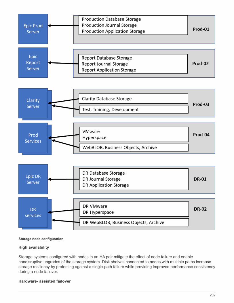
Storage node configuration
High availability
Storage systems configured with nodes in an HA pair mitigate the effect of node failure and enablenondisruptive upgrades of the storage system. Disk shelves connected to nodes with multiple paths increasestorage resiliency by protecting against a single-path failure while providing improved performance consistencyduring a node failover.
Hardware- assisted failover
239

Hardware-assisted failover minimizes storage node failover time by enabling the remote LAN module orservice processor module of one node to notify its partner of a node failure faster than a heartbeat-timeouttrigger, reducing the time elapsed before failover. When storage is virtualized, failover times improve becausecontroller identity does not need to move during failover. Only software disk ownership changes.
NetApp Support tools and services
NetApp offers a complete set of support tools and services. The NetApp AutoSupport tool should be enabledand configured on NetApp storage systems to call home if a hardware failure or system misconfigurationoccurs. For mission-critical environments, NetApp also recommends the SupportEdge Premium package,which provides access to operational expertise, extended support hours, and fast response times on partsreplacement.
All-flash optimized personality on AFF A300 and AFF A700 controllers
For the AFF solution to function properly, the environment variable bootarg.init.flash_optimized must
be set to true on both nodes in an HA pair of all-flash-optimized FAS80x0 systems. Platforms with the all-flash-optimized personality support only SSDs.
Volume configuration
Snapshot Copies
A nightly volume-level Snapshot schedule should be set for volumes that provide storage for the productiondatabase. Volume-level Snapshot copies can also be used as the source for cloning the production databasefor use in nonproduction environments such as development, test, and staging. NetApp has developedOnCommand WFA workflows for Epic that automate the backup of production databases and the refresh oftest environments. These workflows freeze and thaw the database for application-consistent Snapshot copies.The backup copies of production are automatically presented to test servers for support, release, and releasevalidation. These workflows can also be used for backup streaming and integrity checks.
Snapshot copies can be used to support the restore operations of Epic’s production database.
You can use SnapMirror to maintain Snapshot copies on storage systems separate from production.
For SAN volumes, disable the default Snapshot policy on each volume. These Snapshot copies are typicallymanaged by a backup application or by OnCommand WFA workflows. NetApp recommends turning on allefficiency settings to maximize disk utilization.
Volume affinity
To support concurrent processing, ONTAP assesses its available hardware on startup and divides itsaggregates and volumes into separate classes, called affinities. In general terms, volumes that belong to oneaffinity can be serviced in parallel with volumes that are in other affinities. In contrast, two volumes that are inthe same affinity often have to take turns waiting for scheduling time (serial processing) on the node’s CPU.
The AFF A300 and AFF A700 have a single aggregate affinity and four volume affinities per node. For bestnode utilization and use of volume affinity, the storage layout should be one aggregate per node and at leastfour volumes per node. Typically, eight volumes or LUNs are used for an Epic database.
LUN configuration
The document “Epic Database Storage Layout Recommendations” details the size and number of LUNs foreach database. It is important for the customer to review that with Epic support and finalize the number ofLUNs and LUN sizes; they might need to be adjusted slightly.
240
Starting with larger size LUNs is recommended because the size of the LUNs themselves has no cost tostorage. For ease of operation, make sure that the number of LUNs and initial size can grow well beyondexpected requirements after three years. Growing LUNs is much easier to manage than adding LUNs whenscaling. With thin provisioning on the LUN and volume, only storage used shows in the aggregate.
Use one LUN per volume for Epic production and for Clarity. For larger deployments, NetApp recommends 24to 32 LUNs for Epic databases.
Factors that determine the number of LUNs to use are:
• Overall size of the Epic DB after three years. For larger DBs, determine the maximum size of the LUN forthat OS and make sure that you have enough LUNs to scale. For example, if you need a 60TB Epicdatabase and the OS LUNs have a 4TB maximum, you would need 24 to 32 LUNs to provide scale andheadroom.
Epic requires database, journal, and application or system storage to be presented to databaseservers as LUNs through FC.
Deployment and configuration
Overview
The NetApp storage FlexPod deployment guidance provided in this document covers:
• Environments that use ONTAP
• Environments that use Cisco UCS blade and rack-mount servers
This document does not cover:
• Detailed deployment of FlexPod Datacenter environment. See FlexPod Datacenter with FC Cisco ValidatedDesign.
• Overview of Epic software environments, reference architectures, and integration best practices guidance.See NetApp TR-3928: NetApp Best Practices for Epic.
• Quantitative performance requirements and sizing guidance. See NetApp TR-3930: NetApp SizingGuidelines for Epic.
• Use of NetApp SnapMirror technologies to meet backup and disaster recovery requirements.
• Epic database backup and recovery, including SnapCenter.
• Generic NetApp storage deployment guidance.
• Deployment guidance for Clarity reporting environments. See NetApp TR-4590: Best Practice Guide forMicrosoft SQL Server with ONTAP.
This section describes the lab environment setup with infrastructure deployment best practices. The GenIOtool is used to simulate the Epic EHR application workload. This section lists the various infrastructurehardware and software components and the versions used.
Cabling diagram
The following figure illustrates the 16Gb FC/40GbE topology diagram for an Epic deployment.
241

Next: Infrastructure Hardware and Software Components.
Infrastructure hardware and software components
Always use the Interoperability Matrix Tool (IMT) to validate that all versions of software and firmware aresupported. The following table lists the infrastructure hardware and software components that were used intesting.
Layer Product family Version or release Details
Compute Cisco UCS 5108 One chassis
Cisco UCS blade servers 4 x B200 M5 Each with 18 CPU coresand 768GB RAMBIOS 2.2(8))
Cisco UCS VIC 4 x UCS 1340 VMware ESXi fNIC FCdriver: 1.6.0.34VMware ESXi eNICEthernet driver: 1.0.6.0
242

Layer Product family Version or release Details
2 x Cisco UCS FI 6332-16UP with CiscoUCSM 3.2 (2f)
Network Cisco Ethernet switches 7.0(3)I7(2) 2 x Cisco Nexus 9372PX-E
Storage network iSCSI: IP solution usingN9k
FI and UCS chassis
FC: Cisco MDS 9148S 8.2(2) Two Cisco 9148Sswitches
Storage 2 x NetApp AFF A700s ONTAP 9.3 GA 1 x 2-node cluster
2 x DS224C disk shelf
SSD 48 x 960GB
Software Hypervisor VMware vSphere ESXi6.5 U1
VMs RHEL 7.4
Hypervisor managementsystem
VMware vCenter Server6.5 U1 (VCSA)
vCenter Server Appliance
NetApp Virtual StorageConsole
VSC 7.0P1
SnapCenter SnapCenter 4.0
Cisco UCS Manager 3.2 (2f) *
Next: Base Infrastructure Configuration.
Base infrastructure configuration
Network connectivity
The following network connections must be in place before configuring the infrastructure:
• Link aggregation using port channels and virtual port channels is used throughout, enabling the design forhigher bandwidth and HA.
◦ Virtual port channel is used between the Cisco FI and Cisco Nexus switches.
◦ Each server has vNICs with redundant connectivity to the unified fabric. NIC failover is used betweenFI for redundancy.
◦ Each server has vHBAs with redundant connectivity to the unified fabric.
• The Cisco UCS FI are configured in end-host mode as recommended, providing dynamic pinning of vNICsto uplink switches.
Storage connectivity
The following storage connections must be in place before configuring the infrastructure:
• Storage ports ifgroups (vPC)
243
• 10G link to switch N9k-A
• 10G link to switch N9k-B
• In- band management (active-passive bond):
◦ 1G link to management switch N9k-A
◦ 1G link to management switch N9k-B
• 16G FC end-to-end connectivity through Cisco MDS switches. Single initiator zoning configured.
• FC SAN boot to fully achieve stateless computing. Servers are booted from LUNs in the boot volumehosted on the AFF storage cluster.
• All Epic workloads are hosted on FC LUNs, which are spread across the storage controller nodes.
Host software
The following software must be installed:
• ESXi is installed on the Cisco UCS blades.
• vCenter is installed and configured, with all the hosts registered in vCenter.
• VSC is installed and registered in vCenter.
• A NetApp cluster is configured.
Next: Cisco UCS Blade Server and Switch Configuration
Cisco UCS blade server and switch configuration
The FlexPod for Epic software is designed with fault tolerance at every level. There is no single point of failurein the system. We recommend the use of hot spare blade servers for optimal performance.
This document is intended to provide high-level guidance on the basic configuration of a FlexPod environmentfor Epic software. In this section, we present high-level steps with some examples to prepare the Cisco UCScompute platform element of the FlexPod configuration. A prerequisite for this guidance is that the FlexPodconfiguration is racked, powered, and cabled per the instructions in the FlexPod Datacenter with FC Storage.
Cisco Nexus switch configuration
A fault-tolerant pair of Cisco Nexus 9300 Series Ethernet switches is deployed for the solution. These switchesshould be cabled as described in the section “Cabling Diagram.” The Cisco Nexus configuration makes surethat Ethernet traffic flows are optimized for the Epic application.
1. After the initial setup and licensing are completed, run the following commands to set global configurationparameters on both switches:
244
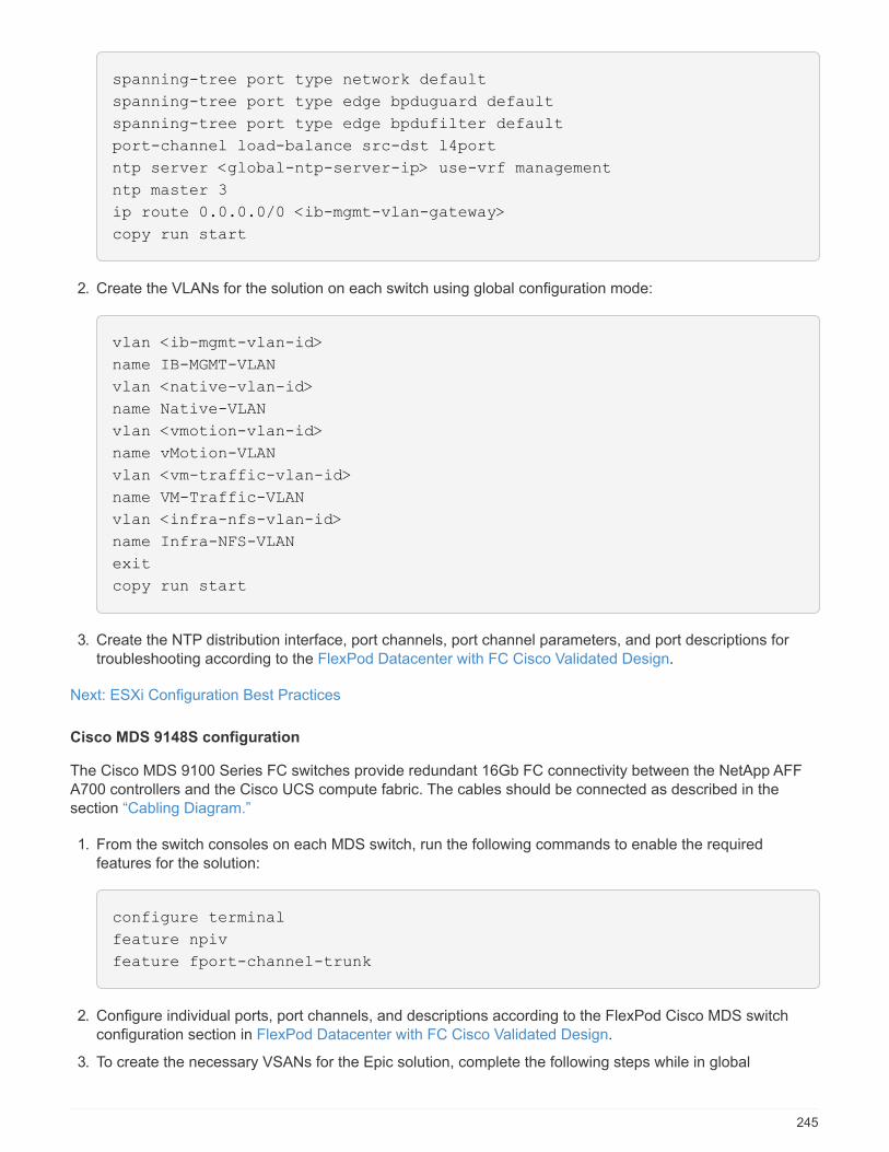
spanning-tree port type network default
spanning-tree port type edge bpduguard default
spanning-tree port type edge bpdufilter default
port-channel load-balance src-dst l4port
ntp server <global-ntp-server-ip> use-vrf management
ntp master 3
ip route 0.0.0.0/0 <ib-mgmt-vlan-gateway>
copy run start
2. Create the VLANs for the solution on each switch using global configuration mode:
vlan <ib-mgmt-vlan-id>
name IB-MGMT-VLAN
vlan <native-vlan-id>
name Native-VLAN
vlan <vmotion-vlan-id>
name vMotion-VLAN
vlan <vm-traffic-vlan-id>
name VM-Traffic-VLAN
vlan <infra-nfs-vlan-id>
name Infra-NFS-VLAN
exit
copy run start
3. Create the NTP distribution interface, port channels, port channel parameters, and port descriptions fortroubleshooting according to the FlexPod Datacenter with FC Cisco Validated Design.
Next: ESXi Configuration Best Practices
Cisco MDS 9148S configuration
The Cisco MDS 9100 Series FC switches provide redundant 16Gb FC connectivity between the NetApp AFFA700 controllers and the Cisco UCS compute fabric. The cables should be connected as described in thesection “Cabling Diagram.”
1. From the switch consoles on each MDS switch, run the following commands to enable the requiredfeatures for the solution:
configure terminal
feature npiv
feature fport-channel-trunk
2. Configure individual ports, port channels, and descriptions according to the FlexPod Cisco MDS switchconfiguration section in FlexPod Datacenter with FC Cisco Validated Design.
3. To create the necessary VSANs for the Epic solution, complete the following steps while in global
245
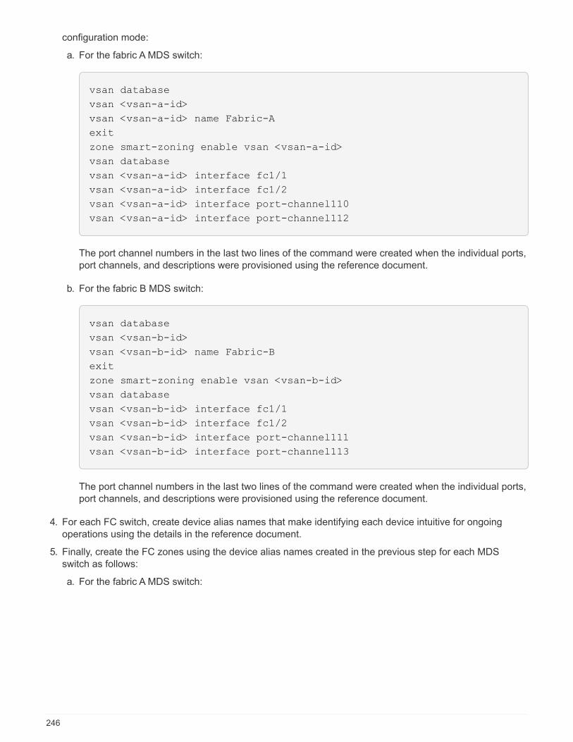
configuration mode:
a. For the fabric A MDS switch:
vsan database
vsan <vsan-a-id>
vsan <vsan-a-id> name Fabric-A
exit
zone smart-zoning enable vsan <vsan-a-id>
vsan database
vsan <vsan-a-id> interface fc1/1
vsan <vsan-a-id> interface fc1/2
vsan <vsan-a-id> interface port-channel110
vsan <vsan-a-id> interface port-channel112
The port channel numbers in the last two lines of the command were created when the individual ports,port channels, and descriptions were provisioned using the reference document.
b. For the fabric B MDS switch:
vsan database
vsan <vsan-b-id>
vsan <vsan-b-id> name Fabric-B
exit
zone smart-zoning enable vsan <vsan-b-id>
vsan database
vsan <vsan-b-id> interface fc1/1
vsan <vsan-b-id> interface fc1/2
vsan <vsan-b-id> interface port-channel111
vsan <vsan-b-id> interface port-channel113
The port channel numbers in the last two lines of the command were created when the individual ports,port channels, and descriptions were provisioned using the reference document.
4. For each FC switch, create device alias names that make identifying each device intuitive for ongoingoperations using the details in the reference document.
5. Finally, create the FC zones using the device alias names created in the previous step for each MDSswitch as follows:
a. For the fabric A MDS switch:
246
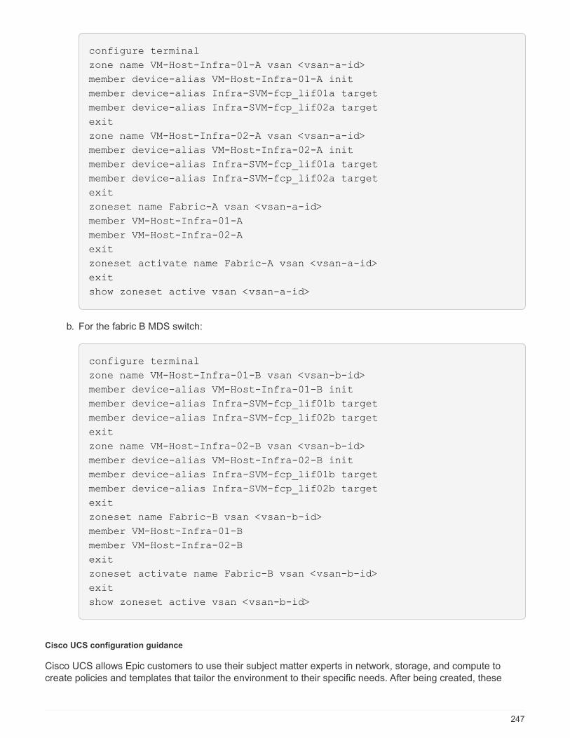
configure terminal
zone name VM-Host-Infra-01-A vsan <vsan-a-id>
member device-alias VM-Host-Infra-01-A init
member device-alias Infra-SVM-fcp_lif01a target
member device-alias Infra-SVM-fcp_lif02a target
exit
zone name VM-Host-Infra-02-A vsan <vsan-a-id>
member device-alias VM-Host-Infra-02-A init
member device-alias Infra-SVM-fcp_lif01a target
member device-alias Infra-SVM-fcp_lif02a target
exit
zoneset name Fabric-A vsan <vsan-a-id>
member VM-Host-Infra-01-A
member VM-Host-Infra-02-A
exit
zoneset activate name Fabric-A vsan <vsan-a-id>
exit
show zoneset active vsan <vsan-a-id>
b. For the fabric B MDS switch:
configure terminal
zone name VM-Host-Infra-01-B vsan <vsan-b-id>
member device-alias VM-Host-Infra-01-B init
member device-alias Infra-SVM-fcp_lif01b target
member device-alias Infra-SVM-fcp_lif02b target
exit
zone name VM-Host-Infra-02-B vsan <vsan-b-id>
member device-alias VM-Host-Infra-02-B init
member device-alias Infra-SVM-fcp_lif01b target
member device-alias Infra-SVM-fcp_lif02b target
exit
zoneset name Fabric-B vsan <vsan-b-id>
member VM-Host-Infra-01-B
member VM-Host-Infra-02-B
exit
zoneset activate name Fabric-B vsan <vsan-b-id>
exit
show zoneset active vsan <vsan-b-id>
Cisco UCS configuration guidance
Cisco UCS allows Epic customers to use their subject matter experts in network, storage, and compute tocreate policies and templates that tailor the environment to their specific needs. After being created, these
247

policies and templates can be combined into service profiles that deliver consistent, repeatable, reliable, andfast deployments of Cisco blade and rack servers.
Cisco UCS provides three methods for managing a Cisco UCS system (called a domain):
• Cisco UCS Manager HTML 5 GUI
• Cisco UCS CLI
• Cisco UCS Central for multidomain environments
The following figure shows a sample screenshot of the SAN node in Cisco UCS Manager.
In larger deployments, independent Cisco UCS domains can be built for additional fault tolerance at the majorEpic functional component level.
In highly fault-tolerant designs with two or more data centers, Cisco UCS Manager plays a key role in settingglobal policy and global service profiles for consistency between hosts throughout the enterprise.
Complete the following procedures to set up the Cisco UCS compute platform. Perform these procedures afterthe Cisco UCS B200 M5 blade servers are installed in the Cisco UCS 5108AC blade chassis. Also, the cablingrequirements must be completed as described in the section “Cabling Diagram.”
1. Upgrade the Cisco UCS Manager firmware to version 3.2(2f) or later.
2. Configure the reporting, call home features, and NTP settings for the domain.
3. Configure the server and uplink ports on each fabric interconnect.
4. Edit the chassis discovery policy.
5. Create the address pools for out-of-band management, UUIDs, MAC address, servers, WWNN, andWWPN.
6. Create the Ethernet and FC uplink port channels and VSANs.
7. Create policies for SAN connectivity, network control, server pool qualification, power control, server BIOS,
248

and default maintenance.
8. Create vNIC and vHBA templates.
9. Create vMedia and FC boot policies.
10. Create service profile templates and service profiles for each Epic platform element.
11. Associate the service profiles with the appropriate blade servers.
For the detailed steps to configure each key element of the Cisco UCS service profiles for FlexPod, see theFlexPod Datacenter with FC Cisco Validated Design document.
For Epic deployments, Cisco recommends a range of service profile types, based on the Epic elements beingdeployed. By using server pools and server pool qualification, customers can identify and automate thedeployment of service profiles to particular host roles. A sample list of service profiles are as follows:
• For the Epic Chronicle Caché database hosts:
◦ Production host service profile
◦ Reporting service host profile
◦ Disaster recovery host service profile
◦ Hot spare host service profile
• For Epic Hyperspace hosts:
◦ VDI host service profile
◦ Citrix XenApp host service profile
◦ Disaster recovery host service profile
◦ Hot spare host service profile
• For the Epic Cogito and Clarity database hosts:
◦ Database host service profile (Clarity RDBMS and business objects)
• For the Epic Services hosts:
◦ Application host profile (print format and relay, communications, web BLOB, and so on)
ESXi configuration best practices
For the ESXi host-side configuration, see the InterSystems Best practices for VMware. Configure the VMwarehosts as you would to run any enterprise database workload:
• Virtual Storage Console (VSC) for VMware vSphere checks and sets the ESXi host multipathing settingsand HBA timeout settings that work best with NetApp storage systems. The values that VSC sets arebased on rigorous internal testing by NetApp.
• For the best storage performance, customers should consider using VMware vStorage APIs for ArrayIntegration (VAAI)–capable storage hardware. The NetApp Plug-In for VAAI is a software library thatintegrates the VMware Virtual Disk Libraries that are installed on the ESXi host. The VMware VAAIpackage enables the offloading of certain tasks from the physical hosts to the storage array.
You can perform tasks such as thin provisioning and hardware acceleration at the array level to reduce theworkload on the ESXi hosts. The copy offload feature and space reservation feature improve theperformance of VSC operations. You can download the plug-in installation package and obtain theinstructions for installing the plug-in from the NetApp Support site.
249

VSC sets ESXi host timeouts, multipath settings, and HBA timeout settings and other values for optimalperformance and successful failover of the NetApp storage controllers.
1. From the VMware vSphere Web Client home page, click vCenter > Hosts.
2. Right-click a host and then select Actions > NetApp VSC > Set Recommended Values.
3. In the NetApp Recommended Settings dialog box, select the values that work best with your system.
The standard recommended values are set by default.
4. Click OK.
Next: NetApp Configuration.
NetApp configuration
NetApp storage deployed for Epic software environments uses storage controllers in a high-availability (HA)pair configuration. Storage is required to be presented from both controllers to Epic database servers over theFC Protocol (FCP). The configuration presents storage from both controllers to evenly balance the applicationload during normal operation.
Epic requirements for separating production workloads into fault domains call pools is detailed in the Epic All-Flash Reference Architecture Strategy Handbook. Read this document in detail before continuing. Note that anONTAP node can be considered a separate pool of storage.
ONTAP configuration
This section describes a sample deployment and provisioning procedures using the relevant ONTAPcommands. The emphasis is to show how storage is provisioned to implement the storage layoutrecommended by NetApp, which uses an HA controller pair. One of the major advantages with ONTAP is theability to scale out without disturbing the existing HA pairs.
Epic provides detailed storage performance requirements and layout guidance, including the storagepresentation and host-side storage layout, to each customer. Epic will provide these custom documents:
• The Epic Hardware Configuration Guide used for sizing during presales.
• The Epic Database Storage Layout Recommendations used for LUN and volume layout duringdeployment.
A customer-specific storage system layout and configuration that meet these requirements must be developedby referring to the Epic Database Storage Layout Recommendations.
250

The following example describes the deployment of an AFF A700 storage system supporting a 10TB database.The provisioning parameters of the storage used to support the production database in the exampledeployment are shown in the table below.
Parameter Controller 1 Controller 2
Controller host name Prod1-01 Prod1-02
Aggregates ONTAP aggr0_prod1-01 (ADP 11-partitions) aggr0_prod1-02 (ADP 11-partitions)
Aggregates data Prod1-01_aggr1 (22-partitions) Prod1-02_aggr1 (22-partitions)
Volumes (size) epic_prod_db1 (2TB)epic_prod_db2 (2TB)epic_prod_db3 (2TB)epic_prod_db4 (2TB)epic_prod_db5 (2TB)epic_prod_db6 (2TB)epic_prod_db7 (2TB)epic_prod_db8 (2TB)epic_prod_inst (1TB)epic_prod_jrn1 (1200GB)epic_prod_jrn2 (1200GB)
epic_report_db1 (2TB)epic_report_db2 (2TB)epic_report_db3 (2TB)epic_report_db4 (2TB)epic_report_db5 (2TB)epic_report_db6 (2TB)epic_report_db7 (2TB)epic_report_db8 (2TB)epic_report_inst (1TB)epic_report_jrn1 (1200GB)epic_report_jrn2 (1200GB)
LUN paths (size) /epic_prod_db1/epic_prod_db1(1.4TB)/epic_prod_db2/epic_prod_db2(1.4TB)/epic_prod_db3/epic_prod_db3(1.4TB)/epic_prod_db4/epic_prod_db4(1.4TB)/epic_prod_db5/epic_prod_db5(1.4TB)/epic_prod_db6/epic_prod_db6(1.4TB)/epic_prod_db7/epic_prod_db7(1.4TB)/epic_prod_db8/epic_prod_db8(1.4TB)/epic_prod_inst/epic_prod_inst(700GB)/epic_prod_jrn1/epic_prod_jrn1(800GB)/epic_prod_jrn2/epic_prod_jrn2(800GB)
/epic_prod_db1/epic_report_db1(1.4TB)/epic_prod_db2/epic_report_db2(1.4TB)/epic_prod_db3/epic_report_db3(1.4TB)/epic_prod_db4/epic_report_db4(1.4TB)/epic_prod_db5/epic_report_db5(1.4TB)/epic_prod_db6/epic_report_db6(1.4TB)/epic_prod_db7/epic_report_db7(1.4TB)/epic_prod_db8/epic_report_db8(1.4TB)/epic_report_inst/epic_report_inst(700GB)/epic_report_jrn1/epic_report_jrn1(800GB)/epic_report_jrn2/epic_report_jrn2(800GB)
VMs RHEL RHEL
LUN type Linux (mounted as RDMs directlyby the RHEL VMs using FC)
Linux (mounted as RDMs directlyby the RHEL VMs using FC)
FCP initiator group (igroup) name ig_epic_prod (Linux) ig_epic_report (Linux)
Host operating system VMware VMware
Epic database server host name epic_prod epic_report
251

Parameter Controller 1 Controller 2
SVM svm_prod svm_ps (production services)svm_cifs
ONTAP licenses
After the storage controllers are set up, apply licenses to enable ONTAP features recommended by NetApp.The licenses necessary for Epic workloads are FC, CIFS, Snapshot, SnapRestore, FlexClone, and SnapMirror.
To apply the licenses, open NetApp System Manager and go to Configuration-Licenses and add appropriatelicenses. Alternatively, run the following command to add licenses using the CLI:
license add -license-code <code>
AutoSupport configuration
The AutoSupport tool sends summary support information to NetApp through HTTPS. To configureAutoSupport, run the following ONTAP commands:
autosupport modify -node * -state enable
autosupport modify -node * -mail-hosts <mailhost.customer.com>
autosupport modify -node prod1-01 -from [email protected]
autosupport modify -node prod1-02 -from [email protected]
autosupport modify -node * -to [email protected]
autosupport modify -node * -support enable
autosupport modify -node * -transport https
autosupport modify -node * -hostnamesubj true
Hardware-assisted takeover configuration
On each node, enable hardware-assisted takeover to minimize the time required to initiate a takeover followingthe unlikely failure of a controller. To configure hardware-assisted takeover, complete the following steps:
1. Run the following ONTAP command. Set the partner address option to the IP address of the managementport for prod1-01.
EPIC::> storage failover modify -node prod1-01 -hwassist-partner-ip
<prod1-02-mgmt-ip>
2. Run the following ONTAP command. Set the partner address option to the IP address of the managementport for cluster1-02.
EPIC::> storage failover modify -node prod1-02 -hwassist-partner-ip
<prod1-01-mgmt-ip>
252
3. Run the following ONTAP command to enable hardware-assisted takeover on both prod1-01 and prod1-02HA controller pair:
EPIC::> storage failover modify -node prod1-01 -hwassist true
EPIC::> storage failover modify -node prod1-02 -hwassist true
ONTAP storage provisioning
The storage provisioning workflow is as follows:
1. Create the aggregates.
2. Create a storage virtual machine (SVM).
After aggregate creation, the next step is to create an SVM. In ONTAP the storage is virtualized in the formof an SVM. Hosts and clients no longer access the physical storage hardware. Create an SVM using theSystem Manager GUI or the CLI.
3. Create FC LIFs.
Ports and storage are provisioned on the SVM and presented to hosts and clients through virtual portscalled logical interfaces (LIFs).
You can run all the workloads in one SVM with all the protocols. For Epic, NetApp recommends having anSVM for production FC and one SVM for CIFS.
a. Enable and start FC from SVM settings in the System Manager GUI.
b. Add FC LIFs to the SVM. Configure multiple FC LIFs on each storage node, depending on the numberof paths architected per LUN.
4. Create initiator groups (igroups).
Igroups are tables of FC- protocol host WWPNs or iSCSI host node names that define which LUNs areavailable to the hosts. For example, if you have a host cluster, you can use igroups to ensure that specificLUNs are visible to only one host in the cluster or to all the hosts in the cluster. You can define multipleigroups and map them to LUNs to control which initiators have access to LUNs.
Create FC igroups of type VMware using the System Manager GUI or the CLI.
5. Create zones on the FC switch.
An FC or FCoE zone is a logical grouping of one or more ports in a fabric. For devices to be able to seeeach other, connect, create sessions with one another, and communicate, both ports need to have acommon zone membership. Single initiator zoning is recommended.
a. Create zones on the switch and add the NetApp target and the Cisco UCS blade initiators in the zone.
NetApp best practice is single initiator zoning. Each zone contains only one initiator and the targetWWPN on the controller. The zones use the port name and not the node name.
6. Create volumes and LUNs.
a. Create volumes to host the LUNs using the System Manager GUI (or the CLI). All the storage efficiencysettings and data protection are set by default on the volume. You can optionally turn on volume
253
encryption and QoS policies on the volume using the vol modify command. Note that the volumesneed to be large enough to contain the LUNs and Snapshot copies. To protect the volume from
capacity issues, enable the autosize and autodelete options. After the volumes are created,create the LUNs that will house the Epic workload.
b. Create FC LUNs of type VMware that will host the Epic workload using the System Manager GUI (orthe CLI). NetApp has simplified LUN creation in a very easy to follow wizard in System Manager.
You can also use VSC to provision volumes and LUNs. See the FC Configuration for ESX ExpressGuide.
See the SAN Administration and the SAN Configuration Guide if you are not using VSC.
7. Map the LUNs to the igroups.
After the LUNs and igroups are created, map the LUNs to the relevant igroups that give the desired hostsaccess to the LUNs.
The LUNs are now ready to be discovered and mapped to the ESXi servers. Refresh the storage on theESXi hosts and add the newly discovered LUNs.
Next: GenIO Tool.
GenIO tool
GenIO is the storage-performance testing tool used by Epic. It simulates the workload generated by anInterSystems Caché database used in an Epic production environment, including the write-cycle patterns. It isavailable as a command-line application on various host operating systems on which Caché is deployed.Always test with the latest copy of the GenIO tool from Epic.
A performance test run involves executing the GenIO application on the production Epic database host with aset of I/O parameters. These parameters simulate the I/O patterns for the customer’s Epic environment,including the write cycles.
Epic pushes the controller past the 100% full load detailed in the hardware configuration guide to determinehow much headroom is on the controller. Epic also runs a full load test and simulates backup operations.
Epic server support representatives use it to verify storage performance from the host perspective. NetApp hasalso used GenIO to validate the performance of NetApp storage systems in the lab.
Where to find additional information
To learn more about the information that is described in this document, see the following documents orwebsites:
FlexPod design zone
• FlexPod design zone
https://www.cisco.com/c/en/us/solutions/design-zone/data-center-design-guides/flexpod-design-guides.html
• FlexPod DC with FC Storage (MDS Switches) Using NetApp AFF, vSphere 6.5U1, and Cisco UCSManager
254
https://www.cisco.com/c/en/us/td/docs/unified_computing/ucs/UCS_CVDs/flexpod_esxi65u1_n9fc.html
• Cisco Best Practices with Epic on Cisco UCS
https://www.cisco.com/c/dam/en_us/solutions/industries/healthcare/Epic_on_UCS_tech_brief_FNL.pdf
NetApp technical reports
• TR-3929: Reallocate Best Practices Guide
https://fieldportal.netapp.com/content/192896
• TR-3987: Snap Creator Framework Plug-In for InterSystems Caché
https://fieldportal.netapp.com/content/248308
• TR-3928: NetApp Best Practices for Epic
https://fieldportal.netapp.com/?oparams=68646
• TR-4017: FC SAN Best Practices
http://media.netapp.com/documents/tr-4017.pdf
• TR-3446: SnapMirror Async Overview and Best Practices Guide
http://media.netapp.com/documents/tr-3446.pdf
ONTAP documentation
• NetApp Product Documentation
https://www.netapp.com/us/documentation/index.aspx
• Virtual Storage Console (VSC) for vSphere documentation
https://mysupport.netapp.com/documentation/productlibrary/index.html?productID=30048
• ONTAP 9 Documentation Center
http://docs.netapp.com/ontap-9/index.jsp
• FC Express Guide for ESXi
http://docs.netapp.com/ontap-9/topic/com.netapp.doc.exp-fc-esx-cpg/home.html
• All ONTAP 9.3 Documentation
https://mysupport.netapp.com/documentation/docweb/index.html?productID=62579
◦ Software Setup Guide
http://docs.netapp.com/ontap-9/topic/com.netapp.doc.dot-cm-ssg/home.html?lang=dot-cm-ssg
◦ Disks and Aggregates Power Guide
255
http://docs.netapp.com/ontap-9/topic/com.netapp.doc.dot-cm-psmg/home.html?lang=dot-cm-psmg
◦ SAN Administration Guide
http://docs.netapp.com/ontap-9/topic/com.netapp.doc.dot-cm-sanag/home.html?lang=dot-cm-sanag
◦ SAN Configuration Guide
http://docs.netapp.com/ontap-9/topic/com.netapp.doc.dot-cm-sanconf/home.html?lang=dot-cm-sanconf
◦ FC Configuration for Red Hat Enterprise Linux Express Guide
http://docs.netapp.com/ontap-9/topic/com.netapp.doc.exp-fc-rhel-cg/home.html?lang=exp-fc-rhel-cg
◦ FC Configuration for Windows Express Guide
http://docs.netapp.com/ontap-9/topic/com.netapp.doc.exp-fc-cpg/home.html?lang=exp-fc-cpg
◦ FC SAN Optimized AFF Setup Guide
http://docs.netapp.com/ontap-9/topic/com.netapp.doc.cdot-fcsan-optaff-sg/home.html?lang=cdot-fcsan-optaff-sg
◦ High-Availability Configuration Guide
http://docs.netapp.com/ontap-9/topic/com.netapp.doc.dot-cm-hacg/home.html?lang=dot-cm-hacg
◦ Logical Storage Management Guide
http://docs.netapp.com/ontap-9/topic/com.netapp.doc.dot-cm-vsmg/home.html?lang=dot-cm-vsmg
◦ Performance Management Power Guide
http://docs.netapp.com/ontap-9/topic/com.netapp.doc.pow-perf-mon/home.html?lang=pow-perf-mon
◦ SMB/CIFS Configuration Power Guide
http://docs.netapp.com/ontap-9/topic/com.netapp.doc.pow-cifs-cg/home.html?lang=pow-cifs-cg
◦ SMB/CIFS Reference
http://docs.netapp.com/ontap-9/topic/com.netapp.doc.cdot-famg-cifs/home.html?lang=cdot-famg-cifs
◦ Data Protection Power Guide
http://docs.netapp.com/ontap-9/topic/com.netapp.doc.pow-dap/home.html?lang=pow-dap
◦ Data Protection Tape Backup and Recovery Guide
http://docs.netapp.com/ontap-9/topic/com.netapp.doc.dot-cm-ptbrg/home.html?lang=dot-cm-ptbrg
◦ NetApp Encryption Power Guide
http://docs.netapp.com/ontap-9/topic/com.netapp.doc.pow-nve/home.html?lang=pow-nve
◦ Network Management Guide
256

http://docs.netapp.com/ontap-9/topic/com.netapp.doc.dot-cm-nmg/home.html?lang=dot-cm-nmg
◦ Commands: Manual Page Reference for ONTAP 9.3
http://docs.netapp.com/ontap-9/topic/com.netapp.doc.dot-cm-cmpr-930/home.html?lang=dot-cm-cmpr-930
Cisco Nexus, MDS, Cisco UCS, and Cisco UCS Manager guides
• Cisco UCS Servers Overview
https://www.cisco.com/c/en/us/products/servers-unified-computing/index.html
• Cisco UCS Blade Servers Overview
https://www.cisco.com/c/en/us/products/servers-unified-computing/ucs-b-series-blade-servers/index.html
• Cisco UCS B200 M5 Datasheet
https://www.cisco.com/c/en/us/products/servers-unified-computing/ucs-b-series-blade-servers/index.html
• Cisco UCS Manager Overview
https://www.cisco.com/c/en/us/products/servers-unified-computing/ucs-manager/index.html
• Cisco UCS Manager 3.2(3a) Infrastructure Bundle (requires Cisco.com authorization)
https://software.cisco.com/download/home/283612660/type/283655658/release/3.2%25283a%2529
• Cisco Nexus 9300 Platform Switches
https://www.cisco.com/c/en/us/products/collateral/switches/nexus-9000-series-switches/datasheet-c78-736967.html
• Cisco MDS 9148S FC Switch
https://www.cisco.com/c/en/us/products/storage-networking/mds-9148s-16g-multilayer-fabric-switch/index.html
Acknowledgements
The following people contributed to the writing of this guide.
• Ganesh Kamath, Technical Marketing Engineer, NetApp
• Atul Bhalodia, Technical Marketing Engineer, NetApp
• Ketan Mota, Product Manager, NetApp
• Jon Ebmeier, Cisco
• Mike Brennan, Cisco
257
FlexPod for Epic Performance Testing
TR-4784: FlexPod for Epic Performance Testing
Brian O’Mahony,Ganesh KamathAtul BhalodiaBrandon Agee
In partnership with:
Objective
The objective of this report is to highlight the performance of FlexPod with NetApp All Flash A300 and A700storage systems with Epic Healthcare workloads.
Epic Hardware configuration guide
For acceptable end-user performance, Epic production and disaster recovery operational database (ODB)target- read and target- write time requirements are as follows:
• For randomly placed reads to database files measured at the system call level:
◦ Average read latencies must be 2ms or less
◦ 99% of read latencies must be below 60ms
◦ 99.9% of read latencies must be below 200ms
◦ 99.99% of read latencies must be below 600ms
• For randomly placed writes to database files measured at the system call level:
◦ Average write latencies must be 1ms or less depending on size
These requirements change with time. Epic prepares a customer- specific Epic HardwareConfiguration Guide (HCG). Refer to your HCG for details on requirements.
Overall solution benefits
By running an Epic environment on a FlexPod architectural foundation, healthcare organizations can see animprovement in staff productivity and a decrease in capital and operating expenses. FlexPod Datacenter withEpic delivers several benefits specific to the healthcare industry:
• Simplified operations and lowered costs. Eliminate the expense and complexity of legacy proprietaryRISC/UNIX platforms by replacing them with a more efficient and scalable shared resource capable ofsupporting clinicians wherever they are. This solution delivers higher resource utilization for greater ROI.
• Quicker deployment of infrastructure. Whether it’s in an existing data center or in a remote location, theintegrated and tested design of FlexPod Datacenter with Epic enables customers to have newinfrastructure up and running in less time with less effort.
• Scale-out architecture. Scale SAN and NAS from terabytes to tens of petabytes without reconfiguring
258
running applications.
• Nondisruptive operations. Perform storage maintenance, hardware lifecycle operations, and softwareupgrades without interrupting business operations.
• Secure multitenancy. FlexPod supports the needs of shared virtualized server and storage infrastructure,enabling secure multitenancy of facility-specific information, particularly if you are hosting multipleinstances of databases and software.
• Pooled resource optimization. FlexPod can help reduce physical server and storage controller countsand load- balance workload demands. It can also boost utilization while improving performance.
• Quality of service (QoS). FlexPod offers QoS on the entire stack. Industry-leading QoS storage policiesenable differentiated service levels in a shared environment. These policies enable optimal performance forworkloads and help isolate and control runaway applications.
• Storage efficiency. Reduce storage costs with the NetApp 7:1 storage efficiency guarantee.
• Agility. The industry-leading workflow automation, orchestration, and management tools offered byFlexPod systems allow IT to be far more responsive to business requests. These business requests canrange from Epic backup and provisioning of additional test and training environments to analytics databasereplications for population health management initiatives.
• Productivity. Quickly deploy and scale this solution for optimal clinician end-user experiences.
• Data Fabric. The NetApp Data Fabric architecture weaves data together across sites, beyond physicalboundaries, and across applications. The NetApp Data Fabric is built for data-driven enterprises in a data-centric world. Data is created and used in multiple locations, and it often must be leveraged and sharedwith other locations, applications, and infrastructures. Customers want a way to manage data that isconsistent and integrated. It provides a way to manage data that puts IT in control and simplifies ever-increasing IT complexity.
Cisco Unified Computing System, Cisco Nexus and MDS Switching, and ONTAP all-flash storage
The FlexPod for Epic Healthcare delivers the performance, efficiency, manageability, scalability, and dataprotection that IT organizations need to meet for the most stringent Epic requirements. By accelerating Epicproduction database performance and by reducing application deployment time from months to weeks,FlexPod helps organizations maximize the potential of their Epic investment.
Cisco Unified Computing System
As a self-integrating, self-aware system, Cisco Unified Computing System (UCS) consists of a singlemanagement domain interconnected with a unified I/O infrastructure. The Cisco UCS for Epic environmentshas been aligned with Epic infrastructure recommendations and best practices to help make sure thatinfrastructure can deliver critical patient information with maximum availability.
The foundation of Epic on the Cisco UCS architecture is Cisco UCS technology with its integrated systemsmanagement, Intel Xeon processors, and server virtualization. These integrated technologies solve data-center challenges and enable you to meet your goals for data- center design for Epic. Cisco UCS unifies LAN,SAN, and systems management into one simplified link for rack servers, blade servers, and virtual machines.The Cisco UCS is an end-to-end I/O architecture that incorporates Cisco Unified Fabric and Cisco fabricextender (FEX) technology to connect every component in the Cisco UCS with a single network fabric and asingle network layer.
The system is designed as a single virtual blade chassis that incorporates and scales across multiple bladechassis. The system implements a radically simplified architecture that eliminates the multiple redundantdevices that populate traditional blade server chassis and result in layers of complexity. Examples includeEthernet switches, Fibre Channel switches, and chassis management modules. The Cisco UCS contains aredundant pair of Cisco fabric interconnects that provide a single point of management and a single point of
259
control for all I/O traffic.
The Cisco UCS uses service profiles to help ensure that virtual servers in the UCS infrastructure areconfigured correctly. Service profiles include critical server information about the server identity such as LANand SAN addressing, I/O configurations, firmware versions, boot order, network VLAN, physical port, andquality-of-service (QoS) policies. Service profiles can be dynamically created and associated with any physicalserver in the system within minutes rather than within hours or days. The association of service profiles withphysical servers is performed as a single, simple operation that enables migration of identities between serversin the environment without any physical configuration changes. It facilitates rapid bare-metal provisioning ofreplacements for failed servers.
Using service profiles helps to ensure that servers are configured consistently throughout the enterprise. Whenusing multiple Cisco UCS management domains, UCS Central can use global service profiles to synchronizeconfiguration and policy information across domains. If maintenance is required in one domain, the virtualinfrastructure can be migrated to another domain. Therefore, applications continue to run with high availabilityeven when a single domain is offline.
Cisco UCS has been extensively tested with Epic over a multiyear period to demonstrate that it meets serverconfiguration requirements. Cisco UCS is a supported server platform, as listed in customers’ “Epic HardwareConfiguration Guide.”
Cisco Nexus and Cisco MDS Ethernet and Fibre Channel switching
Cisco Nexus switches and MDS multilayer directors provide enterprise-class connectivity and SANconsolidation. Cisco multiprotocol storage networking reduces business risk by providing flexibility and options.Supported protocols include Fibre Channel (FC), Fibre Connection (FICON), FC over Ethernet (FCoE), SCSIover IP (iSCSI), and FC over IP (FCIP).
Cisco Nexus switches offer one of the most comprehensive data- center- network feature sets in a singleplatform. They deliver high performance and density for both the data center and the campus core. They alsooffer a full feature set for data- center aggregation, end-of-row deployments, and data center interconnectdeployments in a highly resilient, modular platform.
The Cisco UCS integrates computing resources with Cisco Nexus switches and a unified I/O fabric thatidentifies and handles different types of network traffic, including storage I/O, streamed desktop traffic,management, and access to clinical and business applications.
In summary, the Cisco UCS provides the following important advantages for Epic deployments:
• Infrastructure scalability. Virtualization, efficient power and cooling, cloud scale with automation, highdensity, and performance all support efficient data- center growth.
• Operational continuity. The design integrates hardware, NX-OS software features, and management tosupport zero-downtime environments.
• Transport flexibility. Incrementally adopt new networking technologies with a cost-effective solution.
Together, Cisco UCS with Cisco Nexus switches and MDS multilayer directors provide a compelling computer,networking, and SAN connectivity solution for Epic.
NetApp all-flash storage systems
NetApp AFF systems address enterprise storage requirements with high performance, superior flexibility, andbest-in-class data management. Built on ONTAP data management software, AFF systems speed up yourbusiness without compromising the efficiency, reliability, or flexibility of your IT operations. With enterprise-grade all-flash arrays, AFF systems accelerate, manage, and protect your business-critical data and enable an
260

easy and risk-free transition to flash media for your data center.
Designed specifically for flash, AFF A-series all-flash systems deliver industry-leading performance, capacity,density, scalability, security, and network connectivity in a dense form factor. With the addition of a new entry-level system, the new AFF A- series family extends enterprise-grade flash to midsize businesses. At up toseven million IOPS per cluster with sub- millisecond latency, the AFF A series is the fastest family of all-flasharrays, built on a true unified scale-out architecture.
With the AFF A series, you can complete twice the work at half the latency relative to the previous generationof AFF systems. The members of the AFF A series are the industry’s first all-flash arrays that provide both40Gb Ethernet (40GbE) and 32Gb Fibre Channel (FC) connectivity. Therefore, they eliminate the bandwidthbottlenecks that are increasingly moving from storage to the network as flash becomes faster and faster.
NetApp has taken the lead for all-flash storage innovations with the latest solid-state-drive (SSD) technologies.As the first all-flash array to support 15TB SSDs, AFF systems, with the introduction of the A series, alsobecome the first to use multistream write SSDs. Multistream write capability significantly increases the usablecapacity of SSDs.
NetApp ONTAP Flash Essentials is the power behind the performance of All Flash FAS. ONTAP is industry-leading data management software. However, it is not widely known that ONTAP, with its NetApp WAFL (WriteAnywhere File Layout) file system, is natively optimized for flash media.
ONTAP Flash Essentials optimizes SSD performance and endurance with the following features, amongothers:
• NetApp data-reduction technologies, including inline compression, inline deduplication, and inline datacompaction, can provide significant space savings. Savings can be further increased by using NetAppSnapshot and NetApp FlexClone technologies. Studies based on customer deployments have shown thatthese data-reduction technologies have enabled space savings of up to 933 times.
• Coalesced writes to free blocks maximize performance and flash media longevity.
• Flash-specific read-path optimizations provide consistent low latency.
• Parallelized processing handles more requests at once.
• Software-defined access to flash maximizes deployment flexibility.
• Advanced Disk Partitioning (ADP) increases storage efficiency and further increases usable capacity byalmost 20%.
• The Data Fabric enables live workload migration between flash and hard-disk-drive tiers on the premisesor to the cloud.
QoS capability guarantees minimum service-level objectives in multiworkload and multitenant environments.
The key differentiators with adaptive QOS are as follows:
• Simple self-managing IOPS/TB or throughput MB/TB. Performance grows as data capacity grows.
• Simplified consumption of storage based on service- level performance policies.
• Consolidation of mixed workloads onto a single cluster with guaranteed performance service levels. Nomore silos are required for critical applications.
• Major cost saving by consolidating nodes and disk.
261
Executive Summary
To showcase the storage efficiency and performance of NetApp’s All Flash FAS platform, NetApp performed astudy to measure Epic EHR performance on AFF A300 and AFF A700 systems. NetApp measured the datathroughput, peak IOPS, and average latency of an AFF A300 running ONTAP 9.5 and an AFF A700 storagecontroller running ONTAP 9.4, each running an Epic EHR workload. In a manner similar to SPC-3 testing, allinline storage efficiency features were enabled.
We ran the Epic GenIO workload generator on an AFF A300 cluster that contained a total of twenty-four 3.8TBSSDs and on an AFF A700 cluster that contained a total of forty-eight 3.8TB SSDs. We tested our cluster at arange of load points that drove the storage to peak CPU utilization. At each load point, we collected informationabout the storage IOPS and latency.
NetApp has consistently with each software upgrade improved performance in the range of 40-50%. Innovationwith performance enhancements has varied based on workload and protocol.
The Epic performance test demonstrated that the AFF A300 cluster IOPS increased from 75,000 IOPS at<1ms to a peak performance of 188,929 IOPS at <1ms. For all load points at or below 200,000 IOPS, we wereable to maintain consistent storage latencies of no greater than 1ms. Additionally, the Epic performance testdemonstrated that the AFF A700 cluster IOPS increased from 75,000 IOPS at <1ms to a peak performance of319,000 IOPS at <1ms. For all load points at or below 320,000 IOPS, we were able to maintain consistentstorage latencies of no greater than 1ms.
Test methodology
Test plan
The GenerationIO tool (GenIO) is used by Epic to validate that storage is production ready. This test focuseson performance by pushing storage to its limits and determining the headroom on storage controllers byramping up until requirements fail.
The tests performed here are focused on determining headroom as well as using Adaptive Quality of Service(AQOS) to protect critical Epic workloads. For AFF A300 testing, two servers are used with GenIO loaded onboth to drive I/O on the storage controllers. Three servers are used with GenIO loaded on all three to drive I/Oon the AFF A700 storage controllers. Three servers are used because of server performance limits, and threeservers are required for an AFF A700.
Test environment
Hardware and software
For this study, we configured three Red Hat Linux virtual machines (VMs) on VMware ESXi 6.5 running onCisco UCS B200-M5s. We connected the ESXi hosts to the AFF storage controller nodes with Cisco MDS-series switches by using 16Gb FC on the server side and 16Gb FC on the storage side. The AFF A700 nodeswere connected to one DS2446 disk shelf with 3.8TB SSDs by following NetApp cabling best practices.
The three tables below list the hardware and software components that we used for the Epic performance testconfiguration.
The following table lists Epic Test hardware and software components.
Hardware and software components Details
Operating system for VM RHEL 7.4 VMs
262
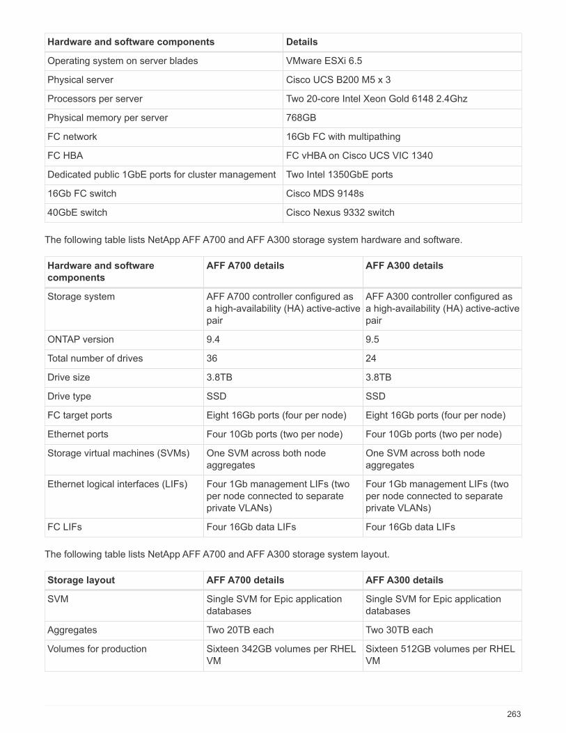
Hardware and software components Details
Operating system on server blades VMware ESXi 6.5
Physical server Cisco UCS B200 M5 x 3
Processors per server Two 20-core Intel Xeon Gold 6148 2.4Ghz
Physical memory per server 768GB
FC network 16Gb FC with multipathing
FC HBA FC vHBA on Cisco UCS VIC 1340
Dedicated public 1GbE ports for cluster management Two Intel 1350GbE ports
16Gb FC switch Cisco MDS 9148s
40GbE switch Cisco Nexus 9332 switch
The following table lists NetApp AFF A700 and AFF A300 storage system hardware and software.
Hardware and software
components
AFF A700 details AFF A300 details
Storage system AFF A700 controller configured asa high-availability (HA) active-activepair
AFF A300 controller configured asa high-availability (HA) active-activepair
ONTAP version 9.4 9.5
Total number of drives 36 24
Drive size 3.8TB 3.8TB
Drive type SSD SSD
FC target ports Eight 16Gb ports (four per node) Eight 16Gb ports (four per node)
Ethernet ports Four 10Gb ports (two per node) Four 10Gb ports (two per node)
Storage virtual machines (SVMs) One SVM across both nodeaggregates
One SVM across both nodeaggregates
Ethernet logical interfaces (LIFs) Four 1Gb management LIFs (twoper node connected to separateprivate VLANs)
Four 1Gb management LIFs (twoper node connected to separateprivate VLANs)
FC LIFs Four 16Gb data LIFs Four 16Gb data LIFs
The following table lists NetApp AFF A700 and AFF A300 storage system layout.
Storage layout AFF A700 details AFF A300 details
SVM Single SVM for Epic applicationdatabases
Single SVM for Epic applicationdatabases
Aggregates Two 20TB each Two 30TB each
Volumes for production Sixteen 342GB volumes per RHELVM
Sixteen 512GB volumes per RHELVM
263
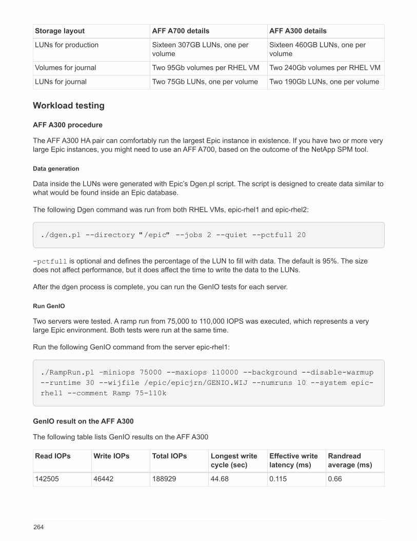
Storage layout AFF A700 details AFF A300 details
LUNs for production Sixteen 307GB LUNs, one pervolume
Sixteen 460GB LUNs, one pervolume
Volumes for journal Two 95Gb volumes per RHEL VM Two 240Gb volumes per RHEL VM
LUNs for journal Two 75Gb LUNs, one per volume Two 190Gb LUNs, one per volume
Workload testing
AFF A300 procedure
The AFF A300 HA pair can comfortably run the largest Epic instance in existence. If you have two or more verylarge Epic instances, you might need to use an AFF A700, based on the outcome of the NetApp SPM tool.
Data generation
Data inside the LUNs were generated with Epic’s Dgen.pl script. The script is designed to create data similar towhat would be found inside an Epic database.
The following Dgen command was run from both RHEL VMs, epic-rhel1 and epic-rhel2:
./dgen.pl --directory "/epic" --jobs 2 --quiet --pctfull 20
-pctfull is optional and defines the percentage of the LUN to fill with data. The default is 95%. The sizedoes not affect performance, but it does affect the time to write the data to the LUNs.
After the dgen process is complete, you can run the GenIO tests for each server.
Run GenIO
Two servers were tested. A ramp run from 75,000 to 110,000 IOPS was executed, which represents a verylarge Epic environment. Both tests were run at the same time.
Run the following GenIO command from the server epic-rhel1:
./RampRun.pl –miniops 75000 --maxiops 110000 --background --disable-warmup
--runtime 30 --wijfile /epic/epicjrn/GENIO.WIJ --numruns 10 --system epic-
rhel1 --comment Ramp 75-110k
GenIO result on the AFF A300
The following table lists GenIO results on the AFF A300
Read IOPs Write IOPs Total IOPs Longest write
cycle (sec)
Effective write
latency (ms)
Randread
average (ms)
142505 46442 188929 44.68 0.115 0.66
264
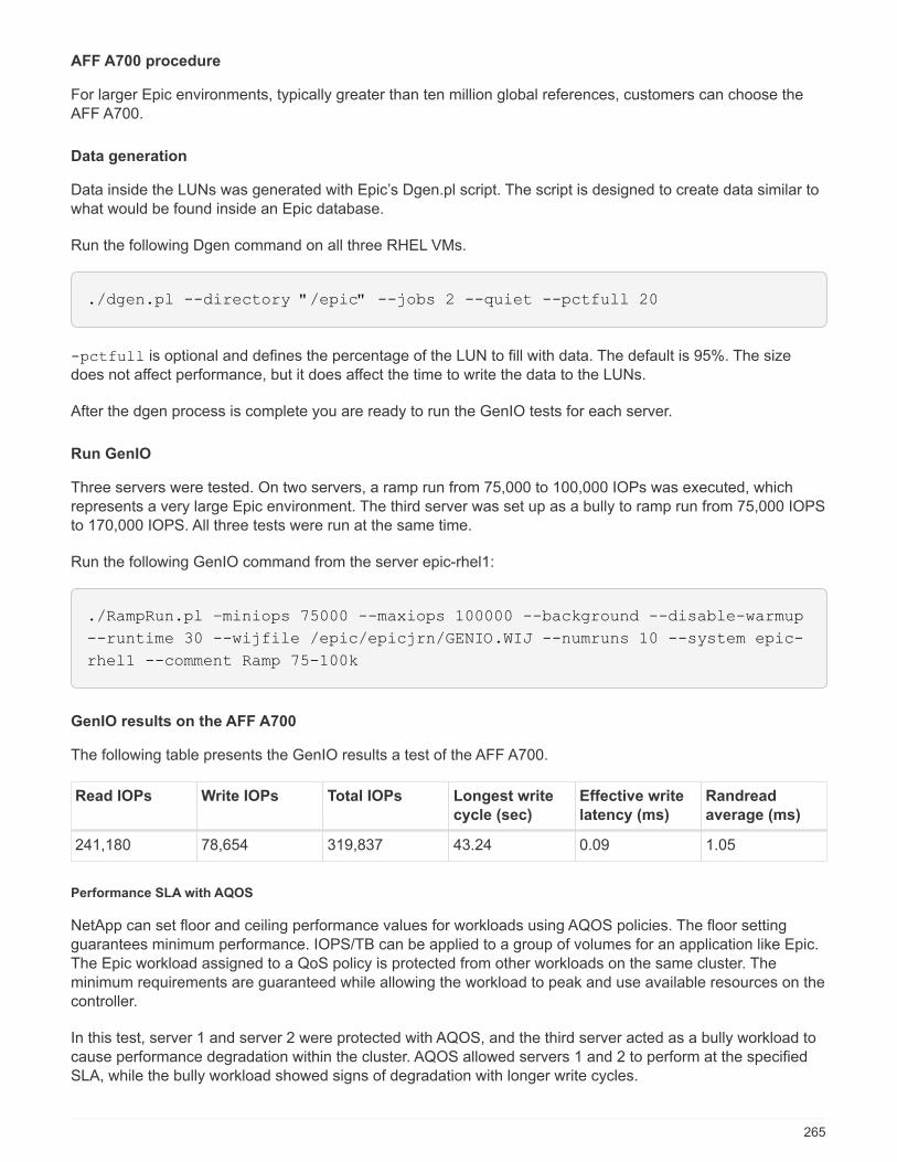
AFF A700 procedure
For larger Epic environments, typically greater than ten million global references, customers can choose theAFF A700.
Data generation
Data inside the LUNs was generated with Epic’s Dgen.pl script. The script is designed to create data similar towhat would be found inside an Epic database.
Run the following Dgen command on all three RHEL VMs.
./dgen.pl --directory "/epic" --jobs 2 --quiet --pctfull 20
-pctfull is optional and defines the percentage of the LUN to fill with data. The default is 95%. The sizedoes not affect performance, but it does affect the time to write the data to the LUNs.
After the dgen process is complete you are ready to run the GenIO tests for each server.
Run GenIO
Three servers were tested. On two servers, a ramp run from 75,000 to 100,000 IOPs was executed, whichrepresents a very large Epic environment. The third server was set up as a bully to ramp run from 75,000 IOPSto 170,000 IOPS. All three tests were run at the same time.
Run the following GenIO command from the server epic-rhel1:
./RampRun.pl –miniops 75000 --maxiops 100000 --background --disable-warmup
--runtime 30 --wijfile /epic/epicjrn/GENIO.WIJ --numruns 10 --system epic-
rhel1 --comment Ramp 75-100k
GenIO results on the AFF A700
The following table presents the GenIO results a test of the AFF A700.
Read IOPs Write IOPs Total IOPs Longest write
cycle (sec)
Effective write
latency (ms)
Randread
average (ms)
241,180 78,654 319,837 43.24 0.09 1.05
Performance SLA with AQOS
NetApp can set floor and ceiling performance values for workloads using AQOS policies. The floor settingguarantees minimum performance. IOPS/TB can be applied to a group of volumes for an application like Epic.The Epic workload assigned to a QoS policy is protected from other workloads on the same cluster. Theminimum requirements are guaranteed while allowing the workload to peak and use available resources on thecontroller.
In this test, server 1 and server 2 were protected with AQOS, and the third server acted as a bully workload tocause performance degradation within the cluster. AQOS allowed servers 1 and 2 to perform at the specifiedSLA, while the bully workload showed signs of degradation with longer write cycles.
265
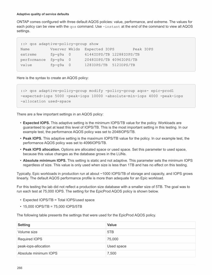
Adaptive quality of service defaults
ONTAP comes configured with three default AQOS policies: value, performance, and extreme. The values for
each policy can be view with the qos command. Use -instant at the end of the command to view all AQOSsettings.
::> qos adaptive-policy-group show
Name Vserver Wklds Expected IOPS Peak IOPS
extreme fp-g9a 0 6144IOPS/TB 12288IOPS/TB
performance fp-g9a 0 2048IOPS/TB 4096IOPS/TB
value fp-g9a 0 128IOPS/TB 512IOPS/TB
Here is the syntax to create an AQOS policy:
::> qos adaptive-policy-group modify -policy-group aqos- epic-prod1
-expected-iops 5000 -peak-iops 10000 -absolute-min-iops 4000 -peak-iops
-allocation used-space
There are a few important settings in an AQOS policy:
• Expected IOPS. This adaptive setting is the minimum IOPS/TB value for the policy. Workloads areguaranteed to get at least this level of IOPS/TB. This is the most important setting in this testing. In ourexample test, the performance AQOS policy was set to 2048IOPS/TB.
• Peak IOPS. This adaptive setting is the maximum IOPS/TB value for the policy. In our example test, theperformance AQOS policy was set to 4096IOPS/TB.
• Peak IOPS allocation. Options are allocated space or used space. Set this parameter to used space,because this value changes as the database grows in the LUNs.
• Absolute minimum IOPS. This setting is static and not adaptive. This parameter sets the minimum IOPSregardless of size. This value is only used when size is less than 1TB and has no effect on this testing.
Typically, Epic workloads in production run at about ~1000 IOPS/TB of storage and capacity, and IOPS growslinearly. The default AQOS performance profile is more than adequate for an Epic workload.
For this testing the lab did not reflect a production size database with a smaller size of 5TB. The goal was torun each test at 75,000 IOPS. The setting for the EpicProd AQOS policy is shown below.
• Expected IOPS/TB = Total IOPS/used space
• 15,000 IOPS/TB = 75,000 IOPS/5TB
The following table presents the settings that were used for the EpicProd AQOS policy.
Setting Value
Volume size 5TB
Required IOPS 75,000
peak-iops-allocation Used space
Absolute minimum IOPS 7,500
266

Setting Value
Expected IOPS/TB 15,000
Peak IOPS/TB 30,000
The following figure shows how floor IOPS and ceiling IOPS are calculated as the used space grows over time.
For a production-sized database, you can either create a custom AQOS profile like the one used in the lastexample, or you can use the default performance AQOS policy. The settings for the performance AQOS policyare show in the table below.
Setting Value
Volume size 75TB
Required IOPS 75,000
peak-iops-allocation Used space
Absolute minimum IOPS 500
Expected IOPS/TB 1,000
Peak IOPS/TB 2,000
The following figure shows how floor and ceiling IOPS are calculated as the used space grows over time forthe default performance AQOS policy.
267
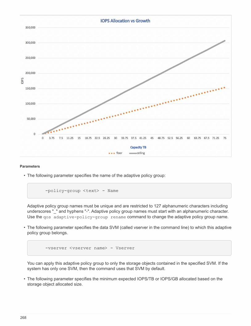
Parameters
• The following parameter specifies the name of the adaptive policy group:
-policy-group <text> - Name
Adaptive policy group names must be unique and are restricted to 127 alphanumeric characters includingunderscores "_" and hyphens "-". Adaptive policy group names must start with an alphanumeric character.
Use the qos adaptive-policy-group rename command to change the adaptive policy group name.
• The following parameter specifies the data SVM (called vserver in the command line) to which this adaptivepolicy group belongs.
-vserver <vserver name> - Vserver
You can apply this adaptive policy group to only the storage objects contained in the specified SVM. If thesystem has only one SVM, then the command uses that SVM by default.
• The following parameter specifies the minimum expected IOPS/TB or IOPS/GB allocated based on thestorage object allocated size.
268

-expected-iops {<integer>[IOPS[/{GB|TB}]] (default: TB)} - Expected
IOPS
• The following parameter specifies the maximum possible IOPS/TB or IOPS/GB allocated based on thestorage object allocated size or the storage object used size.
-peak-iops {<integer>[IOPS[/{GB|TB}]] (default: TB)} - Peak IOPS
• The following parameter specifies the absolute minimum IOPS that is used as an override when theexpected IOPS is less than this value.
[-absolute-min-iops <qos_tput>] - Absolute Minimum IOPS
The default value is computed as follows:
qos adaptive-policy-group modify -policy-group aqos- epic-prod1
-expected-iops 5000 -peak-iops 10000 -absolute-min-iops 4000 -peak-iops
-allocation used-space
qos adaptive-policy-group modify -policy-group aqos- epic-prod2
-expected-iops 6000 -peak-iops 20000 -absolute-min-iops 5000 -peak-iops
-allocation used-space
qos adaptive-policy-group modify -policy-group aqos- epic-bully
-expected-iops 3000 -peak-iops 2000 -absolute-min-iops 2000 -peak-iops
-allocation used-space
Data generation
Data inside the LUNs was generated with the Epic Dgen.pl script. The script is designed to create datasimilar to what would be found inside an Epic database.
The following Dgen command was run on all three RHEL VMs:
./dgen.pl --directory "/epic" --jobs 2 --quiet --pctfull 20
Run GenIO
Three servers were tested. Two ran at a constant 75,000 IOPS, which represents a very large Epicenvironment. The third server was setup as a bully to ramp run from 75,000 IOPS to 150,000 IOPS. All three
269
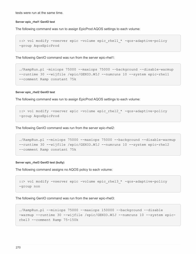
tests were run at the same time.
Server epic_rhel1 GenIO test
The following command was run to assign EpicProd AQOS settings to each volume:
::> vol modify -vserver epic -volume epic_rhel1_* -qos-adaptive-policy
-group AqosEpicProd
The following GenIO command was run from the server epic-rhel1:
./RampRun.pl –miniops 75000 --maxiops 75000 --background --disable-warmup
--runtime 30 --wijfile /epic/GENIO.WIJ --numruns 10 --system epic-rhel1
--comment Ramp constant 75k
Server epic_rhel2 GenIO test
The following command was run to assign EpicProd AQOS settings to each volume:
::> vol modify -vserver epic -volume epic_rhel2_* -qos-adaptive-policy
-group AqosEpicProd
The following GenIO command was run from the server epic-rhel2:
./RampRun.pl --miniops 75000 --maxiops 75000 --background --disable-warmup
--runtime 30 --wijfile /epic/GENIO.WIJ --numruns 10 --system epic-rhel2
--comment Ramp constant 75k
Server epic_rhel3 GenIO test (bully)
The following command assigns no AQOS policy to each volume:
::> vol modify -vserver epic -volume epic_rhel3_* -qos-adaptive-policy
-group non
The following GenIO command was run from the server epic-rhel3:
./RampRun.pl --miniops 75000 --maxiops 150000 --background --disable
-warmup --runtime 30 --wijfile /epic/GENIO.WIJ --numruns 10 --system epic-
rhel3 --comment Ramp 75-150k
270
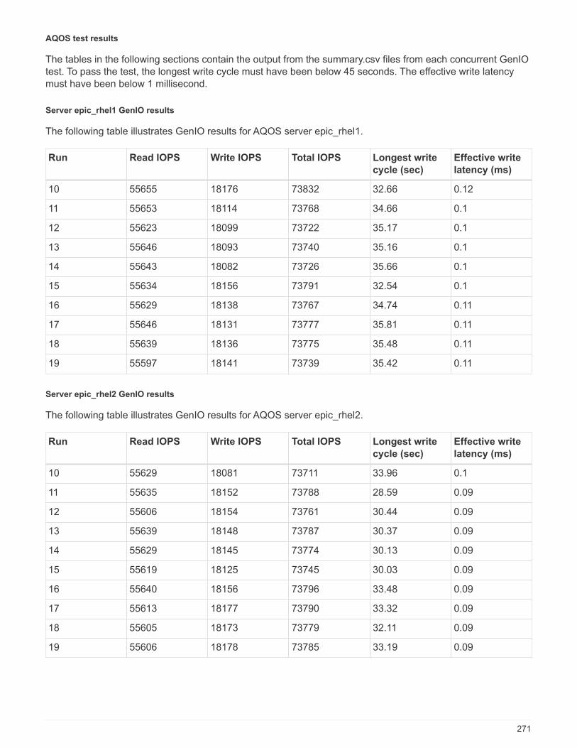
AQOS test results
The tables in the following sections contain the output from the summary.csv files from each concurrent GenIOtest. To pass the test, the longest write cycle must have been below 45 seconds. The effective write latencymust have been below 1 millisecond.
Server epic_rhel1 GenIO results
The following table illustrates GenIO results for AQOS server epic_rhel1.
Run Read IOPS Write IOPS Total IOPS Longest write
cycle (sec)
Effective write
latency (ms)
10 55655 18176 73832 32.66 0.12
11 55653 18114 73768 34.66 0.1
12 55623 18099 73722 35.17 0.1
13 55646 18093 73740 35.16 0.1
14 55643 18082 73726 35.66 0.1
15 55634 18156 73791 32.54 0.1
16 55629 18138 73767 34.74 0.11
17 55646 18131 73777 35.81 0.11
18 55639 18136 73775 35.48 0.11
19 55597 18141 73739 35.42 0.11
Server epic_rhel2 GenIO results
The following table illustrates GenIO results for AQOS server epic_rhel2.
Run Read IOPS Write IOPS Total IOPS Longest write
cycle (sec)
Effective write
latency (ms)
10 55629 18081 73711 33.96 0.1
11 55635 18152 73788 28.59 0.09
12 55606 18154 73761 30.44 0.09
13 55639 18148 73787 30.37 0.09
14 55629 18145 73774 30.13 0.09
15 55619 18125 73745 30.03 0.09
16 55640 18156 73796 33.48 0.09
17 55613 18177 73790 33.32 0.09
18 55605 18173 73779 32.11 0.09
19 55606 18178 73785 33.19 0.09
271
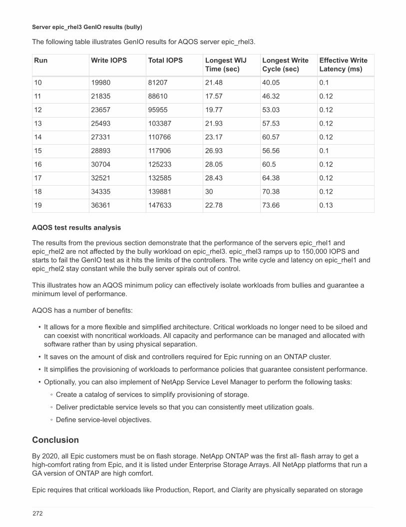
Server epic_rhel3 GenIO results (bully)
The following table illustrates GenIO results for AQOS server epic_rhel3.
Run Write IOPS Total IOPS Longest WIJ
Time (sec)
Longest Write
Cycle (sec)
Effective Write
Latency (ms)
10 19980 81207 21.48 40.05 0.1
11 21835 88610 17.57 46.32 0.12
12 23657 95955 19.77 53.03 0.12
13 25493 103387 21.93 57.53 0.12
14 27331 110766 23.17 60.57 0.12
15 28893 117906 26.93 56.56 0.1
16 30704 125233 28.05 60.5 0.12
17 32521 132585 28.43 64.38 0.12
18 34335 139881 30 70.38 0.12
19 36361 147633 22.78 73.66 0.13
AQOS test results analysis
The results from the previous section demonstrate that the performance of the servers epic_rhel1 andepic_rhel2 are not affected by the bully workload on epic_rhel3. epic_rhel3 ramps up to 150,000 IOPS andstarts to fail the GenIO test as it hits the limits of the controllers. The write cycle and latency on epic_rhel1 andepic_rhel2 stay constant while the bully server spirals out of control.
This illustrates how an AQOS minimum policy can effectively isolate workloads from bullies and guarantee aminimum level of performance.
AQOS has a number of benefits:
• It allows for a more flexible and simplified architecture. Critical workloads no longer need to be siloed andcan coexist with noncritical workloads. All capacity and performance can be managed and allocated withsoftware rather than by using physical separation.
• It saves on the amount of disk and controllers required for Epic running on an ONTAP cluster.
• It simplifies the provisioning of workloads to performance policies that guarantee consistent performance.
• Optionally, you can also implement of NetApp Service Level Manager to perform the following tasks:
◦ Create a catalog of services to simplify provisioning of storage.
◦ Deliver predictable service levels so that you can consistently meet utilization goals.
◦ Define service-level objectives.
Conclusion
By 2020, all Epic customers must be on flash storage. NetApp ONTAP was the first all- flash array to get ahigh-comfort rating from Epic, and it is listed under Enterprise Storage Arrays. All NetApp platforms that run aGA version of ONTAP are high comfort.
Epic requires that critical workloads like Production, Report, and Clarity are physically separated on storage
272
allocations called pools. NetApp provides multiple pools of storage in a single cluster with each node and offersa simplified single cluster and single OS for the entire Epic solution. ONTAP supports all protocols for NAS andSAN, with mixed tiers of storage for SSD, HDD, and cloud.
The introduction of Adaptive QoS in ONTAP 9.3, with significant enhancements in ONTAP 9.4, allows for thecreation of storage pools with software without the need for physical separation. This capability greatlysimplifies architecture development, permits the consolidation of nodes and disks, and improves performancefor critical workloads like production by spreading across nodes. It also eliminates storage performance issuescaused by bullies and guarantees consistent performance for the life of the workload.
Where to find additional information
To learn more about the information that is described in this document, see the following documents orwebsites:
FlexPod Design Zone
• NetApp FlexPod Design Zone
https://www.cisco.com/c/en/us/solutions/design-zone/data-center-design-guides/flexpod-design-guides.html
• FlexPod DC with FC Storage (MDS Switches) Using NetApp AFF, vSphere 6.5U1, and Cisco UCSManager
https://www.cisco.com/c/en/us/td/docs/unified_computing/ucs/UCS_CVDs/flexpod_esxi65u1_n9fc.html
• Cisco Best Practices with Epic on Cisco UCS
https://www.cisco.com/c/dam/en_us/solutions/industries/healthcare/Epic_on_UCS_tech_brief_FNL.pdf
NetApp technical reports
• TR-4693: FlexPod Datacenter for Epic EHR Deployment Guide
https://www.netapp.com/us/media/tr-4693.pdf
• TR-4707: FlexPod for Epic Directional Sizing Guide
https://www.netapp.com/us/media/tr-4707.pdf
• TR-3929: Reallocate Best Practices Guide
https://www.netapp.com/us/media/tr-3929.pdf
• TR-3987: Snap Creator Framework Plug-In for InterSystems Caché
https://www.netapp.com/us/media/tr-3987.pdf
• TR-3928: NetApp Best Practices for Epic
https://www.netapp.com/us/media/tr-3928.pdf
• TR-4017: FC SAN Best Practices
273
https://www.netapp.com/us/media/tr-4017.pdf
• TR-3446: SnapMirror Async Overview and Best Practices Guide
https://www.netapp.com/us/media/tr-3446.pdf
ONTAP documentation
• NetApp product documentation
https://www.netapp.com/us/documentation/index.aspx
• Virtual Storage Console (VSC) for vSphere documentation
https://mysupport.netapp.com/documentation/productlibrary/index.html?productID=30048
• ONTAP 9 Documentation Center
http://docs.netapp.com/ontap-9/index.jsp
Cisco Nexus, MDS, Cisco UCS, and Cisco UCS Manager guides
• Cisco UCS Servers Overview
https://www.cisco.com/c/en/us/products/servers-unified-computing/index.html
• Cisco UCS Blade Servers Overview
https://www.cisco.com/c/en/us/products/servers-unified-computing/ucs-b-series-blade-servers/index.html
• Cisco UCS B200 M5 Datasheet
https://www.cisco.com/c/en/us/products/servers-unified-computing/ucs-b-series-blade-servers/index.html
• Cisco UCS Manager Overview
https://www.cisco.com/c/en/us/products/servers-unified-computing/ucs-manager/index.html
• Cisco UCS Manager 3.2(3a) Infrastructure Bundle (requires Cisco.com authorization)
https://software.cisco.com/download/home/283612660/type/283655658/release/3.2%25283a%2529
• Cisco Nexus 9300 Platform Switches
https://www.cisco.com/c/en/us/products/collateral/switches/nexus-9000-series-switches/datasheet-c78-736967.html
• Cisco MDS 9148S FC Switch
https://www.cisco.com/c/en/us/products/storage-networking/mds-9148s-16g-multilayer-fabric-switch/index.html
274

Acknowledgements
The following people contributed to the creation of this guide:
• Ganesh Kamath, Technical Marketing Engineer, NetApp
• Atul Bhalodia, Technical Marketing Engineer, NetApp
• Brandon Agee, Technical Marketing Engineer, NetApp
• Brian O’Mahony, Solution Architect – Healthcare, NetApp
• Ketan Mota, Product Manager, NetApp
• Jon Ebmeier, Technical Solutions Architect, Cisco Systems, Inc
• Mike Brennan, Product Manager, Cisco Systems, Inc
FlexPod for MEDITECH Directional Sizing Guide
TR-4774: FlexPod for MEDITECH Directional Sizing
Brandon Agee, John Duignan, NetAppMike Brennan, Jon Ebmeir, Cisco
In partnership with:
This report provides guidance for sizing FlexPod for a MEDITECH EHR application software environment.
Purpose
FlexPod systems can be deployed to host MEDITECH EXPANSE, 6.x, 5.x, and MAGIC services. FlexPodservers that host the MEDITECH application layer provide an integrated platform for a dependable, high-performance infrastructure. The FlexPod integrated platform is deployed rapidly by skilled FlexPod channelpartners and is supported by Cisco and NetApp technical assistance centers.
Sizing is based on information in MEDITECH’s hardware configuration proposal and the MEDITECH taskdocument. The goal is to determine the optimal size for compute, network, and storage infrastructurecomponents.
The MEDITECH Workload Overview section describes the types of compute and storage workloads that canbe found in MEDITECH environments.
The Technical Specifications for Small, Medium, and Large Architectures section details a sample Bill ofMaterials for the different storage architectures described in the section. The configurations given are generalguidelines only. Always size the systems using the sizers based on the workload and tune the configurationsaccordingly.
Overall solution benefits
Running a MEDITECH environment on the FlexPod architectural foundation can help healthcare organizationsimprove productivity and decrease capital and operating expenses. FlexPod provides a prevalidated, rigorously
275

tested, converged infrastructure from the strategic partnership of Cisco and NetApp. It is engineered anddesigned specifically for delivering predictable low-latency system performance and high availability. Thisapproach results in faster response time for users of the MEDITECH EHR system.
The FlexPod solution from Cisco and NetApp meets MEDITECH system requirements with a high performing,modular, prevalidated, converged, virtualized, efficient, scalable, and cost-effective platform. FlexPodDatacenter with MEDITECH delivers several benefits specific to the healthcare industry:
• Modular architecture. FlexPod addresses the various needs of the MEDITECH modular architecture withcustomized FlexPod systems for each specific workload. All components are connected through aclustered server and storage management fabric and use a cohesive management toolset.
• Simplified operations and lowered costs. You can eliminate the expense and complexity of legacyplatforms by replacing them with a more efficient and scalable shared resource that can support clinicianswherever they are. This solution delivers better resource usage for greater return on investment (ROI).
• Quicker deployment of infrastructure. The integrated design of FlexPod Datacenter with MEDITECHenables customers to have the new infrastructure up and running quickly and easily for both on-site andremote data centers.
• Scale-out architecture. You can scale SAN and NAS from terabytes to tens of petabytes withoutreconfiguring running applications.
• Nondisruptive operations. You can perform storage maintenance, hardware lifecycle operations, andsoftware upgrades without interrupting the business.
• Secure multitenancy. This benefit supports the increased needs of virtualized server and shared storageinfrastructure, enabling secure multitenancy of facility-specific information. This benefit is important if youare hosting multiple instances of databases and software.
• Pooled resource optimization. This benefit can help reduce physical server and storage controllercounts, load balance workload demands, boost utilization, and simultaneously improve performance.
• Quality of service (QoS). FlexPod offers quality of service (QoS) on the entire stack. Industry-leading QoSstorage policies enable differentiated service levels in a shared environment. These policies enable optimalperformance for workloads and help in isolating and controlling runaway applications.
• Storage efficiency. You can reduce storage costs with NetApp 7:1 storage efficiency.
• Agility. The industry-leading workflow automation, orchestration, and management tools offered byFlexPod systems allow IT to be far more responsive to business requests. These business requests canrange from MEDITECH backup and provisioning of more testing and training environments to analyticsdatabase replications for population health management initiatives.
• Productivity. You can quickly deploy and scale this solution for optimal clinician end-user experiences.
• Data Fabric. The NetApp Data Fabric architecture weaves data together across sites, beyond physicalboundaries, and across applications. The NetApp Data Fabric is built for data-driven enterprises in a data-centric world. Data is created and used in multiple locations, and is often shared with applications andinfrastructures. Data Fabric provides a way to manage data that is consistent and integrated. It also offersIT more control of the data and simplifies ever-increasing IT complexity.
Scope
This document covers environments that use Cisco UCS and NetApp ONTAP based storage. It providessample reference architectures for hosting MEDITECH.
It does not cover:
• Detailed sizing guidance using NetApp System Performance Modeler (SPM) or other NetApp sizing tools.
276

• Sizing for nonproduction workloads.
Audience
This document is intended for NetApp and partner systems engineers and NetApp Professional Servicespersonnel. NetApp assumes that the reader has a good understanding of compute and storage sizing conceptsas well as technical familiarity with Cisco UCS and NetApp storage systems.
Related Documents
The following technical reports and other documents are relevant to this Technical Report, and make up acomplete set of documents required for sizing, designing, and deploying MEDITECH on FlexPod infrastructure.
• TR-4753: FlexPod Datacenter for MEDITECH Deployment Guide
• TR-4190: NetApp Sizing Guidelines for MEDITECH Environments
• TR-4319: NetApp Deployment Guidelines for MEDITECH Environments
Login credentials for the NetApp Field Portal are required to access some of these reports.
MEDITECH Workload Overview
This section describes the types of compute and storage workloads that you might find in MEDITECHenvironments.
MEDITECH and backup workloads
When you size NetApp storage systems for MEDITECH environments, you must consider both the MEDITECHproduction workload and the backup workload.
MEDITECH Host
A MEDITECH host is a database server. This host is also referred to as a MEDITECH file server (for theEXPANSE, 6.x or C/S 5.x platform) or a MAGIC machine (for the MAGIC platform). This document uses theterm MEDITECH host to refer to a MEDITECH file server and a MAGIC machine.
The following sections describe the I/O characteristics and performance requirements of these two workloads.
MEDITECH workload
In a MEDITECH environment, multiple servers that run MEDITECH software perform various tasks as anintegrated system known as the MEDITECH system. For more information about the MEDITECH system, seethe MEDITECH documentation:
• For production MEDITECH environments, consult the appropriate MEDITECH documentation to determinethe number of MEDITECH hosts and the storage capacity that must be included as part of sizing theNetApp storage system.
• For new MEDITECH environments, consult the hardware configuration proposal document. For existingMEDITECH environments, consult the hardware evaluation task document. The hardware evaluation taskis associated with a MEDITECH ticket. Customers can request either of these documents fromMEDITECH.
You can scale the MEDITECH system to provide increased capacity and performance by adding hosts. Each
277
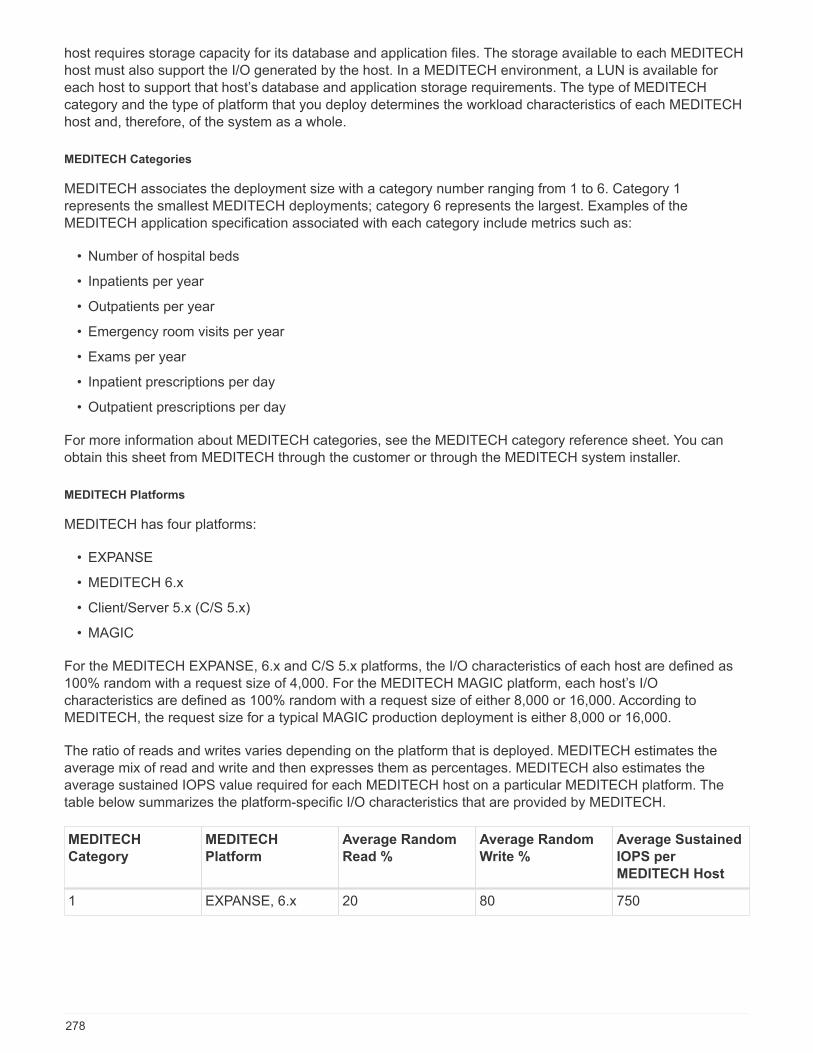
host requires storage capacity for its database and application files. The storage available to each MEDITECHhost must also support the I/O generated by the host. In a MEDITECH environment, a LUN is available foreach host to support that host’s database and application storage requirements. The type of MEDITECHcategory and the type of platform that you deploy determines the workload characteristics of each MEDITECHhost and, therefore, of the system as a whole.
MEDITECH Categories
MEDITECH associates the deployment size with a category number ranging from 1 to 6. Category 1represents the smallest MEDITECH deployments; category 6 represents the largest. Examples of theMEDITECH application specification associated with each category include metrics such as:
• Number of hospital beds
• Inpatients per year
• Outpatients per year
• Emergency room visits per year
• Exams per year
• Inpatient prescriptions per day
• Outpatient prescriptions per day
For more information about MEDITECH categories, see the MEDITECH category reference sheet. You canobtain this sheet from MEDITECH through the customer or through the MEDITECH system installer.
MEDITECH Platforms
MEDITECH has four platforms:
• EXPANSE
• MEDITECH 6.x
• Client/Server 5.x (C/S 5.x)
• MAGIC
For the MEDITECH EXPANSE, 6.x and C/S 5.x platforms, the I/O characteristics of each host are defined as100% random with a request size of 4,000. For the MEDITECH MAGIC platform, each host’s I/Ocharacteristics are defined as 100% random with a request size of either 8,000 or 16,000. According toMEDITECH, the request size for a typical MAGIC production deployment is either 8,000 or 16,000.
The ratio of reads and writes varies depending on the platform that is deployed. MEDITECH estimates theaverage mix of read and write and then expresses them as percentages. MEDITECH also estimates theaverage sustained IOPS value required for each MEDITECH host on a particular MEDITECH platform. Thetable below summarizes the platform-specific I/O characteristics that are provided by MEDITECH.
MEDITECH
Category
MEDITECH
Platform
Average Random
Read %
Average Random
Write %
Average Sustained
IOPS per
MEDITECH Host
1 EXPANSE, 6.x 20 80 750
278
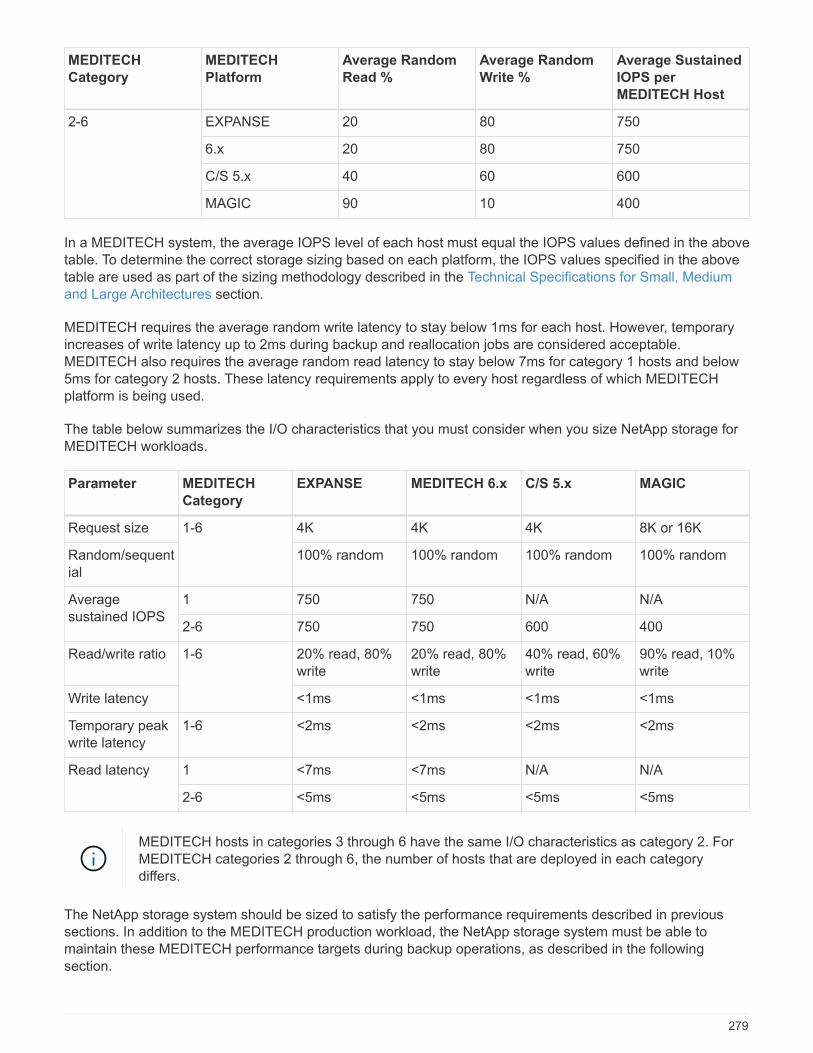
MEDITECH
Category
MEDITECH
Platform
Average Random
Read %
Average Random
Write %
Average Sustained
IOPS per
MEDITECH Host
2-6 EXPANSE 20 80 750
6.x 20 80 750
C/S 5.x 40 60 600
MAGIC 90 10 400
In a MEDITECH system, the average IOPS level of each host must equal the IOPS values defined in the abovetable. To determine the correct storage sizing based on each platform, the IOPS values specified in the abovetable are used as part of the sizing methodology described in the Technical Specifications for Small, Mediumand Large Architectures section.
MEDITECH requires the average random write latency to stay below 1ms for each host. However, temporaryincreases of write latency up to 2ms during backup and reallocation jobs are considered acceptable.MEDITECH also requires the average random read latency to stay below 7ms for category 1 hosts and below5ms for category 2 hosts. These latency requirements apply to every host regardless of which MEDITECHplatform is being used.
The table below summarizes the I/O characteristics that you must consider when you size NetApp storage forMEDITECH workloads.
Parameter MEDITECH
Category
EXPANSE MEDITECH 6.x C/S 5.x MAGIC
Request size 1-6 4K 4K 4K 8K or 16K
Random/sequential
100% random 100% random 100% random 100% random
Averagesustained IOPS
1 750 750 N/A N/A
2-6 750 750 600 400
Read/write ratio 1-6 20% read, 80%write
20% read, 80%write
40% read, 60%write
90% read, 10%write
Write latency <1ms <1ms <1ms <1ms
Temporary peakwrite latency
1-6 <2ms <2ms <2ms <2ms
Read latency 1 <7ms <7ms N/A N/A
2-6 <5ms <5ms <5ms <5ms
MEDITECH hosts in categories 3 through 6 have the same I/O characteristics as category 2. ForMEDITECH categories 2 through 6, the number of hosts that are deployed in each categorydiffers.
The NetApp storage system should be sized to satisfy the performance requirements described in previoussections. In addition to the MEDITECH production workload, the NetApp storage system must be able tomaintain these MEDITECH performance targets during backup operations, as described in the followingsection.
279

Backup Workload Description
MEDITECH certified backup software backs up the LUN used by each MEDITECH host in a MEDITECHsystem. For the backups to be in an application-consistent state, the backup software quiesces the MEDITECHsystem and suspends I/O requests to disk. While the system is in a quiesced state, the backup software issuesa command to the NetApp storage system to create a NetApp Snapshot copy of the volumes that contain theLUNs. The backup software later unquiesces the MEDITECH system, which enables production I/O requeststo continue to the database. The software creates a NetApp FlexClone volume based on the Snapshot copy.This volume is used by the backup source while production I/O requests continue on the parent volumes thathost the LUNs.
The workload that is generated by the backup software comes from the sequential reading of the LUNs thatreside in the FlexClone volumes. The workload is defined as a 100% sequential read workload with a requestsize of 64,000. For the MEDITECH production workload, the performance criterion is to maintain the requiredIOPS and the associated read/write latency levels. For the backup workload, however, the attention is shiftedto the overall data throughput (MBps) that is generated during the backup operation. MEDITECH LUN backupsare required to be completed in an eight-hour backup window, but NetApp recommends that the backup of allMEDITECH LUNs be completed in six hours or less. Aiming to complete the backup in less than six hoursmitigates for events such as an unplanned increase in the MEDITECH workload, NetApp ONTAP backgroundoperations, or data growth over time. Any of these events might incur extra backup time. Regardless of theamount of application data stored, the backup software performs a full block-level backup of the entire LUN foreach MEDITECH host.
Calculate the sequential read throughput that is required to complete the backup within this window as afunction of the other factors involved:
• The desired backup duration
• The number of LUNs
• The size of each LUN to be backed up
For example, in a 50-host MEDITECH environment in which each host’s LUN size is 200GB, the total LUNcapacity to backup is 10TB.
To back up 10TB of data in eight hours, the following throughput is required:
• = (10 x 10^6)MB (8 x 3,600)s
• = 347.2MBps
However, to account for unplanned events, a conservative backup window of 5.5 hours is selected to provideheadroom beyond the six hours that is recommended.
To back up 10TB of data in eight hours, the following throughput is required:
• = (10 x 10^6)MB (5.5 x 3,600)s
• = 500MBps
At the throughput rate of 500MBps, the backup can complete within a 5.5-hour time frame, comfortably withinthe 8-hour backup requirement.
The table below summarizes the I/O characteristics of the backup workload to use when you size the storagesystem.
280
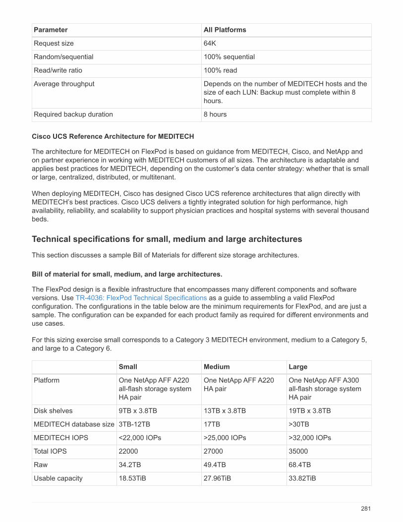
Parameter All Platforms
Request size 64K
Random/sequential 100% sequential
Read/write ratio 100% read
Average throughput Depends on the number of MEDITECH hosts and thesize of each LUN: Backup must complete within 8hours.
Required backup duration 8 hours
Cisco UCS Reference Architecture for MEDITECH
The architecture for MEDITECH on FlexPod is based on guidance from MEDITECH, Cisco, and NetApp andon partner experience in working with MEDITECH customers of all sizes. The architecture is adaptable andapplies best practices for MEDITECH, depending on the customer’s data center strategy: whether that is smallor large, centralized, distributed, or multitenant.
When deploying MEDITECH, Cisco has designed Cisco UCS reference architectures that align directly withMEDITECH’s best practices. Cisco UCS delivers a tightly integrated solution for high performance, highavailability, reliability, and scalability to support physician practices and hospital systems with several thousandbeds.
Technical specifications for small, medium and large architectures
This section discusses a sample Bill of Materials for different size storage architectures.
Bill of material for small, medium, and large architectures.
The FlexPod design is a flexible infrastructure that encompasses many different components and softwareversions. Use TR-4036: FlexPod Technical Specifications as a guide to assembling a valid FlexPodconfiguration. The configurations in the table below are the minimum requirements for FlexPod, and are just asample. The configuration can be expanded for each product family as required for different environments anduse cases.
For this sizing exercise small corresponds to a Category 3 MEDITECH environment, medium to a Category 5,and large to a Category 6.
Small Medium Large
Platform One NetApp AFF A220all-flash storage systemHA pair
One NetApp AFF A220HA pair
One NetApp AFF A300all-flash storage systemHA pair
Disk shelves 9TB x 3.8TB 13TB x 3.8TB 19TB x 3.8TB
MEDITECH database size 3TB-12TB 17TB >30TB
MEDITECH IOPS <22,000 IOPs >25,000 IOPs >32,000 IOPs
Total IOPS 22000 27000 35000
Raw 34.2TB 49.4TB 68.4TB
Usable capacity 18.53TiB 27.96TiB 33.82TiB
281
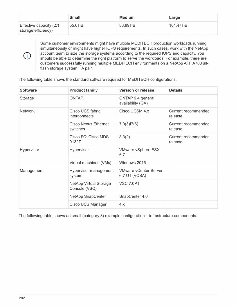
Small Medium Large
Effective capacity (2:1storage efficiency)
55.6TiB 83.89TiB 101.47TiB
Some customer environments might have multiple MEDITECH production workloads runningsimultaneously or might have higher IOPS requirements. In such cases, work with the NetAppaccount team to size the storage systems according to the required IOPS and capacity. Youshould be able to determine the right platform to serve the workloads. For example, there arecustomers successfully running multiple MEDITECH environments on a NetApp AFF A700 all-flash storage system HA pair.
The following table shows the standard software required for MEDITECH configurations.
Software Product family Version or release Details
Storage ONTAP ONTAP 9.4 generalavailability (GA)
Network Cisco UCS fabricinterconnects
Cisco UCSM 4.x Current recommendedrelease
Cisco Nexus Ethernetswitches
7.0(3)I7(6) Current recommendedrelease
Cisco FC: Cisco MDS9132T
8.3(2) Current recommendedrelease
Hypervisor Hypervisor VMware vSphere ESXi6.7
Virtual machines (VMs) Windows 2016
Management Hypervisor managementsystem
VMware vCenter Server6.7 U1 (VCSA)
NetApp Virtual StorageConsole (VSC)
VSC 7.0P1
NetApp SnapCenter SnapCenter 4.0
Cisco UCS Manager 4.x
The following table shows an small (category 3) example configuration – infrastructure components.
282
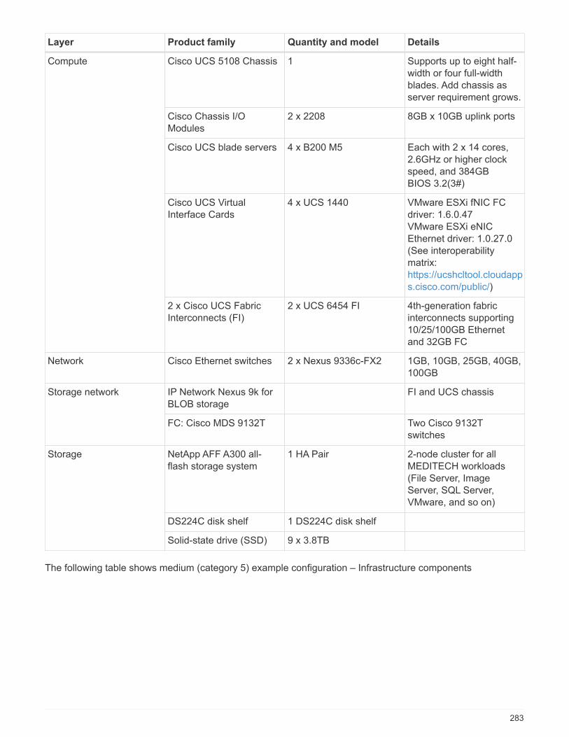
Layer Product family Quantity and model Details
Compute Cisco UCS 5108 Chassis 1 Supports up to eight half-width or four full-widthblades. Add chassis asserver requirement grows.
Cisco Chassis I/OModules
2 x 2208 8GB x 10GB uplink ports
Cisco UCS blade servers 4 x B200 M5 Each with 2 x 14 cores,2.6GHz or higher clockspeed, and 384GBBIOS 3.2(3#)
Cisco UCS VirtualInterface Cards
4 x UCS 1440 VMware ESXi fNIC FCdriver: 1.6.0.47VMware ESXi eNICEthernet driver: 1.0.27.0(See interoperabilitymatrix:https://ucshcltool.cloudapps.cisco.com/public/)
2 x Cisco UCS FabricInterconnects (FI)
2 x UCS 6454 FI 4th-generation fabricinterconnects supporting10/25/100GB Ethernetand 32GB FC
Network Cisco Ethernet switches 2 x Nexus 9336c-FX2 1GB, 10GB, 25GB, 40GB,100GB
Storage network IP Network Nexus 9k forBLOB storage
FI and UCS chassis
FC: Cisco MDS 9132T Two Cisco 9132Tswitches
Storage NetApp AFF A300 all-flash storage system
1 HA Pair 2-node cluster for allMEDITECH workloads(File Server, ImageServer, SQL Server,VMware, and so on)
DS224C disk shelf 1 DS224C disk shelf
Solid-state drive (SSD) 9 x 3.8TB
The following table shows medium (category 5) example configuration – Infrastructure components
283
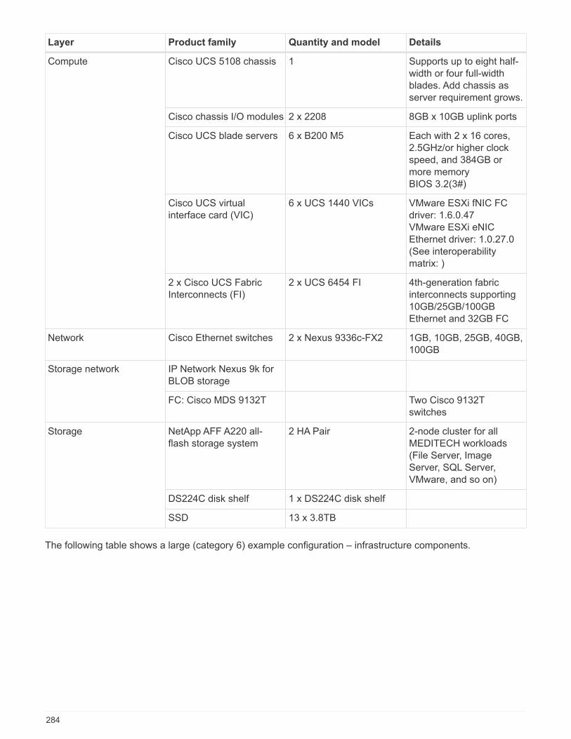
Layer Product family Quantity and model Details
Compute Cisco UCS 5108 chassis 1 Supports up to eight half-width or four full-widthblades. Add chassis asserver requirement grows.
Cisco chassis I/O modules 2 x 2208 8GB x 10GB uplink ports
Cisco UCS blade servers 6 x B200 M5 Each with 2 x 16 cores,2.5GHz/or higher clockspeed, and 384GB ormore memoryBIOS 3.2(3#)
Cisco UCS virtualinterface card (VIC)
6 x UCS 1440 VICs VMware ESXi fNIC FCdriver: 1.6.0.47VMware ESXi eNICEthernet driver: 1.0.27.0(See interoperabilitymatrix: )
2 x Cisco UCS FabricInterconnects (FI)
2 x UCS 6454 FI 4th-generation fabricinterconnects supporting10GB/25GB/100GBEthernet and 32GB FC
Network Cisco Ethernet switches 2 x Nexus 9336c-FX2 1GB, 10GB, 25GB, 40GB,100GB
Storage network IP Network Nexus 9k forBLOB storage
FC: Cisco MDS 9132T Two Cisco 9132Tswitches
Storage NetApp AFF A220 all-flash storage system
2 HA Pair 2-node cluster for allMEDITECH workloads(File Server, ImageServer, SQL Server,VMware, and so on)
DS224C disk shelf 1 x DS224C disk shelf
SSD 13 x 3.8TB
The following table shows a large (category 6) example configuration – infrastructure components.
284
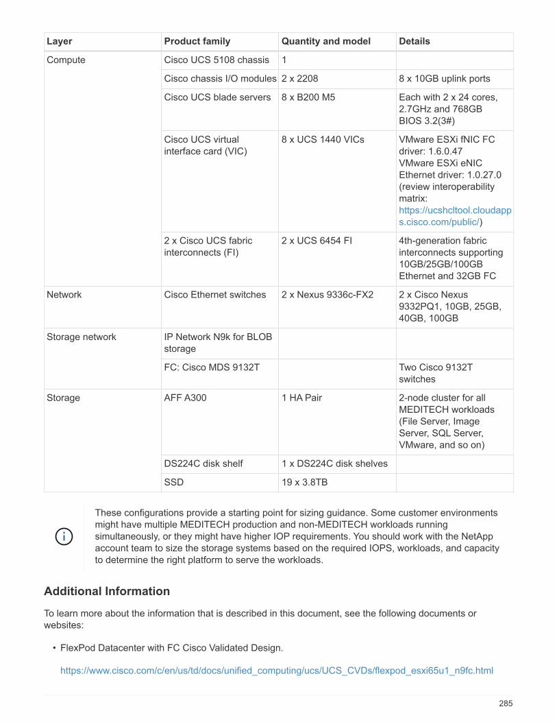
Layer Product family Quantity and model Details
Compute Cisco UCS 5108 chassis 1
Cisco chassis I/O modules 2 x 2208 8 x 10GB uplink ports
Cisco UCS blade servers 8 x B200 M5 Each with 2 x 24 cores,2.7GHz and 768GBBIOS 3.2(3#)
Cisco UCS virtualinterface card (VIC)
8 x UCS 1440 VICs VMware ESXi fNIC FCdriver: 1.6.0.47VMware ESXi eNICEthernet driver: 1.0.27.0(review interoperabilitymatrix:https://ucshcltool.cloudapps.cisco.com/public/)
2 x Cisco UCS fabricinterconnects (FI)
2 x UCS 6454 FI 4th-generation fabricinterconnects supporting10GB/25GB/100GBEthernet and 32GB FC
Network Cisco Ethernet switches 2 x Nexus 9336c-FX2 2 x Cisco Nexus9332PQ1, 10GB, 25GB,40GB, 100GB
Storage network IP Network N9k for BLOBstorage
FC: Cisco MDS 9132T Two Cisco 9132Tswitches
Storage AFF A300 1 HA Pair 2-node cluster for allMEDITECH workloads(File Server, ImageServer, SQL Server,VMware, and so on)
DS224C disk shelf 1 x DS224C disk shelves
SSD 19 x 3.8TB
These configurations provide a starting point for sizing guidance. Some customer environmentsmight have multiple MEDITECH production and non-MEDITECH workloads runningsimultaneously, or they might have higher IOP requirements. You should work with the NetAppaccount team to size the storage systems based on the required IOPS, workloads, and capacityto determine the right platform to serve the workloads.
Additional Information
To learn more about the information that is described in this document, see the following documents orwebsites:
• FlexPod Datacenter with FC Cisco Validated Design.
https://www.cisco.com/c/en/us/td/docs/unified_computing/ucs/UCS_CVDs/flexpod_esxi65u1_n9fc.html
285
• NetApp Deployment Guidelines for MEDITECH Environments.
https://fieldportal.netapp.com/content/248456 (NetApp login required)
• NetApp Sizing Guidelines for MEDITECH Environments.
www.netapp.com/us/media/tr-4190.pdf
• FlexPod Datacenter for Epic EHR Deployment
www.netapp.com/us/media/tr-4693.pdf
• FlexPod Design Zone
https://www.cisco.com/c/en/us/solutions/design-zone/data-center-design-guides/flexpod-design-guides.html
• FlexPod DC with FC Storage (MDS Switches) Using NetApp AFF, vSphere 6.5U1, and Cisco UCSManager
https://www.cisco.com/c/en/us/td/docs/unified_computing/ucs/UCS_CVDs/flexpod_esxi65u1_n9fc.html
• Cisco Healthcare
https://www.cisco.com/c/en/us/solutions/industries/healthcare.html?dtid=osscdc000283
Acknowledgments
The following people contributed to the writing and creation of this guide.
• Brandon Agee, Technical Marketing Engineer, NetApp
• John Duignan, Solutions Architect - Healthcare, NetApp
• Ketan Mota, Product Manager, NetApp
• Jon Ebmeier, Technical Solutions Architect, Cisco Systems, Inc
• Mike Brennan, Product Manager, Cisco Systems, Inc
FlexPod Datacenter for MEDITECH Deployment Guide
TR-4753: FlexPod Datacenter for MEDITECH Deployment Guide
Brandon Agee and John Duignan, NetAppMike Brennan and Jon Ebmeier, Cisco
In partnership with:
286
Overall solution benefits
By running a MEDITECH environment on the FlexPod architectural foundation, your healthcare organizationcan expect an improvement in staff productivity and a decrease in capital and operational expenditures.FlexPod Datacenter for MEDITECH delivers several benefits that are specific to the healthcare industry,including:
• Simplified operations and lowered costs. Eliminate the expense and complexity of legacy platforms byreplacing them with a more efficient and scalable shared resource that can support clinicians whereverthey are. This solution delivers higher resource utilization for greater return on investment (ROI).
• Faster deployment of infrastructure. Whether it’s an existing data center or a remote location, with theintegrated and tested design of FlexPod Datacenter, you can have your new infrastructure up and runningin less time, with less effort.
• Certified storage. NetApp ONTAP data management software with MEDITECH gives you the superiorreliability of a tested and certified storage vendor. MEDITECH does not certify other infrastructurecomponents.
• Scale-out architecture. Scale SAN and NAS from terabytes (TB) to tens of petabytes (PB) withoutreconfiguring running applications.
• Nondisruptive operations. Perform storage maintenance, hardware lifecycle operations, and FlexPodupgrades without interrupting the business.
• Secure multitenancy. Support the increased needs of virtualized server and storage shared infrastructure,enabling secure multitenancy of facility-specific information, particularly if your system hosts multipleinstances of databases and software.
• Pooled resource optimization. Help reduce physical server and storage controller counts, load- balanceworkload demands, and boost utilization while improving performance.
• Quality of service (QoS). FlexPod offers QoS on the entire stack. Industry-leading QoS network,compute, and storage policies enable differentiated service levels in a shared environment. These policiesenable optimal performance for workloads and help in isolating and controlling runaway applications.
• Storage efficiency. Reduce storage costs with the NetApp 7:1 storage efficiency guarantee.
• Agility. With the industry-leading workflow automation, orchestration, and management tools that FlexPodsystems provide, your IT team can be far more responsive to business requests. These business requestscan range from MEDITECH backup and provisioning of more test and training environments to analyticsdatabase replications for population health management initiatives.
• Increased productivity. Quickly deploy and scale this solution for optimal clinician end- user experiences.
• NetApp Data Fabric. The NetApp Data Fabric architecture weaves data together across sites, beyondphysical boundaries, and across applications. The NetApp Data Fabric is built for data-driven enterprises ina data-centric world. Data is created and is used in multiple locations, and often you need to leverage andto share it with other locations, applications, and infrastructures. You need a way to manage your data thatis consistent and integrated. The Data Fabric provides a way to manage data that puts IT in control andthat simplifies ever-increasing IT complexity.
FlexPod
New infrastructure approach for MEDITECH EHRs
Healthcare provider organizations like yours remain under pressure to maximize the benefits from substantialinvestments in industry-leading MEDITECH electronic health records (EHRs). For mission-critical applications,when customers design their data centers for MEDITECH solutions, they often identify the following goals fortheir data center architecture:
287
• High availability of the MEDITECH applications
• High performance
• Ease of implementing MEDITECH in the data center
• Agility and scalability to enable growth with new MEDITECH releases or applications
• Cost effectiveness
• Alignment with MEDITECH guidance and target platforms
• Manageability, stability, and ease of support
• Robust data protection, backup, recovery, and business continuance
As MEDITECH users evolve their organizations to become accountable care organizations and adjust totightened, bundled reimbursement models, the challenge becomes delivering the required MEDITECHinfrastructure in a more efficient and agile IT delivery model.
Value of prevalidated converged infrastructure
Because of an overarching requirement to deliver predictable low-latency system performance and highavailability, MEDITECH is prescriptive as to its customers’ hardware requirements.
FlexPod is a prevalidated, rigorously tested converged infrastructure from the strategic partnership of Ciscoand NetApp. It is engineered and designed specifically to deliver predictable low-latency system performanceand high availability. This approach results in MEDITECH compliance and ultimately optimal response time forusers of the MEDITECH system.
The FlexPod solution from Cisco and NetApp meets MEDITECH system requirements with a high- performing,modular, prevalidated, converged, virtualized, efficient, scalable, and cost-effective platform. It provides:
• Modular architecture. FlexPod meets the varied needs of the MEDITECH modular architecture withpurpose-configured FlexPod platforms for each specific workload. All components are connected through aclustered server and a storage management fabric and a cohesive management toolset.
• Industry-leading technology at each level of the converged stack. Cisco, NetApp, VMware, andMicrosoft Windows are all ranked as number 1 or number 2 by industry analysts in their respectivecategories of servers, networking, storage, and operating systems.
• Investment protection with standardized, flexible IT. The FlexPod reference architecture anticipatesnew product versions and updates, with rigorous ongoing interoperability testing to accommodate futuretechnologies as they become available.
• Proven deployment across a broad range of environments. Pretested and jointly validated with popularhypervisors, operating systems, applications, and infrastructure software, FlexPod has been installed inmultiple MEDITECH customer organizations.
Proven FlexPod architecture and cooperative support
FlexPod is a proven data center solution, offering a flexible, shared infrastructure that easily scales to supportyour growing workload demands without negatively affecting performance. By leveraging the FlexPodarchitecture, this solution delivers the full benefits of FlexPod, including:
• Performance to meet the MEDITECH workload requirements. Depending on your MEDITECHHardware Configuration Proposal requirements, different ONTAP platforms can be deployed to meet yourrequired I/O and latency requirements.
• Scalability to easily accommodate clinical data growth. Dynamically scale virtual machines (VMs),servers, and storage capacity on demand, without traditional limits.
288
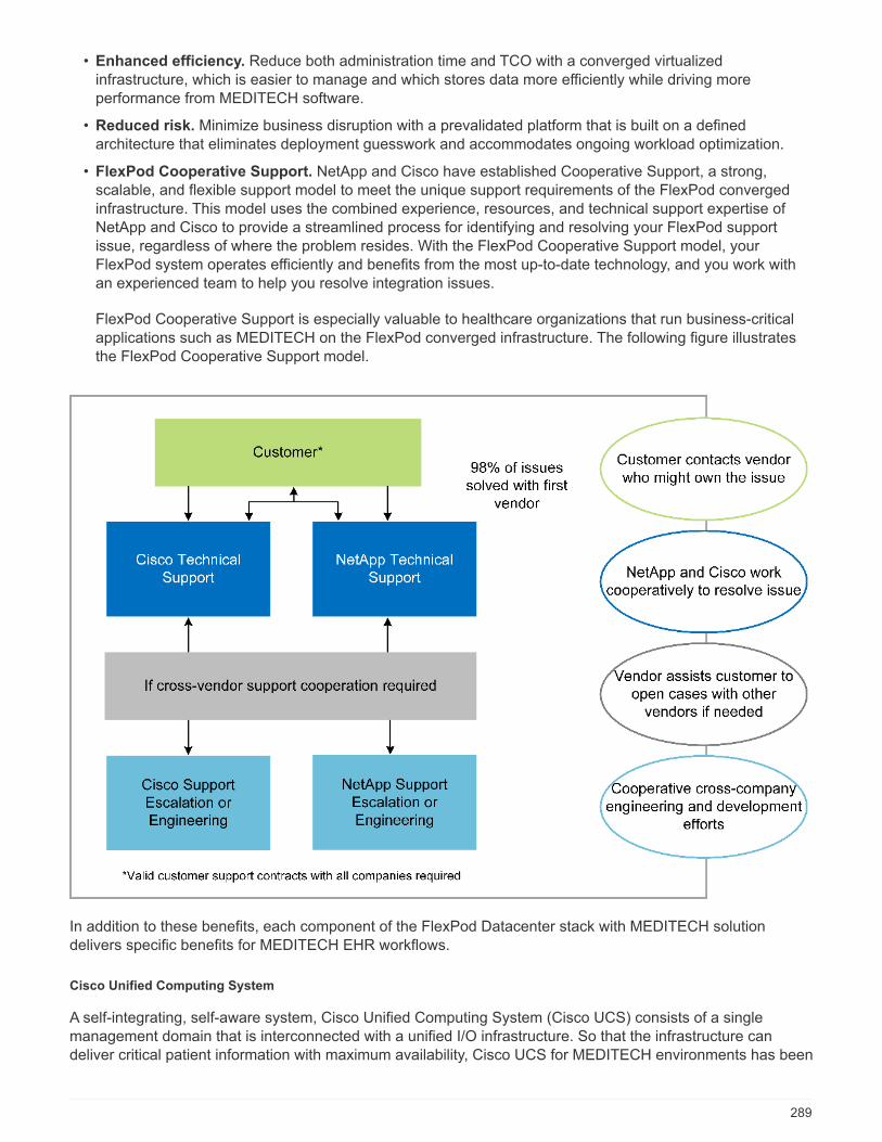
• Enhanced efficiency. Reduce both administration time and TCO with a converged virtualizedinfrastructure, which is easier to manage and which stores data more efficiently while driving moreperformance from MEDITECH software.
• Reduced risk. Minimize business disruption with a prevalidated platform that is built on a definedarchitecture that eliminates deployment guesswork and accommodates ongoing workload optimization.
• FlexPod Cooperative Support. NetApp and Cisco have established Cooperative Support, a strong,scalable, and flexible support model to meet the unique support requirements of the FlexPod convergedinfrastructure. This model uses the combined experience, resources, and technical support expertise ofNetApp and Cisco to provide a streamlined process for identifying and resolving your FlexPod supportissue, regardless of where the problem resides. With the FlexPod Cooperative Support model, yourFlexPod system operates efficiently and benefits from the most up-to-date technology, and you work withan experienced team to help you resolve integration issues.
FlexPod Cooperative Support is especially valuable to healthcare organizations that run business-criticalapplications such as MEDITECH on the FlexPod converged infrastructure. The following figure illustratesthe FlexPod Cooperative Support model.
In addition to these benefits, each component of the FlexPod Datacenter stack with MEDITECH solutiondelivers specific benefits for MEDITECH EHR workflows.
Cisco Unified Computing System
A self-integrating, self-aware system, Cisco Unified Computing System (Cisco UCS) consists of a singlemanagement domain that is interconnected with a unified I/O infrastructure. So that the infrastructure candeliver critical patient information with maximum availability, Cisco UCS for MEDITECH environments has been
289
aligned with MEDITECH infrastructure recommendations and best practices.
The foundation of MEDITECH on Cisco UCS architecture is Cisco UCS technology, with its integrated systemsmanagement, Intel Xeon processors, and server virtualization. These integrated technologies solve data centerchallenges and help you meet your goals for data center design for MEDITECH. Cisco UCS unifies LAN, SAN,and systems management into one simplified link for rack servers, blade servers, and VMs. Cisco UCS is anend-to-end I/O architecture that incorporates Cisco Unified Fabric and Cisco Fabric Extender Technology (FEXTechnology) to connect every component in Cisco UCS with a single network fabric and a single network layer.
The system can be deployed as a single or multiple logical units that incorporate and scale across multipleblade chassis, rack servers, racks, and data centers. The system implements a radically simplified architecturethat eliminates the multiple redundant devices that populate traditional blade server chassis and rack servers.In traditional systems, redundant devices such as Ethernet and FC adapters and chassis managementmodules result in layers of complexity. Cisco UCS consists of a redundant pair of Cisco UCS FabricInterconnects (FIs) that provide a single point of management, and a single point of control, for all I/O traffic.
Cisco UCS uses service profiles to help ensure that virtual servers in the Cisco UCS infrastructure areconfigured correctly. Service profiles are composed of network, storage, and compute policies that are createdonce by subject-matter experts in each discipline. Service profiles include critical server information about theserver identity such as LAN and SAN addressing, I/O configurations, firmware versions, boot order, networkvirtual LAN (VLAN), physical port, and QoS policies. Service profiles can be dynamically created andassociated with any physical server in the system in minutes, rather than in hours or days. The association ofservice profiles with physical servers is performed as a simple, single operation and enables migration ofidentities between servers in the environment without requiring any physical configuration changes. It facilitatesrapid bare-metal provisioning of replacements for retired servers.
The use of service profiles helps ensure that servers are configured consistently throughout the enterprise.When multiple Cisco UCS management domains are employed, Cisco UCS Central can use global serviceprofiles to synchronize configuration and policy information across domains. If maintenance needs to beperformed in one domain, the virtual infrastructure can be migrated to another domain. This approach helps toensure that even when a single domain is offline, applications continue to run with high availability.
To demonstrate that it meets the server configuration requirements, Cisco UCS has been extensively testedwith MEDITECH over a multiyear period. Cisco UCS is a supported server platform, as listed on theMEDITECH Product Resources System Support site.
Cisco networking
Cisco Nexus switches and Cisco MDS multilayer directors provide enterprise-class connectivity and SANconsolidation. Cisco multiprotocol storage networking reduces business risk by providing flexibility and options:FC, Fibre Connection (FICON), FC over Ethernet (FCoE), SCSI over IP (iSCSI), and FC over IP (FCIP).
Cisco Nexus switches offer one of the most comprehensive data center network feature sets in a singleplatform. They deliver high performance and density for both data center and campus cores. They also offer afull feature set for data center aggregation, end-of-row, and data center interconnect deployments in a highlyresilient modular platform.
Cisco UCS integrates computing resources with Cisco Nexus switches and a unified I/O fabric that identifiesand handles different types of network traffic. This traffic includes storage I/O, streamed desktop traffic,management, and access to clinical and business applications. You get:
• Infrastructure scalability. Virtualization, efficient power and cooling, cloud scale with automation, highdensity, and high performance all support efficient data center growth.
• Operational continuity. The design integrates hardware, NX-OS software features, and management tosupport zero-downtime environments.
290

• Network and computer QoS. Cisco delivers policy-driven class of service (CoS) and QoS across thenetworking, storage, and compute fabric for optimal performance of mission- critical applications.
• Transport flexibility. Incrementally adopt new networking technologies with a cost-effective solution.
Together, Cisco UCS with Cisco Nexus switches and Cisco MDS multilayer directors provides an optimalcompute, networking, and SAN connectivity solution for MEDITECH.
NetApp ONTAP
NetApp storage that runs ONTAP software reduces your overall storage costs while it delivers the low-latencyread and write response times and IOPS that MEDITECH workloads need. ONTAP supports both all-flash andhybrid storage configurations to create an optimal storage platform that meets MEDITECH requirements.NetApp flash-accelerated systems have received MEDITECH’s validation and certification, giving you as aMEDITECH customer the performance and responsiveness that are key to latency-sensitive MEDITECHoperations. By creating multiple fault domains in a single cluster, NetApp systems can also isolate productionfrom nonproduction. NetApp systems also reduce performance issues with a guaranteed performance levelminimum for workloads with ONTAP QoS.
The scale-out architecture of the ONTAP software can flexibly adapt to various I/O workloads. To deliver thenecessary throughput and low latency that clinical applications need while also providing a modular scale-outarchitecture, all-flash configurations are typically used in ONTAP architectures. NetApp AFF nodes can becombined in the same scale-out cluster with hybrid (HDD and flash) storage nodes that are suitable for storinglarge datasets with high throughput. Along with a MEDITECH-approved backup solution, you can clone,replicate, and back up your MEDITECH environment from expensive solid-state drive (SSD) storage to moreeconomical HDD storage on other nodes. This approach meets or exceeds MEDITECH guidelines for SAN-based cloning and backup of production pools.
Many of the ONTAP features are especially useful in MEDITECH environments: simplifying management,increasing availability and automation, and reducing the total amount of storage needed. With these features,you get:
• Outstanding performance. The NetApp AFF solution shares the Unified Storage Architecture, ONTAPsoftware, management interface, rich data services, and advanced feature set that the rest of the NetAppFAS product families have. This innovative combination of all-flash media with ONTAP delivers theconsistent low latency and high IOPS of all-flash storage with the industry-leading quality of ONTAPsoftware.
• Storage efficiency. Reduce total capacity requirements with deduplication, NetApp FlexClone datareplication technology, inline compression, inline compaction, thin replication, thin provisioning, andaggregate deduplication.
NetApp deduplication provides block-level deduplication in a NetApp FlexVol volume or data constituent.Essentially, deduplication removes duplicate blocks, storing only unique blocks in the FlexVol volume ordata constituent.
Deduplication works with a high degree of granularity and operates on the active file system of the FlexVolvolume or data constituent. It is application transparent; therefore, you can use it to deduplicate data thatoriginates from any application that uses the NetApp system. You can run volume deduplication as aninline process (starting in ONTAP 8.3.2). You can also run it as a background process that you canconfigure to run automatically, to be scheduled, or to run manually through the CLI, NetApp ONTAPSystem Manager, or NetApp Active IQ Unified Manager.
The following figure illustrates how NetApp deduplication works at the highest level.
291
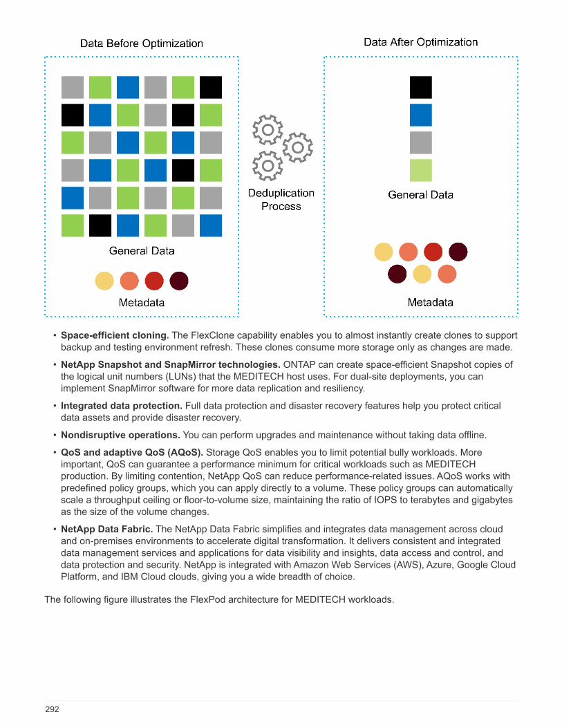
• Space-efficient cloning. The FlexClone capability enables you to almost instantly create clones to supportbackup and testing environment refresh. These clones consume more storage only as changes are made.
• NetApp Snapshot and SnapMirror technologies. ONTAP can create space-efficient Snapshot copies ofthe logical unit numbers (LUNs) that the MEDITECH host uses. For dual-site deployments, you canimplement SnapMirror software for more data replication and resiliency.
• Integrated data protection. Full data protection and disaster recovery features help you protect criticaldata assets and provide disaster recovery.
• Nondisruptive operations. You can perform upgrades and maintenance without taking data offline.
• QoS and adaptive QoS (AQoS). Storage QoS enables you to limit potential bully workloads. Moreimportant, QoS can guarantee a performance minimum for critical workloads such as MEDITECHproduction. By limiting contention, NetApp QoS can reduce performance-related issues. AQoS works withpredefined policy groups, which you can apply directly to a volume. These policy groups can automaticallyscale a throughput ceiling or floor-to-volume size, maintaining the ratio of IOPS to terabytes and gigabytesas the size of the volume changes.
• NetApp Data Fabric. The NetApp Data Fabric simplifies and integrates data management across cloudand on-premises environments to accelerate digital transformation. It delivers consistent and integrateddata management services and applications for data visibility and insights, data access and control, anddata protection and security. NetApp is integrated with Amazon Web Services (AWS), Azure, Google CloudPlatform, and IBM Cloud clouds, giving you a wide breadth of choice.
The following figure illustrates the FlexPod architecture for MEDITECH workloads.
292

MEDITECH overview
Medical Information Technology, Inc., commonly known as MEDITECH, is a Massachusetts-based softwarecompany that provides information systems for healthcare organizations. MEDITECH provides an EHR systemthat is designed to store and to organize the latest patient data and provides the data to clinical staff. Patientdata includes, but is not limited to, demographics; medical history; medication; laboratory test results; radiologyimages; and personal information such as age, height, and weight.
It is beyond the scope of this document to cover the wide span of functions that MEDITECH software supports.Appendix A provides more information about these broad sets of MEDITECH functions. MEDITECHapplications require several VMs to support these functions. To deploy these applications, see therecommendations from MEDITECH.
For each deployment, from the storage system point of view, all MEDITECH software systems require adistributed patient-centric database. MEDITECH has its own proprietary database, which uses the Windowsoperating system.
BridgeHead and Commvault are the two backup software applications that are certified by both NetApp andMEDITECH. The scope of this document does not cover the deployment of these backup applications.
The primary focus of this document is to enable the FlexPod stack (servers and storage) to meet theperformance-driven requirements for the MEDITECH database and the backup requirements in the EHRenvironment.
Purpose-built for specific MEDITECH workloads
MEDITECH does not resell server, network, or storage hardware, hypervisors, or operating systems; however,it has specific requirements for each component of the infrastructure stack. Therefore, Cisco and NetApp
293
worked together to test and to enable FlexPod Datacenter to be successfully configured, deployed, andsupported to meet the MEDITECH production environment requirements of customers like you.
MEDITECH categories
MEDITECH associates the deployment size with a category number that ranges from 1 to 6. Category 1represents the smallest MEDITECH deployments, and category 6 represents the largest MEDITECHdeployments.
For information about the I/O characteristics and performance requirements for a MEDITECH host in eachcategory, see NetApp TR-4190: NetApp Sizing Guidelines for MEDITECH Environments.
MEDITECH platform
The MEDITECH Expanse platform is the latest version of the company’s EHR software. Earlier MEDITECHplatforms are Client/Server 5.x and MAGIC. This section describes the MEDITECH platform (applicable toExpanse, 6.x, C/S 5.x, and MAGIC), pertaining to the MEDITECH host and its storage requirements.
For all the preceding MEDITECH platforms, multiple servers run MEDITECH software, performing varioustasks. The previous figure depicts a typical MEDITECH system, including MEDITECH hosts serving asapplication database servers and other MEDITECH servers. Examples of other MEDITECH servers include theData Repository application, the Scanning and Archiving application, and Background Job Clients. For thecomplete list of other MEDITECH servers, see the “Hardware Configuration Proposal” (for new deployments)and “Hardware Evaluation Task” (for existing deployments) documents. You can obtain these documents fromMEDITECH through the MEDITECH system integrator or from your MEDITECH Technical Account Manager(TAM).
MEDITECH host
A MEDITECH host is a database server. This host is also referred to as a MEDITECH file server (for theExpanse, 6.x, or C/S 5.x platform) or as a MAGIC machine (for the MAGIC platform). This document uses theterm MEDITECH host to refer to a MEDITECH file server or a MAGIC machine.
MEDITECH hosts can be physical servers or VMs that run on the Microsoft Windows Server operating system.Most commonly in the field, MEDITECH hosts are deployed as Windows VMs that run on a VMware ESXiserver. As of this writing, VMware is the only hypervisor that MEDITECH supports. A MEDITECH host storesits program, dictionary, and data files on a Microsoft Windows drive (for example, drive E) on the Windowssystem.
In a virtual environment, a Windows E drive resides on a LUN that is attached to the VM by way of a rawdevice mapping (RDM) in physical compatibility mode. The use of Virtual Machine Disk (VMDK) files as aWindows E drive in this scenario is not supported by MEDITECH.
MEDITECH host workload I/O characteristic
The I/O characteristic of each MEDITECH host and the system as a whole depends on the MEDITECHplatform that you deploy. All MEDITECH platforms (Expanse, 6.x, C/S 5.x, and MAGIC) generate workloadsthat are 100% random.
The MEDITECH Expanse platform generates the most demanding workload because it has the highestpercentage of write operations and overall IOPS per host, followed by 6.x, C/S 5.x, and the MAGIC platforms.
For more details about the MEDITECH workload descriptions, see TR-4190: NetApp Sizing Guidelines forMEDITECH Environments.
294
Storage network
MEDITECH requires that the FC Protocol be used for data traffic between the NetApp FAS or AFF system andthe MEDITECH hosts of all categories.
Storage presentation for a MEDITECH host
Each MEDITECH host uses two Windows drives:
• Drive C. This drive stores the Windows Server operating system and the MEDITECH host application files.
• Drive E. The MEDITECH host stores its program, dictionary, and data files on drive E of the WindowsServer operating system. Drive E is a LUN that is mapped from the NetApp FAS or AFF system by usingthe FC Protocol. MEDITECH requires that the FC Protocol be used so that the MEDITECH host’s IOPSand read and write latency requirements are met.
Volume and LUN naming convention
MEDITECH requires that a specific naming convention be used for all LUNs.
Before any storage deployment, verify the MEDITECH Hardware Configuration Proposal to confirm the namingconvention for the LUNs. The MEDITECH backup process relies on the volume and LUN naming convention toproperly identify the specific LUNs to back up.
Comprehensive management tools and automation capabilities
Cisco UCS with Cisco UCS Manager
Cisco focuses on three key elements to deliver a superior data center infrastructure: simplification, security,and scalability. The Cisco UCS Manager software combined with platform modularity provides a simplified,secure, and scalable desktop virtualization platform:
• Simplified. Cisco UCS provides a radical new approach to industry-standard computing and provides thecore of the data center infrastructure for all workloads. Cisco UCS offers many features and benefits,including reduction in the number of servers that you need and reduction in the number of cables that areused per server. Another important feature is the capability to rapidly deploy or to reprovision serversthrough Cisco UCS service profiles. With fewer servers and cables to manage and with streamlined serverand application workload provisioning, operations are simplified. Scores of blade and rack servers can beprovisioned in minutes with Cisco UCS Manager service profiles. Cisco UCS service profiles eliminateserver integration runbooks and eliminate configuration drift. This approach accelerates the time toproductivity for end users, improves business agility, and allows IT resources to be allocated to other tasks.
Cisco UCS Manager automates many mundane, error-prone data center operations such as configurationand provisioning of server, network, and storage access infrastructure. In addition, Cisco UCS B-SeriesBlade Servers and C-Series Rack Servers with large memory footprints enable high application userdensity, which helps reduce server infrastructure requirements.
Simplification leads to a faster, more successful MEDITECH infrastructure deployment.
• Secure. Although VMs are inherently more secure than their physical predecessors, they introduce newsecurity challenges. Mission-critical web and application servers that use a common infrastructure such asvirtual desktops are now at a higher risk for security threats. Inter- VM traffic now poses an importantsecurity consideration that your IT managers must address, especially in dynamic environments in whichVMs, using VMware vMotion, move across the server infrastructure.
Virtualization, therefore, significantly increases the need for VM- level awareness of policy and security,
295

especially given the dynamic and fluid nature of VM mobility across an extended computing infrastructure.The ease with which new virtual desktops can proliferate magnifies the importance of a virtualization-awarenetwork and security infrastructure. Cisco data center infrastructure (Cisco UCS, Cisco MDS, and CiscoNexus family solutions) for desktop virtualization provides strong data center, network, and desktopsecurity, with comprehensive security from the desktop to the hypervisor. Security is enhanced withsegmentation of virtual desktops, VM-aware policies and administration, and network security across theLAN and WAN infrastructure.
• Scalable. Growth of virtualization solutions is all but inevitable, so a solution must be able to scale, and toscale predictably, with that growth. The Cisco virtualization solutions support high VM density (VMs perserver), and more servers scale with near-linear performance. Cisco data center infrastructure provides aflexible platform for growth and improves business agility. Cisco UCS Manager service profiles allow on-demand host provisioning and make it as easy to deploy hundreds of hosts as it is to deploy dozens.
Cisco UCS Servers provide near-linear performance and scale. Cisco UCS implements the patented CiscoExtended Memory Technology to offer large memory footprints with fewer sockets (with scalability of up to1TB of memory with 2- and 4-socket servers). By using Unified Fabric technology as a building block,Cisco UCS Server aggregate bandwidth can scale up to 80Gbps per server, and the northbound CiscoUCS Fabric Interconnect can output 2Tbps at line rate. This capability helps prevent desktop virtualizationI/O and memory bottlenecks. Cisco UCS, with its high-performance, low-latency Unified Fabric-basednetworking architecture, supports high volumes of virtual desktop traffic, including high-resolution video andcommunications traffic. In addition, ONTAP helps to maintain data availability and optimal performanceduring boot and login storms as part of the FlexPod virtualization solutions.
Cisco UCS, Cisco MDS, and Cisco Nexus data center infrastructure designs provide an excellent platformfor growth. You get transparent scaling of server, network, and storage resources to support desktopvirtualization, data center applications, and cloud computing.
VMware vCenter Server
VMware vCenter Server provides a centralized platform for managing MEDITECH environments so that yourhealthcare organization can automate and deliver a virtual infrastructure with confidence:
• Simple deployment. Quickly and easily deploy vCenter Server by using a virtual appliance.
• Centralized control and visibility. Administer the entire VMware vSphere infrastructure from a singlelocation.
• Proactive optimization. Allocate and optimize resources for maximum efficiency.
• Management. Use powerful plug-ins and tools to simplify management and to extend control.
Virtual Storage Console for VMware vSphere
Virtual Storage Console (VSC), vSphere API for Storage Awareness (VASA) Provider, and VMware StorageReplication Adapter (SRA) for VMware vSphere from NetApp make up a single virtual appliance. The productsuite includes SRA and VASA Provider as plug-ins to vCenter Server, which provides end-to-end lifecyclemanagement for VMs in VMware environments that use NetApp storage systems.
The virtual appliance for VSC, VASA Provider, and SRA integrates smoothly with the VMware vSphere WebClient and enables you to use SSO services. In an environment with multiple VMware vCenter Serverinstances, each vCenter Server instance that you want to manage must have its own registered instance ofVSC. The VSC dashboard page enables you to quickly check the overall status of your datastores and VMs.
By deploying the virtual appliance for VSC, VASA Provider, and SRA, you can perform the following tasks:
296
• Use VSC to deploy and manage storage and to configure the ESXi host. You can use VSC to addcredentials, to remove credentials, to assign credentials, and to set up permissions for storage controllersin your VMware environment. In addition, you can manage ESXi servers that are connected to NetAppstorage systems. With a couple clicks, you can set recommended best practice values for host timeouts,NAS, and multipathing for all the hosts. You can also view storage details and collect diagnosticinformation.
• Use VASA Provider to create storage capability profiles and to set alarms. VASA Provider for ONTAPis registered with VSC when you enable the VASA Provider extension. You can create and use storagecapability profiles and virtual datastores. You can also set alarms to alert you when the thresholds forvolumes and aggregates are almost full. You can monitor the performance of VMDKs and the VMs that arecreated on virtual datastores.
• Use SRA for disaster recovery. You can use SRA to configure protected and recovery sites in yourenvironment for disaster recovery during failures.
NetApp OnCommand Insight and ONTAP
NetApp OnCommand Insight integrates infrastructure management into the MEDITECH service delivery chain.This approach gives your healthcare organization better control, automation, and analysis of your storage,network, and compute infrastructure. IT can optimize your current infrastructure for maximum benefit whilesimplifying the process of determining what and when to buy. It also mitigates the risks that are associated withcomplex technology migrations. Because it requires no agents, installation is straightforward andnondisruptive. Installed storage and SAN devices are continually discovered, and detailed information iscollected for full visibility of your entire storage environment. You can quickly identify misused, misaligned,underused, or orphaned assets and reclaim them to fuel future expansion. OnCommand Insight helps you:
• Optimize existing resources. Identify misused, underused, or orphaned assets by using established bestpractices to avoid problems and to meet service levels.
• Make better decisions. Real-time data helps resolve capacity problems more quickly to accurately planfuture purchases, to avoid overspending, and to defer capital expenditures.
• Accelerate IT initiatives. Better understand your virtual environments to help you manage risks, minimizedowntime, and speed cloud deployment.
Design
The architecture of FlexPod for MEDITECH is based on guidance from MEDITECH, Cisco, and NetApp andfrom partner experience in working with MEDITECH customers of all sizes. The architecture is adaptable andapplies best practices for MEDITECH, depending on your data center strategy; the size of your organization;and whether your system is centralized, distributed, or multitenant.
The correct storage architecture can be determined by the overall size with the total IOPS. Performance aloneis not the only factor, and you might decide to use a larger node count based on additional customerrequirements. The advantage of using NetApp storage is that you can easily and nondisruptively scale up thecluster as your requirements change. You can also nondisruptively remove nodes from the cluster to repurposeequipment or during equipment refreshes.
Here are some of the benefits of the NetApp ONTAP storage architecture:
• Easy, nondisruptive scale-up and scale-out. You can upgrade, add, or remove disks and nodes by usingONTAP nondisruptive operations. You can start with four nodes and move to six nodes or upgrade to largercontrollers nondisruptively.
• Storage efficiencies. Reduce your total capacity requirements with deduplication, NetApp FlexClone,inline compression, inline compaction, thin replication, thin provisioning, and aggregate deduplication. The
297
FlexClone capability enables you to almost instantly create clones to support backup and testingenvironment refreshes. These clones consume more storage only as changes are made.
• Disaster recovery shadow database server. The disaster recovery shadow database server is part ofyour business continuity strategy (used to support storage read-only functionality and potentially configuredto be a storage read/write instance). Therefore, the placement and sizing of the third storage system areusually the same as in your production database storage system.
• Database consistency (requires some consideration). If you use NetApp SnapMirror backup copies inrelation to business continuity, see TR-3446: SnapMirror Async Overview and Best Practices Guide.
Storage layout
Dedicated aggregates for MEDITECH hosts
The first step toward meeting MEDITECH’s high-performance and high-availability requirements is to properlydesign the storage layout for the MEDITECH environment to isolate the MEDITECH host production workloadonto dedicated, high-performance storage.
One dedicated aggregate should be provisioned on each storage controller for storing the program, dictionary,and data files of the MEDITECH hosts. To eliminate the possibility of other workloads using the same disks andaffecting performance, no other storage is provisioned from these aggregates.
Storage that you provision for the other MEDITECH servers should not be placed on thededicated aggregate for the LUNs that are used by the MEDITECH hosts. You should place thestorage for other MEDITECH servers on a separate aggregate. Storage requirements for otherMEDITECH servers are available in the “Hardware Configuration Proposal” (for newdeployments) and “Hardware Evaluation Task” (for existing deployments) documents. You canobtain these documents from MEDITECH through the MEDITECH system integrator or fromyour MEDITECH Technical Account Manager (TAM). NetApp solutions engineers might consultwith the NetApp MEDITECH Independent Software Vendor (ISV) team to facilitate a proper andcomplete NetApp storage sizing configuration.
Spread MEDITECH host workload evenly across all storage controllers
NetApp FAS and AFF systems are deployed as one or more high-availability pairs. NetApp recommends thatyou spread the MEDITECH Expanse and 6.x workloads evenly across each storage controller to apply thecompute, network, and caching resources on each storage controller.
Use the following guidelines to spread the MEDITECH workloads evenly across each storage controller:
• If you know the IOPS for each MEDITECH host, you can spread the MEDITECH Expanse and 6.xworkloads evenly across all storage controllers by confirming that each controller services a similar numberof IOPS from the MEDITECH hosts.
• If you do not know the IOPS for each MEDITECH host, you can still spread the MEDITECH Expanse and6.x workloads evenly across all storage controllers. Complete this task by confirming that the capacity ofthe aggregates for the MEDITECH hosts is evenly distributed across all storage controllers. By doing so,the number of disks is the same across all data aggregates that are dedicated to the MEDITECH hosts.
• Use similar disk types and identical RAID groups to create the storage aggregates of both controllers fordistributing the workloads equally. Before you create the storage aggregate, contact a NetApp CertifiedIntegrator.
298
According to MEDITECH, two hosts in the MEDITECH system generate higher IOPS than therest of the hosts. The LUNs for these two hosts should be placed on separate storagecontrollers. You should identify these two hosts with the assistance of the MEDITECH teambefore you deploy your system.
Storage Placement
Database storage for MEDITECH hosts
The database storage for a MEDITECH host is presented as a block device (that is, a LUN) from the NetAppFAS or AFF system. The LUN is typically mounted to the Windows operating system as the E drive.
Other storage
The MEDITECH host operating system and the database application normally generate a considerable amountof IOPS on the storage. Storage provisioning for the MEDITECH host VMs and their VMDK files, if necessary,is considered independent from the storage that is required to meet the MEDITECH performance thresholds.
Storage that is provisioned for the other MEDITECH servers should not be placed on the dedicated aggregatefor the LUNs that the MEDITECH hosts use. Place the storage for other MEDITECH servers on a separateaggregate.
Storage controller configuration
High availability
To mitigate the effect of controller failure and to enable nondisruptive upgrades of the storage system, youshould configure your storage system with controllers in a high-availability pair in the high-availability mode.
With the high-availability controller pair configuration, disk shelves should be connected to controllers bymultiple paths. This connection increases storage resiliency by protecting against a single-path failure, and itimproves performance consistency if a controller failover occurs.
Storage performance during storage controller failover
For storage systems that are configured with controllers in a high-availability pair, in the unlikely event of acontroller failure, the partner controller takes over the failed controller’s storage resources and workloads. It isimportant to consult the customer to determine the performance requirements that must be met if there is acontroller failure and to size the system accordingly.
Hardware-assisted takeover
NetApp recommends that you turn on the hardware-assisted takeover feature on both storage controllers.
Hardware-assisted takeover is designed to minimize the storage controller failover time. It enables onecontroller’s Remote LAN Module or Service Processor module to notify its partner about a controller failurefaster than a heartbeat timeout trigger can, reducing the time that it takes to failover. The hardware-assistedtakeover feature is enabled by default for storage controllers in a high-availability configuration.
For more information about hardware-assisted takeover, see the ONTAP 9 Documentation Center.
Disk type
To support the low read latency requirement of MEDITECH workloads, NetApp recommends that you use a
299

high-performance SSD for aggregates on AFF systems that are dedicated for the MEDITECH hosts.
NetApp AFF
NetApp offers high-performance AFF arrays to address MEDITECH workloads that demand high throughputand that have random data access patterns and low- latency requirements. For MEDITECH workloads, AFFarrays offer performance advantages over systems that are based on HDDs. The combination of flashtechnology and enterprise data management delivers advantages in three major areas: performance,availability, and storage efficiency.
NetApp Support tools and services
NetApp offers a complete set of support tools and services. The NetApp AutoSupport tool should be enabledand configured on NetApp AFF/FAS systems to call home if there is a hardware failure or systemmisconfiguration. Calling home alerts the NetApp Support team to remediate any issues in a timely manner.NetApp Active IQ is a web based application that is based on AutoSupport information from your NetAppsystems providing predictive and proactive insight to help improve availability, efficiency, and performance.
Deployment and configuration
Overview
The NetApp storage guidance for FlexPod deployment that is provided in this document covers:
• Environments that use ONTAP
• Environments that use Cisco UCS blade and rack-mount servers
This document does not cover:
• Detailed deployment of the FlexPod Datacenter environment
For more information, see FlexPod Datacenter with FC Cisco Validated Design (CVD).
• An overview of MEDITECH software environments, reference architectures, and integration best practicesguidance.
For more information, see TR-4300i: NetApp FAS and All-Flash Storage Systems for MEDITECHEnvironments Best Practices Guide (NetApp login required).
• Quantitative performance requirements and sizing guidance.
For more information, see TR-4190: NetApp Sizing Guidelines for MEDITECH Environments.
• Use of NetApp SnapMirror technologies to meet backup and disaster recovery requirements.
• Generic NetApp storage deployment guidance.
This section provides an example configuration with infrastructure deployment best practices and lists thevarious infrastructure hardware and software components and the versions that you can use.
Cabling diagram
The following figure illustrates the 32Gb FC/40GbE topology diagram for a MEDITECH deployment.
300
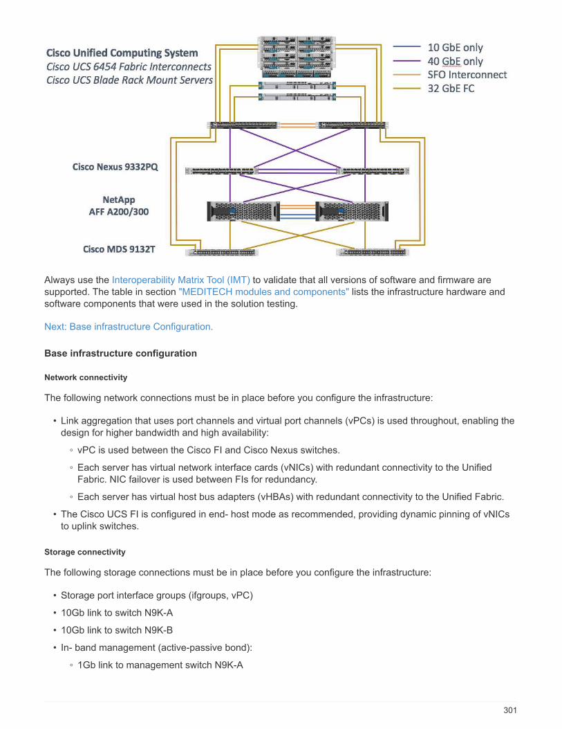
Always use the Interoperability Matrix Tool (IMT) to validate that all versions of software and firmware aresupported. The table in section "MEDITECH modules and components" lists the infrastructure hardware andsoftware components that were used in the solution testing.
Next: Base infrastructure Configuration.
Base infrastructure configuration
Network connectivity
The following network connections must be in place before you configure the infrastructure:
• Link aggregation that uses port channels and virtual port channels (vPCs) is used throughout, enabling thedesign for higher bandwidth and high availability:
◦ vPC is used between the Cisco FI and Cisco Nexus switches.
◦ Each server has virtual network interface cards (vNICs) with redundant connectivity to the UnifiedFabric. NIC failover is used between FIs for redundancy.
◦ Each server has virtual host bus adapters (vHBAs) with redundant connectivity to the Unified Fabric.
• The Cisco UCS FI is configured in end- host mode as recommended, providing dynamic pinning of vNICsto uplink switches.
Storage connectivity
The following storage connections must be in place before you configure the infrastructure:
• Storage port interface groups (ifgroups, vPC)
• 10Gb link to switch N9K-A
• 10Gb link to switch N9K-B
• In- band management (active-passive bond):
◦ 1Gb link to management switch N9K-A
301
◦ 1Gb link to management switch N9K-B
• 32Gb FC end-to-end connectivity through Cisco MDS switches; single initiator zoning configured
• FC SAN boot to fully achieve stateless computing; servers are booted from LUNs in the boot volume that ishosted on the AFF storage cluster
• All MEDITECH workloads are hosted on FC LUNs, which are spread across the storage controller nodes
Host software
The following software must be installed:
• ESXi installed on the Cisco UCS blades
• VMware vCenter installed and configured (with all the hosts registered in vCenter)
• VSC installed and registered in VMware vCenter
• NetApp cluster configured
Next: Cisco UCS Blade Server and Switch Configuration.
Cisco UCS blade server and switch configuration
The FlexPod for MEDITECH software is designed with fault tolerance at every level. There is no single point offailure in the system. For optimal performance, Cisco recommends the use of hot spare blade servers.
This document provides high-level guidance on the basic configuration of a FlexPod environment forMEDITECH software. In this section, we present high-level steps with some examples to prepare the CiscoUCS compute platform element of the FlexPod configuration. A prerequisite for this guidance is that theFlexPod configuration is racked, powered, and cabled per the instructions in the FlexPod Datacenter with FibreChannel Storage using VMware vSphere 6.5 Update 1, NetApp AFF A-series and Cisco UCS Manager 3.2CVD.
Cisco Nexus switch configuration
A fault- tolerant pair of Cisco Nexus 9300 Series Ethernet switches is deployed for the solution. You shouldcable these switches as described in the Cabling Diagram section. The Cisco Nexus configuration helpsensure that Ethernet traffic flows are optimized for the MEDITECH application.
1. After you have completed the initial setup and licensing, run the following commands to set globalconfiguration parameters on both switches:
spanning-tree port type network default
spanning-tree port type edge bpduguard default
spanning-tree port type edge bpdufilter default
port-channel load-balance src-dst l4port
ntp server <global-ntp-server-ip> use-vrf management
ntp master 3
ip route 0.0.0.0/0 <ib-mgmt-vlan-gateway>
copy run start
2. Create the VLANs for the solution on each switch using the global configuration mode:
302
vlan <ib-mgmt-vlan-id>
name IB-MGMT-VLAN
vlan <native-vlan-id>
name Native-VLAN
vlan <vmotion-vlan-id>
name vMotion-VLAN
vlan <vm-traffic-vlan-id>
name VM-Traffic-VLAN
vlan <infra-nfs-vlan-id>
name Infra-NFS-VLAN
exit
copy run start
3. Create the Network Time Protocol (NTP) distribution interface, port channels, port channel parameters, andport descriptions for troubleshooting per FlexPod Datacenter with Fibre Channel Storage using VMwarevSphere 6.5 Update 1, NetApp AFF A-series and Cisco UCS Manager 3.2 CVD.
Cisco MDS 9132T configuration
The Cisco MDS 9100 Series FC switches provide redundant 32Gb FC connectivity between the NetApp AFFA200 or AFF A300 controllers and the Cisco UCS compute fabric. You should connect the cables as describedin the Cabling Diagram section.
1. From the consoles on each MDS switch, run the following commands to enable the required features forthe solution:
configure terminal
feature npiv
feature fport-channel-trunk
2. Configure individual ports, port channels, and descriptions as per the FlexPod Cisco MDS switchconfiguration section in FlexPod Datacenter with FC Cisco Validated Design.
3. To create the necessary virtual SANs (VSANs) for the solution, complete the following steps while in globalconfiguration mode:
a. For the Fabric-A MDS switch, run the following commands:
303
vsan database
vsan <vsan-a-id>
vsan <vsan-a-id> name Fabric-A
exit
zone smart-zoning enable vsan <vsan-a-id>
vsan database
vsan <vsan-a-id> interface fc1/1
vsan <vsan-a-id> interface fc1/2
vsan <vsan-a-id> interface port-channel110
vsan <vsan-a-id> interface port-channel112
The port channel numbers in the last two lines of the command were created when the individual ports,port channels, and descriptions were provisioned by using the reference document.
b. For the Fabric-B MDS switch, run the following commands:
vsan database
vsan <vsan-b-id>
vsan <vsan-b-id> name Fabric-B
exit
zone smart-zoning enable vsan <vsan-b-id>
vsan database
vsan <vsan-b-id> interface fc1/1
vsan <vsan-b-id> interface fc1/2
vsan <vsan-b-id> interface port-channel111
vsan <vsan-b-id> interface port-channel113
The port channel numbers in the last two lines of the command were created when the individual ports,port channels, and descriptions were provisioned by using the reference document.
4. For each FC switch, create device alias names that make the identification of each device intuitive forongoing operations by using the details in the reference document.
5. Finally, create the FC zones by using the device alias names that were created in step 4 for each MDSswitch as follows:
a. For the Fabric-A MDS switch, run the following commands:
304
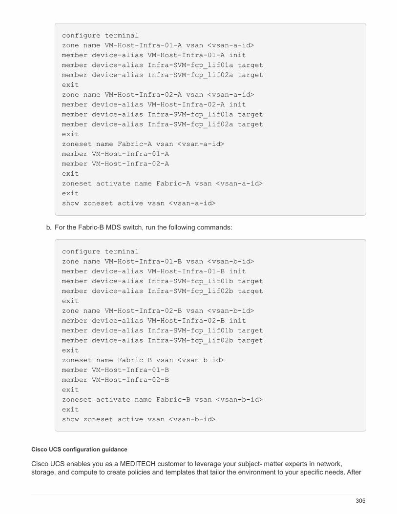
configure terminal
zone name VM-Host-Infra-01-A vsan <vsan-a-id>
member device-alias VM-Host-Infra-01-A init
member device-alias Infra-SVM-fcp_lif01a target
member device-alias Infra-SVM-fcp_lif02a target
exit
zone name VM-Host-Infra-02-A vsan <vsan-a-id>
member device-alias VM-Host-Infra-02-A init
member device-alias Infra-SVM-fcp_lif01a target
member device-alias Infra-SVM-fcp_lif02a target
exit
zoneset name Fabric-A vsan <vsan-a-id>
member VM-Host-Infra-01-A
member VM-Host-Infra-02-A
exit
zoneset activate name Fabric-A vsan <vsan-a-id>
exit
show zoneset active vsan <vsan-a-id>
b. For the Fabric-B MDS switch, run the following commands:
configure terminal
zone name VM-Host-Infra-01-B vsan <vsan-b-id>
member device-alias VM-Host-Infra-01-B init
member device-alias Infra-SVM-fcp_lif01b target
member device-alias Infra-SVM-fcp_lif02b target
exit
zone name VM-Host-Infra-02-B vsan <vsan-b-id>
member device-alias VM-Host-Infra-02-B init
member device-alias Infra-SVM-fcp_lif01b target
member device-alias Infra-SVM-fcp_lif02b target
exit
zoneset name Fabric-B vsan <vsan-b-id>
member VM-Host-Infra-01-B
member VM-Host-Infra-02-B
exit
zoneset activate name Fabric-B vsan <vsan-b-id>
exit
show zoneset active vsan <vsan-b-id>
Cisco UCS configuration guidance
Cisco UCS enables you as a MEDITECH customer to leverage your subject- matter experts in network,storage, and compute to create policies and templates that tailor the environment to your specific needs. After
305
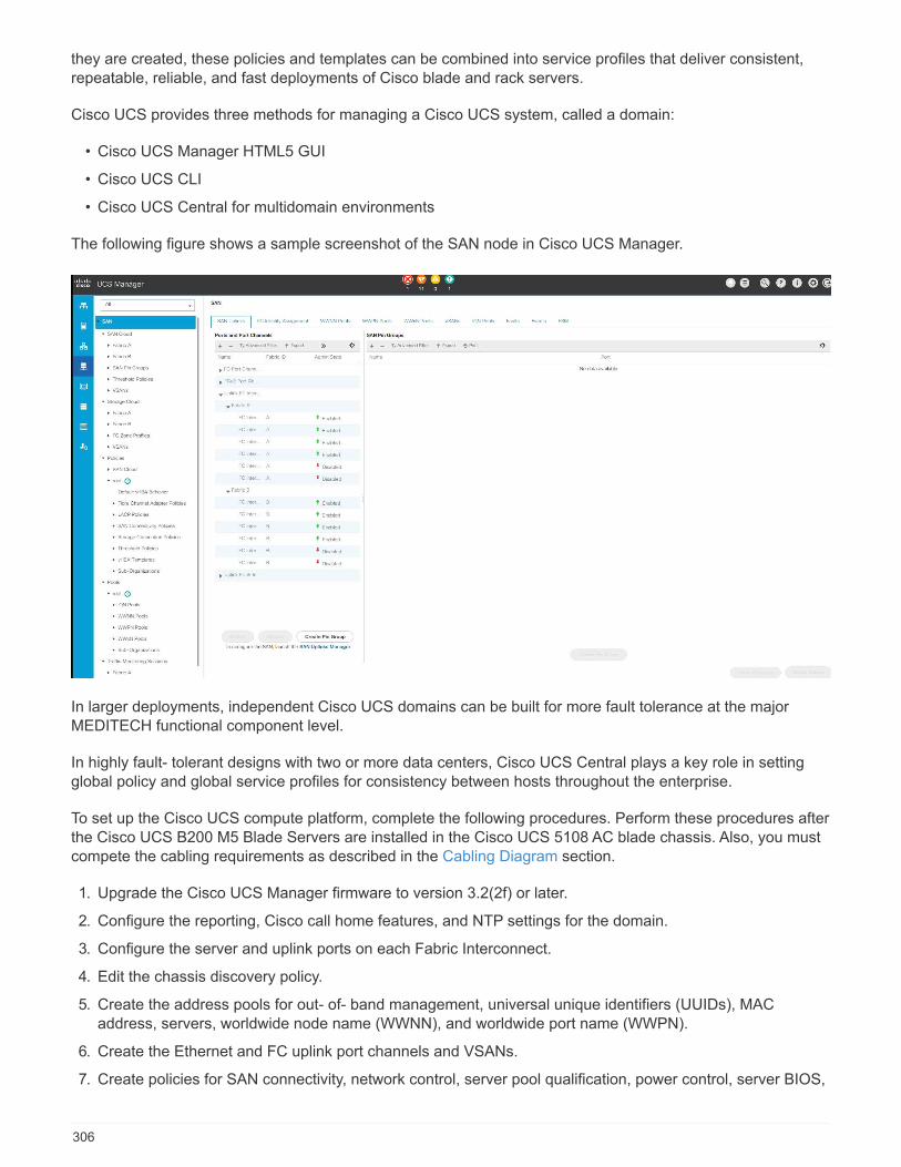
they are created, these policies and templates can be combined into service profiles that deliver consistent,repeatable, reliable, and fast deployments of Cisco blade and rack servers.
Cisco UCS provides three methods for managing a Cisco UCS system, called a domain:
• Cisco UCS Manager HTML5 GUI
• Cisco UCS CLI
• Cisco UCS Central for multidomain environments
The following figure shows a sample screenshot of the SAN node in Cisco UCS Manager.
In larger deployments, independent Cisco UCS domains can be built for more fault tolerance at the majorMEDITECH functional component level.
In highly fault- tolerant designs with two or more data centers, Cisco UCS Central plays a key role in settingglobal policy and global service profiles for consistency between hosts throughout the enterprise.
To set up the Cisco UCS compute platform, complete the following procedures. Perform these procedures afterthe Cisco UCS B200 M5 Blade Servers are installed in the Cisco UCS 5108 AC blade chassis. Also, you mustcompete the cabling requirements as described in the Cabling Diagram section.
1. Upgrade the Cisco UCS Manager firmware to version 3.2(2f) or later.
2. Configure the reporting, Cisco call home features, and NTP settings for the domain.
3. Configure the server and uplink ports on each Fabric Interconnect.
4. Edit the chassis discovery policy.
5. Create the address pools for out- of- band management, universal unique identifiers (UUIDs), MACaddress, servers, worldwide node name (WWNN), and worldwide port name (WWPN).
6. Create the Ethernet and FC uplink port channels and VSANs.
7. Create policies for SAN connectivity, network control, server pool qualification, power control, server BIOS,
306

and default maintenance.
8. Create vNIC and vHBA templates.
9. Create vMedia and FC boot policies.
10. Create service profile templates and service profiles for each MEDITECH platform element.
11. Associate the service profiles with the appropriate blade servers.
For the detailed steps to configure each key element of the Cisco UCS service profiles for FlexPod, see theFlexPod Datacenter with Fibre Channel Storage using VMware vSphere 6.5 Update 1, NetApp AFF A-seriesand Cisco UCS Manager 3.2 CVD document.
Next: ESXi Configuration Best Practices.
ESXi configuration best practices
For the ESXi host-side configuration, configure the VMware hosts as you would run any enterprise databaseworkload:
• VSC for VMware vSphere checks and sets the ESXi host multipathing settings and HBA timeout settingsthat work best with NetApp storage systems. The values that VSC sets are based on rigorous internaltesting by NetApp.
• For optimal storage performance, consider using storage hardware that supports VMware vStorage APIs -Array Integration (VAAI). The NetApp Plug- In for VAAI is a software library that integrates the VMwareVirtual Disk Libraries that are installed on the ESXi host. The VMware VAAI package enables the offloadingof certain tasks from the physical hosts to the storage array.
You can perform tasks such as thin provisioning and hardware acceleration at the array level to reduce theworkload on the ESXi hosts. The copy offload feature and space reservation feature improve theperformance of VSC operations. You can download the plug-in installation package and obtain theinstructions for installing the plug-in from the NetApp Support site.
VSC sets ESXi host timeouts, multipath settings, and HBA timeout settings and other values for optimalperformance and successful failover of the NetApp storage controllers. Follow these steps:
1. From the VMware vSphere Web Client home page, select vCenter > Hosts.
2. Right-click a host and then select Actions > NetApp VSC > Set Recommended Values.
3. In the NetApp Recommended Settings dialog box, select the values that work best with your system.
The standard recommended values are set by default.
307
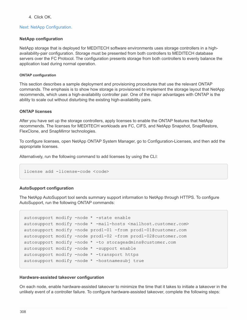
4. Click OK.
Next: NetApp Configuration.
NetApp configuration
NetApp storage that is deployed for MEDITECH software environments uses storage controllers in a high-availability-pair configuration. Storage must be presented from both controllers to MEDITECH databaseservers over the FC Protocol. The configuration presents storage from both controllers to evenly balance theapplication load during normal operation.
ONTAP configuration
This section describes a sample deployment and provisioning procedures that use the relevant ONTAPcommands. The emphasis is to show how storage is provisioned to implement the storage layout that NetApprecommends, which uses a high-availability controller pair. One of the major advantages with ONTAP is theability to scale out without disturbing the existing high-availability pairs.
ONTAP licenses
After you have set up the storage controllers, apply licenses to enable the ONTAP features that NetApprecommends. The licenses for MEDITECH workloads are FC, CIFS, and NetApp Snapshot, SnapRestore,FlexClone, and SnapMirror technologies.
To configure licenses, open NetApp ONTAP System Manager, go to Configuration-Licenses, and then add theappropriate licenses.
Alternatively, run the following command to add licenses by using the CLI:
license add -license-code <code>
AutoSupport configuration
The NetApp AutoSupport tool sends summary support information to NetApp through HTTPS. To configureAutoSupport, run the following ONTAP commands:
autosupport modify -node * -state enable
autosupport modify -node * -mail-hosts <mailhost.customer.com>
autosupport modify -node prod1-01 -from [email protected]
autosupport modify -node prod1-02 -from [email protected]
autosupport modify -node * -to [email protected]
autosupport modify -node * -support enable
autosupport modify -node * -transport https
autosupport modify -node * -hostnamesubj true
Hardware-assisted takeover configuration
On each node, enable hardware-assisted takeover to minimize the time that it takes to initiate a takeover in theunlikely event of a controller failure. To configure hardware-assisted takeover, complete the following steps:
308
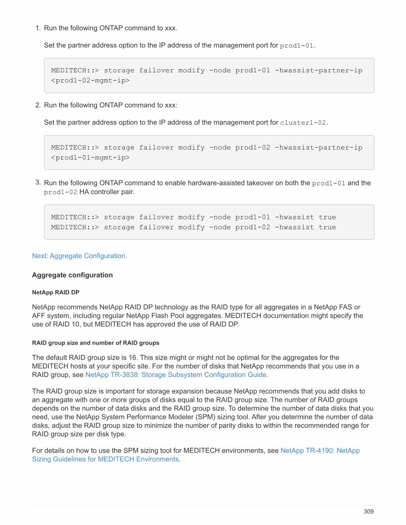
1. Run the following ONTAP command to xxx.
Set the partner address option to the IP address of the management port for prod1-01.
MEDITECH::> storage failover modify -node prod1-01 -hwassist-partner-ip
<prod1-02-mgmt-ip>
2. Run the following ONTAP command to xxx:
Set the partner address option to the IP address of the management port for cluster1-02.
MEDITECH::> storage failover modify -node prod1-02 -hwassist-partner-ip
<prod1-01-mgmt-ip>
3. Run the following ONTAP command to enable hardware-assisted takeover on both the prod1-01 and the
prod1-02 HA controller pair.
MEDITECH::> storage failover modify -node prod1-01 -hwassist true
MEDITECH::> storage failover modify -node prod1-02 -hwassist true
Next: Aggregate Configuration.
Aggregate configuration
NetApp RAID DP
NetApp recommends NetApp RAID DP technology as the RAID type for all aggregates in a NetApp FAS orAFF system, including regular NetApp Flash Pool aggregates. MEDITECH documentation might specify theuse of RAID 10, but MEDITECH has approved the use of RAID DP.
RAID group size and number of RAID groups
The default RAID group size is 16. This size might or might not be optimal for the aggregates for theMEDITECH hosts at your specific site. For the number of disks that NetApp recommends that you use in aRAID group, see NetApp TR-3838: Storage Subsystem Configuration Guide.
The RAID group size is important for storage expansion because NetApp recommends that you add disks toan aggregate with one or more groups of disks equal to the RAID group size. The number of RAID groupsdepends on the number of data disks and the RAID group size. To determine the number of data disks that youneed, use the NetApp System Performance Modeler (SPM) sizing tool. After you determine the number of datadisks, adjust the RAID group size to minimize the number of parity disks to within the recommended range forRAID group size per disk type.
For details on how to use the SPM sizing tool for MEDITECH environments, see NetApp TR-4190: NetAppSizing Guidelines for MEDITECH Environments.
309

Storage expansion considerations
When you expand aggregates with more disks, add the disks in groups that are equal to the aggregate RAIDgroup size. Following this approach helps provide performance consistency throughout the aggregate.
For example, to add storage to an aggregate that was created with a RAID group size of 20, the number ofdisks that NetApp recommends adding is one or more 20-disk groups. So, you should add 20, 40, 60, and soon, disks.
After you expand aggregates, you can improve performance by running reallocation tasks on the affectedvolumes or aggregate to spread existing data stripes over the new disks. This action is helpful particularly if theexisting aggregate was nearly full.
You should plan reallocation of schedules during nonproduction hours because it is a high-CPUand disk-intensive task.
For more information about using reallocation after an aggregate expansion, see NetApp TR-3929: ReallocateBest Practices Guide.
Aggregate-level Snapshot copies
Set the aggregate-level NetApp Snapshot copy reserve to zero and disable the default aggregate Snapshotschedule. Delete any preexisting aggregate-level Snapshot copies if possible.
Next: Storage Virtual Machine Configuration.
Storage virtual machine configuration
This section pertains to deployment on ONTAP 8.3 and later versions.
A storage virtual machine (SVM) is also known as a Vserver in the ONTAP API and in theONTAP CLI.
SVM for MEDITECH host LUNs
You should create one dedicated SVM per ONTAP storage cluster to own and to manage the aggregates thatcontain the LUNs for the MEDITECH hosts.
SVM language encoding setting
NetApp recommends that you set the language encoding for all SVMs. If no language encoding setting isspecified at the time that the SVM is created, the default language encoding setting is used. The defaultlanguage encoding setting is C.UTF-8 for ONTAP. After the language encoding has been set, you cannotmodify the language of an SVM with Infinite Volume later.
The volumes that are associated with the SVM inherit the SVM language encoding setting unless you explicitlyspecify another setting when the volumes are created. To enable certain operations to work, you should usethe language encoding setting consistently in all volumes for your site. For example, SnapMirror requires thesource and destination SVM to have the same language encoding setting.
Next: Volume Configuration.
310
Volume configuration
Volume provisioning
MEDITECH volumes that are dedicated for MEDITECH hosts can be either thick or thin provisioned.
Default volume-level Snapshot copies
Snapshot copies are created as part of the backup workflow. Each Snapshot copy can be used to access thedata stored in the MEDITECH LUNs at different times. The MEDITECH- approved backup solution createsthin-provisioned FlexClone volumes based on these Snapshot copies to provide point-in-time copies of theMEDITECH LUNs. The MEDITECH environment is integrated with an approved backup software solution.Therefore, NetApp recommends that you disable the default Snapshot copy schedule on each of the NetAppFlexVol volumes that make up the MEDITECH production database LUNs.
Important: FlexClone volumes share parent data volume space, so it is vital for the volume to have enoughspace for the MEDITECH data LUNs and the FlexClone volumes that the backup servers create. FlexClonevolumes do not occupy more space the way that data volumes do. However, if there are huge deletions on theMEDITECH LUNs in a short time, the clone volumes might grow.
Number of volumes per aggregate
For a NetApp FAS system that uses Flash Pool or NetApp Flash Cache caching, NetApp recommendsprovisioning three or more volumes per aggregate that are dedicated for storing the MEDITECH program,dictionary, and data files.
For AFF systems, NetApp recommends dedicating four or more volumes per aggregate for storing theMEDITECH program, dictionary, and data files.
Volume-level reallocate schedule
The data layout of storage becomes less optimal over time, especially when it is used by write-intensiveworkloads such as the MEDITECH Expanse, 6.x, and C/S 5.x platforms. Over time, this situation mightincrease sequential read latency, resulting in a longer time to complete the backup. Bad data layout orfragmentation can also affect the write latency. You can use volume-level reallocation to optimize the layout ofdata on disk to improve write latencies and sequential read access. The improved storage layout helps tocomplete the backup within the allocated time window of 8 hours.
Best practice
At a minimum, NetApp recommends that you implement a weekly volume reallocation schedule to runreallocation operations during the allocated maintenance downtime or during off-peak hours on a productionsite.
NetApp highly recommends that you run the reallocation task on one volume at a time percontroller.
For more information about determining an appropriate volume reallocation schedule for your productiondatabase storage, see section 3.12 in NetApp TR-3929: Reallocate Best Practices Guide. That section alsoguides you on how to create a weekly reallocation schedule for a busy site.
Next: LUN Configuration.
311
LUN configuration
The number of MEDITECH hosts in your environment determines the number of LUNs that are created withinthe NetApp FAS or AFF system. The Hardware Configuration Proposal specifies the size of each LUN.
LUN provisioning
MEDITECH LUNs that are dedicated for MEDITECH hosts can be either thick or thin provisioned.
LUN operating system type
To properly align the LUNs that are created, you must correctly set the operating system type for the LUNs.Misaligned LUNs incur unnecessary write operation overhead, and it is costly to correct a misaligned LUN.
The MEDITECH host server typically runs in the virtualized Windows Server environment by using the VMwarevSphere hypervisor. The host server can also run in the Windows Server environment on a bare-metal server.To determine the correct operating system type value to set, refer to the “LUN Create” section of ClusteredData ONTAP 8.3 Commands: Manual Page Reference.
LUN size
To determine the LUN size for each MEDITECH host, see the Hardware Configuration Proposal (newdeployment) or the Hardware Evaluation Task (existing deployment) document from MEDITECH.
LUN presentation
MEDITECH requires that storage for program, dictionary, and data files be presented to MEDITECH hosts asLUNs by using the FC Protocol. In the VMware virtual environment, the LUNs are presented to the VMwareESXi servers that host the MEDITECH hosts. Then each LUN that is presented to the VMware ESXi server ismapped to each MEDITECH host VM by using RDM in the physical compatibility mode.
You should present the LUNs to the MEDITCH hosts by using the proper LUN naming conventions. For
example, for easy administration, you must present the LUN MTFS01E to the MEDITECH host mt-host-01.
Refer to the MEDITECH Hardware Configuration Proposal when you consult with the MEDITECH and backupsystem installer to devise a consistent naming convention for the LUNs that the MEDITECH hosts use.
An example of a MEDITECH LUN name is MTFS05E, in which:
• MTFS denotes the MEDITECH file server (for the MEDITECH host).
• 05 denotes host number 5.
• E denotes the Windows E drive.
Next: Initiator Group Configuration.
Initiator group configuration
When you use FC as the data network protocol, create two initiator groups (igroups) on each storagecontroller. The first igroup contains the WWPNs of the FC host interface cards on the VMware ESXi serversthat host the MEDITECH host VMs (igroup for MEDITECH).
You must set the MEDITECH igroup operating system type according to the environment setup. For example:
• Use the igroup operating system type Windows for applications that are installed on bare-metal-server
312

hardware in a Windows Server environment.
• Use the igroup operating system type VMware for applications that are virtualized by using the VMwarevSphere hypervisor.
The operating system type for an igroup might be different from the operating system type for aLUN. As an example, for virtualized MEDITECH hosts, you should set the igroup operating
system type to VMware. For the LUNs that are used by the virtualized MEDITECH hosts, you
should set the operating system type to Windows 2008 or later. Use this setting becausethe MEDITECH host operating system is the Windows Server 2008 R2 64-bit Enterprise Edition.
To determine the correct value for the operating system type, see the sections “LUN Igroup Create” and “LUNCreate” in the Clustered Data ONTAP 8.2 Commands: Manual Page Reference.
Next: LUN Mappings.
LUN mappings
LUN mappings for the MEDITECH hosts are established when the LUNs are created.
MEDITECH modules and components
The MEDITECH application covers several modules and components. The following table lists the functionsthat are covered by these modules. For additional information about setting up and deploying these modules,see the MEDITECH documentation.
Function Type
Connectivity • Web server
• Live application server (WI – Web Integration)
• Test application server (WI)
• SAML authentication server (WI)
• SAML proxy server (WI)
• Database server
Infrastructure • File server
• Background Job Client
• Connection server
• Transaction server
Scanning and archiving • Image server
Data repository • SQL Server
Business and clinical analytics • Live intelligence server (BCA)
• Test intelligence server (BCA)
• Database server (BCA)
313

Function Type
Home care • Remote site solution
• Connectivity
• Infrastructure
• Printing
• Field devices
• Scanning
• Hosted site requirements
• Firewall configuration
Support • Background Job Client (CALs – Client AccessLicense)
User devices • Tablets
• Fixed devices
Printing • Live network print server (required; might alreadyexist)
• Test network print server (required; might alreadyexist)
Third-party requirement • First Databank (FDB) MedKnowledge Frameworkv4.3
Acknowledgments
The following people contributed to the creation of this guide.
• Brandon Agee, Technical Marketing Engineer, NetApp
• Atul Bhalodia, Technical Marketing Engineer, NetApp
• Ketan Mota, Senior Product Manager, NetApp
• John Duignan, Solutions Architect—Healthcare, NetApp
• Jon Ebmeier, Cisco
• Mike Brennan, Cisco
Where to find additional information
To learn more about the information that is described in this document, review the following documents orwebsites:
FlexPod design zone
• FlexPod Design Zone
314
• FlexPod Data Center with FC Storage (MDS Switches) Using NetApp AFF, vSphere 6.5U1, and Cisco UCSManager
NetApp technical reports
• TR-3929: Reallocate Best Practices Guide
• TR-3987: Snap Creator Framework Plug-In for InterSystems Caché
• TR-4300i: NetApp FAS and All-Flash Storage Systems for MEDITECH Environments Best Practices Guide
• TR-4017: FC SAN Best Practices
• TR-3446: SnapMirror Async Overview and Best Practices Guide
ONTAP documentation
• NetApp Product Documentation
• Virtual Storage Console (VSC) for vSphere documentation
• ONTAP 9 Documentation Center:
◦ FC Express Guide for ESXi
• All ONTAP 9.3 Documentation:
◦ Software Setup Guide
◦ Disks and Aggregates Power Guide
◦ SAN Administration Guide
◦ SAN Configuration Guide
◦ FC Configuration for Windows Express Guide
◦ FC SAN Optimized AFF Setup Guide
◦ High-Availability Configuration Guide
◦ Logical Storage Management Guide
◦ Performance Management Power Guide
◦ SMB/CIFS Configuration Power Guide
◦ SMB/CIFS Reference
◦ Data Protection Power Guide
◦ Data Protection Tape Backup and Recovery Guide
◦ NetApp Encryption Power Guide
◦ Network Management Guide
◦ Commands: Manual Page Reference for ONTAP 9.3
Cisco Nexus, MDS, Cisco UCS, and Cisco UCS Manager guides
• Cisco UCS Servers Overview
• Cisco UCS Blade Servers Overview
• Cisco UCS B200 M5 Datasheet
• Cisco UCS Manager Overview
315
• Cisco UCS Manager 3.2(3a) Infrastructure Bundle (requires Cisco.com authorization)
• Cisco Nexus 9300 Platform Switches
• Cisco MDS 9132T FC Switch
FlexPod for Medical Imaging
TR-4865: FlexPod for Medical Imaging
Jaya Kishore Esanakula and Atul Bhalodia, NetApp
Medical imaging accounts for 70% of all data that is generated by Healthcare organizations. As digitalmodalities continue to advance and new modalities emerge, the amount of data will continue to increase. Forexample, the transition from analog to digital pathology will dramatically increase image sizes at a rate that willchallenge any data management strategies currently in place.
COVID-19 has clearly reshaped the digital transformation; according to a recent report, COVID-19 hasaccelerated digital commerce by 5 years. The technological innovation driven by problem solvers isfundamentally changing the way that we go about our daily life. This technology-driven change will overhaulmany critical aspects of our life, including healthcare.
Healthcare is poised to undergo a major change in the coming years. COVID is accelerating innovation inhealthcare that will propel the industry by at least several years. At the heart of this change is the need to makehealthcare more flexible in handling pandemics by being more affordable, available, and accessible, withoutcompromising reliability.
At the foundation of this healthcare change is a well-designed platform. One of the key metrics to measure theplatform is the ease with which platform changes can be implemented. Speed is the new scale and dataprotection cannot be compromised. Some of the world’s most critical data is being created and consumed bythe clinical systems that support clinicians. NetApp has made critical data available for patient care where theclinicians need it, on premise, in the cloud, or in a hybrid setting. Hybrid multi- cloud environments are thecurrent state of the art for IT architecture.
Healthcare as we know it revolves around providers (doctors, nurses, radiologists, medical device technicians,and so on) and patients. As we bring patients and providers closer together, making the geographic location amere data point, it becomes even more important for the underlying platform to be available when providersand patients need it. The platform must be both efficient and cost-effective in the long term. In their efforts todrive patient care costs even lower, Accountable Care Organizations (ACOs) would be empowered by anefficient platform.
When it comes to health information systems used by healthcare organizations, the question of build versuspurchase tends to have a single answer: purchase. This could be for many subjective reasons. Purchasingdecisions made over many years can create heterogeneous information systems. Each system has a specificset of requirements for the platform that they are deployed on. The most significant issue is the large, diverseset of storage protocols and performance levels that information systems require, which makes platformstandardization and optimal operational efficiency a significant challenge. Healthcare organizations cannotfocus on mission critical issues because their attention is spread thin by trivial operational needs like the largeset of platforms that require a diversified set of skills and thus SME retention.
The challenges can be classified into the following categories:
• Heterogeneous storage needs
• Departmental silos
316
• IT operational complexity
• Cloud connectivity
• Cybersecurity
• Artificial intelligence and deep learning
With FlexPod, you get a single platform that supports FC, FCoE, iSCSI, NFS/pNFS, SMB/CIFS and so on froma single platform. People, processes, and technology are part of the DNA that FlexPod is designed and builtupon. FlexPod adaptive QoS helps to break down the departmental silos by supporting multiple mission criticalclinical systems on the same underlying FlexPod platform. FlexPod is FedRAMP certified and FIPS 140-2certified. Additionally, healthcare organizations are faced with opportunities such as artificial intelligence anddeep learning. FlexPod and NetApp solve these challenges and make the data available where it is needed onpremises or in a hybrid multi- cloud setting in a standardized platform. For more information and a seriescustomer success stories, see FlexPod Healthcare.
Typical medical imaging information and PACS systems have the following set of capabilities:
• Reception and registration
• Scheduling
• Imaging
• Transcription
• Management
• Data exchange
• Image archive
• Image viewing for image capturing and reading for technicians and image viewing for clinicians
Regarding imaging, the healthcare sector is trying to solve the following clinical challenges:
• Wider adoption of natural language processing (NLP)-based assistants by technicians and physicians forimage reading. Radiology department can benefit from voice recognition to transcribe reports. NLP can beused to identify and anonymize a patient’s record, specifically DICOM tags embedded in the DICOMimage. NLP capabilities require high performing platforms with low latency response times for imageprocessing. FlexPod QoS not only delivers and performance but also provides mature capacity projectionsfor future growth.
• Wider adoption of standardized clinical pathways and protocols by ACOs and community healthorganizations. Historically, clinical pathways have been used as a static set of guidelines rather than anintegrated workflow that guides clinical decisions. With advancements in NLP and image processing,DICOM tags in images can be integrated into clinical pathways as facts to drive clinical decisions.Therefore, these processes require high performance, low latency, and high throughput from the underlyinginfrastructure platform and storage systems.
• ML models that leverage convolutional neural networks enable automation of image- processingcapabilities in real time and thus require infrastructure that is GPU-capable. FlexPod offers both CPU andGPU compute components built into the same system, and CPUs and GPUs can be scaled independentlyof each other.
• If DICOM tags are used as facts in clinical best-practice advisories, then the system must perform morereads of DICOM artifacts with low latency and high throughput.
• When evaluating images, real-time collaboration between radiologists across organizations requires highperformance graphics processing in the end- user compute devices. NetApp provides industry- leading VDIsolutions specifically designed and proven for high-end graphics use cases. More information can be found
317
here.
• Image and media management across ACO health organizations can uses a single platform, regardless ofthe system of record for the image, by using protocols such as Digital Imaging and Communications inMedicine ( DICOM) and web access to DICOM-persistent objects ( WADO)
• Health information exchange ( HIE) includes images embedded in messages.
• Mobile modalities, such as handheld, wireless scanning devices (for example, pocket handheld ultrasoundscanners attached to a phone), require a robust network infrastructure with DoD-level security, reliability,and latency at the edge, the core, and in the cloud. A data fabric enabled by NetApp provide organizationswith this capability at scale.
• Newer modalities have exponential storage needs; for example, CT and MRI require a few hundred MBsfor each modality, but digital pathology images (including whole slide imaging) can be a few GBs in size.FlexPod is designed with performance, reliability and scaling as foundational traits.
A well-architected medical imaging system platform is at the heart of innovation. The FlexPod architectureprovides flexible compute and storage capabilities with industry-leading storage efficiency.
Overall solution benefits
By running an imaging application environment on a FlexPod architectural foundation, your healthcareorganization can expect to see an improvement in staff productivity and a decrease in capital and operatingexpenses. FlexPod provides a rigorously tested, prevalidated, converged that is engineered and designed todeliver predictable low-latency system performance and high availability. This approach results in high comfortlevels and, ultimately, optimal response times for users of the medical imaging system.
Different components of the imaging system might require the storage of data in SMB/CIFS, NFS, Ext4, orNTFS file systems. That requirement means that the infrastructure must provide data access over the NFS,SMB/CIFS, and SAN protocols. A single NetApp storage system can support the NFS, SMB/CIFS, and SANprotocols, thus eliminating the need for the legacy practice of protocol- specific storage systems.
The FlexPod infrastructure is a modular, converged, virtualized, scalable (scale-out and scale- up), and cost-effective platform. With the FlexPod platform, you can independently scale out compute, network, and storageto accelerate your application deployment. And the modular architecture enables nondisruptive operationseven during system scale-out and upgrade activities.
FlexPod delivers several benefits that are specific to the medical imaging industry:
• Low-latency system performance. Radiologist time is a high- value resource, and efficient use of aradiologist’s time is paramount. Waiting for images or videos to load can contribute to clinician burnout andcan affect clinician’s efficiency and patient safety.
• Modular architecture. FlexPod components are connected through a clustered server, a storagemanagement fabric, and a cohesive management toolset. As imaging facilities grow year over year and thenumber of studies increase, there will be a need for the underlying infrastructure to scale accordingly.FlexPod can scale compute, storage, and network independently.
• Quicker deployment of infrastructure. Whether it is in an existing data center or a remote location, theintegrated and tested design of FlexPod Datacenter with Medical Imaging enables you to get the newinfrastructure up and running in less time, with less effort.
• Accelerated application deployment. A prevalidated architecture reduces implementation integrationtime and risk for any workload, and NetApp technology automates infrastructure deployment. Whether youuse the solution for an initial rollout of medical imaging, a hardware refresh, or expansion, you can shiftmore resources to the business value of the project.
• Simplified operations and lower costs. You can eliminate the expense and complexity of legacy
318

proprietary platforms by replacing them with a more efficient and scalable shared resource that can meetthe dynamic needs of your workload. This solution delivers higher infrastructure resource utilization forgreater return on investment (ROI).
• Scale-out architecture. You can scale SAN and NAS from terabytes to tens of petabytes withoutreconfiguring running applications.
• Nondisruptive operations. You can perform storage maintenance, hardware lifecycle operations, andsoftware upgrades without interrupting your business.
• Secure multitenancy. This benefit supports the increased needs of virtualized server and storage sharedinfrastructure, enabling secure multitenancy of facility-specific information, particularly if you are hostingmultiple instances of databases and software.
• Pooled resource optimization. This benefit can help you reduce physical server and storage controllercounts, load- balance workload demands, and boost utilization while improving performance.
• Quality of service (QoS). FlexPod offers QoS on the entire stack. These industry-leading QoS storagepolicies enable differentiated service levels in a shared environment. These policies help optimizeperformance for workloads and help to isolate and control runaway applications.
• Support for storage tier SLAs by using QoS. You don’t have to deploy different storage systems for thedifferent storage tiers that a medical imaging environment typically requires. A single storage cluster withmultiple NetApp FlexVol volumes with specific QoS policies for different tiers can serve that purpose. Withthis approach, storage infrastructure can be shared by dynamically accommodating the changing needs ofa particular storage tier. NetApp AFF can support different SLAs for storage tiers by allowing QoS at thelevel of the FlexVol volume, thus eliminating the need for different storage systems for different storagetiers for the application.
• Storage efficiency. Medical images are typically pre-compressed by the imaging application to jpeg2klossless compression which is around 2.5:1. However, this is imaging application and vendor specific. Inlarger imaging application environments (greater than 1PB), 5-10% storage savings are possible, and youcan reduce storage costs with NetApp storage efficiency features. Work with your imaging applicationvendors and your NetApp subject matter expert to unlock potential storage efficiencies for your medicalimaging system.
• Agility. With the industry-leading workflow automation, orchestration, and management tools that FlexPodsystems offer, your IT team can be far more responsive to business requests. These business requestscan range from medical imaging backup and provisioning of additional test and training environments toanalytics database replications for population health- management initiatives.
• Higher productivity. You can quickly deploy and scale this solution for optimal clinician end-userexperiences.
• Data fabric. Your data fabric powered by NetApp weaves data together across sites, beyond physicalboundaries, and across applications. Your data fabric powered by NetApp is built for data-drivenenterprises in a data-centric world. Data is created and used in multiple locations, and it often needs to beleveraged and shared with other locations, applications, and infrastructures. So, you want a consistent andintegrated way to manage it. This solution provides a way to manage data that puts your IT team in controland that simplifies ever-increasing IT complexity.
• FabricPool. NetApp ONTAP FabricPool helps reduce storage costs without compromising performance,efficiency, security, or protection. FabricPool is transparent to enterprise applications and capitalizes oncloud efficiencies by lowering storage TCO without the need to rearchitect the application infrastructure.FlexPod can benefit from the storage tiering capabilities of FabricPool to make more efficient use ofONTAP flash storage. For full information, see FlexPod with FabricPool.
• FlexPod security. Security is at the very foundation of FlexPod. In the past few years, ransomware hasbecome a significant and increasing threat. Ransomware is malware that is based on crypto virology, theuse of cryptography to build malicious software. This malware can use both symmetric and asymmetric keyencryption to lock a victim’s data and demand a ransom to provide the key to decrypt the data. To learn
319
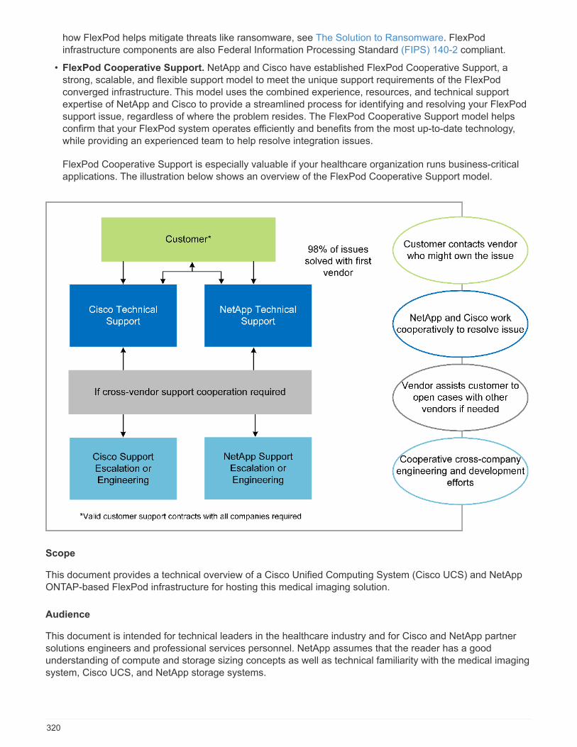
how FlexPod helps mitigate threats like ransomware, see The Solution to Ransomware. FlexPodinfrastructure components are also Federal Information Processing Standard (FIPS) 140-2 compliant.
• FlexPod Cooperative Support. NetApp and Cisco have established FlexPod Cooperative Support, astrong, scalable, and flexible support model to meet the unique support requirements of the FlexPodconverged infrastructure. This model uses the combined experience, resources, and technical supportexpertise of NetApp and Cisco to provide a streamlined process for identifying and resolving your FlexPodsupport issue, regardless of where the problem resides. The FlexPod Cooperative Support model helpsconfirm that your FlexPod system operates efficiently and benefits from the most up-to-date technology,while providing an experienced team to help resolve integration issues.
FlexPod Cooperative Support is especially valuable if your healthcare organization runs business-criticalapplications. The illustration below shows an overview of the FlexPod Cooperative Support model.
Scope
This document provides a technical overview of a Cisco Unified Computing System (Cisco UCS) and NetAppONTAP-based FlexPod infrastructure for hosting this medical imaging solution.
Audience
This document is intended for technical leaders in the healthcare industry and for Cisco and NetApp partnersolutions engineers and professional services personnel. NetApp assumes that the reader has a goodunderstanding of compute and storage sizing concepts as well as technical familiarity with the medical imagingsystem, Cisco UCS, and NetApp storage systems.
320
Medical imaging application
A typical medical imaging application offers a suite of applications that together make an enterprise-gradeimaging solution for small, medium, and large healthcare organizations.
At the heart of the product suite are the following clinical capabilities:
• Enterprise imaging repository
• Supports traditional image sources such as radiology and cardiology. Also supports other care areas likeophthalmology, dermatology, colonoscopy, and other medical imaging objects like photos and videos.
• Picture archiving and communication system (PACS), which is a computerized means of replacing theroles of conventional radiological film
• Enterprise Imaging Vendor Neutral Archive (VNA):
◦ Scalable consolidation of DICOM and non-DICOM documents
◦ Centralized Medical Imaging system
◦ Support for document synchronization and data integrity between multiple (PACSs) in the enterprise
◦ Document lifecycle management by a rules-based expert system that leverages document metadata,such as:
◦ Modality type
◦ Age of study
◦ Patient age (current and at the time of image capture)
◦ Single point of integration within and outside (HIE) of the enterprise:
◦ Context- aware document linking
◦ Health Level Seven International (HL7), DICOM, and WADO
◦ Storage- agnostic archiving capability
• Integration with other health information systems that use HL7 and context-aware linking:
◦ Enables EHRs to implement direct links to patient images from patient charts, imaging workflows, andso on.
◦ Helps embed a patient’s longitudinal care image history into EHRs.
• Radiology technologist workflows
• Enterprise zero footprint viewers for image viewing from anywhere on any capable device
• Analytical tools that leverage retrospective and real-time data:
◦ Compliance reporting
◦ Operational reports
◦ Quality control and quality assurance reports
Size of the healthcare organization and platform sizing
Healthcare organizations can be broadly classified by using standards-based methods that help programssuch as ACO. One such classification uses the concept of a clinical integrated network (CIN). A group ofhospitals can be called a CIN if they collaborate and adhere to proven standard clinical protocols and pathwaysto improve the value of care and reduce patient costs. Hospitals within a CIN have controls and practices inplace to onboard physicians who follow the core values of the CIN. Traditionally, an integrated deliverynetworks (IDN) has been limited to hospitals and physician groups. A CIN crosses traditional IDN boundaries,
321
and a CIN can still be part of an ACO. Following the principles of a CIN, healthcare organizations can beclassified into small, medium, and large.
Small healthcare organizations
A healthcare organization is small if it includes only a single hospital with ambulatory clinics and an inpatientdepartment, but it is not part of a CIN. Physicians work as caregivers and coordinate patient care during a carecontinuum. These small organizations typically include physician-operated facilities. They might or might notoffer emergency and trauma care as integrated care for the patient. Typically, a small-sized healthcareorganization performs about 250,000 clinical imaging studies annually. Imaging centers are considered to besmall healthcare organizations and they do provide imaging services. Some also provide radiology dictationservices to other organizations.
Medium healthcare organizations
A healthcare organization considered to be of medium size if it includes multiple hospital systems with focusedorganizations, such as the following:
• Adult care clinics and adult inpatient hospitals
• Labor and delivery departments
• Childcare clinics and child inpatient hospitals
• A cancer treatment center
• Adult emergency departments
• Child emergency departments
• A family medicine and primary care office
• An adult trauma care center
• A child trauma care center
In a medium-sized healthcare organization, physicians follow the principles of a CIN and operate as a singleunit. Hospitals have separate hospital, physician, and pharmacy billing functions. Hospitals might beassociated with academic research institutes and perform interventional clinical research and trials. A mediumhealthcare organization performs as many as 500,000 clinical imaging studies annually.
Large healthcare organizations
A healthcare organization is considered to be large if it includes the traits of a medium- sized healthcareorganization and offers the medium-sized clinical capabilities to the community in multiple geographicallocations.
A large healthcare organization typically performs the following functions:
• Has a central office to manage the overall functions
• Participates in joint ventures with other hospitals
• Negotiates rates with payer organizations annually
• Negotiates payer rates by state and region
• Participates in Meaningful Use (MU) programs
• Performs advanced clinical research across population health cohorts by using standards-basedpopulation health management (PHM) tools
322
• Performs up to one million clinical imaging studies annually
Some large healthcare organizations that participate in a CIN also have AI- based imaging reading capabilities.These organizations typically perform one to two million clinical imaging studies annually.
Before you look into how these different-sized organizations translate into an optimally sized FlexPod system,you should understand the various FlexPod components and the different capabilities of a FlexPod system.
FlexPod
Cisco Unified Computing System
Cisco UCS consists of a single management domain that is interconnected with a unified I/O infrastructure.Cisco UCS for medical imaging environments has been aligned with NetApp medical imaging systeminfrastructure recommendations and best practices so that the infrastructure can deliver critical patientinformation with maximum availability.
The compute foundation of enterprise medical imaging is Cisco UCS technology, with its integrated systemsmanagement, Intel Xeon processors, and server virtualization. These integrated technologies solve data centerchallenges and enable you to meet your goals for data center design with a typical medical imaging system.Cisco UCS unifies LAN, SAN, and systems management into one simplified link for rack servers, bladeservers, and virtual machines (VMs). Cisco UCS consists of a redundant pair of Cisco UCS fabricinterconnects that provide a single point of management and a single point of control for all I/O traffic.
Cisco UCS uses service profiles so that virtual servers in the Cisco UCS infrastructure are configured correctlyand consistently. Service profiles include critical server information about the server identity, such as LAN andSAN addressing, I/O configurations, firmware versions, boot order, network virtual LAN (VLAN), physical port,and QoS policies. Service profiles can be dynamically created and associated with any physical server in thesystem in minutes rather than in hours or days. The association of service profiles with physical servers isperformed as a single, simple operation that enables migration of identities between servers in the environmentwithout requiring any physical configuration changes. It also facilitates rapid bare-metal provisioning ofreplacements for failed servers.
The use of service profiles helps confirm that servers are configured consistently throughout the enterprise.When using multiple Cisco UCS management domains, Cisco UCS Central can use global service profiles tosynchronize configuration and policy information across domains. If maintenance must be performed in onedomain, the virtual infrastructure can be migrated to another domain. With this approach, even when a singledomain is offline, applications continue to run with high availability.
Cisco UCS is a next-generation solution for blade and rack server computing. The system integrates a low-latency, lossless, 40GbE unified network fabric with enterprise-class, x86-architecture servers. The system isan integrated, scalable, multi-chassis platform in which all resources participate in a unified managementdomain. Cisco UCS accelerates the delivery of new services simply, reliably, and securely through end-to-endprovisioning and migration support for both virtualized and nonvirtualized systems. Cisco UCS provides thefollowing features:
• Comprehensive management
• Radical simplification
• High performance
Cisco UCS consists of the following components:
• Compute. The system is based on an entirely new class of computing system that incorporates rack-mounted and blade servers based on the Intel Xeon scalable processor product family.
323
• Network. The system is integrated into a low-latency, lossless, 40Gbps unified network fabric. Thisnetwork foundation consolidates LANs, SANs, and high-performance computing networks, which areseparate networks today. The unified fabric lowers costs by reducing the number of network adapters,switches, and cables and also by decreasing power and cooling requirements.
• Virtualization. The system unleashes the full potential of virtualization by enhancing the scalability,performance, and operational control of virtual environments. Cisco security, policy enforcement, anddiagnostic features are now extended into virtualized environments to better support changing businessand IT requirements.
• Storage access. The system provides consolidated access to both SAN storage and NAS over the unifiedfabric. It is also an ideal system for software-defined storage. By combining the benefits of a singleframework to manage both the compute and the storage servers in a single pane, QoS can beimplemented if needed to inject I/O throttling in the system. And your server administrators can preassignstorage-access policies to storage resources, which simplifies storage connectivity and management andcan help increase productivity. In addition to external storage, both rack and blade servers have internalstorage that can be accessed through built-in hardware RAID controllers. By setting up the storage profileand disk configuration policy in Cisco UCS Manager, the storage needs of the host OS and application dataare fulfilled by user-defined RAID groups. The result is high availability and better performance.
• Management. The system uniquely integrates all system components so that the entire solution can bemanaged as a single entity by Cisco UCS Manager. To manage all system configuration and operations,Cisco UCS Manager has an intuitive GUI, a CLI, and a powerful scripting library module for MicrosoftWindows PowerShell that are built on a robust API.
Cisco Unified Computing System fuses access layer networking and servers. This high-performance, next-generation server system gives your data center a high degree of workload agility and scalability.
Cisco UCS Manager
Cisco UCS Manager provides unified, embedded management for all software and hardware components inCisco UCS. By using single- connection technology, UCS Manager manages, controls, and administersmultiple chassis for thousands of VMs. Through an intuitive GUI, a CLI, or an XML API, your administrators usethe software to manage the entire Cisco UCS as a single logical entity. Cisco UCS Manager resides on a pairof Cisco UCS 6300 Series Fabric Interconnects that use clustered, active-standby configuration for highavailability.
Cisco UCS Manager offers a unified embedded management interface that integrates your servers, network,and storage. Cisco UCS Manager performs auto discovery to detect the inventory of, to manage, and toprovision system components that you add or change. It offers a comprehensive set of XML APIs for third-partyintegration, and it exposes 9,000 points of integration. It also facilitates custom development for automation, fororchestration, and to achieve new levels of system visibility and control.
Service profiles benefit both virtualized and nonvirtualized environments. They increase the mobility ofnonvirtualized servers, such as when you move workloads from server to server or when you take a serveroffline for service or upgrade. You can also use profiles in conjunction with virtualization clusters to bring newresources online easily, complementing existing VM mobility.
For more information about Cisco UCS Manager, see the Cisco UCS Manager product page.
Cisco UCS differentiators
Cisco Unified Computing System is revolutionizing the way that servers are managed in the data center. Seethe following unique differentiators of Cisco UCS and Cisco UCS Manager:
• Embedded management. In Cisco UCS, the servers are managed by the embedded firmware in the fabricinterconnects, eliminating the need for any external physical or virtual devices to manage them.
324

• Unified fabric. In Cisco UCS, from blade server chassis or rack servers to fabric interconnects, a singleEthernet cable is used for LAN, SAN, and management traffic. This converged I/O reduces the number ofcables, SFPs, and adapters that you need, in turn reducing your capital and operational expenses for theoverall solution.
• Autodiscovery. By simply inserting the blade server in the chassis or by connecting rack servers to thefabric interconnects, discovery and inventory of compute resource occurs automatically without anymanagement intervention. The combination of unified fabric and auto discovery enables the wire-oncearchitecture of Cisco UCS, where its compute capability can be extended easily while keeping the existingexternal connectivity to LAN, SAN, and management networks.
• Policy-based resource classification. When a compute resource is discovered by Cisco UCS Manager, itcan be automatically classified to a given resource pool based on the policies that you defined. Thiscapability is useful in multitenant cloud computing.
• Combined rack and blade server management. Cisco UCS Manager can manage B-Series bladeservers and C-Series rack servers under the same Cisco UCS domain. This feature, along with statelesscomputing, makes compute resources truly hardware form factor–agnostic.
• Model-based management architecture. The Cisco UCS Manager architecture and managementdatabase are model-based and data-driven. The open XML API that is provided to operate on themanagement model enables easy and scalable integration of Cisco UCS Manager with other managementsystems.
• Policies, pools, and templates. The management approach in Cisco UCS Manager is based on definingpolicies, pools, and templates instead of a cluttered configuration. It enables a simple, loosely coupled,data-driven approach in managing compute, network, and storage resources.
• Loose referential integrity. In Cisco UCS Manager, a service profile, a port profile, or policies can refer toother policies or to other logical resources with loose referential integrity. A referred policy cannot exist atthe time of authoring the referring policy, but a referred policy can be deleted even though other policiesare referring to it. This feature enables different subject-matter experts to work independently from eachother. You gain great flexibility by enabling different experts from different domains—such as network,storage, security, server, and virtualization—to work together to accomplish a complex task.
• Policy resolution. In Cisco UCS Manager, you can create a tree structure of organizational unit hierarchythat mimics the real-life tenants and organizational relationships. You can define various policies, pools,and templates at different levels of your organizational hierarchy. A policy that refers to another policy byname is resolved in the organizational hierarchy with the closest policy match. If no policy with a specificname is found in the hierarchy of the root organization, then a special policy named “default” is searched.This policy resolution practice enables automation-friendly management APIs and provides great flexibilityto the owners of the different organizations.
• Service profiles and stateless computing. A service profile is a logical representation of a server,carrying its various identities and policies. You can assign this logical server to any physical computeresource, as long as it meets the resource requirements. Stateless computing enables procurement of aserver within minutes, which used to take days in legacy server management systems.
• Built-in multitenancy support. The combination of policies, pools, templates, a loose referential integrity,policy resolution in organizational hierarchy, and a service profiles- based approach to compute resourcesmakes Cisco UCS Manager inherently friendly to multitenant environments that are typically observed inprivate and public clouds.
• Extended memory. The enterprise-class Cisco UCS B200 M5 Blade Server extends the capabilities of theCisco Unified Computing System portfolio in a half-width blade form factor. The Cisco UCS B200 M5harnesses the power of the latest Intel Xeon scalable- processor CPUs with up to 3TB of RAM. Thisfeature enables the huge VM-to-physical- server ratio that many deployments need or enables certainarchitectures to support large memory operations, such as big data.
• Virtualization- aware network. Cisco Virtual Machine Fabric Extender (VM-FEX) technology makes the
325
access network layer aware of host virtualization. This awareness prevents pollution of compute andnetwork domains with virtualization when a virtual network is managed by port profiles that are defined byyour network administrator team. VM-FEX also offloads hypervisor CPU by performing switching in thehardware, thus enabling the hypervisor CPU to perform more virtualization- related tasks. To simplify cloudmanagement, VM-FEX technology is well integrated with VMware vCenter, Linux Kernel-Based VirtualMachine (KVM), and Microsoft Hyper-V SR-IOV.
• Simplified QoS. Even though FC and Ethernet are converged in the Cisco UCS, built-in support for QoSand lossless Ethernet make it seamless. By representing all system classes in one GUI panel, networkQoS is simplified in Cisco UCS Manager.
Cisco Nexus IP and MDS switches
Cisco Nexus switches and Cisco MDS multilayer directors give you enterprise-class connectivity and SANconsolidation. Cisco multiprotocol storage networking helps reduce your business risk by providing flexibilityand options: FC, Fiber Connection (FICON), FC over Ethernet (FCoE), iSCSI, and FC over IP (FCIP).
Cisco Nexus switches offer one of the most comprehensive data center network feature sets in a singleplatform. They deliver high performance and density for both the data center and the campus core. They alsooffer a full feature set for data center aggregation, end-of-row, and data center interconnect deployments in ahighly resilient modular platform.
Cisco UCS integrates compute resources with Cisco Nexus switches and a unified fabric that identifies andhandles different types of network traffic. This traffic includes storage I/O, streamed desktop traffic,management, and access to clinical and business applications. You get the following capabilities:
• Infrastructure scalability. Virtualization, efficient power and cooling, cloud scale with automation, highdensity, and performance all support efficient data center growth.
• Operational continuity. The design integrates hardware, Cisco NX-OS software features, andmanagement to support zero-downtime environments.
• Transport flexibility. You can incrementally adopt new networking technologies with this cost-effectivesolution.
Together, Cisco UCS with Cisco Nexus switches and MDS multilayer directors provide a compute, networking,and SAN connectivity solution for an enterprise medical Imaging system.
NetApp all-flash storage
NetApp storage that runs ONTAP software reduces your overall storage costs while delivering the low- latencyread and write response times and high IOPS that medical imaging system workloads need. To create anoptimal storage system that meets a typical medical imaging system requirement, ONTAP supports both all-flash and hybrid storage configurations. NetApp flash storage gives medical imaging system customers likeyou the key components of high performance and responsiveness to support latency-sensitive medical imagingsystem operations. By creating multiple fault domains in a single cluster, NetApp technology can also isolateyour production environments from your nonproduction environments. And by guaranteeing that systemperformance do not drop below a certain level for workloads with ONTAP minimum QoS, NetApp reducesperformance issues for your system.
The scale-out architecture of ONTAP software can flexibly adapt to your various I/O workloads. To deliver thenecessary throughput and low latency that clinical applications need and to provide a modular scale-outarchitecture, all-flash configurations are typically used in ONTAP architectures. NetApp AFF nodes can becombined in the same scale-out cluster with hybrid (HDD and flash) storage nodes, suitable for storing largedatasets with high throughput. You can clone, replicate, and back up your medical imaging systemenvironment from expensive SSD storage to more economical HDD storage on other nodes. With NetAppcloud-enabled storage and a data fabric delivered by NetApp, you can back up to object storage on premises
326

or in the cloud.
For medical imaging, ONTAP has been validated by most leading medical imaging systems. That means it hasbeen tested to deliver fast and reliable performance for medical imaging. Additionally, the following featuressimplify management, increase availability and automation, and reduce the total amount of storage that youneed.
• Outstanding performance. The NetApp AFF solution shares the same unified storage architecture,ONTAP software, management interface, rich data services, and advanced feature set as the rest of theNetApp FAS product families. This innovative combination of all-flash media with ONTAP gives you theconsistent low latency and high IOPS of all-flash storage with industry- leading ONTAP software.
• Storage efficiency. You can reduce your total capacity requirements work with your NetApp SME tounderstand how this applied your specific medical imaging system.
• Space-efficient cloning. With the FlexClone capability, your system can almost instantly create clones tosupport backup and testing environment refresh. These clones consume additional storage only aschanges are made.
• Integrated data protection. Full data protection and disaster recovery features help you protect yourcritical data assets and provide disaster recovery.
• Nondisruptive operations. You can perform upgrades and maintenance without taking data offline.
• QoS. Storage QoS helps you limit potential bully workloads. More importantly, QoS creates a minimumperformance guarantee that your system performance will not drop below a certain level for criticalworkloads such as a medical imaging system’s production environment. And by limiting contention, NetAppQoS can also reduce performance-related issues.
• Data fabric. To accelerate digital transformation, your data fabric delivered by NetApp simplifies andintegrates data management across cloud and on-premises environments. It delivers consistent andintegrated data management services and applications for superior data visibility and insights, data accessand control, and data protection and security. NetApp is integrated with large public clouds, such AWS,Azure, Google Cloud, and IBM Cloud, giving you a wide breadth of choice.
Host virtualization — VMware vSphere
FlexPod architectures are validated with VMware vSphere 6.x, which is the industry- leading virtualizationplatform. VMware ESXi 6.x is used to deploy and run the VMs. vCenter Server Appliance 6.x is used tomanage the ESXi hosts and VMs. Multiple ESXi hosts that run on Cisco UCS B200 M5 blades are used to forma VMware ESXi cluster. The VMware ESXi cluster pools the compute, memory, and network resources from allthe cluster nodes and provides a resilient platform for the VMs that are running on the cluster. The VMwareESXi cluster features, vSphere high availability, and Distributed Resource Scheduler (DRS) all contribute to thevSphere cluster’s tolerance to withstand failures, and they help distribute the resources across the VMwareESXi hosts.
The NetApp storage plug-in and the Cisco UCS plug-in integrate with VMware vCenter to enable operationalworkflows for your required storage and compute resources.
The VMware ESXi cluster and vCenter Server give you a centralized platform for deploying medical imagingenvironments in VMs. Your healthcare organization can realize all the benefits of an industry- leading virtualinfrastructure with confidence, such as the following:
• Simple deployment. Quickly and easily deploy vCenter Server by using a virtual appliance.
• Centralized control and visibility. Administer the entire vSphere infrastructure from a single location.
• Proactive optimization. Allocate, optimize, and migrate resources for maximum efficiency.
• Management. Use powerful plug-ins and tools to simplify management and to extend control.
327

Architecture
The FlexPod architecture is designed to provide high availability if a component or a link fails in your entirecompute, network, and storage stack. Multiple network paths for client access and storage access provide loadbalancing and optimal resource utilization.
The following figure illustrates the 16Gb FC/40Gb Ethernet (40GbE) topology for the medical imaging systemsolution deployment.
Storage architecture
Use the storage architecture guidelines in this section to configure your storage infrastructure for an enterprisemedical imaging system.
Storage tiers
A typical enterprise medical imaging environment consists of several different storage tiers. Each tier hasspecific performance and storage protocol requirements. NetApp storage supports various RAID technologies;more information can be found here. Here is how NetApp AFF storage systems serve the needs of differentstorage tiers for the imaging system:
• Performance Storage (tier 1). This tier offers high performance and high redundancy for databases, OSdrives, VMware Virtual Machine File System (VMFS) datastores, and so on. Block I/O moves over fiber to a
328
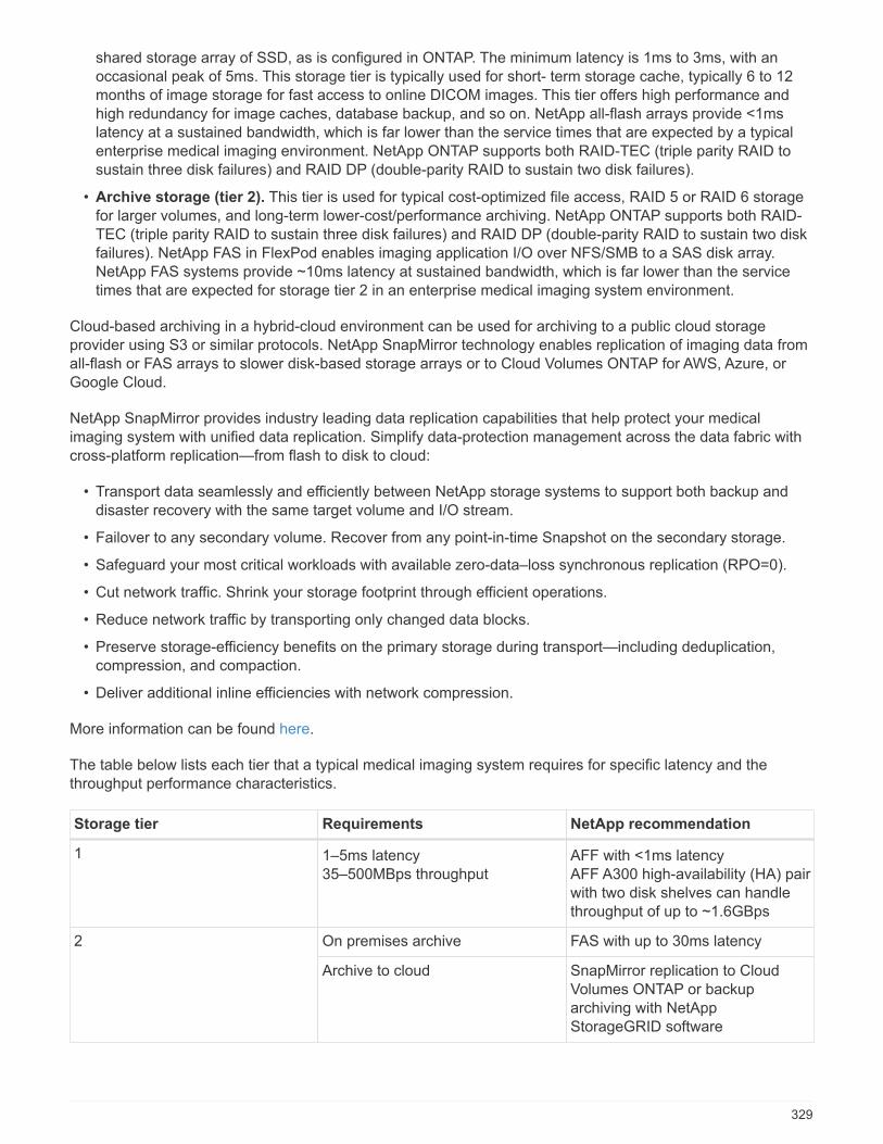
shared storage array of SSD, as is configured in ONTAP. The minimum latency is 1ms to 3ms, with anoccasional peak of 5ms. This storage tier is typically used for short- term storage cache, typically 6 to 12months of image storage for fast access to online DICOM images. This tier offers high performance andhigh redundancy for image caches, database backup, and so on. NetApp all-flash arrays provide <1mslatency at a sustained bandwidth, which is far lower than the service times that are expected by a typicalenterprise medical imaging environment. NetApp ONTAP supports both RAID-TEC (triple parity RAID tosustain three disk failures) and RAID DP (double-parity RAID to sustain two disk failures).
• Archive storage (tier 2). This tier is used for typical cost-optimized file access, RAID 5 or RAID 6 storagefor larger volumes, and long-term lower-cost/performance archiving. NetApp ONTAP supports both RAID-TEC (triple parity RAID to sustain three disk failures) and RAID DP (double-parity RAID to sustain two diskfailures). NetApp FAS in FlexPod enables imaging application I/O over NFS/SMB to a SAS disk array.NetApp FAS systems provide ~10ms latency at sustained bandwidth, which is far lower than the servicetimes that are expected for storage tier 2 in an enterprise medical imaging system environment.
Cloud-based archiving in a hybrid-cloud environment can be used for archiving to a public cloud storageprovider using S3 or similar protocols. NetApp SnapMirror technology enables replication of imaging data fromall-flash or FAS arrays to slower disk-based storage arrays or to Cloud Volumes ONTAP for AWS, Azure, orGoogle Cloud.
NetApp SnapMirror provides industry leading data replication capabilities that help protect your medicalimaging system with unified data replication. Simplify data-protection management across the data fabric withcross-platform replication—from flash to disk to cloud:
• Transport data seamlessly and efficiently between NetApp storage systems to support both backup anddisaster recovery with the same target volume and I/O stream.
• Failover to any secondary volume. Recover from any point-in-time Snapshot on the secondary storage.
• Safeguard your most critical workloads with available zero-data–loss synchronous replication (RPO=0).
• Cut network traffic. Shrink your storage footprint through efficient operations.
• Reduce network traffic by transporting only changed data blocks.
• Preserve storage-efficiency benefits on the primary storage during transport—including deduplication,compression, and compaction.
• Deliver additional inline efficiencies with network compression.
More information can be found here.
The table below lists each tier that a typical medical imaging system requires for specific latency and thethroughput performance characteristics.
Storage tier Requirements NetApp recommendation
1 1–5ms latency35–500MBps throughput
AFF with <1ms latencyAFF A300 high-availability (HA) pairwith two disk shelves can handlethroughput of up to ~1.6GBps
2 On premises archive FAS with up to 30ms latency
Archive to cloud SnapMirror replication to CloudVolumes ONTAP or backuparchiving with NetAppStorageGRID software
329

Storage network connectivity
FC fabric
• The FC fabric is for host OS I/O from compute to storage.
• Two FC fabrics (Fabric A and Fabric B) are connected to Cisco UCS Fabric A and UCS Fabric B,respectively.
• A storage virtual machine (SVM) with two FC logical interfaces (LIFs) is on each controller node. On eachnode, one LIF is connected to Fabric A and the other is connected to Fabric B.
• 16Gbps FC end-to-end connectivity is through Cisco MDS switches. A single initiator, multiple target ports,and zoning are all configured.
• FC SAN boot is used to create fully stateless computing. Servers are booted from LUNs in the boot volumethat is hosted on the AFF storage cluster.
IP network for storage access over iSCSI, NFS, and SMB/CIFS
• Two iSCSI LIFs are in the SVM on each controller node. On each node, one LIF is connected to Fabric Aand the second is connected to Fabric B.
• Two NAS data LIFs are in the SVM on each controller node. On each node, one LIF is connected to FabricA and the second is connected to Fabric B.
• Storage port interface groups (virtual port channel [vPC]) for 10Gbps link to switch N9k-A and for 10Gbpslink to switch N9k-B.
• Workload in Ext4 or NTFS file systems from VM to storage:
◦ iSCSI protocol over IP.
• VMs hosted in NFS datastore:
◦ VM OS I/O goes over multiple Ethernet paths through Nexus switches.
In-band management (active-passive bond)
• 1Gbps link to management switch N9k-A, and 1Gbps link to management switch N9k-B.
Backup and recovery
FlexPod Datacenter is built on a storage array that is managed by NetApp ONTAP data management software.ONTAP software has evolved over 20 years to provide many data management features for VMs, Oracledatabases, SMB/CIFS file shares, and NFS. It also provides protection technology such as NetApp Snapshottechnology, SnapMirror technology, and NetApp FlexClone data replication technology. NetApp SnapCentersoftware has a server and a GUI client to use ONTAP Snapshot, SnapRestore, and FlexClone features for VM,SMB/CIFS file shares, NFS, and Oracle database backup and recovery.
NetApp SnapCenter software employs patented Snapshot technology to create a backup of an entire VM orOracle database on a NetApp storage volume instantaneously. Compared with Oracle Recovery Manager(RMAN), Snapshot copies do not require a full baseline backup copy, because they are not stored as physicalcopies of blocks. Snapshot copies are stored as pointers to the storage blocks as they existed in the ONTAPWAFL file system when the Snapshot copies were created. Because of this tight physical relationship, theSnapshot copies are maintained on the same storage array as the original data. Snapshot copies can also becreated at the file level to give you more granular control for the backup.
Snapshot technology is based on a redirect-on-write technique. It initially contains only metadata pointers anddoes not consume much space until the first data change to a storage block. If an existing block is locked by a
330
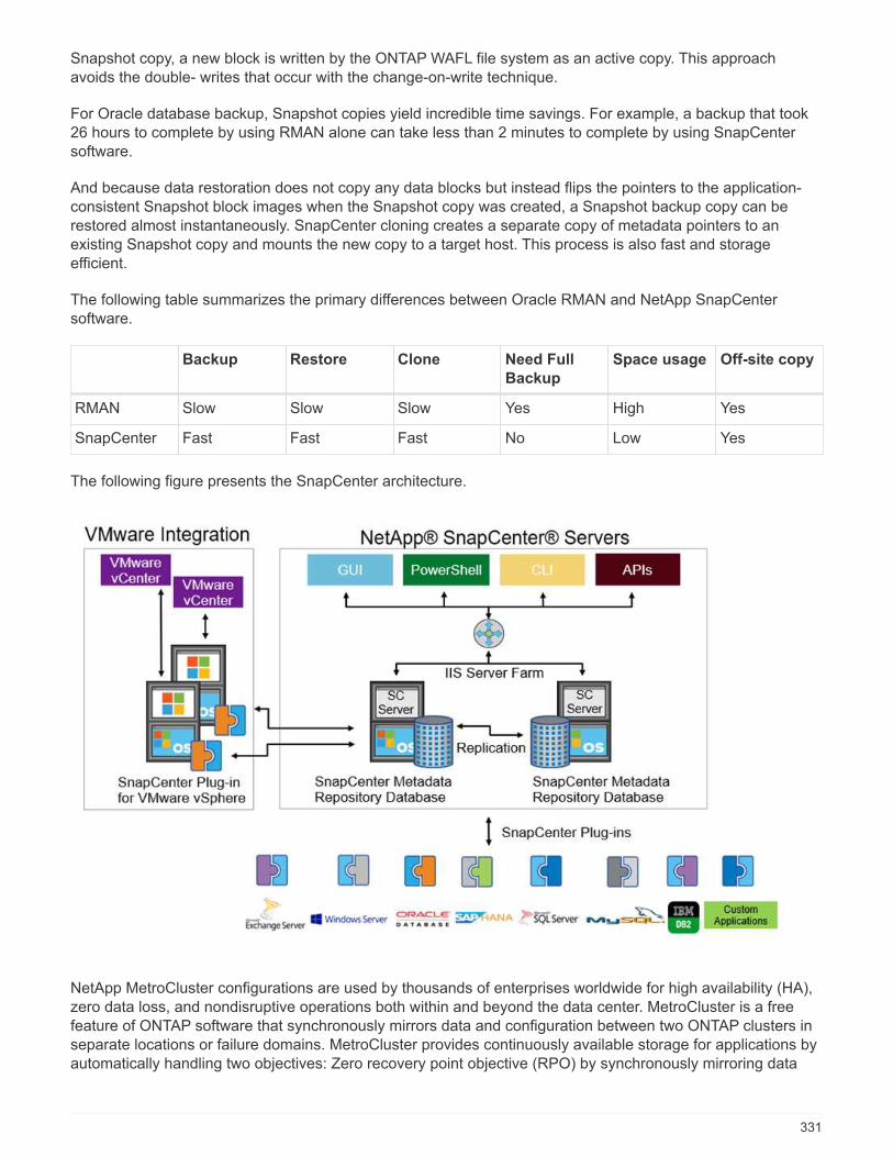
Snapshot copy, a new block is written by the ONTAP WAFL file system as an active copy. This approachavoids the double- writes that occur with the change-on-write technique.
For Oracle database backup, Snapshot copies yield incredible time savings. For example, a backup that took26 hours to complete by using RMAN alone can take less than 2 minutes to complete by using SnapCentersoftware.
And because data restoration does not copy any data blocks but instead flips the pointers to the application-consistent Snapshot block images when the Snapshot copy was created, a Snapshot backup copy can berestored almost instantaneously. SnapCenter cloning creates a separate copy of metadata pointers to anexisting Snapshot copy and mounts the new copy to a target host. This process is also fast and storageefficient.
The following table summarizes the primary differences between Oracle RMAN and NetApp SnapCentersoftware.
Backup Restore Clone Need Full
Backup
Space usage Off-site copy
RMAN Slow Slow Slow Yes High Yes
SnapCenter Fast Fast Fast No Low Yes
The following figure presents the SnapCenter architecture.
NetApp MetroCluster configurations are used by thousands of enterprises worldwide for high availability (HA),zero data loss, and nondisruptive operations both within and beyond the data center. MetroCluster is a freefeature of ONTAP software that synchronously mirrors data and configuration between two ONTAP clusters inseparate locations or failure domains. MetroCluster provides continuously available storage for applications byautomatically handling two objectives: Zero recovery point objective (RPO) by synchronously mirroring data
331
written to the cluster. Near zero recovery time objective (RTO) by mirroring configuration and automatingaccess to data at the second site MetroCluster provides simplicity with automatic mirroring of data andconfiguration between the two independent clusters located in the two sites. As storage is provisioned withinone cluster, it is automatically mirrored to the second cluster at the second site. NetApp SyncMirror technologyprovides a complete copy of all data with a zero RPO. , Therefore, workloads from one site can switch over atany time to the opposite site and continue serving data without data loss. More information can be found here.
Networking
A pair of Cisco Nexus switches provides redundant paths for IP traffic from compute to storage, and forexternal clients of the medical imaging system image viewer:
• Link aggregation that uses port channels and vPCs is employed throughout, enabling the design for higherbandwidth and high availability:
◦ vPC is used between the NetApp storage array and the Cisco Nexus switches.
◦ vPC is used between the Cisco UCS fabric interconnect and the Cisco Nexus switches.
◦ Each server has virtual network interface cards (vNICs) with redundant connectivity to the unifiedfabric. NIC failover is used between fabric interconnects for redundancy.
◦ Each server has virtual host bus adapters (vHBAs) with redundant connectivity to the unified fabric.
• The Cisco UCS fabric interconnects are configured in end-host mode as recommended, providing dynamicpinning of vNICs to uplink switches.
• An FC storage network is provided by a pair of Cisco MDS switches.
Compute—Cisco Unified Computing System
Two Cisco UCS fabrics through different fabric interconnects provide two failure domains. Each fabric isconnected to both IP networking switches and to different FC networking switches.
Identical service profiles for each Cisco UCS blade are created as per FlexPod best practices to run VMwareESXi. Each service profile should have the following components:
• Two vNICs (one on each fabric) to carry NFS, SMB/CIFS, and client or management traffic
• Additional required VLANs to the vNICs for NFS, SMB/CIFS, and client or management traffic
• Two vNICs (one on each fabric) to carry iSCSI traffic
• Two storage FC HBAs (one on each fabric) for FC traffic to storage
• SAN boot
Virtualization
The VMware ESXi host cluster runs workload VMs. The cluster comprises ESXi instances running on CiscoUCS blade servers.
Each ESXi host includes the following network components:
• SAN boot over FC or iSCSI
• Boot LUNs on NetApp storage (in a dedicated FlexVol for boot OS)
• Two VMNICs (Cisco UCS vNIC) for NFS, SMB/CIFS, or management traffic
• Two storage HBAs (Cisco UCS FC vHBA) for FC traffic to storage
332
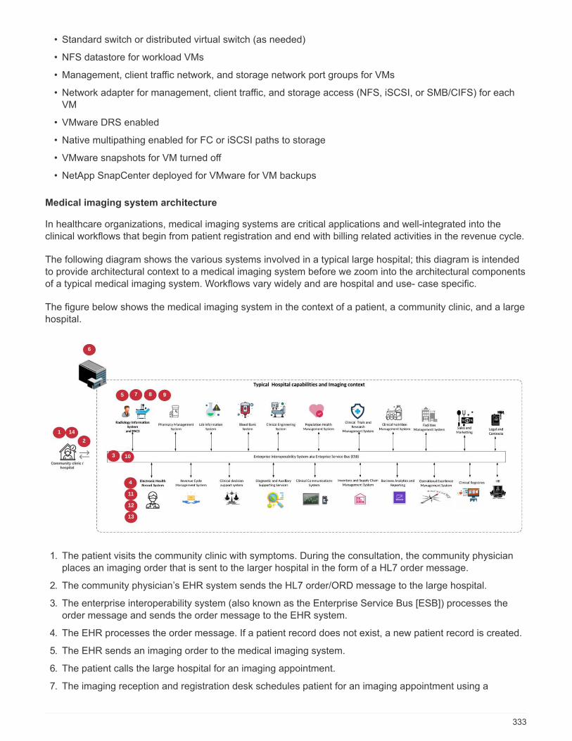
• Standard switch or distributed virtual switch (as needed)
• NFS datastore for workload VMs
• Management, client traffic network, and storage network port groups for VMs
• Network adapter for management, client traffic, and storage access (NFS, iSCSI, or SMB/CIFS) for eachVM
• VMware DRS enabled
• Native multipathing enabled for FC or iSCSI paths to storage
• VMware snapshots for VM turned off
• NetApp SnapCenter deployed for VMware for VM backups
Medical imaging system architecture
In healthcare organizations, medical imaging systems are critical applications and well-integrated into theclinical workflows that begin from patient registration and end with billing related activities in the revenue cycle.
The following diagram shows the various systems involved in a typical large hospital; this diagram is intendedto provide architectural context to a medical imaging system before we zoom into the architectural componentsof a typical medical imaging system. Workflows vary widely and are hospital and use- case specific.
The figure below shows the medical imaging system in the context of a patient, a community clinic, and a largehospital.
1. The patient visits the community clinic with symptoms. During the consultation, the community physicianplaces an imaging order that is sent to the larger hospital in the form of a HL7 order message.
2. The community physician’s EHR system sends the HL7 order/ORD message to the large hospital.
3. The enterprise interoperability system (also known as the Enterprise Service Bus [ESB]) processes theorder message and sends the order message to the EHR system.
4. The EHR processes the order message. If a patient record does not exist, a new patient record is created.
5. The EHR sends an imaging order to the medical imaging system.
6. The patient calls the large hospital for an imaging appointment.
7. The imaging reception and registration desk schedules patient for an imaging appointment using a
333
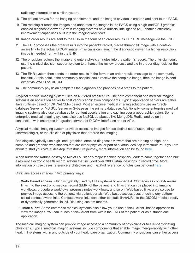
radiology information or similar system.
8. The patient arrives for the imaging appointment, and the images or video is created and sent to the PACS.
9. The radiologist reads the images and annotates the images in the PACS using a high-end/GPU graphics-enabled diagnostic viewer. Certain imaging systems have artificial intelligence (AI)- enabled efficiencyimprovement capabilities built into the imaging workflows.
10. Image order results are sent to the EHR in the form of an order results HL7 ORU message via the ESB.
11. The EHR processes the order results into the patient’s record, places thumbnail image with a context-aware link to the actual DICOM image. Physicians can launch the diagnostic viewer if a higher resolutionimage is needed from within the EHR.
12. The physician reviews the image and enters physician notes into the patient’s record. The physician coulduse the clinical decision support system to enhance the review process and aid in proper diagnosis for thepatient.
13. The EHR system then sends the order results in the form of an order results message to the communityhospital. At this point, if the community hospital could receive the complete image, then the image is senteither via WADO or DICOM.
14. The community physician completes the diagnosis and provides next steps to the patient.
A typical medical imaging system uses an N- tiered architecture. The core component of a medical imagingsystem is an application server to host various application components. Typical application servers are eitherJava runtime- based or C# .Net CLR- based. Most enterprise medical imaging solutions use an Oracledatabase Server or MS SQL Server or Sybase as the primary database. Additionally, some enterprise medicalimaging systems also use databases for content acceleration and caching over a geographic region. Someenterprise medical imaging systems also use NoSQL databases like MongoDB, Redis, and so on inconjunction with enterprise integration servers for DICOM interfaces and or APIs.
A typical medical imaging system provides access to images for two distinct set of users: diagnosticuser/radiologist, or the clinician or physician that ordered the imaging.
Radiologists typically use high- end, graphics- enabled diagnostic viewers that are running on high- endcompute and graphics workstations that are either physical or part of a virtual desktop infrastructure. If you areabout to start your virtual desktop infrastructure journey, more information can be found here.
When hurricane Katrina destroyed two of Louisiana’s major teaching hospitals, leaders came together and builta resilient electronic health record system that included over 3000 virtual desktops in record time. Moreinformation on use cases reference architecture and FlexPod reference bundles can be found here.
Clinicians access images in two primary ways:
• Web- based access. which is typically used by EHR systems to embed PACS images as context- awarelinks into the electronic medical record (EMR) of the patient, and links that can be placed into imagingworkflows, procedure workflows, progress notes workflows, and so on. Web based links are also use toprovide image access to the patients via patient portals. Web based access uses a technology patterncalled context aware links. Context aware links can either be static links/URIs to the DICOM media directlyor dynamically generated links/URIs using custom macros.
• Thick client. Some enterprise medical systems also allow you to use a thick- client- based approach toview the images. You can launch a thick client from within the EMR of the patient or as a standaloneapplication.
The medical imaging system can provide image access to a community of physicians or to CIN-participatingphysicians. Typical medical imaging systems include components that enable image interoperability with otherhealth IT systems within and outside of your healthcare organization. Community physicians can either access
334
images via a web-based application or leverage an image exchange platform for image interoperability. Image-exchange platforms typically use either WADO or DICOM as the underlying image exchange protocol.
Medical imaging systems can also support academic medical centers that need PACS or imaging systems foruse in a classroom. To support academic activities, a typical medical imaging system can have the capabilitiesof a PACS system in a smaller footprint or a teaching- only imaging environment. Typical vendor- neutralarchiving systems and some enterprise- class medical imaging systems offer DICOM image tag morphingcapabilities to anonymize the images that are used for teaching purposes. Tag morphing enables healthcareorganization to exchange DICOM images between different vendor medical imaging systems in a vendor-neutral fashion. Also, tag morphing enables medical imaging systems to implement an enterprise- wide,vendor- neutral archival capability for medical images.
Medical imaging systems are starting to use GPU-based compute capabilities to enhance human workflows bypreprocessing the images and thus improving efficiencies. Typical enterprise medical imaging systems takeadvantage of industry- leading NetApp storage efficiency capabilities. Enterprise medical imaging systemstypically use RMAN for backup, recovery, and restore activities. For better performance and to reduce the timethat it takes to create backups, Snapshot technology is available for backup operations and SnapMirrortechnology is available for replication.
The figure below shows the logical application components in a layered architectural view.
335
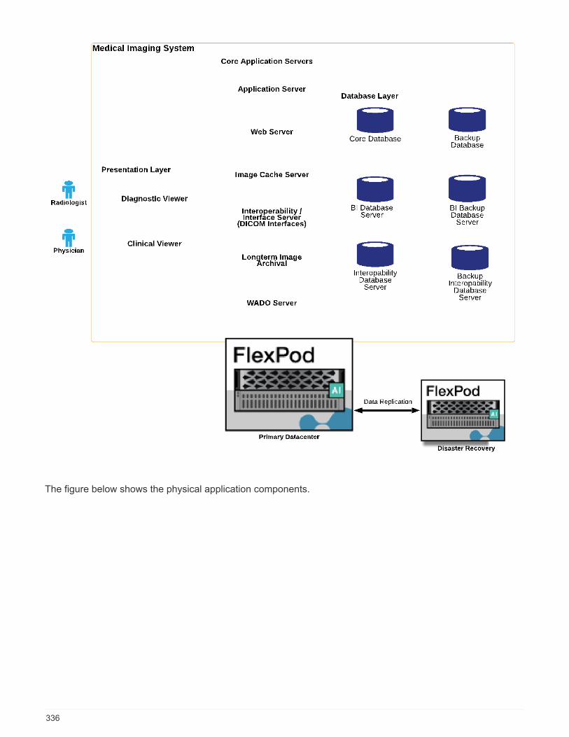
The figure below shows the physical application components.
336
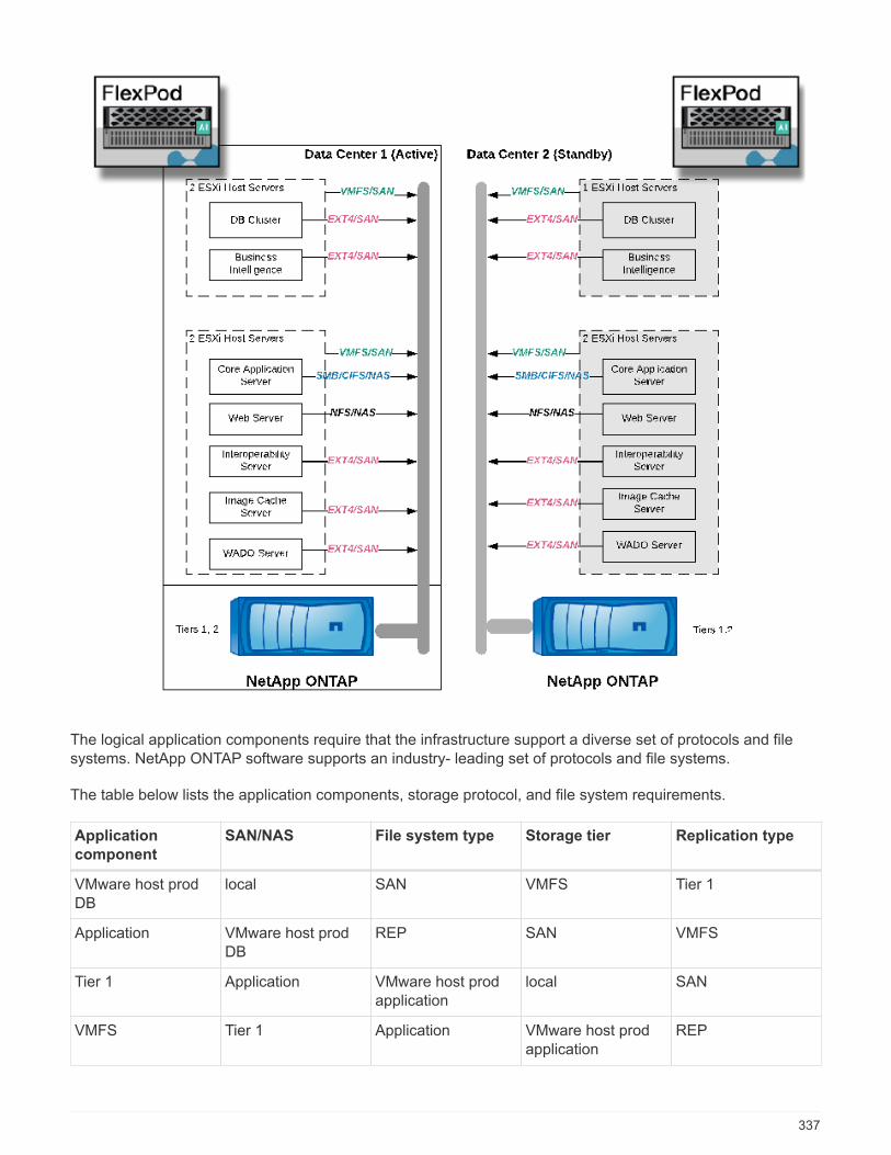
The logical application components require that the infrastructure support a diverse set of protocols and filesystems. NetApp ONTAP software supports an industry- leading set of protocols and file systems.
The table below lists the application components, storage protocol, and file system requirements.
Application
component
SAN/NAS File system type Storage tier Replication type
VMware host prodDB
local SAN VMFS Tier 1
Application VMware host prodDB
REP SAN VMFS
Tier 1 Application VMware host prodapplication
local SAN
VMFS Tier 1 Application VMware host prodapplication
REP
337
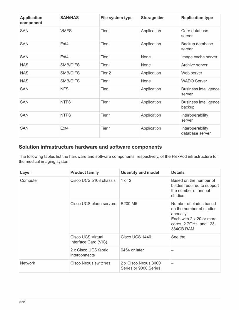
Application
component
SAN/NAS File system type Storage tier Replication type
SAN VMFS Tier 1 Application Core databaseserver
SAN Ext4 Tier 1 Application Backup databaseserver
SAN Ext4 Tier 1 None Image cache server
NAS SMB/CIFS Tier 1 None Archive server
NAS SMB/CIFS Tier 2 Application Web server
NAS SMB/CIFS Tier 1 None WADO Server
SAN NFS Tier 1 Application Business intelligenceserver
SAN NTFS Tier 1 Application Business intelligencebackup
SAN NTFS Tier 1 Application Interoperabilityserver
SAN Ext4 Tier 1 Application Interoperabilitydatabase server
Solution infrastructure hardware and software components
The following tables list the hardware and software components, respectively, of the FlexPod infrastructure forthe medical imaging system.
Layer Product family Quantity and model Details
Compute Cisco UCS 5108 chassis 1 or 2 Based on the number ofblades required to supportthe number of annualstudies
Cisco UCS blade servers B200 M5 Number of blades basedon the number of studiesannuallyEach with 2 x 20 or morecores, 2.7GHz, and 128-384GB RAM
Cisco UCS VirtualInterface Card (VIC)
Cisco UCS 1440 See the
2 x Cisco UCS fabricinterconnects
6454 or later –
Network Cisco Nexus switches 2 x Cisco Nexus 3000Series or 9000 Series
–
338

Layer Product family Quantity and model Details
Storage network IP network for storageaccess over SMB/CIFS,NFS, or iSCSI protocols
Same network switchesas above
–
Storage access over FC 2 x Cisco MDS 9132T –
Storage NetApp AFF A400 all-flash storage system
1 or more HA pair Cluster with two or morenodes
Disk shelf 1 or more DS224C orNS224 disk shelves
Fully populated with 24drives
SSD >24, 1.2TB or largercapacity
–
Software Product family Version or release Details
Enterprise medicalimaging system MS SQL or Oracle
Database ServerAs suggested by themedical imaging systemvendor
No SQL DBs likeMongoDB Server
As suggested by themedical imaging systemvendor
Application Servers As suggested by themedical imaging systemvendor
Integration Server (MSBiztalk, MuleSoft,Rhapsody, Tibco)
As suggested by themedical imaging systemvendor
VMs Linux (64 bit)
VMs Windows Server (64 bit)
Storage ONTAP ONTAP 9.7 or later
Network Cisco UCS FabricInterconnect
Cisco UCS Manager 4.1or later
Cisco Ethernet switches 9.2(3)I7(2) or later
Cisco FC: Cisco MDS9132T
8.4(2) or later
Hypervisor Hypervisor VMware vSphere ESXi6.7 U2 or later
Management Hypervisor managementsystem
VMware vCenter Server6.7 U1 (vCSA) or later
NetApp Virtual StorageConsole (VSC)
VSC 9.7 or later
SnapCenter SnapCenter 4.3 or later
339
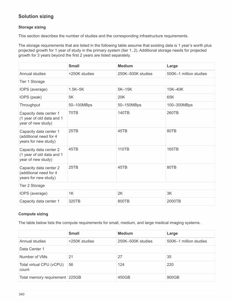
Solution sizing
Storage sizing
This section describes the number of studies and the corresponding infrastructure requirements.
The storage requirements that are listed in the following table assume that existing data is 1 year’s worth plusprojected growth for 1 year of study in the primary system (tier 1, 2). Additional storage needs for projectedgrowth for 3 years beyond the first 2 years are listed separately.
Small Medium Large
Annual studies <250K studies 250K–500K studies 500K–1 million studies
Tier 1 Storage
IOPS (average) 1.5K–5K 5K–15K 15K–40K
IOPS (peak) 5K 20K 65K
Throughput 50–100MBps 50–150MBps 100–300MBps
Capacity data center 1(1 year of old data and 1year of new study)
70TB 140TB 260TB
Capacity data center 1(additional need for 4years for new study)
25TB 45TB 80TB
Capacity data center 2(1 year of old data and 1year of new study)
45TB 110TB 165TB
Capacity data center 2(additional need for 4years for new study)
25TB 45TB 80TB
Tier 2 Storage
IOPS (average) 1K 2K 3K
Capacity data center 1 320TB 800TB 2000TB
Compute sizing
The table below lists the compute requirements for small, medium, and large medical imaging systems.
Small Medium Large
Annual studies <250K studies 250K–500K studies 500K–1 million studies
Data Center 1
Number of VMs 21 27 35
Total virtual CPU (vCPU)count
56 124 220
Total memory requirement 225GB 450GB 900GB
340
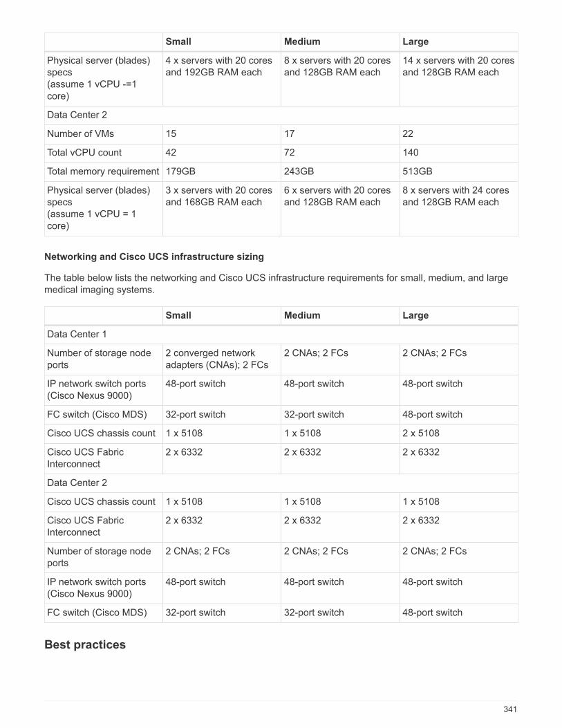
Small Medium Large
Physical server (blades)specs(assume 1 vCPU -=1core)
4 x servers with 20 coresand 192GB RAM each
8 x servers with 20 coresand 128GB RAM each
14 x servers with 20 coresand 128GB RAM each
Data Center 2
Number of VMs 15 17 22
Total vCPU count 42 72 140
Total memory requirement 179GB 243GB 513GB
Physical server (blades)specs(assume 1 vCPU = 1core)
3 x servers with 20 coresand 168GB RAM each
6 x servers with 20 coresand 128GB RAM each
8 x servers with 24 coresand 128GB RAM each
Networking and Cisco UCS infrastructure sizing
The table below lists the networking and Cisco UCS infrastructure requirements for small, medium, and largemedical imaging systems.
Small Medium Large
Data Center 1
Number of storage nodeports
2 converged networkadapters (CNAs); 2 FCs
2 CNAs; 2 FCs 2 CNAs; 2 FCs
IP network switch ports(Cisco Nexus 9000)
48-port switch 48-port switch 48-port switch
FC switch (Cisco MDS) 32-port switch 32-port switch 48-port switch
Cisco UCS chassis count 1 x 5108 1 x 5108 2 x 5108
Cisco UCS FabricInterconnect
2 x 6332 2 x 6332 2 x 6332
Data Center 2
Cisco UCS chassis count 1 x 5108 1 x 5108 1 x 5108
Cisco UCS FabricInterconnect
2 x 6332 2 x 6332 2 x 6332
Number of storage nodeports
2 CNAs; 2 FCs 2 CNAs; 2 FCs 2 CNAs; 2 FCs
IP network switch ports(Cisco Nexus 9000)
48-port switch 48-port switch 48-port switch
FC switch (Cisco MDS) 32-port switch 32-port switch 48-port switch
Best practices
341
Storage best practices
High availability
The NetApp storage cluster design provides high availability at every level:
• Cluster nodes
• Back-end storage connectivity
• RAID TEC that can sustain three disk failures
• RAID DP that can sustain two disk failures
• Physical connectivity to two physical networks from each node
• Multiple data paths to storage LUNs and volumes
Secure multitenancy
NetApp storage virtual machines (SVMs) provide a virtual storage array construct to separate your securitydomain, policies, and virtual networking. NetApp recommends that you create separate SVMs for each tenantorganization that hosts data on the storage cluster.
NetApp storage best practices
Consider the following NetApp storage best practices:
• Always enable NetApp AutoSupport technology, which sends support summary information to NetAppthrough HTTPS.
• For maximum availability and mobility, make sure that a LIF is created for each SVM on each node in theNetApp ONTAP cluster. Asymmetric logical unit access (ALUA) is used to parse paths and to identify activeoptimized (direct) paths versus active nonoptimized paths. ALUA is used for both FC or FCoE and iSCSI.
• A volume that contains only LUNs does not need to be internally mounted, nor is a junction path required.
• If you use the Challenge-Handshake Authentication Protocol (CHAP) in ESXi for target authentication, you
must also configure it in ONTAP. Use the CLI (vserver iscsi security create) or NetApp ONTAPSystem Manager (edit Initiator Security under Storage > SVMs > SVM Settings > Protocols > iSCSI).
SAN boot
NetApp recommends that you implement SAN boot for Cisco UCS Servers in the FlexPod Datacenter solution.This step enables the operating system to be safely secured by the NetApp AFF storage system, providingbetter performance. The design that is outlined in this solution uses iSCSI SAN boot.
In iSCSI SAN boot, each Cisco UCS Server is assigned two iSCSI vNICs (one for each SAN fabric), whichprovide redundant connectivity all the way to the storage. The storage ports in this example, e2a and e2e,which are connected to the Cisco Nexus switches, are grouped together to form one logical port called aninterface group (ifgrp) (in this example, a0a). The iSCSI VLANs are created on the igroup, and the iSCSI LIFsare created on iSCSI port groups (in this example, a0a-<iSCSI-A-VLAN>). The iSCSI boot LUN is exposed tothe servers through the iSCSI LIF by using igroups. This approach enables only the authorized server to haveaccess to the boot LUN. For the port and LIF layout, see the figure below.
342
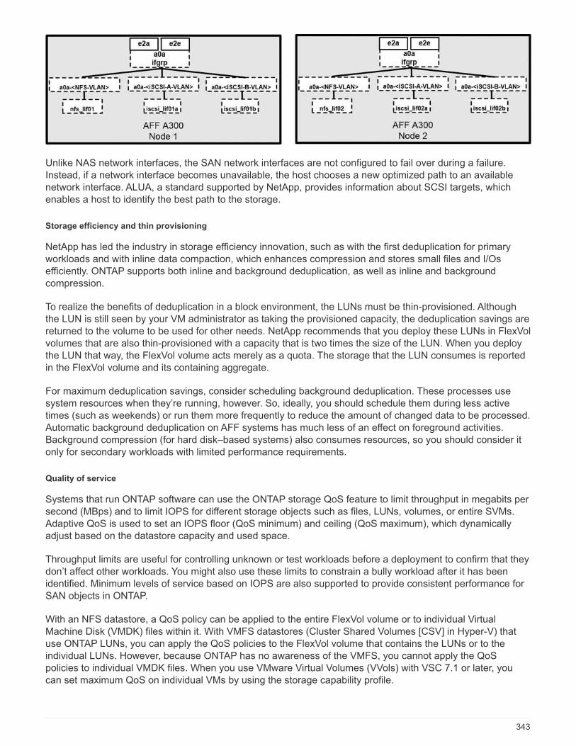
Unlike NAS network interfaces, the SAN network interfaces are not configured to fail over during a failure.Instead, if a network interface becomes unavailable, the host chooses a new optimized path to an availablenetwork interface. ALUA, a standard supported by NetApp, provides information about SCSI targets, whichenables a host to identify the best path to the storage.
Storage efficiency and thin provisioning
NetApp has led the industry in storage efficiency innovation, such as with the first deduplication for primaryworkloads and with inline data compaction, which enhances compression and stores small files and I/Osefficiently. ONTAP supports both inline and background deduplication, as well as inline and backgroundcompression.
To realize the benefits of deduplication in a block environment, the LUNs must be thin-provisioned. Althoughthe LUN is still seen by your VM administrator as taking the provisioned capacity, the deduplication savings arereturned to the volume to be used for other needs. NetApp recommends that you deploy these LUNs in FlexVolvolumes that are also thin-provisioned with a capacity that is two times the size of the LUN. When you deploythe LUN that way, the FlexVol volume acts merely as a quota. The storage that the LUN consumes is reportedin the FlexVol volume and its containing aggregate.
For maximum deduplication savings, consider scheduling background deduplication. These processes usesystem resources when they’re running, however. So, ideally, you should schedule them during less activetimes (such as weekends) or run them more frequently to reduce the amount of changed data to be processed.Automatic background deduplication on AFF systems has much less of an effect on foreground activities.Background compression (for hard disk–based systems) also consumes resources, so you should consider itonly for secondary workloads with limited performance requirements.
Quality of service
Systems that run ONTAP software can use the ONTAP storage QoS feature to limit throughput in megabits persecond (MBps) and to limit IOPS for different storage objects such as files, LUNs, volumes, or entire SVMs.Adaptive QoS is used to set an IOPS floor (QoS minimum) and ceiling (QoS maximum), which dynamicallyadjust based on the datastore capacity and used space.
Throughput limits are useful for controlling unknown or test workloads before a deployment to confirm that theydon’t affect other workloads. You might also use these limits to constrain a bully workload after it has beenidentified. Minimum levels of service based on IOPS are also supported to provide consistent performance forSAN objects in ONTAP.
With an NFS datastore, a QoS policy can be applied to the entire FlexVol volume or to individual VirtualMachine Disk (VMDK) files within it. With VMFS datastores (Cluster Shared Volumes [CSV] in Hyper-V) thatuse ONTAP LUNs, you can apply the QoS policies to the FlexVol volume that contains the LUNs or to theindividual LUNs. However, because ONTAP has no awareness of the VMFS, you cannot apply the QoSpolicies to individual VMDK files. When you use VMware Virtual Volumes (VVols) with VSC 7.1 or later, youcan set maximum QoS on individual VMs by using the storage capability profile.
343
To assign a QoS policy to a LUN, including VMFS or CSV, you can obtain the ONTAP SVM (displayed as
Vserver), LUN path, and serial number from the Storage Systems menu on the VSC home page. Select thestorage system (SVM), then Related Objects > SAN. Use this approach when you specify QoS by using one ofthe ONTAP tools.
You can set the QoS maximum throughput limit on an object in MBps and in IOPS. If you use both, the firstlimit that is reached is enforced by ONTAP. A workload can contain multiple objects, and a QoS policy can beapplied to one or more workloads. When you apply a policy to multiple workloads, the workloads share thetotal limit of the policy. Nested objects are not supported (for example, for a file within a volume, they cannoteach have their own policy). QoS minimums can be set only in IOPS.
Storage layout
This section provides best practices for layout of LUNs, volumes, and aggregates on storage.
Storage LUNs
For optimal performance, management, and backup, NetApp recommends the following LUN-design bestpractices:
• Create a separate LUN to store database data and log files.
• Create a separate LUN for each instance to store Oracle database log backups. The LUNs can be part ofthe same volume.
• Provision LUNs with thin provisioning (disable the Space Reservation option) for database files and logfiles.
• All imaging data is hosted in FC LUNs. Create these LUNs in FlexVol volumes that are spread across theaggregates that are owned by different storage controller nodes.
For placement of the LUNs in a storage volume, follow the guidelines in the next section.
Storage volumes
For optimal performance, management, and backup operations, NetApp recommends the following volumedesign best practices:
• Isolate databases with I/O-intensive queries throughout the day in different volumes and eventually haveseparate jobs to back them up.
• For faster recovery, place large databases and databases that have minimal recovery time objectives(RTOs) in separate volumes.
• Consolidate into a single volume your small-to-medium-sized databases that are less critical or that havefewer I/O requirements. When you back up a large number of databases that reside in the same volume,fewer Snapshot copies need to be maintained. NetApp also recommends that you consolidate Oracledatabase server instances to use the same volumes to control the number of backup Snapshot copies thatare created.
• For database replicas, place the data and log files for replicas in an identical folder structure on all nodes.
• Place database files in a single FlexVol; don’t spread them across FlexVols.
• Configure a volume auto size policy, when appropriate, to help prevent out-of-space conditions.
• When the database I/O profile consists mostly of large sequential reads, such as with decision supportsystem workloads, enable read reallocation on the volume. Read reallocation optimizes the blocks forbetter performance.
344
• For ease of monitoring from an operational perspective, set the Snapshot copy reserve value in the volumeto zero.
• Disable storage Snapshot copy schedules and retention policies. Instead, use NetApp SnapCenter Plug-Infor Oracle Database to coordinate Snapshot copies of the Oracle data volumes.
• Place user data files and log files on separate FlexVols so that appropriate QoS can be configured for therespective FlexVols and so that different backup schedules can be created.
Aggregates
Aggregates are the primary storage containers for NetApp storage configurations and contain one or moreRAID groups that consist of both data disks and parity disks.
NetApp performed various I/O workload characterization tests by using shared and dedicated aggregates withdata files and transaction log files separated. The tests show that one large aggregate with more RAID groupsand drives (HDDs or SSDs) optimizes and improves storage performance and is easier for administrators tomanage for two reasons:
• One large aggregate makes the I/O abilities of all drives available to all files.
• One large aggregate enables the most efficient use of disk space.
For effective disaster recovery, NetApp recommends that you place the asynchronous replica on an aggregatethat is part of a separate storage cluster in your disaster recovery site and use SnapMirror technology toreplicate content.
For optimal storage performance, NetApp recommends that you have at least 10% free space available in anaggregate.
Storage aggregate layout guidance for AFF A300 systems (with two disk shelves with 24 drives) includes:
• Keep two spare drives.
• Use Advanced Disk Partitioning to create three partitions on each drive: root and data.
• Use a total of 20 data partitions and two parity partitions for each aggregate.
Backup best practices
NetApp SnapCenter is used for VM and database backups. NetApp recommends the following backup bestpractices:
• When SnapCenter is deployed to create Snapshot copies for backups, turn off the Snapshot schedule forthe FlexVol that host VMs and application data.
• Create a dedicated FlexVol for host boot LUNs.
• Use a similar or a single backup policy for VMs that serve the same purpose.
• Use a similar or a single backup policy per workload type; for example, use a similar policy for all databaseworkloads. Use different policies for databases, web servers, end-user virtual desktops, and so on.
• Enable verification of the backup in SnapCenter.
• Configure archiving of the backup Snapshot copies to the NetApp SnapVault backup solution.
• Configure retention of the backups on primary storage based on the archiving schedule.
345
Infrastructure best practices
Networking best practices
NetApp recommends the following networking best practices:
• Make sure that your system includes redundant physical NICs for production and storage traffic.
• Separate VLANs for iSCSI, NFS, and SMB/CIFS traffic between compute and storage.
• Make sure that your system includes a dedicated VLAN for client access to the medical imaging system.
You can find additional networking best practices in the FlexPod infrastructure design and deployment guides.
Compute best practices
NetApp recommends the following compute best practice:
• Make sure that each specified vCPU is supported by a physical core.
Virtualization best practices
NetApp recommends the following virtualization best practices:
• Use VMware vSphere 6 or later.
• Set the ESXi host server BIOS and OS layer to Custom Controlled–High Performance.
• Create backups during off-peak hours.
Medical imaging system best practices
See the following best practices and some requirements from a typical medical imaging system:
• Do not overcommit virtual memory.
• Make sure that the total number of vCPUs equals the number of physical CPUs.
• If you have a large environment, dedicated VLANs are required.
• Configure database VMs with dedicated HA clusters.
• Make sure that the VM OS VMDKs are hosted in fast tier 1 storage.
• Work with the medical imaging system vendor to identify the best approach to prepare VM templates forquick deployment and maintenance.
• Management, storage, and production networks require LAN segregation for the database, with isolatedVLANs for VMware vMotion.
• Use the NetApp storage-array-based replication technology called SnapMirror instead of vSphere- basedreplication.
• Use backup technologies that leverage VMware APIs; backup windows should be outside the normalproduction hours.
Conclusion
By running a medical imaging environment on FlexPod, your healthcare organization can expect to see animprovement in staff productivity and a decrease in capital and operating expenses. FlexPod provides aprevalidated, rigorously tested converged infrastructure from the strategic partnership of Cisco and NetApp. It
346
is engineered and designed specifically to deliver predictable low-latency system performance and highavailability. This approach results in a superior user experience and optimal response time for users of themedical imaging system.
Different components of a medical imaging system require data storage in SMB/CIFS, NFS, Ext4, and NTFSfile systems. Therefore, your infrastructure must provide data access over NFS, SMB/CIFS, and SANprotocols. NetApp storage systems support these protocols from a single storage array.
High availability, storage efficiency, Snapshot copy-based scheduled fast backups, fast restore operations, datareplication for disaster recovery, and the FlexPod storage infrastructure capabilities all provide an industry-leading data storage and management system.
Additional information
To learn more about the information that is described in this document, review the following documents andwebsites:
• FlexPod Datacenter for AI/ML with Cisco UCS 480 ML for Deep Learning Design Guide
https://www.cisco.com/c/en/us/td/docs/unified_computing/ucs/UCS_CVDs/flexpod_c480m5l_aiml_design.html
• FlexPod Datacenter Infrastructure with VMware vSphere 6.7 U1, Cisco UCS 4th Generation, and NetAppAFF A-Series
https://www.cisco.com/c/en/us/td/docs/unified_computing/ucs/UCS_CVDs/flexpod_datacenter_vmware_netappaffa.html
• FlexPod Datacenter Oracle Database Backup with SnapCenter Solution Brief
https://www.netapp.com/us/media/sb-3999.pdf
• FlexPod Datacenter with Oracle RAC Databases on Cisco UCS and NetApp AFF A-Series
https://www.cisco.com/c/en/us/td/docs/unified_computing/ucs/UCS_CVDs/flexpod_orc12cr2_affaseries.html
• FlexPod Datacenter with Oracle RAC on Oracle Linux
https://www.cisco.com/c/en/us/td/docs/unified_computing/ucs/UCS_CVDs/flexpod_orcrac_12c_bm.html
• FlexPod for Microsoft SQL Server
https://flexpod.com/solutions/use-cases/microsoft-sql-server/
• FlexPod from Cisco and NetApp
https://flexpod.com/
• NetApp Solutions for MongoDB Solution Brief (NetApp login required)
https://fieldportal.netapp.com/content/734702
• TR-4700: SnapCenter Plug-In for Oracle Database
https://www.netapp.com/us/media/tr-4700.pdf
347

• NetApp Product Documentation
https://www.netapp.com/us/documentation/index.aspx
• FlexPod for Virtual Desktop Infrastructure (VDI) Solutions
https://flexpod.com/solutions/use-cases/virtual-desktop-infrastructure/
348

Virtual Desktop Infrastructure
349

Modern Apps
350

Microsoft Apps
351

FlexPod Express
FlexPod Express with Cisco UCS C-Series and NetApp AFFC190 Series Design Guide
NVA-1139-DESIGN: FlexPod Express with Cisco UCS C-Series and NetApp AFFC190 Series
Savita Kumari, NetApp
In partnership with:
Industry trends indicate a vast data center transformation toward shared infrastructure and cloud computing. Inaddition, organizations seek a simple and effective solution for remote and branch offices that uses thetechnology that they are familiar with in their data center.
FlexPod Express is a predesigned, best practice data center architecture that is built on the Cisco UnifiedComputing System (Cisco UCS), the Cisco Nexus family of switches, and NetApp AFF systems. Thecomponents of FlexPod Express are like their FlexPod Datacenter counterparts, enabling managementsynergies across the complete IT infrastructure environment on a smaller scale. FlexPod Datacenter andFlexPod Express are optimal platforms for virtualization and for bare-metal operating systems and enterpriseworkloads.
Next: Program summary.
Program summary
FlexPod Converged Infrastructure Portfolio
FlexPod reference architectures are delivered as Cisco Validated Designs (CVDs) or as NetApp VerifiedArchitectures (NVAs). Deviations that are based on customer requirements from a given CVD or NVA arepermitted if those variations do not result in the deployment of unsupported configurations.
As illustrated in the following figure, the FlexPod portfolio includes the following solutions: FlexPod Expressand FlexPod Datacenter.
• FlexPod Express is an entry-level solution with technologies from Cisco and NetApp.
• FlexPod Datacenter delivers an optimal multipurpose foundation for various workloads and applications.
352

NetApp Verified Architecture program
The NetApp Verified Architecture program offers customers a verified architecture for NetApp solutions. AnNVA solution has the following qualities:
• Is thoroughly tested
• Is prescriptive in nature
• Minimizes deployment risks
• Accelerates time to market This guide details the design of FlexPod Express with VMware vSphere.
In addition, this design leverages the all-new AFF C190 system, which runs NetApp ONTAP 9.6 software,Cisco Nexus 31108 switches, and Cisco UCS C220 M5 servers as hypervisor nodes.
Solution overview
FlexPod Express is designed to run mixed virtualization workloads. It is targeted for remote and branch officesand for small to midsize businesses. It is also optimal for larger businesses that want to implement a dedicatedsolution for a specific purpose. This new solution for FlexPod Express adds new technologies such as NetAppONTAP 9.6, NetApp AFF C190 system, and VMware vSphere 6.7U2.
353
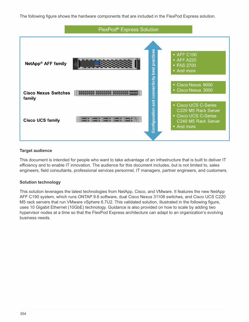
The following figure shows the hardware components that are included in the FlexPod Express solution.
Target audience
This document is intended for people who want to take advantage of an infrastructure that is built to deliver ITefficiency and to enable IT innovation. The audience for this document includes, but is not limited to, salesengineers, field consultants, professional services personnel, IT managers, partner engineers, and customers.
Solution technology
This solution leverages the latest technologies from NetApp, Cisco, and VMware. It features the new NetAppAFF C190 system, which runs ONTAP 9.6 software, dual Cisco Nexus 31108 switches, and Cisco UCS C220M5 rack servers that run VMware vSphere 6.7U2. This validated solution, illustrated in the following figure,uses 10 Gigabit Ethernet (10GbE) technology. Guidance is also provided on how to scale by adding twohypervisor nodes at a time so that the FlexPod Express architecture can adapt to an organization’s evolvingbusiness needs.
354
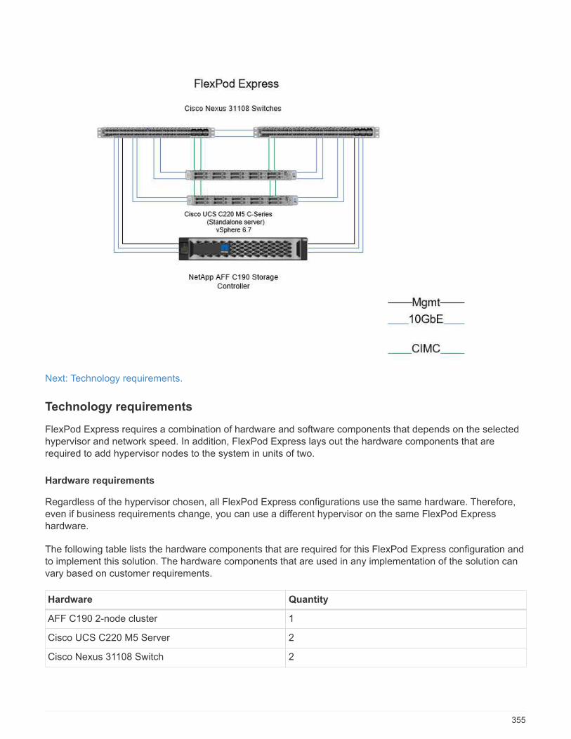
Next: Technology requirements.
Technology requirements
FlexPod Express requires a combination of hardware and software components that depends on the selectedhypervisor and network speed. In addition, FlexPod Express lays out the hardware components that arerequired to add hypervisor nodes to the system in units of two.
Hardware requirements
Regardless of the hypervisor chosen, all FlexPod Express configurations use the same hardware. Therefore,even if business requirements change, you can use a different hypervisor on the same FlexPod Expresshardware.
The following table lists the hardware components that are required for this FlexPod Express configuration andto implement this solution. The hardware components that are used in any implementation of the solution canvary based on customer requirements.
Hardware Quantity
AFF C190 2-node cluster 1
Cisco UCS C220 M5 Server 2
Cisco Nexus 31108 Switch 2
355
Hardware Quantity
Cisco UCS Virtual Interface Card (VIC) 1457 for CiscoUCS C220 M5 rack server
2
Software requirements
The following table lists the software components that are required to implement the architectures of theFlexPod Express solution.
Software Version Details
Cisco Integrated ManagementController (CIMC)
4.0.4 For C220 M5 rack servers
Cisco NX-OS 7.0(3)I7(6) For Cisco Nexus 31108 switches
NetApp ONTAP 9.6 For NetApp AFF C190 controllers
The following table lists the software that is required for all VMware vSphere implementations on FlexPodExpress.
Software Version
VMware vCenter Server Appliance 6.7U2
VMware vSphere ESXi 6.7U2
NetApp VAAI Plug-In for ESXi 1.1.2
NetApp Virtual Storage Console 9.6
Next: Design choices.
Design choices
The technologies listed in this section were chosen during the architectural design phase. Each technologyserves a specific purpose in the FlexPod Express infrastructure solution.
NetApp AFF C190 Series with ONTAP 9.6
This solution leverages two of the newest NetApp products: NetApp AFF C190 system and ONTAP 9.6software.
AFF C190 system
The target group is customers who want to modernize their IT infrastructure with all- flash technology at anaffordable price. The AFF C190 system comes with the new ONTAP 9.6 and flash bundle licensing, whichmeans that the following functions are on board:
• CIFS, NFS, iSCSI, and FCP
• NetApp SnapMirror data replication software, NetApp SnapVault backup software, NetApp SnapRestoredata recovery software, NetApp SnapManager storage management software product suite, and NetAppSnapCenter software
• FlexVol technology
356

• Deduplication, compression, and compaction
• Thin provisioning
• Storage QoS
• NetApp RAID DP technology
• NetApp Snapshot technology
• FabricPool
The following figures show the two options for host connectivity.
The following figure illustrates UTA 2 ports where SFP+ module can be inserted.
The following figure illustrates 10GBASE-T ports for connection through conventional RJ-45 Ethernet cables.
For the 10GBASE-T port option, you must have a 10GBASE-T based uplink switch.
The AFF C190 system is offered exclusively with 960GB SSDs. There are four stages of expansions fromwhich you can choose:
• 8x 960GB
• 12x 960GB
• 18x 960GB
• 24x 960GB
For full information about the AFF C190 hardware system, see the NetApp AFF C190 All-Flash Array page.
ONTAP 9.6 software
NetApp AFF C190 systems use the new ONTAP 9.6 data management software. ONTAP 9.6 is the industry’sleading enterprise data management software. It combines new levels of simplicity and flexibility with powerfuldata management capabilities, storage efficiencies, and leading cloud integration.
357
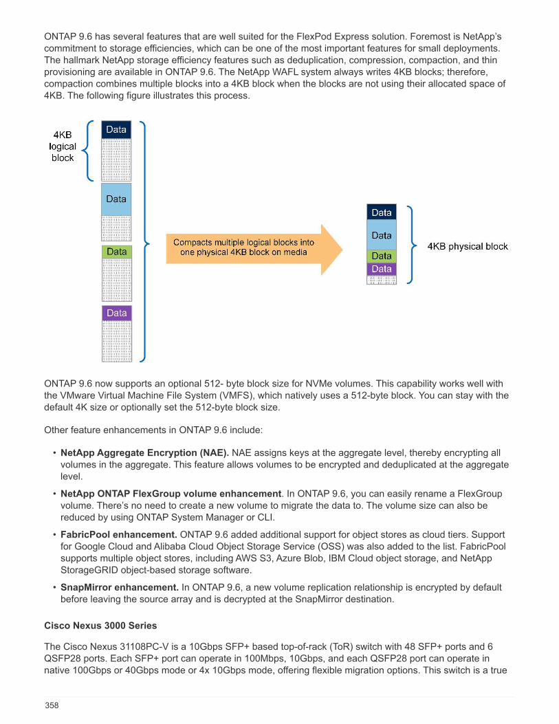
ONTAP 9.6 has several features that are well suited for the FlexPod Express solution. Foremost is NetApp’scommitment to storage efficiencies, which can be one of the most important features for small deployments.The hallmark NetApp storage efficiency features such as deduplication, compression, compaction, and thinprovisioning are available in ONTAP 9.6. The NetApp WAFL system always writes 4KB blocks; therefore,compaction combines multiple blocks into a 4KB block when the blocks are not using their allocated space of4KB. The following figure illustrates this process.
ONTAP 9.6 now supports an optional 512- byte block size for NVMe volumes. This capability works well withthe VMware Virtual Machine File System (VMFS), which natively uses a 512-byte block. You can stay with thedefault 4K size or optionally set the 512-byte block size.
Other feature enhancements in ONTAP 9.6 include:
• NetApp Aggregate Encryption (NAE). NAE assigns keys at the aggregate level, thereby encrypting allvolumes in the aggregate. This feature allows volumes to be encrypted and deduplicated at the aggregatelevel.
• NetApp ONTAP FlexGroup volume enhancement. In ONTAP 9.6, you can easily rename a FlexGroupvolume. There’s no need to create a new volume to migrate the data to. The volume size can also bereduced by using ONTAP System Manager or CLI.
• FabricPool enhancement. ONTAP 9.6 added additional support for object stores as cloud tiers. Supportfor Google Cloud and Alibaba Cloud Object Storage Service (OSS) was also added to the list. FabricPoolsupports multiple object stores, including AWS S3, Azure Blob, IBM Cloud object storage, and NetAppStorageGRID object-based storage software.
• SnapMirror enhancement. In ONTAP 9.6, a new volume replication relationship is encrypted by defaultbefore leaving the source array and is decrypted at the SnapMirror destination.
Cisco Nexus 3000 Series
The Cisco Nexus 31108PC-V is a 10Gbps SFP+ based top-of-rack (ToR) switch with 48 SFP+ ports and 6QSFP28 ports. Each SFP+ port can operate in 100Mbps, 10Gbps, and each QSFP28 port can operate innative 100Gbps or 40Gbps mode or 4x 10Gbps mode, offering flexible migration options. This switch is a true
358
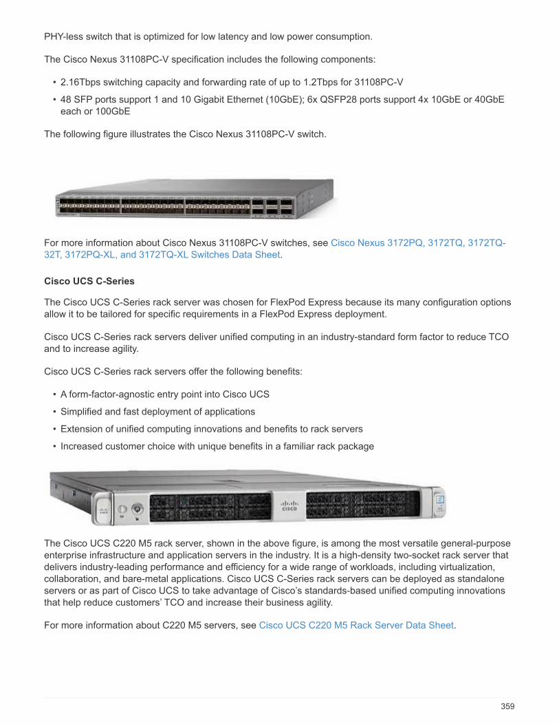
PHY-less switch that is optimized for low latency and low power consumption.
The Cisco Nexus 31108PC-V specification includes the following components:
• 2.16Tbps switching capacity and forwarding rate of up to 1.2Tbps for 31108PC-V
• 48 SFP ports support 1 and 10 Gigabit Ethernet (10GbE); 6x QSFP28 ports support 4x 10GbE or 40GbEeach or 100GbE
The following figure illustrates the Cisco Nexus 31108PC-V switch.
For more information about Cisco Nexus 31108PC-V switches, see Cisco Nexus 3172PQ, 3172TQ, 3172TQ-32T, 3172PQ-XL, and 3172TQ-XL Switches Data Sheet.
Cisco UCS C-Series
The Cisco UCS C-Series rack server was chosen for FlexPod Express because its many configuration optionsallow it to be tailored for specific requirements in a FlexPod Express deployment.
Cisco UCS C-Series rack servers deliver unified computing in an industry-standard form factor to reduce TCOand to increase agility.
Cisco UCS C-Series rack servers offer the following benefits:
• A form-factor-agnostic entry point into Cisco UCS
• Simplified and fast deployment of applications
• Extension of unified computing innovations and benefits to rack servers
• Increased customer choice with unique benefits in a familiar rack package
The Cisco UCS C220 M5 rack server, shown in the above figure, is among the most versatile general-purposeenterprise infrastructure and application servers in the industry. It is a high-density two-socket rack server thatdelivers industry-leading performance and efficiency for a wide range of workloads, including virtualization,collaboration, and bare-metal applications. Cisco UCS C-Series rack servers can be deployed as standaloneservers or as part of Cisco UCS to take advantage of Cisco’s standards-based unified computing innovationsthat help reduce customers’ TCO and increase their business agility.
For more information about C220 M5 servers, see Cisco UCS C220 M5 Rack Server Data Sheet.
359
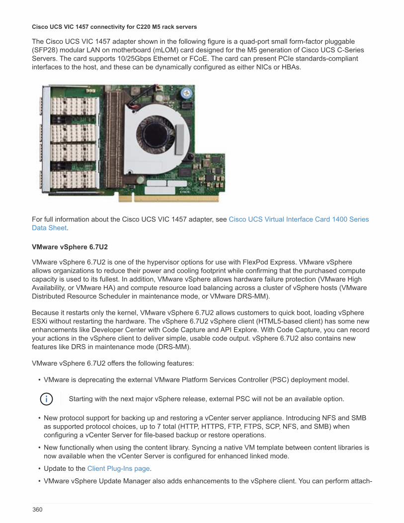
Cisco UCS VIC 1457 connectivity for C220 M5 rack servers
The Cisco UCS VIC 1457 adapter shown in the following figure is a quad-port small form-factor pluggable(SFP28) modular LAN on motherboard (mLOM) card designed for the M5 generation of Cisco UCS C-SeriesServers. The card supports 10/25Gbps Ethernet or FCoE. The card can present PCIe standards-compliantinterfaces to the host, and these can be dynamically configured as either NICs or HBAs.
For full information about the Cisco UCS VIC 1457 adapter, see Cisco UCS Virtual Interface Card 1400 SeriesData Sheet.
VMware vSphere 6.7U2
VMware vSphere 6.7U2 is one of the hypervisor options for use with FlexPod Express. VMware vSphereallows organizations to reduce their power and cooling footprint while confirming that the purchased computecapacity is used to its fullest. In addition, VMware vSphere allows hardware failure protection (VMware HighAvailability, or VMware HA) and compute resource load balancing across a cluster of vSphere hosts (VMwareDistributed Resource Scheduler in maintenance mode, or VMware DRS-MM).
Because it restarts only the kernel, VMware vSphere 6.7U2 allows customers to quick boot, loading vSphereESXi without restarting the hardware. The vSphere 6.7U2 vSphere client (HTML5-based client) has some newenhancements like Developer Center with Code Capture and API Explore. With Code Capture, you can recordyour actions in the vSphere client to deliver simple, usable code output. vSphere 6.7U2 also contains newfeatures like DRS in maintenance mode (DRS-MM).
VMware vSphere 6.7U2 offers the following features:
• VMware is deprecating the external VMware Platform Services Controller (PSC) deployment model.
Starting with the next major vSphere release, external PSC will not be an available option.
• New protocol support for backing up and restoring a vCenter server appliance. Introducing NFS and SMBas supported protocol choices, up to 7 total (HTTP, HTTPS, FTP, FTPS, SCP, NFS, and SMB) whenconfiguring a vCenter Server for file-based backup or restore operations.
• New functionally when using the content library. Syncing a native VM template between content libraries isnow available when the vCenter Server is configured for enhanced linked mode.
• Update to the Client Plug-Ins page.
• VMware vSphere Update Manager also adds enhancements to the vSphere client. You can perform attach-
360
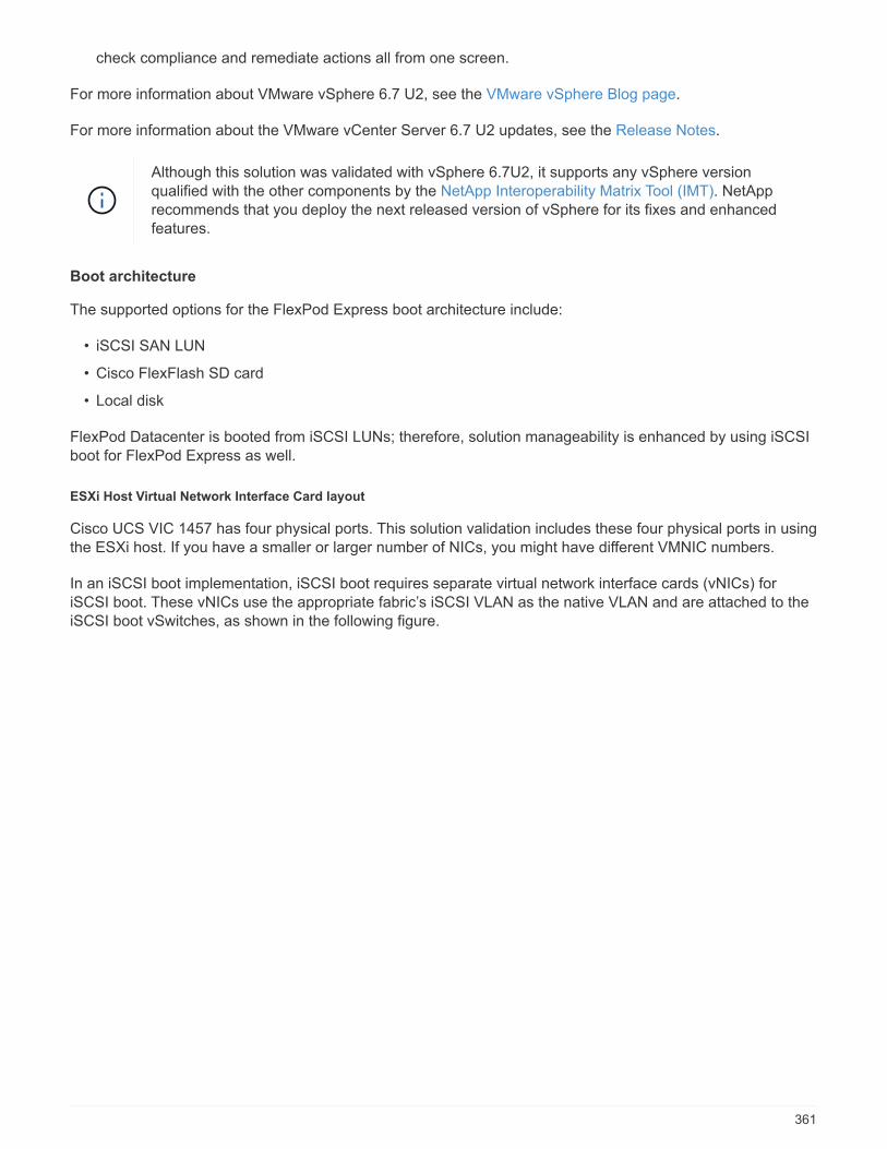
check compliance and remediate actions all from one screen.
For more information about VMware vSphere 6.7 U2, see the VMware vSphere Blog page.
For more information about the VMware vCenter Server 6.7 U2 updates, see the Release Notes.
Although this solution was validated with vSphere 6.7U2, it supports any vSphere versionqualified with the other components by the NetApp Interoperability Matrix Tool (IMT). NetApprecommends that you deploy the next released version of vSphere for its fixes and enhancedfeatures.
Boot architecture
The supported options for the FlexPod Express boot architecture include:
• iSCSI SAN LUN
• Cisco FlexFlash SD card
• Local disk
FlexPod Datacenter is booted from iSCSI LUNs; therefore, solution manageability is enhanced by using iSCSIboot for FlexPod Express as well.
ESXi Host Virtual Network Interface Card layout
Cisco UCS VIC 1457 has four physical ports. This solution validation includes these four physical ports in usingthe ESXi host. If you have a smaller or larger number of NICs, you might have different VMNIC numbers.
In an iSCSI boot implementation, iSCSI boot requires separate virtual network interface cards (vNICs) foriSCSI boot. These vNICs use the appropriate fabric’s iSCSI VLAN as the native VLAN and are attached to theiSCSI boot vSwitches, as shown in the following figure.
361
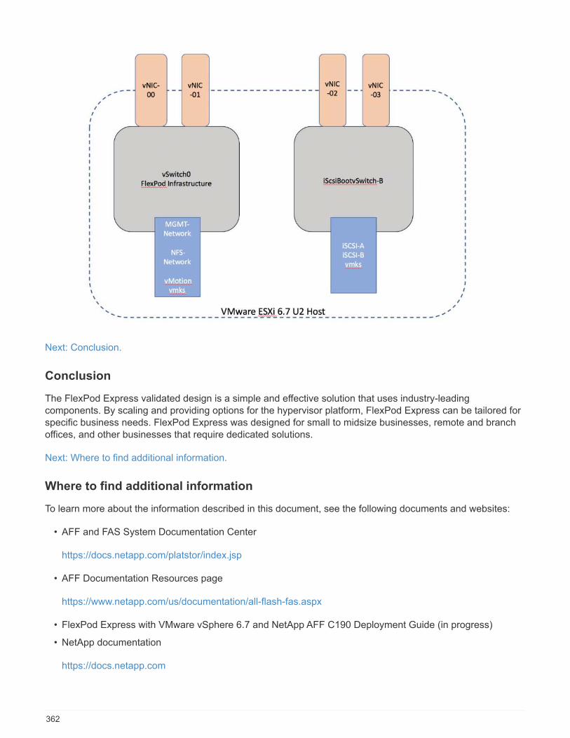
Next: Conclusion.
Conclusion
The FlexPod Express validated design is a simple and effective solution that uses industry-leadingcomponents. By scaling and providing options for the hypervisor platform, FlexPod Express can be tailored forspecific business needs. FlexPod Express was designed for small to midsize businesses, remote and branchoffices, and other businesses that require dedicated solutions.
Next: Where to find additional information.
Where to find additional information
To learn more about the information described in this document, see the following documents and websites:
• AFF and FAS System Documentation Center
https://docs.netapp.com/platstor/index.jsp
• AFF Documentation Resources page
https://www.netapp.com/us/documentation/all-flash-fas.aspx
• FlexPod Express with VMware vSphere 6.7 and NetApp AFF C190 Deployment Guide (in progress)
• NetApp documentation
https://docs.netapp.com
362
FlexPod Express with Cisco UCS C-Series and NetApp AFFC190 Series Deployment Guide
NVA-1142-DEPLOY: FlexPod Express with Cisco UCS C-Series and NetApp AFFC190 Series - NVA Deployment
Savita Kumari, NetApp
Industry trends indicate that a vast data center transformation is occurring toward shared infrastructure andcloud computing. In addition, organizations seek a simple and effective solution for remote and branch officesthat uses technology that they are familiar with in their data center.
FlexPod® Express is a predesigned, best practice data center architecture that is built on the Cisco UnifiedComputing System (Cisco UCS), the Cisco Nexus family of switches, and NetApp® storage technologies. Thecomponents in a FlexPod Express system are like their FlexPod Datacenter counterparts, enablingmanagement synergies across the complete IT infrastructure environment on a smaller scale. FlexPodDatacenter and FlexPod Express are optimal platforms for virtualization and for bare-metal operating systemsand enterprise workloads.
FlexPod Datacenter and FlexPod Express deliver a baseline configuration and have the flexibility to be sizedand optimized to accommodate many different use cases and requirements. Existing FlexPod Datacentercustomers can manage their FlexPod Express system with the tools to which they are accustomed. NewFlexPod Express customers can easily transition to managing FlexPod Datacenter as their environment grows.
FlexPod Express is an optimal infrastructure foundation for remote and branch offices and for small to midsizebusinesses. It is also an optimal solution for customers who want to provide infrastructure for a dedicatedworkload.
FlexPod Express provides an easy-to-manage infrastructure that is suitable for almost any workload.
Solution overview
This FlexPod Express solution is part of the FlexPod Converged Infrastructure Program.
FlexPod converged infrastructure program
FlexPod reference architectures are delivered as Cisco Validated Designs (CVDs) or NetApp VerifiedArchitectures (NVAs). Deviations based on customer requirements from a given CVD or NVA are permitted ifthese variations do not create an unsupported configuration.
The FlexPod program includes two solutions: FlexPod Express and FlexPod Datacenter.
• FlexPod Express. Offers customers an entry-level solution with technologies from Cisco and NetApp.
• FlexPod Datacenter. Delivers an optimal multipurpose foundation for various workloads and applications.
363

NetApp Verified Architecture program
The NetApp Verified Architecture program offers customers a verified architecture for NetApp solutions. ANetApp Verified Architecture provides a NetApp solution architecture with the following qualities:
• Thoroughly tested
• Prescriptive in nature
• Minimized deployment risks
• Accelerated time to market
This guide details the design of FlexPod Express with VMware vSphere. In addition, this design uses the all-new AFF C190 system (running NetApp ONTAP® 9.6), the Cisco Nexus 31108, and Cisco UCS C-Series C220M5 servers as hypervisor nodes.
Solution technology
This solution leverages the latest technologies from NetApp, Cisco, and VMware. This solution features thenew NetApp AFF C190 running ONTAP 9.6, dual Cisco Nexus 31108 switches, and Cisco UCS C220 M5 rack
364
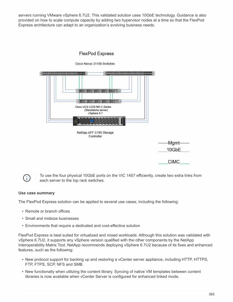
servers running VMware vSphere 6.7U2. This validated solution uses 10GbE technology. Guidance is alsoprovided on how to scale compute capacity by adding two hypervisor nodes at a time so that the FlexPodExpress architecture can adapt to an organization’s evolving business needs.
To use the four physical 10GbE ports on the VIC 1457 efficiently, create two extra links fromeach server to the top rack switches.
Use case summary
The FlexPod Express solution can be applied to several use cases, including the following:
• Remote or branch offices
• Small and midsize businesses
• Environments that require a dedicated and cost-effective solution
FlexPod Express is best suited for virtualized and mixed workloads. Although this solution was validated withvSphere 6.7U2, it supports any vSphere version qualified with the other components by the NetAppInteroperability Matrix Tool. NetApp recommends deploying vSphere 6.7U2 because of its fixes and enhancedfeatures, such as the following:
• New protocol support for backing up and restoring a vCenter server appliance, including HTTP, HTTPS,FTP, FTPS, SCP, NFS and SMB.
• New functionally when utilizing the content library. Syncing of native VM templates between contentlibraries is now available when vCenter Server is configured for enhanced linked mode.
365
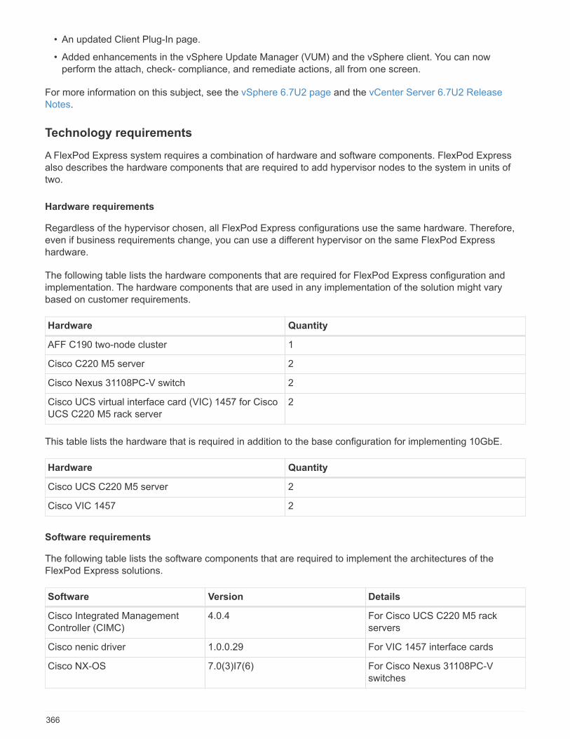
• An updated Client Plug-In page.
• Added enhancements in the vSphere Update Manager (VUM) and the vSphere client. You can nowperform the attach, check- compliance, and remediate actions, all from one screen.
For more information on this subject, see the vSphere 6.7U2 page and the vCenter Server 6.7U2 ReleaseNotes.
Technology requirements
A FlexPod Express system requires a combination of hardware and software components. FlexPod Expressalso describes the hardware components that are required to add hypervisor nodes to the system in units oftwo.
Hardware requirements
Regardless of the hypervisor chosen, all FlexPod Express configurations use the same hardware. Therefore,even if business requirements change, you can use a different hypervisor on the same FlexPod Expresshardware.
The following table lists the hardware components that are required for FlexPod Express configuration andimplementation. The hardware components that are used in any implementation of the solution might varybased on customer requirements.
Hardware Quantity
AFF C190 two-node cluster 1
Cisco C220 M5 server 2
Cisco Nexus 31108PC-V switch 2
Cisco UCS virtual interface card (VIC) 1457 for CiscoUCS C220 M5 rack server
2
This table lists the hardware that is required in addition to the base configuration for implementing 10GbE.
Hardware Quantity
Cisco UCS C220 M5 server 2
Cisco VIC 1457 2
Software requirements
The following table lists the software components that are required to implement the architectures of theFlexPod Express solutions.
Software Version Details
Cisco Integrated ManagementController (CIMC)
4.0.4 For Cisco UCS C220 M5 rackservers
Cisco nenic driver 1.0.0.29 For VIC 1457 interface cards
Cisco NX-OS 7.0(3)I7(6) For Cisco Nexus 31108PC-Vswitches
366

Software Version Details
NetApp ONTAP 9.6 For AFF C190 controllers
This table lists the software that is required for all VMware vSphere implementations on FlexPod Express.
Software Version
VMware vCenter server appliance 6.7U2
VMware vSphere ESXi hypervisor 6.7U2
NetApp VAAI Plug-In for ESXi 1.1.2
NetApp VSC 9.6
FlexPod Express cabling information
This reference validation is cabled as shown in the following figures and tables.
This figure shows the reference validation cabling.
The following table lists the cabling information for Cisco Nexus switch 31108PC-V-A.
367
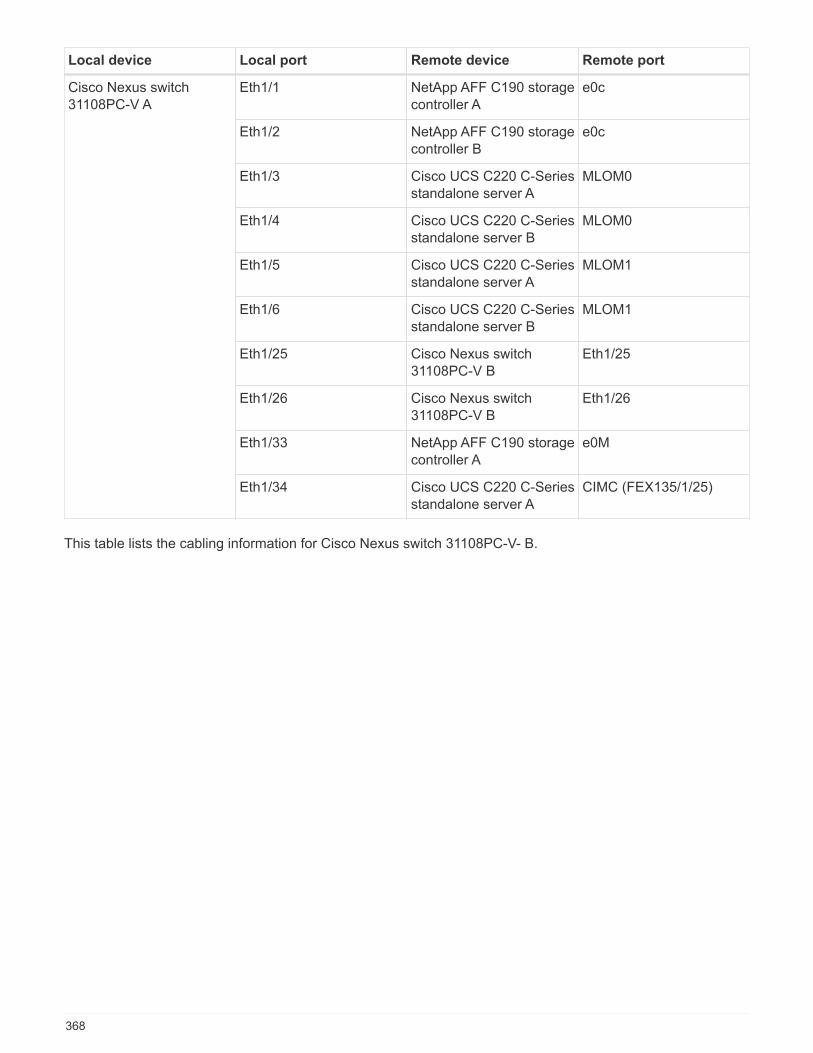
Local device Local port Remote device Remote port
Cisco Nexus switch31108PC-V A
Eth1/1 NetApp AFF C190 storagecontroller A
e0c
Eth1/2 NetApp AFF C190 storagecontroller B
e0c
Eth1/3 Cisco UCS C220 C-Seriesstandalone server A
MLOM0
Eth1/4 Cisco UCS C220 C-Seriesstandalone server B
MLOM0
Eth1/5 Cisco UCS C220 C-Seriesstandalone server A
MLOM1
Eth1/6 Cisco UCS C220 C-Seriesstandalone server B
MLOM1
Eth1/25 Cisco Nexus switch31108PC-V B
Eth1/25
Eth1/26 Cisco Nexus switch31108PC-V B
Eth1/26
Eth1/33 NetApp AFF C190 storagecontroller A
e0M
Eth1/34 Cisco UCS C220 C-Seriesstandalone server A
CIMC (FEX135/1/25)
This table lists the cabling information for Cisco Nexus switch 31108PC-V- B.
368
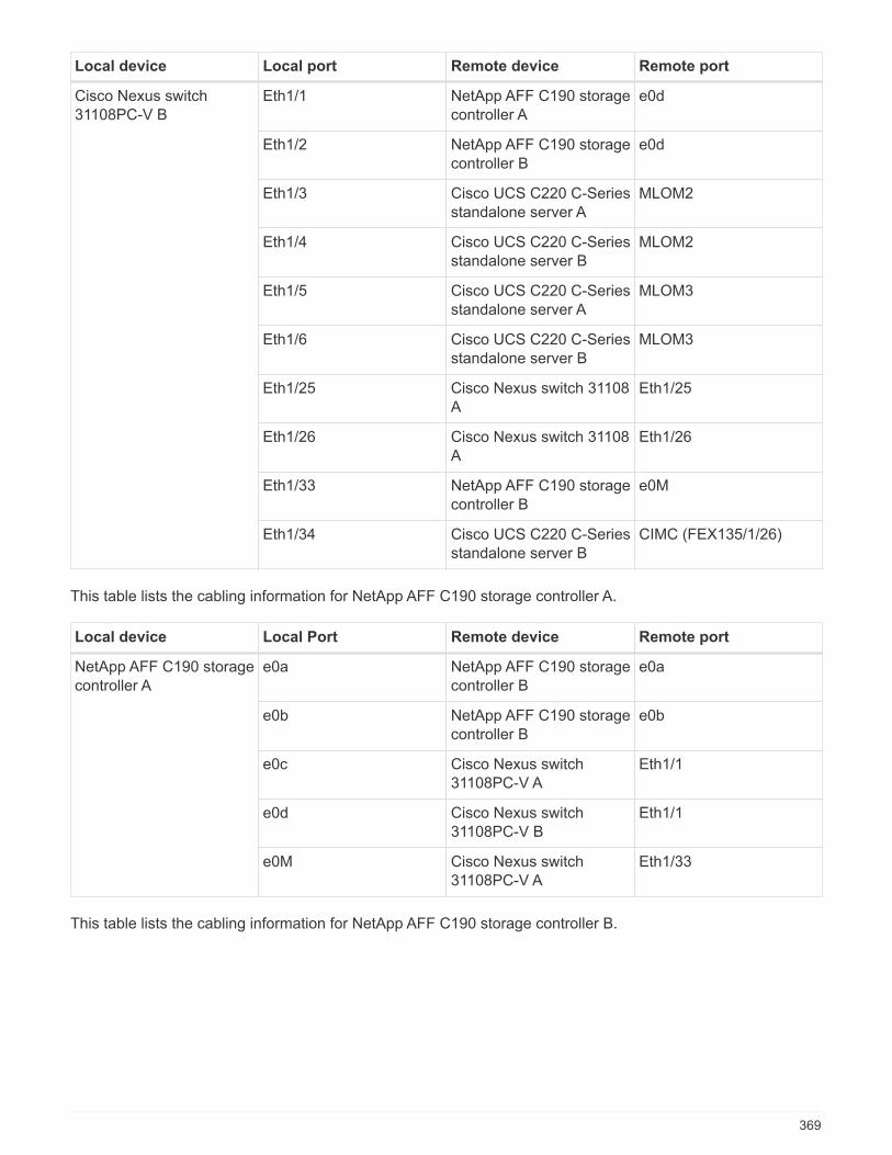
Local device Local port Remote device Remote port
Cisco Nexus switch31108PC-V B
Eth1/1 NetApp AFF C190 storagecontroller A
e0d
Eth1/2 NetApp AFF C190 storagecontroller B
e0d
Eth1/3 Cisco UCS C220 C-Seriesstandalone server A
MLOM2
Eth1/4 Cisco UCS C220 C-Seriesstandalone server B
MLOM2
Eth1/5 Cisco UCS C220 C-Seriesstandalone server A
MLOM3
Eth1/6 Cisco UCS C220 C-Seriesstandalone server B
MLOM3
Eth1/25 Cisco Nexus switch 31108A
Eth1/25
Eth1/26 Cisco Nexus switch 31108A
Eth1/26
Eth1/33 NetApp AFF C190 storagecontroller B
e0M
Eth1/34 Cisco UCS C220 C-Seriesstandalone server B
CIMC (FEX135/1/26)
This table lists the cabling information for NetApp AFF C190 storage controller A.
Local device Local Port Remote device Remote port
NetApp AFF C190 storagecontroller A
e0a NetApp AFF C190 storagecontroller B
e0a
e0b NetApp AFF C190 storagecontroller B
e0b
e0c Cisco Nexus switch31108PC-V A
Eth1/1
e0d Cisco Nexus switch31108PC-V B
Eth1/1
e0M Cisco Nexus switch31108PC-V A
Eth1/33
This table lists the cabling information for NetApp AFF C190 storage controller B.
369
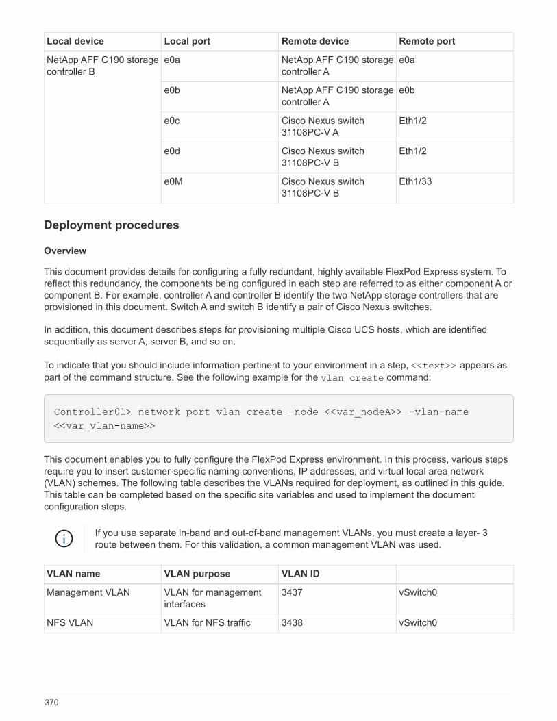
Local device Local port Remote device Remote port
NetApp AFF C190 storagecontroller B
e0a NetApp AFF C190 storagecontroller A
e0a
e0b NetApp AFF C190 storagecontroller A
e0b
e0c Cisco Nexus switch31108PC-V A
Eth1/2
e0d Cisco Nexus switch31108PC-V B
Eth1/2
e0M Cisco Nexus switch31108PC-V B
Eth1/33
Deployment procedures
Overview
This document provides details for configuring a fully redundant, highly available FlexPod Express system. Toreflect this redundancy, the components being configured in each step are referred to as either component A orcomponent B. For example, controller A and controller B identify the two NetApp storage controllers that areprovisioned in this document. Switch A and switch B identify a pair of Cisco Nexus switches.
In addition, this document describes steps for provisioning multiple Cisco UCS hosts, which are identifiedsequentially as server A, server B, and so on.
To indicate that you should include information pertinent to your environment in a step, <<text>> appears as
part of the command structure. See the following example for the vlan create command:
Controller01> network port vlan create –node <<var_nodeA>> -vlan-name
<<var_vlan-name>>
This document enables you to fully configure the FlexPod Express environment. In this process, various stepsrequire you to insert customer-specific naming conventions, IP addresses, and virtual local area network(VLAN) schemes. The following table describes the VLANs required for deployment, as outlined in this guide.This table can be completed based on the specific site variables and used to implement the documentconfiguration steps.
If you use separate in-band and out-of-band management VLANs, you must create a layer- 3route between them. For this validation, a common management VLAN was used.
VLAN name VLAN purpose VLAN ID
Management VLAN VLAN for managementinterfaces
3437 vSwitch0
NFS VLAN VLAN for NFS traffic 3438 vSwitch0
370

VLAN name VLAN purpose VLAN ID
VMware vMotion VLAN VLAN designated for themovement of virtualmachines (VMs) from onephysical host to another
3441 vSwitch0
VM traffic VLAN VLAN for VM applicationtraffic
3442 vSwitch0
iSCSI-A-VLAN VLAN for iSCSI traffic onfabric A
3439 iScsiBootvSwitch
iSCSI-B-VLAN VLAN for iSCSI traffic onfabric B
3440 iScsiBootvSwitch
Native VLAN VLAN to which untaggedframes are assigned
2
The VLAN numbers are needed throughout the configuration of FlexPod Express. The VLANs are referred to
as <<var_xxxx_vlan>>, where xxxx is the purpose of the VLAN (such as iSCSI-A).
There are two vSwitches created in this validation.
The following table lists the solution vSwitches.
vSwitch name Active adapters Ports MTU Load balancing
vSwitch0 Vmnic2, vmnic4 default (120) 9000 Route based on IPhash
iScsiBootvSwitch Vmnic3, vmnic5 default (120) 9000 Route based on theoriginating virtualport ID.
The IP hash method of load balancing requires proper configuration for the underlying physicalswitch using SRC-DST-IP EtherChannel with a static (mode on) port-channel. In the event ofintermittent connectivity due to possible switch misconfiguration, temporarily shut down one ofthe two associated uplink ports on the Cisco switch to restore communication to the ESXimanagement vmkernel port while troubleshooting the port-channel settings.
The following table lists the VMware VMs that are created.
VM description Host name
VMware vCenter Server FlexPod-VCSA
Virtual Storage Console FlexPod-VSC
Deploy Cisco Nexus 31108PC-V
This section details the Cisco Nexus 331108PC-V switch configuration used in a FlexPod Expressenvironment.
371
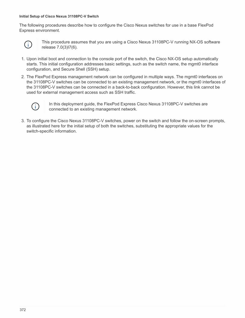
Initial Setup of Cisco Nexus 31108PC-V Switch
The following procedures describe how to configure the Cisco Nexus switches for use in a base FlexPodExpress environment.
This procedure assumes that you are using a Cisco Nexus 31108PC-V running NX-OS softwarerelease 7.0(3)I7(6).
1. Upon initial boot and connection to the console port of the switch, the Cisco NX-OS setup automaticallystarts. This initial configuration addresses basic settings, such as the switch name, the mgmt0 interfaceconfiguration, and Secure Shell (SSH) setup.
2. The FlexPod Express management network can be configured in multiple ways. The mgmt0 interfaces onthe 31108PC-V switches can be connected to an existing management network, or the mgmt0 interfaces ofthe 31108PC-V switches can be connected in a back-to-back configuration. However, this link cannot beused for external management access such as SSH traffic.
In this deployment guide, the FlexPod Express Cisco Nexus 31108PC-V switches areconnected to an existing management network.
3. To configure the Cisco Nexus 31108PC-V switches, power on the switch and follow the on-screen prompts,as illustrated here for the initial setup of both the switches, substituting the appropriate values for theswitch-specific information.
372
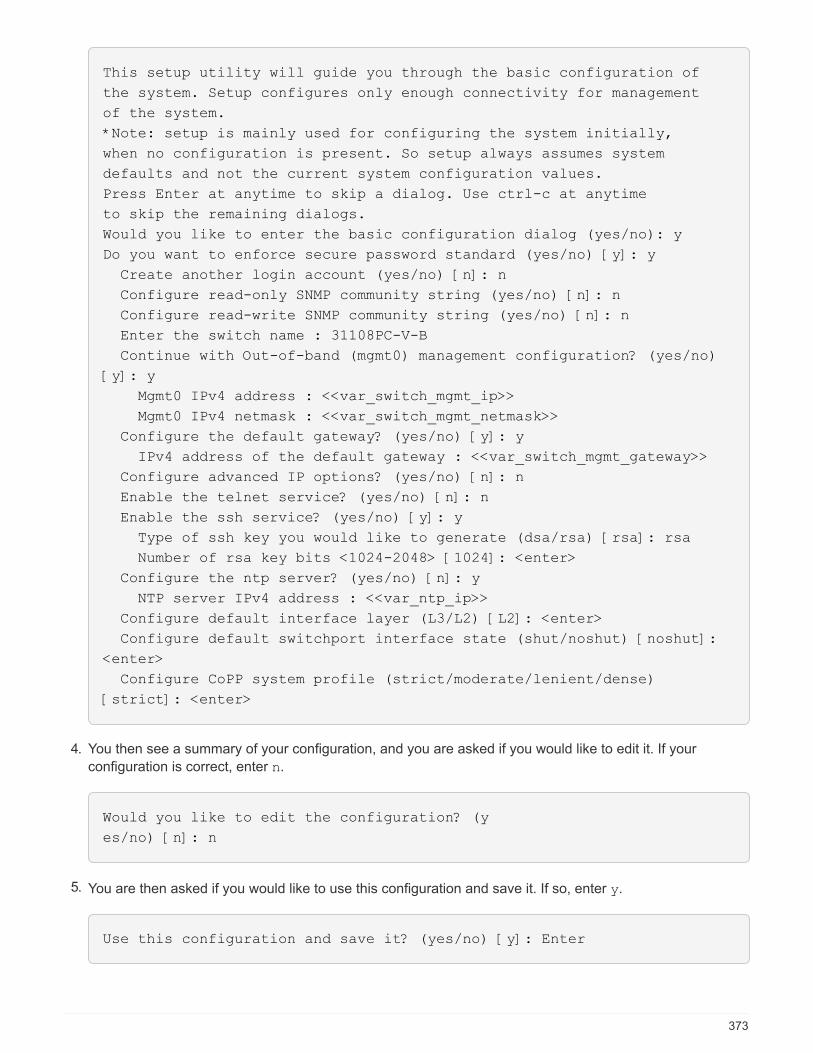
This setup utility will guide you through the basic configuration of
the system. Setup configures only enough connectivity for management
of the system.
*Note: setup is mainly used for configuring the system initially,
when no configuration is present. So setup always assumes system
defaults and not the current system configuration values.
Press Enter at anytime to skip a dialog. Use ctrl-c at anytime
to skip the remaining dialogs.
Would you like to enter the basic configuration dialog (yes/no): y
Do you want to enforce secure password standard (yes/no) [y]: y
Create another login account (yes/no) [n]: n
Configure read-only SNMP community string (yes/no) [n]: n
Configure read-write SNMP community string (yes/no) [n]: n
Enter the switch name : 31108PC-V-B
Continue with Out-of-band (mgmt0) management configuration? (yes/no)
[y]: y
Mgmt0 IPv4 address : <<var_switch_mgmt_ip>>
Mgmt0 IPv4 netmask : <<var_switch_mgmt_netmask>>
Configure the default gateway? (yes/no) [y]: y
IPv4 address of the default gateway : <<var_switch_mgmt_gateway>>
Configure advanced IP options? (yes/no) [n]: n
Enable the telnet service? (yes/no) [n]: n
Enable the ssh service? (yes/no) [y]: y
Type of ssh key you would like to generate (dsa/rsa) [rsa]: rsa
Number of rsa key bits <1024-2048> [1024]: <enter>
Configure the ntp server? (yes/no) [n]: y
NTP server IPv4 address : <<var_ntp_ip>>
Configure default interface layer (L3/L2) [L2]: <enter>
Configure default switchport interface state (shut/noshut) [noshut]:
<enter>
Configure CoPP system profile (strict/moderate/lenient/dense)
[strict]: <enter>
4. You then see a summary of your configuration, and you are asked if you would like to edit it. If your
configuration is correct, enter n.
Would you like to edit the configuration? (y
es/no) [n]: n
5. You are then asked if you would like to use this configuration and save it. If so, enter y.
Use this configuration and save it? (yes/no) [y]: Enter
373

6. Repeat this procedure for Cisco Nexus switch B.
Enable the advanced features
Certain advanced features must be enabled in Cisco NX-OS to provide additional configuration options. Toenable the appropriate features on Cisco Nexus switch A and switch B, enter configuration mode using thecommand (config t) and run the following commands:
feature interface-vlan
feature lacp
feature vpc
The default port channel load-balancing hash uses the source and destination IP addresses todetermine the load-balancing algorithm across the interfaces in the port channel. You canachieve better distribution across the members of the port channel by providing more inputs tothe hash algorithm beyond the source and destination IP addresses. For the same reason,NetApp highly recommends adding the source and destination TCP ports to the hash algorithm.
From configuration mode (config t), enter the following commands to set the global port channel load-balancingconfiguration on Cisco Nexus switch A and switch B:
port-channel load-balance src-dst ip-l4port
Configure global spanning tree
The Cisco Nexus platform uses a new protection feature called bridge assurance. Bridge assurance helpsprotect against a unidirectional link or other software failure with a device that continues to forward data trafficwhen it is no longer running the spanning-tree algorithm. Ports can be placed in one of several states,including network or edge, depending on the platform.
NetApp recommends setting bridge assurance so that all ports are considered to be network ports by default.This setting forces the network administrator to review the configuration of each port. It also reveals the mostcommon configuration errors, such as unidentified edge ports or a neighbor that does not have the bridgeassurance feature enabled. In addition, it is safer to have the spanning tree block many ports rather than toofew, which allows the default port state to enhance the overall stability of the network.
Pay close attention to the spanning-tree state when adding servers, storage, and uplink switches, especially ifthey do not support bridge assurance. In such cases, you might need to change the port type to make the portsactive.
The Bridge Protocol Data Unit (BPDU) guard is enabled on edge ports by default as another layer ofprotection. To prevent loops in the network, this feature shuts down the port if BPDUs from another switch areseen on this interface.
From configuration mode (config t), run the following commands to configure the default spanning tree options,including the default port type and BPDU guard, on Cisco Nexus switch A and switch B:
374

spanning-tree port type network default
spanning-tree port type edge bpduguard default
spanning-tree port type edge bpdufilter default
ntp server <<var_ntp_ip>> use-vrf management
ntp master 3
Define the VLANs
Before individual ports with different VLANs are configured, the layer- 2 VLANs must be defined on the switch.It is also a good practice to name the VLANs for easy troubleshooting in the future.
From configuration mode (config t), run the following commands to define and describe the layer- 2 VLANs onCisco Nexus switch A and switch B:
vlan <<nfs_vlan_id>>
name NFS-VLAN
vlan <<iSCSI_A_vlan_id>>
name iSCSI-A-VLAN
vlan <<iSCSI_B_vlan_id>>
name iSCSI-B-VLAN
vlan <<vmotion_vlan_id>>
name vMotion-VLAN
vlan <<vmtraffic_vlan_id>>
name VM-Traffic-VLAN
vlan <<mgmt_vlan_id>>
name MGMT-VLAN
vlan <<native_vlan_id>>
name NATIVE-VLAN
exit
Configure access and management port descriptions
As is the case with assigning names to the layer- 2 VLANs, setting descriptions for all the interfaces can helpwith both provisioning and troubleshooting.
From configuration mode (config t) in each of the switches, enter the following port descriptions for the FlexPodExpress large configuration:
Cisco Nexus Switch A
375

int eth1/1
description AFF C190-A e0c
int eth1/2
description AFF C190-B e0c
int eth1/3
description UCS-Server-A: MLOM port 0 vSwitch0
int eth1/4
description UCS-Server-B: MLOM port 0 vSwitch0
int eth1/5
description UCS-Server-A: MLOM port 1 iScsiBootvSwitch
int eth1/6
description UCS-Server-B: MLOM port 1 iScsiBootvSwitch
int eth1/25
description vPC peer-link 31108PC-V-B 1/25
int eth1/26
description vPC peer-link 31108PC-V-B 1/26
int eth1/33
description AFF C190-A e0M
int eth1/34
description UCS Server A: CIMC
Cisco Nexus Switch B
int eth1/1
description AFF C190-A e0d
int eth1/2
description AFF C190-B e0d
int eth1/3
description UCS-Server-A: MLOM port 2 vSwitch0
int eth1/4
description UCS-Server-B: MLOM port 2 vSwitch0
int eth1/5
description UCS-Server-A: MLOM port 3 iScsiBootvSwitch
int eth1/6
description UCS-Server-B: MLOM port 3 iScsiBootvSwitch
int eth1/25
description vPC peer-link 31108PC-V-A 1/25
int eth1/26
description vPC peer-link 31108PC-V-A 1/26
int eth1/33
description AFF C190-B e0M
int eth1/34
description UCS Server B: CIMC
376
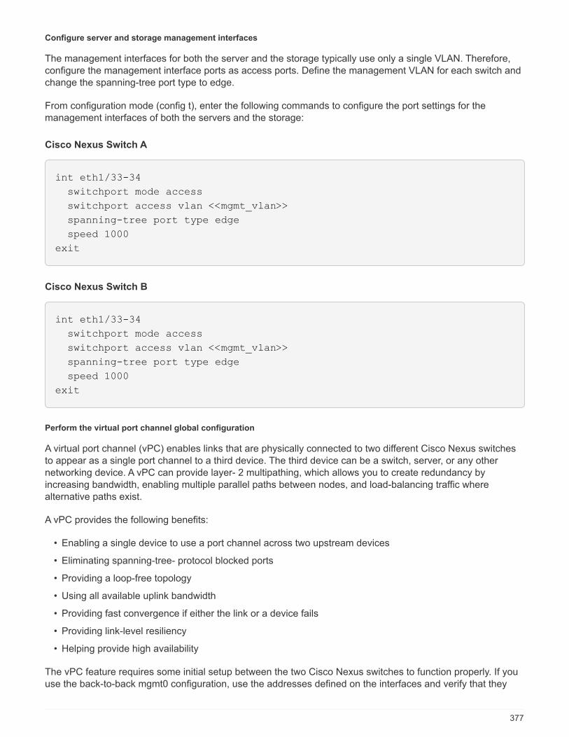
Configure server and storage management interfaces
The management interfaces for both the server and the storage typically use only a single VLAN. Therefore,configure the management interface ports as access ports. Define the management VLAN for each switch andchange the spanning-tree port type to edge.
From configuration mode (config t), enter the following commands to configure the port settings for themanagement interfaces of both the servers and the storage:
Cisco Nexus Switch A
int eth1/33-34
switchport mode access
switchport access vlan <<mgmt_vlan>>
spanning-tree port type edge
speed 1000
exit
Cisco Nexus Switch B
int eth1/33-34
switchport mode access
switchport access vlan <<mgmt_vlan>>
spanning-tree port type edge
speed 1000
exit
Perform the virtual port channel global configuration
A virtual port channel (vPC) enables links that are physically connected to two different Cisco Nexus switchesto appear as a single port channel to a third device. The third device can be a switch, server, or any othernetworking device. A vPC can provide layer- 2 multipathing, which allows you to create redundancy byincreasing bandwidth, enabling multiple parallel paths between nodes, and load-balancing traffic wherealternative paths exist.
A vPC provides the following benefits:
• Enabling a single device to use a port channel across two upstream devices
• Eliminating spanning-tree- protocol blocked ports
• Providing a loop-free topology
• Using all available uplink bandwidth
• Providing fast convergence if either the link or a device fails
• Providing link-level resiliency
• Helping provide high availability
The vPC feature requires some initial setup between the two Cisco Nexus switches to function properly. If youuse the back-to-back mgmt0 configuration, use the addresses defined on the interfaces and verify that they
377

can communicate by using the ping <<switch_A/B_mgmt0_ip_addr>>vrf management command.
From configuration mode (config t), run the following commands to configure the vPC global configuration forboth switches:
Cisco Nexus Switch A
vpc domain 1
role priority 10
peer-keepalive destination <<switch_B_mgmt0_ip_addr>> source
<<switch_A_mgmt0_ip_addr>> vrf
management
peer-switch
peer-gateway
auto-recovery
delay restore 150
ip arp synchronize
int eth1/25-26
channel-group 10 mode active
int Po10
description vPC peer-link
switchport
switchport mode trunk
switchport trunk native vlan <<native_vlan_id>>
switchport trunk allowed vlan <<nfs_vlan_id>>,<<vmotion_vlan_id>>,
<<vmtraffic_vlan_id>>, <<mgmt_vlan>, <<iSCSI_A_vlan_id>>,
<<iSCSI_B_vlan_id>>
spanning-tree port type network
vpc peer-link
no shut
exit
copy run start
Cisco Nexus Switch B
378
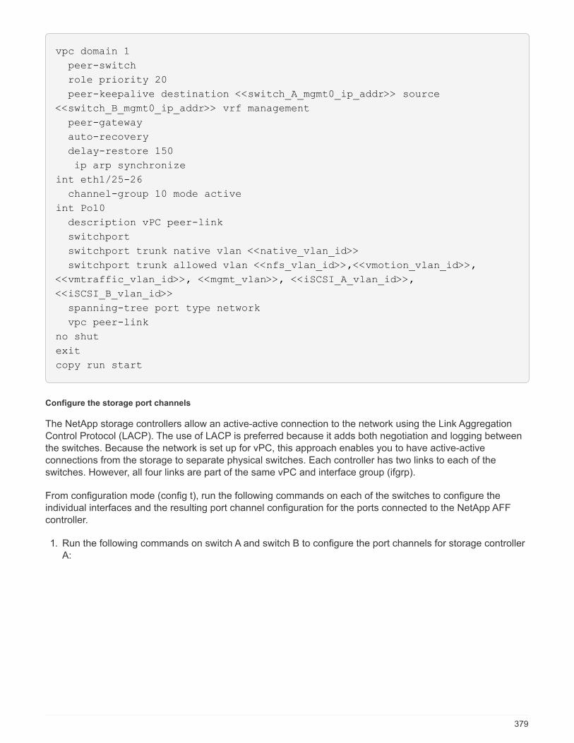
vpc domain 1
peer-switch
role priority 20
peer-keepalive destination <<switch_A_mgmt0_ip_addr>> source
<<switch_B_mgmt0_ip_addr>> vrf management
peer-gateway
auto-recovery
delay-restore 150
ip arp synchronize
int eth1/25-26
channel-group 10 mode active
int Po10
description vPC peer-link
switchport
switchport trunk native vlan <<native_vlan_id>>
switchport trunk allowed vlan <<nfs_vlan_id>>,<<vmotion_vlan_id>>,
<<vmtraffic_vlan_id>>, <<mgmt_vlan>>, <<iSCSI_A_vlan_id>>,
<<iSCSI_B_vlan_id>>
spanning-tree port type network
vpc peer-link
no shut
exit
copy run start
Configure the storage port channels
The NetApp storage controllers allow an active-active connection to the network using the Link AggregationControl Protocol (LACP). The use of LACP is preferred because it adds both negotiation and logging betweenthe switches. Because the network is set up for vPC, this approach enables you to have active-activeconnections from the storage to separate physical switches. Each controller has two links to each of theswitches. However, all four links are part of the same vPC and interface group (ifgrp).
From configuration mode (config t), run the following commands on each of the switches to configure theindividual interfaces and the resulting port channel configuration for the ports connected to the NetApp AFFcontroller.
1. Run the following commands on switch A and switch B to configure the port channels for storage controllerA:
379

int eth1/1
channel-group 11 mode active
int Po11
description vPC to Controller-A
switchport
switchport mode trunk
switchport trunk native vlan <<native_vlan_id>>
switchport trunk allowed vlan
<<nfs_vlan_id>>,<<mgmt_vlan_id>>,<<iSCSI_A_vlan_id>>,
<<iSCSI_B_vlan_id>>
spanning-tree port type edge trunk
mtu 9216
vpc 11
no shut
2. Run the following commands on switch A and switch B to configure the port channels for storage controllerB:
int eth1/2
channel-group 12 mode active
int Po12
description vPC to Controller-B
switchport
switchport mode trunk
switchport trunk native vlan <<native_vlan_id>>
switchport trunk allowed vlan <<nfs_vlan_id>>,<<mgmt_vlan_id>>,
<<iSCSI_A_vlan_id>>, <<iSCSI_B_vlan_id>>
spanning-tree port type edge trunk
mtu 9216
vpc 12
no shut
exit
copy run start
Configure the server connections
The Cisco UCS servers have a four-port virtual interface card, VIC1457, that is used for data traffic and bootingof the ESXi operating system using iSCSI. These interfaces are configured to fail over to one another,providing additional redundancy beyond a single link. Spreading these links across multiple switches enablesthe server to survive even a complete switch failure.
From configuration mode (config t), run the following commands to configure the port settings for the interfacesconnected to each server.
380
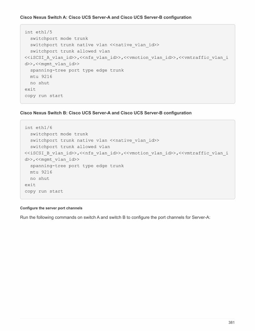
Cisco Nexus Switch A: Cisco UCS Server-A and Cisco UCS Server-B configuration
int eth1/5
switchport mode trunk
switchport trunk native vlan <<native_vlan_id>>
switchport trunk allowed vlan
<<iSCSI_A_vlan_id>>,<<nfs_vlan_id>>,<<vmotion_vlan_id>>,<<vmtraffic_vlan_i
d>>,<<mgmt_vlan_id>>
spanning-tree port type edge trunk
mtu 9216
no shut
exit
copy run start
Cisco Nexus Switch B: Cisco UCS Server-A and Cisco UCS Server-B configuration
int eth1/6
switchport mode trunk
switchport trunk native vlan <<native_vlan_id>>
switchport trunk allowed vlan
<<iSCSI_B_vlan_id>>,<<nfs_vlan_id>>,<<vmotion_vlan_id>>,<<vmtraffic_vlan_i
d>>,<<mgmt_vlan_id>>
spanning-tree port type edge trunk
mtu 9216
no shut
exit
copy run start
Configure the server port channels
Run the following commands on switch A and switch B to configure the port channels for Server-A:
381
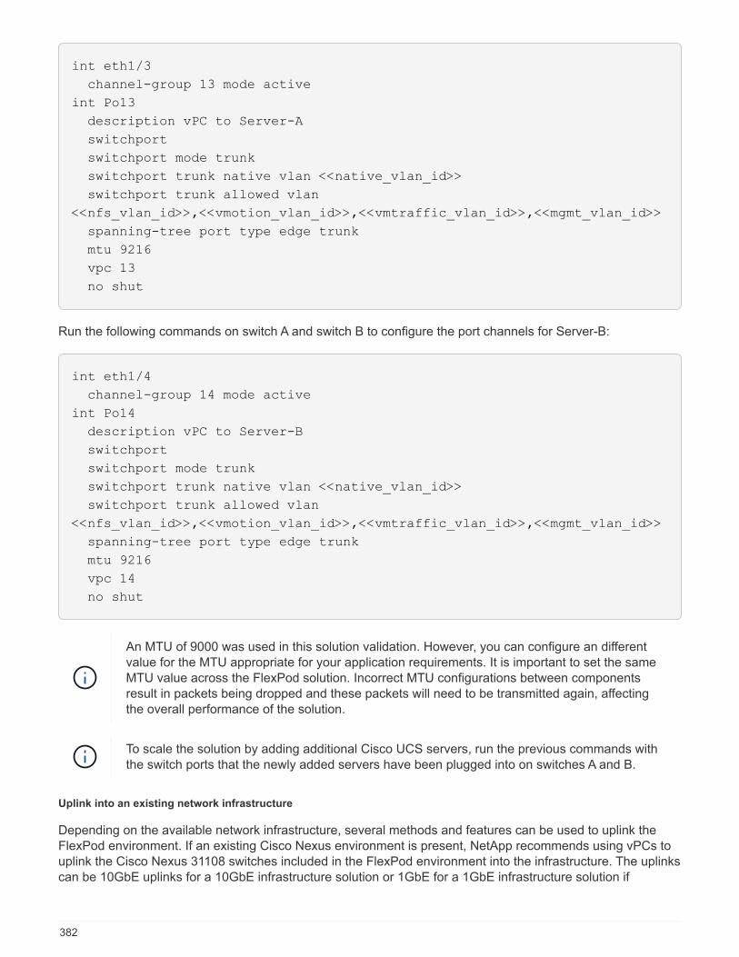
int eth1/3
channel-group 13 mode active
int Po13
description vPC to Server-A
switchport
switchport mode trunk
switchport trunk native vlan <<native_vlan_id>>
switchport trunk allowed vlan
<<nfs_vlan_id>>,<<vmotion_vlan_id>>,<<vmtraffic_vlan_id>>,<<mgmt_vlan_id>>
spanning-tree port type edge trunk
mtu 9216
vpc 13
no shut
Run the following commands on switch A and switch B to configure the port channels for Server-B:
int eth1/4
channel-group 14 mode active
int Po14
description vPC to Server-B
switchport
switchport mode trunk
switchport trunk native vlan <<native_vlan_id>>
switchport trunk allowed vlan
<<nfs_vlan_id>>,<<vmotion_vlan_id>>,<<vmtraffic_vlan_id>>,<<mgmt_vlan_id>>
spanning-tree port type edge trunk
mtu 9216
vpc 14
no shut
An MTU of 9000 was used in this solution validation. However, you can configure an differentvalue for the MTU appropriate for your application requirements. It is important to set the sameMTU value across the FlexPod solution. Incorrect MTU configurations between componentsresult in packets being dropped and these packets will need to be transmitted again, affectingthe overall performance of the solution.
To scale the solution by adding additional Cisco UCS servers, run the previous commands withthe switch ports that the newly added servers have been plugged into on switches A and B.
Uplink into an existing network infrastructure
Depending on the available network infrastructure, several methods and features can be used to uplink theFlexPod environment. If an existing Cisco Nexus environment is present, NetApp recommends using vPCs touplink the Cisco Nexus 31108 switches included in the FlexPod environment into the infrastructure. The uplinkscan be 10GbE uplinks for a 10GbE infrastructure solution or 1GbE for a 1GbE infrastructure solution if
382

required. The previously described procedures can be used to create an uplink vPC to the existingenvironment. Make sure to run copy start to save the configuration on each switch after the configuration iscompleted.
Next: NetApp storage deployment procedure (part 1)
NetApp storage deployment procedure (part 1)
This section describes the NetApp AFF storage deployment procedure.
NetApp storage controller AFF C190 Series installation
NetApp Hardware Universe
The NetApp Hardware Universe (HWU) application provides supported hardware and software components forany specific ONTAP version. It provides configuration information for all the NetApp storage appliancescurrently supported by ONTAP software. It also provides a table of component compatibilities.
Confirm that the hardware and software components that you would like to use are supported with the versionof ONTAP that you plan to install:
Access the HWU application to view the system configuration guides. Click the Controllers tab to view thecompatibility between different version of the ONTAP software and the NetApp storage appliances with yourdesired specifications.
Alternatively, to compare components by storage appliance, click Compare Storage Systems.
Controller AFFC190 Series prerequisites
To plan the physical location of the storage systems, see the NetApp Hardware Universe. Refer to thefollowing sections:
• Electrical Requirements
• Supported Power Cords
• Onboard Ports and Cables
Storage controllers
Follow the physical installation procedures for the controllers in the AFF C190 Documentation.
NetApp ONTAP 9.6
Configuration worksheet
Before running the setup script, complete the configuration worksheet from the product manual. Theconfiguration worksheet is available in the ONTAP 9.6 Software Setup Guide.
This system is set up in a two-node switchless cluster configuration.
The following table provides the ONTAP 9.6 installation and configuration information.
383

Cluster detail Cluster detail value
Cluster node A IP address <<var_nodeA_mgmt_ip>>
Cluster node A netmask <<var_nodeA_mgmt_mask>>
Cluster node A gateway <<var_nodeA_mgmt_gateway>>
Cluster node A name <<var_nodeA>>
Cluster node B IP address <<var_nodeB_mgmt_ip>>
Cluster node B netmask <<var_nodeB_mgmt_mask>>
Cluster node B gateway <<var_nodeB_mgmt_gateway>>
Cluster node B name <<var_nodeB>>
ONTAP 9.6 URL <<var_url_boot_software>>
Name for cluster <<var_clustername>>
Cluster management IP address <<var_clustermgmt_ip>>
Cluster B gateway <<var_clustermgmt_gateway>>
Cluster B netmask <<var_clustermgmt_mask>>
Domain name <<var_domain_name>>
DNS server IP (you can enter more than one) <var_dns_server_ip
NTP server IP (you can enter more than one) <<var_ntp_server_ip>>
Configure Node A
To configure node A, complete the following steps:
1. Connect to the storage system console port. You should see a Loader-A prompt. However, if the storagesystem is in a reboot loop, press Ctrl-C to exit the autoboot loop when you see this message:
Starting AUTOBOOT press Ctrl-C to abort…
Allow the system to boot.
autoboot
2. Press Ctrl-C to enter the Boot menu.
If ONTAP 9.6 is not the version of software being booted, continue with the following stepsto install new software. If ONTAP 9.6 is the version being booted, select option 8 and y toreboot the node. Then, continue with step 14.
3. To install new software, select option 7.
4. Enter y to perform an upgrade.
384

5. Select e0M for the network port you want to use for the download.
6. Enter y to reboot now.
7. Enter the IP address, netmask, and default gateway for e0M in their respective places.
<<var_nodeA_mgmt_ip>> <<var_nodeA_mgmt_mask>> <<var_nodeA_mgmt_gateway>>
8. Enter the URL where the software can be found.
This web server must be pingable.
<<var_url_boot_software>>
9. Press Enter for the user name, indicating no user name.
10. Enter y to set the newly installed software as the default to be used for subsequent reboots.
11. Enter y to reboot the node.
When installing new software, the system might perform firmware upgrades to the BIOS andadapter cards, causing reboots and possible stops at the Loader-A prompt. If these actionsoccur, the system might deviate from this procedure.
12. Press Ctrl-C to enter the Boot menu.
13. Select option 4 for Clean Configuration and Initialize All Disks.
14. Enter y to zero disks, reset config, and install a new file system.
15. Enter y to erase all the data on the disks.
The initialization and creation of the root aggregate can take 90 minutes or more tocomplete, depending on the number and type of disks attached. When initialization iscomplete, the storage system reboots. Note that SSDs take considerably less time toinitialize. You can continue with the node B configuration while the disks for node A arezeroing.
While node A is initializing, begin configuring node B.
Configure Node B
To configure node B, complete the following steps:
1. Connect to the storage system console port. You should see a Loader-A prompt. However, if the storagesystem is in a reboot loop, press Ctrl-C to exit the autoboot loop when you see this message:
Starting AUTOBOOT press Ctrl-C to abort…
2. Press Ctrl-C to enter the Boot menu.
385
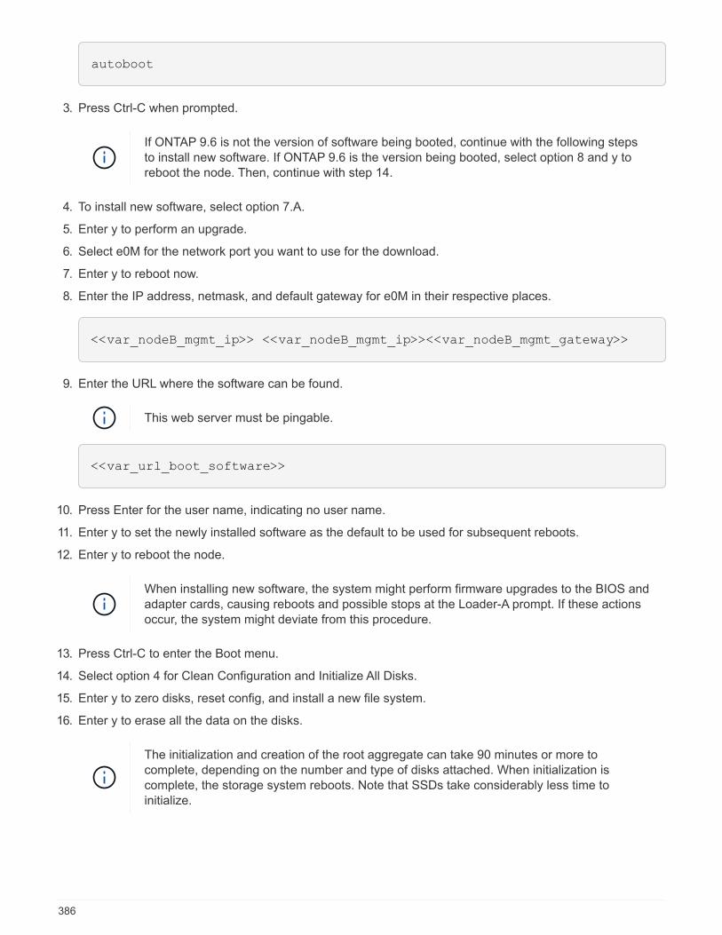
autoboot
3. Press Ctrl-C when prompted.
If ONTAP 9.6 is not the version of software being booted, continue with the following stepsto install new software. If ONTAP 9.6 is the version being booted, select option 8 and y toreboot the node. Then, continue with step 14.
4. To install new software, select option 7.A.
5. Enter y to perform an upgrade.
6. Select e0M for the network port you want to use for the download.
7. Enter y to reboot now.
8. Enter the IP address, netmask, and default gateway for e0M in their respective places.
<<var_nodeB_mgmt_ip>> <<var_nodeB_mgmt_ip>><<var_nodeB_mgmt_gateway>>
9. Enter the URL where the software can be found.
This web server must be pingable.
<<var_url_boot_software>>
10. Press Enter for the user name, indicating no user name.
11. Enter y to set the newly installed software as the default to be used for subsequent reboots.
12. Enter y to reboot the node.
When installing new software, the system might perform firmware upgrades to the BIOS andadapter cards, causing reboots and possible stops at the Loader-A prompt. If these actionsoccur, the system might deviate from this procedure.
13. Press Ctrl-C to enter the Boot menu.
14. Select option 4 for Clean Configuration and Initialize All Disks.
15. Enter y to zero disks, reset config, and install a new file system.
16. Enter y to erase all the data on the disks.
The initialization and creation of the root aggregate can take 90 minutes or more tocomplete, depending on the number and type of disks attached. When initialization iscomplete, the storage system reboots. Note that SSDs take considerably less time toinitialize.
386

Continuation of the node A configuration and cluster configuration
From a console port program attached to the storage controller A (node A) console port, run the node setupscript. This script appears when ONTAP 9.6 boots on the node for the first time.
The node and cluster setup procedure has changed slightly in ONTAP 9.6. The cluster setupwizard is now used to configure the first node in a cluster, and NetApp ONTAP System Manager(formerly OnCommand® System Manager) is used to configure the cluster.
1. Follow the prompts to set up node A.
Welcome to the cluster setup wizard.
You can enter the following commands at any time:
"help" or "?" - if you want to have a question clarified,
"back" - if you want to change previously answered questions, and
"exit" or "quit" - if you want to quit the cluster setup wizard.
Any changes you made before quitting will be saved.
You can return to cluster setup at any time by typing "cluster setup".
To accept a default or omit a question, do not enter a value.
This system will send event messages and periodic reports to NetApp
Technical
Support. To disable this feature, enter
autosupport modify -support disable
within 24 hours.
Enabling AutoSupport can significantly speed problem determination and
resolution should a problem occur on your system.
For further information on AutoSupport, see:
http://support.netapp.com/autosupport/
Type yes to confirm and continue {yes}: yes
Enter the node management interface port [e0M]:
Enter the node management interface IP address: <<var_nodeA_mgmt_ip>>
Enter the node management interface netmask: <<var_nodeA_mgmt_mask>>
Enter the node management interface default gateway:
<<var_nodeA_mgmt_gateway>>
A node management interface on port e0M with IP address
<<var_nodeA_mgmt_ip>> has been created.
Use your web browser to complete cluster setup by accessing
https://<<var_nodeA_mgmt_ip>>
Otherwise, press Enter to complete cluster setup using the command line
interface:
2. Navigate to the IP address of the node’s management interface.
Cluster setup can also be performed by using the CLI. This document describes clustersetup using System Manager guided setup.
3. Click Guided Setup to configure the cluster.
387

4. Enter <<var_clustername>> for the cluster name and <<var_nodeA>> and <<var_nodeB>> for eachof the nodes that you are configuring. Enter the password that you would like to use for the storage system.Select Switchless Cluster for the cluster type. Enter the cluster base license.
5. You can also enter feature licenses for Cluster, NFS, and iSCSI.
6. You see a status message stating the cluster is being created. This status message cycles through severalstatuses. This process takes several minutes.
7. Configure the network.
a. Deselect the IP Address Range option.
b. Enter <<var_clustermgmt_ip>> in the Cluster Management IP Address field,
<<var_clustermgmt_mask>> in the Netmask field, and <<var_clustermgmt_gateway>> in theGateway field. Use the … selector in the Port field to select e0M of node A.
c. The node management IP for node A is already populated. Enter <<var_nodeA_mgmt_ip>> for nodeB.
d. Enter <<var_domain_name>> in the DNS Domain Name field. Enter <<var_dns_server_ip>> inthe DNS Server IP Address field.
You can enter multiple DNS server IP addresses.
e. Enter 10.63.172.162 in the Primary NTP Server field.
You can also enter an alternate NTP server. The IP address 10.63.172.162 from
<<var_ntp_server_ip>> is the Nexus Mgmt IP.
8. Configure the support information.
a. If your environment requires a proxy to access AutoSupport, enter the URL in Proxy URL.
b. Enter the SMTP mail host and email address for event notifications.
You must, at a minimum, set up the event notification method before you can proceed.You can select any of the methods.
388
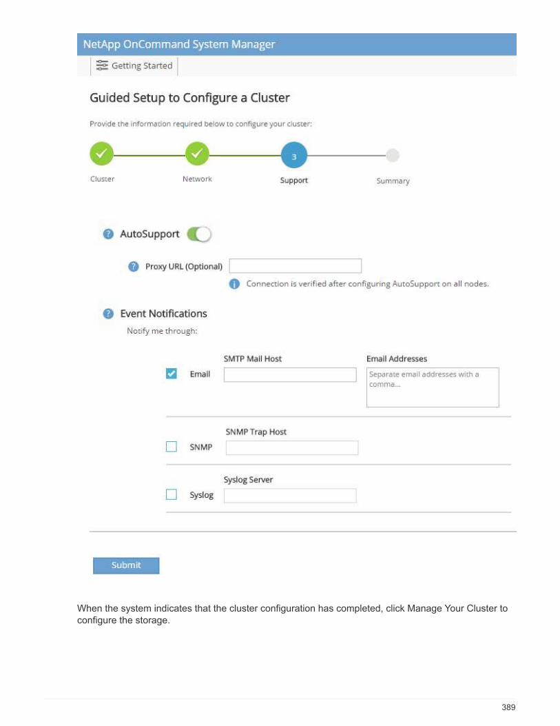
When the system indicates that the cluster configuration has completed, click Manage Your Cluster toconfigure the storage.
389
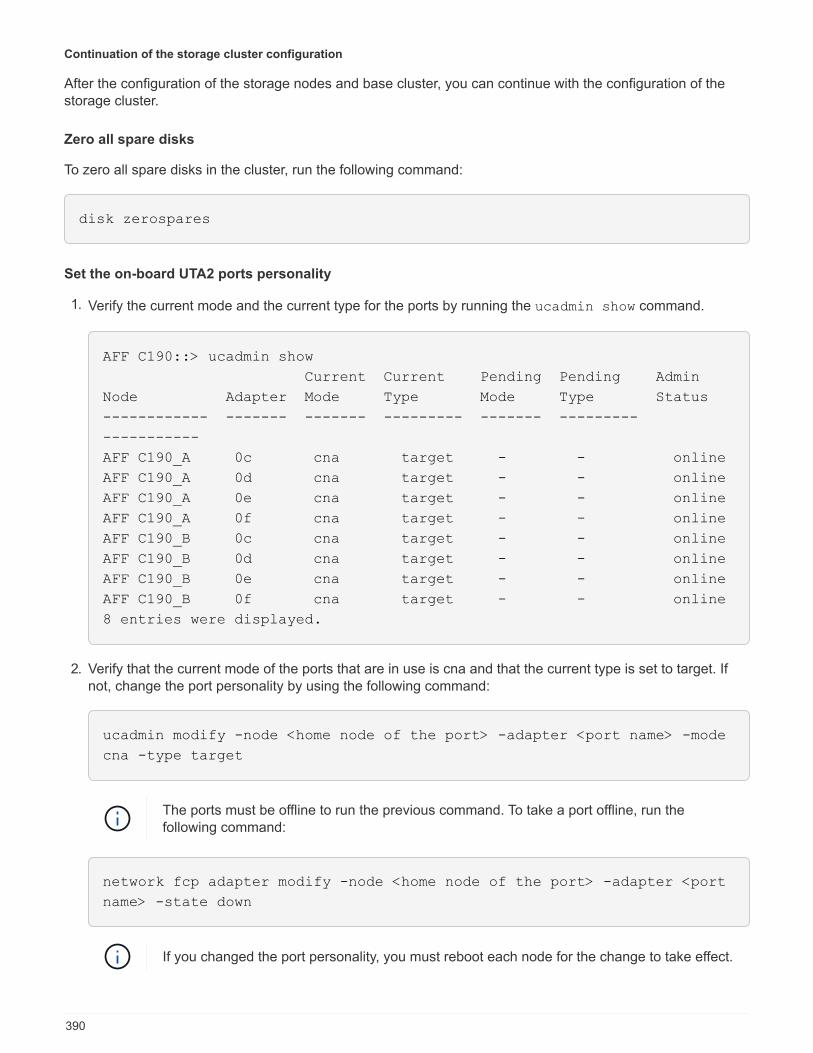
Continuation of the storage cluster configuration
After the configuration of the storage nodes and base cluster, you can continue with the configuration of thestorage cluster.
Zero all spare disks
To zero all spare disks in the cluster, run the following command:
disk zerospares
Set the on-board UTA2 ports personality
1. Verify the current mode and the current type for the ports by running the ucadmin show command.
AFF C190::> ucadmin show
Current Current Pending Pending Admin
Node Adapter Mode Type Mode Type Status
------------ ------- ------- --------- ------- ---------
-----------
AFF C190_A 0c cna target - - online
AFF C190_A 0d cna target - - online
AFF C190_A 0e cna target - - online
AFF C190_A 0f cna target - - online
AFF C190_B 0c cna target - - online
AFF C190_B 0d cna target - - online
AFF C190_B 0e cna target - - online
AFF C190_B 0f cna target - - online
8 entries were displayed.
2. Verify that the current mode of the ports that are in use is cna and that the current type is set to target. Ifnot, change the port personality by using the following command:
ucadmin modify -node <home node of the port> -adapter <port name> -mode
cna -type target
The ports must be offline to run the previous command. To take a port offline, run thefollowing command:
network fcp adapter modify -node <home node of the port> -adapter <port
name> -state down
If you changed the port personality, you must reboot each node for the change to take effect.
390
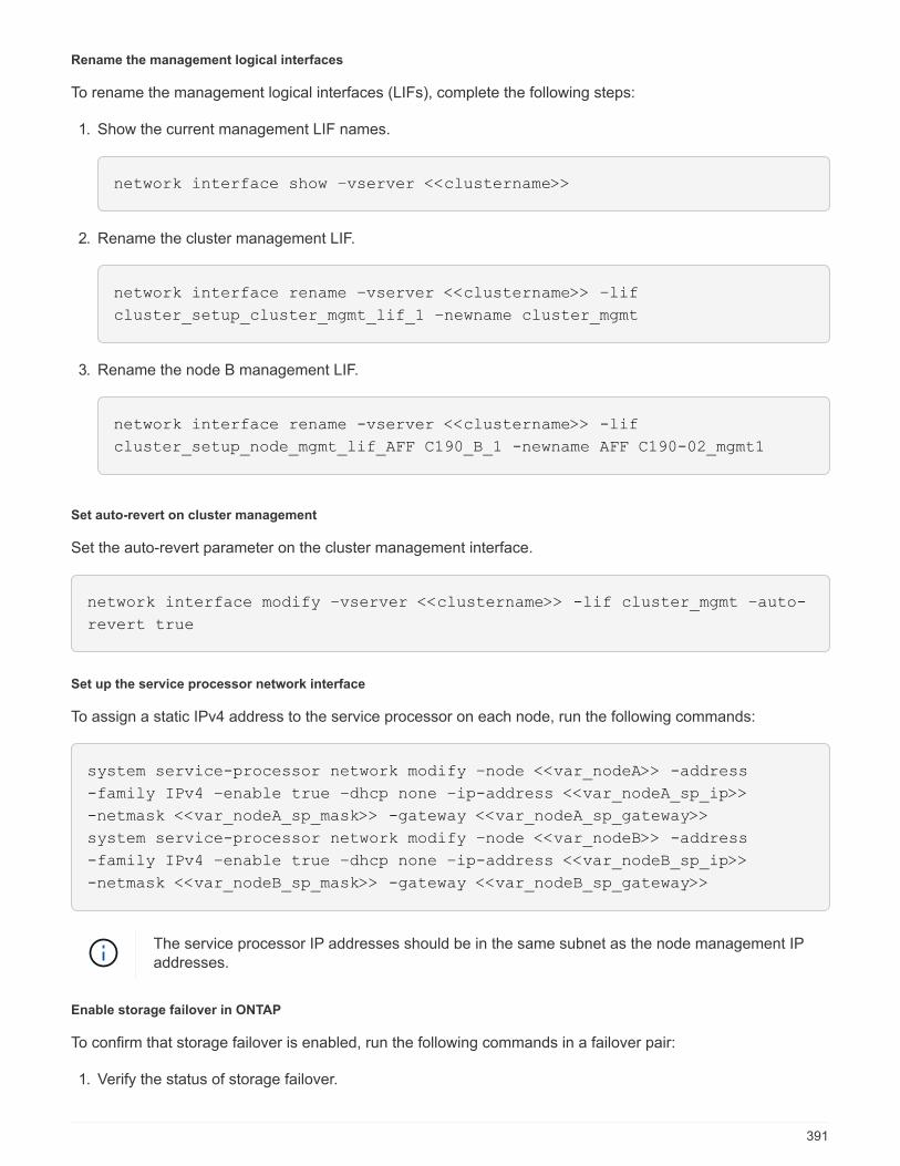
Rename the management logical interfaces
To rename the management logical interfaces (LIFs), complete the following steps:
1. Show the current management LIF names.
network interface show –vserver <<clustername>>
2. Rename the cluster management LIF.
network interface rename –vserver <<clustername>> –lif
cluster_setup_cluster_mgmt_lif_1 –newname cluster_mgmt
3. Rename the node B management LIF.
network interface rename -vserver <<clustername>> -lif
cluster_setup_node_mgmt_lif_AFF C190_B_1 -newname AFF C190-02_mgmt1
Set auto-revert on cluster management
Set the auto-revert parameter on the cluster management interface.
network interface modify –vserver <<clustername>> -lif cluster_mgmt –auto-
revert true
Set up the service processor network interface
To assign a static IPv4 address to the service processor on each node, run the following commands:
system service-processor network modify –node <<var_nodeA>> -address
-family IPv4 –enable true –dhcp none –ip-address <<var_nodeA_sp_ip>>
-netmask <<var_nodeA_sp_mask>> -gateway <<var_nodeA_sp_gateway>>
system service-processor network modify –node <<var_nodeB>> -address
-family IPv4 –enable true –dhcp none –ip-address <<var_nodeB_sp_ip>>
-netmask <<var_nodeB_sp_mask>> -gateway <<var_nodeB_sp_gateway>>
The service processor IP addresses should be in the same subnet as the node management IPaddresses.
Enable storage failover in ONTAP
To confirm that storage failover is enabled, run the following commands in a failover pair:
1. Verify the status of storage failover.
391
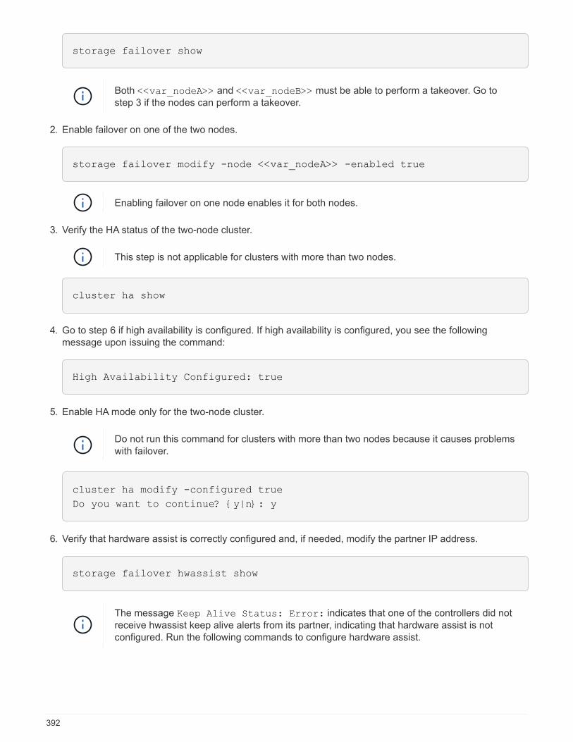
storage failover show
Both <<var_nodeA>> and <<var_nodeB>> must be able to perform a takeover. Go tostep 3 if the nodes can perform a takeover.
2. Enable failover on one of the two nodes.
storage failover modify -node <<var_nodeA>> -enabled true
Enabling failover on one node enables it for both nodes.
3. Verify the HA status of the two-node cluster.
This step is not applicable for clusters with more than two nodes.
cluster ha show
4. Go to step 6 if high availability is configured. If high availability is configured, you see the followingmessage upon issuing the command:
High Availability Configured: true
5. Enable HA mode only for the two-node cluster.
Do not run this command for clusters with more than two nodes because it causes problemswith failover.
cluster ha modify -configured true
Do you want to continue? {y|n}: y
6. Verify that hardware assist is correctly configured and, if needed, modify the partner IP address.
storage failover hwassist show
The message Keep Alive Status: Error: indicates that one of the controllers did notreceive hwassist keep alive alerts from its partner, indicating that hardware assist is notconfigured. Run the following commands to configure hardware assist.
392
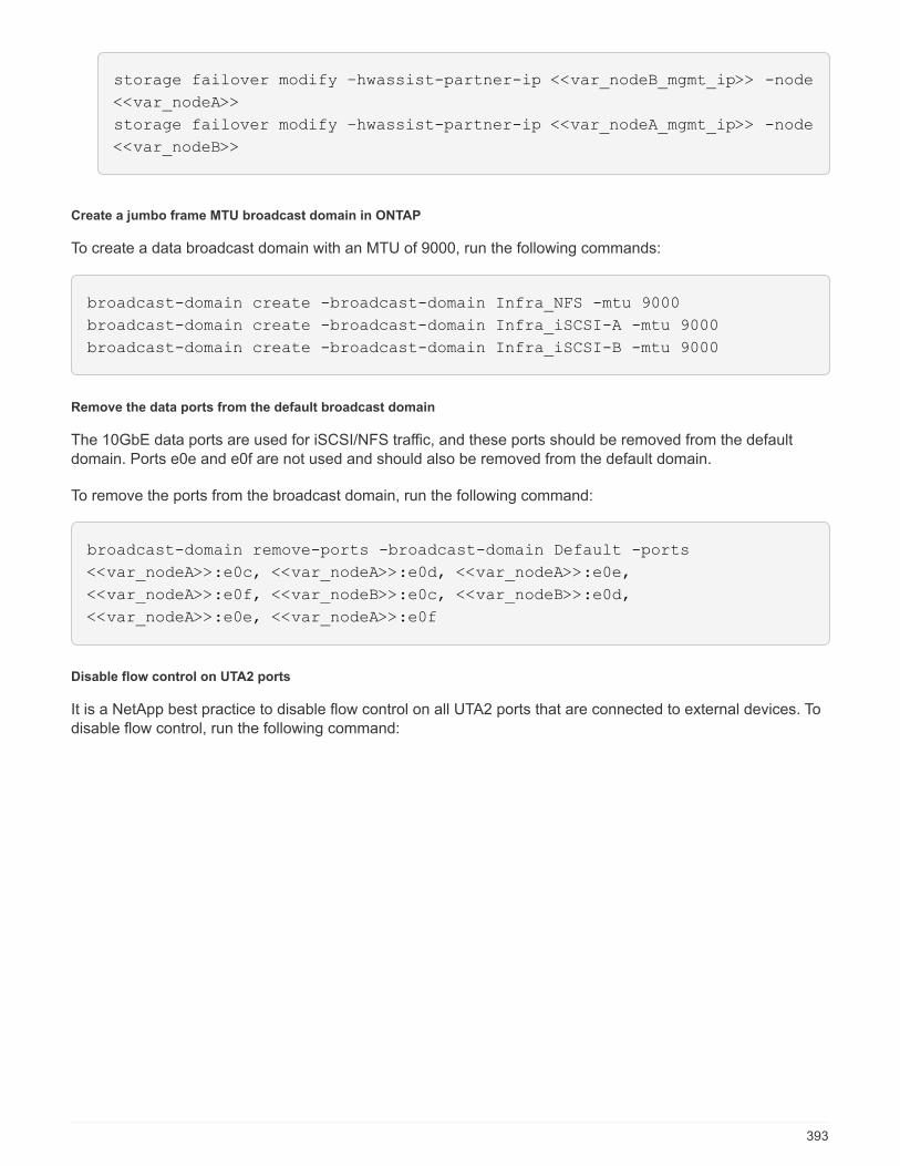
storage failover modify –hwassist-partner-ip <<var_nodeB_mgmt_ip>> -node
<<var_nodeA>>
storage failover modify –hwassist-partner-ip <<var_nodeA_mgmt_ip>> -node
<<var_nodeB>>
Create a jumbo frame MTU broadcast domain in ONTAP
To create a data broadcast domain with an MTU of 9000, run the following commands:
broadcast-domain create -broadcast-domain Infra_NFS -mtu 9000
broadcast-domain create -broadcast-domain Infra_iSCSI-A -mtu 9000
broadcast-domain create -broadcast-domain Infra_iSCSI-B -mtu 9000
Remove the data ports from the default broadcast domain
The 10GbE data ports are used for iSCSI/NFS traffic, and these ports should be removed from the defaultdomain. Ports e0e and e0f are not used and should also be removed from the default domain.
To remove the ports from the broadcast domain, run the following command:
broadcast-domain remove-ports -broadcast-domain Default -ports
<<var_nodeA>>:e0c, <<var_nodeA>>:e0d, <<var_nodeA>>:e0e,
<<var_nodeA>>:e0f, <<var_nodeB>>:e0c, <<var_nodeB>>:e0d,
<<var_nodeA>>:e0e, <<var_nodeA>>:e0f
Disable flow control on UTA2 ports
It is a NetApp best practice to disable flow control on all UTA2 ports that are connected to external devices. Todisable flow control, run the following command:
393

net port modify -node <<var_nodeA>> -port e0c -flowcontrol-admin none
Warning: Changing the network port settings will cause a several second
interruption in carrier.
Do you want to continue? {y|n}: y
net port modify -node <<var_nodeA>> -port e0d -flowcontrol-admin none
Warning: Changing the network port settings will cause a several second
interruption in carrier.
Do you want to continue? {y|n}: y
net port modify -node <<var_nodeA>> -port e0e -flowcontrol-admin none
Warning: Changing the network port settings will cause a several second
interruption in carrier.
Do you want to continue? {y|n}: y
net port modify -node <<var_nodeA>> -port e0f -flowcontrol-admin none
Warning: Changing the network port settings will cause a several second
interruption in carrier.
Do you want to continue? {y|n}: y
net port modify -node <<var_nodeB>> -port e0c -flowcontrol-admin none
Warning: Changing the network port settings will cause a several second
interruption in carrier.
Do you want to continue? {y|n}: y
net port modify -node <<var_nodeB>> -port e0d -flowcontrol-admin none
Warning: Changing the network port settings will cause a several second
interruption in carrier.
Do you want to continue? {y|n}: y
net port modify -node <<var_nodeB>> -port e0e -flowcontrol-admin none
Warning: Changing the network port settings will cause a several second
interruption in carrier.
Do you want to continue? {y|n}: y
net port modify -node <<var_nodeB>> -port e0f -flowcontrol-admin none
Warning: Changing the network port settings will cause a several second
interruption in carrier.
Do you want to continue? {y|n}: y
Configure the interface group LACP in ONTAP
This type of interface group requires two or more Ethernet interfaces and a switch that supports LACP. makesure it’s configured based on the steps in this guide in section 5.1.
From the cluster prompt, complete the following steps:
394

ifgrp create -node <<var_nodeA>> -ifgrp a0a -distr-func port -mode
multimode_lacp
network port ifgrp add-port -node <<var_nodeA>> -ifgrp a0a -port e0c
network port ifgrp add-port -node <<var_nodeA>> -ifgrp a0a -port e0d
ifgrp create -node << var_nodeB>> -ifgrp a0a -distr-func port -mode
multimode_lacp
network port ifgrp add-port -node <<var_nodeB>> -ifgrp a0a -port e0c
network port ifgrp add-port -node <<var_nodeB>> -ifgrp a0a -port e0d
Configure the jumbo frames in ONTAP
To configure an ONTAP network port to use jumbo frames (usually with an MTU of 9,000 bytes), run thefollowing commands from the cluster shell:
AFF C190::> network port modify -node node_A -port a0a -mtu 9000
Warning: This command will cause a several second interruption of service
on
this network port.
Do you want to continue? {y|n}: y
AFF C190::> network port modify -node node_B -port a0a -mtu 9000
Warning: This command will cause a several second interruption of service
on
this network port.
Do you want to continue? {y|n}: y
Create VLANs in ONTAP
To create VLANs in ONTAP, complete the following steps:
1. Create NFS VLAN ports and add them to the data broadcast domain.
network port vlan create –node <<var_nodeA>> -vlan-name a0a-
<<var_nfs_vlan_id>>
network port vlan create –node <<var_nodeB>> -vlan-name a0a-
<<var_nfs_vlan_id>>
broadcast-domain add-ports -broadcast-domain Infra_NFS -ports
<<var_nodeA>>:a0a-<<var_nfs_vlan_id>>, <<var_nodeB>>:a0a-
<<var_nfs_vlan_id>>
2. Create iSCSI VLAN ports and add them to the data broadcast domain.
395
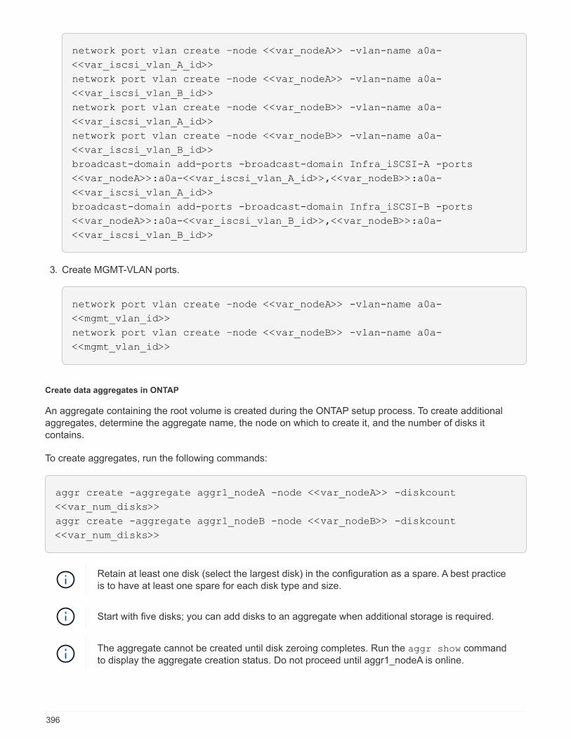
network port vlan create –node <<var_nodeA>> -vlan-name a0a-
<<var_iscsi_vlan_A_id>>
network port vlan create –node <<var_nodeA>> -vlan-name a0a-
<<var_iscsi_vlan_B_id>>
network port vlan create –node <<var_nodeB>> -vlan-name a0a-
<<var_iscsi_vlan_A_id>>
network port vlan create –node <<var_nodeB>> -vlan-name a0a-
<<var_iscsi_vlan_B_id>>
broadcast-domain add-ports -broadcast-domain Infra_iSCSI-A -ports
<<var_nodeA>>:a0a-<<var_iscsi_vlan_A_id>>,<<var_nodeB>>:a0a-
<<var_iscsi_vlan_A_id>>
broadcast-domain add-ports -broadcast-domain Infra_iSCSI-B -ports
<<var_nodeA>>:a0a-<<var_iscsi_vlan_B_id>>,<<var_nodeB>>:a0a-
<<var_iscsi_vlan_B_id>>
3. Create MGMT-VLAN ports.
network port vlan create –node <<var_nodeA>> -vlan-name a0a-
<<mgmt_vlan_id>>
network port vlan create –node <<var_nodeB>> -vlan-name a0a-
<<mgmt_vlan_id>>
Create data aggregates in ONTAP
An aggregate containing the root volume is created during the ONTAP setup process. To create additionalaggregates, determine the aggregate name, the node on which to create it, and the number of disks itcontains.
To create aggregates, run the following commands:
aggr create -aggregate aggr1_nodeA -node <<var_nodeA>> -diskcount
<<var_num_disks>>
aggr create -aggregate aggr1_nodeB -node <<var_nodeB>> -diskcount
<<var_num_disks>>
Retain at least one disk (select the largest disk) in the configuration as a spare. A best practiceis to have at least one spare for each disk type and size.
Start with five disks; you can add disks to an aggregate when additional storage is required.
The aggregate cannot be created until disk zeroing completes. Run the aggr show commandto display the aggregate creation status. Do not proceed until aggr1_nodeA is online.
396
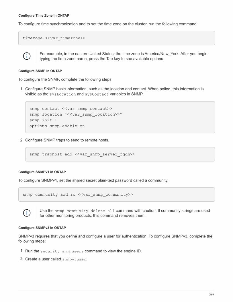
Configure Time Zone in ONTAP
To configure time synchronization and to set the time zone on the cluster, run the following command:
timezone <<var_timezone>>
For example, in the eastern United States, the time zone is America/New_York. After you begintyping the time zone name, press the Tab key to see available options.
Configure SNMP in ONTAP
To configure the SNMP, complete the following steps:
1. Configure SNMP basic information, such as the location and contact. When polled, this information is
visible as the sysLocation and sysContact variables in SNMP.
snmp contact <<var_snmp_contact>>
snmp location “<<var_snmp_location>>”
snmp init 1
options snmp.enable on
2. Configure SNMP traps to send to remote hosts.
snmp traphost add <<var_snmp_server_fqdn>>
Configure SNMPv1 in ONTAP
To configure SNMPv1, set the shared secret plain-text password called a community.
snmp community add ro <<var_snmp_community>>
Use the snmp community delete all command with caution. If community strings are usedfor other monitoring products, this command removes them.
Configure SNMPv3 in ONTAP
SNMPv3 requires that you define and configure a user for authentication. To configure SNMPv3, complete thefollowing steps:
1. Run the security snmpusers command to view the engine ID.
2. Create a user called snmpv3user.
397
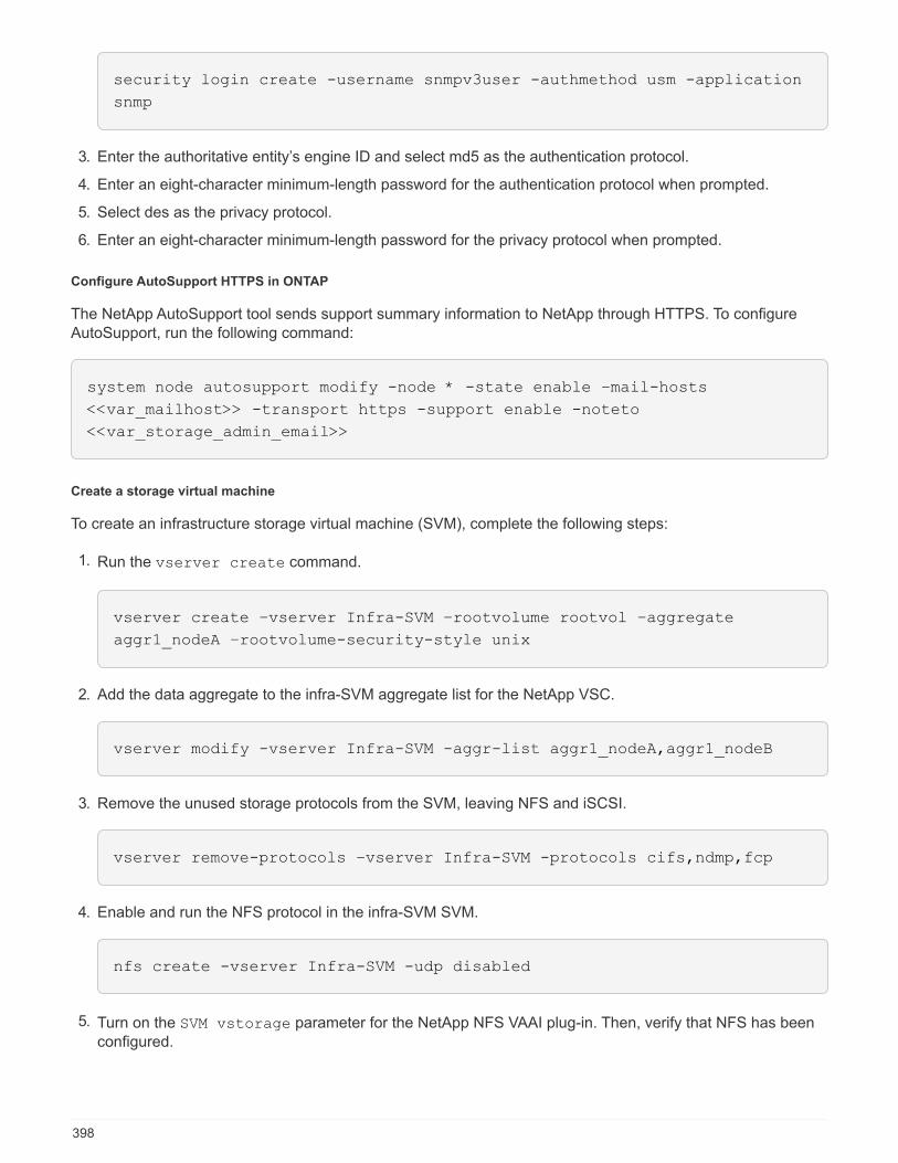
security login create -username snmpv3user -authmethod usm -application
snmp
3. Enter the authoritative entity’s engine ID and select md5 as the authentication protocol.
4. Enter an eight-character minimum-length password for the authentication protocol when prompted.
5. Select des as the privacy protocol.
6. Enter an eight-character minimum-length password for the privacy protocol when prompted.
Configure AutoSupport HTTPS in ONTAP
The NetApp AutoSupport tool sends support summary information to NetApp through HTTPS. To configureAutoSupport, run the following command:
system node autosupport modify -node * -state enable –mail-hosts
<<var_mailhost>> -transport https -support enable -noteto
<<var_storage_admin_email>>
Create a storage virtual machine
To create an infrastructure storage virtual machine (SVM), complete the following steps:
1. Run the vserver create command.
vserver create –vserver Infra-SVM –rootvolume rootvol –aggregate
aggr1_nodeA –rootvolume-security-style unix
2. Add the data aggregate to the infra-SVM aggregate list for the NetApp VSC.
vserver modify -vserver Infra-SVM -aggr-list aggr1_nodeA,aggr1_nodeB
3. Remove the unused storage protocols from the SVM, leaving NFS and iSCSI.
vserver remove-protocols –vserver Infra-SVM -protocols cifs,ndmp,fcp
4. Enable and run the NFS protocol in the infra-SVM SVM.
nfs create -vserver Infra-SVM -udp disabled
5. Turn on the SVM vstorage parameter for the NetApp NFS VAAI plug-in. Then, verify that NFS has beenconfigured.
398

vserver nfs modify –vserver Infra-SVM –vstorage enabled
vserver nfs show
Commands are prefaced by vserver in the command line because SVMs were previouslycalled Vservers.
Configure NFSv3 in ONTAP
The following table lists the information needed to complete this configuration.
Detail Detail value
ESXi host A NFS IP address <<var_esxi_hostA_nfs_ip>>
ESXi host B NFS IP address <<var_esxi_hostB_nfs_ip>>
To configure NFS on the SVM, run the following commands:
1. Create a rule for each ESXi host in the default export policy.
2. For each ESXi host being created, assign a rule. Each host has its own rule index. Your first ESXi host hasrule index 1, your second ESXi host has rule index 2, and so on.
vserver export-policy rule create –vserver Infra-SVM -policyname default
–ruleindex 1 –protocol nfs -clientmatch <<var_esxi_hostA_nfs_ip>>
-rorule sys –rwrule sys -superuser sys –allow-suid false
vserver export-policy rule create –vserver Infra-SVM -policyname default
–ruleindex 2 –protocol nfs -clientmatch <<var_esxi_hostB_nfs_ip>>
-rorule sys –rwrule sys -superuser sys –allow-suid false
vserver export-policy rule show
3. Assign the export policy to the infrastructure SVM root volume.
volume modify –vserver Infra-SVM –volume rootvol –policy default
The NetApp VSC automatically handles export policies if you choose to install it aftervSphere has been set up. If you do not install it, you must create export policy rules whenadditional Cisco UCS C-Series servers are added.
Create the iSCSI service in ONTAP
To create the iSCSI service on the SVM, run the following command. This command also starts the iSCSIservice and sets the iSCSI IQN for the SVM. Verify that iSCSI has been configured.
399
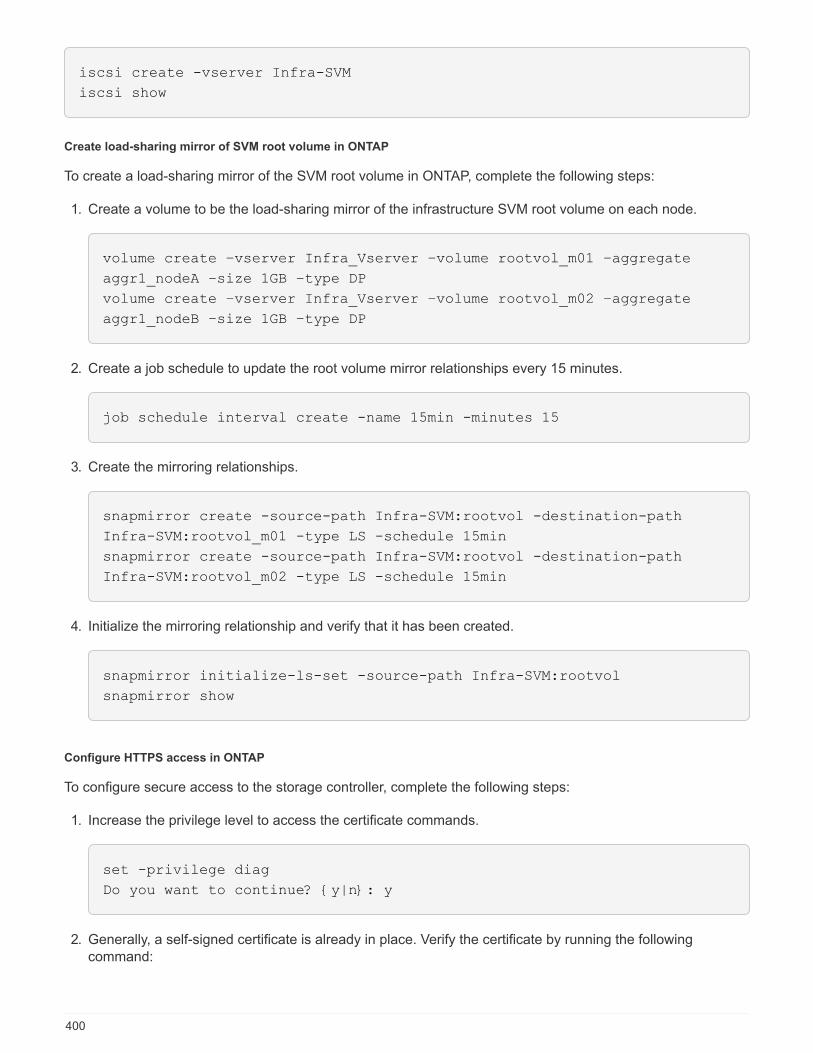
iscsi create -vserver Infra-SVM
iscsi show
Create load-sharing mirror of SVM root volume in ONTAP
To create a load-sharing mirror of the SVM root volume in ONTAP, complete the following steps:
1. Create a volume to be the load-sharing mirror of the infrastructure SVM root volume on each node.
volume create –vserver Infra_Vserver –volume rootvol_m01 –aggregate
aggr1_nodeA –size 1GB –type DP
volume create –vserver Infra_Vserver –volume rootvol_m02 –aggregate
aggr1_nodeB –size 1GB –type DP
2. Create a job schedule to update the root volume mirror relationships every 15 minutes.
job schedule interval create -name 15min -minutes 15
3. Create the mirroring relationships.
snapmirror create -source-path Infra-SVM:rootvol -destination-path
Infra-SVM:rootvol_m01 -type LS -schedule 15min
snapmirror create -source-path Infra-SVM:rootvol -destination-path
Infra-SVM:rootvol_m02 -type LS -schedule 15min
4. Initialize the mirroring relationship and verify that it has been created.
snapmirror initialize-ls-set -source-path Infra-SVM:rootvol
snapmirror show
Configure HTTPS access in ONTAP
To configure secure access to the storage controller, complete the following steps:
1. Increase the privilege level to access the certificate commands.
set -privilege diag
Do you want to continue? {y|n}: y
2. Generally, a self-signed certificate is already in place. Verify the certificate by running the followingcommand:
400
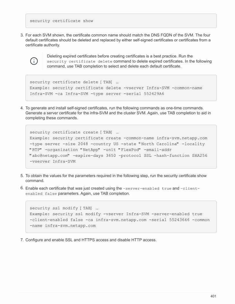
security certificate show
3. For each SVM shown, the certificate common name should match the DNS FQDN of the SVM. The fourdefault certificates should be deleted and replaced by either self-signed certificates or certificates from acertificate authority.
Deleting expired certificates before creating certificates is a best practice. Run the
security certificate delete command to delete expired certificates. In the followingcommand, use TAB completion to select and delete each default certificate.
security certificate delete [TAB] …
Example: security certificate delete -vserver Infra-SVM -common-name
Infra-SVM -ca Infra-SVM -type server -serial 552429A6
4. To generate and install self-signed certificates, run the following commands as one-time commands.Generate a server certificate for the infra-SVM and the cluster SVM. Again, use TAB completion to aid incompleting these commands.
security certificate create [TAB] …
Example: security certificate create -common-name infra-svm.netapp.com
-type server -size 2048 -country US -state "North Carolina" -locality
"RTP" -organization "NetApp" -unit "FlexPod" -email-addr
"[email protected]" -expire-days 3650 -protocol SSL -hash-function SHA256
-vserver Infra-SVM
5. To obtain the values for the parameters required in the following step, run the security certificate showcommand.
6. Enable each certificate that was just created using the –server-enabled true and –client-
enabled false parameters. Again, use TAB completion.
security ssl modify [TAB] …
Example: security ssl modify -vserver Infra-SVM -server-enabled true
-client-enabled false -ca infra-svm.netapp.com -serial 55243646 -common
-name infra-svm.netapp.com
7. Configure and enable SSL and HTTPS access and disable HTTP access.
401

system services web modify -external true -sslv3-enabled true
Warning: Modifying the cluster configuration will cause pending web
service requests to be interrupted as the web servers are restarted.
Do you want to continue {y|n}: y
system services firewall policy delete -policy mgmt -service http
–vserver <<var_clustername>>
It is normal for some of these commands to return an error message stating that the entrydoes not exist.
8. Revert to the admin privilege level and create the setup to allow the SVM to be available by the web.
set –privilege admin
vserver services web modify –name spi –vserver * -enabled true
Create a NetApp FlexVol volume in ONTAP
To create a NetApp FlexVol® volume, enter the volume name, size, and the aggregate on which it exists.Create two VMware datastore volumes and a server boot volume.
volume create -vserver Infra-SVM -volume infra_datastore -aggregate
aggr1_nodeB -size 500GB -state online -policy default -junction-path
/infra_datastore -space-guarantee none -percent-snapshot-space 0
volume create -vserver Infra-SVM -volume infra_swap -aggregate aggr1_nodeA
-size 100GB -state online -policy default -junction-path /infra_swap
-space-guarantee none -percent-snapshot-space 0 -snapshot-policy none
-efficiency-policy none
volume create -vserver Infra-SVM -volume esxi_boot -aggregate aggr1_nodeA
-size 100GB -state online -policy default -space-guarantee none -percent
-snapshot-space 0
Create LUNs in ONTAP
To create two boot LUNs, run the following commands:
lun create -vserver Infra-SVM -volume esxi_boot -lun VM-Host-Infra-A -size
15GB -ostype vmware -space-reserve disabled
lun create -vserver Infra-SVM -volume esxi_boot -lun VM-Host-Infra-B -size
15GB -ostype vmware -space-reserve disabled
When adding an extra Cisco UCS C-Series server, you must create an extra boot LUN.
402

Create iSCSI LIFs in ONTAP
The following table lists the information needed to complete this configuration.
Detail Detail value
Storage node A iSCSI LIF01A <<var_nodeA_iscsi_lif01a_ip>>
Storage node A iSCSI LIF01A network mask <<var_nodeA_iscsi_lif01a_mask>>
Storage node A iSCSI LIF01B <<var_nodeA_iscsi_lif01b_ip>>
Storage node A iSCSI LIF01B network mask <<var_nodeA_iscsi_lif01b_mask>>
Storage node B iSCSI LIF01A <<var_nodeB_iscsi_lif01a_ip>>
Storage node B iSCSI LIF01A network mask <<var_nodeB_iscsi_lif01a_mask>>
Storage node B iSCSI LIF01B <<var_nodeB_iscsi_lif01b_ip>>
Storage node B iSCSI LIF01B network mask <<var_nodeB_iscsi_lif01b_mask>>
Create four iSCSI LIFs, two on each node.
network interface create -vserver Infra-SVM -lif iscsi_lif01a -role data
-data-protocol iscsi -home-node <<var_nodeA>> -home-port a0a-
<<var_iscsi_vlan_A_id>> -address <<var_nodeA_iscsi_lif01a_ip>> -netmask
<<var_nodeA_iscsi_lif01a_mask>> –status-admin up –failover-policy disabled
–firewall-policy data –auto-revert false
network interface create -vserver Infra-SVM -lif iscsi_lif01b -role data
-data-protocol iscsi -home-node <<var_nodeA>> -home-port a0a-
<<var_iscsi_vlan_B_id>> -address <<var_nodeA_iscsi_lif01b_ip>> -netmask
<<var_nodeA_iscsi_lif01b_mask>> –status-admin up –failover-policy disabled
–firewall-policy data –auto-revert false
network interface create -vserver Infra-SVM -lif iscsi_lif02a -role data
-data-protocol iscsi -home-node <<var_nodeB>> -home-port a0a-
<<var_iscsi_vlan_A_id>> -address <<var_nodeB_iscsi_lif01a_ip>> -netmask
<<var_nodeB_iscsi_lif01a_mask>> –status-admin up –failover-policy disabled
–firewall-policy data –auto-revert false
network interface create -vserver Infra-SVM -lif iscsi_lif02b -role data
-data-protocol iscsi -home-node <<var_nodeB>> -home-port a0a-
<<var_iscsi_vlan_B_id>> -address <<var_nodeB_iscsi_lif01b_ip>> -netmask
<<var_nodeB_iscsi_lif01b_mask>> –status-admin up –failover-policy disabled
–firewall-policy data –auto-revert false
network interface show
Create NFS LIFs in ONTAP
The following table lists the information needed to complete this configuration.
403
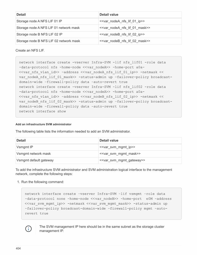
Detail Detail value
Storage node A NFS LIF 01 IP <<var_nodeA_nfs_lif_01_ip>>
Storage node A NFS LIF 01 network mask <<var_nodeA_nfs_lif_01_mask>>
Storage node B NFS LIF 02 IP <<var_nodeB_nfs_lif_02_ip>>
Storage node B NFS LIF 02 network mask <<var_nodeB_nfs_lif_02_mask>>
Create an NFS LIF.
network interface create -vserver Infra-SVM -lif nfs_lif01 -role data
-data-protocol nfs -home-node <<var_nodeA>> -home-port a0a-
<<var_nfs_vlan_id>> –address <<var_nodeA_nfs_lif_01_ip>> -netmask <<
var_nodeA_nfs_lif_01_mask>> -status-admin up –failover-policy broadcast-
domain-wide –firewall-policy data –auto-revert true
network interface create -vserver Infra-SVM -lif nfs_lif02 -role data
-data-protocol nfs -home-node <<var_nodeA>> -home-port a0a-
<<var_nfs_vlan_id>> –address <<var_nodeB_nfs_lif_02_ip>> -netmask <<
var_nodeB_nfs_lif_02_mask>> -status-admin up –failover-policy broadcast-
domain-wide –firewall-policy data –auto-revert true
network interface show
Add an infrastructure SVM administrator
The following table lists the information needed to add an SVM administrator.
Detail Detail value
Vsmgmt IP <<var_svm_mgmt_ip>>
Vsmgmt network mask <<var_svm_mgmt_mask>>
Vsmgmt default gateway <<var_svm_mgmt_gateway>>
To add the infrastructure SVM administrator and SVM administration logical interface to the managementnetwork, complete the following steps:
1. Run the following command:
network interface create –vserver Infra-SVM –lif vsmgmt –role data
–data-protocol none –home-node <<var_nodeB>> -home-port e0M –address
<<var_svm_mgmt_ip>> -netmask <<var_svm_mgmt_mask>> -status-admin up
–failover-policy broadcast-domain-wide –firewall-policy mgmt –auto-
revert true
The SVM management IP here should be in the same subnet as the storage clustermanagement IP.
404
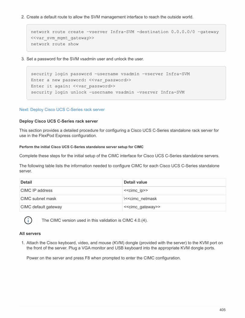
2. Create a default route to allow the SVM management interface to reach the outside world.
network route create –vserver Infra-SVM -destination 0.0.0.0/0 –gateway
<<var_svm_mgmt_gateway>>
network route show
3. Set a password for the SVM vsadmin user and unlock the user.
security login password –username vsadmin –vserver Infra-SVM
Enter a new password: <<var_password>>
Enter it again: <<var_password>>
security login unlock –username vsadmin –vserver Infra-SVM
Next: Deploy Cisco UCS C-Series rack server
Deploy Cisco UCS C-Series rack server
This section provides a detailed procedure for configuring a Cisco UCS C-Series standalone rack server foruse in the FlexPod Express configuration.
Perform the initial Cisco UCS C-Series standalone server setup for CIMC
Complete these steps for the initial setup of the CIMC interface for Cisco UCS C-Series standalone servers.
The following table lists the information needed to configure CIMC for each Cisco UCS C-Series standaloneserver.
Detail Detail value
CIMC IP address <<cimc_ip>>
CIMC subnet mask \<<cimc_netmask
CIMC default gateway <<cimc_gateway>>
The CIMC version used in this validation is CIMC 4.0.(4).
All servers
1. Attach the Cisco keyboard, video, and mouse (KVM) dongle (provided with the server) to the KVM port onthe front of the server. Plug a VGA monitor and USB keyboard into the appropriate KVM dongle ports.
Power on the server and press F8 when prompted to enter the CIMC configuration.
405
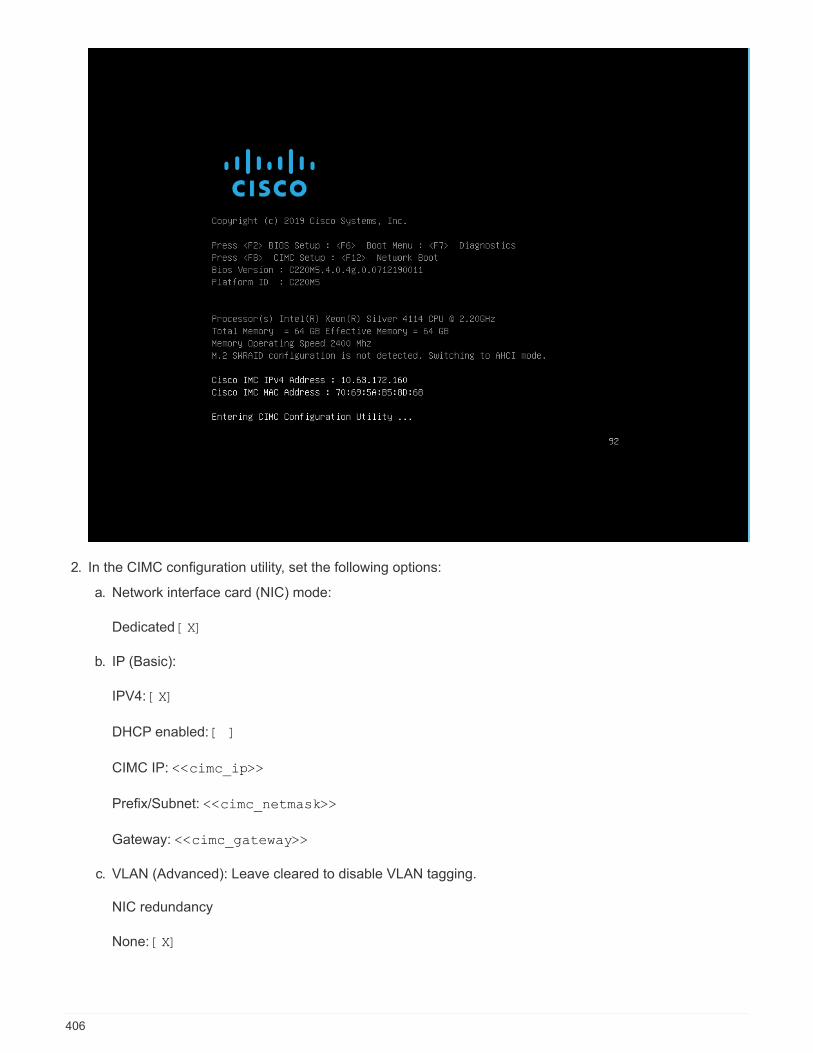
2. In the CIMC configuration utility, set the following options:
a. Network interface card (NIC) mode:
Dedicated [X]
b. IP (Basic):
IPV4: [X]
DHCP enabled: [ ]
CIMC IP: <<cimc_ip>>
Prefix/Subnet: <<cimc_netmask>>
Gateway: <<cimc_gateway>>
c. VLAN (Advanced): Leave cleared to disable VLAN tagging.
NIC redundancy
None: [X]
406
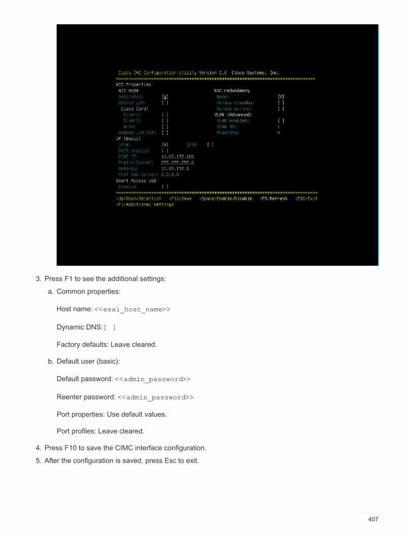
3. Press F1 to see the additional settings:
a. Common properties:
Host name: <<esxi_host_name>>
Dynamic DNS: [ ]
Factory defaults: Leave cleared.
b. Default user (basic):
Default password: <<admin_password>>
Reenter password: <<admin_password>>
Port properties: Use default values.
Port profiles: Leave cleared.
4. Press F10 to save the CIMC interface configuration.
5. After the configuration is saved, press Esc to exit.
407
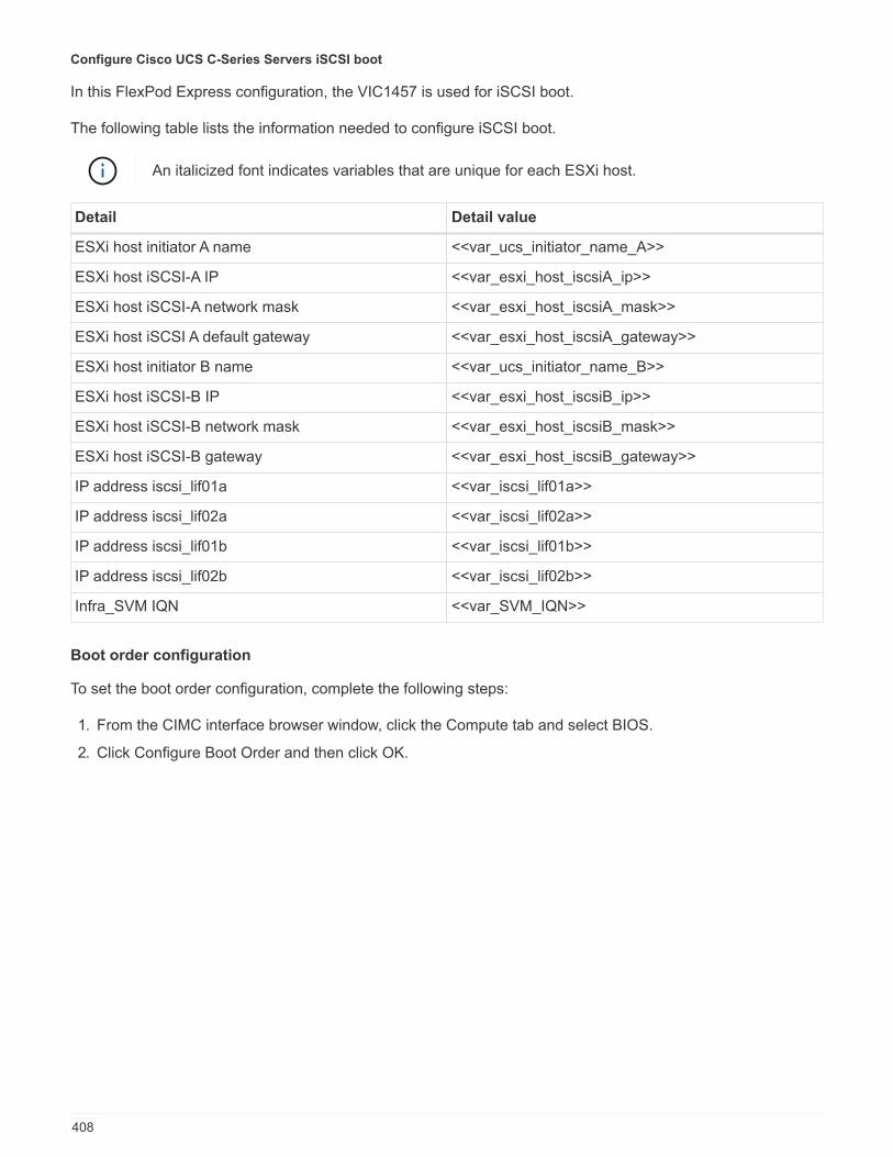
Configure Cisco UCS C-Series Servers iSCSI boot
In this FlexPod Express configuration, the VIC1457 is used for iSCSI boot.
The following table lists the information needed to configure iSCSI boot.
An italicized font indicates variables that are unique for each ESXi host.
Detail Detail value
ESXi host initiator A name <<var_ucs_initiator_name_A>>
ESXi host iSCSI-A IP <<var_esxi_host_iscsiA_ip>>
ESXi host iSCSI-A network mask <<var_esxi_host_iscsiA_mask>>
ESXi host iSCSI A default gateway <<var_esxi_host_iscsiA_gateway>>
ESXi host initiator B name <<var_ucs_initiator_name_B>>
ESXi host iSCSI-B IP <<var_esxi_host_iscsiB_ip>>
ESXi host iSCSI-B network mask <<var_esxi_host_iscsiB_mask>>
ESXi host iSCSI-B gateway <<var_esxi_host_iscsiB_gateway>>
IP address iscsi_lif01a <<var_iscsi_lif01a>>
IP address iscsi_lif02a <<var_iscsi_lif02a>>
IP address iscsi_lif01b <<var_iscsi_lif01b>>
IP address iscsi_lif02b <<var_iscsi_lif02b>>
Infra_SVM IQN <<var_SVM_IQN>>
Boot order configuration
To set the boot order configuration, complete the following steps:
1. From the CIMC interface browser window, click the Compute tab and select BIOS.
2. Click Configure Boot Order and then click OK.
408
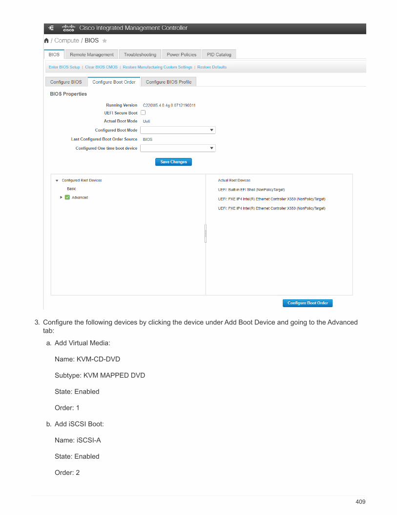
3. Configure the following devices by clicking the device under Add Boot Device and going to the Advancedtab:
a. Add Virtual Media:
Name: KVM-CD-DVD
Subtype: KVM MAPPED DVD
State: Enabled
Order: 1
b. Add iSCSI Boot:
Name: iSCSI-A
State: Enabled
Order: 2
409

Slot: MLOM
Port: 1
c. Click Add iSCSI Boot:
Name: iSCSI-B
State: Enabled
Order: 3
Slot: MLOM
Port: 3
4. Click Add Device.
5. Click Save Changes and then click Close.
6. Reboot the server to boot with your new boot order.
Disable RAID controller (if present)
Complete the following steps if your C-Series server contains a RAID controller. A RAID controller is notneeded in the boot from SAN configuration. Optionally, you can also physically remove the RAID controllerfrom the server.
1. Under the Compute tab, click BIOS in the left navigation pane in CIMC.
2. Select Configure BIOS.
3. Scroll down to PCIe Slot:HBA Option ROM.
4. If the value is not already disabled, set it to disabled.
410

Configure Cisco VIC1457 for iSCSI boot
The following configuration steps are for the Cisco VIC 1457 for iSCSI boot.
The default port-channeling between ports 0, 1, 2, and 3 must be turned off before the fourindividual ports can be configured. If port channeling is not turned off, only two ports appear forthe VIC 1457. Complete the following steps to enable the port channel on the CIMC:
1. Under the networking tab, click the Adapter Card MLOM.
2. Under the General tab, uncheck the port channel.
3. Save the changes and reboot the CIMC.
411

Create iSCSI vNICs
To create iSCSI vNICS, complete the following steps:
1. Under the networking tab, click Adapter Card MLOM.
2. Click Add vNIC to create a vNIC.
3. In the Add vNIC section, enter the following settings:
◦ Name: eth1
◦ CDN Name: iSCSI-vNIC-A
◦ MTU: 9000
◦ Default VLAN: <<var_iscsi_vlan_a>>
◦ VLAN Mode: TRUNK
◦ Enable PXE boot: Check
4. Click Add vNIC and then click OK.
5. Repeat the process to add a second vNIC:
◦ Name the vNIC eth3.
◦ CDN Name: iSCSI-vNIC-B
◦ Enter <<var_iscsi_vlan_b>> as the VLAN.
◦ Set the uplink port to 3.
412
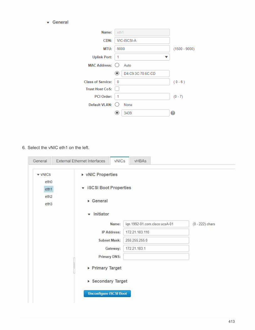
6. Select the vNIC eth1 on the left.
413

7. Under iSCSI Boot Properties, enter the initiator details:
◦ Name: <<var_ucsa_initiator_name_a>>
◦ IP address: <<var_esxi_hostA_iscsiA_ip>>
◦ Subnet mask: <<var_esxi_hostA_iscsiA_mask>>
◦ Gateway: <<var_esxi_hostA_iscsiA_gateway>>
8. Enter the primary target details:
◦ Name: IQN number of infra-SVM
◦ IP address: IP address of iscsi_lif01a
◦ Boot LUN: 0
9. Enter the secondary target details:
◦ Name: IQN number of infra-SVM
◦ IP address: IP address of iscsi_lif02a
◦ Boot LUN:0
You can obtain the storage IQN number by running the vserver iscsi showcommand.
Be sure to record the IQN names for each vNIC. You need them for a later step. Inaddition, the IQN names for initiators must be unique for each server and for the iSCSIvNIC.
10. Click Save Changes.
11. Select the vNIC eth3 and click the iSCSI Boot button located on the top of the Host Ethernet Interfacessection.
12. Repeat the process to configure eth3.
13. Enter the initiator details:
414

◦ Name: <<var_ucsa_initiator_name_b>>
◦ IP address: <<var_esxi_hostb_iscsib_ip>>
◦ Subnet mask: <<var_esxi_hostb_iscsib_mask>>
◦ Gateway: <<var_esxi_hostb_iscsib_gateway>>
14. Enter the primary target details:
◦ Name: IQN number of infra-SVM
◦ IP address: IP address of iscsi_lif01b
◦ Boot LUN: 0
15. Enter the secondary target details:
◦ Name: IQN number of infra-SVM
◦ IP address: IP address of iscsi_lif02b
◦ Boot LUN: 0
You can obtain the storage IQN number by using the vserver iscsi showcommand.
Be sure to record the IQN names for each vNIC. You need them for a later step.
16. Click Save Changes.
17. Repeat this process to configure iSCSI boot for Cisco UCS server B.
Configure vNICs for ESXi
To configure vNICS for ESXi, complete the following steps:
1. From the CIMC interface browser window, click Inventory and then click Cisco VIC adapters on the rightpane.
415
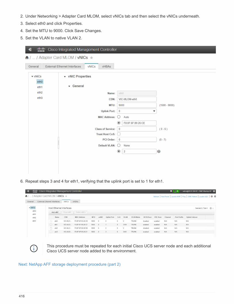
2. Under Networking > Adapter Card MLOM, select vNICs tab and then select the vNICs underneath.
3. Select eth0 and click Properties.
4. Set the MTU to 9000. Click Save Changes.
5. Set the VLAN to native VLAN 2.
6. Repeat steps 3 and 4 for eth1, verifying that the uplink port is set to 1 for eth1.
This procedure must be repeated for each initial Cisco UCS server node and each additionalCisco UCS server node added to the environment.
Next: NetApp AFF storage deployment procedure (part 2)
416

NetApp AFF storage deployment procedure (part 2)
Set up ONTAP SAN boot storage
Create iSCSI igroups
You need the iSCSI initiator IQNs from the server configuration for this step.
To create igroups, run the following commands from the cluster management node SSH connection. To view
the three igroups created in this step, run the igroup show command.
igroup create –vserver Infra-SVM –igroup VM-Host-Infra-A –protocol iscsi
–ostype vmware –initiator <<var_vm_host_infra_a_iSCSI-
A_vNIC_IQN>>,<<var_vm_host_infra_a_iSCSI-B_vNIC_IQN>>
igroup create –vserver Infra-SVM –igroup VM-Host-Infra-B –protocol iscsi
–ostype vmware –initiator <<var_vm_host_infra_b_iSCSI-
A_vNIC_IQN>>,<<var_vm_host_infra_b_iSCSI-B_vNIC_IQN>>
This step must be completed when adding additional Cisco UCS C-Series servers.
Map boot LUNs to igroups
To map boot LUNs to igroups, run the following commands from the cluster
management SSH connection:
lun map –vserver Infra-SVM –volume esxi_boot –lun VM-Host-Infra-A –igroup
VM-Host-Infra-A –lun-id 0
lun map –vserver Infra-SVM –volume esxi_boot –lun VM-Host-Infra-B –igroup
VM-Host-Infra-B –lun-id 0
This step must be completed when adding additional Cisco UCS C-Series servers.
Next: VMware vSphere 6.7U2 deployment procedure
VMware vSphere 6.7U2 deployment procedure
This section provides detailed procedures for installing VMware ESXi 6.7U2 in a FlexPod Expressconfiguration. The deployment procedures that follow are customized to include the environment variablesdescribed in previous sections.
Multiple methods exist for installing VMware ESXi in such an environment. This procedure uses the virtualKVM console and virtual media features of the CIMC interface for Cisco UCS C-Series servers to map remoteinstallation media to each individual server.
This procedure must be completed for Cisco UCS server A and Cisco UCS server B.
This procedure must be completed for any additional nodes added to the cluster.
417
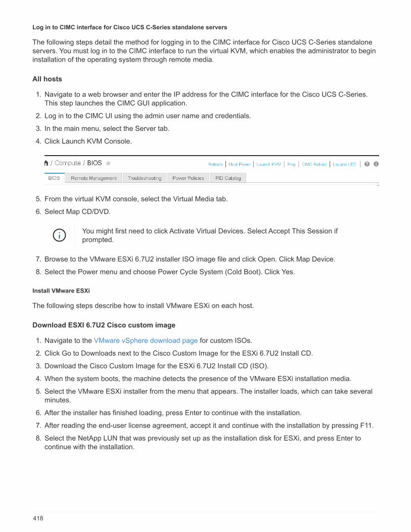
Log in to CIMC interface for Cisco UCS C-Series standalone servers
The following steps detail the method for logging in to the CIMC interface for Cisco UCS C-Series standaloneservers. You must log in to the CIMC interface to run the virtual KVM, which enables the administrator to begininstallation of the operating system through remote media.
All hosts
1. Navigate to a web browser and enter the IP address for the CIMC interface for the Cisco UCS C-Series.This step launches the CIMC GUI application.
2. Log in to the CIMC UI using the admin user name and credentials.
3. In the main menu, select the Server tab.
4. Click Launch KVM Console.
5. From the virtual KVM console, select the Virtual Media tab.
6. Select Map CD/DVD.
You might first need to click Activate Virtual Devices. Select Accept This Session ifprompted.
7. Browse to the VMware ESXi 6.7U2 installer ISO image file and click Open. Click Map Device.
8. Select the Power menu and choose Power Cycle System (Cold Boot). Click Yes.
Install VMware ESXi
The following steps describe how to install VMware ESXi on each host.
Download ESXI 6.7U2 Cisco custom image
1. Navigate to the VMware vSphere download page for custom ISOs.
2. Click Go to Downloads next to the Cisco Custom Image for the ESXi 6.7U2 Install CD.
3. Download the Cisco Custom Image for the ESXi 6.7U2 Install CD (ISO).
4. When the system boots, the machine detects the presence of the VMware ESXi installation media.
5. Select the VMware ESXi installer from the menu that appears. The installer loads, which can take severalminutes.
6. After the installer has finished loading, press Enter to continue with the installation.
7. After reading the end-user license agreement, accept it and continue with the installation by pressing F11.
8. Select the NetApp LUN that was previously set up as the installation disk for ESXi, and press Enter tocontinue with the installation.
418

9. Select the appropriate keyboard layout and press Enter.
10. Enter and confirm the root password and press Enter.
11. The installer warns you that existing partitions are removed on the volume. Continue with the installation bypressing F11. The server reboots after the installation of ESXi.
Set up VMware ESXi host management networking
The following steps describe how to add the management network for each VMware ESXi host.
All hosts
1. After the server has finished rebooting, enter the option to customize the system by pressing F2.
2. Log in with root as the login name and the root password previously entered during the installation process.
3. Select the Configure Management Network option.
4. Select Network Adapters and press Enter.
5. Select the desired ports for vSwitch0. Press Enter.
6. Select the ports that correspond to eth0 and eth1 in CIMC.
419

7. Select VLAN (optional) and press Enter.
8. Enter the VLAN ID <<mgmt_vlan_id>>. Press Enter.
9. From the Configure Management Network menu, select IPv4 Configuration to configure the IP address ofthe management interface. Press Enter.
10. Use the arrow keys to highlight Set Static IPv4 Address and use the space bar to select this option.
11. Enter the IP address for managing the VMware ESXi host <<esxi_host_mgmt_ip>>.
12. Enter the subnet mask for the VMware ESXi host <<esxi_host_mgmt_netmask>>.
13. Enter the default gateway for the VMware ESXi host <<esxi_host_mgmt_gateway>>.
14. Press Enter to accept the changes to the IP configuration.
15. Enter the IPv6 configuration menu.
16. Use the space bar to disable IPv6 by unselecting the Enable IPv6 (restart required) option. Press Enter.
17. Enter the menu to configure the DNS settings.
18. Because the IP address is assigned manually, the DNS information must also be entered manually.
19. Enter the primary DNS server’s IP address <<nameserver_ip>>.
20. (Optional) Enter the secondary DNS server’s IP address.
21. Enter the FQDN for the VMware ESXi host name: <<esxi_host_fqdn>>.
22. Press Enter to accept the changes to the DNS configuration.
23. Exit the Configure Management Network submenu by pressing Esc.
24. Press Y to confirm the changes and reboot the server.
25. Select Troubleshooting Options, and then Enable ESXi Shell and SSH.
420
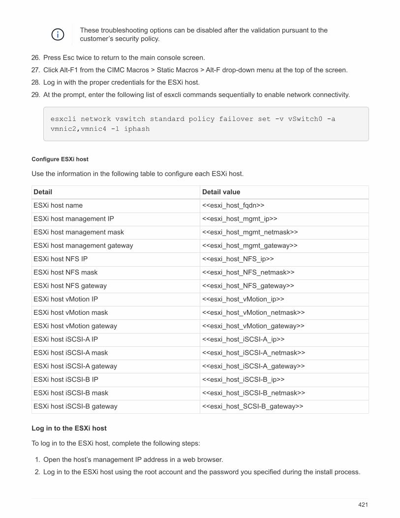
These troubleshooting options can be disabled after the validation pursuant to thecustomer’s security policy.
26. Press Esc twice to return to the main console screen.
27. Click Alt-F1 from the CIMC Macros > Static Macros > Alt-F drop-down menu at the top of the screen.
28. Log in with the proper credentials for the ESXi host.
29. At the prompt, enter the following list of esxcli commands sequentially to enable network connectivity.
esxcli network vswitch standard policy failover set -v vSwitch0 -a
vmnic2,vmnic4 -l iphash
Configure ESXi host
Use the information in the following table to configure each ESXi host.
Detail Detail value
ESXi host name <<esxi_host_fqdn>>
ESXi host management IP <<esxi_host_mgmt_ip>>
ESXi host management mask <<esxi_host_mgmt_netmask>>
ESXi host management gateway <<esxi_host_mgmt_gateway>>
ESXi host NFS IP <<esxi_host_NFS_ip>>
ESXi host NFS mask <<esxi_host_NFS_netmask>>
ESXi host NFS gateway <<esxi_host_NFS_gateway>>
ESXi host vMotion IP <<esxi_host_vMotion_ip>>
ESXi host vMotion mask <<esxi_host_vMotion_netmask>>
ESXi host vMotion gateway <<esxi_host_vMotion_gateway>>
ESXi host iSCSI-A IP <<esxi_host_iSCSI-A_ip>>
ESXi host iSCSI-A mask <<esxi_host_iSCSI-A_netmask>>
ESXi host iSCSI-A gateway <<esxi_host_iSCSI-A_gateway>>
ESXi host iSCSI-B IP <<esxi_host_iSCSI-B_ip>>
ESXi host iSCSI-B mask <<esxi_host_iSCSI-B_netmask>>
ESXi host iSCSI-B gateway <<esxi_host_SCSI-B_gateway>>
Log in to the ESXi host
To log in to the ESXi host, complete the following steps:
1. Open the host’s management IP address in a web browser.
2. Log in to the ESXi host using the root account and the password you specified during the install process.
421
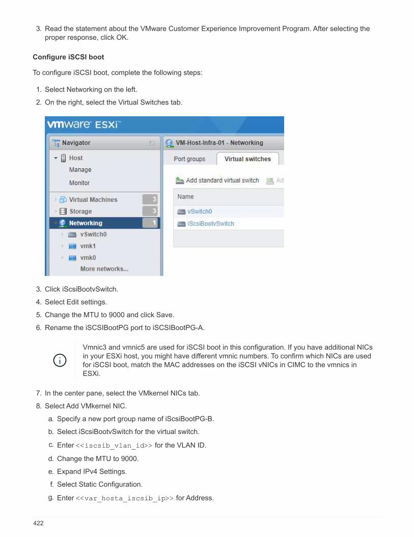
3. Read the statement about the VMware Customer Experience Improvement Program. After selecting theproper response, click OK.
Configure iSCSI boot
To configure iSCSI boot, complete the following steps:
1. Select Networking on the left.
2. On the right, select the Virtual Switches tab.
3. Click iScsiBootvSwitch.
4. Select Edit settings.
5. Change the MTU to 9000 and click Save.
6. Rename the iSCSIBootPG port to iSCSIBootPG-A.
Vmnic3 and vmnic5 are used for iSCSI boot in this configuration. If you have additional NICsin your ESXi host, you might have different vmnic numbers. To confirm which NICs are usedfor iSCSI boot, match the MAC addresses on the iSCSI vNICs in CIMC to the vmnics inESXi.
7. In the center pane, select the VMkernel NICs tab.
8. Select Add VMkernel NIC.
a. Specify a new port group name of iScsiBootPG-B.
b. Select iScsiBootvSwitch for the virtual switch.
c. Enter <<iscsib_vlan_id>> for the VLAN ID.
d. Change the MTU to 9000.
e. Expand IPv4 Settings.
f. Select Static Configuration.
g. Enter <<var_hosta_iscsib_ip>> for Address.
422
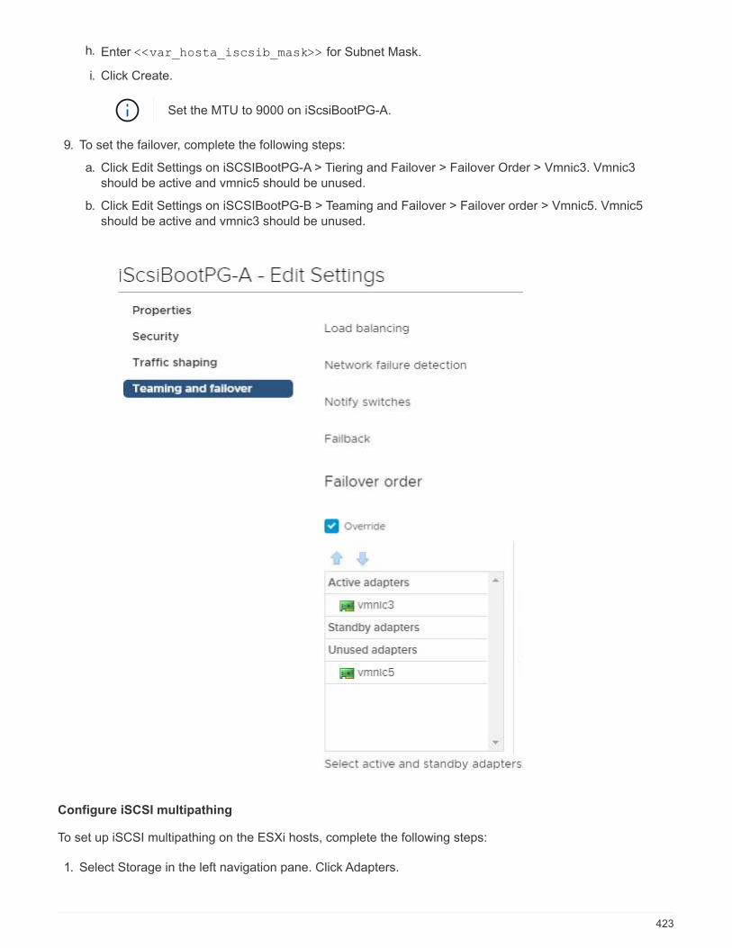
h. Enter <<var_hosta_iscsib_mask>> for Subnet Mask.
i. Click Create.
Set the MTU to 9000 on iScsiBootPG-A.
9. To set the failover, complete the following steps:
a. Click Edit Settings on iSCSIBootPG-A > Tiering and Failover > Failover Order > Vmnic3. Vmnic3should be active and vmnic5 should be unused.
b. Click Edit Settings on iSCSIBootPG-B > Teaming and Failover > Failover order > Vmnic5. Vmnic5should be active and vmnic3 should be unused.
Configure iSCSI multipathing
To set up iSCSI multipathing on the ESXi hosts, complete the following steps:
1. Select Storage in the left navigation pane. Click Adapters.
423
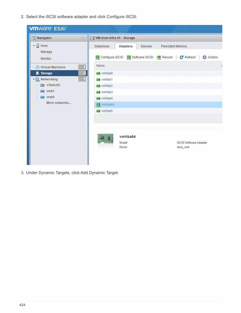
2. Select the iSCSI software adapter and click Configure iSCSI.
3. Under Dynamic Targets, click Add Dynamic Target.
424

4. Enter the IP address iscsi_lif01a.
a. Repeat with the IP addresses iscsi_lif01b, iscsi_lif02a, and iscsi_lif02b.
b. Click Save Configuration.
You can find the iSCSI LIF IP addresses by running the network interface showcommand on the NetApp cluster or by looking at the Network Interfaces tab in SystemManager.
Configure the ESXi host
To configure ESXi boot, complete the following steps:
1. In the left navigation pane, select Networking.
425
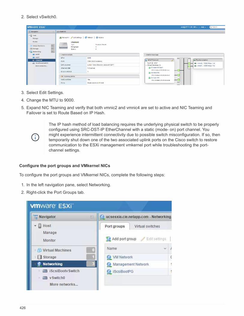
2. Select vSwitch0.
3. Select Edit Settings.
4. Change the MTU to 9000.
5. Expand NIC Teaming and verify that both vmnic2 and vmnic4 are set to active and NIC Teaming andFailover is set to Route Based on IP Hash.
The IP hash method of load balancing requires the underlying physical switch to be properlyconfigured using SRC-DST-IP EtherChannel with a static (mode- on) port channel. Youmight experience intermittent connectivity due to possible switch misconfiguration. If so, thentemporarily shut down one of the two associated uplink ports on the Cisco switch to restorecommunication to the ESXi management vmkernel port while troubleshooting the port-channel settings.
Configure the port groups and VMkernel NICs
To configure the port groups and VMkernel NICs, complete the following steps:
1. In the left navigation pane, select Networking.
2. Right-click the Port Groups tab.
426
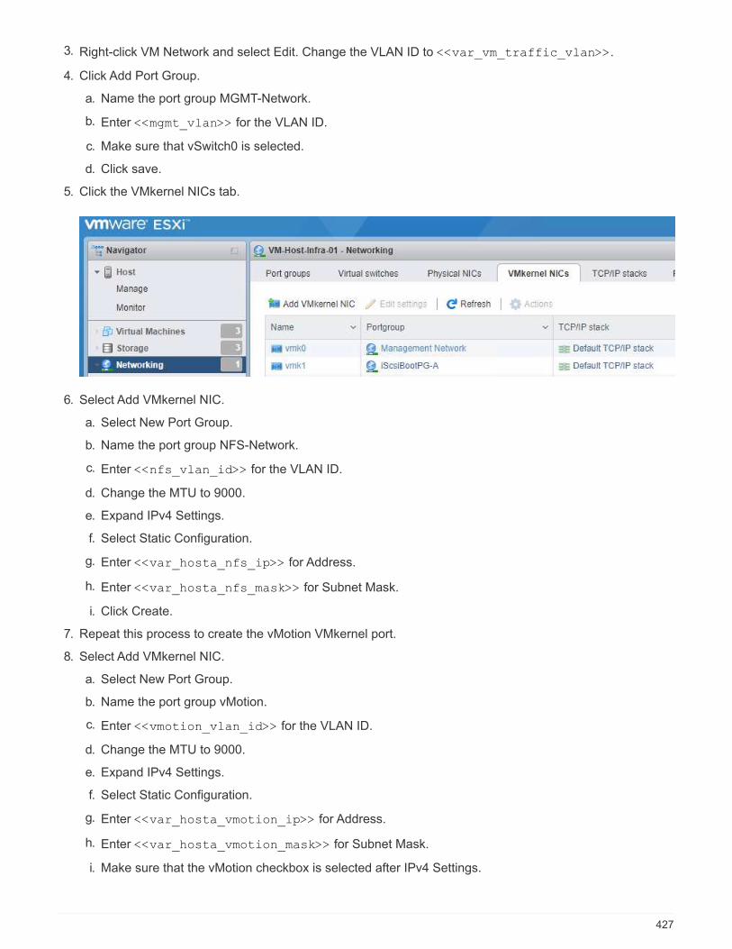
3. Right-click VM Network and select Edit. Change the VLAN ID to <<var_vm_traffic_vlan>>.
4. Click Add Port Group.
a. Name the port group MGMT-Network.
b. Enter <<mgmt_vlan>> for the VLAN ID.
c. Make sure that vSwitch0 is selected.
d. Click save.
5. Click the VMkernel NICs tab.
6. Select Add VMkernel NIC.
a. Select New Port Group.
b. Name the port group NFS-Network.
c. Enter <<nfs_vlan_id>> for the VLAN ID.
d. Change the MTU to 9000.
e. Expand IPv4 Settings.
f. Select Static Configuration.
g. Enter <<var_hosta_nfs_ip>> for Address.
h. Enter <<var_hosta_nfs_mask>> for Subnet Mask.
i. Click Create.
7. Repeat this process to create the vMotion VMkernel port.
8. Select Add VMkernel NIC.
a. Select New Port Group.
b. Name the port group vMotion.
c. Enter <<vmotion_vlan_id>> for the VLAN ID.
d. Change the MTU to 9000.
e. Expand IPv4 Settings.
f. Select Static Configuration.
g. Enter <<var_hosta_vmotion_ip>> for Address.
h. Enter <<var_hosta_vmotion_mask>> for Subnet Mask.
i. Make sure that the vMotion checkbox is selected after IPv4 Settings.
427

There are many ways to configure ESXi networking, including by using the VMwarevSphere distributed switch if your licensing allows it. Alternative network configurationsare supported in FlexPod Express if they are required to meet business requirements.
Mount the first datastores
The first datastores to be mounted are the infra_datastore datastore for VMs and the infra_swapdatastore for VM swap files.
1. Click Storage in the left navigation pane, and then click New Datastore.
428
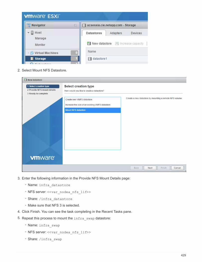
2. Select Mount NFS Datastore.
3. Enter the following information in the Provide NFS Mount Details page:
◦ Name: infra_datastore
◦ NFS server: <<var_nodea_nfs_lif>>
◦ Share: /infra_datastore
◦ Make sure that NFS 3 is selected.
4. Click Finish. You can see the task completing in the Recent Tasks pane.
5. Repeat this process to mount the infra_swap datastore:
◦ Name: infra_swap
◦ NFS server: <<var_nodea_nfs_lif>>
◦ Share: /infra_swap
429
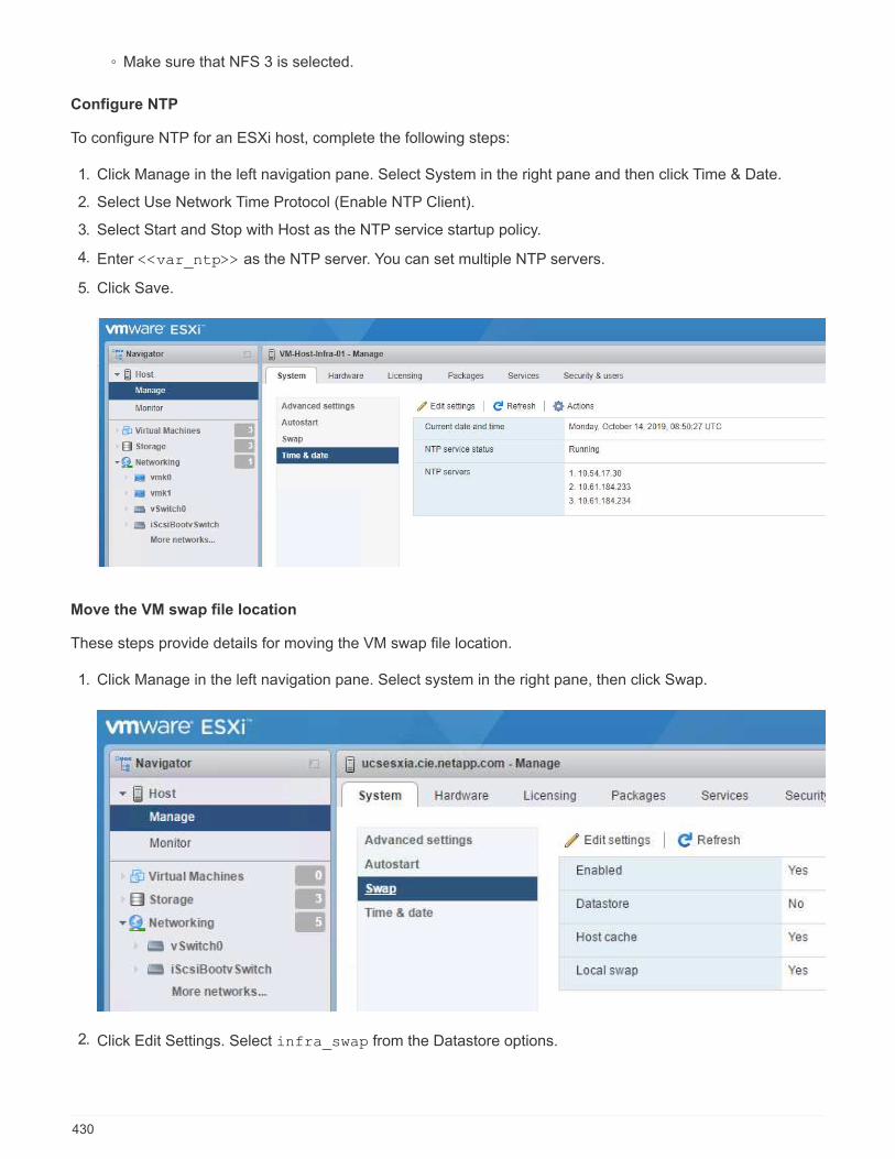
◦ Make sure that NFS 3 is selected.
Configure NTP
To configure NTP for an ESXi host, complete the following steps:
1. Click Manage in the left navigation pane. Select System in the right pane and then click Time & Date.
2. Select Use Network Time Protocol (Enable NTP Client).
3. Select Start and Stop with Host as the NTP service startup policy.
4. Enter <<var_ntp>> as the NTP server. You can set multiple NTP servers.
5. Click Save.
Move the VM swap file location
These steps provide details for moving the VM swap file location.
1. Click Manage in the left navigation pane. Select system in the right pane, then click Swap.
2. Click Edit Settings. Select infra_swap from the Datastore options.
430

3. Click Save.
Next: VMware vCenter Server 6.7U2 installation procedure
VMware vCenter Server 6.7U2 installation procedure
This section provides detailed procedures for installing VMware vCenter Server 6.7 in aFlexPod Express configuration.
FlexPod Express uses the VMware vCenter Server Appliance (VCSA).
Download the VMware vCenter Server Appliance
To download the VMware vCenter Server Appliance (VCSA), complete the following steps:
1. Download the VCSA. Access the download link by clicking the Get vCenter Server icon when managingthe ESXi host.
2. Download the VCSA from the VMware site.
3. Although the Microsoft Windows vCenter Server installable is supported, VMware recommends the VCSAfor new deployments.
4. Mount the ISO image.
5. Navigate to the vcsa- ui-installer > win32 directory. Double-click installer.exe.
6. Click Install.
7. Click Next on the Introduction page.
431
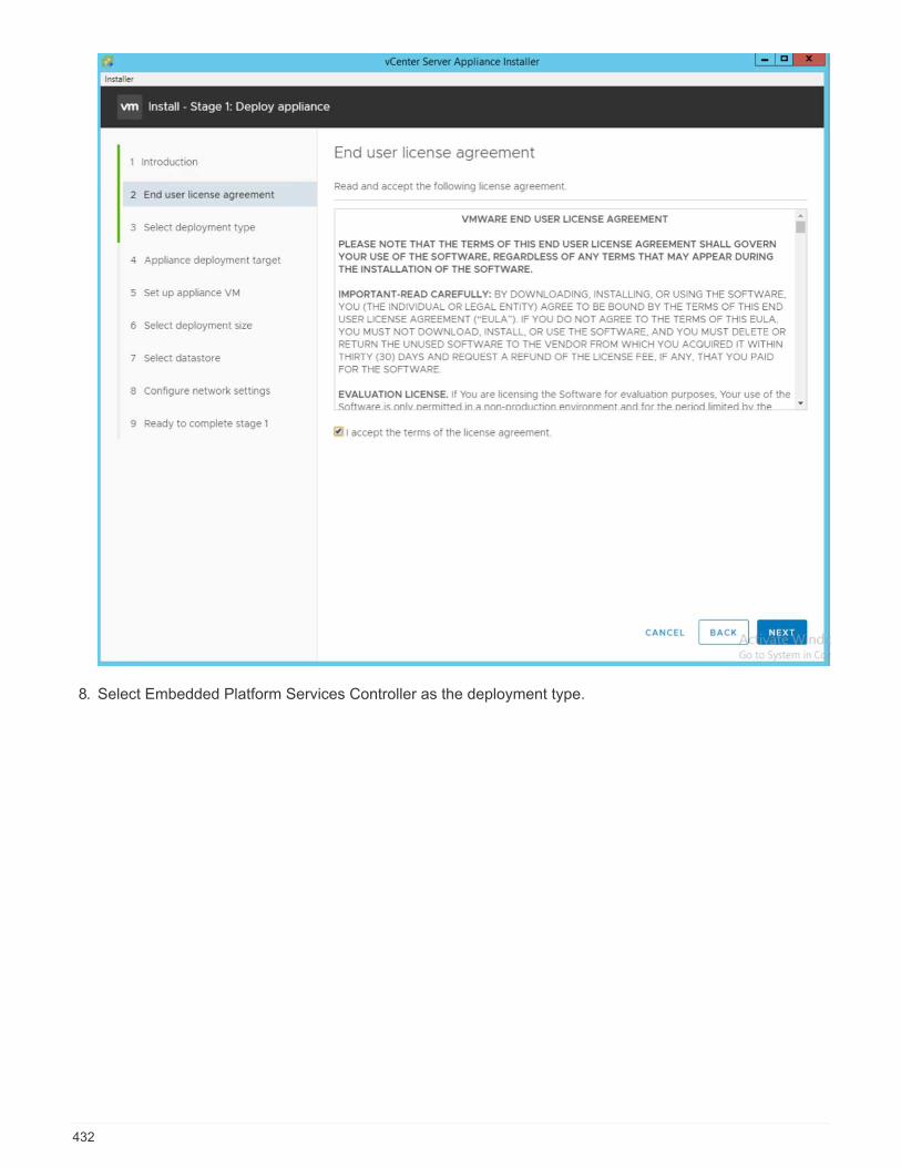
8. Select Embedded Platform Services Controller as the deployment type.
432
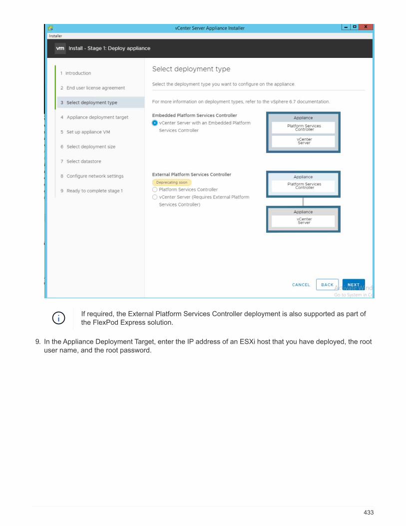
If required, the External Platform Services Controller deployment is also supported as part ofthe FlexPod Express solution.
9. In the Appliance Deployment Target, enter the IP address of an ESXi host that you have deployed, the rootuser name, and the root password.
433

10. Set the appliance VM by entering VCSA as the VM name and the root password that you would like to usefor the VCSA.
434
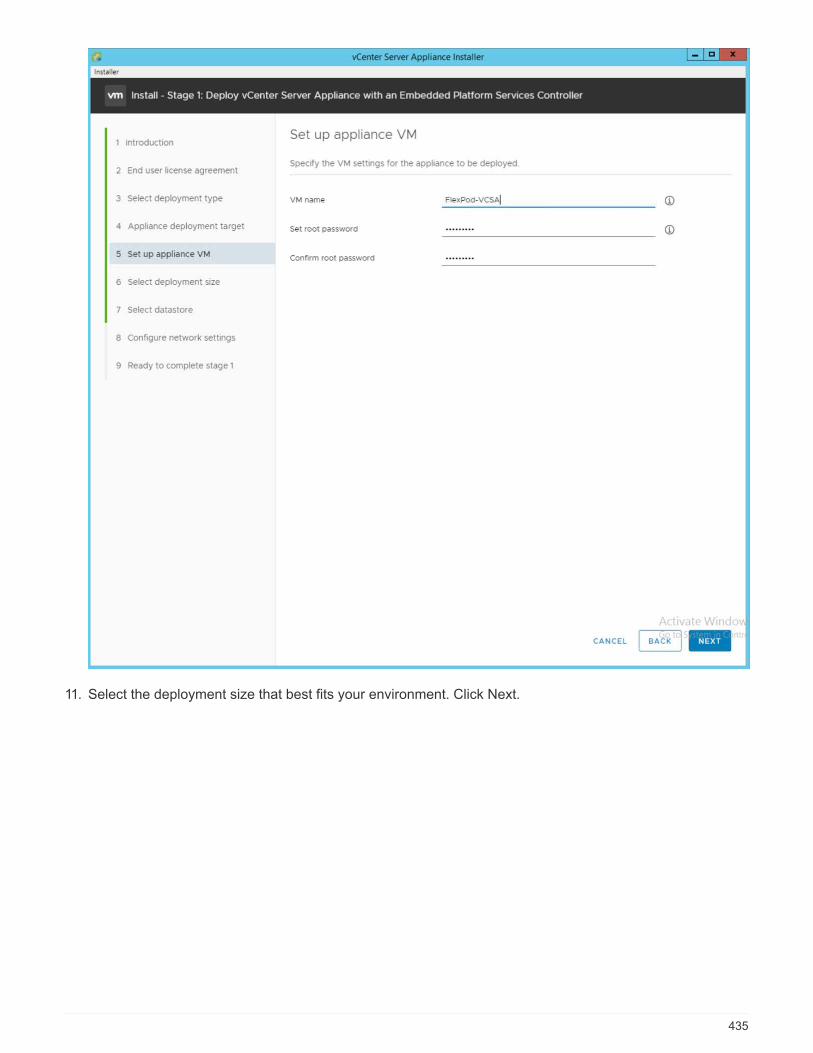
11. Select the deployment size that best fits your environment. Click Next.
435
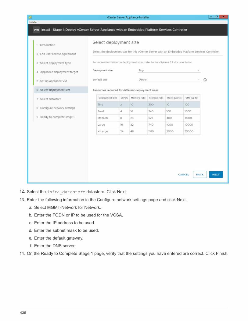
12. Select the infra_datastore datastore. Click Next.
13. Enter the following information in the Configure network settings page and click Next.
a. Select MGMT-Network for Network.
b. Enter the FQDN or IP to be used for the VCSA.
c. Enter the IP address to be used.
d. Enter the subnet mask to be used.
e. Enter the default gateway.
f. Enter the DNS server.
14. On the Ready to Complete Stage 1 page, verify that the settings you have entered are correct. Click Finish.
436
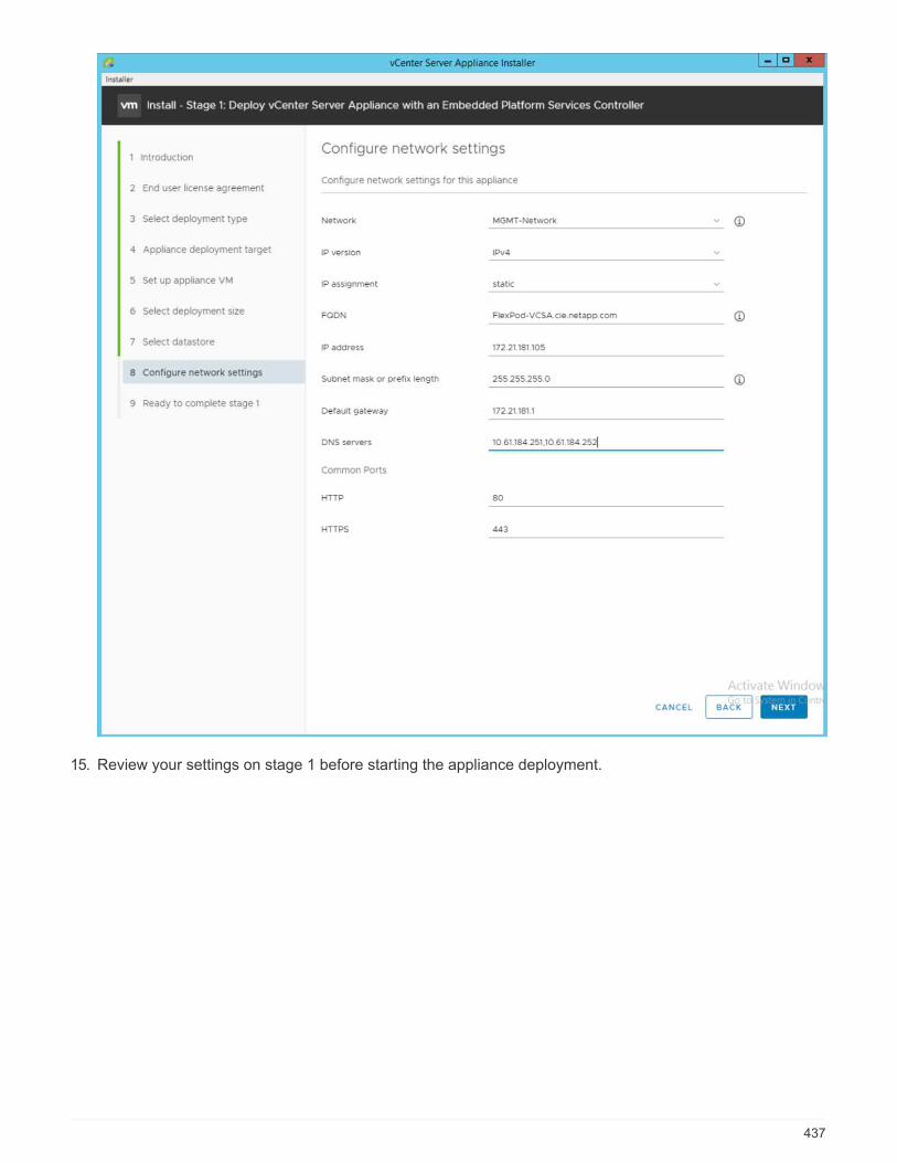
15. Review your settings on stage 1 before starting the appliance deployment.
437
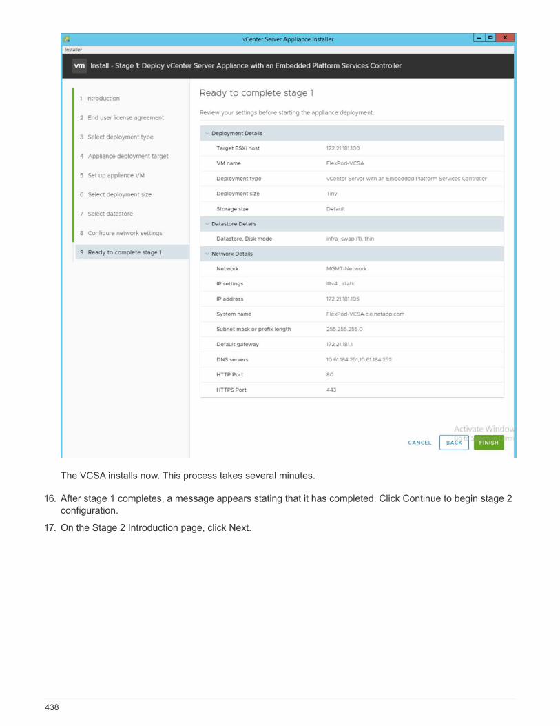
The VCSA installs now. This process takes several minutes.
16. After stage 1 completes, a message appears stating that it has completed. Click Continue to begin stage 2configuration.
17. On the Stage 2 Introduction page, click Next.
438
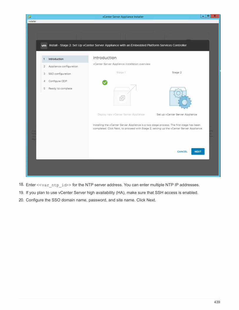
18. Enter <<var_ntp_id>> for the NTP server address. You can enter multiple NTP IP addresses.
19. If you plan to use vCenter Server high availability (HA), make sure that SSH access is enabled.
20. Configure the SSO domain name, password, and site name. Click Next.
439
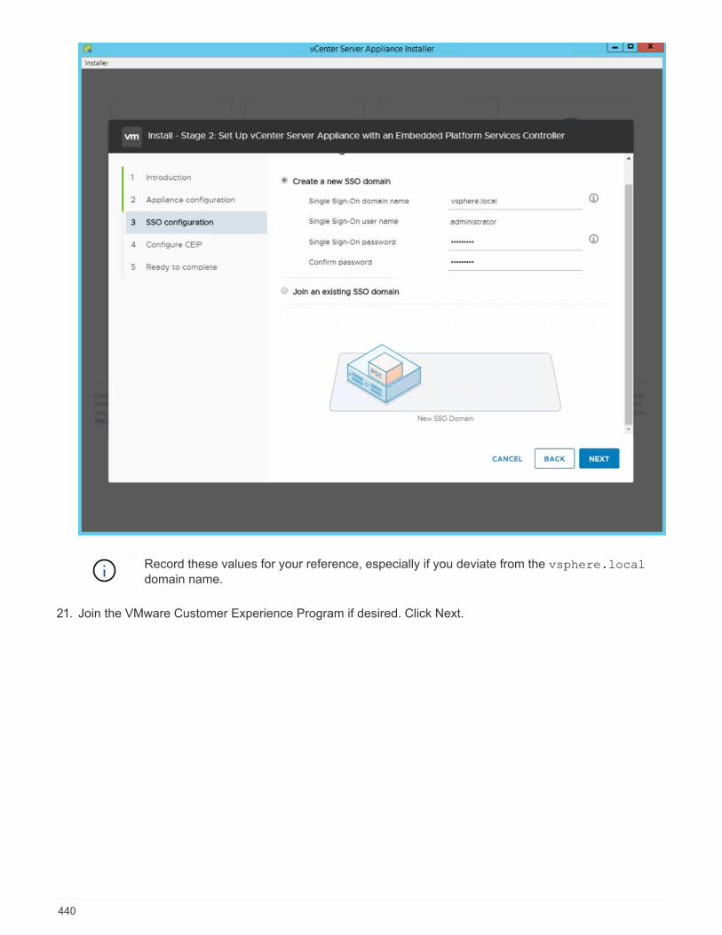
Record these values for your reference, especially if you deviate from the vsphere.localdomain name.
21. Join the VMware Customer Experience Program if desired. Click Next.
440
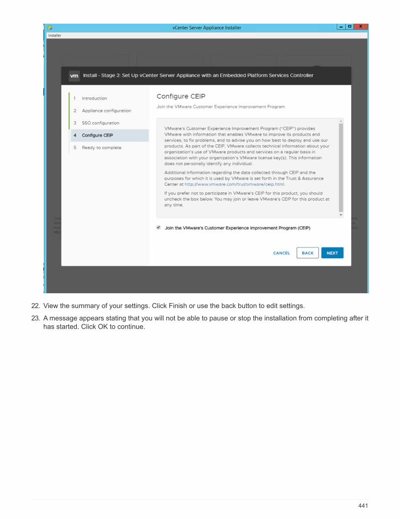
22. View the summary of your settings. Click Finish or use the back button to edit settings.
23. A message appears stating that you will not be able to pause or stop the installation from completing after ithas started. Click OK to continue.
441
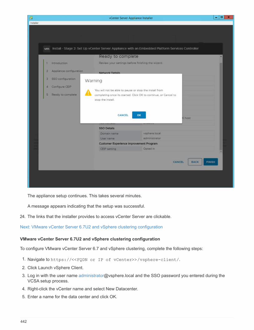
The appliance setup continues. This takes several minutes.
A message appears indicating that the setup was successful.
24. The links that the installer provides to access vCenter Server are clickable.
Next: VMware vCenter Server 6.7U2 and vSphere clustering configuration
VMware vCenter Server 6.7U2 and vSphere clustering configuration
To configure VMware vCenter Server 6.7 and vSphere clustering, complete the following steps:
1. Navigate to https://<<FQDN or IP of vCenter>>/vsphere-client/.
2. Click Launch vSphere Client.
3. Log in with the user name [email protected] and the SSO password you entered during theVCSA setup process.
4. Right-click the vCenter name and select New Datacenter.
5. Enter a name for the data center and click OK.
442
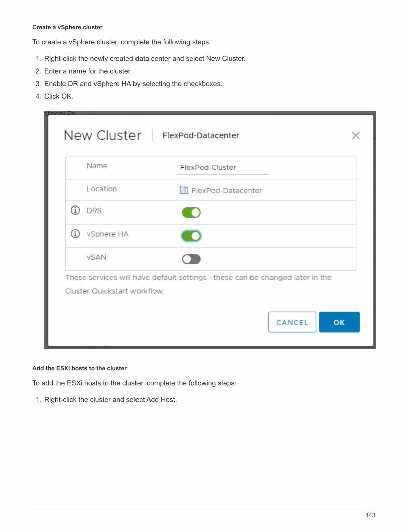
Create a vSphere cluster
To create a vSphere cluster, complete the following steps:
1. Right-click the newly created data center and select New Cluster.
2. Enter a name for the cluster.
3. Enable DR and vSphere HA by selecting the checkboxes.
4. Click OK.
Add the ESXi hosts to the cluster
To add the ESXi hosts to the cluster, complete the following steps:
1. Right-click the cluster and select Add Host.
443

2. To add an ESXi host to the cluster, complete the following steps:
a. Enter the IP or FQDN of the host. Click Next.
b. Enter the root user name and password. Click Next.
c. Click Yes to replace the host’s certificate with a certificate signed by the VMware certificate server.
d. Click Next on the Host Summary page.
e. Click the green + icon to add a license to the vSphere host.
3. This step can be completed later if desired.
a. Click Next to leave lockdown mode disabled.
b. Click Next at the VM location page.
c. Review the Ready to Complete page. Use the back button to make any changes or select Finish.
4. Repeat steps 1 and 2 for Cisco UCS host B.
This process must be completed for any additional hosts added to the FlexPod Expressconfiguration.
Configure coredump on the ESXi hosts
To configure coredump on the ESXi hosts, complete the following steps:
1. Log into https:// vCenter IP:5480/, enter root for the user name, and enter the root password.
2. Click on services and select VMware vSphere ESXI Dump collector.
3. Start the VMware vSphere ESXI Dump collector service.
444
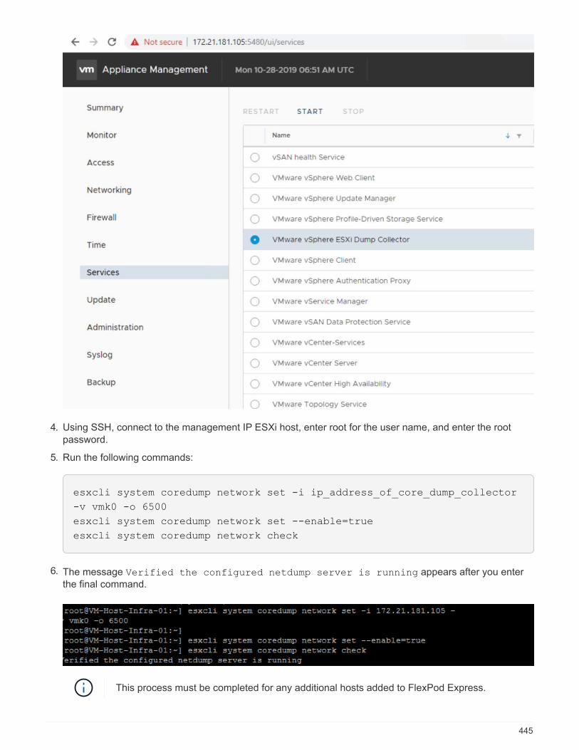
4. Using SSH, connect to the management IP ESXi host, enter root for the user name, and enter the rootpassword.
5. Run the following commands:
esxcli system coredump network set -i ip_address_of_core_dump_collector
-v vmk0 -o 6500
esxcli system coredump network set --enable=true
esxcli system coredump network check
6. The message Verified the configured netdump server is running appears after you enterthe final command.
This process must be completed for any additional hosts added to FlexPod Express.
445
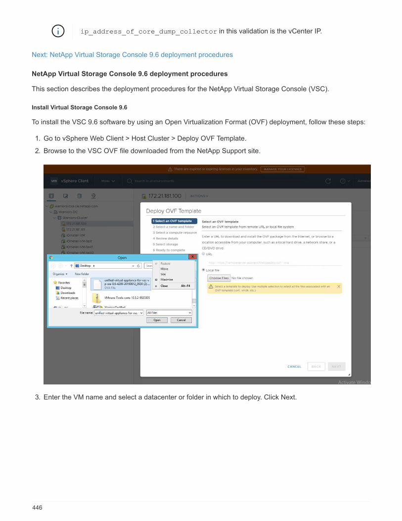
ip_address_of_core_dump_collector in this validation is the vCenter IP.
Next: NetApp Virtual Storage Console 9.6 deployment procedures
NetApp Virtual Storage Console 9.6 deployment procedures
This section describes the deployment procedures for the NetApp Virtual Storage Console (VSC).
Install Virtual Storage Console 9.6
To install the VSC 9.6 software by using an Open Virtualization Format (OVF) deployment, follow these steps:
1. Go to vSphere Web Client > Host Cluster > Deploy OVF Template.
2. Browse to the VSC OVF file downloaded from the NetApp Support site.
3. Enter the VM name and select a datacenter or folder in which to deploy. Click Next.
446
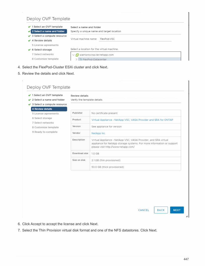
4. Select the FlexPod-Cluster ESXi cluster and click Next.
5. Review the details and click Next.
6. Click Accept to accept the license and click Next.
7. Select the Thin Provision virtual disk format and one of the NFS datastores. Click Next.
447
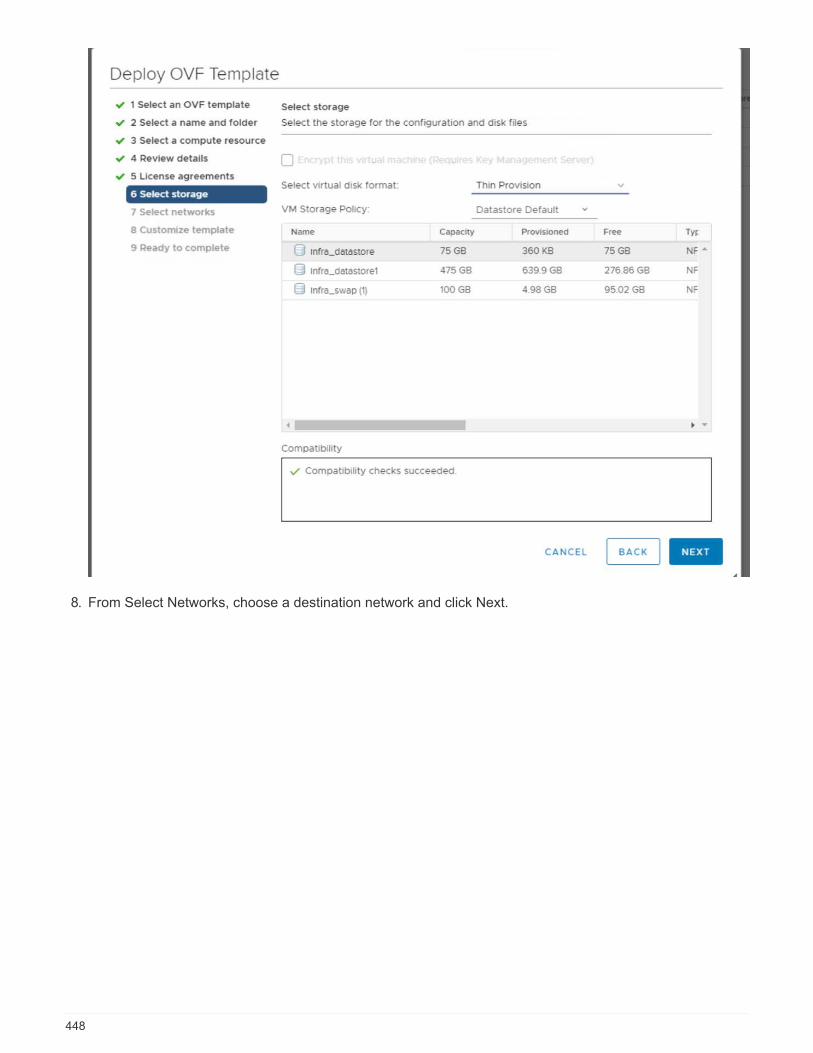
8. From Select Networks, choose a destination network and click Next.
448
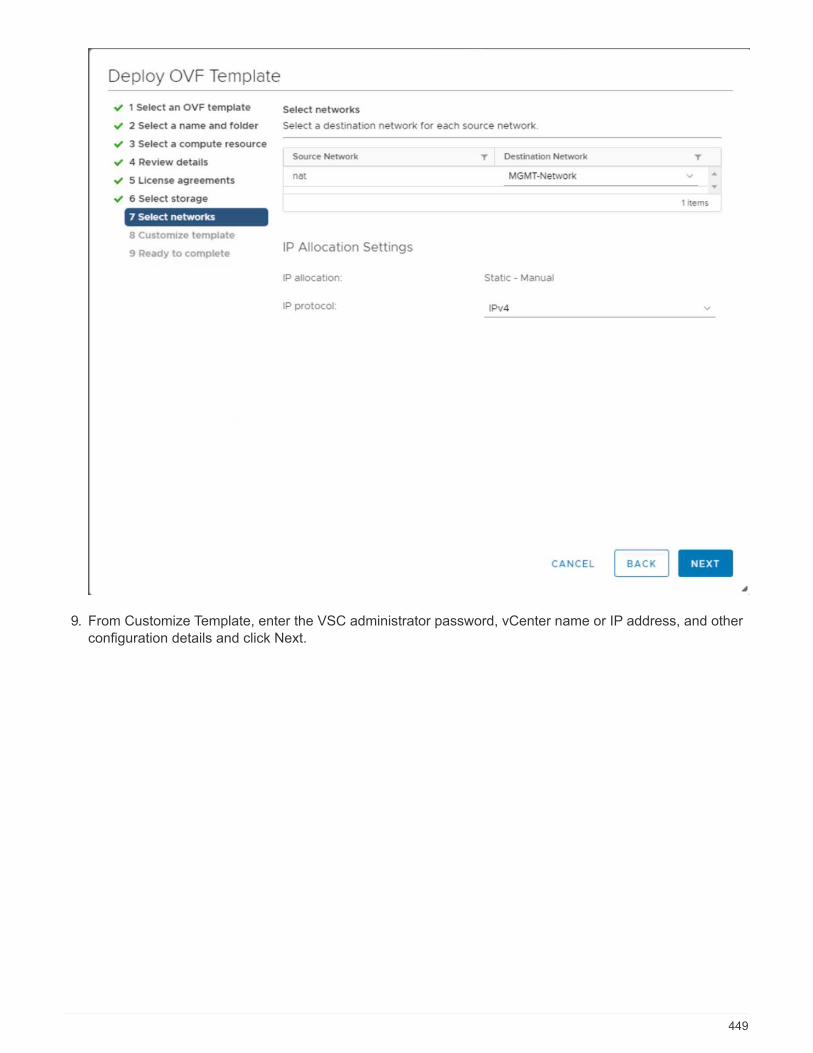
9. From Customize Template, enter the VSC administrator password, vCenter name or IP address, and otherconfiguration details and click Next.
449
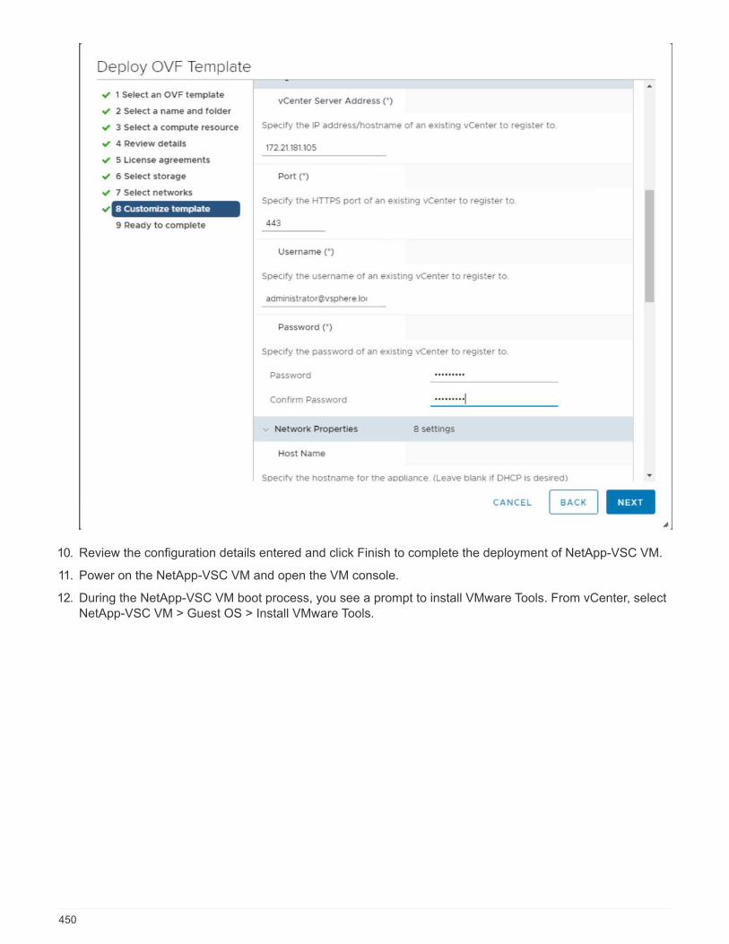
10. Review the configuration details entered and click Finish to complete the deployment of NetApp-VSC VM.
11. Power on the NetApp-VSC VM and open the VM console.
12. During the NetApp-VSC VM boot process, you see a prompt to install VMware Tools. From vCenter, selectNetApp-VSC VM > Guest OS > Install VMware Tools.
450

13. Networking configuration and vCenter registration information was provided during OVF templatecustomization. Therefore, after the NetApp-VSC VM is running, VSC, vSphere API for Storage Awareness(VASA), and VMware Storage Replication Adapter (SRA) are registered with vCenter.
14. Log out of the vCenter Client and log in again. From the Home menu, confirm that the NetApp VSC isinstalled.
451

Download and install the NetApp NFS VAAI Plug-In
To download and install the NetApp NFS VAAI Plug-In, complete the following steps:
1. Download the NetApp NFS Plug-In 1.1.2 for VMware . vib file from the NFS Plugin Download page andsave it to your local machine or admin host.
2. Download the NetApp NFS Plug-in for VMware VAAI:
a. Go to the software download page.
452
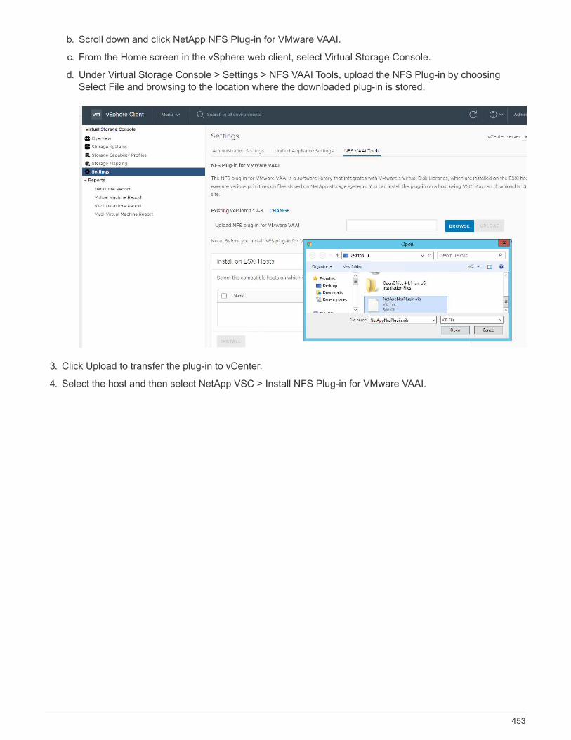
b. Scroll down and click NetApp NFS Plug-in for VMware VAAI.
c. From the Home screen in the vSphere web client, select Virtual Storage Console.
d. Under Virtual Storage Console > Settings > NFS VAAI Tools, upload the NFS Plug-in by choosingSelect File and browsing to the location where the downloaded plug-in is stored.
3. Click Upload to transfer the plug-in to vCenter.
4. Select the host and then select NetApp VSC > Install NFS Plug-in for VMware VAAI.
453
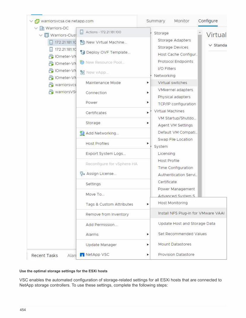
Use the optimal storage settings for the ESXi hosts
VSC enables the automated configuration of storage-related settings for all ESXi hosts that are connected toNetApp storage controllers. To use these settings, complete the following steps:
454

1. From the Home screen, select vCenter > Hosts and Clusters. For each ESXi host, right-click and selectNetApp VSC > Set Recommended Values.
2. Check the settings that you would like to apply to the selected vSphere hosts. Click OK to apply thesettings.
455
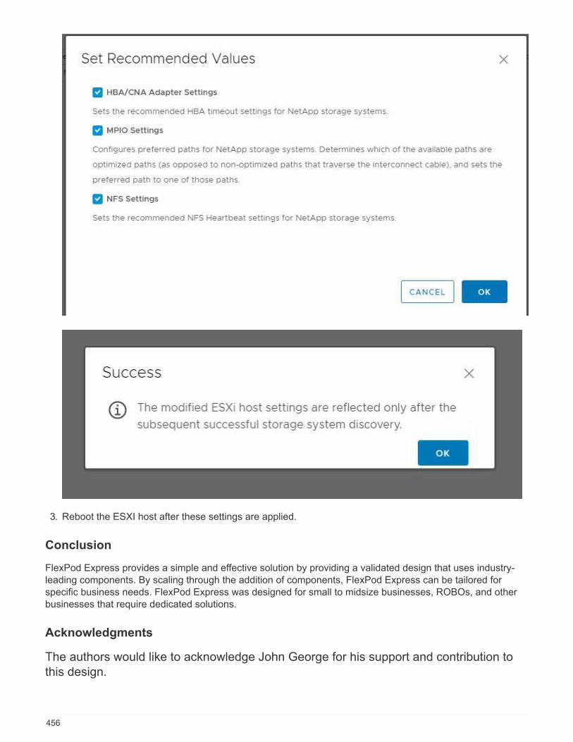
3. Reboot the ESXI host after these settings are applied.
Conclusion
FlexPod Express provides a simple and effective solution by providing a validated design that uses industry-leading components. By scaling through the addition of components, FlexPod Express can be tailored forspecific business needs. FlexPod Express was designed for small to midsize businesses, ROBOs, and otherbusinesses that require dedicated solutions.
Acknowledgments
The authors would like to acknowledge John George for his support and contribution tothis design.
456
Where to find additional information
To learn more about the information described in this document, refer to the following documents and/orwebsites:
NetApp Product Documentation
http://docs. netapp.com
FlexPod Express with Guide
NVA-1139-DESIGN: FlexPod Express with Cisco UCS C-Series and NetApp AFF C190 Series
https://www.netapp.com/us/media/nva-1139-design.pdf
Version history
Version Date Document version history
Version 1.0 November 2019 Initial release.
FlexPod Express with Cisco UCS C-Series and AFF A220Series Design Guide
NVA-1125-DESIGN: FlexPod Express with Cisco UCS C-Series and AFF A220 Series
*:hardbreaks::icons: font:linkattrs::relative_path: ./express/:imagesdir: /tmp/d20220413-5910-1yx0c1c/source/./express/./../media/
Savita Kumari, NetAppIn partnership with:
Industry trends indicate a vast data center transformation toward shared infrastructure and cloud computing. Inaddition, organizations seek a simple and effective solution for remote and branch offices, leveraging thetechnology that they are familiar with in their data center.
FlexPod Express is a predesigned, best practice data center architecture that is built on the Cisco UnifiedComputing System (Cisco UCS), the Cisco Nexus family of switches, and NetApp AFF. The components inFlexPod Express are like their FlexPod Datacenter counterparts, enabling management synergies across thecomplete IT infrastructure environment on a smaller scale. FlexPod Datacenter and FlexPod Express areoptimal platforms for virtualization and for bare-metal operating systems and enterprise workloads.
Next: Program summary.
457
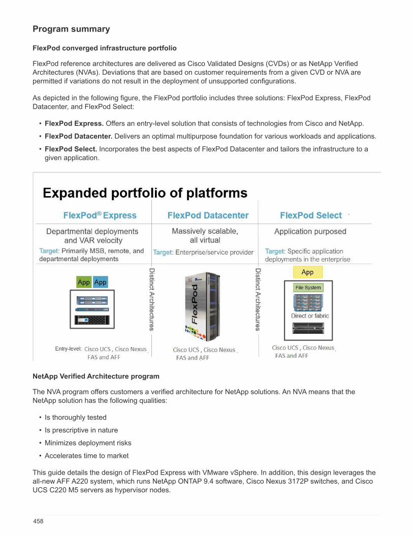
Program summary
FlexPod converged infrastructure portfolio
FlexPod reference architectures are delivered as Cisco Validated Designs (CVDs) or as NetApp VerifiedArchitectures (NVAs). Deviations that are based on customer requirements from a given CVD or NVA arepermitted if variations do not result in the deployment of unsupported configurations.
As depicted in the following figure, the FlexPod portfolio includes three solutions: FlexPod Express, FlexPodDatacenter, and FlexPod Select:
• FlexPod Express. Offers an entry-level solution that consists of technologies from Cisco and NetApp.
• FlexPod Datacenter. Delivers an optimal multipurpose foundation for various workloads and applications.
• FlexPod Select. Incorporates the best aspects of FlexPod Datacenter and tailors the infrastructure to agiven application.
NetApp Verified Architecture program
The NVA program offers customers a verified architecture for NetApp solutions. An NVA means that theNetApp solution has the following qualities:
• Is thoroughly tested
• Is prescriptive in nature
• Minimizes deployment risks
• Accelerates time to market
This guide details the design of FlexPod Express with VMware vSphere. In addition, this design leverages theall-new AFF A220 system, which runs NetApp ONTAP 9.4 software, Cisco Nexus 3172P switches, and CiscoUCS C220 M5 servers as hypervisor nodes.
458
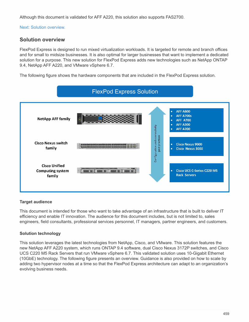
Although this document is validated for AFF A220, this solution also supports FAS2700.
Next: Solution overview.
Solution overview
FlexPod Express is designed to run mixed virtualization workloads. It is targeted for remote and branch officesand for small to midsize businesses. It is also optimal for larger businesses that want to implement a dedicatedsolution for a purpose. This new solution for FlexPod Express adds new technologies such as NetApp ONTAP9.4, NetApp AFF A220, and VMware vSphere 6.7.
The following figure shows the hardware components that are included in the FlexPod Express solution.
Target audience
This document is intended for those who want to take advantage of an infrastructure that is built to deliver ITefficiency and enable IT innovation. The audience for this document includes, but is not limited to, salesengineers, field consultants, professional services personnel, IT managers, partner engineers, and customers.
Solution technology
This solution leverages the latest technologies from NetApp, Cisco, and VMware. This solution features thenew NetApp AFF A220 system, which runs ONTAP 9.4 software, dual Cisco Nexus 3172P switches, and CiscoUCS C220 M5 Rack Servers that run VMware vSphere 6.7. This validated solution uses 10-Gigabit Ethernet(10GbE) technology. The following figure presents an overview. Guidance is also provided on how to scale byadding two hypervisor nodes at a time so that the FlexPod Express architecture can adapt to an organization’sevolving business needs.
459
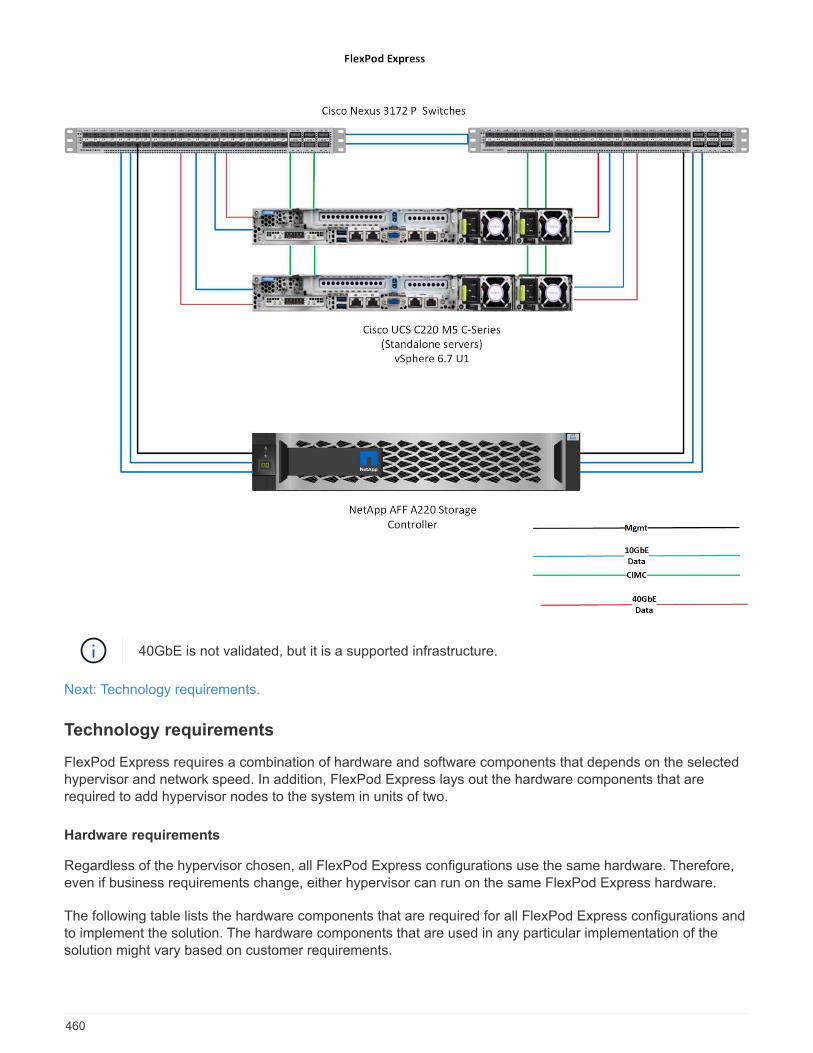
40GbE is not validated, but it is a supported infrastructure.
Next: Technology requirements.
Technology requirements
FlexPod Express requires a combination of hardware and software components that depends on the selectedhypervisor and network speed. In addition, FlexPod Express lays out the hardware components that arerequired to add hypervisor nodes to the system in units of two.
Hardware requirements
Regardless of the hypervisor chosen, all FlexPod Express configurations use the same hardware. Therefore,even if business requirements change, either hypervisor can run on the same FlexPod Express hardware.
The following table lists the hardware components that are required for all FlexPod Express configurations andto implement the solution. The hardware components that are used in any particular implementation of thesolution might vary based on customer requirements.
460
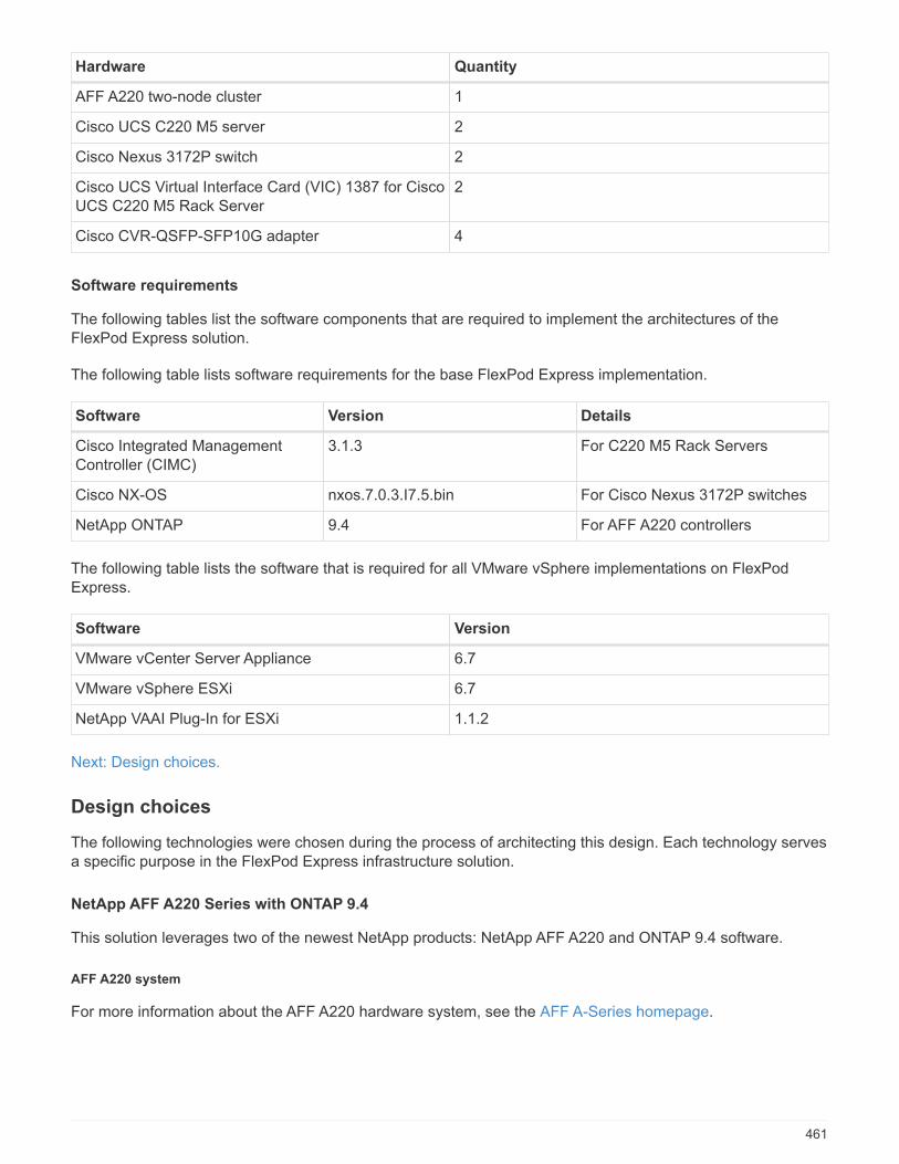
Hardware Quantity
AFF A220 two-node cluster 1
Cisco UCS C220 M5 server 2
Cisco Nexus 3172P switch 2
Cisco UCS Virtual Interface Card (VIC) 1387 for CiscoUCS C220 M5 Rack Server
2
Cisco CVR-QSFP-SFP10G adapter 4
Software requirements
The following tables list the software components that are required to implement the architectures of theFlexPod Express solution.
The following table lists software requirements for the base FlexPod Express implementation.
Software Version Details
Cisco Integrated ManagementController (CIMC)
3.1.3 For C220 M5 Rack Servers
Cisco NX-OS nxos.7.0.3.I7.5.bin For Cisco Nexus 3172P switches
NetApp ONTAP 9.4 For AFF A220 controllers
The following table lists the software that is required for all VMware vSphere implementations on FlexPodExpress.
Software Version
VMware vCenter Server Appliance 6.7
VMware vSphere ESXi 6.7
NetApp VAAI Plug-In for ESXi 1.1.2
Next: Design choices.
Design choices
The following technologies were chosen during the process of architecting this design. Each technology servesa specific purpose in the FlexPod Express infrastructure solution.
NetApp AFF A220 Series with ONTAP 9.4
This solution leverages two of the newest NetApp products: NetApp AFF A220 and ONTAP 9.4 software.
AFF A220 system
For more information about the AFF A220 hardware system, see the AFF A-Series homepage.
461
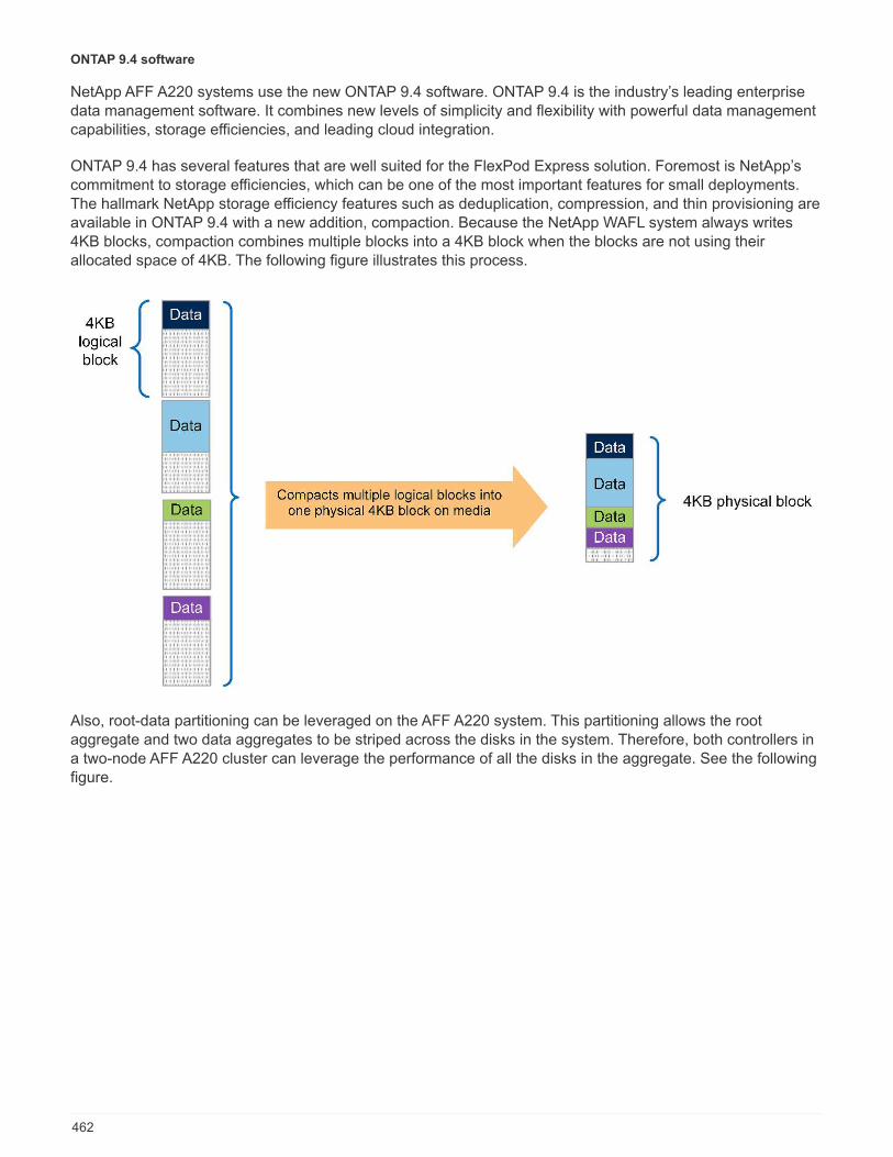
ONTAP 9.4 software
NetApp AFF A220 systems use the new ONTAP 9.4 software. ONTAP 9.4 is the industry’s leading enterprisedata management software. It combines new levels of simplicity and flexibility with powerful data managementcapabilities, storage efficiencies, and leading cloud integration.
ONTAP 9.4 has several features that are well suited for the FlexPod Express solution. Foremost is NetApp’scommitment to storage efficiencies, which can be one of the most important features for small deployments.The hallmark NetApp storage efficiency features such as deduplication, compression, and thin provisioning areavailable in ONTAP 9.4 with a new addition, compaction. Because the NetApp WAFL system always writes4KB blocks, compaction combines multiple blocks into a 4KB block when the blocks are not using theirallocated space of 4KB. The following figure illustrates this process.
Also, root-data partitioning can be leveraged on the AFF A220 system. This partitioning allows the rootaggregate and two data aggregates to be striped across the disks in the system. Therefore, both controllers ina two-node AFF A220 cluster can leverage the performance of all the disks in the aggregate. See the followingfigure.
462
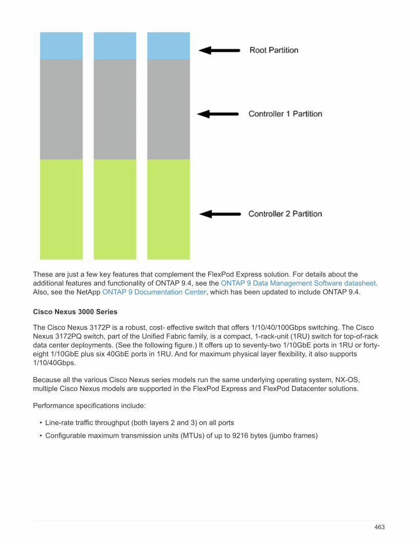
These are just a few key features that complement the FlexPod Express solution. For details about theadditional features and functionality of ONTAP 9.4, see the ONTAP 9 Data Management Software datasheet.Also, see the NetApp ONTAP 9 Documentation Center, which has been updated to include ONTAP 9.4.
Cisco Nexus 3000 Series
The Cisco Nexus 3172P is a robust, cost- effective switch that offers 1/10/40/100Gbps switching. The CiscoNexus 3172PQ switch, part of the Unified Fabric family, is a compact, 1-rack-unit (1RU) switch for top-of-rackdata center deployments. (See the following figure.) It offers up to seventy-two 1/10GbE ports in 1RU or forty-eight 1/10GbE plus six 40GbE ports in 1RU. And for maximum physical layer flexibility, it also supports1/10/40Gbps.
Because all the various Cisco Nexus series models run the same underlying operating system, NX-OS,multiple Cisco Nexus models are supported in the FlexPod Express and FlexPod Datacenter solutions.
Performance specifications include:
• Line-rate traffic throughput (both layers 2 and 3) on all ports
• Configurable maximum transmission units (MTUs) of up to 9216 bytes (jumbo frames)
463
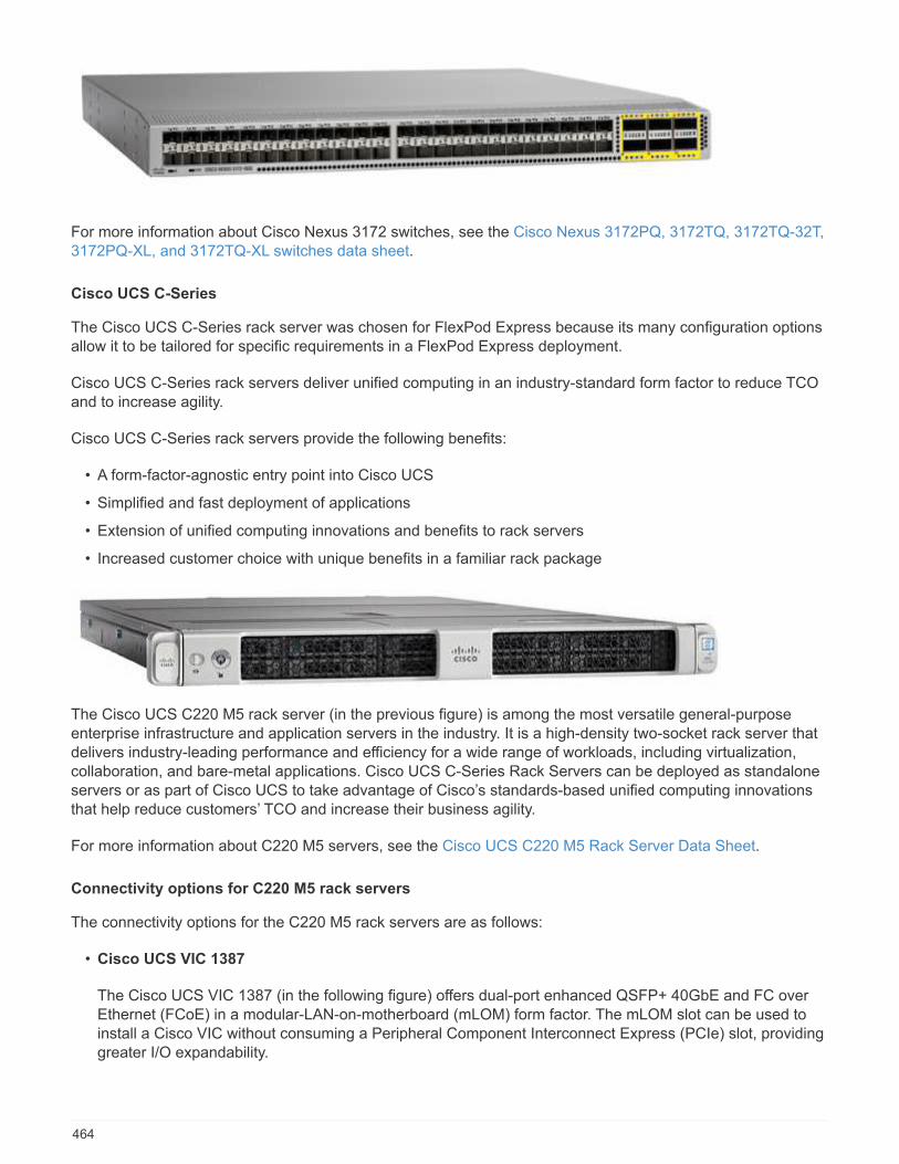
For more information about Cisco Nexus 3172 switches, see the Cisco Nexus 3172PQ, 3172TQ, 3172TQ-32T,3172PQ-XL, and 3172TQ-XL switches data sheet.
Cisco UCS C-Series
The Cisco UCS C-Series rack server was chosen for FlexPod Express because its many configuration optionsallow it to be tailored for specific requirements in a FlexPod Express deployment.
Cisco UCS C-Series rack servers deliver unified computing in an industry-standard form factor to reduce TCOand to increase agility.
Cisco UCS C-Series rack servers provide the following benefits:
• A form-factor-agnostic entry point into Cisco UCS
• Simplified and fast deployment of applications
• Extension of unified computing innovations and benefits to rack servers
• Increased customer choice with unique benefits in a familiar rack package
The Cisco UCS C220 M5 rack server (in the previous figure) is among the most versatile general-purposeenterprise infrastructure and application servers in the industry. It is a high-density two-socket rack server thatdelivers industry-leading performance and efficiency for a wide range of workloads, including virtualization,collaboration, and bare-metal applications. Cisco UCS C-Series Rack Servers can be deployed as standaloneservers or as part of Cisco UCS to take advantage of Cisco’s standards-based unified computing innovationsthat help reduce customers’ TCO and increase their business agility.
For more information about C220 M5 servers, see the Cisco UCS C220 M5 Rack Server Data Sheet.
Connectivity options for C220 M5 rack servers
The connectivity options for the C220 M5 rack servers are as follows:
• Cisco UCS VIC 1387
The Cisco UCS VIC 1387 (in the following figure) offers dual-port enhanced QSFP+ 40GbE and FC overEthernet (FCoE) in a modular-LAN-on-motherboard (mLOM) form factor. The mLOM slot can be used toinstall a Cisco VIC without consuming a Peripheral Component Interconnect Express (PCIe) slot, providinggreater I/O expandability.
464

For more information about the Cisco UCS VIC 1387 adapter, see the Cisco UCS Virtual Interface Card 1387data sheet.
• CVR-QSFP-SFP10G adapter
The Cisco QSA Module converts a QSFP port into an SFP or SFP+ port. With this adapter, customershave the flexibility to use any SFP+ or SFP module or cable to connect to a lower-speed port on the otherend of the network. This flexibility enables a cost-effective transition to 40GbE by maximizing the use ofhigh-density 40GbE QSFP platforms. This adapter supports all SFP+ optics and cable reaches, and itsupports several 1GbE SFP modules. Because this project has been validated by using 10GbEconnectivity and because the VIC 1387 used is 40GbE, the CVR-QSFP-SFP10G adapter (in the followingfigure) is used for conversion.
VMware vSphere 6.7
VMware vSphere 6.7 is one hypervisor option for use with FlexPod Express. VMware vSphere allowsorganizations to reduce their power and cooling footprint while confirming that the purchased compute capacityis used to its fullest. In addition, VMware vSphere allows hardware failure protection (VMware High Availability,or VMware HA) and compute resource load balancing across a cluster of vSphere hosts (VMware DistributedResource Scheduler, or VMware DRS).
Because it restarts only the kernel, VMware vSphere 6.7 allows customers to “quick boot” where it loadsvSphere ESXi without restarting the hardware. This feature is available only with platforms and drivers that are
465

on the Quick Boot Whitelist. vSphere 6.7 extends the capabilities of the vSphere Client, which can do about90% of what the vSphere Web Client can do.
In vSphere 6.7, VMware has extended this capability to enable customers to set Enhanced vMotionCompatibility (EVC) per virtual machine (VM) rather than per host basis. In vSphere 6.7, VMware has alsoexposed the APIs that can be used to create instant clones.
The following are some of the features of vSphere 6.7 U1:
• Fully featured HTML5 web-based vSphere Client
• vMotion for NVIDIA GRID vGPU VMs. Support for Intel FPGA.
• vCenter Server Converge Tool to move from external PSC to internal PCS.
• Enhancements for vSAN (HCI updates).
• Enhanced content library.
For details about vSphere 6.7 U1, see What’s New in vCenter Server 6.7 Update 1. Although this solution wasvalidated with vSphere 6.7, it supports any vSphere version qualified with the other components by the NetAppInteroperability Matrix Tool. NetApp recommends deploying vSphere 6.7U1 for its fixes and enhanced features.
Boot architecture
Following are the supported options for the FlexPod Express boot architecture:
• iSCSI SAN LUN
• Cisco FlexFlash SD Card
• Local disk
Because FlexPod Datacenter is booted from iSCSI LUNs, solution manageability is enhanced by also usingiSCSI boot for FlexPod Express.
Next: Solution verification.
Solution verification
Cisco and NetApp designed and built FlexPod Express to serve as a premier infrastructure platform for theircustomers. Because it was designed with industry-leading components, customers can trust FlexPod Expressas their infrastructure foundation. In keeping with the fundamental principles of the FlexPod portfolio, theFlexPod Express architecture was thoroughly tested by Cisco and NetApp data center architects andengineers. From redundancy and availability to each individual feature, the entire FlexPod Express architectureis validated to instill confidence in our customers and to build trust in the design process.
VMware vSphere 6.7 was verified on the FlexPod Express infrastructure components. This validation included10GbE uplink connectivity options for the hypervisor.
Next: Conclusion.
Conclusion
FlexPod Express offers a simple and effective solution by providing a validated design that uses industry-leading components. By scaling and by providing options for the hypervisor platform, FlexPod Express can betailored for specific business needs. FlexPod Express was designed keeping in mind small to midsizebusinesses, remote and branch offices, and other businesses that require dedicated solutions.
466
Next: Where to find additional information.
Where to find additional information
To learn more about the information that is described in this document, see the following documents andwebsites:
• NetApp documentation
https://docs.netapp.com
• FlexPod Express with VMware vSphere 6.7 and NetApp AFF A220 Deployment Guide
https://www.netapp.com/us/media/nva-1123-deploy.pdf
FlexPod Express with Cisco UCS C-Series and AFF A220Series Deployment Guide
NVA-1123-DEPLOY: FlexPod Express with VMware vSphere 6.7 and NetApp AFFA220 deployment guide
Savita Kumari, NetApp
In partnership with:
Industry trends indicate a vast data center transformation toward shared infrastructure and cloud computing. Inaddition, organizations seek a simple and effective solution for remote and branch offices, leveraging thetechnology with which they are familiar in their data center.
FlexPod Express is a predesigned, best practice data center architecture that is built on the Cisco UnifiedComputing System (Cisco UCS), the Cisco Nexus family of switches, and NetApp storage technologies. Thecomponents in a FlexPod Express system are like their FlexPod Datacenter counterparts, enablingmanagement synergies across the complete IT infrastructure environment on a smaller scale. FlexPodDatacenter and FlexPod Express are optimal platforms for virtualization and for bare-metal operating systemsand enterprise workloads.
FlexPod Datacenter and FlexPod Express deliver a baseline configuration and have the flexibility to be sizedand optimized to accommodate many different use cases and requirements. Existing FlexPod Datacentercustomers can manage their FlexPod Express system with the tools to which they are accustomed. NewFlexPod Express customers can easily adapt to managing FlexPod Datacenter as their environment grows.
FlexPod Express is an optimal infrastructure foundation for remote and branch offices and for small to midsizebusinesses. It is also an optimal solution for customers who want to provide infrastructure for a dedicatedworkload.
FlexPod Express provides an easy-to-manage infrastructure that is suitable for almost any workload.
467
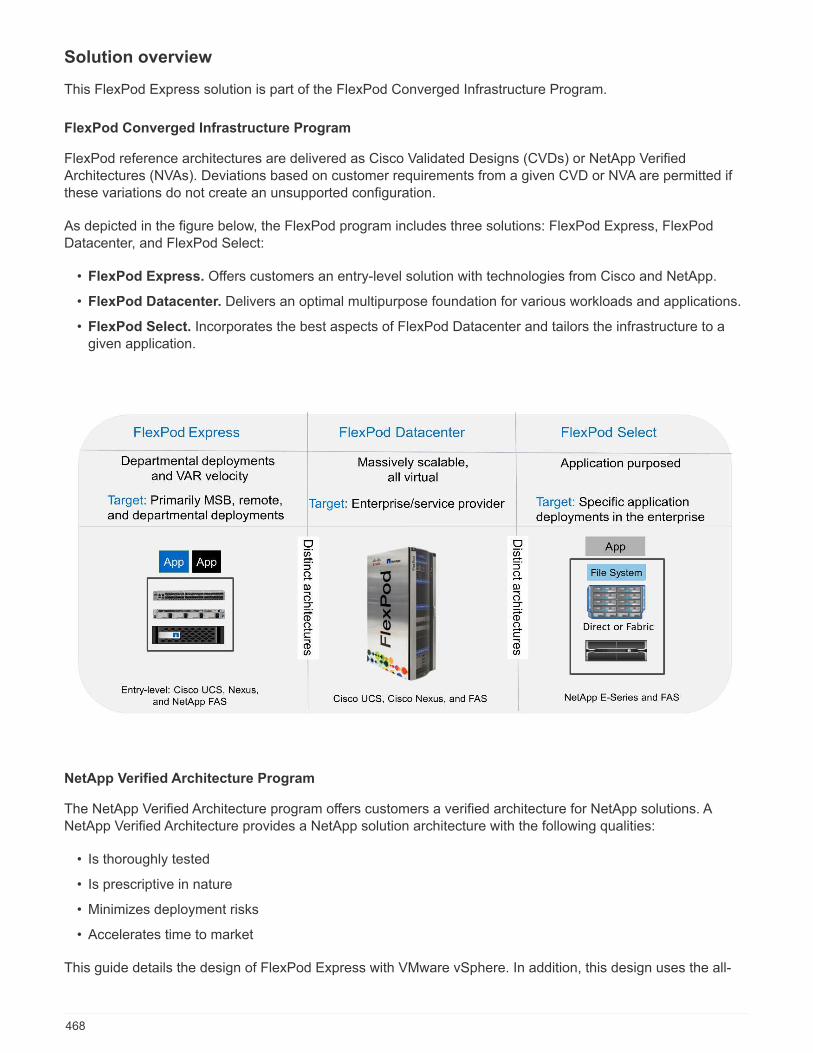
Solution overview
This FlexPod Express solution is part of the FlexPod Converged Infrastructure Program.
FlexPod Converged Infrastructure Program
FlexPod reference architectures are delivered as Cisco Validated Designs (CVDs) or NetApp VerifiedArchitectures (NVAs). Deviations based on customer requirements from a given CVD or NVA are permitted ifthese variations do not create an unsupported configuration.
As depicted in the figure below, the FlexPod program includes three solutions: FlexPod Express, FlexPodDatacenter, and FlexPod Select:
• FlexPod Express. Offers customers an entry-level solution with technologies from Cisco and NetApp.
• FlexPod Datacenter. Delivers an optimal multipurpose foundation for various workloads and applications.
• FlexPod Select. Incorporates the best aspects of FlexPod Datacenter and tailors the infrastructure to agiven application.
NetApp Verified Architecture Program
The NetApp Verified Architecture program offers customers a verified architecture for NetApp solutions. ANetApp Verified Architecture provides a NetApp solution architecture with the following qualities:
• Is thoroughly tested
• Is prescriptive in nature
• Minimizes deployment risks
• Accelerates time to market
This guide details the design of FlexPod Express with VMware vSphere. In addition, this design uses the all-
468

new AFF A220 system, which runs NetApp ONTAP 9.4; the Cisco Nexus 3172P; and Cisco UCS C-SeriesC220 M5 servers as hypervisor nodes.
Solution technology
This solution leverages the latest technologies from NetApp, Cisco, and VMware. This solution features thenew NetApp AFF A220 running ONTAP 9.4, dual Cisco Nexus 3172P switches, and Cisco UCS C220 M5 rackservers that run VMware vSphere 6.7. This validated solution uses 10GbE technology. Guidance is alsoprovided on how to scale compute capacity by adding two hypervisor nodes at a time so that the FlexPodExpress architecture can adapt to an organization’s evolving business needs.
The following figure shows FlexPod Express with VMware vSphere 10GbE architecture.
This validation uses 10GbE connectivity and a Cisco UCS VIC 1387, which is 40GbE. Toachieve 10GbE connectivity, the CVR-QSFP-SFP10G adapter is used.
Use case summary
The FlexPod Express solution can be applied to several use cases, including the following:
469

• Remote offices or branch offices
• Small and midsize businesses
• Environments that require a dedicated and cost-effective solution
FlexPod Express is best suited for virtualized and mixed workloads.
Although this solution was validated with vSphere 6.7, it supports any vSphere version qualifiedwith the other components by the NetApp Interoperability Matrix Tool. NetApp recommendsdeploying vSphere 6.7U1 for its fixes and enhanced features.
Following are some features of vSphere 6.7 U1:
• Fully featured HTML5 web-based vSphere client
• vMotion for NVIDIA GRID vGPU VMs. Support for Intel FPGA
• vCenter Server Converge Tool to move from external PSC to internal PCS
• Enhancements for vSAN (HCI updates)
• Enhanced content library
For details about vSphere 6.7 U1, see What’s New in vCenter Server 6.7 Update 1.
Technology requirements
A FlexPod Express system requires a combination of hardware and software components. FlexPod Expressalso describes the hardware components that are required to add hypervisor nodes to the system in units oftwo.
Hardware requirements
Regardless of the hypervisor chosen, all FlexPod Express configurations use the same hardware. Therefore,even if business requirements change, either hypervisor can run on the same FlexPod Express hardware.
The following table lists the hardware components required for all FlexPod Express configurations.
Hardware Quantity
AFF A220 HA Pair 1
Cisco C220 M5 server 2
Cisco Nexus 3172P switch 2
Cisco UCS virtual interface card (VIC) 1387 for theC220 M5 server
2
CVR-QSFP-SFP10G adapter 4
The following table lists the hardware required in addition to the base configuration for implementing 10GbE.
Hardware Quantity
Cisco UCS C220 M5 server 2
Cisco VIC 1387 2
470

Hardware Quantity
CVR-QSFP-SFP10G adapter 4
Software requirements
The following table lists the software components required to implement the architectures of the FlexPodExpress solutions.
Software Version Details
Cisco Integrated ManagementController (CIMC)
3.1(3g) For Cisco UCS C220 M5 rackservers
Cisco nenic driver 1.0.25.0 For VIC 1387 interface cards
Cisco NX-OS nxos.7.0.3.I7.5.bin For Cisco Nexus 3172P switches
NetApp ONTAP 9.4 For AFF A220 controllers
The following table lists the software required for all VMware vSphere implementations on FlexPod Express.
Software Version
VMware vCenter server appliance 6.7
VMware vSphere ESXi hypervisor 6.7
NetApp VAAI Plug-In for ESXi 1.1.2
FlexPod Express cabling information
The following figure shows the reference validation cabling.
471
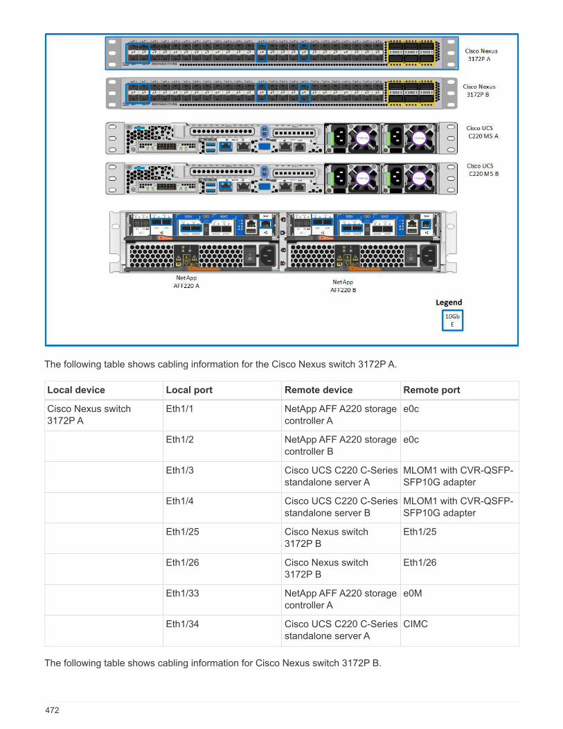
The following table shows cabling information for the Cisco Nexus switch 3172P A.
Local device Local port Remote device Remote port
Cisco Nexus switch3172P A
Eth1/1 NetApp AFF A220 storagecontroller A
e0c
Eth1/2 NetApp AFF A220 storagecontroller B
e0c
Eth1/3 Cisco UCS C220 C-Seriesstandalone server A
MLOM1 with CVR-QSFP-SFP10G adapter
Eth1/4 Cisco UCS C220 C-Seriesstandalone server B
MLOM1 with CVR-QSFP-SFP10G adapter
Eth1/25 Cisco Nexus switch3172P B
Eth1/25
Eth1/26 Cisco Nexus switch3172P B
Eth1/26
Eth1/33 NetApp AFF A220 storagecontroller A
e0M
Eth1/34 Cisco UCS C220 C-Seriesstandalone server A
CIMC
The following table shows cabling information for Cisco Nexus switch 3172P B.
472

Local device Local port Remote device Remote port
Cisco Nexus switch3172P B
Eth1/1 NetApp AFF A220 storagecontroller A
e0d
Eth1/2 NetApp AFF A220 storagecontroller B
e0d
Eth1/3 Cisco UCS C220 C-Seriesstandalone server A
MLOM2 with CVR-QSFP-SFP10G adapter
Eth1/4 Cisco UCS C220 C-Seriesstandalone server B
MLOM2 with CVR-QSFP-SFP10G adapter
Eth1/25 Cisco Nexus switch3172P A
Eth1/25
Eth1/26 Cisco Nexus switch3172P A
Eth1/26
Eth1/33 NetApp AFF A220 storagecontroller B
e0M
Eth1/34 Cisco UCS C220 C-Seriesstandalone server B
CIMC
The following table shows the cabling information for NetApp AFF A220 storage controller A.
Local device Local port Remote device Remote port
NetApp AFF A220 storagecontroller A
e0a NetApp AFF A220 storagecontroller B
e0a
e0b NetApp AFF A220 storagecontroller B
e0b
e0c Cisco Nexus switch3172P A
Eth1/1
e0d Cisco Nexus switch3172P B
Eth1/1
e0M Cisco Nexus switch3172P A
Eth1/33
The following table shows cabling information for NetApp AFF A220 storage controller B.
Local device Local port Remote device Remote port
NetApp AFF A220 storagecontroller B
e0a NetApp AFF A220 storagecontroller A
e0a
e0b NetApp AFF A220 storagecontroller A
e0b
e0c Cisco Nexus switch3172P A
Eth1/2
e0d Cisco Nexus switch3172P B
Eth1/2
473
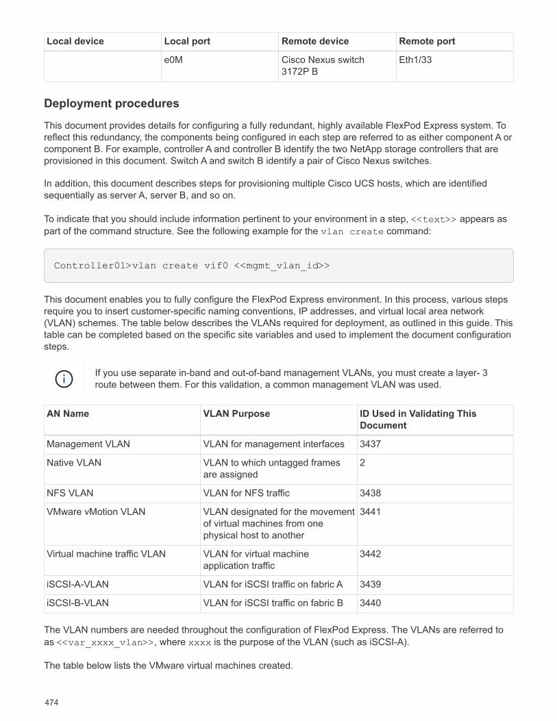
Local device Local port Remote device Remote port
e0M Cisco Nexus switch3172P B
Eth1/33
Deployment procedures
This document provides details for configuring a fully redundant, highly available FlexPod Express system. Toreflect this redundancy, the components being configured in each step are referred to as either component A orcomponent B. For example, controller A and controller B identify the two NetApp storage controllers that areprovisioned in this document. Switch A and switch B identify a pair of Cisco Nexus switches.
In addition, this document describes steps for provisioning multiple Cisco UCS hosts, which are identifiedsequentially as server A, server B, and so on.
To indicate that you should include information pertinent to your environment in a step, <<text>> appears as
part of the command structure. See the following example for the vlan create command:
Controller01>vlan create vif0 <<mgmt_vlan_id>>
This document enables you to fully configure the FlexPod Express environment. In this process, various stepsrequire you to insert customer-specific naming conventions, IP addresses, and virtual local area network(VLAN) schemes. The table below describes the VLANs required for deployment, as outlined in this guide. Thistable can be completed based on the specific site variables and used to implement the document configurationsteps.
If you use separate in-band and out-of-band management VLANs, you must create a layer- 3route between them. For this validation, a common management VLAN was used.
AN Name VLAN Purpose ID Used in Validating This
Document
Management VLAN VLAN for management interfaces 3437
Native VLAN VLAN to which untagged framesare assigned
2
NFS VLAN VLAN for NFS traffic 3438
VMware vMotion VLAN VLAN designated for the movementof virtual machines from onephysical host to another
3441
Virtual machine traffic VLAN VLAN for virtual machineapplication traffic
3442
iSCSI-A-VLAN VLAN for iSCSI traffic on fabric A 3439
iSCSI-B-VLAN VLAN for iSCSI traffic on fabric B 3440
The VLAN numbers are needed throughout the configuration of FlexPod Express. The VLANs are referred to
as <<var_xxxx_vlan>>, where xxxx is the purpose of the VLAN (such as iSCSI-A).
The table below lists the VMware virtual machines created.
474

Virtual machine description Host name
VMware vCenter Server
Cisco Nexus 3172P deployment procedure
The following section details the Cisco Nexus 3172P switch configuration used in a FlexPod Expressenvironment.
Initial setup of Cisco Nexus 3172P switch
The following procedures describe how to configure the Cisco Nexus switches for use in a base FlexPodExpress environment.
This procedure assumes that you are using a Cisco Nexus 3172P running NX-OS softwarerelease 7.0(3)I7(5).
1. Upon initial boot and connection to the console port of the switch, the Cisco NX-OS setup automaticallystarts. This initial configuration addresses basic settings, such as the switch name, the mgmt0 interfaceconfiguration, and Secure Shell (SSH) setup.
2. The FlexPod Express management network can be configured in multiple ways. The mgmt0 interfaces onthe 3172P switches can be connected to an existing management network, or the mgmt0 interfaces of the3172P switches can be connected in a back-to-back configuration. However, this link cannot be used forexternal management access such as SSH traffic.
In this deployment guide, the FlexPod Express Cisco Nexus 3172P switches are connected to an existingmanagement network.
3. To configure the Cisco Nexus 3172P switches, power on the switch and follow the on- screen prompts, asillustrated here for the initial setup of both the switches, substituting the appropriate values for the switch-specific information.
475
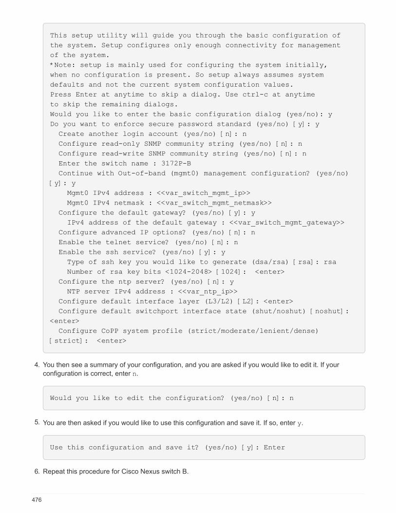
This setup utility will guide you through the basic configuration of
the system. Setup configures only enough connectivity for management
of the system.
*Note: setup is mainly used for configuring the system initially,
when no configuration is present. So setup always assumes system
defaults and not the current system configuration values.
Press Enter at anytime to skip a dialog. Use ctrl-c at anytime
to skip the remaining dialogs.
Would you like to enter the basic configuration dialog (yes/no): y
Do you want to enforce secure password standard (yes/no) [y]: y
Create another login account (yes/no) [n]: n
Configure read-only SNMP community string (yes/no) [n]: n
Configure read-write SNMP community string (yes/no) [n]: n
Enter the switch name : 3172P-B
Continue with Out-of-band (mgmt0) management configuration? (yes/no)
[y]: y
Mgmt0 IPv4 address : <<var_switch_mgmt_ip>>
Mgmt0 IPv4 netmask : <<var_switch_mgmt_netmask>>
Configure the default gateway? (yes/no) [y]: y
IPv4 address of the default gateway : <<var_switch_mgmt_gateway>>
Configure advanced IP options? (yes/no) [n]: n
Enable the telnet service? (yes/no) [n]: n
Enable the ssh service? (yes/no) [y]: y
Type of ssh key you would like to generate (dsa/rsa) [rsa]: rsa
Number of rsa key bits <1024-2048> [1024]: <enter>
Configure the ntp server? (yes/no) [n]: y
NTP server IPv4 address : <<var_ntp_ip>>
Configure default interface layer (L3/L2) [L2]: <enter>
Configure default switchport interface state (shut/noshut) [noshut]:
<enter>
Configure CoPP system profile (strict/moderate/lenient/dense)
[strict]: <enter>
4. You then see a summary of your configuration, and you are asked if you would like to edit it. If your
configuration is correct, enter n.
Would you like to edit the configuration? (yes/no) [n]: n
5. You are then asked if you would like to use this configuration and save it. If so, enter y.
Use this configuration and save it? (yes/no) [y]: Enter
6. Repeat this procedure for Cisco Nexus switch B.
476

Enable advanced features
Certain advanced features must be enabled in Cisco NX-OS to provide additional configuration options.
The interface-vlan feature is required only if you use the back-to-back mgmt0 optiondescribed throughout this document. This feature allows you to assign an IP address to theinterface VLAN (switch virtual interface), which enables in-band management communication tothe switch (such as through SSH).
1. To enable the appropriate features on Cisco Nexus switch A and switch B, enter configuration mode using
the command (config t) and run the following commands:
feature interface-vlan
feature lacp
feature vpc
The default port channel load-balancing hash uses the source and destination IP addresses to determinethe load-balancing algorithm across the interfaces in the port channel. You can achieve better distributionacross the members of the port channel by providing more inputs to the hash algorithm beyond the sourceand destination IP addresses. For the same reason, NetApp highly recommends adding the source anddestination TCP ports to the hash algorithm.
2. From configuration mode (config t), enter the following commands to set the global port channel load-balancing configuration on Cisco Nexus switch A and switch B:
port-channel load-balance src-dst ip-l4port
Perform global spanning-tree configuration
The Cisco Nexus platform uses a new protection feature called bridge assurance. Bridge assurance helpsprotect against a unidirectional link or other software failure with a device that continues to forward data trafficwhen it is no longer running the spanning-tree algorithm. Ports can be placed in one of several states,including network or edge, depending on the platform.
NetApp recommends setting bridge assurance so that all ports are considered to be network ports by default.This setting forces the network administrator to review the configuration of each port. It also reveals the mostcommon configuration errors, such as unidentified edge ports or a neighbor that does not have the bridgeassurance feature enabled. In addition, it is safer to have the spanning tree block many ports rather than toofew, which allows the default port state to enhance the overall stability of the network.
Pay close attention to the spanning- tree state when adding servers, storage, and uplink switches, especially ifthey do not support bridge assurance. In such cases, you might need to change the port type to make the portsactive.
The Bridge Protocol Data Unit (BPDU) guard is enabled on edge ports by default as another layer ofprotection. To prevent loops in the network, this feature shuts down the port if BPDUs from another switch areseen on this interface.
From configuration mode (config t), run the following commands to configure the default spanning- treeoptions, including the default port type and BPDU guard, on Cisco Nexus switch A and switch B:
477
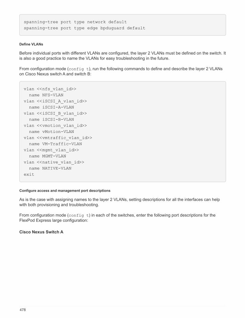
spanning-tree port type network default
spanning-tree port type edge bpduguard default
Define VLANs
Before individual ports with different VLANs are configured, the layer 2 VLANs must be defined on the switch. Itis also a good practice to name the VLANs for easy troubleshooting in the future.
From configuration mode (config t), run the following commands to define and describe the layer 2 VLANson Cisco Nexus switch A and switch B:
vlan <<nfs_vlan_id>>
name NFS-VLAN
vlan <<iSCSI_A_vlan_id>>
name iSCSI-A-VLAN
vlan <<iSCSI_B_vlan_id>>
name iSCSI-B-VLAN
vlan <<vmotion_vlan_id>>
name vMotion-VLAN
vlan <<vmtraffic_vlan_id>>
name VM-Traffic-VLAN
vlan <<mgmt_vlan_id>>
name MGMT-VLAN
vlan <<native_vlan_id>>
name NATIVE-VLAN
exit
Configure access and management port descriptions
As is the case with assigning names to the layer 2 VLANs, setting descriptions for all the interfaces can helpwith both provisioning and troubleshooting.
From configuration mode (config t) in each of the switches, enter the following port descriptions for theFlexPod Express large configuration:
Cisco Nexus Switch A
478
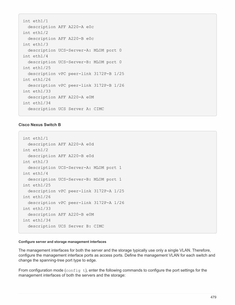
int eth1/1
description AFF A220-A e0c
int eth1/2
description AFF A220-B e0c
int eth1/3
description UCS-Server-A: MLOM port 0
int eth1/4
description UCS-Server-B: MLOM port 0
int eth1/25
description vPC peer-link 3172P-B 1/25
int eth1/26
description vPC peer-link 3172P-B 1/26
int eth1/33
description AFF A220-A e0M
int eth1/34
description UCS Server A: CIMC
Cisco Nexus Switch B
int eth1/1
description AFF A220-A e0d
int eth1/2
description AFF A220-B e0d
int eth1/3
description UCS-Server-A: MLOM port 1
int eth1/4
description UCS-Server-B: MLOM port 1
int eth1/25
description vPC peer-link 3172P-A 1/25
int eth1/26
description vPC peer-link 3172P-A 1/26
int eth1/33
description AFF A220-B e0M
int eth1/34
description UCS Server B: CIMC
Configure server and storage management interfaces
The management interfaces for both the server and the storage typically use only a single VLAN. Therefore,configure the management interface ports as access ports. Define the management VLAN for each switch andchange the spanning-tree port type to edge.
From configuration mode (config t), enter the following commands to configure the port settings for themanagement interfaces of both the servers and the storage:
479

Cisco Nexus Switch A
int eth1/33-34
switchport mode access
switchport access vlan <<mgmt_vlan>>
spanning-tree port type edge
speed 1000
exit
Cisco Nexus Switch B
int eth1/33-34
switchport mode access
switchport access vlan <<mgmt_vlan>>
spanning-tree port type edge
speed 1000
exit
Perform virtual port channel global configuration
A virtual port channel (vPC) enables links that are physically connected to two different Cisco Nexus switchesto appear as a single port channel to a third device. The third device can be a switch, server, or any othernetworking device. A vPC can provide layer-2 multipathing, which allows you to create redundancy byincreasing bandwidth, enabling multiple parallel paths between nodes, and load-balancing traffic wherealternative paths exist.
A vPC provides the following benefits:
• Enabling a single device to use a port channel across two upstream devices
• Eliminating spanning-tree protocol blocked ports
• Providing a loop-free topology
• Using all available uplink bandwidth
• Providing fast convergence if either the link or a device fails
• Providing link-level resiliency
• Helping provide high availability
The vPC feature requires some initial setup between the two Cisco Nexus switches to function properly. If youuse the back-to-back mgmt0 configuration, use the addresses defined on the interfaces and verify that they
can communicate by using the ping [switch_A/B_mgmt0_ip_addr]vrf management command.
From configuration mode (config t), run the following commands to configure the vPC global configurationfor both switches:
Cisco Nexus Switch A
480
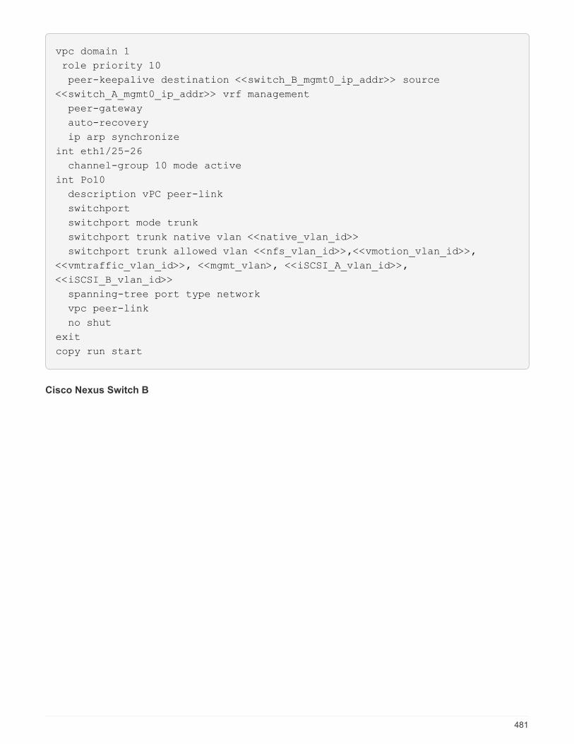
vpc domain 1
role priority 10
peer-keepalive destination <<switch_B_mgmt0_ip_addr>> source
<<switch_A_mgmt0_ip_addr>> vrf management
peer-gateway
auto-recovery
ip arp synchronize
int eth1/25-26
channel-group 10 mode active
int Po10
description vPC peer-link
switchport
switchport mode trunk
switchport trunk native vlan <<native_vlan_id>>
switchport trunk allowed vlan <<nfs_vlan_id>>,<<vmotion_vlan_id>>,
<<vmtraffic_vlan_id>>, <<mgmt_vlan>, <<iSCSI_A_vlan_id>>,
<<iSCSI_B_vlan_id>>
spanning-tree port type network
vpc peer-link
no shut
exit
copy run start
Cisco Nexus Switch B
481
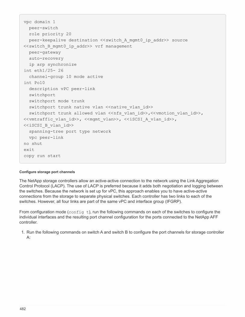
vpc domain 1
peer-switch
role priority 20
peer-keepalive destination <<switch_A_mgmt0_ip_addr>> source
<<switch_B_mgmt0_ip_addr>> vrf management
peer-gateway
auto-recovery
ip arp synchronize
int eth1/25- 26
channel-group 10 mode active
int Po10
description vPC peer-link
switchport
switchport mode trunk
switchport trunk native vlan <<native_vlan_id>>
switchport trunk allowed vlan <<nfs_vlan_id>>,<<vmotion_vlan_id>>,
<<vmtraffic_vlan_id>>, <<mgmt_vlan>>, <<iSCSI_A_vlan_id>>,
<<iSCSI_B_vlan_id>>
spanning-tree port type network
vpc peer-link
no shut
exit
copy run start
Configure storage port channels
The NetApp storage controllers allow an active-active connection to the network using the Link AggregationControl Protocol (LACP). The use of LACP is preferred because it adds both negotiation and logging betweenthe switches. Because the network is set up for vPC, this approach enables you to have active-activeconnections from the storage to separate physical switches. Each controller has two links to each of theswitches. However, all four links are part of the same vPC and interface group (IFGRP).
From configuration mode (config t), run the following commands on each of the switches to configure theindividual interfaces and the resulting port channel configuration for the ports connected to the NetApp AFFcontroller.
1. Run the following commands on switch A and switch B to configure the port channels for storage controllerA:
482
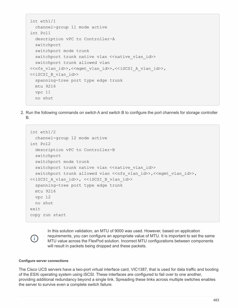
int eth1/1
channel-group 11 mode active
int Po11
description vPC to Controller-A
switchport
switchport mode trunk
switchport trunk native vlan <<native_vlan_id>>
switchport trunk allowed vlan
<<nfs_vlan_id>>,<<mgmt_vlan_id>>,<<iSCSI_A_vlan_id>>,
<<iSCSI_B_vlan_id>>
spanning-tree port type edge trunk
mtu 9216
vpc 11
no shut
2. Run the following commands on switch A and switch B to configure the port channels for storage controllerB.
int eth1/2
channel-group 12 mode active
int Po12
description vPC to Controller-B
switchport
switchport mode trunk
switchport trunk native vlan <<native_vlan_id>>
switchport trunk allowed vlan <<nfs_vlan_id>>,<<mgmt_vlan_id>>,
<<iSCSI_A_vlan_id>>, <<iSCSI_B_vlan_id>>
spanning-tree port type edge trunk
mtu 9216
vpc 12
no shut
exit
copy run start
In this solution validation, an MTU of 9000 was used. However, based on applicationrequirements, you can configure an appropriate value of MTU. It is important to set the sameMTU value across the FlexPod solution. Incorrect MTU configurations between componentswill result in packets being dropped and these packets.
Configure server connections
The Cisco UCS servers have a two-port virtual interface card, VIC1387, that is used for data traffic and bootingof the ESXi operating system using iSCSI. These interfaces are configured to fail over to one another,providing additional redundancy beyond a single link. Spreading these links across multiple switches enablesthe server to survive even a complete switch failure.
483
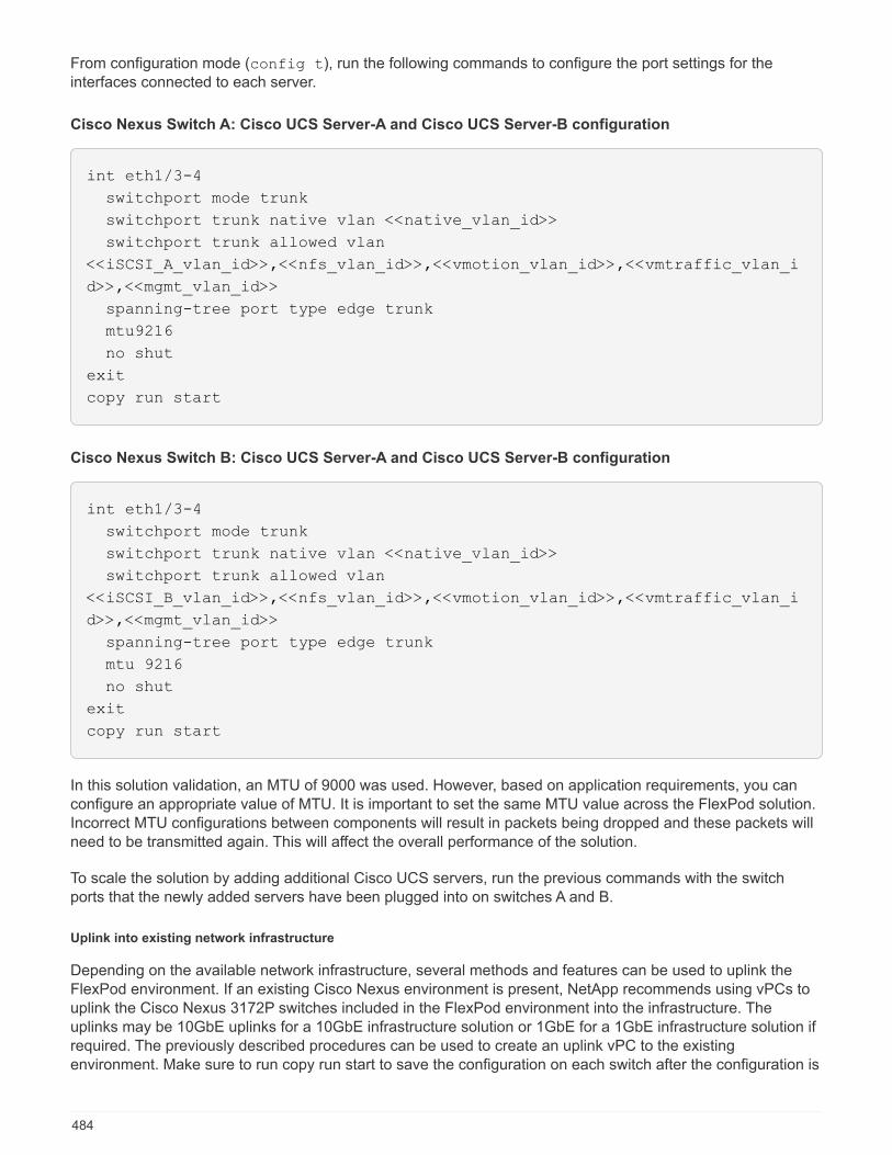
From configuration mode (config t), run the following commands to configure the port settings for theinterfaces connected to each server.
Cisco Nexus Switch A: Cisco UCS Server-A and Cisco UCS Server-B configuration
int eth1/3-4
switchport mode trunk
switchport trunk native vlan <<native_vlan_id>>
switchport trunk allowed vlan
<<iSCSI_A_vlan_id>>,<<nfs_vlan_id>>,<<vmotion_vlan_id>>,<<vmtraffic_vlan_i
d>>,<<mgmt_vlan_id>>
spanning-tree port type edge trunk
mtu9216
no shut
exit
copy run start
Cisco Nexus Switch B: Cisco UCS Server-A and Cisco UCS Server-B configuration
int eth1/3-4
switchport mode trunk
switchport trunk native vlan <<native_vlan_id>>
switchport trunk allowed vlan
<<iSCSI_B_vlan_id>>,<<nfs_vlan_id>>,<<vmotion_vlan_id>>,<<vmtraffic_vlan_i
d>>,<<mgmt_vlan_id>>
spanning-tree port type edge trunk
mtu 9216
no shut
exit
copy run start
In this solution validation, an MTU of 9000 was used. However, based on application requirements, you canconfigure an appropriate value of MTU. It is important to set the same MTU value across the FlexPod solution.Incorrect MTU configurations between components will result in packets being dropped and these packets willneed to be transmitted again. This will affect the overall performance of the solution.
To scale the solution by adding additional Cisco UCS servers, run the previous commands with the switchports that the newly added servers have been plugged into on switches A and B.
Uplink into existing network infrastructure
Depending on the available network infrastructure, several methods and features can be used to uplink theFlexPod environment. If an existing Cisco Nexus environment is present, NetApp recommends using vPCs touplink the Cisco Nexus 3172P switches included in the FlexPod environment into the infrastructure. Theuplinks may be 10GbE uplinks for a 10GbE infrastructure solution or 1GbE for a 1GbE infrastructure solution ifrequired. The previously described procedures can be used to create an uplink vPC to the existingenvironment. Make sure to run copy run start to save the configuration on each switch after the configuration is
484
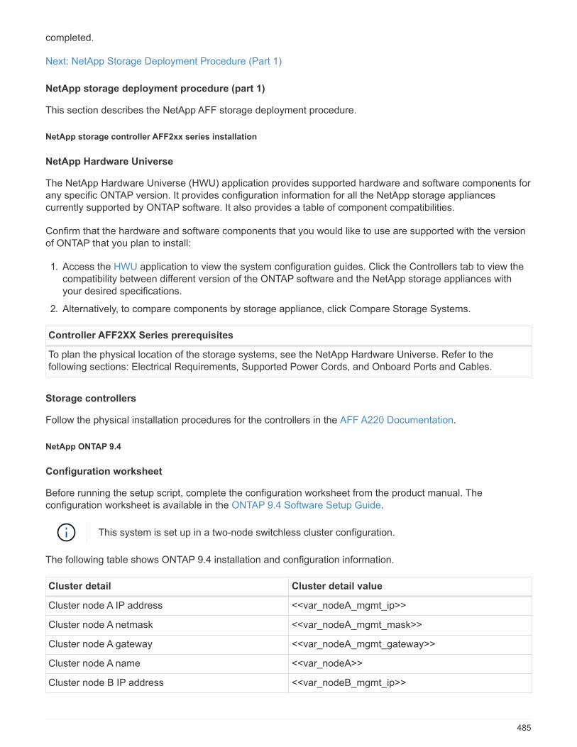
completed.
Next: NetApp Storage Deployment Procedure (Part 1)
NetApp storage deployment procedure (part 1)
This section describes the NetApp AFF storage deployment procedure.
NetApp storage controller AFF2xx series installation
NetApp Hardware Universe
The NetApp Hardware Universe (HWU) application provides supported hardware and software components forany specific ONTAP version. It provides configuration information for all the NetApp storage appliancescurrently supported by ONTAP software. It also provides a table of component compatibilities.
Confirm that the hardware and software components that you would like to use are supported with the versionof ONTAP that you plan to install:
1. Access the HWU application to view the system configuration guides. Click the Controllers tab to view thecompatibility between different version of the ONTAP software and the NetApp storage appliances withyour desired specifications.
2. Alternatively, to compare components by storage appliance, click Compare Storage Systems.
Controller AFF2XX Series prerequisites
To plan the physical location of the storage systems, see the NetApp Hardware Universe. Refer to thefollowing sections: Electrical Requirements, Supported Power Cords, and Onboard Ports and Cables.
Storage controllers
Follow the physical installation procedures for the controllers in the AFF A220 Documentation.
NetApp ONTAP 9.4
Configuration worksheet
Before running the setup script, complete the configuration worksheet from the product manual. Theconfiguration worksheet is available in the ONTAP 9.4 Software Setup Guide.
This system is set up in a two-node switchless cluster configuration.
The following table shows ONTAP 9.4 installation and configuration information.
Cluster detail Cluster detail value
Cluster node A IP address <<var_nodeA_mgmt_ip>>
Cluster node A netmask <<var_nodeA_mgmt_mask>>
Cluster node A gateway <<var_nodeA_mgmt_gateway>>
Cluster node A name <<var_nodeA>>
Cluster node B IP address <<var_nodeB_mgmt_ip>>
485
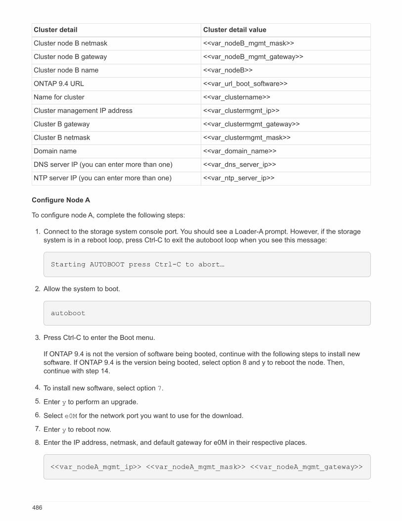
Cluster detail Cluster detail value
Cluster node B netmask <<var_nodeB_mgmt_mask>>
Cluster node B gateway <<var_nodeB_mgmt_gateway>>
Cluster node B name <<var_nodeB>>
ONTAP 9.4 URL <<var_url_boot_software>>
Name for cluster <<var_clustername>>
Cluster management IP address <<var_clustermgmt_ip>>
Cluster B gateway <<var_clustermgmt_gateway>>
Cluster B netmask <<var_clustermgmt_mask>>
Domain name <<var_domain_name>>
DNS server IP (you can enter more than one) <<var_dns_server_ip>>
NTP server IP (you can enter more than one) <<var_ntp_server_ip>>
Configure Node A
To configure node A, complete the following steps:
1. Connect to the storage system console port. You should see a Loader-A prompt. However, if the storagesystem is in a reboot loop, press Ctrl-C to exit the autoboot loop when you see this message:
Starting AUTOBOOT press Ctrl-C to abort…
2. Allow the system to boot.
autoboot
3. Press Ctrl-C to enter the Boot menu.
If ONTAP 9.4 is not the version of software being booted, continue with the following steps to install newsoftware. If ONTAP 9.4 is the version being booted, select option 8 and y to reboot the node. Then,continue with step 14.
4. To install new software, select option 7.
5. Enter y to perform an upgrade.
6. Select e0M for the network port you want to use for the download.
7. Enter y to reboot now.
8. Enter the IP address, netmask, and default gateway for e0M in their respective places.
<<var_nodeA_mgmt_ip>> <<var_nodeA_mgmt_mask>> <<var_nodeA_mgmt_gateway>>
486

9. Enter the URL where the software can be found.
This web server must be pingable.
<<var_url_boot_software>>
10. Press Enter for the user name, indicating no user name.
11. Enter y to set the newly installed software as the default to be used for subsequent reboots.
12. Enter y to reboot the node.
When installing new software, the system might perform firmware upgrades to the BIOS and adapter cards,causing reboots and possible stops at the Loader-A prompt. If these actions occur, the system mightdeviate from this procedure.
13. Press Ctrl-C to enter the Boot menu.
14. Select option 4 for Clean Configuration and Initialize All Disks.
15. Enter y to zero disks, reset config, and install a new file system.
16. Enter y to erase all the data on the disks.
The initialization and creation of the root aggregate can take 90 minutes or more to complete, dependingon the number and type of disks attached. When initialization is complete, the storage system reboots.Note that SSDs take considerably less time to initialize. You can continue with the node B configurationwhile the disks for node A are zeroing.
17. While node A is initializing, begin configuring node B.
Configure Node B
To configure node B, complete the following steps:
1. Connect to the storage system console port. You should see a Loader-A prompt. However, if the storagesystem is in a reboot loop, press Ctrl-C to exit the autoboot loop when you see this message:
Starting AUTOBOOT press Ctrl-C to abort…
2. Press Ctrl-C to enter the Boot menu.
autoboot
3. Press Ctrl-C when prompted.
If ONTAP 9.4 is not the version of software being booted, continue with the following steps to install newsoftware. If ONTAP 9.4 is the version being booted, select option 8 and y to reboot the node. Then,continue with step 14.
4. To install new software, select option 7.
487
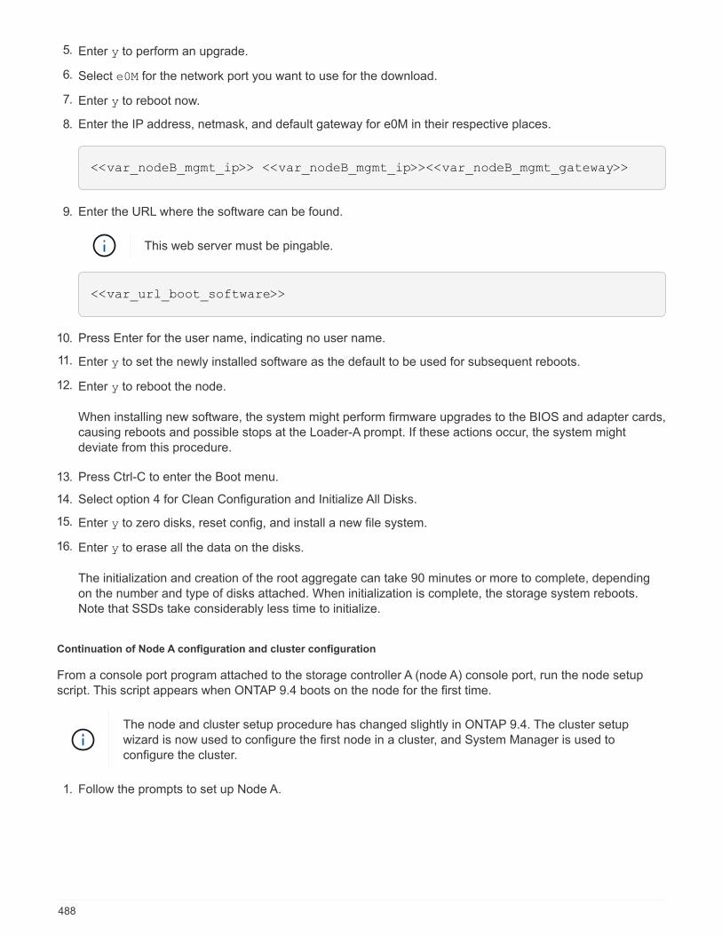
5. Enter y to perform an upgrade.
6. Select e0M for the network port you want to use for the download.
7. Enter y to reboot now.
8. Enter the IP address, netmask, and default gateway for e0M in their respective places.
<<var_nodeB_mgmt_ip>> <<var_nodeB_mgmt_ip>><<var_nodeB_mgmt_gateway>>
9. Enter the URL where the software can be found.
This web server must be pingable.
<<var_url_boot_software>>
10. Press Enter for the user name, indicating no user name.
11. Enter y to set the newly installed software as the default to be used for subsequent reboots.
12. Enter y to reboot the node.
When installing new software, the system might perform firmware upgrades to the BIOS and adapter cards,causing reboots and possible stops at the Loader-A prompt. If these actions occur, the system mightdeviate from this procedure.
13. Press Ctrl-C to enter the Boot menu.
14. Select option 4 for Clean Configuration and Initialize All Disks.
15. Enter y to zero disks, reset config, and install a new file system.
16. Enter y to erase all the data on the disks.
The initialization and creation of the root aggregate can take 90 minutes or more to complete, dependingon the number and type of disks attached. When initialization is complete, the storage system reboots.Note that SSDs take considerably less time to initialize.
Continuation of Node A configuration and cluster configuration
From a console port program attached to the storage controller A (node A) console port, run the node setupscript. This script appears when ONTAP 9.4 boots on the node for the first time.
The node and cluster setup procedure has changed slightly in ONTAP 9.4. The cluster setupwizard is now used to configure the first node in a cluster, and System Manager is used toconfigure the cluster.
1. Follow the prompts to set up Node A.
488
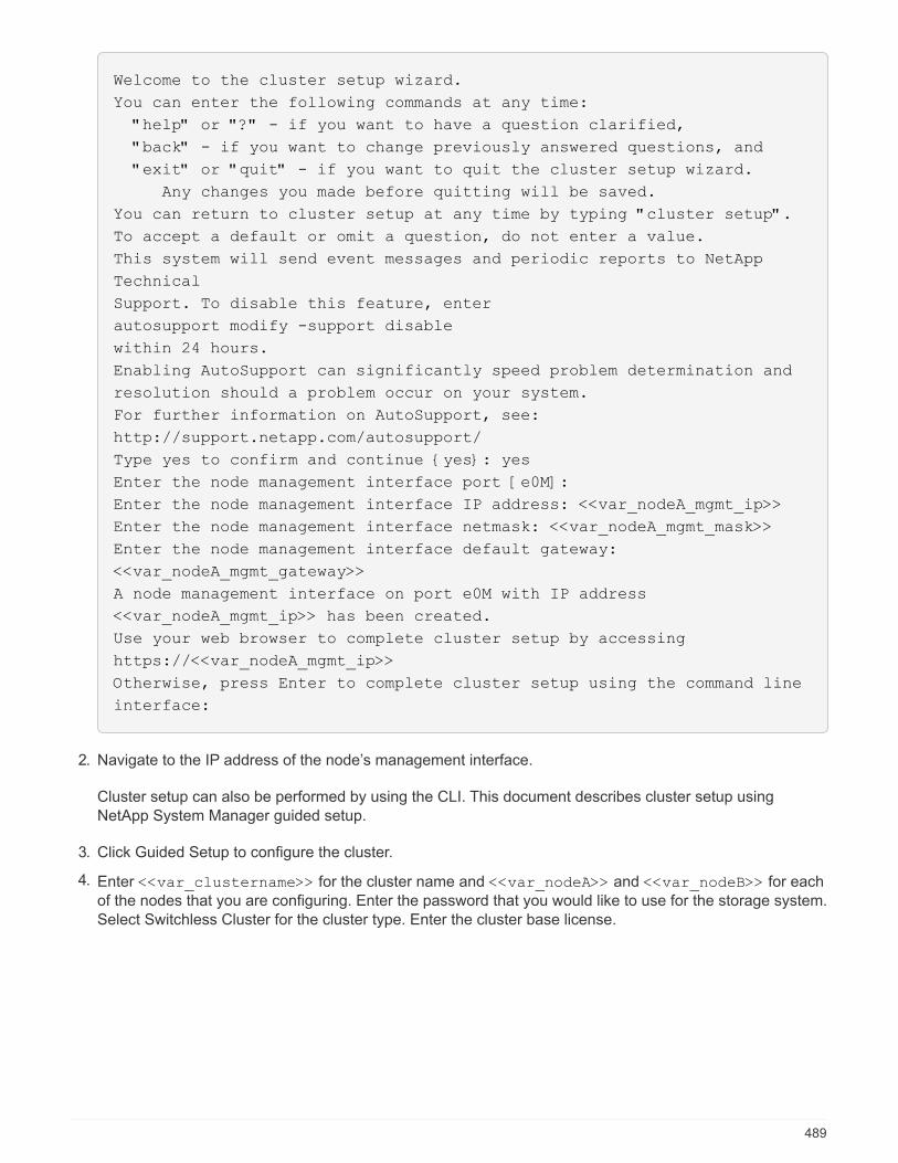
Welcome to the cluster setup wizard.
You can enter the following commands at any time:
"help" or "?" - if you want to have a question clarified,
"back" - if you want to change previously answered questions, and
"exit" or "quit" - if you want to quit the cluster setup wizard.
Any changes you made before quitting will be saved.
You can return to cluster setup at any time by typing "cluster setup".
To accept a default or omit a question, do not enter a value.
This system will send event messages and periodic reports to NetApp
Technical
Support. To disable this feature, enter
autosupport modify -support disable
within 24 hours.
Enabling AutoSupport can significantly speed problem determination and
resolution should a problem occur on your system.
For further information on AutoSupport, see:
http://support.netapp.com/autosupport/
Type yes to confirm and continue {yes}: yes
Enter the node management interface port [e0M]:
Enter the node management interface IP address: <<var_nodeA_mgmt_ip>>
Enter the node management interface netmask: <<var_nodeA_mgmt_mask>>
Enter the node management interface default gateway:
<<var_nodeA_mgmt_gateway>>
A node management interface on port e0M with IP address
<<var_nodeA_mgmt_ip>> has been created.
Use your web browser to complete cluster setup by accessing
https://<<var_nodeA_mgmt_ip>>
Otherwise, press Enter to complete cluster setup using the command line
interface:
2. Navigate to the IP address of the node’s management interface.
Cluster setup can also be performed by using the CLI. This document describes cluster setup usingNetApp System Manager guided setup.
3. Click Guided Setup to configure the cluster.
4. Enter <<var_clustername>> for the cluster name and <<var_nodeA>> and <<var_nodeB>> for eachof the nodes that you are configuring. Enter the password that you would like to use for the storage system.Select Switchless Cluster for the cluster type. Enter the cluster base license.
489

5. You can also enter feature licenses for Cluster, NFS, and iSCSI.
6. You see a status message stating the cluster is being created. This status message cycles through severalstatuses. This process takes several minutes.
7. Configure the network.
a. Deselect the IP Address Range option.
b. Enter <<var_clustermgmt_ip>> in the Cluster Management IP Address field,
<<var_clustermgmt_mask>> in the Netmask field, and <<var_clustermgmt_gateway>> in theGateway field. Use the … selector in the Port field to select e0M of node A.
c. The node management IP for node A is already populated. Enter <<var_nodeA_mgmt_ip>> for nodeB.
490
d. Enter <<var_domain_name>> in the DNS Domain Name field. Enter <<var_dns_server_ip>> inthe DNS Server IP Address field.
You can enter multiple DNS server IP addresses.
e. Enter <<var_ntp_server_ip>> in the Primary NTP Server field.
You can also enter an alternate NTP server.
8. Configure the support information.
a. If your environment requires a proxy to access AutoSupport, enter the URL in Proxy URL.
b. Enter the SMTP mail host and email address for event notifications.
You must, at a minimum, set up the event notification method before you can proceed. You can selectany of the methods.
491

9. When indicated that the cluster configuration has completed, click Manage Your Cluster to configure thestorage.
Continuation of storage cluster configuration
After the configuration of the storage nodes and base cluster, you can continue with the configuration of the
492
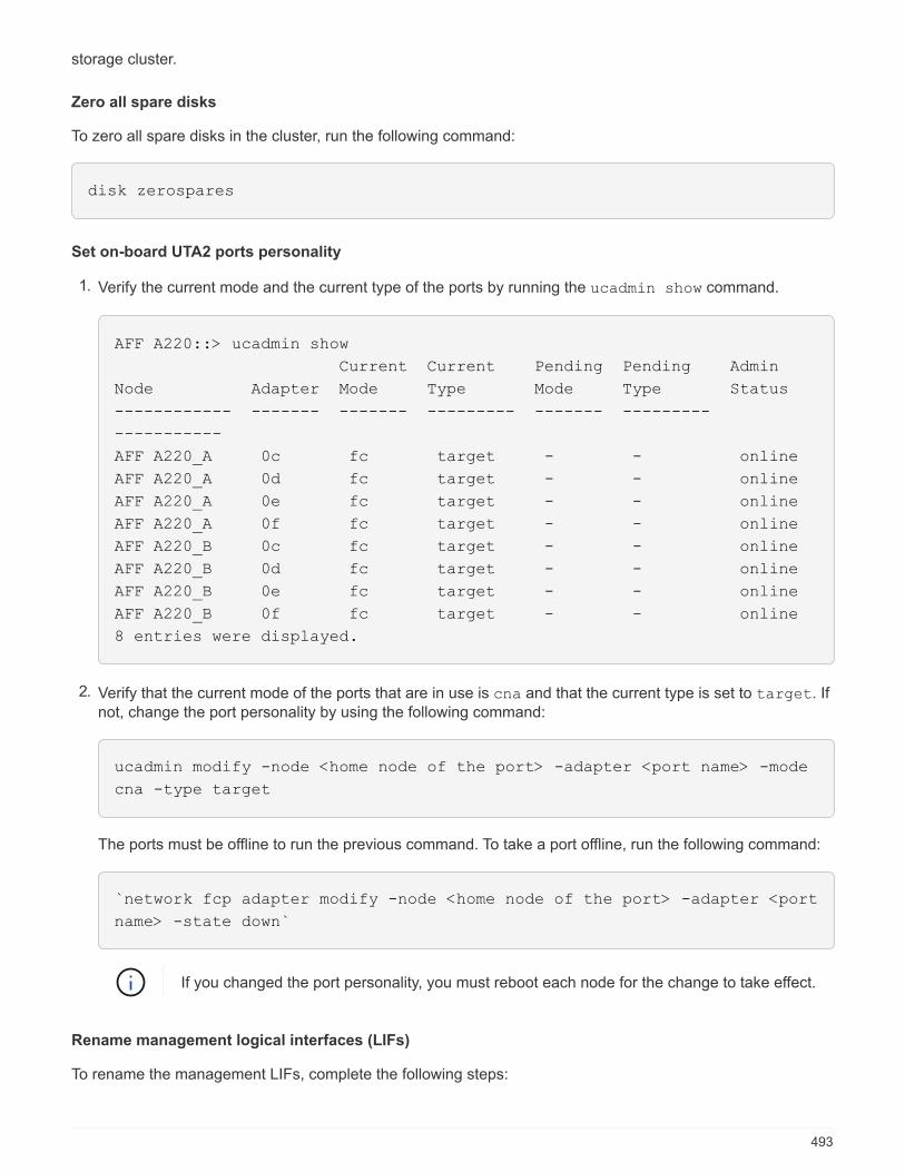
storage cluster.
Zero all spare disks
To zero all spare disks in the cluster, run the following command:
disk zerospares
Set on-board UTA2 ports personality
1. Verify the current mode and the current type of the ports by running the ucadmin show command.
AFF A220::> ucadmin show
Current Current Pending Pending Admin
Node Adapter Mode Type Mode Type Status
------------ ------- ------- --------- ------- ---------
-----------
AFF A220_A 0c fc target - - online
AFF A220_A 0d fc target - - online
AFF A220_A 0e fc target - - online
AFF A220_A 0f fc target - - online
AFF A220_B 0c fc target - - online
AFF A220_B 0d fc target - - online
AFF A220_B 0e fc target - - online
AFF A220_B 0f fc target - - online
8 entries were displayed.
2. Verify that the current mode of the ports that are in use is cna and that the current type is set to target. Ifnot, change the port personality by using the following command:
ucadmin modify -node <home node of the port> -adapter <port name> -mode
cna -type target
The ports must be offline to run the previous command. To take a port offline, run the following command:
`network fcp adapter modify -node <home node of the port> -adapter <port
name> -state down`
If you changed the port personality, you must reboot each node for the change to take effect.
Rename management logical interfaces (LIFs)
To rename the management LIFs, complete the following steps:
493

1. Show the current management LIF names.
network interface show –vserver <<clustername>>
2. Rename the cluster management LIF.
network interface rename –vserver <<clustername>> –lif
cluster_setup_cluster_mgmt_lif_1 –newname cluster_mgmt
3. Rename the node B management LIF.
network interface rename -vserver <<clustername>> -lif
cluster_setup_node_mgmt_lif_AFF A220_B_1 -newname AFF A220-02_mgmt1
Set auto-revert on cluster management
Set the auto-revert parameter on the cluster management interface.
network interface modify –vserver <<clustername>> -lif cluster_mgmt –auto-
revert true
Set up service processor network interface
To assign a static IPv4 address to the service processor on each node, run the following commands:
system service-processor network modify –node <<var_nodeA>> -address
-family IPv4 –enable true –dhcp none –ip-address <<var_nodeA_sp_ip>>
-netmask <<var_nodeA_sp_mask>> -gateway <<var_nodeA_sp_gateway>>
system service-processor network modify –node <<var_nodeB>> -address
-family IPv4 –enable true –dhcp none –ip-address <<var_nodeB_sp_ip>>
-netmask <<var_nodeB_sp_mask>> -gateway <<var_nodeB_sp_gateway>>
The service processor IP addresses should be in the same subnet as the node management IPaddresses.
Enable storage failover in ONTAP
To confirm that storage failover is enabled, run the following commands in a failover pair:
1. Verify the status of storage failover.
494
storage failover show
Both <<var_nodeA>> and <<var_nodeB>> must be able to perform a takeover. Go to step 3 if the nodescan perform a takeover.
2. Enable failover on one of the two nodes.
storage failover modify -node <<var_nodeA>> -enabled true
Enabling failover on one node enables it for both nodes.
3. Verify the HA status of the two-node cluster.
This step is not applicable for clusters with more than two nodes.
cluster ha show
4. Go to step 6 if high availability is configured. If high availability is configured, you see the followingmessage upon issuing the command:
High Availability Configured: true
5. Enable HA mode only for the two-node cluster.
Do not run this command for clusters with more than two nodes because it causes problemswith failover.
cluster ha modify -configured true
Do you want to continue? {y|n}: y
6. Verify that hardware assist is correctly configured and, if needed, modify the partner IP address.
storage failover hwassist show
The message Keep Alive Status : Error: did not receive hwassist keep alive
alerts from partner indicates that hardware assist is not configured. Run the following commands toconfigure hardware assist.
495
storage failover modify –hwassist-partner-ip <<var_nodeB_mgmt_ip>> -node
<<var_nodeA>>
storage failover modify –hwassist-partner-ip <<var_nodeA_mgmt_ip>> -node
<<var_nodeB>>
Create jumbo frame MTU broadcast domain in ONTAP
To create a data broadcast domain with an MTU of 9000, run the following commands:
broadcast-domain create -broadcast-domain Infra_NFS -mtu 9000
broadcast-domain create -broadcast-domain Infra_iSCSI-A -mtu 9000
broadcast-domain create -broadcast-domain Infra_iSCSI-B -mtu 9000
Remove data ports from default broadcast domain
The 10GbE data ports are used for iSCSI/NFS traffic, and these ports should be removed from the defaultdomain. Ports e0e and e0f are not used and should also be removed from the default domain.
To remove the ports from the broadcast domain, run the following command:
broadcast-domain remove-ports -broadcast-domain Default -ports
<<var_nodeA>>:e0c, <<var_nodeA>>:e0d, <<var_nodeA>>:e0e,
<<var_nodeA>>:e0f, <<var_nodeB>>:e0c, <<var_nodeB>>:e0d,
<<var_nodeA>>:e0e, <<var_nodeA>>:e0f
Disable flow control on UTA2 ports
It is a NetApp best practice to disable flow control on all UTA2 ports that are connected to external devices. Todisable flow control, run the following command:
496
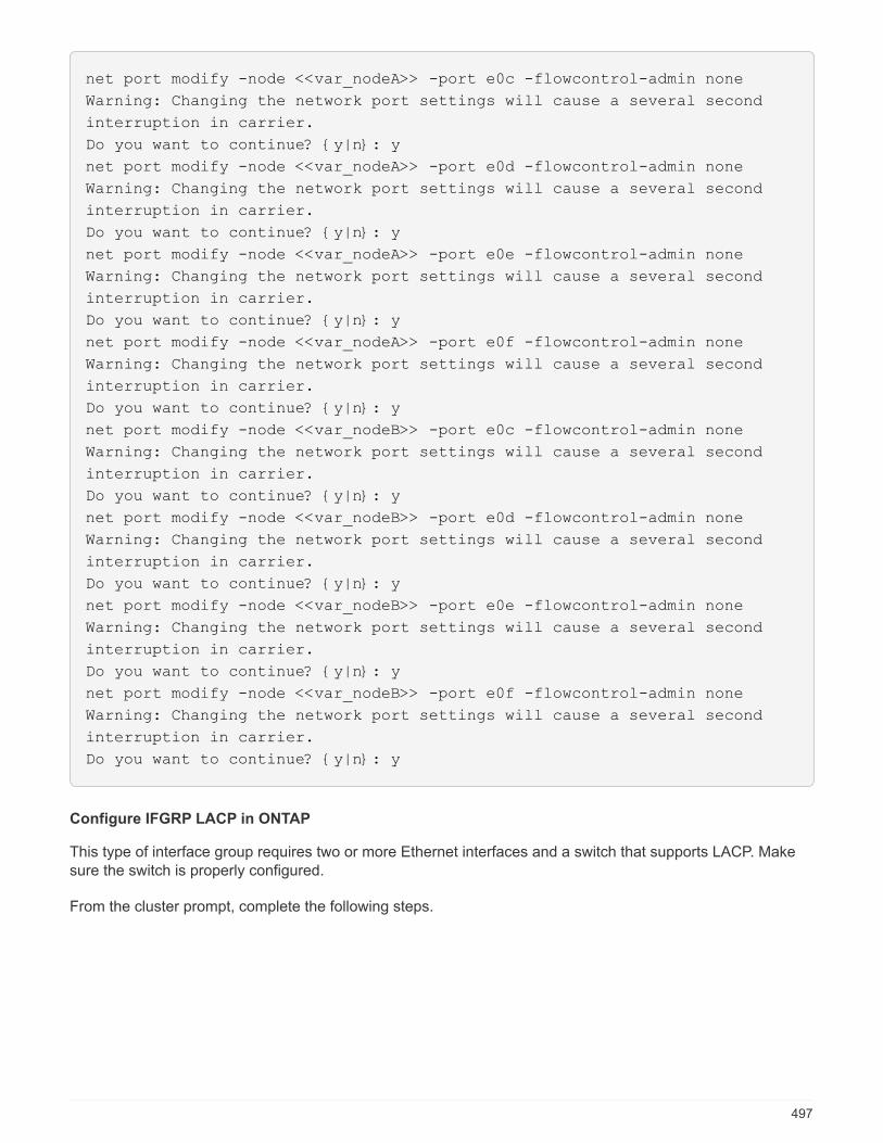
net port modify -node <<var_nodeA>> -port e0c -flowcontrol-admin none
Warning: Changing the network port settings will cause a several second
interruption in carrier.
Do you want to continue? {y|n}: y
net port modify -node <<var_nodeA>> -port e0d -flowcontrol-admin none
Warning: Changing the network port settings will cause a several second
interruption in carrier.
Do you want to continue? {y|n}: y
net port modify -node <<var_nodeA>> -port e0e -flowcontrol-admin none
Warning: Changing the network port settings will cause a several second
interruption in carrier.
Do you want to continue? {y|n}: y
net port modify -node <<var_nodeA>> -port e0f -flowcontrol-admin none
Warning: Changing the network port settings will cause a several second
interruption in carrier.
Do you want to continue? {y|n}: y
net port modify -node <<var_nodeB>> -port e0c -flowcontrol-admin none
Warning: Changing the network port settings will cause a several second
interruption in carrier.
Do you want to continue? {y|n}: y
net port modify -node <<var_nodeB>> -port e0d -flowcontrol-admin none
Warning: Changing the network port settings will cause a several second
interruption in carrier.
Do you want to continue? {y|n}: y
net port modify -node <<var_nodeB>> -port e0e -flowcontrol-admin none
Warning: Changing the network port settings will cause a several second
interruption in carrier.
Do you want to continue? {y|n}: y
net port modify -node <<var_nodeB>> -port e0f -flowcontrol-admin none
Warning: Changing the network port settings will cause a several second
interruption in carrier.
Do you want to continue? {y|n}: y
Configure IFGRP LACP in ONTAP
This type of interface group requires two or more Ethernet interfaces and a switch that supports LACP. Makesure the switch is properly configured.
From the cluster prompt, complete the following steps.
497
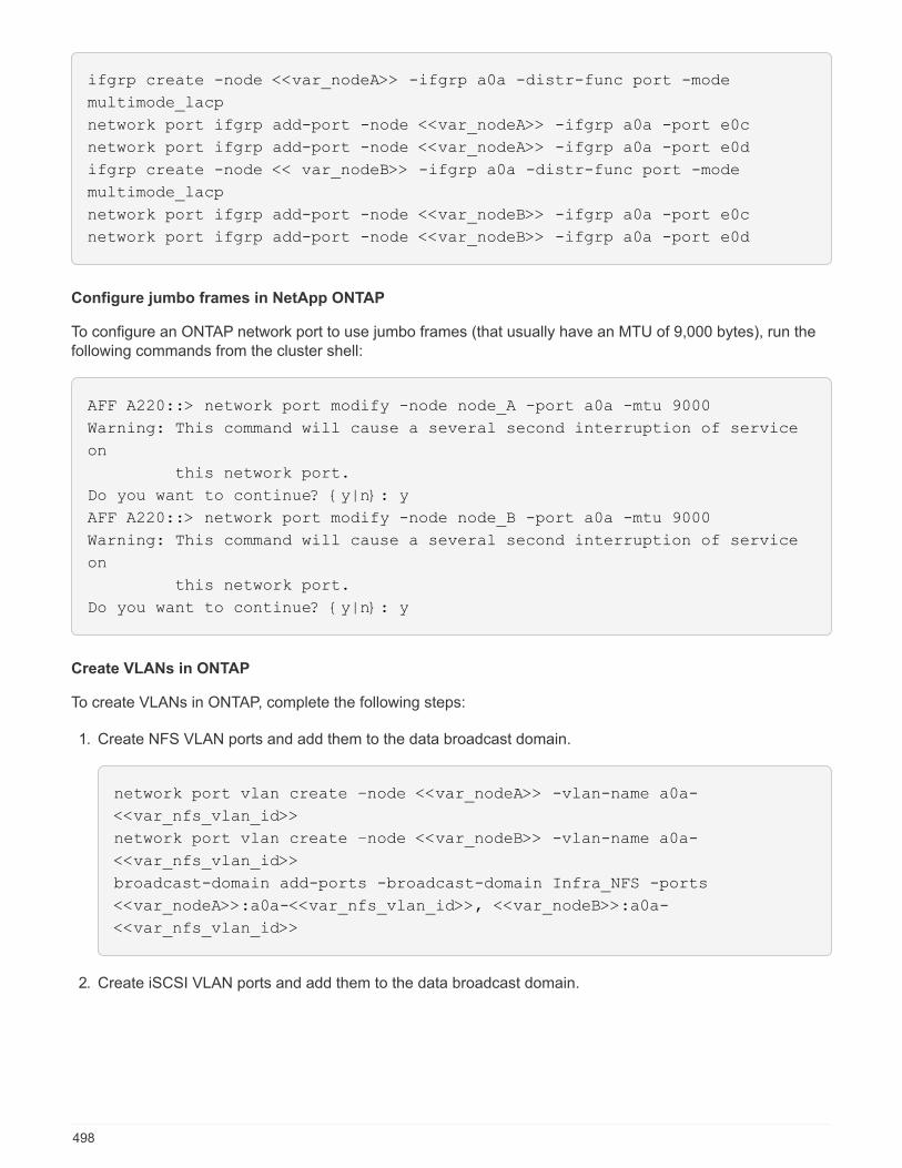
ifgrp create -node <<var_nodeA>> -ifgrp a0a -distr-func port -mode
multimode_lacp
network port ifgrp add-port -node <<var_nodeA>> -ifgrp a0a -port e0c
network port ifgrp add-port -node <<var_nodeA>> -ifgrp a0a -port e0d
ifgrp create -node << var_nodeB>> -ifgrp a0a -distr-func port -mode
multimode_lacp
network port ifgrp add-port -node <<var_nodeB>> -ifgrp a0a -port e0c
network port ifgrp add-port -node <<var_nodeB>> -ifgrp a0a -port e0d
Configure jumbo frames in NetApp ONTAP
To configure an ONTAP network port to use jumbo frames (that usually have an MTU of 9,000 bytes), run thefollowing commands from the cluster shell:
AFF A220::> network port modify -node node_A -port a0a -mtu 9000
Warning: This command will cause a several second interruption of service
on
this network port.
Do you want to continue? {y|n}: y
AFF A220::> network port modify -node node_B -port a0a -mtu 9000
Warning: This command will cause a several second interruption of service
on
this network port.
Do you want to continue? {y|n}: y
Create VLANs in ONTAP
To create VLANs in ONTAP, complete the following steps:
1. Create NFS VLAN ports and add them to the data broadcast domain.
network port vlan create –node <<var_nodeA>> -vlan-name a0a-
<<var_nfs_vlan_id>>
network port vlan create –node <<var_nodeB>> -vlan-name a0a-
<<var_nfs_vlan_id>>
broadcast-domain add-ports -broadcast-domain Infra_NFS -ports
<<var_nodeA>>:a0a-<<var_nfs_vlan_id>>, <<var_nodeB>>:a0a-
<<var_nfs_vlan_id>>
2. Create iSCSI VLAN ports and add them to the data broadcast domain.
498
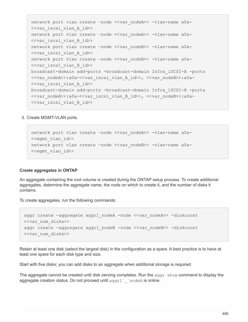
network port vlan create –node <<var_nodeA>> -vlan-name a0a-
<<var_iscsi_vlan_A_id>>
network port vlan create –node <<var_nodeA>> -vlan-name a0a-
<<var_iscsi_vlan_B_id>>
network port vlan create –node <<var_nodeB>> -vlan-name a0a-
<<var_iscsi_vlan_A_id>>
network port vlan create –node <<var_nodeB>> -vlan-name a0a-
<<var_iscsi_vlan_B_id>>
broadcast-domain add-ports -broadcast-domain Infra_iSCSI-A -ports
<<var_nodeA>>:a0a-<<var_iscsi_vlan_A_id>>, <<var_nodeB>>:a0a-
<<var_iscsi_vlan_A_id>>
broadcast-domain add-ports -broadcast-domain Infra_iSCSI-B -ports
<<var_nodeA>>:a0a-<<var_iscsi_vlan_B_id>>, <<var_nodeB>>:a0a-
<<var_iscsi_vlan_B_id>>
3. Create MGMT-VLAN ports.
network port vlan create –node <<var_nodeA>> -vlan-name a0a-
<<mgmt_vlan_id>>
network port vlan create –node <<var_nodeB>> -vlan-name a0a-
<<mgmt_vlan_id>>
Create aggregates in ONTAP
An aggregate containing the root volume is created during the ONTAP setup process. To create additionalaggregates, determine the aggregate name, the node on which to create it, and the number of disks itcontains.
To create aggregates, run the following commands:
aggr create -aggregate aggr1_nodeA -node <<var_nodeA>> -diskcount
<<var_num_disks>>
aggr create -aggregate aggr1_nodeB -node <<var_nodeB>> -diskcount
<<var_num_disks>>
Retain at least one disk (select the largest disk) in the configuration as a spare. A best practice is to have atleast one spare for each disk type and size.
Start with five disks; you can add disks to an aggregate when additional storage is required.
The aggregate cannot be created until disk zeroing completes. Run the aggr show command to display the
aggregate creation status. Do not proceed until aggr1`_`nodeA is online.
499
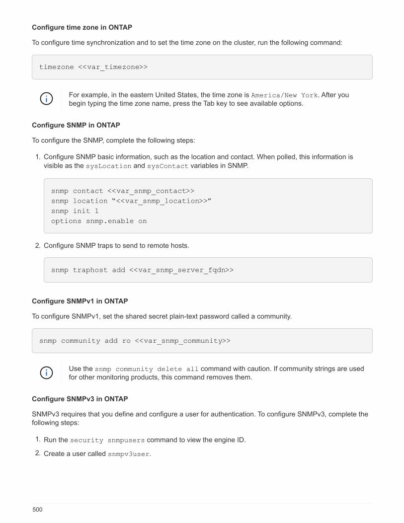
Configure time zone in ONTAP
To configure time synchronization and to set the time zone on the cluster, run the following command:
timezone <<var_timezone>>
For example, in the eastern United States, the time zone is America/New York. After youbegin typing the time zone name, press the Tab key to see available options.
Configure SNMP in ONTAP
To configure the SNMP, complete the following steps:
1. Configure SNMP basic information, such as the location and contact. When polled, this information is
visible as the sysLocation and sysContact variables in SNMP.
snmp contact <<var_snmp_contact>>
snmp location “<<var_snmp_location>>”
snmp init 1
options snmp.enable on
2. Configure SNMP traps to send to remote hosts.
snmp traphost add <<var_snmp_server_fqdn>>
Configure SNMPv1 in ONTAP
To configure SNMPv1, set the shared secret plain-text password called a community.
snmp community add ro <<var_snmp_community>>
Use the snmp community delete all command with caution. If community strings are usedfor other monitoring products, this command removes them.
Configure SNMPv3 in ONTAP
SNMPv3 requires that you define and configure a user for authentication. To configure SNMPv3, complete thefollowing steps:
1. Run the security snmpusers command to view the engine ID.
2. Create a user called snmpv3user.
500

security login create -username snmpv3user -authmethod usm -application
snmp
3. Enter the authoritative entity’s engine ID and select md5 as the authentication protocol.
4. Enter an eight-character minimum-length password for the authentication protocol when prompted.
5. Select des as the privacy protocol.
6. Enter an eight-character minimum-length password for the privacy protocol when prompted.
Configure AutoSupport HTTPS in ONTAP
The NetApp AutoSupport tool sends support summary information to NetApp through HTTPS. To configureAutoSupport, run the following command:
system node autosupport modify -node * -state enable –mail-hosts
<<var_mailhost>> -transport https -support enable -noteto
<<var_storage_admin_email>>
Create a storage virtual machine
To create an infrastructure storage virtual machine (SVM), complete the following steps:
1. Run the vserver create command.
vserver create –vserver Infra-SVM –rootvolume rootvol –aggregate
aggr1_nodeA –rootvolume-security-style unix
2. Add the data aggregate to the infra-SVM aggregate list for the NetApp VSC.
vserver modify -vserver Infra-SVM -aggr-list aggr1_nodeA,aggr1_nodeB
3. Remove the unused storage protocols from the SVM, leaving NFS and iSCSI.
vserver remove-protocols –vserver Infra-SVM -protocols cifs,ndmp,fcp
4. Enable and run the NFS protocol in the infra-SVM SVM.
`nfs create -vserver Infra-SVM -udp disabled`
5. Turn on the SVM vstorage parameter for the NetApp NFS VAAI plug-in. Then, verify that NFS has beenconfigured.
501
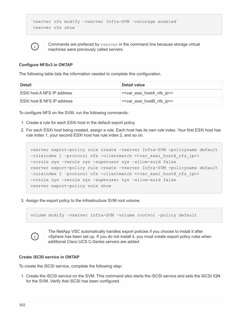
`vserver nfs modify –vserver Infra-SVM –vstorage enabled`
`vserver nfs show `
Commands are prefaced by vserver in the command line because storage virtualmachines were previously called servers.
Configure NFSv3 in ONTAP
The following table lists the information needed to complete this configuration.
Detail Detail value
ESXi host A NFS IP address <<var_esxi_hostA_nfs_ip>>
ESXi host B NFS IP address <<var_esxi_hostB_nfs_ip>>
To configure NFS on the SVM, run the following commands:
1. Create a rule for each ESXi host in the default export policy.
2. For each ESXi host being created, assign a rule. Each host has its own rule index. Your first ESXi host hasrule index 1, your second ESXi host has rule index 2, and so on.
vserver export-policy rule create –vserver Infra-SVM -policyname default
–ruleindex 1 –protocol nfs -clientmatch <<var_esxi_hostA_nfs_ip>>
-rorule sys –rwrule sys -superuser sys –allow-suid false
vserver export-policy rule create –vserver Infra-SVM -policyname default
–ruleindex 2 –protocol nfs -clientmatch <<var_esxi_hostB_nfs_ip>>
-rorule sys –rwrule sys -superuser sys –allow-suid false
vserver export-policy rule show
3. Assign the export policy to the infrastructure SVM root volume.
volume modify –vserver Infra-SVM –volume rootvol –policy default
The NetApp VSC automatically handles export policies if you choose to install it aftervSphere has been set up. If you do not install it, you must create export policy rules whenadditional Cisco UCS C-Series servers are added.
Create iSCSI service in ONTAP
To create the iSCSI service, complete the following step:
1. Create the iSCSI service on the SVM. This command also starts the iSCSI service and sets the iSCSI IQNfor the SVM. Verify that iSCSI has been configured.
502
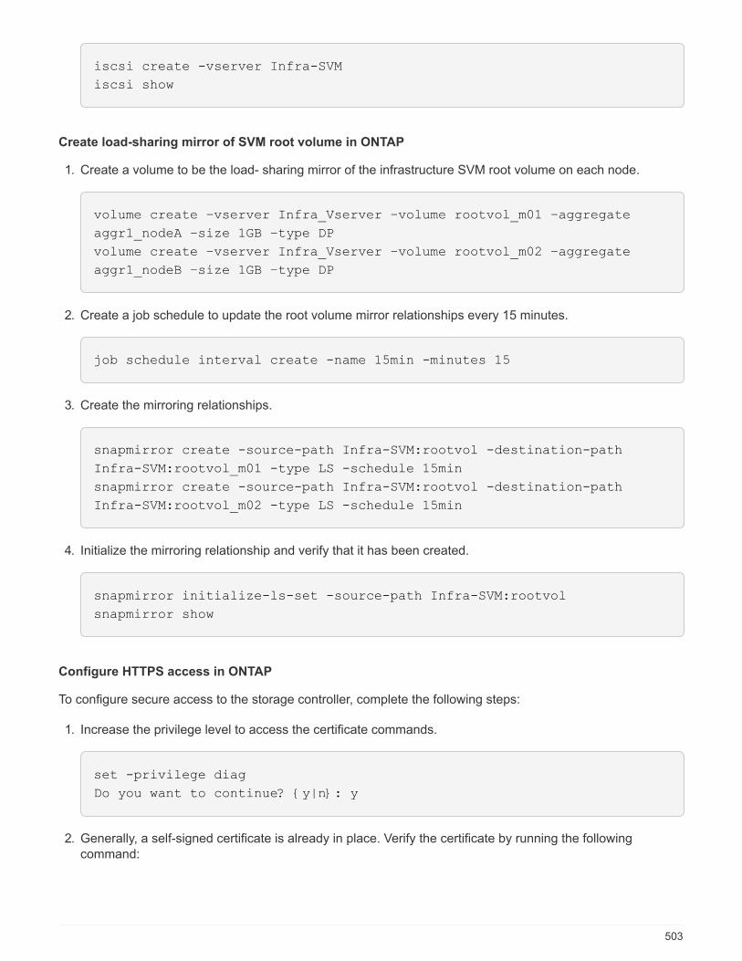
iscsi create -vserver Infra-SVM
iscsi show
Create load-sharing mirror of SVM root volume in ONTAP
1. Create a volume to be the load- sharing mirror of the infrastructure SVM root volume on each node.
volume create –vserver Infra_Vserver –volume rootvol_m01 –aggregate
aggr1_nodeA –size 1GB –type DP
volume create –vserver Infra_Vserver –volume rootvol_m02 –aggregate
aggr1_nodeB –size 1GB –type DP
2. Create a job schedule to update the root volume mirror relationships every 15 minutes.
job schedule interval create -name 15min -minutes 15
3. Create the mirroring relationships.
snapmirror create -source-path Infra-SVM:rootvol -destination-path
Infra-SVM:rootvol_m01 -type LS -schedule 15min
snapmirror create -source-path Infra-SVM:rootvol -destination-path
Infra-SVM:rootvol_m02 -type LS -schedule 15min
4. Initialize the mirroring relationship and verify that it has been created.
snapmirror initialize-ls-set -source-path Infra-SVM:rootvol
snapmirror show
Configure HTTPS access in ONTAP
To configure secure access to the storage controller, complete the following steps:
1. Increase the privilege level to access the certificate commands.
set -privilege diag
Do you want to continue? {y|n}: y
2. Generally, a self-signed certificate is already in place. Verify the certificate by running the followingcommand:
503
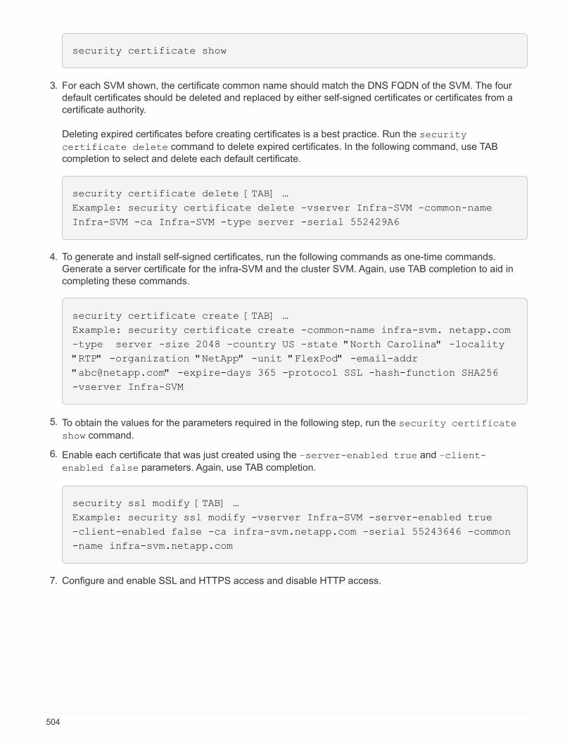
security certificate show
3. For each SVM shown, the certificate common name should match the DNS FQDN of the SVM. The fourdefault certificates should be deleted and replaced by either self-signed certificates or certificates from acertificate authority.
Deleting expired certificates before creating certificates is a best practice. Run the security
certificate delete command to delete expired certificates. In the following command, use TABcompletion to select and delete each default certificate.
security certificate delete [TAB] …
Example: security certificate delete -vserver Infra-SVM -common-name
Infra-SVM -ca Infra-SVM -type server -serial 552429A6
4. To generate and install self-signed certificates, run the following commands as one-time commands.Generate a server certificate for the infra-SVM and the cluster SVM. Again, use TAB completion to aid incompleting these commands.
security certificate create [TAB] …
Example: security certificate create -common-name infra-svm. netapp.com
-type server -size 2048 -country US -state "North Carolina" -locality
"RTP" -organization "NetApp" -unit "FlexPod" -email-addr
"[email protected]" -expire-days 365 -protocol SSL -hash-function SHA256
-vserver Infra-SVM
5. To obtain the values for the parameters required in the following step, run the security certificate
show command.
6. Enable each certificate that was just created using the –server-enabled true and –client-
enabled false parameters. Again, use TAB completion.
security ssl modify [TAB] …
Example: security ssl modify -vserver Infra-SVM -server-enabled true
-client-enabled false -ca infra-svm.netapp.com -serial 55243646 -common
-name infra-svm.netapp.com
7. Configure and enable SSL and HTTPS access and disable HTTP access.
504

system services web modify -external true -sslv3-enabled true
Warning: Modifying the cluster configuration will cause pending web
service requests to be
interrupted as the web servers are restarted.
Do you want to continue {y|n}: y
system services firewall policy delete -policy mgmt -service http
–vserver <<var_clustername>>
It is normal for some of these commands to return an error message stating that the entrydoes not exist.
8. Revert to the admin privilege level and create the setup to allow SVM to be available by the web.
set –privilege admin
vserver services web modify –name spi|ontapi|compat –vserver * -enabled
true
Create a NetApp FlexVol volume in ONTAP
To create a NetApp FlexVol volume, enter the volume name, size, and the aggregate on which it exists. Createtwo VMware datastore volumes and a server boot volume.
volume create -vserver Infra-SVM -volume infra_datastore_1 -aggregate
aggr1_nodeA -size 500GB -state online -policy default -junction-path
/infra_datastore_1 -space-guarantee none -percent-snapshot-space 0
volume create -vserver Infra-SVM -volume infra_swap -aggregate aggr1_nodeA
-size 100GB -state online -policy default -junction-path /infra_swap
-space-guarantee none -percent-snapshot-space 0 -snapshot-policy none
volume create -vserver Infra-SVM -volume esxi_boot -aggregate aggr1_nodeA
-size 100GB -state online -policy default -space-guarantee none -percent
-snapshot-space 0
Enable deduplication in ONTAP
To enable deduplication on appropriate volumes, run the following commands:
volume efficiency on –vserver Infra-SVM -volume infra_datastore_1
volume efficiency on –vserver Infra-SVM -volume esxi_boot
Create LUNs in ONTAP
To create two boot LUNs, run the following commands:
505

lun create -vserver Infra-SVM -volume esxi_boot -lun VM-Host-Infra-A -size
15GB -ostype vmware -space-reserve disabled
lun create -vserver Infra-SVM -volume esxi_boot -lun VM-Host-Infra-B -size
15GB -ostype vmware -space-reserve disabled
When adding an extra Cisco UCS C-Series server, an extra boot LUN must be created.
Create iSCSI LIFs in ONTAP
The following table lists the information needed to complete this configuration.
Detail Detail value
Storage node A iSCSI LIF01A <<var_nodeA_iscsi_lif01a_ip>>
Storage node A iSCSI LIF01A network mask <<var_nodeA_iscsi_lif01a_mask>>
Storage node A iSCSI LIF01B <<var_nodeA_iscsi_lif01b_ip>>
Storage node A iSCSI LIF01B network mask <<var_nodeA_iscsi_lif01b_mask>>
Storage node B iSCSI LIF01A <<var_nodeB_iscsi_lif01a_ip>>
Storage node B iSCSI LIF01A network mask <<var_nodeB_iscsi_lif01a_mask>>
Storage node B iSCSI LIF01B <<var_nodeB_iscsi_lif01b_ip>>
Storage node B iSCSI LIF01B network mask <<var_nodeB_iscsi_lif01b_mask>>
1. Create four iSCSI LIFs, two on each node.
506

network interface create -vserver Infra-SVM -lif iscsi_lif01a -role data
-data-protocol iscsi -home-node <<var_nodeA>> -home-port a0a-
<<var_iscsi_vlan_A_id>> -address <<var_nodeA_iscsi_lif01a_ip>> -netmask
<<var_nodeA_iscsi_lif01a_mask>> –status-admin up –failover-policy
disabled –firewall-policy data –auto-revert false
network interface create -vserver Infra-SVM -lif iscsi_lif01b -role data
-data-protocol iscsi -home-node <<var_nodeA>> -home-port a0a-
<<var_iscsi_vlan_B_id>> -address <<var_nodeA_iscsi_lif01b_ip>> -netmask
<<var_nodeA_iscsi_lif01b_mask>> –status-admin up –failover-policy
disabled –firewall-policy data –auto-revert false
network interface create -vserver Infra-SVM -lif iscsi_lif02a -role data
-data-protocol iscsi -home-node <<var_nodeB>> -home-port a0a-
<<var_iscsi_vlan_A_id>> -address <<var_nodeB_iscsi_lif01a_ip>> -netmask
<<var_nodeB_iscsi_lif01a_mask>> –status-admin up –failover-policy
disabled –firewall-policy data –auto-revert false
network interface create -vserver Infra-SVM -lif iscsi_lif02b -role data
-data-protocol iscsi -home-node <<var_nodeB>> -home-port a0a-
<<var_iscsi_vlan_B_id>> -address <<var_nodeB_iscsi_lif01b_ip>> -netmask
<<var_nodeB_iscsi_lif01b_mask>> –status-admin up –failover-policy
disabled –firewall-policy data –auto-revert false
network interface show
Create NFS LIFs in ONTAP
The following table lists the information needed to complete this configuration.
Detail Detail Value
Storage node A NFS LIF 01 IP <<var_nodeA_nfs_lif_01_ip>>
Storage node A NFS LIF 01 network mask <<var_nodeA_nfs_lif_01_mask>>
Storage node B NFS LIF 02 IP <<var_nodeB_nfs_lif_02_ip>>
Storage node B NFS LIF 02 network mask <<var_nodeB_nfs_lif_02_mask>>
1. Create an NFS LIF.
507
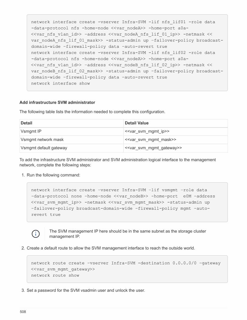
network interface create -vserver Infra-SVM -lif nfs_lif01 -role data
-data-protocol nfs -home-node <<var_nodeA>> -home-port a0a-
<<var_nfs_vlan_id>> –address <<var_nodeA_nfs_lif_01_ip>> -netmask <<
var_nodeA_nfs_lif_01_mask>> -status-admin up –failover-policy broadcast-
domain-wide –firewall-policy data –auto-revert true
network interface create -vserver Infra-SVM -lif nfs_lif02 -role data
-data-protocol nfs -home-node <<var_nodeA>> -home-port a0a-
<<var_nfs_vlan_id>> –address <<var_nodeB_nfs_lif_02_ip>> -netmask <<
var_nodeB_nfs_lif_02_mask>> -status-admin up –failover-policy broadcast-
domain-wide –firewall-policy data –auto-revert true
network interface show
Add infrastructure SVM administrator
The following table lists the information needed to complete this configuration.
Detail Detail Value
Vsmgmt IP <<var_svm_mgmt_ip>>
Vsmgmt network mask <<var_svm_mgmt_mask>>
Vsmgmt default gateway <<var_svm_mgmt_gateway>>
To add the infrastructure SVM administrator and SVM administration logical interface to the managementnetwork, complete the following steps:
1. Run the following command:
network interface create –vserver Infra-SVM –lif vsmgmt –role data
–data-protocol none –home-node <<var_nodeB>> -home-port e0M –address
<<var_svm_mgmt_ip>> -netmask <<var_svm_mgmt_mask>> -status-admin up
–failover-policy broadcast-domain-wide –firewall-policy mgmt –auto-
revert true
The SVM management IP here should be in the same subnet as the storage clustermanagement IP.
2. Create a default route to allow the SVM management interface to reach the outside world.
network route create –vserver Infra-SVM -destination 0.0.0.0/0 –gateway
<<var_svm_mgmt_gateway>>
network route show
3. Set a password for the SVM vsadmin user and unlock the user.
508

security login password –username vsadmin –vserver Infra-SVM
Enter a new password: <<var_password>>
Enter it again: <<var_password>>
security login unlock –username vsadmin –vserver Infra-SVM
Next: Cisco UCS C-Series Rack Server Deployment Procedure
Cisco UCS C-Series rack server deployment procedure
The following section provides a detailed procedure for configuring a Cisco UCS C-Series standalone rackserver for use in the FlexPod Express configuration.
Perform initial Cisco UCS C-Series standalone server setup for Cisco Integrated Management Server
Complete these steps for the initial setup of the CIMC interface for Cisco UCS C-Series standalone servers.
The following table lists the information needed to configure CIMC for each Cisco UCS C-Series standaloneserver.
Detail Detail value
CIMC IP address <<cimc_ip>>
CIMC subnet mask <<cimc_netmask>>
CIMC default gateway <<cimc_gateway>>
The CIMC version used in this validation is CIMC 3.1.3(g).
All servers
1. Attach the Cisco keyboard, video, and mouse (KVM) dongle (provided with the server) to the KVM port onthe front of the server. Plug a VGA monitor and USB keyboard into the appropriate KVM dongle ports.
2. Power on the server and press F8 when prompted to enter the CIMC configuration.
509
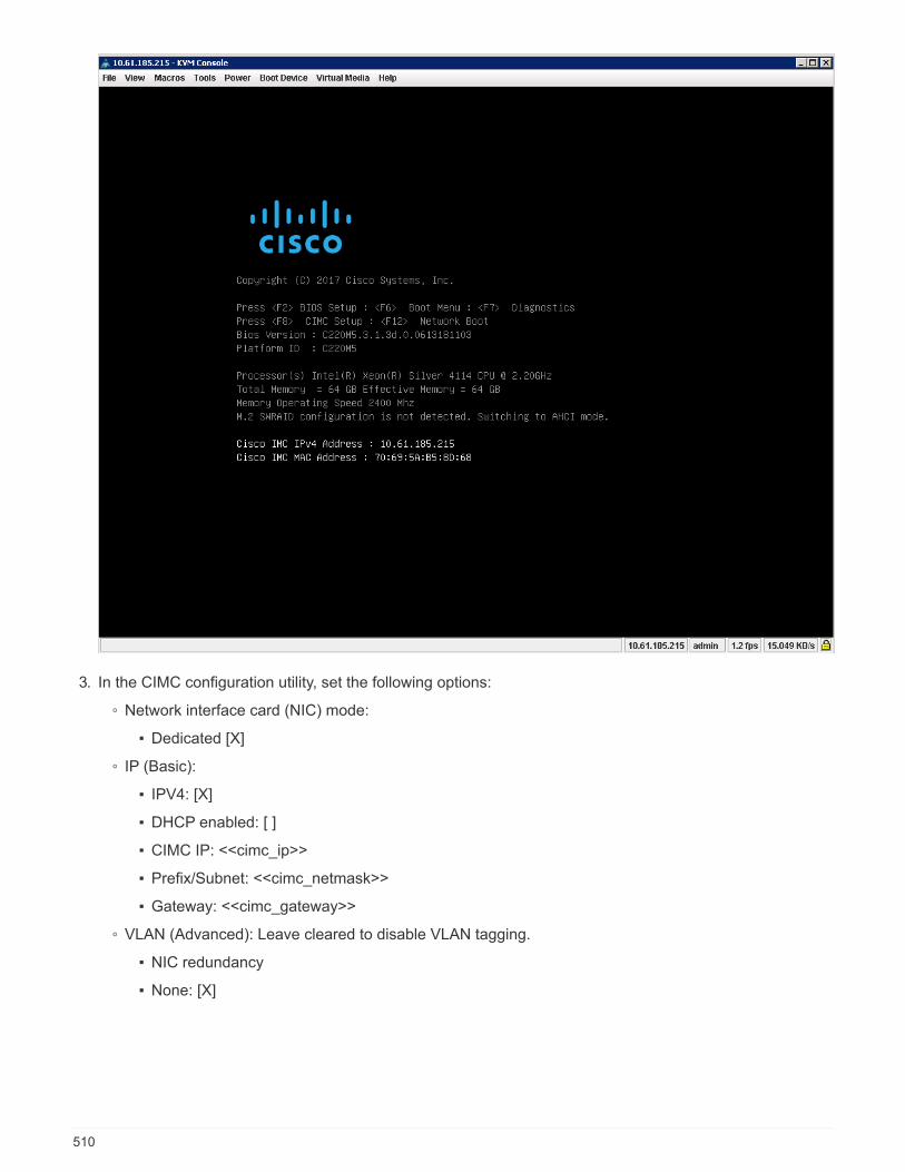
3. In the CIMC configuration utility, set the following options:
◦ Network interface card (NIC) mode:
▪ Dedicated [X]
◦ IP (Basic):
▪ IPV4: [X]
▪ DHCP enabled: [ ]
▪ CIMC IP: <<cimc_ip>>
▪ Prefix/Subnet: <<cimc_netmask>>
▪ Gateway: <<cimc_gateway>>
◦ VLAN (Advanced): Leave cleared to disable VLAN tagging.
▪ NIC redundancy
▪ None: [X]
510

4. Press F1 to see additional settings.
◦ Common properties:
▪ Host name: <<esxi_host_name>>
▪ Dynamic DNS: [ ]
▪ Factory defaults: Leave cleared.
◦ Default user (basic):
▪ Default password: <<admin_password>>
▪ Reenter password: <<admin_password>>
▪ Port properties: Use default values.
▪ Port profiles: Leave cleared.
511
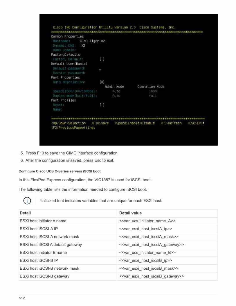
5. Press F10 to save the CIMC interface configuration.
6. After the configuration is saved, press Esc to exit.
Configure Cisco UCS C-Series servers iSCSI boot
In this FlexPod Express configuration, the VIC1387 is used for iSCSI boot.
The following table lists the information needed to configure iSCSI boot.
Italicized font indicates variables that are unique for each ESXi host.
Detail Detail value
ESXi host initiator A name <<var_ucs_initiator_name_A>>
ESXi host iSCSI-A IP <<var_esxi_host_iscsiA_ip>>
ESXi host iSCSI-A network mask <<var_esxi_host_iscsiA_mask>>
ESXi host iSCSI A default gateway <<var_esxi_host_iscsiA_gateway>>
ESXi host initiator B name <<var_ucs_initiator_name_B>>
ESXi host iSCSI-B IP <<var_esxi_host_iscsiB_ip>>
ESXi host iSCSI-B network mask <<var_esxi_host_iscsiB_mask>>
ESXi host iSCSI-B gateway <<var_esxi_host_iscsiB_gateway>>
512
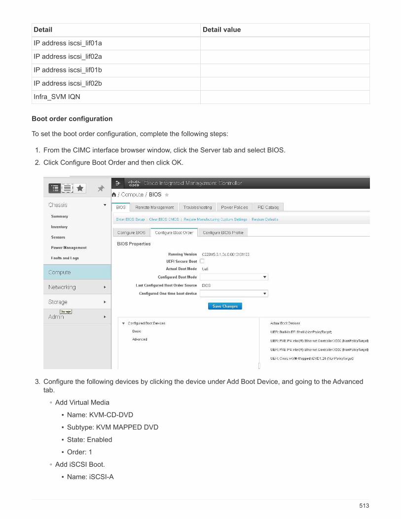
Detail Detail value
IP address iscsi_lif01a
IP address iscsi_lif02a
IP address iscsi_lif01b
IP address iscsi_lif02b
Infra_SVM IQN
Boot order configuration
To set the boot order configuration, complete the following steps:
1. From the CIMC interface browser window, click the Server tab and select BIOS.
2. Click Configure Boot Order and then click OK.
3. Configure the following devices by clicking the device under Add Boot Device, and going to the Advancedtab.
◦ Add Virtual Media
▪ Name: KVM-CD-DVD
▪ Subtype: KVM MAPPED DVD
▪ State: Enabled
▪ Order: 1
◦ Add iSCSI Boot.
▪ Name: iSCSI-A
513
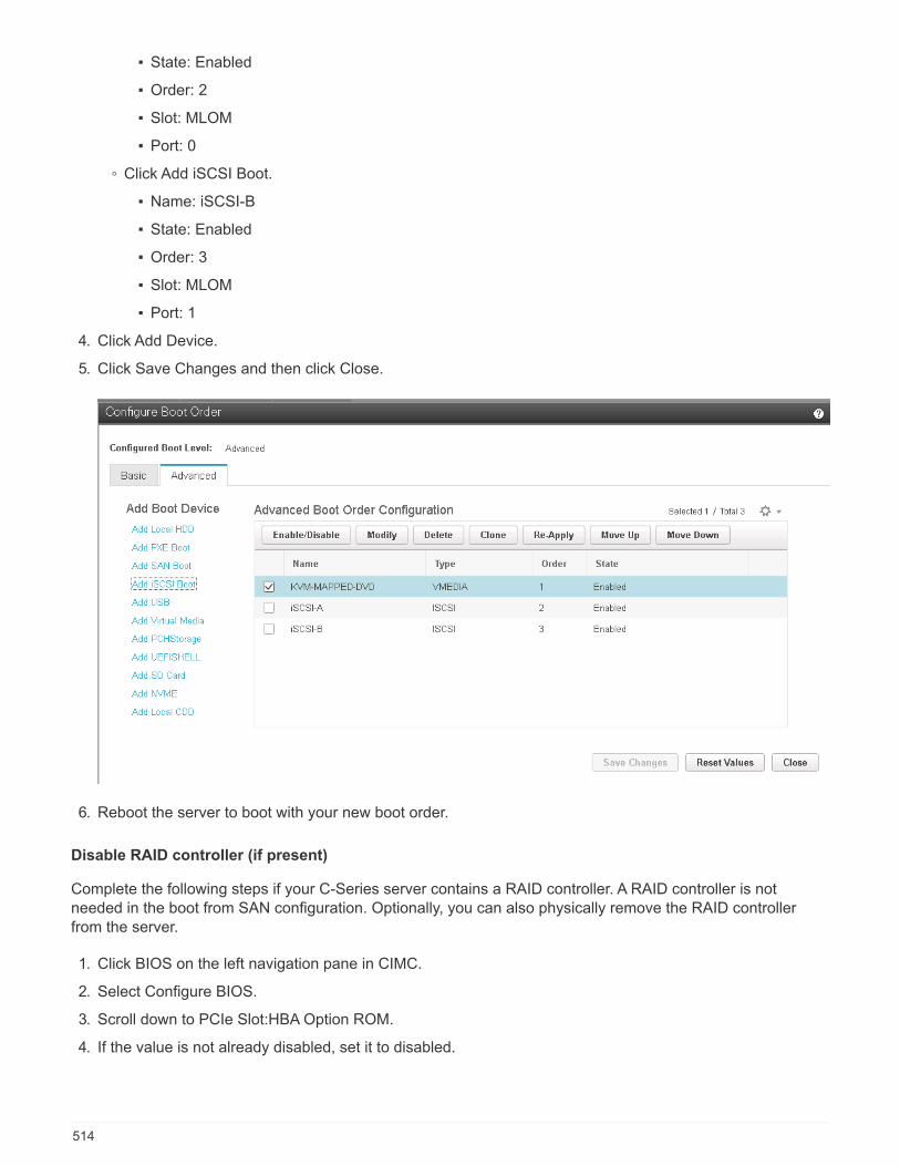
▪ State: Enabled
▪ Order: 2
▪ Slot: MLOM
▪ Port: 0
◦ Click Add iSCSI Boot.
▪ Name: iSCSI-B
▪ State: Enabled
▪ Order: 3
▪ Slot: MLOM
▪ Port: 1
4. Click Add Device.
5. Click Save Changes and then click Close.
6. Reboot the server to boot with your new boot order.
Disable RAID controller (if present)
Complete the following steps if your C-Series server contains a RAID controller. A RAID controller is notneeded in the boot from SAN configuration. Optionally, you can also physically remove the RAID controllerfrom the server.
1. Click BIOS on the left navigation pane in CIMC.
2. Select Configure BIOS.
3. Scroll down to PCIe Slot:HBA Option ROM.
4. If the value is not already disabled, set it to disabled.
514
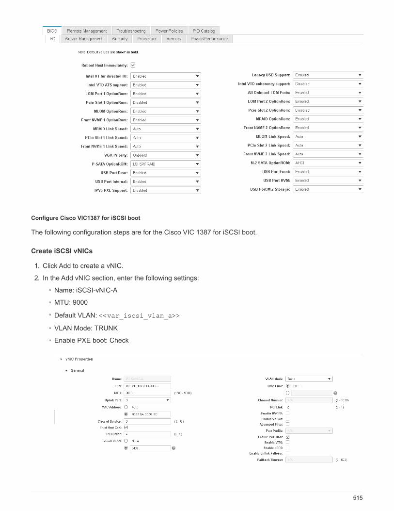
Configure Cisco VIC1387 for iSCSI boot
The following configuration steps are for the Cisco VIC 1387 for iSCSI boot.
Create iSCSI vNICs
1. Click Add to create a vNIC.
2. In the Add vNIC section, enter the following settings:
◦ Name: iSCSI-vNIC-A
◦ MTU: 9000
◦ Default VLAN: <<var_iscsi_vlan_a>>
◦ VLAN Mode: TRUNK
◦ Enable PXE boot: Check
515
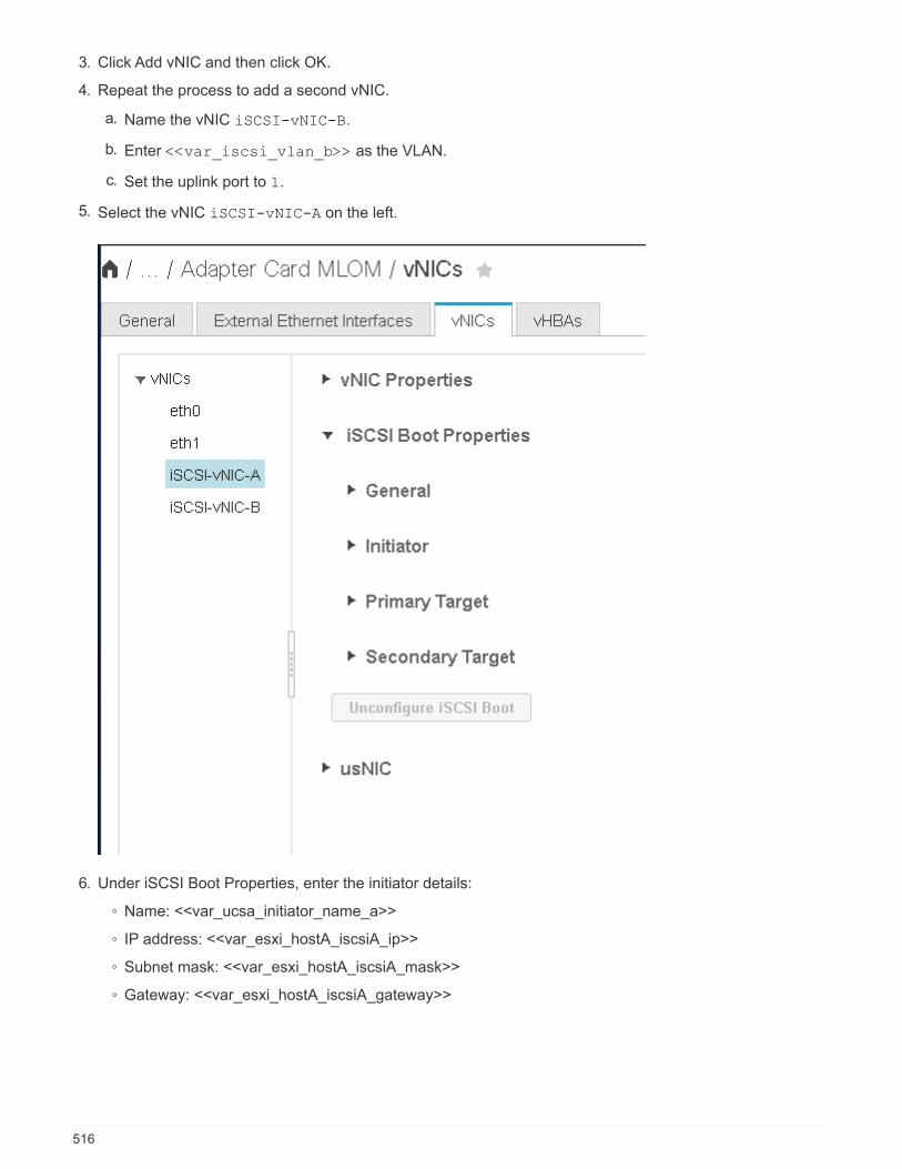
3. Click Add vNIC and then click OK.
4. Repeat the process to add a second vNIC.
a. Name the vNIC iSCSI-vNIC-B.
b. Enter <<var_iscsi_vlan_b>> as the VLAN.
c. Set the uplink port to 1.
5. Select the vNIC iSCSI-vNIC-A on the left.
6. Under iSCSI Boot Properties, enter the initiator details:
◦ Name: <<var_ucsa_initiator_name_a>>
◦ IP address: <<var_esxi_hostA_iscsiA_ip>>
◦ Subnet mask: <<var_esxi_hostA_iscsiA_mask>>
◦ Gateway: <<var_esxi_hostA_iscsiA_gateway>>
516
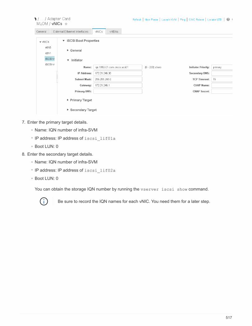
7. Enter the primary target details.
◦ Name: IQN number of infra-SVM
◦ IP address: IP address of iscsi_lif01a
◦ Boot LUN: 0
8. Enter the secondary target details.
◦ Name: IQN number of infra-SVM
◦ IP address: IP address of iscsi_lif02a
◦ Boot LUN: 0
You can obtain the storage IQN number by running the vserver iscsi show command.
Be sure to record the IQN names for each vNIC. You need them for a later step.
517

9. Click Configure iSCSI.
10. Select the vNIC iSCSI-vNIC- B and click the iSCSI Boot button located on the top of the Host EthernetInterfaces section.
11. Repeat the process to configure iSCSI-vNIC-B.
12. Enter the initiator details.
◦ Name: <<var_ucsa_initiator_name_b>>
◦ IP address: <<var_esxi_hostb_iscsib_ip>>
◦ Subnet mask: <<var_esxi_hostb_iscsib_mask>>
◦ Gateway: <<var_esxi_hostb_iscsib_gateway>>
13. Enter the primary target details.
◦ Name: IQN number of infra-SVM
◦ IP address: IP address of iscsi_lif01b
◦ Boot LUN: 0
14. Enter the secondary target details.
◦ Name: IQN number of infra-SVM
◦ IP address: IP address of iscsi_lif02b
◦ Boot LUN: 0
You can obtain the storage IQN number by using the vserver iscsi show command.
Be sure to record the IQN names for each vNIC. You need them for a later step.
15. Click Configure ISCSI.
16. Repeat this process to configure iSCSI boot for Cisco UCS server B.
518

Configure vNICs for ESXi
1. From the CIMC interface browser window, click Inventory and then click Cisco VIC adapters on the rightpane.
2. Under Adapter Cards, select Cisco UCS VIC 1387 and then select the vNICs underneath.
3. Select eth0 and click Properties.
4. Set the MTU to 9000. Click Save Changes.
519
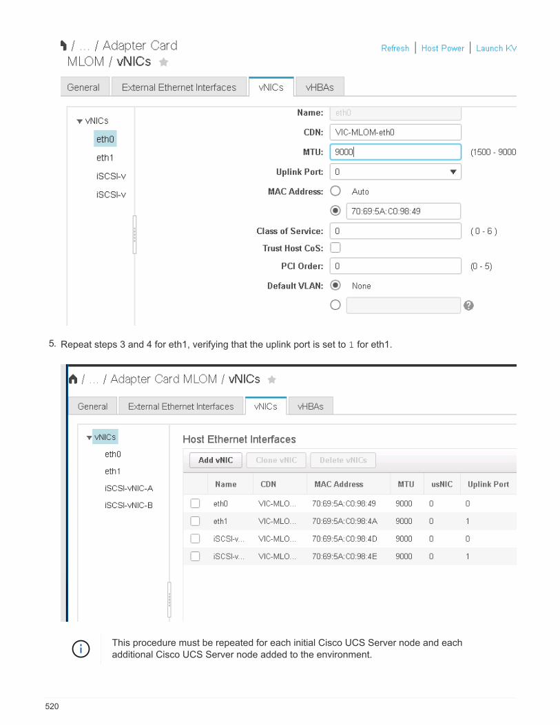
5. Repeat steps 3 and 4 for eth1, verifying that the uplink port is set to 1 for eth1.
This procedure must be repeated for each initial Cisco UCS Server node and eachadditional Cisco UCS Server node added to the environment.
520
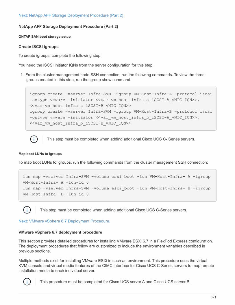
Next: NetApp AFF Storage Deployment Procedure (Part 2)
NetApp AFF Storage Deployment Procedure (Part 2)
ONTAP SAN boot storage setup
Create iSCSI igroups
To create igroups, complete the following step:
You need the iSCSI initiator IQNs from the server configuration for this step.
1. From the cluster management node SSH connection, run the following commands. To view the threeigroups created in this step, run the igroup show command.
igroup create –vserver Infra-SVM –igroup VM-Host-Infra-A –protocol iscsi
–ostype vmware –initiator <<var_vm_host_infra_a_iSCSI-A_vNIC_IQN>>,
<<var_vm_host_infra_a_iSCSI-B_vNIC_IQN>>
igroup create –vserver Infra-SVM –igroup VM-Host-Infra-B –protocol iscsi
–ostype vmware –initiator <<var_vm_host_infra_b_iSCSI-A_vNIC_IQN>>,
<<var_vm_host_infra_b_iSCSI-B_vNIC_IQN>>
This step must be completed when adding additional Cisco UCS C- Series servers.
Map boot LUNs to igroups
To map boot LUNs to igroups, run the following commands from the cluster management SSH connection:
lun map –vserver Infra-SVM –volume esxi_boot –lun VM-Host-Infra- A –igroup
VM-Host-Infra- A –lun-id 0
lun map –vserver Infra-SVM –volume esxi_boot –lun VM-Host-Infra- B –igroup
VM-Host-Infra- B –lun-id 0
This step must be completed when adding additional Cisco UCS C-Series servers.
Next: VMware vSphere 6.7 Deployment Procedure.
VMware vSphere 6.7 deployment procedure
This section provides detailed procedures for installing VMware ESXi 6.7 in a FlexPod Express configuration.The deployment procedures that follow are customized to include the environment variables described inprevious sections.
Multiple methods exist for installing VMware ESXi in such an environment. This procedure uses the virtualKVM console and virtual media features of the CIMC interface for Cisco UCS C-Series servers to map remoteinstallation media to each individual server.
This procedure must be completed for Cisco UCS server A and Cisco UCS server B.
521
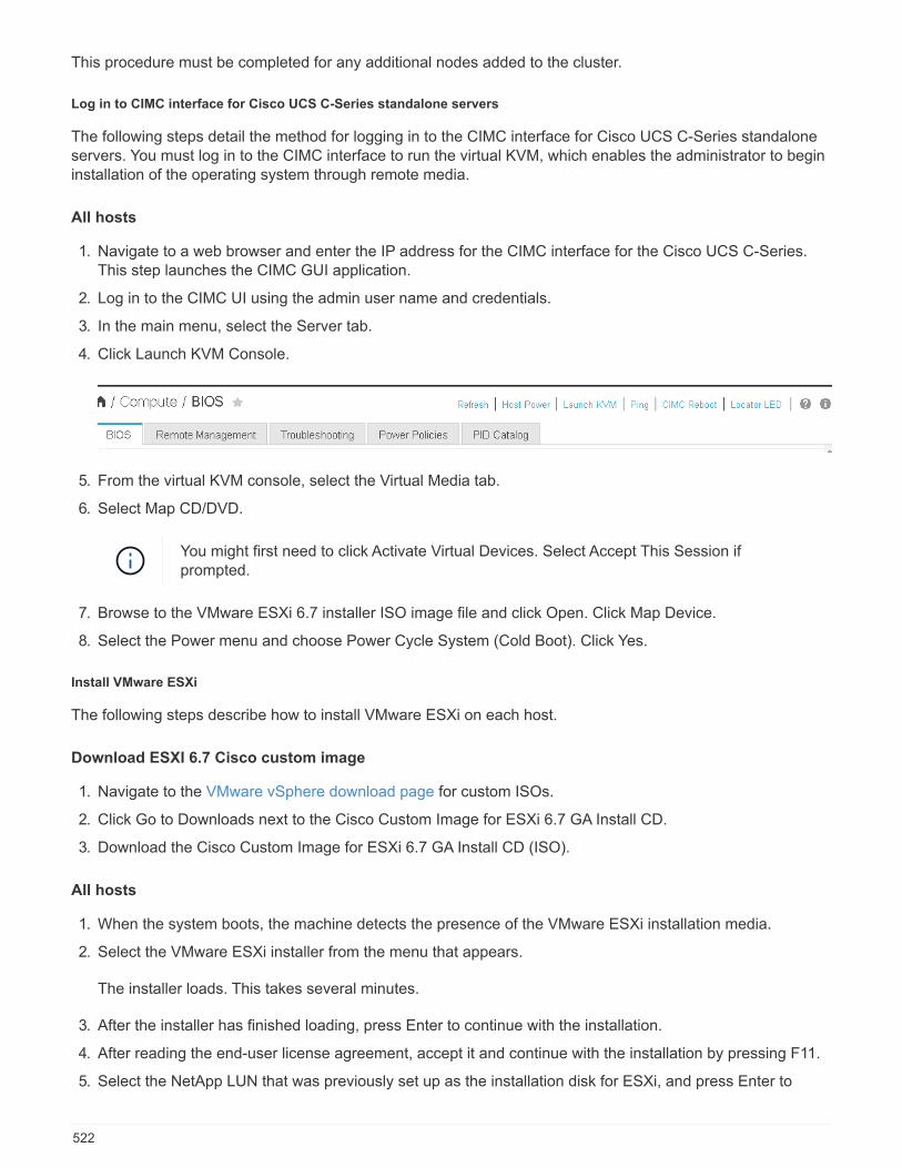
This procedure must be completed for any additional nodes added to the cluster.
Log in to CIMC interface for Cisco UCS C-Series standalone servers
The following steps detail the method for logging in to the CIMC interface for Cisco UCS C-Series standaloneservers. You must log in to the CIMC interface to run the virtual KVM, which enables the administrator to begininstallation of the operating system through remote media.
All hosts
1. Navigate to a web browser and enter the IP address for the CIMC interface for the Cisco UCS C-Series.This step launches the CIMC GUI application.
2. Log in to the CIMC UI using the admin user name and credentials.
3. In the main menu, select the Server tab.
4. Click Launch KVM Console.
5. From the virtual KVM console, select the Virtual Media tab.
6. Select Map CD/DVD.
You might first need to click Activate Virtual Devices. Select Accept This Session ifprompted.
7. Browse to the VMware ESXi 6.7 installer ISO image file and click Open. Click Map Device.
8. Select the Power menu and choose Power Cycle System (Cold Boot). Click Yes.
Install VMware ESXi
The following steps describe how to install VMware ESXi on each host.
Download ESXI 6.7 Cisco custom image
1. Navigate to the VMware vSphere download page for custom ISOs.
2. Click Go to Downloads next to the Cisco Custom Image for ESXi 6.7 GA Install CD.
3. Download the Cisco Custom Image for ESXi 6.7 GA Install CD (ISO).
All hosts
1. When the system boots, the machine detects the presence of the VMware ESXi installation media.
2. Select the VMware ESXi installer from the menu that appears.
The installer loads. This takes several minutes.
3. After the installer has finished loading, press Enter to continue with the installation.
4. After reading the end-user license agreement, accept it and continue with the installation by pressing F11.
5. Select the NetApp LUN that was previously set up as the installation disk for ESXi, and press Enter to
522

continue with the installation.
6. Select the appropriate keyboard layout and press Enter.
7. Enter and confirm the root password and press Enter.
8. The installer warns you that existing partitions are removed on the volume. Continue with the installation bypressing F11. The server reboots after the installation of ESXi.
Set up VMware ESXi host management networking
The following steps describe how to add the management network for each VMware ESXi host.
All hosts
1. After the server has finished rebooting, enter the option to customize the system by pressing F2.
2. Log in with root as the login name and the root password previously entered during the installation process.
3. Select the Configure Management Network option.
4. Select Network Adapters and press Enter.
5. Select the desired ports for vSwitch0. Press Enter.
Select the ports that correspond to eth0 and eth1 in CIMC.
523
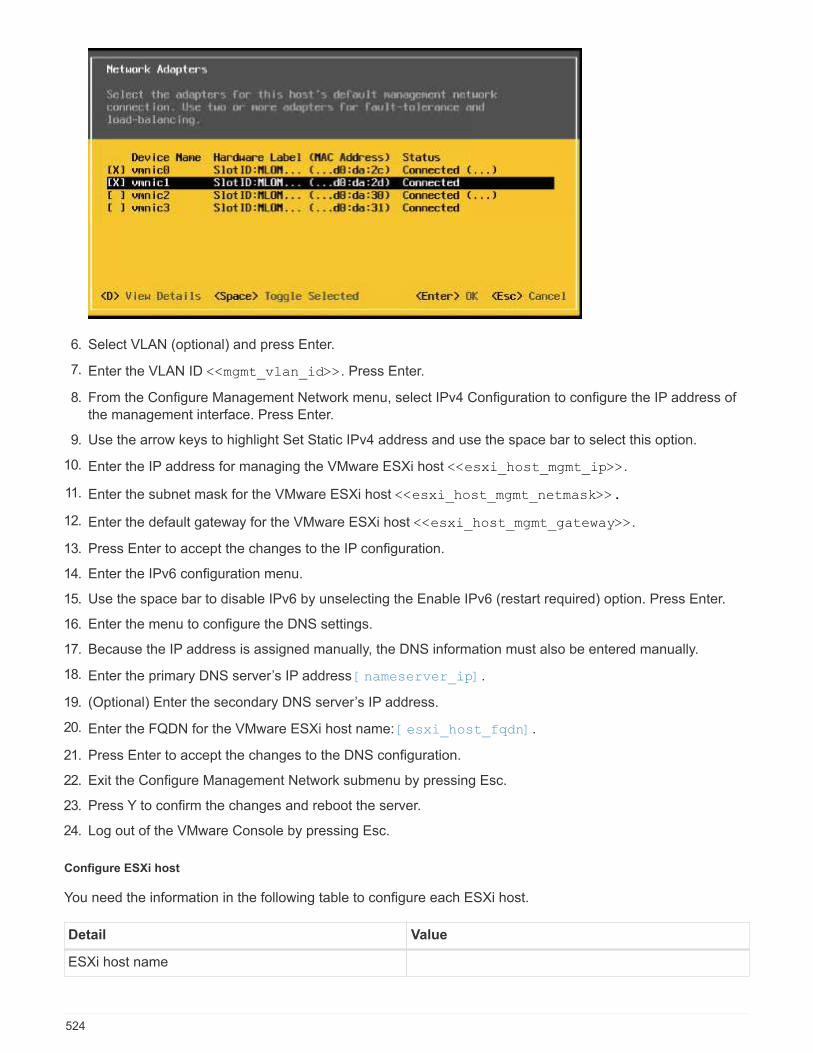
6. Select VLAN (optional) and press Enter.
7. Enter the VLAN ID <<mgmt_vlan_id>>. Press Enter.
8. From the Configure Management Network menu, select IPv4 Configuration to configure the IP address ofthe management interface. Press Enter.
9. Use the arrow keys to highlight Set Static IPv4 address and use the space bar to select this option.
10. Enter the IP address for managing the VMware ESXi host <<esxi_host_mgmt_ip>>.
11. Enter the subnet mask for the VMware ESXi host <<esxi_host_mgmt_netmask>>.
12. Enter the default gateway for the VMware ESXi host <<esxi_host_mgmt_gateway>>.
13. Press Enter to accept the changes to the IP configuration.
14. Enter the IPv6 configuration menu.
15. Use the space bar to disable IPv6 by unselecting the Enable IPv6 (restart required) option. Press Enter.
16. Enter the menu to configure the DNS settings.
17. Because the IP address is assigned manually, the DNS information must also be entered manually.
18. Enter the primary DNS server’s IP address [nameserver_ip].
19. (Optional) Enter the secondary DNS server’s IP address.
20. Enter the FQDN for the VMware ESXi host name: [esxi_host_fqdn].
21. Press Enter to accept the changes to the DNS configuration.
22. Exit the Configure Management Network submenu by pressing Esc.
23. Press Y to confirm the changes and reboot the server.
24. Log out of the VMware Console by pressing Esc.
Configure ESXi host
You need the information in the following table to configure each ESXi host.
Detail Value
ESXi host name
524
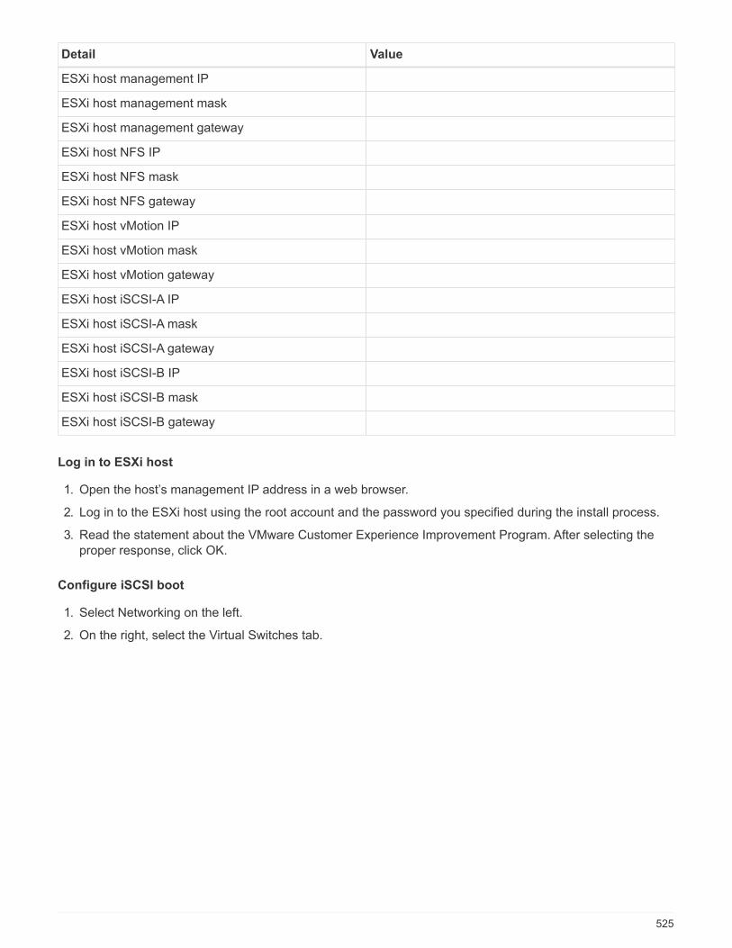
Detail Value
ESXi host management IP
ESXi host management mask
ESXi host management gateway
ESXi host NFS IP
ESXi host NFS mask
ESXi host NFS gateway
ESXi host vMotion IP
ESXi host vMotion mask
ESXi host vMotion gateway
ESXi host iSCSI-A IP
ESXi host iSCSI-A mask
ESXi host iSCSI-A gateway
ESXi host iSCSI-B IP
ESXi host iSCSI-B mask
ESXi host iSCSI-B gateway
Log in to ESXi host
1. Open the host’s management IP address in a web browser.
2. Log in to the ESXi host using the root account and the password you specified during the install process.
3. Read the statement about the VMware Customer Experience Improvement Program. After selecting theproper response, click OK.
Configure iSCSI boot
1. Select Networking on the left.
2. On the right, select the Virtual Switches tab.
525
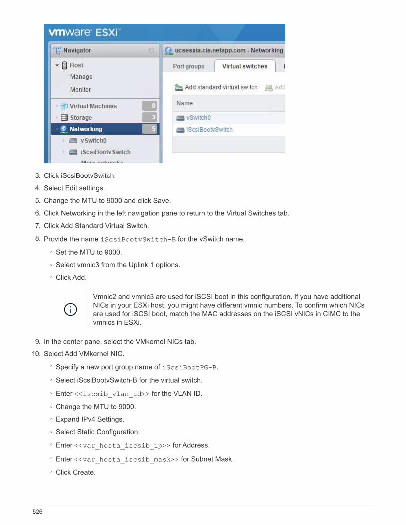
3. Click iScsiBootvSwitch.
4. Select Edit settings.
5. Change the MTU to 9000 and click Save.
6. Click Networking in the left navigation pane to return to the Virtual Switches tab.
7. Click Add Standard Virtual Switch.
8. Provide the name iScsiBootvSwitch-B for the vSwitch name.
◦ Set the MTU to 9000.
◦ Select vmnic3 from the Uplink 1 options.
◦ Click Add.
Vmnic2 and vmnic3 are used for iSCSI boot in this configuration. If you have additionalNICs in your ESXi host, you might have different vmnic numbers. To confirm which NICsare used for iSCSI boot, match the MAC addresses on the iSCSI vNICs in CIMC to thevmnics in ESXi.
9. In the center pane, select the VMkernel NICs tab.
10. Select Add VMkernel NIC.
◦ Specify a new port group name of iScsiBootPG-B.
◦ Select iScsiBootvSwitch-B for the virtual switch.
◦ Enter <<iscsib_vlan_id>> for the VLAN ID.
◦ Change the MTU to 9000.
◦ Expand IPv4 Settings.
◦ Select Static Configuration.
◦ Enter <<var_hosta_iscsib_ip>> for Address.
◦ Enter <<var_hosta_iscsib_mask>> for Subnet Mask.
◦ Click Create.
526
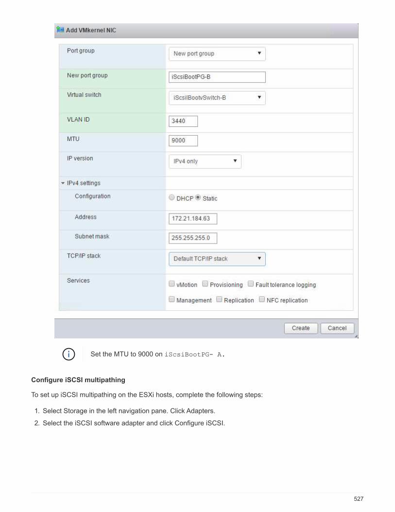
Set the MTU to 9000 on iScsiBootPG- A.
Configure iSCSI multipathing
To set up iSCSI multipathing on the ESXi hosts, complete the following steps:
1. Select Storage in the left navigation pane. Click Adapters.
2. Select the iSCSI software adapter and click Configure iSCSI.
527

3. Under Dynamic Targets, click Add Dynamic Target.
528
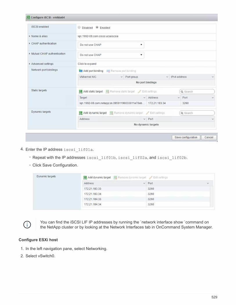
4. Enter the IP address iscsi_lif01a.
◦ Repeat with the IP addresses iscsi_lif01b, iscsi_lif02a, and iscsi_lif02b.
◦ Click Save Configuration.
You can find the iSCSI LIF IP addresses by running the `network interface show `command onthe NetApp cluster or by looking at the Network Interfaces tab in OnCommand System Manager.
Configure ESXi host
1. In the left navigation pane, select Networking.
2. Select vSwitch0.
529

3. Select Edit Settings.
4. Change the MTU to 9000.
5. Expand NIC Teaming and verify that both vmnic0 and vmnic1 are set to active.
Configure port groups and VMkernel NICs
1. In the left navigation pane, select Networking.
2. Right-click the Port Groups tab.
3. Right-click VM Network and select Edit. Change the VLAN ID to <<var_vm_traffic_vlan>>.
4. Click Add Port Group.
◦ Name the port group MGMT-Network.
◦ Enter <<mgmt_vlan>> for the VLAN ID.
◦ Make sure that vSwitch0 is selected.
◦ Click Add.
530

5. Click the VMkernel NICs tab.
6. Select Add VMkernel NIC.
◦ Select New Port Group.
◦ Name the port group NFS-Network.
◦ Enter <<nfs_vlan_id>> for the VLAN ID.
◦ Change the MTU to 9000.
◦ Expand IPv4 Settings.
◦ Select Static Configuration.
◦ Enter <<var_hosta_nfs_ip>> for Address.
◦ Enter <<var_hosta_nfs_mask>> for Subnet Mask.
◦ Click Create.
531
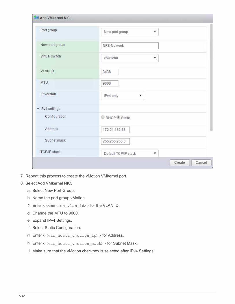
7. Repeat this process to create the vMotion VMkernel port.
8. Select Add VMkernel NIC.
a. Select New Port Group.
b. Name the port group vMotion.
c. Enter <<vmotion_vlan_id>> for the VLAN ID.
d. Change the MTU to 9000.
e. Expand IPv4 Settings.
f. Select Static Configuration.
g. Enter <<var_hosta_vmotion_ip>> for Address.
h. Enter <<var_hosta_vmotion_mask>> for Subnet Mask.
i. Make sure that the vMotion checkbox is selected after IPv4 Settings.
532
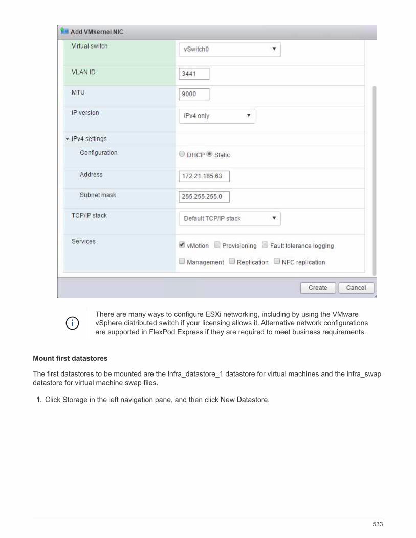
There are many ways to configure ESXi networking, including by using the VMwarevSphere distributed switch if your licensing allows it. Alternative network configurationsare supported in FlexPod Express if they are required to meet business requirements.
Mount first datastores
The first datastores to be mounted are the infra_datastore_1 datastore for virtual machines and the infra_swapdatastore for virtual machine swap files.
1. Click Storage in the left navigation pane, and then click New Datastore.
533

2. Select Mount NFS Datastore.
3. Next, enter the following information in the Provide NFS Mount Details page:
◦ Name: infra_datastore_1
◦ NFS server: <<var_nodea_nfs_lif>>
◦ Share: /infra_datastore_1
◦ Make sure that NFS 3 is selected.
4. Click Finish. You can see the task completing in the Recent Tasks pane.
5. Repeat this process to mount the infra_swap datastore:
◦ Name: infra_swap
◦ NFS server: <<var_nodea_nfs_lif>>
◦ Share: /infra_swap
534
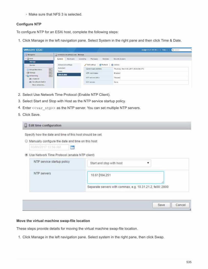
◦ Make sure that NFS 3 is selected.
Configure NTP
To configure NTP for an ESXi host, complete the following steps:
1. Click Manage in the left navigation pane. Select System in the right pane and then click Time & Date.
2. Select Use Network Time Protocol (Enable NTP Client).
3. Select Start and Stop with Host as the NTP service startup policy.
4. Enter <<var_ntp>> as the NTP server. You can set multiple NTP servers.
5. Click Save.
Move the virtual machine swap-file location
These steps provide details for moving the virtual machine swap-file location.
1. Click Manage in the left navigation pane. Select system in the right pane, then click Swap.
535
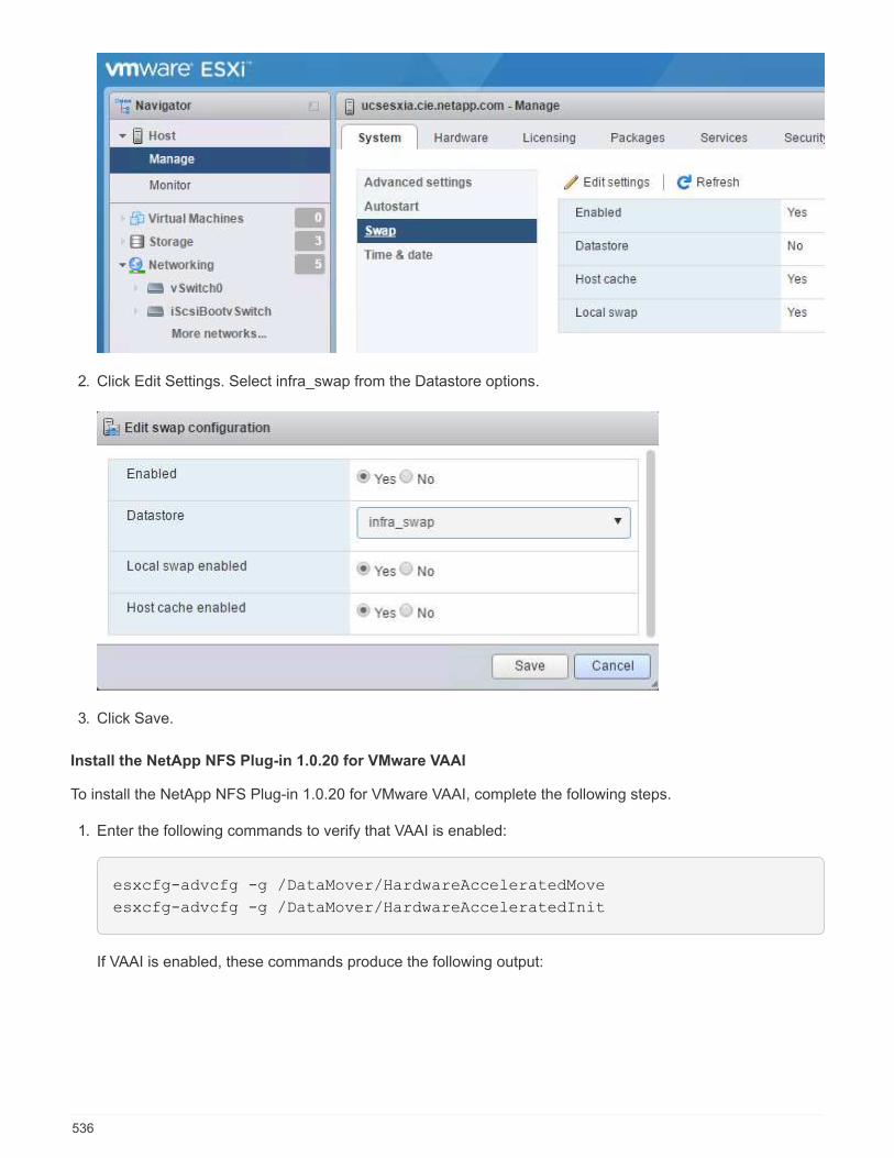
2. Click Edit Settings. Select infra_swap from the Datastore options.
3. Click Save.
Install the NetApp NFS Plug-in 1.0.20 for VMware VAAI
To install the NetApp NFS Plug-in 1.0.20 for VMware VAAI, complete the following steps.
1. Enter the following commands to verify that VAAI is enabled:
esxcfg-advcfg -g /DataMover/HardwareAcceleratedMove
esxcfg-advcfg -g /DataMover/HardwareAcceleratedInit
If VAAI is enabled, these commands produce the following output:
536
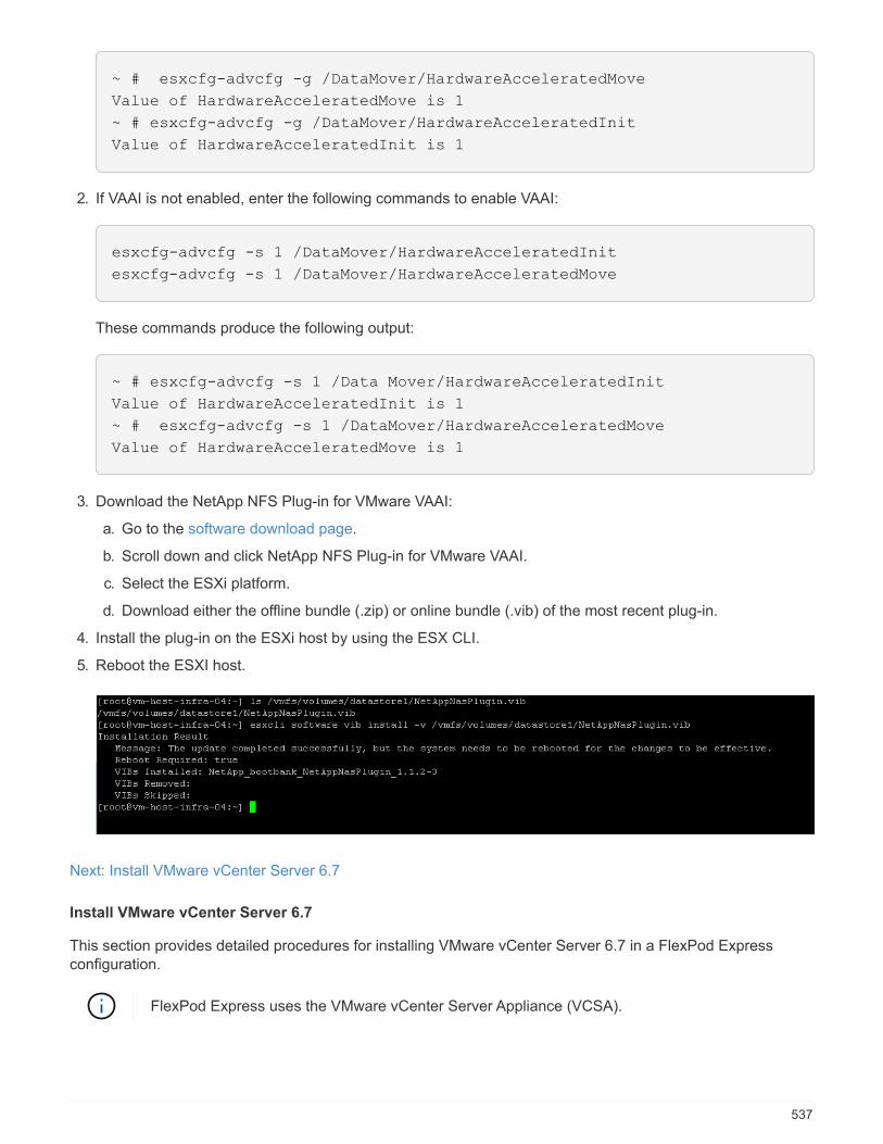
~ # esxcfg-advcfg -g /DataMover/HardwareAcceleratedMove
Value of HardwareAcceleratedMove is 1
~ # esxcfg-advcfg -g /DataMover/HardwareAcceleratedInit
Value of HardwareAcceleratedInit is 1
2. If VAAI is not enabled, enter the following commands to enable VAAI:
esxcfg-advcfg -s 1 /DataMover/HardwareAcceleratedInit
esxcfg-advcfg -s 1 /DataMover/HardwareAcceleratedMove
These commands produce the following output:
~ # esxcfg-advcfg -s 1 /Data Mover/HardwareAcceleratedInit
Value of HardwareAcceleratedInit is 1
~ # esxcfg-advcfg -s 1 /DataMover/HardwareAcceleratedMove
Value of HardwareAcceleratedMove is 1
3. Download the NetApp NFS Plug-in for VMware VAAI:
a. Go to the software download page.
b. Scroll down and click NetApp NFS Plug-in for VMware VAAI.
c. Select the ESXi platform.
d. Download either the offline bundle (.zip) or online bundle (.vib) of the most recent plug-in.
4. Install the plug-in on the ESXi host by using the ESX CLI.
5. Reboot the ESXI host.
Next: Install VMware vCenter Server 6.7
Install VMware vCenter Server 6.7
This section provides detailed procedures for installing VMware vCenter Server 6.7 in a FlexPod Expressconfiguration.
FlexPod Express uses the VMware vCenter Server Appliance (VCSA).
537
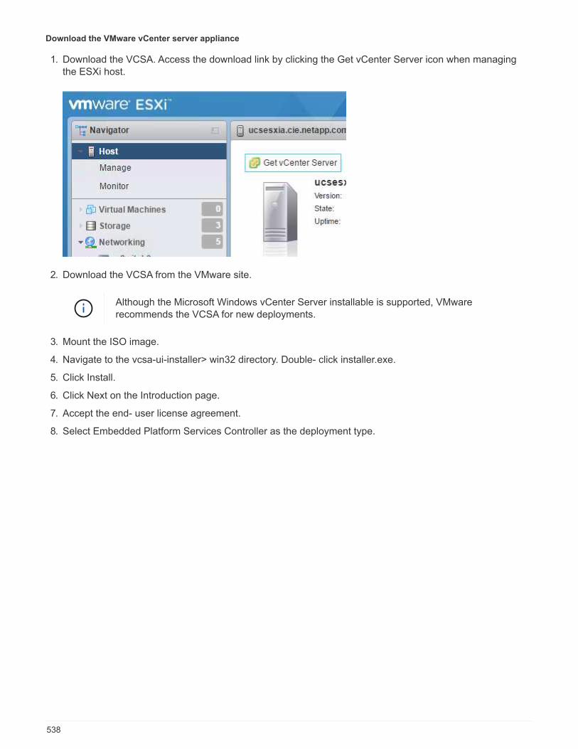
Download the VMware vCenter server appliance
1. Download the VCSA. Access the download link by clicking the Get vCenter Server icon when managingthe ESXi host.
2. Download the VCSA from the VMware site.
Although the Microsoft Windows vCenter Server installable is supported, VMwarerecommends the VCSA for new deployments.
3. Mount the ISO image.
4. Navigate to the vcsa-ui-installer> win32 directory. Double- click installer.exe.
5. Click Install.
6. Click Next on the Introduction page.
7. Accept the end- user license agreement.
8. Select Embedded Platform Services Controller as the deployment type.
538

If required, the External Platform Services Controller deployment is also supported as part ofthe FlexPod Express solution.
9. In the Appliance Deployment Target, enter the IP address of an ESXi host you have deployed, and the rootuser name and root password.
539

10. Set the appliance VM by entering VCSA as the VM name and the root password you would like to use forthe VCSA.
540

11. Select the deployment size that best fits your environment. Click Next.
541

12. Select the infra_datastore_1 datastore. Click Next.
13. Enter the following information in the Configure network settings page and click Next.
a. Select MGMT-Network for Network.
b. Enter the FQDN or IP to be used for the VCSA.
c. Enter the IP address to be used.
d. Enter the subnet mask to be used.
e. Enter the default gateway.
f. Enter the DNS server.
14. On the Ready to Complete Stage 1 page, verify that the settings you have entered are correct. Click Finish.
542

The VCSA installs now. This process takes several minutes.
15. After stage 1 completes, a message appears stating that it has completed. Click Continue to begin stage 2configuration.
16. On the Stage 2 Introduction page, click Next.
543
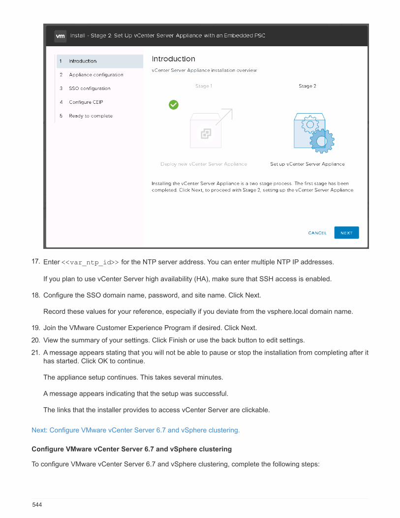
17. Enter <<var_ntp_id>> for the NTP server address. You can enter multiple NTP IP addresses.
If you plan to use vCenter Server high availability (HA), make sure that SSH access is enabled.
18. Configure the SSO domain name, password, and site name. Click Next.
Record these values for your reference, especially if you deviate from the vsphere.local domain name.
19. Join the VMware Customer Experience Program if desired. Click Next.
20. View the summary of your settings. Click Finish or use the back button to edit settings.
21. A message appears stating that you will not be able to pause or stop the installation from completing after ithas started. Click OK to continue.
The appliance setup continues. This takes several minutes.
A message appears indicating that the setup was successful.
The links that the installer provides to access vCenter Server are clickable.
Next: Configure VMware vCenter Server 6.7 and vSphere clustering.
Configure VMware vCenter Server 6.7 and vSphere clustering
To configure VMware vCenter Server 6.7 and vSphere clustering, complete the following steps:
544
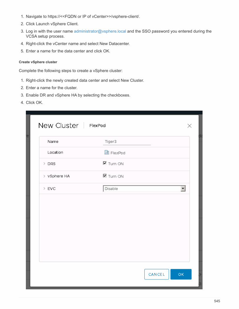
1. Navigate to https://<<FQDN or IP of vCenter>>/vsphere-client/.
2. Click Launch vSphere Client.
3. Log in with the user name [email protected] and the SSO password you entered during theVCSA setup process.
4. Right-click the vCenter name and select New Datacenter.
5. Enter a name for the data center and click OK.
Create vSphere cluster
Complete the following steps to create a vSphere cluster:
1. Right-click the newly created data center and select New Cluster.
2. Enter a name for the cluster.
3. Enable DR and vSphere HA by selecting the checkboxes.
4. Click OK.
545
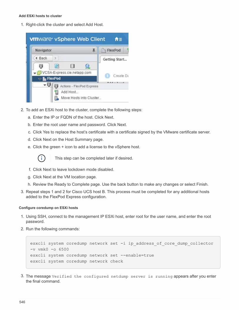
Add ESXi hosts to cluster
1. Right-click the cluster and select Add Host.
2. To add an ESXi host to the cluster, complete the following steps:
a. Enter the IP or FQDN of the host. Click Next.
b. Enter the root user name and password. Click Next.
c. Click Yes to replace the host’s certificate with a certificate signed by the VMware certificate server.
d. Click Next on the Host Summary page.
e. Click the green + icon to add a license to the vSphere host.
This step can be completed later if desired.
f. Click Next to leave lockdown mode disabled.
g. Click Next at the VM location page.
h. Review the Ready to Complete page. Use the back button to make any changes or select Finish.
3. Repeat steps 1 and 2 for Cisco UCS host B. This process must be completed for any additional hostsadded to the FlexPod Express configuration.
Configure coredump on ESXi hosts
1. Using SSH, connect to the management IP ESXi host, enter root for the user name, and enter the rootpassword.
2. Run the following commands:
esxcli system coredump network set -i ip_address_of_core_dump_collector
-v vmk0 -o 6500
esxcli system coredump network set --enable=true
esxcli system coredump network check
3. The message Verified the configured netdump server is running appears after you enterthe final command.
546
This process must be completed for any additional hosts added to FlexPod Express.
Conclusion
FlexPod Express provides a simple and effective solution by providing a validated design that uses industry-leading components. By scaling through the addition of additional components, FlexPod Express can betailored for specific business needs. FlexPod Express was designed by keeping in mind small to midsizebusinesses, ROBOs, and other businesses that require dedicated solutions.
Where to find additional information
To learn more about the information described in this document, refer to the following documents and/orwebsites:
• NetApp product documentation
http://docs.netapp.com
• FlexPod Express with VMware vSphere 6.7 and NetApp AFF A220 Design Guide
https://www.netapp.com/us/media/nva-1125-design.pdf
FlexPod Express with VMware vSphere 6.7U1 and NetAppAFF A220 with Direct-Attached IP-Based Storage DesignGuide
NVA-1130-DESIGN: FlexPod Express with VMware vSphere 6.7U1 and NetApp AFFA220 with Direct-Attached IP-Based Storage
Sree Lakshmi Lanka, NetApp
In partnership with:
Industry trends indicate a vast data center transformation toward shared infrastructure and cloud computing. Inaddition, organizations seek a simple and effective solution for remote and branch offices, leveraging thetechnology that they are familiar with in their data center.
FlexPod Express is a predesigned, best practice architecture that is built on the Cisco Unified ComputingSystem (Cisco UCS), the Cisco Nexus family of switches, and NetApp AFF. The components in FlexPodExpress are like their FlexPod Datacenter counterparts, enabling management synergies across the completeIT infrastructure environment on a smaller scale. FlexPod Datacenter and FlexPod Express are optimalplatforms for virtualization and for bare-metal operating systems and enterprise workloads.
FlexPod Datacenter and FlexPod Express deliver a baseline configuration and have the versatility to be sizedand optimized to accommodate many different use cases and requirements. Existing FlexPod Datacentercustomers can manage their FlexPod Express by using the tools that they are accustomed to, and newFlexPod Express customers can easily adapt to managing a FlexPod Datacenter as their environment grows.
547
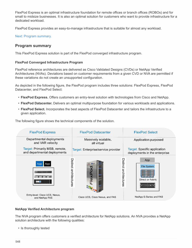
FlexPod Express is an optimal infrastructure foundation for remote offices or branch offices (ROBOs) and forsmall to midsize businesses. It is also an optimal solution for customers who want to provide infrastructure for adedicated workload.
FlexPod Express provides an easy-to-manage infrastructure that is suitable for almost any workload.
Next: Program summary.
Program summary
This FlexPod Express solution is part of the FlexPod converged infrastructure program.
FlexPod Converged Infrastructure Program
FlexPod reference architectures are delivered as Cisco Validated Designs (CVDs) or NetApp VerifiedArchitectures (NVAs). Deviations based on customer requirements from a given CVD or NVA are permitted ifthese variations do not create an unsupported configuration.
As depicted in the following figure, the FlexPod program includes three solutions: FlexPod Express, FlexPodDatacenter, and FlexPod Select:
• FlexPod Express. Offers customers an entry-level solution with technologies from Cisco and NetApp.
• FlexPod Datacenter. Delivers an optimal multipurpose foundation for various workloads and applications.
• FlexPod Select. Incorporates the best aspects of FlexPod Datacenter and tailors the infrastructure to agiven application.
The following figure shows the technical components of the solution.
NetApp Verified Architecture program
The NVA program offers customers a verified architecture for NetApp solutions. An NVA provides a NetAppsolution architecture with the following qualities:
• Is thoroughly tested
548
• Is prescriptive in nature
• Minimizes deployment risks
• Accelerates time to market
This guide details the design of FlexPod Express with direct-attached NetApp storage. The following sectionslist the components used in this solution design.
Hardware components
• NetApp AFF A220 or FAS 2750/2720
• Cisco UCS Mini
• Cisco UCS B200 M5
• Cisco UCS VIC 1440/1480
• Cisco Nexus 3000 Series Switches
Software components
• NetApp ONTAP 9.5
• VMware vSphere 6.7U1
• Cisco UCS Manager 4.0 (1b)
• Cisco NXOS firmware 7.0(3)I6(1)
Next: Solution overview.
Solution overview
FlexPod Express is designed to run mixed virtualization workloads. It is targeted for remote and branch officesand for small to midsize businesses. It is also optimal for larger businesses that want to implement a dedicatedsolution for a purpose. The primary driver of the new FlexPod Express solution is to add new technologiessuch as ONTAP 9.5, FAS27xx/AFF220, VMware vSphere 6.7U1 to FlexPod Express.
The following figure shows the hardware components that are included in the FlexPod Express solution.
549

Target audience
This document is intended for people who want to take advantage of an infrastructure that is built to deliver ITefficiency and enable IT innovation. The audience for this document includes, but is not limited to, salesengineers, field consultants, professional services personnel, IT managers, partner engineers, and customers.
Solution technology
This solution uses the latest technologies from NetApp, Cisco, and VMware. It features NetApp AFF A220running ONTAP 9.5, dual Cisco Nexus 31108PCV switches, and Cisco UCS B200 M5 servers that run VMwarevSphere 6.7U1. This validated solution uses Direct Connect IP storage over 10GbE technology.
The following figure illustrates FlexPod Express with VMware vSphere 6.7U1 IP-Based Direct Connectarchitecture.
550
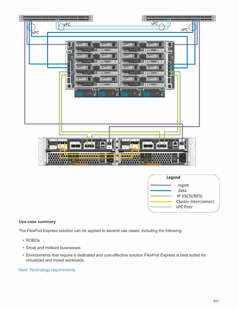
Use case summary
The FlexPod Express solution can be applied to several use cases, including the following:
• ROBOs
• Small and midsize businesses
• Environments that require a dedicated and cost-effective solution FlexPod Express is best suited forvirtualized and mixed workloads.
Next: Technology requirements.
551

Technology requirements
A FlexPod Express system requires a combination of hardware and software components. FlexPod Expressalso describes the hardware components that are required to add hypervisor nodes to the system in units oftwo.
Hardware requirements
Regardless of the hypervisor chosen, all FlexPod Express configurations use the same hardware. Therefore,even if business requirements change, either hypervisor can run on the same FlexPod Express hardware.
The following table lists the hardware components that are required for all FlexPod Express configurations.
Hardware Quantity
AFF A220 HA pair 1
Cisco UCS B200 M5 server 2
Cisco Nexus 31108PCV switch 2
Cisco UCS Virtual Interface Card (VIC) 1440 for theB200 M5 server
2
Cisco UCS Mini with two integrated UCS-FI-M-6324fabric interconnects
1
Software requirements
The following table lists the software components that are required to implement the architectures of theFlexPod Express solutions.
Software Version Details
Cisco UCS Manager 4.0(1b) For Cisco UCS fabric interconnectFI-6324UP
Cisco Blade software 4.0(1b) For Cisco UCS B200 M5 servers
Cisco nenic driver 1.0.25.0 For Cisco VIC 1440 interface cards
Cisco NX-OS 7.0(3)I6(1) For Cisco Nexus 31108PCVswitches
NetApp ONTAP 9.5 For AFF A220 controllers
The following table lists the software that is required for all VMware vSphere implementations on FlexPodExpress.
Software Version
VMware vCenter Server Appliance 6.7U1
VMware vSphere ESXi hypervisor 6.7U1
Next: Design choices.
552

Design choices
The following technologies were chosen during the process of architecting this design. Each technology servesa specific purpose in the FlexPod Express infrastructure solution.
NetApp AFF A220 or FAS27xx Series with ONTAP 9.5
The solution uses two of the newest NetApp products, NetApp FAS 2750 or FAS 2720 and AFF A220 systemswith ONTAP 9.5.
FAS2750/FAS2720 system
The NetApp FAS2700 series is designed to support more of your IT needs, the NetApp FAS2700 hybridstorage arrays offer more value than other systems in their class. The FAS2700 running NetApp ONTAPstorage software simplifies the task of managing growth and complexity by delivering high performance,providing leading integration with the cloud, supporting a broader range of workloads, and seamlessly scalingperformance and capacity.
For more information about the FAS2700 hardware system, see the FAS2700 Hybrid Storage System productpage.
AFF A220 system
The newly refreshed AFF A220 platform for small and medium enterprise environments delivers 30% moreperformance than its predecessor to continue NetApp leadership in this segment.
NetApp AFF systems help you meet your enterprise storage requirements with industry’s highest performance,superior flexibility, and best-in-class data management and cloud integration. Combined with the industry’s firstend-to-end NVMe technologies and NetApp ONTAP data management software, AFF systems accelerate,manage, and protect your business-critical data. With an AFF system, you can make an easy and risk-freetransition to flash for your digital transformation.
For more information about the AFF A220 hardware system, see the NetApp AFF Datasheet.
553
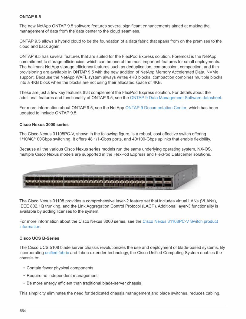
ONTAP 9.5
The new NetApp ONTAP 9.5 software features several significant enhancements aimed at making themanagement of data from the data center to the cloud seamless.
ONTAP 9.5 allows a hybrid cloud to be the foundation of a data fabric that spans from on the premises to thecloud and back again.
ONTAP 9.5 has several features that are suited for the FlexPod Express solution. Foremost is the NetAppcommitment to storage efficiencies, which can be one of the most important features for small deployments.The hallmark NetApp storage efficiency features such as deduplication, compression, compaction, and thinprovisioning are available in ONTAP 9.5 with the new addition of NetApp Memory Accelerated Data, NVMesupport. Because the NetApp WAFL system always writes 4KB blocks, compaction combines multiple blocksinto a 4KB block when the blocks are not using their allocated space of 4KB.
These are just a few key features that complement the FlexPod Express solution. For details about theadditional features and functionality of ONTAP 9.5, see the ONTAP 9 Data Management Software datasheet.
For more information about ONTAP 9.5, see the NetApp ONTAP 9 Documentation Center, which has beenupdated to include ONTAP 9.5.
Cisco Nexus 3000 series
The Cisco Nexus 31108PC-V, shown in the following figure, is a robust, cost effective switch offering1/10/40/100Gbps switching. It offers 48 1/1-Gbps ports, and 40/100-Gbps uplinks that enable flexibility.
Because all the various Cisco Nexus series models run the same underlying operating system, NX-OS,multiple Cisco Nexus models are supported in the FlexPod Express and FlexPod Datacenter solutions.
The Cisco Nexus 31108 provides a comprehensive layer-2 feature set that includes virtual LANs (VLANs),IEEE 802.1Q trunking, and the Link Aggregation Control Protocol (LACP). Additional layer-3 functionality isavailable by adding licenses to the system.
For more information about the Cisco Nexus 3000 series, see the Cisco Nexus 31108PC-V Switch productinformation.
Cisco UCS B-Series
The Cisco UCS 5108 blade server chassis revolutionizes the use and deployment of blade-based systems. Byincorporating unified fabric and fabric-extender technology, the Cisco Unified Computing System enables thechassis to:
• Contain fewer physical components
• Require no independent management
• Be more energy efficient than traditional blade-server chassis
This simplicity eliminates the need for dedicated chassis management and blade switches, reduces cabling,
554

and allows scalability to 20 chassis without adding complexity. The Cisco UCS 5108 blade server chassis is acritical component for delivering simplicity and IT responsiveness for the data center as part of the CiscoUnified Computing System.
The Cisco UCS B-Series B200M5 server, shown in the following figure, was chosen for FlexPod Expressbecause its many configuration options allow it to be tailored for the specific requirements of FlexPod Expressdeployment.
The enterprise-class Cisco UCS B200 M5 blade server extends the capabilities of the Cisco UCS portfolio in ahalf-width blade form factor. The Cisco UCS B200 M5 blade server harnesses the power of the latest IntelXeon processor scalable family CPUs with up to 3072GB of RAM (using 128GB DIMMs), two solid-state drives(SSDs) or HDDs, and up to 80Gbps throughput connectivity.
For more information about Cisco UCS B200 M5 blade server, see Cisco UCS B200 M5 Blade Server SpecSheet.
Cisco UCS Virtual Interface Card 1440/1480
The Cisco UCS VIC 1440 is a dual-port 40Gbps or dual 4x10Gbps Ethernet/FCoE capable modular LAN onmotherboard (mLOM) designed exclusively for the M5 generation of Cisco UCS B-Series blade servers. Whenused with an optional port expander, the Cisco UCS VIC 1440 capabilities are enabled for two 40GbpsEthernet ports. The Cisco UCS VIC 1440 enables a policy-based, stateless, agile server infrastructure that canpresent to the host PCIe standards-compliant interfaces that can be dynamically configured as either NICs orHBAs.
The Cisco UCS VIC 1480, shown in the following figure, is similar to the VIC 1440 except that it is mezzaninecard.
555
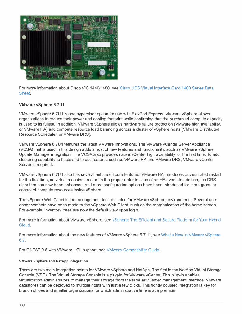
For more information about Cisco VIC 1440/1480, see Cisco UCS Virtual Interface Card 1400 Series DataSheet.
VMware vSphere 6.7U1
VMware vSphere 6.7U1 is one hypervisor option for use with FlexPod Express. VMware vSphere allowsorganizations to reduce their power and cooling footprint while confirming that the purchased compute capacityis used to its fullest. In addition, VMware vSphere allows hardware failure protection (VMware high availability,or VMware HA) and compute resource load balancing across a cluster of vSphere hosts (VMware DistributedResource Scheduler, or VMware DRS).
VMware vSphere 6.7U1 features the latest VMware innovations. The VMware vCenter Server Appliance(VCSA) that is used in this design adds a host of new features and functionality, such as VMware vSphereUpdate Manager integration. The VCSA also provides native vCenter high availability for the first time. To addclustering capability to hosts and to use features such as VMware HA and VMware DRS, VMware vCenterServer is required.
VMware vSphere 6.7U1 also has several enhanced core features. VMware HA introduces orchestrated restartfor the first time, so virtual machines restart in the proper order in case of an HA event. In addition, the DRSalgorithm has now been enhanced, and more configuration options have been introduced for more granularcontrol of compute resources inside vSphere.
The vSphere Web Client is the management tool of choice for VMware vSphere environments. Several userenhancements have been made to the vSphere Web Client, such as the reorganization of the home screen.For example, inventory trees are now the default view upon login.
For more information about VMware vSphere, see vSphere: The Efficient and Secure Platform for Your HybridCloud.
For more information about the new features of VMware vSphere 6.7U1, see What’s New in VMware vSphere6.7.
For ONTAP 9.5 with VMware HCL support, see VMware Compatibility Guide.
VMware vSphere and NetApp integration
There are two main integration points for VMware vSphere and NetApp. The first is the NetApp Virtual StorageConsole (VSC). The Virtual Storage Console is a plug-in for VMware vCenter. This plug-in enablesvirtualization administrators to manage their storage from the familiar vCenter management interface. VMwaredatastores can be deployed to multiple hosts with just a few clicks. This tightly coupled integration is key forbranch offices and smaller organizations for which administrative time is at a premium.
556
The second integration is the NetApp NFS Plug-in for VMware VAAI. Although VAAI is supported natively byblock protocols, all storage arrays require a VAAI plug-in to provide the VAAI integration for NFS. Some NFSVAAI integrations include space reservation and copy offload. The VAAI plug-in can be installed by using VSC.
For more information about the NetApp VSC for VMware vSphere, see the NetApp Virtual InfrastructureManagement product page.
Next: Solution verification.
Solution verification
Cisco and NetApp designed and built FlexPod Express to serve as a premier infrastructure platform for theircustomers. Because it was designed by using industry-leading components, customers can trust FlexPodExpress as their infrastructure foundation. In keeping with the fundamental principles of the FlexPod program,the FlexPod Express architecture was thoroughly tested by Cisco and NetApp data center architects andengineers. From redundancy and availability to each individual feature, the entire FlexPod Express architectureis validated to instill confidence in our customers and to build trust in the design process.
The VMware vSphere 6.7U1 hypervisor was verified on FlexPod Express infrastructure components. Thisvalidation included iSCSI Direct Connect SAN Boot connection and NFS Direct Connect datastores using the10GbE connectivity option.
Next: Conclusion.
Conclusion
FlexPod Express provides a simple and effective solution by providing a validated design that uses industry-leading components. By scaling and by providing options for a hypervisor platform, FlexPod Express can betailored for specific business needs. FlexPod Express was designed with small to midsize businesses, ROBOs,and other businesses that require dedicated solutions in mind.
Next: Where to find additional information.
Where to find additional information
To learn more about the information that is described in this document, see the following documents andwebsites:
• NVA- 1131-DEPLOY: FlexPod Express with VMware vSphere 6.7UI and NetApp AFF A220 with DirectAttached IP-Based Storage NVA Deploy
https://www.netapp.com/us/media/nva-1131-deploy.pdf
• AFF and FAS Systems Documentation Center
http://docs.netapp.com/platstor/index.jsp
• ONTAP 9 Documentation Center
http://docs.netapp.com/ontap-9/index.jsp
• NetApp Product Documentation
https://docs.netapp.com
557
FlexPod Express with VMware vSphere 6.7U1 and NetAppAFF A220 with Direct-Attached IP-Based Storage
NVA-1131-DEPLOY: FlexPod Express with VMware vSphere 6.7U1 and NetApp AFFA220 with Direct-Attached IP-Based Storage
Sree Lakshmi Lanka, NetApp
Industry trends indicate a vast data center transformation toward shared infrastructure and cloud computing. Inaddition, organizations seek a simple and effective solution for remote and branch offices, leveraging thetechnology with which they are familiar in their data center.
FlexPod Express is a predesigned, best practice architecture that is built on the Cisco Unified ComputingSystem (Cisco UCS), the Cisco Nexus family of switches, and NetApp storage technologies. The componentsin a FlexPod Express system are like their FlexPod Datacenter counterparts, enabling management synergiesacross the complete IT infrastructure environment on a smaller scale. FlexPod Datacenter and FlexPodExpress are optimal platforms for virtualization and for bare-metal OSs and enterprise workloads.
FlexPod Datacenter and FlexPod Express deliver a baseline configuration and have the versatility to be sizedand optimized to accommodate many different use cases and requirements. Existing FlexPod Datacentercustomers can manage their FlexPod Express system with the tools to which they are accustomed. NewFlexPod Express customers can easily adapt to managing FlexPod Datacenter as their environment grows.
FlexPod Express is an optimal infrastructure foundation for remote offices and branch offices (ROBOs) and forsmall to midsize businesses. It is also an optimal solution for customers who want to provide infrastructure for adedicated workload.
FlexPod Express provides an easy-to-manage infrastructure that is suitable for almost any workload.
Solution Overview
This FlexPod Express solution is part of the FlexPod converged infrastructure program.
FlexPod Converged Infrastructure Program
FlexPod reference architectures are delivered as Cisco Validated Designs (CVDs) or NetApp VerifiedArchitectures (NVAs). Deviations based on customer requirements from a given CVD or NVA are permitted ifthese variations do not create an unsupported configuration.
As depicted in the figure below, the FlexPod program includes three solutions: FlexPod Express, FlexPodDatacenter, and FlexPod Select:
• FlexPod Express offers customers an entry-level solution with technologies from Cisco and NetApp.
• FlexPod Datacenter delivers an optimal multipurpose foundation for various workloads and applications.
• FlexPod Select incorporates the best aspects of FlexPod Datacenter and tailors the infrastructure to agiven application.
The following figure shows the technical components of the solution.
558
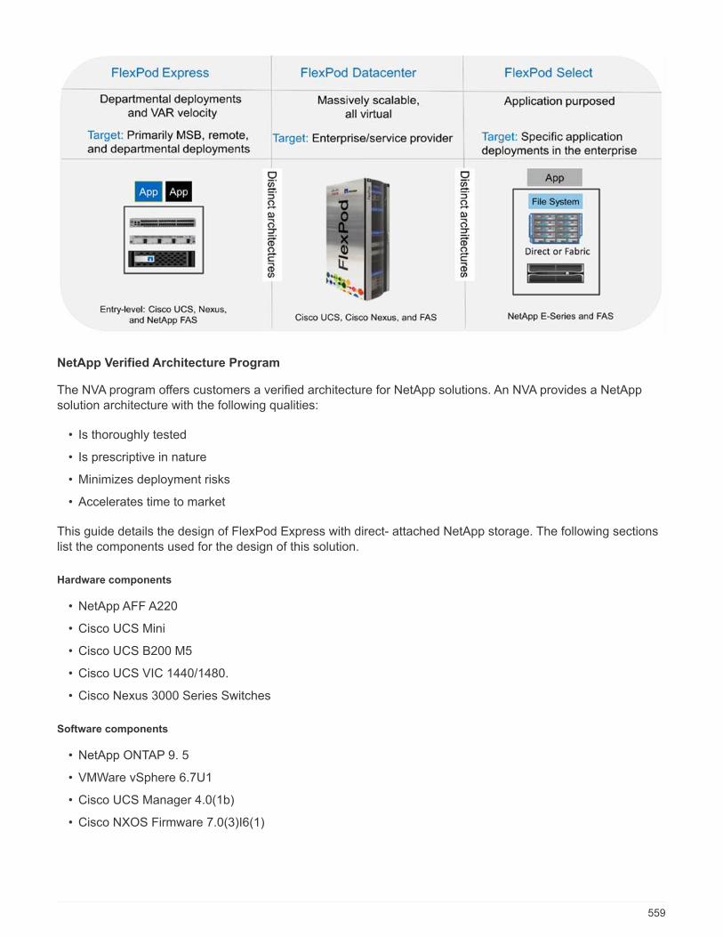
NetApp Verified Architecture Program
The NVA program offers customers a verified architecture for NetApp solutions. An NVA provides a NetAppsolution architecture with the following qualities:
• Is thoroughly tested
• Is prescriptive in nature
• Minimizes deployment risks
• Accelerates time to market
This guide details the design of FlexPod Express with direct- attached NetApp storage. The following sectionslist the components used for the design of this solution.
Hardware components
• NetApp AFF A220
• Cisco UCS Mini
• Cisco UCS B200 M5
• Cisco UCS VIC 1440/1480.
• Cisco Nexus 3000 Series Switches
Software components
• NetApp ONTAP 9. 5
• VMWare vSphere 6.7U1
• Cisco UCS Manager 4.0(1b)
• Cisco NXOS Firmware 7.0(3)I6(1)
559
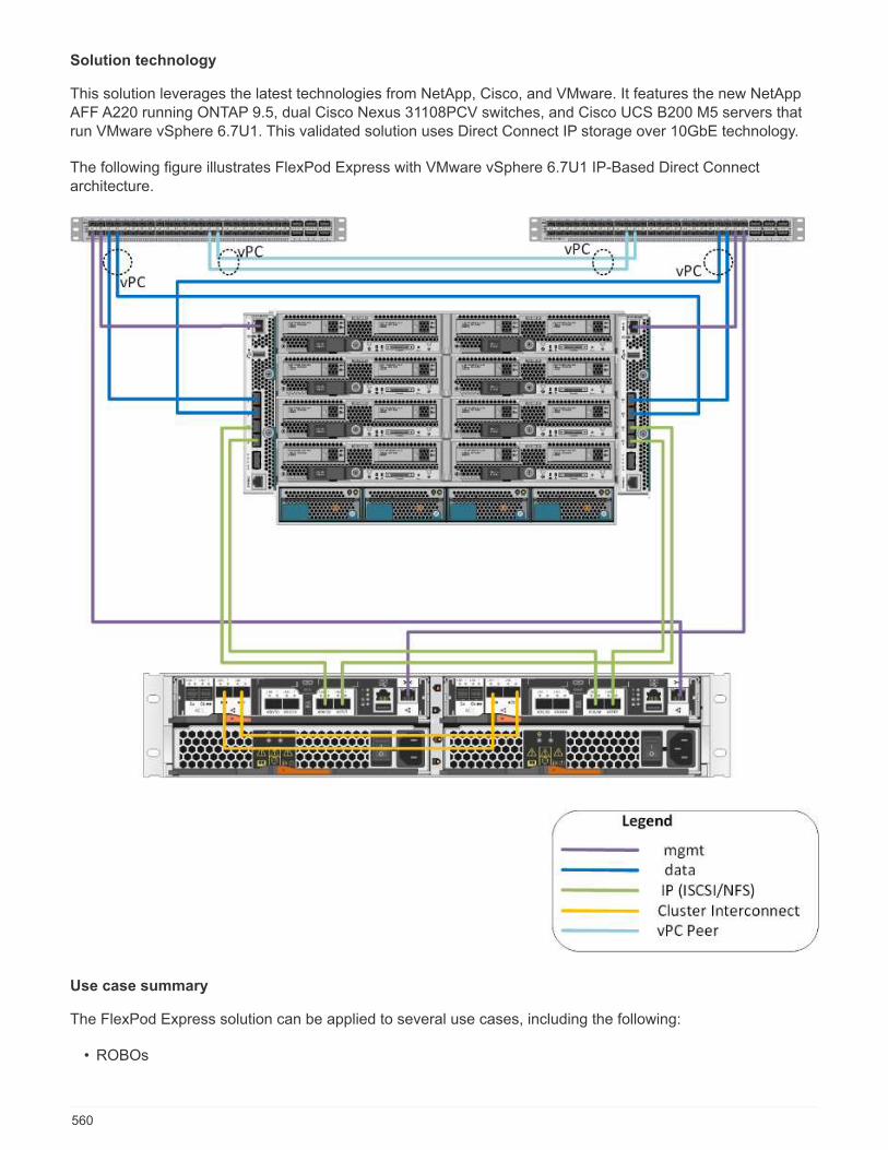
Solution technology
This solution leverages the latest technologies from NetApp, Cisco, and VMware. It features the new NetAppAFF A220 running ONTAP 9.5, dual Cisco Nexus 31108PCV switches, and Cisco UCS B200 M5 servers thatrun VMware vSphere 6.7U1. This validated solution uses Direct Connect IP storage over 10GbE technology.
The following figure illustrates FlexPod Express with VMware vSphere 6.7U1 IP-Based Direct Connectarchitecture.
Use case summary
The FlexPod Express solution can be applied to several use cases, including the following:
• ROBOs
560
• Small and midsize businesses
• Environments that require a dedicated and cost-effective solution
FlexPod Express is best suited for virtualized and mixed workloads.
Technology requirements
A FlexPod Express system requires a combination of hardware and software components. FlexPod Expressalso describes the hardware components that are required to add hypervisor nodes to the system in units oftwo.
Hardware requirements
Regardless of the hypervisor chosen, all FlexPod Express configurations use the same hardware. Therefore,even if business requirements change, either hypervisor can run on the same FlexPod Express hardware.
The following table lists the hardware components that are required for all FlexPod Express configurations.
Hardware Quantity
AFF A220 HA Pair 1
Cisco UCS B200 M5 server 2
Cisco Nexus 31108PCV switch 2
Cisco UCS Virtual Interface Card (VIC) 1440 for theCisco UCS B200 M5 server
2
Cisco UCS Mini with two Integrated UCS-FI-M-6324fabric interconnects
1
Software requirements
The following table lists the software components that are required to implement the architectures of theFlexPod Express solutions.
Software Version Details
Cisco UCS Manager 4.0(1b) For Cisco UCS Fabric InterconnectFI-6324UP
Cisco Blade software 4.0(1b) For Cisco UCS B200 M5 servers
Cisco nenic driver 1.0.25.0 For Cisco VIC 1440 interface cards
Cisco NX-OS 7.0(3)I6(1) For Cisco Nexus 31108PCVswitches
NetApp ONTAP 9.5 For AFF A220 controllers
The following table lists the software that is required for all VMware vSphere implementations on FlexPodExpress.
Software Version
VMware vCenter Server Appliance 6.7U1
561
Software Version
VMware vSphere ESXi hypervisor 6.7U1
FlexPod Express Cabling Information
The reference validation cabling is documented in the following tables.
The following table lists cabling information for Cisco Nexus switch 31108PCV A.
Local device Local port Remote device Remote port
Cisco Nexus switch31108PCV A
Eth1/1 NetApp AFF A220 storagecontroller A
e0M
Eth1/2 Cisco UCS-mini FI-A mgmt0
Eth1/3 Cisco UCS-mini FI-A Eth1/1
Eth 1/4 Cisco UCS-mini FI-B Eth1/1
Eth 1/13 Cisco NX 31108PCV B Eth 1/13
Eth 1/14 Cisco NX 31108PCV B Eth 1/14
The following table lists the cabling information for Cisco Nexus switch 31108PCV B.
Local device Local port Remote device Remote port
Cisco Nexus switch31108PCV B
Eth1/1 NetApp AFF A220 storagecontroller B
e0M
Eth1/2 Cisco UCS-mini FI-B mgmt0
Eth1/3 Cisco UCS-mini FI-A Eth1/2
Eth 1/4 Cisco UCS-mini FI-B Eth1/2
Eth 1/13 Cisco NX 31108PCV A Eth 1/13
Eth 1/14 Cisco NX 31108PCV A Eth 1/14
The following table lists cabling information for NetApp AFF A220 storage controller A.
Local device Local port Remote device Remote port
NetApp AFF A220 storagecontroller A
e0a NetApp AFF A220 storagecontroller B
e0a
e0b NetApp AFF A220 storagecontroller B
e0b
e0e Cisco UCS-mini FI-A Eth1/3
e0f Cisco UCS-mini FI-B Eth1/3
e0M Cisco NX 31108PCV A Eth1/1
The following table lists cabling information for NetApp AFF A220 storage controller B.
562
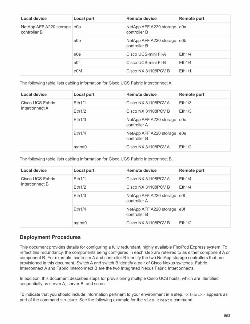
Local device Local port Remote device Remote port
NetApp AFF A220 storagecontroller B
e0a NetApp AFF A220 storagecontroller B
e0a
e0b NetApp AFF A220 storagecontroller B
e0b
e0e Cisco UCS-mini FI-A Eth1/4
e0f Cisco UCS-mini FI-B Eth1/4
e0M Cisco NX 31108PCV B Eth1/1
The following table lists cabling information for Cisco UCS Fabric Interconnect A.
Local device Local port Remote device Remote port
Cisco UCS FabricInterconnect A
Eth1/1 Cisco NX 31108PCV A Eth1/3
Eth1/2 Cisco NX 31108PCV B Eth1/3
Eth1/3 NetApp AFF A220 storagecontroller A
e0e
Eth1/4 NetApp AFF A220 storagecontroller B
e0e
mgmt0 Cisco NX 31108PCV A Eth1/2
The following table lists cabling information for Cisco UCS Fabric Interconnect B.
Local device Local port Remote device Remote port
Cisco UCS FabricInterconnect B
Eth1/1 Cisco NX 31108PCV A Eth1/4
Eth1/2 Cisco NX 31108PCV B Eth1/4
Eth1/3 NetApp AFF A220 storagecontroller A
e0f
Eth1/4 NetApp AFF A220 storagecontroller B
e0f
mgmt0 Cisco NX 31108PCV B Eth1/2
Deployment Procedures
This document provides details for configuring a fully redundant, highly available FlexPod Express system. Toreflect this redundancy, the components being configured in each step are referred to as either component A orcomponent B. For example, controller A and controller B identify the two NetApp storage controllers that areprovisioned in this document. Switch A and switch B identify a pair of Cisco Nexus switches. FabricInterconnect A and Fabric Interconnect B are the two Integrated Nexus Fabric Interconnects.
In addition, this document describes steps for provisioning multiple Cisco UCS hosts, which are identifiedsequentially as server A, server B, and so on.
To indicate that you should include information pertinent to your environment in a step, <<text>> appears as
part of the command structure. See the following example for the vlan create command:
563
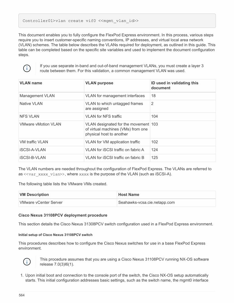
Controller01>vlan create vif0 <<mgmt_vlan_id>>
This document enables you to fully configure the FlexPod Express environment. In this process, various stepsrequire you to insert customer-specific naming conventions, IP addresses, and virtual local area network(VLAN) schemes. The table below describes the VLANs required for deployment, as outlined in this guide. Thistable can be completed based on the specific site variables and used to implement the document configurationsteps.
If you use separate in-band and out-of-band management VLANs, you must create a layer 3route between them. For this validation, a common management VLAN was used.
VLAN name VLAN purpose ID used in validating this
document
Management VLAN VLAN for management interfaces 18
Native VLAN VLAN to which untagged framesare assigned
2
NFS VLAN VLAN for NFS traffic 104
VMware vMotion VLAN VLAN designated for the movementof virtual machines (VMs) from onephysical host to another
103
VM traffic VLAN VLAN for VM application traffic 102
iSCSI-A-VLAN VLAN for iSCSI traffic on fabric A 124
iSCSI-B-VLAN VLAN for iSCSI traffic on fabric B 125
The VLAN numbers are needed throughout the configuration of FlexPod Express. The VLANs are referred to
as <<var_xxxx_vlan>>, where xxxx is the purpose of the VLAN (such as iSCSI-A).
The following table lists the VMware VMs created.
VM Description Host Name
VMware vCenter Server Seahawks-vcsa.cie.netapp.com
Cisco Nexus 31108PCV deployment procedure
This section details the Cisco Nexus 31308PCV switch configuration used in a FlexPod Express environment.
Initial setup of Cisco Nexus 31108PCV switch
This procedures describes how to configure the Cisco Nexus switches for use in a base FlexPod Expressenvironment.
This procedure assumes that you are using a Cisco Nexus 31108PCV running NX-OS softwarerelease 7.0(3)I6(1).
1. Upon initial boot and connection to the console port of the switch, the Cisco NX-OS setup automaticallystarts. This initial configuration addresses basic settings, such as the switch name, the mgmt0 interface
564

configuration, and Secure Shell (SSH) setup.
2. The FlexPod Express management network can be configured in multiple ways. The mgmt0 interfaces onthe 31108PCV switches can be connected to an existing management network, or the mgmt0 interfaces ofthe 31108PCV switches can be connected in a back-to-back configuration. However, this link cannot beused for external management access such as SSH traffic.
In this deployment guide, the FlexPod Express Cisco Nexus 31108PCV switches are connected to anexisting management network.
3. To configure the Cisco Nexus 31108PCV switches, power on the switch and follow the on-screen prompts,as illustrated here for the initial setup of both the switches, substituting the appropriate values for theswitch-specific information.
This setup utility will guide you through the basic configuration of the
system. Setup configures only enough connectivity for management of the
system.
565
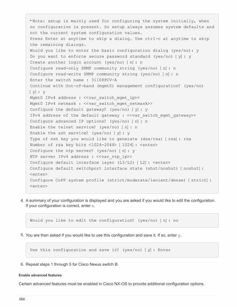
*Note: setup is mainly used for configuring the system initially, when
no configuration is present. So setup always assumes system defaults and
not the current system configuration values.
Press Enter at anytime to skip a dialog. Use ctrl-c at anytime to skip
the remaining dialogs.
Would you like to enter the basic configuration dialog (yes/no): y
Do you want to enforce secure password standard (yes/no) [y]: y
Create another login account (yes/no) [n]: n
Configure read-only SNMP community string (yes/no) [n]: n
Configure read-write SNMP community string (yes/no) [n]: n
Enter the switch name : 31108PCV-A
Continue with Out-of-band (mgmt0) management configuration? (yes/no)
[y]: y
Mgmt0 IPv4 address : <<var_switch_mgmt_ip>>
Mgmt0 IPv4 netmask : <<var_switch_mgmt_netmask>>
Configure the default gateway? (yes/no) [y]: y
IPv4 address of the default gateway : <<var_switch_mgmt_gateway>>
Configure advanced IP options? (yes/no) [n]: n
Enable the telnet service? (yes/no) [n]: n
Enable the ssh service? (yes/no) [y]: y
Type of ssh key you would like to generate (dsa/rsa) [rsa]: rsa
Number of rsa key bits <1024-2048> [1024]: <enter>
Configure the ntp server? (yes/no) [n]: y
NTP server IPv4 address : <<var_ntp_ip>>
Configure default interface layer (L3/L2) [L2]: <enter>
Configure default switchport interface state (shut/noshut) [noshut]:
<enter>
Configure CoPP system profile (strict/moderate/lenient/dense) [strict]:
<enter>
4. A summary of your configuration is displayed and you are asked if you would like to edit the configuration.
If your configuration is correct, enter n.
Would you like to edit the configuration? (yes/no) [n]: no
5. You are then asked if you would like to use this configuration and save it. If so, enter y.
Use this configuration and save it? (yes/no) [y]: Enter
6. Repeat steps 1 through 5 for Cisco Nexus switch B.
Enable advanced features
Certain advanced features must be enabled in Cisco NX-OS to provide additional configuration options.
566
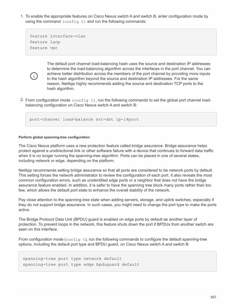
1. To enable the appropriate features on Cisco Nexus switch A and switch B, enter configuration mode by
using the command (config t) and run the following commands:
feature interface-vlan
feature lacp
feature vpc
The default port channel load-balancing hash uses the source and destination IP addressesto determine the load-balancing algorithm across the interfaces in the port channel. You canachieve better distribution across the members of the port channel by providing more inputsto the hash algorithm beyond the source and destination IP addresses. For the samereason, NetApp highly recommends adding the source and destination TCP ports to thehash algorithm.
2. From configuration mode (config t), run the following commands to set the global port channel load-balancing configuration on Cisco Nexus switch A and switch B:
port-channel load-balance src-dst ip-l4port
Perform global spanning-tree configuration
The Cisco Nexus platform uses a new protection feature called bridge assurance. Bridge assurance helpsprotect against a unidirectional link or other software failure with a device that continues to forward data trafficwhen it is no longer running the spanning-tree algorithm. Ports can be placed in one of several states,including network or edge, depending on the platform.
NetApp recommends setting bridge assurance so that all ports are considered to be network ports by default.This setting forces the network administrator to review the configuration of each port. It also reveals the mostcommon configuration errors, such as unidentified edge ports or a neighbor that does not have the bridgeassurance feature enabled. In addition, it is safer to have the spanning tree block many ports rather than toofew, which allows the default port state to enhance the overall stability of the network.
Pay close attention to the spanning-tree state when adding servers, storage, and uplink switches, especially ifthey do not support bridge assurance. In such cases, you might need to change the port type to make the portsactive.
The Bridge Protocol Data Unit (BPDU) guard is enabled on edge ports by default as another layer ofprotection. To prevent loops in the network, this feature shuts down the port if BPDUs from another switch areseen on this interface.
From configuration mode (config t), run the following commands to configure the default spanning-treeoptions, including the default port type and BPDU guard, on Cisco Nexus switch A and switch B:
spanning-tree port type network default
spanning-tree port type edge bpduguard default
567

Define VLANs
Before individual ports with different VLANs are configured, the layer-2 VLANs must be defined on the switch.It is also a good practice to name the VLANs for easy troubleshooting in the future.
From configuration mode (config t), run the following commands to define and describe the layer 2 VLANson Cisco Nexus switch A and switch B:
vlan <<nfs_vlan_id>>
name NFS-VLAN
vlan <<iSCSI_A_vlan_id>>
name iSCSI-A-VLAN
vlan <<iSCSI_B_vlan_id>>
name iSCSI-B-VLAN
vlan <<vmotion_vlan_id>>
name vMotion-VLAN
vlan <<vmtraffic_vlan_id>>
name VM-Traffic-VLAN
vlan <<mgmt_vlan_id>>
name MGMT-VLAN
vlan <<native_vlan_id>>
name NATIVE-VLAN
exit
Configure access and management port descriptions
As is the case with assigning names to the layer-2 VLANs, setting descriptions for all the interfaces can helpwith both provisioning and troubleshooting.
From configuration mode (config t) in each of the switches, enter the following port descriptions for theFlexPod Express large configuration:
Cisco Nexus switch A
int eth1/1
description AFF A220-A e0M
int eth1/2
description Cisco UCS FI-A mgmt0
int eth1/3
description Cisco UCS FI-A eth1/1
int eth1/4
description Cisco UCS FI-B eth1/1
int eth1/13
description vPC peer-link 31108PVC-B 1/13
int eth1/14
description vPC peer-link 31108PVC-B 1/14
568
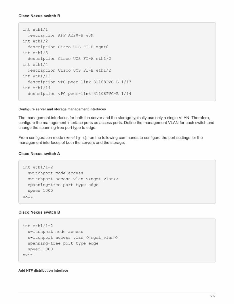
Cisco Nexus switch B
int eth1/1
description AFF A220-B e0M
int eth1/2
description Cisco UCS FI-B mgmt0
int eth1/3
description Cisco UCS FI-A eth1/2
int eth1/4
description Cisco UCS FI-B eth1/2
int eth1/13
description vPC peer-link 31108PVC-B 1/13
int eth1/14
description vPC peer-link 31108PVC-B 1/14
Configure server and storage management interfaces
The management interfaces for both the server and the storage typically use only a single VLAN. Therefore,configure the management interface ports as access ports. Define the management VLAN for each switch andchange the spanning-tree port type to edge.
From configuration mode (config t), run the following commands to configure the port settings for themanagement interfaces of both the servers and the storage:
Cisco Nexus switch A
int eth1/1-2
switchport mode access
switchport access vlan <<mgmt_vlan>>
spanning-tree port type edge
speed 1000
exit
Cisco Nexus switch B
int eth1/1-2
switchport mode access
switchport access vlan <<mgmt_vlan>>
spanning-tree port type edge
speed 1000
exit
Add NTP distribution interface
569
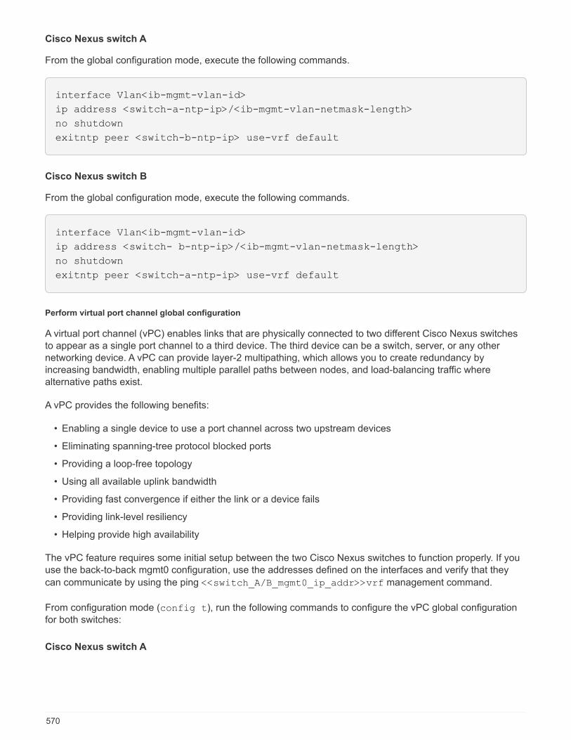
Cisco Nexus switch A
From the global configuration mode, execute the following commands.
interface Vlan<ib-mgmt-vlan-id>
ip address <switch-a-ntp-ip>/<ib-mgmt-vlan-netmask-length>
no shutdown
exitntp peer <switch-b-ntp-ip> use-vrf default
Cisco Nexus switch B
From the global configuration mode, execute the following commands.
interface Vlan<ib-mgmt-vlan-id>
ip address <switch- b-ntp-ip>/<ib-mgmt-vlan-netmask-length>
no shutdown
exitntp peer <switch-a-ntp-ip> use-vrf default
Perform virtual port channel global configuration
A virtual port channel (vPC) enables links that are physically connected to two different Cisco Nexus switchesto appear as a single port channel to a third device. The third device can be a switch, server, or any othernetworking device. A vPC can provide layer-2 multipathing, which allows you to create redundancy byincreasing bandwidth, enabling multiple parallel paths between nodes, and load-balancing traffic wherealternative paths exist.
A vPC provides the following benefits:
• Enabling a single device to use a port channel across two upstream devices
• Eliminating spanning-tree protocol blocked ports
• Providing a loop-free topology
• Using all available uplink bandwidth
• Providing fast convergence if either the link or a device fails
• Providing link-level resiliency
• Helping provide high availability
The vPC feature requires some initial setup between the two Cisco Nexus switches to function properly. If youuse the back-to-back mgmt0 configuration, use the addresses defined on the interfaces and verify that they
can communicate by using the ping <<switch_A/B_mgmt0_ip_addr>>vrf management command.
From configuration mode (config t), run the following commands to configure the vPC global configurationfor both switches:
Cisco Nexus switch A
570
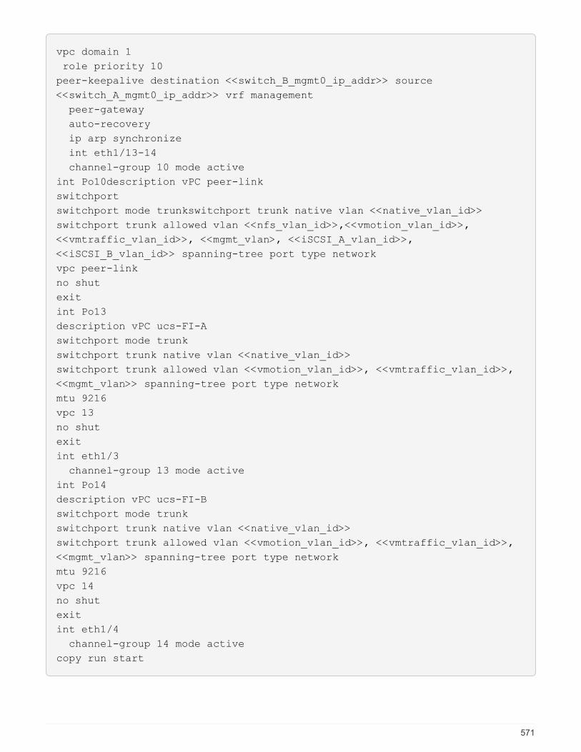
vpc domain 1
role priority 10
peer-keepalive destination <<switch_B_mgmt0_ip_addr>> source
<<switch_A_mgmt0_ip_addr>> vrf management
peer-gateway
auto-recovery
ip arp synchronize
int eth1/13-14
channel-group 10 mode active
int Po10description vPC peer-link
switchport
switchport mode trunkswitchport trunk native vlan <<native_vlan_id>>
switchport trunk allowed vlan <<nfs_vlan_id>>,<<vmotion_vlan_id>>,
<<vmtraffic_vlan_id>>, <<mgmt_vlan>, <<iSCSI_A_vlan_id>>,
<<iSCSI_B_vlan_id>> spanning-tree port type network
vpc peer-link
no shut
exit
int Po13
description vPC ucs-FI-A
switchport mode trunk
switchport trunk native vlan <<native_vlan_id>>
switchport trunk allowed vlan <<vmotion_vlan_id>>, <<vmtraffic_vlan_id>>,
<<mgmt_vlan>> spanning-tree port type network
mtu 9216
vpc 13
no shut
exit
int eth1/3
channel-group 13 mode active
int Po14
description vPC ucs-FI-B
switchport mode trunk
switchport trunk native vlan <<native_vlan_id>>
switchport trunk allowed vlan <<vmotion_vlan_id>>, <<vmtraffic_vlan_id>>,
<<mgmt_vlan>> spanning-tree port type network
mtu 9216
vpc 14
no shut
exit
int eth1/4
channel-group 14 mode active
copy run start
571
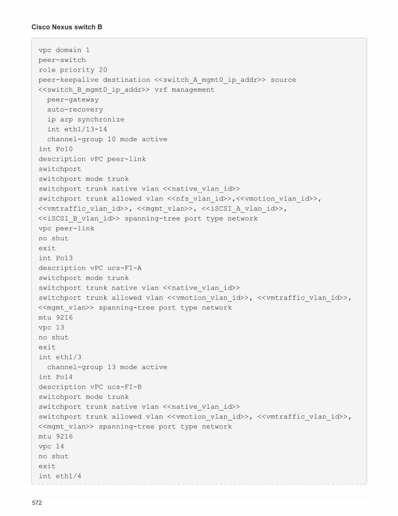
Cisco Nexus switch B
vpc domain 1
peer-switch
role priority 20
peer-keepalive destination <<switch_A_mgmt0_ip_addr>> source
<<switch_B_mgmt0_ip_addr>> vrf management
peer-gateway
auto-recovery
ip arp synchronize
int eth1/13-14
channel-group 10 mode active
int Po10
description vPC peer-link
switchport
switchport mode trunk
switchport trunk native vlan <<native_vlan_id>>
switchport trunk allowed vlan <<nfs_vlan_id>>,<<vmotion_vlan_id>>,
<<vmtraffic_vlan_id>>, <<mgmt_vlan>>, <<iSCSI_A_vlan_id>>,
<<iSCSI_B_vlan_id>> spanning-tree port type network
vpc peer-link
no shut
exit
int Po13
description vPC ucs-FI-A
switchport mode trunk
switchport trunk native vlan <<native_vlan_id>>
switchport trunk allowed vlan <<vmotion_vlan_id>>, <<vmtraffic_vlan_id>>,
<<mgmt_vlan>> spanning-tree port type network
mtu 9216
vpc 13
no shut
exit
int eth1/3
channel-group 13 mode active
int Po14
description vPC ucs-FI-B
switchport mode trunk
switchport trunk native vlan <<native_vlan_id>>
switchport trunk allowed vlan <<vmotion_vlan_id>>, <<vmtraffic_vlan_id>>,
<<mgmt_vlan>> spanning-tree port type network
mtu 9216
vpc 14
no shut
exit
int eth1/4
572
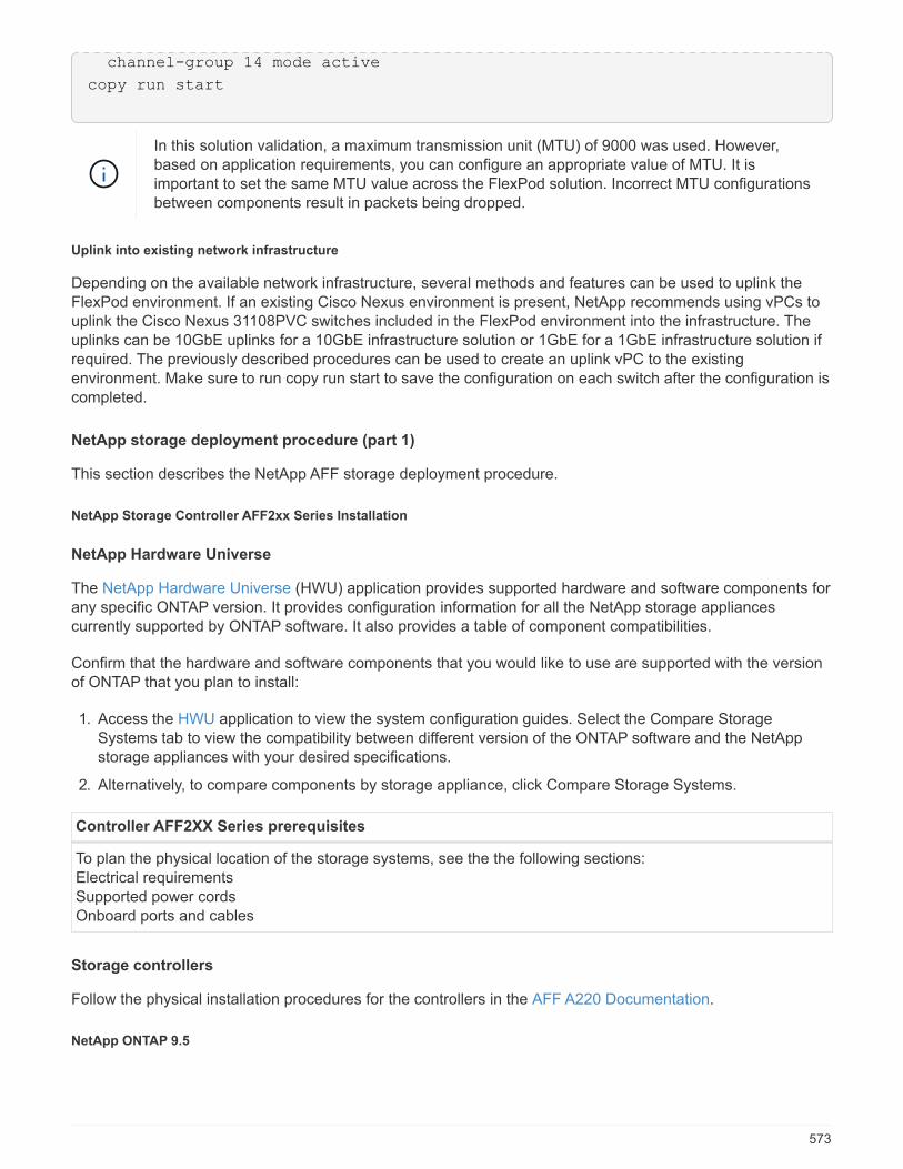
channel-group 14 mode active
copy run start
In this solution validation, a maximum transmission unit (MTU) of 9000 was used. However,based on application requirements, you can configure an appropriate value of MTU. It isimportant to set the same MTU value across the FlexPod solution. Incorrect MTU configurationsbetween components result in packets being dropped.
Uplink into existing network infrastructure
Depending on the available network infrastructure, several methods and features can be used to uplink theFlexPod environment. If an existing Cisco Nexus environment is present, NetApp recommends using vPCs touplink the Cisco Nexus 31108PVC switches included in the FlexPod environment into the infrastructure. Theuplinks can be 10GbE uplinks for a 10GbE infrastructure solution or 1GbE for a 1GbE infrastructure solution ifrequired. The previously described procedures can be used to create an uplink vPC to the existingenvironment. Make sure to run copy run start to save the configuration on each switch after the configuration iscompleted.
NetApp storage deployment procedure (part 1)
This section describes the NetApp AFF storage deployment procedure.
NetApp Storage Controller AFF2xx Series Installation
NetApp Hardware Universe
The NetApp Hardware Universe (HWU) application provides supported hardware and software components forany specific ONTAP version. It provides configuration information for all the NetApp storage appliancescurrently supported by ONTAP software. It also provides a table of component compatibilities.
Confirm that the hardware and software components that you would like to use are supported with the versionof ONTAP that you plan to install:
1. Access the HWU application to view the system configuration guides. Select the Compare StorageSystems tab to view the compatibility between different version of the ONTAP software and the NetAppstorage appliances with your desired specifications.
2. Alternatively, to compare components by storage appliance, click Compare Storage Systems.
Controller AFF2XX Series prerequisites
To plan the physical location of the storage systems, see the the following sections:Electrical requirementsSupported power cordsOnboard ports and cables
Storage controllers
Follow the physical installation procedures for the controllers in the AFF A220 Documentation.
NetApp ONTAP 9.5
573
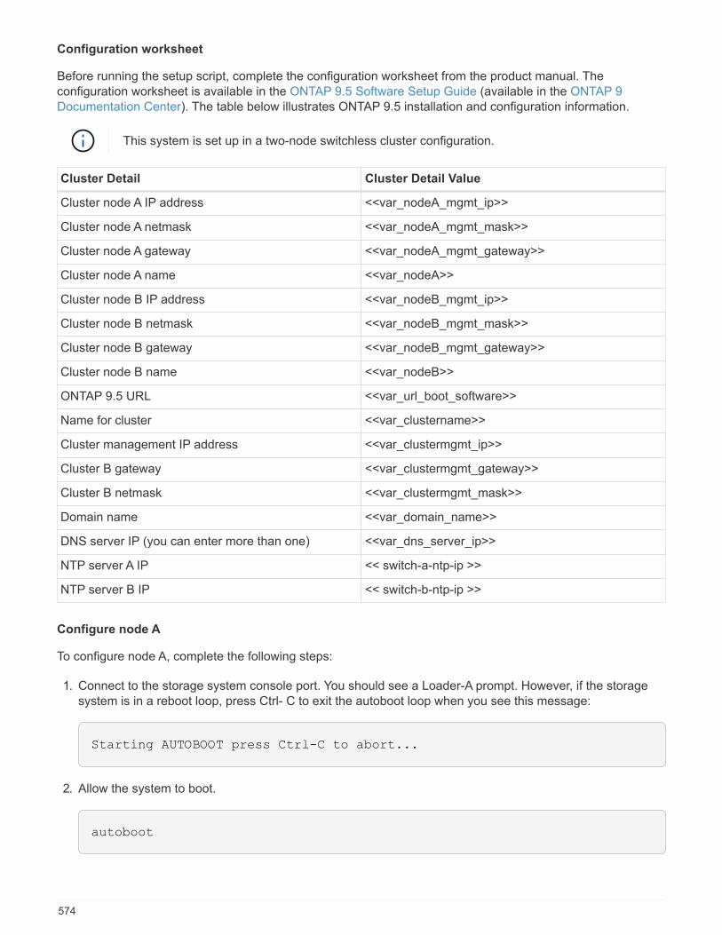
Configuration worksheet
Before running the setup script, complete the configuration worksheet from the product manual. Theconfiguration worksheet is available in the ONTAP 9.5 Software Setup Guide (available in the ONTAP 9Documentation Center). The table below illustrates ONTAP 9.5 installation and configuration information.
This system is set up in a two-node switchless cluster configuration.
Cluster Detail Cluster Detail Value
Cluster node A IP address <<var_nodeA_mgmt_ip>>
Cluster node A netmask <<var_nodeA_mgmt_mask>>
Cluster node A gateway <<var_nodeA_mgmt_gateway>>
Cluster node A name <<var_nodeA>>
Cluster node B IP address <<var_nodeB_mgmt_ip>>
Cluster node B netmask <<var_nodeB_mgmt_mask>>
Cluster node B gateway <<var_nodeB_mgmt_gateway>>
Cluster node B name <<var_nodeB>>
ONTAP 9.5 URL <<var_url_boot_software>>
Name for cluster <<var_clustername>>
Cluster management IP address <<var_clustermgmt_ip>>
Cluster B gateway <<var_clustermgmt_gateway>>
Cluster B netmask <<var_clustermgmt_mask>>
Domain name <<var_domain_name>>
DNS server IP (you can enter more than one) <<var_dns_server_ip>>
NTP server A IP << switch-a-ntp-ip >>
NTP server B IP << switch-b-ntp-ip >>
Configure node A
To configure node A, complete the following steps:
1. Connect to the storage system console port. You should see a Loader-A prompt. However, if the storagesystem is in a reboot loop, press Ctrl- C to exit the autoboot loop when you see this message:
Starting AUTOBOOT press Ctrl-C to abort...
2. Allow the system to boot.
autoboot
574

3. Press Ctrl- C to enter the Boot menu.
If ONTAP 9. 5 is not the version of software being booted, continue with the following steps to install newsoftware. If ONTAP 9. 5 is the version being booted, select option 8 and y to reboot the node. Then,continue with step 14.
4. To install new software, select option 7.
5. Enter y to perform an upgrade.
6. Select e0M for the network port you want to use for the download.
7. Enter y to reboot now.
8. Enter the IP address, netmask, and default gateway for e0M in their respective places.
<<var_nodeA_mgmt_ip>> <<var_nodeA_mgmt_mask>> <<var_nodeA_mgmt_gateway>>
9. Enter the URL where the software can be found.
This web server must be pingable.
10. Press Enter for the user name, indicating no user name.
11. Enter y to set the newly installed software as the default to be used for subsequent reboots.
12. Enter y to reboot the node.
When installing new software, the system might perform firmware upgrades to the BIOS and adapter cards,causing reboots and possible stops at the Loader-A prompt. If these actions occur, the system mightdeviate from this procedure.
13. Press Ctrl- C to enter the Boot menu.
14. Select option 4 for Clean Configuration and Initialize All Disks.
15. Enter y to zero disks, reset config, and install a new file system.
16. Enter y to erase all the data on the disks.
The initialization and creation of the root aggregate can take 90 minutes or more to complete, dependingon the number and type of disks attached. When initialization is complete, the storage system reboots.Note that SSDs take considerably less time to initialize. You can continue with the node B configurationwhile the disks for node A are zeroing.
17. While node A is initializing, begin configuring node B.
Configure node B
To configure node B, complete the following steps:
1. Connect to the storage system console port. You should see a Loader-A prompt. However, if the storagesystem is in a reboot loop, press Ctrl-C to exit the autoboot loop when you see this message:
575

Starting AUTOBOOT press Ctrl-C to abort...
2. Press Ctrl-C to enter the Boot menu.
autoboot
3. Press Ctrl-C when prompted.
If ONTAP 9. 5 is not the version of software being booted, continue with the following steps to install newsoftware. If ONTAP 9.4 is the version being booted, select option 8 and y to reboot the node. Then,continue with step 14.
4. To install new software, select option 7.
5. Enter y to perform an upgrade.
6. Select e0M for the network port you want to use for the download.
7. Enter y to reboot now.
8. Enter the IP address, netmask, and default gateway for e0M in their respective places.
<<var_nodeB_mgmt_ip>> <<var_nodeB_mgmt_ip>><<var_nodeB_mgmt_gateway>>
9. Enter the URL where the software can be found.
This web server must be pingable.
<<var_url_boot_software>>
10. Press Enter for the user name, indicating no user name
11. Enter y to set the newly installed software as the default to be used for subsequent reboots.
12. Enter y to reboot the node.
When installing new software, the system might perform firmware upgrades to the BIOS and adapter cards,causing reboots and possible stops at the Loader-A prompt. If these actions occur, the system mightdeviate from this procedure.
13. Press Ctrl-C to enter the Boot menu.
14. Select option 4 for Clean Configuration and Initialize All Disks.
15. Enter y to zero disks, reset config, and install a new file system.
16. Enter y to erase all the data on the disks.
The initialization and creation of the root aggregate can take 90 minutes or more to complete, dependingon the number and type of disks attached. When initialization is complete, the storage system reboots.Note that SSDs take considerably less time to initialize.
576

Continuation node A configuration and cluster configuration
From a console port program attached to the storage controller A (node A) console port, run the node setupscript. This script appears when ONTAP 9.5 boots on the node for the first time.
The node and cluster setup procedure has changed slightly in ONTAP 9.5. The cluster setup wizard is nowused to configure the first node in a cluster, and System Manager is used to configure the cluster.
1. Follow the prompts to set up node A.
Welcome to the cluster setup wizard.
You can enter the following commands at any time:
"help" or "?" - if you want to have a question clarified,
"back" - if you want to change previously answered questions, and
"exit" or "quit" - if you want to quit the cluster setup wizard.
Any changes you made before quitting will be saved.
You can return to cluster setup at any time by typing "cluster setup".
To accept a default or omit a question, do not enter a value.
This system will send event messages and periodic reports to NetApp
Technical Support. To disable this feature, enter
autosupport modify -support disable
within 24 hours.
Enabling AutoSupport can significantly speed problem determination and
resolution should a problem occur on your system.
For further information on AutoSupport, see:
http://support.netapp.com/autosupport/
Type yes to confirm and continue {yes}: yes
Enter the node management interface port [e0M]:
Enter the node management interface IP address: <<var_nodeA_mgmt_ip>>
Enter the node management interface netmask: <<var_nodeA_mgmt_mask>>
Enter the node management interface default gateway:
<<var_nodeA_mgmt_gateway>>
A node management interface on port e0M with IP address
<<var_nodeA_mgmt_ip>> has been created.
Use your web browser to complete cluster setup by accessing
https://<<var_nodeA_mgmt_ip>>
Otherwise, press Enter to complete cluster setup using the command line
interface:
2. Navigate to the IP address of the node’s management interface.
Cluster setup can also be performed by using the CLI. This document describes clustersetup using NetApp System Manager guided setup.
3. Click Guided Setup to configure the cluster.
4. Enter <<var_clustername>> for the cluster name and <<var_nodeA>> and <<var_nodeB>> for eachof the nodes that you are configuring. Enter the password that you would like to use for the storage system.
577

Select Switchless Cluster for the cluster type. Enter the cluster base license.
5. You can also enter feature licenses for Cluster, NFS, and iSCSI.
6. You see a status message stating the cluster is being created. This status message cycles through severalstatuses. This process takes several minutes.
7. Configure the network.
a. Deselect the IP Address Range option.
b. Enter <<var_clustermgmt_ip>> in the Cluster Management IP Address field,
<<var_clustermgmt_mask>> in the Netmask field, and <<var_clustermgmt_gateway>> in theGateway field. Use the … selector in the Port field to select e0M of node A.
c. The node management IP for node A is already populated. Enter <<var_nodeA_mgmt_ip>> for nodeB.
d. Enter <<var_domain_name>> in the DNS Domain Name field. Enter <<var_dns_server_ip>> inthe DNS Server IP Address field.
You can enter multiple DNS server IP addresses.
e. Enter <<switch-a-ntp-ip>> in the Primary NTP Server field.
You can also enter an alternate NTP server as <<switch- b-ntp-ip>>.
8. Configure the support information.
a. If your environment requires a proxy to access AutoSupport, enter the URL in Proxy URL.
b. Enter the SMTP mail host and email address for event notifications.
You must, at a minimum, set up the event notification method before you can proceed. You can selectany of the methods.
9. When indicated that the cluster configuration has completed, click Manage Your Cluster to configure thestorage.
Continuation of storage cluster configuration
After the configuration of the storage nodes and base cluster, you can continue with the configuration of thestorage cluster.
Zero all spare disks
To zero all spare disks in the cluster, run the following command:
disk zerospares
Set on-board UTA2 ports personality
1. Verify the current mode and the current type of the ports by running the ucadmin show command.
578
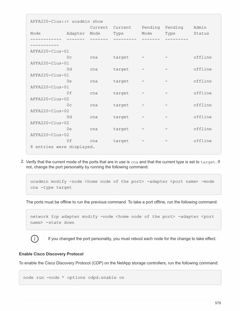
AFFA220-Clus::> ucadmin show
Current Current Pending Pending Admin
Node Adapter Mode Type Mode Type Status
------------ ------- ------- --------- ------- ---------
-----------
AFFA220-Clus-01
0c cna target - - offline
AFFA220-Clus-01
0d cna target - - offline
AFFA220-Clus-01
0e cna target - - offline
AFFA220-Clus-01
0f cna target - - offline
AFFA220-Clus-02
0c cna target - - offline
AFFA220-Clus-02
0d cna target - - offline
AFFA220-Clus-02
0e cna target - - offline
AFFA220-Clus-02
0f cna target - - offline
8 entries were displayed.
2. Verify that the current mode of the ports that are in use is cna and that the current type is set to target. Ifnot, change the port personality by running the following command:
ucadmin modify -node <home node of the port> -adapter <port name> -mode
cna -type target
The ports must be offline to run the previous command. To take a port offline, run the following command:
network fcp adapter modify -node <home node of the port> -adapter <port
name> -state down
If you changed the port personality, you must reboot each node for the change to take effect.
Enable Cisco Discovery Protocol
To enable the Cisco Discovery Protocol (CDP) on the NetApp storage controllers, run the following command:
node run -node * options cdpd.enable on
579
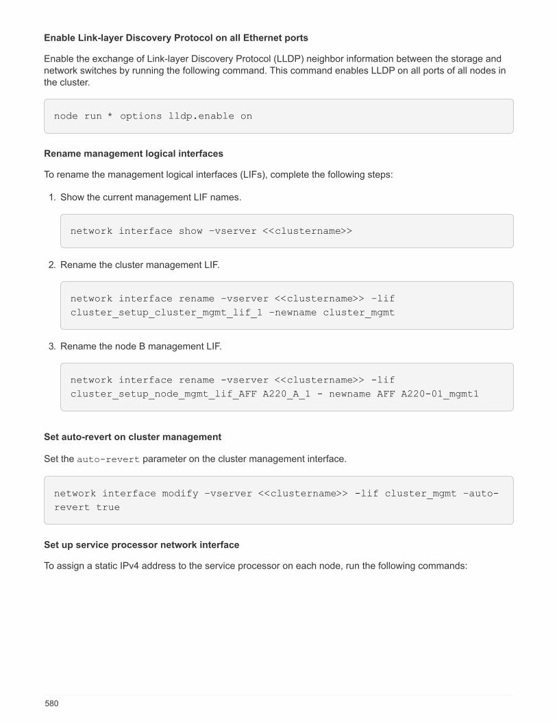
Enable Link-layer Discovery Protocol on all Ethernet ports
Enable the exchange of Link-layer Discovery Protocol (LLDP) neighbor information between the storage andnetwork switches by running the following command. This command enables LLDP on all ports of all nodes inthe cluster.
node run * options lldp.enable on
Rename management logical interfaces
To rename the management logical interfaces (LIFs), complete the following steps:
1. Show the current management LIF names.
network interface show –vserver <<clustername>>
2. Rename the cluster management LIF.
network interface rename –vserver <<clustername>> –lif
cluster_setup_cluster_mgmt_lif_1 –newname cluster_mgmt
3. Rename the node B management LIF.
network interface rename -vserver <<clustername>> -lif
cluster_setup_node_mgmt_lif_AFF A220_A_1 - newname AFF A220-01_mgmt1
Set auto-revert on cluster management
Set the auto-revert parameter on the cluster management interface.
network interface modify –vserver <<clustername>> -lif cluster_mgmt –auto-
revert true
Set up service processor network interface
To assign a static IPv4 address to the service processor on each node, run the following commands:
580
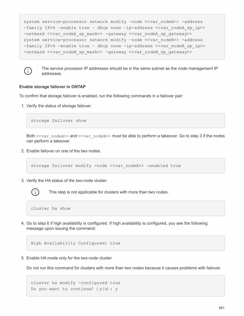
system service-processor network modify –node <<var_nodeA>> -address
-family IPv4 –enable true – dhcp none –ip-address <<var_nodeA_sp_ip>>
-netmask <<var_nodeA_sp_mask>> -gateway <<var_nodeA_sp_gateway>>
system service-processor network modify –node <<var_nodeB>> -address
-family IPv4 –enable true – dhcp none –ip-address <<var_nodeB_sp_ip>>
-netmask <<var_nodeB_sp_mask>> -gateway <<var_nodeB_sp_gateway>>
The service processor IP addresses should be in the same subnet as the node management IPaddresses.
Enable storage failover in ONTAP
To confirm that storage failover is enabled, run the following commands in a failover pair:
1. Verify the status of storage failover.
storage failover show
Both <<var_nodeA>> and <<var_nodeB>> must be able to perform a takeover. Go to step 3 if the nodescan perform a takeover.
2. Enable failover on one of the two nodes.
storage failover modify -node <<var_nodeA>> -enabled true
3. Verify the HA status of the two-node cluster.
This step is not applicable for clusters with more than two nodes.
cluster ha show
4. Go to step 6 if high availability is configured. If high availability is configured, you see the followingmessage upon issuing the command:
High Availability Configured: true
5. Enable HA mode only for the two-node cluster.
Do not run this command for clusters with more than two nodes because it causes problems with failover.
cluster ha modify -configured true
Do you want to continue? {y|n}: y
581
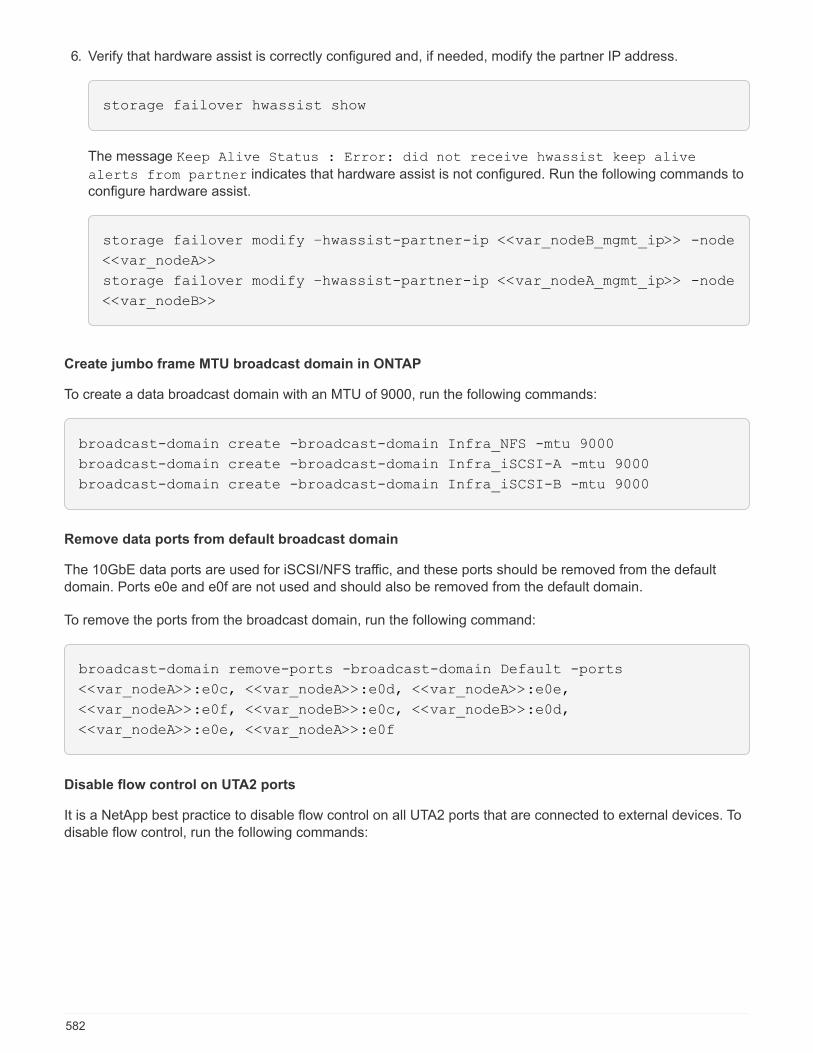
6. Verify that hardware assist is correctly configured and, if needed, modify the partner IP address.
storage failover hwassist show
The message Keep Alive Status : Error: did not receive hwassist keep alive
alerts from partner indicates that hardware assist is not configured. Run the following commands toconfigure hardware assist.
storage failover modify –hwassist-partner-ip <<var_nodeB_mgmt_ip>> -node
<<var_nodeA>>
storage failover modify –hwassist-partner-ip <<var_nodeA_mgmt_ip>> -node
<<var_nodeB>>
Create jumbo frame MTU broadcast domain in ONTAP
To create a data broadcast domain with an MTU of 9000, run the following commands:
broadcast-domain create -broadcast-domain Infra_NFS -mtu 9000
broadcast-domain create -broadcast-domain Infra_iSCSI-A -mtu 9000
broadcast-domain create -broadcast-domain Infra_iSCSI-B -mtu 9000
Remove data ports from default broadcast domain
The 10GbE data ports are used for iSCSI/NFS traffic, and these ports should be removed from the defaultdomain. Ports e0e and e0f are not used and should also be removed from the default domain.
To remove the ports from the broadcast domain, run the following command:
broadcast-domain remove-ports -broadcast-domain Default -ports
<<var_nodeA>>:e0c, <<var_nodeA>>:e0d, <<var_nodeA>>:e0e,
<<var_nodeA>>:e0f, <<var_nodeB>>:e0c, <<var_nodeB>>:e0d,
<<var_nodeA>>:e0e, <<var_nodeA>>:e0f
Disable flow control on UTA2 ports
It is a NetApp best practice to disable flow control on all UTA2 ports that are connected to external devices. Todisable flow control, run the following commands:
582
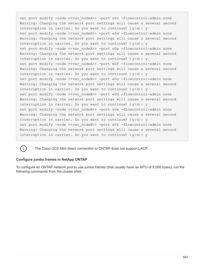
net port modify -node <<var_nodeA>> -port e0c -flowcontrol-admin none
Warning: Changing the network port settings will cause a several second
interruption in carrier. Do you want to continue? {y|n}: y
net port modify -node <<var_nodeA>> -port e0d -flowcontrol-admin none
Warning: Changing the network port settings will cause a several second
interruption in carrier. Do you want to continue? {y|n}: y
net port modify -node <<var_nodeA>> -port e0e -flowcontrol-admin none
Warning: Changing the network port settings will cause a several second
interruption in carrier. Do you want to continue? {y|n}: y
net port modify -node <<var_nodeA>> -port e0f -flowcontrol-admin none
Warning: Changing the network port settings will cause a several second
interruption in carrier. Do you want to continue? {y|n}: y
net port modify -node <<var_nodeB>> -port e0c -flowcontrol-admin none
Warning: Changing the network port settings will cause a several second
interruption in carrier. Do you want to continue? {y|n}: y
net port modify -node <<var_nodeB>> -port e0d -flowcontrol-admin none
Warning: Changing the network port settings will cause a several second
interruption in carrier. Do you want to continue? {y|n}: y
net port modify -node <<var_nodeB>> -port e0e -flowcontrol-admin none
Warning: Changing the network port settings will cause a several second
interruption in carrier. Do you want to continue? {y|n}: y
net port modify -node <<var_nodeB>> -port e0f -flowcontrol-admin none
Warning: Changing the network port settings will cause a several second
interruption in carrier. Do you want to continue? {y|n}: y
The Cisco UCS Mini direct connection to ONTAP does not support LACP.
Configure jumbo frames in NetApp ONTAP
To configure an ONTAP network port to use jumbo frames (that usually have an MTU of 9,000 bytes), run thefollowing commands from the cluster shell:
583
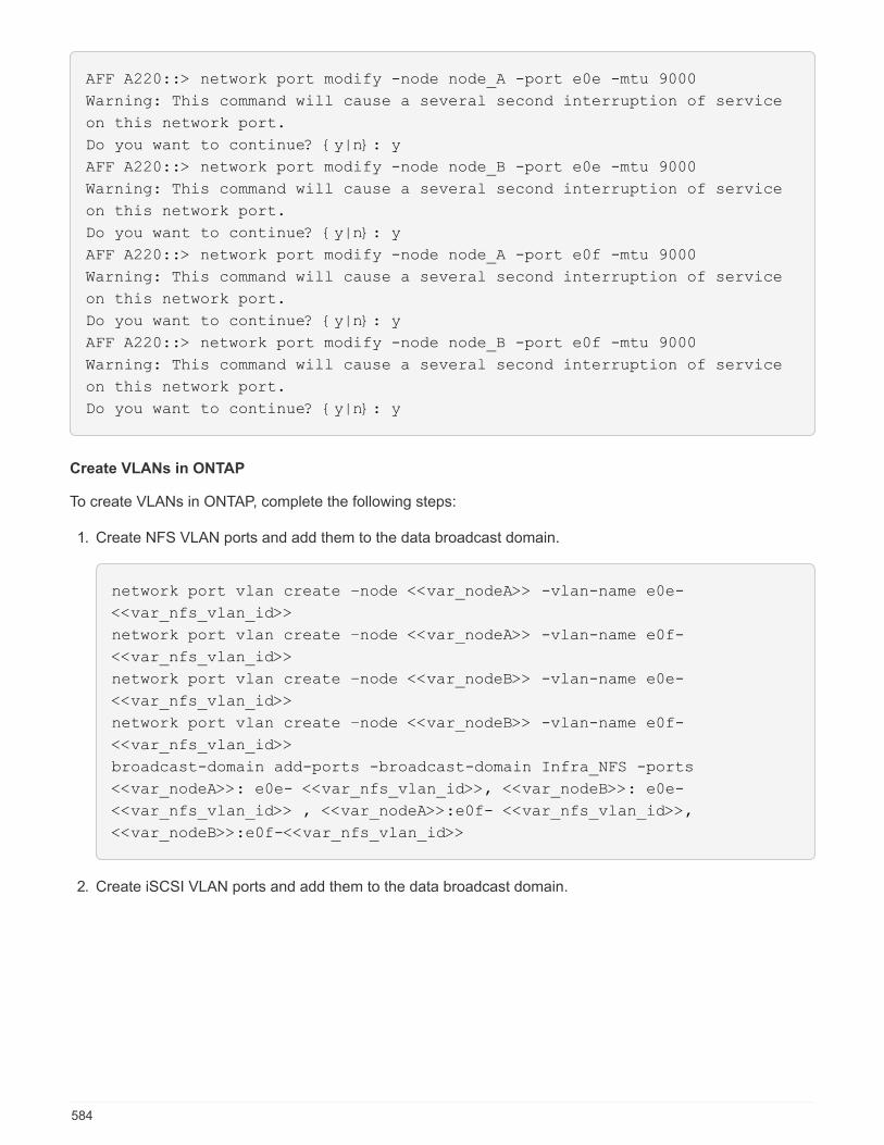
AFF A220::> network port modify -node node_A -port e0e -mtu 9000
Warning: This command will cause a several second interruption of service
on this network port.
Do you want to continue? {y|n}: y
AFF A220::> network port modify -node node_B -port e0e -mtu 9000
Warning: This command will cause a several second interruption of service
on this network port.
Do you want to continue? {y|n}: y
AFF A220::> network port modify -node node_A -port e0f -mtu 9000
Warning: This command will cause a several second interruption of service
on this network port.
Do you want to continue? {y|n}: y
AFF A220::> network port modify -node node_B -port e0f -mtu 9000
Warning: This command will cause a several second interruption of service
on this network port.
Do you want to continue? {y|n}: y
Create VLANs in ONTAP
To create VLANs in ONTAP, complete the following steps:
1. Create NFS VLAN ports and add them to the data broadcast domain.
network port vlan create –node <<var_nodeA>> -vlan-name e0e-
<<var_nfs_vlan_id>>
network port vlan create –node <<var_nodeA>> -vlan-name e0f-
<<var_nfs_vlan_id>>
network port vlan create –node <<var_nodeB>> -vlan-name e0e-
<<var_nfs_vlan_id>>
network port vlan create –node <<var_nodeB>> -vlan-name e0f-
<<var_nfs_vlan_id>>
broadcast-domain add-ports -broadcast-domain Infra_NFS -ports
<<var_nodeA>>: e0e- <<var_nfs_vlan_id>>, <<var_nodeB>>: e0e-
<<var_nfs_vlan_id>> , <<var_nodeA>>:e0f- <<var_nfs_vlan_id>>,
<<var_nodeB>>:e0f-<<var_nfs_vlan_id>>
2. Create iSCSI VLAN ports and add them to the data broadcast domain.
584
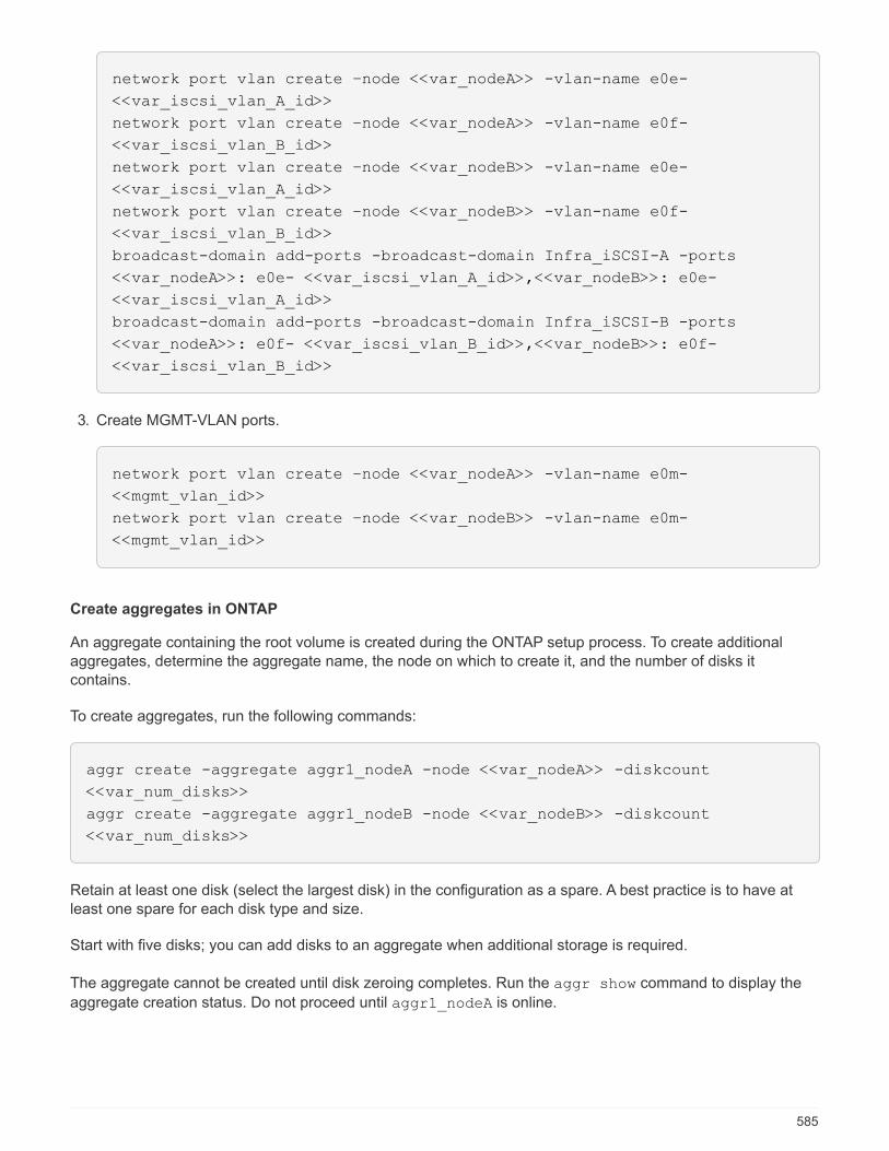
network port vlan create –node <<var_nodeA>> -vlan-name e0e-
<<var_iscsi_vlan_A_id>>
network port vlan create –node <<var_nodeA>> -vlan-name e0f-
<<var_iscsi_vlan_B_id>>
network port vlan create –node <<var_nodeB>> -vlan-name e0e-
<<var_iscsi_vlan_A_id>>
network port vlan create –node <<var_nodeB>> -vlan-name e0f-
<<var_iscsi_vlan_B_id>>
broadcast-domain add-ports -broadcast-domain Infra_iSCSI-A -ports
<<var_nodeA>>: e0e- <<var_iscsi_vlan_A_id>>,<<var_nodeB>>: e0e-
<<var_iscsi_vlan_A_id>>
broadcast-domain add-ports -broadcast-domain Infra_iSCSI-B -ports
<<var_nodeA>>: e0f- <<var_iscsi_vlan_B_id>>,<<var_nodeB>>: e0f-
<<var_iscsi_vlan_B_id>>
3. Create MGMT-VLAN ports.
network port vlan create –node <<var_nodeA>> -vlan-name e0m-
<<mgmt_vlan_id>>
network port vlan create –node <<var_nodeB>> -vlan-name e0m-
<<mgmt_vlan_id>>
Create aggregates in ONTAP
An aggregate containing the root volume is created during the ONTAP setup process. To create additionalaggregates, determine the aggregate name, the node on which to create it, and the number of disks itcontains.
To create aggregates, run the following commands:
aggr create -aggregate aggr1_nodeA -node <<var_nodeA>> -diskcount
<<var_num_disks>>
aggr create -aggregate aggr1_nodeB -node <<var_nodeB>> -diskcount
<<var_num_disks>>
Retain at least one disk (select the largest disk) in the configuration as a spare. A best practice is to have atleast one spare for each disk type and size.
Start with five disks; you can add disks to an aggregate when additional storage is required.
The aggregate cannot be created until disk zeroing completes. Run the aggr show command to display the
aggregate creation status. Do not proceed until aggr1_nodeA is online.
585

Configure time zone in ONTAP
To configure time synchronization and to set the time zone on the cluster, run the following command:
timezone <<var_timezone>>
For example, in the eastern United States, the time zone is America/New_York. After youbegin typing the time zone name, press the Tab key to see available options.
Configure SNMP in ONTAP
To configure the SNMP, complete the following steps:
1. Configure SNMP basic information, such as the location and contact. When polled, this information is
visible as the sysLocation and sysContact variables in SNMP.
snmp contact <<var_snmp_contact>>
snmp location “<<var_snmp_location>>”
snmp init 1
options snmp.enable on
2. Configure SNMP traps to send to remote hosts.
snmp traphost add <<var_snmp_server_fqdn>>
Configure SNMPv1 in ONTAP
To configure SNMPv1, set the shared secret plain-text password called a community.
snmp community add ro <<var_snmp_community>>
Use the snmp community delete all command with caution. If community strings are usedfor other monitoring products, this command removes them.
Configure SNMPv3 in ONTAP
SNMPv3 requires that you define and configure a user for authentication. To configure SNMPv3, complete thefollowing steps:
1. Run the security snmpusers command to view the engine ID.
2. Create a user called snmpv3user.
586
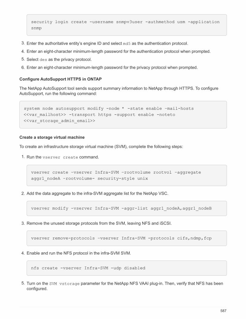
security login create -username snmpv3user -authmethod usm -application
snmp
3. Enter the authoritative entity’s engine ID and select md5 as the authentication protocol.
4. Enter an eight-character minimum-length password for the authentication protocol when prompted.
5. Select des as the privacy protocol.
6. Enter an eight-character minimum-length password for the privacy protocol when prompted.
Configure AutoSupport HTTPS in ONTAP
The NetApp AutoSupport tool sends support summary information to NetApp through HTTPS. To configureAutoSupport, run the following command:
system node autosupport modify -node * -state enable –mail-hosts
<<var_mailhost>> -transport https -support enable -noteto
<<var_storage_admin_email>>
Create a storage virtual machine
To create an infrastructure storage virtual machine (SVM), complete the following steps:
1. Run the vserver create command.
vserver create –vserver Infra-SVM –rootvolume rootvol –aggregate
aggr1_nodeA –rootvolume- security-style unix
2. Add the data aggregate to the infra-SVM aggregate list for the NetApp VSC.
vserver modify -vserver Infra-SVM -aggr-list aggr1_nodeA,aggr1_nodeB
3. Remove the unused storage protocols from the SVM, leaving NFS and iSCSI.
vserver remove-protocols –vserver Infra-SVM -protocols cifs,ndmp,fcp
4. Enable and run the NFS protocol in the infra-SVM SVM.
nfs create -vserver Infra-SVM -udp disabled
5. Turn on the SVM vstorage parameter for the NetApp NFS VAAI plug-in. Then, verify that NFS has beenconfigured.
587
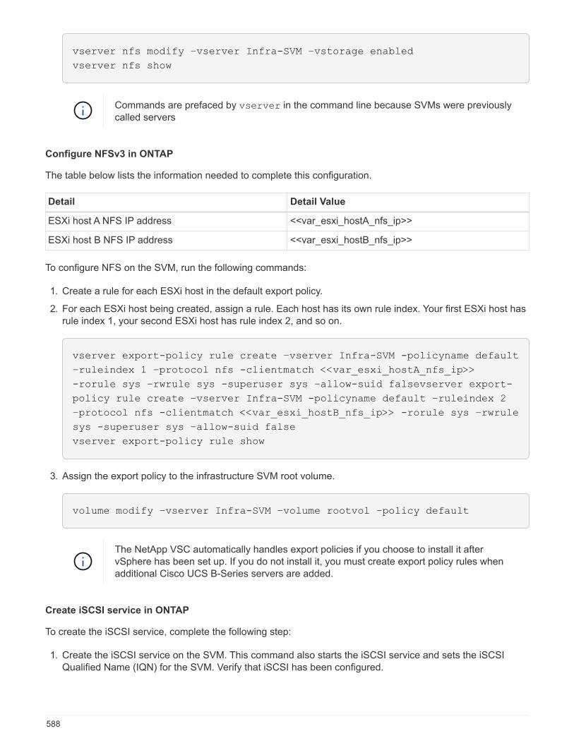
vserver nfs modify –vserver Infra-SVM –vstorage enabled
vserver nfs show
Commands are prefaced by vserver in the command line because SVMs were previouslycalled servers
Configure NFSv3 in ONTAP
The table below lists the information needed to complete this configuration.
Detail Detail Value
ESXi host A NFS IP address <<var_esxi_hostA_nfs_ip>>
ESXi host B NFS IP address <<var_esxi_hostB_nfs_ip>>
To configure NFS on the SVM, run the following commands:
1. Create a rule for each ESXi host in the default export policy.
2. For each ESXi host being created, assign a rule. Each host has its own rule index. Your first ESXi host hasrule index 1, your second ESXi host has rule index 2, and so on.
vserver export-policy rule create –vserver Infra-SVM -policyname default
–ruleindex 1 –protocol nfs -clientmatch <<var_esxi_hostA_nfs_ip>>
-rorule sys –rwrule sys -superuser sys –allow-suid falsevserver export-
policy rule create –vserver Infra-SVM -policyname default –ruleindex 2
–protocol nfs -clientmatch <<var_esxi_hostB_nfs_ip>> -rorule sys –rwrule
sys -superuser sys –allow-suid false
vserver export-policy rule show
3. Assign the export policy to the infrastructure SVM root volume.
volume modify –vserver Infra-SVM –volume rootvol –policy default
The NetApp VSC automatically handles export policies if you choose to install it aftervSphere has been set up. If you do not install it, you must create export policy rules whenadditional Cisco UCS B-Series servers are added.
Create iSCSI service in ONTAP
To create the iSCSI service, complete the following step:
1. Create the iSCSI service on the SVM. This command also starts the iSCSI service and sets the iSCSIQualified Name (IQN) for the SVM. Verify that iSCSI has been configured.
588
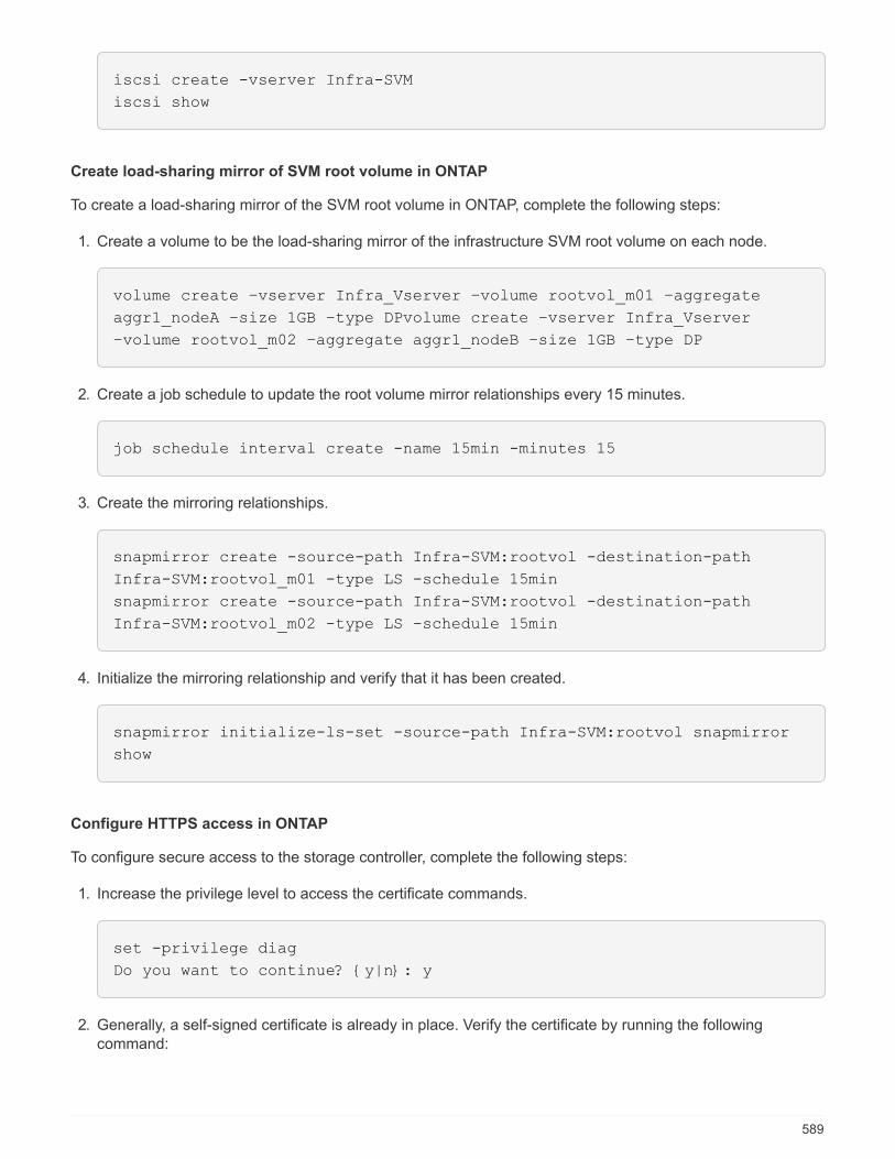
iscsi create -vserver Infra-SVM
iscsi show
Create load-sharing mirror of SVM root volume in ONTAP
To create a load-sharing mirror of the SVM root volume in ONTAP, complete the following steps:
1. Create a volume to be the load-sharing mirror of the infrastructure SVM root volume on each node.
volume create –vserver Infra_Vserver –volume rootvol_m01 –aggregate
aggr1_nodeA –size 1GB –type DPvolume create –vserver Infra_Vserver
–volume rootvol_m02 –aggregate aggr1_nodeB –size 1GB –type DP
2. Create a job schedule to update the root volume mirror relationships every 15 minutes.
job schedule interval create -name 15min -minutes 15
3. Create the mirroring relationships.
snapmirror create -source-path Infra-SVM:rootvol -destination-path
Infra-SVM:rootvol_m01 -type LS -schedule 15min
snapmirror create -source-path Infra-SVM:rootvol -destination-path
Infra-SVM:rootvol_m02 -type LS -schedule 15min
4. Initialize the mirroring relationship and verify that it has been created.
snapmirror initialize-ls-set -source-path Infra-SVM:rootvol snapmirror
show
Configure HTTPS access in ONTAP
To configure secure access to the storage controller, complete the following steps:
1. Increase the privilege level to access the certificate commands.
set -privilege diag
Do you want to continue? {y|n}: y
2. Generally, a self-signed certificate is already in place. Verify the certificate by running the followingcommand:
589
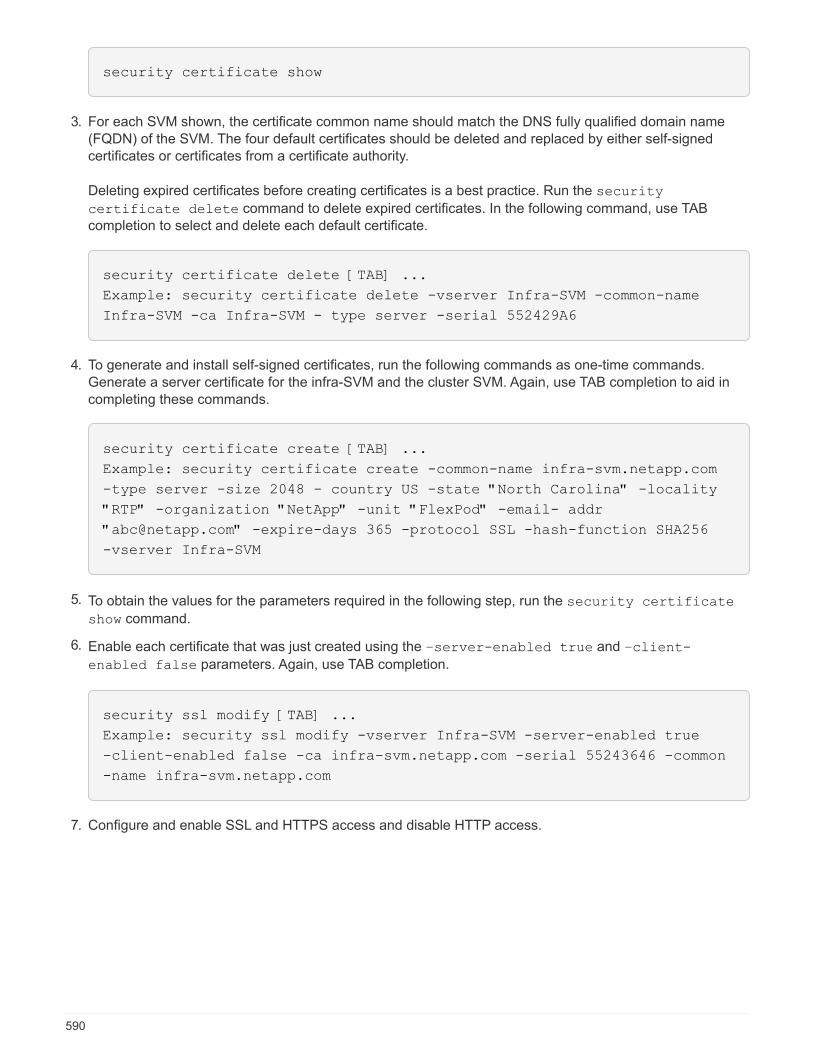
security certificate show
3. For each SVM shown, the certificate common name should match the DNS fully qualified domain name(FQDN) of the SVM. The four default certificates should be deleted and replaced by either self-signedcertificates or certificates from a certificate authority.
Deleting expired certificates before creating certificates is a best practice. Run the security
certificate delete command to delete expired certificates. In the following command, use TABcompletion to select and delete each default certificate.
security certificate delete [TAB] ...
Example: security certificate delete -vserver Infra-SVM -common-name
Infra-SVM -ca Infra-SVM - type server -serial 552429A6
4. To generate and install self-signed certificates, run the following commands as one-time commands.Generate a server certificate for the infra-SVM and the cluster SVM. Again, use TAB completion to aid incompleting these commands.
security certificate create [TAB] ...
Example: security certificate create -common-name infra-svm.netapp.com
-type server -size 2048 - country US -state "North Carolina" -locality
"RTP" -organization "NetApp" -unit "FlexPod" -email- addr
"[email protected]" -expire-days 365 -protocol SSL -hash-function SHA256
-vserver Infra-SVM
5. To obtain the values for the parameters required in the following step, run the security certificate
show command.
6. Enable each certificate that was just created using the –server-enabled true and –client-
enabled false parameters. Again, use TAB completion.
security ssl modify [TAB] ...
Example: security ssl modify -vserver Infra-SVM -server-enabled true
-client-enabled false -ca infra-svm.netapp.com -serial 55243646 -common
-name infra-svm.netapp.com
7. Configure and enable SSL and HTTPS access and disable HTTP access.
590

system services web modify -external true -sslv3-enabled true
Warning: Modifying the cluster configuration will cause pending web
service requests to be interrupted as the web servers are restarted.
Do you want to continue {y|n}: y
System services firewall policy delete -policy mgmt -service http
-vserver <<var_clustername>>
It is normal for some of these commands to return an error message stating that the entrydoes not exist.
8. Revert to the admin privilege level and create the setup to allow SVM to be available by the web.
set –privilege admin
vserver services web modify –name spi|ontapi|compat –vserver * -enabled
true
Create a NetApp FlexVol volume in ONTAP
To create a NetApp FlexVol® volume, enter the volume name, size, and the aggregate on which it exists.Create two VMware datastore volumes and a server boot volume.
volume create -vserver Infra-SVM -volume infra_datastore_1 -aggregate
aggr1_nodeA -size 500GB - state online -policy default -junction-path
/infra_datastore_1 -space-guarantee none -percent- snapshot-space 0
volume create -vserver Infra-SVM -volume infra_datastore_2 -aggregate
aggr1_nodeB -size 500GB - state online -policy default -junction-path
/infra_datastore_2 -space-guarantee none -percent- snapshot-space 0
volume create -vserver Infra-SVM -volume infra_swap -aggregate aggr1_nodeA
-size 100GB -state online -policy default -juntion-path /infra_swap -space
-guarantee none -percent-snapshot-space 0 -snapshot-policy none
volume create -vserver Infra-SVM -volume esxi_boot -aggregate aggr1_nodeA
-size 100GB -state online -policy default -space-guarantee none -percent
-snapshot-space 0
Enable deduplication in ONTAP
To enable deduplication on appropriate volumes once a day, run the following commands:
591
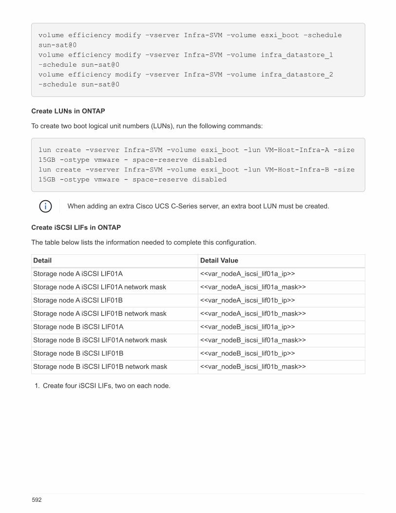
volume efficiency modify –vserver Infra-SVM –volume esxi_boot –schedule
sun-sat@0
volume efficiency modify –vserver Infra-SVM –volume infra_datastore_1
–schedule sun-sat@0
volume efficiency modify –vserver Infra-SVM –volume infra_datastore_2
–schedule sun-sat@0
Create LUNs in ONTAP
To create two boot logical unit numbers (LUNs), run the following commands:
lun create -vserver Infra-SVM -volume esxi_boot -lun VM-Host-Infra-A -size
15GB -ostype vmware - space-reserve disabled
lun create -vserver Infra-SVM -volume esxi_boot -lun VM-Host-Infra-B -size
15GB -ostype vmware - space-reserve disabled
When adding an extra Cisco UCS C-Series server, an extra boot LUN must be created.
Create iSCSI LIFs in ONTAP
The table below lists the information needed to complete this configuration.
Detail Detail Value
Storage node A iSCSI LIF01A <<var_nodeA_iscsi_lif01a_ip>>
Storage node A iSCSI LIF01A network mask <<var_nodeA_iscsi_lif01a_mask>>
Storage node A iSCSI LIF01B <<var_nodeA_iscsi_lif01b_ip>>
Storage node A iSCSI LIF01B network mask <<var_nodeA_iscsi_lif01b_mask>>
Storage node B iSCSI LIF01A <<var_nodeB_iscsi_lif01a_ip>>
Storage node B iSCSI LIF01A network mask <<var_nodeB_iscsi_lif01a_mask>>
Storage node B iSCSI LIF01B <<var_nodeB_iscsi_lif01b_ip>>
Storage node B iSCSI LIF01B network mask <<var_nodeB_iscsi_lif01b_mask>>
1. Create four iSCSI LIFs, two on each node.
592

network interface create -vserver Infra-SVM -lif iscsi_lif01a -role data
-data-protocol iscsi - home-node <<var_nodeA>> -home-port e0e-
<<var_iscsi_vlan_A_id>> -address <<var_nodeA_iscsi_lif01a_ip>> -netmask
<<var_nodeA_iscsi_lif01a_mask>> –status-admin up – failover-policy
disabled –firewall-policy data –auto-revert false
network interface create -vserver Infra-SVM -lif iscsi_lif01b -role data
-data-protocol iscsi - home-node <<var_nodeA>> -home-port e0f-
<<var_iscsi_vlan_B_id>> -address <<var_nodeA_iscsi_lif01b_ip>> -netmask
<<var_nodeA_iscsi_lif01b_mask>> –status-admin up – failover-policy
disabled –firewall-policy data –auto-revert false
network interface create -vserver Infra-SVM -lif iscsi_lif02a -role data
-data-protocol iscsi - home-node <<var_nodeB>> -home-port e0e-
<<var_iscsi_vlan_A_id>> -address <<var_nodeB_iscsi_lif01a_ip>> -netmask
<<var_nodeB_iscsi_lif01a_mask>> –status-admin up – failover-policy
disabled –firewall-policy data –auto-revert false
network interface create -vserver Infra-SVM -lif iscsi_lif02b -role data
-data-protocol iscsi - home-node <<var_nodeB>> -home-port e0f-
<<var_iscsi_vlan_B_id>> -address <<var_nodeB_iscsi_lif01b_ip>> -netmask
<<var_nodeB_iscsi_lif01b_mask>> –status-admin up – failover-policy
disabled –firewall-policy data –auto-revert false
network interface show
Create NFS LIFs in ONTAP
The following table lists the information needed to complete this configuration.
Detail Detail value
Storage node A NFS LIF 01 a IP <<var_nodeA_nfs_lif_01_a_ip>>
Storage node A NFS LIF 01 a network mask <<var_nodeA_nfs_lif_01_a_mask>>
Storage node A NFS LIF 01 b IP <<var_nodeA_nfs_lif_01_b_ip>>
Storage node A NFS LIF 01 b network mask <<var_nodeA_nfs_lif_01_b_mask>>
Storage node B NFS LIF 02 a IP <<var_nodeB_nfs_lif_02_a_ip>>
Storage node B NFS LIF 02 a network mask <<var_nodeB_nfs_lif_02_a_mask>>
Storage node B NFS LIF 02 b IP <<var_nodeB_nfs_lif_02_b_ip>>
Storage node B NFS LIF 02 b network mask <<var_nodeB_nfs_lif_02_b_mask>>
1. Create an NFS LIF.
593
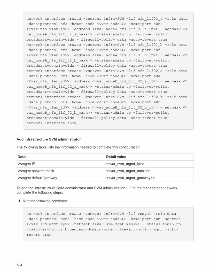
network interface create -vserver Infra-SVM -lif nfs_lif01_a -role data
-data-protocol nfs -home- node <<var_nodeA>> -home-port e0e-
<<var_nfs_vlan_id>> –address <<var_nodeA_nfs_lif_01_a_ip>> - netmask <<
var_nodeA_nfs_lif_01_a_mask>> -status-admin up –failover-policy
broadcast-domain-wide – firewall-policy data –auto-revert true
network interface create -vserver Infra-SVM -lif nfs_lif01_b -role data
-data-protocol nfs -home- node <<var_nodeA>> -home-port e0f-
<<var_nfs_vlan_id>> –address <<var_nodeA_nfs_lif_01_b_ip>> - netmask <<
var_nodeA_nfs_lif_01_b_mask>> -status-admin up –failover-policy
broadcast-domain-wide – firewall-policy data –auto-revert true
network interface create -vserver Infra-SVM -lif nfs_lif02_a -role data
-data-protocol nfs -home- node <<var_nodeB>> -home-port e0e-
<<var_nfs_vlan_id>> –address <<var_nodeB_nfs_lif_02_a_ip>> - netmask <<
var_nodeB_nfs_lif_02_a_mask>> -status-admin up –failover-policy
broadcast-domain-wide – firewall-policy data –auto-revert true
network interface create -vserver Infra-SVM -lif nfs_lif02_b -role data
-data-protocol nfs -home- node <<var_nodeB>> -home-port e0f-
<<var_nfs_vlan_id>> –address <<var_nodeB_nfs_lif_02_b_ip>> - netmask <<
var_nodeB_nfs_lif_02_b_mask>> -status-admin up –failover-policy
broadcast-domain-wide – firewall-policy data –auto-revert true
network interface show
Add infrastructure SVM administrator
The following table lists the information needed to complete this configuration.
Detail Detail value
Vsmgmt IP <<var_svm_mgmt_ip>>
Vsmgmt network mask <<var_svm_mgmt_mask>>
Vsmgmt default gateway <<var_svm_mgmt_gateway>>
To add the infrastructure SVM administrator and SVM administration LIF to the management network,complete the following steps:
1. Run the following command:
network interface create –vserver Infra-SVM –lif vsmgmt –role data
–data-protocol none –home-node <<var_nodeB>> -home-port e0M –address
<<var_svm_mgmt_ip>> -netmask <<var_svm_mgmt_mask>> - status-admin up
–failover-policy broadcast-domain-wide –firewall-policy mgmt –auto-
revert true
594
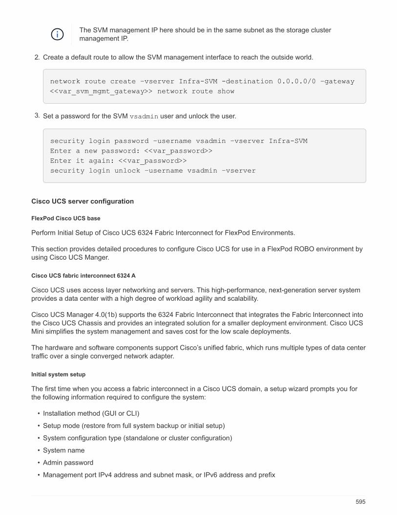
The SVM management IP here should be in the same subnet as the storage clustermanagement IP.
2. Create a default route to allow the SVM management interface to reach the outside world.
network route create –vserver Infra-SVM -destination 0.0.0.0/0 –gateway
<<var_svm_mgmt_gateway>> network route show
3. Set a password for the SVM vsadmin user and unlock the user.
security login password –username vsadmin –vserver Infra-SVM
Enter a new password: <<var_password>>
Enter it again: <<var_password>>
security login unlock –username vsadmin –vserver
Cisco UCS server configuration
FlexPod Cisco UCS base
Perform Initial Setup of Cisco UCS 6324 Fabric Interconnect for FlexPod Environments.
This section provides detailed procedures to configure Cisco UCS for use in a FlexPod ROBO environment byusing Cisco UCS Manger.
Cisco UCS fabric interconnect 6324 A
Cisco UCS uses access layer networking and servers. This high-performance, next-generation server systemprovides a data center with a high degree of workload agility and scalability.
Cisco UCS Manager 4.0(1b) supports the 6324 Fabric Interconnect that integrates the Fabric Interconnect intothe Cisco UCS Chassis and provides an integrated solution for a smaller deployment environment. Cisco UCSMini simplifies the system management and saves cost for the low scale deployments.
The hardware and software components support Cisco’s unified fabric, which runs multiple types of data centertraffic over a single converged network adapter.
Initial system setup
The first time when you access a fabric interconnect in a Cisco UCS domain, a setup wizard prompts you forthe following information required to configure the system:
• Installation method (GUI or CLI)
• Setup mode (restore from full system backup or initial setup)
• System configuration type (standalone or cluster configuration)
• System name
• Admin password
• Management port IPv4 address and subnet mask, or IPv6 address and prefix
595
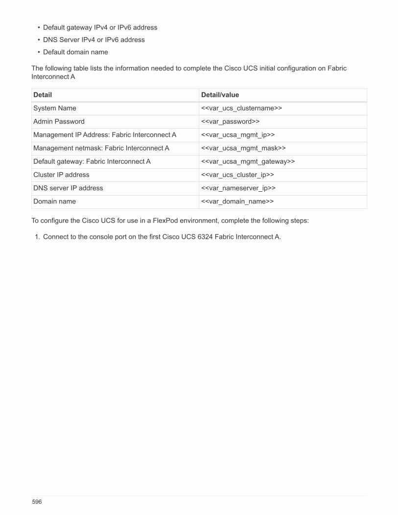
• Default gateway IPv4 or IPv6 address
• DNS Server IPv4 or IPv6 address
• Default domain name
The following table lists the information needed to complete the Cisco UCS initial configuration on FabricInterconnect A
Detail Detail/value
System Name <<var_ucs_clustername>>
Admin Password <<var_password>>
Management IP Address: Fabric Interconnect A <<var_ucsa_mgmt_ip>>
Management netmask: Fabric Interconnect A <<var_ucsa_mgmt_mask>>
Default gateway: Fabric Interconnect A <<var_ucsa_mgmt_gateway>>
Cluster IP address <<var_ucs_cluster_ip>>
DNS server IP address <<var_nameserver_ip>>
Domain name <<var_domain_name>>
To configure the Cisco UCS for use in a FlexPod environment, complete the following steps:
1. Connect to the console port on the first Cisco UCS 6324 Fabric Interconnect A.
596
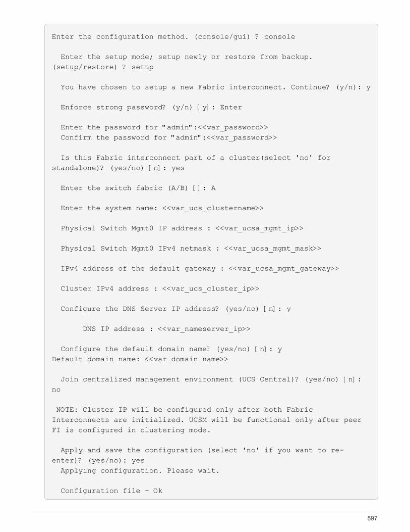
Enter the configuration method. (console/gui) ? console
Enter the setup mode; setup newly or restore from backup.
(setup/restore) ? setup
You have chosen to setup a new Fabric interconnect. Continue? (y/n): y
Enforce strong password? (y/n) [y]: Enter
Enter the password for "admin":<<var_password>>
Confirm the password for "admin":<<var_password>>
Is this Fabric interconnect part of a cluster(select 'no' for
standalone)? (yes/no) [n]: yes
Enter the switch fabric (A/B) []: A
Enter the system name: <<var_ucs_clustername>>
Physical Switch Mgmt0 IP address : <<var_ucsa_mgmt_ip>>
Physical Switch Mgmt0 IPv4 netmask : <<var_ucsa_mgmt_mask>>
IPv4 address of the default gateway : <<var_ucsa_mgmt_gateway>>
Cluster IPv4 address : <<var_ucs_cluster_ip>>
Configure the DNS Server IP address? (yes/no) [n]: y
DNS IP address : <<var_nameserver_ip>>
Configure the default domain name? (yes/no) [n]: y
Default domain name: <<var_domain_name>>
Join centralized management environment (UCS Central)? (yes/no) [n]:
no
NOTE: Cluster IP will be configured only after both Fabric
Interconnects are initialized. UCSM will be functional only after peer
FI is configured in clustering mode.
Apply and save the configuration (select 'no' if you want to re-
enter)? (yes/no): yes
Applying configuration. Please wait.
Configuration file - Ok
597

2. Review the settings displayed on the console. If they are correct, answer yes to apply and save theconfiguration.
3. Wait for the login prompt to verify that the configuration has been saved.
The following table lists the information needed to complete the Cisco UCS initial configuration on FabricInterconnect B.
Detail Detail/value
System Name <<var_ucs_clustername>>
Admin Password <<var_password>>
Management IP Address-FI B <<var_ucsb_mgmt_ip>>
Management Netmask-FI B <<var_ucsb_mgmt_mask>>
Default Gateway-FI B <<var_ucsb_mgmt_gateway>>
Cluster IP Address <<var_ucs_cluster_ip>>
DNS Server IP address <<var_nameserver_ip>>
Domain Name <<var_domain_name>>
1. Connect to the console port on the second Cisco UCS 6324 Fabric Interconnect B.
598
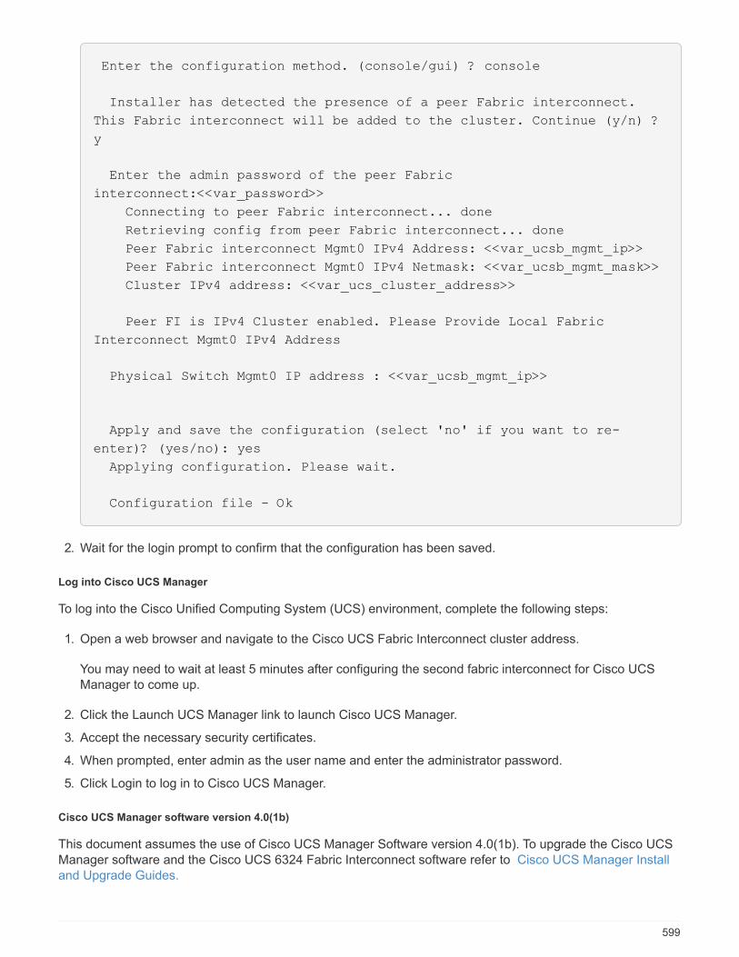
Enter the configuration method. (console/gui) ? console
Installer has detected the presence of a peer Fabric interconnect.
This Fabric interconnect will be added to the cluster. Continue (y/n) ?
y
Enter the admin password of the peer Fabric
interconnect:<<var_password>>
Connecting to peer Fabric interconnect... done
Retrieving config from peer Fabric interconnect... done
Peer Fabric interconnect Mgmt0 IPv4 Address: <<var_ucsb_mgmt_ip>>
Peer Fabric interconnect Mgmt0 IPv4 Netmask: <<var_ucsb_mgmt_mask>>
Cluster IPv4 address: <<var_ucs_cluster_address>>
Peer FI is IPv4 Cluster enabled. Please Provide Local Fabric
Interconnect Mgmt0 IPv4 Address
Physical Switch Mgmt0 IP address : <<var_ucsb_mgmt_ip>>
Apply and save the configuration (select 'no' if you want to re-
enter)? (yes/no): yes
Applying configuration. Please wait.
Configuration file - Ok
2. Wait for the login prompt to confirm that the configuration has been saved.
Log into Cisco UCS Manager
To log into the Cisco Unified Computing System (UCS) environment, complete the following steps:
1. Open a web browser and navigate to the Cisco UCS Fabric Interconnect cluster address.
You may need to wait at least 5 minutes after configuring the second fabric interconnect for Cisco UCSManager to come up.
2. Click the Launch UCS Manager link to launch Cisco UCS Manager.
3. Accept the necessary security certificates.
4. When prompted, enter admin as the user name and enter the administrator password.
5. Click Login to log in to Cisco UCS Manager.
Cisco UCS Manager software version 4.0(1b)
This document assumes the use of Cisco UCS Manager Software version 4.0(1b). To upgrade the Cisco UCSManager software and the Cisco UCS 6324 Fabric Interconnect software refer to Cisco UCS Manager Installand Upgrade Guides.
599

Configure Cisco UCS Call Home
Cisco highly recommends that you configure Call Home in Cisco UCS Manager. Configuring Call Homeaccelerates the resolution of support cases. To configure Call Home, complete the following steps:
1. In Cisco UCS Manager, click Admin on the left.
2. Select All > Communication Management > Call Home.
3. Change the State to On.
4. Fill in all the fields according to your Management preferences and click Save Changes and OK tocomplete configuring Call Home.
Add block of IP addresses for keyboard, video, mouse access
To create a block of IP addresses for in band server keyboard, video, mouse (KVM) access in the Cisco UCSenvironment, complete the following steps:
1. In Cisco UCS Manager, click LAN on the left.
2. Expand Pools > root > IP Pools.
3. Right-click IP Pool ext-mgmt and select Create Block of IPv4 Addresses.
4. Enter the starting IP address of the block, number of IP addresses required, and the subnet mask andgateway information.
5. Click OK to create the block.
6. Click OK in the confirmation message.
Synchronize Cisco UCS to NTP
To synchronize the Cisco UCS environment to the NTP servers in the Nexus switches, complete the followingsteps:
600

1. In Cisco UCS Manager, click Admin on the left.
2. Expand All > Time Zone Management.
3. Select Time Zone.
4. In the Properties pane, select the appropriate time zone in the Time Zone menu.
5. Click Save Changes and click OK.
6. Click Add NTP Server.
7. Enter <switch-a-ntp-ip> or <Nexus-A-mgmt-IP> and click OK. Click OK.
8. Click Add NTP Server.
9. Enter <switch-b-ntp-ip> or <Nexus-B-mgmt-IP> and click OK. Click OK on the confirmation.
Edit chassis discovery policy
Setting the discovery policy simplifies the addition of Cisco UCS B-Series chassis and of additional fabricextenders for further Cisco UCS C-Series connectivity. To modify the chassis discovery policy, complete thefollowing steps:
601

1. In Cisco UCS Manager, click Equipment on the left and select Equipment in the second list.
2. In the right pane, select the Policies tab.
3. Under Global Policies, set the Chassis/FEX Discovery Policy to match the minimum number of uplink portsthat are cabled between the chassis or fabric extenders (FEXes) and the fabric interconnects.
4. Set the Link Grouping Preference to Port Channel. If the environment being setup contains a large amountof multicast traffic, set the Multicast Hardware Hash setting to Enabled.
5. Click Save Changes.
6. Click OK.
Enable server, uplink, and storage ports
To enable server and uplink ports, complete the following steps:
1. In Cisco UCS Manager, in the navigation pane, select the Equipment tab.
2. Expand Equipment > Fabric Interconnects > Fabric Interconnect A > Fixed Module.
3. Expand Ethernet Ports.
4. Select ports 1 and 2 that are connected to the Cisco Nexus 31108 switches, right-click, and selectConfigure as Uplink Port.
5. Click Yes to confirm the uplink ports and click OK.
6. Select ports 3 and 4 that are connected to the NetApp Storage Controllers, right-click, and select Configureas Appliance Port.
7. Click Yes to confirm the appliance ports.
8. On the Configure as Appliance Port window, click OK.
9. Click OK to confirm.
10. In the left pane, select Fixed Module under Fabric Interconnect A.
11. From the Ethernet Ports tab, confirm that ports have been configured correctly in the If Role column. If anyport C-Series servers were configured on the Scalability port, click on it to verify port connectivity there.
602
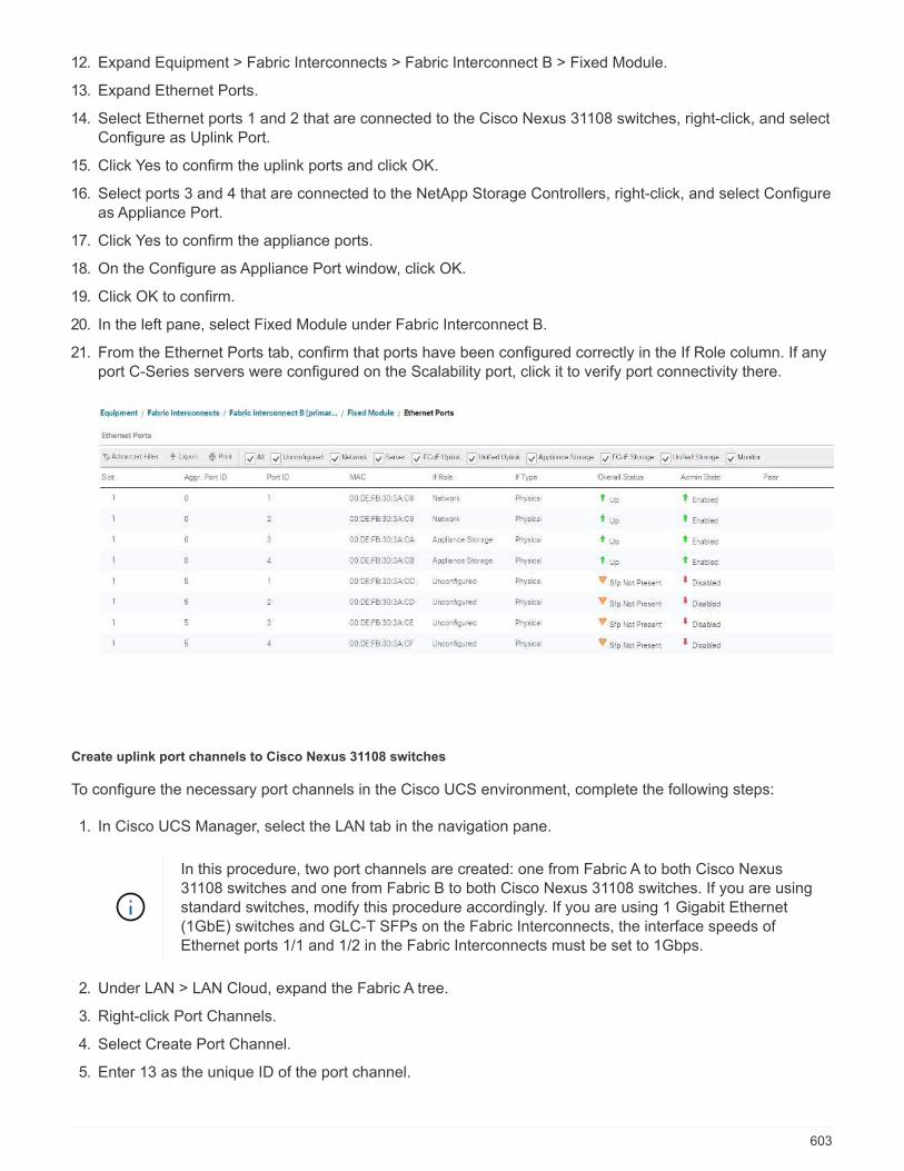
12. Expand Equipment > Fabric Interconnects > Fabric Interconnect B > Fixed Module.
13. Expand Ethernet Ports.
14. Select Ethernet ports 1 and 2 that are connected to the Cisco Nexus 31108 switches, right-click, and selectConfigure as Uplink Port.
15. Click Yes to confirm the uplink ports and click OK.
16. Select ports 3 and 4 that are connected to the NetApp Storage Controllers, right-click, and select Configureas Appliance Port.
17. Click Yes to confirm the appliance ports.
18. On the Configure as Appliance Port window, click OK.
19. Click OK to confirm.
20. In the left pane, select Fixed Module under Fabric Interconnect B.
21. From the Ethernet Ports tab, confirm that ports have been configured correctly in the If Role column. If anyport C-Series servers were configured on the Scalability port, click it to verify port connectivity there.
Create uplink port channels to Cisco Nexus 31108 switches
To configure the necessary port channels in the Cisco UCS environment, complete the following steps:
1. In Cisco UCS Manager, select the LAN tab in the navigation pane.
In this procedure, two port channels are created: one from Fabric A to both Cisco Nexus31108 switches and one from Fabric B to both Cisco Nexus 31108 switches. If you are usingstandard switches, modify this procedure accordingly. If you are using 1 Gigabit Ethernet(1GbE) switches and GLC-T SFPs on the Fabric Interconnects, the interface speeds ofEthernet ports 1/1 and 1/2 in the Fabric Interconnects must be set to 1Gbps.
2. Under LAN > LAN Cloud, expand the Fabric A tree.
3. Right-click Port Channels.
4. Select Create Port Channel.
5. Enter 13 as the unique ID of the port channel.
603

6. Enter vPC-13-Nexus as the name of the port channel.
7. Click Next.
8. Select the following ports to be added to the port channel:
a. Slot ID 1 and port 1
b. Slot ID 1 and port 2
9. Click >> to add the ports to the port channel.
10. Click Finish to create the port channel. Click OK.
11. Under Port Channels, select the newly created port channel.
The port channel should have an Overall Status of Up.
12. In the navigation pane, under LAN > LAN Cloud, expand the Fabric B tree.
13. Right-click Port Channels.
14. Select Create Port Channel.
15. Enter 14 as the unique ID of the port channel.
16. Enter vPC-14-Nexus as the name of the port channel. Click Next.
17. Select the following ports to be added to the port channel:
a. Slot ID 1 and port 1
b. Slot ID 1 and port 2
18. Click >> to add the ports to the port channel.
19. Click Finish to create the port channel. Click OK.
604
20. Under Port Channels, select the newly created port-channel.
21. The port channel should have an Overall Status of Up.
Create an organization (optional)
Organizations are used to organizing resources and restricting access to various groups within the ITorganization, thereby enabling multitenancy of the compute resources.
Although this document does not assume the use of organizations, this procedure providesinstructions for creating one.
To configure an organization in the Cisco UCS environment, complete the following steps:
1. In Cisco UCS Manager, from the New menu in the toolbar at the top of the window, select CreateOrganization.
2. Enter a name for the organization.
3. Optional: Enter a description for the organization. Click OK.
4. Click OK in the confirmation message.
Configure storage appliance ports and storage VLANs
To configure the storage appliance ports and storage VLANs, complete the following steps:
1. In the Cisco UCS Manager, select the LAN tab.
2. Expand the Appliances cloud.
3. Right-click VLANs under Appliances Cloud.
4. Select Create VLANs.
5. Enter NFS-VLAN as the name for the Infrastructure NFS VLAN.
6. Leave Common/Global selected.
7. Enter <<var_nfs_vlan_id>> for the VLAN ID.
8. Leave Sharing Type set to None.
605
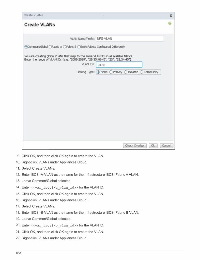
9. Click OK, and then click OK again to create the VLAN.
10. Right-click VLANs under Appliances Cloud.
11. Select Create VLANs.
12. Enter iSCSI-A-VLAN as the name for the Infrastructure iSCSI Fabric A VLAN.
13. Leave Common/Global selected.
14. Enter <<var_iscsi-a_vlan_id>> for the VLAN ID.
15. Click OK, and then click OK again to create the VLAN.
16. Right-click VLANs under Appliances Cloud.
17. Select Create VLANs.
18. Enter iSCSI-B-VLAN as the name for the Infrastructure iSCSI Fabric B VLAN.
19. Leave Common/Global selected.
20. Enter <<var_iscsi-b_vlan_id>> for the VLAN ID.
21. Click OK, and then click OK again to create the VLAN.
22. Right-click VLANs under Appliances Cloud.
606

23. Select Create VLANs.
24. Enter Native-VLAN as the name for the Native VLAN.
25. Leave Common/Global selected.
26. Enter <<var_native_vlan_id>> for the VLAN ID.
27. Click OK, and then click OK again to create the VLAN.
28. In the navigation pane, under LAN > Policies, expand Appliances and right-click Network Control Policies.
29. Select Create Network Control Policy.
30. Name the policy Enable_CDP_LLPD and select Enabled next to CDP.
31. Enable the Transmit and Receive features for LLDP.
32. Click OK and then click OK again to create the policy.
607
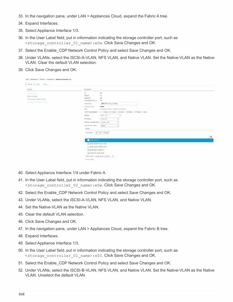
33. In the navigation pane, under LAN > Appliances Cloud, expand the Fabric A tree.
34. Expand Interfaces.
35. Select Appliance Interface 1/3.
36. In the User Label field, put in information indicating the storage controller port, such as
<storage_controller_01_name>:e0e. Click Save Changes and OK.
37. Select the Enable_CDP Network Control Policy and select Save Changes and OK.
38. Under VLANs, select the iSCSI-A-VLAN, NFS VLAN, and Native VLAN. Set the Native-VLAN as the NativeVLAN. Clear the default VLAN selection.
39. Click Save Changes and OK.
40. Select Appliance Interface 1/4 under Fabric A.
41. In the User Label field, put in information indicating the storage controller port, such as
<storage_controller_02_name>:e0e. Click Save Changes and OK.
42. Select the Enable_CDP Network Control Policy and select Save Changes and OK.
43. Under VLANs, select the iSCSI-A-VLAN, NFS VLAN, and Native VLAN.
44. Set the Native-VLAN as the Native VLAN.
45. Clear the default VLAN selection.
46. Click Save Changes and OK.
47. In the navigation pane, under LAN > Appliances Cloud, expand the Fabric B tree.
48. Expand Interfaces.
49. Select Appliance Interface 1/3.
50. In the User Label field, put in information indicating the storage controller port, such as
<storage_controller_01_name>:e0f. Click Save Changes and OK.
51. Select the Enable_CDP Network Control Policy and select Save Changes and OK.
52. Under VLANs, select the iSCSI-B-VLAN, NFS VLAN, and Native VLAN. Set the Native-VLAN as the NativeVLAN. Unselect the default VLAN.
608

53. Click Save Changes and OK.
54. Select Appliance Interface 1/4 under Fabric B.
55. In the User Label field, put in information indicating the storage controller port, such as
<storage_controller_02_name>:e0f. Click Save Changes and OK.
56. Select the Enable_CDP Network Control Policy and select Save Changes and OK.
57. Under VLANs, select the iSCSI-B-VLAN, NFS VLAN, and Native VLAN. Set the Native-VLAN as the NativeVLAN. Unselect the default VLAN.
58. Click Save Changes and OK.
Set jumbo frames in Cisco UCS fabric
To configure jumbo frames and enable quality of service in the Cisco UCS fabric, complete the following steps:
1. In Cisco UCS Manager, in the navigation pane, click the LAN tab.
2. Select LAN > LAN Cloud > QoS System Class.
3. In the right pane, click the General tab.
4. On the Best Effort row, enter 9216 in the box under the MTU column.
609

5. Click Save Changes.
6. Click OK.
Acknowledge Cisco UCS chassis
To acknowledge all Cisco UCS chassis, complete the following steps:
1. In Cisco UCS Manager, select the Equipment tab, then Expand the Equipment tab on the right.
2. Expand Equipment > Chassis.
3. In the Actions for Chassis 1, select Acknowledge Chassis.
4. Click OK and then click OK to complete acknowledging the chassis.
5. Click Close to close the Properties window.
Load Cisco UCS 4.0(1b) firmware images
To upgrade the Cisco UCS Manager software and the Cisco UCS Fabric Interconnect software to version4.0(1b) refer to Cisco UCS Manager Install and Upgrade Guides.
Create host firmware package
Firmware management policies allow the administrator to select the corresponding packages for a given serverconfiguration. These policies often include packages for adapter, BIOS, board controller, FC adapters, host busadapter (HBA) option ROM, and storage controller properties.
To create a firmware management policy for a given server configuration in the Cisco UCS environment,complete the following steps:
1. In Cisco UCS Manager, click Servers on the left.
2. Select Policies > root.
3. Expand Host Firmware Packages.
4. Select default.
5. In the Actions pane, select Modify Package Versions.
6. Select the version 4.0(1b) for both the Blade Packages.
610

7. Click OK then OK again to modify the host firmware package.
Create MAC address pools
To configure the necessary MAC address pools for the Cisco UCS environment, complete the following steps:
1. In Cisco UCS Manager, click LAN on the left.
2. Select Pools > root.
In this procedure, two MAC address pools are created, one for each switching fabric.
3. Right-click MAC Pools under the root organization.
4. Select Create MAC Pool to create the MAC address pool.
5. Enter MAC-Pool-A as the name of the MAC pool.
6. Optional: Enter a description for the MAC pool.
7. Select Sequential as the option for Assignment Order. Click Next.
8. Click Add.
9. Specify a starting MAC address.
611
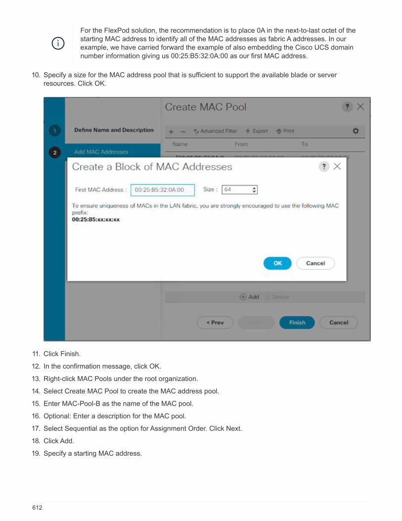
For the FlexPod solution, the recommendation is to place 0A in the next-to-last octet of thestarting MAC address to identify all of the MAC addresses as fabric A addresses. In ourexample, we have carried forward the example of also embedding the Cisco UCS domainnumber information giving us 00:25:B5:32:0A:00 as our first MAC address.
10. Specify a size for the MAC address pool that is sufficient to support the available blade or serverresources. Click OK.
11. Click Finish.
12. In the confirmation message, click OK.
13. Right-click MAC Pools under the root organization.
14. Select Create MAC Pool to create the MAC address pool.
15. Enter MAC-Pool-B as the name of the MAC pool.
16. Optional: Enter a description for the MAC pool.
17. Select Sequential as the option for Assignment Order. Click Next.
18. Click Add.
19. Specify a starting MAC address.
612

For the FlexPod solution, it is recommended to place 0B in the next to last octet of thestarting MAC address to identify all the MAC addresses in this pool as fabric B addresses.Once again, we have carried forward in our example of also embedding the Cisco UCSdomain number information giving us 00:25:B5:32:0B:00 as our first MAC address.
20. Specify a size for the MAC address pool that is sufficient to support the available blade or serverresources. Click OK.
21. Click Finish.
22. In the confirmation message, click OK.
Create iSCSI IQN pool
To configure the necessary IQN pools for the Cisco UCS environment, complete the following steps:
1. In Cisco UCS Manager, click SAN on the left.
2. Select Pools > root.
3. Right- click IQN Pools.
4. Select Create IQN Suffix Pool to create the IQN pool.
5. Enter IQN-Pool for the name of the IQN pool.
6. Optional: Enter a description for the IQN pool.
7. Enter iqn.1992-08.com.cisco as the prefix.
8. Select Sequential for Assignment Order. Click Next.
9. Click Add.
10. Enter ucs-host as the suffix.
If multiple Cisco UCS domains are being used, a more specific IQN suffix might need to beused.
11. Enter 1 in the From field.
12. Specify the size of the IQN block sufficient to support the available server resources. Click OK.
613
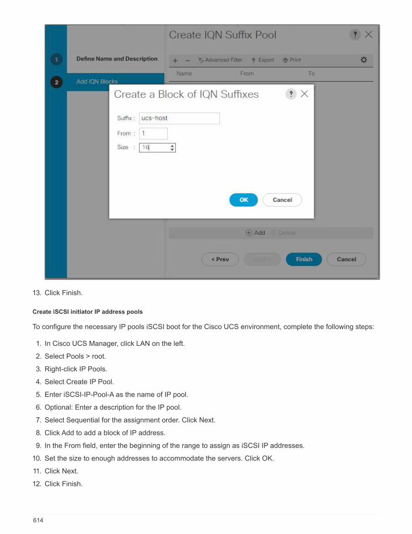
13. Click Finish.
Create iSCSI initiator IP address pools
To configure the necessary IP pools iSCSI boot for the Cisco UCS environment, complete the following steps:
1. In Cisco UCS Manager, click LAN on the left.
2. Select Pools > root.
3. Right-click IP Pools.
4. Select Create IP Pool.
5. Enter iSCSI-IP-Pool-A as the name of IP pool.
6. Optional: Enter a description for the IP pool.
7. Select Sequential for the assignment order. Click Next.
8. Click Add to add a block of IP address.
9. In the From field, enter the beginning of the range to assign as iSCSI IP addresses.
10. Set the size to enough addresses to accommodate the servers. Click OK.
11. Click Next.
12. Click Finish.
614
13. Right-click IP Pools.
14. Select Create IP Pool.
15. Enter iSCSI-IP-Pool-B as the name of IP pool.
16. Optional: Enter a description for the IP pool.
17. Select Sequential for the assignment order. Click Next.
18. Click Add to add a block of IP address.
19. In the From field, enter the beginning of the range to assign as iSCSI IP addresses.
20. Set the size to enough addresses to accommodate the servers. Click OK.
21. Click Next.
22. Click Finish.
Create UUID suffix pool
To configure the necessary universally unique identifier (UUID) suffix pool for the Cisco UCS environment,complete the following steps:
1. In Cisco UCS Manager, click Servers on the left.
2. Select Pools > root.
3. Right-click UUID Suffix Pools.
4. Select Create UUID Suffix Pool.
5. Enter UUID-Pool as the name of the UUID suffix pool.
6. Optional: Enter a description for the UUID suffix pool.
7. Keep the prefix at the derived option.
8. Select Sequential for the Assignment Order.
9. Click Next.
10. Click Add to add a block of UUIDs.
11. Keep the From field at the default setting.
12. Specify a size for the UUID block that is sufficient to support the available blade or server resources. ClickOK.
13. Click Finish.
14. Click OK.
Create server pool
To configure the necessary server pool for the Cisco UCS environment, complete the following steps:
Consider creating unique server pools to achieve the granularity that is required in yourenvironment.
1. In Cisco UCS Manager, click Servers on the left.
2. Select Pools > root.
3. Right-click Server Pools.
615
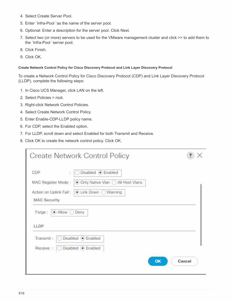
4. Select Create Server Pool.
5. Enter `Infra-Pool `as the name of the server pool.
6. Optional: Enter a description for the server pool. Click Next.
7. Select two (or more) servers to be used for the VMware management cluster and click >> to add them tothe `Infra-Pool `server pool.
8. Click Finish.
9. Click OK.
Create Network Control Policy for Cisco Discovery Protocol and Link Layer Discovery Protocol
To create a Network Control Policy for Cisco Discovery Protocol (CDP) and Link Layer Discovery Protocol(LLDP), complete the following steps:
1. In Cisco UCS Manager, click LAN on the left.
2. Select Policies > root.
3. Right-click Network Control Policies.
4. Select Create Network Control Policy.
5. Enter Enable-CDP-LLDP policy name.
6. For CDP, select the Enabled option.
7. For LLDP, scroll down and select Enabled for both Transmit and Receive.
8. Click OK to create the network control policy. Click OK.
616
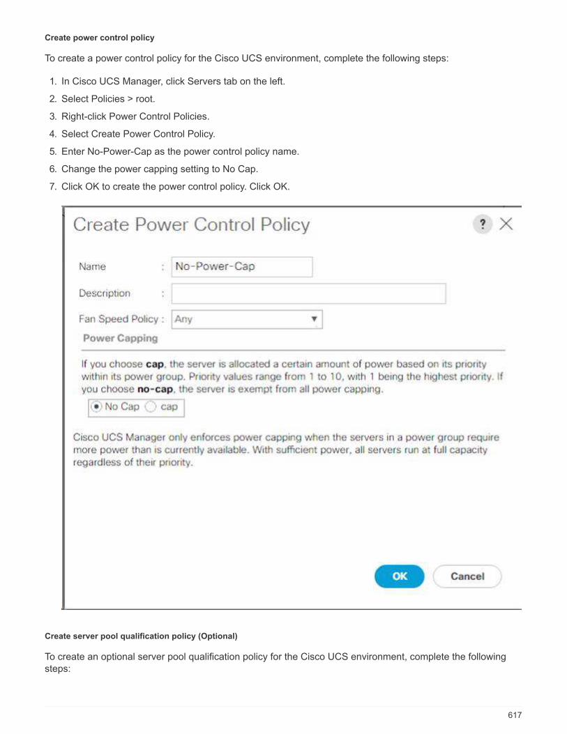
Create power control policy
To create a power control policy for the Cisco UCS environment, complete the following steps:
1. In Cisco UCS Manager, click Servers tab on the left.
2. Select Policies > root.
3. Right-click Power Control Policies.
4. Select Create Power Control Policy.
5. Enter No-Power-Cap as the power control policy name.
6. Change the power capping setting to No Cap.
7. Click OK to create the power control policy. Click OK.
Create server pool qualification policy (Optional)
To create an optional server pool qualification policy for the Cisco UCS environment, complete the followingsteps:
617

This example creates a policy for Cisco UCS B-Series servers with the Intel E2660 v4 XeonBroadwell processors.
1. In Cisco UCS Manager, click Servers on the left.
2. Select Policies > root.
3. Select Server Pool Policy Qualifications.
4. Select Create Server Pool Policy Qualification or Add.
5. Name the policy Intel.
6. Select Create CPU/Cores Qualifications.
7. Select Xeon for the Processor/Architecture.
8. Enter <UCS-CPU- PID> as the process ID (PID).
9. Click OK to create the CPU/Core qualification.
10. Click OK to create the policy, and then click OK for the confirmation.
Create server BIOS policy
To create a server BIOS policy for the Cisco UCS environment, complete the following steps:
1. In Cisco UCS Manager, click Servers on the left.
2. Select Policies > root.
3. Right-click BIOS Policies.
4. Select Create BIOS Policy.
5. Enter VM-Host as the BIOS policy name.
6. Change the Quiet Boot setting to disabled.
7. Change Consistent Device Naming to enabled.
618

8. Select the Processor tab and set the following parameters:
◦ Processor C State: disabled
◦ Processor C1E: disabled
◦ Processor C3 Report: disabled
◦ Processor C7 Report: disabled
9. Scroll down to the remaining Processor options and set the following parameters:
◦ Energy Performance: performance
◦ Frequency Floor Override: enabled
◦ DRAM Clock Throttling: performance
619
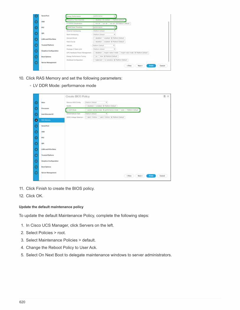
10. Click RAS Memory and set the following parameters:
◦ LV DDR Mode: performance mode
11. Click Finish to create the BIOS policy.
12. Click OK.
Update the default maintenance policy
To update the default Maintenance Policy, complete the following steps:
1. In Cisco UCS Manager, click Servers on the left.
2. Select Policies > root.
3. Select Maintenance Policies > default.
4. Change the Reboot Policy to User Ack.
5. Select On Next Boot to delegate maintenance windows to server administrators.
620

6. Click Save Changes.
7. Click OK to accept the change.
Create vNIC templates
To create multiple virtual network interface card (vNIC) templates for the Cisco UCS environment, complete theprocedures described in this section.
A total of four vNIC templates are created.
Create infrastructure vNICs
To create an infrastructure vNIC, complete the following steps:
1. In Cisco UCS Manager, click LAN on the left.
2. Select Policies > root.
3. Right-click vNIC Templates.
4. Select Create vNIC Template.
5. Enter Site-XX-vNIC_A as the vNIC template name.
6. Select updating-template as the Template Type.
7. For Fabric ID, select Fabric A.
8. Ensure that the Enable Failover option is not selected.
9. Select Primary Template for Redundancy Type.
10. Leave the Peer Redundancy Template set to <not set>.
11. Under Target, make sure that only the Adapter option is selected.
12. Set Native-VLAN as the native VLAN.
13. Select vNIC Name for the CDN Source.
14. For MTU, enter 9000.
15. Under Permitted VLANs, select Native-VLAN, Site-XX-IB-MGMT, Site-XX-NFS, Site-XX-VM-
Traffic, and Site-XX-vMotion. Use the Ctrl key to make this multiple selection.
16. Click Select. These VLANs should now appear under Selected VLANs.
17. In the MAC Pool list, select MAC_Pool_A.
621
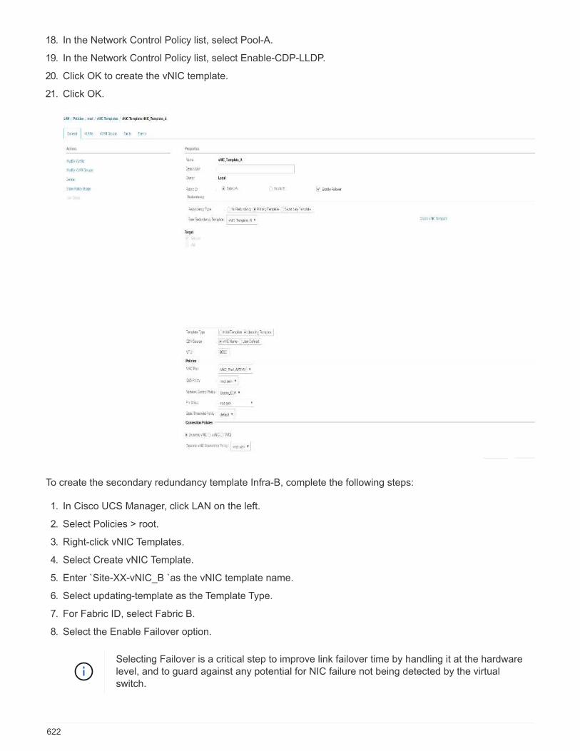
18. In the Network Control Policy list, select Pool-A.
19. In the Network Control Policy list, select Enable-CDP-LLDP.
20. Click OK to create the vNIC template.
21. Click OK.
To create the secondary redundancy template Infra-B, complete the following steps:
1. In Cisco UCS Manager, click LAN on the left.
2. Select Policies > root.
3. Right-click vNIC Templates.
4. Select Create vNIC Template.
5. Enter `Site-XX-vNIC_B `as the vNIC template name.
6. Select updating-template as the Template Type.
7. For Fabric ID, select Fabric B.
8. Select the Enable Failover option.
Selecting Failover is a critical step to improve link failover time by handling it at the hardwarelevel, and to guard against any potential for NIC failure not being detected by the virtualswitch.
622
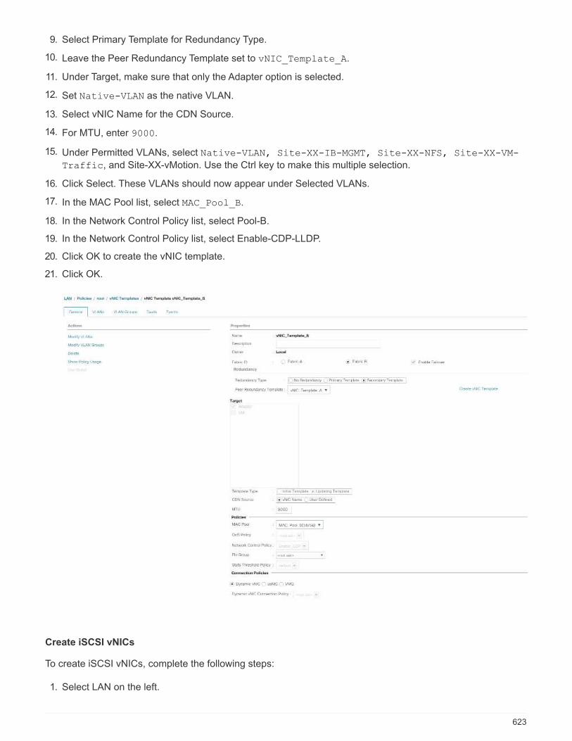
9. Select Primary Template for Redundancy Type.
10. Leave the Peer Redundancy Template set to vNIC_Template_A.
11. Under Target, make sure that only the Adapter option is selected.
12. Set Native-VLAN as the native VLAN.
13. Select vNIC Name for the CDN Source.
14. For MTU, enter 9000.
15. Under Permitted VLANs, select Native-VLAN, Site-XX-IB-MGMT, Site-XX-NFS, Site-XX-VM-
Traffic, and Site-XX-vMotion. Use the Ctrl key to make this multiple selection.
16. Click Select. These VLANs should now appear under Selected VLANs.
17. In the MAC Pool list, select MAC_Pool_B.
18. In the Network Control Policy list, select Pool-B.
19. In the Network Control Policy list, select Enable-CDP-LLDP.
20. Click OK to create the vNIC template.
21. Click OK.
Create iSCSI vNICs
To create iSCSI vNICs, complete the following steps:
1. Select LAN on the left.
623

2. Select Policies > root.
3. Right-click vNIC Templates.
4. Select Create vNIC Template.
5. Enter Site- 01-iSCSI_A as the vNIC template name.
6. Select Fabric A. Do not select the Enable Failover option.
7. Leave Redundancy Type set at No Redundancy.
8. Under Target, make sure that only the Adapter option is selected.
9. Select Updating Template for Template Type.
10. Under VLANs, select only Site- 01-iSCSI_A_VLAN.
11. Select Site- 01-iSCSI_A_VLAN as the native VLAN.
12. Leave vNIC Name set for the CDN Source.
13. Under MTU, enter 9000.
14. From the MAC Pool list, select MAC-Pool-A.
15. From the Network Control Policy list, select Enable-CDP-LLDP.
16. Click OK to complete creating the vNIC template.
17. Click OK.
624

18. Select LAN on the left.
19. Select Policies > root.
20. Right-click vNIC Templates.
21. Select Create vNIC Template.
22. Enter Site- 01-iSCSI_B as the vNIC template name.
23. Select Fabric B. Do not select the Enable Failover option.
24. Leave Redundancy Type set at No Redundancy.
25. Under Target, make sure that only the Adapter option is selected.
26. Select Updating Template for Template Type.
27. Under VLANs, select only Site- 01-iSCSI_B_VLAN.
28. Select Site- 01-iSCSI_B_VLAN as the native VLAN.
29. Leave vNIC Name set for the CDN Source.
30. Under MTU, enter 9000.
31. From the MAC Pool list, select MAC-Pool-B.
32. From the Network Control Policy list, select Enable-CDP-LLDP.
33. Click OK to complete creating the vNIC template.
34. Click OK.
625
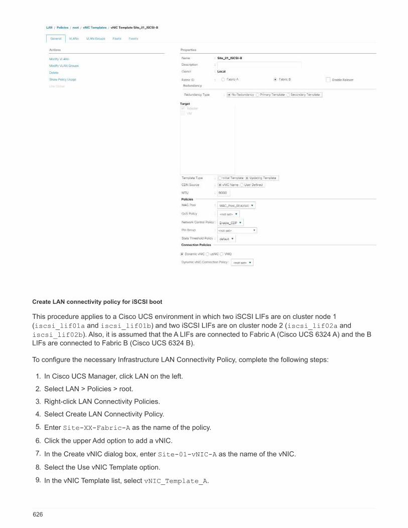
Create LAN connectivity policy for iSCSI boot
This procedure applies to a Cisco UCS environment in which two iSCSI LIFs are on cluster node 1
(iscsi_lif01a and iscsi_lif01b) and two iSCSI LIFs are on cluster node 2 (iscsi_lif02a and
iscsi_lif02b). Also, it is assumed that the A LIFs are connected to Fabric A (Cisco UCS 6324 A) and the BLIFs are connected to Fabric B (Cisco UCS 6324 B).
To configure the necessary Infrastructure LAN Connectivity Policy, complete the following steps:
1. In Cisco UCS Manager, click LAN on the left.
2. Select LAN > Policies > root.
3. Right-click LAN Connectivity Policies.
4. Select Create LAN Connectivity Policy.
5. Enter Site-XX-Fabric-A as the name of the policy.
6. Click the upper Add option to add a vNIC.
7. In the Create vNIC dialog box, enter Site-01-vNIC-A as the name of the vNIC.
8. Select the Use vNIC Template option.
9. In the vNIC Template list, select vNIC_Template_A.
626

10. From the Adapter Policy drop-down list, select VMWare.
11. Click OK to add this vNIC to the policy.
12. Click the upper Add option to add a vNIC.
13. In the Create vNIC dialog box, enter Site-01-vNIC-B as the name of the vNIC.
14. Select the Use vNIC Template option.
15. In the vNIC Template list, select vNIC_Template_B.
16. From the Adapter Policy drop-down list, select VMWare.
17. Click OK to add this vNIC to the policy.
18. Click the upper Add option to add a vNIC.
19. In the Create vNIC dialog box, enter Site-01- iSCSI-A as the name of the vNIC.
20. Select the Use vNIC Template option.
21. In the vNIC Template list, select Site-01-iSCSI-A.
22. From the Adapter Policy drop-down list, select VMWare.
23. Click OK to add this vNIC to the policy.
24. Click the upper Add option to add a vNIC.
627

25. In the Create vNIC dialog box, enter Site-01-iSCSI-B as the name of the vNIC.
26. Select the Use vNIC Template option.
27. In the vNIC Template list, select Site-01-iSCSI-B.
28. From the Adapter Policy drop-down list, select VMWare.
29. Click OK to add this vNIC to the policy.
30. Expand the Add iSCSI vNICs option.
31. Click the Lower Add option in the Add iSCSI vNICs space to add the iSCSI vNIC.
32. In the Create iSCSI vNIC dialog box, enter Site-01-iSCSI-A as the name of the vNIC.
33. Select the Overlay vNIC as Site-01-iSCSI-A.
34. Leave the iSCSI Adapter Policy option to Not Set.
35. Select the VLAN as Site-01-iSCSI-Site-A (native).
36. Select None (used by default) as the MAC address assignment.
37. Click OK to add the iSCSI vNIC to the policy.
628

38. Click the Lower Add option in the Add iSCSI vNICs space to add the iSCSI vNIC.
39. In the Create iSCSI vNIC dialog box, enter Site-01-iSCSI-B as the name of the vNIC.
40. Select the Overlay vNIC as Site-01-iSCSI-B.
41. Leave the iSCSI Adapter Policy option to Not Set.
42. Select the VLAN as Site-01-iSCSI-Site-B (native).
43. Select None(used by default) as the MAC Address Assignment.
44. Click OK to add the iSCSI vNIC to the policy.
45. Click Save Changes.
629
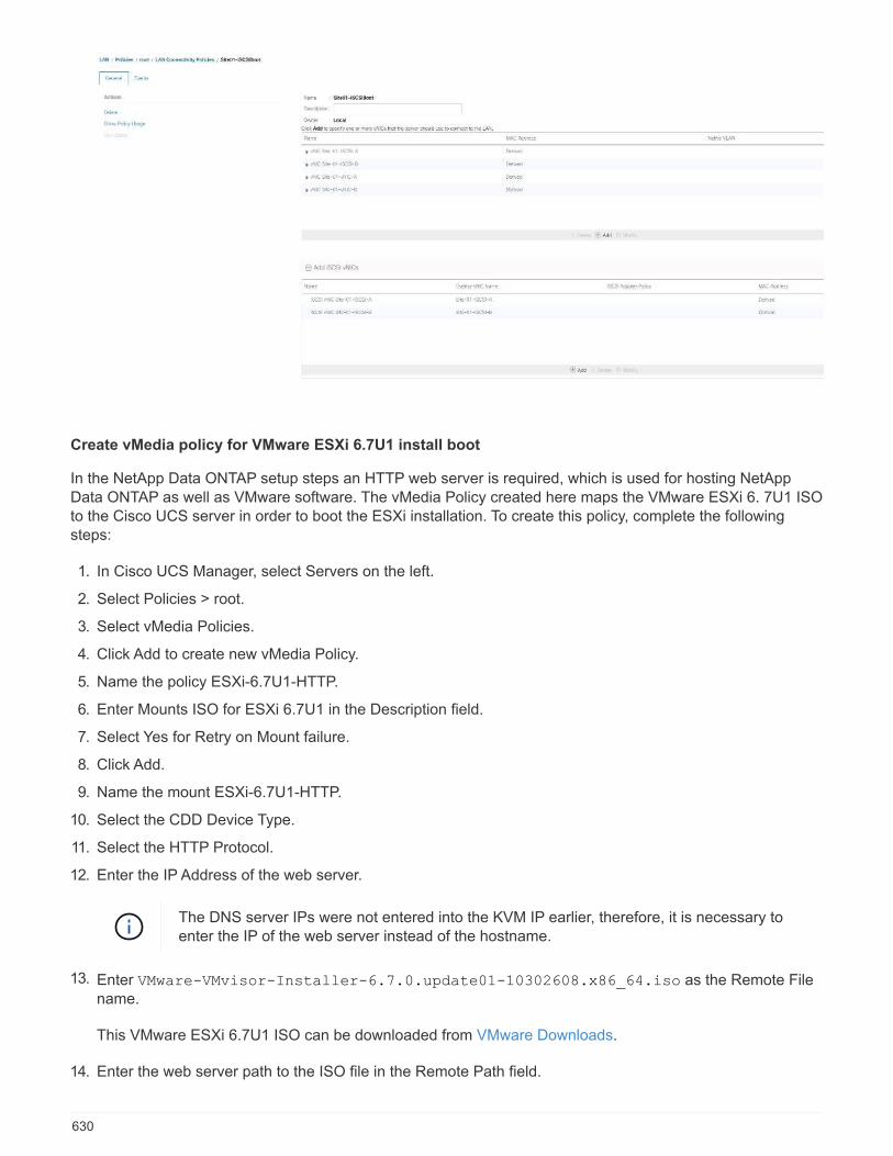
Create vMedia policy for VMware ESXi 6.7U1 install boot
In the NetApp Data ONTAP setup steps an HTTP web server is required, which is used for hosting NetAppData ONTAP as well as VMware software. The vMedia Policy created here maps the VMware ESXi 6. 7U1 ISOto the Cisco UCS server in order to boot the ESXi installation. To create this policy, complete the followingsteps:
1. In Cisco UCS Manager, select Servers on the left.
2. Select Policies > root.
3. Select vMedia Policies.
4. Click Add to create new vMedia Policy.
5. Name the policy ESXi-6.7U1-HTTP.
6. Enter Mounts ISO for ESXi 6.7U1 in the Description field.
7. Select Yes for Retry on Mount failure.
8. Click Add.
9. Name the mount ESXi-6.7U1-HTTP.
10. Select the CDD Device Type.
11. Select the HTTP Protocol.
12. Enter the IP Address of the web server.
The DNS server IPs were not entered into the KVM IP earlier, therefore, it is necessary toenter the IP of the web server instead of the hostname.
13. Enter VMware-VMvisor-Installer-6.7.0.update01-10302608.x86_64.iso as the Remote Filename.
This VMware ESXi 6.7U1 ISO can be downloaded from VMware Downloads.
14. Enter the web server path to the ISO file in the Remote Path field.
630

15. Click OK to create the vMedia Mount.
16. Click OK then OK again to complete creating the vMedia Policy.
For any new servers added to the Cisco UCS environment the vMedia service profile template can be usedto install the ESXi host. On first boot, the host boots into the ESXi installer since the SAN mounted disk isempty. After ESXi is installed, the vMedia is not referenced as long as the boot disk is accessible.
Create iSCSI boot policy
The procedure in this section applies to a Cisco UCS environment in which two iSCSI logical interfaces (LIFs)
are on cluster node 1 (iscsi_lif01a and iscsi_lif01b) and two iSCSI LIFs are on cluster node 2
(iscsi_lif02a and iscsi_lif02b). Also, it is assumed that the A LIFs are connected to Fabric A (CiscoUCS Fabric Interconnect A) and the B LIFs are connected to Fabric B (Cisco UCS Fabric Interconnect B).
One boot policy is configured in this procedure. The policy configures the primary target to be
iscsi_lif01a.
To create a boot policy for the Cisco UCS environment, complete the following steps:
1. In Cisco UCS Manager, click Servers on the left.
2. Select Policies > root.
3. Right-click Boot Policies.
4. Select Create Boot Policy.
631

5. Enter Site-01-Fabric-A as the name of the boot policy.
6. Optional: Enter a description for the boot policy.
7. Keep the Reboot on Boot Order Change option cleared.
8. Boot Mode is Legacy.
9. Expand the Local Devices drop-down menu and select Add Remote CD/DVD.
10. Expand the iSCSI vNICs drop-down menu and select Add iSCSI Boot.
11. In the Add iSCSI Boot dialog box, enter Site-01-iSCSI-A. Click OK.
12. Select Add iSCSI Boot.
13. In the Add iSCSI Boot dialog box, enter Site-01-iSCSI-B. Click OK.
14. Click OK to create the policy.
Create service profile template
In this procedure, one service profile template for Infrastructure ESXi hosts is created for Fabric A boot.
To create the service profile template, complete the following steps:
1. In Cisco UCS Manager, click Servers on the left.
2. Select Service Profile Templates > root.
3. Right-click root.
4. Select Create Service Profile Template to open the Create Service Profile Template wizard.
5. Enter VM-Host-Infra-iSCSI-A as the name of the service profile template. This service profile templateis configured to boot from storage node 1 on fabric A.
6. Select the Updating Template option.
7. Under UUID, select UUID_Pool as the UUID pool. Click Next.
632

Configure storage provisioning
To configure storage provisioning, complete the following steps:
1. If you have servers with no physical disks, click Local Disk Configuration Policy and select the SAN BootLocal Storage Policy. Otherwise, select the default Local Storage Policy.
2. Click Next.
Configure networking options
To configure the networking options, complete the following steps:
1. Keep the default setting for Dynamic vNIC Connection Policy.
2. Select the Use Connectivity Policy option to configure the LAN connectivity.
3. Select iSCSI-Boot from the LAN Connectivity Policy drop-down menu.
4. Select IQN_Pool in Initiator Name Assignment. Click Next.
633

Configure SAN connectivity
To configure SAN connectivity, complete the following steps:
1. For the vHBAs, select No for the How Would you Like to Configure SAN Connectivity? option.
2. Click Next.
Configure zoning
To configure zoning, simply click Next.
Configure vNIC/HBA placement
To configure vNIC/HBA placement, complete the following steps:
1. From the Select Placement drop-down list, leave the placement policy as Let System Perform Placement.
2. Click Next.
Configure vMedia policy
To configure the vMedia policy, complete the following steps:
1. Do not select a vMedia Policy.
2. Click Next.
634
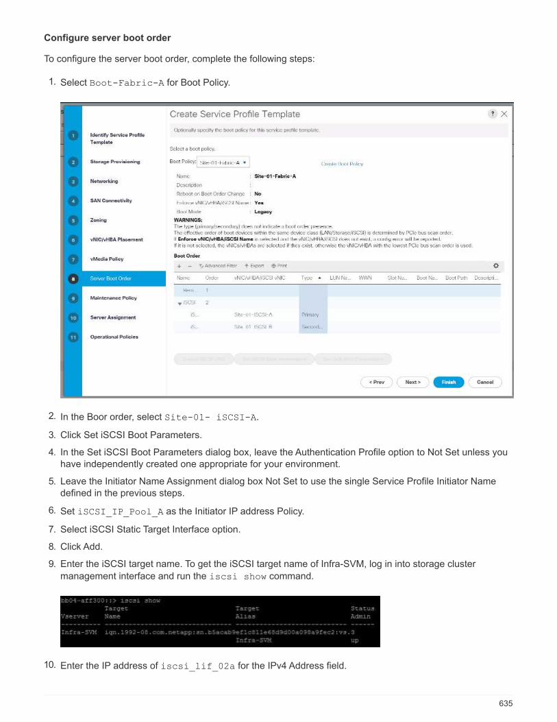
Configure server boot order
To configure the server boot order, complete the following steps:
1. Select Boot-Fabric-A for Boot Policy.
2. In the Boor order, select Site-01- iSCSI-A.
3. Click Set iSCSI Boot Parameters.
4. In the Set iSCSI Boot Parameters dialog box, leave the Authentication Profile option to Not Set unless youhave independently created one appropriate for your environment.
5. Leave the Initiator Name Assignment dialog box Not Set to use the single Service Profile Initiator Namedefined in the previous steps.
6. Set iSCSI_IP_Pool_A as the Initiator IP address Policy.
7. Select iSCSI Static Target Interface option.
8. Click Add.
9. Enter the iSCSI target name. To get the iSCSI target name of Infra-SVM, log in into storage cluster
management interface and run the iscsi show command.
10. Enter the IP address of iscsi_lif_02a for the IPv4 Address field.
635

11. Click OK to add the iSCSI static target.
12. Click Add.
13. Enter the iSCSI target name.
14. Enter the IP address of iscsi_lif_01a for the IPv4 Address field.
15. Click OK to add the iSCSI static target.
636
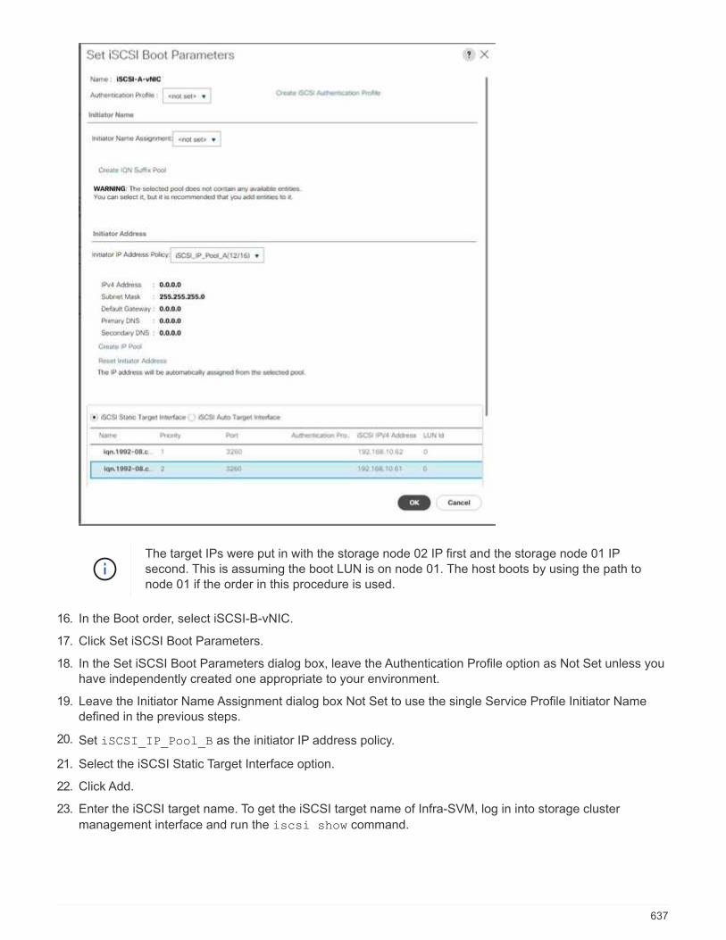
The target IPs were put in with the storage node 02 IP first and the storage node 01 IPsecond. This is assuming the boot LUN is on node 01. The host boots by using the path tonode 01 if the order in this procedure is used.
16. In the Boot order, select iSCSI-B-vNIC.
17. Click Set iSCSI Boot Parameters.
18. In the Set iSCSI Boot Parameters dialog box, leave the Authentication Profile option as Not Set unless youhave independently created one appropriate to your environment.
19. Leave the Initiator Name Assignment dialog box Not Set to use the single Service Profile Initiator Namedefined in the previous steps.
20. Set iSCSI_IP_Pool_B as the initiator IP address policy.
21. Select the iSCSI Static Target Interface option.
22. Click Add.
23. Enter the iSCSI target name. To get the iSCSI target name of Infra-SVM, log in into storage cluster
management interface and run the iscsi show command.
637
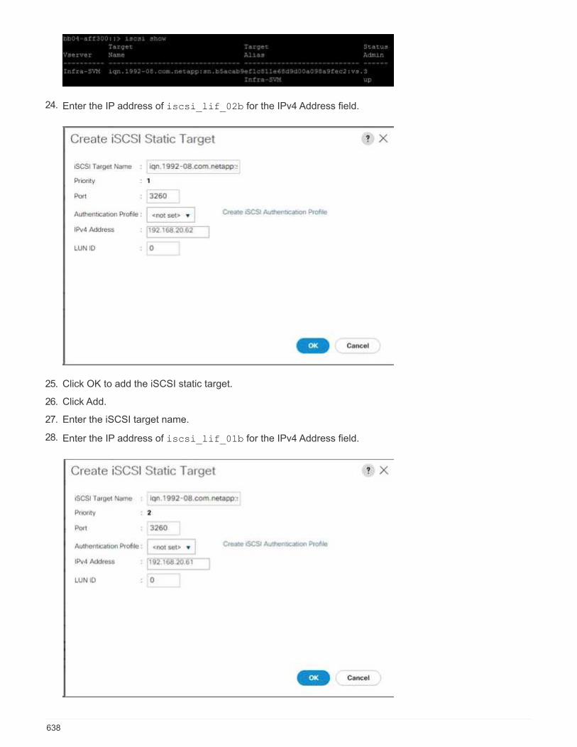
24. Enter the IP address of iscsi_lif_02b for the IPv4 Address field.
25. Click OK to add the iSCSI static target.
26. Click Add.
27. Enter the iSCSI target name.
28. Enter the IP address of iscsi_lif_01b for the IPv4 Address field.
638

29. Click OK to add the iSCSI static target.
30. Click Next.
Configure maintenance policy
To configure the maintenance policy, complete the following steps:
1. Change the maintenance policy to default.
639

2. Click Next.
Configure server assignment
To configure the server assignment, complete the following steps:
1. In the Pool Assignment list, select Infra-Pool.
2. Select Down as the power state to be applied when the profile is associated with the server.
3. Expand Firmware Management at the bottom of the page and select the default policy.
640
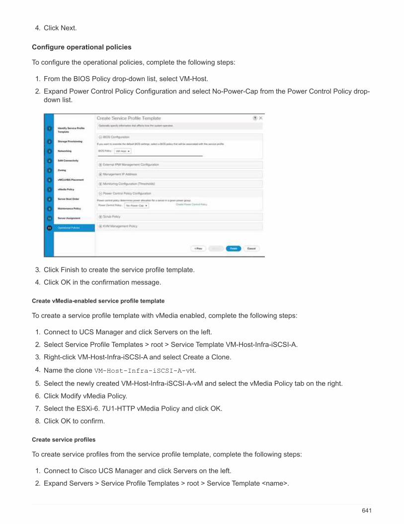
4. Click Next.
Configure operational policies
To configure the operational policies, complete the following steps:
1. From the BIOS Policy drop-down list, select VM-Host.
2. Expand Power Control Policy Configuration and select No-Power-Cap from the Power Control Policy drop-down list.
3. Click Finish to create the service profile template.
4. Click OK in the confirmation message.
Create vMedia-enabled service profile template
To create a service profile template with vMedia enabled, complete the following steps:
1. Connect to UCS Manager and click Servers on the left.
2. Select Service Profile Templates > root > Service Template VM-Host-Infra-iSCSI-A.
3. Right-click VM-Host-Infra-iSCSI-A and select Create a Clone.
4. Name the clone VM-Host-Infra-iSCSI-A-vM.
5. Select the newly created VM-Host-Infra-iSCSI-A-vM and select the vMedia Policy tab on the right.
6. Click Modify vMedia Policy.
7. Select the ESXi-6. 7U1-HTTP vMedia Policy and click OK.
8. Click OK to confirm.
Create service profiles
To create service profiles from the service profile template, complete the following steps:
1. Connect to Cisco UCS Manager and click Servers on the left.
2. Expand Servers > Service Profile Templates > root > Service Template <name>.
641
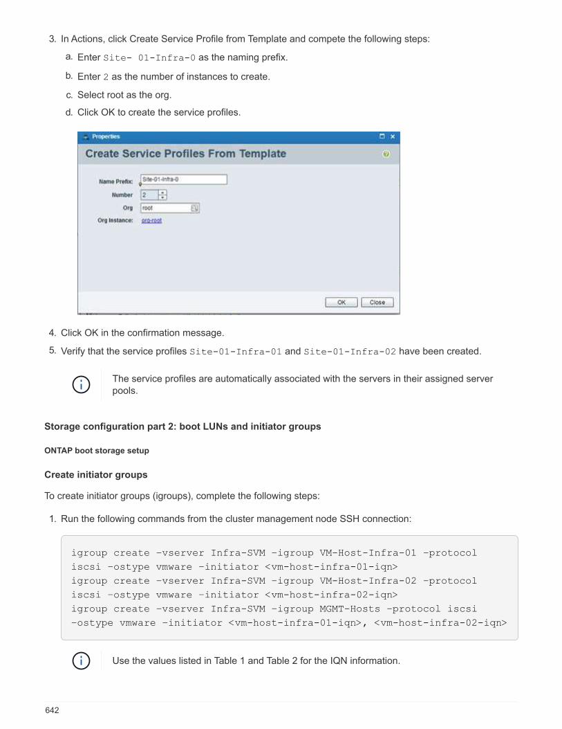
3. In Actions, click Create Service Profile from Template and compete the following steps:
a. Enter Site- 01-Infra-0 as the naming prefix.
b. Enter 2 as the number of instances to create.
c. Select root as the org.
d. Click OK to create the service profiles.
4. Click OK in the confirmation message.
5. Verify that the service profiles Site-01-Infra-01 and Site-01-Infra-02 have been created.
The service profiles are automatically associated with the servers in their assigned serverpools.
Storage configuration part 2: boot LUNs and initiator groups
ONTAP boot storage setup
Create initiator groups
To create initiator groups (igroups), complete the following steps:
1. Run the following commands from the cluster management node SSH connection:
igroup create –vserver Infra-SVM –igroup VM-Host-Infra-01 –protocol
iscsi –ostype vmware –initiator <vm-host-infra-01-iqn>
igroup create –vserver Infra-SVM –igroup VM-Host-Infra-02 –protocol
iscsi –ostype vmware –initiator <vm-host-infra-02-iqn>
igroup create –vserver Infra-SVM –igroup MGMT-Hosts –protocol iscsi
–ostype vmware –initiator <vm-host-infra-01-iqn>, <vm-host-infra-02-iqn>
Use the values listed in Table 1 and Table 2 for the IQN information.
642

2. To view the three igroups just created, run the igroup show command.
Map boot LUNs to igroups
To map boot LUNs to igroups, complete the following step:
1. From the storage cluster management SSH connection, run the following commands:
lun map –vserver Infra-SVM –volume esxi_boot –lun VM-Host-Infra- A
–igroup VM-Host-Infra-01 –lun-id 0lun map –vserver Infra-SVM –volume
esxi_boot –lun VM-Host-Infra- B –igroup VM-Host-Infra-02 –lun-id 0
VMware vSphere 6.7U1 deployment procedure
This section provides detailed procedures for installing VMware ESXi 6.7U1 in a FlexPod Expressconfiguration. After the procedures are completed, two booted ESXi hosts are provisioned.
Several methods exist for installing ESXi in a VMware environment. These procedures focus on how to use thebuilt-in KVM console and virtual media features in Cisco UCS Manager to map remote installation media toindividual servers and connect to their boot LUNs.
Download Cisco custom image for ESXi 6.7U1
If the VMware ESXi custom image has not been downloaded, complete the following steps to complete thedownload:
1. Click the following xref:./express/ VMware vSphere Hypervisor (ESXi) 6.7U1.
2. You need a user ID and password on vmware.com to download this software.
3. Download the .iso file.
Cisco UCS Manager
The Cisco UCS IP KVM enables the administrator to begin the installation of the OS through remote media. Itis necessary to log in to the Cisco UCS environment to run the IP KVM.
To log in to the Cisco UCS environment, complete the following steps:
1. Open a web browser and enter the IP address for the Cisco UCS cluster address. This step launches theCisco UCS Manager application.
2. Click the Launch UCS Manager link under HTML to launch the HTML 5 UCS Manager GUI.
3. If prompted to accept security certificates, accept as necessary.
4. When prompted, enter admin as the user name and enter the administrative password.
5. To log in to Cisco UCS Manager, click Login.
6. From the main menu, click Servers on the left.
7. Select Servers > Service Profiles > root > VM-Host-Infra-01.
8. Right-click VM-Host-Infra-01 and select KVM Console.
643
9. Follow the prompts to launch the Java-based KVM console.
10. Select Servers > Service Profiles > root > VM-Host-Infra-02.
11. Right-click VM-Host-Infra-02. and select KVM Console.
12. Follow the prompts to launch the Java-based KVM console.
Set up VMware ESXi installation
ESXi Hosts VM-Host-Infra-01 and VM-Host- Infra-02
To prepare the server for the OS installation, complete the following steps on each ESXi host:
1. In the KVM window, click Virtual Media.
2. Click Activate Virtual Devices.
3. If prompted to accept an Unencrypted KVM session, accept as necessary.
4. Click Virtual Media and select Map CD/DVD.
5. Browse to the ESXi installer ISO image file and click Open.
6. Click Map Device.
7. Click the KVM tab to monitor the server boot.
Install ESXi
ESXi Hosts VM-Host-Infra-01 and VM-Host-Infra-02
To install VMware ESXi to the iSCSI-bootable LUN of the hosts, complete the following steps on each host:
1. Boot the server by selecting Boot Server and clicking OK. Then click OK again.
2. On reboot, the machine detects the presence of the ESXi installation media. Select the ESXi installer fromthe boot menu that is displayed.
3. After the installer is finished loading, press Enter to continue with the installation.
4. Read and accept the end-user license agreement (EULA). Press F11 to accept and continue.
5. Select the LUN that was previously set up as the installation disk for ESXi and press Enter to continue withthe installation.
6. Select the appropriate keyboard layout and press Enter.
7. Enter and confirm the root password and press Enter.
8. The installer issues a warning that the selected disk will be repartitioned. Press F11 to continue with theinstallation.
9. After the installation is complete, select the Virtual Media tab and clear the P mark next to the ESXiinstallation media. Click Yes.
The ESXi installation image must be unmapped to make sure that the server reboots intoESXi and not into the installer.
10. After the installation is complete, press Enter to reboot the server.
11. In Cisco UCS Manager, bind the current service profile to the non-vMedia service profile template toprevent mounting the ESXi installation iso over HTTP.
644

Set up management networking for ESXi hosts
Adding a management network for each VMware host is necessary for managing the host. To add amanagement network for the VMware hosts, complete the following steps on each ESXi host:
ESXi Host VM-Host-Infra-01 and VM-Host-Infra-02
To configure each ESXi host with access to the management network, complete the following steps:
1. After the server has finished rebooting, press F2 to customize the system.
2. Log in as root, enter the corresponding password, and press Enter to log in.
3. Select Troubleshooting Options and press Enter.
4. Select Enable ESXi Shell and press Enter.
5. Select Enable SSH and press Enter.
6. Press Esc to exit the Troubleshooting Options menu.
7. Select the Configure Management Network option and press Enter.
8. Select Network Adapters and press Enter.
9. Verify that the numbers in the Hardware Label field match the numbers in the Device Name field.
10. Press Enter.
11. Select the VLAN (Optional) option and press Enter.
12. Enter the <ib-mgmt-vlan-id> and press Enter.
13. Select IPv4 Configuration and press Enter.
14. Select the Set Static IPv4 Address and Network Configuration option by using the space bar.
15. Enter the IP address for managing the first ESXi host.
16. Enter the subnet mask for the first ESXi host.
645

17. Enter the default gateway for the first ESXi host.
18. Press Enter to accept the changes to the IP configuration.
19. Select the DNS Configuration option and press Enter.
Because the IP address is assigned manually, the DNS information must also be enteredmanually.
20. Enter the IP address of the primary DNS server.
21. Optional: Enter the IP address of the secondary DNS server.
22. Enter the FQDN for the first ESXi host.
23. Press Enter to accept the changes to the DNS configuration.
24. Press Esc to exit the Configure Management Network menu.
25. Select Test Management Network to verify that the management network is set up correctly and pressEnter.
26. Press Enter to run the test, press Enter again once the test has completed, review environment if there is afailure.
27. Select the Configure Management Network again and press Enter.
28. Select the IPv6 Configuration option and press Enter.
29. Using the spacebar, select Disable IPv6 (restart required) and press Enter.
30. Press Esc to exit the Configure Management Network submenu.
31. Press Y to confirm the changes and reboot the ESXi host.
Reset VMware ESXi host VMkernel port vmk0 MAC address (optional)
ESXi Host VM-Host-Infra-01 and VM-Host-Infra-02
By default, the MAC address of the management VMkernel port vmk0 is the same as the MAC address of theEthernet port on which it is placed. If the ESXi host’s boot LUN is remapped to a different server with differentMAC addresses, a MAC address conflict will occur because vmk0 retains the assigned MAC address unlessthe ESXi system configuration is reset. To reset the MAC address of vmk0 to a random VMware-assigned MACaddress, complete the following steps:
1. From the ESXi console menu main screen, press Ctrl-Alt-F1 to access the VMware console command lineinterface. In the UCSM KVM, Ctrl-Alt-F1 appears in the list of static macros.
2. Log in as root.
3. Type esxcfg-vmknic –l to get a detailed listing of interface vmk0. vmk0 should be a part of theManagement Network port group. Note the IP address and netmask of vmk0.
4. To remove vmk0, enter the following command:
esxcfg-vmknic –d “Management Network”
5. To add vmk0 again with a random MAC address, enter the following command:
646
esxcfg-vmknic –a –i <vmk0-ip> -n <vmk0-netmask> “Management Network””.
6. Verify that vmk0 has been added again with a random MAC address
esxcfg-vmknic –l
7. Type exit to log out of the command line interface.
8. Press Ctrl-Alt-F2 to return to the ESXi console menu interface.
Log into VMware ESXi hosts with VMware host client
ESXi Host VM-Host-Infra-01
To log in to the VM-Host-Infra-01 ESXi host by using the VMware Host Client, complete the following steps:
1. Open a web browser on the management workstation and navigate to the VM-Host-Infra-01management IP address.
2. Click Open the VMware Host Client.
3. Enter root for the user name.
4. Enter the root password.
5. Click Login to connect.
6. Repeat this process to log in to VM-Host-Infra-02 in a separate browser tab or window.
Install VMware drivers for the Cisco Virtual Interface Card (VIC)
Download and extract the offline bundle for the following VMware VIC driver to the Management workstation:
• nenic Driver version 1.0.25.0
ESXi hosts VM-Host-Infra-01 and VM-Host-Infra-02
To install VMware VIC Drivers on the ESXi host VM-Host-Infra-01 and VM-Host-Infra-02, complete thefollowing steps:
1. From each Host Client, select Storage.
2. Right-click datastore1 and select Browse.
3. In the Datastore browser, click Upload.
4. Navigate to the saved location for the downloaded VIC drivers and select VMW-ESX-6.7.0-nenic-1.0.25.0-offline_bundle-11271332.zip.
5. In the Datastore browser, click Upload.
6. Click Open to upload the file to datastore1.
7. Make sure the file has been uploaded to both ESXi hosts.
8. Place each host into Maintenance mode if it isn’t already.
9. Connect to each ESXi host through ssh from a shell connection or putty terminal.
647
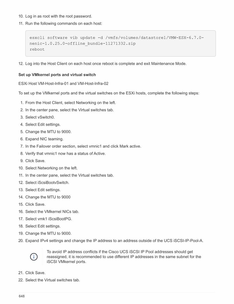
10. Log in as root with the root password.
11. Run the following commands on each host:
esxcli software vib update -d /vmfs/volumes/datastore1/VMW-ESX-6.7.0-
nenic-1.0.25.0-offline_bundle-11271332.zip
reboot
12. Log into the Host Client on each host once reboot is complete and exit Maintenance Mode.
Set up VMkernel ports and virtual switch
ESXi Host VM-Host-Infra-01 and VM-Host-Infra-02
To set up the VMkernel ports and the virtual switches on the ESXi hosts, complete the following steps:
1. From the Host Client, select Networking on the left.
2. In the center pane, select the Virtual switches tab.
3. Select vSwitch0.
4. Select Edit settings.
5. Change the MTU to 9000.
6. Expand NIC teaming.
7. In the Failover order section, select vmnic1 and click Mark active.
8. Verify that vmnic1 now has a status of Active.
9. Click Save.
10. Select Networking on the left.
11. In the center pane, select the Virtual switches tab.
12. Select iScsiBootvSwitch.
13. Select Edit settings.
14. Change the MTU to 9000
15. Click Save.
16. Select the VMkernel NICs tab.
17. Select vmk1 iScsiBootPG.
18. Select Edit settings.
19. Change the MTU to 9000.
20. Expand IPv4 settings and change the IP address to an address outside of the UCS iSCSI-IP-Pool-A.
To avoid IP address conflicts if the Cisco UCS iSCSI IP Pool addresses should getreassigned, it is recommended to use different IP addresses in the same subnet for theiSCSI VMkernel ports.
21. Click Save.
22. Select the Virtual switches tab.
648

23. Select the Add standard virtual switch.
24. Provide a name of iScsciBootvSwitch-B for the vSwitch Name.
25. Set the MTU to 9000.
26. Select vmnic3 from the Uplink 1 drop-down menu.
27. Click Add.
28. In the center pane, select the VMkernel NICs tab.
29. Select Add VMkernel NIC
30. Specify a New port group name of iScsiBootPG-B.
31. Select iScsciBootvSwitch-B for Virtual switch.
32. Set the MTU to 9000. Do not enter a VLAN ID.
33. Select Static for the IPv4 settings and expand the option to provide the Address and Subnet Mask withinthe Configuration.
To avoid IP address conflicts, if the Cisco UCS iSCSI IP Pool addresses should getreassigned, it is recommended to use different IP addresses in the same subnet for theiSCSI VMkernel ports.
34. Click Create.
35. On the left, select Networking, then select the Port groups tab.
36. In the center pane, right-click VM Network and select Remove.
37. Click Remove to complete removing the port group.
38. In the center pane, select Add port group.
39. Name the port group Management Network and enter <ib-mgmt-vlan-id> in the VLAN ID field, andmake sure Virtual switch vSwitch0 is selected.
40. Click Add to finalize the edits for the IB-MGMT Network.
41. At the top, select the VMkernel NICs tab.
42. Click Add VMkernel NIC.
43. For New port group, enter VMotion.
44. For Virtual switch, select vSwitch0 selected.
45. Enter <vmotion-vlan-id> for the VLAN ID.
46. Change the MTU to 9000.
47. Select Static IPv4 settings and expand IPv4 settings.
48. Enter the ESXi host vMotion IP address and netmask.
49. Select the vMotion stack TCP/IP stack.
50. Select vMotion under Services.
51. Click Create.
52. Click Add VMkernel NIC.
53. For New port group, enter NFS_Share.
54. For Virtual switch, select vSwitch0 selected.
649

55. Enter <infra-nfs-vlan-id> for the VLAN ID
56. Change the MTU to 9000.
57. Select Static IPv4 settings and expand IPv4 settings.
58. Enter the ESXi host Infrastructure NFS IP address and netmask.
59. Do not select any of the Services.
60. Click Create.
61. Select the Virtual Switches tab, then select vSwitch0. The properties for vSwitch0 VMkernel NICs shouldbe similar to the following example:
62. Select the VMkernel NICs tab to confirm the configured virtual adapters. The adapters listed should besimilar to the following example:
650
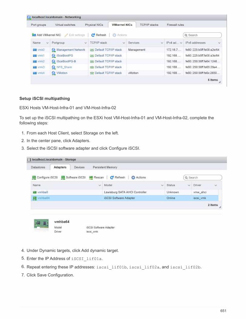
Setup iSCSI multipathing
ESXi Hosts VM-Host-Infra-01 and VM-Host-Infra-02
To set up the iSCSI multipathing on the ESXi host VM-Host-Infra-01 and VM-Host-Infra-02, complete thefollowing steps:
1. From each Host Client, select Storage on the left.
2. In the center pane, click Adapters.
3. Select the iSCSI software adapter and click Configure iSCSI.
4. Under Dynamic targets, click Add dynamic target.
5. Enter the IP Address of iSCSI_lif01a.
6. Repeat entering these IP addresses: iscsi_lif01b, iscsi_lif02a, and iscsi_lif02b.
7. Click Save Configuration.
651

To obtain all of the iscsi_lif IP addresses, log in to NetApp storage cluster management interface and
run the network interface show command.
The host automatically rescans the storage adapter and the targets are added to statictargets.
Mount required datastores
ESXi Hosts VM-Host-Infra-01 and VM-Host-Infra-02
To mount the required datastores, complete the following steps on each ESXi host:
1. From the Host Client, select Storage on the left.
2. In the center pane, select Datastores.
3. In the center pane, select New Datastore to add a new datastore.
4. In the New datastore dialog box, select Mount NFS datastore and click Next.
652
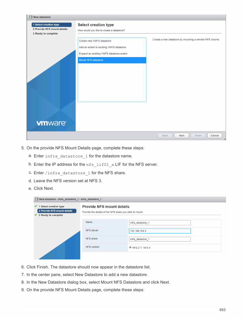
5. On the provide NFS Mount Details page, complete these steps:
a. Enter infra_datastore_1 for the datastore name.
b. Enter the IP address for the nfs_lif01_a LIF for the NFS server.
c. Enter /infra_datastore_1 for the NFS share.
d. Leave the NFS version set at NFS 3.
e. Click Next.
6. Click Finish. The datastore should now appear in the datastore list.
7. In the center pane, select New Datastore to add a new datastore.
8. In the New Datastore dialog box, select Mount NFS Datastore and click Next.
9. On the provide NFS Mount Details page, complete these steps:
653

a. Enter infra_datastore_2 for the datastore name.
b. Enter the IP address for the nfs_lif02_a LIF for the NFS server.
c. Enter /infra_datastore_2 for the NFS share.
d. Leave the NFS version set at NFS 3.
e. Click Next.
10. Click Finish. The datastore should now appear in the datastore list.
11. Mount both datastores on both ESXi hosts.
Configure NTP on ESXi hosts
ESXi Hosts VM-Host-Infra-01 and VM-Host-Infra-02
To configure NTP on the ESXi hosts, complete the following steps on each host:
1. From the Host Client, select Manage on the left.
2. In the center pane, select the Time & Date tab.
3. Click Edit Settings.
4. Make sure Use Network Time Protocol (enable NTP client) is selected.
5. Use the drop-down menu to select Start and Stop with Host.
6. Enter the two Nexus switch NTP addresses in the NTP servers box separated by a comma.
654
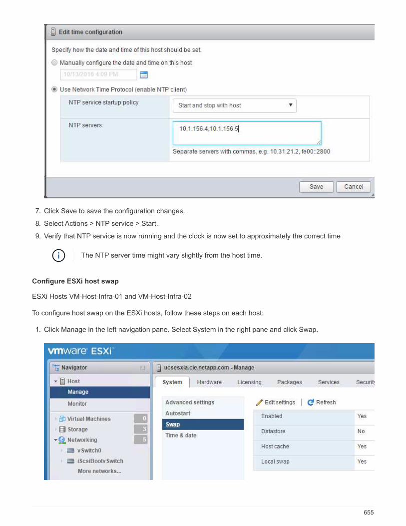
7. Click Save to save the configuration changes.
8. Select Actions > NTP service > Start.
9. Verify that NTP service is now running and the clock is now set to approximately the correct time
The NTP server time might vary slightly from the host time.
Configure ESXi host swap
ESXi Hosts VM-Host-Infra-01 and VM-Host-Infra-02
To configure host swap on the ESXi hosts, follow these steps on each host:
1. Click Manage in the left navigation pane. Select System in the right pane and click Swap.
655
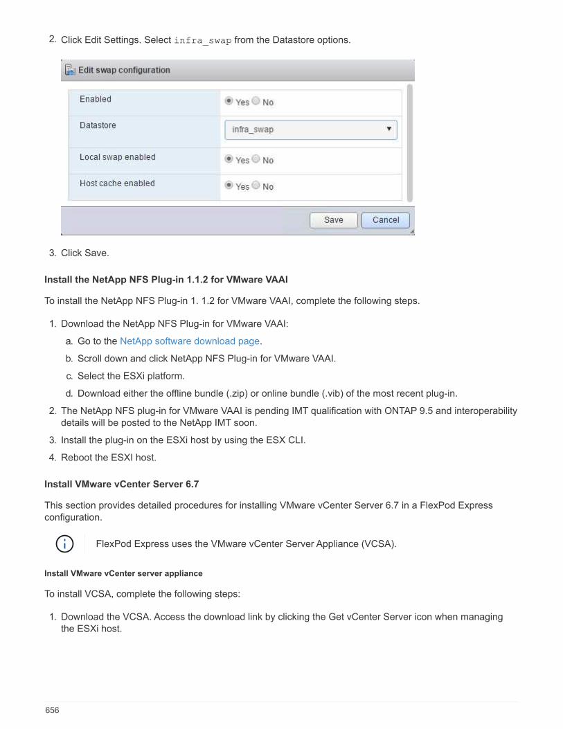
2. Click Edit Settings. Select infra_swap from the Datastore options.
3. Click Save.
Install the NetApp NFS Plug-in 1.1.2 for VMware VAAI
To install the NetApp NFS Plug-in 1. 1.2 for VMware VAAI, complete the following steps.
1. Download the NetApp NFS Plug-in for VMware VAAI:
a. Go to the NetApp software download page.
b. Scroll down and click NetApp NFS Plug-in for VMware VAAI.
c. Select the ESXi platform.
d. Download either the offline bundle (.zip) or online bundle (.vib) of the most recent plug-in.
2. The NetApp NFS plug-in for VMware VAAI is pending IMT qualification with ONTAP 9.5 and interoperabilitydetails will be posted to the NetApp IMT soon.
3. Install the plug-in on the ESXi host by using the ESX CLI.
4. Reboot the ESXI host.
Install VMware vCenter Server 6.7
This section provides detailed procedures for installing VMware vCenter Server 6.7 in a FlexPod Expressconfiguration.
FlexPod Express uses the VMware vCenter Server Appliance (VCSA).
Install VMware vCenter server appliance
To install VCSA, complete the following steps:
1. Download the VCSA. Access the download link by clicking the Get vCenter Server icon when managingthe ESXi host.
656

2. Download the VCSA from the VMware site.
Although the Microsoft Windows vCenter Server installable is supported, VMwarerecommends the VCSA for new deployments.
3. Mount the ISO image.
4. Navigate to the vcsa-ui-installer > win32 directory. Double-click installer.exe.
5. Click Install.
6. Click Next on the Introduction page.
7. Accept the EULA.
8. Select Embedded Platform Services Controller as the deployment type.
657
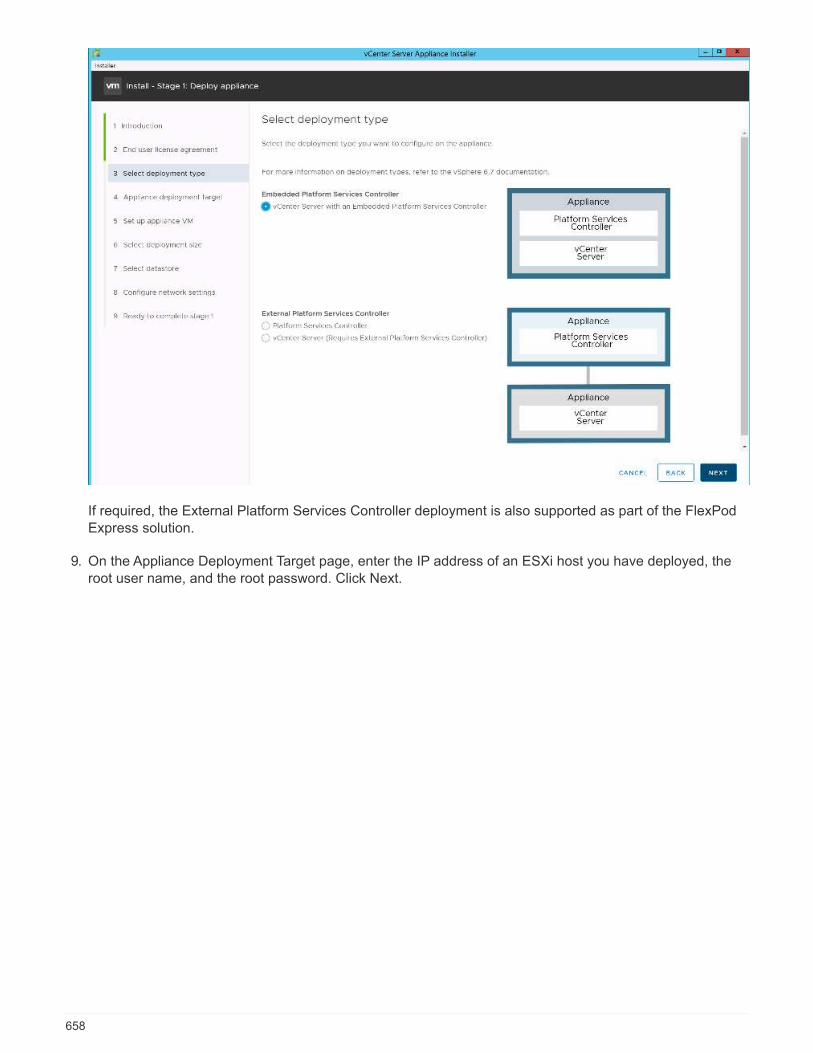
If required, the External Platform Services Controller deployment is also supported as part of the FlexPodExpress solution.
9. On the Appliance Deployment Target page, enter the IP address of an ESXi host you have deployed, theroot user name, and the root password. Click Next.
658
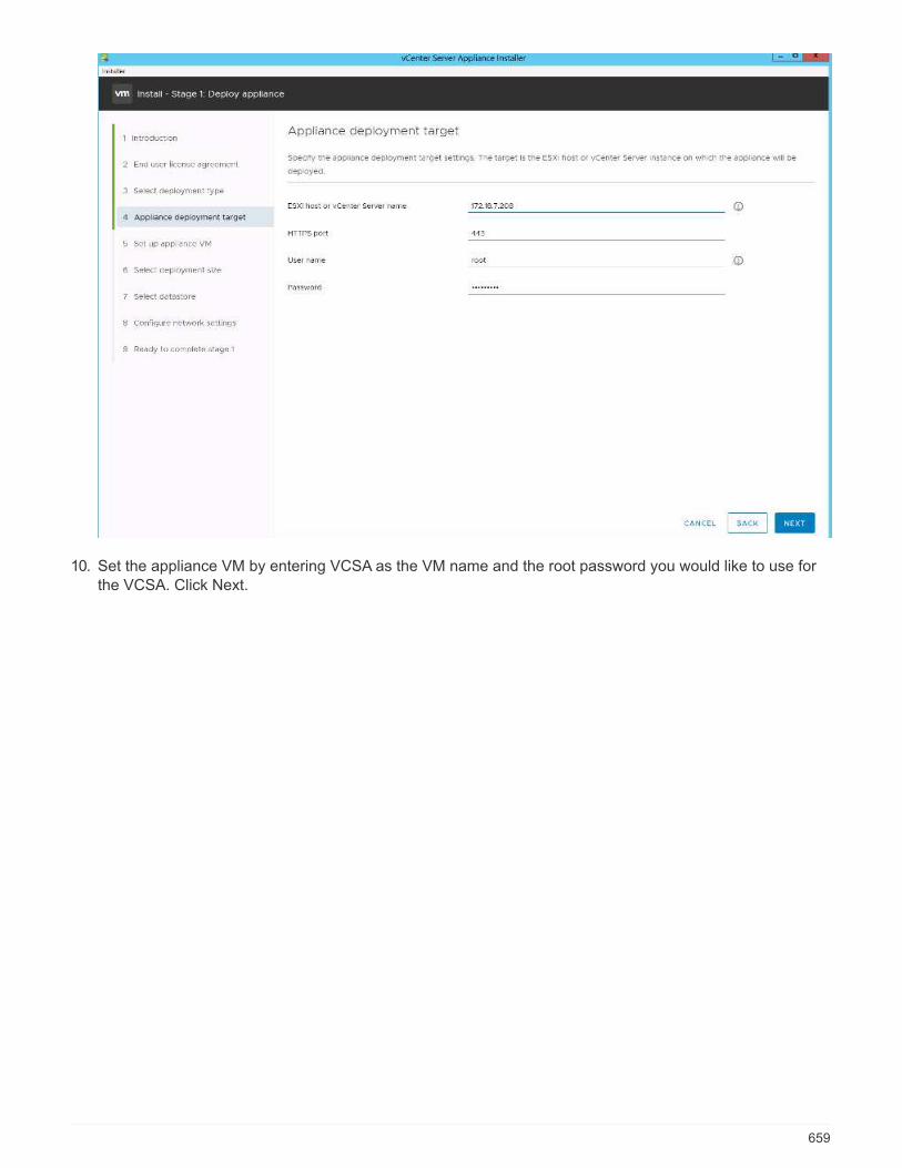
10. Set the appliance VM by entering VCSA as the VM name and the root password you would like to use forthe VCSA. Click Next.
659
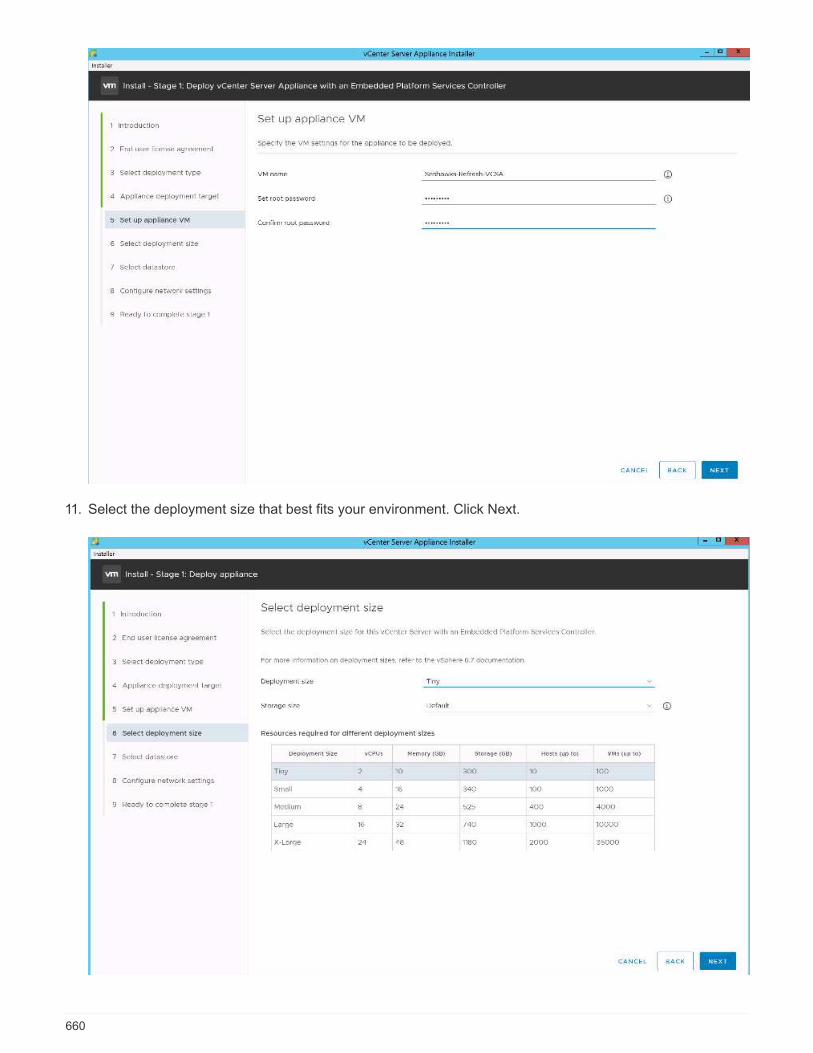
11. Select the deployment size that best fits your environment. Click Next.
660

12. Select the infra_datastore_1 datastore. Click Next.
13. Enter the following information on the Configure Network Settings page and click Next.
a. Select MGMT-Network as your network.
b. Enter the FQDN or IP to be used for the VCSA.
c. Enter the IP address to be used.
d. Enter the subnet mask to be used.
e. Enter the default gateway.
f. Enter the DNS server.
661
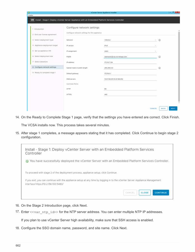
14. On the Ready to Complete Stage 1 page, verify that the settings you have entered are correct. Click Finish.
The VCSA installs now. This process takes several minutes.
15. After stage 1 completes, a message appears stating that it has completed. Click Continue to begin stage 2configuration.
16. On the Stage 2 Introduction page, click Next.
17. Enter <<var_ntp_id>> for the NTP server address. You can enter multiple NTP IP addresses.
If you plan to use vCenter Server high availability, make sure that SSH access is enabled.
18. Configure the SSO domain name, password, and site name. Click Next.
662
Record these values for your reference, especially if you deviate from the vsphere.local domain name.
19. Join the VMware Customer Experience Program if desired. Click Next.
20. View the summary of your settings. Click Finish or use the back button to edit settings.
21. A message appears stating that you are not able to pause or stop the installation from completing after ithas started. Click OK to continue.
The appliance setup continues. This takes several minutes.
A message appears indicating that the setup was successful.
The links that the installer provides to access vCenter Server are clickable.
Configure VMware vCenter Server 6.7 and vSphere clustering
To configure VMware vCenter Server 6.7 and vSphere clustering, complete the following steps:
1. Navigate to https://<<FQDN or IP of vCenter>>/vsphere-client/.
2. Click Launch vSphere Client.
3. Log in with the user name [email protected] and the SSO password you entered during theVCSA setup process.
4. Right-click the vCenter name and select New Datacenter.
5. Enter a name for the data center and click OK.
Create vSphere Cluster.
To create a vSphere cluster, complete the following steps:
1. Right-click the newly created data center and select New Cluster.
2. Enter a name for the cluster.
3. Select and enable DRS and vSphere HA options.
4. Click OK.
663
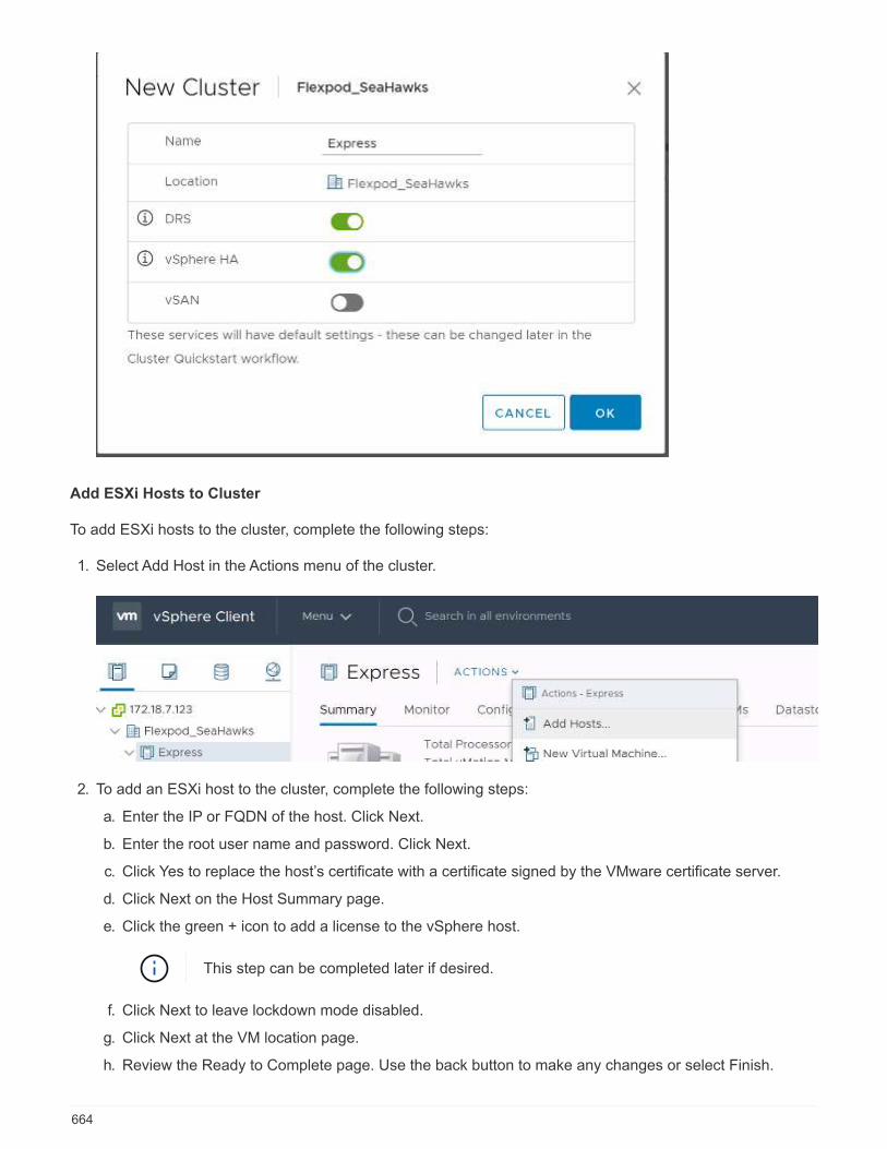
Add ESXi Hosts to Cluster
To add ESXi hosts to the cluster, complete the following steps:
1. Select Add Host in the Actions menu of the cluster.
2. To add an ESXi host to the cluster, complete the following steps:
a. Enter the IP or FQDN of the host. Click Next.
b. Enter the root user name and password. Click Next.
c. Click Yes to replace the host’s certificate with a certificate signed by the VMware certificate server.
d. Click Next on the Host Summary page.
e. Click the green + icon to add a license to the vSphere host.
This step can be completed later if desired.
f. Click Next to leave lockdown mode disabled.
g. Click Next at the VM location page.
h. Review the Ready to Complete page. Use the back button to make any changes or select Finish.
664
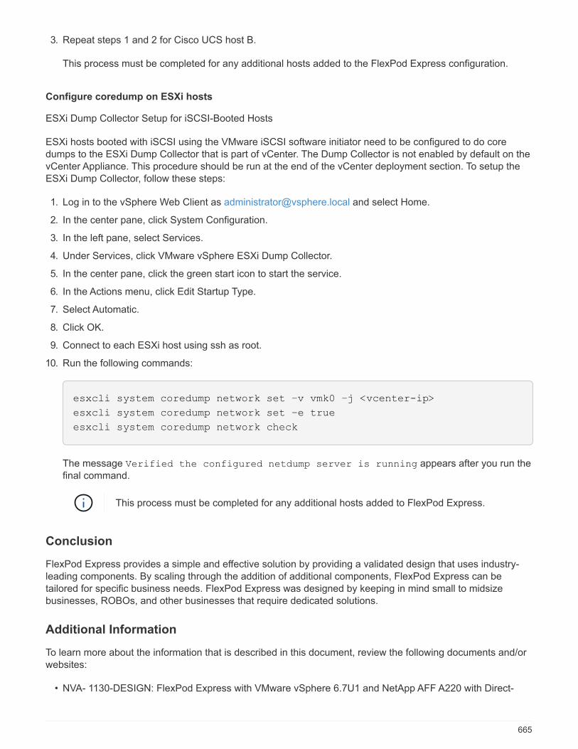
3. Repeat steps 1 and 2 for Cisco UCS host B.
This process must be completed for any additional hosts added to the FlexPod Express configuration.
Configure coredump on ESXi hosts
ESXi Dump Collector Setup for iSCSI-Booted Hosts
ESXi hosts booted with iSCSI using the VMware iSCSI software initiator need to be configured to do coredumps to the ESXi Dump Collector that is part of vCenter. The Dump Collector is not enabled by default on thevCenter Appliance. This procedure should be run at the end of the vCenter deployment section. To setup theESXi Dump Collector, follow these steps:
1. Log in to the vSphere Web Client as [email protected] and select Home.
2. In the center pane, click System Configuration.
3. In the left pane, select Services.
4. Under Services, click VMware vSphere ESXi Dump Collector.
5. In the center pane, click the green start icon to start the service.
6. In the Actions menu, click Edit Startup Type.
7. Select Automatic.
8. Click OK.
9. Connect to each ESXi host using ssh as root.
10. Run the following commands:
esxcli system coredump network set –v vmk0 –j <vcenter-ip>
esxcli system coredump network set –e true
esxcli system coredump network check
The message Verified the configured netdump server is running appears after you run thefinal command.
This process must be completed for any additional hosts added to FlexPod Express.
Conclusion
FlexPod Express provides a simple and effective solution by providing a validated design that uses industry-leading components. By scaling through the addition of additional components, FlexPod Express can betailored for specific business needs. FlexPod Express was designed by keeping in mind small to midsizebusinesses, ROBOs, and other businesses that require dedicated solutions.
Additional Information
To learn more about the information that is described in this document, review the following documents and/orwebsites:
• NVA- 1130-DESIGN: FlexPod Express with VMware vSphere 6.7U1 and NetApp AFF A220 with Direct-
665

Attached IP=Based Storage NVA Design
https://www.netapp.com/us/media/nva-1130-design.pdf
• AFF and FAS Systems Documentation Center
http://docs.netapp.com/platstor/index.jsp
• ONTAP 9 Documentation Center
http://docs.netapp.com/ontap-9/index.jsp
• NetApp Product Documentation
https://docs.netapp.com
666
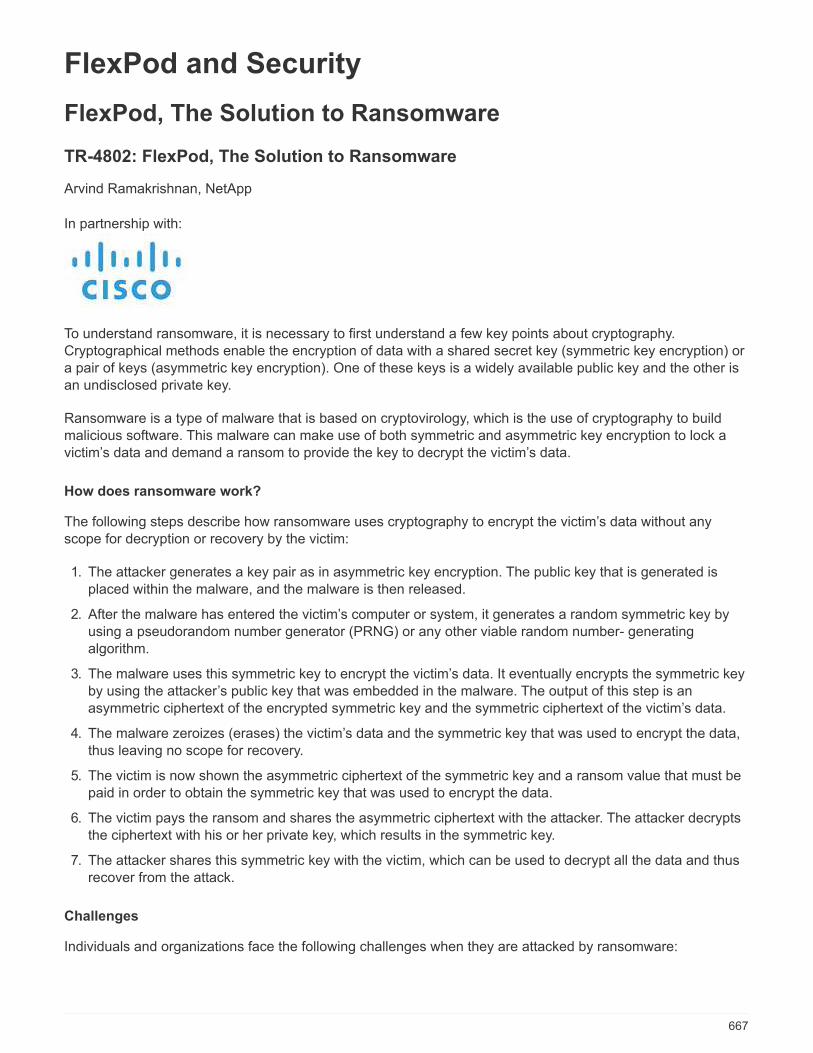
FlexPod and Security
FlexPod, The Solution to Ransomware
TR-4802: FlexPod, The Solution to Ransomware
Arvind Ramakrishnan, NetApp
In partnership with:
To understand ransomware, it is necessary to first understand a few key points about cryptography.Cryptographical methods enable the encryption of data with a shared secret key (symmetric key encryption) ora pair of keys (asymmetric key encryption). One of these keys is a widely available public key and the other isan undisclosed private key.
Ransomware is a type of malware that is based on cryptovirology, which is the use of cryptography to buildmalicious software. This malware can make use of both symmetric and asymmetric key encryption to lock avictim’s data and demand a ransom to provide the key to decrypt the victim’s data.
How does ransomware work?
The following steps describe how ransomware uses cryptography to encrypt the victim’s data without anyscope for decryption or recovery by the victim:
1. The attacker generates a key pair as in asymmetric key encryption. The public key that is generated isplaced within the malware, and the malware is then released.
2. After the malware has entered the victim’s computer or system, it generates a random symmetric key byusing a pseudorandom number generator (PRNG) or any other viable random number- generatingalgorithm.
3. The malware uses this symmetric key to encrypt the victim’s data. It eventually encrypts the symmetric keyby using the attacker’s public key that was embedded in the malware. The output of this step is anasymmetric ciphertext of the encrypted symmetric key and the symmetric ciphertext of the victim’s data.
4. The malware zeroizes (erases) the victim’s data and the symmetric key that was used to encrypt the data,thus leaving no scope for recovery.
5. The victim is now shown the asymmetric ciphertext of the symmetric key and a ransom value that must bepaid in order to obtain the symmetric key that was used to encrypt the data.
6. The victim pays the ransom and shares the asymmetric ciphertext with the attacker. The attacker decryptsthe ciphertext with his or her private key, which results in the symmetric key.
7. The attacker shares this symmetric key with the victim, which can be used to decrypt all the data and thusrecover from the attack.
Challenges
Individuals and organizations face the following challenges when they are attacked by ransomware:
667

• The most important challenge is that it takes an immediate toll on the productivity of the organization or theindividual. It takes time to return to a state of normalcy, because all the important files must be regained,and the systems must be secured.
• It could lead to a data breach that contains sensitive and confidential information that belongs to clients orcustomers and leads to a crisis situation that an organization would clearly want to avoid.
• There is a very good chance of data getting into the wrong hands or being erased completely, which leadsto a point of no return that could be disastrous for organizations and individuals.
• After paying the ransom, there is no guarantee that the attacker will provide the key to restore the data.
• There is no assurance that the attacker will refrain from broadcasting the sensitive data in spite of payingthe ransom.
• In large enterprises, identifying the loophole that led to a ransomware attack is a tedious task, and securingall the systems involves a lot of effort.
Who is at risk?
Anyone can be attacked by ransomware, including individuals and large organizations. Organizations that donot implement well- defined security measures and practices are even more vulnerable to such attacks. Theeffect of the attack on a large organization can be several times larger than what an individual might endure.
Ransomware accounts for approximately 28% of all malware attacks. In other words, more than one in fourmalware incidents is a ransomware attack. Ransomware can spread automatically and indiscriminately throughthe internet, and, when there is a security lapse, it can enter into the victim’s systems and continue to spread toother connected systems. Attackers tend to target people or organizations that perform a lot of file sharing,have a lot of sensitive and critical data, or maintain inadequate protection against attacks.
Attackers tend to focus on the following potential targets:
• Universities and student communities
• Government offices and agencies
• Hospitals
• Banks
This is not an exhaustive list of targets. You cannot consider yourself safe from attacks if you fall outside of oneof these categories.
How does ransomware enter a system or spread?
There are several ways in which ransomware can enter a system or spread to other systems. In today’s world,almost all systems are connected to one another other through the internet, LANs, WANs, and so on. Theamount of data that is being generated and exchanged between these systems is only increasing.
Some of the most common ways by which ransomware can spread include methods that we use on a dailybasis to share or access data:
• P2P networks
• File downloads
• Social networking
• Mobile devices
668

• Connecting to insecure public networks
• Accessing web URLs
Consequences of data loss
The consequences or effects of data loss can reach more widely than organizations might anticipate. Theeffects can vary depending on the duration of downtime or the time period during which an organization doesn’thave access to its data. The longer the attack endures, the bigger the effect on the organization’s revenue,brand, and reputation. An organization can also face legal issues and a steep decline in productivity.
As these issues continue to persist over time, they begin to magnify and might end up changing anorganization’s culture, depending on how it responds to the attack. In today’s world, information spreads at arapid rate and negative news about an organization could cause permanent damage to its reputation. Anorganization could face huge penalties for data loss, which could eventually lead to the closure of a business.
Financial effects
According to a recent McAfee report, the global costs incurred due to cybercrime are roughly $600 billion,which is approximately 0.8% of global GDP. When this amount is compared against the growing worldwideinternet economy of $4.2 trillion, it equates to a 14% tax on growth.
Ransomware takes a significant share of this financial cost. In 2018, the costs incurred due to ransomwareattacks were approximately $8 billion―an amount predicted to reach $11.5 billion in 2019.
What is the solution?
Recovering from a ransomware attack with minimal downtime is only possible by implementing a proactivedisaster recovery plan. Having the ability to recover from an attack is good, but preventing an attack altogetheris ideal.
Although there are several fronts that you must review and fix to prevent an attack, the core component thatallows you to prevent or recover from an attack is the data center.
The data center design and the features it provides to secure the network, compute, and storage end-pointsplay a critical role in building a secure environment for day-to-day operations. This document shows how thefeatures of a FlexPod hybrid cloud infrastructure can help in quick data recovery in the event of an attack andcan also help to prevent attacks altogether.
FlexPod Overview
FlexPod is a predesigned, integrated, and validated architecture that combines Cisco Unified ComputingSystem (Cisco UCS) servers, the Cisco Nexus family of switches, Cisco MDS fabric switches, and NetAppstorage arrays into a single, flexible architecture. FlexPod solutions are designed for high availability with nosingle points of failure, while maintaining cost-effectiveness and design flexibility to support a wide variety ofworkloads. A FlexPod design can support different hypervisors and bare metal servers and can also be sizedand optimized based on customer workload requirements.
The figure below illustrates the FlexPod architecture and clearly highlights the high availability across all thelayers of the stack. The infrastructure components of storage, network, and compute are configured in such away that the operations can instantaneously fail over to the surviving partner in case one of the componentsfail.
669

A major advantage for a FlexPod system is that it is predesigned, integrated, and validated for severalworkloads. Detailed design and deployment guides are published for every solution validation. Thesedocuments include the best practices that you must employ for workloads to run seamlessly on FlexPod.These solutions are built with the best- in-class compute, network, and storage products and a host of featuresthat focus on security and hardening of the entire infrastructure.
IBM’s X-Force Threat Intelligence Index states, “Human error responsible for two-thirds of compromisedrecords including historic 424% jump in misconfigured cloud infrastructure.”
With a FlexPod system, you can avoid misconfiguring your infrastructure by using automation through Ansibleplaybooks that perform an end-to-end setup of the infrastructure according to the best practices described inCisco Validated Designs (CVDs) and NetApp Verified Architectures (NVAs).
Ransomware protection measures
This section discusses the key features of NetApp ONTAP data management software and the tools for CiscoUCS and Cisco Nexus that you can use to effectively protect and recover from ransomware attacks.
Storage: NetApp ONTAP
ONTAP software provides many features useful for data protection, most of which are free of charge tocustomers who have an ONTAP system. You can use the following features at all times to safeguard data fromattacks:
• NetApp Snapshot technology. A Snapshot copy is a read-only image of a volume that captures the state
670

of a file system at a point in time. These copies help protect data with no effect on system performanceand, at the same time, do not occupy a lot of storage space. NetApp recommends that you create aschedule for the creation of Snapshot copies. You should also maintain a long retention time becausesome malware can go dormant and then reactivate weeks or months after an infection. In the event of anattack, the volume can be rolled back using a Snapshot copy that was taken before the infection.
• NetApp SnapRestore technology. SnapRestore data recovery software is extremely useful to recoverfrom data corruption or to revert only the file contents. SnapRestore does not revert the attributes of avolume; it is much faster than what an administrator can achieve by copying files from the Snapshot copyto the active file system. The speed at which data can be recovered is helpful when many files must berecovered as quickly as possible. In the event of an attack, this highly efficient recovery process helps toget business back online quickly.
• NetApp SnapCenter technology. SnapCenter software uses NetApp storage-based backup andreplication functions to provide application- consistent data protection. This software integrates withenterprise applications and provides application- specific and database- specific workflows to meet theneeds of application, database, and virtual infrastructure administrators. SnapCenter provides an easy-to-use enterprise platform to securely coordinate and manage data protection across applications, databases,and file systems. Its ability to provide application- consistent data protection is critical during data recoverybecause it makes it easy to restore applications to a consistent state more quickly.
• NetApp SnapLock technology. SnapLock provides a special purpose volume in which files can be storedand committed to a nonerasable, nonrewritable state. The user’s production data residing in a FlexVolvolume can be mirrored or vaulted to a SnapLock volume through NetApp SnapMirror or SnapVaulttechnology, respectively. The files in the SnapLock volume, the volume itself, and its hosting aggregatecannot be deleted until the end of the retention period.
• NetApp FPolicy technology. Use FPolicy software to prevent attacks by disallowing operations on fileswith specific extensions. An FPolicy event can be triggered for specific file operations. The event is tied to apolicy, which calls out the engine it needs to use. You might configure a policy with a set of file extensionsthat could potentially contain ransomware. When a file with a disallowed extension tries to perform anunauthorized operation, FPolicy prevents that operation from executing.
Network: Cisco Nexus
Cisco NX OS software supports the NetFlow feature that enables enhanced detection of network anomaliesand security. NetFlow captures the metadata of every conversation on the network, the parties involved in thecommunication, the protocol being used, and the duration of the transaction. After the information isaggregated and analyzed, it can provide insight into normal behavior.
The collected data also allows identification of questionable patterns of activity, such as malware spreadingacross the network, which might otherwise go unnoticed.
NetFlow uses flows to provide statistics for network monitoring. A flow is a unidirectional stream of packets thatarrives on a source interface (or VLAN) and has the same values for the keys. A key is an identified value for afield within the packet. You create a flow using a flow record to define the unique keys for your flow. You canexport the data that NetFlow gathers for your flows by using a flow exporter to a remote NetFlow collector, suchas Cisco Stealthwatch. Stealthwatch uses this information for continuous monitoring of the network andprovides real-time threat detection and incident response forensics if a ransomware outbreak occurs.
Compute: Cisco UCS
Cisco UCS is the compute endpoint in a FlexPod architecture. You can use several Cisco products that canhelp to secure this layer of the stack at the operating system level.
You can implement the following key products in the compute or application layer:
671

• Cisco Advanced Malware Protection (AMP) for Endpoints. Supported on Microsoft Windows and Linuxoperating systems, this solution integrates prevention, detection, and response capabilities. This securitysoftware prevents breaches, blocks malware at the point of entry, and continuously monitors and analyzesfile and process activity to rapidly detect, contain, and remediate threats that can evade front-line defenses.
The Malicious Activity Protection (MAP) component of AMP continually monitors all endpoint activity andprovides run-time detection and blocking of abnormal behavior of a running program on the endpoint. Forexample, when endpoint behavior indicates ransomware, the offending processes are terminated,preventing endpoint encryption and stopping the attack.
• Cisco Advanced Malware Protection for Email Security. Emails have become the prime vehicle tospread malware and to carry out cyber-attacks. On average, approximately 100 billion emails areexchanged in a single day, which provides attackers with an excellent penetration vector into user’ssystems. Therefore, it is absolutely essential to defend against this line of attack.
AMP analyzes emails for threats such as zero-day exploits and stealthy malware hidden in maliciousattachments. It also uses industry-leading URL intelligence to combat malicious links. It gives usersadvanced protection against spear phishing, ransomware, and other sophisticated attacks.
• Next-Generation Intrusion Prevention System (NGIPS). Cisco Firepower NGIPS can be deployed as aphysical appliance in the datacenter or as a virtual appliance on VMware (NGIPSv for VMware). This highlyeffective intrusion prevention system provides reliable performance and a low total cost of ownership.Threat protection can be expanded with optional subscription licenses to provide AMP, application visibilityand control, and URL filtering capabilities. Virtualized NGIPS inspects traffic between virtual machines(VMs) and make it easier to deploy and manage NGIPS solutions at sites with limited resources, increasingprotection for both physical and virtual assets.
Protect and recover data on FlexPod
This section describes how an end user’s data can be recovered in the event of an attack and how attacks canbe prevented by using a FlexPod system.
Testbed overview
To showcase FlexPod detection, remediation, and prevention, a testbed was built based on the guidelines thatare specified in the latest platform CVD available at the time this document was authored: FlexPod Datacenterwith VMware vSphere 6.7 U1, Cisco UCS 4th Generation, and NetApp AFF A-Series CVD.
A Windows 2016 VM, which provided a CIFS share from NetApp ONTAP software, was deployed in theVMware vSphere infrastructure. Then NetApp FPolicy was configured on the CIFS share to prevent theexecution of files with certain extension types. NetApp SnapCenter software was also deployed to manage theSnapshot copies of the VMs in the infrastructure to provide application- consistent Snapshot copies.
State of VM and its files prior to an attack
This section provides shows the state of the files prior to an attack on the VM and the CIFS share that wasmapped to it.
The Documents folder of the VM had a set of PDF files that have not yet been encrypted by the WannaCrymalware.
672
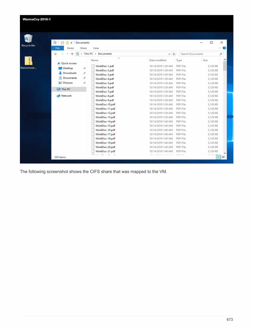
The following screenshot shows the CIFS share that was mapped to the VM.
673

The following screenshot shows the files on the CIFS share fpolicy_share that have not yet beenencrypted by the WannaCry malware.
674

Deduplication and Snapshot information before an attack
The storage efficiency details and size of the Snapshot copy prior to an attack are indicated and used as areference during the detection phase.
Storage savings of 19% were achieved with deduplication on the volume hosting the VM.
Storage savings of 45% were achieved with deduplication on the CIFS share fpolicy_share.
675
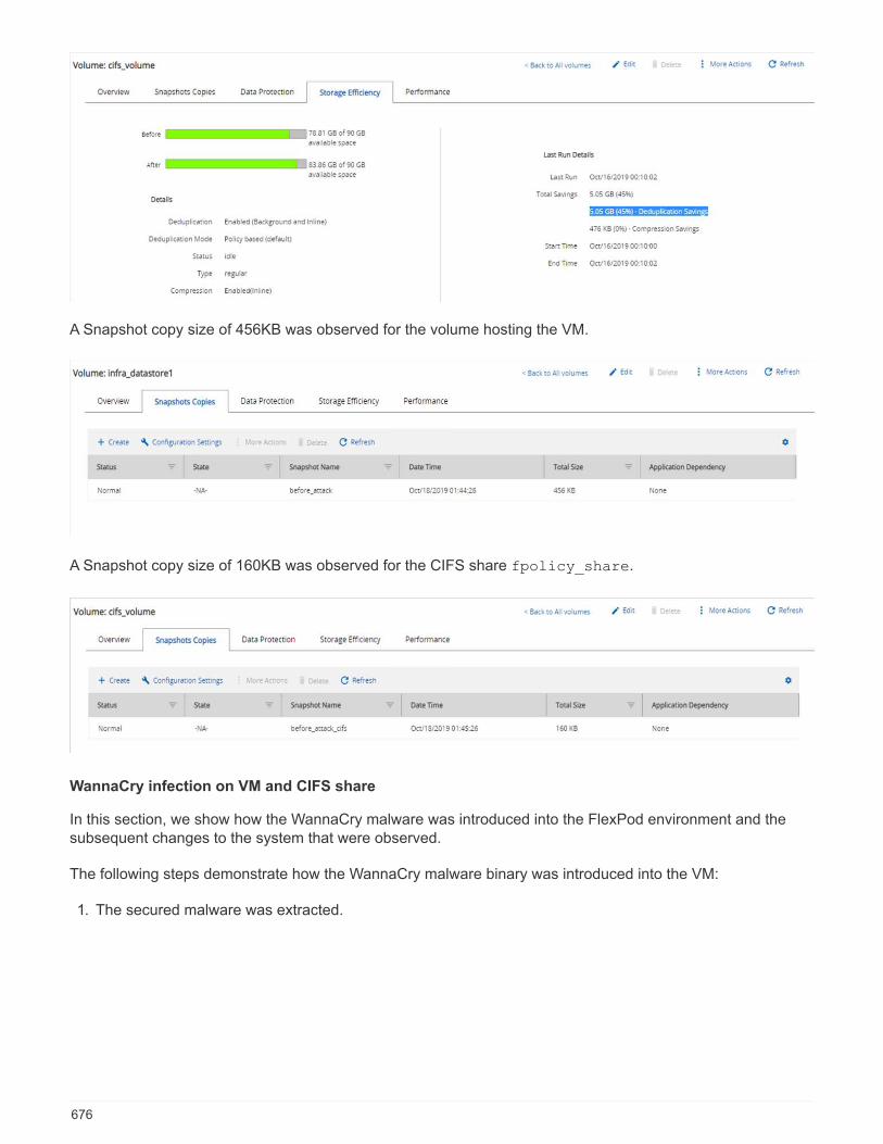
A Snapshot copy size of 456KB was observed for the volume hosting the VM.
A Snapshot copy size of 160KB was observed for the CIFS share fpolicy_share.
WannaCry infection on VM and CIFS share
In this section, we show how the WannaCry malware was introduced into the FlexPod environment and thesubsequent changes to the system that were observed.
The following steps demonstrate how the WannaCry malware binary was introduced into the VM:
1. The secured malware was extracted.
676

2. The binary was executed.
Case 1: WannaCry encrypts the file system within the VM and mapped CIFS share
The local file system and the mapped CIFS share were encrypted by the WannaCry malware.
Malware starts to encrypt files with WNCRY extensions.
677
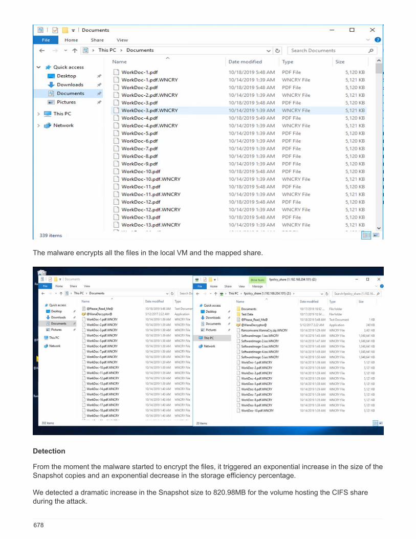
The malware encrypts all the files in the local VM and the mapped share.
Detection
From the moment the malware started to encrypt the files, it triggered an exponential increase in the size of theSnapshot copies and an exponential decrease in the storage efficiency percentage.
We detected a dramatic increase in the Snapshot size to 820.98MB for the volume hosting the CIFS shareduring the attack.
678
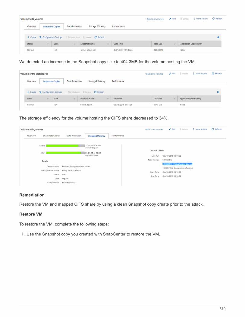
We detected an increase in the Snapshot copy size to 404.3MB for the volume hosting the VM.
The storage efficiency for the volume hosting the CIFS share decreased to 34%.
Remediation
Restore the VM and mapped CIFS share by using a clean Snapshot copy create prior to the attack.
Restore VM
To restore the VM, complete the following steps:
1. Use the Snapshot copy you created with SnapCenter to restore the VM.
679

2. Select the desired VMware- consistent Snapshot copy for restore.
680
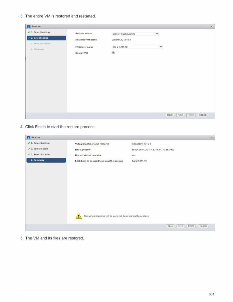
3. The entire VM is restored and restarted.
4. Click Finish to start the restore process.
5. The VM and its files are restored.
681
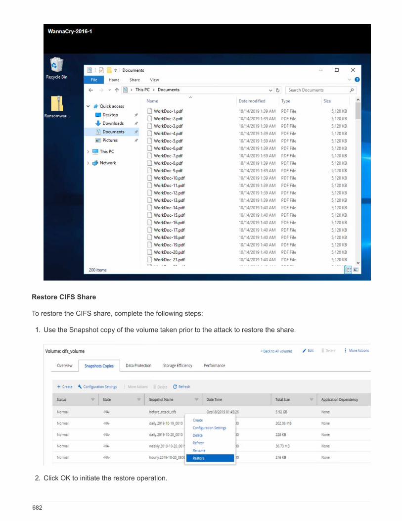
Restore CIFS Share
To restore the CIFS share, complete the following steps:
1. Use the Snapshot copy of the volume taken prior to the attack to restore the share.
2. Click OK to initiate the restore operation.
682
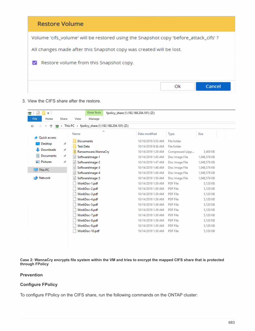
3. View the CIFS share after the restore.
Case 2: WannaCry encrypts file system within the VM and tries to encrypt the mapped CIFS share that is protectedthrough FPolicy
Prevention
Configure FPolicy
To configure FPolicy on the CIFS share, run the following commands on the ONTAP cluster:
683
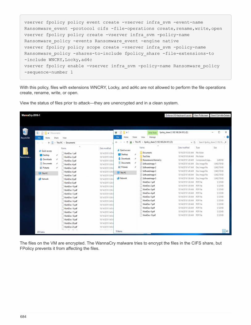
vserver fpolicy policy event create -vserver infra_svm -event-name
Ransomware_event -protocol cifs -file-operations create,rename,write,open
vserver fpolicy policy create -vserver infra_svm -policy-name
Ransomware_policy -events Ransomware_event -engine native
vserver fpolicy policy scope create -vserver infra_svm -policy-name
Ransomware_policy -shares-to-include fpolicy_share -file-extensions-to
-include WNCRY,Locky,ad4c
vserver fpolicy enable -vserver infra_svm -policy-name Ransomware_policy
-sequence-number 1
With this policy, files with extensions WNCRY, Locky, and ad4c are not allowed to perform the file operationscreate, rename, write, or open.
View the status of files prior to attack—they are unencrypted and in a clean system.
The files on the VM are encrypted. The WannaCry malware tries to encrypt the files in the CIFS share, butFPolicy prevents it from affecting the files.
684
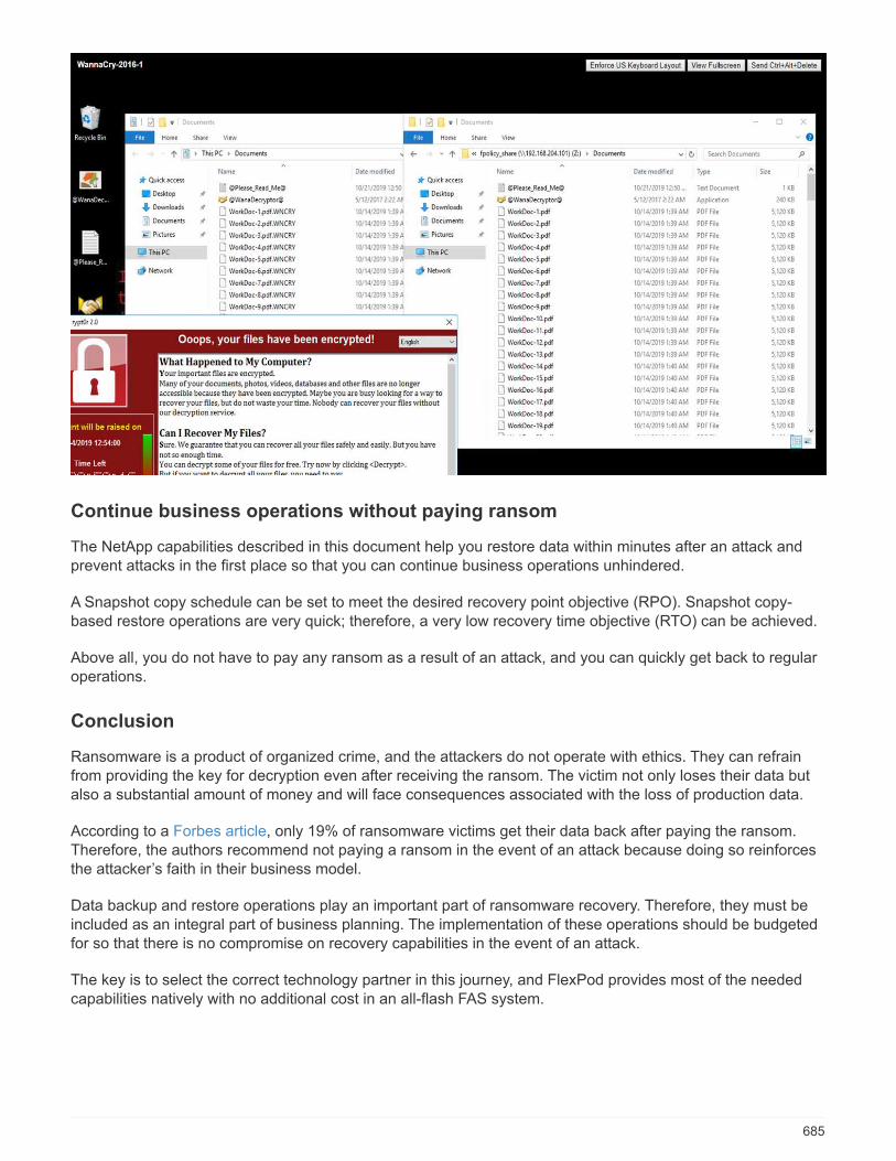
Continue business operations without paying ransom
The NetApp capabilities described in this document help you restore data within minutes after an attack andprevent attacks in the first place so that you can continue business operations unhindered.
A Snapshot copy schedule can be set to meet the desired recovery point objective (RPO). Snapshot copy-based restore operations are very quick; therefore, a very low recovery time objective (RTO) can be achieved.
Above all, you do not have to pay any ransom as a result of an attack, and you can quickly get back to regularoperations.
Conclusion
Ransomware is a product of organized crime, and the attackers do not operate with ethics. They can refrainfrom providing the key for decryption even after receiving the ransom. The victim not only loses their data butalso a substantial amount of money and will face consequences associated with the loss of production data.
According to a Forbes article, only 19% of ransomware victims get their data back after paying the ransom.Therefore, the authors recommend not paying a ransom in the event of an attack because doing so reinforcesthe attacker’s faith in their business model.
Data backup and restore operations play an important part of ransomware recovery. Therefore, they must beincluded as an integral part of business planning. The implementation of these operations should be budgetedfor so that there is no compromise on recovery capabilities in the event of an attack.
The key is to select the correct technology partner in this journey, and FlexPod provides most of the neededcapabilities natively with no additional cost in an all-flash FAS system.
685

Acknowledgements
The author would like to thank the following people for their support in the creation of this document:
• Jorge Gomez Navarrete, NetApp
• Ganesh Kamath, NetApp
Additional information
To learn more about the information that is described in this document, review the following documents and/orwebsites:
• NetApp Snapshot software
https://www.netapp.com/us/products/platform-os/snapshot.aspx
• SnapCenter Backup Management
https://www.netapp.com/us/products/backup-recovery/snapcenter-backup-management.aspx
• SnapLock Data Compliance
https://www.netapp.com/us/products/backup-recovery/snaplock-compliance.aspx
• NetApp Product Documentation
https://www.netapp.com/us/documentation/index.aspx
• Cisco Advanced Malware Protection (AMP)
https://www.cisco.com/c/en/us/products/security/advanced-malware-protection/index.html
• Cisco Stealthwatch
https://www.cisco.com/c/en_in/products/security/stealthwatch/index.html
FIPS 140-2 security-compliant FlexPod solution forhealthcare
TR-4892: FIPS 140-2 security-compliant FlexPod solution for healthcare
JayaKishore Esanakula, NetAppJohn McAbel, Cisco
The Health Information Technology for Economic and Clinical Health Act (HITECH) requires FederalInformation Processing Standard (FIPS) 140-2-validated encryption of electronic Protected Health Information(ePHI). Health information technology (HIT) applications and software are required to be compliant with FIPS140-2 for obtaining the Promoting Interoperability Program (formerly, Meaningful Use Incentive Program)certification. Eligible providers and hospitals are required to use a FIPS 140-2 (level 1) compliant HIT forreceiving Medicare and Medicaid incentives and for avoiding reimbursement penalties from the Center forMedicare and Medicaid (CMS). FIPS 140-2 certified encryption algorithms qualify as technical safeguards thatare required as per the Security Rule of the Health Information Portability and Accountability Act (HIPAA).
686
FIPS 140-2 is a U.S. government standard that sets security requirements for cryptographic modules inhardware, software, and firmware that protect sensitive information. Compliance with the standard is mandatedfor use by U.S. government agencies, and it is also often used in such regulated industries as financialservices and healthcare. This technical report helps the reader to understand the FIPS 140-2 security standardat a high level. It also helps the audience understand various threats faced by healthcare organizations. Finally,the technical report helps one to understand how a FIPS 140-2 compliant FlexPod system can help securehealthcare assets when deployed on a FlexPod converged infrastructure.
Scope
This document is a technical overview of a Cisco Unified Computing System (Cisco UCS), Cisco Nexus, CiscoMDS and NetApp ONTAP-based FlexPod infrastructure for hosting one or more healthcare IT applications orsolutions that require FIPS 140-2 security compliance.
Audience
This document is intended for technical leaders in the healthcare industry and for Cisco and NetApp partnersolutions engineers and professional services personnel. NetApp assumes that the reader has a goodunderstanding of compute and storage sizing concepts as well as a technical familiarity with healthcare threats,healthcare security, healthcare IT systems, Cisco UCS, and NetApp storage systems.
Next: Cybersecurity threats in healthcare.
Cybersecurity threats in healthcare
Previous: Introduction.
Every problem presents a new opportunity—an example of one such opportunity is presented by the COVIDpandemic. According to a report by the Department of Health and Human Services (HHS) CybersecurityProgram, the COVID response has resulted in an increased number of ransomware attacks. There were 6,000new internet domains registered just in the third week of March 2020. More than 50% of the domains hostedmalware. Ransomware attacks were responsible for almost 50% of all healthcare data breaches in 2020affecting more than 630 healthcare organizations and approximately 29 million healthcare records. Nineteenleakers/sites doubled the extortion. At 24.5%, the healthcare industry saw the highest number of data breachesin 2020.
Malicious agents attempted to breach security and privacy of Protected Health Information (PHI) by selling theinformation or by threatening to destroy or expose it. Targeted and mass-broadcast attempts are frequentlymade to gain unauthorized access to ePHI. Approximately 75% of the exposed patient records in the secondhalf of 2020 were due to compromised business associates.
The following list of healthcare organizations were targeted by the malicious agents:
• Hospital systems
• Life science labs
• Research labs
• Rehabilitation facilities
• Community hospitals and clinics
The diversity of applications that constitute a healthcare organization is undeniable and increasingly growing incomplexity. Information security offices are challenged to provide governance for the vast array of IT systemsand assets. The following figure depicts the clinical capabilities of a typical hospital system.
687
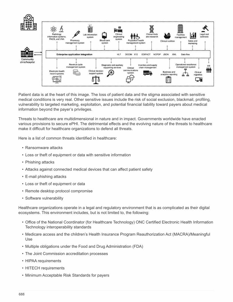
Patient data is at the heart of this image. The loss of patient data and the stigma associated with sensitivemedical conditions is very real. Other sensitive issues include the risk of social exclusion, blackmail, profiling,vulnerability to targeted marketing, exploitation, and potential financial liability toward payers about medicalinformation beyond the payer’s privileges.
Threats to healthcare are multidimensional in nature and in impact. Governments worldwide have enactedvarious provisions to secure ePHI. The detrimental effects and the evolving nature of the threats to healthcaremake it difficult for healthcare organizations to defend all threats.
Here is a list of common threats identified in healthcare:
• Ransomware attacks
• Loss or theft of equipment or data with sensitive information
• Phishing attacks
• Attacks against connected medical devices that can affect patient safety
• E-mail phishing attacks
• Loss or theft of equipment or data
• Remote desktop protocol compromise
• Software vulnerability
Healthcare organizations operate in a legal and regulatory environment that is as complicated as their digitalecosystems. This environment includes, but is not limited to, the following:
• Office of the National Coordinator (for Healthcare Technology) ONC Certified Electronic Health InformationTechnology interoperability standards
• Medicare access and the children’s Health Insurance Program Reauthorization Act (MACRA)/MeaningfulUse
• Multiple obligations under the Food and Drug Administration (FDA)
• The Joint Commission accreditation processes
• HIPAA requirements
• HITECH requirements
• Minimum Acceptable Risk Standards for payers
688
• State privacy and security rules
• Federal Information Security Modernization Act requirements as incorporated into federal contracts andresearch grants through agencies such as the National Institutes of Health
• Payment Card Industry Data Security Standard (PCI-DSS)
• Substance Abuse and Mental Health Services Administration (SAMHSA) requirements
• The Gramm-Leach-Bliley Act for financial processing
• The Stark Law as it relates to providing services to affiliated organizations
• Family Educational Rights and Privacy Act (FERPA) for institutions that participate in higher education
• Genetic Information Nondiscrimination Act (GINA)
• The new General Data Protection Regulation (GDPR) in the European Union
Security architecture standards are fast evolving to stop the malicious actors from impacting healthcareinformation systems. One such standard is FIPS 140-2, defined by the National Institute of Standards andTechnology (NIST). FIPS publication 140-2 details the U.S. government requirements for a cryptographicmodule. The security requirements cover areas related to a secure design and implementation of acryptographic module and can be applied to HIT. Well-defined cryptographic boundaries allow for easiersecurity management while staying current with the cryptographic modules. These boundaries help preventweak crypto modules that can be easily exploited by malicious actors. They can also help prevent humanerrors when managing standard cryptographic modules.
NIST along with the Communications Security Establishment (CSE) have established the CryptographicModule Validation Program (CMVP) to certify cryptographic modules for FIPS 140-2 validation levels. Using aFIPS 140-2 certified module, federal organizations are required to protect sensitive or valuable data while at-rest as well as while in motion. Due to its success in protecting sensitive or valuable information, manyhealthcare systems have chosen to encrypt ePHI by using FIPS 140-2 cryptographic modules beyond thelegally required minimum level of security.
Leveraging and implementing the FlexPod FIPS 140-2 capabilities only takes hours (not days). Becoming FIPScompliant is within reach for most healthcare organizations, regardless of size. With clearly definedcryptographic boundaries and well-documented and simple implementation steps, a FIPS 140-2 compliantFlexPod architecture can set a solid security foundation for infrastructure and allow for simple enhancementsto further increase protection for security threats.
Next: Overview of FIPS 140-2.
Overview of FIPS 140-2
Previous: Cybersecurity threats in healthcare.
FIPS 140-2 specifies the security requirements for a cryptographic module used within a security system thatprotects sensitive information in computer and telecommunication systems. A cryptographic module should bea set of hardware, software, firmware, or a combination. FIPS applies to the cryptographic algorithms, keygeneration and key managers contained within a cryptographic boundary. It is important to understand thatFIPS 140-2 applies specifically to the cryptographic module, not the product, architecture, data, or ecosystem.The cryptographic module, which is defined in the key terms later in this document, is the specific component(whether it’s hardware, software, and/or firmware) that implements approved security functions. In addition,FIPS 140-2 specifies four levels. Approved cryptographic algorithms are common to all levels. Key elementsand requirements of each security level include:
• Security level 1
689
◦ Specifies basic security requirements for a cryptographic module (at least one approved algorithm orsecurity function is required).
◦ No specified physical security mechanisms are required for level 1 beyond the basic requirements forproduction-grade components.
• Security level 2
◦ Enhances the physical security mechanisms by adding the requirement for tamper-evidence by usingtamper-evident solutions such as coatings or seals, locks on removable covers or doors of thecryptographic modules.
◦ Requires, at minimum, role-based access control (RBAC) in which the cryptographic moduleauthenticates the authorization of an operator or administrator to assume a specific role and perform acorresponding set of functions.
• Security level 3
◦ Builds on the tamper-evident requirements of level 2 and attempts to prevent further access to criticalsecurity parameters (CSPs) within the cryptographic module.
◦ Physical security mechanisms required at level 3 are intended to have a high probability to detect andrespond to attempts at physical access, or any use or modification of the cryptographic module.Examples might include strong enclosures, tamper detection, and response circuitry that zeros allplaintext CSPs when a removable cover on the cryptographic module is opened.
◦ Requires identity-based authentication mechanisms to enhance the security of the RBAC mechanismsspecified in level 2. A cryptographic module authenticates the identity of an operator and verifies thatthe operator is authorized to use a role and perform the functions of the role.
• Security level 4
◦ The highest level of security in FIPS 140-2.
◦ The most useful level for operations in physically unprotected environments.
◦ At this level, the physical security mechanisms are intended to provide complete protection around thecryptographic module with the responsibility of detecting and responding to any unauthorized attemptsat physical access.
◦ Penetration or exposure of the cryptographic module should have a high probability of detection andresult in the immediate zeroization of all unsecure or plaintext CSPs.
Next: Control plane versus data plane.
Control plane versus data plane
Previous: Overview of FIPS 140-2.
When implementing a FIPS 140-2 strategy, it is important to understand what is being protected. This caneasily be broken down into two areas: control plane and data plane. A control plane refers to the aspects thataffect the control and operation of the components within the FlexPod system: for example, administrativeaccess to the NetApp storage controllers, Cisco Nexus switches, and Cisco UCS servers. Protection at thislayer is provided by limiting the protocols and cryptographic cyphers that administrators can use to connect todevices and make changes. A data plane refers to the actual information, such as the PHI, within the FlexPodsystem. This is protected by encrypting data at rest and again for FIPS, ensuring that the cryptographicmodules in use meet the standards.
Next: FlexPod Cisco UCS compute and FIPS 140-2.
690

FlexPod Cisco UCS compute and FIPS 140-2
Previous: Control plane versus data plane.
A FlexPod architecture can be designed with a Cisco UCS server that is FIPS 140-2 compliant. In accordancewith the U. S. NIST, Cisco UCS server can operate in FIPS 140-2 level 1 compliance mode. For a complete listof FIPS-compliant Cisco components, see Cisco’s FIPS 140 page. Cisco UCS Manager is FIPS 140-2validated.
Cisco UCS and Fabric Interconnect
Cisco UCS Manager is deployed and runs from the Cisco Fabric Interconnects (FIs).
For more information about Cisco UCS and how to enable FIPS, see the Cisco UCS Manager documentation.
To enable FIPS mode on the Cisco fabric interconnect on each fabric A and B, run the following commands:
fp-health-fabric-A# connect local-mgmt
fp-health-fabric-A(local-mgmt)# enable fips-mode
FIPS mode is enabled
To replace an FI in a cluster on Cisco UCS Manager Release 3.2(3) with an FI on a release
earlier than Cisco UCS Manager Release 3.2(3), disable FIPS mode (disable fips-mode) onthe existing FI before adding the replacement FI to the cluster. After the cluster is formed, aspart of the Cisco UCS Manager boot up, FIPS mode is automatically enabled.
Cisco offers the following key products that can be implemented in the compute or application layer:
• Cisco Advanced Malware Protection (AMP) for endpoints. Supported on Microsoft Windows and Linuxoperating systems, this solution integrates prevention, detection, and response capabilities. This securitysoftware prevents breaches, blocks malware at the point of entry, and continuously monitors and analyzesfile and process activity to rapidly detect, contain, and remediate threats that can evade front-line defenses.The Malicious Activity Protection (MAP) component of AMP continually monitors all endpoint activity andprovides run-time detection and blocking of abnormal behavior of a running program on the endpoint. Forexample, when endpoint behavior indicates ransomware, the offending processes are terminated,preventing endpoint encryption and stopping the attack.
• AMP for email security. Emails have become the prime vehicle to spread malware and to carry outcyberattacks. On average, approximately 100 billion emails are exchanged in a single day, which providesattackers with an excellent penetration vector into user’s systems. Therefore, it is absolutely essential todefend against this line of attack. AMP analyzes emails for threats such as zero-day exploits and stealthymalware hidden in malicious attachments. It also uses industry-leading URL intelligence to combatmalicious links. It gives users advanced protection against spear phishing, ransomware, and othersophisticated attacks.
• Next- Generation Intrusion Prevention System (NGIPS). Cisco Firepower NGIPS can be deployed as aphysical appliance in the data center or as a virtual appliance on VMware (NGIPSv for VMware). Thishighly effective intrusion prevention system provides reliable performance and a low total cost ofownership. Threat protection can be expanded with optional subscription licenses to provide AMP,application visibility and control, and URL filtering capabilities. Virtualized NGIPS inspects traffic betweenvirtual machines (VMs) and makes it easier to deploy and manage NGIPS solutions at sites with limitedresources, increasing protection for both physical and virtual assets.
691
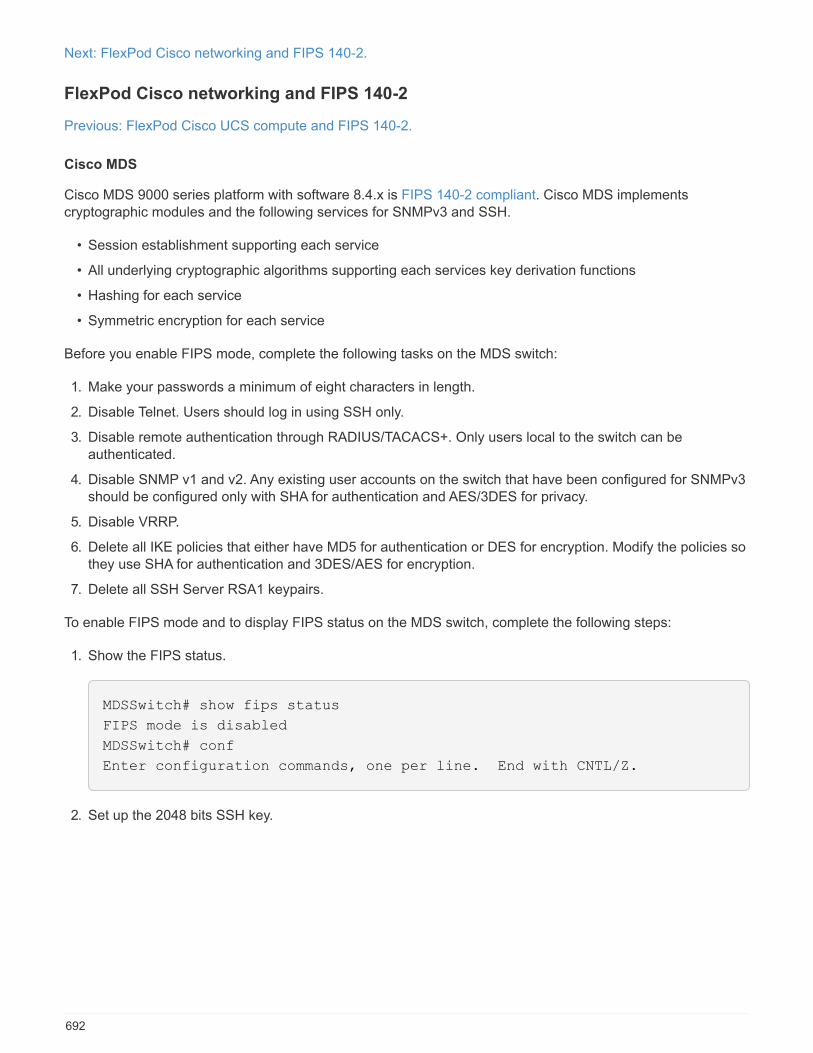
Next: FlexPod Cisco networking and FIPS 140-2.
FlexPod Cisco networking and FIPS 140-2
Previous: FlexPod Cisco UCS compute and FIPS 140-2.
Cisco MDS
Cisco MDS 9000 series platform with software 8.4.x is FIPS 140-2 compliant. Cisco MDS implementscryptographic modules and the following services for SNMPv3 and SSH.
• Session establishment supporting each service
• All underlying cryptographic algorithms supporting each services key derivation functions
• Hashing for each service
• Symmetric encryption for each service
Before you enable FIPS mode, complete the following tasks on the MDS switch:
1. Make your passwords a minimum of eight characters in length.
2. Disable Telnet. Users should log in using SSH only.
3. Disable remote authentication through RADIUS/TACACS+. Only users local to the switch can beauthenticated.
4. Disable SNMP v1 and v2. Any existing user accounts on the switch that have been configured for SNMPv3should be configured only with SHA for authentication and AES/3DES for privacy.
5. Disable VRRP.
6. Delete all IKE policies that either have MD5 for authentication or DES for encryption. Modify the policies sothey use SHA for authentication and 3DES/AES for encryption.
7. Delete all SSH Server RSA1 keypairs.
To enable FIPS mode and to display FIPS status on the MDS switch, complete the following steps:
1. Show the FIPS status.
MDSSwitch# show fips status
FIPS mode is disabled
MDSSwitch# conf
Enter configuration commands, one per line. End with CNTL/Z.
2. Set up the 2048 bits SSH key.
692
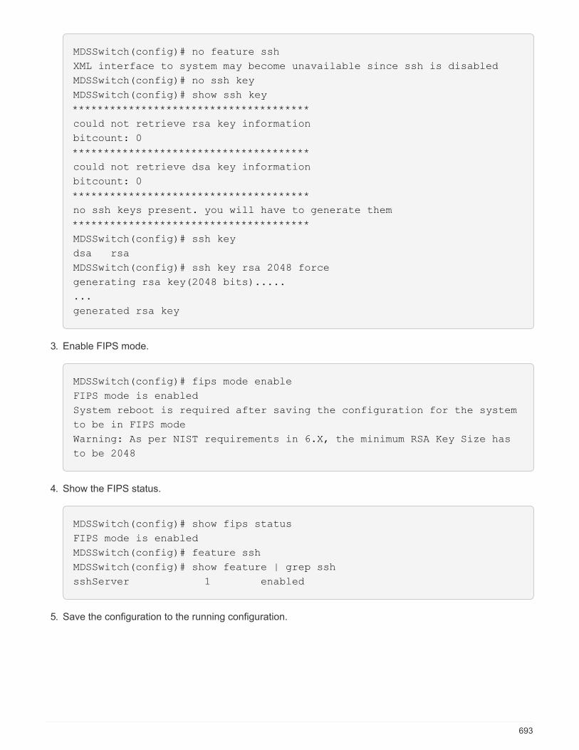
MDSSwitch(config)# no feature ssh
XML interface to system may become unavailable since ssh is disabled
MDSSwitch(config)# no ssh key
MDSSwitch(config)# show ssh key
**************************************
could not retrieve rsa key information
bitcount: 0
**************************************
could not retrieve dsa key information
bitcount: 0
**************************************
no ssh keys present. you will have to generate them
**************************************
MDSSwitch(config)# ssh key
dsa rsa
MDSSwitch(config)# ssh key rsa 2048 force
generating rsa key(2048 bits).....
...
generated rsa key
3. Enable FIPS mode.
MDSSwitch(config)# fips mode enable
FIPS mode is enabled
System reboot is required after saving the configuration for the system
to be in FIPS mode
Warning: As per NIST requirements in 6.X, the minimum RSA Key Size has
to be 2048
4. Show the FIPS status.
MDSSwitch(config)# show fips status
FIPS mode is enabled
MDSSwitch(config)# feature ssh
MDSSwitch(config)# show feature | grep ssh
sshServer 1 enabled
5. Save the configuration to the running configuration.
693
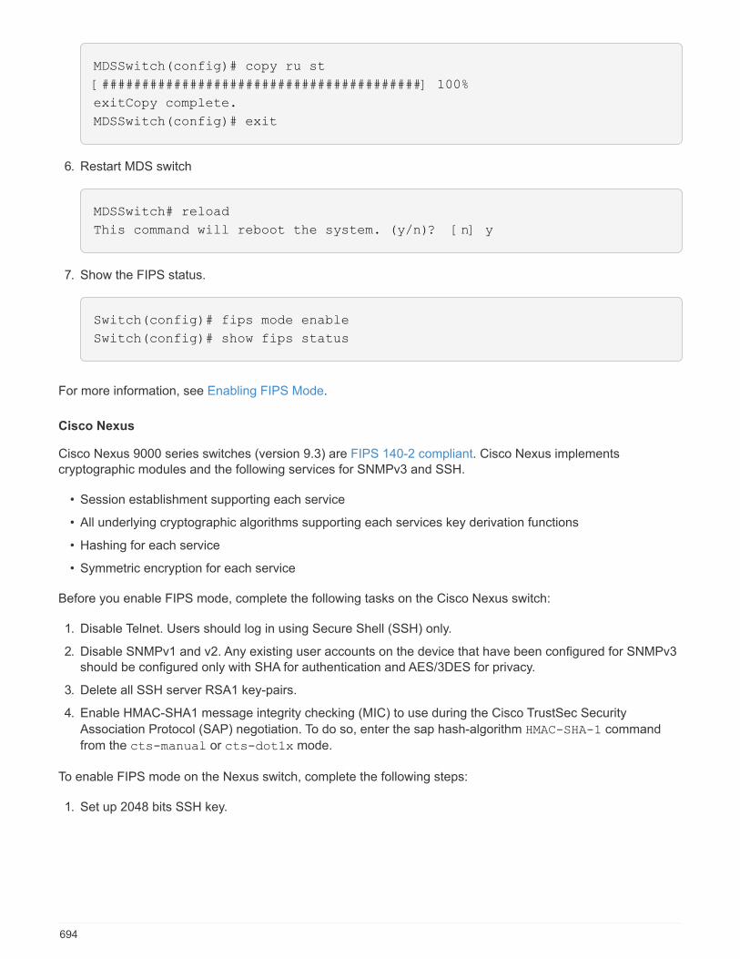
MDSSwitch(config)# copy ru st
[########################################] 100%
exitCopy complete.
MDSSwitch(config)# exit
6. Restart MDS switch
MDSSwitch# reload
This command will reboot the system. (y/n)? [n] y
7. Show the FIPS status.
Switch(config)# fips mode enable
Switch(config)# show fips status
For more information, see Enabling FIPS Mode.
Cisco Nexus
Cisco Nexus 9000 series switches (version 9.3) are FIPS 140-2 compliant. Cisco Nexus implementscryptographic modules and the following services for SNMPv3 and SSH.
• Session establishment supporting each service
• All underlying cryptographic algorithms supporting each services key derivation functions
• Hashing for each service
• Symmetric encryption for each service
Before you enable FIPS mode, complete the following tasks on the Cisco Nexus switch:
1. Disable Telnet. Users should log in using Secure Shell (SSH) only.
2. Disable SNMPv1 and v2. Any existing user accounts on the device that have been configured for SNMPv3should be configured only with SHA for authentication and AES/3DES for privacy.
3. Delete all SSH server RSA1 key-pairs.
4. Enable HMAC-SHA1 message integrity checking (MIC) to use during the Cisco TrustSec Security
Association Protocol (SAP) negotiation. To do so, enter the sap hash-algorithm HMAC-SHA-1 command
from the cts-manual or cts-dot1x mode.
To enable FIPS mode on the Nexus switch, complete the following steps:
1. Set up 2048 bits SSH key.
694
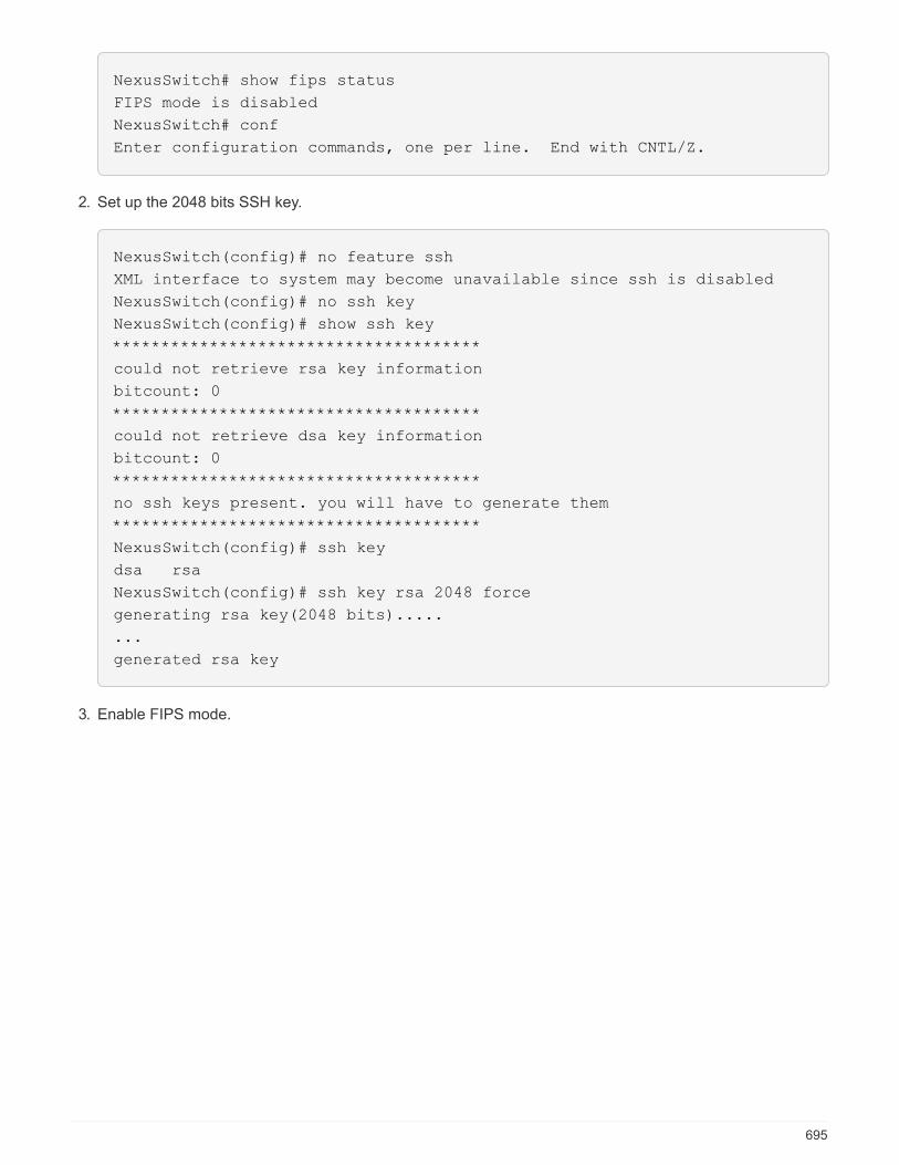
NexusSwitch# show fips status
FIPS mode is disabled
NexusSwitch# conf
Enter configuration commands, one per line. End with CNTL/Z.
2. Set up the 2048 bits SSH key.
NexusSwitch(config)# no feature ssh
XML interface to system may become unavailable since ssh is disabled
NexusSwitch(config)# no ssh key
NexusSwitch(config)# show ssh key
**************************************
could not retrieve rsa key information
bitcount: 0
**************************************
could not retrieve dsa key information
bitcount: 0
**************************************
no ssh keys present. you will have to generate them
**************************************
NexusSwitch(config)# ssh key
dsa rsa
NexusSwitch(config)# ssh key rsa 2048 force
generating rsa key(2048 bits).....
...
generated rsa key
3. Enable FIPS mode.
695
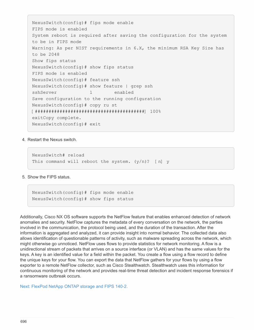
NexusSwitch(config)# fips mode enable
FIPS mode is enabled
System reboot is required after saving the configuration for the system
to be in FIPS mode
Warning: As per NIST requirements in 6.X, the minimum RSA Key Size has
to be 2048
Show fips status
NexusSwitch(config)# show fips status
FIPS mode is enabled
NexusSwitch(config)# feature ssh
NexusSwitch(config)# show feature | grep ssh
sshServer 1 enabled
Save configuration to the running configuration
NexusSwitch(config)# copy ru st
[########################################] 100%
exitCopy complete.
NexusSwitch(config)# exit
4. Restart the Nexus switch.
NexusSwitch# reload
This command will reboot the system. (y/n)? [n] y
5. Show the FIPS status.
NexusSwitch(config)# fips mode enable
NexusSwitch(config)# show fips status
Additionally, Cisco NX OS software supports the NetFlow feature that enables enhanced detection of networkanomalies and security. NetFlow captures the metadata of every conversation on the network, the partiesinvolved in the communication, the protocol being used, and the duration of the transaction. After theinformation is aggregated and analyzed, it can provide insight into normal behavior. The collected data alsoallows identification of questionable patterns of activity, such as malware spreading across the network, whichmight otherwise go unnoticed. NetFlow uses flows to provide statistics for network monitoring. A flow is aunidirectional stream of packets that arrives on a source interface (or VLAN) and has the same values for thekeys. A key is an identified value for a field within the packet. You create a flow using a flow record to definethe unique keys for your flow. You can export the data that NetFlow gathers for your flows by using a flowexporter to a remote NetFlow collector, such as Cisco Stealthwatch. Stealthwatch uses this information forcontinuous monitoring of the network and provides real-time threat detection and incident response forensics ifa ransomware outbreak occurs.
Next: FlexPod NetApp ONTAP storage and FIPS 140-2.
696
FlexPod NetApp ONTAP storage and FIPS 140-2
Previous: FlexPod Cisco networking and FIPS 140-2.
NetApp offers a variety of hardware, software, and services, which can include various components of thecryptographic modules validated under the standard. Therefore, NetApp uses a variety of approaches for FIPS140-2 compliance for the control plane and data plane:
• NetApp includes cryptographic modules that have achieved level 1 validation for data-in-transit and data-at-rest encryption.
• NetApp acquires both hardware and software modules that have been FIPS 140-2 validated by thesuppliers of those components. For example, the NetApp Storage Encryption solution leverages FIPS level2 validated drives.
• NetApp products can use a validated module in a way that complies with the standard even though theproduct or feature is not within the boundary of the validation. For example, NetApp Volume Encryption(NVE) is FIPS 140-2 compliant. Although not separately validated, it leverages the NetApp cryptographicmodule, which is level 1 validated. To understand the specifics of compliance for your version of ONTAP,contact your FlexPod SME.
NetApp Cryptographic modules are FIPS 140-2 level 1 validated
• The NetApp Cryptographic Security Module (NCSM) is FIPS 140-2 level 1 validated.
NetApp self-encrypting drives are FIPS 140-2 level 2 validated
NetApp purchases self-encrypting drives (SEDs) that have been FIPS 140-2 validated by the originalequipment manufacturer (OEM); customers seeking these drives must specify them when ordering. Drives arevalidated at level 2. The following NetApp products can leverage validated SEDs:
• AFF A-Series and FAS storage systems
• E-Series and EF-Series storage systems
NetApp Aggregate Encryption and NetApp Volume Encryption
NVE and NetApp Aggregate Encryption (NAE) technologies enable encryption of data at the volume andaggregate level respectively, making the solution agnostic to the physical drive.
NVE is a software-based, data-at-rest encryption solution available starting with ONTAP 9.1, and it has beenFIPS 140-2 compliant since ONTAP 9.2. NVE allows ONTAP to encrypt data for each volume for granularity.NAE, available with ONTAP 9.6, is an outgrowth of NVE; it allows ONTAP to encrypt data for each volume, andthe volumes can share keys across the aggregate. Both NVE and NAE use AES 256-bit encryption. Data canalso be stored on disk without SEDs. NVE and NAE enable you to use storage efficiency features even whenencryption is enabled. An application- layer- only encryption defeats all benefits of storage efficiency. With NVEand NAE, storage efficiencies are maintained because the data comes in from the network through NetAppWAFL to the RAID layer, which determines whether the data should be encrypted. For greater storageefficiency, you can use aggregate deduplication with NAE. NVE volumes and NAE volumes can coexist on thesame NAE aggregate. NAE aggregates do not support unencrypted volumes.
Here’s how the process works: When data is encrypted, it is sent to the cryptographic module which is FIPS140-2 level 1 validated. The cryptographic module encrypts the data and sends it back to the RAID layer. Theencrypted data is then sent to the disk. Therefore, with the combination of NVE and NAE, the data is alreadyencrypted on the way to the disk. Reads follow the reverse path. In other words, the data leaves the diskencrypted, is sent to RAID, is decrypted by the cryptographic module, and is then sent up the rest of the stack,as shown in the following figure.
697
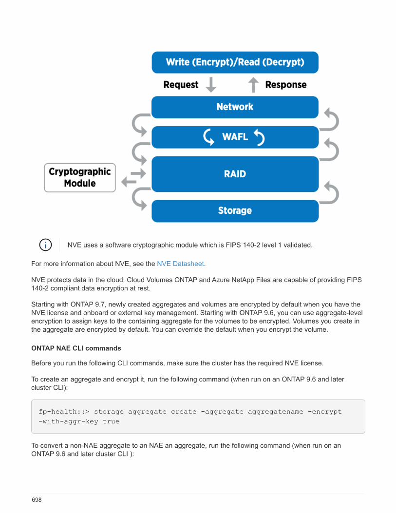
NVE uses a software cryptographic module which is FIPS 140-2 level 1 validated.
For more information about NVE, see the NVE Datasheet.
NVE protects data in the cloud. Cloud Volumes ONTAP and Azure NetApp Files are capable of providing FIPS140-2 compliant data encryption at rest.
Starting with ONTAP 9.7, newly created aggregates and volumes are encrypted by default when you have theNVE license and onboard or external key management. Starting with ONTAP 9.6, you can use aggregate-levelencryption to assign keys to the containing aggregate for the volumes to be encrypted. Volumes you create inthe aggregate are encrypted by default. You can override the default when you encrypt the volume.
ONTAP NAE CLI commands
Before you run the following CLI commands, make sure the cluster has the required NVE license.
To create an aggregate and encrypt it, run the following command (when run on an ONTAP 9.6 and latercluster CLI):
fp-health::> storage aggregate create -aggregate aggregatename -encrypt
-with-aggr-key true
To convert a non-NAE aggregate to an NAE an aggregate, run the following command (when run on anONTAP 9.6 and later cluster CLI ):
698
fp-health::> storage aggregate modify -aggregate aggregatename -node
svmname -encrypt-with-aggr-key true
To convert an NAE aggregate to an non-NAE an aggregate, run the following command (when run on anONTAP 9.6 and later cluster CLI):
fp-health::> storage aggregate modify -aggregate aggregatename -node
svmname -encrypt-with-aggr-key false
ONTAP NVE CLI commands
Starting with ONTAP 9.6, you can use aggregate-level encryption to assign keys to the containing aggregatefor the volumes to be encrypted. Volumes you create in the aggregate are encrypted by default.
To create a volume on an aggregate that is NAE enabled, run the following command (when run on an ONTAP9.6 and later cluster CLI):
fp-health::> volume create -vserver svmname -volume volumename -aggregate
aggregatename -encrypt true
To enable encryption of an existing volume “inplace” without a volume move, run the following command (whenrun on an ONTAP 9.6 and later cluster CLI):
fp-health::> volume encryption conversion start -vserver svmname -volume
volumename
To verify that volumes are enabled for encryption, run the following CLI command:
fp-health::> volume show -is-encrypted true
NSE
NSE uses SEDs to perform the data encryption through a hardware-accelerated mechanism.
NSE is configured to use FIPS 140-2 level 2 self-encrypting drives to facilitate compliance and spares return byenabling the protection of data at rest through AES 256-bit transparent disk encryption. The drives perform allof the data encryption operations internally, as depicted in the following figure, including encryption keygeneration. To prevent unauthorized access to the data, the storage system must authenticate itself with thedrive using an authentication key that is established the first time the drive is used.
699
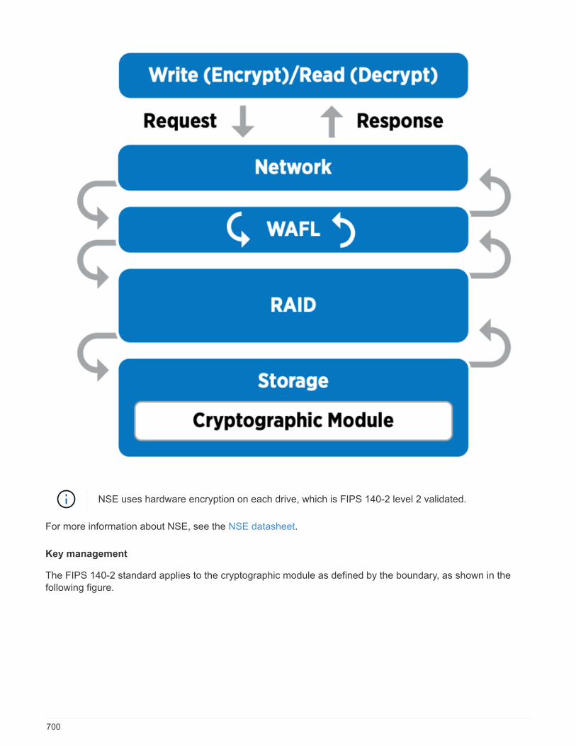
NSE uses hardware encryption on each drive, which is FIPS 140-2 level 2 validated.
For more information about NSE, see the NSE datasheet.
Key management
The FIPS 140-2 standard applies to the cryptographic module as defined by the boundary, as shown in thefollowing figure.
700
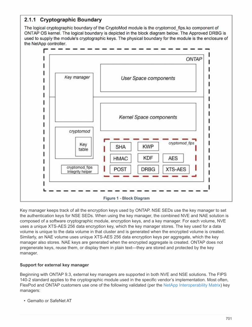
Key manager keeps track of all the encryption keys used by ONTAP. NSE SEDs use the key manager to setthe authentication keys for NSE SEDs. When using the key manager, the combined NVE and NAE solution iscomposed of a software cryptographic module, encryption keys, and a key manager. For each volume, NVEuses a unique XTS-AES 256 data encryption key, which the key manager stores. The key used for a datavolume is unique to the data volume in that cluster and is generated when the encrypted volume is created.Similarly, an NAE volume uses unique XTS-AES 256 data encryption keys per aggregate, which the keymanager also stores. NAE keys are generated when the encrypted aggregate is created. ONTAP does notpregenerate keys, reuse them, or display them in plain text—they are stored and protected by the keymanager.
Support for external key manager
Beginning with ONTAP 9.3, external key managers are supported in both NVE and NSE solutions. The FIPS140-2 standard applies to the cryptographic module used in the specific vendor’s implementation. Most often,FlexPod and ONTAP customers use one of the following validated (per the NetApp Interoperability Matrix) keymanagers:
• Gemalto or SafeNet AT
701

• Vormetric (Thales)
• IBM SKLM
• Utimaco (formerly Microfocus, HPE)
NSE and NVMe SED authentication key is backed up to an external key manager by using the industry-standard OASIS Key Management Interoperability Protocol (KMIP). Only the storage system, drive, and keymanager have access to the key, and the drive cannot be unlocked if it is moved outside the security domain,thus preventing data leakage. The external key manager also stores NVE volume encryption keys and NAEaggregate encryption keys. If the controller and disks are moved and no longer have access to the external keymanager, the NVE and NAE volumes won’t be accessible and cannot be decrypted.
The following example command adds two key management servers to the list of servers used by the external
key manager for store virtual machine (SVM) svmname1.
fp-health::> security key-manager external add-servers -vserver svmname1
-key-servers 10.0.0.20:15690, 10.0.0.21:15691
When a FlexPod Datacenter is being used in a multitenancy scenario, ONTAP enables users by providingtenancy separation for security reasons at the SVM level.
To verify list of external key managers, run the following CLI command:
fp-health::> security key-manager external show
Combine encryption for double encryption (layered defense)
If you need to segregate access to data and make sure that data is protected all the time, NSE SEDs can becombined with network- or fabric-level encryption. NSE SEDs act like a backstop if an administrator forgets toconfigure or misconfigures higher-level encryption. For two distinct layers of encryption, you can combine NSESEDs with NVE and NAE.
NetApp ONTAP cluster-wide control plane FIPS mode
NetApp ONTAP data management software has a FIPS mode configuration that instantiates an added level ofsecurity for the customer. This FIPS mode only applies to the control plane. When FIPS mode is enabled, inaccordance with key elements of FIPS 140-2, Transport Layer Security v1 (TLSv1) and SSLv3 are disabled,and only TLS v1.1 and TLS v1.2 remain enabled.
ONTAP cluster-wide control pane in FIPS mode is FIPS 140-2 level 1 compliant. Cluster-wideFIPS mode uses a software-based cryptographic module provided by NCSM.
FIPS 140-2 compliance mode for cluster-wide control plane secures all control Interfaces of ONTAP. By
default, the FIPS 140-2 only mode is disabled; however you can enable this mode by setting the is- fips-
enabled parameter to true for the security config modify command.
To enable FIPS mode on the ONTAP cluster, run the following command:
702

fp-health::> security config modify -interface SSL -is-fips-enabled true
When SSL FIPS mode is enabled, SSL communication from ONTAP to the external client or servercomponents outside of ONTAP will use FIPS complaint cryptographic for SSL.
To show the FIPS status for the entire cluster, run the following commands:
fp-health::> set advanced
fp-health::*> security config modify -interface SSL -is-fips-enabled true
Next: Solution benefits of FlexPod converged infrastructure.
Solution benefits of FlexPod converged infrastructure
Previous: FlexPod NetApp ONTAP storage and FIPS 140-2.
Healthcare organizations have several mission-critical systems. Two of the most critical systems are theelectronic health record (EHR) systems and medical imaging systems. To demonstrate the FIPS setup on aFlexPod system, we used an open-source EHR and an open-source picture archiving and communicationsystem (PACS) system for the lab setup and workload validation on the FlexPod system. For a complete list ofEHR capabilities, EHR logical application components, and how EHR systems benefit when implemented on aFlexPod system see TR-4881: FlexPod for Electronic Health Record Systems. For a complete list of a medicalimaging system capabilities, logical application components, and how medical imaging systems benefit whenimplemented on FlexPod, see TR-4865: FlexPod for Medical Imaging.
During the FIPS setup and workload validation, we exercised workload characteristics that were representativeof a typical healthcare organization. For example, we exercised an open-source EHR system to includerealistic patient data access and change scenarios. Additionally, we exercised medical imaging workloads that
included digital imaging and communications in medicine (DICOM) objects in a *. dcm file format. DICOMobjects with metadata were stored on both the file and block storage. Additionally, we implementedmultipathing capabilities from within a virtualized RedHat Enterprise Linux (RHEL) server. We stored DICOMobjects on an NFS, mounted LUNs using iSCSI, and mounted LUNs using FC. During the FIPS setup andvalidation, we observed that the FlexPod converged infrastructure exceeded our expectations and performedseamlessly.
The following figure depicts the FlexPod system used for FIPS setup and validation. We leveraged the FlexPodDatacenter with VMware vSphere 7.0 and NetApp ONTAP 9.7 Cisco Validated Design (CVD) during the setupprocess.
703
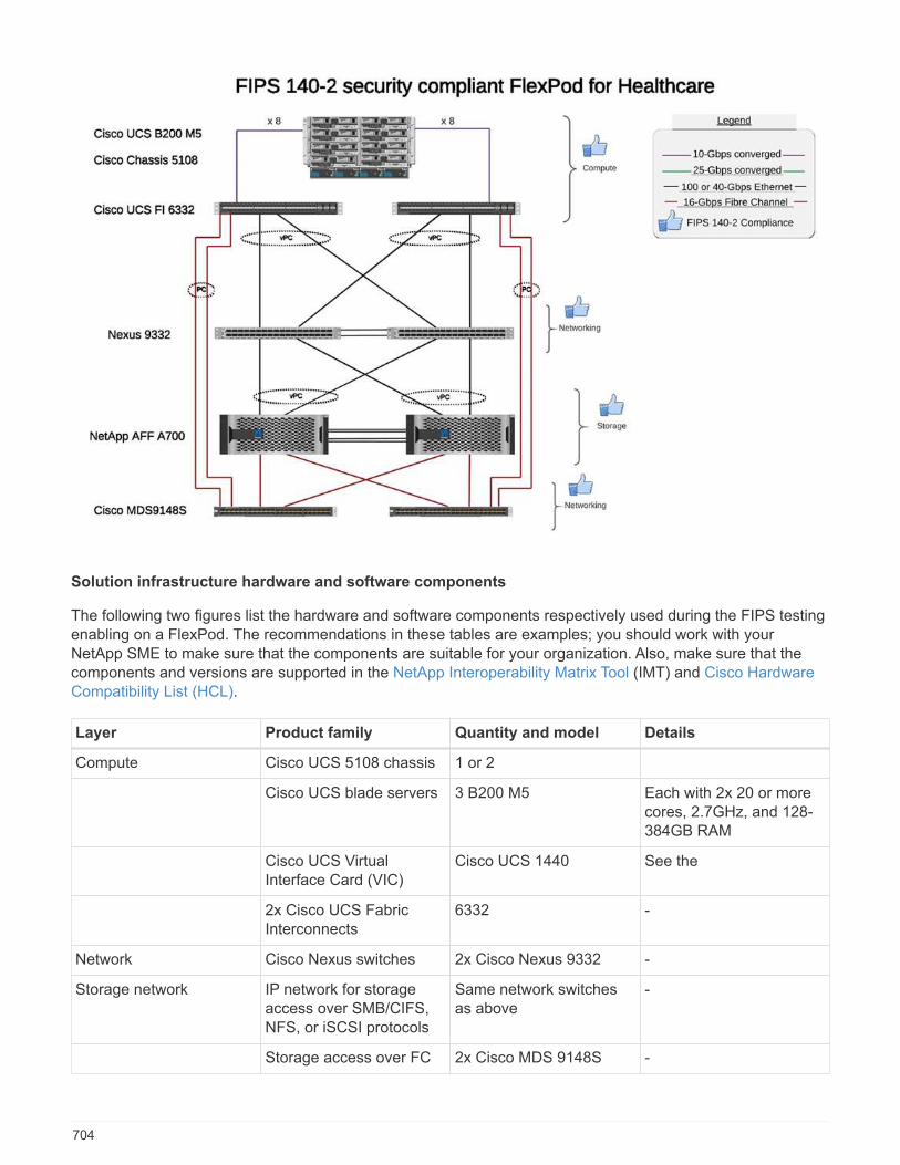
Solution infrastructure hardware and software components
The following two figures list the hardware and software components respectively used during the FIPS testingenabling on a FlexPod. The recommendations in these tables are examples; you should work with yourNetApp SME to make sure that the components are suitable for your organization. Also, make sure that thecomponents and versions are supported in the NetApp Interoperability Matrix Tool (IMT) and Cisco HardwareCompatibility List (HCL).
Layer Product family Quantity and model Details
Compute Cisco UCS 5108 chassis 1 or 2
Cisco UCS blade servers 3 B200 M5 Each with 2x 20 or morecores, 2.7GHz, and 128-384GB RAM
Cisco UCS VirtualInterface Card (VIC)
Cisco UCS 1440 See the
2x Cisco UCS FabricInterconnects
6332 -
Network Cisco Nexus switches 2x Cisco Nexus 9332 -
Storage network IP network for storageaccess over SMB/CIFS,NFS, or iSCSI protocols
Same network switchesas above
-
Storage access over FC 2x Cisco MDS 9148S -
704
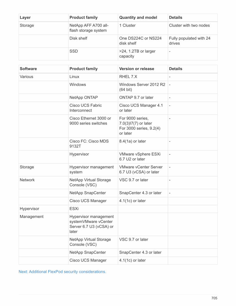
Layer Product family Quantity and model Details
Storage NetApp AFF A700 all-flash storage system
1 Cluster Cluster with two nodes
Disk shelf One DS224C or NS224disk shelf
Fully populated with 24drives
SSD >24, 1.2TB or largercapacity
-
Software Product family Version or release Details
Various Linux RHEL 7.X -
Windows Windows Server 2012 R2(64 bit)
-
NetApp ONTAP ONTAP 9.7 or later -
Cisco UCS FabricInterconnect
Cisco UCS Manager 4.1or later
-
Cisco Ethernet 3000 or9000 series switches
For 9000 series,7.0(3)I7(7) or laterFor 3000 series, 9.2(4)or later
-
Cisco FC: Cisco MDS9132T
8.4(1a) or later -
Hypervisor VMware vSphere ESXi6.7 U2 or later
-
Storage Hypervisor managementsystem
VMware vCenter Server6.7 U3 (vCSA) or later
-
Network NetApp Virtual StorageConsole (VSC)
VSC 9.7 or later -
NetApp SnapCenter SnapCenter 4.3 or later -
Cisco UCS Manager 4.1(1c) or later
Hypervisor ESXi
Management Hypervisor managementsystemVMware vCenterServer 6.7 U3 (vCSA) orlater
NetApp Virtual StorageConsole (VSC)
VSC 9.7 or later
NetApp SnapCenter SnapCenter 4.3 or later
Cisco UCS Manager 4.1(1c) or later
Next: Additional FlexPod security considerations.
705

Additional FlexPod security considerations
Previous: Solution benefits of FlexPod converged infrastructure.
The FlexPod infrastructure is a modular, converged, optionally virtualized, scalable (scale out and scale up),and cost-effective platform. With the FlexPod platform, you can independently scale out compute, network, andstorage to accelerate your application deployment. And the modular architecture enables nondisruptiveoperations even during your system scale-out and upgrade activities.
Different components of an HIT system require data to be stored in SMB/CIFS, NFS, Ext4, and NTFS filesystems. This requirement means that the infrastructure must provide data access over the NFS, CIFS, andSAN protocols. A single NetApp storage system can support all these protocols, eliminating the need for thelegacy practice of protocol-specific storage systems. Additionally, a single NetApp storage system can supportmultiple HIT workloads such as EHRs, PACS or VNA, genomics, VDI, and more, with guaranteed andconfigurable performance levels.
When deployed in a FlexPod system, HIT delivers several benefits that are specific to the healthcare industry.The following list is a high-level description of these benefits:
• FlexPod security. Security is at the very foundation of a FlexPod system. In the past few years,ransomware has become a threat. Ransomware is a type of malware that is based on cryptovirology, theuse of cryptography to build malicious software. This malware can use both symmetric and asymmetric keyencryption to lock a victim’s data and demand a ransom to provide the key to decrypt the data. To learnhow the FlexPod solution helps mitigate threats like ransomware, see TR-4802: The Solution toRansomware. FlexPod infrastructure components are also FIPS 140-2-compliant.
• Cisco Intersight. Cisco Intersight is an innovative, cloud-based, management-as-a-service platform thatprovides a single pane of glass for full-stack FlexPod management and orchestration. The Intersightplatform uses FIPS 140-2 security-compliant cryptographic modules. The platform’s out-of-bandmanagement architecture makes it out of scope for some standards or audits such as HIPAA. No individualidentifiable health information on the network is ever sent to the Intersight portal.
• NetApp FPolicy technology. NetApp FPolicy (an evolution of the name file policy) is a file-accessnotification framework for monitoring and to managing file access over the NFS or SMB/CIFS protocols.This technology has been part of the ONTAP data management software for more than a decade—it isuseful in helping detect ransomware. This Zero Trust engine provides extra security measures beyondpermissions in access control lists (ACLs). FPolicy has two modes of operation: native and external:
◦ Native mode provides both blacklisting and whitelisting of file extensions.
◦ External mode has the same capabilities as native mode, but it also integrates with an FPolicy serverthat runs externally to the ONTAP system as well as a security information and event management(SIEM) system. For more information about how to fight ransomware, see the Fighting Ransomware:Part Three – ONTAP FPolicy, Another Powerful Native (aka Free) Tool blog.
• Data at rest. ONTAP 9 and later has three FIPS 140-2-compliant, data-at-rest encryption solutions:
◦ NSE is a hardware solution that uses self-encrypting drives.
◦ NVE is a software solution that enables encryption of any data volume on any drive type where it isenabled with a unique key for each volume.
◦ NAE is a software solution that enables encryption of any data volume on any drive type where it isenabled with unique keys for each aggregate.
Starting with ONTAP 9.7, NAE and NVE are enabled by default if the NetApp NVE licensepackage with name VE is in place.
706
• Data in flight. Starting with ONTAP 9.8, Internet Protocol security (IPsec) provides end-to-end encryptionsupport for all IP traffic between a client and an ONTAP SVM. IPsec data encryption for all IP trafficincludes NFS, iSCSI, and SMB/CIFS protocols. IPsec provides the only encryption in flight option for iSCSItraffic.
• End-to-end data encryption across a hybrid, multicloud data fabric. Customers who use data-at-restencryption technologies such as NSE or NVE and Cluster Peering Encryption (CPE) for data replicationtraffic can now use end-to-end encryption between client and storage across their hybrid multicloud datafabric by upgrading to ONTAP 9.8 or later and using IPsec. Beginning with ONTAP 9, you can enable theFIPS 140-2 compliance mode for cluster-wide control plane interfaces. By default, the FIPS 140-2-onlymode is disabled. Starting with ONTAP 9.6, CPE provides TLS 1.2 AES-256 GCM encryption support forONTAP data replication features such as NetApp SnapMirror, NetApp SnapVault, and NetApp FlexCachetechnologies. Encryption is setup by way of a pre-shared key (PSK) between two cluster peers.
• Secure multitenancy. Supports the increased needs of virtualized server and storage sharedinfrastructure, enabling secure multitenancy of facility-specific information, particularly when hostingmultiple instances of databases and software.
Next: Conclusion.
Conclusion
Previous: Additional FlexPod security considerations.
By running your healthcare application on a FlexPod platform, your healthcare organization is better protectedby a FIPS 140-2-enabled platform. FlexPod offers multilayered protection at every single component: compute,network and storage. FlexPod data protection capabilities protect data at rest or in flight, and keep backupssafe and ready when needed.
Avoid human errors by leveraging the FlexPod prevalidated designs that are rigorously tested convergedinfrastructures from the strategic partnership of Cisco and NetApp. A FlexPod system engineered anddesigned to deliver predictable, low-latency system performance and high availability with little impact, evenwhen FIPS 140-2 is enabled in the compute, networking, and storage layers. This approach results in asuperior user experience and optimal response time for users of your HIT system.
Next: Acknowledgements, version history, and where to find additional information.
Acknowledgements, version history, and where to find additional information
Previous: Conclusion.
To learn more about the information that is described in this document, review the following documents andwebsites:
• Cisco MDS 9000 Family NX-OS Security Configuration Guide
https://www.cisco.com/c/en/us/td/docs/switches/datacenter/mds9000/sw/8_x/config/security/cisco_mds9000_security_config_guide_8x/configuring_fips.html#task_1188151
• Cisco Nexus 9000 Series NX-OS Security Configuration Guide, Release 9.3(x)
https://www.cisco.com/c/en/us/td/docs/switches/datacenter/nexus9000/sw/93x/security/configuration/guide/b-cisco-nexus-9000-nx-os-security-configuration-guide-93x/m-configuring-fips.html
• NetApp and Federal Information Processing Standard (FIPS) Publication 140-2
707

https://www.netapp.com/company/trust-center/compliance/fips-140-2/
• FIPS 140-2
https://fieldportal.netapp.com/content/902303
• NetApp ONTAP 9 Hardening Guide
https://www.netapp.com/us/media/tr-4569.pdf
• NetApp Encryption Power Guide
https://docs.netapp.com/ontap-9/index.jsp?topic=%2Fcom.netapp.doc.pow-nve%2Fhome.html
• NVE and NAE Datasheet
https://www.netapp.com/us/media/ds-3899.pdf
• NSE Datasheet
https://www.netapp.com/us/media/ds-3213-en.pdf
• ONTAP 9 Documentation Center
http://docs.netapp.com
• NetApp and Federal Information Processing Standard (FIPS) Publication 140-2
https://www.netapp.com/company/trust-center/compliance/fips-140-2/
• Cisco and FIPS 140-2 Compliance
https://www.cisco.com/c/en/us/solutions/industries/government/global-government-certifications/fips-140.html
• NetApp Cryptographic Security Module
https://csrc.nist.gov/csrc/media/projects/cryptographic-module-validation-program/documents/security-policies/140sp2648.pdf
• Health industry cybersecurity practices: managing threats and protecting patients
https://www.phe.gov/Preparedness/planning/405d/Pages/hic-practices.aspx
• Cybersecurity practices for medium and large healthcare organizations
https://www.phe.gov/Preparedness/planning/405d/Documents/tech-vol2-508.pdf
• Cisco and Cryptographic Module Validation Program (CMVP)
https://csrc.nist.gov/projects/cryptographic-module-validation-program/validated-modules/search?SearchMode=Basic&Vendor=cisco&CertificateStatus=Active&ValidationYear=0
• NetApp Storage Encryption, NVMe Self-Encrypting Drives, NetApp Volume Encryption, and NetAppAggregate Encryption
708
https://www.netapp.com/pdf.html?item=/media/17073-ds-3898.pdf
• NetApp Volume Encryption and NetApp Aggregate Encryption
https://www.netapp.com/pdf.html?item=/media/17070-ds-3899.pdf
• NetApp Storage Encryption
https://www.netapp.com/pdf.html?item=/media/7563-ds-3213-en.pdf
• FlexPod for Electronic Health Record Systems
https://www.netapp.com/pdf.html?item=/media/22199-tr-4881.pdf
• Data Now: Improving Performance in Epic EHR Environments with Cloud-Connected Flash Technology
https://www.netapp.com/media/10809-cloud-connected-flash-wp.pdf
• FlexPod Datacenter for Epic EHR Infrastructure
https://www.netapp.com/pdf.html?item=/media/17061-ds-3683.pdf
• FlexPod Datacenter for Epic EHR Deployment Guide
https://www.netapp.com/media/10658-tr-4693.pdf
• FlexPod Datacenter Infrastructure for MEDITECH Software
https://www.netapp.com/media/8552-flexpod-for-meditech-software.pdf
• The FlexPod Standard Extends to MEDITECH Software
https://blog.netapp.com/the-flexpod-standard-extends-to-meditech-software/
• FlexPod for MEDITECH Directional Sizing Guide
https://www.netapp.com/pdf.html?item=/media/12429-tr4774.pdf
• FlexPod for medical imaging
https://www.netapp.com/media/19793-tr-4865.pdf
• AI in Healthcare
https://www.netapp.com/us/media/na-369.pdf
• FlexPod for healthcare Ease Your Transformation
https://flexpod.com/solutions/verticals/healthcare/
• FlexPod from Cisco and NetApp
https://flexpod.com/
709
Acknowledgements
• Abhinav Singh, Technical Marketing Engineer, NetApp
• Brian O’Mahony, Solution Architect Healthcare (Epic), NetApp
• Brian Pruitt, Pursuit Business Development Manager, NetApp
• Arvind Ramakrishnan, Senior Solutions Architect, NetApp
• Michael Hommer, FlexPod Global Field CTO, NetApp
Version History
Version Date Document version history
Version 1.0 April 2021 Initial release
710
Cisco Intersight with NetApp ONTAP storagequick start guide
Cisco Intersight with NetApp ONTAP storage: quick startguide
Rachel Lithman and Jyh-Shing Chen, NetApp
In partnership with:
Introduction
NetApp and Cisco have partnered to provide Cisco Intersight, a single-pane view of the FlexPod ecosystem.This simplified integration creates a unified management platform for all components in the FlexPodinfrastructure and FlexPod solution. Cisco Intersight allows you to monitor NetApp storage, Cisco compute,and VMware inventory. It also allows you to orchestrate or automate workflows to accomplish storage andvirtualization tasks in tandem.
For more information, see TR 4883: FlexPod Datacenter with ONTAP 9.8, ONTAP Storage Connector forCisco Intersight, and Cisco Intersight Managed Mode.
What’s new
This section lists new features and functionality available for Cisco Intersight with NetApp ONTAP storage.
April 2022
To ensure compatibility and complete functionality with future releases, it is recommended thatyou upgrade your NetApp Active IQ Unified Manager to version 9.10P1.
• Added Broadcast Domain to Ethernet Port Detail page
• Changed the term “Aggregate” to “Tier” for the Aggregate and SVM within the user interface
• Changed the term "Cluster Status" to "Array Status"
• MTU filter now works for <,>,=,⇐,>= characters
• Added Network Interface Page to Cluster Inventory
• Added AutoSupport to Cluster Inventory
• Added cdpd.enable option to node
• Added an object for CDP neighbor
• Added NetApp workflow storage tasks within Cisco Intersight. See Use case 3 Custom workflows usingdesigner-free form for a complete list of NetApp storage tasks.
711

January 2022
• Added event-based Intersight alarms for NetApp Active IQ Unified Manager 9.10 or above.
To ensure compatibility and complete functionality with future releases, it is recommended thatyou upgrade your NetApp Active IQ Unified Manager to version 9.10.
• Explicitly set each protocol enabled (true or false) for Storage Virtual Machine
• Mapped clusterHealthStatus state ok-with-suppressed to OK
• Renamed Health column to Cluster Status column under the Cluster list page
• Showing storage array “Unreachable” if the cluster is down or otherwise unreachable
• Renamed Health column to Array Status column under the Cluster General page
• SVM now has a “Volumes” tab that shows all the volumes for the SVM
• Volume has a snapshot capacity section
• Licenses now display correctly
October 2021
• Updated list of NetApp storage tasks available within Cisco Intersight. See Use case 3 Custom workflowsusing designer-free form for a complete list of NetApp storage tasks.
• Added Health column under the Cluster list page.
• Expanded details now available under the General page for a selected cluster.
• NTP Server table now accessible through the navigation pane.
• Added a new Sensors tab containingthe General page for the Storage Virtual Machine.
• VLAN and link aggregation group summary now available under the Port General page.
• Total Data Capacity column added under the Volume Total Capacity table.
• Latency, IOPS, and Throughput columns added under Average Volume Statistics, Average LUN Statistics,Average Aggregate Statistics, Average Storage VM Statistics, and Average Node Statistics tables
The above performance metrics are only available for storage arrays monitored throughNetApp Active IQ Unified Manager 9.9 or above.
Requirements
Check that you meet the hardware, software, and licensing requirements for NetAppONTAP storage integration with Cisco Intersight.
Hardware and software requirements
These are the minimum hardware and software components required to implement the solution. Thecomponents that are used in any particular implementation of the solution might vary based on customerrequirements.
712
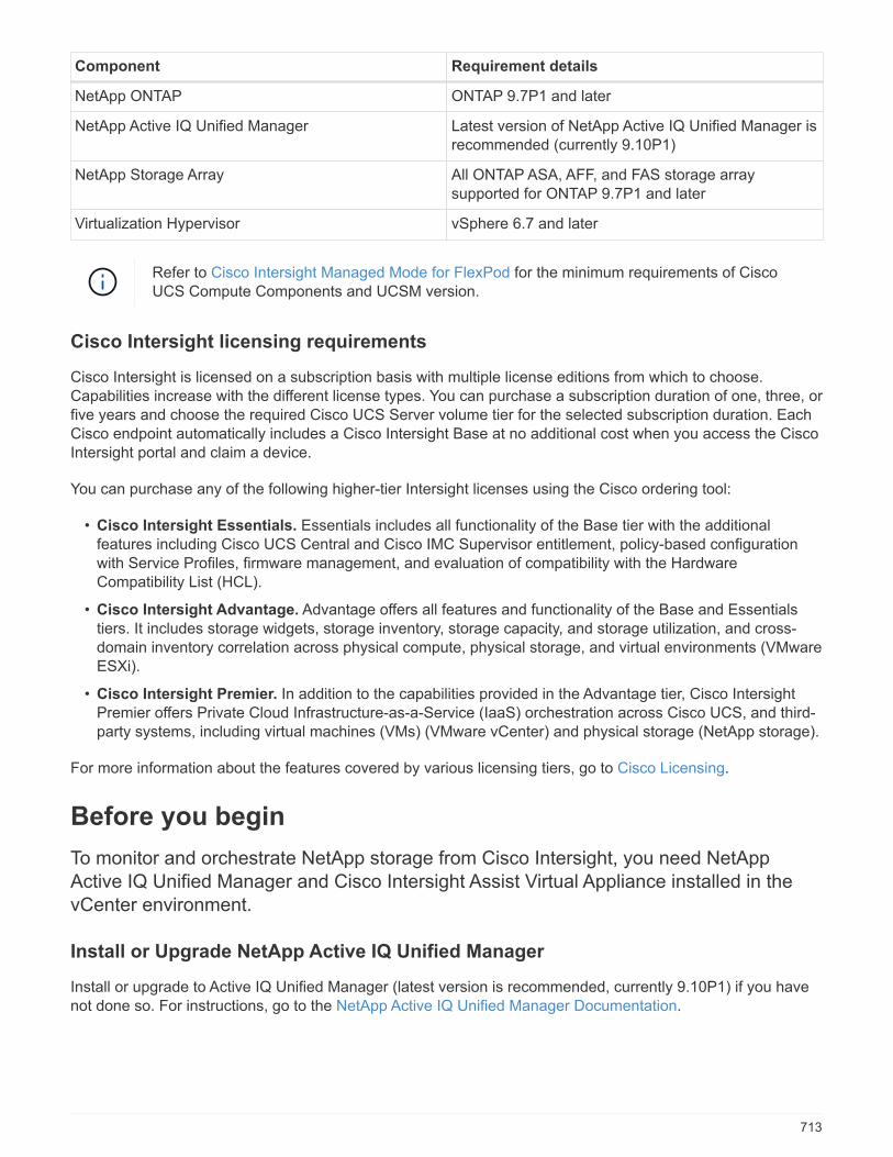
Component Requirement details
NetApp ONTAP ONTAP 9.7P1 and later
NetApp Active IQ Unified Manager Latest version of NetApp Active IQ Unified Manager isrecommended (currently 9.10P1)
NetApp Storage Array All ONTAP ASA, AFF, and FAS storage arraysupported for ONTAP 9.7P1 and later
Virtualization Hypervisor vSphere 6.7 and later
Refer to Cisco Intersight Managed Mode for FlexPod for the minimum requirements of CiscoUCS Compute Components and UCSM version.
Cisco Intersight licensing requirements
Cisco Intersight is licensed on a subscription basis with multiple license editions from which to choose.Capabilities increase with the different license types. You can purchase a subscription duration of one, three, orfive years and choose the required Cisco UCS Server volume tier for the selected subscription duration. EachCisco endpoint automatically includes a Cisco Intersight Base at no additional cost when you access the CiscoIntersight portal and claim a device.
You can purchase any of the following higher-tier Intersight licenses using the Cisco ordering tool:
• Cisco Intersight Essentials. Essentials includes all functionality of the Base tier with the additionalfeatures including Cisco UCS Central and Cisco IMC Supervisor entitlement, policy-based configurationwith Service Profiles, firmware management, and evaluation of compatibility with the HardwareCompatibility List (HCL).
• Cisco Intersight Advantage. Advantage offers all features and functionality of the Base and Essentialstiers. It includes storage widgets, storage inventory, storage capacity, and storage utilization, and cross-domain inventory correlation across physical compute, physical storage, and virtual environments (VMwareESXi).
• Cisco Intersight Premier. In addition to the capabilities provided in the Advantage tier, Cisco IntersightPremier offers Private Cloud Infrastructure-as-a-Service (IaaS) orchestration across Cisco UCS, and third-party systems, including virtual machines (VMs) (VMware vCenter) and physical storage (NetApp storage).
For more information about the features covered by various licensing tiers, go to Cisco Licensing.
Before you begin
To monitor and orchestrate NetApp storage from Cisco Intersight, you need NetAppActive IQ Unified Manager and Cisco Intersight Assist Virtual Appliance installed in thevCenter environment.
Install or Upgrade NetApp Active IQ Unified Manager
Install or upgrade to Active IQ Unified Manager (latest version is recommended, currently 9.10P1) if you havenot done so. For instructions, go to the NetApp Active IQ Unified Manager Documentation.
713

Install Cisco Intersight Assist Virtual Appliance
Ensure that you meet the Cisco Intersight Virtual Appliance Licensing, System, and Network requirements.
Steps
1. Create a Cisco Intersight Account.Visit https://intersight.com/ to create your Intersight account. You must have a valid Cisco ID to create aCisco Intersight account.
2. Download the Intersight Virtual Appliance at software.cisco.com. For more information, go to the IntersightAppliance Install and Upgrade Guide.
3. Deploy the OVA. DNS and NTP are required to deploy the OVA.
a. Configure DNS with A/PTR and CNAME Alias records prior to deploying the OVA. See the examplebelow.
b. Choose the appropriate configuration size (Tiny, Small, or Medium) based on your OVA deploymentrequirements for Intersight Virtual Appliance.
TIP: For a two-node ONTAP cluster with a large number of storage objects, NetApp recommends thatyou use the Small (16 vCPU, 32 Gi RAM) option.
714
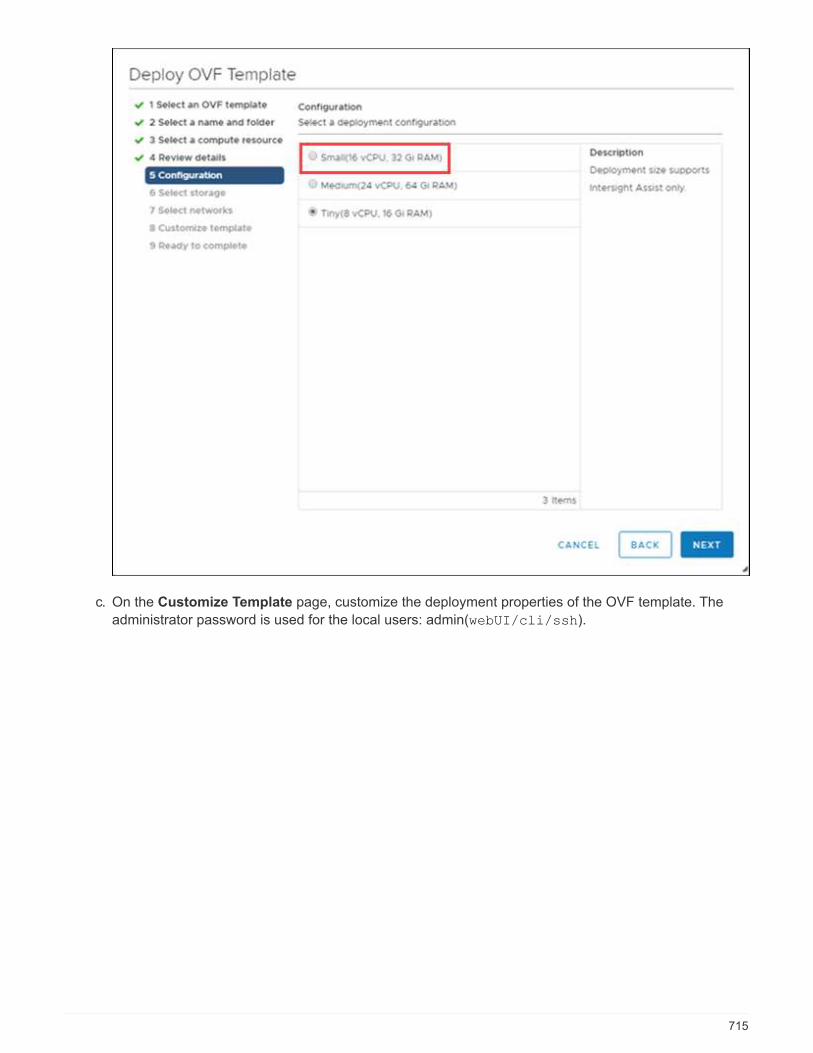
c. On the Customize Template page, customize the deployment properties of the OVF template. The
administrator password is used for the local users: admin(webUI/cli/ssh).
715
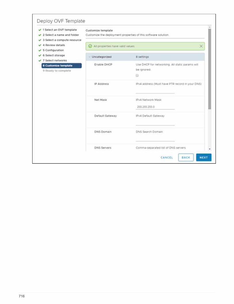
716

d. Click Next.
4. Post-deploy the Intersight Assist Appliance.
a. Navigate to https://FQDN-of-your-appliance to complete the post-install set-up of your appliance.
The installation process automatically begins. Installation can take up to one hour depending onbandwidth to Intersight.com. It can also take several seconds for the secure site to be operational afterthe VM powers on.
b. During the post-deployment process, select what you would like to install:
▪ Intersight Connected Virtual Appliance. This deployment requires a connection back to Ciscoand Intersight services for updates and access to required services for full functionality ofIntersight.com.
▪ Intersight Private Virtual Appliance. This deployment is intended for an environment where youoperate data centers in a disconnected (air gap) mode.
▪ Intersight Assist. This deployment enables SaaS model to connect to Cisco Intersight.
If you select Intersight Assist, take note of the device ID and claim code before youcontinue.
717
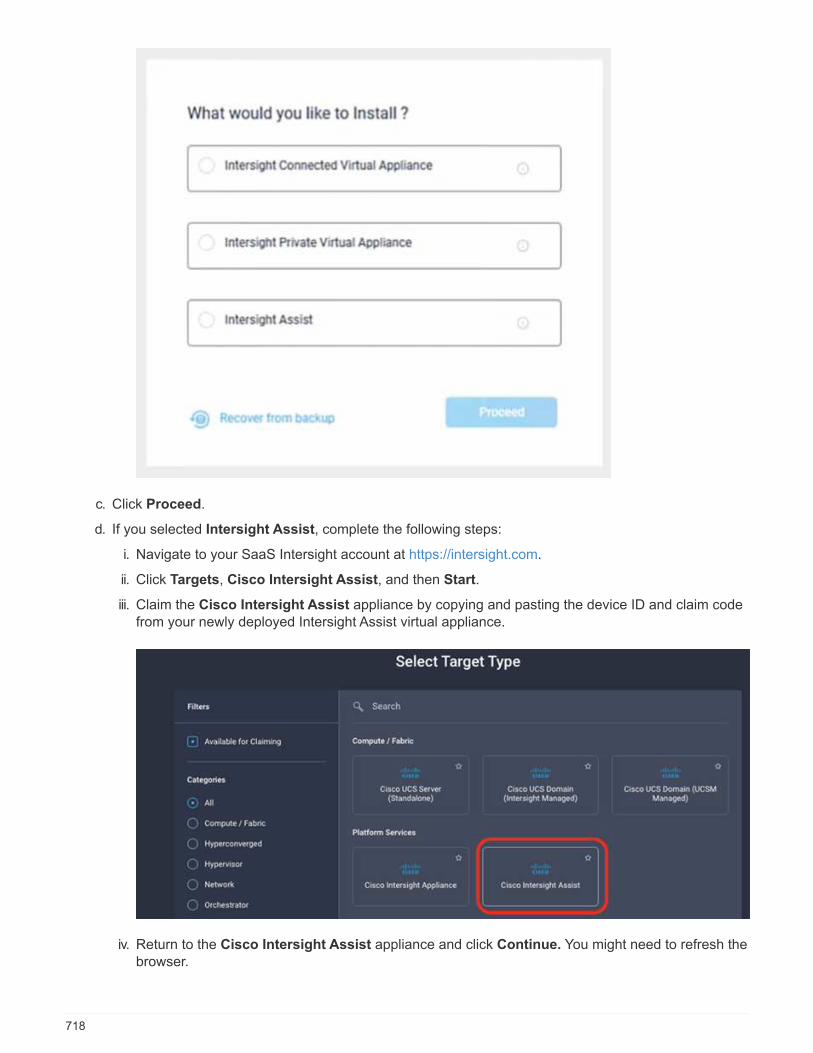
c. Click Proceed.
d. If you selected Intersight Assist, complete the following steps:
i. Navigate to your SaaS Intersight account at https://intersight.com.
ii. Click Targets, Cisco Intersight Assist, and then Start.
iii. Claim the Cisco Intersight Assist appliance by copying and pasting the device ID and claim codefrom your newly deployed Intersight Assist virtual appliance.
iv. Return to the Cisco Intersight Assist appliance and click Continue. You might need to refresh thebrowser.
718
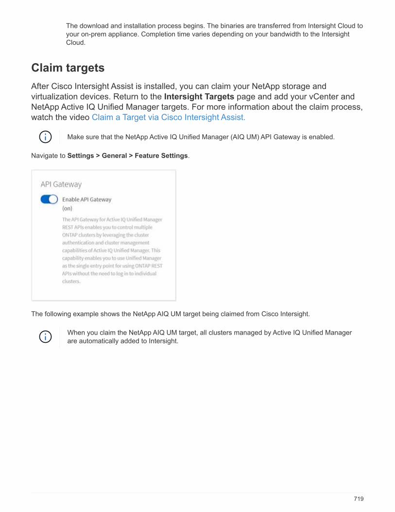
The download and installation process begins. The binaries are transferred from Intersight Cloud toyour on-prem appliance. Completion time varies depending on your bandwidth to the IntersightCloud.
Claim targets
After Cisco Intersight Assist is installed, you can claim your NetApp storage andvirtualization devices. Return to the Intersight Targets page and add your vCenter andNetApp Active IQ Unified Manager targets. For more information about the claim process,watch the video Claim a Target via Cisco Intersight Assist.
Make sure that the NetApp Active IQ Unified Manager (AIQ UM) API Gateway is enabled.
Navigate to Settings > General > Feature Settings.
The following example shows the NetApp AIQ UM target being claimed from Cisco Intersight.
When you claim the NetApp AIQ UM target, all clusters managed by Active IQ Unified Managerare automatically added to Intersight.
719
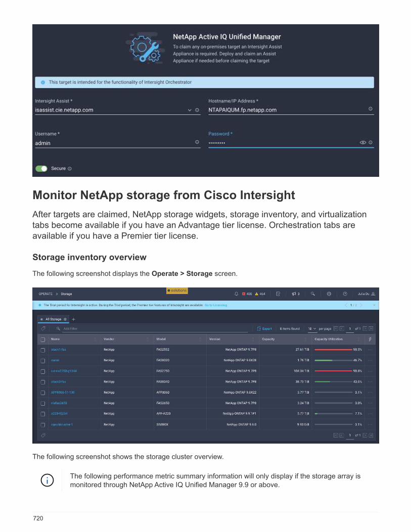
Monitor NetApp storage from Cisco Intersight
After targets are claimed, NetApp storage widgets, storage inventory, and virtualizationtabs become available if you have an Advantage tier license. Orchestration tabs areavailable if you have a Premier tier license.
Storage inventory overview
The following screenshot displays the Operate > Storage screen.
The following screenshot shows the storage cluster overview.
The following performance metric summary information will only display if the storage array ismonitored through NetApp Active IQ Unified Manager 9.9 or above.
720
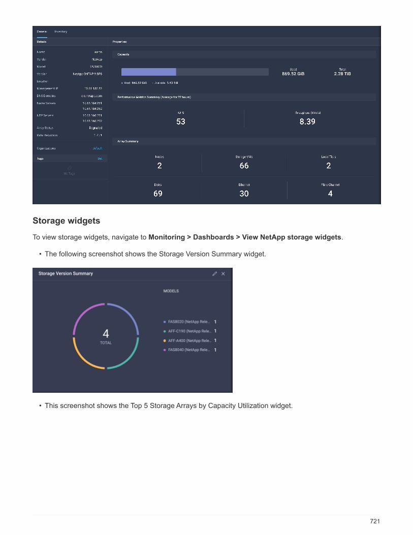
Storage widgets
To view storage widgets, navigate to Monitoring > Dashboards > View NetApp storage widgets.
• The following screenshot shows the Storage Version Summary widget.
• This screenshot shows the Top 5 Storage Arrays by Capacity Utilization widget.
721
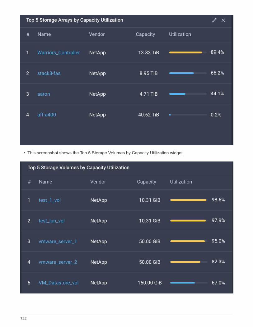
• This screenshot shows the Top 5 Storage Volumes by Capacity Utilization widget.
722
Use cases
These are a few use case examples for monitoring and orchestration of NetApp storagefrom Cisco Intersight.
Use case 1: Monitoring NetApp storage inventory and widgets
When the NetApp storage environment is available in Cisco Intersight, you can monitor NetApp storage objectsin detail from storage inventory and get an overview from storage widgets.
1. Deploy Intersight Assist OVA (OnPrem task in vCenter Environment).
2. Add NetApp AIQ UM devices in Intersight Assist.
3. Go to Storage and navigate through NetApp storage inventory.
4. Add Widgets for NetApp storage to your Monitor Dashboard.
Here is a link to the video showing NetApp ONTAP Storage Monitoring Features from Cisco Intersight.
Use case 2: NetApp storage orchestration using Reference Workflows
When NetApp storage and vCenter environments are available in Cisco Intersight, you can execute end-to-endReference Workflows available out of box that include storage and virtualization tasks.
1. Deploy Intersight Assist OVA (OnPrem task in vCenter Environment).
2. Add NetApp AIQ UM devices in Intersight Assist.
3. Add the vCenter target to Intersight via Intersight Assist.
4. Execute Reference Workflows available out of box.
Here is a list of Reference Workflows:
◦ New Storage Interface
◦ New VMFS Datastore
◦ Update VMFS Datastore
◦ Remove VMFS Datastore
◦ New NAS Datastore
◦ Update NAS Datastore
◦ Remove NAS Datastore
◦ New Storage Host
◦ Update Storage Host
◦ Remove Storage Host
◦ New Storage Export Policy
◦ Remove Storage Export Policy
◦ New Storage Virtual Machine
◦ New Virtual Machine
723

Use case 3: Custom workflows using designer-free form
When the NetApp Storage and vCenter environments are available in Cisco Intersight, you can build customworkflows using the NetApp storage and virtualization tasks.
1. Deploy Intersight Assist OVA (OnPrem task in vCenter Environment)
2. Add NetApp AIQ UM devices in Intersight Assist.
3. Add vCenter target to Intersight via Intersight Assist.
4. Navigate to the Orchestration tab in Intersight.
5. Select Create Workflow.
6. Add storage and virtualization tasks to your workflows.
Here are the NetApp storage tasks that are available from Cisco Intersight:
◦ Add Storage Export Policy to Volume
◦ Connect Initiators to Storage Host (igroup)
◦ Expand Storage LUN
◦ Expand Storage Volume
◦ Find NetApp igroup LUN Map
◦ Find Storage LUN by ID
◦ Find Storage Volume by ID
◦ New Storage Export Policy
◦ New Storage Fibre Channel Interface
◦ New Storage Host
◦ New storage IP interface
◦ New storage LUN
◦ New storage LUN ID
◦ New Storage Virtual Machine
◦ New storage volume
◦ Remove storage export policy
◦ Remove storage host
◦ Remove storage LUN
◦ Remove storage LUN ID
◦ Remove storage volume
◦ New Storage Snapshot Policy
◦ New Storage Snapshot Policy Schedule
◦ Remove Storage Snapshot Policy
◦ Remove Storage Snapshot Policy Schedule
◦ Edit Storage Snapshot Policy
◦ Edit Storage Snapshot Policy Schedule
724

◦ New Storage Volume Snapshot
◦ Remove Storage Volume Snapshot
◦ Rename Storage Volume Snapshot
◦ New Storage Export Policy Rule
◦ Edit Storage Export Policy Rule
◦ Remove Storage Export Policy Rule
◦ Disconnect Storage Export Policy From Volume
◦ Remove Storage FC Interface
◦ Remove Storage IP Interface
◦ Remove Storage Virtual Machine
◦ Edit Aggregates for Storage Virtual Machine
◦ New Storage NAS Smart Volume
◦ New Storage Smart LUN
◦ Remove Storage Smart LUN
The New Storage NAS Smart Volume and New Storage Smart LUN tasks will only workwith ONTAP 9.8 and above. ONTAP 9.7P1 is currently the minimum supported version.
To learn more about customizing workflows with NetApp storage and virtualization tasks, watch the videoNetApp ONTAP Storage Orchestration in Cisco Intersight.
References
To learn more, see the following documents and websites:
TR 4883: FlexPod Datacenter with ONTAP 9.8, ONTAP Storage Connector for Cisco Intersight, and CiscoIntersight Managed Mode
Cisco Intersight Managed Mode for FlexPod
Cisco Intersight Getting Started Overview
Intersight Appliance Install and Upgrade Guide
725
Infrastructure
End-to-End NVMe for FlexPod with Cisco UCSM, VMwarevSphere 7.0, and NetApp ONTAP 9
TR-4914: End-to-End NVMe for FlexPod with Cisco UCSM, VMware vSphere 7.0,and NetApp ONTAP 9
Chris Schmitt and Kamini Singh, NetApp
In partnership with:
The NVMe data-storage standard, an emerging core technology, is transforming enterprise data storageaccess and transport by delivering very high bandwidth and very low latency storage access for current andfuture memory technologies. NVMe replaces the SCSI command set with the NVMe command set.
NVMe was designed to work with nonvolatile flash drives, multicore CPUs, and gigabytes of memory. It alsotakes advantage of the significant advances in computer science since the 1970s, enabling streamlinedcommand sets that more efficiently parse and manipulate data. An end-to-end NVMe architecture also enablesdata center administrators to rethink the extent to which they can push their virtualized and containerizedenvironments and the amount of scalability that their transaction-oriented databases can support.
FlexPod is a best-practice data center architecture that includes the Cisco Unified Computing System (CiscoUCS), Cisco Nexus switches, Cisco MDS switches, and NetApp AFF systems. These components areconnected and configured according to the best practices of both Cisco and NetApp to provide an excellentplatform for running a variety of enterprise workloads with confidence. FlexPod can scale up for greaterperformance and capacity (adding compute, network, or storage resources individually as needed), or it canscale out for environments that require multiple consistent deployments (such as rolling out of additionalFlexPod stacks).
The following figure presents the FlexPod component families.
726

FlexPod is the ideal platform for introducing FC-NVMe. It can be supported with the addition of the Cisco UCSVIC 1400 Series and Port Expander in existing Cisco UCS B200 M5 or M6 servers or Cisco UCS C-Series M5or M6 Rack Servers and simple, nondisruptive software upgrades to the Cisco UCS system, the Cisco MDS32Gbps switches, and the NetApp AFF storage arrays. After the supported hardware and software are inplace, the configuration of FC-NVMe is similar to the FCP configuration.
NetApp ONTAP 9.5 and later provides a complete FC-NVMe solution. A nondisruptive ONTAP software updatefor AFF A300, AFF A400, AFF A700, AFF A700s, and AFF A800 arrays allow these devices to support an end-to-end NVMe storage stack. Therefore, servers with sixth-generation host bus adapters (HBAs) and NVMedriver support can communicate with these arrays using native NVMe.
Objective
This solution provides a high-level summary of the FC-NVMe performance with VMware vSphere 7 onFlexPod. The solution was verified to successfully pass FC-NVMe traffic, and performance metrices werecaptured for FC-NVMe with various data block sizes.
Solution benefits
End-to-end NVMe for FlexPod delivers exceptional value for customers with the following solution benefits:
727
• NVMe relies on PCIe, a high-speed and high-bandwidth hardware protocol that is substantially faster thanolder standards such as SCSI, SAS, and SATA. High-bandwidth, ultra-low latency connectivity between theCisco UCS Server and NetApp storage array for most of the demanding applications.
• An FC-NVMe solution is lossless and can handle the scalability requirements of next-generationapplications. These new technologies include artificial intelligence (AI), machine learning (ML), deeplearning (DL), real-time analytics, and other mission-critical applications.
• Reduces the cost of IT by efficiently using all resources throughout the stack.
• Dramatically reduces response times and boosts application performance, which corresponds to improvedIOPS and throughput with reduced latency. The solution delivers ~60% more performance and reduceslatency by ~50% for existing workloads.
• FC-NVMe is a streamlined protocol with excellent queuing capabilities, especially in situations with moreI/O operations per second (IOPS; that is, more transactions) and parallel activities.
• Offers nondisruptive software upgrades to the FlexPod components such as Cisco UCS, Cisco MDS, andthe NetApp AFF storage arrays. Requires no modification to applications.
Next: Testing approach.
Testing approach
Previous: Introduction.
This section provides a high-level summary of the FC-NVMe on FlexPod validation testing. It includes both thetest environment/configuration and the test plan adopted to perform the workload testing with respect to FC-NVMe for FlexPod with VMware vSphere 7.
Test environment
The Cisco Nexus 9000 Series Switches support two modes of operation:
• NX-OS standalone mode, using Cisco NX-OS software
• ACI fabric mode, using the Cisco Application Centric Infrastructure (Cisco ACI) platform
In standalone mode, the switch performs like a typical Cisco Nexus switch, with increased port density, lowlatency, and 40GbE and 100GbE connectivity.
FlexPod with NX-OS is designed to be fully redundant in the computing, network, and storage layers. There isno single point of failure from a device or traffic path perspective. The figure below shows the connection of thevarious elements of the latest FlexPod design used in this validation of FC-NVMe.
728
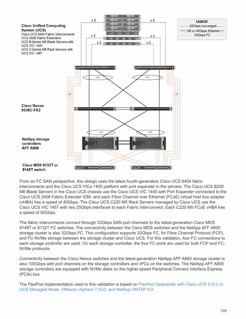
From an FC SAN perspective, this design uses the latest fourth-generation Cisco UCS 6454 fabricinterconnects and the Cisco UCS VICs 1400 platform with port expander in the servers. The Cisco UCS B200M6 Blade Servers in the Cisco UCS chassis use the Cisco UCS VIC 1440 with Port Expander connected to theCisco UCS 2408 Fabric Extender IOM, and each Fibre Channel over Ethernet (FCoE) virtual host bus adapter(vHBA) has a speed of 40Gbps. The Cisco UCS C220 M5 Rack Servers managed by Cisco UCS use theCisco UCS VIC 1457 with two 25Gbps interfaces to each Fabric Interconnect. Each C220 M5 FCoE vHBA hasa speed of 50Gbps.
The fabric interconnects connect through 32Gbps SAN port channels to the latest-generation Cisco MDS9148T or 9132T FC switches. The connectivity between the Cisco MDS switches and the NetApp AFF A800storage cluster is also 32Gbps FC. This configuration supports 32Gbps FC, for Fibre Channel Protocol (FCP),and FC-NVMe storage between the storage cluster and Cisco UCS. For this validation, four FC connections toeach storage controller are used. On each storage controller, the four FC ports are used for both FCP and FC-NVMe protocols.
Connectivity between the Cisco Nexus switches and the latest-generation NetApp AFF A800 storage cluster isalso 100Gbps with port channels on the storage controllers and vPCs on the switches. The NetApp AFF A800storage controllers are equipped with NVMe disks on the higher-speed Peripheral Connect Interface Express(PCIe) bus.
The FlexPod implementation used in this validation is based on FlexPod Datacenter with Cisco UCS 4.2(1) inUCS Managed Mode, VMware vSphere 7.0U2, and NetApp ONTAP 9.9.
729

Validated hardware and software
The following table lists the hardware and software versions used during the solution validation process. Notethat Cisco and NetApp have interoperability matrixes that should be referenced to determine support for anyspecific implementation of FlexPod. For more information, see the following resources:
• NetApp Interoperability Matrix Tool
• Cisco UCS Hardware and Software Interoperability Tool
Layer Device Image Comments
Computing • Two Cisco UCS 6454Fabric Interconnects
• One Cisco UCS 5108blade chassis with twoCisco UCS 2408 I/Omodules
• Four Cisco UCS B200M6 blades, each withone Cisco UCS VIC1440 adapter and portexpander card
Release 4.2(1f) Includes Cisco UCSManager, Cisco UCS VIC1440, and port expander
CPU Two Intel Xeon Gold 6330CPUs at 2.0 GHz, with 42-MB Layer 3 cache and 28cores per CPU
– –
Memory 1024GB (16x 64GBDIMMS operating at3200MHz)
– –
Network Two Cisco Nexus 9336C-FX2 switches in NX-OSstandalone mode
Release 9.3(8) –
Storage network Two Cisco MDS 9132T32Gbps 32-port FCswitches
Release 8.4(2c) Supports FC-NVMe SANanalytics
Storage Two NetApp AFF A800storage controllers with24x 1.8TB NVMe SSDs
NetApp ONTAP 9.9.1P1 –
Software Cisco UCS Manager Release 4.2(1f) –
VMware vSphere 7.0U2 –
VMware ESXi 7.0.2 –
VMware ESXi native FibreChannel NIC driver(NFNIC)
5.0.0.12 Supports FC-NVMe onVMware
730
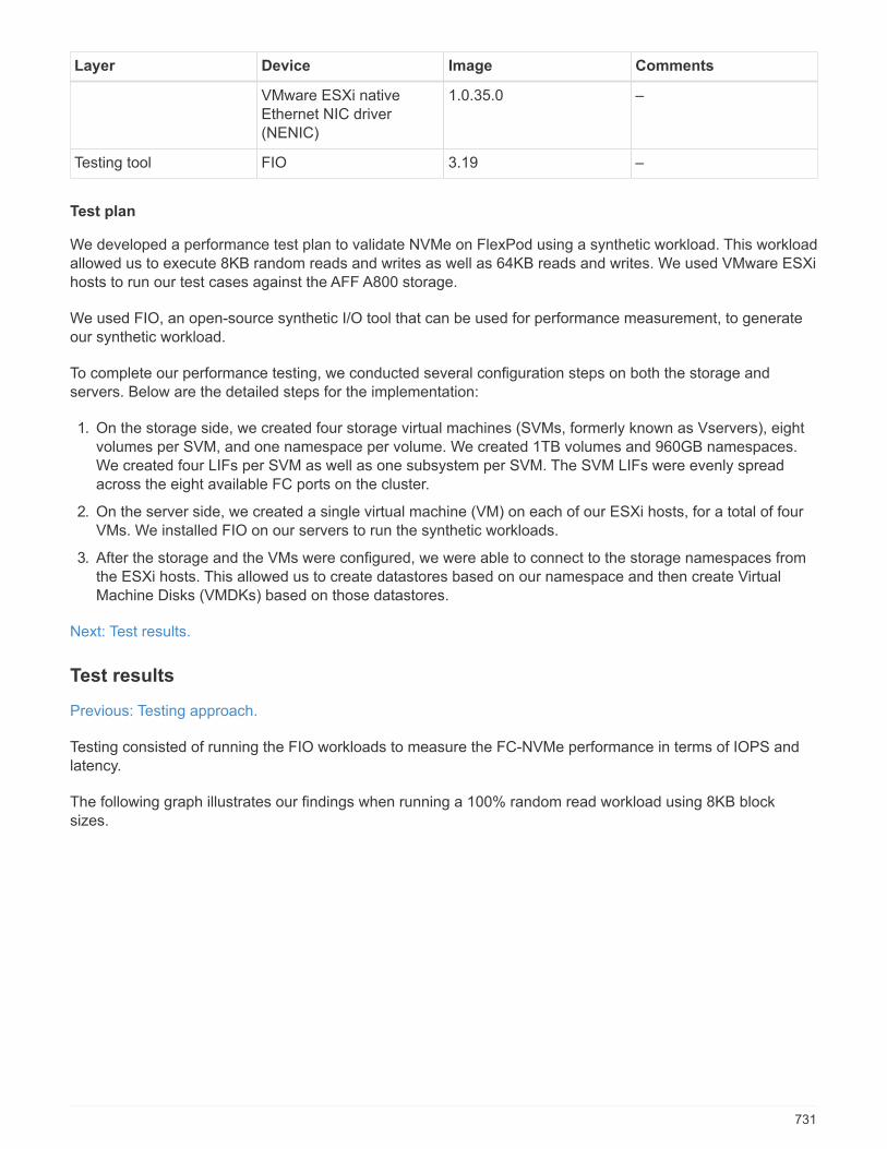
Layer Device Image Comments
VMware ESXi nativeEthernet NIC driver(NENIC)
1.0.35.0 –
Testing tool FIO 3.19 –
Test plan
We developed a performance test plan to validate NVMe on FlexPod using a synthetic workload. This workloadallowed us to execute 8KB random reads and writes as well as 64KB reads and writes. We used VMware ESXihosts to run our test cases against the AFF A800 storage.
We used FIO, an open-source synthetic I/O tool that can be used for performance measurement, to generateour synthetic workload.
To complete our performance testing, we conducted several configuration steps on both the storage andservers. Below are the detailed steps for the implementation:
1. On the storage side, we created four storage virtual machines (SVMs, formerly known as Vservers), eightvolumes per SVM, and one namespace per volume. We created 1TB volumes and 960GB namespaces.We created four LIFs per SVM as well as one subsystem per SVM. The SVM LIFs were evenly spreadacross the eight available FC ports on the cluster.
2. On the server side, we created a single virtual machine (VM) on each of our ESXi hosts, for a total of fourVMs. We installed FIO on our servers to run the synthetic workloads.
3. After the storage and the VMs were configured, we were able to connect to the storage namespaces fromthe ESXi hosts. This allowed us to create datastores based on our namespace and then create VirtualMachine Disks (VMDKs) based on those datastores.
Next: Test results.
Test results
Previous: Testing approach.
Testing consisted of running the FIO workloads to measure the FC-NVMe performance in terms of IOPS andlatency.
The following graph illustrates our findings when running a 100% random read workload using 8KB blocksizes.
731
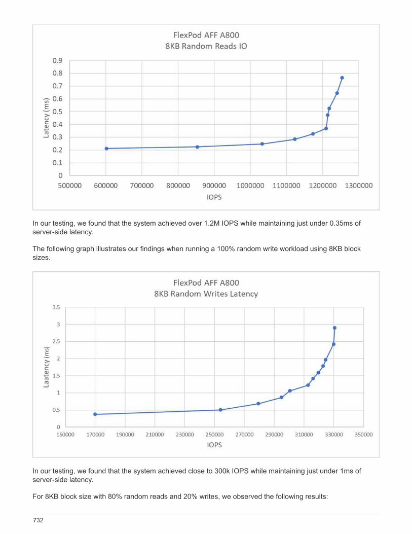
In our testing, we found that the system achieved over 1.2M IOPS while maintaining just under 0.35ms ofserver-side latency.
The following graph illustrates our findings when running a 100% random write workload using 8KB blocksizes.
In our testing, we found that the system achieved close to 300k IOPS while maintaining just under 1ms ofserver-side latency.
For 8KB block size with 80% random reads and 20% writes, we observed the following results:
732
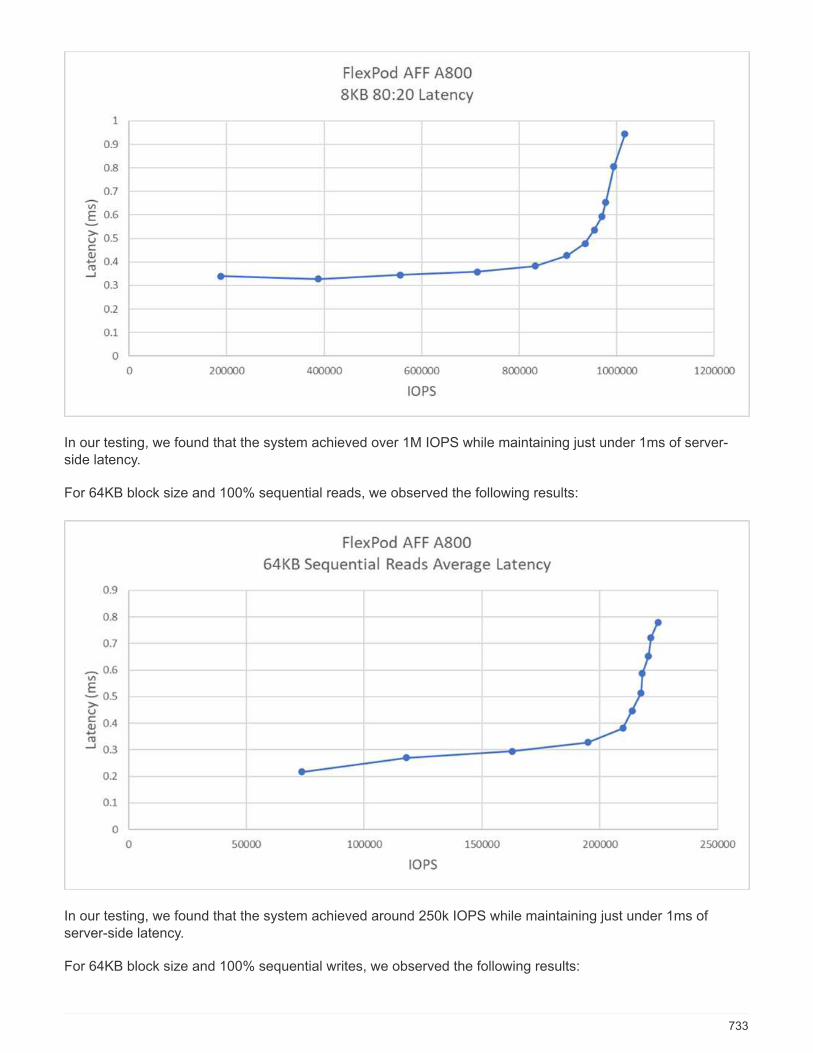
In our testing, we found that the system achieved over 1M IOPS while maintaining just under 1ms of server-side latency.
For 64KB block size and 100% sequential reads, we observed the following results:
In our testing, we found that the system achieved around 250k IOPS while maintaining just under 1ms ofserver-side latency.
For 64KB block size and 100% sequential writes, we observed the following results:
733

In our testing, we found that the system achieved around 120k IOPS while maintaining under 1ms of server-side latency.
Next: Conclusion.
Conclusion
Previous: Test results.
The observed throughput for this solution was 14GBps and 220k IOPS for a sequential read workload under1ms latency. For random read workloads, we reached a throughput of 9.5GBps and 1.25M IOPS. The ability ofFlexPod to provide this performance with FC-NVMe can address the needs of any mission-critical applications.
FlexPod Datacenter with VMware vSphere 7.0 U2 is the optimal shared infrastructure foundation to deploy FC-NVMe for a variety of IT workloads thereby providing high-performance storage access to applications thatrequire it. As FC-NVMe evolves to include high availability, multipathing, and additional operating systemsupport, FlexPod is well suited as the platform of choice, providing the scalability and reliability needed tosupport these capabilities.
With FlexPod, Cisco and NetApp have created a platform that is both flexible and scalable for multiple usecases and applications. With FC-NVMe, FlexPod adds another feature to help organizations efficiently andeffectively support business-critical applications running simultaneously from the same shared infrastructure.The flexibility and scalability of FlexPod also enables customers to start with a right-sized infrastructure thatcan grow with and adapt to their evolving business requirements.
Additional information
To learn more about the information that is described in this document, review the following documents and/orwebsites:
• Cisco Unified Computing System (UCS)
734
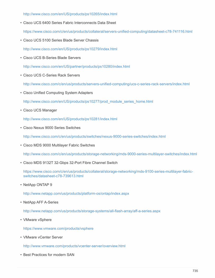
http://www.cisco.com/en/US/products/ps10265/index.html
• Cisco UCS 6400 Series Fabric Interconnects Data Sheet
https://www.cisco.com/c/en/us/products/collateral/servers-unified-computing/datasheet-c78-741116.html
• Cisco UCS 5100 Series Blade Server Chassis
http://www.cisco.com/en/US/products/ps10279/index.html
• Cisco UCS B-Series Blade Servers
http://www.cisco.com/en/US/partner/products/ps10280/index.html
• Cisco UCS C-Series Rack Servers
http://www.cisco.com/c/en/us/products/servers-unified-computing/ucs-c-series-rack-servers/index.html
• Cisco Unified Computing System Adapters
http://www.cisco.com/en/US/products/ps10277/prod_module_series_home.html
• Cisco UCS Manager
http://www.cisco.com/en/US/products/ps10281/index.html
• Cisco Nexus 9000 Series Switches
http://www.cisco.com/c/en/us/products/switches/nexus-9000-series-switches/index.html
• Cisco MDS 9000 Multilayer Fabric Switches
http://www.cisco.com/c/en/us/products/storage-networking/mds-9000-series-multilayer-switches/index.html
• Cisco MDS 9132T 32-Gbps 32-Port Fibre Channel Switch
https://www.cisco.com/c/en/us/products/collateral/storage-networking/mds-9100-series-multilayer-fabric-switches/datasheet-c78-739613.html
• NetApp ONTAP 9
http://www.netapp.com/us/products/platform-os/ontap/index.aspx
• NetApp AFF A-Series
http://www.netapp.com/us/products/storage-systems/all-flash-array/aff-a-series.aspx
• VMware vSphere
https://www.vmware.com/products/vsphere
• VMware vCenter Server
http://www.vmware.com/products/vcenter-server/overview.html
• Best Practices for modern SAN
735
https://www.netapp.com/us/media/tr-4080.pdf
• Introducing End-to-End NVMe for FlexPod
https://www.cisco.com/c/en/us/products/collateral/servers-unified-computing/ucs-b-series-blade-servers/whitepaper-c11-741907.html
Interoperability matrixes
• NetApp Interoperability Matrix Tool
http://support.netapp.com/matrix/
• Cisco UCS Hardware Compatibility Matrix
https://ucshcltool.cloudapps.cisco.com/public/
• VMware Compatibility Guide
http://www.vmware.com/resources/compatibility
Acknowledgements
The authors would like to thank John George from Cisco and Scott Lane and Bobby Oommen from NetApp forthe assistance and guidance offered during this project execution.
736

Copyright Information
Copyright © 2022 NetApp, Inc. All rights reserved. Printed in the U.S. No part of this documentcovered by copyright may be reproduced in any form or by any means-graphic, electronic, ormechanical, including photocopying, recording, taping, or storage in an electronic retrieval system-without prior written permission of the copyright owner.
Software derived from copyrighted NetApp material is subject to the following license and disclaimer:
THIS SOFTWARE IS PROVIDED BY NETAPP “AS IS” AND WITHOUT ANY EXPRESS OR IMPLIEDWARRANTIES, INCLUDING, BUT NOT LIMITED TO, THE IMPLIED WARRANTIES OFMERCHANTABILITY AND FITNESS FOR A PARTICULAR PURPOSE, WHICH ARE HEREBYDISCLAIMED. IN NO EVENT SHALL NETAPP BE LIABLE FOR ANY DIRECT, INDIRECT,INCIDENTAL, SPECIAL, EXEMPLARY, OR CONSEQUENTIAL DAMAGES (INCLUDING, BUT NOTLIMITED TO, PROCUREMENT OF SUBSTITUTE GOODS OR SERVICES; LOSS OF USE, DATA, ORPROFITS; OR BUSINESS INTERRUPTION) HOWEVER CAUSED AND ON ANY THEORY OFLIABILITY, WHETHER IN CONTRACT, STRICT LIABILITY, OR TORT (INCLUDING NEGLIGENCE OROTHERWISE) ARISING IN ANY WAY OUT OF THE USE OF THIS SOFTWARE, EVEN IF ADVISED OFTHE POSSIBILITY OF SUCH DAMAGE.
NetApp reserves the right to change any products described herein at any time, and without notice.NetApp assumes no responsibility or liability arising from the use of products described herein,except as expressly agreed to in writing by NetApp. The use or purchase of this product does notconvey a license under any patent rights, trademark rights, or any other intellectual propertyrights of NetApp.
The product described in this manual may be protected by one or more U.S. patents,foreign patents, or pending applications.
RESTRICTED RIGHTS LEGEND: Use, duplication, or disclosure by the government is subject torestrictions as set forth in subparagraph (c)(1)(ii) of the Rights in Technical Data andComputer Software clause at DFARS 252.277-7103 (October 1988) and FAR 52-227-19 (June 1987).
Trademark Information
NETAPP, the NETAPP logo, and the marks listed at http://www.netapp.com/TM are trademarks ofNetApp, Inc. Other company and product names may be trademarks of their respective owners.
737
Related Documents