Technical Report FlexPod Datacenter with ACI Solutions Guide Jens Dickmeis, John George, Chris Reno, and Lindsey Street, NetApp April 2015 | TR-4399 In Collaboration with Cisco Software-defined services and cloud computing are growing industry trends that indicate a vast data center transformation toward shared infrastructures and data centers that deliver services more quickly. Enterprise customers are moving away from application silos and toward shared infrastructures, virtualized environments, and eventually cloud computing to increase agility and reduce costs. Cisco and NetApp have developed FlexPod ® with Cisco ® Application Centric Infrastructure (ACI) and NetApp ® clustered Data ONTAP ® to address these virtualization needs and to simplify the evolution toward shared, virtualized, and cloud infrastructures while leveraging the capabilities of software-defined networking.

Welcome message from author
This document is posted to help you gain knowledge. Please leave a comment to let me know what you think about it! Share it to your friends and learn new things together.
Transcript
Technical Report
FlexPod Datacenter with ACI Solutions Guide
Jens Dickmeis, John George, Chris Reno, and Lindsey Street, NetApp
April 2015 | TR-4399
In Collaboration with Cisco
Software-defined services and cloud computing are growing industry trends that indicate a
vast data center transformation toward shared infrastructures and data centers that deliver
services more quickly. Enterprise customers are moving away from application silos and
toward shared infrastructures, virtualized environments, and eventually cloud computing to
increase agility and reduce costs. Cisco and NetApp have developed FlexPod® with Cisco
®
Application Centric Infrastructure (ACI) and NetApp® clustered Data ONTAP
® to address these
virtualization needs and to simplify the evolution toward shared, virtualized, and cloud
infrastructures while leveraging the capabilities of software-defined networking.
2 FlexPod Datacenter with ACI Solutions Guide © 2015 NetApp, Inc. All rights reserved.
TABLE OF CONTENTS
1 Introduction ........................................................................................................................................... 4
1.1 FlexPod Design ...............................................................................................................................................4
1.2 Target Audience ..............................................................................................................................................8
2 Business Benefits................................................................................................................................. 8
2.1 Increased Resource Utilization Through Infrastructure Virtualization ..............................................................8
2.2 Repeatable......................................................................................................................................................9
2.3 Flexible............................................................................................................................................................9
2.4 Right-Sized and Scalable .............................................................................................................................. 10
2.5 Ability to Insert Network Services .................................................................................................................. 10
2.6 Continuous Operations ................................................................................................................................. 11
2.7 Lower Total Cost of Ownership ..................................................................................................................... 11
3 FlexPod Design Elements .................................................................................................................. 11
3.1 Cisco UCS .................................................................................................................................................... 11
3.2 Cisco Nexus 9000 Series Switches and Cisco APIC .................................................................................... 14
3.3 NetApp Storage Infrastructure ...................................................................................................................... 15
3.4 Cisco UCS Director ....................................................................................................................................... 18
4 Data Center Solutions ........................................................................................................................ 18
4.1 FlexPod Infrastructure ................................................................................................................................... 18
4.2 Microsoft SharePoint on FlexPod with Cisco ACI and NetApp Clustered Data ONTAP ............................... 22
4.3 Solution Overview ......................................................................................................................................... 23
4.4 Microsoft Exchange on FlexPod with Cisco ACI and NetApp Clustered Data ONTAP ................................. 27
4.5 Cisco UCS Director for FlexPod with ACI and NetApp Clustered Data ONTAP ........................................... 31
5 Conclusion .......................................................................................................................................... 33
References ................................................................................................................................................. 33
LIST OF TABLES
Table 1) Microsoft SharePoint search components. ..................................................................................................... 24
Table 2) Microsoft SharePoint databases that support search. .................................................................................... 25
Table 3) List of VMs and relevant roles. ....................................................................................................................... 26
LIST OF FIGURES
Figure 1) FlexPod components. .....................................................................................................................................5
Figure 2) FlexPod configuration. ....................................................................................................................................6
Figure 3) FlexPod ACI configuration. .............................................................................................................................7
3 FlexPod Datacenter with ACI Solutions Guide © 2015 NetApp, Inc. All rights reserved.
Figure 4) Example of virtualizing the FlexPod configuration. ..........................................................................................9
Figure 5) FlexPod solutions and applications. .............................................................................................................. 19
Figure 6) Base FlexPod ACI design. ............................................................................................................................ 20
Figure 7) FlexPod ACI tenant construct........................................................................................................................ 22
Figure 8) Microsoft SharePoint roles. ........................................................................................................................... 23
Figure 9) Microsoft SharePoint roles. ........................................................................................................................... 24
Figure 10) Microsoft SharePoint roles. ......................................................................................................................... 26
Figure 11) Detailed storage configuration for Microsoft SharePoint design. ................................................................. 27
Figure 12) iSCSI boot FlexPod infrastructure. .............................................................................................................. 28
Figure 13) SME architecture. ........................................................................................................................................ 29
Figure 14) Example of scaling a FlexPod configuration. .............................................................................................. 32
4 FlexPod Datacenter with ACI Solutions Guide © 2015 NetApp, Inc. All rights reserved.
1 Introduction
Software-defined services and cloud computing are growing industry trends that indicate a vast data
center transformation toward shared infrastructures and data centers that deliver services more quickly.
Shared infrastructures, those architectures that house multiple applications and multiple use cases, have
become the de facto design for many customers, as opposed to the traditional application silo models.
Cisco and NetApp developed FlexPod with Cisco Application Centric Infrastructure (ACI) and NetApp
clustered Data ONTAP to address these virtualization needs and to simplify the evolution to shared,
virtualized, and cloud infrastructures while leveraging the capabilities of software-defined networking.
Similar to the traditional FlexPod Datacenter architecture, FlexPod with Cisco ACI and NetApp clustered
Data ONTAP is a predesigned base configuration that is built on the Cisco Unified Computing System™
(Cisco UCS®), NetApp FAS storage components, and software from a range of partners. With the addition
of Cisco Nexus® 9000 Series data center switches and the Application Policy Infrastructure Controller
(APIC), the network becomes a differentiator with an application-focused approach. Furthermore, when
coupled with NetApp clustered Data ONTAP, applications can be delivered as wholly secure containers
with various services inserted into the network application profile. The final piece to the puzzle of
delivering application containers is the use of automation and orchestration with Cisco UCS Director.
FlexPod can scale up for greater performance and capacity, or it can scale out for environments that
need consistent multiple deployments. FlexPod is a baseline configuration, but it also has the flexibility to
be sized and optimized to accommodate many different business solutions. The Cisco ACI network
topology employs a spine and leaf architecture that delivers pools of storage and compute that are
accessible anywhere in the fabric through the use of policies and enabled by leveraging a 40Gbps
network backbone. A technology differentiator of FlexPod with Cisco ACI is the ability to insert layer 4–7
services into the network topology from the Cisco APIC GUI, through the use of scripts or Cisco UCS
Director orchestration. This document describes several reference architectures that showcase Cisco ACI
and NetApp clustered Data ONTAP working in concert to deliver a variety of application use cases.
Note: FlexPod serves as a base infrastructure layer for a variety of IT solutions. A variety of solutions built on FlexPod are described in more detail on the FlexPod Solutions website.®
Note: Additional collateral is available for authorized partners at CiscoNetApp.com.
1.1 FlexPod Design
Cisco and NetApp have provided documentation for best practices and the deployment collateral
necessary to build the FlexPod shared infrastructure stack with Cisco ACI and NetApp clustered Data
ONTAP. Since its inception, FlexPod has aimed to reduce infrastructure complexity and provide guidance
in the form of reference architectures that provide a standardized deployment model. FlexPod with Cisco
ACI and clustered Data ONTAP continues with this model and provides further guidance for multi-tenant
and multiapplication deployment models.
Specifically, FlexPod is a defined set of hardware and software that serves as a foundation for data
center deployments. FlexPod includes NetApp storage, Cisco networking, and Cisco UCS in a single
deployment. The solution can be scaled, while still maintaining its integrity, by augmenting a single
FlexPod instance to provide the appropriate network, compute, or storage capacity needed within a single
pod or by using the port density of the Cisco Nexus networking platform to readily accommodate multiple
FlexPod instances. In either case, the flexibility of the pod construct allows numerous solutions to be built
on top of one or more FlexPod configurations, providing enterprise flexibility, supportability, and
manageability for both virtualized and nonvirtualized environments. Furthermore, existing equipment can
be leveraged to complete a given FlexPod instance. In the context of ACI-ready topologies, Cisco Nexus
9000 switches deployed as top of rack (TOR) switches can be leveraged and reused as part of a spine
leaf architecture.
Figure 1 shows a FlexPod configuration that supports Cisco ACI and NetApp clustered Data ONTAP.
5 FlexPod Datacenter with ACI Solutions Guide © 2015 NetApp, Inc. All rights reserved.
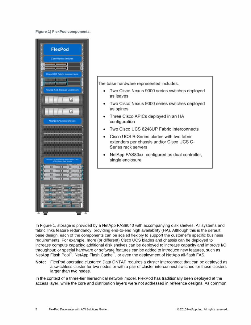
Figure 1) FlexPod components.
In Figure 1, storage is provided by a NetApp FAS8040 with accompanying disk shelves. All systems and
fabric links feature redundancy, providing end-to-end high availability (HA). Although this is the default
base design, each of the components can be scaled flexibly to support the customer’s specific business
requirements. For example, more (or different) Cisco UCS blades and chassis can be deployed to
increase compute capacity; additional disk shelves can be deployed to increase capacity and improve I/O
throughput; or special hardware or software features can be added to introduce new features, such as
NetApp Flash Pool™
, NetApp Flash Cache™
, or even the deployment of NetApp all-flash FAS.
Note: FlexPod operating clustered Data ONTAP requires a cluster interconnect that can be deployed as a switchless cluster for two nodes or with a pair of cluster interconnect switches for those clusters larger than two nodes.
In the context of a three-tier hierarchical network model, FlexPod has traditionally been deployed at the
access layer, while the core and distribution layers were not addressed in reference designs. As common
6 FlexPod Datacenter with ACI Solutions Guide © 2015 NetApp, Inc. All rights reserved.
as three-tier designs are, the limitations of spanning tree and the needs of today’s applications are driving
IT practitioners toward spine leaf architectures.
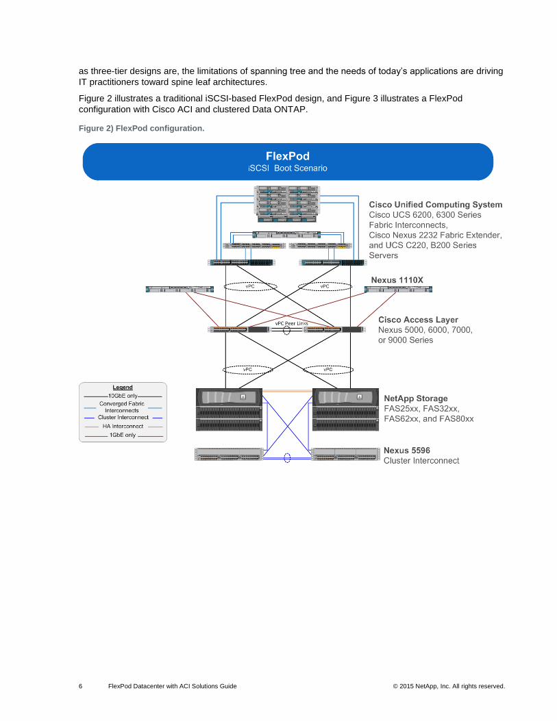
Figure 2 illustrates a traditional iSCSI-based FlexPod design, and Figure 3 illustrates a FlexPod
configuration with Cisco ACI and clustered Data ONTAP.
Figure 2) FlexPod configuration.
7 FlexPod Datacenter with ACI Solutions Guide © 2015 NetApp, Inc. All rights reserved.
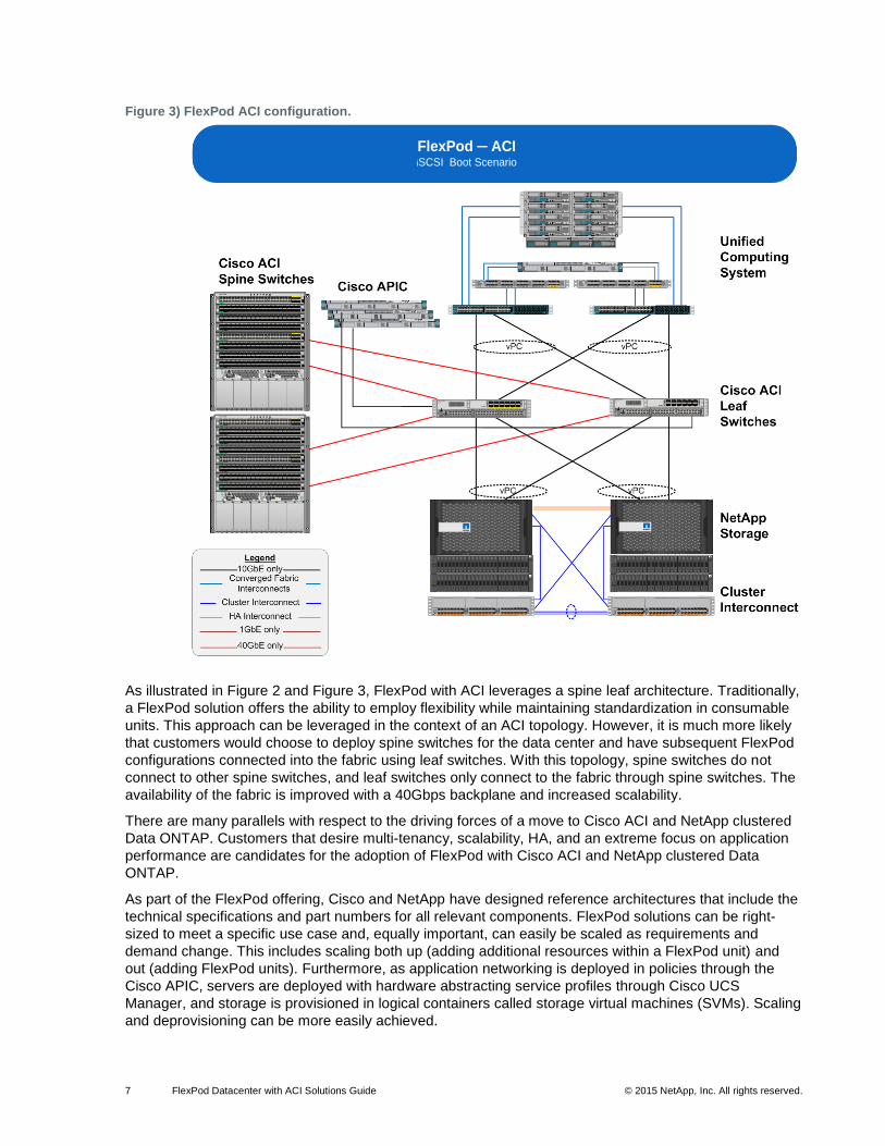
Figure 3) FlexPod ACI configuration.
As illustrated in Figure 2 and Figure 3, FlexPod with ACI leverages a spine leaf architecture. Traditionally,
a FlexPod solution offers the ability to employ flexibility while maintaining standardization in consumable
units. This approach can be leveraged in the context of an ACI topology. However, it is much more likely
that customers would choose to deploy spine switches for the data center and have subsequent FlexPod
configurations connected into the fabric using leaf switches. With this topology, spine switches do not
connect to other spine switches, and leaf switches only connect to the fabric through spine switches. The
availability of the fabric is improved with a 40Gbps backplane and increased scalability.
There are many parallels with respect to the driving forces of a move to Cisco ACI and NetApp clustered
Data ONTAP. Customers that desire multi-tenancy, scalability, HA, and an extreme focus on application
performance are candidates for the adoption of FlexPod with Cisco ACI and NetApp clustered Data
ONTAP.
As part of the FlexPod offering, Cisco and NetApp have designed reference architectures that include the
technical specifications and part numbers for all relevant components. FlexPod solutions can be right-
sized to meet a specific use case and, equally important, can easily be scaled as requirements and
demand change. This includes scaling both up (adding additional resources within a FlexPod unit) and
out (adding FlexPod units). Furthermore, as application networking is deployed in policies through the
Cisco APIC, servers are deployed with hardware abstracting service profiles through Cisco UCS
Manager, and storage is provisioned in logical containers called storage virtual machines (SVMs). Scaling
and deprovisioning can be more easily achieved.
FlexPod ─ ACI iSCSI Boot Scenario
8 FlexPod Datacenter with ACI Solutions Guide © 2015 NetApp, Inc. All rights reserved.
Through the use of Cisco ACI and clustered Data ONTAP, application instances can be easily deployed
in a repeatable fashion. Figure 2 illustrates a few FlexPod scaling options. FlexPod is a baseline
configuration, but it also has the flexibility to be sized and optimized to accommodate many different use
cases.
1.2 Target Audience
This document describes the basic FlexPod with Cisco ACI and clustered Data ONTAP architectures as
well as several solutions that can be built on FlexPod. The target audience for this document includes, but
is not limited to, sales engineers, field consultants, professional services, IT managers, partner
engineering, and customers who want to deploy solutions on top of a FlexPod configuration.
2 Business Benefits
FlexPod solutions offer a variety of business benefits to the consumer. This section describes some of
these benefits at a high level.
2.1 Increased Resource Utilization Through Infrastructure Virtualization
The practice of increasing resource utilization for underutilized resources is not a new notion. The use of
virtualization to enable organizations to do more with less has ridden the wave of various industry trends.
Beginning in the 1970s, virtualization has seen varying degrees of adoption from IBM logical partitions
through to today’s rampant adoption of industry players such as VMware, Microsoft, KVM, and XEN.
However, never before have IT practitioners had the ability to virtualize the compute, network, and
storage into manageable application containers, provisioned through profiles.
Historically, the perceived challenge with deploying applications on shared infrastructure was the need to
provide reliability, security, and performance. NetApp and Cisco have a long history of solving these
problems with published validated architectures such as secure multi-tenancy, secure separation, and
secure enclaves. All of these architectures looked to enable organizations to increase utilization while
deploying secure application containers. FlexPod with Cisco ACI and NetApp clustered Data ONTAP is
the evolution of these exercises in that applications are deployed as containers, thereby increasing the
utilization of the infrastructure. Additionally, this design is completely hypervisor agnostic while still able to
leverage the unique data management features of clustered Data ONTAP.
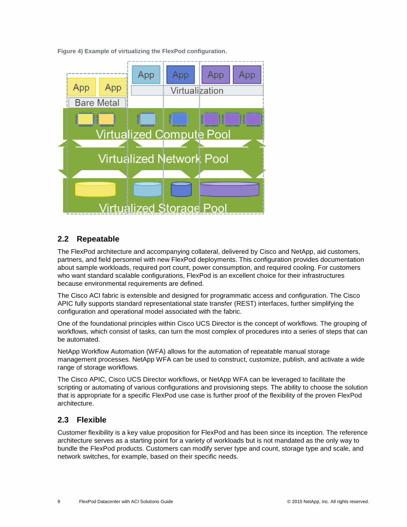
Because Cisco ACI and NetApp clustered Data ONTAP are hypervisor and OS agnostic, computer
virtualization is not required or mandated. However, the technologies that allow for the virtualization of the
entire infrastructure include:
Cisco ACI application network profiles
Clustered Data ONTAP and SVMs
Cisco UCS service profiles and organizational aspects
Hypervisor virtualization
Cisco UCS Director application containers
Figure 4 is an example of the FlexPod configuration virtualization.
9 FlexPod Datacenter with ACI Solutions Guide © 2015 NetApp, Inc. All rights reserved.
Figure 4) Example of virtualizing the FlexPod configuration.
2.2 Repeatable
The FlexPod architecture and accompanying collateral, delivered by Cisco and NetApp, aid customers,
partners, and field personnel with new FlexPod deployments. This configuration provides documentation
about sample workloads, required port count, power consumption, and required cooling. For customers
who want standard scalable configurations, FlexPod is an excellent choice for their infrastructures
because environmental requirements are defined.
The Cisco ACI fabric is extensible and designed for programmatic access and configuration. The Cisco
APIC fully supports standard representational state transfer (REST) interfaces, further simplifying the
configuration and operational model associated with the fabric.
One of the foundational principles within Cisco UCS Director is the concept of workflows. The grouping of
workflows, which consist of tasks, can turn the most complex of procedures into a series of steps that can
be automated.
NetApp Workflow Automation (WFA) allows for the automation of repeatable manual storage
management processes. NetApp WFA can be used to construct, customize, publish, and activate a wide
range of storage workflows.
The Cisco APIC, Cisco UCS Director workflows, or NetApp WFA can be leveraged to facilitate the
scripting or automating of various configurations and provisioning steps. The ability to choose the solution
that is appropriate for a specific FlexPod use case is further proof of the flexibility of the proven FlexPod
architecture.
2.3 Flexible
Customer flexibility is a key value proposition for FlexPod and has been since its inception. The reference
architecture serves as a starting point for a variety of workloads but is not mandated as the only way to
bundle the FlexPod products. Customers can modify server type and count, storage type and scale, and
network switches, for example, based on their specific needs.
10 FlexPod Datacenter with ACI Solutions Guide © 2015 NetApp, Inc. All rights reserved.
Since going to market in 2010, Cisco and NetApp have worked to provide enablement for a variety of use
cases. Solutions include validations for Microsoft Hyper-V and VMware vSphere while serving VDI,
Microsoft Exchange, Microsoft SharePoint, and Oracle, among many other applications and hypervisors.
A FlexPod solution can be designed for a variety of use cases.
2.4 Right-Sized and Scalable
As previously mentioned, the reference architecture can be scaled and right-sized based on a customer’s
use case. Proper sizing can be achieved by using the appropriate Cisco and NetApp tools such as:
Storage Performance Modeler (SPM)
Cisco UCS Application Sizer
Cisco RESCOMP
FlexPod guided solution sizing (GSS)
Depending on their application requirements, customers can choose the appropriate hardware for their
deployments by working with their subject matter experts. This allows them to avoid purchasing an
infrastructure stack that is underused.
Note: The sizing data found within FlexPod GSS covers typical enterprise workloads. However, individual customers might have lighter or heavier workloads related to the greater headroom required for growth or during system failure. Take these factors into consideration as well as the application profiles when sizing for individual customers.
2.5 Ability to Insert Network Services
Another challenge that IT practitioners face is the management of the services that are deployed in their
data centers. Provisioning the infrastructure elements and the hypervisor or operating systems of the
hosts is only one aspect that concerns the data center. As applications are deployed, the complexity of
the services can increase because IT practitioners might have to manage multiple devices with differing
levels of security characteristics.
Cisco ACI has the ability to insert layer 4–7 services into an application profile using an approach called a
service graph. The typical approach to add these functions is to add the devices capable of providing the
required services into the path between the endpoints in question. With the Cisco ACI service graph
technology, the Cisco APIC serves as a single interface in which a variety of services can be managed.
Furthermore, because the APIC has knowledge of the entire fabric, physical or virtual appliances do not
need to be inserted between endpoints. Rather, they can reside anywhere in the fabric.
The services that Cisco APIC can provide include:
Firewalls
Load balancing
Traffic inspection
Secure Sockets Layer (SSL) offloading
Application acceleration
The main benefits to the IT application practitioner of using Cisco ACI and the APIC to insert layer 4–7
services include:
Single point of provisioning
Ability to script and program the environment with a Python software development kit (SDK)
Instantaneous provisioning of very complex network topologies
Ability to eliminate human error and intervention in the creation and decommissioning of the load balancers or firewall configurations
Ability to instantiate logical function flows as opposed to sequencing layer 4–7 devices
11 FlexPod Datacenter with ACI Solutions Guide © 2015 NetApp, Inc. All rights reserved.
Multi-tenancy through network slicing on the fabric and service devices
Ability to create portable configuration templates
Intuitive GUI, enabling an easy configuration process
2.6 Continuous Operations
Another challenge presented to IT practitioners is the inability to perform requisite or routine maintenance
when an upgrade requires any downtime. This challenge is further compounded when you consider the
fact that an integrated infrastructure, when virtualized, can house multiple applications and be beholden
to many stakeholders. The entire integrated infrastructure must be able to deliver nondisruptive
operations (NDO) and nondisruptive upgrades (NDU). The alternative is that the simple operation of load
balancing a given application or performing software upgrades can be quite time consuming when
considering the need to find the required downtime.
Clustered Data ONTAP is designed at its core to deliver upon the need for NDO and NDU when
considering maintenance and lifecycle operations as well as those unplanned events when hardware or
software fails. Clustered Data ONTAP is designed so that data is always accessible and reliable.
Standard NetApp features that allow for the abstraction of data access from the physical resources
include:
Aggregate relocate. Aggregates are logical pools configured on storage nodes that abstract the underlying RAID groups and disks. Aggregate relocate allows the administrator to transfer aggregates from one controller to another within an HA pair without actual data movement.
DataMotion™ for volumes. Allows the administrator to move data volumes from one storage aggregate to another on the same or a different cluster node.
Logical interface (LIF) migrate. LIFs virtualize the physical network or SAN ports used for data access within a clustered Data ONTAP storage domain. LIF migrate allows the administrator to move NAS LIFs from one network port to another on the same or a different cluster node.
2.7 Lower Total Cost of Ownership
Because the FlexPod with Cisco ACI and NetApp clustered Data ONTAP architecture is virtualized,
repeatable, flexible, and right-sized to application requirements, the purchase cost, deployment time, and
provisioning time are all lowered. This standardized approach to the data center also decreases training
time for staff and increases their ability to work with tenants or different business units and meet their
needs. These are substantial benefits to the customer, and when combined with NetApp storage
efficiency and Cisco UCS stateless computing, they can lower the total cost of ownership (TCO) of the
infrastructure.
Cisco and NetApp have developed FlexPod as a platform that can address current data center needs and
simplify the evolution toward an IT-as-a-service (ITaaS) infrastructure.
3 FlexPod Design Elements
This section describes the elements that compose a FlexPod architecture. Because FlexPod is not a rigid
configuration, customers can build an infrastructure that includes best-in-class technologies from Cisco
and NetApp.
3.1 Cisco UCS
Cisco UCS is a next-generation data center platform that unites compute, network, storage access, and
virtualization into a cohesive system designed to reduce TCO and increase business agility. The system
integrates a low-latency, lossless 10 Gigabit Ethernet (10GbE) unified network fabric with enterprise-
class, x86-architecture servers. The system is an integrated, scalable, multichassis platform in which all
12 FlexPod Datacenter with ACI Solutions Guide © 2015 NetApp, Inc. All rights reserved.
resources participate in a unified management domain. A Cisco UCS deployment consists of Cisco UCS
fabric interconnects, blade server chassis, B-Series blades, C-Series rack mount servers, and adapter
connectivity.
For more information, see the following Cisco documentation:
Cisco UCS white papers
Unified Computing and Servers
Cisco UCS Manager
Cisco UCS Manager (Cisco UCSM) is robust device management software that is embedded in every
Cisco UCS deployment and can support up to 160 servers. Cisco UCSM allows management of the
entire compute environment from a highly available single interface. Cisco UCS Manager provides flexible
role-based and policy-based management of resources through the use of service profiles and templates.
The use of service profiles and templates abstracts those elements that typically denote server
personality (such as MAC address, WWPN, system UUID, and firmware revisions) from the role that the
compute resource serves in the data center. Through this methodology, firmware, boot order, NIC and
HBA settings, boot targets, and so on are no longer tied to a specific piece of server hardware. This
approach enables IT infrastructure to be deployed in minutes rather than days and allows organizations to
focus on strategy rather than on monotonous maintenance tasks.
With respect to element management, Cisco UCS Manager provides:
Device discovery
Firmware management
Inventory
Kernel-based virtual machine (VM) console access
Diagnostics
Quality of service (QoS)
Monitoring
Statistics collection
Auditing
Cisco UCS Fabric Interconnect
The Cisco UCS 6200 Series Fabric Interconnects, housing Cisco UCS Manager, are a core part of the
Cisco UCS environment, providing both network connectivity and management capabilities. Deployed as
a clustered pair, the Cisco UCS 6200 Series Fabric Interconnects offer line-rate, low-latency, lossless
10GbE and Fibre Channel over Ethernet (FCoE) functions.
The Cisco UCS 6200 Series Fabric Interconnects are the management and communication backbone for
the Cisco UCS B-Series Blade Servers, the Cisco UCS 5100 Series Blade Server Chassis, and C-Series
Rack-Mount Servers. All chassis, all blades, and all rack mounts attached to the Cisco UCS 6200 Series
Fabric Interconnects become part of a single highly available management domain. In addition, by
supporting unified fabric, the Cisco UCS 6200 Series Fabric Interconnects provide both the LAN and the
storage area network (SAN) connectivity for all blades within their domain.
Note: The Cisco UCS 6200UP supports unified ports. Therefore, ports can be configured to support 10GbE, Fibre Channel (FC), or FCoE.
Cisco recently released a new Cisco UCS architecture that leverages the 6324 Fabric Interconnect. This
new design consists of a Cisco UCS blade chassis with a smaller form factor fabric interconnect installed
in the rear of the chassis (in the place of the typically deployed fabric extenders). This design currently
includes support for up to 15 servers (8 Cisco UCS B-Series Servers and 7 Cisco UCS C-Series Servers).
13 FlexPod Datacenter with ACI Solutions Guide © 2015 NetApp, Inc. All rights reserved.
For more information about the Cisco UCS 6200 Series Fabric Interconnect, see the Cisco UCS 6200
Series Fabric Interconnects website.
For more information about the Cisco UCS 6300 Series Fabric Interconnect, see the Cisco UCS 6300
Series Fabric Interconnects website.
Cisco UCS B-Series Blades and Blade Server Chassis
The Cisco UCS 5100 Series Blade Server Chassis is a crucial building block of Cisco UCS, delivering a
scalable and flexible blade server chassis for today’s and tomorrow’s data center while helping to reduce
TCO.
Cisco’s first blade server chassis offering, the Cisco UCS 5108 Blade Server Chassis is six rack units
high and can be mounted in an industry-standard 19-inch rack. A chassis can house up to eight half-width
Cisco UCS B-Series Blade Servers and can accommodate both half-width and full-width blade form
factors. The following blade server options are available for purchase or can be leveraged from existing
infrastructures to construct a FlexPod configuration:
Cisco UCS B22 M3 Blade Server
Cisco UCS B200 M3 Blade server
Cisco UCS B200 M4 Blade Server
Cisco UCS B230 M2 Blade Server
Cisco UCS B420 M3 Blade Server
Cisco UCS B440 M2 Blade Server
Cisco UCS B260 M4 Blade Server
Cisco UCS B460 M4 Blade Server
Four single-phase, hot-swappable power supplies are accessible from the front of the chassis. These
power supplies are 92% efficient and can be configured to support nonredundant, N+1-redundant, and
grid-redundant configurations. The rear of the chassis contains eight hot-swappable fans, four power
connectors (one per power supply), and two input/output (I/O) bays for either the Cisco UCS 2204XP or
2208XP Fabric Extenders.
A passive midplane provides up to 20Gbps of I/O bandwidth per half-width server slot and up to 40Gbps
of I/O bandwidth per full-width server slot. The chassis is capable of supporting future 40GbE standards.
For more information, see Cisco UCS B-Series Blade Servers Compare Models.
Cisco UCS C-Series Rack-Mount Servers
Cisco UCS C-Series Rack-Mount Servers extend unified computing innovations to an industry-standard
form factor to help reduce TCO and increase business agility. The innovations embodied in this series
include a standards-based unified network fabric, Cisco VN-Link virtualization support, and Cisco
Extended Memory Technology. It supports an incremental deployment model and protects customer
investment with a migration path to unified computing.
The following seven rack-mount server options are available for purchase:
Cisco UCS C22 M3 Rack Server
Cisco UCS C220 M3 Rack Server
Cisco UCS C220 M4 Rack Server
Cisco UCS C24 M3 Rack Server
Cisco UCS C240 M3 Rack Server
Cisco UCS C240 M4 Rack Server
Cisco UCS C260 M2 Rack Server
14 FlexPod Datacenter with ACI Solutions Guide © 2015 NetApp, Inc. All rights reserved.
Cisco UCS C420 M3 Rack Server
Cisco UCS C460 M2 Rack Server
Cisco UCS C460 M4 Rack Server
Each server model addresses varying workload challenges through a balance of processing, memory,
I/O, and internal storage resources.
For more information, see the Cisco UCS C-Series Rack Servers Compare Models.
Cisco UCS Virtual Interface Card
Cisco virtual interface cards (VICs) were developed from the ground up to provide acceleration for the
various new operational modes introduced by server virtualization. The VICs are highly configurable, self-
virtualized adapters that can create up to 128 PCI Express (PCIe) endpoints per adapter. These PCIe
endpoints are created in the adapter firmware and present fully compliant standard PCIe topology to the
host OS or hypervisor. Versions of the VIC are available for both the B-Series Blades and the C-Series
Rack-Mount Servers.
Each of the PCIe endpoints created by the VIC can be configured for the following attributes:
Interface type. FCoE, Ethernet, Dynamic Ethernet interface device
Resource maps that are presented to the host. PCIe base address registers, interrupt arrays
Network presence and attributes. Maximum transmission unit (MTU), VLAN membership
QoS parameters. 802.1p class, enhanced transmission selection (ETS) attributes, rate limiting, shaping
For more information, see the Cisco UCS Virtual Interface Card 1280 product site.
3.2 Cisco Nexus 9000 Series Switches and Cisco APIC
The networking foundation for any FlexPod deployment with ACI is the Cisco Nexus 9000. The Cisco
Nexus 9000 enables a variety of transport protocols including iSCSI, NFS, and CIFS. When considering a
FlexPod with ACI topology, the Cisco Nexus 9000 Series Switches operate in fabric mode versus NX-OS
mode.
Cisco Nexus 9000 Series Switches
The Cisco Nexus 9000 Series Switches offer both modular and fixed 10/40/100 GbE switch
configurations with scalability up to 30Tbps of nonblocking performance with less than 5-microsecond
latency; 1,152 10Gbps or 288 40Gbps nonblocking Layer 2 and Layer 3 Ethernet ports; and wire-speed
VXLAN gateway, bridging, and routing support.
As previously mentioned, the Cisco Nexus 9000 family of switches also supports two modes of operation:
NxOS standalone mode and ACI fabric mode. In standalone mode, the switch performs as a typical Cisco
Nexus switch with increased port density, low latency, and 40G connectivity. In fabric mode, the
administrator can take advantage of Cisco ACI.
Cisco Nexus 9000 standalone mode FlexPod design consists of a single pair of Cisco Nexus 9000 top of
rack switches. The integration of ACI fabric in the future will introduce Cisco Nexus 9500- and 9300-
based spine leaf architecture. Although the reference architecture covered in this document does not
leverage ACI, it lays the foundation for customer migration to ACI by leveraging the Cisco Nexus 9000
Switches.
To expand upon the benefits of ACI, previously mentioned in this document, ACI is a holistic architecture
with centralized automation and policy-driven application profiles. ACI delivers software flexibility with the
scalability of hardware performance. Key characteristics of ACI include:
Simplified automation by an application-driven policy model
15 FlexPod Datacenter with ACI Solutions Guide © 2015 NetApp, Inc. All rights reserved.
Centralized visibility with real-time, application health monitoring
Open software flexibility for DevOps teams and ecosystem partner integration
Scalable performance and multi-tenancy in hardware
The future of networking with ACI is about providing a network that is deployed, monitored, and managed
in a fashion that supports DevOps and rapid application change. ACI does so through the reduction of
complexity and a common policy framework that can automate provisioning and managing of resources.
For more information, see the Cisco Nexus 9000 Series Switches product site.
Cisco APIC
Cisco APIC is a core capability of the ACI fabric. It serves as the single point of configuration required for
all network profiles. The APIC contains all of the fabric information, improves application scale and
performance, and supports the provisioning of application instances across physical and virtual
resources.
For more information, see the Cisco APIC product information site.
3.3 NetApp Storage Infrastructure
The NetApp Unified Storage Architecture provides customers with an agile and scalable storage platform.
All NetApp storage systems use the Data ONTAP operating system. NetApp clustered Data ONTAP
provides SAN (FCoE, FC, and iSCSI) and NAS (CIFS and NFS). A single process for activities such as
installation, provisioning, mirroring, backup, and upgrading is used throughout the entire product line,
from the entry level to enterprise-class controllers. Having a single set of software and processes
provides simplicity to even the most complex enterprise data management challenges. Unifying storage
and data management software and processes reduces the complexity of data ownership, enables
companies to adapt to their changing business needs without interruption, and results in reduced TCO.
In a shared infrastructure, the availability and performance of the storage infrastructure are critical
because storage outages or performance issues can affect thousands of users. The storage architecture
must provide a high level of availability and performance. For detailed documentation about best
practices, NetApp and its technology partners have developed a number of best practice documents.
For more information, see the following documentation:
NetApp Data Storage Systems
TR-3437: Storage Subsystem Resiliency Guide
TR-3702: NetApp Storage Best Practices for Microsoft Virtualization and NetApp SnapManager for Hyper-V
TR-4068: VMware vSphere 5 on NetApp Clustered Data ONTAP Best Practices
NetApp Unified Storage Architecture
When it comes to storage platforms, NetApp views simplicity as the key to delivering value to customers.
That’s why every NetApp storage controller is available with the Data ONTAP operating system. Data
ONTAP is the foundation for providing unified storage through multiprotocol support on every platform.
The NetApp family of controllers consists of platforms that are capable of serving all business needs. The
FlexPod program leverages the FAS2xxx and FAS8xxx product lines to build efficient infrastructures.
Storage Virtual Machines
SVMs are logical instantiations of storage systems that provide data access to clients without regard to
the underlying physical storage or controller. SVMs enable increased utilization of resources, mobility of
data, and more granular tuning of applications and workloads. SVMs serve data through a construct
called LIF, further providing a layer of abstraction from the physical resources.
16 FlexPod Datacenter with ACI Solutions Guide © 2015 NetApp, Inc. All rights reserved.
RAID DP
With any shared infrastructure deployment, data protection is critical because any RAID failure could
result in hundreds to thousands of end users being disconnected from their virtual desktops or
applications, resulting in lost productivity. NetApp RAID DP® offers performance that is comparable to that
of RAID 10, yet it requires fewer disks to achieve equivalent protection. RAID DP protects against double
disk failure, as compared to RAID 5, which can protect against only one disk failure per RAID group. For
more information about RAID-DP, see TR-3298: RAID DP: NetApp Implementation of Double-Parity RAID
for Data Protection.
Storage Efficiency
One of the critical barriers to adopting shared infrastructure is the increased cost of using shared storage
to obtain a highly available enterprise-quality infrastructure. Virtual desktop and other enterprise
deployments can create a high level of data redundancy, especially for the VM OS data. With traditional
storage, the total storage required equals the sum of the storage required by each VM. For example, if
each VM is 20GB in size, and there are 1,000 VMs in the solution, it would require at least 20TB of usable
data on the shared storage.
Thin provisioning, data deduplication, and FlexClone® thin-cloning technology are the critical components
of the NetApp solution, offering multiple levels of storage efficiency across the virtual desktop OS data,
installed applications, and user data. This helps customers save 50% to 90% of the cost associated with
shared storage (based on existing customer deployments and NetApp solutions lab validation).
Flexible Volumes and Aggregates
Aggregates are the NetApp virtualization layer, which abstracts physical disks from logical datasets,
referred to as flexible volumes (also known as NetApp FlexVol® volumes). Aggregates offer storage
administrators pooled disk resources, including input/output operations per second (IOPS). The FlexVol
volumes contained in each aggregate have their own unique logical capacity. FlexVol volumes can be
thin provisioned and the logical capacity resized as needed by the storage administrator.
FlexVol volumes are shared out as file-level (NFS or CIFS) mount points or are further allocated as LUNs
for block-level (iSCSI or FCP) access. FlexVol volumes can be readily offered to the VMware environment
as datastores. NetApp recommends a one-to-one alignment between the FlexVol volume and VMware
ESX datastore assets. Using VMware as an example, alignment makes mapping easy between the
VMware server administrator’s view and the storage administrator’s view of the virtual environment.
NetApp also suggests large aggregates to support most VMware environments. VMware environments
often have random I/O requirements. Large aggregates provide maximum flexibility to VMware
administrators because a large pool of I/O resources is made readily available. With NetApp’s inherent
storage virtualization techniques, which apply to all hypervisors, all datasets or VMs housed in a shared
storage infrastructure take advantage of RAID DP from a performance and protection standpoint.
Thin Provisioning
Thin provisioning is a way of logically presenting more storage to hosts than is physically available. With
thin provisioning, the storage administrator can access a pool of physical disks (known as an aggregate)
to create logical volumes for different applications to use, while not preallocating space to those volumes.
The space is allocated only when the host needs it. The unused aggregate space is available for the
existing thin-provisioned volumes to expand or for use in the creation of new volumes. For more
information about thin provisioning, see TR-3563: NetApp Thin Provisioning Increases Storage Utilization
with On-Demand Allocation.
17 FlexPod Datacenter with ACI Solutions Guide © 2015 NetApp, Inc. All rights reserved.
NetApp Deduplication
NetApp deduplication saves space on primary storage by removing redundant copies of blocks in a
volume that is hosting hundreds of virtual desktops. This process is transparent to the application and
user and can be enabled and disabled on the fly. In a virtual desktop infrastructure (VDI) environment,
deduplication provides significant space savings, given that each VM has an identical copy of the OS,
applications, and patches. The savings are also achieved for the user data hosted on CIFS home
directories. For more information about NetApp deduplication, see TR-3505: NetApp Deduplication for
FAS and V-Series Deployment and Implementation Guide.
Using NetApp deduplication and file FlexClone technology can reduce the overall storage footprint of VDI
desktops and improve performance by leveraging transparent storage cache sharing. Data that is
deduplicated (or nonduplicated, in the case of file FlexClone data) on disk exists in the storage array
cache only once per volume. All subsequent reads from any of the VM disks of a block that is already in
cache are read from cache and not from disk, thus improving performance tenfold. Any nondeduplicated
data that is not in cache must be read from disk. Data that is deduplicated but does not have as many
block references as a heavily deduplicated VM disk (VMDK) appears in cache only once, but based on
the frequency of access might be evicted earlier than data that has many references or is heavily used.
NetApp recommends the following deduplication guidelines:
Deduplication is configured and operates on the FlexVol volumes only.
Data can be deduplicated up to 255:1 without consuming additional space.
Each storage platform has different deduplication limits.
Each volume has dense and nondense size limits.
Transparent Storage Cache Sharing
Transparent storage cache sharing (TSCS) allows customers to benefit from the storage efficiency of
NetApp and at the same time significantly increase I/O performance. TSCS is natively built into the Data
ONTAP operating system and works by leveraging block-sharing technologies such as NetApp primary
storage deduplication and FlexClone technology to reduce the amount of cache required and eliminate
duplicate disk reads. Only one instance of any duplicate block is read into cache, thus requiring less
cache than traditional storage solutions. VDI implementations can see up to 99% initial space savings
(validated in the NetApp solutions lab) by using space-efficient NetApp cloning technologies. This
translates into higher cache deduplication and high cache hit rates. TSCS is especially effective in
addressing the simultaneous system boot, or boot storm, of hundreds to thousands of virtual desktop
systems that can overload a traditional legacy storage system.
NetApp Flash Cache and FlexScale
NetApp Flash Cache is a hardware device that extends the native Data ONTAP TSCS capabilities. Flash
Cache increases the amount of available cache, which helps to reduce virtual desktop storm activities.
For more information about NetApp Flash Cache technology, see the NetApp Flash Cache 2 Technical
Specifications.
NetApp FlexScale™
is the tunable software component of Flash Cache. It is a licensed feature of Data
ONTAP 7.3 and later. FlexScale allows three different caching modes to be used, based on the type of
workload:
Metadata only
Normal user data
Low-priority blocks
For example, FlexScale allows system administrators to tune the VMware View environments of their
NetApp controllers.
18 FlexPod Datacenter with ACI Solutions Guide © 2015 NetApp, Inc. All rights reserved.
NetApp Virtual Storage Console and OnCommand Unified Manager
Implementation and management complexities associated with deploying a virtualization solution are
another potential barrier to adoption. To provide operationally agile management of storage on the
vSphere platform, the NetApp Virtual Storage Console (VSC) integrates directly into VMware vCenter for
rapidly provisioning, managing, configuring, and backing up a VDI implementation.
NetApp OnCommand® Unified Manager offers a comprehensive monitoring and management solution for
the storage infrastructure. It provides comprehensive reports of utilization and trends for capacity planning
and space usage. It also monitors system performance, storage capacity, and health to resolve potential
problems.
For more information about OnCommand Unified Manager, go to the OnCommand Unified Manager
product site.
3.4 Cisco UCS Director
Cisco UCSD can be an integral component for FlexPod because it allows holistic management through
centralized automation and orchestration from a single, unified view. When FlexPod and Cisco UCSD are
combined, IT can shift time and focus from managing infrastructure to delivering new service innovation.
Used together, FlexPod and Cisco UCSD deliver:
Enhanced IT agility with a prevalidated, unified architecture that easily scales up or out to large data center environments without design changes
Dramatically reduced capital and operating expenses through end-to-end management of the FlexPod platform with real-time reporting of utilization and consumption based on trends set to customer-specific time frames
Enhanced collaboration between computing, network, storage, and virtualization teams, allowing subject matter experts to define policies and processes that are utilized when resources are consumed
Support for multiple infrastructure stacks in a single data center, as well as across multiple data
centers globally
The extensive Cisco UCS Director task library lets you quickly assemble, configure, and manage
workflows for FlexPod, clustered Data ONTAP, and FlexPod Express. You can use the workflows
immediately or publish them in an infrastructure catalog. Specific workflows can be assigned to the entire
organization or specific groups based on your organizational structure, which can be imported from
Lightweight Directory Access Protocol (LDAP). The drag-and-drop workflow designer tool eliminates the
need for service engagements or the need to bring together multiproduct solutions or third-party adapters.
For more information, see the Cisco UCS Director product site.
4 Data Center Solutions
When deploying a shared infrastructure, customers often have both virtualized and nonvirtualized
workloads deployed in their data centers. This section details available solutions and describes how to
deploy FlexPod as the basis for any data center workload.
4.1 FlexPod Infrastructure
This section describes infrastructure architectures that support both virtualized and nonvirtualized
platforms that might be deployed within the guidelines of a FlexPod with Cisco ACI and NetApp clustered
Data ONTAP.
19 FlexPod Datacenter with ACI Solutions Guide © 2015 NetApp, Inc. All rights reserved.
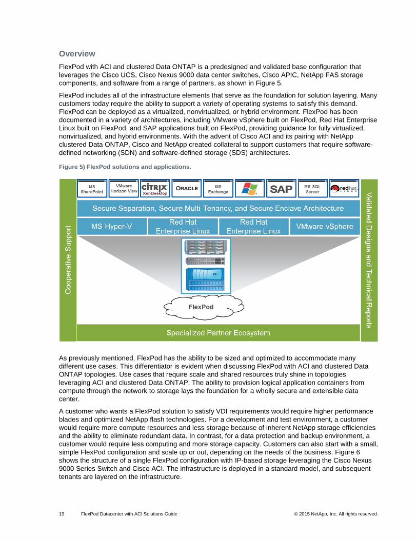
Overview
FlexPod with ACI and clustered Data ONTAP is a predesigned and validated base configuration that
leverages the Cisco UCS, Cisco Nexus 9000 data center switches, Cisco APIC, NetApp FAS storage
components, and software from a range of partners, as shown in Figure 5.
FlexPod includes all of the infrastructure elements that serve as the foundation for solution layering. Many
customers today require the ability to support a variety of operating systems to satisfy this demand.
FlexPod can be deployed as a virtualized, nonvirtualized, or hybrid environment. FlexPod has been
documented in a variety of architectures, including VMware vSphere built on FlexPod, Red Hat Enterprise
Linux built on FlexPod, and SAP applications built on FlexPod, providing guidance for fully virtualized,
nonvirtualized, and hybrid environments. With the advent of Cisco ACI and its pairing with NetApp
clustered Data ONTAP, Cisco and NetApp created collateral to support customers that require software-
defined networking (SDN) and software-defined storage (SDS) architectures.
Figure 5) FlexPod solutions and applications.
As previously mentioned, FlexPod has the ability to be sized and optimized to accommodate many
different use cases. This differentiator is evident when discussing FlexPod with ACI and clustered Data
ONTAP topologies. Use cases that require scale and shared resources truly shine in topologies
leveraging ACI and clustered Data ONTAP. The ability to provision logical application containers from
compute through the network to storage lays the foundation for a wholly secure and extensible data
center.
A customer who wants a FlexPod solution to satisfy VDI requirements would require higher performance
blades and optimized NetApp flash technologies. For a development and test environment, a customer
would require more compute resources and less storage because of inherent NetApp storage efficiencies
and the ability to eliminate redundant data. In contrast, for a data protection and backup environment, a
customer would require less computing and more storage capacity. Customers can also start with a small,
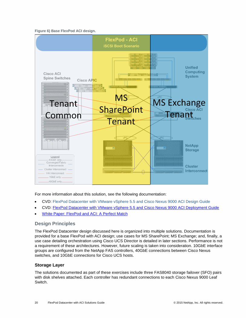
simple FlexPod configuration and scale up or out, depending on the needs of the business. Figure 6
shows the structure of a single FlexPod configuration with IP-based storage leveraging the Cisco Nexus
9000 Series Switch and Cisco ACI. The infrastructure is deployed in a standard model, and subsequent
tenants are layered on the infrastructure.
20 FlexPod Datacenter with ACI Solutions Guide © 2015 NetApp, Inc. All rights reserved.
Figure 6) Base FlexPod ACI design.
For more information about this solution, see the following documentation:
CVD: FlexPod Datacenter with VMware vSphere 5.5 and Cisco Nexus 9000 ACI Design Guide
CVD: FlexPod Datacenter with VMware vSphere 5.5 and Cisco Nexus 9000 ACI Deployment Guide
White Paper: FlexPod and ACI: A Perfect Match
Design Principles
The FlexPod Datacenter design discussed here is organized into multiple solutions. Documentation is
provided for a base FlexPod with ACI design; use cases for MS SharePoint; MS Exchange; and, finally, a
use case detailing orchestration using Cisco UCS Director is detailed in later sections. Performance is not
a requirement of these architectures. However, future scaling is taken into consideration. 10GbE interface
groups are configured from the NetApp FAS controllers, 40GbE connections between Cisco Nexus
switches, and 10GbE connections for Cisco UCS hosts.
Storage Layer
The solutions documented as part of these exercises include three FAS8040 storage failover (SFO) pairs
with disk shelves attached. Each controller has redundant connections to each Cisco Nexus 9000 Leaf
Switch.
21 FlexPod Datacenter with ACI Solutions Guide © 2015 NetApp, Inc. All rights reserved.
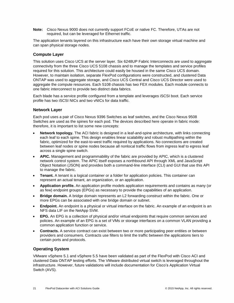
Note: Cisco Nexus 9000 does not currently support FCoE or native FC. Therefore, UTAs are not required, but can be leveraged for Ethernet traffic.
The application tenants layered on this infrastructure each have their own storage virtual machine and
can span physical storage nodes.
Compute Layer
This solution uses Cisco UCS at the server layer. Six 6248UP Fabric Interconnects are used to aggregate
connectivity from the three Cisco UCS 5108 chassis and to manage the templates and service profiles
required for this solution. This architecture could easily be housed in the same Cisco UCS domain.
However, to maintain isolation, separate FlexPod configurations were constructed, and clustered Data
ONTAP was used to aggregate storage, and Cisco UCS Central and Cisco UCS Director were used to
aggregate the compute resources. Each 5108 chassis has two FEX modules. Each module connects to
one fabric interconnect to provide two distinct data fabrics.
Each blade has a service profile configured from a template and leverages iSCSI boot. Each service
profile has two iSCSI NICs and two vNICs for data traffic.
Network Layer
Each pod uses a pair of Cisco Nexus 9396 Switches as leaf switches, and the Cisco Nexus 9508
Switches are used as the spines for each pod. The devices described here operate in fabric mode:
therefore, it is important to list some new concepts:
Network topology. The ACI fabric is designed in a leaf-and-spine architecture, with links connecting each leaf to each spine. This design enables linear scalability and robust multipathing within the fabric, optimized for the east-to-west traffic required by applications. No connections are created between leaf nodes or spine nodes because all nonlocal traffic flows from ingress leaf to egress leaf across a single spine switch.
APIC. Management and programmability of the fabric are provided by APIC, which is a clustered network control system. The APIC itself exposes a northbound API through XML and JavaScript Object Notation (JSON) and provides both a command-line interface (CLI) and GUI that use this API to manage the fabric.
Tenant. A tenant is a logical container or a folder for application policies. This container can represent an actual tenant, an organization, or an application.
Application profile. An application profile models application requirements and contains as many (or as few) endpoint groups (EPGs) as necessary to provide the capabilities of an application.
Bridge domain. A bridge domain represents an L2 forwarding construct within the fabric. One or more EPGs can be associated with one bridge domain or subnet.
Endpoint. An endpoint is a physical or virtual interface on the fabric. An example of an endpoint is an NFS data LIF on the NetApp SVM.
EPG. An EPG is a collection of physical and/or virtual endpoints that require common services and policies. An example of an EPG is a set of VMs or storage interfaces on a common VLAN providing a common application function or service.
Contracts. A service contract can exist between two or more participating peer entities or between providers and consumers. Contracts use filters to limit the traffic between the applications tiers to certain ports and protocols.
Operating System
VMware vSphere 5.1 and vSphere 5.5 have been validated as part of the FlexPod with Cisco ACI and
clustered Data ONTAP testing efforts. The VMware distributed virtual switch is leveraged throughout the
infrastructure. However, future validations will include documentation for Cisco’s Application Virtual
Switch (AVS).
22 FlexPod Datacenter with ACI Solutions Guide © 2015 NetApp, Inc. All rights reserved.
Applications
Microsoft SharePoint 2013 and Microsoft Exchange 2013 are documented application use cases with
Cisco ACI and NetApp clustered Data ONTAP. Additionally, documentation is provided for NetApp
SnapManager® suite.
Orchestration
Orchestration for these efforts is documented with Cisco UCS Director 5.2. Various workflows are
targeted to provision the infrastructure from end to end.
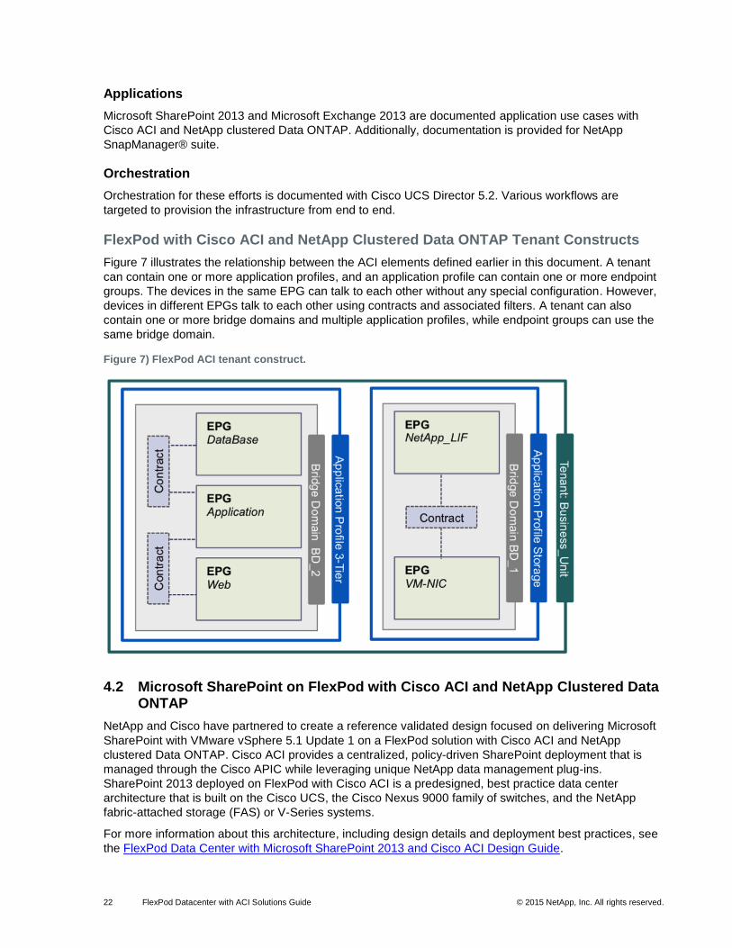
FlexPod with Cisco ACI and NetApp Clustered Data ONTAP Tenant Constructs
Figure 7 illustrates the relationship between the ACI elements defined earlier in this document. A tenant
can contain one or more application profiles, and an application profile can contain one or more endpoint
groups. The devices in the same EPG can talk to each other without any special configuration. However,
devices in different EPGs talk to each other using contracts and associated filters. A tenant can also
contain one or more bridge domains and multiple application profiles, while endpoint groups can use the
same bridge domain.
Figure 7) FlexPod ACI tenant construct.
4.2 Microsoft SharePoint on FlexPod with Cisco ACI and NetApp Clustered Data ONTAP
NetApp and Cisco have partnered to create a reference validated design focused on delivering Microsoft
SharePoint with VMware vSphere 5.1 Update 1 on a FlexPod solution with Cisco ACI and NetApp
clustered Data ONTAP. Cisco ACI provides a centralized, policy-driven SharePoint deployment that is
managed through the Cisco APIC while leveraging unique NetApp data management plug-ins.
SharePoint 2013 deployed on FlexPod with Cisco ACI is a predesigned, best practice data center
architecture that is built on the Cisco UCS, the Cisco Nexus 9000 family of switches, and the NetApp
fabric-attached storage (FAS) or V-Series systems.
For more information about this architecture, including design details and deployment best practices, see
the FlexPod Data Center with Microsoft SharePoint 2013 and Cisco ACI Design Guide.
23 FlexPod Datacenter with ACI Solutions Guide © 2015 NetApp, Inc. All rights reserved.
4.3 Solution Overview
SharePoint Server 2013 is an extensible and scalable web-based platform consisting of tools and
technologies that support the collaboration and sharing of information within teams, throughout the
enterprise, and on the web. The total package is a platform on which one can build business applications
to help better store, share, and manage information within an organization. Microsoft SharePoint turns
users into participants, allowing users to easily create, share, and connect with information, applications,
and people. SharePoint Server 2013 provides all the good features present in the earlier versions of the
product, along with several new features and important architectural changes to improve the product. The
reference architecture documented in this section details the application design when deployed on
FlexPod with ACI and NetApp clustered Data ONTAP.
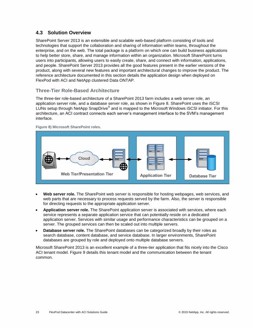
Three-Tier Role-Based Architecture
The three-tier role-based architecture of a SharePoint 2013 farm includes a web server role, an
application server role, and a database server role, as shown in Figure 8. SharePoint uses the iSCSI
LUNs setup through NetApp SnapDrive® and is mapped to the Microsoft Windows iSCSI initiator. For this
architecture, an ACI contract connects each server’s management interface to the SVM’s management
interface.
Figure 8) Microsoft SharePoint roles.
Web server role. The SharePoint web server is responsible for hosting webpages, web services, and web parts that are necessary to process requests served by the farm. Also, the server is responsible for directing requests to the appropriate application server.
Application server role. The SharePoint application server is associated with services, where each service represents a separate application service that can potentially reside on a dedicated application server. Services with similar usage and performance characteristics can be grouped on a server. The grouped services can then be scaled out into multiple servers.
Database server role. The SharePoint databases can be categorized broadly by their roles as search database, content database, and service database. In larger environments, SharePoint databases are grouped by role and deployed onto multiple database servers.
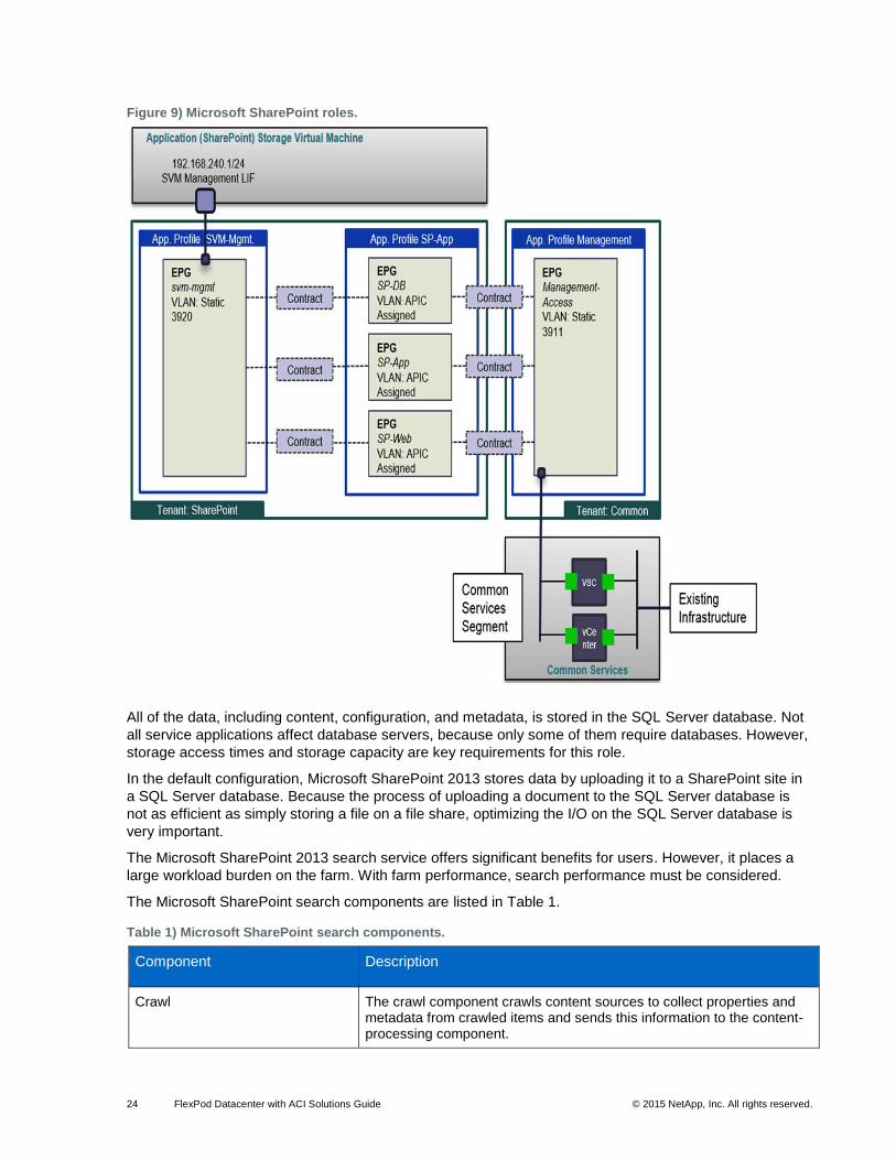
Microsoft SharePoint 2013 is an excellent example of a three-tier application that fits nicely into the Cisco
ACI tenant model. Figure 9 details this tenant model and the communication between the tenant
common.
24 FlexPod Datacenter with ACI Solutions Guide © 2015 NetApp, Inc. All rights reserved.
Figure 9) Microsoft SharePoint roles.
All of the data, including content, configuration, and metadata, is stored in the SQL Server database. Not
all service applications affect database servers, because only some of them require databases. However,
storage access times and storage capacity are key requirements for this role.
In the default configuration, Microsoft SharePoint 2013 stores data by uploading it to a SharePoint site in
a SQL Server database. Because the process of uploading a document to the SQL Server database is
not as efficient as simply storing a file on a file share, optimizing the I/O on the SQL Server database is
very important.
The Microsoft SharePoint 2013 search service offers significant benefits for users. However, it places a
large workload burden on the farm. With farm performance, search performance must be considered.
The Microsoft SharePoint search components are listed in Table 1.
Table 1) Microsoft SharePoint search components.
Component Description
Crawl The crawl component crawls content sources to collect properties and metadata from crawled items and sends this information to the content-processing component.
25 FlexPod Datacenter with ACI Solutions Guide © 2015 NetApp, Inc. All rights reserved.
Component Description
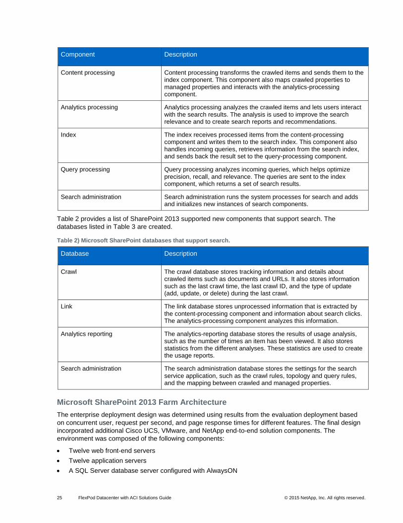
Content processing Content processing transforms the crawled items and sends them to the index component. This component also maps crawled properties to managed properties and interacts with the analytics-processing component.
Analytics processing Analytics processing analyzes the crawled items and lets users interact with the search results. The analysis is used to improve the search relevance and to create search reports and recommendations.
Index The index receives processed items from the content-processing component and writes them to the search index. This component also handles incoming queries, retrieves information from the search index, and sends back the result set to the query-processing component.
Query processing Query processing analyzes incoming queries, which helps optimize precision, recall, and relevance. The queries are sent to the index component, which returns a set of search results.
Search administration Search administration runs the system processes for search and adds and initializes new instances of search components.
Table 2 provides a list of SharePoint 2013 supported new components that support search. The
databases listed in Table 3 are created.
Table 2) Microsoft SharePoint databases that support search.
Database Description
Crawl The crawl database stores tracking information and details about crawled items such as documents and URLs. It also stores information such as the last crawl time, the last crawl ID, and the type of update (add, update, or delete) during the last crawl.
Link The link database stores unprocessed information that is extracted by the content-processing component and information about search clicks. The analytics-processing component analyzes this information.
Analytics reporting The analytics-reporting database stores the results of usage analysis, such as the number of times an item has been viewed. It also stores statistics from the different analyses. These statistics are used to create the usage reports.
Search administration The search administration database stores the settings for the search service application, such as the crawl rules, topology and query rules, and the mapping between crawled and managed properties.
Microsoft SharePoint 2013 Farm Architecture
The enterprise deployment design was determined using results from the evaluation deployment based
on concurrent user, request per second, and page response times for different features. The final design
incorporated additional Cisco UCS, VMware, and NetApp end-to-end solution components. The
environment was composed of the following components:
Twelve web front-end servers
Twelve application servers
A SQL Server database server configured with AlwaysON
26 FlexPod Datacenter with ACI Solutions Guide © 2015 NetApp, Inc. All rights reserved.
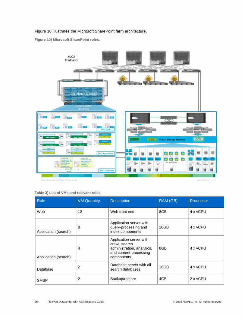
Figure 10 illustrates the Microsoft SharePoint farm architecture.
Figure 10) Microsoft SharePoint roles.
Table 3) List of VMs and relevant roles.
Role VM Quantity Description RAM (GB) Processor
Web 12 Web front end 8GB 4 x vCPU
Application (search) 8
Application server with query-processing and index components
16GB 4 x vCPU
Application (search)
4
Application server with crawl, search administration, analytics, and content-processing components
8GB 4 x vCPU
Database 2
Database server with all search databases
16GB 4 x vCPU
SMSP 2 Backup/restore 4GB 2 x vCPU
27 FlexPod Datacenter with ACI Solutions Guide © 2015 NetApp, Inc. All rights reserved.
Storage Configuration
When planning content storage for Microsoft SharePoint 2013, you must choose a suitable storage
architecture. Microsoft SharePoint 2013 content storage has a significant dependency on the underlying
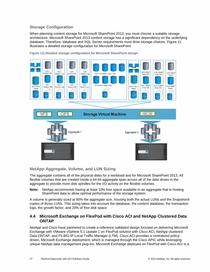
database. Therefore, database and SQL Server requirements must drive storage choices. Figure 11
illustrates a detailed storage configuration for Microsoft SharePoint.
Figure 11) Detailed storage configuration for Microsoft SharePoint design.
NetApp Aggregate, Volume, and LUN Sizing
The aggregate contains all of the physical disks for a workload and for Microsoft SharePoint 2013. All
flexible volumes that are created inside a 64-bit aggregate span across all of the data drives in the
aggregate to provide more disk spindles for the I/O activity on the flexible volumes.
Note: NetApp recommends having at least 10% free space available in an aggregate that is hosting SharePoint data to allow optimal performance of the storage system.
A volume is generally sized at 90% the aggregate size, housing both the actual LUNs and the Snapshot®
copies of those LUNs. This sizing takes into account the database, the content database, the transaction
logs, the growth factor, and 20% of free disk space.
4.4 Microsoft Exchange on FlexPod with Cisco ACI and NetApp Clustered Data ONTAP
NetApp and Cisco have partnered to create a reference validated design focused on delivering Microsoft
Exchange with VMware vSphere 5.1 Update 1 on FlexPod solution with Cisco ACI, NetApp clustered
Data ONTAP, and F5 BIG-IP Local Traffic Manager (LTM). Cisco ACI provides a centralized policy-
driven, Microsoft Exchange deployment, which is managed through the Cisco APIC while leveraging
unique NetApp data management plug-ins. Microsoft Exchange deployed on FlexPod with Cisco ACI is a
28 FlexPod Datacenter with ACI Solutions Guide © 2015 NetApp, Inc. All rights reserved.
predesigned, best practice data center architecture that is built on the Cisco UCS, the Cisco Nexus 9000
family of switches, NetApp fabric-attached storage (FAS), and F5 Big-IP Application Delivery Controller
(ADC).
For more information about this architecture, including design details and best practices, see the FlexPod
Datacenter with Microsoft Exchange 2013, F5 Big-IP and Cisco Application Centric Infrastructure.
Solution Overview
Microsoft Exchange 2013 is a global calendaring software, mail server, and contact manager that is
critical to communications for many global enterprise customers. A core element, Microsoft Exchange
Server is designed to serve as the foundation for today’s e-mail-centric communication methodologies.
Microsoft Exchange Server is design to work with Microsoft Outlook, Microsoft Outlook webmail, and
various mobile devices. The reference architecture documented in this section details the application
design when deployed on FlexPod with ACI and NetApp clustered Data ONTAP.
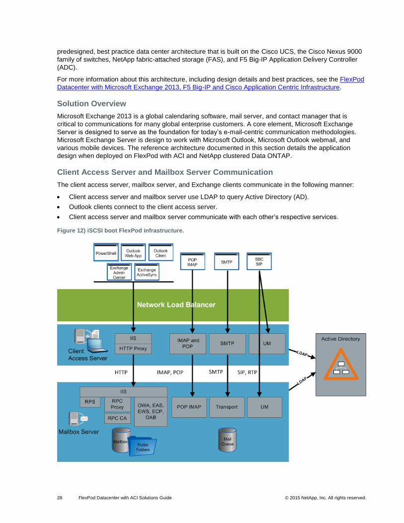
Client Access Server and Mailbox Server Communication
The client access server, mailbox server, and Exchange clients communicate in the following manner:
Client access server and mailbox server use LDAP to query Active Directory (AD).
Outlook clients connect to the client access server.
Client access server and mailbox server communicate with each other’s respective services.
Figure 12) iSCSI boot FlexPod infrastructure.
29 FlexPod Datacenter with ACI Solutions Guide © 2015 NetApp, Inc. All rights reserved.
High Availability and Site Resiliency
Mailbox server has built-in HA and site resiliency. Like in Exchange 2010, the database availability group
(DAG) and Windows failover clustering are the base component for HA and site resiliency in Exchange
2013. Up to 16 mailbox servers can participate in a single DAG.
Database Availability Group
The DAG uses database copies and replication combined with database mobility and activation to
implement data center HA and site resiliency. Up to 16 copies of each database can be maintained at any
given time. One of these copies of each database can be active at any time, while the remainder of the
databases are passive copies. These databases are distributed across multiple DAG member servers, for
which the Activation Manager manages the activation.
Site Resiliency
Site resiliency is implemented by stretching a DAG across two data center sites, which is achieved by
placing member servers from the same namespace and client access server roles in two sites. Multiple
copies of each database are deployed on DAG members in both sites to facilitate mailbox databases
availability in all sites. Database activation controls which site has the active database. The DAG
replication keeps the database copies synchronized.
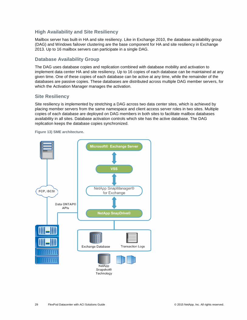
Figure 13) SME architecture.
30 FlexPod Datacenter with ACI Solutions Guide © 2015 NetApp, Inc. All rights reserved.
SnapManager for Exchange Server and Snapshot Copies
A Snapshot copy is a point-in-time, real-time, online, and read-only copy of a LUN stored on a volume.
SnapManager for Exchange Server (SME) backups use Snapshot copy technology to create copies of
Exchange Server databases that reside in these LUNs.
Data ONTAP software allows a maximum of 255 Snapshot copies per volume. To avoid reaching this
limit, delete old SME backups that are no longer needed. This is necessary because SME backups
automatically create Snapshot copies.
SnapManager for Exchange Server and SnapDrive
SnapDrive provides an underlying layer of support for SME by working with the Windows New
Technology File System (NTFS), volume manager, and LUNs to help manage resources on the storage
system in the Windows environment.
SnapDrive software also integrates with the volume manager on the Windows OS and with VMware
vSphere so that storage systems can function as virtual storage devices for Exchange Server data on
Windows VMs. SnapDrive uses the VMware virtual infrastructure (VI) Software Development Kit (SDK),
which includes the Web Services Description Language (WSDL) that exposes the VMware infrastructure
web service API on the ESXi server. The VI SDK enables SnapDrive to invoke web service interface
functions to provision raw device mapping (RDM) LUNs for the guest OS. The use of RDM LUNs helps
manage the storage-level backups.
Note: Use SME for all backup-related operations. Use SnapDrive only to create and manage the LUNs and storage system volumes that contain Exchange Server data.
SnapManager for Exchange Server and Volume Shadow Copy Service
Volume Shadow Copy Service (VSS) is a set of Component Object Model (COM) APIs that implements a
framework that allows volume backups to be performed while applications on the system continue to write
to the volumes.
SME is a Microsoft VSS framework requestor and uses the VSS subsystem to initiate backups. The Data
ONTAP VSS hardware provider (part of the SnapDrive installation package) integrates the SnapDrive
service and storage systems running Data ONTAP in the VSS framework.
Note: For more information about VSS, see the Volume Shadow Copy Service Overview page on the Microsoft Developer Network site.
Backup and Recovery Software for Exchange and SnapManager 7.0 for Exchange Server
SME provides an integrated data management solution for Microsoft Exchange Server 2013 that
enhances the availability, scalability, and reliability of Exchange databases. SME provides rapid backups
and restores of online databases, along with local or remote backup set mirroring for disaster recovery.
SME uses the online Snapshot copy technology, which is part of Data ONTAP, and integrates with
Exchange Server backup and restore application programming interface (APIs), as well as VSS. SME
uses SnapMirror® software to support disaster recovery, even if native Exchange DAG replication is
used.
SME provides the following data management capabilities:
Migrates Exchange data from local or remote storage to NetApp LUNs
Creates application-consistent backups of Exchange databases and transaction logs from NetApp LUNs
Verifies Exchange databases and transaction logs in backup sets
31 FlexPod Datacenter with ACI Solutions Guide © 2015 NetApp, Inc. All rights reserved.
Manages backup sets
Archives backup sets
Restores Exchange databases and transaction logs from backup sets, providing lower recovery time objectives (RTOs) and more frequent recovery point objectives (RPOs)
Restores active or passive databases by using rapid reseed and prevents a full reseed of a replica database across the network
SME includes the following new features:
Gapless DAG backup enhancements
Backup retention management enhancements
Backup management improvements for additional remote backups
Use SME when deploying Exchange Server 2013 on NetApp storage systems. SME performs data
migration from local disks to NetApp LUNs. It also manages that data, handling all backup, restore, and
verification operations.
DAG Management Groups
All nodes in a DAG management unit can be managed by registering the DAG with SME. Each DAG
node can also be managed individually at the server level.
The database replication status must be healthy before the migration. When migrating the Exchange
Server mailbox databases on a DAG, make sure that NetApp storage is provisioned for each server that
has a database copy. Each server uses the same path specified during the migration. Install SME on all
of the member servers of the DAG before migrating the mailbox databases.
If SME is not installed on a member server in the DAG:
Any databases hosted by that member server are not migrated by SME (including active and passive databases).
SME cannot back up databases on that server.
SnapManager for Exchange Server Architecture
SME supports Microsoft Exchange Server 2013. SME features tight integration with Microsoft Exchange,
allowing consistent online backups of Microsoft Exchange environments while leveraging NetApp
Snapshot copy technology. SME is a VSS requestor, meaning it uses the VSS framework supported by
Microsoft to initiate backups. SME works with the DAG, providing the ability to back up and restore data
from both active database copies and passive database copies.
4.5 Cisco UCS Director for FlexPod with ACI and NetApp Clustered Data ONTAP
NetApp and Cisco have partnered to create a reference validated design focused on delivering Cisco
UCS Director automation and orchestration with Cisco ACI and NetApp clustered Data ONTAP. Cisco
ACI provides applications through centralized policy methodologies, which is managed through the Cisco
APIC. Cisco UCS Director allows for the automation and orchestration of the entire FlexPod
infrastructure.
For more information about this architecture, including design details and best practices for deploying this
design architecture, see FlexPod Datacenter with VMware vSphere 5.5 Update 2 and Cisco Nexus 9000
ACI.
Solution Overview
Figure 14 illustrates the layered approach to automation and orchestration commonly employed by
FlexPod customers. Cisco UCS Manager provides orchestration and provisioning for a single Cisco UCS
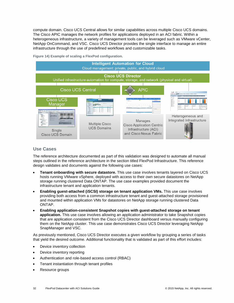
32 FlexPod Datacenter with ACI Solutions Guide © 2015 NetApp, Inc. All rights reserved.
compute domain. Cisco UCS Central allows for similar capabilities across multiple Cisco UCS domains.
The Cisco APIC manages the network profiles for applications deployed in an ACI fabric. Within a
heterogeneous infrastructure, a variety of management tools can be leveraged such as VMware vCenter,
NetApp OnCommand, and VSC. Cisco UCS Director provides the single interface to manage an entire
infrastructure through the use of predefined workflows and customizable tasks.
Figure 14) Example of scaling a FlexPod configuration.
Use Cases
The reference architecture documented as part of this validation was designed to automate all manual
steps outlined in the reference architecture in the section titled FlexPod Infrastructure. This reference
design validates and documents against the following use cases:
Tenant onboarding with secure datastore. This use case involves tenants layered on Cisco UCS hosts running VMware vSphere, deployed with access to their own secure datastores on NetApp storage running clustered Data ONTAP. The use case examples provided document the infrastructure tenant and application tenants.
Enabling guest-attached (iSCSI) storage on tenant application VMs. This use case involves providing both access from a common infrastructure tenant and guest-attached storage provisioned and mounted within application VMs for datastores on NetApp storage running clustered Data ONTAP.
Enabling application-consistent Snapshot copies with guest-attached storage on tenant application. This use case involves allowing an application administrator to take Snapshot copies that are application consistent from the Cisco UCS Director dashboard versus manually configuring them on the NetApp cluster. This use case demonstrates Cisco UCS Director leveraging NetApp SnapManager and VSC.
As previously mentioned, Cisco UCS Director executes a given workflow by grouping a series of tasks
that yield the desired outcome. Additional functionality that is validated as part of this effort includes:
Device inventory collection
Device inventory reporting
Authentication and role-based access control (RBAC)
Tenant instantiation through tenant profiles
Resource groups
33 FlexPod Datacenter with ACI Solutions Guide © 2015 NetApp, Inc. All rights reserved.
End-to-end workflow automation
APIC integration
Cisco UCS Manager integration
NetApp clustered Data ONTAP integration
VMware vCenter Server integration
5 Conclusion
NetApp and Cisco have combined their technologies to develop FlexPod, a new solution for virtual
computing. FlexPod is a defined set of hardware and software that serves as an integrated infrastructure
stack for all virtualization solutions. Combining best-in-class compute, network, and storage elements,
FlexPod offers an uncompromising infrastructure solution for customers who want to deploy virtualized,
nonvirtualized, and hybrid infrastructure solutions for a variety of enterprise applications.
References
This document uses the following references:
TR-3298: RAID-DP: NetApp Implementation of RAID Double Parity for Data Protection www.netapp.com/us/system/pdf-reader.aspx?pdfuri=tcm:10-60325-16&m=tr-3298.pdf
TR-3437: Storage Subsystem Resiliency Guide www.netapp.com/us/system/pdf-reader.aspx?pdfuri=tcm:10-60064-16&m=tr-3437.pdf
TR-3505: NetApp Deduplication for FAS and V-Series Deployment and Implementation Guide www.netapp.com/us/system/pdf-reader.aspx?pdfuri=tcm:10-60084-16&m=tr-3505.pdf
TR-3563: NetApp Thin Provisioning Increases Storage Utilization with On-Demand Allocation www.netapp.com/us/system/pdf-reader.aspx?pdfuri=tcm:10-61045-16&m=tr-3563.pdf
TR-3702: NetApp Storage Best Practices for Microsoft Virtualization and NetApp SnapManager for Hyper-V www.netapp.com/us/system/pdf-reader.aspx?pdfuri=tcm:10-60173-16&m=tr-3702.pdf
TR-4068: VMware vSphere 5 on NetApp Clustered Data ONTAP 8.1 www.netapp.com/us/system/pdf-reader.aspx?padfuri=tcm:10-61602-16&m=tr-4068.pdf

34 FlexPod Datacenter with ACI Solutions Guide © 2015 NetApp, Inc. All rights reserved.
Refer to the Interoperability Matrix Tool (IMT) on the NetApp Support site to validate that the exact
product and feature versions described in this document are supported for your specific environment.
The NetApp IMT defines the product components and versions that can be used to construct
configurations that are supported by NetApp. Specific results depend on each customer's installation in
accordance with published specifications.
Trademark Information
NetApp, the NetApp logo, Go Further, Faster, AltaVault, ASUP, AutoSupport, Campaign Express, Cloud
ONTAP, Clustered Data ONTAP, Customer Fitness, Data ONTAP, DataMotion, Fitness, Flash Accel,
Flash Cache, Flash Pool, FlashRay, FlexArray, FlexCache, FlexClone, FlexPod, FlexScale, FlexShare,
FlexVol, FPolicy, GetSuccessful, LockVault, Manage ONTAP, Mars, MetroCluster, MultiStore, NetApp
Insight, OnCommand, ONTAP, ONTAPI, RAID DP, RAID-TEC, SANtricity, SecureShare, Simplicity,
Simulate ONTAP, SnapCenter, Snap Creator, SnapCopy, SnapDrive, SnapIntegrator, SnapLock,
SnapManager, SnapMirror, SnapMover, SnapProtect, SnapRestore, Snapshot, SnapValidator,
SnapVault, StorageGRID, Tech OnTap, Unbound Cloud, WAFL and other names are trademarks or
registered trademarks of NetApp Inc., in the United States and/or other countries. All other brands or
products are trademarks or registered trademarks of their respective holders and should be treated as
such. A current list of NetApp trademarks is available on the Web at
http://www.netapp.com/us/legal/netapptmlist.aspx. TR-4399-0415
Copyright Information
Copyright © 1994–2015 NetApp, Inc. All rights reserved. Printed in the U.S. No part of this document
covered by copyright may be reproduced in any form or by any means—graphic, electronic, or
mechanical, including photocopying, recording, taping, or storage in an electronic retrieval system—
without prior written permission of the copyright owner.
Software derived from copyrighted NetApp material is subject to the following license and disclaimer:
THIS SOFTWARE IS PROVIDED BY NETAPP "AS IS" AND WITHOUT ANY EXPRESS OR IMPLIED
WARRANTIES, INCLUDING, BUT NOT LIMITED TO, THE IMPLIED WARRANTIES OF
MERCHANTABILITY AND FITNESS FOR A PARTICULAR PURPOSE, WHICH ARE HEREBY
DISCLAIMED. IN NO EVENT SHALL NETAPP BE LIABLE FOR ANY DIRECT, INDIRECT,
INCIDENTAL, SPECIAL, EXEMPLARY, OR CONSEQUENTIAL DAMAGES (INCLUDING, BUT NOT
LIMITED TO, PROCUREMENT OF SUBSTITUTE GOODS OR SERVICES; LOSS OF USE, DATA, OR
PROFITS; OR BUSINESS INTERRUPTION) HOWEVER CAUSED AND ON ANY THEORY OF
LIABILITY, WHETHER IN CONTRACT, STRICT LIABILITY, OR TORT (INCLUDING NEGLIGENCE OR
OTHERWISE) ARISING IN ANY WAY OUT OF THE USE OF THIS SOFTWARE, EVEN IF ADVISED
OF THE POSSIBILITY OF SUCH DAMAGE.
NetApp reserves the right to change any products described herein at any time, and without notice.
NetApp assumes no responsibility or liability arising from the use of products described herein, except as
expressly agreed to in writing by NetApp. The use or purchase of this product does not convey a license
under any patent rights, trademark rights, or any other intellectual property rights of NetApp.
The product described in this manual may be protected by one or more U.S. patents, foreign patents, or
pending applications.
RESTRICTED RIGHTS LEGEND: Use, duplication, or disclosure by the government is subject to
restrictions as set forth in subparagraph (c)(1)(ii) of the Rights in Technical Data and Computer Software
clause at DFARS 252.277-7103 (October 1988) and FAR 52-227-19 (June 1987).
Related Documents