Flexi EDGE BTS Configurations

Flexi EDGE BTS Configurations
Oct 21, 2015
Flexi EDGE BTS Configurations
Welcome message from author
This document is posted to help you gain knowledge. Please leave a comment to let me know what you think about it! Share it to your friends and learn new things together.
Transcript

Flexi EDGE BTS Configurations

2 © Nokia Siemens Networks Module 4 - Configurations / MNa / 10 September, 2007
Nokia Flexi EDGE BTS: from small to large configurations
Flexible capacity increase from small to very large configurations
• 1 to 24 TRX in 1-6 sectors under 1 BCF
• up to 216 TRX per site
High site capacities possible even without a cabinet
All dual band configurations supported
• ANSI and ETSI frequencies
• GSM 800/1800, GSM 800/1900, GSM 900/1800
Min configuration 1-2 TRX , 2 modules
Max configuration / BCF 8+8+8 TRX, 14 modules

3 © Nokia Siemens Networks Module 4 - Configurations / MNa / 10 September, 2007
Sys m
od
ule
Sect
mo
du
le
Sect module
Sect module
Sys module
Sect module
Stack 2+2+2 8+8+8 Indoor 48V DC 4+4+4 Outdoor with Batteries
2 TRX, wall Stack 4+4+4
Examples of Nokia Flexi EDGE BTS configurations
DTRX
DTRX
DTRX
DTRX
DTRX
DTRX
DTRX
DTRX
DTRX
Sys ext module
Sys module
Sys ext module
DTRX (Dual TRX)
Sector module (DTRX + duplex filter)
GSM/EDGE Modules
DTRX
DTRX
DTRX
Weight: ~150 kg
Low weight load of Nokia Flexi EDGE BTS simplifies site construction work
Weight: ~100 kg Weight: ~250 kg
DTRX
MIBBU
HEX LTE
LTE
LTE
LTE
FAN batt batt batt batt
DTRX DT
RX
Sect module
Sect module
Sect module
Sys module
Sect module
Sect module
Sys module
Sect
mo
du
le
Sect module
Sect module
Sect module
Sys module

4 © Nokia Siemens Networks Module 4 - Configurations / MNa / 10 September, 2007
GSM 4+4+4 & WCDMA 4+4+4
WCDMA/HSPA Modules
2+2+2 4+4+4
GSM/EDGE
GSM/EDGE
GSM/EDGE/ WCDMA/HSPA
GSM/EDGE
WCDMA/ HSPA
RF module
DTRX
DTRX
DTRX
Example of Nokia Flexi BTS growth path
Sys module
Sys ext module
DTRX (Dual TRX)
Sector module (DTRX + duplex filter)
GSM/EDGE Modules
Sys module
RF module
Sys module
RF module
RF module
Sect module
Sys module
Sect module
Sect module
Sect module
Sys module
Sect module
Sect module
DTRX
DTRX
DTRX
Sect module
Sys module
Sect module
Sect module

5 © Nokia Siemens Networks Module 4 - Configurations / MNa / 10 September, 2007
Configurations in this material
Common Configurations
• 1 TRX 1UD – Simplest configuration
• 2 TRX bypass, 2UD
• 4+4+4, 2UD
• 3+3 Upgrade Optimised
Large Configuration
• 8+8+8 4-way combining, 2UD, single cabinet
• 6+6+6 RTC – (one sector only shown)
New features /SRC
• 1+1+1 DP 2UD
• 2+2+2 IDD 4UD

1 TRX, no diversity. Simplest possible configuration

7 © Nokia Siemens Networks Module 4 - Configurations / MNa / 10 September, 2007
1-TRX Combining Bypass, 1UD schematic
LNA
LNA
Du
ple
xe
r D
up
lex
er
LNA+ Multi-
coupler
LNA+ Multi-
coupler
Du
ple
xe
r D
up
lex
er
Dual Duplexer Dual TRX
TX1
RX1 Main Div
RX2 Main Div
TX2
Div
Antenna
_
Simplest possible configuration.
DIV

8 © Nokia Siemens Networks Module 4 - Configurations / MNa / 10 September, 2007
1 TRX combining bypass, 1UD – Module view

9 © Nokia Siemens Networks Module 4 - Configurations / MNa / 10 September, 2007
1 TRX combining bypass, 1UD - Connected

2 TRX Combining By-pass with 2-way RX diversity 2 TRX/Sector, 2 antennas

11 © Nokia Siemens Networks Module 4 - Configurations / MNa / 10 September, 2007
2 TRX Combining By-pass with 2-way RX diversity (2UD) - Schematic
Example: 2 TRX/cell
LNA
LNA
Du
ple
xe
r D
up
lex
er
LNA+ Multi-
coupler
LNA+ Multi-
coupler
Du
ple
xe
r D
up
lex
er
Dual Duplexer Dual TRX
TX1
RX1 Main Div
RX2 Main Div
TX2
Div
Antennas
X
12 © Nokia Siemens Networks Module 4 - Configurations / MNa / 10 September, 2007
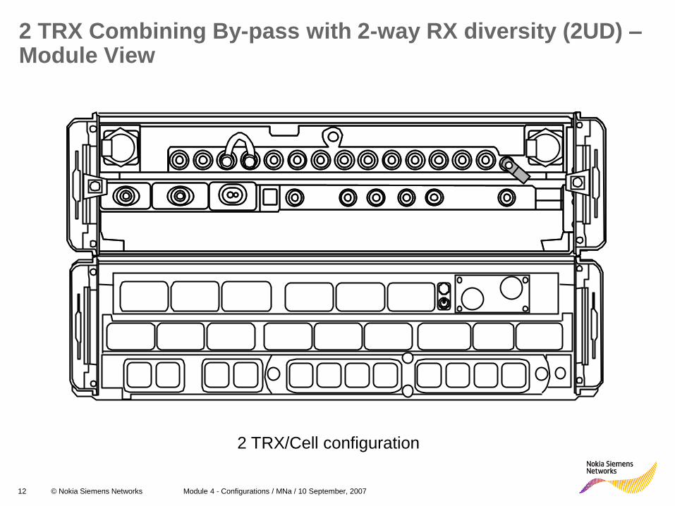
2 TRX Combining By-pass with 2-way RX diversity (2UD) – Module View
2 TRX/Cell configuration

13 © Nokia Siemens Networks Module 4 - Configurations / MNa / 10 September, 2007
2 TRX Combining By-pass with 2-way RX diversity (2UD) -Solution:
2 TRX/Cell configuration

2-way Wideband Combining with 2-way RX diversity E.g., 4+4+4, 2 antennas per sector

15 © Nokia Siemens Networks Module 4 - Configurations / MNa / 10 September, 2007
Example: 4 TRX/cell
Dual TRXs
2-way Wideband Combining with 2-way RX diversity - Schematic
Antennas
X
TX1
RX1 Main Div
RX2 Main Div
TX2
Div
TX3
RX3 Main Div
RX4 Main Div
TX4
Div
Dual Duplexer
LNA
LNA
Du
ple
xe
r D
up
lex
er
LNA+ Multi-
coupler
LNA+ Multi-
coupler
Du
ple
xe
r D
up
lex
er
Wideband Combiners
WBC
WBC

16 © Nokia Siemens Networks Module 4 - Configurations / MNa / 10 September, 2007
Example: 2-way, 2UD – Module view Example: 4 TRX/cell (4+4+4, one sector)

19 © Nokia Siemens Networks Module 4 - Configurations / MNa / 10 September, 2007
Example: 2-way, 2UD, TX and RX Cabling Example: 4 TRX/cell (4+4+4, one sector)

20 © Nokia Siemens Networks Module 4 - Configurations / MNa / 10 September, 2007
3+3 Cost-optimised 2-way RX diversity (2UD)
One DTRX is split between two cells:
DDU 1
TxA TxB RxA
1 RxA
2 RxA
3 RxA
4 RxB
1 RxB
2 RxB
3 RxB
4 ExtB ExtA RxAI RxAO
DTRX 1
WBC
TxA TxB
RX 1 RX 1 Div RX 2 RX 2 Div
T XA T XB T X OUT
DP
DTRX 2
WBC
TxA TxB
RX 1 RX 1 Div RX 2 RX 2 Div
T XA T XB T X OUT
DP
DDU 2
TxA TxB RxA
1 RxA
2 RxA
3 RxA
4 RxB
1 RxB
2 RxB
3 RxB
4 ExtB ExtA RxAI RxAO
DTRX 3
WBC
TxA TxB
RX 1 RX 1 Div RX 2 RX 2 Div
T XA T XB T X OUT
DP WBC
T XA T XB T X OUT
DP

8+8+8, 2 antennas/cell 4-way combining, 2-way Uplink Diversity 1 cabinet

22 © Nokia Siemens Networks Module 4 - Configurations / MNa / 10 September, 2007
4-way Wideband Combining with 2-way RX diversity (2UD)
Dual Duplexer
Antennas
X
LNA
LNA
Du
ple
xe
r D
up
lex
er
WBC WBC
WBC
WBC
Wideband Combiners Dual TRXs
WBC
WBC
TX1
RX1 Main Div
RX2 Main Div TX2
Div
TX3
RX3 Main Div
RX4 Main Div TX4
Div
TX5
RX5 Main Div
RX6 Main Div TX6
Div
TX7
RX7 Main Div
RX8 Main Div TX8
Div
LNA+ Multi-
coupler
LNA+ Multi-
coupler
Du
ple
xe
r D
up
lex
er
Example: 8 TRX/cell
For each sector:
14 TRX cables
8 Receive cables

23 © Nokia Siemens Networks Module 4 - Configurations / MNa / 10 September, 2007
EDGE/BTS 8+8+8 WBC 4:1
1 2 3 4 5 6 7 8
9 10 11 12 13 14 15 16 17 18 19 20
21 22 23
24 25 26
27 28 29 30
31 32 33
34 35 36
DTRX 1
DTRX 2
DTRX 4
ESMA
DDU 1
DTRX 3
T
DTRX 5
DTRX 6
DTRX 8
DDU 2
DTRX7
DTRX 9
DTRX 10
DTRX 12
DDU 3
DTRX 11
ESEA
WBC 1
WBC 2 WBC 3
WBC 4 WBC 5
WBC 8 WBC 9
WBC 10 WBC 11
WBC 14 WBC 15
WBC 16 WBC 17
WBC 6
WBC 7
WBC 12
WBC 13
WBC 18
8+8+8
4-way
2UD

24 © Nokia Siemens Networks Module 4 - Configurations / MNa / 10 September, 2007
NOTE:
1) One sector shown in picture.
2) All three sectors have identical cabling
structure.
3) Before continuing to the next sector be sure
that all cables are correctly installed.
4) It's recommended to use empty boxes in table
as an connection check list.
SECTORS
NUMBER CABL
E FROM – TO A B C
1 99493
1 TxA - TxA
(WBC)
2 99493
1 TxB - TxB
(WBC)
3 99493
1 (WBC)TxOut -
TxB(WBC)
4 99493
1 TxA - TxA
(WBC)
5 99493
1 TxB - TxB
(WBC)
6 99493
1 (WBC)TxOut -
TxA(WBC)
7 99493
1 (WBC)TxOut -
TxA (DDU)
8 99493
1 TxA - TxA
(WBC)
9 99493
1 TxB - TxB
(WBC)
10 99493
1 (WBC)TxOut -
TxA(WBC)
11 99493
1 TxA - TxA
(WBC)
12 99493
1 TxB - TxB
(WBC)
13 99493
1 (WBC)TxOut -
TxB(WBC)
14 99493
1 (WBC)TxOut –
TxB(DDU)
RF Cables, Tx
3
4
2
6
5
14
8 9 10
EDGE/BTS 8+8+8 WBC 4:1
13
12
11
7
1

25 © Nokia Siemens Networks Module 4 - Configurations / MNa / 10 September, 2007
RF Cables, Rx
SECTORS
NUMBER CABL
E FROM – TO A B C
1 994933 RxA – RxA4
2 994933 RxB – RxB4
3 994931 RxA – RxA1
4 994931 RxB – RxB3
5 994931 RxA – RxA3
6 994931 RxB – RxB2
7 994931 RxA – RxA2
8 994931 RxB – RxB1
1
3
4
2
6 5
8 7
NOTE:
1) One sector shown in picture.
2) All three sectors have identical cabling
structure.
3) Before continuing to the next sector be sure
that all cables are correctly installed.
4) It's recommended to use empty boxes in table
as an connection check list.
EDGE/BTS 8+8+8 WBC 4:1
6+6+6, Remote Tune Combiner (1 Cabinet)

27 © Nokia Siemens Networks Module 4 - Configurations / MNa / 10 September, 2007
Remote Tune Combining with 2-way RX diversity -One sector of a 6+6+6
With RTC up to 6 Tx signals can be combined into 1 antenna, minimizing the combiner loss

28 © Nokia Siemens Networks Module 4 - Configurations / MNa / 10 September, 2007
Flexi EDGE BTS 6+6+6 RTC

29 © Nokia Siemens Networks Module 4 - Configurations / MNa / 10 September, 2007
Module order
RTC 1
DTRX
RTC 2
DTRX
ESEA
RTC 3
DTRX
ESMA.
DTRX
DTRX
DTRX
DTRX
DTRX
DTRX
Flexi EDGE BTS 6+6+6 RTC

NOTE:
1) One sector shown in picture.
2) All three sectors have identical
cabling structure.
3) Before continuing to the next sector
be sure that all cables are
correctly installed.
4) It's recommended to use empty
boxes in table as an connection
check list.
SECTORS
NUMBER
CABLE
FROM – TO(DTRX)
A B C
1 99493
1 TX1 - TxA
2 99493
4 TX2 - TxB
3 99493
4 TX3 - TxA
4 99493
4 TX4 - TxB
5 99493
5 TX5 - TxA
6 99493
5 TX6 – TxB
RF Cables, TX cables
Flexi EDGE BTS
6+6+6 RTC
DTRX 1
TxA TxB
RX 1 RX 1 Div RX 2 RX 2 Div
DTRX 2
TxA TxB
RX 1 RX 1 Div RX 2 RX 2 Div
DTRX 3
TxA TxB
RX 1 RX 1 Div RX 2 RX 2 Div
ANT
RTC
Rx 1 Rx 2 Rx 3 Rx 4 Rx 6 Rx 5
Tx 1 Tx 2 Tx 3 Tx 4 Tx 6 Tx 5
R X DIV
R X ext I n R X ext Out

NOTE:
1) One sector shown in picture.
2) All three sectors have identical
cabling structure.
3) Before continuing to the next sector
be sure that all cables are
correctly installed.
4) It's recommended to use empty
boxes in table as an connection
check list.
SECTORS
NUMBER
CABLE
FROM – TO (DTRX)
A B C
1 99493
1 RX1 - RxA
2 99493
1 RX2 - RxB
3 99493
1 RX3 - RxA
4 99493
1 RX4 - RxB
5 99493
4 RX5 - RxA
6 99493
4 RX6 – RxB
RF Cables, RX cables
Flexi EDGE BTS
6(+6+6) RTC
DTRX 1
TxA TxB
RX1 RX1 Div RX2 RX2 Div
DTRX 2
TxA TxB
RX1 RX1 Div RX2 RX2 Div
DTRX 3
TxA TxB
RX1 RX1 Div RX2 RX2 Div
ANT
RTC
Rx1 Rx2 Rx3 Rx4 Rx6Rx5
Tx1 Tx2 Tx3 Tx4 Tx6Tx5
RX DIV
RX ext InRX ext Out

(Optional) Other configurations

33 © Nokia Siemens Networks Module 4 - Configurations / MNa / 10 September, 2007
Remote Tune Combining with 2-way RX diversity
Ext-RF Cable
34 © Nokia Siemens Networks Module 4 - Configurations / MNa / 10 September, 2007
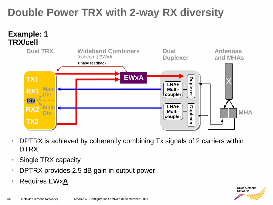
Double Power TRX with 2-way RX diversity
Wideband Combiners (coherent) EWxA
Dual Duplexer
Example: 1 TRX/cell
LNA+ Multi-
coupler
LNA+ Multi-
coupler
Du
ple
xe
r D
up
lex
er EWxA
Dual TRX
TX1
RX1 Main Div
RX2 Main Div
TX2
Div
• DPTRX is achieved by coherently combining Tx signals of 2 carriers within
DTRX
• Single TRX capacity
• DPTRX provides 2.5 dB gain in output power
• Requires EWxA
Phase feedback
MHA
Antennas and MHAs
X

36 © Nokia Siemens Networks Module 4 - Configurations / MNa / 10 September, 2007
Antennas
X
X
Wideband Combiners (coherent)
Dual Duplexers
DTRX Units
Double Power TRX with 4-way RX diversity
Example: 2 TRX/cell
EWxA TX1
RX1 Main Div
RX2 Main Div
TX2
TX3
RX3 Main Div
RX4 Main Div
TX4
Phase feedback
Phase feedback
LNA+ Multi-
coupler
LNA+ Multi-
coupler
Du
ple
xe
r D
up
lex
er
EWxA
LNA+ Multi-
coupler
LNA+ Multi-
coupler
Du
ple
xe
r D
up
lex
er

37 © Nokia Siemens Networks Module 4 - Configurations / MNa / 10 September, 2007
Dual Duplexer
LNA+ Multi-
coupler
LNA+ Multi-
coupler
Du
ple
xe
r D
up
lex
er
Antennas and MHAs
X
Dual TRX
TX1
RX1 Main Div
RX2 Main Div
TX2
Div
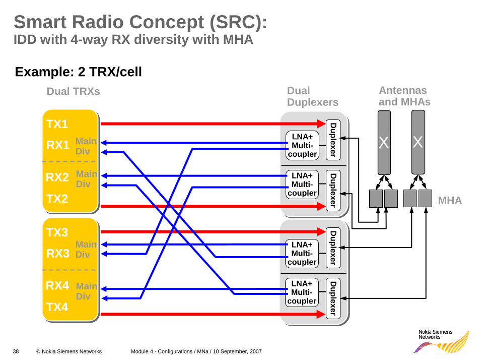
IDD and 2-way RX diversity (with MHA) Example: 1 TRX/cell
• Intelligent Downlink Diversity (IDD) is an effective way of boosting the downlink: it is based on space and time diversity and signal tuning
• IDD gives on average 5 dBm gain in downlink path
MHA
38 © Nokia Siemens Networks Module 4 - Configurations / MNa / 10 September, 2007
LNA+ Multi-
coupler
LNA+ Multi-
coupler
Du
ple
xe
r D
up
lex
er
LNA+ Multi-
coupler
LNA+ Multi-
coupler
Du
ple
xe
r D
up
lex
er
X
Dual Duplexers
Dual TRXs
TX1
RX1 Main Div
RX2 Main Div
TX2
TX3
RX3 Main Div
RX4 Main Div
TX4
Smart Radio Concept (SRC): IDD with 4-way RX diversity with MHA
Example: 2 TRX/cell
Antennas and MHAs
MHA
X

39 © Nokia Siemens Networks Module 4 - Configurations / MNa / 10 September, 2007
Nokia Flexi EDGE BTS RF performance
BTS Output Power DTRX 800/900/1800/19
00
DPTRX 800/900/1800/1900
Max # of TRXs /
antenna element
Frequency hopping
dBm W dBm W
TRX output 47.0 50 49.5 89.5 - -
IDD 50.5 112 53 200 1 RF & BB
Combiner by-pass 46.2 41.7 48.5 71 1 RF & BB
RTC 44.0 25 6 BB
WBC 2:1 42.7 18.5 2 RF & BB
WBC 4:1 39.4 8.7 4 RF & BB
BTS Receiver Sensitivity, with Nokia High Gain MHA
Sensitivity 800/900&1900
Sensitivity 1800
dBm dBm
4-way diversity -118 -118.5
2-way diversity -115.5 -116
Single branch -112.5 -113
NOTE: RF performance results are not finalized.

40 © Nokia Siemens Networks Module 4 - Configurations / MNa / 10 September, 2007
Nokia Flexi EDGE BTS output power
BTS nominal output power values are measured at the Dual Duplexer module’s antenna connector (same as TOC figures of traditional cabinets)
Output power values are defined with GMSK modulation. With 8-PSK modulation, values are 2 dB smaller.
Intelligent Downlink Diversity (IDD) doubles (~3 dB) the received signal power at the handset and multiple diversity gains add downlink by average of 1-2 dB, giving average 4.5 dB gain in total. Shown output power values are after air-combining without antenna gain.
Combining options: • Combiner by-pass = No combining – 1 TRX to one antenna
• WBC 2:1 = One stage Wide Band Combining – 1...2 TRXs to one antenna
• WBC 4:1 = Two stage Wide Band Combining – 1...4 TRXs to one antenna
• RTC 6:1 = Remote Tune Combining (cavity combining) – 1...6 TRXs to one antenna
Output power values for RTC are given with 6 TRX and minimum channel spacing. With less TRXs and extended channel spacing, output power is up to 0.5 dB higher.

Minimum and Maximum configurations
Capacity Expansion Steps
RF Cabling
Combining Options

42 © Nokia Siemens Networks Module 4 - Configurations / MNa / 10 September, 2007
One Sector configuration table
#of carriers
Combining # of EXxA
# of ERxA
# of ECxA
# of ESMA
# of ESEA
height # of antennas
1 By-pass 1UD 1 1 0 1 0 3HU 1
1-2 By-pass 2UD 1 1 0 1 0 3HU 2
2 2-way 1UD 1) 1 1 0 1 0 3HU 1
3 By-pass 2UD 2 2 0 1 0 6HU 3
4 By-pass 2UD 2 2 0 1 0 6HU 4
3-4 4-way 1UD 1) 2 1 0 1 0 5HU 1
1 By-pass DP 2UD 1 1 0 1 0 3HU 2
2 By-pass DP 2UD 2 1 0 1 0 5HU 2
3 By-pass DP 2UD or 4UD
3 2 0 1 0 8HU 3 or 4
4 By-pass DP 2UD or 4UD
4 2 0 1 0 10HU 4
1-2 By-pass SRC 1) or DP 4UD
2 2 0 1 0 6HU 4
3-4 2-way 2UD 2 1 0 1 0 5HU 2
5-6 4-way 2UD 3 1 0 1 0 7HU 2
7-8 4-way 2UD 4 1 0 1 0 9HU 2
Up to 12 RTC Up to 6
0 Up to 2
1 1 Up to 20HU
2
1) supported with SCF overrule 2) SRC==IDD+4UD

43 © Nokia Siemens Networks Module 4 - Configurations / MNa / 10 September, 2007
Stack configuration table
Configuration Combining # of EXxA
# of ERxA
# of EWxA
# of ESMA
# of FPAA
Max Height 1)
# of Antennas
1 to 2 omni By-pass 2UD 1 1 0 1 1 9HU 2
3 to 4 omni 2-way 2UD 2 1 2 1 1 11HU 2
5 to 6 omni 4-way 2UD 3 1 6 1 2 13HU 2
7 to 8 omni 4-way 2UD 4 1 6 1 2 15HU 2
1+1 By-pass 1UD 1 1 0 1 1 9HU 2
1+1 or 2+2 By-pass 2UD 2 2 0 1 1 12HU 4
3+3 By-pass 2UD 3 2 4 1 2 14HU 4
4+4 By-pass 2UD 4 2 4 1 2 16HU 4
1+1+1 or 2+2+2 By-pass 2UD 3 3 0 1 2 15HU 6
3+3+3 2-way 2UD 5 2) 3 6 1 3 19HU 6
4+4+4 2-way 2UD 6 3 6 1 3 21HU 6
1+1+1 By-pass DP 2UD 3 3 3 1 2 15HU 6
2+2+2 By-pass DP 2UD 6 3 6 1 3 21HU 6
1+1+1 or 2+2+2 By-pass DP or SRC 3) 4UD
6 6 3 or 6 1 0 21HU 12
2+2+2/2+2+2 dual band
By-pass 2UD 6 6 0 1 0 21HU 12
1) Assuming built for Cost-optimised. Upgrade-optimised needs 6 x EXxA. 2) SRC==IDD+4UD 3) Inc. FPMA

44 © Nokia Siemens Networks Module 4 - Configurations / MNa / 10 September, 2007
Pole and Wall mount configuration table
Configuration Combining # of EXxA
# of ERxA
# of EWxA
# of ESMA
# of FPAA
# of stacks
# of antennas
1 to 2 omni By-pass 2UD 1 1 0 1 1 1 2
3 to 4 omni 2-way 2UD 2 1 2 1 1 2 2
5 to 6 omni 4-way 2UD 3 1 6 1 2 2 2
7 to 8 omni 4-way 2UD 4 1 6 1 2 3 2
1+1 By-pass 1UD 1 1 0 1 1 1 2
1+1 or 2+2 By-pass 2UD 2 2 0 1 1 2 4
3+3 By-pass 2UD 3 2 4 1 2 2 4
4+4 By-pass 2UD 4 2 4 1 2 3 4
1+1+1 or 2+2+2 By-pass 2UD 3 3 0 1 2 2 6
3+3+3 2-way 2UD 5 3 6 1 3 3 6
4+4+4 2-way 2UD 6 3 6 1 3 4 6
1+1+1 By-pass DP 2UD 3 3 3 1 2 2 6
2+2+2 By-pass DP 2UD 6 3 6 1 3 4 6
1+1+1 or 2+2+2 By-pass DP or SRC 4UD
6 6 3 or 6 1 3 4 12
2+2+2 /2+2+2 dual band
By-pass 6 6 0 1 3 4 12

45 © Nokia Siemens Networks Module 4 - Configurations / MNa / 10 September, 2007
Indoor or Outoor cabinet configuration table
Configuration Combining EXxA’s ERxA’s ECxA’s ESMA’s ESEA’s height antenna
1 to 2 omni By-pass 2UD 1 1 0 1 0 6HU 2
3 to 4 omni 2-way 2UD 2 1 0 1 0 8HU 2
5 to 6 omni 4-way 2UD 3 1 0 1 0 10HU 2
7 to 8 omni 4-way 2UD 4 1 0 1 0 12HU 2
1 to 6 omni RTC 2UD 1 to 3 0 1 1 1 19HU 2
7 to 12 omni RTC 2UD 4 to 6 0 2 1 1 29HU* 2
1+1 By-pass 1UD 1 1 0 1 0 6HU 2
1+1 or 2+2 By-pass 2UD 2 2 0 1 0 9HU 4
3+3 By-pass 2UD 3 2 0 1 0 11HU 4
4+4 By-pass 2UD 4 2 0 1 0 13HU 4
1+1+1 or 2+2+2 By-pass 2UD 3 3 0 1 0 12HU 6
3+3+3 2-way 2UD 5 3 0 1 0 16HU 6
4+4+4 2-way 2UD 6 3 0 1 0 18HU 6
1+1+1 By-pass DP 2UD 3 3 0 1 0 12HU 6
2+2+2 By-pass DP 2UD 6 3 0 1 0 18HU 6
1+1+1 or 2+2+2 By-pass DP or SRC 4UD
6 6 0 1 0 21HU* 12
6+6+6 RTC 2UD 9 0 3 1 1 36HU* 6
12 RTC 2UD 6 0 2 1 1 29HU* 2
12+6 RTC 2UD 9 0 3 1 1 36HU* 4
8+8+8 4-way 2UD 12 3 0 1 1 33HU* 6
* Two cabinets required

46 © Nokia Siemens Networks Module 4 - Configurations / MNa / 10 September, 2007
Flexi EDGE BTS Licensed Features & SW Compatibility
47 © Nokia Siemens Networks Module 4 - Configurations / MNa / 10 September, 2007
Licensed Flexi EDGE BTS features
In EP1:
• Flexi EDGE TRX capacity management
– Name of the licence in the purchasing tool: ‘Flexi EDGE Operating SW’
– Note: also known as ’Flexi EDGE TRX SW support’
In EP2:
• DPTRX i.e. Double Power TRX
• Transmission features

48 © Nokia Siemens Networks Module 4 - Configurations / MNa / 10 September, 2007
TRX Capacity Licence control in BSC
BSC checks that the licence is valid and that operator cannot have more Flexi EDGE TRXs in use than the licence allows.
Operator can also check the amount of Flexi EDGE TRXs that are in use.
The current capacity level usage is requested with service fmn_capacity_usage_inquiry_as from BSC software that has registered itself as capacity manager (PUBDAT).
Feature name Feature number
Feature code / Licence code
Licence type Licence Time limited (short term / long term)
Flexi EDGE TRX SW support
BSS20212 73 Feature: on/off long term

49 © Nokia Siemens Networks Module 4 - Configurations / MNa / 10 September, 2007
Allowed values of licensed transmission features in EP2
Feature (SW
licence)
Capacity
range
Used
licence
capasity by
BCF
Abis termination via
Pseudo-wire
Emulation
(FlexiEDGE Abis
over IP/ Ethernet)
ON/OFF 1
Abis termination via
E1/T1 in blocks of 2
(FlexiEDGE
Additional 2 E1/T1)
1...3/OFF 1 per blocks
of 2
Cross-connection
(FlexiEDGE TRS
Abis Grooming)
ON/OFF 1
Loop Protection
(FlexiEDGE TRS
Loop Protection)
ON/OFF 1

50 © Nokia Siemens Networks Module 4 - Configurations / MNa / 10 September, 2007
Flexi EDGE BTS EP1 SW Compatibility
Compatibility between Flexi EDGE BTS, BSC, NetAct, LMU and FIFA transmission
submodule software

51 © Nokia Siemens Networks Module 4 - Configurations / MNa / 10 September, 2007
Flexi EDGE BTS EP2 SW Compatibility
EP2.0
• EP2.0 will be the second Flexi EDGE BTS SW feature release.
• Flexi EDGE BTS EP2.0 release will be compatible with BSS13 and NetAct OSS4.2.
EP2.0 will support the following licensed features:
• DPTRX with 2UD and 4UD
• Transmission license management

Flexi EDGE BTS Feederless Site

53 © Nokia Siemens Networks Module 4 - Configurations / MNa / 10 September, 2007
Feederless Concept Masthead Solution
• One EOCA pair is needed per 3 DTRXs. In 3 sector system each EOCA pair supports 2+2+2 configuration.
• Maximum of 4+4+4 is supported in masthead configuration.
• Each 2+2+2 requires own DC Feed and Optical Fiber. This replaces six antenna feeders of 3-sector diversity configuration.
• Benefit in 4+4+4 configuration is smaller due to no new antenna feeders are required in feeder case and 2nd pair of DC and optical interfaces are needed in feederless case.
• 2+2+2 4-way diversity case saves 12 antenna feeders with two sets of DC and optical interfaces.
54 © Nokia Siemens Networks Module 4 - Configurations / MNa / 10 September, 2007
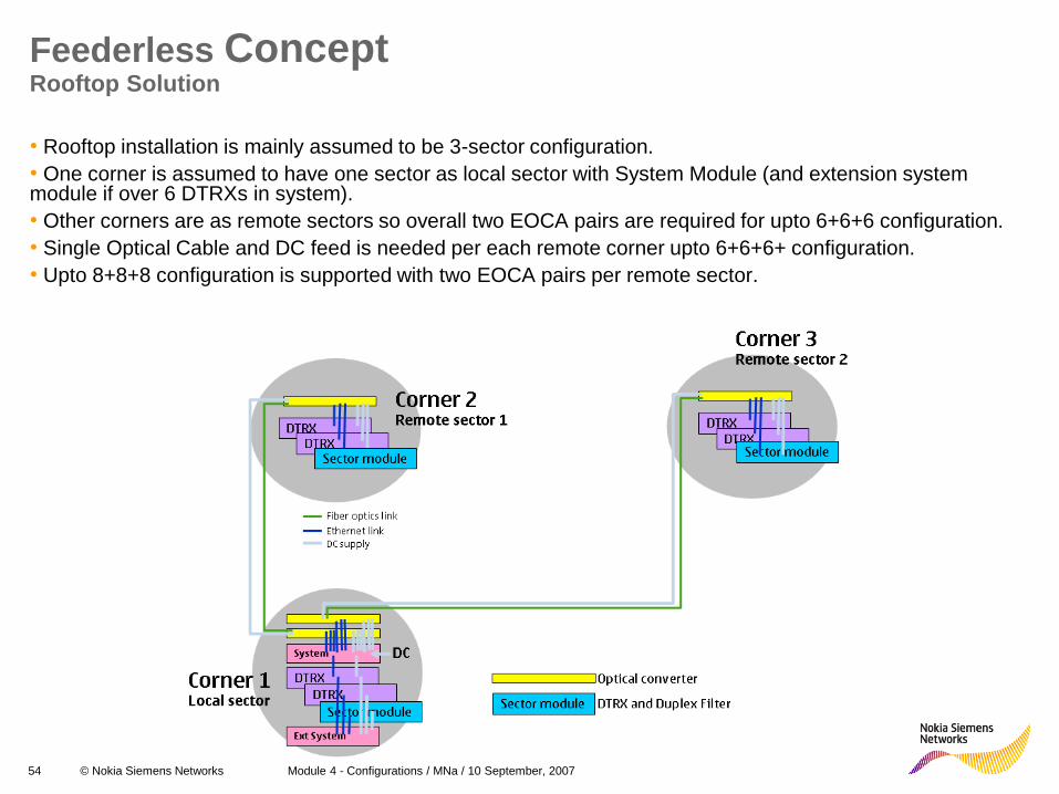
Feederless Concept Rooftop Solution
• Rooftop installation is mainly assumed to be 3-sector configuration.
• One corner is assumed to have one sector as local sector with System Module (and extension system module if over 6 DTRXs in system).
• Other corners are as remote sectors so overall two EOCA pairs are required for upto 6+6+6 configuration.
• Single Optical Cable and DC feed is needed per each remote corner upto 6+6+6+ configuration.
• Upto 8+8+8 configuration is supported with two EOCA pairs per remote sector.

55 © Nokia Siemens Networks Module 4 - Configurations / MNa / 10 September, 2007
48V Input
48V Output/Sense 1
BUS Interface 1
BUS Interface 2
BUS Interface 3
Optical Interface
48V Output/Sense 2
48V Output/Sense 3
OVP Plug-In Module
Unit Construction Interfaces
• EOCA contains: – Three BUS interfaces (one from back as pre-installed longer cable interface)
– Three 48V DC Output/Sense interfaces (one from back as pigtail interface)
– 48V DC input interface
– Optical Fiber Interface
– OVP Plug-In Module interface
• BUS interfaces are connected to ESMA or ESEA at local end and to DTRXs at remote end.
• 48V output/sense interfaces are connected to DTRXs at remote end. At local end they can be connected to ESMA if sensing is used. 48V control can be handled purely as commands over Ethernet and likely sensing will not be supported eventually to reduce amount of cables needed in the setup.
• Optical interface is connected between EOCA of local sector and EOCA of remote sector.
• DC inputs are connected to 48V source at local end. Remote can get its 48V from local end or locally from the 48V source at remote end.
Related Documents