For more information about DreamLine ® Shower Doors, Tub Doors & Enclosures, please visit DreamLine.com Flex Shower Enclosure 30x30, 34x34 S HOWER E NCLOSURE I NSTALLATION I NSTRUCTIONS IMPORTANT DreamLine ® reserves the right to alter, modify or redesign products at any time without prior notice. For the latest up-to-date technical drawings, manuals, warranty information or additional details please refer to your model’s web page on DreamLine.com ©2018 DreamLine. All Rights Reserved FLEX SHOWER ENCLOSURE 30x30, 34x34 = + STEP 1: Refer to Return Panel Manual STEP 2: Refer to Shower Door Manual FLEX Shower Enclosure 30x30, 34x34

Welcome message from author
This document is posted to help you gain knowledge. Please leave a comment to let me know what you think about it! Share it to your friends and learn new things together.
Transcript
For more information about DreamLine® Shower Doors, Tub Doors & Enclosures, please visit DreamLine.com
Flex Shower Enclosure 30x30, 34x34SHOWER ENCLOSURE INSTALLATION INSTRUCTIONS
IMPORTANTDreamLine® reserves the right to alter, modify or redesign products at any time without prior notice. For the latest up-to-date technical drawings, manuals, warranty information or additional details please refer to your model’s web page on DreamLine.com
©2018 DreamLine. All Rights ReservedFLEX SHOWER ENCLOSURE 30x30, 34x34
= +
STEP 1: Refer to Return Panel Manual
STEP 2: Refer to Shower Door Manual
FLEX Shower Enclosure 30x30, 34x34
Please review this entire manual prior to installation.
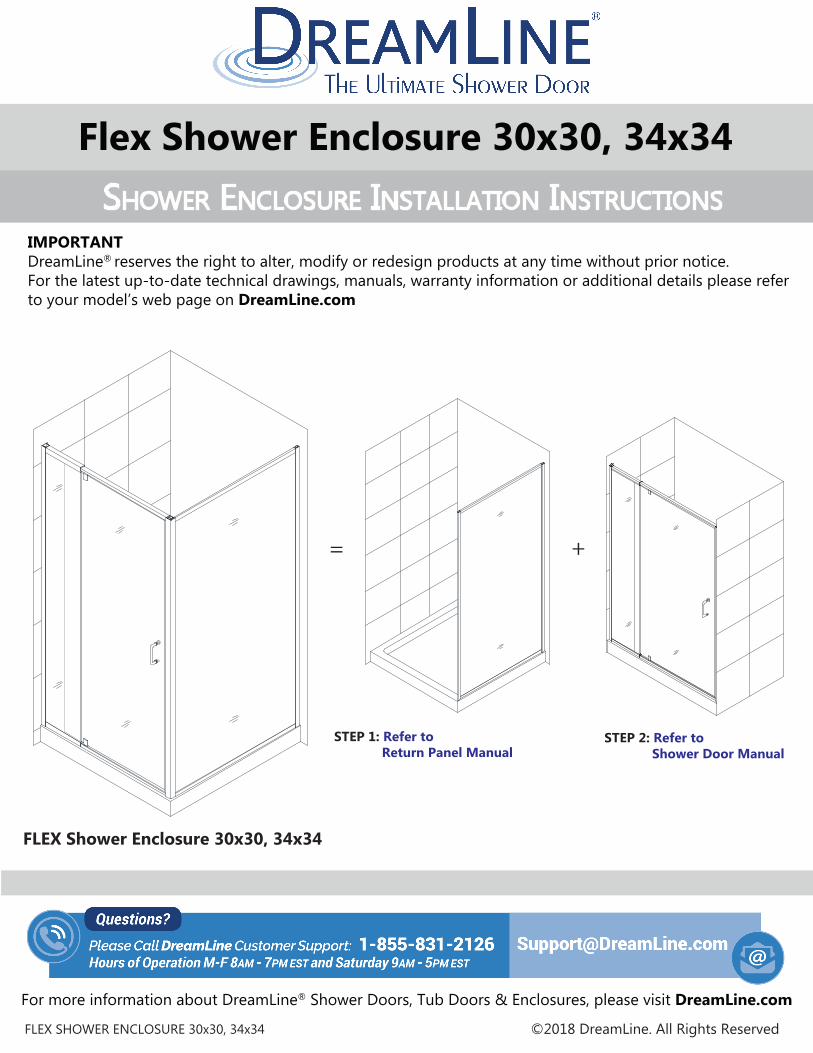
Right-hand return panel installation shown
##=finish01- Chrome04 - Brushed Nickel
FLEX ENCLOSURESHOWER ENCLOSURE INSTALLATION INSTRUCTIONS
IMPORTANTDreamLine® reserves the right to alter, modify or redesign products at any time without prior notice. For the latest up-to-date technical drawings, manuals, warranty information or additional details please refer to your model’s web page on DreamLine.com
For more information about DreamLine® Shower Doors, Tub Doors & Enclosures, please visit DreamLine.com
MODEL #sSHDR-2230300-RT-##SHDR-2234340-RT-##
MODEL #sSHDR-2234460-RT-##SHDR-2234580-RT-##
FLEX Shower Enclosure manual Ver 3 Rev 3 03/2018 ©2018 DreamLine. All Rights Reserved

NOTE: This model is reversible for left or right-hand installation. This manual will show the right-hand return panel installation. For a left-hand installation, simply begin on the opposite wall and reverse the orientation of the parts as necessary.
FLEX Shower Enclosure manual Ver 3 Rev 3 03/2018 ©2018 DreamLine. All Rights Reserved
Wall profile*( *not used with corner profile)
Expandable rail
Expandable rail
Door Glass
Stationary panel glass
Wall profile
Corner profile
panel glassReturn
Return panelWall profile
USE THE INSTALLATION MANUAL THAT IS PACKAGED WITH THE FLEX DOOR TO ASSEMBLE AND INSTALL THE DOOR SECTION.
USE THIS MANUAL TO ASSEMBLE AND INSTALL THE RETURN PANEL AND FOR THE ENCLOSURE DIMENSIONS
!
door
return panel

Diagram of Shower enclosure componentsParts List
Table of ContentsSection title Page #
ToolsPreparationShower Enclosure Diagram
Vinyl Seals
Installation Steps
Product maintenance
8654
1917
910-18
3FLEX Shower Enclosure manual Ver 3 Rev 3 03/2018
©20
18 D
ream
Line
. All
Righ
ts R
eser
ved
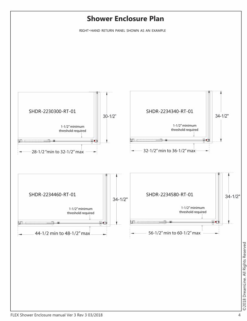
Shower Enclosure Plan
4FLEX Shower Enclosure manual Ver 3 Rev 3 03/2018
©20
18 D
ream
Line
. All
Righ
ts R
eser
ved
56-1/2” min to 60-1/2” max
34-1/2"
1-1/2” minimumthreshold required
34-1/2"
1-1/2” minimumthreshold required
32-1/2” min to 36-1/2” max
44-1/2 min to 48-1/2” max
34-1/2"
1-1/2” minimumthreshold required
30-1/2”
1-1/2” minimumthreshold required
28-1/2 “min to 32-1/2” max
SHDR-2230300-RT-01 SHDR-2234340-RT-01
SHDR-2234460-RT-01 SHDR-2234580-RT-01
RIGHT-HAND RETURN PANEL SHOWN AS AN EXAMPLE

5FLEX Shower Enclosure manual Ver 3 Rev 3 03/2018
©20
18 D
ream
Line
. All
Righ
ts R
eser
ved
Dimensions represent the outside of the installed shower enclosure (not the shower base or threshold)
34-1/2”44-1/2” min to 48-1/2”max
32-1/2” min to 36-1/2” max
28-1/2 “min to 32-1/2” max56-1/2” min to 60-1/2”max
1-1/2” minimumthreshold required
30-1/2”
RIGHT-HAND RETURN PANEL SHOWN AS AN EXAMPLE
This shower enclosure requires a minimum 1-1/2” wide threshold for installation. Compare the overall outside dimensions of the shower enclosure model size as shown on the “Shower Enclosure Plan” with the finished threshold to ensure proper fit prior to beginning installation.
Preparation1. Prior to installation, examine all boxes and packages for shipping damage and compare the piece count with the packing slip. After opening all boxes and packages read this introduction carefully. Check that all of the necessary parts are included in the package by checking off the components on the “Detailed Diagram of Shower Door Components”. If the unit has been damaged, has a finishing defect, or has missing parts, please contact our customer support department within 3 business days of the delivery date. Please note that DreamLine® will not replace any damaged products or missing parts free of charge after 3 business days or if the product has been installed. Feel free to contact DreamLine® if you have any questions, and please provide an order number, job name or other proof of purchase to help identify the original order.
2. Please note that you should consult your local building codes with questions on installation compliance standards. Building and plumbing codes may vary by location, and DreamLine® is not responsible for code compliance standards for your project and will not accept any returns.
3. If this unit is going to be installed in new construction, please install all of the required plumbing and drainage before installing the shower. Use a competent and licensed (if required by local code) plumber for all plumbing installation.
4. Make sure that prior to beginning the installation, the surfaces are leveled and solid and will be able to support the total weight of the unit. Also make sure the walls are at right angles. Irregular installation surface level, radius corners or improper angle of side walls will result in serious prob-lems for your installation. Note that some adjustments and drilling will be necessary during the installation process.
5. Protect all primary surfaces of the product during installation. Never set the glass down directly onto a tile floor. Leave corner protectors in place until necessary to remove them. Always use a piece of wood or cardboard to protect the bottom edge and corners of the glass prior to and during installation.
6. This unit must be installed upon a finished threshold and against finished walls.
7. This model has 1/2” of adjustment for out-of-plumb wall conditions within the wall profiles and 3“ of adjustment with the expanding rails for the door section. Verify that your walls are plumb and that the threshold is level before proceeding with the installation.
8. This model requires a minumum of 1-1/2” of flat threshold space for installation.
9. Professional installation recommended.
NOTE: DO NOT attach the handle to the door glass until instructed. DO NOT attempt to lift the door glass with the handle as this may result in damage to the glass and/or serious personal injury. Use a professional grade glass suction cup and an assistant.
6FLEX Shower Enclosure manual Ver 3 Rev 3 03/2018
©20
18 D
ream
Line
. All
Righ
ts R
eser
ved
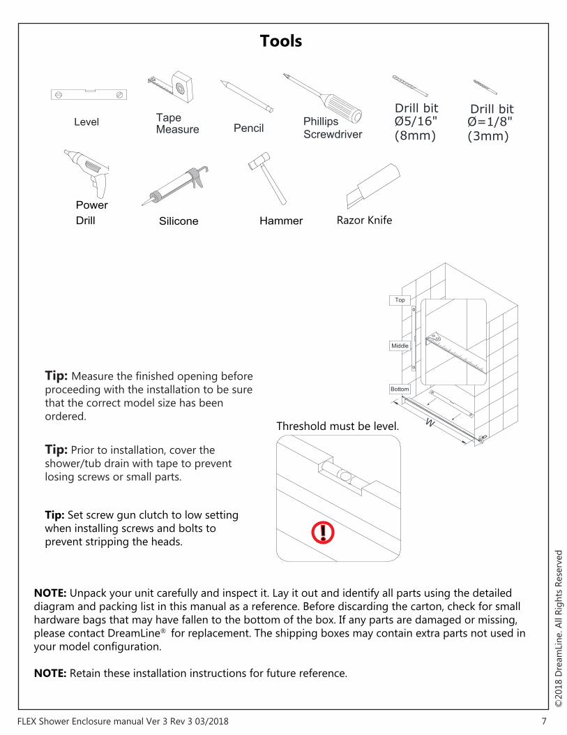
Tools
Tip: Measure the finished opening before proceeding with the installation to be sure that the correct model size has been ordered.
Tip: Prior to installation, cover the shower/tub drain with tape to prevent losing screws or small parts.
NOTE: Unpack your unit carefully and inspect it. Lay it out and identify all parts using the detailed diagram and packing list in this manual as a reference. Before discarding the carton, check for small hardware bags that may have fallen to the bottom of the box. If any parts are damaged or missing, please contact DreamLine® for replacement. The shipping boxes may contain extra parts not used in your model configuration.
NOTE: Retain these installation instructions for future reference.
Tip: Set screw gun clutch to low setting when installing screws and bolts to prevent stripping the heads.
7FLEX Shower Enclosure manual Ver 3 Rev 3 03/2018
©20
18 D
ream
Line
. All
Righ
ts R
eser
ved
Ø=1/8"(3mm)
Drill bitØ5/16"(8mm)
Drill bit
DrillPower
HammerSilicone Razor Knife
W
Top
Middle
Bottom
Level TapeMeasure Pencil Screwdriver
Phillips
!
Threshold must be level.

Detailed Diagram of shower door components
8FLEX Shower Enclosure manual Ver 3 Rev 3 03/2018
©20
18 D
ream
Line
. All
Righ
ts R
eser
ved
3
4
5
6
7
8
2
13
9
1 10 11
Enclosure Model
RIGHT-HAND RETURN PANEL SHOWN AS AN EXAMPLE
Door
Return panel

Parts List
9FLEX Shower Enclosure manual Ver 3 Rev 3 03/2018
©20
18 D
ream
Line
. All
Righ
ts R
eser
ved
Door packing List 01 Wall profile* 2pcs* 06 Decorative cover 10pcs 02 Door assembly 1set 07 Flanged anti-water strip 1pc 03 Wall anchor 8pcs 08 Bottom anti-water strip 1pc 04 Pan head screw ST4.2×10 10pcs 13 Handle 1pc 05 Truss head screws ST4.2×40 8pcs
Return panel packing List 04 Round head screw ST4.2x10 6pcs 10 Corner profile 1pc 06 Decorative cover 3pcs 11 Return panel wall pofile 1pc 09 Return Panel Assembly 1pc
* Only one Wall Profile is used with the shower enclosure installation

Installation steps
10FLEX Shower Enclosure manual Ver 3 Rev 3 03/2018
©20
18 D
ream
Line
. All
Righ
ts R
eser
ved
Fig 1
Table 1
SHDR-2230300-RT-01SHDR-2234340-RT-01SHDR-2234460-RT-01SHDR-2234580-RT-01 34-1/2” 56-1/2” ~ 60-1/2”
34-1/2” 44-1/2” ~ 48-1/2”34-1/2” 32-1/2” ~ 36-1/2”30-1/2” 28-1/2” ~ 32-1/2”
MODEL # W1 W2(DOOR AREA W)
PLACEMENT OF
RETURN PANEL
PLACEMENT OF
DOOR SECTION
(RETURN PANEL W)
W1 W2
Return ProfileWall Profile
RIGHT-HAND RETURN PANEL SHOWN AS AN EXAMPLE
door return panel
1. The width of the shower enclosure model is adjustable and can be adjusted to the size of your shower base or custom threshold.Mark the position of the Wall profile (#01) and the Return Panel Wall Profile (#11) on the wall according to the model size and dimensions provided in the size table below.
Place the Wall Profile (#01) and the Return Panel Wall Profile (#11) onto the threshold against the finished wall. Use a level to adjust to plumb. (Fig #1) (Table 1)

11FLEX Shower Enclosure manual Ver 3 Rev 3 03/2018
©20
18 D
ream
Line
. All
Righ
ts R
eser
ved
Fig 2
Fig 3a
Fig 3b
2 3
Ø 5/16"
6
1
4 5
2
Ø 5/16"
3
5 6
1
4
3. Mark the holes on the wall for drilling through the pre-drilled hole in the Return Panel Wall Profile (#11).
Drill the holes into the wall using a Ø 5/16” drill bit and insert the Wall Anchors (#03). Apply silicone to the back surface of the Return Panel Wall Profile (#11) and place it back in position on the wall.
Attach the Return Panel Wall Profile (#11) to the wall with the Truss head screws ST4.2×40 (#05). (Fig 3a and 3b)
2. Mark the holes on the wall for drilling through the pre-drilled holes in the Wall Profile (#01).
Drill the holes into the wall using a Ø 5/16 drill bit and insert the Wall Anchors (#03).
Apply silicone to the back surface of the Wall Profile (#01 ) and place it back in position on the wall.
Attach the Wall profile (#01) to the wall with the Truss head screws ST4.2×40 (#05). (Fig 2)

12FLEX Shower Enclosure manual Ver 3 Rev 3 03/2018
©20
18 D
ream
Line
. All
Righ
ts R
eser
ved
RIGHT-HAND RETURN PANEL SHOWN AS AN EXAMPLE
Fig 4
28” and 32” model
Pre-assembled Assembly required
42”, 48” and 60” model
USE THE INSTALLATION MANUAL PACKAGED WITH THE FLEX DOOR TO ASSEMBLE AND INSTALL THE DOOR SECTION. (Fig 4)
4. Move the Door assembly onto the threshold and slide the Stationary glass profile into the Wall profile (#01). (Fig 4)

13FLEX Shower Enclosure manual Ver 3 Rev 3 03/2018
©20
18 D
ream
Line
. All
Righ
ts R
eser
ved
inside
outside
Fig 5
Fig 6
1
2
3
Ø 1/8"
6. Slide the Return Panel Assembly (#09) into the Return Panel Wall Profile (#11). (Fig 6)
5. Slide the Corner profile (#10) over the aluminum edge of the Return Panel Assembly (#09). Drill Ø 1/8” holes through the predrilled holes on the Corner profile (#10) into the aluminum profile on the Return Panel Assembly (#09).
Secure the Corner profile (#10) to the Return Panel Assembly (#09) with the Pan head screws ST4.2×10 (#04). (Fig 5)
14FLEX Shower Enclosure manual Ver 3 Rev 3 03/2018
©20
18 D
ream
Line
. All
Righ
ts R
eser
ved
1 2
3 4
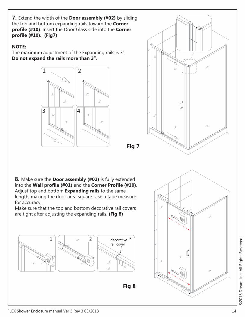
Fig 7
Fig 8
decorativerail cover
321
7. Extend the width of the Door assembly (#02) by sliding the top and bottom expanding rails toward the Corner profile (#10). Insert the Door Glass side into the Corner profile (#10). (Fig7)
NOTE: The maximum adjustment of the Expanding rails is 3”. Do not expand the rails more than 3”.
8. Make sure the Door assembly (#02) is fully extended into the Wall profile (#01) and the Corner Profile (#10).Adjust top and bottom Expanding rails to the same length, making the door area square. Use a tape measure for accuracy. Make sure that the top and bottom decorative rail covers are tight after adjusting the expanding rails. (Fig 8)

15FLEX Shower Enclosure manual Ver 3 Rev 3 03/2018
©20
18 D
ream
Line
. All
Righ
ts R
eser
ved
inside
inside
Ø 1/8”
Ø 1/8”
Fig 9
1 2 3
4 5 6
9. From inside of the shower, drill holes into the top and bottom Expanding rails through the predrilled holes using an Ø 1/8” drill bit.
ATTENTION:Drill only through the first layer of the Expanding rail.
Secure the Expanding rails using Pan head screws ST4.2×10 (#04) with the raised white washers. Cover exposed screw heads with Decorative covers (#06). (Fig 9)

16FLEX Shower Enclosure manual Ver 3 Rev 3 03/2018
©20
18 D
ream
Line
. All
Righ
ts R
eser
ved
insideinside
Fig 10
1
2
3
Ø 1/8”
View from inside View from inside
4
5
6
Ø 1/8”
RIGHT-HAND RETURN PANEL SHOWN AS AN EXAMPLE
Door Return panel
10. Perform the final adjustments to the Door assembly (#02) and Return panel glass (#09) as necessary. Operate the Door Glass to make sure that the magnetic strips are aligned and make full contact from top to bottom. Drill holes into the aluminum profile of the Door assembly through the predrilled holes in the Wall profile (#01) using an Ø 1/8” drill bit. Drill Ø 1/8” holes into the aluminum profile through the predrilled holes in the Return panel wall profile (#11).
ATTENTION:Drill only through the first layer of the profiles.
Secure the Door assembly (#02) to the Wall profile (#01) and the Return panel assembly (#09) to the Return panel wall profile (#11) using the Pan head screws ST4.2×10 (#04) with the raised white washers.Cover the exposed screws with the Decorative covers (#06). (Fig 10)
17FLEX Shower Enclosure manual Ver 3 Rev 3 03/2018
©20
18 D
ream
Line
. All
Righ
ts R
eser
ved
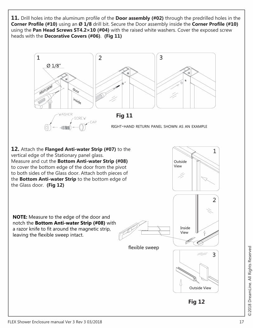
NOTE: Measure to the edge of the door and notch the Bottom Anti-water Strip (#08) with a razor knife to fit around the magnetic strip, leaving the flexible sweep intact.
Fig 11
Fig 12
1 2 3
1
2
3
Ø 1/8”
Inside View
Outside View
Outside View
RIGHT-HAND RETURN PANEL SHOWN AS AN EXAMPLE
inside
doorreturn panel
flexible sweep
12. Attach the Flanged Anti-water Strip (#07) to the vertical edge of the Stationary panel glass. Measure and cut the Bottom Anti-water Strip (#08) to cover the bottom edge of the door from the pivot to both sides of the Glass door. Attach both pieces of the Bottom Anti-water Strip to the bottom edge of the Glass door. (Fig 12)
11. Drill holes into the aluminum profile of the Door assembly (#02) through the predrilled holes in the Corner Profile (#10) using an Ø 1/8 drill bit. Secure the Door assembly inside the Corner Profile (#10) using the Pan Head Screws ST4.2×10 (#04) with the raised white washers. Cover the exposed screw heads with the Decorative Covers (#06). (Fig 11)
18FLEX Shower Enclosure manual Ver 3 Rev 3 03/2018
©20
18 D
ream
Line
. All
Righ
ts R
eser
ved
Fig 13
RIGHT-HAND RETURN PANEL SHOWN AS AN EXAMPLE
24Hours
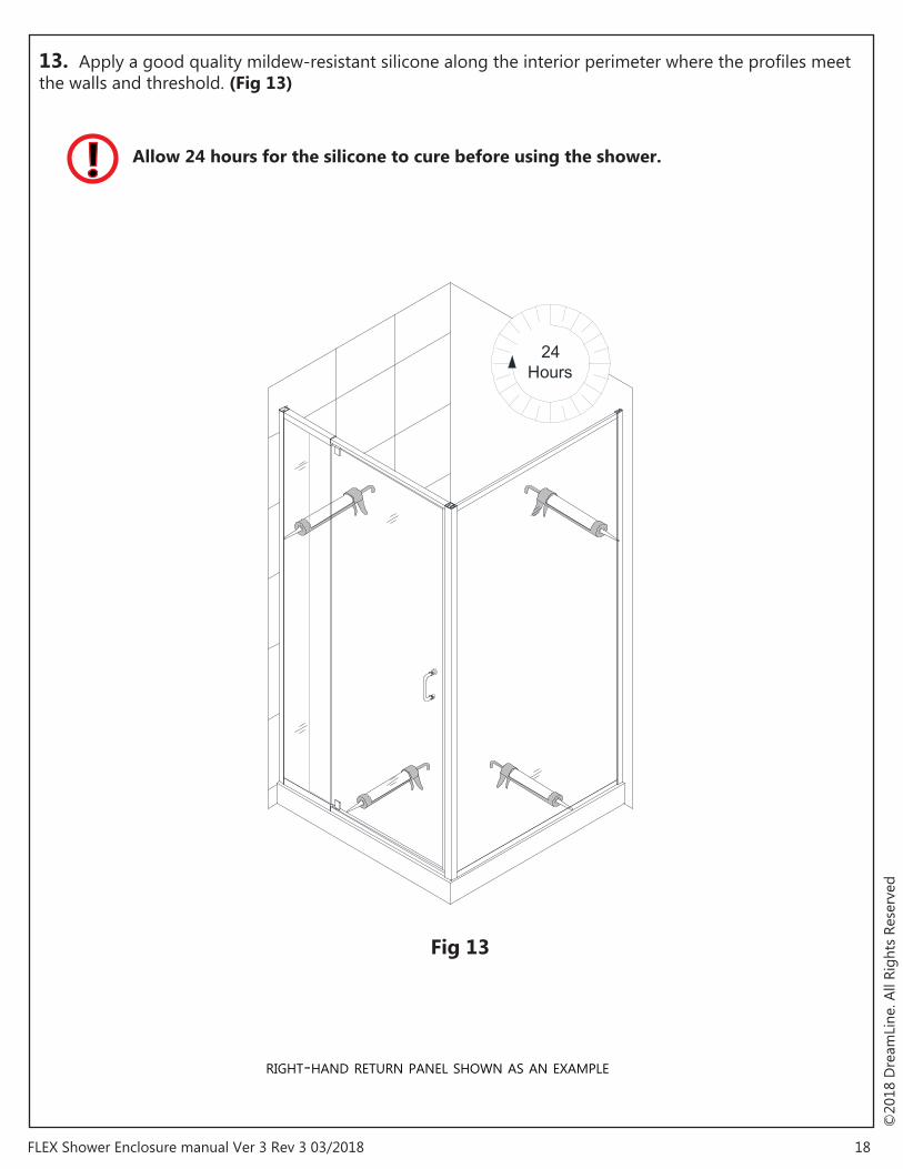
13. Apply a good quality mildew-resistant silicone along the interior perimeter where the profiles meet the walls and threshold. (Fig 13)
! Allow 24 hours for the silicone to cure before using the shower.

Product Maintenance
BASES and BACKWALLS: To ensure long-lasting life for your acrylic back walls, wipe them off after each use with a soft cloth. To clean the acrylic back walls use non-abrasive sprays or cream based cleaners. Avoid the use of aerosol spray cleaners. Never use abrasive cleansers, metal brushes or scrapers that could scratch or dull the surface.
GLASS: To ensure long-lasting life for your glass shower products, wipe them off after each use with a soft cloth. Rinse and wipe off the glass using either a soft cloth or a squeegee to prevent soap buildup and water spots (Hard water can etch the surface of the glass over time if left to dry). To prevent scratching the surface: never use abrasive cleaners or cleaning products that contain scouring agents. Never use bristle brushes or abrasive sponges that may scratch the surface.
HARDWARE: To ensure a long-lasting finish, wipe off the metal parts after each use with a soft cloth. Do not use abrasive cleaners or cleaning products containing ammonia, bleach or acid. If accidentally used, rinse the surface as soon as possible to prevent damage to the finish (peeling or corrosion). After cleaning the polished finishes, rinse thoroughly and wipe dry with soft cloth. Clean stainless steel surfaces at least once a week. When applying stainless steel cleaner or polish to stainless steel hardware, work with (not across) the grain. Never use an abrasive sponge or cloth, steel wool or wired brush as these may permanently scratch the surfaces.
NOTE: To maximize the life of your door, it is important to regularly inspect the glass and all hardware for misalignment, proper attachment, and/or damage. Contact DreamLine® with any questions or concerns.
DreamLine® shower doors and enclosures are designed not to leak when installed properly and the flow of water is not pointed directly at the door pivots or vinyl seals.
19 FLEX Shower Enclosure manual Ver 3 Rev 3 03/2018
©20
18 D
ream
Line
. All
Righ
ts R
eser
ved

TEL: 866-731-2244FAX: 866-857-3638DREAMLINE.COM
For more information on DreamLine® Shower Doors and Enclosures please visit DreamLine.com
©20
18 D
ream
Line
. All
Righ
ts R
eser
ved
Fig ## Fig ##

FLEX Shower Door Manual Ver 2 Rev 8 01/2018 © 2018 DreamLine. All Rights Reserved 1
FLEX 28”x 72” / 32” x 72”
SHOWER DOOR INSTALLATION INSTRUCTIONS
IMPORTANT
DreamLine® reserves the right to alter, modify or redesign products at any time without prior
notice. For the latest up-to-date technical drawings, manuals, warranty information or any
other details, please refer to your model’s web page on DreamLine.com
For more information about DreamLine
® products please visit DreamLine.com
Right hand door installation shown
Model#s: SHDR-22287200-01
SHDR-22327200-01
Finish -01 = Chrome
FLEX Shower Door Manual Ver 2 Rev 8 01/2018 © 2018 DreamLine. All Rights Reserved 2
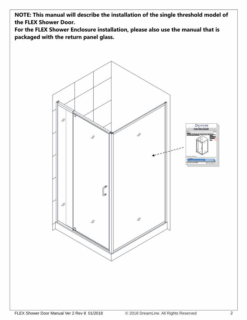
NOTE: This manual will describe the installation of the single threshold model of
the FLEX Shower Door.
For the FLEX Shower Enclosure installation, please also use the manual that is
packaged with the return panel glass.

FLEX Shower Door Manual Ver 2 Rev 8 01/2018 © 2018 DreamLine. All Rights Reserved 3
Preparation
1. Prior to installation, examine all boxes and packages for shipping damage and compare the piece
count with your packing slip. After opening all boxes and packages read this introduction carefully.
Check that all of the needed parts are included in the package by checking off the components
on the “Detailed Diagram of Shower Door Components”. If the unit has been damaged, has a
finishing defect, or has missing parts, please contact our customer support department within
3 business days of the delivery date. Please note that DreamLine® will not replace any
damaged products or missing parts free of charge after 3 business days or if the product
has been installed. Feel free to contact DreamLine® if you have any questions, and please
provide an order number, job name or other proof of purchase to help us identify your original
order.
2. Please note that you should consult your local building codes with questions about
installation compliance standards. Building and plumbing codes may vary by location, and
DreamLine® is not responsible for code compliance standards for your project and will not
accept any returns.
3. If this unit is going to be installed in a new construction, please install all of the required
plumbing and drainage before installing the shower. Use a competent and licensed (if required
by local code) plumber for all plumbing installation.
4. Please make sure that prior to beginning the installation, the surfaces are leveled and solid and
will be able to support the total weight of the unit. Also make sure the walls are at right angles.
Irregular installation surface level, radius corners or improper angle of side walls will result in
serious problems for your installation. Please, note that some adjustments and drilling may be
necessary during the installation process.
5. Please protect all primary surfaces of the product during installation. Never set your glass down
directly onto a tile floor. Leave corner protectors in place until necessary to remove them.
Always use a piece of wood or cardboard to protect the bottom edge and corners of the glass
prior to and during installation.
6. This unit must be installed upon a finished threshold and against finished walls.
7. This model has 4” of total width adjustment: including 1/2” of adjustment per wall profile for out-of-
plumb wall conditions plus 3” of overall width adjustment with the expanding top and bottom rails.
Be sure that you have ordered the correct model size to fit your finished opening.
8. This model requires a minimum 1-3/8” of flat threshold space for installation.
9. Professional installation recommended.
NOTE: This door is reversible for right or left-hand door installation. The right-hand door installation is
shown as an example throughout this manual.
FLEX Shower Door Manual Ver 2 Rev 8 01/2018 © 2018 DreamLine. All Rights Reserved 4
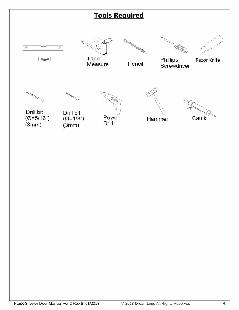
Tools Required
FLEX Shower Door Manual Ver 2 Rev 8 01/2018 © 2018 DreamLine. All Rights Reserved 5
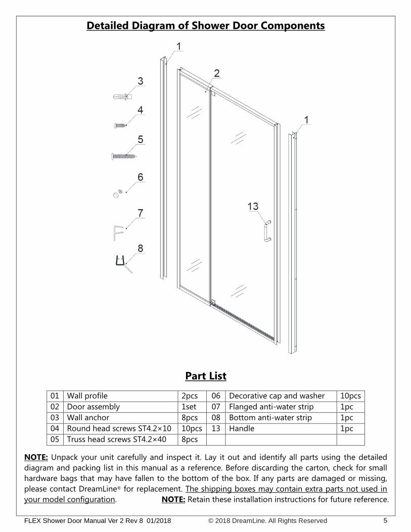
Detailed Diagram of Shower Door Components
Part List
01 Wall profile 2pcs 06 Decorative cap and washer 10pcs
02 Door assembly 1set 07 Flanged anti-water strip 1pc
03 Wall anchor 8pcs 08 Bottom anti-water strip 1pc
04 Round head screws ST4.2×10 10pcs 13 Handle 1pc
05 Truss head screws ST4.2×40 8pcs
NOTE: Unpack your unit carefully and inspect it. Lay it out and identify all parts using the detailed
diagram and packing list in this manual as a reference. Before discarding the carton, check for small
hardware bags that may have fallen to the bottom of the box. If any parts are damaged or missing,
please contact DreamLine® for replacement. The shipping boxes may contain extra parts not used in
your model configuration. NOTE: Retain these installation instructions for future reference.

FLEX Shower Door Manual Ver 2 Rev 8 01/2018 © 2018 DreamLine. All Rights Reserved 6
Door Assembly Diagram
Alluminum profile
Expandable rail
Expandable rail
Glass door
Stationary glass
Alluminum profile

FLEX Shower Door Manual Ver 2 Rev 8 01/2018 © 2018 DreamLine. All Rights Reserved 7
Shower Door Installation
1. Prior to the Shower door installation, the installation of
the shower base and plumbing must be completed.
See Fig. 1 for details.
2. Slide the Wall profiles (01) over the Door assembly
(02) on both sides. Be sure that the flanges on the
Wall Profiles (01) face in towards the shower.
See Fig. 2 & Fig. 3 for details.
W
Fig. 1
Fig. 2

FLEX Shower Door Manual Ver 2 Rev 8 01/2018 © 2018 DreamLine. All Rights Reserved 8
NOTE:
Flip the entire assembly for opposite installation.
3. Move the Door assembly (02) with the
Wall profiles (01) onto the Shower base
with the Stationary glass side tight to the
wall. Adjust the Door assembly (02) by
stretching the top and bottom Expanding
rails evenly to extend the Door assembly
(02) tight to the opposite wall. If the top
and bottom wall opening measurements
are different or if the walls are out-of-
plumb, make adjustments by slightly
pulling the Wall profiles (01) out of the
Door assembly (02).
NOTICE:
The maximum adjustment width of the
Expanding rails is 3”. The wall profiles
allow for 1/2” adjustment for each side.
See Fig. 4 for details.
Fig. 3
1
2
Fig. 4

FLEX Shower Door Manual Ver 2 Rev 8 01/2018 © 2018 DreamLine. All Rights Reserved 9
4. Adjust the Door assembly (02) so that it is
plumb by checking with a level.
See Fig. 5 for details.
5. Have an assistant hold the Door assembly (02) in the
correct position and mark the walls through the pre-drilled
holes in the flange of the Wall Profiles (01).
See Fig. 6 for details.
Fig. 6
Fig. 5
1
2
Inside
Inside
Outside
FLEX Shower Door Manual Ver 2 Rev 8 01/2018 © 2018 DreamLine. All Rights Reserved 10
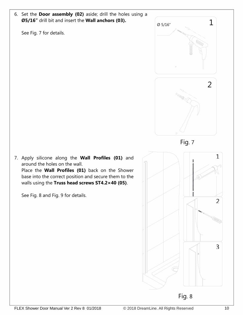
6. Set the Door assembly (02) aside; drill the holes using a
Ø5/16” drill bit and insert the Wall anchors (03).
See Fig. 7 for details.
7. Apply silicone along the Wall Profiles (01) and
around the holes on the wall.
Place the Wall Profiles (01) back on the Shower
base into the correct position and secure them to the
walls using the Truss head screws ST4.2×40 (05).
See Fig. 8 and Fig. 9 for details.
Fig. 8
2
Ø 5/16”
1
2
3
1
Fig. 7
FLEX Shower Door Manual Ver 2 Rev 8 01/2018 © 2018 DreamLine. All Rights Reserved 11
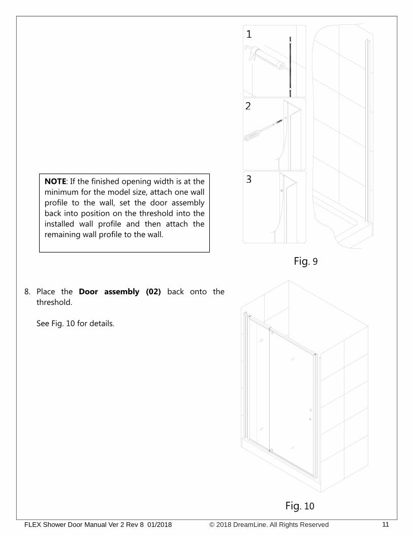
8. Place the Door assembly (02) back onto the
threshold.
See Fig. 10 for details.
Fig. 10
1
2
3
Fig. 9
NOTE: If the finished opening width is at the
minimum for the model size, attach one wall
profile to the wall, set the door assembly
back into position on the threshold into the
installed wall profile and then attach the
remaining wall profile to the wall.
FLEX Shower Door Manual Ver 2 Rev 8 01/2018 © 2018 DreamLine. All Rights Reserved 12
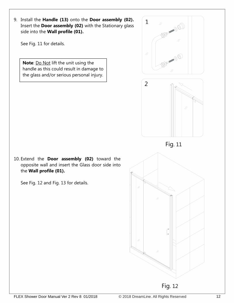
9. Install the Handle (13) onto the Door assembly (02).
Insert the Door assembly (02) with the Stationary glass
side into the Wall profile (01).
See Fig. 11 for details.
Fig. 10
Fig. 11
10. Extend the Door assembly (02) toward the
opposite wall and insert the Glass door side into
the Wall profile (01).
See Fig. 12 and Fig. 13 for details.
Fig. 12
1
2
Note: Do Not lift the unit using the
handle as this could result in damage to
the glass and/or serious personal injury.

FLEX Shower Door Manual Ver 2 Rev 8 01/2018 © 2018 DreamLine. All Rights Reserved 13
11. Make sure the Door assembly (02) is fully extended into
the Wall profiles (01).
Adjust the top and bottom Expanding rails to the same
length so that the door opening is square.
Use a tape measure for accuracy.
See Fig. 14 for details.
Fig. 14
Fig. 13

FLEX Shower Door Manual Ver 2 Rev 8 01/2018 © 2018 DreamLine. All Rights Reserved 14
12. Drill holes into the top and bottom Expanding
rails through the predrilled holes using an Ø 1/8”
drill bit.
ATTENTION:
Do not drill all the way through the Expanding
rail, only through the first layer.
Secure the Expanding rails using the Round head
screws ST4.2×10 (04) and the raised white
washers.
Cover the exposed screw heads and washers with
the Decorative caps (06).
See Fig. 15 for details.
13. Make any final adjustments to the
Door assembly (02) with the Wall
profiles (01). Operate the Glass
door to make sure that the
magnetic strips create a good seal.
From inside the shower, drill holes
in the aluminum profile of the
Door assembly at the top and
bottom of the Wall profile using
an Ø 1/8” drill bit.
ATTENTION:
Do not drill all the way through
the Expanding rail, only through
the first layer.
Secure the Door assembly inside
the Wall profile using the Round
head screws ST4.2×10 (04) with
the raised white washers.
Cover the exposed screw heads
and washers with the Decorative
caps (06).
See Fig. 16 for details. Fig. 16
Fig. 15
Ø 1/8"
1
2
3
4
5
6
Ø 1/8"
Ø 1/8"1
2
3
inside
inside
inside
inside

FLEX Shower Door Manual Ver 2 Rev 8 01/2018 © 2018 DreamLine. All Rights Reserved 15
14. Attach the Flanged Anti-water strip (07) to the vertical edge of the
Stationary glass.
Open the door and attach the Bottom Anti-water strip (08) to the
bottom of the door glass from the pivot to the edge of the magnetic
strike rail and trim off the excess. Next, attach the cut off to the
bottom of the door glass, opposite of the pivot and trim to fit.
Attach both pieces of the Bottom Anti-water strip (08) to the
bottom edge of the Glass door.
See Fig. 17 for details.
15. Apply a good quality, mildew-resistant silicone along
the wall profiles and the bottom expanding rail
where they meet the walls and threshold from both
inside and outside the shower.
Allow 24 hours for the silicone to fully cure before
first use.
See Fig. 18 for details.
Caulk
Fig. 17
Fig. 18
outside
NOTE: Measure to the strike edge of the
door and notch the Bottom anti-water
strip (#08) with a razor knife to fit around
the magnet strip, leaving the bottom
sweep intact.
FLEX Shower Door Manual Ver 2 Rev 8 01/2018 © 2018 DreamLine. All Rights Reserved 16
Product Maintenance
BASES and BACKWALLS: To ensure long lasting life for your acrylic back walls: wipe them off
after each use with a soft cloth. To clean the acrylic back walls use non-abrasive sprays or cream
based cleaners. Avoid the use of aerosol spray cleaners. Never use abrasive cleansers, metal
brushes or scrapers that could scratch or dull the surface.
GLASS: To ensure long lasting life for your glass shower products: wipe them off after each use
with a soft cloth. Rinse and wipe off the glass using either a soft cloth or a squeegee to prevent
soap buildup and water spots (Hard water can etch the surface of the glass over time if left to dry).
To prevent scratching the surface: never use abrasive cleaners or cleaning products that contain
scouring agents. Never use bristle brushes or abrasive sponges that may scratch the surface.
HARDWARE: To ensure a long lasting finish: wipe off the metal parts after each use with a soft
cloth. Do not use abrasive cleaners or cleaning products containing ammonia, bleach or acid. If
accidentally used, rinse the surface as soon as possible to prevent damage to the finish (peeling or
corrosion). After cleaning the polished finishes, rinse thoroughly and wipe dry with soft cloth.
Clean stainless steel surfaces at least once a week. When applying stainless steel cleaner or polish
to stainless steel hardware, work with (not across) the grain. Never use an abrasive sponge or cloth,
steel wool or wired brush as these may permanently scratch the surfaces.
NOTE: To maximize the life of your door, it is important to regularly inspect the glass and
other hardware for misalignment, proper attachment, and/or damage. Contact DreamLine
with any questions or concerns.

TEL: 866-731-2244
FAX: 866-857-3638
DREAMLINE.COM
For more information on DreamLine® Shower Doors and Enclosures please visit DreamLine.com
Related Documents