CAVEX ® Schneckengetriebe Worm Gear Units Réducteurs á vis sans fin

Flender_Cavex_puzni
Oct 26, 2015
katalog
Welcome message from author
This document is posted to help you gain knowledge. Please leave a comment to let me know what you think about it! Share it to your friends and learn new things together.
Transcript
CAVEX®
SchneckengetriebeWorm Gear UnitsRéducteurs á vis sans fin

2 K88 DE/EN/FR
CAVEXSchneckengetriebe Worm Gear Units Réducteurs à vis sans fin
Bauartenübersicht Summary of Basic Types Représentation des types
Alle Getriebe wahlweise mit Laterne zum Anbauvon IEC-Motoren.All gear units are optionally available with bellhousing for mounting IEC motors.Tous les réducteurs sont livrables avec lanterneen option, pour adaptation de moteurs IEC.
Alle Getriebe wahlweise als Stirnrad-Schnecken-getriebe, z.B. CSUW.All gear units are optionally available as helicalworm gear combination, e.g. CSUW.Tous les réducteurs sont livrables avec coupled’engrenages cylindriques et roue et vis sans fincombinés, par ex. CSUW.
Alle Getriebe wahlweise als Doppelschnecken-getriebe, z.B. CDUW.All gear units are optionally available as doubleworm gear units, e.g. CDUW.Tous les réducteurs sont livrables avec deuxcouples roue et vis sans fin combinés, par ex.CDUW.
A

3K88 DE/EN/FR
CAVEXSchneckengetriebe Worm Gear Units Réducteurs à vis sans fin
Inhaltsübersicht Contents Sommaire
Charakteristische VorzügePrinzip der Verzahnung
Characteristic featuresPrinciple of the gear teeth system
Avantages caractéristiquesPrincipe de la denture
SeitePage
5
GrößenbestimmungBelastungskennwerteBetriebsfaktorenBerechnungsbeispielAllgemeine Hinweise, Bestellangaben
Selection of sizeLoad classification symbolsService factorsCalculation exampleGeneral information, Ordering details
Instructions concernant le choix des taillesFacteurs de chargeFacteurs de serviceExemple de calcul; Exécution standard;Données techniques indispensables lors dela commande
6 - 16
Einstufige CAVEX-Schneckengetriebe
Leistungen und DrehmomenteMaße und Einbaulagen
Single stage CAVEX worm gear units
Power ratings and torquesDimensions and mounting positions
Réducteurs CAVEX à train d’engrenagesunique à vis sans finPuissances et couplesDimensions et positions de montage
17 - 41
CAVEX-Stirnrad-Schneckengetriebe
Leistungen und DrehmomenteMaße und Einbaulagen
CAVEX helical worm gear units
Power ratings and torquesDimensions and mounting positions
Réducteurs CAVEX combinés avec un traind’engrenages cylindriquesPuissances et couplesDimensions et positions de montage
42 - 66
CAVEX-DoppelschneckengetriebeLeistungen und DrehmomenteMaße und Einbaulagen
CAVEX double worm gear unitsPower ratings and torquesDimensions and mounting positions
Réducteurs CAVEX à double vis sans finPuissances et couplesDimensions et positions de montage
67 - 89
CAVEX-SchneckengetriebeAnbau von IEC-Motoren
CAVEX worm gear unitsMounting of IEC motors
Réducteurs à vis sans fin CAVEXAdaption des moteurs selon normes IEC
90 - 93
CAVEX-Schneckengetriebemit Rücklaufsperrenmit Schrumpfscheibenmit zusätzlichen Flanschflächenmit zusätzlichen Anbauflächen
CAVEX worm gear unitswith backstopswith shrink diskswith additional flange surfaceswith additional mounting surfaces
Réducteur à vis sans fin CAVEXmuni d’anti-devireursmuni de frettes de serrageSurfaces de bride supplémentairesSurfaces de fixation supplémentaires
94 - 97
Entlüftung, Ölstand, Ölablaß, Ölmengen undGewichteAnbauanleitung und Befestigung von Auf-steckgetrieben
Vent, oil level, oil drain, oil quantities andweightsInstallation instructions, fastening of shaft-mounted worm gear units
Aération, Niveau d’huile, Vidange, Quantitéd’huile, PoidsInstructions de montage et de fixation pourréducteurs “flottants”
98 - 101
Zusatzkräfte auf An- und Abtriebswellen
Kurven für ZusatzkräfteWirkungsgrade, Selbsthemmung, Auslaufenund Bremsen
Additional forces on input and output shafts
Diagrams for additional forcesEfficiencies, irreversibility, decelerationand braking
Charges additionelles pour les arbresd’entrée et de sortieAbaques pour charges additionellesRendement, Irréversibilité, Ralentissementet freinage
102 - 113
Massenträgheitsmomente J Mass moments of inertia J Moments d’ inertie J 114
Variationen der Normalausführung, sowieGroßgetriebe bis Achsabstand 1200 mm undSonderkonstruktionen auf Anfrage
Variants of the standard design, as wellas large gear units with centre distancesup to 1200 mm, and special designs onrequest
Des variantes par rapport aux éxécutionsnormales ainsi que des gros réducteursd’entraxe jusqu’ à 1200 mm ou des exécu-tions spéciales peuvent être fournis surdemande

4 K88 DE/EN/FR
CAVEXSchneckengetriebe Worm Gear Units Réducteurs à vis sans fin
Allgemeine Hinweise General Information Informations générales
Achtung!
Folgende Punkte sind unbedingt zubeachten!
� Abbildungen sind beispielhaft undnicht verbindlich.
� Maßänderungen bleiben vorbehal-ten.
� Umlaufende Teile müssen vomKäufer gegen unbeabsichtigtesBerühren geschützt werden.(Gesetz über technische Arbeits-mittel vom 24.6.1968).
� Die gültigen Sicherheitsbestim-mungen des jeweiligen Einsatzlan-des sind zu beachten.
� Vor Inbetriebnahme ist die Be-triebsanleitung zu beachten.
� Gewichte sind unverbindliche Mit-telwerte.
� Die Ölviskosität muß den Angabendes Typenschildes entsprechen.
� Ölmengenangaben sind unver-bindliche Richtwerte.
� Es dürfen nur freigegebeneSchmierstoffe verwendet werden.Aktuelle Betriebsanleitungen undSchmierstofftabellen finden Sie aufunserer Homepage unter:
www.flender.com
Attention!
The following items are absolutely tobe observed!
� Illustrations are examples only andare not strictly binding.
� Dimensions are subject to change.
� To prevent accidents, all rotatingparts should be guarded accordingto local and national safety regula-tions.
� Prior to commissioning, the oper-ating instructions must be observ-ed.
� Weights are mean values only.
� The oil viscosity has to correspondto the data given on the name plate.
� Oil quantities given are guidevalues only.
� Permitted lubricants may be usedonly.You will find current operatinginstructions and lubricant selec-tion tables on our home page at:
www.flender.com
Attention!
Les points suivants doivent impérati-vement être lus!
� Les schémas sont donnés à titreindicatif, sans engagement.
� Nous nous réservons le droit demodifier les cotes que nousdonnons.
� L’acheteur s’engage de protégerles pièces rotatives contre toutcontact accidentel et selon la légis-lation en vigueur.
� Les consignes de sécurité envigueur dans chaque pays d’uti-lisation doivent être respectés.
� Avant la mise en service, lire atten-tivement la notice de fonctionne-ment.
� Les poids sont donnés de manière indicative.
� La viscosité de l’huile doit être con-forme aux indications de la plaquesignalétique.
� Les quantités d’huile données sontdes valeurs indicatives sans enga-gement.
� Seules les lubrifiants homologuéssont autorisés.Vous trouverez nos manuels d’utili-sation en vigueur avec les tableauxdes lubrifiants recommandés surnotre site internet:
www.flender.com
5K88 DE/EN/FR
CAVEXSchneckengetriebe Worm Gear Units Réducteurs à vis sans fin
Charakteristische Vorzüge Characteristic Features CharactéristiquesPrinzip der Verzahnung Principle of the Gear Teeth System Principe de la denture
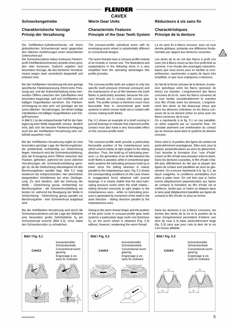
Die Hohlflanken-Zylinderschnecke mit ihremgloboidischen Schneckenrad weist gegenüberden üblichen Ausführungen einen wesentlichenUnterschied auf.Die Schneckenzähne haben konkaves Flanken-profil (Hohlflankenschnecke) anstelle eines gera-den oder konvexen. Dadurch ergeben sichbesondere Vorzüge, die des leichteren Verständ-nisses wegen stark vereinfacht dargestellt underläutert sind.
Bei der Hohlflanken-Verzahnung tritt eine geringespezifische Flankenpressung (Hertz’sche Pres-sung) auf, und die Aufrechterhaltung eines tren-nenden Ölfilms zwischen den Zahnflanken wirdbesonders begünstigt, weil sich Hohlflanken mitballigen Gegenflanken berühren. Die Flanken-schmiegung ist also sehr viel günstiger als beisonst üblichen Verzahnungen, bei denen balligeZahnflanken mit balligen Gegenflanken zum Ein-griff kommen.In Bild 5.1 ist der entsprechende Fall für die Gleit-lagerung einer Welle dargestellt, woraus deutlichwird, daß sich die bessere Flankenschmiegungauch bei der Hohlflanken-Verzahnung sehr vor-teilhaft auswirken muß.
Bei der Hohlflanken-Verzahnung ergibt ich einebesonders günstige Lage der Berührungslinien,die größtenteils rechtwinklig zur Gleitrichtungliegen. Hierdurch wird die Schmierdruckbildung,also die Erzeugung eines Ölfilms zwischen denFlanken, gefördert, während bei sonst üblichenVerzahnungen die Schmierdruckbildung gerin-ger ist, da die Gleitrichtung überwiegend mit denBerührungslinien parallel liegt. Bild 5.2 zeigtwiederum die entsprechenden, hier übertriebendargestellten Verhältnisse bei einer Gleitlage-rung. Es wird deutlich, daß bei Drehung derWelle - Gleitrichtung genau rechtwinklig zurBerührungslinie - die Schmierdruckbildung ambesten ist, während bei Bewegung der Welle inAchsrichtung - Gleitrichtung genau parallel zurBerührungslinie - kein Schmierdruck aufgebautwird.
Bei der Hohlflanken-Verzahnung wird durch dieSchneckenzahnform und die Lage der Wälzlinieeine besonders große Zahnfußdicke S2 amSchneckenrad erreicht (Bild 5.3), ohne dabeiden Schneckenzahn zu schwächen.
The concave-profile cylindrical worm with itsenveloping worm wheel is substantially differentto conventional designs.
The worm threads have a concave profile insteadof an involute or convex one. The illustrations andexplantations in the following show in a verysimplified form the operating advantages thisprofile provides.
The concave-profile teeth are subject to only lowspecific tooth pressure (Hertzian pressure) andthe maintenance of an oil film between the toothflanks is particularly assisted, because the con-cave threads are in contact with convex gearteeth. The profile contact is therefore much morefavourable than in conventional gear teethsystems in which convex teeth are in contact withconvex mating tooth flanks.
Fig. 5.1 shows an example of a shaft running injournal bearings to indicate that improved profilecontact must also have a very favourable effecton the concave-profile teeth.
The concave-profile teeth provide a particularlyfavourable position of the instantaneous axeswhich extend mainly at right angles to the slidingdirection. Thus, the build-up of lubricating pres-sure, i.e. the generation of an oil film between thetooth flanks is assisted, while in conventional gearteeth systems the lubricating pressure build-up islower since the sliding direction is mainlyparallel to the instantaneous axes. Fig. 5.2 showsthe corresponding conditions (in this case shownin exaggerated form) obtained with journalbearings. It is clearly visible that the best lubri-cating pressure exists when the shaft rotates -sliding direction precisely at right angles to theinstantaneous axes - while no lubricating pres-sure is generated by movement of the shaft in theaxial direction - sliding direction parallel to theinstantaneous axes.
Owing to the worm thread shape and the positionof the pitch circle in concave-profile gear teethsystems a particularly large tooth root thicknessS2 on the worm wheel is obtained (Fig. 5.3)without, however, weakening the worm thread.
La vis sans fin à flancs concave, avec sa rouedentée globique, présente une différence fonda-mentale par rapport aux dentures courantes.
Les dents de la vis ont des flancs à profil concave (vis à flancs creux) au lieu d’un profil droit ouconvexe. Il en résulte des avantages caractéris-tiques que nous avons pour en faciliter la com-préhension, représentés ci-après de façon trèssimplifiée, et que nous expliquons ci-dessous.
Du fait de la forme concave de la denture, la pres-sion spécifique entre les flancs (pression deHertz) est moindre. L’engrènement des flancsconcaves de la vis avec les flancs convexes dela roue facilite considérablement le maintiend’un film d’huile entre les dentures. L’engrène-ment des dents se fait beaucoup mieux quedans les dentures ordinaires où les flancs con-vexes de la vis doivent entrer en prise avec lesflancs convexes de la roue.On a représenté à la fig. 5.1 un cas parallèle:un arbre supporté par un coussinet lisse. Onconstate aisément une amélioration du contactqui se retrouve aussi dans le système de dentureconcave.
Dans celui-ci, la position des lignes de contact estparticulièrement avantageuse. Elles sont, pour laplupart, perpendiculaires au sens du glissement.Ceci favorise la formation d’un “coin d’huile”créant un film d’huile sous pression entre le dents.Dans les dentures courantes, le film d’huile s’éta-blit plus difficilement du fait que la plupart deslignes de contact sont parallèles au sens du glis-sement. On a encore représenté à la fig. 5.2, defaçon exagérée, le conditions semblables d’unarbre à palier lisse. On voit bien que si l’arbretourne (déplacement pependiculaire aux lignesde contact) la formation du film d’huile est lameilleure, tandis que, si l’arbre se déplace dansle sens axial (déplacement parallèle aux lignes decontact) le film d’huile ne peut se former.
Dans les dentures à vis à flancs concaves, lesformes des dents de la vis et la position de laligne d’engrènement permettent d’obtenir unedent de roue à la base particulièrement large(fig. 5.3) sans que pour cela la dent de la viss’en trouve affaiblie.
Bild / Fig. 5.1 Bild / Fig. 5.2 Bild / Fig. 5.3
CAVEX CAVEX
konventionellerSchneckentriebConventional wormgearingEngrenage à vissans fin ordinaire
CAVEX
konventionellerSchneckentriebConventional wormgearingEngrenage à vissans fin ordinaire
konventionellerSchneckentriebConventional wormgearingEngrenage à vissans fin ordinaire

6 K88 DE/EN/FR
CAVEXSchneckengetriebe Worm Gear Units Réducteurs à vis sans fin
Erklärung der Bezeichnungen Key to Symbols Explication des symbolesGrößenbestimmung Selection of Size Sélection de taille
Erklärung der Bezeichnungen:
ED = Einschaltdauer in %(z.B. ED = 80% je Stunde)
f1...f6 = Faktoren siehe Seite 10
f7 = Faktor aus Leistungstabellen
i = Übersetzung = n1 / n2
n1 = Antriebsdrehzahl (1/min)
n2 = Abtriebsdrehzahl (1/min)
P1N = Nenn-Antriebsleistung (kW)
P2 = Leistung der Arbeitsmaschine (kW)
T2 = Abtriebsdrehmoment (Nm)T2 = 9550 x P2 / n2
T2A = Betriebsspitzen-, Anfahr- oder Brems-moment (Nm)
T2max = Kurzzeitig zulässiges maximalesDrehmoment (Nm)
T2max*= Kurzzeitig zulässiges maximalesDrehmoment bei der in den Tabellenangegebenen niedrigsten Drehzahl n1
Key to symbols:
ED = Operating cycle per hour in %(e.g. ED = 80% / h)
f1...f6 = For factors, see page 10
f7 = For factor, see rating tables
i = Transmission ratio = n1 / n2
n1 = Input speed (1/min)
n2 = Output speed (1/min)
P1N = Nominal input power rating (kW)
P2 = Power rating of driven machine (kW)
T2 = Output torque (Nm)T2 = 9550 x P2 / n2
T2A = Peak operating-, starting- or brakingtorque (Nm)
T2max = Briefly permissible maximum torque(Nm)
T2max*= Briefly permissible maximum torquefor the lowest speed n1 indicated in thetables
Explication des symboles:
ED = Durée d’utilisation en %(par ex: ED = 80% par heure)
f1...f6 = Facteurs voir page 10
f7 = Facteur voir tableau de puissance
i = Rapports = n1 / n2
n1 = Vitesse d’entrée (1/min)
n2 = Vitesse de sortie (1/min)
P1N = Puissance nominale d’entrée (kW)
P2 = Puissance de la machine réceptrice(kW)
T2 = Couples de sortieT2 = 9550 x P2 / n2
T2A = pointes de fonctionnement, couple de freinage ou de démarrage (Nm)
T2max = Couple maximal acceptable sur unecoute durée (Nm)
T2max*= Couple maximal acceptable sur unecourte durée par des vitesses d’entréeinferieures n1 données dans les table-aux
GrößenbestimmungNach einer Vorabauswahl des Getriebes, bei derT2N ≥ 1,2 x T2 sein soll, müssen folgende Bedin-gungen erfüllt sein:
Selection of sizeAfter a first selection of the gear unit where T2Nshould be ≥ 1.2 x T2, the following conditionsshould be fulfilled:
Détermination des taillesAprés une pré-selection du réducteur effectuéecomme suit T2N ≥ 1,2 x T2, les conditions sui-vantes doivent être remplies:
I) T2N ≥ T2 x f1 x f2 x f3II) T2N ≥ T2 x f3 x f4 x f5 x f7III) T2max ≥ T2A x f2 x f3IV) T2max* ≥ T2A x f2 x f6
Sind die Bedingungen reichlich erfüllt, kann einkleineres Getriebe versucht werden.Sind die Bedingungen nicht erfüllt, muß eingrößeres Getriebe gewählt werden.
Zusätzliche HinweiseBei festliegender Drehrichtungszuordnung zwi-schen An- und Abtriebswelle wird evtl. linksstei-gende Verzahnung erforderlich.
Bei Anläufen unter Last ist zur ausreichendenBemessung des Antriebsmotors der Anlaufwir-kungsgrad zu berücksichtigen, siehe Seite 112.
Bei vorgesehenen antriebsseitigen Bremsungenist das zulässige Bremsmoment zu berücksichti-gen, siehe Seite 113.
Bei Forderungen nach Selbsthemmung oderSelbstbremsung siehe Seite 113.
Etwa vom Getriebe aufzunehmende äußereKräfte sind zu überprüfen, siehe Seite 102.
Bei der Größenbestimmung werden durch dieBedingung II thermische Einflüsse berücksich-tigt, wobei eine Schmierstofftemperatur von+100 °C zugrunde liegt.
Bei Umgebungstemperaturen unter -10 °C oderüber +50 °C ist Rücksprache erforderlich.
If the conditions are generously fulfilled one cantry to select a smaller gear unit.If the conditions are not fulfilled a larger gear unithas to be selected.
Additional notesIf the direction of rotation for input and outputshaft has been definitely decided, LH gear teethmight possibly become necessary.
For starts under load, the starting efficiency has tobe taken into account for a sufficient dimen-sioning of the prime mover, refer to page 112.
If braking on the input side is intended, thepermissible braking torque has to be taken intoaccount, refer to page 113.
If automatic locking or automatic braking isrequired, refer to page 113.
Possible external forces to be taken up by thegear unit are to be checked, refer to page 102.
When selecting the size, thermal influences aretaken into consideration with condition II based ona lubricant temperature of +100 °C.
For ambient temperatures below -10 °C or above+50 °C, please refer to us.
Les conditions sont largement remplies, le choixd’un réducteur plus petit peut être testé.Les conditions ne sont pas remplies le choix d’unplus gros réducteur doit être test.
Informations complémentairesUne denture avec angle d’inclinaison à gauchepeut être nécéssaire dans le cas où l’arrange-ment des sens de rotation entre entrée et sortieest fixe.
Lors de demarrages sous charge, le rendementau demarrage doit être pris en compte pour ladétermination du moteur d’entraînement, voirpage 112.
Lors de freinages prevus coté entrée réducteur lecouple de freinage supplementaire doit être prisen compte, voir page 113.
Lors d’une demande d’irréversibilité on d’un frei-nage voir page 113.
Les reprises d’efforts exterieurs par le réducteursont à étudier, voir page 102.
Lors de la détermination des tailles l’influence dela donnée thermique II, basée sur une tempera-ture de lubrifiant de +100 °C, doit être prise encompte.
Lors de température ambiante en dessous de-10 °C ou au dessus de +50 °C veuillez nous con-sulter.

7K88 DE/EN/FR
CAVEXSchneckengetriebe
Belastungskennwerte
Die aufgeführten Belastungskennwerte sindErfahrungswerte. Ihre Anwendung setzt für diegenannten Maschinen oder Anlagen allgemeinbekannte Konstruktions- und Belastungsbe-dingungen voraus. Bei Abweichung von Normal-bedingungen ist Rückfrage erforderlich.
Änderung des erforderlichen Belastungskenn-wertes kann ggf. nach Angabe der genauenBetriebsbedingungen erfolgen.
G = Gleichmäßige BelastungM = Mittlere BelastungS = Schwere Belastung
* = Nur für 24-Stunden-Betrieb auslegen
** = Genaue Einstufung der Belastung kannz.B. nach FEM 1001 erfolgen
7.I Zuordnung des Belastungskennwertes nach der Art der Arbeitsmaschine
AbwasserM Kreiselbelüfter *
PumpenS KolbenpumpenG Kreiselpumpen (leichte Flüssigkeit)M Kreiselpumpen (zähe Flüssigkeit)S Plungerpumpen *S Preßpumpen *M Saugumpen
BaggerS EimerkettenbaggerS Fahrwerke (Raupe)M Fahrwerke (Schiene)M ManövrierwindenS SchaufelräderS SchneidköpfeM Schwenkwerke
BaumaschinenM BauaufzügeM Straßenbaumaschinen
Chemische IndustrieS Extruder *S Gummikneter *M Kalander *M Kühltrommeln *M MischerG Rührwerke (leichte Flüssigkeit)M Rührwerke (zähe Flüssigkeit)M Trockentrommeln *S Walzwerke *G Zentrifugen (leicht)M Zentrifugen (schwer)M Zerkleinerungsmaschinen
EisenhüttenwesenM Blechwender *S Blockdrücker *M Rollenrichtmaschinen *M Rollgänge (leicht) *S Rollgänge (schwer) *
ScherenS Blechscheren *S Knüppelscheren *M Saumscheren *S Schopfscheren *
WalzenS Brammen-revers. *S Feinblech-revers. *S Grobblech-revers. *S Blocktransportanlagen *M DrahtzügeS Entzunderbrecher *
M Haspeln (Band und Draht) *S Kaltwalzwerke *M Kettenschlepper *M Kühlbetten *M Querschlepper *S Rohrschweißanlagen *S Stranggußanlagen *S Verschiebevorrichtungen *M Walzenanstellungen
ErdölgewinnungM Pipeline-Pumpen *S Rotary-Bohranlagen
FörderanlagenM FörderhaspelnS Fördermaschinen *M GliederbandfördererM Gurtbandförderer (Schüttgut)S Gurtbandförderer (Stückgut)M GurttaschenbecherwerkeM KettenbahnenM KreiselfördererM LastaufzügeG MehlbecherwerkeM PersonenaufzügeM PlattenbänderM SchneckenfördererM SchotterbecherwerkeS Schrägaufzüge *M StahlbandfördererM Trogkettenförderer
FrequenzumformerS FrequenzumformerS GeneratorenS Schweißgeneratoren
HolzbearbeitungsmaschinenM HobelmaschinenG HolzbearbeitungsmaschinenS Sägegatter *
KolbenverdichterS Kolbenverdichter
Krananlagen **S FahrwerkeS HubwerkeM SchwenkwerkeM Wippwerke
KühltürmeG Gebläse (axial und radial)M Kühlturmlüfter
MetallbearbeitungsmaschinenM BlechbiegemaschinenS BlechrichtmaschinenS Hämmer *S HobelmaschinenS PressenM ScherenS SchmiedepressenS StanzenG Vorgelege, WellensträngeM Werkzeugmaschinen-HauptantriebeG Werkzeugmaschinen-Hilfsantriebe
NahrungsmittelindustrieG AbfüllmaschinenM KnetmaschinenM MaischenG Verpackungsmaschinen
RohrzuckerherstellungM Zuckerrohrbrecher *M Zuckerrohrmesser *M Zuckerrohrmühlen *
RübenzuckerherstellungM ZuckerrübenschneiderM Zuckerrübenwäscher
PapiermaschinenS alle Papiermaschinen *
TextilmaschinenM AufwicklerM Druckerei-FärbereimaschinenM GerbfässerM ReißwölfeM Webstühle
Rotierende VerdichterM Rotierende Verdichter
WäschereimaschinenM TrommeltrocknerM Waschmaschinen
ZementindustrieM BetonmischmaschinenS BrecherS Drehöfen *S Hammermühlen *S Kugelmühlen *S Rohrmühlen *S Schlagmühlen *S Ziegelpressen

8 K88 DE/EN/FR
CAVEXWorm Gear Units
Load Classification Symbols
The listed load classification symbols are empiri-cal values. Prerequisite for their application is thatthe machinery and equipment mentioned corres-pond to generally accepted design- and load spe-cifications. In case of deviations from standardconditions, please refer to us.
Listed load classification symbols may be modi-fied after giving exact details of operating condi-tions.
U = Uniform loadM = Medium shock loadH = Heavy shock load
* = Only on the basis of 24 hrs service
** = Load can be exactly classified, for instance,according to FEM 1001
8.I Load classification symbols listed acc. to applications and industries
Building machineryM HoistsM Road construction machinery
Cement industryH Ball mills *H Beater mills *H BreakersH Brick pressesM Concrete mixersH Hammer mills *H Rotary kilns *H Tube mills *
Centrifugal compressorsM Centrifugal compressors
Chemical industryU Agitators (liquid material)M Agitators (semi-liquid material)M Calenders *M Centrifuges (heavy)U Centrifuges (light)M Cooling drums *M CrushersH Dough mills *M Drying drums *H Extruders *M MixersH Rolling mills *
ConveyorsM Apron conveyorsM Ballast elevatorsM Band pocket conveyorsM Belt conveyors (bulk material)H Belt conveyors (piece goods)U Bucket conveyors for flourM Chain conveyorsM Circular conveyorsM Goods liftsM Hauling winchesH Hoists *H Inclined hoists *M Link conveyorsM Passenger liftsM Screw conveyorsM Steel belt conveyorsM Trough chain conveyors
Cooling towersU Blowers (axial and radial)M Cooling tower fans
Cranes **M Derricking jib gearsH Hoisting gearsM Slewing gearsH Travelling gears
DredgersH Bucket conveyorsH Bucket wheelsH Cutter headsM Manoeuvring winchesM Slewing gearsH Travelling gears (caterpillar)M Travelling gears (rails)
Food industry machineryU Bottling and container filling machinesM Kneading machinesM Mash tubs, crystallizersU Packaging machines
Beet sugar productionM Sugar beet cuttersM Sugar beet washing machines
Cane sugar productionM Cane crushers *M Cane knives *M Cane mills *
Frequency convertersH Frequency convertersH GeneratorsH Welding generators
LaundriesM TumblersM Washing machines
Metal working machinesU Countershafts, line shaftsH Forging pressesH Hammers *U Machine tools, auxiliary drivesM Machine tools, main drivesH Metal planing machinesH Plate straightening machinesH PressesH Punch pressesM ShearsM Sheet metal bending machines
Metal working millsH Ingot pushers *M Plate tilters *M Roller straighteners *H Roller tables (heavy) *M Roller tables (light) *
RollsM Chain transfers *H Cold rolling mills *H Continuous casting plants *M Cooling beds *M Cross transfers *H Descaling machines *H Ingot handling machinery *H Manipulators *H Reversing plate mills *H Reversing sheet mills *H Reversing slabbing mills *M Roll adjustment drivesH Tube welding machines *M Winding machines (strip and wire) *M Wire drawing benches
ShearsH Billet shears *H Cropping shears *H Plate shears *M Trimming shears *
Oil industryM Pipeline pumps *H Rotary drilling equipment
Paper machinesH Paper machines of all kind *
Piston compressorsH Piston compressors
Textile machinesM BatchersM LoomsM Printing and dyeing machinesM Tanning vatsM Willows
Waste water treatmentM Aerators *
PumpsU Centrifugal pumps (light liquids)M Centrifugal pumps (viscous liquids)H Piston pumpsH Plunger pumps *H Pressure pumps *M Suction pumps
Wood working machinesM Planing machinesH Saw frames *U Wood working machines

9K88 DE/EN/FR
CAVEXRéducteurs à vis sans fin
Facteurs de charge
Les facteurs mentionnés sont des valeurs issuesde notre experience. Si les conditions de fonction-nement ne sont pas respectées ou si l’utilisationde machines réceptrices non citées est prevue,nous vous prions de bien vouloir nous consulter.
G = Charge uniformeM = Charge moyenneS = Charge forte
* = Détermination seulement pour servicecontinu
** = Un classement précis de la charge peutêtre effectué par exemple selon FEM 1001
9.I Détermination des charges selon la nature de la machine
BoisG Machines à boisM RaboteusesS Scies alternatives *
Compresseurs à pistonsS Compresseurs à pistons
Compresseurs rotatifsM Compresseurs rotatifs
Convertisseurs de fréquenceS GénératricesS Génératrices de soudureS Convertisseurs de fréquence
Engins de levage **S Mouvement de levageM Mouvement de relevageS Mouvement de translationM Mouvement d’orientation
Industrie alimentaireM Cuves à moûtG EmboiteusesG EmboutisseusesM Malaxeurs
Fabrication de sucre de betteravesM Coupeuses de betteravesM Laveurs de betteraves
Fabrication de sucre de canneM Broyeurs de canne à sucre *M Concasseurs de canne à sucre *M Coupe canne à sucre *
Industrie chimiqueM Agitateurs (viscosité haute)G Agitateurs (viscosité légère)M Calandre *G Centrifugeuses (légères)M Centrifugeuses (lourdes)M ConcasseursS Extrudeuses *S Laminoirs *M MalaxeursS Pétrisseurs de caoutchouc *M Tambours de refroidissement *M Tambours sécheurs *
Industrie du cimentS ConcasseursS Broyeur rotatifs *S Broyeurs à boulets *S Broyeurs à marteaux *S Broyeurs à percussion *S Fours rotatifs *
M Malaxeur à betonS Presses à tuiles
Installations de lavageM Machines à laverM Tambours sécheurs
LaminoirsM Bobineuses *M Lignes de rouleaux (légères) *S Lignes de rouleaux (lourdes) *S Pousseurs de brames *M Retourneurs de tôles *
CisaillesS Cisailles à billettes *M Cisailles à ébouter *S Cisailles à rogner *S Cisailles à tôles *
LaminoirsM Bobineuses (bande et fil) *S Cages décalamineuses *M Commande de serrageS Coulées continues *S Laminoirs à froid *S Machines de soudure des tuyaux *S Manipulateurs *M Refroidisseur *S Retourneurs de tôles fines *S Retourneurs de tôles fortes *M Ripeur transversal *S Slabbings réversibles *M Tracteurs à chaînes *S Trains à lingots et à brames *M Tréfileuse
Métallurgie et travail des métauxG Arbres de transmissionM CisaillesG Entraînement auxiliaire de machines-
outilsM Entraînement principal de machines-
outilsS EstampeusesS Marteaux *M PlieusesS RaboteusesS RedresseusesS PressesS Presses à forger
Pétrole (extractionM Foreuses rotary *S Pompes de pipe-line
TerrasementS Excavateurs à godes
S Mécanismes de translation (sur chenilles)M Mécanismes de translation (sur rails)M Mécanismes d’orientationS Roues pellesS Têtes de forageM Treuils de manoeuvre
TextilesM DéchiqueteusesM Machines à imprimerM Métiers à tisserM OurdissoirsM Tonneaux de tannerie
Toutes machines à papierS Toutes machines à papier *
Traitement des eauxM Agitateurs *
PompesM AspirantesS à compression *S à pistonsS à pistons plongeurs *G Centrifuges (à liquides)M Centrifuges (à produits visqueux)
Transporteurs-convoyeursM Basculeurs de tôlesM Convoyeur à bandes articuléesM Convoyeur à bandes pour matières
en vracS Convoyeur à bandes pour matières
solidesS Convoyeurs *M Convoyeurs circulairesG Élévateurs à godets pour céréale/farineM Élévateurs à godets pour déchets
métalliquesM Élévateurs à godets pour pierrailleM Monte-chargesS Monte-charges inclinés *M Transporteurs à augesM Transporteurs à bandes métalliquesM Transporteurs à chaînesM Transporteurs à tabliers métalliquesM Transporteurs à visM Treuils de puits
Travaux publicsM Monte chargesM Machines de construction de routes
Ventilateurs et soufflantesM Tours de réfrigérationG Ventilateurs (axiaux ou radiaux)
10 K88 DE/EN/FR
CAVEXSchneckengetriebe Worm Gear Units Réducteurs à vis sans fin
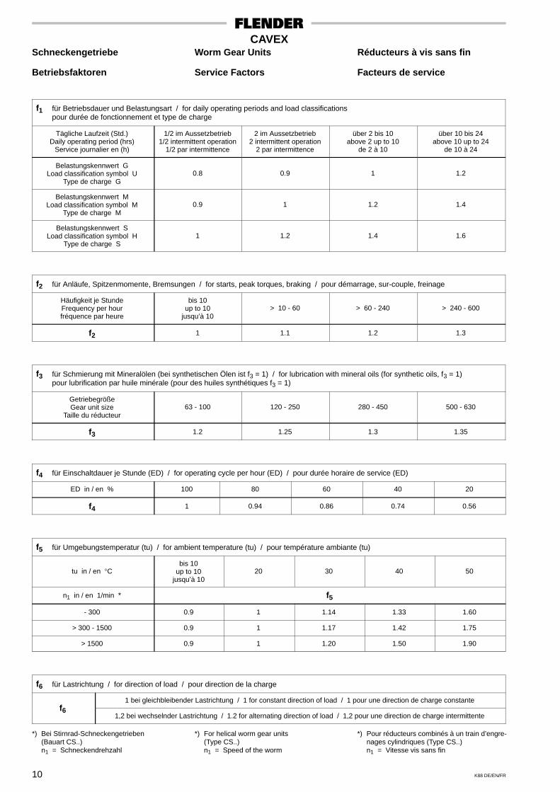
Betriebsfaktoren Service Factors Facteurs de service
f1 für Betriebsdauer und Belastungsart / for daily operating periods and load classificationspour durée de fonctionnement et type de charge
Tägliche Laufzeit (Std.)Daily operating period (hrs)
Service journalier en (h)
1/2 im Aussetzbetrieb1/2 intermittent operation
1/2 par intermittence
2 im Aussetzbetrieb2 intermittent operation
2 par intermittence
über 2 bis 10above 2 up to 10
de 2 à 10
über 10 bis 24above 10 up to 24
de 10 à 24
Belastungskennwert GLoad classification symbol U
Type de charge G0.8 0.9 1 1.2
Belastungskennwert MLoad classification symbol M
Type de charge M0.9 1 1.2 1.4
Belastungskennwert SLoad classification symbol H
Type de charge S1 1.2 1.4 1.6
f2 für Anläufe, Spitzenmomente, Bremsungen / for starts, peak torques, braking / pour démarrage, sur-couple, freinage
Häufigkeit je StundeFrequency per hourfréquence par heure
bis 10up to 10
jusqu’à 10> 10 - 60 > 60 - 240 > 240 - 600
f2 1 1.1 1.2 1.3
f3 für Schmierung mit Mineralölen (bei synthetischen Ölen ist f3 = 1) / for lubrication with mineral oils (for synthetic oils, f3 = 1)pour lubrification par huile minérale (pour des huiles synthétiques f3 = 1)
GetriebegrößeGear unit size
Taille du réducteur63 - 100 120 - 250 280 - 450 500 - 630
f3 1.2 1.25 1.3 1.35
f4 für Einschaltdauer je Stunde (ED) / for operating cycle per hour (ED) / pour durée horaire de service (ED)
ED in / en % 100 80 60 40 20
f4 1 0.94 0.86 0.74 0.56
f5 für Umgebungstemperatur (tu) / for ambient temperature (tu) / pour température ambiante (tu)
tu in / en °Cbis 10
up to 10jusqu’à 10
20 30 40 50
n1 in / en 1/min * f5
- 300 0.9 1 1.14 1.33 1.60
> 300 - 1500 0.9 1 1.17 1.42 1.75
> 1500 0.9 1 1.20 1.50 1.90
f6 für Lastrichtung / for direction of load / pour direction de la charge
1 bei gleichbleibender Lastrichtung / 1 for constant direction of load / 1 pour une direction de charge constantef6
1,2 bei wechselnder Lastrichtung / 1.2 for alternating direction of load / 1,2 pour une direction de charge intermittente
*) Bei Stirnrad-Schneckengetrieben(Bauart CS..)n1 = Schneckendrehzahl
*) For helical worm gear units(Type CS..)n1 = Speed of the worm
*) Pour réducteurs combinés à un train d’engre-nages cylindriques (Type CS..)n1 = Vitesse vis sans fin

11K88 DE/EN/FR
CAVEXSchneckengetriebe
Betriebsfaktoren fürKrananlagen
Beim Einsatz von Getrieben mit veränderlicher Belastung – wie sie bei Krananlagen in der Regel vorliegen – empfiehlt sich eine Einstufung nachFEM. Hierbei können der Arbeitsmaschinenfaktor f1 und der Spitzenmomentfaktor f3 entsprechend der Triebwerksgruppe M1...M8 – Richtwertegemäß nachstehender Tabelle 1 – abhängig von der Beanspruchung (Kollektivklassen L1...L4) und der Betriebsdauer (Betriebsklassen T0...T9) derTabelle 2 auf Seite 14 entnommen werden.Der kubische Mittelwert K zur Berücksichtigung der Lastverteilung bei veränderlicher Belastung in einem repräsentativen Zeitraum t errechnet sichzu:
K = � � • + ... � � •P1
P
3 t1t
Pn
P3 tn
t
3
Hierbei ist P1...Pn der Betriebszyklus im Zeitzyklus t1...tn.
0 10 50 100
1.0
0.4
0.1
t1 t2 t30 16.7 33.3 100
t1 t2 t3
50
t4
1.0
0.733
0.467
0.2
0 50 100
1.0
0.4
t1 t2
0 90 100
1.0
0.8
t1 t2
T1P1
T2P2
T3P3
L1 L2 L3 L4
LastkollektiveLaufzeit
Last
Tabelle 1 Einstufung der Triebwerke in Gruppensiehe FEM 1001 Sektion I
3. Ausgabe, Tabelle T.2.1.3.5
Art des TriebwerkesKranart
BezeichnungAngaben zur Art der
Nutzung (*) HubwerkEinzieh-
WippwerkKatz-
fahrwerkKran-
fahrwerk
Montagekrane M2 - M3 M1 - M2 M1 - M2 M2 - M3
Verladebrücken Haken M5 - M6 - M4 - M5 M5 - M6
Verladebrücken Greifer oder Magnet M7 - M8 - M6 - M7 M7 - M8
Werkstattkrane M6 - M4 M5
Laufkrane, Fallwerkkrane, Schrottplatzkrane Greifer oder Magnet M8 - M6 - M7 M7 - M8
Entladebrücken, Container-PortalkraneAndere Portalkrane (mit Katze und/oder Drehkran)
a) Haken oder Spreaderb) Haken
M6 - M7M4 - M5
M3 - M4-
M6 - M7M4 - M5
M4 - M5M4 - M5
Entladebrücken, Portalkrane(mit Katze und/oder Drehkran) Greifer oder Magnet M8 M3 - M4 M7 - M8 M4 - M5
Hellingkrane, Werftkrane, Demontagekrane Haken M5 - M6 M4 - M5 M4 - M5 M5 - M6
Hafenkrane (drehbar, auf Portal, ...)Schwimmkrane und Schwimmscherenkrane Haken M6 - M7 M5 - M6 - M3 - M4
Hafenkrane (drehbar, auf Portal, ...)Schwimmkrane und Schwimmscherenkrane Greifer oder Magnet M7 - M8 M6 - M7 - M4 - M5
Schwimmkrane und Schwimmscherenkrane fürsehr große Lasten (Gewöhnlich über 100 t) M3 - M4 M3 - M4 - -
Bordkrane Haken M4 M3 - M4 M2 M3
Bordkrane Greifer oder Magnet M5 - M6 M3 - M4 M4 - M5 M3 - M4
Turmkrane für Baustellen M4 M4 M3 M3
Derrick-Krane M2 - M3 M1 - M2 - -
In Zügen zugelassene Eisenbahnkrane M3 - M4 M3 - M3 - -
Fahrzeugkrane Haken M3 - M4 M2 - M3 - -
*) In dieser Rubrik sind nur als Hinweis einige typische Nutzungsarten angegeben.
Der Antriebsmaschinenfaktor f2 kann bei Antrieb durch Elektro- oder Hydromotor mit f2 = 1 vorgesehen werden.Die auf Seite 14 aufgeführten Faktoren sind Erfahrungswerte. Ihre Anwendung setzt für die genannten Maschinen oder Anlagen hierfür allgemeinbekannte Konstruktions- und Belastungsbedingungen voraus. Bei Abweichungen von Normalbedingungen ist Rückfrage erforderlich.Für nicht aufgeführte Arbeitsmaschinen bitten wir um Rückfrage.
12 K88 DE/EN/FR
CAVEXWorm Gear Units
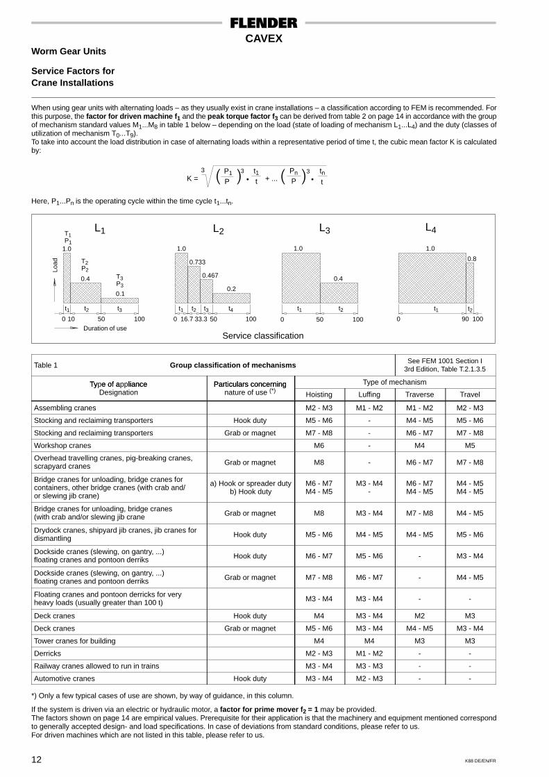
Service Factors forCrane Installations
When using gear units with alternating loads – as they usually exist in crane installations – a classification according to FEM is recommended. Forthis purpose, the factor for driven machine f1 and the peak torque factor f3 can be derived from table 2 on page 14 in accordance with the groupof mechanism standard values M1...M8 in table 1 below – depending on the load (state of loading of mechanism L1...L4) and the duty (classes ofutilization of mechanism T0...T9).To take into account the load distribution in case of alternating loads within a representative period of time t, the cubic mean factor K is calculatedby:
K = � � • + ... � � •P1
P
3 t1t
Pn
P3 tn
t
3
Here, P1...Pn is the operating cycle within the time cycle t1...tn.
Service classificationDuration of use
Load
0 10 50 100
1.0
0.4
0.1
t1 t2 t30 16.7 33.3 100
t1 t2 t3
50
t4
1.0
0.733
0.467
0.2
0 50 100
1.0
0.4
t1 t2
0 90 100
1.0
0.8
t1 t2
T1P1
T2P2
T3P3
L1 L2 L3 L4
Table 1 Group classification of mechanismsSee FEM 1001 Section I
3rd Edition, Table T.2.1.3.5
Type of appliance Particulars concerning Type of mechanismTy e of a lianceDesignation
Particulars concerningnature of use (*) Hoisting Luffing Traverse Travel
Assembling cranes M2 - M3 M1 - M2 M1 - M2 M2 - M3
Stocking and reclaiming transporters Hook duty M5 - M6 - M4 - M5 M5 - M6
Stocking and reclaiming transporters Grab or magnet M7 - M8 - M6 - M7 M7 - M8
Workshop cranes M6 - M4 M5
Overhead travelling cranes, pig-breaking cranes,scrapyard cranes Grab or magnet M8 - M6 - M7 M7 - M8
Bridge cranes for unloading, bridge cranes forcontainers, other bridge cranes (with crab and/or slewing jib crane)
a) Hook or spreader dutyb) Hook duty
M6 - M7M4 - M5
M3 - M4-
M6 - M7M4 - M5
M4 - M5M4 - M5
Bridge cranes for unloading, bridge cranes(with crab and/or slewing jib crane Grab or magnet M8 M3 - M4 M7 - M8 M4 - M5
Drydock cranes, shipyard jib cranes, jib cranes fordismantling Hook duty M5 - M6 M4 - M5 M4 - M5 M5 - M6
Dockside cranes (slewing, on gantry, ...)floating cranes and pontoon derriks Hook duty M6 - M7 M5 - M6 - M3 - M4
Dockside cranes (slewing, on gantry, ...)floating cranes and pontoon derriks Grab or magnet M7 - M8 M6 - M7 - M4 - M5
Floating cranes and pontoon derricks for veryheavy loads (usually greater than 100 t) M3 - M4 M3 - M4 - -
Deck cranes Hook duty M4 M3 - M4 M2 M3
Deck cranes Grab or magnet M5 - M6 M3 - M4 M4 - M5 M3 - M4
Tower cranes for building M4 M4 M3 M3
Derricks M2 - M3 M1 - M2 - -
Railway cranes allowed to run in trains M3 - M4 M3 - M3 - -
Automotive cranes Hook duty M3 - M4 M2 - M3 - -
*) Only a few typical cases of use are shown, by way of guidance, in this column.
If the system is driven via an electric or hydraulic motor, a factor for prime mover f2 = 1 may be provided.The factors shown on page 14 are empirical values. Prerequisite for their application is that the machinery and equipment mentioned correspondto generally accepted design- and load specifications. In case of deviations from standard conditions, please refer to us.For driven machines which are not listed in this table, please refer to us.
13K88 DE/EN/FR
CAVEXRéducteurs à vis sans fin
Facteurs de service pourengins de levage
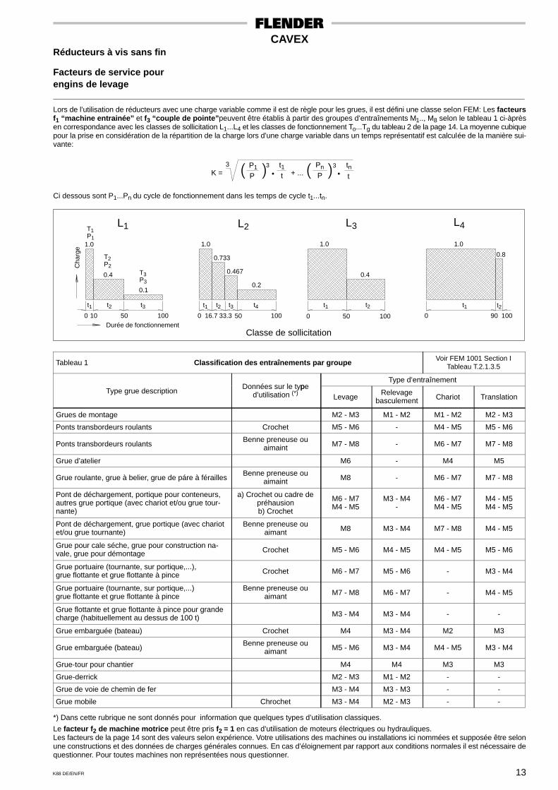
Lors de l’utilisation de réducteurs avec une charge variable comme il est de règle pour les grues, il est défini une classe selon FEM: Les facteursf1 “machine entrainée” et f3 “couple de pointe”peuvent être établis à partir des groupes d’entraînements M1.., M8 selon le tableau 1 ci-àprèsen correspondance avec les classes de sollicitation L1...L4 et les classes de fonctionnement To...Tg du tableau 2 de la page 14. La moyenne cubiquepour la prise en considération de la répartition de la charge lors d’une charge variable dans un temps représentatif est calculée de la manière sui-vante:
K = � � • + ... � � •P1
P
3 t1t
Pn
P3 tn
t
3
Ci dessous sont P1...Pn du cycle de fonctionnement dans les temps de cycle t1...tn.
Classe de sollicitationDurée de fonctionnement
Cha
rge
0 10 50 100
1.0
0.4
0.1
t1 t2 t30 16.7 33.3 100
t1 t2 t3
50
t4
1.0
0.733
0.467
0.2
0 50 100
1.0
0.4
t1 t2
0 90 100
1.0
0.8
t1 t2
T1P1
T2P2
T3P3
L1 L2 L3 L4
Tableau 1 Classification des entraînements par groupeVoir FEM 1001 Section I
Tableau T.2.1.3.5
pType d’entraînement
Type grue descriptionDonnées sur le type
d’utilisation (*) LevageRelevage
basculement Chariot Translation
Grues de montage M2 - M3 M1 - M2 M1 - M2 M2 - M3
Ponts transbordeurs roulants Crochet M5 - M6 - M4 - M5 M5 - M6
Ponts transbordeurs roulantsBenne preneuse ou
aimaint M7 - M8 - M6 - M7 M7 - M8
Grue d’atelier M6 - M4 M5
Grue roulante, grue à belier, grue de páre à féraillesBenne preneuse ou
aimaint M8 - M6 - M7 M7 - M8
Pont de déchargement, portique pour conteneurs,autres grue portique (avec chariot et/ou grue tour-nante)
a) Crochet ou cadre depréhausionb) Crochet
M6 - M7M4 - M5
M3 - M4-
M6 - M7M4 - M5
M4 - M5M4 - M5
Pont de déchargement, grue portique (avec chariotet/ou grue tournante)
Benne preneuse ouaimant M8 M3 - M4 M7 - M8 M4 - M5
Grue pour cale séche, grue pour construction na-vale, grue pour démontage Crochet M5 - M6 M4 - M5 M4 - M5 M5 - M6
Grue portuaire (tournante, sur portique,...),grue flottante et grue flottante à pince Crochet M6 - M7 M5 - M6 - M3 - M4
Grue portuaire (tournante, sur portique,...)grue flottante et grue flottante à pince
Benne preneuse ouaimant M7 - M8 M6 - M7 - M4 - M5
Grue flottante et grue flottante à pince pour grandecharge (habituellement au dessus de 100 t) M3 - M4 M3 - M4 - -
Grue embarguée (bateau) Crochet M4 M3 - M4 M2 M3
Grue embarguée (bateau)Benne preneuse ou
aimant M5 - M6 M3 - M4 M4 - M5 M3 - M4
Grue-tour pour chantier M4 M4 M3 M3
Grue-derrick M2 - M3 M1 - M2 - -
Grue de voie de chemin de fer M3 - M4 M3 - M3 - -
Grue mobile Chrochet M3 - M4 M2 - M3 - -
*) Dans cette rubrique ne sont donnés pour information que quelques types d’utilisation classiques.
Le facteur f2 de machine motrice peut être pris f2 = 1 en cas d’utilisation de moteurs électriques ou hydrauliques.Les facteurs de la page 14 sont des valeurs selon expérience. Votre utilisations des machines ou installations ici nommées et supposée être selonune constructions et des données de charges générales connues. En cas d’éloignement par rapport aux conditions normales il est nécessaire dequestionner. Pour toutes machines non représentées nous questionner.
14 K88 DE/EN/FR
CAVEXSchneckengetriebe Worm Gear Units Réducteurs à vis sans fin
Betriebsfaktoren für Service Factors for Facteurs de service pourKrananlagen Crane Installations engins de levage
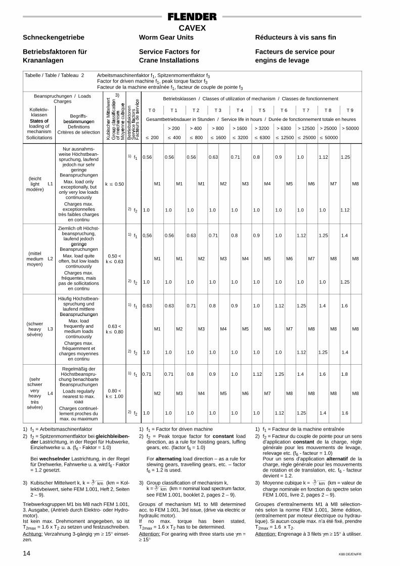
Tabelle / Table / Tableau 2 Arbeitsmaschinenfaktor f1, Spitzenmomentfaktor f3Factor for driven machine f1, peak torque factor f3Facteur de la machine entraînée f1, facteur de couple de pointe f3
Beanspruchungen / LoadsCharges
3)
ert
ion
e ice Betriebsklassen / Classes of utilization of mechanism / Classes de fonctionnement
Kollektiv-itt
elw
ifica
tiom bi
que
ren
rs serv
ic
T 0 T 1 T 2 T 3 T 4 T 5 T 6 T 7 T 8 T 9klassenStates of
Begriffs-bestimmungen er
Mit
lass
ifan
ism
e cu
bfa
kto
fact
o d
e s
Gesamtbetriebsdauer in Stunden / Service life in hours / Durée de fonctionnement totale en heuresStates ofloading of
bestimmungenDefinitions
isch
eup
cla
echa
enne
riebs
fvi
ce fa
teur
s
> 200 > 400 > 800 > 1600 > 3200 > 6300 > 12500 > 25000 > 50000mechanismSollicitations
Critères de sélection
Kub
iG
rou
of m
eM
oye
Bet
riS
erv
Fac
te� 200 � 400 � 800 � 1600 � 3200 � 6300 � 12500 � 25000 � 50000
Nur ausnahms-weise Höchstbean-spruchung, laufend
jedoch nur sehr
1) f1 0.56 0.56 0.56 0.63 0.71 0.8 0.9 1.0 1.12 1.25
(leichtlight
modére)L1
geringeBeanspruchungen
Max. load onlyexceptionally, but
only very low loads
k � 0.50 M1 M1 M1 M2 M3 M4 M5 M6 M7 M8
continuouslyCharges max.
exceptionnellestrès faibles charges
en continu
2) f2 1.0 1.0 1.0 1.0 1.0 1.0 1.0 1.0 1.0 1.12
Ziemlich oft Höchst-beanspruchung,laufend jedoch
geringe
1) f1 0,56 0.56 0.63 0.71 0.8 0.9 1.0 1.12 1.25 1.4
(mittelmediummoyen)
L2
geringeBeanspruchungen
Max. load quiteoften, but low loads
continuously
0.50 <k� 0.63
M1 M1 M2 M3 M4 M5 M6 M7 M8 M8
Charges max.fréquentes, mais
pas de sollicitationsen continu
2) f2 1.0 1.0 1.0 1.0 1.0 1.0 1.0 1.0 1.0 1.25
Häufig Höchstbean-spruchung undlaufend mittlere
Beanspruchungen
1) f1 0.63 0.63 0.71 0.8 0.9 1.0 1.12 1.25 1.4 1.6
(schwerheavy
sévère)L3
Beans ruchungenMax. load
frequently andmedium loadscontinuously
0.63 <k� 0.80
M1 M2 M3 M4 M5 M6 M7 M8 M8 M8
Charges max.fréquemment et
charges moyennesen continu
2) f2 1.0 1.0 1.0 1.0 1.0 1.0 1.0 1.12 1.25 1.4
(sehr
Regelmäßig derHöchstbeanspru-
chung benachbarte1) f1 0.71 0.71 0.8 0.9 1.0 1.12 1.25 1.4 1.6 1.8
schwervery
heavy L4
BeanspruchungenLoads regularlynearest to max.
0.80 <k� 1.00
M2 M3 M4 M5 M6 M7 M8 M8 M8 M8
trèssévère)
loadCharges continuel-lement proches dumax. ou maximum
2) f2 1.0 1.0 1.0 1.0 1.0 1.0 1.12 1.25 1.4 1.6
1) f1 = Arbeitsmaschinenfaktor2) f2 = Spitzenmomentfaktor bei gleichbleiben-
der Lastrichtung, in der Regel für Hubwerke,Einziehwerke u. a. (f6 - Faktor = 1.0)
Bei wechselnder Lastrichtung, in der Regelfür Drehwerke, Fahrwerke u. a. wird f6 - Faktor= 1.2 gesetzt.
3) Kubischer Mittelwert k, k = 3 km (km = Kol-lektivbeiwert, siehe FEM 1.001, Heft 2, Seiten2 – 9).
Triebwerksgruppen M1 bis M8 nach FEM 1.001,3. Ausgabe, (Antrieb durch Elektro- oder Hydro-motor).Ist kein max. Drehmoment angegeben, so istT2max = 1.6 x T2 zu setzen und festzuschreiben.Achtung: Verzahnung 3-gängig γm ≥ 15° einset-zen.
1) f1 = Factor for driven machine2) f2 = Peak torque factor for constant load
direction, as a rule for hoisting gears, luffinggears, etc. (factor f6 = 1.0)
For alternating load direction – as a rule forslewing gears, travelling gears, etc. – factorf6 = 1.2 is used.
3) Group classification of mechanism k,k = 3 km (km = nominal load spectrum factor,see FEM 1.001, booklet 2, pages 2 – 9).
Groups of mechanism M1 to M8 determinedacc. to FEM 1.001, 3rd issue, (drive via electric orhydraulic motor).If no max. torque has been stated,T2max = 1.6 x T2 has to be determined.Attention: For gearing with three starts use γm =≥ 15°
1) f1 = Facteur de la machine entraînée2) f2 = Facteur du couple de pointe pour un sens
d’application constant de la charge, règlegénérale pour les mouvements de levage,relevage etc. (f6 - facteur = 1.0)Pour un sens d’application alternatif de lacharge, règle générale pour les mouvementsde rotation et de translation, etc. f6 - facteurdevient = 1.2.
3) Moyenne cubique k = 3 km (km = valeur decharge nominale en fonction du spectre selonFEM 1.001, livre 2, pages 2 – 9).
Groupes d’entraînements M1 à M8 sélection-nés selon la norme FEM 1.001, 3ème édition,(entraînement par moteur électrique ou hydrau-lique). Si aucun couple max. n’a été fixé, prendreT2max = 1.6 x T2.Attention: Engrenage à 3 filets γm ≥ 15° à utiliser.

15K88 DE/EN/FR
CAVEXSchneckengetriebe Worm Gear Units Réducteurs à vis sans fin
Berechnungsbeispiel Calculation Example Exemple de calcul
Gesucht:CAVEX-Getriebe, Bauart CDA für den Antriebeines Gurtbandförderers für Schüttgut; dasGetriebe soll mit Mineralöl geschmiert werden.
Elektromotor: P1 = 3 kW
Motor-Drehzahl: n1 = 1000/min.
Übersetzung: i ≈ 40
Soll-Drehmoment: T2 = 850 Nm
Max. Abtriebsdrehmoment: T2A = 1750 Nm
Tägliche Betriebsdauer: 16 Stunden
Anläufe je Stunde: 30
Einschaltdauer je Stunde: ED = 40 %
Umgebungstemperatur: bis 40 °C
Lösung:Eine Vorabauswahl mit (1,2 x 850 Nm = 1020 Nm)ergibt auf Seite 20 die Größe 120 mit i = 40,T2N = 1590 Nm, f7 = 0,60, T2max = 2090 Nm undT2max* = 3170 Nm.
Required:CAVEX gear unit type CDA for a belt conveyordrive for bulk material; the gear unit is to be lubri-cated with mineral oil.
Electric motor: P1 = 3 kW
Motor speed: n1 = 1000/min.
Transmission ratio: i ≈ 40
Required torque: T2 = 850 Nm
Max. output torque: T2A = 1750 Nm
Daily operating period: 16 hours
Starts per hour: 30
Operating cycle per hour: ED = 40 %
Ambient temperature: up to 40 °C
Solution:A first selection with (1.2 x 850 Nm = 1020 Nm)results in size 120 with i = 40, T2N = 1590 Nm,f7 = 0.60, T2max = 2090 Nm and T2max* = 3170Nm, as shown on page 20.
On recherche:Un réducteur CAVEX, type CDA pour l’entraîne-ment d’un transporteur à bande pour matières envrac. Le réducteur sera lubrifié par une huileminérale.
Moteur électrique: P1 = 3 kW
Vitesse moteur: n1 = 1000/min.
Rapport: i ≈ 40
Couple nécessaire: T2 = 850 Nm
Couple max. absorbé: T2A = 1750 Nm
Service journalier: 16 hours
Démarrages par heure: 30
Durée horaire de service: ED = 40 %
Température ambiante: jusqu’à 40 °C
Solution:Un choix préliminaire est effectué avec (1,2 x 850Nm = 1020 Nm). De la page 20 on obtient la taille120 avec i = 40, T2N = 1590 Nm, f7 = 0,60,T2max = 2090 Nm et T2max* = 3170 Nm.
Damit ist das Getriebe zu überprüfen für:
Belastungswert M (über 10 Std.) f1 = 1,4
Anlaufhäufigkeit: 30 Anläufe/Std. f2 = 1,1
Mineralöl f3 = 1,25
Einschaltdauer: ED = 40 % f4 = 0,74
Umgebungstemperatur: bis 40 °C f5 = 1,42
Lastrichtung gleichbleibend f6 = 1
und f7 = 0,60
Thus, the gear unit has to be checked for:
Load classification M (above 10 hrs) f1 = 1.4
Starting frequency: 30 starts/hour f2 = 1.1
Mineral oil f3 = 1.25
Operating cycle per hour: ED = 40 % f4 = 0.74
Ambient temperature: up to 40 °C f5 = 1.42
Constant direction of load f6 = 1
and f7 = 0.60
Ensuite le réducteur est verifié avec les facteurssuivants:
Faux de charge M (sup. à 10 h) f1 = 1,4
Fréquence de démarrage: 30/h f2 = 1,1
Huile minérale f3 = 1,25
Durée horaire de service: ED = 40 % f4 = 0,74
Température ambiante: jusqu’à 40 °C f5 = 1,42
Direction de la charge dans f6 = 1le même sens
et f7 = 0,60
I) T2N = 1590 ≥ 850 x 1.4 x 1.1 x 1.25 = 1636
II) T2N = 1590 ≥ 850 x 1.25 x 0.74 x 1.42 x 0.60 = 670
III) T2max = 2090 ≥ 1750 x 1.1 x 1.25 = 2406
IV) T2max* = 3170 ≥ 1750 x 1.1 x 1 = 1925
Die Bedingungen I und III sind nicht erfüllt; dahermuß synthetisches Öl oder die Größe 140 ge-wählt werden.
Conditions I and III have not been fulfilled; there-fore, either synthetic oil or size 140 is to beselected.
Le conditions I et III ne sont pas remplies; d’oùune huile synthétique ou la taille 140 doit êtrechoisie.
16 K88 DE/EN/FR
CAVEXSchneckengetriebe Worm Gear Units Réducteurs à vis sans fin
Allgemeine Hinweise General Information Exécution standardBestellangaben Ordering Details Données pour la commande
Normalausführung
Rechtssteigende Verzahnung
Hohlwellen mit Paßfedernut nach DIN 6885 Teil 1und an der Seite des Abschlußdeckels mit Ring-nut nach DIN 472.
Wellenenden mit Paßfeder nach DIN 6885 Teil 1Form A und mit Zentrierbohrungen nach DIN 332Form DS, geeignet für beide Drehrichtungen.
Angeflanschte IEC-Motoren sind Drehstrom-Käfigläufer-Motoren für 50 Hz, bis 2,2 kW 220 VDreieck / 380 V Stern, ab 3 kW 380 V Dreieck,
Schutzart IP 44 nach DIN 40 050Isolationsklasse B nach VDE 0530Klemmenkasten am Motor und der Motor selbersind jeweils um 90° drehbar.
Ablieferungszustand bei Normalausführung
Wellenenden sind mit Rostschutzanstrich ver-sehen. Er ist seewasser- und tropenfest für dieDauer eines Jahres. Der Außenanstrich istbeständig gegen Säuren, schwache Alkalien,Öle und Lösungsmittel. Er ist tropen- und see-wasserfest, temperaturbeständig bis 140 °C undentspricht dem Farbton RAL 5015 himmelblau.
Alle Fettschmierstellen sind mit Schmierstoffversehen, und auch die Erstbefüllung desGetriebes mit synthetischem Öl (Langzeit-schmierung) ist durchgeführt. Wenn die Erst-befüllung ausdrücklich nicht gewünscht wird,werden die Getriebeinnenteile konserviert fürnormale Transportbedingungen – auch Übersee-transport – und einen Zeitraum von 6 Monaten.
Abbildungen, Maße und Gewichte
Gleichartige Drehrichtungspfeile in den Abbildun-gen kennzeichnen die Abhängigkeit der Dreh-richtung bei rechtssteigender Verzahnung.
Die angegebenen Gewichte sind unverbindlicheMittelwerte; die Abbildungen sind nicht strengverbindlich. Maßänderungen sowie Änderungentechnischer Angaben sind möglich.
Wir behalten uns vor, die Getriebe ohne Lüfterauszuführen.
Erforderliche Angaben für die Bestellung
Beschreibung der Belastungs- und Umgebungs-verhältnisse, mindestens jedoch n1 und T2.
Gewählte Bauart, Größe und Übersetzung
Ausführung und Einbaulage entsprechend demzugehörigen Maßblatt.
Zusätzlich bei angebautem Motor:
Größe der Kupplung sowie Größe, Bauform,Schutzart, Leistung, Drehzahl, Spannung undFrequenz des Motors.
Falls keine Erstbefüllung gewünscht wird, ist die-ses ausdrücklich zu erwähnen mit dem Hinweis:
ohne Ölfüllung, vorgesehen ist synthetisches Öl,oder ohne Ölfüllung, vorgesehen ist Mineralöl.
Standard design
RH gearing
Hollow shafts with parallel keyway acc. to DIN6885/1 and at the side of the end cover with ringgroove acc. to DIN 472.
Shaft ends with parallel key acc. to DIN 6885/1form A and with centre holes acc. to DIN 332form DS, suitable for both directions of rotation.
Flanged-on IEC motors are three-phase squirrel-cage motors for 50 Hz up to 2.2 kW, 220 V deltaconnection / 380 V star connection, from 3 kW up380 V delta connection;Type of protection IP 44 acc. to DIN 40050;Insulation class B acc. to VDE 0530;Terminal box on the motor and the motor itself areeach rotatable through 90°.
State at time of supply for standard designThe shaft ends are coated with a rust inhibitorwhich is resistant to sea water and tropical condi-tions for one year. The outside coating is resistantto acids, weak alkalis, oils and solvents, sea waterand tropical conditions, and can withstand tempe-ratures up to 140 °C; standard colour RAL 5015sky blue.
All lubricating points are provided with lubricant.The gear unit is filled at the factory with its synthe-tic oil filling (long term lubrication). Should thecustomer expressly require that the gear unit issupplied without oil filling, the internal compo-nents are protected against corrosion for normaltransport conditions – overseas shipment in- cluded – and a period of six months.
Illustrations, dimensions and weights
Equal arrows in drawings show the relative direc-tion of rotation for right hand gearing.
The weights shown are mean values and, like theillustrations, are not strictly binding. Changes indimensions and technical specifications are pos-sible without prior notice due to further technicaldevelopment.
We reserve the right to supply the gear unitswithout fan.
Ordering details
Description of the load and ambient conditions, atleast, however, n1 and T2.
Chosen type, size, and transmission ratio
Design and mounting position according to therespective dimensioned drawing.
Additionally for a flange-mounted motor:
Size of coupling; size and type of motor, type ofprotection, power rating, speed, voltage and fre-quency.
If the gear unit is required without its initial oilfilling, this must be expressly stated in the orderas follows:
Either: Without oil filling; operation with syntheticoil is intended. Or: Without oil filling; operationwith mineral oil is intended.
Exécution standard
Engrenages avec sens d’hélice à droite
Arbres creux avec rainure pour clavettes selonDIN 6885/1 et côté couvercle avec rainure sup-plémentaire pour circlips selon DIN 472.
Bouts d’arbre avec clavettes selon DIN 6885/1forme A et avec centrages selon DIN 332 formeDS (avec taraudage). Convient pour les deuxsens de rotation.
Les moteurs bridés IEC sont des moteursasynchrone à cage, 50 Hz jusqu’à 2.2 kW 220 Vtriangle / 380V étoile, à partir de 3 kW 380 Vtriangle.Protection IP 44 selon DIN 40050Isolation classe B selon VDE 0530Boîtes à bornes orientables 90°.
Etat de livraison pour exécution standardLes bouts d’arbre sont protégés par une coucheanti-rouille. Elle est prévue pour résister à l’eau demer et au climat tropical pendant un an. La pein-ture extérieure résiste aux acides, alcalins fai-bles, huiles et solvants. Elle résiste à l’eau de mer,aux influences du climat tropical, et des tempéra-tures jusqu’à 140 °C. Sa couleur bleu ciel corres-pond au ton RAL 5015.
Le remplissage de tous les graisseurs est faitavant expédition, ainsi que le premier remplis-sage des carters avec une huile synthétique(graissage longue durée). Au cas où le premierremplissage n’est pas souhaité par le client nousprotégeons l’intérieur du réducteur contre lacorrosion. Cette protection est suffisante pour untransport normal (y compris le transport maritime)et pour une durée de six mois jusqu’à la premièremise en service.
Illustrations, côtes et poids
Les flèches semblables dans les illustrations indi-quent la correspondance des sens de rotationpour des engrenages dont le sens d’hélice est àdroite.
Les poids indiqués dans les tableaux sont desvaleurs indicatives. Les illustrations sont sansengagement. Nous nous réservons tous droits demodification des côtes et données techniques.
Nous exécutons eventuellement, si les conditionsde service le permettent, les réducteurs sansventilateur.
Données indispensables lors de la com-mande:Déscriptions des charges et du milieu ambiant,mais au minimum n1 et T2.
Type choisi, taille et rapport
Exécution et position de montage d’après lesfeuilles d’encombrement correspondantes.
De plus pour les moto-réducteurs:
Taille de l’accouplement ainsi que taille, exécu-tion, type de protection, puissance, vitesse, ten-sion et fréquence du moteur électrique.
Au cas où le premier remplissage du réducteurpar nos soins n’est pas souhaité par le client, ilfaut le mentionner expressément avec la remar-que suivante:
Sans remplissage d’huile, prévu pour huile syn-thétique, ou: sans remplissage d’huile, prévupour huile minérale.

ab Vorrat ex stock en stock
17K88 DE/EN/FR
CAVEX Größe / Size / Taille 63Schneckengetriebe, einstufig Worm Gear Units, Réducteurs à train
Single Stage d’engrenage unique
Leistungen und Drehmomente Power Ratings and Torques Puissances et couples
Übersetzungen i, Steigungswinkel γm, Drehzahlen n1 und n2, Antriebsleistung P1N, Abtriebsdrehmomente T2N und T2max, Faktor f7Transmission ratios i, lead angles γm, speeds n1 and n2, input power rating P1N, output torques T2N and T2max, factor f7Rapports i, angle d’hélice γm, vitesse n1 et n2, puissances d’entrée P1N, couples de sortie T2N et T2max, facteur f7
i n1 n2 P1N T2N T2max
γm 1/min kW Nmf7
3000 581 6.41 101 174
2400 465 6.20 122 202
1800 348 5.76 150 238
1500 290 5.39 168 261
1200 232 4.88 189 2875.17 1000 194 4.44 206 307
ca. 750 145 3.75 230 336 0.53
ca.32 ° 500 96.8 2.84 259 370
300 58.1 1.91 286 402
150 29.0 1.04 309 429
60 11.6 0.446 325 446
10 1.94 0.081 334 456
3000 455 5.75 115 189
2400 364 5.48 137 217
1800 273 4.99 165 253
1500 227 4.62 183 275
6.6 1200 182 4.14 203 3016.6 1000 152 3.74 219 320
ca.°
750 114 3.12 242 348 0.53
27 ° 500 75.8 2.34 269 379
300 45.5 1.56 294 408
150 22.7 0.843 315 433
60 9.09 0.358 328 449
10 1.52 0.065 336 458
3000 364 5.22 130 204
2400 291 4.92 152 233
1800 218 4.42 181 269
1500 182 4.06 199 291
8.25 1200 145 3.61 219 3168.25 1000 121 3.25 235 336
ca.°
750 90.9 2.69 257 362 0.53
22 ° 500 60.6 2.00 283 393
300 36.4 1.32 307 421
150 18.2 0.712 327 444
60 7.27 0.302 339 460
10 1.21 0.055 347 468
3000 290 4.66 144 217
2400 232 4.36 167 246
1800 174 3.88 196 283
1500 145 3.55 214 305
10.33 1200 116 3.14 235 33010.33 1000 96.8 2.81 251 349
ca.°
750 72.6 2.32 273 376 0.53
18 ° 500 48.4 1.72 298 406
300 29.0 1.14 322 434
150 14.5 0.610 341 457
60 5.81 0.259 354 472
10 0.968 0.048 361 481
i n1 n2 P1N T2N T2max
γm 1/min kW Nmf7
3000 237 3.89 145 215
2400 189 3.59 167 242
1800 142 3.17 194 276
1500 118 2.88 210 296
1200 94.7 2.53 229 31912.67 1000 78.9 2.26 243 336
ca. 750 59.2 1.85 263 360 0.53
ca.16 ° 500 39.5 1.36 285 387
300 23.7 0.894 305 411
150 11.8 0.479 322 431
60 4.74 0.203 333 444
10 0.789 0.038 339 452
3000 194 3.67 165 235
2400 155 3.39 189 265
1800 116 2.98 218 301
1500 96.8 2.71 236 323
15.5 1200 77.4 2.38 257 34815.5 1000 64.5 2.12 272 367
ca.°
750 48.4 1.74 294 392 0.53
12 ° 500 32.3 1.29 318 422
300 19.4 0.847 340 449
150 9.68 0.454 359 471
60 3.87 0.194 371 485
10 0.645 0.036 377 493
3000 154 2.98 166 232
2400 123 2.72 188 260
1800 92.3 2.37 215 293
1500 76.9 2.15 231 313
19.5 1200 61.5 1.88 250 33619.5 1000 51.3 1.67 263 352
ca.°
750 38.5 1.36 282 376 0.53
10 ° 500 25.6 1.00 304 402
300 15.4 0.657 323 425
150 7.69 0.352 339 445
60 3.08 0.150 349 457
10 0.513 0.029 355 464
3000 122 2.37 162 224
2400 98.0 2.15 182 249
1800 73.5 1.86 207 280
1500 61.2 1.68 222 298
24.5 1200 49.0 1.47 238 31924.5 1000 40.8 1.30 250 334
ca.°
750 30.6 1.06 267 354 0.53
8.8 ° 500 20.4 0.780 286 378
300 12.2 0.509 303 399
150 6.12 0.273 317 416
60 2.45 0.117 326 427
10 0.408 0.022 330 431
i n1 n2 P1N T2N T2max
γm 1/min kW Nmf7
3000 96.8 2.30 191 254 0.57
2400 77.4 2.10 214 284 0.54
1800 58.1 1.83 244 320
1500 48.4 1.66 262 341
1200 38.7 1.46 282 36631 1000 32.3 1.30 297 384
ca. 750 24.2 1.07 317 409ca.6.1 ° 500 16.1 0.796 341 438
0.53
300 9.68 0.528 362 464
150 4.84 0.285 379 485
60 1.94 0.123 391 498
10 0.323 0.024 397 506
3000 76.9 1.85 187 247 0.56
2400 61.5 1.68 209 274
1800 46.2 1.46 236 307
1500 38.5 1.32 252 327
39 1200 30.8 1.16 270 34939 1000 25.6 1.03 283 366
ca.°
750 19.2 0.847 302 388 0.535.2 ° 500 12.8 0.630 323 414
0.53
300 7.69 0.416 341 437
150 3.85 0.225 357 456
60 1.54 0.098 367 468
10 0.256 0.020 372 475
3000 61.2 1.48 181 238 0.54
2400 49.0 1.34 201 263
1800 36.7 1.16 226 293
1500 30.6 1.05 240 311
49 1200 24.5 0.918 257 33149 1000 20.4 0.817 269 346
ca.°
750 15.3 0.672 285 366 0.534.4 ° 500 10.2 0.500 304 389
0.53
300 6.12 0.330 321 410
150 3.06 0.179 334 426
60 1.22 0.078 343 437
10 0.204 0.016 348 443
3000 49.2 1.19 175 228
2400 39.3 1.08 193 251
1800 29.5 0.934 216 279
1500 24.6 0.844 229 296
61 1200 19.7 0.739 244 31461 1000 16.4 0.657 255 327
ca.°
750 12.3 0.541 270 346 0.53
3.8 ° 500 8.20 0.393 279 357
300 4.92 0.247 280 358
150 2.46 0.129 281 358
60 0.984 0.056 281 358
10 0.164 0.011 281 359
Bei den Einbaulagen VU und VO (Schnecke vertikal)mit Drehzahl n2 ≥ 360/min ist Rückfrage erforderlich.
For mounting positions VU and VO (worm vertical)with speed n2 ≥ 360/min, please refer to us.
Pour les positions de montage VU et VO (arbre-visverticale) avec vitesses de rotation n2 ≥ 360/min,veuillez nous consulter.

ab Vorrat ex stock en stock
18 K88 DE/EN/FR
CAVEX Größe / Size / Taille 80Schneckengetriebe, einstufig Worm Gear Units, Réducteurs à train
Single Stage d’engrenage unique
Leistungen und Drehmomente Power Ratings and Torques Puissances et couples
Übersetzungen i, Steigungswinkel γm, Drehzahlen n1 und n2, Antriebsleistung P1N, Abtriebsdrehmomente T2N und T2max, Faktor f7Transmission ratios i, lead angles γm, speeds n1 and n2, input power rating P1N, output torques T2N and T2max, factor f7Rapports i, angle d’hélice γm, vitesse n1 et n2, puissances d’entrée P1N, couples de sortie T2N et T2max, facteur f7
i n1 n2 P1N T2N T2max
γm 1/min kW Nmf7
3000 581 11.4 180 310
2400 465 11.1 219 365
1800 348 10.5 274 437
1500 290 9.90 310 484
1200 232 9.07 353 5395.17 1000 194 8.32 388 582
ca. 750 145 7.09 439 645 0.53
ca.33 ° 500 96.8 5.44 501 720
300 58.1 3.70 561 792
150 29.0 2.05 614 855
60 11.6 0.879 649 897
10 1.94 0.160 671 922
3000 455 10.3 207 342
2400 364 9.93 249 397
1800 273 9.18 305 471
1500 227 8.58 341 517
6.6 1200 182 7.76 384 5716.6 1000 152 7.06 417 613
ca.°
750 114 5.95 466 673 0.53
27 ° 500 75.8 4.51 525 745
300 45.5 3.03 581 812
150 22.7 1.66 629 870
60 9.09 0.710 661 908
10 1.52 0.129 680 931
3000 364 9.35 234 370
2400 291 8.91 277 427
1800 218 8.13 335 501
1500 182 7.55 371 547
8.25 1200 145 6.77 415 6018.25 1000 121 6.12 448 643
ca.°
750 90.9 5.12 496 702 0.53
23 ° 500 60.6 3.85 553 772
300 36.4 2.57 607 838
150 18.2 1.40 653 894
60 7.27 0.598 684 930
10 1.21 0.109 702 952
3000 290 8.22 255 387
2400 232 7.77 299 444
1800 174 7.02 358 518
1500 145 6.48 394 564
10.33 1200 116 5.78 437 61710.33 1000 96.8 5.21 470 658
ca.°
750 72.6 4.33 517 717 0.53
18 ° 500 48.4 3.24 573 785
300 29.0 2.16 625 848
150 14.5 1.17 670 903
60 5.81 0.501 700 938
10 0.968 0.093 717 959
i n1 n2 P1N T2N T2max
γm 1/min kW Nmf7
3000 237 6.96 262 389
2400 189 6.51 304 444
1800 142 5.82 360 514
1500 118 5.34 393 556
1200 94.7 4.73 433 60612.67 1000 78.9 4.24 463 644
ca. 750 59.2 3.50 506 697 0.53
ca.16 ° 500 39.5 2.60 557 759
300 23.7 1.73 603 816
150 11.8 0.931 643 864
60 4.74 0.398 668 896
10 0.789 0.074 683 914
3000 194 6.44 292 418 0.55
2400 155 6.01 338 476
1800 116 5.35 397 551
1500 96.8 4.91 434 596
15.5 1200 77.4 4.35 476 64915.5 1000 64.5 3.90 509 689
ca.°
750 48.4 3.22 555 746 0.5312 ° 500 32.3 2.40 610 813
0.53
300 19.4 1.59 660 874
150 9.68 0.863 703 927
60 3.87 0.371 730 961
10 0.645 0.070 747 981
3000 154 5.34 300 423 0.56
2400 123 4.94 344 479 0.54
1800 92.3 4.36 400 549
1500 76.9 3.98 434 591
19.5 1200 61.5 3.50 474 64119.5 1000 51.3 3.12 504 678
ca.°
750 38.5 2.57 546 73011 ° 500 25.6 1.90 595 791
0.53
300 15.4 1.26 640 846
150 7.69 0.680 678 893
60 3.08 0.292 702 923
10 0.513 0.056 717 941
3000 122 4.27 297 412 0.56
2400 98.0 3.92 337 464
1800 73.5 3.44 388 528
1500 61.2 3.12 419 567
24.5 1200 49.0 2.73 455 61124.5 1000 40.8 2.43 482 645
ca.°
750 30.6 1.99 519 692 0.539.2 ° 500 20.4 1.47 562 745
0.53
300 12.2 0.974 602 794
150 6.12 0.523 634 835
60 2.45 0.225 656 862
10 0.408 0.043 668 876
i n1 n2 P1N T2N T2max
γm 1/min kW Nmf7
3000 96.8 4.02 339 454 0.64
2400 77.4 3.71 386 513 0.61
1800 58.1 3.28 445 587 0.57
1500 48.4 3.00 482 632 0.55
1200 38.7 2.64 524 68431 1000 32.3 2.36 556 724
ca. 750 24.2 1.95 602 780ca.6.2 ° 500 16.1 1.46 655 845
300 9.68 0.977 703 905 0.53
150 4.84 0.531 745 956
60 1.94 0.232 771 989
10 0.323 0.046 787 1010
3000 76.9 3.31 342 455 0.64
2400 61.5 3.04 387 510 0.61
1800 46.2 2.68 443 581 0.57
1500 38.5 2.43 477 623 0.54
39 1200 30.8 2.14 517 67239 1000 25.6 1.91 546 709
ca.°
750 19.2 1.57 588 7615.4 ° 500 12.8 1.17 636 820
300 7.69 0.785 680 875 0.53
150 3.85 0.426 717 920
60 1.54 0.186 741 950
10 0.256 0.038 755 967
3000 61.2 2.63 331 437 0.62
2400 49.0 2.41 372 489 0.59
1800 36.7 2.12 424 553 0.54
1500 30.6 1.92 455 592
49 1200 24.5 1.68 490 63649 1000 20.4 1.50 517 669
ca.°
750 15.3 1.23 554 7164.6 ° 500 10.2 0.919 597 769 0.53
300 6.12 0.617 636 817
0.53
150 3.06 0.334 668 857
60 1.22 0.147 689 883
10 0.204 0.030 701 899
3000 49.2 2.12 320 419 0.60
2400 39.3 1.94 358 467 0.57
1800 29.5 1.70 405 526
1500 24.6 1.53 433 562
61 1200 19.7 1.34 466 60261 1000 16.4 1.20 490 633
ca.°
750 12.3 0.987 524 6753.9 ° 500 8.20 0.735 562 723
0.53
300 4.92 0.469 568 729
150 2.46 0.244 569 730
60 0.984 0.105 570 730
10 0.164 0.022 570 731
Bei den Einbaulagen VU und VO (Schnecke vertikal)mit Drehzahl n2 ≥ 340/min ist Rückfrage erforderlich.
For mounting positions VU and VO (worm vertical)with speed n2 ≥ 340/min, please refer to us.
Pour les positions de montage VU et VO (arbre-visverticale) avec vitesses de rotation n2 ≥ 340/min,veuillez nous consulter.
ab Vorrat ex stock en stock
19K88 DE/EN/FR
CAVEX Größe / Size / Taille 100Schneckengetriebe, einstufig Worm Gear Units, Réducteurs à train
Single Stage d’engrenage unique
Leistungen und Drehmomente Power Ratings and Torques Puissances et couples
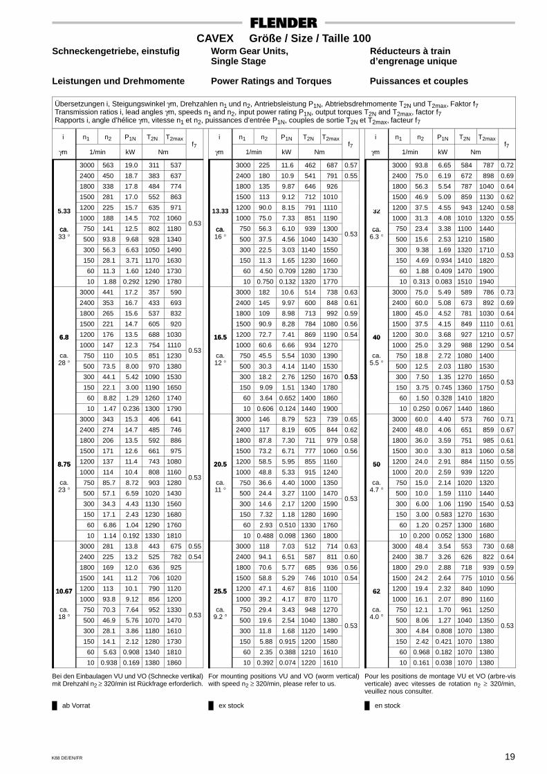
Übersetzungen i, Steigungswinkel γm, Drehzahlen n1 und n2, Antriebsleistung P1N, Abtriebsdrehmomente T2N und T2max, Faktor f7Transmission ratios i, lead angles γm, speeds n1 and n2, input power rating P1N, output torques T2N and T2max, factor f7Rapports i, angle d’hélice γm, vitesse n1 et n2, puissances d’entrée P1N, couples de sortie T2N et T2max, facteur f7
i n1 n2 P1N T2N T2max
γm 1/min kW Nmf7
3000 563 19.0 311 537
2400 450 18.7 383 637
1800 338 17.8 484 774
1500 281 17.0 552 863
1200 225 15.7 635 9715.33 1000 188 14.5 702 1060
ca. 750 141 12.5 802 1180 0.53
ca.33 ° 500 93.8 9.68 928 1340
300 56.3 6.63 1050 1490
150 28.1 3.71 1170 1630
60 11.3 1.60 1240 1730
10 1.88 0.292 1290 1780
3000 441 17.2 357 590
2400 353 16.7 433 693
1800 265 15.6 537 832
1500 221 14.7 605 920
6.8 1200 176 13.5 688 10306.8 1000 147 12.3 754 1110
ca.°
750 110 10.5 851 1230 0.53
28 ° 500 73.5 8.00 970 1380
300 44.1 5.42 1090 1530
150 22.1 3.00 1190 1650
60 8.82 1.29 1260 1740
10 1.47 0.236 1300 1790
3000 343 15.3 406 641
2400 274 14.7 485 746
1800 206 13.5 592 886
1500 171 12.6 661 975
8.75 1200 137 11.4 743 10808.75 1000 114 10.4 808 1160
ca.°
750 85.7 8.72 903 1280 0.53
23 ° 500 57.1 6.59 1020 1430
300 34.3 4.43 1130 1560
150 17.1 2.43 1230 1680
60 6.86 1.04 1290 1760
10 1.14 0.192 1330 1810
3000 281 13.8 443 675 0.55
2400 225 13.2 525 782 0.54
1800 169 12.0 636 925
1500 141 11.2 706 1020
10.67 1200 113 10.1 790 112010.67 1000 93.8 9.12 856 1200
ca.°
750 70.3 7.64 952 133018 ° 500 46.9 5.76 1070 1470
0.53
300 28.1 3.86 1180 1610
150 14.1 2.12 1280 1730
60 5.63 0.908 1340 1810
10 0.938 0.169 1380 1860
i n1 n2 P1N T2N T2max
γm 1/min kW Nmf7
3000 225 11.6 462 687 0.57
2400 180 10.9 541 791 0.55
1800 135 9.87 646 926
1500 113 9.12 712 1010
1200 90.0 8.15 791 111013.33 1000 75.0 7.33 851 1190
ca. 750 56.3 6.10 939 1300ca.16 ° 500 37.5 4.56 1040 1430
0.53
300 22.5 3.03 1140 1550
150 11.3 1.65 1230 1660
60 4.50 0.709 1280 1730
10 0.750 0.132 1320 1770
3000 182 10.6 514 738 0.63
2400 145 9.97 600 848 0.61
1800 109 8.98 713 992 0.59
1500 90.9 8.28 784 1080 0.56
16.5 1200 72.7 7.41 869 1190 0.5416.5 1000 60.6 6.66 934 1270
ca.°
750 45.5 5.54 1030 139012 ° 500 30.3 4.14 1140 1530
300 18.2 2.76 1250 1670 0.53
150 9.09 1.51 1340 1780
0.53
60 3.64 0.652 1400 1860
10 0.606 0.124 1440 1900
3000 146 8.79 523 739 0.65
2400 117 8.19 605 844 0.62
1800 87.8 7.30 711 979 0.58
1500 73.2 6.71 777 1060 0.56
20.5 1200 58.5 5.95 855 116020.5 1000 48.8 5.33 915 1240
ca.°
750 36.6 4.40 1000 135011 ° 500 24.4 3.27 1100 1470
300 14.6 2.17 1200 1590 0.53
150 7.32 1.18 1280 1690
60 2.93 0.510 1330 1760
10 0.488 0.098 1360 1800
3000 118 7.03 512 714 0.63
2400 94.1 6.51 587 811 0.60
1800 70.6 5.77 685 936 0.56
1500 58.8 5.29 746 1010 0.54
25.5 1200 47.1 4.67 816 110025.5 1000 39.2 4.17 870 1170
ca.°
750 29.4 3.43 948 12709.2 ° 500 19.6 2.54 1040 1380
300 11.8 1.68 1120 1490 0.53
150 5.88 0.915 1200 1580
60 2.35 0.388 1210 1610
10 0.392 0.074 1220 1610
i n1 n2 P1N T2N T2max
γm 1/min kW Nmf7
3000 93.8 6.65 584 787 0.72
2400 75.0 6.19 672 898 0.69
1800 56.3 5.54 787 1040 0.64
1500 46.9 5.09 859 1130 0.62
1200 37.5 4.55 943 1240 0.5832 1000 31.3 4.08 1010 1320 0.55
ca. 750 23.4 3.38 1100 1440ca.6.3 ° 500 15.6 2.53 1210 1580
300 9.38 1.69 1320 1710
150 4.69 0.934 1410 1820 0.53
60 1.88 0.409 1470 1900
10 0.313 0.083 1510 1940
3000 75.0 5.49 589 786 0.73
2400 60.0 5.08 673 892 0.69
1800 45.0 4.52 781 1030 0.64
1500 37.5 4.15 849 1110 0.61
40 1200 30.0 3.68 927 1210 0.5740 1000 25.0 3.29 988 1290 0.54
ca.°
750 18.8 2.72 1080 14005.5 ° 500 12.5 2.03 1180 1530
300 7.50 1.35 1270 1650
150 3.75 0.745 1360 1750 0.53
60 1.50 0.328 1410 1820
10 0.250 0.067 1440 1860
3000 60.0 4.40 573 760 0.71
2400 48.0 4.06 651 859 0.67
1800 36.0 3.59 751 985 0.61
1500 30.0 3.30 813 1060 0.58
50 1200 24.0 2.91 884 1150 0.5550 1000 20.0 2.59 939 1220
ca.°
750 15.0 2.14 1020 13204.7 ° 500 10.0 1.59 1110 1440
300 6.00 1.06 1190 1540 0.53
150 3.00 0.583 1270 1630
0.53
60 1.20 0.257 1300 1680
10 0.200 0.052 1300 1680
3000 48.4 3.54 553 730 0.68
2400 38.7 3.26 626 822 0.64
1800 29.0 2.88 718 939 0.59
1500 24.2 2.64 775 1010 0.56
62 1200 19.4 2.32 840 109062 1000 16.1 2.07 890 1160
ca.°
750 12.1 1.70 961 12504.0 ° 500 8.06 1.27 1040 1350
300 4.84 0.808 1070 1380 0.53
150 2.42 0.421 1070 1380
60 0.968 0.182 1070 1380
10 0.161 0.038 1070 1380
Bei den Einbaulagen VU und VO (Schnecke vertikal)mit Drehzahl n2 ≥ 320/min ist Rückfrage erforderlich.
For mounting positions VU and VO (worm vertical)with speed n2 ≥ 320/min, please refer to us.
Pour les positions de montage VU et VO (arbre-visverticale) avec vitesses de rotation n2 ≥ 320/min,veuillez nous consulter.
ab Vorrat ex stock en stock
20 K88 DE/EN/FR
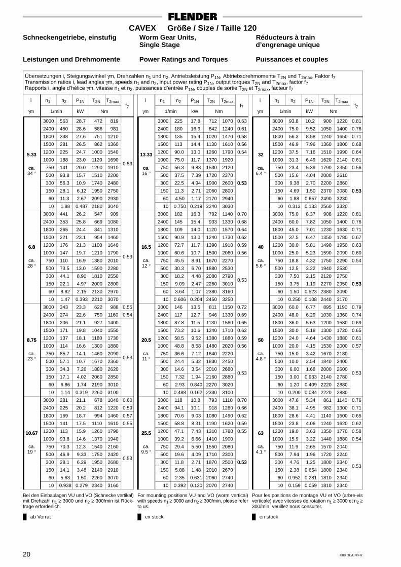
CAVEX Größe / Size / Taille 120Schneckengetriebe, einstufig Worm Gear Units, Réducteurs à train
Single Stage d’engrenage unique
Leistungen und Drehmomente Power Ratings and Torques Puissances et couples
Übersetzungen i, Steigungswinkel γm, Drehzahlen n1 und n2, Antriebsleistung P1N, Abtriebsdrehmomente T2N und T2max, Faktor f7Transmission ratios i, lead angles γm, speeds n1 and n2, input power rating P1N, output torques T2N and T2max, factor f7Rapports i, angle d’hélice γm, vitesse n1 et n2, puissances d’entrée P1N, couples de sortie T2N et T2max, facteur f7
i n1 n2 P1N T2N T2max
γm 1/min kW Nmf7
3000 563 28.7 472 819
2400 450 28.6 586 981
1800 338 27.6 751 1210
1500 281 26.5 862 1360
1200 225 24.7 1000 15405.33 1000 188 23.0 1120 1690
ca. 750 141 20.0 1290 1910 0.53
ca.34 ° 500 93.8 15.7 1510 2200
300 56.3 10.9 1740 2480
150 28.1 6.12 1950 2750
60 11.3 2.67 2090 2930
10 1.88 0.487 2180 3040
3000 441 26.2 547 909
2400 353 25.8 669 1080
1800 265 24.4 841 1310
1500 221 23.1 954 1460
6.8 1200 176 21.3 1100 16406.8 1000 147 19.7 1210 1790
ca.°
750 110 16.9 1380 2010 0.53
28 ° 500 73.5 13.0 1590 2280
300 44.1 8.90 1810 2550
150 22.1 4.97 2000 2800
60 8.82 2.15 2130 2970
10 1.47 0.393 2210 3070
3000 343 23.3 622 988 0.55
2400 274 22.6 750 1160 0.54
1800 206 21.1 927 1400
1500 171 19.8 1040 1550
8.75 1200 137 18.1 1180 17308.75 1000 114 16.6 1300 1880
ca.°
750 85.7 14.1 1460 209023 ° 500 57.1 10.7 1670 2360
0.53
300 34.3 7.26 1880 2620
150 17.1 4.02 2060 2850
60 6.86 1.74 2190 3010
10 1.14 0.319 2260 3100
3000 281 21.1 678 1040 0.60
2400 225 20.2 812 1220 0.59
1800 169 18.7 994 1460 0.57
1500 141 17.5 1110 1610 0.55
10.67 1200 113 15.9 1260 179010.67 1000 93.8 14.6 1370 1940
ca.°
750 70.3 12.3 1540 216019 ° 500 46.9 9.33 1750 2420
300 28.1 6.29 1950 2680 0.53
150 14.1 3.48 2140 2910
60 5.63 1.50 2260 3070
10 0.938 0.279 2340 3160
i n1 n2 P1N T2N T2max
γm 1/min kW Nmf7
3000 225 17.8 712 1070 0.63
2400 180 16.9 842 1240 0.61
1800 135 15.4 1020 1470 0.58
1500 113 14.4 1130 1610 0.56
1200 90.0 13.0 1260 1790 0.5413.33 1000 75.0 11.7 1370 1920
ca. 750 56.3 9.83 1530 2120ca.16 ° 500 37.5 7.39 1720 2370
300 22.5 4.94 1900 2600 0.53
150 11.3 2.71 2060 2800
0.53
60 4.50 1.17 2170 2940
10 0.750 0.219 2240 3030
3000 182 16.3 792 1140 0.70
2400 145 15.4 933 1330 0.68
1800 109 14.0 1120 1570 0.64
1500 90.9 13.0 1240 1730 0.62
16.5 1200 72.7 11.7 1390 1910 0.5916.5 1000 60.6 10.7 1500 2060 0.56
ca.°
750 45.5 8.91 1670 227012 ° 500 30.3 6.70 1880 2530
300 18.2 4.48 2080 2790
150 9.09 2.47 2260 3010 0.53
60 3.64 1.07 2380 3160
10 0.606 0.204 2450 3250
3000 146 13.5 811 1150 0.72
2400 117 12.7 946 1330 0.69
1800 87.8 11.5 1130 1560 0.65
1500 73.2 10.6 1240 1710 0.62
20.5 1200 58.5 9.52 1380 1880 0.5920.5 1000 48.8 8.58 1480 2020 0.56
ca.°
750 36.6 7.12 1640 222011 ° 500 24.4 5.32 1830 2450
300 14.6 3.54 2010 2680
150 7.32 1.94 2160 2880 0.53
60 2.93 0.840 2270 3020
10 0.488 0.162 2330 3100
3000 118 10.8 793 1110 0.70
2400 94.1 10.1 918 1280 0.66
1800 70.6 9.03 1080 1490 0.62
1500 58.8 8.31 1190 1620 0.59
25.5 1200 47.1 7.43 1310 1780 0.5525.5 1000 39.2 6.66 1410 1900
ca.°
750 29.4 5.50 1550 20809.5 ° 500 19.6 4.09 1710 2300
300 11.8 2.71 1870 2500 0.53
150 5.88 1.48 2010 2670
0.53
60 2.35 0.631 2060 2740
10 0.392 0.120 2070 2740
i n1 n2 P1N T2N T2max
γm 1/min kW Nmf7
3000 93.8 10.2 900 1220 0.81
2400 75.0 9.52 1050 1400 0.76
1800 56.3 8.58 1240 1650 0.71
1500 46.9 7.96 1360 1800 0.68
1200 37.5 7.16 1510 1990 0.6432 1000 31.3 6.49 1620 2140 0.61
ca. 750 23.4 5.39 1790 2350 0.56ca.6.4 ° 500 15.6 4.04 2000 2610
300 9.38 2.70 2200 2860
150 4.69 1.50 2370 3080 0.53
60 1.88 0.657 2490 3230
0.53
10 0.313 0.133 2560 3320
3000 75.0 8.37 908 1220 0.81
2400 60.0 7.82 1050 1400 0.76
1800 45.0 7.01 1230 1630 0.71
1500 37.5 6.47 1350 1780 0.67
40 1200 30.0 5.81 1490 1950 0.6340 1000 25.0 5.23 1590 2090 0.60
ca.°
750 18.8 4.32 1750 2290 0.545.6 ° 500 12.5 3.22 1940 2530
300 7.50 2.15 2120 2750
150 3.75 1.19 2270 2950 0.53
60 1.50 0.523 2380 3090
0.53
10 0.250 0.108 2440 3170
3000 60.0 6.77 895 1190 0.79
2400 48.0 6.29 1030 1360 0.74
1800 36.0 5.63 1200 1580 0.69
1500 30.0 5.18 1300 1720 0.65
50 1200 24.0 4.64 1430 1880 0.6150 1000 20.0 4.15 1530 2000 0.57
ca.°
750 15.0 3.42 1670 21804.8 ° 500 10.0 2.54 1840 2400
300 6.00 1.68 2000 2600
150 3.00 0.933 2140 2780 0.53
60 1.20 0.409 2220 2880
10 0.200 0.084 2220 2880
3000 47.6 5.34 861 1140 0.76
2400 38.1 4.95 982 1300 0.71
1800 28.6 4.41 1140 1500 0.65
1500 23.8 4.06 1240 1620 0.62
63 1200 19.0 3.63 1350 1770 0.5863 1000 15.9 3.22 1440 1880 0.54
ca.°
750 11.9 2.65 1570 20404.1 ° 500 7.94 1.96 1720 2240
300 4.76 1.25 1800 2340
150 2.38 0.654 1800 2340 0.53
60 0.952 0.281 1810 2340
10 0.159 0.059 1810 2340
Bei den Einbaulagen VU und VO (Schnecke vertikal)mit Drehzahl n1 ≥ 3000 und n2 ≥ 300/min ist Rück-frage erforderlich.
For mounting positions VU and VO (worm vertical)with speeds n1 ≥ 3000 and n2 ≥ 300/min, please referto us.
Pour les positions de montage VU et VO (arbre-visverticale) avec vitesses de rotation n1 ≥ 3000 et n2 ≥300/min, veuillez nous consulter.
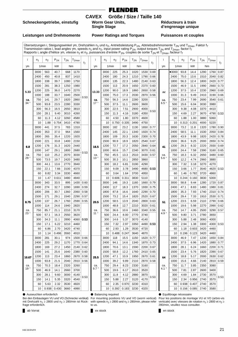
ab Vorrat ex stock en stock
21K88 DE/EN/FR
CAVEX Größe / Size / Taille 140Schneckengetriebe, einstufig Worm Gear Units, Réducteurs à train
Single Stage d’engrenage unique
Leistungen und Drehmomente Power Ratings and Torques Puissances et couples
Übersetzungen i, Steigungswinkel γm, Drehzahlen n1 und n2, Antriebsleistung P1N, Abtriebsdrehmomente T2N und T2max, Faktor f7Transmission ratios i, lead angles γm, speeds n1 and n2, input power rating P1N, output torques T2N and T2max, factor f7Rapports i, angle d’hélice γm, vitesse n1 et n2, puissances d’entrée P1N, couples de sortie T2N et T2max, facteur f7
i n1 n2 P1N T2N T2max
γm 1/min kW Nmf7
3000 563 40.7 668 1170
2400 450 40.8 837 1410
1800 338 39.7 1080 1750
1500 281 38.3 1250 1980
1200 225 36.0 1470 22705.33 1000 188 33.7 1640 2500
ca. 750 141 29.7 1920 2860 0.53
ca.34 ° 500 93.8 23.5 2280 3330
300 56.3 16.5 2650 3810
150 28.1 9.40 3010 4260
60 11.3 4.12 3260 4580
10 1.88 0.754 3410 4780
3000 441 37.5 783 1310
2400 353 37.0 964 1560
1800 265 35.4 1220 1920
1500 221 33.8 1400 2150
6.8 1200 176 31.3 1620 24406.8 1000 147 29.1 1800 2680
ca.°
750 110 25.2 2070 3030 0.53
29 ° 500 73.5 19.7 2420 3480
300 44.1 13.6 2770 3940
150 22.1 7.66 3100 4370
60 8.82 3.34 3330 4660
10 1.47 0.611 3480 4840
3000 343 33.5 895 1430 0.60
2400 274 32.7 1090 1690 0.59
1800 206 30.7 1360 2060 0.58
1500 171 29.1 1540 2290 0.57
8.75 1200 137 26.7 1760 2590 0.558.75 1000 114 24.6 1940 2820
ca.°
750 85.7 21.1 2210 317023 ° 500 57.1 16.3 2550 3620
300 34.3 11.1 2890 4060 0.53
150 17.1 6.22 3210 4460
0.53
60 6.86 2.70 3420 4740
10 1.14 0.496 3560 4910
3000 281 30.1 974 1500 0.66
2400 225 29.2 1170 1770 0.64
1800 169 27.2 1450 2140 0.62
1500 141 25.6 1640 2380 0.60
10.67 1200 113 23.4 1860 2670 0.5810.67 1000 93.8 21.5 2040 2910 0.56
ca.°
750 70.3 18.4 2320 326019 ° 500 46.9 14.1 2660 3700
300 28.1 9.60 3000 4140
150 14.1 5.35 3320 4540 0.53
60 5.63 2.32 3530 4820
10 0.938 0.430 3660 4990
i n1 n2 P1N T2N T2max
γm 1/min kW Nmf7
3000 225 25.3 1020 1530 0.69
2400 180 24.3 1210 1790 0.66
1800 135 22.3 1480 2140 0.63
1500 113 20.9 1650 2370 0.60
1200 90.0 18.9 1860 2650 0.5813.33 1000 75.0 17.3 2030 2870 0.56
ca. 750 56.3 14.6 2280 3200ca.17 ° 500 37.5 11.1 2600 3600
300 22.5 7.51 2900 4000
150 11.3 4.16 3180 4350 0.53
60 4.50 1.80 3370 4600
10 0.750 0.335 3490 4750
3000 182 23.2 1130 1650 0.77
2400 145 22.1 1340 1920 0.74
1800 109 20.3 1630 2300 0.70
1500 90.9 18.9 1820 2540 0.67
16.5 1200 72.7 17.2 2050 2840 0.6416.5 1000 60.6 15.7 2240 3070 0.61
ca.°
750 45.5 13.3 2510 3430 0.5713 ° 500 30.3 10.1 2850 3860
300 18.2 6.81 3190 4290
150 9.09 3.78 3490 4680 0.53
60 3.64 1.64 3700 4950
0.53
10 0.606 0.311 3830 5110
3000 146 19.3 1160 1660 0.79
2400 117 18.3 1370 1930 0.75
1800 87.8 16.6 1640 2290 0.70
1500 73.2 15.4 1820 2520 0.67
20.5 1200 58.5 13.9 2040 2800 0.6320.5 1000 48.8 12.7 2210 3020 0.61
ca.°
750 36.6 10.6 2460 3340 0.5511 ° 500 24.4 8.00 2770 3740
300 14.6 5.37 3070 4140
150 7.32 2.97 3350 4490 0.53
60 2.93 1.29 3530 4720
0.53
10 0.488 0.247 3640 4870
3000 118 15.5 1150 1620 0.77
2400 94.1 14.6 1340 1870 0.73
1800 70.6 13.1 1590 2200 0.67
1500 58.8 12.2 1760 2410 0.65
25.5 1200 47.1 10.9 1950 2670 0.6125.5 1000 39.2 9.89 2110 2870 0.58
ca.°
750 29.4 8.23 2330 31609.7 ° 500 19.6 6.17 2610 3520
300 11.8 4.12 2880 3870
150 5.88 2.27 3120 4170 0.53
60 2.35 0.970 3230 4310
10 0.392 0.183 3230 4320
i n1 n2 P1N T2N T2max
γm 1/min kW Nmf7
�3000 93.8 14.4 1290 1760 0.87
2400 75.0 13.6 1510 2040 0.82
1800 56.3 12.4 1800 2420 0.77
1500 46.9 11.5 1990 2660 0.73
1200 37.5 10.4 2230 2960 0.6932 1000 31.3 9.49 2410 3190 0.66
ca. 750 23.4 7.99 2690 3540 0.61ca.6.5 ° 500 15.6 6.04 3030 3980
300 9.38 4.08 3370 4410
150 4.69 2.27 3670 4790 0.53
60 1.88 1.00 3880 5060
0.53
10 0.313 0.201 4000 5220
3000 73.2 11.8 1320 1780 0.90
2400 58.5 11.1 1530 2050 0.84
1800 43.9 9.98 1820 2420 0.78
1500 36.6 9.25 2000 2650 0.74
41 1200 29.3 8.32 2220 2930 0.6941 1000 24.4 7.58 2390 3160 0.65
ca.°
750 18.3 6.32 2650 3480 0.605.6 ° 500 12.2 4.74 2960 3880
300 7.32 3.18 3270 4270
150 3.66 1.77 3540 4620 0.53
60 1.46 0.782 3720 4860
0.53
10 0.244 0.160 3830 5000
3000 58.8 9.44 1280 1720 0.87
2400 47.1 8.83 1480 1980 0.81
1800 35.3 7.93 1740 2310 0.74
1500 29.4 7.33 1910 2530 0.71
51 1200 23.5 6.59 2110 2790 0.6651 1000 19.6 5.98 2270 2990 0.62
ca.°
750 14.7 4.95 2500 3290 0.574.9 ° 500 9.80 3.71 2780 3650
300 5.88 2.48 3060 4000
150 2.94 1.38 3300 4300 0.53
60 1.18 0.603 3420 4460
0.53
10 0.196 0.123 3420 4460
3000 46.9 7.47 1230 1650 0.84
2400 37.5 6.96 1420 1880 0.77
1800 28.1 6.24 1660 2200 0.71
1500 23.4 5.76 1820 2390 0.67
64 1200 18.8 5.17 2000 2630 0.6264 1000 15.6 4.66 2140 2810 0.59
ca.°
750 11.7 3.85 2350 30804.1 ° 500 7.81 2.87 2600 3400
300 4.69 1.84 2730 3570
150 2.34 0.956 2740 3570 0.53
60 0.938 0.407 2740 3570
10 0.156 0.085 2740 3580
� Auswuchten erforderlichBei den Einbaulagen VU und VO (Schnecke vertikal)mit Drehzahl n1 ≥ 2800 und n2 ≥ 280/min ist Rück-frage erforderlich.
� Balancing requiredFor mounting positions VU and VO (worm vertical)with speeds n1 ≥ 2800 and n2 ≥ 280/min, please referto us.
� Equilibrage nécessairePour les positions de montage VU et VO (arbre-visverticale) avec vitesses de rotation n1 ≥ 2800 et n2 ≥280/min, veuillez nous consulter.

ab Vorrat ex stock en stock
22 K88 DE/EN/FR
CAVEX Größe / Size / Taille 160Schneckengetriebe, einstufig Worm Gear Units, Réducteurs à train
Single Stage d’engrenage unique
Leistungen und Drehmomente Power Ratings and Torques Puissances et couples
Übersetzungen i, Steigungswinkel γm, Drehzahlen n1 und n2, Antriebsleistung P1N, Abtriebsdrehmomente T2N und T2max, Faktor f7Transmission ratios i, lead angles γm, speeds n1 and n2, input power rating P1N, output torques T2N and T2max, factor f7Rapports i, angle d’hélice γm, vitesse n1 et n2, puissances d’entrée P1N, couples de sortie T2N et T2max, facteur f7
i n1 n2 P1N T2N T2max
γm 1/min kW Nmf7
3000 529 53.4 934 1620
2400 424 53.7 1170 1960
1800 318 52.4 1520 2450
1500 265 50.7 1760 2780
1200 212 47.7 2070 32005.67 1000 176 44.8 2320 3540
ca. 750 132 39.6 2730 4080 0.53
ca.34 ° 500 88.2 31.6 3260 4770
300 52.9 22.3 3820 5510
150 26.5 12.8 4350 6200
60 10.6 5.63 4740 6700
10 1.76 1.03 4980 7010
3000 417 48.6 1080 1790 0.58
2400 333 48.1 1330 2150 0.57
1800 250 46.1 1690 2650 0.56
1500 208 44.2 1940 2980 0.55
7.2 1200 167 41.1 2250 3400 0.547.2 1000 139 38.2 2500 3740
ca.°
750 104 33.4 2900 427028 ° 500 69.4 26.2 3410 4940
300 41.7 18.2 3940 5630 0.53
150 20.8 10.3 4440 6280
0.53
60 8.33 4.51 4800 6740
10 1.39 0.827 5010 7020
3000 324 43.4 1230 1960 0.66
2400 259 42.4 1490 2330 0.64
1800 195 40.0 1870 2840 0.62
1500 162 38.0 2130 3180 0.60
9.25 1200 130 35.0 2440 3600 0.589.25 1000 108 32.3 2700 3940 0.56
ca.°
750 81.1 27.9 3090 446023 ° 500 54.1 21.7 3600 5120
300 32.4 14.9 4110 5790
150 16.2 8.39 4590 6420 0.53
60 6.49 3.65 4920 6850
10 1.08 0.672 5130 7120
3000 265 39.2 1350 2070 0.73
2400 212 38.0 1630 2450 0.70
1800 159 35.6 2020 2980 0.67
1500 132 33.6 2290 3330 0.65
11.33 1200 106 30.9 2610 3760 0.6211.33 1000 88.2 28.4 2880 4110 0.60
ca.°
750 66.2 24.5 3280 4630 0.5619 ° 500 44.1 18.9 3790 5300
300 26.5 12.9 4310 5980
150 13.2 7.26 4800 6610 0.53
60 5.29 3.16 5140 7050
0.53
10 0.882 0.586 5340 7320
i n1 n2 P1N T2N T2max
γm 1/min kW Nmf7
3000 209 32.5 1400 2110 0.76
2400 167 31.2 1680 2480 0.72
1800 126 28.9 2060 2990 0.68
1500 105 27.1 2310 3320 0.65
1200 83.7 24.6 2610 3720 0.6214.33 1000 69.8 22.5 2860 4040 0.60
ca. 750 52.3 19.2 3220 4530 0.55ca.16 ° 500 34.9 14.7 3690 5130
300 20.9 9.95 4150 5740
150 10.5 5.54 4580 6300 0.53
60 4.19 2.40 4870 6680
0.53
10 0.698 0.448 5050 6910
3000 171 30.0 1560 2270 0.85
2400 137 28.8 1860 2660 0.80
1800 103 26.5 2270 3200 0.75
1500 85.7 24.9 2540 3560 0.72
17.5 1200 68.6 22.6 2870 3990 0.6917.5 1000 57.1 20.7 3140 4340 0.66
ca.°
750 42.9 17.7 3550 4870 0.6113 ° 500 28.6 13.5 4060 5530 0.54
300 17.1 9.19 4580 6200
150 8.57 5.13 5050 6810
60 3.43 2.24 5380 7240 0.53
10 0.571 0.424 5580 7500
3000 140 25.1 1580 2270 0.86
2400 112 23.8 1870 2650 0.80
1800 83.7 21.8 2260 3170 0.75
1500 69.8 20.3 2520 3500 0.72
21.5 1200 55.8 18.4 2830 3910 0.6821.5 1000 46.5 16.7 3080 4230 0.64
ca.°
750 34.9 14.2 3450 4720 0.5911 ° 500 23.3 10.7 3920 5330
300 14.0 7.26 4380 5930
150 6.98 4.04 4800 6480 0.53
60 2.79 1.76 5090 6850
0.53
10 0.465 0.336 5270 7080
3000 113 20.3 1570 2220 0.85
2400 90.6 19.2 1830 2570 0.79
1800 67.9 17.4 2200 3060 0.73
1500 56.6 16.2 2440 3370 0.69
26.5 1200 45.3 14.5 2720 3740 0.6526.5 1000 37.7 13.2 2950 4040 0.62
ca.°
750 28.3 11.1 3290 4480 0.569.7 ° 500 18.9 8.38 3710 5030
300 11.3 5.64 4120 5570
150 5.66 3.12 4490 6050 0.53
60 2.26 1.30 4550 6110
0.53
10 0.377 0.244 4550 6120
i n1 n2 P1N T2N T2max
γm 1/min kW Nmf7
�3000 90.9 19.0 1750 2400 0.96
2400 72.7 18.0 2060 2800 0.89
1800 54.5 16.4 2480 3350 0.82
1500 45.5 15.3 2760 3700 0.78
1200 36.4 13.9 3100 4140 0.7433 1000 30.3 12.7 3370 4490 0.70
ca. 750 22.7 10.8 3780 5020 0.65ca.6.6 ° 500 15.2 8.24 4300 5680 0.57
300 9.09 5.60 4820 6350
150 4.55 3.14 5290 6950
60 1.82 1.39 5620 7380 0.53
10 0.303 0.277 5820 7640
3000 71.4 15.4 1780 2420 0.96
2400 57.1 14.6 2080 2800 0.90
1800 42.9 13.2 2480 3320 0.82
1500 35.7 12.3 2750 3660 0.78
42 1200 28.6 11.1 3070 4080 0.7342 1000 23.8 10.1 3320 4400 0.69
ca.°
750 17.9 8.54 3700 4900 0.635.7 ° 500 11.9 6.46 4180 5510 0.55
300 7.14 4.37 4650 6110
150 3.57 2.44 5070 6660
60 1.43 1.08 5370 7040 0.53
10 0.238 0.220 5540 7270
3000 57.7 12.5 1750 2360 0.94
2400 46.2 11.8 2030 2720 0.88
1800 34.6 10.7 2410 3220 0.80
1500 28.8 9.87 2660 3530 0.75
52 1200 23.1 8.89 2950 3910 0.7152 1000 19.2 8.10 3190 4220 0.67
ca.°
750 14.4 6.79 3540 4670 0.614.9 ° 500 9.62 5.11 3970 5230
300 5.77 3.44 4390 5770
150 2.88 1.92 4770 6270 0.53
60 1.15 0.830 4890 6420
0.53
10 0.192 0.166 4900 6420
3000 46.2 10.0 1700 2270 0.92
2400 36.9 9.35 1960 2610 0.85
1800 27.7 8.42 2310 3070 0.77
1500 23.1 7.79 2540 3360 0.72
65 1200 18.5 7.00 2810 3710 0.6765 1000 15.4 6.36 3020 3990 0.63
ca.°
750 11.5 5.29 3340 4400 0.574.2 ° 500 7.69 3.97 3720 4900
300 4.62 2.57 3950 5190
150 2.31 1.33 3960 5200 0.53
60 0.923 0.564 3970 5200
0.53
10 0.154 0.116 3970 5200
� Auswuchten erforderlichBei den Einbaulagen VU und VO (Schnecke vertikal)mit Drehzahl n1 ≥ 2600 und n2 ≥ 260/min ist Rück-frage erforderlich.
� Balancing requiredFor mounting positions VU and VO (worm vertical)with speeds n1 ≥ 2600 and n2 ≥ 260/min, please referto us.
� Equilibrage nécessairePour les positions de montage VU et VO (arbre-visverticale) avec vitesses de rotation n1 ≥ 2600 et n2 ≥260/min, veuillez nous consulter.

ab Vorrat ex stock en stock
23K88 DE/EN/FR
CAVEX Größe / Size / Taille 180Schneckengetriebe, einstufig Worm Gear Units, Réducteurs à train
Single Stage d’engrenage unique
Leistungen und Drehmomente Power Ratings and Torques Puissances et couples
Übersetzungen i, Steigungswinkel γm, Drehzahlen n1 und n2, Antriebsleistung P1N, Abtriebsdrehmomente T2N und T2max, Faktor f7Transmission ratios i, lead angles γm, speeds n1 and n2, input power rating P1N, output torques T2N and T2max, factor f7Rapports i, angle d’hélice γm, vitesse n1 et n2, puissances d’entrée P1N, couples de sortie T2N et T2max, facteur f7
i n1 n2 P1N T2N T2max
γm 1/min kW Nmf7
2800 494 69.3 1300 2240 0.54
2400 424 69.6 1520 2560
1800 318 68.4 1990 3220
1500 265 66.5 2310 3680
1200 212 63.0 2730 42505.67 1000 176 59.4 3090 4730
ca. 750 132 52.9 3650 5490 0.53ca.34 ° 500 88.2 42.7 4410 6500
0.53
300 52.9 30.4 5220 7580
150 26.5 17.6 6020 8620
60 10.6 7.80 6600 9390
10 1.76 1.43 6970 9870
2800 389 63.3 1500 2490 0.62
2400 333 62.9 1740 2830 0.61
1800 250 60.7 2230 3510 0.59
1500 208 58.4 2570 3970 0.58
7.2 1200 167 54.7 3000 4560 0.577.2 1000 139 51.1 3360 5040 0.55
ca.°
750 104 44.9 3910 579029 ° 500 69.4 35.6 4650 6770
300 41.7 25.0 5430 7800
150 20.8 14.3 6180 8790 0.53
60 8.33 6.29 6720 9490
10 1.39 1.15 7050 9930
2800 303 56.4 1710 2720 0.71
2400 259 55.6 1960 3070 0.69
1800 195 52.8 2480 3780 0.66
1500 162 50.4 2830 4250 0.64
9.25 1200 130 46.7 3260 4840 0.629.25 1000 108 43.3 3630 5320 0.60
ca.°
750 81.1 37.6 4180 6070 0.5624 ° 500 54.1 29.5 4910 7030
300 32.4 20.5 5660 8030
150 16.2 11.6 6380 8970 0.53
60 6.49 5.07 6890 9640
0.53
10 1.08 0.933 7200 10100
2800 247 51.0 1880 2890 0.78
2400 212 50.0 2140 3250 0.75
1800 159 47.1 2680 3980 0.71
1500 132 44.7 3050 4460 0.69
11.33 1200 106 41.2 3500 5070 0.6611.33 1000 88.2 38.1 3880 5560 0.64
ca.°
750 66.2 33.0 4450 6330 0.6019 ° 500 44.1 25.7 5190 7310 0.54
300 26.5 17.8 5970 8320
150 13.2 10.1 6690 9280
60 5.29 4.40 7210 9950 0.53
10 0.882 0.815 7530 10400
i n1 n2 P1N T2N T2max
γm 1/min kW Nmf7
2800 195 42.1 1950 2930 0.81
2400 167 41.0 2210 3280 0.78
1800 126 38.1 2720 3980 0.72
1500 105 35.9 3070 4440 0.69
1200 83.7 32.8 3490 5000 0.6614.33 1000 69.8 30.1 3840 5460 0.63
ca. 750 52.3 25.8 4370 6160 0.59ca.17 ° 500 34.9 19.9 5040 7050
300 20.9 13.6 5720 7960
150 10.5 7.64 6360 8800 0.53
60 4.19 3.33 6800 9380
0.53
10 0.698 0.619 7080 9750
2800 160 39.2 2190 3180 0.91
2400 137 38.1 2470 3560 0.87
1800 103 35.4 3040 4310 0.81
1500 85.7 33.3 3420 4810 0.78
17.5 1200 68.6 30.4 3890 5430 0.7417.5 1000 57.1 27.9 4270 5930 0.71
ca.°
750 42.9 24.0 4850 6700 0.6513 ° 500 28.6 18.5 5600 7670 0.58
300 17.1 12.7 6370 8680
150 8.57 7.12 7080 9610
60 3.43 3.12 7590 10300 0.53
10 0.571 0.589 7890 10700
2800 130 32.2 2180 3130 0.91
2400 112 31.1 2450 3490 0.86
1800 83.7 28.6 2990 4200 0.79
1500 69.8 26.8 3340 4670 0.76
21.5 1200 55.8 24.4 3780 5250 0.7221.5 1000 46.5 22.3 4130 5710 0.68
ca.°
750 34.9 19.0 4670 6410 0.6311 ° 500 23.3 14.6 5340 7300 0.55
300 14.0 9.92 6030 8210
150 6.98 5.55 6670 9040
60 2.79 2.42 7110 9620 0.53
10 0.465 0.462 7380 9970
2800 106 26.1 2150 3060 0.89
2400 90.6 25.1 2410 3400 0.85
1800 67.9 22.9 2910 4060 0.77
1500 56.6 21.4 3240 4500 0.74
26.5 1200 45.3 19.3 3640 5030 0.6926.5 1000 37.7 17.6 3960 5450 0.65
ca.°
750 28.3 14.9 4450 6090 0.609.8 ° 500 18.9 11.3 5060 6900
300 11.3 7.68 5670 7700
150 5.66 4.28 6230 8430 0.53
60 2.26 1.79 6330 8560
0.53
10 0.377 0.333 6340 8570
i n1 n2 P1N T2N T2max
γm 1/min kW Nmf7
�2800 84.8 24.4 2430 3330 1.01
�2400 72.7 23.6 2720 3710 0.96
1800 54.5 21.7 3300 4470 0.88
1500 45.5 20.4 3680 4970 0.84
1200 36.4 18.5 4160 5580 0.7933 1000 30.3 17.0 4550 6090 0.75
ca. 750 22.7 14.5 5140 6850 0.69ca.6.7 ° 500 15.2 11.2 5890 7830 0.61
300 9.09 7.66 6670 8830
150 4.55 4.31 7390 9760
60 1.82 1.91 7890 10400 0.53
10 0.303 0.380 8210 10800
2800 66.7 19.7 2450 3340 1.02
2400 57.1 19.0 2730 3700 0.96
1800 42.9 17.4 3290 4430 0.87
1500 35.7 16.2 3650 4900 0.83
42 1200 28.6 14.7 4100 5480 0.7842 1000 23.8 13.4 4460 5950 0.74
ca.°
750 17.9 11.4 5010 6660 0.675.8 ° 500 11.9 8.70 5700 7550 0.59
300 7.14 5.92 6390 8460
150 3.57 3.33 7030 9290
60 1.43 1.47 7480 9870 0.53
10 0.238 0.298 7750 10200
2800 53.8 16.1 2410 3270 1.00
2400 46.2 15.4 2680 3620 0.94
1800 34.6 14.1 3210 4300 0.86
1500 28.8 13.1 3550 4750 0.81
52 1200 23.1 11.8 3970 5290 0.7552 1000 19.2 10.8 4300 5730 0.72
ca.°
750 14.4 9.11 4810 6380 0.655.0 ° 500 9.62 6.91 5440 7210 0.56
300 5.77 4.69 6070 8030
150 2.88 2.63 6650 8780
60 1.15 1.13 6840 9020 0.53
10 0.192 0.226 6840 9020
2800 43.1 12.8 2330 3140 0.97
2400 36.9 12.2 2580 3460 0.91
1800 27.7 11.1 3070 4100 0.82
1500 23.1 10.3 3380 4510 0.77
65 1200 18.5 9.25 3760 5010 0.7165 1000 15.4 8.43 4070 5410 0.67
ca.°
750 11.5 7.09 4530 6000 0.614.3 ° 500 7.69 5.36 5090 6740
300 4.62 3.52 5500 7260
150 2.31 1.81 5510 7270 0.53
60 0.923 0.766 5520 7280
0.53
10 0.154 0.156 5520 7280
� Auswuchten erforderlichBei den Einbaulagen VU und VO (Schnecke vertikal)mit Drehzahl n1 ≥ 2400 und n2 ≥ 240/min ist Rück-frage erforderlich.
� Balancing requiredFor mounting positions VU and VO (worm vertical)with speeds n1 ≥ 2400 and n2 ≥ 240/min, please referto us.
� Equilibrage nécessairePour les positions de montage VU et VO (arbre-visverticale) avec vitesses de rotation n1 ≥ 2400 et n2 ≥240/min, veuillez nous consulter.

ab Vorrat ex stock en stock
24 K88 DE/EN/FR
CAVEX Größe / Size / Taille 200Schneckengetriebe, einstufig Worm Gear Units, Réducteurs à train
Single Stage d’engrenage unique
Leistungen und Drehmomente Power Ratings and Torques Puissances et couples
Übersetzungen i, Steigungswinkel γm, Drehzahlen n1 und n2, Antriebsleistung P1N, Abtriebsdrehmomente T2N und T2max, Faktor f7Transmission ratios i, lead angles γm, speeds n1 and n2, input power rating P1N, output torques T2N and T2max, factor f7Rapports i, angle d’hélice γm, vitesse n1 et n2, puissances d’entrée P1N, couples de sortie T2N et T2max, facteur f7
i n1 n2 P1N T2N T2max
γm 1/min kW Nmf7
2600 459 87.3 1760 3020 0.57
2400 424 87.5 1910 3240 0.56
1800 318 86.5 2510 4100 0.55
1500 265 84.4 2940 4700 0.55
1200 212 80.5 3490 5460 0.545.67 1000 176 76.2 3960 6110
ca. 750 132 68.2 4720 7140ca.34 ° 500 88.2 55.5 5750 8520
300 52.9 40.0 6880 10000 0.53
150 26.5 23.3 8010 11500
0.53
60 10.6 10.4 8850 12600
10 1.76 1.91 9380 13400
2600 361 79.6 2030 3360 0.65
2400 333 79.4 2200 3590 0.65
1800 250 77.0 2830 4490 0.62
1500 208 74.4 3280 5100 0.61
7.2 1200 167 70.1 3850 5880 0.597.2 1000 139 65.7 4320 6530 0.58
ca.°
750 104 58.0 5080 7560 0.5529 ° 500 69.4 46.5 6090 8910
300 41.7 33.0 7180 10400
150 20.8 19.0 8240 11800 0.53
60 8.33 8.40 9020 12800
0.53
10 1.39 1.54 9510 13500
2600 281 71.0 2320 3680 0.75
2400 259 70.4 2490 3920 0.73
1800 195 67.4 3160 4850 0.69
1500 162 64.5 3620 5480 0.68
9.25 1200 130 60.1 4210 6280 0.659.25 1000 108 56.0 4700 6940 0.63
ca.°
750 81.1 48.9 5460 7960 0.5924 ° 500 54.1 38.7 6460 9310 0.54
300 32.4 27.1 7530 10700
150 16.2 15.5 8550 12100
60 6.49 6.81 9290 13100 0.53
10 1.08 1.25 9760 13700
2600 229 63.3 2510 3860 0.81
2400 212 62.7 2700 4110 0.79
1800 159 59.5 3390 5060 0.75
1500 132 56.7 3870 5700 0.72
11.33 1200 106 52.5 4470 6510 0.6911.33 1000 88.2 48.8 4970 7170 0.67
ca.°
750 66.2 42.4 5740 8210 0.6219 ° 500 44.1 33.4 6760 9560 0.56
300 26.5 23.3 7840 11000
150 13.2 13.3 8870 12400
60 5.29 5.82 9610 13300 0.53
10 0.882 1.08 10100 13900
i n1 n2 P1N T2N T2max
γm 1/min kW Nmf7
2600 181 52.6 2620 3950 0.85
2400 167 51.9 2800 4190 0.83
1800 126 48.6 3480 5110 0.76
1500 105 46.0 3940 5730 0.73
1200 83.7 42.2 4510 6500 0.7014.33 1000 69.8 38.9 4980 7120 0.67
ca. 750 52.3 33.6 5700 8090 0.62ca.17 ° 500 34.9 26.1 6630 9330 0.55
300 20.9 18.0 7600 10600
150 10.5 10.2 8510 11800
60 4.19 4.44 9160 12700 0.53
10 0.698 0.826 9560 13200
2600 149 48.3 2900 4230 0.93
2400 137 47.6 3100 4490 0.91
1800 103 44.5 3830 5470 0.84
1500 85.7 42.1 4330 6130 0.81
17.5 1200 68.6 38.6 4950 6950 0.7717.5 1000 57.1 35.6 5460 7630 0.73
ca.°
750 42.9 30.7 6250 8670 0.6813 ° 500 28.6 23.9 7280 10000 0.60
300 17.1 16.5 8350 11400
150 8.57 9.35 9360 12800
60 3.43 4.11 10100 13700 0.53
10 0.571 0.775 10500 14300
2600 121 40.1 2940 4220 0.94
2400 112 39.4 3120 4470 0.92
1800 83.7 36.5 3830 5410 0.84
1500 69.8 34.4 4300 6040 0.80
21.5 1200 55.8 31.3 4880 6820 0.7621.5 1000 46.5 28.8 5360 7450 0.72
ca.°
750 34.9 24.7 6090 8420 0.6611 ° 500 23.3 19.0 7030 9670 0.58
300 14.0 13.1 8000 10900
150 6.98 7.34 8910 12100
60 2.79 3.22 9550 13000 0.53
10 0.465 0.612 9950 13500
2600 98.1 32.7 2920 4150 0.94
2400 90.6 32.1 3090 4390 0.91
1800 67.9 29.5 3760 5280 0.83
1500 56.6 27.6 4200 5870 0.78
26.5 1200 45.3 25.0 4750 6590 0.7326.5 1000 37.7 22.9 5190 7180 0.70
ca.°
750 28.3 19.5 5860 8070 0.6410 ° 500 18.9 14.9 6710 9210 0.55
300 11.3 10.2 7580 10400
150 5.66 5.71 8390 11400
60 2.26 2.40 8590 11700 0.53
10 0.377 0.444 8610 11700
i n1 n2 P1N T2N T2max
γm 1/min kW Nmf7
�2600 76.5 29.6 3260 4490 1.05
�2400 70.6 29.0 3460 4750 1.02
1800 52.9 26.9 4220 5750 0.93
1500 44.1 25.3 4730 6410 0.88
1200 35.3 23.1 5370 7240 0.8334 1000 29.4 21.2 5890 7920 0.79
ca. 750 22.1 18.2 6690 8970 0.73ca.6.6 ° 500 14.7 14.1 7730 10300 0.64
300 8.82 9.75 8810 11700 0.54
150 4.41 5.52 9840 13100
60 1.76 2.45 10600 14000 0.53
10 0.294 0.487 11000 14600
0.53
2600 60.5 24.0 3290 4490 1.06
2400 55.8 23.6 3480 4750 1.03
1800 41.9 21.7 4220 5710 0.93
1500 34.9 20.4 4700 6340 0.88
43 1200 27.9 18.5 5310 7130 0.8343 1000 23.3 16.9 5800 7770 0.78
ca.°
750 17.4 14.5 6540 8750 0.725.8 ° 500 11.6 11.1 7500 10000 0.62
300 6.98 7.62 8490 11300
150 3.49 4.29 9400 12500
60 1.40 1.91 10100 13300 0.53
10 0.233 0.385 10500 13900
2600 49.1 19.6 3230 4390 1.04
2400 45.3 19.2 3410 4630 1.01
1800 34.0 17.5 4110 5540 0.90
1500 28.3 16.4 4560 6130 0.85
53 1200 22.6 14.8 5120 6870 0.8053 1000 18.9 13.5 5580 7460 0.75
ca.°
750 14.2 11.5 6260 8360 0.685 ° 500 9.43 8.79 7140 9510 0.59
300 5.66 6.00 8020 10700
150 2.83 3.38 8840 11700
60 1.13 1.46 9170 12200 0.53
10 0.189 0.289 9180 12200
2600 39.4 15.6 3110 4200 1.00
2400 36.4 15.2 3280 4430 0.96
1800 27.3 13.9 3930 5280 0.86
1500 22.7 12.9 4350 5830 0.81
66 1200 18.2 11.7 4870 6510 0.7666 1000 15.2 10.6 5280 7060 0.70
ca.°
750 11.4 9.03 5910 7880 0.644.3 ° 500 7.58 6.87 6700 8920 0.55
300 4.55 4.54 7290 9680
150 2.27 2.33 7300 9690
60 0.909 0.981 7310 9700 0.53
10 0.152 0.199 7320 9700
� Auswuchten erforderlichBei den Einbaulagen VU und VO (Schnecke vertikal)mit Drehzahl n1 ≥ 2200 und n2 ≥ 220/min ist Rück-frage erforderlich.
� Balancing requiredFor mounting positions VU and VO (worm vertical)with speeds n1 ≥ 2200 and n2 ≥ 220/min, please referto us.
� Equilibrage nécessairePour les positions de montage VU et VO (arbre-visverticale) avec vitesses de rotation n1 ≥ 2200 et n2 ≥220/min, veuillez nous consulter.

ab Vorrat ex stock en stock
25K88 DE/EN/FR
CAVEX Größe / Size / Taille 225Schneckengetriebe, einstufig Worm Gear Units, Réducteurs à train
Single Stage d’engrenage unique
Leistungen und Drehmomente Power Ratings and Torques Puissances et couples
Übersetzungen i, Steigungswinkel γm, Drehzahlen n1 und n2, Antriebsleistung P1N, Abtriebsdrehmomente T2N und T2max, Faktor f7Transmission ratios i, lead angles γm, speeds n1 and n2, input power rating P1N, output torques T2N and T2max, factor f7Rapports i, angle d’hélice γm, vitesse n1 et n2, puissances d’entrée P1N, couples de sortie T2N et T2max, facteur f7
i n1 n2 P1N T2N T2max
γm 1/min kW Nmf7
2400 411 111 2510 4260 0.61
1800 309 110 3310 5420 0.59
1500 257 108 3880 6220 0.58
1200 206 103 4630 7270 0.575.83 1000 171 98.4 5270 8160 0.56
750 129 88.4 6310 9590 0.54ca.35 ° 500 85.7 72.5 7750 1160035 °
300 51.4 52.6 9360 13700
150 25.7 31.0 11000 15900 0.53
60 10.3 13.9 12200 17600
0.53
10 1.71 2.56 13000 18700
2400 324 101 2880 4720 0.70
1800 243 98.5 3730 5930 0.67
1500 203 95.4 4330 6760 0.65
1200 162 90.3 5100 7840 0.637.4 1000 135 85.0 5750 8740 0.62
750 101 75.4 6800 10200 0.58ca.29 ° 500 67.6 60.9 8220 1210029
300 40.5 43.5 9770 14200
150 20.3 25.3 11300 16300 0.53
60 8.11 11.2 12500 17800
0.53
10 1.35 2.06 13200 18800
2400 259 91.4 3230 5130 0.79
1800 195 88.0 4140 6390 0.74
1500 162 84.6 4760 7260 0.72
1200 130 79.3 5570 8360 0.699.25 1000 108 74.2 6240 9280 0.66
750 81.1 65.3 7310 10700 0.63ca.24 ° 500 54.1 52.1 8740 12700 0.5724
300 32.4 36.9 10300 14800
150 16.2 21.3 11800 16800
60 6.49 9.40 12900 18300 0.53
10 1.08 1.73 13600 19300
2400 206 79.4 3510 5380 0.85
1800 154 75.6 4450 6660 0.80
1500 129 72.2 5090 7530 0.76
1200 103 67.4 5910 8650 0.7311.67 1000 85.7 62.7 6590 9570 0.70
750 64.3 54.8 7670 11000 0.66ca.19 ° 500 42.9 43.5 9100 13000 0.5919
300 25.7 30.6 10600 15000
150 12.9 17.6 12100 17000
60 5.14 7.75 13300 18500 0.53
10 0.857 1.43 13900 19400
i n1 n2 P1N T2N T2max
γm 1/min kW Nmf7
2400 164 66.5 3680 5530 0.89
1800 123 62.6 4600 6790 0.82
1500 102 59.4 5220 7630 0.79
1200 81.8 54.8 6000 8700 0.7414.67 1000 68.2 50.7 6650 9580 0.71
750 51.1 43.9 7660 10900 0.66ca.17 ° 500 34.1 34.4 8990 12700 0.5817 °
300 20.5 24.0 10400 14600
150 10.2 13.6 11700 16400
60 4.09 5.98 12700 17700 0.53
10 0.682 1.11 13300 18600
2400 130 59.7 4100 5960 1.00
1800 97.3 55.9 5100 7310 0.91
1500 81.1 53.0 5770 8210 0.87
1200 64.9 48.9 6630 9360 0.8218.5 1000 54.1 45.2 7340 10300 0.78
750 40.5 39.1 8440 11800 0.73ca.13 ° 500 27.0 30.6 9890 13700 0.6413
300 16.2 21.3 11400 15800 0.54
150 8.11 12.1 12900 17700
60 3.24 5.35 14000 19200 0.53
10 0.541 1.01 14700 20100
0.53
2400 107 49.5 4110 5910 1.00
1800 80.0 46.1 5060 7200 0.91
1500 66.7 43.5 5700 8060 0.86
1200 53.3 39.8 6510 9140 0.8022.5 1000 44.4 36.7 7170 10000 0.77
750 33.3 31.5 8190 11400 0.70ca.11 ° 500 22.2 24.5 9530 13200 0.6211
300 13.3 16.9 10900 15000
150 6.67 9.58 12200 16800
60 2.67 4.21 13200 18100 0.53
10 0.444 0.799 13800 18900
2400 87.3 40.1 4020 5740 0.98
1800 65.5 37.1 4920 6950 0.88
1500 54.5 34.9 5520 7750 0.83
1200 43.6 31.8 6260 8750 0.7827.5 1000 36.4 29.1 6870 9570 0.73
750 27.3 24.9 7810 10800 0.67ca.10 ° 500 18.2 19.2 9020 12400 0.5810
300 10.9 13.2 10300 14100
150 5.45 7.43 11400 15700
60 2.18 3.06 11500 15800 0.53
10 0.364 0.564 11500 15800
i n1 n2 P1N T2N T2max
γm 1/min kW Nmf7
�2400 70.6 37.3 4470 6170 1.09
�1800 52.9 34.7 5490 7520 0.98
1500 44.1 32.7 6180 8430 0.93
1200 35.3 30.2 7050 9570 0.8734 1000 29.4 27.8 7770 10500 0.83
750 22.1 24.0 8890 12000 0.76ca.
6.8 ° 500 14.7 18.7 10400 13900 0.686.8 ° 300 8.82 13.0 11900 16000 0.56
150 4.41 7.42 13400 18000
60 1.76 3.30 14500 19400 0.53
10 0.294 0.652 15200 20300
0.53
2400 55.8 30.6 4550 6240 1.11
1800 41.9 28.3 5540 7550 0.99
1500 34.9 26.6 6200 8430 0.93
1200 27.9 24.3 7040 9530 0.8743 1000 23.3 22.3 7720 10400 0.82
750 17.4 19.1 8780 11800 0.76ca.
5.9 ° 500 11.6 14.8 10200 13600 0.665.9 300 6.98 10.2 11600 15500 0.55
150 3.49 5.81 13000 17300
60 1.40 2.58 13900 18600 0.53
10 0.233 0.518 14600 19400
0.53
2400 44.4 24.5 4470 6100 1.09
1800 33.3 22.5 5410 7340 0.97
1500 27.8 21.2 6030 8170 0.91
1200 22.2 19.2 6810 9200 0.8454 1000 18.5 17.6 7450 10000 0.80
750 13.9 15.0 8420 11300 0.72ca.
5.1 ° 500 9.26 11.6 9680 13000 0.635.1 300 5.56 7.95 11000 14700
150 2.78 4.49 12200 16300
60 1.11 1.90 12400 16600 0.53
10 0.185 0.373 12400 16600
2400 35.8 19.6 4310 5860 1.05
1800 26.9 17.9 5190 7020 0.93
1500 22.4 16.8 5770 7790 0.87
1200 17.9 15.2 6490 8740 0.8067 1000 14.9 13.9 7070 9510 0.76
750 11.2 11.8 7960 10700 0.69ca.
4.4 ° 500 7.46 9.02 9100 12200 0.594.4 300 4.48 6.01 9970 13300
150 2.24 3.07 9990 13400
60 0.896 1.29 10000 13400 0.53
10 0.149 0.258 10000 13400
� Auswuchten erforderlichBei den Einbaulagen VU und VO (Schnecke vertikal)mit Drehzahl n1 ≥ 2000 und n2 ≥ 200/min ist Rück-frage erforderlich.
� Balancing requiredFor mounting positions VU and VO (worm vertical)with speeds n1 ≥ 2000 and n2 ≥ 200/min, please referto us.
� Equilibrage nécessairePour les positions de montage VU et VO (arbre-visverticale) avec vitesses de rotation n1 ≥ 2000 et n2 ≥200/min, veuillez nous consulter.
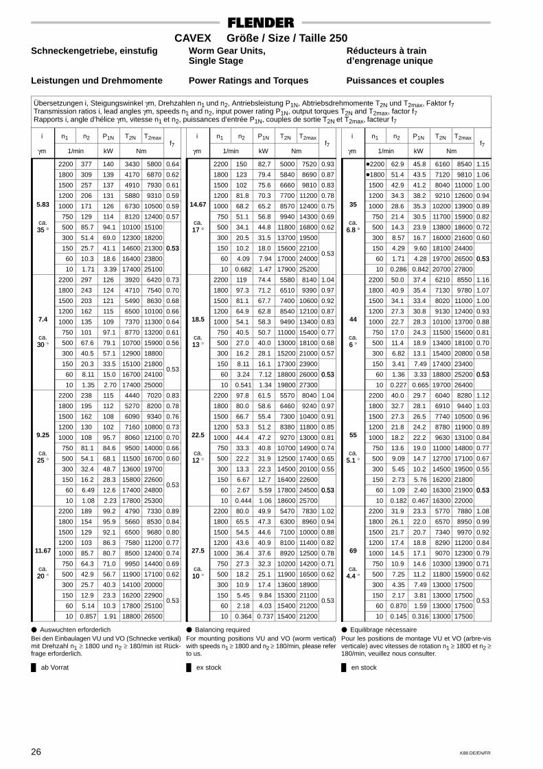
ab Vorrat ex stock en stock
26 K88 DE/EN/FR
CAVEX Größe / Size / Taille 250Schneckengetriebe, einstufig Worm Gear Units, Réducteurs à train
Single Stage d’engrenage unique
Leistungen und Drehmomente Power Ratings and Torques Puissances et couples
Übersetzungen i, Steigungswinkel γm, Drehzahlen n1 und n2, Antriebsleistung P1N, Abtriebsdrehmomente T2N und T2max, Faktor f7Transmission ratios i, lead angles γm, speeds n1 and n2, input power rating P1N, output torques T2N and T2max, factor f7Rapports i, angle d’hélice γm, vitesse n1 et n2, puissances d’entrée P1N, couples de sortie T2N et T2max, facteur f7
i n1 n2 P1N T2N T2max
γm 1/min kW Nmf7
2200 377 140 3430 5800 0.64
1800 309 139 4170 6870 0.62
1500 257 137 4910 7930 0.61
1200 206 131 5880 9310 0.595.83 1000 171 126 6730 10500 0.59
750 129 114 8120 12400 0.57ca.35 ° 500 85.7 94.1 10100 1510035 °
300 51.4 69.0 12300 18200
150 25.7 41.1 14600 21300 0.53
60 10.3 18.6 16400 23800
0.53
10 1.71 3.39 17400 25100
2200 297 126 3920 6420 0.73
1800 243 124 4710 7540 0.70
1500 203 121 5490 8630 0.68
1200 162 115 6500 10100 0.667.4 1000 135 109 7370 11300 0.64
750 101 97.1 8770 13200 0.61ca.30 ° 500 67.6 79.1 10700 15900 0.5630
300 40.5 57.1 12900 18800
150 20.3 33.5 15100 21800
60 8.11 15.0 16700 24100 0.53
10 1.35 2.70 17400 25000
2200 238 115 4440 7020 0.83
1800 195 112 5270 8200 0.78
1500 162 108 6090 9340 0.76
1200 130 102 7160 10800 0.739.25 1000 108 95.7 8060 12100 0.70
750 81.1 84.6 9500 14000 0.66ca.25 ° 500 54.1 68.1 11500 16700 0.6025
300 32.4 48.7 13600 19700
150 16.2 28.3 15800 22600
60 6.49 12.6 17400 24800 0.53
10 1.08 2.23 17800 25300
2200 189 99.2 4790 7330 0.89
1800 154 95.9 5660 8530 0.84
1500 129 92.1 6500 9680 0.80
1200 103 86.3 7580 11200 0.7711.67 1000 85.7 80.7 8500 12400 0.74
750 64.3 71.0 9950 14400 0.69ca.20 ° 500 42.9 56.7 11900 17100 0.6220
300 25.7 40.3 14100 20000
150 12.9 23.3 16200 22900
60 5.14 10.3 17800 25100 0.53
10 0.857 1.91 18800 26500
i n1 n2 P1N T2N T2max
γm 1/min kW Nmf7
2200 150 82.7 5000 7520 0.93
1800 123 79.4 5840 8690 0.87
1500 102 75.6 6660 9810 0.83
1200 81.8 70.3 7700 11200 0.7814.67 1000 68.2 65.2 8570 12400 0.75
750 51.1 56.8 9940 14300 0.69ca.17 ° 500 34.1 44.8 11800 16800 0.6217 °
300 20.5 31.5 13700 19500
150 10.2 18.0 15600 22100
60 4.09 7.94 17000 24000 0.53
10 0.682 1.47 17900 25200
2200 119 74.4 5580 8140 1.04
1800 97.3 71.2 6510 9390 0.97
1500 81.1 67.7 7400 10600 0.92
1200 64.9 62.8 8540 12100 0.8718.5 1000 54.1 58.3 9490 13400 0.83
750 40.5 50.7 11000 15400 0.77ca.13 ° 500 27.0 40.0 13000 18100 0.6813
300 16.2 28.1 15200 21000 0.57
150 8.11 16.1 17300 23900
60 3.24 7.12 18800 26000 0.53
10 0.541 1.34 19800 27300
0.53
2200 97.8 61.5 5570 8040 1.04
1800 80.0 58.6 6460 9240 0.97
1500 66.7 55.4 7300 10400 0.91
1200 53.3 51.2 8380 11800 0.8522.5 1000 44.4 47.2 9270 13000 0.81
750 33.3 40.8 10700 14900 0.74ca.12 ° 500 22.2 31.9 12500 17400 0.6512
300 13.3 22.3 14500 20100 0.55
150 6.67 12.7 16400 22600
60 2.67 5.59 17800 24500 0.53
10 0.444 1.06 18600 25700
0.53
2200 80.0 49.9 5470 7830 1.02
1800 65.5 47.3 6300 8960 0.94
1500 54.5 44.6 7100 10000 0.88
1200 43.6 40.9 8100 11400 0.8227.5 1000 36.4 37.6 8920 12500 0.78
750 27.3 32.3 10200 14200 0.71ca.10 ° 500 18.2 25.1 11900 16500 0.6210
300 10.9 17.4 13600 18900
150 5.45 9.84 15300 21100
60 2.18 4.03 15400 21200 0.53
10 0.364 0.737 15400 21200
i n1 n2 P1N T2N T2max
γm 1/min kW Nmf7
�2200 62.9 45.8 6160 8540 1.15
�1800 51.4 43.5 7120 9810 1.06
1500 42.9 41.2 8040 11000 1.00
1200 34.3 38.2 9210 12600 0.9435 1000 28.6 35.3 10200 13900 0.89
750 21.4 30.5 11700 15900 0.82ca.
6.8 ° 500 14.3 23.9 13800 18600 0.726.8 ° 300 8.57 16.7 16000 21600 0.60
150 4.29 9.60 18100 24400
60 1.71 4.28 19700 26500 0.53
10 0.286 0.842 20700 27800
0.53
2200 50.0 37.4 6210 8550 1.16
1800 40.9 35.4 7130 9780 1.07
1500 34.1 33.4 8020 11000 1.00
1200 27.3 30.8 9130 12400 0.9344 1000 22.7 28.3 10100 13700 0.88
750 17.0 24.3 11500 15600 0.81ca.6 ° 500 11.4 18.9 13400 18100 0.706
300 6.82 13.1 15400 20800 0.58
150 3.41 7.49 17400 23400
60 1.36 3.33 18800 25200 0.53
10 0.227 0.665 19700 26400
0.53
2200 40.0 29.7 6040 8280 1.12
1800 32.7 28.1 6910 9440 1.03
1500 27.3 26.5 7740 10500 0.96
1200 21.8 24.2 8780 11900 0.8955 1000 18.2 22.2 9630 13100 0.84
750 13.6 19.0 11000 14800 0.77ca.
5.1 ° 500 9.09 14.7 12700 17100 0.675.1 300 5.45 10.2 14500 19500 0.55
150 2.73 5.76 16200 21800
60 1.09 2.40 16300 21900 0.53
10 0.182 0.467 16300 22000
0.53
2200 31.9 23.3 5770 7880 1.08
1800 26.1 22.0 6570 8950 0.99
1500 21.7 20.7 7340 9970 0.92
1200 17.4 18.8 8290 11200 0.8469 1000 14.5 17.1 9070 12300 0.79
750 10.9 14.6 10300 13900 0.71ca.
4.4 ° 500 7.25 11.2 11800 15900 0.624.4 300 4.35 7.49 13000 17500
150 2.17 3.81 13000 17500
60 0.870 1.59 13000 17500 0.53
10 0.145 0.316 13000 17500
� Auswuchten erforderlichBei den Einbaulagen VU und VO (Schnecke vertikal)mit Drehzahl n1 ≥ 1800 und n2 ≥ 180/min ist Rück-frage erforderlich.
� Balancing requiredFor mounting positions VU and VO (worm vertical)with speeds n1 ≥ 1800 and n2 ≥ 180/min, please referto us.
� Equilibrage nécessairePour les positions de montage VU et VO (arbre-visverticale) avec vitesses de rotation n1 ≥ 1800 et n2 ≥180/min, veuillez nous consulter.
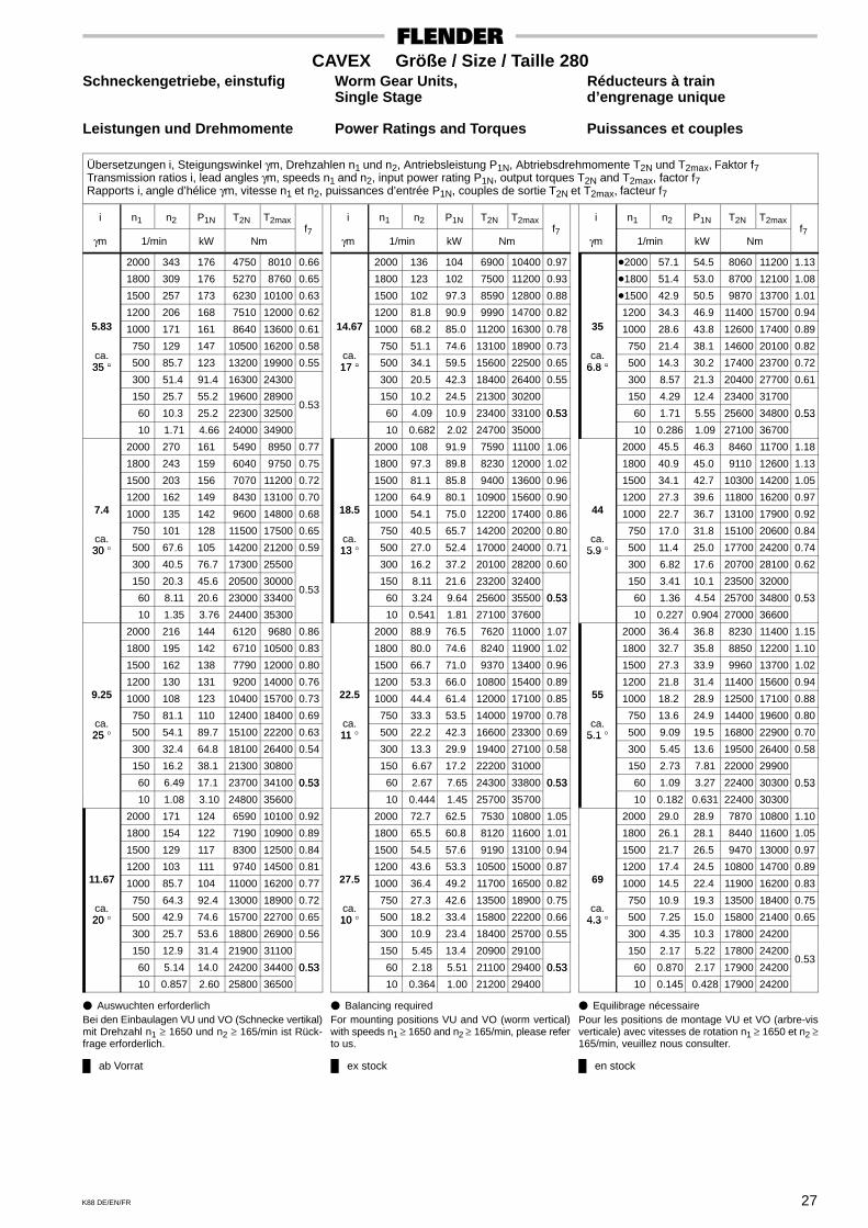
ab Vorrat ex stock en stock
27K88 DE/EN/FR
CAVEX Größe / Size / Taille 280Schneckengetriebe, einstufig Worm Gear Units, Réducteurs à train
Single Stage d’engrenage unique
Leistungen und Drehmomente Power Ratings and Torques Puissances et couples
Übersetzungen i, Steigungswinkel γm, Drehzahlen n1 und n2, Antriebsleistung P1N, Abtriebsdrehmomente T2N und T2max, Faktor f7Transmission ratios i, lead angles γm, speeds n1 and n2, input power rating P1N, output torques T2N and T2max, factor f7Rapports i, angle d’hélice γm, vitesse n1 et n2, puissances d’entrée P1N, couples de sortie T2N et T2max, facteur f7
i n1 n2 P1N T2N T2max
γm 1/min kW Nmf7
2000 343 176 4750 8010 0.66
1800 309 176 5270 8760 0.65
1500 257 173 6230 10100 0.63
1200 206 168 7510 12000 0.625.83 1000 171 161 8640 13600 0.61
750 129 147 10500 16200 0.58ca.35 ° 500 85.7 123 13200 19900 0.5535 °
300 51.4 91.4 16300 24300
150 25.7 55.2 19600 28900
60 10.3 25.2 22300 32500 0.53
10 1.71 4.66 24000 34900
2000 270 161 5490 8950 0.77
1800 243 159 6040 9750 0.75
1500 203 156 7070 11200 0.72
1200 162 149 8430 13100 0.707.4 1000 135 142 9600 14800 0.68
750 101 128 11500 17500 0.65ca.30 ° 500 67.6 105 14200 21200 0.5930
300 40.5 76.7 17300 25500
150 20.3 45.6 20500 30000
60 8.11 20.6 23000 33400 0.53
10 1.35 3.76 24400 35300
2000 216 144 6120 9680 0.86
1800 195 142 6710 10500 0.83
1500 162 138 7790 12000 0.80
1200 130 131 9200 14000 0.769.25 1000 108 123 10400 15700 0.73
750 81.1 110 12400 18400 0.69ca.25 ° 500 54.1 89.7 15100 22200 0.6325
300 32.4 64.8 18100 26400 0.54
150 16.2 38.1 21300 30800
60 6.49 17.1 23700 34100 0.53
10 1.08 3.10 24800 35600
0.53
2000 171 124 6590 10100 0.92
1800 154 122 7190 10900 0.89
1500 129 117 8300 12500 0.84
1200 103 111 9740 14500 0.8111.67 1000 85.7 104 11000 16200 0.77
750 64.3 92.4 13000 18900 0.72ca.20 ° 500 42.9 74.6 15700 22700 0.6520
300 25.7 53.6 18800 26900 0.56
150 12.9 31.4 21900 31100
60 5.14 14.0 24200 34400 0.53
10 0.857 2.60 25800 36500
0.53
i n1 n2 P1N T2N T2max
γm 1/min kW Nmf7
2000 136 104 6900 10400 0.97
1800 123 102 7500 11200 0.93
1500 102 97.3 8590 12800 0.88
1200 81.8 90.9 9990 14700 0.8214.67 1000 68.2 85.0 11200 16300 0.78
750 51.1 74.6 13100 18900 0.73ca.17 ° 500 34.1 59.5 15600 22500 0.6517 °
300 20.5 42.3 18400 26400 0.55
150 10.2 24.5 21300 30200
60 4.09 10.9 23400 33100 0.53
10 0.682 2.02 24700 35000
0.53
2000 108 91.9 7590 11100 1.06
1800 97.3 89.8 8230 12000 1.02
1500 81.1 85.8 9400 13600 0.96
1200 64.9 80.1 10900 15600 0.9018.5 1000 54.1 75.0 12200 17400 0.86
750 40.5 65.7 14200 20200 0.80ca.13 ° 500 27.0 52.4 17000 24000 0.7113
300 16.2 37.2 20100 28200 0.60
150 8.11 21.6 23200 32400
60 3.24 9.64 25600 35500 0.53
10 0.541 1.81 27100 37600
0.53
2000 88.9 76.5 7620 11000 1.07
1800 80.0 74.6 8240 11900 1.02
1500 66.7 71.0 9370 13400 0.96
1200 53.3 66.0 10800 15400 0.8922.5 1000 44.4 61.4 12000 17100 0.85
750 33.3 53.5 14000 19700 0.78ca.11 ° 500 22.2 42.3 16600 23300 0.6911
300 13.3 29.9 19400 27100 0.58
150 6.67 17.2 22200 31000
60 2.67 7.65 24300 33800 0.53
10 0.444 1.45 25700 35700
0.53
2000 72.7 62.5 7530 10800 1.05
1800 65.5 60.8 8120 11600 1.01
1500 54.5 57.6 9190 13100 0.94
1200 43.6 53.3 10500 15000 0.8727.5 1000 36.4 49.2 11700 16500 0.82
750 27.3 42.6 13500 18900 0.75ca.10 ° 500 18.2 33.4 15800 22200 0.6610
300 10.9 23.4 18400 25700 0.55
150 5.45 13.4 20900 29100
60 2.18 5.51 21100 29400 0.53
10 0.364 1.00 21200 29400
0.53
i n1 n2 P1N T2N T2max
γm 1/min kW Nmf7
�2000 57.1 54.5 8060 11200 1.13
�1800 51.4 53.0 8700 12100 1.08
�1500 42.9 50.5 9870 13700 1.01
1200 34.3 46.9 11400 15700 0.9435 1000 28.6 43.8 12600 17400 0.89
750 21.4 38.1 14600 20100 0.82ca.
6.8 ° 500 14.3 30.2 17400 23700 0.726.8 ° 300 8.57 21.3 20400 27700 0.61
150 4.29 12.4 23400 31700
60 1.71 5.55 25600 34800 0.53
10 0.286 1.09 27100 36700
0.53
2000 45.5 46.3 8460 11700 1.18
1800 40.9 45.0 9110 12600 1.13
1500 34.1 42.7 10300 14200 1.05
1200 27.3 39.6 11800 16200 0.9744 1000 22.7 36.7 13100 17900 0.92
750 17.0 31.8 15100 20600 0.84ca.
5.9 ° 500 11.4 25.0 17700 24200 0.745.9 300 6.82 17.6 20700 28100 0.62
150 3.41 10.1 23500 32000
60 1.36 4.54 25700 34800 0.53
10 0.227 0.904 27000 36600
0.53
2000 36.4 36.8 8230 11400 1.15
1800 32.7 35.8 8850 12200 1.10
1500 27.3 33.9 9960 13700 1.02
1200 21.8 31.4 11400 15600 0.9455 1000 18.2 28.9 12500 17100 0.88
750 13.6 24.9 14400 19600 0.80ca.
5.1 ° 500 9.09 19.5 16800 22900 0.705.1 300 5.45 13.6 19500 26400 0.58
150 2.73 7.81 22000 29900
60 1.09 3.27 22400 30300 0.53
10 0.182 0.631 22400 30300
0.53
2000 29.0 28.9 7870 10800 1.10
1800 26.1 28.1 8440 11600 1.05
1500 21.7 26.5 9470 13000 0.97
1200 17.4 24.5 10800 14700 0.8969 1000 14.5 22.4 11900 16200 0.83
750 10.9 19.3 13500 18400 0.75ca.
4.3 ° 500 7.25 15.0 15800 21400 0.654.3 300 4.35 10.3 17800 24200
150 2.17 5.22 17800 24200
60 0.870 2.17 17900 24200 0.53
10 0.145 0.428 17900 24200
� Auswuchten erforderlichBei den Einbaulagen VU und VO (Schnecke vertikal)mit Drehzahl n1 ≥ 1650 und n2 ≥ 165/min ist Rück-frage erforderlich.
� Balancing requiredFor mounting positions VU and VO (worm vertical)with speeds n1 ≥ 1650 and n2 ≥ 165/min, please referto us.
� Equilibrage nécessairePour les positions de montage VU et VO (arbre-visverticale) avec vitesses de rotation n1 ≥ 1650 et n2 ≥165/min, veuillez nous consulter.
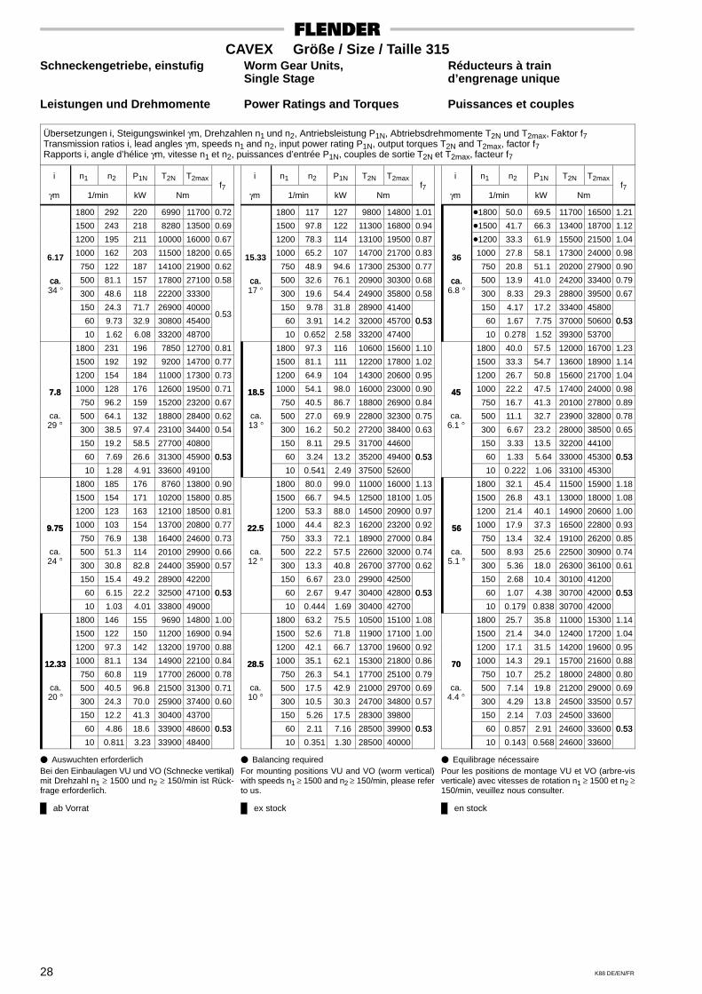
ab Vorrat ex stock en stock
28 K88 DE/EN/FR
CAVEX Größe / Size / Taille 315Schneckengetriebe, einstufig Worm Gear Units, Réducteurs à train
Single Stage d’engrenage unique
Leistungen und Drehmomente Power Ratings and Torques Puissances et couples
Übersetzungen i, Steigungswinkel γm, Drehzahlen n1 und n2, Antriebsleistung P1N, Abtriebsdrehmomente T2N und T2max, Faktor f7Transmission ratios i, lead angles γm, speeds n1 and n2, input power rating P1N, output torques T2N and T2max, factor f7Rapports i, angle d’hélice γm, vitesse n1 et n2, puissances d’entrée P1N, couples de sortie T2N et T2max, facteur f7
i n1 n2 P1N T2N T2max
γm 1/min kW Nmf7
1800 292 220 6990 11700 0.72
1500 243 218 8280 13500 0.69
1200 195 211 10000 16000 0.67
1000 162 203 11500 18200 0.656.17 750 122 187 14100 21900 0.62
ca. 500 81.1 157 17800 27100 0.58ca.34 ° 300 48.6 118 22200 33300
150 24.3 71.7 26900 40000
60 9.73 32.9 30800 45400 0.53
10 1.62 6.08 33200 48700
1800 231 196 7850 12700 0.81
1500 192 192 9200 14700 0.77
1200 154 184 11000 17300 0.73
7.8 1000 128 176 12600 19500 0.717.8 750 96.2 159 15200 23200 0.67
ca.°
500 64.1 132 18800 28400 0.6229 ° 300 38.5 97.4 23100 34400 0.54
150 19.2 58.5 27700 40800
60 7.69 26.6 31300 45900 0.53
10 1.28 4.91 33600 49100
0.53
1800 185 176 8760 13800 0.90
1500 154 171 10200 15800 0.85
1200 123 163 12100 18500 0.81
9.75 1000 103 154 13700 20800 0.779.75 750 76.9 138 16400 24600 0.73
ca.°
500 51.3 114 20100 29900 0.6624 ° 300 30.8 82.8 24400 35900 0.57
150 15.4 49.2 28900 42200
60 6.15 22.2 32500 47100 0.53
10 1.03 4.01 33800 49000
0.53
1800 146 155 9690 14800 1.00
1500 122 150 11200 16900 0.94
1200 97.3 142 13200 19700 0.88
12.33 1000 81.1 134 14900 22100 0.8412.33 750 60.8 119 17700 26000 0.78
ca.°
500 40.5 96.8 21500 31300 0.7120 ° 300 24.3 70.0 25900 37400 0.60
150 12.2 41.3 30400 43700
60 4.86 18.6 33900 48600 0.53
10 0.811 3.23 33900 48400
0.53
i n1 n2 P1N T2N T2max
γm 1/min kW Nmf7
1800 117 127 9800 14800 1.01
1500 97.8 122 11300 16800 0.94
1200 78.3 114 13100 19500 0.87
1000 65.2 107 14700 21700 0.8315.33 750 48.9 94.6 17300 25300 0.77
ca. 500 32.6 76.1 20900 30300 0.68ca.17 ° 300 19.6 54.4 24900 35800 0.58
150 9.78 31.8 28900 41400
60 3.91 14.2 32000 45700 0.53
10 0.652 2.58 33200 47400
0.53
1800 97.3 116 10600 15600 1.10
1500 81.1 111 12200 17800 1.02
1200 64.9 104 14300 20600 0.95
18.5 1000 54.1 98.0 16000 23000 0.9018.5 750 40.5 86.7 18800 26900 0.84
ca.°
500 27.0 69.9 22800 32300 0.7513 ° 300 16.2 50.2 27200 38400 0.63
150 8.11 29.5 31700 44600
60 3.24 13.2 35200 49400 0.53
10 0.541 2.49 37500 52600
0.53
1800 80.0 99.0 11000 16000 1.13
1500 66.7 94.5 12500 18100 1.05
1200 53.3 88.0 14500 20900 0.97
22.5 1000 44.4 82.3 16200 23200 0.9222.5 750 33.3 72.1 18900 27000 0.84
ca.°
500 22.2 57.5 22600 32000 0.7412 ° 300 13.3 40.8 26700 37700 0.62
150 6.67 23.0 29900 42500
60 2.67 9.47 30400 42800 0.53
10 0.444 1.69 30400 42700
0.53
1800 63.2 75.5 10500 15100 1.08
1500 52.6 71.8 11900 17100 1.00
1200 42.1 66.7 13700 19600 0.92
28.5 1000 35.1 62.1 15300 21800 0.8628.5 750 26.3 54.1 17700 25100 0.79
ca.°
500 17.5 42.9 21000 29700 0.6910 ° 300 10.5 30.3 24700 34800 0.57
150 5.26 17.5 28300 39800
60 2.11 7.16 28500 39900 0.53
10 0.351 1.30 28500 40000
0.53
i n1 n2 P1N T2N T2max
γm 1/min kW Nmf7
�1800 50.0 69.5 11700 16500 1.21
�1500 41.7 66.3 13400 18700 1.12
�1200 33.3 61.9 15500 21500 1.04
1000 27.8 58.1 17300 24000 0.9836 750 20.8 51.1 20200 27900 0.90
ca. 500 13.9 41.0 24200 33400 0.79ca.6.8 ° 300 8.33 29.3 28800 39500 0.67
150 4.17 17.2 33400 45800
60 1.67 7.75 37000 50600 0.53
10 0.278 1.52 39300 53700
0.53
1800 40.0 57.5 12000 16700 1.23
1500 33.3 54.7 13600 18900 1.14
1200 26.7 50.8 15600 21700 1.04
45 1000 22.2 47.5 17400 24000 0.9845 750 16.7 41.3 20100 27800 0.89
ca.°
500 11.1 32.7 23900 32800 0.786.1 ° 300 6.67 23.2 28000 38500 0.65
150 3.33 13.5 32200 44100
60 1.33 5.64 33000 45300 0.53
10 0.222 1.06 33100 45300
0.53
1800 32.1 45.4 11500 15900 1.18
1500 26.8 43.1 13000 18000 1.08
1200 21.4 40.1 14900 20600 1.00
56 1000 17.9 37.3 16500 22800 0.9356 750 13.4 32.4 19100 26200 0.85
ca.°
500 8.93 25.6 22500 30900 0.745.1 ° 300 5.36 18.0 26300 36100 0.61
150 2.68 10.4 30100 41200
60 1.07 4.38 30700 42000 0.53
10 0.179 0.838 30700 42000
0.53
1800 25.7 35.8 11000 15300 1.14
1500 21.4 34.0 12400 17200 1.04
1200 17.1 31.5 14200 19600 0.95
70 1000 14.3 29.1 15700 21600 0.8870 750 10.7 25.2 18000 24800 0.80
ca.°
500 7.14 19.8 21200 29000 0.694.4 ° 300 4.29 13.8 24500 33500 0.57
150 2.14 7.03 24500 33600
60 0.857 2.91 24600 33600 0.53
10 0.143 0.568 24600 33600
0.53
� Auswuchten erforderlichBei den Einbaulagen VU und VO (Schnecke vertikal)mit Drehzahl n1 ≥ 1500 und n2 ≥ 150/min ist Rück-frage erforderlich.
� Balancing requiredFor mounting positions VU and VO (worm vertical)with speeds n1 ≥ 1500 and n2 ≥ 150/min, please referto us.
� Equilibrage nécessairePour les positions de montage VU et VO (arbre-visverticale) avec vitesses de rotation n1 ≥ 1500 et n2 ≥150/min, veuillez nous consulter.

ab Vorrat ex stock en stock
29K88 DE/EN/FR
CAVEX Größe / Size / Taille 355Schneckengetriebe, einstufig Worm Gear Units, Réducteurs à train
Single Stage d’engrenage unique
Leistungen und Drehmomente Power Ratings and Torques Puissances et couples
Übersetzungen i, Steigungswinkel γm, Drehzahlen n1 und n2, Antriebsleistung P1N, Abtriebsdrehmomente T2N und T2max, Faktor f7Transmission ratios i, lead angles γm, speeds n1 and n2, input power rating P1N, output torques T2N and T2max, factor f7Rapports i, angle d’hélice γm, vitesse n1 et n2, puissances d’entrée P1N, couples de sortie T2N et T2max, facteur f7
i n1 n2 P1N T2N T2max
γm 1/min kW Nmf7
1650 268 282 9760 16300 0.75
1500 243 280 10700 17600 0.73
1200 195 273 13000 21000 0.70
1000 162 264 15000 24000 0.686.17 750 122 244 18500 29000 0.65
ca. 500 81.1 208 23600 36300 0.61ca.35 ° 300 48.6 158 29800 45200 0.54
150 24.3 97.7 36800 55100
60 9.73 45.4 42500 63300 0.53
10 1.62 8.25 45100 66900
0.53
1650 212 252 11000 17800 0.85
1500 192 249 11900 19200 0.82
1200 154 240 14400 22800 0.78
7.8 1000 128 230 16500 25800 0.757.8 750 96.2 210 20000 30900 0.70
ca.°
500 64.1 176 25200 38300 0.6529 ° 300 38.5 132 31300 47100 0.57
150 19.2 80.2 38000 56600
60 7.69 36.9 43400 64300 0.53
10 1.28 6.57 45100 66600
0.53
1650 169 225 12200 19300 0.94
1500 154 221 13200 20700 0.91
1200 123 212 15700 24400 0.86
9.75 1000 103 202 18000 27600 0.819.75 750 76.9 183 21600 32800 0.76
ca.°
500 51.3 152 26900 40300 0.6924 ° 300 30.8 112 33100 49100 0.60
150 15.4 67.5 39700 58500
60 6.15 30.8 45000 66100 0.53
10 1.03 5.52 46800 68500
0.53
1650 134 192 13000 20000 1.01
1500 122 188 14100 21500 0.97
1200 97.3 179 16700 25200 0.90
12.33 1000 81.1 170 19000 28400 0.8612.33 750 60.8 153 22700 33700 0.80
ca.°
500 40.5 126 28000 41200 0.7219 ° 300 24.3 92.6 34200 50000 0.62
150 12.2 55.5 40900 59300
60 4.86 25.3 46200 66700 0.53
10 0.811 4.72 49700 71700
0.53
i n1 n2 P1N T2N T2max
γm 1/min kW Nmf7
1650 108 160 13500 20400 1.03
1500 97.8 157 14500 21900 1.00
1200 78.3 148 17000 25500 0.93
1000 65.2 139 19200 28600 0.8715.33 750 48.9 124 22800 33600 0.80
ca. 500 32.6 101 27800 40700 0.71ca.17 ° 300 19.6 73.4 33500 48800 0.61
150 9.78 43.5 39500 57300
60 3.91 19.6 44200 63900 0.53
10 0.652 3.66 47300 68200
0.53
1650 84.6 137 14500 21400 1.12
1500 76.9 134 15600 22900 1.08
1200 61.5 126 18200 26600 0.99
19.5 1000 51.3 119 20500 29800 0.9319.5 750 38.5 106 24300 35100 0.86
ca.°
500 25.6 86.4 29600 42400 0.7713 ° 300 15.4 62.6 35700 50900 0.65
150 7.69 37.1 42100 59800
60 3.08 16.8 47100 66700 0.53
10 0.513 3.05 48500 68700
0.53
1650 70.2 117 14800 21700 1.14
1500 63.8 115 15900 23200 1.10
1200 51.1 108 18500 26900 1.00
23.5 1000 42.6 101 20800 30100 0.9423.5 750 31.9 89.6 24500 35200 0.87
ca.°
500 21.3 72.3 29600 42300 0.7611 ° 300 12.8 52.1 35400 50500 0.64
150 6.38 30.7 41500 58900
60 2.55 13.8 46200 65400 0.53
10 0.426 2.62 49200 69700
0.53
1650 55.9 92.4 14500 21000 1.12
1500 50.8 90.1 15500 22500 1.07
1200 40.7 84.1 17900 25900 0.97
29.5 1000 33.9 78.8 20000 28900 0.9129.5 750 25.4 69.2 23400 33600 0.83
ca.°
500 16.9 55.4 28100 40100 0.7310 ° 300 10.2 39.5 33300 47400 0.60
150 5.08 22.7 38000 53900
60 2.03 9.25 38100 54000 0.53
10 0.339 1.67 38200 54100
0.53
i n1 n2 P1N T2N T2max
γm 1/min kW Nmf7
�1650 44.6 86.0 16300 23000 1.26
�1500 40.5 83.9 17500 24600 1.21
�1200 32.4 78.8 20300 28500 1.11
1000 27.0 74.1 22800 31900 1.0437 750 20.3 65.9 26800 37400 0.95
ca. 500 13.5 53.4 32500 45200 0.84ca.6.8 ° 300 8.11 38.5 39000 54100 0.71
150 4.05 22.9 45800 63400 0.55
60 1.62 10.4 51100 70700
10 0.270 2.04 54600 75500 0.53
1650 35.9 70.2 16200 22800 1.25
1500 32.6 68.4 17400 24400 1.20
1200 26.1 64.0 20100 28200 1.09
46 1000 21.7 60.1 22500 31400 1.0246 750 16.3 53.0 26300 36600 0.93
ca.°
500 10.9 42.6 31600 43900 0.815.9 ° 300 6.52 30.5 37600 52100 0.68
150 3.26 18.0 43800 60600
60 1.30 8.16 48600 67200 0.53
10 0.217 1.62 51700 71500
0.53
1650 28.9 56.5 15900 22300 1.23
1500 26.3 55.1 16900 23700 1.17
1200 21.1 51.3 19600 27300 1.06
57 1000 17.5 48.2 21800 30300 0.9957 750 13.2 42.2 25300 35200 0.89
ca.°
500 8.77 33.7 30200 41900 0.785.1 ° 300 5.26 24.0 35700 49500 0.65
150 2.63 14.0 41300 57100
60 1.05 5.82 41700 57700 0.53
10 0.175 1.10 41700 57700
0.53
1650 23.2 44.6 15200 21300 1.18
1500 21.1 43.5 16200 22600 1.12
1200 16.9 40.5 18600 26000 1.01
71 1000 14.1 37.9 20700 28800 0.9471 750 10.6 33.0 23900 33300 0.84
ca.°
500 7.04 26.1 28400 39400 0.734.4 ° 300 4.23 18.5 33400 46200 0.60
150 2.11 9.43 33500 46300
60 0.845 3.89 33500 46300 0.53
10 0.141 0.753 33500 46300
0.53
� Auswuchten erforderlichBei den Einbaulagen VU und VO (Schnecke vertikal)mit Drehzahl n1 ≥ 1350 und n2 ≥ 135/min ist Rück-frage erforderlich.
� Balancing requiredFor mounting positions VU and VO (worm vertical)with speeds n1 ≥ 1350 and n2 ≥ 135/min, please referto us.
� Equilibrage nécessairePour les ositions de montage VU et VO (arbre-visverticale) avec vitesses de rotation n1 ≥ 1350 et n2 ≥135/min, veuillex nous consulter.
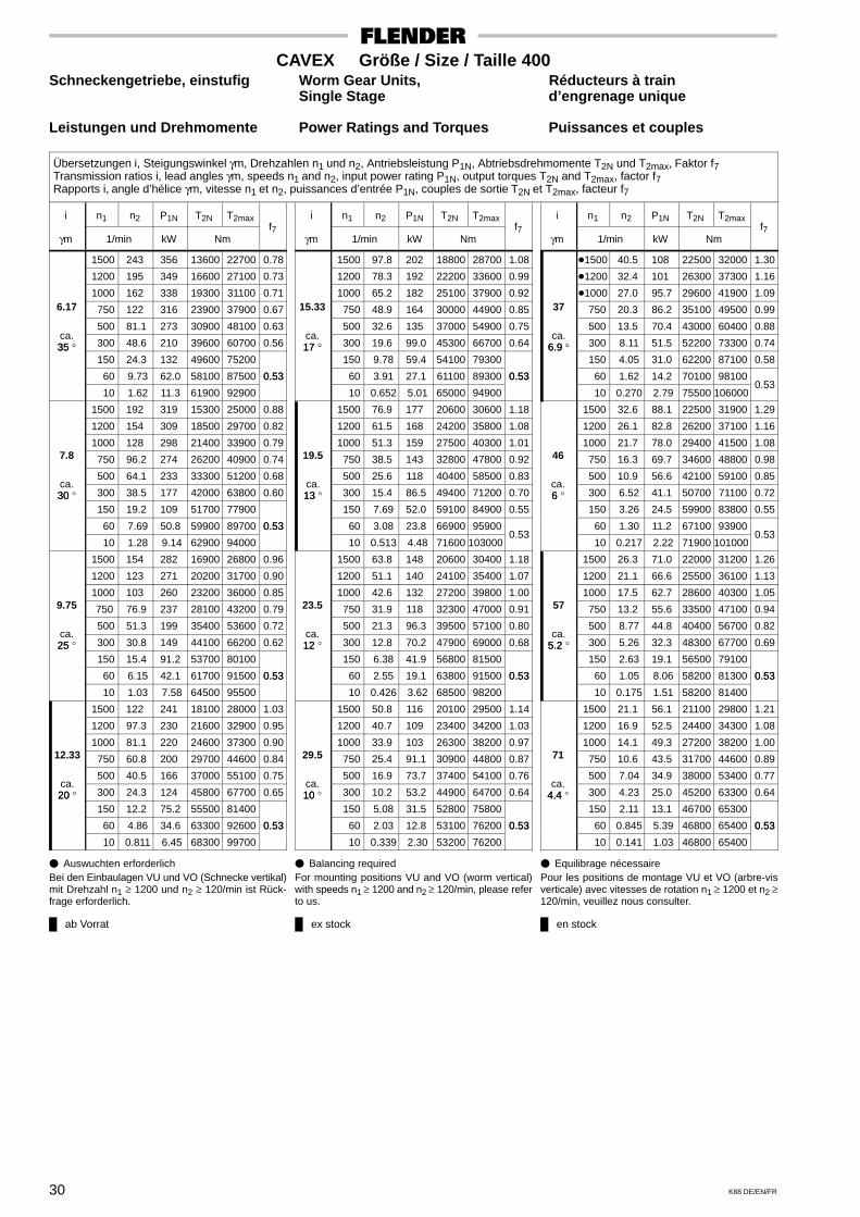
ab Vorrat ex stock en stock
30 K88 DE/EN/FR
CAVEX Größe / Size / Taille 400Schneckengetriebe, einstufig Worm Gear Units, Réducteurs à train
Single Stage d’engrenage unique
Leistungen und Drehmomente Power Ratings and Torques Puissances et couples
Übersetzungen i, Steigungswinkel γm, Drehzahlen n1 und n2, Antriebsleistung P1N, Abtriebsdrehmomente T2N und T2max, Faktor f7Transmission ratios i, lead angles γm, speeds n1 and n2, input power rating P1N, output torques T2N and T2max, factor f7Rapports i, angle d’hélice γm, vitesse n1 et n2, puissances d’entrée P1N, couples de sortie T2N et T2max, facteur f7
i n1 n2 P1N T2N T2max
γm 1/min kW Nmf7
1500 243 356 13600 22700 0.78
1200 195 349 16600 27100 0.73
1000 162 338 19300 31100 0.716.17 750 122 316 23900 37900 0.67
500 81.1 273 30900 48100 0.63ca.35 ° 300 48.6 210 39600 60700 0.5635 °
150 24.3 132 49600 75200
60 9.73 62.0 58100 87500 0.53
10 1.62 11.3 61900 92900
0.53
1500 192 319 15300 25000 0.88
1200 154 309 18500 29700 0.82
1000 128 298 21400 33900 0.797.8 750 96.2 274 26200 40900 0.74
500 64.1 233 33300 51200 0.68ca.30 ° 300 38.5 177 42000 63800 0.6030
150 19.2 109 51700 77900
60 7.69 50.8 59900 89700 0.53
10 1.28 9.14 62900 94000
0.53
1500 154 282 16900 26800 0.96
1200 123 271 20200 31700 0.90
1000 103 260 23200 36000 0.859.75 750 76.9 237 28100 43200 0.79
500 51.3 199 35400 53600 0.72ca.25 ° 300 30.8 149 44100 66200 0.6225
150 15.4 91.2 53700 80100
60 6.15 42.1 61700 91500 0.53
10 1.03 7.58 64500 95500
0.53
1500 122 241 18100 28000 1.03
1200 97.3 230 21600 32900 0.95
1000 81.1 220 24600 37300 0.9012.33 750 60.8 200 29700 44600 0.84
500 40.5 166 37000 55100 0.75ca.20 ° 300 24.3 124 45800 67700 0.6520
150 12.2 75.2 55500 81400
60 4.86 34.6 63300 92600 0.53
10 0.811 6.45 68300 99700
0.53
i n1 n2 P1N T2N T2max
γm 1/min kW Nmf7
1500 97.8 202 18800 28700 1.08
1200 78.3 192 22200 33600 0.99
1000 65.2 182 25100 37900 0.9215.33 750 48.9 164 30000 44900 0.85
500 32.6 135 37000 54900 0.75ca.17 ° 300 19.6 99.0 45300 66700 0.6417 °
150 9.78 59.4 54100 79300
60 3.91 27.1 61100 89300 0.53
10 0.652 5.01 65000 94900
0.53
1500 76.9 177 20600 30600 1.18
1200 61.5 168 24200 35800 1.08
1000 51.3 159 27500 40300 1.0119.5 750 38.5 143 32800 47800 0.92
500 25.6 118 40400 58500 0.83ca.13 ° 300 15.4 86.5 49400 71200 0.7013
150 7.69 52.0 59100 84900 0.55
60 3.08 23.8 66900 95900
10 0.513 4.48 71600 103000 0.53
1500 63.8 148 20600 30400 1.18
1200 51.1 140 24100 35400 1.07
1000 42.6 132 27200 39800 1.0023.5 750 31.9 118 32300 47000 0.91
500 21.3 96.3 39500 57100 0.80ca.12 ° 300 12.8 70.2 47900 69000 0.6812
150 6.38 41.9 56800 81500
60 2.55 19.1 63800 91500 0.53
10 0.426 3.62 68500 98200
0.53
1500 50.8 116 20100 29500 1.14
1200 40.7 109 23400 34200 1.03
1000 33.9 103 26300 38200 0.9729.5 750 25.4 91.1 30900 44800 0.87
500 16.9 73.7 37400 54100 0.76ca.10 ° 300 10.2 53.2 44900 64700 0.6410
150 5.08 31.5 52800 75800
60 2.03 12.8 53100 76200 0.53
10 0.339 2.30 53200 76200
0.53
i n1 n2 P1N T2N T2max
γm 1/min kW Nmf7
�1500 40.5 108 22500 32000 1.30
�1200 32.4 101 26300 37300 1.16
�1000 27.0 95.7 29600 41900 1.0937 750 20.3 86.2 35100 49500 0.99
500 13.5 70.4 43000 60400 0.88ca.
6.9 ° 300 8.11 51.5 52200 73300 0.746.9 ° 150 4.05 31.0 62200 87100 0.58
60 1.62 14.2 70100 98100
10 0.270 2.79 75500 106000 0.53
1500 32.6 88.1 22500 31900 1.29
1200 26.1 82.8 26200 37100 1.16
1000 21.7 78.0 29400 41500 1.0846 750 16.3 69.7 34600 48800 0.98
500 10.9 56.6 42100 59100 0.85ca.6 ° 300 6.52 41.1 50700 71100 0.726
150 3.26 24.5 59900 83800 0.55
60 1.30 11.2 67100 93900
10 0.217 2.22 71900 101000 0.53
1500 26.3 71.0 22000 31200 1.26
1200 21.1 66.6 25500 36100 1.13
1000 17.5 62.7 28600 40300 1.0557 750 13.2 55.6 33500 47100 0.94
500 8.77 44.8 40400 56700 0.82ca.
5.2 ° 300 5.26 32.3 48300 67700 0.695.2 150 2.63 19.1 56500 79100
60 1.05 8.06 58200 81300 0.53
10 0.175 1.51 58200 81400
0.53
1500 21.1 56.1 21100 29800 1.21
1200 16.9 52.5 24400 34300 1.08
1000 14.1 49.3 27200 38200 1.0071 750 10.6 43.5 31700 44600 0.89
500 7.04 34.9 38000 53400 0.77ca.
4.4 ° 300 4.23 25.0 45200 63300 0.644.4 150 2.11 13.1 46700 65300
60 0.845 5.39 46800 65400 0.53
10 0.141 1.03 46800 65400
0.53
� Auswuchten erforderlichBei den Einbaulagen VU und VO (Schnecke vertikal)mit Drehzahl n1 ≥ 1200 und n2 ≥ 120/min ist Rück-frage erforderlich.
� Balancing requiredFor mounting positions VU and VO (worm vertical)with speeds n1 ≥ 1200 and n2 ≥ 120/min, please referto us.
� Equilibrage nécessairePour les positions de montage VU et VO (arbre-visverticale) avec vitesses de rotation n1 ≥ 1200 et n2 ≥120/min, veuillez nous consulter.
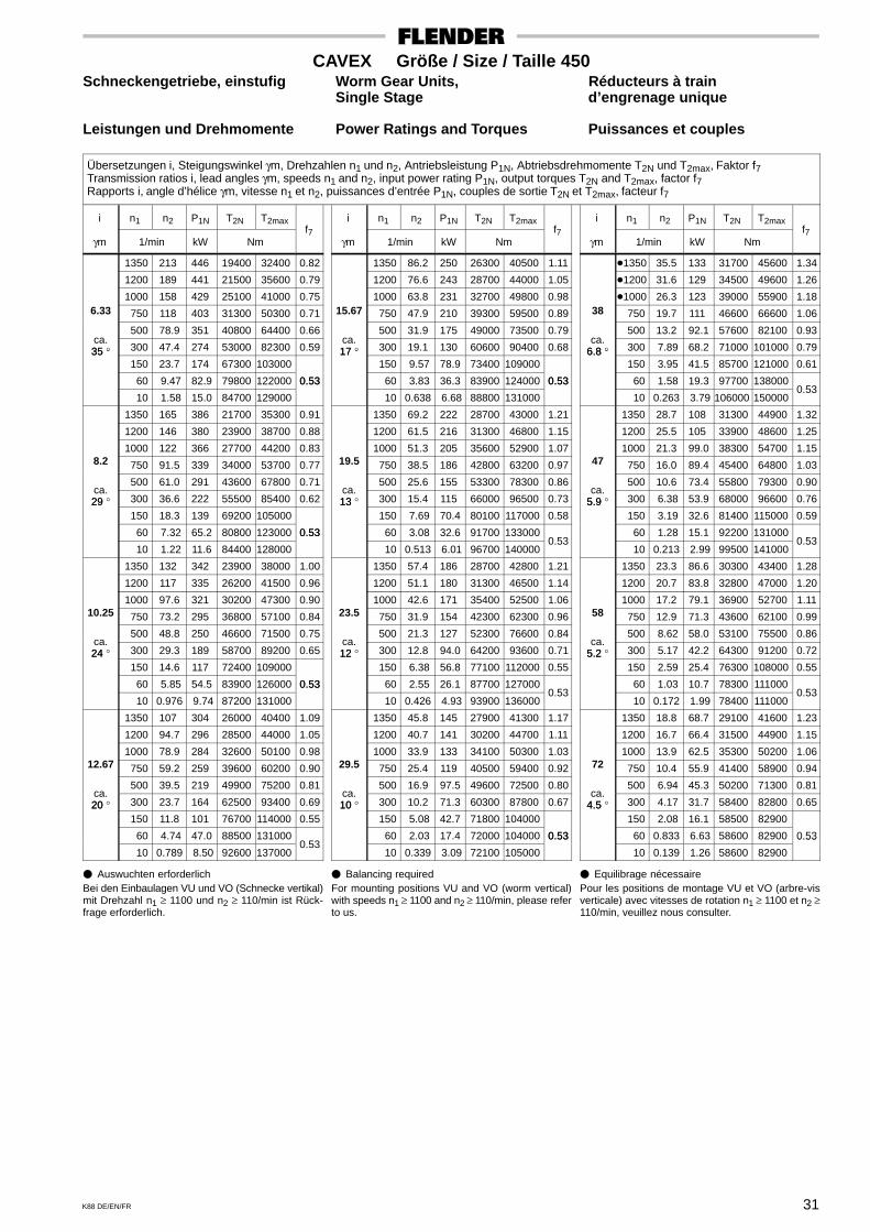
31K88 DE/EN/FR
CAVEX Größe / Size / Taille 450Schneckengetriebe, einstufig Worm Gear Units, Réducteurs à train
Single Stage d’engrenage unique
Leistungen und Drehmomente Power Ratings and Torques Puissances et couples
Übersetzungen i, Steigungswinkel γm, Drehzahlen n1 und n2, Antriebsleistung P1N, Abtriebsdrehmomente T2N und T2max, Faktor f7Transmission ratios i, lead angles γm, speeds n1 and n2, input power rating P1N, output torques T2N and T2max, factor f7Rapports i, angle d’hélice γm, vitesse n1 et n2, puissances d’entrée P1N, couples de sortie T2N et T2max, facteur f7
i n1 n2 P1N T2N T2max
γm 1/min kW Nmf7
1350 213 446 19400 32400 0.82
1200 189 441 21500 35600 0.79
1000 158 429 25100 41000 0.756.33 750 118 403 31300 50300 0.71
500 78.9 351 40800 64400 0.66ca.35 ° 300 47.4 274 53000 82300 0.5935 °
150 23.7 174 67300 103000
60 9.47 82.9 79800 122000 0.53
10 1.58 15.0 84700 129000
0.53
1350 165 386 21700 35300 0.91
1200 146 380 23900 38700 0.88
1000 122 366 27700 44200 0.838.2 750 91.5 339 34000 53700 0.77
500 61.0 291 43600 67800 0.71ca.29 ° 300 36.6 222 55500 85400 0.6229
150 18.3 139 69200 105000
60 7.32 65.2 80800 123000 0.53
10 1.22 11.6 84400 128000
0.53
1350 132 342 23900 38000 1.00
1200 117 335 26200 41500 0.96
1000 97.6 321 30200 47300 0.9010.25 750 73.2 295 36800 57100 0.84
500 48.8 250 46600 71500 0.75ca.24 ° 300 29.3 189 58700 89200 0.6524
150 14.6 117 72400 109000
60 5.85 54.5 83900 126000 0.53
10 0.976 9.74 87200 131000
0.53
1350 107 304 26000 40400 1.09
1200 94.7 296 28500 44000 1.05
1000 78.9 284 32600 50100 0.9812.67 750 59.2 259 39600 60200 0.90
500 39.5 219 49900 75200 0.81ca.20 ° 300 23.7 164 62500 93400 0.6920
150 11.8 101 76700 114000 0.55
60 4.74 47.0 88500 131000
10 0.789 8.50 92600 137000 0.53
i n1 n2 P1N T2N T2max
γm 1/min kW Nmf7
1350 86.2 250 26300 40500 1.11
1200 76.6 243 28700 44000 1.05
1000 63.8 231 32700 49800 0.9815.67 750 47.9 210 39300 59500 0.89
500 31.9 175 49000 73500 0.79ca.17 ° 300 19.1 130 60600 90400 0.6817 °
150 9.57 78.9 73400 109000
60 3.83 36.3 83900 124000 0.53
10 0.638 6.68 88800 131000
0.53
1350 69.2 222 28700 43000 1.21
1200 61.5 216 31300 46800 1.15
1000 51.3 205 35600 52900 1.0719.5 750 38.5 186 42800 63200 0.97
500 25.6 155 53300 78300 0.86ca.13 ° 300 15.4 115 66000 96500 0.7313
150 7.69 70.4 80100 117000 0.58
60 3.08 32.6 91700 133000
10 0.513 6.01 96700 140000 0.53
1350 57.4 186 28700 42800 1.21
1200 51.1 180 31300 46500 1.14
1000 42.6 171 35400 52500 1.0623.5 750 31.9 154 42300 62300 0.96
500 21.3 127 52300 76600 0.84ca.12 ° 300 12.8 94.0 64200 93600 0.7112
150 6.38 56.8 77100 112000 0.55
60 2.55 26.1 87700 127000
10 0.426 4.93 93900 136000 0.53
1350 45.8 145 27900 41300 1.17
1200 40.7 141 30200 44700 1.11
1000 33.9 133 34100 50300 1.0329.5 750 25.4 119 40500 59400 0.92
500 16.9 97.5 49600 72500 0.80ca.10 ° 300 10.2 71.3 60300 87800 0.6710
150 5.08 42.7 71800 104000
60 2.03 17.4 72000 104000 0.53
10 0.339 3.09 72100 105000
0.53
i n1 n2 P1N T2N T2max
γm 1/min kW Nmf7
�1350 35.5 133 31700 45600 1.34
�1200 31.6 129 34500 49600 1.26
�1000 26.3 123 39000 55900 1.1838 750 19.7 111 46600 66600 1.06
500 13.2 92.1 57600 82100 0.93ca.
6.8 ° 300 7.89 68.2 71000 101000 0.796.8 ° 150 3.95 41.5 85700 121000 0.61
60 1.58 19.3 97700 138000
10 0.263 3.79 106000 150000 0.53
1350 28.7 108 31300 44900 1.32
1200 25.5 105 33900 48600 1.25
1000 21.3 99.0 38300 54700 1.1547 750 16.0 89.4 45400 64800 1.03
500 10.6 73.4 55800 79300 0.90ca.
5.9 ° 300 6.38 53.9 68000 96600 0.765.9 150 3.19 32.6 81400 115000 0.59
60 1.28 15.1 92200 131000
10 0.213 2.99 99500 141000 0.53
1350 23.3 86.6 30300 43400 1.28
1200 20.7 83.8 32800 47000 1.20
1000 17.2 79.1 36900 52700 1.1158 750 12.9 71.3 43600 62100 0.99
500 8.62 58.0 53100 75500 0.86ca.
5.2 ° 300 5.17 42.2 64300 91200 0.725.2 150 2.59 25.4 76300 108000 0.55
60 1.03 10.7 78300 111000
10 0.172 1.99 78400 111000 0.53
1350 18.8 68.7 29100 41600 1.23
1200 16.7 66.4 31500 44900 1.15
1000 13.9 62.5 35300 50200 1.0672 750 10.4 55.9 41400 58900 0.94
500 6.94 45.3 50200 71300 0.81ca.
4.5 ° 300 4.17 31.7 58400 82800 0.654.5 150 2.08 16.1 58500 82900
60 0.833 6.63 58600 82900 0.53
10 0.139 1.26 58600 82900
0.53
� Auswuchten erforderlichBei den Einbaulagen VU und VO (Schnecke vertikal)mit Drehzahl n1 ≥ 1100 und n2 ≥ 110/min ist Rück-frage erforderlich.
� Balancing requiredFor mounting positions VU and VO (worm vertical)with speeds n1 ≥ 1100 and n2 ≥ 110/min, please referto us.
� Equilibrage nécessairePour les positions de montage VU et VO (arbre-visverticale) avec vitesses de rotation n1 ≥ 1100 et n2 ≥110/min, veuillez nous consulter.
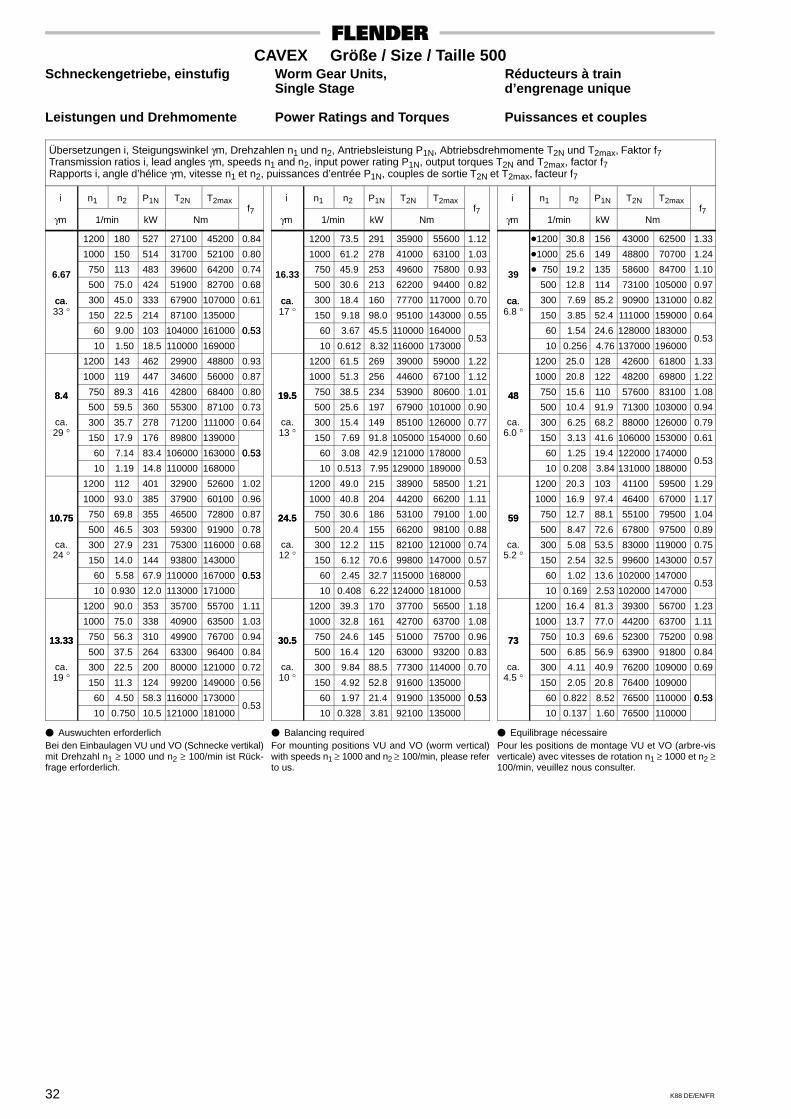
32 K88 DE/EN/FR
CAVEX Größe / Size / Taille 500Schneckengetriebe, einstufig Worm Gear Units, Réducteurs à train
Single Stage d’engrenage unique
Leistungen und Drehmomente Power Ratings and Torques Puissances et couples
Übersetzungen i, Steigungswinkel γm, Drehzahlen n1 und n2, Antriebsleistung P1N, Abtriebsdrehmomente T2N und T2max, Faktor f7Transmission ratios i, lead angles γm, speeds n1 and n2, input power rating P1N, output torques T2N and T2max, factor f7Rapports i, angle d’hélice γm, vitesse n1 et n2, puissances d’entrée P1N, couples de sortie T2N et T2max, facteur f7
i n1 n2 P1N T2N T2max
γm 1/min kW Nmf7
1200 180 527 27100 45200 0.84
1000 150 514 31700 52100 0.80
750 113 483 39600 64200 0.746.67 500 75.0 424 51900 82700 0.68
ca. 300 45.0 333 67900 107000 0.61ca.33 ° 150 22.5 214 87100 135000
60 9.00 103 104000 161000 0.53
10 1.50 18.5 110000 169000
0.53
1200 143 462 29900 48800 0.93
1000 119 447 34600 56000 0.87
8.4 750 89.3 416 42800 68400 0.808.4 500 59.5 360 55300 87100 0.73
ca.°
300 35.7 278 71200 111000 0.6429 ° 150 17.9 176 89800 139000
60 7.14 83.4 106000 163000 0.53
10 1.19 14.8 110000 168000
0.53
1200 112 401 32900 52600 1.02
1000 93.0 385 37900 60100 0.96
10.75 750 69.8 355 46500 72800 0.8710.75 500 46.5 303 59300 91900 0.78
ca.°
300 27.9 231 75300 116000 0.6824 ° 150 14.0 144 93800 143000
60 5.58 67.9 110000 167000 0.53
10 0.930 12.0 113000 171000
0.53
1200 90.0 353 35700 55700 1.11
1000 75.0 338 40900 63500 1.03
13.33 750 56.3 310 49900 76700 0.9413.33 500 37.5 264 63300 96400 0.84
ca.°
300 22.5 200 80000 121000 0.7219 ° 150 11.3 124 99200 149000 0.56
60 4.50 58.3 116000 173000
10 0.750 10.5 121000 181000 0.53
i n1 n2 P1N T2N T2max
γm 1/min kW Nmf7
1200 73.5 291 35900 55600 1.12
1000 61.2 278 41000 63100 1.03
750 45.9 253 49600 75800 0.9316.33 500 30.6 213 62200 94400 0.82
ca. 300 18.4 160 77700 117000 0.70ca.17 ° 150 9.18 98.0 95100 143000 0.55
60 3.67 45.5 110000 164000
10 0.612 8.32 116000 173000 0.53
1200 61.5 269 39000 59000 1.22
1000 51.3 256 44600 67100 1.12
19.5 750 38.5 234 53900 80600 1.0119.5 500 25.6 197 67900 101000 0.90
ca.°
300 15.4 149 85100 126000 0.7713 ° 150 7.69 91.8 105000 154000 0.60
60 3.08 42.9 121000 178000
10 0.513 7.95 129000 189000 0.53
1200 49.0 215 38900 58500 1.21
1000 40.8 204 44200 66200 1.11
24.5 750 30.6 186 53100 79100 1.0024.5 500 20.4 155 66200 98100 0.88
ca.°
300 12.2 115 82100 121000 0.7412 ° 150 6.12 70.6 99800 147000 0.57
60 2.45 32.7 115000 168000
10 0.408 6.22 124000 181000 0.53
1200 39.3 170 37700 56500 1.18
1000 32.8 161 42700 63700 1.08
30.5 750 24.6 145 51000 75700 0.9630.5 500 16.4 120 63000 93200 0.83
ca.°
300 9.84 88.5 77300 114000 0.7010 ° 150 4.92 52.8 91600 135000
60 1.97 21.4 91900 135000 0.53
10 0.328 3.81 92100 135000
0.53
i n1 n2 P1N T2N T2max
γm 1/min kW Nmf7
�1200 30.8 156 43000 62500 1.33
�1000 25.6 149 48800 70700 1.24
� 750 19.2 135 58600 84700 1.1039 500 12.8 114 73100 105000 0.97
ca. 300 7.69 85.2 90900 131000 0.82ca.6.8 ° 150 3.85 52.4 111000 159000 0.64
60 1.54 24.6 128000 183000
10 0.256 4.76 137000 196000 0.53
1200 25.0 128 42600 61800 1.33
1000 20.8 122 48200 69800 1.22
48 750 15.6 110 57600 83100 1.0848 500 10.4 91.9 71300 103000 0.94
ca.°
300 6.25 68.2 88000 126000 0.796.0 ° 150 3.13 41.6 106000 153000 0.61
60 1.25 19.4 122000 174000
10 0.208 3.84 131000 188000 0.53
1200 20.3 103 41100 59500 1.29
1000 16.9 97.4 46400 67000 1.17
59 750 12.7 88.1 55100 79500 1.0459 500 8.47 72.6 67800 97500 0.89
ca.°
300 5.08 53.5 83000 119000 0.755.2 ° 150 2.54 32.5 99600 143000 0.57
60 1.02 13.6 102000 147000
10 0.169 2.53 102000 147000 0.53
1200 16.4 81.3 39300 56700 1.23
1000 13.7 77.0 44200 63700 1.11
73 750 10.3 69.6 52300 75200 0.9873 500 6.85 56.9 63900 91800 0.84
ca.°
300 4.11 40.9 76200 109000 0.694.5 ° 150 2.05 20.8 76400 109000
60 0.822 8.52 76500 110000 0.53
10 0.137 1.60 76500 110000
0.53
� Auswuchten erforderlichBei den Einbaulagen VU und VO (Schnecke vertikal)mit Drehzahl n1 ≥ 1000 und n2 ≥ 100/min ist Rück-frage erforderlich.
� Balancing requiredFor mounting positions VU and VO (worm vertical)with speeds n1 ≥ 1000 and n2 ≥ 100/min, please referto us.
� Equilibrage nécessairePour les positions de montage VU et VO (arbre-visverticale) avec vitesses de rotation n1 ≥ 1000 et n2 ≥100/min, veuillez nous consulter.

33K88 DE/EN/FR
CAVEX Größe / Size / Taille 560Schneckengetriebe, einstufig Worm Gear Units, Réducteurs à train
Single Stage d’engrenage unique
Leistungen und Drehmomente Power Ratings and Torques Puissances et couples
Übersetzungen i, Steigungswinkel γm, Drehzahlen n1 und n2, Antriebsleistung P1N, Abtriebsdrehmomente T2N und T2max, Faktor f7Transmission ratios i, lead angles γm, speeds n1 and n2, input power rating P1N, output torques T2N and T2max, factor f7Rapports i, angle d’hélice γm, vitesse n1 et n2, puissances d’entrée P1N, couples de sortie T2N et T2max, facteur f7
i n1 n2 P1N T2N T2max
γm 1/min kW Nmf7
1100 165 656 36800 61800 0.87
1000 150 648 39900 66700 0.84
750 113 613 50300 82700 0.776.67 500 75.0 544 66600 108000 0.71
ca. 300 45.0 433 88300 141000 0.63ca.35 ° 150 22.5 283 115000 181000
60 9.00 138 140000 219000 0.53
10 1.50 24.9 149000 232000
0.53
1100 128 565 40800 67100 0.96
1000 116 556 44100 72200 0.93
8.6 750 87.2 520 54800 88600 0.848.6 500 58.1 454 71400 114000 0.76
ca.°
300 34.9 355 93000 147000 0.6729 ° 150 17.4 227 119000 186000 0.54
60 6.98 109 142000 221000
10 1.16 19.4 148000 230000 0.53
1100 102 497 44600 72000 1.06
1000 93.0 487 48100 77200 1.01
10.75 750 69.8 452 59300 94300 0.9110.75 500 46.5 391 76500 120000 0.81
ca.°
300 27.9 302 98500 153000 0.7024 ° 150 14.0 192 125000 193000 0.56
60 5.58 91.3 148000 227000
10 0.930 16.2 153000 235000 0.53
1100 82.5 437 48200 76100 1.14
1000 75.0 427 51900 81600 1.09
13.33 750 56.3 395 63700 99300 0.9813.33 500 37.5 340 81700 126000 0.87
ca.°
300 22.5 261 105000 160000 0.7519 ° 150 11.3 165 132000 201000 0.59
60 4.50 78.3 155000 236000
10 0.750 14.0 162000 245000 0.53
i n1 n2 P1N T2N T2max
γm 1/min kW Nmf7
1100 66.0 353 48400 75800 1.14
1000 60.0 344 52000 81100 1.09
750 45.0 316 63200 98000 0.9716.67 500 30.0 268 80100 123000 0.85
ca. 300 18.0 204 101000 155000 0.73ca.17 ° 150 9.00 127 126000 191000 0.57
60 3.60 59.5 146000 222000
10 0.600 10.8 154000 233000 0.53
1100 53.7 317 52800 80700 1.24
1000 48.8 310 56600 86300 1.19
20.5 750 36.6 284 68900 104000 1.0620.5 500 24.4 242 87500 132000 0.93
ca.°
300 14.6 185 111000 166000 0.8013 ° 150 7.32 115 138000 206000 0.62
60 2.93 54.5 162000 241000
10 0.488 10.2 174000 259000 0.53
1100 43.1 257 52700 80100 1.25
1000 39.2 250 56400 85500 1.19
25.5 750 29.4 228 68100 103000 1.0525.5 500 19.6 192 85600 129000 0.91
ca.°
300 11.8 145 107000 161000 0.7711 ° 150 5.88 89.6 132000 197000 0.60
60 2.35 42.0 153000 228000
10 0.392 7.74 161000 239000 0.53
1100 34.9 202 50700 76800 1.20
1000 31.7 197 54200 81900 1.14
31.5 750 23.8 179 65000 98000 1.0131.5 500 15.9 150 81100 122000 0.86
ca.°
300 9.52 112 101000 151000 0.7210 ° 150 4.76 66.7 120000 178000 0.54
60 1.90 27.1 120000 179000
10 0.317 4.80 120000 179000 0.53
i n1 n2 P1N T2N T2max
γm 1/min kW Nmf7
�1100 27.5 189 57900 85300 1.38
�1000 25.0 184 61900 91100 1.31
� 750 18.8 168 74900 110000 1.1540 500 12.5 143 94300 138000 1.00
ca. 300 7.50 108 119000 173000 0.85ca.6.7 ° 150 3.75 67.6 147000 214000 0.66
60 1.50 32.0 171000 249000
10 0.250 6.18 184000 267000 0.53
1100 22.4 155 57300 84200 1.36
1000 20.4 151 61200 89800 1.29
49 750 15.3 138 73600 108000 1.1449 500 10.2 116 92000 134000 0.98
ca.°
300 6.12 87.2 115000 167000 0.835.9 ° 150 3.06 53.9 141000 205000 0.64
60 1.22 25.4 163000 237000
10 0.204 5.04 178000 258000 0.53
1100 18.3 124 55300 81100 1.30
1000 16.7 121 59000 86400 1.24
60 750 12.5 110 70600 103000 1.0860 500 8.33 92.3 87700 128000 0.93
ca.°
300 5.00 68.8 109000 158000 0.785.2 ° 150 2.50 42.3 132000 192000 0.60
60 1.00 17.8 136000 198000
10 0.167 3.29 136000 198000 0.53
1100 14.9 99.3 53100 77800 1.25
1000 13.5 96.6 56600 82700 1.19
74 750 10.1 87.7 67400 98400 1.0474 500 6.76 72.8 83200 121000 0.88
ca.°
300 4.05 53.9 102000 149000 0.734.5 ° 150 2.03 27.3 102000 149000
60 0.811 11.2 103000 149000 0.53
10 0.135 2.10 103000 149000
0.53
� Auswuchten erforderlichBei den Einbaulagen VU und VO (Schnecke vertikal)mit Drehzahl n1 ≥ 900 und n2 ≥ 90/min ist Rückfrageerforderlich.
� Balancing requiredFor mounting positions VU and VO (worm vertical)with speeds n1 ≥ 900 and n2 ≥ 90/min, please referto us.
� Equilibrage nécessairePour les positions de montage VU et VO (arbre-visverticale) avec vitesses de rotation n1 ≥ 900 et n2 ≥90/min, veuillez nous consulter.
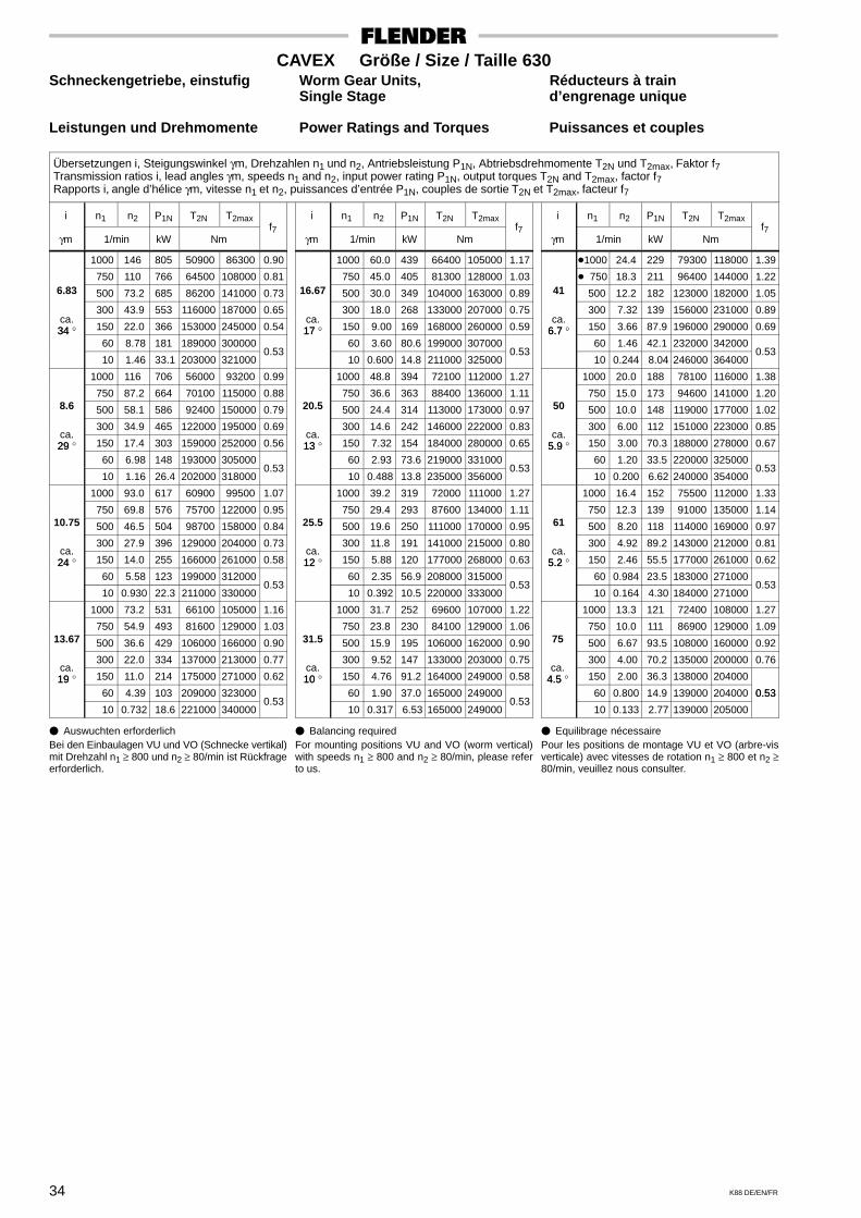
34 K88 DE/EN/FR
CAVEX Größe / Size / Taille 630Schneckengetriebe, einstufig Worm Gear Units, Réducteurs à train
Single Stage d’engrenage unique
Leistungen und Drehmomente Power Ratings and Torques Puissances et couples
Übersetzungen i, Steigungswinkel γm, Drehzahlen n1 und n2, Antriebsleistung P1N, Abtriebsdrehmomente T2N und T2max, Faktor f7Transmission ratios i, lead angles γm, speeds n1 and n2, input power rating P1N, output torques T2N and T2max, factor f7Rapports i, angle d’hélice γm, vitesse n1 et n2, puissances d’entrée P1N, couples de sortie T2N et T2max, facteur f7
i n1 n2 P1N T2N T2max
γm 1/min kW Nmf7
1000 146 805 50900 86300 0.90
750 110 766 64500 108000 0.816.83 500 73.2 685 86200 141000 0.73
300 43.9 553 116000 187000 0.65ca.34 ° 150 22.0 366 153000 245000 0.5434 °
60 8.78 181 189000 300000
10 1.46 33.1 203000 321000 0.53
1000 116 706 56000 93200 0.99
750 87.2 664 70100 115000 0.888.6 500 58.1 586 92400 150000 0.79
300 34.9 465 122000 195000 0.69ca.29 ° 150 17.4 303 159000 252000 0.5629
60 6.98 148 193000 305000
10 1.16 26.4 202000 318000 0.53
1000 93.0 617 60900 99500 1.07
750 69.8 576 75700 122000 0.9510.75 500 46.5 504 98700 158000 0.84
300 27.9 396 129000 204000 0.73ca.24 ° 150 14.0 255 166000 261000 0.5824
60 5.58 123 199000 312000
10 0.930 22.3 211000 330000 0.53
1000 73.2 531 66100 105000 1.16
750 54.9 493 81600 129000 1.0313.67 500 36.6 429 106000 166000 0.90
300 22.0 334 137000 213000 0.77ca.19 ° 150 11.0 214 175000 271000 0.6219
60 4.39 103 209000 323000
10 0.732 18.6 221000 340000 0.53
i n1 n2 P1N T2N T2max
γm 1/min kW Nmf7
1000 60.0 439 66400 105000 1.17
750 45.0 405 81300 128000 1.0316.67 500 30.0 349 104000 163000 0.89
300 18.0 268 133000 207000 0.75ca.17 ° 150 9.00 169 168000 260000 0.5917 °
60 3.60 80.6 199000 307000
10 0.600 14.8 211000 325000 0.53
1000 48.8 394 72100 112000 1.27
750 36.6 363 88400 136000 1.1120.5 500 24.4 314 113000 173000 0.97
300 14.6 242 146000 222000 0.83ca.13 ° 150 7.32 154 184000 280000 0.6513
60 2.93 73.6 219000 331000
10 0.488 13.8 235000 356000 0.53
1000 39.2 319 72000 111000 1.27
750 29.4 293 87600 134000 1.1125.5 500 19.6 250 111000 170000 0.95
300 11.8 191 141000 215000 0.80ca.12 ° 150 5.88 120 177000 268000 0.6312
60 2.35 56.9 208000 315000
10 0.392 10.5 220000 333000 0.53
1000 31.7 252 69600 107000 1.22
750 23.8 230 84100 129000 1.0631.5 500 15.9 195 106000 162000 0.90
300 9.52 147 133000 203000 0.75ca.10 ° 150 4.76 91.2 164000 249000 0.5810
60 1.90 37.0 165000 249000
10 0.317 6.53 165000 249000 0.53
i n1 n2 P1N T2N T2max
γm 1/min kW Nmf7
�1000 24.4 229 79300 118000 1.39
� 750 18.3 211 96400 144000 1.2241 500 12.2 182 123000 182000 1.05
300 7.32 139 156000 231000 0.89ca.
6.7 ° 150 3.66 87.9 196000 290000 0.696.7 ° 60 1.46 42.1 232000 342000
10 0.244 8.04 246000 364000 0.53
1000 20.0 188 78100 116000 1.38
750 15.0 173 94600 141000 1.2050 500 10.0 148 119000 177000 1.02
300 6.00 112 151000 223000 0.85ca.
5.9 ° 150 3.00 70.3 188000 278000 0.675.9 60 1.20 33.5 220000 325000
10 0.200 6.62 240000 354000 0.53
1000 16.4 152 75500 112000 1.33
750 12.3 139 91000 135000 1.1461 500 8.20 118 114000 169000 0.97
300 4.92 89.2 143000 212000 0.81ca.
5.2 ° 150 2.46 55.5 177000 261000 0.625.2 60 0.984 23.5 183000 271000
10 0.164 4.30 184000 271000 0.53
1000 13.3 121 72400 108000 1.27
750 10.0 111 86900 129000 1.0975 500 6.67 93.5 108000 160000 0.92
300 4.00 70.2 135000 200000 0.76ca.
4.5 ° 150 2.00 36.3 138000 2040004.5 60 0.800 14.9 139000 204000 0.53
10 0.133 2.77 139000 205000
0.53
� Auswuchten erforderlichBei den Einbaulagen VU und VO (Schnecke vertikal)mit Drehzahl n1 ≥ 800 und n2 ≥ 80/min ist Rückfrageerforderlich.
� Balancing requiredFor mounting positions VU and VO (worm vertical)with speeds n1 ≥ 800 and n2 ≥ 80/min, please referto us.
� Equilibrage nécessairePour les positions de montage VU et VO (arbre-visverticale) avec vitesses de rotation n1 ≥ 800 et n2 ≥80/min, veuillez nous consulter.

35K88 DE/EN/FR
CAVEX Bauart / Type CUWSchneckengetriebe Worm Gear Units Réducteurs à vis sans fin
Abtriebswelle auf Seite A, B oder beiderseits Output shaft on side A, B or both sides Arbre de côté A, B ou des deux côtésEinbaulage SU, SO, SR, SL, VO oder VU Mounting position SU, SO, SR, SL, VO or VU Position de montage SU, SO, SR, SL, VO ou VU
SeiteSideCôté
A
SeiteSideCôté
B
SU SR SL VO VU
B
A
A
A
AB
B
B B
A B
AAnsicht / View
Vue X
SO X
GrößeSize a b c d1 l1 d2 l2 e3 e4 E G1 G3 G2 h1 h2 H m1 m2 m3 sSizeTaille mm
63 80 100
146 175 216
140 168 200
20 24 28
18 k6 22 k6 28 m6
35 40 50
28 m6 38 m6 48 m6
50 65 80
69 82 98
119 140 168
63 80 100
85 102 124
122 143 171
72 86 102
63 75 90
126 155 190
208 252 309
115 140 170
120 145 170
– – –
12 15 15
120 140 160
254 290 324
235 260 295
32 36 40
32 m6 38 m6 42 m6
55 60 70
55 m6 65 m6 70 m6
95 105 120
114 126 143
194 220 244
120 140 160
145 165 184
197 224 248
120 132 150
105 115 130
225 255 290
364 416 472
200 230 260
200 225 255
– – –
19 19 19
180 200 225
364 396 440
325 350 380
45 50 55
48 m6 55 m6 60 m6
80 90100
80 m6 90 m6100 m6
140 160 180
159 171 188
272 294 323
180 200 225
205 223 245
276 298 327
165 178 195
140 150 165
320 350 390
522 573 638
290 315 350
280 295 325
– – –
24 24 28
250 280 315
480 525 590
415 450 490
60 65 70
65 m6 70 m6 75 m6
105110120
110 n6120 n6140 n6
200 220 240
204 222 244
354 387 430
250 280 315
270 318 355
358 392 434
212 230 252
180 200 215
430 480 530
703 786 870
385 430 480
355 385 420
– – –
28 35 35
355 400 450
665 748 855
535 585 562
78 85 92
80 m6 90 m6100 m6
130145160
150 n6170 n6190 n6
260 290 320
266 291 322
478 526 596
355 400 450
395 432 485
482 530 600
275 300 332
240 260 290
595 660 740
97710861270
540 605 750
460 510 495
– –
560
42 42 35
500 560 630
95510501175
616 678 750
100110120
110 n6120 n6135 n6
175190210
210 n6230 n6255 n6
350 390 430
355 389 429
663 733 815
500 560 630
540 590 655
668 738 820
365 400 440
315 350 385
815 9101015
141015601745
840 9201030
540 600 660
630 700 780
42 42 48
Bei senkrechter Schneckenwelle ist der Hinweis imBild auf Seite 98 zu beachten.
For vertical worm shaft arrangement, observedirection given in illustration on page 98.
Dans le cas d’un arbre à vis sans fin vertical suivreles instructions illustrées à la page 98.
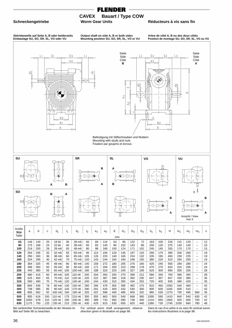
36 K88 DE/EN/FR
CAVEX Bauart / Type COWSchneckengetriebe Worm Gear Units Réducteurs à vis sans fin
Abtriebswelle auf Seite A, B oder beiderseits Output shaft on side A, B or both sides Arbre de côté A, B ou des deux côtésEinbaulage SU, SO, SR, SL, VO oder VU Mounting position SU, SO, SR, SL, VO or VU Position de montage SU, SO, SR, SL, VO ou VU
SeiteSideCôté
A
SeiteSideCôté
B
SO
SU SR SL VO VU
A
AB
BA B
B
A
A
B
A
B
Ansicht / ViewVue X
X
Befestigung mit Stiftschrauben und MutternMounting with studs and nutsFixation par goujons et écrous
GrößeSize a b c d1 l1 d2 l2 e3 e4 E G1 G3 G2 h1 h2 H m1 m2 m3 sSizeTaille mm
63 80 100
146 175 216
140168200
20 24 28
18 k6 22 k6 28 m6
35 40 50
28 m6 38 m6 48 m6
50 65 80
69 82 98
119140168
63 80100
85102124
122143171
72 86102
163 200 245
100 120 145
226 275 335
115 140 170
120 145 170
–––
121515
120 140 160
254 290 324
235260295
32 36 40
32 m6 38 m6 42 m6
55 60 70
55 m6 65 m6 70 m6
95105120
114126143
194220244
120140160
145165184
197224248
120132150
290 335 380
170 195 220
395 450 510
200 230 260
200 225 255
–––
191919
180 200 225
364 396 440
325350380
45 50 55
48 m6 55 m6 60 m6
80 90100
80 m6 90 m6100 m6
140160180
159171188
272294323
180200225
205223245
276298327
165178195
425 470 525
245 270 300
565 620 690
290 315 350
280 295 325
–––
242428
250 280 315
480 525 590
415450490
60 65 70
65 m6 70 m6 75 m6
105110120
110 n6120 n6140 n6
200220240
204222244
354387430
250280315
270318355
358392434
212230252
580 647 720
330 367 405
760 847 935
385 430 480
355 385 420
–––
283535
355 400 450
665 748 855
535585562
78 85 92
80 m6 90 m6100 m6
130145160
150 n6170 n6190 n6
260290320
266291322
478526596
355400450
395432485
482530600
275300332
810 905 980
455 505 530
105011651270
540 605 750
460 510 495
––
560
424235
500 560 630
95510501175
616678750
100110120
110 n6120 n6135 n6
175190210
210 n6230 n6255 n6
350390430
355389429
663733815
500560630
540590655
668738820
365400440
109512101360
595 650 730
141015601745
840 9201030
540 600 660
630700780
424248
Bei senkrechter Schneckenwelle ist der Hinweis imBild auf Seite 98 zu beachten.
For vertical worm shaft arrangement, observedirection given in illustration on page 98.
Dans le cas d’un arbre à vis sans fin vertical suivreles instructions illustrées à la page 98.

37K88 DE/EN/FR
CAVEX Bauart / Type CFWSchneckengetriebe Worm Gear Units Réducteurs à vis sans fin
Flansch auf Seite A oder B Flange on side A or B Bride côté A ou BAbtriebswelle auf Seite A, B oder beiderseits Output shaft on side A, B or both sides Arbre de côté A, B ou des deux côtésEinbaulage SU, SO, SR, SL, VO oder VU Mounting position SU, SO, SR, SL, VO or VU Position de montage SU, SO, SR, SL, VO ou VU
SeiteSideCôté
B
SeiteSideCôté
A
Lochbild bei Größe / Hole pattern for size / Position des perçages pour taille
SO
A
B
B
A
B A
A
B
Ansicht / ViewVue X
SU SR SL VO VU
A
B
AB
X
Befestigung mit Stiftschrauben und MutternMounting with studs and nutsFixation par goujons et écrous
GrößeSize c d1 l1 d2 l2 d3 d4 e1 e2 e3 e4 E g3 G1 G3 G2 k s zSizeTaille mm
63 80 100
7 8 9
18 k6 22 k6 28 m6
35 40 50
28 m6 38 m6 48 m6
50 65 80
188 218 266
150 h8 180 h8 220 h8
63 75 90
82 97119
69 82 98
119140168
63 80100
76 90107
85102124
122143171
72 86102
170 200 245
5 x 9 7 x 9 7 x 11
3.544
120 140 160
101112
32 m6 38 m6 42 m6
55 60 70
55 m6 65 m6 70 m6
95105120
315 360 410
260 h8 305 h8 340 h8
105115130
139161182
114126143
194220244
120140160
125138157
145165184
197224248
120132150
290 335 380
7 x 13.5 7 x 13.5 7 x 17.5
555
180 200 225
131415
48 m6 55 m6 60 m6
80 90100
80 m6 90 m6100 m6
140160180
450 490 540
380 h8 420 h8 465 h8
140150165
202223248
159171188
272294323
180200225
172185202
205223245
276298327
165178195
420 460 505
7 x 17.5 7 x 17.512 x 17.5
555
250 280 315
16.518
19.5
65 m6 70 m6 75 m6
105110120
110 n6120 n6140 n6
200220240
590 665 730
515 h8 575 h8 640 h8
180200215
273306340
204222244
354387430
250280315
220238260
270318355
358392434
212230252
555 625 690
12 x 17.512 x 2212 x 22
666
355 400 450
2122.524
80 m6 90 m6100 m6
130145160
150 n6170 n6190 n6
260290320
825 9101025
725 h8 805 h8 905 h8
240260290
382426530
266291322
478526596
355400450
286312345
395432485
482530600
275300332
780 865 975
12 x 2612 x 2616 x 26
666
500 560 630
25.527
28.5
110 n6120 n6135 n6
175190210
210 n6230 n6255 n6
350390430
115012701405
1015 h81125 h81260 h8
315350385
595650730
355389429
663733815
500560630
380415456
540590655
668738820
365400440
109512101345
16 x 3316 x 3316 x 33
666
Bei senkrechter Schneckenwelle ist der Hinweis imBild auf Seite 98 zu beachten.
For vertical worm shaft arrangement, observedirection given in illustration on page 98.
Dans le cas d’un arbre à vis sans fin vertical suivreles instructions illustrées à la page 98.

38 K88 DE/EN/FR
CAVEX Bauart / Type CDASchneckengetriebe Worm Gear Units Réducteurs à vis sans fin
Drehmomentstütze in Stellung 1, 2, 3 oder 4 ** Torque arm in position 1, 2, 3 or 4 ** Bras de réaction en position 1, 2, 3 ou 4 **Drehmomentstütze auf Seite A oder B Torque arm on side A or B Bras de réaction côté A ou BMit oder ohne Endscheibe With or without end plate Avec ou sans rondelle de démontageEinbaulage SU, SO, SR, SL, VO oder VU Mounting position SU, SO, SR, SL, VO or VU Position de montage SU, SO, SR, SL, VO ou VU
SeiteSideCôté
B
SeiteSideCôté
A
SO
B
A
B
Ansicht / ViewVue X
SU SR SL VO VU
AB
X
A
B
A
BA
A
B
AbschlußdeckelEnd coverCouvercle Endscheibe
End plateRondelle de fixation
EinzelheitDetail
X
** Bei Motoranbau Stel-lung 4 nicht möglichIn case of mountedmotor, position 4 isnot possibleLors du montage dumoteur, la position 4n’est pas possible
Schraube gehört nicht zum LieferumfangBolt does not belong to our scope of supplyVis ne fait pas partie de la livraison
Größec c d l d D2 D5 e e e e E f g G G G L L n P sSize c1 c2 d1 l1 d6
H7 H8e1 e2 e4 e5 E f g4 G1 G3 G2
min. max.*L2 n
min.s
Taillemm
63 80 100
161620
81011
18 k6 22 k6 28 m6
35 40 50
32 40 40
30 40 50
162020
63 75 90
82 97119
119140168
73 89102
63 80100
223
62 74 88
85102124
122143171
65 80 93
95114136
102124147
115139.5165
140 180 225
101214
M 10M 16M 16
120 140 160
202525
121415
32 m6 38 m6 42 m6
55 60 70
50 50 65
60 65 75
252532
105115130
139161182
194220244
115127142
120140160
334
101113126
145165184
197224248
106118132
155173194
167186212
187208.5235.5
270 315 360
161820
M 20M 20M 20
180 200 225
323240
161718
48 m6 55 m6 60 m6
80 90100
65 80 80
85 95105
324040
140150165
202223248
272294323
154165182
180200225
445
138148163
205223245
276298327
144155170
212228250
233250276
259278307
405 450 505
222528
M 20M 24M 24
250 280 315
404050
202224
65 m6 70 m6 75 m6
105110120
80100100
115125140
405050
180200215
273306340
354387430
197213233
250280315
555
178192212
270318355
358392434
185200220
272293322
301326357
335363397
560 630 710
303236
M 24M 24M 30
355 400 450
506060
273033
80 m6 90 m6100 m6
130145160
120120150
160180200
606075
240260290
382426530
478526596
256279308
355400450
556
233256282
395432485
482530600
242265292
354387425
394433480
438481532
800 9001010
404548
M 30M 30M 30
500 560 630
757590
363840
110 n6120 n6135 n6
175190210
150170170
220240270
759090
315350385
595650730
663733815
336370406
500560630
666
310341377
540590655
668738820
320352388
465510560
528583650
585643713
112012601420
505663
M 30M 36M 36
Bei senkrechter Schneckenwelle ist der Hinweis imBild auf Seite 98 zu beachten.*) Lmax gilt nur bei Verwendung der Abdrück-
scheibe.
For vertical worm shaft arrangement, observedirection given in illustration on page 98.*) Lmax is applicable only when using a forcing
plate.
Dans le cas d’un arbre à vis sans fin vertical suivreles instructions illustrées à la page 98.*) Lmax applicable en utilisant la rondelle de
démontage.

39K88 DE/EN/FR
CAVEX Bauart / Type CUASchneckengetriebe Worm Gear Units Réducteurs à vis sans fin
Abschlußdeckel auf Seite A oder B End cover on side A or B Couvercle côté A ou BMit oder ohne Abdrückscheibe With or without forcing plate Avec ou sans rondelle de démontageEinbaulage SU, SO, SR, SL, VO oder VU Mounting position SU, SO, SR, SL, VO or VU Position de montage SU, SO, SR, SL, VO ou VU
SeiteSideCôté
A
SeiteSideCôté
B
AbschlußdeckelEnd coverCouvercle
AbdrückscheibeForcing plateRondelle de démontage
SU SR SL VO VU
SO
A B
B
A
A
B
B
A
B
A
B A
X
Ansicht / ViewVue X
Größea b c c d l D2 D e e E G G G h h H L L m m m P sSize a b c c2 d1 l1
H7D3 e4 e5 E G1 G2 G3 h1 h2
min. max.*L1 m1 m2 m3
min.s
Taillemm
63 80 100
146 175 216
140168200
20 24 28
81011
18 k6 22 k6 28 m6
35 40 50
30 40 50
M 12M 20M 20
119140168
73 89102
63 80100
85102124
65 80 93
122143171
63 75 90
126 155 190
208 252 309
94114136
102124147
105.5128152
115 140 170
120145170
–––
101214
121515
120 140 160
254 290 324
235260295
32 36 40
121415
32 m6 38 m6 42 m6
55 60 70
60 65 75
M 24M 24M 24
194220244
115127142
120140160
145165184
106118132
197224248
105115130
225 255 290
364 416 472
155173194
167186212
173192.5218.5
200 230 260
200225255
–––
161820
191919
180 200 225
364 396 440
325350380
45 50 55
161718
48 m6 55 m6 60 m6
80 90100
85 95105
M 24M 30M 30
272294323
154165182
180200225
205223245
144155170
276298327
140150165
320 350 390
522 573 638
212228250
233250276
240258285
290 315 350
280295325
–––
222528
242428
250 280 315
480 525 590
415450490
60 65 70
202224
65 m6 70 m6 75 m6
105110120
115125140
M 30M 36M 36
354387430
197213233
250280315
270318355
185200220
358392434
180200215
430 480 530
703 786 870
272293322
301326357
311337369
385 430 480
355385420
–––
303236
283535
355 400 450
665 748 855
535585562
78 85 92
273033
80 m6 90 m6100 m6
130145160
160180200
M 36M 36M 36
478526596
256279308
355400450
395432485
242265292
482530600
240260290
595 660 740
97710861270
354387425
394433480
407447495
540 605 750
460510495
––
560
404548
424235
500 560 630
95510501175
616678750
100110120
363840
110 n6120 n6135 n6
175190210
220240270
M 36M 42M 42
663733815
336370406
500560630
540590655
320352388
668738820
315350385
815 9101015
141015601745
465510560
528583650
544600668
840 9201030
540600660
630700780
505663
424248
Bei senkrechter Schneckenwelle ist der Hinweis imBild auf Seite 98 zu beachten.*) Lmax gilt nur bei Verwendung der Abdrück-
scheibe.
For vertical worm shaft arrangement, observedirection given in illustration on page 98.*) Lmax is applicable only when using a forcing
plate.
Dans le cas d’un arbre à vis sans fin vertical suivreles instructions illustrées à la page 98.*) Lmax applicable en utilisant la rondelle de
démontage.

40 K88 DE/EN/FR
CAVEX Bauart / Type COASchneckengetriebe Worm Gear Units Réducteurs à vis sans fin
Abschlußdeckel auf Seite A oder B End cover on side A or B Couvercle côté A ou BMit oder ohne Abdrückscheibe With or without forcing plate Avec ou sans rondelle de démontageEinbaulage SU, SO, SR, SL, VO oder VU Mounting position SU, SO, SR, SL, VO or VU Position de montage SU, SO, SR, SL, VO ou VU
SeiteSideCôté
A
SeiteSideCôté
B
AbschlußdeckelEnd coverCouvercle
AbdrückscheibeForcing plateRondelle de démontage
SU SR SL VO VU
SO
A B
X
Ansicht / ViewVue X
B A
B A
A B
B
A
B
A
Befestigung mit Stiftschrauben und MutternMounting with studs and nutsFixation par goujons et écrous
Größea b c c d l D2 D G G G e e E h h H m m m L L P sSize a b c c2 d1 l1
H7D3 G1 G3 G2 e4 e5 E h1 h2 H m1 m2 m3
min. max.*L1
min.s
Taillemm
63 80 100
146 175 216
140168200
20 24 28
81011
18 k6 22 k6 28 m6
35 40 50
30 40 50
M 12M 20M 20
85102124
122143171
65 80 93
119140168
73 89102
63 80100
163 200 245
100120145
226 275 335
115 140 170
120145170
–––
94114136
102124147
105.5128152
101214
121515
120 140 160
254 290 324
235260295
32 36 40
121415
32 m6 38 m6 42 m6
55 60 70
60 65 75
M 24M 24M 24
145165184
197224248
106118132
194220244
115127142
120140160
290 335 380
170195220
395 450 510
200 230 260
200225255
–––
155173194
167186212
173192.5218.5
161820
191919
180 200 225
364 396 440
325350380
45 50 55
161718
48 m6 55 m6 60 m6
80 90100
85 95105
M 24M 30M 30
205223245
276298327
144155170
272294323
154165182
180200225
425 470 525
245270300
565 620 690
290 315 350
280295325
–––
212228250
233250276
240258285
222528
242428
250 280 315
480 525 590
415450490
60 65 70
202224
65 m6 70 m6 75 m6
105110120
115125140
M 30M 30M 36
270318355
358392434
185200220
354387430
197213233
250280315
580 647 720
330367405
760 847 935
385 430 480
355385420
–––
272293322
301326357
311337369
303236
283535
355 400 450
665 748 855
535585562
78 85 92
273033
80 m6 90 m6100 m6
130145160
160180200
M 36M 36M 36
395432485
482530600
242265292
478526596
256279308
355400450
810 905 980
455505530
105011651270
540 605 750
460510495
––
560
354387425
394433480
407447495
404548
424235
500 560 630
95510501175
616678750
100110120
363840
110 n6120 n6135 n6
175190210
220240270
M 36M 42M 42
540590655
668738820
320352388
663733815
336370406
500560630
109512101360
595650730
141015601745
840 9201030
540600660
630700780
465510560
528583650
544600668
505663
424248
Bei senkrechter Schneckenwelle ist der Hinweis imBild auf Seite 98 zu beachten.*) Lmax gilt nur bei Verwendung der Abdrück-
scheibe.
For vertical worm shaft arrangement, observedirection given in illustration on page 98.*) Lmax is applicable only when using a forcing
plate.
Dans le cas d’un arbre à vis sans fin vertical suivreles instructions illustrées à la page 98.*) Lmax applicable en utilisant la rondelle de
démontage.

41K88 DE/EN/FR
CAVEX Bauart / Type CFASchneckengetriebe Worm Gear Units Réducteurs à vis sans fin
Flanschdeckel auf Seite A oder B Flange cover on side A or B Couvercle-bride côté A ou BMit oder ohne Abdrückscheibe With or without forcing plate Avec ou sans rondelle de démontageEinbaulage SU, SO, SR, SL, VO oder VU Mounting position SU, SO, SR, SL, VO or VU Position de montage SU, SO, SR, SL, VO ou VU
SeiteSideCôté
A
SeiteSideCôté
B
AbschlußdeckelEnd coverCouvercle
AbdrückscheibeForcing plateRondelle de démontage
Lochbild bei GrößeHole pattern for size
Position des perçages pour taille
FlanschdeckelFlange coverCouvercle-bride
SU SR SL VO VU
SO
A
B
X
A B
B
A
A
B
B
A
B
Ansicht / ViewVue X
A
Größec c d l d d4 D2 D e e e e E g G G G k L L P s zSize c c2 d1 l1 d3
h8 H7D3 e1 e2 e4 e5 E g3 G1 G2 G3 k
min. max.*L1
min.s z
Taillemm
63 80 100
131518
81011
18 k6 22 k6 28 m6
35 40 50
145 175 217
95 125 155
30 40 50
M 12M 20M 20
63 75 90
82 97119
119140168
73 89102
63 80100
63 75 90
85102124
65 80 93
122143171
130 160 195
94114136
102124147
105.5128152
101214
6 x M 8 8 X M 8 8 X M 10
33.53.5
120 140 160
202225
121415
32 m6 38 m6 42 m6
55 60 70
258 302 338
190 225 260
60 65 75
M 24M 24M 24
105115130
139161182
194220244
115127142
120140160
104116129
145165184
106118132
197224248
235 275 310
155173194
167186212
173192.5218.5
161820
8 X M 12 8 X M 12 8 X M 16
445
180 200 225
283134
161718
48 m6 55 m6 60 m6
80 90100
379 416 462
295 330 375
85 95105
M 24M 30M 30
140150165
202223248
272294323
154165182
180200225
142152167
205223245
144155170
276298327
350 385 430
212228250
233250276
240258285
222528
8 X M 16 8 X M 1612 X M 16
555
250 280 315
374043
202224
65 m6 70 m6 75 m6
105110120
510 574 638
420 465 530
115125140
M 30M 30M 36
180200215
273306340
354387430
197213233
250280315
181196216
270318355
185200220
358392434
480 535 600
272293322
301326357
311337369
303236
12 X M 1612 X M 2012 X M 20
566
355 400 450
464852
273033
80 m6 90 m6100 m6
130145160
720 804 906
600 680 770
160180200
M 36M 36M 36
240260290
382426530
478526596
256279308
355400450
238260287
395432485
242265292
482530600
680 760 860
354387425
394433480
407447495
404548
12 X M 2412 X M 2416 X M 24
666
500 560 630
556063
363840
110 n6120 n6135 n6
175190210
101411261258
860 9651090
220240270
M 36M 42M 42
315350385
595650730
663733815
336370406
500560630
314346382
540590655
320352388
668738820
96010701200
465510560
528583650
544600668
505663
16 X M 3016 X M 3016 X M 30
666
Bei senkrechter Schneckenwelle ist der Hinweis imBild auf Seite 98 zu beachten.*) Lmax gilt nur bei Verwendung der Abdrück-
scheibe.
For vertical worm shaft arrangement, observedirection given in illustration on page 98.*) Lmax is applicable only when using a forcing
plate.
Dans le cas d’un arbre à vis sans fin vertical suivreles instructions illustrées à la page 98.*) Lmax applicable en utilisant la rondelle de
démontage.

ab Vorrat ex stock en stock
42 K88 DE/EN/FR
CAVEX Größe / Size / Taille 63Stirnrad-Schneckengetriebe Helical Worm Gear Units Réducteurs combinés à un train
d’engrenages cylindriques
Leistungen und Drehmomente Power Ratings and Torques Puissances et couples
Übersetzungen i, Steigungswinkel γm, Drehzahlen n1 und n2, Antriebsleistung P1N, Abtriebsdrehmomente T2N und T2max, Faktor f7Transmission ratios i, lead angles γm, speeds n1 and n2, input power rating P1N, output torques T2N and T2max, factor f7Rapports i, angle d’hélice γm, vitesse n1 et n2, puissances d’entrée P1N, couples de sortie T2N et T2max, facteur f7
i1 x i2= i n1 n2 P1N T2N T2max
f
γm 1/min kW Nm
f7
3000 140 3.55 218 309
2400 112 3.13 238 3342.08 1800 83.8 2.61 262 363
x10.33 1500 69.8 2.30 276 37910.33
= 1200 55.8 1.96 290 39721.49
1000 46.5 1.70 300 409 0.53
750 34.9 1.35 314 425ca.
° 500 23.3 0.953 329 44318 ° 300 14.0 0.601 342 458
150 6.98 0.315 352 470
3000 114 3.17 236 332
2400 91.3 2.77 255 3552.545 1800 68.4 2.27 277 381x10.33 1500 57.0 1.99 289 39510.33
= 1200 45.6 1.68 301 41026.3
1000 38.0 1.45 310 421 0.53
750 28.5 1.14 322 435ca.18 ° 500 19.0 0.794 335 45018
300 11.4 0.499 346 462
150 5.70 0.260 354 472
3000 93.1 2.70 240 328
2400 74.4 2.37 260 3522.08 1800 55.8 1.96 283 380x15.5 1500 46.5 1.73 296 39615.5
= 1200 37.2 1.46 310 41232.24
1000 31.0 1.27 320 424 0.53
750 23.3 1.01 333 440ca.12 ° 500 15.5 0.709 347 45712
300 9.31 0.447 359 471
150 4.65 0.235 369 483
3000 76.0 2.40 258 350
2400 60.8 2.08 277 3722.545 1800 45.6 1.70 297 397x15.5 1500 38.0 1.49 309 41115.5
= 1200 30.4 1.25 321 42639.45
1000 25.3 1.08 330 436 0.53
750 19.0 0.850 341 449ca.12 ° 500 12.7 0.590 353 46412
300 7.60 0.371 363 476
150 3.80 0.194 371 485
3000 61.0 2.09 277 372
2400 48.8 1.79 293 3923.174 1800 36.6 1.44 311 414
x15.5 1500 30.5 1.26 321 42515.5
= 1200 24.4 1.05 331 43849.2
1000 20.3 0.902 338 446 0.53
750 15.2 0.698 348 458ca.12 ° 500 10.2 0.485 358 46912
300 6.10 0.302 366 479
150 3.05 0.158 372 487
i1 x i2= i n1 n2 P1N T2N T2max
f
γm 1/min kW Nm
f7
3000 46.5 1.66 265 346
2400 37.2 1.45 285 3702.080 1800 27.9 1.21 307 397
x31 1500 23.3 1.06 320 41231= 1200 18.6 0.903 333 429
64.48 1000 15.5 0.788 343 440
0.53
750 11.6 0.630 355 455ca.
° 500 7.75 0.442 369 4726.1 ° 300 4.65 0.281 380 486
150 2.33 0.149 389 497
3000 38.0 1.47 283 368
2400 30.4 1.28 301 3892.545 1800 22.8 1.05 321 414x
31 1500 19.0 0.917 332 42731= 1200 15.2 0.777 344 441
78.9 1000 12.7 0.674 352 451
0.53
750 9.51 0.530 363 464ca.
6.1 ° 500 6.34 0.369 374 4786.1 300 3.80 0.233 383 490
150 1.90 0.124 391 499
3000 30.5 1.28 301 389
2400 24.4 1.10 317 4093.174 1800 18.3 0.892 334 430x
31 1500 15.2 0.778 344 44131= 1200 12.2 0.654 353 453
98.39 1000 10.2 0.562 360 461
0.53
750 7.62 0.436 369 472ca.
6.1 ° 500 5.08 0.304 379 4846.1 300 3.05 0.191 386 493
150 1.52 0.102 392 500
3000 23.9 1.08 318 410
2400 19.1 0.920 332 4274.053 1800 14.3 0.741 346 445x
31 1500 11.9 0.643 354 45431= 1200 9.55 0.533 362 464
125.6 1000 7.96 0.453 368 471
0.53
750 5.97 0.350 375 480ca.
6.1 ° 500 3.98 0.243 383 4896.1 300 2.39 0.153 389 496
150 1.19 0.082 394 502
i1 x i2= i n1 n2 P1N T2N T2max
f
γm 1/min kW Nm
f7
3000 20.6 0.972 327 422
2400 16.4 0.824 340 4374.706 1800 12.3 0.660 353 453
x31 1500 10.3 0.568 360 46131= 1200 8.22 0.467 367 470
145.9 1000 6.85 0.396 372 476
0.53
750 5.14 0.307 378 483ca.
° 500 3.43 0.212 385 4916.1 ° 300 2.06 0.133 390 498
150 1.03 0.071 394 503
3000 16.3 0.768 311 399
2400 13.1 0.652 322 4134.706 1800 9.81 0.523 334 427x
39 1500 8.17 0.448 340 43539= 1200 6.54 0.367 346 442
183.5 1000 5.45 0.311 350 448
0.53
750 4.09 0.242 356 454ca.
5.2 ° 500 2.72 0.168 362 4615.2 300 1.63 0.105 366 467
150 0.817 0.057 370 472
3000 13.0 0.610 293 376
2400 10.4 0.518 303 3884.706 1800 7.81 0.416 314 401x
49 1500 6.50 0.355 319 40849= 1200 5.20 0.291 325 415
230.6 1000 4.34 0.247 328 419
0.53
750 3.25 0.192 333 425ca.
4.4 ° 500 2.17 0.133 338 4324.4 300 1.30 0.084 342 437
150 0.650 0.046 346 441
3000 10.4 0.492 277 355
2400 8.36 0.408 279 3574.706 1800 6.27 0.317 280 358x
61 1500 5.22 0.267 280 35861= 1200 4.18 0.215 280 358
287.1 1000 3.48 0.181 280 358
0.53
750 2.61 0.140 281 358ca.
3.8 ° 500 1.74 0.095 281 3583.8 300 1.04 0.060 281 358
150 0.522 0.032 281 359

ab Vorrat ex stock en stock
43K88 DE/EN/FR
CAVEX Größe / Size / Taille 80Stirnrad-Schneckengetriebe Helical Worm Gear Units Réducteurs combinés à un train
d’engrenages cylindriques
Leistungen und Drehmomente Power Ratings and Torques Puissances et couples
Übersetzungen i, Steigungswinkel γm, Drehzahlen n1 und n2, Antriebsleistung P1N, Abtriebsdrehmomente T2N und T2max, Faktor f7Transmission ratios i, lead angles γm, speeds n1 and n2, input power rating P1N, output torques T2N and T2max, factor f7Rapports i, angle d’hélice γm, vitesse n1 et n2, puissances d’entrée P1N, couples de sortie T2N et T2max, facteur f7
i1 x i2= i n1 n2 P1N T2N T2max
f
γm 1/min kW Nm
f7
3000 140 6.49 402 574
2400 112 5.77 444 6262.08 1800 83.8 4.86 495 689
x10.33 1500 69.8 4.31 523 72410.33
= 1200 55.8 3.68 555 76321.49
1000 46.5 3.21 578 791 0.53
750 34.9 2.56 609 828ca.
° 500 23.3 1.82 643 86918 ° 300 14.0 1.15 672 905
150 6.98 0.607 695 933
3000 114 5.84 440 621
2400 91.3 5.13 480 6712.545 1800 68.4 4.25 526 727x10.33 1500 57.0 3.73 552 75910.33
= 1200 45.6 3.16 580 79326.3
1000 38.0 2.74 600 818 0.53
750 28.5 2.17 627 850ca.18 ° 500 19.0 1.53 656 88518
300 11.4 0.960 680 915
150 5.70 0.503 700 939
3000 93.1 4.91 441 606
2400 74.4 4.34 484 6582.08 1800 55.8 3.62 533 719x15.5 1500 46.5 3.20 561 75415.5
= 1200 37.2 2.72 592 79132.24
1000 31.0 2.37 614 818 0.53
750 23.3 1.89 644 855ca.12 ° 500 15.5 1.35 676 89412
300 9.31 0.850 704 929
150 4.65 0.449 727 956
3000 76.0 4.39 480 653
2400 60.8 3.83 519 7022.545 1800 45.6 3.16 564 757x15.5 1500 38.0 2.77 589 78815.5
= 1200 30.4 2.34 616 82139.45
1000 25.3 2.03 636 845 0.53
750 19.0 1.60 661 876ca.12 ° 500 12.7 1.12 689 91012
300 7.60 0.708 712 938
150 3.80 0.372 731 961
3000 61.0 3.83 519 701
2400 48.8 3.31 554 7453.174 1800 36.6 2.69 594 794
x15.5 1500 30.5 2.34 616 82115.5
= 1200 24.4 1.96 639 84949.2
1000 20.3 1.69 656 869 0.53
750 15.2 1.33 677 896ca.12 ° 500 10.2 0.920 700 92412
300 6.10 0.577 720 947
150 3.05 0.303 735 966
i1 x i2= i n1 n2 P1N T2N T2max
f
γm 1/min kW Nm
f7
3000 46.5 3.00 490 642 0.54
2400 37.2 2.63 531 6932.08 1800 27.9 2.20 580 753
x31 1500 23.3 1.94 608 78731= 1200 18.6 1.65 638 824
64.48 1000 15.5 1.44 659 851 0.53
750 11.6 1.15 688 886
0.53
ca.° 500 7.75 0.826 719 9256.2 °
300 4.65 0.524 746 958
150 2.33 0.280 768 984
3000 38.0 2.67 528 688
2400 30.4 2.32 566 7362.545 1800 22.8 1.91 610 791x
31 1500 19.0 1.68 635 82131= 1200 15.2 1.42 661 853
78.9 1000 12.7 1.24 680 876
0.53
750 9.51 0.982 705 907ca.
6.2 ° 500 6.34 0.691 731 9406.2 300 3.80 0.438 754 967
150 1.90 0.233 772 989
3000 30.5 2.32 566 736
2400 24.4 2.00 601 7793.174 1800 18.3 1.63 640 827x
31 1500 15.2 1.42 661 85331= 1200 12.2 1.20 684 881
98.39 1000 10.2 1.04 699 900
0.53
750 7.62 0.814 720 926ca.
6.2 ° 500 5.08 0.566 742 9536.2 300 3.05 0.358 761 976
150 1.52 0.191 775 994
3000 23.9 1.98 604 783
2400 19.1 1.69 634 8204.053 1800 14.3 1.36 668 861x
31 1500 11.9 1.18 686 88331= 1200 9.55 0.986 704 907
125.6 1000 7.96 0.845 717 923
0.53
750 5.97 0.655 735 944ca.
6.2 ° 500 3.98 0.456 752 9656.2 300 2.39 0.286 767 984
150 1.19 0.153 779 998
i1 x i2= i n1 n2 P1N T2N T2max
f
γm 1/min kW Nm
f7
3000 20.6 1.78 625 808
2400 16.4 1.51 652 8424.706 1800 12.3 1.21 683 880
x31 1500 10.3 1.05 699 89931= 1200 8.22 0.870 715 920
145.9 1000 6.85 0.741 727 934
0.53
750 5.14 0.571 742 953ca.
° 500 3.43 0.399 757 9726.2 ° 300 2.06 0.250 770 988
150 1.03 0.134 780 1000
3000 16.3 1.43 609 786
2400 13.1 1.21 634 8184.706 1800 9.81 0.972 661 851x
39 1500 8.17 0.841 676 86939= 1200 6.54 0.697 691 888
183.5 1000 5.45 0.593 701 901
0.53
750 4.09 0.458 715 917ca.
5.4 ° 500 2.72 0.320 729 9345.4 300 1.63 0.201 740 949
150 0.817 0.108 749 960
3000 13.0 1.12 573 739
2400 10.4 0.951 595 7664.706 1800 7.81 0.762 619 796x
49 1500 6.50 0.661 632 81249= 1200 5.20 0.545 645 829
230.6 1000 4.34 0.464 654 840
0.53
750 3.25 0.360 666 855ca.
4.6 ° 500 2.17 0.251 678 8704.6 300 1.30 0.158 688 882
150 0.650 0.086 696 892
3000 10.4 0.897 540 696
2400 8.36 0.761 560 7214.706 1800 6.27 0.595 567 728x
61 1500 5.22 0.507 568 72961= 1200 4.18 0.410 568 729
287.1 1000 3.48 0.344 568 729
0.53
750 2.61 0.263 569 730ca.
3.9 ° 500 1.74 0.181 569 7303.9 300 1.04 0.113 570 730
150 0.522 0.061 570 731

ab Vorrat ex stock en stock
Durch eine zusätzliche Vorschaltstufe, sind außerdem folgende Übersetzungen möglich:By mounting an additional primary gear stage, the following transmission ratios can be obtained:En montant un train d’engrenages supplémentaire, les rapports suivants peuvent être obtenus:
2.08 x 3.217 x 32 = 214.12.545 x 3.217 x 32 = 2623.174 x 3.217 x 32 = 326.74.053 x 3.217 x 32 = 417.2
4.706 x 3.217 x 32 = 484.54.706 x 3.217 x 40 = 605.64.706 x 3.217 x 50 = 7574.706 x 3.217 x 62 = 938.6
Leistungen und Drehmomente auf Anfrage / Power ratings and torques on request / Puissances etcouples sur demande
44 K88 DE/EN/FR
CAVEX Größe / Size / Taille 100Stirnrad-Schneckengetriebe Helical Worm Gear Units Réducteurs combinés à un train
d’engrenages cylindriques
Leistungen und Drehmomente Power Ratings and Torques Puissances et couples
Übersetzungen i, Steigungswinkel γm, Drehzahlen n1 und n2, Antriebsleistung P1N, Abtriebsdrehmomente T2N und T2max, Faktor f7Transmission ratios i, lead angles γm, speeds n1 and n2, input power rating P1N, output torques T2N and T2max, factor f7Rapports i, angle d’hélice γm, vitesse n1 et n2, puissances d’entrée P1N, couples de sortie T2N et T2max, facteur f7
i1 x i2= i n1 n2 P1N T2N T2max
f
γm 1/min kW Nm
f7
3000 143 11.5 699 1010
2400 115 10.4 783 11101.963 1800 86.0 8.84 886 1240
x10.67 1500 71.6 7.89 946 132010.67
= 1200 57.3 6.79 1010 140020.94
1000 47.8 5.96 1060 1460 0.53
750 35.8 4.78 1130 1550ca.
° 500 23.9 3.43 1210 164018 ° 300 14.3 2.20 1270 1730
150 7.16 1.16 1330 1790
3000 114 10.3 787 1120
2400 90.8 9.13 867 12202.478 1800 68.1 7.63 962 1340x10.67 1500 56.8 6.74 1020 141010.67
= 1200 45.4 5.74 1080 148026.43
1000 37.8 4.99 1120 1530 0.53
750 28.4 3.96 1180 1610ca.18 ° 500 18.9 2.81 1240 168018
300 11.4 1.78 1300 1750
150 5.68 0.935 1340 1810
3000 92.6 8.53 777 1070 0.56
2400 74.1 7.64 862 1180 0.541.963 1800 55.6 6.45 964 1310x16.5 1500 46.3 5.72 1020 138016.5
= 1200 37.0 4.90 1090 147032.39
1000 30.9 4.29 1140 1530
750 23.2 3.43 1200 1610 0.53
ca.12 ° 500 15.4 2.46 1280 170012
300 9.26 1.57 1340 1780
150 4.63 0.833 1390 1840
3000 73.4 7.60 866 1180 0.54
2400 58.7 6.67 945 12802.478 1800 44.0 5.53 1040 1400x16.5 1500 36.7 4.87 1090 147016.5
= 1200 29.3 4.13 1150 154040.89
1000 24.5 3.58 1190 1590 0.53
750 18.3 2.84 1250 1660
0.53
ca.12 ° 500 12.2 2.01 1310 174012
300 7.34 1.27 1360 1810
150 3.67 0.671 1400 1860
3000 56.5 6.51 958 1300
2400 45.2 5.63 1030 13903.217 1800 33.9 4.60 1110 1500
x16.5 1500 28.3 4.01 1160 155016.5
= 1200 22.6 3.37 1210 161053.08
1000 18.8 2.90 1240 1660 0.53
750 14.1 2.28 1290 1720ca.12 ° 500 9.42 1.59 1340 178012
300 5.65 1.00 1380 1830
150 2.83 0.526 1410 1870
i1 x i2= i n1 n2 P1N T2N T2max
f
γm 1/min kW Nm
f7
3000 47.8 5.24 851 1120 0.62
2400 38.2 4.69 936 1230 0.581.963 1800 28.7 3.94 1040 1360 0.54
x32 1500 23.9 3.49 1100 143032= 1200 19.1 2.99 1160 1510
62.82 1000 15.9 2.62 1210 1570
750 11.9 2.10 1280 1650 0.53ca.
° 500 7.96 1.51 1350 1740
0.53
6.3 ° 300 4.78 0.970 1410 1820
150 2.39 0.520 1460 1880
3000 37.8 4.67 940 1230 0.58
2400 30.3 4.08 1020 1330 0.552.478 1800 22.7 3.37 1110 1450x
32 1500 18.9 2.97 1170 152032= 1200 15.1 2.52 1220 1590
79.3 1000 12.6 2.19 1260 1640
750 9.46 1.74 1320 1710 0.53
ca.6.3 ° 500 6.31 1.24 1380 17806.3
300 3.78 0.786 1430 1850
150 1.89 0.421 1470 1900
3000 29.2 3.98 1030 1350 0.54
2400 23.3 3.44 1100 14403.217 1800 17.5 2.80 1190 1540x
32 1500 14.6 2.45 1230 160032= 1200 11.7 2.06 1280 1660
102.9 1000 9.72 1.78 1310 1700 0.53
750 7.29 1.40 1360 1760
0.53
ca.6.3 ° 500 4.86 0.984 1410 18206.3
300 2.92 0.624 1450 1870
150 1.46 0.333 1480 1910
3000 22.8 3.39 1110 1450
2400 18.3 2.89 1170 15304.105 1800 13.7 2.33 1250 1620x
32 1500 11.4 2.02 1280 166032= 1200 9.13 1.69 1320 1710
131.4 1000 7.61 1.46 1350 1750
0.53
750 5.71 1.14 1390 1800ca.
6.3 ° 500 3.81 0.791 1430 18506.3 300 2.28 0.499 1460 1890
150 1.14 0.267 1490 1920
i1 x i2= i n1 n2 P1N T2N T2max
f
γm 1/min kW Nm
f7
3000 18.5 2.92 1170 1520
2400 14.8 2.48 1230 15905.063 1800 11.1 1.98 1290 1670
x32 1500 9.26 1.71 1320 171032= 1200 7.41 1.42 1360 1760
162 1000 6.17 1.22 1380 1790
0.53
750 4.63 0.943 1410 1820ca.
° 500 3.09 0.656 1450 18706.3 ° 300 1.85 0.413 1470 1900
150 0.926 0.221 1490 1930
3000 14.8 2.35 1140 1480
2400 11.9 1.99 1190 15405.063 1800 8.89 1.59 1250 1610x
40 1500 7.41 1.37 1280 165040= 1200 5.93 1.14 1310 1690
202.5 1000 4.94 0.971 1330 1720
0.53
750 3.70 0.752 1360 1750ca.
5.5 ° 500 2.47 0.525 1390 17905.5 300 1.48 0.331 1410 1820
150 0.741 0.178 1430 1840
3000 11.8 1.84 1070 1390
2400 9.48 1.56 1120 14505.063 1800 7.11 1.24 1170 1510x
50 1500 5.92 1.07 1200 154050= 1200 4.74 0.892 1220 1580
253.2 1000 3.95 0.760 1240 1600
0.53
750 2.96 0.588 1270 1630ca.
4.7 ° 500 1.97 0.412 1290 16704.7 300 1.18 0.259 1300 1680
150 0.592 0.139 1300 1680
3000 9.56 1.47 1010 1310
2400 7.65 1.24 1050 13605.063 1800 5.73 0.963 1070 1380x
62 1500 4.78 0.815 1070 138062= 1200 3.82 0.663 1070 1380
313.9 1000 3.19 0.558 1070 1380
0.53
750 2.39 0.424 1070 1380ca.4 ° 500 1.59 0.293 1070 13804
300 0.956 0.183 1070 1380
150 0.478 0.099 1070 1380

ab Vorrat ex stock en stock
Durch eine zusätzliche Vorschaltstufe, sind außerdem folgende Übersetzungen möglich:By mounting an additional primary gear stage, the following transmission ratios can be obtained:En montant un train d’engrenages supplémentaire, les rapports suivants peuvent être obtenus:
2.08 x 3.217 x 32 = 214.12.545 x 3.217 x 32 = 2623.174 x 3.217 x 32 = 326.74.053 x 3.217 x 32 = 417.2
4.706 x 3.217 x 32 = 484.54.706 x 3.217 x 40 = 605.64.706 x 3.217 x 50 = 7574.706 x 3.217 x 63 = 953.8
Leistungen und Drehmomente auf Anfrage / Power ratings and torques on request / Puissances etcouples sur demande
45K88 DE/EN/FR
CAVEX Größe / Size / Taille 120Stirnrad-Schneckengetriebe Helical Worm Gear Units Réducteurs combinés à un train
d’engrenages cylindriques
Leistungen und Drehmomente Power Ratings and Torques Puissances et couples
Übersetzungen i, Steigungswinkel γm, Drehzahlen n1 und n2, Antriebsleistung P1N, Abtriebsdrehmomente T2N und T2max, Faktor f7Transmission ratios i, lead angles γm, speeds n1 and n2, input power rating P1N, output torques T2N and T2max, factor f7Rapports i, angle d’hélice γm, vitesse n1 et n2, puissances d’entrée P1N, couples de sortie T2N et T2max, facteur f7
i1 x i2= i n1 n2 P1N T2N T2max
f
γm 1/min kW Nm
f7
3000 143 18.0 1100 1590 0.56
2400 115 16.4 1250 1780 0.541.963 1800 86.0 14.1 1420 2010
x10.67 1500 71.6 12.7 1530 214010.67
= 1200 57.3 11.0 1650 230020.94
1000 47.8 9.65 1740 2410
750 35.8 7.78 1870 2570 0.53
ca.° 500 23.9 5.60 2010 275019 °
300 14.3 3.61 2130 2910
150 7.16 1.92 2240 3040
3000 114 16.3 1250 1790
2400 90.8 14.6 1390 19702.478 1800 68.1 12.3 1560 2180x10.67 1500 56.8 10.9 1660 230010.67
= 1200 45.4 9.30 1760 244026.43
1000 37.8 8.11 1840 2540 0.53
750 28.4 6.46 1950 2680ca.19 ° 500 18.9 4.60 2070 283019
300 11.4 2.93 2180 2960
150 5.68 1.54 2260 3070
3000 92.6 13.4 1230 1710 0.62
2400 74.1 12.1 1380 1900 0.591.963 1800 55.6 10.3 1560 2120 0.55x16.5 1500 46.3 9.21 1660 226016.5
= 1200 37.0 7.91 1780 241032.39
1000 30.9 6.93 1870 2520
750 23.2 5.56 1990 2680 0.53ca.12 ° 500 15.4 3.99 2130 2850
0.53
12 300 9.26 2.56 2250 3010
150 4.63 1.37 2350 3130
3000 73.4 12.0 1380 1900 0.59
2400 58.7 10.7 1520 2080 0.562.478 1800 44.0 8.90 1690 2300x16.5 1500 36.7 7.86 1790 242016.5
= 1200 29.3 6.68 1890 255040.89
1000 24.5 5.81 1970 2650
750 18.3 4.61 2080 2780 0.53
ca.12 ° 500 12.2 3.27 2190 293012
300 7.34 2.08 2290 3060
150 3.67 1.10 2380 3160
3000 56.5 10.4 1550 2110 0.55
2400 45.2 9.06 1680 22803.217 1800 33.9 7.42 1830 2470
x16.5 1500 28.3 6.49 1910 257016.5
= 1200 22.6 5.46 2000 269053.08
1000 18.8 4.71 2070 2770 0.53
750 14.1 3.70 2160 2880
0.53
ca.12 ° 500 9.42 2.60 2250 300012
300 5.65 1.64 2330 3100
150 2.83 0.864 2400 3190
i1 x i2= i n1 n2 P1N T2N T2max
f
γm 1/min kW Nm
f7
3000 47.8 8.19 1350 1790 0.68
2400 38.2 7.37 1500 1980 0.651.963 1800 28.7 6.28 1680 2200 0.59
x32 1500 23.9 5.57 1780 2340 0.5632= 1200 19.1 4.77 1900 2490
62.82 1000 15.9 4.18 1990 2600
750 11.9 3.35 2110 2750ca.
° 500 7.96 2.40 2250 2920 0.53
6.4 ° 300 4.78 1.55 2370 3080
150 2.39 0.836 2470 3200
3000 37.8 7.34 1500 1980 0.64
2400 30.3 6.49 1640 2160 0.602.478 1800 22.7 5.38 1810 2370 0.55x
32 1500 18.9 4.74 1910 249032= 1200 15.1 4.02 2010 2630
79.3 1000 12.6 3.50 2090 2730
750 9.46 2.77 2190 2860 0.53ca.
6.4 ° 500 6.31 1.98 2310 3000
0.53
6.4 300 3.78 1.26 2410 3130
150 1.89 0.676 2490 3230
3000 29.2 6.34 1670 2190 0.60
2400 23.3 5.48 1800 2350 0.563.217 1800 17.5 4.47 1950 2540x
32 1500 14.6 3.91 2030 265032= 1200 11.7 3.28 2120 2760
102.9 1000 9.72 2.84 2190 2850
750 7.29 2.23 2270 2950 0.53
ca.6.4 ° 500 4.86 1.57 2370 30706.4
300 2.92 0.999 2450 3170
150 1.46 0.535 2510 3250
3000 22.8 5.41 1810 2370 0.55
2400 18.3 4.62 1920 25204.105 1800 13.7 3.73 2060 2680x
32 1500 11.4 3.23 2130 277032= 1200 9.13 2.70 2210 2870
131.4 1000 7.61 2.31 2260 2940 0.53
750 5.71 1.82 2330 3030
0.53
ca.6.4 ° 500 3.81 1.27 2410 31306.4
300 2.28 0.803 2470 3210
150 1.14 0.430 2520 3270
i1 x i2= i n1 n2 P1N T2N T2max
f
γm 1/min kW Nm
f7
3000 18.5 4.67 1920 2510
2400 14.8 3.96 2020 26405.063 1800 11.1 3.16 2140 2790
x32 1500 9.26 2.73 2200 287032= 1200 7.41 2.26 2270 2950
162 1000 6.17 1.94 2310 3010
0.53
750 4.63 1.51 2370 3080ca.
° 500 3.09 1.05 2440 31606.4 ° 300 1.85 0.663 2490 3230
150 0.926 0.356 2530 3280
3000 14.8 3.73 1860 2430
2400 11.9 3.16 1960 25505.063 1800 8.89 2.52 2060 2690x
40 1500 7.41 2.17 2120 276040= 1200 5.93 1.79 2180 2830
202.5 1000 4.94 1.54 2220 2890
0.53
750 3.70 1.20 2280 2960ca.
5.6 ° 500 2.47 0.835 2330 30305.6 300 1.48 0.528 2380 3090
150 0.741 0.285 2420 3140
3000 11.8 2.94 1780 2310
2400 9.48 2.48 1860 24205.063 1800 7.11 1.98 1960 2540x
50 1500 5.92 1.70 2010 261050= 1200 4.74 1.41 2060 2680
253.2 1000 3.95 1.21 2100 2720
0.53
750 2.96 0.942 2150 2780ca.
4.8 ° 500 1.97 0.657 2200 28504.8 300 1.18 0.413 2220 2880
150 0.592 0.221 2220 2880
3000 9.40 2.27 1660 2160
2400 7.52 1.92 1740 22605.063 1800 5.64 1.51 1800 2340x
63 1500 4.70 1.27 1800 234063= 1200 3.76 1.03 1800 2340
319 1000 3.13 0.865 1800 2340
0.53
750 2.35 0.660 1800 2340ca.
4.1 ° 500 1.57 0.452 1800 23404.1 300 0.940 0.283 1810 2340
150 0.470 0.153 1810 2340
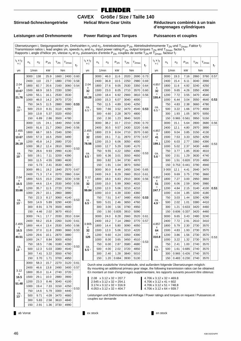
ab Vorrat ex stock en stock
Durch eine zusätzliche Vorschaltstufe, sind außerdem folgende Übersetzungen möglich:By mounting an additional primary gear stage, the following transmission ratios can be obtained:En montant un train d’engrenages supplémentaire, les rapports suivants peuvent être obtenus:
2.08 x 3.12 x 32 = 207.72.545 x 3.12 x 32 = 254.13.174 x 3.12 x 32 = 316.94.053 x 3.12 x 32 = 404.7
4.706 x 3.12 x 32 = 469.84.706 x 3.12 x 41 = 6024.706 x 3.12 x 51 = 748.84.706 x 3.12 x 64 = 939.7
Leistungen und Drehmomente auf Anfrage / Power ratings and torques on request / Puissances etcouples sur demande
46 K88 DE/EN/FR
CAVEX Größe / Size / Taille 140Stirnrad-Schneckengetriebe Helical Worm Gear Units Réducteurs combinés à un train
d’engrenages cylindriques
Leistungen und Drehmomente Power Ratings and Torques Puissances et couples
Übersetzungen i, Steigungswinkel γm, Drehzahlen n1 und n2, Antriebsleistung P1N, Abtriebsdrehmomente T2N und T2max, Faktor f7Transmission ratios i, lead angles γm, speeds n1 and n2, input power rating P1N, output torques T2N and T2max, factor f7Rapports i, angle d’hélice γm, vitesse n1 et n2, puissances d’entrée P1N, couples de sortie T2N et T2max, facteur f7
i1 x i2= i n1 n2 P1N T2N T2max
f
γm 1/min kW Nm
f7
3000 138 25.9 1660 2400 0.60
2400 110 23.7 1880 2700 0.582.04 1800 82.7 20.6 2160 3060 0.54
x10.67 1500 68.9 18.5 2330 328010.67
= 1200 55.1 16.1 2530 353021.76
1000 46.0 14.2 2670 3720
750 34.5 11.5 2880 3980 0.53ca.
° 500 23.0 8.31 3110 4280
0.53
19 ° 300 13.8 5.37 3320 4550
150 6.89 2.86 3500 4780
3000 115 24.1 1840 2650 0.58
2400 91.6 21.7 2060 2940 0.562.455 1800 68.7 18.5 2340 3290x10.67 1500 57.3 16.5 2500 349010.67
= 1200 45.8 14.2 2680 372026.19
1000 38.2 12.4 2810 3900
750 28.6 9.93 2990 4130 0.53
ca.19 ° 500 19.1 7.11 3200 439019
300 11.5 4.55 3380 4630
150 5.73 2.41 3530 4820
3000 89.1 19.2 1840 2570 0.67
2400 71.3 17.4 2070 2860 0.642.04 1800 53.5 15.0 2360 3230 0.59x16.5 1500 44.6 13.4 2530 3450 0.5616.5
= 1200 35.7 11.5 2720 370033.66
1000 29.7 10.1 2860 3880
750 22.3 8.17 3060 4140ca.13 ° 500 14.9 5.89 3290 4430
0.5313
300 8.91 3.79 3500 4690
150 4.46 2.02 3670 4910
3000 74.1 17.7 2030 2810 0.64
2400 59.2 15.8 2260 3100 0.612.455 1800 44.4 13.4 2530 3450 0.56x16.5 1500 37.0 11.8 2690 3660 0.5316.5
= 1200 29.6 10.1 2870 388040.51
1000 24.7 8.84 3000 4050
750 18.5 7.06 3180 4280ca.
13 ° 500 12.3 5.03 3380 4540 0.53
13 300 7.41 3.22 3550 4760
150 3.70 1.71 3700 4950
3000 58.3 15.7 2270 3120 0.61
2400 46.6 13.8 2490 3400 0.573.12 1800 35.0 11.4 2740 3720
x16.5 1500 29.1 10.0 2880 390016.5
= 1200 23.3 8.46 3040 410051.48
1000 19.4 7.33 3150 4250
750 14.6 5.79 3300 4440 0.53
ca.13 ° 500 9.71 4.09 3470 466013
300 5.83 2.58 3610 4840
150 2.91 1.36 3730 4990
i1 x i2= i n1 n2 P1N T2N T2max
f
γm 1/min kW Nm
f7
3000 46.0 11.6 2020 2690 0.73
2400 36.8 10.5 2250 2980 0.692.04 1800 27.6 9.05 2530 3350 0.64
x32 1500 23.0 8.05 2710 3570 0.6032= 1200 18.4 6.92 2900 3810 0.56
65.28 1000 15.3 6.07 3040 4000
750 11.5 4.89 3240 4250ca.
° 500 7.66 3.52 3470 4540 0.536.5 ° 300 4.60 2.28 3670 4800
0.53
150 2.30 1.23 3840 5020
3000 38.2 10.7 2210 2930 0.70
2400 30.5 9.57 2430 3220 0.662.455 1800 22.9 8.04 2710 3570 0.60x
32 1500 19.1 7.11 2870 3770 0.5732= 1200 15.3 6.06 3050 4000
78.56 1000 12.7 5.29 3180 4170
750 9.55 4.22 3350 4390ca.
6.5 ° 500 6.36 3.01 3550 4650 0.53
6.5 300 3.82 1.94 3730 4870
150 1.91 1.04 3870 5050
3000 30.0 9.49 2450 3240 0.65
2400 24.0 8.29 2660 3510 0.613.12 1800 18.0 6.83 2910 3830 0.56x32 1500 15.0 5.99 3060 402032= 1200 12.0 5.06 3210 4210
99.84 1000 10.0 4.39 3330 4360
750 7.51 3.47 3480 4550 0.53ca.
6.5 ° 500 5.01 2.46 3650 4760
0.53
6.5 300 3.00 1.56 3790 4950
150 1.50 0.835 3910 5090
3000 24.0 8.28 2660 3520 0.61
2400 19.2 7.14 2860 3770 0.573.905 1800 14.4 5.80 3090 4050x
32 1500 12.0 5.06 3210 422032= 1200 9.60 4.24 3350 4390
125 1000 8.00 3.65 3450 4510
750 6.00 2.87 3580 4680 0.53
ca.6.5 ° 500 4.00 2.02 3720 48506.5
300 2.40 1.28 3840 5010
150 1.20 0.684 3930 5130
i1 x i2= i n1 n2 P1N T2N T2max
f
γm 1/min kW Nm
f7
3000 19.3 7.16 2860 3760 0.57
2400 15.4 6.11 3040 39904.857 1800 11.6 4.92 3240 4250
x32 1500 9.65 4.26 3350 439032= 1200 7.72 3.55 3470 4540
155.4 1000 6.44 3.04 3550 4640 0.53
750 4.83 2.38 3660 4780
0.53
ca.° 500 3.22 1.66 3770 49306.5 °
300 1.93 1.05 3870 5050
150 0.965 0.561 3950 5150
3000 15.1 5.64 2800 3680 0.56
2400 12.1 4.80 2970 38904.857 1800 9.04 3.85 3150 4130 x
41 1500 7.53 3.33 3250 425041= 1200 6.03 2.77 3360 4390
199.1 1000 5.02 2.37 3430 4480
0.53
750 3.77 1.85 3530 4610ca.
5.6 ° 500 2.51 1.29 3630 47405.6 300 1.51 0.820 3720 4850
150 0.753 0.441 3790 4940
3 000 12.1 4.41 2640 3470
2400 9.69 3.75 2790 36604.857 1800 7.27 3.00 2950 3860x
51 1500 6.06 2.59 3040 398051= 1200 4.84 2.15 3140 4100 0.53
247.7 1000 4.04 1.85 3200 4180
0.53
750 3.03 1.44 3290 4290ca.
4.9 ° 500 2.02 1.01 3380 44104.9 300 1.21 0.633 3420 4460
150 0.606 0.337 3420 4460
3000 9.65 3.43 2480 3240
2400 7.72 2.91 2610 34104.857 1800 5.79 2.30 2730 3570x
64 1500 4.83 1.93 2730 357064= 1200 3.86 1.56 2730 3570
310.8 1000 3.22 1.32 2730 3570
0.53
750 2.41 1.00 2740 3570ca.
4.1 ° 500 1.61 0.685 2740 35704.1 300 0.965 0.426 2740 3570
150 0.483 0.230 2740 3570

ab Vorrat ex stock en stock
Durch eine zusätzliche Vorschaltstufe, sind außerdem folgende Übersetzungen möglich:By mounting an additional primary gear stage, the following transmission ratios can be obtained:En montant un train d’engrenages supplémentaire, les rapports suivants peuvent être obtenus:
2.08 x 3.12 x 33 = 214.22.545 x 3.12 x 33 = 2623.174 x 3.12 x 33 = 326.84.053 x 3.12 x 33 = 417.3
4.706 x 3.12 x 33 = 484.54.706 x 3.12 x 42 = 616.74.706 x 3.12 x 52 = 763.54.706 x 3.12 x 65 = 954.4
Leistungen und Drehmomente auf Anfrage / Power ratings and torques on request / Puissances etcouples sur demande
47K88 DE/EN/FR
CAVEX Größe / Size / Taille 160Stirnrad-Schneckengetriebe Helical Worm Gear Units Réducteurs combinés à un train
d’engrenages cylindriques
Leistungen und Drehmomente Power Ratings and Torques Puissances et couples
Übersetzungen i, Steigungswinkel γm, Drehzahlen n1 und n2, Antriebsleistung P1N, Abtriebsdrehmomente T2N und T2max, Faktor f7Transmission ratios i, lead angles γm, speeds n1 and n2, input power rating P1N, output torques T2N and T2max, factor f7Rapports i, angle d’hélice γm, vitesse n1 et n2, puissances d’entrée P1N, couples de sortie T2N et T2max, facteur f7
i1 x i2= i n1 n2 P1N T2N T2max
f
γm 1/min kW Nm
f7
3000 130 34.1 2310 3370 0.65
2400 104 31.2 2640 3800 0.622.04 1800 77.9 27.3 3050 4340 0.59
x11.33 1500 64.9 24.6 3310 4670 0.5611.33
= 1200 51.9 21.5 3600 505023.12
1000 43.3 19.0 3810 5330
750 32.4 15.4 4120 5740ca.
° 500 21.6 11.2 4480 6200 0.53
19 ° 300 13.0 7.28 4810 6620
150 6.49 3.89 5080 6980
3000 108 31.7 2590 3720 0.63
2400 86.3 28.7 2910 4150 0.602.455 1800 64.7 24.6 3310 4670 0.56x11.33 1500 53.9 22.0 3550 499011.33
= 1200 43.1 19.0 3820 534027.82
1000 35.9 16.7 4020 5600
750 27.0 13.4 4300 5960 0.53ca.19 ° 500 18.0 9.63 4610 6370
0.53
19 300 10.8 6.18 4900 6740
150 5.39 3.28 5130 7040
3000 84.0 25.2 2570 3600 0.72
2400 67.2 22.9 2900 4030 0.682.04 1800 50.4 19.8 3320 4580 0.64x17.5 1500 42.0 17.8 3580 4900 0.6117.5
= 1200 33.6 15.4 3870 5280 0.5735.70
1000 28.0 13.6 4080 5560
750 21.0 11.0 4390 5960ca.13 ° 500 14.0 7.96 4740 6410 0.5313
300 8.40 5.15 5060 6830
0.53
150 4.20 2.75 5330 7170
3000 69.8 23.3 2850 3960 0.69
2400 55.9 20.9 3180 4380 0.652.455 1800 41.9 17.8 3580 4910 0.60x17.5 1500 34.9 15.8 3820 5220 0.5717.5
= 1200 27.9 13.6 4090 557042.96
1000 23.3 11.9 4290 5820
750 17.5 9.52 4560 6180ca.13 ° 500 11.6 6.81 4870 6580
0.5313
300 6.98 4.37 5150 6940
150 3.49 2.32 5380 7230
3000 54.9 20.7 3200 4420 0.65
2400 44.0 18.3 3510 4820 0.613.12 1800 33.0 15.2 3890 5310 0.56
x17.5 1500 27.5 13.4 4110 559017.5
= 1200 22.0 11.4 4350 590054.6
1000 18.3 9.89 4520 6130
750 13.7 7.83 4760 6430 0.53ca.13 ° 500 9.16 5.55 5010 6770
0.53
13 300 5.49 3.52 5240 7060
150 2.75 1.86 5430 7300
i1 x i2= i n1 n2 P1N T2N T2max
f
γm 1/min kW Nm
f7
3000 44.6 15.5 2790 3740 0.78
2400 35.7 14.1 3130 4180 0.742.04 1800 26.7 12.2 3550 4720 0.68
x33 1500 22.3 10.9 3810 5050 0.6533= 1200 17.8 9.41 4100 5430 0.60
67.32 1000 14.9 8.29 4320 5710 0.57
750 11.1 6.70 4630 6100ca.
° 500 7.43 4.85 4980 65606.6 ° 300 4.46 3.15 5300 6970
0.53
150 2.23 1.70 5570 7310
3000 37.0 14.3 3070 4100 0.75
2400 29.6 12.8 3410 4530 0.702.455 1800 22.2 10.9 3810 5060 0.65x
33 1500 18.5 9.66 4050 5360 0.6133= 1200 14.8 8.27 4330 5710 0.57
81.02 1000 12.3 7.24 4530 5970
750 9.26 5.80 4800 6330ca.
6.6 ° 500 6.17 4.15 5110 6720 0.536.6 300 3.70 2.67 5390 7080
0.53
150 1.85 1.44 5620 7370
3000 29.1 12.7 3430 4560 0.70
2400 23.3 11.2 3750 4970 0.653.12 1800 17.5 9.29 4130 5460 0.60x33 1500 14.6 8.17 4340 5740 0.5633= 1200 11.7 6.93 4580 6050
103 1000 9.71 6.02 4760 6270
750 7.28 4.77 5000 6570ca.
6.6 ° 500 4.85 3.39 5260 6910 0.53
6.6 300 2.91 2.16 5490 7200
150 1.46 1.15 5670 7440
3000 23.3 11.2 3750 4970 0.65
2400 18.6 9.70 4050 5350 0.613.905 1800 14.0 7.93 4390 5800 0.55x
33 1500 11.6 6.92 4590 605033= 1200 9.31 5.82 4800 6320
128.9 1000 7.76 5.03 4950 6510
750 5.82 3.95 5150 6770 0.53ca.
6.6 ° 500 3.88 2.79 5370 7050
0.53
6.6 300 2.33 1.77 5560 7300
150 1.16 0.944 5710 7490
i1 x i2= i n1 n2 P1N T2N T2max
f
γm 1/min kW Nm
f7
3000 18.7 9.73 4040 5350 0.61
2400 15.0 8.33 4310 5700 0.574.857 1800 11.2 6.74 4620 6090
x33 1500 9.36 5.85 4790 631033= 1200 7.49 4.88 4980 6550
160.3 1000 6.24 4.19 5110 6710
750 4.68 3.28 5280 6940 0.53
ca.° 500 3.12 2.30 5460 71706.6 °
300 1.87 1.45 5620 7370
150 0.936 0.775 5740 7530
3000 14.7 7.66 3940 5200 0.60
2400 11.8 6.54 4190 5520 0.554.857 1800 8.82 5.27 4470 5880x
42 1500 7.35 4.56 4620 608042= 1200 5.88 3.80 4790 6300
204 1000 4.90 3.26 4910 6450
750 3.68 2.56 5060 6640 0.53
ca.5.7 ° 500 2.45 1.79 5220 68505.7
300 1.47 1.13 5360 7030
150 0.735 0.607 5470 7170
3000 11.9 6.07 3750 4950 0.57
2400 9.50 5.17 3980 52404.857 1800 7.13 4.16 4230 5570x
52 1500 5.94 3.60 4370 575052= 1200 4.75 3.00 4520 5940
252.6 1000 3.96 2.57 4620 6070 0.53
750 2.97 2.01 4760 6250
0.53
ca.4.9 ° 500 1.98 1.40 4890 64204.9
300 1.19 0.870 4890 6420
150 0.594 0.461 4900 6420
3000 9.50 4.73 3530 4650
2400 7.60 4.02 3730 49104.857 1800 5.70 3.22 3950 5190x
65 1500 4.75 2.70 3950 519065= 1200 3.80 2.18 3950 5190
315.7 1000 3.17 1.83 3960 5190
0.53
750 2.38 1.40 3960 5200ca.
4.2 ° 500 1.58 0.949 3960 52004.2 300 0.950 0.592 3960 5200
150 0.475 0.316 3970 5200

ab Vorrat ex stock en stock
Durch eine zusätzliche Vorschaltstufe, sind außerdem folgende Übersetzungen möglich:By mounting an additional primary gear stage, the following transmission ratios can be obtained:En montant un train d’engrenages supplémentaire, les rapports suivants peuvent être obtenus:
1.963 x 3.174 x 33 = 205.62.478 x 3.174 x 33 = 259.63.217 x 3.174 x 33 = 3374.105 x 3.174 x 33 = 430
5.063 x 3.174 x 33 = 530.35.063 x 3.174 x 42 = 674.95.063 x 3.174 x 52 = 835.65.063 x 3.174 x 65 = 1045
Leistungen und Drehmomente auf Anfrage / Power ratings and torques on request / Puissances etcouples sur demande
48 K88 DE/EN/FR
CAVEX Größe / Size / Taille 180Stirnrad-Schneckengetriebe Helical Worm Gear Units Réducteurs combinés à un train
d’engrenages cylindriques
Leistungen und Drehmomente Power Ratings and Torques Puissances et couples
Übersetzungen i, Steigungswinkel γm, Drehzahlen n1 und n2, Antriebsleistung P1N, Abtriebsdrehmomente T2N und T2max, Faktor f7Transmission ratios i, lead angles γm, speeds n1 and n2, input power rating P1N, output torques T2N and T2max, factor f7Rapports i, angle d’hélice γm, vitesse n1 et n2, puissances d’entrée P1N, couples de sortie T2N et T2max, facteur f7
i1 x i2= i n1 n2 P1N T2N T2max
f
γm 1/min kW Nm
f7
3000 130 45.3 3090 4520 0.69
2400 104 41.8 3540 5120 0.662.04 1800 77.9 36.7 4130 5900 0.62
x11.33 1500 64.9 33.3 4490 6380 0.6011.33
= 1200 51.9 29.2 4910 6930 0.5623.12
1000 43.3 25.9 5230 7350
750 32.4 21.2 5680 7950ca.
° 500 21.6 15.5 6220 8650 0.5319 ° 300 13.0 10.1 6710 9300
0.53
150 6.49 5.42 7130 9850
3000 108 42.4 3460 5020 0.67
2400 86.3 38.5 3920 5630 0.642.455 1800 64.7 33.3 4490 6380 0.60x11.33 1500 53.9 29.9 4840 6840 0.5711.33
= 1200 43.1 25.9 5230 736027.82
1000 35.9 22.8 5530 7750
750 27.0 18.4 5940 8290ca.19 ° 500 18.0 13.3 6420 8910
0.5319
300 10.8 8.58 6850 9470
150 5.39 4.57 7200 9940
3000 84.0 33.7 3460 4870 0.77
2400 67.2 30.8 3930 5480 0.732.04 1800 50.4 26.8 4530 6270 0.68x17.5 1500 42.0 24.2 4890 6750 0.6517.5
= 1200 33.6 21.0 5310 7300 0.6135.7
1000 28.0 18.6 5630 7720 0.57
750 21.0 15.1 6090 8310ca.13 ° 500 14.0 11.0 6610 900013
300 8.40 7.15 7100 9630 0.53
150 4.20 3.83 7510 10200
3000 69.8 31.3 3850 5380 0.74
2400 55.9 28.2 4320 5990 0.702.455 1800 41.9 24.2 4900 6750 0.65x17.5 1500 34.9 21.6 5240 7210 0.6217.5
= 1200 27.9 18.6 5640 7720 0.5842.96
1000 23.3 16.3 5930 8110 0.54
750 17.5 13.1 6340 8640ca.13 ° 500 11.6 9.44 6810 925013
300 6.98 6.07 7230 9800 0.53
150 3.49 3.24 7580 10300
3000 54.0 27.7 4390 6080 0.70
2400 43.2 24.6 4840 6670 0.663.174 1800 32.4 20.5 5380 7390 0.60
x17.5 1500 27.0 18.2 5700 7800 0.5717.5
= 1200 21.6 15.4 6050 826055.55
1000 18.0 13.5 6300 8590
750 13.5 10.7 6650 9050ca.13 ° 500 9.00 7.58 7040 9560
0.5313
300 5.40 4.82 7380 10000
150 2.70 2.55 7660 10400
i1 x i2= i n1 n2 P1N T2N T2max
f
γm 1/min kW Nm
f7
3000 44.6 20.6 3730 5020 0.83
2400 35.7 18.7 4200 5640 0.792.04 1800 26.7 16.2 4810 6420 0.73
x33 1500 22.3 14.7 5180 6900 0.6933= 1200 17.8 12.7 5600 7450 0.64
67.32 1000 14.9 11.2 5930 7870 0.60
750 11.1 9.13 6380 8460 0.55ca.
° 500 7.43 6.65 6910 91506.7 ° 300 4.46 4.33 7400 9780 0.53
150 2.23 2.34 7810 10300
0.53
3000 37.0 19.0 4120 5530 0.79
2400 29.6 17.1 4600 6150 0.752.455 1800 22.2 14.7 5180 6910 0.69x
33 1500 18.5 13.1 5530 7360 0.6533= 1200 14.8 11.2 5930 7880 0.61
81.02 1000 12.3 9.85 6230 8260 0.57
750 9.26 7.92 6640 8800ca.
6.7 ° 500 6.17 5.70 7110 94106.7 300 3.70 3.69 7540 9950
0.53
150 1.85 1.98 7890 10400
3000 28.7 16.8 4670 6240 0.74
2400 22.9 14.9 5120 6830 0.693.174 1800 17.2 12.4 5670 7540 0.64x
33 1500 14.3 11.0 5990 7950 0.6033= 1200 11.5 9.32 6340 8410 0.55
104.7 1000 9.55 8.12 6600 8740
750 7.16 6.45 6950 9200ca.
6.7 ° 500 4.78 4.59 7350 9710 0.536.7 300 2.87 2.93 7690 10200
0.53
150 1.43 1.57 7970 10500
3000 22.4 14.7 5160 6880 0.69
2400 18.0 12.8 5590 7440 0.644.053 1800 13.5 10.5 6090 8080 0.59x
33 1500 11.2 9.17 6370 8450 0.5533= 1200 8.98 7.73 6680 8850
133.7 1000 7.48 6.68 6910 9140
750 5.61 5.26 7200 9530ca.
6.7 ° 500 3.74 3.72 7530 9950 0.53
6.7 300 2.24 2.35 7810 10300
150 1.12 1.26 8030 10600
i1 x i2= i n1 n2 P1N T2N T2max
f
γm 1/min kW Nm
f7
3000 18.0 12.8 5590 7440 0.65
2400 14.4 11.0 5980 7940 0.605.063 1800 10.8 8.90 6430 8530 0.54
x33 1500 8.98 7.74 6680 885033= 1200 7.18 6.47 6950 9200
167.1 1000 5.98 5.56 7140 9440
750 4.49 4.35 7400 9770 0.53ca.
° 500 2.99 3.05 7670 10100
0.53
6.7 ° 300 1.80 1.93 7900 10400
150 0.898 1.03 8080 10700
3000 14.1 9.99 5420 7200 0.63
2400 11.3 8.55 5780 7660 0.585.063 1800 8.47 6.90 6180 8190x
42 1500 7.06 5.98 6410 848042= 1200 5.64 4.99 6650 8790
212.6 1000 4.70 4.29 6820 9010
750 3.53 3.36 7040 9300 0.53
ca.5.8 ° 500 2.35 2.35 7280 96105.8
300 1.41 1.49 7480 9870
150 0.706 0.796 7640 10100
3000 11.4 7.94 5190 6880 0.60
2400 9.12 6.78 5510 7300 0.555.063 1800 6.84 5.47 5880 7780x
52 1500 5.70 4.73 6090 805052= 1200 4.56 3.94 6300 8330
263.3 1000 3.80 3.39 6460 8530
750 2.85 2.65 6660 8790 0.53
ca.5 ° 500 1.90 1.85 6830 90105
300 1.14 1.14 6840 9020
150 0.570 0.602 6840 9020
3000 9.12 6.17 4870 6450 0.56
2400 7.29 5.26 5160 68305.063 1800 5.47 4.23 5490 7250x
65 1500 4.56 3.55 5500 726065= 1200 3.65 2.86 5500 7270
329.1 1000 3.04 2.40 5500 7270 0.53
750 2.28 1.83 5510 7270
0.53
ca.4.3 ° 500 1.52 1.24 5510 72704.3
300 0.912 0.773 5520 7280
150 0.456 0.411 5520 7280
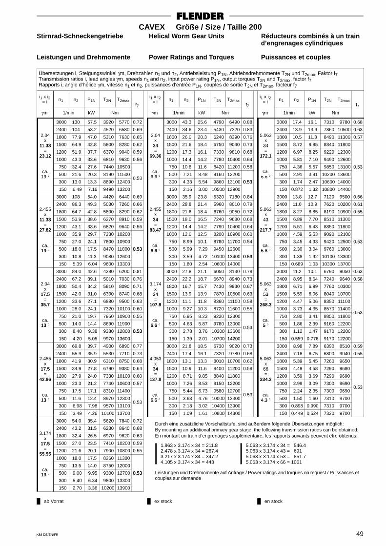
ab Vorrat ex stock en stock
Durch eine zusätzliche Vorschaltstufe, sind außerdem folgende Übersetzungen möglich:By mounting an additional primary gear stage, the following transmission ratios can be obtained:En montant un train d’engrenages supplémentaire, les rapports suivants peuvent être obtenus:
1.963 x 3.174 x 34 = 211.82.478 x 3.174 x 34 = 267.43.217 x 3.174 x 34 = 347.24.105 x 3.174 x 34 = 443
5.063 x 3.174 x 34 = 546.45.063 x 3.174 x 43 = 6915.063 x 3.174 x 53 = 851.75.063 x 3.174 x 66 = 1061
Leistungen und Drehmomente auf Anfrage / Power ratings and torques on request / Puissances etcouples sur demande
49K88 DE/EN/FR
CAVEX Größe / Size / Taille 200Stirnrad-Schneckengetriebe Helical Worm Gear Units Réducteurs combinés à un train
d’engrenages cylindriques
Leistungen und Drehmomente Power Ratings and Torques Puissances et couples
Übersetzungen i, Steigungswinkel γm, Drehzahlen n1 und n2, Antriebsleistung P1N, Abtriebsdrehmomente T2N und T2max, Faktor f7Transmission ratios i, lead angles γm, speeds n1 and n2, input power rating P1N, output torques T2N and T2max, factor f7Rapports i, angle d’hélice γm, vitesse n1 et n2, puissances d’entrée P1N, couples de sortie T2N et T2max, facteur f7
i1 x i2= i n1 n2 P1N T2N T2max
f
γm 1/min kW Nm
f7
3000 130 57.5 3920 5770 0.72
2400 104 53.2 4520 6580 0.692.04 1800 77.9 47.0 5310 7630 0.65
x11.33 1500 64.9 42.8 5800 8280 0.6211.33
= 1200 51.9 37.7 6370 9040 0.5923.12
1000 43.3 33.6 6810 9630 0.56
750 32.4 27.6 7440 10500ca.
° 500 21.6 20.3 8190 1150019 ° 300 13.0 13.3 8890 12400
0.53
150 6.49 7.16 9490 13200
3000 108 54.0 4420 6440 0.69
2400 86.3 49.3 5030 7260 0.662.455 1800 64.7 42.8 5800 8290 0.62x11.33 1500 53.9 38.6 6270 8910 0.5911.33
= 1200 43.1 33.6 6820 9640 0.5627.82
1000 35.9 29.7 7230 10200
750 27.0 24.1 7800 10900ca.19 ° 500 18.0 17.5 8470 11800 0.5319
300 10.8 11.3 9080 12600
0.53
150 5.39 6.04 9600 13300
3000 84.0 42.6 4380 6200 0.81
2400 67.2 39.1 5010 7030 0.762.04 1800 50.4 34.2 5810 8090 0.71x17.5 1500 42.0 31.0 6300 8740 0.6817.5
= 1200 33.6 27.1 6880 9500 0.6335.7
1000 28.0 24.1 7320 10100 0.60
750 21.0 19.7 7950 10900 0.55ca.13 ° 500 14.0 14.4 8690 1190013
300 8.40 9.38 9380 12800 0.53
150 4.20 5.05 9970 13600
0.53
3000 69.8 39.7 4900 6890 0.77
2400 55.9 35.9 5530 7710 0.732.455 1800 41.9 30.9 6310 8750 0.68x17.5 1500 34.9 27.8 6790 9380 0.6417.5
= 1200 27.9 24.0 7330 10100 0.6042.96
1000 23.3 21.2 7740 10600 0.57
750 17.5 17.1 8310 11400ca.13 ° 500 11.6 12.4 8970 1230013
300 6.98 7.98 9570 13100 0.53
150 3.49 4.26 10100 13700
3000 54.0 35.4 5620 7840 0.72
2400 43.2 31.5 6230 8640 0.683.174 1800 32.4 26.5 6970 9620 0.63
x17.5 1500 27.0 23.5 7410 10200 0.5917.5
= 1200 21.6 20.1 7900 10800 0.5555.55
1000 18.0 17.5 8260 11300
750 13.5 14.0 8750 12000ca.13 ° 500 9.00 9.95 9300 12700 0.5313
300 5.40 6.34 9800 13300
0.53
150 2.70 3.36 10200 13900
i1 x i2= i n1 n2 P1N T2N T2max
f
γm 1/min kW Nm
f7
3000 43.3 25.6 4790 6490 0.88
2400 34.6 23.4 5430 7320 0.832.04 1800 26.0 20.3 6240 8390 0.76
x34 1500 21.6 18.4 6750 9040 0.7334= 1200 17.3 16.1 7330 9810 0.68
69.36 1000 14.4 14.2 7780 10400 0.64
750 10.8 11.6 8420 11200 0.58ca.
° 500 7.21 8.48 9160 122006.6 ° 300 4.33 5.54 9860 13100 0.53
150 2.16 3.00 10500 13900
0.53
3000 35.9 23.8 5320 7180 0.84
2400 28.8 21.4 5960 8010 0.792.455 1800 21.6 18.4 6760 9050 0.72x
34 1500 18.0 16.5 7240 9680 0.6834= 1200 14.4 14.2 7790 10400 0.64
83.47 1000 12.0 12.5 8200 10900 0.60
750 8.99 10.1 8780 11700 0.54ca.
6.6 ° 500 5.99 7.29 9450 126006.6 300 3.59 4.72 10100 13400 0.53
150 1.80 2.54 10600 14000
0.53
3000 27.8 21.1 6050 8130 0.78
2400 22.2 18.7 6670 8940 0.733.174 1800 16.7 15.7 7430 9930 0.67x
34 1500 13.9 13.9 7870 10500 0.6334= 1200 11.1 11.8 8360 11100 0.58
107.9 1000 9.27 10.3 8720 11600 0.55
750 6.95 8.23 9220 12300ca.
6.6 ° 500 4.63 5.87 9780 130006.6 300 2.78 3.76 10300 13600
0.53
150 1.39 2.01 10700 14200
3000 21.8 18.5 6730 9020 0.73
2400 17.4 16.1 7320 9780 0.684.053 1800 13.1 13.3 8010 10700 0.62x
34 1500 10.9 11.6 8400 11200 0.5834= 1200 8.71 9.85 8840 11800
137.8 1000 7.26 8.53 9150 12200
750 5.44 6.73 9580 12700ca.
6.6 ° 500 3.63 4.76 10000 13300 0.53
6.6 300 2.18 3.02 10400 13900
150 1.09 1.61 10800 14300
i1 x i2= i n1 n2 P1N T2N T2max
f
γm 1/min kW Nm
f7
3000 17.4 16.1 7310 9780 0.68
2400 13.9 13.9 7860 10500 0.635.063 1800 10.5 11.3 8490 11300 0.57
x34 1500 8.72 9.85 8840 1180034= 1200 6.97 8.25 9220 12300
172.1 1000 5.81 7.10 9490 12600
750 4.36 5.57 9850 13100 0.53ca.
° 500 2.91 3.91 10200 13600
0.53
6.6 ° 300 1.74 2.47 10600 14000
150 0.872 1.32 10800 14400
3000 13.8 12.7 7120 9500 0.66
2400 11.0 10.9 7620 10200 0.615.063 1800 8.27 8.85 8190 10900 0.55x
43 1500 6.89 7.70 8510 1130043= 1200 5.51 6.43 8850 11800
217.7 1000 4.59 5.53 9090 12100
750 3.45 4.33 9420 12500 0.53ca.
5.8 ° 500 2.30 3.04 9760 13000
0.53
5.8 300 1.38 1.92 10100 13300
150 0.689 1.03 10300 13700
3000 11.2 10.1 6790 9050 0.63
2400 8.95 8.64 7240 9640 0.585.063 1800 6.71 6.99 7760 10300x
53 1500 5.59 6.06 8040 1070053= 1200 4.47 5.06 8350 11100
268.3 1000 3.73 4.35 8570 11400
750 2.80 3.41 8850 11800 0.53
ca.5 ° 500 1.86 2.39 9160 122005
300 1.12 1.47 9170 12200
150 0.559 0.776 9170 12200
3000 8.98 7.89 6390 8510 0.59
2400 7.18 6.75 6800 9040 0.555.063 1800 5.39 5.45 7260 9650x
66 1500 4.49 4.58 7290 968066= 1200 3.59 3.69 7290 9690
334.2 1000 2.99 3.09 7300 9690
750 2.24 2.35 7300 9690 0.53
ca.4.3 ° 500 1.50 1.60 7310 97004.3
300 0.898 0.990 7310 9700
150 0.449 0.524 7320 9700
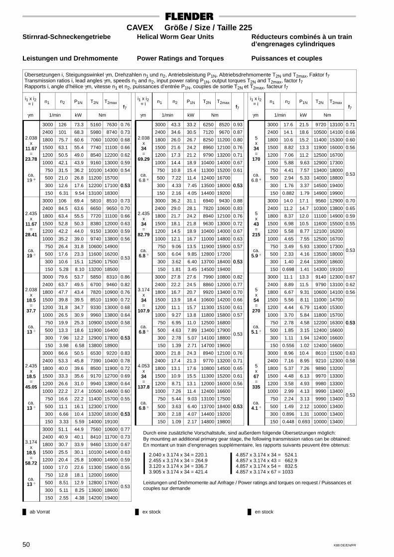
ab Vorrat ex stock en stock
Durch eine zusätzliche Vorschaltstufe, sind außerdem folgende Übersetzungen möglich:By mounting an additional primary gear stage, the following transmission ratios can be obtained:En montant un train d’engrenages supplémentaire, les rapports suivants peuvent être obtenus:
2.040 x 3.174 x 34 = 220.12.455 x 3.174 x 34 = 264.93.120 x 3.174 x 34 = 336.73.905 x 3.174 x 34 = 421.4
4.857 x 3.174 x 34 = 524.14.857 x 3.174 x 43 = 662.94.857 x 3.174 x 54 = 832.54.857 x 3.174 x 67 = 1033
Leistungen und Drehmomente auf Anfrage / Power ratings and torques on request / Puissances etcouples sur demande
50 K88 DE/EN/FR
CAVEX Größe / Size / Taille 225Stirnrad-Schneckengetriebe Helical Worm Gear Units Réducteurs combinés à un train
d’engrenages cylindriques
Leistungen und Drehmomente Power Ratings and Torques Puissances et couples
Übersetzungen i, Steigungswinkel γm, Drehzahlen n1 und n2, Antriebsleistung P1N, Abtriebsdrehmomente T2N und T2max, Faktor f7Transmission ratios i, lead angles γm, speeds n1 and n2, input power rating P1N, output torques T2N and T2max, factor f7Rapports i, angle d’hélice γm, vitesse n1 et n2, puissances d’entrée P1N, couples de sortie T2N et T2max, facteur f7
i1 x i2= i n1 n2 P1N T2N T2max
f
γm 1/min kW Nm
f7
3000 126 73.3 5160 7630 0.76
2400 101 68.3 5980 8740 0.732.038 1800 75.7 60.6 7060 10200 0.68
x11.67 1500 63.1 55.4 7740 11100 0.6611.67
= 1200 50.5 49.0 8540 12200 0.6223.78
1000 42.1 43.9 9160 13000 0.59
750 31.5 36.2 10100 14300 0.54ca.
° 500 21.0 26.8 11200 1570019 ° 300 12.6 17.6 12200 17100 0.53
150 6.31 9.54 13100 18300
0.53
3000 106 69.4 5810 8510 0.73
2400 84.5 63.6 6650 9650 0.702.435 1800 63.4 55.5 7720 11100 0.66x11.67 1500 52.8 50.3 8380 12000 0.6311.67
= 1200 42.2 44.0 9150 13000 0.5928.41
1000 35.2 39.0 9740 13800 0.56
750 26.4 31.8 10600 14900ca.19 ° 500 17.6 23.3 11600 1620019
300 10.6 15.1 12500 17500 0.53
150 5.28 8.10 13200 18500
3000 79.6 53.7 5850 8310 0.86
2400 63.7 49.5 6700 9460 0.822.038 1800 47.7 43.4 7820 10900 0.76x18.5 1500 39.8 39.5 8510 11900 0.7218.5
= 1200 31.8 34.7 9330 13000 0.6837.7
1000 26.5 30.9 9960 13800 0.64
750 19.9 25.3 10900 15000 0.58ca.13 ° 500 13.3 18.6 11900 1640013
300 7.96 12.2 12900 17800 0.53
150 3.98 6.58 13800 18900
0.53
3000 66.6 50.5 6530 9220 0.83
2400 53.3 45.8 7390 10400 0.782.435 1800 40.0 39.6 8500 11900 0.72x18.5 1500 33.3 35.6 9170 12700 0.6918.5
= 1200 26.6 31.0 9940 13800 0.6445.05
1000 22.2 27.4 10500 14600 0.60
750 16.6 22.2 11400 15700 0.55ca.13 ° 500 11.1 16.1 12300 1700013
300 6.66 10.4 13200 18100 0.53
150 3.33 5.59 14000 19100
0.53
3000 51.1 44.9 7560 10600 0.77
2400 40.9 40.1 8410 11700 0.733.174 1800 30.7 33.9 9460 13100 0.67
x18.5 1500 25.5 30.1 10100 14000 0.6318.5
= 1200 20.4 25.8 10800 14900 0.5958.72
1000 17.0 22.6 11300 15600 0.55
750 12.8 18.1 12000 16600ca.13 ° 500 8.51 12.9 12800 1760013
300 5.11 8.25 13600 18600 0.53
150 2.55 4.38 14200 19400
i1 x i2= i n1 n2 P1N T2N T2max
f
γm 1/min kW Nm
f7
3000 43.3 33.2 6250 8520 0.93
2400 34.6 30.5 7120 9670 0.872.038 1800 26.0 26.7 8250 11200 0.80
x34 1500 21.6 24.2 8960 12100 0.7634= 1200 17.3 21.2 9790 13200 0.71
69.29 1000 14.4 18.9 10400 14000 0.67
750 10.8 15.4 11300 15200 0.61ca.
° 500 7.22 11.4 12400 167006.8 ° 300 4.33 7.45 13500 18000 0.53
150 2.16 4.05 14400 19200
0.53
3000 36.2 31.1 6940 9430 0.88
2400 29.0 28.1 7820 10600 0.832.435 1800 21.7 24.2 8940 12100 0.76x
34 1500 18.1 21.8 9630 13000 0.7234= 1200 14.5 18.9 10400 14000 0.67
82.79 1000 12.1 16.7 11000 14800 0.63
750 9.06 13.5 11900 15900 0.57ca.
6.8 ° 500 6.04 9.85 12800 172006.8 300 3.62 6.40 13700 18400 0.53
150 1.81 3.45 14500 19400
0.53
3000 27.8 27.6 7990 10800 0.82
2400 22.2 24.5 8860 12000 0.773.174 1800 16.7 20.7 9920 13400 0.70x
34 1500 13.9 18.4 10600 14200 0.6634= 1200 11.1 15.7 11300 15100 0.61
107.9 1000 9.27 13.8 11800 15800 0.57
750 6.95 11.0 12500 16800ca.
6.8 ° 500 4.63 7.89 13400 179006.8 300 2.78 5.07 14100 18800
0.53
150 1.39 2.71 14700 19600
3000 21.8 24.3 8940 12100 0.76
2400 17.4 21.3 9770 13200 0.714.053 1800 13.1 17.6 10800 14500 0.65x
34 1500 10.9 15.5 11300 15200 0.6134= 1200 8.71 13.1 12000 16000 0.56
137.8 1000 7.26 11.4 12400 16600
750 5.44 9.03 13100 17500ca.
6.8 ° 500 3.63 6.40 13700 18400 0.536.8 300 2.18 4.07 14400 19200
0.53
150 1.09 2.17 14800 19800
i1 x i2= i n1 n2 P1N T2N T2max
f
γm 1/min kW Nm
f7
3000 17.6 21.5 9720 13100 0.71
2400 14.1 18.6 10500 14100 0.665 1800 10.6 15.2 11400 15300 0.60x
34 1500 8.82 13.3 11900 16000 0.5634= 1200 7.06 11.2 12500 16700
170 1000 5.88 9.63 12900 17300
750 4.41 7.57 13400 18000ca.
° 500 2.94 5.33 14000 18800 0.53
6.8 ° 300 1.76 3.37 14500 19400
150 0.882 1.79 14900 19900
3000 14.0 17.1 9560 12900 0.70
2400 11.2 14.7 10300 13800 0.655 1800 8.37 12.0 11100 14900 0.59x
43 1500 6.98 10.5 11600 15500 0.5543= 1200 5.58 8.77 12100 16200
215 1000 4.65 7.55 12500 16700
750 3.49 5.93 13000 17300ca.
5.9 ° 500 2.33 4.16 13500 18000 0.53
5.9 300 1.40 2.64 13900 18600
150 0.698 1.41 14300 19100
3000 11.1 13.3 9140 12300 0.67
2400 8.89 11.5 9790 13100 0.625 1800 6.67 9.31 10600 14100 0.56x
54 1500 5.56 8.11 11000 1470054= 1200 4.44 6.79 11400 15300
270 1000 3.70 5.84 11800 15700
750 2.78 4.58 12200 16300 0.53ca.
5.1 ° 500 1.85 3.15 12400 16600
0.53
5.1 300 1.11 1.94 12400 16600
150 0.556 1.02 12400 16600
3000 8.96 10.4 8610 11500 0.63
2400 7.16 8.95 9210 12300 0.585 1800 5.37 7.26 9890 13200x
67 1500 4.48 6.13 9970 1330067= 1200 3.58 4.93 9980 13300
335 1000 2.99 4.13 9990 13400
750 2.24 3.13 9990 13400 0.53
ca.4.1 ° 500 1.49 2.12 10000 134004.1
300 0.896 1.31 10000 13400
150 0.448 0.693 10000 13400
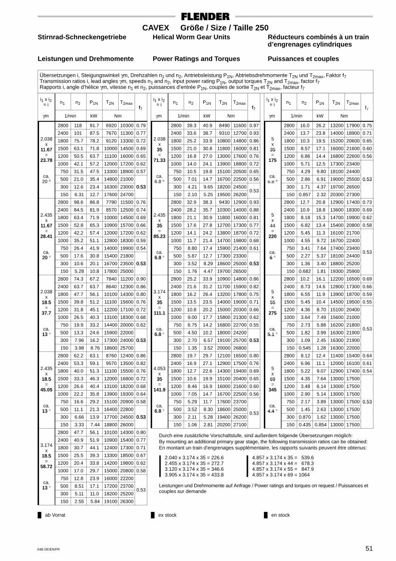
ab Vorrat ex stock en stock
Durch eine zusätzliche Vorschaltstufe, sind außerdem folgende Übersetzungen möglich:By mounting an additional primary gear stage, the following transmission ratios can be obtained:En montant un train d’engrenages supplémentaire, les rapports suivants peuvent être obtenus:
2.040 x 3.174 x 35 = 226.62.455 x 3.174 x 35 = 272.73.120 x 3.174 x 35 = 346.63.905 x 3.174 x 35 = 433.8
4.857 x 3.174 x 35 = 539.64.857 x 3.174 x 44 = 678.34.857 x 3.174 x 55 = 847.94.857 x 3.174 x 69 = 1064
Leistungen und Drehmomente auf Anfrage / Power ratings and torques on request / Puissances etcouples sur demande
51K88 DE/EN/FR
CAVEX Größe / Size / Taille 250Stirnrad-Schneckengetriebe Helical Worm Gear Units Réducteurs combinés à un train
d’engrenages cylindriques
Leistungen und Drehmomente Power Ratings and Torques Puissances et couples
Übersetzungen i, Steigungswinkel γm, Drehzahlen n1 und n2, Antriebsleistung P1N, Abtriebsdrehmomente T2N und T2max, Faktor f7Transmission ratios i, lead angles γm, speeds n1 and n2, input power rating P1N, output torques T2N and T2max, factor f7Rapports i, angle d’hélice γm, vitesse n1 et n2, puissances d’entrée P1N, couples de sortie T2N et T2max, facteur f7
i1 x i2= i n1 n2 P1N T2N T2max
f
γm 1/min kW Nm
f7
2800 118 91.7 6920 10300 0.79
2400 101 87.5 7670 11300 0.772.038 1800 75.7 78.2 9120 13300 0.72
x11.67 1500 63.1 71.8 10000 14500 0.6911.67
= 1200 50.5 63.7 11100 16000 0.6523.78
1000 42.1 57.2 12000 17200 0.62
750 31.5 47.5 13300 18900 0.57ca.
° 500 21.0 35.4 14800 2100020 ° 300 12.6 23.4 16300 23000 0.53
150 6.31 12.7 17600 24700
0.53
2800 98.6 86.8 7790 11500 0.76
2400 84.5 81.9 8570 12500 0.742.435 1800 63.4 71.9 10000 14500 0.69x11.67 1500 52.8 65.3 10900 15700 0.6611.67
= 1200 42.2 57.4 12000 17200 0.6228.41
1000 35.2 51.1 12800 18300 0.59
750 26.4 41.9 14000 19900 0.54ca.20 ° 500 17.6 30.8 15400 2180020
300 10.6 20.1 16700 23500 0.53
150 5.28 10.8 17800 25000
0.53
2800 74.3 67.2 7840 11200 0.90
2400 63.7 63.7 8640 12300 0.862.038 1800 47.7 56.1 10100 14300 0.80x18.5 1500 39.8 51.2 11100 15600 0.7618.5
= 1200 31.8 45.1 12200 17100 0.7237.7
1000 26.5 40.3 13100 18300 0.68
750 19.9 33.2 14400 20000 0.62ca.13 ° 500 13.3 24.6 15900 2200013
300 7.96 16.2 17300 24000 0.53
150 3.98 8.76 18600 25700
0.53
2800 62.2 63.1 8760 12400 0.86
2400 53.3 59.1 9570 13500 0.822.435 1800 40.0 51.3 11100 15500 0.76x18.5 1500 33.3 46.3 12000 16800 0.7218.5
= 1200 26.6 40.4 13100 18200 0.6845.05
1000 22.2 35.8 13900 19300 0.64
750 16.6 29.2 15100 20900 0.58ca.13 ° 500 11.1 21.3 16400 2280013
300 6.66 13.9 17700 24500 0.53
150 3.33 7.44 18800 26000
0.53
2800 47.7 56.1 10100 14300 0.80
2400 40.9 51.9 10900 15400 0.773.174 1800 30.7 44.1 12400 17300 0.71
x18.5 1500 25.5 39.3 13300 18500 0.6718.5
= 1200 20.4 33.8 14200 19800 0.6258.72
1000 17.0 29.7 15000 20800 0.58
750 12.8 23.9 16000 22200ca.13 ° 500 8.51 17.1 17200 2370013
300 5.11 11.0 18200 25200 0.53
150 2.55 5.84 19100 26300
i1 x i2= i n1 n2 P1N T2N T2max
f
γm 1/min kW Nm
f7
2800 39.3 40.9 8490 11600 0.97
2400 33.6 38.7 9310 12700 0.932.038 1800 25.2 33.9 10800 14800 0.86
x35 1500 21.0 30.8 11800 16000 0.8135= 1200 16.8 27.0 13000 17600 0.76
71.33 1000 14.0 24.1 13900 18800 0.72
750 10.5 19.8 15100 20500 0.65ca.
° 500 7.01 14.7 16700 22500 0.566.8 ° 300 4.21 9.65 18200 24500
150 2.10 5.25 19500 26200 0.53
2800 32.9 38.3 9430 12900 0.93
2400 28.2 35.7 10300 14000 0.882.435 1800 21.1 30.9 11800 16000 0.81x
35 1500 17.6 27.8 12700 17300 0.7735= 1200 14.1 24.2 13800 18700 0.72
85.23 1000 11.7 21.4 14700 19800 0.68
750 8.80 17.4 15900 21400 0.61ca.
6.8 ° 500 5.87 12.7 17300 233006.8 300 3.52 8.29 18600 25000 0.53
150 1.76 4.47 19700 26500
0.53
2800 25.2 33.9 10900 14800 0.86
2400 21.6 31.2 11700 15900 0.823.174 1800 16.2 26.4 13200 17800 0.75x
35 1500 13.5 23.5 14000 19000 0.7135= 1200 10.8 20.2 15000 20300 0.66
111.1 1000 9.00 17.7 15800 21300 0.62
750 6.75 14.2 16800 22700 0.55ca.
6.8 ° 500 4.50 10.2 18000 242006.8 300 2.70 6.57 19100 25700 0.53
150 1.35 3.52 20000 26800
0.53
2800 19.7 29.7 12100 16500 0.80
2400 16.9 27.1 12900 17500 0.764.053 1800 12.7 22.6 14300 19400 0.69x
35 1500 10.6 19.9 15100 20400 0.6535= 1200 8.46 16.9 16000 21600 0.60
141.9 1000 7.05 14.7 16700 22500 0.56
750 5.29 11.7 17600 23700ca.
6.8 ° 500 3.52 8.30 18600 250006.8 300 2.11 5.28 19400 26200
0.53
150 1.06 2.81 20200 27100
i1 x i2= i n1 n2 P1N T2N T2max
f
γm 1/min kW Nm
f7
2800 16.0 26.2 13200 17900 0.75
2400 13.7 23.8 14000 18900 0.715 1800 10.3 19.5 15200 20600 0.65x
35 1500 8.57 17.1 16000 21600 0.6035= 1200 6.86 14.4 16800 22600 0.56
175 1000 5.71 12.5 17300 23400
750 4.29 9.80 18100 24400ca.
° 500 2.86 6.91 19000 25500 0.536.8 ° 300 1.71 4.37 19700 26500
0.53
150 0.857 2.32 20300 27300
2800 12.7 20.8 12900 17400 0.73
2400 10.9 18.8 13600 18300 0.695 1800 8.18 15.3 14700 19900 0.62x
44 1500 6.82 13.4 15400 20800 0.5844= 1200 5.45 11.3 16100 21700
220 1000 4.55 9.72 16700 22400
750 3.41 7.64 17400 23400ca.6 ° 500 2.27 5.37 18100 24400
0.536
300 1.36 3.40 18800 25200
150 0.682 1.81 19300 25900
2800 10.2 16.1 12200 16500 0.69
2400 8.73 14.6 12800 17300 0.665 1800 6.55 11.9 13900 18700 0.59x
55 1500 5.45 10.4 14500 19500 0.5555= 1200 4.36 8.70 15100 20400
275 1000 3.64 7.49 15600 21000
750 2.73 5.88 16200 21800ca.
5.1 ° 500 1.82 3.99 16300 21900 0.53
5.1 300 1.09 2.45 16300 21900
150 0.545 1.28 16300 22000
2800 8.12 12.4 11400 15400 0.64
2400 6.96 11.1 12000 16100 0.615 1800 5.22 9.07 12900 17400 0.54x
69 1500 4.35 7.64 13000 1750069= 1200 3.48 6.14 13000 17500
345 1000 2.90 5.14 13000 17500
750 2.17 3.89 13000 17500 0.53ca.
4.4 ° 500 1.45 2.63 13000 17500
0.53
4.4 300 0.870 1.62 13000 17500
150 0.435 0.854 13000 17500

ab Vorrat ex stock en stock
Durch eine zusätzliche Vorschaltstufe, sind außerdem folgende Übersetzungen möglich:By mounting an additional primary gear stage, the following transmission ratios can be obtained:En montant un train d’engrenages supplémentaire, les rapports suivants peuvent être obtenus:
2.040 x 3.19 x 35 = 227.82.455 x 3.19 x 35 = 274.13.174 x 3.19 x 35 = 354.44.053 x 3.19 x 35 = 452.5
5.063 x 3.19 x 35 = 565.35.063 x 3.19 x 44 = 710.65.063 x 3.19 x 55 = 888.35.063 x 3.19 x 69 = 1114
Leistungen und Drehmomente auf Anfrage / Power ratings and torques on request / Puissances etcouples sur demande
52 K88 DE/EN/FR
CAVEX Größe / Size / Taille 280Stirnrad-Schneckengetriebe Helical Worm Gear Units Réducteurs combinés à un train
d’engrenages cylindriques
Leistungen und Drehmomente Power Ratings and Torques Puissances et couples
Übersetzungen i, Steigungswinkel γm, Drehzahlen n1 und n2, Antriebsleistung P1N, Abtriebsdrehmomente T2N und T2max, Faktor f7Transmission ratios i, lead angles γm, speeds n1 and n2, input power rating P1N, output torques T2N and T2max, factor f7Rapports i, angle d’hélice γm, vitesse n1 et n2, puissances d’entrée P1N, couples de sortie T2N et T2max, facteur f7
i1 x i2= i n1 n2 P1N T2N T2max
f
γm 1/min kW Nm
f7
2600 109 115 9350 13900 0.82
2400 101 112 9880 14700 0.802.04 1800 75.6 101 11800 17400 0.75
x11.67 1500 63.0 93.4 13100 19100 0.7211.67
= 1200 50.4 83.4 14600 21200 0.6823.8
1000 42.0 75.3 15800 22800 0.65
750 31.5 62.9 17600 25300 0.59ca.
° 500 21.0 47.2 19800 2830020 ° 300 12.6 31.5 21900 31200 0.53
150 6.30 17.2 23900 33900
0.53
2600 90.8 108 10600 15600 0.78
2400 83.8 105 11100 16400 0.772.455 1800 62.8 93.3 13100 19100 0.72x11.67 1500 52.4 85.1 14400 20800 0.6911.67
= 1200 41.9 75.2 15800 22900 0.6528.64
1000 34.9 67.2 17000 24400 0.62
750 26.2 55.4 18700 26700 0.56ca.20 ° 500 17.5 41.0 20700 2950020
300 10.5 27.0 22600 32100 0.53
150 5.24 14.6 24200 34300
0.53
2600 68.9 83.4 10500 15100 0.92
2400 63.6 81.2 11100 15800 0.902.04 1800 47.7 72.4 13100 18600 0.83x18.5 1500 39.7 66.4 14400 20400 0.7918.5
= 1200 31.8 58.9 15900 22500 0.7437.74
1000 26.5 52.8 17200 24200 0.70
750 19.9 43.8 19000 26600 0.64ca.13 ° 500 13.2 32.7 21200 29600 0.5613
300 7.95 21.7 23300 32500
150 3.97 11.8 25200 35000 0.53
2600 57.2 78.2 11800 16800 0.87
2400 52.8 75.8 12400 17600 0.852.455 1800 39.6 66.3 14400 20400 0.79x18.5 1500 33.0 60.1 15700 22100 0.7518.5
= 1200 26.4 52.8 17200 24200 0.7045.42
1000 22.0 47.0 18300 25800 0.66
750 16.5 38.5 20000 28000 0.60ca.13 ° 500 11.0 28.3 22000 3070013
300 6.61 18.5 23900 33300 0.53
150 3.30 10.0 25500 35500
0.53
2600 44.1 69.8 13700 19400 0.81
2400 40.7 67.1 14200 20200 0.803.19 1800 30.5 57.5 16200 22900 0.73
x18.5 1500 25.4 51.5 17400 24500 0.7018.5
= 1200 20.3 44.5 18800 26400 0.6559.02
1000 16.9 39.2 19900 27800 0.61
750 12.7 31.7 21400 29800 0.55ca.13 ° 500 8.47 22.9 23100 3220013
300 5.08 14.8 24600 34300 0.53
150 2.54 7.87 25900 36000
0.53
i1 x i2= i n1 n2 P1N T2N T2max
f
γm 1/min kW Nm
f7
�2600 36.4 48.9 11000 15100 0.96
2400 33.6 47.6 11500 15800 0.932.04 1800 25.2 42.1 13500 18500 0.86
x35 1500 21.0 38.5 14800 20200 0.8135= 1200 16.8 34.0 16300 22300 0.76
71.4 1000 14.0 30.4 17500 23900 0.72
750 10.5 25.2 19300 26200 0.65ca.
° 500 7.00 18.7 21400 29100 0.566.8 ° 300 4.20 12.4 23400 31800
150 2.10 6.80 25300 34300 0.53
2600 30.3 45.8 12200 16800 0.90
2400 27.9 44.2 12800 17600 0.882.455 1800 20.9 38.4 14800 20300 0.81x
35 1500 17.5 34.7 16100 21900 0.7735= 1200 14.0 30.4 17500 23900 0.72
85.93 1000 11.6 27.0 18700 25400 0.68
750 8.73 22.1 20300 27600 0.61ca.
6.8 ° 500 5.82 16.2 22200 302006.8 300 3.49 10.6 24000 32600 0.53
150 1.75 5.75 25600 34700
0.53
2600 23.3 40.5 14100 19300 0.84
2400 21.5 38.9 14600 20000 0.823.19 1800 16.1 33.2 16600 22700 0.75x35 1500 13.4 29.6 17800 24200 0.7135= 1200 10.7 25.6 19100 26100 0.66
111.7 1000 8.95 22.5 20100 27400 0.62
750 6.71 18.2 21600 29300 0.55ca.
6.8 ° 500 4.48 13.1 23200 315006.8 300 2.69 8.46 24700 33600 0.53
150 1.34 4.54 26000 35200
0.53
2600 19.1 36.6 15400 21100 0.79
2400 17.6 34.9 16000 21800 0.773.889 1800 13.2 29.3 17900 24400 0.70x
35 1500 11.0 26.0 19000 25900 0.6635= 1200 8.82 22.2 20200 27500 0.61
136.1 1000 7.35 19.4 21200 28800 0.57
750 5.51 15.5 22400 30500ca.
6.8 ° 500 3.67 11.1 23900 324006.8 300 2.20 7.10 25200 34100
0.53
150 1.10 3.80 26200 35600
i1 x i2= i n1 n2 P1N T2N T2max
f
γm 1/min kW Nm
f7
2600 14.7 31.3 17200 23500 0.73
2400 13.6 29.8 17700 24200 0.715.059 1800 10.2 24.6 19400 26500 0.64
x35 1500 8.47 21.6 20400 27800 0.6135= 1200 6.78 18.3 21500 29300 0.56
177.1 1000 5.65 15.8 22300 30400
750 4.23 12.5 23400 31800ca.
° 500 2.82 8.84 24600 33400 0.536.8 ° 300 1.69 5.60 25700 34800
0.53
150 0.847 2.98 26500 35900
2600 11.7 26.0 17600 23900 0.74
2400 10.8 24.7 18100 24600 0.725.059 1800 8.09 20.3 19800 26900 0.66x
44 1500 6.74 17.8 20700 28200 0.6144= 1200 5.39 15.0 21800 29600 0.56
222.6 1000 4.49 13.0 22500 30600
750 3.37 10.2 23600 32000ca.
5.9 ° 500 2.25 7.23 24700 33500 0.535.9 300 1.35 4.58 25700 34800
0.53
150 0.674 2.44 26500 35900
2600 9.35 20.2 16700 22700 0.71
2400 8.63 19.2 17100 23300 0.695.059 1800 6.47 15.7 18700 25400 0.62x
55 1500 5.39 13.8 19500 26500 0.5855= 1200 4.31 11.6 20500 27800
278.2 1000 3.59 10.0 21100 28700
750 2.70 7.89 22100 29900ca.
5.1 ° 500 1.80 5.39 22400 30300 0.53
5.1 300 1.08 3.30 22400 30300
150 0.539 1.72 22400 30300
2600 7.45 15.6 15600 21200 0.66
2400 6.87 14.8 16000 21800 0.645.059 1800 5.16 12.1 17400 23600 0.58x
69 1500 4.30 10.4 17800 2420069= 1200 3.44 8.33 17800 24200
349.1 1000 2.86 6.97 17800 24200
750 2.15 5.27 17800 24200 0.53ca.
4.3 ° 500 1.43 3.57 17800 24200
0.53
4.3 300 0.859 2.19 17900 24200
150 0.430 1.15 17900 24200
� Auswuchten erforderlich � Balancing required � Equilibrage nécessaire

ab Vorrat ex stock en stock
Durch eine zusätzliche Vorschaltstufe, sind außerdem folgende Übersetzungen möglich:By mounting an additional primary gear stage, the following transmission ratios can be obtained:En montant un train d’engrenages supplémentaire, les rapports suivants peuvent être obtenus:
2.040 x 3.19 x 36 = 234.32.455 x 3.19 x 36 = 281.93.174 x 3.19 x 36 = 364.54.053 x 3.19 x 36 = 465.4
5.063 x 3.19 x 36 = 581.45.063 x 3.19 x 45 = 726.85.063 x 3.19 x 56 = 904.55.063 x 3.19 x 70 = 1131
Leistungen und Drehmomente auf Anfrage / Power ratings and torques on request / Puissances etcouples sur demande
53K88 DE/EN/FR
CAVEX Größe / Size / Taille 315Stirnrad-Schneckengetriebe Helical Worm Gear Units Réducteurs combinés à un train
d’engrenages cylindriques
Leistungen und Drehmomente Power Ratings and Torques Puissances et couples
Übersetzungen i, Steigungswinkel γm, Drehzahlen n1 und n2, Antriebsleistung P1N, Abtriebsdrehmomente T2N und T2max, Faktor f7Transmission ratios i, lead angles γm, speeds n1 and n2, input power rating P1N, output torques T2N and T2max, factor f7Rapports i, angle d’hélice γm, v itesse n1 et n2, puissances d’entrée P1N, couples de sortie T2N et T2max, facteur f7
i1 x i2= i n1 n2 P1N T2N T2max
f
γm 1/min kW Nm
f7
2400 95.4 144 13400 20000 0.88
1800 71.5 130 16100 23800 0.812.04
x 1500 59.6 120 17800 26200 0.78x12.33 1200 47.7 108 20000 29200 0.74
=25.16 1000 39.7 97.7 21700 31600 0.7025.16
750 29.8 81.9 24200 35100 0.64
ca.°
500 19.9 61.9 27400 39500 0.5620 °
300 11.9 41.5 30600 43900
150 5.96 22.8 33400 47800 0.53
2400 79.3 135 15100 22400 0.83
1800 59.4 120 17900 26300 0.782.455
x 1500 49.5 110 19600 28700 0.74x12.33
= 1200 39.6 97.5 21700 31600 0.70=30.28 1000 33.0 87.5 23400 33900 0.67
750 24.8 72.4 25800 37200 0.61
ca.°
500 16.5 53.8 28700 4130020 °
300 9.91 35.5 31500 45100 0.53
150 4.95 19.3 33900 48500
0.53
2400 63.6 106 14400 20900 0.95
1800 47.7 95.3 17200 24700 0.882.04
x 1500 39.7 87.6 19000 27200 0.83x18.5
= 1200 31.8 78.2 21200 30200 0.78=37.74 1000 26.5 70.5 22900 32600 0.74
750 19.9 58.9 25500 36100 0.68
ca.°
500 13.2 44.3 28700 40500 0.5913 °
300 7.95 29.6 31800 44800
150 3.97 16.2 34700 48700 0.53
2400 52.8 99.1 16200 23300 0.90
1800 39.6 87.5 19100 27200 0.832.455
x 1500 33.0 79.8 20800 29700 0.79x18.5
= 1200 26.4 70.4 23000 32600 0.74=45.42 1000 22.0 62.9 24600 34900 0.70
750 16.5 51.9 27000 38200 0.64
ca.°
500 11.0 38.4 29900 42200 0.5513 °
300 6.61 25.3 32700 46000
150 3.30 13.7 35200 49400 0.53
2400 40.7 88.6 18800 26900 0.84
1800 30.5 76.4 21600 30700 0.773.19
x 1500 25.4 68.8 23300 33100 0.73x18.5
= 1200 20.3 59.8 25300 35800 0.68=59.02 1000 16.9 52.8 26800 37900 0.64
750 12.7 42.9 29000 40900 0.58
ca.°
500 8.47 31.2 31500 4430013 °
300 5.08 20.2 33800 47500 0.53
150 2.54 10.8 35800 50200
0.53
i1 x i2= i n1 n2 P1N T2N T2max
f
γm 1/min kW Nm
f7
�2400 32.7 62.8 15700 21800 1.03
1800 24.5 56.3 18600 25700 0.942.04
x 1500 20.4 51.7 20400 28200 0.89x36 1200 16.3 45.9 22700 31200 0.84=
73.44 1000 13.6 41.3 24400 33600 0.7973.44
750 10.2 34.4 27100 37200 0.72
ca.°
500 6.81 25.8 30300 41600 0.626.8 °
300 4.08 17.2 33500 45900
150 2.04 9.50 36400 49800 0.53
2400 27.2 58.8 17500 24300 0.97
1800 20.4 51.6 20400 28200 0.892.455
x 1500 17.0 46.9 22300 30700 0.84x36= 1200 13.6 41.2 24500 33700 0.79=
88.38 1000 11.3 36.8 26200 36000 0.74
750 8.49 30.3 28600 39300 0.67
ca.°
500 5.66 22.4 31600 43300 0.586.8 °
300 3.39 14.8 34400 47200
150 1.70 8.04 36900 50500 0.53
2400 20.9 52.2 20200 27900 0.90
1800 15.7 44.9 23100 31800 0.823.19
x 1500 13.1 40.3 24800 34200 0.78x36= 1200 10.5 34.9 26900 36900 0.72=
114.8 1000 8.71 30.8 28400 39000 0.68
750 6.53 25.0 30600 42000 0.61
ca.°
500 4.36 18.2 33200 455006.8 °
300 2.61 11.8 35500 48700 0.53
150 1.31 6.35 37500 51400
0.53
2400 17.1 47.1 22200 30600 0.85
1800 12.9 39.9 25000 34400 0.783.889
x 1500 10.7 35.5 26600 36600 0.73x36= 1200 8.57 30.5 28500 39200 0.68=
140 1000 7.14 26.7 30000 41100 0.63
750 5.36 21.5 31900 43800 0.57
ca.°
500 3.57 15.4 34200 468006.8 °
300 2.14 9.91 36200 49600 0.53
150 1.07 5.31 37900 51900
0.53
i1 x i2= i n1 n2 P1N T2N T2max
f
γm 1/min kW Nm
f7
2400 13.2 40.5 24700 34100 0.78
1800 9.88 33.6 27400 37600 0.715.059
x 1500 8.24 29.6 28900 39600 0.67x36 1200 6.59 25.2 30600 41900 0.62=
182.1 1000 5.49 21.9 31800 43600 0.57182.1
750 4.12 17.4 33500 45900
ca.°
500 2.75 12.3 35300 484006.8 °
300 1.65 7.83 37000 50600 0.53
150 0.824 4.17 38300 52400
2400 10.5 32.3 24400 33500 0.77
1800 7.91 26.7 26700 36700 0.695.059
x 1500 6.59 23.4 28100 38600 0.65x45= 1200 5.27 19.9 29600 40600 0.60=
227.7 1000 4.39 17.2 30700 42100 0.56
750 3.29 13.6 32200 44200
ca.°
500 2.20 9.29 32700 452006.1 °
300 1.32 5.69 33000 45300 0.53
150 0.659 2.95 33100 45400
2400 8.47 25.2 22900 31500 0.73
1800 6.35 20.8 25100 34500 0.655.059
x 1500 5.29 18.3 26400 36200 0.61x56= 1200 4.24 15.4 27800 38100 0.56=
283.3 1000 3.53 13.4 28800 39400
750 2.65 10.6 30200 41300
ca.°
500 1.76 7.24 30600 41900 0.535.1 °
300 1.06 4.42 30700 42000
0.53
150 0.529 2.29 30700 42000
2400 6.78 19.5 21500 29600 0.68
1800 5.08 16.0 23500 32200 0.615.059
x 1500 4.24 14.0 24500 33500 0.57x70= 1200 3.39 11.2 24500 33600=
354.1 1000 2.82 9.40 24500 33600
750 2.12 7.09 24500 33600
ca.°
500 1.41 4.80 24500 33600 0.53
4.4 ° 300 0.847 2.94 24600 33600
150 0.424 1.54 24600 33600
� Auswuchten erforderlich � Balancing required � Equilibrage nécessaire

ab Vorrat ex stock en stock
Durch eine zusätzliche Vorschaltstufe, sind außerdem folgende Übersetzungen möglich:By mounting an additional primary gear stage, the following transmission ratios can be obtained:En montant un train d’engrenages supplémentaire, les rapports suivants peuvent être obtenus:
2.038 x 3.2 x 37 = 241.32.435 x 3.2 x 37 = 288.33.174 x 3.2 x 37 = 375.84.053 x 3.2 x 37 = 479.9
5.000 x 3.2 x 37 = 5925.000 x 3.2 x 46 = 7365.000 x 3.2 x 57 = 9125.000 x 3.2 x 71 = 1136
Leistungen und Drehmomente auf Anfrage / Power ratings and torques on request / Puissances etcouples sur demande
54 K88 DE/EN/FR
CAVEX Größe / Size / Taille 355Stirnrad-Schneckengetriebe Helical Worm Gear Units Réducteurs combinés à un train
d’engrenages cylindriques
Leistungen und Drehmomente Power Ratings and Torques Puissances et couples
Übersetzungen i, Steigungswinkel γm, Drehzahlen n1 und n2, Antriebsleistung P1N, Abtriebsdrehmomente T2N und T2max, Faktor f7Transmission ratios i, lead angles γm, speeds n1 and n2, input power rating P1N, output torques T2N and T2max, factor f7Rapports i, angle d’hélice γm, vitesse n1 et n2, puissances d’entrée P1N, couples de sortie T2N et T2max, facteur f7
i1 x i2= i n1 n2 P1N T2N T2max
f
γm 1/min kW Nm
f7
2200 87.4 177 18000 27100 0.88
1800 71.5 166 20600 30700 0.842.04
x 1500 59.6 155 22900 34100 0.80x12.33 1200 47.7 140 25900 38200 0.75
=25.16 1000 39.7 127 28300 41600 0.7225.16
750 29.8 108 31900 46600 0.66
ca.°
500 19.9 82.2 36400 53100 0.5819 °
300 11.9 55.7 41000 59500
150 5.96 30.9 45300 65500 0.53
2200 72.7 167 20400 30400 0.84
1800 59.4 155 23000 34100 0.802.455
x 1500 49.5 142 25400 37500 0.76x12.33
= 1200 39.6 127 28300 41600 0.72=30.28 1000 33.0 115 30600 44900 0.68
750 24.8 95.6 34000 49700 0.62
ca.°
500 16.5 71.8 38200 55600 0.5519 °
300 9.91 47.9 42400 61400
150 4.95 26.2 46100 66600 0.53
2200 55.3 125 19600 28500 0.96
1800 45.2 116 22200 32100 0.902.04
x 1500 37.7 107 24600 35400 0.85x19.5
= 1200 30.2 96.3 27500 39500 0.80=39.78 1000 25.1 87.1 29800 42800 0.76
750 18.9 73.2 33400 47700 0.69
ca.°
500 12.6 55.3 37800 53800 0.6013 °
300 7.54 37.3 42200 60000
150 3.77 20.6 46200 65600 0.53
2200 46.0 117 22000 31800 0.90
1800 37.6 107 24600 35500 0.852.455
x 1500 31.3 98.2 27000 38800 0.81x19.5
= 1200 25.1 87.0 29900 42800 0.76=47.87 1000 20.9 78.0 32100 46000 0.72
750 15.7 64.7 35500 50600 0.65
ca.°
500 10.4 48.2 39500 56300 0.5613 °
300 6.27 31.9 43500 61800
150 3.13 17.4 47000 66600 0.53
2200 35.3 104 25500 36700 0.84
1800 28.8 94.0 28100 40300 0.793.2x 1500 24.0 84.9 30400 43600 0.75x
19.5= 1200 19.2 74.1 33100 47400 0.70=
62.4 1000 16.0 65.7 35200 50300 0.66
750 12.0 53.6 38200 54500 0.59
ca.°
500 8.01 39.1 41800 5940013 °
300 4.81 25.5 45100 63900
0.53
150 2.40 13.7 47900 679000
i1 x i2= i n1 n2 P1N T2N T2max
f
γm 1/min kW Nm
f7
�2200 29.1 77.6 21800 30500 1.06
1800 23.8 72.3 24500 34300 1.002.04
x 1500 19.9 66.7 27100 37800 0.94x37 1200 15.9 59.6 30200 42100 0.88=
75.48 1000 13.2 53.8 32700 45500 0.8375.48
750 9.94 45.1 36500 50700 0.76
ca.°
500 6.62 34.1 41200 57100 0.666.8 °
300 3.97 23.0 45900 63600 0.54
150 1.99 12.7 50200 69500 0.53
2200 24.2 72.7 24300 34000 1.00
1800 19.8 66.6 27100 37900 0.942.455
x 1500 16.5 60.8 29700 41400 0.89x37= 1200 13.2 53.7 32800 45600 0.83=
90.84 1000 11.0 48.1 35200 48900 0.78
750 8.26 39.8 38800 53800 0.71
ca.°
500 5.50 29.7 43100 59700 0.616.8 °
300 3.30 19.7 47300 65500
150 1.65 10.8 51000 70600 0.53
2200 18.6 64.5 28000 39100 0.92
1800 15.2 58.2 30800 42900 0.873.2x 1500 12.7 52.4 33300 46400 0.82x
37= 1200 10.1 45.7 36300 50300 0.76=
118.4 1000 8.45 40.4 38500 53400 0.72
750 6.33 33.0 41700 57800 0.65
ca.°
500 4.22 24.1 45500 62900 0.556.8 °
300 2.53 15.7 49000 67800
150 1.27 8.51 52000 71900 0.53
2200 14.9 57.5 31200 43400 0.86
1800 12.2 51.2 33900 47100 0.814x 1500 10.1 45.7 36300 50300 0.76x
37= 1200 8.11 39.3 39000 54100 0.71=
148 1000 6.76 34.6 41000 56900 0.66
750 5.07 27.9 43900 60800 0.60
ca.°
500 3.38 20.1 47100 653006.8 °
300 2.03 13.0 50100 69300 0.53
150 1.01 6.96 52600 72800
0.53
i1 x i2= i n1 n2 P1N T2N T2max
f
γm 1/min kW Nm
f7
2200 11.6 49.8 34500 47900 0.80
1800 9.52 43.8 37000 51400 0.755.111
x 1500 7.93 38.7 39200 54400 0.70x37 1200 6.35 33.0 41700 57800 0.65=
189.1 1000 5.29 28.8 43500 60200 0.61189.1
750 3.97 22.9 46000 63600 0.54
ca.°
500 2.64 16.3 48700 674006.8 °
300 1.59 10.4 51200 70800 0.53
150 0.793 5.56 53200 73600
0.53
2200 9.36 39.7 33500 46500 0.77
1800 7.66 34.8 35800 49700 0.725.111
x 1500 6.38 30.7 37800 52500 0.68x46= 1200 5.10 26.1 40100 55500 0.62=
235.1 1000 4.25 22.7 41700 57800 0.58
750 3.19 18.0 44000 60800
ca.°
500 2.13 12.8 46500 643005.9 °
300 1.28 8.17 48700 67300 0.53
150 0.638 4.37 50500 69800
2200 7.55 31.3 31900 44300 0.74
1800 6.18 27.4 34100 47300 0.695.111
x 1500 5.15 24.1 35900 49800 0.64x57= 1200 4.12 20.4 37900 52500 0.59=
291.3 1000 3.43 17.8 39400 54600 0.55
750 2.57 14.1 41400 57300
ca.°
500 1.72 9.54 41700 576005.1 °
300 1.03 5.82 41700 57700 0.53
150 0.515 3.02 41700 57700
2200 6.06 24.3 30000 41500 0.69
1800 4.96 21.2 31900 44200 0.645.111
x 1500 4.13 18.5 33400 46200 0.60x71= 1200 3.31 14.9 33400 46300=
362.9 1000 2.76 12.5 33400 46300
750 2.07 9.42 33500 46300
ca.°
500 1.38 6.37 33500 46300 0.53
4.4 ° 300 0.827 3.89 33500 46300
150 0.413 2.03 33500 46300
� Auswuchten erforderlich � Balancing required � Equilibrage nécessaire

ab Vorrat ex stock en stock
Durch eine zusätzliche Vorschaltstufe, sind außerdem folgende Übersetzungen möglich:By mounting an additional primary gear stage, the following transmission ratios can be obtained:En montant un train d’engrenages supplémentaire, les rapports suivants peuvent être obtenus:
2.038 x 3.2 x 37 = 241.32.435 x 3.2 x 37 = 288.33.174 x 3.2 x 37 = 375.84.053 x 3.2 x 37 = 479.9
5.000 x 3.2 x 37 = 5925.000 x 3.2 x 46 = 7365.000 x 3.2 x 57 = 9125.000 x 3.2 x 71 = 1136
Leistungen und Drehmomente auf Anfrage / Power ratings and torques on request / Puissances etcouples sur demande
55K88 DE/EN/FR
CAVEX Größe / Size / Taille 400Stirnrad-Schneckengetriebe Helical Worm Gear Units Réducteurs combinés à un train
d’engrenages cylindriques
Leistungen und Drehmomente Power Ratings and Torques Puissances et couples
Übersetzungen i, Steigungswinkel γm, Drehzahlen n1 und n2, Antriebsleistung P1N, Abtriebsdrehmomente T2N und T2max, Faktor f7Transmission ratios i, lead angles γm, speeds n1 and n2, input power rating P1N, output torques T2N and T2max, factor f7Rapports i, angle d’hélice γm, vitesse n1 et n2, puissances d’entrée P1N, couples de sortie T2N et T2max, facteur f7
i1 x i2= i n1 n2 P1N T2N T2max
f
γm 1/min kW Nm
f7
2000 79.5 223 24900 37800 0.90
1800 71.5 216 26800 40400 0.872.04
x 1500 59.6 202 30000 45100 0.83x12.33 1200 47.7 184 34100 50900 0.79
=25.16 1000 39.7 168 37400 55600 0.7525.16
750 29.8 143 42400 62800 0.69
ca.°
500 19.9 110 49000 72100 0.6120 °
300 11.9 75.6 55700 81700
150 5.96 42.3 62000 90800 0.53
2000 66.1 210 28200 42400 0.86
1800 59.4 202 30100 45100 0.832.455
x 1500 49.5 187 33400 49900 0.79x12.33
= 1200 39.6 168 37400 55700 0.75=30.28 1000 33.0 152 40700 60300 0.71
750 24.8 128 45500 67200 0.65
ca.°
500 16.5 96.7 51600 75900 0.5720 °
300 9.91 65.1 57700 84600
150 4.95 35.9 63200 92500 0.53
2000 50.3 161 27800 40800 1.01
1800 45.2 155 29700 43500 0.972.04
x 1500 37.7 145 33100 48300 0.92x19.50
= 1200 30.2 131 37300 54300 0.86=39.78 1000 25.1 119 40700 59100 0.82
750 18.9 101 45900 66400 0.75
ca.°
500 12.6 76.8 52500 75700 0.6613 °
300 7.54 52.2 59300 85200 0.54
150 3.77 29.1 65600 94100 0.53
2000 41.8 151 31200 45600 0.95
1800 37.6 145 33200 48400 0.922.455
x 1500 31.3 133 36600 53200 0.87x19.5
= 1200 25.1 119 40800 59100 0.81=47.87 1000 20.9 107 44100 63800 0.77
750 15.7 89.3 49100 70800 0.71
ca.°
500 10.4 67.2 55200 79500 0.6113 °
300 6.27 44.9 61300 88000
150 3.13 24.7 66700 95700 0.53
2000 32.1 134 36200 52600 0.88
1800 28.8 128 38200 55400 0.853.2x 1500 24.0 116 41600 60200 0.81x
19.5= 1200 19.2 102 45600 65900 0.75=
62.4 1000 16.0 90.6 48700 70300 0.71
750 12.0 74.4 53200 76600 0.65
ca.°
500 8.01 54.8 58600 84200 0.5513 °
300 4.81 35.9 63700 91500
150 2.40 19.4 68200 97700 0.53
i1 x i2= i n1 n2 P1N T2N T2max
f
γm 1/min kW Nm
f7
�2000 26.5 97.0 30000 42400 1.08
1800 23.8 93.5 32000 45200 1.042.04
x 1500 19.9 87.2 35500 50100 0.99x37 1200 15.9 78.3 39800 56100 0.92=
75.48 1000 13.2 71.1 43300 61000 0.8775.48
750 9.94 60.0 48700 68400 0.79
ca.°
500 6.62 45.7 55500 77800 0.696.9 °
300 3.97 31.1 62400 87400 0.57
150 1.99 17.4 68800 96300 0.53
2000 22.0 90.8 33500 47300 1.02
1800 19.8 87.1 35500 50200 0.982.455
x 1500 16.5 79.8 39100 55100 0.93x37= 1200 13.2 71.0 43400 61000 0.87=
90.84 1000 11.0 63.9 46800 65800 0.82
750 8.26 53.2 51900 72800 0.75
ca.°
500 5.50 39.9 58200 81600 0.656.9 °
300 3.30 26.7 64400 90200
150 1.65 14.7 70000 97900 0.53
2000 16.9 80.7 38600 54500 0.94
1800 15.2 76.5 40700 57300 0.913.2x 1500 12.7 69.3 44200 62100 0.86x
37= 1200 10.1 60.7 48300 67900 0.80=
118.4 1000 8.45 54.0 51500 72300 0.75
750 6.33 44.3 56200 78700 0.68
ca.°
500 4.22 32.6 61700 86400 0.586.9 °
300 2.53 21.4 66900 93600
150 1.27 11.6 71500 99900 0.53
2000 13.5 71.9 43000 60400 0.87
1800 12.2 67.7 45000 63200 0.854x 1500 10.1 60.7 48300 67900 0.80x
37= 1200 8.11 52.5 52200 73300 0.74=
148 1000 6.76 46.3 55200 77400 0.70
750 5.07 37.5 59300 83100 0.63
ca.°
500 3.38 27.2 64200 899006.9 °
300 2.03 17.7 68700 96100 0.53
150 1.01 9.50 72400 101000
0.53
i1 x i2= i n1 n2 P1N T2N T2max
f
γm 1/min kW Nm
f7
2000 10.6 62.3 47600 66800 0.81
1800 9.52 58.4 49400 69400 0.785.111
x 1500 7.93 51.8 52600 73800 0.74x37 1200 6.35 44.3 56100 78700 0.68=
189.1 1000 5.29 38.8 58800 82300 0.64189.1
750 3.97 31.0 62400 87400 0.57
ca.°
500 2.64 22.2 66500 931006.9 °
300 1.59 14.2 70300 98300 0.53
150 0.793 7.61 73300 103000
0.53
2000 8.51 49.9 46400 65100 0.79
1800 7.66 46.7 48200 67600 0.765.111
x 1500 6.38 41.3 51100 71600 0.71x46= 1200 5.10 35.3 54400 76200 0.66=
235.1 1000 4.25 30.8 56800 79500 0.61
750 3.19 24.6 60100 84200 0.55
ca.°
500 2.13 17.5 63900 894006 °
300 1.28 11.2 67300 94000 0.53
150 0.638 6.02 70000 97900
0.53
2000 6.87 39.4 44400 62200 0.76
1800 6.18 36.8 46000 64400 0.735.111
x 1500 5.15 32.4 48600 68100 0.68x57= 1200 4.12 27.7 51600 72200 0.62=
291.3 1000 3.43 24.1 53800 75300 0.58
750 2.57 19.2 56800 79400
ca.°
500 1.72 13.2 58100 813005.2 °
300 1.03 8.05 58200 81300 0.53
150 0.515 4.17 58200 81300
2000 5.51 30.6 41600 58300 0.71
1800 4.96 28.5 43100 60400 0.685.111
x 1500 4.13 25.1 45500 63700 0.64x71= 1200 3.31 20.7 46600 65300 0.56=
362.9 1000 2.76 17.3 46700 65300
750 2.07 13.1 46700 65300
ca.°
500 1.38 8.83 46700 65300 0.534.4 °
300 0.827 5.39 46800 65400
0.53
150 0.413 2.80 46800 65400
� Auswuchten erforderlich � Balancing required � Equilibrage nécessaire

Durch eine zusätzliche Vorschaltstufe, sind außerdem folgende Übersetzungen möglich:By mounting an additional primary gear stage, the following transmission ratios can be obtained:En montant un train d’engrenages supplémentaire, les rapports suivants peuvent être obtenus:
2.040 x 3.13 x 38 = 242.62.455 x 3.13 x 38 = 2923.190 x 3.13 x 38 = 379.43.889 x 3.13 x 38 = 462.6
5.059 x 3.13 x 38 = 601.75.059 x 3.13 x 47 = 744.25.059 x 3.13 x 58 = 918.45.059 x 3.13 x 72 = 1140
Leistungen und Drehmomente auf Anfrage / Power ratings and torques on request / Puissances etcouples sur demande
56 K88 DE/EN/FR
CAVEX Größe / Size / Taille 450Stirnrad-Schneckengetriebe Helical Worm Gear Units Réducteurs combinés à un train
d’engrenages cylindriques
Leistungen und Drehmomente Power Ratings and Torques Puissances et couples
Übersetzungen i, Steigungswinkel γm, Drehzahlen n1 und n2, Antriebsleistung P1N, Abtriebsdrehmomente T2N und T2max, Faktor f7Transmission ratios i, lead angles γm, speeds n1 and n2, input power rating P1N, output torques T2N and T2max, factor f7Rapports i, angle d’hélice γm, vitesse n1 et n2, puissances d’entrée P1N, couples de sortie T2N et T2max, facteur f7
i1 x i2= i n1 n2 P1N T2N T2max
f
γm 1/min kW Nm
f7
1800 72.4 282 34700 53100 0.95
1.963 1500 60.3 266 39100 59500 0.90x
12.67 1200 48.3 244 44800 67700 0.8512.67= 1000 40.2 225 49400 74500 0.81
24.86 750 30.2 194 56700 85000 0.75
500 20.1 151 66200 98800 0.66ca.20 ° 300 12.1 105 76400 113000 0.5520
150 6.03 59.3 86100 128000 0.53
1800 57.3 262 40400 61400 0.89
2.478 1500 47.8 243 45000 68100 0.85x
12.67 1200 38.2 220 50700 76400 0.8012.67= 1000 31.9 200 55300 83000 0.76
31.39 750 23.9 169 62300 93100 0.70
500 15.9 129 71200 106000 0.61ca.20 ° 300 9.56 87.2 80200 11900020
150 4.78 48.4 88400 131000 0.53
1800 47.0 204 37700 56000 1.04
1.963 1500 39.2 191 42300 62500 0.98x
19.5 1200 31.3 174 48100 70800 0.9119.5= 1000 26.1 160 52800 77600 0.87
38.28 750 19.6 137 60200 88100 0.79
500 13.1 106 69700 102000 0.70ca.13 ° 300 7.84 72.9 79800 116000 0.5813
150 3.92 41.1 89400 130000 0.53
1800 37.2 188 43600 64400 0.96
2.478 1500 31.0 174 48300 71200 0.91x
19.5 1200 24.8 156 54100 79500 0.8519.5= 1000 20.7 141 58800 86100 0.81
48.33 750 15.5 119 65800 96200 0.74
500 10.3 89.8 74600 109000 0.64ca.13 ° 300 6.21 60.6 83500 12100013
150 3.10 33.5 91600 133000 0.53
1800 29.5 170 49700 73100 0.90
3.13 1500 24.6 155 54400 79800 0.85x
19.5 1200 19.7 137 60100 88000 0.7919.5= 1000 16.4 123 64500 94300 0.75
61.04 750 12.3 101 71100 104000 0.68
500 8.19 75.4 79000 115000 0.59ca.13 ° 300 4.91 49.9 86700 12600013
150 2.46 27.1 93500 136000 0.53
i1 x i2= i n1 n2 P1N T2N T2max
f
γm 1/min kW Nm
f7
�1800 24.1 122 41300 59100 1.13
1.963 1500 20.1 114 46100 65900 1.07x
38 1200 16.1 104 52200 74400 0.9938= 1000 13.4 94.9 57100 81400 0.94
74.59 750 10.1 80.9 64800 92200 0.86
500 6.70 62.4 74800 106000 0.75ca.
6.8 ° 300 4.02 43.0 85300 121000 0.626.8
150 2.01 24.3 95300 135000 0.53
1800 19.1 112 47500 67800 1.05
2.478 1500 15.9 103 52400 74800 0.99x
38 1200 12.7 92.4 58500 83300 0.9238= 1000 10.6 83.5 63400 90200 0.87
94.17 750 7.96 70.0 70700 100000 0.79
500 5.31 53.0 80000 113000 0.69ca.
6.8 ° 300 3.19 35.7 89200 126000 0.576.8
150 1.59 19.8 97700 138000 0.53
1800 15.1 101 53800 76700 0.97
3.13 1500 12.6 91.9 58800 83700 0.92x
38 1200 10.1 81.1 64700 92100 0.8638= 1000 8.40 72.5 69400 98600 0.81
119 750 6.30 59.8 76200 108000 0.73
500 4.20 44.5 84500 120000 0.63ca.6.8 300 2.52 29.4 92500 1310006.8
150 1.26 16.1 99600 141000 0.53
1800 11.7 88.2 60800 86600 0.90
4.053 1500 9.74 79.4 65700 93400 0.85x
38 1200 7.79 69.0 71300 101000 0.7938= 1000 6.49 61.0 75600 107000 0.74
154 750 4.87 49.7 81700 116000 0.67
500 3.25 36.3 88900 126000 0.57ca.
6.8 ° 300 1.95 23.6 95600 1350006.8
150 0.974 12.8 101000 144000 0.53
i1 x i2= i n1 n2 P1N T2N T2max
f
γm 1/min kW Nm
f7
1800 9.58 78.6 66100 93900 0.84
4.944 1500 7.98 70.1 70700 100000 0.79x
38 1200 6.39 60.3 75900 108000 0.7438= 1000 5.32 53.1 79900 113000 0.69
187.9 750 3.99 42.8 85500 121000 0.62
500 2.66 30.8 91800 130000ca.
6.8 ° 300 1.60 19.9 97600 138000 0.536.8
150 0.798 10.7 102000 145000
0.53
1800 7.75 62.3 63600 90300 0.81
4.944 1500 6.45 55.4 67800 96200 0.76x
47 1200 5.16 47.6 72600 103000 0.7047= 1000 4.30 41.7 76200 108000 0.66
232.4 750 3.23 33.6 81200 115000 0.59
500 2.15 24.1 86900 123000ca.
5.9 ° 300 1.29 15.5 92100 130000 0.535.9
150 0.645 8.34 96400 136000
0.53
1800 6.28 48.9 60300 85500 0.77
4.944 1500 5.23 43.4 64100 90900 0.72x
58 1200 4.18 37.2 68400 97000 0.6658= 1000 3.49 32.6 71700 102000 0.62
286.8 750 2.62 26.1 76100 108000 0.55
500 1.74 18.0 78300 111000ca.
5.2 ° 300 1.05 11.0 78300 111000 0.535.2
150 0.523 5.67 78400 111000
0.53
1800 5.06 38.1 56700 80400 0.72
4.944 1500 4.21 32.8 58400 82800 0.66x
72 1200 3.37 26.3 58400 82800 0.5772= 1000 2.81 22.0 58500 82800
356 750 2.11 16.7 58500 82900
500 1.40 11.2 58500 82900 0.53ca.
4.5 ° 300 0.843 6.84 58600 82900
0.53
4.5
150 0.421 3.55 58600 82900
� Auswuchten erforderlich � Balancing required � Equilibrage nécessaire
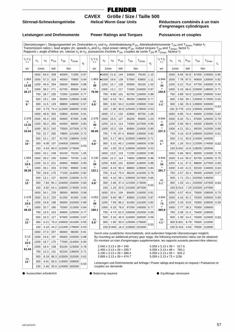
Durch eine zusätzliche Vorschaltstufe, sind außerdem folgende Übersetzungen möglich:By mounting an additional primary gear stage, the following transmission ratios can be obtained:En montant un train d’engrenages supplémentaire, les rapports suivants peuvent être obtenus:
2.040 x 3.13 x 39 = 2492.455 x 3.13 x 39 = 299.73.190 x 3.13 x 39 = 389.43.889 x 3.13 x 39 = 474.7
5.059 x 3.13 x 39 = 617.65.059 x 3.13 x 48 = 760.15.059 x 3.13 x 59 = 934.25.059 x 3.13 x 73 = 1156
Leistungen und Drehmomente auf Anfrage / Power ratings and torques on request / Puissances etcouples sur demande
57K88 DE/EN/FR
CAVEX Größe / Size / Taille 500Stirnrad-Schneckengetriebe Helical Worm Gear Units Réducteurs combinés à un train
d’engrenages cylindriques
Leistungen und Drehmomente Power Ratings and Torques Puissances et couples
Übersetzungen i, Steigungswinkel γm, Drehzahlen n1 und n2, Antriebsleistung P1N, Abtriebsdrehmomente T2N und T2max, Faktor f7Transmission ratios i, lead angles γm, speeds n1 and n2, input power rating P1N, output torques T2N and T2max, factor f7Rapports i, angle d’hélice γm, vitesse n1 et n2, puissances d’entrée P1N, couples de sortie T2N et T2max, facteur f7
i1 x i2= i n1 n2 P1N T2N T2max
f
γm 1/min kW Nm
f7
1650 63.0 328 46300 71300 0.97
1.963 1500 57.3 318 49300 75800 0.94x
13.33 1200 45.9 294 56600 86600 0.8813.33= 1000 38.2 271 62700 95500 0.84
26.17 750 28.7 235 72300 110000 0.77
500 19.1 184 85000 128000 0.68ca.9 ° 300 11.5 129 98800 148000 0.579
150 5.73 73.4 112000 168000 0.53
1650 49.9 303 53800 82400 0.91
2.478 1500 45.4 293 56900 87000 0.88x
13.33 1200 36.3 265 64400 98000 0.8313.33= 1000 30.3 242 70500 107000 0.79
33.04 750 22.7 205 79800 121000 0.72
500 15.1 157 91700 138000 0.63ca.19 ° 300 9.08 107 104000 15600019
150 4.54 60.0 115000 173000 0.53
1650 43.1 248 50100 75100 1.05
1.963 1500 39.2 240 53300 79700 1.02x
19.5 1200 31.3 221 60900 90800 0.9519.5= 1000 26.1 203 67200 99900 0.90
38.28 750 19.6 175 77100 114000 0.82
500 13.1 137 90200 133000 0.73ca.13 ° 300 7.84 95.1 104000 154000 0.6013
150 3.92 54.1 118000 173000 0.53
1650 34.1 229 58000 86500 0.98
2.478 1500 31.0 220 61200 91300 0.95x
19.5 1200 24.8 198 69000 102000 0.8919.5= 1000 20.7 180 75300 112000 0.84
48.33 750 15.5 153 84800 125000 0.77
500 10.3 117 97000 143000 0.67ca.13 ° 300 6.21 79.3 109000 161000 0.5513
150 3.10 44.2 121000 178000 0.53
1650 27.0 207 66000 98200 0.91
3.13 1500 24.6 197 69300 103000 0.88x
19.5 1200 19.7 175 77000 114000 0.8319.5= 1000 16.4 158 83100 123000 0.78
61.04 750 12.3 131 92100 136000 0.71
500 8.19 98.3 103000 152000 0.62ca.13 ° 300 4.91 65.5 114000 16800013
150 2.46 35.9 124000 182000 0.53
i1 x i2= i n1 n2 P1N T2N T2max
f
γm 1/min kW Nm
f7
�1650 21.6 144 54600 79100 1.15
1.963 �1500 19.6 139 57900 83800 1.11x
39 1200 15.7 128 65900 95100 1.0339= 1000 13.1 117 72400 104000 0.97
76.56 750 9.80 101 82700 119000 0.88
500 6.53 78.1 96200 138000 0.77ca.
6.8 ° 300 3.92 54.2 111000 159000 0.646.8
150 1.96 30.9 125000 178000 0.53
1650 17.1 132 62800 90700 1.06
2.478 1500 15.5 127 66200 95600 1.03x
39 1200 12.4 114 74300 107000 0.9539= 1000 10.3 104 80800 116000 0.90
96.65 750 7.76 87.4 90600 130000 0.82
500 5.17 66.5 103000 148000 0.71ca.
6.8 ° 300 3.10 45.2 116000 166000 0.596.8
150 1.55 25.3 128000 183000 0.53
1650 13.5 119 71200 103000 0.99
3.130 1500 12.3 114 74600 108000 0.96x
39 1200 9.83 101 82600 119000 0.8839= 1000 8.19 90.4 88800 128000 0.84
122.1 750 6.14 75.0 98100 141000 0.76
500 4.10 56.1 109000 157000 0.65ca.
6.8 ° 300 2.46 37.4 121000 1730006.8
150 1.23 20.5 131000 187000 0.53
1650 10.4 104 80400 116000 0.91
4.053 1500 9.49 98.7 83800 121000 0.87x
39 1200 7.59 86.2 91400 131000 0.8239= 1000 6.33 76.5 97200 140000 0.77
158.1 750 4.74 62.5 106000 152000 0.69
500 3.16 45.9 116000 166000 0.59ca.
6.8 ° 300 1.90 30.0 125000 1790006.8
150 0.949 16.3 133000 191000 0.53
i1 x i2= i n1 n2 P1N T2N T2max
f
γm 1/min kW Nm
f7
1650 8.56 92.8 87400 126000 0.85
4.944 1500 7.78 87.5 90600 130000 0.82x
39 1200 6.22 75.6 97700 140000 0.7639= 1000 5.19 66.6 103000 148000 0.71
192.8 750 3.89 53.9 111000 159000 0.64
500 2.59 39.1 120000 172000 0.55ca.
6.8 ° 300 1.56 25.3 128000 1830006.8
150 0.778 13.6 135000 193000 0.53
1650 6.95 74.4 84600 122000 0.82
4.944 1500 6.32 70.1 87600 126000 0.79x
48 1200 5.06 60.4 94200 135000 0.7348= 1000 4.21 53.1 99200 142000 0.69
237.3 750 3.16 42.9 106000 152000 0.61
500 2.11 30.9 114000 164000ca.6 ° 300 1.26 20.0 122000 174000 0.536
150 0.632 10.8 128000 183000
0.53
1650 5.66 58.5 80000 115000 0.78
4.944 1500 5.14 55.0 82700 119000 0.75x
59 1200 4.11 47.3 88600 127000 0.6959= 1000 3.43 41.5 93100 134000 0.64
291.7 750 2.57 33.4 99300 142000 0.57
500 1.71 23.1 102000 146000ca.
5.2 ° 300 1.03 14.1 102000 147000 0.535.2
150 0.514 7.24 102000 147000
0.53
1650 4.57 45.6 75000 108000 0.73
4.944 1500 4.16 42.2 76200 109000 0.69x
73 1200 3.33 33.8 76300 109000 0.5973= 1000 2.77 28.3 76300 109000
360.9 750 2.08 21.4 76400 109000
500 1.39 14.4 76400 110000 0.53ca.
4.5 ° 300 0.831 8.79 76500 110000
0.53
4.5
150 0.416 4.54 76500 110000
� Auswuchten erforderlich � Balancing required � Equilibrage nécessaire
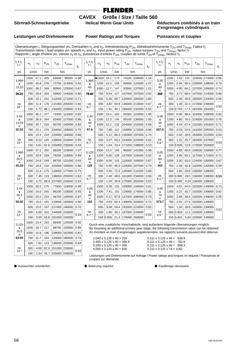
Durch eine zusätzliche Vorschaltstufe, sind außerdem folgende Übersetzungen möglich:By mounting an additional primary gear stage, the following transmission ratios can be obtained:En montant un train d’engrenages supplémentaire, les rapports suivants peuvent être obtenus:
2.040 x 3.125 x 40 = 2552.455 x 3.125 x 40 = 306.93.200 x 3.125 x 40 = 4004.000 x 3.125 x 40 = 500
5.111 x 3.125 x 40 = 638.95.111 x 3.125 x 49 = 782.65.111 x 3.125 x 60 = 958.35.111 x 3.125 x 74 = 1182
Leistungen und Drehmomente auf Anfrage / Power ratings and torques on request / Puissances etcouples sur demande
58 K88 DE/EN/FR
CAVEX Größe / Size / Taille 560Stirnrad-Schneckengetriebe Helical Worm Gear Units Réducteurs combinés à un train
d’engrenages cylindriques
Leistungen und Drehmomente Power Ratings and Torques Puissances et couples
Übersetzungen i, Steigungswinkel γm, Drehzahlen n1 und n2, Antriebsleistung P1N, Abtriebsdrehmomente T2N und T2max, Faktor f7Transmission ratios i, lead angles γm, speeds n1 and n2, input power rating P1N, output torques T2N and T2max, factor f7Rapports i, angle d’hélice γm, vitesse n1 et n2, puissances d’entrée P1N, couples de sortie T2N et T2max, facteur f7
i1 x i2= i n1 n2 P1N T2N T2max
f
γm 1/min kW Nm
f7
1500 57.2 405 63000 98200 0.991.966
x 1200 45.8 376 72700 113000 0.92x13.33 1000 38.2 349 80900 125000 0.87
=26.21 750 28.6 304 93900 144000 0.8026.21
500 19.1 241 112000 171000 0.71
ca.°
300 11.4 170 131000 200000 0.6019 °
150 5.72 98.1 150000 229000 0.53
1500 46.1 377 72400 112000 0.922.44
x 1200 36.9 344 82400 127000 0.86x13.33
= 1000 30.7 316 90700 140000 0.82=32.53 750 23.1 270 104000 159000 0.75
500 15.4 210 120000 184000 0.66
ca.°
300 9.22 145 138000 210000 0.5519 °
150 4.61 81.6 155000 235000 0.53
1500 37.2 292 68200 103000 1.071.966
x 1200 29.8 269 78200 118000 0.99x20.5
= 1000 24.8 249 86700 131000 0.93=40.29 750 18.6 216 100000 150000 0.86
500 12.4 170 118000 177000 0.75
ca.°
300 7.45 119 138000 205000 0.6313 °
150 3.72 68.4 157000 234000 0.53
1500 30.0 270 77900 118000 0.992.44
x 1200 24.0 245 88200 133000 0.93x20.5
= 1000 20.0 224 96700 145000 0.87=50.02 750 15.0 191 110000 165000 0.80
500 10.0 147 127000 190000 0.70
ca.°
300 6.00 101 144000 21600013 °
150 3.00 56.8 161000 240000 0.53
1500 23.4 243 89400 135000 0.923.125
x 1200 18.7 217 99700 150000 0.86x20.5
= 1000 15.6 196 108000 162000 0.81=64.06 750 11.7 164 120000 180000 0.74
500 7.81 123 136000 203000 0.64
ca.°
300 4.68 82.9 151000 22600013 °
150 2.34 45.7 165000 246000 0.53
i1 x i2= i n1 n2 P1N T2N T2max
f
γm 1/min kW Nm
f7
�1500 19.1 173 74100 109000 1.161.966
x 1200 15.3 159 84600 124000 1.07x40 1000 12.7 147 93500 137000 1.01=
78.62 750 9.54 127 107000 157000 0.9278.62
500 6.36 99.7 126000 184000 0.80
ca.°
300 3.82 69.8 146000 213000 0.676.7 °
150 1.91 40.1 166000 242000 0.53
1500 15.4 160 84300 123000 1.082.44
x 1200 12.3 145 95100 139000 1.00x40= 1000 10.2 132 104000 152000 0.94=
97.6 750 7.68 112 118000 171000 0.86
500 5.12 86.3 135000 197000 0.74
ca.°
300 3.07 59.2 154000 223000 0.626.7 °
150 1.54 33.4 171000 248000 0.53
1500 12.0 143 96300 141000 0.993.125
x 1200 9.60 128 107000 156000 0.92x40= 1000 8.00 115 116000 169000 0.87=
125 750 6.00 96.0 129000 187000 0.79
500 4.00 72.3 145000 211000 0.68
ca.°
300 2.40 48.6 161000 234000 0.566.7 °
150 1.20 26.9 175000 255000 0.53
1500 9.26 125 109000 159000 0.914.05
x 1200 7.41 110 119000 174000 0.85x40= 1000 6.17 97.8 127000 186000 0.79=
162 750 4.63 80.4 139000 203000 0.72
500 3.09 59.4 153000 223000 0.62
ca.°
300 1.85 39.1 167000 2430006.7 °
150 0.926 21.3 179000 260000 0.53
i1 x i2= i n1 n2 P1N T2N T2max
f
γm 1/min kW Nm
f7
1500 7.43 110 119000 174000 0.855.05
x 1200 5.94 95.4 129000 188000 0.79x40 1000 4.95 84.2 137000 199000 0.74=
202 750 3.71 68.4 147000 214000 0.66202
500 2.48 49.8 160000 233000 0.56
ca.°
300 1.49 32.4 172000 2490006.7 °
150 0.743 17.4 181000 264000 0.53
1500 6.06 88.4 115000 168000 0.825.05
x 1200 4.85 76.5 124000 181000 0.76x49= 1000 4.04 67.4 131000 191000 0.71=
247.5 750 3.03 54.6 141000 205000 0.63
500 2.02 39.6 153000 222000 0.54
ca.°
300 1.21 25.7 163000 2370005.9 °
150 0.606 13.8 172000 250000 0.53
1500 4.95 69.8 109000 159000 0.775.05
x 1200 3.96 60.2 117000 171000 0.71x60= 1000 3.30 53.0 124000 180000 0.67=
303 750 2.48 42.8 132000 192000 0.59
500 1.65 29.6 136000 198000
ca.°
300 0.990 18.0 136000 198000 0.535.2 °
150 0.495 9.24 136000 198000
0.53
1500 4.01 54.5 102000 149000 0.735.05
x 1200 3.21 43.7 102000 149000 0.62x74= 1000 2.68 36.6 102000 149000 0.55=
373.7 750 2.01 27.6 102000 149000
500 1.34 18.6 103000 149000
ca.°
300 0.803 11.3 103000 149000 0.53
4.5 ° 150 0.401 5.84 103000 149000
� Auswuchten erforderlich � Balancing required � Equilibrage nécessaire
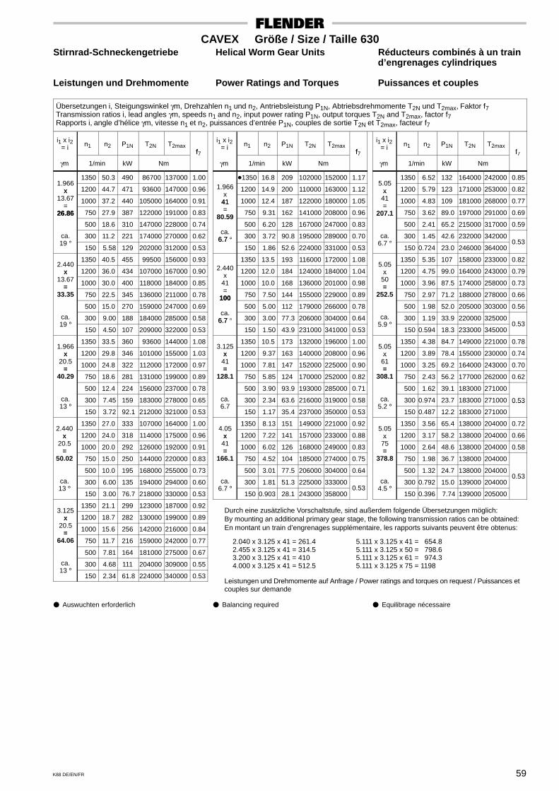
Durch eine zusätzliche Vorschaltstufe, sind außerdem folgende Übersetzungen möglich:By mounting an additional primary gear stage, the following transmission ratios can be obtained:En montant un train d’engrenages supplémentaire, les rapports suivants peuvent être obtenus:
2.040 x 3.125 x 41 = 261.42.455 x 3.125 x 41 = 314.53.200 x 3.125 x 41 = 4104.000 x 3.125 x 41 = 512.5
5.111 x 3.125 x 41 = 654.85.111 x 3.125 x 50 = 798.65.111 x 3.125 x 61 = 974.35.111 x 3.125 x 75 = 1198
Leistungen und Drehmomente auf Anfrage / Power ratings and torques on request / Puissances etcouples sur demande
59K88 DE/EN/FR
CAVEX Größe / Size / Taille 630Stirnrad-Schneckengetriebe Helical Worm Gear Units Réducteurs combinés à un train
d’engrenages cylindriques
Leistungen und Drehmomente Power Ratings and Torques Puissances et couples
Übersetzungen i, Steigungswinkel γm, Drehzahlen n1 und n2, Antriebsleistung P1N, Abtriebsdrehmomente T2N und T2max, Faktor f7Transmission ratios i, lead angles γm, speeds n1 and n2, input power rating P1N, output torques T2N and T2max, factor f7Rapports i, angle d’hélice γm, vitesse n1 et n2, puissances d’entrée P1N, couples de sortie T2N et T2max, facteur f7
i1 x i2= i n1 n2 P1N T2N T2max
f
γm 1/min kW Nm
f7
1350 50.3 490 86700 137000 1.001.966
x 1200 44.7 471 93600 147000 0.96x13.67 1000 37.2 440 105000 164000 0.91
=26.86 750 27.9 387 122000 191000 0.8326.86
500 18.6 310 147000 228000 0.74
ca.°
300 11.2 221 174000 270000 0.6219 °
150 5.58 129 202000 312000 0.53
1350 40.5 455 99500 156000 0.932.440
x 1200 36.0 434 107000 167000 0.90x13.67
= 1000 30.0 400 118000 184000 0.85=33.35 750 22.5 345 136000 211000 0.78
500 15.0 270 159000 247000 0.69
ca.°
300 9.00 188 184000 285000 0.5819 °
150 4.50 107 209000 322000 0.53
1350 33.5 360 93600 144000 1.081.966
x 1200 29.8 346 101000 155000 1.03x20.5
= 1000 24.8 322 112000 172000 0.97=40.29 750 18.6 281 131000 199000 0.89
500 12.4 224 156000 237000 0.78
ca.°
300 7.45 159 183000 278000 0.6513 °
150 3.72 92.1 212000 321000 0.53
1350 27.0 333 107000 164000 1.002.440
x 1200 24.0 318 114000 175000 0.96x20.5
= 1000 20.0 292 126000 192000 0.91=50.02 750 15.0 250 144000 220000 0.83
500 10.0 195 168000 255000 0.73
ca.°
300 6.00 135 194000 294000 0.6013 °
150 3.00 76.7 218000 330000 0.53
1350 21.1 299 123000 187000 0.923.125
x 1200 18.7 282 130000 199000 0.89x20.5
= 1000 15.6 256 142000 216000 0.84=64.06 750 11.7 216 159000 242000 0.77
500 7.81 164 181000 275000 0.67
ca.°
300 4.68 111 204000 309000 0.5513 °
150 2.34 61.8 224000 340000 0.53
i1 x i2= i n1 n2 P1N T2N T2max
f
γm 1/min kW Nm
f7
�1350 16.8 209 102000 152000 1.171.966 1200 14.9 200 110000 163000 1.12
x41 1000 12.4 187 122000 180000 1.0541= 750 9.31 162 141000 208000 0.96
80.59 500 6.20 128 167000 247000 0.83
ca.6.7 ° 300 3.72 90.8 195000 289000 0.706.7 °
150 1.86 52.6 224000 331000 0.53
1350 13.5 193 116000 172000 1.082.440 1200 12.0 184 124000 184000 1.04
x41 1000 10.0 168 136000 201000 0.98=
100 750 7.50 144 155000 229000 0.89100 500 5.00 112 179000 266000 0.78
ca.6.7 ° 300 3.00 77.3 206000 304000 0.646.7
150 1.50 43.9 231000 341000 0.53
1350 10.5 173 132000 196000 1.003.125
x 1200 9.37 163 140000 208000 0.96x41= 1000 7.81 147 152000 225000 0.90=
128.1 750 5.85 124 170000 252000 0.82
500 3.90 93.9 193000 285000 0.71
ca. 300 2.34 63.6 216000 319000 0.586.7
150 1.17 35.4 237000 350000 0.53
1350 8.13 151 149000 221000 0.924.05
x 1200 7.22 141 157000 233000 0.88x41= 1000 6.02 126 168000 249000 0.83=
166.1 750 4.52 104 185000 274000 0.75
500 3.01 77.5 206000 304000 0.64
ca.°
300 1.81 51.3 225000 3330006.7 °
150 0.903 28.1 243000 358000 0.53
i1 x i2= i n1 n2 P1N T2N T2max
f
γm 1/min kW Nm
f7
1350 6.52 132 164000 242000 0.855.05
x 1200 5.79 123 171000 253000 0.82x41 1000 4.83 109 181000 268000 0.77=
207.1 750 3.62 89.0 197000 291000 0.69207.1
500 2.41 65.2 215000 317000 0.59
ca.°
300 1.45 42.6 232000 3420006.7 °
150 0.724 23.0 246000 364000 0.53
1350 5.35 107 158000 233000 0.825.05
x 1200 4.75 99.0 164000 243000 0.79x50= 1000 3.96 87.5 174000 258000 0.73=
252.5 750 2.97 71.2 188000 278000 0.66
500 1.98 52.0 205000 303000 0.56
ca.°
300 1.19 33.9 220000 3250005.9 °
150 0.594 18.3 233000 345000 0.53
1350 4.38 84.7 149000 221000 0.785.05
x 1200 3.89 78.4 155000 230000 0.74x61= 1000 3.25 69.2 164000 243000 0.70=
308.1 750 2.43 56.2 177000 262000 0.62
500 1.62 39.1 183000 271000
ca.°
300 0.974 23.7 183000 271000 0.535.2 °
150 0.487 12.2 183000 271000
0.53
1350 3.56 65.4 138000 204000 0.725.05
x 1200 3.17 58.2 138000 204000 0.66x75= 1000 2.64 48.6 138000 204000 0.58=
378.8 750 1.98 36.7 138000 204000
500 1.32 24.7 138000 204000
ca.°
300 0.792 15.0 139000 204000 0.53
4.5 ° 150 0.396 7.74 139000 205000
� Auswuchten erforderlich � Balancing required � Equilibrage nécessaire

60 K88 DE/EN/FR
CAVEX Bauart / Type CSUWStirnrad-Schneckengetriebe Helical Worm Gear Units Réducteurs combinés à un train
d’engrenages cylindriques
Abtriebswelle auf Seite A, B oder beiderseits Output shaft on side A, B or both sides Arbre de sortie côté A, B ou des deux côtésAntriebswelle in Stellung a, b, c oder d 1) Input shaft in position a, b, c or d 1) Arbre d’entrée en position a, b, c ou d 1)
Einbaulage SU, SO, SR, SL, VO oder VU Mounting position SU, SO, SR, SL, VO or VU Position de montage SU, SO, SR, SL, VO ou VU
SeiteSideCôté
A
SeiteSideCôté
B
SU SR SL VO VU
SO
A B
B
A
A
B
B A
A
B
A
B
Ansicht / ViewVue X
X
A B
Größea b c d1 l1 d1 l1 d e e E E G G h h H l m m m sSize a b c
i1 < 3.6 i1 > 3.6d2 e3 e4 E E1 G1 G2 h1 h2 H l2 m1 m2 m3 s
Taillemm
63 80 100
146 175 216
140168200
20 24 28
16 k616 k622 k6
30 30 35
14 k614 k618 k6
30 30 35
28 m6 38 m6 48 m6
69 82 98
119140168
63 80100
50 50 63
168 182 220
72 86102
113125153
126 155 190
208 252 309
50 65 80
115 140 170
120145170
–––
121515
120 140 160
254 290 324
235260295
32 36 40
22 k628 m628 m6
35 40 40
18 k622 k622 k6
35 40 40
55 m6 65 m6 70 m6
114126143
194220244
120140160
63 80 80
241 286 304
120132150
168195210
225 255 290
364 416 472
95105120
200 230 260
200225255
–––
191919
180 200 225
364 396 440
325350380
45 50 55
35 m635 m642 m6
50 50 60
28 m628 m638 m6
50 50 60
80 m6 90 m6100 m6
159171188
272294323
180200225
100100125
350 368 419
165178195
240250290
320 350 390
522 573 638
140160180
290 315 350
280295325
–––
242428
250 280 315
480 525 590
415450490
60 65 70
42 m648 m648 m6
60 70 70
38 m642 m642 m6
60 70 70
110 n6120 n6140 n6
204222244
354387430
250280315
125160160
442 506 539
212230252
305360375
430 480 530
703 786 870
200220240
385 430 480
355385420
–––
283535
355 400 450
665 748 855
535585562
78 85 92
55 m655 m670 m6
80 80100
48 m648 m660 m6
80 80100
150 n6170 n6190 n6
266291322
478526596
355400450
200200250
620 662 784
275300332
440460540
595 660 740
97710861270
260290320
540 605 750
460510495
––
560
424235
500 560 630
95510501175
616678750
100110120
70 m685 m685 m6
100120120
60 m675 m675 m6
100120120
210 n6230 n6255 n6
355389429
663733815
500560630
250315315
838 9571022
365400440
565665700
815 9101015
141015601745
350390430
840 9201030
540600660
630700780
424248
1) Antriebswelle in Stellung ”a” ist zu bevorzugen;bei Größe 63 ist nur Stellung ”a” möglich.
1) Input shaft in position ”a” to be preferred; for size63 position ”a” is possible only.
1) La position de l’arbre d’entrée en ”a” est préfé-rable. Pour la taille 63, c’est la seule possible.

61K88 DE/EN/FR
CAVEX Bauart / Type CSOWStirnrad-Schneckengetriebe Helical Worm Gear Units Réducteurs combinés à un train
d’engrenages cylindriques
Abtriebswelle auf Seite A, B oder beiderseits Output shaft on side A, B or both sides Arbre de côté A, B ou des deux côtésAntriebswelle in Stellung a, b, c oder d 1) Input shaft in position a, b, c or d 1) Arbre d’entrée en position a, b, c ou d 1)
Einbaulage SU, SO, SR, SL, VO oder VU Mounting position SU, SO, SR, SL, VO or VU Position de montage SU, SO, SR, SL, VO ou VU
SeiteSideCoté
A
SeiteSideCoté
B
A B
Ansicht / ViewVue X
X
AB
SU SR SL VO VU
SO
B A
A B
B
A
B
A
Befestigung mit Stiftschrauben und MutternMounting with studs and nutsFixation par goujons et écrous
B A
Größea b c d1 l1 d1 l1 d l e e E E G G h h H m m m sSize a b c
i1 < 3.6 i1 > 3.6d2 l2 e3 e4 E E1 G1 G2 h1 h2 H m1 m2 m3 s
Taillemm
63 80 100
146 175 216
140168200
20 24 28
16 k616 k622 k6
30 30 35
14 k614 k618 k6
30 30 35
28 m6 38 m6 48 m6
50 65 80
69 82 98
119140168
63 80100
50 50 63
168 182 220
72 86102
113 150 182
100120145
226 275 335
115 140 170
120145170
–––
121515
120 140 160
254 290 324
235260295
32 36 40
22 k628 m628 m6
35 40 40
18 k622 k622 k6
35 40 40
55 m6 65 m6 70 m6
95105120
114126143
194220244
120140160
63 80 80
241 286 304
120132150
227 255 300
170195220
395 450 510
200 230 260
200225255
–––
191919
180 200 225
364 396 440
325350380
45 50 55
35 m635 m642 m6
50 50 60
28 m628 m638 m6
50 50 60
80 m6 90 m6100 m6
140160180
159171188
272294323
180200225
100100125
350 368 419
165178195
325 370 400
245270300
565 620 690
290 315 350
280295325
–––
242428
250 280 315
480 525 590
415450490
60 65 70
42 m648 m648 m6
60 70 70
38 m642 m642 m6
60 70 70
110 n6120 n6140 n6
200220240
204222244
354387430
250280315
125160160
442 506 539
212230252
455 487 560
330367405
760 847 935
385 430 480
355385420
–––
283535
355 400 450
665 748 855
535585562
78 85 92
55 m655 m670 m6
80 80100
48 m648 m660 m6
80 80100
150 n6170 n6190 n6
260290320
266291322
478526596
355400450
200200250
620 662 784
275300332
610 705 730
455505530
105011651270
540 605 750
460510495
––
560
424235
500 560 630
95510501175
616678750
100110120
70 m685 m685 m6
100120120
60 m675 m675 m6
100120120
210 n6230 n6255 n6
350390430
355389429
663733815
500560630
250315315
838 9571022
365400440
845 8951045
595650730
141015601745
840 9201030
540600660
630700780
424248
1) Antriebswelle in Stellung ”a” ist zu bevorzugen;bei Größe 63 ist nur Stellung ”a” möglich.
1) Input shaft in position ”a” to be preferred; for size63 position ”a” is possible only.
1) La position de l’arbre d’entrée en ”a” est préfé-rable. Pour la taille 63, c’est la seule possible.

62 K88 DE/EN/FR
CAVEX Bauart / Type CSFWStirnrad-Schneckengetriebe Helical Worm Gear Units Réducteurs combinés à un train
d’engrenages cylindriquesFlansch auf Seite A oder B Flange on side A or B Bride côté A ou BAbtriebswelle auf Seite A, B oder beiderseits Output shaft on side A, B or both sides Arbre de côté A, B ou des deux côtésAntriebswelle in Stellung a, b, c oder d 1) Input shaft in position a, b, c or d 1) Arbre d’entrée en position a, b, c ou d 1)
Einbaulage SU, SO, SR, SL, VO oder VU Mounting position SU, SO, SR, SL, VO or VU Position de montage SU, SO, SR, SL, VO ou VU
SeiteSideCôté
B
SeiteSideCôté
A BA
Befestigung mit Stiftschrau-ben und MutternMounting with studsand nutsFixation par goujonset écrous
Lochbild bei Größe / Hole pattern for size / Position des perçages pour taille
A B
Ansicht / ViewVue X
X
SU SR SL VO VU
SO
B A
A B
BB
AB A
A
2)
2)
Größec d1 l1 d1 l1 d l d d4 e e e e E E g G G k s zSize c
i1 < 3.6 i1 > 3.6d2 l2 d3
h8e1 e2 e3 e4 E E1 g3 G1 G2 k s z
Taillemm
63 80 100
7 8 9
16 k616 k622 k6
30 30 35
14 k614 k618 k6
30 30 35
28 m6 38 m6 48 m6
50 65 80
188 218 266
150 180 220
63 75 90
82 97119
69 82 98
119140168
63 80100
50 50 63
76 90107
168 182 220
72 86102
170 200 245
5 x 9 7 x 9 7 x 11
3.544
120 140 160
101112
22 k628 m628 m6
35 40 40
18 k622 k622 k6
35 40 40
55 m6 65 m6 70 m6
95105120
315 360 410
260 305 340
105115130
139161182
114126143
194220244
120140160
63 80 80
125138157
241 286 304
120132150
290 335 380
7 x 13.5 7 x 13.5 7 x 17.5
555
180 200 225
131415
35 m635 m642 m6
50 50 60
28 m628 m638 m6
50 50 60
80 m6 90 m6100 m6
140160180
450 490 540
380 420 465
140150165
202223248
159171188
272294323
180200225
100100125
172185202
350 368 419
165178195
420 460 505
7 x 17.5 7 x 17.512 x 17.5
555
250 280 315
16.518
19.5
42 m648 m648 m6
60 70 70
38 m642 m642 m6
60 70 70
110 n6120 n6140 n6
200220240
590 665 730
515 575 640
180200215
273306340
204222244
354387430
250280315
125160160
220238260
442 506 539
212230252
555 625 690
12 x 17.512 x 2212 x 22
666
355 400 450
2122.524
55 m655 m670 m6
80 80100
48 m648 m660 m6
80 80100
150 n6170 n6190 n6
260290320
825 9101025
725 805 905
240260290
382426530
266291322
478526596
355400450
200200250
286312345
620 662 784
275300332
780 865 975
12 x 2612 x 2616 x 26
666
500 560 630
25.527
28.5
70 m685 m685 m6
100120120
60 m675 m675 m6
100120120
210 n6230 n6255 n6
350390430
115012701405
101511251260
315350385
595650730
355389429
663733815
500560630
250315315
380415456
838 9571022
365400440
109512101345
16 x 3316 x 3316 x 33
666
1) Antriebswelle in Stellung ”a” ist zu bevorzugen;bei Größe 63 ist nur Stellung ”a” möglich.
2) Flansch nur an dieser Stelle möglich.
1) Input shaft in position ”a” to be preferred; for size63 position ”a” is possible only.
2) Flange possible in this position only.
1) La position de l’arbre d’entrée en ”a” est préfé-rable. Pour la taille 63, c’est la seule possible.
2) Bride seulement possible dans cette position.

63K88 DE/EN/FR
CAVEX Bauart / Type CSDAStirnrad-Schneckengetriebe Helical Worm Gear Units Réducteurs combinés à un train
d’engrenages cylindriquesDrehm.-stütze auf Seite A o. B in Stellung 1, 2 o. 3 Torque arm on side A or B in position 1, 2 or 3 Bras de reaction côté A ou B en pos. 1, 2 ou 3Mit oder ohne Endscheibe With or without end plate Avec ou sans rondelle de démontageAntriebswelle in Stellung a, b, c oder d 1) Input shaft in position a, b, c or d 1) Arbre d’entrée en position a, b, c ou d 1)
Einbaulage SU, SO, SR, SL, VO oder VU Mounting position SU, SO, SR, SL, VO or VU Position de montage SU, SO, SR, SL, VO ou VU
SeiteSideCôté
B
SeiteSideCôté
A BA
AbschlußdeckelEnd coverCouvercle
EinzelheitDetail
X
EndscheibeEnd plateRondelle de fixation
A B
Ansicht / ViewVue X
X
SU SR SL VO VU
SO
B A
A B
BB
A
B A
A
Schraube gehört nicht zum LieferumfangBolt does not belong to our scope of supplyVis ne fait pas partie de la livraison
Größec c d1 l1 d1 l1 d D2 D5 e e e e E E f g G G L L n P sSize c1 c2
i1 < 3.6 i1 > 3.6d6
H7 H8e1 e2 e4 e5 E E1 f g4 G1 G2
min. max.*L2 n
min.s
Taillemm
63 80 100
161620
81011
16 k616 k622 k6
30 30 35
14 k614 k618 k6
30 30 35
32 40 40
30 40 50
162020
63 75 90
82 97119
119140168
73 89102
63 80100
50 50 63
223
62 74 88
168 182 220
65 80 93
94114136
102124147
115139.5165
140 180 225
101214
M 10M 16M 16
120 140 160
202525
121415
22 k628 m628 m6
35 40 40
18 k622 k622 k6
35 40 40
50 50 65
60 65 75
252532
105115130
139161182
194220244
115127142
120140160
63 80 80
334
101113126
241 286 304
106118132
155173194
167186212
187208.5235.5
270 315 360
161820
M 20M 20M 20
180 200 225
323240
161718
35 m635 m642 m6
50 50 60
28 m628 m638 m6
50 50 60
65 80 80
85 95105
324040
140150165
202223248
272294323
154165182
180200225
100100125
445
138148163
350 368 419
144155170
212228250
233250276
259278307
405 450 505
222528
M 20M 24M 24
250 280 315
404050
202224
42 m648 m648 m6
60 70 70
38 m642 m642 m6
60 70 70
80100100
115125140
405050
180200215
273306340
354387430
197213233
250280315
125160160
555
178192212
442 506 539
185200220
272293322
301326357
335363397
560 630 710
303236
M 24M 24M 30
355 400 450
506060
273033
55 m655 m670 m6
80 80100
48 m648 m660 m6
80 80100
120120150
160180200
606075
240260290
382426530
478526596
256279308
355400450
200200250
556
233256282
620 662 784
242265292
354387425
394433480
438481532
800 9001010
404548
M 30M 30M 30
500 560 630
757590
363840
70 m685 m685 m6
100120120
60 m675 m675 m6
100120120
150170170
220240270
759090
315350385
595650730
663733815
336370406
500560630
250315315
666
310351377
838 9571022
320352388
465510560
528583650
585643713
112012601420
505663
M 30M 36M 36
*) Lmax gilt nur bei Verwendung der Abdrück-scheibe.
1) Antriebswelle in Stellung ”a” ist zu bevorzugen;bei Größe 63 ist nur Stellung ”a” möglich.
*) Lmax is applicable only when using a forcingplate.
1) Input shaft in position ”a” to be preferred; for size63 position ”a” is possible only.
*) Lmax applicable en utilisant la rondelle dedémontage.
1) La position de l’arbre d’entrée en ”a” est préfé-rable. Pour la taille 63, c’est la seule possible.

64 K88 DE/EN/FR
CAVEX Bauart / Type CSUAStirnrad-Schneckengetriebe Helical Worm Gear Units Réducteurs combinés à un train
d’engrenages cylindriquesAbschlußdeckel auf Seite A oder B End cover on side A or B Couvercle côté A ou BMit oder ohne Abdrückscheibe With or without forcing plate Avec ou sans rondelle de démontageAntriebswelle in Stellung a, b, c oder d 1) Input shaft in position a, b, c or d 1) Arbre d’entrée en position a, b, c ou d 1)
Einbaulage SU, SO, SR, SL, VO oder VU Mounting position SU, SO, SR, SL, VO or VU Position de montage SU, SO, SR, SL, VO ou VU
SeiteSideCôté
B
SeiteSideCôté
A
SO
B
A
B
Ansicht / ViewVue X
SU SR SL VO VU
AB
X
A
B
A
BA
A
B
AbschlußdeckelEnd coverCouvercle
AbdrückscheibeForcing plateRondelle de démontage
BA
Größea b c c d1 l1 d1 l1 D2 D e e E E G G h h H m m m L L P sSize a b c c2
i1 < 3.6 i1 > 3.6 H7D3 e4 e5 E E1 G1 G2 h1 h2 H m1 m2 m3
min. max.*L1
min.s
Taillemm
63 80 100
146 175 216
140168200
20 24 28
81011
16 k616 k622 k6
30 30 35
14 k614 k618 k6
30 30 35
30 40 50
M 12M 20M 20
119140168
73 89102
63 80100
50 50 63
168 182 220
65 80 93
113125153
126 155 190
208 252 309
115 140 170
120145170
–––
94114136
102124147
105.5128152
101214
121515
120 140 160
254 290 324
235260295
32 36 40
121415
22 k628 m628 m6
35 40 40
18 k622 k622 k6
35 40 40
60 65 75
M 24M 24M 24
194220244
115127142
120140160
63 80 80
241 286 304
106118132
168195210
225 255 290
364 416 472
200 230 260
200225255
–––
155173194
167186212
173192.5218.5
161820
191919
180 200 225
364 396 440
325350380
45 50 55
161718
35 m635 m642 m6
50 50 60
28 m628 m638 m6
50 50 60
85 95105
M 24M 30M 30
272294323
154165182
180200225
100100125
350 368 419
144155170
240250290
320 350 390
522 573 638
290 315 350
280295325
–––
212228250
233250276
240258285
222528
242428
250 280 315
480 525 590
415450490
60 65 70
202224
42 m648 m648 m6
60 70 70
38 m642 m642 m6
60 70 70
115125140
M 30M 30M 36
354387430
197213233
250280315
125160160
442 506 539
185200220
305360375
430 480 530
703 786 870
385 430 480
355385420
–––
272293322
301326357
311337369
303236
283535
355 400 450
665 748 855
535585562
78 85 92
273033
55 m655 m670 m6
80 80100
48 m648 m660 m6
80 80100
160180200
M 36M 36M 36
478526596
256279308
355400450
200200250
620 662 784
242265292
440460540
595 660 740
97710861270
540 605 750
460510495
––
560
354387425
394433480
407447495
404548
424235
500 560 630
95510501175
616678750
100110120
363840
70 m685 m685 m6
100120120
60 m675 m675 m6
100120120
220240270
M 36M 42M 42
663733815
336370406
500560630
250315315
838 9571022
320352388
565665700
815 9101015
141015601745
840 9201030
540600660
630700780
465510560
528583650
544600668
505663
424248
*) Lmax gilt nur bei Verwendung der Abdrück-scheibe.
1) Antriebswelle in Stellung ”a” ist zu bevorzugen;bei Größe 63 ist nur Stellung ”a” möglich.
*) Lmax is applicable only when using a forcingplate.
1) Input shaft in position ”a” to be preferred; for size63 position ”a” is possible only.
*) Lmax applicable en utilisant la rondelle dedémontage.
1) La position de l’arbre d’entrée en ”a” est préfé-rable pour la taille 63, c’est la seule possible.

65K88 DE/EN/FR
CAVEX Bauart / Type CSOAStirnrad-Schneckengetriebe Helical Worm Gear Units Réducteurs combinés à un train
d’engrenages cylindriquesAbschlußdeckel auf Seite A oder B End cover on side A or B Couvercle côté A ou BMit oder ohne Abdrückscheibe With or without forcing plate Avec ou sans rondelle de démontageAntriebswelle in Stellung a, b, c oder d 1) Input shaft in position a, b, c or d 1) Arbre d’entrée en position a, b, c ou d 1)
Einbaulage SU, SO, SR, SL, VO oder VU Mounting position SU, SO, SR, SL, VO or VU Position de montage SU, SO, SR, SL, VO ou VU
SeiteSideCôté
A
SeiteSideCôté
B
AbschlußdeckelEnd coverCouvercle
SU SR SL VO VU
SO
A B
X
Ansicht / ViewVue X
B A
B A
A B
B
A
B
A
Befestigung mit Stiftschrauben und MutternMounting with studsand nutsFixation par goujonset écrous
AbdrückscheibeForcing plate Rondelle de démontage
B A
Größea b c c d1 l1 d1 l1 D2 D e e E E G G h h H L m m m L P sSize a b c c2
i1 < 3.6 i1 > 3.6 H7D3 e4 e5 E E1 G1 G2 h1 h2 H
min. max.*m1 m2 m3 L1
min.s
Taillemm
63 80 100
146 175 216
140168200
20 24 28
81011
16 k616 k622 k6
30 30 35
14 k614 k618 k6
30 30 35
30 40 50
M 12M 20M 20
119140168
73 89102
63 80100
50 50 63
168 182 220
65 80 93
113 150 182
100120145
226 275 335
94114136
102124147
115 140 170
120145170
–––
105.5128152
101214
121515
120 140 160
254 290 324
235260295
32 36 40
121415
22 k628 m628 m6
35 40 40
18 k622 k622 k6
35 40 40
60 65 75
M 24M 24M 24
194220244
115127142
120140160
63 80 80
241 286 304
106118132
227 255 300
170195220
395 450 510
155173194
167186212
200 230 260
200225255
–––
173192.5218.5
161820
191919
180 200 225
364 396 440
325350380
45 50 55
161718
35 m635 m642 m6
50 50 60
28 m628 m638 m6
50 50 60
85 95105
M 24M 30M 30
272294323
154165182
180200225
100100125
350 368 419
144155170
325 370 400
245270300
565 620 690
212228250
233250276
290 315 350
280295325
–––
240258285
222528
242428
250 280 315
480 525 590
415450490
60 65 70
202224
42 m648 m648 m6
60 70 70
38 m642 m642 m6
60 70 70
115125140
M 30M 30M 36
354387430
197213233
250280315
125160160
442 506 539
185200220
455 487 560
330367405
760 847 935
272293322
301326357
385 430 480
355385420
–––
311337369
303236
283535
355 400 450
665 748 855
535585562
78 85 92
273033
55 m655 m670 m6
80 80100
48 m648 m660 m6
80 80100
160180200
M 36M 36M 36
478526596
256279308
355400450
200200250
620 662 784
242265292
610 705 730
455505530
105011651270
354387425
394433480
540 605 750
460510495
––
560
407447495
404548
424235
500 560 630
95510501175
616678750
100110120
363840
70 m685 m685 m6
100120120
60 m675 m675 m6
100120120
220240270
M 36M 42M 42
663733815
336370406
500560630
250315315
838 9571022
320352388
845 8951045
595650730
141015601745
465510560
528583650
840 9201030
540600660
630700780
544600668
505663
424248
*) Lmax gilt nur bei Verwendung der Abdrück-scheibe.
1) Antriebswelle in Stellung ”a” ist zu bevorzugen;bei Größe 63 ist nur Stellung ”a” möglich.
*) Lmax is applicable only when using a forcingplate.
2) Input shaft in position ”a” to be preferred; for size63 position ”a” is possible only.
*) Lmax applicable en utilisant la rondelle dedémontage.
1) La position de l’arbre d’entrée en ”a” est préfé-rable pour la taille 63, c’est la seule possible.
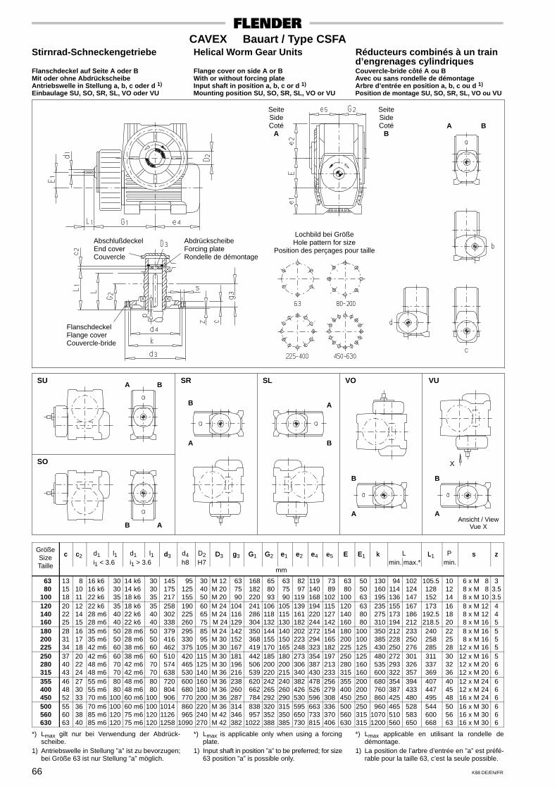
66 K88 DE/EN/FR
CAVEX Bauart / Type CSFAStirnrad-Schneckengetriebe Helical Worm Gear Units Réducteurs combinés à un train
d’engrenages cylindriquesFlanschdeckel auf Seite A oder B Flange cover on side A or B Couvercle-bride côté A ou BMit oder ohne Abdrückscheibe With or without forcing plate Avec ou sans rondelle de démontageAntriebswelle in Stellung a, b, c oder d 1) Input shaft in position a, b, c or d 1) Arbre d’entrée en position a, b, c ou d 1)
Einbaulage SU, SO, SR, SL, VO oder VU Mounting position SU, SO, SR, SL, VO or VU Position de montage SU, SO, SR, SL, VO ou VU
SeiteSideCoté
A
SeiteSideCoté
B
AbschlußdeckelEnd coverCouvercle
Lochbild bei GrößeHole pattern for size
Position des perçages pour taille
FlanschdeckelFlange coverCouvercle-bride
SU SR SL VO VU
SO
A
B
X
A B
B
A
A
B
B
A
B
Ansicht / ViewVue X
A
AbdrückscheibeForcing plateRondelle de démontage
A B
Größec c d1 l1 d1 l1 d d4 D2 D g G G e e e e E E k L L P s zSize c c2
i1 < 3.6 i1 > 3.6d3
h8 H7D3 g3 G1 G2 e1 e2 e4 e5 E E1 k
min. max.*L1
min.s z
Taillemm
63 80 100
131518
81011
16 k616 k622 k6
30 30 35
14 k614 k618 k6
30 30 35
145 175 217
95 125 155
30 40 50
M 12M 20M 20
63 75 90
168 182 220
65 80 93
63 75 90
82 97119
119140168
73 89102
63 80100
50 50 63
130 160 195
94114136
102124147
105.5128152
101214
6 x M 8 8 x M 8 8 x M 10
33.53.5
120 140 160
202225
121415
22 k628 m628 m6
35 40 40
18 k622 k622 k6
35 40 40
258 302 338
190 225 260
60 65 75
M 24M 24 M 24
104116129
241 286 304
106118132
105115130
139161182
194220244
115127142
120140160
63 80 80
235 275 310
155173194
167186212
173192.5218.5
161820
8 x M 12 8 x M 12 8 x M 16
445
180 200 225
283134
161718
35 m635 m642 m6
50 50 60
28 m628 m638 m6
50 50 60
379 416 462
295 330 375
85 95105
M 24M 30M 30
142152167
350 368 419
144155170
140150165
202223248
272294323
154165182
180200225
100100125
350 385 430
212228250
233250276
240258285
222528
8 x M 16 8 x M 1612 x M 16
555
250 280 315
374043
202224
42 m648 m648 m6
60 70 70
38 m642 m642 m6
60 70 70
510 574 638
420 465 530
115125140
M 30M 30M 36
181196216
442 506 539
185200220
180200215
273306340
354387430
197213233
250280315
125160160
480 535 600
272293322
301326357
311337369
303236
12 x M 1612 x M 2012 x M 20
566
355 400 450
464852
273033
55 m655 m670 m6
80 80100
48 m648 m660 m6
80 80100
720 804 906
600 680 770
160180200
M 36M 36M 36
238260287
620 662 784
242265292
240260290
382426530
478526596
256279308
355400450
200200250
680 760 860
354387425
394433480
407447495
404548
12 x M 2412 x M 2416 x M 24
666
500 560 630
556063
363840
70 m685 m685 m6
100120120
60 m675 m675 m6
100120120
101411261258
860 9651090
220240270
M 36M 42M 42
314346382
838 9571022
320352388
315350385
595650730
663733815
336370406
500560630
250315315
96010701200
465510560
528583650
544600668
505663
16 x M 3016 x M 3016 x M 30
666
*) Lmax gilt nur bei Verwendung der Abdrück-scheibe.
1) Antriebswelle in Stellung ”a” ist zu bevorzugen;bei Größe 63 ist nur Stellung ”a” möglich.
*) Lmax is applicable only when using a forcingplate.
1) Input shaft in position ”a” to be preferred; for size63 position ”a” is possible only.
*) Lmax applicable en utilisant la rondelle dedémontage.
1) La position de l’arbre d’entrée en ”a” est préfé-rable pour la taille 63, c’est la seule possible.

ab Vorrat ex stock en stock
67K88 DE/EN/FR
CAVEX Größe / Size / Taille 100Doppelschneckengetriebe Double Worm Gear Units Réducteurs à double vis sans fin
Leistungen und Drehmomente Power Ratings and Torques Puissances et couples
Übersetzungen i, Steigungswinkel γm, Drehzahlen n1 und n2, Antriebsleistung P1N, Abtriebsdrehmomente T2N und T2max, Faktor f7Transmission ratios i, lead angles γm, speeds n1 and n2, input power rating P1N, output torques T2N and T2max, factor f7Rapports i, angle d’hélice γm, vitesse n1 et n2, puissances d’entrée P1N, couples de sortie T2N et T2max, facteur f7
i1 x i2= i n1 n2 P1N T2N T2max
f
γm 1/min kW Nm
f7
3000 17.6 2.93 1260 1670
10.33 2400 14.1 2.46 1290 172010.33x 1800 10.6 1.96 1330 1760
16.5= 1500 8.80 1.69 1350 1780=
170.5 1200 7.04 1.40 1370 1810 0.53
1000 5.87 1.20 1380 1830
0.53
ca.° 750 4.40 0.936 1400 185018 °
12 ° 500 2.93 0.668 1410 1870
300 1.76 0.426 1430 1890
3000 14.4 2.52 1290 1710
12.67 2400 11.5 2.09 1320 175012.67x 1800 8.61 1.66 1350 1790
16.5= 1500 7.18 1.43 1360 1810
209 1200 5.74 1.18 1380 1830 0.53
1000 4.78 1.01 1390 1840
0.53
ca.16 ° 750 3.59 0.793 1410 186016 12 ° 500 2.39 0.561 1420 1880
300 1.44 0.360 1430 1890
3000 11.7 2.17 1310 1750
15.5 2400 9.38 1.81 1340 178015.5x 1800 7.04 1.44 1370 1810
16.5= 1500 5.86 1.23 1380 1830
255.8 1200 4.69 1.03 1390 1840 0.53
1000 3.91 0.882 1400 1850
0.53
ca.12 ° 750 2.93 0.693 1410 187012 12 ° 500 1.95 0.494 1420 1880
300 1.17 0.322 1430 1890
3000 9.07 1.86 1330 1720
10.33 2400 7.26 1.57 1360 176010.33x 1800 5.44 1.27 1400 1800
32= 1500 4.54 1.10 1410 1830
330.7 1200 3.63 0.911 1430 1850 0.53
1000 3.02 0.785 1450 1870
0.53
ca.18 ° 750 2.27 0.623 1460 189018 6.3 ° 500 1.51 0.449 1480 1910
300 0.907 0.292 1490 1930
3000 7.40 1.60 1360 1760
12.67 2400 5.92 1.35 1390 179012.67x 1800 4.44 1.08 1420 1830
32= 1500 3.70 0.928 1430 1850
405.3 1200 2.96 0.781 1450 1870 0.53
1000 2.47 0.674 1460 1880
0.53
ca.16 ° 750 1.85 0.528 1470 190016 6.3 ° 500 1.23 0.381 1490 1920
300 0.740 0.250 1500 1930
i1 x i2= i n1 n2 P1N T2N T2max
f
γm 1/min kW Nm
f7
3000 6.05 1.41 1380 1790
15.5 2400 4.84 1.18 1410 182015.5x 1800 3.63 0.943 1430 1850
32= 1500 3.02 0.816 1450 1870=
496 1200 2.42 0.690 1460 1880 0.53
1000 2.02 0.598 1470 1890
0.53
ca.° 750 1.51 0.470 1480 191012 °
6.3 ° 500 1.01 0.342 1490 1920
300 0.605 0.226 1500 1930
3000 4.81 1.17 1410 1820
19.5 2400 3.85 0.992 1430 185019.5x 1800 2.88 0.796 1450 1870
32= 1500 2.40 0.691 1460 1880
624 1200 1.92 0.577 1470 1900 0.53
1000 1.60 0.500 1480 1910
0.53
ca.10 ° 750 1.20 0.399 1490 192010 6.3 ° 500 0.801 0.290 1500 1930
300 0.481 0.191 1500 1940
3000 3.83 0.990 1430 1850
24.5 2400 3.06 0.831 1450 187024.5x 1800 2.30 0.668 1460 1890
32= 1500 1.91 0.581 1470 1900
784 1200 1.53 0.493 1480 1910 0.53
1000 1.28 0.427 1490 1920
0.53
ca.8.8 ° 750 0.957 0.341 1490 19208.8 6.3 ° 500 0.638 0.249 1500 1930
300 0.383 0.163 1510 1940
3000 3.02 0.880 1450 1870
31 2400 2.42 0.753 1460 188031x 1800 1.81 0.607 1470 1900
32= 1500 1.51 0.531 1480 1910
992 1200 1.21 0.454 1490 1920 0.53
1000 1.01 0.397 1490 1920
0.53
ca.6.1 ° 750 0.756 0.321 1500 19306.1 6.3 ° 500 0.504 0.239 1500 1940
300 0.302 0.160 1510 1940
3000 2.40 0.752 1460 1880
39 2400 1.92 0.638 1470 190039x 1800 1.44 0.521 1480 1910
32= 1500 1.20 0.458 1490 1920
1248 1200 0.962 0.388 1490 1920 0.53
1000 0.801 0.343 1500 1930
0.53
ca.5.2 ° 750 0.601 0.278 1500 19405.2 6.3 ° 500 0.401 0.205 1510 1940
300 0.240 0.138 1510 1950
i1 x i2= i n1 n2 P1N T2N T2max
f
γm 1/min kW Nm
f7
3000 1.91 0.639 1470 1900
49 2400 1.53 0.551 1480 191049x 1800 1.15 0.446 1490 1920
32= 1500 0.957 0.397 1490 1920=
1568 1200 0.765 0.337 1500 1930 0.53
1000 0.638 0.298 1500 1930
0.53
ca.° 750 0.478 0.242 1500 19404.4 °
6.3 ° 500 0.319 0.181 1510 1940
300 0.191 0.120 1510 1950
3000 1.54 0.549 1480 1910
61 2400 1.23 0.476 1490 192061x 1800 0.922 0.391 1490 1930
32= 1500 0.768 0.344 1500 1930
1952 1200 0.615 0.296 1500 1930 0.53
1000 0.512 0.259 1500 1940
0.53
ca.3.8 ° 750 0.384 0.213 1510 19403.8 6.3 ° 500 0.256 0.158 1510 1950
300 0.154 0.106 1510 1950
3000 1.23 0.469 1420 1830
61 2400 0.984 0.410 1420 183061x 1800 0.738 0.336 1430 1840
40= 1500 0.615 0.301 1430 1850
2440 1200 0.492 0.258 1430 1850 0.53
1000 0.410 0.227 1440 1850
0.53
ca.3.8 ° 750 0.307 0.187 1440 18603.8 5.5 ° 500 0.205 0.140 1440 1860
300 0.123 0.093 1440 1860
3000 0.984 0.395 1300 1680
61 2400 0.787 0.349 1300 168061x 1800 0.590 0.288 1300 1680
50= 1500 0.492 0.257 1300 1680
3050 1200 0.393 0.221 1300 1680 0.53
1000 0.328 0.195 1300 1680
0.53
ca.3.8 ° 750 0.246 0.161 1300 16803.8 4.7 ° 500 0.164 0.120 1300 1680
300 0.098 0.081 1300 1680
3000 0.793 0.319 1070 1380
61 2400 0.635 0.281 1070 138061x 1800 0.476 0.235 1070 1380
62= 1500 0.397 0.211 1070 1380
3782 1200 0.317 0.184 1070 1380 0.53
1000 0.264 0.163 1070 1380
0.53
ca.3.8 ° 750 0.198 0.134 1070 13803.8 4.0 ° 500 0.132 0.101 1070 1380
300 0.079 0.068 1070 1380

ab Vorrat ex stock en stock
68 K88 DE/EN/FR
CAVEX Größe / Size / Taille 120Doppelschneckengetriebe Double Worm Gear Units Réducteurs à double vis sans fin
Leistungen und Drehmomente Power Ratings and Torques Puissances et couples
Übersetzungen i, Steigungswinkel γm, Drehzahlen n1 und n2, Antriebsleistung P1N, Abtriebsdrehmomente T2N und T2max, Faktor f7Transmission ratios i, lead angles γm, speeds n1 and n2, input power rating P1N, output torques T2N and T2max, factor f7Rapports i, angle d’hélice γm, vitesse n1 et n2, puissances d’entrée P1N, couples de sortie T2N et T2max, facteur f7
i1 x i2= i n1 n2 P1N T2N T2max
f
γm 1/min kW Nm
f7
3000 17.6 4.66 2100 3160
10.33 2400 14.1 3.89 2160 288010.33x 1800 10.6 3.10 2230 2970
16.5= 1500 8.80 2.66 2260 3020=
170.5 1200 7.04 2.20 2300 3070 0.53
1000 5.87 1.89 2330 3100
0.53
ca.° 750 4.40 1.48 2360 314018 °
12 ° 500 2.93 1.04 2390 3180
300 1.76 0.662 2420 3220
3000 14.4 3.89 2100 3120
12.67 2400 11.5 3.31 2210 295012.67x 1800 8.61 2.61 2270 3020
16.5= 1500 7.18 2.24 2300 3060
209 1200 5.74 1.85 2330 3100 0.53
1000 4.78 1.59 2350 3130
0.53
ca.16 ° 750 3.59 1.24 2380 316016 12 ° 500 2.39 0.875 2410 3200
300 1.44 0.557 2430 3230
3000 11.7 3.42 2200 2940
15.5 2400 9.38 2.83 2250 300015.5x 1800 7.04 2.24 2300 3070
16.5= 1500 5.86 1.93 2330 3100
255.8 1200 4.69 1.60 2350 3130 0.53
1000 3.91 1.37 2370 3150
0.53
ca.12 ° 750 2.93 1.07 2390 318012 12 ° 500 1.95 0.761 2420 3210
300 1.17 0.491 2430 3240
3000 9.07 2.87 2210 2870
10.33 2400 7.26 2.41 2270 296010.33x 1800 5.44 1.94 2340 3040
32= 1500 4.54 1.68 2380 3090
330.7 1200 3.63 1.39 2420 3140 0.53
1000 3.02 1.20 2440 3170
0.53
ca.18 ° 750 2.27 0.945 2470 321018 6.4 ° 500 1.51 0.673 2510 3250
300 0.907 0.439 2530 3290
3000 7.40 2.45 2270 2950
12.67 2400 5.92 2.05 2320 302012.67x 1800 4.44 1.64 2380 3090
32= 1500 3.70 1.42 2410 3130
405.3 1200 2.96 1.18 2440 3170 0.53
1000 2.47 1.01 2460 3200
0.53
ca.16 ° 750 1.85 0.800 2490 323016 6.4 ° 500 1.23 0.570 2520 3270
300 0.740 0.371 2540 3290
i1 x i2= i n1 n2 P1N T2N T2max
f
γm 1/min kW Nm
f7
3000 6.05 2.13 2320 3010
15.5 2400 4.84 1.79 2370 307015.5x 1800 3.63 1.43 2420 3140
32= 1500 3.02 1.23 2440 3170=
496 1200 2.42 1.03 2470 3200 0.53
1000 2.02 0.890 2480 3220
0.53
ca.° 750 1.51 0.704 2510 325012 °
6.4 ° 500 1.01 0.509 2530 3280
300 0.605 0.334 2550 3300
3000 4.81 1.78 2370 3080
19.5 2400 3.85 1.49 2410 312019.5x 1800 2.88 1.18 2450 3180
32= 1500 2.40 1.03 2470 3200
624 1200 1.92 0.857 2490 3230 0.53
1000 1.60 0.742 2500 3250
0.53
ca.10 ° 750 1.20 0.593 2520 327010 6.4 ° 500 0.801 0.426 2540 3290
300 0.481 0.280 2550 3310
3000 3.83 1.50 2410 3130
24.5 2400 3.06 1.25 2440 317024.5x 1800 2.30 0.998 2470 3210
32= 1500 1.91 0.859 2490 3230
784 1200 1.53 0.725 2510 3250 0.53
1000 1.28 0.628 2520 3260
0.53
ca.8.8 ° 750 0.957 0.498 2530 32808.8 6.4 ° 500 0.638 0.362 2550 3300
300 0.383 0.237 2560 3320
3000 3.02 1.31 2440 3170
31 2400 2.42 1.10 2470 320031x 1800 1.81 0.887 2490 3230
32= 1500 1.51 0.774 2510 3250
992 1200 1.21 0.652 2520 3270 0.53
1000 1.01 0.570 2530 3280
0.53
ca.6.1 ° 750 0.756 0.460 2540 32906.1 6.4 ° 500 0.504 0.338 2550 3310
300 0.302 0.227 2560 3320
3000 2.40 1.10 2470 3200
39 2400 1.92 0.926 2490 323039x 1800 1.44 0.748 2510 3250
32= 1500 1.20 0.656 2520 3270
1248 1200 0.962 0.558 2530 3280 0.53
1000 0.801 0.487 2540 3290
0.53
ca.5.2 ° 750 0.601 0.394 2550 33005.2 6.4 ° 500 0.401 0.290 2560 3310
300 0.240 0.195 2560 3320
i1 x i2= i n1 n2 P1N T2N T2max
f
γm 1/min kW Nm
f7
3000 1.91 0.925 2490 3230
49 2400 1.53 0.791 2510 325049x 1800 1.15 0.640 2520 3270
32= 1500 0.957 0.562 2530 3280=
1568 1200 0.765 0.479 2540 3290 0.53
1000 0.638 0.419 2550 3300
0.53
ca.° 750 0.478 0.340 2550 33104.4 °
6.4 ° 500 0.319 0.252 2560 3320
300 0.191 0.168 2570 3330
3000 1.54 0.795 2510 3250
61 2400 1.23 0.677 2520 327061x 1800 0.922 0.555 2530 3280
32= 1500 0.768 0.487 2540 3290
1952 1200 0.615 0.417 2550 3300 0.53
1000 0.512 0.364 2550 3310
0.53
ca.3.8 ° 750 0.384 0.296 2560 33203.8 6.4 ° 500 0.256 0.221 2560 3320
300 0.154 0.147 2570 3330
3000 1.23 0.663 2390 3100
61 2400 0.984 0.570 2410 312061x 1800 0.738 0.467 2420 3140
40= 1500 0.615 0.413 2420 3140
2440 1200 0.492 0.356 2430 3150 0.53
1000 0.410 0.310 2440 3160
0.53
ca.3.8 ° 750 0.307 0.254 2440 31603.8 5.6 ° 500 0.205 0.191 2450 3170
300 0.123 0.127 2450 3180
3000 0.984 0.549 2220 2880
61 2400 0.787 0.476 2220 288061x 1800 0.590 0.391 2220 2880
50= 1500 0.492 0.344 2220 2880
3050 1200 0.393 0.296 2220 2880 0.53
1000 0.328 0.262 2220 2880
0.53
ca.3.8 ° 750 0.246 0.215 2220 28803.8 4.8 ° 500 0.164 0.161 2220 2880
300 0.098 0.109 2220 2880
3000 0.781 0.426 1810 2340
61 2400 0.625 0.370 1810 234061x 1800 0.468 0.304 1810 2340
63= 1500 0.390 0.274 1810 2340
3843 1200 0.312 0.235 1810 2340 0.53
1000 0.260 0.207 1810 2340
0.53
ca.3.8 ° 750 0.195 0.170 1810 23403.8 4.1 ° 500 0.130 0.130 1810 2340
300 0.078 0.087 1810 2340
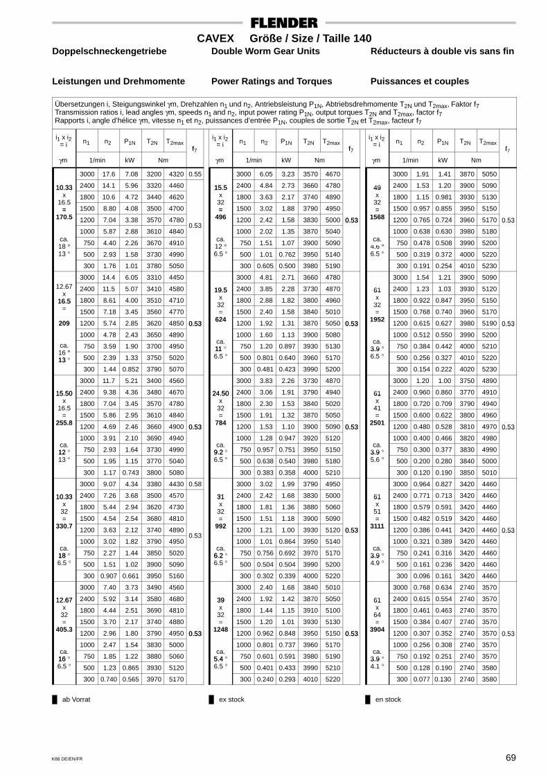
ab Vorrat ex stock en stock
69K88 DE/EN/FR
CAVEX Größe / Size / Taille 140Doppelschneckengetriebe Double Worm Gear Units Réducteurs à double vis sans fin
Leistungen und Drehmomente Power Ratings and Torques Puissances et couples
Übersetzungen i, Steigungswinkel γm, Drehzahlen n1 und n2, Antriebsleistung P1N, Abtriebsdrehmomente T2N und T2max, Faktor f7Transmission ratios i, lead angles γm, speeds n1 and n2, input power rating P1N, output torques T2N and T2max, factor f7Rapports i, angle d’hélice γm, vitesse n1 et n2, puissances d’entrée P1N, couples de sortie T2N et T2max, facteur f7
i1 x i2= i n1 n2 P1N T2N T2max
f
γm 1/min kW Nm
f7
3000 17.6 7.08 3200 4320 0.55
10.33 2400 14.1 5.96 3320 446010.33x 1800 10.6 4.72 3440 4620
16.5= 1500 8.80 4.08 3500 4700=
170.5 1200 7.04 3.38 3570 4780
1000 5.87 2.88 3610 4840 0.53
ca.° 750 4.40 2.26 3670 491018 °
13 ° 500 2.93 1.58 3730 4990
300 1.76 1.01 3780 5050
3000 14.4 6.05 3310 445012.67 2400 11.5 5.07 3410 4580
x16.5 1800 8.61 4.00 3510 471016.5
= 1500 7.18 3.45 3560 4770
209 1200 5.74 2.85 3620 4850 0.53
1000 4.78 2.43 3650 4890
0.53
ca.°
750 3.59 1.90 3700 495016 °13 ° 500 2.39 1.33 3750 502013
300 1.44 0.852 3790 5070
3000 11.7 5.21 3400 4560
15.50 2400 9.38 4.36 3480 467015.50x 1800 7.04 3.45 3570 4780
16.5= 1500 5.86 2.95 3610 4840
255.8 1200 4.69 2.46 3660 4900 0.53
1000 3.91 2.10 3690 4940
0.53
ca.12 ° 750 2.93 1.64 3730 499012 13 ° 500 1.95 1.15 3770 5040
300 1.17 0.743 3800 5080
3000 9.07 4.34 3380 4430 0.58
10.33 2400 7.26 3.68 3500 457010.33x 1800 5.44 2.94 3620 4730
32= 1500 4.54 2.54 3680 4810
330.7 1200 3.63 2.12 3740 4890
1000 3.02 1.82 3790 4950 0.53
ca.18 ° 750 2.27 1.44 3850 502018 6.5 ° 500 1.51 1.02 3900 5090
300 0.907 0.661 3950 5160
3000 7.40 3.73 3490 4560
12.67 2400 5.92 3.14 3580 468012.67x 1800 4.44 2.51 3690 4810
32= 1500 3.70 2.17 3740 4880
405.3 1200 2.96 1.80 3790 4950 0.53
1000 2.47 1.54 3830 5000
0.53
ca.16 ° 750 1.85 1.22 3880 506016 6.5 ° 500 1.23 0.865 3930 5120
300 0.740 0.565 3970 5170
i1 x i2= i n1 n2 P1N T2N T2max
f
γm 1/min kW Nm
f7
3000 6.05 3.23 3570 4670
15.5 2400 4.84 2.73 3660 478015.5x 1800 3.63 2.17 3740 4890
32= 1500 3.02 1.88 3790 4950=
496 1200 2.42 1.58 3830 5000 0.53
1000 2.02 1.35 3870 5040
0.53
ca.° 750 1.51 1.07 3900 509012 °
6.5 ° 500 1.01 0.762 3950 5140
300 0.605 0.500 3980 5190
3000 4.81 2.71 3660 4780
19.5 2400 3.85 2.28 3730 487019.5x 1800 2.88 1.82 3800 4960
32= 1500 2.40 1.58 3840 5010
624 1200 1.92 1.31 3870 5050 0.53
1000 1.60 1.13 3900 5080
0.53
ca.11 ° 750 1.20 0.897 3930 513011 6.5 ° 500 0.801 0.640 3960 5170
300 0.481 0.423 3990 5200
3000 3.83 2.26 3730 4870
24.50 2400 3.06 1.91 3790 494024.50x 1800 2.30 1.53 3840 5020
32= 1500 1.91 1.32 3870 5050
784 1200 1.53 1.10 3900 5090 0.53
1000 1.28 0.947 3920 5120
0.53
ca.9.2 ° 750 0.957 0.751 3950 51509.2 6.5 ° 500 0.638 0.540 3980 5180
300 0.383 0.358 4000 5210
3000 3.02 1.99 3790 4950
31 2400 2.42 1.68 3830 500031x 1800 1.81 1.36 3880 5060
32= 1500 1.51 1.18 3900 5090
992 1200 1.21 1.00 3930 5120 0.53
1000 1.01 0.864 3950 5140
0.53
ca.6.2 ° 750 0.756 0.692 3970 51706.2 6.5 ° 500 0.504 0.504 3990 5200
300 0.302 0.339 4000 5220
3000 2.40 1.68 3840 5010
39 2400 1.92 1.42 3870 505039x 1800 1.44 1.15 3910 5100
32= 1500 1.20 1.01 3930 5130
1248 1200 0.962 0.848 3950 5150 0.53
1000 0.801 0.737 3960 5170
0.53
ca.5.4 ° 750 0.601 0.591 3980 51905.4 6.5 ° 500 0.401 0.433 3990 5210
300 0.240 0.293 4010 5220
i1 x i2= i n1 n2 P1N T2N T2max
f
γm 1/min kW Nm
f7
3000 1.91 1.41 3870 5050
49 2400 1.53 1.20 3900 509049x 1800 1.15 0.981 3930 5130
32= 1500 0.957 0.855 3950 5150=
1568 1200 0.765 0.724 3960 5170 0.53
1000 0.638 0.630 3980 5180
0.53
ca.° 750 0.478 0.508 3990 52004.6 °
6.5 ° 500 0.319 0.372 4000 5220
300 0.191 0.254 4010 5230
3000 1.54 1.21 3900 5090
61 2400 1.23 1.03 3930 512061x 1800 0.922 0.847 3950 5150
32= 1500 0.768 0.740 3960 5170
1952 1200 0.615 0.627 3980 5190 0.53
1000 0.512 0.550 3990 5200
0.53
ca.3.9 ° 750 0.384 0.442 4000 52103.9 6.5 ° 500 0.256 0.327 4010 5220
300 0.154 0.222 4020 5230
3000 1.20 1.00 3750 4890
61 2400 0.960 0.860 3770 491061x 1800 0.720 0.709 3790 4940
41= 1500 0.600 0.622 3800 4960
2501 1200 0.480 0.528 3810 4970 0.53
1000 0.400 0.466 3820 4980
0.53
ca.3.9 ° 750 0.300 0.377 3830 49903.9 5.6 ° 500 0.200 0.280 3840 5000
300 0.120 0.190 3850 5010
3000 0.964 0.827 3420 4460
61 2400 0.771 0.713 3420 446061x 1800 0.579 0.591 3420 4460
51= 1500 0.482 0.519 3420 4460
3111 1200 0.386 0.441 3420 4460 0.53
1000 0.321 0.389 3420 4460
0.53
ca.3.9 ° 750 0.241 0.316 3420 44603.9 4.9 ° 500 0.161 0.236 3420 4460
300 0.096 0.161 3420 4460
3000 0.768 0.634 2740 3570
61 2400 0.615 0.554 2740 357061x 1800 0.461 0.463 2740 3570
64= 1500 0.384 0.407 2740 3570
3904 1200 0.307 0.352 2740 3570 0.53
1000 0.256 0.308 2740 3570
0.53
ca.3.9 ° 750 0.192 0.251 2740 35703.9 4.1 ° 500 0.128 0.190 2740 3580
300 0.077 0.130 2740 3580

ab Vorrat ex stock en stock
70 K88 DE/EN/FR
CAVEX Größe / Size / Taille 160Doppelschneckengetriebe Double Worm Gear Units Réducteurs à double vis sans fin
Leistungen und Drehmomente Power Ratings and Torques Puissances et couples
Übersetzungen i, Steigungswinkel γm, Drehzahlen n1 und n2, Antriebsleistung P1N, Abtriebsdrehmomente T2N und T2max, Faktor f7Transmission ratios i, lead angles γm, speeds n1 and n2, input power rating P1N, output torques T2N and T2max, factor f7Rapports i, angle d’hélice γm, vitesse n1 et n2, puissances d’entrée P1N, couples de sortie T2N et T2max, facteur f7
i1 x i2= i n1 n2 P1N T2N T2max
f
γm 1/min kW Nm
f7
3000 16.6 7.6 3500 5300
10.33 2400 13.3 7.77 4660 692010.33x 1800 9.96 6.31 4970 6710
17.5= 1500 8.30 5.44 5070 6830=
180.8 1200 6.64 4.50 5170 6970 0.53
1000 5.53 3.85 5240 7060
0.53
ca.° 750 4.15 3.00 5330 718018 °
13 ° 500 2.77 2.10 5420 7300
300 1.66 1.34 5500 7400
3000 13.5 7.10 4160 6190
12.67 2400 10.8 6.64 4820 704012.67x 1800 8.12 5.35 5080 6850
17.5= 1500 6.77 4.60 5160 6960
221.7 1200 5.41 3.80 5250 7070 0.53
1000 4.51 3.24 5310 7150
0.53
ca.16 ° 750 3.38 2.53 5380 724016 13 ° 500 2.26 1.77 5460 7340
300 1.35 1.13 5520 7430
3000 11.1 6.44 4540 6500 0.55
15.50 2400 8.85 5.79 5030 679015.50x 1800 6.63 4.57 5170 6970
17.5= 1500 5.53 3.93 5240 7060
271.3 1200 4.42 3.25 5310 7150
1000 3.69 2.78 5360 7220 0.53
ca.12 ° 750 2.76 2.17 5420 730012 13 ° 500 1.84 1.52 5490 7380
300 1.11 0.976 5540 7450
3000 8.80 5.87 4850 6380 0.63
10.33 2400 7.04 4.96 5020 6610 0.5610.33x 1800 5.28 3.95 5210 6850
33= 1500 4.40 3.43 5310 6980
341 1200 3.52 2.85 5410 7110
1000 2.93 2.44 5480 7200 0.53ca.18 ° 750 2.20 1.92 5570 7320
0.53
18 6.6 ° 500 1.47 1.36 5670 7440
300 0.880 0.878 5750 7540
3000 7.18 5.03 5010 6590 0.57
12.67 2400 5.74 4.23 5160 678012.67x 1800 4.31 3.37 5320 6990
33= 1500 3.59 2.91 5400 7100
418 1200 2.87 2.41 5490 7210
1000 2.39 2.07 5550 7290 0.53
ca.16 ° 750 1.79 1.63 5630 738016 6.6 ° 500 1.20 1.15 5700 7480
300 0.718 0.747 5770 7560
i1 x i2= i n1 n2 P1N T2N T2max
f
γm 1/min kW Nm
f7
3000 5.87 4.35 5150 6770
15.5 2400 4.69 3.66 5280 693015.5x 1800 3.52 2.91 5410 7110
33= 1500 2.93 2.51 5480 7200=
511.5 1200 2.35 2.09 5560 7290 0.53
1000 1.96 1.80 5610 7360
0.53
ca.° 750 1.47 1.41 5670 744012 °
6.6 ° 500 0.978 1.01 5730 7520
300 0.587 0.658 5790 7590
3000 4.66 3.64 5280 6940
19.50 2400 3.73 3.06 5390 708019.50x 1800 2.80 2.42 5500 7220
33= 1500 2.33 2.09 5560 7300
643.5 1200 1.86 1.74 5620 7370 0.53
1000 1.55 1.50 5660 7420
0.53
ca.11 ° 750 1.17 1.18 5710 749011 6.6 ° 500 0.777 0.842 5760 7550
300 0.466 0.553 5800 7610
3000 3.71 3.04 5390 7080
24.5 2400 2.97 2.54 5480 7190 24.5x 1800 2.23 2.02 5570 7310
33= 1500 1.86 1.74 5620 7370
808.5 1200 1.48 1.45 5670 7430 0.53
1000 1.24 1.25 5700 7480
0.53
ca.9.2 ° 750 0.928 0.986 5740 75309.2 6.6 ° 500 0.618 0.706 5780 7580
300 0.371 0.466 5810 7620
3000 2.93 2.63 5480 7200
31 2400 2.35 2.21 5560 729031x 1800 1.76 1.78 5630 7390
33= 1500 1.47 1.55 5670 7440
1023 1200 1.17 1.30 5710 7490 0.53
1000 0.978 1.12 5730 7520
0.53
ca.6.2 ° 750 0.733 0.895 5770 75606.2 6.6 ° 500 0.489 0.648 5800 7600
300 0.293 0.434 5830 7640
3000 2.33 2.20 5560 7300
39 2400 1.86 1.86 5620 737039x 1800 1.40 1.50 5680 7450
33= 1500 1.17 1.30 5710 7490
1287 1200 0.932 1.10 5740 7530 0.53
1000 0.777 0.952 5760 7550
0.53
ca.5.4 ° 750 0.583 0.759 5790 75905.4 6.6 ° 500 0.389 0.552 5810 7620
300 0.233 0.373 5830 7650
i1 x i2= i n1 n2 P1N T2N T2max
f
γm 1/min kW Nm
f7
3000 1.86 1.85 5620 7370
49 2400 1.48 1.57 5670 743049x 1800 1.11 1.27 5720 7500
33= 1500 0.928 1.10 5740 7530=
1617 1200 0.742 0.932 5760 7560 0.53
1000 0.618 0.806 5780 7580
0.53
ca.° 750 0.464 0.647 5800 76104.6 °
6.6 ° 500 0.309 0.474 5820 7640
300 0.186 0.322 5840 7660
3000 1.49 1.57 5670 7430
61 2400 1.19 1.33 5700 748061x 1800 0.894 1.09 5740 7530
33= 1500 0.745 0.946 5760 7560
2013 1200 0.596 0.798 5780 7590 0.53
1000 0.497 0.697 5800 7600
0.53
ca.3.9 ° 750 0.373 0.560 5810 76203.9 6.6 ° 500 0.248 0.413 5830 7650
300 0.149 0.279 5850 7660
3000 1.17 1.28 5400 7090
61 2400 0.937 1.10 5440 713061x 1800 0.703 0.899 5470 7180
42= 1500 0.585 0.787 5490 7200
2562 1200 0.468 0.666 5510 7220 0.53
1000 0.390 0.582 5520 7240
0.53
ca.3.9 ° 750 0.293 0.470 5540 72603.9 5.7 ° 500 0.195 0.350 5550 7280
300 0.117 0.237 5560 7290
3000 0.946 1.04 4890 6420
61 2400 0.757 0.894 4900 642061x 1800 0.567 0.732 4900 6420
52= 1500 0.473 0.641 4900 6420
3172 1200 0.378 0.544 4900 6420 0.53
1000 0.315 0.479 4900 6420
0.53
ca.3.9 ° 750 0.236 0.387 4900 64203.9 4.9 ° 500 0.158 0.288 4900 6420
300 0.095 0.196 4900 6420
3000 0.757 0.785 3970 5200
61 2400 0.605 0.679 3970 520061x 1800 0.454 0.564 3970 5200
65= 1500 0.378 0.496 3970 5200
3965 1200 0.303 0.425 3970 5200 0.53
1000 0.252 0.373 3970 5200
0.53
ca.3.9 ° 750 0.189 0.303 3970 52003.9 4.2 ° 500 0.126 0.229 3970 5200
300 0.076 0.156 3970 5200

ab Vorrat ex stock en stock
71K88 DE/EN/FR
CAVEX Größe / Size / Taille 180Doppelschneckengetriebe Double Worm Gear Units Réducteurs à double vis sans fin
Leistungen und Drehmomente Power Ratings and Torques Puissances et couples
Übersetzungen i, Steigungswinkel γm, Drehzahlen n1 und n2, Antriebsleistung P1N, Abtriebsdrehmomente T2N und T2max, Faktor f7Transmission ratios i, lead angles γm, speeds n1 and n2, input power rating P1N, output torques T2N and T2max, factor f7Rapports i, angle d’hélice γm, vitesse n1 et n2, puissances d’entrée P1N, couples de sortie T2N et T2max, facteur f7
i1 x i2= i n1 n2 P1N T2N T2max
f
γm 1/min kW Nm
f7
3000 16.1 12.8 6450 8780 0.64
10.67 2400 12.9 10.8 6710 9120 0.5810.67x 1800 9.64 8.56 6980 9480
17.5= 1500 8.03 7.39 7130 9670=
186.7 1200 6.43 6.14 7280 9870
1000 5.36 5.25 7390 10000 0.53ca.
° 750 4.02 4.08 7520 10200
0.53
18 °13 ° 500 2.68 2.84 7660 10400
300 1.61 1.80 7780 10500
3000 12.9 10.8 6710 9120 0.58
13.33 2400 10.3 9.03 6930 941013.33x 1800 7.72 7.15 7160 9710
17.5= 1500 6.43 6.15 7280 9870
233.3 1200 5.14 5.08 7410 10000
1000 4.29 4.34 7500 10100 0.53
ca.16 ° 750 3.21 3.37 7610 1030016 13 ° 500 2.14 2.35 7720 10400
300 1.29 1.49 7820 10600
3000 10.4 9.19 6920 9390 0.55
16.5 2400 8.31 7.68 7110 964016.5x 1800 6.23 6.08 7300 9900
17.5= 1500 5.19 5.23 7400 10000
288.8 1200 4.16 4.34 7510 10200
1000 3.46 3.71 7580 10300 0.53
ca.12 ° 750 2.60 2.88 7670 1040012 13 ° 500 1.73 2.01 7770 10500
300 1.04 1.28 7840 10600
3000 8.52 7.90 6750 8940 0.67
10.67 2400 6.82 6.69 7010 9270 0.6010.67x 1800 5.11 5.35 7290 9630
33= 1500 4.26 4.62 7440 9820
352 1200 3.41 3.87 7590 10000
1000 2.84 3.32 7700 10200 0.53ca.18 ° 750 2.13 2.59 7830 10300
0.53
18 6.7 ° 500 1.42 1.83 7970 10500
300 0.852 1.17 8090 10700
3000 6.82 6.68 7010 9270 0.60
13.33 2400 5.45 5.61 7230 956013.33x 1800 4.09 4.49 7470 9860
33= 1500 3.41 3.87 7590 10000
440 1200 2.73 3.23 7720 10200
1000 2.27 2.76 7800 10300 0.53
ca.16 ° 750 1.70 2.16 7920 1040016 6.7 ° 500 1.14 1.52 8030 10600
300 0.682 0.981 8130 10700
i1 x i2= i n1 n2 P1N T2N T2max
f
γm 1/min kW Nm
f7
3000 5.51 5.75 7220 9550 0.54
16.5 2400 4.41 4.84 7410 979016.5x 1800 3.31 3.86 7610 10000
33= 1500 2.75 3.34 7710 10200=
544.5 1200 2.20 2.79 7820 10300
1000 1.84 2.39 7890 10400 0.53
ca.° 750 1.38 1.87 7980 1050012 °
6.7 ° 500 0.918 1.33 8080 10700
300 0.551 0.857 8150 10800
3000 4.43 4.86 7410 9780
20.50 2400 3.55 4.07 7560 999020.50x 1800 2.66 3.25 7730 10200
33= 1500 2.22 2.81 7820 10300
676.5 1200 1.77 2.34 7900 10400 0.53
1000 1.48 2.01 7960 10500
0.53
ca.11 ° 750 1.11 1.57 8040 1060011 6.7 ° 500 0.739 1.12 8110 10700
300 0.443 0.723 8180 10800
3000 3.57 4.08 7560 9990
25.5 2400 2.85 3.43 7690 1020025.5x 1800 2.14 2.73 7830 10300
33= 1500 1.78 2.37 7900 10400
841.5 1200 1.43 1.97 7970 10500 0.53
1000 1.19 1.69 8020 10600
0.53
ca.9.2 ° 750 0.891 1.33 8080 107009.2 6.7 ° 500 0.594 0.945 8140 10700
300 0.357 0.616 8190 10800
3000 2.84 3.58 7700 10200
32 2400 2.27 3.02 7800 1030032x 1800 1.70 2.43 7920 10400
33= 1500 1.42 2.12 7970 10500
1056 1200 1.14 1.79 8030 10600 0.53
1000 0.947 1.54 8070 10600
0.53
ca.6.3 ° 750 0.710 1.22 8120 107006.3 6.7 ° 500 0.473 0.873 8170 10800
300 0.284 0.577 8210 10800
3000 2.27 3.02 7800 10300
40 2400 1.82 2.55 7890 1040040x 1800 1.36 2.06 7980 10500
33= 1500 1.14 1.80 8030 10600
1320 1200 0.909 1.52 8080 10700 0.53
1000 0.758 1.31 8110 10700
0.53
ca.5.5 ° 750 0.568 1.04 8150 107005.5 6.7 ° 500 0.379 0.748 8190 10800
300 0.227 0.494 8220 10800
i1 x i2= i n1 n2 P1N T2N T2max
f
γm 1/min kW Nm
f7
3000 1.82 2.55 7890 10400
50 2400 1.45 2.16 7970 1050050x 1800 1.09 1.75 8040 10600
33= 1500 0.909 1.54 8080 10700=
1650 1200 0.727 1.30 8120 10700 0.53
1000 0.606 1.12 8140 10700
0.53
ca.° 750 0.455 0.887 8170 108004.7 °
6.7 ° 500 0.303 0.642 8210 10800
300 0.182 0.428 8230 10900
3000 1.47 2.18 7960 10500
62 2400 1.17 1.85 8020 1060062x 1800 0.880 1.51 8080 10700
33= 1500 0.733 1.33 8110 10700
2046 1200 0.587 1.11 8150 10700 0.53
1000 0.489 0.963 8170 10800
0.53
ca.4.0 ° 750 0.367 0.769 8190 108004.0 6.7 ° 500 0.244 0.557 8220 10800
300 0.147 0.374 8240 10900
3000 1.15 1.77 7540 9950
62 2400 0.922 1.51 7590 1000062x 1800 0.691 1.24 7640 10100
42= 1500 0.576 1.10 7670 10100
2604 1200 0.461 0.927 7700 10200 0.53
1000 0.384 0.803 7720 10200
0.53
ca.4.0 ° 750 0.288 0.644 7740 102004.0 5.8 ° 500 0.192 0.470 7760 10200
300 0.115 0.317 7780 10300
3000 0.931 1.44 6840 9020
62 2400 0.744 1.24 6840 902062x 1800 0.558 1.02 6840 9020
52= 1500 0.465 0.905 6840 9020
3224 1200 0.372 0.765 6840 9020 0.53
1000 0.310 0.664 6840 9020
0.53
ca.4.0 ° 750 0.233 0.532 6840 90204.0 5.0 ° 500 0.155 0.389 6840 9020
300 0.093 0.263 6840 9020
3000 0.744 1.11 5520 7280
62 2400 0.596 0.958 5520 728062x 1800 0.447 0.795 5520 7280
65= 1500 0.372 0.712 5520 7280
4030 1200 0.298 0.602 5520 7280 0.53
1000 0.248 0.524 5520 7280
0.53
ca.4.0 ° 750 0.186 0.422 5520 72804.0 4.3 ° 500 0.124 0.310 5520 7280
300 0.074 0.210 5520 7280

ab Vorrat ex stock en stock
72 K88 DE/EN/FR
CAVEX Größe / Size / Taille 200Doppelschneckengetriebe Double Worm Gear Units Réducteurs à double vis sans fin
Leistungen und Drehmomente Power Ratings and Torques Puissances et couples
Übersetzungen i, Steigungswinkel γm, Drehzahlen n1 und n2, Antriebsleistung P1N, Abtriebsdrehmomente T2N und T2max, Faktor f7Transmission ratios i, lead angles γm, speeds n1 and n2, input power rating P1N, output torques T2N and T2max, factor f7Rapports i, angle d’hélice γm, vitesse n1 et n2, puissances d’entrée P1N, couples de sortie T2N et T2max, facteur f7
i1 x i2= i n1 n2 P1N T2N T2max
f
γm 1/min kW Nm
f7
3000 16.1 13.8 7020 10700 0.56
10.67 2400 12.9 13.2 8300 12400 0.5710.67x 1800 9.64 11.1 9220 12600
17.5= 1500 8.03 9.56 9430 12900=
186.7 1200 6.43 7.96 9650 13200
1000 5.36 6.79 9800 13400 0.53ca.
° 750 4.02 5.28 10000 13600
0.53
18 °13 ° 500 2.68 3.68 10200 13900
300 1.61 2.32 10400 14100
3000 12.9 11.6 7300 10900 0.57
13.33 2400 10.3 10.9 8530 12500 0.5513.33x 1800 7.72 9.25 9470 12900
17.5= 1500 6.43 7.95 9650 13200
233.3 1200 5.14 6.58 9830 13400
1000 4.29 5.61 9960 13600 0.53ca.16 ° 750 3.21 4.35 10100 13800
0.53
16 13 ° 500 2.14 3.03 10300 14000
300 1.29 1.92 10400 14200
3000 10.4 10.6 8110 11600 0.63
16.50 2400 8.31 9.92 9390 12800 0.6116.50x 1800 6.23 7.85 9680 13200
17.5= 1500 5.19 6.75 9820 13400
288.8 1200 4.16 5.59 9980 13600
1000 3.46 4.77 10100 13700 0.53ca.12 ° 750 2.60 3.70 10200 13900
0.53
12 13 ° 500 1.73 2.58 10300 14100
300 1.04 1.64 10500 14200
3000 8.27 9.95 8930 11900 0.71
10.67 2400 6.62 8.41 9300 12400 0.6410.67x 1800 4.96 6.72 9700 12900 0.55
34= 1500 4.14 5.82 9910 13200
362.7 1200 3.31 4.86 10100 13500
1000 2.76 4.17 10300 13600ca.18 ° 750 2.07 3.25 10500 13900
0.5318 6.6 ° 500 1.38 2.29 10700 14200
300 0.827 1.47 10900 14400
3000 6.62 8.40 9300 12400 0.64
13.33 2400 5.29 7.07 9610 12800 0.5713.33x 1800 3.97 5.63 9950 13200
34= 1500 3.31 4.86 10100 13500
453.3 1200 2.65 4.04 10300 13700
1000 2.21 3.46 10400 13900 0.53ca.16 ° 750 1.65 2.70 10600 14100
0.53
16 6.6 ° 500 1.10 1.90 10800 14300
300 0.662 1.22 10900 14500
i1 x i2= i n1 n2 P1N T2N T2max
f
γm 1/min kW Nm
f7
3000 5.35 7.21 9600 12800 0.57
16.5 2400 4.28 6.06 9870 1310016.5x 1800 3.21 4.84 10200 13500
34= 1500 2.67 4.17 10300 13700=
561 1200 2.14 3.48 10500 13900
1000 1.78 2.98 10600 14000 0.53
ca.° 750 1.34 2.33 10700 1420012 °
6.6 ° 500 0.891 1.64 10800 14400
300 0.535 1.06 10900 14500
3000 4.30 6.09 9860 13100
20.5 2400 3.44 5.09 10100 1340020.5x 1800 2.58 4.05 10300 13700
34= 1500 2.15 3.50 10500 13900
697 1200 1.72 2.91 10600 14000 0.53
1000 1.43 2.50 10700 14200
0.53
ca.11 ° 750 1.08 1.95 10800 1430011 6.6 ° 500 0.717 1.38 10900 14400
300 0.430 0.892 11000 14600
3000 3.46 5.12 10100 13400
25.5 2400 2.77 4.29 10300 1360025.5x 1800 2.08 3.40 10500 13900
34= 1500 1.73 2.95 10600 14000
867 1200 1.38 2.45 10700 14200 0.53
1000 1.15 2.09 10800 14300
0.53
ca.9.2 ° 750 0.865 1.64 10800 144009.2 6.6 ° 500 0.577 1.17 10900 14500
300 0.346 0.757 11000 14600
3000 2.76 4.45 10300 13600
32 2400 2.21 3.73 10400 1390032x 1800 1.65 2.99 10600 14100
34= 1500 1.38 2.60 10700 14200
1088 1200 1.10 2.19 10800 14300 0.53
1000 0.919 1.89 10800 14400
0.53
ca.6.3 ° 750 0.689 1.49 10900 144006.36.6 ° 500 0.460 1.06 11000 14500
300 0.276 0.700 11000 14600
3000 2.21 3.74 10400 13900
40 2400 1.76 3.15 10600 1400040x 1800 1.32 2.53 10700 14200
34= 1500 1.10 2.20 10800 14300
1360 1200 0.882 1.85 10800 14400 0.53
1000 0.735 1.60 10900 14400
0.53
ca.5.5 ° 750 0.551 1.26 10900 145005.5 6.6 ° 500 0.368 0.907 11000 14600
300 0.221 0.599 11000 14600
i1 x i2= i n1 n2 P1N T2N T2max
f
γm 1/min kW Nm
f7
3000 1.76 3.15 10600 14000
50 2400 1.41 2.65 10700 1420050x 1800 1.06 2.14 10800 14300
34= 1500 0.882 1.88 10800 14400=
1700 1200 0.706 1.57 10900 14400 0.53
1000 0.588 1.36 10900 14500
0.53
ca.° 750 0.441 1.07 11000 146004.7 °
6.6 ° 500 0.294 0.776 11000 14600
300 0.176 0.516 11100 14700
3000 1.42 2.67 10700 14200
62 2400 1.14 2.26 10800 1430062x 1800 0.854 1.83 10800 14400
34= 1500 0.712 1.61 10900 14400
2108 1200 0.569 1.35 10900 14500 0.53
1000 0.474 1.16 11000 14500
0.53
ca.4.0 ° 750 0.356 0.926 11000 146004.0 6.6 ° 500 0.237 0.672 11000 14600
300 0.142 0.450 11100 14700
3000 1.13 2.18 10100 13500
62 2400 0.900 1.85 10200 1360062x 1800 0.675 1.51 10300 13700
43= 1500 0.563 1.33 10300 13700
2666 1200 0.450 1.12 10400 13800 0.53
1000 0.375 0.968 10400 13800
0.53
ca.4.0 ° 750 0.281 0.774 10400 138004.0 5.8 ° 500 0.188 0.563 10500 13900
300 0.113 0.380 10500 13900
3000 0.913 1.76 9170 12200
62 2400 0.730 1.49 9170 1220062x 1800 0.548 1.22 9170 12200
53= 1500 0.456 1.08 9170 12200
3286 1200 0.365 0.907 9170 12200 0.53
1000 0.304 0.786 9180 12200
0.53
ca.4.0 ° 750 0.228 0.630 9180 122004.0 5.0 ° 500 0.152 0.460 9180 12200
300 0.091 0.311 9180 12200
3000 0.733 1.30 7320 9700
62 2400 0.587 1.12 7320 970062x 1800 0.440 0.929 7320 9700
66= 1500 0.367 0.826 7320 9700
4092 1200 0.293 0.698 7320 9700 0.53
1000 0.244 0.608 7320 9700
0.53
ca.4.0 ° 750 0.183 0.490 7320 97004.0 4.3 ° 500 0.122 0.359 7320 9700
300 0.073 0.244 7320 9710

ab Vorrat ex stock en stock
73K88 DE/EN/FR
CAVEX Größe / Size / Taille 225Doppelschneckengetriebe Double Worm Gear Units Réducteurs à double vis sans fin
Leistungen und Drehmomente Power Ratings and Torques Puissances et couples
Übersetzungen i, Steigungswinkel γm, Drehzahlen n1 und n2, Antriebsleistung P1N, Abtriebsdrehmomente T2N und T2max, Faktor f7Transmission ratios i, lead angles γm, speeds n1 and n2, input power rating P1N, output torques T2N and T2max, factor f7Rapports i, angle d’hélice γm, vitesse n1 et n2, puissances d’entrée P1N, couples de sortie T2N et T2max, facteur f7
i1 x i2= i n1 n2 P1N T2N T2max
f
γm 1/min kW Nm
f7
3000 15.2 21.1 11400 17500 0.71
10.67 2400 12.2 18.1 12100 16700 0.6510.67x 1800 9.12 14.4 12700 17500 0.56
18.5= 1500 7.60 12.5 13000 17900=
197.3 1200 6.08 10.4 13300 18300
1000 5.07 8.91 13600 18600ca.
° 750 3.80 6.90 13900 19000 0.53
19 °13 ° 500 2.53 4.80 14200 19400
300 1.52 3.01 14400 19700
3000 12.2 17.8 12000 17900 0.64
13.33 2400 9.73 15.2 12600 17300 0.5813.33x 1800 7.30 12.0 13100 18000
18.5= 1500 6.08 10.4 13300 18300
246.7 1200 4.86 8.60 13600 18700
1000 4.05 7.35 13800 18900 0.53ca.16 ° 750 3.04 5.69 14000 19200
0.53
16 13 ° 500 2.03 3.94 14300 19600
300 1.22 2.47 14500 19800
3000 9.83 15.4 12600 17300 0.67
16.5 2400 7.86 12.9 13000 17800 0.5716.5x 1800 5.90 10.2 13400 18400
18.5= 1500 4.91 8.81 13600 18700
305.3 1200 3.93 7.32 13800 19000
1000 3.28 6.28 14000 19200 0.53ca.12 ° 750 2.46 4.85 14200 19400
0.53
12 13 ° 500 1.64 3.36 14400 19700
300 0.983 2.11 14600 19900
3000 8.27 13.3 12100 16200 0.75
10.67 2400 6.62 11.3 12600 16900 0.6810.67x 1800 4.96 9.05 13200 17700 0.59
34= 1500 4.14 7.85 13500 18100
362.7 1200 3.31 6.57 13900 18600
1000 2.76 5.66 14100 18900ca.19 ° 750 2.07 4.41 14400 19200
0.5319 6.8 ° 500 1.38 3.08 14700 19600
300 0.827 1.96 15000 20000
3000 6.62 11.3 12600 16900 0.68
13.33 2400 5.29 9.51 13100 17500 0.6113.33x 1800 3.97 7.59 13600 18200
34= 1500 3.31 6.57 13900 18600
453.3 1200 2.65 5.48 14100 18900
1000 2.21 4.70 14300 19200 0.53ca.16 ° 750 1.65 3.66 14600 19500
0.53
16 6.8 ° 500 1.10 2.55 14800 19800
300 0.662 1.62 15000 20100
i1 x i2= i n1 n2 P1N T2N T2max
f
γm 1/min kW Nm
f7
3000 5.35 9.71 13100 17500 0.61
16.5 2400 4.28 8.18 13500 18000 0.5416.5x 1800 3.21 6.53 13900 18600
34= 1500 2.67 5.64 14100 18900=
561 1200 2.14 4.72 14400 19200
1000 1.78 4.07 14500 19400 0.53ca.
° 750 1.34 3.16 14700 19700
0.53
12 °6.8 ° 500 0.891 2.20 14900 19900
300 0.535 1.41 15100 20200
3000 4.30 8.20 13500 18000 0.55
20.5 2400 3.44 6.89 13800 1850020.5x 1800 2.58 5.48 14200 18900
34= 1500 2.15 4.74 14400 19200
697 1200 1.72 3.97 14600 19400
1000 1.43 3.40 14700 19600 0.53
ca.11 ° 750 1.08 2.64 14800 1980011 6.8 ° 500 0.717 1.85 15000 20100
300 0.430 1.18 15200 20200
3000 3.46 6.90 13800 18500
25.5 2400 2.77 5.79 14100 1880025.5x 1800 2.08 4.60 14400 19200
34= 1500 1.73 3.97 14500 19400
867 1200 1.38 3.34 14700 19600 0.53
1000 1.15 2.85 14800 19800
0.53
ca.9.5 ° 750 0.865 2.21 14900 200009.5 6.8 ° 500 0.577 1.55 15100 20100
300 0.346 0.995 15200 20300
3000 2.76 6.01 14100 18900
32 2400 2.21 5.06 14300 1920032x 1800 1.65 4.06 14600 19500
34= 1500 1.38 3.53 14700 19600
1088 1200 1.10 2.98 14800 19800 0.53
1000 0.919 2.58 14900 19900
0.53
ca.6.4 ° 750 0.689 2.02 15000 201006.4 6.8 ° 500 0.460 1.42 15100 20200
300 0.276 0.920 15200 20300
3000 2.21 5.06 14300 19200
40 2400 1.76 4.27 14500 1940040x 1800 1.32 3.43 14700 19700
34= 1500 1.10 2.99 14800 19800
1360 1200 0.882 2.53 14900 19900 0.53
1000 0.735 2.19 15000 20000
0.53
ca.5.6 ° 750 0.551 1.71 15100 202005.6 6.8 ° 500 0.368 1.21 15200 20300
300 0.221 0.784 15300 20400
i1 x i2= i n1 n2 P1N T2N T2max
f
γm 1/min kW Nm
f7
3000 1.76 4.25 14500 19400
50 2400 1.41 3.60 14700 1960050x 1800 1.06 2.90 14900 19800
34= 1500 0.882 2.53 14900 19900=
1700 1200 0.706 2.16 15000 20100 0.53
1000 0.588 1.85 15100 20100
0.53
ca.° 750 0.441 1.44 15100 202004.8 °
6.8 ° 500 0.294 1.03 15200 20300
300 0.176 0.670 15300 20400
3000 1.40 3.57 14700 19600
63 2400 1.12 3.02 14800 1980063x 1800 0.840 2.45 15000 20000
34= 1500 0.700 2.15 15000 20100
2142 1200 0.560 1.83 15100 20200 0.53
1000 0.467 1.56 15100 20200
0.53
ca.4.1 ° 750 0.350 1.23 15200 203004.1 6.8 ° 500 0.233 0.876 15200 20400
300 0.140 0.574 15300 20400
3000 1.11 2.93 14100 18800
63 2400 0.886 2.49 14200 1900063x 1800 0.664 2.04 14300 19100
43= 1500 0.554 1.79 14400 19200
2709 1200 0.443 1.53 14400 19300 0.53
1000 0.369 1.31 14500 19300
0.53
ca.4.1 ° 750 0.277 1.03 14500 194004.1 5.9 ° 500 0.185 0.739 14600 19500
300 0.111 0.486 14600 19500
3000 0.882 2.29 12400 16600
63 2400 0.705 1.95 12400 1660063x 1800 0.529 1.60 12400 16600
54= 1500 0.441 1.41 12400 16600
3402 1200 0.353 1.22 12400 16600 0.53
1000 0.294 1.04 12400 16600
0.53
ca.4.1 ° 750 0.220 0.818 12400 166004.1 5.1 ° 500 0.147 0.586 12400 16600
300 0.088 0.386 12400 16600
3000 0.711 1.73 10000 13400
63 2400 0.569 1.49 10000 1340063x 1800 0.426 1.24 10000 13400
67= 1500 0.355 1.10 10000 13400
4221 1200 0.284 0.955 10000 13400 0.53
1000 0.237 0.815 10000 13400
0.53
ca.4.1 ° 750 0.178 0.644 10000 134004.1 4.4 ° 500 0.118 0.462 10000 13400
300 0.071 0.306 10000 13400

ab Vorrat ex stock en stock
74 K88 DE/EN/FR
CAVEX Größe / Size / Taille 250Doppelschneckengetriebe Double Worm Gear Units Réducteurs à double vis sans fin
Leistungen und Drehmomente Power Ratings and Torques Puissances et couples
Übersetzungen i, Steigungswinkel γm, Drehzahlen n1 und n2, Antriebsleistung P1N, Abtriebsdrehmomente T2N und T2max, Faktor f7Transmission ratios i, lead angles γm, speeds n1 and n2, input power rating P1N, output torques T2N and T2max, factor f7Rapports i, angle d’hélice γm, vitesse n1 et n2, puissances d’entrée P1N, couples de sortie T2N et T2max, facteur f7
i x ii1 x i2= i n1 n2 P1N T2N T2max
f
γm 1/min kW Nm
f7
3000 15.2 21.1 11500 17600 0.60
10.67 2400 12.2 20.2 13700 20600 0.5910.67x 1800 9.12 18.7 16800 24600 0.59
18.5= 1500 7.60 16.3 17400 24100 0.55=
197.3 1200 6.08 13.6 17900 24700
1000 5.07 11.7 18200 25200ca.
° 750 3.80 9.05 18700 25700 0.5319 °13 ° 500 2.53 6.29 19100 26300
0.53
300 1.52 3.94 19500 26800
3000 12.2 17.8 12000 18000 0.63
13.33 2400 9.73 16.9 14200 20900 0.6113.33x 1800 7.30 15.4 17100 24700 0.58
18.5= 1500 6.08 13.6 17900 24700=
246.7 1200 4.86 11.3 18300 25300
1000 4.05 9.63 18600 25600ca.
° 750 3.04 7.45 18900 26100 0.53
16 °13 ° 500 2.03 5.16 19300 26600
300 1.22 3.23 19600 27000
3000 9.83 16.3 13400 19300 0.70
16.50 2400 7.86 15.4 15700 22300 0.6816.50x 1800 5.90 13.4 18000 24800 0.61
18.5= 1500 4.91 11.5 18300 25200 0.55=
305.3 1200 3.93 9.55 18600 25700
1000 3.28 8.19 18800 26000ca.
° 750 2.46 6.32 19100 26400 0.5312 °13 ° 500 1.64 4.37 19400 26800
0.53
300 0.983 2.75 19700 27100
3000 8.04 17.0 16200 21900 0.81
10.67 2400 6.43 14.4 17000 22900 0.7310.67x 1800 4.82 11.5 17800 24000 0.63
35= 1500 4.02 9.99 18300 24600 0.57=
373.3 1200 3.21 8.35 18800 25200
1000 2.68 7.20 19100 25700ca.
° 750 2.01 5.59 19500 26300 0.5319 °6.8 ° 500 1.34 3.92 20000 26800
0.53
300 0.804 2.48 20300 27300
3000 6.43 14.4 17000 22900 0.73
13.33 2400 5.14 12.1 17600 23800 0.6513.33x 1800 3.86 9.67 18400 24700 0.56
35= 1500 3.21 8.35 18800 25200=
466.7 1200 2.57 6.96 19200 25800
1000 2.14 5.96 19400 26100ca.
° 750 1.61 4.64 19800 26600 0.53
16 °6.8 ° 500 1.07 3.23 20100 27100
300 0.643 2.05 20500 27500
i x ii1 x i2= i n1 n2 P1N T2N T2max
f
γm 1/min kW Nm
f7
3000 5.19 12.4 17600 23700 0.66
16.5 2400 4.16 10.4 18200 24500 0.5916.5x 1800 3.12 8.27 18800 25300
35= 1500 2.60 7.15 19100 25800=
577.5 1200 2.08 5.95 19500 26200
1000 1.73 5.13 19700 26500 0.53ca.
° 750 1.30 3.98 20000 26900
0.53
12 °6.8 ° 500 0.866 2.77 20300 27300
300 0.519 1.77 20500 27600
3000 4.18 10.4 18200 24500 0.59
20.5 2400 3.34 8.75 18700 2510020.5x 1800 2.51 6.93 19200 25800
35= 1500 2.09 5.98 19500 26200=
717.5 1200 1.67 5.00 19700 26500
1000 1.39 4.28 19900 26800 0.53
ca.° 750 1.05 3.32 20200 2710011 °
6.8 ° 500 0.697 2.32 20400 27400
300 0.418 1.48 20600 27700
3000 3.36 8.75 18700 25100 0.57
25.5 2400 2.69 7.33 19100 2570025.5x 1800 2.02 5.80 19500 26200
35= 1500 1.68 5.00 19700 26500=
892.5 1200 1.34 4.19 20000 26800
1000 1.12 3.58 20100 27000 0.53
ca.° 750 0.840 2.77 20300 273009.5 °
6.8 ° 500 0.560 1.94 20500 27600
300 0.336 1.24 20700 27800
3000 2.68 7.57 19100 25700 0.60
32 2400 2.14 6.35 19400 2610032x 1800 1.61 5.07 19800 26600
35= 1500 1.34 4.40 20000 26800=
1120 1200 1.07 3.70 20100 27100
1000 0.893 3.19 20300 27300 0.53
ca.° 750 0.670 2.50 20400 275006.4 °
6.8 ° 500 0.446 1.75 20600 27700
300 0.268 1.13 20700 27900
3000 2.14 6.34 19400 26100 0.61
40 2400 1.71 5.33 19700 2650040x 1800 1.29 4.27 20000 26900
35= 1500 1.07 3.71 20100 27100=
1400 1200 0.857 3.13 20300 27300
1000 0.714 2.69 20400 27400 0.53
ca.° 750 0.536 2.10 20500 276005.6 °
6.8 ° 500 0.357 1.48 20700 27800
300 0.214 0.963 20800 27900
i x ii1 x i2= i n1 n2 P1N T2N T2max
f
γm 1/min kW Nm
f7
3000 1.71 5.31 19700 26500 0.62
50 2400 1.37 4.48 19900 2680050x 1800 1.03 3.59 20200 27100
35= 1500 0.857 3.13 20300 27300=
1750 1200 0.686 2.65 20400 27500
1000 0.571 2.27 20500 27600 0.53
ca.° 750 0.429 1.77 20600 277004.8 °
6.8 ° 500 0.286 1.26 20700 27800
300 0.171 0.819 20800 28000
3000 1.36 4.45 19900 26800 0.64
63 2400 1.09 3.75 20100 27100 0.5463x 1800 0.816 3.02 20300 27300
35= 1500 0.680 2.64 20400 27500=
2205 1200 0.544 2.24 20500 27600
1000 0.454 1.91 20600 27700 0.53ca.
° 750 0.340 1.50 20700 27800
0.53
4.1 °6.8 ° 500 0.227 1.07 20800 27900
300 0.136 0.700 20800 28000
3000 1.08 3.60 19000 25500
63 2400 0.866 3.05 19100 2570063x 1800 0.649 2.48 19300 26000
44= 1500 0.541 2.17 19400 26100=
2772 1200 0.433 1.85 19500 26200 0.53
1000 0.361 1.58 19500 26300
0.53
ca.° 750 0.271 1.24 19600 264004.1 °
6 ° 500 0.180 0.891 19700 26500
300 0.108 0.586 19700 26500
3000 0.866 2.74 16300 21900
63 2400 0.693 2.32 16300 2200063x 1800 0.519 1.89 16300 22000
55= 1500 0.433 1.66 16300 22000=
3465 1200 0.346 1.42 16300 22000 0.53
1000 0.289 1.21 16300 22000
0.53
ca.° 750 0.216 0.955 16300 220004.1 °
5.1 ° 500 0.144 0.686 16300 22000
300 0.087 0.453 16300 22000
3000 0.690 2.01 13000 17500
63 2400 0.552 1.72 13000 1750063x 1800 0.414 1.42 13000 17500
69= 1500 0.345 1.26 13000 17500=
4347 1200 0.276 1.09 13000 17500 0.53
1000 0.230 0.927 13000 17500
0.53
ca.° 750 0.173 0.732 13000 175004.1 °
4.4 ° 500 0.115 0.526 13000 17500
300 0.069 0.349 13000 17500

ab Vorrat ex stock en stock
75K88 DE/EN/FR
CAVEX Größe / Size / Taille 280Doppelschneckengetriebe Double Worm Gear Units Réducteurs à double vis sans fin
Leistungen und Drehmomente Power Ratings and Torques Puissances et couples
Übersetzungen i, Steigungswinkel γm, Drehzahlen n1 und n2, Antriebsleistung P1N, Abtriebsdrehmomente T2N und T2max, Faktor f7Transmission ratios i, lead angles γm, speeds n1 and n2, input power rating P1N, output torques T2N and T2max, factor f7Rapports i, angle d’hélice γm, vitesse n1 et n2, puissances d’entrée P1N, couples de sortie T2N et T2max, facteur f7
i1 x i2= i n1 n2 P1N T2N T2max
f
γm 1/min kW Nm
f7
3000 15.2 30.1 16500 25400 0.66
10.67 2400 12.2 29.2 19900 29900 0.6710.67x 1800 9.12 25.3 22800 31800 0.63
18.5= 1500 7.60 21.9 23400 32700 0.58=
197.3 1200 6.08 18.3 24100 33600
1000 5.07 15.7 24600 34300ca.
° 750 3.80 12.2 25300 35100 0.5319 °13 ° 500 2.53 8.50 25900 36000
0.53
300 1.52 5.33 26500 36800
3000 12.2 25.3 17200 25900 0.69
13.33 2400 9.73 24.3 20500 30300 0.6613.33x 1800 7.30 21.2 23600 32900 0.60
18.5= 1500 6.08 18.3 24100 33600
246.7 1200 4.86 15.2 24700 34400
1000 4.05 13.0 25100 35000ca.17 ° 750 3.04 10.1 25700 35700
0.5317 13 ° 500 2.03 6.99 26200 36400
300 1.22 4.39 26700 37000
3000 9.83 23.2 19100 27800 0.77
16.5 2400 7.86 22.1 22700 32400 0.7316.5x 1800 5.90 18.0 24200 33700 0.62
18.5= 1500 4.91 15.5 24700 34400 0.55
305.3 1200 3.93 12.9 25200 35100
1000 3.28 11.0 25500 35500ca.13 ° 750 2.46 8.56 26000 36100 0.5313 13 ° 500 1.64 5.92 26400 36700
0.53
300 0.983 3.72 26800 37200
3000 8.04 21.7 20700 28200 0.82
10.67 2400 6.43 18.5 21800 29600 0.7410.67x 1800 4.82 14.9 23000 31200 0.64
35= 1500 4.02 12.9 23600 32000 0.58
373.3 1200 3.21 10.8 24300 32900
1000 2.68 9.31 24700 33600ca.19 ° 750 2.01 7.28 25400 34400 0.5319 6.8 ° 500 1.34 5.10 26000 35200
0.53
300 0.804 3.22 26500 36000
3000 6.43 18.5 21800 29600 0.74
13.33 2400 5.14 15.6 22700 30900 0.6613.33x 1800 3.86 12.5 23700 32200 0.57
35= 1500 3.21 10.8 24300 32900
466.7 1200 2.57 8.99 24800 33700
1000 2.14 7.75 25200 34200ca.17 ° 750 1.61 6.03 25700 34900
0.5317 6.8 ° 500 1.07 4.21 26300 35600
300 0.643 2.68 26700 36200
i1 x i2= i n1 n2 P1N T2N T2max
f
γm 1/min kW Nm
f7
3000 5.19 15.9 22700 30800 0.66
16.5 2400 4.16 13.4 23500 31900 0.5916.5x 1800 3.12 10.7 24400 33100
35= 1500 2.60 9.24 24800 33700=
577.5 1200 2.08 7.70 25300 34300
1000 1.73 6.64 25600 34700 0.53ca.
° 750 1.30 5.19 26000 35300
0.53
13 °6.8 ° 500 0.866 3.62 26500 35900
300 0.519 2.30 26800 36400
3000 4.18 13.4 23500 31900 0.59
20.5 2400 3.34 11.3 24200 3280020.5x 1800 2.51 8.99 24900 33800
35= 1500 2.09 7.75 25300 34300
717.5 1200 1.67 6.46 25700 34800
1000 1.39 5.57 25900 35200 0.53
ca.11 ° 750 1.05 4.34 26300 3560011 6.8 ° 500 0.697 3.03 26600 36100
300 0.418 1.93 26900 36500
3000 3.36 11.3 24100 32800 0.56
25.5 2400 2.69 9.50 24700 3360025.5x 1800 2.02 7.52 25300 34400
35= 1500 1.68 6.49 25700 34800
892.5 1200 1.34 5.42 26000 35200
1000 1.12 4.67 26200 35500 0.53
ca.9.7 ° 750 0.840 3.61 26500 359009.7 6.8 ° 500 0.560 2.53 26800 36300
300 0.336 1.62 27000 36600
�3000 2.68 9.81 24700 33600 0.59
32 2400 2.14 8.25 25200 3420032x 1800 1.61 6.59 25700 34900
35= 1500 1.34 5.71 26000 35200
1120 1200 1.07 4.79 26300 35600
1000 0.893 4.15 26400 35800 0.53
ca.6.5 ° 750 0.670 3.26 26700 362006.5 6.8 ° 500 0.446 2.30 26900 36500
300 0.268 1.48 27100 36700
3000 2.09 8.09 25300 34300 0.61
41 2400 1.67 6.80 25700 3480041x 1800 1.25 5.45 26100 35400
35= 1500 1.05 4.73 26300 35600
1435 1200 0.836 3.97 26500 35900
1000 0.697 3.46 26600 36100 0.53
ca.5.6 ° 750 0.523 2.70 26800 364005.6 6.8 ° 500 0.348 1.90 27000 36600
300 0.209 1.23 27200 36800
i1 x i2= i n1 n2 P1N T2N T2max
f
γm 1/min kW Nm
f7
3000 1.68 6.81 25700 34800 0.63
51 2400 1.34 5.75 26000 3520051x 1800 1.01 4.60 26300 35700
35= 1500 0.840 4.00 26500 35900=
1785 1200 0.672 3.38 26700 36100
1000 0.560 2.94 26800 36300 0.53
ca.° 750 0.420 2.29 26900 365004.9 °
6.8 ° 500 0.280 1.62 27100 36700
300 0.168 1.06 27200 36900
3000 1.34 5.71 26000 35200 0.64
64 2400 1.07 4.82 26300 3560064x 1800 0.804 3.87 26500 36000
35= 1500 0.670 3.38 26700 36200
2240 1200 0.536 2.86 26800 36300
1000 0.446 2.48 26900 36500 0.53
ca.4.1 ° 750 0.335 1.94 27000 366004.1 6.8 ° 500 0.223 1.38 27100 36800
300 0.134 0.903 27200 36900
3000 1.07 4.83 26000 35300 0.54
64 2400 0.852 4.10 26300 3560064x 1800 0.639 3.31 26500 36000
44= 1500 0.533 2.90 26700 36100
2816 1200 0.426 2.46 26800 36300
1000 0.355 2.14 26900 36400 0.53
ca.4.1 ° 750 0.266 1.67 27000 366004.1 5.9 ° 500 0.178 1.20 27100 36700
300 0.107 0.789 27200 36800
3000 0.852 3.68 22400 30300
64 2400 0.682 3.12 22400 3030064x 1800 0.511 2.52 22400 30300
55= 1500 0.426 2.22 22400 30300
3520 1200 0.341 1.89 22400 30300 0.53
1000 0.284 1.64 22400 30300
0.53
ca.4.1 ° 750 0.213 1.29 22400 303004.1 5.1 ° 500 0.142 0.924 22400 30300
300 0.085 0.608 22400 30300
3000 0.679 2.71 17900 24200
64 2400 0.543 2.32 17900 2420064x 1800 0.408 1.90 17900 24200
69= 1500 0.340 1.68 17900 24200
4416 1200 0.272 1.45 17900 24200 0.53
1000 0.226 1.26 17900 24200
0.53
ca.4.1 ° 750 0.170 0.992 17900 242004.1 4.3 ° 500 0.113 0.714 17900 24200
300 0.068 0.471 17900 24200
� Auswuchten erforderlichBei Einbaulagen mit vertikaler Antriebswelle undDrehzahlen n1 ≥ 2800/min ist Rückfrage erforderlich.
� Balancing requiredFor mounting positions with vertical input shaftarrangement and input speeds n1 ≥ 2800/min,please refer to us.
� Equilibrage nécessairePour des constructions à arbre vertical et desvitesses n1 ≥ 2800/min, veuillez nous consulter.

ab Vorrat ex stock en stock
76 K88 DE/EN/FR
CAVEX Größe / Size / Taille 315Doppelschneckengetriebe Double Worm Gear Units Réducteurs à double vis sans fin
Leistungen und Drehmomente Power Ratings and Torques Puissances et couples
Übersetzungen i, Steigungswinkel γm, Drehzahlen n1 und n2, Antriebsleistung P1N, Abtriebsdrehmomente T2N und T2max, Faktor f7Transmission ratios i, lead angles γm, speeds n1 and n2, input power rating P1N, output torques T2N and T2max, factor f7Rapports i, angle d’hélice γm, vitesse n1 et n2, puissances d’entrée P1N, couples de sortie T2N et T2max, facteur f7
i1 x i2= i n1 n2 P1N T2N T2max
f
γm 1/min kW Nm
f7
3000 14.3 39.2 22900 35200 0.73
11.33 2400 11.4 38.0 27600 41600 0.7011.33x 1800 8.58 32.8 31400 44200 0.65
18.5= 1500 7.15 28.4 32400 45500 0.60=
209.7 1200 5.72 23.7 33400 46900 0.54
1000 4.77 20.3 34100 47800ca.
° 750 3.58 15.9 35000 4910019 °13 ° 500 2.38 11.0 35900 50400
0.53
300 1.43 6.93 36700 51500
3000 11.3 32.5 23800 35800 0.76
14.33 2400 9.05 31.2 28400 42000 0.7214.33x 1800 6.79 27.2 32600 45900 0.64
18.5= 1500 5.66 23.4 33400 46900 0.57
265.2 1200 4.52 19.5 34200 48100
1000 3.77 16.7 34800 48900ca.16 ° 750 2.83 12.9 35600 49900 0.5316 13 ° 500 1.89 8.98 36300 51000
0.53
300 1.13 5.63 37000 51900
3000 9.26 30.0 26400 38400 0.84
17.5 2400 7.41 28.8 31400 45000 0.8017.5x 1800 5.56 23.4 33500 47000 0.66
18.5= 1500 4.63 20.1 34200 48000 0.58
323.8 1200 3.71 16.7 34900 48900
1000 3.09 14.3 35400 49600ca.13 ° 750 2.32 11.1 36000 50500 0.5313 13 ° 500 1.54 7.70 36600 51400
0.53
300 0.926 4.84 37200 52100
3000 7.35 28.5 29700 40800 0.89
11.33 2400 5.88 24.3 31300 43000 0.7911.33x 1800 4.41 19.6 33100 45400 0.69
36= 1500 3.68 17.0 34100 46700 0.63
408 1200 2.94 14.2 35100 48000 0.56
1000 2.45 12.2 35800 49000ca.19 ° 750 1.84 9.63 36700 5020019 6.8 ° 500 1.23 6.73 37700 51500
0.53
300 0.735 4.26 38500 52600
3000 5.81 24.0 31400 43100 0.79
14.33 2400 4.65 20.4 32800 45000 0.7114.33x 1800 3.49 16.3 34300 47000 0.61
36= 1500 2.91 14.1 35100 48100 0.56
516 1200 2.33 11.7 36000 49200
1000 1.94 10.1 36500 50000ca.16 ° 750 1.45 7.88 37300 51000 0.5316 6.8 ° 500 0.969 5.51 38100 52100
0.53
300 0.581 3.50 38700 53000
i1 x i2= i n1 n2 P1N T2N T2max
f
γm 1/min kW Nm
f7
3000 4.76 21.0 32700 44800 0.72
17.5 2400 3.81 17.7 33900 46400 0.6417.5x 1800 2.86 14.1 35200 48200 0.55
36= 1500 2.38 12.2 35900 49100=
630 1200 1.90 10.2 36600 50100
1000 1.59 8.74 37100 50800ca.
° 750 1.19 6.86 37700 51600 0.53
13 °6.8 ° 500 0.794 4.79 38400 52500
300 0.476 3.05 38900 53200
3000 3.88 17.9 33800 46300 0.65
21.50 2400 3.10 15.0 34800 47700 0.5821.50x 1800 2.33 12.0 36000 49200
36= 1500 1.94 10.3 36500 50000
774 1200 1.55 8.59 37100 50800
1000 1.29 7.39 37600 51400 0.53ca.11 ° 750 0.969 5.78 38100 52100
0.53
11 6.8 ° 500 0.646 4.03 38600 52900
300 0.388 2.57 39100 53500
3000 3.14 15.2 34800 47600 0.63
26.5 2400 2.52 12.7 35700 4890026.5x 1800 1.89 10.1 36600 50100
36= 1500 1.57 8.69 37100 50800
954 1200 1.26 7.24 37600 51500
1000 1.05 6.24 38000 51900 0.53
ca.9.7 ° 750 0.786 4.85 38400 525009.7 6.8 ° 500 0.524 3.40 38800 53100
300 0.314 2.17 39200 53600
�3000 2.53 13.2 35700 48800 0.66
33 2400 2.02 11.1 36400 49900 0.5533x 1800 1.52 8.87 37200 50900
36= 1500 1.26 7.68 37600 51500
1188 1200 1.01 6.43 38000 52000
1000 0.842 5.55 38300 52400 0.53ca.
6.6 ° 750 0.631 4.39 38700 52900
0.53
6.6 6.8 ° 500 0.421 3.08 39000 53400
300 0.253 1.98 39300 53800
3000 1.98 10.9 36500 49900 0.68
42 2400 1.59 9.20 37100 50800 0.5642x 1800 1.19 7.37 37700 51600
36= 1500 0.992 6.38 38100 52100
1512 1200 0.794 5.34 38400 52500
1000 0.661 4.63 38600 52800 0.53ca.
5.7 ° 750 0.496 3.65 38900 53200
0.53
5.7 6.8 ° 500 0.331 2.57 39200 53600
300 0.198 1.66 39400 53900
i1 x i2= i n1 n2 P1N T2N T2max
f
γm 1/min kW Nm
f7
3000 1.60 9.25 37100 50700 0.70
52 2400 1.28 7.79 37600 51400 0.5852x 1800 0.962 6.25 38100 52100
36= 1500 0.801 5.41 38400 52500=
1872 1200 0.641 4.54 38600 52900
1000 0.534 3.96 38800 53100 0.53ca.
° 750 0.401 3.11 39100 53400
0.53
4.9 °6.8 ° 500 0.267 2.19 39300 53700
300 0.160 1.43 39500 54000
3000 1.28 7.76 37600 51400 0.71
65 2400 1.03 6.55 38000 52000 0.5965x 1800 0.769 5.24 38400 52600
36= 1500 0.641 4.57 38600 52900
2340 1200 0.513 3.85 38900 53200
1000 0.427 3.35 39000 53400 0.53ca.
4.2 ° 750 0.321 2.62 39200 53600
0.53
4.2 6.8 ° 500 0.214 1.86 39400 53900
300 0.128 1.21 39500 54100
3000 1.03 5.89 33000 45400 0.54
65 2400 0.821 4.96 33100 4540065x 1800 0.615 3.97 33100 45400
45= 1500 0.513 3.47 33100 45400
2925 1200 0.410 2.92 33100 45400
1000 0.342 2.55 33100 45400 0.53
ca.4.2 ° 750 0.256 1.99 33100 454004.2 6.1 ° 500 0.171 1.42 33100 45300
300 0.103 0.924 33000 45200
3000 0.824 4.81 30700 42000
65 2400 0.659 4.07 30700 4200065x 1800 0.495 3.29 30700 42000
56= 1500 0.412 2.88 30700 42000
3640 1200 0.330 2.44 30700 42000 0.53
1000 0.275 2.14 30700 42000
0.53
ca.4.2 ° 750 0.206 1.68 30700 420004.2 5.1 ° 500 0.137 1.20 30700 42000
300 0.082 0.788 30700 42000
3000 0.659 3.55 24600 33600
65 2400 0.527 3.03 24600 3360065x 1800 0.396 2.48 24600 33600
70= 1500 0.330 2.19 24600 33600
4550 1200 0.264 1.87 24600 33600 0.53
1000 0.220 1.64 24600 33600
0.53
ca.4.2 ° 750 0.165 1.29 24600 336004.2 4.4 ° 500 0.110 0.927 24600 33600
300 0.066 0.612 24600 33600
� Auswuchten erforderlichBei Einbaulagen mit vertikaler Antriebswelle undDrehzahlen n1 ≥ 2600/min ist Rückfrage erforderlich.
� Balancing requiredFor mounting positions with vertical input shaftarrangement and input speeds n1 ≥ 2600/min,please refer to us.
� Equilibrage nécessairePour des constructions à arbre vertical et desvitesses n1 ≥ 2600/min, veuillez nous consulter.

ab Vorrat ex stock en stock
77K88 DE/EN/FR
CAVEX Größe / Size / Taille 355Doppelschneckengetriebe Double Worm Gear Units Réducteurs à double vis sans fin
Leistungen und Drehmomente Power Ratings and Torques Puissances et couples
Übersetzungen i, Steigungswinkel γm, Drehzahlen n1 und n2, Antriebsleistung P1N, Abtriebsdrehmomente T2N und T2max, Faktor f7Transmission ratios i, lead angles γm, speeds n1 and n2, input power rating P1N, output torques T2N and T2max, factor f7Rapports i, angle d’hélice γm, vitesse n1 et n2, puissances d’entrée P1N, couples de sortie T2N et T2max, facteur f7
i1 x i2= i n1 n2 P1N T2N T2max
f
γm 1/min kW Nm
f7
2800 12.7 51.0 33600 51600 0.78
11.33 2400 10.9 50.0 38300 58000 0.7611.33x 1800 8.14 40.9 41200 58600 0.67
19.5= 1500 6.79 35.4 42500 60400 0.61=
221 1200 5.43 29.6 43900 62400 0.55
1000 4.52 25.4 44900 63700ca.
° 750 3.39 19.9 46200 6550019 °3 ° 500 2.26 13.9 47600 67400
0.53
300 1.36 8.69 48600 68900
2800 10.0 42.1 34700 52300 0.81
14.33 2400 8.60 41.0 39300 58500 0.7714.33x 1800 6.45 33.9 42900 60900 0.64
19.5= 1500 5.38 29.3 44000 62500 0.57
279.5 1200 4.30 24.3 45200 64100
1000 3.58 20.8 46000 65200ca.17 ° 750 2.69 16.2 47100 66700 0.5317 13 ° 500 1.79 11.3 48200 68300
0.53
300 1.08 7.00 48600 68900
2800 8.20 39.2 38900 56700 0.91
17.5 2400 7.03 36.7 42300 60100 0.8417.5x 1800 5.27 29.2 44100 62600 0.67
19.5= 1500 4.39 25.2 45100 63900 0.59
341.3 1200 3.52 20.9 46100 65300
1000 2.93 17.9 46800 66300ca.13 ° 750 2.20 13.9 47700 67500 0.5313 13 ° 500 1.46 9.67 48500 68900
0.53
300 0.879 5.99 48600 68900
2800 6.68 35.8 41100 57000 0.92
11.33 2400 5.72 32.1 42700 59200 0.8511.33x 1800 4.29 26.0 45300 62800 0.73
37= 1500 3.58 22.6 46700 64700 0.67
419.3 1200 2.86 18.9 48300 66800 0.60
1000 2.38 16.3 49300 68200 0.55ca.19 ° 750 1.79 12.8 50700 7010019 6.8 ° 500 1.19 8.98 52200 72100 0.53
300 0.715 5.70 53400 73800
0.53
2800 5.28 30.2 43500 60200 0.81
14.33 2400 4.53 27.0 44900 62100 0.7514.33x 1800 3.39 21.6 47100 65200 0.65
37= 1500 2.83 18.8 48300 66900 0.60
530.3 1200 2.26 15.6 49600 68600
1000 1.89 13.4 50500 69800ca.17 ° 750 1.41 10.5 51600 71400 0.5317 6.8 ° 500 0.943 7.36 52800 73000
0.53
300 0.566 4.66 53800 74400
i1 x i2= i n1 n2 P1N T2N T2max
f
γm 1/min kW Nm
f7
2800 4.32 26.4 45300 62700 0.74
17.5 2400 3.71 23.5 46500 64300 0.6817.5x 1800 2.78 18.8 48400 67000 0.59
37= 1500 2.32 16.3 49500 68400 0.54=
647.5 1200 1.85 13.5 50600 69900
1000 1.54 11.6 51300 70900ca.
° 750 1.16 9.13 52300 72300 0.5313 °6.8 ° 500 0.772 6.38 53300 73600
0.53
300 0.463 4.06 54100 74800
2800 3.52 22.5 46900 64900 0.67
21.5 2400 3.02 20.0 47900 66300 0.6221.5x 1800 2.26 16.0 49600 68600
37= 1500 1.89 13.8 50500 69800
795.5 1200 1.51 11.4 51400 71100
1000 1.26 9.81 52000 71900 0.53ca.11 ° 750 0.943 7.70 52800 73000
0.53
11 6.8 ° 500 0.629 5.37 53600 74200
300 0.377 3.42 54300 75100
2800 2.86 19.1 48300 66800 0.65
26.5 2400 2.45 16.9 49200 68000 0.5726.5x 1800 1.84 13.5 50600 70000
37= 1500 1.53 11.6 51300 71000
980.5 1200 1.22 9.62 52100 72000
1000 1.02 8.27 52600 72700 0.53ca.
9.8 ° 750 0.765 6.47 53300 73700
0.53
9.8 6.8 ° 500 0.510 4.52 54000 74600
300 0.306 2.88 54500 75400
�2800 2.29 16.6 49500 68500 0.68
33 �2400 1.97 14.8 50300 69500 0.6033x 1800 1.47 11.8 51500 71200
37= 1500 1.23 10.2 52100 72000
1221 1200 0.983 8.54 52700 72900
1000 0.819 7.36 53100 73500 0.53ca.
6.7 ° 750 0.614 5.82 53700 74200
0.53
6.7 6.8 ° 500 0.410 4.09 54200 75000
300 0.246 2.62 54700 75600
2800 1.80 13.8 50700 70100 0.71
42 2400 1.54 12.2 51300 70900 0.6142x 1800 1.16 9.77 52300 72300
37= 1500 0.965 8.46 52800 72900
1554 1200 0.772 7.07 53300 73600
1000 0.644 6.09 53600 74100 0.53ca.
5.8 ° 750 0.483 4.83 54000 74700
0.53
5.8 6.8 ° 500 0.322 3.39 54500 75300
300 0.193 2.19 54800 75800
i1 x i2= i n1 n2 P1N T2N T2max
f
γm 1/min kW Nm
f7
2800 1.46 11.6 51500 71200 0.72
52 2400 1.25 10.3 52000 71900 0.6352x 1800 0.936 8.30 52800 73000
37= 1500 0.780 7.18 53200 73600=
1924 1200 0.624 6.00 53700 74200
1000 0.520 5.20 53900 74600 0.53ca.
° 750 0.390 4.11 54300 75000
0.53
5.0 °6.8 ° 500 0.260 2.89 54700 75500
300 0.156 1.88 54900 75900
2800 1.16 9.77 52200 72200 0.74
65 2400 0.998 8.69 52700 72800 0.6465x 1800 0.748 6.99 53300 73700
37= 1500 0.624 6.03 53700 74200
2405 1200 0.499 5.08 54000 74600
1000 0.416 4.40 54200 74900 0.53ca.
4.3 ° 750 0.312 3.47 54500 75300
0.53
4.3 6.8 ° 500 0.208 2.46 54800 75700
300 0.125 1.60 55000 76000
2800 0.936 7.97 49600 68600 0.60
65 2400 0.803 7.11 50000 6910065x 1800 0.602 5.75 50600 69900
46= 1500 0.502 4.98 50900 70300
2990 1200 0.401 4.21 51200 70700
1000 0.334 3.66 51400 71000 0.53
ca.4.3 ° 750 0.251 2.89 51600 713004.3 6.1 ° 500 0.167 2.06 51900 71700
300 0.100 1.35 52100 72000
2800 0.756 5.98 41700 57700
65 2400 0.648 5.34 41700 5770065x 1800 0.486 4.32 41700 57700
57= 1500 0.405 3.75 41700 57700
3705 1200 0.324 3.17 41700 57700 0.53
1000 0.270 2.77 41700 57700
0.53
ca.4.3 ° 750 0.202 2.19 41700 577004.3 5.1 ° 500 0.135 1.56 41700 57700
300 0.081 1.02 41800 57700
2800 0.607 4.44 33500 46300
65 2400 0.520 3.98 33500 4630065x 1800 0.390 3.27 33500 46300
71= 1500 0.325 2.86 33500 46300
4615 1200 0.260 2.43 33500 46300 0.53
1000 0.217 2.13 33500 46300
0.53
ca.4.3 ° 750 0.163 1.69 33500 463004.3 4.4 ° 500 0.108 1.21 33500 46300
300 0.065 0.796 33500 46300
� Auswuchten erforderlichBei Einbaulagen mit vertikaler Antriebswelle undDrehzahlen n1 ≥ 2400/min ist Rückfrage erforderlich.
� Balancing requiredFor mounting positions with vertical input shaftarrangement and input speeds n1 ≥ 2400/min,please refer to us.
� Equilibrage nécessairePour des constructions à arbre vertical et desvitesses n1 ≥ 2400/min, veuillez nous consulter.

ab Vorrat ex stock en stock
78 K88 DE/EN/FR
CAVEX Größe / Size / Taille 400Doppelschneckengetriebe Double Worm Gear Units Réducteurs à double vis sans fin
Leistungen und Drehmomente Power Ratings and Torques Puissances et couples
Übersetzungen i, Steigungswinkel γm, Drehzahlen n1 und n2, Antriebsleistung P1N, Abtriebsdrehmomente T2N und T2max, Faktor f7Transmission ratios i, lead angles γm, speeds n1 and n2, input power rating P1N, output torques T2N and T2max, factor f7Rapports i, angle d’hélice γm, vitesse n1 et n2, puissances d’entrée P1N, couples de sortie T2N et T2max, facteur f7
i1 x i2= i n1 n2 P1N T2N T2max
f
γm 1/min kW Nm
f7
2600 11.8 63.3 45000 69100 0.81
11.33 2400 10.9 62.7 48200 73500 0.7911.33x 1800 8.14 57.4 58400 84000 0.74
19.5= 1500 6.79 49.9 60400 86900 0.67=
221 1200 5.43 41.8 62600 90000 0.60
1000 4.52 35.9 64200 92200 0.55ca.
° 750 3.39 28.2 66300 9500019 °13 ° 500 2.26 19.7 68400 98100 0.53
300 1.36 12.4 70300 101000
0.53
2600 9.30 52.6 46900 70500 0.84
14.33 2400 8.59 51.9 50000 74800 0.8214.33x 1800 6.44 47.8 61000 87600 0.75
19.5= 1500 5.37 41.4 62800 90100 0.66
279.5 1200 4.29 34.4 64600 92700 0.57
1000 3.58 29.5 65900 94600ca.17 ° 750 2.68 23.0 67600 9700017 13 ° 500 1.79 16.0 69400 99500
0.53
300 1.07 10.0 70900 102000
2600 7.62 48.3 51800 75400 0.93
17.5 2400 7.03 47.6 55200 79900 0.9117.5x 1800 5.27 41.2 62900 90300 0.78
19.5= 1500 4.39 35.6 64400 92500 0.68
341.3 1200 3.52 29.5 66000 94700 0.58
1000 2.93 25.3 67100 96300ca.13 ° 750 2.20 19.7 68600 9830013 13 ° 500 1.46 13.7 70100 100000
0.53
300 0.879 8.60 71300 102000
2600 6.20 45.4 56500 79200 0.93
11.33 2400 5.72 42.9 57600 80800 0.9011.33x 1800 4.29 34.9 61500 86100 0.78
37= 1500 3.58 30.4 63600 89000 0.71
419.3 1200 2.86 25.5 65800 92100 0.63
1000 2.38 22.0 67400 94300 0.58ca.19 ° 750 1.79 17.3 69500 9720019 6.9 ° 500 1.19 12.2 71700 100000 0.53
300 0.715 7.72 73600 103000
0.53
2600 4.90 38.4 59800 83800 0.83
14.33 2400 4.53 36.2 60800 85200 0.8014.33x 1800 3.39 29.2 64100 89800 0.69
37= 1500 2.83 25.3 65900 92300 0.63
530.3 1200 2.26 21.1 67800 94900 0.56
1000 1.89 18.2 69200 96800ca.17 ° 750 1.41 14.2 70900 9920017 6.9 ° 500 0.943 9.95 72700 102000
0.53
300 0.566 6.30 74200 104000
i1 x i2= i n1 n2 P1N T2N T2max
f
γm 1/min kW Nm
f7
2600 4.02 33.5 62300 87200 0.75
17.5 2400 3.71 31.5 63200 88500 0.7217.5x 1800 2.78 25.3 66100 92500 0.62
37= 1500 2.32 21.9 67700 94700 0.57=
647.5 1200 1.85 18.3 69300 96900
1000 1.54 15.7 70400 98500ca.
° 750 1.16 12.3 71900 101000 0.5313 °6.9 ° 500 0.772 8.62 73400 103000
0.53
300 0.463 5.47 74700 104000
2600 3.27 28.6 64500 90300 0.68
21.5 2400 3.02 26.9 65300 91400 0.6521.5x 1800 2.26 21.5 67800 94900 0.56
37= 1500 1.89 18.6 69200 96800
795.5 1200 1.51 15.4 70500 98700
1000 1.26 13.2 71500 100000ca.11 ° 750 0.943 10.4 72700 102000
0.5311 6.9 ° 500 0.629 7.24 74000 103000
300 0.377 4.61 75000 105000
2600 2.65 24.3 66500 93100 0.70
26.5 2400 2.45 22.8 67200 94000 0.6526.5x 1800 1.84 18.2 69300 97000
37= 1500 1.53 15.7 70500 98600
980.5 1200 1.22 13.0 71600 100000
1000 1.02 11.1 72400 101000 0.53ca.10 ° 750 0.765 8.72 73400 103000
0.53
10 6.9 ° 500 0.510 6.08 74500 104000
300 0.306 3.88 75300 105000
�2600 2.07 20.7 68500 95900 0.73
34 �2400 1.91 19.4 69100 96600 0.6834x 1800 1.43 15.5 70800 99100 0.54
37= 1500 1.19 13.4 71700 100000
1258 1200 0.954 11.2 72700 102000
1000 0.795 9.65 73300 102000ca.
6.6 ° 750 0.596 7.59 74100 104000 0.53
6.6 6.9 ° 500 0.397 5.35 74900 105000
300 0.238 3.42 75600 106000
2600 1.63 17.2 70100 98000 0.76
43 2400 1.51 16.1 70500 98700 0.7043x 1800 1.13 12.9 72000 101000 0.55
37= 1500 0.943 11.2 72700 102000
1591 1200 0.754 9.33 73500 103000
1000 0.629 8.02 74000 103000ca.
5.8 ° 750 0.471 6.34 74600 104000 0.53
5.8 6.9 ° 500 0.314 4.46 75300 105000
300 0.189 2.86 75600 106000
i1 x i2= i n1 n2 P1N T2N T2max
f
γm 1/min kW Nm
f7
2600 1.33 14.5 71200 99600 0.77
53 2400 1.22 13.7 71600 100000 0.7253x 1800 0.918 10.9 72800 102000 0.56
37= 1500 0.765 9.49 73400 103000=
1961 1200 0.612 7.91 74100 104000
1000 0.510 6.81 74500 104000ca.
° 750 0.382 5.39 75000 105000 0.53
5.0 °6.9 ° 500 0.255 3.79 75500 106000
300 0.153 2.44 75500 106000
2600 1.06 12.2 72200 101000 0.78
66 2400 0.983 11.5 72600 101000 0.7366x 1800 0.737 9.26 73500 103000 0.57
37= 1500 0.614 8.01 74000 104000
2442 1200 0.491 6.70 74600 104000
1000 0.410 5.79 74900 105000ca.
4.3 ° 750 0.307 4.58 75300 105000 0.53
4.3 6.9 ° 500 0.205 3.22 75600 106000
300 0.123 2.09 75400 105000
2600 0.856 10.0 69000 96500 0.64
66 2400 0.791 9.46 69300 96900 0.6066x 1800 0.593 7.64 70200 98100
46= 1500 0.494 6.62 70700 98800
3036 1200 0.395 5.57 71100 99400
1000 0.329 4.82 71400 99800 0.53ca.
4.3 ° 750 0.247 3.82 71800 100000
0.53
4.3 6.0 ° 500 0.165 2.71 72200 101000
300 0.099 1.77 72500 101000
2600 0.691 7.52 58200 81300
66 2400 0.638 7.09 58200 8130066x 1800 0.478 5.72 58200 81300
57= 1500 0.399 4.97 58200 81300
3762 1200 0.319 4.18 58200 81300 0.53
1000 0.266 3.62 58200 81400
0.53
ca.4.3 ° 750 0.199 2.87 58200 814004.3 5.2 ° 500 0.133 2.04 58200 81400
300 0.080 1.33 58200 81400
2600 0.555 5.57 46800 65400
66 2400 0.512 5.26 46800 6540066x 1800 0.384 4.30 46800 65400
71= 1500 0.320 3.76 46800 65400
4686 1200 0.256 3.19 46800 65400 0.53
1000 0.213 2.77 46800 65400
0.53
ca.4.3 ° 750 0.160 2.21 46800 654004.3 4.4 ° 500 0.107 1.58 46800 65400
300 0.064 1.04 46800 65400
� Auswuchten erforderlichBei Einbaulagen mit vertikaler Antriebswelle undDrehzahlen n1 ≥ 2200/min ist Rückfrage erforderlich.
� Balancing requiredFor mounting positions with vertical input shaftarrangement and input speeds n1 ≥ 2200/min,please refer to us.
� Equilibrage nécessairePour des constructions à arbre vertical et desvitesses n1 ≥ 2200/min, veuillez nous consulter.

79K88 DE/EN/FR
CAVEX Größe / Size / Taille 450Doppelschneckengetriebe Double Worm Gear Units Réducteurs à double vis sans fin
Leistungen und Drehmomente Power Ratings and Torques Puissances et couples
Übersetzungen i, Steigungswinkel γm, Drehzahlen n1 und n2, Antriebsleistung P1N, Abtriebsdrehmomente T2N und T2max, Faktor f7Transmission ratios i, lead angles γm, speeds n1 and n2, input power rating P1N, output torques T2N and T2max, factor f7Rapports i, angle d’hélice γm,v itesse n1 et n2, puissances d’entrée P1N, couples de sortie T2N et T2max, facteur f7
i1 x i2= i n1 n2 P1N T2N T2max
f
γm 1/min kW Nm
f7
2400 10.5 80.5 63900 97800 0.8711.67
x 1800 7.91 75.7 79600 116000 0.80x19.5 1500 6.59 66.0 82600 120000 0.71
=227.5 1200 5.27 55.4 85800 125000 0.63227.5
1000 4.40 47.7 88100 128000 0.58
ca. 750 3.30 37.4 91100 132000ca.19 °
° 500 2.20 26.1 94300 137000 0.53
13 ° 300 1.32 16.4 96800 141000
0.53
2400 8.39 66.5 65800 98900 0.9014.67
x 1800 6.29 62.6 82000 121000 0.82x19.5 1500 5.24 55.0 85900 125000 0.73
=286 1200 4.20 45.9 88600 129000 0.62286
1000 3.50 39.4 90500 131000 0.55
ca. 750 2.62 30.7 93000 135000ca.17 °
° 500 1.75 21.4 95700 139000 0.53
13 ° 300 1.05 13.3 96900 141000
0.53
2400 6.65 59.7 73200 106000 1.0018.5
x 1800 4.99 53.4 86500 126000 0.87x19.5 1500 4.16 46.1 88700 129000 0.75
=360.8 1200 3.33 38.4 91000 132000 0.64360.8
1000 2.77 32.8 92600 134000 0.57
ca. 750 2.08 25.5 94700 137000ca.13 °
° 500 1.39 17.8 96800 141000 0.53
13 ° 300 0.831 10.9 96900 141000
0.53
2400 5.41 56.0 79600 113000 0.9511.67
x 1800 4.06 45.6 85200 121000 0.82x38 1500 3.38 39.8 88300 125000 0.75=
443.3 1200 2.71 33.5 91600 130000 0.67443.3 1000 2.26 28.9 94000 133000 0.61
ca. 750 1.69 22.8 97100 137000ca.19 °
° 500 1.13 16.0 100000 142000 0.53
6.8 ° 300 0.677 10.2 103000 146000
0.53
2400 4.31 47.5 84100 119000 0.8514.67
x 1800 3.23 38.4 89000 126000 0.74x38 1500 2.69 33.3 91700 130000 0.67=
557.3 1200 2.15 27.9 94500 134000 0.60557.3 1000 1.79 24.0 96500 137000 0.55
ca. 750 1.35 18.8 99100 140000ca.17 °
° 500 0.897 13.1 102000 144000 0.53
6.8 ° 300 0.538 8.32 104000 147000
0.53
i1 x i2= i n1 n2 P1N T2N T2max
f
γm 1/min kW Nm
f7
2400 3.41 40.5 88100 125000 0.7618.5
x 1800 2.56 32.5 92300 131000 0.66x38 1500 2.13 28.2 94600 134000 0.60=
703 1200 1.71 23.6 97000 137000703 1000 1.42 20.2 98600 140000
ca. 750 1.07 15.8 101000 143000 0.53ca.13 °
° 500 0.711 11.1 103000 146000
0.53
6.8 ° 300 0.427 7.02 105000 148000
2400 2.81 34.8 91100 129000 0.7022.5
x 1800 2.11 27.8 94800 134000 0.59x38 1500 1.75 24.1 96700 137000 0.54=
885 1200 1.40 20.0 98800 140000885 1000 1.17 17.1 100000 142000
ca. 750 0.877 13.4 102000 144000 0.53ca.11 °
° 500 0.585 9.36 104000 147000
0.53
6.8 ° 300 0.351 5.96 105000 149000
2400 2.30 29.7 93700 133000 0.7327.5
x 1800 1.72 23.7 96900 137000 0.56x38 1500 1.44 20.5 98600 140000=
1045 1200 1.15 17.0 100000 1420001045 1000 0.957 14.5 101000 144000
ca. 750 0.718 11.3 103000 146000 0.53
ca.10 °
° 500 0.478 7.91 105000 148000
6.8 ° 300 0.287 5.04 106000 150000
�2400 1.86 26.0 96100 136000 0.7634x �1800 1.39 20.8 98800 140000 0.59x
38 1500 1.16 18.0 100000 142000=
1292 1200 0.929 15.1 102000 1440001292 1000 0.774 12.9 103000 145000
ca. 750 0.580 10.1 104000 147000 0.53
ca.6.8 °
° 500 0.387 7.13 105000 149000
6.8 ° 300 0.232 4.54 106000 150000
2400 1.47 21.6 98400 139000 0.7843x 1800 1.10 17.3 101000 142000 0.60x
38 1500 0.918 15.0 102000 144000=
1634 1200 0.734 12.5 103000 1460001634 1000 0.612 10.7 104000 147000
ca. 750 0.459 8.42 105000 148000 0.53
ca.5.9 °
° 500 0.306 5.93 106000 150000
6.8 ° 300 0.184 3.78 106000 149000
i1 x i2= i n1 n2 P1N T2N T2max
f
γm 1/min kW Nm
f7
2400 1.17 18.0 100000 142000 0.8054x 1800 0.877 14.4 102000 144000 0.62x
38 1500 0.731 12.6 103000 146000 0.54=
2052 1200 0.585 10.5 104000 1470002052 1000 0.487 8.98 104000 148000
ca. 750 0.365 7.07 105000 149000 0.53ca.5.1 °
° 500 0.244 4.95 106000 150000
0.53
6.8 ° 300 0.146 3.18 105000 149000
2400 0.943 15.2 102000 144000 0.8267x 1800 0.707 12.2 103000 146000 0.63x
38 1500 0.589 10.6 104000 147000 0.54=
2546 1200 0.471 8.83 105000 1480002546 1000 0.393 7.61 105000 149000
ca. 750 0.295 5.99 106000 150000 0.53ca.4.4 °
° 500 0.196 4.19 106000 150000
0.53
6.8 ° 300 0.118 2.71 105000 149000
2400 0.762 12.3 95600 135000 0.6667
1800 0.572 9.96 96900 137000x
47 1500 0.476 8.71 97600 13800047=
1200 0.381 7.26 98300 1390003149 1000 0.318 6.27 98700 140000 0.53
ca. 750 0.238 4.95 99300 141000
0.53
ca.4.4 °
° 500 0.159 3.50 99900 141000
5.9 ° 300 0.095 2.29 100000 142000
2400 0.618 9.09 78400 11100067x 1800 0.463 7.33 78400 111000x
58 1500 0.386 6.42 78400 111000=
3886 1200 0.309 5.35 78400 1110003886 1000 0.257 4.62 78400 111000
0.53
ca. 750 0.193 3.65 78400 111000ca.4.4 °
° 500 0.129 2.58 78400 111000
5.2 ° 300 0.077 1.69 78400 111000
2400 0.498 6.40 58600 8290067x 1800 0.373 5.24 58600 82900x
72 1500 0.311 4.63 58600 82900=
4824 1200 0.249 3.89 58600 829004824 1000 0.207 3.36 58600 82900
0.53
ca. 750 0.155 2.67 58600 82900ca.4.4 °
° 500 0.104 1.90 58600 82900
4.5 ° 300 0.062 1.25 58600 82900
� Auswuchten erforderlichBei Einbaulagen mit vertikaler Antriebswelle undDrehzahlen n1 ≥ 2000/min ist Rückfrage erforderlich.
� Balancing requiredFor mounting positions with vertical input shaftarrangement and input speeds n1 ≥ 2000/min,please refer to us.
� Equilibrage nécessairePour des constructions à arbre vertical et desvitesses n1 ≥ 2000/min, veuillez nous consulter.

80 K88 DE/EN/FR
CAVEX Größe / Size / Taille 500Doppelschneckengetriebe Double Worm Gear Units Réducteurs à double vis sans fin
Leistungen und Drehmomente Power Ratings and Torques Puissances et couples
Übersetzungen i, Steigungswinkel γm, Drehzahlen n1 und n2, Antriebsleistung P1N, Abtriebsdrehmomente T2N und T2max, Faktor f7Transmission ratios i, lead angles γm, speeds n1 and n2, input power rating P1N, output torques T2N and T2max, factor f7Rapports i, angle d’hélice γm, vitesse n1 et n2, puissances d’entrée P1N, couples de sortie T2N et T2max, facteur f7
i1 x i2= i n1 n2 P1N T2N T2max
f
γm 1/min kW Nm
f7
2200 9.67 101 87100 133000 0.9111.67
x 1800 7.91 97.2 103000 155000 0.86x19.5 1500 6.59 86.0 108000 159000 0.76
=227.5 1200 5.27 72.4 113000 166000 0.67227.5
1000 4.40 62.5 116000 171000 0.61
ca. 750 3.30 49.1 120000 177000ca.20 °
° 500 2.20 34.4 125000 184000 0.53
13 ° 300 1.32 21.6 129000 189000
0.53
2200 7.69 82.7 89400 135000 0.9314.67
x 1800 6.29 79.4 104000 155000 0.87x19.5 1500 5.24 72.0 113000 166000 0.79
=286 1200 4.20 60.2 117000 172000 0.67286
1000 3.50 51.7 120000 176000 0.59
ca. 750 2.62 40.3 123000 181000ca.17 °
° 500 1.75 28.1 127000 186000 0.53
13 ° 300 1.05 17.4 129000 189000
0.53
2200 6.10 74.4 99700 145000 1.0418.5
x 1800 4.99 69.8 114000 167000 0.95x19.5 1500 4.16 60.4 117000 172000 0.82
=360.8 1200 3.33 50.4 120000 177000 0.70360.8
1000 2.77 43.1 122000 180000 0.61
ca. 750 2.08 33.5 125000 184000ca.13 °
° 500 1.39 23.3 129000 189000 0.53
13 ° 300 0.831 14.3 129000 189000
0.53
2200 4.84 66.2 105000 151000 0.9511.67
x 1800 3.96 57.4 110000 158000 0.86x39 1500 3.30 50.3 115000 164000 0.79=
455 1200 2.64 42.4 119000 171000 0.70455 1000 2.20 36.7 123000 176000 0.64
ca. 750 1.65 28.9 127000 182000 0.55ca.20 °
° 500 1.10 20.3 132000 189000
6.8 ° 300 0.659 12.9 136000 195000
0.53
2200 3.85 56.2 111000 159000 0.8514.67
x 1800 3.15 48.5 116000 166000 0.77x39 1500 2.62 42.1 119000 171000 0.70=
572 1200 2.10 35.4 123000 177000 0.63572 1000 1.75 30.4 126000 181000 0.57
ca. 750 1.31 23.8 130000 186000ca.17 °
° 500 0.874 16.7 134000 192000 0.53
6.8 ° 300 0.524 10.6 137000 197000
0.53
i1 x i2= i n1 n2 P1N T2N T2max
f
γm 1/min kW Nm
f7
2200 3.05 47.9 116000 167000 0.7618.5
x 1800 2.49 41.1 120000 173000 0.68x39 1500 2.08 35.6 124000 177000 0.62=
721.5 1200 1.66 29.9 127000 182000 0.56721.5 1000 1.39 25.7 129000 185000
ca. 750 1.04 20.0 132000 190000ca.13 °
° 500 0.693 14.0 135000 194000
0.53
6.8 ° 300 0.416 8.82 137000 197000
2200 2.51 41.1 120000 172000 0.6922.5
x 1800 2.05 35.2 124000 177000 0.62x39 1500 1.71 30.5 127000 181000 0.56=
877.5 1200 1.37 25.5 129000 185000877.5 1000 1.14 21.8 131000 188000
ca. 750 0.855 17.0 134000 192000 0.53ca.12 °
° 500 0.570 11.9 137000 196000
0.53
6.8 ° 300 0.342 7.45 137000 197000
2200 2.05 35.1 124000 177000 0.7227.5
x 1800 1.68 30.0 127000 182000 0.60x39 1500 1.40 25.9 129000 185000=
1072 1200 1.12 21.5 132000 1890001072 1000 0.932 18.4 133000 191000
ca. 750 0.699 14.3 135000 194000 0.53
ca.10 °
° 500 0.466 9.96 137000 197000
6.8 ° 300 0.280 6.26 137000 197000
�2200 1.61 30.1 127000 183000 0.7635x �1800 1.32 25.7 130000 186000 0.63x
39 1500 1.10 22.3 132000 189000 0.54=
1365 1200 0.879 18.7 134000 1920001365 1000 0.733 16.1 135000 194000
ca. 750 0.549 12.5 137000 196000 0.53ca.6.8 °
° 500 0.366 8.71 137000 197000
0.53
6.8 ° 300 0.220 5.50 137000 196000
2200 1.28 25.1 130000 187000 0.7844x 1800 1.05 21.5 132000 189000 0.65x
39 1500 0.874 18.6 134000 192000 0.55=
1716 1200 0.699 15.7 135000 1940001716 1000 0.583 13.4 137000 196000
ca. 750 0.437 10.4 137000 197000 0.53ca.6.0 °
° 500 0.291 7.22 137000 197000
0.53
6.8 ° 300 0.175 4.59 137000 196000
i1 x i2= i n1 n2 P1N T2N T2max
f
γm 1/min kW Nm
f7
2200 1.03 21.0 132000 190000 0.7955x 1800 0.839 18.0 134000 192000 0.66x
39 1500 0.699 15.7 135000 194000 0.57=
2145 1200 0.559 13.1 137000 1960002145 1000 0.466 11.2 137000 197000
ca. 750 0.350 8.68 137000 197000 0.53ca.5.1 °
° 500 0.233 6.05 137000 196000
0.53
6.8 ° 300 0.140 3.87 137000 196000
2200 0.818 17.6 134000 192000 0.8169x 1800 0.669 15.1 136000 194000 0.68x
39 1500 0.557 13.1 137000 196000 0.58=
2691 1200 0.446 10.9 137000 1970002691 1000 0.372 9.31 137000 197000
ca. 750 0.279 7.24 137000 197000 0.53ca.4.4 °
° 500 0.186 5.06 137000 196000
0.53
6.8 ° 300 0.111 3.27 137000 196000
2200 0.664 14.4 127000 182000 0.6769x 1800 0.543 12.4 129000 184000 0.55x
48 1500 0.453 10.8 129000 185000=
3312 1200 0.362 9.06 130000 1870003312 1000 0.302 7.80 131000 188000
ca. 750 0.226 6.10 131000 188000 0.53
ca.4.4 °
° 500 0.151 4.28 131000 188000
6.0 ° 300 0.091 2.78 131000 188000
2200 0.540 10.5 102000 14700069x 1800 0.442 9.04 102000 147000x
59 1500 0.368 7.91 102000 147000=
4071 1200 0.295 6.61 102000 1470004071 1000 0.246 5.69 102000 147000
0.53
ca. 750 0.184 4.46 102000 147000ca.4.4 °
° 500 0.123 3.14 102000 147000
5.2 ° 300 0.074 2.06 102000 147000
2200 0.437 7.44 76500 11000069x 1800 0.357 6.47 76500 110000x
73 1500 0.298 5.72 76500 110000=
5037 1200 0.238 4.81 76500 1100005037 1000 0.199 4.15 76500 110000
0.53
ca. 750 0.149 3.27 76500 110000ca.4.4 °
° 500 0.099 2.31 76500 110000
4.5 ° 300 0.060 1.52 76500 110000
� Auswuchten erforderlichBei Einbaulagen mit vertikaler Antriebswelle undDrehzahlen n1 ≥ 1800/min ist Rückfrage erforderlich.
� Balancing requiredFor mounting positions with vertical input shaftarrangement and input speeds n1 ≥ 1800/min,please refer to us.
� Equilibrage nécessairePour des constructions à arbre vertical et desvitesses n1 ≥ 1800/min, veuillez nous consulter.

81K88 DE/EN/FR
CAVEX Größe / Size / Taille 560Doppelschneckengetriebe Double Worm Gear Units Réducteurs à double vis sans fin
Leistungen und Drehmomente Power Ratings and Torques Puissances et couples
Übersetzungen i, Steigungswinkel γm, Drehzahlen n1 und n2, Antriebsleistung P1N, Abtriebsdrehmomente T2N und T2max, Faktor f7Transmission ratios i, lead angles γm, speeds n1 and n2, input power rating P1N, output torques T2N and T2max, factor f7Rapports i, angle d’hélice γm, vitesse n1 et n2, puissances d’entrée P1N, couples de sortie T2N et T2max, facteur f7
i1 x i2= i n1 n2 P1N T2N T2max
f
γm 1/min kW Nm
f7
2000 8.36 127 127000 194000 0.9411.67
x 1800 7.53 124 137000 205000 0.91x20.5 1500 6.27 108 143000 214000 0.78
=239.2 1200 5.02 91.3 150000 223000 0.69239.2
1000 4.18 79.2 154000 230000 0.63
ca. 750 3.14 62.3 160000 239000 0.55ca.20 °
° 500 2.09 43.8 167000 249000
13 ° 300 1.25 27.7 173000 257000
0.53
2000 6.65 104 130000 195000 0.9714.67
x 1800 5.99 102 141000 211000 0.93x20.5 1500 4.99 90.8 150000 223000 0.82
=300.7 1200 3.99 76.1 155000 232000 0.69300.7
1000 3.33 65.6 159000 237000 0.60
ca. 750 2.49 51.3 164000 245000ca.17 °
° 500 1.66 35.8 170000 253000 0.53
13 ° 300 0.998 22.5 174000 259000
0.53
2000 5.27 91.9 142000 208000 1.0618.5
x 1800 4.75 88.1 151000 225000 1.00x20.5 1500 3.95 76.3 155000 232000 0.85
=379.3 1200 3.16 63.8 160000 239000 0.72379.3
1000 2.64 54.9 164000 244000 0.63
ca. 750 1.98 42.8 168000 250000ca.13 °
° 500 1.32 29.8 172000 257000 0.53
13 ° 300 0.791 18.5 174000 259000
0.53
2000 4.29 79.5 142000 207000 0.9511.67
x 1800 3.86 73.9 146000 212000 0.90x40 1500 3.21 64.8 152000 221000 0.82=
466.7 1200 2.57 54.9 159000 231000 0.74466.7 1000 2.14 47.7 164000 238000 0.67
ca. 750 1.61 37.6 170000 247000 0.58ca.20 °
° 500 1.07 26.6 177000 257000
6.7 ° 300 0.643 16.9 183000 266000
0.53
2000 3.41 67.5 150000 219000 0.8514.67
x 1800 3.07 62.5 154000 223000 0.81x40 1500 2.56 54.5 159000 231000 0.73=
586.7 1200 2.05 45.8 165000 240000 0.66586.7 1000 1.70 39.6 169000 245000 0.60
ca. 750 1.28 31.1 174000 253000ca.17 °
° 500 0.852 21.8 180000 261000 0.53
6.7 ° 300 0.511 13.8 184000 268000
0.53
i1 x i2= i n1 n2 P1N T2N T2max
f
γm 1/min kW Nm
f7
2000 2.70 57.6 157000 229000 0.7618.5
x 1800 2.43 53.1 160000 233000 0.72x40 1500 2.03 46.1 165000 240000 0.65=
740 1200 1.62 38.8 170000 247000 0.58740 1000 1.35 33.6 173000 252000
ca. 750 1.01 26.2 178000 258000ca.13 °
° 500 0.676 18.4 182000 265000
0.53
6.7 ° 300 0.405 11.5 184000 268000
2000 2.22 49.5 163000 237000 0.6922.5
x 1800 2.00 45.6 165000 240000 0.65x40 1500 1.67 39.6 169000 246000 0.59=
900 1200 1.33 33.2 173000 252000900 1000 1.11 28.5 176000 256000
ca. 750 0.833 22.3 180000 262000 0.53ca.11 °
° 500 0.556 15.6 184000 268000
0.53
6.7 ° 300 0.333 9.73 184000 268000
2000 1.82 42.2 167000 243000 0.7127.5
x 1800 1.64 38.9 170000 247000 0.64x40 1500 1.36 33.7 173000 252000 0.55=
1100 1200 1.09 28.2 177000 2570001100 1000 0.909 24.1 179000 260000
ca. 750 0.682 18.8 182000 265000 0.53ca.10 °
° 500 0.455 13.0 184000 268000
0.53
6.7 ° 300 0.273 8.18 184000 267000
�2000 1.43 36.1 172000 250000 0.7535x �1800 1.29 33.2 174000 253000 0.67x
40 �1500 1.07 28.8 177000 257000 0.57=
1400 1200 0.857 24.2 180000 2610001400 1000 0.714 21.0 182000 264000
ca. 750 0.536 16.3 184000 268000 0.53ca.6.8 °
° 500 0.357 11.3 184000 268000
0.53
6.7 ° 300 0.214 7.15 184000 267000
2000 1.14 30.3 176000 256000 0.7744x 1800 1.02 27.8 178000 258000 0.70x
40 1500 0.852 24.2 180000 261000 0.59=
1760 1200 0.682 20.3 182000 2650001760 1000 0.568 17.5 184000 268000
ca. 750 0.426 13.6 184000 268000 0.53ca.5.9 °
° 500 0.284 9.45 184000 267000
0.53
6.7 ° 300 0.170 5.99 184000 267000
i1 x i2= i n1 n2 P1N T2N T2max
f
γm 1/min kW Nm
f7
2000 0.909 25.3 179000 260000 0.7955x 1800 0.818 23.4 180000 262000 0.72x
40 1500 0.682 20.3 182000 265000 0.61=
2200 1200 0.545 17.1 184000 2680002200 1000 0.455 14.6 184000 268000
ca. 750 0.341 11.3 184000 268000 0.53ca.5.1 °
° 500 0.227 7.92 184000 267000
0.53
6.7 ° 300 0.136 5.05 184000 267000
2000 0.725 21.2 182000 264000 0.8169x 1800 0.652 19.6 183000 265000 0.73x
40 1500 0.543 17.0 184000 268000 0.62=
2760 1200 0.435 14.3 184000 2680002760 1000 0.362 12.2 184000 268000
ca. 750 0.272 9.49 184000 267000 0.53ca.4.3 °
° 500 0.181 6.64 184000 267000
0.53
6.7 ° 300 0.109 4.28 183000 266000
2000 0.592 17.5 172000 250000 0.6769x 1800 0.532 16.2 173000 251000 0.60x
49 1500 0.444 14.1 174000 253000=
3381 1200 0.355 12.0 176000 2550003381 1000 0.296 10.3 177000 257000
ca. 750 0.222 8.06 178000 258000 0.53
ca.4.3 °
° 500 0.148 5.67 178000 258000
5.9 ° 300 0.089 3.67 177000 257000
2000 0.483 12.6 136000 19800069x 1800 0.435 11.7 136000 198000x
60 1500 0.362 10.2 136000 198000=
4140 1200 0.290 8.69 136000 1980004140 1000 0.242 7.45 136000 198000
0.53
ca. 750 0.181 5.85 136000 198000ca.4.3 °
° 500 0.121 4.13 136000 198000
5.2 ° 300 0.072 2.70 136000 198000
2000 0.392 9.03 103000 14900069x 1800 0.353 8.40 103000 149000x
74 1500 0.294 7.39 103000 149000=
5106 1200 0.235 6.38 103000 1490005106 1000 0.196 5.49 103000 149000
0.53
ca. 750 0.147 4.33 103000 149000ca.4.3 °
° 500 0.098 3.07 103000 149000
4.5 ° 300 0.059 2.01 103000 149000
� Auswuchten erforderlichBei Einbaulagen mit vertikaler Antriebswelle undDrehzahlen n1 ≥ 1650/min ist Rückfrage erforderlich.
� Balancing requiredFor mounting positions with vertical input shaftarrangement and input speeds n1 ≥ 1650/min,please refer to us.
� Equilibrage nécessairePour des constructions à arbre vertical et desvitesses n1 ≥ 1650/min, veuillez nous consulter.
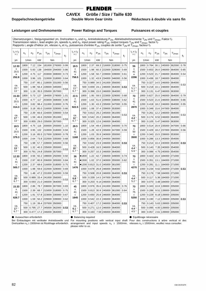
82 K88 DE/EN/FR
CAVEX Größe / Size / Taille 630Doppelschneckengetriebe Double Worm Gear Units Réducteurs à double vis sans fin
Leistungen und Drehmomente Power Ratings and Torques Puissances et couples
Übersetzungen i, Steigungswinkel γm, Drehzahlen n1 und n2, Antriebsleistung P1N, Abtriebsdrehmomente T2N und T2max, Faktor f7Transmission ratios i, lead angles γm, speeds n1 and n2, input power rating P1N, output torques T2N and T2max, factor f7Rapports i, angle d’hélice γm, vitesse n1 et n2, puissances d’entrée P1N, couples de sortie T2N et T2max, facteur f7
i1 x i2= i n1 n2 P1N T2N T2max
f
γm 1/min kW Nm
f7
12.33 1800 7.12 154 181000 276000 0.9912.33x 1500 5.93 138 194000 294000 0.86
20.5= 1200 4.75 117 203000 308000 0.73=
252.8 1000 3.96 101 210000 318000 0.64
750 2.97 80.1 218000 331000 0.56ca.
° 500 1.98 56.4 228000 34500020 °13 ° 300 1.19 35.5 235000 357000
0.53
15.33 1800 5.73 127 184000 278000 1.0115.33x 1500 4.77 117 203000 308000 0.90
20.5= 1200 3.82 98.4 211000 319000 0.76
314.3 1000 3.18 85.0 216000 328000 0.66
750 2.39 66.6 224000 339000 0.54ca.17 ° 500 1.59 46.6 232000 35100017 13 ° 300 0.955 29.0 235000 357000
0.53
18.5 1800 4.75 116 200000 293000 1.1018.5x 1500 3.95 102 210000 318000 0.94
20.5= 1200 3.16 85.5 217000 328000 0.78
379.3 1000 2.64 73.8 222000 335000 0.68
750 1.98 57.7 228000 345000 0.56ca.13 ° 500 1.32 40.3 235000 35500013 13 ° 300 0.791 24.8 235000 357000
0.53
12.33 1800 3.56 92.2 198000 292000 0.9212.33x 1500 2.97 80.9 206000 305000 0.84
41= 1200 2.37 68.6 216000 318000 0.75
505.7 1000 1.98 59.6 222000 328000 0.69
750 1.48 47.2 231000 342000 0.59ca.20 ° 500 0.989 33.4 241000 35600020 6.7 ° 300 0.593 21.0 246000 364000
0.53
15.33 1800 2.86 78.7 208000 307000 0.8315.33x 1500 2.39 68.7 215000 318000 0.75
41= 1200 1.91 57.8 223000 330000 0.67
628.7 1000 1.59 50.2 229000 339000 0.62
750 1.19 39.4 237000 350000ca.17 ° 500 0.795 27.7 245000 362000 0.5317 6.7 ° 300 0.477 17.2 246000 364000
0.53
i1 x i2= i n1 n2 P1N T2N T2max
f
γm 1/min kW Nm
f7
18.5 1800 2.37 69.3 216000 318000 0.7518.5x 1500 1.98 60.3 222000 328000 0.69
41= 1200 1.58 50.7 229000 339000 0.61=
758.5 1000 1.32 43.9 234000 346000 0.56
750 0.989 34.5 241000 356000ca.
° 500 0.659 24.1 246000 364000 0.5313 °6.7 ° 300 0.396 15.0 246000 364000
0.53
22.5 1800 1.95 59.5 223000 329000 0.6822.5x 1500 1.63 51.6 229000 338000 0.62
41= 1200 1.30 43.3 235000 347000 0.55
922.5 1000 1.08 37.4 239000 353000
750 0.813 29.2 245000 361000ca.12 ° 500 0.542 20.2 246000 364000
0.5312 6.7 ° 300 0.325 12.6 246000 364000
28.5 1800 1.54 49.4 230000 340000 0.7028.5x 1500 1.28 42.9 235000 347000 0.59
41= 1200 1.03 35.9 240000 355000
1168 1000 0.856 30.8 244000 360000
750 0.642 23.9 246000 364000 0.53ca.10 ° 500 0.428 16.5 246000 364000
0.53
10 6.7 ° 300 0.257 10.3 246000 364000
36 �1800 1.22 42.7 236000 349000 0.7436x
�1500 1.02 37.0 240000 355000 0.6241= �1200 0.813 31.0 245000 361000
1476 1000 0.678 26.8 246000 364000
750 0.508 20.8 246000 364000 0.53ca.
6.8 ° 500 0.339 14.5 247000 364000
0.53
6.8 6.7 ° 300 0.203 9.14 246000 364000
45 1800 0.976 35.6 241000 356000 0.7645x 1500 0.813 30.9 245000 361000 0.64
41= 1200 0.650 25.8 246000 364000
1845 1000 0.542 22.3 246000 364000
750 0.407 17.2 246000 364000 0.53ca.
6.1 ° 500 0.271 12.0 246000 364000
0.53
6.1 6.7 ° 300 0.163 7.59 246000 364000
i1 x i2= i n1 n2 P1N T2N T2max
f
γm 1/min kW Nm
f7
56 1800 0.784 30.1 245000 362000 0.7856x 1500 0.653 26.0 246000 364000 0.65
41= 1200 0.523 21.7 246000 364000 0.54=
2296 1000 0.436 18.7 246000 364000
750 0.327 14.5 246000 364000ca.
° 500 0.218 10.1 246000 364000 0.53
5.1 °6.7 ° 300 0.131 6.47 246000 363000
70 1800 0.627 25.0 246000 364000 0.7970x 1500 0.523 21.6 246000 364000 0.66
41= 1200 0.418 18.2 246000 364000 0.55
2870 1000 0.348 15.6 247000 364000
750 0.261 12.2 246000 364000ca.
4.4 ° 500 0.174 8.52 246000 364000 0.53
4.4 6.7 ° 300 0.105 5.47 246000 363000
70 1800 0.514 20.9 235000 347000 0.6670x 1500 0.429 18.2 237000 350000 0.56
50= 1200 0.343 15.5 239000 353000
3500 1000 0.286 13.3 240000 354000
750 0.214 10.4 240000 354000 0.53ca.
4.4 ° 500 0.143 7.35 240000 354000
0.53
4.4 5.9 ° 300 0.086 4.75 240000 354000
70 1800 0.422 15.0 184000 27100070x 1500 0.351 13.1 184000 271000
61= 1200 0.281 11.1 184000 271000
4270 1000 0.234 9.62 184000 271000 0.53
750 0.176 7.58 184000 271000
0.53
ca.4.4 ° 500 0.117 5.36 184000 2710004.4 5.2 ° 300 0.070 3.48 184000 271000
70 1800 0.343 10.8 139000 20500070x 1500 0.286 9.51 139000 205000
75= 1200 0.229 8.18 139000 205000
5250 1000 0.190 7.12 139000 205000 0.53
750 0.143 5.63 139000 205000
0.53
ca.4.4 ° 500 0.095 4.00 139000 2050004.4 4.5 ° 300 0.057 2.61 139000 205000
� Auswuchten erforderlichBei Einbaulagen mit vertikaler Antriebswelle undDrehzahlen n1 ≥ 1500/min ist Rückfrage erforderlich.
� Balancing requiredFor mounting positions with vertical input shaftarrangement and input speeds n1 ≥ 1500/min,please refer to us.
� Equilibrage nécessairePour des constructions à arbre vertical et desvitesses n1 ≥ 1500/min, veuillez nous consulter.
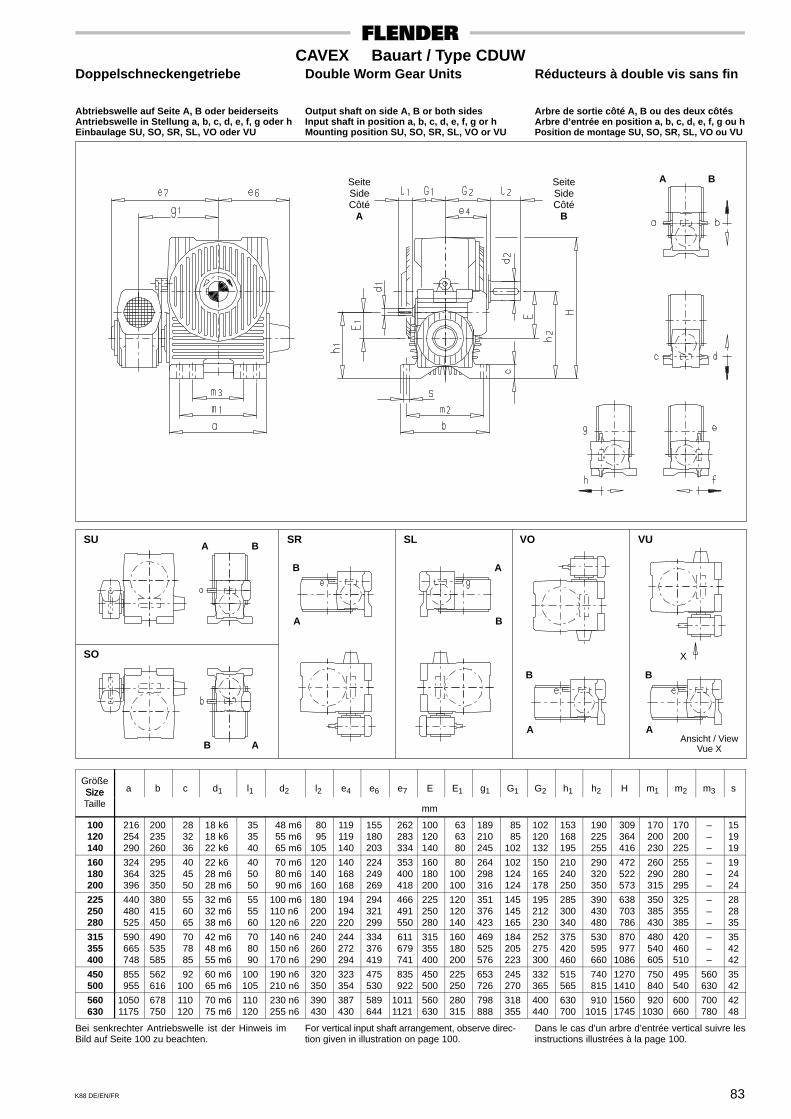
83K88 DE/EN/FR
CAVEX Bauart / Type CDUWDoppelschneckengetriebe Double Worm Gear Units Réducteurs à double vis sans fin
Abtriebswelle auf Seite A, B oder beiderseits Output shaft on side A, B or both sides Arbre de sortie côté A, B ou des deux côtésAntriebswelle in Stellung a, b, c, d, e, f, g oder h Input shaft in position a, b, c, d, e, f, g or h Arbre d’entrée en position a, b, c, d, e, f, g ou hEinbaulage SU, SO, SR, SL, VO oder VU Mounting position SU, SO, SR, SL, VO or VU Position de montage SU, SO, SR, SL, VO ou VU
SeiteSideCôté
A
SeiteSideCôté
B
A B
SU SR SL VO VU
SO
A B
B
A
A
B
B A
B
A
B
A
X
Ansicht / ViewVue X
GrößeSize a b c d1 l1 d2 l2 e4 e6 e7 E E1 g1 G1 G2 h1 h2 H m1 m2 m3 sSizeTaille mm
100 120 140
216 254 290
200235260
28 32 36
18 k618 k622 k6
35 35 40
48 m6 55 m6 65 m6
80 95105
119119140
155180203
262 283 334
100120140
63 63 80
189210245
85 85102
102120132
153168195
190 225 255
309 364 416
170 200 230
170200225
–––
151919
160 180 200
324 364 396
295325350
40 45 50
22 k628 m628 m6
40 50 50
70 m6 80 m6 90 m6
120140160
140168168
224249269
353 400 418
160180200
80100100
264298316
102124124
150165178
210240250
290 320 350
472 522 573
260 290 315
255280295
–––
192424
225 250 280
440 480 525
380415450
55 60 65
32 m632 m638 m6
55 55 60
100 m6110 n6120 n6
180200220
194194220
294321299
466 491 550
225250280
120120140
351376423
145145165
195212230
285300340
390 430 480
638 703 786
350 385 430
325355385
–––
282835
315 355 400
590 665 748
490535585
70 78 85
42 m648 m655 m6
70 80 90
140 n6150 n6170 n6
240260290
244272294
334376419
611 679 741
315355400
160180200
469525576
184205223
252275300
375420460
530 595 660
870 9771086
480 540 605
420460510
–––
354242
450 500
855 955
562616
92100
60 m665 m6
100105
190 n6210 n6
320350
323354
475530
835 922
450500
225250
653726
245270
332365
515565
740 815
12701410
750 840
495540
560630
3542
560 630
10501175
678750
110120
70 m675 m6
110120
230 n6255 n6
390430
387430
589644
10111121
560630
280315
798888
318355
400440
630700
9101015
15601745
9201030
600660
700780
4248
Bei senkrechter Antriebswelle ist der Hinweis imBild auf Seite 100 zu beachten.
For vertical input shaft arrangement, observe direc-tion given in illustration on page 100.
Dans le cas d’un arbre d’entrée vertical suivre lesinstructions illustrées à la page 100.
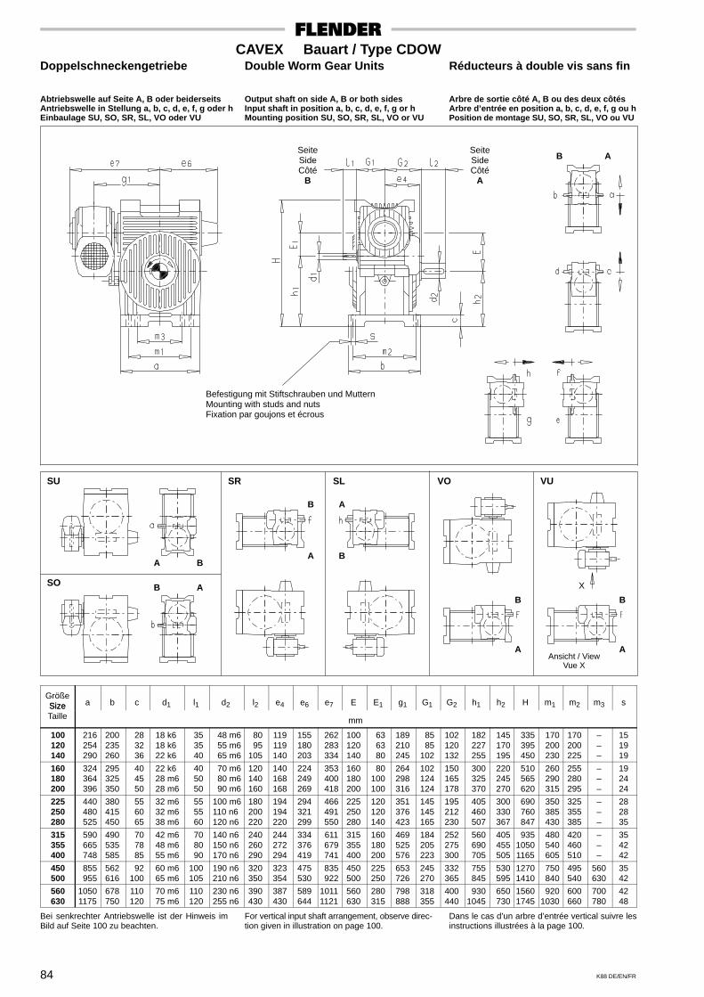
84 K88 DE/EN/FR
CAVEX Bauart / Type CDOWDoppelschneckengetriebe Double Worm Gear Units Réducteurs à double vis sans fin
Abtriebswelle auf Seite A, B oder beiderseits Output shaft on side A, B or both sides Arbre de sortie côté A, B ou des deux côtésAntriebswelle in Stellung a, b, c, d, e, f, g oder h Input shaft in position a, b, c, d, e, f, g or h Arbre d’entrée en position a, b, c, d, e, f, g ou hEinbaulage SU, SO, SR, SL, VO oder VU Mounting position SU, SO, SR, SL, VO or VU Position de montage SU, SO, SR, SL, VO ou VU
SeiteSideCôté
B
SeiteSideCôté
A
B A
SU SR SL VO VU
SO
A B
B A
B
A
A
B
B
A
B
A
X
Ansicht / ViewVue X
Befestigung mit Stiftschrauben und MutternMounting with studs and nutsFixation par goujons et écrous
GrößeSize a b c d1 l1 d2 l2 e4 e6 e7 E E1 g1 G1 G2 h1 h2 H m1 m2 m3 sSizeTaille mm
100 120 140
216 254 290
200235260
28 32 36
18 k618 k622 k6
35 35 40
48 m6 55 m6 65 m6
80 95105
119119140
155180203
262 283 334
100120140
63 63 80
189210245
85 85102
102120132
182 227 255
145 170 195
335 395 450
170 200 230
170200225
–––
151919
160 180 200
324 364 396
295325350
40 45 50
22 k628 m628 m6
40 50 50
70 m6 80 m6 90 m6
120140160
140168168
224249269
353 400 418
160180200
80100100
264298316
102124124
150165178
300 325 370
220 245 270
510 565 620
260 290 315
255280295
–––
192424
225 250 280
440 480 525
380415450
55 60 65
32 m632 m638 m6
55 55 60
100 m6110 n6120 n6
180200220
194194220
294321299
466 491 550
225250280
120120140
351376423
145145165
195212230
405 460 507
300 330 367
690 760 847
350 385 430
325355385
–––
282835
315 355 400
590 665 748
490535585
70 78 85
42 m648 m655 m6
70 80 90
140 n6150 n6170 n6
240260290
244272294
334376419
611 679 741
315355400
160180200
469525576
184205223
252275300
560 690 705
405 455 505
93510501165
480 540 605
420460510
–––
354242
450 500
855 955
562616
92100
60 m665 m6
100105
190 n6210 n6
320350
323354
475530
835 922
450500
225250
653726
245270
332365
755 845
530 595
12701410
750 840
495540
560630
3542
560 630
10501175
678750
110120
70 m675 m6
110120
230 n6255 n6
390430
387430
589644
10111121
560630
280315
798888
318355
400440
9301045
650 730
15601745
9201030
600660
700780
4248
Bei senkrechter Antriebswelle ist der Hinweis imBild auf Seite 100 zu beachten.
For vertical input shaft arrangement, observe direc-tion given in illustration on page 100.
Dans le cas d’un arbre d’entrée vertical suivre lesinstructions illustrées à la page 100.
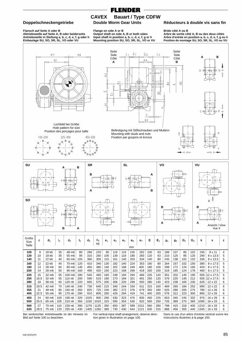
85K88 DE/EN/FR
CAVEX Bauart / Type CDFWDoppelschneckengetriebe Double Worm Gear Units Réducteurs à double vis sans fin
Flansch auf Seite A oder B Flange on side A or B Bride côté A ou BAbtriebswelle auf Seite A, B oder beiderseits Output shaft on side A, B or both sides Arbre de sortie côté A, B ou des deux côtésAntriebswelle in Stellung a, b, c, d, e, f, g oder h Input shaft in position a, b, c, d, e, f, g or h Arbre d’entrée en position a, b, c, d, e, f, g ou hEinbaulage SU, SO, SR, SL, VO oder VU Mounting position SU, SO, SR, SL, VO or VU Position de montage SU, SO, SR, SL, VO ou VU
SeiteSideCôté
A
SeiteSideCôté
B
A B
SU SR SL VO VU
SO
A B
X
Ansicht / ViewVue X
Befestigung mit Stiftschrauben und MutternMounting with studs and nutsFixation par goujons et écrous
Lochbild bei GrößeHole pattern for size
Position des perçages pour taille
B A
B
A B
A
B
A
B
A
Größec d l d l d d4 e e e e e E E g g G G k s zSize c d1 l1 d2 l2 d3
h8e1 e2 e4 e6 e7 E E1 g1 g3 G1 G2 k s z
Taillemm
100 120 140
91011
18 k618 k622 k6
35 35 40
48 m6 55 m6 65 m6
80 95105
266 315 360
220 260 305
90105115
119139161
119119140
155180203
262 283 334
100120140
63 63 80
189210245
107125138
85 85102
102120132
245 290 335
8 x 11 8 x 13.5 8 x 13.5
455
160 180 200
121314
22 k628 m628 m6
40 50 50
70 m6 80 m6 90 m6
120140160
410 450 490
340 380 420
130140150
182202223
140168168
224249269
353 400 418
160180200
80100100
264298316
157172185
102124124
150165178
380 420 460
8 x 17.5 8 x 17.5 8 x 17.5
555
225 250 280
1516.518
32 m632 m638 m6
55 55 60
100 m6110 n6120 n6
180200220
540 590 665
465 515 575
165180200
248273306
194194220
294321299
466 491 550
225250280
120120140
351376423
202220238
145145165
195212230
505 555 625
12 x 17.512 x 17.512 x 22
566
315 355 400
19.521
22.5
42 m648 m655 m6
70 80 90
140 n6150 n6170 n6
240260290
730 825 910
640 725 805
215240260
340382426
244272294
334376419
611 679 741
315355400
160180200
469525576
260286312
184205223
252275300
690 780 865
12 x 2212 x 2612 x 26
666
450 500
2425.5
60 m665 m6
100105
190 n6210 n6
320350
10251150
9051015
290315
530595
323354
475530
835 922
450500
225250
653726
345389
245270
332365
9751095
16 x 2616 x 33
66
560 630
2728.5
70 m675 m6
110120
230 n6255 n6
390430
12701405
11251260
350385
650730
387430
589644
10111121
560630
280315
798888
415456
318355
400440
12101345
16 x 3316 x 33
66
Bei senkrechter Antriebswelle ist der Hinweis imBild auf Seite 100 zu beachten.
For vertical input shaft arrangement, observe direc-tion given in illustration on page 100.
Dans le cas d’un arbre d’entrée vertical suivre lesinstructions illustrées à la page 100.

86 K88 DE/EN/FR
CAVEX Bauart / Type CDDADoppelschneckengetriebe Double Worm Gear Units Réducteurs à double vis sans fin
Drehm.-stütze auf Seite A o. B in Stellung 1, 2 o. 3 Torque arm on side A or B in position 1, 2 or 3 Bras de reaction côté A ou B en pos. 1, 2 ou 3Mit oder ohne Endscheibe With or without end plate Avec ou sans rondelle de démontageAntriebswelle in Stellung a, b, c, d, e, f, g oder h Input shaft in position a, b, c, d, e, f, g or h Arbre d’entrée en position a, b, c, d, e, f, g ou hEinbaulage SU, SO, SR, SL, VO oder VU Mounting position SU, SO, SR, SL, VO or VU Position de montage SU, SO, SR, SL, VO ou VU
SeiteSideCôté
A
SeiteSideCôté
B A B
SU SR SL VO VU
SO
A B
X
Ansicht / ViewVue XB A
B
A
A
B
B B
A A
AbschlußdeckelEnd coverCouvercle
EinzelheitDetail
X
EndscheibeEnd plateRondelle de fixation
Schraube gehört nicht zum LieferumfangBolt does not belong to our scope of supplyVis ne fait pas partie de la livraison
Größec c d l d D2 D5 e e e e e E E f g g G G L L n P sSize c1 c2 d1 l1 d6
H7 H8e1 e2 e4 e6 e7 E E1 f g1 g4 G1 G2
min. max.*L2 n
min.s
Taillemm
100 120 140
202025
111214
18 k618 k622 k6
35 35 40
40 50 50
50 60 65
202525
90105115
119139161
119119140
155180203
262 283 334
100120140
63 63 80
333
189210245
88101113
85 85102
93106118
136155173
147167186
165187
208.5
225 270 315
141618
M 16M 20M 20
160 180 200
253232
151617
22 k628 m628 m6
40 50 50
65 65 80
75 85 95
323240
130140150
182202223
140168168
224249269
353 400 418
160180200
80100100
444
264298316
126138148
102124124
132144155
194212228
212233250
235.5259278
360 405 450
202225
M 20M 20M 24
225 250 280
404040
182022
32 m632 m638 m6
55 55 60
80 80100
105115125
404050
165180200
248273306
194194220
294321299
466 491 550
225250280
120120140
555
351376423
163178192
145145165
170185200
250272293
276301326
307335363
505 560 630
283032
M 24M 24M 24
315 355 400
505060
242730
42 m648 m655 m6
70 80 90
100120120
140160180
506060
215240260
340382426
244272294
334376419
611 679 741
315355400
160180200
555
469525576
212233256
184205223
220242265
322354387
357394433
397438481
710 800 900
364045
M 30M 30M 30
450 500
6075
3336
60 m665 m6
100105
150150
200220
7575
290315
530595
323354
475530
835 922
450500
225250
66
653726
282310
245270
292320
425465
480528
532585
10101120
4850
M 30M 36
560 630
7590
3840
70 m675 m6
110120
170170
240270
9090
350385
650730
387430
589644
10111121
560630
280315
66
798888
341377
318355
352388
510560
583650
643713
12601420
5663
M 36M 36
Bei senkrechter Schneckenwelle ist der Hinweis imBild auf Seite 100 zu beachten.*) Lmax gilt nur bei Verwendung der Abdrück-
scheibe.
For vertical worm shaft arrangement, observedirection given in illustration on page 100.*) Lmax is applicable only when using a forcing
plate.
Dans le cas d’un arbre à vis sans fin vertical suivreles instructions illustrées à la page 100.*) Lmax applicable en utilisant la rondelle de
démontage.
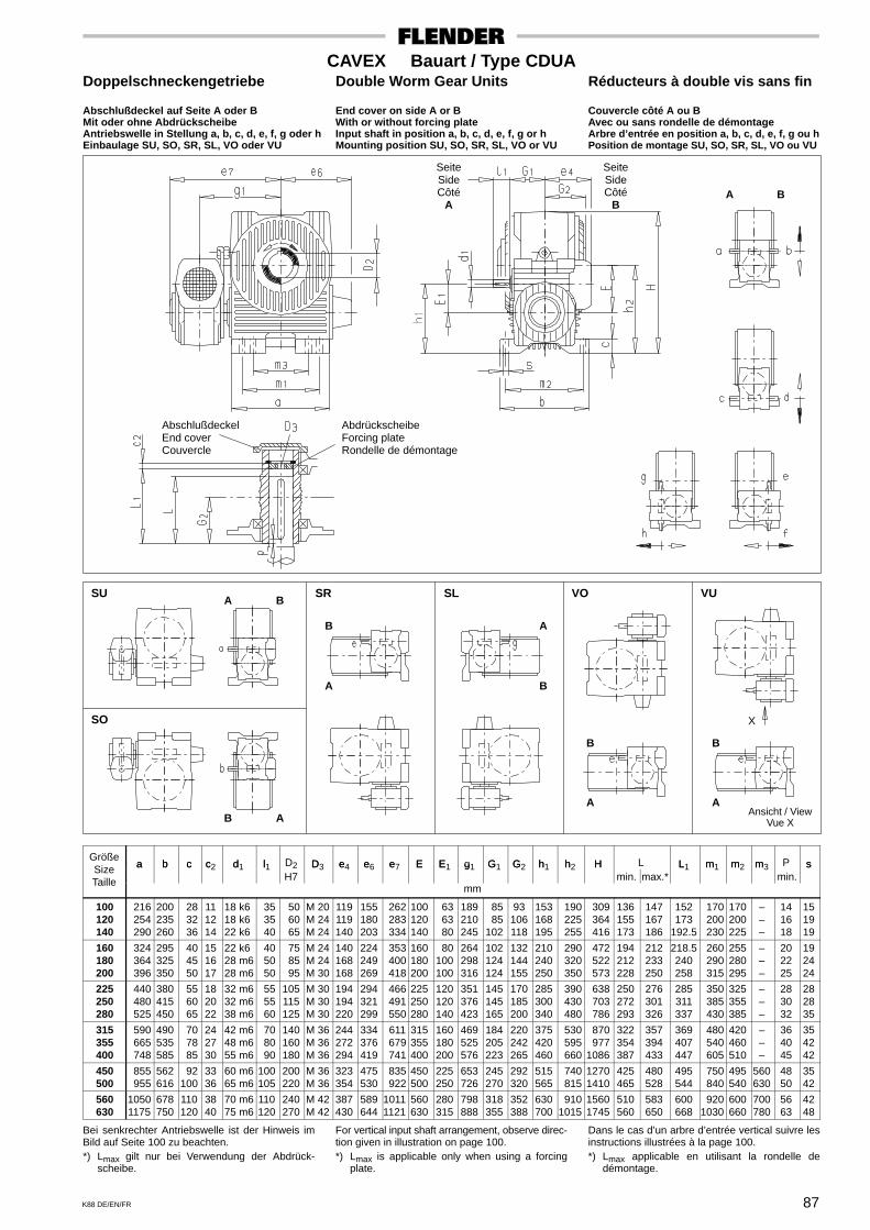
87K88 DE/EN/FR
CAVEX Bauart / Type CDUADoppelschneckengetriebe Double Worm Gear Units Réducteurs à double vis sans fin
Abschlußdeckel auf Seite A oder B End cover on side A or B Couvercle côté A ou BMit oder ohne Abdrückscheibe With or without forcing plate Avec ou sans rondelle de démontageAntriebswelle in Stellung a, b, c, d, e, f, g oder h Input shaft in position a, b, c, d, e, f, g or h Arbre d’entrée en position a, b, c, d, e, f, g ou hEinbaulage SU, SO, SR, SL, VO oder VU Mounting position SU, SO, SR, SL, VO or VU Position de montage SU, SO, SR, SL, VO ou VU
SeiteSideCôté
A
SeiteSideCôté
B
AbschlußdeckelEnd coverCouvercle
AbdrückscheibeForcing plateRondelle de démontage
SU SR SL VO VU
SO X
A B
Ansicht / ViewVue XB A
B
A
A
B
B
A
B
A
A B
Größea b c c d l D2 D e e e E E g G G h h H L L m m m P sSize a b c c2 d1 l1
H7D3 e4 e6 e7 E E1 g1 G1 G2 h1 h2 H
min. max.*L1 m1 m2 m3
min.s
Taillemm
100 120 140
216 254 290
200235260
28 32 36
111214
18 k618 k622 k6
35 35 40
50 60 65
M 20M 24M 24
119119140
155180203
262 283 334
100120140
63 63 80
189210245
85 85102
93106118
153168195
190 225 255
309 364 416
136155173
147167186
152173
192.5
170 200 230
170200225
–––
141618
151919
160 180 200
324 364 396
295325350
40 45 50
151617
22 k628 m628 m6
40 50 50
75 85 95
M 24M 24M 30
140168168
224249269
353 400 418
160180200
80100100
264298316
102124124
132144155
210240250
290 320 350
472 522 573
194212228
212233250
218.5240258
260 290 315
255280295
–––
202225
192424
225 250 280
440 480 525
380415450
55 60 65
182022
32 m632 m638 m6
55 55 60
105115125
M 30M 30M 30
194194220
294321299
466 491 550
225250280
120120140
351376423
145145165
170185200
285300340
390 430 480
638 703 786
250272293
276301326
285311337
350 385 430
325355385
–––
283032
282835
315 355 400
590 665 748
490535585
70 78 85
242730
42 m648 m655 m6
70 80 90
140160180
M 36M 36M 36
244272294
334376419
611 679 741
315355400
160180200
469525576
184205223
220242265
375420460
530 595 660
870 9771086
322354387
357394433
369407447
480 540 605
420460510
–––
364045
354242
450 500
855 955
562616
92100
3336
60 m665 m6
100105
200220
M 36M 36
323354
475530
835 922
450500
225250
653726
245270
292320
515565
740 815
12701410
425465
480528
495544
750 840
495540
560630
4850
3542
560 630
10501175
678750
110120
3840
70 m675 m6
110120
240270
M 42M 42
387430
589644
10111121
560630
280315
798888
318355
352388
630700
9101015
15601745
510560
583650
600668
9201030
600660
700780
5663
4248
Bei senkrechter Antriebswelle ist der Hinweis imBild auf Seite 100 zu beachten.*) Lmax gilt nur bei Verwendung der Abdrück-
scheibe.
For vertical input shaft arrangement, observe direc-tion given in illustration on page 100.*) Lmax is applicable only when using a forcing
plate.
Dans le cas d’un arbre d’entrée vertical suivre lesinstructions illustrées à la page 100.*) Lmax applicable en utilisant la rondelle de
démontage.
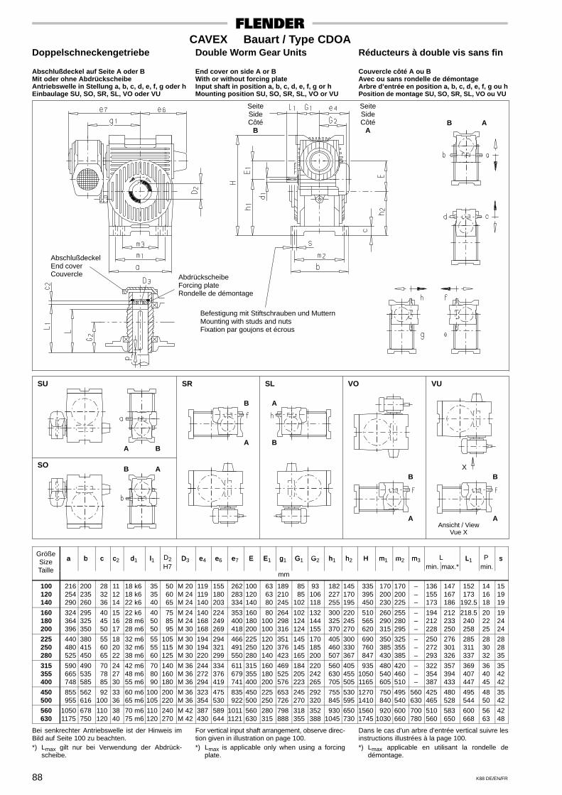
88 K88 DE/EN/FR
CAVEX Bauart / Type CDOADoppelschneckengetriebe Double Worm Gear Units Réducteurs à double vis sans fin
Abschlußdeckel auf Seite A oder B End cover on side A or B Couvercle côté A ou BMit oder ohne Abdrückscheibe With or without forcing plate Avec ou sans rondelle de démontageAntriebswelle in Stellung a, b, c, d, e, f, g oder h Input shaft in position a, b, c, d, e, f, g or h Arbre d’entrée en position a, b, c, d, e, f, g ou hEinbaulage SU, SO, SR, SL, VO oder VU Mounting position SU, SO, SR, SL, VO or VU Position de montage SU, SO, SR, SL, VO ou VU
SeiteSideCôté
B
SeiteSideCôté
A
AbschlußdeckelEnd coverCouvercle Abdrückscheibe
Forcing plateRondelle de démontage
SU SR SL VO VU
SO
B A
Befestigung mit Stiftschrauben und MutternMounting with studs and nutsFixation par goujons et écrous
A B
B A
B
A
A
B
B
A
B
A
X
Ansicht / ViewVue X
Größea b c c d l D2 D e e e E E g G G h h H m m m L L P sSize a b c c2 d1 l1
H7D3 e4 e6 e7 E E1 g1 G1 G2 h1 h2 H m1 m2 m3
min. max.*L1
min.s
Taillemm
100 120 140
216 254 290
200235260
28 32 36
111214
18 k618 k622 k6
35 35 40
50 60 65
M 20M 24M 24
119119140
155180203
262 283 334
100120140
63 63 80
189210245
85 85102
93106118
182 227 255
145170195
335 395 450
170 200 230
170200225
–––
136155173
147167186
152173
192.5
141618
151919
160 180 200
324 364 396
295325350
40 45 50
151617
22 k628 m628 m6
40 50 50
75 85 95
M 24M 24M 30
140168168
224249269
353 400 418
160180200
80100100
264298316
102124124
132144155
300 325 370
220245270
510 565 620
260 290 315
255280295
–––
194212228
212233250
218.5240258
202225
192424
225 250 280
440 480 525
380415450
55 60 65
182022
32 m632 m638 m6
55 55 60
105115125
M 30M 30M 30
194194220
294321299
466 491 550
225250280
120120140
351376423
145145165
170185200
405 460 507
300330367
690 760 847
350 385 430
325355385
–––
250272293
276301326
285311337
283032
282835
315 355 400
590 665 748
490535585
70 78 85
242730
42 m648 m655 m6
70 80 90
140160180
M 36M 36M 36
244272294
334376419
611 679 741
315355400
160180200
469525576
184205223
220242265
560 630 705
405455505
93510501165
480 540 605
420460510
–––
322354387
357394433
369407447
364045
354242
450 500
855 955
562616
92100
3336
60 m665 m6
100105
200220
M 36M 36
323354
475530
835 922
450500
225250
653726
245270
292320
755 845
530595
12701410
750 840
495540
560630
425465
480528
495544
4850
3542
560 630
10501175
678750
110120
3840
70 m675 m6
110120
240270
M 42M 42
387430
589644
10111121
560630
280315
798888
318355
352388
9301045
650730
15601745
9201030
600660
700780
510560
583650
600668
5663
4248
Bei senkrechter Antriebswelle ist der Hinweis imBild auf Seite 100 zu beachten.*) Lmax gilt nur bei Verwendung der Abdrück-
scheibe.
For vertical input shaft arrangement, observe direc-tion given in illustration on page 100.*) Lmax is applicable only when using a forcing
plate.
Dans le cas d’un arbre d’entrée vertical suivre lesinstructions illustrées à la page 100.*) Lmax applicable en utilisant la rondelle de
démontage.
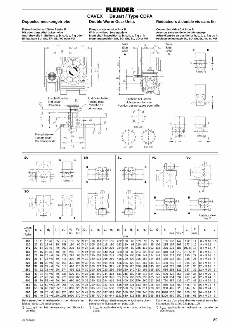
89K88 DE/EN/FR
CAVEX Bauart / Type CDFADoppelschneckengetriebe Double Worm Gear Units Réducteurs à double vis sans fin
Flanschdeckel auf Seite A oder B Flange cover on side A or B Couvercle-bride côté A ou BMit oder ohne Abdrückscheibe With or without forcing plate Avec ou sans rondelle de démontageAntriebswelle in Stellung a, b, c, d, e, f, g oder h Input shaft in position a, b, c, d, e, f, g or h Arbre d’entrée en position a, b, c, d, e, f, g ou hEinbaulage SU, SO, SR, SL, VO oder VU Mounting position SU, SO, SR, SL, VO or VU Position de montage SU, SO, SR, SL, VO ou VU
SeiteSideCôté
A
SeiteSideCôté
B
AbschlußdeckelEnd coverCouvercle
AbdrückscheibeForcing plateRondelle dedémontage
SU SR SL VO VU
SO
A B
A B
B A
B
A
A
B
B
A
B
A
Lochbild bei GrößeHole pattern for size
Position des perçages pour taille
FlanschdeckelFlange coverCouvercle-bride
X
Ansicht / ViewVue X
Größec c d l d d4 D2 D e e e e e E E g g G G k L L P s zSize c c2 d1 l1 d3
h8 H7D3 e1 e2 e4 e6 e7 E E1 g1 g3 G1 G2 k
min. max.*L1
min.s z
Taillemm
100 120 140
182022
111214
18 k618 k622 k6
35 35 40
217 258 302
155 190 225
50 60 65
M 20M 24M 24
90105115
119139161
119119140
155180203
262 283 334
100120140
63 63 80
189210245
90104116
85 85102
93106118
195 235 275
136155173
147167186
152173
192.5
141618
8 x M 10 8 x M 12 8 x M 12
3.544
160 180 200
252831
151617
22 k628 m628 m6
40 50 50
338 379 416
260 295 330
75 85 95
M 24M 24M 30
130140150
182202223
140168168
224249269
353 400 418
160180200
80100100
264298316
129142152
102124124
132144155
310 350 385
194212228
212233250
218.5240258
202225
8 x M 16 8 x M 16 8 x M 16
555
225 250 280
343740
182022
32 m632 m638 m6
55 55 60
462 510 574
375 420 465
105115125
M 30M 30M 30
165180200
248273306
194194220
294321299
466 491 550
225250280
120120140
351376423
167181196
145145165
170185200
430 480 535
250272293
276301326
285311337
283032
12 x M 1612 x M 1612 x M 20
556
315 355 400
434648
242730
42 m648 m655 m6
70 80 90
638 720 804
530 600 680
140160180
M 36M 36M 36
215240260
340382426
244272294
334376419
611 679 741
315355400
160180200
469525576
216238260
184205223
220242265
600 680 760
322354387
357394433
369407447
364045
12 x M 2012 x M 2412 x M 24
666
450 500
5255
3336
60 m665 m6
100105
9061014
770 860
200220
M 36M 36
290315
530595
323354
475530
835 922
450500
225250
653726
287314
245270
292320
860 960
425465
480528
495544
4850
16 x M 2416 x M 24
66
560 630
6063
3840
70 m675 m6
110120
11261258
9651090
240270
M 42M 42
350385
650730
387430
589644
10111121
560630
280315
798888
346382
318355
352388
10701200
510560
583650
600668
5663
16 x M 2416 x M 24
66
Bei senkrechter Antriebswelle ist der Hinweis imBild auf Seite 100 zu beachten.*) Lmax gilt nur bei Verwendung der Abdrück-
scheibe.
For vertical input shaft arrangement, observe direc-tion given in illustration on page 100.*) Lmax is applicable only when using a forcing
plate.
Dans le cas d’un arbre d’entrée vertical suivre lesinstructions illustrées à la page 100.*) Lmax applicable en utilisant la rondelle de
démontage.
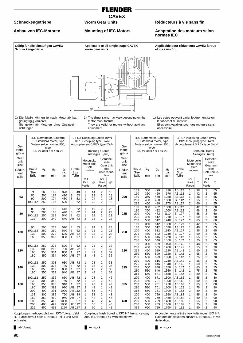
ab Vorrat ex stock en stock
90 K88 DE/EN/FR
CAVEXSchneckengetriebe Worm Gear Units Réducteurs à vis sans fin
Anbau von IEC-Motoren Mounting of IEC Motors Adaptation des moteurs selonnormes IEC
Applicable to all single stage CAVEXworm gear units
Applicable pour réducteurs CAVEX à roueet vis sans fin
Gültig für alle einstufigen CAVEX-Schneckengetriebe
1) Die Maße können je nach Motorfabrikatgeringfügig variieren.Sie gelten für Motoren ohne Zusatzein-richtungen.
1) The dimensions may vary depending on themotor manufacture.They are valid for motors without auxiliaryequipment.
1) Les cotes peuvent varier légèrement selonle fabricant du moteur.Elles sont valables pour des moteurs sansaccessoire.
Ge-triebe-größe
IEC-Normmotor, BauformIEC standard motor, type
Moteur selon normes IEC,type
B5, V1 oder / or / ou V3
BIPEX-Kupplung Bauart BWNBIPEX coupling type BWN
Accouplement BIPEX type BWN
Bohrung / Bores Alésages (mm)
Ge-triebe-größe
IEC-Normmotor, BauformIEC standard motor, type
Moteur selon normes IEC,type
B5, V1 oder / or / ou V3
BIPEX-Kupplung Bauart BWNBIPEX coupling type BWN
Accouplement BIPEX type BWN
Bohrung / Bores Alésages (mm)
Gearunitsize
Réduc-teur
GrößeSizeTaille
a1
mm
g5
mm
g6ca.mm
GrößeSizeTaille
MotorseiteMotor side
Côtémoteur
Getriebe-seite
Gear unitside
Côté réduc-teur
Gearunitsize
Réduc-teur
GrößeSizeTaille
a1
mm
g5
mm
g6ca.mm
GrößeSizeTaille
MotorseiteMotor side
Côtémoteur
Getriebe-seite
Gear unitside
Côté réduc-teurtaille Taille mm mm mm Taille
TeilPart
Partie
TeilPart
Partie
taille Taille mm mm mm TailleTeilPart
Partie
TeilPart
Partie
63
718090
100/112
160200200250
162174174196
370 410 450 520
B 43B 53B 53B 62
1111
14192428
2222
18181818
200
132160180200225
300350350400450
420450450450480
820 970103010801170
AB 112AB 112AB 112B 112AB 127
11112
3842485560
22221
5555555555
80
8090
100/112132
200200250300
198198218240
430 470 540 640
B 62B 62B 62AB 72
1112
19242838
2221
22222222
225
160180200225250
350350400450550
482482482512512
10001060111012101240
AB 112AB 112B 127B 127B 127
1111
4248556065
22222
6060606060
100
90100/112
132160
200250300350
238250272308
510 570 680 830
B 53B 62AB 72A 97
1121
24283842
2212
28282828
250
160180200225250280
350350400450550550
512512512542546546
103010901140124012701460
AB 127AB 127AB 127B 127B 142B 142
111111
424855606575
222222
656565656565
120
100/112132160180
250300350350
276298334334
600 700 860 920
B 62AB 72A 97AB 97
1212
28384248
2121
32323232
280
180200225250280
350400450550550
569569599599599
11501200129013201500
AB 142AB 142AB 142B 142B 142
11111
4855606575
22222
7070707070
140
100/112132160180
250300350350
303323359359
630 730 880 940
AB 72B 72A 97AB 97
1112
28384248
2221
38383838
315
200225250280315
400450550550660
616646646646681
12401340137015501650
AB 142AB 142B 142B 142B 162
11111
5560657580
22222
7575757575
160
100/112132160180200
250300350350400
332352388388391
660 760 910 9701020
AB 72B 72A 97AB 97AB 112
11122
2838424855
22211
4242424242
355
200225250280315
400450550550660
671701701701731
13001390142016001700
AB 162AB 162AB 162B 162B 162
11111
5560657580
22222
8080808080
180
132160180200225
300350350400450
386419419422452
790 940100010501150
AB 84AB 97B 97AB 112AB 127
11122
3842485560
22211
4848484848
400
200225250280315
400450550550660
729759759759789
13601450148016601760
AB 182AB 182AB 182AB 182B 182
11111
5560657580
22222
9090909090
Kupplungen fertiggebohrt mit ISO-ToleranzfeldH7, Paßfedernut nach DIN 6885 Teil 1 und Stell-schraube.
Couplings finish bored to ISO H7 limits. Keywayacc. to DIN 6885 / 1 with set screw.
Accouplements alésés aux tolérances ISO H7.Rainures de clavettes suivant DIN 6885/1 et visde fixation.

ab Vorrat ex stock en stock
91K88 DE/EN/FR
CAVEXStirnradschneckengetriebe Helical Worm Gear Units Réducteurs combinés avec un
train d’engrenages cylindriquesAnbau von IEC-Motoren Mounting of IEC Motors Adaptation des moteurs selon
normes IEC
Applicable to all CAVEX helical wormgear units
Applicable pour réducteurs CAVEX avectrain d’engrenage cylindrique en primaine
Gültig für alle CAVEX-Stirnrad-schneckengetriebe
1) Die Maße können je nach Motorfabrikatgeringfügig variieren.Sie gelten für Motoren ohne Zusatzein-richtungen.
1) The dimensions may vary depending on themotor manufacture.They are valid for motors without auxiliaryequipment.
1) Les cotes peuvent varier légèrement selonle fabricant du moteur.Elles sont valables pour des moteurs sansaccessoire.
Ge-triebe-größe
IEC-Normmotor, BauformIEC standard motor, typeMoteur selon normes IEC,
typeB5, V1 oder /or / ou V3
BIPEX-Kupplung Bauart BWNBIPEX coupling type BWN
Accouplement BIPEX type BWN
Bohrung / Bores Alésages (mm)
Ge-triebe-größe
IEC-Normmotor, BauformIEC standard motor, type
Moteur selon normes IEC,type
B5, V1 oder /or / ou V3
BIPEX-Kupplung Bauart BWNBIPEX coupling type BWN
Accouplement BIPEX type BWN
Bohrung / Bores Alésages (mm)
Gearunitsize
Réduc-teur
GrößeSizeTaille
a1
mm
g5
mm
g6ca.mm
GrößeSizeTaille
MotorseiteMotor side
Côtémoteur
Getriebe-seite
Gear unitside
Côté réducteur
Gearunitsize
Réduc-teur
GrößeSizeTaille
a1
mm
g5
mm
g6ca.mm
GrößeSizeTaille
MotorseiteMotor side
Côtémoteur
Getriebe-seite
Gear unitside
Côté réducteur
taille Taille mm mm mm TailleTeilPart
Partie
TeilPart
Partiei1 <3.6
i1 >3.6
taille Taille mm mm mm TailleTeilPart
Partie
TeilPart
Partiei1 <3.6
i1 >3.6
63718090
160200200
240252252
448 488 528
B 43B 43B 43
111
141924
222
161616
141414
200
90100/112
132160
200250300350
482494516552
754 814 9241074
B 62B 62B 72A 97
1111
24283842
2222
35353535
28282828
80718090
160200200
254266266
462 502 542
B 43B 43B 43
111
141924
222
161616
141414
225
100/112132160180
250300350350
557577613613
884 98411341194
AB 72B 72A 97AB 97
1112
28384248
2221
42424242
38383838
100
718090
100/112
160200200250
297309309331
505545585655
B 43B 53B 53B 62
1111
14192428
2222
22222222
18181818
250
100/112132160180
250300350350
580600636636
907100711571217
AB 72B 72A 97AB 97
1112
28384248
2221
42424242
38383838
120
718090
100/112
160200200250
318330330352
526566606676
B 43B 53B 53B 62
1211
14192428
2222
22222222
18181818
280
100/112132160180200
250300350350400
654674710710713
9801080123012901340
AB 84AB 84AB 97B 97AB 112
11112
2838424855
22221
4848484848
4242424242
140
8090
100/112132
200200250300
382382402424
614 654 724 824
B 62B 62B 62AB 72
1112
19242838
2221
28282828
22222222
315
100/112132160180200
250300350350400
687707743743746
10101110126013201370
AB 84AB 84AB 97B 97AB 112
11112
2838424855
22221
4848484848
4242424242
160
8090
100/112132
200200250300
400400420442
632 672 742 842
B 62B 62B 62AB 72
1112
19242838
2221
28282828
22222222
355
132160180200225
300350350400450
801834834837867
11301360142014701570
AB 112AB 112AB 112B 112AB 127
11112
3842485560
22221
5555555555
4848484848
180
90100/112
132160
200250300350
464476498534
736 796 9061056
B 62B 62B 72A 97
1111
24283842
2222
35353535
28282828
400
132160180200225
300350350400450
843876876879909
11701400146015001600
AB 112AB 112AB 112B 112AB 127
11112
3842485560
22221
5555555555
4848484848
Kupplungen fertiggebohrt mit ISO-ToleranzfeldH7, Paßfedernut nach DIN 6885 Teil 1 und Stell-schraube.
Couplings finish bored to ISO H7 limits. Keywayacc. to DIN 6885 / 1 with set screw.
Accouplements alésés aux tolérances ISO H7.Rainures de clavettes suivant DIN 6885/1 et visde fixation.

ab Vorrat ex stock en stock
92 K88 DE/EN/FR
CAVEXDoppelschneckengetriebe Double Worm Gear Units Réducteurs à double vis sans fin
Anbau von IEC-Motoren Mounting of IEC Motors Adaptation des moteurs selonnormes IEC
1) Die Maße können je nach Motorfabrikatgeringfügig variieren.Sie gelten für Motoren ohne Zusatzein-richtungen.
1) The dimensions may vary depending on themotor manufacture.They are valid for motors without auxiliaryequipment.
1) Les cotes peuvent varier légèrement selonle fabricant du moteur.Elles sont valables pour des moteurs sansaccessoire.
Gültig für alle CAVEX-Doppelschneckenge-triebe; bei Antriebswelle in Stellung e oderg gilt Seite 93
Applicable to all CAVEX double worm gearunits. For input shaft in position e or g, seepage 93.
Applicable pour reducteurs CAVEX a doublevis sans fin; pour l’arbre d’entrée en positione ou g, voir page 93.
Ge-triebe-größe
Gear
IEC-Normmotor, BauformIEC standard motor, type
Moteur selon normes IEC,type
B5, V1 oder / or / ou V3
BIPEX-Kupplung Bauart BWNBIPEX coupling type BWN
Accouplement BIPEX type BWN
Bohrung / Bores Alésages (mm)
Ge-triebe-größe
Gear
IEC-Normmotor, BauformIEC standard motor, typeMoteur selon normes IEC,
typeB5, V1 oder / or / ou V3
BIPEX-Kupplung Bauart BWNBIPEX coupling type BWN
Accouplement BIPEX type BWN
Bohrung / Bores Alésages (mm)
unitsize
Réduc- Größe a1 g5 g6 Größe
MotorseiteMotor side
Côté moteur
GetriebeseiteGear unit sideCôté réducteur
unitsize
Réduc- Größe a1 g5 g6 Größe
MotorseiteMotor side
Côté moteur
GetriebeseiteGear unit sideCôté réducteurRéduc
teurtaille
SizeTaille mm mm
ca.mm
SizeTaille Teil
PartPartie
TeilPart
Partie
Réducteurtaille
SizeTaille mm mm
ca.mm
SizeTaille Teil
PartPartie
TeilPart
Partie
100
718090
100/112
160200200250
162174174196
370410450520
B 43B 53B 53B 62
1111
14192428
2222
18181818
280
100/112132160180
250300350350
303323359359
630 730 880 940
AB 72B 72A 97AB 97
1112
28384248
2221
38383838
120
718090
100/112
160200200250
162174174196
370410450520
B 43B 53B 53B 62
1111
14192428
2222
18181818
315
100/112132160180200
250300350350400
332352388388391
660 760 910 9701020
AB 72B 72A 97AB 97AB 112
11122
2838424855
22211
4242424242
140
8090
100/112132
200200250300
198198218240
430470540640
B 62B 62B 62AB 72
1112
19242838
2221
22222222
355
132160180200225
300350350400450
386419419422452
890 940100010501150
AB 84AB 97B 97AB 112AB 127
11122
3842485560
22211
4848484848
160
8090
100/112132
200200250300
198198218240
430470540640
B 62B 62B 62AB 72
1112
19242838
2221
22222222
400
132160180200225
300350350400450
420450450450480
820 970103010801170
AB 112AB 112AB 112B 112AB 127
11112
3842485560
22221
5555555555
180
90100/112
132160
200250300350
238250272308
510570680830
B 53B 62AB 72A 97
1121
24283842
2212
28282828
450
160180200225250
350350400450550
482482482512512
10001060111012101240
AB 112AB 112B 112B 127B 127
11111
4248556065
22222
6060606060
200
90100/112
132160
200250300350
238250272308
510570680830
B 53B 62AB 72A 97
1121
24283842
2212
28282828
500
160180200225250280
350350400450550550
512512512542546546
103010901140124012701460
AB 127AB 127AB 127B 127B 142B 142
111111
424855606575
222222
656565656565
225
100/112132160180
250300350350
276298334334
600700860920
B 62AB 72A 97AB 97
1212
28384248
2121
32323232
560
180200225250280
350400450550550
569569599599599
11501200129013201500
AB 142AB 142AB 142B 142B 142
11111
4855606575
22222
7070707070
250
100/112132160180
250300350350
276298334334
600700860920
B 62AB 72A 97AB 97
1212
28384248
2121
32323232
630
200225250280315
400450550550660
616646646646681
12401340137015501650
AB 142AB 142B 142B 142B 142
11111
5560657580
22222
7575757575
Kupplungen fertiggebohrt mit ISO-ToleranzfeldH7, Paßfedernut nach DIN 6885 Teil 1 und Stell-schraube.
Couplings finish bored to ISO H7 limits. Keywayacc. to DIN 6885 / 1 with set screw.
Accouplements alésés aux tolérances ISO H7.Rainures de clavettes suivant DIN 6885/1 et visde fixation.
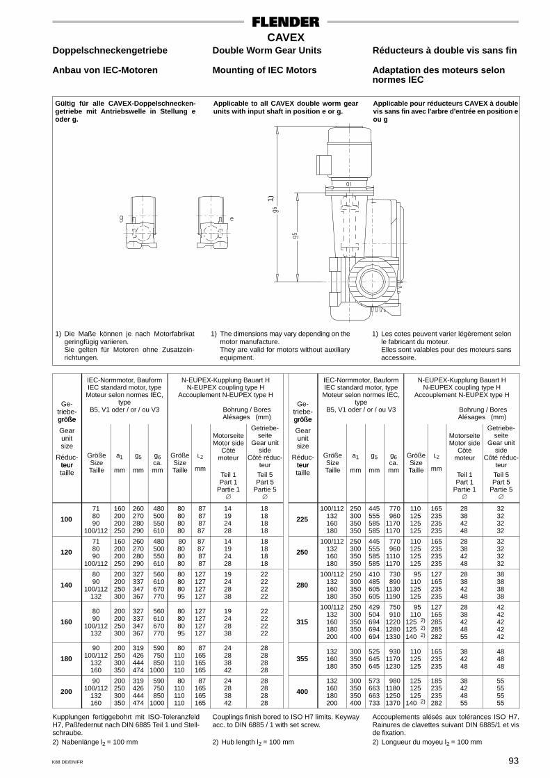
93K88 DE/EN/FR
CAVEXDoppelschneckengetriebe Double Worm Gear Units Réducteurs à double vis sans fin
Anbau von IEC-Motoren Mounting of IEC Motors Adaptation des moteurs selonnormes IEC
Gültig für alle CAVEX-Doppelschnecken-getriebe mit Antriebswelle in Stellung eoder g.
Applicable to all CAVEX double worm gearunits with input shaft in position e or g.
Applicable pour réducteurs CAVEX à doublevis sans fin avec l’arbre d’entrée en position eou g
1) Die Maße können je nach Motorfabrikatgeringfügig variieren.Sie gelten für Motoren ohne Zusatzein-richtungen.
1) The dimensions may vary depending on themotor manufacture.They are valid for motors without auxiliaryequipment.
1) Les cotes peuvent varier légèrement selonle fabricant du moteur.Elles sont valables pour des moteurs sansaccessoire.
1)
Ge-triebe-größe
IEC-Normmotor, BauformIEC standard motor, type
Moteur selon normes IEC,type
B5, V1 oder / or / ou V3
N-EUPEX-Kupplung Bauart HN-EUPEX coupling type H
Accouplement N-EUPEX type H
Bohrung / Bores Alésages (mm)
Ge-triebe-größe
IEC-Normmotor, BauformIEC standard motor, typeMoteur selon normes IEC,
typeB5, V1 oder / or / ou V3
N-EUPEX-Kupplung Bauart HN-EUPEX coupling type H
Accouplement N-EUPEX type H
Bohrung / Bores Alésages (mm)größe
Gearunitsize
Réduc-teur
GrößeSize
a1 g5 g6ca.
GrößeSize
LZ
MotorseiteMotor side
Côtémoteur
Getriebe-seite
Gear unitside
Côté réduc-teur
größe
Gearunitsize
Réduc-teur
GrößeSize
a1 g5 g6ca.
GrößeSize
LZ
MotorseiteMotor side
Côtémoteur
Getriebe-seite
Gear unitside
Côté réduc-teurteur
taille Taille mm mm mm Taille mmTeil 1Part 1
Partie 1
Teil 5Part 5
Partie 5
teurtaille Taille mm mm mm Taille mm
Teil 1Part 1
Partie 1
Teil 5Part 5
Partie 5
100
718090
100/112
160200200250
260270280290
480 500 550 610
80 80 80 80
87 87 87 87
14192428
18181818
225
100/112132160180
250300350350
445555585585
770 96011701170
110125125125
165235235235
28384248
32323232
120
718090
100/112
160200200250
260270280290
480 500 550 610
80 80 80 80
87 87 87 87
14192428
18181818
250
100/112132160180
250300350350
445555585585
770 96011101170
110125125125
165235235235
28384248
32323232
140
8090
100/112132
200200250300
327337347367
560 610 670 770
80 80 80 95
127127127127
19242838
22222222
280
100/112132160180
250300350350
410485605605
730 89011301190
95110125125
127165235235
28384248
38383838
160
8090
100/112132
200200250300
327337347367
560 610 670 770
80 80 80 95
127127127127
19242838
22222222
315
100/112132160180200
250300350350400
429504694694694
750 910122012801330
95110
125 2)
125 2)
140 2)
127165285285282
2838424855
4242424242
180
90100/112
132160
200250300350
319426444474
590 750 8501000
80110110110
87165165165
24283842
28282828
355132160180
300350350
525645645
93011701230
110125125
165235235
384248
484848
200
90100/112
132160
200250300350
319426444474
590 750 8501000
80110110110
87165165165
24283842
28282828
400
132160180200
300350350400
573663663733
980118012501370
125125125
140 2)
185235235282
38424855
55555555
Kupplungen fertiggebohrt mit ISO-ToleranzfeldH7, Paßfedernut nach DIN 6885 Teil 1 und Stell-schraube.2) Nabenlänge l2 = 100 mm
Couplings finish bored to ISO H7 limits. Keywayacc. to DIN 6885 / 1 with set screw.
2) Hub length l2 = 100 mm
Accouplements alésés aux tolérances ISO H7.Rainures de clavettes suivant DIN 6885/1 et visde fixation.2) Longueur du moyeu l2 = 100 mm

94 K88 DE/EN/FR
CAVEXSchneckengetriebe Worm Gear Units Réducteurs à vis sans fin
mit Rücklaufsperren With Backstops muni d’anti-dévireurs
Rücklaufsperre Ausführung BBackstop design BAnti-dévireur exécution B
Bei allen CAVEX-Getrieben ist der Einbau einerRücklaufsperre möglich. Es werden zwei Ausfüh-rungen unterschieden:
Ausführung A:Bei dieser Standardausführung bleiben alleMaße unverändert. Die Rücklaufsperre wird imLagerdeckel unter der Lüfterhaube eingebaut.Eine nachträgliche Drehrichtungsänderung istnur mit hohem Aufwand möglich.
Ausführung B:Diese Ausführung kann gewählt werden, wennmit einer nachträglichen Drehrichtungsänderunggerechnet werden muß. Da kein Lüfter angebautwerden kann, ist Ausführung B nur für geringeEinschaltdauer oder niedrige Drehzahlen geeig-net.Bei Doppelschneckengetrieben wird die Rück-laufsperre an der Vorschaltstufe angebaut.
Backstops can be fitted into all CAVEX gear units.Two designs are possible:
Design A:With this standard design all dimensions remainunchanged. The backstop is fitted into the bear-ing cover under the fan cover. A change in the di-rection of rotation carried out later will be entailinggreat expenses.
Design B:This design can be selected under circumstanceswhere a later change in the direction of rotation isto be expected. Since a fan cannot be fitted,design B is only suitable for low operating cyclesor low speeds.
On double worm gear units, the backstop is fittedto the primary gear stage.
Le montage d’anti-dévireurs est possible sur tousles réducteurs CAVEX selon deux options:
Option A:Il s’agit d’une exécution standard pour laquelletoutes les cotes restent inchangées. L’anti-dévi-reur est monté dans le couvercle sous le capotventilateur. Une modification ultérieure du sensde rotation deviendra dès lors trés difficile.
Option B:Cette option peut être choisie si une modificationultérieure du sens de rotation est envisagée.Puisqu’aucun ventilateur ne peut être monté,l’option B n’est pertinente que si l’on prévoit d’utili-ser le réducteur sur de courtes durées ou à faiblerégime (faible nombre de tours).Dans le cas d’un réducteur à double vis sans fin,l’anti-dévireur est monté sur le train primaire.
BauartType
Größe / Size / Taille
C..CS..
63 80 100 120 140 160 180 200 225 250 280 315 355 400
CD..100
120
140
160
180
200
225
250280 315 355 400
Abmessungen für Ausführung B in mm / Dimensions for design B in mm / Dimensions en exécution B en mm
a 136 150 171 182 200 218 239 256 288 308 389 423 452 507
d 90 90 95 95 100 110 125 125 150 150 175 190 190 210
Maximales Sperrmoment in Nm / Max. reverse torque in Nm / Couple de rupture in Nm
AusführungDesignOption
A
74 136 210 210 500 600 900 900 1520 1600 1900 1900 3200 5000
AusführungDesignOption
B
120 120 180 180 250 300 450 450 800 800 1100 1600 1600 2500
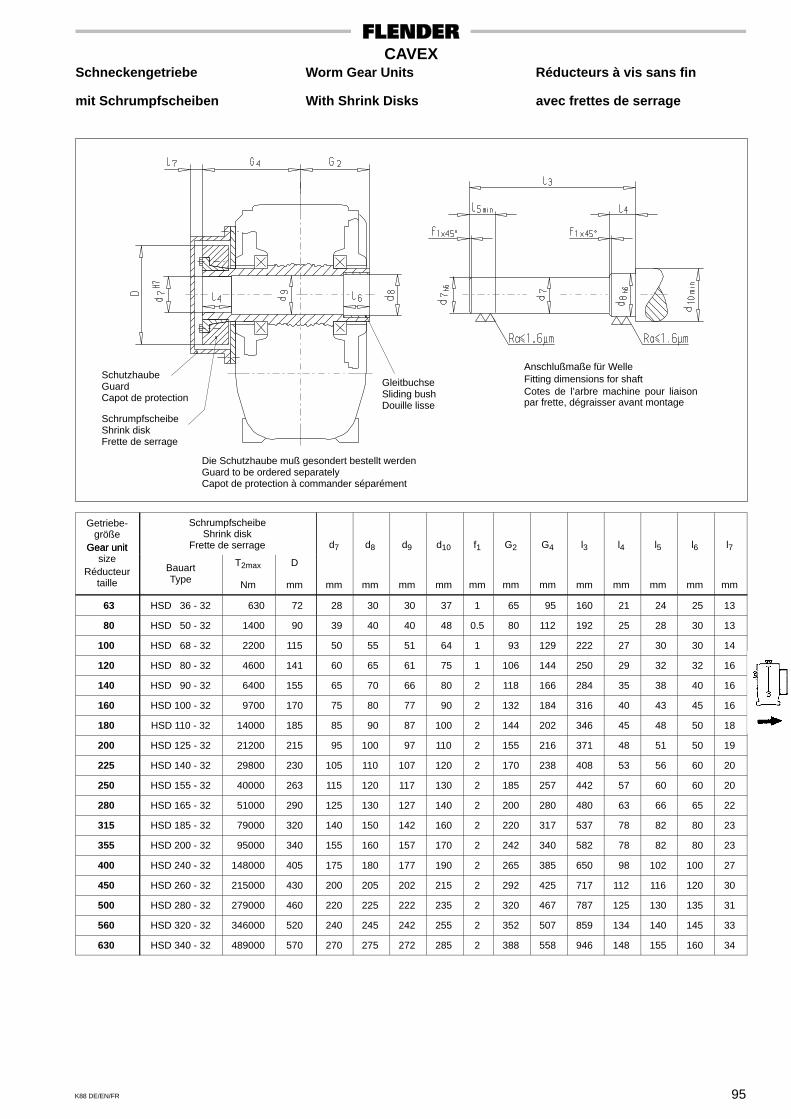
95K88 DE/EN/FR
CAVEXSchneckengetriebe Worm Gear Units Réducteurs à vis sans fin
mit Schrumpfscheiben With Shrink Disks avec frettes de serrage
Anschlußmaße für WelleFitting dimensions for shaftCotes de l’arbre machine pour liaisonpar frette, dégraisser avant montage
GleitbuchseSliding bushDouille lisse
Die Schutzhaube muß gesondert bestellt werdenGuard to be ordered separatelyCapot de protection à commander séparément
SchrumpfscheibeShrink diskFrette de serrage
SchutzhaubeGuardCapot de protection
Getriebe-größe
Gear unit
SchrumpfscheibeShrink disk
Frette de serrage d7 d8 d9 d10 f1 G2 G4 l3 l4 l5 l6 l7Gear unitsize
Réducteurtaille
BauartType
T2max
Nm
D
mm mm mm mm mm mm mm mm mm mm mm mm mm
63 HSD 36 - 32 630 72 28 30 30 37 1 65 95 160 21 24 25 13
80 HSD 50 - 32 1400 90 39 40 40 48 0.5 80 112 192 25 28 30 13
100 HSD 68 - 32 2200 115 50 55 51 64 1 93 129 222 27 30 30 14
120 HSD 80 - 32 4600 141 60 65 61 75 1 106 144 250 29 32 32 16
140 HSD 90 - 32 6400 155 65 70 66 80 2 118 166 284 35 38 40 16
160 HSD 100 - 32 9700 170 75 80 77 90 2 132 184 316 40 43 45 16
180 HSD 110 - 32 14000 185 85 90 87 100 2 144 202 346 45 48 50 18
200 HSD 125 - 32 21200 215 95 100 97 110 2 155 216 371 48 51 50 19
225 HSD 140 - 32 29800 230 105 110 107 120 2 170 238 408 53 56 60 20
250 HSD 155 - 32 40000 263 115 120 117 130 2 185 257 442 57 60 60 20
280 HSD 165 - 32 51000 290 125 130 127 140 2 200 280 480 63 66 65 22
315 HSD 185 - 32 79000 320 140 150 142 160 2 220 317 537 78 82 80 23
355 HSD 200 - 32 95000 340 155 160 157 170 2 242 340 582 78 82 80 23
400 HSD 240 - 32 148000 405 175 180 177 190 2 265 385 650 98 102 100 27
450 HSD 260 - 32 215000 430 200 205 202 215 2 292 425 717 112 116 120 30
500 HSD 280 - 32 279000 460 220 225 222 235 2 320 467 787 125 130 135 31
560 HSD 320 - 32 346000 520 240 245 242 255 2 352 507 859 134 140 145 33
630 HSD 340 - 32 489000 570 270 275 272 285 2 388 558 946 148 155 160 34
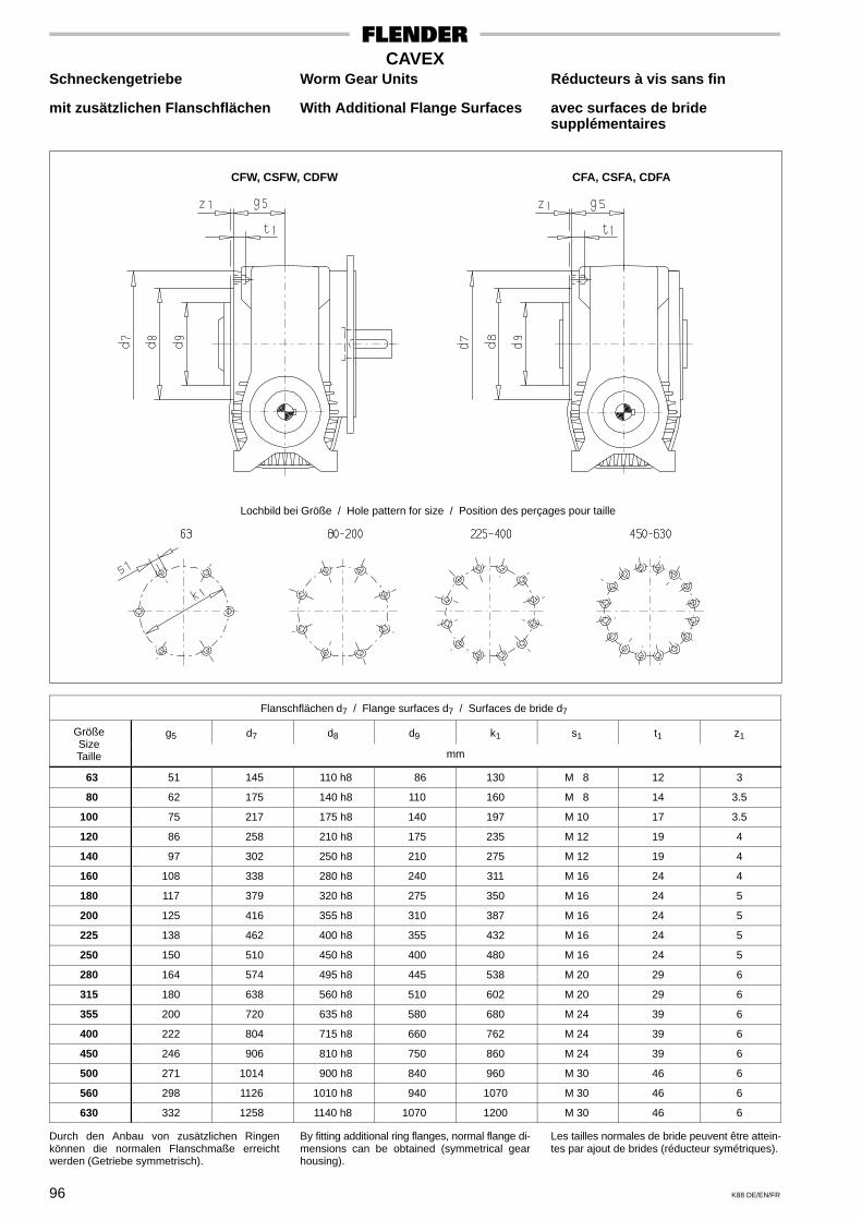
96 K88 DE/EN/FR
CAVEXSchneckengetriebe Worm Gear Units Réducteurs à vis sans fin
mit zusätzlichen Flanschflächen With Additional Flange Surfaces avec surfaces de bridesupplémentaires
Lochbild bei Größe / Hole pattern for size / Position des perçages pour taille
CFW, CSFW, CDFW CFA, CSFA, CDFA
Flanschflächen d7 / Flange surfaces d7 / Surfaces de bride d7
Größe g5 d7 d8 d9 k1 s1 t1 z1SizeTaille mm
63 51 145 110 h8 86 130 M 8 12 3
80 62 175 140 h8 110 160 M 8 14 3.5
100 75 217 175 h8 140 197 M 10 17 3.5
120 86 258 210 h8 175 235 M 12 19 4
140 97 302 250 h8 210 275 M 12 19 4
160 108 338 280 h8 240 311 M 16 24 4
180 117 379 320 h8 275 350 M 16 24 5
200 125 416 355 h8 310 387 M 16 24 5
225 138 462 400 h8 355 432 M 16 24 5
250 150 510 450 h8 400 480 M 16 24 5
280 164 574 495 h8 445 538 M 20 29 6
315 180 638 560 h8 510 602 M 20 29 6
355 200 720 635 h8 580 680 M 24 39 6
400 222 804 715 h8 660 762 M 24 39 6
450 246 906 810 h8 750 860 M 24 39 6
500 271 1014 900 h8 840 960 M 30 46 6
560 298 1126 1010 h8 940 1070 M 30 46 6
630 332 1258 1140 h8 1070 1200 M 30 46 6
Durch den Anbau von zusätzlichen Ringenkönnen die normalen Flanschmaße erreichtwerden (Getriebe symmetrisch).
By fitting additional ring flanges, normal flange di-mensions can be obtained (symmetrical gearhousing).
Les tailles normales de bride peuvent être attein-tes par ajout de brides (réducteur symétriques).
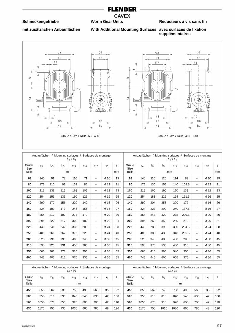
97K88 DE/EN/FR
CAVEXSchneckengetriebe Worm Gear Units Réducteurs à vis sans fin
mit zusätzlichen Anbauflächen With Additional Mounting Surfaces avec surfaces de fixationsupplémentaires
Größe / Size / Taille 63 - 400 Größe / Size / Taille 450 - 630
Anbauflächen / Mounting surfaces / Surfaces de montagea3 x b3
Anbauflächen / Mounting surfaces / Surfaces de montagea4 x b4
Größe a3 b3 h3 m3 m4 m7 s3 t Größe a4 b4 h4 m5 m6 m8 s3 tSzeTaille mm mm
SizeTaille mm mm
63 146 91 78 110 71 – M 10 19 63 146 110 126 114 89 – M 10 19
80 175 110 93 133 86 – M 12 21 80 175 130 155 140 109.5 – M 12 21
100 216 131 115 163 105 – M 12 23 100 216 160 190 170 133 – M 12 23
120 254 155 135 190 125 – M 16 25 120 254 183 225 194 151.5 – M 16 25
140 290 172 156 220 140 – M 16 26 140 290 204 255 220 172 – M 16 26
160 324 189 177 245 155 – M 16 27 160 324 223 290 240 187.5 – M 16 27
180 354 210 197 275 170 – M 20 30 180 364 245 320 268 209.5 – M 20 30
200 396 222 217 300 182 – M 20 31 200 396 260 350 280 219 – M 20 31
225 440 246 242 335 200 – M 24 38 225 440 280 390 300 234.5 – M 24 38
250 480 266 267 370 220 – M 24 40 250 480 305 430 340 265.5 – M 24 40
280 525 296 298 400 240 – M 30 45 280 525 345 480 430 290 – M 30 45
315 590 325 331 450 265 – M 30 45 315 590 370 530 480 310 – M 30 45
355 665 363 373 510 295 – M 36 55 355 665 415 595 540 350 – M 36 55
400 748 403 416 570 335 – M 36 55 400 748 445 660 605 375 – M 36 55
Anbauflächen / Mounting surfaces / Surfaces de montagea3 x b3
Anbauflächen / Mounting surfaces / Surfaces de montagea4 x b4
Größe a3 b3 h3 m3 m4 m7 s3 t Größe a4 b4 h4 m5 m6 m8 s3 tSizeTaille mm
SizeTaille mm
450 855 562 530 750 495 560 35 92 450 855 562 740 750 495 560 35 92
500 955 616 595 840 540 630 42 100 500 955 616 815 840 540 630 42 100
560 1050 678 650 920 600 700 42 110 560 1050 678 910 920 600 700 42 110
630 1175 750 730 1030 660 780 48 120 630 1175 750 1015 1030 660 780 48 120
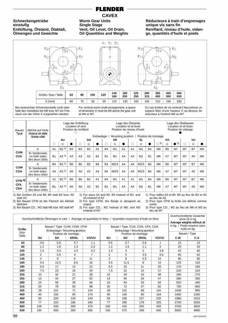
98 K88 DE/EN/FR
CAVEXSchneckengetriebe Worm Gear Units Réducteurs à train d’engrenageseinstufig Single Stage unique vis sans finEntlüftung, Ölstand, Ölablaß, Vent, Oil Level, Oil Drain, Reniflard, niveau d’huile, vidan-Ölmengen und Gewichte Oil Quantities and Weights ge, quantités d’huile et poids
Bei senkrechter Schneckenwelle muß ober-halb des Getriebes bei M6 bzw. M7 ein Frei-raum von der Höhe X vorgesehen werden.
For vertical worm shaft arrangement, a spaceof dimension X must be left above the gear unitat M6 or M7.
En cas d’arbre de vis vertical il faut prévoir unespace libre d’une hauteur X au-dessus duréducteur à l’endroit M6 ou M7.
Größe / Size / Taille
X (mm)
100 120 140160
180200
225250
280315
355400
60 70 82 95 110 135 160 190 210
80 450500
560630
240 280
63
BauartType
Abtrieb auf SeiteOutput on side
Lage der EntlüftungLocation of vent
Position du reniflard�
Lage des ÖlstandsLocation of oil level
Position de niveau d’huile
Lage des ÖlablassesLocation of oil drainPosition de vidange
�Ty e Out ut on sideSortie côté Einbaulage / Mounting position / Position de montageSortie côté
SU SO SR SL VO VU� � � � � � � � �
3)�
3)� �
A A1 B2 1) B3 B3 B2 A1 B4 M1 A1 A1 M1 B4 M6 B5 M7 M7 B7 M6CUWCUA
B / beiderseitson both sides
des deux côtésB1 A2 1) A3 A3 A2 B1 B1 M1 A4 A4 M1 B1 M6 A7 M7 M7 A5 M6
A B4 B2 1) B6 B6 B2 B4 B4 M2/3 A4 A4 M2/3 B4 M6 B5 M7 M7 B7 M6COWCOA
B / beiderseitson both sides
des deux côtésA4 A2 1) A6 A6 A2 A4 B4 M2/3 A4 A4 M2/3 B4 M6 A7 M7 M7 A5 M6
2) A A1 B2 1) B6 B6 B2 A1 B4 M1 A1 A1 M1 B4 M6 B5 M7 M7 B7 M6CFW 2)
CFACDA
B / beiderseitson both sides
des deux côtésB1 A2 1) A6 A6 A2 B1 B1 M1 A4 A4 M1 B1 M6 A7 M7 M7 A5 M6
1) Bei Größen 63 und 80: B5 statt B2 bzw. A5statt A2
2) Bei Bauart CFW ist der Flansch als Abtriebdefiniert.
3) Bei Bauart CD..: M2 statt M6 bzw. M3 statt M7
1) For sizes 63 and 80: B5 instead of B2, andA5 instead of A2
2) For type CFW, the flange is designed asoutput.
3) For type CD..: M2 instead of M6, and M3instead of M7
1) Pour tailles 63 et 80: B5 au lieu de B2 et A5au lieu de A2
2) Pour type CFW la bride est définie commesortie.
3) Pour type CD..: M2 au lieu de M6 et M3 aulieu de M7
Durchschnittliche Ölmengen in Liter / Average oil quantities in litres / Quantités moyennes d’huile en litresDurchschnittliche Gewichte
ohne Öl in kgAverage weights without oil
GrößeBauart / Type CUW, COW, CFW
pBauart / Type CUA, COA, CFA, CDA
p
Average weights without oilin kg / Poids moyens sans
huile en kgGrößeSize
Einbaulage / Mounting positionPosition de montage
Einbaulage / Mounting positionPosition de montage Bauart / Type
TailleSU SO SR/SL VO/VU SU SO SR/SL VO/VU C.W C.A
63 0.6 0.8 0.7 1.1 0.6 0.7 0.6 1 15 15 80 1.2 1.8 1.3 2.2 1.2 1.6 1.1 2 25 25100 1.3 3.3 2.3 4.2 1.3 3 2 3.8 42 40120 2 5.5 4 7 2 5 3.5 6.5 65 62140 3 9 6 11 3 8 5.5 10 90 85160 4.5 12.5 8.5 16 4.5 11.5 8 15 125 120180 5.5 17 12 22 5.5 16 11 20 170 160200 7.5 23 16 29 7.5 22 15 27 220 210225 10 32 21 39 10 29 20 36 290 270250 13 44 27 52 13 40 26 47 380 360280 15 58 35 66 15 54 33 62 520 490315 20 78 50 88 20 72 47 82 700 660355 28 110 71 124 28 102 68 116 1030 980400 40 155 95 174 40 145 90 164 1400 1340450 55 220 133 243 55 208 127 232 1980 1910500 77 310 186 340 77 295 178 325 2700 2620560 108 430 260 475 108 410 250 455 3700 3600630 150 600 360 665 150 575 348 640 5000 4880
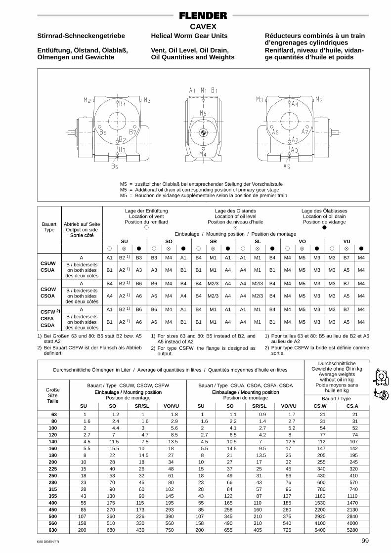
99K88 DE/EN/FR
CAVEXStirnrad-Schneckengetriebe Helical Worm Gear Units Réducteurs combinés à un train
d’engrenages cylindriquesEntlüftung, Ölstand, Ölablaß, Vent, Oil Level, Oil Drain, Reniflard, niveau d’huile, vidan-Ölmengen und Gewichte Oil Quantities and Weights ge quantités d’huile et poids
M5 = zusätzlicher Ölablaß bei entsprechender Stellung der VorschaltstufeM5 = Additional oil drain at corresponding position of primary gear stageM5 = Bouchon de vidange supplémentaire selon la position de premier train
Bauartp
Abtrieb auf Seitep
Lage der EntlüftungLocation of vent
Position du reniflard�
Lage des ÖlstandsLocation of oil level
Position de niveau d’huile
Lage des ÖlablassesLocation of oil drainPosition de vidange
�Type Output on sideSortie côté Einbaulage / Mounting position / Position de montageSortie côté
SU SO SR SL VO VU� � � � � � � � � � � �
A A1 B2 1) B3 B3 M4 A1 B4 M1 A1 A1 M1 B4 M4 M5 M3 M3 B7 M4CSUWCSUA
B / beiderseitson both sides
des deux côtésB1 A2 1) A3 A3 M4 B1 B1 M1 A4 A4 M1 B1 M4 M5 M3 M3 A5 M4
A B4 B2 1) B6 B6 M4 B4 B4 M2/3 A4 A4 M2/3 B4 M4 M5 M3 M3 B7 M4CSOWCSOA
B / beiderseitson both sides
des deux côtésA4 A2 1) A6 A6 M4 A4 B4 M2/3 A4 A4 M2/3 B4 M4 M5 M3 M3 A5 M4
2) A A1 B2 1) B6 B6 M4 A1 B4 M1 A1 A1 M1 B4 M4 M5 M3 M3 B7 M4CSFW 2)
CSFACSDA
B / beiderseitson both sides
des deux côtésB1 A2 1) A6 A6 M4 B1 B1 M1 A4 A4 M1 B1 M4 M5 M3 M3 A5 M4
1) Bei Größen 63 und 80: B5 statt B2 bzw. A5statt A2
2) Bei Bauart CSFW ist der Flansch als Abtriebdefiniert.
1) For sizes 63 and 80: B5 instead of B2, andA5 instead of A2
2) For type CSFW, the flange is designed asoutput.
1) Pour tailles 63 et 80: B5 au lieu de B2 et A5au lieu de A2
2) Pour type CSFW la bride est définie commesortie.
Durchschnittliche Ölmengen in Liter / Average oil quantities in litres / Quantités moyennes d’huile en litresDurchschnittliche
Gewichte ohne Öl in kgAverage weights
GrößeBauart / Type CSUW, CSOW, CSFW
Einbaulage / Mounting positionBauart / Type CSUA, CSOA, CSFA, CSDA
Einbaulage / Mounting position
without oil in kgPoids moyens sans
huile en kgSizeTaille
Einbaulage / Mounting ositionPosition de montage
Einbaulage / Mounting ositionPosition de montage Bauart / TypeTaille
SU SO SR/SL VO/VU SU SO SR/SL VO/VU CS.W CS.A
63 1 1.2 1 1.8 1 1.1 0.9 1.7 21 21 80 1.6 2.4 1.6 2.9 1.6 2.2 1.4 2.7 31 31100 2 4.4 3 5.6 2 4.1 2.7 5.2 54 52120 2.7 7 4.7 8.5 2.7 6.5 4.2 8 77 74140 4.5 11.5 7.5 13.5 4.5 10.5 7 12.5 112 107160 5.5 15.5 10 18 5.5 14.5 9.5 17 147 142180 8 22 14.5 27 8 21 13.5 25 205 195200 10 28 18 34 10 27 17 32 255 245225 15 40 26 48 15 37 25 45 340 320250 18 53 32 61 18 49 31 56 430 410280 23 70 45 80 23 66 43 76 600 570315 28 90 60 102 28 84 57 96 780 740355 43 130 90 145 43 122 87 137 1160 1110400 55 175 115 195 55 165 110 185 1530 1470450 85 270 173 293 85 258 160 280 2200 2130500 107 360 226 390 107 345 210 375 2920 2840560 158 510 330 560 158 490 310 540 4100 4000630 200 680 430 750 200 655 405 725 5400 5280

100 K88 DE/EN/FR
CAVEXDoppelschneckengetriebe Double Worm Gear Units Réducteurs à vis sans fin
Entlüftung, Ölstand, Ölablaß, Vent, Oil Level, Oil Drain, Reniflard, niveau d’huile, vidan-Ölmengen und Gewichte Oil Quantities and Weights ge quantitiés d’huile et poids
Bei senkrechter Antriebswelle muß oberhalbdes Getriebes bei M6 bzw. M7 ein Freiraumvon der Höhe X vorgesehen werden.
For vertical input shaft arrangement, a freespace of dimension X must be left above thegear unit at M6 or M7.
En cas d’arbre d’entrée de vis vertical il fautprévoir un espace libre d’une hauteur Xau-dessus du réducteur à l’endroit M6 ou M7.
VorschaltgetriebePrimary gear unitRéducteur primaire
Größe / Size / Taille
X (mm)
180200
225250
280315
355400
60 70 82 95 110 135
450500
560630
160 190
100120
140160
Antriebswellein StellungInput shaft
Lage der EntlüftungLocation of vent
Position du reniflard�
Lage des ÖlstandsLocation of oil level
Position de niveau d’huile
Lage des ÖlablassesLocation of oil drainPosition de vidange
�In ut shaftin position an der Vorschaltstufe / on primary gear stage / du réducteur primairein osition
Arbre d’entrée Einbaulage / Mounting position / Position de montageArbre d entréeen position SU SO SR SL VO VU
� � � � � � � � � � � �
a A6 A2 B1 B1 A2 1) A6 M7 A5 M6 M6 A7 M7 A4 M1 B1 B1 M1 A4
b B6 B2 A1 A1 B2 1) B6 M6 B5 M7 M7 B7 M6 B4 M1 A1 A1 M1 B4
c A1 B2 1) B6 B6 B2 A1 M7 B7 M6 M6 B5 M7 B4 M1 A1 A1 M1 B4
d B1 A2 1) A6 A6 A2 B1 M6 A7 M7 M7 A5 M6 A4 M1 B1 B1 M1 A4
e M6 A7 M7 M7 A5 M6 A6 A2 B1 B1 A2 1) A6 A4 M1 B1 B1 M1 A4
f M7 B7 M6 M6 B5 M7 B6 B2 A1 A1 B2 1) B6 B4 M1 A1 A1 M1 B4
g M6 B5 M7 M7 B7 M6 A1 B2 1) B6 B6 B2 A1 B4 M1 A1 A1 M1 B4
h M7 A5 M6 M6 A7 M7 B1 A2 1) A6 A6 A2 B1 A4 M1 B1 B1 M1 A4
1) Bei Größen 100 – 160: B5 statt B2 bzw. A5statt A2
1) For sizes 100 – 160: B5 instead of B2, andA5 instead of A2
1) Pour tailles 100 – 160: B5 au lieu de B2 et A5au lieu de A2
Durchschnittliche Ölmengen der Vorschaltstufe in LiterAverage oil quantities of the primary gear stage in litres
Quantités moyennes d’huile en litres du réducteur primaire
Durchschnittliche Gewichte vonVorschalt- und Hauptstufe ohne Öl
Average weights of primary andmain gear stage without oil
Poids moyens des réducteursprimaires et principaux sans huile
Einbaulage / Mounting position / Position de montage Bauart / TypeGröße SU SO SR SL VO / VUSize
Stellung der Antriebswelle / Position of input shaft / Position de l’arbre d’entréeCD.W CD.A
Taillea / b c / d e - h a / b c / d e - h a - d e / f g / h a - d e / f g / h a - h
kg kg
100 0.7 0.6 1 0.6 0.7 1 1 0.7 0.6 1 0.6 0.7 0.6 57 55120 0.7 0.6 1 0.6 0.7 1 1 0.7 0.6 1 0.6 0.7 0.6 80 77140 1.6 1.2 2 1.2 1.6 2 2 1.6 1.2 2 1.2 1.6 1.1 115 110160 1.6 1.2 2 1.2 1.6 2 2 1.6 1.2 2 1.2 1.6 1.1 150 145180 3 1.3 3.8 1.3 3 3.8 3.8 3 1.3 3.8 1.3 3 2 210 200200 3 1.3 3.8 1.3 3 3.8 3.8 3 1.3 3.8 1.3 3 2 260 250225 5 2 6.5 2 5 6.5 6.5 5 2 6.5 2 5 3.5 350 330250 5 2 6.5 2 5 6.5 6.5 5 2 6.5 2 5 3.5 440 420280 8 3 10 3 8 10 10 8 3 10 3 8 5.5 600 570315 11.5 4.5 15 4.5 11.5 15 15 11.5 4.5 15 4.5 11.5 8 810 770355 16 5.5 20 5.5 16 20 20 16 5.5 20 5.5 16 11 1180 1130400 22 7.5 27 7.5 22 27 27 22 7.5 27 7.5 22 15 1600 1540450 29 10 36 10 29 36 36 29 10 36 10 29 20 2240 2170500 40 13 47 13 40 47 47 40 13 47 13 40 26 3040 2960560 54 15 62 15 54 62 62 54 15 62 15 54 33 4170 4070630 72 20 82 20 72 82 82 72 20 82 20 72 47 5630 5510
Bei den Hauptstufen gelten die Angaben für ein-stufige Bauarten mit den gleichen 2 Endbuch-staben, siehe Seite 98.
For the main gear stages, the data for single stagetypes with the same two ending letters apply, seepage 98.
Pour les trains principaux les désignations dutype à un seul train sont valables avec les 2mêmes lettres finales, voir page 98.

101K88 DE/EN/FR
CAVEXSchneckengetriebe Worm Gear Units Réducteurs à vis sans fin
Anbauanleitung und Befestigung Installation Instructions, Fastening Montage et de fixation pourvon Aufsteckgetrieben of Shaft-mounted Worm Gear Units réducteurs flottants
Kräfte an einem CAVEX-Aufsteckgetriebe,Bauart CDA
F1 = Kraft aus dem Gewicht des Aufsteck-getriebes auf die Maschinenwelle
n2 = Drehrichtung der Hohlwelle D2TR = Reaktionsdrehmoment am Getriebege-
häuse = Abtriebsdrehmoment T2FS = Abstützkraft von der Drehmoment-
stütze auf die AufhängungF2 = Kraft auf die Maschinenwelle
= Kraft FS
*) Die Bohrungstoleranz H7 in der Hohlwelleist ein Mittelwert. Um einerseits das Aufzie-hen des Getriebes zu erleichtern, anderer-seits aber einen festen Sitz auf der Wellezu erreichen, ist die Bohrungstoleranz bisG7 erweitert, in der Mitte des Paßsitzeswird die Bohrung enger bis J7. In Hohlwel-lenmitte ist auf etwa 1/3 der Gesamtlängeeine Aussparung vorhanden.
Schéma des forces agissant sur un réducteur”flottant” CAVEX type CDA
F1 = Force agissant sur l’arbre de la machineprovenant du poids du réducteur
n2 = Sens de rotation de l’arbre creux D2TR = Couple de réaction sur le carter du
réducteur = couple de sortie T2FS = Force au point de suspension du bras
de réactionF2 = Force appliquée sur l’arbre de la ma-
chine = force FS
*) La tolérance H7 dans l’arbre creux est unevaleur moyenne. Pour faciliter le montageet garantir néanmoins un ajustement serré,elle est élargie jusqu’ à G7 aux extrémitéset réduite jusqu’à J7 vers le centre. Un évi-dement est prévu au milieu de l’arbre creuxsur 1/3 de la longueur totale environ.
Forces acting on a shaft-mounted CAVEXgear unit type CDA
F1 = Force resulting from the weight of thegear unit on the machine shaft
n2 = Direction of rotation of hollow shaft D2TR = Reaction torque on gear housing = out-
put torque T2FS = Torque support arm force acting on
suspensionF2 = Force on driven machine shaft
= force FS
*) The hollow shaft tolerance H7 is a meanvalue. In order to facilitate mounting of gearunits and still obtain a tight shaft fit, thetolerance has been widened to G7 at theends of the hollow shaft, while the centre ofthe fit narrows to J7. The centre part of thehollow shaft is recessed over approxima-tely 1/3 of its total length.
DruckölanschlußPressure oil connectionConnection d’huile sous pression
*
Anbauanleitung für Aufsteckgetriebe
Zweckmäßig erfolgt die Abstützung des Drehmo-mentes über Bolzen und Laschen, damit dasGetriebe verspannunsfrei bleibt.
Bei Verformungen der Maschinenwelle ist derdadurch hervorgerufene Kupplungsversatz ander Antriebswelle zu beachten. Es empfiehlt sich,den Motor anzuflanschen.
Befestigung der CAVEX-Aufsteckgetriebe
Das Wellenende der anzutreibenden Arbeitsma-schine muß mit Paßfeder nach DIN 6885 / 1 aus-geführt sein und sollte stirnseitig eine ZentrierungForm DS nach DIN 332 haben. Wir empfehlen dieBefestigung des Getriebes mit einer Endscheibe,die auch als Abdrückhilfe benutzt werden kann.Zu diesem Zweck haben alle Hohlwellen eineSeegerring-Nut nach DIN 472.Um ein Abziehen der Aufsteckgetriebe zu erleich-tern, empfehlen wir, im Wellenende der Arbeits-maschine vor der Montage eine Bohrung gemäßobenstehender Abbildung vorzusehen. Durchdiese Bohrung soll nach Anschluß eines Injektorsim Bedarfsfall Rostlöser an den Radkörpersitzgebracht werden können. Hierzu ist es erforder-lich, daß die Querbohrung im Bereich der Aus-drehung der Hohlwelle mündet.
Installation instructions for shaft-mountedgear unitsThe most functional torque support is with adamping and flexible suspension.
Deformations of the machine shaft causecoupling misalignment on the input shaft andshould be taken into account; a flanged motor isrecommended.
Fastening of shaft-mounted CAVEX wormgear unitsThe shaft end of the driven machine should havea parallel key acc. to DIN 6885 sheet 1, and atapped centre hole acc. to DIN 332, form DS. Werecommend to fasten the gear unit with an endplate which can also be used as a forcing plate.For this purpose, all hollow shafts are furnishedwith ring grooves for circlips acc. to DIN 472.
To facilitate pulling off of the mounted gear units ata later stage we recommend to drill a hole into theshaft end of the driven machine before fitting thegear unit, see illustration above. By means of aninjector fitted to the hole, rust solvent can bebrought to the shaft seat through it, if necessary.To accomplish this, it will, of course, be necessaryfor the outlet of the vertical bore to be within therecessed part of the hollow shaft.
Instructions de montage des réducteursflottantsIl est utille de suspendre le bras de réaction parl’intermédiaire d’un organe élastique absorbant.On empêche ainsi les tensions dans la transmis-sion.Une déformation de l’arbre de la machine peutprovoquer un désalignement de l’accouplement àl’arbre d’entrée. Il est recommandé d’utiliser unmoteur à bride.
Fixation des réducteurs CAVEX flottants
Le bout d’arbre de la machine entraînée doit êtreexécuté avec clavette selon DIN 6885 feuille 1 etdevra comporter un centrage de forme D5, selonDIN 332. Nous conseillons de fixer le réducteur àl’aide d’une rondelle de fixation, qui peut servirégalement de rondelle de démontage. Pour cetteraison, tous les arbres creux possèdent unerainure de circlips selon DIN 472.Après plusieurs années de service, l’influence dutemps, de l’atmosphère ambiante et de la rouillede contact peuvent rendre le démontage difficile.Afin de faciliter le démontage, nous conseillonsde prévoir dans le bout d’arbre de la machine unperçage tel qu’il est représenté ci-dessus. Si be-soin est, on doit pouvoir introduire, par ce trou, uninjecteur permettant de pulvériser un produit anti-rouille à l’intérieur du moyeu de la roue. Il est doncnécessaire qu’un alésage radial aboutisse dansl’embrèvement du moyeu.

FR’ =FR x 63
38 + aFR’ =
FR x 76.5
44 + aFR’ =
FR x 87
47 + aFR’ =
FR x 99.5
52 + aFR’ =
FR x 108.5
56 + a
FR’ =FR x 119
59 + aFR’ =
FR x 133
63 + aFR’ =
FR x 150
70 + aFR’ =
FR x 168
78 + aFR’ =
FR x 184
84 + a
FR’ =FR x 197
87 + aFR’ =
FR x 214
94 + aFR’ =
FR x 229
99 + aFR’ =
FR x 251
106 + aFR’ =
FR x 279
119 + a
FR’ =FR x 302
127 + aFR’ =
FR x 326
131 + aFR’ =
FR x 361
146 + a
102 K88 DE/EN/FR
CAVEXSchneckengetriebe Worm Gear Units Réducteurs à vis sans fin
Zusatzkräfte auf Additional Forces on Charges additionnelles sur lesAn- und Abtriebswellen Input and Output Shafts arbres d’entrée et de sortie
AntriebswellenWenn die Getriebe durch Keilriemen, Zahn-riemen oder Ketten angetrieben werden, ist inaller Regel keine Lagerverstärkung erforderlich.
Lediglich bei starker Riemenvorspannung(Flachriemen) oder ungünstigem Krafteingriff(zum Wellenende hin verschoben) bitten wir umRückfrage.Antriebswellen an der Lüfterseite sind nicht fürZusatzkräfte geeignet.
AbtriebswellenZulässige äußere Radialbelastungen FR aufMitte Wellenende lassen sich anhand der nach-folgenden Diagramme ermitteln. Dabei werdensowohl die Betriebsverhältnisse durch den Faktorf = (f1 x f2) als auch die Übersetzung i, das Ab-triebsdrehmoment T2 und die Abtriebsdrehzahln2 berücksichtigt.Die in den Kurvenscharen angegebenen Zahlensind die Abtriebsdrehzahlen n2. Zahlen ohneKlammern gelten für die Normallagerung, einge-klammerte Zahlen für die verstärkte Lagerung.
Beispiel: Getriebe, Bauart CUWTechnische Angaben ansonsten wie BeispielSeite 11
Getriebe- i = 40 T2 = 850 Nmgröße 120: n2 = 25/min f1 = 1.4
f2 = 1.1 f6 = 1
T2 x f = 850 Nm x (1.4 x 1.1) = 1309 Nm
Von diesem Wert auf Seite 104 ausgehendwaagerecht auf die Drehzahlkurve 25 und dannsenkrecht auf den Wert FR x f 15200 N erhältman die zulässige Radialkraft FR = 15200 Ndividiert durch (1.4 x 1.1) = 9870 N.Während des Anlaufs oder in kurzzeitigen Bela-stungsspitzen dürfen die Werte der Hüllkurvendividiert durch (f2 x f6) zugelassen werden. Imvorgenannten Beispiel ist T2A mit 1750 Nm ange-geben. Die dabei zulässige Zusatzkraft FR ist23600 N dividiert durch (1.1 x 1) = 21450 N.Liegt der Kraftangriffspunkt über Mitte Wellen-ende hinaus, so läßt sich die zulässige Radialbe-lastung FR’ nach folgenden Formeln bestimmen,wobei a der Abstand der Angriffsstelle vomWellenbund in mm ist.
Input shaftsAs a rule, worm gear units driven by V-belts,timing belts or chains do not require bearing rein-forcement.
However, applications with a considerableamount of initial belt tension (flat belts) or unfa-vourable force application point (towards shaftend), should be referred to us.Input shafts on the fan side are not capable oftaking up additional forces.
Output shaftsPermissible external radial loads FR acting onthe centre of the shaft extension can be deter-mined with the diagrams on the following pages.Operating conditions are taken into account withfactor f = (f1 x f2), as well as transmission ratio i,output torque T2 and output speed n2.
Figures in diagrams are output speeds n2. Num-bers without brackets refer to standard bearings,bracketed numbers apply to reinforced bearingsupport.
Example: Gear unit, type CUWTechnical data similar to example on page 11
Gear unit i = 40 T2 = 50 Nmsize 120: n2 = 25/min f1 = 1.4
f2 = 1.1 f6 = 1
T2 x f = 850 Nm x (1.4 x 1.1) = 1309 Nm
Enter the diagram on page 104 for appropriatesize and ratio at this value horizontally as far asspeed curve 25 and then trace vertically down tofind FR x f = 15200 N, this divided by (1.4 x 1.1)results in 9870 N.During starting or momentary peak loads, valuesof the envelope curves divided by (f2 x f6) can beallowed. In the above example T2A is given with1750 Nm, the permissible additional force FR is23600 N divided by (1.1 x 1) = 21540 N.In case the radial force application point is awayfrom the shaft centre toward the shaft end, thepermissible radial load FR’ can be calculated withthe following formulae, where ”a” represents thedistance of the force application point from theshaft shoulder in mm.
Arbres d’entréeLes réducteurs entraînés par courroies trapé-zoïdales, courroies crantrées ou par chaînes nenécessitent pas, en général, un renforcement depalier.En cas de fortes pré-tensions (courroies plates)ou si la position du point d’application de l’effortest défavorable (vers l’extrémité de l’arbre) prièrede nous consulter.
Arbres de sortieLes charges additionelles radiales admissiblesFR appliquées au milieu du bout d’arbre de sortiepeuvent être déterminées à l’aide des abaquessuivants. Ils tiennent compte des conditions deservice par le facteur f = (f1 x f2), du rapport i, ducouple de sortie T2 et de la vitesse de sortie n2.
Les chiffres imbriqués dans les courbes indiquentles vitesses de sortie n2. Les chiffres sans pa-renthèses se réfèrent aux paliers standards, leschiffres entre parenthèses aux paliers renforcés.
Example: Réducteur, type CUWDonnées techniques comme par exemple enpage 11
Taille du i = 40 T2 = 850 Nmréducteur 120: n2 = 25/min f1 = 1.4
f2 = 1.1 f6 = 1
T2 x f = 850 Nm x (1.4 x 1.1) = 1309 Nm
Cette valeur, introduite horizontalement dansl’ abaque jusqu’à la courbe n2 donne pour FR x fla valeur de 15200 N environ. On trouve doncFR admissible = 15200 N divisé par (1.4 x 1.1)= 9870 N.Pendant le démarrage ou en cas de pointes decharge les valeurs de courbes enveloppantespeuvent être admises. Dans l’exemple ci-dessusT2A est indiqué avec 1750 Nm et le couple com-plémentaire permis FR est de 21540 N.Si le point d’application de l’effort se trouvedéplacé vers l’extrémité de l’arbre, on peuttrouver l’effort radial admissible FR’ selon lesformules suivantes (a = distance entre le pointd’application et l’ épaulement de l’arbre).
Größe / Size / Taille 63 Größe / Size / Taille 80 Größe / Size / Taille 100 Größe / Size / Taille 120 Größe / Size / Taille 140
Größe / Size / Taille 160 Größe / Size / Taille 180 Größe / Size / Taille 200 Größe / Size / Taille 225 Größe / Size / Taille 250
Größe / Size / Taille 280 Größe / Size / Taille 315 Größe / Size / Taille 355 Größe / Size / Taille 400 Größe / Size / Taille 450
Größe / Size / Taille 500 Größe / Size / Taille 560 Größe / Size / Taille 630
Bei äußeren Axialbelastungen bitten wir umRückfrage.
HohlwellenGrundsätzlich sind auch Hohlwellengetriebe inder Lage, Zusatzkräfte aufzunehmen. Eine kata-logmäßige Auflistung wäre jedoch zu aufwendig.Gegebenenfalls bitten wir um Rückfrage mit An-gabe der Größe, Lage und Richtung der Kraft.
For applications with external thrust loads, pleaserefer to us.
Hollow shaftsBasically, shaft-mounted gear units are also ableto accept additional forces. A catalogue listingwould be rather large-scale. We, therefore, ask torefer to us, stating magnitude, application pointand direction of force.
Si l’arbre doit supporter des efforts axiaux, veuil-lez nous consulter.
Arbres creuxEn principe les réducteurs à arbre creux sont toutà fait capables de supporter des charges addi-tionelles. Nous estimons cependant qu’il n’estpas nécessaire de les faire figurer dans cettebrochure. Le cas échéant, veuillez nous consulteren indiquant les efforts, leurs positions et leursdirections.

103K88 DE/EN/FR
CAVEXSchneckengetriebe Worm Gear Units Réducteurs à vis sans fin
Zusatzkräfte auf Abtriebswellen Additional Forces on Output Charges additionnelles sur lesShafts arbres de sortie
Größe / Size / Taille 63 i = 5.17 - 6.6 Größe / Size / Taille 80 i = 5.17 - 6.6
Größe / Size / Taille 63 i = 8.25 - 12.67 Größe / Size / Taille 80 i = 8.25 - 12.67
Größe / Size / Taille 63 i � 15.5 Größe / Size / Taille 80 i � 15.5
FR x f
T2
x f
FR x f
T2
x f
T2
x f
FR x f
T2
x f
FR x f
FR x f
T2
x f
T2
x f
FR x f

104 K88 DE/EN/FR
CAVEXSchneckengetriebe Worm Gear Units Réducteurs à vis sans finZusatzkräfte auf Abtriebswellen Additional Forces on Output Charges additionnelles sur les
Shafts arbres de sortie1) Grenzkurve für COW, CSOW, und CDOW 1) Limiting curve for COW, CSOW, and CDOW 1) Courbe limite pour COW, CSOW, et CDOW( ) mit Lagerverstärkung ( ) with bearing reinforcement ( ) avec renforcement du palier
Größe / Size / Taille 100 i = 5.33 - 6.8 Größe / Size / Taille 120 i = 5.33 - 6.8
Größe / Size / Taille 100 i = 8.75 - 13.33 Größe / Size / Taille 120 i = 8.75 - 13.33
Größe / Size / Taille 100 i � 16.5 Größe / Size / Taille 120 i � 17.5
FR x f
T2
x f
FR x f
T2
x f
T2
x f
FR x f
T2
x f
FR x f
FR x f
T2
x f
T2
x f
FR x f

105K88 DE/EN/FR
CAVEXSchneckengetriebe Worm Gear Units Réducteurs à vis sans finZusatzkräfte auf Abtriebswellen Additional Forces on Output Charges additionnelles sur les
Shafts arbres de sortie1) Grenzkurve für COW, CSOW, und CDOW 1) Limiting curve for COW, CSOW, and CDOW 1) Courbe limite pour COW, CSOW, et CDOW( ) mit Lagerverstärkung ( ) with bearing reinforcement ( ) avec renforcement du palier
Größe / Size / Taille 140 i = 5.33 - 6.8 Größe / Size / Taille 160 i = 5.67 - 7.2
Größe / Size / Taille 140 i = 8.75 - 13.33 Größe / Size / Taille 160 i = 9.25 - 14.33
Größe / Size / Taille 140 i � 16.5 Größe / Size / Taille 160 i � 17.5
FR x f
T2
x f
FR x f
T2
x f
T2
x f
FR x f
T2
x f
FR x f
FR x f
T2
x f
T2
x f
FR x f
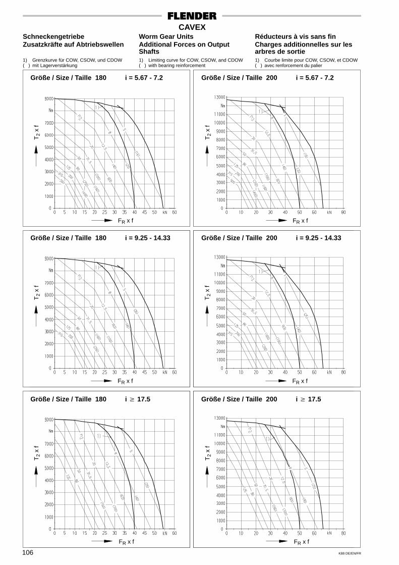
106 K88 DE/EN/FR
CAVEXSchneckengetriebe Worm Gear Units Réducteurs à vis sans finZusatzkräfte auf Abtriebswellen Additional Forces on Output Charges additionnelles sur les
Shafts arbres de sortie1) Grenzkurve für COW, CSOW, und CDOW 1) Limiting curve for COW, CSOW, and CDOW 1) Courbe limite pour COW, CSOW, et CDOW( ) mit Lagerverstärkung ( ) with bearing reinforcement ( ) avec renforcement du palier
Größe / Size / Taille 180 i = 5.67 - 7.2 Größe / Size / Taille 200 i = 5.67 - 7.2
Größe / Size / Taille 180 i = 9.25 - 14.33 Größe / Size / Taille 200 i = 9.25 - 14.33
Größe / Size / Taille 180 i � 17.5 Größe / Size / Taille 200 i � 17.5
FR x f
T2
x f
FR x f
T2
x f
T2
x f
FR x f
T2
x f
FR x f
FR x f
T2
x f
T2
x f
FR x f

107K88 DE/EN/FR
CAVEXSchneckengetriebe Worm Gear Units Réducteurs à vis sans finZusatzkräfte auf Abtriebswellen Additional Forces on Output Charges additionnelles sur les
Shafts arbres de sortie1) Grenzkurve für COW, CSOW, und CDOW 1) Limiting curve for COW, CSOW, and CDOW 1) Courbe limite pour COW, CSOW, et CDOW( ) mit Lagerverstärkung ( ) with bearing reinforcement ( ) avec renforcement du palier
Größe / Size / Taille 225 i = 5.83 - 7.4 Größe / Size / Taille 250 i = 5.83 - 7.4
Größe / Size / Taille 225 i = 9.25 - 14.67 Größe / Size / Taille 250 i = 9.25 - 14.67
Größe / Size / Taille 225 i � 18.5 Größe / Size / Taille 250 i � 18.5
FR x f
T2
x f
FR x f
T2
x f
T2
x f
FR x f
T2
x f
FR x f
FR x f
T2
x f
T2
x f
FR x f
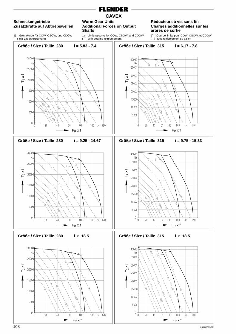
108 K88 DE/EN/FR
CAVEXSchneckengetriebe Worm Gear Units Réducteurs à vis sans finZusatzkräfte auf Abtriebswellen Additional Forces on Output Charges additionnelles sur les
Shafts arbres de sortie1) Grenzkurve für COW, CSOW, und CDOW 1) Limiting curve for COW, CSOW, and CDOW 1) Courbe limite pour COW, CSOW, et CDOW( ) mit Lagerverstärkung ( ) with bearing reinforcement ( ) avec renforcement du palier
Größe / Size / Taille 280 i = 5.83 - 7.4 Größe / Size / Taille 315 i = 6.17 - 7.8
Größe / Size / Taille 280 i = 9.25 - 14.67 Größe / Size / Taille 315 i = 9.75 - 15.33
Größe / Size / Taille 280 i � 18.5 Größe / Size / Taille 315 i � 18.5
FR x f
T2
x f
FR x f
T2
x f
T2
x f
FR x f
T2
x f
FR x f
FR x f
T2
x f
T2
x f
FR x f

109K88 DE/EN/FR
CAVEXSchneckengetriebe Worm Gear Units Réducteurs à vis sans finZusatzkräfte auf Abtriebswellen Additional Forces on Output Charges additionnelles sur les
Shafts arbres de sortie1) Grenzkurve für COW, CSOW, und CDOW 1) Limiting curve for COW, CSOW, and CDOW 1) Courbe limite pour COW, CSOW, et CDOW( ) mit Lagerverstärkung ( ) with bearing reinforcement ( ) avec renforcement du palier
Größe / Size / Taille 355 i = 6.17 - 7.8 Größe / Size / Taille 400 i = 6.17 - 7.8
Größe / Size / Taille 355 i = 9.75 - 15.33 Größe / Size / Taille 400 i = 9.75 - 15.33
Größe / Size / Taille 355 i � 19.5 Größe / Size / Taille 400 i � 19.5
FR x f
T2
x f
FR x f
T2
x f
T2
x f
FR x f
T2
x f
FR x f
FR x f
T2
x f
T2
x f
FR x f

110 K88 DE/EN/FR
CAVEXSchneckengetriebe Worm Gear Units Réducteurs à vis sans fin
Zusatzkräfte auf Abtriebswellen Additional Forces on Output Charges additionnelles sur lesShafts arbres de sortie
Größe / Size / Taille 450 i = 6.33 - 8.2 Größe / Size / Taille 500 i = 6.67 - 8.4
Größe / Size / Taille 450 i = 10.25 - 15.67 Größe / Size / Taille 500 i = 10.75 - 16.33
Größe / Size / Taille 450 i � 19.5 Größe / Size / Taille 500 i � 19.5
FR x f
T2
x f
FR x f
T2
x f
T2
x f
FR x f
T2
x f
FR x f
FR x f
T2
x f
T2
x f
FR x f

111K88 DE/EN/FR
CAVEXSchneckengetriebe Worm Gear Units Réducteurs à vis sans fin
Zusatzkräfte auf Abtriebswellen Additional Forces on Output Charges additionnelles sur lesShafts arbres de sortie
Größe / Size / Taille 560 i = 6.67 - 8.6 Größe / Size / Taille 630 i = 6.83 - 8.6
Größe / Size / Taille 560 i = 10.75 - 16.67 Größe / Size / Taille 630 i = 10.75 - 16.67
Größe / Size / Taille 560 i � 20.5 Größe / Size / Taille 630 i � 20.5
FR x f
T2
x f
FR x f
T2
x f
T2
x f
FR x f
T2
x f
FR x f
FR x f
T2
x f
T2
x f
FR x f

112 K88 DE/EN/FR
CAVEXSchneckengetriebe Worm Gear Units Réducteurs à vis sans fin
Wirkungsgrade, Selbsthemmung Efficiencies, Irreversibility Rendements, IrréversibilitésAuslaufen und Bremsen Deceleration and Braking Ralentissement et freinage
Bei Doppelschneckengetrieben sind die beidenStufen getrennt zu betrachten.
Einflußgrößen für WirkungsgradeAllgemein gilt, daß der Wirkungsgrad ansteigtmit: steigender Gleitgeschwindigkeit an der Ver-zahnung, zunehmendem Steigungswinkel undder Getriebegröße.
Ferner sind die Oberflächenbeschaffenheit derZahnflanken, die Flankenform, die Werkstoff-paarung und die Schmierung von entscheidenderBedeutung.
Ermittlung der WirkungsgradeDie Wirkungsgrade η gelten normalerweise fürgut eingelaufene und ordnungsgemäß ge-schmierte Getriebe mit Wälzlagerung bei an-nähernd Nennlast und treibender Schnecke. Beitreibendem Schneckenrad ist der Wirkungsgradη’ stets geringer.Anhaltswerte für die Wirkungsgrade η und η’lassen sich anhand der nachstehenden Formelnermitteln:
For double worm gear units the two gear stagesmust be separately considered.
Factors influencing the efficiencyEfficiency increases, as a general rule, with risingsliding velocity on the teeth, with increasing leadangle, and with larger gear unit size.
Furthermore, the surface finish of the tooth flanks,the tooth form, mating materials and lubricationare of decisive importance.
Determination of efficiencyThe efficiency η of a gear unit normally applies toa unit that is well run-in, correctly lubricated, fittedwith rolling bearings, near full load, and wormdriving. Efficiency η’ is always smaller if the wormwheel is driving.
Guide values for efficiencies η and η’ can befound with the help of the formulae:
Pour les réducteurs à double vis sans fin, il fautconsidérer chaque train d’engrenages séparé-ment.
Facteurs influant sur les rendementsEn règle générale, le rendement augmente enfonction: de l’accroissement de la vitesse deglissement entre les dentures, de l’augmentationde l’angle d’inclinaison de la vis, et de la tailledu réducteur.De plus, la qualité des surfaces des dentures, laforme des dents, le choix des matériaux entre viset roue et la lubrification jouent un rôle pré-pondérant.
Détermination des rendementsLes rendements η entendent normalement pourun réducteur bien rodé, conformément lubrifié,avec paliers à roulements, sous pleine charge etvis menante. Lorsque l’entraînement se fait par laroue, le rendement η’ est plus faible:
Les valeurs indicatives des rendements η et η’peuvent être calculées à l’aide des formulessuivantes:
η =T2N x n2
P1N x 9550η ’ = 2 –
1η
Die Werte T2N, n2 und P1N sind den Leistungs-tafeln zu entnehmen.
AnlaufwirkungsgradEin Schmierfilm zwischen den Zahnflanken bildetsich erst nach dem Anlaufen des Getriebes mitder Gleitbewegung. Daher ist der Anlaufwir-kungsgrad ηA stets geringer als der Betriebswir-kungsgrad η. Beim Anlauf unter Last wird einerhöhtes Drehmoment benötigt.
Aus Tafel 112.I sind Anhaltswerte für den Anlauf-wirkungsgrad ηA zu entnehmen; sie gelten beitreibender Schnecke. Nach längeren Betriebs-pausen unter Last tendiert der Anlaufwirkungs-grad ηA zu den unteren Werten des Streubandes.
Der Anlaufwirkungsgrad ηA ist abhängig vomSteigungswinkel γm, der den Leistungstafeln zuentnehmen ist.
Values for T2N, n2 and P1N can be found in the rating tables.
Starting efficiencyA lubricating film between the tooth flanks onlyforms when the sliding movement of the gears inthe unit has started. It is for this reason that thestarting efficiency ηA is always lower than theoperating efficiency η. A higher torque is requiredwhen starting under load.
Guide values for the starting efficiency ηA, can bederived from table 112.I; they are valid when theworm is driving. With longer rest periods betweenoperations of the gear unit under load, the startingefficiency ηA tends to be in the lower region of thevariable efficiency band.The starting efficiency ηA depends on the leadangle γm, shown in the rating tables.
T2N, n2 et P1N figurent dans les tableaux de puis-sance.
Rendement de démarrageLe film d’huile entre les flancs des dentures abesoin, pour se former, de la mise en mouvementdes engrenages. Il ne s’établit donc qu’après ledémarrage du réducteur. Le rendement dedémarrage ηA se trouve, de ce fait, sensiblementinférieur au rendement de service η. Un démar-rage sous charge nécessite un plus grand coupled’entraînement.L’abaque montre les valeurs indicatives du rende-ment de démarrage ηA. Elles sont valables quandla vis est menante. Si des périodes d’arrêt sontrélativement longues, ηA à tendance de se rap-procher de la courbe inférieure du diagramme.
Le rendement de démarrage ηA dépend égale-ment de l’angle d’inclinaison γm d’hélice qu’ontrouve dans les tableaux de puissance.
112.I
Sta
rtin
g ef
ficie
ncy
Steigungswinkel γ m der Schnecke
η A
Anl
auf-
Wirk
ungs
grad
η A
Ren
dem
ent d
e dé
mar
rage
η A
Lead angle γ m Angle d’ inclinaison γ m de l’héliceof worm

113K88 DE/EN/FR
CAVEXSchneckengetriebe Worm Gear Units Réducteurs à vis sans fin
Wirkungsgrade, Selbsthemmung Efficiencies, Irreversibility Rendements, IrréversibilitésAuslaufen und Bremsen Deceleration and Braking Ralentissement et freinage
Selbsthemmung im StillstandEin Schneckengetriebe ist ”im Stillstand selbst-hemmend”, wenn ein Anlaufen aus dem Still-stand bei treibendem Schneckenrad nicht mög-lich ist. Mit ”Selbsthemmung im Stillstand” kannbei CAVEX-Radsätzen und -Getrieben nurgerechnet werden, wenn der Steigungswinkel< 5° ist.Erschütterungen können die Selbsthemmungaufheben. Eine selbsthemmende Verzahnungkann daher eine Bremse oder Rücklaufsperrenicht immer ersetzen.
Selbstbremsung aus dem LaufEin Schneckengetriebe ist ”aus dem Lauf selbst-bremsend”, wenn beim laufenden Getriebe einWeiterlaufen bei treibendem Schneckenrad nichtmöglich ist,- wenn also das laufende Getriebe beitreibendem Schneckenrad zum Stillstand kommt.“Selbstbremsung aus dem Lauf” ist nur bei klei-nen Getrieben mit großen Übersetzungen imBereich sehr niedriger Drehzahlen möglich.
Auslaufen und BremsenWenn angetriebene Teile große Massen-trägheitsmomente mit geringen Laufwiderstän-den haben, muß nach Abschalten des Antriebeseine entsprechend bemessene Auslaufzeit ge-währleistet sein, um eine Überbeanspruchungder Antriebsteile zu verhindern. (Beispiel: Fahr-werk, Schwenkwerk, Drehtisch)
Bei Verwendung von Schneckengetrieben inähnlichen Fällen darf während des Auslaufvor-ganges keine Selbstbremsung auftreten, dasonst außerordentlich hohe Belastungsspitzenauftreten können.In derartigen Fällen soll möglichst eine Schneckemit γm ≥ 8° vorgesehen werden.Wird in solchen Fällen ein Bremsmotor oder eineseparate Bremse an der Antriebsseite vorgese-hen, so errechnet sich das maximal zulässigeBremsmoment TB für die Antriebswelle:
Irreversibility from restA worm gear unit is considered irreversible whenat rest if a start out of this position with drivingworm wheel is impossible. CAVEX gear units andworm and wheel sets are only irreversible fromrest if the lead angle is smaller than 5°.
Vibrations can nullify this self-locking effect.Therefore, self-locking gearing is no real substi-tute for a brake or backstop.
Automatic braking when runningA worm gear unit can be considered as ”automati-cally braking”, if, with the worm wheel driving itcannot run on. This means the gear unit stopswith a driving worm wheel. ”Automatic brakingwhen running” can only be accomplished in smallgear units with high ratios and very low speeds.
Deceleration and brakingFor driven loads with high mass moments ofinertia and a low rolling resistance an adequaterunning-down time to full stop has to be allowedto prevent overloading of the drive elements.(Example: travelling gear, slewing mechanism,rotary table).
If in similar applications worm gear units are used,no automatic braking may occur while slowingdown, since otherwise very high peak loads mayoccur.
Worm shafts with a lead angle of at least 8° shouldbe specified in such cases.If it is intended to use a brake motor or a separatebrake on the input side of the gear unit, the max.permissible braking torque TB on the input shaftcan be calculated with the equation:
Irréversibilité à l’arrêtUn réducteur à vis sans fin est ”irréversible àl’arrêt” s’il est impossible de le mettre en mouve-ment par l’entraînement de la roue. Les coupleset réducteurs CAVEX sont irréversibles à l’arrêtseulement si l’angle d’inclinaison < 5°.
Des secousses peuvent cependant annulerl’irréversibilité. Une denture dite irréversible nepeut donc pas toujours remplacer un frein ou undispositif ”anti-retour”.
Irréversibilité en mouvementUn réducteur à vis sans fin est ”irréversible enmouvement” si, le réducteur étant en marche, lemouvement ne peut continuer si la roue devientmenante; ou si la rotation du réducteur s’arrêtedès que cesse l’entraînement par la vis.Une ”irréversibilité en mouvement n’est possibleque pour des petits réducteurs de rapports élevéset pour des vitesses très basses.
Ralentissement et freinageLorsque les organes entraînés ont une trèsgrande énergie cinétique (grandes massesd’inertie et vitesse élevée), il est alors nécessairede prévoir un certain temps de ralentissement”après arrêt du moteur, pour éviter une surchagedes organes d’entraînement (Ex: Translationd’un pont roulant à vitesse élevée, mécanismesd’orientation).Si on utilise des réducteurs à vis sans fin pour descas semblables, on ne peut tolérer une irréversi-bilité pendant la période de freinage. En effet, unblocage brusque du réducteur risquerait d’entra-îner des surchages extrêmement élevées.On doit prévoir pour ces cas une vis avec γ m ≥ 8°.
Si un moteur-frein ou un frein séparé ont étéprévus côté entraînement, on devra calculer lecouple de freinage maximum admissible TB pourl’arbre d’entrée de la maniére suivante:
TB =T2max60 x η60’
i x f2 x f6in Nm
T2max60 = T2max bei / at / à n1 = 60/min
η60’ = (2 –1
η60); wobei / where / ou η60 = Wirkungsgrad bei / Efficiency at / Rendement à
n1 = 60/min
i = Übersetzung / Ratio / Rapport
f2 / f6 siehe Seite 10 / see page 10 / voir page 10

114 K88 DE/EN/FR
CAVEXSchneckengetriebe Worm Gear Units Réducteurs à vis sans fin
Massenträgheitsmomente J1 Mass Moments of Inertia J1 Moments d’inertie J1
Massenträgheitsmomente J1 in kgm2 / Mass moments of inertia J1 kgm2 / Moments d’inertie J1 kgm2
Getriebegröße / Gear unit size / Taille du réducteurÜbersetzung
Ratio 63 80 100 120 140 160 180 200 225Réduction
Einstufige CAVEX-Schneckengetriebe / Single stage CAVEX worm gear units / Réducteur CAVEX à un étage roue et vis
5 - 6 6 - 8 8 - 10
0.000150.000130.00011
0.000520.000410.00035
0.00160.00130.0011
0.00340.00270.0023
0.00760.00590.0049
0.0140.0110.009
0.0240.0190.016
0.0370.0290.024
0.0610.0480.040
10 - 15 15 - 30 30 - 67
0.000100.000090.00008
0.000300.000260.00024
0.00100.00090.0008
0.00200.00170.0016
0.00420.00360.0033
0.0080.0070.006
0.0140.0120.011
0.0200.0180.016
0.0330.0280.026
CAVEX-Stirnrad-Schneckengetriebe / CAVEX helical worm gear units / Réducteur CAVEX avec un train d’engrenages cylindriques
20 - 25 25 - 30 30 - 38
0.000110.000090.00010
0.000170.000120.00015
0.000500.000380.00051
0.000820.000570.00071
0.00210.00150.0019
0.00300.00210.0027
0.00630.00450.0064
0.00860.00570.0074
0.0170.0120.015
38 - 46 46 - 60 60 - 73
0.000090.000070.00010
0.000120.000090.00014
0.000470.000270.00049
0.000520.000360.00070
0.00140.00100.0018
0.00190.00120.0025
0.00430.00300.0056
0.00510.00360.0070
0.0110.0080.015
73 - 90 90 - 112112 - 140140 - 335
0.000090.000070.000050.00004
0.000110.000090.000070.00006
0.000350.000270.000220.00015
0.000500.000360.000260.00018
0.00140.00100.00070.0005
0.00180.00120.00090.0006
0.00410.00290.00210.0015
0.00480.00350.00240.0017
0.0110.0080.0060.004
CAVEX-Doppelschneckengetriebe / CAVEX double worm gear units / Réducteur CAVEX à double vis sans fin
170 - 580580 - 4300
––
––
0.000100.00008
0.000100.00009
0.000310.00025
0.000330.00026
0.00100.0008
0.00110.0008
0.00200.0016
Massenträgheitsmomente J1 in kgm2 / Mass moments of inertia J1 kgm2 / Moments d’inertie J1 kgm2
Getriebegröße / Gear unit size / Taille du réducteurÜbersetzung
Ratio 250 280 315 355 400 450 500 560 630Réduction
Einstufige CAVEX-Schneckengetriebe / Single stage CAVEX worm gear units / Réducteur CAVEX à un étage roue et vis
5 - 7 7 - 9 9 - 11.5
0.100.080.06
0.140.110.09
0.230.180.15
0.380.300.24
0.630.490.39
1.070.810.67
1.581.200.95
2.591.851.45
4.082.942.23
11.5 - 18 18 - 33 33 - 75
0.060.050.04
0.080.070.06
0.130.110.10
0.200.170.15
0.320.250.22
0.590.490.43
0.810.670.57
1.210.950.80
1.751.321.07
CAVEX-Stirnrad-Schneckengetriebe / CAVEX helical worm gear units / Réducteur CAVEX avec un train d’engrenages cylindriques
22 - 28 28 - 35 35 - 43
0.0230.0160.020
0.0500.0380.047
0.0620.0470.058
0.140.110.13
0.170.130.15
0.460.340.44
0.520.370.48
1.270.941.21
1.401.021.30
43 - 55 55 - 68 68 - 83
0.0140.0100.019
0.0360.0250.045
0.0440.0300.055
0.100.070.13
0.120.080.15
0.320.230.42
0.350.250.46
0.900.651.17
0.950.691.24
83 - 104104 - 135135 - 170170 - 380
0.0130.0100.0070.005
0.0350.0250.0180.012
0.0420.0290.0210.014
0.100.070.050.04
0.110.080.060.04
0.310.220.160.11
0.340.240.170.12
0.870.640.460.33
0.910.670.480.35
CAVEX-Doppelschneckengetriebe / CAVEX double worm gear units / Réducteur CAVEX à double vis sans fin
180 - 660660 - 4800
0.00210.0016
0.00400.0033
0.0080.006
0.0140.011
0.0200.016
200 - 800800 - 5300
0.0360.029
0.0640.051
0.0870.071
0.140.11

FLENDER Germany (2003-01)
A. FRIEDR. FLENDER GMBH - DE- 46393 BocholtLieferanschrift: Alfred-Flender-Strasse 77, DE- 46395 BocholtTel.: (0 28 71) 92 - 0; Fax: (0 28 71) 92 - 25 96E-mail: [email protected] � http://www.flender.com
–––––––––––––––––––––––––––––––––––––––––––––––––––––––––––––––––––––––––––––––––––
VERTRIEBSZENTRUM HERNE DE- 44607 HerneWestring 303, DE- 44629 HerneTel.: (0 23 23) 4 97 - 0; Fax: (0 23 23) 4 97 - 2 50E-mail: [email protected]
_______________________________________________________________________________________________________________________________________________
VERTRIEBSZENTRUM STUTTGART DE- 70472 StuttgartFriolzheimer Strasse 3, DE- 70499 StuttgartTel.: (07 11) 7 80 54 - 51; Fax: (07 11) 7 80 54 - 50E-mail: [email protected]
_______________________________________________________________________________________________________________________________________________
VERTRIEBSZENTRUM MÜNCHEN DE- 85750 KarlsfeldLiebigstrasse 14, DE- 85757 KarlsfeldTel.: (0 81 31) 90 03 - 0; Fax: (0 81 31) 90 03 - 33E-mail: [email protected]
_______________________________________________________________________________________________________________________________________________
VERTRIEBSZENTRUM BERLIN Schlossallee 8, DE- 13156 BerlinTel.: (0 30) 91 42 50 58; Fax: (0 30) 47 48 79 30E-mail: [email protected]
–––––––––––––––––––––––––––––––––––––––––––––––––––––––––––––––––––––––––––––––––––
A. FRIEDR. FLENDER GMBH Industriepark Bocholt, Schlavenhorst 100, DE- 46395 Bocholt
Kupplungswerk Mussum Tel.: (0 28 71) 92 - 28 68; Fax: (0 28 71) 92 - 25 79E-mail: [email protected] � http://www.flender.com
A. FRIEDR. FLENDER GMBH Am Industriepark 2, DE- 46562 Voerde
Werk Friedrichsfeld Tel.: (0 28 71) 92 - 0; Fax: (0 28 71) 92 - 25 96E-mail: [email protected] � http://www.flender.com
A. FRIEDR. FLENDER GMBH Thierbacher Strasse 24, DE- 09322 Penig
Getriebewerk Penig Tel.: (03 73 81) 60; Fax: (03 73 81) 8 02 86E-mail: [email protected] � http://www.flender.com
FLENDER TÜBINGEN GMBH DE- 72007 TübingenBahnhofstrasse 40, DE- 72072 TübingenTel.: (0 70 71) 7 07 - 0; Fax: (0 70 71) 7 07 - 4 00E-mail: [email protected] � http://www.flender.com
FLENDER SERVICE GMBH DE- 44607 HerneSüdstrasse 111, DE- 44625 HerneTel.: (0 23 23) 9 40 - 0; Fax: (0 23 23) 9 40 - 2 00E-mail: [email protected]://www.flender-service.com
A. FRIEDR. FLENDER GMBH Obere Hauptstrasse 228 - 230, DE- 09228 Chemnitz / Wittgensdorf
FLENDER GUSS Tel.: (0 37 22) 64 - 0; Fax: (0 37 22) 64 - 21 89E-mail: [email protected] � http://www.flender-guss.de
LOHER GMBH DE- 94095 RuhstorfHans-Loher-Strasse 32, DE- 94099 RuhstorfTel.: (0 85 31) 3 90; Fax: (0 85 31) 3 94 37E-mail: [email protected] � http://www.loher.de
FLENDER International (2003-01)
E U R O P EAUSTRIAFlender Ges.m.b.H.Industriezentrum Nö-SüdStrasse 4, Objekt 14Postfach 132AT - 2355 Wiener NeudorfPhone: +43 (0) 22 36 - 6 45 70Fax: +43 (0) 22 36 - 6 45 70 10E-mail: [email protected]://www.flender.at
BELGIUM & LUXEMBOURGN.V. Flender Belge S.A.Cyriel Buyssestraat 130BE - 1800 VilvoordePhone: +32 (0) 2 - 2 53 10 30Fax: +32 (0) 2 - 2 53 09 66E-mail: [email protected]
BULGARIA / ROMANIAA. Friedr. Flender GmbHVertriebszentrum Europa-OstSchlossallee 8DE - 13156 BerlinPhone: +49 (0) 30 - 91 42 50 58Fax: +49 (0) 30 - 47 48 79 30E-mail: [email protected]
CROATIA / SLOVENIABOSNIA-HERZEGOVINAA. Friedr. Flender GmbHBranch Officec/o HUM - NakladaMareticeva 11HR - 10000 ZagrebPhone: +385 (0) 1 - 6 60 08 86Fax: +385 (0) 1 - 6 60 08 86E-mail:[email protected]
CZECH REPUBLICA. Friedr. Flender GmbHBranch OfficeHotel DUO, Teplicka 17CZ - 19000 Praha 9Phone: +420 (0) 2 - 83 88 23 00Fax: +420 (0) 2 - 83 88 22 05E-mail:[email protected]
DENMARKFLENDER ASSydmarken 46DK - 2860 SøborgPhone: +45 - 70 25 30 00Fax: +45 - 70 25 30 01E-mail: [email protected]://www.fst.dk
ESTHONIA / LATVIALITHUANIABranch OfficeAddinol Mineralöl Marketing OÜSuur-Söjamäe 32EE - 11415 Tallinn / EsthoniaPhone: +372 (0) 6 - 27 99 99Fax: +372 (0) 6 - 27 99 90E-mail: [email protected]://www.addinol.ee
FINLANDFlender OyRuosilantie 2 BFI - 00390 Helsinki
Phone: +358 (0) 9 - 4 77 84 10Fax: +358 (0) 9 - 4 36 14 10E-mail: [email protected]://www.flender.fi
FRANCEFlender s.a.r.l.3, rue Jean Monnet - B.P. 5FR - 78996 Elancourt CedexPhone: +33 (0) 1 - 30 66 39 00Fax: +33 (0) 1 - 30 66 35 13E-mail: [email protected]
SALES OFFICE:Flender s.a.r.l36, rue Jean BroquinFR - 69006 LyonPhone: +33 (0) 4 - 72 83 95 20Fax: +33 (0) 4 - 72 83 95 39E-mail: [email protected]
Flender-Graffenstaden SA1, rue du Vieux MoulinFR - 67400 Illkirch-GraffenstadenB.P. 84FR - 67402 Illkirch-GraffenstadenPhone: +33 (0) 3 - 88 67 60 00Fax: +33 (0) 3 - 88 67 06 17E-mail:[email protected]
GREECEFlender Hellas Ltd.2, Delfon str.GR - 11146 AthensPhone: +30 (0) 10 - 2 91 72 80Fax: +30 (0) 10 - 2 91 71 02E-mail: [email protected]
Mangrinox S.A.14, Grevenon str.GR - 11855 AthensPhone: +30 (0) 10 - 3 42 32 01Fax: +30 (0) 10 - 3 45 99 28E-mail: [email protected]
HUNGARYA. Friedr. Flender GmbHBranch OfficeBécsi Út 3 - 5HU - 1023 BudapestPhone: +36 (0) 1 - 3 45 07 90Fax: +36 (0) 1 - 3 45 07 92E-mail:[email protected]
ITALYFlender Cigala S.p.A.Via Privata da StradaProvinciale, 215IT - 20040 Caponago (MI)Phone: +39 (0) 02 - 95 96 31Fax: +39 (0) 02 - 95 74 21 94E-mail: [email protected]
THE NETHERLANDSFlender Nederland B.V.Industrieterrein LansinghagePlatinastraat 133NL - 2718 ST ZoetermeerPostbus 725NL - 2700 AS Zoetermeer
Phone: +31 (0) 79 - 3 61 54 70Fax: +31 (0) 79 - 3 61 54 69E-mail: [email protected]://www.flender.nl
SALES OFFICE:Flender Nederland B.V.Lage Brink 5 - 7NL - 7317 BD ApeldoornPostbus 1073NL - 7301 BH ApeldoornPhone: +31 (0) 55 - 5 27 50 00Fax: +31 (0) 55 - 5 21 80 11E-mail:[email protected]
Bruinhof B.V.Boterdiep 37NL - 3077 AW RotterdamPostbus 9607NL - 3007 AP RotterdamPhone: +31 (0) 10 - 4 97 08 08Fax: +31 (0) 10 - 4 82 43 50E-mail: [email protected]://www.bruinhof.nl
NORWAYElektroprosess ASFrysjaveien 40, NO - 0884 OsloPostboks 165, KjelsåsNO - 0411 OsloPhone: +47 (0) 2 - 2 02 10 30Fax: +47 (0) 2 - 2 02 10 50E-mail: [email protected]
POLANDA. Friedr. Flender GmbHBranch OfficeOddzial Mikolówul. Wyzwolenia 27PL - 43 - 190 MikolówPhone: +48 (0) 32 - 2 26 45 61Fax: +48 (0) 32 - 2 26 45 62E-mail: [email protected]
PORTUGALRF Portugal Rolamentose Componentes Lda.Rua do Bairro, 155Lugar do OuteiroPT - 4485 - 029 Aveleda VCDPhone: +351 (0) 22 - 9 98 32 41Fax: +351 (0) 22 - 9 98 32 40E-mail: [email protected]
RUSSIAF & F GmbHTjuschina 4 - 6RU - 191119 St. PetersburgPhone: +7 (0) 8 12 - 1 64 11 26Fax: +7 (0) 8 12 - 1 64 00 54E-mail: [email protected]
SLOVAKIAA. Friedr. Flender GmbHBranch OfficeVajanského 49, P.O. Box 286SK - 08001 PresovPhone: +421 (0) 51 - 7 70 32 67Fax: +421 (0) 51 - 7 70 32 67E-mail:[email protected]
SPAINFlender Ibérica S.A.Poligono Industrial San MarcosCalle Morse, 31 (Parcela D-15)ES - 28906 Getafe, MadridPhone: +34 (0) 91 - 6 83 61 86Fax: +34 (0) 91 - 6 83 46 50E-mail: [email protected]://www.flender.es
SWEDENFlender Svenska ABEllipsvägen 11SE - 14175 Kungens kurva StockholmPhone: +46 (0) 8 - 4 49 56 70Fax: +46 (0) 8 - 4 49 56 90E-mail: [email protected]://www.flender.se
SWITZERLANDFlender AGZeughausstr. 48CH - 5600 LenzburgPhone: +41 (0) 62 - 8 85 76 00Fax: +41 (0) 62 - 8 85 76 76E-mail: [email protected]://www.flender.ch
TURKEYFlender Güc Aktarma SistemleriSanayi ve Ticaret Ltd. Sti.IMES Sanayi, SitesiE Blok 502, Sokak No. 22TR - 81260 Dudullu - IstanbulPhone: +90 (0) 2 16 - 4 66 51 41 4 66 51 42Fax: +90 (0) 2 16 - 3 64 59 13E-mail: [email protected]://www.flendertr.com
UKRAINEA. Friedr. Flender GmbHBranch Officec/o DIV - Deutsche Industrievertr.Prospect Pobedy 44UA - 252057 KievPhone: +380 (0) 44 - 4 46 80 49Fax: +380 (0) 44 - 2 30 29 30E-mail: [email protected]
UNITED KINGDOM & EIREFlender Power Transmission Ltd.Thornbury Works, Leeds RoadGB - BradfordWest Yorkshire BD3 7EBPhone: +44 (0) 12 74 - 65 77 00Fax: +44 (0) 12 74 - 66 98 36E-mail:[email protected]://www.flender-power.co.uk
YUGOSLAVIA / ALBANIAMACEDONIAA. Friedr. Flender GmbHBranch OfficeStudentska 31YU - 11070 Novo BeogradPhone: +381 (0) 11 - 60 44 73Fax: +381 (0) 11 - 60 44 73E-mail: [email protected]
A F R I C A
NORTH AFRICANCOUNTRIESPlease refer to Flender s.a.r.l3, rue Jean Monnet - B.P. 5FR - 78996 Elancourt CedexPhone: +33 (0) 1 - 30 66 39 00Fax: +33 (0) 1 - 30 66 35 13E-mail: [email protected]
EGYPTSons of Farid Hassanen81 Matbaa Ahlia StreetEG - Boulac 11221, CairoPhone: +20 (0) 2 - 5 75 15 44Fax: +20 (0) 2 - 5 75 17 02E-mail: [email protected]
SOUTH AFRICAFlender PowerTransmission (Pty.) Ltd.Cnr. Furnace St & Quality Rd.P.O. Box 131ZA - Isando, 1600JohannesburgPhone: +27 (0) 11 - 5 71 20 00Fax: +27 (0) 11 - 3 92 24 34E-mail: [email protected]://www.flender.co.za
SALES OFFICES:Flender PowerTransmission (Pty.) Ltd.Unit 3 Marconi Park9 Marconi Crescent, MontagueGardens, P.O. Box 28283ZA - Bothasig, 7406Cape TownPhone: +27 (0) 21 - 5 51 50 03Fax: +27 (0) 21 - 5 52 38 24E-mail: [email protected]
Flender PowerTransmission (Pty.) Ltd.Unit 3 Goshawk ParkFalcon Industrial EstateP.O. Box 1608ZA - New Germany, 3620DurbanPhone: +27 (0) 31 - 7 05 38 92Fax: +27 (0) 31 - 7 05 38 72E-mail: [email protected]
Flender PowerTransmission (Pty.) Ltd.9 Industrial Crescent, Ext. 25P.O. Box 17609ZA - Witbank, 1035Phone: +27 (0) 13 - 6 92 34 38Fax: +27 (0) 13 - 6 92 34 52E-mail: [email protected]
Flender PowerTransmission (Pty.) Ltd.Unit 14 King Fisher Park, AltonCnr. Ceramic Curve & AluminaAllee, P.O. Box 101995ZA - Meerensee, 3901Richards BayPhone: +27 (0) 3 51 - 7 51 15 63Fax: +27 (0) 3 51 - 7 51 15 64E-mail: [email protected]
A M E R I C A
BRASILFlender Brasil Ltda.Rua Quatorze60 - Cidade IndustrialCaixa Postal 29632.211-970BR - Contagem - MGPhone: +55 (0) 31 - 33 69 20 00Fax: +55 (0) 31 - 33 69 21 66
SALES OFFICES:Flender Brasil Ltda.Rua Cruzeiro549 - Barra Funda01.137-000BR - São Paulo - SPPhone: +55 (0) 11 - 36 12 30 30Fax: +55 (0) 11 - 36 12 34 32E-mail: [email protected]
Flender Brasil Ltda.Rua São José1010, S/22 - Centro14.010-160BR - Ribeirão Preto - SPPhone: +55 (0) 16 - 6 35 15 90Fax: +55 (0) 16 - 6 35 11 05E-mail:[email protected]
CANADAFlender Power Transmission Inc.215 Shields Court, Units 4 - 6CA - MarkhamOntario L3R 8V2Phone: +1 (0) 9 05 - 3 05 10 21Fax: +1 (0) 9 05 - 3 05 10 23E-mail: [email protected]://www.flenderpti.com
SALES OFFICE:Flender Power Transmission Inc.34992 Bernina CourtCA - Abbotsford-VancouverB.C. V3G 1C2Phone: +1 (0) 6 04 - 8 59 66 75Fax: +1 (0) 6 04 - 8 59 68 78E-mail: [email protected]
CHILE / ARGENTINABOLIVIA / ECUADORPARAGUAY / URUGUAYFlender Cono Sur LimitadaAvda. Galvarino Gallardo 1534ProvidenciaCL - SantiagoPhone: +56 (0) 2 - 2 35 32 49Fax: +56 (0) 2 - 2 64 20 25E-mail: [email protected]://www.flender.cl
COLOMBIAA.G.P. Representaciones Ltda.Flender Liaison Office ColombiaAv Boyaca No 23A50 Bodega UA 7-1CO - BogotáPhone: +57 (0) 1 - 5 70 63 53Fax: +57 (0) 1 - 5 70 73 35E-mail: [email protected]://www.agp.com.co
MEXICOFlender de Mexico S.A. de C.V.Vista Hermosa No. 23Col. Romero VargasApdo. Postal 2 - 85, C.P. 72121MX - Puebla, PueblaPhone: +52 (0) 2 22 - 2 31 09 51Fax: +52 (0) 2 22 - 2 31 09 13E-mail:[email protected]://www.flendermexico.com
SALES OFFICES:Flender de Mexico S.A. de C.V.Lago Nargis No. 38Col. Granada, C.P. 11520MX - Mexico, D.F.Phone: +52 (0) 55 - 52 54 30 37Fax: +52 (0) 55 - 55 31 69 39E-mail: [email protected]
Flender de Mexico S.A. de C.V.Rio Necaxa 1207Col. Valle Oriente, C.P. 66220MX - Garza Garcia, N.L.Phone: +52 (0) 81 - 83 63 82 82Fax: +52 (0) 81 - 83 63 82 83E-mail: [email protected]
PERUPotencia Industrial E.I.R.L.Calle Victor GonzálezOlaechea, N° 110Urb. La Aurora - MirafloresP.O. Box Av. 2 de Mayo N° 679Of. 108 - MirafloresCasilla N° 392PE - Lima 18Phone: +51 (0) 1 - 2 42 84 68Fax: +51 (0) 1 - 2 42 08 62E-mail:[email protected]
USAFlender Corporation950 Tollgate RoadP.O. Box 1449US - Elgin, IL. 60123Phone: +1 (0) 8 47 - 9 31 19 90Fax: +1 (0) 8 47 - 9 31 07 11E-mail:[email protected]://www.flenderusa.com
Flender CorporationService Centers West4234 Foster Ave.US - Bakersfield, CA. 93308Phone: +1 (0) 6 61 - 3 25 44 78Fax: +1 (0) 6 61 - 3 25 44 70E-mail: [email protected]
VENEZUELAF. H. Transmisiones S.A.Urbanización Buena VistaCalle Johan Schafer o SegundaCalleMunicipio Sucre, PetareVE - CaracasPhone: +58 (0) 2 - 21 52 61Fax: +58 (0) 2 - 21 18 38E-mail: [email protected]://www.fhtransmisiones.com
A S I A
BANGLADESH / SRI LANKAPlease refer to Flender LimitedNo. 2 St. George’s Gate Road5th Floor, HastingsIN - Kolkata - 700 022Phone: +91 (0) 33 - 2 23 05 45 2 23 08 46Fax: +91 (0) 33 - 2 23 18 57E-mail:[email protected]
PEOPLE’S REPUBLIC OFCHINAFlender Power Transmission(Tianjin) Co., Ltd.ShuangHu Rd. - ShuangchenRd. West, Beichen EconomicDevelopment Area (BEDA)CN - Tianjin - 300 400Phone: +86 (0) 22 - 26 97 20 63Fax: +86 (0) 22 - 26 97 20 61E-mail: [email protected]://www.flendertj.com
Flender ChiefRepresentative OfficeC - 415, Lufthansa Center50 Liangmaqiao RoadChaoyang DistrictCN - Beijing - 100 016Phone: +86 (0) 10 - 64 62 21 51Fax: +86 (0) 10 - 64 62 21 43E-mail:[email protected]
Flender ShanghaiRepresentative OfficeUnit 1101 - 1102Harbour Ring PlazaNo. 18 Xizang Zhong RoadCN - Shanghai - 200 001Phone: +86 (0) 21 - 53 85 31 47Fax: +86 (0) 21 - 53 85 31 46E-mail:[email protected]
Flender GuangzhouRepresentative OfficeRoom 952, Business TowerChina Hotel, Liuhua RoadCN - Guangzhou - 510 015Phone: +86 (0) 20 - 86 66 13 23Fax: +86 (0) 20 - 86 66 28 60E-mail:[email protected]
Flender ChengduRepresentative OfficeUnit G, 6 / F, Sichuan GuoxinMansion, 77 Xiyu StreetCN - Chengdu - 610 015Phone: +86 (0) 28 - 86 19 83 72Fax: +86 (0) 28 - 86 19 88 10E-mail:[email protected]
Flender WuhanRepresentative OfficeRoom 1104, Business TowerWuhan Plaza, 688 Jiefang RoadWuhan-hankouCN - Wuhan - 430 022Phone: +86 (0) 27 - 85 48 67 15Fax: +86 (0) 27 - 85 48 68 36E-mail:[email protected]

INDIAFlender LimitedHead Office:No. 2 St. George’s Gate Road5th Floor, HastingsIN - Kolkata - 700 022Phone: +91 (0) 33 - 2 23 05 45 2 23 08 46Fax: +91 (0) 33 - 2 23 18 57E-mail:[email protected]
Flender LimitedIndustrial Growth CentreRakhajungle, NimpuraIN - Kharagpur - 721 302Phone: +91 (0) 32 - 22 73 33 07 22 73 33 08Fax: +91 (0) 32 - 22 73 33 64E-mail: [email protected]
SALES OFFICES:Flender LimitedEastern Regional OfficeNo. 2 St. George’s Gate Road5th Floor, HastingsIN - Kolkata - 700 022Phone: +91 (0) 33 - 2 23 05 45 2 23 08 46Fax: +91 (0) 33 - 2 23 08 30E-mail: [email protected]
Flender LimitedWestern Regional OfficePlot No. 23Sector 19 - C, VashiIN - Navi Mumbai - 400 705Phone: +91 (0) 22 - 7 65 72 27 7 66 95 98Fax: +91 (0) 22 - 7 65 72 28E-mail: [email protected]
Flender LimitedSouthern Regional Office41 Nelson Manickam RoadAminjikaraiIN - Chennai - 600 029Phone: +91 (0) 44 - 3 74 39 21 3 74 39 22Fax: +91 (0) 44 - 3 74 39 19E-mail: [email protected]
Flender LimitedNorthern Regional Office209 - A, Masjid Moth, 2nd Floor(Behind South Extension II)IN - New DelhiPhone: +91 (0) 11 - 6 25 02 21 6 25 01 04Fax: +91 (0) 11 - 6 25 63 72E-mail: [email protected]
INDONESIAFlender JakartaRepresentative OfficePerkantoran Puri Niaga IIJalan Puri Kencana Blok J1No. 2i, KembanganID - Jakarta Barat 11610Phone: +62 (0) 21 - 5 82 86 24Fax: +62 (0) 21 - 5 82 86 23E-mail: [email protected]
PT Flenindo AditransimisiJI. Ketintang Wiyata VI, No. 22ID - Surabaya 60231Phone: +62 (0) 31 - 8 29 10 82Fax: +62 (0) 31 - 8 28 63 63E-mail: [email protected]
IRANCimaghand Co. Ltd.P.O. Box 15745-493No. 13, 16th East StreetBeyhaghi Ave., Argentina Sq.IR - Tehran 15156Phone: +98 (0) 21 - 8 73 02 14 8 73 02 59Fax: +98 (0) 21 - 8 73 39 70E-mail: [email protected]
ISRAELGreenshpon EngineeringWorks Ltd.Haamelim Street 20P.O. Box 10108IL - 26110 HaifaPhone: +972 (0) 4 - 8 72 11 87Fax: +972 (0) 4 - 8 72 62 31E-mail:[email protected]://www.greenshpon.com
JAPANIshibashi Manufacturing Co. Ltd.4636 - 15, Oaza KamitonnoNoogata CityJP - Fukuoka, (Zip 822 - 0003)Phone: +81 (0) 94 92 - 6 37 11Fax: +81 (0) 94 92 - 6 39 02E-mail:[email protected]
KOREAFlender Ltd.7th Fl. Dorim Bldg.1823 Bangbae-Dong, Seocho-KuKR - Seoul 137-060Phone: +82 (0) 2 - 34 78 63 37Fax: +82 (0) 2 - 34 78 63 45E-mail: [email protected]
KUWAITSouth Gulf CompanyAl-Reqai, Plot 1, Block 96P.O. Box 26229KW - Safat 13123Phone: +965 (0) - 4 88 39 15Fax: +965 (0) - 4 88 39 14E-mail:[email protected]
LEBANONGabriel Acar & Fils s.a.r.l.Dahr-el-JamalZone Industrielle, Sin-el-FilB.P. 80484LB - BeyrouthPhone: +961 (0) 1 - 49 47 86Fax: +961 (0) 1 - 49 49 71E-mail: [email protected]
MALAYSIAFlender Singapore Pte. Ltd.Sales Office:37 A - 2, Jalan PJU 1/39Dataran PrimaMY - 47301 Petaling JayaSelangor Darul EhsanPhone: +60 (0) 3 - 78 80 42 63Fax: +60 (0) 3 - 78 80 42 73E-mail: [email protected]
PAKISTANPlease refer toA. Friedr. Flender GmbHDE - 46393 BocholtPhone: +49 (0) 28 71 - 92 22 59Fax: +49 (0) 28 71 - 92 15 16E-mail:[email protected]
PHILIPPINESOtec Philippines, Inc.Rm 209 - 210, Quinio Building# 64 Sen. Gil J. Puyat AvenuePH - Makati CityPhone: +63 (0) 2 - 8 44 82 18 8 92 46 36Fax: +63 (0) 2 - 8 43 72 44E-mail: [email protected]
BAHRAIN / IRAQ / LYBIAJORDAN / OMAN / QATARU.A.E. / YEMENPlease refer toA. Friedr. Flender GmbHMiddle East Sales OfficeIMES Sanayi SitesiE Blok 502, Sokak No. 22TR - 81260 Dudullu-IstanbulPhone: +90 (0) 2 16 - 4 99 66 23Fax: +90 (0) 2 16 - 3 64 59 13E-mail: [email protected]
SAUDI ARABIASouth Gulf Sands est.Al-Thoqba, Kharaj RoadCross 1P.O. Box 20434SA - Al-KhobarPhone: +966 (0) 3 - 8 93 76 33Fax: +966 (0) 3 - 8 93 76 47E-mail:[email protected]
SINGAPOREFlender Singapore Pte. Ltd.13 A, Tech Park CrescentSG - Singapore 637843Phone: +65 (0) - 68 97 94 66Fax: +65 (0) - 68 97 94 11E-mail: [email protected]://www.flender.com.sg
SYRIAMisrabi Co & TradingMezzeh Autostrade TransportationBuilding 4/A, 5th FloorP.O. Box 12450SY - DamascusPhone: +963 (0) 11 - 6 11 67 94Fax: +963 (0) 11 - 6 11 09 08E-mail: [email protected]
TAIWANA. Friedr. Flender GmbHTaiwan Branch Company1F, No. 5, Alley 17, Lane 194Huanho Street, HsichihTW - Taipei HsienPhone: +886 (0) 2 - 26 93 24 41Fax: +886 (0) 2 - 26 94 36 11E-mail:[email protected]
THAILANDFlender Representative Office23/F M Thai Tower, All SeasonsPlace87 Wireless Road, PhatumwanTH - Bangkok 10330Phone: +66 (0) 2 - 6 27 91 09Fax: +66 (0) 2 - 6 27 90 01E-mail: christian.beckers@ flender.th.com
VIETNAMFlender Representative OfficeSuite 6/6A, 16F Saigon Tower29 Le Duan Street, District 1Ho Chi Minh CityVN - VietnamPhone: +84 (0) 8 - 8 23 62 97Fax: +84 (0) 8 - 8 23 62 88E-mail: [email protected]
A U S T R A L I AFlender (Australia) Pty. Ltd.9 Nello Place, P.O. Box 6047Whetherill ParkAU - N.S.W. 2164, SydneyPhone: +61 (0) 2 - 97 56 23 22Fax: +61 (0) 2 - 97 56 48 92E-mail: [email protected]://www.flender.com.au
SALES OFFICES:Flender (Australia) Pty. Ltd.Suite 3, 261 Centre Rd.AU - Bentleigh, VIC, 3204 MelbournePhone: +61 (0) 3 - 95 57 08 11Fax: +61 (0) 3 - 95 57 08 22E-mail: [email protected]
Flender (Australia) Pty. Ltd.Suite 5, 1407 Logan Rd.Mt. GravattAU - QLD 4122, BrisbanePhone: +61 (0) 7 - 34 22 23 89Fax: +61 (0) 7 - 34 22 24 03E-mail: [email protected]
Flender (Australia) Pty. Ltd.Suite 2403 Great Eastern HighwayAU - W.A. 6104, Redcliffe, PerthPhone: +61 (0) 8 - 94 77 41 66Fax: +61 (0) 8 - 94 77 65 11E-mail: [email protected]
NEW ZEALANDPlease refer to Flender(Australia) Pty. Ltd.9 Nello Place, P.O. Box 6047Whetherill ParkAU - N.S.W. 2164, SydneyPhone: +61 (0) 2 - 97 56 23 22Fax: +61 (0) 2 - 97 56 48 92E-mail: [email protected]

119K88 DE/EN/FR
CNC-Drehmaschine INDEX G200 mit Stangenlade-magazin, Entladeeinrichtung und MARPOSS-Meßeinrichtung
CNC lathe INDEX G200 with bar feed magazine,unloading device and MARPOSS measuring device
Tour à commande nummérique INDEX G200 avecmagazin de bar brut, dispositif de déchargement etdevice de measure MARPOSS
CNC-Schneckenschleifmaschine Typ REISHAUERRG 500 mit Ladeportal PROMOT COMPACT 200
CNC worm grinding machine type REISHAUER RG500 with loading device PROMOT COMPACT 200
Machine à rectifier des vis type REISHAUER RG 500avec dispositif de chargement
CNC-Wirbelmaschine “LEISTRITZ” mit Ladeeinrichtung
CNC whirling machine “LEISTRITZ” with loading device
Tour billoner à commande nummérique “LEISTRITZ”avec dispositif de chargement

A. Friedr. Flender GmbH · Alfred-Flender-Strasse 77 · DE-46395 BocholtPhone: +49(0)2871-920 · Fax: +49(0)2871-922596 · www.flender.comK
88
DE
/EN
/FR
200
3-01
Beratung, Planung, KonstruktionConsulting, Planning, EngineeringConseil, Conception, Construction
SteuerungstechnikControl EngineeringTechnique de commande
FrequenzumrichterFrequency InvertersVariateurs de fréquence
ÖlversorgungsanlagenOil Supply SystemsSystème d´alimentation en huile
Elektro-MotorenElectric MotorsMoteurs électriques
GetriebemotorenGeared MotorsMoto-réducteurs
KupplungenCouplings + ClutchesAccouplements
Stirnrad-, Kegelstirnrad-, KegelradgetriebeHelical, Bevel-helical, Bevel Gear UnitsRéducteurs cylindriques, coniques et cylindro-coniques
Schneckengetriebe, SchneckenradsätzeWorm Gear Units, Worm and Wheel SetsRéducteurs à vis sans fin, Couples avec vis sans fin
PlanetengetriebePlanetary Gear UnitsRéducteurs planétaires
Zustandsanalyse, Instandsetzung, ErsatzteileCondition Analysis, Repair, Spare PartsAnalyse de conditions de fonctionnement,Contrats d´entretien, Fabrication de pièces de rechange