FLENDER gear units FLENDER SIG Standard industrial gear units Answers for industry. Catalog MD 30.1 Edition 2014 © Siemens AG 2014

Welcome message from author
This document is posted to help you gain knowledge. Please leave a comment to let me know what you think about it! Share it to your friends and learn new things together.
Transcript

FLENDER gear units
FLENDER SIG Standard industrial gear units
Answers for industry.
CatalogMD 30.1
Edition2014
© Siemens AG 2014

Related catalogs
FLENDER SIP MD 31.1Standard Industrial Planetary Gear Units
E86060-K5731-A111-A3-7600
FLENDER couplings MD 10.1Standard Couplings
E86060-K5710-A111-A4-7600
ARPEX MD 10.2High Performance Couplings
E86060-K5710-A121-A1-7600
ARPEX MD 10.5Composite Couplings
E86060-K5710-A151-A2-7400
ARPEX MD 10.10Couplings Miniature
E86060-K5710-A211-A2-6300
ARPEX MD 10.11Torque Limiters
E86060-K5710-A221-A2-7400
Gear Units MD 20.1Sizes 3 – 22
E86060-K5720-A111-A2-6300
Gear Units MD 20.11
E86060-K5720-A211-A3-6300
Gear Units MD 20.12Fast Track
E86060-K5720-A221-A1-6300
Bucket Elevator Drives MD 20.2
E86060-K5720-A121-A3-6300
PLANUREX 2 MD 20.3Planetary Gear Units
E86060-K5720-A131-A2-6300
Paper Machine Drives MD 20.5
E86060-K5720-A151-A2-6300
Conveyor Drives MD 20.6
E86060-K5720-A161-A2-6300
Marine Reduction Gearboxes MD 20.7
E86060-K5720-A171-A1-7400
DUORED 2 MD 20.8Helical Gear Units, Load-sharing
E86060-K5720-A181-A1-6300
SIMOGEAR MD 50.1Geared Motors
E86060-K5250-A111-A3-7600
Products for Automation and Drives CA 01Interactive Catalog, DVD
E86060-D4001-A510-D4-7600
Industry Mall Information and Ordering Platform in the Internet
www.siemens.com/industrymall
© Siemens AG 2014

Answers for industry.
FLENDER SIG Standard industrial gear units
Catalog MD 30.1 · 2014
Dear customer,
We are happy to present the new Catalog MD 30.1 to you. This catalog contains the current product range of FLENDER standard industrial gear units (FLENDER SIG).
In addition to the horizontal mounting position for FLENDER SIG gear units, we are now able to offer you a vertical mounting position with dip lubrication for a number of sizes. We have also added new output shaft designs to our extensive product spectrum: Hollow shaft with involute splines and solid shaft without keyway for flange coupling with backlash free cone-clamping-connection.
A further mounting position is available as of October 2014: the mounting position "L" stands for the upright installation at the housing side next to the horizontal low speed shaft (low speed shaft Lower than the high speed shaft). For the single-stage helical gear units H1 the forced lubrication via a flange mounted pump is available now. With this option the use of labyrinth seals can be incorporated into gear units at much lower speeds.
The modular gear unit system from Siemens thus supports a huge variety of possible variants, so that FLENDER SIG is available in 1-stage to 4-stage helical and 2-stage to 4-stage bevel-helical gear units in many different sizes and designs - both for mounting on foundations and as shaft-mounted gear units.
With the FLENDER SIG series Siemens provides highly-developed universal solutions for the drive tasks of the future. These gear units are extremely compact and, by comparison with the series predecessor, offer an even greater torque rating in a similar size. By a harmonized torque rating you will always be able to find the right gear unit in this series. Numerous options have already been standardized.
When implementing drive ideas you can look forward to take advantage of our experience in the industry, application know-how, solution expertise, first-class engineering, the latest technology and a highly-functional drive-train concept. FLENDER SIG was developed on the basis of long-term empirical values from our customers and the latest technical insights. The new series is our contribution to your long-term success.
Please test the new technology now.
We hope that you will enjoy using Catalog MD 30.1 as a reference for placing new orders and look forward to receiving your questions about our products. Any ideas and suggestions for improvement will be gratefully received.
Up-to-date information about FLENDER SIG is available in the Internet at: www.siemens.com/sig
With kind regards,
Uwe Krämer FLENDER SIG Product Management Siemens PD MD AP PRL PRM
Siemens Industriegetriebe GmbH
© Siemens AG 2014

© Siemens AG 2014

FLENDER gear unitsFLENDER SIG Standard industrial gear units
Catalog MD 30.1 · 2014
Supersedes:Catalog MD 30.1 · 2012 Revised edition December 2013
© Siemens AG 2014
The products and sys-tems described in this catalog are manufac-tured/distributed under application of a certified quality management system in accordance with DIN EN ISO 9001 (Certified Registration No. 01 100 000708). The certificate is recognized by all IQNet countries.
Introduction 1
Technical information 2
Design of the gear units 3
Helical gear units horizontal mounting position
4
Helical gear units vertical mounting position
5
Helical gear units upright mounting position, output at bottom
6
Bevel-helical gear units horizontal mounting position
7
Bevel-helical gear units vertical mounting position
8
Bevel-helical gear units upright mounting position, output at bottom
9
Connection dimensions 10
Options for operation 11
Options for externally mounted parts 12
Appendix 13
Printed on paper from sustainably managed forests and controlled sources.
www.pefc.org
© Siemens AG 2014

2 Siemens MD 30.1 · 2014
Answers for industry.
The central task in drive engineering is to optimize interoperation
of the controller, frequency converter, motor, coupling and gear
unit. Through many years of system expertise, well-proven,
standardized and reliable solutions have been available from
Siemens over the long term. During the development of the new
FLENDER SIG series of industrial gear units the main focus of the
design engineers was also on the drive train.
FLENDER SIG offers a number of innova-tive features: Up to 15 % more torque than the highly developed Flender gear units is really impressive. The new series is extremely versatile, and suitable for use in numerous applications. It offers a high degree of flexibility in system planning and many advantages in daily operation. Further benefits are the extended standards for externally mounted parts and peripherals as well as an additional mounting surface.
Various different cooling solutions are also available as options for FLENDER SIG. The harmonized torque stages mean that you will be closer to your desired torque across the entire spectrum, with positive effects on costs and logistics.
The FLENDER SIG product range is extensive even now. This catalog will provide you with an overview.
© Siemens AG 2014

Siemens MD 30.1 · 2014
11/2 Notes1/2 Summary of basic types/
Gear unit designations1/3 Orientation in space 1/4 Characteristic features1/4 Notes on selection and operation
Introduction
© Siemens AG 2014

IntroductionNotes
Summary of basic types/Gear unit designations
1/2 Siemens MD 30.1 · 2014
1 ■ Overview
Types Structure of gear unit designation
Further details required in orders• Transmission ratio i• Designs A, B, C, D, etc.
Example B3SH 511A16• Bevel-helical gear unit, 3-stage• Solid output shaft design • Horizontal mounting position• Size 511• Design A • i = 16
Helical gear units
Types H1.., H2.., H3.., H4..
1- ... 4-stage, iN = 1.12 – 400
Bevel-helical gear units
Types B2.., B3.., B4..
2- ... 4-stage, iN = 5 – 355
Type B 3 S H 5 1 1
Type Helical gear unit H
Bevel-helical gear unit B
No. of stages 1 1
2 2
3 3
4 4
Output shaft design
Solid shaft S
Hollow shaft with keyway to DIN 6885/1
H
Hollow shaft for shrink disk D
Hollow shaft with spline in accordance with DIN 5480
K
Solid shaft without keyway C
Mounting position
Horizontal H
Vertical V
Upright, output at bottom L
Upright, output at top U
Gear unit size • 503 5 0 3
• 504 5 0 4
• 505 5 0 5
• 506 5 0 6
• 507 5 0 7
• 508 5 0 8
• 509 5 0 9
• 510 5 1 0
• 511 5 1 1
• 512 5 1 2
• 513 5 1 3
• 514 5 1 4
© Siemens AG 2014

IntroductionNotes
Orientation in space
1/3Siemens MD 30.1 · 2014
1■ Overview
Mounting positions
FLENDER SIG gear units are available for mounting in the horizontal (H), vertical (V) and upright position with output end (L) at the bottom. Versions for mounting in the upright position with output end at the top (U) or for inclined or pivoted mounting positions can also be supplied subject to consultation with the supplier.
Designation of gear unit faces
Irrespective of the spatial position of the gear unit, the face designa-tions "right" and "left" always refer to the horizontal mounting position with the view directed at face 1. Face 2 is at the top. Assembly cover at top (2), view directed at drive end face (1): • Face 3 = Right • Face 6 = Left
Standard mounting surfaces
Mounting position Surface
Mounting position H Gear unit face 5 Mounting position L Gear unit face 4 Mounting position V Gear unit face 3 Mounting position U –
Alternative mounting surfaces to those specified above, depending on the mounting position, are available on request.
G_MD30_XX_00192
H
LV
U
6
5
4
6
5
4
2
3
1
G_MD30_XX_00193
© Siemens AG 2014

IntroductionNotesCharacteristic features Notes on selection and operation
1/4 Siemens MD 30.1 · 2014
1 ■ Overview
Characteristic features
Design
FLENDER SIG gear units are a completely new design. Advantages are:• Even more torque for the same size• Even greater flexibility through additional mounting positions• Even greater plant availability thanks to longer rolling bearing
service life• Even closer to the customer's desired torque thanks to
considerably harmonized torque stages• Wide range of variants from 7 types with a variety of solid shaft
or hollow shaft designs• Available, if required, with dust-tight taconite seals• Internal cooling or standardized fan mounting, as required• Fast availability worldwide• Attractive price/performance ratio• Higher operational reliability combined with increased power
density
Noise behavior
New concepts were applied to clearly improve the noise emission of the FLENDER SIG gear units by• Grinding the bevel gears• Optimizing the wheel set• Developing a compact monoblock housing• Achieving exceptionally large contact ratios.
Thermal conduction
FLENDER SIG gear units not only have a high efficiency but also a favorable thermal conduction• Through enlarged housing surface areas• Because large fans incorporating a new type of air conduction
fan cowl are being used.
The selection of gear units is based on a lower maximum oil temperature. By that, the operational reliability will be increased and the cost of maintenance reduced due to longer oil change intervals.
Storing
FLENDER SIG gear units have been designed according to a new unit construction principle. Through this, the variety of parts could be reduced. The parts are mainly on stock enabling the Siemens manufacturing plants worldwide to deliver at short term.
■ Overview
Notes on selection and operation • Illustrations are examples only and are not strictly binding.
Dimensions are subject to change.• The weights are mean values and not strictly binding.• To prevent accidents, all rotating parts should be guarded
according to local and national safety regulations.• Prior to commissioning, the operating instructions must be
observed. The gear units are delivered ready for operation but without oil filling.
• Oil quantities given are guide values only. The exact quantity of oil depends on the marks on the oil dipstick.
• The oil viscosity has to correspond to the data given on the name plate.
• Approved lubricants may be used only. You will find current operating instructions and lubricant selection tables on the Internet at:http://support.automation.siemens.com/WW/view/en/44231658
• The gear units are supplied with radial shaft seals. For other sealing variants see Chapter 11.
• Directions of rotation refer to the output shaft d2.• In case of outdoor installation, insolation is to be avoided.
The customer has to provide adequate protection.
Explanation of symbols used in the dimensional drawings:
Foundation bolts of min. property class 8.8. Tolerance of the clearance holes in the housing acc. to EN 20273 – "coarse" series. The gear housings are protected against corrosion and lacquered in the color RAL 5015.
Guards and protection devices are coated in "Signal Yellow" paint (RAL 1003).
Certified acc. to EN ISO 9001.
Symbol Explanation
Oil dipstick
Breather
Oil drain
Oil filler
© Siemens AG 2014

Siemens MD 30.1 · 2014
22/2 Preservation 2/2 Selection of oil2/2 Shaft misalignment2/2 Maintenance
Technical information
© Siemens AG 2014

Technical information
Preservation, selection of oil, shaft misalignment, maintenance
2/2 Siemens MD 30.1 · 2014
2
■ Overview
Preservation
The internal preservation of Siemens industrial gear units is dependent on the oil used and the shaft seals provided.
For gear units with corrosion prevention, the following storage times are possible:
If the storage periods mentioned are exceeded, the anti-corro-sive agent in the gear unit is to be renewed.
Selection of oil
Siemens industrial gear units may be filled with oils from produc-ers authorized by Siemens AG, the oil producer or supplier be-ing responsible for the quality of the product. For the selection of oil grade and viscosity, the limits of application given in the table are to be taken into consideration.
A minimum operating viscosity of 25 cSt must be ensured.
Dip lubrication:
In case of dip lubrication, all parts to be lubricated are lying in the oil.
If the temperatures are below the values as listed in the table, the oil must be heated.
In case of dip lubrication, the oil temperature must not drop below the pour point of the selected oil.
Oil circulation lubrication:
With an oil circulation lubrication system, all bearings that are not immersed in oil are supplied with oil by a flange-mounted pump.
Selection criteria see page 11/4.
When an oil circulation lubrication system is used, the operating viscosity must not exceed 1800 cSt.
At temperature limits below those listed in the table, a dip lubrication or gear unit heating system must be provided.
Shaft misalignment
Shaft misalignment is the result of displacement during assem-bly and operation and, where machines constructed with two radial bearings each are rigidly coupled, will cause high loads being placed on the bearings. Elastic deformation of base frame, foundation and machine housing will lead to shaft mis-alignment which cannot be prevented, even by precise align-ment. Furthermore, because individual components of the drive train heat up differently during operation, heat expansion of the machine housings causes shaft misalignment.
Poorly aligned drives are often the cause of seal or rolling bear-ing failure. Alignment should be carried out by specialist person-nel in accordance with the Siemens operating instructions.
Depending on the direction of the effective shaft misalignment a distinction is made between:
The shaft misalignment expected must be taken into account on selecting the connection between the components and the input shaft or output shaft. Guidelines and limits for compensation of shaft misalignment can be obtained from the manufacturer.
Maintenance
Compliance with the conditions for operation and installation is essential. To prevent damage to the gear unit or failure of the drive, regular inspection and maintenance must be performed as specified in the operating instructions.
Seal type of gear unit Maximum preservation life
Mineral oil PAO oil PG oil
Standard preservation
Without restriction Up to 6 months
Up to 6 months
Up to 6 months
Long-term preservation
Labyrinth seal in combination with V-ring seal
Up to 12 months
Up to 12 months
Up to 12 months
Shaft seal or taconite seal 1)
Up to 24 months
Up to 24 months
Up to 36 months
Viscosity ISO-VG at 40 °C in mm2/s (cSt)
Minimum temperature limits in °C
Mineral oil PAO oil PG oil
Dip lubrication
VG 220 -10 -30 -25
VG 320 -10 -30 -25
VG 460 -6 -25 -25
Oil circulation lubrication
VG 220 10 0 10
VG 320 15 10 10
1) When storing outside, the maximum storage time can be reduced to 12 months depending on the package type. Please observe the operating instructions.
Axial misalignment
Angular misalignment
Radial misalignment
© Siemens AG 2014
Siemens MD 30.1 · 2014
3Guidelines for selection
3/2 Constant mechanical power rating3/4 Variable power rating3/5 Key to symbols3/6 Calculation example3/8 Service factors
Overview tables3/10 Type H13/22 Type H23/28 Type H33/34 Type H43/38 Type B23/50 Type B33/56 Type B43/60 Types H1, H2, H3, H4
Moments of inertia J1 3/62 Types B2, B3, B4
Moments of inertia J1 3/64 Types H1, H2, H3, H4
Actual ratio 3/66 Types B2, B3, B4
Actual ratio
Design of the gear units
© Siemens AG 2014

Design of the gear unitsGuidelines for selection
Constant mechanical power rating
3/2 Siemens MD 30.1 · 2014
3
■ Overview
1. Determination of gear unit type and size
1.1.Find the transmission ratio
1.2.Determine the nominal power rating of the gear unit
It is not necessary to consult us, if:
1.3 Check for maximum torque e.g.: peak operating, starting or braking torque
Gear unit sizes and number of reduction stages are given in rating tables depending on iN and P2N.
1.4 Check whether additional forces on the output shaft are permissible; it is essential to consult Siemens!
1.5 Check whether the actual ratio i as per tables on pages 3/64 to 3/66 is acceptable.
2. Determination of oil supply:
Horizontal mounting position (H)• Dip lubrication
(all parts to be lubricated are immersed in the oil or are splash lubricated)
• Oil circulation lubrication by means of flange-mounted pump (type H1 only)
Vertical mounting position (V)• Dip lubrication with oil expansion unit• Forced lubrication on request
Upright mounting positions (L, U)• Dip lubrication with oil expansion unit• Forced lubrication on request
n1n2
is =
P2N ≥ P2 f1 f2
P2 ≥ P2N3.33
TA n1
9550P2N ≥ f3
© Siemens AG 2014

Design of the gear unitsGuidelines for selection
Constant mechanical power rating
3/3Siemens MD 30.1 · 2014
3
■ Overview (continued)
3. Determination of required thermal capacity PG
Assumptions deviatingfrom operating conditions
f8 = .........(see pages 3/14 - 3/59)1)PGD15 = .........
f5 = .........
Gear unit withfan andcooling coilis sufficient
5) Water-/ air-oil cooler
Variation of the following items is possible:
Please consult the sales person responsiblePG < P2
G_MD30_EN_00048cThe type of the possibly required auxiliary cooling is dependent on the operating conditions at the customer site (dust, cooling water connection, etc).
"X.CAT-NG"
Recalculation withotherassumptions:
Oil grade / viscosity / levelGear unit on foundation or shaft-mounted gear unitApplication of an oil supply system…
Gear unit withselectedcoolingis sufficient
PG ≥ P2
PG ≥ P2
1) Values refer to a cooling water inlet temperature of 20 °C and a maximum variation of the cooling water temperature of 15K
PG < P2: Auxiliary cooling is required
PG = PGD15 x f5 x f8PG = .........
4) Fan and cooling coil possible
f8 = .........(see pages 3/14 - 3/59)1)PGC15 = .........
f5 = .........
Gear unit withcooling coilis sufficient
4) Fan and cooling coil5) Water-/ air-oil cooler
PG ≥ P2
PG < P2: Auxiliary cooling is required
PG = PGC15 x f5 x f8PG = .........
3) Cooling coil possible
f8 = .........(see pages 3/14 - 3/59)PGB = .........
f4 = .........
Gear unit withfan coolingis sufficient
3) Cooling coil4) Fan and cooling coil5) Water-/ air-oil cooler
PG ≥ P2
PG < P2: Auxiliary cooling is required
PG = PGB x f4 x f8PG = .........
2) Fan possible
f8 = .........(see pages 3/14 - 3/59)PGA = .........
f4 = .........
Gear unit withoutauxiliary coolingis sufficient
2) Fan3) Cooling coil4) Fan and cooling coil5) Water-/ air-oil cooler
PG ≥ P2
PG < P2: Auxiliary cooling is required
PG = PGA x f4 x f8PG = .........
Gear unit with dip lubricationOperating cycle: 100 %Installation in a large hall (wind velocity ≥ 1.4 m/s) altitude up to 1000 mGear unit with mineral oil ISO-VG460
For the calculation below, the following has been assumed:
Assumptions corresponding to operating conditions
1) Without auxiliary cooling
TypeSizeNominal ratioAmbient temperatureInput speed (1000/1200/1500/1800 rpm)
Data required:
© Siemens AG 2014

Design of the gear unitsGuidelines for selection
Variable power rating
3/4 Siemens MD 30.1 · 2014
3
■ Overview
For driven machines with constant speeds and variable power ratings the gear unit can be designed according to the equiva-lent power rating. For this a working cycle where phases I, II...n require power PI, PII ... Pn and the respective power ratings operate for time fractions XI, XII...Xn is taken as a basis. The equivalent power rating can be calculated from these specifi-cations with the following formula:
The size of the gear unit can then be determined analogously to points 1.1 ... 1.5 and 3.
The following applies:
Then, when P2N has been determined, the power and time fractions must be checked by applying the following require-ments:• The individual power fractions PI, PII... Pn must be greater than
0.4 x P2N.• The individual power fractions PI, PII ... Pn must not exceed
1.4 x P2N.• If power fractions PI, PII ... Pn are greater than P2N, the sum of
time fractions XI, XII ... Xn must not exceed 10 %.
If any one of the three requirements is not met, P2eq must be recalculated.
It must be borne in mind that a brief peak power rating not included in the calculation of P2eq must not be greater than Pmax = 2 x P2N.
In applications where the torque is variable but the speed constant, the gear unit can be designed on the basis of the so?called equivalent torque.
A gear unit design which is finite-life fatigue-resistant can be sufficient for certain applications, for example, sporadic operation (lockgate drives) or low output speeds (n2 < 4 rpm).
Example: Service classification
nIII 100XI
100XII
P2eq = 100Xn+ P 6.6 + ... P 6.6
6.6P 6.6
P2N ≥ P2eq f1 f2
P2eq
G_MD30_EN_00043
Xl=15%
X=100%
XlV=15%XlI=30% XlII=40%
III III IV
Pll
Pl
P
X
Plll PlV
© Siemens AG 2014

Design of the gear unitsGuidelines for selection
Key to symbols
3/5Siemens MD 30.1 · 2014
3
■ Overview
Key to symbols
Notes and legend for tables of thermal capacities
PGA (kW): Gear units without auxiliary cooling; Values refer to: Operating cycle 100 %, Installation in a large hall, Altitude up to 1000 m
PGB (kW): Gear units with fan; Values refer to: Operating cycle 100 %, Installation in a large hall, Altitude up to 1000 m
PGC15 (kW): Gear units with built-in cooling coil; Values refer to: Operating cycle 100 %, Installation in a large hall, Altitude up to 1000 m, Cooling water inlet temperature of 20 °C with limitation of cooling water temperature difference to 15 K.
PGD15 (kW): Gear units with fan and built-in cooling coil; Values refer to: Operating cycle 100 %, Installation in a large hall, Altitude up to 1000 m, Cooling water inlet temperature of 20 °C with limitation of cooling water temperature difference to 15 K.
Symbol Explanation Chapter/Page
ED Operating cycle per hour in % (e.g. ED = 80 % per hour)
f1 Factor for driven machine 3/8
f2 Factor for prime mover 3/9
f3 Peak torque factor 3/9
f4 Thermal factors 3/9
f5 Thermal factors 3/9
f8 Oil supply factor 3/9
i Actual ratio 3/64, 3/66
iN Nominal ratio
is Required ratio
n1 Input speed (rpm)
n2 Output speed (rpm)
PG Required thermal capacity 3/3
PGA Thermal capacity for gear units without auxiliary cooling
PGB Thermal capacity for gear units with fan cooling
PGC Thermal capacity for gear units with built-in cooling coil
PGC15 Thermal capacity for gear units with built-in cooling coil, limitation of cooling water temperature difference to 15 K
PGD Thermal capacity for gear units with built-in cooling coil and fan
PGD15 Thermal capacity for gear units with built-in cooling coil and fan, limitation of cooling water temperature difference to 15 K
P2N Nominal power rating of gear unit (kW), see rating tables
P2 Power rating of driven machine (kW)
t Ambient temperature (°C)
TA Max. torque occurring on input shaft, e.g.: peak operating, starting, or braking torque (Nm)
T2N Nominal output torque (kNm)
T2max Max. permissible output torque (kNm)
TM Nominal motor torque (Nm)
TMA Motor starting torque (Nm)
TMK Pull-out motor torque (Nm)
P2eq Equivalent power rating (kW)
PI, PII, Pn Fractions of power rating (kW) obtained from service classification
XI, XII, Xn Fractions of time (%) obtained from service classification
* On request
© Siemens AG 2014

Design of the gear unitsGuidelines for selection
Calculation example
3/6 Siemens MD 30.1 · 2014
3
■ Overview
Known criteria for the calculation example
Prime mover• Electric motor: P1 = 75 kW• Motor speed: n1 = 1500 rpm• Max. starting torque: Ta = 720 Nm
Driven machine• Belt conveyor: P2 = 66 kW• Speed: n2 = 26 rpm• Duty: 12 h/day• Starts per hour: 7• Operating cycle per hour: ED = 100 %• Ambient temperature: 30 °C• Installation in a large hall: Wind velocity ≥ 1.4 m/s• Altitude: Sea level
Gear unit design• Bevel-helical gear unit• Mounting position: Horizontal• Output shaft d2: On right-hand side, design C,
solid shaft• Direction of rotation of
output shaft d2: ccw
Required:• Type of gear unit• Gear unit size
1. Determination of gear unit type and size
1.1.Find the transmission ratio
1.2.Determine the nominal power rating of the gear unit
Selected from power rating table: type B3SH, gear unit size 509 with P2N = 102 kW.
It is not necessary to consult us
1.3 Check the starting torque
2. Determination of oil supply
Gear unit with dip lubrication
n1n2
is = iN = 56 150026
= = 57.7
P2N ≥ P2 f1 f2 = 66 1 = 1.3 85.8 kW
P2 ≥ P2N 66 = kW > P2N3.33 3.33 219.8
TA n1
9550P2N ≥ f3 =
720 15009550
P2N = 102 kW >
0.65 = 73.5 kW
73.5 kW
© Siemens AG 2014
Design of the gear unitsGuidelines for selection
Calculation example
3/7Siemens MD 30.1 · 2014
3
■ Overview (continued)
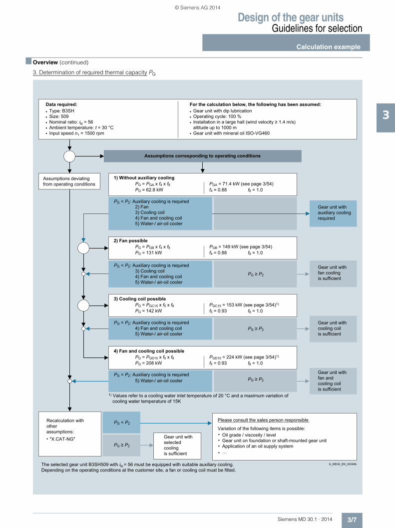
3. Determination of required thermal capacity PG
Assumptions deviatingfrom operating conditions
f8 = 1.0PGD15 = 224 kW (see page 3/54)1)
f5 = 0.93
Gear unit withfan andcooling coilis sufficient
5) Water-/ air-oil cooler
Variation of the following items is possible:
Please consult the sales person responsiblePG < P2
G_MD30_EN_00049bThe selected gear unit B3SH509 with iN = 56 must be equipped with suitable auxiliary cooling.Depending on the operating conditions at the customer site, a fan or cooling coil must be fitted.
"X.CAT-NG"
Recalculation withotherassumptions:
Oil grade / viscosity / levelGear unit on foundation or shaft-mounted gear unitApplication of an oil supply system…
Gear unit withselectedcoolingis sufficient
PG ≥ P2
PG ≥ P2
1) Values refer to a cooling water inlet temperature of 20 °C and a maximum variation of cooling water temperature of 15K
PG < P2: Auxiliary cooling is required
PG = PGD15 x f5 x f8PG = 208 kW
4) Fan and cooling coil possible
f8 = 1.0PGC15 = 153 kW (see page 3/54)1)
f5 = 0.93
Gear unit withcooling coilis sufficient
4) Fan and cooling coil5) Water-/ air-oil cooler
PG ≥ P2
PG < P2: Auxiliary cooling is required
PG = PGC15 x f5 x f8PG = 142 kW
3) Cooling coil possible
f8 = 1.0PGB = 149 kW (see page 3/54) f4 = 0.88
Gear unit withfan coolingis sufficient
3) Cooling coil4) Fan and cooling coil5) Water-/ air-oil cooler
PG ≥ P2
PG < P2: Auxiliary cooling is required
PG = PGB x f4 x f8PG = 131 kW
2) Fan possible
f8 = 1.0PGA = 71.4 kW (see page 3/54)f4 = 0.88
Gear unit withauxiliary coolingrequired
2) Fan3) Cooling coil4) Fan and cooling coil5) Water-/ air-oil cooler
PG < P2: Auxiliary cooling is required
PG = PGA x f4 x f8PG = 62.8 kW
Gear unit with dip lubricationOperating cycle: 100 %Installation in a large hall (wind velocity ≥ 1.4 m/s) altitude up to 1000 mGear unit with mineral oil ISO-VG460
For the calculation below, the following has been assumed:
Assumptions corresponding to operating conditions
1) Without auxiliary cooling
Type: B3SHSize: 509Nominal ratio: iN = 56Ambient temperature: t = 30 °CInput speed n1 = 1500 rpm
Data required:
© Siemens AG 2014

Design of the gear unitsGuidelines for selection
Service factors
3/8 Siemens MD 30.1 · 2014
3
■ Overview
Factor for driven machines f1
Note: The listed load parameters are empirical values. Prerequisite for their application is that the machinery and equipment men-tioned correspond to generally accepted design and load specifi-cations. In case of deviations from standard conditions, please contact us. For driven machines which are not listed in this table, please refer to us.
Driven machines Effective operating period under load in hours≤ 0.5 > 0.5 - 10 > 10
Waste water treatment• Thickeners (central drive) – – 1.2• Filter presses 1.0 1.3 1.5• Flocculation apparatus 0.8 1.0 1.3• Aerators – 1.8 2.0• Raking equipment 1.0 1.2 1.3• Combined longitudinal and
rotary rakes1.0 1.3 1.5
• Pre-thickeners – 1.1 1.3• Screw pumps – 1.3 1.5• Water turbines – – 2.0Pumps• Centrifugal pumps 1.0 1.2 1.3• Positive-displacement pumps
- 1 piston 1.3 1.4 1.8- > 1 piston 1.2 1.4 1.5
Dredgers• Bucket conveyors – 1.6 1.6• Dumping devices – 1.3 1.5• Caterpillar traveling gears 1.2 1.6 1.8Bucket wheel excavators
- as pick-up – 1.7 1.7- for primitive material – 2.2 2.2
• Cutter heads – 2.2 2.2• Slewing gears 1) – 1.4 1.8Plate bending machines 1) – 1.0 1.0Chemical Industry• Extruders – – 1.6• Dough mills – 1.8 1.8• Rubber calenders – 1.5 1.5• Cooling drums – 1.3 1.4Mixers for
- uniform media 1.0 1.3 1.4- non-uniform media 1.4 1.6 1.7
Agitators for/media with- uniform density 1.0 1.3 1.5- non-uniform density 1.2 1.4 1.6- non-uniform gas absorption 1.4 1.6 1.8
• Toasters 1.0 1.3 1.5• Centrifuges 1.0 1.2 1.3Metal working mills• Plate tilters 1.0 1.0 1.2• Ingot pushers 1.0 1.2 1.2• Winding machines – 1.6 1.6• Cooling bed transfer frames – 1.5 1.5• Roller straighteners – 1.6 1.6Roller tables
- continuous – 1.5 1.5- intermittent – 2.0 2.0
• Reversing tube mills – 1.8 1.8Shears
- continuous 1) – 1.5 1.5- crank type 1) 1.0 1.0 1.0
• Continuous casting drivers 1) – 1.4 1.4
Design for power rating of driven machine P21) Designed power corresponding to max. torque2) Load can be exactly classified, for instance, according to FEM 10013) A check for thermal capacity is absolutely essential
Driven machines Effective operating period under load in hours≤ 0.5 > 0.5 - 10 > 10
Rolls- Reversing blooming mills – 2.5 2.5- Reversing slabbing mills – 2.5 2.5- Reversing wire mills – 1.8 1.8- Reversing sheet mills – 2.0 2.0- Reversing plate mills – 1.8 1.8
• Roll adjustment drives 0.9 1.0 –Conveyors• Bucket conveyors – 1.4 1.5• Hauling winches 1.4 1.6 1.6• Hoists – 1.5 1.8• Belt conveyors ≤ 150 kW 1.0 1.2 1.3• Belt conveyors ≥ 150 kW 1.1 1.3 1.4• Goods lifts 1) – 1.2 1.5• Passenger lifts 1) – 1.5 1.8• Apron conveyors – 1.2 1.5• Escalators 1.0 1.2 1.4• Railway vehicles – 1.5 –Frequency converter, electromechanical – 1.8 2.0Reciprocating compressors – 1.8 1.9Cranes 2)
• Slewing gears 1) 1.0 1.4 1.8• Luffing gears On request • Traveling gears On request • Hoisting gears On request • Derricking jib cranes On request Cooling towers• Cooling tower fans – – 2.0• Blowers (axial and radial) – 1.4 1.5Food industryCane sugar production• Cane knives 1) – – 1.7• Cane mills – – 1.7Beet sugar production• Beet cossettes macerators – – 1.2• Extraction plants, mechanical
refrigerators, juice boilers– – 1.4
• Sugar beet washing machines, sugar beet cutters
– – 1.5
Paper machines• Of all kinds 3) – 1.8 2.0• Pulper drives (on request)Centrifugal compressors – 1.4 1.5Cableways• Material ropeways – 1.3 1.4• To-and-fro system aerial ropeways – 1.6 1.8• T-bar lifts – 1.3 1.4• Continuous ropeways – 1.4 1.6Cement industry• Concrete mixers – 1.5 1.5• Breakers 1) – 1.2 1.4• Rotary kilns – – 2.0• Tube mills – – 2.0• Separators – 1.6 1.6• Roll crushers – – 2.0
© Siemens AG 2014

Design of the gear unitsGuidelines for selection
Service factors
3/9Siemens MD 30.1 · 2014
3
■ Overview (continued)
Factor for prime mover f2
Peak torque factor f3
Thermal factor f4(Gear units without auxiliary cooling or with fan)
Thermal factor f5(For cooling with cooling coil, or with fan and cooling coil)
Oil supply factor f8
Factor for prime mover f2Electric motors, hydraulic motors, turbines
1.0
Piston engines 4 - 6 cylinders, cyclic variation 1 : 100 to 1 : 200
1.25
Piston engines 1 - 3 cylinders,cyclic variation 1 : 100
1.5
Peak torque factor f3Load peaks per hour1 - 5 6 - 30 31 - 100 > 100
Steady direction of load 0.5 0.65 0.7 0.85
Alternating direction of load 0.7 0.95 1.10 1.25
Ambient temperature
10 °C 15 °C 20 °C 25 °C 30 °C 35 °C 40 °C 45 °C 50 °C
Thermal factor f4
1.11 1.06 1.00 0.94 0.88 0.82 0.75 0.69 0.63
Ambient temperature
10 °C 15 °C 20 °C 25 °C 30 °C 35 °C 40 °C 45 °C 50 °C
Thermal factor f5
1.05 1.03 1.00 0.97 0.93 0.90 0.87 0.84 0.81
Oil supply
Type Oil supply factor f8
Without auxiliary cooling
Withfan
With cooling coil
With fan and cool-ing coil
Dip lubri-cation 1)
H..H, B..H 1 1 1 1
H..V, B..V 0.95 0.95 0.95 0.95
H..L, B..L 0.95 0.95 0.95 0.95
1) In combination with shaft seals or taconite. Values of >1 are possible and available on request with oil circulation lubrication or dip lubrication combined with labyrinth seals.
© Siemens AG 2014

Design of the gear unitsOverview tablesType H1 Nominal power ratings, gear unit sizes 503 to 510
3/10 Siemens MD 30.1 · 2014
3
■ Technical specifications
Nominal power ratings P2N (kW) type H1
Gear unit sizesiN n1 n2 503 504 505 506 507 508 509 510
1.12 1800 1607 496 909 1380 – 2474 – 3870 –1500 1339 414 757 1150 – 2061 – 3225 –1200 1071 331 606 920 – 1649 – 2579 –1000 893 276 505 767 – 1375 – 2151 –
1.25 1800 1440 467 859 1297 – 2413 – 3770 –1500 1200 390 716 1081 – 2010 – 3141 –1200 960 312 573 865 – 1608 – 2513 –1000 800 260 477 720 – 1340 – 2094 –
1.32 1800 1364 – – – – – 2614 – 39991500 1136 – – – – – 2177 – 33311200 909 – – – – – 1742 – 26651000 758 – – – – – 1453 – 2222
1.4 1800 1286 438 794 1225 1481 2249 – 3501 –1500 1071 364 662 1021 1234 1873 – 2916 –1200 857 292 529 817 987 1499 – 2333 –1000 714 243 441 680 822 1249 – 1944 –
1.5 1800 1200 – – – – – 2463 – 37701500 1000 – – – – – 2052 – 31411200 800 – – – – – 1642 – 25131000 667 – – – – – 1369 – 2095
1.6 1800 1125 401 730 1131 1366 2085 – 3298 –1500 938 334 609 943 1139 1738 – 2750 –1200 750 267 487 754 911 1390 – 2199 –1000 625 223 406 628 759 1158 – 1832 –
1.7 1800 1059 – – – – – 2251 – 34381500 882 – – – – – 1875 – 28631200 706 – – – – – 1501 – 22921000 588 – – – – – 1250 – 1909
1.8 1800 1000 356 649 1026 1267 2010 – 3351 –1500 833 297 541 855 1055 1675 – 2791 –1200 667 237 433 684 845 1341 – 2235 –1000 556 198 361 571 704 1118 – 1863 –
1.9 1800 947 – – – – – 2162 – 32721500 789 – – – – – 1801 – 27261200 632 – – – – – 1443 – 21841000 526 – – – – – 1201 – 1818
2 1800 900 320 584 924 1197 1809 – 3025 –1500 750 267 487 770 997 1508 – 2521 –1200 600 214 390 616 798 1206 – 2017 –1000 500 178 325 513 665 1005 – 1681 –
2.12 1800 849 – – – – – 2134 – 35561500 708 – – – – – 1779 – 29651200 566 – – – – – 1422 – 23711000 472 – – – – – 1186 – 1977
2.24 1800 804 286 522 825 1120 1616 – 2702 –1500 670 239 435 688 933 1347 – 2252 –1200 536 191 348 550 746 1078 – 1802 –1000 446 159 290 458 621 897 – 1499 –
2.36 1800 763 – – – – – 1997 – 32361500 636 – – – – – 1665 – 26971200 508 – – – – – 1330 – 21541000 424 – – – – – 1110 – 1798
2.5 1800 720 256 467 739 1003 1448 – 2428 –1500 600 214 390 616 836 1206 – 2023 –1200 480 171 312 493 668 965 – 1618 –1000 400 142 260 410 557 804 – 1349 –
© Siemens AG 2014

Design of the gear unitsOverview tables
Type H1Nominal power ratings, gear unit sizes 503 to 510
3/11Siemens MD 30.1 · 2014
3
■ Technical specifications (continued)
Nominal power ratings P2N (kW) type H1 (continued)
Gear unit sizesiN n1 n2 503 504 505 506 507 508 509 510
2.65 1800 679 – – – – – 1777 – 29581500 566 – – – – – 1482 – 24661200 453 – – – – – 1186 – 19731000 377 – – – – – 987 – 1642
2.8 1800 643 229 417 660 895 1293 – 2175 –1500 536 191 348 550 746 1078 – 1813 –1200 429 153 279 440 597 862 – 1451 –1000 357 127 232 366 497 718 – 1207 –
3 1800 600 – – – – – 1571 – 26141500 500 – – – – – 1309 – 21781200 400 – – – – – 1047 – 17421000 333 – – – – – 872 – 1451
3.15 1800 571 203 371 586 795 1148 – 1931 –1500 476 169 309 488 663 957 – 1610 –1200 381 136 247 391 531 766 – 1289 –1000 317 113 206 325 441 637 – 1072 –
3.35 1800 537 – – – – – 1406 – 23391500 448 – – – – – 1173 – 19511200 358 – – – – – 937 – 15591000 299 – – – – – 783 – 1302
3.55 1800 507 181 329 520 706 1019 – 1715 –1500 423 151 275 434 589 850 – 1431 –1200 338 120 219 347 471 680 – 1143 –1000 282 100 183 289 393 567 – 954 –
3.75 1800 480 – – – – – 1257 – 20911500 400 – – – – – 1047 – 17421200 320 – – – – – 838 – 13941000 267 – – – – – 699 – 1163
4 1800 450 160 292 462 627 905 – 1522 –1500 375 134 243 385 522 754 – 1268 –1200 300 107 195 308 418 603 – 1015 –1000 250 89 162 257 348 503 – 846 –
4.25 1800 424 – – – – – 1110 – 18471500 353 – – – – – 924 – 15381200 282 – – – – – 738 – 12281000 235 – – – – – 615 – 1024
4.5 1800 400 134 260 410 557 775 – 1173 –1500 333 112 216 342 464 645 – 976 –1200 267 89 173 274 372 517 – 783 –1000 222 74 144 228 309 430 – 651 –
4.75 1800 379 – – – – – 937 – 16271500 316 – – – – – 781 – 13571200 253 – – – – – 625 – 10861000 211 – – – – – 521 – 906
5 1800 360 113 234 358 501 660 – 905 –1500 300 94 195 298 418 550 – 754 –1200 240 75 156 239 334 440 – 603 –1000 200 63 130 199 279 366 – 503 –
5.3 1800 340 – – – – – 801 – 11391500 283 – – – – – 667 – 9481200 226 – – – – – 532 – 7571000 189 – – – – – 445 – 633
5.6 1800 321 94 205 306 417 571 – 689 –1500 268 79 171 255 348 477 – 575 –1200 214 63 137 204 278 381 – 459 –1000 179 52 114 171 232 319 – 384 –
6 1800 300 – – – – – 660 – 9271500 250 – – – – – 550 – 7721200 200 – – – – – 440 – 6181000 167 – – – – – 367 – 516
© Siemens AG 2014

Design of the gear unitsOverview tablesType H1 – Nominal output torques Gear unit sizes 503 to 510
3/12 Siemens MD 30.1 · 2014
3
■ Technical specifications (continued)
Nominal output torques T2N (kNm) type H1
Gear unit sizesiN 503 504 505 506 507 508 509 510 511 512 513 514 Type
1.12 2.95 5.4 8.2 – 14.7 – 23 – – – – –
H1
1.25 3.1 5.7 8.6 – 16 – 25 – – – – –1.32 – – – – – 18.3 – 28 – – – –1.4 3.25 5.9 9.1 11 16.7 – 26 – – – – –1.5 – – – – – 19.6 – 30 – – – –1.6 3.4 6.2 9.6 11.6 17.7 – 28 – – – – –1.7 – – – – – 20.3 – 31 – – – –1.8 3.4 6.2 9.8 12.1 19.2 – 32 – – – – –1.9 – – – – – 21.8 – 33 – – – –2 3.4 6.2 9.8 12.7 19.2 – 32.1 – – – – –2.12 – – – – – 24 – 40 – – – –2.24 3.4 6.2 9.8 13.3 19.2 – 32.1 – – – – –2.36 – – – – – 25 – 40.5 – – – –2.5 3.4 6.2 9.8 13.3 19.2 – 32.2 – – – – –2.65 – – – – – 25 – 41.6 – – – –2.8 3.4 6.2 9.8 13.3 19.2 – 32.3 – – – – –3 – – – – – 25 – 41.6 – – – –3.15 3.4 6.2 9.8 13.3 19.2 – 32.3 – – – – –3.35 – – – – – 25 – 41.6 – – – –3.55 3.4 6.2 9.8 13.3 19.2 – 32.3 – – – – –3.75 – – – – – 25 – 41.6 – – – –4 3.4 6.2 9.8 13.3 19.2 – 32.3 – – – – –4.25 – – – – – 25 – 41.6 – – – –4.5 3.2 6.2 9.8 13.3 18.5 – 28 – – – – –4.75 – – – – – 23.6 – 41 – – – –5 3 6.2 9.5 13.3 17.5 – 24 – – – – –5.3 – – – – – 22.5 – 32 – – – –5.6 2.8 6.1 9.1 12.4 17 – 20.5 – – – – –6 – – – – – 21 – 29.5 – – – –6.3 – 7 11.6 – 21.5 – 37 – 63.5 – 101.5 –
H2
7.1 – 7 11.6 – 21.5 – 37 – 63.5 – 101.5 –8 – 7 11.6 – 21.5 28.3 37 48.5 63.5 81 101.5 1259 – 7 11.6 16.2 21.5 28.3 37 48.5 63.5 81 101.5 125
10 – 7 11.6 16.2 21.5 28.3 37 48.5 63.5 81 101.5 12511.2 – 7 11.6 16.2 21.5 28.3 37 48.5 63.5 81 101.5 12512.5 – 7 11.6 16.2 21.5 28.3 37 48.5 63.5 81 101.5 12514 – 7 11.6 16.2 21.5 28.3 37 48.5 63.5 81 101.5 12516 – 7 11.6 16.2 21.5 28.3 37 48.5 63.5 81 101.5 12518 – 7 11.6 16.2 21.5 28.3 37 48.5 63.5 81 101.5 12520 – 7 11.6 16.2 21.5 28.3 37 48.5 63.5 81 101.5 12522.4 – – 11.6 16.2 21.5 28.3 37 48.5 63.5 81 101.5 12525 – – 11.6 16.2 21.5 28.3 37 48.5 63.5 81 101.5 125
H3
28 – – 11.6 16.2 21.5 28.3 37 48.5 63.5 81 101.5 12531.5 – – 11.6 16.2 21.5 28.3 37 48.5 63.5 81 101.5 12535.5 – – 11.6 16.2 21.5 28.3 37 48.5 63.5 81 101.5 12540 – – 11.6 16.2 21.5 28.3 37 48.5 63.5 81 101.5 12545 – – 11.6 16.2 21.5 28.3 37 48.5 63.5 81 101.5 12550 – – 11.6 16.2 21.5 28.3 37 48.5 63.5 81 101.5 12556 – – 11.6 16.2 21.5 28.3 37 48.5 63.5 81 101.5 12563 – – 11.6 16.2 21.5 28.3 37 48.5 63.5 81 101.5 12571 – – 11.6 16.2 21.5 28.3 37 48.5 63.5 81 101.5 12580 – – – 16.2 – 28.3 – 48.5 – 81 – 12590 – – – 16.2 – 28.3 – 48.5 – 81 – 125
100 – – – 16.2 – – – – – – – –
Type H2, see page 3/23 Type H3, see page 3/29 Type H4, see page 3/35
© Siemens AG 2014

Design of the gear unitsOverview tables
Type H1 – Nominal output torquesGear unit sizes 503 to 510
3/13Siemens MD 30.1 · 2014
3
■ Technical specifications (continued)
Nominal output torques T2N (kNm) type H1
Gear unit sizesiN 503 504 505 506 507 508 509 510 511 512 513 514 Type80 – – – – 21.5 – 37 – 63.5 – 101.5 –
H4
90 – – – – 21.5 – 37 – 63.5 – 101.5 –100 – – – – 21.5 28.3 37 48.5 63.5 81 101.5 125112 – – – – 21.5 28.3 37 48.5 63.5 81 101.5 125125 – – – – 21.5 28.3 37 48.5 63.5 81 101.5 125140 – – – – 21.5 28.3 37 48.5 63.5 81 101.5 125160 – – – – 21.5 28.3 37 48.5 63.5 81 101.5 125180 – – – – 21.5 28.3 37 48.5 63.5 81 101.5 125200 – – – – 21.5 28.3 37 48.5 63.5 81 101.5 125224 – – – – 21.5 28.3 37 48.5 63.5 81 101.5 125250 – – – – 21.5 28.3 37 48.5 63.5 81 101.5 125280 – – – – 21.5 28.3 37 48.5 63.5 81 101.5 125315 – – – – – 28.3 37 48.5 63.5 81 101.5 125355 – – – – – 28.3 – 48.5 – 81 – 125400 – – – – – – – 48.5 – 81 – 125
Type H2, see page 3/23 Type H3, see page 3/29 Type H4, see page 3/35
© Siemens AG 2014

Design of the gear unitsOverview tables
3/14 Siemens MD 30.1 · 2014
3
■ Technical specifications (continued)
Thermal capacities PG (kW) type H1
Gear unit sizesiN 503 504 505 506 507 508 509 510
1.12 PGA 139 156 102 – * – * –PGB 359 471 592 – 764 – 1046 –PGC15 414 735 743 – 626 – 1314 –PGD15 610 1003 1160 – 1271 – 2138 –
1.25 PGA 143 174 130 – 54.9 – * –PGB 356 478 567 – 806 – 1112 –PGC15 404 732 702 – 675 – 1361 –PGD15 596 992 1077 – 1288 – 2141 –
1.32 PGA – – – – – 131 – *PGB – – – – – 1062 – 1184PGC15 – – – – – 870 – 1424PGD15 – – – – – 1619 – 2288
1.4 PGA 145 182 169 193 122 – 99.9 –PGB 349 474 618 749 823 – 1140 –PGC15 389 722 757 883 697 – 1378 –PGD15 572 974 1149 1365 1285 – 2132 –
1.5 PGA – – – – – 213 – 57.7PGB – – – – – 1060 – 1224PGC15 – – – – – 883 – 1445PGD15 – – – – – 1585 – 2256
1.6 PGA 145 185 192 201 189 – 221 –PGB 339 461 617 695 890 – 1148 –PGC15 368 679 748 815 761 – 1371 –PGD15 545 918 1120 1247 1357 – 2075 –
1.7 PGA – – – – – 252 – 165PGB – – – – – 1044 – 1234PGC15 – – – – – 879 – 1451PGD15 – – – – – 1543 – 2230
1.8 PGA 142 186 185 231 239 – 280 –PGB 326 449 554 732 890 – 1142 –PGC15 349 647 670 857 772 – 1354 –PGD15 513 878 993 1298 1332 – 2019 –
1.9 PGA – – – – – 298 – 269PGB – – – – – 1048 – 1226PGC15 – – – – – 893 – 1431PGD15 – – – – – 1532 – 2155
2 PGA 138 182 189 242 257 – 325 –PGB 312 428 537 707 865 – 1123 –PGC15 328 605 651 828 757 – 1328 –PGD15 486 822 959 1241 1283 – 1953 –
2.12 PGA – – – – – 341 – 320PGB – – – – – 1066 – 1204PGC15 – – – – – 919 – 1401PGD15 – – – – – 1540 – 2081
2.24 PGA 142 164 202 226 268 – 350 –PGB 314 374 548 628 835 – 1086 –PGC15 325 517 664 736 738 – 1282 –PGD15 483 701 969 1092 1230 – 1865 –
2.36 PGA – – – – – 345 – 358PGB – – – – – 1016 – 1172PGC15 – – – – – 883 – 1363PGD15 – – – – – 1461 – 1999
2.5 PGA 134 185 196 224 272 – 363 –PGB 294 418 514 602 799 – 1035 –PGC15 300 568 625 709 712 – 1224 –PGD15 447 774 909 1046 1171 – 1761 –
For notes and legend for tables, see page 3/5
Type H1 – Thermal capacities n1 = 1000 rpm
© Siemens AG 2014

Design of the gear unitsOverview tables
3/15Siemens MD 30.1 · 2014
3
■ Technical specifications (continued)
Thermal capacities PG (kW) type H1 (continued)
Gear unit sizesiN 503 504 505 506 507 508 509 510
2.65 PGA – – – – – 324 – 379PGB – – – – – 909 – 1127PGC15 – – – – – 797 – 1310PGD15 – – – – – 1304 – 1902
2.8 PGA 127 164 187 231 268 – 361 –PGB 277 364 479 601 752 – 973 –PGC15 280 485 586 709 676 – 1152 –PGD15 417 661 844 1036 1097 – 1644 –
3 PGA – – – – – 318 – 385PGB – – – – – 858 – 1069PGC15 – – – – – 757 – 1247PGD15 – – – – – 1227 – 1790
3.15 PGA 113 162 195 220 287 – 406 –PGB 240 350 479 559 759 – 1014 –PGC15 243 453 589 663 689 – 1202 –PGD15 359 620 844 965 1108 – 1696 –
3.35 PGA – – – – – 304 – 380PGB – – – – – 795 – 997PGC15 – – – – – 709 – 1166PGD15 – – – – – 1135 – 1661
3.55 PGA 104 162 170 208 272 – 397 –PGB 219 335 407 517 704 – 952 –PGC15 219 428 504 616 646 – 1135 –PGD15 324 584 715 890 1042 – 1595 –
3.75 PGA – – – – – 299 – 423PGB – – – – – 768 – 1029PGC15 – – – – – 689 – 1206PGD15 – – – – – 1104 – 1706
4 PGA 104 149 172 216 259 – 368 –PGB 215 304 404 519 656 – 853 –PGC15 212 382 493 624 608 – 1025 –PGD15 315 520 701 894 975 – 1431 –
4.25 PGA – – – – – 281 – 409PGB – – – – – 723 – 961PGC15 – – – – – 653 – 1134PGD15 – – – – – 1059 – 1595
4.5 PGA 101 135 168 188 250 – 383 –PGB 203 277 379 443 644 – 840 –PGC15 199 340 456 534 599 – 1013 –PGD15 293 469 645 762 960 – 1400 –
4.75 PGA – – – – – 266 – 377PGB – – – – – 670 – 860PGC15 – – – – – 610 – 1013PGD15 – – – – – 979 – 1422
5 PGA 94.7 120 157 187 227 – 345 –PGB 192 245 357 433 575 – 756 –PGC15 185 298 420 526 542 – 913 –PGD15 274 410 600 745 862 – 1254 –
5.3 PGA – – – – – 260 – 394PGB – – – – – 660 – 858PGC15 – – – – – 606 – 994PGD15 – – – – – 975 – 1390
5.6 PGA 89.6 119 144 177 204 – 327 –PGB 180 239 323 395 509 – 703 –PGC15 171 284 375 481 484 – 858 –PGD15 256 393 537 675 763 – 1169 –
6 PGA – – – – – 236 – 357PGB – – – – – 589 – 772PGC15 – – – – – 547 – 882PGD15 – – – – – 870 – 1232
Type H1 – Thermal capacitiesn1 = 1000 rpm
© Siemens AG 2014

Design of the gear unitsOverview tables
3/16 Siemens MD 30.1 · 2014
3
■ Technical specifications (continued)
Thermal capacities PG (kW) type H1
Gear unit sizesiN 503 504 505 506 507 508 509 510
1.12 PGA 119 96.9 * – * – * –PGB 391 492 602 – 756 – 994 –PGC15 440 719 687 – 495 – 1138 –PGD15 680 1050 1199 – 1295 – 2177 –
1.25 PGA 127 130 25.2 – * – * –PGB 391 507 582 – 830 – 1108 –PGC15 433 727 659 – 583 – 1245 –PGD15 667 1048 1121 – 1338 – 2217 –
1.32 PGA – – – – – * – *PGB – – – – – 1106 – 1140PGC15 – – – – – 771 – 1249PGD15 – – – – – 1702 – 2342
1.4 PGA 134 146 84.8 91.8 * – * –PGB 385 510 647 785 858 – 1166 –PGC15 418 721 723 839 622 – 1291 –PGD15 642 1032 1203 1432 1346 – 2227 –
1.5 PGA – – – – – 16.8 – *PGB – – – – – 1128 – 1234PGC15 – – – – – 816 – 1332PGD15 – – – – – 1683 – 2349
1.6 PGA 138 160 133 121 28.2 – * –PGB 377 500 657 734 931 – 1207 –PGC15 398 699 729 783 691 – 1320 –PGD15 613 991 1184 1314 1426 – 2190 –
1.7 PGA – – – – – 98.8 – *PGB – – – – – 1117 – 1268PGC15 – – – – – 824 – 1367PGD15 – – – – – 1644 – 2336
1.8 PGA 136 166 144 164 115 – 73.9 –PGB 364 490 597 779 934 – 1207 –PGC15 379 681 660 833 715 – 1317 –PGD15 582 961 1055 1371 1404 – 2141 –
1.9 PGA – – – – – 175 – *PGB – – – – – 1122 – 1291PGC15 – – – – – 847 – 1383PGD15 – – – – – 1632 – 2276
2 PGA 134 166 159 193 165 – 160 –PGB 352 470 585 765 922 – 1187 –PGC15 361 653 649 818 718 – 1294 –PGD15 558 916 1024 1320 1364 – 2069 –
2.12 PGA – – – – – 233 – 120PGB – – – – – 1143 – 1274PGC15 – – – – – 880 – 1367PGD15 – – – – – 1644 – 2209
2.24 PGA 141 152 176 190 198 – 213 –PGB 352 412 599 683 900 – 1149 –PGC15 354 561 667 733 713 – 1256 –PGD15 547 789 1041 1168 1316 – 1976 –
2.36 PGA – – – – – 263 – 199PGB – – – – – 1100 – 1243PGC15 – – – – – 860 – 1335PGD15 – – – – – 1568 – 2121
2.5 PGA 134 175 177 196 219 – 263 –PGB 330 461 566 660 867 – 1110 –PGC15 328 616 631 711 699 – 1215 –PGD15 506 868 977 1123 1260 – 1879 –
For notes and legend for tables, see page 3/5
Type H1 – Thermal capacities n1 = 1200 rpm
© Siemens AG 2014

Design of the gear unitsOverview tables
3/17Siemens MD 30.1 · 2014
3
■ Technical specifications (continued)
Thermal capacities PG (kW) type H1 (continued)
Gear unit sizesiN 503 504 505 506 507 508 509 510
2.65 PGA – – – – – 267 – 246PGB – – – – – 993 – 1197PGC15 – – – – – 786 – 1291PGD15 – – – – – 1407 – 2020
2.8 PGA 128 157 173 209 229 – 290 –PGB 311 402 529 660 823 – 1053 –PGC15 306 526 594 717 671 – 1159 –PGD15 473 743 911 1118 1185 – 1763 –
3 PGA – – – – – 275 – 289PGB – – – – – 940 – 1147PGC15 – – – – – 757 – 1241PGD15 – – – – – 1330 – 1910
3.15 PGA 115 159 185 204 263 – 366 –PGB 271 388 532 618 839 – 1116 –PGC15 267 494 602 673 694 – 1231 –PGD15 409 699 911 1041 1206 – 1843 –
3.35 PGA – – – – – 273 – 311PGB – – – – – 877 – 1082PGC15 – – – – – 713 – 1174PGD15 – – – – – 1236 – 1782
3.55 PGA 106 163 164 196 258 – 369 –PGB 247 376 455 573 783 – 1059 –PGC15 239 472 517 627 654 – 1172 –PGD15 369 660 775 964 1134 – 1733 –
3.75 PGA – – – – – 278 – 384PGB – – – – – 851 – 1140PGC15 – – – – – 697 – 1240PGD15 – – – – – 1207 – 1854
4 PGA 106 151 168 209 250 – 350 –PGB 243 342 451 578 731 – 950 –PGC15 233 419 518 638 618 – 1062 –PGD15 358 589 770 967 1063 – 1557 –
4.25 PGA – – – – – 270 – 382PGB – – – – – 804 – 1068PGC15 – – – – – 662 – 1168PGD15 – – – – – 1152 – 1734
4.5 PGA 106 135 168 183 239 – 382 –PGB 231 310 425 493 713 – 942 –PGC15 219 375 491 549 608 – 1058 –PGD15 335 530 720 827 1044 – 1531 –
4.75 PGA – – – – – 258 – 362PGB – – – – – 745 – 958PGC15 – – – – – 621 – 1058PGD15 – – – – – 1069 – 1557
5 PGA 97.8 121 156 185 219 – 344 –PGB 217 274 400 484 640 – 847 –PGC15 203 326 461 542 551 – 954 –PGD15 312 463 678 811 935 – 1370 –
5.3 PGA – – – – – 249 – 396PGB – – – – – 733 – 961PGC15 – – – – – 615 – 1067PGD15 – – – – – 1059 – 1547
5.6 PGA 92.8 121 144 179 198 – 329 –PGB 204 269 364 444 567 – 791 –PGC15 188 312 411 500 493 – 898 –PGD15 291 446 608 738 832 – 1281 –
6 PGA – – – – – 228 – 356PGB – – – – – 655 – 866PGC15 – – – – – 556 – 963PGD15 – – – – – 949 – 1384
Type H1 – Thermal capacitiesn1 = 1200 rpm
© Siemens AG 2014

Design of the gear unitsOverview tables
3/18 Siemens MD 30.1 · 2014
3
■ Technical specifications (continued)
Thermal capacities PG (kW) type H1
Gear unit sizesiN 503 504 505 506 507 508 509 510
1.12 PGA 71 * * – * – * –PGB 423 507 598 – 665 – 741 –PGC15 464 676 579 – 171 – 671 –PGD15 770 1103 1234 – 1257 – 2087 –
1.25 PGA 87.4 30.3 * – * – * –PGB 428 531 596 – 803 – 987 –PGC15 462 693 581 – 367 – 924 –PGD15 759 1104 1170 – 1353 – 2218 –
1.32 PGA – – – – – * – *PGB – – – – – 1088 – 906PGC15 – – – – – 511 – 778PGD15 – – – – – 1737 – 2270
1.4 PGA 106 58.9 * * * – * –PGB 429 538 672 817 859 – 1105 –PGC15 450 693 655 755 450 – 1043 –PGD15 735 1092 1265 1506 1384 – 2274 –
1.5 PGA – – – – – * – *PGB – – – – – 1157 – 1119PGC15 – – – – – 633 – 1005PGD15 – – – – – 1758 – 2356
1.6 PGA 117 98.6 * * * – * –PGB 424 539 689 778 961 – 1211 –PGC15 432 684 673 722 549 – 1153 –PGD15 705 1060 1253 1395 1492 – 2282 –
1.7 PGA – – – – – * – *PGB – – – – – 1171 – 1217PGC15 – – – – – 684 – 1114PGD15 – – – – – 1742 – 2389
1.8 PGA 119 116 41.3 32.2 * – * –PGB 412 534 632 835 991 – 1243 –PGC15 415 674 620 779 611 – 1190 –PGD15 673 1034 1121 1462 1488 – 2254 –
1.9 PGA – – – – – * – *PGB – – – – – 1200 – 1299PGC15 – – – – – 740 – 1215PGD15 – – – – – 1750 – 2380
2 PGA 121 126 73 84.5 * – * –PGB 399 517 627 821 981 – 1246 –PGC15 397 651 618 774 630 – 1204 –PGD15 645 988 1096 1412 1452 – 2199 –
2.12 PGA – – – – – * – *PGB – – – – – 1240 – 1316PGC15 – – – – – 800 – 1242PGD15 – – – – – 1777 – 2329
2.24 PGA 131 124 115 106 19.4 – * –PGB 403 458 655 737 961 – 1227 –PGC15 391 577 648 702 638 – 1195 –PGD15 634 864 1121 1254 1407 – 2118 –
2.36 PGA – – – – – 74.1 – *PGB – – – – – 1193 – 1303PGC15 – – – – – 791 – 1246PGD15 – – – – – 1697 – 2258
2.5 PGA 128 148 129 127 70.7 – 16.1 –PGB 379 515 624 720 932 – 1188 –PGC15 363 651 622 689 636 – 1167 –PGD15 588 970 1059 1210 1350 – 2017 –
For notes and legend for tables, see page 3/5
Type H1 – Thermal capacities n1 = 1500 rpm
© Siemens AG 2014

Design of the gear unitsOverview tables
3/19Siemens MD 30.1 · 2014
3
■ Technical specifications (continued)
Thermal capacities PG (kW) type H1 (continued)
Gear unit sizesiN 503 504 505 506 507 508 509 510
2.65 PGA – – – – – 124 – *PGB – – – – – 1080 – 1277PGC15 – – – – – 734 – 1230PGD15 – – – – – 1526 – 2165
2.8 PGA 124 137 136 156 123 – 96.6 –PGB 358 453 588 729 895 – 1129 –PGC15 338 574 591 703 629 – 1119 –PGD15 549 848 991 1211 1282 – 1890 –
3 PGA – – – – – 157 – 45.7PGB – – – – – 1026 – 1230PGC15 – – – – – 711 – 1195PGD15 – – – – – 1443 – 2050
3.15 PGA 114 146 158 163 196 – 251 –PGB 313 438 598 686 929 – 1220 –PGC15 297 546 606 668 675 – 1219 –PGD15 477 804 997 1133 1320 – 2016 –
3.35 PGA – – – – – 186 – 124PGB – – – – – 967 – 1162PGC15 – – – – – 686 – 1139PGD15 – – – – – 1349 – 1919
3.55 PGA 106 159 145 164 208 – 285 –PGB 286 429 513 640 878 – 1175 –PGC15 266 526 524 628 650 – 1183 –PGD15 430 766 851 1051 1249 – 1908 –
3.75 PGA – – – – – 220 – 272PGB – – – – – 947 – 1249PGC15 – – – – – 682 – 1233PGD15 – – – – – 1325 – 2027
4 PGA 107 149 154 184 218 – 294 –PGB 281 391 511 651 823 – 1072 –PGC15 259 469 528 645 618 – 1090 –PGD15 418 687 848 1063 1170 – 1717 –
4.25 PGA – – – – – 230 – 301PGB – – – – – 900 – 1192PGC15 – – – – – 658 – 1186PGD15 – – – – – 1269 – 1904
4.5 PGA 110 132 162 167 209 – 358 –PGB 270 354 488 560 802 – 1076 –PGC15 248 416 507 559 603 – 1104 –PGD15 393 616 798 908 1149 – 1700 –
4.75 PGA – – – – – 231 – 307PGB – – – – – 839 – 1079PGC15 – – – – – 620 – 1086PGD15 – – – – – 1180 – 1717
5 PGA 101 119 149 173 195 – 320 –PGB 252 314 456 551 719 – 962 –PGC15 227 364 479 554 550 – 990 –PGD15 366 538 754 894 1032 – 1522 –
5.3 PGA – – – – – 220 – 374PGB – – – – – 822 – 1095PGC15 – – – – – 611 – 1111PGD15 – – – – – 1166 – 1717
5.6 PGA 95.6 119 139 175 178 – 315 –PGB 238 309 416 510 639 – 901 –PGC15 211 349 441 518 495 – 940 –PGD15 342 518 689 818 917 – 1424 –
6 PGA – – – – – 203 – 335PGB – – – – – 737 – 984PGC15 – – – – – 556 – 1004PGD15 – – – – – 1046 – 1538
Type H1 – Thermal capacitiesn1 = 1500 rpm
© Siemens AG 2014

Design of the gear unitsOverview tables
3/20 Siemens MD 30.1 · 2014
3
■ Technical specifications (continued)
Thermal capacities PG (kW) type H1
Gear unit sizesiN 503 504 505 506 507 508 509 510
1.12 PGA 4.1 * * – * – * –PGB 446 506 548 – 449 – 113 –PGC15 477 612 422 – 449 – 113 –PGD15 844 1132 1220 – 1111 – 1790 –
1.25 PGA 27.2 * * – * – * –PGB 452 546 575 – 685 – 653 –PGC15 477 646 465 – 588 – 310 –PGD15 835 1149 1182 – 1283 – 2062 –
1.32 PGA – – – – – * – *PGB – – – – – 954 – 282PGC15 – – – – – 714 – 281PGD15 – – – – – 1665 – 1979
1.4 PGA 58.1 * * * * – * –PGB 458 559 670 806 790 – 891 –PGC15 468 656 556 622 162 – 595 –PGD15 811 1141 1291 1532 1355 – 2185 –
1.5 PGA – – – – – * – *PGB – – – – – 1098 – 794PGC15 – – – – – 302 – 372PGD15 – – – – – 1751 – 2207
1.6 PGA 83.8 12.3 * * * – * –PGB 458 564 710 788 926 – 1105 –PGC15 456 653 601 623 329 – 859 –PGD15 783 1109 1299 1433 1494 – 2275 –
1.7 PGA – – – – – * – *PGB – – – – – 1147 – 1001PGC15 – – – – – 442 – 654PGD15 – – – – – 1760 – 2304
1.8 PGA 90.7 38.7 * * * – * –PGB 448 560 663 858 993 – 1189 –PGC15 438 647 570 696 453 – 967 –PGD15 752 1084 1176 1518 1527 – 2285 –
1.9 PGA – – – – – * – *PGB – – – – – 1207 – 1196PGC15 – – – – – 556 – 913PGD15 – – – – – 1799 – 2374
2 PGA 98.1 61.9 * * * – * –PGB 437 546 661 860 1000 – 1231 –PGC15 420 630 573 713 503 – 1032 –PGD15 715 1041 1150 1476 1502 – 2256 –
2.12 PGA – – – – – * – *PGB – – – – – 1278 – 1262PGC15 – – – – – 658 – 1011PGD15 – – – – – 1850 – 2363
2.24 PGA 112 78.8 19.4 * * – * –PGB 447 489 687 783 995 – 1241 –PGC15 422 566 606 660 535 – 1066 –PGD15 713 916 1175 1322 1464 – 2196 –
2.36 PGA – – – – – * – *PGB – – – – – 1244 – 1293PGC15 – – – – – 678 – 1071PGD15 – – – – – 1778 – 2317
2.5 PGA 112 106 50.8 34.5 * – * –PGB 420 555 658 765 977 – 1220 –PGC15 390 643 589 652 556 – 1070 –PGD15 662 1031 1115 1277 1420 – 2104 –
For notes and legend for tables, see page 3/5
Type H1 – Thermal capacities n1 = 1800 rpm
© Siemens AG 2014

Design of the gear unitsOverview tables
3/21Siemens MD 30.1 · 2014
3
■ Technical specifications (continued)
Thermal capacities PG (kW) type H1 (continued)
Gear unit sizesiN 503 504 505 506 507 508 509 510
2.65 PGA – – – – – * – *PGB – – – – – 1136 – 1291PGC15 – – – – – 652 – 1099PGD15 – – – – – 1609 – 2245
2.8 PGA 112 106 77.1 73.4 * – * –PGB 398 490 628 773 938 – 1178 –PGC15 365 571 569 669 558 – 1050 –PGD15 619 903 1050 1278 1349 – 1990 –
3 PGA – – – – – * – *PGB – – – – – 1092 – 1267PGC15 – – – – – 650 – 1098PGD15 – – – – – 1534 – 2147
3.15 PGA 110 123 116 96.2 76.9 – 80.6 –PGB 350 479 645 733 984 – 1298 –PGC15 322 561 593 642 621 – 1179 –PGD15 539 873 1062 1200 1396 – 2139 –
3.35 PGA – – – – – 35.8 – *PGB – – – – – 1028 – 1209PGC15 – – – – – 630 – 1070PGD15 – – – – – 1434 – 2018
3.55 PGA 103 148 115 113 128 – 145 –PGB 320 474 557 689 947 – 1248 –PGC15 289 555 519 611 617 – 1149 –PGD15 486 843 912 1120 1336 – 2038 –
3.75 PGA – – – – – 118 – 103PGB – – – – – 1009 – 1326PGC15 – – – – – 637 – 1194PGD15 – – – – – 1409 – 2160
4 PGA 105 141 130 146 157 – 191 –PGB 316 434 560 706 893 – 1149 –PGC15 281 512 527 635 601 – 1070 –PGD15 473 771 910 1137 1256 – 1841 –
4.25 PGA – – – – – 156 – 168PGB – – – – – 970 – 1268PGC15 – – – – – 631 – 1156PGD15 – – – – – 1355 – 2034
4.5 PGA 112 123 149 139 147 – 306 –PGB 306 393 540 610 865 – 1181 –PGC15 272 453 514 555 582 – 1119 –PGD15 448 691 864 975 1228 – 1841 –
4.75 PGA – – – – – 180 – 207PGB – – – – – 908 – 1164PGC15 – – – – – 604 – 1075PGD15 – – – – – 1262 – 1839
5 PGA 101 111 134 151 152 – 273 –PGB 284 348 503 605 780 – 1049 –PGC15 247 396 484 556 534 – 1001 –PGD15 416 605 815 962 1105 – 1641 –
5.3 PGA – – – – – 169 – 322PGB – – – – – 888 – 1202PGC15 – – – – – 590 – 1131PGD15 – – – – – 1246 – 1855
5.6 PGA 96 113 127 164 146 – 280 –PGB 268 344 460 564 695 – 990 –PGC15 229 380 447 528 484 – 957 –PGD15 387 585 744 888 986 – 1545 –
6 PGA – – – – – 166 – 287PGB – – – – – 799 – 1074PGC15 – – – – – 540 – 1015PGD15 – – – – – 1122 – 1661
Type H1 – Thermal capacitiesn1 = 1800 rpm
© Siemens AG 2014

Design of the gear unitsOverview tablesType H2 Nominal power ratings, gear unit sizes 504 to 514
3/22 Siemens MD 30.1 · 2014
3
■ Technical specifications
Nominal power ratings P2N (kW) type H2
Gear unit sizes
iN n1 n2 504 505 506 507 508 509 510 511 512 513 514
6.3 1800 286 208 343 – 648 – 1084 – 1851 – 3037 –1500 238 173 286 – 540 – 903 – 1543 – 2531 –1200 190 138 229 – 432 – 723 – 1234 – 2024 –1000 159 115 191 – 360 – 602 – 1028 – 1687 –
7.1 1800 254 184 311 – 585 – 982 – 1672 – 2733 –1500 211 153 259 – 487 – 818 – 1393 – 2277 –1200 169 123 207 – 390 – 655 – 1115 – 1822 –1000 141 102 173 – 325 – 546 – 929 – 1518 –
8 1800 225 167 270 – 517 672 855 1127 1505 1912 2450 29411500 188 139 225 – 431 560 712 939 1254 1593 2042 24511200 150 111 180 – 345 448 570 751 1003 1274 1634 19611000 125 93 150 – 287 373 475 626 836 1062 1361 1634
9 1800 200 152 244 346 463 607 766 1020 1348 1727 2186 26471500 167 126 204 289 386 505 639 850 1124 1439 1822 22061200 133 101 163 231 309 404 511 680 899 1151 1458 17651000 111 84 136 192 257 337 426 567 749 959 1215 1471
10 1800 180 135 221 314 414 537 683 888 1202 1554 1939 23731500 150 112 184 262 345 447 570 740 1001 1295 1616 19781200 120 90 147 209 276 358 456 592 801 1036 1293 15821000 100 75 123 174 230 298 380 493 668 863 1077 1319
11.2 1800 161 122 195 272 358 480 602 796 1064 1393 1708 21181500 134 101 163 227 298 400 502 664 887 1160 1424 17651200 107 81 130 182 239 320 401 531 709 928 1139 14121000 89 68 109 151 199 267 334 442 591 774 949 1177
12.5 1800 144 104 175 247 320 429 531 710 924 1241 1518 18791500 120 87 145 206 267 358 443 592 770 1034 1265 15651200 96 70 116 165 213 286 354 473 616 827 1012 12521000 80 58 97 137 178 238 295 394 513 689 844 1044
14 1800 129 94 153 223 284 372 477 625 825 1099 1330 16541500 107 78 127 186 236 310 397 521 688 916 1108 13791200 86 62 102 149 189 248 318 417 550 733 886 11031000 71 52 85 124 158 206 265 347 458 610 739 919
16 1800 113 83 136 198 253 332 429 552 751 954 1171 14711500 94 70 113 165 210 277 358 460 626 795 976 12261200 75 56 90 132 168 221 286 368 501 636 781 9801000 63 46 75 110 140 185 238 307 417 530 651 817
18 1800 100 74 121 176 235 294 382 496 662 852 1093 12881500 83 62 101 147 196 245 318 413 551 710 911 10731200 67 49 81 118 157 196 255 330 441 568 729 8591000 56 41 67 98 130 164 212 275 368 473 607 715
20 1800 90 66 – 154 – 262 – 446 – 776 – 11341500 75 55 – 129 – 218 – 372 – 647 – 9451200 60 44 – 103 – 175 – 297 – 517 – 7561000 50 37 – 86 – 146 – 248 – 431 – 630
22.4 1800 80 – – 137 – 244 – 397 – 683 – 10591500 67 – – 114 – 203 – 331 – 569 – 8821200 54 – – 91 – 162 – 265 – 455 – 7061000 45 – – 76 – 135 – 221 – 379 – 588
25 1800 72 – – 122 – – – – – – – –1500 60 – – 102 – – – – – – – –1200 48 – – 81 – – – – – – – –1000 40 – – 68 – – – – – – – –
© Siemens AG 2014

Design of the gear unitsOverview tables
Type H2 – Nominal output torquesGear unit sizes 504 to 514
3/23Siemens MD 30.1 · 2014
3
■ Technical specifications (continued)
Nominal output torques T2N (kNm) type H2
Gear unit sizesiN 503 504 505 506 507 508 509 510 511 512 513 514 Type
1.12 2.95 5.4 8.2 – 14.7 – 23 – – – – –
H1
1.25 3.1 5.7 8.6 – 16 – 25 – – – – –1.32 – – – – – 18.3 – 28 – – – –1.4 3.25 5.9 9.1 11 16.7 – 26 – – – – –1.5 – – – – – 19.6 – 30 – – – –1.6 3.4 6.2 9.6 11.6 17.7 – 28 – – – – –1.7 – – – – – 20.3 – 31 – – – –1.8 3.4 6.2 9.8 12.1 19.2 – 32 – – – – –1.9 – – – – – 21.8 – 33 – – – –2 3.4 6.2 9.8 12.7 19.2 – 32.1 – – – – –2.12 – – – – – 24 – 40 – – – –2.24 3.4 6.2 9.8 13.3 19.2 – 32.1 – – – – –2.36 – – – – – 25 – 40.5 – – – –2.5 3.4 6.2 9.8 13.3 19.2 – 32.2 – – – – –2.65 – – – – – 25 – 41.6 – – – –2.8 3.4 6.2 9.8 13.3 19.2 – 32.3 – – – – –3 – – – – – 25 – 41.6 – – – –3.15 3.4 6.2 9.8 13.3 19.2 – 32.3 – – – – –3.35 – – – – – 25 – 41.6 – – – –3.55 3.4 6.2 9.8 13.3 19.2 – 32.3 – – – – –3.75 – – – – – 25 – 41.6 – – – –4 3.4 6.2 9.8 13.3 19.2 – 32.3 – – – – –4.25 – – – – – 25 – 41.6 – – – –4.5 3.2 6.2 9.8 13.3 18.5 – 28 – – – – –4.75 – – – – – 23.6 – 41 – – – –5 3 6.2 9.5 13.3 17.5 – 24 – – – – –5.3 – – – – – 22.5 – 32 – – – –5.6 2.8 6.1 9.1 12.4 17 – 20.5 – – – – –6 – – – – – 21 – 29.5 – – – –6.3 – 7 11.6 – 21.5 – 37 – 63.5 – 101.5 –
H2
7.1 – 7 11.6 – 21.5 – 37 – 63.5 – 101.5 –8 – 7 11.6 – 21.5 28.3 37 48.5 63.5 81 101.5 1259 – 7 11.6 16.2 21.5 28.3 37 48.5 63.5 81 101.5 125
10 – 7 11.6 16.2 21.5 28.3 37 48.5 63.5 81 101.5 12511.2 – 7 11.6 16.2 21.5 28.3 37 48.5 63.5 81 101.5 12512.5 – 7 11.6 16.2 21.5 28.3 37 48.5 63.5 81 101.5 12514 – 7 11.6 16.2 21.5 28.3 37 48.5 63.5 81 101.5 12516 – 7 11.6 16.2 21.5 28.3 37 48.5 63.5 81 101.5 12518 – 7 11.6 16.2 21.5 28.3 37 48.5 63.5 81 101.5 12520 – 7 11.6 16.2 21.5 28.3 37 48.5 63.5 81 101.5 12522.4 – – 11.6 16.2 21.5 28.3 37 48.5 63.5 81 101.5 12525 – – 11.6 16.2 21.5 28.3 37 48.5 63.5 81 101.5 125
H3
28 – – 11.6 16.2 21.5 28.3 37 48.5 63.5 81 101.5 12531.5 – – 11.6 16.2 21.5 28.3 37 48.5 63.5 81 101.5 12535.5 – – 11.6 16.2 21.5 28.3 37 48.5 63.5 81 101.5 12540 – – 11.6 16.2 21.5 28.3 37 48.5 63.5 81 101.5 12545 – – 11.6 16.2 21.5 28.3 37 48.5 63.5 81 101.5 12550 – – 11.6 16.2 21.5 28.3 37 48.5 63.5 81 101.5 12556 – – 11.6 16.2 21.5 28.3 37 48.5 63.5 81 101.5 12563 – – 11.6 16.2 21.5 28.3 37 48.5 63.5 81 101.5 12571 – – 11.6 16.2 21.5 28.3 37 48.5 63.5 81 101.5 12580 – – – 16.2 – 28.3 – 48.5 – 81 – 12590 – – – 16.2 – 28.3 – 48.5 – 81 – 125
100 – – – 16.2 – – – – – – – –
Type H1, see page 3/12 Type H3, see page 3/29 Type H4, see page 3/35
© Siemens AG 2014
Design of the gear unitsOverview tables
3/24 Siemens MD 30.1 · 2014
3
■ Technical specifications (continued)
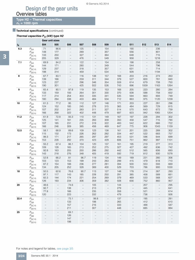
Thermal capacities PG (kW) type H2
Gear unit sizes
iN 504 505 506 507 508 509 510 511 512 513 514
6.3 PGA 71 86.6 – 125 – 154 – 190 – 236 –PGB 148 177 – 289 – 357 – 556 – 801 –PGC15 133 250 – 327 – 364 – 648 – 715 –PGD15 205 329 – 476 – 549 – 958 – 1218 –
7.1 PGA 69.9 84.2 – 122 – 154 – 198 – 258 –PGB 144 171 – 280 – 349 – 544 – 796 –PGC15 129 237 – 318 – 357 – 631 – 714 –PGD15 198 314 – 459 – 534 – 928 – 1194 –
8 PGA 67.7 83.1 – 116 138 157 168 203 216 273 263PGB 139 166 – 259 311 344 379 527 600 781 840PGC15 123 227 – 296 346 354 559 614 679 708 750PGD15 190 301 – 425 502 526 743 896 1009 1163 1264
9 PGA 65.4 80.1 97.8 119 135 153 168 205 223 280 284PGB 133 159 193 264 301 330 370 508 588 758 832PGC15 117 214 254 303 335 341 535 594 663 693 749PGD15 180 284 338 433 484 504 712 863 975 1120 1239
10 PGA 61.3 77.2 95 112 127 148 171 203 227 281 296PGB 124 152 185 245 278 315 365 484 569 729 815PGC15 107 202 241 283 311 327 514 570 643 672 739PGD15 166 268 322 402 448 479 687 823 942 1065 1204
11.2 PGA 61.9 72.8 93.3 110 131 149 167 197 228 294 302PGB 125 141 181 235 283 309 350 458 547 715 790PGC15 107 185 231 272 319 322 483 542 622 666 722PGD15 166 246 309 385 456 469 647 775 906 1043 1159
12.5 PGA 58.1 68.9 89.6 109 123 138 161 201 225 289 302PGB 115 132 173 226 262 282 334 447 522 683 757PGC15 99.3 171 217 265 297 297 453 531 596 644 699PGD15 153 228 292 370 423 429 606 751 862 997 1101
14 PGA 55.2 67.4 86.1 104 120 137 161 195 219 277 313PGB 109 128 165 213 252 275 327 427 492 636 742PGC15 92.8 163 205 250 286 292 442 512 565 606 693PGD15 143 218 276 348 405 419 592 719 812 930 1078
16 PGA 52.8 66.2 81 96.7 119 134 149 189 221 280 306PGB 103 123 153 199 243 263 299 415 479 618 710PGC15 87.2 154 188 236 277 281 394 500 553 593 669PGD15 134 205 252 328 389 400 529 703 786 900 1030
18 PGA 50.5 62.6 76.6 90.7 113 127 148 178 214 267 293PGB 97.1 117 143 185 228 250 291 385 458 589 661PGC15 82.3 144 174 221 254 269 379 469 533 568 627PGD15 126 193 234 306 359 382 508 656 752 860 957
20 PGA 48.6 – 74.6 – 105 – 144 – 207 – 295PGB 92.7 – 138 – 213 – 279 – 445 – 641PGC15 77.8 – 166 – 235 – 358 – 521 – 614PGD15 120 – 223 – 332 – 479 – 736 – 926
22.4 PGA – – 73.1 – 98.8 – 137 – 195 – 281PGB – – 133 – 198 – 265 – 412 – 610PGC15 – – 157 – 216 – 333 – 488 – 587PGD15 – – 211 – 307 – 448 – 685 – 884
25 PGA – – 69.1 – – – – – – – –PGB – – 126 – – – – – – – –PGC15 – – 147 – – – – – – – –PGD15 – – 198 – – – – – – – –
For notes and legend for tables, see page 3/5
Type H2 – Thermal capacities n1 = 1000 rpm
© Siemens AG 2014
Design of the gear unitsOverview tables
3/25Siemens MD 30.1 · 2014
3
■ Technical specifications (continued)
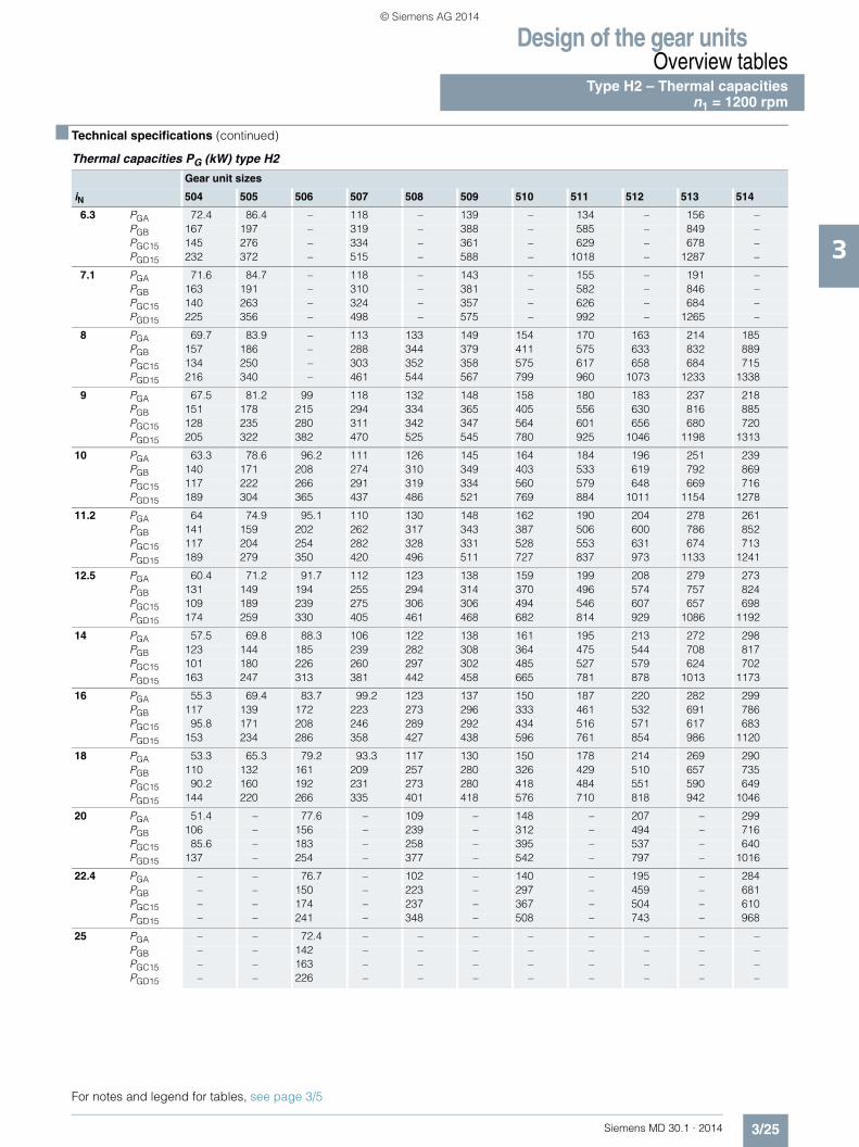
Thermal capacities PG (kW) type H2
Gear unit sizes
iN 504 505 506 507 508 509 510 511 512 513 514
6.3 PGA 72.4 86.4 – 118 – 139 – 134 – 156 –PGB 167 197 – 319 – 388 – 585 – 849 –PGC15 145 276 – 334 – 361 – 629 – 678 –PGD15 232 372 – 515 – 588 – 1018 – 1287 –
7.1 PGA 71.6 84.7 – 118 – 143 – 155 – 191 –PGB 163 191 – 310 – 381 – 582 – 846 –PGC15 140 263 – 324 – 357 – 626 – 684 –PGD15 225 356 – 498 – 575 – 992 – 1265 –
8 PGA 69.7 83.9 – 113 133 149 154 170 163 214 185PGB 157 186 – 288 344 379 411 575 633 832 889PGC15 134 250 – 303 352 358 575 617 658 684 715PGD15 216 340 – 461 544 567 799 960 1073 1233 1338
9 PGA 67.5 81.2 99 118 132 148 158 180 183 237 218PGB 151 178 215 294 334 365 405 556 630 816 885PGC15 128 235 280 311 342 347 564 601 656 680 720PGD15 205 322 382 470 525 545 780 925 1046 1198 1313
10 PGA 63.3 78.6 96.2 111 126 145 164 184 196 251 239PGB 140 171 208 274 310 349 403 533 619 792 869PGC15 117 222 266 291 319 334 560 579 648 669 716PGD15 189 304 365 437 486 521 769 884 1011 1154 1278
11.2 PGA 64 74.9 95.1 110 130 148 162 190 204 278 261PGB 141 159 202 262 317 343 387 506 600 786 852PGC15 117 204 254 282 328 331 528 553 631 674 713PGD15 189 279 350 420 496 511 727 837 973 1133 1241
12.5 PGA 60.4 71.2 91.7 112 123 138 159 199 208 279 273PGB 131 149 194 255 294 314 370 496 574 757 824PGC15 109 189 239 275 306 306 494 546 607 657 698PGD15 174 259 330 405 461 468 682 814 929 1086 1192
14 PGA 57.5 69.8 88.3 106 122 138 161 195 213 272 298PGB 123 144 185 239 282 308 364 475 544 708 817PGC15 101 180 226 260 297 302 485 527 579 624 702PGD15 163 247 313 381 442 458 665 781 878 1013 1173
16 PGA 55.3 69.4 83.7 99.2 123 137 150 187 220 282 299PGB 117 139 172 223 273 296 333 461 532 691 786PGC15 95.8 171 208 246 289 292 434 516 571 617 683PGD15 153 234 286 358 427 438 596 761 854 986 1120
18 PGA 53.3 65.3 79.2 93.3 117 130 150 178 214 269 290PGB 110 132 161 209 257 280 326 429 510 657 735PGC15 90.2 160 192 231 273 280 418 484 551 590 649PGD15 144 220 266 335 401 418 576 710 818 942 1046
20 PGA 51.4 – 77.6 – 109 – 148 – 207 – 299PGB 106 – 156 – 239 – 312 – 494 – 716PGC15 85.6 – 183 – 258 – 395 – 537 – 640PGD15 137 – 254 – 377 – 542 – 797 – 1016
22.4 PGA – – 76.7 – 102 – 140 – 195 – 284PGB – – 150 – 223 – 297 – 459 – 681PGC15 – – 174 – 237 – 367 – 504 – 610PGD15 – – 241 – 348 – 508 – 743 – 968
25 PGA – – 72.4 – – – – – – – –PGB – – 142 – – – – – – – –PGC15 – – 163 – – – – – – – –PGD15 – – 226 – – – – – – – –
For notes and legend for tables, see page 3/5
Type H2 – Thermal capacitiesn1 = 1200 rpm
© Siemens AG 2014

Design of the gear unitsOverview tables
3/26 Siemens MD 30.1 · 2014
3
■ Technical specifications (continued)
Thermal capacities PG (kW) type H2
Gear unit sizes
iN 504 505 506 507 508 509 510 511 512 513 514
6.3 PGA 70.4 81.3 – 100 – 99.5 – 29.5 – * –PGB 192 224 – 356 – 418 – 615 – 877 –PGC15 160 287 – 332 – 343 – 586 – 584 –PGD15 271 410 – 562 – 631 – 1081 – 1344 –
7.1 PGA 71.5 81.8 – 104 – 112 – 66 – 46.1 –PGB 189 217 – 347 – 416 – 617 – 889 –PGC15 155 278 – 326 – 344 – 591 – 615 –PGD15 263 397 – 545 – 621 – 1062 – 1336 –
8 PGA 70.5 82.5 – 103 115 127 116 94.7 62.5 103 *PGB 182 213 – 325 384 419 446 612 670 890 922PGC15 148 274 – 307 351 352 571 591 617 634 623PGD15 252 389 – 507 594 619 858 1032 1137 1316 1399
9 PGA 68.7 80.6 94.4 110 118 132 127 116 97.8 146 76.5PGB 175 204 245 332 375 407 443 603 668 877 933PGC15 142 264 303 317 344 345 564 585 621 640 652PGD15 241 373 434 519 576 597 839 997 1117 1283 1388
10 PGA 64.7 78.2 94.3 106 116 133 142 136 124 175 133PGB 163 195 238 310 349 391 446 587 661 854 931PGC15 130 250 293 298 324 336 567 577 620 637 668PGD15 222 354 419 483 536 572 832 959 1092 1238 1366
11.2 PGA 65.8 75.7 95 108 123 140 146 157 144 228 172PGB 164 183 231 300 358 388 432 561 650 861 915PGC15 129 230 286 291 334 336 550 556 615 661 673PGD15 221 325 407 464 548 563 801 910 1055 1231 1330
12.5 PGA 62.7 72.4 92.1 113 118 134 147 184 161 244 199PGB 153 173 222 293 333 356 416 558 635 838 889PGC15 121 213 269 287 314 313 530 558 606 654 668PGD15 205 302 385 451 510 518 766 892 1011 1192 1282
14 PGA 59.9 71.7 89 108 119 135 154 187 180 249 252PGB 144 167 213 276 322 350 411 536 606 794 896PGC15 113 203 254 272 306 310 526 542 584 630 691PGD15 192 289 364 425 490 508 752 858 956 1120 1274
16 PGA 57.9 72.8 85.7 99.9 124 138 146 178 207 275 266PGB 137 162 198 257 314 339 378 519 599 784 871PGC15 107 195 233 257 302 303 483 528 584 635 683PGD15 180 274 334 400 475 489 688 836 937 1093 1231
18 PGA 56.4 68.1 81.5 94.2 119 130 148 171 209 260 269PGB 129 153 186 240 295 321 371 484 575 744 823PGC15 101 181 216 241 286 290 468 497 567 608 655PGD15 170 257 310 374 447 466 665 781 901 1043 1155
20 PGA 54.5 – 80.4 – 110 – 149 – 199 – 293PGB 124 – 181 – 275 – 358 – 557 – 810PGC15 95.8 – 206 – 269 – 446 – 552 – 660PGD15 161 – 297 – 420 – 628 – 877 – 1129
22.4 PGA – – 80.8 – 104 – 141 – 190 – 277PGB – – 175 – 256 – 340 – 519 – 771PGC15 – – 198 – 253 – 413 – 520 – 631PGD15 – – 281 – 392 – 591 – 818 – 1074
25 PGA – – 75.7 – – – – – – – –PGB – – 165 – – – – – – – –PGC15 – – 183 – – – – – – – –PGD15 – – 265 – – – – – – – –
For notes and legend for tables, see page 3/5
Type H2 – Thermal capacities n1 = 1500 rpm
© Siemens AG 2014

Design of the gear unitsOverview tables
3/27Siemens MD 30.1 · 2014
3
■ Technical specifications (continued)
Thermal capacities PG (kW) type H2
Gear unit sizes
iN 504 505 506 507 508 509 510 511 512 513 514
6.3 PGA 65.2 69.9 – 71.9 – 50.7 – * – * –PGB 215 247 – 381 – 442 – 611 – 846 –PGC15 172 292 – 321 – 318 – 510 – 430 –PGD15 306 442 – 597 – 665 – 1102 – 1342 –
7.1 PGA 68.1 72.9 – 80.5 – 70.7 – * – * –PGB 212 240 – 374 – 441 – 624 – 885 –PGC15 167 284 – 318 – 323 – 532 – 498 –PGD15 297 428 – 581 – 656 – 1095 – 1359 –
8 PGA 68.1 77.1 – 85.8 88.2 92.3 67.5 * * * *PGB 205 236 – 352 413 446 472 631 669 903 891PGC15 160 281 – 303 341 334 559 547 542 544 469PGD15 286 419 – 544 633 654 902 1081 1163 1354 1398
9 PGA 67.6 77.1 84.5 95.1 95.8 103 87.3 34.8 * * *PGB 197 227 272 363 403 435 471 628 681 905 928PGC15 153 271 309 315 337 332 556 552 563 573 535PGD15 273 403 468 557 615 635 885 1051 1154 1335 1413
10 PGA 64.6 75.5 86.6 94.4 99.3 112 108 64 28.2 71.4 *PGB 184 218 263 340 380 423 474 616 685 895 948PGC15 140 261 301 298 321 328 561 550 577 589 581PGD15 251 387 453 520 575 612 879 1011 1138 1299 1408
11.2 PGA 66 75.1 89.9 101 109 125 119 99.9 64.8 164 41.1PGB 185 205 258 330 391 422 463 598 680 915 948PGC15 140 246 296 294 333 333 548 544 581 631 609PGD15 250 360 443 503 589 606 849 962 1112 1304 1384
12.5 PGA 63.6 71.9 89.3 110 107 123 126 150 94 188 98.9PGB 172 193 248 326 365 390 449 603 666 893 931PGC15 131 234 286 294 315 312 533 558 577 631 621PGD15 232 341 425 491 550 559 815 953 1070 1264 1345
14 PGA 60.9 71.8 87.5 106 113 128 139 164 127 207 189PGB 163 188 237 307 355 385 448 584 649 851 952PGC15 123 224 275 280 310 312 532 545 576 616 664PGD15 218 327 408 463 530 550 805 919 1017 1199 1349
16 PGA 59.5 75 85.8 97.7 122 134 136 156 175 253 212PGB 155 183 221 286 350 375 414 564 651 853 928PGC15 116 215 258 263 310 309 494 530 587 638 662PGD15 205 312 378 434 517 532 740 893 1003 1184 1307
18 PGA 58.7 69.3 81.7 92.6 118 127 140 156 187 237 227PGB 147 173 209 268 329 356 408 528 628 812 882PGC15 111 200 237 248 294 295 490 502 572 610 644PGD15 194 292 351 407 487 507 727 838 966 1128 1236
20 PGA 56.7 – 81.4 – 108 – 146 – 179 – 273PGB 141 – 203 – 307 – 397 – 607 – 882PGC15 105 – 226 – 276 – 478 – 555 – 664PGD15 184 – 335 – 457 – 699 – 939 – 1220
22.4 PGA – – 83.8 – 102 – 138 – 177 – 256PGB – – 197 – 286 – 376 – 567 – 840PGC15 – – 218 – 260 – 452 – 526 – 634PGD15 – – 320 – 428 – 663 – 879 – 1163
25 PGA – – 77.6 – – – – – – – –PGB – – 186 – – – – – – – –PGC15 – – 203 – – – – – – – –PGD15 – – 300 – – – – – – – –
For notes and legend for tables, see page 3/5
Type H2 – Thermal capacitiesn1 = 1800 rpm
© Siemens AG 2014
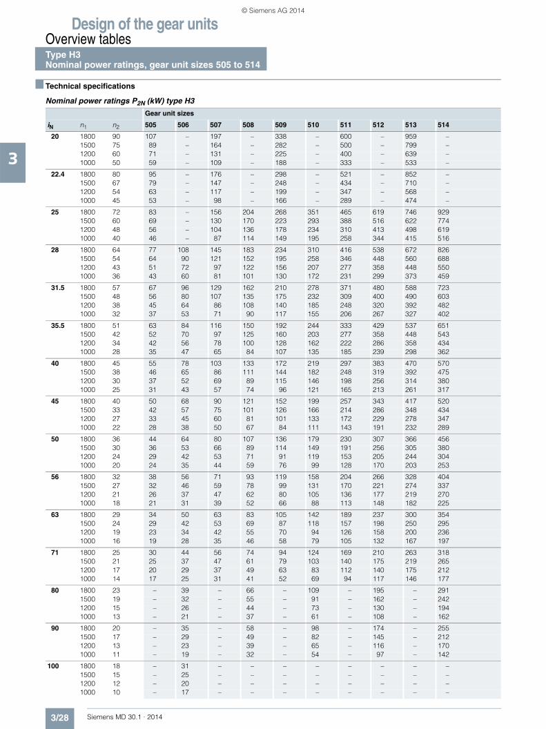
Design of the gear unitsOverview tablesType H3 Nominal power ratings, gear unit sizes 505 to 514
3/28 Siemens MD 30.1 · 2014
3
■ Technical specifications
Nominal power ratings P2N (kW) type H3
Gear unit sizes
iN n1 n2 505 506 507 508 509 510 511 512 513 514
20 1800 90 107 – 197 – 338 – 600 – 959 –1500 75 89 – 164 – 282 – 500 – 799 –1200 60 71 – 131 – 225 – 400 – 639 –1000 50 59 – 109 – 188 – 333 – 533 –
22.4 1800 80 95 – 176 – 298 – 521 – 852 –1500 67 79 – 147 – 248 – 434 – 710 –1200 54 63 – 117 – 199 – 347 – 568 –1000 45 53 – 98 – 166 – 289 – 474 –
25 1800 72 83 – 156 204 268 351 465 619 746 9291500 60 69 – 130 170 223 293 388 516 622 7741200 48 56 – 104 136 178 234 310 413 498 6191000 40 46 – 87 114 149 195 258 344 415 516
28 1800 64 77 108 145 183 234 310 416 538 672 8261500 54 64 90 121 152 195 258 346 448 560 6881200 43 51 72 97 122 156 207 277 358 448 5501000 36 43 60 81 101 130 172 231 299 373 459
31.5 1800 57 67 96 129 162 210 278 371 480 588 7231500 48 56 80 107 135 175 232 309 400 490 6031200 38 45 64 86 108 140 185 248 320 392 4821000 32 37 53 71 90 117 155 206 267 327 402
35.5 1800 51 63 84 116 150 192 244 333 429 537 6511500 42 52 70 97 125 160 203 277 358 448 5431200 34 42 56 78 100 128 162 222 286 358 4341000 28 35 47 65 84 107 135 185 239 298 362
40 1800 45 55 78 103 133 172 219 297 383 470 5701500 38 46 65 86 111 144 182 248 319 392 4751200 30 37 52 69 89 115 146 198 256 314 3801000 25 31 43 57 74 96 121 165 213 261 317
45 1800 40 50 68 90 121 152 199 257 343 417 5201500 33 42 57 75 101 126 166 214 286 348 4341200 27 33 45 60 81 101 133 172 229 278 3471000 22 28 38 50 67 84 111 143 191 232 289
50 1800 36 44 64 80 107 136 179 230 307 366 4561500 30 36 53 66 89 114 149 191 256 305 3801200 24 29 42 53 71 91 119 153 205 244 3041000 20 24 35 44 59 76 99 128 170 203 253
56 1800 32 38 56 71 93 119 158 204 266 328 4041500 27 32 46 59 78 99 131 170 221 274 3371200 21 26 37 47 62 80 105 136 177 219 2701000 18 21 31 39 52 66 88 113 148 182 225
63 1800 29 34 50 63 83 105 142 189 237 300 3541500 24 29 42 53 69 87 118 157 198 250 2951200 19 23 34 42 55 70 94 126 158 200 2361000 16 19 28 35 46 58 79 105 132 167 197
71 1800 25 30 44 56 74 94 124 169 210 263 3181500 21 25 37 47 61 79 103 140 175 219 2651200 17 20 29 37 49 63 83 112 140 175 2121000 14 17 25 31 41 52 69 94 117 146 177
80 1800 23 – 39 – 66 – 109 – 195 – 2911500 19 – 32 – 55 – 91 – 162 – 2421200 15 – 26 – 44 – 73 – 130 – 1941000 13 – 21 – 37 – 61 – 108 – 162
90 1800 20 – 35 – 58 – 98 – 174 – 2551500 17 – 29 – 49 – 82 – 145 – 2121200 13 – 23 – 39 – 65 – 116 – 1701000 11 – 19 – 32 – 54 – 97 – 142
100 1800 18 – 31 – – – – – – – –1500 15 – 25 – – – – – – – –1200 12 – 20 – – – – – – – –1000 10 – 17 – – – – – – – –
© Siemens AG 2014

Design of the gear unitsOverview tables
Type H3 – Nominal output torquesGear unit sizes 505 to 514
3/29Siemens MD 30.1 · 2014
3
■ Technical specifications (continued)
Nominal output torques T2N (kNm) type H3
Gear unit sizesiN 503 504 505 506 507 508 509 510 511 512 513 514 Type
6.3 – 7 11.6 – 21.5 – 37 – 63.5 – 101.5 –
H2
7.1 – 7 11.6 – 21.5 – 37 – 63.5 – 101.5 –8 – 7 11.6 – 21.5 28.3 37 48.5 63.5 81 101.5 1259 – 7 11.6 16.2 21.5 28.3 37 48.5 63.5 81 101.5 125
10 – 7 11.6 16.2 21.5 28.3 37 48.5 63.5 81 101.5 12511.2 – 7 11.6 16.2 21.5 28.3 37 48.5 63.5 81 101.5 12512.5 – 7 11.6 16.2 21.5 28.3 37 48.5 63.5 81 101.5 12514 – 7 11.6 16.2 21.5 28.3 37 48.5 63.5 81 101.5 12516 – 7 11.6 16.2 21.5 28.3 37 48.5 63.5 81 101.5 12518 – 7 11.6 16.2 21.5 28.3 37 48.5 63.5 81 101.5 12520 – 7 11.6 16.2 21.5 28.3 37 48.5 63.5 81 101.5 12522.4 – – 11.6 16.2 21.5 28.3 37 48.5 63.5 81 101.5 12525 – – 11.6 16.2 21.5 28.3 37 48.5 63.5 81 101.5 125
H3
28 – – 11.6 16.2 21.5 28.3 37 48.5 63.5 81 101.5 12531.5 – – 11.6 16.2 21.5 28.3 37 48.5 63.5 81 101.5 12535.5 – – 11.6 16.2 21.5 28.3 37 48.5 63.5 81 101.5 12540 – – 11.6 16.2 21.5 28.3 37 48.5 63.5 81 101.5 12545 – – 11.6 16.2 21.5 28.3 37 48.5 63.5 81 101.5 12550 – – 11.6 16.2 21.5 28.3 37 48.5 63.5 81 101.5 12556 – – 11.6 16.2 21.5 28.3 37 48.5 63.5 81 101.5 12563 – – 11.6 16.2 21.5 28.3 37 48.5 63.5 81 101.5 12571 – – 11.6 16.2 21.5 28.3 37 48.5 63.5 81 101.5 12580 – – – 16.2 21.5 28.3 37 48.5 63.5 81 101.5 12590 – – – 16.2 21.5 28.3 37 48.5 63.5 81 101.5 125
100 – – – 16.2 21.5 28.3 37 48.5 63.5 81 101.5 125
H4
112 – – – – 21.5 28.3 37 48.5 63.5 81 101.5 125125 – – – – 21.5 28.3 37 48.5 63.5 81 101.5 125140 – – – – 21.5 28.3 37 48.5 63.5 81 101.5 125160 – – – – 21.5 28.3 37 48.5 63.5 81 101.5 125180 – – – – 21.5 28.3 37 48.5 63.5 81 101.5 125200 – – – – 21.5 28.3 37 48.5 63.5 81 101.5 125224 – – – – 21.5 28.3 37 48.5 63.5 81 101.5 125250 – – – – 21.5 28.3 37 48.5 63.5 81 101.5 125280 – – – – 21.5 28.3 37 48.5 63.5 81 101.5 125315 – – – – – 28.3 37 48.5 63.5 81 101.5 125355 – – – – – 28.3 – 48.5 – 81 – 125400 – – – – – – – 48.5 – 81 – 125
Type H1, see page 3/12 Type H2, see page 3/23 Type H4, see page 3/35
© Siemens AG 2014

Design of the gear unitsOverview tables
3/30 Siemens MD 30.1 · 2014
3
■ Technical specifications (continued)
Thermal capacities PG (kW) type H3
For notes and legend for tables, see page 3/5
Gear unit sizesiN 505 506 507 508 509 510 511 512 513 514
20 PGA 53.4 – 84 – 112 – 160 – 222 –PGB 83.3 – 137 – 180 – 270 – 395 –PGC15 127 – 199 – 234 – 411 – 467 –PGD15 154 – 245 – 296 – 507 – 620 –
22.4 PGA 51.2 – 80.6 – 105 – 156 – 216 –PGB 79.8 – 131 – 168 – 261 – 382 –PGC15 122 – 190 218 – 397 – 452 –PGD15 147 – 235 – 276 – 490 – 599 –
25 PGA 50 – 77.2 91 103 121 151 172 205 237PGB 78.1 – 125 146 165 191 252 285 363 413PGC15 119 – 182 204 215 303 383 424 429 484PGD15 144 – 225 253 271 365 472 525 568 641
28 PGA 48.4 58.9 75.7 87.3 99.1 113 145 167 208 229PGB 75.1 90.2 122 140 158 178 238 276 361 400PGC15 111 129 179 195 206 282 362 409 428 467PGD15 135 157 220 243 259 340 445 507 563 618
31.5 PGA 47.3 56.2 72.5 83.5 97.8 111 140 162 197 218PGB 73.3 86.3 117 134 155 176 230 267 342 379PGC15 108 123 170 186 203 278 350 395 406 443PGD15 131 150 210 232 255 335 430 488 533 585
35.5 PGA 44.7 55 71.2 82.1 92.4 107 138 155 193 221PGB 69 84.3 114 131 145 167 225 251 330 376PGC15 101 121 166 178 192 256 343 374 395 443PGD15 122 147 204 221 240 310 419 460 516 582
40 PGA 43.7 53.2 68.1 78.4 91 105 133 150 183 209PGB 67.5 81.1 109 125 143 164 217 243 313 356PGC15 98.4 112 158 170 189 252 331 361 374 418PGD15 120 138 195 211 236 305 405 444 488 549
45 PGA 40 51.9 64.1 77.1 83.3 99.2 128 147 177 204PGB 61.1 79.2 101 122 130 154 205 237 297 345PGC15 87 110 146 161 172 232 316 354 359 408PGD15 106 134 179 201 214 281 384 433 466 532
50 PGA 39.2 49.1 61.3 73.6 82 97.8 124 142 168 194PGB 59.8 74.5 96.8 116 128 152 198 229 281 326PGC15 85.1 102 139 154 169 228 306 342 341 386PGD15 103 125 171 192 211 277 372 418 440 503
56 PGA 38.3 48 58.6 69.2 79.7 89.4 119 137 164 187PGB 58 72.9 92 108 123 137 189 216 272 309PGC15 81.9 100 131 142 164 202 292 326 332 370PGD15 99.6 122 160 177 203 245 354 397 428 479
63 PGA 35.7 43.9 56.4 66.2 75.8 88 114 132 162 177PGB 53.5 65.9 87.4 104 116 135 179 209 264 293PGC15 74 88.4 121 135 156 199 279 315 326 351PGD15 89.8 108 149 169 191 241 335 384 417 453
71 PGA 34.9 43 54 63.3 74.6 85.4 111 127 154 173PGB 52.3 64.4 83.6 98.3 114 131 173 199 251 284PGC15 72.3 86.3 116 127 153 189 270 301 308 341PGD15 87.9 106 143 159 189 229 325 365 394 440
80 PGA – 41.9 – 60.8 – 81.1 – 121 – 170PGB – 62.5 – 93.3 – 122 – 188 – 276PGC15 – 83.2 – 118 – 173 – 287 – 335PGD15 – 102 – 147 – 210 – 346 – 429
90 PGA – 39 – 58.3 – 80 – 118 – 162PGB – 57.6 – 89.3 – 121 – 182 – 261PGC15 – 75.1 – 113 – 171 – 278 – 317PGD15 – 91.9 – 141 – 207 – 335 – 406
100 PGA – 38.2 – – – – – – – –PGB – 56.4 – – – – – – – –PGC15 – 73.4 – – – – – – – –PGD15 – 89.8 – – – – – – – –
Type H3 – Thermal capacities n1 = 1000 rpm
© Siemens AG 2014

Design of the gear unitsOverview tables
3/31Siemens MD 30.1 · 2014
3
■ Technical specifications (continued)
Thermal capacities PG (kW) type H3
Gear unit sizesiN 505 506 507 508 509 510 511 512 513 514
20 PGA 55.7 – 87.4 – 115 – 161 – 221 –PGB 93.3 – 153 – 199 – 296 – 433 –PGC15 142 – 209 – 244 – 425 – 483 –PGD15 174 – 267 – 321 – 545 – 670 –
22.4 PGA 53.5 – 84 – 108 – 156 – 215 –PGB 89.3 – 146 – 186 – 286 – 419 –PGC15 135 – 200 – 228 – 411 – 467 –PGD15 167 – 256 – 299 – 526 – 648 –
25 PGA 52.3 – 80.3 94.8 107 124 152 174 205 237PGB 87.1 – 140 164 184 211 277 313 398 453PGC15 132 – 191 218 225 335 397 439 444 501PGD15 163 – 244 279 295 412 508 563 613 693
28 PGA 50.8 61.5 79.1 91 103 116 148 168 211 230PGB 84 101 137 157 175 198 263 303 398 439PGC15 123 143 187 209 215 313 378 425 445 484PGD15 153 178 239 268 281 384 479 544 611 669
31.5 PGA 49.6 58.9 75.8 87.1 101 115 143 163 201 220PGB 82.1 96.3 131 150 173 194 255 293 377 417PGC15 121 137 179 199 212 308 365 411 423 459PGD15 149 170 228 255 277 378 464 525 579 634
35.5 PGA 47.1 57.7 74.7 85.7 96.1 111 142 159 199 225PGB 77.4 94.2 128 146 162 186 249 278 366 416PGC15 112 133 176 196 201 283 359 390 413 462PGD15 139 166 224 250 261 350 453 496 561 631
40 PGA 46 55.8 71.5 82.1 94.6 109 137 153 189 214PGB 75.6 90.7 122 140 160 183 241 268 347 395PGC15 110 125 169 187 198 279 347 377 391 437PGD15 136 156 214 238 256 344 438 479 532 597
45 PGA 42.3 54.6 67.6 81 87.3 103 133 152 184 211PGB 68.6 88.6 114 137 145 172 228 262 331 381PGC15 96.7 122 159 178 181 257 332 370 377 427PGD15 120 152 200 228 233 318 416 468 507 579
50 PGA 41.5 51.8 64.7 77.3 86 102 129 147 175 200PGB 67.1 83.5 109 130 143 169 221 254 314 362PGC15 94.8 113 152 170 178 253 321 358 358 404PGD15 117 142 192 218 229 313 402 452 481 548
56 PGA 40.5 50.5 61.8 73.2 84 93.8 124 142 172 195PGB 65.2 81.6 104 122 138 153 211 240 304 344PGC15 91.2 111 145 156 173 224 307 342 349 389PGD15 113 139 182 200 222 277 384 430 466 522
63 PGA 38 46.3 59.7 70 80.5 92.4 120 138 171 185PGB 60.2 73.8 98.5 116 130 151 200 232 296 326PGC15 82.1 98.1 134 149 165 221 294 331 344 369PGD15 102 123 169 192 209 273 364 415 456 496
71 PGA 37.2 45.4 57.3 66.8 79.2 90 117 133 162 181PGB 59 72.4 94.4 111 128 146 194 222 281 317PGC15 80.4 96 129 141 162 210 284 317 326 360PGD15 100 120 162 180 206 260 353 396 431 480
80 PGA – 44.4 – 64.5 – 86.3 – 128 – 180PGB – 70.2 – 105 – 137 – 211 – 309PGC15 – 92.6 – 131 – 193 – 303 – 354PGD15 – 116 – 167 – 239 – 376 – 469
90 PGA – 41.6 – 61.9 – 84.7 – 124 – 171PGB – 64.8 – 101 – 135 – 204 – 292PGC15 – 83.5 – 125 – 189 – 293 – 335PGD15 – 105 – 160 – 235 – 363 – 444
100 PGA – 40.6 – – – – – – – –PGB – 63.5 – – – – – – – –PGC15 – 81.8 – – – – – – – –PGD15 – 102 – – – – – – – –
For notes and legend for tables, see page 3/5
Type H3 – Thermal capacitiesn1 = 1200 rpm
© Siemens AG 2014

Design of the gear unitsOverview tables
3/32 Siemens MD 30.1 · 2014
3
■ Technical specifications (continued)
Thermal capacities PG (kW) type H3
Gear unit sizesiN 505 506 507 508 509 510 511 512 513 514
20 PGA 58 – 90.4 – 116 – 155 – 208 –PGB 107 – 174 – 225 – 327 – 476 –PGC15 160 – 220 – 255 – 438 – 493 –PGD15 204 – 296 – 353 – 591 – 728 –
22.4 PGA 55.7 – 87.1 – 109 – 152 – 204 –PGB 102 – 168 – 210 – 318 – 462 –PGC15 153 – 211 – 239 – 425 – 478 –PGD15 194 – 283 – 330 – 572 – 704 –
25 PGA 54.5 – 83.6 98.5 108 126 148 169 196 226PGB 99.7 – 161 187 208 239 307 346 439 500PGC15 150 – 202 230 235 381 410 454 456 513PGD15 190 – 270 310 325 478 552 612 670 754
28 PGA 53.1 64.4 82.8 94.9 106 118 147 165 209 221PGB 96.3 115 157 180 199 223 295 336 444 484PGC15 140 162 198 220 226 355 393 440 462 497PGD15 178 207 265 297 311 445 524 592 670 730
31.5 PGA 52.1 61.6 79.2 90.9 105 117 143 160 200 212PGB 94.3 110 150 172 196 220 286 325 422 461PGC15 137 155 190 211 223 348 381 425 439 473PGD15 174 198 253 283 306 438 507 571 636 693
35.5 PGA 49.6 60.3 78.3 89.9 99.9 115 145 159 201 224PGB 89 108 147 168 185 211 281 312 411 465PGC15 127 152 187 207 212 320 376 407 432 479PGD15 162 194 248 277 289 405 497 542 618 693
40 PGA 48.6 58.8 75.1 86 98.5 113 140 154 191 214PGB 87 104 140 161 182 208 271 301 390 441PGC15 124 141 179 198 208 316 364 394 410 455PGD15 159 182 237 265 284 399 480 525 586 657
45 PGA 44.9 57.5 71.6 85.1 91.5 108 138 156 191 214PGB 79.1 102 131 157 166 196 260 296 374 430PGC15 111 138 170 196 191 292 350 388 398 447PGD15 141 178 223 260 259 369 458 514 562 638
50 PGA 44 54.7 68.6 81.6 90.2 106 134 151 181 204PGB 77.4 96 126 150 163 193 250 286 356 406PGC15 108 129 162 187 188 287 338 376 378 424PGD15 138 166 213 248 255 363 442 497 533 605
56 PGA 43.1 53.5 65.9 77.6 88.7 98.5 130 148 180 202PGB 75.4 93.7 120 140 158 176 240 273 347 391PGC15 104 126 155 177 184 255 325 361 369 411PGD15 133 162 203 233 247 322 423 473 518 580
63 PGA 40.8 49.4 64.1 74.2 86 97 127 143 181 192PGB 70 85.2 114 134 150 172 229 264 338 371PGC15 94.1 111 150 169 176 252 312 349 366 390PGD15 120 143 195 223 234 319 403 457 507 549
71 PGA 39.9 48.2 61.3 71.3 84.7 95.2 123 139 172 190PGB 68.4 83.3 110 128 147 167 222 252 321 360PGC15 92 109 144 159 173 238 302 335 347 382PGD15 117 140 187 210 230 303 390 437 480 533
80 PGA – 47.3 – 69.2 – 92.1 – 135 – 191PGB – 81 – 122 – 158 – 241 – 352PGC15 – 105 – 148 – 220 – 322 – 377PGD15 – 136 – 196 – 278 – 416 – 523
90 PGA – 44.7 – 66.2 – 90.8 – 131 – 181PGB – 75.2 – 117 – 156 – 233 – 334PGC15 – 95.3 – 142 – 216 – 311 – 358PGD15 – 123 – 187 – 275 – 403 – 494
100 PGA – 43.8 – – – – – – – –PGB – 73.5 – – – – – – – –PGC15 – 93 – – – – – – – –PGD15 – 120 – – – – – – – –
For notes and legend for tables, see page 3/5
Type H3 – Thermal capacities n1 = 1500 rpm
© Siemens AG 2014

Design of the gear unitsOverview tables
3/33Siemens MD 30.1 · 2014
3
■ Technical specifications (continued)
Thermal capacities PG (kW) type H3
Gear unit sizesiN 505 506 507 508 509 510 511 512 513 514
20 PGA 59 – 90.4 – 111 – 141 – 188 –PGB 119 – 194 – 246 – 350 – 508 –PGC15 177 – 228 – 261 – 443 – 495 –PGD15 230 – 321 – 381 – 626 – 775 –
22.4 PGA 56.8 – 87.3 – 106 – 140 – 187 –PGB 114 – 186 – 231 – 341 – 495 –PGC15 170 – 219 – 245 – 430 – 482 –PGD15 220 – 308 – 357 – 607 – 751 –
25 PGA 55.6 – 84.2 99 105 122 138 157 182 208PGB 111 – 179 208 228 261 330 372 472 535PGC15 166 – 210 239 242 401 417 460 459 517PGD15 215 – 294 336 351 519 587 650 714 804
28 PGA 54.7 65.9 84.7 95.8 107 116 142 154 198 206PGB 108 129 176 199 220 246 320 361 478 520PGC15 155 179 207 229 234 375 402 447 469 502PGD15 202 234 288 322 337 485 560 630 716 778
31.5 PGA 53.6 63.1 81.4 92 106 115 138 151 190 199PGB 105 123 168 191 217 242 310 349 454 495PGC15 153 171 198 219 230 370 390 432 447 479PGD15 198 224 275 308 331 478 542 609 680 739
35.5 PGA 51.2 61.9 81 92.3 101 116 143 154 196 215PGB 99.7 120 164 187 205 233 307 338 446 501PGC15 141 167 196 216 219 355 388 417 442 489PGD15 184 219 270 302 314 456 534 580 664 742
40 PGA 50.2 60.6 77.4 88.5 100 115 138 150 187 206PGB 97.6 117 157 180 202 229 297 327 423 475PGC15 138 156 187 207 216 349 375 403 420 464PGD15 180 206 258 288 309 449 516 561 630 703
45 PGA 46.8 59.3 74.3 88.1 94.3 110 139 154 192 210PGB 89 114 147 176 184 216 285 324 410 466PGC15 122 153 178 204 200 322 363 401 412 459PGD15 160 201 243 283 282 416 493 552 606 686
50 PGA 45.9 56.7 71.3 84.2 92.8 108 135 150 183 201PGB 87 108 141 168 181 214 276 313 389 442PGC15 120 143 170 195 197 319 351 388 392 436PGD15 156 188 233 271 277 410 476 534 575 650
56 PGA 45.2 55.5 68.9 80.7 91.9 102 133 150 183 204PGB 84.8 105 135 158 176 195 266 301 381 427PGC15 116 139 163 186 192 283 339 375 385 426PGD15 151 183 222 255 269 365 457 510 561 626
63 PGA 43 51.6 67.5 77.4 90.1 100 132 145 188 195PGB 78.9 95.7 129 151 168 192 255 291 375 406PGC15 105 123 158 177 185 278 328 363 384 405PGD15 137 163 213 243 256 359 437 493 552 592
71 PGA 42.1 50.5 64.7 74.6 88.9 98.8 128 142 178 195PGB 77.2 93.6 123 143 165 186 246 279 355 397PGC15 102 121 151 170 182 265 317 349 364 398PGD15 133 160 204 232 252 342 423 473 522 579
80 PGA – 49.6 – 73 – 96.8 – 141 – 199PGB – 91.4 – 137 – 177 – 268 – 390PGC15 – 117 – 164 – 244 – 338 – 396PGD15 – 154 – 222 – 316 – 451 – 568
90 PGA – 47.1 – 70 – 95.4 – 136 – 189PGB – 84.8 – 132 – 175 – 259 – 370PGC15 – 106 – 157 – 240 – 327 – 376PGD15 – 140 – 213 – 311 – 437 – 538
100 PGA – 46.2 – – – – – – – –PGB – 83 – – – – – – – –PGC15 – 104 – – – – – – – –PGD15 – 137 – – – – – – – –
For notes and legend for tables, see page 3/5
Type H3 – Thermal capacitiesn1 = 1800 rpm
© Siemens AG 2014

Design of the gear unitsOverview tablesType H4 Nominal power ratings, gear unit sizes 507 to 514
3/34 Siemens MD 30.1 · 2014
3
■ Technical specifications
Nominal power ratings P2N (kW) type H4
Gear unit sizes
iN n1 n2 507 508 509 510 511 512 513 514
80 1800 23 50 – 83 – 142 – 233 –1500 19 41 – 69 – 118 – 194 –1200 15 33 – 56 – 94 – 155 –1000 13 28 – 46 – 79 – 129 –
90 1800 20 44 – 74 – 126 – 205 –1500 17 37 – 62 – 105 – 171 –1200 13 30 – 50 – 84 – 137 –1000 11 25 – 41 – 70 – 114 –
100 1800 18 40 52 65 87 112 146 184 2251500 15 33 43 54 72 93 122 154 1881200 12 27 34 43 58 75 97 123 1501000 10 22 29 36 48 62 81 102 125
112 1800 16 35 46 60 77 104 130 161 1991500 13 30 38 50 64 87 109 134 1661200 11 24 31 40 52 69 87 108 1331000 9 20 26 33 43 58 72 90 110
125 1800 14 32 41 53 68 92 116 145 1781500 12 27 34 44 56 77 96 121 1491200 10 22 28 35 45 62 77 97 1191000 8 18 23 29 38 51 64 80 99
140 1800 13 29 37 49 62 83 108 132 1561500 11 24 31 41 52 70 90 110 1301200 9 19 25 33 42 56 72 88 1041000 7 16 20 27 35 46 60 73 87
160 1800 11 26 34 43 55 74 95 119 1401500 9 22 28 36 46 62 79 99 1171200 8 17 22 29 36 49 64 79 931000 6 14 19 24 30 41 53 66 78
180 1800 10 23 30 39 51 64 86 104 1281500 8 19 25 33 43 54 72 87 1071200 7 15 20 26 34 43 58 70 851000 6 13 17 22 28 36 48 58 71
200 1800 9 20 27 34 45 57 77 94 1151500 8 17 22 28 37 48 64 78 961200 6 13 18 23 30 38 51 63 771000 5 11 15 19 25 32 43 52 64
224 1800 8 18 24 30 41 51 67 82 1011500 7 15 20 25 34 42 55 68 841200 5 12 16 20 27 34 44 55 671000 4 9.7 13 17 23 28 37 46 56
250 1800 7 16 21 27 35 45 59 72 911500 6 13 17 22 30 38 49 60 761200 5 10 14 18 24 30 39 48 611000 4 8.7 12 15 20 25 33 40 50
280 1800 6 14 18 24 31 40 53 65 801500 5 11 15 20 26 34 44 54 661200 4 9.2 12 16 21 27 35 43 531000 4 7.6 10 13 17 22 29 36 44
315 1800 6 – 16 21 28 36 47 58 701500 5 – 14 17 23 30 39 49 581200 4 – 11 14 19 24 31 39 471000 3 – 9.0 12 16 20 26 32 39
355 1800 5 – 14 – 25 – 42 – 631500 4 – 12 – 20 – 35 – 521200 3 – 9.5 – 16 – 28 – 421000 3 – 8.0 – 14 – 23 – 35
400 1800 5 – – – 22 – 37 – 571500 4 – – – 18 – 31 – 471200 3 – – – 15 – 25 – 381000 3 – – – 12 – 21 – 31
© Siemens AG 2014

Design of the gear unitsOverview tables
Type H4 – Nominal output torquesGear unit sizes 507 to 514
3/35Siemens MD 30.1 · 2014
3
■ Technical specifications (continued)
Nominal output torques T2N (kNm) type H4
Gear unit sizesiN 503 504 505 506 507 508 509 510 511 512 513 514 Type
6.3 – 7 11.6 – 21.5 – 37 – 63.5 – 101.5 –
H2
7.1 – 7 11.6 – 21.5 – 37 – 63.5 – 101.5 –8 – 7 11.6 – 21.5 28.3 37 48.5 63.5 81 101.5 1259 – 7 11.6 16.2 21.5 28.3 37 48.5 63.5 81 101.5 125
10 – 7 11.6 16.2 21.5 28.3 37 48.5 63.5 81 101.5 12511.2 – 7 11.6 16.2 21.5 28.3 37 48.5 63.5 81 101.5 12512.5 – 7 11.6 16.2 21.5 28.3 37 48.5 63.5 81 101.5 12514 – 7 11.6 16.2 21.5 28.3 37 48.5 63.5 81 101.5 12516 – 7 11.6 16.2 21.5 28.3 37 48.5 63.5 81 101.5 12518 – 7 11.6 16.2 21.5 28.3 37 48.5 63.5 81 101.5 12520 – 7 11.6 16.2 21.5 28.3 37 48.5 63.5 81 101.5 12522.4 – – 11.6 16.2 21.5 28.3 37 48.5 63.5 81 101.5 12525 – – 11.6 16.2 21.5 28.3 37 48.5 63.5 81 101.5 125
H3
28 – – 11.6 16.2 21.5 28.3 37 48.5 63.5 81 101.5 12531.5 – – 11.6 16.2 21.5 28.3 37 48.5 63.5 81 101.5 12535.5 – – 11.6 16.2 21.5 28.3 37 48.5 63.5 81 101.5 12540 – – 11.6 16.2 21.5 28.3 37 48.5 63.5 81 101.5 12545 – – 11.6 16.2 21.5 28.3 37 48.5 63.5 81 101.5 12550 – – 11.6 16.2 21.5 28.3 37 48.5 63.5 81 101.5 12556 – – 11.6 16.2 21.5 28.3 37 48.5 63.5 81 101.5 12563 – – 11.6 16.2 21.5 28.3 37 48.5 63.5 81 101.5 12571 – – 11.6 16.2 21.5 28.3 37 48.5 63.5 81 101.5 12580 – – – 16.2 21.5 28.3 37 48.5 63.5 81 101.5 12590 – – – 16.2 21.5 28.3 37 48.5 63.5 81 101.5 125
100 – – – 16.2 21.5 28.3 37 48.5 63.5 81 101.5 125
H4
112 – – – – 21.5 28.3 37 48.5 63.5 81 101.5 125125 – – – – 21.5 28.3 37 48.5 63.5 81 101.5 125140 – – – – 21.5 28.3 37 48.5 63.5 81 101.5 125160 – – – – 21.5 28.3 37 48.5 63.5 81 101.5 125180 – – – – 21.5 28.3 37 48.5 63.5 81 101.5 125200 – – – – 21.5 28.3 37 48.5 63.5 81 101.5 125224 – – – – 21.5 28.3 37 48.5 63.5 81 101.5 125250 – – – – 21.5 28.3 37 48.5 63.5 81 101.5 125280 – – – – 21.5 28.3 37 48.5 63.5 81 101.5 125315 – – – – – 28.3 37 48.5 63.5 81 101.5 125355 – – – – – 28.3 – 48.5 – 81 – 125400 – – – – – – – 48.5 – 81 – 125
Type H1, see page 3/12 Type H2, see page 3/23 Type H3, see page 3/29
© Siemens AG 2014

Design of the gear unitsOverview tables
3/36 Siemens MD 30.1 · 2014
3
■ Technical specifications (continued)
Thermal capacities PG (kW) type H4 n1 = 1000 rpm
Thermal capacities PG (kW) type H4 n1 = 1200 rpm
Gear unit sizes
iN 507 508 509 510 511 512 513 514
80 PGA 49.7 – 68.3 – 104 – 139 –
90 PGA 47.7 – 65.8 – 99.9 – 132 –
100 PGA 46.6 53.6 64 72.7 96 110 129 147
112 PGA 44.8 51.5 61.7 70 93.7 106 123 138
125 PGA 43.2 50.3 60 68.1 89.9 102 120 135
140 PGA 41.4 48.4 57.2 65.7 87.4 99.1 114 129
160 PGA 40 46.6 55.5 63.9 83.9 95.2 112 126
180 PGA 38.5 44.7 52 60.8 78.8 92.4 105 120
200 PGA 36.8 43.2 50.6 59.2 75.7 88.7 102 117
224 PGA 34.8 41.5 48.9 55.3 72.4 83.3 97.8 109
250 PGA 33.4 39.7 45.9 53.8 69.5 80 91.1 107
280 PGA 31.9 37.6 44.6 52 66.7 76.5 89.1 103
315 PGA – 36 42.7 48.9 64.4 73.6 85.5 95.7
355 PGA – 34.5 – 47.6 – 70.6 – 93.6
400 PGA – – – 45.6 – 68.3 – 89.7
Gear unit sizes
iN 507 508 509 510 511 512 513 514
80 PGA 52.5 – 72.3 – 110 – 146 –
90 PGA 50.5 – 69.5 – 106 – 138 –
100 PGA 49.4 56.7 67.7 76.9 101 116 135 154
112 PGA 47.4 54.5 65.5 74.2 99.1 112 130 146
125 PGA 45.7 53.3 63.7 72.1 95.1 107 127 143
140 PGA 43.9 51.2 60.7 69.6 92.6 105 121 136
160 PGA 42.6 49.4 59 67.7 88.9 101 118 133
180 PGA 41 47.5 55.5 64.6 83.6 98 111 127
200 PGA 39.3 46 54 62.8 80.2 94 108 124
224 PGA 37 44.2 52.1 59 77.1 88.4 104 116
250 PGA 35.6 42.4 48.5 57.4 73.8 84.9 97 114
280 PGA 34.1 39.9 47.2 55.4 70.9 81.4 94.8 109
315 PGA – 38.4 45.2 51.6 68.6 77.9 91.1 102
355 PGA – 36.7 – 50.2 – 74.9 – 99.6
400 PGA – – – 48.1 – 72.5 – 95.5
For notes and legend for tables, see page 3/5
Type H4 – Thermal capacities n1 = 1000 rpm, n1 = 1200 rpm
© Siemens AG 2014

Design of the gear unitsOverview tables
3/37Siemens MD 30.1 · 2014
3
■ Technical specifications (continued)
Thermal capacities PG (kW) type H4 n1 = 1500 rpm
Thermal capacities PG (kW) type H4 n1 = 1800 rpm
Gear unit sizes
iN 507 508 509 510 511 512 513 514
80 PGA 55.9 – 77.1 – 116 – 153 –
90 PGA 53.6 – 74.3 – 112 – 145 –
100 PGA 52.6 60.3 72 82.2 108 123 143 162
112 PGA 50.6 58 69.8 79.1 105 119 138 154
125 PGA 48.9 56.9 68 76.7 101 114 135 151
140 PGA 46.9 54.7 65 74.4 98.6 112 129 145
160 PGA 45.9 52.7 63.3 72.4 94.8 107 126 142
180 PGA 44.1 50.7 59.8 69.2 89.5 105 119 135
200 PGA 42.4 49.6 58.1 67.3 86 100 116 132
224 PGA 40 47.6 56.3 63.6 82.8 94.8 112 125
250 PGA 38.5 45.7 52.5 61.9 79.6 91 104 122
280 PGA 36.8 43.2 51.1 59.8 76.6 87.6 102 117
315 PGA – 41.5 48.9 55.9 74.1 84.2 98 110
355 PGA – 39.6 – 54.2 – 80.9 – 107
400 PGA – – – 52 – 78.3 – 103
Gear unit sizes
iN 507 508 509 510 511 512 513 514
80 PGA 58.3 – 80.8 – 120 – 158 –
90 PGA 56 – 77.8 – 116 – 150 –
100 PGA 55 63.1 75.7 86.1 112 128 147 167
112 PGA 52.9 60.6 73.5 82.9 110 123 143 159
125 PGA 51.3 59.7 71.4 80.8 106 119 140 156
140 PGA 49.4 57.3 68.3 78.2 104 117 135 151
160 PGA 48.6 55.5 66.5 76 99.7 112 132 148
180 PGA 46.7 53.4 63.4 72.7 94.3 110 125 142
200 PGA 44.9 52.5 61.7 70.9 90.5 106 122 139
224 PGA 42.5 50.4 59.7 67.4 87.6 99.5 118 132
250 PGA 40.8 48.5 55.8 65.6 84.5 95.9 110 129
280 PGA 39.1 45.8 54.3 63.4 81.2 92.6 108 124
315 PGA – 44.1 52.1 59.3 78.6 89.4 104 116
355 PGA – 42.1 – 57.8 – 85.9 – 114
400 PGA – – – 55.4 – 83.2 – 109
For notes and legend for tables, see page 3/5
Type H4 – Thermal capacitiesn1 = 1500 rpm, n1 = 1800 rpm
© Siemens AG 2014

Design of the gear unitsOverview tablesType B2 Nominal power ratings, gear unit sizes 503 to 510
3/38 Siemens MD 30.1 · 2014
3
■ Technical specifications
Nominal power ratings P2N (kW) type B2
Gear unit sizesiN n1 n2 503 504 505 506 507 508 509 510
5 1800 360 128 234 369 – 724 – 1218 –1500 300 107 195 308 – 603 – 1015 –1200 240 85 156 246 – 483 – 812 –1000 200 71 130 205 – 402 – 676 –
5.6 1800 321 104 208 329 – 645 – 1086 –1500 268 87 174 275 – 539 – 906 –1200 214 69 139 220 – 430 – 724 –1000 179 58 116 184 – 360 – 605 –
6 1800 300 – – – – – 785 – 13071500 250 – – – – – 654 – 10891200 200 – – – – – 524 – 8711000 167 – – – – – 437 – 727
6.3 1800 286 102 186 293 419 575 – 967 –1500 238 85 155 244 349 478 – 805 –1200 190 68 123 195 279 382 – 643 –1000 159 57 103 163 233 320 – 538 –
6.7 1800 269 – – – – – 710 – 11721500 224 – – – – – 591 – 9761200 179 – – – – – 472 – 7801000 149 – – – – – 393 – 649
7.1 1800 254 85 165 261 372 511 – 859 –1500 211 71 137 217 309 424 – 714 –1200 169 57 110 173 248 340 – 572 –1000 141 47 92 145 207 283 – 477 –
7.5 1800 240 – – – – – 628 – 9631500 200 – – – – – 524 – 8021200 160 – – – – – 419 – 6421000 133 – – – – – 348 – 533
8 1800 225 80 146 231 330 452 – 761 –1500 188 67 122 193 276 378 – 636 –1200 150 53 97 154 220 302 – 507 –1000 125 45 81 128 183 251 – 423 –
8.5 1800 212 – – – – – 555 – 9121500 176 – – – – – 461 – 7571200 141 – – – – – 369 – 6071000 118 – – – – – 309 – 508
9 1800 200 65 130 205 293 402 – 676 –1500 167 54 108 171 245 336 – 565 –1200 133 43 86 136 195 267 – 450 –1000 111 36 72 114 163 223 – 375 –
9.5 1800 189 – – – – – 495 – 7481500 158 – – – – – 414 – 6251200 126 – – – – – 330 – 4991000 105 – – – – – 275 – 416
10 1800 180 64 117 185 251 362 – 609 –1500 150 53 97 154 209 302 – 507 –1200 120 43 78 123 167 241 – 406 –1000 100 36 65 103 139 201 – 338 –
10.6 1800 170 – – – – – 445 – 7231500 142 – – – – – 372 – 6041200 113 – – – – – 296 – 4801000 94 – – – – – 246 – 400
11.2 1800 161 56 105 165 236 324 – 545 –1500 134 46 87 138 196 269 – 453 –1200 107 37 69 110 157 215 – 362 –1000 89 31 58 91 130 179 – 301 –
11.8 1800 153 – – – – – 401 – 5671500 127 – – – – – 332 – 4711200 102 – – – – – 267 – 3781000 85 – – – – – 223 – 315
© Siemens AG 2014

Design of the gear unitsOverview tables
Type B2Nominal power ratings, gear unit sizes 503 to 510
3/39Siemens MD 30.1 · 2014
3
■ Technical specifications (continued)
Nominal power ratings P2N (kW) type B2 (continued)
Gear unit sizesiN n1 n2 503 504 505 506 507 508 509 510
12.5 1800 144 51 93 148 188 290 – 487 –1500 120 43 78 123 157 241 – 406 –1200 96 34 62 99 126 193 – 325 –1000 80 28 52 82 105 161 – 271 –
13.2 1800 136 – – – – – 363 – 5921500 114 – – – – – 304 – 4971200 91 – – – – – 243 – 3961000 76 – – – – – 203 – 331
14 1800 129 46 84 132 189 259 – 436 –1500 107 38 69 110 157 215 – 362 –1200 86 31 56 88 126 173 – 291 –1000 71 25 46 73 104 143 – 240 –
15 1800 120 – – – – – 302 – 5131500 100 – – – – – 251 – 4271200 80 – – – – – 201 – 3421000 67 – – – – – 168 – 286
16 1800 113 40 73 116 166 227 – 382 –1500 94 33 61 96 138 189 – 318 –1200 75 27 49 77 110 151 – 254 –1000 63 22 41 65 92 127 – 213 –
17 1800 106 – – – – – 277 – 4531500 88 – – – – – 230 – 3761200 71 – – – – – 186 – 3031000 59 – – – – – 154 – 252
18 1800 100 – – – 147 – – – –1500 83 – – – 122 – – – –1200 67 – – – 98 – – – –1000 56 – – – 82 – – – –
19 1800 95 – – – – – 239 – 3941500 79 – – – – – 199 – 3281200 63 – – – – – 158 – 2611000 53 – – – – – 133 – 220
20 1800 90 – – – 132 – – – –1500 75 – – – 110 – – – –1200 60 – – – 88 – – – –1000 50 – – – 73 – – – –
© Siemens AG 2014
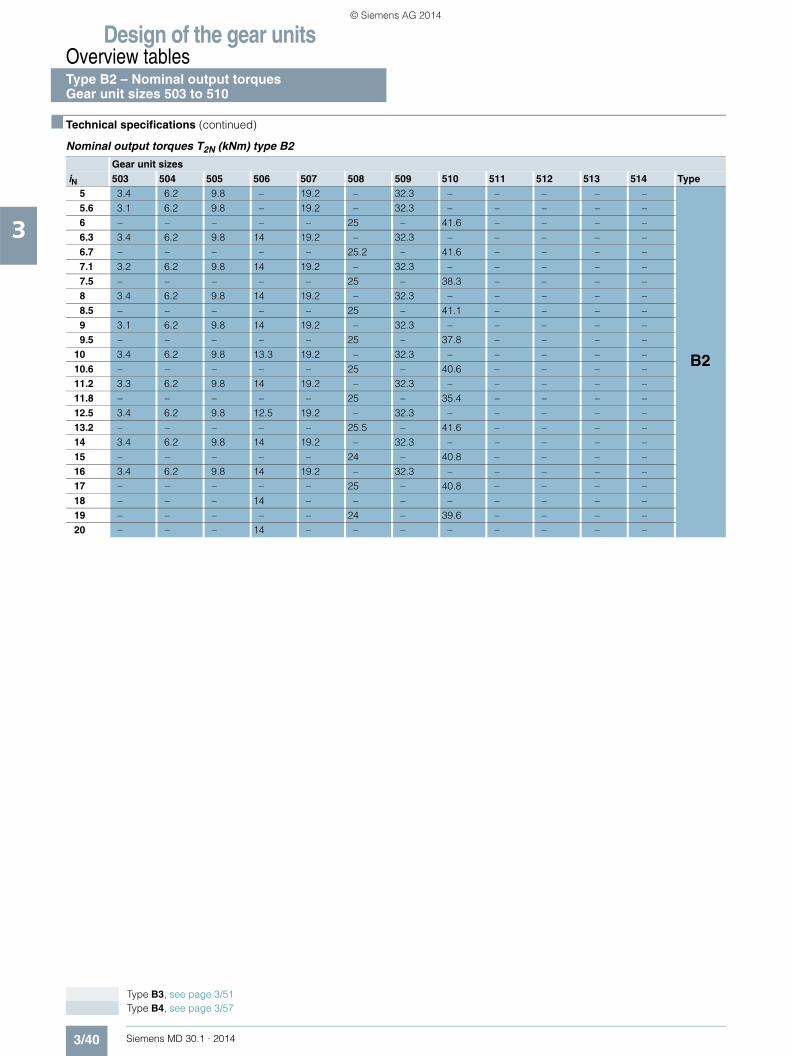
Design of the gear unitsOverview tablesType B2 – Nominal output torquesGear unit sizes 503 to 510
3/40 Siemens MD 30.1 · 2014
3
■ Technical specifications (continued)
Nominal output torques T2N (kNm) type B2
Gear unit sizesiN 503 504 505 506 507 508 509 510 511 512 513 514 Type
5 3.4 6.2 9.8 – 19.2 – 32.3 – – – – –
B2
5.6 3.1 6.2 9.8 – 19.2 – 32.3 – – – – –6 – – – – – 25 – 41.6 – – – –6.3 3.4 6.2 9.8 14 19.2 – 32.3 – – – – –6.7 – – – – – 25.2 – 41.6 – – – –7.1 3.2 6.2 9.8 14 19.2 – 32.3 – – – – –7.5 – – – – – 25 – 38.3 – – – –8 3.4 6.2 9.8 14 19.2 – 32.3 – – – – –8.5 – – – – – 25 – 41.1 – – – –9 3.1 6.2 9.8 14 19.2 – 32.3 – – – – –9.5 – – – – – 25 – 37.8 – – – –
10 3.4 6.2 9.8 13.3 19.2 – 32.3 – – – – –10.6 – – – – – 25 – 40.6 – – – –11.2 3.3 6.2 9.8 14 19.2 – 32.3 – – – – –11.8 – – – – – 25 – 35.4 – – – –12.5 3.4 6.2 9.8 12.5 19.2 – 32.3 – – – – –13.2 – – – – – 25.5 – 41.6 – – – –14 3.4 6.2 9.8 14 19.2 – 32.3 – – – – –15 – – – – – 24 – 40.8 – – – –16 3.4 6.2 9.8 14 19.2 – 32.3 – – – – –17 – – – – – 25 – 40.8 – – – –18 – – – 14 – – – – – – – –19 – – – – – 24 – 39.6 – – – –20 – – – 14 – – – – – – – –
Type B3, see page 3/51 Type B4, see page 3/57
© Siemens AG 2014

Design of the gear unitsOverview tables
Type B2 – Nominal output torquesGear unit sizes 503 to 510
3/41Siemens MD 30.1 · 2014
3
■ Technical specifications (continued)
Nominal output torques T2N (kNm) type B2 (continued)
Gear unit sizesiN 503 504 505 506 507 508 509 510 511 512 513 514 Type14 – – 11.6 – 21.5 – 37 – 63.5 – 101.5 –
B3
16 – 7 11.6 – 21.5 – 37 – 63.5 – 101.5 –18 – 7 11.6 – 21.5 28.3 37 48.5 63.5 81 101.5 12520 – 7 11.6 16.2 21.5 28.3 37 48.5 63.5 81 101.5 12522.4 – 7 11.6 16.2 21.5 28.3 37 48.5 63.5 81 101.5 12525 – 7 11.6 16.2 21.5 28.3 37 48.5 63.5 81 101.5 12528 – 7 11.6 16.2 21.5 28.3 37 48.5 63.5 81 101.5 12531.5 – 7 11.6 16.2 21.5 28.3 37 48.5 63.5 81 101.5 12535.5 – 7 11.6 16.2 21.5 28.3 37 48.5 63.5 81 101.5 12540 – 7 11.6 16.2 21.5 28.3 37 48.5 63.5 81 101.5 12545 – 7 11.6 16.2 21.5 28.3 37 48.5 63.5 81 101.5 12550 – 7 11.6 16.2 21.5 28.3 37 48.5 63.5 81 101.5 12556 – 7 11.6 16.2 21.5 28.3 37 48.5 63.5 81 101.5 12563 – 7 11.6 16.2 21.5 28.3 37 48.5 63.5 81 101.5 12571 – – 11.6 16.2 21.5 28.3 37 48.5 63.5 81 101.5 12580 – – 11.6 16.2 21.5 28.3 37 48.5 63.5 81 101.5 125
B4
90 – – 11.6 16.2 21.5 28.3 37 48.5 63.5 81 101.5 125100 – – 11.6 16.2 21.5 28.3 37 48.5 63.5 81 101.5 125112 – – 11.6 16.2 21.5 28.3 37 48.5 63.5 81 101.5 125125 – – 11.6 16.2 21.5 28.3 37 48.5 63.5 81 101.5 125140 – – 11.6 16.2 21.5 28.3 37 48.5 63.5 81 101.5 125160 – – 11.6 16.2 21.5 28.3 37 48.5 63.5 81 101.5 125180 – – 11.6 16.2 21.5 28.3 37 48.5 63.5 81 101.5 125200 – – 11.6 16.2 21.5 28.3 37 48.5 63.5 81 101.5 125224 – – 11.6 16.2 21.5 28.3 37 48.5 63.5 81 101.5 125250 – – 11.6 16.2 21.5 28.3 37 48.5 63.5 81 101.5 125280 – – 11.6 16.2 21.5 28.3 37 48.5 63.5 81 101.5 125315 – – – 16.2 – 28.3 – 48.5 – 81 – 125355 – – – 16.2 – 28.3 – 48.5 – 81 – 125
Type B3, see page 3/51 Type B4, see page 3/57
© Siemens AG 2014

Design of the gear unitsOverview tables
3/42 Siemens MD 30.1 · 2014
3
■ Technical specifications (continued)
Thermal capacities PG (kW) type B2
Gear unit sizesiN 503 504 505 506 507 508 509 510
5 PGA 57.2 87.4 91.8 – 133 – 155 –PGB 119 184 254 – 358 – 493 –PGC15 142 277 281 – 340 – 568 –PGD15 198 362 426 – 547 – 868 –
5.6 PGA 56.9 84 92.3 – 131 – 150 –PGB 118 176 254 – 350 – 470 –PGC15 141 264 281 – 332 – 540 –PGD15 196 345 425 – 533 – 823 –
6 PGA – – – – – 139 – 159PGB – – – – – 366 – 497PGC15 – – – – – 345 – 570PGD15 – – – – – 553 – 868
6.3 PGA 51.2 76.8 82.9 99.6 124 – 150 –PGB 103 157 219 268 313 – 431 –PGC15 118 224 249 293 304 – 507 –PGD15 165 296 371 445 477 – 758 –
6.7 PGA – – – – – 136 – 154PGB – – – – – 356 – 473PGC15 – – – – – 336 – 542PGD15 – – – – – 537 – 824
7.1 PGA 50.8 73.9 83 99 122 – 144 –PGB 103 151 218 266 305 – 411 –PGC15 117 215 249 290 298 – 483 –PGD15 164 282 370 441 467 – 721 –
7.5 PGA – – – – – 129 – 154PGB – – – – – 319 – 436PGC15 – – – – – 309 – 510PGD15 – – – – – 483 – 760
8 PGA 46.7 69.4 73.3 89.2 112 – 141 –PGB 92.5 139 186 230 271 – 385 –PGC15 103 191 218 258 270 – 462 –PGD15 145 254 319 385 416 – 679 –
8.5 PGA – – – – – 127 – 148PGB – – – – – 310 – 414PGC15 – – – – – 300 – 486PGD15 – – – – – 470 – 722
9 PGA 46.3 66.9 73.3 88.9 110 – 135 –PGB 91.9 134 186 228 265 – 368 –PGC15 103 183 218 256 264 – 442 –PGD15 144 243 318 381 407 – 648 –
9.5 PGA – – – – – 117 – 146PGB – – – – – 276 – 389PGC15 – – – – – 274 – 465PGD15 – – – – – 421 – 681
10 PGA 39.2 58.6 64.2 78.5 98.1 – 121 –PGB 76.1 116 159 196 231 – 319 –PGC15 81.5 153 187 226 235 – 392 –PGD15 116 203 272 331 357 – 568 –
10.6 PGA – – – – – 114 – 140PGB – – – – – 269 – 371PGC15 – – – – – 267 – 443PGD15 – – – – – 409 – 649
11.2 PGA 39 56.7 64.1 78.1 96.6 – 117 –PGB 75.7 111 159 194 226 – 307 –PGC15 80.8 147 187 224 231 – 376 –PGD15 115 196 272 328 350 – 545 –
For notes and legend for tables, see page 3/5
Type B2 – Thermal capacities n1 = 1000 rpm
© Siemens AG 2014

Design of the gear unitsOverview tables
3/43Siemens MD 30.1 · 2014
3
■ Technical specifications (continued)
Thermal capacities PG (kW) type B2 (continued)
Gear unit sizesiN 503 504 505 506 507 508 509 510
11.8 PGA – – – – – 102 – 125PGB – – – – – 236 – 323PGC15 – – – – – 238 – 391PGD15 – – – – – 361 – 567
12.5 PGA 33 49.2 54.4 68.6 83.5 – 130 –PGB 62.5 94.7 130 167 191 – 305 –PGC15 64.5 119 147 197 200 – 378 –PGD15 92 161 216 285 298 – 530 –
13.2 PGA – – – – – 99.9 – 121PGB – – – – – 230 – 310PGC15 – – – – – 233 – 373PGD15 – – – – – 352 – 541
14 PGA 32.7 47.6 54.4 68.2 82.1 – 125 –PGB 62.2 91.5 130 165 187 – 291 –PGC15 64 115 147 196 196 – 362 –PGD15 91.6 155 216 283 293 – 506 –
15 PGA – – – – – 86.9 – 134PGB – – – – – 195 – 308PGC15 – – – – – 203 – 356PGD15 – – – – – 302 – 509
16 PGA 31.1 47.7 56.8 58 86.8 – 119 –PGB 58.3 89.2 128 137 188 – 272 –PGC15 59.8 112 145 167 198 – 345 –PGD15 85.1 150 210 237 291 – 478 –
17 PGA – – – – – 85.2 – 128PGB – – – – – 190 – 294PGC15 – – – – – 198 – 339PGD15 – – – – – 295 – 486
18 PGA – – – 57.6 – – – –PGB – – – 136 – – – –PGC15 – – – 166 – – – –PGD15 – – – 236 – – – –
19 PGA – – – – – 89.7 – 122PGB – – – – – 191 – 276PGC15 – – – – – 201 – 313PGD15 – – – – – 293 – 449
20 PGA – – – 60 – – – –PGB – – – 134 – – – –PGC15 – – – 165 – – – –PGD15 – – – 231 – – – –
For notes and legend for tables, see page 3/5
Type B2 – Thermal capacitiesn1 = 1000 rpm
© Siemens AG 2014

Design of the gear unitsOverview tables
3/44 Siemens MD 30.1 · 2014
3
■ Technical specifications (continued)
Thermal capacities PG (kW) type B2
Gear unit sizesiN 503 504 505 506 507 508 509 510
5 PGA 57.6 87.1 87.1 – 119 – 124 –PGB 133 206 282 – 391 – 530 –PGC15 156 286 287 – 338 – 563 –PGD15 224 391 461 – 588 – 922 –
5.6 PGA 57.3 83.8 87.9 – 118 – 122 –PGB 132 197 282 – 383 – 507 –PGC15 155 274 286 – 330 – 537 –PGD15 222 374 461 – 574 – 877 –
6 PGA – – – – – 126 – 128PGB – – – – – 399 – 535PGC15 – – – – – 342 – 565PGD15 – – – – – 595 – 922
6.3 PGA 52.3 77.5 80.3 95.2 117 – 130 –PGB 116 176 244 298 344 – 468 –PGC15 129 246 255 298 306 – 508 –PGD15 188 334 402 482 516 – 809 –
6.7 PGA – – – – – 124 – 126PGB – – – – – 388 – 510PGC15 – – – – – 334 – 539PGD15 – – – – – 578 – 877
7.1 PGA 51.9 74.7 80.6 95.4 115 – 126 –PGB 115 169 244 296 337 – 447 –PGC15 129 236 254 296 300 – 485 –PGD15 186 321 401 478 504 – 770 –
7.5 PGA – – – – – 122 – 134PGB – – – – – 351 – 473PGC15 – – – – – 311 – 511PGD15 – – – – – 523 – 811
8 PGA 47.9 70.6 72.1 87.1 108 – 128 –PGB 104 156 208 257 300 – 421 –PGC15 114 210 224 265 274 – 466 –PGD15 165 287 346 418 451 – 727 –
8.5 PGA – – – – – 120 – 130PGB – – – – – 342 – 451PGC15 – – – – – 303 – 487PGD15 – – – – – 508 – 772
9 PGA 47.6 68.1 72.2 86.8 106 – 123 –PGB 104 150 208 254 294 – 403 –PGC15 112 202 224 263 268 – 446 –PGD15 164 275 346 414 440 – 694 –
9.5 PGA – – – – – 113 – 132PGB – – – – – 306 – 425PGC15 – – – – – 278 – 469PGD15 – – – – – 456 – 730
10 PGA 40.5 59.8 63.7 77.4 95.7 – 112 –PGB 85.9 130 178 219 256 – 350 –PGC15 89.5 168 197 232 240 – 398 –PGD15 131 231 299 360 387 – 609 –
10.6 PGA – – – – – 111 – 128PGB – – – – – 298 – 406PGC15 – – – – – 271 – 448PGD15 – – – – – 444 – 695
11.2 PGA 40.2 57.9 63.7 77.3 93.9 – 109 –PGB 85.5 125 178 217 251 – 337 –PGC15 88.6 162 196 231 235 – 382 –PGD15 131 222 299 356 379 – 584 –
For notes and legend for tables, see page 3/5
Type B2 – Thermal capacities n1 = 1200 rpm
© Siemens AG 2014

Design of the gear unitsOverview tables
3/45Siemens MD 30.1 · 2014
3
■ Technical specifications (continued)
Thermal capacities PG (kW) type B2 (continued)
Gear unit sizesiN 503 504 505 506 507 508 509 510
11.8 PGA – – – – – 99.9 – 116PGB – – – – – 261 – 354PGC15 – – – – – 243 – 400PGD15 – – – – – 391 – 611
12.5 PGA 34.2 50.5 54.4 68.3 82.1 – 129 –PGB 70.6 107 146 187 212 – 339 –PGC15 70.8 132 162 203 205 – 392 –PGD15 105 182 245 310 324 – 576 –
13.2 PGA – – – – – 98 – 113PGB – – – – – 256 – 339PGC15 – – – – – 238 – 384PGD15 – – – – – 382 – 585
14 PGA 34 49 54.4 68 80.8 – 124 –PGB 70.4 103 146 185 208 – 324 –PGC15 70.4 128 161 202 201 – 375 –PGD15 104 176 244 308 318 – 549 –
15 PGA – – – – – 85.8 – 133PGB – – – – – 216 – 343PGC15 – – – – – 208 – 390PGD15 – – – – – 327 – 573
16 PGA 32.5 49.7 58.5 58.2 88.4 – 118 –PGB 66.1 101 145 153 211 – 304 –PGC15 65.8 124 159 173 206 – 357 –PGD15 96.9 170 238 258 318 – 519 –
17 PGA – – – – – 83.9 – 127PGB – – – – – 212 – 328PGC15 – – – – – 203 – 374PGD15 – – – – – 320 – 548
18 PGA – – – 57.8 – – – –PGB – – – 152 – – – –PGC15 – – – 172 – – – –PGD15 – – – 256 – – – –
19 PGA – – – – – 91.6 – 121PGB – – – – – 214 – 307PGC15 – – – – – 208 – 344PGD15 – – – – – 321 – 507
20 PGA – – – 61.9 – – – –PGB – – – 151 – – – –PGC15 – – – 172 – – – –PGD15 – – – 252 – – – –
For notes and legend for tables, see page 3/5
Type B2 – Thermal capacitiesn1 = 1200 rpm
© Siemens AG 2014

Design of the gear unitsOverview tables
3/46 Siemens MD 30.1 · 2014
3
■ Technical specifications (continued)
Thermal capacities PG (kW) type B2
Gear unit sizesiN 503 504 505 506 507 508 509 510
5 PGA 56.4 82.9 74 – 89.9 – 53.2 –PGB 152 234 317 – 430 – 565 –PGC15 174 295 287 – 325 – 536 –PGD15 260 428 505 – 636 – 978 –
5.6 PGA 56.1 80.4 74.6 – 91.1 – 57.6 –PGB 152 224 317 – 422 – 542 –PGC15 173 283 288 – 320 – 515 –PGD15 258 410 505 – 622 – 933 –
6 PGA – – – – – 96.9 – 55.3PGB – – – – – 437 – 568PGC15 – – – – – 331 – 538PGD15 – – – – – 644 – 978
6.3 PGA 52.3 76 72.7 82.2 97.8 – 86.9 –PGB 134 201 275 335 382 – 505 –PGC15 144 260 258 300 301 – 495 –PGD15 219 371 441 528 562 – 865 –
6.7 PGA – – – – – 97.6 – 60.9PGB – – – – – 427 – 545PGC15 – – – – – 324 – 515PGD15 – – – – – 626 – 932
7.1 PGA 52 73.6 73.5 82 97.4 – 86.3 –PGB 133 193 275 333 374 – 485 –PGC15 144 250 259 299 296 – 474 –PGD15 217 355 441 524 550 – 826 –
7.5 PGA – – – – – 104 – 90.9PGB – – – – – 389 – 510PGC15 – – – – – 306 – 497PGD15 – – – – – 569 – 867
8 PGA 48.6 70.2 67.2 80 96.2 – 96.5 –PGB 121 179 236 290 335 – 460 –PGC15 127 236 229 269 273 – 461 –PGD15 193 332 382 460 493 – 782 –
8.5 PGA – – – – – 103 – 90.5PGB – – – – – 380 – 488PGC15 – – – – – 299 – 476PGD15 – – – – – 554 – 826
9 PGA 48.3 67.9 67.5 80.1 95 – 94.3 –PGB 120 172 236 288 329 – 440 –PGC15 126 226 229 267 268 – 441 –PGD15 191 319 381 456 483 – 748 –
9.5 PGA – – – – – 101 – 101PGB – – – – – 342 – 464PGC15 – – – – – 278 – 463PGD15 – – – – – 499 – 785
10 PGA 41.3 60.2 60.3 73.1 87.5 – 90.5 –PGB 99.6 149 202 248 288 – 384 –PGC15 99.8 188 201 238 241 – 396 –PGD15 153 268 329 396 425 – 658 –
10.6 PGA – – – – – 100 – 98.4PGB – – – – – 334 – 444PGC15 – – – – – 271 – 444PGD15 – – – – – 487 – 748
11.2 PGA 41.1 58.4 60.2 72.8 86.3 – 88 –PGB 98.7 144 202 246 282 – 370 –PGC15 99.5 182 201 236 237 – 381 –PGD15 152 259 329 393 417 – 631 –
For notes and legend for tables, see page 3/5
Type B2 – Thermal capacities n1 = 1500 rpm
© Siemens AG 2014

Design of the gear unitsOverview tables
3/47Siemens MD 30.1 · 2014
3
■ Technical specifications (continued)
Thermal capacities PG (kW) type B2 (continued)
Gear unit sizesiN 503 504 505 506 507 508 509 510
11.8 PGA – – – – – 91.9 – 94.4PGB – – – – – 293 – 388PGC15 – – – – – 245 – 398PGD15 – – – – – 431 – 659
12.5 PGA 35.1 51.2 52.1 65.2 76.4 – 121 –PGB 82 122 167 212 239 – 382 –PGC15 79 148 173 209 207 – 403 –PGD15 122 212 275 341 356 – 631 –
13.2 PGA – – – – – 90.6 – 92.2PGB – – – – – 287 – 374PGC15 – – – – – 240 – 383PGD15 – – – – – 420 – 633
14 PGA 35 49.8 52.3 65 75.5 – 116 –PGB 81.4 119 167 211 234 – 365 –PGC15 78.8 143 172 207 204 – 386 –PGD15 122 206 275 339 350 – 604 –
15 PGA – – – – – 80.3 – 125PGB – – – – – 244 – 386PGC15 – – – – – 210 – 407PGD15 – – – – – 360 – 634
16 PGA 33.8 51.5 59.5 56.2 88 – 111 –PGB 76.7 117 167 174 240 – 343 –PGC15 73.7 140 175 178 213 – 368 –PGD15 113 199 273 285 353 – 571 –
17 PGA – – – – – 79.1 – 120PGB – – – – – 239 – 369PGC15 – – – – – 206 – 388PGD15 – – – – – 353 – 605
18 PGA – – – 55.8 – – – –PGB – – – 174 – – – –PGC15 – – – 177 – – – –PGD15 – – – 283 – – – –
19 PGA – – – – – 91.3 – 115PGB – – – – – 244 – 347PGC15 – – – – – 215 – 371PGD15 – – – – – 356 – 573
20 PGA – – – 63.1 – – – –PGB – – – 174 – – – –PGC15 – – – 180 – – – –PGD15 – – – 280 – – – –
For notes and legend for tables, see page 3/5
Type B2 – Thermal capacitiesn1 = 1500 rpm
© Siemens AG 2014

Design of the gear unitsOverview tables
3/48 Siemens MD 30.1 · 2014
3
■ Technical specifications (continued)
Thermal capacities PG (kW) type B2
Gear unit sizesiN 503 504 505 506 507 508 509 510
5 PGA 52.9 75.4 51.8 – 45 – * –PGB 169 257 342 – 453 – 574 –PGC15 189 300 282 – 301 – 488 –PGD15 293 461 539 – 669 – 1008 –
5.6 PGA 52.9 72.7 53.8 – 49.5 – * –PGB 168 248 344 – 447 – 554 –PGC15 188 287 283 – 298 – 471 –PGD15 291 441 540 – 656 – 963 –
6 PGA – – – – – 51.7 – *PGB – – – – – 462 – 577PGC15 – – – – – 306 – 488PGD15 – – – – – 675 – 1006
6.3 PGA 50.9 71.6 60.6 61 71.8 – 23.9 –PGB 150 223 300 363 408 – 525 –PGC15 158 265 257 296 288 – 468 –PGD15 247 399 473 563 596 – 901 –
6.7 PGA – – – – – 56.4 – *PGB – – – – – 453 – 556PGC15 – – – – – 303 – 472PGD15 – – – – – 661 – 962
7.1 PGA 50.7 69.9 62 62 73 – 28.6 –PGB 149 214 300 361 401 – 507 –PGC15 157 255 257 296 284 – 451 –PGD15 245 383 472 560 584 – 864 –
7.5 PGA – – – – – 78.3 – 26.9PGB – – – – – 415 – 530PGC15 – – – – – 293 – 470PGD15 – – – – – 604 – 902
8 PGA 47.9 67.5 59 68.5 77.9 – 50.4 –PGB 135 199 258 316 360 – 482 –PGC15 139 242 230 268 266 – 443 –PGD15 218 358 410 493 526 – 820 –
8.5 PGA – – – – – 79.1 – 31.7PGB – – – – – 407 – 509PGC15 – – – – – 288 – 452PGD15 – – – – – 589 – 862
9 PGA 47.6 65.7 59.6 69.2 77.6 – 51.6 –PGB 134 191 258 314 354 – 464 –PGC15 138 233 230 267 261 – 424 –PGD15 216 344 409 489 515 – 784 –
9.5 PGA – – – – – 83.6 – 54.5PGB – – – – – 368 – 487PGC15 – – – – – 270 – 445PGD15 – – – – – 532 – 822
10 PGA 41.2 58.8 54.1 65.3 74 – 57.7 –PGB 112 166 222 271 311 – 404 –PGC15 109 206 203 239 237 – 384 –PGD15 174 301 354 425 454 – 690 –
10.6 PGA – – – – – 82.9 – 55.9PGB – – – – – 359 – 467PGC15 – – – – – 265 – 428PGD15 – – – – – 520 – 786
11.2 PGA 41 57.1 54.6 65.3 73.5 – 57.3 –PGB 111 160 222 270 306 – 392 –PGC15 109 199 203 237 233 – 370 –PGD15 172 291 354 422 446 – 665 –
For notes and legend for tables, see page 3/5
Type B2 – Thermal capacities n1 = 1800 rpm
© Siemens AG 2014

Design of the gear unitsOverview tables
3/49Siemens MD 30.1 · 2014
3
■ Technical specifications (continued)
Thermal capacities PG (kW) type B2 (continued)
Gear unit sizesiN 503 504 505 506 507 508 509 510
11.8 PGA – – – – – 79.1 – 62PGB – – – – – 318 – 410PGC15 – – – – – 241 – 386PGD15 – – – – – 460 – 693
12.5 PGA 35.3 50.4 47.9 59.4 66.8 – 106 –PGB 92.3 137 183 233 259 – 416 –PGC15 86.3 162 175 210 205 – 407 –PGD15 139 239 297 367 382 – 677 –
13.2 PGA – – – – – 78 – 61.6PGB – – – – – 311 – 393PGC15 – – – – – 236 – 372PGD15 – – – – – 450 – 665
14 PGA 35.2 49.1 48.1 59.4 66.2 – 102 –PGB 91.6 133 183 231 255 – 398 –PGC15 86 157 174 209 202 – 390 –PGD15 138 232 296 365 374 – 646 –
15 PGA – – – – – 71.2 – 111PGB – – – – – 264 – 420PGC15 – – – – – 209 – 411PGD15 – – – – – 387 – 680
16 PGA 34.4 52.4 59.1 52 84.9 – 98.9 –PGB 86.3 132 186 192 265 – 374 –PGC15 80.6 154 181 181 216 – 373 –PGD15 129 225 296 307 382 – 612 –
17 PGA – – – – – 70.2 – 107PGB – – – – – 259 – 401PGC15 – – – – – 205 – 393PGD15 – – – – – 379 – 650
18 PGA – – – 52 – – – –PGB – – – 191 – – – –PGC15 – – – 180 – – – –PGD15 – – – 305 – – – –
19 PGA – – – – – 88.7 – 103PGB – – – – – 269 – 377PGC15 – – – – – 219 – 375PGD15 – – – – – 385 – 613
20 PGA – – – 62.8 – – – –PGB – – – 194 – – – –PGC15 – – – 186 – – – –PGD15 – – – 305 – – – –
For notes and legend for tables, see page 3/5
Type B2 – Thermal capacitiesn1 = 1800 rpm
© Siemens AG 2014

Design of the gear unitsOverview tablesType B3 Nominal power ratings, gear unit sizes 504 to 514
3/50 Siemens MD 30.1 · 2014
3
■ Technical specifications
Nominal power ratings P2N (kW) type B3
Gear unit sizes
iN n1 n2 504 505 506 507 508 509 510 511 512 513 514
14 1800 129 – 157 – 294 – 491 – 864 – 1394 –1500 107 – 131 – 245 – 409 – 720 – 1162 –1200 86 – 104 – 196 – 327 – 576 – 929 –1000 71 – 87 – 163 – 273 – 480 – 774 –
16 1800 113 86 139 – 254 – 433 – 765 – 1228 –1500 94 72 116 – 212 – 360 – 637 – 1023 –1200 75 58 92 – 170 – 288 – 510 – 819 –1000 63 48 77 – 141 – 240 – 425 – 682 –
18 1800 100 74 124 – 227 305 382 510 664 892 1091 13501500 83 62 103 – 189 254 318 425 554 743 909 11251200 67 49 83 – 151 203 254 340 443 595 728 9001000 56 41 69 – 126 169 212 284 369 495 606 750
20 1800 90 67 108 158 201 264 343 450 593 790 956 11891500 75 55 90 132 168 220 286 375 494 658 796 9911200 60 44 72 105 134 176 228 300 395 526 637 7931000 50 37 60 88 112 146 190 250 330 439 531 661
22.4 1800 80 59 97 140 179 236 297 397 516 686 849 10571500 67 49 81 117 149 196 247 330 430 572 707 8811200 54 40 65 93 119 157 198 264 344 457 566 7051000 45 33 54 78 99 131 165 220 287 381 471 587
25 1800 72 52 85 125 159 209 267 356 461 612 743 9261500 60 44 71 104 132 174 222 297 384 510 619 7711200 48 35 57 83 106 139 178 237 307 408 495 6171000 40 29 47 70 88 116 148 198 256 340 413 514
28 1800 64 47 78 110 143 185 236 308 400 533 679 8221500 54 39 65 91 119 155 197 257 333 444 566 6851200 43 31 52 73 95 124 157 206 266 355 453 5481000 36 26 43 61 80 103 131 171 222 296 377 457
31.5 1800 57 42 68 99 127 165 212 277 357 476 595 7201500 48 35 57 82 106 137 177 231 297 397 496 6001200 38 28 46 66 85 110 141 185 238 317 397 4801000 32 23 38 55 70 91 118 154 198 265 330 400
35.5 1800 51 37 63 86 116 149 192 245 334 413 548 6581500 42 31 52 72 96 124 160 204 278 344 457 5481200 34 25 42 57 77 99 128 163 222 275 366 4391000 28 21 35 48 64 83 107 136 185 229 305 366
40 1800 45 34 55 79 103 132 172 220 298 368 480 5761500 38 28 46 66 85 110 144 183 248 307 400 4801200 30 23 37 53 68 88 115 147 199 246 320 3841000 25 19 31 44 57 73 96 122 166 205 267 320
45 1800 40 30 49 69 90 120 150 199 261 345 428 5311500 33 25 41 57 75 100 125 166 217 287 357 4431200 27 20 33 46 60 80 100 133 174 230 285 3541000 22 17 27 38 50 67 83 111 145 191 238 295
50 1800 36 26 43 64 80 106 135 179 233 308 375 4651500 30 22 36 53 67 89 112 149 194 256 313 3871200 24 18 29 42 53 71 90 119 155 205 250 3101000 20 15 24 35 45 59 75 99 129 171 208 258
56 1800 32 24 39 56 73 94 122 156 211 269 340 4151500 27 20 33 46 60 78 102 130 176 224 284 3461200 21 16 26 37 48 62 81 104 141 179 227 2771000 18 13 22 31 40 52 68 86 117 150 189 230
63 1800 29 21 – 50 – 83 – 140 – 240 – 3631500 24 18 – 41 – 69 – 116 – 200 – 3031200 19 14 – 33 – 55 – 93 – 160 – 2421000 16 12 – 28 – 46 – 78 – 134 – 202
71 1800 25 – – 44 – 75 – 127 – 218 – 3291500 21 – – 36 – 63 – 106 – 182 – 2751200 17 – – 29 – 50 – 84 – 145 – 2201000 14 – – 24 – 42 – 70 – 121 – 183
80 1800 23 – – 39 – – – – – – – –1500 19 – – 33 – – – – – – – –1200 15 – – 26 – – – – – – – –1000 13 – – 22 – – – – – – – –
© Siemens AG 2014
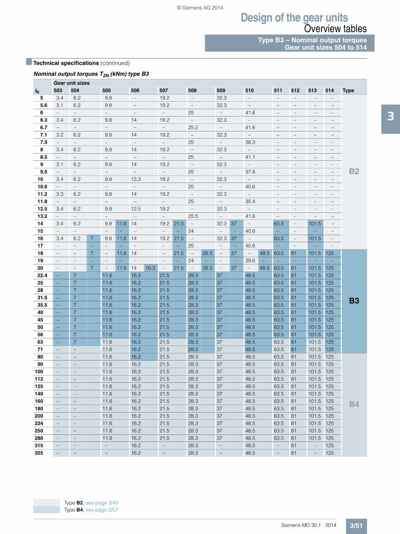
Design of the gear unitsOverview tables
Type B3 – Nominal output torquesGear unit sizes 504 to 514
3/51Siemens MD 30.1 · 2014
3
■ Technical specifications (continued)
Nominal output torques T2N (kNm) type B3
Gear unit sizesiN 503 504 505 506 507 508 509 510 511 512 513 514 Type
5 3.4 6.2 9.8 – 19.2 – 32.3 – – – – –
B2
5.6 3.1 6.2 9.8 – 19.2 – 32.3 – – – – –6 – – – – – 25 – 41.6 – – – –6.3 3.4 6.2 9.8 14 19.2 – 32.3 – – – – –6.7 – – – – – 25.2 – 41.6 – – – –7.1 3.2 6.2 9.8 14 19.2 – 32.3 – – – – –7.5 – – – – – 25 – 38.3 – – – –8 3.4 6.2 9.8 14 19.2 – 32.3 – – – – –8.5 – – – – – 25 – 41.1 – – – –9 3.1 6.2 9.8 14 19.2 – 32.3 – – – – –9.5 – – – – – 25 – 37.8 – – – –
10 3.4 6.2 9.8 13.3 19.2 – 32.3 – – – – –10.6 – – – – – 25 – 40.6 – – – –11.2 3.3 6.2 9.8 14 19.2 – 32.3 – – – – –11.8 – – – – – 25 – 35.4 – – – –12.5 3.4 6.2 9.8 12.5 19.2 – 32.3 – – – – –13.2 – – – – – 25.5 – 41.6 – – – –14 3.4 6.2 9.8 11.6 14 19.2 21.5 – 32.3 37 – 63.5 – 101.5 –15 – – – – – – – 24 – – 40.8 – – – –16 3.4 6.2 7 9.8 11.6 14 19.2 21.5 – 32.3 37 – 63.5 – 101.5 –17 – – – – – – – – 25 – – 40.8 – – – –18 – – 7 – 11.6 14 – 21.5 – 28.3 – 37 – 48.5 63.5 81 101.5 125
B3
19 – – – – – – – – 24 – – – 39.6 – – – – –20 – – 7 – 11.6 14 16.2 – 21.5 – 28.3 – 37 – 48.5 63.5 81 101.5 12522.4 – 7 11.6 16.2 21.5 28.3 37 48.5 63.5 81 101.5 12525 – 7 11.6 16.2 21.5 28.3 37 48.5 63.5 81 101.5 12528 – 7 11.6 16.2 21.5 28.3 37 48.5 63.5 81 101.5 12531.5 – 7 11.6 16.2 21.5 28.3 37 48.5 63.5 81 101.5 12535.5 – 7 11.6 16.2 21.5 28.3 37 48.5 63.5 81 101.5 12540 – 7 11.6 16.2 21.5 28.3 37 48.5 63.5 81 101.5 12545 – 7 11.6 16.2 21.5 28.3 37 48.5 63.5 81 101.5 12550 – 7 11.6 16.2 21.5 28.3 37 48.5 63.5 81 101.5 12556 – 7 11.6 16.2 21.5 28.3 37 48.5 63.5 81 101.5 12563 – 7 11.6 16.2 21.5 28.3 37 48.5 63.5 81 101.5 12571 – – 11.6 16.2 21.5 28.3 37 48.5 63.5 81 101.5 12580 – – 11.6 16.2 21.5 28.3 37 48.5 63.5 81 101.5 125
B4
90 – – 11.6 16.2 21.5 28.3 37 48.5 63.5 81 101.5 125100 – – 11.6 16.2 21.5 28.3 37 48.5 63.5 81 101.5 125112 – – 11.6 16.2 21.5 28.3 37 48.5 63.5 81 101.5 125125 – – 11.6 16.2 21.5 28.3 37 48.5 63.5 81 101.5 125140 – – 11.6 16.2 21.5 28.3 37 48.5 63.5 81 101.5 125160 – – 11.6 16.2 21.5 28.3 37 48.5 63.5 81 101.5 125180 – – 11.6 16.2 21.5 28.3 37 48.5 63.5 81 101.5 125200 – – 11.6 16.2 21.5 28.3 37 48.5 63.5 81 101.5 125224 – – 11.6 16.2 21.5 28.3 37 48.5 63.5 81 101.5 125250 – – 11.6 16.2 21.5 28.3 37 48.5 63.5 81 101.5 125280 – – 11.6 16.2 21.5 28.3 37 48.5 63.5 81 101.5 125315 – – – 16.2 – 28.3 – 48.5 – 81 – 125355 – – – 16.2 – 28.3 – 48.5 – 81 – 125
Type B2, see page 3/40 Type B4, see page 3/57
© Siemens AG 2014
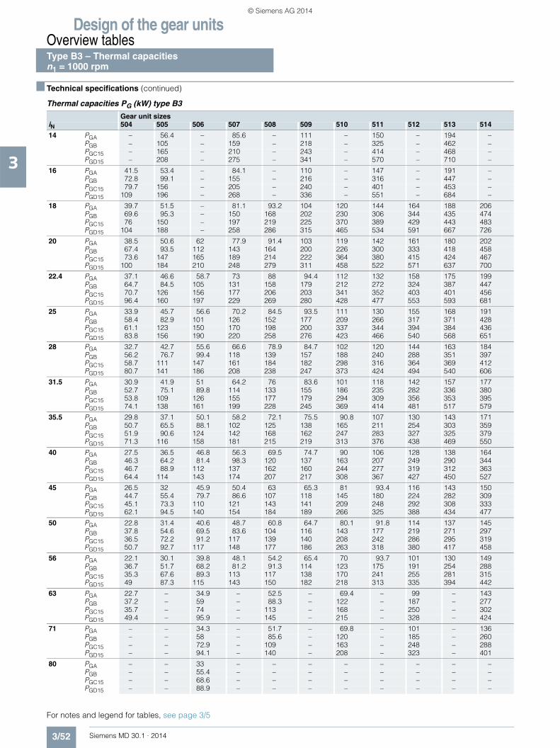
Design of the gear unitsOverview tables
3/52 Siemens MD 30.1 · 2014
3
■ Technical specifications (continued)
Thermal capacities PG (kW) type B3
For notes and legend for tables, see page 3/5
Gear unit sizesiN 504 505 506 507 508 509 510 511 512 513 514
14 PGA – 56.4 – 85.6 – 111 – 150 – 194 –PGB – 105 – 159 – 218 – 325 – 462 –PGC15 – 165 – 210 – 243 – 414 – 468 –PGD15 – 208 – 275 – 341 – 570 – 710 –
16 PGA 41.5 53.4 – 84.1 – 110 – 147 – 191 –PGB 72.8 99.1 – 155 – 216 – 316 – 447 –PGC15 79.7 156 – 205 – 240 – 401 – 453 –PGD15 109 196 – 268 – 336 – 551 – 684 –
18 PGA 39.7 51.5 – 81.1 93.2 104 120 144 164 188 206PGB 69.6 95.3 – 150 168 202 230 306 344 435 474PGC15 76 150 – 197 219 225 370 389 429 443 483PGD15 104 188 – 258 286 315 465 534 591 667 726
20 PGA 38.5 50.6 62 77.9 91.4 103 119 142 161 180 202PGB 67.4 93.5 112 143 164 200 226 300 333 418 458PGC15 73.6 147 165 189 214 222 364 380 415 424 467PGD15 100 184 210 248 279 311 458 522 571 637 700
22.4 PGA 37.1 46.6 58.7 73 88 94.4 112 132 158 175 199PGB 64.7 84.5 105 131 158 179 212 272 324 387 447PGC15 70.7 126 156 177 206 203 341 352 403 401 456PGD15 96.4 160 197 229 269 280 428 477 553 593 681
25 PGA 33.9 45.7 56.6 70.2 84.5 93.5 111 130 155 168 191PGB 58.4 82.9 101 126 152 177 209 266 317 371 428PGC15 61.1 123 150 170 198 200 337 344 394 384 436PGD15 83.8 156 190 220 258 276 423 466 540 568 651
28 PGA 32.7 42.7 55.6 66.6 78.9 84.7 102 120 144 163 184PGB 56.2 76.7 99.4 118 139 157 188 240 288 351 397PGC15 58.7 111 147 161 184 182 298 316 364 369 412PGD15 80.7 141 186 208 238 247 373 424 494 540 606
31.5 PGA 30.9 41.9 51 64.2 76 83.6 101 118 142 157 177PGB 52.7 75.1 89.8 114 133 155 186 235 282 336 380PGC15 53.8 109 126 155 177 179 294 309 356 353 395PGD15 74.1 138 161 199 228 245 369 414 481 517 579
35.5 PGA 29.8 37.1 50.1 58.2 72.1 75.5 90.8 107 130 143 171PGB 50.7 65.5 88.1 102 125 138 165 211 254 303 359PGC15 51.9 90.6 124 142 168 162 247 283 327 325 379PGD15 71.3 116 158 181 215 219 313 376 438 469 550
40 PGA 27.5 36.5 46.8 56.3 69.5 74.7 90 106 128 138 164PGB 46.3 64.2 81.4 98.3 120 137 163 207 249 290 344PGC15 46.7 88.9 112 137 162 160 244 277 319 312 363PGD15 64.4 114 143 174 207 217 308 367 427 450 527
45 PGA 26.5 32 45.9 50.4 63 65.3 81 93.4 116 143 150PGB 44.7 55.4 79.7 86.6 107 118 145 180 224 282 309PGC15 45.1 73.3 110 121 143 141 209 248 292 308 333PGD15 62.1 94.5 140 154 184 189 266 325 388 434 477
50 PGA 22.8 31.4 40.6 48.7 60.8 64.7 80.1 91.8 114 137 145PGB 37.8 54.6 69.5 83.6 104 116 143 177 219 271 297PGC15 36.5 72.2 91.2 117 139 140 208 242 286 295 319PGD15 50.7 92.7 117 148 177 186 263 318 380 417 458
56 PGA 22.1 30.1 39.8 48.1 54.2 65.4 70 93.7 101 130 149PGB 36.7 51.7 68.2 81.2 91.3 114 123 175 191 254 288PGC15 35.3 67.6 89.3 113 117 138 170 241 255 281 315PGD15 49 87.3 115 143 150 182 218 313 335 394 442
63 PGA 22.7 – 34.9 – 52.5 – 69.4 – 99 – 143PGB 37.2 – 59 – 88.3 – 122 – 187 – 277PGC15 35.7 – 74 – 113 – 168 – 250 – 302PGD15 49.4 – 95.9 – 145 – 215 – 328 – 424
71 PGA – – 34.3 – 51.7 – 69.8 – 101 – 136PGB – – 58 – 85.6 – 120 – 185 – 260PGC15 – – 72.9 – 109 – 163 – 248 – 288PGD15 – – 94.1 – 140 – 208 – 323 – 401
80 PGA – – 33 – – – – – – – –PGB – – 55.4 – – – – – – – –PGC15 – – 68.6 – – – – – – – –PGD15 – – 88.9 – – – – – – – –
Type B3 – Thermal capacities n1 = 1000 rpm
© Siemens AG 2014

Design of the gear unitsOverview tables
3/53Siemens MD 30.1 · 2014
3
■ Technical specifications (continued)
Thermal capacities PG (kW) type B3
For notes and legend for tables, see page 3/5
Gear unit sizes
iN 504 505 506 507 508 509 510 511 512 513 514
14 PGA – 57.8 – 86.5 – 109 – 143 – 177 –PGB – 118 – 177 – 242 – 356 – 500 –PGC15 – 176 – 218 – 249 – 422 – 468 –PGD15 – 229 – 298 – 370 – 612 – 760 –
16 PGA 42.9 55 – 85.2 – 109 – 142 – 177 –PGB 81.7 112 – 173 – 239 – 347 – 486 –PGC15 87.4 167 – 213 – 246 – 410 – 455 –PGD15 123 216 – 292 – 364 – 593 – 735 –
18 PGA 41.2 53.2 – 82.4 94.4 103 119 141 159 175 190PGB 78.2 107 – 167 187 224 254 338 378 475 513PGC15 83.4 160 – 205 227 231 383 399 438 445 484PGD15 118 207 – 281 310 342 500 576 634 715 777
20 PGA 39.9 52.3 63.9 79.4 93 102 118 138 157 169 189PGB 75.7 105 126 160 183 222 250 332 367 456 498PGC15 80.8 157 183 197 222 228 377 391 425 428 470PGD15 114 203 236 269 304 337 492 563 615 685 751
22.4 PGA 38.5 48.3 60.7 75.1 89.8 95.3 112 132 155 169 187PGB 72.9 95.5 119 147 176 200 235 301 358 425 487PGC15 77.8 140 172 185 214 210 353 363 414 408 460PGD15 109 181 223 249 292 305 461 515 597 640 731
25 PGA 35.4 47.4 58.6 72.3 86.5 94.6 111 130 152 163 180PGB 65.8 93.4 114 141 170 197 233 295 351 408 468PGC15 66.9 137 166 177 205 207 349 355 405 391 442PGD15 95.1 177 215 240 280 301 455 503 582 613 700
28 PGA 34.1 44.4 57.5 69 81.5 86.3 103 121 144 160 178PGB 63.3 86.4 112 133 155 176 209 267 319 387 435PGC15 64.5 124 162 169 192 188 319 327 375 377 420PGD15 91.6 161 210 226 259 270 411 459 533 584 654
31.5 PGA 32.3 43.7 53.1 66.4 78.4 85.5 102 119 142 154 173PGB 59.3 84.8 101 128 149 174 207 261 312 370 417PGC15 58.9 121 140 163 185 186 315 320 368 362 403PGD15 84.1 157 183 218 249 267 406 448 521 559 625
35.5 PGA 31.2 38.7 52.1 60.6 74.7 77.4 93 109 131 142 168PGB 57.3 74 99.3 115 140 155 184 235 283 333 395PGC15 56.8 101 137 149 176 169 273 294 339 332 388PGD15 81 132 179 197 235 239 353 407 475 507 595
40 PGA 28.7 38.1 48.8 58.4 72 76.6 92.1 107 129 137 162PGB 52.3 72.5 91.9 110 135 153 182 231 276 320 379PGC15 51.1 98.7 124 143 169 167 270 287 331 320 372PGD15 73.1 130 162 190 226 236 350 398 463 487 569
45 PGA 27.7 33.5 47.9 52.5 65.5 67.3 83.2 95.2 118 147 149PGB 50.4 62.7 90 97.3 121 131 162 201 249 314 341PGC15 49.4 81.3 121 129 154 147 232 257 303 321 342PGD15 70.6 108 159 170 204 206 302 352 421 473 516
50 PGA 23.7 33 42.5 50.8 63.2 66.6 82.4 93.4 116 141 143PGB 42.4 61.6 78.6 94.4 117 131 160 197 244 302 328PGC15 39.7 80.2 101 125 149 146 229 252 297 308 328PGD15 57.1 106 134 164 197 203 298 344 411 455 496
56 PGA 23.1 31.6 41.7 50.6 56.7 68.3 72.3 97.2 103 134 153PGB 41 58.4 77 91.9 103 129 138 197 213 284 321PGC15 38.5 75.2 99.2 123 129 145 187 252 265 294 329PGD15 55.5 99.3 131 159 170 200 246 341 364 430 482
63 PGA 23.8 – 36.7 – 54.9 – 71.6 – 101 – 148PGB 41.6 – 66.7 – 99.5 – 137 – 208 – 309PGC15 39 – 81.8 – 125 – 186 – 260 – 315PGD15 55.8 – 109 – 165 – 244 – 356 – 462
71 PGA – – 36 – 54.5 – 73.1 – 105 – 140PGB – – 65.5 – 96.8 – 135 – 208 – 290PGC15 – – 80.5 – 121 – 181 – 260 – 300PGD15 – – 107 – 159 – 236 – 352 – 438
80 PGA – – 34.5 – – – – – – – –PGB – – 62.1 – – – – – – – –PGC15 – – 75.9 – – – – – – – –PGD15 – – 101 – – – – – – – –
Type B3 – Thermal capacitiesn1 = 1200 rpm
© Siemens AG 2014

Design of the gear unitsOverview tables
3/54 Siemens MD 30.1 · 2014
3
■ Technical specifications (continued)
Thermal capacities PG (kW) type B3
For notes and legend for tables, see page 3/5
Gear unit sizes
iN 504 505 506 507 508 509 510 511 512 513 514
14 PGA – 58.1 – 84.7 – 102 – 124 – 131 –PGB – 136 – 201 – 270 – 391 – 533 –PGC15 – 185 – 225 – 252 – 424 – 449 –PGD15 – 252 – 329 – 406 – 662 – 809 –
16 PGA 43.9 55.7 – 83.8 – 102 – 127 – 139 –PGB 94.1 128 – 197 – 267 – 383 – 523 –PGC15 97.5 175 – 221 – 249 – 413 – 441 –PGD15 144 238 – 322 – 401 – 641 – 787 –
18 PGA 42.2 54.1 – 81.4 93.3 97.5 112 127 140 141 146PGB 90 124 – 190 212 252 285 374 414 516 549PGC15 93.4 168 – 213 235 235 395 405 441 437 466PGD15 137 229 – 310 343 376 545 626 687 771 827
20 PGA 41.1 53.4 65 78.6 92.2 97.2 112 126 142 138 152PGB 87.2 122 144 182 208 249 281 369 406 497 539PGC15 90.2 165 191 205 230 233 389 398 429 421 459PGD15 133 225 261 298 335 372 537 613 666 741 806
22.4 PGA 39.7 49.8 62.1 76.1 89.4 93.4 107 125 143 150 155PGB 84.2 110 137 169 201 226 265 337 397 467 530PGC15 87 153 181 193 222 216 366 371 420 407 452PGD15 128 206 246 276 323 337 502 562 649 695 788
25 PGA 36.6 49 60.1 73.5 86.3 92.7 107 124 141 146 151PGB 76.1 108 132 162 193 224 262 331 390 449 510PGC15 74.7 150 174 186 214 213 362 364 413 392 436PGD15 111 202 237 266 310 333 497 550 636 666 756
28 PGA 35.4 46.2 59.1 70.8 83 86.1 102 117 138 147 160PGB 73.3 100 129 153 178 200 237 300 356 428 477PGC15 72 140 171 177 201 195 333 337 385 381 420PGD15 107 188 232 251 287 299 451 502 582 636 708
31.5 PGA 33.7 45.3 55 68.3 80.1 85.3 101 116 137 143 156PGB 68.8 98.5 117 147 171 197 235 294 350 411 460PGC15 65.7 138 158 171 193 193 328 331 378 366 405PGD15 98.2 184 213 242 276 296 445 491 570 610 680
35.5 PGA 32.6 40.4 54 62.5 77 77.6 93.2 107 129 133 156PGB 66.2 85.7 115 132 161 176 210 266 318 370 437PGC15 63.5 114 155 156 185 175 299 304 350 338 392PGD15 94.9 155 208 219 261 266 400 446 520 554 648
40 PGA 30.1 39.7 50.9 60.4 74.3 77.1 92.3 105 127 129 151PGB 60.5 84.3 106 128 155 175 207 260 312 357 419PGC15 57 112 140 151 178 173 295 298 343 325 377PGD15 85.6 152 190 211 251 263 396 437 508 533 622
45 PGA 29.1 35.1 49.9 54.4 67.7 68.3 84.1 94.3 117 148 141PGB 58.5 73 105 113 139 151 185 227 281 356 378PGC15 55.1 92.6 138 136 163 153 261 267 314 334 347PGD15 82.5 126 186 188 227 229 349 386 462 524 564
50 PGA 24.9 34.6 44.3 52.7 65.5 67.7 83.4 92.9 115 143 137PGB 49.1 71.5 91 109 134 149 183 223 275 343 364PGC15 44.2 90.7 114 132 157 152 259 262 308 321 334PGD15 66.9 124 156 182 219 226 345 378 453 504 542
56 PGA 24.2 33.4 43.6 53.4 59 71.4 73.7 100 103 136 156PGB 47.6 67.9 89.3 107 119 149 158 224 240 322 364PGC15 42.8 85.5 112 130 142 153 212 264 276 307 343PGD15 64.7 117 153 178 196 224 286 376 400 477 533
63 PGA 25.4 – 38.5 – 57.1 – 73.1 – 101 – 150PGB 48.4 – 77.3 – 115 – 156 – 236 – 350PGC15 43.7 – 93.1 – 137 – 210 – 270 – 329PGD15 65.6 – 128 – 189 – 283 – 392 – 512
71 PGA – – 38 – 57.6 – 76.5 – 109 – 143PGB – – 76 – 112 – 156 – 237 – 329PGC15 – – 91.2 – 135 – 205 – 273 – 314PGD15 – – 126 – 184 – 275 – 389 – 484
80 PGA – – 36.5 – – – – – – – –PGB – – 72 – – – – – – – –PGC15 – – 85.5 – – – – – – – –PGD15 – – 118 – – – – – – – –
Type B3 – Thermal capacities n1 = 1500 rpm
© Siemens AG 2014

Design of the gear unitsOverview tables
3/55Siemens MD 30.1 · 2014
3
■ Technical specifications (continued)
Thermal capacities PG (kW) type B3
For notes and legend for tables, see page 3/5
Gear unit sizes
iN 504 505 506 507 508 509 510 511 512 513 514
14 PGA – 57.1 – 80 – 89.7 – 91.3 – 59.8 –PGB – 151 – 221 – 293 – 411 – 546 –PGC15 – 190 – 229 – 249 – 413 – 411 –PGD15 – 273 – 355 – 435 – 695 – 837 –
16 PGA 43.7 54.9 – 79.8 – 91.4 – 99.7 – 80.1 –PGB 105 143 – 217 – 290 – 405 – 542 –PGC15 106 181 – 224 – 248 – 407 – 411 –PGD15 163 258 – 348 – 430 – 677 – 819 –
18 PGA 42.3 53.7 – 77.9 89.3 88.4 101 104 110 87.2 75.6PGB 101 139 – 209 234 275 309 400 437 536 562PGC15 101 174 – 217 240 234 400 401 430 411 429PGD15 155 249 – 335 370 404 581 662 722 803 855
20 PGA 41.3 52.8 64.3 75.5 88.7 88.6 103 105 117 91.6 93.9PGB 97.7 136 161 202 230 272 305 394 431 520 555PGC15 98.5 171 198 209 235 233 396 396 424 399 429PGD15 150 244 283 322 363 400 573 650 705 776 836
22.4 PGA 39.9 50.1 61.7 74.9 86.4 87.7 98.6 113 122 118 104PGB 94.2 124 152 187 221 248 288 364 425 495 551PGC15 95.2 159 187 198 227 217 373 374 418 395 428PGD15 145 223 268 300 349 364 538 598 688 733 823
25 PGA 37.1 49.4 60 72.4 83.9 87.5 98.8 113 122 117 106PGB 85.2 121 147 180 213 245 286 358 418 478 534PGC15 81.4 156 181 191 218 215 369 368 413 383 416PGD15 126 219 258 288 335 359 532 587 675 706 793
28 PGA 36 46.9 59.4 70.7 82.3 83 96.6 110 127 126 130PGB 82.4 113 144 170 198 220 260 326 386 455 506PGC15 78.6 146 177 183 207 198 341 342 388 374 409PGD15 121 204 253 273 312 324 483 537 622 675 748
31.5 PGA 34.4 46.2 55.7 68.6 79.5 82.4 96.1 109 127 123 128PGB 77.5 111 132 164 190 218 257 320 379 440 487PGC15 71.7 144 164 177 200 196 337 336 382 361 395PGD15 111 200 231 262 300 320 478 525 609 648 719
35.5 PGA 33.3 41.2 54.9 63.1 77.4 75.8 90.6 101 122 118 135PGB 74.7 96.6 129 148 180 195 231 289 345 398 467PGC15 69.1 126 161 162 191 179 308 309 355 334 386PGD15 108 175 227 238 284 288 431 478 556 589 687
40 PGA 30.8 40.6 51.8 61 74.7 75.4 89.9 100 120 115 132PGB 68.1 94.9 120 142 173 193 228 284 339 384 449PGC15 62.1 124 152 156 184 177 304 303 348 323 373PGD15 97 172 211 230 273 285 426 468 544 567 660
45 PGA 29.8 36 50.9 55.3 68.6 67.4 82.5 90.6 112 146 126PGB 65.9 82.1 117 126 155 166 204 248 306 390 406PGC15 60.2 102 149 142 168 157 276 273 320 342 345PGD15 93.8 143 207 205 247 248 383 414 495 566 600
50 PGA 25.6 35.5 45.5 53.6 66.4 66.9 81.8 89.2 111 142 123PGB 55.3 80.8 102 122 150 165 202 244 300 376 391PGC15 47.9 101 126 137 163 156 273 268 314 330 333PGD15 75.7 141 177 199 239 246 379 406 485 544 577
56 PGA 24.9 34.5 44.7 55.2 60.1 73.2 72.9 101 99.8 135 153PGB 53.7 76.7 101 120 133 166 175 249 262 354 398PGC15 46.5 94.5 124 136 147 159 232 274 282 315 351PGD15 73.5 133 174 194 213 245 322 407 429 515 576
63 PGA 26.5 – 39.7 – 58.2 – 72.5 – 98.3 – 148PGB 55 – 87.1 – 128 – 173 – 258 – 383PGC15 47.9 – 103 – 143 – 230 – 277 – 338PGD15 74.5 – 145 – 206 – 319 – 420 – 553
71 PGA – – 39.1 – 59.7 – 78.8 – 110 – 142PGB – – 85.5 – 126 – 174 – 262 – 360PGC15 – – 101 – 141 – 228 – 283 – 323PGD15 – – 143 – 201 – 312 – 421 – 524
80 PGA – – 37.9 – – – – – – – –PGB – – 81.2 – – – – – – – –PGC15 – – 94.7 – – – – – – – –PGD15 – – 134 – – – – – – – –
Type B3 – Thermal capacitiesn1 = 1800 rpm
© Siemens AG 2014

Design of the gear unitsOverview tablesType B4 Nominal power ratings, gear unit sizes 505 to 514
3/56 Siemens MD 30.1 · 2014
3
■ Technical specifications
Nominal power ratings P2N (kW) type B4
Gear unit sizes
iN n1 n2 505 506 507 508 509 510 511 512 513 514
63 1800 29 35 – 63 – 108 – 182 – 298 –1500 24 29 – 52 – 90 – 152 – 248 –1200 19 23 – 42 – 72 – 122 – 199 –1000 16 19 – 35 – 60 – 101 – 165 –
71 1800 25 31 – 57 – 97 – 163 – 263 –1500 21 26 – 47 – 81 – 136 – 219 –1200 17 21 – 38 – 64 – 109 – 175 –1000 14 17 – 31 – 54 – 91 – 146 –
80 1800 23 27 – 50 65 85 113 145 188 236 2891500 19 23 – 42 54 71 94 120 157 197 2401200 15 18 – 34 43 56 75 96 126 157 1921000 13 15 – 28 36 47 63 80 105 131 160
90 1800 20 24 35 44 59 76 100 128 168 204 2551500 17 20 29 37 49 63 84 107 140 170 2121200 13 16 23 30 39 51 67 86 112 136 1701000 11 14 19 25 33 42 56 71 94 114 141
100 1800 18 21 31 40 52 67 88 114 149 183 2291500 15 18 26 33 44 55 73 95 124 153 1911200 12 14 21 26 35 44 59 76 100 122 1521000 10 12 17 22 29 37 49 63 83 102 127
112 1800 16 20 27 36 46 61 79 103 133 162 1981500 13 16 23 30 38 51 66 86 111 135 1651200 11 13 18 24 31 41 53 68 88 108 1321000 8.9 11 15 20 26 34 44 57 74 90 110
125 1800 14 17 25 32 41 53 69 91 118 146 1781500 12 14 21 26 34 44 58 76 98 122 1481200 10 11 16 21 27 36 46 61 78 97 1181000 8.0 9.5 14 18 23 30 38 51 65 81 99
140 1800 13 16 21 29 37 49 63 83 106 132 1571500 11 13 18 24 31 41 53 69 88 110 1311200 8.6 11 14 19 25 33 42 55 71 88 1051000 7.1 8.8 12 16 21 27 35 46 59 73 87
160 1800 11 14 20 26 33 43 55 74 94 119 1411500 9.4 11 16 21 27 36 46 61 78 99 1181200 7.5 9.2 13 17 22 29 37 49 63 79 941000 6.3 7.6 11 14 18 24 31 41 52 66 79
180 1800 10 12 17 22 30 38 51 65 86 103 1281500 8.3 10 14 19 25 32 43 54 71 86 1071200 6.7 8.2 12 15 20 26 34 43 57 69 851000 5.6 6.8 9.6 12 17 21 28 36 48 57 71
200 1800 9.0 11 16 20 27 34 45 57 76 93 1151500 7.5 9.0 13 17 22 28 37 48 63 77 961200 6.0 7.2 11 13 18 22 30 38 51 62 771000 5.0 6.0 8.8 11 15 19 25 32 42 51 64
224 1800 8.0 9.8 14 18 23 31 40 52 67 84 1001500 6.7 8.2 12 15 19 25 33 44 56 70 831200 5.4 6.5 9.3 12 16 20 27 35 45 56 671000 4.5 5.4 7.7 10 13 17 22 29 37 47 55
250 1800 7.2 8.5 12 16 21 27 35 46 59 74 901500 6.0 7.1 10 13 17 22 29 38 49 61 751200 4.8 5.7 8.3 11 14 18 23 31 40 49 601000 4.0 4.7 6.9 8.8 12 15 19 25 33 41 50
280 1800 6.4 7.7 11 14 19 24 32 41 54 66 811500 5.4 6.4 9.1 12 16 20 26 34 45 55 681200 4.3 5.2 7.3 9.4 13 16 21 27 36 44 541000 3.6 4.3 6.1 7.9 10 13 18 23 30 37 45
315 1800 5.7 – 9.8 – 17 – 28 – 47 – 711500 4.8 – 8.2 – 14 – 23 – 39 – 601200 3.8 – 6.5 – 11 – 19 – 32 – 481000 3.2 – 5.4 – 9.2 – 15 – 26 – 40
355 1800 5.1 – 8.7 – 15 – 25 – 42 – 641500 4.2 – 7.2 – 12 – 21 – 35 – 541200 3.4 – 5.8 – 9.7 – 16 – 28 – 431000 2.8 – 4.8 – 8.1 – 14 – 23 – 36
© Siemens AG 2014

Design of the gear unitsOverview tables
Type B4 – Nominal output torquesGear unit sizes 505 to 514
3/57Siemens MD 30.1 · 2014
3
■ Technical specifications (continued)
Nominal output torques T2N (kNm) type B4
Gear unit sizesiN 503 504 505 506 507 508 509 510 511 512 513 514 Type
5 3.4 6.2 9.8 – 19.2 – 32.3 – – – – –
B2
5.6 3.1 6.2 9.8 – 19.2 – 32.3 – – – – –6 – – – – – 25 – 41.6 – – – –6.3 3.4 6.2 9.8 14 19.2 – 32.3 – – – – –6.7 – – – – – 25.2 – 41.6 – – – –7.1 3.2 6.2 9.8 14 19.2 – 32.3 – – – – –7.5 – – – – – 25 – 38.3 – – – –8 3.4 6.2 9.8 14 19.2 – 32.3 – – – – –8.5 – – – – – 25 – 41.1 – – – –9 3.1 6.2 9.8 14 19.2 – 32.3 – – – – –9.5 – – – – – 25 – 37.8 – – – –
10 3.4 6.2 9.8 13.3 19.2 – 32.3 – – – – –10.6 – – – – – 25 – 40.6 – – – –11.2 3.3 6.2 9.8 14 19.2 – 32.3 – – – – –11.8 – – – – – 25 – 35.4 – – – –12.5 3.4 6.2 9.8 12.5 19.2 – 32.3 – – – – –13.2 – – – – – 25.5 – 41.6 – – – –14 3.4 6.2 9.8 11.6 14 19.2 21.5 – 32.3 37 – 63.5 – 101.5 –15 – – – – – – – 24 – – 40.8 – – – –16 3.4 6.2 7 9.8 11.6 14 19.2 21.5 – 32.3 37 – 63.5 – 101.5 –17 – – – – – – – – 25 – – 40.8 – – – –18 – – 7 – 11.6 14 – 21.5 – 28.3 – 37 – 48.5 63.5 81 101.5 125
B3
19 – – – – – – – – 24 – – – 39.6 – – – – –20 – – 7 – 11.6 14 16.2 – 21.5 – 28.3 – 37 – 48.5 63.5 81 101.5 12522.4 – 7 11.6 16.2 21.5 28.3 37 48.5 63.5 81 101.5 12525 – 7 11.6 16.2 21.5 28.3 37 48.5 63.5 81 101.5 12528 – 7 11.6 16.2 21.5 28.3 37 48.5 63.5 81 101.5 12531.5 – 7 11.6 16.2 21.5 28.3 37 48.5 63.5 81 101.5 12535.5 – 7 11.6 16.2 21.5 28.3 37 48.5 63.5 81 101.5 12540 – 7 11.6 16.2 21.5 28.3 37 48.5 63.5 81 101.5 12545 – 7 11.6 16.2 21.5 28.3 37 48.5 63.5 81 101.5 12550 – 7 11.6 16.2 21.5 28.3 37 48.5 63.5 81 101.5 12556 – 7 11.6 16.2 21.5 28.3 37 48.5 63.5 81 101.5 12563 – 7 11.6 16.2 21.5 28.3 37 48.5 63.5 81 101.5 12571 – – 11.6 16.2 21.5 28.3 37 48.5 63.5 81 101.5 12580 – – 11.6 16.2 21.5 28.3 37 48.5 63.5 81 101.5 125
B4
90 – – 11.6 16.2 21.5 28.3 37 48.5 63.5 81 101.5 125100 – – 11.6 16.2 21.5 28.3 37 48.5 63.5 81 101.5 125112 – – 11.6 16.2 21.5 28.3 37 48.5 63.5 81 101.5 125125 – – 11.6 16.2 21.5 28.3 37 48.5 63.5 81 101.5 125140 – – 11.6 16.2 21.5 28.3 37 48.5 63.5 81 101.5 125160 – – 11.6 16.2 21.5 28.3 37 48.5 63.5 81 101.5 125180 – – 11.6 16.2 21.5 28.3 37 48.5 63.5 81 101.5 125200 – – 11.6 16.2 21.5 28.3 37 48.5 63.5 81 101.5 125224 – – 11.6 16.2 21.5 28.3 37 48.5 63.5 81 101.5 125250 – – 11.6 16.2 21.5 28.3 37 48.5 63.5 81 101.5 125280 – – 11.6 16.2 21.5 28.3 37 48.5 63.5 81 101.5 125315 – – – 16.2 – 28.3 – 48.5 – 81 – 125355 – – – 16.2 – 28.3 – 48.5 – 81 – 125
Type B2, see page 3/40 Type B3, see page 3/51
© Siemens AG 2014
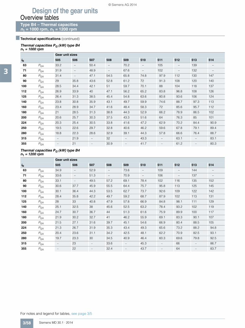
Design of the gear unitsOverview tables
3/58 Siemens MD 30.1 · 2014
3
■ Technical specifications (continued)
Thermal capacities PG (kW) type B4 n1 = 1000 rpm
Thermal capacities PG (kW) type B4 n1 = 1200 rpm
Gear unit sizes
iN 505 506 507 508 509 510 511 512 513 514
63 PGA 33.2 – 50.4 – 70.2 – 105 – 139 –
71 PGA 31.9 – 48.9 – 67.6 – 102 – 132 –
80 PGA 31.4 – 47.1 54.5 65.8 74.8 97.9 112 130 147
90 PGA 29 35.8 43.6 52.8 61.2 72 91.3 108 120 140
100 PGA 28.5 34.4 42.1 51 59.7 70.1 88 104 118 137
112 PGA 26.9 33.9 40 47.1 56.2 65.2 83.8 96.8 108 126
125 PGA 26.4 31.3 38.5 45.4 54.8 63.6 80.8 93.6 106 124
140 PGA 23.8 30.8 35.9 43.1 49.7 59.9 74.6 88.7 97.3 113
160 PGA 23.4 28.9 34.7 41.6 48.4 58.3 72 85.6 95.7 112
180 PGA 21 28.5 31.3 38.8 44.3 52.9 66.2 78.9 86.5 102
200 PGA 20.6 25.7 30.3 37.5 43.3 51.6 64 76.3 85 101
224 PGA 20.3 25.4 30.5 33.8 41.6 47.2 62.9 70.2 84.4 90.9
250 PGA 19.5 22.6 29.7 32.8 40.6 46.2 59.6 67.8 79.1 89.4
280 PGA 18.8 22.3 28.6 32.9 39.1 44.3 57.8 66.6 76.4 88.7
315 PGA – 21.9 – 32 – 43.3 – 63.1 – 83.1
355 PGA – 21 – 30.9 – 41.7 – 61.2 – 80.3
Gear unit sizes
iN 505 506 507 508 509 510 511 512 513 514
63 PGA 34.9 – 52.9 – 73.6 – 109 – 144 –
71 PGA 33.6 – 51.3 – 70.9 – 106 – 137 –
80 PGA 33.1 – 49.5 57.2 69.1 78.4 102 116 135 152
90 PGA 30.6 37.7 45.9 55.5 64.4 75.7 95.8 113 125 145
100 PGA 30.1 36.4 44.3 53.5 62.7 73.7 92.6 109 122 142
112 PGA 28.4 35.8 42.2 49.7 59.2 68.7 87.9 102 113 131
125 PGA 28 33 40.8 47.9 57.8 66.9 84.8 98.1 111 129
140 PGA 25.1 32.5 38 45.6 52.5 63.2 78.4 93.2 102 119
160 PGA 24.7 30.7 36.7 44 51.3 61.6 75.9 89.9 100 117
180 PGA 21.9 30.2 32.7 41 46.2 55.9 69.1 83.3 90.1 107
200 PGA 21.5 27.1 31.6 39.7 45.1 54.6 66.9 80.4 88.5 105
224 PGA 21.3 26.7 31.9 35.3 43.4 49.3 65.6 73.2 88.2 94.8
250 PGA 20.4 23.6 31.1 34.2 42.5 48.1 62.2 70.9 82.5 93.1
280 PGA 19.7 23.3 30 34.5 40.9 46.4 60.3 69.6 79.8 92.5
315 PGA – 23 – 33.6 – 45.3 – 66 – 86.7
355 PGA – 22 – 32.4 – 43.7 – 64 – 83.7
For notes and legend for tables, see page 3/5
Type B4 – Thermal capacities n1 = 1000 rpm, n1 = 1200 rpm
© Siemens AG 2014

Design of the gear unitsOverview tables
3/59Siemens MD 30.1 · 2014
3
■ Technical specifications (continued)
Thermal capacities PG (kW) type B4 n1 = 1500 rpm
Thermal capacities PG (kW) type B4 n1 = 1800 rpm
Gear unit sizes
iN 505 506 507 508 509 510 511 512 513 514
63 PGA 36.9 – 55.7 – 76.9 – 114 – 147 –
71 PGA 35.5 – 54.1 – 74.4 – 110 – 141 –
80 PGA 35 – 52.2 60.4 72.6 82.2 107 121 139 156
90 PGA 32.5 39.9 48.6 58.6 68.1 79.5 101 117 129 149
100 PGA 32 38.5 46.9 56.4 66.5 77.5 97.4 114 127 147
112 PGA 30.3 37.9 44.8 52.6 62.9 72.7 92.8 107 118 136
125 PGA 29.8 35.2 43.3 50.8 61.2 70.9 89.8 103 116 134
140 PGA 26.8 34.6 40.5 48.5 55.7 67.1 83.2 98.6 107 124
160 PGA 26.4 32.7 39.2 46.9 54.5 65.5 80.1 95.2 105 122
180 PGA 23 32.2 34.5 43.8 49.1 59.4 73.3 88.1 94.8 113
200 PGA 22.7 29 33.4 42.3 48 58.1 71 85.1 93.4 111
224 PGA 22.6 28.6 33.9 37.2 46.1 52.3 70.2 77.6 93.9 99.9
250 PGA 21.6 24.8 32.9 36 44.7 51.2 65.8 75.3 87.1 97.9
280 PGA 20.8 24.5 31.7 36.5 43.1 49.2 63.8 74.3 84.2 98.5
315 PGA – 24.4 – 35.6 – 47.8 – 69.6 – 91.5
355 PGA – 23.3 – 34.3 – 46 – 67.5 – 88.4
Gear unit sizes
iN 505 506 507 508 509 510 511 512 513 514
63 PGA 38.3 – 57.5 – 79.1 – 116 – 146 –
71 PGA 37 – 55.9 – 76.4 – 113 – 141 –
80 PGA 36.4 – 54 62.5 74.7 84.7 109 124 139 156
90 PGA 33.8 41.6 50.6 60.7 70.7 81.9 104 120 131 150
100 PGA 33.4 40.2 48.9 58.6 69 80 100 117 129 148
112 PGA 31.7 39.6 46.7 54.9 65.5 75.5 96.1 110 120 139
125 PGA 31.2 36.7 45.2 53.1 64 73.7 92.9 107 118 137
140 PGA 28.1 36.2 42.3 50.6 58.4 69.9 86.4 102 110 127
160 PGA 27.7 34.3 41 48.9 56.9 68.3 83.5 99 108 125
180 PGA 24.2 33.7 36.1 45.8 51.4 62.3 76.5 91.6 97.8 116
200 PGA 23.8 30.4 35 44.3 50.3 60.7 74 88.7 96.3 114
224 PGA 24 30 35.8 39 48.5 54.8 73.6 81.2 98.5 103
250 PGA 22.7 26.1 34.8 37.9 47.2 53.7 69.2 78.4 91.3 101
280 PGA 22 25.7 33.6 38.6 45.4 51.7 67.1 78.1 88.2 103
315 PGA – 25.8 – 37.6 – 50.2 – 73.2 – 95.8
355 PGA – 24.5 – 36.2 – 48.3 – 71.1 – 92.6
For notes and legend for tables, see page 3/5
Type B4 – Thermal capacitiesn1 = 1500 rpm, n1 = 1800 rpm
© Siemens AG 2014

Design of the gear unitsOverview tables
3/60 Siemens MD 30.1 · 2014
3
■ Technical specifications
Moments of inertia J1 (kgm2) without fan
The moments of inertia J1 in kgm2 are referred to the input shaft of the gear units and apply to gear units without a fan. JL1 must be added to J1 for gear units with a fan.
The moment of inertia J2 in kgm2 referred to the output shaft of the gear unit is calculated according to the following formula:J2 = iN
2 x J1
Moments of inertia J1 in kgm2 referred to the input shaft
Gear unit sizes
iN 503 504 505 506 507 508 509 510 511 512 513 514 Type
1.12 0.03320 0.09331 0.19985 – 0.55790 – 1.15512 – – – – –
H1
1.25 0.03012 0.08009 0.17598 – 0.47525 – 0.98841 – – – – –
1.32 – – – – – 0.69638 – 1.41265 – – – –
1.4 0.02612 0.07247 0.15616 0.28321 0.42781 – 0.89201 – – – – –
1.5 – – – – – 0.59994 – 1.21925 – – – –
1.6 0.02270 0.06249 0.13502 0.25139 0.38416 – 0.76512 – – – – –
1.7 – – – – – 0.54274 – 1.10454 – – – –
1.8 0.02118 0.05538 0.11797 0.22222 0.31917 – 0.66780 – – – – –
1.9 – – – – – 0.47639 – 0.95000 – – – –
2 0.01944 0.05039 0.10730 0.19158 0.29054 – 0.60305 – – – – –
2.12 – – – – – 0.41019 – 0.83447 – – – –
2.24 0.01699 0.04512 0.09435 0.16800 0.26550 – 0.54335 – – – – –
2.36 – – – – – 0.37242 – 0.75177 – – – –
2.5 0.01533 0.04015 0.08484 0.15171 0.23841 – 0.48790 – – – – –
2.65 – – – – – 0.32983 – 0.67465 – – – –
2.8 0.01382 0.03570 0.07523 0.13132 0.21150 – 0.43124 – – – –
3 – – – – – 0.29502 – 0.60234 – – – –
3.15 0.00978 0.02560 0.05558 0.11689 0.16858 – 0.32533 – – – – –
3.35 – – – – – 0.26063 – 0.52956 – – – –
3.55 0.00833 0.02080 0.04790 0.10267 0.13472 – 0.28649 – – – – –
3.75 – – – – – 0.21054 – 0.40835 – – – –
4 0.00694 0.01794 0.04155 0.07893 0.11805 – 0.24482 – – – – –
4.25 – – – – – 0.17090 – 0.35656 – – – –
4.5 0.00520 0.01525 0.03354 0.06750 0.09900 – 0.19081 – – – – –
4.75 – – – – – 0.14846 – 0.30267 – – – –
5 0.00447 0.01357 0.02829 0.05811 0.08363 – 0.17361 – – – – –
5.3 – – – – – 0.12489 – 0.23975 – – – –
5.6 0.00392 0.01179 0.02455 0.04715 0.07328 – 0.14460 – – – – –
6 – – – – – 0.10497 – 0.21761 – – – –
JL1 0.013 0.013 0.032 0.032 0.070 0.070 0.070 0.070 – – – –
Types H1, H2, H3, H4 Moments of inertia J1
© Siemens AG 2014
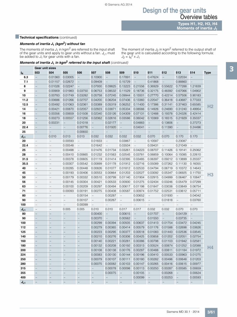
Design of the gear unitsOverview tables
3/61Siemens MD 30.1 · 2014
3
■ Technical specifications (continued)
Moments of inertia J1 (kgm2) without fan
The moments of inertia J1 in kgm2 are referred to the input shaft of the gear units and apply to gear units without a fan. JL1 must be added to J1 for gear units with a fan.
The moment of inertia J2 in kgm2 referred to the output shaft of the gear unit is calculated according to the following formula:J2 = iN
2 x J1
Moments of inertia J1 in kgm2 referred to the input shaft (continued)
Gear unit sizes
iN 503 504 505 506 507 508 509 510 511 512 513 514 Type
6.3 – 0.01360 0.03005 – 0.10900 – 0.17891 – 0.47624 – 1.02034 –
H2
7.1 – 0.01157 0.02672 – 0.09409 – 0.15729 – 0.41868 – 0.88860 –
8 – 0.01026 0.02247 – 0.07930 0.09825 0.13223 0.21556 0.36929 0.55622 0.77288 1.21839
9 – 0.00909 0.01983 0.03750 0.06753 0.08532 0.11529 0.18736 0.32175 0.48392 0.67066 1.04902
10 – 0.00783 0.01749 0.03282 0.05758 0.07245 0.09944 0.15501 0.27770 0.42214 0.57506 0.90183
11.2 – 0.00686 0.01266 0.02707 0.04200 0.06204 0.07436 0.13360 0.22047 0.36418 0.43687 0.77333
12.5 – 0.00492 0.01063 0.02361 0.03389 0.05319 0.06252 0.11400 0.17386 0.31141 0.37463 0.65585
14 – 0.00421 0.00870 0.02057 0.02823 0.03871 0.05334 0.08566 0.14926 0.24690 0.31240 0.49954
16 – 0.00356 0.00659 0.01508 0.02340 0.03126 0.04309 0.07131 0.12488 0.19378 0.24326 0.42414
18 – 0.00273 0.00557 0.01256 0.02062 0.02616 0.03586 0.06042 0.10369 0.16515 0.21929 0.35037
20 – 0.00231 – 0.01018 – 0.02177 – 0.04883 – 0.13806 – 0.27273
22.4 – – – 0.00776 – 0.01920 – 0.04041 – 0.11390 – 0.24496
25 – – – 0.00650 – – – – – – – –
JL1 0.010 0.013 0.013 0.032 0.032 0.032 0.032 0.070 0.070 0.170 0.170
20 – – 0.00593 – 0.01833 – 0.03867 – 0.10587 – 0.23087 –
H3
22.4 – – 0.00548 – 0.01642 – 0.03504 – 0.09431 – 0.21049 –
25 – – 0.00498 – 0.01476 0.01734 0.03261 0.04223 0.08707 0.11426 0.19141 0.25062
28 – – 0.00410 0.00665 0.01232 0.01563 0.02545 0.03781 0.06859 0.10064 0.15085 0.22610
31.5 – – 0.00378 0.00605 0.01119 0.01414 0.02395 0.03485 0.06397 0.09212 0.13899 0.20337
35.5 – – 0.00307 0.00542 0.00899 0.01178 0.01912 0.02716 0.05089 0.07262 0.11130 0.16055
40 – – 0.00285 0.00448 0.00826 0.01077 0.01812 0.02533 0.04794 0.06719 0.10372 0.14643
45 – – 0.00193 0.00406 0.00553 0.00864 0.01203 0.02027 0.03092 0.05347 0.06925 0.11750
50 – – 0.00179 0.00332 0.00510 0.00799 0.01140 0.01904 0.02915 0.04999 0.06467 0.10847
56 – – 0.00145 0.00304 0.00421 0.00533 0.00930 0.01275 0.02434 0.03246 0.05479 0.07299
63 – – 0.00100 0.00209 0.00297 0.00494 0.00617 0.01198 0.01847 0.03038 0.03849 0.06754
71 – – 0.00093 0.00191 0.00275 0.00408 0.00587 0.00974 0.01752 0.02531 0.03612 0.05711
80 – – – 0.00154 – 0.00287 – 0.00652 – 0.01930 – 0.04042
90 – – – 0.00107 – 0.00267 – 0.00615 – 0.01818 – 0.03760
100 – – – 0.00099 – – – – – – – –
JL1 – – 0.005 0.005 0.010 0.010 0.017 0.017 0.032 0.032 0.070 0.070
80 – – – – 0.00400 – 0.00615 – 0.01707 – 0.04129 –
H4
90 – – – – 0.00370 – 0.00562 – 0.01550 – 0.03735 –
100 – – – – 0.00299 0.00394 0.00505 0.00637 0.01413 0.01754 0.03472 0.04245
112 – – – – 0.00279 0.00365 0.00414 0.00579 0.01176 0.01588 0.02698 0.03826
125 – – – – 0.00223 0.00295 0.00377 0.00518 0.01083 0.01443 0.02536 0.03545
140 – – – – 0.00210 0.00276 0.00306 0.00425 0.00858 0.01202 0.02051 0.02754
160 – – – – 0.00140 0.00221 0.00281 0.00386 0.00798 0.01103 0.01942 0.02581
180 – – – – 0.00132 0.00208 0.00192 0.00313 0.00524 0.00874 0.01252 0.02088
200 – – – – 0.00108 0.00138 0.00176 0.00287 0.00488 0.00811 0.01184 0.01972
224 – – – – 0.00083 0.00130 0.00144 0.00196 0.00410 0.00533 0.00963 0.01275
250 – – – – 0.00079 0.00107 0.00111 0.00180 0.00282 0.00496 0.00648 0.01203
280 – – – – 0.00075 0.00082 0.00103 0.00147 0.00265 0.00416 0.00615 0.00977
315 – – – – – 0.00078 0.00098 0.00113 0.00250 0.00287 0.00585 0.00659
355 – – – – – 0.00075 – 0.00105 – 0.00268 – 0.00624
400 – – – – – – – 0.00099 – 0.00253 – 0.00593
JL1 – – – – – – – – – – – –
Types H1, H2, H3, H4Moments of inertia J1
© Siemens AG 2014
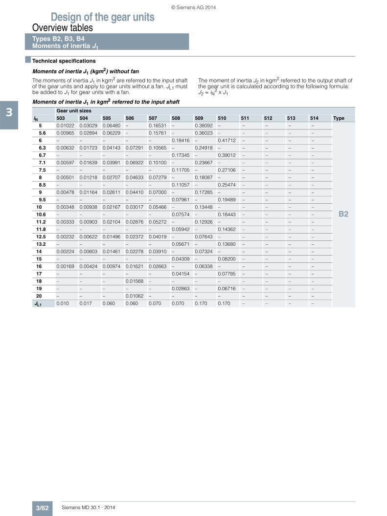
Design of the gear unitsOverview tables
3/62 Siemens MD 30.1 · 2014
3
■ Technical specifications
Moments of inertia J1 (kgm2) without fan
The moments of inertia J1 in kgm2 are referred to the input shaft of the gear units and apply to gear units without a fan. JL1 must be added to J1 for gear units with a fan.
The moment of inertia J2 in kgm2 referred to the output shaft of the gear unit is calculated according to the following formula:J2 = iN
2 x J1
Moments of inertia J1 in kgm2 referred to the input shaft
Gear unit sizes
iN 503 504 505 506 507 508 509 510 511 512 513 514 Type
5 0.01022 0.03029 0.06480 – 0.16531 – 0.38092 – – – – –
B2
5.6 0.00965 0.02894 0.06229 – 0.15761 – 0.36023 – – – – –
6 – – – – – 0.18416 – 0.41712 – – – –
6.3 0.00632 0.01723 0.04143 0.07291 0.10565 – 0.24918 – – – – –
6.7 – – – – – 0.17345 – 0.39012 – – – –
7.1 0.00597 0.01639 0.03991 0.06922 0.10100 – 0.23667 – – – – –
7.5 – – – – – 0.11705 – 0.27106 – – – –
8 0.00501 0.01218 0.02707 0.04633 0.07279 – 0.18087 – – – – –
8.5 – – – – – 0.11057 – 0.25474 – – – –
9 0.00478 0.01164 0.02611 0.04410 0.07000 – 0.17285 – – – – –
9.5 – – – – – 0.07961 – 0.19489 – – – –
10 0.00348 0.00938 0.02167 0.03017 0.05466 – 0.13448 – – – – –
10.6 – – – – – 0.07574 – 0.18443 – – – –
11.2 0.00333 0.00903 0.02104 0.02876 0.05272 – 0.12926 – – – – –
11.8 – – – – – 0.05942 – 0.14362 – – – –
12.5 0.00232 0.00622 0.01496 0.02372 0.04019 – 0.07643 – – – – –
13.2 – – – – – 0.05671 – 0.13680 – – – –
14 0.00224 0.00603 0.01461 0.02278 0.03910 – 0.07324 – – – – –
15 – – – – – 0.04309 – 0.08200 – – – –
16 0.00169 0.00424 0.00974 0.01621 0.02663 – 0.06338 – – – – –
17 – – – – – 0.04154 – 0.07785 – – – –
18 – – – 0.01568 – – – – – – – –
19 – – – – – 0.02863 – 0.06716 – – – –
20 – – – 0.01062 – – – – – – – –
JL1 0.010 0.017 0.060 0.060 0.070 0.070 0.170 0.170 – – – –
Types B2, B3, B4 Moments of inertia J1
© Siemens AG 2014

Design of the gear unitsOverview tables
3/63Siemens MD 30.1 · 2014
3
■ Technical specifications (continued)
Moments of inertia J1 (kgm2) without fan
The moments of inertia J1 in kgm2 are referred to the input shaft of the gear units and apply to gear units without a fan. JL1 must be added to J1 for gear units with a fan.
The moment of inertia J2 in kgm2 referred to the output shaft of the gear unit is calculated according to the following formula:J2 = iN
2 x J1
Moments of inertia J1 in kgm2 referred to the input shaft (continued)
Gear unit sizes
iN 503 504 505 506 507 508 509 510 511 512 513 514 Type
14 – – 0.01329 – 0.04499 – 0.08544 – 0.22304 – 0.50306 –
B3
16 – 0.00566 0.01214 – 0.04005 – 0.07831 – 0.20426 – 0.45976 –
18 – 0.00512 0.01137 – 0.03687 0.04278 0.07235 0.09296 0.18547 0.24045 0.42637 0.54481
20 – 0.00478 0.01053 0.01484 0.03411 0.03839 0.06838 0.08415 0.17369 0.21791 0.39508 0.49213
22.4 – 0.00448 0.00704 0.01336 0.02131 0.03554 0.04599 0.07690 0.11784 0.19577 0.27665 0.45195
25 – 0.00284 0.00651 0.01234 0.01960 0.03307 0.04359 0.07204 0.11072 0.18190 0.25774 0.41470
28 – 0.00265 0.00547 0.01127 0.01479 0.02049 0.02996 0.04874 0.08009 0.12406 0.19848 0.29212
31.5 – 0.00204 0.00513 0.00764 0.01369 0.01896 0.02844 0.04581 0.07582 0.11568 0.18636 0.26960
35.5 – 0.00192 0.00378 0.00698 0.01109 0.01426 0.02358 0.03170 0.05975 0.08381 0.14595 0.20839
40 – 0.00170 0.00356 0.00585 0.01037 0.01328 0.02257 0.02984 0.05677 0.07880 0.13805 0.19396
45 – 0.00162 0.00250 0.00543 0.00728 0.01074 0.01616 0.02472 0.04339 0.06235 0.08343 0.15241
50 – 0.00109 0.00238 0.00403 0.00685 0.01010 0.01555 0.02350 0.04158 0.05885 0.07861 0.14300
56 – 0.00104 0.00180 0.00375 0.00491 0.00707 0.01051 0.01686 0.02866 0.04498 0.06779 0.08737
63 – 0.00083 – 0.00265 – 0.00668 – 0.01611 – 0.04284 – 0.08163
71 – – – 0.00249 – 0.00478 – 0.01098 – 0.02970 – 0.07028
80 – – – 0.00190 – – – – – – – –
JL1 – 0.005 0.010 0.010 0.017 0.017 0.032 0.032 0.070 0.070 0.170 0.170
63 – – 0.00193 – 0.00571 – 0.01276 – 0.03724 – 0.08055 –
B4
71 – – 0.00178 – 0.00525 – 0.01186 – 0.03463 – 0.07410 –
80 – – 0.00163 – 0.00486 0.00560 0.01091 0.01313 0.03235 0.03802 0.06979 0.08246
90 – – 0.00122 0.00201 0.00313 0.00517 0.00734 0.01216 0.01992 0.03525 0.04705 0.07558
100 – – 0.00113 0.00184 0.00289 0.00479 0.00675 0.01113 0.01851 0.03284 0.04444 0.07098
112 – – 0.00098 0.00168 0.00223 0.00308 0.00566 0.00753 0.01390 0.02031 0.03063 0.04795
125 – – 0.00092 0.00126 0.00207 0.00285 0.00528 0.00689 0.01299 0.01881 0.02898 0.04517
140 – – 0.00071 0.00116 0.00182 0.00220 0.00390 0.00578 0.01051 0.01415 0.02402 0.03119
160 – – 0.00067 0.00100 0.00172 0.00205 0.00366 0.00537 0.00992 0.01319 0.02293 0.02943
180 – – 0.00047 0.00094 0.00117 0.00180 0.00258 0.00398 0.00691 0.01067 0.01639 0.02439
200 – – 0.00045 0.00073 0.00110 0.00170 0.00244 0.00371 0.00657 0.01004 0.01576 0.02323
224 – – 0.00028 0.00068 0.00088 0.00115 0.00185 0.00263 0.00468 0.00700 0.01069 0.01662
250 – – 0.00026 0.00048 0.00067 0.00109 0.00157 0.00247 0.00368 0.00664 0.00833 0.01595
280 – – 0.00025 0.00045 0.00063 0.00087 0.00149 0.00188 0.00348 0.00475 0.00794 0.01084
315 – – – 0.00029 – 0.00066 – 0.00159 – 0.00373 – 0.00844
355 – – – 0.00026 – 0.00063 – 0.00151 – 0.00352 – 0.00803
JL1 – – – – – – – – – – – –
Types B2, B3, B4Moments of inertia J1
© Siemens AG 2014
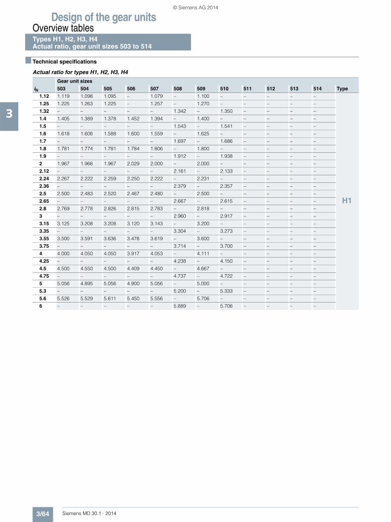
Design of the gear unitsOverview tablesTypes H1, H2, H3, H4 Actual ratio, gear unit sizes 503 to 514
3/64 Siemens MD 30.1 · 2014
3
■ Technical specifications
Actual ratio for types H1, H2, H3, H4
Gear unit sizes
iN 503 504 505 506 507 508 509 510 511 512 513 514 Type
1.12 1.119 1.098 1.095 – 1.079 – 1.100 – – – – –
H1
1.25 1.225 1.263 1.225 – 1.257 – 1.270 – – – – –
1.32 – – – – – 1.342 – 1.350 – – – –
1.4 1.405 1.389 1.378 1.452 1.394 – 1.400 – – – – –
1.5 – – – – – 1.543 – 1.541 – – – –
1.6 1.618 1.606 1.588 1.600 1.559 – 1.625 – – – – –
1.7 – – – – – 1.697 – 1.686 – – – –
1.8 1.781 1.774 1.781 1.784 1.806 – 1.800 – – – – –
1.9 – – – – – 1.912 – 1.938 – – – –
2 1.967 1.966 1.967 2.029 2.000 – 2.000 – – – – –
2.12 – – – – – 2.161 – 2.133 – – – –
2.24 2.267 2.222 2.259 2.250 2.222 – 2.231 – – – – –
2.36 – – – – – 2.379 – 2.357 – – – –
2.5 2.500 2.483 2.520 2.467 2.480 – 2.500 – – – – –
2.65 – – – – – 2.667 – 2.615 – – – –
2.8 2.769 2.778 2.826 2.815 2.783 – 2.818 – – – – –
3 – – – – – 2.960 – 2.917 – – – –
3.15 3.125 3.208 3.208 3.120 3.143 – 3.200 – – – – –
3.35 – – – – – 3.304 – 3.273 – – – –
3.55 3.500 3.591 3.636 3.478 3.619 – 3.600 – – – – –
3.75 – – – – – 3.714 – 3.700 – – – –
4 4.000 4.050 4.050 3.917 4.053 – 4.111 – – – – –
4.25 – – – – – 4.238 – 4.150 – – – –
4.5 4.500 4.550 4.500 4.409 4.450 – 4.667 – – – – –
4.75 – – – – – 4.737 – 4.722 – – – –
5 5.056 4.895 5.056 4.900 5.056 – 5.000 – – – – –
5.3 – – – – – 5.200 – 5.333 – – – –
5.6 5.526 5.529 5.611 5.450 5.556 – 5.706 – – – – –
6 – – – – – 5.889 – 5.706 – – – –
© Siemens AG 2014

Design of the gear unitsOverview tables
Types H1, H2, H3, H4Actual ratio, gear unit sizes 503 to 514
3/65Siemens MD 30.1 · 2014
3
■ Technical specifications (continued)
Actual ratio for types H1, H2, H3, H4 (continued)
Gear unit sizes
iN 503 504 505 506 507 508 509 510 511 512 513 514 Type
6.3 – 6.36 6.38 – 6.26 – 6.43 – 6.47 – 6.30 –
H2
7.1 – 7.18 7.04 – 6.93 – 7.10 – 7.16 – 7.00 –
8 – 7.89 8.11 – 7.84 7.94 8.16 8.11 7.95 7.99 7.81 8.01
9 – 8.71 8.95 8.81 8.75 8.79 9.10 8.96 8.88 8.84 8.75 8.90
10 – 9.80 9.91 9.73 9.80 9.94 10.21 10.29 9.96 9.82 9.86 9.93
11.2 – 10.86 11.18 11.21 11.31 11.11 11.59 11.48 11.25 10.96 11.20 11.13
12.5 – 12.63 12.53 12.37 12.66 12.43 13.13 12.87 12.95 12.30 12.60 12.54
14 – 14.07 14.32 13.70 14.28 14.35 14.63 14.62 14.50 13.89 14.39 14.24
16 – 15.79 16.11 15.46 16.04 16.06 16.25 16.57 15.93 16.00 16.33 16.02
18 – 17.87 18.09 17.32 17.26 18.12 18.26 18.45 18.09 17.92 17.50 18.29
20 – 19.93 20.50 19.79 20.57 20.36 20.64 20.50 19.96 19.67 19.95 20.77
22.4 – – 22.96 22.26 23.02 21.90 23.39 23.03 22.98 22.35 22.44 22.25
25 – – 26.25 25.01 25.97 26.10 26.05 26.03 25.73 24.65 25.63 25.37
H3
28 – – 28.39 28.34 27.95 29.21 29.76 29.51 28.78 28.39 28.47 28.54
31.5 – – 32.45 31.75 31.52 32.94 33.15 32.86 32.23 31.79 32.51 32.59
35.5 – – 34.69 36.28 34.82 35.45 36.36 37.55 35.98 35.56 35.61 36.19
40 – – 39.64 39.25 39.27 39.99 40.50 41.82 40.29 39.82 40.66 41.33
45 – – 43.84 44.86 45.15 44.18 45.96 45.87 46.51 44.44 45.82 45.27
50 – – 50.11 47.95 50.92 49.83 51.19 51.09 52.08 49.77 52.32 51.70
56 – – 57.26 54.80 57.13 57.27 58.50 57.98 58.74 57.45 58.28 58.25
63 – – 63.29 60.61 63.95 64.60 66.39 64.58 63.40 64.34 63.70 66.53
71 – – 72.33 69.26 72.12 72.47 73.94 73.80 70.99 72.56 72.74 74.09
80 – – – 79.16 81.47 81.13 83.79 83.75 84.61 78.32 82.23 80.99
90 – – – 87.49 91.40 91.50 93.84 93.28 94.70 87.70 93.20 92.49
100 – – – 99.99 101.83 103.35 107.25 105.70 106.80 104.52 103.8 104.55
H4
112 – – – – 114.25 115.96 116.03 118.39 114.94 116.98 118.6 118.50
125 – – – – 125.33 129.19 132.60 135.30 129.64 131.93 132.09 131.98
140 – – – – 140.62 144.95 141.75 146.37 143.23 141.99 144.90 150.79
160 – – – – 157.38 159.01 162.00 167.28 161.54 160.14 161.38 167.94
180 – – – – 176.57 178.40 179.16 178.82 185.69 176.93 183.13 184.22
200 – – – – 203.67 199.66 204.75 204.37 209.43 199.55 203.96 205.18
224 – – – – 230.47 224.01 234.00 226.01 234.97 229.38 233.10 232.84
250 – – – – 258.57 258.38 258.63 258.30 263.02 258.70 264.52 259.32
280 – – – – 292.59 292.38 295.58 295.20 296.65 290.25 294.61 296.37
315 – – – – – 328.04 332.53 326.27 333.27 324.91 327.35 336.32
355 – – – – – 371.20 – 372.88 – 366.45 – 374.58
400 – – – – – – – 419.49 – 411.69 – 416.20
© Siemens AG 2014

Design of the gear unitsOverview tablesTypes B2, B3, B4 Actual ratio, gear unit sizes 503 to 514
3/66 Siemens MD 30.1 · 2014
3
■ Technical specifications
Actual ratio for types B2, B3, B4
Gear unit sizesiN 503 504 505 506 507 508 509 510 511 512 513 514 Type
5 4.93 5.06 5.06 – 5.04 – 5.01 – – – – –
B2
5.6 5.64 5.71 5.63 – 5.64 – 5.72 – – – – –6 – – – – – 5.90 – 5.77 – – – –6.3 6.26 6.43 6.51 6.13 6.48 – 6.44 – – – – –6.7 – – – – – 6.59 – 6.57 – – – –7.1 7.16 7.25 7.25 6.82 7.25 – 7.36 – – – – –7.5 – – – – – 7.58 – 7.43 – – – –8 7.82 8.03 8.18 7.89 8.37 – 8.05 – – – – –8.5 – – – – – 8.48 – 8.45 – – – –9 8.94 9.05 9.11 8.77 9.37 – 9.19 – – – – –9.5 – – – – – 9.80 – 9.28 – – – –
10 9.69 9.94 10.07 9.92 10.02 – 9.97 – – – – –10.6 – – – – – 10.95 – 10.56 – – – –11.2 11.08 11.22 11.22 11.03 11.22 – 11.38 – – – – –11.8 – – – – – 11.74 – 11.49 – – – –12.5 12.41 12.73 12.89 12.21 12.83 – 12.76 – – – – –13.2 – – – – – 13.12 – 13.08 – – – –14 14.18 14.36 14.36 13.97 13.57 14.37 13.80 – 14.58 14.20 – 13.86 – 13.72 –15 – – – – – – – 15.03 – – 14.71 – – – –16 15.64 15.83 15.30 15.83 15.76 15.63 15.84 15.94 – 16.07 16.12 – 15.65 – 15.58 –17 – – – – – – – – 16.79 – – 16.74 – – – –18 – – 17.80 – 17.65 17.37 – 17.84 – 17.51 – 18.27 – 17.91 18.02 17.12 17.53 17.45
B3
19 – – – – – – – – 18.52 – – – 18.46 – – – – –20 – – 19.83 – 20.17 19.15 19.31 – 20.12 – 20.22 – 20.35 – 20.33 20.18 19.33 20.02 19.8122.4 – 22.25 22.42 21.79 22.66 22.64 23.50 23.05 23.18 22.26 22.55 22.2925 – 25.18 25.62 24.40 25.56 25.53 26.17 25.67 25.95 24.93 25.75 25.4528 – 28.25 28.00 27.89 28.30 28.75 29.55 29.64 29.95 28.63 28.16 28.6731.5 – 31.46 32.00 30.99 31.92 32.42 32.91 33.02 33.54 32.06 32.16 32.7435.5 – 35.29 34.69 35.41 35.07 35.91 36.36 37.27 35.87 37.00 34.89 35.8140 – 38.97 39.64 38.71 39.55 40.50 40.50 41.51 40.17 41.43 39.85 40.8945 – 43.72 44.41 44.24 44.89 44.49 46.56 45.87 45.92 44.31 44.67 44.3650 – 49.90 50.76 47.95 50.63 50.17 51.85 51.09 51.42 49.62 51.02 50.6656 – 55.98 55.96 54.80 55.83 56.96 57.17 58.73 56.70 56.73 56.25 56.8063 – 61.72 63.04 61.39 64.40 64.24 64.40 65.41 65.57 63.52 64.23 64.8671 – – 70.60 70.16 71.75 70.83 72.13 72.12 73.39 70.04 72.80 71.5180 – – 80.69 77.36 80.50 81.70 82.43 81.24 82.77 81.00 81.08 81.66
B4
90 – – 89.66 87.14 91.11 91.02 91.60 90.99 93.20 90.66 93.63 92.56100 – – 102.47 97.60 102.23 102.12 104.68 103.99 105.12 102.25 104.28 103.09112 – – 112.00 111.54 113.81 115.59 114.42 115.56 116.42 115.13 117.73 119.05125 – – 128.00 123.94 127.69 129.69 130.76 132.06 131.31 129.85 131.12 132.59140 – – 138.75 141.65 141.00 144.39 141.75 144.34 144.23 143.81 144.90 149.68160 – – 158.57 154.82 158.20 162.00 162.00 164.96 162.67 162.20 161.38 166.71180 – – 177.65 176.94 180.52 178.88 181.48 178.82 184.66 178.17 185.51 184.22200 – – 203.02 191.81 202.54 200.70 207.41 204.37 208.27 200.94 206.61 205.18224 – – 223.85 219.21 223.31 229.02 228.68 228.95 229.63 228.11 227.80 235.86250 – – 255.08 245.57 254.47 256.95 260.59 261.65 261.67 257.27 259.59 262.69280 – – 285.45 280.65 287.95 283.31 293.16 288.49 293.97 283.66 288.43 289.63315 – – – 309.44 – 322.84 – 328.75 – 323.24 – 330.05355 – – – 352.61 – 365.32 – 369.84 – 363.14 – 366.72
© Siemens AG 2014

Siemens MD 30.1 · 2014
44/2 Type H1
Gear unit dimensions4/2 Single-stage, gear unit sizes 503 to 5084/4 Single-stage, gear unit sizes 509 and 510
4/6 Type H2Gear unit dimensions
4/6 Two-stage, gear unit sizes 504 to 5084/8 Two-stage, gear unit sizes 509 to 5124/10 Two-stage, gear unit sizes 513 and 514
4/12 Type H3Gear unit dimensions
4/12 Three-stage, gear unit sizes 505 to 5084/14 Three-stage, gear unit sizes 509 to 5124/16 Three-stage, gear unit sizes 513 and 514
4/18 Type H4Gear unit dimensions
4/18 Four-stage, gear unit sizes 507 and 5084/20 Four-stage, gear unit sizes 509 to 514
4/22 Types H1, H2, H3 and H44/22 Article No. overview
Helical gear units horizontal mounting position
© Siemens AG 2014

Helical gear units horizontal mounting positionType H1Gear unit dimensions Single-stage, gear unit sizes 503 to 508
4/2 Siemens MD 30.1 · 2014
4
■ Selection and ordering data
Air inlet
Fan
G_M
D30
_EN
_001
36a
Ød 1
ØD5
Ød 6
Øs ca.30°
m3 m1 n1
n2
n6
n 4 A 1A
2
n 4
a
E
G1
B2 B1
g c1 h 5h
H
n3
A3
A5
A4
G3
b
c
l3
l1
Dimensions in mm
Gear unit sizes
Input Fan 1)
d1 l1 l3 d1 l1 l3 d1 l1 l3 G1 G3 A1 A2 A3 A4 A5 B1 B2 d6
iN = 1.12 – 2.8 3.15 – 4 4.5 – 5.6
503 60 m6 125 105 45 m6 100 80 32 m6 80 60 205 225 185 250 200 185 100 250 185 175
iN = 1.12 – 2.8 3.15 – 5.6
504 70 m6 135 105 50 m6 110 80 220 250 215 275 230 220 135 275 215 175
iN = 1.12 – 2.8 3.15 – 4 4.5 – 5.6
505 80 m6 160 130 60 m6 140 110 50 m6 110 80 255 285 230 305 260 245 160 315 235 190
iN = 1.4 – 3.55 4 – 5 5.6
506 80 m6 160 130 60 m6 140 110 50 m6 110 80 255 285 235 305 260 245 160 315 235 190
iN = 1.12 – 2.8 3.15 – 4 4.5 – 5.6
507 100 m6 180 145 80 m6 165 130 70 m6 140 105 290 325 305 370 315 300 165 360 285 225
iN = 1.32 – 3.35 3.75 – 4.75 5.3 – 6
508 100 m6 180 145 80 m6 165 130 70 m6 140 105 290 325 305 370 315 300 165 360 285 225
Gear unit sizes
Dimensions in mm
a b c c1 D5 E g H h 2) h5 m1 m3 n1 n2 n3 n4 n6 s
503 448 260 25 25 19 128 105 460 200 90 290 220 78 110 230 175 165 15
504 544 325 30 30 24 159 132.5 510 225 220 360 280 96.5 137.5 290 195 195 19
505 605 360 30 30 24 185 150 560 250 155 435 320 85 145 345 220 200 19
506 656 360 30 30 24 216 150 560 250 155 486 320 85 165 376 220 220 19
507 713 465 35 40 28 228 192.5 700 315 155 480 410 118 145 415 280 225 24
508 773 465 35 40 28 258 192.5 700 315 155 540 410 118 175 445 280 255 24
Note:Remove air guide cover before fitting the foundation bolts.
Note:For shaft details, see pages 10/2 to 10/7.
1) Max. dimensions including bolted connection. See order-related documentation for exact data.
2) Permissible tolerance: -1 mm.
© Siemens AG 2014

Helical gear units horizontal mounting positionType H1
Gear unit dimensionsSingle-stage, gear unit sizes 503 to 508
4/3Siemens MD 30.1 · 2014
4
■ Selection and ordering data (continued)
Output
Oil quantity 1)
Weight 1) 2) 7th position of Article No. and Article No. supplementfor 11th to 16th position see pages 4/22 to 4/26
Article No.: 2LP202.-■ ■K..-....
Type Size d2 l2 G2 l kg Solid shaft
H1SH 503 65 m6 140 185 10.5 150 2 A
504 80 m6 170 220 17 300 3 A
505 90 m6 210 240 23 350 4 A
506 100 m6 210 240 25 395 5 A
507 105 n6 235 295 44 686 6 A
508 120 n6 250 295 48 710 7 A
Type Size D2 G4 l kg Hollow shaft with keyway
H1HH 3) 503 – – – –
504 80 H7 220 17 300 3 D
505 95 H7 240 23 350 4 D
506 105 H7 240 25 395 5 D
507 115 H7 295 44 686 6 D
508 125 H7 295 48 710 7 D
G_MD30_XX_00138
G2 I2
Ød 2
G_MD30_XX_00139
G4 G4
ØD
2H7
1) Approximate values for radial shaft seals; exact data acc. to order-related documentation.
2) Without oil filling. 3) Not possible in conjunction with fan.
© Siemens AG 2014

Helical gear units horizontal mounting positionType H1Gear unit dimensions Single-stage, gear unit sizes 509 and 510
4/4 Siemens MD 30.1 · 2014
4
■ Selection and ordering data
Air inlet
Fan
G_M
D30
_EN
_001
36a
Ød 1
ØD5
Ød 6
Øs ca.30°
m3 m1 n1
n2
n6
n 4 A 1A
2
n 4
a
E
G1
B2 B1
g c1 h 5h
H
n3
A3
A5
A4
G3
b
c
l3
l1
Dimensions in mm
Gear unit sizes
Input Fan 1)
d1 l1 l3 d1 l1 l3 d1 l1 l3 G1 G3 A1 A2 A3 A4 A5 B1 B2 d6
iN = 1.12 – 2.8 3.15 – 4 4.5 – 5.6
509 110 n6 200 165 90 m6 165 130 75 m6 140 105 340 375 345 410 355 340 215 405 330 260
iN = 1.32 – 3.35 3.75 – 4.75 5.3 – 6
510 110 n6 200 165 90 m6 165 130 75 m6 140 105 340 375 345 410 355 340 215 405 330 260
Gear unit sizes
Dimensions in mm
a b c c1 D5 E g H h 2) h5 m1 m3 n1 n2 n3 n4 n6 s
509 860 550 40 55 35 265 220 780 355 160 575 480 145 190 480 307.5 282.5 28
510 916 550 40 55 35 296 220 780 355 160 631 480 145 215 511 307.5 307.5 28
Note:Remove air guide cover before fitting the foundation bolts.
Note:For shaft details, see pages 10/2 to 10/7.
1) Max. dimensions including bolted connection. See order-related documentation for exact data.
2) Permissible tolerance: -1 mm.
© Siemens AG 2014

Helical gear units horizontal mounting positionType H1
Gear unit dimensionsSingle-stage, gear unit sizes 509 and 510
4/5Siemens MD 30.1 · 2014
4
■ Selection and ordering data (continued)
Output
Oil quantity 1)
Weight 1) 2) 7th position of Article No. and Article No. supplementfor 11th to 16th position see pages 4/22 to 4/26
Article No.: 2LP202.-■ ■K..-....
Type Size d2 l2 G2 l kg Solid shaft
H1SH 509 135 n6 260 335 70 970 8 A
510 150 n6 280 335 74 1150 0 B
Type Size D2 G4 l kg Hollow shaft with keyway
H1HH 3) 509 135 H7 335 70 970 8 D
510 145 H7 335 74 1150 0 E
G_MD30_XX_00138
G2 I2
Ød 2
G_MD30_XX_00139
G4 G4
ØD
2H7
1) Approximate values for radial shaft seals; exact data acc. to order-related documentation.
2) Without oil filling. 3) Not possible in conjunction with fan.
© Siemens AG 2014

Helical gear units horizontal mounting positionType H2Gear unit dimensions Two-stage, gear unit sizes 504 to 508
4/6 Siemens MD 30.1 · 2014
4
■ Selection and ordering data
Fan
Air inlet
G_M
D30
_EN
_000
05b
n2 E
n1
a
m1
A2
A 1
H
h
h 5Øs
Ød 1
ca.30°
Ød 6
c
G1 l1
A4
A5
A3
m3
b
B2 B1
G3 l3
Dimensions in mm
Gear unit sizes
Drive Designs G, H, I on request for all ratios
Fan 1)
d1 l1 l3 d1 l1 l3 d1 l1 l3 G1 G3 A1 A2 A3 A4 A5 B1 B2 d6
iN = 6.3 – 11.2 12.5 – 16 18 – 20
504 45 m6 100 80 35 m6 80 60 28 m6 70 50 170 190 200 245 185 145 70 240 175 150
iN = 6.3 – 10 11.2 – 14 16 – 18
505 60 m6 125 105 45 m6 100 80 32 m6 80 60 195 215 230 280 195 180 85 255 180 160
iN = 9 – 14 16 – 20 22.4 – 25
506 60 m6 125 105 45 m6 100 80 32 m6 80 60 195 215 230 280 195 180 85 255 180 160
iN = 6.3 – 10 11.2 – 18
507 70 m6 135 105 50 m6 110 80 215 245 280 335 235 215 100 290 205 190
iN = 8 – 12.5 14 – 22.4
508 70 m6 135 105 50 m6 110 80 215 245 280 335 235 215 100 290 205 190
Gear unit sizes
Dimensions in mm
a b c E H h 2) h5 m1 m3 n1 n2 s
504 604 210 28 269.5 465 200 220 415 170 95 130 19
505 684 250 30 310 530 230 355 490 200 95 145 19
506 807 250 30 363 530 230 355 613 200 95 215 19
507 855 295 35 384 635 280 300 595 230 129 180 24
508 962 295 35 431 635 280 300 702 230 129 240 24
Note:Remove air guide cover before fitting the foundation bolts.
Note:For shaft details, see pages 10/2 to 10/7.
1) Max. dimensions including bolted connection. See order-related documentation for exact data.
2) Permissible tolerance: -1 mm.
© Siemens AG 2014

Helical gear units horizontal mounting positionType H2
Gear unit dimensionsTwo-stage, gear unit sizes 504 to 508
4/7Siemens MD 30.1 · 2014
4
■ Selection and ordering data (continued)
Output
Oil quantity 1)
Weight 1) 2) 7th position of Article No. and Article No. supplementfor 11th to 16th position see pages 4/22 to 4/26
Article No.: 2LP202.-■ ■L..-....
Type Size d2 l2 G2 l kg Solid shaft
H2SH 504 80 m6 170 140 12 190 3 A
505 100 m6 210 165 18 295 4 A
506 110 n6 210 165 19 360 5 A
507 120 n6 210 195 30 515 6 A
508 130 n6 250 195 35 620 7 A
Type Size D2 G4 l kg Hollow shaft with keyway
H2HH 504 80 H7 140 12 190 3 D
505 95 H7 165 18 295 4 D
506 105 H7 165 19 360 5 D
507 115 H7 195 30 515 6 D
508 125 H7 195 35 620 7 D
Type Size D2 D3 G4 G5 l kg Hollow shaft for shrink disk
H2DH 504 85 H6 85 140 215 12 190 3 G
505 100 H6 100 165 255 18 295 4 G
506 110 H6 110 165 260 19 360 5 G
507 120 H6 120 195 290 30 515 6 G
508 130 H6 130 195 305 35 620 7 G
Type Size N/DIN 5480 D2 D3 G4 l kg Hollow shaft with spline in accordance with DIN 5480
H2KH 504 N80×3×25×9H 74 80 140 12 190 3 N
505 N95×3×30×9H 89 100 165 18 295 4 N
506 N95×3×30×9H 89 110 165 19 360 5 N
507 N120×3×38×9H 114 120 195 30 515 6 N
508 N120×3×38×9H 114 130 195 35 620 7 N
Type Size d2 l2 G2 l kg Solid shaft without keyway
H2CH 504 85 g6 100 140 12 190 3 U
505 110 g6 115 165 18 295 4 U
506 120 g6 115 165 19 360 5 U
507 130 g6 115 195 30 515 6 U
508 130 g6 115 195 35 620 7 U
G_M
D30
_XX
_000
12
G2 I2
Ød 2
G_M
D30
_XX
_000
13
G4 G4
ØD
2H7
G_M
D30
_XX
_000
14
G5 G4
ØD
3
ØD
2H6
G_M
D30
_XX
_001
87
NG4 G4
ØD
3
ØD
2H11
G2 l2
G_M
D30
_XX
_001
86
Ød 2
1) Approximate values; exact data acc. to order-related documentation.2) Without oil filling.
© Siemens AG 2014

Helical gear units horizontal mounting positionType H2Gear unit dimensions Two-stage, gear unit sizes 509 to 512
4/8 Siemens MD 30.1 · 2014
4
■ Selection and ordering data
Fan
Air inlet
G_M
D30
_EN
_000
05b
n2 E
n1
a
m1
A2
A 1
H
h
h 5Øs
Ød 1
ca.30°
Ød 6
c
G1 l1
A4
A5
A3
m3
b
B2 B1
G3 l3
Note:Remove air guide cover before fitting the foundation bolts.
Note:For shaft details, see pages 10/2 to 10/7.
1) Max. dimensions including bolted connection. See order-related documentation for exact data.
2) Permissible tolerance: -1 mm.
Dimensions in mm
Gear unit sizes
Drive Designs G, H, I on request for all ratios
Fan 1)
d1 l1 l3 d1 l1 l3 d1 l1 l3 G1 G3 A1 A2 A3 A4 A5 B1 B2 d6
iN = 6.3 – 10 11.2 – 14 16 – 18
509 80 m6 160 130 60 m6 140 110 50 m6 110 80 240 270 320 375 265 245 100 320 245 175
iN = 8 – 12.5 14 – 18 20 – 22.4
510 80 m6 160 130 60 m6 140 110 50 m6 110 80 240 270 320 375 265 245 100 320 245 175
iN = 6.3 – 10 11.2 – 14 16 – 18
511 100 m6 180 145 80 m6 165 130 70 m6 140 105 275 310 380 440 320 295 155 360 285 240
iN = 8 – 12.5 14 – 18 20 – 22.4
512 100 m6 180 145 80 m6 165 130 70 m6 140 105 275 310 380 440 320 295 155 360 285 240
Gear unit sizes
Dimensions in mm
a b c E H h 2) h5 m1 m3 n1 n2 s
509 988 370 40 447 715 320 360 680 290 162 205 28
510 1106 370 40 500 715 320 360 798 290 162 270 28
511 1204 430 50 547 830 380 430 825 340 202 255 35
512 1332 430 50 605 830 380 430 953 340 202 325 35
© Siemens AG 2014

Helical gear units horizontal mounting positionType H2
Gear unit dimensionsTwo-stage, gear unit sizes 509 to 512
4/9Siemens MD 30.1 · 2014
4
■ Selection and ordering data (continued)
Output
Oil quantity 1)
Weight 1) 2) 7th position of Article No. and Article No. supplementfor 11th to 16th position see pages 4/22 to 4/26
Article No.: 2LP202.-■ ■L..-....
Type Size d2 l2 G2 l kg Solid shaft
H2SH 509 145 n6 250 240 52 830 8 A
510 160 n6 300 240 55 945 0 B
511 175 n6 300 270 84 1250 1 B
512 185 n6 350 270 89 1570 2 B
Type Size D2 G4 l kg Hollow shaft with keyway
H2HH 509 135 H7 235 52 830 8 D
510 150 H7 235 55 945 0 E
511 165 H7 270 84 1250 1 E
512 180 H7 270 89 1570 2 E
Type Size D2 D3 G4 G5 l kg Hollow shaft for shrink disk
H2DH 509 140 H6 145 235 350 52 830 8 G
510 150 H6 155 235 370 55 945 0 H
511 165 H6 170 270 420 84 1250 1 H
512 180 H6 185 270 425 89 1570 2 H
Type Size N/DIN 5480 D2 D3 G4 l kg Hollow shaft with spline in accordance with DIN 5480
H2KH 509 N140×3×45×9H 134 145 235 52 830 8 N
510 N140×3×45×9H 134 155 235 55 945 0 P
511 N170× 5×32×9H 160 170 270 84 1250 1 P
512 N170×5×32×9H 160 185 270 89 1570 2 P
Type Size d2 l2 G2 l kg Solid shaft without keyway
H2CH 509 150 g6 140 240 52 830 8 U
510 170 g6 140 240 55 945 0 V
511 180 g6 145 270 84 1250 1 V
512 190 g6 145 270 89 1570 2 V
G_M
D30
_XX
_000
12
G2 I2
Ød 2
G_M
D30
_XX
_000
13
G4 G4
ØD
2H7
G_M
D30
_XX
_000
14
G5 G4
ØD
3
ØD
2H6
G_M
D30
_XX
_001
87
NG4 G4
ØD
3
ØD
2H11
G2 l2
G_M
D30
_XX
_001
86
Ød 2
1) Approximate values; exact data acc. to order-related documentation.2) Without oil filling.
© Siemens AG 2014

Helical gear units horizontal mounting positionType H2Gear unit dimensions Two-stage, gear unit sizes 513 and 514
4/10 Siemens MD 30.1 · 2014
4
■ Selection and ordering data
g l1
l3
G1
hH
Fan
Air inlet
G_M
D30
_EN
_003
04
ca.30°
a
E
h 5
A4 A3A5
A2
A1
c1
Ød 1
Øs
Ød 6
ØD5
c
n 4n 4
m3b
G3
B2 B1
m1 n1
n2n6 n3
Note:Remove air guide cover before fitting the foundation bolts.
Note:For shaft details, see pages 10/2 to 10/7.
1) Max. dimensions including bolted connection. See order-related documentation for exact data.
2) Permissible tolerance: -1 mm.
Dimensions in mm
Gear unit sizes
Drive Designs G, H, I on request for all ratios
Fan 1)
d1 l1 l3 d1 l1 l3 d1 l1 l3 G1 G3 A1 A2 A3 A4 A5 B1 B2 d6
iN = 6.3 – 10 11.2 – 14 16 – 18
513 110 n6 200 165 90 m6 165 130 75 m6 140 105 330 365 440 505 380 350 200 430 335 225
iN = 8 – 12.5 14 – 18 20 – 22.4
514 110 n6 200 165 90 m6 165 130 75 m6 140 105 330 365 440 505 380 350 200 430 335 225
Gear unit sizes
Dimensions in mm
a b c c1 D5 E g H h 2) h5 m1 m3 n1 n2 n3 n4 n6 s
513 1345 535 60 65 48 640 202.5 950 440 195 920 445 245 260 842 380 380 42
514 1463 535 60 65 48 718 202.5 950 440 195 1038 445 245 300 920 380 420 42
© Siemens AG 2014

Helical gear units horizontal mounting positionType H2
Gear unit dimensionsTwo-stage, gear unit sizes 513 and 514
4/11Siemens MD 30.1 · 2014
4
■ Selection and ordering data (continued)
Output
Oil quantity 1)
Weight 1) 2) 7th position of Article No. and Article No. supplementfor 11th to 16th position see pages 4/22 to 4/26
Article No.: 2LP202.-■ ■L..-....
Type Size d2 l2 G2 l kg Solid shaft
H2SH 513 200 n6 350 330 150 2600 3 B
514 210 n6 350 330 155 2965 4 B
Type Size D2 G4 l kg Hollow shaft with keyway
H2HH 513 190 H7 330 150 2600 3 E
514 210 H7 330 155 2965 4 E
Type Size D2 D3 G4 G5 l kg Hollow shaft for shrink disk
H2DH 513 190 H6 195 330 495 150 2600 3 H
514 210 H6 215 330 495 155 2965 4 H
Type Size N/DIN 5480 D2 D3 G4 l kg Hollow shaft with spline in accordance with DIN 5480
H2KH 513 N190×5×36×9H 180 195 330 150 2600 3 P
514 N190×5×36×9H 180 215 330 155 2965 4 P
Type Size d2 l2 G2 l kg Solid shaft without keyway
H2CH 513 220 g6 165 330 150 2600 3 V
514 220 g6 165 330 155 2965 4 V
G_M
D30
_XX
_000
12
G2 I2
Ød 2
G_M
D30
_XX
_000
13
G4 G4
ØD
2H7
G_M
D30
_XX
_000
14
G5 G4
ØD
3
ØD
2H6
G_M
D30
_XX
_001
87
NG4 G4
ØD
3
ØD
2H11
G2 l2
G_M
D30
_XX
_001
86
Ød 2
1) Approximate values; exact data acc. to order-related documentation.2) Without oil filling.
© Siemens AG 2014

Helical gear units horizontal mounting positionType H3Gear unit dimensions Three-stage, gear unit sizes 505 to 508
4/12 Siemens MD 30.1 · 2014
4
■ Selection and ordering data
Fan
Air inlet
30°ca.
l1
b
l3
B1B2
m3
G3
A2A3
A4
m1 n1
a
En2
G1
Ød 6
A1
A1
h 5h
H
c
Øs
Ød 1
Dimensions in mm
Gear unit sizes
Input Fan 1)
d1 l1 l3 d1 l1 l3 d1 l1 l3 G1 G3 A1 A2 A3 A4 B1 B2 d6
iN = 20 – 40 45 – 56 63 – 71
505 40 m6 90 70 30 m6 70 50 24 k6 60 40 180 200 145 150 140 85 215 175 135
iN = 28 – 56 63 – 80 90 – 100
506 40 m6 90 70 30 m6 70 50 24 k6 60 40 180 200 145 150 140 85 215 175 135
iN = 20 – 40 45 – 56 63 – 71
507 45 m6 100 80 35 m6 80 60 28 m6 70 50 210 230 175 185 190 115 245 205 150
iN = 25 – 50 56 – 71 80 – 90
508 45 m6 100 80 35 m6 80 60 28 m6 70 50 210 230 175 185 190 115 245 205 150
Gear unit sizes
Dimensions in mm
a b c E H h 2) h5 m1 m3 n1 n2 s
505 727 250 30 400 530 230 350 530 200 97.5 145 19
506 850 250 30 453 530 230 350 653 200 97.5 215 19
507 912 295 35 493.5 635 280 295 680 230 101 180 24
508 1019 295 35 540.5 635 280 295 787 230 101 240 24
Note:For shaft details, see pages 10/2 to 10/7.
1) Max. dimensions including bolted connection. See order-related documentation for exact data.
2) Permissible tolerance: -1 mm.
© Siemens AG 2014

Helical gear units horizontal mounting positionType H3
Gear unit dimensionsThree-stage, gear unit sizes 505 to 508
4/13Siemens MD 30.1 · 2014
4
■ Selection and ordering data (continued)
Output
Oil quantity 1)
Weight 1) 2) 7th position of Article No. and Article No. supplementfor 11th to 16th position see pages 4/22 to 4/26
Article No.: 2LP202.-■ ■M..-....
Type Size d2 l2 G2 l kg Solid shaft
H3SH 505 100 m6 210 165 20 310 4 A
506 110 n6 210 165 21 380 5 A
507 120 n6 210 195 35 550 6 A
508 130 n6 250 195 37 650 7 A
Type Size D2 G4 l kg Hollow shaft with keyway
H3HH 505 95 H7 165 20 310 4 D
506 105 H7 165 21 380 5 D
507 115 H7 195 35 550 6 D
508 125 H7 195 37 650 7 D
Type Size D2 D3 G4 G5 l kg Hollow shaft for shrink disk
H3DH 505 100 H6 100 165 255 20 310 4 G
506 110 H6 110 165 260 21 380 5 G
507 120 H6 120 195 290 35 550 6 G
508 130 H6 130 195 305 37 650 7 G
Type Size N/DIN 5480 D2 D3 G4 l kg Hollow shaft with spline in accordance with DIN 5480
H3KH 505 N95×3×30×9H 89 100 165 20 310 4 N
506 N95×3×30×9H 89 110 165 21 380 5 N
507 N120×3×38×9H 114 120 195 35 550 6 N
508 N120×3×38×9H 114 130 195 37 650 7 N
Type Size d2 l2 G2 l kg Solid shaft without keyway
H3CH 505 110 g6 115 165 20 310 4 U
506 120 g6 115 165 21 380 5 U
507 130 g6 115 195 35 550 6 U
508 130 g6 115 195 37 650 7 U
G_M
D30
_XX
_000
12
G2 I2
Ød 2
G_M
D30
_XX
_000
13
G4 G4
ØD
2H7
G_M
D30
_XX
_000
14
G5 G4
ØD
3
ØD
2H6
G_M
D30
_XX
_001
87
NG4 G4
ØD
3
ØD
2H11
G2 l2
G_M
D30
_XX
_001
86
Ød 2
1) Approximate values; exact data acc. to order-related documentation.2) Without oil filling.
© Siemens AG 2014

Helical gear units horizontal mounting positionType H3Gear unit dimensions Three-stage, gear unit sizes 509 to 512
4/14 Siemens MD 30.1 · 2014
4
■ Selection and ordering data
Fan
Air inlet
30°ca.
l1
b
l3
B1B2
m3
G3
A2A3
A4
m1 n1
a
En2
G1
Ød 6
A1
A1
h 5h
H
c
Øs
Ød 1
Note:For shaft details, see pages 10/2 to 10/7.
1) Max. dimensions including bolted connection. See order-related documentation for exact data.
2) Permissible tolerance: -1 mm.
Dimensions in mm
Gear unit sizes
Input Fan 1)
d1 l1 l3 d1 l1 l3 d1 l1 l3 G1 G3 A1 A2 A3 A4 B1 B2 d6
iN = 20 – 40 45 – 56 63 – 71
509 60 m6 125 105 45 m6 100 80 32 m6 80 60 255 275 195 205 190 135 285 235 160
iN = 25 – 50 56 – 71 80 – 90
510 60 m6 125 105 45 m6 100 80 32 m6 80 60 255 275 195 205 190 135 285 235 160
iN = 20 – 40 45 – 56 63 – 71
511 70 m6 135 105 50 m6 110 80 48 m6 110 80 275 305 225 245 240 165 325 270 190
iN = 25 – 50 56 – 71 80 – 90
512 70 m6 135 105 50 m6 110 80 48 m6 110 80 275 305 225 245 240 165 325 270 190
Gear unit sizes
Dimensions in mm
a b c E H h 2) h5 m1 m3 n1 n2 s
509 1054 370 40 575 715 320 350 785 290 122.5 205 28
510 1172 370 40 628 715 320 350 903 290 122.5 270 28
511 1296 430 50 706 830 380 420 960 340 158.5 255 35
512 1424 430 50 764 830 380 420 1088 340 158.5 325 35
© Siemens AG 2014
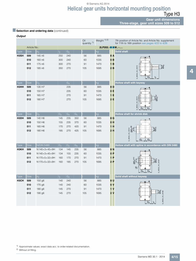
Helical gear units horizontal mounting positionType H3
Gear unit dimensionsThree-stage, gear unit sizes 509 to 512
4/15Siemens MD 30.1 · 2014
4
■ Selection and ordering data (continued)
Output
Oil quantity 1)
Weight 1) 2) 7th position of Article No. and Article No. supplementfor 11th to 16th position see pages 4/22 to 4/26
Article No.: 2LP202.-■ ■M..-....
Type Size d2 l2 G2 l kg Solid shaft
H3SH 509 145 n6 250 240 56 885 8 A
510 160 n6 300 240 60 1035 0 B
511 175 n6 300 270 91 1470 1 B
512 185 n6 350 270 105 1695 2 B
Type Size D2 G4 l kg Hollow shaft with keyway
H3HH 509 135 H7 235 56 885 8 D
510 150 H7 235 60 1035 0 E
511 165 H7 270 91 1470 1 E
512 180 H7 270 105 1695 2 E
Type Size D2 D3 G4 G5 l kg Hollow shaft for shrink disk
H3DH 509 140 H6 145 235 350 56 885 8 G
510 150 H6 155 235 370 60 1035 0 H
511 165 H6 170 270 420 91 1470 1 H
512 180 H6 185 270 425 105 1695 2 H
Type Size N/DIN 5480 D2 D3 G4 l kg Hollow shaft with spline in accordance with DIN 5480
H3KH 509 N140×3×45×9H 134 145 235 56 885 8 N
510 N140×3×45×9H 134 155 235 60 1035 0 P
511 N170×5×32×9H 160 170 270 91 1470 1 P
512 N170×5×32×9H 160 185 270 105 1695 2 P
Type Size d2 l2 G2 l kg Solid shaft without keyway
H3CH 509 150 g6 140 240 56 885 8 U
510 170 g6 140 240 60 1035 0 V
511 180 g6 145 270 91 1470 1 V
512 190 g6 145 270 105 1695 2 V
G_M
D30
_XX
_000
12
G2 I2
Ød 2
G_M
D30
_XX
_000
13
G4 G4
ØD
2H7
G_M
D30
_XX
_000
14
G5 G4
ØD
3
ØD
2H6
G_M
D30
_XX
_001
87
NG4 G4
ØD
3
ØD
2H11
G2 l2
G_M
D30
_XX
_001
86
Ød 2
1) Approximate values; exact data acc. to order-related documentation.2) Without oil filling.
© Siemens AG 2014

Helical gear units horizontal mounting positionType H3Gear unit dimensions Three-stage, gear unit sizes 513 and 514
4/16 Siemens MD 30.1 · 2014
4
■ Selection and ordering data
l3
hH
g l1G1
Fan
Air inlet
G_M
D30
_EN
_003
05
ca.30°
h 5
A3
A4
A2
A1
A1
Ød 1
Ød 6
c
n 4n 4
Øs
m3
b
G3
B2 B1 a
E ØD5
m1 n1
n2
n6 n3
c1
Note:For shaft details, see pages 10/2 to 10/7.
1) Max. dimensions including bolted connection. See order-related documentation for exact data.
2) Permissible tolerance: -1 mm.
Dimensions in mm
Gear unit sizes
Input Fan 1)
d1 l1 l3 d1 l1 l3 d1 l1 l3 G1 G3 A1 A2 A3 A4 B1 B2 d6
iN = 20 – 40 45 – 56 63 – 71
513 85 m6 160 130 65 m6 140 110 50 m6 110 80 320 350 275 295 270 190 380 325 175
iN = 25 – 50 56 – 71 80 – 90
514 85 m6 160 130 65 m6 140 110 50 m6 110 80 320 350 275 295 270 190 380 325 175
Gear unit sizes
Dimensions in mm
a b c c1 D5 E g H h 2) h5 m1 m3 n1 n2 n3 n4 n6 s
513 1452 535 60 65 48 825 202.5 950 440 180 1092 445 180 260 952 380 380 42
514 1570 535 60 65 48 903 202.5 950 440 180 1210 445 180 300 1030 380 420 42
© Siemens AG 2014

Helical gear units horizontal mounting positionType H3
Gear unit dimensionsThree-stage, gear unit sizes 513 and 514
4/17Siemens MD 30.1 · 2014
4
■ Selection and ordering data (continued)
Output
Oil quantity 1)
Weight 1) 2) 7th position of Article No. and Article No. supplementfor 11th to 16th position see pages 4/22 to 4/26
Article No.: 2LP202.-■ ■M..-....
Type Size d2 l2 G2 l kg Solid shaft
H3SH 513 200 n6 350 330 150 2420 3 B
514 210 n6 350 330 155 2720 4 B
Type Size D2 G4 l kg Hollow shaft with keyway
H3HH 513 190 H7 330 150 2420 3 E
514 210 H7 330 155 2720 4 E
Type Size D2 D3 G4 G5 l kg Hollow shaft for shrink disk
H3DH 513 190 H6 195 330 495 150 2420 3 H
514 210 H6 215 330 495 155 2720 4 H
Type Size N/DIN 5480 D2 D3 G4 l kg Hollow shaft with spline in accordance with DIN 5480
H3KH 513 N190×5×36×9H 180 195 330 150 2420 3 P
514 N190×5×36×9H 180 215 330 155 2720 4 P
Type Size d2 l2 G2 l kg Solid shaft without keyway
H3CH 513 220 g6 165 330 150 2420 3 V
514 220 g6 165 330 155 2720 4 V
G_M
D30
_XX
_000
12
G2 I2
Ød 2
G_M
D30
_XX
_000
13
G4 G4
ØD
2H7
G_M
D30
_XX
_000
14
G5 G4
ØD
3
ØD
2H6
G_M
D30
_XX
_001
87
NG4 G4
ØD
3
ØD
2H11
G2 l2
G_M
D30
_XX
_001
86
Ød 2
1) Approximate values; exact data acc. to order-related documentation.2) Without oil filling.
© Siemens AG 2014

Helical gear units horizontal mounting positionType H4Gear unit dimensions Four-stage, gear unit sizes 507 and 508
4/18 Siemens MD 30.1 · 2014
4
■ Selection and ordering data
c1
b
m3
G1 l1
m1 n1
a
En2
n6
n3
g
n 4h 4
n 4
Ød 1
h 5h
H
c
ØD5
Øs
G_M
D30
_XX
_000
02a
Dimensions in mm
Gear unit sizes
Input
Designs G, H, I on request for
d1 l1 d1 l1 G1
iN = 80 – 140 160 – 280 224 – 280
507 35 m6 60 28 m6 50 215
iN = 100 – 180 200 – 355 280 – 355
508 35 m6 60 28 m6 50 215
Gear unit sizes
Dimensions in mm
a b c c1 D5 E g H h 1) h4 h5 m1 m3 n1 n2 n3 n4 n6 s
507 899 295 35 35 28 493.5 112.5 635 280 198 115 680 230 104 180 567.5 242.5 257.5 24
508 1006 295 35 35 28 540.5 112.5 635 280 198 115 787 230 104 240 614.5 242.5 317.5 24
Note:For shaft details, see pages 10/2 to 10/7.
1) Permissible tolerance: -1 mm.
© Siemens AG 2014

Helical gear units horizontal mounting positionType H4
Gear unit dimensionsFour-stage, gear unit sizes 507 and 508
4/19Siemens MD 30.1 · 2014
4
■ Selection and ordering data (continued)
Output
Oil quantity 1)
Weight 1) 2) 7th position of Article No. and Article No. supplementfor 11th to 16th position see pages 4/22 to 4/26
Article No.: 2LP202.-■ ■N..-....
Type Size d2 l2 G2 l kg Solid shaft
H4SH 507 120 n6 210 195 30 520 6 A
508 130 n6 250 195 36 640 7 A
Type Size D2 G4 l kg Hollow shaft with keyway
H4HH 507 115 H7 195 30 520 6 D
508 125 H7 195 36 640 7 D
Type Size D2 D3 G4 G5 l kg Hollow shaft for shrink disk
H4DH 507 120 H6 120 195 290 30 520 6 G
508 130 H6 130 195 305 36 640 7 G
Type Size N/DIN 5480 D2 D3 G4 l kg Hollow shaft with spline in accordance with DIN 5480
H4KH 507 N120×3×38×9H 114 120 195 30 520 6 N
508 N120×3×38×9H 114 130 195 36 640 7 N
Type Size d2 l2 G2 l kg Solid shaft without keyway
H4CH 507 130 g6 115 195 30 520 6 U
508 130 g6 115 195 36 640 7 U
G2 I2
Ød 2
G4 G4
ØD
2H7
G_M
D30
_XX
_000
11
G5 G4
ØD
3
ØD
2H6
G_M
D30
_XX
_001
87
NG4 G4
ØD
3
ØD
2H11
G2 l2
G_M
D30
_XX
_001
86
Ød 2
1) Approximate values; exact data acc. to order-related documentation.2) Without oil filling.
© Siemens AG 2014

Helical gear units horizontal mounting positionType H4Gear unit dimensions Four-stage, gear unit sizes 509 to 514
4/20 Siemens MD 30.1 · 2014
4
■ Selection and ordering data
c1
b
m3
G1 l1
m1 n1
a
En2
n6
n3
g
n 4h 4
n 4
Ød 1
h 5h
H
c
ØD5
Øs
G_M
D30
_XX
_000
02a
Note:For shaft details, see pages 10/2 to 10/7.
1) Permissible tolerance: -1 mm.
Dimensions in mm
Gear unit sizes
Input
Designs G, H, I on request for
d1 l1 d1 l1 d1 l1 G1
iN = 80 – 160 180 – 315 250 – 315
509 35 m6 60 28 m6 50 225
iN = 100 – 200 224 – 400 315 – 400
510 35 m6 60 28 m6 50 225
iN = 80 – 160 180 – 224 250 – 315 250 – 315
511 45 m6 100 35 m6 80 28 m6 70 255
iN = 100 – 200 224 – 280 315 – 400 315 – 400
512 45 m6 100 35 m6 80 28 m6 70 255
iN = 80 – 160 180 – 224 250 – 315 250 – 315
513 60 m6 125 45 m6 100 32 m6 80 305
iN = 100 – 200 224 – 280 315 – 400 315 – 400
514 60 m6 125 45 m6 100 32 m6 80 305
Gear unit sizes
Dimensions in mm
a b c c1 D5 E g H h 1) h4 h5 m1 m3 n1 n2 n3 n4 n6 s
509 1040 370 40 45 35 575 140 715 320 230 135 785 290 125 205 458 275 290 28
510 1158 370 40 45 35 628 140 715 320 230 135 903 290 125 270 713 275 355 28
511 1281 430 50 60 40 706 155 830 380 270.5 145 960 340 161 255 812.5 330 362.5 35
512 1409 430 50 60 40 764 155 830 380 270.5 145 1088 340 161 325 870.5 330 432.5 35
513 1455 535 60 65 48 825 202.5 950 440 312 165 1092 445 183 260 952 380 380 42
514 1573 535 60 65 48 903 202.5 950 440 312 165 1210 445 183 300 1030 380 420 42
© Siemens AG 2014
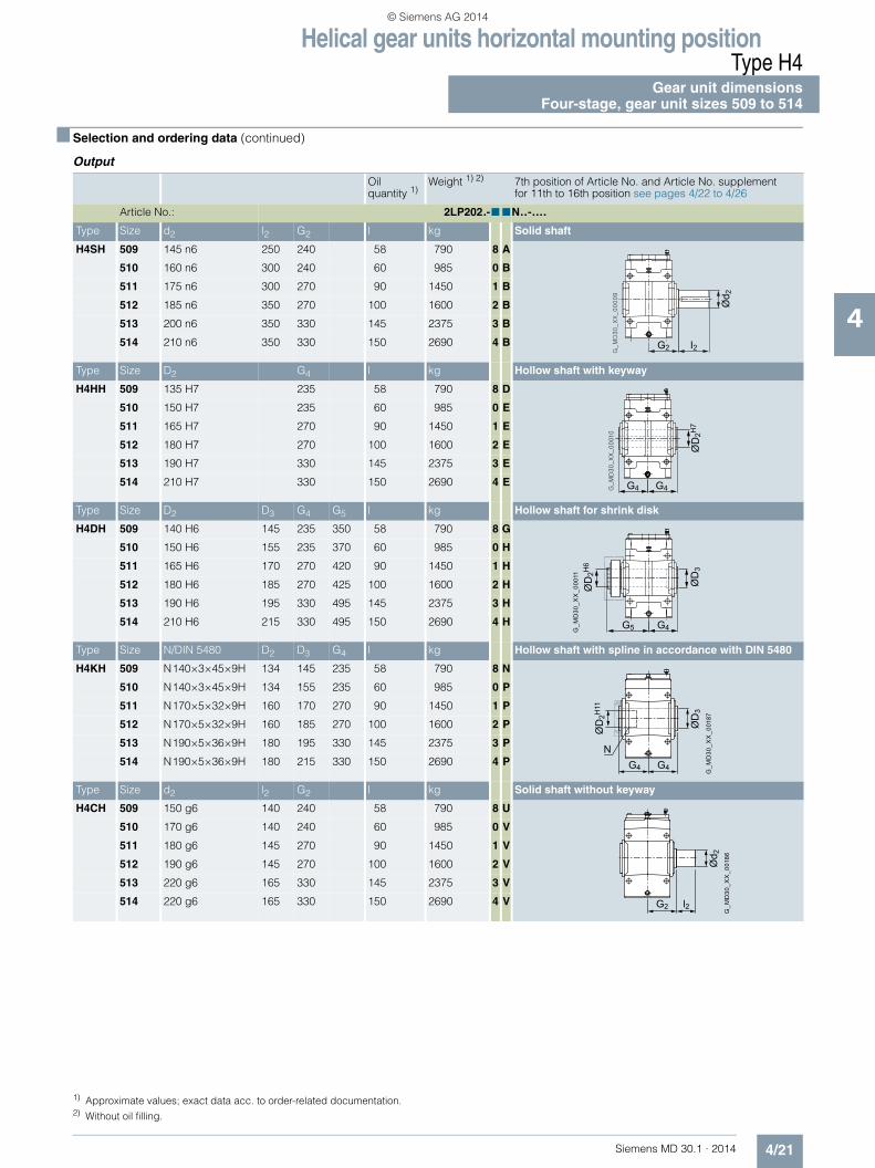
Helical gear units horizontal mounting positionType H4
Gear unit dimensionsFour-stage, gear unit sizes 509 to 514
4/21Siemens MD 30.1 · 2014
4
■ Selection and ordering data (continued)
Output
Oil quantity 1)
Weight 1) 2) 7th position of Article No. and Article No. supplementfor 11th to 16th position see pages 4/22 to 4/26
Article No.: 2LP202.-■ ■N..-....
Type Size d2 l2 G2 l kg Solid shaft
H4SH 509 145 n6 250 240 58 790 8 A
510 160 n6 300 240 60 985 0 B
511 175 n6 300 270 90 1450 1 B
512 185 n6 350 270 100 1600 2 B
513 200 n6 350 330 145 2375 3 B
514 210 n6 350 330 150 2690 4 B
Type Size D2 G4 l kg Hollow shaft with keyway
H4HH 509 135 H7 235 58 790 8 D
510 150 H7 235 60 985 0 E
511 165 H7 270 90 1450 1 E
512 180 H7 270 100 1600 2 E
513 190 H7 330 145 2375 3 E
514 210 H7 330 150 2690 4 E
Type Size D2 D3 G4 G5 l kg Hollow shaft for shrink disk
H4DH 509 140 H6 145 235 350 58 790 8 G
510 150 H6 155 235 370 60 985 0 H
511 165 H6 170 270 420 90 1450 1 H
512 180 H6 185 270 425 100 1600 2 H
513 190 H6 195 330 495 145 2375 3 H
514 210 H6 215 330 495 150 2690 4 H
Type Size N/DIN 5480 D2 D3 G4 l kg Hollow shaft with spline in accordance with DIN 5480
H4KH 509 N140×3×45×9H 134 145 235 58 790 8 N
510 N140×3×45×9H 134 155 235 60 985 0 P
511 N170×5×32×9H 160 170 270 90 1450 1 P
512 N170×5×32×9H 160 185 270 100 1600 2 P
513 N190×5×36×9H 180 195 330 145 2375 3 P
514 N190×5×36×9H 180 215 330 150 2690 4 P
Type Size d2 l2 G2 l kg Solid shaft without keyway
H4CH 509 150 g6 140 240 58 790 8 U
510 170 g6 140 240 60 985 0 V
511 180 g6 145 270 90 1450 1 V
512 190 g6 145 270 100 1600 2 V
513 220 g6 165 330 145 2375 3 V
514 220 g6 165 330 150 2690 4 V
G2 I2
Ød 2
G4 G4
ØD
2H7
G_M
D30
_XX
_000
11
G5 G4
ØD
3
ØD
2H6
G_M
D30
_XX
_001
87
NG4 G4
ØD
3
ØD
2H11
G2 l2
G_M
D30
_XX
_001
86
Ød 2
1) Approximate values; exact data acc. to order-related documentation.2) Without oil filling.
© Siemens AG 2014

Helical gear units horizontal mounting positionTypes H1, H2, H3 and H4
Article No. overview
4/22 Siemens MD 30.1 · 2014
4
■ Selection and ordering data
7th position of the Article No.
Data position of Article No.
1 to 6 7 8 9 10 11 12 13 14 15 16 "-Z" and order code
Article No. 2LP202 ■ - . . . . . - . . . . -Z . . .
Design variant (view directed at face 2, face 1 at bottom)
Type
H1.. H2.. H3.. H4..
A0
B1
C --2
D --3
Irrespective of the spatial position of the gear unit, the face designations "right" and "left" always refer to the horizontal mounting position with the view directed at face 1. Face 2 is at the top.Assembly cover at top (2), view directed at drive end face (1): • Face 3 = right • Face 6 = left
E --4
A
G_MD30_XX_00146 G_MD30_XX_00020
1
A
G8
ØD
8
G_MD30_XX_00024
1
A
G8
ØD
8
G_MD30_XX_00028
1
A
G8
ØD
8
6
5
4
6
5
4
2
3
1
G_MD30_XX_00233
G_MD30_XX_00147
B
G_MD30_XX_00021
1G8
ØD
8
B
G_MD30_XX_00025
1G8
ØD
8
B
G_MD30_XX_00029
1G8
ØD
8
B
G_MD30_XX_00022
1 G8
ØD
8
C
G_MD30_XX_00026
1G8
ØD
8
C
G_MD30_XX_00030
1 G8
ØD
8
C
G_MD30_XX_00023
1G8
ØD
8
D
G_MD30_XX_00027
1G8
ØD
8
D
G_MD30_XX_00031
1G8
ØD
8
D
1 G8
ØD
8
E
G_MD30_XX_00148
1G8
ØD
8
G_MD30_XX_00153
E
1 G8
ØD
8
G_MD30_XX_00158
E
$ Backstop
© Siemens AG 2014

Helical gear units horizontal mounting positionTypes H1, H2, H3 and H4
Article No. overview
4/23Siemens MD 30.1 · 2014
4
■ Selection and ordering data (continued)
7th position of the Article No. (continued)
$ Backstop 1) Designs G, H, I on request.
Data position of Article No.
1 to 6 7 8 9 10 11 12 13 14 15 16 "-Z" and order code
Article No. 2LP202 ■ - . . . . . - . . . . -Z . . .
Design variant (view directed at face 2, face 1 at bottom)
Type
H1.. H2.. 1) H3.. H4..
F --5
G --6
H --7
I --8
1G8
ØD
8
G_MD30_XX_00149
F
1G8
ØD
8F
G_MD30_XX_00154
F
1G8
ØD
8
G_MD30_XX_00159
G_MD30_XX_00150
G G
G_MD30_XX_00155 G_MD30_XX_00160
G
G_MD30_XX_00151
H
G_MD30_XX_00156
H
G_MD30_XX_00161
H
G_MD30_XX_00152
I
G_MD30_XX_00157
I
G_MD30_XX_00162
I
© Siemens AG 2014

Helical gear units horizontal mounting positionTypes H1, H2, H3 and H4
Article No. overview
4/24 Siemens MD 30.1 · 2014
4
■ Selection and ordering data (continued)
8th to 10th position of the Article No.
Data position of Article No.
1 to 6 7 8 9 10 11 12 13 14 15 16 "-Z" and order code
Article No. 2LP202 . - ■ ■ ■ . . - . . . . -Z . . .
Output shaft, gear unit size
Output shaft Gear unit size
Solid shaft (S)
503 2 A
504 3 A
505 4 A
506 5 A
507 6 A
508 7 A
509 8 A
510 0 B
511 1 B
512 2 B
513 3 B
514 4 B
Hollow shaft with keyway (H)
504 3 D
505 4 D
506 5 D
507 6 D
508 7 D
509 8 D
510 0 E
511 1 E
512 2 E
513 3 E
514 4 E
Hollow shaft for shrink disk (D)
504 3 G
505 4 G
506 5 G
507 6 G
508 7 G
509 8 G
510 0 H
511 1 H
512 2 H
513 3 H
514 4 H
© Siemens AG 2014
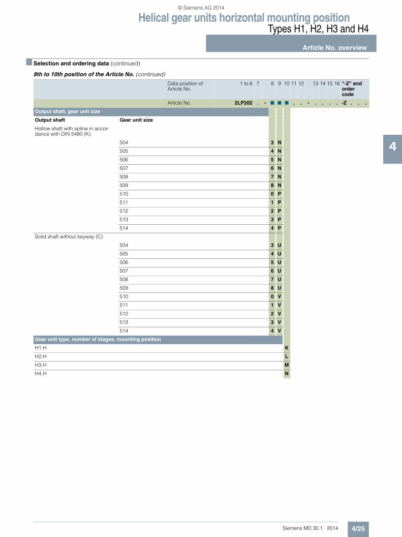
Helical gear units horizontal mounting positionTypes H1, H2, H3 and H4
Article No. overview
4/25Siemens MD 30.1 · 2014
4
■ Selection and ordering data (continued)
8th to 10th position of the Article No. (continued)
Data position of Article No.
1 to 6 7 8 9 10 11 12 13 14 15 16 "-Z" and order code
Article No. 2LP202 . - ■ ■ ■ . . - . . . . -Z . . .
Output shaft, gear unit size
Output shaft Gear unit size
Hollow shaft with spline in accor-dance with DIN 5480 (K)
504 3 N
505 4 N
506 5 N
507 6 N
508 7 N
509 8 N
510 0 P
511 1 P
512 2 P
513 3 P
514 4 P
Solid shaft without keyway (C)
504 3 U
505 4 U
506 5 U
507 6 U
508 7 U
509 8 U
510 0 V
511 1 V
512 2 V
513 3 V
514 4 V
Gear unit type, number of stages, mounting position
H1.H K
H2.H L
H3.H M
H4.H N
© Siemens AG 2014

Helical gear units horizontal mounting positionTypes H1, H2, H3 and H4
Article No. overview
4/26 Siemens MD 30.1 · 2014
4
■ Selection and ordering data (continued)
Article No. supplement, 11th to 16th position
Data position of Article No.
1 to 6 7 8 9 10 11 12 13 14 15 16 "-Z" and order code
Article No. 2LP202 . - . . . ■ ■ - ■ ■ ■ ■ -Z ■ ■ ■
Seal for shaft 1 1)
Shaft d1 at one end with 1 × shaft seal 0
Shaft d1 at both ends with 1 × shaft seal at both ends 1
Shaft d1 with labyrinth seal 2
Shaft d1 at one end with taconite E 4
Shaft d1 at both ends with taconite E at both ends 5
Seal for shaft 2 1)
Shaft d2 at one end with 1 × shaft seal 0
Shaft d2 at both ends with 1 × shaft seal at both ends 1
Shaft d2 with labyrinth seal 2
Shaft d2 at one end with taconite F 4
Shaft d2 at both ends with taconite F at both ends 5
Shaft d2 with taconite F-F 6
Shaft d2 with taconite F-H 7
Shaft d2 with taconite F-K 8
Shaft variants
Standard shaft d1 and standard shaft d2 0
Gear ratio
Type/gear unit size H1.H H2.H H3.H H4.H503, 504, 505, 507, 509
506 508, 510 504 ... 514 504 ... 514 507 ... 514
iN 1.12 – – 6.3 20 80 A
iN 1.25 – – 7.1 22.4 90 B
iN 1.4 1.4 1.32 8 25 100 C
iN 1.6 1.6 1.5 9 28 112 D
iN 1.8 1.8 1.7 10 31.5 125 E
iN 2 2 1.9 11.2 35.5 140 F
iN 2.24 2.24 2.12 12.5 40 160 G
iN 2.5 2.5 2.36 14 45 180 H
iN 2.8 2.8 2.65 16 50 200 J
iN 3.15 3.15 3 18 56 224 K
iN 3.55 3.55 3.35 20 63 250 L
iN 4 4 3.75 22.4 71 280 M
iN 4.5 4.5 4.25 25 80 315 N
iN 5 5 4.75 – 90 355 P
iN 5.6 5.6 5.3 – 100 400 Q
iN – – 6 – – – R
Oil supply
Dip lubrication A
Other oil supply Z Q 0 Y
Auxiliary cooling
Without auxiliary cooling 0
Auxiliary cooling with fan 1
Auxiliary cooling by cooling coil, connections to gear unit face 4 (end face d2) 2
Auxiliary cooling by fan and cooling coil, connections to gear unit face 4 (end face d2) 3
Auxiliary cooling by cooling coil, connections to gear unit face 1 (end face d1) 4
Auxiliary cooling by fan and cooling coil, connections to gear unit face 1 (end face d1) 5
1) Additional details see page 11/2.
© Siemens AG 2014

Siemens MD 30.1 · 2014
55/2 Type H1
Gear unit dimensions5/2 Single-stage, gear unit sizes 503 to 5085/4 Single-stage, gear unit sizes 509 and 510
5/6 Type H2Gear unit dimensions
5/6 Two-stage, gear unit sizes 513 and 514
5/8 Type H3Gear unit dimensions
5/8 Three-stage, gear unit sizes 513 and 514
5/10 Type H4Gear unit dimensions
5/10 Four-stage, gear unit sizes 507 and 5085/12 Four-stage, gear unit sizes 509 to 514
5/14 Types H1, H2, H3 and H45/14 Dimensions of oil expansion unit 5/15 Article No. overview
Helical gear units vertical mounting position
© Siemens AG 2014

Helical gear units vertical mounting positionType H1Gear unit dimensions Single-stage, gear unit sizes 503 to 508
5/2 Siemens MD 30.1 · 2014
5
■ Selection and ordering data
G_M
D30
_EN
_002
34
bg
c 1
E h6
an6n3
b3 b4
l 1G
1
Hh
b2b2n4 n4
f 2
1)
1)
1) 1)
Ød1
ØD5
Dimensions in mm
Gear unit sizes
Input
d1 l1 d1 l1 d1 l1 G1
iN = 1.12 – 2.8 3.15 – 4 4.5 – 5.6
503 60 m6 125 45 m6 100 32 m6 80 205
iN = 1.12 – 2.8 3.15 – 5.6
504 70 m6 135 50 m6 110 220
iN = 1.12 – 2.8 3.15 – 4 4.5 – 5.6
505 80 m6 160 60 m6 140 50 m6 110 255
iN = 1.4 – 3.55 4 – 5 5.6
506 80 m6 160 60 m6 140 50 m6 110 255
iN = 1.12 – 2.8 3.15 – 4 4.5 – 5.6
507 100 m6 180 80 m6 165 70 m6 140 290
iN = 1.32 – 3.35 3.75 – 4.75 5.3 – 6
508 100 m6 180 80 m6 165 70 m6 140 290
Gear unit sizes
Dimensions in mm
a b b2 2) b3 2) b4 2) c1 D5 E f2 2) g H h 3) h6 3) n3 n4 n6
503 455 260 93 202 74 25 19 128 55 105 440 200 190 230 175 165
504 555 325 105 256 97 30 24 159 58 132.5 490 225 225 290 195 195
505 620 360 121 298 113 30 24 185 60 150 540 250 230 345 220 200
506 670 360 126 340 124 30 24 216 60 150 540 250 250 376 220 220
507 730 465 149 367 139 40 28 228 63 192.5 670 315 260 415 280 225
508 790 465 154 397 139 40 28 258 63 192.5 670 315 290 445 280 255
Note:"Dip lubrication with oil expansion unit" is provided as the standard oil supply. Dimensions of oil expansion unit see page 5/14. For shaft details, see pages 10/2 to 10/7.
1) Position dependent on other options. 2) Minimum dimensions, space requirements dependent on other options. 3) Permissible tolerance: -1 mm.
© Siemens AG 2014

Helical gear units vertical mounting positionType H1
Gear unit dimensionsSingle-stage, gear unit sizes 503 to 508
5/3Siemens MD 30.1 · 2014
5
■ Selection and ordering data (continued)
Output
Oil quantity 1)
Weight 1) 2) 7th position of Article No. and Article No. supplementfor 11th to 16th position see pages 5/15 to 5/19
Article No.: 2LP202.-■ ■W..-....
Type Size d2 l2 G2 l kg Solid shaft
H1SV 503 65 m6 140 185 21 150 2 A
504 80 m6 170 220 34 300 3 A
505 90 m6 210 240 46 350 4 A
506 100 m6 210 240 50 395 5 A
507 105 n6 235 295 88 686 6 A
508 120 n6 250 295 96 710 7 A
Type Size D2 G4 l kg Hollow shaft with keyway
H1HV 503 – – – –
504 80 H7 220 34 300 3 D
505 95 H7 240 46 350 4 D
506 105 H7 240 50 395 5 D
507 115 H7 295 88 686 6 D
508 125 H7 295 96 710 7 D
I 2G
2
Ød2
G_MD30_XX_00235
G_MD30_XX_00281
G4
G4
ØD2H7
1) Approximate values; exact data acc. to order-related documentation.2) Without oil filling.
© Siemens AG 2014

Helical gear units vertical mounting positionType H1Gear unit dimensions Single-stage, gear unit sizes 509 and 510
5/4 Siemens MD 30.1 · 2014
5
■ Selection and ordering data
G_M
D30
_EN
_002
34
bg
c 1
E h6
an6n3
b3 b4
l 1G
1
Hh
b2b2n4 n4
f 2
1)
1)
1) 1)
Ød1
ØD5
Dimensions in mm
Gear unit sizes
Input
d1 l1 d1 l1 d1 l1 G1
iN = 1.12 – 2.8 3.15 – 4 4.5 – 5.6
509 110 n6 200 90 m6 165 75 m6 140 340
iN = 1.32 – 3.35 3.75 – 4.75 5.3 – 6
510 110 n6 200 90 m6 165 75 m6 140 340
Gear unit sizes
Dimensions in mm
a b b2 2) b3 2) b4 2) c1 D5 E g f2 2) H h 3) h6 3) n3 n4 n6
509 875 550 160 425 160 55 35 265 220 60 755 355 330 480 307.5 282.5
510 935 550 170 466 170 55 35 296 220 60 755 355 355 511 307.5 307.5
Note:"Dip lubrication with oil expansion unit" is provided as the standard oil supply. Dimensions of oil expansion unit see page 5/14. For shaft details, see pages 10/2 to 10/7.
1) Position dependent on other options. 2) Minimum dimensions, space requirements dependent on other options. 3) Permissible tolerance: -1 mm.
© Siemens AG 2014

Helical gear units vertical mounting positionType H1
Gear unit dimensionsSingle-stage, gear unit sizes 509 and 510
5/5Siemens MD 30.1 · 2014
5
■ Selection and ordering data (continued)
Output
Oil quantity 1)
Weight 1) 2) 7th position of Article No. and Article No. supplementfor 11th to 16th position see pages 5/15 to 5/19
Article No.: 2LP202.-■ ■W..-....
Type Size d2 l2 G2 l kg Solid shaft
H1SV 509 135 n6 260 335 140 970 8 A
510 150 n6 280 335 148 1150 0 B
Type Size D2 G4 l kg Hollow shaft with keyway
H1HV 509 135 H7 335 140 970 8 D
510 145 H7 335 148 1150 0 E
I 2G
2
Ød2
G_MD30_XX_00235
G_MD30_XX_00281
G4
G4
ØD2H7
1) Approximate values; exact data acc. to order-related documentation.2) Without oil filling.
© Siemens AG 2014

Helical gear units vertical mounting positionType H2Gear unit dimensions Two-stage, gear unit sizes 513 and 514
5/6 Siemens MD 30.1 · 2014
5
■ Selection and ordering data
G_M
D30
_EN
_002
36
Ød1
ØD5
1)
1)
1) 1)
a
E
f 2
hH
G1
l 1
b4b3n3 n6
b2b2n4 n4
h6
c 1g
b
Dimensions in mm
Gear unit sizes
Drive Designs G, H, I on request for all ratios
d1 l1 d1 l1 d1 l1 G1
iN = 6.3 – 10 11.2 – 14 16 – 18
513 110 n6 200 90 m6 165 75 m6 140 330
iN = 8 – 12.5 14 – 18 20 – 22.4
514 110 n6 200 90 m6 165 75 m6 140 330
Gear unit sizes
Dimensions in mm
a b b2 2) b3 2) b4 2) c1 D5 E g f2 2) H h 3) h6 3) n3 n4 n6
513 1360 535 205 800 205 65 48 640 202.5 63 935 440 440 842 380 380
514 1475 535 220 878 220 65 48 718 202.5 63 935 440 480 920 380 420
Note:"Dip lubrication with oil expansion unit" is provided as the standard oil supply. Dimensions of oil expansion unit see page 5/14. For shaft details, see pages 10/2 to 10/7.
1) Position dependent on other options. 2) Minimum dimensions, space requirements dependent on other options. 3) Permissible tolerance: -1 mm.
© Siemens AG 2014

Helical gear units vertical mounting positionType H2
Gear unit dimensionsTwo-stage, gear unit sizes 513 and 514
5/7Siemens MD 30.1 · 2014
5
■ Selection and ordering data (continued)
Output
Oil quantity 1)
Weight 1) 2) 7th position of Article No. and Article No. supplementfor 11th to 16th position see pages 5/15 to 5/19
Article No.: 2LP202.-■ ■S..-....
Type Size d2 l2 G2 l kg Solid shaft
H2SV 513 200 n6 350 330 300 2600 3 B
514 210 n6 350 330 310 2965 4 B
Type Size D2 G4 l kg Hollow shaft with keyway
H2HV 513 190 H7 330 300 2600 3 E
514 210 H7 330 310 2965 4 E
Type Size D2 D3 G4 G5 l kg Hollow shaft for shrink disk
H2DV 3) 513 190 H6 195 330 495 300 2600 3 H
514 210 H6 215 330 495 310 2965 4 H
Type Size N/DIN 5480 D2 D3 G4 l kg Hollow shaft with spline in accordance with DIN 5480
H2KV 513 N190×5×36×9H 180 195 330 300 2600 3 P
514 N190×5×36×9H 180 215 330 310 2965 4 P
Type Size d2 l2 G2 l kg Solid shaft without keyway
H2CV 3) 513 220 g6 165 330 300 2600 3 V
514 220 g6 165 330 310 2965 4 V
I 2G
2
Ød2G_MD30_XX_00237
G4
G4
ØD2H7
G_MD30_XX_00241
G4
G5
ØD3
ØD2H6
G_MD30_XX_00242
G_MD30_XX_00243
N
G4
G4
ØD3
ØD2H11
G2
l 2
G_MD30_XX_00244
Ød2
1) Approximate values; exact data acc. to order-related documentation.2) Without oil filling.
3) Shaft variant designed to withstand axial forces (including those caused by weight of gear unit) on request.
© Siemens AG 2014
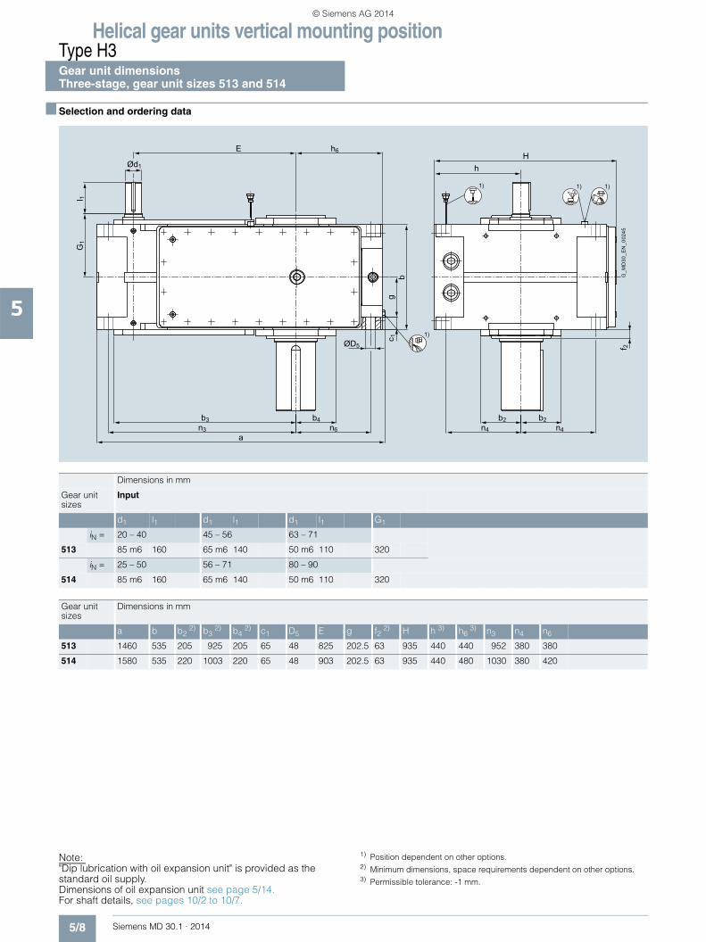
Helical gear units vertical mounting positionType H3Gear unit dimensions Three-stage, gear unit sizes 513 and 514
5/8 Siemens MD 30.1 · 2014
5
■ Selection and ordering data
G_M
D30
_EN
_002
45
1)
1)1)1)
ØD5
an6n3
b3 b4
G1
l 1
gc 1
b
hH
b2b2n4 n4
f 2
Ød1
E h6
Note: "Dip lubrication with oil expansion unit" is provided as the standard oil supply. Dimensions of oil expansion unit see page 5/14. For shaft details, see pages 10/2 to 10/7.
1) Position dependent on other options. 2) Minimum dimensions, space requirements dependent on other options. 3) Permissible tolerance: -1 mm.
Dimensions in mm
Gear unit sizes
Input
d1 l1 d1 l1 d1 l1 G1
iN = 20 – 40 45 – 56 63 – 71
513 85 m6 160 65 m6 140 50 m6 110 320
iN = 25 – 50 56 – 71 80 – 90
514 85 m6 160 65 m6 140 50 m6 110 320
Gear unit sizes
Dimensions in mm
a b b2 2) b3 2) b4 2) c1 D5 E g f2 2) H h 3) h6 3) n3 n4 n6
513 1460 535 205 925 205 65 48 825 202.5 63 935 440 440 952 380 380
514 1580 535 220 1003 220 65 48 903 202.5 63 935 440 480 1030 380 420
© Siemens AG 2014

Helical gear units vertical mounting positionType H3
Gear unit dimensionsThree-stage, gear unit sizes 513 and 514
5/9Siemens MD 30.1 · 2014
5
■ Selection and ordering data (continued)
Output
Oil quantity 1)
Weight 1) 2) 7th position of Article No. and Article No. supplementfor 11th to 16th position see pages 5/15 to 5/19
Article No.: 2LP202.-■ ■T..-....
Type Size d2 l2 G2 l kg Solid shaft
H3SV 513 200 n6 350 330 300 2420 3 B
514 210 n6 350 330 310 2720 4 B
Type Size D2 G4 l kg Hollow shaft with keyway
H3HV 513 190 H7 330 300 2420 3 E
514 210 H7 330 310 2720 4 E
Type Size D2 D3 G4 G5 l kg Hollow shaft for shrink disk
H3DV 3) 513 190 H6 195 330 495 300 2420 3 H
514 210 H6 215 330 495 310 2720 4 H
Type Size N/DIN 5480 D2 D3 G4 l kg Hollow shaft with spline in accordance with DIN 5480
H3KV 513 N190×5×36×9H 180 195 330 300 2420 3 P
514 N190×5×36×9H 180 215 330 310 2720 4 P
Type Size d2 l2 G2 l kg Solid shaft without keyway
H3CV 3) 513 220 g6 165 330 300 2420 3 V
514 220 g6 165 330 310 2720 4 V
I 2G
2
Ød2G_MD30_XX_00237
G4
G4
ØD2H7
G_MD30_XX_00241
G4
G5
ØD3
ØD2H6
G_MD30_XX_00242
G_MD30_XX_00243
N
G4
G4
ØD3
ØD2H11
G2
l 2
G_MD30_XX_00244
Ød2
1) Approximate values; exact data acc. to order-related documentation.2) Without oil filling.
3) Shaft variant designed to withstand axial forces (including those caused by weight of gear unit) on request.
© Siemens AG 2014

Helical gear units vertical mounting positionType H4Gear unit dimensions Four-stage, gear unit sizes 507 and 508
5/10 Siemens MD 30.1 · 2014
5
■ Selection and ordering data
G_MD30_XX_00250
1)1)1)
1)
f2
H
h4
h
b2b2
n4 n4
Ød1
E h6
bg
c1
ØD5
G1
l1
an6n3
b4b3
Dimensions in mm
Gear unit sizes
Input Designs G, H, I on request for
d1 l1 d1 l1 G1
iN = 80 – 140 160 – 280 224 – 280
507 35 m6 60 28 m6 50 215
iN = 100 – 180 200 – 355 280 – 355
508 35 m6 60 28 m6 50 215
Gear unit sizes
Dimensions in mm
a b b2 2) b3 2) b4 2) c1 D5 E g f2 2) H h 3) h4 h6 3) n3 n4 n6
507 915 295 140 556 125 35 28 493.5 112.5 48 605 280 198 295 567.5 242.5 257.5
508 1020 295 140 603 142 35 28 540.5 112.5 48 605 280 198 355 614.5 242.5 317.5
Note:"Dip lubrication with oil expansion unit" is provided as the standard oil supply. Dimensions of oil expansion unit see page 5/14. For shaft details, see pages 10/2 to 10/7.
1) Position dependent on other options. 2) Minimum dimensions, space requirements dependent on other options. 3) Permissible tolerance: -1 mm.
© Siemens AG 2014
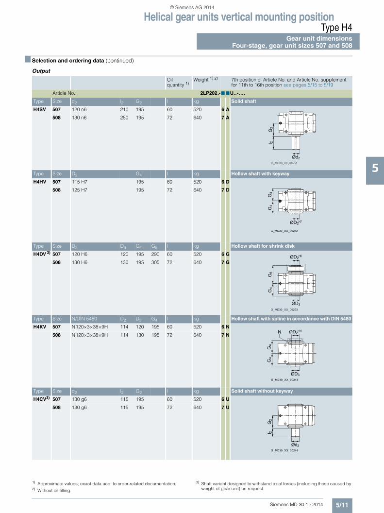
Helical gear units vertical mounting positionType H4
Gear unit dimensionsFour-stage, gear unit sizes 507 and 508
5/11Siemens MD 30.1 · 2014
5
■ Selection and ordering data (continued)
Output
Oil quantity 1)
Weight 1) 2) 7th position of Article No. and Article No. supplementfor 11th to 16th position see pages 5/15 to 5/19
Article No.: 2LP202.-■ ■U..-....
Type Size d2 l2 G2 l kg Solid shaft
H4SV 507 120 n6 210 195 60 520 6 A
508 130 n6 250 195 72 640 7 A
Type Size D2 G4 l kg Hollow shaft with keyway
H4HV 507 115 H7 195 60 520 6 D
508 125 H7 195 72 640 7 D
Type Size D2 D3 G4 G5 l kg Hollow shaft for shrink disk
H4DV 3) 507 120 H6 120 195 290 60 520 6 G
508 130 H6 130 195 305 72 640 7 G
Type Size N/DIN 5480 D2 D3 G4 l kg Hollow shaft with spline in accordance with DIN 5480
H4KV 507 N120×3×38×9H 114 120 195 60 520 6 N
508 N120×3×38×9H 114 130 195 72 640 7 N
Type Size d2 l2 G2 l kg Solid shaft without keyway
H4CV3) 507 130 g6 115 195 60 520 6 U
508 130 g6 115 195 72 640 7 U
G2
I 2
Ød2
G_MD30_XX_00252
G4
G4
ØD2H7
G_MD30_XX_00253
G5
G4
ØD2H6
ØD3
G_MD30_XX_00243
N
G4
G4
ØD3
ØD2H11
G2
l 2
G_MD30_XX_00244
Ød2
1) Approximate values; exact data acc. to order-related documentation.2) Without oil filling.
3) Shaft variant designed to withstand axial forces (including those caused by weight of gear unit) on request.
© Siemens AG 2014
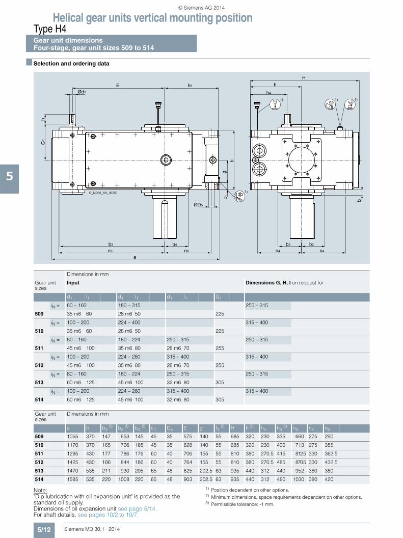
Helical gear units vertical mounting positionType H4Gear unit dimensions Four-stage, gear unit sizes 509 to 514
5/12 Siemens MD 30.1 · 2014
5
■ Selection and ordering data
G_MD30_XX_00250
1)1)1)
1)
f2
H
h4
h
b2b2
n4 n4
Ød1
E h6
bg
c1
ØD5
G1
l1
an6n3
b4b3
Note:"Dip lubrication with oil expansion unit" is provided as the standard oil supply. Dimensions of oil expansion unit see page 5/14. For shaft details, see pages 10/2 to 10/7.
1) Position dependent on other options. 2) Minimum dimensions, space requirements dependent on other options. 3) Permissible tolerance: -1 mm.
Dimensions in mm
Gear unit sizes
Input Dimensions G, H, I on request for
d1 l1 d1 l1 d1 l1 G1
iN = 80 – 160 180 – 315 250 – 315
509 35 m6 60 28 m6 50 225
iN = 100 – 200 224 – 400 315 – 400
510 35 m6 60 28 m6 50 225
iN = 80 – 160 180 – 224 250 – 315 250 – 315
511 45 m6 100 35 m6 80 28 m6 70 255
iN = 100 – 200 224 – 280 315 – 400 315 – 400
512 45 m6 100 35 m6 80 28 m6 70 255
iN = 80 – 160 180 – 224 250 – 315 250 – 315
513 60 m6 125 45 m6 100 32 m6 80 305
iN = 100 – 200 224 – 280 315 – 400 315 – 400
514 60 m6 125 45 m6 100 32 m6 80 305
Gear unit sizes
Dimensions in mm
a b b2 2) b3 2) b4 2) c1 D5 E g f2 2) H h 3) h4 h6 3) n3 n4 n6
509 1055 370 147 653 145 45 35 575 140 55 685 320 230 335 660 275 290
510 1170 370 165 706 165 45 35 628 140 55 685 320 230 400 713 275 355
511 1295 430 177 786 176 60 40 706 155 55 810 380 270.5 415 812.5 330 362.5
512 1425 430 186 844 186 60 40 764 155 55 810 380 270.5 485 870.5 330 432.5
513 1470 535 211 930 205 65 48 825 202.5 63 935 440 312 440 952 380 380
514 1585 535 220 1008 220 65 48 903 202.5 63 935 440 312 480 1030 380 420
© Siemens AG 2014

Helical gear units vertical mounting positionType H4
Gear unit dimensionsFour-stage, gear unit sizes 509 to 514
5/13Siemens MD 30.1 · 2014
5
■ Selection and ordering data (continued)
Output
Oil quantity 1)
Weight 1) 2) 7th position of Article No. and Article No. supplementfor 11th to 16th position see pages 5/15 to 5/19
Article No.: 2LP202.-■ ■U..-....
Type Size d2 l2 G2 l kg Solid shaft
H4SV 509 145 n6 250 240 116 790 8 A
510 160 n6 300 240 120 985 0 B
511 175 n6 300 270 180 1450 1 B
512 185 n6 350 270 200 1600 2 B
513 200 n6 350 330 290 2375 3 B
514 210 n6 350 330 300 2690 4 B
Type Size D2 G4 l kg Hollow shaft with keyway
H4HV 509 135 H7 235 116 790 8 D
510 150 H7 235 120 985 0 E
511 165 H7 270 180 1450 1 E
512 180 H7 270 200 1600 2 E
513 190 H7 330 290 2375 3 E
514 210 H7 330 300 2690 4 E
Type Size D2 D3 G4 G5 l kg Hollow shaft for shrink disk
H4DV 3) 509 140 H6 145 235 350 116 790 8 G
510 150 H6 155 235 370 120 985 0 H
511 165 H6 170 270 420 180 1450 1 H
512 180 H6 185 270 425 200 1600 2 H
513 190 H6 195 330 495 290 2375 3 H
514 210 H6 215 330 495 300 2690 4 H
Type Size N/DIN 5480 D2 D3 G4 l kg Hollow shaft with spline in accordance with DIN 5480
H4KV 509 N140×3×45×9H 134 145 235 116 790 8 N
510 N140×3×45×9H 134 155 235 120 985 0 P
511 N170×5×32×9H 160 170 270 180 1450 1 P
512 N170×5×32×9H 160 185 270 200 1600 2 P
513 N190×5×36×9H 180 195 330 290 2375 3 P
514 N190×5×36×9H 180 215 330 300 2690 4 P
Type Size d2 l2 G2 l kg Solid shaft without keyway
H4CV3) 509 150 g6 140 240 116 790 8 U
510 170 g6 140 240 120 985 0 V
511 180 g6 145 270 180 1450 1 V
512 190 g6 145 270 200 1600 2 V
513 220 g6 165 330 290 2375 3 V
514 220 g6 165 330 300 2690 4 V
G2
I 2
Ød2
G_MD30_XX_00252
G4
G4
ØD2H7
G_MD30_XX_00253
G5
G4
ØD2H6
ØD3
G_MD30_XX_00243
N
G4
G4
ØD3
ØD2H11
G2
l 2
G_MD30_XX_00244
Ød2
1) Approximate values; exact data acc. to order-related documentation.2) Without oil filling.
3) Shaft variant designed to withstand axial forces (including those caused by weight of gear unit) on request.
© Siemens AG 2014
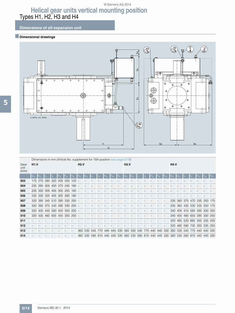
Helical gear units vertical mounting positionTypes H1, H2, H3 and H4
Dimensions of oil expansion unit
5/14 Siemens MD 30.1 · 2014
5
■ Dimensional drawings
b2 b3l1l2
h3h4
h5
G_MD30_XX_00254
Dimensions in mm (Article No. supplement for 15th position see page 5/19)
Gearunitsizes
H1.V H2.V H3.V H4.V
b2 b3 l1 l2 h3 h4 h5 b2 b3 l1 l2 h3 h4 h5 b2 b3 l1 l2 h3 h4 h5 b2 b3 l1 l2 h3 h4 h5
503 175 270 260 320 205 205 125 – – – – – – – – – – – – – – – – – – – – –
504 235 295 305 400 270 245 180 – – – – – – – – – – – – – – – – – – – – –
505 235 320 305 405 305 250 180 – – – – – – – – – – – – – – – – – – – – –
506 235 320 325 425 305 280 180 – – – – – – – – – – – – – – – – – – – – –
507 320 395 345 510 390 330 250 – – – – – – – – – – – – – – 235 365 375 470 235 250 175
508 320 395 375 540 390 330 250 – – – – – – – – – – – – – – 235 365 435 530 235 250 175
509 320 435 435 580 455 350 250 – – – – – – – – – – – – – – 340 405 415 585 295 330 250
510 320 435 460 605 455 350 250 – – – – – – – – – – – – – – 340 405 480 650 295 330 250
511 – – – – – – – – – – – – – – – – – – – – – 320 465 520 665 350 335 250
512 – – – – – – – – – – – – – – – – – – – – – 320 465 590 735 350 335 250
513 – – – – – – – 360 535 545 770 440 440 330 360 535 545 770 440 440 330 360 535 545 770 440 440 330
514 – – – – – – – 360 535 585 810 440 440 330 360 535 585 810 440 440 330 360 535 585 810 440 440 330
© Siemens AG 2014

Helical gear units vertical mounting positionTypes H1, H2, H3 and H4
Article No. overview
5/15Siemens MD 30.1 · 2014
5
■ Selection and ordering data
7th position of the Article No.
Data position of Article No.
1 to 6 7 8 9 10 11 12 13 14 15 16 "-Z" and order code
Article No. 2LP202 ■ - . . . . . - . . . . -Z . . .
Design variant (view directed at face 2, face 1 on left)
Type
H1.. H2.. H3.. H4..
A0
B1
C --2
D --3
Irrespective of the spatial position of the gear unit, the face designations "right" and "left" always refer to the horizontal mounting position with the view directed at face 1. Face 2 is at the top.Assembly cover at top (2), view directed at drive end face (1): • Face 3 = right • Face 6 = left
E --4
AG_MD30_XX_00255 G_MD30_XX_00256
A
G_MD30_XX_00257
AG_MD30_XX_00258
A
6
5
4
6
5
4
2
3
1
G_MD30_XX_00233
G_MD30_XX_00259
B
G_MD30_XX_00260
B
G_MD30_XX_00261
B
G_MD30_XX_00262
B
G_MD30_XX_00263
C C
G_MD30_XX_00264 G_MD30_XX_00265
C
G_MD30_XX_00266
DG_MD30_XX_00267
DG_MD30_XX_00268
D
E
G_MD30_XX_00269 G_MD30_XX_00270
E
G_MD30_XX_00271
E
© Siemens AG 2014

Helical gear units vertical mounting positionTypes H1, H2, H3 and H4
Article No. overview
5/16 Siemens MD 30.1 · 2014
5
■ Selection and ordering data (continued)
7th position of the Article No. (continued)
Data position of Article No.
1 to 6 7 8 9 10 11 12 13 14 15 16 "-Z" and order code
Article No. 2LP202 ■ - . . . . . - . . . . -Z . . .
Design variant (view directed at face 2, face 1 on left)
Type
H1.. H2.. 1) H3.. H4..
F --5
G --6
H --7
I --8
Irrespective of the spatial position of the gear unit, the face designations "right" and "left" always refer to the horizontal mounting position with the view directed at face 1. Face 2 is at the top.Assembly cover at top (2), view directed at drive end face (1): • Face 3 = right • Face 6 = left
G_MD30_XX_00272
F F
G_MD30_XX_00273
F
G_MD30_XX_00274
6
5
4
6
5
4
2
3
1
G_MD30_XX_00233
G_MD30_XX_00275
G G
G_MD30_XX_00276 G_MD30_XX_00277
G
G_MD30_XX_00301
H
G_MD30_XX_00302
H
G_MD30_XX_00303
H
G_MD30_XX_00278
I
G_MD30_XX_00279
I
G_MD30_XX_00280
I
1) Designs G, H, I on request.
© Siemens AG 2014

Helical gear units vertical mounting positionTypes H1, H2, H3 and H4
Article No. overview
5/17Siemens MD 30.1 · 2014
5
■ Selection and ordering data (continued)
8th to 10th position of the Article No.
Data position of Article No.
1 to 6 7 8 9 10 11 12 13 14 15 16 "-Z" and order code
Article No. 2LP202 . - ■ ■ ■ . . - . . . . -Z . . .
Output shaft, gear unit size
Output shaft Gear unit size
Solid shaft (S)
503 2 A
504 3 A
505 4 A
506 5 A
507 6 A
508 7 A
509 8 A
510 0 B
511 1 B
512 2 B
513 3 B
514 4 B
Hollow shaft with keyway (H)
504 3 D
505 4 D
506 5 D
507 6 D
508 7 D
509 8 D
510 0 E
511 1 E
512 2 E
513 3 E
514 4 E
Hollow shaft for shrink disk (D)
507 6 G
508 7 G
509 8 G
510 0 H
511 1 H
512 2 H
513 3 H
514 4 H
© Siemens AG 2014

Helical gear units vertical mounting positionTypes H1, H2, H3 and H4
Article No. overview
5/18 Siemens MD 30.1 · 2014
5
■ Selection and ordering data (continued)
8th to 10th position of the Article No. (continued)
Data position of Article No.
1 to 6 7 8 9 10 11 12 13 14 15 16 "-Z" and order code
Article No. 2LP202 . - ■ ■ ■ . . - . . . . -Z . . .
Output shaft, gear unit size
Output shaft Gear unit size
Hollow shaft with spline in accordance with DIN 5480 (K)
507 6 N
508 7 N
509 8 N
510 0 P
511 1 P
512 2 P
513 3 P
514 4 P
Solid shaft without keyway (C)
507 6 U
508 7 U
509 8 U
510 0 V
511 1 V
512 2 V
513 3 V
514 4 V
Gear unit type, number of stages, mounting position
H1.V W
H2.V S
H3.V T
H4.V U
© Siemens AG 2014

Helical gear units vertical mounting positionTypes H1, H2, H3 and H4
Article No. overview
5/19Siemens MD 30.1 · 2014
5
■ Selection and ordering data (continued)
Article No. supplement, 11th to 16th position
Data position of Article No.
1 to 6 7 8 9 10 11 12 13 14 15 16 "-Z" and order code
Article No. 2LP202 . - . . . ■ ■ - ■ ■ ■ ■ -Z ■ ■ ■
Seal for shaft 1 1)
Shaft d1 at one end with 1 × shaft seal 0
Shaft d1 at both ends with 1 × shaft seal at both ends 1
Shaft d1 at one end with taconite E 4
Shaft d1 at both ends with taconite E at both ends 5
Seal for shaft 2 1)
Shaft d2 at one end with 1 × shaft seal 0
Shaft d2 at both ends with 1 × shaft seal at both ends 1
Shaft d2 at one end with taconite F 4
Shaft d2 at both ends with taconite F at both ends 5
Shaft d2 with taconite F-F 6
Shaft d2 with taconite F-H 7
Shaft d2 with taconite F-K 8
Shaft variants
Standard shaft d1 and standard shaft d2 0
Gear ratio
Type/gear unit size
H1.. H2.. H3.. H4..
503, 504, 505, 507, 509
506 508, 510 504 ... 514 504 ... 514 507 ... 514
iN 1.12 – – 6.3 20 80 A
iN 1.25 – – 7.1 22.4 90 B
iN 1.4 1.4 1.32 8 25 100 C
iN 1.6 1.6 1.5 9 28 112 D
iN 1.8 1.8 1.7 10 31.5 125 E
iN 2 2 1.9 11.2 35.5 140 F
iN 2.24 2.24 2.12 12.5 40 160 G
iN 2.5 2.5 2.36 14 45 180 H
iN 2.8 2.8 2.65 16 50 200 J
iN 3.15 3.15 3 18 56 224 K
iN 3.55 3.55 3.35 20 63 250 L
iN 4 4 3.75 22.4 71 280 M
iN 4.5 4.5 4.25 25 80 315 N
iN 5 5 4.75 – 90 355 P
iN 5.6 5.6 5.3 – 100 400 Q
iN – – 6 – – – R
Oil supply
Dip lubrication with oil expansion unit B
Other oil supply Z Q 0 Y
Auxiliary cooling
Without auxiliary cooling 0
Auxiliary cooling by cooling coil, connections to gear unit face 4 (end face d2)
2
Auxiliary cooling by cooling coil, connections to gear unit face 1 (end face d1)
4
1) Additional details see page 11/3.
© Siemens AG 2014

Helical gear units vertical mounting positionTypes H1, H2, H3 and H4
Notes
5/20 Siemens MD 30.1 · 2014
5
© Siemens AG 2014

Siemens MD 30.1 · 2014
66/2 Type H1
Gear unit dimensions6/2 Single-stage, gear unit sizes 503 to 5086/4 Single-stage, gear unit sizes 509 and 510
6/6 Type H2Gear unit dimensions
6/6 Two-stage, gear unit sizes 504 to 5086/8 Two-stage, gear unit sizes 509 to 5126/10 Two-stage, gear unit sizes 513 and 514
6/12 Type H3Gear unit dimensions
6/12 Three-stage, gear unit sizes 505 to 5086/14 Three-stage, gear unit sizes 509 to 5126/16 Three-stage, gear unit sizes 513 and 514
6/18 Type H4Gear unit dimensions
6/18 Four-stage, gear unit sizes 507 and 5086/20 Four-stage, gear unit sizes 509 to 514
6/22 Types H1, H2, H3 and H46/22 Dimensions of oil expansion unit6/23 Article No. overview
Helical gear units upright mounting position, output at bottom
© Siemens AG 2014

Helical gear units upright mounting position, output at bottomType H1Gear unit dimensions Single-stage, gear unit sizes 503 to 508
6/2 Siemens MD 30.1 · 2014
6
■ Selection and ordering data
1) 1) 1)
G_MD30_EN_00217
Air inletFan
m6
m3
b
n 2m
1n 1 A
3
A5
A4
n 6 h 6
n 3a
c 2
n5n4n4
hH
ØD7
Ød 1
Ød 6
Øs
cm5 G3l3
ca. 30°
G1A2 A1 c1l1 g
B1 B2
ØD
5E
Dimensions in mm
Gear unit sizes
Input Fan 2)
d1 l1 l3 d1 l1 l3 d1 l1 l3 G1 G3 A1 A2 A3 A4 A5 B1 B2 d6
iN = 1.12 – 2.8 3.15 – 4 4.5 – 5.6
503 60 m6 125 105 45 m6 100 80 32 m6 80 60 205 225 185 250 200 185 100 250 185 175
iN = 1.12 – 2.8 3.15 – 5.6
504 70 m6 135 105 50 m6 110 80 220 250 215 275 230 220 135 275 215 175
iN = 1.12 – 2.8 3.15 – 4 4.5 – 5.6
505 80 m6 160 130 60 m6 140 110 50 m6 110 80 255 285 230 305 260 245 160 315 235 190
iN = 1.4 – 3.55 4 – 5 5.6
506 80 m6 160 130 60 m6 140 110 50 m6 110 80 255 285 235 305 260 245 160 315 235 190
iN = 1.12 – 2.8 3.15 – 4 4.5 – 5.6
507 100 m6 180 145 80 m6 165 130 70 m6 140 105 290 325 305 370 315 300 165 360 285 225
iN = 1.32 – 3.35 3.75 – 4.75 5.3 – 6
508 100 m6 180 145 80 m6 165 130 70 m6 140 105 290 325 305 370 315 300 165 360 285 225
Gear unit sizes
Dimensions in mm
a b c c1 c2 D5 D7 E g H h 3) h6 3) m1 m3 m5 m6 n1 n2 n3 n4 n5 n6 s
503 448 260 25 25 30 19 19 128 105 440 200 190 290 220 240 220 78 110 230 175 120 165 15
504 544 325 30 30 30 24 24 159 132.5 490 225 225 360 280 265 280 96.5 137.5 290 195 132.5 195 19
505 605 360 30 30 35 24 24 185 150 540 250 230 435 320 320 315 85 145 345 220 160 200 19
506 656 360 30 30 35 24 24 216 150 540 250 250 486 320 320 315 85 165 376 220 160 220 19
507 713 465 35 40 40 28 28 228 192.5 670 315 260 480 410 390 410 118 145 415 280 195 225 24
508 773 465 35 40 40 28 28 258 192.5 670 315 290 540 410 390 410 118 175 445 280 195 255 24
Note:"Dip lubrication with oil expansion unit" is provided as the standard oil supply. Dimensions of oil expansion unit see page 6/22. For shaft details, see pages 10/2 to 10/7.
1) Position dependent on other options.2) Maximum dimensions incl. bolted connection and coupling devices.
Exact data according to order-related documentation.3) Permissible tolerance: -1 mm.
© Siemens AG 2014

Helical gear units upright mounting position, output at bottomType H1
Gear unit dimensionsSingle-stage, gear unit sizes 503 to 508
6/3Siemens MD 30.1 · 2014
6
■ Selection and ordering data (continued)
Output
Oil quantity 1)
Weight 1) 2) 7th position of Article No. and Article No. supplementfor 11th to 16th position see pages 6/23 to 6/27
Article No. 2LP202 .-■ ■V. . - . . . .
Type Size d2 l2 G2 l kg Solid shaft
H1SL 503 65 m6 140 185 21 150 2 A
504 80 m6 170 220 34 300 3 A
505 90 m6 210 240 46 350 4 A
506 100 m6 210 240 50 395 5 A
507 105 n6 235 295 88 686 6 A
508 120 n6 250 295 96 710 7 A
Type Size D2 G4 l kg Hollow shaft with keyway
H1HL 3) 503 – – – –
504 80 H7 220 34 300 3 D
505 95 H7 240 46 350 4 D
506 105 H7 240 50 395 5 D
507 115 H7 295 88 686 6 D
508 125 H7 295 96 710 7 D
G_MD30_XX_00138
G2 I2
Ød 2
G_MD30_XX_00139
G4 G4
ØD
2H7
1) Approximate values; exact data acc. to order-related documentation.2) Without oil filling.3) Not possible in conjunction with fan.
© Siemens AG 2014

Helical gear units upright mounting position, output at bottomType H1Gear unit dimensions Single-stage, gear unit sizes 509 and 510
6/4 Siemens MD 30.1 · 2014
6
■ Selection and ordering data
1) 1) 1)
G_MD30_EN_00217
Air inletFan
m6
m3
b
n 2m
1n 1 A
3
A5
A4
n 6 h 6
n 3a
c 2
n5n4n4
hH
ØD7
Ød 1
Ød 6
Øs
cm5 G3l3
ca. 30°
G1A2 A1 c1l1 g
B1 B2
ØD
5E
Dimensions in mm
Gear unit sizes
Input Fan 2)
d1 l1 l3 d1 l1 l3 d1 l1 l3 G1 G3 A1 A2 A3 A4 A5 B1 B2 d6
iN = 1.12 – 2.8 3.15 – 4 4.5 – 5.6
509 110 n6 200 165 90 m6 165 130 75 m6 140 105 340 375 345 410 355 340 215 405 330 260
iN = 1.32 – 3.35 3.75 – 4.75 5.3 – 6
510 110 n6 200 165 90 m6 165 130 75 m6 140 105 340 375 345 410 355 340 215 405 330 260
Gear unit sizes
Dimensions in mm
a b c c1 c2 D5 D7 E g H h 3) h6 3) m1 m3 m5 m6 n1 n2 n3 n4 n5 n6 s
509 860 550 40 55 50 35 35 265 220 755 355 330 575 480 415 475 145 190 480 307.5 207.5 282.5 28
510 916 550 40 55 50 35 35 296 220 755 355 355 631 480 415 475 145 215 511 307.5 207.5 307.5 28
Note:"Dip lubrication with oil expansion unit" is provided as the standard oil supply. Dimensions of oil expansion unit see page 6/22. For shaft details, see pages 10/2 to 10/7.
1) Position dependent on other options.2) Maximum dimensions incl. bolted connection and coupling devices.
Exact data according to order-related documentation.3) Permissible tolerance: -1 mm.
© Siemens AG 2014

Helical gear units upright mounting position, output at bottomType H1
Gear unit dimensionsSingle-stage, gear unit sizes 509 and 510
6/5Siemens MD 30.1 · 2014
6
■ Selection and ordering data (continued)
Output
Oil quantity 1)
Weight 1) 2) 7th position of Article No. and Article No. supplementfor 11th to 16th position see pages 6/23 to 6/27
Article No. 2LP202 . -■ ■V. . - . . . .
Type Size d2 l2 G2 l kg Solid shaft
H1SL 509 135 n6 260 335 140 970 8 A
510 150 n6 280 335 148 1150 0 B
Type Size D2 G4 l kg Hollow shaft with keyway
H1HL 3) 509 135 H7 335 140 970 8 D
510 145 H7 335 148 1150 0 E
G_MD30_XX_00138
G2 I2
Ød 2
G_MD30_XX_00139
G4 G4
ØD
2H7
1) Approximate values; exact data acc. to order-related documentation.2) Without oil filling.3) Not possible in conjunction with fan.
© Siemens AG 2014

Helical gear units upright mounting position, output at bottomType H2Gear unit dimensions Two-stage, gear unit sizes 504 to 508
6/6 Siemens MD 30.1 · 2014
6
■ Selection and ordering data
1)1) 1)
G_MD30_EN_00220
Air inletFan
m6
m3
b
n 2m
1n 1 A
3
A5
A4
Ea
n5
hH
ØD7
cm5
h 6
Ød 1
Ød 6
G3I3
ca. 30°
G1I1B1 B2
Øs
c 2
A2 A1
Dimensions in mm
Gear unit sizes
InputDesigns G, H, I on request for all ratios.
Fan 2)
d1 l1 l3 d1 l1 l3 d1 l1 l3 G1 G3 A1 A2 A3 A4 A5 B1 B2 d6
iN = 6.3 – 11.2 12.5 – 16 18 – 20
504 45 m6 100 80 35 m6 80 60 28 m6 70 50 170 190 200 245 185 145 70 240 175 150
iN = 6.3 – 10 11.2 – 14 16 – 18
505 60 m6 125 105 45 m6 100 80 32 m6 80 60 195 215 230 280 195 180 85 255 180 160
iN = 9 – 14 16 – 20 22.4 – 25
506 60 m6 125 105 45 m6 100 80 32 m6 80 60 195 215 230 280 195 180 85 255 180 160
iN = 6.3 – 10 11.2 – 18
507 70 m6 135 105 50 m6 110 80 215 245 280 335 235 215 100 290 205 190
iN = 8 – 12.5 14 – 22.4
508 70 m6 135 105 50 m6 110 80 215 245 280 335 235 215 100 290 205 190
Gear unit sizes
Dimensions in mm
a b c c2 D7 E H h 3) h6 3) m1 m3 m5 m6 n1 n2 n5 s
504 590 210 28 28 19 269.5 430 200 210 415 170 280 170 95 130 140 19
505 670 250 30 35 24 310 500 230 230 490 200 280 205 95 145 140 19
506 793 250 30 35 24 363 500 230 300 613 200 280 205 95 215 140 19
507 839 295 35 40 28 384 605 280 295 595 230 320 240 129 180 160 24
508 946 295 35 40 28 431 605 280 355 702 230 320 240 129 240 160 24
Note:"Dip lubrication" is provided as the standard oil supply. "Dip lubrication with oil expansion unit" is required when heating elements or a cooling coil are installed. Dimensions of oil expansion unit see page 6/22. For shaft details, see pages 10/2 to 10/7.
1) Position dependent on other options.2) Maximum dimensions incl. bolted connection and coupling devices.
Exact data according to order-related documentation. 3) Permissible tolerance: -1 mm.
© Siemens AG 2014

Helical gear units upright mounting position, output at bottomType H2
Gear unit dimensionsTwo-stage, gear unit sizes 504 to 508
6/7Siemens MD 30.1 · 2014
6
■ Selection and ordering data (continued)
Output
Oil quantity 1)
Weight 1) 2) 7th position of Article No. and Article No. supplementfor 11th to 16th position see pages 6/23 to 6/27
Article No. 2LP202 . -■ ■P. . - . . . .
Type Size d2 l2 G2 l kg Solid shaft
H2SL 504 80 m6 170 140 24 190 3 A
505 100 m6 210 165 36 295 4 A
506 110 n6 210 165 38 360 5 A
507 120 n6 210 195 60 515 6 A
508 130 n6 250 195 70 620 7 A
Type Size D2 G4 l kg Hollow shaft with keyway
H2HL 504 80 H7 140 24 190 3 D
505 95 H7 165 36 295 4 D
506 105 H7 165 38 360 5 D
507 115 H7 195 60 515 6 D
508 125 H7 195 70 620 7 D
Type Size D2 D3 G4 G5 l kg Hollow shaft for shrink disk
H2DL 504 85 H6 85 140 215 24 190 3 G
505 100 H6 100 165 255 36 295 4 G
506 110 H6 110 165 260 38 360 5 G
507 120 H6 120 195 290 60 515 6 G
508 130 H6 130 195 305 70 620 7 G
Type Size N/DIN 5480 D2 D3 G4 l kg Hollow shaft with spline in accordance with DIN 5480
H2KL 504 N80×3×25×9H 74 80 140 24 190 3 N
505 N95×3×30×9H 89 100 165 36 295 4 N
506 N95×3×30×9H 89 110 165 38 360 5 N
507 N120×3×38×9H 114 120 195 60 515 6 N
508 N120×3×38×9H 114 130 195 70 620 7 N
Type Size d2 I2 G2 l kg Solid shaft without keyway
H2CL 504 85 g6 100 140 24 190 3 U
505 110 g6 115 165 36 295 4 U
506 120 g6 115 165 38 360 5 U
507 130 g6 115 195 60 515 6 U
508 130 g6 115 195 70 620 7 U
1) Approximate values; exact data acc. to order-related documentation.2) Without oil filling.
G_M
D30
_XX
_000
12
G2 I2
Ød 2
G_M
D30
_XX
_000
13
G4 G4
ØD
2H7
G_M
D30
_XX
_000
14
G5 G4
ØD
3
ØD
2H6
G_M
D30
_XX
_001
87
NG4 G4
ØD
3
ØD
2H11
G2 l2
G_M
D30
_XX
_001
86
Ød 2
© Siemens AG 2014
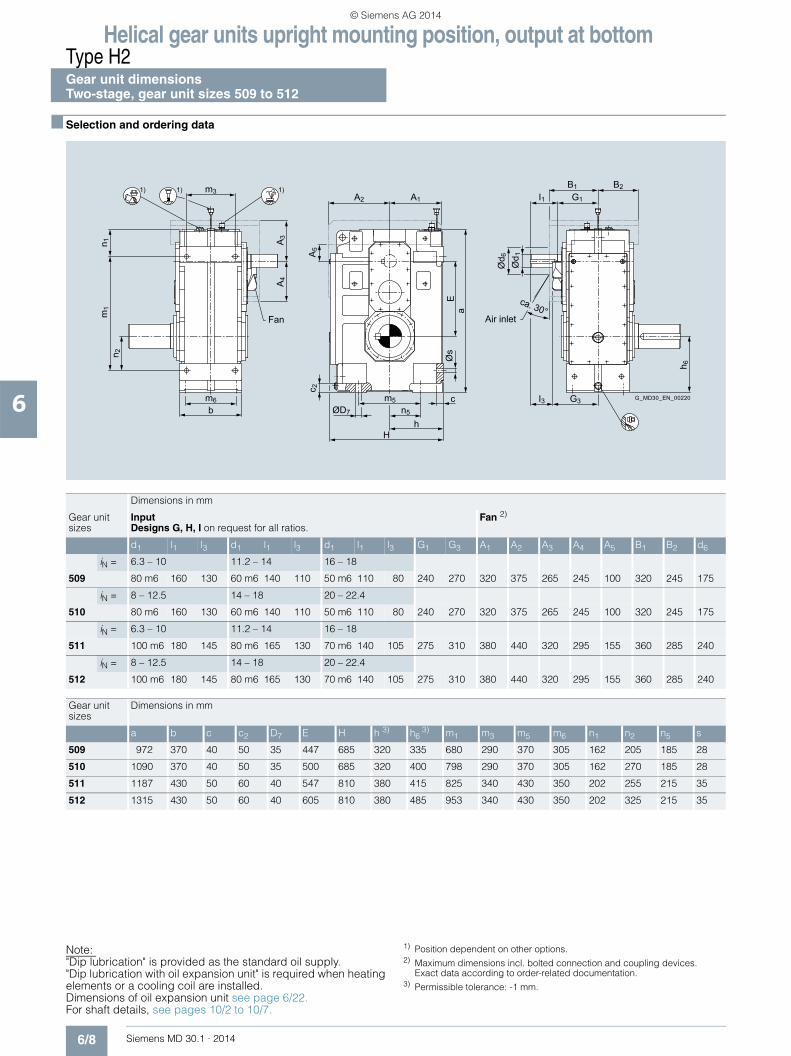
Helical gear units upright mounting position, output at bottomType H2Gear unit dimensions Two-stage, gear unit sizes 509 to 512
6/8 Siemens MD 30.1 · 2014
6
■ Selection and ordering data
1)1) 1)
G_MD30_EN_00220
Air inletFan
m6
m3
b
n 2m
1n 1 A
3
A5
A4
Ea
n5
hH
ØD7
cm5
h 6
Ød 1
Ød 6
G3I3
ca. 30°
G1I1B1 B2
Øs
c 2
A2 A1
Note: "Dip lubrication" is provided as the standard oil supply. "Dip lubrication with oil expansion unit" is required when heating elements or a cooling coil are installed. Dimensions of oil expansion unit see page 6/22. For shaft details, see pages 10/2 to 10/7.
1) Position dependent on other options.2) Maximum dimensions incl. bolted connection and coupling devices.
Exact data according to order-related documentation. 3) Permissible tolerance: -1 mm.
Dimensions in mm
Gear unit sizes
InputDesigns G, H, I on request for all ratios.
Fan 2)
d1 l1 l3 d1 l1 l3 d1 l1 l3 G1 G3 A1 A2 A3 A4 A5 B1 B2 d6
iN = 6.3 – 10 11.2 – 14 16 – 18
509 80 m6 160 130 60 m6 140 110 50 m6 110 80 240 270 320 375 265 245 100 320 245 175
iN = 8 – 12.5 14 – 18 20 – 22.4
510 80 m6 160 130 60 m6 140 110 50 m6 110 80 240 270 320 375 265 245 100 320 245 175
iN = 6.3 – 10 11.2 – 14 16 – 18
511 100 m6 180 145 80 m6 165 130 70 m6 140 105 275 310 380 440 320 295 155 360 285 240
iN = 8 – 12.5 14 – 18 20 – 22.4
512 100 m6 180 145 80 m6 165 130 70 m6 140 105 275 310 380 440 320 295 155 360 285 240
Gear unit sizes
Dimensions in mm
a b c c2 D7 E H h 3) h6 3) m1 m3 m5 m6 n1 n2 n5 s
509 972 370 40 50 35 447 685 320 335 680 290 370 305 162 205 185 28
510 1090 370 40 50 35 500 685 320 400 798 290 370 305 162 270 185 28
511 1187 430 50 60 40 547 810 380 415 825 340 430 350 202 255 215 35
512 1315 430 50 60 40 605 810 380 485 953 340 430 350 202 325 215 35
© Siemens AG 2014

Helical gear units upright mounting position, output at bottomType H2
Gear unit dimensionsTwo-stage, gear unit sizes 509 to 512
6/9Siemens MD 30.1 · 2014
6
■ Selection and ordering data (continued)
Output
Oil quantity 1)
Weight 1) 2) 7th position of Article No. and Article No. supplementfor 11th to 16th position see pages 6/23 to 6/27
Article No. 2LP202 . -■ ■P. . - . . . .
Type Size d2 l2 G2 l kg Solid shaft
H2SL 509 145 n6 250 240 104 830 8 A
510 160 n6 300 240 110 945 0 B
511 175 n6 300 270 168 1250 1 B
512 185 n6 350 270 178 1570 2 B
Type Size D2 G4 l kg Hollow shaft with keyway
H2HL 509 135 H7 235 104 830 8 D
510 150 H7 235 110 945 0 E
511 165 H7 270 168 1250 1 E
512 180 H7 270 178 1570 2 E
Type Size D2 D3 G4 G5 l kg Hollow shaft for shrink disk
H2DL 509 140 H6 145 235 350 104 830 8 G
510 150 H6 155 235 370 110 945 0 H
511 165 H6 170 270 420 168 1250 1 H
512 180 H6 185 270 425 178 1570 2 H
Type Size N/DIN 5480 D2 D3 G4 l kg Hollow shaft with spline in accordance with DIN 5480
H2KL 509 N140×3×45×9H 134 145 235 104 830 8 N
510 N140×3×45×9H 134 155 235 110 945 0 P
511 N170×5×32×9H 160 170 270 168 1250 1 P
512 N170×5×32×9H 160 185 270 178 1570 2 P
Type Size d2 I2 G2 l kg Solid shaft without keyway
H2CL 509 150 g6 140 240 104 830 8 U
510 170 g6 140 240 110 945 0 V
511 180 g6 145 270 168 1250 1 V
512 190 g6 145 270 178 1570 2 V
G_M
D30
_XX
_000
12
G2 I2
Ød 2
G_M
D30
_XX
_000
13
G4 G4
ØD
2H7
G_M
D30
_XX
_000
14
G5 G4
ØD
3
ØD
2H6
G_M
D30
_XX
_001
87
NG4 G4
ØD
3
ØD
2H11
G2 l2
G_M
D30
_XX
_001
86
Ød 2
1) Approximate values; exact data acc. to order-related documentation.2) Without oil filling.
© Siemens AG 2014

Helical gear units upright mounting position, output at bottomType H2Gear unit dimensions Two-stage, gear unit sizes 513 and 514
6/10 Siemens MD 30.1 · 2014
6
■ Selection and ordering data
1)1) 1)
G_MD30_EN_00221
Air inletFan
m3
m6b
n 2m
1n 1 A
3
A5
A2 A1
A4
n 6n 3
a
c
c 2
n5n4n4
hH
ØD7
m5
h 6
G3l3
ca. 30°
Ød 1
Ød 6
G1 g c1l1B1 B2
ØD
5Ø
sE
Note: "Dip lubrication" is provided as the standard oil supply. "Dip lubrication with oil expansion unit" is required when heating elements or a cooling coil are installed. Dimensions of oil expansion unit see page 6/22. For shaft details, see pages 10/2 to 10/7.
1) Position dependent on other options.2) Maximum dimensions incl. bolted connection and coupling devices.
Exact data according to order-related documentation. 3) Permissible tolerance: -1 mm.
Dimensions in mm
Gear unit sizes
InputDesigns G, H, I on request for all ratios.
Fan 2)
d1 l1 l3 d1 l1 l3 d1 l1 l3 G1 G3 A1 A2 A3 A4 A5 B1 B2 d6
iN = 6.3 – 10 11.2 – 14 16 – 18
513 110 n6 200 165 90 m6 165 130 75 m6 140 105 330 365 440 505 380 350 200 430 335 225
iN = 8 – 12.5 14 – 18 20 – 22.4
514 110 n6 200 165 90 m6 165 130 75 m6 140 105 330 365 440 505 380 350 200 430 335 225
Gear unit sizes
Dimensions in mm
a b c c1 c2 D5 D7 E g H h 3) h6 3) m1 m3 m5 m6 n1 n2 n3 n4 n5 n6 s
513 1345 535 60 65 65 48 48 640 202.5 935 440 440 920 445 510 445 245 260 842 380 255 380 42
514 1463 535 60 65 65 48 48 718 202.5 935 440 480 1038 445 510 445 245 300 920 380 255 420 42
© Siemens AG 2014
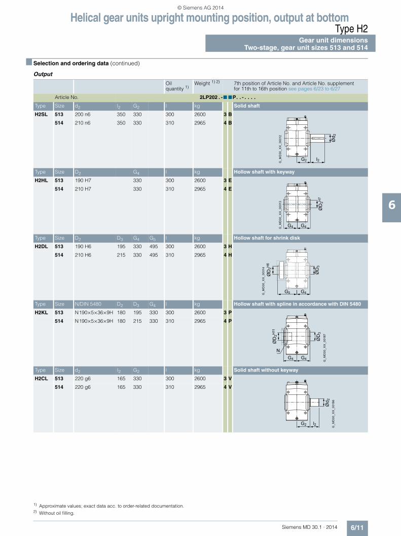
Helical gear units upright mounting position, output at bottomType H2
Gear unit dimensionsTwo-stage, gear unit sizes 513 and 514
6/11Siemens MD 30.1 · 2014
6
■ Selection and ordering data (continued)
Output
Oil quantity 1)
Weight 1) 2) 7th position of Article No. and Article No. supplementfor 11th to 16th position see pages 6/23 to 6/27
Article No. 2LP202 . -■ ■P. . - . . . .
Type Size d2 l2 G2 l kg Solid shaft
H2SL 513 200 n6 350 330 300 2600 3 B
514 210 n6 350 330 310 2965 4 B
Type Size D2 G4 l kg Hollow shaft with keyway
H2HL 513 190 H7 330 300 2600 3 E
514 210 H7 330 310 2965 4 E
Type Size D2 D3 G4 G5 l kg Hollow shaft for shrink disk
H2DL 513 190 H6 195 330 495 300 2600 3 H
514 210 H6 215 330 495 310 2965 4 H
Type Size N/DIN 5480 D2 D3 G4 l kg Hollow shaft with spline in accordance with DIN 5480
H2KL 513 N190×5×36×9H 180 195 330 300 2600 3 P
514 N190×5×36×9H 180 215 330 310 2965 4 P
Type Size d2 I2 G2 l kg Solid shaft without keyway
H2CL 513 220 g6 165 330 300 2600 3 V
514 220 g6 165 330 310 2965 4 V
G_M
D30
_XX
_000
12
G2 I2
Ød 2
G_M
D30
_XX
_000
13
G4 G4
ØD
2H7
G_M
D30
_XX
_000
14
G5 G4
ØD
3
ØD
2H6
G_M
D30
_XX
_001
87
NG4 G4
ØD
3
ØD
2H11
G2 l2
G_M
D30
_XX
_001
86
Ød 2
1) Approximate values; exact data acc. to order-related documentation.2) Without oil filling.
© Siemens AG 2014

Helical gear units upright mounting position, output at bottomType H3Gear unit dimensions Three-stage, gear unit sizes 505 to 508
6/12 Siemens MD 30.1 · 2014
6
■ Selection and ordering data
1)1) 1)
G_MD30_EN_00222
Air inletFan
m3
m6b
n 2m
1n 1 A
2
A4
A3
c 2
h 6
G3I3
ca. 30°
Ød 1
Ød 6
G1A1 A1
l1B1 B2
Øs
n5
hH
ØD7
cm5
Ea
Dimensions in mm
Gear unit sizes
Input Fan 2)
d1 l1 l3 d1 l1 l3 d1 l1 l3 G1 G3 A1 A2 A3 A4 B1 B2 d6
iN = 20 – 40 45 – 56 63 – 71
505 40 m6 90 70 30 m6 70 50 24 k6 60 40 180 200 145 150 140 85 215 175 135
iN = 28 – 56 63 – 80 90 – 100
506 40 m6 90 70 30 m6 70 50 24 k6 60 40 180 200 145 150 140 85 215 175 135
iN = 20 – 40 45 – 56 63 – 71
507 45 m6 100 80 35 m6 80 60 28 m6 70 50 210 230 175 185 190 115 245 205 150
iN = 25 – 50 56 – 71 80 – 90
508 45 m6 100 80 35 m6 80 60 28 m6 70 50 210 230 175 185 190 115 245 205 150
Gear unit sizes
Dimensions in mm
a b c c2 D7 E H h 3) h6 3) m1 m3 m5 m6 n1 n2 n5 s
505 713 250 30 35 24 400 500 230 230 530 200 280 205 97.5 145 140 19
506 836 250 30 35 24 453 500 230 300 653 200 280 205 97.5 215 140 19
507 897 295 35 40 28 493.5 605 280 295 680 230 320 240 101 180 160 24
508 1004 295 35 40 28 540.5 605 280 355 787 230 320 240 101 240 160 24
Note:"Dip lubrication with oil expansion unit" is provided as the standard oil supply. Dimensions of oil expansion unit see page 6/22. For shaft details, see pages 10/2 to 10/7.
1) Position dependent on other options.2) Maximum dimensions incl. bolted connection and coupling devices.
Exact data according to order-related documentation.3) Permissible tolerance: -1 mm.
© Siemens AG 2014

Helical gear units upright mounting position, output at bottomType H3
Gear unit dimensionsThree-stage, gear unit sizes 505 to 508
6/13Siemens MD 30.1 · 2014
6
■ Selection and ordering data (continued)
Output
Oil quantity 1)
Weight 1) 2) 7th position of Article No. and Article No. supplementfor 11th to 16th position see pages 6/23 to 6/27
Article No. 2LP202 . -■ ■Q . . - . . . .
Type Size d2 l2 G2 l kg Solid shaft
H3SL 505 100 m6 210 165 40 310 4 A
506 110 n6 210 165 42 380 5 A
507 120 n6 210 195 70 550 6 A
508 130 n6 250 195 74 650 7 A
Type Size D2 G4 l kg Hollow shaft with keyway
H3HL 505 95 H7 165 40 310 4 D
506 105 H7 165 42 380 5 D
507 115 H7 195 70 550 6 D
508 125 H7 195 74 650 7 D
Type Size D2 D3 G4 G5 l kg Hollow shaft for shrink disk
H3DL 505 100 H6 100 165 255 40 310 4 G
506 110 H6 110 165 260 42 380 5 G
507 120 H6 120 195 290 70 550 6 G
508 130 H6 130 195 305 74 650 7 G
Type Size N/DIN 5480 D2 D3 G4 l kg Hollow shaft with spline in accordance with DIN 5480
H3KL 505 N95×3×30×9H 89 100 165 40 310 4 N
506 N95×3×30×9H 89 110 165 42 380 5 N
507 N120×3×38×9H 114 120 195 70 550 6 N
508 N120×3×38×9H 114 130 195 74 650 7 N
Type Size d2 I2 G2 l kg Solid shaft without keyway
H3CL 505 110 g6 115 165 40 310 4 U
506 120 g6 115 165 42 380 5 U
507 130 g6 115 195 70 550 6 U
508 130 g6 115 195 74 650 7 U
G_M
D30
_XX
_000
12
G2 I2
Ød 2
G_M
D30
_XX
_000
13
G4 G4
ØD
2H7
G_M
D30
_XX
_000
14
G5 G4
ØD
3
ØD
2H6
G_M
D30
_XX
_001
87
NG4 G4
ØD
3
ØD
2H11
G2 l2
G_M
D30
_XX
_001
86
Ød 2
1) Approximate values; exact data acc. to order-related documentation.2) Without oil filling.
© Siemens AG 2014

Helical gear units upright mounting position, output at bottomType H3Gear unit dimensions Three-stage, gear unit sizes 509 to 512
6/14 Siemens MD 30.1 · 2014
6
■ Selection and ordering data
1)1) 1)
G_MD30_EN_00222
Air inletFan
m3
m6b
n 2m
1n 1 A
2
A4
A3
c 2
h 6
G3I3
ca. 30°
Ød 1
Ød 6
G1A1 A1
l1B1 B2
Øs
n5
hH
ØD7
cm5
Ea
Note:"Dip lubrication with oil expansion unit" is provided as the standard oil supply. Dimensions of oil expansion unit see page 6/22. For shaft details, see pages 10/2 to 10/7.
1) Position dependent on other options.2) Maximum dimensions incl. bolted connection and coupling devices.
Exact data according to order-related documentation.3) Permissible tolerance: -1 mm.
Dimensions in mm
Gear unit sizes
Input Fan 2)
d1 l1 l3 d1 l1 l3 d1 l1 l3 G1 G3 A1 A2 A3 A4 B1 B2 d6
iN = 20 – 40 45 – 56 63 – 71
509 60 m6 125 105 45 m6 100 80 32 m6 80 60 255 275 195 205 190 135 285 235 160
iN = 25 – 50 56 – 71 80 – 90
510 60 m6 125 105 45 m6 100 80 32 m6 80 60 255 275 195 205 190 135 285 235 160
iN = 20 – 40 45 – 56 63 – 71
511 70 m6 135 105 50 m6 110 80 48 m6 110 80 275 305 225 245 240 165 325 270 190
iN = 25 – 50 56 – 71 80 – 90
512 70 m6 135 105 50 m6 110 80 48 m6 110 80 275 305 225 245 240 165 325 270 190
Gear unit sizes
Dimensions in mm
a b c c2 D7 E H h 3) h6 3) m1 m3 m5 m6 n1 n2 n5 s
509 1038 370 40 50 35 575 685 320 335 785 290 370 305 122.5 205 185 28
510 1156 370 40 50 35 628 685 320 400 903 290 370 305 122.5 270 185 28
511 1279 430 50 60 40 706 810 380 415 960 340 430 350 158.5 255 215 35
512 1407 430 50 60 40 764 810 380 485 1088 340 430 350 158.5 325 215 35
© Siemens AG 2014

Helical gear units upright mounting position, output at bottomType H3
Gear unit dimensionsThree-stage, gear unit sizes 509 to 512
6/15Siemens MD 30.1 · 2014
6
■ Selection and ordering data (continued)
Output
Oil quantity 1)
Weight 1) 2) 7th position of Article No. and Article No. supplementfor 11th to 16th position see pages 6/23 to 6/27
Article No. 2LP202 . -■ ■Q . . - . . . .
Type Size d2 l2 G2 l kg Solid shaft
H3SL 509 145 n6 250 240 112 885 8 A
510 160 n6 300 240 120 1035 0 B
511 175 n6 300 270 182 1470 1 B
512 185 n6 350 270 210 1695 2 B
Type Size D2 G4 l kg Hollow shaft with keyway
H3HL 509 135 H7 235 112 885 8 D
510 150 H7 235 120 1035 0 E
511 165 H7 270 182 1470 1 E
512 180 H7 270 210 1695 2 E
Type Size D2 D3 G4 G5 l kg Hollow shaft for shrink disk
H3DL 509 140 H6 145 235 350 112 885 8 G
510 150 H6 155 235 370 120 1035 0 H
511 165 H6 170 270 420 182 1470 1 H
512 180 H6 185 270 425 210 1695 2 H
Type Size N/DIN 5480 D2 D3 G4 l kg Hollow shaft with spline in accordance with DIN 5480
H3KL 509 N140×3×45×9H 134 145 235 112 885 8 N
510 N140×3×45×9H 134 155 235 120 1035 0 P
511 N170×5×32×9H 160 170 270 182 1470 1 P
512 N170×5×32×9H 160 185 270 210 1695 2 P
Type Size d2 I2 G2 l kg Solid shaft without keyway
H3CL 509 150 g6 140 240 112 885 8 U
510 170 g6 140 240 120 1035 0 V
511 180 g6 145 270 182 1470 1 V
512 190 g6 145 270 210 1695 2 V
G_M
D30
_XX
_000
12
G2 I2
Ød 2
G_M
D30
_XX
_000
13
G4 G4
ØD
2H7
G_M
D30
_XX
_000
14
G5 G4
ØD
3
ØD
2H6
G_M
D30
_XX
_001
87
NG4 G4
ØD
3
ØD
2H11
G2 l2
G_M
D30
_XX
_001
86
Ød 2
1) Approximate values; exact data acc. to order-related documentation.2) Without oil filling.
© Siemens AG 2014

Helical gear units upright mounting position, output at bottomType H3Gear unit dimensions Three-stage, gear unit sizes 513 and 514
6/16 Siemens MD 30.1 · 2014
6
■ Selection and ordering data
1)1) 1)
G_MD30_EN_00223
Air inletFan
m3
m6b
n 2m
1n 1 A
2
A4
A1 A1
A3
c 2
n5n4n4
hH
ØD7
m5 c
h 6
G3l3
ca. 30°
G1 g c1l1B1 B2
Ød 1
Ød 6
n 6n 3
a
ØD
5Ø
sE
Note:"Dip lubrication with oil expansion unit" is provided as the standard oil supply. Dimensions of oil expansion unit see page 6/22. For shaft details, see pages 10/2 to 10/7.
1) Position dependent on other options.2) Maximum dimensions incl. bolted connection and coupling devices.
Exact data according to order-related documentation.3) Permissible tolerance: -1 mm.
Dimensions in mm
Gear unit sizes
Input Fan 2)
d1 l1 l3 d1 l1 l3 d1 l1 l3 G1 G3 A1 A2 A3 A4 B1 B2 d6
iN = 20 – 40 45 – 56 63 – 71
513 85 m6 160 130 65 m6 140 110 50 m6 110 80 320 350 275 295 270 190 380 325 175
iN = 25 – 50 56 – 71 80 – 90
514 85 m6 160 130 65 m6 140 110 50 m6 110 80 320 350 275 295 270 190 380 325 175
Gear unit sizes
Dimensions in mm
a b c c1 c2 D5 D7 E g H h 3) h6 3) m1 m3 m5 m6 n1 n2 n3 n4 n5 n6 s
513 1452 535 60 65 65 48 48 825 202.5 935 440 440 1092 445 510 445 180 260 952 380 255 380 42
514 1570 535 60 65 65 48 48 903 202.5 935 440 480 1210 445 510 445 180 300 1030 380 255 420 42
© Siemens AG 2014

Helical gear units upright mounting position, output at bottomType H3
Gear unit dimensionsThree-stage, gear unit sizes 513 and 514
6/17Siemens MD 30.1 · 2014
6
■ Selection and ordering data (continued)
Output
Oil quantity 1)
Weight 1) 2) 7th position of Article No. and Article No. supplementfor 11th to 16th position see pages 6/23 to 6/27
Article No. 2LP202 . -■ ■Q . . - . . . .
Type Size d2 l2 G2 l kg Solid shaft
H3SL 513 200 n6 350 330 300 2420 3 B
514 210 n6 350 330 310 2720 4 B
Type Size D2 G4 l kg Hollow shaft with keyway
H3HL 513 190 H7 330 300 2420 3 E
514 210 H7 330 310 2720 4 E
Type Size D2 D3 G4 G5 l kg Hollow shaft for shrink disk
H3DL 513 190 H6 195 330 495 300 2420 3 H
514 210 H6 215 330 495 310 2720 4 H
Type Size N/DIN 5480 D2 D3 G4 l kg Hollow shaft with spline in accordance with DIN 5480
H3KL 513 N190×5×36×9H 180 195 330 300 2420 3 P
514 N190×5×36×9H 180 215 330 310 2720 4 P
Type Size d2 I2 G2 l kg Solid shaft without keyway
H3CL 513 220 g6 165 330 300 2420 3 V
514 220 g6 165 330 310 2720 4 V
G_M
D30
_XX
_000
12
G2 I2
Ød 2
G_M
D30
_XX
_000
13
G4 G4
ØD
2H7
G_M
D30
_XX
_000
14
G5 G4
ØD
3
ØD
2H6
G_M
D30
_XX
_001
87
NG4 G4
ØD
3
ØD
2H11
G2 l2
G_M
D30
_XX
_001
86
Ød 2
1) Approximate values; exact data acc. to order-related documentation.2) Without oil filling.
© Siemens AG 2014

Helical gear units upright mounting position, output at bottomType H4Gear unit dimensions Four-stage, gear unit sizes 507 and 508
6/18 Siemens MD 30.1 · 2014
6
■ Selection and ordering data
1)1) 1)
G_MD30_XX_00224
m3 h4
m6b
n 2m
1n 1
c 2
n5n4n4
hH
ØD7
m5
c
h 6
G1 g c1I1
Ød 1
n 6n 3
a
ØD
5Ø
sE
Dimensions in mm
Gear unit sizes
Input
Designs G, H, I on request for
d1 l1 d1 l1 G1
iN = 80 – 140 160 – 280 224 – 280
507 35 m6 60 28 m6 50 215
iN = 100 – 180 200 – 355 280 – 355
508 35 m6 60 28 m6 50 215
Gear unit sizes
Dimensions in mm
a b c c1 c2 D5 D7 E g H h 2) h4 h6 2) m1 m3 m5 m6 n1 n2 n3 n4 n5 n6 s
507 899 295 35 35 40 28 28 493.5 112.5 605 280 198 295 680 230 320 240 104 180 567.5 242.5 160 257.5 24
508 1006 295 35 35 40 28 28 540.5 112.5 605 280 198 355 787 230 320 240 104 240 614.5 242.5 160 317.5 24
Note:"Dip lubrication with oil expansion unit" is provided as the standard oil supply. Dimensions of oil expansion unit see page 6/22. For shaft details, see pages 10/2 to 10/7.
1) Position dependent on other options.2) Permissible tolerance: -1 mm.
© Siemens AG 2014

Helical gear units upright mounting position, output at bottomType H4
Gear unit dimensionsFour-stage, gear unit sizes 507 and 508
6/19Siemens MD 30.1 · 2014
6
■ Selection and ordering data (continued)
Output
Oil quantity 1)
Weight 1) 2) 7th position of Article No. and Article No. supplementfor 11th to 16th position see pages 6/23 to 6/27
Article No. 2LP202 . -■ ■R . . - . . . .
Type Size d2 l2 G2 l kg Solid shaft
H4SL 507 120 n6 210 195 60 520 6 A
508 130 n6 250 195 72 640 7 A
Type Size D2 G4 l kg Hollow shaft with keyway
H4HL 507 115 H7 195 60 520 6 D
508 125 H7 195 72 640 7 D
Type Size D2 D3 G4 G5 l kg Hollow shaft for shrink disk
H4DL 507 120 H6 120 195 290 60 520 6 G
508 130 H6 130 195 305 72 640 7 G
Type Size N/DIN 5480 D2 D3 G4 l kg Hollow shaft with spline in accordance with DIN 5480
H4KL 507 N120×3×38×9H 114 120 195 60 520 6 N
508 N120×3×38×9H 114 130 195 72 640 7 N
Type Size d2 I2 G2 l kg Solid shaft without keyway
H4CL 507 130 g6 115 195 60 520 6 U
508 130 g6 115 195 72 640 7 U
G2 I2
Ød 2
G4 G4
ØD
2H7
G_M
D30
_XX
_000
11
G5 G4
ØD
3
ØD
2H6
G_M
D30
_XX
_001
87
NG4 G4
ØD
3
ØD
2H11
G2 l2
G_M
D30
_XX
_001
86
Ød 2
1) Approximate values; exact data acc. to order-related documentation.2) Without oil filling.
© Siemens AG 2014

Helical gear units upright mounting position, output at bottomType H4Gear unit dimensions Four-stage, gear unit sizes 509 to 514
6/20 Siemens MD 30.1 · 2014
6
■ Selection and ordering data
1)1) 1)
G_MD30_XX_00224
m3 h4
m6b
n 2m
1n 1
c 2
n5n4n4
hH
ØD7
m5
c
h 6
G1 g c1I1
Ød 1
n 6n 3
a
ØD
5Ø
sE
Note:"Dip lubrication with oil expansion unit" is provided as the standard oil supply. Dimensions of oil expansion unit see page 6/22. For shaft details, see pages 10/2 to 10/7.
1) Position dependent on other options.2) Permissible tolerance: -1 mm.
Dimensions in mm
Gear unit sizes
Input
Designs G, H, I on request for
d1 l1 d1 l1 d1 l1 G1
iN = 80 – 160 180 – 315 250 – 315
509 35 m6 60 28 m6 50 225
iN = 100 – 200 224 – 400 315 – 400
510 35 m6 60 28 m6 50 225
iN = 80 – 160 180 – 224 250 – 315 250 – 315
511 45 m6 100 35 m6 80 28 m6 70 255
iN = 100 – 200 224 – 280 315 – 400 315 – 400
512 45 m6 100 35 m6 80 28 m6 70 255
iN = 80 – 160 180 – 224 250 – 315 250 – 315
513 60 m6 125 45 m6 100 32 m6 80 305
iN = 100 – 200 224 – 280 315 – 400 315 – 400
514 60 m6 125 45 m6 100 32 m6 80 305
Gear unit sizes
Dimensions in mm
a b c c1 c2 D5 D7 E g H h 2) h4 h6 2) m1 m3 m5 m6 n1 n2 n3 n4 n5 n6 s
509 1040 370 40 45 50 35 35 575 140 685 320 230 335 785 290 370 305 125 205 660 275 185 290 28
510 1158 370 40 45 50 35 35 628 140 685 320 230 400 903 290 370 305 125 270 713 275 185 355 28
511 1281 430 50 60 60 40 40 706 155 810 380 270.5 415 960 340 430 350 161 255 812.5 330 215 362.5 35
512 1409 430 50 60 60 40 40 764 155 810 380 270.5 485 1088 340 430 350 161 325 870.5 330 215 432.5 35
513 1455 535 60 65 65 48 48 825 202.5 935 440 312 440 1092 445 510 445 183 260 952 380 255 380 42
514 1573 535 60 65 65 48 48 903 202.5 935 440 312 480 1210 445 510 445 183 300 1030 380 255 420 42
© Siemens AG 2014

Helical gear units upright mounting position, output at bottomType H4
Gear unit dimensionsFour-stage, gear unit sizes 509 to 514
6/21Siemens MD 30.1 · 2014
6
■ Selection and ordering data (continued)
Output
Oil quantity 1)
Weight 1) 2) 7th position of Article No. and Article No. supplementfor 11th to 16th position see pages 6/23 to 6/27
Article No. 2LP202 . -■ ■R . . - . . . .
Type Size d2 l2 G2 l kg Solid shaft
H4SL 509 145 n6 250 240 116 790 8 A
510 160 n6 300 240 120 985 0 B
511 175 n6 300 270 180 1450 1 B
512 185 n6 350 270 200 1600 2 B
513 200 n6 350 330 290 2375 3 B
514 210 n6 350 330 300 2690 4 B
Type Size D2 G4 l kg Hollow shaft with keyway
H4HL 509 135 H7 235 116 790 8 D
510 150 H7 235 120 985 0 E
511 165 H7 270 180 1450 1 E
512 180 H7 270 200 1600 2 E
513 190 H7 330 290 2375 3 E
514 210 H7 330 300 2690 4 E
Type Size D2 D3 G4 G5 l kg Hollow shaft for shrink disk
H4DL 509 140 H6 145 235 350 116 790 8 G
510 150 H6 155 235 370 120 985 0 H
511 165 H6 170 270 420 180 1450 1 H
512 180 H6 185 270 425 200 1600 2 H
513 190 H6 195 330 495 290 2375 3 H
514 210 H6 215 330 495 300 2690 4 H
Type Size N/DIN 5480 D2 D3 G4 l kg Hollow shaft with spline in accordance with DIN 5480
H4KL 509 N140×3×45×9H 134 145 235 116 790 8 N
510 N140×3×45×9H 134 155 235 120 985 0 P
511 N170×5×32×9H 160 170 270 180 1450 1 P
512 N170×5×32×9H 160 185 270 200 1600 2 P
513 N190×5×36×9H 180 195 330 290 2375 3 P
514 N190×5×36×9H 180 215 330 300 2690 4 P
Type Size d2 I2 G2 l kg Solid shaft without keyway
H4CL 509 150 g6 140 240 116 790 8 U
510 170 g6 140 240 120 985 0 V
511 180 g6 145 270 180 1450 1 V
512 190 g6 145 270 200 1600 2 V
513 220 g6 165 330 290 2375 3 V
514 220 g6 165 330 300 2690 4 V
G2 I2
Ød 2
G4 G4
ØD
2H7
G_M
D30
_XX
_000
11
G5 G4
ØD
3
ØD
2H6
G_M
D30
_XX
_001
87
NG4 G4
ØD
3
ØD
2H11
G2 l2
G_M
D30
_XX
_001
86
Ød 2
1) Approximate values; exact data acc. to order-related documentation.2) Without oil filling.
© Siemens AG 2014

Helical gear units upright mounting position, output at bottomTypes H1, H2, H3 and H4
Dimensions of oil expansion unit
6/22 Siemens MD 30.1 · 2014
6
■ Overview
G_M
D30
_XX
_002
25
h 3h 4
h 5
b3 h
ØD3
Note:"Dip lubrication with oil expansion unit" is provided as the standard oil supply for helical gear units H1.L, H3.L, H4.L. "Dip lubrication with oil expansion unit" is requiredfor H2.L gear units only when heating elements or a cooling coil are installed.
1) Permissible tolerance: -1 mm.
Dimensions in mm (Article No. supplement for 15th position see page 6/27)
Gear unit sizes
H1.L H2.L H3.L H4.L
h 1) b3 d3 h3 h4 h5 h 1) b3 D3 h3 h4 h5 h 1) b3 D3 h3 h4 h5 h 1) b3 D3 h3 h4 h5
503 200 240 168 448 220 395 – – – – – – – – – – – – – – – – – –
504 225 265 188 544 265 485 200 230 148 590 195 340 – – – – – – – – – – – –
505 250 290 208 605 335 590 230 270 168 670 220 395 230 270 168 713 215 325 – – – – – –
506 250 290 208 656 335 590 230 270 168 793 220 395 230 270 168 836 215 325 – – – – – –
507 315 355 248 713 385 700 280 325 188 839 265 485 280 325 188 897 260 400 280 325 148 899 195 330
508 315 355 248 773 385 700 280 325 188 946 265 485 280 325 188 1004 260 400 280 325 148 1006 195 330
509 355 400 298 860 455 815 320 365 208 972 335 590 320 365 208 1038 330 500 320 365 168 1040 220 380
510 355 400 298 916 455 815 320 365 208 1090 335 590 320 365 208 1156 330 500 320 365 168 1158 220 380
511 – – – – – – 380 430 248 1187 385 700 380 430 248 1279 380 590 380 430 188 1281 265 465
512 – – – – – – 380 430 248 1315 385 700 380 430 248 1407 380 590 380 430 188 1409 265 465
513 – – – – – – 440 495 298 1345 455 815 440 495 298 1452 450 700 440 495 208 1455 335 565
514 – – – – – – 440 495 298 1463 455 815 440 495 298 1570 450 700 440 495 208 1573 335 565
© Siemens AG 2014

Helical gear units upright mounting position, output at bottomTypes H1, H2, H3 and H4
Article No. overview
6/23Siemens MD 30.1 · 2014
6
■ Selection and ordering data
7th position of the Article No.
Data position of Article No. 1 to 6 7 8 9 10 11 12 13 14 15 16 "-Z" and order code
Article No. 2LP202 ■ - . . . . . - . . . . -Z . . .
Design variant (view directed at face 2, face 4 at bottom)
Type
H1. . H2. . H3. . H4. .
A 0
B 1
C – 2
D – 3Irrespective of the spatial position of the gear unit, the face designations "right" and "left" always refer to the horizontal mounting position with the view directed at face 1. Face 2 is at the top.Assembly cover at top (2), view directed at drive end face (1): Face 3 = right Face 6 = left
E – 4
A
G_MD30_XX_00311 G_MD30_XX_00310
1
A
G8
ØD
8
G_MD30_XX_00309
1
A
G8
ØD
8
G_MD30_XX_00308
1
A
G8
ØD
8
6
5
4
6
5
4
2
3
1
G_MD30_XX_00233
G_MD30_XX_00315
B
G_MD30_XX_00314
1G8
ØD
8
B
G_MD30_XX_00313
1
G8
ØD
8
B
G_MD30_XX_00312
1G8
ØD
8
B
G_MD30_XX_00318
1G8
ØD
8
C
G_MD30_XX_00317
1
G8
ØD
8
C
G_MD30_XX_00316
1G8
ØD
8
C
G_MD30_XX_00321
1G8
ØD
8
D
G_MD30_XX_00320
1
G8
ØD
8
D
G_MD30_XX_00319
1G8
ØD
8
D
1G8
ØD
8
E
G_MD30_XX_00324
1
G8
ØD
8
G_MD30_XX_00323
E
1G8
ØD
8
G_MD30_XX_00322
E
$ Backstop
© Siemens AG 2014

Helical gear units upright mounting position, output at bottomTypes H1, H2, H3 and H4
Article No. overview
6/24 Siemens MD 30.1 · 2014
6
■ Selection and ordering data (continued)
7th position of the Article No. (continued)
Data position of Article No. 1 to 6 7 8 9 10 11 12 13 14 15 16 "-Z" and order code
Article No. 2LP202 ■ - . . . . . - . . . . -Z . . .
Design variant (view directed at face 2, face 4 at bottom)
Type
H1. . H2. . 1) H3. . H4. .
F – 5
G – 6
H – 7
I – 8Irrespective of the spatial position of the gear unit, the face designations "right" and "left" always refer to the horizontal mounting position with the view directed at face 1. Face 2 is at the top.Assembly cover at top (2), view directed at drive end face (1): Face 3 = right Face 6 = left
1G8
ØD
8
G_MD30_XX_00327
F
1
G8
ØD
8
F
G_MD30_XX_00326
F
1G8
ØD
8
G_MD30_XX_00325
6
5
4
6
5
4
2
3
1
G_MD30_XX_00233
G_MD30_XX_00330
G G
G_MD30_XX_00329 G_MD30_XX_00328
G
G_MD30_XX_00333
H
G_MD30_XX_00332
H
G_MD30_XX_00331
H
G_MD30_XX_00336
I
G_MD30_XX_00335
I
G_MD30_XX_00334
I
$ Backstop1) Designs G, H, I on request.
© Siemens AG 2014

Helical gear units upright mounting position, output at bottomTypes H1, H2, H3 and H4
Article No. overview
6/25Siemens MD 30.1 · 2014
6
■ Selection and ordering data (continued)
8th to 10th position of the Article No.
Data position of Article No. 1 to 6 7 8 9 10 11 12 13 14 15 16 "-Z" and order code
Article No. 2LP202 . - ■ ■ ■ . . - . . . . -Z . . .
Output shaft, gear unit size
Output shaft Gear unit size
Solid shaft (S)
503 2 A
504 3 A
505 4 A
506 5 A
507 6 A
508 7 A
509 8 A
510 0 B
511 1 B
512 2 B
513 3 B
514 4 B
Hollow shaft with keyway (H)
504 3 D
505 4 D
506 5 D
507 6 D
508 7 D
509 8 D
510 0 E
511 1 E
512 2 E
513 3 E
514 4 E
Hollow shaft for shrink disk (D)
504 3 G
505 4 G
506 5 G
507 6 G
508 7 G
509 8 G
510 0 H
511 1 H
512 2 H
513 3 H
514 4 H
© Siemens AG 2014

Helical gear units upright mounting position, output at bottomTypes H1, H2, H3 and H4
Article No. overview
6/26 Siemens MD 30.1 · 2014
6
■ Selection and ordering data (continued)
8th to 10th position of the Article No. (continued)
Data position of Article No. 1 to 6 7 8 9 10 11 12 13 14 15 16 "-Z" and order code
Article No. 2LP202 . - ■ ■ ■ . . - . . . . -Z . . .
Output shaft, gear unit size
Output shaft Gear unit size
Hollow shaft with spline in accordance with DIN 5480 (K)
504 3 N
505 4 N
506 5 N
507 6 N
508 7 N
509 8 N
510 0 P
511 1 P
512 2 P
513 3 P
514 4 P
Solid shaft without keyway (C)
504 3 U
505 4 U
506 5 U
507 6 U
508 7 U
509 8 U
510 0 V
511 1 V
512 2 V
513 3 V
514 4 V
Gear unit type, number of stages, mounting position
H1.L V
H2.L P
H3.L Q
H4.L R
© Siemens AG 2014
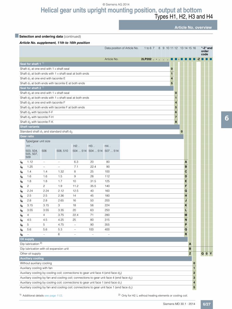
Helical gear units upright mounting position, output at bottomTypes H1, H2, H3 and H4
Article No. overview
6/27Siemens MD 30.1 · 2014
6
■ Selection and ordering data (continued)
Article No. supplement, 11th to 16th position
Data position of Article No. 1 to 6 7 8 9 10 11 12 13 14 15 16 "-Z" and order code
Article No. 2LP202 . - . . . ■ ■ - ■ ■ ■ ■ -Z ■ ■ ■
Seal for shaft 1 1)
Shaft d1 at one end with 1 × shaft seal 0
Shaft d1 at both ends with 1 × shaft seal at both ends 1
Shaft d1 at one end with taconite E 4
Shaft d1 at both ends with taconite E at both ends 5
Seal for shaft 2 1)
Shaft d2 at one end with 1 × shaft seal 0
Shaft d2 at both ends with 1 × shaft seal at both ends 1
Shaft d2 at one end with taconite F 4
Shaft d2 at both ends with taconite F at both ends 5
Shaft d2 with taconite F-F 6
Shaft d2 with taconite F-H 7
Shaft d2 with taconite F-K 8
Shaft variants
Standard shaft d1 and standard shaft d2 0
Gear ratio
Type/gear unit size
H1. . H2. . H3. . H4. .
503, 504, 505, 507, 509
506 508, 510 504 ... 514 504 ... 514 507 ... 514
iN 1.12 – – 6.3 20 80 A
iN 1.25 – – 7.1 22.4 90 B
iN 1.4 1.4 1.32 8 25 100 C
iN 1.6 1.6 1.5 9 28 112 D
iN 1.8 1.8 1.7 10 31.5 125 E
iN 2 2 1.9 11.2 35.5 140 F
iN 2.24 2.24 2.12 12.5 40 160 G
iN 2.5 2.5 2.36 14 45 180 H
iN 2.8 2.8 2.65 16 50 200 J
iN 3.15 3.15 3 18 56 224 K
iN 3.55 3.55 3.35 20 63 250 L
iN 4 4 3.75 22.4 71 280 M
iN 4.5 4.5 4.25 25 80 315 N
iN 5 5 4.75 – 90 355 P
iN 5.6 5.6 5.3 – 100 400 Q
iN – – 6 – – – R
Oil supply
Dip lubrication 2) A
Dip lubrication with oil expansion unit B
Other oil supply Z Q 0 Y
Auxiliary cooling
Without auxiliary cooling 0
Auxiliary cooling with fan 1
Auxiliary cooling by cooling coil; connections to gear unit face 4 (end face d2) 2
Auxiliary cooling by fan and cooling coil; connections to gear unit face 4 (end face d2) 3
Auxiliary cooling by cooling coil; connections to gear unit face 1 (end face d1) 4
Auxiliary cooling by fan and cooling coil; connections to gear unit face 1 (end face d1) 5
1) Additional details see page 11/2. 2) Only for H2.L without heating elements or cooling coil.
© Siemens AG 2014

Helical gear units upright mounting position, output at bottomTypes H1, H2, H3 and H4
Notes
6/28 Siemens MD 30.1 · 2014
6
© Siemens AG 2014

Siemens MD 30.1 · 2014
77/2 Type B2
Gear unit dimensions7/2 Two-stage, gear unit sizes 503 to 5087/4 Two-stage, gear unit sizes 509 and 510
7/6 Type B3Gear unit dimensions
7/6 Three-stage, gear unit sizes 504 to 5087/8 Three-stage, gear unit sizes 509 to 5127/10 Three-stage, gear unit sizes 513 and 514
7/12 Type B4Gear unit dimensions
7/12 Four-stage, gear unit sizes 505 to 5087/14 Four-stage, gear unit sizes 509 to 514
7/16 Types B2, B3 and B47/16 Article No. overview
Bevel-helical gear units horizontal mounting position
© Siemens AG 2014

Bevel-helical gear units horizontal mounting positionType B2Gear unit dimensions Two-stage, gear unit sizes 503 to 508
7/2 Siemens MD 30.1 · 2014
7
■ Selection and ordering data
Air inlet
Fan
G_M
D30
_EN
_001
37
n2n1
n6
E
a
m1
n 4n 4
Hh
h 5
Øs
Ød 1
Ød 6
ca.30°
A 1A
2
c
ØD5B1
c1
G1n3
m3b
l1
l3e3
A3
G3G6
Dimensions in mm
Gear unit sizes
Input Fan 1)
d1 l1 l3 d1 l1 l3 G1 G3 A1 A2 A3 B1 d6 G6
iN = 5 – 14 16
503 40 m6 90 70 35 m6 80 60 393 413 190 255 130 195 135 433
iN = 5 – 14 16
504 50 m6 110 90 40 m6 90 70 465 485 215 280 160 230 150 504
iN = 5 – 14 16
505 60 m6 120 90 50 m6 110 80 550 580 240 305 190 260 175 600
iN = 6.3 – 18 20
506 60 m6 120 90 50 m6 110 80 581 611 240 305 190 260 175 631
iN = 5 – 14 16
507 75 m6 135 100 60 m6 135 100 656 691 300 370 225 320 210 718
iN = 6 – 17 19
508 75 m6 135 100 60 m6 135 100 686 721 300 370 225 320 210 748
Gear unit sizes
Dimensions in mm
a b c c1 D5 E e3 H h 2) h5 m1 m3 n1 n2 n3 n4 n6 s
503 448 260 25 25 19 128 130 460 200 85 290 220 78 110 230 175 165 15
504 544 325 30 30 24 159 160 510 225 205 360 280 96.5 137.5 290 195 195 19
505 605 360 30 30 24 185 190 560 250 145 435 320 85 145 345 220 200 19
506 656 360 30 30 24 216 190 560 250 145 486 320 85 165 376 220 220 19
507 713 465 35 40 28 228 225 700 315 145 480 410 118 145 415 280 225 24
508 773 465 35 40 28 258 225 700 315 145 540 410 118 175 445 280 255 24
Note:
For shaft details, see pages 10/2 to 10/7.
1) Maximum dimension including bolted connection. See order-related documentation for exact data.
2) Permissible tolerance: -1 mm.
© Siemens AG 2014

Bevel-helical gear units horizontal mounting positionType B2
Gear unit dimensionsTwo-stage, gear unit sizes 503 to 508
7/3Siemens MD 30.1 · 2014
7
■ Selection and ordering data (continued)
Output
Oil quantity 1)
Weight 1) 2) 7th position of Article No. and Article No. supplementfor 11th to 16th position see pages 7/16 to 7/19
Article No.: 2LP202.-■ ■A..-....
Type Size d2 l2 G2 l kg Solid shaft
B2SH 503 65 m6 140 185 10 175 2 A
504 80 m6 170 220 16 280 3 A
505 90 m6 210 240 22 428 4 A
506 100 m6 210 240 24 450 5 A
507 105 n6 235 295 42 725 6 A
508 120 n6 250 295 45 790 7 A
Type Size D2 G4 l kg Hollow shaft with keyway
B2HH 503 – – – –
504 80 H7 220 16 280 3 D
505 95 H7 240 22 428 4 D
506 105 H7 240 24 450 5 D
507 115 H7 295 42 725 6 D
508 125 H7 295 45 790 7 D
Type Size D2 D3 G4 G5 l kg Hollow shaft for shrink disk
B2DH 503 – – – – – –
504 85 H6 85 220 295 16 280 3 G
505 100 H6 100 240 325 22 428 4 G
506 110 H6 110 240 330 24 450 5 G
507 120 H6 120 295 390 42 725 6 G
508 130 H6 130 295 400 45 790 7 G
G_MD30_XX_00138
G2 I2
Ød 2
G_MD30_XX_00139
G4 G4
ØD
2H7
G_MD30_XX_00140
G5 G4
D3ØD
2H6
1) Approximate values; exact data acc. to order-related documentation.2) Without oil filling.
© Siemens AG 2014

Bevel-helical gear units horizontal mounting positionType B2Gear unit dimensions Two-stage, gear unit sizes 509 and 510
7/4 Siemens MD 30.1 · 2014
7
■ Selection and ordering data
Air inlet
Fan
G_M
D30
_EN
_001
37n2
n1n6
E
a
m1
n 4n 4
Hh
h 5
Øs
Ød 1
Ød 6
ca.30°
A 1A
2
c
ØD5B1
c1
G1n3
m3b
l1
l3e3
A3
G3G6
Dimensions in mm
Gear unit sizes
Input Fan 1)
d1 l1 l3 d1 l1 l3 G1 G3 A1 A2 A3 B1 d6 G6
iN = 5 – 11.2 12.5 –16
509 80 m6 165 130 70 m6 140 105 792 827 340 410 265 360 240 850
iN = 6 – 13.2 15 – 19
510 80 m6 165 130 70 m6 140 105 823 858 340 410 265 360 240 881
Gear unit sizes
Dimensions in mm
a b c c1 D5 E e3 H h 2) h5 m1 m3 n1 n2 n3 n4 n6 s
509 860 550 40 55 35 265 265 780 355 150 575 480 145 190 480 307.5 282.5 28
510 916 550 40 55 35 296 265 780 355 150 631 480 145 215 511 307.5 307.5 28
Note:
For shaft details, see pages 10/2 to 10/7.
1) Maximum dimension including bolted connection. See order-related documentation for exact data.
2) Permissible tolerance: -1 mm.
© Siemens AG 2014

Bevel-helical gear units horizontal mounting positionType B2
Gear unit dimensionsTwo-stage, gear unit sizes 509 and 510
7/5Siemens MD 30.1 · 2014
7
■ Selection and ordering data (continued)
Output
Oil quantity 1)
Weight 1) 2) 7th position of Article No. and Article No. supplementfor 11th to 16th position see pages 7/16 to 7/19
Article No.: 2LP202.-■ ■A..-....
Type Size d2 l2 G2 l kg Solid shaft
B2SH 509 135 n6 260 335 66 1140 8 A
510 150 n6 280 335 71 1254 0 B
Type Size D2 G4 l kg Hollow shaft with keyway
B2HH 509 135 H7 335 66 1140 8 D
510 145 H7 335 71 1254 0 E
Type Size D2 D3 G4 G5 l kg Hollow shaft for shrink disk
B2DH 509 140 H6 145 335 450 66 1140 8 G
510 145 H6 150 335 470 71 1254 0 H
G_MD30_XX_00138
G2 I2
Ød 2
G_MD30_XX_00139
G4 G4
ØD
2H7
G_MD30_XX_00140
G5 G4
D3ØD
2H6
1) Approximate values; exact data acc. to order-related documentation.2) Without oil filling.
© Siemens AG 2014

Bevel-helical gear units horizontal mounting positionType B3Gear unit dimensions Three-stage, gear unit sizes 504 to 508
7/6 Siemens MD 30.1 · 2014
7
■ Selection and ordering data
Fan
Air inlet
Fan
n2
E
n1
am1
A3H
h
h 5
Øs
Ød 1
Ød 6
ca.30°
A 1A
2
c
B1
G1
m3
b
l1
l3
e3
G3
G6
Dimensions in mm
Gear unit sizes
Input Fan 1)
d1 l1 l3 d1 l1 l3 G1 G3 A1 A2 A3 B1 d6 G6
iN = 16 – 56 63
504 35 m6 80 60 32 m6 70 50 500 520 195 245 50 175 115 535
iN = 14 – 50 56
505 40 m6 90 70 35 m6 80 60 575 595 225 280 50 195 135 610
iN = 20 – 71 80
506 40 m6 90 70 35 m6 80 60 628 648 225 280 50 195 135 663
iN = 14 – 50 56
507 50 m6 110 90 40 m6 90 70 690 710 275 335 65 220 160 725
iN = 18 – 63 71
508 50 m6 110 90 40 m6 90 70 737 757 275 335 65 220 160 772
Gear unit sizes
Dimensions in mm
a b c E e3 H h 2) h5 m1 m3 n1 n2 s
504 604 210 28 269.5 110.5 465 200 215 415 170 95 130 19
505 684 250 30 310 130 530 230 350 490 200 95 145 19
506 807 250 30 363 130 530 230 350 613 200 95 215 19
507 855 295 35 384 160 635 280 305 595 230 129 180 24
508 962 295 35 431 160 635 280 305 702 230 129 240 24
Note:
For shaft details, see pages 10/2 to 10/7.
1) Maximum dimension including bolted connection. See order-related documentation for exact data.
2) Permissible tolerance: -1 mm.
© Siemens AG 2014
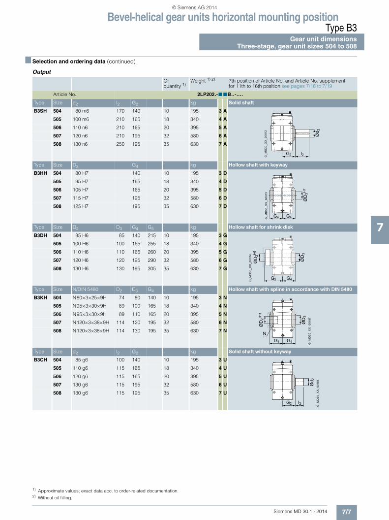
Bevel-helical gear units horizontal mounting positionType B3
Gear unit dimensionsThree-stage, gear unit sizes 504 to 508
7/7Siemens MD 30.1 · 2014
7
■ Selection and ordering data (continued)
Output
Oil quantity 1)
Weight 1) 2) 7th position of Article No. and Article No. supplementfor 11th to 16th position see pages 7/16 to 7/19
Article No.: 2LP202.-■ ■B..-....
Type Size d2 l2 G2 l kg Solid shaft
B3SH 504 80 m6 170 140 10 195 3 A
505 100 m6 210 165 18 340 4 A
506 110 n6 210 165 20 395 5 A
507 120 n6 210 195 32 580 6 A
508 130 n6 250 195 35 630 7 A
Type Size D2 G4 l kg Hollow shaft with keyway
B3HH 504 80 H7 140 10 195 3 D
505 95 H7 165 18 340 4 D
506 105 H7 165 20 395 5 D
507 115 H7 195 32 580 6 D
508 125 H7 195 35 630 7 D
Type Size D2 D3 G4 G5 l kg Hollow shaft for shrink disk
B3DH 504 85 H6 85 140 215 10 195 3 G
505 100 H6 100 165 255 18 340 4 G
506 110 H6 110 165 260 20 395 5 G
507 120 H6 120 195 290 32 580 6 G
508 130 H6 130 195 305 35 630 7 G
Type Size N/DIN 5480 D2 D3 G4 l kg Hollow shaft with spline in accordance with DIN 5480
B3KH 504 N80×3×25×9H 74 80 140 10 195 3 N
505 N95×3×30×9H 89 100 165 18 340 4 N
506 N95×3×30×9H 89 110 165 20 395 5 N
507 N120×3×38×9H 114 120 195 32 580 6 N
508 N120×3×38×9H 114 130 195 35 630 7 N
Type Size d2 l2 G2 l kg Solid shaft without keyway
B3CH 504 85 g6 100 140 10 195 3 U
505 110 g6 115 165 18 340 4 U
506 120 g6 115 165 20 395 5 U
507 130 g6 115 195 32 580 6 U
508 130 g6 115 195 35 630 7 U
G_M
D30
_XX
_000
12
G2 I2
Ød 2
G_M
D30
_XX
_000
13
G4 G4
ØD
2H7
G_M
D30
_XX
_000
14
G5 G4
ØD
3
ØD
2H6
G_M
D30
_XX
_001
87
NG4 G4
ØD
3
ØD
2H11
G2 l2
G_M
D30
_XX
_001
86
Ød 2
1) Approximate values; exact data acc. to order-related documentation.2) Without oil filling.
© Siemens AG 2014

Bevel-helical gear units horizontal mounting positionType B3Gear unit dimensions Three-stage, gear unit sizes 509 to 512
7/8 Siemens MD 30.1 · 2014
7
■ Selection and ordering data
Fan
Air inlet
Fan
n2
E
n1
am1
A3H
h
h 5
Øs
Ød 1
Ød 6
ca.30°
A 1A
2
c
B1
G1
m3
b
l1
l3
e3
G3
G6
Note:
For shaft details, see pages 10/2 to 10/7.
1) Maximum dimension including bolted connection. See order-related documentation for exact data.
2) Permissible tolerance: -1 mm.
Dimensions in mm
Gear unit sizes
Input Fan 1)
d1 l1 l3 d1 l1 l3 G1 G3 A1 A2 A3 B1 d6 G6
iN = 14 – 50 56
509 60 m6 120 90 50 m6 110 80 812 842 315 375 95 270 175 862
iN = 18 – 63 71
510 60 m6 120 90 50 m6 110 80 865 895 315 375 95 270 175 915
iN = 14 – 50 56
511 75 m6 135 100 60 m6 135 100 975 1010 370 440 125 315 175 1030
iN = 18 – 63 71
512 75 m6 135 100 60 m6 135 100 1033 1068 370 440 125 315 175 1088
Gear unit sizes
Dimensions in mm
a b c E e3 H h 2) h5 m1 m3 n1 n2 s
509 988 370 40 447 190 715 320 350 680 290 162 205 28
510 1106 370 40 500 190 715 320 350 798 290 162 270 28
511 1204 430 50 547 225 830 380 425 825 340 202 255 35
512 1332 430 50 605 225 830 380 425 953 340 202 325 35
© Siemens AG 2014

Bevel-helical gear units horizontal mounting positionType B3
Gear unit dimensionsThree-stage, gear unit sizes 509 to 512
7/9Siemens MD 30.1 · 2014
7
■ Selection and ordering data (continued)
Output
Oil quantity 1)
Weight 1) 2) 7th position of Article No. and Article No. supplementfor 11th to 16th position see pages 7/16 to 7/19
Article No.: 2LP202.-■ ■B..-....
Type Size d2 l2 G2 l kg Solid shaft
B3SH 509 145 n6 250 240 53 905 8 A
510 160 n6 300 240 51 960 0 B
511 175 n6 300 270 84 1455 1 B
512 185 n6 350 270 100 1570 2 B
Type Size D2 G4 l kg Hollow shaft with keyway
B3HH 509 135 H7 235 53 905 8 D
510 150 H7 235 51 960 0 E
511 165 H7 270 84 1455 1 E
512 180 H7 270 100 1570 2 E
Type Size D2 D3 G4 G5 l kg Hollow shaft for shrink disk
B3DH 509 140 H6 145 235 350 53 905 8 G
510 150 H6 155 235 370 51 960 0 H
511 165 H6 170 270 420 84 1455 1 H
512 180 H6 185 270 425 100 1570 2 H
Type Size N/DIN 5480 D2 D3 G4 l kg Hollow shaft with spline in accordance with DIN 5480
B3KH 509 N140×3×45×9H 134 145 235 53 905 8 N
510 N140×3×45×9H 134 155 235 51 960 0 P
511 N170×5×32×9H 160 170 270 84 1455 1 P
512 N170×5×32×9H 160 185 270 100 1570 2 P
Type Size d2 l2 G2 l kg Solid shaft without keyway
B3CH 509 150 g6 140 240 53 905 8 U
510 170 g6 140 240 51 960 0 V
511 180 g6 145 270 84 1455 1 V
512 190 g6 145 270 100 1570 2 V
G_M
D30
_XX
_000
12
G2 I2
Ød 2
G_M
D30
_XX
_000
13
G4 G4
ØD
2H7
G_M
D30
_XX
_000
14
G5 G4
ØD
3
ØD
2H6
G_M
D30
_XX
_001
87
NG4 G4
ØD
3
ØD
2H11
G2 l2
G_M
D30
_XX
_001
86
Ød 2
1) Approximate values; exact data acc. to order-related documentation.2) Without oil filling.
© Siemens AG 2014

Bevel-helical gear units horizontal mounting positionType B3Gear unit dimensions Three-stage, gear unit sizes 513 and 514
7/10 Siemens MD 30.1 · 2014
7
■ Selection and ordering data
G_MD30_EN_00306
Air inlet
Fanca.30°
g
b
m3
n3
G1 l1
l3
B1
c1 ØD5
Øs
c
h 5h
n 4n 4
A2
A1
H
Ød 1
Ød 6
A3
a
E
m1 n1
n2
n6
e3
G3
G6
Note:
For shaft details, see pages 10/2 to 10/7.
1) Maximum dimension including bolted connection. See order-related documentation for exact data.
2) Permissible tolerance: -1 mm.
Dimensions in mm
Gear unit sizes
Input Fan 1)
d1 l1 l3 d1 l1 l3 G1 G3 A1 A2 A3 B1 d6 G6
iN = 14 – 40 45 – 56
513 80 m6 165 130 70 m6 140 105 1167 1202 435 495 160 375 210 1220
iN = 18 – 50 56 – 71
514 80 m6 165 130 70 m6 140 105 1245 1280 435 495 160 375 210 1298
Gear unit sizes
Dimensions in mm
a b c c1 D5 E e3 g H h 2) h5 m1 m3 n1 n2 n3 n4 n6 s
513 1345 535 60 65 48 640 265 202.5 950 440 185 920 445 245 260 842 380 380 42
514 1463 535 60 65 48 718 265 202.5 950 440 185 1038 445 245 300 920 380 420 42
© Siemens AG 2014

Bevel-helical gear units horizontal mounting positionType B3
Gear unit dimensionsThree-stage, gear unit sizes 513 and 514
7/11Siemens MD 30.1 · 2014
7
■ Selection and ordering data (continued)
Output
Oil quantity 1)
Weight 1) 2) 7th position of Article No. and Article No. supplementfor 11th to 16th position see pages 7/16 to 7/19
Article No.: 2LP202.-■ ■B..-....
Type Size d2 l2 G2 l kg Solid shaft
B3SH 513 200 n6 350 330 145 2500 3 B
514 210 n6 350 330 155 2850 4 B
Type Size D2 G4 l kg Hollow shaft with keyway
B3HH 513 190 H7 330 145 2500 3 E
514 210 H7 330 155 2850 4 E
Type Size D2 D3 G4 G5 l kg Hollow shaft for shrink disk
B3DH 513 190 H6 195 330 495 145 2500 3 H
514 210 H6 215 330 495 155 2850 4 H
Type Size N/DIN 5480 D2 D3 G4 l kg Hollow shaft with spline in accordance with DIN 5480
B3KH 513 N190×5×36×9H 180 195 330 145 2500 3 P
514 N190×5×36×9H 180 215 330 155 2850 4 P
Type Size d2 l2 G2 l kg Solid shaft without keyway
B3CH 513 220 g6 165 330 145 2500 3 V
514 220 g6 165 330 155 2850 4 V
G_M
D30
_XX
_000
12
G2 I2
Ød 2
G_M
D30
_XX
_000
13
G4 G4
ØD
2H7
G_M
D30
_XX
_000
14
G5 G4
ØD
3
ØD
2H6
G_M
D30
_XX
_001
87
NG4 G4
ØD
3
ØD
2H11
G2 l2
G_M
D30
_XX
_001
86
Ød 2
1) Approximate values; exact data acc. to order-related documentation.2) Without oil filling.
© Siemens AG 2014

Bevel-helical gear units horizontal mounting positionType B4Gear unit dimensions Four-stage, gear unit sizes 505 to 508
7/12 Siemens MD 30.1 · 2014
7
■ Selection and ordering data
c1
b
m3
G1 l1
m1 n1
e3
a
En2
n6
n3
g
n 4n 4
h 5h
H
c
ØD5
Ød 1
Øs
G_M
D30
_XX
_000
03a
Dimensions in mm
Gear unit sizes
Input
d1 l1 d1 l1 d1 l1 G1
iN = 63 – 200 224 – 280
505 28 m6 55 20 k6 50 610
iN = 90 – 280 315 – 355
506 28 m6 55 20 k6 50 663
iN = 63 – 200 224 250 – 280
507 35 m6 80 32 m6 70 25 k6 60 724
iN = 80 – 250 280 315 – 355
508 35 m6 80 32 m6 70 25 k6 60 771
Gear unit sizes
Dimensions in mm
a b c c1 D5 E e3 g H h 1) h5 m1 m3 n1 n2 n3 n4 n6 s
505 720 250 30 30 24 400 90 95 530 230 105 530 200 105 145 457.5 202.5 202.5 19
506 843 250 30 30 24 453 90 95 530 230 105 653 200 105 215 510.5 202.5 272.5 19
507 899 295 35 35 28 493.5 110.5 112.5 635 280 115 680 230 104 180 567.5 242.5 257.5 24
508 1006 295 35 35 28 540.5 110.5 112.5 635 280 115 787 230 104 240 614.5 242.5 317.5 24
Note:
For shaft details, see pages 10/2 to 10/7.
1) Permissible tolerance: -1 mm.
© Siemens AG 2014
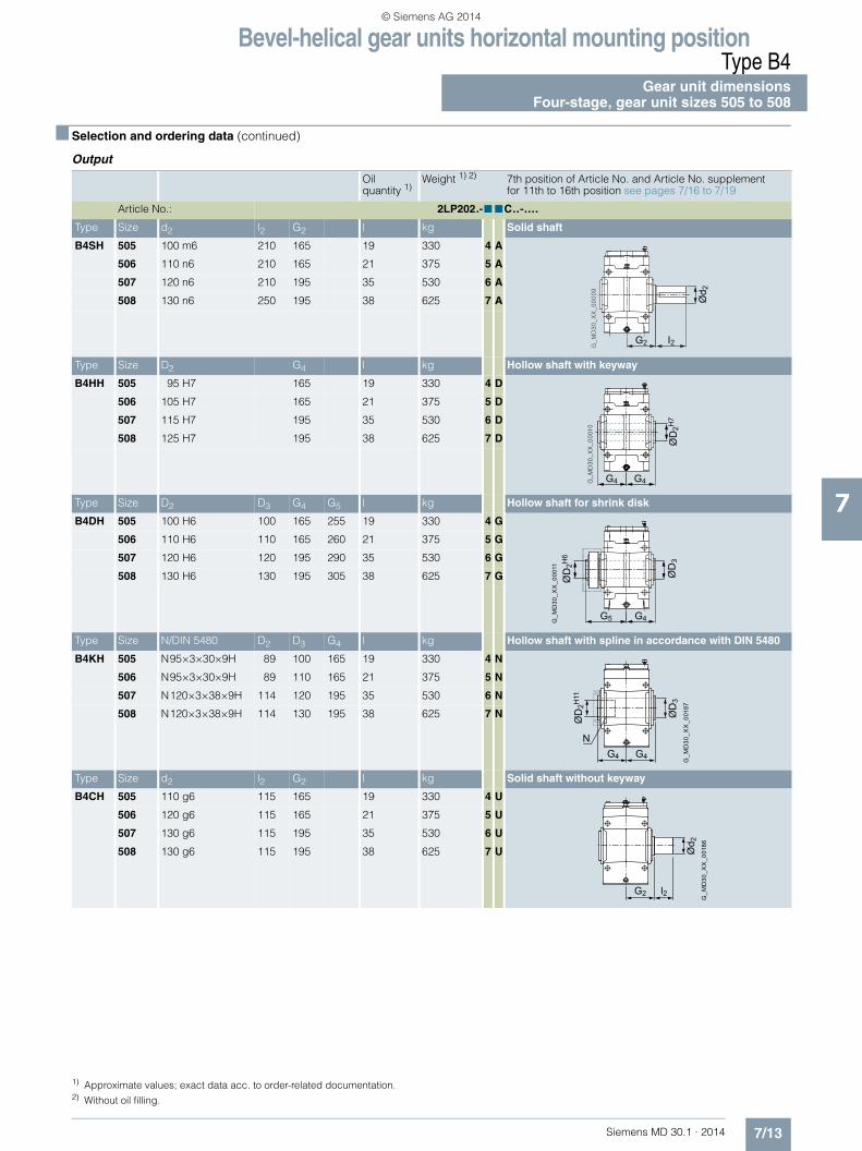
Bevel-helical gear units horizontal mounting positionType B4
Gear unit dimensionsFour-stage, gear unit sizes 505 to 508
7/13Siemens MD 30.1 · 2014
7
■ Selection and ordering data (continued)
Output
Oil quantity 1)
Weight 1) 2) 7th position of Article No. and Article No. supplementfor 11th to 16th position see pages 7/16 to 7/19
Article No.: 2LP202.-■ ■C..-....
Type Size d2 l2 G2 l kg Solid shaft
B4SH 505 100 m6 210 165 19 330 4 A
506 110 n6 210 165 21 375 5 A
507 120 n6 210 195 35 530 6 A
508 130 n6 250 195 38 625 7 A
Type Size D2 G4 l kg Hollow shaft with keyway
B4HH 505 95 H7 165 19 330 4 D
506 105 H7 165 21 375 5 D
507 115 H7 195 35 530 6 D
508 125 H7 195 38 625 7 D
Type Size D2 D3 G4 G5 l kg Hollow shaft for shrink disk
B4DH 505 100 H6 100 165 255 19 330 4 G
506 110 H6 110 165 260 21 375 5 G
507 120 H6 120 195 290 35 530 6 G
508 130 H6 130 195 305 38 625 7 G
Type Size N/DIN 5480 D2 D3 G4 l kg Hollow shaft with spline in accordance with DIN 5480
B4KH 505 N95×3×30×9H 89 100 165 19 330 4 N
506 N95×3×30×9H 89 110 165 21 375 5 N
507 N120×3×38×9H 114 120 195 35 530 6 N
508 N120×3×38×9H 114 130 195 38 625 7 N
Type Size d2 l2 G2 l kg Solid shaft without keyway
B4CH 505 110 g6 115 165 19 330 4 U
506 120 g6 115 165 21 375 5 U
507 130 g6 115 195 35 530 6 U
508 130 g6 115 195 38 625 7 U
G2 I2
Ød 2
G4 G4
ØD
2H7
G_M
D30
_XX
_000
11
G5 G4
ØD
3
ØD
2H6
G_M
D30
_XX
_001
87
NG4 G4
ØD
3
ØD
2H11
G2 l2
G_M
D30
_XX
_001
86
Ød 2
1) Approximate values; exact data acc. to order-related documentation.2) Without oil filling.
© Siemens AG 2014
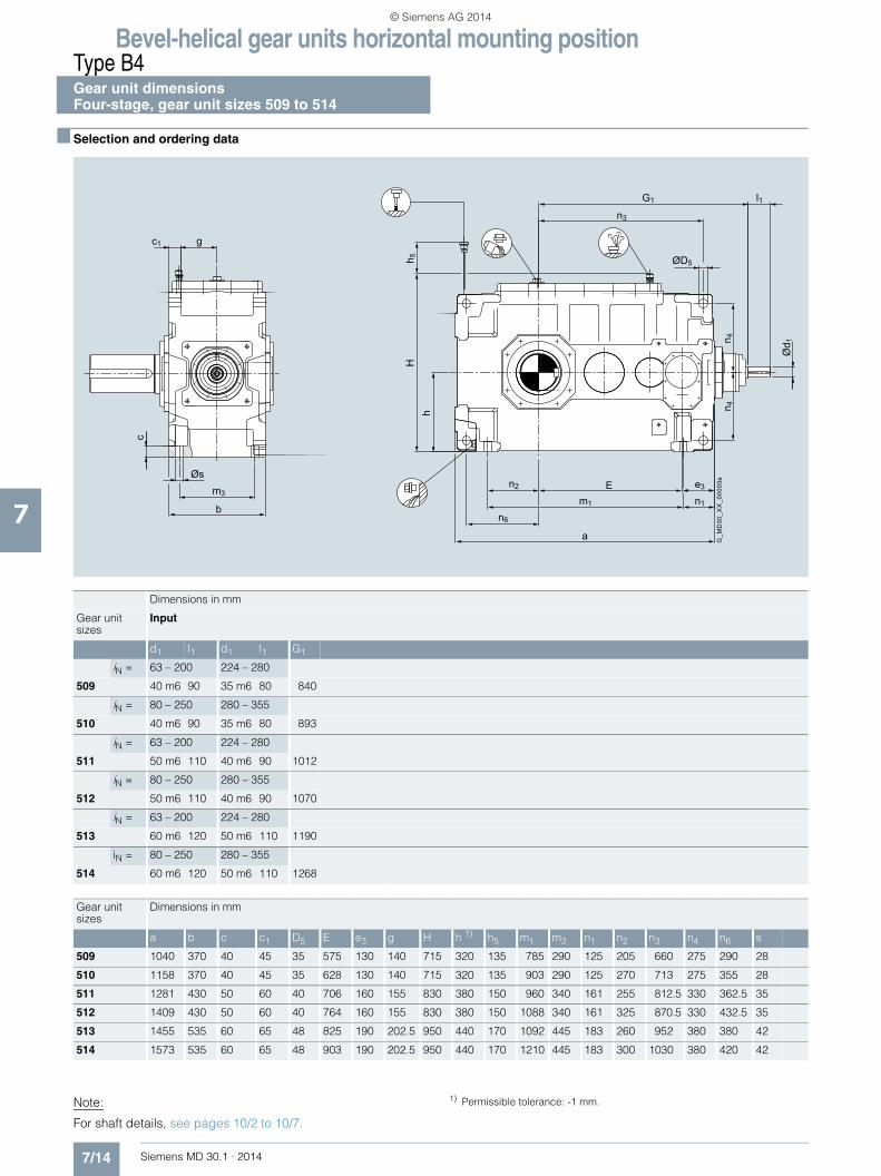
Bevel-helical gear units horizontal mounting positionType B4Gear unit dimensions Four-stage, gear unit sizes 509 to 514
7/14 Siemens MD 30.1 · 2014
7
■ Selection and ordering data
c1
b
m3
G1 l1
m1 n1
e3
a
En2
n6
n3
g
n 4n 4
h 5h
H
c
ØD5
Ød 1
Øs
G_M
D30
_XX
_000
03a
Note:
For shaft details, see pages 10/2 to 10/7.
1) Permissible tolerance: -1 mm.
Dimensions in mm
Gear unit sizes
Input
d1 l1 d1 l1 G1
iN = 63 – 200 224 – 280
509 40 m6 90 35 m6 80 840
iN = 80 – 250 280 – 355
510 40 m6 90 35 m6 80 893
iN = 63 – 200 224 – 280
511 50 m6 110 40 m6 90 1012
iN = 80 – 250 280 – 355
512 50 m6 110 40 m6 90 1070
iN = 63 – 200 224 – 280
513 60 m6 120 50 m6 110 1190
iN = 80 – 250 280 – 355
514 60 m6 120 50 m6 110 1268
Gear unit sizes
Dimensions in mm
a b c c1 D5 E e3 g H h 1) h5 m1 m3 n1 n2 n3 n4 n6 s
509 1040 370 40 45 35 575 130 140 715 320 135 785 290 125 205 660 275 290 28
510 1158 370 40 45 35 628 130 140 715 320 135 903 290 125 270 713 275 355 28
511 1281 430 50 60 40 706 160 155 830 380 150 960 340 161 255 812.5 330 362.5 35
512 1409 430 50 60 40 764 160 155 830 380 150 1088 340 161 325 870.5 330 432.5 35
513 1455 535 60 65 48 825 190 202.5 950 440 170 1092 445 183 260 952 380 380 42
514 1573 535 60 65 48 903 190 202.5 950 440 170 1210 445 183 300 1030 380 420 42
© Siemens AG 2014

Bevel-helical gear units horizontal mounting positionType B4
Gear unit dimensionsFour-stage, gear unit sizes 509 to 514
7/15Siemens MD 30.1 · 2014
7
■ Selection and ordering data (continued)
Output
Oil quantity 1)
Weight 1) 2) 7th position of Article No. and Article No. supplementfor 11th to 16th position see pages 7/16 to 7/19
Article No.: 2LP202.-■ ■C..-....
Type Size d2 l2 G2 l kg Solid shaft
B4SH 509 145 n6 250 240 60 800 8 A
510 160 n6 300 240 60 995 0 B
511 175 n6 300 270 93 1495 1 B
512 185 n6 350 270 97 1565 2 B
513 200 n6 350 330 160 2400 3 B
514 210 n6 350 330 165 2700 4 B
Type Size D2 G4 l kg Hollow shaft with keyway
B4HH 509 135 H7 235 60 800 8 D
510 150 H7 235 60 995 0 E
511 165 H7 270 93 1495 1 E
512 180 H7 270 97 1565 2 E
513 190 H7 330 160 2400 3 E
514 210 H7 330 165 2700 4 E
Type Size D2 D3 G4 G5 l kg Hollow shaft for shrink disk
B4DH 509 140 H6 145 235 350 60 800 8 G
510 150 H6 155 235 370 60 995 0 H
511 165 H6 170 270 420 93 1495 1 H
512 180 H6 185 270 425 97 1565 2 H
513 190 H6 195 330 495 160 2400 3 H
514 210 H6 215 330 495 165 2700 4 H
Type Size N/DIN 5480 D2 D3 G4 l kg Hollow shaft with spline in accordance with DIN 5480
B4KH 509 N140×3×45×9H 134 140 235 60 800 8 N
510 N140×3×45×9H 134 155 235 60 995 0 P
511 N170×5×32×9H 160 170 270 93 1495 1 P
512 N170×5×32×9H 160 185 270 97 1565 2 P
513 N190×5×36×9H 180 195 330 160 2400 3 P
514 N190×5×36×9H 180 215 330 165 2700 4 P
Type Size d2 l2 G2 l kg Solid shaft without keyway
B4CH 509 150 g6 140 240 60 800 8 U
510 170 g6 140 240 60 995 0 V
511 180 g6 145 270 93 1495 1 V
512 190 g6 145 270 97 1565 2 V
513 220 g6 165 330 160 2400 3 V
514 220 g6 165 330 165 2700 4 V
G2 I2
Ød 2
G4 G4
ØD
2H7
G_M
D30
_XX
_000
11
G5 G4
ØD
3
ØD
2H6
G_M
D30
_XX
_001
87
NG4 G4
ØD
3
ØD
2H11
G2 l2
G_M
D30
_XX
_001
86
Ød 2
1) Approximate values; exact data acc. to order-related documentation.2) Without oil filling.
© Siemens AG 2014

Bevel-helical gear units horizontal mounting positionTypes B2, B3 and B4
Article No. overview
7/16 Siemens MD 30.1 · 2014
7
■ Selection and ordering data
7th position of the Article No.
Data position of Article No.
1 to 6 7 8 9 10 11 12 13 14 15 16 "-Z" and order code
Article No. 2LP202 ■ - . . . . . - . . . . -Z . . .
Design variant (view directed at face 2, face 1 at bottom)
Type
B2 to B3 to B4 to
A0
B1
C2
D3
Irrespective of the spatial position of the gear unit, the face designations "right" and "left" always refer to the horizontal mounting position with the view directed at face 1. Face 2 is at the top.Assembly cover at top (2), view directed at drive end face (1): • Face 3 = right • Face 6 = left
E4
F5
1
A
G8
ØD
8
G_MD30_XX_00163 G_MD30_XX_00032
1
A
G8
ØD
8
G_MD30_XX_00036
2
3
ØD
8
G8 G8
ØD
8
A
6
5
4
6
5
4
2
3
1
G_MD30_XX_00193
1
G8
ØD
8
G_MD30_XX_00164
B
G_MD30_XX_00033
1
G8
ØD
8
B
G_MD30_XX_00037
2
3G8 G8
ØD
8
ØD
8
B
1
G8
ØD
8
G_MD30_XX_00165
C
G_MD30_XX_00034
1
G8
ØD
8
C
G_MD30_XX_00038
3
2ØD
8
G8 G8
ØD
8
C
1
G_MD30_XX_00166
D
G8
ØD
8
G_MD30_XX_00035
1
G8
ØD
8
D
G_MD30_DE_00039
3
2
G8 G8
ØD
8 ØD
8
D
1
G8
ØD
8
G_MD30_XX_00167
E
1
E
G8
ØD
8
G_MD30_XX_00169
2
3
ØD
8
G8 G8
ØD
8
E
G_MD30_XX_00171
1
G_MD30_XX_00168
F
G8
ØD
8
1
F
G8
ØD
8
G_MD30_XX_00170
2
3
ØD
8
G8 G8
ØD
8
F
G_MD30_XX_00172
$ Backstop for types B2 and B3. Backstop not possible for: Type B2SH, designs B, D, E, F and Type B2DH, designs A and C.
% Backstop for type B4, gear unit sizes 505 and 506
& Backstop for type B4, gear unit sizes 507 to 514
© Siemens AG 2014

Bevel-helical gear units horizontal mounting positionTypes B2, B3 and B4
Article No. overview
7/17Siemens MD 30.1 · 2014
7
■ Selection and ordering data (continued)
8th to 10th position of the Article No.
Data position of Article No.
1 to 6 7 8 9 10 11 12 13 14 15 16 "-Z" and order code
Article No. 2LP202 . - ■ ■ ■ . . - . . . . -Z . . .
Output shaft, gear unit size
Output shaft Gear unit size
Solid shaft (S)
503 2 A
504 3 A
505 4 A
506 5 A
507 6 A
508 7 A
509 8 A
510 0 B
511 1 B
512 2 B
513 3 B
514 4 B
Hollow shaft with keyway (H)
504 3 D
505 4 D
506 5 D
507 6 D
508 7 D
509 8 D
510 0 E
511 1 E
512 2 E
513 3 E
514 4 E
Hollow shaft for shrink disk (D)
504 3 G
505 4 G
506 5 G
507 6 G
508 7 G
509 8 G
510 0 H
511 1 H
512 2 H
513 3 H
514 4 H
© Siemens AG 2014

Bevel-helical gear units horizontal mounting positionTypes B2, B3 and B4
Article No. overview
7/18 Siemens MD 30.1 · 2014
7
■ Selection and ordering data (continued)
8th to 10th position of the Article No. (continued)
Data position of Article No.
1 to 6 7 8 9 10 11 12 13 14 15 16 "-Z" and order code
Article No. 2LP202 . - ■ ■ ■ . . - . . . . -Z . . .
Output shaft, gear unit size
Output shaft Gear unit size
Hollow shaft with spline in accordance with DIN 5480 (K)
504 3 N
505 4 N
506 5 N
507 6 N
508 7 N
509 8 N
510 0 P
511 1 P
512 2 P
513 3 P
514 4 P
Solid shaft without keyway (C)
504 3 U
505 4 U
506 5 U
507 6 U
508 7 U
509 8 U
510 0 V
511 1 V
512 2 V
513 3 V
514 4 V
Gear unit type, number of stages, mounting position
B2.H A
B3.H B
B4.H C
© Siemens AG 2014

Bevel-helical gear units horizontal mounting positionTypes B2, B3 and B4
Article No. overview
7/19Siemens MD 30.1 · 2014
7
■ Selection and ordering data (continued)
Article No. supplement, 11th to 16th position
Data position of Article No.
1 to 6 7 8 9 10 11 12 13 14 15 16 "-Z" and order code
Article No. 2LP202 . - . . . ■ ■ - ■ ■ ■ ■ -Z ■ ■ ■
Seal for shaft 1 1)
Shaft d1 at one end with 1 × shaft seal 0
Shaft d1 at one end with taconite E 4
Seal for shaft 2 1)
Shaft d2 at one end with 1 × shaft seal 0
Shaft d2 at both ends with 1 × shaft seal at both ends 1
Shaft d2 at one end with taconite F 4
Shaft d2 at both ends with taconite F at both ends 5
Shaft d2 taconite F-F 6
Shaft d2 taconite F-H 7
Shaft d2 taconite F-K 8
Shaft variants
Standard shaft d1 and standard shaft d2 0
Gear ratio
Type/gear unit size
B2.H B3.H B4.H
503, 504, 505, 507, 509
506 508, 510 504 ... 514 505 ... 514
iN 5 – – 14 63 A
iN 5.6 – 6 16 71 B
iN 6.3 6.3 6.7 18 80 C
iN 7.1 7.1 7.5 20 90 D
iN 8 8 8.5 22.4 100 E
iN 9 9 9.5 25 112 F
iN 10 10 10.6 28 125 G
iN 11.2 11.2 11.8 31.5 140 H
iN 12.5 12.5 13.2 35.5 160 J
iN 14 14 15 40 180 K
iN 16 16 17 45 200 L
iN – 18 19 50 224 M
iN – 20 – 56 250 N
iN – – – 63 280 P
iN – – – 71 315 Q
iN – – – 80 355 R
Oil supply
Dip lubrication A
Other oil supply Z Q 0 Y
Auxiliary cooling
Without auxiliary cooling 0
Auxiliary cooling with fan 1
Auxiliary cooling by cooling coil, connections to gear unit face 4 (end face d2)
2
Auxiliary cooling by fan and cooling coil, connections to gear unit face 4 (end face d2)
3
Auxiliary cooling by cooling coil, connections to gear unit face 1 (end face d1)
4
1) Additional details see page 11/2.
© Siemens AG 2014

Bevel-helical gear units horizontal mounting positionTypes B2, B3 and B4
Notes
7/20 Siemens MD 30.1 · 2014
7
© Siemens AG 2014

Siemens MD 30.1 · 2014
88/2 Type B2
Gear unit dimensions8/2 Two-stage, gear unit sizes 503 to 5088/4 Two-stage, gear unit sizes 509 and 510
8/6 Type B3Gear unit dimensions
8/6 Three-stage, gear unit sizes 513 and 514
8/8 Type B4Gear unit dimensions
8/8 Four-stage, gear unit sizes 505 to 5088/10 Four-stage, gear unit sizes 509 to 514
8/12 Types B2, B3 and B48/12 Dimensions of oil expansion unit 8/13 Article No. overview
Bevel-helical gear units vertical mounting position
© Siemens AG 2014

Bevel-helical gear units vertical mounting positionType B2Gear unit dimensions Two-stage, gear unit sizes 503 to 508
8/2 Siemens MD 30.1 · 2014
8
■ Selection and ordering data
G_M
D30
_EN
_002
46
Fan
Air inlet
A3
e3
b4b3n6n3
a
b2b2n4n4
A2A1G3
G1 hH
l1
l3
G6 h6
1) 1)
1)
1)E
ØD5
c 1 f 2B
1
gbØd 1
Ød 6
ca. 30°
Dimensions in mm
Gear unit sizes
Input Fan 2)
d1 l1 l3 d1 l1 l3 G1 G3 A1 A2 A3 B1 d6 G6
iN = 5 – 14 16
503 40 m6 90 70 35 m6 80 60 393 413 190 255 130 195 135 433
iN = 5 – 14 16
504 50 m6 110 90 40 m6 90 70 465 485 215 280 160 230 150 504
iN = 5 – 14 16
505 60 m6 120 90 50 m6 110 80 550 580 240 305 190 260 175 600
iN = 6.3 – 18 20
506 60 m6 120 90 50 m6 110 80 581 611 240 305 190 260 175 631
iN = 5 – 14 16
507 75 m6 135 100 60 m6 135 100 656 691 300 370 225 320 210 718
iN = 6 – 17 19
508 75 m6 135 100 60 m6 135 100 686 721 300 370 225 320 210 748
Gear unit sizes
Dimensions in mm
a b b2 3) b3 3) b4 3) c1 D5 E e3 f2 3) g H h 4) h6 4) n3 n4 n6
503 455 260 93 202 74 25 19 128 130 55 105 440 200 190 230 175 165
504 555 325 105 256 97 30 24 159 160 58 132.5 490 225 225 290 195 195
505 620 360 121 298 113 30 24 185 190 60 150 540 250 230 345 220 200
506 670 360 126 340 124 30 24 216 190 60 150 540 250 250 376 220 220
507 730 465 149 367 139 40 28 228 225 63 192.5 670 315 260 415 280 225
508 790 465 154 397 139 40 28 258 225 63 192.5 670 315 290 445 280 255
Note:"Dip lubrication with oil expansion unit" is provided as the stan-dard oil supply. Dimensions of oil expansion unit see page 8/12. For shaft details, see pages 10/2 to 10/7.
1) Position dependent on other options. 2) Maximum dimensions including bolted connection.
See order-related documentation for exact data. 3) Minimum dimensions, space requirements dependent on other options. 4) Permissible tolerance: -1 mm.
© Siemens AG 2014

Bevel-helical gear units vertical mounting positionType B2
Gear unit dimensionsTwo-stage, gear unit sizes 503 to 508
8/3Siemens MD 30.1 · 2014
8
■ Selection and ordering data (continued)
Output
Oil quantity 1)
Weight 1) 2) 7th position of Article No. and Article No. supplementfor 11th to 16th position see pages 8/13 to 8/16
Article No. 2LP202.-■ ■G..-....
Type Size d2 l2 G2 l kg Solid shaft
B2SV 503 65 m6 140 185 20 175 2 A
504 80 m6 170 220 32 280 3 A
505 90 m6 210 240 44 428 4 A
506 100 m6 210 240 48 450 5 A
507 105 n6 235 295 84 725 6 A
508 120 n6 250 295 90 790 7 A
Type Size D2 G4 l kg Hollow shaft with keyway
B2HV 503 – – – –
504 80 H7 220 32 280 3 D
505 95 H7 240 44 428 4 D
506 105 H7 240 48 450 5 D
507 115 H7 295 84 725 6 D
508 125 H7 295 90 790 7 D
Type Size D2 D3 G4 G5 l kg Hollow shaft for shrink disk
B2DV 3) 503 – – – – – –
504 85 H6 85 220 295 32 280 3 G
505 100 H6 100 240 325 44 428 4 G
506 110 H6 110 240 330 48 450 5 G
507 120 H6 120 295 390 84 725 6 G
508 130 H6 130 295 400 90 790 7 G
I 2G
2
Ød2
G_MD30_XX_00235
G_MD30_XX_00281
G4
G4
ØD2H7
ØD3
G_MD30_XX_00282
G5
G4
ØD2H6
1) Approximate values; exact data acc. to order-related documentation.2) Without oil filling.
3) Shaft variant designed to withstand axial forces (including those caused by weight of gear unit) on request.
© Siemens AG 2014

Bevel-helical gear units vertical mounting positionType B2Gear unit dimensions Two-stage, gear unit sizes 509 and 510
8/4 Siemens MD 30.1 · 2014
8
■ Selection and ordering data
G_M
D30
_EN
_002
46
Fan
Air inlet
A3
e3
b4b3n6n3
a
b2b2n4n4
A2A1G3
G1 hH
l1
l3
G6 h6
1) 1)
1)
1)E
ØD5
c 1 f 2B
1
gbØd 1
Ød 6
ca. 30°
Dimensions in mm
Gear unit sizes
Input Fan 2)
d1 l1 l3 d1 l1 l3 G1 G3 A1 A2 A3 B1 d6 G6
iN = 5 – 11.2 12.5 –16
509 80 m6 165 130 70 m6 140 105 792 827 340 410 265 360 240 850
iN = 6 – 13.2 15 – 19
510 80 m6 165 130 70 m6 140 105 823 858 340 410 265 360 240 881
Gear unit sizes
Dimensions in mm
a b b2 3) b3 3) b4 3) c1 D5 E e3 f2 3) g H h 4) h6 4) n3 n4 n6
509 875 550 160 425 160 55 35 265 265 60 220 755 355 330 480 307.5 282.5
510 935 550 170 466 170 55 35 296 265 60 220 755 355 355 511 307.5 307.5
Note:"Dip lubrication with oil expansion unit" is provided as the stan-dard oil supply. Dimensions of oil expansion unit see page 8/12. For shaft details, see pages 10/2 to 10/7.
1) Position dependent on other options. 2) Maximum dimensions including bolted connection.
See order-related documentation for exact data. 3) Minimum dimensions, space requirements dependent on other options. 4) Permissible tolerance: -1 mm.
© Siemens AG 2014

Bevel-helical gear units vertical mounting positionType B2
Gear unit dimensionsTwo-stage, gear unit sizes 509 and 510
8/5Siemens MD 30.1 · 2014
8
■ Selection and ordering data (continued)
Output
Oil quantity 1)
Weight 1) 2) 7th position of Article No. and Article No. supplementfor 11th to 16th position see pages 8/13 to 8/16
Article No. 2LP202.-■ ■G..-....
Type Size d2 l2 G2 l kg Solid shaft
B2SV 509 135 n6 260 335 132 1140 8 A
510 150 n6 280 335 142 1254 0 B
Type Size D2 G4 l kg Hollow shaft with keyway
B2HV 509 135 H7 335 132 1140 8 D
510 145 H7 335 142 1254 0 E
Type Size D2 D3 G4 G5 l kg Hollow shaft for shrink disk
B2DV 3) 509 140 H6 145 335 450 132 1140 8 G
510 145 H6 150 335 470 142 1254 0 HI 2
G2
Ød2
G_MD30_XX_00235
G_MD30_XX_00281
G4
G4
ØD2H7
ØD3
G_MD30_XX_00282
G5
G4
ØD2H6
1) Approximate values; exact data acc. to order-related documentation.2) Without oil filling.
3) Shaft variant designed to withstand axial forces (including those caused by weight of gear unit) on request.
© Siemens AG 2014
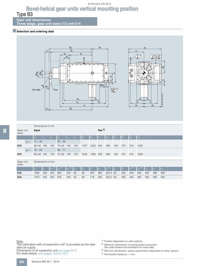
Bevel-helical gear units vertical mounting positionType B3Gear unit dimensions Three-stage, gear unit sizes 513 and 514
8/6 Siemens MD 30.1 · 2014
8
■ Selection and ordering data
G_M
D30
_EN
_002
47
FanAir inlet
A3
b2b2n4n4
A2A1
hH
b4b3n6n3
aG3l3
1) 1) 1)
1)
e3
G1l1G6 h6
E
f 2B
1
c 1g
bØd 1
Ød 6
ca. 30°ØD5
Dimensions in mm
Gear unit sizes
Input Fan 2)
d1 l1 l3 d1 l1 l3 G1 G3 A1 A2 A3 B1 d6 G6
iN = 14 – 40 45 – 56
513 80 m6 165 130 70 m6 140 105 1167 1202 435 495 160 375 210 1220
iN = 18 – 50 56 – 71
514 80 m6 165 130 70 m6 140 105 1245 1280 435 495 160 375 210 1298
Gear unit sizes
Dimensions in mm
a b b2 3) b3 3) b4 3) c1 D5 E e3 f2 3) g H h 4) h6 4) n3 n4 n6
513 1360 535 205 800 205 65 48 640 265 202.5 63 935 440 440 842 380 380
514 1475 535 220 878 220 65 48 718 265 202.5 63 935 440 480 920 380 420
Note:"Dip lubrication with oil expansion unit" is provided as the stan-dard oil supply. Dimensions of oil expansion unit see page 8/12. For shaft details, see pages 10/2 to 10/7.
1) Position dependent on other options. 2) Maximum dimensions including bolted connection.
See order-related documentation for exact data. 3) Minimum dimensions, space requirements dependent on other options. 4) Permissible tolerance: -1 mm.
© Siemens AG 2014
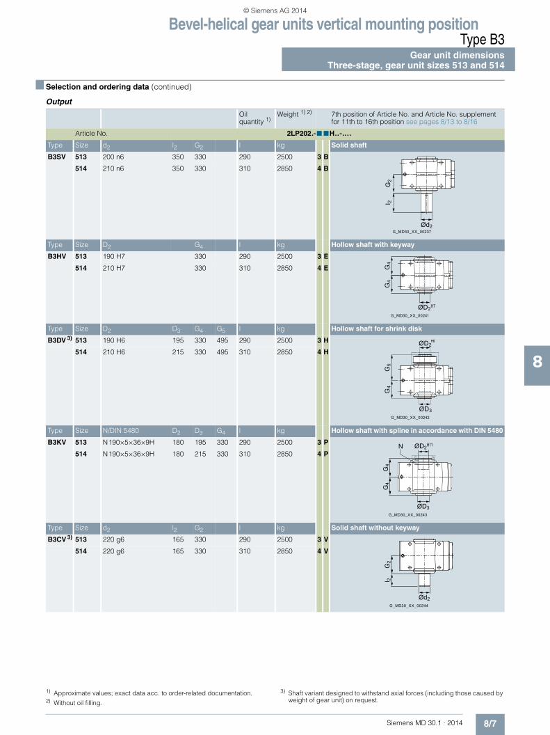
Bevel-helical gear units vertical mounting positionType B3
Gear unit dimensionsThree-stage, gear unit sizes 513 and 514
8/7Siemens MD 30.1 · 2014
8
■ Selection and ordering data (continued)
Output
Oil quantity 1)
Weight 1) 2) 7th position of Article No. and Article No. supplementfor 11th to 16th position see pages 8/13 to 8/16
Article No. 2LP202.-■ ■H..-....
Type Size d2 l2 G2 l kg Solid shaft
B3SV 513 200 n6 350 330 290 2500 3 B
514 210 n6 350 330 310 2850 4 B
Type Size D2 G4 l kg Hollow shaft with keyway
B3HV 513 190 H7 330 290 2500 3 E
514 210 H7 330 310 2850 4 E
Type Size D2 D3 G4 G5 l kg Hollow shaft for shrink disk
B3DV 3) 513 190 H6 195 330 495 290 2500 3 H
514 210 H6 215 330 495 310 2850 4 H
Type Size N/DIN 5480 D2 D3 G4 l kg Hollow shaft with spline in accordance with DIN 5480
B3KV 513 N190×5×36×9H 180 195 330 290 2500 3 P
514 N190×5×36×9H 180 215 330 310 2850 4 P
Type Size d2 l2 G2 l kg Solid shaft without keyway
B3CV 3) 513 220 g6 165 330 290 2500 3 V
514 220 g6 165 330 310 2850 4 V
I 2G
2
Ød2G_MD30_XX_00237
G4
G4
ØD2H7
G_MD30_XX_00241
G4
G5
ØD3
ØD2H6
G_MD30_XX_00242
G_MD30_XX_00243
N
G4
G4
ØD3
ØD2H11
G2
l 2
G_MD30_XX_00244
Ød2
1) Approximate values; exact data acc. to order-related documentation.2) Without oil filling.
3) Shaft variant designed to withstand axial forces (including those caused by weight of gear unit) on request.
© Siemens AG 2014

Bevel-helical gear units vertical mounting positionType B4Gear unit dimensions Four-stage, gear unit sizes 505 to 508
8/8 Siemens MD 30.1 · 2014
8
■ Selection and ordering data
b2b2n4n4
b4b3n6n3
a
1) 1) 1)
e3
G1l1 h6
EH
h
f 2c 1g
bØd 1
1)
ØD5
G_M
D30
_XX
_002
48
Dimensions in mm
Gear unit sizes
Input
d1 l1 d1 l1 d1 l1 G1
iN = 63 – 200 224 – 280
505 28 m6 55 20 k6 50 610
iN = 90 – 280 315 – 355
506 28 m6 55 20 k6 50 663
iN = 63 – 200 224 250 – 280
507 35 m6 80 32 m6 70 25 k6 60 724
iN = 80 – 250 280 315 – 355
508 35 m6 80 32 m6 70 25 k6 60 771
Gear unit sizes
Dimensions in mm
a b b2 2) b3 2) b4 2) c1 D5 E e3 f2 2) g H h 3) h6 3) n3 n4 n6
505 735 250 106 491 106 30 24 400 90 40 95 500 230 230 457.5 202.5 202.5
506 855 250 115 513 115 30 24 453 90 40 95 500 230 300 510.5 202.5 272.5
507 915 295 140 556 125 35 28 493.5 110.5 48 112.5 605 280 295 567.5 242.5 257.5
508 1020 295 140 603 142 35 28 540.5 110.5 48 112.5 605 280 355 614.5 242.5 317.5
Note:"Dip lubrication with oil expansion unit" is provided as the stan-dard oil supply. Dimensions of oil expansion unit see page 8/12. For shaft details, see pages 10/2 to 10/7.
1) Position dependent on other options. 2) Minimum dimensions, space requirements dependent on other options. 3) Permissible tolerance: -1 mm.
© Siemens AG 2014

Bevel-helical gear units vertical mounting positionType B4
Gear unit dimensionsFour-stage, gear unit sizes 505 to 508
8/9Siemens MD 30.1 · 2014
8
■ Selection and ordering data (continued)
Output
Oil quantity 1)
Weight 1) 2) 7th position of Article No. and Article No. supplementfor 11th to 16th position see pages 8/13 to 8/16
Article No. 2LP202.-■ ■J..-....
Type Size d2 l2 G2 l kg Solid shaft
B4SV 505 100 m6 210 165 38 330 4 A
506 110 n6 210 165 42 375 5 A
507 120 n6 210 195 70 530 6 A
508 130 n6 250 195 76 625 7 A
Type Size D2 G4 l kg Hollow shaft with keyway
B4HV 505 95 H7 165 38 330 4 D
506 105 H7 165 42 375 5 D
507 115 H7 195 70 530 6 D
508 125 H7 195 76 625 7 D
Type Size D2 D3 G4 G5 l kg Hollow shaft for shrink disk
B4DV 3) 505 100 H6 100 165 255 38 330 4 G
506 110 H6 110 165 260 42 375 5 G
507 120 H6 120 195 290 70 530 6 G
508 130 H6 130 195 305 76 625 7 G
Type Size N/DIN 5480 D2 D3 G4 l kg Hollow shaft with spline in accordance with DIN 5480
B4KV 505 N95×3×30×9H 89 100 165 38 330 4 N
506 N95×3×30×9H 89 110 165 42 375 5 N
507 N120×3×38×9H 114 120 195 70 530 6 N
508 N120×3×38×9H 114 130 195 76 625 7 N
Type Size d2 l2 G2 l kg Solid shaft without keyway
B4CV 3) 505 110 g6 115 165 38 330 4 U
506 120 g6 115 165 42 375 5 U
507 130 g6 115 195 70 530 6 U
508 130 g6 115 195 76 625 7 U
G2
I 2
Ød2
G_MD30_XX_00252
G4
G4
ØD2H7
G_MD30_XX_00253
G5
G4
ØD2H6
ØD3
G_MD30_XX_00243
N
G4
G4
ØD3
ØD2H11
G2
l 2
G_MD30_XX_00244
Ød2
1) Approximate values; exact data acc. to order-related documentation.2) Without oil filling.
3) Shaft variant designed to withstand axial forces (including those caused by weight of gear unit) on request.
© Siemens AG 2014

Bevel-helical gear units vertical mounting positionType B4Gear unit dimensions Four-stage, gear unit sizes 509 to 514
8/10 Siemens MD 30.1 · 2014
8
■ Selection and ordering data
b2b2n4n4
b4b3n6n3
a
1) 1) 1)
e3
G1l1 h6
EH
h
f 2c 1g
bØd 1
1)
ØD5
G_M
D30
_XX
_002
48
Note:"Dip lubrication with oil expansion unit" is provided as the stan-dard oil supply. Dimensions of oil expansion unit see page 8/12. For shaft details, see pages 10/2 to 10/7.
1) Position dependent on other options. 2) Minimum dimensions, space requirements dependent on other options. 3) Permissible tolerance: -1 mm.
Dimensions in mm
Gear unit sizes
Input
d1 l1 d1 l1 G1
iN = 63 – 200 224 – 280
509 40 m6 90 35 m6 80 840
iN = 80 – 250 280 – 355
510 40 m6 90 35 m6 80 893
iN = 63 – 200 224 – 280
511 50 m6 110 40 m6 90 1012
iN = 80 – 250 280 – 355
512 50 m6 110 40 m6 90 1070
iN = 63 – 200 224 – 280
513 60 m6 120 50 m6 110 1190
iN = 80 – 250 280 – 355
514 60 m6 120 50 m6 110 1268
Gear unit sizes
Dimensions in mm
a b b2 2) b3 2) b4 2) c1 D5 E e3 f2 2) g H h 3) h6 3) n3 n4 n6
509 1055 370 147 653 145 45 35 575 130 55 140 685 320 335 660 275 290
510 1170 370 165 706 165 45 35 628 130 55 140 685 320 400 713 275 355
511 1295 430 177 786 176 60 40 706 160 55 155 810 380 415 812.5 330 362.5
512 1425 430 186 844 186 60 40 764 160 55 155 810 380 485 870.5 330 432.5
513 1470 535 211 930 205 65 48 825 190 63 202.5 935 440 440 952 380 380
514 1585 535 220 1008 220 65 48 903 190 63 202.5 935 440 480 1030 380 420
© Siemens AG 2014

Bevel-helical gear units vertical mounting positionType B4
Gear unit dimensionsFour-stage, gear unit sizes 509 to 514
8/11Siemens MD 30.1 · 2014
8
■ Selection and ordering data (continued)
Output
Oil quantity 1)
Weight 1) 2) 7th position of Article No. and Article No. supplementfor 11th to 16th position see pages 8/13 to 8/16
Article No. 2LP202.-■ ■J..-....
Type Size d2 l2 G2 l kg Solid shaft
B4SV 509 145 n6 250 240 120 800 8 A
510 160 n6 300 240 120 995 0 B
511 175 n6 300 270 186 1495 1 B
512 185 n6 350 270 194 1565 2 B
513 200 n6 350 330 320 2400 3 B
514 210 n6 350 330 330 2700 4 B
Type Size D2 G4 l kg Hollow shaft with keyway
B4HV 509 135 H7 235 120 800 8 D
510 150 H7 235 120 995 0 E
511 165 H7 270 186 1495 1 E
512 180 H7 270 194 1565 2 E
513 190 H7 330 320 2400 3 E
514 210 H7 330 330 2700 4 E
Type Size D2 D3 G4 G5 l kg Hollow shaft for shrink disk
B4DV 3) 509 140 H6 145 235 350 120 800 8 G
510 150 H6 155 235 370 120 995 0 H
511 165 H6 170 270 420 186 1495 1 H
512 180 H6 185 270 425 194 1565 2 H
513 190 H6 195 330 495 320 2400 3 H
514 210 H6 215 330 495 330 2700 4 H
Type Size N/DIN 5480 D2 D3 G4 l kg Hollow shaft with spline in accordance with DIN 5480
B4KV 509 N140×3×45×9H 134 145 235 120 800 8 N
510 N140×3×45×9H 134 155 235 120 995 0 P
511 N170×5×32×9H 160 170 270 186 1495 1 P
512 N170×5×32×9H 160 185 270 194 1565 2 P
513 N190×5×36×9H 180 195 330 320 2400 3 P
514 N190×5×36×9H 180 215 330 330 2700 4 P
Type Size d2 l2 G2 l kg Solid shaft without keyway
B4CV 3) 509 150 g6 140 240 120 800 8 U
510 170 g6 140 240 120 995 0 V
511 180 g6 145 270 186 1495 1 V
512 190 g6 145 270 194 1565 2 V
513 220 g6 165 330 320 2400 3 V
514 220 g6 165 330 330 2700 4 V
G2
I 2
Ød2
G_MD30_XX_00252
G4
G4
ØD2H7
G_MD30_XX_00253
G5
G4
ØD2H6
ØD3
G_MD30_XX_00243
N
G4
G4
ØD3
ØD2H11
G2
l 2
G_MD30_XX_00244
Ød2
1) Approximate values; exact data acc. to order-related documentation.2) Without oil filling.
3) Shaft variant designed to withstand axial forces (including those caused by weight of gear unit) on request.
© Siemens AG 2014

Bevel-helical gear units vertical mounting positionTypes B2, B3 and B4
Dimensions of oil expansion unit
8/12 Siemens MD 30.1 · 2014
8
■ Selection and ordering data
h 5h 4
l1 b2 b3
l2h 3
G_M
D30
_XX
_002
49
Dimensions in mm (Article No. supplement for 15th position see page 8/16)
Gear unitsizes
B2.V B3.V B4.V
b2 b3 l1 l2 h3 h4 h5 b2 b3 l1 l2 h3 h4 h5 b2 b3 l1 l2 h3 h4 h5
503 175 270 260 320 205 205 125 – – – – – – – – – – – – – –
504 235 295 305 400 270 245 180 – – – – – – – – – – – – – –
505 235 320 305 405 305 250 180 – – – – – – – 235 310 305 405 200 240 175
506 235 320 325 425 305 280 180 – – – – – – – 235 310 375 475 200 240 175
507 320 395 345 510 390 330 250 – – – – – – – 235 365 375 470 235 250 175
508 320 395 375 540 390 330 250 – – – – – – – 235 365 435 530 235 250 175
509 320 435 435 580 455 350 250 – – – – – – – 340 405 415 585 295 330 250
510 320 435 460 605 455 350 250 – – – – – – – 340 405 480 650 295 330 250
511 – – – – – – – – – – – – – – 320 465 520 665 350 335 250
512 – – – – – – – – – – – – – – 320 465 590 735 350 335 250
513 – – – – – – – 360 535 545 770 440 440 330 360 535 545 770 440 440 330
514 – – – – – – – 360 535 585 810 440 440 330 360 535 585 810 440 440 330
© Siemens AG 2014

Bevel-helical gear units vertical mounting positionTypes B2, B3 and B4
Article No. overview
8/13Siemens MD 30.1 · 2014
8
■ Selection and ordering data
7th position of the Article No.
Data position of Article No.
1 to 6 7 8 9 10 11 12 13 14 15 16 "-Z" and order code
Article No. 2LP202 ■ - . . . . . - . . . . -Z . . .
Design variant (view directed at face 2, face 1 on left)
Type
B2 to B3 to B4 to
A0
B1
C2
D3
Irrespective of the spatial position of the gear unit, the face designations "right" and "left" always refer to the horizontal mounting position with the view directed at face 1. Face 2 is at the top.Assembly cover at top (2), view directed at drive end face (1): • Face 3 = right • Face 6 = left
E4
F5
A
G_MD30_XX_00283 G_MD30_XX_00284
A
G_MD30_XX_00285
A
6
5
4
6
5
4
2
3
1
G_MD30_XX_00193
G_MD30_XX_00286
B
G_MD30_XX_00287
B
G_MD30_XX_00288
B
G_MD30_XX_00289
C
G_MD30_XX_00290
C
G_MD30_XX_00291
C
G_MD30_XX_00292
D
G_MD30_XX_00293
D D
G_MD30_XX_00294
G_MD30_XX_00295
E E
G_MD30_XX_00296
E
G_MD30_XX_00297
G_MD30_XX_00298
F F
G_MD30_XX_00299
F
G_MD30_XX_00300
© Siemens AG 2014

Bevel-helical gear units vertical mounting positionTypes B2, B3 and B4
Article No. overview
8/14 Siemens MD 30.1 · 2014
8
■ Selection and ordering data (continued)
8th to 10th position of the Article No.
Data position of Article No.
1 to 6 7 8 9 10 11 12 13 14 15 16 "-Z" and order code
Article No. 2LP202 . - ■ ■ ■ . . - . . . . -Z . . .
Output shaft, gear unit size
Output shaft Gear unit size
Solid shaft (S)
503 2 A
504 3 A
505 4 A
506 5 A
507 6 A
508 7 A
509 8 A
510 0 B
511 1 B
512 2 B
513 3 B
514 4 B
Hollow shaft with keyway (H)
504 3 D
505 4 D
506 5 D
507 6 D
508 7 D
509 8 D
510 0 E
511 1 E
512 2 E
513 3 E
514 4 E
Hollow shaft for shrink disk (D)
504 3 G
505 4 G
506 5 G
507 6 G
508 7 G
509 8 G
510 0 H
511 1 H
512 2 H
513 3 H
514 4 H
© Siemens AG 2014

Bevel-helical gear units vertical mounting positionTypes B2, B3 and B4
Article No. overview
8/15Siemens MD 30.1 · 2014
8
■ Selection and ordering data (continued)
8th to 10th position of the Article No. (continued)
Data position of Article No.
1 to 6 7 8 9 10 11 12 13 14 15 16 "-Z" and order code
Article No. 2LP202 . - ■ ■ ■ . . - . . . . -Z . . .
Output shaft, gear unit size
Output shaft Gear unit size
Hollow shaft with spline in accordance with DIN 5480 (K)
505 4 N
506 5 N
507 6 N
508 7 N
509 8 N
510 0 P
511 1 P
512 2 P
513 3 P
514 4 P
Solid shaft without keyway (C)
505 4 U
506 5 U
507 6 U
508 7 U
509 8 U
510 0 V
511 1 V
512 2 V
513 3 V
514 4 V
Gear unit type, number of stages, mounting position
B2.V G
B3.V H
B4.V J
© Siemens AG 2014

Bevel-helical gear units vertical mounting positionTypes B2, B3 and B4
Article No. overview
8/16 Siemens MD 30.1 · 2014
8
■ Selection and ordering data (continued)
Article No. supplement, 11th to 16th position
Data position of Article No.
1 to 6 7 8 9 10 11 12 13 14 15 16 "-Z" and order code
Article No. 2LP202 . - . . . ■ ■ - ■ ■ ■ ■ -Z ■ ■ ■
Seal for shaft 1 1)
Shaft d1 at one end with 1 × shaft seal 0
Shaft d1 at one end with taconite E 4
Seal for shaft 2 1)
Shaft d2 at one end with 1 × shaft seal 0
Shaft d2 at both ends with 1 × shaft seal at both ends 1
Shaft d2 at one end with taconite F 4
Shaft d2 at both ends with taconite F at both ends 5
Shaft d2 taconite F-F 6
Shaft d2 taconite F-H 7
Shaft d2 taconite F-K 8
Shaft variants
Standard shaft d1 and standard shaft d2 0
Gear ratio
Type/gear unit size
B2 to B3 to B4 to
503, 504, 505, 507, 509
506 508, 510 504 ... 514 505 ... 514
iN 5 – – 14 63 A
iN 5.6 – 6 16 71 B
iN 6.3 6.3 6.7 18 80 C
iN 7.1 7.1 7.5 20 90 D
iN 8 8 8.5 22.4 100 E
iN 9 9 9.5 25 112 F
iN 10 10 10.6 28 125 G
iN 11.2 11.2 11.8 31.5 140 H
iN 12.5 12.5 13.2 35.5 160 J
iN 14 14 15 40 180 K
iN 16 16 17 45 200 L
iN – 18 19 50 224 M
iN – 20 – 56 250 N
iN – – – 63 280 P
iN – – – 71 315 Q
iN – – – 80 355 R
Oil supply
Dip lubrication with oil expansion unit B
Other oil supply Z Q 0 Y
Auxiliary cooling
Without auxiliary cooling 0
Auxiliary cooling with fan 1
Auxiliary cooling by cooling coil connections to gear unit face 4 (end face d2)
2
Auxiliary cooling by fan and cooling coil connections to gear unit face 4 (end face d2)
3
Auxiliary cooling by cooling coil connections to gear unit face 1 (end face d1)
4
Auxiliary cooling by fan and cooling coil connections to gear unit face 1 (end face d1)
5
1) Additional details see page 11/2.
© Siemens AG 2014

Siemens MD 30.1 · 2014
99/2 Type B2
Gear unit dimensions9/2 Two-stage, gear unit sizes 503 to 5089/4 Two-stage, gear unit sizes 509 and 510
9/6 Type B3Gear unit dimensions
9/6 Three-stage, gear unit sizes 504 to 5089/8 Three-stage, gear unit sizes 509 to 5129/10 Three-stage, gear unit sizes 513 and 514
9/12 Type B4Gear unit dimensions
9/12 Four-stage, gear unit sizes 505 to 5089/14 Four-stage, gear unit sizes 509 to 514
9/16 Types B2, B3 and B49/16 Dimensions of oil expansion unit
with standard motor bell housing 9/17 Article No. overview
Bevel-helical gear units upright mounting position, output at bottom
© Siemens AG 2014

Bevel-helical gear units upright mounting position, output at bottomType B2Gear unit dimensions Two-stage, gear unit sizes 503 to 508
9/2 Siemens MD 30.1 · 2014
9
■ Selection and ordering data
G_M
D30
_EN
_001
85
Air inlet
Fan
c 2
n 6 h 6
e 3
n5gm3
c1
m1
n 1a
n 2B1
m6b
l 1G
1n 3
ØD
5
n4 n4
A2
1) 1) 1)
A1
Ød1
Ød6 ca. 30°A
3
EG
6
G3
l 3
Øs
ØD7 cm5
hH
Dimensions in mm
Gear unit sizes
Input Fan 2)
d1 l1 l3 d1 l1 l3 G1 G3 A1 A2 A3 B1 d6 G6
iN = 5 – 14 16
503 40 m6 90 70 35 m6 80 60 393 413 190 255 130 195 135 433
iN = 5 – 14 16
504 50 m6 110 90 40 m6 90 70 465 485 215 280 160 230 150 504
iN = 5 – 14 16
505 60 m6 120 90 50 m6 110 80 550 580 240 305 190 260 175 600
iN = 6.3 – 18 20
506 60 m6 120 90 50 m6 110 80 581 611 240 305 190 260 175 631
iN = 5 – 14 16
507 75 m6 135 100 60 m6 135 100 656 691 300 370 225 320 210 718
iN = 6 – 17 19
508 75 m6 135 100 60 m6 135 100 686 721 300 370 225 320 210 748
Gear unit sizes
Dimensions in mm
a b c c1 c2 D5 D7 E e3 g H h 3) h63) m1 m3 m5 m6 n1 n2 n3 n4 n5 n6 s
503 448 260 25 25 30 19 19 128 130 105 440 200 190 290 220 240 220 78 110 230 175 120 165 15
504 544 325 30 30 30 24 24 159 160 132.5 490 225 225 360 280 265 280 96.5 137.5 290 195 132.5 195 19
505 605 360 30 30 35 24 24 185 190 150 540 250 230 435 320 320 315 85 145 345 220 160 200 19
506 656 360 30 30 35 24 24 216 190 150 540 250 250 486 320 320 315 85 165 376 220 160 220 19
507 713 465 35 40 40 28 28 228 225 192.5 670 315 260 480 410 390 410 118 145 415 280 195 225 24
508 773 465 35 40 40 28 28 258 225 192.5 670 315 290 540 410 390 410 118 175 445 280 195 255 24
Note:"Dip lubrication with oil expansion unit" is provided as the stan-dard oil supply. Dimensions of oil expansion unit see page 9/16. For shaft details, see pages 10/2 to 10/7.
1) Position dependent on combination of selected options. 2) Max. dimensions including bolted connection.
See order-related documentation for exact data. 3) Permissible tolerance: -1 mm.
© Siemens AG 2014

Bevel-helical gear units upright mounting position, output at bottomType B2
Gear unit dimensionsTwo-stage, gear unit sizes 503 to 508
9/3Siemens MD 30.1 · 2014
9
■ Selection and ordering data (continued)
Output
Oil quantity 1)
Weight 1) 2) 7th position of Article No. and Article No. supplementfor 11th to 16th position see pages 9/17 to 9/20
Article No. 2LP202.-■ ■D..-....
Type Size d2 l2 G2 l kg Solid shaft
B2SL 503 65 m6 140 185 20 175 2 A
504 80 m6 170 220 32 280 3 A
505 90 m6 210 240 44 428 4 A
506 100 m6 210 240 48 450 5 A
507 105 n6 235 295 84 725 6 A
508 120 n6 250 295 90 790 7 A
Type Size D2 G4 l kg Hollow shaft with keyway
B2HL 503 – – – –
504 80 H7 220 32 280 3 D
505 95 H7 240 44 428 4 D
506 105 H7 240 48 450 5 D
507 115 H7 295 84 725 6 D
508 125 H7 295 90 790 7 D
Type Size D2 D3 G4 G5 l kg Hollow shaft for shrink disk
B2DL 503 – – – – – –
504 85 H6 85 220 295 32 280 3 G
505 100 H6 100 240 325 44 428 4 G
506 110 H6 110 240 330 48 450 5 G
507 120 H6 120 295 390 84 725 6 G
508 130 H6 130 295 400 90 790 7 G
G_MD30_XX_00138
G2 I2
Ød 2
G_MD30_XX_00139
G4 G4
ØD
2H7
G_MD30_XX_00140
G5 G4D
3ØD
2H6
1) Approximate values; exact data acc. to order-related documentation.2) Without oil filling.
© Siemens AG 2014

Bevel-helical gear units upright mounting position, output at bottomType B2Gear unit dimensions Two-stage, gear unit sizes 509 and 510
9/4 Siemens MD 30.1 · 2014
9
■ Selection and ordering data
G_M
D30
_EN
_001
85
Air inlet
Fan
c 2
n 6 h 6
e 3
n5gm3
c1
m1
n 1a
n 2B1
m6b
l 1G
1n 3
ØD
5
n4 n4
A2
1) 1) 1)
A1
Ød1
Ød6 ca. 30°A
3
EG
6
G3
l 3
Øs
ØD7 cm5
hH
Dimensions in mm
Gear unit sizes
Input Fan 2)
d1 l1 l3 d1 l1 l3 G1 G3 A1 A2 A3 B1 d6 G6
iN = 5 – 11.2 12.5 –16
509 80 m6 165 130 70 m6 140 105 792 827 340 410 265 360 240 850
iN = 6 – 13.2 15 – 19
510 80 m6 165 130 70 m6 140 105 823 858 340 410 265 360 240 881
Gear unit sizes
Dimensions in mm
a b c c1 c2 D5 D7 E e3 g H h 3) h6 3)
m1 m3 m5 m6 n1 n2 n3 n4 n5 n6 s
509 860 550 40 55 50 35 35 265 265 220 755 355 330 575 480 415 475 145 190 480 307.5 207.5 282.5 28
510 916 550 40 55 50 35 35 296 265 220 755 355 355 631 480 415 475 145 215 511 307.5 207.5 307.5 28
Note:"Dip lubrication with oil expansion unit" is provided as the stan-dard oil supply. Dimensions of oil expansion unit see page 9/16. For shaft details, see pages 10/2 to 10/7.
1) Position dependent on combination of selected options. 2) Max. dimensions including bolted connection.
See order-related documentation for exact data. 3) Permissible tolerance: -1 mm.
© Siemens AG 2014

Bevel-helical gear units upright mounting position, output at bottomType B2
Gear unit dimensionsTwo-stage, gear unit sizes 509 and 510
9/5Siemens MD 30.1 · 2014
9
■ Selection and ordering data (continued)
Output
Oil quantity 1)
Weight 1) 2) 7th position of Article No. and Article No. supplementfor 11th to 16th position see pages 9/17 to 9/20
Article No. 2LP202.-■ ■D..-....
Type Size d2 l2 G2 l kg Solid shaft
B2SL 509 135 n6 260 335 132 1140 8 A
510 150 n6 280 335 142 1254 0 B
Type Size D2 G4 l kg Hollow shaft with keyway
B2HL 509 135 H7 335 132 1140 8 D
510 145 H7 335 142 1254 0 E
Type Size D2 D3 G4 G5 l kg Hollow shaft for shrink disk
B2DL 509 140 H6 145 335 450 132 1140 8 G
510 145 H6 150 335 470 142 1254 0 H
G_MD30_XX_00138
G2 I2
Ød 2
G_MD30_XX_00139
G4 G4
ØD
2H7
G_MD30_XX_00140
G5 G4D
3ØD
2H6
1) Approximate values; exact data acc. to order-related documentation.2) Without oil filling.
© Siemens AG 2014

Bevel-helical gear units upright mounting position, output at bottomType B3Gear unit dimensions Three-stage, gear unit sizes 504 to 508
9/6 Siemens MD 30.1 · 2014
9
■ Selection and ordering data
1) 1) 1)Air inlet Fan
G_M
D30
_EN
_001
89
m3
B1
A2 A1
Ød1
Ød6 ca. 30°c 2
Øs
n5ØD7 cm5
hH
m6
h 6
l 3l 1
Ee 3
A3
G6
G3G
1
b
m1
n 1a
n 2
Dimensions in mm
Gear unit sizes
Input Fan 2)
d1 l1 l3 d1 l1 l3 G1 G3 A1 A2 A3 B1 d6 G6
iN = 16 – 56 63
504 35 m6 80 60 32 m6 70 50 500 520 195 245 50 175 115 535
iN = 14 – 50 56
505 40 m6 90 70 35 m6 80 60 575 595 225 280 50 195 135 610
iN = 20 – 71 80
506 40 m6 90 70 35 m6 80 60 628 648 225 280 50 195 135 663
iN = 14 – 50 56
507 50 m6 110 90 40 m6 90 70 690 710 275 335 65 220 160 725
iN = 18 – 63 71
508 50 m6 110 90 40 m6 90 70 737 757 275 335 65 220 160 772
Gear unit sizes
Dimensions in mm
a b c c2 D7 E e3 H h 3) h6 3) m1 m3 m5 m6 n1 n2 n5 s
504 590 210 28 28 19 269.5 110.5 430 200 210 415 170 280 170 95 130 140 19
505 670 250 30 35 24 310 130 500 230 230 490 200 280 205 95 145 140 19
506 793 250 30 35 24 363 130 500 230 300 613 200 280 205 95 215 140 19
507 839 295 35 40 28 384 160 605 280 295 595 230 320 240 129 180 160 24
508 946 295 35 40 28 431 160 605 280 355 702 230 320 240 129 240 160 24
Note:"Dip lubrication with oil expansion unit" is provided as the stan-dard oil supply. Dimensions of oil expansion unit see page 9/16. For shaft details, see pages 10/2 to 10/7.
1) Position dependent on combination of selected options. 2) Max. dimensions including bolted connection.
See order-related documentation for exact data. 3) Permissible tolerance: -1 mm.
© Siemens AG 2014

Bevel-helical gear units upright mounting position, output at bottomType B3
Gear unit dimensionsThree-stage, gear unit sizes 504 to 508
9/7Siemens MD 30.1 · 2014
9
■ Selection and ordering data (continued)
Output
Oil quantity 1)
Weight 1) 2) 7th position of Article No. and Article No. supplementfor 11th to 16th position see pages 9/17 to 9/20
Article No. 2LP202.-■ ■E..-....
Type Size d2 l2 G2 l kg Solid shaft
B3SL 504 80 m6 170 140 20 195 3 A
505 100 m6 210 165 36 340 4 A
506 110 n6 210 165 40 395 5 A
507 120 n6 210 195 64 580 6 A
508 130 n6 250 195 70 630 7 A
Type Size D2 G4 l kg Hollow shaft with keyway
B3HL 504 80 H7 140 20 195 3 D
505 95 H7 165 36 340 4 D
506 105 H7 165 40 395 5 D
507 115 H7 195 64 580 6 D
508 125 H7 195 70 630 7 D
Type Size D2 D3 G4 G5 l kg Hollow shaft for shrink disk
B3DL 504 85 H6 85 140 215 20 195 3 G
505 100 H6 100 165 255 36 340 4 G
506 110 H6 110 165 260 40 395 5 G
507 120 H6 120 195 290 64 580 6 G
508 130 H6 130 195 305 70 630 7 G
Type Size N/DIN 5480 D2 D3 G4 l kg Hollow shaft with spline in accordance with DIN 5480
B3KL 504 N80×3×25×9H 74 80 140 20 195 3 N
505 N95×3×30×9H 89 100 165 36 340 4 N
506 N95×3×30×9H 89 110 165 40 395 5 N
507 N120×3×38×9H 114 120 195 64 580 6 N
508 N120×3×38×9H 114 130 195 70 630 7 N
Type Size d2 l2 G2 l kg Solid shaft without keyway
B3CL 504 85 g6 100 140 20 195 3 U
505 110 g6 115 165 36 340 4 U
506 120 g6 115 165 40 395 5 U
507 130 g6 115 195 64 580 6 U
508 130 g6 115 195 70 630 7 U
G_M
D30
_XX
_000
12
G2 I2
Ød 2
G_M
D30
_XX
_000
13
G4 G4
ØD
2H7
G_M
D30
_XX
_000
14
G5 G4
ØD
3
ØD
2H6
G_M
D30
_XX
_001
87
NG4 G4
ØD
3
ØD
2H11
G2 l2
G_M
D30
_XX
_001
86
Ød 2
1) Approximate values; exact data acc. to order-related documentation.2) Without oil filling.
© Siemens AG 2014

Bevel-helical gear units upright mounting position, output at bottomType B3Gear unit dimensions Three-stage, gear unit sizes 509 to 512
9/8 Siemens MD 30.1 · 2014
9
■ Selection and ordering data
1) 1) 1)Air inlet Fan
G_M
D30
_EN
_001
89
m3
B1
A2 A1
Ød1
Ød6 ca. 30°c 2
Øs
n5ØD7 cm5
hH
m6
h 6
l 3l 1
Ee 3
A3
G6
G3G
1
b
m1
n 1a
n 2
Note:"Dip lubrication with oil expansion unit" is provided as the stan-dard oil supply. Dimensions of oil expansion unit see page 9/16. For shaft details, see pages 10/2 to 10/7.
1) Position dependent on combination of selected options. 2) Max. dimensions including bolted connection.
See order-related documentation for exact data.3) Permissible tolerance: -1 mm.
Dimensions in mm
Gear unit sizes
Input Fan 2)
d1 l1 l3 d1 l1 l3 G1 G3 A1 A2 A3 B1 d6 G6
iN = 14 – 50 56
509 60 m6 120 90 50 m6 110 80 812 842 315 375 95 270 175 862
iN = 18 – 63 71
510 60 m6 120 90 50 m6 110 80 865 895 315 375 95 270 175 915
iN = 14 – 50 56
511 75 m6 135 100 60 m6 135 100 975 1010 370 440 125 315 175 1030
iN = 18 – 63 71
512 75 m6 135 100 60 m6 135 100 1033 1068 370 440 125 315 175 1088
Gear unit sizes
Dimensions in mm
a b c c2 D7 E e3 H h 3) h6 3) m1 m3 m5 m6 n1 n2 n5 s
509 972 370 40 50 35 447 190 685 320 335 680 290 370 305 162 205 185 28
510 1090 370 40 50 35 500 190 685 320 400 798 290 370 305 162 270 185 28
511 1187 430 50 60 40 547 225 810 380 415 825 340 430 350 202 255 215 35
512 1315 430 50 60 40 605 225 810 380 485 953 340 430 350 202 325 215 35
© Siemens AG 2014

Bevel-helical gear units upright mounting position, output at bottomType B3
Gear unit dimensionsThree-stage, gear unit sizes 509 to 512
9/9Siemens MD 30.1 · 2014
9
■ Selection and ordering data (continued)
Output
Oil quantity 1)
Weight 1) 2) 7th position of Article No. and Article No. supplementfor 11th to 16th position see pages 9/17 to 9/20
Article No. 2LP202.-■ ■E..-....
Type Size d2 l2 G2 l kg Solid shaft
B3SL 509 145 n6 250 240 106 905 8 A
510 160 n6 300 240 102 960 0 B
511 175 n6 300 270 168 1455 1 B
512 185 n6 350 270 200 1570 2 B
Type Size D2 G4 l kg Hollow shaft with keyway
B3HL 509 135 H7 235 106 905 8 D
510 150 H7 235 102 960 0 E
511 165 H7 270 168 1455 1 E
512 180 H7 270 200 1570 2 E
Type Size D2 D3 G4 G5 l kg Hollow shaft for shrink disk
B3DL 509 140 H6 145 235 350 106 905 8 G
510 150 H6 155 235 370 102 960 0 H
511 165 H6 170 270 420 168 1455 1 H
512 180 H6 185 270 425 200 1570 2 H
Type Size N/DIN 5480 D2 D3 G4 l kg Hollow shaft with spline in accordance with DIN 5480
B3KL 509 N140×3×45×9H 134 145 235 106 905 8 N
510 N140×3×45×9H 134 155 235 102 960 0 P
511 N170×5×32×9H 160 170 270 168 1455 1 P
512 N170×5×32×9H 160 185 270 200 1570 2 P
Type Size d2 l2 G2 l kg Solid shaft without keyway
B3CL 509 150 g6 140 240 106 905 8 U
510 170 g6 140 240 102 960 0 V
511 180 g6 145 270 168 1455 1 V
512 190 g6 145 270 200 1570 2 V
G_M
D30
_XX
_000
12
G2 I2
Ød 2
G_M
D30
_XX
_000
13
G4 G4
ØD
2H7
G_M
D30
_XX
_000
14
G5 G4
ØD
3
ØD
2H6
G_M
D30
_XX
_001
87
NG4 G4
ØD
3
ØD
2H11
G2 l2
G_M
D30
_XX
_001
86
Ød 2
1) Approximate values; exact data acc. to order-related documentation.2) Without oil filling.
© Siemens AG 2014

Bevel-helical gear units upright mounting position, output at bottomType B3Gear unit dimensions Three-stage, gear unit sizes 513 and 514
9/10 Siemens MD 30.1 · 2014
9
■ Selection and ordering data
1) 1) 1)
Air inletFan
G_MD30_EN_00190
m3
gc1
B1
A2n4 n4
A1
Ød1
Ød6 ca. 30°
Øs
n5ØD7
ØD
5
cm5
c 2
hH
m6
h 6
l 3l 1
Ee 3A3
G6
n 6G
3
G1
b
m1
n 1
n 3
a
n 2
Note:"Dip lubrication with oil expansion unit" is provided as the stan-dard oil supply. Dimensions of oil expansion unit see page 9/16. For shaft details, see pages 10/2 to 10/7.
1) Position dependent on combination of selected options. 2) Max. dimensions including bolted connection.
See order-related documentation for exact data. 3) Permissible tolerance: -1 mm.
Dimensions in mm
Gear unit sizes
Input Fan 2)
d1 l1 l3 d1 l1 l3 G1 G3 A1 A2 A3 B1 d6 G6
iN = 14 – 40 45 – 56
513 80 m6 165 130 70 m6 140 105 1167 1202 435 495 160 375 210 1220
iN = 18 – 50 56 – 71
514 80 m6 165 130 70 m6 140 105 1245 1280 435 495 160 375 210 1298
Gear unit sizes
Dimensions in mm
a b c c1 c2 D5 D7 E e3 g H h 3) h6 3) m1 m3 m5 m6 n1 n2 n3 n4 n5 n6 s
513 1345 535 60 65 65 48 48 640 265 202.5 935 440 440 920 445 510 445 245 260 842 380 255 380 42
514 1463 535 60 65 65 48 48 718 265 202.5 935 440 480 1038 445 510 445 245 300 920 380 255 420 42
© Siemens AG 2014

Bevel-helical gear units upright mounting position, output at bottomType B3
Gear unit dimensionsThree-stage, gear unit sizes 513 and 514
9/11Siemens MD 30.1 · 2014
9
■ Selection and ordering data (continued)
Output
Oil quantity 1)
Weight 1) 2) 7th position of Article No. and Article No. supplementfor 11th to 16th position see pages 9/17 to 9/20
Article No. 2LP202.-■ ■E..-....
Type Size d2 l2 G2 l kg Solid shaft
B3SL 513 200 n6 350 330 290 2500 3 B
514 160 n6 350 330 310 2850 4 B
Type Size D2 G4 l kg Hollow shaft with keyway
B3HL 513 190 H7 330 290 2500 3 E
514 210 H7 330 310 2850 4 E
Type Size D2 D3 G4 G5 l kg Hollow shaft for shrink disk
B3DL 513 190 H6 195 330 495 290 2500 3 H
514 210 H6 215 330 495 310 2850 4 H
Type Size N/DIN 5480 D2 D3 G4 l kg Hollow shaft with spline in accordance with DIN 5480
B3KL 513 N190×5×36×9H 180 195 330 290 2500 3 P
514 N190×5×36×9H 180 215 330 310 2850 4 P
Type Size d2 l2 G2 l kg Solid shaft without keyway
B3CL 513 220 g6 165 330 290 2500 3 V
514 220 g6 165 330 310 2850 4 V
G_M
D30
_XX
_000
12
G2 I2
Ød 2
G_M
D30
_XX
_000
13
G4 G4
ØD
2H7
G_M
D30
_XX
_000
14
G5 G4
ØD
3
ØD
2H6
G_M
D30
_XX
_001
87
NG4 G4
ØD
3
ØD
2H11
G2 l2
G_M
D30
_XX
_001
86
Ød 2
1) Approximate values; exact data acc. to order-related documentation.2) Without oil filling.
© Siemens AG 2014

Bevel-helical gear units upright mounting position, output at bottomType B4Gear unit dimensions Four-stage, gear unit sizes 505 to 508
9/12 Siemens MD 30.1 · 2014
9
■ Selection and ordering data
1) 1) 1)
G_MD30_EN_00191
m3
gc1
n4 n4
Ød1
Øs
n5ØD7
ØD
5
cm5
c 2
h
m6
b
H
l 1
Ee 3
n 6 h 6
G1
m1
n 1
n 3
a
n 2
Dimensions in mm
Gear unit sizes
Input
d1 l1 d1 l1 d1 l1 G1
iN = 63 – 200 224 – 280
505 28 m6 55 20 k6 50 610
iN = 90 – 280 315 – 355
506 28 m6 55 20 k6 50 663
iN = 63 – 200 224 250 – 280
507 35 m6 80 32 m6 70 25 k6 60 724
iN = 80 – 250 280 315 – 355
508 35 m6 80 32 m6 70 25 k6 60 771
Gear unit sizes
Dimensions in mm
a b c c1 c2 D5 D7 E e3 g H h 2) h6 2) m1 m3 m5 m6 n1 n2 n3 n4 n5 n6 s
505 720 250 30 30 35 24 24 400 90 95 500 230 230 530 200 280 205 105 145 457.5 202.5 140 202.5 19
506 843 250 30 30 35 24 24 453 90 95 500 230 300 653 200 280 205 105 215 510.5 202.5 140 272.5 19
507 899 295 35 35 40 28 28 493.5 110.5 112.5 605 280 295 680 230 320 240 104 180 567.5 242.5 160 257.5 24
508 1006 295 35 35 40 28 28 540.5 110.5 112.5 605 280 355 787 230 320 240 104 240 614.5 242.5 160 317.5 24
Note:"Dip lubrication with oil expansion unit" is provided as the stan-dard oil supply. Dimensions of oil expansion unit see page 9/16. For shaft details, see pages 10/2 to 10/7.
1) Position dependent on combination of selected options. 2) Permissible tolerance: -1 mm.
© Siemens AG 2014

Bevel-helical gear units upright mounting position, output at bottomType B4
Gear unit dimensionsFour-stage, gear unit sizes 505 to 508
9/13Siemens MD 30.1 · 2014
9
■ Selection and ordering data (continued)
Output
Oil quantity 1)
Weight 1) 2) 7th position of Article No. and Article No. supplementfor 11th to 16th position see pages 9/17 to 9/20
Article No. 2LP202.-■ ■F..-....
Type Size d2 l2 G2 l kg Solid shaft
B4SL 505 100 m6 210 165 38 330 4 A
506 110 n6 210 165 42 375 5 A
507 120 n6 210 195 70 530 6 A
508 130 n6 250 195 76 625 7 A
Type Size D2 G4 l kg Hollow shaft with keyway
B4HL 505 95 H7 165 38 330 4 D
506 105 H7 165 42 375 5 D
507 115 H7 195 70 530 6 D
508 125 H7 195 76 625 7 D
Type Size D2 D3 G4 G5 l kg Hollow shaft for shrink disk
B4DL 505 100 H6 100 165 255 38 330 4 G
506 110 H6 110 165 260 42 375 5 G
507 120 H6 120 195 290 70 530 6 G
508 130 H6 130 195 305 76 625 7 G
Type Size N/DIN 5480 D2 D3 G4 l kg Hollow shaft with spline in accordance with DIN 5480
B4KL 505 N95×3×30×9H 89 100 165 38 330 4 N
506 N95×3×30×9H 89 110 165 42 375 5 N
507 N120×3×38×9H 114 120 195 70 530 6 N
508 N120×3×38×9H 114 130 195 76 625 7 N
Type Size d2 l2 G2 l kg Solid shaft without keyway
B4CL 505 110 g6 115 165 38 330 4 U
506 120 g6 115 165 42 375 5 U
507 130 g6 115 195 70 530 6 U
508 130 g6 115 195 76 625 7 U
G2 I2
Ød 2
G4 G4
ØD
2H7
G_M
D30
_XX
_000
11
G5 G4
ØD
3
ØD
2H6
G_M
D30
_XX
_001
87
NG4 G4
ØD
3
ØD
2H11
G2 l2
G_M
D30
_XX
_001
86
Ød 2
1) Approximate values; exact data acc. to order-related documentation.2) Without oil filling.
© Siemens AG 2014

Bevel-helical gear units upright mounting position, output at bottomType B4Gear unit dimensions Four-stage, gear unit sizes 509 to 514
9/14 Siemens MD 30.1 · 2014
9
■ Selection and ordering data
1) 1) 1)
G_MD30_EN_00191
m3
gc1
n4 n4
Ød1
Øs
n5ØD7
ØD
5
cm5
c 2
h
m6
b
H
l 1
Ee 3
n 6 h 6
G1
m1
n 1
n 3
a
n 2
Note:"Dip lubrication with oil expansion unit" is provided as the stan-dard oil supply. Dimensions of oil expansion unit see page 9/16. For shaft details, see pages 10/2 to 10/7.
1) Position dependent on combination of selected options. 2) Permissible tolerance: -1 mm.
Dimensions in mm
Gear unit sizes
Input
d1 l1 d1 l1 G1
iN = 63 – 200 224 – 280
509 40 m6 90 35 m6 80 840
iN = 80 – 250 280 – 355
510 40 m6 90 35 m6 80 893
iN = 63 – 200 224 – 280
511 50 m6 110 40 m6 90 1012
iN = 80 – 250 280 – 355
512 50 m6 110 40 m6 90 1070
iN = 63 – 200 224 – 280
513 60 m6 120 50 m6 110 1190
iN = 80 – 250 280 – 355
514 60 m6 120 50 m6 110 1268
Gear unit sizes
Dimensions in mm
a b c c1 c2 D5 D7 E e3 g H h 2) h6 2) m1 m3 m5 m6 n1 n2 n3 n4 n5 n6 s
509 1040 370 40 45 50 35 35 575 130 140 685 320 335 785 290 370 305 125 205 660 275 185 290 28
510 1158 370 40 45 50 35 35 628 130 140 685 320 400 903 290 370 305 125 270 713 275 185 355 28
511 1281 430 50 60 60 40 40 706 160 155 810 380 415 960 340 430 350 161 255 812.5 330 215 362.5 35
512 1409 430 50 60 60 40 40 764 160 155 810 380 485 1088 340 430 350 161 325 870.5 330 215 432.5 35
513 1455 535 60 65 65 48 48 825 190 202.5 935 440 440 1092 445 510 445 183 260 952 380 255 380 42
514 1573 535 60 65 65 48 48 903 190 202.5 935 440 480 1210 445 510 445 183 300 1030 380 255 420 42
© Siemens AG 2014

Bevel-helical gear units upright mounting position, output at bottomType B4
Gear unit dimensionsFour-stage, gear unit sizes 509 to 514
9/15Siemens MD 30.1 · 2014
9
■ Selection and ordering data (continued)
Output
Oil quantity 1)
Weight 1) 2) 7th position of Article No. and Article No. supplementfor 11th to 16th position see pages 9/17 to 9/20
Article No. 2LP202.-■ ■F..-....
Type Size d2 l2 G2 l kg Solid shaft
B4SL 509 145 n6 250 240 120 800 8 A
510 160 n6 300 240 120 995 0 B
511 175 n6 300 270 186 1495 1 B
512 185 n6 350 270 194 1565 2 B
513 200 n6 350 330 320 2400 3 B
514 210 n6 350 330 330 2700 4 B
Type Size D2 G4 l kg Hollow shaft with keyway
B4HL 509 135 H7 235 120 800 8 D
510 150 H7 235 120 995 0 E
511 165 H7 270 186 1495 1 E
512 180 H7 270 194 1565 2 E
513 190 H7 330 320 2400 3 E
514 210 H7 330 330 2700 4 E
Type Size D2 D3 G4 G5 l kg Hollow shaft for shrink disk
B4DL 509 140 H6 145 235 350 120 800 8 G
510 150 H6 155 235 370 120 995 0 H
511 165 H6 170 270 420 186 1495 1 H
512 180 H6 185 270 425 194 1565 2 H
513 190 H6 195 330 495 320 2400 3 H
514 210 H6 215 330 495 330 2700 4 H
Type Size N/DIN 5480 D2 D3 G4 l kg Hollow shaft with spline in accordance with DIN 5480
B4KL 509 N140×3×45×9H 134 145 235 120 800 8 N
510 N140×3×45×9H 134 155 235 120 995 0 P
511 N170×5×32×9H 160 170 270 186 1495 1 P
512 N170×5×32×9H 160 185 270 194 1565 2 P
513 N190×5×36×9H 180 195 330 320 2400 3 P
514 N190×5×36×9H 180 215 330 330 2700 4 P
Type Size d2 l2 G2 l kg Solid shaft without keyway
B4CL 509 150 g6 140 240 120 800 8 U
510 170 g6 140 240 120 995 0 V
511 180 g6 145 270 186 1495 1 V
512 190 g6 145 270 194 1565 2 V
513 220 g6 165 330 320 2400 3 V
514 220 g6 165 330 330 2700 4 V
G2 I2
Ød 2
G4 G4
ØD
2H7
G_M
D30
_XX
_000
11
G5 G4
ØD
3
ØD
2H6
G_M
D30
_XX
_001
87
NG4 G4
ØD
3
ØD
2H11
G2 l2
G_M
D30
_XX
_001
86
Ød 2
1) Approximate values; exact data acc. to order-related documentation.2) Without oil filling.
© Siemens AG 2014

Bevel-helical gear units upright mounting position, output at bottomTypes B2, B3 and B4Dimensions of oil expansion unit with standard motor bell housing
9/16 Siemens MD 30.1 · 2014
9
■ Selection and ordering data
Dimensions in mm (Article No. supplement for 15th position see page 9/20)
Gear unit sizes
B2.L B3.L B4.L
h 2) b3 l1 l2 h3 h4 h5 h 2) b3 l1 l2 h3 h4 h5 h 2) b3 l1 l2 h3 h4 h5
503 200 240 190 315 470 230 150 – – – – – – – – – – – – – –
504 225 265 235 400 580 270 200 200 290 165 315 600 230 150 – – – – – – –
505 250 290 255 445 665 270 200 230 330 190 390 700 270 200 230 270 200 360 720 270 200
506 250 290 255 445 715 270 200 230 330 190 390 820 270 200 230 270 200 360 845 270 200
507 315 355 290 540 800 335 265 280 385 220 405 875 270 200 280 325 215 365 905 270 200
508 315 355 290 540 860 335 265 280 385 220 405 985 270 200 280 325 215 365 1015 270 200
509 355 400 325 550 1005 335 265 320 425 255 540 1030 335 265 320 365 250 475 1065 335 265
510 355 400 325 550 1060 335 265 320 425 255 540 1150 335 265 320 365 250 475 1185 335 265
511 – – – – – – – 380 490 280 545 1270 335 265 380 430 280 490 1320 335 265
512 – – – – – – – 380 490 280 545 1400 335 265 380 430 280 490 1450 335 265
513 – – – – – – – 440 495 325 650 1450 420 315 440 495 325 640 1465 420 315
514 – – – – – – – 440 495 325 650 1570 420 315 440 495 325 640 1580 420 315
G_M
D30
_XX
_001
88
b3 l1l2
h
h 3h 4
h 5
1)
Note:Oil expansion unit without standard motor bell housing on request.
1) Mounting end for expansion unit as depicted in diagram can be selected. 2) Permissible tolerance: -1 mm.
© Siemens AG 2014

Bevel-helical gear units upright mounting position, output at bottomTypes B2, B3 and B4
Article No. overview
9/17Siemens MD 30.1 · 2014
9
■ Selection and ordering data
7th position of the Article No.
Data position of Article No. 1 to 6 7 8 9 10 11 12 13 14 15 16 "-Z" and order code
Article No. 2LP202 ■ - . . . . . - . . . . -Z . . .
Design variant (view directed at face 2, face 1 at bottom)
Type
B2 to B3 to B4 to
A0
B1
C2
D3
Irrespective of the spatial position of the gear unit, the face designations "right" and "left" always refer to the horizontal mounting position with the view directed at face 1. Face 2 is at the top.Assembly cover at top (2), view directed at drive end face (1): • Face 3 = right • Face 6 = left
E4
F5
1
A
G8
ØD
8
G_MD30_XX_00163 G_MD30_XX_00032
1
A
G8
ØD
8
G_MD30_XX_00036
2
3
ØD
8
G8 G8
ØD
8
A
6
5
4
6
5
4
2
3
1
G_MD30_XX_00193
1
G8
ØD
8
G_MD30_XX_00164
B
G_MD30_XX_00033
1
G8
ØD
8
B
G_MD30_XX_00037
2
3G8 G8
ØD
8
ØD
8
B
1
G8
ØD
8
G_MD30_XX_00165
C
G_MD30_XX_00034
1
G8
ØD
8
C
G_MD30_XX_00038
3
2ØD
8
G8 G8
ØD
8
C
1
G_MD30_XX_00166
D
G8
ØD
8
G_MD30_XX_00035
1
G8
ØD
8
D
G_MD30_DE_00039
3
2
G8 G8
ØD
8 ØD
8
D
1
G8
ØD
8
G_MD30_XX_00167
E
1
E
G8
ØD
8
G_MD30_XX_00169
2
3
ØD
8
G8 G8
ØD
8
E
G_MD30_XX_00171
1
G_MD30_XX_00168
F
G8
ØD
8
1
F
G8
ØD
8
G_MD30_XX_00170
2
3
ØD
8
G8 G8
ØD
8
F
G_MD30_XX_00172
$ Backstop for types B2 and B3. Backstop not possible for: Type B2SL, designs B, D, E, F and type B2DL, designs A and C.
% Backstop for type B4, gear unit sizes 505 to 506
& Backstop for type B4, gear unit sizes 507 to 514
© Siemens AG 2014

Bevel-helical gear units upright mounting position, output at bottomTypes B2, B3 and B4
Article No. overview
9/18 Siemens MD 30.1 · 2014
9
■ Selection and ordering data (continued)
8th to 10th position of the Article No.
Data position of Article No.
1 to 6 7 8 9 10 11 12 13 14 15 16 "-Z" and order code
Article No. 2LP202 . - ■ ■ ■ . . - . . . . -Z . . .
Output shaft, gear unit size
Output shaft Gear unit size
Solid shaft (S)
503 2 A
504 3 A
505 4 A
506 5 A
507 6 A
508 7 A
509 8 A
510 0 B
511 1 B
512 2 B
513 3 B
514 4 B
Hollow shaft with keyway (H)
504 3 D
505 4 D
506 5 D
507 6 D
508 7 D
509 8 D
510 0 E
511 1 E
512 2 E
513 3 E
514 4 E
Hollow shaft for shrink disk (D)
504 3 G
505 4 G
506 5 G
507 6 G
508 7 G
509 8 G
510 0 H
511 1 H
512 2 H
513 3 H
514 4 H
© Siemens AG 2014

Bevel-helical gear units upright mounting position, output at bottomTypes B2, B3 and B4
Article No. overview
9/19Siemens MD 30.1 · 2014
9
■ Selection and ordering data (continued)
8th to 10th position of the Article No. (continued)
Data position of Article No.
1 to 6 7 8 9 10 11 12 13 14 15 16 "-Z" and order code
Article No. 2LP202 . - ■ ■ ■ . . - . . . . -Z . . .
Output shaft, gear unit size
Output shaft Gear unit size
Hollow shaft with spline in accordance with DIN 5480 (K)
504 3 N
505 4 N
506 5 N
507 6 N
508 7 N
509 8 N
510 0 P
511 1 P
512 2 P
513 3 P
514 4 P
Solid shaft without keyway (C)
504 3 U
505 4 U
506 5 U
507 6 U
508 7 U
509 8 U
510 0 V
511 1 V
512 2 V
513 3 V
514 4 V
Gear unit type, number of stages, mounting position
B2.L D
B3.L E
B4.L F
© Siemens AG 2014

Bevel-helical gear units upright mounting position, output at bottomTypes B2, B3 and B4
Article No. overview
9/20 Siemens MD 30.1 · 2014
9
■ Selection and ordering data (continued)
Article No. supplement, 11th to 16th position
Data position of Article No.
1 to 6 7 8 9 10 11 12 13 14 15 16 "-Z" and order code
Article No. 2LP202 . - . . . ■ ■ - ■ ■ ■ ■ -Z ■ ■ ■
Seal for shaft 1
Shaft d1 at one end with 1 × shaft seal 0
Shaft d1 at one end with taconite E 4
Seal for shaft 2
Shaft d2 at one end with 1 × shaft seal 0
Shaft d2 at both ends with 1 × shaft seal at both ends 1
Shaft d2 at one end with taconite F 4
Shaft d2 at both ends with taconite F at both ends 5
Shaft d2 taconite F-F 6
Shaft d2 taconite F-H 7
Shaft d2 taconite F-K 8
Shaft variants
Standard shaft d1 and standard shaft d2 0
Gear ratio
Type/gear unit size
B2 to B3 to B4 to
503, 504, 505, 507, 509
506 508, 510 504 ... 514 505 ... 514
iN 5 – – 14 63 A
iN 5.6 – 6 16 71 B
iN 6.3 6.3 6.7 18 80 C
iN 7.1 7.1 7.5 20 90 D
iN 8 8 8.5 22.4 100 E
iN 9 9 9.5 25 112 F
iN 10 10 10.6 28 125 G
iN 11.2 11.2 11.8 31.5 140 H
iN 12.5 12.5 13.2 35.5 160 J
iN 14 14 15 40 180 K
iN 16 16 17 45 200 L
iN – 18 19 50 224 M
iN – 20 – 56 250 N
iN – – – 63 280 P
iN – – – 71 315 Q
iN – – – 80 355 R
Oil supply
Dip lubrication with oil expansion unit Mounted on gear unit face 6 (left)
B
Dip lubrication with oil expansion unit Mounted on gear unit face 3 (right)
C
Other oil supply Z Q 0 Y
Auxiliary cooling
Without auxiliary cooling 0
Auxiliary cooling with fan 1
Auxiliary cooling by cooling coil, connections to gear unit face 4 (end face d2)
2
Auxiliary cooling by fan and cooling coil, connections to gear unit face 4 (end face d2)
3
Auxiliary cooling by cooling coil, connections to gear unit face 1 (end face d1)
4
© Siemens AG 2014

Siemens MD 30.1 · 2014
1010/2 Cylindrical shaft ends 10/2 Central holes, DS form
in shaft ends DIN 332/110/3 Selection of fit
10/4 Cover cap second shaft end for solid shafts at both ends
10/5 Parallel keys, parallel keyways and hollow shafts with keyway
10/6 Hollow shafts for shrink disk
10/7 Hollow shafts with keyway according to DIN 6885/1
10/8 Hollow shafts with spline according to DIN 5480
Connection dimensions
© Siemens AG 2014

Connection dimensionsCylindrical shaft endsCentral holes, DS form in shaft ends DIN 332/1
10/2 Siemens MD 30.1 · 2014
10
■ Dimensional drawings
DS form with thread, straight running surface and protective counterbore
Ra 6.3
G_MD30_EN_00047a
Ød 6
Ød 2
Ød 1 Ø
d 3
Ød 4
Ød 5
t2t1
t3t4
t5
60°
120°
Recommended diameter ranges d6 1)
DS form
DS centering
d1 d2 2) d3 d4 d5 t1 t2 t3 t4 t5
above to +2 min. max.
mm mm mm mm mm mm mm mm mm mm mm mm mm
16 21 DS 6 M 6 5.0 6.4 9.6 10.5 16.0 21 23 5.0 2.8 0.4
21 24 DS 8 M 8 6.8 8.4 12.2 13.2 19.0 25 28 6.0 3.3 0.4
24 30 DS 10 M10 8.5 10.5 14.9 16.3 22.0 30 34 7.5 3.8 0.6
30 38 DS 12 M 12 10.2 13.0 18.1 19.8 28.0 37 42 9.5 4.4 0.7
38 50 DS 16 M 16 14.0 17.0 23.0 25.3 36.0 45 50 12.0 5.2 1.0
50 85 DS 20 M 20 17.5 21.0 28.4 31.3 42.0 53 59 15.0 6.4 1.3
85 130 DS 24 M 24 21.0 25.0 34.2 38.0 50.0 63 68 18.0 8.0 1.6
130 225 DS 30 3) M 30 26.5 31.0 40.2 44.6 60.0 77 83 17.0 8.0 1.9
225 320 DS 36 3) M 36 32.0 37.0 49.7 55.0 74.0 93 99 22.0 11.0 2.3
320 500 DS 42 3) M 42 37.5 43.0 60.3 66.6 84.0 105 111 26.0 15.0 2.7
1) Diameter refers to the finished workpiece2) Tap hole drill diameter acc. to DIN 336 Part 13) Dimensions not acc. to DIN 332
© Siemens AG 2014

Connection dimensionsCylindrical shaft ends
Selection of fit
10/3Siemens MD 30.1 · 2014
10
■ Overview
Selection of fit for solid shaft studs with keyway
For heavy duty operating conditions, e.g. reversing under load, it is recommended that a tighter fit and for the hub keyway width the ISO tolerance P9 is selected (special design).
In this case, the customer should give the relevant information.
Solid shaft studs without keyway are manufactured with shaft tolerance g6 irrespective of the shaft diameter and are designed for the use of flange couplings with zero-backlash conical clamping connection (on request).
Selection of fit Shaft d Shaft tolerance
Bore tolerance
above to
mm mm
Shaft tolerance acc. to FLENDER standard
25 k6
25 100 m6 H7
100 n6
© Siemens AG 2014

Connection dimensionsCover cap second shaft end for solid shafts at both ends
10/4 Siemens MD 30.1 · 2014
10
■ Dimensional drawings
H2S., H3S., H4S., B2S., B3S., B4S., H2C., H3C., H4C., B3C., B4C.
■ Selection and ordering data
Ordering information
When ordering a cover cap at the second shaft end, the letter -Z and the following order codes must be added to the Article No.
G_M
D30
_XX
_003
39
ØD
H2
ØD
H2
ØD
H1
g2 g2
g1
Gear unit sizes
Dimensions in mm
Input shaft Output shaft
H2.. H3.. H4.. H2S., H3S., H4S., H2C. B3S., B4S., B3C., B4C. B2S.
DH1 g1 DH1 g1 DH1 g1 DH2 g2 DH2 g2 DH2 g2
503 – – – – – – – – – – 190 155
504 120 110 – – – – 245 180 245 180 225 185
505 135 135 110 100 – – 250 225 250 225 255 225
506 135 135 110 100 – – 260 225 260 225 270 225
507 145 145 120 110 105 70 335 225 335 225 305 250
508 145 145 120 110 105 70 310 265 310 265 325 265
509 165 170 135 135 105 70 315 265 315 265 340 275
510 165 170 135 135 105 70 350 315 350 315 350 295
511 205 190 145 145 120 110 385 315 385 315 – –
512 205 190 145 145 120 110 400 365 400 365 – –
513 215 210 165 170 145 135 445 365 445 365 – –
514 215 210 165 170 145 135 475 365 475 365 – –
Data position of Article No. 1 to 6 7 8 9 10 11 12 13 14 15 16 Order code
Article No. 2LP202 . - . . . . . - . . . . -Z ■ ■ ■
Cover cap at second shaft end for solid shafts at both ends
Cover cap at shaft d1, mounted on gear unit face 6 (left) G 1 0
Cover cap at shaft d1, mounted on gear unit face 3 (right) G 1 1
Cover cap at shaft d2, mounted on gear unit face 6 (left) G 2 0
Cover cap at shaft d2, mounted on gear unit face 3 (right) G 2 1
© Siemens AG 2014

Connection dimensionsParallel keys, parallel keyways and hollow shafts with keyway
10/5Siemens MD 30.1 · 2014
10
■ Dimensional drawings
Parallel keys and parallel keyways
For heavy-duty operating conditions, e.g. reversing under load, it is recommended that a tighter fit and for the hub keyway width the ISO tolerance P9 is selected (special design). In this case, the customer should give the relevant information.
Diameter Width Height Shaft keyway depth
Hub keyway depth
d b 1) h t1 d + t2above to DIN 6885/1
mm mm mm mm mm mm
17 22 6 6 3.5 d + 2.8
22 30 8 7 4 d + 3.3
30 38 10 8 5 d + 3.3
38 44 12 8 5 d + 3.3
44 50 14 9 5.5 d + 3.8
50 58 16 10 6 d + 4.3
58 65 18 11 7 d + 4.4
65 75 20 12 7.5 d + 4.9
75 85 22 14 9 d + 5.4
85 95 25 14 9 d + 5.4
95 110 28 16 10 d + 6.4
110 130 32 18 11 d + 7.4
130 150 36 20 12 d + 8.4
150 170 40 22 13 d + 9.4
170 200 45 25 15 d + 10.4
200 230 50 28 17 d + 11.4
230 260 56 32 20 d + 12.4
260 290 63 32 20 d + 12.4
290 330 70 36 22 d + 14.4
330 390 80 40 25 d + 15.4
390 440 90 45 28 d + 17.4
G_MD30_XX_00046h
bØ
d+t 2
Ød
t 1
Drive type fastening without taper action
Parallel key and keyway to DIN 6885/1
Parallel key form B
1) The tolerance zone for the hub keyway width b is ISO JS9, or ISO P9 for heavy-duty operating conditions (P9 special design).
© Siemens AG 2014

Connection dimensionsHollow shafts for shrink disk
10/6 Siemens MD 30.1 · 2014
10
■ Dimensional drawings
Types H2D., H3D., H4D., B2D., B3D., B4D.
Types H2D., H3D., H4D., B3D., B4D.
Type B2D.
1.6 1.6
C2 -0.2
Ød 3
min
r max
Guard
End plate
End plate Input shaft with center holesBush
Output
Circlip
X = Space required for torque wrench Driven machine shaft for shrink disk connection. Driven machine shaft must be free of oil or grease.
G5
S1
f115°
30°
I1 I1
H
X
W
G4
g2
I
DH
2 m ØD
9
c1
Ød 1
Ød 2
Ød 4
Ød 3
Ød 8 s
Ød 7
d 9
Ød
ØD
2 H
6
ØD
3
Gearunitsizes
Dimensions in mm
Driven machine shaft 2) End plate Circlip Hollow shaft Shrink disk 3)
Screw Covercap
d2 d3 d4 d5 f1 l l1 r c1 c2 d7 d8 D9 m s Qty. DIN 472
D2 D3 G4 G5 d d1 H W s1 ØDH2
g2
504 85 g6 85 h6 84.5 95 4 336 53 2 17 7 90 70 22 50 M8 2 90x3 85 85 140 215 110 185 54 22 M12 245 235
505 100 g6 100 h6 99.5 114 5 398 59 2 20 8 105 80 26 55 M10 2 105x4 100 100 165 255 125 215 60 26 M12 285 275
506 110 g6 110 h6 109.5 124 5 403 64 3 20 8 115 85 26 60 M10 2 115x4 110 110 165 260 140 240 67 26 M14 300 280
507 120 g6 120 h6 119.5 134 5 463 68 3 20 8 125 90 26 65 M12 2 125x4 120 120 195 290 150 263 71 26 M14 335 310
508 130 g6 130 h6 129.5 145 6 478 81 3 20 8 135 100 26 70 M12 2 135x4 130 130 195 305 165 290 81 27 M16 360 320
509 140 g6 145 m6 139.5 160 6 559 85 4 23 10 150 110 33 80 M12 2 150x4 140 145 235 350 175 300 86 31 M16 365 375
510 150 g6 155 m6 149.5 170 6 579 101 4 23 10 160 120 33 90 M12 2 160x4 150 155 235 370 185 320 101 31 M16 400 395
511 165 f6 170 m6 164.5 185 7 664 119 4 23 10 175 130 33 90 M12 2 175x4 165 170 270 420 200 340 118 32 M16 445 445
512 180 f6 185 m6 179.5 200 7 669 125 4 23 10 190 140 33 100 M16 2 190x4 180 185 270 425 220 370 125 32 M20 460 450
513 190 f6 195 m6 189.5 213 7 799 130 5 23 10 200 150 33 110 M16 2 200x4 190 195 330 495 240 405 131 32 M20 515 520
514 210 f6 215 m6 209.5 233 8 794 124 5 28 14 220 170 33 130 M16 2 220x5 210 215 330 495 260 430 126 38 M20 540 520
Gearunitsizes
Dimensions in mm
Driven machine shaft 2) End plate Circlip Hollow shaft Shrink disk 3)
Screw Covercap
d2 d3 d4 d5 f1 l l1 r c1 c2 d7 d8 D9 m s Qty. DIN 472
D2 D3 G4 G5 d d1 H W s1 @
DH2
g2
504 85 g6 85 h6 84.5 95 4 496 53 2 17 7 90 70 22 50 M8 2 90x3 85 85 220 295 110 185 54 22 M12 250 315
505 100 g6 100 h6 99.5 114 5 543 59 2 20 8 105 80 26 55 M10 2 105x4 100 100 240 325 125 215 60 26 M12 280 345
506 110 g6 110 h6 109.5 124 5 548 64 3 20 8 115 85 26 60 M10 2 115x4 110 110 240 330 140 240 67 26 M14 290 350
507 120 g6 120 h6 119.5 134 5 663 68 3 20 8 125 90 26 65 M12 2 125x4 120 120 295 390 150 263 71 26 M14 335 410
508 130 g6 130 h6 129.5 145 6 673 81 3 20 8 135 100 26 70 M12 2 135x4 130 130 295 400 165 290 81 27 M16 345 415
509 140 g6 145 m6 139.5 160 6 759 85 4 23 10 150 110 33 80 M12 2 150x4 140 145 335 450 175 300 86 31 M16 360 475
510 145 g6 150 m6 144.5 165 6 779 101 4 23 10 160 120 33 90 M12 2 160x4 145 150 335 470 185 320 101 31 M16 380 495
1) Assignment of central holes as specified on page 10/2. 2) Material of driven machine shaft C60N or higher strength.
3) Shrink disk and cover cap are included in the scope of supply. The shrink disk is supplied loose.
© Siemens AG 2014

Connection dimensionsHollow shafts with keyway according to DIN 6885/1
10/7Siemens MD 30.1 · 2014
10
■ Dimensional drawings
Types H1H., H2H., H3H., H4H., B2H., B3H., B4H.
Types H2H., H3H., H4H., B3H., B4H.
Types H1H., B2H.
1.6
1.6
Ød 5
min
Output
End plate
Screws
G_M
D30
_EN
_000
45c
r max
End plate Input shaft with center holes
Driven machine shaftn for parallel key connection, keyway acc. to DIN 6885/1 and center hole.
f1
15°
I1I1
t
G4 G4g2
I
m m ØD
c
Ød 4 Øds
ØD
2 H
7
Ød 2
h6
ØD
9
ØD
H2
Gear unit sizes
Dimensions in mm
Driven machine shaft 2) End plate Screw Hollow shaft
Cover cap
d2 d4 d5 f1 l l1 r s t c d D D9 m Size Qty. D2 G4 ØDH2 g2
504 80 79.5 88 4 278 35 1.2 M10 18 10 100 11 22 60 M10 x 25 2 80 140 245 30
505 95 94.5 105 5 328 40 1.6 M10 18 10 120 11 26 70 M10 x 25 2 95 165 250 45
506 105 104.5 116 5 328 45 1.6 M10 18 10 120 11 26 70 M10 x 25 2 105 165 260 40
507 115 114.5 126 5 388 50 1.6 M12 20 12 140 13.5 26 80 M12 x 30 2 115 195 335 50
508 125 124.5 136 6 388 55 2.5 M12 20 12 150 13.5 26 85 M12 x 30 2 125 195 310 40
509 135 134.5 147 6 467 60 2.5 M12 20 12 160 13.5 33 90 M12 x 30 2 135 235 315 45
510 150 149.5 162 6 467 65 2.5 M12 20 12 185 13.5 33 110 M12 x 30 2 150 235 350 40
511 165 164.5 177 7 537 70 2.5 M16 28 15 195 17.5 33 120 M16 x 40 2 165 270 385 45
512 180 179.5 192 7 537 75 2.5 M16 28 15 220 17.5 33 130 M16 x 40 2 180 270 400 45
513 190 189.5 206 7 657 80 3 M16 28 18 230 17.5 33 140 M16 x 40 2 190 330 445 50
514 210 209.5 226 8 657 85 3 M16 28 18 250 17.5 33 160 M16 x 40 2 210 330 475 65
Gear unit sizes
Dimensions in mm
Driven machine shaft 2) End plate Screw Hollow shaft
Cover cap
d2 d4 d5 f1 l l1 r s t c d D D9 m Size Qty. D2 G4 ØDH2 g2
504 80 79.5 88 4 438 35 1.2 M10 18 10 100 11 22 60 M10 x 25 2 80 220 225 35
505 95 94.5 105 5 478 40 1.6 M10 18 10 120 11 26 70 M10 x 25 2 95 240 255 40
506 105 104.5 116 5 478 45 1.6 M10 18 10 120 11 26 70 M10 x 25 2 105 240 270 40
507 115 114.5 126 5 588 50 1.6 M12 20 12 140 13.5 26 80 M12 x 30 2 115 295 305 40
508 125 124.5 136 6 588 55 2.5 M12 20 12 150 13.5 26 85 M12 x 30 2 125 295 325 40
509 135 134.5 147 6 667 60 2.5 M12 20 12 160 13.5 33 90 M12 x 30 2 135 335 340 50
510 145 144.5 157 6 667 65 2.5 M12 20 12 185 13.5 33 110 M12 x 30 2 145 335 350 50
Note:
Parallel key is not included in our scope of supply. Please order separately, if required.
1) Assignment of central holes as specified on page 10/2. 2) Material of driven machine shaft C60N or higher strength.
© Siemens AG 2014

Connection dimensionsHollow shafts with spline in accordance with DIN 5480
10/8 Siemens MD 30.1 · 2014
10
■ Dimensional drawings
Types H2K., H3K., H4K., B3K., B4K.
Types H2K., H3K., H4K., B3K., B4K.
c2 -0.2
6.3 1.63.2
r max End plate
G_MD30_EN_00307Circlip
End plate
Cover cap
Output
Bush
Driven machine shaft for thread center drilling 1)
Driven machine shaft for shrink disk connection, lubricated while mounting
g2 G4G4
c1
Ød m Ø
D9
Ød 8
Øs
Ød 7
d 9
ØD
2 H
11
45°
30°
II1I2
f1
Ød 4
Ød 3
Ød 5
min
Ød 2
h 1
1
ØD
3
ØD
H2
Gear unit sizes
Dimensions in mm
Driven machine shaft 2) End plate Jacking thread
Cir-clip
Hollow shaft Cover cap
Bolts for threaded central hole 1)
External spline d2 d3 d4 d5 f1 l l1 l2 r c1 c2 d7 d8 D9 m s Qty. DIN 472
D2 D3 G4 ØDH2
g2
504 W80×3×25×8f 79.4 80h6 78 95 3 238 43 75 2 27 27 90 90 22 55 M8 2 90×3 74 80 140 245 30 M20
505 W95×3×30×8f 94.4 100h6 93 114 3 308 53 90 2 20 8 105 80 26 55 M10 2 105×4 89 100 165 250 45 M24
506 W95×3×30×8f 94.4 110h6 93 124 3 308 58 90 3 20 8 105 80 26 55 M10 2 105×4 89 110 165 260 40 M24
507 W120×3×38×8f 119.4 120h6 118 134 3 368 68 105 3 20 8 125 90 26 65 M12 2 125×4 114 120 195 335 50 M24
508 W120×3×38×8f 119.4 130h6 118 145 3 368 73 105 3 20 8 125 90 26 65 M12 2 125×4 114 130 195 310 40 M24
509 W140×3×45×8f 139.4 145m6 138 160 3 444 82 125 4 23 10 150 110 33 80 M12 2 150×4 134 145 235 315 45 M30
510 W140×3×45×8f 139.4 155m6 138 170 3 444 92 125 4 23 10 150 110 33 80 M12 2 150×4 134 155 235 350 40 M30
511 W170×5×32×8f 169 170m6 168 185 5 514 112 150 4 23 10 175 130 33 90 M12 2 175×4 160 170 270 385 45 M30
512 W170×5×32×8f 169 185m6 168 200 5 514 122 150 4 23 10 175 130 33 90 M12 2 175×4 160 185 270 400 45 M30
513 W190×5×36×8f 189 195m6 188 213 5 634 137 180 5 23 10 200 150 33 110 M16 2 200×4 180 195 330 445 50 M30
514 W190×5×36×8f 189 215m6 188 233 5 634 147 180 5 23 10 200 150 33 110 M16 2 200×4 180 215 330 475 65 M30
1) Assignment of central holes as specified on page 10/2. 2) Material of driven machine shaft C60N or higher strength.
© Siemens AG 2014

Siemens MD 30.1 · 2014
1111/2 Shaft seals 11/2 Radial shaft seal11/2 Taconite11/4 Labyrinth seal
11/5 Oil circulation lubrication11/5 Flange-mounted pump, type H1,
horizontal mounting position11/5 Monitoring devices
11/6 Cooling11/6 Fan11/6 Cooling coil
11/7 Heating11/7 Heating elements 11/8 Heating elements, types H1 and B211/9 Heating elements, types H2 and B311/10 Heating elements, type H311/11 Heating elements, types H4 and B4
11/12 Backstop
11/14 Oil level indicator, housing material, oil drain valve, breather
11/15 Auxiliary drive11/15 Maintenance drive and load drive
for type B311/24 Speed monitoring for type B3
11/26 Explosion protection as per ATEX 95
11/28 Corrosivity category, climatic stress
11/29 Application
11/30 Coating system
11/31 Color selection
11/32 Information about oil, information about installation
11/33 Factory certificates, further information
Options for operation
© Siemens AG 2014

Options for operationShaft sealsRadial shaft seal Taconite
11/2 Siemens MD 30.1 · 2014
11
■ Overview
Radial shaft seal
Radial shaft seals are suitable for low to average operating speeds. They can be used for all types and sizes.
A second, redundant radial shaft seal 1) can be fitted at sealing points which are particularly vulnerable or difficult to access.
Other features are:• Wearing seal, however, easy to maintain• Local heat development on sealing lip; therefore, adequate
lubrication (cooling) required• Commercial product• Design with low oil level on request
Taconite
Taconite seals are grease-filled, refillable labyrinth seal combinations.
With this seal a high degree of operational reliability is achieved for the gear unit in dusty environments. This seal is a combina-tion of three sealing elements which protect the gear unit from the ingress of dust-like particles.
When motor bell housings are used in accordance with the section on motor connection, taconite E seals are not required because the coupling enclosure is sealed dust-tight.
G_MD30_XX_00041 G_MD30_XX_00040
1) Not for types B2, B3, B4 in conjunction with motor bell housing.
© Siemens AG 2014

Options for operationShaft seals
Radial shaft sealTaconite
11/3Siemens MD 30.1 · 2014
11
Ordering information:
Data position of Article No. 1 to 6 7 8 9 10 11 12 13 14 15 16 Order code
Article No.: 2LP202 . - . . . ■ ■ - A . 0 . -Z ■ ■ ■
Shaft designs
Shaft d1 at one end with 1 × shaft seal 0
Shaft d1 at one end with twin shaft seal 1) 9 L 0 L
Shaft d1 at one end with taconite E 4
Shaft d1 at both ends with 1 × shaft seal at both ends 1
Shaft d1 at both ends with twin shaft seal at both ends 9 L 0 M
Shaft d1 at both ends with taconite E at both ends 5
Shaft d1 at both ends with 1 × shaft seal at gear unit face 3 (right) and twin shaft seal at gear unit face 6 (left)
9 L 0 N
Shaft d1 at both ends with twin shaft seal at gear unit face 3 (right) and 1 × shaft seal at gear unit face 6 (left)
9 L 0 P
Shaft d1 at both ends with 1 × shaft seal at gear unit face 3 (right) and taconite E at gear unit face 6 (left)
9 L 0 A
Shaft d1 at both ends with taconite E at gear unit face 3 (right) and 1 × shaft seal at gear unit face 6 (left)
9 L 0 B
Shaft d1 at both ends with twin shaft seal at gear unit face 3 (right) and taconite E at gear unit face 6 (left)
9 L 0 Q
Shaft d1 at both ends with taconite E at gear unit face 3 (right) and twin shaft seal at gear unit face 6 (left)
9 L 0 R
Shaft d2 at one end with 1 × shaft seal 0
Shaft d2 at one end with twin shaft seal 9 M 0 L
Shaft d2 at one end with taconite F 4
Shaft d2 at both ends with 1 × shaft seal at both ends 1
Shaft d2 at both ends with twin shaft seal at both ends 9 M 0 M
Shaft d2 at both ends with taconite F at both ends 5
Shaft d2 at both ends with 1 × shaft seal at gear unit face 3 (right) and twin shaft seal at gear unit face 6 (left)
9 M 0 N
Shaft d2 at both ends with twin shaft seal at gear unit face 3 (right) and 1 × shaft seal at gear unit face 6 (left)
9 M 0 P
Shaft d2 at both ends with 1 × shaft seal at gear unit face 3 (right) and taconite F at gear unit face 6 (left)
9 M 0 A
Shaft d2 at both ends with taconite F at gear unit face 3 (right) and 1 × shaft seal at gear unit face 6 (left)
9 M 0 B
Shaft d2 at both ends with twin shaft seal at gear unit face 3 (right) and taconite F at gear unit face 6 (left)
9 M 0 Q
Shaft d2 at both ends with taconite F at gear unit face 3 (right) and twin shaft seal at gear unit face 6 (left)
9 M 0 R
Shaft d2 with taconite F-F For gear units with hollow shaft with keyway (..H.) or hollow shaft for shrink disk (..D.), design: taconite seal at both ends and cover cap at one end as protection against accidental contact
6
Shaft d2 with taconite F-H For gear units with hollow shaft with keyway (..H.), design: taconite seal at driven machine end and dustproof cover cap at opposite end
7
Shaft d2 with taconite F-K For gear units with hollow shaft for shrink disk (..D.), design: taconite seal at driven machine end and dustproof cover cap at opposite end
8
1) Not for types B2, B3, B4 in conjunction with motor bell housing.
© Siemens AG 2014

Options for operationShaft seals
Labyrinth seal
11/4 Siemens MD 30.1 · 2014
11
■ Overview
Labyrinth seal
Labyrinth seals are especially suitable for higher operating speeds. They can only be used with gear units of H1SH type.
For special protection when the gear unit is at a standstill, the labyrinth seal can be combined with a V-ring seal that is attached to the outer surface of the labyrinth.
Other features are:• Contact-free and therefore wear-free • No heat generated locally, so maintenance-free • Minimal installation space
The following criteria must be taken into account when selecting labyrinth seals:• For use with stationary drives only
(e.g. not for traveling gears) • With dip lubrication or oil circulation lubrication only
(other lubrication variants available on request), • Extremely dusty installation locations or those subject to
polluted water hazards must be avoided • Shaft planes must be horizontal • Refer to table for minimum input speed n1 required for dip
lubrication. If the input speed is lower than the minimum input speed n1, it may be possible to use the labyrinth seal in combination with oil circulation lubrication. Radial shaft seals must otherwise be provided.
• To achieve a preservation life in excess of 6 months, the combination of labyrinth seal with additional V-ring seal must be used.
• Use of the combination of labyrinth seal with additional V-ring seal is recommended for applications with frequent down-times.
Minimum input speed n1 for labyrinth seals, H1SH type
– Variant cannot be constructed.
x Labyrinth seal can be used only in combination with oil circulation lubrication.
Ordering information:
G_MD30_XX_00145
Gear unit sizes
iN 503 504 505 506 507 508 509 510
1.12 x x x – x – x –
1.25 x x x – x – x –
1.32 – – – – – x – x
1.4 x x x x x – x –
1.5 – – – – – x – x
1.6 515 410 350 305 280 – 250 –
1.7 – – – – – 265 – 230
1.8 545 440 380 325 310 – 265 –
1.9 – – – – – 280 – 250
2 585 470 405 350 330 – 285 –
2.12 – – – – – 310 – 265
2.24 645 510 445 380 355 – 310 –
2.36 – – – – – 330 – 285
2.5 690 555 480 405 385 – 335 –
2.65 – – – – – 355 – 310
2.8 745 600 525 445 420 – 365 –
3 – – – – – 385 – 335
3.15 820 670 580 480 460 – 405 –
3.35 – – – – – 420 – 365
3.55 890 735 635 525 515 – 445 –
3.75 – – – – – 460 – 405
4 990 805 695 580 565 – 490 –
4.25 – – – – – 515 – 445
4.5 1095 890 760 635 610 – 545 –
4.75 – – – – – 565 – 490
5 1200 945 835 695 675 – 580 –
5.3 – – – – – 610 – 545
5.6 1300 1045 910 760 735 – 650 –
6 – – – – – 675 – 580
"-Z" and order code
Article No.: 2LP202 . - . . K■ ■ -0 . A . -Z ■ ■ ■
Shaft d1 with labyrinth seal 2
Shaft d1 with labyrinth seal and V-ring seal
9 L 0 J
Shaft d2 with labyrinth seal 2
Shaft d2 with labyrinth seal and V-ring seal
9 M 0 J
© Siemens AG 2014
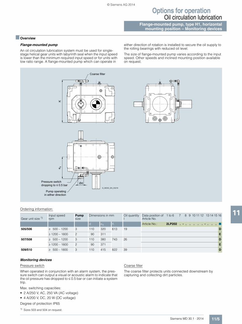
Options for operationOil circulation lubrication
Flange-mounted pump, type H1, horizontalmounting position – Monitoring devices
11/5Siemens MD 30.1 · 2014
11
■ Overview
Flange-mounted pump
An oil circulation lubrication system must be used for single-stage helical gear units with labyrinth seal when the input speed is lower than the minimum required input speed or for units with low ratio range. A flange-mounted pump which can operate in
either direction of rotation is installed to secure the oil supply to the rolling bearings with reduced oil level.
The size of flange-mounted pump varies according to the input speed. Other speeds and inclined mounting position available on request.
Ordering information:
Monitoring devices
Pressure switch
When operated in conjunction with an alarm system, the pres-sure switch can output a visual or acoustic alarm to indicate that the oil pressure has dropped to ≤ 0.5 bar or can initiate a system trip.
Max. switching capacities:• 2 A/250 V, AC, 250 VA (AC voltage)• 4 A/200 V, DC, 20 W (DC voltage)
Degree of protection IP65
Coarse filter
The coarse filter protects units connected downstream by capturing and collecting dirt particles.
G_MD30_EN_00218
Pump operating in either direction
Pressure switchdropping to ≤ 0.5 bar
Coarse filter
Ød
e 4K
Gear unit size 1)Input speed rpm
Pump size
Dimensions in mm Oil quantity l
Data position of Article No.
1 to 6 7 8 9 10 11 12 13 14 15 16
d e4 K Article No.: 2LP202 . - . . . . . - . . . ■
505/506 ≥ 500 – 1200 3 110 320 613 19 D
≥ 1200 – 1800 2 90 311 E
507/508 ≥ 500 – 1200 3 110 380 743 26 D
≥ 1200 – 1800 2 90 371 E
509/510 ≥ 500 – 1800 3 110 415 822 39 D
1) Sizes 503 and 504 on request.
© Siemens AG 2014

Options for operationCoolingFan Cooling coil
11/6 Siemens MD 30.1 · 2014
11
■ Overview
Fan and cooling coil
Fans and/or cooling coils can be used for auxiliary cooling.
Fan:• The standard fan is a radial fan that is mounted on the shaft d1
(= fast-rotating shaft). On designs with shaft studs at both ends (designs G, H, I), the fan is mounted either at gear unit face 3 (right) or gear unit face 6 (left).
• An adapted air guide cover ensures optimized air flow on the gear unit and therefore high-performance cooling
• A fan can be retrofitted• The connection dimensions at the input shaft are changed if a
fan is mounted
Cooling coil:• The cooling coil is connected either at
- gear unit face 4 (end face d2) or - gear unit face 1 (end face d1).
• The cooling coil is suitable for freshwater, seawater and brackish water
• See table for connection dimensions • Water connection: G ½ "
Parameters for attainment of the specified thermal capacities:• See right-hand column of tables for volumetric flow rate of
cooling water in l/min. The flow rate can exceed the specified values, but this might result in elevated noise levels.
• Max. permissible cooling water pressure: 8 bar
Connection to gear unit face 4 (end face d2)
Connection to gear unit face 1 (end face d1)
H1, B2 types
H2, H3, B3 types
Ordering information:
b10e10
h 10
G_MD30_XX_00008
h10
b10 e11
G_M
D30
_XX
_002
19
Gear unit sizes
Cooling coil
Dimensions in mm l/min
b10 e10 e11 h10 H1/B2
503 80 185 255 42 4
504 120 215 310 50 4
505 120 220 365 50 4
506 120 240 395 50 4
507 180 235 430 65 4
508 180 265 460 65 4
509 200 290 490 80 8
510 200 315 520 80 8
Gear unit sizes
Cooling coil
Dimensions in mm l/min
b10 e10
H2/B3e11
H3e11 h10 H2/H3/B3
504 80 250 415 – 40 4
505 95 275 475 525 45 4
506 95 345 525 575 45 4
507 100 340 580 640 60 4
508 100 400 630 690 60 4
509 130 385 675 745 70 4
510 130 450 730 795 70 8
511 150 465 805 905 80 8
512 150 535 865 960 80 8
513 160 380 835 945 85 8
514 160 420 910 1020 85 8
Order code
Article No.: 2LP202 .- . . . . .-0 .A ■ -Z ■ ■ ■
Auxiliary cooling
Auxiliary cooling with:
• Fan (with shaft d1 at one end) 1
• Fan at gear unit face 3 (with shaft d1 at both ends) 9 R 1 A
• Fan at gear unit face 6 (with shaft d1 at both ends) 9 R 1 F
• Cooling coil, connections at gear unit face 4 2
• Cooling coil, connections at gear unit face 1 4
• Fan (with shaft d1 at one end) and cooling coil, connections at gear unit face 4
3
• Fan (with shaft d1 at one end) and cooling coil, connections at gear unit face 1
5
• Fan at gear unit face 3 (with shaft d1 at both ends) and cooling coil, connections at gear unit face 4
9 R 1 B
• Fan at gear unit face 3 (with shaft d1 at both ends) and cooling coil, connections at gear unit face 1
9 R 1 C
• Fan at gear unit face 6 (with shaft d1 at both ends) and cooling coil, connections at gear unit face 4
9 R 1 G
• Fan at gear unit face 6 (with shaft d1 at both ends) and cooling coil, connections at gear unit face 1
9 R 1 H
Without auxiliary cooling 0
© Siemens AG 2014
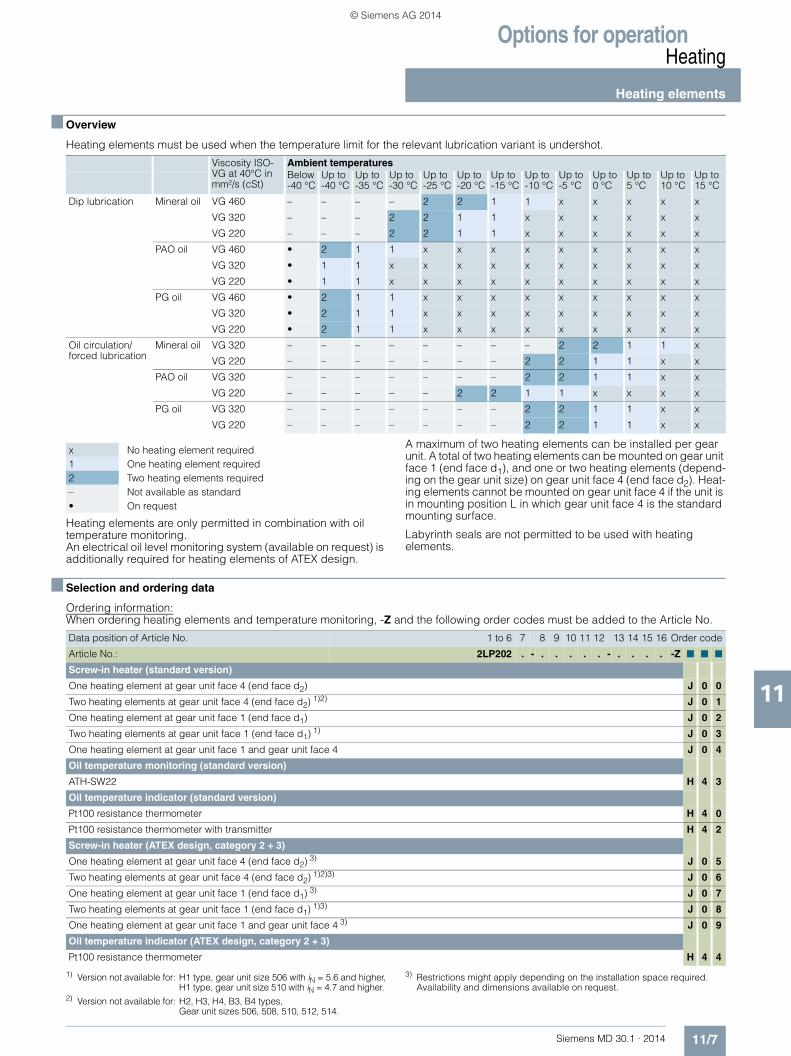
Options for operationHeating
Heating elements
11/7Siemens MD 30.1 · 2014
11
■ Overview
Heating elements must be used when the temperature limit for the relevant lubrication variant is undershot.
Heating elements are only permitted in combination with oil temperature monitoring.An electrical oil level monitoring system (available on request) is additionally required for heating elements of ATEX design.
A maximum of two heating elements can be installed per gear unit. A total of two heating elements can be mounted on gear unit face 1 (end face d1), and one or two heating elements (depend-ing on the gear unit size) on gear unit face 4 (end face d2). Heat-ing elements cannot be mounted on gear unit face 4 if the unit is in mounting position L in which gear unit face 4 is the standard mounting surface.
Labyrinth seals are not permitted to be used with heating elements.
■ Selection and ordering data
Ordering information:When ordering heating elements and temperature monitoring, -Z and the following order codes must be added to the Article No.
Viscosity ISO-VG at 40°C in mm²/s (cSt)
Ambient temperaturesBelow -40 °C
Up to -40 °C
Up to -35 °C
Up to -30 °C
Up to -25 °C
Up to -20 °C
Up to -15 °C
Up to -10 °C
Up to -5 °C
Up to 0 °C
Up to 5 °C
Up to 10 °C
Up to 15 °C
Dip lubrication Mineral oil VG 460 – – – – 2 2 1 1 x x x x x
VG 320 – – – 2 2 1 1 x x x x x x
VG 220 – – – 2 2 1 1 x x x x x x
PAO oil VG 460 • 2 1 1 x x x x x x x x x
VG 320 • 1 1 x x x x x x x x x x
VG 220 • 1 1 x x x x x x x x x x
PG oil VG 460 • 2 1 1 x x x x x x x x x
VG 320 • 2 1 1 x x x x x x x x x
VG 220 • 2 1 1 x x x x x x x x x
Oil circulation/forced lubrication
Mineral oil VG 320 – – – – – – – – 2 2 1 1 x
VG 220 – – – – – – – 2 2 1 1 x x
PAO oil VG 320 – – – – – – – 2 2 1 1 x x
VG 220 – – – – – 2 2 1 1 x x x x
PG oil VG 320 – – – – – – – 2 2 1 1 x x
VG 220 – – – – – – – 2 2 1 1 x x
x No heating element required1 One heating element required2 Two heating elements required– Not available as standard• On request
Data position of Article No. 1 to 6 7 8 9 10 11 12 13 14 15 16 Order code
Article No.: 2LP202 . - . . . . . - . . . . -Z ■ ■ ■
Screw-in heater (standard version)
One heating element at gear unit face 4 (end face d2) J 0 0
Two heating elements at gear unit face 4 (end face d2) 1)2) J 0 1
One heating element at gear unit face 1 (end face d1) J 0 2
Two heating elements at gear unit face 1 (end face d1) 1) J 0 3
One heating element at gear unit face 1 and gear unit face 4 J 0 4
Oil temperature monitoring (standard version)
ATH-SW22 H 4 3
Oil temperature indicator (standard version)
Pt100 resistance thermometer H 4 0
Pt100 resistance thermometer with transmitter H 4 2
Screw-in heater (ATEX design, category 2 + 3)
One heating element at gear unit face 4 (end face d2) 3) J 0 5
Two heating elements at gear unit face 4 (end face d2) 1)2)3) J 0 6
One heating element at gear unit face 1 (end face d1) 3) J 0 7
Two heating elements at gear unit face 1 (end face d1) 1)3) J 0 8
One heating element at gear unit face 1 and gear unit face 4 3) J 0 9
Oil temperature indicator (ATEX design, category 2 + 3)
Pt100 resistance thermometer H 4 4
1) Version not available for: H1 type, gear unit size 506 with iN = 5.6 and higher,H1 type, gear unit size 510 with iN = 4.7 and higher.
2) Version not available for: H2, H3, H4, B3, B4 types,Gear unit sizes 506, 508, 510, 512, 514.
3) Restrictions might apply depending on the installation space required. Availability and dimensions available on request.
© Siemens AG 2014

Options for operationHeatingHeating elements Types H1 and B2, gear unit sizes 503 to 510
11/8 Siemens MD 30.1 · 2014
11
■ Dimensional drawings
Depending on the version, screw-in heaters and temperature monitors/resistance thermometers can be arranged in a mirror image. The cable entry point of the screw-in heater is arranged axially on the connection head in the direction of installation.
1) 3)
2)
3) 1)
h1
bbl4 l1e4 e1
e2
h1h2
bb
e3e3
100
100
G_M
D30
_XX
_001
41
Installation space required
Installation space required
Connected load in W Dimensions in mm
Gear unit size Heating elements Heating elements Installation space Temperature monitors
1 heating element
2 heating elements
e1 e4 b h1 l1 l4 e2 e3 h2
503 189 378 225 290 40 42 300 300 290 40 130
504 189 378 250 345 60 50 300 300 325 50 155
505 281 562 255 400 60 50 450 450 330 50 170
506 3) 312 624 275 430 60 50 500 500 350 50 170
507 472 944 300 495 90 65 500 500 360 100 235
508 472 944 330 525 90 65 500 500 390 100 235
509 701 1402 350 550 100 80 600 600 430 110 265
510 3) 815 1630 375 585 100 80 700 700 455 110 265
1) Screw-in heater: Technical data and notes: Degree of protection IP 65, 230 V, 50 Hz.
2) Temperature monitor ATH-SW22: Technical data and notes: IP 65 degree of protection, two change-over contacts (adjustable). Max. contact rating: 2 A/230 V AC/460 VA cos ϕ = 0.6 (alternating voltage); 0.25 A/230 V DC/58 W (direct voltage) Or alternatively: Pt100 resistance thermometer: Technical data and notes: Connection head IP 54 degree of protection, PG 9, two-wire circuit Connection with three or four-wire circuit also possible by the customer. Connection to an evaluation unit is necessary.
3) It is not possible to install 2 heating elements on H1 type size 506 with iN = 5.6 or higher! It is not possible to install 2 heating elements on H1 type size 510 with iN = 4.7 or higher!
© Siemens AG 2014
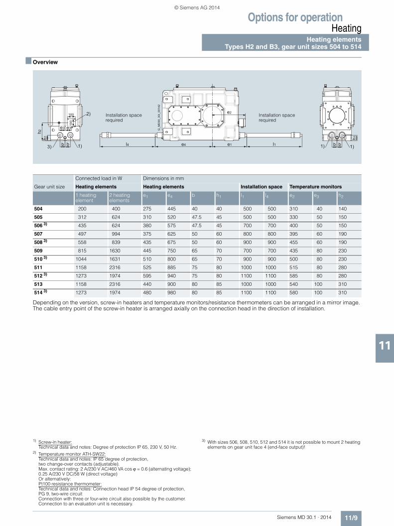
Options for operationHeating
Heating elementsTypes H2 and B3, gear unit sizes 504 to 514
11/9Siemens MD 30.1 · 2014
11
■ Overview
Depending on the version, screw-in heaters and temperature monitors/resistance thermometers can be arranged in a mirror image. The cable entry point of the screw-in heater is arranged axially on the connection head in the direction of installation.
1) 1)
2)
3) 1)
h1
bbl4 l1e4 e1
e2
h1h2
bb
e3e3
100
100
G_M
D30
_XX
_001
42
Installation space required
Installation space required
Connected load in W Dimensions in mm
Gear unit size Heating elements Heating elements Installation space Temperature monitors
1 heating element
2 heating elements
e1 e4 b h1 l1 l4 e2 e3 h2
504 200 400 275 445 40 40 500 500 310 40 140
505 312 624 310 520 47.5 45 500 500 330 50 150
506 3) 435 624 380 575 47.5 45 700 700 400 50 150
507 497 994 375 625 50 60 800 800 395 60 190
508 3) 558 839 435 675 50 60 900 900 455 60 190
509 815 1630 445 750 65 70 700 700 435 80 230
510 3) 1044 1631 510 800 65 70 900 900 500 80 230
511 1158 2316 525 885 75 80 1000 1000 515 80 280
512 3) 1273 1974 595 940 75 80 1100 1100 585 80 280
513 1158 2316 440 900 80 85 1000 1000 540 100 310
514 3) 1273 1974 480 980 80 85 1100 1100 580 100 310
1) Screw-in heater: Technical data and notes: Degree of protection IP 65, 230 V, 50 Hz.
2) Temperature monitor ATH-SW22: Technical data and notes: IP 65 degree of protection, two change-over contacts (adjustable). Max. contact rating: 2 A/230 V AC/460 VA cos ϕ = 0.6 (alternating voltage); 0.25 A/230 V DC/58 W (direct voltage) Or alternatively: Pt100 resistance thermometer: Technical data and notes: Connection head IP 54 degree of protection, PG 9, two-wire circuit Connection with three or four-wire circuit also possible by the customer. Connection to an evaluation unit is necessary.
3) With sizes 506, 508, 510, 512 and 514 it is not possible to mount 2 heating elements on gear unit face 4 (end-face output)!
© Siemens AG 2014
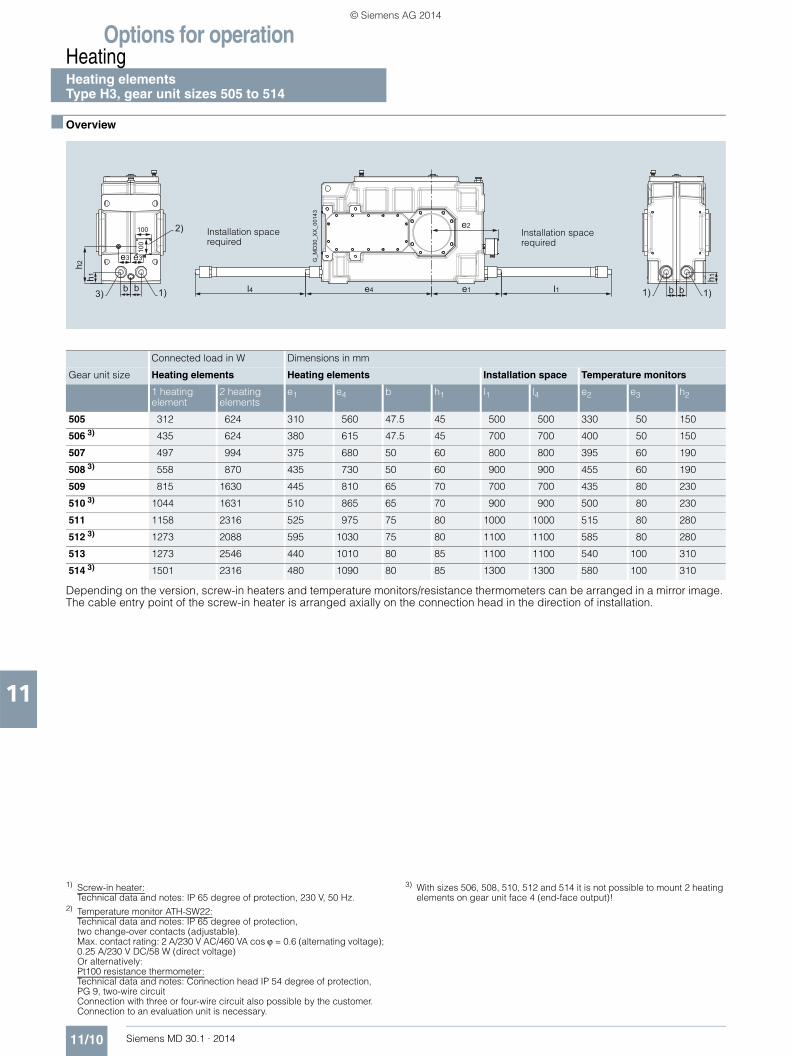
Options for operationHeatingHeating elements Type H3, gear unit sizes 505 to 514
11/10 Siemens MD 30.1 · 2014
11
■ Overview
Depending on the version, screw-in heaters and temperature monitors/resistance thermometers can be arranged in a mirror image. The cable entry point of the screw-in heater is arranged axially on the connection head in the direction of installation.
1) 1)
2)
3) 1)
h1
bbl4 l1e4 e1
e2
h1h2
bb
e3e3
100
100
G_M
D30
_XX
_001
43
Installation space required
Installation space required
Connected load in W Dimensions in mm
Gear unit size Heating elements Heating elements Installation space Temperature monitors
1 heating element
2 heating elements
e1 e4 b h1 l1 l4 e2 e3 h2
505 312 624 310 560 47.5 45 500 500 330 50 150
506 3) 435 624 380 615 47.5 45 700 700 400 50 150
507 497 994 375 680 50 60 800 800 395 60 190
508 3) 558 870 435 730 50 60 900 900 455 60 190
509 815 1630 445 810 65 70 700 700 435 80 230
510 3) 1044 1631 510 865 65 70 900 900 500 80 230
511 1158 2316 525 975 75 80 1000 1000 515 80 280
512 3) 1273 2088 595 1030 75 80 1100 1100 585 80 280
513 1273 2546 440 1010 80 85 1100 1100 540 100 310
514 3) 1501 2316 480 1090 80 85 1300 1300 580 100 310
1) Screw-in heater: Technical data and notes: IP 65 degree of protection, 230 V, 50 Hz.
2) Temperature monitor ATH-SW22: Technical data and notes: IP 65 degree of protection, two change-over contacts (adjustable). Max. contact rating: 2 A/230 V AC/460 VA cos ϕ = 0.6 (alternating voltage); 0.25 A/230 V DC/58 W (direct voltage) Or alternatively: Pt100 resistance thermometer: Technical data and notes: Connection head IP 54 degree of protection, PG 9, two-wire circuit Connection with three or four-wire circuit also possible by the customer. Connection to an evaluation unit is necessary.
3) With sizes 506, 508, 510, 512 and 514 it is not possible to mount 2 heating elements on gear unit face 4 (end-face output)!
© Siemens AG 2014

Options for operationHeating
Heating elementsTypes H4 and B4, gear unit sizes 505 to 514
11/11Siemens MD 30.1 · 2014
11
■ Overview
Depending on the version, screw-in heaters and temperature monitors/resistance thermometers can be arranged in a mirror image. The cable entry point of the screw-in heater is arranged axially on the connection head in the direction of installation.
1) 1)
2)
3) 1)
h1
bbl4 l1e4 e1
e2
h1h2
bb
e3e3
100
100
G_M
D30
_XX
_001
44
Installation space required
Installation space required
Connected load in W Dimensions in mm
Gear unit size Heating elements Heating elements Installation space Temperature monitors
1 heating element
2 heating elements
e1 e4 b h1 l1 l4 e2 e3 h2
505 312 624 255 510 42.5 37 500 500 330 50 150
506 3) 435 624 325 565 42.5 37 700 700 400 50 150
507 435 870 305 615 50 50 700 700 395 60 190
508 3) 497 778 365 665 50 50 800 800 455 60 190
509 815 1630 365 735 57.5 57.5 700 700 435 80 230
510 3) 1044 1631 430 790 57.5 57.5 900 900 500 80 230
511 1158 2316 425 880 75 65 1000 1000 515 80 280
512 3) 1273 1974 495 935 75 65 1100 1100 585 80 280
513 1273 2546 440 1010 80 85 1100 1100 540 100 310
514 3) 1501 2316 480 1090 80 85 1300 1300 580 100 310
1) Screw-in heater: Technical data and notes: IP 65 degree of protection, 230 V, 50 Hz.
2) Temperature monitor ATH-SW22: Technical data and notes: IP 65 degree of protection, two change-over contacts (adjustable). Max. contact rating: 2 A/230 V AC/460 VA cos ϕ = 0.6 (alternating voltage); 0.25 A/230 V DC/58 W (direct voltage) Or alternatively: Pt100 resistance thermometer: Technical data and notes: Connection head IP 54 degree of protection, PG 9, two-wire circuit Connection with three or four-wire circuit also possible by the customer. Connection to an evaluation unit is necessary.
3) With sizes 506, 508, 510, 512 and 514 it is not possible to mount 2 heating elements on gear unit face 4 (end-face output)!
© Siemens AG 2014

Options for operationBackstop
11/12 Siemens MD 30.1 · 2014
11
■ Overview
Backstop
For certain requirements, FLENDER SIG gear units can be or-dered with a mechanical backstop. In this case, the direction of rotation of shaft d2 must be specified. For gear units with a d2 shaft at both ends, the direction of rotation must be specified for
the relevant shaft stud. The direction of rotation is determined by the view of the end face of shaft d2.
For determining the direction of rotation for gear units without a backstop, see page 11/33.
Helical gear unit – type Bevel-helical gear unit – type
Design H2 H3 H4 B2 B3 B4
A
B
C
D
E
F
G_MD30_XX_00020
1
A
G8
ØD
8
G_MD30_XX_00024
1
A
G8
ØD
8
G_MD30_XX_00028
1
A
G8Ø
D8
1
A
G8
ØD
8
G_MD30_XX_00163 G_MD30_XX_00032
1
A
G8
ØD
8
G_MD30_XX_00036
2
3
ØD
8
G8 G8
ØD
8
A
G_MD30_XX_00021
1G8
ØD
8
B
G_MD30_XX_00025
1G8
ØD
8
B
G_MD30_XX_00029
1G8
ØD
8
B
1
G8
ØD
8
G_MD30_XX_00164
B
G_MD30_XX_00033
1
G8
ØD
8
B
G_MD30_XX_00037
2
3G8 G8
ØD
8
ØD
8
B
G_MD30_XX_00022
1 G8
ØD
8
C
G_MD30_XX_00026
1G8
ØD
8
C
G_MD30_XX_00030
1 G8
ØD
8
C
1
G8
ØD
8
G_MD30_XX_00165
C
G_MD30_XX_00034
1
G8
ØD
8
C
G_MD30_XX_00038
3
2ØD
8
G8 G8
ØD
8
C
G_MD30_XX_00023
1G8
ØD
8
D
G_MD30_XX_00027
1G8
ØD
8
D
G_MD30_XX_00031
1G8
ØD
8
D
1
G_MD30_XX_00166
D
G8
ØD
8
G_MD30_XX_00035
1
G8
ØD
8
D
G_MD30_DE_00039
3
2
G8 G8
ØD
8 ØD
8
D
1 G8
ØD
8
E
G_MD30_XX_00148
1G8
ØD
8
G_MD30_XX_00153
E
1 G8
ØD
8
G_MD30_XX_00158
E
1
G8
ØD
8
G_MD30_XX_00167
E
1
E
G8
ØD
8
G_MD30_XX_00169
2
3
ØD
8
G8 G8
ØD
8
E
G_MD30_XX_00171
1G8
ØD
8
G_MD30_XX_00149
F
1G8
ØD
8
F
G_MD30_XX_00154
F
1G8
ØD
8
G_MD30_XX_00159
1
G_MD30_XX_00168
F
G8
ØD
8
1
F
G8
ØD
8
G_MD30_XX_00170
2
3
ØD
8
G8 G8
ØD
8
F
G_MD30_XX_00172
$ Backstop, vertical mounting position only for H2, H3, H4 designs B, D, F or B2 designs A, B, E or B3 designs C, D, F.
% Backstop for type B4, gear unit sizes 505 and 506, vertical mounting position only for designs C, D, F.
& Backstop for type B4, gear unit sizes 507 to 514, vertical mounting position only for designs A, B, E.
© Siemens AG 2014
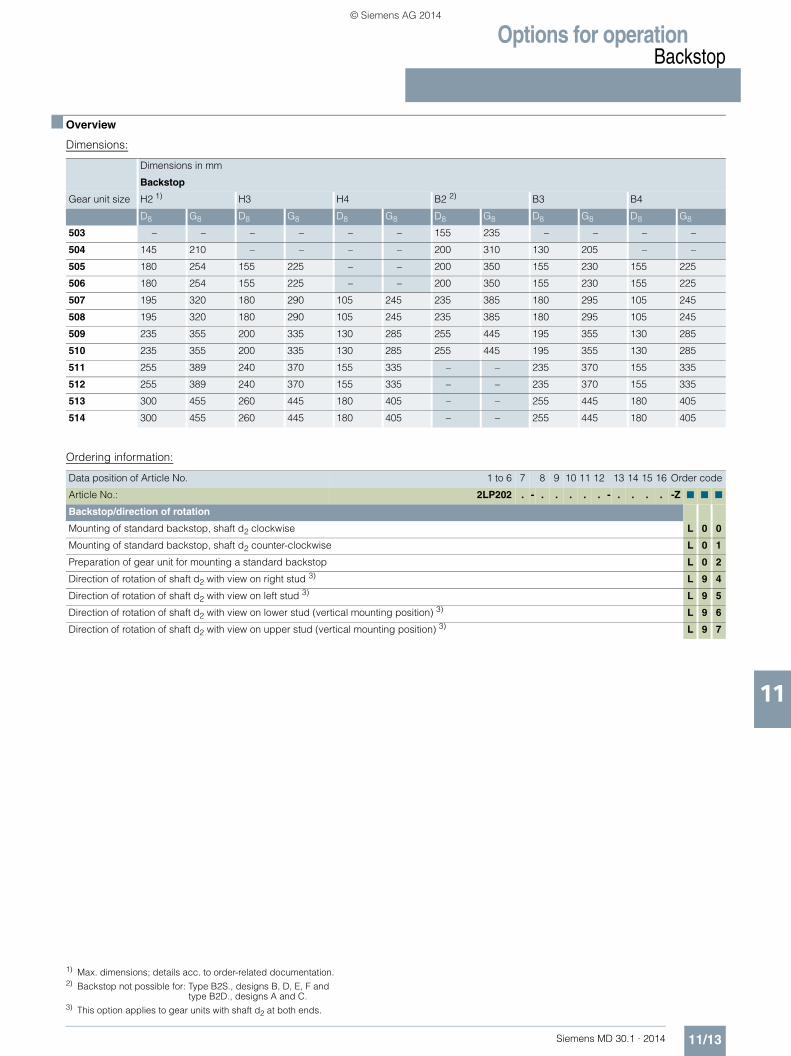
Options for operationBackstop
11/13Siemens MD 30.1 · 2014
11
■ Overview
Dimensions:
Ordering information:
Dimensions in mm
Backstop
Gear unit size H2 1) H3 H4 B2 2) B3 B4
D8 G8 D8 G8 D8 G8 D8 G8 D8 G8 D8 G8
503 – – – – – – 155 235 – – – –
504 145 210 – – – – 200 310 130 205 – –
505 180 254 155 225 – – 200 350 155 230 155 225
506 180 254 155 225 – – 200 350 155 230 155 225
507 195 320 180 290 105 245 235 385 180 295 105 245
508 195 320 180 290 105 245 235 385 180 295 105 245
509 235 355 200 335 130 285 255 445 195 355 130 285
510 235 355 200 335 130 285 255 445 195 355 130 285
511 255 389 240 370 155 335 – – 235 370 155 335
512 255 389 240 370 155 335 – – 235 370 155 335
513 300 455 260 445 180 405 – – 255 445 180 405
514 300 455 260 445 180 405 – – 255 445 180 405
Data position of Article No. 1 to 6 7 8 9 10 11 12 13 14 15 16 Order code
Article No.: 2LP202 . - . . . . . - . . . . -Z ■ ■ ■
Backstop/direction of rotation
Mounting of standard backstop, shaft d2 clockwise L 0 0
Mounting of standard backstop, shaft d2 counter-clockwise L 0 1
Preparation of gear unit for mounting a standard backstop L 0 2
Direction of rotation of shaft d2 with view on right stud 3) L 9 4
Direction of rotation of shaft d2 with view on left stud 3) L 9 5
Direction of rotation of shaft d2 with view on lower stud (vertical mounting position) 3) L 9 6
Direction of rotation of shaft d2 with view on upper stud (vertical mounting position) 3) L 9 7
1) Max. dimensions; details acc. to order-related documentation.2) Backstop not possible for: Type B2S., designs B, D, E, F and
type B2D., designs A and C.3) This option applies to gear units with shaft d2 at both ends.
© Siemens AG 2014
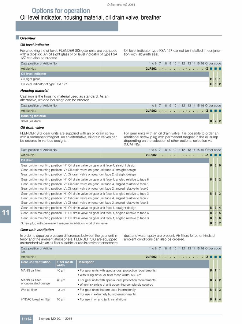
Options for operationOil level indicator, housing material, oil drain valve, breather
11/14 Siemens MD 30.1 · 2014
11
■ Overview
Oil level indicator
For checking the oil level, FLENDER SIG gear units are equipped with a dipstick. An oil sight glass or oil level indicator of type FSA 127 can also be ordered.
Oil level indicator type FSA 127 cannot be installed in conjunc-tion with labyrinth seal.
Housing material
Cast iron is the housing material used as standard. As an alternative, welded housings can be ordered.
Oil drain valve
FLENDER SIG gear units are supplied with an oil drain screw with a permanent magnet. As an alternative, oil drain valves can be ordered in various designs.
For gear units with an oil drain valve, it is possible to order an additional screw plug with permanent magnet in the oil sump depending on the selection of other options, selection via X.CAT NG.
Gear unit ventilation
In order to equalize pressure differences between the gear unit in-terior and the ambient atmosphere, FLENDER SIG are equipped as standard with an air filter suitable for use in environments where
dust and water spray are present. Air filters for other kinds of ambient conditions can also be ordered.
Data position of Article No. 1 to 6 7 8 9 10 11 12 13 14 15 16 Order code
Article No.: 2LP202 . - . . . . . - . . . . -Z ■ ■ ■
Oil level indicator
Oil sight glass H 5 1
Oil level indicator of type FSA 127 H 5 2
Data position of Article No. 1 to 6 7 8 9 10 11 12 13 14 15 16 Order code
Article No.: 2LP202 . - . . . . . - . . . . -Z ■ ■ ■
Housing material
Steel (welded) K 2 2
Data position of Article No. 1 to 6 7 8 9 10 11 12 13 14 15 16 Order code
Article No.: 2LP202 . - . . . . . - . . . . -Z ■ ■ ■
Oil drain
Gear unit in mounting position "H": Oil drain valve on gear unit face 4, straight designGear unit in mounting position "V": Oil drain valve on gear unit face 4, straight designGear unit in mounting position "L": Oil drain valve on gear unit face 2, straight design
K 3 0
Gear unit in mounting position "H": Oil drain valve on gear unit face 4, angled relative to face 6Gear unit in mounting position "V": Oil drain valve on gear unit face 4, angled relative to face 5Gear unit in mounting position "L": Oil drain valve on gear unit face 2, angled relative to face 6
K 3 2
Gear unit in mounting position "H": Oil drain valve on gear unit face 4, angled relative to face 3Gear unit in mounting position "V": Oil drain valve on gear unit face 4, angled relative to face 2Gear unit in mounting position "L": Oil drain valve on gear unit face 2, angled relative to face 3
K 3 3
Gear unit in mounting position "H": Oil drain valve on gear unit face 1, straight design K 3 4
Gear unit in mounting position "H": Oil drain valve on gear unit face 1, angled relative to face 6 K 3 5
Gear unit in mounting position "H": Oil drain valve on gear unit face 1, angled relative to face 3 K 3 6
Screw plug with permanent magnet in addition to oil drain valve K 3 7
Data position of Article No.
1 to 6 7 8 9 10 11 12 13 14 15 16 Order code
Article No.: 2LP202 . - . . . . . - . . . . -Z ■ ■ ■
Gear unit ventilation Filter mesh width
Description
MANN air filter 40 μm • For gear units with special dust protection requirements• With filling sieve, oil filter mesh width: 530 μm
K 7 1
MANN air filter, encapsulated design
40 μm • For gear units with special dust protection requirements • When risk exists of unit becoming completely covered
K 7 2
Wet air filter 3 μm • For gear units that are used intermittently • For use in extremely humid environments
K 7 3
HYDAC breather filter 10 μm • For use in oil and tank installations K 7 4
© Siemens AG 2014

Options for operationAuxiliary drive
Maintenance drive and load drivefor type B3
11/15Siemens MD 30.1 · 2014
11
■ Overview
An auxiliary drive can be mounted for gear units of type B3 in designs A or C.
When an auxiliary drive is installed, oil of viscosity grade VG 220 or VG 320 must be used for the main gear unit.
Two auxiliary drives with different ratings are available for each gear unit size to suit the application case.
Maintenance drive
The motor of the auxiliary drive is dimensioned such that the bucket conveyor can be operated with empty buckets at low speed in the same direction of rotation.
Load drive
The motor of the auxiliary drive is dimensioned such that the bucket conveyor can be operated with full buckets at low speed in the same direction of rotation.
The auxiliary drive is not dimensioned for the rated output torque of the main drive, please observe T3.
Design of the auxiliary drive
The auxiliary drive is flange-mounted onto the main gear unit via an adapter flange. The auxiliary drive is a bevel-helical geared motor of type KZ that is coupled to the main gear unit through an overrunning clutch. The overrunning clutch is installed in the adapter flange and is supplied with oil from the main gear unit. The bevel-helical geared motor has a separate oil filling and is supplied filled with oil. To prevent overspeed in the case of malfunctioning of the overrunning clutch, the drive combination must be equipped with speed monitoring for safety reasons, see page 11/25.
The auxiliary drives as load drives for main gear units of sizes 505 to 510 are fitted with a high inertia fan to support soft start-up.
Motors
Motors with IE1 efficiency are recommended for use in auxiliary drives intended for intermittent periodic duty (S3). However, IE2 motors (High Efficiency) are also available.
Main gear unit
Maintenance drive IE2 Load drive IE2
Geared motor 1) PM TMA/TM I 2) i Geared motor 1) PM TMA/TM I 2) i
Size Type kW A Type kW A
504 KZ39-LE80MH4E 0.75 2.2 1.79 36.21 KZ49-LE90SG4E-I 1.1 2.3 2.5 32.57
505 KZ49-LE90SG4E 1.1 2.3 2.5 44.63 KZ69-LE90LH4E-I 1.5 2.6 3.3 45.14
506 KZ49-LE90LH4E 1.5 2.6 3.3 32.57 KZ69-LE100LE4E-I 2.2 2.1 4.65 29.18
507 KZ69-LE100LE4E 2.2 2.1 4.65 39.69 KZ89-LE112ME4E-I 4 2.5 8.2 32.96
508 KZ69-LE100LE4E 2.2 2.1 4.65 39.69 KZ89-LE112ME4E-I 4 2.5 8.2 32.96
509 KZ79-LE100LK4E 3 2.0 6.2 36.26 KZ89-LE132SF4E-I 5.5 2.3 11.3 39.29
510 KZ79-LE100LK4E 3 2.0 6.2 36.26 KZ89-LE132SF4E-I 5.5 2.3 11.3 39.29
511 KZ89-LE112ME4E 4 2.5 8.2 41.54 KZ109-LE160MF4E 11 2.1 21 34.15
512 KZ89-LE112ME4E 4 2.5 8.2 41.54 KZ109-LE160MF4E 11 2.1 21 34.15
513 KZ89-LE132SF4E 5.5 2.3 11.3 39.29 KZ129-LE160LD4E 15 2.3 28 38.37
514 KZ89-LE132SF4E 5.5 2.3 11.3 39.29 KZ129-LE160LD4E 15 2.3 28 38.37
Main gear unit
Maintenance drive IE1 Load drive IE1
Geared motor 1) PM TMA/TM I 2) i Geared motor 1) PM TMA/TM I 2) i
Size Type kW A Type kW A
504 – – – – – – – – – –
505 – – – – – – – – – –
506 – – – – – KZ69-LE100LB4I 2.2 2.2 4.9 29.18
507 KZ69-LE100LB4 2.2 2.2 4.9 39.69 KZ89-LE112ME4I 4 2.2 8.2 32.96
508 KZ69-LE100LB4 2.2 2.2 4.9 39.69 KZ89-LE112ME4I 4 2.2 8.2 32.96
509 KZ79-LE100LH4 3 2.4 6.3 36.26 KZ89-LE132SF4I 5.5 2.3 11 39.29
510 KZ79-LE100LH4 3 2.4 6.3 36.26 KZ89-LE132SF4I 5.5 2.3 11 39.29
511 KZ89-LE112ME4 4 2.2 8.2 41.54 KZ109-LE160MD4 11 2.3 22 36.44
512 KZ89-LE112ME4 4 2.2 8.2 41.54 KZ109-LE160MD4 11 2.3 22 36.44
513 KZ89-LE132SF4 5.5 2.3 11 39.29 KZ129-LE160LA4 15 2.5 30 39.19
514 KZ89-LE132SF4 5.5 2.3 11 39.29 KZ129-LE160LA4 15 2.5 30 39.19
1) SIMOGEAR bevel-helical geared motor. 2) Rated current at 400 V.
© Siemens AG 2014
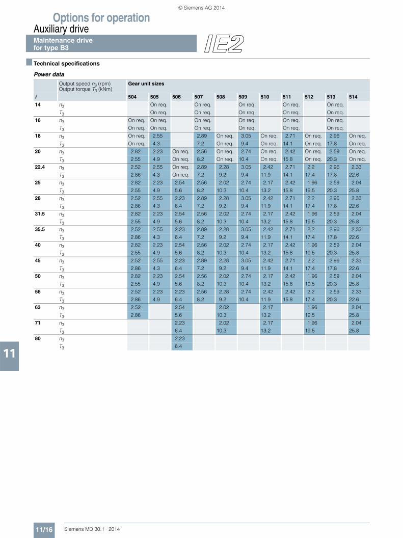
Options for operationAuxiliary driveMaintenance drive for type B3
11/16 Siemens MD 30.1 · 2014
11
■ Technical specifications
Power data
Output speed n3 (rpm) Output torque T3 (kNm)
Gear unit sizes
i 504 505 506 507 508 509 510 511 512 513 514
14 n3 On req. On req. On req. On req. On req.
T3 On req. On req. On req. On req. On req.
16 n3 On req. On req. On req. On req. On req. On req.
T3 On req. On req. On req. On req. On req. On req.
18 n3 On req. 2.55 2.89 On req. 3.05 On req. 2.71 On req. 2.96 On req.
T3 On req. 4.3 7.2 On req. 9.4 On req. 14.1 On req. 17.8 On req.
20 n3 2.82 2.23 On req. 2.56 On req. 2.74 On req. 2.42 On req. 2.59 On req.
T3 2.55 4.9 On req. 8.2 On req. 10.4 On req. 15.8 On req. 20.3 On req.
22.4 n3 2.52 2.55 On req. 2.89 2.28 3.05 2.42 2.71 2.2 2.96 2.33
T3 2.86 4.3 On req. 7.2 9.2 9.4 11.9 14.1 17.4 17.8 22.6
25 n3 2.82 2.23 2.54 2.56 2.02 2.74 2.17 2.42 1.96 2.59 2.04
T3 2.55 4.9 5.6 8.2 10.3 10.4 13.2 15.8 19.5 20.3 25.8
28 n3 2.52 2.55 2.23 2.89 2.28 3.05 2.42 2.71 2.2 2.96 2.33
T3 2.86 4.3 6.4 7.2 9.2 9.4 11.9 14.1 17.4 17.8 22.6
31.5 n3 2.82 2.23 2.54 2.56 2.02 2.74 2.17 2.42 1.96 2.59 2.04
T3 2.55 4.9 5.6 8.2 10.3 10.4 13.2 15.8 19.5 20.3 25.8
35.5 n3 2.52 2.55 2.23 2.89 2.28 3.05 2.42 2.71 2.2 2.96 2.33
T3 2.86 4.3 6.4 7.2 9.2 9.4 11.9 14.1 17.4 17.8 22.6
40 n3 2.82 2.23 2.54 2.56 2.02 2.74 2.17 2.42 1.96 2.59 2.04
T3 2.55 4.9 5.6 8.2 10.3 10.4 13.2 15.8 19.5 20.3 25.8
45 n3 2.52 2.55 2.23 2.89 2.28 3.05 2.42 2.71 2.2 2.96 2.33
T3 2.86 4.3 6.4 7.2 9.2 9.4 11.9 14.1 17.4 17.8 22.6
50 n3 2.82 2.23 2.54 2.56 2.02 2.74 2.17 2.42 1.96 2.59 2.04
T3 2.55 4.9 5.6 8.2 10.3 10.4 13.2 15.8 19.5 20.3 25.8
56 n3 2.52 2.23 2.23 2.56 2.28 2.74 2.42 2.42 2.2 2.59 2.33
T3 2.86 4.9 6.4 8.2 9.2 10.4 11.9 15.8 17.4 20.3 22.6
63 n3 2.52 2.54 2.02 2.17 1.96 2.04
T3 2.86 5.6 10.3 13.2 19.5 25.8
71 n3 2.23 2.02 2.17 1.96 2.04
T3 6.4 10.3 13.2 19.5 25.8
80 n3 2.23
T3 6.4
© Siemens AG 2014

Options for operationAuxiliary drive
Maintenance drivefor type B3
11/17Siemens MD 30.1 · 2014
11
■ Dimensional drawings
Mounting position of auxiliary drive: M4 (vertical, preferred)
Mounting position of auxiliary drive: M1 (horizontal)
Dimensions in mm
Main gear unit Auxiliary gear unit Maintenance drive
Size Type/size/motor L1 L3 L4 1) L5
504 KZ39-LE80MH4E 420 140 425 140
505 KZ49-LE90SG4E 470 125 500 125
506 KZ49-LE90LH4E 470 125 500 125
507 KZ69-LE100LE4E 570 150 575 150
508 KZ69-LE100LE4E 570 150 575 150
509 KZ79-LE100LK4E 620 175 580 175
510 KZ79-LE100LK4E 620 175 580 175
511 KZ89-LE112ME4E 765 225 620 180
512 KZ89-LE112ME4E 765 225 620 180
513 KZ89-LE132SF4E 860 225 775 180
514 KZ89-LE132SF4E 860 225 775 180
G_MD30_EN_00174
Backstop Overrunning clutch
L 4
L1
L 3
L4 L1
L5
G_MD30_XX_00175
Note:
For mounting position M4, it is recommended that a geared motor with a cover cap is used.
The canopy is indicated in the designation of the auxiliary drive by the suffix "-W".
1) For operation with a cover cap, the following applies for Motor frame size 80: L4 + 26 mm, Motor frame size 90: L4 + 16 mm, Motor frame size 100/112: L4 + 40 mm, Motor frame size 132: L4 + 60 mm.
© Siemens AG 2014

Options for operationAuxiliary driveMaintenance drive for type B3
11/18 Siemens MD 30.1 · 2014
11
■ Technical specifications
Power data
Output speed n3 (rpm) Output torque T3 (kNm)
Gear unit sizes
i 504 505 506 507 508 509 510 511 512 513 514
14 n3 – On req. On req. On req. On req.
T3 – On req. On req. On req. On req.
16 n3 – – On req. On req. On req. On req.
T3 – – On req. On req. On req. On req.
18 n3 – – 2.83 On req. 2.99 On req. 2.67 On req. 2.93 On req.
T3 – – 7.7 On req. 10.0 On req. 14.9 On req. 18.7 On req.
20 n3 – – – 2.51 On req. 2.69 On req. 2.38 On req. 2.57 On req.
T3 – – – 8.7 On req. 11.1 On req. 16.7 On req. 21.3 On req.
22.4 n3 – – – 2.83 2.24 2.99 2.37 2.67 2.16 2.93 2.30
T3 – – – 7.7 9.8 10.0 12.6 14.9 18.4 18.7 23.8
25 n3 – – – 2.51 1.98 2.69 2.13 2.38 1.93 2.57 2.02
T3 – – – 8.7 11.0 11.1 14.0 16.7 20.6 21.3 27.1
28 n3 – – – 2.83 2.24 2.99 2.37 2.67 2.16 2.93 2.30
T3 – – – 7.7 9.8 10.0 12.6 14.9 18.4 18.7 23.8
31.5 n3 – – – 2.51 1.98 2.69 2.13 2.38 1.93 2.57 2.02
T3 – – – 8.7 11.0 11.1 14.0 16.7 20.6 21.3 27.1
35.5 n3 – – – 2.83 2.24 2.99 2.37 2.67 2.16 2.93 2.30
T3 – – – 7.7 9.8 10.0 12.6 14.9 18.4 18.7 23.8
40 n3 – – – 2.51 1.98 2.69 2.13 2.38 1.93 2.57 2.02
T3 – – – 8.7 11.0 11.1 14.0 16.7 20.6 21.3 27.1
45 n3 – – – 2.83 2.24 2.99 2.37 2.67 2.16 2.93 2.30
T3 – – – 7.7 9.8 10.0 12.6 14.9 18.4 18.7 23.8
50 n3 – – – 2.51 1.98 2.69 2.13 2.38 1.93 2.57 2.02
T3 – – – 8.7 11.0 11.1 14.0 16.7 20.6 21.3 27.1
56 n3 – – – 2.51 2.24 2.69 2.37 2.38 2.16 2.57 2.30
T3 – – – 8.7 9.8 11.1 12.6 16.7 18.4 21.3 23.8
63 n3 – – 1.98 2.13 1.93 2.02
T3 – – 11.0 14.0 20.6 27.1
71 n3 – 1.98 2.13 1.93 2.02
T3 – 11.0 14.0 20.6 27.1
80 n3 –
T3 –
© Siemens AG 2014

Options for operationAuxiliary drive
Maintenance drivefor type B3
11/19Siemens MD 30.1 · 2014
11
■ Dimensional drawings
Mounting position of auxiliary drive: M4 (vertical, preferred)
Mounting position of auxiliary drive: M1 (horizontal)
Dimensions in mm
Main gear unit Auxiliary gear unit Maintenance drive
Size Type/size/motor L1 L3 L4 1) L5
504 – – – – –
505 – – – – –
506 – – – – –
507 KZ69-LE100LB4 570 150 572 132
508 KZ69-LE100LB4 570 150 572 132
509 KZ79-LE100LH4 616 175 580 140
510 KZ79-LE100LH4 616 175 580 140
511 KZ89-LE112ME4 763 225 618 180
512 KZ89-LE112ME4 763 225 618 180
513 KZ89-LE132SF4 857 225 671 180
514 KZ89-LE132SF4 857 225 671 180
G_MD30_EN_00174
Backstop Overrunning clutch
L 4
L1
L 3
L4 L1
L5
G_MD30_XX_00175
Note:
For mounting position M4, it is recommended that a geared motor with a cover cap is used.
The canopy is indicated in the designation of the auxiliary drive by the suffix "-W".
1) For operation with a cover cap, the following applies for Motor frame size 90: L4 + 16 mm, Motor frame size 100/112: L4 + 40 mm, Motor frame size 132: L4 + 60 mm.
© Siemens AG 2014

Options for operationAuxiliary driveLoad drive for type B3
11/20 Siemens MD 30.1 · 2014
11
■ Technical specifications
Power data
Output speed n3 (rpm) Output torque T3 (kNm)
Gear unit sizes
i 504 505 506 507 508 509 510 511 512 513 514
14 n3 On req. On req. On req. On req. On req.
T3 On req. On req. On req. On req. On req.
16 n3 On req. On req. On req. On req. On req. On req.
T3 On req. On req. On req. On req. On req. On req.
18 n3 On req. 2.54 3.5 On req. 2.84 On req. 3.32 On req. 3.05 On req.
T3 On req. 5.6 10.9 On req. 18.5 On req. 31.6 On req. 46.9 On req.
20 n3 3.1 2.22 On req. 3.1 On req. 2.55 On req. 2.97 On req. 2.67 On req.
T3 3.55 6.5 On req. 12.3 On req. 20.6 On req. 35.4 On req. 53.6 On req.
22.4 n3 2.77 2.54 On req. 3.5 2.76 2.84 2.25 3.32 2.69 3.05 2.4
T3 3.98 5.6 On req. 10.9 13.9 18.5 23.4 31.6 39 46.9 59.7
25 n3 3.1 2.22 2.88 3.1 2.45 2.55 2.02 2.97 2.4 2.67 2.1
T3 3.55 6.5 7.3 12.3 15.6 20.6 26 35.4 43.7 53.6 68.1
28 n3 2.77 2.54 2.52 3.5 2.76 2.84 2.25 3.32 2.69 3.05 2.4
T3 3.98 5.6 8.3 10.9 13.9 18.5 23.4 31.6 39 46.9 59.7
31.5 n3 3.1 2.22 2.88 3.1 2.45 2.55 2.02 2.97 2.4 2.67 2.1
T3 3.55 6.5 7.3 12.3 15.6 20.6 26 35.4 43.7 53.6 68.1
35.5 n3 2.77 2.54 2.52 3.5 2.76 2.84 2.25 3.32 2.69 3.05 2.4
T3 3.98 5.6 8.3 10.9 13.9 18.5 23.4 31.6 39 46.9 59.7
40 n3 3.1 2.22 2.88 3.1 2.45 2.55 2.02 2.97 2.4 2.67 2.1
T3 3.55 6.5 7.3 12.3 15.6 20.6 26 35.4 43.7 53.6 68.1
45 n3 2.77 2.54 2.52 3.5 2.76 2.84 2.25 3.32 2.69 3.05 2.4
T3 3.98 5.6 8.3 10.9 13.9 18.5 23.4 31.6 39 46.9 59.7
50 n3 3.1 2.22 2.88 3.1 2.45 2.55 2.02 2.97 2.4 2.67 2.1
T3 3.55 6.5 7.3 12.3 15.6 20.6 26 35.4 43.7 53.6 68.1
56 n3 2.77 2.22 2.52 3.1 2.76 2.55 2.25 2.97 2.69 2.67 2.4
T3 3.98 6.5 8.3 12.3 13.9 20.6 23.4 35.4 39 53.6 59.7
63 n3 2.77 2.88 2.45 2.02 2.4 2.1
T3 3.98 7.3 15.6 26 43.7 68.1
71 n3 2.52 2.45 2.02 2.4 2.1
T3 8.3 15.6 26 43.7 68.1
80 n3 2.52
T3 8.3
© Siemens AG 2014

Options for operationAuxiliary drive
Load drivefor type B3
11/21Siemens MD 30.1 · 2014
11
■ Dimensional drawings
Mounting position of auxiliary drive: M4 (vertical, preferred)
Mounting position of auxiliary drive: M1 (horizontal)
Dimensions in mm
Main gear unit Auxiliary gear unit Load drive
Size Type/size/motor L1 L3 L4 1) L5
504 KZ49-LE90SG4E-I 450 140 500 140
505 KZ69-LE90LH4E-I 480 125 520 132
506 KZ69-LE100LE4E-I 490 125 575 132
507 KZ89-LE112ME4E-I 585 150 620 180
508 KZ89-LE112ME4E-I 585 150 620 180
509 KZ89-LE132SF4E-I 685 175 675 180
510 KZ89-LE132SF4E-I 685 175 675 180
511 KZ109-LE160MF4E 826 225 772 212
512 KZ109-LE160MF4E 826 225 772 212
513 KZ129-LE160LD4E 918 225 802 265
514 KZ129-LE160LD4E 918 225 802 265
G_MD30_EN_00174
Backstop Overrunning clutch
L 4
L1
L 3
L4 L1
L5
G_MD30_XX_00175
Note:
For mounting position M4, it is recommended that a geared motor with a cover cap is used.The output torque of the main drive that can be achieved via the auxiliary drive may be less than its rated output torque. It is recommended that a high inertia fan is used on the auxiliary drive. The canopy is indicated in the designation of the auxiliary drive by the suffix "-W".1) For operation with a cover cap, the following applies for Motor frame size 90: L4 + 16 mm,
Motor frame size 100/112: L4 + 40 mm, Motor frame size 132: L4 + 60 mm, Motor frame size 160: L4 + 60 mm.
© Siemens AG 2014

Options for operationAuxiliary driveLoad drive for type B3
11/22 Siemens MD 30.1 · 2014
11
■ Technical specifications
Power data
Output speed n3 (rpm) Output torque T3 (kNm)
Gear unit sizes
i 504 505 506 507 508 509 510 511 512 513 514
14 n3 – On req. On req. On req. On req.
T3 – On req. On req. On req. On req.
16 n3 – – On req. On req. On req. On req.
T3 – – On req. On req. On req. On req.
18 n3 – – 3.44 On req. 2.81 On req. 3.3 On req. 3.02 On req.
T3 – – 11.6 On req. 19.5 On req. 33.2 On req. 49.4 On req.
20 n3 – – On req. 3.05 On req. 2.52 On req. 2.95 On req. 2.67 On req.
T3 – – On req. 13.1 On req. 21.7 On req. 37.1 On req. 56.4 On req.
22.4 n3 – – On req. 3.44 2.71 2.81 2.22 3.3 2.67 3.02 2.38
T3 – – On req. 11.6 14.7 19.5 24.6 33.2 41 49.4 62.8
25 n3 – – 2.82 3.05 2.4 2.52 2.00 2.95 2.39 2.67 2.08
T3 – – 7.8 13.1 16.6 21.7 27.4 37.1 45.8 56.4 71.7
28 n3 – – 2.47 3.44 2.71 2.81 2.22 3.3 2.67 3.02 2.38
T3 – – 8.9 11.6 14.7 19.5 24.6 33.2 41 49.4 62.8
31.5 n3 – – 2.82 3.05 2.4 2.52 2.00 2.95 2.39 2.67 2.08
T3 – – 7.8 13.1 16.6 21.7 27.4 37.1 45.8 56.4 71.7
35.5 n3 – – 2.47 3.44 2.71 2.81 2.22 3.3 2.67 3.02 2.38
T3 – – 8.9 11.6 14.7 19.5 24.6 33.2 41 49.4 62.8
40 n3 – – 2.82 3.05 2.4 2.52 2.00 2.95 2.39 2.67 2.08
T3 – – 7.8 13.1 16.6 21.7 27.4 37.1 45.8 56.4 71.7
45 n3 – – 2.47 3.44 2.71 2.81 2.22 3.3 2.67 3.02 2.38
T3 – – 8.9 11.6 14.7 19.5 24.6 33.2 41 49.4 62.8
50 n3 – – 2.82 3.05 2.4 2.52 2.00 2.95 2.39 2.67 2.08
T3 – – 7.8 13.1 16.6 21.7 27.4 37.1 45.8 56.4 71.7
56 n3 – – 2.47 3.05 2.71 2.52 2.22 2.95 2.67 2.67 2.38
T3 – – 8.9 13.1 14.7 21.7 24.6 37.1 41 56.4 62.8
63 n3 – 2.82 2.4 2.00 2.39 2.08
T3 – 7.8 16.6 27.4 45.8 71.7
71 n3 2.47 2.4 2.00 2.39 2.08
T3 8.9 16.6 27.4 45.8 71.7
80 n3 2.47
T3 8.9
© Siemens AG 2014
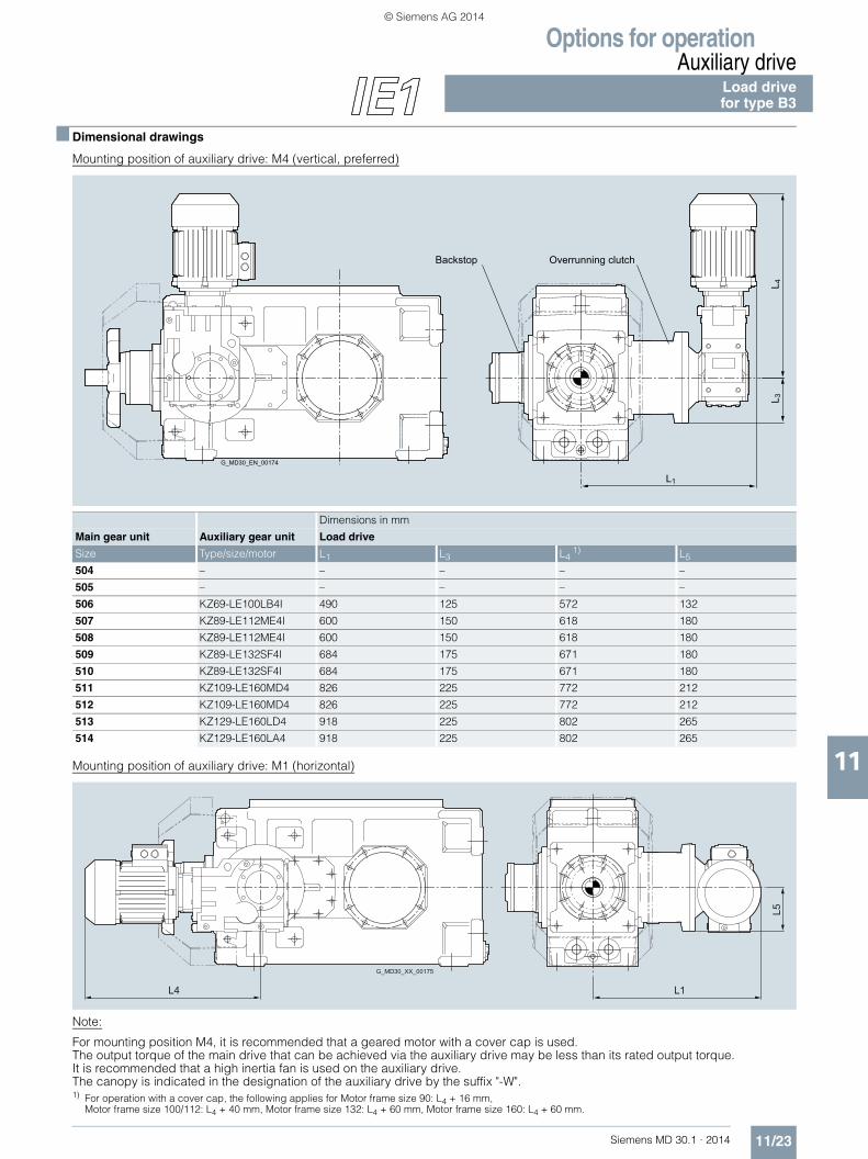
Options for operationAuxiliary drive
Load drivefor type B3
11/23Siemens MD 30.1 · 2014
11
■ Dimensional drawings
Mounting position of auxiliary drive: M4 (vertical, preferred)
Mounting position of auxiliary drive: M1 (horizontal)
Dimensions in mm
Main gear unit Auxiliary gear unit Load drive
Size Type/size/motor L1 L3 L4 1) L5
504 – – – – –
505 – – – – –
506 KZ69-LE100LB4I 490 125 572 132
507 KZ89-LE112ME4I 600 150 618 180
508 KZ89-LE112ME4I 600 150 618 180
509 KZ89-LE132SF4I 684 175 671 180
510 KZ89-LE132SF4I 684 175 671 180
511 KZ109-LE160MD4 826 225 772 212
512 KZ109-LE160MD4 826 225 772 212
513 KZ129-LE160LD4 918 225 802 265
514 KZ129-LE160LA4 918 225 802 265
G_MD30_EN_00174
Backstop Overrunning clutch
L 4
L1
L 3
L4 L1
L5
G_MD30_XX_00175
Note:
For mounting position M4, it is recommended that a geared motor with a cover cap is used.The output torque of the main drive that can be achieved via the auxiliary drive may be less than its rated output torque. It is recommended that a high inertia fan is used on the auxiliary drive. The canopy is indicated in the designation of the auxiliary drive by the suffix "-W".1) For operation with a cover cap, the following applies for Motor frame size 90: L4 + 16 mm,
Motor frame size 100/112: L4 + 40 mm, Motor frame size 132: L4 + 60 mm, Motor frame size 160: L4 + 60 mm.
© Siemens AG 2014

Options for operationAuxiliary driveSpeed monitoring for type B3
11/24 Siemens MD 30.1 · 2014
11
■ Overview
The EWD electrical speed monitor can be used wherever a permanently set speed is not permitted to be undershot or over-shot. This universally implementable speed monitoring feature comprises the EWD speed monitor, a contactless pulse genera-tor and a trip cam made of ferrous metal. To prevent overspeed of the geared motors in the case of mal-functioning of the overrunning clutch, the drive combination
must be equipped with a speed monitor for safety reasons. A malfunction would be, for example, if a signal is output by the pulse generator when drive takes place via the main motor.The pulse generator is a NAMUR sensor in accordance with EN 60947-5-6. These can also be used in hazardous areas with the appropriate isolation amplifiers. The trip cam is located in the adapter flange on the overrunning clutch.
■ Technical specifications ■ Dimensional drawings
Pulse generator BI5-M18E-Y1X-H1141
Round connector WWAK4.21-2/P00
Speed monitor (EWD) on request.
Pulse generator
Rated switching distance 5 mm
Fitting condition Flush
Housing material CuZn, chromed
Thread M18 × 1 mm
Connection Plug-in connector, M12 × 1
Material • Surface PA12-GF30• End cap Trogamid
Operating temperature -25 °C ... +70 °C
Degree of protection IP 67
Tightening torque 25 Nm
Output signal According to EN 60947-5-6 (NAMUR)
Output current• ?Operated ≤1.2 mA• Not operated ≥ 2.1 mA
Output voltage Nominal 8.2 V DC
Time delay before availability ≤1 ms
Switching frequency ≤1 kHz
Switching hysteresis 1 ... 10 %
Temperature drift ≤10 %
Reproducibility ≤ 2 %
Round connector
Plug-in connector Coupling, M12 × 1, angled
Number of poles 2-pole
Contacts Metal, CuZn, gold-plated
Contact carrier Plastic, TPU, black
Grip Plastic, TPU, blue
Seal Plastic, FPM/FKM
Degree of protection IP 67, only in screwed-in state
Mechanical endurance Min. 100 plug-in operations
Degree of pollution 3
Cable P00, LiYY
Cable diameter Ø 5.2 mm
Cable length 2 m
Cable sheath PVC, blue
Core insulation material PVC
Core insulation colors BN, BU
Core cross-section 2 × 0.5 mm2
Strands 16 × 0.2 mm2
Bending radius (in motion) Min. 10 × cable diameter
Rated voltage Max. 250 V
Insulation resistance ≥ 105 Ω
Current-carrying capacity 4 A
Volume resistance ≤ 5 mΩ
Ambient temperature• Plug-in connector -30 °C ... +90 °C• Cable -40 °C ... +80 °C
M18x1
M12x1
7256
G_M
D30
_XX
_001
83
G_M
D30
_DE
_001
84
26,5
31,5
M12x1
© Siemens AG 2014

Options for operationAuxiliary drive
Maintenance drive, load drive andspeed monitoring for type B3
11/25Siemens MD 30.1 · 2014
11
■ Selection and ordering data
Ordering information:
When ordering the auxiliary drive, -Z and the following order codes must be added to the Article No.
The standard auxiliary drive can be implemented as a single drive. Please consult us regarding intended use as twin or multi-drive.
When ordering the mounting kit for mounting the auxiliary drive at a later date, the following Article No. must be used.
Data position of Article No. 1 to 6 7 8 9 10 11 12 13 14 15 16 Order code
Article No.: 2LP202 . - . . . . . - . . . . -Z ■ ■ ■
SIG gear unit
With load drive mounted 1) M 0 0
With maintenance drive mounted 1) M 0 1
Prepared for mounting a load drive at later date 2) M 0 2
Prepared for mounting a maintenance drive at later date 2) M 0 3
Type of drive
Single drive M 6 0
Auxiliary drive in mounting position
M4 (vertical, standard) M 7 0
M1 (horizontal) M 7 1
Speed monitoring
Supplied pulse generator BI5-M18E-Y1X-H1141 and round connector WWAK4.21/P00 M 8 0
With electrical speed monitor (EWD) supplied incl. pulse generator and round connector WWAK4.21/P00 M 8 1
Prepared for customer installation of speed monitoring, connection thread M18 × 1, including trip cams M 8 2
Provided by the customer with connection thread M18 × 1 M 8 3
Provided by the customer with other connection thread M 8 4
Data position of Article No. 1 to 6 7 8 9 10 11 12 13 14 15 16
Article No.: 2LP046 ■ - ■ ■ ■ 0 0 - 0 A A 0
Mounting kit
For SIG with load drive 7 0
For SIG with maintenance drive 7 1
For gear units of type B3 of size
504 B B
505 B C
506 B D
507 B E
508 B F
509 B G
510 B H
511 B J
512 B K
513 B L
514 B M
1) The auxiliary drive is not included in the scope of supply of the gear unit. It must be ordered separately and is supplied mounted on the gear unit.
2) This design does not include the overrunning clutch and the flange cou-pling for connecting the auxiliary drive to the SIG gear unit. The components required later for mounting can be purchased separately in the form of a mounting kit.
© Siemens AG 2014

Options for operationExplosion protection as per ATEX 95
11/26 Siemens MD 30.1 · 2014
11
■ Overview
Explosion protection as per ATEX 95
FLENDER SIG gear units are certified in accordance with Directive 94/9/EU and are permitted to be used in hazardous environments.
Position in code Designation Variance SIG standard Note
1 Equipment group CE EX II Equipment group II
CE EX I Equipment group I
2 Zone 2G (gases, vapors and mist) Zone 1 Combination possible
2D (dust) Zone 21
3G (gases, vapors and mist) Zone 2 Combination possible
3D (dust) Zone 22
3 Explosion subgroup II B II B (includes II A) Omitted for dust
II C
4 Temperature class T4 T4 (includes T3, T2, T1) Combination possible
5 D 120 °C 120 °C or higher
6 Type of protection b Ignition source monitoring c Constructional enclosure k Liquid enclosure
ck Standard Category 3 bck Standard Category 2
7 Ambient temperature range -20 °C ≤ Ta ≤ 40 °C
© Siemens AG 2014

Options for operationExplosion protection as per ATEX 95
11/27Siemens MD 30.1 · 2014
11
■ Ordering information and ATEX codes
Explosion protection
Data position of Article No. 1 ... 6 7 8 9 10 11 12 13 14 15 16 Order code
Further necessary options
Article No.: 2LP202 . - . . . . . - . . . . -Z Taconite Pt100 (ATEX)
Coating system acc. to IIC condition■ ■ ■
Zone Minimum ignition energy
ATEX code1 2 3 4 5 6 1) 7 2)
21 > 3 mJ CE Ex II 2D D 120 °C bck -20 °C ≤ Ta ≤ 40 °C X 3 4 x x≤ 3 mJ CE Ex II 2D D 120 °C bck -20 °C ≤ Ta ≤ 40 °C X 3 5 x x x
22 > 3 mJ CE Ex II 3D D 120 °C ck -20 °C ≤ Ta ≤ 40 °C X 3 6 x≤ 3 mJ CE Ex II 3D D 120 °C ck -20 °C ≤ Ta ≤ 40 °C X 3 7 x x
1 – CE Ex II 2G IIA T1 bck -20 °C ≤ Ta ≤ 40 °C X 3 8 xCE Ex II 2G IIA T2 bck -20 °C ≤ Ta ≤ 40 °C X 3 9 xCE Ex II 2G IIA T3 bck -20 °C ≤ Ta ≤ 40 °C X 4 0 xCE Ex II 2G IIA T4 bck -20 °C ≤ Ta ≤ 40 °C X 4 1 xCE Ex II 2G IIB T1 bck -20 °C ≤ Ta ≤ 40 °C X 4 2 xCE Ex II 2G IIB T2 bck -20 °C ≤ Ta ≤ 40 °C X 4 3 xCE Ex II 2G IIB T3 bck -20 °C ≤ Ta ≤ 40 °C X 4 4 xCE Ex II 2G IIB T4 bck -20 °C ≤ Ta ≤ 40 °C X 4 5 xCE Ex II 2G IIC T1 bck -20 °C ≤ Ta ≤ 40 °C X 4 6 x xCE Ex II 2G IIC T2 bck -20 °C ≤ Ta ≤ 40 °C X 4 7 x xCE Ex II 2G IIC T3 bck -20 °C ≤ Ta ≤ 40 °C X 4 8 x xCE Ex II 2G IIC T4 bck -20 °C ≤ Ta ≤ 40 °C X 4 9 x x
2 – CE Ex II 3G IIA T1 ck -20 °C ≤ Ta ≤ 40 °C X 5 0CE Ex II 3G IIA T2 ck -20 °C ≤ Ta ≤ 40 °C X 5 1CE Ex II 3G IIA T3 ck -20 °C ≤ Ta ≤ 40 °C X 5 2CE Ex II 3G IIA T4 ck -20 °C ≤ Ta ≤ 40 °C X 5 3CE Ex II 3G IIB T1 ck -20 °C ≤ Ta ≤ 40 °C X 5 4CE Ex II 3G IIB T2 ck -20 °C ≤ Ta ≤ 40 °C X 5 5CE Ex II 3G IIB T3 ck -20 °C ≤ Ta ≤ 40 °C X 5 6CE Ex II 3G IIB T4 ck -20 °C ≤ Ta ≤ 40 °C X 5 7CE Ex II 3G IIC T1 ck -20 °C ≤ Ta ≤ 40 °C X 5 8 xCE Ex II 3G IIC T2 ck -20 °C ≤ Ta ≤ 40 °C X 5 9 xCE Ex II 3G IIC T3 ck -20 °C ≤ Ta ≤ 40 °C X 6 0 xCE Ex II 3G IIC T4 ck -20 °C ≤ Ta ≤ 40 °C X 6 1 x
21/1 > 3 mJ CE Ex II 2G IIA T1 D 120 °C bck -20 °C ≤ Ta ≤ 40 °C X 6 2 x xCE Ex II 2G IIA T2 D 120 °C bck -20 °C ≤ Ta ≤ 40 °C X 6 3 x xCE Ex II 2G IIA T3 D 120 °C bck -20 °C ≤ Ta ≤ 40 °C X 6 4 x xCE Ex II 2G IIA T4 D 120 °C bck -20 °C ≤ Ta ≤ 40 °C X 6 5 x xCE Ex II 2G IIB T1 D 120 °C bck -20 °C ≤ Ta ≤ 40 °C X 6 6 x xCE Ex II 2G IIB T2 D 120 °C bck -20 °C ≤ Ta ≤ 40 °C X 6 7 x xCE Ex II 2G IIB T3 D 120 °C bck -20 °C ≤ Ta ≤ 40 °C X 6 8 x xCE Ex II 2G IIB T4 D 120 °C bck -20 °C ≤ Ta ≤ 40 °C X 3 0 x x
≤ 3 mJ CE Ex II 2G IIC T1 D 120 °C bck -20 °C ≤ Ta ≤ 40 °C X 6 9 x x xCE Ex II 2G IIC T2 D 120 °C bck -20 °C ≤ Ta ≤ 40 °C X 7 0 x x xCE Ex II 2G IIC T3 D 120 °C bck -20 °C ≤ Ta ≤ 40 °C X 7 1 x x xCE Ex II 2G IIC T4 D 120 °C bck -20 °C ≤ Ta ≤ 40 °C X 3 2 x x x
22/2 > 3 mJ CE Ex II 3G IIA T1 D 120 °C ck -20 °C ≤ Ta ≤ 40 °C X 7 2 xCE Ex II 3G IIA T2 D 120 °C ck -20 °C ≤ Ta ≤ 40 °C X 7 3 xCE Ex II 3G IIA T3 D 120 °C ck -20 °C ≤ Ta ≤ 40 °C X 7 4 xCE Ex II 3G IIA T4 D 120 °C ck -20 °C ≤ Ta ≤ 40 °C X 7 5 xCE Ex II 3G IIB T1 D 120 °C ck -20 °C ≤ Ta ≤ 40 °C X 7 6 xCE Ex II 3G IIB T2 D 120 °C ck -20 °C ≤ Ta ≤ 40 °C X 7 7 xCE Ex II 3G IIB T3 D 120 °C ck -20 °C ≤ Ta ≤ 40 °C X 7 8 xCE Ex II 3G IIB T4 D 120 °C ck -20 °C ≤ Ta ≤ 40 °C X 3 1 x
≤ 3 mJ CE Ex II 3G IIC T1 D 120 °C ck -20 °C ≤ Ta ≤ 40 °C X 7 9 x xCE Ex II 3G IIC T2 D 120 °C ck -20 °C ≤ Ta ≤ 40 °C X 8 0 x xCE Ex II 3G IIC T3 D 120 °C ck -20 °C ≤ Ta ≤ 40 °C X 8 1 x xCE Ex II 3G IIC T4 D 120 °C ck -20 °C ≤ Ta ≤ 40 °C X 3 3 x x
1) Type of protection b must be provided additionally when electrical equipment such as Pt100, heating element, etc. is optionally installed.2) The product designation is based on the ambient temperature range stated for a specific order (order codes Y01 and Y02).
© Siemens AG 2014

Options for operationCorrosivity category, climatic stress
11/28 Siemens MD 30.1 · 2014
11
■ Overview
Corrosivity category
The atmospheric ambient conditions have been divided into five corrosivity categories based on ISO 12944-2. These are described below.
Climatic stress
In order to determine the applicable climatic stress, the climatic conditions at the site of installation, on the intended transport routes and in intermediate storage areas (where relevant) must be taken into account.
The assigned corrosivity category is required for selecting the correct coating system.
Ordering information:
Corrosivity category Description
C1Normal environmental pollution
• Indoor installation• Heated buildings with a neutral atmosphere
C2Low environmental pollution
• Indoor and outdoor installation• Unheated buildings with condensation, production areas with low humidity, e.g. warehouses• Atmospheres with little pollution, rural areas
C3Average environmental pollution
• Indoor and outdoor installation• Production areas with high levels of humidity and some air pollution• Urban and industrial atmospheres with moderate sulfur dioxide loads• Coastal areas with low salinity
C4High environmental pollution
• Indoor and outdoor installation• Environments with high humidity and occasionally high levels of atmospheric and chemical pollution• Occasional acidic or caustic wet cleaning• Industrial areas and coastal areas with moderate salinity
C5Very high environmental pollution
• Indoor and outdoor installation• Buildings/areas with almost constant condensation and severe pollution• Industrial areas with high humidity and aggressive atmosphere• Regular acidic or caustic wet cleaning, including cleaning with chemical agents• Coastal and offshore areas with high salinity
Data position of Article No. 1 to 6 7 8 9 10 11 12 13 14 15 16 Order code Assigned corrosivity categoryArticle No.: 2LP202 . - . . . . . - . . . . -Z ■ ■ ■
Climatic stress
Moderate climate zone (e.g. Central European conditions) B 0 1 C2
Maritime coastal areas, marine climate, maritime transport, tropical, subtropical B 0 2 C4
Corrosive, chemical atmosphere, aggressive environmental conditions B 0 3 C5
© Siemens AG 2014

Options for operationApplication
11/29Siemens MD 30.1 · 2014
11
■ Overview
Application
The level of corrosion protection required is determined according to the intended application. The assigned corrosivity category reflects the typical, atmospheric environmental conditions for the application and is needed to select the correct coating system.
If the environmental conditions might become more aggressive than typical in individual cases, a higher corrosivity category must be selected according to the description on page 11/28 .
Ordering information:
The application is set as standard to: General mechanical engineering
Data position of Article No. 1 to 6 7 8 9 10 11 12 13 14 15 16 Order code Assigned corrosivity category
Article No.: 2LP202 . - . . . . . - . . . . -Z ■ ■ ■
Application
Wastewater treatment, sewage treatment plant A 0 0 C5
Excavators and bucket wheel excavators 1) A 0 1 C4
Chemical industry 1) A 0 2 C3
Metal working mills A 0 3 C2
Conveyors A 0 4 C2
Cranes, general, standard A 0 6 C2
Cranes, harbor cranes, standard 1) A 0 7 C5
Cooling tower drive, standard A 0 9 C4
Sugar production A 1 0 C4
Paper production, printing presses 1) A 1 1 C4
Paper production, drying drum drives A 1 2 C4
Cableways A 1 3 C4
Building materials production, general A 1 4 C2
Building materials production, cement industry A 1 5 C4
Building materials production, brickworks A 1 6 C4
Transport of persons, elevators, escalators A 1 7 C2
Mining machinery A 1 8 C2
Woodworking machines A 1 9 C2
General mechanical engineering A 2 0 C2
Food processing industry, general A 2 1 C2
Food processing industry, mixer drives A 2 2 C2
Food processing industry, drum dryer drives A 2 3 C2
Food processing industry, cooking appliance drives A 2 4 C2
Food processing industry, toaster drives A 2 5 C2
Shipbuilding and offshore machinery A 2 6 C5
Prime movers, general A 2 7 C4
Prime movers, water turbines A 2 8 C2
Casting machines A 3 1 C2
Artificial fertilizer and potash works A 3 2 C2
Lauter tub drive, standard A 3 3 C4
Agitator drives, standard 1) A 3 4 C2
Oil pump drives A 4 5 C4
Compressor drives A 4 6 C2
Palm oil presses A 4 7 C4
Preheater drives A 4 8 C2
Centrifuge drives A 4 9 C2
Cooling drum drives A 5 0 C4
Calander drives A 5 1 C4
Kneader drives A 5 2 C2
Mill drives, standard 1) A 5 3 C2
1) Further options available for specific applications, selection via X.CAT NG.
© Siemens AG 2014

Options for operationCoating system
11/30 Siemens MD 30.1 · 2014
11
■ Overview
Coating system
The coating system is selected according to the intended application, the prevailing climatic stress and, where appropri-ate, requirements for explosion protection in accordance with ATEX 95.
The coating system is selected according to the highest corro-sivity category that is deemed applicable on the basis of climatic stress and application or information provided by the customer.
If explosion protection in accordance with ATEX 95 is required for areas of explosion subgroup IIC or with minimum ignition energy ≤ 3 mJ, it is absolutely essential to select the electro-statically conductive coating (order codes B85, B86, B87) of the relevant corrosivity category, or alternatively, a coating system with a coating thickness of maximum 0.2 mm (order codes B73, B75).
Ordering information:
Highest calculated corrosivity category
Standard coating with top coat
Explosion protection ATEX 95 with explosion subgroup IIC or minimum ignition energy ≤ 3mJ
Electrostatically conductive coating Max. coating thickness 0.2 mm
C1 - C3 B41 B85 B73
C4 B43 B86 B75
C5 B44 B87 B75
Data position of Article No. 1 to 6 7 8 9 10 11 12 13 14 15 16 Order code
Article No.: 2LP202 . - . . . . . - . . . . -Z ■ ■ ■
Coating system
Standard coating with top coat, moderate climate zones B 4 1
Standard coating with top coat, all climate zones B 4 3
Standard coating with top coat, all climate zones, high resistance to chemicals B 4 4
Standard coating with top coat for all climate zones and design with explosion protection according to ATEX 95 with explosion subgroup II C or minimum ignition energy ≤ 3 mJ
B 7 3
Standard coating with top coat, high resistance to chemicals and design with explosion protection according to ATEX 95 with explosion subgroup II C or minimum ignition energy ≤ 3 mJ
B 7 5
Electrostatically conductive coating with top coat, corrosivity category C3 (design with explosion protection to ATEX 95 with explosion subgroup IIC or minimum ignition energy ≤ 3 mJ)
B 8 5
Electrostatically conductive coating with top coat, corrosivity category C4 (design with explosion protection to ATEX 95 with explosion subgroup IIC or minimum ignition energy ≤ 3 mJ)
B 8 6
Electrostatically conductive coating with top coat, corrosivity category C5 (design with explosion protection to ATEX 95 with explosion subgroup IIC or minimum ignition energy ≤ 3 mJ)
B 8 7
Standard coating without top coat, all climate zones 1) B 4 2
1) Not suitable for areas and applications with corrosivity category C5 or explosion protection according to ATEX 95 with explosion subgroup IIC or minimum ignition energy ≤ 3 mJ.
© Siemens AG 2014

Options for operationColor selection
11/31Siemens MD 30.1 · 2014
11
■ Overview
Color selection
The top coat for FLENDER SIG gear units is applied as standard in the color RAL 5015 (sky blue). The gear units can also be supplied in other colors, if required.
Shaft cover caps and fan guards at the gear unit end are painted as standard in the warning color RAL 1003 ("signal yellow") to warn of the hazard of rotating parts. Cover caps/fan guards are also optionally available in the same color as the gear unit.
Ordering information:
When ordering gear units in a different color, -Z must be added to the Article No.
Other colors are available on request (see also page 11/33 Further information).
Data position of Article No. 1 to 6 7 8 9 10 11 12 13 14 15 16 Order code
Article No.: 2LP202 . - . . . . . - . . . . -Z ■ ■ ■
Color selection
RAL 5009 azure blue C 0 1
RAL 5010 gentian blue C 0 2
RAL 5015 sky blue C 0 0
RAL 6011 reseda green C 0 6
RAL 7011 steel gray C 1 3
RAL 7016 anthracite gray C 1 2
RAL 7030 stone gray C 1 1
RAL 7031 blue gray C 0 7
RAL 7035 light gray C 0 8
RAL 9005 jet black C 1 0
Cover caps/fan guards in same color as gear unit K 2 4
© Siemens AG 2014

Options for operationInformation about oil, information about installation
11/32 Siemens MD 30.1 · 2014
11
■ Overview
Information about oil
FLENDER SIG gear units are supplied without oil as standard.
Ordering information:
The following options can be selected by ordering the gear units with the order code -Z:• Permissible types of oil
• Permissible oil viscosities
Note:See page 2/2 Dip lubrication
Information about installation
Ordering information:
The following options regarding altitude and installation location are selected using the order code -Z:• Altitude
• Installation location
Data position of Article No. 1 to 6 7 8 9 10 11 12 13 14 15 16 Order code
Article No.: 2LP202 . - . . . . . - . . . . -Z ■ ■ ■
Permissible types of oil
Provided for mineral oil H 0 0
Provided for synthetic oil on a polyglycolic basis (PG oil) H 0 1
Provided for synthetic oil on a polyalphaolefin basis (PAO oil) H 0 2
Provided for synthetic low-temperature oil on a polyalphaolefin basis (PAO-T oil) H 0 3
Data position of Article No. 1 to 6 7 8 9 10 11 12 13 14 15 16 Order code
Article No.: 2LP202 . - . . . . . - . . . . -Z ■ ■ ■
Oil viscosity
ISO VG 460 1) H 1 0
ISO VG 320 H 1 1
ISO VG 220 H 1 2
Data position of Article No. 1 to 6 7 8 9 10 11 12 13 14 15 16 Order code
Article No.: 2LP202 . - . . . . . - . . . . -Z ■ ■ ■
Altitude
Up to 1000 m G 3 0
1001 to 2000 m G 3 1
2001 to 3000 m G 3 2
3001 to 4000 m G 3 3
4001 to 5000 m G 3 4
Data position of Article No. 1 to 6 7 8 9 10 11 12 13 14 15 16 Order code
Article No.: 2LP202 . - . . . . . - . . . . -Z ■ ■ ■
Installation location
Small, closed rooms G 3 5
Large rooms, halls G 3 6
Outdoors G 3 7
1) Not available for gear units in mounting positions L and V, gear units with forced lubrication and gear units with mounted auxiliary drive.
© Siemens AG 2014

Options for operationFactory certificates, further information
11/33Siemens MD 30.1 · 2014
11
■ Overview
Factory certificates
The declaration of compliance with the order in accordance with EN 10204-2.1 is part of the standard scope of supply.• Declaration of compliance with the order 2.1
Certificate in which the manufacturer confirms that the supplied products comply with the requirements of the order without details of test results.
• Test report 2.2 Certificate in which the manufacturer confirms that the supplied products comply with the requirements of the order complete with the results of non-specific tests.
Ordering information:
When ordering with additional test report in accordance with EN 10204-2.2, -Z must be added to the Article No.
Direction of rotation
For gear units without a backstop, the direction of rotation of shaft d2 can be specified using the following order codes. For gear units with a d2 shaft at both ends, the direction of rotation must be specified for the relevant shaft stud. The direction of rotation is determined by the view of the end face of shaft d2.
For gear units with direction of rotation identical "at both ends", no order code is required.
For determining the direction of rotation for gear units with a backstop, see page 11/12.
Further information
Ordering information:
The following further information can be provided in the Article No. using the order code -Z.
Data position of Article No. 1 to 6 7 8 9 10 11 12 13 14 15 16 Order code
Article No.: 2LP202 . - . . . . . - . . . . -Z ■ ■ ■
Factory certificates
Additionally with test report to EN 10204-2.2 D 9 7
Data position of Article No. 1 to 6 7 8 9 10 11 12 13 14 15 16 Order code
Article No.: 2LP202 . - . . . . . - . . . . -Z ■ ■ ■
Direction of rotation
Shaft d2 clockwise L 9 0
Shaft d2 counter-clockwise L 9 3
Direction of rotation of shaft d2 with view on right stud 1) L 9 4
Direction of rotation of shaft d2 with view on left stud 1) L 9 5
Direction of rotation of shaft d2 with view on lower stud (vertical mounting position) 1) L 9 6
Direction of rotation of shaft d2 with view on upper stud (vertical mounting position) 1) L 9 7
Data position of Article No. 1 to 6 7 8 9 10 11 12 13 14 15 16 Order code
Article No.: 2LP202 . - . . . . . - . . . . -Z ■ ■ ■
Further information
RAL color for top coat 2) Y 0 0
Minimum ambient temperature (°C) Y 0 1
Maximum ambient temperature (°C) Y 0 2
Input speed n1 FLENDER SIG (rpm) Y 2 0
Power rating of driven machine P2 (kW) 3) Y 2 1
Torque of the driven machine T2 (Nm) 3) Y 2 2
Input power P1 FLENDER SIG (kW) Y 2 3
Additional text available for product description Y 9 9
1) This option applies to gear units with shaft d2 at both ends. 2) Further colors, other than those offered in the catalog.3) Specify P2 or T2
© Siemens AG 2014

Options for operationFactory certificates, further information
11/34 Siemens MD 30.1 · 2014
11
■ Overview (continued)
Type plate
FLENDER SIG units are supplied as standard with a type plate that is glued to the gear unit and then sealed with varnish and, where appropriate, with other labels made of weather-resistant,
temperature-resistant foil. A set of labels made of stainless steel that are attached by stainless-steel button head pins can be ordered as an alternative.
Data position of Article No. 1 to 6 7 8 9 10 11 12 13 14 15 16 Order code
Article No.: 2LP202 . - . . . . . - . . . . -Z ■ ■ ■
Type plate, general labels
Stainless-steel set of labels K 2 7
Additional text for type plate (max. 30 characters) Y 2 5
© Siemens AG 2014

Siemens MD 30.1 · 2014
1212/2 Vibration reducing torque reaction arm 12/2 Types H2, H3, H4, B2, B3 and B4
Motor bell housing for IEC motors 12/4 Type H2, gear unit sizes 504 to 506
with N-EUPEX coupling12/6 Type H2, gear unit sizes 507 to 512
with N-EUPEX coupling12/8 Type H3, gear unit sizes 505 to 508
with N-EUPEX coupling12/10 Type H3, gear unit sizes 509 to 514
with N-EUPEX coupling12/12 Type H4, gear unit sizes 507 to 512
with N-EUPEX coupling12/14 Type H4, gear unit sizes 513 to 514
with N-EUPEX coupling12/16 Type B2, gear unit sizes 503 to 506
with N-EUPEX coupling12/18 Type B2, gear unit sizes 507 to 510
with N-EUPEX coupling12/20 Type B3, gear unit sizes 504 to 508
with N-EUPEX coupling12/22 Type B3, gear unit sizes 509 to 514
with N-EUPEX coupling12/24 Type B4, gear unit sizes 505 to 508
with N-EUPEX coupling12/26 Type B4, gear unit sizes 509 to 514
with N-EUPEX coupling12/28 Fitting dimensions for IEC motors
Options for externally mounted parts
© Siemens AG 2014

Options for externally mounted partsVibration reducing torque reaction arm
Types H2, H3, H4, B2, B3 and B4
12/2 Siemens MD 30.1 · 2014
12
■ Dimensional drawings
Note
For gear units without motor bell housings, couplings that do not transmit any lateral forces must be used.
Only for gear units in horizontal mounting position with hollow or solid shaft without parallel key and with mounted flange coupling.
When the housing torque arm is used in conjunction with the solid shaft without parallel key, the maximum permissible input torque is limited to: T2max = 1.5 × T2N
This limitation ceases to apply if the clearance dimension of the torque arm AP is at least doubled.
AH
AP
G_MD30_XX_00134
Dimensions in mm
Gear unit sizes
Types
H1/B2 1) H2/B3 1) H3 B4 H4/B4
AH AP AH AP AH AP AH AP AH AP
503 510 180 – – – – – – – –
504 535 222.5 510 285 – – – – – –
505 725 290 690 345 690 385 690 385 – –
506 725 321 690 398 690 438 690 438 – –
507 890 335 855 415 855 500 – – 855 500
508 890 365 855 462 855 547 – – 855 547
509 930 385 895 475 895 580 – – 895 580
510 930 416 895 528 895 633 – – 895 633
511 – – 970 570 970 705 – – 970 705
512 – – 970 628 970 763 – – 970 763
513 – – 1030 660 1030 832 – – 1030 832
514 – – 1030 738 1030 910 – – 1030 910
1) Torque arms in combination with fans are available on request only.
© Siemens AG 2014

Options for externally mounted partsVibration reducing torque reaction arm
Types H2, H3, H4, B2, B3 and B4
12/3Siemens MD 30.1 · 2014
12
■ Dimensional drawings (continued)
Connection dimensions
Type B2..
Types H2.., H3.., H4.., B3.., B4..
Ordering information
When ordering the torque arm, -Z and the following order code must be added to the Article No.
Gear unit size Dimensions in mm Weight in kg
Torque arm
A B Ø d3 F m n s1 Metalastic socket
503 200 160 19 170 160 120 20 095 23
504 200 160 19 170 160 120 20 095 24
505 / 506 320 200 19 195 260 130 25 772 62
507 / 508 400 300 24 320 320 240 30 805 174
509 / 510 400 300 24 320 320 240 30 805 176
G_M
D30
_XX
_001
35n
B
d3
s1
m
A
F
Gear unit size Dimensions in mm Weight in kg
Torque arm
A B Ø d3 F m n s1 Metalastic socket
504 200 160 19 170 160 120 20 095 23
505 / 506 320 200 19 195 260 130 25 772 58
507 / 508 400 300 24 320 320 240 30 805 170
509 / 510 400 300 24 320 320 240 30 805 172
511 / 512 400 300 24 320 320 240 30 805 174
513 / 514 400 300 24 320 320 240 30 805 179
Data position of Article No. 1 to 6 7 8 9 10 11 12 13 14 15 16 Order code
Article No. 2LP202 . - . . . . . - . . . . -Z
Vibration reducing torque reaction arm
Vibration reducing torque reaction arm for gear unit housing K 0 0
© Siemens AG 2014

Options for externally mounted partsMotor bell housing for IEC motorsType H2, gear unit sizes 504 to 506 with N-EUPEX coupling
12/4 Siemens MD 30.1 · 2014
12
■ Design
• For plants with special design requirements (high switching frequency, alternating direction of load; e.g. hoisting gears, traveling gears, etc.) the coupling design is to be checked in accordance with the respective valid coupling brochure. For other couplings, please consult us.
• For fitting dimensions for IEC standard motors EN 50347 (View X), see page 12/28.
• Helical gear unit in design C, D, G, H and I on request only.• For type H2D. design A and B, on request only.• Not in connection with taconite E on input shaft
(see note on page 11/2).
G_MD30_XX_00016
Z
X
Z
h1
h2
ØD
2
ØD
1
f
NL NLsk
Dimensions in mm
Gear unit sizes
Basic dimensions Ratio range 1 Ratio range 2 Ratio range 3
IEC motor 1)
N-EUPEX Sk NL D2 D1 h1 h2 f D1 h1 h2 f D1 h1 h2 f
504 iN = 6.3 - 11.2 iN = 12.5 - 16 iN = 18 - 20
160M B095 3 35 42 35 0 0 363 28 5 5 363
B110 3 40 42 35 0 0 363 28 5 5 363
B125 3 50 42 35 0 0 363 28 5 5 363
B140 3 55 42 35 0 0 363 28 5 5 363
160L B110 3 40 42 35 0 0 363 28 5 5 363
B125 3 50 42 35 0 0 363 28 5 5 363
B140 3 55 42 35 0 0 363 28 5 5 363
180M B110 3 40 48 35 0 0 363 28 5 5 363
B125 3 50 48 35 0 0 363 28 5 5 363
B140 3 55 48 35 0 0 363 28 5 5 363
180L B125 3 50 48 35 0 0 363 28 5 5 363
B140 3 55 48 35 0 0 363 28 5 5 363
200L B140 3 55 55 45 0 0 383 35 7 13 383 28 0 0 353
B160 4 60 55 45 0 0 383 35 7 12 383
225S 2) B140 3 55 60 45 7 11 431 35 7 7 407 28 0 2 385
B160 4 60 60 45 7 10 431 35 7 6 407 28 0 0 385
B180 4 70 60 45 7 10 431 35 7 6 407
B200 4 80 60 45 7 10 431 35 12 0 407
B225 4 90 60 45 10 7 431
225M 2) B160 4 60 60 45 7 10 431 35 7 6 407 28 0 0 385
B180 4 70 60 45 7 10 431 35 7 6 407
B200 4 80 60 45 7 10 431 35 12 0 407
B225 4 90 60 45 10 7 431
250M 2) B160 4 60 65 45 2 3 419 35 10 15 419
B180 4 70 65 45 2 3 419 35 12 13 419
B200 4 80 65 45 2 3 419 35 12 13 419
© Siemens AG 2014

Options for externally mounted partsMotor bell housing for IEC motors
Type H2, gear unit sizes 504 to 506with N-EUPEX coupling
12/5Siemens MD 30.1 · 2014
12
■ Design (continued)
Dimensions in mm
Gear unit sizes
Basic dimensions Ratio range 1 Ratio range 2 Ratio range 3
IEC motor 1)
N-EUPEX Sk NL D2 D1 h1 h2 f D1 h1 h2 f D1 h1 h2 f
505 iN = 6.3 - 10 iN = 11.2 - 14 iN = 16 - 18
506 iN = 9 - 14 iN = 16 - 20 iN = 22.4 - 25
225S B140 3 55 60 45 0 2 440 32 0 0 418
B160 4 60 60 45 0 0 440 32 0 0 418
B180 4 70 60 45 0 0 440
225M B160 4 60 60 45 0 0 440 32 0 0 418
B180 4 70 60 45 0 0 440
250M 2) B160 4 60 65 60 8 10 482 45 6 7 452 32 12 21 452
B180 4 70 65 60 8 10 482 45 6 7 452 32 15 18 452
B200 4 80 65 60 8 10 482 45 10 3 452
B225 4 90 65 60 8 10 482
280S 2) B180 4 70 75 60 8 10 482 45 6 7 452
B200 4 80 75 60 8 10 482 45 10 3 452
B225 4 90 75 60 8 10 482
280M 2) B180 4 70 75 60 8 10 482 45 6 7 452
B200 4 80 75 60 8 10 482 45 10 3 452
B225 4 90 75 60 8 10 482
315S 2) B200 4 80 80 60 12 22 528 45 7 7 483
B225 4 90 80 60 15 19 528 45 15 0 483
B250 6 100 80 60 15 17 528
315M 2) B200 4 80 80 60 12 22 528 45 7 7 483
B225 4 90 80 60 15 19 528 45 15 0 483
B250 6 100 80 60 15 17 528
315L 2) 3) B200 4 80 80 60 12 22 528
B225 4 90 80 60 15 19 528
B250 6 100 80 60 15 17 528
315L 2) 4) B225 4 90 80 60 15 19 528
B250 6 100 80 60 15 17 528
1) Other motor sizes on request.2) Notice: Motor flange radius ∅P/2 is greater than gear unit shaft height h!3) Standard motor 315L with PN < 160 kW (motor designation not included in EN 50347). 4) Standard motor 315L with PN < 200 kW (motor designation not included in EN 50347).
© Siemens AG 2014
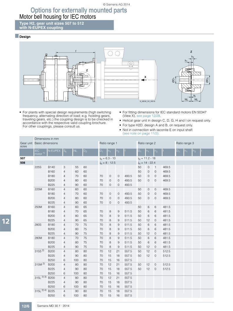
Options for externally mounted partsMotor bell housing for IEC motorsType H2, gear unit sizes 507 to 512 with N-EUPEX coupling
12/6 Siemens MD 30.1 · 2014
12
■ Design
• For plants with special design requirements (high switching frequency, alternating direction of load; e.g. hoisting gears, traveling gears, etc.) the coupling design is to be checked in accordance with the respective valid coupling brochure. For other couplings, please consult us.
• For fitting dimensions for IEC standard motors EN 50347 (View X), see page 12/28.
• Helical gear unit in design C, D, G, H and I on request only.• For type H2D. design A and B, on request only.• Not in connection with taconite E on input shaft
(see note on page 11/2).
G_MD30_XX_00016
Z
X
Z
h1
h2
ØD
2
ØD
1
f
NL NLsk
Dimensions in mm
Gear unit sizes
Basic dimensions Ratio range 1 Ratio range 2 Ratio range 3
IEC motor 1)
N-EUPEX Sk NL D2 D1 h1 h2 f D1 h1 h2 f D1 h1 h2 f
507 iN = 6.3 - 10 iN = 11.2 - 18
508 iN = 8 - 12.5 iN = 14 - 22.4
225S B140 3 55 60 50 0 1 469.5
B160 4 60 60 50 0 0 469.5
B180 4 70 60 70 0 0 493.5 50 0 0 469.5
B200 4 80 60 70 0 0 493.5 50 0 0 469.5
B225 4 90 60 70 0 0 493.5
225M B160 4 60 60 50 0 0 469.5
B180 4 70 60 70 0 0 493.5 50 0 0 469.5
B200 4 80 60 70 0 0 493.5 50 0 0 469.5
B225 4 90 60 70 0 0 493.5
250M B160 4 60 65 50 6 6 481.5
B180 4 70 65 70 8 9 511.5 50 6 6 481.5
B200 4 80 65 70 8 9 511.5 50 6 6 481.5
B225 4 90 65 70 8 9 511.5 50 12 0 481.5
280S B180 4 70 75 70 8 9 511.5 50 6 6 481.5
B200 4 80 75 70 8 9 511.5 50 6 6 481.5
B225 4 90 75 70 8 9 511.5 50 12 0 481.5
280M B180 4 70 75 70 8 9 511.5 50 6 6 481.5
B200 4 80 75 70 8 9 511.5 50 6 6 481.5
B225 4 90 75 70 8 9 511.5 50 12 0 481.5
315S 2) B200 4 80 80 70 12 21 557.5 50 12 0 512.5
B225 4 90 80 70 15 18 557.5 50 12 0 512.5
B250 6 100 80 70 15 16 557.5
315M 2) B200 4 80 80 70 12 21 557.5 50 12 0 512.5
B225 4 90 80 70 15 18 557.5 50 12 0 512.5
B250 6 100 80 70 15 16 557.5
315L 2) 3) B200 4 80 80 70 12 21 557.5
B225 4 90 80 70 15 18 557.5
B250 6 100 80 70 15 16 557.5
315L 2) 4) B225 4 90 80 70 15 18 557.5
B250 6 100 80 70 15 16 557.5
© Siemens AG 2014

Options for externally mounted partsMotor bell housing for IEC motors
Type H2, gear unit sizes 507 to 512with N-EUPEX coupling
12/7Siemens MD 30.1 · 2014
12
■ Design (continued)
Dimensions in mm
Gear unit sizes
Basic dimensions Ratio range 1 Ratio range 2 Ratio range 3
IEC motor 1)
N-EUPEX Sk NL D2 D1 h1 h2 f D1 h1 h2 f D1 h1 h2 f
509 iN = 6.3 - 10 iN = 11.2 - 14 iN = 16 - 18
510 iN = 8 - 12.5 iN = 14 - 18 iN = 20 - 22.4
280M B180 4 70 75 50 3 3 500
B200 4 80 75 50 3 3 500
B225 4 90 75 50 6 0 500
315S 2) B200 4 80 80 60 10 12 576 50 0 7 531
B225 4 90 80 60 10 12 576 50 7 0 531
B250 6 100 80 60 10 10 576
315M 2) B200 4 80 80 60 10 12 576 50 0 7 531
B225 4 90 80 60 10 12 576 50 7 0 531
B250 6 100 80 60 10 10 576
315L 2) 3) B200 4 80 80 60 10 12 576 50 0 7 531
B225 4 90 80 60 10 12 576 50 7 0 531
B250 6 100 80 60 10 10 576
315L 2) 4) B225 4 90 80 60 10 12 576
B250 6 100 80 60 10 10 576
315L 2) 5) B225 4 90 85 80 0 0 575 60 0 19 575
B250 6 100 85 80 0 0 575 60 0 19 575
315L 2) 6) B250 6 100 85 80 0 0 575
511 iN = 11.2 - 14 iN = 16 - 18
512 iN = 14 - 18 iN = 20 - 22.4
315L 2) 5) B225 4 90 85 80 On request 70 On request
B250 6 100 85 80 On request 70 On request
315L 2) 6) B250 6 100 85 80 On request 70 On request
1) Other motor sizes on request.2) Notice: Motor flange radius ∅P/2 is greater than gear unit shaft height h!3) Standard motor 315L with PN < 160 kW (motor designation not included in EN 50347). 4) Standard motor 315L with PN < 200 kW (motor designation not included in EN 50347). 5) Standard motor 315L with PN < 250 kW (motor designation not included in EN 50347). 6) Standard motor 315L with PN < 315 kW (motor designation not included in EN 50347).
© Siemens AG 2014

Options for externally mounted partsMotor bell housing for IEC motorsType H3, gear unit sizes 505 to 508 with N-EUPEX coupling
12/8 Siemens MD 30.1 · 2014
12
■ Design
• For plants with special design requirements (high switching frequency, alternating direction of load; e.g. hoisting gears, traveling gears, etc.) the coupling design is to be checked in accordance with the respective valid coupling brochure. For other couplings, please consult us.
• For fitting dimensions for IEC standard motors EN 50347 (View X), see page 12/28.
• Not in connection with taconite E on input shaft (see note on page 11/2).
G_MD30_XX_00016
Z
X
Z
h1
h2
ØD
2
ØD
1
f
NL NLsk
Dimensions in mm
Gear unit sizes
Basic dimensions Ratio range 1 Ratio range 2 Ratio range 3
IEC motor 1)
N-EUPEX Sk NL D2 D1 h1 h2 f D1 h1 h2 f D1 h1 h2 f
505 iN = 20 - 40 iN = 45 - 56 iN = 63 - 71
506 iN = 28 - 56 iN = 63 - 80 iN = 90 - 100
132S B080 3 30 38 30 0 3 336.5 24 6 7 336.5
B095 3 35 38 40 3 4 360 30 0 3 336.5 24 6 7 336.5
B110 3 40 38 40 3 4 360 30 0 3 336.5 24 6 7 336.5
B125 3 50 38 40 3 4 360 30 3 0 336.5
B140 3 55 38 40 3 4 360
132M B095 3 35 38 40 3 4 360 30 0 3 336.5 24 6 7 336.5
B110 3 40 38 40 3 4 360 30 0 3 336.5 24 6 7 336.5
B125 3 50 38 40 3 4 360 30 3 0 336.5
B140 3 55 38 40 3 4 360
160M B095 3 35 42 40 3 4 390 30 0 0 363 24 5 5 363
B110 3 40 42 40 3 4 390 30 0 0 363 24 5 5 363
B125 3 50 42 40 3 4 390 30 0 0 363
B140 3 55 42 40 3 4 390
160L B110 3 40 42 40 3 4 390 30 0 0 363 24 5 5 363
B125 3 50 42 40 3 4 390 30 0 0 363
B140 3 55 42 40 3 4 390
180M B110 3 40 48 40 3 4 390 30 0 0 363 24 5 5 363
B125 3 50 48 40 3 4 390 30 0 0 363 30 10 0 363
B140 3 55 48 40 3 4 390
180L B125 3 50 48 40 3 4 390 30 0 0 363 24 10 0 363
B140 3 55 48 40 3 4 390
200L B125 3 50 55 24 12 15 380
B140 3 55 55 40 10 17 410 30 10 7 380 24 18 9 380
B160 4 60 55 40 10 16 410
225S B140 3 55 60 40 0 0 413
B160 4 60 60 40 0 0 413
225M B160 4 60 60 40 0 0 413
250M 2) B160 4 60 65 40 10 23 447
B180 4 70 65 40 12 21 447
© Siemens AG 2014

Options for externally mounted partsMotor bell housing for IEC motors
Type H3, gear unit sizes 505 to 508with N-EUPEX coupling
12/9Siemens MD 30.1 · 2014
12
■ Design (continued)
Dimensions in mm
Gear unit sizes
Basic dimensions Ratio range 1 Ratio range 2 Ratio range 3
IEC motor 1)
N-EUPEX Sk NL D2 D1 h1 h2 f D1 h1 h2 f D1 h1 h2 f
507 iN = 20 - 40 iN = 45 - 56 iN = 63 - 71
508 iN = 25 - 50 iN = 56 - 71 iN = 80 - 90
160M B095 3 35 42 28 5 7 405.5
B110 3 40 42 28 5 7 405.5
B125 3 50 42 28 5 7 405.5
B140 3 55 42 28 5 7 405.5
160L B110 3 40 42 28 5 7 405.5
B125 3 50 42 28 5 7 405.5
B140 3 55 42 28 5 7 405.5
180M B110 3 40 48 35 0 2 405.5 28 5 7 405.5
B125 3 50 48 35 0 2 405.5 28 5 7 405.5
B140 3 55 48 35 0 2 405.5 28 5 7 405.5
180L B125 3 50 48 35 0 2 405.5 28 5 7 405.5
B140 3 55 48 35 0 2 405.5 28 5 7 405.5
200L B140 3 55 55 45 0 2 425.5 35 10 12 425.5 28 0 2 395.5
B160 4 60 55 45 0 2 425.5 35 10 11 425.5
225S B140 3 55 60 45 10 10 473.5 35 7 9 449.5 28 0 4 427.5
B160 4 60 60 45 10 9 473.5 35 7 8 449.5 28 0 3 427.5
B180 4 70 60 45 10 9 473.5 35 7 8 449.5
B200 4 80 60 45 10 9 473.5 35 12 3 449.5
B225 4 90 60 45 10 9 473.5
225M B140 3 55 60 28 0 4 427.5
B160 4 60 60 45 10 9 473.5 35 7 8 449.5 28 0 3 427.5
B180 4 70 60 45 10 9 473.5 35 7 8 449.5
B200 4 80 60 45 10 9 473.5 35 12 3 449.5
B225 4 90 60 45 10 9 473.5
250M B160 4 60 65 45 2 5 461.5 35 10 17 461.5
B180 4 70 65 45 2 5 461.5 35 12 15 461.5
B200 4 80 65 45 2 5 461.5 35 12 15 461.5
280S B180 4 70 75 45 2 5 461.5
B200 4 80 75 45 2 5 461.5
280M B180 4 70 75 45 2 5 461.5
B200 4 80 75 45 2 5 461.5
1) Other motor sizes on request.2) Notice: Motor flange radius ∅P/2 is greater than gear unit shaft height h!
© Siemens AG 2014

Options for externally mounted partsMotor bell housing for IEC motorsType H3, gear unit sizes 509 to 514 with N-EUPEX coupling
12/10 Siemens MD 30.1 · 2014
12
■ Design
• For plants with special design requirements (high switching frequency, alternating direction of load; e.g. hoisting gears, traveling gears, etc.) the coupling design is to be checked in accordance with the respective valid coupling brochure. For other couplings, please consult us.
• For fitting dimensions for IEC standard motors EN 50347 (View X), see page 12/28.
• Not in connection with taconite E on input shaft (see note on page 11/2).
G_MD30_XX_00016
Z
X
Z
h1
h2
ØD
2
ØD
1
f
NL NLsk
Dimensions in mm
Gear unit sizes
Basic dimensions Ratio range 1 Ratio range 2 Ratio range 3
IEC motor 1)
N-EUPEX Sk NL D2 D1 h1 h2 f D1 h1 h2 f D1 h1 h2 f
509 iN = 20 - 40 iN = 45 - 56 iN = 63 - 71
510 iN = 25 - 50 iN = 56 - 71 iN = 80 - 90
225S B140 3 55 60 60 0 1 524 45 0 2 500 32 0 0 478
B160 4 60 60 60 0 0 524 45 0 0 500 32 0 0 478
B180 4 70 60 60 0 0 524 45 0 0 500
B200 4 80 60 60 0 0 524
B225 4 90 60 60 0 0 524
225M B160 4 60 60 60 0 0 524 45 0 0 500 32 0 0 478
B180 4 70 60 60 0 0 524 45 0 0 500
B200 4 80 60 60 0 0 524
B225 4 90 60 60 0 0 524
250M B160 4 60 65 60 8 10 542 45 6 7 512 32 12 21 512
B180 4 70 65 60 8 10 542 45 6 7 512 32 15 18 512
B200 4 80 65 60 8 10 542 45 10 3 512
B225 4 90 65 60 8 10 542
280S B180 4 70 75 60 8 10 542 45 6 7 512
B200 4 80 75 60 8 10 542 45 10 3 512
B225 4 90 75 60 8 10 542
280M B180 4 70 75 60 8 10 542 45 6 7 512
B200 4 80 75 60 8 10 542 45 10 3 512
B225 4 90 75 60 8 10 542
315S 2) B200 4 80 80 60 12 22 588
B225 4 90 80 60 15 19 588
B250 6 100 80 60 15 17 588
315M 2) B200 4 80 80 60 12 22 588
B225 4 90 80 60 15 19 588
B250 6 100 80 60 15 17 588
315L 2) 3) B200 4 80 80 60 12 22 588
B225 4 90 80 60 15 19 588
B250 6 100 80 60 15 17 588
315L 2) 4) B225 4 90 80 60 15 19 588
B250 6 100 80 60 15 17 588
© Siemens AG 2014
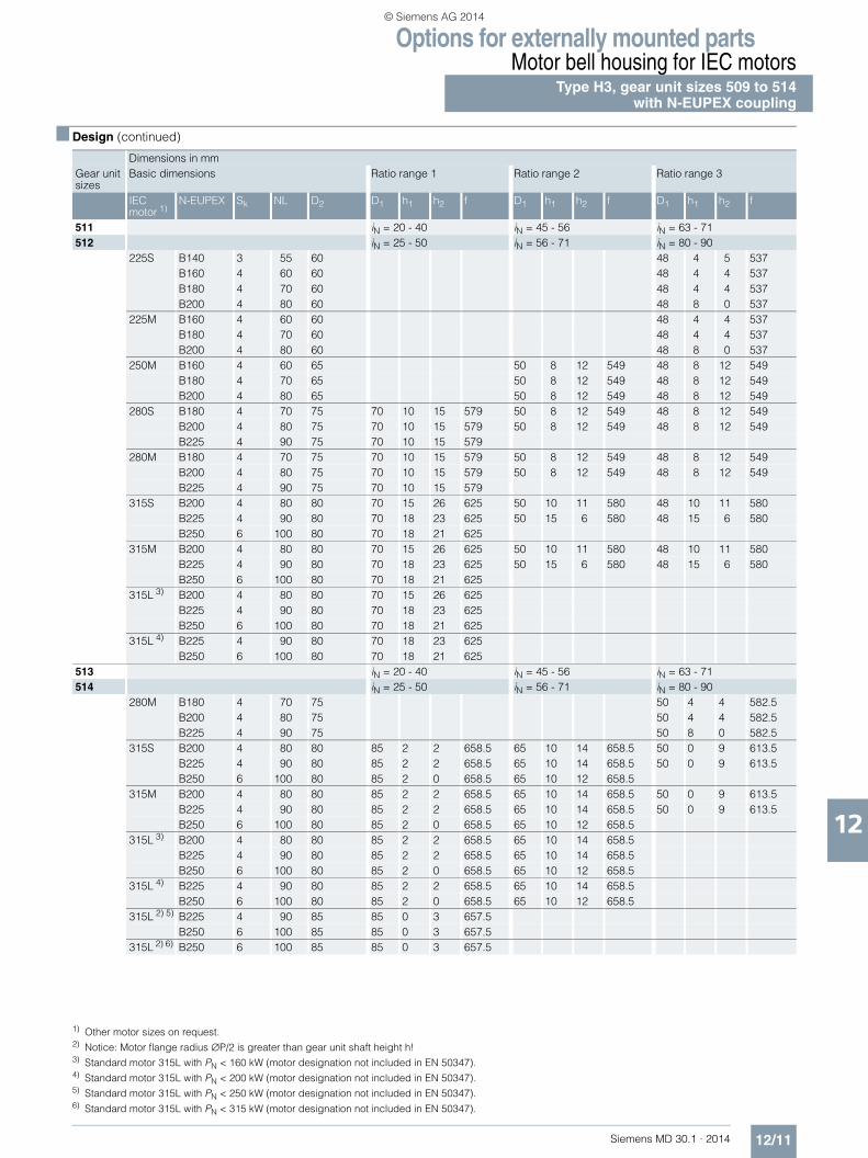
Options for externally mounted partsMotor bell housing for IEC motors
Type H3, gear unit sizes 509 to 514with N-EUPEX coupling
12/11Siemens MD 30.1 · 2014
12
■ Design (continued)
Dimensions in mmGear unit sizes
Basic dimensions Ratio range 1 Ratio range 2 Ratio range 3
IEC motor 1)
N-EUPEX Sk NL D2 D1 h1 h2 f D1 h1 h2 f D1 h1 h2 f
511 iN = 20 - 40 iN = 45 - 56 iN = 63 - 71512 iN = 25 - 50 iN = 56 - 71 iN = 80 - 90
225S B140 3 55 60 48 4 5 537B160 4 60 60 48 4 4 537B180 4 70 60 48 4 4 537B200 4 80 60 48 8 0 537
225M B160 4 60 60 48 4 4 537B180 4 70 60 48 4 4 537B200 4 80 60 48 8 0 537
250M B160 4 60 65 50 8 12 549 48 8 12 549B180 4 70 65 50 8 12 549 48 8 12 549B200 4 80 65 50 8 12 549 48 8 12 549
280S B180 4 70 75 70 10 15 579 50 8 12 549 48 8 12 549B200 4 80 75 70 10 15 579 50 8 12 549 48 8 12 549B225 4 90 75 70 10 15 579
280M B180 4 70 75 70 10 15 579 50 8 12 549 48 8 12 549B200 4 80 75 70 10 15 579 50 8 12 549 48 8 12 549B225 4 90 75 70 10 15 579
315S B200 4 80 80 70 15 26 625 50 10 11 580 48 10 11 580B225 4 90 80 70 18 23 625 50 15 6 580 48 15 6 580B250 6 100 80 70 18 21 625
315M B200 4 80 80 70 15 26 625 50 10 11 580 48 10 11 580B225 4 90 80 70 18 23 625 50 15 6 580 48 15 6 580B250 6 100 80 70 18 21 625
315L 3) B200 4 80 80 70 15 26 625B225 4 90 80 70 18 23 625B250 6 100 80 70 18 21 625
315L 4) B225 4 90 80 70 18 23 625B250 6 100 80 70 18 21 625
513 iN = 20 - 40 iN = 45 - 56 iN = 63 - 71514 iN = 25 - 50 iN = 56 - 71 iN = 80 - 90
280M B180 4 70 75 50 4 4 582.5B200 4 80 75 50 4 4 582.5B225 4 90 75 50 8 0 582.5
315S B200 4 80 80 85 2 2 658.5 65 10 14 658.5 50 0 9 613.5B225 4 90 80 85 2 2 658.5 65 10 14 658.5 50 0 9 613.5B250 6 100 80 85 2 0 658.5 65 10 12 658.5
315M B200 4 80 80 85 2 2 658.5 65 10 14 658.5 50 0 9 613.5B225 4 90 80 85 2 2 658.5 65 10 14 658.5 50 0 9 613.5B250 6 100 80 85 2 0 658.5 65 10 12 658.5
315L 3) B200 4 80 80 85 2 2 658.5 65 10 14 658.5B225 4 90 80 85 2 2 658.5 65 10 14 658.5B250 6 100 80 85 2 0 658.5 65 10 12 658.5
315L 4) B225 4 90 80 85 2 2 658.5 65 10 14 658.5B250 6 100 80 85 2 0 658.5 65 10 12 658.5
315L 2) 5) B225 4 90 85 85 0 3 657.5 B250 6 100 85 85 0 3 657.5
315L 2) 6) B250 6 100 85 85 0 3 657.5
1) Other motor sizes on request.2) Notice: Motor flange radius ∅P/2 is greater than gear unit shaft height h!3) Standard motor 315L with PN < 160 kW (motor designation not included in EN 50347). 4) Standard motor 315L with PN < 200 kW (motor designation not included in EN 50347). 5) Standard motor 315L with PN < 250 kW (motor designation not included in EN 50347). 6) Standard motor 315L with PN < 315 kW (motor designation not included in EN 50347).
© Siemens AG 2014
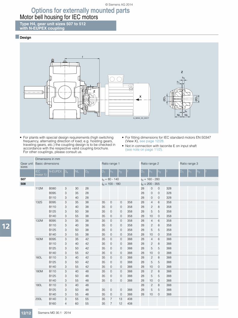
Options for externally mounted partsMotor bell housing for IEC motorsType H4, gear unit sizes 507 to 512 with N-EUPEX coupling
12/12 Siemens MD 30.1 · 2014
12
■ Design
• For plants with special design requirements (high switching frequency, alternating direction of load; e.g. hoisting gears, traveling gears, etc.) the coupling design is to be checked in accordance with the respective valid coupling brochure. For other couplings, please consult us.
• For fitting dimensions for IEC standard motors EN 50347 (View X), see page 12/28.
• Not in connection with taconite E on input shaft (see note on page 11/2).
G_MD30_XX_00017
Z
Z
ØD
1
ØD
2
f
X
NL NLsk
h1
h2
Dimensions in mm
Gear unit sizes
Basic dimensions Ratio range 1 Ratio range 2 Ratio range 3
IEC motor 1)
N-EUPEX Sk NL D2 D1 h1 h2 f D1 h1 h2 f D1 h1 h2 f
507 iN = 80 - 140 iN = 160 - 280
508 iN = 100 - 180 iN = 200 - 355
112M B080 3 30 28 28 0 0 328
B095 3 35 28 28 0 0 328
B110 3 40 28 28 0 0 328
132S B095 3 35 38 35 0 0 358 28 4 6 358
B110 3 40 38 35 0 0 358 28 2 8 358
B125 3 50 38 35 0 0 358 28 5 5 358
B140 3 55 38 35 0 0 358 28 10 0 358
132M B095 3 35 38 35 0 0 358 28 4 6 358
B110 3 40 38 35 0 0 358 28 2 8 358
B125 3 50 38 35 0 0 358 28 5 5 358
B140 3 55 38 35 0 0 358 28 10 0 358
160M B095 3 35 42 35 0 0 388 28 4 6 388
B110 3 40 42 35 0 0 388 28 2 8 388
B125 3 50 42 35 0 0 388 28 5 5 388
B140 3 55 42 35 0 0 388 28 10 0 388
160L B110 3 40 42 35 0 0 388 28 2 8 388
B125 3 50 42 35 0 0 388 28 5 5 388
B140 3 55 42 35 0 0 388 28 10 0 388
180M B110 3 40 48 35 0 0 388 28 2 8 388
B125 3 50 48 35 0 0 388 28 5 5 388
B140 3 55 48 35 0 0 388 28 10 0 388
180L B110 3 40 48 28 2 8 388
B125 3 50 48 35 0 0 388 28 5 5 388
B140 3 55 48 35 0 0 388 28 10 0 388
200L B140 3 55 55 35 7 13 408
B160 4 60 55 35 7 12 408
© Siemens AG 2014

Options for externally mounted partsMotor bell housing for IEC motors
Type H4, gear unit sizes 507 to 512with N-EUPEX coupling
12/13Siemens MD 30.1 · 2014
12
■ Design (continued)
Dimensions in mm
Gear unit sizes
Basic dimensions Ratio range 1 Ratio range 2 Ratio range 3
IEC motor 1)
N-EUPEX Sk NL D2 D1 h1 h2 f D1 h1 h2 f D1 h1 h2 f
509 iN = 80 - 160 iN = 180 - 315
510 iN = 100 - 200 iN = 224 - 400
160M B095 3 35 42 35 0 0 398 28 4 6 398
B110 3 40 42 35 0 0 398 28 2 8 398
B125 3 50 42 35 0 0 398
160L B110 3 40 42 35 0 0 398 28 2 8 398
B125 3 50 42 35 0 0 398
180M B110 3 40 48 35 0 0 398 28 2 8 398
B125 3 50 48 35 0 0 398
180L B125 3 50 48 35 0 0 398 28 10 0 398
200L B125 3 50 55 28 10 2 415
B140 3 55 55 35 7 10 415 28 15 12 415
225S B140 3 55 60 35 7 12 447
B160 4 60 60 35 12 6 447
225M B160 4 60 60 35 12 6 447
511 iN = 80 - 160 iN = 180 - 224 iN = 250 - 315
512 iN = 100 - 200 iN = 224 - 280 iN = 315 - 400
160M B095 3 35 42 35 5 5 458
B110 3 40 42 35 4 6 458
B125 3 50 42 35 5 5 458 28 6 14 458
B140 3 55 42 35 5 5 458 28 10 10 458
160L B110 3 40 42 35 4 6 458
B125 3 50 42 35 5 5 458 28 6 14 458
B140 3 55 42 35 5 5 458 28 10 10 458
180M B110 3 40 48 35 4 6 458 28 8 12 458
B125 3 50 48 35 5 5 458 28 10 10 458
B140 3 55 48 35 5 5 458
180L B125 3 50 48 35 5 5 458 28 10 10 458
B140 3 55 48 35 5 5 458
200L B140 3 55 55 45 5 5 478 35 0 0 448 28 5 5 448
B160 4 60 55 45 5 0 478
225S B140 3 55 60 45 2 2 502 35 0 2 480 28 5 7 480
B160 4 60 60 45 2 0 502 35 0 0 480 28 8 3 480
B180 4 70 60 45 2 0 502
B200 4 80 60 45 2 0 502
225M B140 3 55 60 35 0 2 480 28 5 7 480
B160 4 60 60 45 2 0 502 35 0 0 480 28 8 3 480
B180 4 70 60 45 2 0 502
B200 4 80 60 45 2 0 502
250M B160 4 60 65 45 7 8 514
B180 4 70 65 45 7 8 514
B200 4 80 65 45 7 8 514
280S B180 4 70 75 45 7 8 514
B200 4 80 75 45 7 8 514
280M B180 4 70 75 45 7 8 514
B200 4 80 75 45 7 8 514
1) Other motor sizes on request.
© Siemens AG 2014

Options for externally mounted partsMotor bell housing for IEC motorsType H4, gear unit sizes 513 and 514 with N-EUPEX coupling
12/14 Siemens MD 30.1 · 2014
12
■ Design
• For plants with special design requirements (high switching frequency, alternating direction of load; e.g. hoisting gears, traveling gears, etc.) the coupling design is to be checked in accordance with the respective valid coupling brochure. For other couplings, please consult us.
• For fitting dimensions for IEC standard motors EN 50347(View X), see page 12/28.
• Not in connection with taconite E on input shaft (see note on page 11/2).
G_MD30_XX_00017
Z
Z
ØD
1
ØD
2
f
X
NL NLsk
h1
h2
© Siemens AG 2014

Options for externally mounted partsMotor bell housing for IEC motors
Type H4, gear unit sizes 513 and 514with N-EUPEX coupling
12/15Siemens MD 30.1 · 2014
12
■ Design (continued)
Dimensions in mm
Gear unit sizes
Basic dimensions Ratio range 1 Ratio range 2 Ratio range 3
IEC motor 1)
N-EUPEX Sk NL D2 D1 h1 h2 f D1 h1 h2 f D1 h1 h2 f
513 iN = 80 - 160 iN = 180 - 224 iN = 250 - 315
514 iN = 100 - 200 iN = 224 - 280 iN = 315 - 400
225S B140 3 55 60 45 7 15 570.5 32 7 11 546.5
B160 4 60 60 45 8 13 570.5 32 8 9 546.5
B180 4 70 60 45 10 11 570.5
B200 4 80 60 45 12 9 570.5
225M B160 4 60 60 45 8 13 570.5 32 8 9 546.5
B180 4 70 60 45 10 11 570.5
B200 4 80 60 45 12 9 570.5
250M B160 4 60 65 60 7 7 588.5 45 4 5 558.5 32 10 19 558.5
B180 4 70 65 60 7 7 588.5 45 4 5 558.5
B200 4 80 65 60 7 7 588.5 45 10 0 558.5
B225 4 90 65 60 7 7 588.5
280S B180 4 70 75 60 7 7 588.5 45 4 5 558.5
B200 4 80 75 60 7 7 588.5 45 10 0 558.5
B225 4 90 75 60 7 7 588.5
280M B180 4 70 75 60 7 7 588.5 45 4 5 558.5
B200 4 80 75 60 7 7 588.5 45 10 0 558.5
B225 4 90 75 60 7 7 588.5
315S B200 4 80 80 60 12 18 634.5
B225 4 90 80 60 12 18 634.5
B250 6 100 80 60 12 16 634.5
315M B200 4 80 80 60 12 18 634.5
B225 4 90 80 60 12 18 634.5
B250 6 100 80 60 12 16 634.5
1) Other motor sizes on request.
© Siemens AG 2014

Options for externally mounted partsMotor bell housing for IEC motorsType B2, gear unit sizes 503 to 506 with N-EUPEX coupling
12/16 Siemens MD 30.1 · 2014
12
■ Design
• For plants with special design requirements (high switching frequency, alternating direction of load; e.g. hoisting gears, traveling gears, etc.) the coupling design is to be checked in accordance with the respective valid coupling brochure. For other couplings, please consult us.
• For fitting dimensions for IEC standard motors EN 50347 (View X), see page 12/28.
• Not in connection with taconite E on input shaft (see note on page 11/2).
G_MD30_EN_00182
fL Gear unit sizes: 506, 508, 510f Gear unit sizes: 503, 504, 505, 507, 509
Z
ØD
2
ØD
1
h1
h2
NLNL
sk
X
ZA
Dimensions in mm
Gear unit sizes
Basic dimensions Ratio range 1 Ratio range 2
IEC motor 1)
N–EUPEX Sk NL D2 A D1 h1 h2 f fL D1 h1 h2 f fL
503 iN = 5 - 14 iN = 16
160M B095 3 35 42 @ 315 35 5 5 596 –
B110 3 40 42 @ 315 35 5 5 596 –
B125 3 50 42 @ 315 35 5 5 596 –
B140 3 55 42 @ 315 35 5 5 596 –
160L B110 3 40 42 @ 315 35 5 5 596 –
B125 3 50 42 @ 315 35 5 5 596 –
B140 3 55 42 @ 315 35 5 5 596 –
180M B110 3 40 48 @ 315 40 0 0 596 – 35 5 5 596 –
B125 3 50 48 @ 315 40 0 0 596 – 35 5 5 596 –
B140 3 55 48 @ 315 40 0 0 596 – 35 5 5 596 –
180L B125 3 50 48 @ 315 40 0 0 596 – 35 5 5 596 –
B140 3 55 48 @ 315 40 0 0 596 – 35 5 5 596 –
200L B140 3 55 55 @ 315 40 7 13 616 –
B160 4 60 55 @ 315 40 7 12 616 –
225S 2) B140 3 55 60 @ 315 40 7 7 640 –
B160 4 60 60 @ 315 40 7 6 640 –
B180 4 70 60 @ 315 40 7 6 640 –
B200 4 80 60 @ 315 40 7 6 640 –
225M 2) B160 4 60 60 @ 315 40 7 6 640 –
B180 4 70 60 @ 315 40 7 6 640 –
B200 4 80 60 @ 315 40 7 6 640 –
250M 2) B160 4 60 65 @ 315 40 8 17 652 –
B180 4 70 65 @ 315 40 12 13 652 –
B200 4 80 65 @ 315 40 12 13 652 –
© Siemens AG 2014

Options for externally mounted partsMotor bell housing for IEC motors
Type B2, gear unit sizes 503 to 506with N-EUPEX coupling
12/17Siemens MD 30.1 · 2014
12
■ Design (continued)
Dimensions in mm
Gear unit sizes
Basic dimensions Ratio range 1 Ratio range 2
IEC motor 1)
N–EUPEX Sk NL D2 A D1 h1 h2 f fL D1 h1 h2 f fL
504 iN = 5 - 14 iN = 16
180M B125 3 50 48 @ 315 50 0 0 688 – 40 6 14 688 –
B140 3 55 48 @ 315 50 0 0 688 – 40 10 10 688 –
B160 4 60 48 @ 315 50 0 0 688 –
180L B125 3 50 48 @ 315 50 0 0 688 – 40 6 14 688 –
B140 3 55 48 @ 315 50 0 0 688 – 40 10 10 688 –
B160 4 60 48 @ 315 50 0 0 688 –
200L B140 3 55 55 @ 315 50 7 13 708 – 40 5 5 678 –
B160 4 60 55 @ 315 50 7 12 708 –
225S B140 3 55 60 @ 315 50 7 7 732 – 40 6 6 710 –
B160 4 60 60 @ 315 50 7 6 732 – 40 6 5 710 –
B180 4 70 60 @ 315 50 7 6 732 –
B200 4 80 60 @ 315 50 7 6 732 –
225M B160 4 60 60 @ 315 50 7 6 732 – 40 6 5 710 –
B180 4 70 60 @ 315 50 7 6 732 –
B200 4 80 60 @ 315 50 7 6 732 –
505 iN = 5 - 14 iN = 16
506 iN = 6.3 - 18 iN = 20
225S B140 3 55 60 @ 420 50 0 0 803 834
B160 4 60 60 @ 420 50 0 0 803 834
B180 4 70 60 @ 420 50 0 0 803 834
B200 4 80 60 @ 420 50 0 0 803 834
225M B160 4 60 60 @ 420 50 0 0 803 834
B180 4 70 60 @ 420 50 0 0 803 834
B200 4 80 60 @ 420 50 0 0 803 834
250M 2) B160 4 60 65 @ 420 60 0 0 815 846 50 5 6 815 846
B180 4 70 65 @ 420 60 0 0 815 846 50 5 6 815 846
B200 4 80 65 @ 420 60 0 0 815 846 50 5 6 815 846
B225 4 90 65 @ 420 60 0 0 815 846
280S 2) B180 4 70 75 @ 420 60 0 0 815 846 50 5 6 815 846
B200 4 80 75 @ 420 60 0 0 815 846 50 5 6 815 846
B225 4 90 75 @ 420 60 0 0 815 846
280M 2) B180 4 70 75 @ 420 60 0 0 815 846 50 5 6 815 846
B200 4 80 75 @ 420 60 0 0 815 846 50 5 6 815 846
B225 4 90 75 @ 420 60 0 0 815 846
1) Other motor sizes on request. 2) Notice: Motor flange radius ∅P/2 is greater than gear unit shaft height h!
© Siemens AG 2014

Options for externally mounted partsMotor bell housing for IEC motorsType B2, gear unit sizes 507 to 510 with N-EUPEX coupling
12/18 Siemens MD 30.1 · 2014
12
■ Design
• For plants with special design requirements (high switching frequency, alternating direction of load; e.g. hoisting gears, traveling gears, etc.) the coupling design is to be checked in accordance with the respective valid coupling brochure. For other couplings, please consult us.
• For fitting dimensions for IEC standard motors EN 50347 (View X), see page 12/28.
• Not in connection with taconite E on input shaft (see note on page 11/2).
G_MD30_EN_00182
fL Gear unit sizes: 506, 508, 510f Gear unit sizes: 503, 504, 505, 507, 509
Z
ØD
2
ØD
1
h1
h2
NLNL
sk
X
ZA
Dimensions in mm
Gear unit sizes
Basic dimensions Ratio range 1 Ratio range 2
IEC motor 1)
N-EUPEX Sk NL D2 A D1 h1 h2 f fL D1 h1 h2 f fL
507 iN = 5 - 14 iN = 16
508 iN = 6 - 17 iN = 19
280S B180 4 70 75 @ 420 75 0 0 935 965 60 0 0 935 965
B200 4 80 75 @ 420 75 0 0 935 965 60 0 0 935 965
280M B180 4 70 75 @ 420 75 0 0 935 965 60 0 0 935 965
B200 4 80 75 @ 420 75 0 0 935 965 60 0 0 935 965
315S 2) B200 4 80 80 @ 420 75 0 0 966 996 60 0 0 966 996
B225 4 90 80 @ 420 75 0 0 966 996 60 0 0 966 996
B250 6 100 80 @ 420 75 0 0 966 996 60 0 0 966 996
315M 2) B200 4 80 80 @ 420 75 0 0 966 996 60 0 0 966 996
B225 4 90 80 @ 420 75 0 0 966 996 60 0 0 966 996
B250 6 100 80 @ 420 75 0 0 966 996 60 0 0 966 996
© Siemens AG 2014
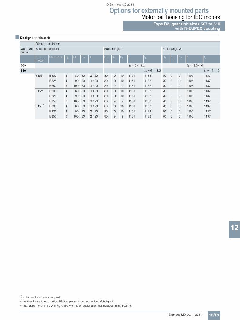
Options for externally mounted partsMotor bell housing for IEC motors
Type B2, gear unit sizes 507 to 510with N-EUPEX coupling
12/19Siemens MD 30.1 · 2014
12
■ Design (continued)
Dimensions in mm
Gear unit sizes
Basic dimensions Ratio range 1 Ratio range 2
IEC motor 1)
N-EUPEX Sk NL D2 A D1 h1 h2 f fL D1 h1 h2 f fL
509 iN = 5 - 11.2 iN = 12.5 - 16
510 iN = 6 - 13.2 iN = 15 - 19
315S B200 4 80 80 @ 420 80 10 10 1151 1182 70 0 0 1106 1137
B225 4 90 80 @ 420 80 10 10 1151 1182 70 0 0 1106 1137
B250 6 100 80 @ 420 80 9 9 1151 1182 70 0 0 1106 1137
315M B200 4 80 80 @ 420 80 10 10 1151 1182 70 0 0 1106 1137
B225 4 90 80 @ 420 80 10 10 1151 1182 70 0 0 1106 1137
B250 6 100 80 @ 420 80 9 9 1151 1182 70 0 0 1106 1137
315L 3) B200 4 80 80 @ 420 80 10 10 1151 1182 70 0 0 1106 1137
B225 4 90 80 @ 420 80 10 10 1151 1182 70 0 0 1106 1137
B250 6 100 80 @ 420 80 9 9 1151 1182 70 0 0 1106 1137
1) Other motor sizes on request. 2) Notice: Motor flange radius ∅P/2 is greater than gear unit shaft height h! 3) Standard motor 315L with PN < 160 kW (motor designation not included in EN 50347).
© Siemens AG 2014

Options for externally mounted partsMotor bell housing for IEC motorsType B3, gear unit sizes 504 to 508 with N-EUPEX coupling
12/20 Siemens MD 30.1 · 2014
12
■ Design
• For plants with special design requirements (high switching frequency, alternating direction of load; e.g. hoisting gears, traveling gears, etc.) the coupling design is to be checked in accordance with the respective valid coupling brochure. For other couplings, please consult us.
• For fitting dimensions for IEC standard motors EN 50347 (View X), see page 12/28.
• Not in connection with taconite E on input shaft (see note on page 11/2).
G_MD30_EN_00015
f Gear unit sizes: 504, 505, 507, 509, 511, 513fL Gear unit sizes: 506, 508, 510, 512, 514
Z
X
Z
ØD
2
ØD
1
h1
h2
NLNL
skA
Dimensions in mmGear unit sizes
Basic dimensions Ratio range 1 Ratio range 2
IEC motor 1)
N-EUPEX Sk NL D2 A D1 h1 h2 f fL D1 h1 h2 f fL
504 iN = 16 - 56 iN = 63132S B095 3 35 38 Ø250 35 0 0 663 – 32 5 5 663 –
B110 3 40 38 Ø250 35 0 0 663 – 32 5 5 663 –B125 3 50 38 Ø250 35 0 0 663 – 32 5 5 663 –B140 3 55 38 Ø250 35 0 0 663 – 32 5 5 663 –
132M B095 3 35 38 Ø250 35 0 0 663 – 32 5 5 663 –B110 3 40 38 Ø250 35 0 0 663 – 32 5 5 663 –B125 3 50 38 Ø250 35 0 0 663 – 32 5 5 663 –B140 3 55 38 Ø250 35 0 0 663 – 32 5 5 663 –
160M B095 3 35 42 Ø250 35 0 0 693 – 32 5 5 693 –B110 3 40 42 Ø250 35 0 0 693 – 32 5 5 693 –B125 3 50 42 Ø250 35 0 0 693 – 32 5 5 693 –B140 3 55 42 Ø250 35 0 0 693 – 32 5 5 693 –
160L B095 3 35 42 Ø250 – 32 5 5 693 –B110 3 40 42 Ø250 35 0 0 693 – 32 5 5 693 –B125 3 50 42 Ø250 35 0 0 693 – 32 5 5 693 –B140 3 55 42 Ø250 35 0 0 693 – 32 5 5 693 –
180M B110 3 40 48 Ø250 35 0 0 693 –B125 3 50 48 Ø250 35 0 0 693 –B140 3 55 48 Ø250 35 0 0 693 –
180L B125 3 50 48 Ø250 35 0 0 693 –B140 3 55 48 Ø250 35 0 0 693 –
200L B140 3 55 55 Ø250 35 7 13 713 –B160 4 60 55 Ø250 35 7 12 713 –
© Siemens AG 2014

Options for externally mounted partsMotor bell housing for IEC motors
Type B3, gear unit sizes 504 to 508with N-EUPEX coupling
12/21Siemens MD 30.1 · 2014
12
■ Design (continued)
Dimensions in mmGear unit sizes
Basic dimensions Ratio range 1 Ratio range 2
IEC motor 1) N-EUPEX Sk NL D2 A D1 h1 h2 f fL D1 h1 h2 f fL505 iN = 14 - 50 iN = 56506 iN = 20 - 71 iN = 80
160M B095 3 35 42 @ 315 40 0 0 778 831 35 5 5 778 831B110 3 40 42 @ 315 40 0 0 778 831 35 5 5 778 831B125 3 50 42 @ 315 40 0 0 778 831 35 5 5 778 831B140 3 55 42 @ 315 40 0 0 778 831 35 5 5 778 831
160L B110 3 40 42 @ 315 40 0 0 778 831 35 5 5 778 831B125 3 50 42 @ 315 40 0 0 778 831 35 5 5 778 831B140 3 55 42 @ 315 40 0 0 778 831 35 5 5 778 831
180M B110 3 40 48 @ 315 40 0 0 778 831 35 5 5 778 831B125 3 50 48 @ 315 40 0 0 778 831 35 5 5 778 831B140 3 55 48 @ 315 40 0 0 778 831 35 5 5 778 831
180L B125 3 50 48 @ 315 40 0 0 778 831 35 5 5 778 831B140 3 55 48 @ 315 40 0 0 778 831 35 5 5 778 831
200L B125 3 50 55 @ 315 35 0 0 768 821B140 3 55 55 @ 315 40 7 13 798 851 35 0 0 768 821B160 4 60 55 @ 315 40 7 12 798 851 35 0 0 768 821
225S B140 3 55 60 @ 315 40 7 7 822 875B160 4 60 60 @ 315 40 7 6 822 875B180 4 70 60 @ 315 40 7 6 822 875B200 4 80 60 @ 315 40 7 6 822 875
225M B160 4 60 60 @ 315 40 7 6 822 875B180 4 70 60 @ 315 40 7 6 822 875B200 4 80 60 @ 315 40 7 6 822 875
250M 2) B180 4 70 65 @ 315 40 12 13 834 887B200 4 80 65 @ 315 40 12 13 834 887
280S 2) B180 4 70 75 @ 315 40 12 13 834 887B200 4 80 75 @ 315 40 10 15 834 887
280M 2) B200 4 80 75 @ 315 40 10 15 834 887507 iN = 14 - 50 iN = 56508 iN = 18 - 63 iN = 71
160M B125 3 50 42 @ 315 40 6 14 913 960B140 3 55 42 @ 315 40 10 10 913 960
160L B125 3 50 42 @ 315 40 6 14 913 960B140 3 55 42 @ 315 40 10 10 913 960
180M B125 3 50 48 @ 315 40 6 14 913 960B140 3 55 48 @ 315 40 10 10 913 960
180L B125 3 50 48 @ 315 40 6 14 913 960B140 3 55 48 @ 315 40 10 10 913 960
200L B140 3 55 55 @ 315 50 7 13 933 980 40 5 5 903 950B160 4 60 55 @ 315 50 7 12 933 980
225S B140 3 55 60 @ 315 50 7 7 957 1004 40 6 6 935 982B160 4 60 60 @ 315 50 7 6 957 1004 40 6 5 935 982B180 4 70 60 @ 315 50 7 6 957 1004B200 4 80 60 @ 315 50 7 6 957 1004
225M B160 4 60 60 @ 315 50 7 6 957 1004 40 6 5 935 982B180 4 70 60 @ 315 50 7 6 957 1004B200 4 80 60 @ 315 50 7 6 957 1004
250M B160 4 60 65 @ 315 50 10 15 969 1016B180 4 70 65 @ 315 50 12 13 969 1016B200 4 80 65 @ 315 50 12 13 969 1016
280S B180 4 70 75 @ 315 50 12 13 969 1016B200 4 80 75 @ 315 50 12 13 969 1016
280M B180 4 70 75 @ 315 50 12 13 969 1016B200 4 80 75 @ 315 50 12 13 969 1016
1) Other motor sizes on request.2) Notice: Motor flange radius ∅P/2 is greater than gear unit shaft height h!
© Siemens AG 2014

Options for externally mounted partsMotor bell housing for IEC motorsType B3, gear unit sizes 509 to 514 with N-EUPEX coupling
12/22 Siemens MD 30.1 · 2014
12
■ Design
• For plants with special design requirements (high switching frequency, alternating direction of load; e.g. hoisting gears, traveling gears, etc.) the coupling design is to be checked in accordance with the respective valid coupling brochure. For other couplings, please consult us.
• For fitting dimensions for IEC standard motors EN 50347 (View X), see page 12/28.
• Not in connection with taconite E on input shaft (see note on page 11/2).
G_MD30_EN_00015
f Gear unit sizes: 504, 505, 507, 509, 511, 513fL Gear unit sizes: 506, 508, 510, 512, 514
Z
X
Z
ØD
2
ØD
1
h1
h2
NLNL
skA
Dimensions in mmGear unit sizes
Basic dimensions Ratio range 1 Ratio range 2
IEC motor 1)
N-EUPEX Sk NL D2 A D1 h1 h2 f fL D1 h1 h2 f fL
509 iN = 14 - 50 iN = 56510 iN = 18 - 63 iN = 71
225S B140 3 55 60 @ 420 60 7 7 1089 1142 50 0 0 1065 1118B160 4 60 60 @ 420 60 7 6 1089 1142 50 0 0 1065 1118B180 4 70 60 @ 420 60 7 6 1089 1142 50 0 0 1065 1118B200 4 80 60 @ 420 60 7 6 1089 1142 50 0 0 1065 1118B225 4 90 60 @ 420 60 7 6 1089 1142
225M B160 4 60 60 @ 420 60 7 6 1089 1142 50 0 0 1065 1118B180 4 70 60 @ 420 60 7 6 1089 1142 50 0 0 1065 1118B200 4 80 60 @ 420 60 7 6 1089 1142 50 0 0 1065 1118B225 4 90 60 @ 420 60 7 6 1089 1142
250M B160 4 60 65 @ 420 60 0 0 1077 1130 50 5 6 1077 1130B180 4 70 65 @ 420 60 0 0 1077 1130 50 5 6 1077 1130B200 4 80 65 @ 420 60 0 0 1077 1130 50 5 6 1077 1130B225 4 90 65 @ 420 60 0 0 1077 1130
280S B180 4 70 75 @ 420 60 0 0 1077 1130 50 5 6 1077 1130B200 4 80 75 @ 420 60 0 0 1077 1130 50 5 6 1077 1130B225 4 90 75 @ 420 60 0 0 1077 1130
280M B180 4 70 75 @ 420 60 0 0 1077 1130 50 5 6 1077 1130B200 4 80 75 @ 420 60 0 0 1077 1130 50 5 6 1077 1130B225 4 90 75 @ 420 60 0 0 1077 1130
315S 2) B200 4 80 80 @ 420 60 0 2 1108 1161B225 4 90 80 @ 420 60 0 2 1108 1161B250 6 100 80 @ 420 60 0 0 1108 1161
315M 2) B200 4 80 80 @ 420 60 0 2 1108 1161B225 4 90 80 @ 420 60 0 2 1108 1161B250 6 100 80 @ 420 60 0 0 1108 1161
© Siemens AG 2014

Options for externally mounted partsMotor bell housing for IEC motors
Type B3, gear unit sizes 509 to 514with N-EUPEX coupling
12/23Siemens MD 30.1 · 2014
12
■ Design (continued)
Dimensions in mmGear unit sizes
Basic dimensions Ratio range 1 Ratio range 2
IEC motor 1)
N-EUPEX Sk NL D2 A D1 h1 h2 f fL D1 h1 h2 f fL
511 iN = 14 - 50 iN = 56512 iN = 18 - 63 iN = 71
225S B140 3 55 60 @ 420 60 6 7 1266 1324B160 4 60 60 @ 420 60 6 6 1266 1324B180 4 70 60 @ 420 60 6 6 1266 1324B200 4 80 60 @ 420 60 6 6 1266 1324B225 4 90 60 @ 420 60 6 6 1266 1324
225M B160 4 60 60 @ 420 60 6 6 1266 1324B180 4 70 60 @ 420 60 6 6 1266 1324B200 4 80 60 @ 420 60 6 6 1266 1324B225 4 90 60 @ 420 60 6 6 1266 1324
250M B160 4 60 65 @ 420 60 0 0 1254 1312B180 4 70 65 @ 420 60 0 0 1254 1312B200 4 80 65 @ 420 60 0 0 1254 1312
280S B180 4 70 75 @ 420 75 0 0 1254 1312 60 0 0 1254 1312B200 4 80 75 @ 420 75 0 0 1254 1312 60 0 0 1254 1312
280M B180 4 70 75 @ 420 75 0 0 1254 1312 60 0 0 1254 1312B200 4 80 75 @ 420 75 0 0 1254 1312 60 0 0 1254 1312
315S B200 4 80 80 @ 420 75 0 0 1285 1343 60 0 0 1285 1343B225 4 90 80 @ 420 75 0 0 1285 1343 60 0 0 1285 1343B250 6 100 80 @ 420 75 0 0 1285 1343 60 0 0 1285 1343
315M B200 4 80 80 @ 420 75 0 0 1285 1343 60 0 0 1285 1343B225 4 90 80 @ 420 75 0 0 1285 1343 60 0 0 1285 1343B250 6 100 80 @ 420 75 0 0 1285 1343 60 0 0 1285 1343
315L 3) B200 4 80 80 @ 420 75 0 0 1285 1343 60 0 0 1285 1343B225 4 90 80 @ 420 75 0 0 1285 1343 60 0 0 1285 1343B250 6 100 80 @ 420 75 0 0 1285 1343 60 0 0 1285 1343
513 iN = 14 - 40 iN = 45 - 56514 iN = 18 - 50 iN = 56 - 71
315S B200 4 80 80 @ 420 80 10 10 1526 1604 70 0 0 1481 1559B225 4 90 80 @ 420 80 10 10 1526 1604 70 0 0 1481 1559B250 6 100 80 @ 420 80 9 9 1526 1604 70 0 0 1481 1559
315M B200 4 80 80 @ 420 80 10 10 1526 1604 70 0 0 1481 1559B225 4 90 80 @ 420 80 10 10 1526 1604 70 0 0 1481 1559B250 6 100 80 @ 420 80 9 9 1526 1604 70 0 0 1481 1559
315L 3) B200 4 80 80 @ 420 80 10 10 1526 1604 70 0 0 1481 1559B225 4 90 80 @ 420 80 10 10 1526 1604 70 0 0 1481 1559B250 6 100 80 @ 420 80 9 9 1526 1604 70 0 0 1481 1559
315L 4) B225 4 90 80 @ 420 80 10 10 1526 1604 70 0 0 1481 1559B250 6 100 80 @ 420 80 9 9 1526 1604 70 0 0 1481 1559
1) Other motor sizes on request.2) Notice: Motor flange radius ∅P/2 is greater than gear unit shaft height h!3) Standard motor 315L with PN < 160 kW (motor designation not included in EN 50347).4) Standard motor 315L with PN < 200 kW (motor designation not included in EN 50347).
© Siemens AG 2014

Options for externally mounted partsMotor bell housing for IEC motorsType B4, gear unit sizes 505 to 508 with N-EUPEX coupling
12/24 Siemens MD 30.1 · 2014
12
■ Design
• For plants with special design requirements (high switching frequency, alternating direction of load; e.g. hoisting gears, traveling gears, etc.) the coupling design is to be checked in accordance with the respective valid coupling brochure. For other couplings, please consult us.
• For fitting dimensions for IEC standard motors EN 50347 (View X), see page 12/28.
• Not in connection with taconite E on input shaft (see note on page 11/2).
G_MD30_EN_00066
f Gear unit sizes: 505, 507, 509, 511, 513fL Gear unit sizes: 506, 508, 510, 512, 514
Z
X
Z
ØD
2
ØD
1
h1
h2
NLNL
sk
A
Dimensions in mm
Gear unit sizes
Basic dimensions Ratio range 1 Ratio range 2
IEC motor 1)
N-EUPEX Sk NL D2 A D1 h1 h2 f fL D1 h1 h2 f fL
505 iN = 63 - 200 iN = 224 - 280
506 iN = 90 - 280 iN = 315 - 355
100L B068 3 20 28 ∅ 250 20 2 3 728 781
B080 3 30 28 ∅ 250 20 2 3 728 781
B095 3 35 28 ∅ 250 20 2 3 728 781
B110 3 40 28 ∅ 250 20 2 3 728 781
112M B080 3 30 28 ∅ 250 28 0 0 728 781 20 2 3 728 781
B095 3 35 28 ∅ 250 28 0 0 728 781 20 2 3 728 781
B110 3 40 28 ∅ 250 28 0 0 728 781 20 2 3 728 781
132S B080 3 30 38 ∅ 250 28 0 3 751 804 20 4 4 751 804
B095 3 35 38 ∅ 250 28 0 3 751 804 20 4 4 751 804
B110 3 40 38 ∅ 250 28 0 3 751 804 20 4 4 751 804
B125 3 50 38 ∅ 250 28 3 0 751 804 20 6 2 751 804
132M B080 3 30 38 ∅ 250 20 4 4 751 804
B095 3 35 38 ∅ 250 28 0 3 751 804 20 4 4 751 804
B110 3 40 38 ∅ 250 28 0 3 751 804 20 4 4 751 804
B125 3 50 38 ∅ 250 28 3 0 751 804 20 6 2 751 804
160M B095 3 35 42 ∅ 250 28 0 3 781 834 20 4 4 781 834
B110 3 40 42 ∅ 250 28 0 3 781 834 20 4 4 781 834
B125 3 50 42 ∅ 250 28 3 0 781 834 20 6 2 781 834
160L B095 3 35 42 ∅ 250 20 4 4 781 834
B110 3 40 42 ∅ 250 28 0 3 781 834 20 4 4 781 834
B125 3 50 42 ∅ 250 28 3 0 781 834 20 6 2 781 834
180M B110 3 40 48 ∅ 250 28 0 3 781 834
B125 3 50 48 ∅ 250 28 3 0 781 834
180L B125 3 50 48 ∅ 250 28 3 0 781 834
© Siemens AG 2014

Options for externally mounted partsMotor bell housing for IEC motors
Type B4, gear unit sizes 505 to 508with N-EUPEX coupling
12/25Siemens MD 30.1 · 2014
12
■ Design (continued)
Dimensions in mm
Gear unit sizes
Basic dimensions Ratio range 1 Ratio range 2
IEC motor 1)
N-EUPEX Sk NL D2 A D1 h1 h2 f fL D1 h1 h2 f fL
507 iN = 63 - 200 iN = 224
508 iN = 80 - 250 iN = 280
132S B095 3 35 38 ∅ 250 35 0 0 887 934 32 5 5 887 934
B110 3 40 38 ∅ 250 35 0 0 887 934 32 5 5 887 934
B125 3 50 38 ∅ 250 35 0 0 887 934 32 5 5 887 934
B140 3 55 38 ∅ 250 35 0 0 887 934 32 5 5 887 934
132M B095 3 35 38 ∅ 250 35 0 0 887 934 32 5 5 887 934
B110 3 40 38 ∅ 250 35 0 0 887 934 32 5 5 887 934
B125 3 50 38 ∅ 250 35 0 0 887 934 32 5 5 887 934
B140 3 55 38 ∅ 250 35 0 0 887 934 32 5 5 887 934
160M B095 3 35 42 ∅ 250 35 0 0 917 964 32 5 5 917 964
B110 3 40 42 ∅ 250 35 0 0 917 964 32 5 5 917 964
B125 3 50 42 ∅ 250 35 0 0 917 964 32 5 5 917 964
B140 3 55 42 ∅ 250 35 0 0 917 964 32 5 5 917 964
160L B095 3 35 42 ∅ 250 32 5 5 917 964
B110 3 40 42 ∅ 250 35 0 0 917 964 32 5 5 917 964
B125 3 50 42 ∅ 250 35 0 0 917 964 32 5 5 917 964
B140 3 55 42 ∅ 250 35 0 0 917 964 32 5 5 917 964
180M B110 3 40 48 ∅ 250 35 0 0 917 964
B125 3 50 48 ∅ 250 35 0 0 917 964
B140 3 55 48 ∅ 250 35 0 0 917 964
180L B125 3 50 48 ∅ 250 35 0 0 917 964
B140 3 55 48 ∅ 250 35 0 0 917 964
200L B140 3 55 55 ∅ 250 35 7 13 937 984
B160 4 60 55 ∅ 250 35 7 12 937 984
Ratio range 3
507 iN = 250 - 280
508 iN = 315 - 355
132S B110 3 40 38 ∅ 250 25 10 10 887 934
B125 3 50 38 ∅ 250 25 10 10 887 934
B140 3 55 38 ∅ 250 25 10 10 887 934
132M B110 3 40 38 ∅ 250 25 10 10 887 934
B125 3 50 38 ∅ 250 25 10 10 887 934
B140 3 55 38 ∅ 250 25 10 10 887 934
160M B125 3 50 42 ∅ 250 25 10 10 917 964
B140 3 55 42 ∅ 250 25 10 10 917 964
160L B125 3 50 42 ∅ 250 25 10 10 917 964
B140 3 55 42 ∅ 250 25 10 10 917 964
1) Other motor sizes on request.
© Siemens AG 2014

Options for externally mounted partsMotor bell housing for IEC motorsType B4, gear unit sizes 509 to 514 with N-EUPEX coupling
12/26 Siemens MD 30.1 · 2014
12
■ Design
• For plants with special design requirements (high switching frequency, alternating direction of load; e.g. hoisting gears, traveling gears, etc.) the coupling design is to be checked in accordance with the respective valid coupling brochure. For other couplings, please consult us.
• For fitting dimensions for IEC standard motors EN 50347 (View X), see page 12/28.
• Not in connection with taconite E on input shaft (see note on page 11/2).
G_MD30_EN_00066
f Gear unit sizes: 505, 507, 509, 511, 513fL Gear unit sizes: 506, 508, 510, 512, 514
Z
X
Z
ØD
2
ØD
1
h1
h2
NLNL
sk
A
Dimensions in mm
Gear unit sizes
Basic dimensions Ratio range 1 Ratio range 2
IEC motor 1)
N-EUPEX Sk NL D2 A D1 h1 h2 f fL D1 h1 h2 f fL
509 iN = 63 - 200 iN = 224 - 280
510 iN = 80 - 250 iN = 280 - 355
160M B095 3 35 42 @ 315 40 0 0 1043 1096 35 5 5 1043 1096
B110 3 40 42 @ 315 40 0 0 1043 1096 35 5 5 1043 1096
B125 3 50 42 @ 315 40 0 0 1043 1096 35 5 5 1043 1096
B140 3 55 42 @ 315 40 0 0 1043 1096 35 5 5 1043 1096
160L B110 3 40 42 @ 315 40 0 0 1043 1096 35 5 5 1043 1096
B125 3 50 42 @ 315 40 0 0 1043 1096 35 5 5 1043 1096
B140 3 55 42 @ 315 40 0 0 1043 1096 35 5 5 1043 1096
180M B110 3 40 48 @ 315 40 0 0 1043 1096 35 5 5 1043 1096
B125 3 50 48 @ 315 40 0 0 1043 1096 35 5 5 1043 1096
B140 3 55 48 @ 315 40 0 0 1043 1096 35 5 5 1043 1096
180L B125 3 50 48 @ 315 40 0 0 1043 1096 35 5 5 1043 1096
B140 3 55 48 @ 315 40 0 0 1043 1096 35 5 5 1043 1096
200L B140 3 55 55 @ 315 40 7 13 1063 1116
B160 4 60 55 @ 315 40 7 12 1063 1116
225S B140 3 55 60 @ 315 40 7 7 1087 1140
B160 4 60 60 @ 315 40 7 6 1087 1140
B180 4 70 60 @ 315 40 7 6 1087 1140
B200 4 80 60 @ 315 40 7 6 1087 1140
225M B160 4 60 60 @ 315 40 7 6 1087 1140
B180 4 70 60 @ 315 40 7 6 1087 1140
B200 4 80 60 @ 315 40 7 6 1087 1140
250M B160 4 60 65 @ 315 40 8 17 1099 1152
B180 4 70 65 @ 315 40 12 13 1099 1152
B200 4 80 65 @ 315 40 12 13 1099 1152
© Siemens AG 2014

Options for externally mounted partsMotor bell housing for IEC motors
Type B4, gear unit sizes 509 to 514with N-EUPEX coupling
12/27Siemens MD 30.1 · 2014
12
■ Design (continued)
Gear unit sizes
Dimensions in mmBasic dimensions Ratio range 1 Ratio range 2IEC motor 1) N-EUPEX Sk NL D2 A D1 h1 h2 f fL D1 h1 h2 f fL
511 iN = 63 - 200 iN = 224 - 280512 iN = 80 - 250 iN = 280 - 355
160M B125 3 50 42 @ 315 40 6 14 1235 1293B140 3 55 42 @ 315 40 10 10 1235 1293
160L B125 3 50 42 @ 315 40 6 14 1235 1293B140 3 55 42 @ 315 40 10 10 1235 1293
180M B125 3 50 48 @ 315 50 0 0 1235 1293 40 6 14 1235 1293B140 3 55 48 @ 315 50 0 0 1235 1293 40 10 10 1235 1293B160 4 60 48 @ 315 50 0 0 1235 1293
180L B125 3 50 48 @ 315 50 0 0 1235 1293 40 6 14 1235 1293B140 3 55 48 @ 315 50 0 0 1235 1293 40 10 10 1235 1293B160 4 60 48 @ 315 50 0 0 1235 1293
200L B140 3 55 55 @ 315 50 7 13 1255 1313 40 5 5 1225 1283B160 4 60 55 @ 315 50 7 12 1255 1313
225S B140 3 55 60 @ 315 50 7 7 1279 1337 40 6 6 1257 1315B160 4 60 60 @ 315 50 7 6 1279 1337 40 6 5 1257 1315B180 4 70 60 @ 315 50 7 6 1279 1337B200 4 80 60 @ 315 50 7 6 1279 1337
225M B160 4 60 60 @ 315 50 7 6 1279 1337 40 6 5 1257 1315B180 4 70 60 @ 315 50 7 6 1279 1337B200 4 80 60 @ 315 50 7 6 1279 1337
250M B160 4 60 65 @ 315 50 10 15 1291 1349B180 4 70 65 @ 315 50 12 13 1291 1349B200 4 80 65 @ 315 50 12 13 1291 1349
280S B180 4 70 75 @ 315 50 12 13 1291 1349B200 4 80 75 @ 315 50 12 13 1291 1349
280M B180 4 70 75 @ 315 50 12 13 1291 1349B200 4 80 75 @ 315 50 12 13 1291 1349
513 iN = 63 - 200 iN = 224 - 280514 iN = 80 - 250 iN = 280 - 355
225S B140 3 55 60 @ 420 60 7 7 1467 1545 50 0 0 1443 1521B160 4 60 60 @ 420 60 7 6 1467 1545 50 0 0 1443 1521B180 4 70 60 @ 420 60 7 6 1467 1545 50 0 0 1443 1521B200 4 80 60 @ 420 60 7 6 1467 1545 50 0 0 1443 1521B225 4 90 60 @ 420 60 7 6 1467 1545
225M B160 4 60 60 @ 420 60 7 6 1467 1545 50 0 0 1443 1521B180 4 70 60 @ 420 60 7 6 1467 1545 50 0 0 1443 1521B200 4 80 60 @ 420 60 7 6 1467 1545 50 0 0 1443 1521B225 4 90 60 @ 420 60 7 6 1467 1545
250M B160 4 60 65 @ 420 60 0 0 1455 1533 50 5 6 1455 1533B180 4 70 65 @ 420 60 0 0 1455 1533 50 5 6 1455 1533B200 4 80 65 @ 420 60 0 0 1455 1533 50 5 6 1455 1533B225 4 90 65 @ 420 60 0 0 1455 1533
280S B180 4 70 75 @ 420 60 0 0 1455 1533 50 5 6 1455 1533B200 4 80 75 @ 420 60 0 0 1455 1533 50 5 6 1455 1533B225 4 90 75 @ 420 60 0 0 1455 1533
280M B180 4 70 75 @ 420 60 0 0 1455 1533 50 5 6 1455 1533B200 4 80 75 @ 420 60 0 0 1455 1533 50 5 6 1455 1533B225 4 90 75 @ 420 60 0 0 1455 1533
315S B200 4 80 80 @ 420 60 0 2 1486 1564B225 4 90 80 @ 420 60 0 2 1486 1564B250 6 100 80 @ 420 60 0 0 1486 1564
315M B200 4 80 80 @ 420 60 0 2 1486 1564B225 4 90 80 @ 420 60 0 2 1486 1564B250 6 100 80 @ 420 60 0 0 1486 1564
315L 2) B200 4 80 80 @ 420 60 0 2 1486 1564B225 4 90 80 @ 420 60 0 2 1486 1564B250 6 100 80 @ 420 60 0 0 1486 1564
1) Other motor sizes on request.2) Standard motor 315L with PN < 160 kW (motor designation not included in EN 50347).
© Siemens AG 2014

Options for externally mounted partsMotor bell housing for IEC motors
Fitting dimensions for IEC motors
12/28 Siemens MD 30.1 · 2014
12
■ Dimensional drawings
Flange dimensionsFor three-phase motors with squirrel-cage rotor acc. to EN 50347
G_M
D30
_EN
_000
18
P = 450 up to 800P = 250 up to 400
View X
ØMØN ØM
ØN
PP
S S
Motor frame sizes
100L 112M 132S132M
160M160L
180M180L
200L 225S225M
250M 280S280M
315S315M
315L 1)
Max. power rating PN at 50 Hz
kW 3 4 7.5 15 22 30 45 55 90 132 200 315
ØP mm 250 250 300 350 350 400 450 550 550 660 660 800ØN (H7) mm 180 180 230 250 250 300 350 450 450 550 550 680ØM mm 215 215 265 300 300 350 400 500 500 600 600 740S 4 x M12 4 x M16 8 x M16 8 x M20
1) Motor designation (not included in EN 50347).
© Siemens AG 2014

Options for externally mounted partsMotor bell housing for IEC motors
Fitting dimensions for IEC motors
12/29Siemens MD 30.1 · 2014
12
■ Selection and ordering data
Ordering informationWhen ordering the motor bell housing, -Z and the following order code must be added to the Article No.
Data position of Article No. 1 to 6 7 8 9 10 11 12 13 14 15 16 Order code
Article No. 2LP202 . - . . . . . - . . . . -Z
Motor bell housing in catalog design for one 4-pole or 6-pole IEC motor for standard coupling
IEC motor 100L for N-EUPEX coupling B068 P 2 6IEC motor 100L for N-EUPEX coupling B080 P 0 0IEC motor 100L for N-EUPEX coupling B095 P 2 7IEC motor 100L for N-EUPEX coupling B110 P 2 8
IEC motor 112M for N-EUPEX coupling B080 P 0 1IEC motor 112M for N-EUPEX coupling B095 P 2 9IEC motor 112M for N-EUPEX coupling B110 P 3 0
IEC motor 132S for N-EUPEX coupling B080 P 0 2IEC motor 132S for N-EUPEX coupling B095 P 0 3IEC motor 132S for N-EUPEX coupling B110 P 3 2IEC motor 132S for N-EUPEX coupling B125 P 3 3IEC motor 132S for N-EUPEX coupling B140 P 3 4
IEC motor 132M for N-EUPEX coupling B080 P 3 1IEC motor 132M for N-EUPEX coupling B095 P 0 4IEC motor 132M for N-EUPEX coupling B110 P 3 5IEC motor 132M for N-EUPEX coupling B125 P 3 6IEC motor 132M for N-EUPEX coupling B140 P 3 7
IEC motor 160M for N-EUPEX coupling B095 P 0 5IEC motor 160M for N-EUPEX coupling B110 P 0 6IEC motor 160M for N-EUPEX coupling B125 P 0 7IEC motor 160M for N-EUPEX coupling B140 P 3 8
IEC motor 160L for N-EUPEX coupling B095 P 3 9IEC motor 160L for N-EUPEX coupling B110 P 0 8IEC motor 160L for N-EUPEX coupling B125 P 0 9IEC motor 160L for N-EUPEX coupling B140 P 4 0
IEC motor 180M for N-EUPEX coupling B110 P 1 0IEC motor 180M for N-EUPEX coupling B125 P 1 1IEC motor 180M for N-EUPEX coupling B140 P 4 1IEC motor 180M for N-EUPEX coupling B160 P 4 2
IEC motor 180L for N-EUPEX coupling B110 P 6 6IEC motor 180L for N-EUPEX coupling B125 P 1 2IEC motor 180L for N-EUPEX coupling B140 P 4 3IEC motor 180L for N-EUPEX coupling B160 P 4 4
IEC motor 200L for N-EUPEX coupling B125 P 4 5IEC motor 200L for N-EUPEX coupling B140 P 1 3IEC motor 200L for N-EUPEX coupling B160 P 4 6
IEC motor 225S for N-EUPEX coupling B140 P 1 4IEC motor 225S for N-EUPEX coupling B160 P 4 7IEC motor 225S for N-EUPEX coupling B180 P 1 5IEC motor 225S for N-EUPEX coupling B200 P 4 8IEC motor 225S for N-EUPEX coupling B225 P 4 9
IEC motor 225M for N-EUPEX coupling B140 P 1 6IEC motor 225M for N-EUPEX coupling B160 P 5 0IEC motor 225M for N-EUPEX coupling B180 P 1 7IEC motor 225M for N-EUPEX coupling B200 P 5 1IEC motor 225M for N-EUPEX coupling B225 P 5 2
IEC motor 250M for N-EUPEX coupling B160 P 1 8IEC motor 250M for N-EUPEX coupling B180 P 1 9IEC motor 250M for N-EUPEX coupling B200 P 5 3IEC motor 250M for N-EUPEX coupling B225 P 5 4
IEC motor 280S for N-EUPEX coupling B180 P 2 0IEC motor 280S for N-EUPEX coupling B200 P 5 5IEC motor 280S for N-EUPEX coupling B225 P 5 6
IEC motor 280M for N-EUPEX coupling B180 P 2 1IEC motor 280M for N-EUPEX coupling B200 P 5 7IEC motor 280M for N-EUPEX coupling B225 P 5 8
IEC motor 315S for N-EUPEX coupling B200 P 2 2IEC motor 315S for N-EUPEX coupling B225 P 5 9IEC motor 315S for N-EUPEX coupling B250 P 6 0
IEC motor 315M for N-EUPEX coupling B200 P 2 3IEC motor 315M for N-EUPEX coupling B225 P 6 1IEC motor 315M for N-EUPEX coupling B250 P 6 2
© Siemens AG 2014

Options for externally mounted partsMotor bell housing for IEC motors
Fitting dimensions for IEC motors
12/30 Siemens MD 30.1 · 2014
12
■ Selection and ordering data (continued)
Ordering informationWhen ordering the motor bell housing, -Z and the following order code must be added to the Article No.
Data position of Article No. 1 to 6 7 8 9 10 11 12 13 14 15 16 Order code
Article No. 2LP202 . - . . . . . - . . . . -Z
Motor bell housing in catalog design for one 4-pole or 6-pole IEC motor for standard coupling
IEC motor 315L (max. 160 kW/50 Hz) for N-EUPEX coupling B200 P 2 4IEC motor 315L (max. 160 kW/50 Hz) for N-EUPEX coupling B225 P 6 3IEC motor 315L (max. 160 kW/50 Hz) for N-EUPEX coupling B250 P 6 4
IEC motor 315L (max. 200 kW/50 Hz) for N-EUPEX coupling B225 P 2 5IEC motor 315L (max. 200 kW/50 Hz) for N-EUPEX coupling B250 P 6 5
IEC motor 315L (max. 250 kW/50 Hz) for N-EUPEX coupling B225 P 6 7IEC motor 315L (max. 250 kW/50 Hz) for N-EUPEX coupling B250 P 6 8
IEC motor 315L (max. 315 kW/50 Hz) for N-EUPEX coupling B250 P 6 9
Mounting of motor bell housing
Mounting flexible coupling piece P 8 0
Mounting flexible coupling and IEC 100 motor P 8 1Mounting flexible coupling and IEC 112 motor P 8 2Mounting flexible coupling and IEC 132 motor P 8 3
Mounting flexible coupling and IEC 160 motor P 8 4Mounting flexible coupling and IEC 180 motor P 8 5Mounting flexible coupling and IEC 200 motor P 8 6
Mounting flexible coupling and IEC 225 motor P 8 7Mounting flexible coupling and IEC 250 motor P 8 8Mounting flexible coupling and IEC 280 motor P 8 9Mounting flexible coupling and IEC 315 motor P 9 0
End for mounting motor bell housing for gear units with shaft d1 at both ends
Mounting of motor bell housing at gear unit face 3 P 9 6Mounting of motor bell housing at gear unit face 6 P 9 5
© Siemens AG 2014

Siemens MD 30.1 · 2014
1313/2 Partner at Industry
13/3 Online Services13/3 Information and Ordering in the Internet
and on DVD13/4 Information and Download Center,
Social Media, Mobile Media
13/5 Industry Services13/5 Your machines and plant can do more
– with Industry Services. 13/6 Industry Services for the entire life cycle
13/10 Index13/10 Subject index13/12 Overview of order codes
13/17 Configuring guide
13/18 Conditions of sale and delivery
Appendix
© Siemens AG 2014

AppendixPartner at Industry
13/2 Siemens MD 30.1 · 2014
13
At Siemens Industry we are resolutely pursuing the same goal: long-term improvement of your competitive ability. We are committed to this goal. Thanks to our commitment, we continue to set new standards in automation and drive tech-nology. In all industries – worldwide.
At your service locally, around the globe for consulting, sales, training, service, support, spare parts ... on the entire Industry Automation and Drive Technologies range.
Your personal contact can be found in our Contacts Database at:www.siemens.com/automation/partner
You start by selecting a• Product group, • Country, • City, • Service.
© Siemens AG 2014

AppendixOnline Services
Information and Orderingin the Internet and on DVD
13/3Siemens MD 30.1 · 2014
13
■ Siemens Industry Automation and Drive Technologies in the WWW
A detailed knowledge of the range of products and services available is essential when planning and configuring automation systems. It goes without saying that this information must always be fully up-to-date.
Siemens Industry Automation and Drive Technologies has therefore built up a comprehensive range of information in the World Wide Web, which offers quick and easy access to all data required.
Under the address
www.siemens.com/industry
you will find everything you need to know about products, systems and services.
■ Product Selection Using the Interactive Catalog CA 01 of Industry
Detailed information together with convenient interactive functions: The interactive catalog CA 01 covers more than 80 000 products and thus provides a full summary of the Siemens Industry Auto-mation and Drive Technologies product base.
Here you will find everything that you need to solve tasks in the fields of automation, switchgear, installation and drives. All information is linked into a user interface which is easy to work with and intuitive.
After selecting the product of your choice you can order at the press of a button, by fax or by online link.
Information on the interactive catalog CA 01 can be found in the Internet under
www.siemens.com/automation/ca01
or on DVD.
■ Easy Shopping with the Industry Mall
The Industry Mall is the electronic ordering platform of Siemens AG on the Internet. Here you have online access to a huge range of products presented in an informative and attractive way.
Data transfer via EDIFACT allows the whole procedure from selection through ordering to tracking and tracing of the order to be carried out. Availability checks, customer-specific discounts and preparation of quotes are also possible.
Numerous additional functions are available to support you.
For example, powerful search functions make it easy to select the required products. Configurators enable you to configure complex product and system components quickly and easily. CAx data types are also provided here.
Please visit the Industry Mall on the Internet under:
www.siemens.com/industrymall
© Siemens AG 2014

AppendixOnline ServicesInformation and Download CenterSocial Media, Mobile Media
13/4 Siemens MD 30.1 · 2014
13
■ Downloading Catalogs
In addition to numerous other useful documents, you can also find the catalogs listed on the back inside cover of this catalog in the Information and Download Center. Without having to register, you can download these catalogs in PDF format or increasingly as digital page-turning e-books.
The filter dialog box above the first catalog displayed makes it possible to carry out targeted searches. If you enter “MD 3” for example, you will find both the MD 30.1 and MD 31.1 catalogs. If you enter “ST 70” both the ST 70 catalog and the associated news or add-ons are displayed.
Visit us on the web at:
www.siemens.com/industry/infocenter
■ Social Media
Connect with Siemens through social media: visit our social networking sites for a wealth of useful information, demos on products and services, the opportunity to provide feedback, to exchange information and ideas with customers and other Siemens employees, and much, much more. Stay in the know and follow us on the ever-expanding global network of social media.
Connect with Siemens Industry at our central access point:
www.siemens.com/industry/socialmedia
Or via our product pages at:
www.siemens.com/automation
or
www.siemens.com/drives
To find out more about Siemens' current social media activities visit us at:
www.siemens.com/socialmedia
■ Mobile Media
Discover the world of Siemens.
We are also constantly expanding our offering of cross-platform apps for smartphones and tablets. You will find the current Siemens apps at the app store (iOS) or at Google Play (Android).
The Siemens app, for example, tells you all about the history, latest developments and future plans of the company – with in-formative pictures, fascinating reports and the most recent press releases.
© Siemens AG 2014

AppendixIndustry Services
Your machines and plants can do more– with Industry Services.
13/5Siemens MD 30.1 · 2014
13
Whether it is production or process industry - in view of rising cost pressure, growing energy costs, and increasingly stringent environmental regulations, services for industry are a crucial competitive factor in manufacturing as well as in process indus-tries.
All over the world Siemens supports its customers with product, system, and application-related services throughout the entire life cycle of a plant. Right from the earliest stages of planning, engineering, and building, all the way to operation and modern-ization. These services enable customers to benefit from the Siemens experts’ unique technological and product knowledge and industry expertise.
Thus downtimes are reduced and the utilization of resources is optimized. The bottom line: increased plant productivity, flexibil-ity, and efficiency, plus reduced overall costs.
Discover all advantages of our service portfolio: www.siemens.com/industry-services
Siemens supports its clients with technology based Services across a plants entire life cycle.
G_DA65_EN_00270
Online SupportTechnical Support
Spare PartsRepair ServicesField Services
Training
Engineer & Build
Operation
Modernization
PlanningPlanning
Modernization
Operation
Engineer & Build
© Siemens AG 2014

AppendixIndustry ServicesIndustry Services for the entire life cycle
13/6 Siemens MD 30.1 · 2014
13
Online Support
Online support is a comprehensive information system for all questions relating to products, systems, and solutions that Siemens has developed for industry over time. With more than 300,000 documents, examples and tools, it offers users of auto-mation and drive technology a way to quickly find up-to-date information. The 24-hour service enables direct, central access to detailed product information as well as numerous solution examples for programming, configuration and application.
The content, in six languages, is increasingly multimediabased – and now also available as a mobile app. Online support’s “Technical Forum” offers users the opportunity to share informa-tion with each other. The “Support Request” option can be used to contact Siemens’ technical support experts. The latest con-tent, software updates, and news via newsletters and Twitter ensure that industry users are always up to date.
www.siemens.com/industry/onlinesupport
Online Support App
Using the Online Support app, you can access over 300,000 documents covering all Siemens industrial products - anywhere, any time. Regardless of whether you need help implementing your project, fault-finding, expanding your system or are planning a new machine.
You have access to FAQs, manuals, certificates, characteristics curves, application examples, product notices (e.g. announce-ments of new products) and information on successor products in the event that a product is discontinued.
Just scan the product code printed on the product directly using the camera of your mobile device to immediately see all technical information available on this product at a glance. The graphical CAx information (3D model, circuit diagrams or EPLAN macros) is also displayed. You can forward this infor-mation to your workplace using the e-mail function.
The search function retrieves product information and articles and supports you with a personalized suggestion list. You can find your favorite pages – articles you need frequently – under “mySupport”. You also receive selected news on new functions, important articles or events in the News section.
The app is available free of charge from the Apple App Store (iOS) or from Google Play (Android).
www.siemens.com/industry/onlinesupportapp
Technical Support
The ability to quickly analyze system and error messages and take appropriate action are key factors in ensuring that plants run safely and efficiently. Questions can arise at any time and in any industry, whether it’s an individual product or a complete automation solution. Siemens technical support offers individual technical assistance in matters related to functionality, how to operate, applications, and fault clearance in industrial products and systems – at any time and globally, over the phone, by e-mail, or via remote access. Experienced experts from Siemens answer incoming questions promptly. Depending on the require-ments, they first consult specialists in the areas of development, on-site services, and sales. Technical support is also available for discontinued products that are no longer available. Using the support request number, any inquiry can be clearly identified and systematically tracked.
Scan the QR code for information on our Online Support app.
© Siemens AG 2014

AppendixIndustry Services
Industry Servicesfor the entire life cycle
13/7Siemens MD 30.1 · 2014
13
Spare Parts
Drive and automation systems must be available at all times. Even a single missing spare part can bring the entire plant to a standstill – and result in substantial financial losses for the oper-ator. The spare parts services from Siemens protects against such losses – with the aid of quickly available, original spare parts that ensure smooth interaction with all other system com-ponents. Spare parts are kept on hand for up to ten years; de-fective parts can be returned. For many products and solutions, individual spare parts packages ensure a preventive stock of spare parts on-site. The spare parts services is available around the world and around the clock. Optimum supply chain logistics ensure that replacement components reach their destination as quickly as possible. Siemens’ logistics experts take care of plan-ning and management as well as procurement, transportation, customs handling, warehousing, and complete order manage-ment for spare parts.
Repair Services
Reliable electrical and electronic equipment is crucial for oper-ating continuous processes. That is why it is essential that mo-tors and converters always undergo highly specialized repair and maintenance. Siemens offers complete customer and repair services – on site and in repair centers – as well as technical emergency services worldwide. The repair services include all measures necessary to quickly restore the functionality of defec-tive units. In addition, services such as spare parts logistics, spare parts storage and rapid manufacturing are available to plant operators in all verticals. With a global network of certified repair shops operated by Siemens as well as third parties, Siemens handles the maintenance and overhaul of motors, con-verters, and other devices as an authorized service partner.
Field Services
It’s a top priority in all industries: the availability of plants and equipment. Siemens offers specialized maintenance services such as inspection and upkeep as well as rapid fault clearance in industrial plants – worldwide, continuously, and even with emergency services as needed. The services include startup as well as maintenance and fault clearance during operation. The startup service includes checking the installation, function tests, parameterization, integration tests for machines and plants, trial operation, final acceptance, and employee training. All services, including remote maintenance of drives, are also available as elements of customized service contracts.
© Siemens AG 2014

AppendixIndustry ServicesIndustry Services for the entire life cycle
13/8 Siemens MD 30.1 · 2014
13
Training
Increasingly, up-to-date knowledge is becoming a determining factor in success. One of the key resources of any company is well-trained staff that can make the right decision at the right moment and take full advantage of the potential. With SITRAIN – Training for Industry, Siemens offers comprehensive advanced training programs. The technical training courses convey exper-tise and practical knowledge directly from the manufacturer. SITRAIN covers Siemens’ entire product and system portfolio in the field of automation and drives. Together with the customer, Siemens determines the company’s individual training needs and then develops an advanced training program tailored to the desired requirements. Additional services guarantee that the knowledge of all Siemens partners and their employees is always up-to-date.
Technical Consulting & Engineering Support
The efficiency of plants and processes leads to sustainable -economic success. Individual services from Siemens help save substantial time and money while also guaranteeing maximum safety. Technical consulting covers the selection of products and systems for efficient industrial plants. The services include plan-ning, consulting, and conceptual design as well as product training, application support, and configuration verification – in all phases of a plant’s lifecycle and in all questions related to product safety. Engineering support offers competent assis-tance throughout the entire project, from developing a precise structure for startup to product-specific preparation for imple-mentation as well as support services in areas such as prototype development, testing and acceptance.
Energy & Environmental Services
Efficient energy use and resource conservation – these top sustainability concerns pay off – both for the environment and for companies. Siemens offers integrated solutions that unlock all technical and organizational potential for successful environ-mental management. Customized consulting services are aimed at sustainably lowering the cost of energy and environmental protection and thus increasing plant efficiency and availability. The experts provide support in the conceptual design and im-plementation of systematic solutions in energy and environmen-tal management, enabling maximum energy efficiency and optimized water consumption throughout the entire company. Improved data transparency makes it possible to identify savings potential, reduce emissions, optimize production processes, and thereby noticeably cut costs.
© Siemens AG 2014

AppendixIndustry Services
Industry Servicesfor the entire life cycle
13/9Siemens MD 30.1 · 2014
13
Modernization & Optimization Services
High machine availability, expanded functionality and selective energy savings – in all industries, these are decisive factors for increasing productivity and lowering costs. Whether a company wants to modernize individual machines, optimize drive sys-tems, or upgrade entire plants, Siemens’ experts support the projects from planning to commissioning.
Expert consulting and project management with solution respon-sibility lead to security and make it possible to specifically iden-tify savings potential in production. This secures investments over the long term and increases economic efficiency in opera-tion.
Plant Maintenance & Condition Monitoring
Modern industrial plants are complex and highly automated. They must operate efficiently in order to ensure the company’s competitive strength. In addition, the steadily increasing net-working of machines and plants require consistent security con-cepts. Maintenance and status monitoring as well as the imple-mentation of integrated security concepts by Siemens’ experts support optimum plant use and avoid downtime. The services in-clude maintenance management as well as consulting on main-tenance concepts, including the complete handling and execu-tion of the necessary measures. Complete solutions also cover remote services, including analysis, remote diagnosis, and remote monitoring. These are based on the Siemens Remote Services platform with certified IT security.
Service Contracts
Making maintenance costs calculable, reducing interfaces, speeding up response times, and unburdening the company’s resources – the reduced downtimes that these measures achieve increase the productivity of a plant. Service contracts from Siemens make maintenance and repairs more cost-effec-tive and efficient. The service packages include local and re-mote maintenance for a system or product group in automation and drive technology. Whether you need extended service peri-ods, defined response times, or special maintenance intervals, the services are compiled individually and according to need. They can be adjusted flexibly at any time and used indepen-dently of each other. The expertise of Siemens’ specialists and the capabilities of remote maintenance thus ensure reliable and fast maintenance processes throughout a plant’s entire lifecycle.
© Siemens AG 2014
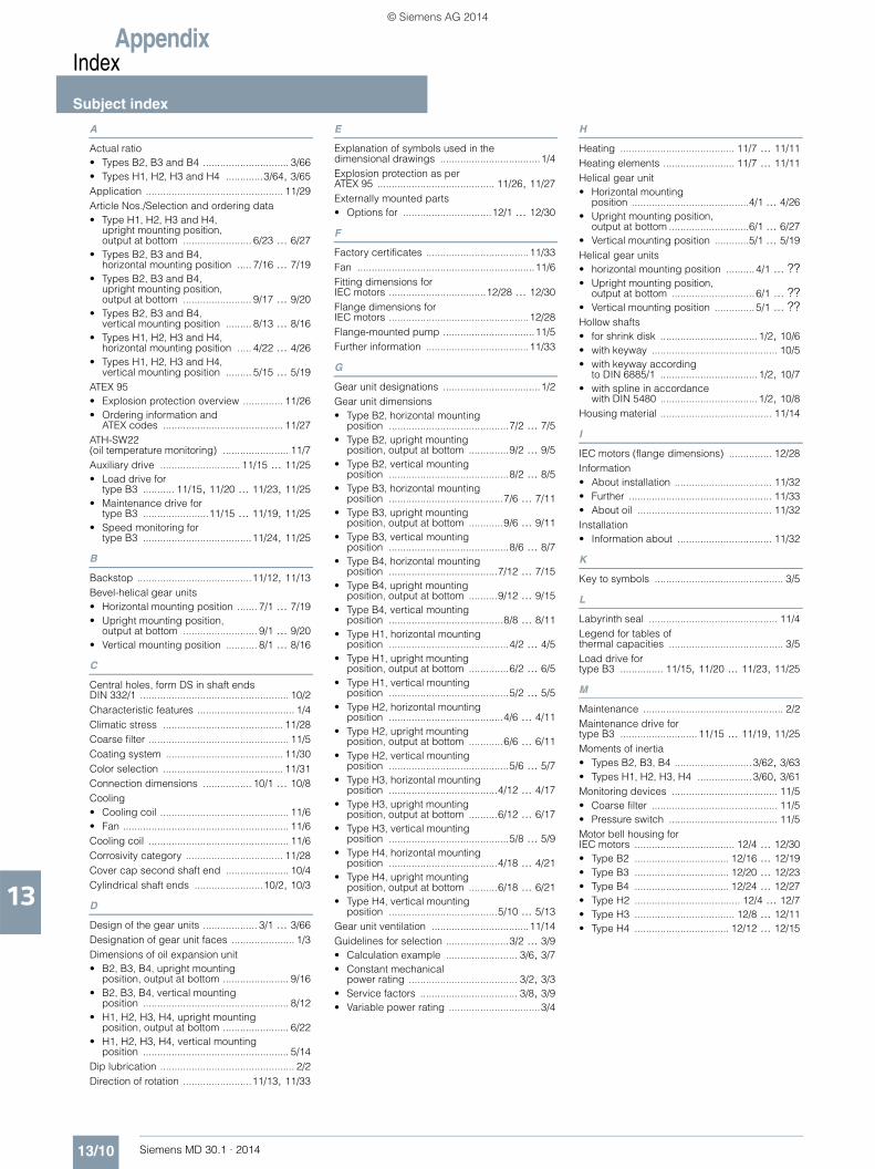
AppendixIndex
Subject index
13/10 Siemens MD 30.1 · 2014
13
A
Actual ratio• Types B2, B3 and B4 .............................. 3/66• Types H1, H2, H3 and H4 .............3/64, 3/65Application ................................................ 11/29Article Nos./Selection and ordering data• Type H1, H2, H3 and H4,
upright mounting position, output at bottom ........................ 6/23 ... 6/27
• Types B2, B3 and B4, horizontal mounting position ..... 7/16 ... 7/19
• Types B2, B3 and B4, upright mounting position, output at bottom ........................ 9/17 ... 9/20
• Types B2, B3 and B4, vertical mounting position ......... 8/13 ... 8/16
• Types H1, H2, H3 and H4, horizontal mounting position ..... 4/22 ... 4/26
• Types H1, H2, H3 and H4, vertical mounting position ......... 5/15 ... 5/19
ATEX 95• Explosion protection overview .............. 11/26• Ordering information and
ATEX codes .......................................... 11/27ATH-SW22 (oil temperature monitoring) ....................... 11/7Auxiliary drive ............................ 11/15 ... 11/25• Load drive for
type B3 ........... 11/15, 11/20 ... 11/23, 11/25• Maintenance drive for
type B3 .......................11/15 ... 11/19, 11/25• Speed monitoring for
type B3 ......................................11/24, 11/25
B
Backstop ........................................11/12, 11/13Bevel-helical gear units• Horizontal mounting position ....... 7/1 ... 7/19• Upright mounting position,
output at bottom .......................... 9/1 ... 9/20• Vertical mounting position ........... 8/1 ... 8/16
C
Central holes, form DS in shaft ends DIN 332/1 .................................................... 10/2Characteristic features .................................. 1/4Climatic stress .......................................... 11/28Coarse filter ................................................. 11/5Coating system ......................................... 11/30Color selection .......................................... 11/31Connection dimensions ................. 10/1 ... 10/8Cooling• Cooling coil ............................................. 11/6• Fan .......................................................... 11/6Cooling coil ................................................. 11/6Corrosivity category .................................. 11/28Cover cap second shaft end ...................... 10/4Cylindrical shaft ends ........................10/2, 10/3
D
Design of the gear units ................... 3/1 ... 3/66Designation of gear unit faces ...................... 1/3Dimensions of oil expansion unit• B2, B3, B4, upright mounting
position, output at bottom ....................... 9/16• B2, B3, B4, vertical mounting
position ................................................... 8/12• H1, H2, H3, H4, upright mounting
position, output at bottom ....................... 6/22• H1, H2, H3, H4, vertical mounting
position ................................................... 5/14Dip lubrication ............................................... 2/2Direction of rotation ........................11/13, 11/33
E
Explanation of symbols used in the dimensional drawings ...................................1/4Explosion protection as per ATEX 95 ......................................... 11/26, 11/27Externally mounted parts• Options for ...............................12/1 ... 12/30
F
Factory certificates ....................................11/33Fan ..............................................................11/6Fitting dimensions for IEC motors ..................................12/28 ... 12/30Flange dimensions for IEC motors .................................................12/28Flange-mounted pump ................................11/5Further information ....................................11/33
G
Gear unit designations ..................................1/2Gear unit dimensions• Type B2, horizontal mounting
position ..........................................7/2 ... 7/5• Type B2, upright mounting
position, output at bottom ..............9/2 ... 9/5• Type B2, vertical mounting
position ..........................................8/2 ... 8/5• Type B3, horizontal mounting
position ........................................7/6 ... 7/11• Type B3, upright mounting
position, output at bottom ............9/6 ... 9/11• Type B3, vertical mounting
position ..........................................8/6 ... 8/7• Type B4, horizontal mounting
position ......................................7/12 ... 7/15• Type B4, upright mounting
position, output at bottom ..........9/12 ... 9/15• Type B4, vertical mounting
position ........................................8/8 ... 8/11• Type H1, horizontal mounting
position ..........................................4/2 ... 4/5• Type H1, upright mounting
position, output at bottom ..............6/2 ... 6/5• Type H1, vertical mounting
position ..........................................5/2 ... 5/5• Type H2, horizontal mounting
position ........................................4/6 ... 4/11• Type H2, upright mounting
position, output at bottom ............6/6 ... 6/11• Type H2, vertical mounting
position ..........................................5/6 ... 5/7• Type H3, horizontal mounting
position ......................................4/12 ... 4/17• Type H3, upright mounting
position, output at bottom ..........6/12 ... 6/17• Type H3, vertical mounting
position ..........................................5/8 ... 5/9• Type H4, horizontal mounting
position ......................................4/18 ... 4/21• Type H4, upright mounting
position, output at bottom ..........6/18 ... 6/21• Type H4, vertical mounting
position ......................................5/10 ... 5/13Gear unit ventilation ..................................11/14Guidelines for selection ......................3/2 ... 3/9• Calculation example ......................... 3/6, 3/7• Constant mechanical
power rating ...................................... 3/2, 3/3• Service factors .................................. 3/8, 3/9• Variable power rating ................................3/4
H
Heating ........................................ 11/7 ... 11/11Heating elements ......................... 11/7 ... 11/11Helical gear unit• Horizontal mounting
position .........................................4/1 ... 4/26• Upright mounting position,
output at bottom ............................6/1 ... 6/27• Vertical mounting position ............5/1 ... 5/19Helical gear units• horizontal mounting position .......... 4/1 ... ??• Upright mounting position,
output at bottom ............................. 6/1 ... ??• Vertical mounting position .............. 5/1 ... ??Hollow shafts• for shrink disk .................................. 1/2, 10/6• with keyway ............................................ 10/5• with keyway according
to DIN 6885/1 .................................. 1/2, 10/7• with spline in accordance
with DIN 5480 .................................. 1/2, 10/8Housing material ....................................... 11/14
I
IEC motors (flange dimensions) ............... 12/28Information• About installation .................................. 11/32• Further .................................................. 11/33• About oil ............................................... 11/32Installation• Information about ................................. 11/32
K
Key to symbols ............................................. 3/5
L
Labyrinth seal ............................................. 11/4Legend for tables of thermal capacities ........................................ 3/5Load drive for type B3 ............... 11/15, 11/20 ... 11/23, 11/25
M
Maintenance ................................................. 2/2Maintenance drive for type B3 ...........................11/15 ... 11/19, 11/25Moments of inertia• Types B2, B3, B4 ........................... 3/62, 3/63• Types H1, H2, H3, H4 ................... 3/60, 3/61Monitoring devices ..................................... 11/5• Coarse filter ............................................ 11/5• Pressure switch ...................................... 11/5Motor bell housing for IEC motors ................................... 12/4 ... 12/30• Type B2 ................................. 12/16 ... 12/19• Type B3 ................................. 12/20 ... 12/23• Type B4 ................................. 12/24 ... 12/27• Type H2 ..................................... 12/4 ... 12/7• Type H3 ................................... 12/8 ... 12/11• Type H4 ................................. 12/12 ... 12/15
© Siemens AG 2014

AppendixIndex
Subject index
13/11Siemens MD 30.1 · 2014
13
N
N-EUPEX coupling• Type B2 ................................. 12/16 ... 12/19• Type B3 ................................. 12/20 ... 12/23• Type B4 ................................. 12/24 ... 12/27• Type H2 ..................................... 12/4 ... 12/7• Type H3 ................................... 12/8 ... 12/11• Type H4 ................................. 12/12 ... 12/15Nominal output torques• Type B2 .........................................3/40, 3/41• Type B3 .................................................. 3/51• Type B4 .................................................. 3/57• Type H1 .........................................3/12, 3/13• Type H2 .................................................. 3/23• Type H3 .................................................. 3/29• Type H4 .................................................. 3/35Nominal power ratings• Type B2 .........................................3/38, 3/39• Type B3 .................................................. 3/50• Type B4 .................................................. 3/56• Type H1 .........................................3/10, 3/11• Type H2 .................................................. 3/22• Type H3 .................................................. 3/28• Type H4 .................................................. 3/34Notes and legend for tables of thermal capacities ........................................ 3/5Notes on selection and operation ................. 1/4
O
Oil• Information about ..................................11/32Oil circulation lubrication ..................... 2/2, 11/5Oil drain valve ...........................................11/14Oil expansion unit – Dimensions• B2, B3, B4, upright mounting
position output at bottom ........................9/16• B2, B3, B4, vertical mounting
position ....................................................8/12• H1, H2, H3, H4, upright mounting
position output at bottom ........................6/22• H1, H2, H3, H4, vertical mounting
position ....................................................5/14Oil level indicator .......................................11/14Oil temperature indicator Pt100• Pt100 resistance thermometer ................11/7• Pt100 resistance thermometer
with transmitter ........................................11/7• Resistance thermometer Pt100
in ATEX design ........................................11/7Oil temperature monitoring ATH-SW22 ...................................................11/7Options• for externally mounted parts ....12/1 ... 12/30• for operation .............................11/1 ... 11/34Orientation in space ......................................1/3
P
Parallel keys ................................................10/5Parallel keyways ..........................................10/5Preservation ..................................................2/2Pressure switch ...........................................11/5Pt100 resistance thermometer ....................11/7• ATEX design ...........................................11/7• with transmitter ........................................11/7
R
Radial shaft seal ..........................................11/2
S
Selection of fit ............................................. 10/3Selection of oil .............................................. 2/2Shaft misalignment ....................................... 2/2Shaft seals ..................................... 11/2 ... 11/4• Labyrinth seal ......................................... 11/4• Radial shaft seal ..................................... 11/2• Taconite .................................................. 11/2Solid shaft ..................................................... 1/2Speed monitoring for type B3 ........ 11/24, 11/25Spline in accordance with DIN 5480 ..................................................... 10/8Stress• Climatic ................................................ 11/28Summary of basic types• Mounting positions ............................ 1/2, 1/3• Structure of gear unit size ........................ 1/2• Structure of types ..................................... 1/2Symbols• Explanation of ........................................... 3/5Symbols in the dimensional drawings• Explanation ............................................... 1/4
T
Taconite ...................................................... 11/2Technical information .................................... 2/2Thermal capacities• Notes and legend for tables ..................... 3/5• Type B2 ..................................... 3/42 ... 3/49• Type B3 ..................................... 3/52 ... 3/55• Type B4 ..................................... 3/58 ... 3/59• Type H1 ..................................... 3/14 ... 3/21• Type H2 ..................................... 3/24 ... 3/27• Type H3 ..................................... 3/30 ... 3/33• Type H4 ..................................... 3/36 ... 3/37Torque arm• Vibration reducing ......................... 12/2, 12/3Type plate ................................................. 11/34
V
Vibration reducing torque reaction arm ....................................... 12/2, 12/3
© Siemens AG 2014

AppendixIndex
Overview of order codes
13/12 Siemens MD 30.1 · 2014
13
■ Overview Order code
Preservation
A00 Preservation application: Wastewater treatment, sewage treatment plant
A01 Preservation application: Excavators and bucket wheel excavators
A02 Preservation application: Chemical industry
A03 Preservation application: Metal working mills
A04 Preservation application: Conveyors
A06 Preservation application: Cranes, general
A07 Preservation application: Cranes, harbor cranes, standard
A09 Preservation application: Cooling tower drive, standard
A10 Preservation application: Sugar production
A11 Preservation application: Paper production, printing presses
A12 Preservation application: Paper production, drying drum drives
A13 Preservation application: Cableways
A14 Preservation application: Building materials production, general
A15 Preservation application: Building materials production, cement industry
A16 Preservation application: Building materials production, brickworks
A17 Preservation application: Transport of persons, elevators, escalators
A18 Preservation application: Mining machinery
A19 Preservation application: Woodworking machines
A20 Preservation application: General mechanical engineering
A21 Preservation application: Food processing industry, general
A22 Preservation application: Food processing industry, mixer drives
A23 Preservation application: Food processing industry, drum dryer drives
A24 Preservation application: Food processing industry, cooking appliance drives
A25 Preservation application: Food processing industry, toaster drives
A26 Preservation application: Shipbuilding and offshore machinery
A27 Preservation application: Prime movers, general
A28 Preservation application: Prime movers, water turbines
A31 Preservation application: Casting machines
A32 Preservation application: Artificial fertilizer and potash works
A33 Preservation application: Lauter tub drives, standard
A34 Preservation application: Agitator drives, standard
A45 Preservation application: Oil pump drives
A46 Preservation application: Compressor drives
A47 Preservation application: Palm oil presses
A48 Preservation application: Preheater drives
A49 Preservation application: Centrifuge drives
A50 Preservation application: Cooling drum drives
A51 Preservation application: Calander drives
A52 Preservation application: Kneader drives
A53 Preservation application: Mill drives, standard
B01 Climatic stress: Moderate climate zones, Central European conditions
B02 Climatic stress: Marine climate, maritime coastal areas, maritime transport, subtropical, tropical
B03 Climatic stress: Corrosive, chemical atmosphere, aggressive environmental conditions
B41 Coating system: Standard, with top coat
B42 Coating system: Standard, without top coat
B43 Coating system: Standard, with top coat
B44 Coating system: Standard, with top coat, high resistance to chemicals
B73 Coating system: Standard, with top coat, for "ATEX IIC" conditions
B75 Coating system: Standard, with top coat, high resistance to chemicals, for "ATEX IIC" conditions
B85 Coating system: Electrostatically conductive, with top coat, for "ATEX IIC" conditions (fulfills corrosivity category C3 in accordance with EN ISO 12944-2)
B86 Coating system: Electrostatically conductive, with top coat, for "ATEX IIC" conditions (fulfills corrosivity category C4 in accordance with EN ISO 12944-2)
B87 Coating system: Electrostatically conductive, with top coat, high resistance to chemicals, for "ATEX IIC" conditions (fulfills corrosivity category C5 in accordance with EN ISO 12944-2)
C00 RAL 5015 sky blue
C01 RAL 5009 azure blue
C02 RAL 5010 gentian blue
C06 RAL 6011 reseda green
C07 RAL 7031 blue gray
C08 RAL 7035 light gray
C10 RAL 9005 jet black
C11 RAL 7030 stone gray
C12 RAL 7016 anthracite gray
C13 RAL 7011 steel gray
Acceptance
D97 Additional test report to EN 10204-2.2
Installation conditions
G10 Cover cap at shaft d1, mounted on gear unit face 6 (left)
G11 Cover cap at shaft d1, mounted on gear unit face 3 (right)
G20 Cover cap at shaft d2, mounted on gear unit face 6 (left)
G21 Cover cap at shaft d2, mounted on gear unit face 3 (right)
G30 Installation: Altitude up to 1,000 m
G31 Installation: Altitude 1,001 m to 2,000 m
G32 Installation: Altitude 2,001 m to 3,000 m
G33 Installation: Altitude 3,001 m to 4,000 m
G34 Installation: Altitude 4,001 m to 5,000 m
G35 Installation location: Small, enclosed rooms
G36 Installation location: Large rooms, halls
G37 Installation location: Outdoors
Information about oil
H00 Intended for mineral oil (oil not included in scope of supply)
H01 Intended for polyglycol-based synthetic oil (PG oil, oil not included in scope of supply)
H02 Intended for poly-alpha-olefin-based synthetic oil (PAO oil, oil not included in scope of supply)
H03 Intended for poly-alpha-olefin-based synthetic oil, suitable for ambient temperatures in excess of -35 degrees (PAO oil, oil not included in scope of supply)
H10 Oil viscosity ISO VG 460
H11 Oil viscosity ISO VG 320
H12 Oil viscosity ISO VG 220
Order code
© Siemens AG 2014

AppendixIndex
Overview of order codes
13/13Siemens MD 30.1 · 2014
13
Oil monitoring
H40 Oil temperature measurement by Pt100 resistance thermometer
H42 Oil temperature measurement by Pt100 resistance thermometer with transmitter
H43 Oil temperature monitoring with ATH-SW22
H44 Oil temperature measurement by Pt100 resistance thermometer in ATEX design (Categories 2+3)
H51 Oil sight glass
H52 Oil level indicator FSA127
Heating element
J00 1 screw-in heater (standard design) IP65, 230V, 50Hz, cable entry point as selected by supplier, mounted on gear unit face 4
J01 2 screw-in heaters (standard design) IP65, 230V, 50Hz, cable entry point as selected by supplier, mounted on gear unit face 4
J02 1 screw-in heater (standard design) IP65, 230V, 50Hz, cable entry point as selected by supplier, mounted on gear unit face 1
J03 2 screw-in heaters (standard design) IP65, 230V, 50Hz, cable entry point as selected by supplier, mounted on gear unit face 1
J04 1 screw-in heater in each case on gear unit faces 1 and 4 (standard design) IP65, 230V, 50Hz, cable entry point as selected by supplier
J05 1 screw-in heater (ATEX design, Categories 2 +3) 230V, 50Hz, cable entry point as selected by supplier, mounted on gear unit face 4
J06 2 screw-in heater (ATEX design, Categories 2 +3) 230V, 50Hz, cable entry point as selected by supplier, mounted on gear unit face 4
J07 1 screw-in heater (ATEX design, Categories 2 +3) 230V, 50Hz, cable entry point as selected by supplier, mounted on gear unit face 1
J08 2 screw-in heaters (ATEX design, Categories 2 +3) 230V, 50Hz, cable entry point as selected by supplier, mounted on gear unit face 1
J09 1 screw-in heater in each case on gear unit faces 1 and 4 (ATEX design, Categories 2+3) 230V, 50Hz, cable entry point as selected by supplier
Mechanical externally mounted parts / gear unit design
K00 Vibration reducing torque reaction arm for gear unit housing
K22 Gear unit housing made of steel, welded
K24 Cover caps / fan guards in same color as gear unit
K27 Stainless-steel set of labels
K30 "Gear unit in mounting position "H": Oil drain valve on gear unit face 4, straight design
Gear unit in mounting position "V": Oil drain valve on gear unit face 4, straight design
Gear unit in mounting position "L": Oil drain valve on gear unit face 2, straight design
K32 "Gear unit in mounting position "H": Oil drain valve on gear unit face 4, angled relative to face 6
Gear unit in mounting position "V": Oil drain valve on gear unit face 4, angled relative to face 5
Gear unit in mounting position "L": Oil drain valve on gear unit face 2, angled relative to face 6
K33 "Gear unit in mounting position "H": Oil drain valve on gear unit face 4, angled relative to face 3
Gear unit in mounting position "V": Oil drain valve on gear unit face 4, angled relative to face 2
Gear unit in mounting position "L": Oil drain valve on gear unit face 2, angled relative to face 3
Order code
K34 Gear unit in mounting position "H": Oil drain valve on gear unit face 1, straight design
K35 Gear unit in mounting position "H": Oil drain valve on gear unit face 1, angled relative to face 6
K36 Gear unit in mounting position "H": Oil drain valve on gear unit face 1, angled relative to face 3
K37 Screw plug with permanent magnet in addition to oil drain valve
K71 MANN air filter (with filling sieve)
K72 MANN air filter in encapsulated design (for dust-laden environments and risk of unit become completely covered)
K73 Wet air filter
K74 Breather filter (HYDAC)
L00 Standard backstop, clockwise
L01 Standard backstop, counter-clockwise
L02 Standard backstop, prepared for mounting
L90 Shaft D2 clockwise
L93 Shaft D2 counter-clockwise
L94 Direction of rotation of shaft d2 with view on right stud (d2 shaft at both ends)
L95 Direction of rotation of shaft d2 with view on left stud (d2 shaft at both ends)
L96 Direction of rotation of shaft d2 with view on lower stud (d2 shaft at both ends, vertical mounting position)
L97 Direction of rotation of shaft d2 with view on upper stud (d2 shaft at both ends, vertical mounting position)
Specifications for mounting an auxiliary drive
M00 Auxiliary drive mounted as load drive
M01 Auxiliary drive mounted as maintenance drive
M02 Auxiliary drive prepared for mounting as load drive
M03 Auxiliary drive prepared for mounting as maintenance drive
M60 Auxiliary drive mounting: Single drive (standard)
M70 Auxiliary drive mounting: Mounting position: M4 (vertical, standard)
M71 Auxiliary drive mounting: Mounting position: M1 (horizontal)
M80 Auxiliary drive mounting: Speed monitoring device: Pulse generator
M81 Auxiliary drive mounting: Speed monitoring device: EWD
M82 Auxiliary drive mounting: Speed monitoring device: by customer, M18x1
M83 Auxiliary drive mounting: Provided by the customer with connection thread M18 x 1
M84 Auxiliary drive mounting: Provided by the customer with other connection thread
Specifications for mounting a motor bell housing
P00 Mounting of motor bell housing for IEC motor 100L 4-pole/6-pole, coupling N-EUPEX B080
P01 Mounting of motor bell housing for IEC motor 112M 4-pole/6-pole, coupling N-EUPEX B080
P02 Mounting of motor bell housing for IEC motor 132S 4-pole/6-pole, coupling N-EUPEX B080
P03 Mounting of motor bell housing for IEC motor 132S 4-pole/6-pole, coupling N-EUPEX B095
P04 Mounting of motor bell housing for IEC motor 132M 4-pole/6-pole, coupling N-EUPEX B095
P05 Mounting of motor bell housing for IEC motor 160M 4-pole/6-pole, coupling N-EUPEX B095
P06 Mounting of motor bell housing for IEC motor 160M 4-pole/6-pole, coupling N-EUPEX B110
P07 Mounting of motor bell housing for IEC motor 160M 4-pole/6-pole, coupling N-EUPEX B125
Order code
© Siemens AG 2014

AppendixIndex
Overview of order codes
13/14 Siemens MD 30.1 · 2014
13
P08 Mounting of motor bell housing for IEC 160L motor 4-pole/6-pole, coupling N-EUPEX B110
P09 Mounting of motor bell housing for IEC motor 160L 4-pole/6-pole, coupling N-EUPEX B125
P10 Mounting of motor bell housing for IEC motor 180M 4-pole/6-pole, coupling N-EUPEX B110
P11 Mounting of motor bell housing for IEC motor 180M 4-pole/6-pole, coupling N-EUPEX B125
P12 Mounting of motor bell housing for IEC motor 180L 4-pole/6-pole, coupling N-EUPEX B125
P13 Mounting of motor bell housing for IEC motor 200L 4-pole/6-pole, coupling N-EUPEX B140
P14 Mounting of motor bell housing for IEC motor 225S 4-pole/6-pole, coupling N-EUPEX B140
P15 Mounting of motor bell housing for IEC motor 225S 4-pole/6-pole, coupling N-EUPEX B180
P16 Mounting of motor bell housing for IEC motor 225M 4-pole/6-pole, coupling N-EUPEX B140
P17 Mounting of motor bell housing for IEC motor 225M 4-pole/6-pole, coupling N-EUPEX B180
P18 Mounting of motor bell housing for IEC motor 250M 4-pole/6-pole, coupling N-EUPEX B160
P19 Mounting of motor bell housing for IEC motor 250M 4-pole/6-pole, coupling N-EUPEX B180
P20 Mounting of motor bell housing for IEC motor 280S 4-pole/6-pole, coupling N-EUPEX B180
P21 Mounting of motor bell housing for IEC motor 280M 4-pole/6-pole, coupling N-EUPEX B180
P22 Mounting of motor bell housing for IEC motor 315S 4-pole/6-pole, coupling N-EUPEX B200
P23 Mounting of motor bell housing for IEC motor 315M 4-pole/6-pole, coupling N-EUPEX B200
P24 Mounting of motor bell housing for IEC motor 315L-160 4-pole/6-pole, coupling N-EUPEX B200
P25 Mounting of motor bell housing for IEC motor 315L-200 4-pole/6-pole, coupling N-EUPEX B225
P26 Mounting of motor bell housing for IEC motor 100L 4-pole/6-pole, coupling N-Eupex B68
P27 Mounting of motor bell housing for IEC motor 100L 4-pole/6-pole, coupling N-Eupex B95
P28 Mounting of motor bell housing for IEC motor 100L 4-pole/6-pole, coupling N-Eupex B110
P29 Mounting of motor bell housing for IEC motor 112M 4-pole/6-pole, coupling N-Eupex B95
P30 Mounting of motor bell housing for IEC motor 112M 4-pole/6-pole, coupling N-Eupex B110
P31 Mounting of motor bell housing for IEC motor 132M 4-pole/6-pole, coupling N-Eupex B80
P32 Mounting of motor bell housing for IEC motor 132S 4-pole/6-pole, coupling N-Eupex B110
P33 Mounting of motor bell housing for IEC motor 132S 4-pole/6-pole, coupling N-Eupex B125
P34 Mounting of motor bell housing for IEC motor 132S 4-pole/6-pole, coupling N-Eupex B140
P35 Mounting of motor bell housing for IEC motor 132M 4-pole/6-pole, coupling N-Eupex B110
P36 Mounting of motor bell housing for IEC motor 132M 4-pole/6-pole, coupling N-Eupex B125
P37 Mounting of motor bell housing for IEC motor 132M 4-pole/6-pole, coupling N-Eupex B140
P38 Mounting of motor bell housing for IEC motor 160M 4-pole/6-pole, couplingN-Eupex B140
P39 Mounting of motor bell housing for IEC motor 160L 4-pole/6-pole, coupling N-Eupex B95
Order code
P40 Mounting of motor bell housing for IEC motor 160L 4-pole/6-pole, coupling N-Eupex B140
P41 Mounting of motor bell housing for IEC motor 180M 4-pole/6-pole, coupling N-Eupex B140
P42 Mounting of motor bell housing for IEC motor 180M 4-pole/6-pole, coupling N-Eupex B160
P43 Mounting of motor bell housing for IEC motor 180L 4-pole/6-pole, coupling N-Eupex B140
P44 Mounting of motor bell housing for IEC motor 180L 4-pole/6-pole, coupling N-Eupex B160
P45 Mounting of motor bell housing for IEC motor 200L 4-pole/6-pole, coupling N-Eupex B125
P46 Mounting of motor bell housing for IEC motor 200L 4-pole/6-pole, coupling N-Eupex B160
P47 Mounting of motor bell housing for IEC motor 225S 4-pole/6-pole, coupling N-Eupex B160
P48 Mounting of motor bell housing for IEC motor 225S 4-pole/6-pole, coupling N-Eupex B200
P49 Mounting of motor bell housing for IEC motor 225S 4-pole/6-pole, coupling N-Eupex B225
P50 Mounting of motor bell housing for IEC motor 225M 4-pole/6-pole, coupling N-Eupex B160
P51 Mounting of motor bell housing for IEC motor 225M 4-pole/6-pole, coupling N-Eupex B200
P52 Mounting of motor bell housing for IEC motor 225M 4-pole/6-pole, coupling N-Eupex B225
P53 Mounting of motor bell housing for IEC motor 250M 4-pole/6-pole, coupling N-Eupex B200
P54 Mounting of motor bell housing for IEC motor 250M 4-pole/6-pole, coupling N-Eupex B225
P55 Mounting of motor bell housing for IEC motor 280S 4-pole/6-pole, coupling N-Eupex B200
P56 Mounting of motor bell housing for IEC motor 280S 4-pole/6-pole, coupling N-Eupex B225
P57 Mounting of motor bell housing for IEC motor 280M 4-pole/6-pole, coupling N-Eupex B200
P58 Mounting of motor bell housing for IEC motor 280M 4-pole/6-pole, coupling N-Eupex B225
P59 Mounting of motor bell housing for IEC motor 315S 4-pole/6-pole, coupling N-Eupex B225
P60 Mounting of motor bell housing for IEC motor 315S 4-pole/6-pole, coupling N-Eupex B250
P61 Mounting of motor bell housing for IEC motor 315M 4-pole/6-pole, coupling N-Eupex B225
P62 Mounting of motor bell housing for IEC motor 315M 4-pole/6-pole, coupling N-Eupex B250
P63 Mounting of motor bell housing for IEC motor 315L_160 4-pole/6-pole, coupling N-EUPEX B225
P64 Mounting of motor bell housing for IEC motor 315L_160 4-pole/6-pole, coupling N-EUPEX B250
P65 Mounting of motor bell housing for IEC motor 315L_200 4-pole/6-pole, coupling N-EUPEX B250
P66 Mounting of motor bell housing for IEC motor 180L 4-pole/6-pole, coupling N-Eupex B110
P67 Mounting of motor bell housing for IEC motor 315L_250 4-pole/6-pole, coupling N-EUPEX B225
P68 Mounting of motor bell housing for IEC motor 315L_250 4-pole/6-pole, coupling N-EUPEX B250
P69 Mounting of motor bell housing for IEC motor 315L_315 4-pole/6-pole, coupling N-EUPEX B250
P80 Mounting of motor bell housing: Mounting flexible coupling piece
P81 Mounting of motor bell housing: Mounting flexible coupling and IEC motor 100
Order code
© Siemens AG 2014

AppendixIndex
Overview of order codes
13/15Siemens MD 30.1 · 2014
13
P82 Mounting of motor bell housing: Mounting flexible coupling and IEC motor 112
P83 Mounting of motor bell housing: Mounting flexible coupling and IEC motor 132
P84 Mounting of motor bell housing: Mounting flexible coupling and IEC motor 160
P85 Mounting of motor bell housing: Mounting flexible coupling and IEC motor 180
P86 Mounting of motor bell housing: Mounting flexible coupling and IEC motor 200
P87 Mounting of motor bell housing: Mounting flexible coupling and IEC motor 225
P88 Mounting of motor bell housing: Mounting flexible coupling and IEC motor 250
P89 Mounting of motor bell housing: Mounting flexible coupling and IEC motor 280
P90 Mounting of motor bell housing: Mounting flexible coupling and IEC motor 315
P95 Mounting of motor bell housing at gear unit face 6
P96 Mounting of motor bell housing at gear unit face 3
Gear units in ATEX design
X30 Gear unit in ATEX design, suitable for above-ground applications, Zone 21/1 (category 2 (high protection), explosive atmosphere gas/mist/vapor and dust), temperature class T4, explosion subgroup IIB, minimum ignition energy >3mJ, type of protection bck
X31 Gear unit in ATEX design, suitable for above-ground applications, Zone 22/2 (category 3 (normal protection), explosive atmosphere gas/mist/vapor and dust), temperature class T4, explosion subgroup IIB, minimum ignition energy >3mJ, type of protection ck
X32 Gear unit in ATEX design, suitable for above-ground applications, Zone 21/1 (category 2 (high protection), explosive atmosphere gas/mist/vapor and dust), temperature class T4, explosion subgroup IIC, minimum ignition energy ≤ 3mJ, type of protection bck
X33 Gear unit in ATEX design, suitable for above-ground applications, Zone 22/2 (category 3 (normal protection), explosive atmosphere gas/mist/vapor and dust), temperature class T4, explosion subgroup IIC, minimum ignition energy ≤3mJ, type of protection ck
X34 Gear unit in ATEX design, suitable for above-ground applications, Zone 21 (category 2 (high protection), explosive atmosphere dust), minimum ignition energy >3mJ, type of protection bck
X35 Gear unit in ATEX design, suitable for above-ground applications, Zone 21 (category 2 (high protection), explosive atmosphere dust), minimum ignition energy ≤3mJ, type of protection bck
X36 Gear unit in ATEX design, suitable for above-ground applications, Zone 22 (category 3 (normal protection), explosive atmosphere dust), minimum ignition energy >3mJ, type of protection ck
X37 Gear unit in ATEX design, suitable for above-ground applications, Zone 22 (category 3 (normal protection), explosive atmosphere dust), minimum ignition energy ≤3mJ, type of protection ck
X38 Gear unit in ATEX design, suitable for above-ground applications, Zone 1 (category 2 (high protection), explosive atmosphere gas/mist/vapor), temperature class T1, explosion subgroup IIA, type of protection bck
X39 Gear unit in ATEX design, suitable for above-ground applications, Zone 1 (category 2 (high protection), explosive atmosphere gas/mist/vapor), temperature class T2, explosion subgroup IIA, type of protection bck
X40 Gear unit in ATEX design, suitable for above-ground applications, Zone 1 (category 2 (high protection), explosive atmosphere gas/mist/vapor), temperature class T3, explosion subgroup IIA, type of protection bck
Order code
X41 Gear unit in ATEX design, suitable for above-ground applications, Zone 1 (category 2 (high protection), explosive atmosphere gas/mist/vapor), temperature class T4, explosion subgroup IIA, type of protection bck
X42 Gear unit in ATEX design, suitable for above-ground applications, Zone 1 (category 2 (high protection), explosive atmosphere gas/mist/vapor), temperature class T1, explosion subgroup IIB, type of protection bck
X43 Gear unit in ATEX design, suitable for above-ground applications, Zone 1 (category 2 (high protection), explosive atmosphere gas/mist/vapor), temperature class T2, explosion subgroup IIB, type of protection bck
X44 Gear unit in ATEX design, suitable for above-ground applications, Zone 1 (category 2 (high protection), explosive atmosphere gas/mist/vapor), temperature class T3, explosion subgroup IIB, type of protection bck
X45 Gear unit in ATEX design, suitable for above-ground applications, Zone 1 (category 2 (high protection), explosive atmosphere gas/mist/vapor), temperature class T4, explosion subgroup IIB, type of protection bck
X46 Gear unit in ATEX design, suitable for above-ground applications, Zone 1 (category 2 (high protection), explosive atmosphere gas/mist/vapor), temperature class T1, explosion subgroup IIC, type of protection bck
X47 Gear unit in ATEX design, suitable for above-ground applications, Zone 1 (category 2 (high protection), explosive atmosphere gas/mist/vapor), temperature class T2, explosion subgroup IIC, type of protection bck
X48 Gear unit in ATEX design, suitable for above-ground applications, Zone 1 (category 2 (high protection), explosive atmosphere gas/mist/vapor), temperature class T3, explosion subgroup IIC, type of protection bck
X49 Gear unit in ATEX design, suitable for above-ground applications, Zone 1 (category 2 (high protection), explosive atmosphere gas/mist/vapor), temperature class T4, explosion subgroup IIC, type of protection bck
X50 Gear unit in ATEX design, suitable for above-ground applications, Zone 2 (category 3 (normal protection), explosive atmosphere gas/mist/vapor), temperature class T1, explosion subgroup IIA, type of protection ck
X51 Gear unit in ATEX design, suitable for above-ground applications, Zone 2 (category 3 (normal protection), explosive atmosphere gas/mist/vapor), temperature class T2, explosion subgroup IIA, type of protection ck
X52 Gear unit in ATEX design, suitable for above-ground applications, Zone 2 (category 3 (normal protection), explosive atmosphere gas/mist/vapor), temperature class T3, explosion subgroup IIA, type of protection ck
X53 Gear unit in ATEX design, suitable for above-ground applications, Zone 2 (category 3 (normal protection), explosive atmosphere gas/mist/vapor), temperature class T4, explosion subgroup IIA, type of protection ck
X54 Gear unit in ATEX design, suitable for above-ground applications, Zone 2 (category 3 (normal protection), explosive atmosphere gas/mist/vapor), temperature class T1, explosion subgroup IIB, type of protection ck
X55 Gear unit in ATEX design, suitable for above-ground applications, Zone 2 (category 3 (normal protection), explosive atmosphere gas/mist/vapor), temperature class T2, explosion subgroup IIB, type of protection ck
X56 Gear unit in ATEX design, suitable for above-ground applications, Zone 2 (category 3 (normal protection), explosive atmosphere gas/mist/vapor), temperature class T3, explosion subgroup IIB, type of protection ck
X57 Gear unit in ATEX design, suitable for above-ground applications, Zone 2 (category 3 (normal protection), explosive atmosphere gas/mist/vapor), temperature class T4, explosion subgroup IIB, type of protection ck
X58 Gear unit in ATEX design, suitable for above-ground applications, Zone 2 (category 3 (normal protection), explosive atmosphere gas/mist/vapor), temperature class T1, explosion subgroup IIC, type of protection ck
Order code
© Siemens AG 2014

AppendixIndex
Overview of order codes
13/16 Siemens MD 30.1 · 2014
13
X59 Gear unit in ATEX design, suitable for above-ground applications, Zone 2 (category 3 (normal protection), explosive atmosphere gas/mist/vapor), temperature class T2, explosion subgroup IIC, type of protection ck
X60 Gear unit in ATEX design, suitable for above-ground applications, Zone 2 (category 3 (normal protection), explosive atmosphere gas/mist/vapor), temperature class T3, explosion subgroup IIC, type of protection ck
X61 Gear unit in ATEX design, suitable for above-ground applications, Zone 2 (category 3 (normal protection), explosive atmosphere gas/mist/vapor), temperature class T4, explosion subgroup IIC, type of protection ck
X62 Gear unit in ATEX design, suitable for above-ground applications, Zone 21/1 (category 2 (high protection), explosive atmosphere gas/mist/vapor and dust), temperature class T1, explosion subgroup IIA, minimum ignition energy >3mJ, type of protection bck
X63 Gear unit in ATEX design, suitable for above-ground applications, Zone 21/1 (category 2 (high protection), explosive atmosphere gas/mist/vapor and dust), temperature class T2, explosion subgroup IIA, minimum ignition energy >3mJ, type of protection bck
X64 Gear unit in ATEX design, suitable for above-ground applications, Zone 21/1 (category 2 (high protection), explosive atmosphere gas/mist/vapor and dust), temperature class T3, explosion subgroup IIA, minimum ignition energy >3mJ, type of protection bck
X65 Gear unit in ATEX design, suitable for above-ground applications, Zone 21/1 (category 2 (high protection), explosive atmosphere gas/mist/vapor and dust), temperature class T4, explosion subgroup IIA, minimum ignition energy >3mJ, type of protection bck
X66 Gear unit in ATEX design, suitable for above-ground applications, Zone 21/1 (category 2 (high protection), explosive atmosphere gas/mist/vapor and dust), temperature class T1, explosion subgroup IIB, minimum ignition energy >3mJ, type of protection bck
X67 Gear unit in ATEX design, suitable for above-ground applications, Zone 21/1 (category 2 (high protection), explosive atmosphere gas/mist/vapor and dust), temperature class T2, explosion subgroup IIB, minimum ignition energy >3mJ, type of protection bck
X68 Gear unit in ATEX design, suitable for above-ground applications, Zone 21/1 (category 2 (high protection), explosive atmosphere gas/mist/vapor and dust), temperature class T3, explosion subgroup IIB, minimum ignition energy >3mJ, type of protection bck
X69 Gear unit in ATEX design, suitable for above-ground applications, Zone 21/1 (category 2 (high protection), explosive atmosphere gas/mist/vapor and dust), temperature class T1, explosion subgroup IIC, minimum ignition energy ≤ 3mJ, type of protection bck
X70 Gear unit in ATEX design, suitable for above-ground applications, Zone 21/1 (category 2 (high protection), explosive atmosphere gas/mist/vapor and dust), temperature class T2, explosion subgroup IIC, minimum ignition energy ≤ 3mJ, type of protection bck
X71 Gear unit in ATEX design, suitable for above-ground applications, Zone 21/1 (category 2 (high protection), explosive atmosphere gas/mist/vapor and dust), temperature class T3, explosion subgroup IIC, minimum ignition energy ≤ 3mJ, type of protection bck
X72 Gear unit in ATEX design, suitable for above-ground applications, Zone 22/2 (category 3 (normal protection), explosive atmosphere gas/mist/vapor and dust), temperature class T1, explosion subgroup IIA, minimum ignition energy >3mJ, type of protection ck
X73 Gear unit in ATEX design, suitable for above-ground applications, Zone 22/2 (category 3 (normal protection), explosive atmosphere gas/mist/vapor and dust), temperature class T2, explosion subgroup IIA, minimum ignition energy >3mJ, type of protection ck
Order code
X74 Gear unit in ATEX design, suitable for above-ground applications, Zone 22/2 (category 3 (normal protection), explosive atmosphere gas/mist/vapor and dust), temperature class T3, explosion subgroup IIA, minimum ignition energy >3mJ, type of protection ck
X75 Gear unit in ATEX design, suitable for above-ground applications, Zone 22/2 (category 3 (normal protection), explosive atmosphere gas/mist/vapor and dust), temperature class T4, explosion subgroup IIA, minimum ignition energy >3mJ, type of protection ck
X76 Gear unit in ATEX design, suitable for above-ground applications, Zone 22/2 (category 3 (normal protection), explosive atmosphere gas/mist/vapor and dust), temperature class T1, explosion subgroup IIB, minimum ignition energy >3mJ, type of protection ck
X77 Gear unit in ATEX design, suitable for above-ground applications, Zone 22/2 (category 3 (normal protection), explosive atmosphere gas/mist/vapor and dust), temperature class T2, explosion subgroup IIB, minimum ignition energy >3mJ, type of protection ck
X78 Gear unit in ATEX design, suitable for above-ground applications, Zone 22/2 (category 3 (normal protection), explosive atmosphere gas/mist/vapor and dust), temperature class T3, explosion subgroup IIB, minimum ignition energy >3mJ, type of protection ck
X79 Gear unit in ATEX design, suitable for above-ground applications, Zone 22/2 (category 3 (normal protection), explosive atmosphere gas/mist/vapor and dust), temperature class T1, explosion subgroup IIC, minimum ignition energy ≤3mJ, type of protection ck
X80 Gear unit in ATEX design, suitable for above-ground applications, Zone 22/2 (category 3 (normal protection), explosive atmosphere gas/mist/vapor and dust), temperature class T2, explosion subgroup IIC, minimum ignition energy ≤3mJ, type of protection ck
X81 Gear unit in ATEX design, suitable for above-ground applications, Zone 22/2 (category 3 (normal protection), explosive atmosphere gas/mist/vapor and dust), temperature class T3, explosion subgroup IIC, minimum ignition energy ≤3mJ, type of protection ck
Order codes with required plain text
Y00 RAL color of top coat
Y01 Minimum ambient temperature
Y02 Maximum ambient temperature
Y20 Speed n1
Y21 Power rating of driven machine P2 [kW]
Y22 Torque of driven machine T2 [kNm]
Y23 Motor power PM [kW]
Y25 Additional text for type plate
Y99 Additional text available
Order code
© Siemens AG 2014
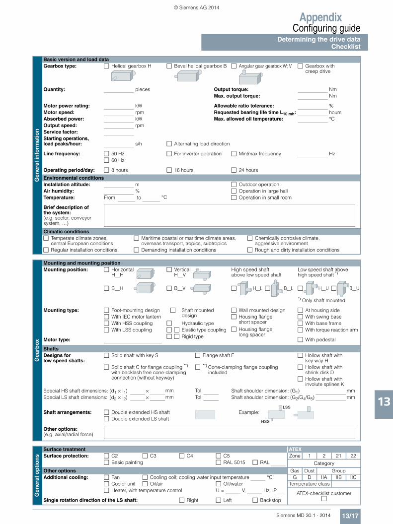
AppendixConfiguring guide
Determining the drive dataChecklist
13/17Siemens MD 30.1 · 2014
13
Gen
eral
info
rmat
ion
Basic version and load dataGearbox type: Helical gearbox H Bevel helical gearbox B Angular gear gearbox W; V Gearbox with
creep drive
Quantity: pieces Output torque: NmMax. output torque: Nm
Motor power rating: kW Allowable ratio tolerance: %Motor speed: rpm Requested bearing life time L10 mh: hoursAbsorbed power: kW Max. allowed oil temperature: °COutput speed: rpmService factor:Starting operations, load peaks/hour: s/h Alternating load direction
Line frequency: 50 Hz For inverter operation Min/max frequency Hz 60 Hz
Operating period/day: 8 hours 16 hours 24 hours
Environmental conditionsInstallation altitude: m Outdoor operationAir humidity: % Operation in large hallTemperature: From Operation in small room
Brief description of the system: (e.g. sector, conveyor system, …)
Climatic conditions Temperate climate zones,
central European conditions Maritime coastal or maritime climate areas,
overseas transport, tropics, subtropics Chemically corrosive climate,
aggressive environment Regular installation conditions Demanding installation conditions Rough and dirty installation conditions
Gea
rbox
Mounting and mounting positionMounting position: Horizontal
H__H Vertical
H__VHigh speed shaft above low speed shaft
Low speed shaft above high speed shaft *)
B__H B__V H__L B__L H__U B__U
*) Only shaft mounted
Mounting type: Foot-mounting design Shaft mounted design
Wall mounted design At housing side With IEC motor lantern Housing flange,
short spacer Housing flange,
long spacer
With swing base With HSS coupling Hydraulic type With base frame With LSS coupling Elastic type coupling
Rigid type With torque reaction arm
Motor type: With pedestal
ShaftsDesigns for low speed shafts:
Solid shaft with key S Flange shaft F Hollow shaft with key way H
Solid shaft C for flange coupling **) with backlash free cone-clamping connection (without keyway)
**) Cone-clamping flange coupling included
Hollow shaft with shrink disk D
Hollow shaft with involute splines K
Special HS shaft dimensions: (d1 × l1) Shaft shoulder dimension: (G1)Special LS shaft dimensions: (d2 × l2) Shaft shoulder dimension: (G2/G4/G5)
Shaft arrangements: Double extended HS shaft Example: Double extended LS shaft
Other options:(e.g. axial/radial force)
Gen
eral
op
tio
ns
Surface treatment ATEXSurface protection: C2 C3 C4 C5 Zone 1 2 21 22
Basic painting RAL 5015 RAL Category
Other options Gas Dust GroupAdditional cooling: Fan Cooling coil; cooling water input temperature °C G D IIA IIB IIC
Cooler unit Oil/air Oil/water Temperature class Heater, with temperature control U = V, Hz, IP ATEX-checklist customer
Single rotation direction of the LS shaft: Right Left Backstop
to °C
× mm Tol. mm× mm Tol. mm
LSS
HSS
© Siemens AG 2014

Appendix
Conditions of sale and delivery
13/18 Siemens MD 30.1 · 2014
13
■ 1. General Provisions
By using this catalog you can acquire hardware and software products described therein from Siemens AG subject to the following Terms and Conditions of Sale and Delivery (hereinafter referred to as "T&C"). Please note that the scope, the quality and the conditions for supplies and services, including software products, by any Siemens entity having a registered office outside Germany, shall be subject exclusively to the General Terms and Conditions of the respective Siemens entity. The following T&C apply exclusively for orders placed with Siemens Aktiengesellschaft, Germany.
1.1 For customers with a seat or registered office in GermanyFor customers with a seat or registered office in Germany, the following applies subordinate to the T&C:• the "General Terms of Payment"1) and,• for software products, the "General License Conditions for
Software Products for Automation and Drives for Customers with a Seat or Registered Office in Germany"1) and,
• for other supplies and services, the "General Conditions for the Supply of Products and Services of the Electrical and Electronics Industry"1).
1.2 For customers with a seat or registered office outside GermanyFor customers with a seat or registered office outside Germany, the following applies subordinate to the T&C:• the "General Terms of Payment"1) and,• for software products, the "General License Conditions for
Software Products for Automation and Drives for Customers with a Seat or Registered Office outside of Germany"1) and
• for other supplies and/or services, the "General Conditions for Supplies of Siemens Industry for Customers with a Seat or Registered Office outside of Germany"1).
■ 2. Prices
The prices are in € (Euro) ex point of delivery, exclusive of packaging.The sales tax (value added tax) is not included in the prices. It shall be charged separately at the respective rate according to the applicable statutory legal regulations.Prices are subject to change without prior notice. We will charget the prices valid at the time of delivery.To compensate for variations in the price of raw materials (e.g. silver, copper, aluminum, lead, gold, dysprosium and neodym), surcharges are calculated on a daily basis using the so-called metal factor for products containing these raw materials. A surcharge for the respective raw material is calculated as a supplement to the price of a product if the basic official price of the raw material in question is exceeded.The metal factor of a product indicates the basic official price (for those raw materials concerned) as of which the surcharges on the price of the product are applied, and with what method of calculation. An exact explanation of the metal factor can be downloaded at:www.siemens.com/automation/salesmaterial-as/catalog/en/ terms_of_trade_en.pdfTo calculate the surcharge (except in the cases of dysprosium and neodym), the official price from the day prior to that on which the order was received or the release order was effected is used.To calculate the surcharge applicable to dysprosium and neodym ("rare earths"), the corresponding three-month basic average price in the quarter prior to that in which the order was received or the release order was effected is used with a one-month buffer (details on the calculation can be found in the explanation of the metal factor).
■ 3. Additional Terms and Conditions
The dimensions are in mm. In Germany, according to the German law on units in measuring technology, data in inches apply only to devices for export.Illustrations are not binding.Insofar as there are no remarks on the individual pages of this catalog - especially with regard to data, dimensions and weights given - these are subject to change without prior notice.
■ 4. Export regulations
We shall not be obligated to fulfill any agreement if such fulfillment is prevented by any impediments arising out of national or international foreign trade or customs requirements or any embargoes and/or other sanctions.Export of goods listed in this catalog may be subject to licensing requirements. We will indicate in the delivery details whether licenses are required under German, European and US export lists. Goods labeled with "AL" not equal to "N" are subject to European or German export authorization when being exported out of the EU. Goods labeled with "ECCN" not equal to "N" are subject to US re-export authorization. The export indications can be viewed in advance in the description of the respective goods on the Industry Mall, our online catalog system. Only the export labels "AL" and "ECCN" indicated on order confirmations, delivery notes and invoices are authoritative.Even without a label, or with label "AL:N" or "ECCN:N", authori-zation may be required i .a. due to the final disposition and intended use of goods.If you transfer goods (hardware and/or software and/or technology as well as corresponding documentation, regardless of the mode of provision) delivered by us or works and services (including all kinds of technical support) performed by us to a third party worldwide, you must comply with all applicable national and international (re-)export control regulations.If required for the purpose of conducting export control checks, you (upon request by us) shall promptly provide us with all infor-mation pertaining to the particular end customer, final dispo-sition and intended use of goods delivered by us respectively works and services provided by us, as well as to any export control restrictions existing in this relation.The products listed in this catalog may be subject to European/German and/or US export regulations. Any export requiring approval is therefore subject to authorization by the relevant authorities.Errors excepted and subject to change without prior notice.
1) The text of the Terms and Conditions of Siemens AG can be downloaded atwww.siemens.com/automation/salesmaterial-as/catalog/en/ terms_of_trade_en.pdf
© Siemens AG 2014

CatalogsIndustry Automation, Drive Technologies and Low-Voltage Power Distribution
Further information can be obtained from our branch officeslisted at www.siemens.com/automation/partner
System Solutions for Industry Interactive Catalog on DVD
Catalog
Products for Automation and Drives, Low-Voltage Power Distribution and Electrical Installation Technology
CA 01
Building ControlGAMMA Building Control ET G1
Drive SystemsSINAMICS G130 Drive Converter Chassis Units SINAMICS G150 Drive Converter Cabinet Units
D 11
SINAMICS GM150, SINAMICS SM150 Medium-Voltage Converters
D 12
SINAMICS PERFECT HARMONY GH180 Medium-Voltage Air-Cooled Drives Germany Edition
D 15.1
SINAMICS G180 Converters – Compact Units, Cabinet Systems, Cabinet Units Air-Cooled and Liquid-Cooled
D 18.1
SINAMICS S120 Chassis Format Units and Cabinet Modules SINAMICS S150 Converter Cabinet Units
D 21.3
SINAMICS DCM DC Converter, Control Module D 23.1SINAMICS DCM Cabinet D 23.2SINAMICS and Motors for Single-Axis Drives D 31SINAMICS G120P and SINAMICS G120P Cabinet pump, fan, compressor converters
D 35
Three-Phase Induction Motors SIMOTICS HV, SIMOTICS TN• Series H-compact• Series H-compact PLUS
D 84.1
Asynchronous Motors Standardline D 86.1Synchronous Motors with Permanent-Magnet Technology, HT-direct
D 86.2
DC Motors DA 12SIMOREG DC MASTER 6RA70 Digital Chassis Converters
DA 21.1
SIMOREG K 6RA22 Analog Chassis Converters DA 21.2Digital: SIMOREG DC MASTER 6RM70 Digital
Converter Cabinet UnitsDA 22
SIMOVERT PM Modular Converter Systems DA 45SIEMOSYN Motors DA 48MICROMASTER 420/430/440 Inverters DA 51.2MICROMASTER 411/COMBIMASTER 411 DA 51.3SIMODRIVE 611 universal and POSMO DA 65.4
Note: Additional catalogs on SIMODRIVE or SINAMICS drive systems and SIMOTICS motors with SINUMERIK and SIMOTION can be found under Motion Control
Low-Voltage Three-Phase-MotorsSIMOTICS Low-Voltage Motors D 81.1SIMOTICS FD Flexible Duty Motors D 81.8LOHER Low-Voltage Motors D 83.1MOTOX Geared Motors D 87.1SIMOGEAR Geared Motors MD 50.1SIMOGEAR Gearboxes with adapter MD 50.11
Mechanical Driving MachinesFLENDER Standard Couplings MD 10.1FLENDER High Performance Couplings MD 10.2FLENDER SIG Standard industrial gear unit MD 30.1FLENDER SIP Standard industrial planetary gear units MD 31.1
Process Instrumentation and AnalyticsField Instruments for Process Automation FI 01Digital: SIPART Controllers and Software MP 31Products for Weighing Technology WT 10Digital: Process Analytical Instruments PA 01Digital: Process Analytics,
Components for the System IntegrationPA 11
Digital: These catalogs are only available as a PDF.
Low-Voltage Power Distribution and Electrical Installation Technology
Catalog
SENTRON · SIVACON · ALPHA Protection, Switching, Measuring and Monitoring Devices, Switchboards and Distribution Systems
LV 10
Standards-Compliant Components for Photovoltaic Plants
LV 11
3WT Air Circuit Breakers up to 4000 A LV 353VT Molded Case Circuit Breakers up to 1600 A LV 36Digital: SIVACON System Cubicles, System Lighting
and System Air-ConditioningLV 50
Digital: ALPHA Distribution Systems LV 51ALPHA FIX Terminal Blocks LV 52SIVACON S4 Power Distribution Boards LV 56Digital: SIVACON 8PS Busbar Trunking Systems LV 70Digital: DELTA Switches and Socket Outlets ET D1
Motion ControlSINUMERIK & SIMODRIVE Automation Systems for Machine Tools
NC 60
SINUMERIK & SINAMICS Equipment for Machine Tools
NC 61
SINUMERIK 840D sl Type 1B Equipment for Machine Tools
NC 62
SINUMERIK 808 Equipment for Machine Tools
NC 81.1
SINUMERIK 828 Equipment for Machine Tools
NC 82
SIMOTION, SINAMICS S120 & SIMOTICS Equipment for Production Machines
PM 21
Drive and Control Components for Cranes CR 1
Power SupplyPower supply SITOP KT 10.1
Safety IntegratedSafety Technology for Factory Automation SI 10
SIMATIC HMI/PC-based AutomationHuman Machine Interface Systems/PC-based Automation
ST 80/ ST PC
SIMATIC IdentIndustrial Identification Systems ID 10
SIMATIC Industrial Automation SystemsProducts for Totally Integrated Automation ST 70SIMATIC PCS 7 Process Control System System components
ST PCS 7
SIMATIC PCS 7 Process Control System Technology components
ST PCS 7 T
Add-ons for the SIMATIC PCS 7 Process Control System
ST PCS 7 AO
SIMATIC NETIndustrial Communication IK PI
SIRIUS Industrial Controls SIRIUS Industrial Controls IC 10
Information and Download Center
Digital versions of the catalogs are available on the Internet at:www.siemens.com/industry/infocenter There you’ll find additional catalogs in other languages.
Please note the section “Downloading catalogs” on page “Online services” in the appendix of this catalog.
© Siemens AG 2014

The information provided in this catalog contains merely generaldescriptions or characteristics of performance which in case of actualuse do not always apply as described or which may change as a resultof further development of the products. An obligation to provide therespective characteristics shall only exist if expressly agreed in theterms of contract. Availability and technical specifications are subjectto change without notice.All product designations may be trademarks or product names ofSiemens AG or supplier companies whose use by third parties for theirown purposes could violate the rights of the owners.
Token fee: 5.00 €
Siemens Industriegetriebe GmbHThierbacher Str. 2409322 PENIGGERMANY
Subject to change without prior noticeArticle No. E86060-K5730-A111-A3-7600E.9115.K1.SGT / Dispo 18407KG 1114 5.0 HOF/AUM 296 EnPrinted in Germany © Siemens AG 2014
www.siemens.com/sig
© Siemens AG 2014
Related Documents