54 1. Principles 1.1 Fields of application Flat roof drains collect the rain water from flat roofs, multi-storey car parks, green roofs and terraces. The rain water is drained away from here via internal drainage pipes. Drains without odour seals are always used in these applications. The drains must also be laid out to ensure that the rain water can be drained off by the shortest possible route. Flat roof drains are designed for poured gravel roofs, and roofs with no general access, with gravel catching baskets and ball gratings. Special care must be taken with these drainage combinations to ensure that they are only used in areas with no general access because they are only suitable for load class H and people can trip up on the gravel baskets. Roof surfaces which are used for roof terraces or multi-storey car parks can also be considered as flat roofs. In the case of these roof areas, the flat roof drains must be equipped with specially designed top sections which can be fitted with class K3, L15 or M125 1) gratings. 1.2 Statutory regulations and standards Failures in planning and laying out flat roof drainage systems can give rise to faulty drainage. In the case of syphonic drainage systems this can lead to cavitation (the formation of air bubbles) which are a hazard to human life and can damage property. Improper assembly of rain water drainage systems also poses additional risks. Criminal proceedings may for example be implemented pursuant to Section 323 German Criminal Code when equipment and construction components are installed in a way which jeopardise building safety and can also cause injury or death. Serious fines can also follow in some cases from the violation of state building regulations. The latter can also give rise to civil law claims arising from legal actions against those directly responsible for the damage (Section 823 German Civil Code) and claims for defects (Section 633ff German Civil Code and Section 13 VOB/B = contractual regulations for construction work and contracts) where contractual agreements or DIN regulations have been violated. Planning and execution is regulated by application-specific standards and regulations. These regu- lations refer to other stipulations, e.g. to EN 1253 which regulates the design of roof drains, and the flat roof directives. Roof drainage systems designed for open channel drainage must be configured pursuant to EN 12056. Flat roof drainage and pipe systems 1) See chapter 2.3. FLAT ROOF DRAINAGE AND PIPE SYSTEMS

Welcome message from author
This document is posted to help you gain knowledge. Please leave a comment to let me know what you think about it! Share it to your friends and learn new things together.
Transcript
54
1. Principles
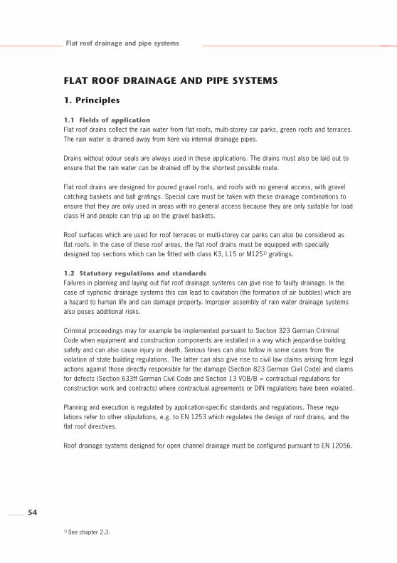
1.1 Fields of application Flat roof drains collect the rain water from flat roofs, multi-storey car parks, green roofs and terraces.The rain water is drained away from here via internal drainage pipes.
Drains without odour seals are always used in these applications. The drains must also be laid out toensure that the rain water can be drained off by the shortest possible route.
Flat roof drains are designed for poured gravel roofs, and roofs with no general access, with gravelcatching baskets and ball gratings. Special care must be taken with these drainage combinations toensure that they are only used in areas with no general access because they are only suitable for loadclass H and people can trip up on the gravel baskets.
Roof surfaces which are used for roof terraces or multi-storey car parks can also be considered asflat roofs. In the case of these roof areas, the flat roof drains must be equipped with speciallydesigned top sections which can be fitted with class K3, L15 or M1251) gratings.
1.2 Statutory regulations and standardsFailures in planning and laying out flat roof drainage systems can give rise to faulty drainage. In thecase of syphonic drainage systems this can lead to cavitation (the formation of air bubbles) which area hazard to human life and can damage property. Improper assembly of rain water drainage systemsalso poses additional risks.
Criminal proceedings may for example be implemented pursuant to Section 323 German CriminalCode when equipment and construction components are installed in a way which jeopardise buildingsafety and can also cause injury or death. Serious fines can also follow in some cases from theviolation of state building regulations. The latter can also give rise to civil law claims arising from legalactions against those directly responsible for the damage (Section 823 German Civil Code) and claimsfor defects (Section 633ff German Civil Code and Section 13 VOB/B = contractual regulations forconstruction work and contracts) where contractual agreements or DIN regulations have been violated.
Planning and execution is regulated by application-specific standards and regulations. These regu-lations refer to other stipulations, e.g. to EN 1253 which regulates the design of roof drains, and theflat roof directives.
Roof drainage systems designed for open channel drainage must be configured pursuant to EN 12056.
Flat roof drainage and pipe systems
1) See chapter 2.3.
FLAT ROOF DRAINAGE AND PIPE SYSTEMS
55
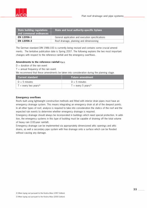
Current standard Future amendment
D = 5 minutes D = 5 minutesT = every two years2) T = every 5 years3)
Flat roof drainage and pipe systems
The German standard DIN 1986-100 is currently being revised and contains some crucial amend-ments. The tentative publication date is Spring 2007. The following explains the two most importantchanges with respect to the reference rainfall and the emergency overflows.
Amendments to the reference rainfall r(D,T)
D = duration of the rain eventT = annual frequency of the rain eventWe recommend that these amendments be taken into consideration during the planning stage.
Emergency overflowsRoofs built using lightweight construction methods and fitted with interior drain pipes must have anemergency drainage system. This means integrating an emergency drain at all of the deepest points.In all other types of roof, analysis is required to take into consideration the statics of the roof and theexpected rain events to determine whether emergency drainage is required. Emergency drainage should always be incorporated in buildings which need special protection. In addi-tion, the emergency systems in this type of building must be capable of draining off the total volumeof heavy rain (100-year rainfall).Emergency drainage can be implemented via appropriately dimensioned attic openings and atticdrains, as well a secondary pipe system with free drainage onto a surface which can be floodedwithout causing any damage.
2) When laying out pursuant to the Kostra Atlas (1997 Edition)
3) When laying out pursuant to the Kostra Atlas (2000 Edition)
State building regulations State and local authority-specific bylawsand communal ordinancesEN 12056-1 General application and execution specificationsEN 12056-3 Roof drainage, planning and dimensioning
56
Flat roof drainage and pipe systems
2. Planning
2.1 Roof structure/ drain typeSelecting the most suitable flat roof drain to drain the rain water from a building is an important partof the planning stage and depends on the type of roof structure.The type of roof structure selected depends on the different specifications laid down for the roof andthe specified loads, e.g. any traffic loads, the drainage of rain water etc.
Most roofs can be divided into three groups:Roof with air insulation with no sealingRoof with air insulation, flat roof/terrace structures without thermal insulation,sealing by one sealing membraneNon-ventilated flat roof, flat roof/terrace structure with thermal insulation, sealed by two sealing membranes
Flat roof drains with the appropriate sealing fixtures have to be selected for installation in the differenttypes of flat roof structures.
4) Terms “upper part” and “intermediate section” are usually used synonymously, although a pure “extension” must
not necessarily be fitted with a flange. Upper parts/intermediate sections do however usually have either a
compression-sealing flange or an adhering flange.
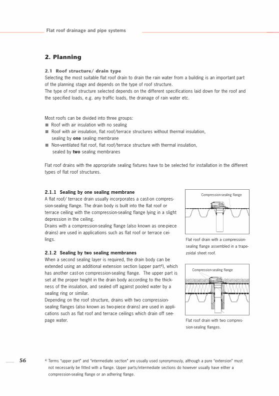
Flat roof drain with a compression-
sealing flange assembled in a trape-
zoidal sheet roof.
Flat roof drain with two compres-
sion-sealing flanges.
2.1.1 Sealing by one sealing membraneA flat roof/ terrace drain usually incorporates a cast-on compres-sion-sealing flange. The drain body is built into the flat roof orterrace ceiling with the compression-sealing flange lying in a slightdepression in the ceiling.Drains with a compression-sealing flange (also known as one-piecedrains) are used in applications such as flat roof or terrace cei-lings.
2.1.2 Sealing by two sealing membranesWhen a second sealing layer is required, the drain body can beextended using an additional extension section (upper part4), whichhas another cast-on compression-sealing flange. The upper part isset at the proper height in the drain body according to the thick-ness of the insulation, and sealed off against pooled water by asealing ring or similar. Depending on the roof structure, drains with two compression-sealing flanges (also known as two-piece drains) are used in appli-cations such as flat roof and terrace ceilings which drain off see-page water.
Compression-sealing flange
Compression-sealing flange
57
Flat roof drainage and pipe systems
2.2 Inclination of the outlet socketThe layout of the pipes is the crucial aspect for selection of the outlet socket angle of a flat roofdrain. Drain bodies with 1.5º inclination (horizontal) for open channel drainage are selected when thepipe is laid in the ceiling. The ceiling construction and the necessary rebates need to be taken intoconsideration.Drain bodies with 90º inclination (vertical) are selected if the pipes are laid beneath the ceilings, e.g.in suspended ceilings or when the hole in the ceiling has to be kept as small as possible for structuralreasons.
2.3 Cover for flat roof drainsDrains with different types of cover are available depending on the application (e.g. terrace, flat roofor multi-storey car park).The associated traffic load must be taken into consideration when selecting the type of cover, whichis why the installation position has to be classified pursuant to EN 1253.
The different types of covers are classified according to the load classes:
In the following, the use and the characteristics of the mentioned cover types are explained:
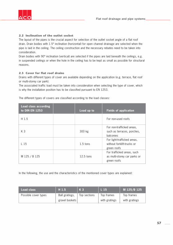
Load class accordingto DIN EN 1253 Load up to Fields of application
H 1.5 For non-used roofs
For non-trafficked areas, K 3 300 kg such as terraces, porches,
balconies For light-trafficked areas,
L 15 1.5 tons without forklift-trucks orgreen roofsFor trafficked areas, such
M 125 / B 125 12.5 tons as multi-storey car parks orgreen roofs
Load class H 1.5 K 3 L 15 M 125/B 125
Possible cover types Ball gratings, Top sections Top frames Top frames
gravel baskets with gratings with gratings
58
5) The diagram shows the DN 70 ACO flat roof drain. The DN 100 ACO flat roof drain must be used with transition frames.
Flat roof drainage and pipe systems
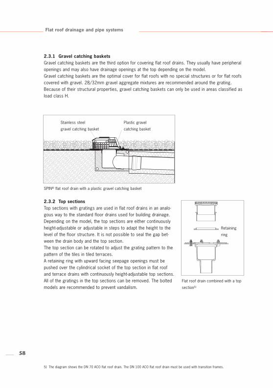
2.3.1 Gravel catching basketsGravel catching baskets are the third option for covering flat roof drains. They usually have peripheralopenings and may also have drainage openings at the top depending on the model.Gravel catching baskets are the optimal cover for flat roofs with no special structures or for flat roofscovered with gravel. 28/32mm gravel aggregate mixtures are recommended around the grating. Because of their structural properties, gravel catching baskets can only be used in areas classified asload class H.
SPIN® flat roof drain with a plastic gravel catching basket
Stainless steel
gravel catching basket
Flat roof drain combined with a top
section5)
2.3.2 Top sectionsTop sections with gratings are used in flat roof drains in an analo-gous way to the standard floor drains used for building drainage.Depending on the model, the top sections are either continuouslyheight-adjustable or adjustable in steps to adapt the height to thelevel of the floor structure. It is not possible to seal the gap bet-ween the drain body and the top section.The top section can be rotated to adjust the grating pattern to thepattern of the tiles in tiled terraces.A retaining ring with upward facing seepage openings must bepushed over the cylindrical socket of the top section in flat roofand terrace drains with continuously height-adjustable top sections.All of the gratings in the top sections can be removed. The boltedmodels are recommended to prevent vandalism.
Retaining
ring
Plastic gravel
catching basket
59
Flat roof drainage and pipe systems
Insulating ring
Sealing ring
Insulating body
Installation option isolation/thermal
insulation
Heating for flat roof drains
1.5º inclination
Heating for flat roof drains
90º inclination
2.3.3 Top frames and gratingsDepending on the type of cover, top frames with gratings are used in terraces as well as areas opento traffic with higher load classes.Top frames with gratings are laid directly on top of the drain body. Top rings can be used to provideadditional height adjustment (corresponding to the building specifications). The top rings arepositioned between the drain body and the top frames or the gratings. Top rings have seepageopenings.
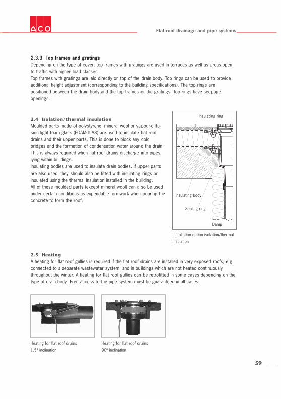
2.4 Isolation/thermal insulationMoulded parts made of polystyrene, mineral wool or vapour-diffu-sion-tight foam glass (FOAMGLAS) are used to insulate flat roofdrains and their upper parts. This is done to block any coldbridges and the formation of condensation water around the drain.This is always required when flat roof drains discharge into pipeslying within buildings.Insulating bodies are used to insulate drain bodies. If upper partsare also used, they should also be fitted with insulating rings orinsulated using the thermal insulation installed in the building.All of these moulded parts (except mineral wool) can also be usedunder certain conditions as expendable formwork when pouring theconcrete to form the roof.
2.5 HeatingA heating for flat roof gullies is required if the flat roof drains are installed in very exposed roofs, e.g.connected to a separate wastewater system, and in buildings which are not heated continuouslythroughout the winter. A heating for flat roof gullies can be retrofitted in some cases depending on thetype of drain body. Free access to the pipe system must be guaranteed in all cases.
Damp
60
Flat roof drainage and pipe systems
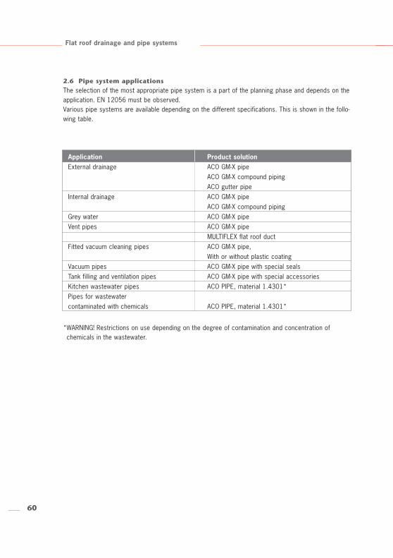
2.6 Pipe system applicationsThe selection of the most appropriate pipe system is a part of the planning phase and depends on theapplication. EN 12056 must be observed. Various pipe systems are available depending on the different specifications. This is shown in the follo-wing table.
*WARNING! Restrictions on use depending on the degree of contamination and concentration ofchemicals in the wastewater.
Application Product solutionExternal drainage ACO GM-X pipe
ACO GM-X compound pipingACO gutter pipe
Internal drainage ACO GM-X pipeACO GM-X compound piping
Grey water ACO GM-X pipeVent pipes ACO GM-X pipe
MULTIFLEX flat roof ductFitted vacuum cleaning pipes ACO GM-X pipe,
With or without plastic coatingVacuum pipes ACO GM-X pipe with special sealsTank filling and ventilation pipes ACO GM-X pipe with special accessoriesKitchen wastewater pipes ACO PIPE, material 1.4301*Pipes for wastewater contaminated with chemicals ACO PIPE, material 1.4301*
61
Nominal width Product description Tightness values
DN 40 GM-X Safety clamp* 15 barDN 50 GM-X Safety clamp* 15 barDN 70 GM-X Safety clamp* 5 barDN 80 GM-X Safety clamp* 5 barDN 100 GM-X Safety clamp* 5 barDN 125 GM-X Safety clamp* 4 barDN 150 GM-X Circlip 4 barDN 200 GM-X Circlip 2 barDN 250 GM-X Circlip 1.2 barDN 300 GM-X Circlip 1 bar
Flat roof drainage and pipe systems
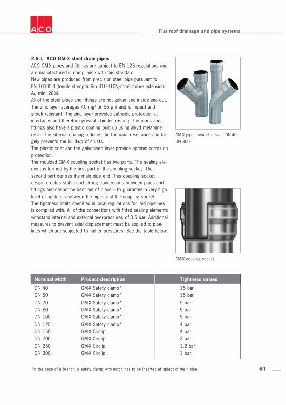
2.6.1 ACO GM-X steel drain pipesACO GM-X pipes and fittings are subject to EN 123 regulations andare manufactured in compliance with this standard. New pipes are produced from precision steel pipe pursuant toEN 10305-3 (tensile strength: Rm 310-410N/mm²; failure extension:A5 min. 28%).All of the steel pipes and fittings are hot galvanised inside and out.The zinc layer averages 40 mg² or 56 µm and is impact andshock resistant. The zinc layer provides cathodic protection atinterfaces and therefore prevents hidden rusting. The pipes andfittings also have a plastic coating built up using alkyd melamineresin. The internal coating reduces the frictional resistance and lar-gely prevents the build-up of crusts.The plastic coat and the galvanised layer provide optimal corrosionprotection.The moulded GM-X coupling socket has two parts. The sealing ele-ment is formed by the first part of the coupling socket. Thesecond part centres the male pipe end. This coupling socketdesign creates stable and strong connections between pipes andfittings and cannot be bent out of place – to guarantee a very highlevel of tightness between the pipes and the coupling socket. The tightness limits specified in local regulations for laid pipelinesis complied with. All of the connections with fitted sealing elementswithstand internal and external overpressures of 0.5 bar. Additionalmeasures to prevent axial displacement must be applied to pipe-lines which are subjected to higher pressures. See the table below.
GM-X pipe – available sizes DN 40-
DN 300
GM-X coupling socket
*In the case of a branch, a safety clamp with notch has to be inserted at spigot of main pipe.
62
d1d2
s1s2
m1
m12
Flat roof drainage and pipe systems
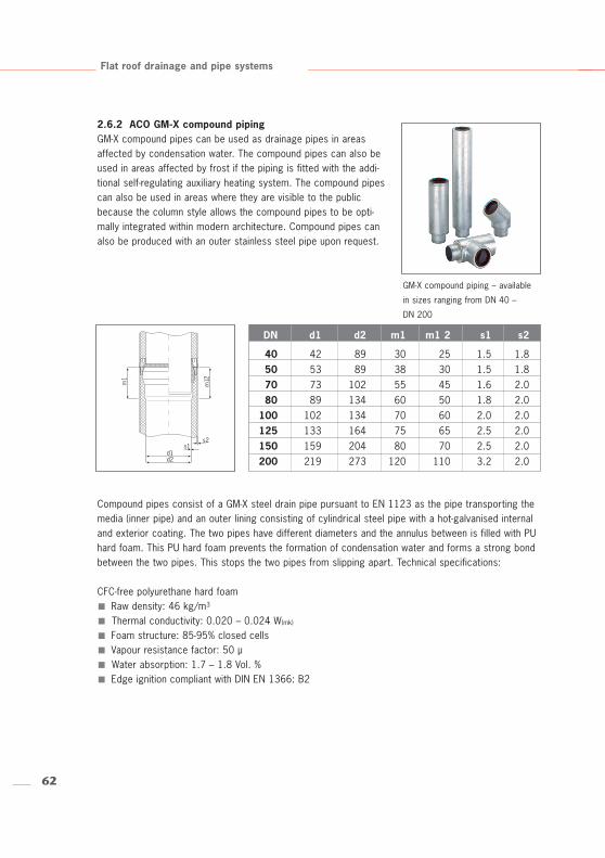
2.6.2 ACO GM-X compound pipingGM-X compound pipes can be used as drainage pipes in areasaffected by condensation water. The compound pipes can also beused in areas affected by frost if the piping is fitted with the addi-tional self-regulating auxiliary heating system. The compound pipescan also be used in areas where they are visible to the publicbecause the column style allows the compound pipes to be opti-mally integrated within modern architecture. Compound pipes canalso be produced with an outer stainless steel pipe upon request.
Compound pipes consist of a GM-X steel drain pipe pursuant to EN 1123 as the pipe transporting themedia (inner pipe) and an outer lining consisting of cylindrical steel pipe with a hot-galvanised internaland exterior coating. The two pipes have different diameters and the annulus between is filled with PUhard foam. This PU hard foam prevents the formation of condensation water and forms a strong bondbetween the two pipes. This stops the two pipes from slipping apart. Technical specifications:
CFC-free polyurethane hard foamRaw density: 46 kg/m3
Thermal conductivity: 0.020 – 0.024 W(mk)
Foam structure: 85-95% closed cellsVapour resistance factor: 50 µWater absorption: 1.7 – 1.8 Vol. %Edge ignition compliant with DIN EN 1366: B2
GM-X compound piping – available
in sizes ranging from DN 40 –
DN 200
DN d1 d2 m1 m1 2 s1 s2
40 42 89 30 25 1.5 1.850 53 89 38 30 1.5 1.870 73 102 55 45 1.6 2.080 89 134 60 50 1.8 2.0
100 102 134 70 60 2.0 2.0125 133 164 75 65 2.5 2.0150 159 204 80 70 2.5 2.0200 219 273 120 110 3.2 2.0
63
Flat roof drainage and pipe systems
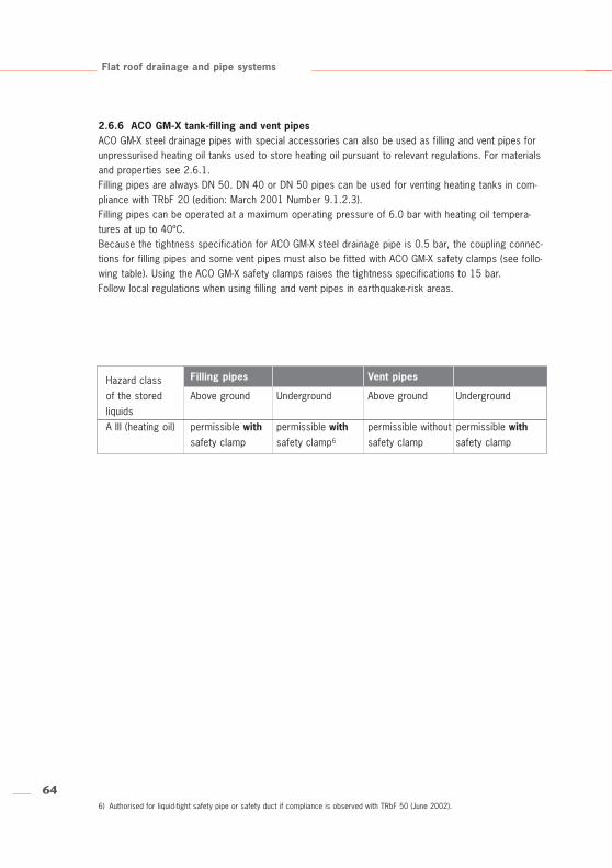
ACO PIPE stainless steel pipe
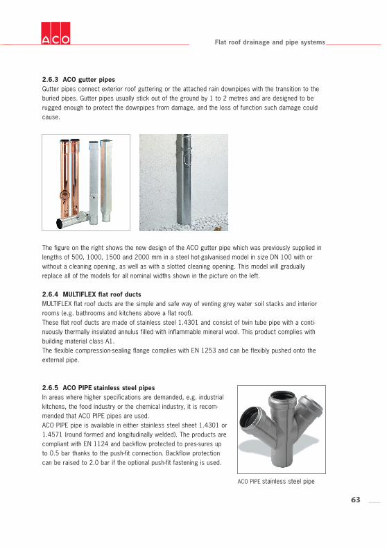
2.6.3 ACO gutter pipesGutter pipes connect exterior roof guttering or the attached rain downpipes with the transition to theburied pipes. Gutter pipes usually stick out of the ground by 1 to 2 metres and are designed to berugged enough to protect the downpipes from damage, and the loss of function such damage couldcause.
The figure on the right shows the new design of the ACO gutter pipe which was previously supplied inlengths of 500, 1000, 1500 and 2000 mm in a steel hot-galvanised model in size DN 100 with orwithout a cleaning opening, as well as with a slotted cleaning opening. This model will graduallyreplace all of the models for all nominal widths shown in the picture on the left.
2.6.4 MULTIFLEX flat roof ductsMULTIFLEX flat roof ducts are the simple and safe way of venting grey water soil stacks and interiorrooms (e.g. bathrooms and kitchens above a flat roof). These flat roof ducts are made of stainless steel 1.4301 and consist of twin tube pipe with a conti-nuously thermally insulated annulus filled with inflammable mineral wool. This product complies withbuilding material class A1.The flexible compression-sealing flange complies with EN 1253 and can be flexibly pushed onto theexternal pipe.
2.6.5 ACO PIPE stainless steel pipesIn areas where higher specifications are demanded, e.g. industrialkitchens, the food industry or the chemical industry, it is recom-mended that ACO PIPE pipes are used.ACO PIPE pipe is available in either stainless steel sheet 1.4301 or1.4571 (round formed and longitudinally welded). The products arecompliant with EN 1124 and backflow protected to pres-sures upto 0.5 bar thanks to the push-fit connection. Backflow protectioncan be raised to 2.0 bar if the optional push-fit fastening is used.
646) Authorised for liquid-tight safety pipe or safety duct if compliance is observed with TRbF 50 (June 2002).
Flat roof drainage and pipe systems
2.6.6 ACO GM-X tank-filling and vent pipesACO GM-X steel drainage pipes with special accessories can also be used as filling and vent pipes forunpressurised heating oil tanks used to store heating oil pursuant to relevant regulations. For materialsand properties see 2.6.1.Filling pipes are always DN 50. DN 40 or DN 50 pipes can be used for venting heating tanks in com-pliance with TRbF 20 (edition: March 2001 Number 9.1.2.3).Filling pipes can be operated at a maximum operating pressure of 6.0 bar with heating oil tempera-tures at up to 40ºC.Because the tightness specification for ACO GM-X steel drainage pipe is 0.5 bar, the coupling connec-tions for filling pipes and some vent pipes must also be fitted with ACO GM-X safety clamps (see follo-wing table). Using the ACO GM-X safety clamps raises the tightness specifications to 15 bar.Follow local regulations when using filling and vent pipes in earthquake-risk areas.
Hazard class Filling pipes Vent pipes
of the stored Above ground Underground Above ground UndergroundliquidsA III (heating oil) permissible with permissible with permissible without permissible with
safety clamp safety clamp6 safety clamp safety clamp
65
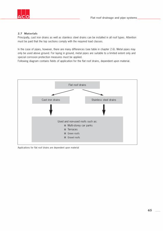
Used and non-used roofs such as:Multi-storey car parksTerracesGreen roofs
Gravel roofs
Flat roof drainage and pipe systems
2.7 MaterialsPrincipally, cast iron drains as well as stainless steel drains can be installed in all roof types. Attentionmust be paid that the top sections comply with the required load classes.
In the case of pipes, however, there are many differences (see table in chapter 2.6). Metal pipes mayonly be used above ground. For laying in ground, metal pipes are suitable to a limited extent only andspecial corrosion protection measures must be applied.Following diagram contains fields of application for the flat roof drains, dependent upon material.
Applications for flat roof drains are dependent upon material
Flat roof drains
Cast iron drains Stainless steel drains
66
Flat roof drainage and pipe systems
2.7.1 Cast ironGJL-200 cast iron is according to EN 1561 an iron-carbon alloy containing carbon flakes embedded inan iron lattice. This “graphite lattice” gives the cast iron its excellent corrosion resistance. No additionalsurface protection is required.
Cast iron material specificationsTemperature resistance to 400ºC with no change in its mechanical propertiesInsensitive to hot-laid flooring materials such as mastic asphalt or bitumen sheetingStrong bond with concrete even when subjected to temperature fluctuations because of the verysimilar coefficient of expansion between concrete and cast ironSound absorbing because of the large massSound insulatingCompletely recyclable and long service life
Cast iron flat roof, multi-storey car park and terrace drains are coated with primer for transport pro-tection and for optical reasons.
2.7.2 Stainless steelMaterial specifications in Chapter 2.6.5.
2.7.3 Galvanised steelMaterial properties given in Chapter 2.6.1 and 2.6.2.
2.8 Determining the drainage typeFlat roof drainage systems are divided into either gravity rainwater drainage systems or syphonic drai-nage systems.Gravity rainwater drainage systems drain off water merely using the force of gravity. In syphonicdrainage systems, the rainwater is drained off in pipes which are always completely full because thisis the way the system operates.Roofs open to the public are best drained using gravity rainwater drainage because of the greaterwidths of the pipes (less risk of blockage from dirt or litter).The most important factors influencing dimensioning of both types of flat roof drainage are the localreference rainfall levels, connection to the main drains, the piping layout, the roof structure and thedifference in heights. ACO Haustechnik provides the optimum flat roof drains, accessories and pipe systems for both appli-cations.
67
Flat roof drainage and pipe systems
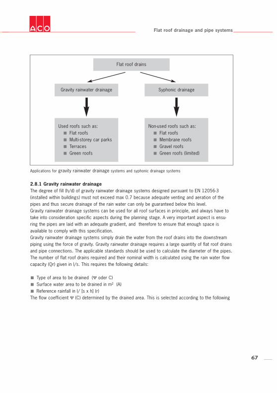
Applications for gravity rainwater drainage systems and syphonic drainage systems
2.8.1 Gravity rainwater drainageThe degree of fill (h/d) of gravity rainwater drainage systems designed pursuant to EN 12056-3(installed within buildings) must not exceed max 0.7 because adequate venting and aeration of thepipes and thus secure drainage of the rain water can only be guaranteed below this level.Gravity rainwater drainage systems can be used for all roof surfaces in principle, and always have totake into consideration specific aspects during the planning stage. A very important aspect is ensu-ring the pipes are laid with an adequate gradient, and therefore to ensure that enough space is available to comply with this specification.Gravity rainwater drainage systems simply drain the water from the roof drains into the downstreampiping using the force of gravity. Gravity rainwater drainage requires a large quantity of flat roof drainsand pipe connections. The applicable standards should be used to calculate the diameter of the pipes.The number of flat roof drains required and their nominal width is calculated using the rain water flowcapacity (Qr) given in l/s. This requires the following details:
Type of area to be drained (Ψ oder C)Surface water area to be drained in m² (A)Reference rainfall in l/ [s x h] (r)
The flow coefficient Ψ (C) determined by the drained area. This is selected according to the following
Flat roof drains
Gravity rainwater drainage
Used roofs such as:Flat roofsMulti-storey car parksTerracesGreen roofs
Non-used roofs such as:Flat roofsMembrane roofsGravel roofsGreen roofs (limited)
Syphonic drainage
68
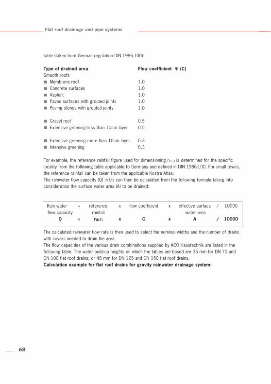
Rain water = reference x flow coefficient x effective surface / 10000flow capacity rainfall water area
Q = r(D,T) x C x A / 10000
Flat roof drainage and pipe systems
table (taken from German regulation DIN 1986-100):
Type of drained area Flow coefficient Ψ (C)Smooth roofs
Membrane roof 1.0Concrete surfaces 1.0Asphalt 1.0Paved surfaces with grouted joints 1.0Paving stones with grouted joints 1.0
Gravel roof 0.5Extensive greening less than 10cm layer 0.5
Extensive greening more than 10cm layer 0.3Intensive greening 0.3
For example, the reference rainfall figure used for dimensioning r(D,T) is determined for the specificlocality from the following table applicable to Germany and defined in DIN 1986-100. For small towns,the reference rainfall can be taken from the applicable Kostra Atlas. The rainwater flow capacity (Q) in l/s can then be calculated from the following formula taking intoconsideration the surface water area (A) to be drained:
The calculated rainwater flow rate is then used to select the nominal widths and the number of drainswith covers needed to drain the area.The flow capacities of the various drain combinations supplied by ACO Haustechnik are listed in thefollowing table. The water build-up heights on which the tables are based are 35 mm for DN 70 andDN 100 flat roof drains; or 45 mm for DN 125 and DN 150 flat roof drains.Calculation example for flat roof drains for gravity rainwater drainage system:
69
Flat roof drainage and pipe systems
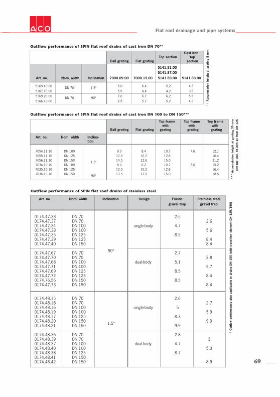
Outflow performance of SPIN flat roof drains of cast iron DN 70**
7054.11.10 DN 100 9.0 8.4 10.7 7.6 12.17055.11.10 DN 125 12.0 10.2 12.6 16.47056.11.10 DN 150 1.5º 14.5 12.6 15.0 21.27034.10.10 DN 100 8.0 6.2 10.7 7.6 15.27035.10.10 DN 125 12.0 10.2 12.6 16.47036.10.10 DN 150 90º 13.5 11.0 15.0 18.5
Outflow performance of SPIN flat roof drains of cast iron DN 100 to DN 150***
** A
ccum
ulat
ion
heig
ht a
t gr
atin
g 5
mm
***
Acc
umul
atio
n he
ight
at
grat
ing
35 m
mw
ith D
N 1
00,
45 m
m a
s fr
om D
N 1
25
Art. no. Nom. width Inclination Design Plastic Stainless steelgravel trap gravel trap
0174.47.33 DN 70 2.50174.47.37 DN 70 2.60174.47.34 DN 100 single-body 4.70174.47.38 DN 100 5.60174.47.35 DN 125 8.50174.47.39 DN 125 8.40174.47.40 DN 150 8.4
90º0174.47.67 DN 70 2.70174.47.70 DN 70 2.80174.47.68 DN 100 dual-body 5.10174.47.71 DN 100 5.70174.47.69 DN 125 8.50174.47.72 DN 125 8.40174.76.56 DN 150 8.50174.47.73 DN 150 8.4
0174.48.15 DN 70 2.60174.48.18 DN 70 2.70174.48.16 DN 100 single-body 50174.48.19 DN 100 5.90174.48.17 DN 125 8.30174.48.20 DN 150 1.5º 9.90174.48.21 DN 150 9.9
0174.48.36 DN 70 2.80174.48.39 DN 70 30174.48.37 DN 100 dual-body 4.70174.48.40 DN 100 5.30174.48.38 DN 125 8.70174.48.41 DN 1500174.48.42 DN 150 8.9
Outflow performance of SPIN flat roof drains of stainless steel
Art. no. Nom. width Inclina-tion
Art. no. Nom. width Inclination 7000.09.00 7000.19.00 5141.89.00 5141.83.00
Cast ironTop section top
Ball grating Flat grating section
Top framewith
Ball grating Flat grating grating
* O
utflo
w p
erfo
rman
ce a
lso
appl
icab
le t
o dr
ains
DN
150
(w
ith t
rans
ition
ele
men
t D
N 1
25/1
50)
5169.40.00 DN 70 1.5º 6.0 6.4 5.2 4.8
5167.10.00 5.5 4.4 4.2 3.8
5169.20.00 DN 70 90º 7.0 6.7 6.2 5.8
5166.10.00 6.5 5.7 5.2 4.6
5141.81.005141.87.00
Top frame with
grating
Top frame with
grating
708) Layout pursuant to new standard, data Kostra DWD 2000
9) The absorption capacity of the pipes must be taken into consideration. See table in DIN 1986-100 (2002/03), table A3.
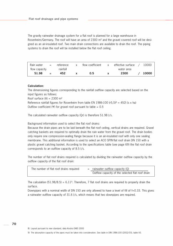
Calculation:The dimensioning figures corresponding to the rainfall outflow capacity are selected based on theinput figures as follows:Roof surface (A) = 2300 m²Reference rainfall figures for Rosenheim from table EN 1986-100 (r5,5)8 = 452l (s x ha)Outflow coefficient (Ψ) for gravel roof pursuant to table = 0.5
The calculated rainwater outflow capacity (Qr) is therefore 51.98 l/s.
Background information used to select the flat roof drains:Because the drain pipes are to be laid beneath the flat roof ceiling, vertical drains are required. Gravelcatching baskets are required to optimally drain the rain water from the gravel roof. The drain bodiesonly require one compression-sealing flange because it is an air-insulated roof with only one sealingmembrane. This additional information is used to select an ACO SPIN flat roof drain DN 150 with aplastic gravel catching basket. According to the specifications table (see page 69) the flat roof draincorresponds to an outflow capacity of 8.5 l/s.
The number of flat roof drains required is calculated by dividing the rainwater outflow capacity by theoutflow capacity of the flat roof drain:
The calculation (51.98/8.5) = 6.119. Therefore, 7 flat roof drains are required to properly drain thesurface.Downpipes with a nominal width of DN 150 are only allowed to have a level of fill of f=0.33. This givesa rainwater outflow capacity of 31.6 l/s, which means that two downpipes are required.
Flat roof drainage and pipe systems
The gravity rainwater drainage system for a flat roof is planned for a large warehouse inRosenheim/Germany. The roof will have an area of 2300 m² and the gravel covered roof will be desi-gned as an air-insulated roof. Two main drain connections are available to drain the roof. The pipingsystems to drain the roof will be installed below the flat roof ceiling.
Rain water = reference x flow coefficient x effective surface / 10000flow capacity rainfall water area
51.98 = 452 x 0.5 x 2300 / 10000
The number of flat roof drains required = rainwater outflow capacity (Q) Outflow capacity of the selected flat roof drain
71
Flat roof drainage and pipe systems
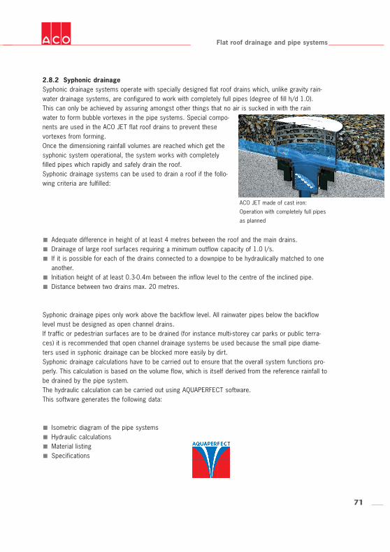
2.8.2 Syphonic drainageSyphonic drainage systems operate with specially designed flat roof drains which, unlike gravity rain-water drainage systems, are configured to work with completely full pipes (degree of fill h/d 1.0).This can only be achieved by assuring amongst other things that no air is sucked in with the rain
ACO JET made of cast iron:
Operation with completely full pipes
as planned
water to form bubble vortexes in the pipe systems. Special compo-nents are used in the ACO JET flat roof drains to prevent thesevortexes from forming.Once the dimensioning rainfall volumes are reached which get thesyphonic system operational, the system works with completelyfilled pipes which rapidly and safely drain the roof.Syphonic drainage systems can be used to drain a roof if the follo-wing criteria are fulfilled:
Adequate difference in height of at least 4 metres between the roof and the main drains.Drainage of large roof surfaces requiring a minimum outflow capacity of 1.0 l/s.If it is possible for each of the drains connected to a downpipe to be hydraulically matched to oneanother.Initiation height of at least 0.3-0.4m between the inflow level to the centre of the inclined pipe.Distance between two drains max. 20 metres.
Syphonic drainage pipes only work above the backflow level. All rainwater pipes below the backflowlevel must be designed as open channel drains.If traffic or pedestrian surfaces are to be drained (for instance multi-storey car parks or public terra-ces) it is recommended that open channel drainage systems be used because the small pipe diame-ters used in syphonic drainage can be blocked more easily by dirt.Syphonic drainage calculations have to be carried out to ensure that the overall system functions pro-perly. This calculation is based on the volume flow, which is itself derived from the reference rainfall tobe drained by the pipe system.The hydraulic calculation can be carried out using AQUAPERFECT software.This software generates the following data:
Isometric diagram of the pipe systemsHydraulic calculations Material listingSpecifications
72
Flat roof drainage and pipe systems
3. Installation and assembly
3.1 Installing the drain bodyies
3.1.1 Pouring inThe flat roof drain (or the drain body/isolating body) can be poured in as required when the concreteceiling is being constructed. Before the concrete is poured, the drain body must be connected to thedrain pipes and fixed firmly in place to prevent it moving sideways or upwards when the concrete ispoured. A protective cover must be put on the drain body while the building is being constructed to protectthe inside of the drain and the drain pipes. Once the concrete has set, this cover should be removedso that a top section can be installed in the drain body before the rest of the floor structure is con-structed.
3.1.2 RebatesThe dimensions of the rebate depend on the design and the type of drain body. We differentiate bet-ween rebates which are included in the construction in advance, and those which have to be createdin the already completed ceiling.An elongated slot is the most practicable rebate if it is already built into the ceiling during construc-tion. This gives enough room for manoeuvre to install the drain body. The drain body can also be fixedin place by pouring in concrete through the remaining opening in the rebate after constructing the pro-per formwork beneath the ceiling.The dimensions of the rebate need to match the type of drain to be installed. Make allowance for thelargest external diameter in the drain body below the compression-sealing flange. If the compression-sealing flange is also to be fitted within the roof construction, allowance must be made in the rebatefor the external diameter of the outside of the flange.The rebates for drains with vertical outlets should include an opening for pouring in the concrete fromabove.Drains with lateral outlets are generally joined to the connecting pipe bend before being fitted into therebate.The dimensions of the rebate required in this case should be based on the dimensions of the drainplus the pipe bend.It is usually very difficult to modify rebates after they have been constructed, and is often impossibleto modify for structural reasons.If the rebate is to be constructed by coring after building the ceiling, precise dimensioning of the re-bate is always necessary. Attention must be paid in particular to the proper means of fastening thedrain, and that there is enough room to pour cement around the drain body to fix it into place.It is practicable here to use drain bodies with round housings and vertical outlets.
73
ø c
b
ø a
Upper side
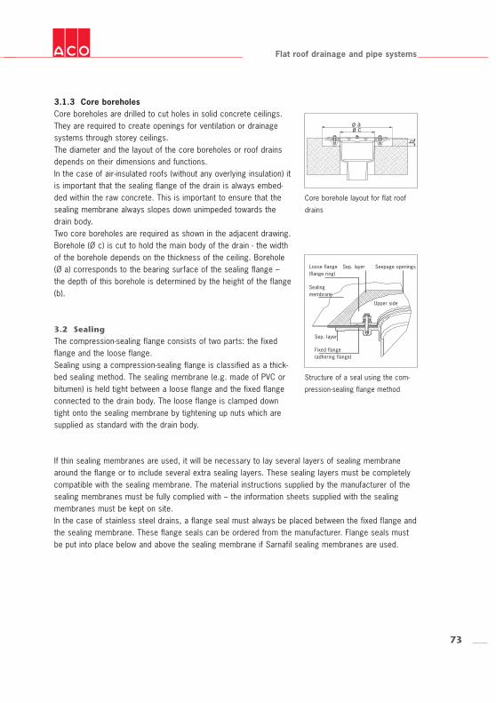
3.1.3 Core boreholesCore boreholes are drilled to cut holes in solid concrete ceilings.They are required to create openings for ventilation or drainagesystems through storey ceilings.The diameter and the layout of the core boreholes or roof drainsdepends on their dimensions and functions. In the case of air-insulated roofs (without any overlying insulation) itis important that the sealing flange of the drain is always embed-ded within the raw concrete. This is important to ensure that thesealing membrane always slopes down unimpeded towards thedrain body.Two core boreholes are required as shown in the adjacent drawing.Borehole (Ø c) is cut to hold the main body of the drain - the widthof the borehole depends on the thickness of the ceiling. Borehole(Ø a) corresponds to the bearing surface of the sealing flange –the depth of this borehole is determined by the height of the flange(b).
3.2 SealingThe compression-sealing flange consists of two parts: the fixedflange and the loose flange. Sealing using a compression-sealing flange is classified as a thick-bed sealing method. The sealing membrane (e.g. made of PVC orbitumen) is held tight between a loose flange and the fixed flangeconnected to the drain body. The loose flange is clamped downtight onto the sealing membrane by tightening up nuts which aresupplied as standard with the drain body.
Flat roof drainage and pipe systems
Core borehole layout for flat roof
drains
If thin sealing membranes are used, it will be necessary to lay several layers of sealing membranearound the flange or to include several extra sealing layers. These sealing layers must be completelycompatible with the sealing membrane. The material instructions supplied by the manufacturer of thesealing membranes must be fully complied with – the information sheets supplied with the sealingmembranes must be kept on site.In the case of stainless steel drains, a flange seal must always be placed between the fixed flange andthe sealing membrane. These flange seals can be ordered from the manufacturer. Flange seals mustbe put into place below and above the sealing membrane if Sarnafil sealing membranes are used.
Structure of a seal using the com-
pression-sealing flange method
Sep. layerLoose flange(flange ring)
Sealingmembrane
Sep. layer
Fixed flange(adhering flange)
Seepage openings
74
Flat roof drainage and pipe systems
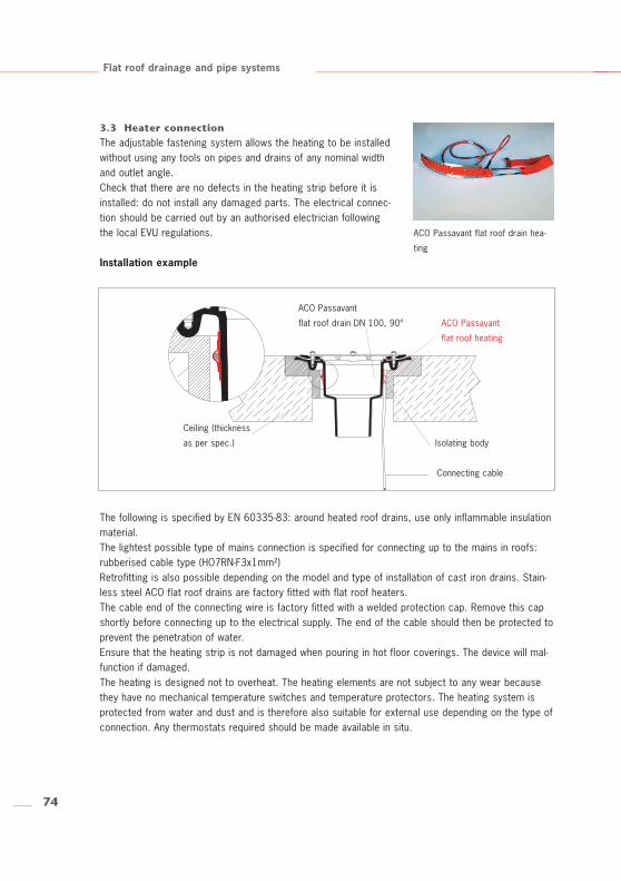
3.3 Heater connectionThe adjustable fastening system allows the heating to be installedwithout using any tools on pipes and drains of any nominal widthand outlet angle. Check that there are no defects in the heating strip before it isinstalled: do not install any damaged parts. The electrical connec-tion should be carried out by an authorised electrician followingthe local EVU regulations.
The following is specified by EN 60335-83: around heated roof drains, use only inflammable insulationmaterial. The lightest possible type of mains connection is specified for connecting up to the mains in roofs:rubberised cable type (HO7RN-F3x1mm²) Retrofitting is also possible depending on the model and type of installation of cast iron drains. Stain-less steel ACO flat roof drains are factory fitted with flat roof heaters.The cable end of the connecting wire is factory fitted with a welded protection cap. Remove this capshortly before connecting up to the electrical supply. The end of the cable should then be protected toprevent the penetration of water.Ensure that the heating strip is not damaged when pouring in hot floor coverings. The device will mal-function if damaged.The heating is designed not to overheat. The heating elements are not subject to any wear becausethey have no mechanical temperature switches and temperature protectors. The heating system isprotected from water and dust and is therefore also suitable for external use depending on the type ofconnection. Any thermostats required should be made available in situ.
Ceiling (thickness
as per spec.)
ACO Passavant
flat roof drain DN 100, 90º ACO Passavant
flat roof heating
Isolating body
Connecting cable
Installation example
ACO Passavant flat roof drain hea-
ting
75
Flat roof drainage and pipe systems
3.4 Pipe mountings and pipe connectionsBefore fixing pipes in place, always consult the manufacturer’s specifications and the regulationsdefined in EN 12056.
3.4.1 Gravity rainwater drainageBecause they are only subject to atmospheric pressure, gravity rainwater drainage systems require nospecial mountings such as safety clamps or fixed points. However, this only applies to downpipes lessthan 5 metres in height. Downpipes exceeding 5 metres in height have to be fastened with downpipe mountings. We alsorecommend that the coupling sockets are also provided with extra protection because problems mayarise if there is backflow in the main drain.
3.4.2 Syphonic drainageSteel GM-X pipes and fittings can be quickly and simply laid as rainwater drains in syphonic drainagesystems. Some parts of the piping systems in syphonic drainage networks can be subjected to significant underor over pressures. The associated reaction forces must be counteracted by implementing the follo-wing measures:
Proper mounting of the syphonic drainage drainsFastening the coupling sockets to prevent axial thrustingSuspending the pipes at fixed pointsFitting pipe clamps
The reaction forces always act on the drain outlets and the pipe sections affected by overpressure.Reaction forces primarily affect the under pressure zones when there are changes in pipe direction.GM-X coupling sockets in these zones should therefore generally be secured with extra safety clampsor safety brackets to stop them being pushed apart.The mountings selected and shown in the following examples are chosen from the range of mountingssupplied by Müpro. It is naturally possible to use mountings and fastenings made by other manufactu-rers if they are suitable for syphonic drainage systems.
76
Z
y
x x
x xy
Z
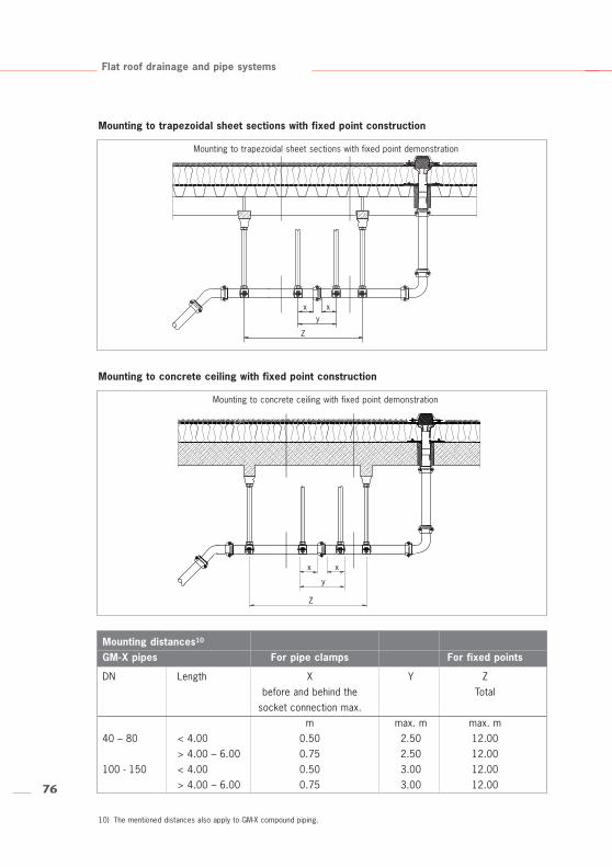
Mounting distances10
GM-X pipes For pipe clamps For fixed points
DN Length X Y Zbefore and behind the Total
socket connection max. m max. m max. m
40 – 80 < 4.00 0.50 2.50 12.00> 4.00 – 6.00 0.75 2.50 12.00
100 - 150 < 4.00 0.50 3.00 12.00> 4.00 – 6.00 0.75 3.00 12.00
Flat roof drainage and pipe systems
10) The mentioned distances also apply to GM-X compound piping.
Mounting to trapezoidal sheet sections with fixed point construction
Mounting to concrete ceiling with fixed point construction
Mounting to trapezoidal sheet sections with fixed point demonstration
Mounting to concrete ceiling with fixed point demonstration
77
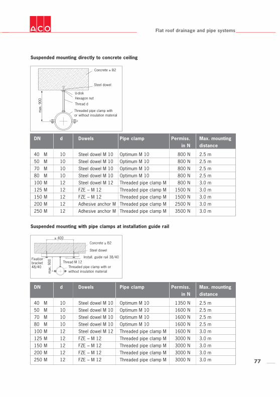
DN d Dowels Pipe clamp Permiss. Max. mountingin N distance
40 M 10 Steel dowel M 10 Optimum M 10 800 N 2.5 m50 M 10 Steel dowel M 10 Optimum M 10 800 N 2.5 m70 M 10 Steel dowel M 10 Optimum M 10 800 N 2.5 m80 M 10 Steel dowel M 10 Optimum M 10 800 N 2.5 m100 M 12 Steel dowel M 12 Threaded pipe clamp M 800 N 3.0 m125 M 12 FZE – M 12 Threaded pipe clamp M 1500 N 3.0 m150 M 12 FZE – M 12 Threaded pipe clamp M 1500 N 3.0 m200 M 12 Adhesive anchor M Threaded pipe clamp M 2500 N 3.0 m250 M 12 Adhesive anchor M Threaded pipe clamp M 3500 N 3.0 m
Flat roof drainage and pipe systems
Suspended mounting with pipe clamps at installation guide rail
Suspended mounting directly to concrete ceiling
DN d Dowels Pipe clamp Permiss. Max. mountingin N distance
40 M 10 Steel dowel M 10 Optimum M 10 1350 N 2.5 m50 M 10 Steel dowel M 10 Optimum M 10 1600 N 2.5 m70 M 10 Steel dowel M 10 Optimum M 10 1600 N 2.5 m80 M 10 Steel dowel M 10 Optimum M 10 1600 N 2.5 m100 M 12 Steel dowel M 12 Threaded pipe clamp M 1600 N 3.0 m125 M 12 FZE – M 12 Threaded pipe clamp M 3000 N 3.0 m150 M 12 FZE – M 12 Threaded pipe clamp M 3000 N 3.0 m200 M 12 FZE – M 12 Threaded pipe clamp M 3000 N 3.0 m250 M 12 FZE – M 12 Threaded pipe clamp M 3000 N 3.0 m
Concrete ≥ B2
Steel dowel
U-diskHexagon nut
Thread d
Threaded pipe clamp withor without insulation material
Concrete ≥ B2
Steel dowel
Install. guide rail 38/40Fixationbracket 48/40 Threaded pipe clamp with or
without insulation material
max
. 90
0
max
. 90
0
≥ 400
Thread M 12
78
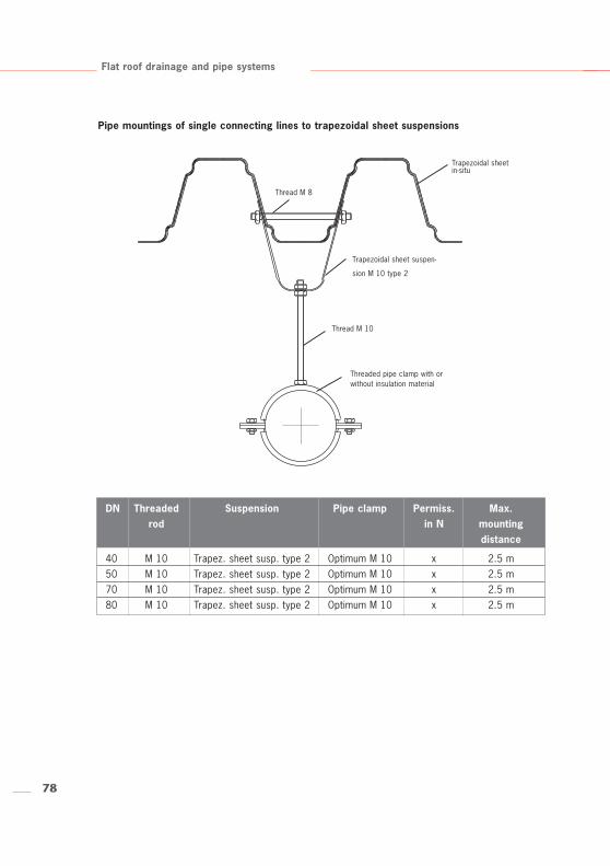
Trapezoidal sheetin-situ
Trapezoidal sheet suspen-
sion M 10 type 2
Threaded pipe clamp with orwithout insulation material
Thread M 10
Thread M 8
DN Threaded Suspension Pipe clamp Permiss. Max. rod in N mounting
distance
40 M 10 Trapez. sheet susp. type 2 Optimum M 10 x 2.5 m50 M 10 Trapez. sheet susp. type 2 Optimum M 10 x 2.5 m70 M 10 Trapez. sheet susp. type 2 Optimum M 10 x 2.5 m80 M 10 Trapez. sheet susp. type 2 Optimum M 10 x 2.5 m
Flat roof drainage and pipe systems
Pipe mountings of single connecting lines to trapezoidal sheet suspensions
79
Flat roof drainage and pipe systems
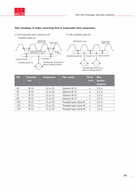
Pipe mountings of single connecting lines to trapezoidal sheet suspensions
(1) with trapezoidal sheet suspension and
installation guide rail
(2) with installation guide rail
DN Threaded Suspension Pipe clamp Perm. Max. rod in N fixation
distance
40 M 10 (1) or (2) Optimum M 10 x 2.5 m50 M 10 (1) or (2) Optimum M 10 x 2.5 m70 M 10 (1) or (2) Optimum M 10 x 2.5 m80 M 10 (1) or (2) Optimum M 10 x 2.5 m100 M 12 (1) or (2) Threaded pipe clamp M x 3.0 m125 M 12 (1) or (2) Threaded pipe clamp M x 3.0 m150 M 12 (1) or (2) Threaded pipe clamp M x 3.0 m
Trapezoidalsheet in-situ
Trapezoidal sheet sus-pension M 10, type 2
Threaded pipe clamp with orwithout insulating material
Thread M 10
Thread M 8
Thread M 12Fixation bracket
Installation guide rail
Trapezoidalsheet in-situ
Self-tapping screw
Threaded pipe clamp with orwithout insulating material
Thread M 12 Fixation bracketInstallation guide rail
80
Flat roof drainage and pipe systems
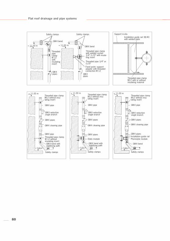
GM-X bend
Safety clamps
ThreadedpipeclampM 12with insulatinginsert
+ 11.00 m
Threaded pipe 3/4” or(1/2)“
Safety clamps
GM-X bend
GM-Xpipes GM-X
pipes
Threaded pipe clampwith welded socket3/4” (1/2)“ with insula-ting insert
Fixed point: supportadapter with threadedconnection M 12
+ 11.00 m
Threaded pipe clampM12 with or withoutinsulating material
Support in-situInstallation guide rail 38/40with welded plate
+ 11.00 m + 11.00 m + 11.00 mThreaded pipe clampM12 without insu-lating insert
Threaded pipe clampM12 without insu-lating insert
Threaded pipe clampM12 without insu-lating insert
GM-X pipe GM-X pipe GM-X pipe
GM-X pipes GM-X pipes GM-X pipes
GM-X pipe GM-X pipes GM-X pipes
GM-X reductionsingle branch
GM-X reductionsingle branch
GM-X reductionsingle branch
GM-X cleaning pipe GM-X cleaning pipe GM-X cleaning pipe
Threaded pipe clampM 12 without insulating insert
Safety clamps
GM-X bend withstabilising path
+ 0.00 m + 0.00 m + 0.00 m
Safety clamps
GM-X bend withstabilising path
Stato moduleInstallation guide railPhomolyte module
Safety clamps
GM-X bend
81
2800
2600
2400
2200
2000
1800
1600
1400
1000
800
600
400
200
0
0 100 200 300 400 500 600 700 800 900
1200
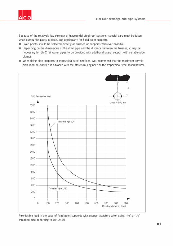
Because of the relatively low strength of trapezoidal steel roof sections, special care must be takenwhen putting the pipes in place, and particularly for fixed point supports.
Fixed points should be selected directly on trusses or supports wherever possible.Depending on the dimensions of the drain pipe and the distance between the trusses, it may benecessary for GM-X rainwater pipes to be provided with additional lateral support with suitable pipeclamps.When fixing pipe supports to trapezoidal steel sections, we recommend that the maximum permis-sible load be clarified in advance with the structural engineer or the trapezoidal steel manufacturer.
Flat roof drainage and pipe systems
Permissible load in the case of fixed point supports with support adapters when using 3/4” or 1/2”threaded pipe according to DIN 2440
F [N] Permissible load
Mounting distance L [mm]
Threaded pipe 3/4”
Threaded pipe 1/2”
Lmax. = 900 mm
L
82
Flat roof drainage and pipe systems
4. Maintenance
Roof drains for open channel drainage systems and syphonic drainage systems both have to bemaintained. Observe the relevant standards.
4.1 Gravity rainwater drainageThe proper functioning of roof drains must be regularly inspected in accordance with national regulations.They should also be cleaned when required.
4.2 Syphonic drainageThe maintenance of syphonic drainage systems is also defined in national regulations. It isparticularly important that the drains are checked every six months to remove any dirt and to ins-pect their overall condition. It is recommended that a maintenance contract be taken out to servicethis type of drainage system.
83
Flat roof drainage and pipe systems
84
2
1
Flat roof drainage and pipe systems
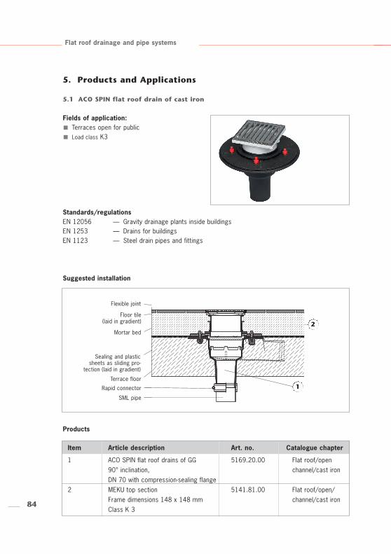
5. Products and Applications
5.1 ACO SPIN flat roof drain of cast iron
Fields of application:Terraces open for public Load class K3
Flexible joint
Floor tile(laid in gradient)
Mortar bed
Sealing and plasticsheets as sliding pro-
tection (laid in gradient)
Terrace floor
Rapid connector
SML pipe
Products
Standards/regulationsEN 12056 — Gravity drainage plants inside buildingsEN 1253 — Drains for buildingsEN 1123 — Steel drain pipes and fittings
Suggested installation
Item Article description Art. no. Catalogue chapter
1 ACO SPIN flat roof drains of GG 5169.20.00 Flat roof/open90° inclination, channel/cast ironDN 70 with compression-sealing flange
2 MEKU top section 5141.81.00 Flat roof/open/Frame dimensions 148 x 148 mm channel/cast ironClass K 3
85
m
s
5l 1
f
d 10
Flat roof drainage and pipe systems
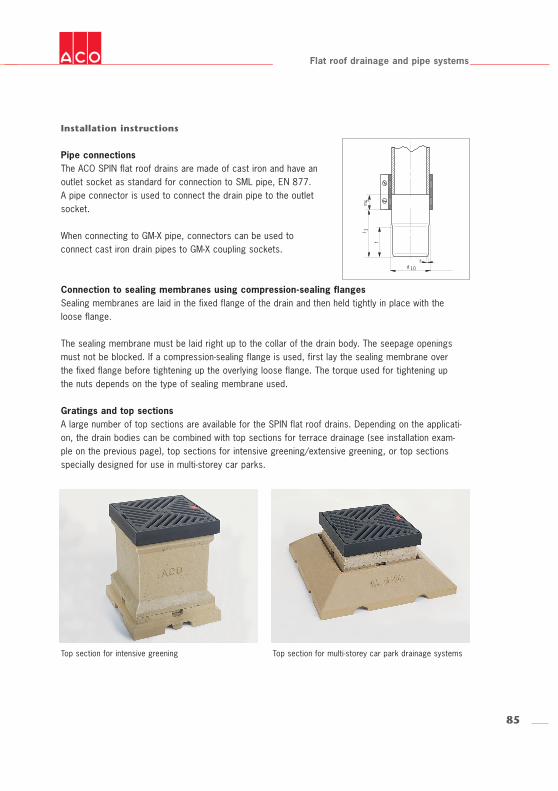
Installation instructions
Pipe connectionsThe ACO SPIN flat roof drains are made of cast iron and have anoutlet socket as standard for connection to SML pipe, EN 877.A pipe connector is used to connect the drain pipe to the outletsocket.
When connecting to GM-X pipe, connectors can be used toconnect cast iron drain pipes to GM-X coupling sockets.
Connection to sealing membranes using compression-sealing flangesSealing membranes are laid in the fixed flange of the drain and then held tightly in place with theloose flange.
The sealing membrane must be laid right up to the collar of the drain body. The seepage openingsmust not be blocked. If a compression-sealing flange is used, first lay the sealing membrane overthe fixed flange before tightening up the overlying loose flange. The torque used for tightening upthe nuts depends on the type of sealing membrane used.
Gratings and top sectionsA large number of top sections are available for the SPIN flat roof drains. Depending on the applicati-on, the drain bodies can be combined with top sections for terrace drainage (see installation exam-ple on the previous page), top sections for intensive greening/extensive greening, or top sectionsspecially designed for use in multi-storey car parks.
Top section for intensive greening Top section for multi-storey car park drainage systems
86
1
Flat roof drainage and pipe systems
Products
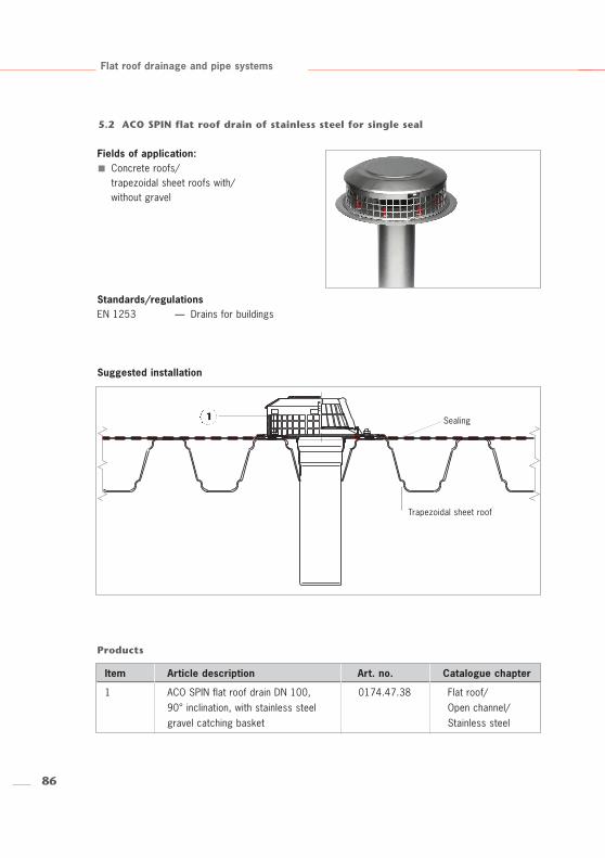
Sealing
Trapezoidal sheet roof
5.2 ACO SPIN flat roof drain of stainless steel for single seal
Fields of application:Concrete roofs/trapezoidal sheet roofs with/without gravel
Standards/regulationsEN 1253 — Drains for buildings
Suggested installation
Item Article description Art. no. Catalogue chapter
1 ACO SPIN flat roof drain DN 100, 0174.47.38 Flat roof/90° inclination, with stainless steel Open channel/gravel catching basket Stainless steel
87
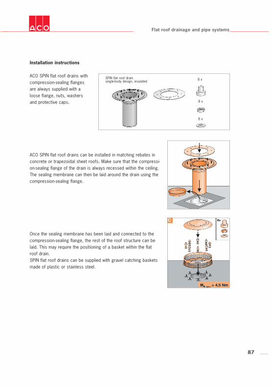
SPIN flat roof drainsingle-body design, insulated
ACO SPIN flat roof drains can be installed in matching rebates inconcrete or trapezoidal sheet roofs. Make sure that the compressi-on-sealing flange of the drain is always recessed within the ceiling. The sealing membrane can then be laid around the drain using thecompression-sealing flange.
Flat roof drainage and pipe systems
Installation instructions
ACO SPIN flat roof drains withcompression-sealing flangesare always supplied with aloose flange, nuts, washersand protective caps.
Once the sealing membrane has been laid and connected to thecompression-sealing flange, the rest of the roof structure can belaid. This may require the positioning of a basket within the flatroof drain. SPIN flat roof drains can be supplied with gravel catching basketsmade of plastic or stainless steel.
8 x
8 x
8 x
88
6
5
2
4
3
1
Flat roof drainage and pipe systems
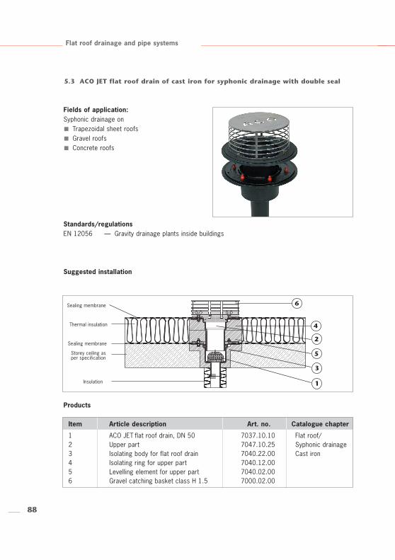
5.3 ACO JET flat roof drain of cast iron for syphonic drainage with double seal
Fields of application:Syphonic drainage on
Trapezoidal sheet roofsGravel roofsConcrete roofs
Products
Standards/regulationsEN 12056 — Gravity drainage plants inside buildings
Suggested installation
Item Article description Art. no. Catalogue chapter
1 ACO JET flat roof drain, DN 50 7037.10.10 Flat roof/2 Upper part 7047.10.25 Syphonic drainage3 Isolating body for flat roof drain 7040.22.00 Cast iron4 Isolating ring for upper part 7040.12.005 Levelling element for upper part 7040.02.006 Gravel catching basket class H 1.5 7000.02.00
Sealing membrane
Thermal insulation
Sealing membrane
Storey ceiling asper specification
Insulation
89
Functionalunit
Functionalunit
Flat roof drainage and pipe systems
FunctionACO flat roof drains for syphonic drainage systems are designed for connection to pipes which, bydefinition, have to be operated when completely full. Pipes of this kind can only be used when theyhave the properly certified hydraulic specifications.The functional elements must always be installed in the drain body. The flat roof drain will not functionfor syphonic drainage without the functional part.
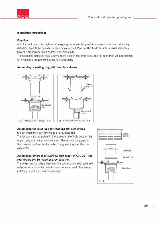
Assembling a sealing ring with two-piece drains
Assembling the pilot tube for ACO JET flat roof drainsDN 50 emergency overflow made of grey cast ironThe lip seal must be placed in the groove of the drain body or theupper part, and coated with lubricant. The accumulating pipe isthen pushed on down to the collar. The gravel trap can then beassembled.
Assembling emergency overflow pilot tube for ACO JET flatroof drains DN 80 made of grey cast ironThe roller ring must be pulled over the socket of the pilot tube androlled uniformly into the drain body or the upper part. The gravelcatching basket can then be assembled.
Installation instructions
Sealing ring
Fig. 1: drain, two-piece design, DN 50
Gravel basket
Pilot tube
Sealingring
Fig. 2: drain, two-piece design, DN 80
Drain body
Lip seal ring
Fig. 3
90
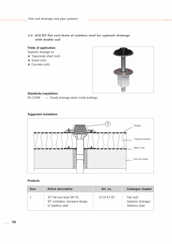
1Sealing
Thermal insulation
Vapour seal
Flat roof ceiling
Flat roof drainage and pipe systems
5.4 ACO JET flat roof drain of stainless steel for syphonic drainage with double seal
Fields of application:Syphonic drainage on
Trapezoidal sheet roofsGravel roofsConcrete roofs
Products
Standards/regulationsEN 12056 — Gravity drainage plants inside buildings
Suggested installation
Item Article description Art. no. Catalogue chapter
1 JET flat roof drain DN 70, 0174.47.00 Flat roof/90° inclination, two-piece design, Syphonic drainage/of stainless steel Stainless steel
91
Bitumen membranes2.0 Nm only
Flat roof drainage and pipe systems
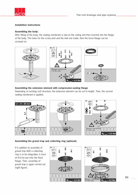
Installation instructions
Assembling the gravel trap and collecting ring (optional)
If in addition to assembly ofgravel trap (left) a collectingring is to be integrated, it mustat first be put onto the fixedflange. Then, assembly ofgravel trap is again carried out(right figure).
Assembling the body:After fitting of the body, the sealing membrane is laid on the ceiling and then inserted into the flangeof the body. The holes for the screw joint and the inlet are made, then the loose flange can bescrewed on.
Assembling the extension element with compression-sealing flangeDepending on existing roof structure, the extension element can be cut to length. Then, the secondsealing membrane is applied.
Bitumen membranes2.0 Nm only
Bitumen membranes2.0 Nm only
92
1
Gravel
Thermal insulation
Concrete ceiling
Flat roof drainage and pipe systems
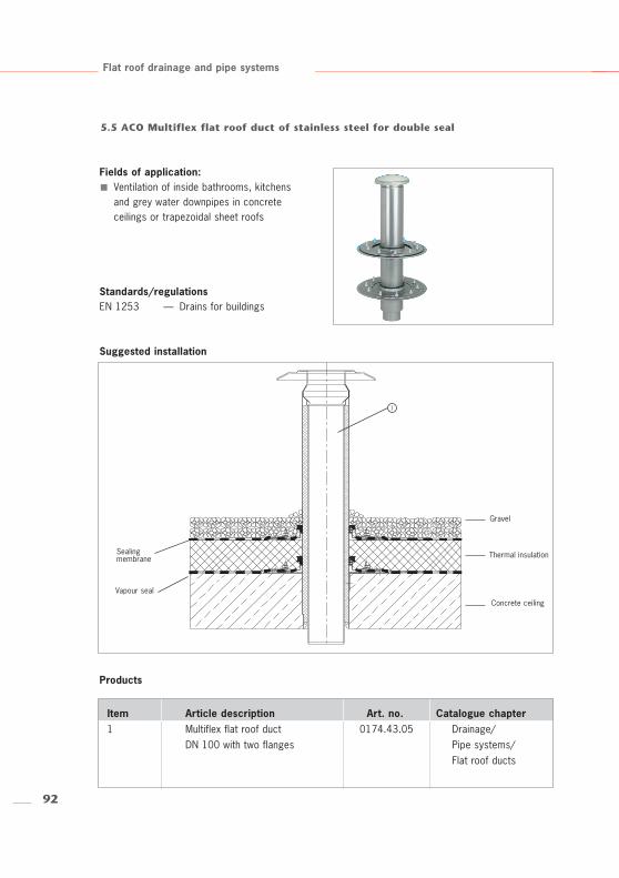
5.5 ACO Multiflex flat roof duct of stainless steel for double seal
Fields of application:Ventilation of inside bathrooms, kitchensand grey water downpipes in concreteceilings or trapezoidal sheet roofs
Products
Standards/regulationsEN 1253 — Drains for buildings
Suggested installation
Item Article description Art. no. Catalogue chapter1 Multiflex flat roof duct 0174.43.05 Drainage/
DN 100 with two flanges Pipe systems/Flat roof ducts
Vapour seal
Sealingmembrane
93
Flat roof drainage and pipe systems
Connection optionsThe flexibility of the flanges attached to the multiflex flat roof ducts allows quick in situ adjustment toany differences in insulation thickness. The shuttering cones and the support sheets available as optio-nal accessories simplify installation.
Installation in concrete roofs1. There must be a rebate in the ceiling.2. The shuttering cone must be placed in a rebate and fixed in place.3. The flat roof duct must be placed in the cone without a flange.4. Pour the concrete into the rebate – allow the concrete to set.5. The first sliding flange is pulled over from the top (adjustable to fit all ceiling thicknesses).6. The vapour diffusion barrier is laid in the compression-sealing flange.7. Install the insulation.8. Pull on the second sliding flange from above (adjustable to all insulation thicknesses).9. Connect the roof sealing membrane to the compression-sealing flange.10. Install the rain protection cap if room ventilation is also required.
Installation in trapezoidal sheet roofs1. Cut out the opening for the flat roof duct.2. Define the length required for connection on the inside.3. Fix the support sheet to the ventilation pipe using the fastening brackets and the self-tapping
screws.4. Position the flat roof duct on the trapezoidal sheet roof.5. Fix the support sheet onto the trapezoidal sheet.6. The first sliding flange is pulled over from the top (adjustable to fit all ceiling thicknesses).7. The vapour diffusion barrier is laid in the compression-sealing flange.8. Install the insulation.9. Pull on the second sliding flange from above (adjustable to all insulation thicknesses).10. Connect the roof sealing membrane to the compression-sealing flange.11. Install the rain protection cap if room ventilation is also required.
Installation instructions
94
1
Flat roof drainage and pipe systems
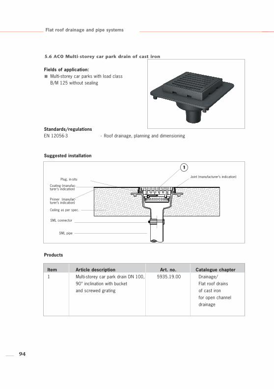
5.6 ACO Multi-storey car park drain of cast iron
Fields of application:Multi-storey car parks with load class B/M 125 without sealing
Products
Standards/regulationsEN 12056-3 - Roof drainage, planning and dimensioning
Suggested installation
Item Article description Art. no. Catalogue chapter1 Multi-storey car park drain DN 100, 5935.19.00 Drainage/
90° inclination with bucket Flat roof drainsand screwed grating of cast iron
for open channel drainage
Joint (manufacturer’s indication)Plug, in-situ
Ceiling as per spec.
Coating (manufac-turer’s indication)
SML pipe
Primer (manufac-turer’s indication)
SML connector
95
Flat roof drainage and pipe systems
Installation (1) Reinforce the housing. Connect the pipes, pour in concrete (seal the seepage openings in situ).(2) Construct the covering layer.(3) Put the bucket into position.(4) Put the grating into position and bolt it down if necessary.
Retrofitting fire protection fittingsThe fire protection fitting can be installed without any lubricants.Installation requires a completely concreted-in drain and ceiling thicknesses of at least 200mm.The fire protection fitting can be removed without tools for maintenance. After maintenance,IMMEDIATELY replace the fire protection fittings.
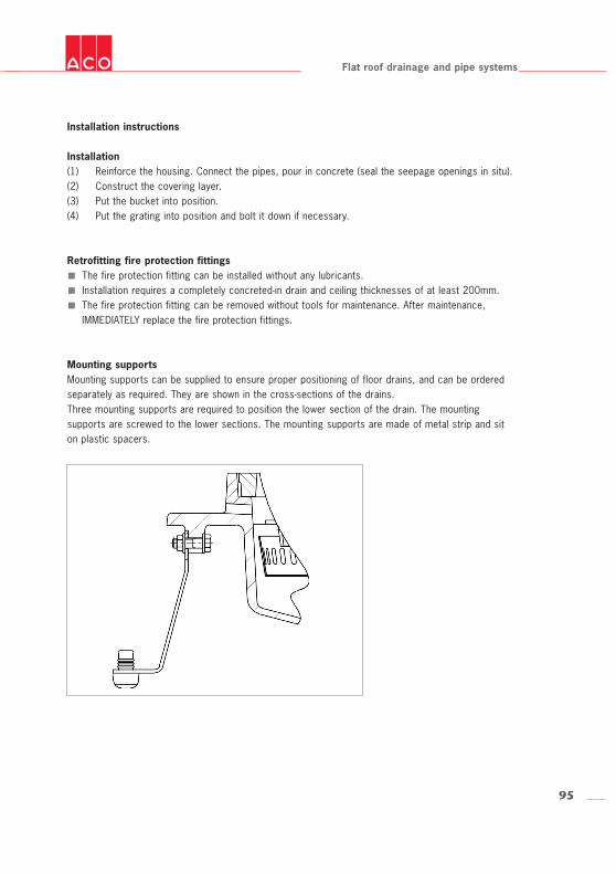
Mounting supportsMounting supports can be supplied to ensure proper positioning of floor drains, and can be orderedseparately as required. They are shown in the cross-sections of the drains. Three mounting supports are required to position the lower section of the drain. The mountingsupports are screwed to the lower sections. The mounting supports are made of metal strip and siton plastic spacers.
Installation instructions
Related Documents