International Journal of Scientific & Engineering Research, Volume 9, Issue 2, Feburary-2018 ISSN 2229-5518 Flare Radiation Mitigation Analysis of Onshore Oil & Gas Production & Refining Facility for a Low Cost De-Bottlenecking using Computer Aided Techniques 1 Anchal Soni* and 2 Nitesh Parmar 1 Research Scholar, 2 Assistant Professor, 1,2 Department of Chemical Engineering, IES, IPS Academy – Indore, Madhya Pradesh, INDIA. *Corresponding Author’s E-mail ID:[email protected] Abstract- Flares are an attempt to deliberately burn the flammable safety relief and/or process vents from a plant. The burning of gas should be complete so that it reduces pollution and helps to maintain a cleaner atmosphere. Gases flared in the stacks are excess process gases, which cannot be vented directly into the atmosphere. These gases are formed in various chemical process hence form a stream of mixture of gases which is burnt in the Flare System. The paper will discuss various mitigation approaches for about 30% increase in 6.0 MMTPA refinery, which intends a low cost de-bottlenecking in its existing facilities to enhance its current capacity to 7.8 MMTPA. The analysis is done by analysing different radiation Isopleths (Contours) generated using Flaresim Software Application and following API-521 for Pressure-relieving and Depressuring Systems. The main objective is to calculate the sterile area around an existing vertical flare of length 112 meters, located in an onshore facility and evaluate whether the current design is acceptable during a General Power Failure (GPF) scenario. The sterile area will be calculated at an elevation of 2m, which represents the typical head height for personnel. Index Terms- Flare Stack, Radiation analysis, Radiation Isopleths analysis, Hydrocarbon Flare, Sour Flare, Assist Fluids & Shielding. —————————— —————————— 1 INTRODUCTION Flaring is intended primarily as a safety measure for disposing of large quantities of gases during plant emergencies. The flare system will be provided for safe disposal of combustible, toxic gases, which are relieved from process plants and off sites during start-up, shut down, normal operation or in case of emergency such as: • Cooling Water failure • General power failure • External fire case • Any other operational failure - Blocked outlet - Reflux failure - Local power failure - Tube rupture The height of the stack is important to the safety of the surroundings and personnel, and the diameter is important to provide sufficient flow velocity to allow the vapours/gases to leave the top of the stack at sufficient velocities to provide good mixing and dilution after ignition at the flare tip by pilot flames. The goal of debottlenecking is to increase production capacity at an existing plant by making modifications to the equipment configuration or workflow. This is accomplished by eliminating bottlenecks that limit throughput. It can be an extremely profitable exercise for users, because in most cases debottlenecking adds extra capacity at a fraction of the cost of new build or expansion. Flaresim Software- Flaresim is a computer program designed to assist professional engineers in the design and evaluation of flare systems. The program calculates the thermal radiation, thermal dose and noise generated by flares and estimates the temperatures of exposed surfaces. It also performs dispersion analysis of the combustion gases or relieved fluid in flame out conditions. The following features highlight the main capabilities of Flaresim: • Applicable to the design of flare systems for offshore platforms, gas plants, refineries and chemical plants. • Modelling of water curtains or solid shields to reduce radiation and noise transmission. • Sterile area calculations to allow the safe distance from flare stack at different radiation limits. • Wide range of algorithms for calculation of thermal radiation. These include the McMurray integrated multipoint methods and the Chamberlain (Shell) method in addition to the Hajek/Ludwig and Brzustowski/Sommer methods which are described in the API guidelines for flare system design. This paper presents the results of a study of emissions from flare systems. The scope of the study includes an evaluation of existing flare systems of a refinery, an examination of flare design using Flaresim Software Application, by assessing the present emission problems. In the system analysis is done over an existing derrick supported elevated flare (Stack Length = 112 meters). The major components of an elevated flare system are the flare stack, flare tip, pilot, gas seal, liquid seal, knockout drum, and ignition system. 975 IJSER © 2018 http://www.ijser.org IJSER

Welcome message from author
This document is posted to help you gain knowledge. Please leave a comment to let me know what you think about it! Share it to your friends and learn new things together.
Transcript
International Journal of Scientific & Engineering Research, Volume 9, Issue 2, Feburary-2018 ISSN 2229-5518
Flare Radiation Mitigation Analysis of Onshore Oil & Gas Production & Refining Facility for a Low Cost
De-Bottlenecking using Computer Aided Techniques 1Anchal Soni* and 2Nitesh Parmar
1Research Scholar, 2Assistant Professor, 1,2Department of Chemical Engineering, IES, IPS Academy – Indore, Madhya Pradesh, INDIA.
*Corresponding Author’s E-mail ID:[email protected]
Abstract- Flares are an attempt to deliberately burn the flammable safety relief and/or process vents from a plant. The burning of gas should be complete so that it reduces pollution and helps to maintain a cleaner atmosphere. Gases flared in the stacks are excess process gases, which cannot be vented directly into the atmosphere. These gases are formed in various chemical process hence form a stream of mixture of gases which is burnt in the Flare System. The paper will discuss various mitigation approaches for about 30% increase in 6.0 MMTPA refinery, which intends a low cost de-bottlenecking in its existing facilities to enhance its current capacity to 7.8 MMTPA. The analysis is done by analysing different radiation Isopleths (Contours) generated using Flaresim Software Application and following API-521 for Pressure-relieving and Depressuring Systems.
The main objective is to calculate the sterile area around an existing vertical flare of length 112 meters, located in an onshore facility and evaluate whether the current design is acceptable during a General Power Failure (GPF) scenario. The sterile area will be calculated at an elevation of 2m, which represents the typical head height for personnel.
Index Terms- Flare Stack, Radiation analysis, Radiation Isopleths analysis, Hydrocarbon Flare, Sour Flare, Assist Fluids & Shielding.
—————————— ——————————
1 INTRODUCTION
Flaring is intended primarily as a safety measure for disposing of large quantities of gases during plant emergencies. The flare system will be provided for safe disposal of combustible, toxic gases, which are relieved from process plants and off sites during start-up, shut down, normal operation or in case of emergency such as:
• Cooling Water failure • General power failure • External fire case • Any other operational failure
- Blocked outlet - Reflux failure - Local power failure - Tube rupture
The height of the stack is important to the safety of the surroundings and personnel, and the diameter is important to provide sufficient flow velocity to allow the vapours/gases to leave the top of the stack at sufficient velocities to provide good mixing and dilution after ignition at the flare tip by pilot flames.
The goal of debottlenecking is to increase production capacity at an existing plant by making modifications to the equipment configuration or workflow. This is accomplished by eliminating bottlenecks that limit throughput. It can be an extremely profitable exercise for users, because in most cases debottlenecking adds extra capacity at a fraction of the cost of new build or expansion.
Flaresim Software- Flaresim is a computer program designed to assist professional engineers in the design and
evaluation of flare systems. The program calculates the thermal radiation, thermal dose and noise generated by flares and estimates the temperatures of exposed surfaces. It also performs dispersion analysis of the combustion gases or relieved fluid in flame out conditions.
The following features highlight the main capabilities of Flaresim:
• Applicable to the design of flare systems for offshore platforms, gas plants, refineries and chemical plants.
• Modelling of water curtains or solid shields to reduce radiation and noise transmission.
• Sterile area calculations to allow the safe distance from flare stack at different radiation limits.
• Wide range of algorithms for calculation of thermal radiation. These include the McMurray integrated multipoint methods and the Chamberlain (Shell) method in addition to the Hajek/Ludwig and Brzustowski/Sommer methods which are described in the API guidelines for flare system design.
This paper presents the results of a study of emissions from flare systems. The scope of the study includes an evaluation of existing flare systems of a refinery, an examination of flare design using Flaresim Software Application, by assessing the present emission problems. In the system analysis is done over an existing derrick supported elevated flare (Stack Length = 112 meters). The major components of an elevated flare system are the flare stack, flare tip, pilot, gas seal, liquid seal, knockout drum, and ignition system.
975
IJSER © 2018 http://www.ijser.org
IJSER
International Journal of Scientific & Engineering Research, Volume 9, Issue 2, Feburary-2018 ISSN 2229-5518
2 METHODS
Calculation Models: API RP-521 includes the calculation of thermal radiation, noise and surface temperature.
F factors calculation- The F Factor or fraction of combustion heat radiated from a flame is the most important single parameter in the calculation of thermal radiation calculation
The fraction of heat radiated is an overall characteristic of the flame, which can be affected by the following variables:
• Gas composition • Flame type • State of air-fuel mixing • Soot/smoke formation • Quantity of fuel being burned • Flame temperature • Flare burner design
F factors calculation can be done using following equations, they can be broadly categorized as empirically derived and theoretically derived:
Empirically derived:
Kent, 1964(Correlation based on mole weight)-
Applicable for:
• Hydrocarbons, f = 0.4 • Propane, f = 0.33 • Methane, f = 0.2
𝑭 = 𝟎. 𝟐√𝟓𝟎. 𝐌𝐖 + 𝟏𝟎𝟎
𝟗𝟎𝟎
Tan, 1967(based on mole weight)
Only applicable for three F- Factor value
Methane = 0.20 (MW = 16)
Propane = 0.33 (MW = 44)
Higher molecular weight hydrocarbons = 0.40
𝑭𝒔 = 𝟎. 𝟎𝟒𝟖 √𝑴𝑾
Cook et al., 1987a (Correlation based on exit velocity)
Values of the fraction of heat radiated varied from 0.017 to 0.344, the mean value over all tests being 0.187 (Cook et al., 1987a).
𝝌 =𝒑
𝑸=
𝒑
𝒎𝒋 . 𝜟𝒉𝒄
P= E Af
Chamberlain, 1987(Empirically derived)
The Fs factor for high velocity 6” diameter tests fall below the curve because the flames are smaller and spectrally different from those at higher flow rates. The correlation, therefore, referred to large flares typical of offshore flare system design flow rates. For small flames at high velocity, the equation will over predict Fs, and flare systems designed for these cases will be conservative unless a more appropriate value of Fs is used.
Fs = 0.11 + 0.21 e -0.00323Uj
Mod. Chamberlain Method (Correlation based on mole weight and exit velocity)
Fs = [0.11 + 0.21 e -0.00323Uj] . f(MW)
Where,
• f(MW) = 1, MW<21 • f (MW) = (MW/21) 0.5, 21< MW <60 • f (MW) = 1.69, 60< MW
Cook et al., 1987b
The complete model was validated by comparing predictions with measured values of incident radiation obtained in 57 field scale experiments. It was found that over 80% of all predictions were within ±30% of the measurements.
f = 0.321 – 0.00041uj
Theoretically derived:
API, 1969
According to API RP 521, flare stack calculation includes thermal radiation, surface temperatures and noise models. Common approach to determining the flame radiation to a point of interest is to consider the flame to have a single radiant epicentre and to use the following empirical equation by Hajek and Ludwig may be used for both subsonic and sonic flares
𝒙 = √𝛕. 𝐅. 𝐐
𝟒. 𝛑. 𝐤
Applicable conditions: Brzustowski and Sommer (1973) suggested that this model is quite accurate close to the flame. Chamberlain (1987) predicted it could only predict thermal radiation accurately in the far field (the opposite to what Brzustowski and Sommer (1973) reported)
Limitations: Ignores wind effects and calculates the distances assuming the centre of radiation is at the base of the flame
(at the flare tip), not in the centre.
976
IJSER © 2018 http://www.ijser.org
IJSER

International Journal of Scientific & Engineering Research, Volume 9, Issue 2, Feburary-2018 ISSN 2229-5518
Brzustowski and Sommer, 1973
Equation extensively verified for large windblown flares.
𝑭 =𝟒𝛑𝐊𝐃𝟐
𝐐 𝐂𝐨𝐬𝛉
Leahey et al., 1979
Based on the geometry of the flame. They represented the flame surface as the frustum of a right cone. Theoretical values are considerably higher than observed values, in wind conditions.
𝝑 = 𝛆 𝛔𝑻𝟒(𝑹 + 𝐑𝐨)√(𝑳𝟐 + (𝑹 + 𝐑𝐨)𝟐
∆𝑯𝐑𝐨𝟐𝑾𝟎
This method do not give limitations in the applicability of the theoretical equation for determining the F-factor. Limited test conditions are provided on the graphs, but no other experimental conditions were stated.
Oenbring and Sifferman, 1980
This method assumed a point-source of radiance, located at one-half the flare flame length.
𝑭 =𝟒𝛑𝐊𝐃𝟐
𝐐
Flame Length Method
Flame length is calculated from heat released using following equation.
𝑳 = 𝑰𝟏 [𝑸
𝑵]
𝑰𝟐
Where L is flame length in m Q is heat release in J/s N is number of tips the constants I1 and I2 take the following values for different tip types
Table 1: Constants I1 and I2 take the following values for different tip types
Thermal radiation effects:
Many investigations have been undertaken to determine the effect of thermal radiation on human skin. Using human subjects, Stoll and Greene [8] found that with an intensity of 6.3 kW/m2, the pain threshold is reached in 8 s and blistering occurs in 20 s. On the bare skin of white rats, an
intensity of 6.3 kW/m2 produces burns in less than 20 s. The same report indicates that an intensity of 23.7 kW/m2 causes burns on the bare skin of white rats in approximately 6s.
The flare owner/operator shall determine the need for a solar-radiation-contribution adjustment to the values given in Table 2 on a case-by-case basis.
Recommended design thermal radiation for personnel
Permissible design level
Conditions
9.46(3000) kW/m2 (Btu/h·ft2)
Maximum radiant heat intensity at any location where urgent emergency action by personnel is required. When personnel enter or work in an area with the potential for radiant heat intensity greater than 6.31 kW/m2 (2 000 Btu/h·ft2), then radiation shielding and/or special protective apparel (e.g. a fire approach suit) should be considered.
6.31 (2 000) kW/m2 (Btu/h·ft2)
Maximum radiant heat intensity in areas where emergency actions lasting up to 30 s can be required by personnel without shielding but with appropriate clothing a
4.73 (1 500) kW/m2 (Btu/h·ft2)
Maximum radiant heat intensity in areas where emergency actions lasting 2 min to 3 min can be required by personnel without shielding but with appropriate clothing a
1.58 (500) kW/m2 (Btu/h·ft2)
Maximum radiant heat intensity at any location where personnel with appropriate clothing a can be continuously exposed
Table 2: Exposure times as per API-521
a Appropriate clothing consists of hard hat, long-sleeved shirts with cuffs buttoned, work gloves, long-legged pants and work shoes. Appropriate clothing minimizes direct skin exposure to thermal radiation.
SAFETY PRECAUTION — It is important to recognize that personnel with appropriate clothing a cannot tolerate thermal radiation at 6.31 kW/m2 (2 000 Btu/h•ft2) for more than a few seconds.
Table 3: Exposure times necessary to reach the pain threshold
Tip Type l1 l2
Pipe flare 0.00331 0.4776
Single Burner Sonic 0.00241 0.4600
Multiple Burner Sonic
0.00129 0.5000
Radiation intensity, kW/m2 (Btu/h·ft2)
Time-to-pain threshold (Seconds)
1.74 (550) 60
2.33(7400) 40
2.90(920) 30
4.73(1500) 16
6.94(2200) 9
9.46(3000) 6
11.67(3700 4
1987(6300) 2
977
IJSER © 2018 http://www.ijser.org
IJSER
International Journal of Scientific & Engineering Research, Volume 9, Issue 2, Feburary-2018 ISSN 2229-5518
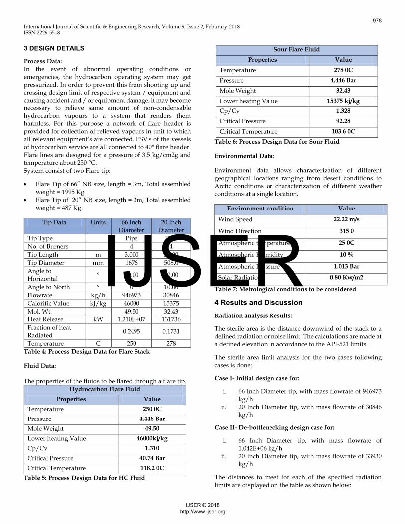
3 DESIGN DETAILS
Process Data:
In the event of abnormal operating conditions or emergencies, the hydrocarbon operating system may get pressurized. In order to prevent this from shooting up and crossing design limit of respective system / equipment and causing accident and / or equipment damage, it may become necessary to relieve same amount of non-condensable hydrocarbon vapours to a system that renders them harmless. For this purpose a network of flare header is provided for collection of relieved vapours in unit to which all relevant equipment’s are connected. PSV's of the vessels of hydrocarbon service are all connected to 40" flare header. Flare lines are designed for a pressure of 3.5 kg/cm2g and temperature about 250 °C. System consist of two Flare tip:
Flare Tip of 66” NB size, length = 3m, Total assembled weight = 1995 Kg
Flare Tip of 20” NB size, length = 3m, Total assembled weight = 487 Kg
Tip Data Units 66 Inch Diameter
20 Inch Diameter
Tip Type Pipe Pipe
No. of Burners 4 4
Tip Length m 3.000 3.000
Tip Diameter mm 1676 508.0
Angle to Horizontal
° 90.00 90.00
Angle to North ° 0 10.00
Flowrate kg/h 946973 30846
Calorific Value kJ/kg 46000 15375
Mol. Wt. 49.50 32.43
Heat Release kW 1.210E+07 131736
Fraction of heat Radiated
0.2495 0.1731
Temperature C 250 278
Table 4: Process Design Data for Flare Stack
Fluid Data:
The properties of the fluids to be flared through a flare tip.
Hydrocarbon Flare Fluid
Properties Value
Temperature 250 0C
Pressure 4.446 Bar
Mole Weight 49.50
Lower heating Value 46000kj/kg
Cp/Cv 1.310
Critical Pressure 40.74 Bar
Critical Temperature 118.2 0C
Table 5: Process Design Data for HC Fluid
Table 6: Process Design Data for Sour Fluid
Environmental Data:
Environment data allows characterization of different geographical locations ranging from desert conditions to Arctic conditions or characterization of different weather conditions at a single location.
Environment condition Value
Wind Speed 22.22 m/s
Wind Direction 315 0
Atmospheric temperature 25 0C
Atmospheric Humidity 10 %
Atmospheric Pressure 1.013 Bar
Solar Radiation 0.80 Kw/m2
Table 7: Metrological conditions to be considered
4 Results and Discussion
Radiation analysis Results:
The sterile area is the distance downwind of the stack to a defined radiation or noise limit. The calculations are made at a defined elevation in accordance to the API-521 limits.
The sterile area limit analysis for the two cases following cases is done:
Case I- Initial design case for:
i. 66 Inch Diameter tip, with mass flowrate of 946973 kg/h
ii. 20 Inch Diameter tip, with mass flowrate of 30846 kg/h
Case II- De-bottlenecking design case for:
i. 66 Inch Diameter tip, with mass flowrate of 1.042E+06 kg/h
ii. 20 Inch Diameter tip, with mass flowrate of 33930 kg/h
The distances to meet for each of the specified radiation limits are displayed on the table as shown below:
Sour Flare Fluid
Properties Value
Temperature 278 0C
Pressure 4.446 Bar
Mole Weight 32.43
Lower heating Value 15375 kj/kg
Cp/Cv 1.328
Critical Pressure 92.28
Critical Temperature 103.6 0C
978
IJSER © 2018 http://www.ijser.org
IJSER
International Journal of Scientific & Engineering Research, Volume 9, Issue 2, Feburary-2018 ISSN 2229-5518
Initial Design Case
Radiation Limit Distance To Limit
kW/m2 m
1.600 390.4
4.700 200.2
6.300 155.1
De-Bottlenecking Design Case
Radiation Limit Distance To Limit
kW/m2 m
1.600 411.7
4.700 214.9
6.300 169.2
Table 8: Radiation result comparison between Initial Design & De-bottlenecking Design
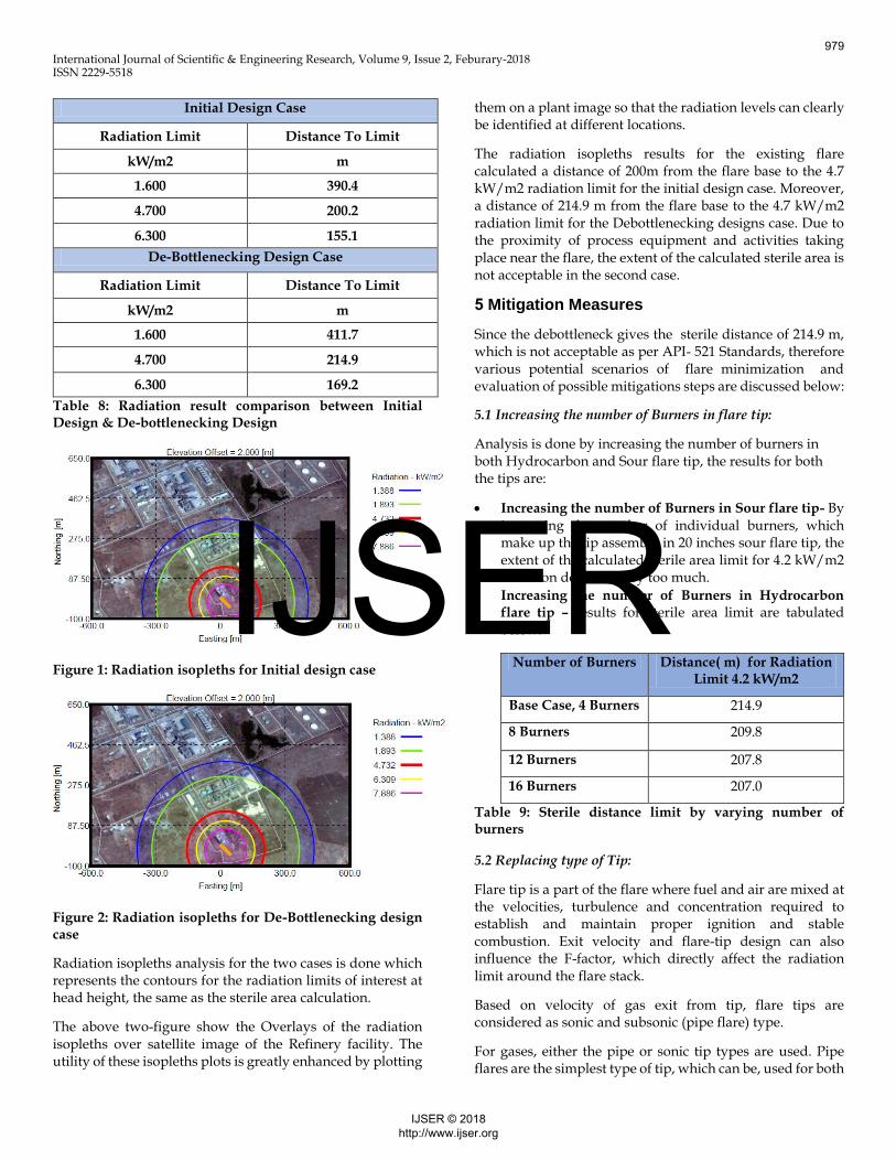
Figure 1: Radiation isopleths for Initial design case
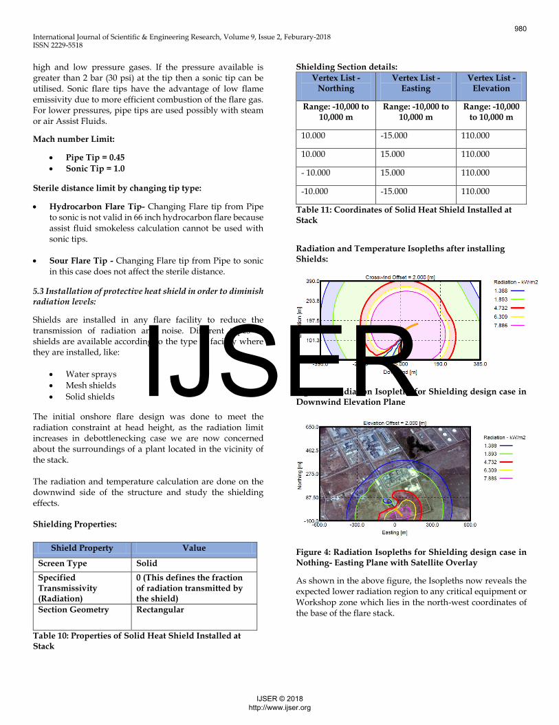
Figure 2: Radiation isopleths for De-Bottlenecking design case
Radiation isopleths analysis for the two cases is done which represents the contours for the radiation limits of interest at head height, the same as the sterile area calculation.
The above two-figure show the Overlays of the radiation isopleths over satellite image of the Refinery facility. The utility of these isopleths plots is greatly enhanced by plotting
them on a plant image so that the radiation levels can clearly be identified at different locations.
The radiation isopleths results for the existing flare calculated a distance of 200m from the flare base to the 4.7 kW/m2 radiation limit for the initial design case. Moreover, a distance of 214.9 m from the flare base to the 4.7 kW/m2 radiation limit for the Debottlenecking designs case. Due to the proximity of process equipment and activities taking place near the flare, the extent of the calculated sterile area is not acceptable in the second case.
5 Mitigation Measures
Since the debottleneck gives the sterile distance of 214.9 m, which is not acceptable as per API- 521 Standards, therefore various potential scenarios of flare minimization and evaluation of possible mitigations steps are discussed below:
5.1 Increasing the number of Burners in flare tip:
Analysis is done by increasing the number of burners in both Hydrocarbon and Sour flare tip, the results for both the tips are:
Increasing the number of Burners in Sour flare tip- By increasing the number of individual burners, which make up the tip assembly in 20 inches sour flare tip, the extent of the calculated sterile area limit for 4.2 kW/m2 radiation does not vary too much.
Increasing the number of Burners in Hydrocarbon flare tip – results for sterile area limit are tabulated below:
Number of Burners Distance( m) for Radiation Limit 4.2 kW/m2
Base Case, 4 Burners 214.9
8 Burners 209.8
12 Burners 207.8
16 Burners 207.0
Table 9: Sterile distance limit by varying number of burners
5.2 Replacing type of Tip:
Flare tip is a part of the flare where fuel and air are mixed at the velocities, turbulence and concentration required to establish and maintain proper ignition and stable combustion. Exit velocity and flare-tip design can also influence the F-factor, which directly affect the radiation limit around the flare stack.
Based on velocity of gas exit from tip, flare tips are considered as sonic and subsonic (pipe flare) type.
For gases, either the pipe or sonic tip types are used. Pipe flares are the simplest type of tip, which can be, used for both
979
IJSER © 2018 http://www.ijser.org
IJSER
International Journal of Scientific & Engineering Research, Volume 9, Issue 2, Feburary-2018 ISSN 2229-5518
high and low pressure gases. If the pressure available is greater than 2 bar (30 psi) at the tip then a sonic tip can be utilised. Sonic flare tips have the advantage of low flame emissivity due to more efficient combustion of the flare gas. For lower pressures, pipe tips are used possibly with steam or air Assist Fluids.
Mach number Limit:
Pipe Tip = 0.45
Sonic Tip = 1.0
Sterile distance limit by changing tip type:
Hydrocarbon Flare Tip- Changing Flare tip from Pipe to sonic is not valid in 66 inch hydrocarbon flare because assist fluid smokeless calculation cannot be used with sonic tips.
Sour Flare Tip - Changing Flare tip from Pipe to sonic in this case does not affect the sterile distance.
5.3 Installation of protective heat shield in order to diminish radiation levels:
Shields are installed in any flare facility to reduce the transmission of radiation and noise. Different types of shields are available according to the type of facility where they are installed, like:
Water sprays
Mesh shields
Solid shields
The initial onshore flare design was done to meet the radiation constraint at head height, as the radiation limit increases in debottlenecking case we are now concerned about the surroundings of a plant located in the vicinity of the stack. The radiation and temperature calculation are done on the downwind side of the structure and study the shielding effects. Shielding Properties:
Table 10: Properties of Solid Heat Shield Installed at Stack
Shielding Section details:
Vertex List - Northing
Vertex List - Easting
Vertex List - Elevation
Range: -10,000 to 10,000 m
Range: -10,000 to 10,000 m
Range: -10,000 to 10,000 m
10.000 -15.000 110.000
10.000 15.000 110.000
- 10.000 15.000 110.000
-10.000 -15.000 110.000
Table 11: Coordinates of Solid Heat Shield Installed at Stack
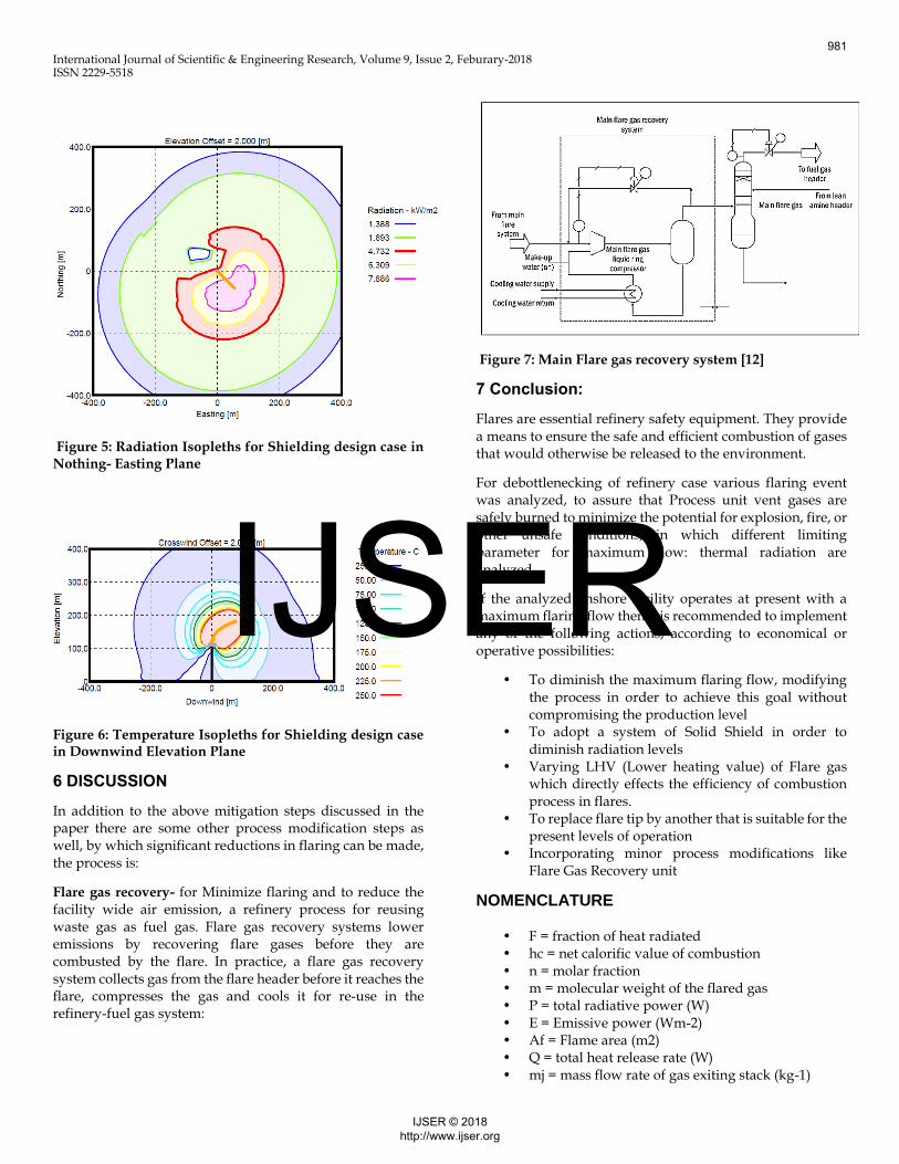
Radiation and Temperature Isopleths after installing Shields:
Figure 3: Radiation Isopleths for Shielding design case in Downwind Elevation Plane
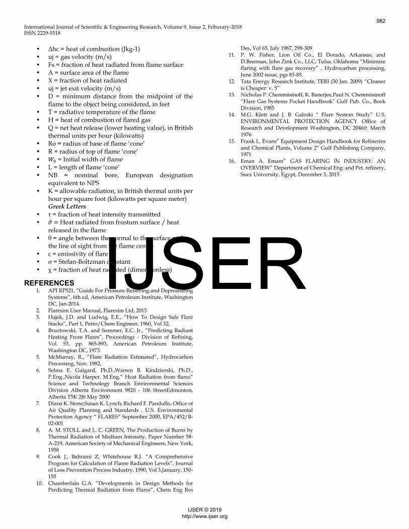
Figure 4: Radiation Isopleths for Shielding design case in Nothing- Easting Plane with Satellite Overlay
As shown in the above figure, the Isopleths now reveals the expected lower radiation region to any critical equipment or Workshop zone which lies in the north-west coordinates of the base of the flare stack.
Shield Property Value
Screen Type Solid
Specified Transmissivity (Radiation)
0 (This defines the fraction of radiation transmitted by the shield)
Section Geometry Rectangular
980
IJSER © 2018 http://www.ijser.org
IJSER
International Journal of Scientific & Engineering Research, Volume 9, Issue 2, Feburary-2018 ISSN 2229-5518
Figure 5: Radiation Isopleths for Shielding design case in Nothing- Easting Plane
Figure 6: Temperature Isopleths for Shielding design case in Downwind Elevation Plane
6 DISCUSSION
In addition to the above mitigation steps discussed in the paper there are some other process modification steps as well, by which significant reductions in flaring can be made, the process is:
Flare gas recovery- for Minimize flaring and to reduce the facility wide air emission, a refinery process for reusing waste gas as fuel gas. Flare gas recovery systems lower emissions by recovering flare gases before they are combusted by the flare. In practice, a flare gas recovery system collects gas from the flare header before it reaches the flare, compresses the gas and cools it for re-use in the refinery-fuel gas system:
Figure 7: Main Flare gas recovery system [12]
7 Conclusion:
Flares are essential refinery safety equipment. They provide a means to ensure the safe and efficient combustion of gases that would otherwise be released to the environment.
For debottlenecking of refinery case various flaring event was analyzed, to assure that Process unit vent gases are safely burned to minimize the potential for explosion, fire, or other unsafe conditions, in which different limiting parameter for maximum flow: thermal radiation are analyzed.
If the analyzed onshore facility operates at present with a maximum flaring flow then it is recommended to implement any of the following actions, according to economical or operative possibilities:
• To diminish the maximum flaring flow, modifying the process in order to achieve this goal without compromising the production level
• To adopt a system of Solid Shield in order to diminish radiation levels
• Varying LHV (Lower heating value) of Flare gas which directly effects the efficiency of combustion process in flares.
• To replace flare tip by another that is suitable for the present levels of operation
• Incorporating minor process modifications like Flare Gas Recovery unit
NOMENCLATURE
• F = fraction of heat radiated • hc = net calorific value of combustion • n = molar fraction • m = molecular weight of the flared gas • P = total radiative power (W) • E = Emissive power (Wm-2) • Af = Flame area (m2) • Q = total heat release rate (W) • mj = mass flow rate of gas exiting stack (kg-1)
981
IJSER © 2018 http://www.ijser.org
IJSER
International Journal of Scientific & Engineering Research, Volume 9, Issue 2, Feburary-2018 ISSN 2229-5518
• Δhc = heat of combustion (Jkg-1) • uj = gas velocity (m/s) • Fs = fraction of heat radiated from flame surface • A = surface area of the flame • X = fraction of heat radiated • uj = jet exit velocity (m/s) • D = minimum distance from the midpoint of the
flame to the object being considered, in feet • T = radiative temperature of the flame • H = heat of combustion of flared gas • Q = net heat release (lower heating value), in British
thermal units per hour (kilowatts) • Ro = radius of base of flame ‘cone’ • R = radius of top of flame ‘cone’ • 𝑊0 = Initial width of flame • L = length of flame ‘cone’ • NB = nominal bore, European designation
equivalent to NPS • K = allowable radiation, in British thermal units per
hour per square foot (kilowatts per square meter) Greek Letters
• τ = fraction of heat intensity transmitted • 𝜗 = Heat radiated from frustum surface / heat
released in the flame • θ = angle between the normal to the surface and
the line of sight from the flame centre • ε = emissivity of flare • σ = Stefan-Boltzman constant • χ = fraction of heat radiated (dimensionless)
REFERENCES 1. API RP521, “Guide For Pressure-Relieving and Depressuring
Systems”, 6th ed, American Petroleum Institute, Washington DC, Jan-2014.
2. Flaresim User Manual, Flaresim Ltd, 2015 3. Hajek, J.D. and Ludwig, E.E., “How To Design Safe Flare
Stacks”, Part 1, Petro/Chem Engineer, 1960, Vol 32, 4. Bruztowski, T.A. and Sommer, E.C. Jr., “Predicting Radiant
Heating From Flares”, Proceedings - Division of Refining, Vol. 53, pp. 865-893, American Petroleum Institute, Washington DC, 1973.
5. McMurray, R., “Flare Radiation Estimated”, Hydrocarbon Processing, Nov. 1982,
6. Selma E. Guigard, Ph.D.,Warren B. Kindzierski, Ph.D., P.Eng.,Nicola Harper, M.Eng.” Heat Radiation from flares” Science and Technology Branch Environmental Sciences Division Alberta Environment 9820 - 106 StreetEdmonton, Alberta T5K 2J6 May 2000
7. Diana K. Stone;Susan K. Lynch; Richard F. Pandullo, Office of Air Quality Planning and Standards , U.S. Environmental Protection Agency “ FLARES” September 2000, EPA/452/B-02-001
8. A. M. STOLL and L. C. GREEN, The Production of Burns by Thermal Radiation of Medium Intensity, Paper Number 58-A-219, American Society of Mechanical Engineers, New York, 1958
9. Cook J., Bahrami Z, Whitehouse R.J. “A Comprehensive Program for Calculation of Flame Radiation Levels”, Journal of Loss Prevention Process Industry, 1990, Vol 3,January, 150-155
10. Chamberlain G.A. “Developments in Design Methods for Predicting Thermal Radiation from Flares”, Chem Eng Res
Des, Vol 65, July 1987, 299-309 11. P. W. Fisher, Lion Oil Co., El Dorado, Arkansas, and
D.Brennan, John Zink Co., LLC, Tulsa, Oklahoma “Minimize flaring with flare gas recovery” , Hydrocarbon processing, June 2002 issue, pgs 83-85.
12. Tata Energy Research Institute, TERI (30 Jan. 2009) “Cleaner is Cheaper: v. 5”
13. Nicholas P. Cheremisinoff, K. Banerjee,Paul N. Cheremisinoff “Flare Gas Systems Pocket Handbook” Gulf Pub. Co., Book Division, 1985
14. M.G. Klett and J. B. Galeski “ Flare System Study” U.S. ENVIRONMENTAL PROTECTION AGENCY Office of Research and Development Washington, DC 20460: March 1976
15. Frank L. Evans” Equipment Design Handbook for Refineries and Chemical Plants, Volume 2” Gulf Publishing Company, 1971
16. Eman A. Emam” GAS FLARING IN INDUSTRY: AN OVERVIEW” Department of Chemical Eng. and Pet. refinery, Suez University, Egypt, December 3, 2015
982
IJSER © 2018 http://www.ijser.org
IJSER
Related Documents