M A D E I N G E R M A N Y M A D E I N G E R M A N Y Zertifiziert nach DIN ISO 9001:2015 Flanschkupplung Flange Coupling [DE] Flanschkupplung Typ FKHYD Gebrauchs- und Bedienungsanleitung [EN] Flange Coupling Type FKHYD User Manual

Welcome message from author
This document is posted to help you gain knowledge. Please leave a comment to let me know what you think about it! Share it to your friends and learn new things together.
Transcript

MADE IN GERMAN
YM
AD
E IN GERMANY
Zertifiziert nach DIN ISO 9001:2015
FlanschkupplungFlange Coupling
[DE] Flanschkupplung Typ FKHYDGebrauchs- und Bedienungsanleitung
[EN] Flange Coupling Type FKHYDUser Manual

02
Inhalt /Contents
[EN] User Manual
1. General Instructions and Symbols 21
2. Safety Instructions and Personal Protection Equipment 22
3. Intended Use 24
4. Transport 25
5. Descriptions and Sectional View 26
6. Installation 28
7. Dismantling and Re-Installation 32
8. Cleaning and Lubrication 36
[DE] Gebrauchs- und Bedienungsanleitung
1. Allgemeine Hinweise und Symbole 03
2. Sicherheitshinweise und persönliche Schutzausrüstung 04
3. Bestimmungsgemäße Verwendung 06
4. Transport 07
5. Bezeichnungen und Schnittansicht 08
6. Montage 10
7. Demontage und erneute Montage 14
8. Reinigung und Schmierung 20

Vor Einbau und Inbetriebnahme der STÜWE Flanschkupplung Typ FKHYD ist die Montageanleitung sorgfältig durchzu-lesen. Hinweise und Gefahrenvermerke sind gesondert gekennzeichnet und müs-sen besonders beachtet werden.
Bedeutung der Symbole in dieser Montageanleitung:
Diese Montageanleitung gilt unter der Voraussetzung, dass die Flanschkupplung für ihren Verwendungszweck richtig aus-gewählt ist. Auswahl und Auslegung der Flanschkupplung sind nicht Gegenstand dieser Montageanleitung.
Diese Montageanleitung ist sorgfältig aufzubewahren und muss im Falle der Weiterleitung der Flanschkupplung, sei es einzeln oder als Teil der Maschine, mitge-geben werden.
Alle Angaben und Hinweise in dieser Gebrauchs- und Bedienungsanleitung er-folgen unter Berücksichtigung unserer bis-herigen Erfahrungen und Erkenntnissen nach bestem Wissen. Die Originalfassung wurde in deutscher Sprache erstellt und von STÜWE geprüft. Eine Vervielfältigung, ist ohne die schriftliche Einwilligung von STÜWE nicht gestattet.
03
1. Allgemeine Hinweise und Symbole [DE]
GEFAHR
GefahrDas Signalwort bezeichnet eine un-mittelbare Gefährdung mit einem ho-hen Risikograd, die, wenn sie nicht vermieden wird, den Tod oder eine schwere Verletzung zur Folge hat.
HINWEIS
HinweisDas Signalwort bezeichnet eine möglicherweise gefährliche Situati-on, die zu Sach- und Umweltscha-den führen kann.
VORSICHT
VorsichtDas Signalwort bezeichnet eine Ge-fährdung mit einem niedrigen Risiko-grad, die, wenn sie nicht vermieden wird, eine geringfügige und mäßige Verletzung zur Folge haben kann.
WARNUNG
WarnungDas Signalwort bezeichnet eine möglicherweise drohende Gefähr-dung mit einem mittleren Risikograd, die, wenn sie nicht vermieden wird, den Tod oder eine schwere Verlet-zung zur Folge haben kann.

Die STÜWE Flanschkupplung Typ FKHYD darf nur dann montiert oder demontiert werden, wenn:
die Gebrauchs- und Bedienungsan-leitung vorab sorgfältig gelesen und verstanden wurde,
dies mit großer Sorgfalt durch Fach-kräfte, bzw. geschultes Personal* erfolgt,
Sie vom Unternehmen hierzu auto risiert sind.
* Als geschultes/unterwiesenes Personal gilt eine Person, die über die ihr über-tragenen Aufgaben und die möglichen Gefahren bei unsachgemäßem Verhalten unterrichtet und erforderlichenfalls ange-lernt wurde. Auch über die notwendigen Schutzeinrichtungen und Schutzmaß- nahmen wurde sie belehrt. Zu schulendes, anzulernendes, einzuweisendes oder im Rahmen einer allgemeinen Ausbildung befindliches Personal darf nur unter ständiger Aufsicht einer erfahrenen Person tätig werden.
Alle Kontaktdaten finden Sie auf unserer Homepage unter www.stuewe.de oder rufen Sie uns unter der Telefon- nummer +49 (0) 2324 394-0 an.
04
2. Sicherheitshinweise und persönliche Schutzausrüstung
VORSICHT
Die Montage und Demontage darf nur bei stillgesetzter und gegen Wiedereinschalten gesicherter Maschine durchgeführt werden.
HINWEIS
Durch die Kombination von Maschine und Flanschkupplung entstehen Gefährdungen durch bewegliche Teile. Durch den Be-treiber sind weitere Maßnahmen zur Risikominderung zu treffen.
Reparaturarbeiten dürfen nur von STÜWE oder nach Rücksprache mit STÜWE vorgenommen werden.
Wenn ein Verdacht auf Fehlfunk-tion vorliegt, ist die Maschine, in der die Flanschkupplung einge-baut ist, sofort außer Betrieb zu nehmen und STÜWE oder eine autorisierte STÜWE-Vertretung zu informieren.

05
2. Sicherheitshinweise und persönliche Schutzausrüstung
Persönliche Schutzausrüstung
(Chemikalienbeständigen) Handschutz verwenden
Augenschutz verwenden
Bei Montage-/Demontagearbeiten besteht eine Gefährdung durch Kontakt mit Schmierstoffen! Es sind die stoff-bezogenen Sicherheitsdatenblätter zu beachten. Handschuhe tragen.
Gefährdung durch scharfe Ecken und Kanten bei der Handhabung.
Die Flanschkupplung kann sich durch externe Wärmequellen im Betrieb stark erwärmen. Achtung vor heißen Oberflä-chen bei Montage-/Demontagearbeiten.
Bei Montage-/Demontagearbeiten be-steht eine Gefährdung durch Kontakt mit Schmierstoffen! Vollsichtbrille (Korbbrille) tragen. Es sind die stoffbezogenen Sicherheitsdatenblätter zu beachten. Diese erhalten Sie auf Anfrage bei uns.
Fußschutz verwenden
Bei Montage-/Demontagearbeiten besteht durch Herabfallen und Absetzen der Teile Verletzungsgefahr. Es ist ein geeigneter Fußschutz zu tragen.
Kopfschutz verwenden
Bei Montage-/Demontagearbeiten besteht durch Anhebung und Absenkung der Teile Verletzungsgefahr sowie Stoßgefahr des Kopfes an vorstehenden Maschinenteilen. Es ist ein geeigneter Kopfschutz zu tragen.
[DE]

06
3. Bestimmungsgemäße Verwendung
Bestimmungsgemäße Verwendung
Zeitliche Grenzen
Die Flanschkupplung Typ FKHYD ist für reibschlüssige starre, nicht schaltbare, lösbare Welle-Nabe-Verbindungen für zylindrische Wellen konzipiert. Die Verwendungsgrenzen werden unter Berücksichtigung einer vernünftigerweise vorhersehbaren Fehlanwendung wie folgt eingegrenzt:
Beachtung der technischen Daten gemäß Produktkatalog bzw. Kunden-zeichnung
Temperaturbereich: Die Standardprodukte sind im Bereich von -20°C bis +100°C einsetzbar. Bitte achten Sie bei Sonderprodukten auf die gesonderten Spezifikationen.
Materialeigenschaft: Das verwendete System aus der ersten und zweiten Welle muss die erforder-lichen Streckgrenzen (siehe Katalog) aufweisen.
Oberflächenbeschaffenheit: Die Oberflächenrauigkeit (Ra) des verwendeten Welle-Nabe-Systems soll-te kleiner sein als 3,2µm.
Umgebungsbedingungen: Standardprodukte sind in nicht korrosi-ven, flüssigen oder gasförmigen Umge-bungen einsetzbar. Bitte achten Sie bei Sonderprodukten auf die gesonderten Spezifikationen.
Eine zeitliche Grenze kann für das Produkt nicht festgelegt werden. Folgende Hinweise sind zu beachten:
Ein Nachschmieren ist vor einem er-neuten Verspannen nicht erforderlich.
Bei Verschmutzungen sind die Kegelflä-chen von Außen- und Innenring, sowie alle Gewinde zu reinigen und neu zu schmieren.
Die Dichtflächen sind frei von Verunrei-nigungen zu halten.
Bei Undichtigkeiten sind die Dichtungen zu erneuern.
Sollte bei häufigem Verspannen der benötigte Druck ansteigen und den maximal zulässigen Druck erreichen, so empfehlen wir die Kontaktaufnahme mit STÜWE.

07
4. Transport
Die Transporttätigkeiten dürfen nur durch geschultes/unterwiesenes Personal ausgeführt werden.
AnschlagpunkteZur Montage der Flanschkupplungen auf eine Welle wird ein Hebeband oder ein anderes geeignetes Hebezeug empfohlen.
WARNUNG
Schwankende oder herabfallende Flanschkupplungen bzw. Einzel-teile. Geeignete Lastaufnahmemit-tel, Kopfschutz und Sicherheits-schuhe verwenden bzw. tragen.
VORSICHT
Mit dem Anschlagen von Lasten nur geschultes/unterwiesenes Personal beauftragen.
Nicht unter schwebenden Lasten aufhalten.
HINWEIS
Verpackung fach- und umweltge-recht entsorgen. Die nationalen Vorschriften sind zu beachten.
[DE]

08
5. Bezeichnungen und Schnittansicht
Bezeichnungen
1
2
33
4
5
6FKHYDExplosionsansicht
1 Kontermutter
2 Stützring
3 Dichtung
4 Außenring
5 Innenring mit Flansch
6 Welle
Flanschkupplung
Gewinde
09
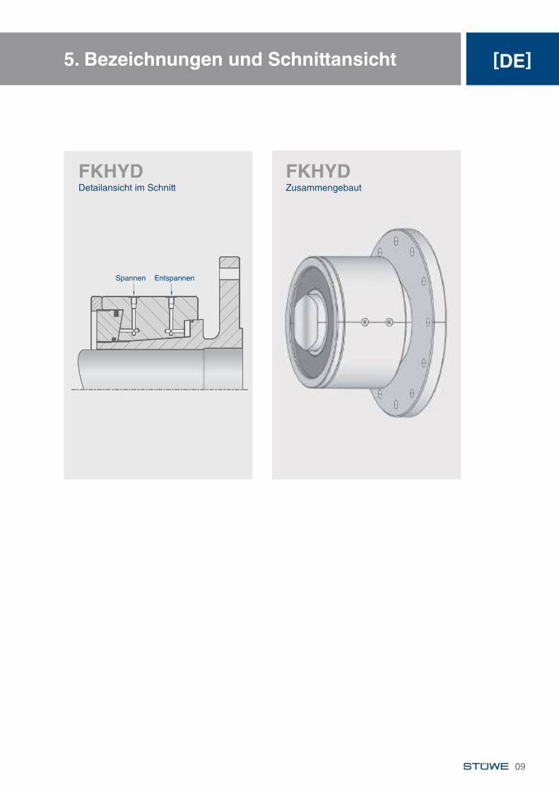
5. Bezeichnungen und Schnittansicht [DE]
FKHYDDetailansicht im Schnitt
FKHYDZusammengebaut
Spannen Entspannen

10
6. Montage
Aufschieben des Flansches auf die Welle.
VORSICHT
Die Flanschkupplung muss auf ihrer ganzen Breite auf der Welle anliegen.
Die STÜWE® Flanschkupplungen Typ FKHYD werden einbaufertig geliefert. In den Druckkammern befindet sich Hydrauliköl.
HINWEIS
Die Flanschkupplung darf vor dem erstmaligen Verspannen nicht ausei-nandergebaut werden.
HINWEIS
Nie die Flanschkupplung spannen, bevor nicht auch die Maschinenwelle eingebaut ist.
Montage
2.
Entfetten der Flanschbohrung und der Welle im Bereich des Flansch-kupplungssitzes.
HINWEIS
Saubere Putztücher und Lösungsmittel verwenden.
1.

11
6. Montage [DE]
Verschlussschrauben von den Anschlüssen „Spannen“ und „Entspannen“ entfernen.
HINWEIS
Das eventuell auslaufende Hydrauliköl auffangen.
4.
3.
Anschließen der Druckleitung an den Anschluss, der mit „Spannen“ gekennzeichnet ist.
HINWEIS
Das eventuell auslaufende Hydrauliköl auffangen.
5. Verspannen der Flanschkupplung durch Aufbringen des Hydraulikdrucks (Anschluss „Spannen“). Steigern des Druckes bis sich der Außenring in axialer Richtung bewegt.

12
6. Montage
Beim Verspannen ist der Flansch anfangs durch Hin- und Herbewegungen in radialer Richtung so lange zu bewegen, bis das Passungsspiel überbrückt ist.
Hierdurch wird ein einwandfreies Setzen der Bohrungs- und Wellenoberfläche ermöglicht und ein Verkanten ausgeschlossen.
6.
7. Verspannungszustand prüfen.
HINWEIS
Der korrekte Verspannungszustand ist erreicht, sobald die Stirnflächen des Außen- und Innen-rings in einer Ebene liegen (nach optischer Betrachtung bündig).
WARNUNG
Der maximal zulässige Spanndruck ist 450 bar.

13
[DE]6. Montage
Kontermutter handfest gegen den Außenring drehen.
HINWEIS
Eventuell den max. Spanndruck etwas reduzieren, um die Kontermutter bis gegen den Außenring drehen zu können.
8.
Verschlussschrauben wieder in die Anschlüsse eindrehen.
HINWEIS
Das Hydrauliköl in der Flanschkupplung belassen
10.
Öldruck ablassen. Dabei wird die Kontermutter durch die vorher ge-speicherte Energie fest gegen den Außenring gedrückt.
9.

14
Demontage und erneute Montage
Schutzbrille tragen.
Verschlussschrauben von beiden Anschlüssen entfernen.
HINWEIS
Das evtl. auslaufendeHydrauliköl auffangen.
1.
Öldruckpumpe an den Anschluss „Spannen“ anschließen. Den Öldruck solange erhöhen, bis ein Spalt zwi-schen Außenring und Mutter sichtbar wird.
WARNUNG
Der maximal zulässige Spanndruck ist 450 bar.
2.
7. Demontage und erneute Montage

15
[DE]7. Demontage und erneute Montage
Halten des Spanndrucks.Kontermutter von Hand losdrehen.
WARNUNG
Die Mutter muss immer mit mindes-tens zwei Gängen auf dem Gewinde verbleiben.
3.
HINWEIS
Während des Entspannens ist weiter-hin Öl in die Paßfuge zu pumpen um den Ölfilm zu erhalten.
Druck ablassen und die Pumpe am Anschluss „Entspannen“ anschließen.
2
1
Bei steigendem Öldruck rutscht der Außen-ring vom Kegel des Innenrings.
WARNUNG
Der maximal zulässige Öldruck beträgt 450 bar.
WARNUNG
Sobald der Außenring sich in Richtung Mutter bewegt, muss der Druck sofort auf max. 150 bar reduziert und begrenzt werden.
5.
4.

16
7. Demontage und erneute Montage
Lösen der Ölpumpe vom Anschluss „Entspannen“.
HINWEIS
Das an den Anschlüssen austretende Hydrauliköl auffangen.
7.
Wenn der Außenring gegen den Stützring fährt, steigt der Hydraulikdruck wieder an. Die Verbindung ist jetzt gelöst.
WARNUNG
Dann sofort den Druck komplett ablassen. Auf keinen Fall 180 bar überschreiten.
6.

17
7. Demontage und erneute Montage [DE]
8.
9.
Hydrauliköl in der entspannten Flanschkupp-lung belassen und die Anschlüsse „Span-nen“ und „Entspannen“ mit den Verschluss-schrauben wieder dicht verschließen.
Abziehen der Flanschkupplung von der Welle.

18
8. Reinigung und Schmierung
Nach dem Reinigen die Kegel-flächen von Außen- und Innenring schmieren, siehe Pfeile.
Reinigung und Schmierung
HINWEIS
Demontierte Flanschkupplungen brauchen vor der erneuten Montage nicht auseinandergenommen und neu geschmiert zu werden.
HINWEIS
Nur wenn die Flanschkupplung verschmutzt ist, ist diese zu reinigen und neu zu schmieren.
HINWEIS
Schmierstoff mit hohem MoS2- Gehalt und einem Reibwert von µ=0,04 verwenden. In der Regel wird eine Kombination von Gleitlack (Innenring) und Paste (Außenring) verwendet.
Bei regelmäßigen Montage- und De-montage-Vorgängen ist ein ölbestän-diger Gleitlack zu empfehlen. Bitte beachten Sie auch die Angaben der Schmierstoffhersteller.
Alle Gewinde schmieren.
HINWEIS
Paste, beispielsweise Molykote G Rapid + verwenden.
2.
1.

19
[DE]8. Reinigung und Schmierung
Empfohlene SchmierstoffeSchmierstoff Handelsform Hersteller
Molykote D 321R Gleitlack/Spray Dow Corning
Molykote G Rapid + Paste/Paste Dow Corning
AVILUB Gleitlack 84 Gleitlack Avia Bantleon
Die Sicherheitsdatenblätter finden Sie auf den Seiten der Hersteller.

Contents
[EN] User Manual
1. General Instructions and Symbols 21
2. Safety Instructions and Personal Protection Equipment 22
3. Intended Use 24
4. Transport 25
5. Descriptions and Sectional View 26
6. Installation 28
7. Dismantling and Re-Installation 32
8. Cleaning and Lubrication 36
20

The installation instructions must be carefully read before installing and com-missioning a STÜWE flange coupling type FKHYD. Instructions and danger warnings are separately marked and special attention must be paid to them.
Meaning of the symbols in these installation instructions:
These installation instructions apply on condition that the flange coupling meets the selection criteria for its proper use. The selection and arrangement of the flange coupling do not form a part of these installation instructions.
These installation instructions must be carefully retained and must passed on if the flange coupling is transferred, be it individually or as part of a machine.
All information and notes in these instruc-tions for use and operation are given to the best of our knowledge while taking into account our previous experience and intelligence. The original version was created in German and checked by STÜWE. A reproduction is not permitted without the written approval of STÜWE.
DANGER
DangerThe signal word indicates an imme-diate danger with a high level of risk which, if it is not avoided, will lead to death or a severe injury.
NOTE
NoteThe signal word indicates a possibly dangerous situation which may lead to damage to material or the environ-ment.
ATTENTION
AttentionThe signal word indicates a danger with a low level of risk which, if it is not avoided, may lead to a minor or slight injury.
WARNING
WarningThe signal word indicates a possible threat of danger with a medium level of risk which, if it is not avoided, may lead to death or a severe injury.
21
1. General Instructions and Symbols [EN]

The STÜWE flange coupling type FKHYD may only be installed and re-moved if:
the instructions for use and operation have been carefully read and understood,
they are carried out with great care by specialists or trained personnel*
who are authorised by the company for this.
* A person is considered as being trained/instructed when he/she has been instructed both in the tasks which have been delegated to him/her and in the possible dangers of improper behaviour and has been trained where necessary. He/she has also been instructed on the necessary protective equipment and pro-tective measures. Personnel to be trained, educated, instructed or who are within their period of general training may only work under constant supervision of an experienced person.
All contact data may be found on our homepage under www.stuewe.de or call us on the telephonenumber +49 (0) 2324 394-0.
22
2. Safety Instructions and Personal Protection Equipment
ATTENTION
Installation and removal may only be carried out when the machine has been brought to a standstill and secured against being switched on again.
NOTE
Dangers occur through moving parts as a result of the combina-tion of the machine and flange coupling. Further measures for the minimizing of risks must be undertaken by the operator.
Repair work may only be under-taken by STÜWE or after consulta-tion with STÜWE.
If the suspicion of a malfunction is present, the machine in which the flange coupling has been fitted must be immediately de-com-missioned and STÜWE or an authorized STÜWE representative informed.

23
2. Safety Instructions and Personal Protection Equipment
Personal Protection Equipment
Use (chemical-resistant) gloves
Use eye protection
A danger exists during installation/removal work through contact with lubricants. Attention must be paid to the safety data sheets relating to materials. Wear gloves.
Danger through sharp corners and edges during handling.
The flange coupling may become very hot during operation due to external heat sources. Pay attention to possible hot surfaces during installation/removal work.
A danger exists during installation/removal work through contact with lubricants. Wear full-vision glasses (goggles). Attention must be paid to the safety data sheets relating to materials. They may be obtained from us on request.
Use foot protection
A danger of injury exists during installation/removal work through the falling down and setting down of the parts. Appropriate foot protection must be worn.
Use head protection
A danger of injury exists during installation/removal work through the raising and lowering of the parts as well as a danger of hitting your head on protruding machine parts. Appropriate head protection must be worn.
[EN]

24
3. Intended Use
Intended Use Time Limits
Flange coupling type FKHYD is designed for friction-type, fixed, non-switchable, removable shaft-hub connections for cylindrical shafts. The limits of use are restricted as follows while taking into consideration any forms of reasonably foreseeable misuse:
Compliance with the technical data in accordance with the product catalogue and customer drawing
Temperature range: The standard products may be used in a range from -20°C to +100°C. Please pay attention to the separate specifica-tions for special products.
Material properties: The system used of a first and second shaft must have the required yield strengths (see catalogue).
Surface quality: The surface roughness (Ra) of the of the shaft and hub system used should be lower than 3.2µm.
Ambient conditions: Standard products are not able be used in corrosive, fluid or gaseous environ-ments. Please pay attention to the sepa-rate specifications for special products.
A time limit cannot be determined for the product. Attention should be paid to the following information:
Re-lubrication is not necessary before re-tensioning.
The tapered surfaces of the outer and inner rings and all threads must be cleaned and re-lubricated where there is soiling.
The sealing areas must be kept free of impurities.
The seals must be replaced where there are any leaks.
Should the necessary pressure in-crease during frequent tensioning and reach the maximum permitted pressure, we recommend that STÜWE be con-tacted.

25
4. Transport
Any transporting may only be carried out by trained/instructed personnel.
Attachment pointsA lifting belt or any other suitable form of lifting equipment is recommended for the installation of the flange couplings onto a shaft.
WARNING
Swinging or falling flange cou-plings and components. Use or wear appropriate load-carrying equipment, head protection and safety shoes.
ATTENTION
Only engage trained/instructed personnel for the fastening of loads.
Do not remain under swinging loads.
NOTE
Dispose of packaging correctly and in an environmentally friendly manner. The national regulations must be complied with.
[EN]

26
Descriptions
1
2
33
4
5
6FKHYDExplosion view
1 Safety nut
2 Support ring
3 Seal
4 Outer ring
5 Inner ring with flange
6 Shaft
Flange coupling
Thread
5. Descriptions and Sectional View
27
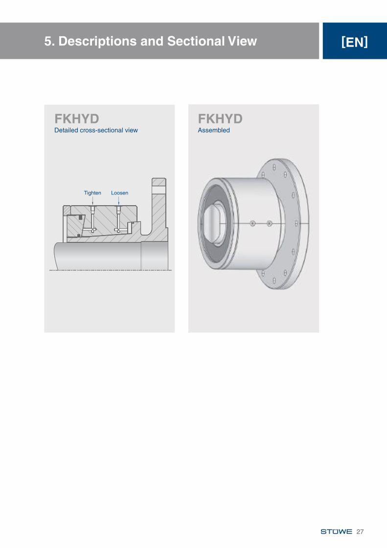
5. Descriptions and Sectional View [EN]
FKHYDDetailed cross-sectional view
FKHYDAssembled
Tighten Loosen

28
6. Installation
Push the flange onto the shaft.
ATTENTION
The flange coupling has to be in contact with the shaft across its full width.
The STÜWE® flange couplings type FKHYD are supplied ready to install. The pressure chambers contain hydraulic oil.
NOTE
The flange coupling may not be dismantled before tensioning for the first time.
NOTE
Never tighten the flange coupling before the machine shaft has been fitted.
Installation
2.
Degrease the flange hole and the shaft in the area where the flange coupling is fitted.
NOTE
Use clean rags and solvents.
1.

29
6. Installation [EN]
Remove screw plugs from the ”Spannen” (Tighten) and ”Entspannen” (Loosen) connections.
NOTE
Collect any hydraulic oil leakage.
4.
3.
Connect the pressure line to the connection that is marked as “Spannen“ (Tighten).
NOTE
Collect any hydraulic oil leakage.
5. Tension the flange coupling by applying hydraulic pressure (connection “Spannen“ [Tighten]). Increase the pressure until the outer ring moves in an axial direction.

30
6. Installation
When tensioning, initially move the flange with an in-and-out radial motion until the fitting clear-ance has been bridged.
As a result, a true fit between hole and shaft surface is achieved and any tilting eliminated.
6.
7. Check tensioning condition.
NOTE
The correct tensioning force is reached as soon as the end faces of the outer and inner ring are aligned (visually observed to be flush).
WARNING
The maximum permitted clamping pressure is 450 bar.

31
6. Installation
Tighten the ring counter nut by hand against the outer ring.
NOTE
Reduce the maximum clamping pressure a little as necessary so that the safety nut is able to be screwed until it is against the outer ring.
8.
Screw the screw plugs back into the connections.
NOTE
Leave the hydraulic oil in the flange coupling
10.
Release the oil pressure. As a result, the safety nut is thus firmly pressed against the outer ring by the stored energy.
9.
[EN]

32
7. Dismantling and Re-Installation
Dismantling and Re-Installation
Wear protective glasses.
Remove screw plugs from both connections.
NOTE
Collect any hydraulic oil leakage.
1.
Connect hydraulic pump to the ”Spannen” (Tighten) connection. Increase the oil pressure until a gap is visible between the outer ring and nut.
WARNING
The maximum permitted clamping pressure is 450 bar.
2.

33
Retain the clamping pressure.Manually loosen the safety nut.
WARNING
The nut must always remain held with at least two turns of its thread.
3.
Release pressure and connect the pump to the connection ”Entspan-nen” (Loosen).
2
1
Increasing the oil pressure will initiate the sliding of the outer ring from the inner ring taper.
WARNING
The maximum permitted oil pressure is 450 bar.
WARNING
As soon as the outer ring starts moving towards the nut, reduce the oil pressure immediately to a maximum of 150 bar.
5.
4.
7. Dismantling and Re-Installation [EN]

34
7. Dismantling and Re-Installation
Release the oil pump from the connection ”Entspannen” (Loosen)
NOTE
Collect any hydraulic oil leakage coming out of the ”Spannen” (Tighten) connection.
7.
When the outer ring reaches the support ring the oil pressure will automatically increase. The connection is now released.
WARNING
At this point fully release the oil pressure. Ensure that the oil pressure does not exceed 180 bar.
6.

35
7. Dismantling and Re-Installation
8.
9.
Leave the hydraulic oil in the loosened flange coupling and tightly close the con-nections ”Spannen” (Tighten) and ”Entspannen” (Loosen) once more with screw plugs.
Remove the flange coupling from the shaft.
[EN]

36
8. Cleaning and Lubrication
Lubricate the tapered surfacesof the outer and inner rings after cleaning, see arrows.
Cleaning and Lubrication
NOTE
Flange couplings which have been removed do not need to be taken apart and re-lubricated before being re-installed.
NOTE
A flange coupling only has to be cleaned and re-lubricated if it is soiled.
Lubricate all threads.
NOTE
Use a paste such as Molykote G Rapid +.
2.
1.
NOTE
Use lubricant with a high content of MoS2 and a coefficient of fric-tion of µ=0.04. Usually a combina-tion of bonded coating (inner ring) and paste (outer ring) is chosen.
Oil-resistant lubricant is re- commended where installation and removal takes place regularly. Please also pay attention to the information given by the lubricant manufacturers.

37
8. Cleaning and Lubrication
Recommended LubricantsLubricant Trade name Source
Molykote D 321R Bonded coating/spray Dow Corning
Molykote G Rapid + Paste/paste Dow Corning
AVILUB bonded coating 84 Bonded coating Avia Bantleon
The safety data sheets may be found on the pages of the manufacturers.
[EN]

Stüwe GmbH & Co. KG - Zum Ludwigstal 35 - 45527 HattingenTel. +49(0)2324-394-0 - Fax +49(0)2324-394-30
www.stuewe.de - [email protected] www.stuewe.de
Related Documents