BRITISH STANDARD BS EN 1092-1:2002 Incorporating Corrigendum No. 1 Flanges and their joints — Circular flanges for pipes, valves, fittings and accessories, PN designated — Part 1: Steel flanges The European Standard EN 1092-1:2001 has the status of a British Standard ICS 23.040.60 NO COPYING WITHOUT BSI PERMISSION EXCEPT AS PERMITTED BY COPYRIGHT LAW Copyright European Committee for Standardization Provided by IHS under license with CEN Not for Resale No reproduction or networking permitted without license from IHS

Welcome message from author
This document is posted to help you gain knowledge. Please leave a comment to let me know what you think about it! Share it to your friends and learn new things together.
Transcript
BRITISH STANDARD BS EN 1092-1:2002Incorporating Corrigendum No. 1
Flanges and their joints — Circular flanges for pipes, valves, fittings and accessories, PN designated —
Part 1: Steel flanges
The European Standard EN 1092-1:2001 has the status of a British Standard
ICS 23.040.60
NO COPYING WITHOUT BSI PERMISSION EXCEPT AS PERMITTED BY COPYRIGHT LAW
Copyright European Committee for Standardization Provided by IHS under license with CEN
Not for ResaleNo reproduction or networking permitted without license from IHS
--```,-`-`,,`,,`,`,,`---

BS EN 1092-1:2002
This British Standard, having been prepared under the direction of the Engineering Sector Policy and Strategy Committee, was published under the authority of the Standards Policy and Strategy Committee on 08 January 2002
© BSI 1 July 2002
ISBN 0 580 38236 2
National foreword
This British Standard is the official English language version of EN 1092-1:2001. It supersedes BS 4504-3.1:1989 which is withdrawn.
The UK participation in its preparation was entrusted to Technical Committee PSE/15, Flanges, which has the responsibility to:
A list of organizations represented on this committee can be obtained on request to its secretary.
Cross-referencesThe British Standards which implement international or European publications referred to in this document may be found in the BSI Catalogue under the section entitled “International Standards Correspondence Index”, or by using the “Search” facility of the BSI Electronic Catalogue or of British Standards Online.
This publication does not purport to include all the necessary provisions of a contract. Users of this publication are responsible for their correct application.
Compliance with a British Standard does not of itself confer immunity from legal obligations.
— aid enquirers to understand the text;
— present to the responsible European committee any enquiries on the interpretation, or proposals for change, and keep the UK interests informed;
— monitor related international and European developments and promulgate them in the UK.
Summary of pagesThis document comprises a front cover, an inside front cover, the EN title page, pages 2 to 70, an inside back cover and a back cover.
The BSI copyright date displayed in this document indicates when the document was last issued.
Amendments issued since publication
Amd. No. Date Comments
13960 Corrigendum No. 1
1 July 2002 Correction of values for neck diameter N1 in Table 7
Copyright European Committee for Standardization Provided by IHS under license with CEN
Not for ResaleNo reproduction or networking permitted without license from IHS
--```,-`-`,,`,,`,`,,`---
EUROPEAN STANDARD
NORME EUROPÉENNE
EUROPÄISCHE NORM
EN 1092-1
December 2001
ICS 23.040.60
English version
Flanges and their joints — Circular flanges for pipes, valves,fittings and accessories, PN designated — Part 1: Steel flanges
Brides et leurs assemblages — Brides circulaires pourtubes, appareils de robinetterie, raccords et accessoires
désignées PN — Partie 1: Brides en acier
Flansche und ihre Verbindungen — Runde Flansche fürRohre, Armaturen, Formstücke und Zubehörteile, nach PN
bezeichnet — Teil 1: Stahlflansche
This European Standard was approved by CEN on 6 July 2001.
CEN members are bound to comply with the CEN/CENELEC Internal Regulations which stipulate the conditions for giving this EuropeanStandard the status of a national standard without any alteration. Up-to-date lists and bibliographical references concerning such nationalstandards may be obtained on application to the Management Centre or to any CEN member.
This European Standard exists in three official versions (English, French, German). A version in any other language made by translationunder the responsibility of a CEN member into its own language and notified to the Management Centre has the same status as the officialversions.
CEN members are the national standards bodies of Austria, Belgium, Czech Republic, Denmark, Finland, France, Germany, Greece,Iceland, Ireland, Italy, Luxembourg, Netherlands, Norway, Portugal, Spain, Sweden, Switzerland and United Kingdom.
EUROPEAN COMMITTEE FOR STANDARDIZATIONC O M I T É E U R OP É E N D E N O R M A LI S A T I O NEUR O P Ä IS C HES KOM I TE E FÜR NOR M UNG
Management Centre: rue de Stassart, 36 B-1050 Brussels
© 2001 CEN All rights of exploitation in any form and by any means reservedworldwide for CEN national Members.
Ref. No. EN 1092-1:2001 E
Copyright European Committee for Standardization Provided by IHS under license with CEN
Not for ResaleNo reproduction or networking permitted without license from IHS
--```,-`-`,,`,,`,`,,`---
EN 1092-1:2001 (E)
2
ContentsPage
Foreword 3
Introduction 4
1 Scope 4
2 Normative references 5
3 Terms and definitions 73.1 DN 73.2 PN73.3 maximum allowable pressure, PS 73.4 maximum allowable temperature, TS 7
4 Designation 74.1 General 74.2 Standard designation 7
5 General requirements 85.1 Flange materials 85.2 Repairs 95.3 Bolting 95.4 Gaskets 95.5 Pressure/temperature (p/T) ratings 95.6 Dimensions 105.7 Flange facings 115.8 Spot facing or back facing of flanges 125.9 Tolerances 125.10 Marking 12
Annex A (normative) Butt weld-end preparation 53
Annex B (informative) Material groups 54
Annex C (informative) Approximate masses of flanges and collars 56
Annex D (informative) Additional materials 64
Annex E (informative) Determination of p/T ratings for flanges using EN materials 65
Annex F (informative) Determination of p/T ratings for flanges using ASTM materials 66
Annex ZA (informative) Essential safety requirements — Clauses of this European Standardaddressing essential requirements or other provisions of EU Directives 68
Bibliography 70
Copyright European Committee for Standardization Provided by IHS under license with CEN
Not for ResaleNo reproduction or networking permitted without license from IHS
--```,-`-`,,`,,`,`,,`---

EN 1092-1:2001 (E)
3
Foreword
This document (EN 1090-1:2001) has been prepared by Technical Committee CEN/TC 74,Flanges and their joints, the Secretariat of which is held by DIN.
This European Standard shall be given the status of a national standard, either by publication of anidentical text or by endorsement, at the latest by June 2002, and conflicting national standardsshall be withdrawn at the latest by June 2002.
This document has been prepared under a mandate given to CEN by the European Commissionand the European Free Trade Association, and supports essential requirements of EU Directive(s).
For relationship with EU Directive(s), see informative annex ZA, which is an integral part of thisdocument.
According to the CEN/CENELEC Internal Regulations, the national standards organizations of thefollowing countries are bound to implement this European Standard: Austria, Belgium,Czech Republic, Denmark, Finland, France, Germany, Greece, Iceland, Ireland, Italy, Luxembourg,Netherlands, Norway, Portugal, Spain, Sweden, Switzerland and the United Kingdom.
EN 1092 consists of the following four parts:
Part 1: Steel flanges;
Part 2: Cast iron flanges;
Part 3: Copper alloy flanges;
Part 4: Aluminium alloy flanges.
This standard includes one normative and eight informative annexes.
Copyright European Committee for Standardization Provided by IHS under license with CEN
Not for ResaleNo reproduction or networking permitted without license from IHS
--```,-`-`,,`,,`,`,,`---
EN 1092-1:2001 (E)
4
Introduction
When Technical Committee CEN/TC 74 commenced its work of producing this European Standardit took as its basis the International Standard ISO 7005-1, Steel flanges.
In taking this decision, CEN/TC 74, agreed that this standard would differ significantly from theISO standard in respect of the following:
a) Whereas ISO 7005-1 included in its scope both the original DIN based flanges and alsothe original ANSI/ASME based flanges, EN 1092-1 contains only the DIN based flanges.CEN/TC 74 has produced a separate series of standards, prEN 1759-1:2000,prEN 1759-3:1994 and prEN 1759-4:1997, dealing with the ANSI/ASME based flanges intheir original Class designations.
b) The opportunity was taken to revise some of the technical requirements applicable to theDIN origin flanges.
Consequently, whilst the mating dimensions, the flange and facing types and designations arecompatible with those given in ISO 7005-1, it is important to take account of the followingdifferences which exist in EN 1092-1:
1) The p/T ratings of this standard have been reduced in many cases by either limiting thelower temperature ratings which can no longer exceed the PN value, or by increasing therate at which allowable pressures shall reduce with increase in temperature.
2) In addition to the range of PN 2,5 to PN 40 DIN origin flanges contained in theISO standard, EN 1092-1 also includes PN 63 and PN 100 flanges.
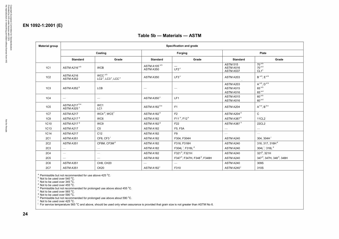
3) This standard specifies grades of European steels similar to those specified inISO 7005-1, but in addition permits the use of those grades of ASTM steels which arespecified in the ISO standard for use with the ANSI/ASME based flanges.
4) This standard gives an informative annex concerning requirements of EU Directives.
1 Scope
This European Standard for a single series of flanges specifies requirements for circular steelflanges in PN designations PN 2,5 to PN 100 and nominal sizes from DN 10 to DN 4 000.
This standard specifies the flange types and their facings, dimensions, tolerances, threading, boltsizes, flange jointing face surface finish, marking, materials, pressure/ temperature ratings andapproximate flange masses.
This standard does not apply to flanges made from bar stock by turning, or to flanges of types 11,12 and 13 made from plate material.
Copyright European Committee for Standardization Provided by IHS under license with CEN
Not for ResaleNo reproduction or networking permitted without license from IHS
--```,-`-`,,`,,`,`,,`---

EN 1092-1:2001 (E)
5
2 Normative references
This European Standard incorporates, by dated or undated reference, provisions from otherpublications. These normative references are cited at the appropriate places in the text and thepublications are listed hereafter. For dated references, subsequent amendments to or revisions ofany of these publications apply to this European Standard only when incorporated in it byamendment or revision. For undated references the latest edition of the publication referred toapplies (including amendments).
EN 764, Pressure equipment — Terminology and symbols — Pressure, temperature, volume.
EN 1333, Pipework components — Definition and selection of PN.
EN 1708-1, Welding — Basic weld joint details in steel — Part 1: Pressurized components.
EN 10025, Hot rolled products of non-alloy structural steels — Technical delivery conditions.
prEN 10028-2:2000, Flat products made of steels for pressure purposes — Part 2: Non alloy andalloy steels with specified elevated temperature properties.
prEN 10028-3:2000, Flat products made of steels for pressure purposes — Part 3: Weldable finegrade steels, normalized.
prEN 10028-4:2000, Flat products made of steels for pressure purposes — Part 4: Nickel alloysteels with specified low temperature properties.
EN 10028-7, Flat products made of steels for pressure purposes — Part 7: Stainless steels.
EN 10213-2, Technical delivery conditions for steel castings for pressure purposes — Part 2: Steelgrades for use at room temperature and elevated temperatures.
EN 10213-3, Technical delivery conditions for steel castings for pressure purposes — Part 3: Steelgrades for use at low temperatures.
EN 10213-4, Technical delivery conditions for steel castings for pressure purposes —Part 4: Austenitic and austenitic-ferritic steel grades.
EN 10222-2, Steel forgings for pressure purposes — Part 2: Ferritic and martensitic steels withspecified elevated temperature properties.
EN 10222-3, Steel forgings for pressure purposes — Part 3: Nickel steel with specified lowtemperature properties.
EN 10222-4, Steel forgings for pressure purposes — Part 4: Weldable fine grain steels with highproof strength.
EN 10222-5, Steel forgings for pressure purposes — Part 5: Austenitic, martensitic andaustenitic-ferritic stainless steels.
prEN ISO 9692-1:2000, Welding and allied processes — Recommendation for joint preparation —Part 1: Manual metal-arc welding, gas-shielded metal-arc welding and gas welding of steels(ISO/DIS 9692-1:2000).
EN ISO 9692-2, Welding and allied processes — Joint preparation — Part 2: Submerged arcwelding of steels (ISO 9692-2:1998).
Copyright European Committee for Standardization Provided by IHS under license with CEN
Not for ResaleNo reproduction or networking permitted without license from IHS
--```,-`-`,,`,,`,`,,`---
EN 1092-1:2001 (E)
6
EN ISO 6708, Pipe components — Definition of DN (nominal size) (ISO 6708:1995).
ISO 7-1, Pipe threads where pressure-tight joints are made on the threads — Part 1: Dimensions,tolerances and designation.
ISO 7-2, Pipe threads where pressure tight joints are made on the threads — Part 2: Verification bymeans of limit gauges.
ISO 887, Plain washers for metric bolts, screws and nuts — General plan.
ASTM A105/A105M, Forgings, Carbon Steel, for Piping Components.
ASTM A182/A 182M, Forged or Rolled Alloy-Steel Pipe Flanges, Forged Fittings, and Valves andParts for High-Temperature Service.
ASTM A203/A203M, Pressure Vessel Plates, Alloy Steel, Nickel.
ASTM A204/A204M, Specification for pressure vessel plates, alloy steel, molybdenum.
ASTM A216/A216M, Steel Castings, Carbon Suitable for Fusion Welding for High-TemperatureService.
ASTM A217/A217M, Steel Castings, Martensitic Stainless and Alloy, for Pressure-Containing PartsSuitable for High-Temperature Service.
ASTM A240/A240M, Heat-Resisting Chromium and Chromium-Nickel Stainless Steel Plate, Sheet,and Strip for Pressure Vessels.
ASTM A325, High-Strength Bolts for Structural Steel Joints.
ASTM A350/A350M, Forgings, Carbon and Low-Alloy Steel, Requiring Notch Toughness Testingfor Piping Components.
ASTM A351/A351M, Castings, Austenitic, Austenitic-Ferritic (Duplex) for Pressure-Containing Parts.
ASTM A352/A352M, Steel Castings, Ferritic and Martensitic, for Pressure-Containing Parts Suitablefor Low-Temperature Service.
ASTM A387/A387M, Pressure Vessel Plates, Alloy Steel, Chromium-Molybdenum.
ASTM A515/A515M, Pressure Vessel Plates, Carbon Steel, for Intermediate and Higher-TemperatureService.
ASTM A516/A516M, Pressure Vessel Plates, Carbon Steel, for Moderate and Lower-TemperatureService.
ASTM A537/A537M, Pressure Vessel Plates, Heat-Treated, Carbon-Manganese-Silicon Steel.
Copyright European Committee for Standardization Provided by IHS under license with CEN
Not for ResaleNo reproduction or networking permitted without license from IHS
--```,-`-`,,`,,`,`,,`---
EN 1092-1:2001 (E)
7
3 Terms and definitions
For the purposes of this standard the following terms and definitions apply.
3.1 DNsee EN ISO 6708
3.2 PNsee EN 1333
3.3 maximum allowable pressure, PSmeans the maximum pressure for which the equipment is designed, as specified by the equipmentmanufacturer
3.4 maximum allowable temperature, TSmeans the maximum temperature for which the equipment is designed, as specified by theequipment manufacturer
4 Designation
4.1 General
Table 1 specifies the flange types and ancillary components.
Figures 1 and 2 show flange types and ancillary components with the relevant flange typenumbers. Flanges shall be denoted with “flange type” and the “flange number”. Ancillarycomponents shall be denoted with ancillary component type and the type number.
Figure 3 shows flange facing types, which may be used with the flanges or components shown inFigures 1 and 2. Flange facings shall be denoted with “type” and the relevant symbol.
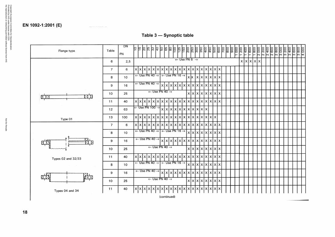
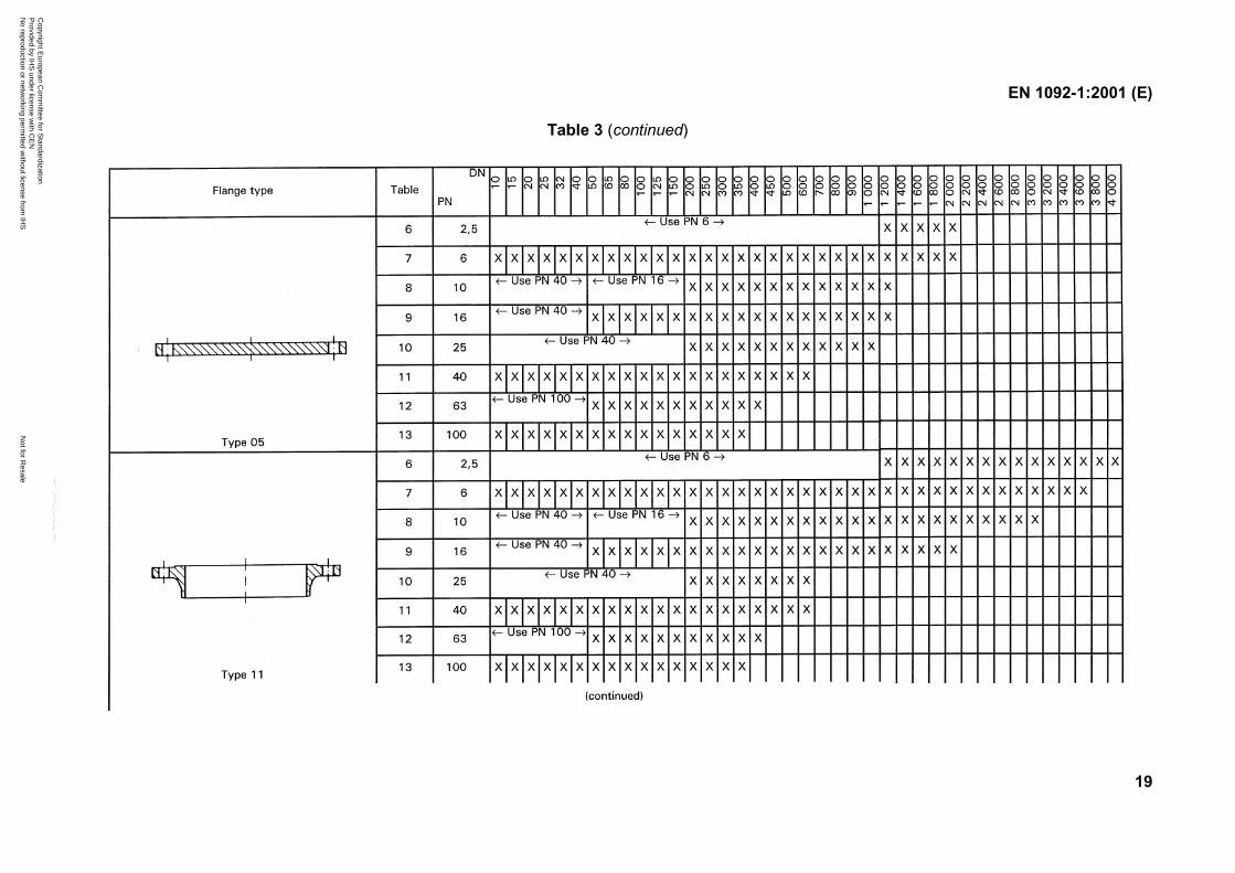
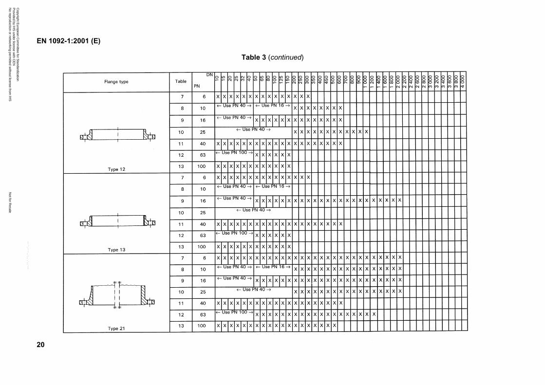
The range of DN, applicable to each flange type and to each PN, shall be as given in Table 3.
4.2 Standard designation
Flanges and ancillary components in accordance with this standard shall be designated with thefollowing:
a) Designation, e.g. flange, lapped end or collar.
b) Number of this standard, EN 1092-1.
c) Number of flange type in accordance with Figures 1 and 2.
d) Type of flange facing in accordance with Figure 3.
e) DN (nominal size).
f) PN designation.
g) Neck thickness S (only for types 11 and 34).
Copyright European Committee for Standardization Provided by IHS under license with CEN
Not for ResaleNo reproduction or networking permitted without license from IHS
--```,-`-`,,`,,`,`,,`---
EN 1092-1:2001 (E)
8
h) For type 13 flanges type of thread (Rp or Rc).
i) Bore diameter (for sizes greater than DN 600):
B1 (only for types 01, 12 and 32);
B2 (only for type 02);
B3 (only for type 04).
j) Either the symbol or the number or the grade of the material (see Tables 5a and 5b).
k) Any heat treatment required.
l) Material certificate, if required (see 5.1).
EXAMPLE 1Designation of a flange type 01 with facing type A and nominal size DN 800, of PN 6 with borediameter B1 = 818 mm, made of material with the symbol S235JR:
Flange EN 1092-1/01 A/DN 800/PN 6/818/S235JR.
EXAMPLE 2Designation of an ancillary component type 32 with facing type A of nominal size DN 400, PN 10and made of material with the symbol S235JR:
Collar EN 1092-1/32 A/DN 400/PN 10/S235JR.
EXAMPLE 3Designation of a flange type 02 with facing type A of nominal size DN 400, PN 10 and made ofmaterial with the number 1.0038:
Flange EN 1092-1/02 A/DN 400/PN 10/1.0038.
EXAMPLE 4Designation of a flange type 11 with facing type B2 of nominal size DN 200, PN 100 and with neckthickness, S = 10 mm, made of material with the symbol 13CrMo4-5:
Flange EN 1092-1/11 B2/DN 200/PN 100/10/13CrMo4-5.
5 General requirements
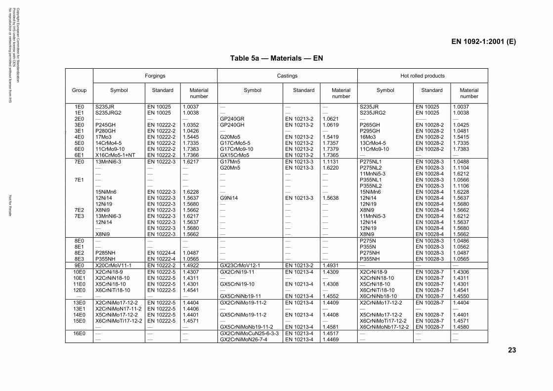
5.1 Flange materials
Flanges shall be manufactured from materials given in Tables 5a and 5b (see also annex D). Fortype 11, 12 and 13 flanges, the manufacture shall be from forgings. For type 21 flanges themanufacture shall be from forgings or steel castings.
The flange manufacturer shall provide documentation to ensure traceability of material. Anequipment manufacturer may require a certificate in accordance with EN 10204 which is suitablefor the category of equipment to which the flange is fitted.
NOTE 1 The materials given in Tables 5a and 5b (see also annex D) are tabulated in groups having the samep/T ratings as given in Tables 15, 16, 17,18,19 and 20 (see annex B).
NOTE 2 The materials of ancillary components are not within the scope of this standard.
Copyright European Committee for Standardization Provided by IHS under license with CEN
Not for ResaleNo reproduction or networking permitted without license from IHS
--```,-`-`,,`,,`,`,,`---
EN 1092-1:2001 (E)
9
5.2 Repairs
Where not otherwise prohibited by the applicable material standard, repairs by welding arepermitted when there is a proven method. All welding shall be carried out in accordance with awritten procedure.
NOTE For approval of welding procedures, see EN 288-1. For approval of welders, see EN 287-1.
5.3 Bolting
Flanges shall be suitable for use with the number and size of bolting as specified in Tables 6 to 13.The bolting shall be chosen by the equipment manufacturer according to the pressure,temperature, flange material and gasket so that the flanged joint remains tight under the expectedoperating conditions. For selection of bolting, see EN 1515-1, for combination of the materials offlanges and bolting see prEN 1515-2:1994, for information.
5.4 Gaskets
The various gasket types, dimensions, design characteristics and materials used are not within thescope of this standard. Dimensions of gaskets are given in EN 1514-1 to EN 1514-4.
5.5 Pressure/temperature (p/T) ratings
The p/T ratings of flanges are given in Tables 15, 16, 17,18, 19 and 20.
The p/T ratings indicate the relationship between the maximum allowable pressure PS and themaximum allowable temperature.
The p/T ratings shall apply only for flange types 05, 11, 12, 13 and 21 having nominal sizes up toand including DN 600. The p/T ratings of all other flanges shall be calculated or subject to specialexperience.
NOTE 1 The rules for the determination of p/T ratings of the above tables are given in annexes E and F.
NOTE 2 For the material groups 10E0 to 16E0 (austenitic steels), Tables 17 and 18 should be used as follows:
— Table 17 should be chosen for application in cases where the flange deformation has to be strictly limited.
— Table 18 should be chosen in all cases where a small amount of plastic deformation of the flanges can beconsidered acceptable.
NOTE 3 Linear interpolation is permitted for intermediate temperatures.
For interpolation between (-10 °C to 50 °C) and 100 °C, 20 °C shall be used.
NOTE 4 The relevant pressures and temperatures are those of the fluid in the pipework system.
Copyright European Committee for Standardization Provided by IHS under license with CEN
Not for ResaleNo reproduction or networking permitted without license from IHS
--```,-`-`,,`,,`,`,,`---
EN 1092-1:2001 (E)
10
5.6 Dimensions
5.6.1 Flanges
The dimensions of flanges shall be as given in Tables 6 to 13 according to the PN designation.Dimension Gmax may be varied from the given value (see NOTE 1) which is a maximum limit. Theneck thickness S is a minimum value selected according to pipe thicknesses given in ISO 4200(see NOTE 2).
NOTE 1 The centre portion of the face of a flange type 05 need not be machined provided that the diameter of theunmachined portion does not exceed the recommended diameter for Gmax given in Tables 6 to 13.
NOTE 2 When requested by the pressure equipment manufacturer, neck thicknesses, other than those given in therelevant tables, may be supplied by agreement with the flange manufacturer.
NOTE 3 A summary of the various types of flanges specified is given in Table 3 showing the nominal sizes applicable toeach type and to each PN.
NOTE 4 Diameters N1, N2 and N3 of flange types 11, 12, 13, 21 and 34 are the theoretical maximum values permittingthe use of ring spanners or the application of normal series plain washers without any additional machining, e.g. spotfacing (see 5.8).
NOTE 5 The bore diameters of flanges type 21 are not specified in this standard, the effective bore diameters areusually given in the relevant component standard(s).
NOTE 6 Approximate masses of flanges are given in annex C.
NOTE 7 The flange thicknesses for flanges type 05, 11, 12, 13, 21 and PN 6, PN 10, PN 16, PN 25 have an unusualstep at DN 600/DN 700. This is based on a change at some flange thicknesses up to and including DN 600 to meet thepressure/temperature ratings (limited to DN 600). The flange thicknesses for flanges DN 700 and above are the same asthey are given in the documents of origin (DIN, BS NFE, IBN, etc.). They will be updated in future based on the flangecalculation method as far as the corresponding work items of CEN/TC 74/WG 10 gives sufficient results.
NOTE 8 For flanges type 21 dimensions A, N3 and R1 are nominal values and are included for guidance only.
5.6.2 Hubs
The hubs of flange types 12 and 13 shall be either:
a) parallel; or
b) taper with an angle not exceeding 7° on the outside surface for forging or castingpurposes.
Details of the weld-end preparation for flanges type 11 and ancillary components type 33 shall beas given in annex A.
5.6.3 Threaded flanges
5.6.3.1 The threads of flanges type 13 shall be parallel (symbol Rp) or tapered (symbol Rc) inaccordance with ISO 7-1. Gauging shall be in accordance with ISO 7-2.
NOTE Parallel threads will be supplied unless otherwise requested by the equipment manufacturer.
Copyright European Committee for Standardization Provided by IHS under license with CEN
Not for ResaleNo reproduction or networking permitted without license from IHS
--```,-`-`,,`,,`,`,,`---
EN 1092-1:2001 (E)
11
5.6.3.2 The thread shall be concentric with the axis of the flange and misalignments shall notexceed 5 mm per metre.
Flanges type 13 shall be manufactured without a parallel counterbore, but to protect the threadthey shall be chamfered to the major diameter of the thread at the hubbed side of the flange at anangle between 30° and 50° to the axis of the thread. The chamfer shall be concentric with thethread and shall be included in the measurement of the thread length provided that the chamferdoes not exceed one pitch in length.
5.6.4 Bolt holes
Bolt holes shall be equally spaced on the pitch circle diameter. In the case of flanges type 21 theyshall be positioned such that they are symmetrical to the principal axes and such that no holes fallon these axes, i.e. positioned “off-centre”, see Figures 5 to 12.
5.6.5 Lapped joints
The dimensions of lapped joints to be used with flanges, type 02 and type 04, are specified inTables 7 to 11.
For ancillary component type 33, the thickness of the lapped end at the facing shall be not lessthan the specified wall thickness of the pipe used.
5.7 Flange facings
5.7.1 Types of facings
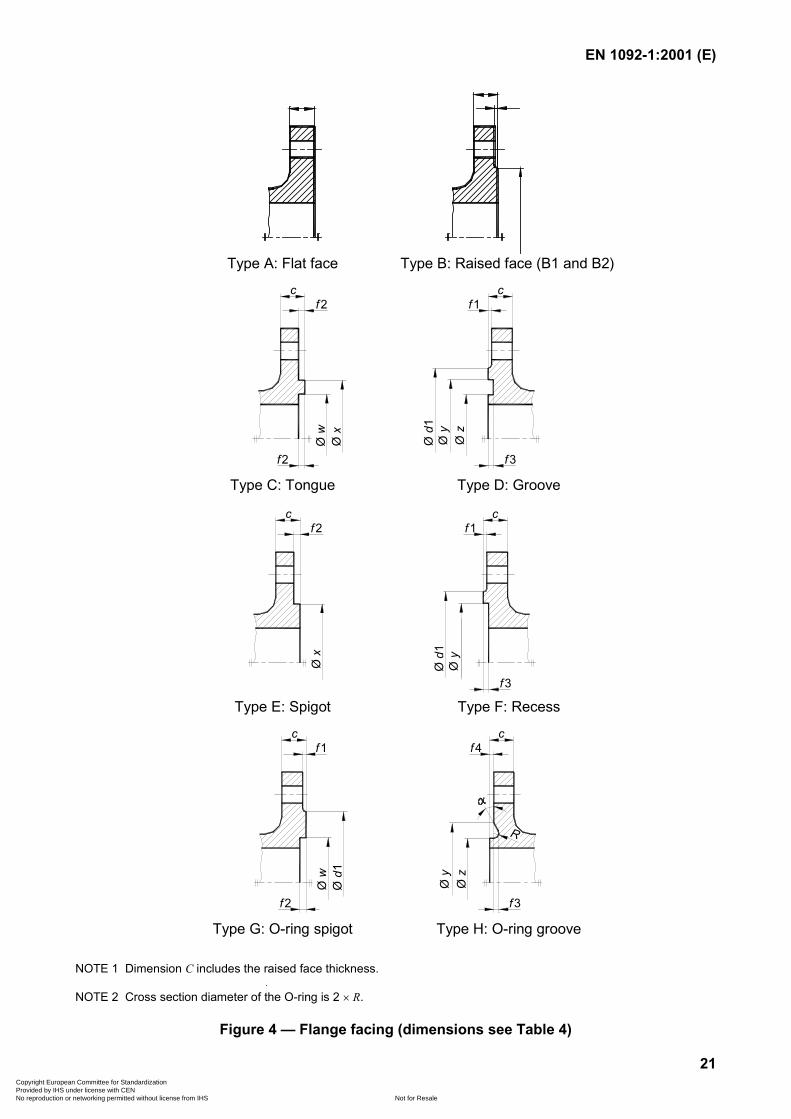
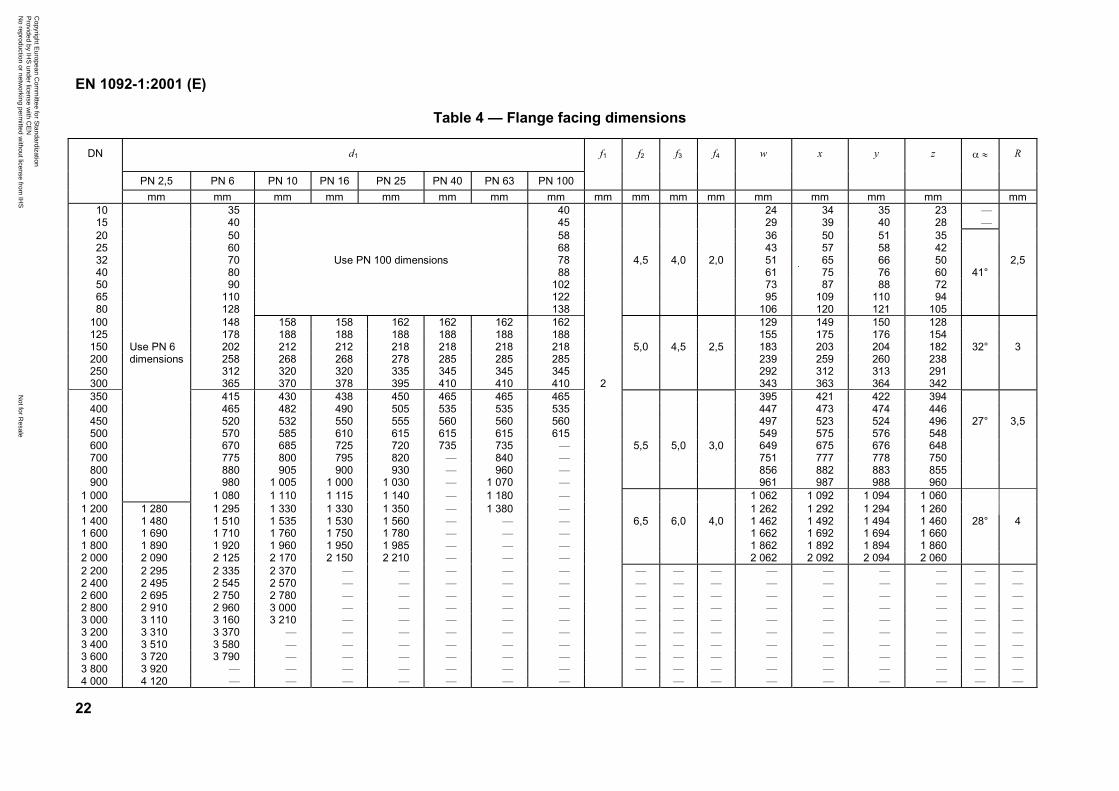
The types of flange facings shall be as given in Figure 3 and their dimensions shall be as given inFigure 4 and Table 4.
For facings types B, D, F and G, the transition from the edge of the raised face to the flange shallbe:
a) radius; or
b) chamfer;
at the choice of the flange manufacturer.
5.7.2 Jointing face finish
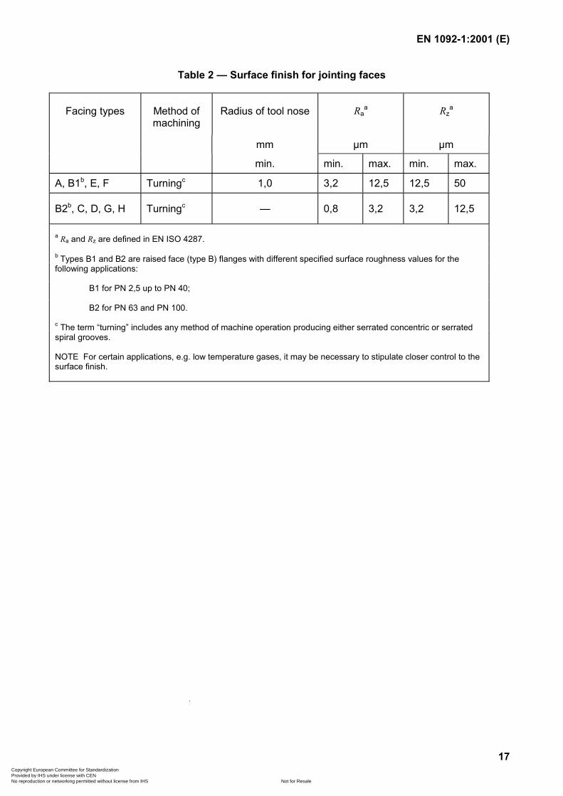
5.7.2.1 All flange jointing faces shall be machine finished and shall have a surface finish inaccordance with the values given in Table 2 when compared with reference specimens by visual ortactile means.
NOTE It is not intended that instrument measurements be taken on the faces themselves; the Ra and Rz values asdefined in EN ISO 4287 relate to the reference specimens.
5.7.2.2 For flanges with facing types A, B1, E and F, turning shall be carried out with a roundnosed tool in accordance with Table 2.
5.7.2.3 Flanges � PN 40 shall have type B1 facings and flanges � PN 63 shall have type B2facings, unless otherwise agreed in the order.
Copyright European Committee for Standardization Provided by IHS under license with CEN
Not for ResaleNo reproduction or networking permitted without license from IHS
--```,-`-`,,`,,`,`,,`---
EN 1092-1:2001 (E)
12
5.8 Spot facing or back facing of flanges
Any spot facing or back facing shall not reduce the flange thickness to less than the flangethickness specified. When spot facing is used, the diameter shall be large enough to accommodatethe outside diameter of the equivalent normal series of washers in accordance with ISO 887 for thebolt size being fitted. The bearing surfaces for the bolting shall be parallel to the flange face withinthe limits given in Table 14. When a flange is back faced a minimum fillet radius R2 (see Figure 13)in accordance with Table 21 shall be maintained.
5.9 Tolerances
Tolerances on dimensions of flanges shall be as given in Table 14.
5.10 Marking
5.10.1 General marking requirements
All flanges, other than type 21 flanges, shall be marked as follows:
a) Flange manufacturer’s name or trade mark, e.g. XXX.
b) Number of this standard, i.e. EN 1092-1.
c) Flange type number, e.g. 11.
d) DN, e.g. DN 150.
e) PN designation, e.g. PN 40.
f) Neck thickness (S), if not to this standard.
g) For EN materials: either the symbol or the number or the grade of the material,e.g. S235JR.
h) For ASTM materials: the material grade, preceded by the specification number wherenecessary, e.g. WC 4.
i) Cast number of melt identification or suitable control number traceable to the castnumber, e.g. 12345, when test certification is required.
EXAMPLE XXX/EN 1092-1/11/DN 150/PN 40/S235JR/12345.
If a flange is too small to enable all the markings required then the minimum marking required shallbe:
a) Flange manufacturer’s name or trade mark.
b) Letters “EN”.
e) PN designation, e.g. PN 40.
g) Either the symbol or the number or the grade of the material.
h) Cast number or melt identification or suitable control number.
Copyright European Committee for Standardization Provided by IHS under license with CEN
Not for ResaleNo reproduction or networking permitted without license from IHS
--```,-`-`,,`,,`,`,,`---
EN 1092-1:2001 (E)
13
5.10.2 Stamping
Where steel stamps are used, the marking shall be positioned on the outer rim of the flange.
NOTE It should be ensured that steel stamp markings are not liable to cause cracks in the flange material.
5.10.3 Declaration of compliance
The marking EN 1092-1, together with the flange manufacturer’s name or trademark on or inrelation to a product, represents the flange manufacturer’s declaration of compliance to thisstandard, i.e. a claim by or on behalf of the flange manufacturer that the product meets therequirements of this standard.
Copyright European Committee for Standardization Provided by IHS under license with CEN
Not for ResaleNo reproduction or networking permitted without license from IHS
--```,-`-`,,`,,`,`,,`---
EN 1092-1:2001 (E)
14
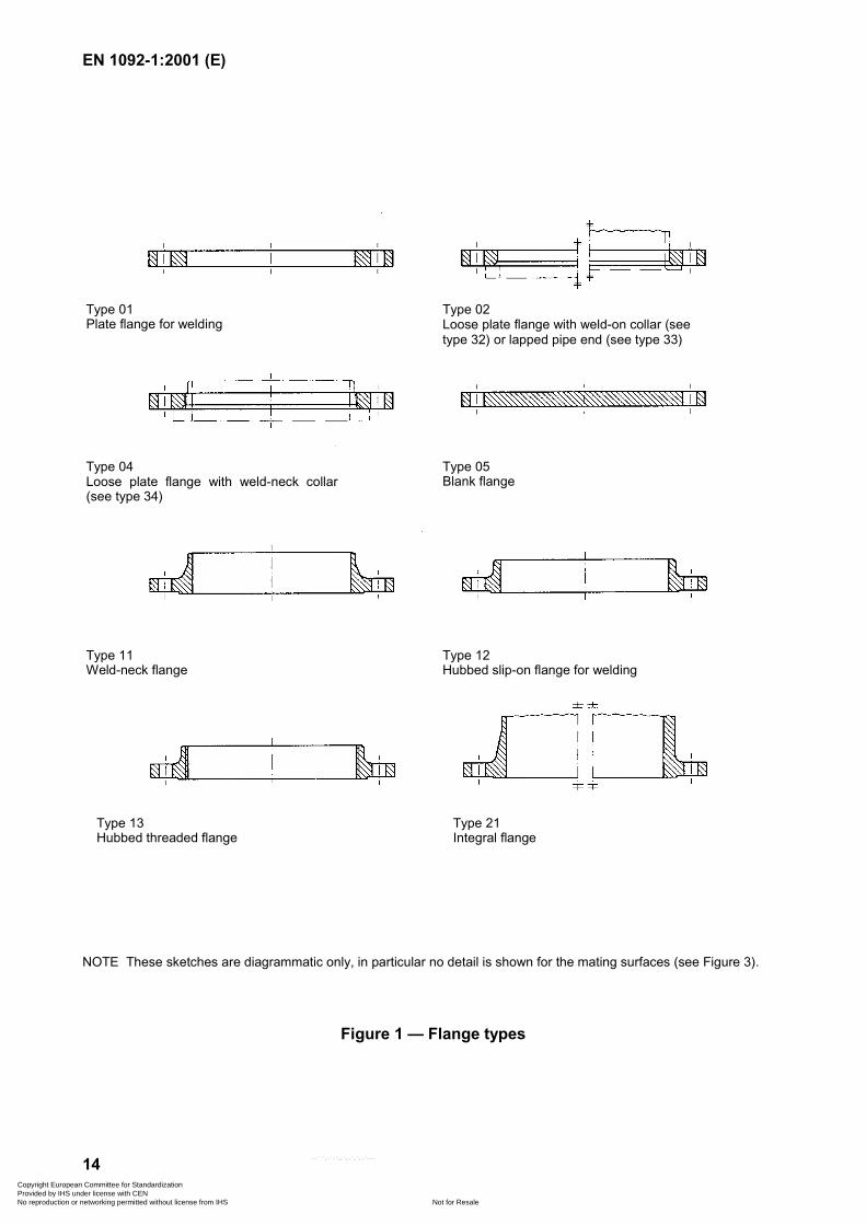
NOTE These sketches are diagrammatic only, in particular no detail is shown for the mating surfaces (see Figure 3).
Figure 1 — Flange types
Type 01Plate flange for welding
Type 02Loose plate flange with weld-on collar (seetype 32) or lapped pipe end (see type 33)
Type 04Loose plate flange with weld-neck collar(see type 34)
Type 05Blank flange
Type 11Weld-neck flange
Type 12Hubbed slip-on flange for welding
Type 13Hubbed threaded flange
Type 21Integral flange
Copyright European Committee for Standardization Provided by IHS under license with CEN
Not for ResaleNo reproduction or networking permitted without license from IHS
--```,-`-`,,`,,`,`,,`---
EN 1092-1:2001 (E)
15
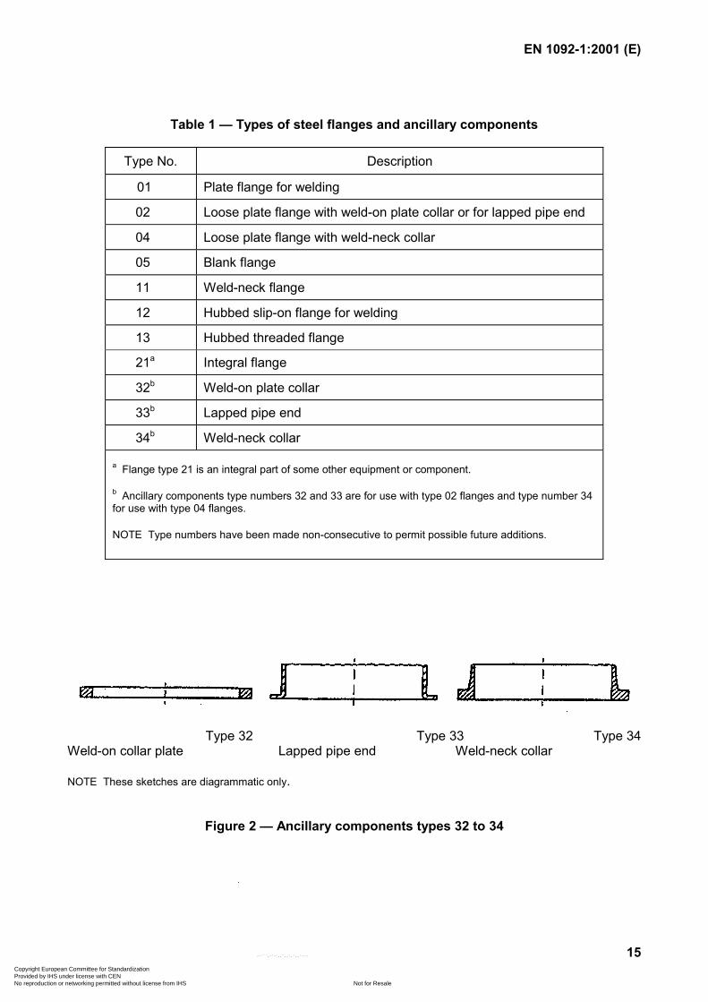
Table 1 — Types of steel flanges and ancillary components
Type No. Description
01 Plate flange for welding
02 Loose plate flange with weld-on plate collar or for lapped pipe end
04 Loose plate flange with weld-neck collar
05 Blank flange
11 Weld-neck flange
12 Hubbed slip-on flange for welding
13 Hubbed threaded flange
21a Integral flange
32b Weld-on plate collar
33b Lapped pipe end
34b Weld-neck collar
a Flange type 21 is an integral part of some other equipment or component.
b Ancillary components type numbers 32 and 33 are for use with type 02 flanges and type number 34for use with type 04 flanges.
NOTE Type numbers have been made non-consecutive to permit possible future additions.
Type 32 Type 33 Type 34Weld-on collar plate Lapped pipe end Weld-neck collar
NOTE These sketches are diagrammatic only.
Figure 2 — Ancillary components types 32 to 34
Copyright European Committee for Standardization Provided by IHS under license with CEN
Not for ResaleNo reproduction or networking permitted without license from IHS
--```,-`-`,,`,,`,`,,`---
EN 1092-1:2001 (E)
16
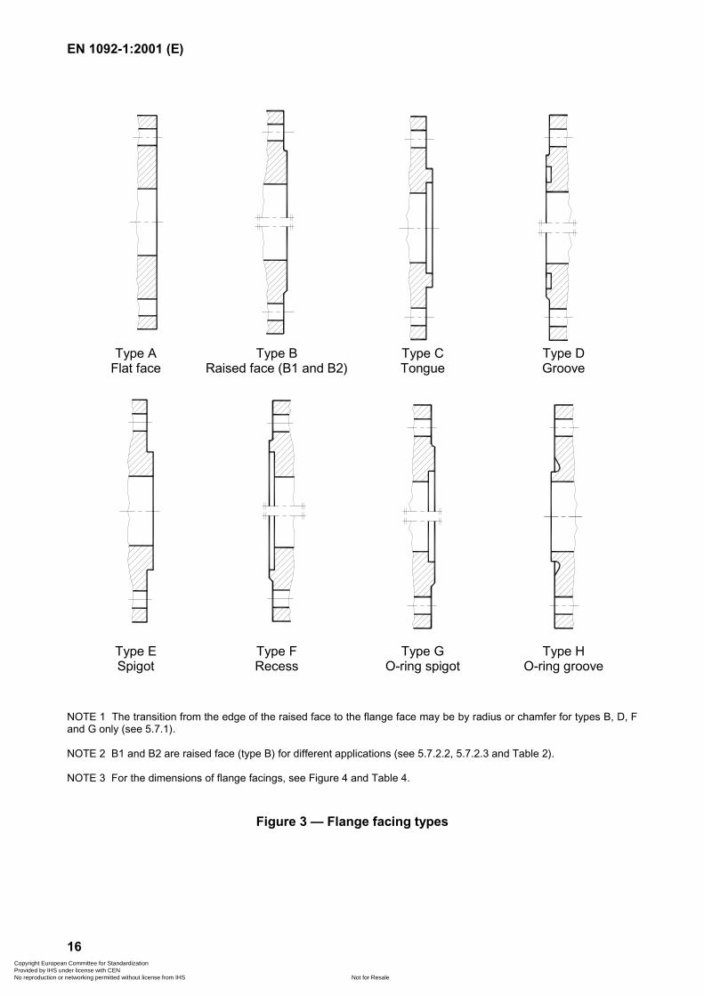
Type AFlat face
Type BRaised face (B1 and B2)
Type CTongue
Type DGroove
Type ESpigot
Type FRecess
Type GO-ring spigot
Type HO-ring groove
NOTE 1 The transition from the edge of the raised face to the flange face may be by radius or chamfer for types B, D, Fand G only (see 5.7.1).
NOTE 2 B1 and B2 are raised face (type B) for different applications (see 5.7.2.2, 5.7.2.3 and Table 2).
NOTE 3 For the dimensions of flange facings, see Figure 4 and Table 4.
Figure 3 — Flange facing types
Copyright European Committee for Standardization Provided by IHS under license with CEN
Not for ResaleNo reproduction or networking permitted without license from IHS
--```,-`-`,,`,,`,`,,`---
EN 1092-1:2001 (E)
17
Table 2 — Surface finish for jointing faces
Facing types Method ofmachining
Radius of tool nose Raa Rz
a
mm µm µm
min. min. max. min. max.
A, B1b, E, F Turningc 1,0 3,2 12,5 12,5 50
B2b, C, D, G, H Turningc — 0,8 3,2 3,2 12,5
a Ra and Rz are defined in EN ISO 4287.
b Types B1 and B2 are raised face (type B) flanges with different specified surface roughness values for thefollowing applications:
B1 for PN 2,5 up to PN 40;
B2 for PN 63 and PN 100.
c The term “turning” includes any method of machine operation producing either serrated concentric or serratedspiral grooves.
NOTE For certain applications, e.g. low temperature gases, it may be necessary to stipulate closer control to thesurface finish.
Copyright European Committee for Standardization Provided by IHS under license with CEN
Not for ResaleNo reproduction or networking permitted without license from IHS
--```,-`-`,,`,,`,`,,`---
EN 1092-1:2001 (E)
18
Table 3 — Synoptic table
Copyright E
uropean Com
mittee for S
tandardization P
rovided by IHS
under license with C
EN
Not for R
esaleN
o reproduction or networking perm
itted without license from
IHS
--```,-`-`,,`,,`,`,,`---
EN 1092-1:2001 (E)
19
Table 3 (continued)
Copyright E
uropean Com
mittee for S
tandardization P
rovided by IHS
under license with C
EN
Not for R
esaleN
o reproduction or networking perm
itted without license from
IHS
--```,-`-`,,`,,`,`,,`---
EN 1092-1:2001 (E)
20
Table 3 (continued)
Copyright E
uropean Com
mittee for S
tandardization P
rovided by IHS
under license with C
EN
Not for R
esaleN
o reproduction or networking perm
itted without license from
IHS
--```,-`-`,,`,,`,`,,`---
EN 1092-1:2001 (E)
21
Type A: Flat face Type B: Raised face (B1 and B2)
Ø w
f2c
f2
Ø x
f3Ø
zØ
y
f1c
Ø d
1
Type C: Tongue Type D: Groove
Ø x
Ø d
1Ø
y
f3
f2c
f1c
Type E: Spigot Type F: Recess
Ø w
f2
Ø d
1
Ø z
Ø y
f3
cf1
cf4
R
Type G: O-ring spigot Type H: O-ring groove
NOTE 1 Dimension C includes the raised face thickness.
NOTE 2 Cross section diameter of the O-ring is 2 � R.
Figure 4 — Flange facing (dimensions see Table 4)
Copyright European Committee for Standardization Provided by IHS under license with CEN
Not for ResaleNo reproduction or networking permitted without license from IHS
--```,-`-`,,`,,`,`,,`---
EN 1092-1:2001 (E)
22
Table 4 — Flange facing dimensions
d1
PN 2,5 PN 6 PN 10 PN 16 PN 25 PN 40 PN 63 PN 100
f1 f2 f3 f4 w x y z � � RDN
mm mm mm mm mm mm mm mm mm mm mm mm mm mm mm mm mm10 35 40 24 34 35 23 —15 40 45 29 39 40 28 —20 50 58 36 50 51 3525 60 68 43 57 58 4232 70 Use PN 100 dimensions 78 4,5 4,0 2,0 51 65 66 50 2,540 80 88 61 75 76 60 41°50 90 102 73 87 88 7265 110 122 95 109 110 9480 128 138 106 120 121 105
100 148 158 158 162 162 162 162 129 149 150 128125 178 188 188 188 188 188 188 155 175 176 154150 202 212 212 218 218 218 218 5,0 4,5 2,5 183 203 204 182 32° 3200 258 268 268 278 285 285 285 239 259 260 238250 312 320 320 335 345 345 345 292 312 313 291300 365 370 378 395 410 410 410 2 343 363 364 342350 415 430 438 450 465 465 465 395 421 422 394400 465 482 490 505 535 535 535 447 473 474 446450 520 532 550 555 560 560 560 497 523 524 496 27° 3,5500 570 585 610 615 615 615 615 549 575 576 548600 670 685 725 720 735 735 — 5,5 5,0 3,0 649 675 676 648700 775 800 795 820 — 840 — 751 777 778 750800 880 905 900 930 — 960 — 856 882 883 855900 980 1 005 1 000 1 030 — 1 070 — 961 987 988 960
1 000
Use PN 6dimensions
1 080 1 110 1 115 1 140 — 1 180 — 1 062 1 092 1 094 1 0601 200 1 280 1 295 1 330 1 330 1 350 — 1 380 — 1 262 1 292 1 294 1 2601 400 1 480 1 510 1 535 1 530 1 560 — — — 6,5 6,0 4,0 1 462 1 492 1 494 1 460 28° 41 600 1 690 1 710 1 760 1 750 1 780 — — — 1 662 1 692 1 694 1 6601 800 1 890 1 920 1 960 1 950 1 985 — — — 1 862 1 892 1 894 1 8602 000 2 090 2 125 2 170 2 150 2 210 — — — 2 062 2 092 2 094 2 0602 200 2 295 2 335 2 370 — — — — — — — — — — — — — —2 400 2 495 2 545 2 570 — — — — — — — — — — — — — —2 600 2 695 2 750 2 780 — — — — — — — — — — — — — —2 800 2 910 2 960 3 000 — — — — — — — — — — — — — —3 000 3 110 3 160 3 210 — — — — — — — — — — — — — —3 200 3 310 3 370 — — — — — — — — — — — — — — —3 400 3 510 3 580 — — — — — — — — — — — — — — —3 600 3 720 3 790 — — — — — — — — — — — — — — —3 800 3 920 — — — — — — — — — — — — — — — —4 000 4 120 — — — — — — — — — — — — — — —
Copyright E
uropean Com
mittee for S
tandardization P
rovided by IHS
under license with C
EN
Not for R
esaleN
o reproduction or networking perm
itted without license from
IHS
--```,-`-`,,`,,`,`,,`---
EN 1092-1:2001 (E)
23
Table 5a — Materials — EN
Forgings Castings Hot rolled products
Group Symbol Standard Materialnumber
Symbol Standard Materialnumber
Symbol Standard Materialnumber
1E0 S235JR EN 10025 1.0037 — — — S235JR EN 10025 1.00371E1 S235JRG2 EN 10025 1.0038 — — — S235JRG2 EN 10025 1.00382E0 — — — GP240GR EN 10213-2 1.0621 — —— —3E0 P245GH EN 10222-2 1.0352 GP240GH EN 10213-2 1.0619 P265GH EN 10028-2 1.04253E1 P280GH EN 10222-2 1.0426 — — — P295GH EN 10028-2 1.04814E0 17Mo3 EN 10222-2 1.5445 G20Mo5 EN 10213-2 1.5419 16Mo3 EN 10028-2 1.54155E0 14CrMo4-5 EN 10222-2 1.7335 G17CrMo5-5 EN 10213-2 1.7357 13CrMo4-5 EN 10028-2 1.73356E0 11CrMo9-10 EN 10222-2 1.7383 G17CrMo9-10 EN 10213-2 1.7379 11CrMo9-10 EN 10028-2 1.73836E1 X16CrMo5-1+NT EN 10222-2 1.7366 GX15CrMo5 EN 10213-2 1.7365 — — —7E0 13MnNi6-3 EN 10222-3 1.6217 G17Mn5 EN 10213-3 1.1131 P275NL1 EN 10028-3 1.0488
— — — G20Mn5 EN 10213-3 1.6220 P275NL2 EN 10028-3 1.1104— — — — — — 11MnNi5-3 EN 10028-4 1.6212
7E1 — — — — — — P355NL1 EN 10028-3 1.0566— — — — — — P355NL2 EN 10028-3 1.110615NiMn6 EN 10222-3 1.6228 — — — 15NiMn6 EN 10028-4 1.622812Ni14 EN 10222-3 1.5637 G9Ni14 EN 10213-3 1.5638 12Ni14 EN 10028-4 1.563712Ni19 EN 10222-3 1.5680 — — — 12Ni19 EN 10028-4 1.5680
7E2 X8Ni9 EN 10222-3 1.5662 — — — X8Ni9 EN 10028-4 1.56627E3 13MnNi6-3 EN 10222-3 1.6217 — — — 11MnNi5-3 EN 10028-4 1.6212
12Ni14 EN 10222-3 1.5637 — — — 12Ni14 EN 10028-4 1.5637— EN 10222-3 1.5680 — — — 12Ni19 EN 10028-4 1.5680X8Ni9 EN 10222-3 1.5662 — — — X8Ni9 EN 10028-4 1.5662
8E0 — — — — — — P275N EN 10028-3 1.04868E1 — — — — — — P355N EN 10028-3 1.05628E2 P285NH EN 10224-4 1.0487 — — — P275NH EN 10028-3 1.04878E3 P355NH EN 10222-4 1.0565 — — — P355NH EN 10028-3 1.05659E0 X20CrMoV11-1 EN 10222-2 1.4922 GX23CrMoV12-1 EN 10213-2 1.4931 — — —
10E0 X2CrNi18-9 EN 10222-5 1.4307 GX2CrNi19-11 EN 10213-4 1.4309 X2CrNi18-9 EN 10028-7 1.430610E1 X2CrNiN18-10 EN 10222-5 1.4311 — — — X2CrNiN18-10 EN 10028-7 1.431111E0 X5CrNi18-10 EN 10222-5 1.4301 GX5CrNi19-10 EN 10213-4 1.4308 X5CrNi18-10 EN 10028-7 1.430112E0 X6CrNiTi18-10 EN 10222-5 1.4541 — — — X6CrNiTi18-10 EN 10028-7 1.4541
— — — — GX5CrNiNb19-11 EN 10213-4 1.4552 X6CrNiNb18-10 EN 10028-7 1.455013E0 X2CrNiMo17-12-2 EN 10222-5 1.4404 GX2CrNiMo19-11-2 EN 10213-4 1.4409 X2CrNiMo17-12-2 EN 10028-7 1.440413E1 X2CrNiMoN17-11-2 EN 10222-5 1.4406 — — — — — —14E0 X5CrNiMo17-12-2 EN 10222-5 1.4401 GX5CrNiMo19-11-2 EN 10213-4 1.4408 X5CrNiMo17-12-2 EN 10028-7 1.440115E0 X6CrNiMoTi17-12-2 EN 10222-5 1.4571 — — — X6CrNiMoTi17-12-2 EN 10028-7 1.4571
— — — GX5CrNiMoNb19-11-2 EN 10213-4 1.4581 X6CrNiMoNb17-12-2 EN 10028-7 1.458016E0 — — — GX2CrNiMoCuN25-6-3-3 EN 10213-4 1.4517 — — —
— — — GX2CrNiMoN26-7-4 EN 10213-4 1.4469 — — —
Copyright E
uropean Com
mittee for S
tandardization P
rovided by IHS
under license with C
EN
Not for R
esaleN
o reproduction or networking perm
itted without license from
IHS
--```,-`-`,,`,,`,`,,`---
EN 1092-1:2001 (E)
24
Table 5b — Materials — ASTM
Specification and grade
Casting Forging Plate
Material group
Standard Grade Standard Grade Standard Grade
1C1 ASTM A216 a b WCB ASTM A105 a b
ASTM A350—LF2 c
ASTM 515ASTM A516ASTM A537
70 a b
70 a d
CL1c
1C2 ASTM A216ASTM A352
WCC a b
LC2 c, LC3 c, LCC c ASTM A350 LF3 c ASTM A203 B a b, E a b
1C3 ASTM A352 a LCB — —ASTM A203ASTM A515ASTM A516
A a b, D a b
65 a b
65 a d
1C4 — — ASTM A350 c LF1 ASTM A515ASTM A516
60 a b
60 a d
1C5 ASTM A217 b e
ASTM A325 cWC1LC1 ASTM A182 b e F1 ASTM A204 A b e, B b e
1C7 ASTM A217 WC4 b, WC5 f ASTM A182 b F2 ASTM A204 d C
1C9 ASTM A217 g WC6 ASTM A182 F11 h, F12 h ASTM A387 h 11CL2
1C10 ASTM A217 g WC9 ASTM A182 g F22 ASTM A387 h 22CL2
1C13 ASTM A217 C5 ASTM A182 F5, F5A — —
1C14 ASTM A217 C12 ASTM A182 F9 — —
2C1 ASTM A351 CF8, CF3 i ASTM A182 F304, F304H ASTM A240 304, 304H i
2C2 ASTM A351 CF8M, CF3M d ASTM A182 F316, F316H ASTM A240 316, 317, 316H d
2C3 — — ASTM A182 F304L i, F316L d ASTM A240 304L i,, 316L d
2C4 — — ASTM A182 F321 b, F321H ASTM A240 321b, 321H
2C5 — — ASTM A182 F347 b, F347H, F348 b, F348H ASTM A240 347 b, 347H, 348 b, 348H
2C6 ASTM A351 CH8, CH20 — — ASTM A240 309S
2C7 ASTM A351 CK20 ASTM A182 j F310 ASTM A240 j 310S
a Permissible but not recommended for use above 425 oC.b Not to be used over 540 oC.c Not to be used over 345 oC.d Not to be used over 455 oC.e Permissible but not recommended for prolonged use above about 455 oC.f Not to be used over 565 oC.g Not to be used over 590 oC.h Permissible but not recommended for prolonged use above about 590 oC.i Not to be used over 425 oC.j For service temperature 565 oC and above, should be used only when assurance is provided that grain size is not greater than ASTM No 6.
Copyright E
uropean Com
mittee for S
tandardization P
rovided by IHS
under license with C
EN
Not for R
esaleN
o reproduction or networking perm
itted without license from
IHS
--```,-`-`,,`,,`,`,,`---
EN 1092-1:2001 (E)
25
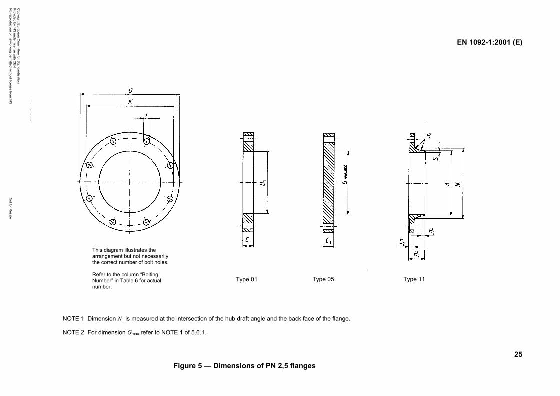
This diagram illustrates thearrangement but not necessarilythe correct number of bolt holes.
Refer to the column “BoltingNumber” in Table 6 for actualnumber.
NOTE 1 Dimension N1 is measured at the intersection of the hub draft angle and the back face of the flange.
NOTE 2 For dimension Gmax refer to NOTE 1 of 5.6.1.
Figure 5 — Dimensions of PN 2,5 flanges
Type 01 Type 05 Type 11
Copyright E
uropean Com
mittee for S
tandardization P
rovided by IHS
under license with C
EN
Not for R
esaleN
o reproduction or networking perm
itted without license from
IHS
--```,-`-`,,`,,`,`,,`---
EN 1092-1:2001 (E)
26
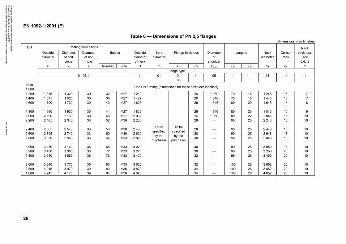
Table 6 — Dimensions of PN 2,5 flangesDimensions in millimetres
Mating dimensions
Outsidediameter
Diameterof boltcircle
Diameterof bolthole
Bolting Outsidediameterof neck
Borediameter
Flange thickness Diameterof
shoulder
Lengths Neckdiameter
Cornerradii
Neckthickness
(see5.6.1)
D K L Number Size A B1 C1 C2 Gmax H2 H3 N1 R1 SFlange type
01,05,11 11 01 01 11 05 11 11 11 11 11
DN
0510 to1 000
Use PN 6 rating (dimensions for these sizes are identical)
1 200 1 375 1 320 30 32 M27 1 219 26 1 160 70 16 1 245 16 71 400 1 575 1 520 30 36 M27 1 422 26 1 346 70 16 1 445 16 71 600 1 790 1 730 30 40 M27 1 626 26 1 546 80 20 1 645 16 8
1 800 1 990 1 930 30 44 M27 1 829 26 1 746 80 20 1 845 16 92 000 2 190 2 130 30 48 M27 2 032 26 1 950 80 22 2 045 16 102 200 2 405 2 340 33 52 M30 2 235 28 — 90 25 2 248 18 10
2 400 2 605 2 540 33 56 M30 2 438 28 — 90 25 2 448 18 102 600 2 805 2 740 33 60 M30 2 620 28 — 90 25 2 648 18 102 800 3 030 2 960 36 64 M33 2 820 30 — 90 25 2 848 18 10
3 000 3 230 3 160 36 68 M33 3 020 30 — 90 25 3 050 18 103 200 3 430 3 360 36 72 M33 3 220 30 — 90 25 3 250 20 103 400 3 630 3 560 36 76 M33 3 420 32 — 95 28 3 450 20 10
3 600 3 840 3 770 36 80 M33 3 620 32 — 100 28 3 652 20 103 800 4 045 3 970 39 80 M36 3 820 34 — 100 28 3 852 20 104 000 4 245 4 170 39 84 M36 4 020
To bespecified
by thepurchaser
To bespecified
by thepurchaser
34 — 100 28 4 052 20 10
Copyright E
uropean Com
mittee for S
tandardization P
rovided by IHS
under license with C
EN
Not for R
esaleN
o reproduction or networking perm
itted without license from
IHS
--```,-`-`,,`,,`,`,,`---
EN 1092-1:2001 (E)
27
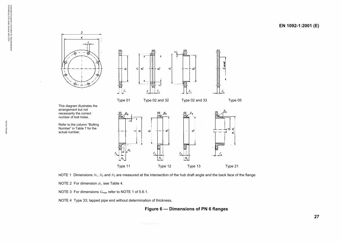
Type 01 Type 02 and 32 Type 02 and 33 Type 05
Type 11 Type 12 Type 13 Type 21
NOTE 1 Dimensions N1, N2 and N3 are measured at the intersection of the hub draft angle and the back face of the flange.
NOTE 2 For dimension d1, see Table 4.
NOTE 3 For dimensions Gmax refer to NOTE 1 of 5.6.1.
NOTE 4 Type 33; lapped pipe end without determination of thickness.
Figure 6 — Dimensions of PN 6 flanges
This diagram illustrates thearrangement but notnecessarily the correctnumber of bolt holes.
Refer to the column “BoltingNumber” in Table 7 for theactual number.
Copyright E
uropean Com
mittee for S
tandardization P
rovided by IHS
under license with C
EN
Not for R
esaleN
o reproduction or networking perm
itted without license from
IHS
--```,-`-`,,`,,`,`,,`---
EN 1092-1:2001 (E)
28
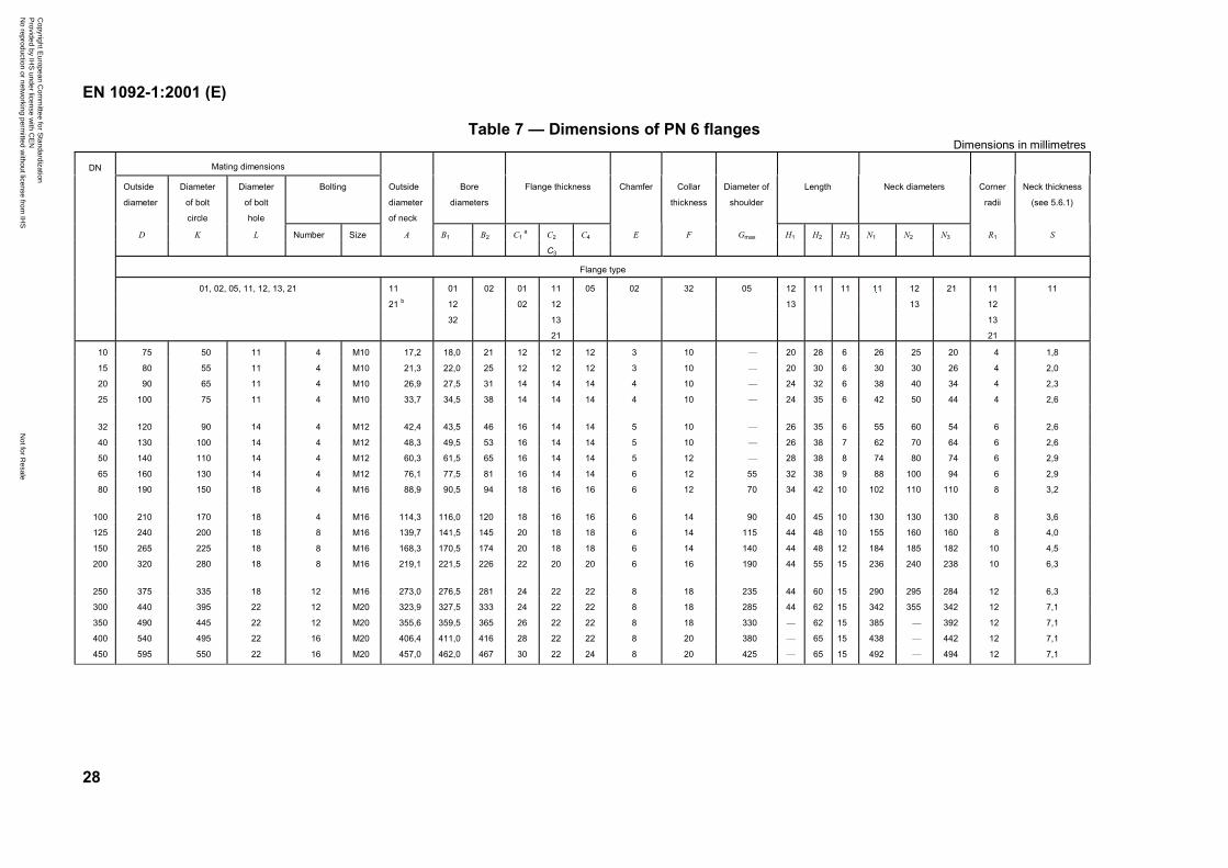
Table 7 — Dimensions of PN 6 flangesDimensions in millimetres
Mating dimensionsDN
Outside
diameter
Diameter
of bolt
circle
Diameter
of bolt
hole
Bolting Outside
diameter
of neck
Bore
diameters
Flange thickness Chamfer Collar
thickness
Diameter of
shoulder
Length Neck diameters Corner
radii
Neck thickness
(see 5.6.1)
D K L Number Size A B1 B2 C1 a C2 C4 E F Gmax H1 H2 H3 N1 N2 N3 R1 S
C3
Flange type
01, 02, 05, 11, 12, 13, 21 11 01 02 01 11 05 02 32 05 12 11 11 11 12 21 11 11
21 b 12 02 12 13 13 12
32 13 13
21 21
10 75 50 11 4 M10 17,2 18,0 21 12 12 12 3 10 — 20 28 6 26 25 20 4 1,8
15 80 55 11 4 M10 21,3 22,0 25 12 12 12 3 10 — 20 30 6 30 30 26 4 2,0
20 90 65 11 4 M10 26,9 27,5 31 14 14 14 4 10 — 24 32 6 38 40 34 4 2,3
25 100 75 11 4 M10 33,7 34,5 38 14 14 14 4 10 — 24 35 6 42 50 44 4 2,6
32 120 90 14 4 M12 42,4 43,5 46 16 14 14 5 10 — 26 35 6 55 60 54 6 2,6
40 130 100 14 4 M12 48,3 49,5 53 16 14 14 5 10 — 26 38 7 62 70 64 6 2,6
50 140 110 14 4 M12 60,3 61,5 65 16 14 14 5 12 — 28 38 8 74 80 74 6 2,9
65 160 130 14 4 M12 76,1 77,5 81 16 14 14 6 12 55 32 38 9 88 100 94 6 2,9
80 190 150 18 4 M16 88,9 90,5 94 18 16 16 6 12 70 34 42 10 102 110 110 8 3,2
100 210 170 18 4 M16 114,3 116,0 120 18 16 16 6 14 90 40 45 10 130 130 130 8 3,6
125 240 200 18 8 M16 139,7 141,5 145 20 18 18 6 14 115 44 48 10 155 160 160 8 4,0
150 265 225 18 8 M16 168,3 170,5 174 20 18 18 6 14 140 44 48 12 184 185 182 10 4,5
200 320 280 18 8 M16 219,1 221,5 226 22 20 20 6 16 190 44 55 15 236 240 238 10 6,3
250 375 335 18 12 M16 273,0 276,5 281 24 22 22 8 18 235 44 60 15 290 295 284 12 6,3
300 440 395 22 12 M20 323,9 327,5 333 24 22 22 8 18 285 44 62 15 342 355 342 12 7,1
350 490 445 22 12 M20 355,6 359,5 365 26 22 22 8 18 330 — 62 15 385 — 392 12 7,1
400 540 495 22 16 M20 406,4 411,0 416 28 22 22 8 20 380 — 65 15 438 — 442 12 7,1
450 595 550 22 16 M20 457,0 462,0 467 30 22 24 8 20 425 — 65 15 492 — 494 12 7,1
Copyright E
uropean Com
mittee for S
tandardization P
rovided by IHS
under license with C
EN
Not for R
esaleN
o reproduction or networking perm
itted without license from
IHS
--```,-`-`,,`,,`,`,,`---
EN 1092-1:2001 (E)
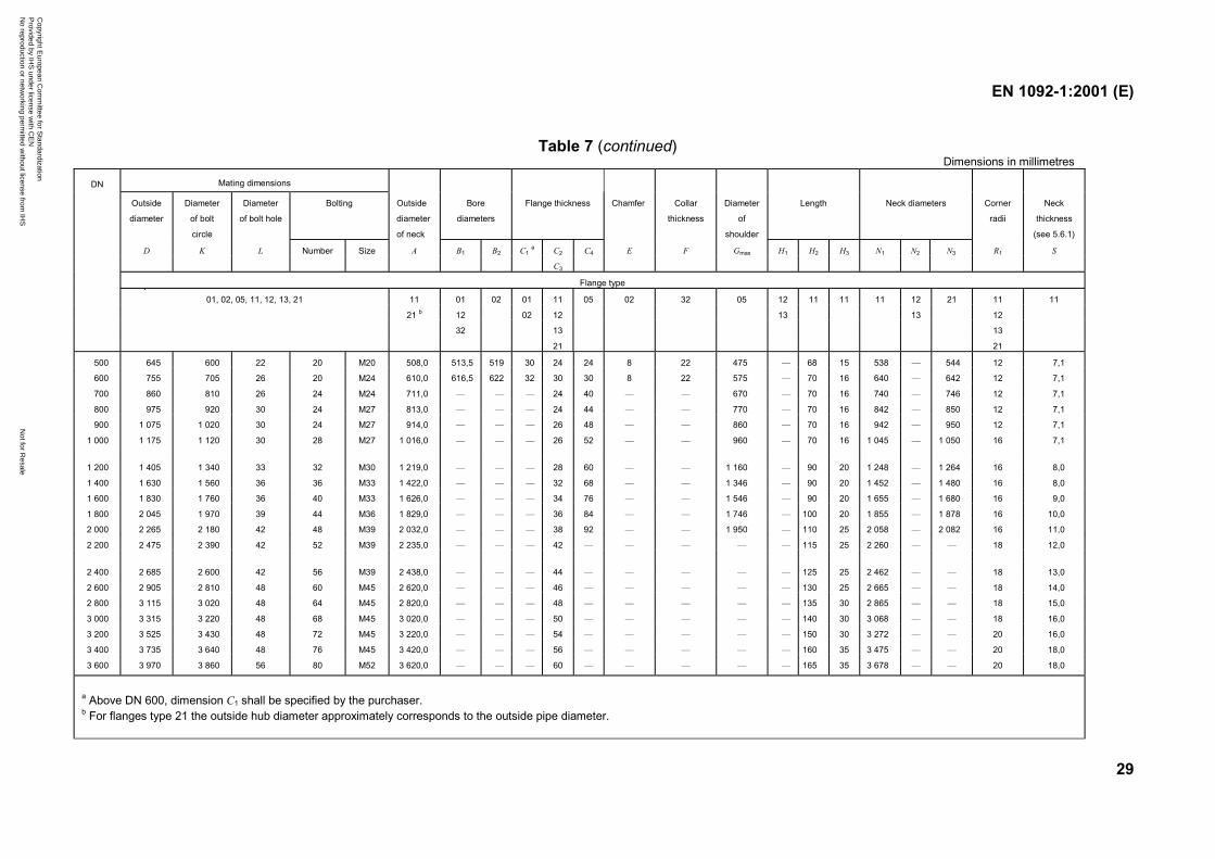
29
Table 7 (continued)Dimensions in millimetres
Mating dimensions
Outside
diameter
Diameter
of bolt
circle
Diameter
of bolt hole
Bolting Outside
diameter
of neck
Bore
diameters
Flange thickness Chamfer Collar
thickness
Diameter
of
shoulder
Length Neck diameters Corner
radii
Neck
thickness
(see 5.6.1)
D K L Number Size A B1 B2 C1 a C2 C4 E F Gmax H1 H2 H3 N1 N2 N3 R1 S
DN
C3
Flange type
01, 02, 05, 11, 12, 13, 21 11 01 02 01 11 05 02 32 05 12 11 11 11 12 21 11 11
21 b 12 02 12 13 13 12
32 13 13
21 21
500 645 600 22 20 M20 508,0 513,5 519 30 24 24 8 22 475 — 68 15 538 — 544 12 7,1
600 755 705 26 20 M24 610,0 616,5 622 32 30 30 8 22 575 — 70 16 640 — 642 12 7,1
700 860 810 26 24 M24 711,0 — — — 24 40 — — 670 — 70 16 740 — 746 12 7,1
800 975 920 30 24 M27 813,0 — — — 24 44 — — 770 — 70 16 842 — 850 12 7,1
900 1 075 1 020 30 24 M27 914,0 — — — 26 48 — — 860 — 70 16 942 — 950 12 7,1
1 000 1 175 1 120 30 28 M27 1 016,0 — — — 26 52 — — 960 — 70 16 1 045 — 1 050 16 7,1
1 200 1 405 1 340 33 32 M30 1 219,0 — — — 28 60 — — 1 160 — 90 20 1 248 — 1 264 16 8,0
1 400 1 630 1 560 36 36 M33 1 422,0 — — — 32 68 — — 1 346 — 90 20 1 452 — 1 480 16 8,0
1 600 1 830 1 760 36 40 M33 1 626,0 — — — 34 76 — — 1 546 — 90 20 1 655 — 1 680 16 9,0
1 800 2 045 1 970 39 44 M36 1 829,0 — — — 36 84 — — 1 746 — 100 20 1 855 — 1 878 16 10,0
2 000 2 265 2 180 42 48 M39 2 032,0 — — — 38 92 — — 1 950 — 110 25 2 058 — 2 082 16 11,0
2 200 2 475 2 390 42 52 M39 2 235,0 — — — 42 — — — — — 115 25 2 260 — — 18 12,0
2 400 2 685 2 600 42 56 M39 2 438,0 — — — 44 — — — — — 125 25 2 462 — — 18 13,0
2 600 2 905 2 810 48 60 M45 2 620,0 — — — 46 — — — — — 130 25 2 665 — — 18 14,0
2 800 3 115 3 020 48 64 M45 2 820,0 — — — 48 — — — — — 135 30 2 865 — — 18 15,0
3 000 3 315 3 220 48 68 M45 3 020,0 — — — 50 — — — — — 140 30 3 068 — — 18 16,0
3 200 3 525 3 430 48 72 M45 3 220,0 — — — 54 — — — — — 150 30 3 272 — — 20 16,0
3 400 3 735 3 640 48 76 M45 3 420,0 — — — 56 — — — — — 160 35 3 475 — — 20 18,0
3 600 3 970 3 860 56 80 M52 3 620,0 — — — 60 — — — — — 165 35 3 678 — — 20 18,0
a Above DN 600, dimension C1 shall be specified by the purchaser.b For flanges type 21 the outside hub diameter approximately corresponds to the outside pipe diameter.
Copyright E
uropean Com
mittee for S
tandardization P
rovided by IHS
under license with C
EN
Not for R
esaleN
o reproduction or networking perm
itted without license from
IHS
--```,-`-`,,`,,`,`,,`---
EN 1092-1:2001 (E)
30
This diagram illustrates thearrangement but notnecessarily the correctnumber of bolt holes.
Refer to the column “BoltingNumber” in Table 8 for theactual number.
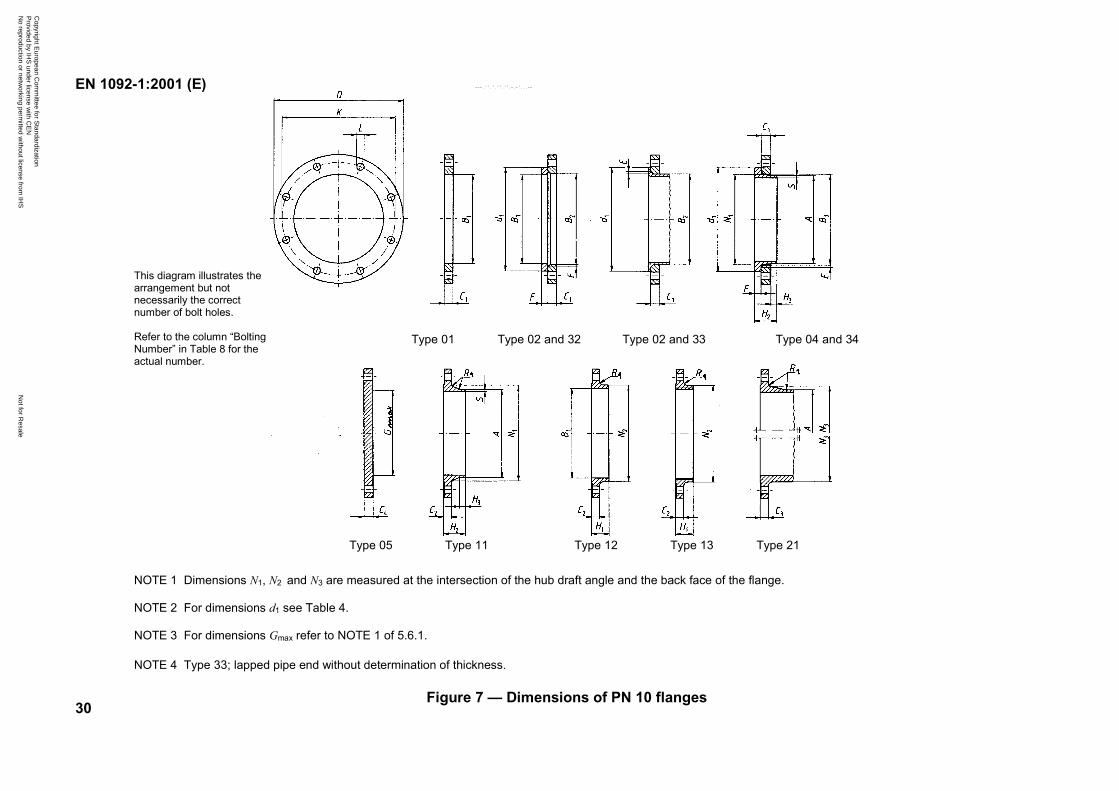
NOTE 1 Dimensions N1, N2 and N3 are measured at the intersection of the hub draft angle and the back face of the flange.
NOTE 2 For dimensions d1 see Table 4.
NOTE 3 For dimensions Gmax refer to NOTE 1 of 5.6.1.
NOTE 4 Type 33; lapped pipe end without determination of thickness.
Figure 7 — Dimensions of PN 10 flanges
Type 11Type 05 Type 12 Type 13 Type 21
Type 01 Type 02 and 32 Type 02 and 33 Type 04 and 34
Copyright E
uropean Com
mittee for S
tandardization P
rovided by IHS
under license with C
EN
Not for R
esaleN
o reproduction or networking perm
itted without license from
IHS
--```,-`-`,,`,,`,`,,`---
EN 1092-1:2001 (E)
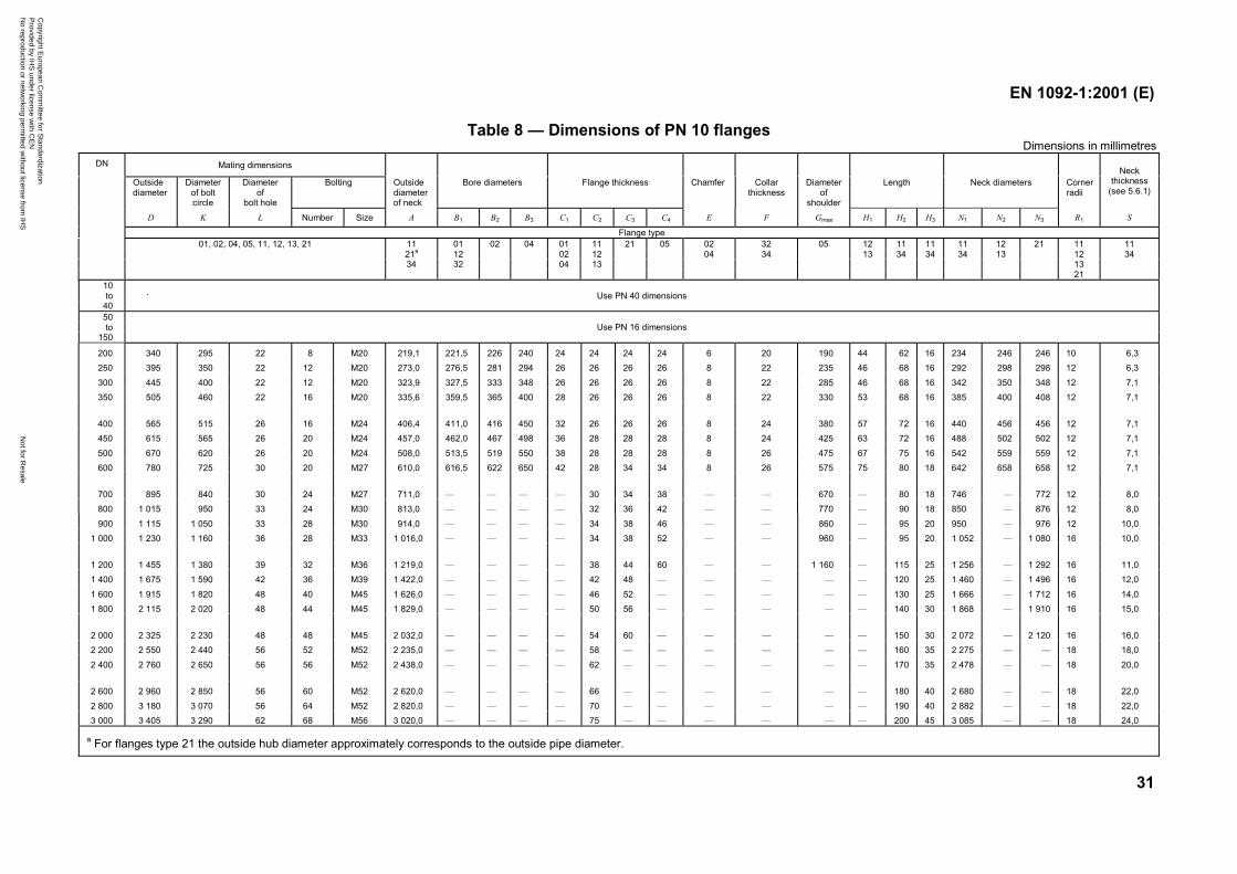
31
Table 8 — Dimensions of PN 10 flangesDimensions in millimetres
Mating dimensions
Outsidediameter
Diameterof boltcircle
Diameterof
bolt hole
Bolting Outsidediameterof neck
Bore diameters Flange thickness Chamfer Collarthickness
Diameterof
shoulder
Length Neck diameters Cornerradii
Neckthickness
(see 5.6.1)
DN
D K L Number Size A B1 B2 B3 C1 C2 C3 C4 E F Gmax H1 H2 H3 N1 N2 N3 R1 S
Flange type01, 02, 04, 05, 11, 12, 13, 21 11 01 02 04 01 11 21 05 02 32 05 12 11 11 11 12 21 11 11
21a 12 02 12 04 34 13 34 34 34 13 12 3434 32 04 13 13
21 10
to 40
Use PN 40 dimensions
50 to
150Use PN 16 dimensions
200 340 295 22 8 M20 219,1 221,5 226 240 24 24 24 24 6 20 190 44 62 16 234 246 246 10 6,3250 395 350 22 12 M20 273,0 276,5 281 294 26 26 26 26 8 22 235 46 68 16 292 298 298 12 6,3300 445 400 22 12 M20 323,9 327,5 333 348 26 26 26 26 8 22 285 46 68 16 342 350 348 12 7,1350 505 460 22 16 M20 335,6 359,5 365 400 28 26 26 26 8 22 330 53 68 16 385 400 408 12 7,1
400 565 515 26 16 M24 406,4 411,0 416 450 32 26 26 26 8 24 380 57 72 16 440 456 456 12 7,1450 615 565 26 20 M24 457,0 462,0 467 498 36 28 28 28 8 24 425 63 72 16 488 502 502 12 7,1500 670 620 26 20 M24 508,0 513,5 519 550 38 28 28 28 8 26 475 67 75 16 542 559 559 12 7,1600 780 725 30 20 M27 610,0 616,5 622 650 42 28 34 34 8 26 575 75 80 18 642 658 658 12 7,1
700 895 840 30 24 M27 711,0 — — — — 30 34 38 — — 670 — 80 18 746 — 772 12 8,0800 1 015 950 33 24 M30 813,0 — — — — 32 36 42 — — 770 — 90 18 850 — 876 12 8,0900 1 115 1 050 33 28 M30 914,0 — — — — 34 38 46 — — 860 — 95 20 950 — 976 12 10,0
1 000 1 230 1 160 36 28 M33 1 016,0 — — — — 34 38 52 — — 960 — 95 20 1 052 — 1 080 16 10,0
1 200 1 455 1 380 39 32 M36 1 219,0 — — — — 38 44 60 — — 1 160 — 115 25 1 256 — 1 292 16 11,01 400 1 675 1 590 42 36 M39 1 422,0 — — — — 42 48 — — — — — 120 25 1 460 — 1 496 16 12,01 600 1 915 1 820 48 40 M45 1 626,0 — — — — 46 52 — — — — — 130 25 1 666 — 1 712 16 14,01 800 2 115 2 020 48 44 M45 1 829,0 — — — — 50 56 — — — — — 140 30 1 868 — 1 910 16 15,0
2 000 2 325 2 230 48 48 M45 2 032,0 — — — — 54 60 — — — — — 150 30 2 072 — 2 120 16 16,02 200 2 550 2 440 56 52 M52 2 235,0 — — — — 58 — — — — — — 160 35 2 275 — — 18 18,02 400 2 760 2 650 56 56 M52 2 438,0 — — — — 62 — — — — — — 170 35 2 478 — — 18 20,0
2 600 2 960 2 850 56 60 M52 2 620,0 — — — — 66 — — — — — — 180 40 2 680 — — 18 22,02 800 3 180 3 070 56 64 M52 2 820,0 — — — — 70 — — — — — — 190 40 2 882 — — 18 22,03 000 3 405 3 290 62 68 M56 3 020,0 — — — — 75 — — — — — — 200 45 3 085 — — 18 24,0
a For flanges type 21 the outside hub diameter approximately corresponds to the outside pipe diameter.
Copyright E
uropean Com
mittee for S
tandardization P
rovided by IHS
under license with C
EN
Not for R
esaleN
o reproduction or networking perm
itted without license from
IHS
--```,-`-`,,`,,`,`,,`---
EN 1092-1:2001 (E)
32
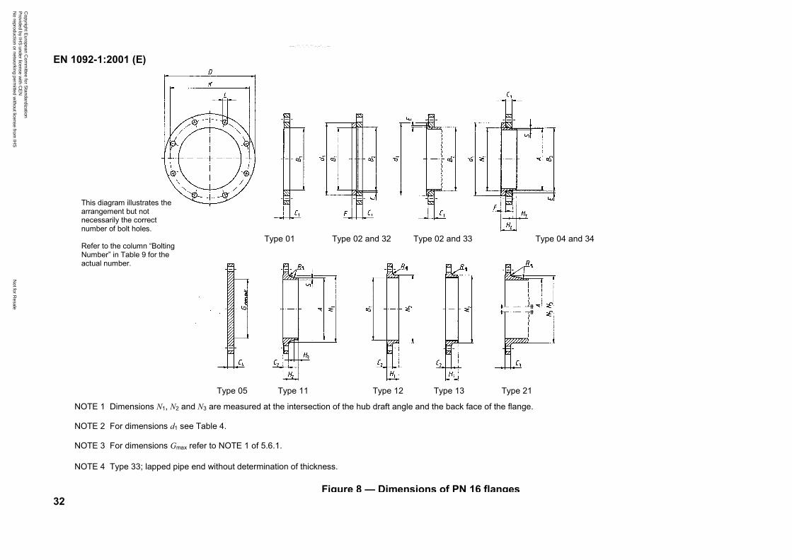
NOTE 1 Dimensions N1, N2 and N3 are measured at the intersection of the hub draft angle and the back face of the flange.
NOTE 2 For dimensions d1 see Table 4.
NOTE 3 For dimensions Gmax refer to NOTE 1 of 5.6.1.
NOTE 4 Type 33; lapped pipe end without determination of thickness.
Figure 8 — Dimensions of PN 16 flanges
Type 11Type 05 Type 12 Type 13 Type 21
Type 01 Type 02 and 32 Type 02 and 33 Type 04 and 34
This diagram illustrates thearrangement but notnecessarily the correctnumber of bolt holes.
Refer to the column “BoltingNumber” in Table 9 for theactual number.
Copyright E
uropean Com
mittee for S
tandardization P
rovided by IHS
under license with C
EN
Not for R
esaleN
o reproduction or networking perm
itted without license from
IHS
--```,-`-`,,`,,`,`,,`---
EN 1092-1:2001 (E)
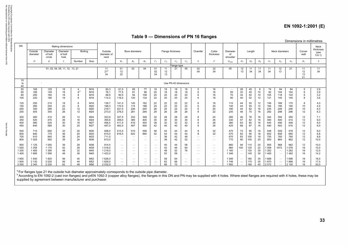
33
Table 9 — Dimensions of PN 16 flangesDimensions in millimetres
Mating dimensions
Outsidediameter
Diameterof boltcircle
Diameterof bolthole
Bolting Outsidediameter of
neck
Bore diameters Flange thickness Chamfer Collarthickness
Diameterof
shoulder
Length Neck diameters Cornerradii
Neckthickness
(see5.6.1)
DN
D K L Number Size A B1 B2 B3 C1 C2 C3 C4 E F Gmax H1 H2 H3 N1 N2 N3 R1 S
Flange type01, 02, 04, 05, 11, 12, 13, 21 11 01 02 04 01 11 21 05 02 32 05 12 11 11 11 12 21 11 11
21a 12 02 12 04 34 13 34 34 34 13 12 3434 32 04 13 13
2110to Use PN 40 dimensions
4050 165 125 18 4 M16 60,3 61,5 65 77 19 18 18 18 5 16 — 28 45 8 74 84 84 5 2,965 185 145 18 8 b M16 76,1 77,5 81 96 20 18 18 18 6 16 55 32 45 10 92 104 104 6 2,980 200 160 18 8 M16 88,9 90,5 94 108 20 20 20 20 6 16 70 34 50 10 105 118 120 6 3,2
100 220 180 18 8 M16 114,3 116,0 120 134 22 20 20 20 6 18 90 40 52 12 131 140 140 8 3,6
125 250 210 18 8 M16 139,7 141,5 145 162 22 22 22 22 6 18 115 44 55 12 156 168 170 8 4,0150 285 240 22 8 M20 168,3 170,5 174 188 24 22 22 22 6 20 140 44 55 12 184 195 190 10 4,5200 340 295 22 12 M20 219,1 221,5 226 240 26 24 24 24 6 20 190 44 62 16 235 246 246 10 6,3250 405 355 26 12 M24 273,0 276,5 281 294 29 26 26 26 8 22 235 46 70 16 292 298 296 12 6,3
300 460 410 26 12 M24 323,9 327,5 333 348 32 28 28 28 8 24 285 46 78 16 344 350 350 12 7,1350 520 470 26 16 M24 355,6 359,0 365 400 35 30 30 30 8 26 330 57 82 16 390 400 410 12 8,0400 580 525 30 16 M27 406,4 411,0 416 454 38 32 32 32 8 28 380 63 85 16 445 456 458 12 8,0450 640 585 30 20 M27 457,0 462,0 467 500 42 40 40 40 8 30 425 68 87 16 490 502 516 12 8,0
500 715 650 33 20 M30 508,0 513,5 510 556 46 44 44 44 8 32 475 73 90 16 548 559 576 12 8,0600 840 770 36 20 M33 610,0 616,5 622 660 52 54 54 54 8 32 575 83 95 18 652 658 690 12 8,8700 910 840 36 24 M33 711,0 — — — — 36 42 48 — — 670 83 100 18 755 760 760 12 8,8800 1 025 950 39 24 M36 813,0 — — — — 38 42 52 — — 770 90 105 20 855 864 862 12 10,0
900 1 125 1 050 39 28 M36 914,0 — — — — 40 44 58 — — 860 94 110 20 955 968 962 12 10,01 000 1 255 1 170 42 28 M39 1 016,0 — — — — 42 46 64 — — 960 100 120 22 1 058 1072 1 076 16 10,01 200 1 485 1 390 48 32 M45 1 219,0 — — — — 48 52 76 — — 1 160 — 130 30 1 262 — 1 282 16 12,51 400 1 685 1 590 48 36 M45 1 422,0 — — — — 52 58 — — — 1 346 — 145 30 1 465 — 1 482 16 14,2
1 600 1 930 1 820 56 40 M52 1 626,0 — — — — 58 64 — — — 1 546 — 160 35 1 668 — 1 696 16 16,01 800 2 130 2 020 56 44 M52 1 829,0 — — — — 62 68 — — — 1 746 — 170 35 1 870 — 1 896 16 17,52 000 2 345 2 230 62 48 M56 2 032,0 — — — — 66 70 — — — 1 950 — 180 40 2 072 — 2 100 16 20,0
a For flanges type 21 the outside hub diameter approximately corresponds to the outside pipe diameter.b According to EN 1092-2 (cast iron flanges) and prEN 1092-3 (copper alloy flanges), the flanges in this DN and PN may be supplied with 4 holes. Where steel flanges are required with 4 holes, these may besupplied by agreement between manufacturer and purchaser.
Copyright E
uropean Com
mittee for S
tandardization P
rovided by IHS
under license with C
EN
Not for R
esaleN
o reproduction or networking perm
itted without license from
IHS
--```,-`-`,,`,,`,`,,`---
EN 1092-1:2001 (E)
34
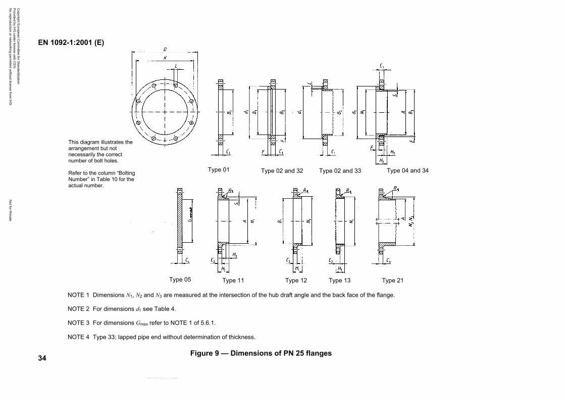
NOTE 1 Dimensions N1, N2 and N3 are measured at the intersection of the hub draft angle and the back face of the flange.
NOTE 2 For dimensions d1 see Table 4.
NOTE 3 For dimensions Gmax refer to NOTE 1 of 5.6.1.
NOTE 4 Type 33; lapped pipe end without determination of thickness.
Figure 9 — Dimensions of PN 25 flanges
Type 11Type 05 Type 12 Type 13 Type 21
Type 01 Type 02 and 32 Type 02 and 33 Type 04 and 34
This diagram illustrates thearrangement but notnecessarily the correctnumber of bolt holes.
Refer to the column “BoltingNumber” in Table 10 for theactual number.
Copyright E
uropean Com
mittee for S
tandardization P
rovided by IHS
under license with C
EN
Not for R
esaleN
o reproduction or networking perm
itted without license from
IHS
--```,-`-`,,`,,`,`,,`---
EN 1092-1:2001 (E)
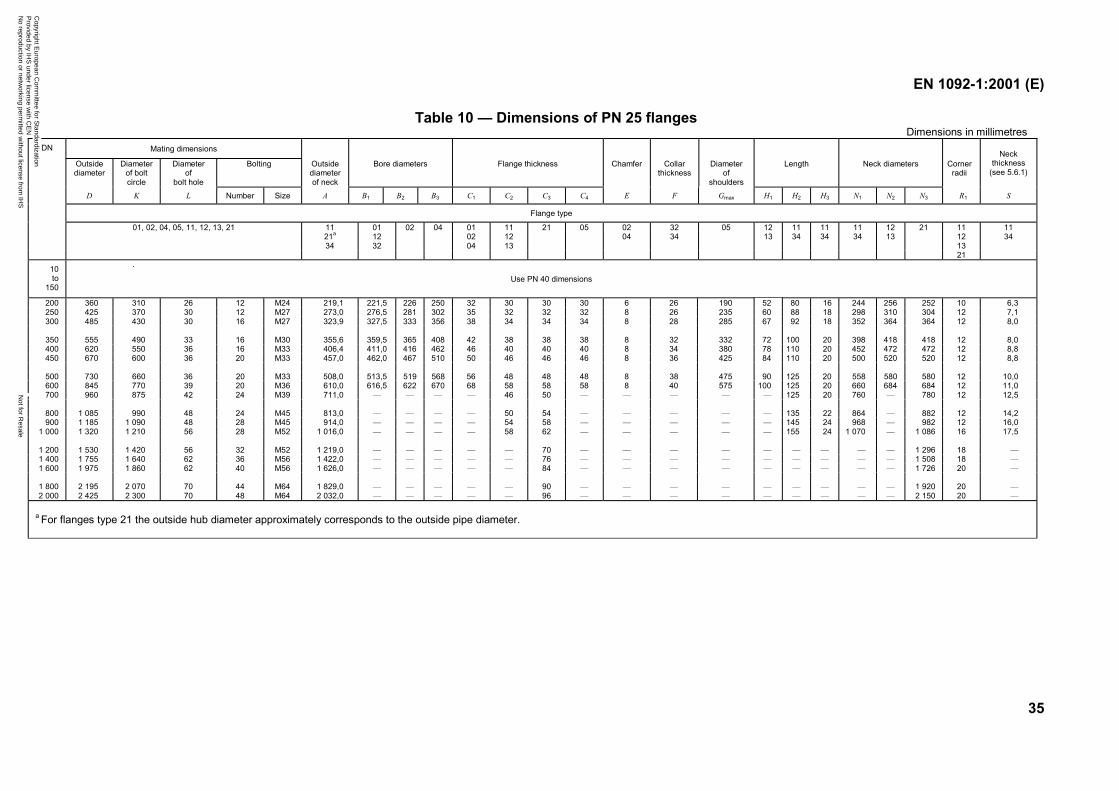
35
Table 10 — Dimensions of PN 25 flangesDimensions in millimetres
Mating dimensions
Outsidediameter
Diameterof boltcircle
Diameterof
bolt hole
Bolting Outsidediameterof neck
Bore diameters Flange thickness Chamfer Collarthickness
Diameterof
shoulders
Length Neck diameters Cornerradii
Neckthickness
(see 5.6.1)
DN
D K L Number Size A B1 B2 B3 C1 C2 C3 C4 E F Gmax H1 H2 H3 N1 N2 N3 R1 S
Flange type
01, 02, 04, 05, 11, 12, 13, 21 11 01 02 04 01 11 21 05 02 32 05 12 11 11 11 12 21 11 1121a 12 02 12 04 34 13 34 34 34 13 12 3434 32 04 13 13
21
10to
150Use PN 40 dimensions
200 360 310 26 12 M24 219,1 221,5 226 250 32 30 30 30 6 26 190 52 80 16 244 256 252 10 6,3250 425 370 30 12 M27 273,0 276,5 281 302 35 32 32 32 8 26 235 60 88 18 298 310 304 12 7,1300 485 430 30 16 M27 323,9 327,5 333 356 38 34 34 34 8 28 285 67 92 18 352 364 364 12 8,0
350 555 490 33 16 M30 355,6 359,5 365 408 42 38 38 38 8 32 332 72 100 20 398 418 418 12 8,0400 620 550 36 16 M33 406,4 411,0 416 462 46 40 40 40 8 34 380 78 110 20 452 472 472 12 8,8450 670 600 36 20 M33 457,0 462,0 467 510 50 46 46 46 8 36 425 84 110 20 500 520 520 12 8,8
500 730 660 36 20 M33 508,0 513,5 519 568 56 48 48 48 8 38 475 90 125 20 558 580 580 12 10,0600 845 770 39 20 M36 610,0 616,5 622 670 68 58 58 58 8 40 575 100 125 20 660 684 684 12 11,0700 960 875 42 24 M39 711,0 — — — — 46 50 — — — — — 125 20 760 — 780 12 12,5
800 1 085 990 48 24 M45 813,0 — — — — 50 54 — — — — — 135 22 864 — 882 12 14,2900 1 185 1 090 48 28 M45 914,0 — — — — 54 58 — — — — — 145 24 968 — 982 12 16,0
1 000 1 320 1 210 56 28 M52 1 016,0 — — — — 58 62 — — — — — 155 24 1 070 — 1 086 16 17,5
1 200 1 530 1 420 56 32 M52 1 219,0 — — — — — 70 — — — — — — — — — 1 296 18 —1 400 1 755 1 640 62 36 M56 1 422,0 — — — — — 76 — — — — — — — — — 1 508 18 —1 600 1 975 1 860 62 40 M56 1 626,0 — — — — — 84 — — — — — — — — — 1 726 20 —
1 800 2 195 2 070 70 44 M64 1 829,0 — — — — — 90 — — — — — — — — — 1 920 20 —2 000 2 425 2 300 70 48 M64 2 032,0 — — — — — 96 — — — — — — — — — 2 150 20 —
a For flanges type 21 the outside hub diameter approximately corresponds to the outside pipe diameter.
Copyright E
uropean Com
mittee for S
tandardization P
rovided by IHS
under license with C
EN
Not for R
esaleN
o reproduction or networking perm
itted without license from
IHS
--```,-`-`,,`,,`,`,,`---
EN 1092-1:2001 (E)
36
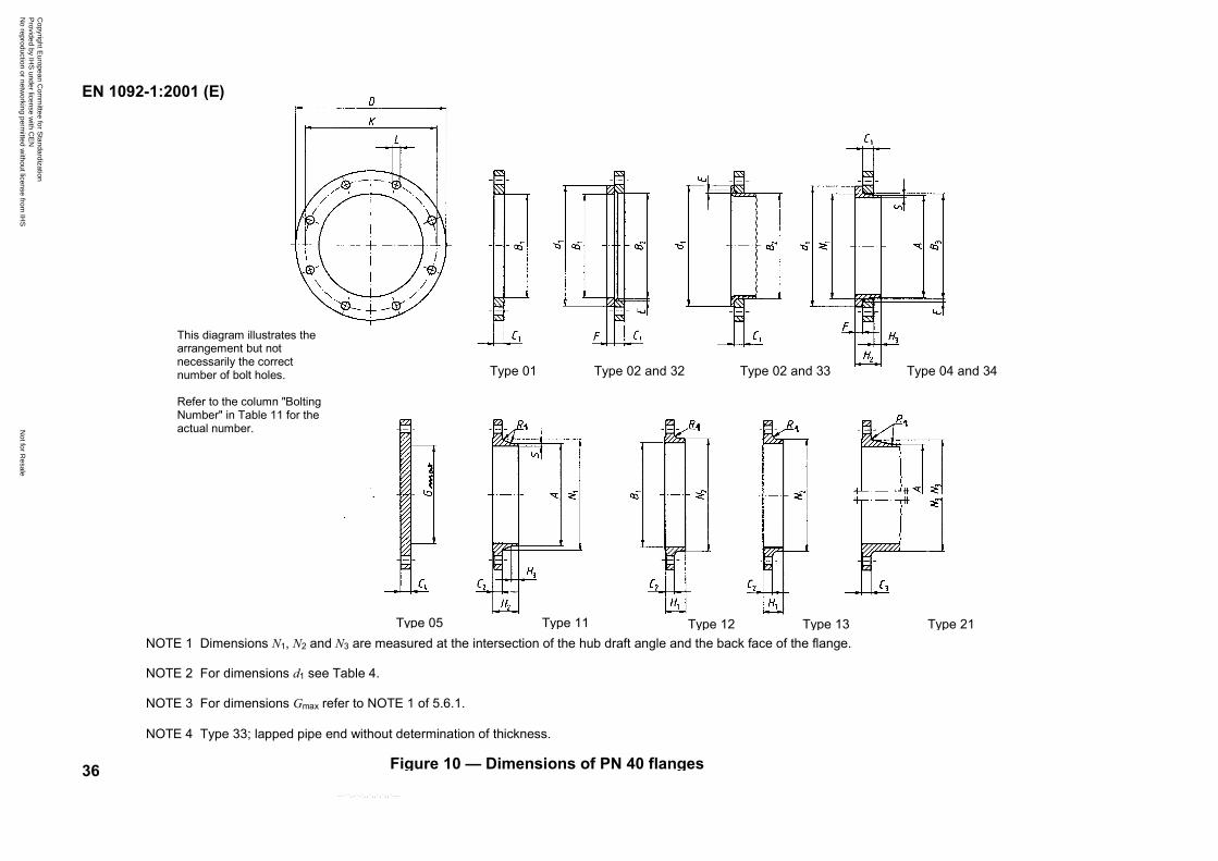
NOTE 1 Dimensions N1, N2 and N3 are measured at the intersection of the hub draft angle and the back face of the flange.
NOTE 2 For dimensions d1 see Table 4.
NOTE 3 For dimensions Gmax refer to NOTE 1 of 5.6.1.
NOTE 4 Type 33; lapped pipe end without determination of thickness.
Figure 10 — Dimensions of PN 40 flanges
Type 11Type 05 Type 12 Type 13 Type 21
Type 01 Type 02 and 32 Type 02 and 33 Type 04 and 34
This diagram illustrates thearrangement but notnecessarily the correctnumber of bolt holes.
Refer to the column "BoltingNumber" in Table 11 for theactual number.
Copyright E
uropean Com
mittee for S
tandardization P
rovided by IHS
under license with C
EN
Not for R
esaleN
o reproduction or networking perm
itted without license from
IHS
--```,-`-`,,`,,`,`,,`---
EN 1092-1:2001 (E)
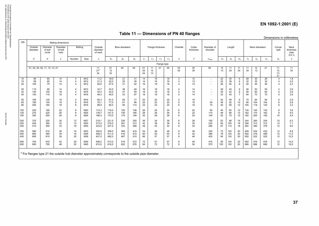
37
Table 11 — Dimensions of PN 40 flangesDimensions in millimetres
Mating dimensions
Outsidediameter
Diameterof boltcircle
Diameterof bolthole
Bolting Outsidediameterof neck
Bore diameters Flange thickness Chamfer Collarthickness
Diameter ofshoulder
Length Neck diameters Cornerradii
Neckthickness
(see5.6.1)
DN
D K L Number Size A B1 B2 B3 C1 C2 C3 C4 E F Gmax H1 H2 H3 N1 N2 N3 R1 S
Flange type
01, 02, 04, 05, 11, 12, 13, 21 11 01 02 04 01 11 21 05 02 32 05 12 11 11 11 12 21 11 1121a 12 02 12 04 34 13 34 34 34 13 12 3434 32 04 13 13
2110 90 60 14 4 M12 17,2 18,0 21 31 14 16 3 12 — 22 35 6 28 30 28 4 1,815 95 65 14 4 M12 21,3 22,0 25 35 14 16 3 12 — 22 38 6 32 35 32 4 2,020 105 75 14 4 M12 26,9 27,5 31 42 16
161618 18 4 14 — 26 40 6 40 45 40 4 2,3
25 115 85 14 4 M12 33,7 34,5 38 49 16 18 4 14 — 28 40 6 46 52 50 4 2,632 140 100 18 4 M16 42,4 43,5 47 59 18 18 5 14 — 30 42 6 56 60 60 6 2,640 150 110 18 4 M16 48,3 49,5 53 67 18
181818 18 5 14 — 32 45 7 64 70 70 6 2,6
50 165 125 18 4 M16 60,3 61,5 65 77 20 20 5 16 — 34 48 8 75 84 84 6 2,965 185 145 18 8 M16 76,1 77,5 81 96 22 22 6 16 55 38 52 10 90 104 104 6 2,980 200 160 18 8 M16 88,9 90,5 94 114 24 24 6 18 70 40 58 12 105 118 120 8 3,2
202224
100 235 190 22 8 M20 114,3 116,0 120 138 26 24 6 20 90 44 65 12 134 145 142 8 3,6125 270 220 26 8 M24 139,7 141,5 145 166 28 26 6 22 115 48 68 12 162 170 162 8 4,0150 300 250 26 8 M24 168,3 170,5 174 194 30 28 6 24 140 52 75 12 192 200 192 10 4,5
242628
200 375 320 30 12 M27 219,1 221,5 226 250 36 36 6 28 190 52 88 16 244 260 254 10 6,3250 450 385 33 12 M30 273,0 276,5 281 312 42 38 8 30 235 60 105 18 306 312 312 12 7,1300 515 450 33 16 M30 323,9 327,5 333 368 48 42 8 34 285 67 115 18 362 380 378 12 8,0
343842
350 580 510 36 16 M33 355,6 359,5 365 418 54 46 8 36 330 72 125 20 408 424 432 12 8,8400 660 585 39 16 M36 406,4 411,0 416 472 60 50 8 42 380 78 135 20 462 478 498 12 11,0450 685 610 39 20 M36 457,0 462,0 467 510 66 57 8 46 425 84 135 20 500 522 522 12 12,5
465057
500 755 670 42 20 M39 508,0 513,5 519 572 72 57 8 50 475 90 140 20 562 576 576 12 14,2600 890 795 48 20 M45 610,0 616,5 622 676 84 72 8 54 575 100 150 20 666 686 686 12 16,0
5772
a For flanges type 21 the outside hub diameter approximately corresponds to the outside pipe diameter.
Copyright E
uropean Com
mittee for S
tandardization P
rovided by IHS
under license with C
EN
Not for R
esaleN
o reproduction or networking perm
itted without license from
IHS
--```,-`-`,,`,,`,`,,`---
EN 1092-1:2001 (E)
38
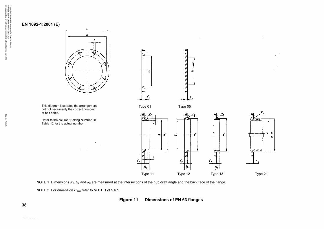
NOTE 1 Dimensions N1, N2 and N3 are measured at the intersections of the hub draft angle and the back face of the flange.
NOTE 2 For dimension Gmax refer to NOTE 1 of 5.6.1.
Figure 11 — Dimensions of PN 63 flanges
Type 11 Type 12 Type 13 Type 21
This diagram illustrates the arrangementbut not necessarily the correct numberof bolt holes.
Refer to the column “Bolting Number” inTable 12 for the actual number.
Type 01 Type 05
Copyright E
uropean Com
mittee for S
tandardization P
rovided by IHS
under license with C
EN
Not for R
esaleN
o reproduction or networking perm
itted without license from
IHS
--```,-`-`,,`,,`,`,,`---
EN 1092-1:2001 (E)
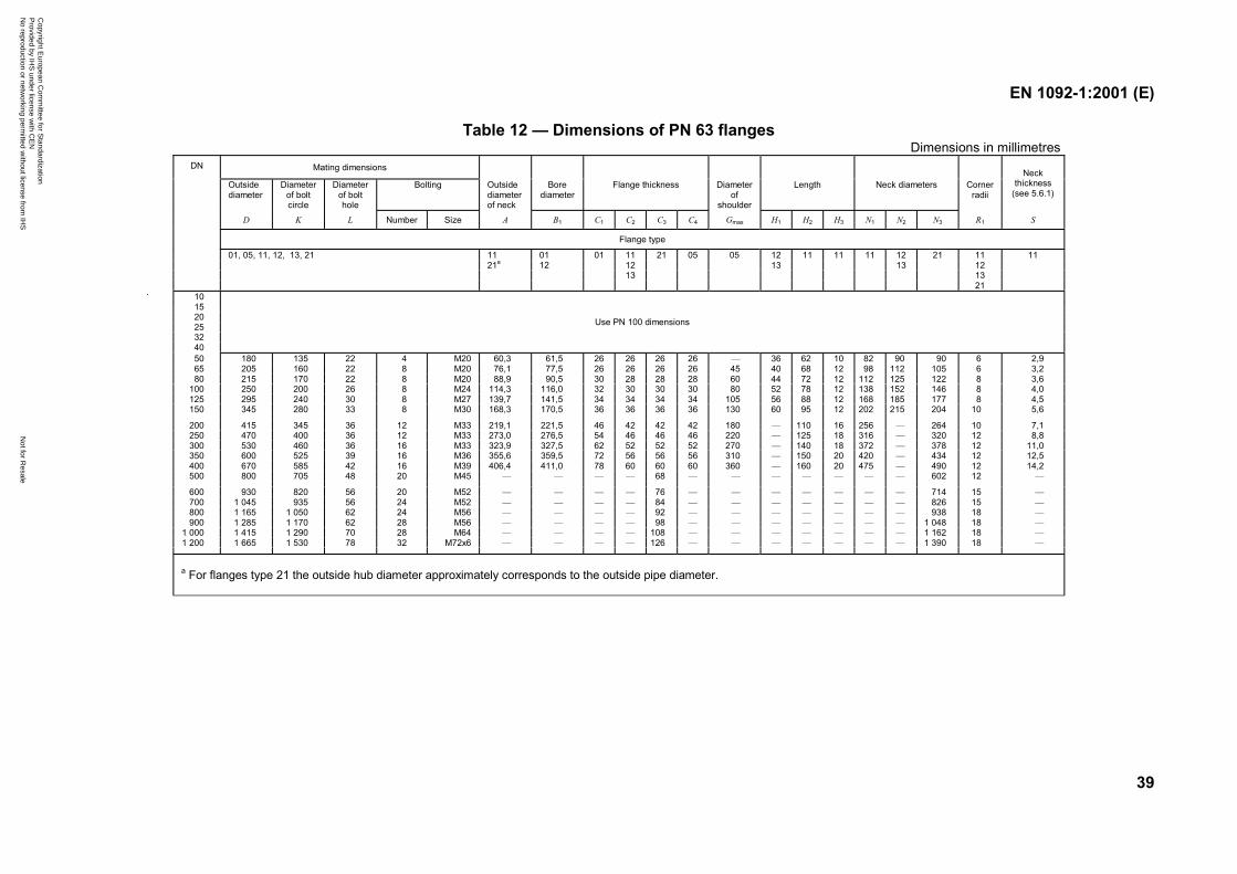
39
Table 12 — Dimensions of PN 63 flangesDimensions in millimetres
Mating dimensions
Outsidediameter
Diameterof boltcircle
Diameterof bolthole
Bolting Outsidediameterof neck
Borediameter
Flange thickness Diameterof
shoulder
Length Neck diameters Cornerradii
Neckthickness
(see 5.6.1)
DN
D K L Number Size A B1 C1 C2 C3 C4 Gmax H1 H2 H3 N1 N2 N3 R1 S
Flange type
01, 05, 11, 12, 13, 21 11 01 11 21 05 05 12 11 11 11 12 21 11 1121a 12 13 13 12
13 13
0112
21101520253240
Use PN 100 dimensions
50 180 135 22 4 M20 60,3 61,5 26 26 26 26 — 36 62 10 82 90 90 6 2,965 205 160 22 8 M20 76,1 77,5 26 26 26 26 45 40 68 12 98 112 105 6 3,280 215 170 22 8 M20 88,9 90,5 30 28 28 28 60 44 72 12 112 125 122 8 3,6
100 250 200 26 8 M24 114,3 116,0 32 30 30 30 80 52 78 12 138 152 146 8 4,0125 295 240 30 8 M27 139,7 141,5 34 34 34 34 105 56 88 12 168 185 177 8 4,5150 345 280 33 8 M30 168,3 170,5 36 36 36 36 130 60 95 12 202 215 204 10 5,6
200 415 345 36 12 M33 219,1 221,5 46 42 42 42 180 — 110 16 256 — 264 10 7,1250 470 400 36 12 M33 273,0 276,5 54 46 46 46 220 — 125 18 316 — 320 12 8,8300 530 460 36 16 M33 323,9 327,5 62 52 52 52 270 — 140 18 372 — 378 12 11,0350 600 525 39 16 M36 355,6 359,5 72 56 56 56 310 — 150 20 420 — 434 12 12,5400 670 585 42 16 M39 406,4 411,0 78 60 60 60 360 — 160 20 475 — 490 12 14,2500 800 705 48 20 M45 — — — — 68 — — — — — — — 602 12 —
600 930 820 56 20 M52 — — — — 76 — — — — — — — 714 15 —700 1 045 935 56 24 M52 — — — — 84 — — — — — — — 826 15 —800 1 165 1 050 62 24 M56 — — — — 92 — — — — — — — 938 18 —900 1 285 1 170 62 28 M56 — — — — 98 — — — — — — — 1 048 18 —
1 000 1 415 1 290 70 28 M64 — — — — 108 — — — — — — — 1 162 18 —1 200 1 665 1 530 78 32 M72x6 — — — — 126 — — — — — — — 1 390 18 —
a For flanges type 21 the outside hub diameter approximately corresponds to the outside pipe diameter.
Copyright E
uropean Com
mittee for S
tandardization P
rovided by IHS
under license with C
EN
Not for R
esaleN
o reproduction or networking perm
itted without license from
IHS
--```,-`-`,,`,,`,`,,`---
EN 1092-1:2001 (E)
40
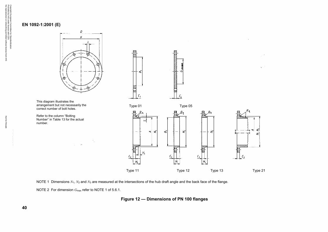
NOTE 1 Dimensions N1, N2 and N3 are measured at the intersections of the hub draft angle and the back face of the flange.
NOTE 2 For dimension Gmax refer to NOTE 1 of 5.6.1.
Figure 12 — Dimensions of PN 100 flanges
Type 01 Type 05
Type 11 Type 12 Type 13 Type 21
This diagram illustrates thearrangement but not necessarily thecorrect number of bolt holes.
Refer to the column “BoltingNumber” in Table 13 for the actualnumber.
Copyright E
uropean Com
mittee for S
tandardization P
rovided by IHS
under license with C
EN
Not for R
esaleN
o reproduction or networking perm
itted without license from
IHS
--```,-`-`,,`,,`,`,,`---
EN 1092-1:2001 (E)
41
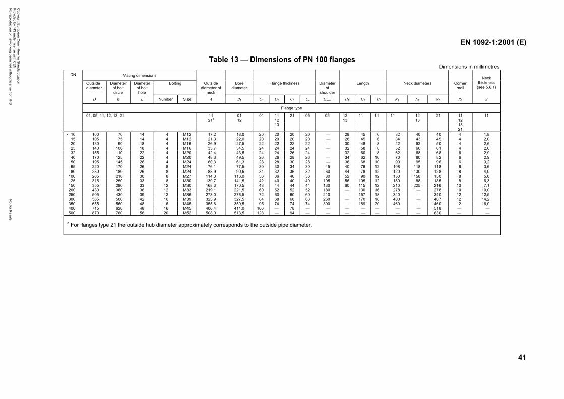
Table 13 — Dimensions of PN 100 flangesDimensions in millimetres
Mating dimensions
Outsidediameter
Diameterof boltcircle
Diameterof bolthole
Bolting Outsidediameter of
neck
Borediameter
Flange thickness Diameterof
shoulder
Length Neck diameters Cornerradii
Neckthickness
(see 5.6.1)
DN
D K L Number Size A B1 C1 C2 C3 C4 Gmax H1 H2 H3 N1 N2 N3 R1 S
Flange type
01, 05, 11, 12, 13, 21 11 01 01 11 21 05 05 12 11 11 11 12 21 11 1121a 12 12 13 13 12
13 1321
10 100 70 14 4 M12 17,2 18,0 20 20 20 20 — 28 45 6 32 40 40 4 1,815 105 75 14 4 M12 21,3 22,0 20 20 20 20 — 28 45 6 34 43 45 4 2,020 130 90 18 4 M16 26,9 27,5 22 22 22 22 — 30 48 8 42 52 50 4 2,625 140 100 18 4 M16 33,7 34,5 24 24 24 24 — 32 58 8 52 60 61 4 2,632 155 110 22 4 M20 42,4 43,5 24 24 26 24 — 32 60 8 62 68 68 6 2,940 170 125 22 4 M20 48,3 49,5 26 26 28 26 — 34 62 10 70 80 82 6 2,950 195 145 26 4 M24 60,3 61,3 28 28 30 28 — 36 68 10 90 95 96 6 3,265 220 170 26 8 M24 76,1 77,5 30 30 34 30 45 40 76 12 108 118 118 6 3,680 230 180 26 8 M24 88,9 90,5 34 32 36 32 60 44 78 12 120 130 128 8 4,0
100 265 210 30 8 M27 114,3 116,0 36 36 40 36 80 52 90 12 150 158 150 8 5,0125 315 250 33 8 M30 139,7 141,5 42 40 40 40 105 56 105 12 180 188 185 8 6,3150 355 290 33 12 M30 168,3 170,5 48 44 44 44 130 60 115 12 210 225 216 10 7,1200 430 360 36 12 M33 219,1 221,5 60 52 52 52 180 — 130 16 278 — 278 10 10,0250 505 430 39 12 M36 273,0 276,5 72 60 60 60 210 — 157 18 340 — 340 12 12,5300 585 500 42 16 M39 323,9 327,5 84 68 68 68 260 — 170 18 400 — 407 12 14,2350 655 560 48 16 M45 355,6 359,5 95 74 74 74 300 — 189 20 460 — 460 12 16,0400 715 620 48 16 M45 406,4 411,0 106 — 78 — — — — — — — 518 — —500 870 760 56 20 M52 508,0 513,5 128 — 94 — — — — — — — 630 — —
a For flanges type 21 the outside hub diameter approximately corresponds to the outside pipe diameter.
Copyright E
uropean Com
mittee for S
tandardization P
rovided by IHS
under license with C
EN
Not for R
esaleN
o reproduction or networking perm
itted without license from
IHS
--```,-`-`,,`,,`,`,,`---
EN 1092-1:2001 (E)
42
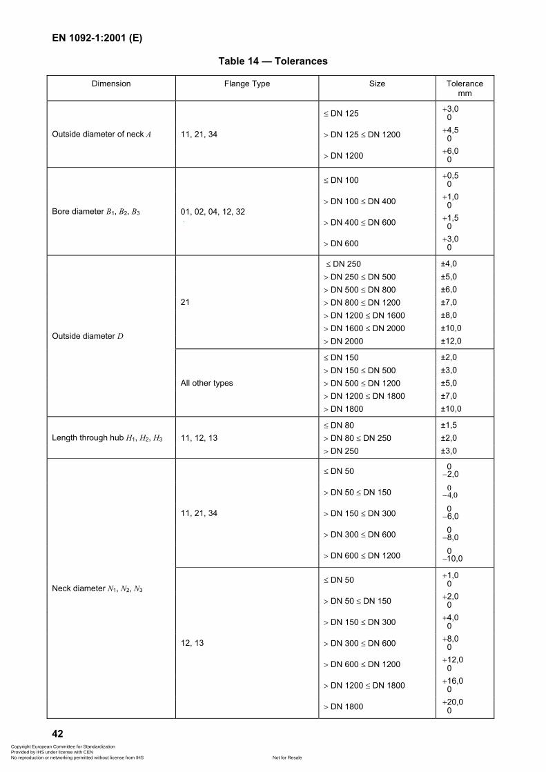
Table 14 — Tolerances
Dimension Flange Type Size Tolerancemm
� DN 125 3,00
�
� DN 125 � DN 1200 4,50
�Outside diameter of neck A 11, 21, 34
� DN 1200 6,00
�
� DN 100 0,50
�
� DN 100 � DN 400 1,00
�
� DN 400 � DN 600 1,50
�
Bore diameter B1, B2, B3 01, 02, 04, 12, 32
� DN 600 3,00
�
� DN 250 ±4,0� DN 250 � DN 500 ±5,0� DN 500 � DN 800 ±6,0� DN 800 � DN 1200 ±7,0� DN 1200 � DN 1600 ±8,0� DN 1600 � DN 2000 ±10,0
21
� DN 2000 ±12,0
� DN 150 ±2,0� DN 150 � DN 500 ±3,0� DN 500 � DN 1200 ±5,0� DN 1200 � DN 1800 ±7,0
Outside diameter D
All other types
� DN 1800 ±10,0
� DN 80 ±1,5� DN 80 � DN 250 ±2,0Length through hub H1, H2, H3 11, 12, 13� DN 250 ±3,0
� DN 50 0 2,0�
� DN 50 � DN 150 004
,�
� DN 150 � DN 300 0 6,0�
� DN 300 � DN 600 0 8,0�
11, 21, 34
� DN 600 � DN 1200 0 10,0�
� DN 50 1,00
�
� DN 50 � DN 150 2,00
�
� DN 150 � DN 300 4,00
�
� DN 300 � DN 600 8,00
�
� DN 600 � DN 1200 12,00
�
� DN 1200 � DN 1800 16,00
�
Neck diameter N1, N2, N3
12, 13
� DN 1800 20,00
�
Copyright European Committee for Standardization Provided by IHS under license with CEN
Not for ResaleNo reproduction or networking permitted without license from IHS
--```,-`-`,,`,,`,`,,`---
EN 1092-1:2001 (E)
43
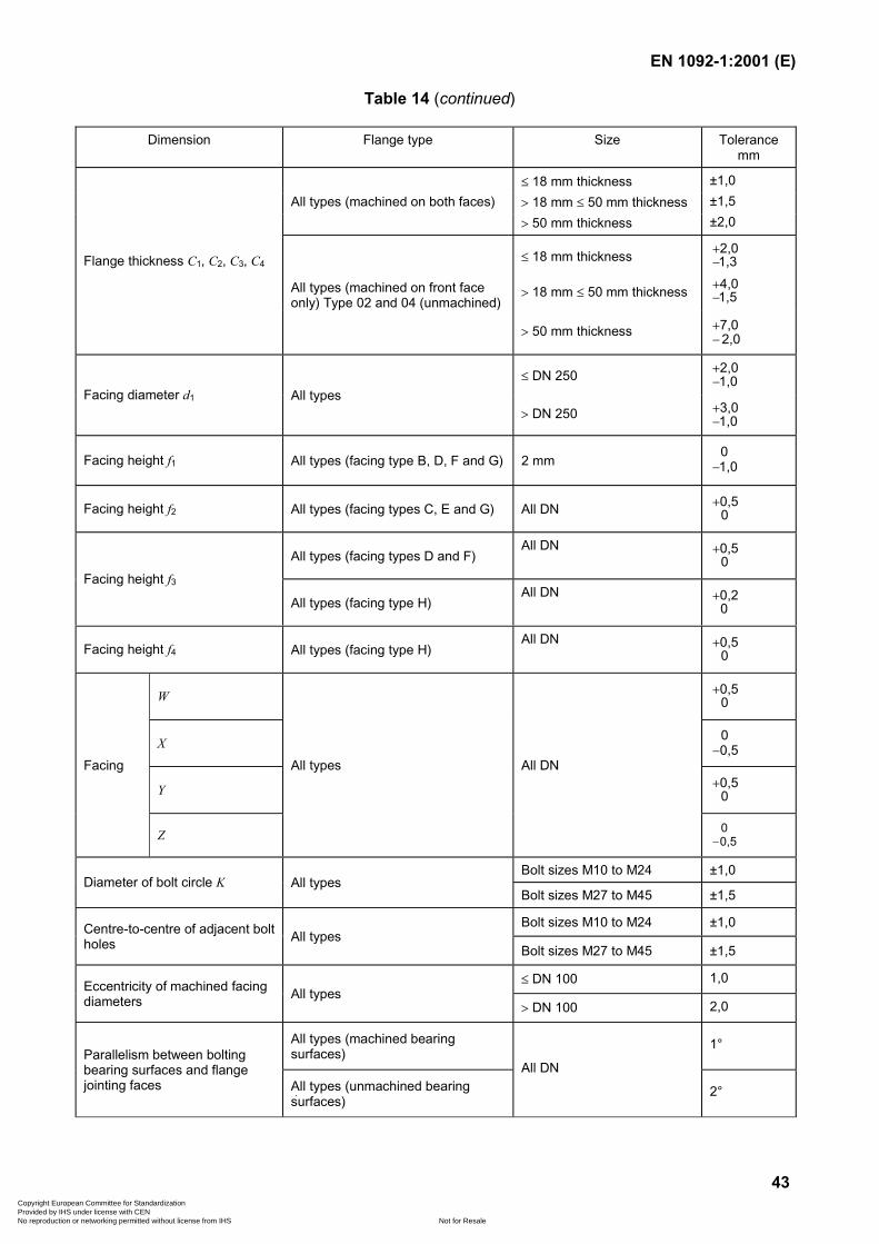
Table 14 (continued)
Dimension Flange type Size Tolerancemm
� 18 mm thickness ±1,0� 18 mm � 50 mm thickness ±1,5All types (machined on both faces)� 50 mm thickness ±2,0
� 18 mm thickness 2,01,3�
�
� 18 mm � 50 mm thickness 4,01,5�
�
Flange thickness C1, C2, C3, C4
All types (machined on front faceonly) Type 02 and 04 (unmachined)
� 50 mm thickness 7,02,0
�
�
� DN 250 2,01,0�
�
Facing diameter d1 All types� DN 250 3,0
1,0�
�
Facing height f1 All types (facing type B, D, F and G) 2 mm 1,00
�
Facing height f2 All types (facing types C, E and G) All DN 00,5�
All types (facing types D and F)All DN
00,5�
Facing height f3All types (facing type H)
All DN00,2�
Facing height f4 All types (facing type H)All DN
00,5�
W 00,5�
X 0,50
�
Y 00,5�
Facing
Z
All types All DN
0,50
�
Bolt sizes M10 to M24 ±1,0Diameter of bolt circle K All types
Bolt sizes M27 to M45 ±1,5
Bolt sizes M10 to M24 ±1,0Centre-to-centre of adjacent boltholes All types
Bolt sizes M27 to M45 ±1,5
� DN 100 1,0Eccentricity of machined facingdiameters All types
� DN 100 2,0
All types (machined bearingsurfaces)
1°Parallelism between boltingbearing surfaces and flangejointing faces All types (unmachined bearing
surfaces)
All DN
2°
Copyright European Committee for Standardization Provided by IHS under license with CEN
Not for ResaleNo reproduction or networking permitted without license from IHS
--```,-`-`,,`,,`,`,,`---
EN 1092-1:2001 (E)
44
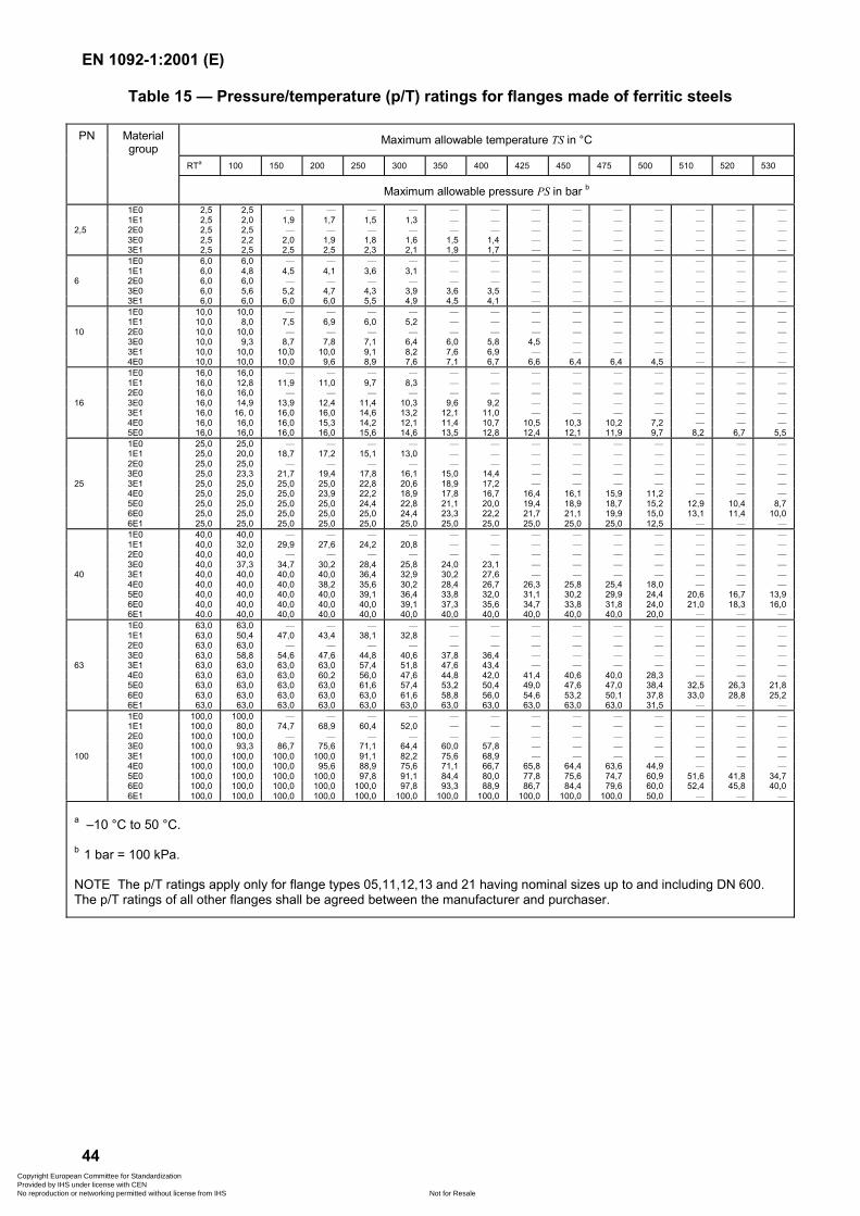
Table 15 — Pressure/temperature (p/T) ratings for flanges made of ferritic steels
Maximum allowable temperature TS in °C
RTa 100 150 200 250 300 350 400 425 450 475 500 510 520 530
PN Materialgroup
Maximum allowable pressure PS in bar b
1E0 2,5 2,5 — — — — — — — — — — — — —1E1 2,5 2,0 1,9 1,7 1,5 1,3 — — — — — — — — —
2,5 2E0 2,5 2,5 — — — — — — — — — — — — —3E0 2,5 2,2 2,0 1,9 1,8 1,6 1,5 1,4 — — — — — — —3E1 2,5 2,5 2,5 2,5 2,3 2,1 1,9 1,7 — — — — — — —1E0 6,0 6,0 — — — — — — — — — — — — —1E1 6,0 4,8 4,5 4,1 3,6 3,1 — — — — — — — — —
6 2E0 6,0 6,0 — — — — — — — — — — — — —3E0 6,0 5,6 5,2 4,7 4,3 3,9 3,6 3,5 — — — — — — —3E1 6,0 6,0 6,0 6,0 5,5 4,9 4,5 4,1 — — — — — — —1E0 10,0 10,0 — — — — — — — — — — — — —1E1 10,0 8,0 7,5 6,9 6,0 5,2 — — — — — — — — —2E0 10,0 10,0 — — — — — — — — — — — — —103E0 10,0 9,3 8,7 7,8 7,1 6,4 6,0 5,8 4,5 — — — — — —3E1 10,0 10,0 10,0 10,0 9,1 8,2 7,6 6,9 — — — — — — —4E0 10,0 10,0 10,0 9,6 8,9 7,6 7,1 6,7 6,6 6,4 6,4 4,5 — — —1E0 16,0 16,0 — — — — — — — — — — — — —1E1 16,0 12,8 11,9 11,0 9,7 8,3 — — — — — — — — —2E0 16,0 16,0 — — — — — — — — — — — — —
16 3E0 16,0 14,9 13,9 12,4 11,4 10,3 9,6 9,2 — — — — — — —3E1 16,0 16, 0 16,0 16,0 14,6 13,2 12,1 11,0 — — — — — — —4E0 16,0 16,0 16,0 15,3 14,2 12,1 11,4 10,7 10,5 10,3 10,2 7,2 — — —5E0 16,0 16,0 16,0 16,0 15,6 14,6 13,5 12,8 12,4 12,1 11,9 9,7 8,2 6,7 5,51E0 25,0 25,0 — — — — — — — — — — — — —1E1 25,0 20,0 18,7 17,2 15,1 13,0 — — — — — — — — —2E0 25,0 25,0 — — — — — — — — — — — — —3E0 25,0 23,3 21,7 19,4 17,8 16,1 15,0 14,4 — — — — — — —
25 3E1 25,0 25,0 25,0 25,0 22,8 20,6 18,9 17,2 — — — — — — —4E0 25,0 25,0 25,0 23,9 22,2 18,9 17,8 16,7 16,4 16,1 15,9 11,2 — — —5E0 25,0 25,0 25,0 25,0 24,4 22,8 21,1 20,0 19,4 18,9 18,7 15,2 12,9 10,4 8,76E0 25,0 25,0 25,0 25,0 25,0 24,4 23,3 22,2 21,7 21,1 19,9 15,0 13,1 11,4 10,06E1 25,0 25,0 25,0 25,0 25,0 25,0 25,0 25,0 25,0 25,0 25,0 12,5 — — —1E0 40,0 40,0 — — — — — — — — — — — — —1E1 40,0 32,0 29,9 27,6 24,2 20,8 — — — — — — — — —2E0 40,0 40,0 — — — — — — — — — — — — —3E0 40,0 37,3 34,7 30,2 28,4 25,8 24,0 23,1 — — — — — — —
40 3E1 40,0 40,0 40,0 40,0 36,4 32,9 30,2 27,6 — — — — — — —4E0 40,0 40,0 40,0 38,2 35,6 30,2 28,4 26,7 26,3 25,8 25,4 18,0 — — —5E0 40,0 40,0 40,0 40,0 39,1 36,4 33,8 32,0 31,1 30,2 29,9 24,4 20,6 16,7 13,96E0 40,0 40,0 40,0 40,0 40,0 39,1 37,3 35,6 34,7 33,8 31,8 24,0 21,0 18,3 16,06E1 40.0 40,0 40,0 40,0 40,0 40,0 40,0 40,0 40,0 40,0 40,0 20,0 — — —1E0 63,0 63,0 — — — — — — — — — — — — —1E1 63,0 50,4 47,0 43,4 38,1 32,8 — — — — — — — — —2E0 63,0 63,0 — — — — — — — — — — — — —3E0 63,0 58,8 54,6 47,6 44,8 40,6 37,8 36,4 — — — — — — —
63 3E1 63,0 63,0 63,0 63,0 57,4 51,8 47,6 43,4 — — — — — — —4E0 63,0 63,0 63,0 60,2 56,0 47,6 44,8 42,0 41,4 40,6 40,0 28,3 — — —5E0 63,0 63,0 63,0 63,0 61,6 57,4 53,2 50,4 49,0 47,6 47,0 38,4 32,5 26,3 21,86E0 63,0 63,0 63,0 63,0 63,0 61,6 58,8 56,0 54,6 53,2 50,1 37,8 33,0 28,8 25,26E1 63,0 63,0 63,0 63,0 63,0 63,0 63,0 63,0 63,0 63,0 63,0 31,5 — — —1E0 100,0 100,0 — — — — — — — — — — — — —1E1 100,0 80,0 74,7 68,9 60,4 52,0 — — — — — — — — —2E0 100,0 100,0 — — — — — — — — — — — — —3E0 100,0 93,3 86,7 75,6 71,1 64,4 60,0 57,8 — — — — — — —
100 3E1 100,0 100,0 100,0 100,0 91,1 82,2 75,6 68,9 — — — — — — —4E0 100,0 100,0 100,0 95,6 88,9 75,6 71,1 66,7 65,8 64,4 63,6 44,9 — — —5E0 100,0 100,0 100,0 100,0 97,8 91,1 84,4 80,0 77,8 75,6 74,7 60,9 51,6 41,8 34,76E0 100,0 100,0 100,0 100,0 100,0 97,8 93,3 88,9 86,7 84,4 79,6 60,0 52,4 45,8 40,06E1 100,0 100,0 100,0 100,0 100,0 100,0 100,0 100,0 100,0 100,0 100,0 50,0 — — —
a –10 °C to 50 °C.
b 1 bar = 100 kPa.
NOTE The p/T ratings apply only for flange types 05,11,12,13 and 21 having nominal sizes up to and including DN 600.The p/T ratings of all other flanges shall be agreed between the manufacturer and purchaser.
Copyright European Committee for Standardization Provided by IHS under license with CEN
Not for ResaleNo reproduction or networking permitted without license from IHS
--```,-`-`,,`,,`,`,,`---
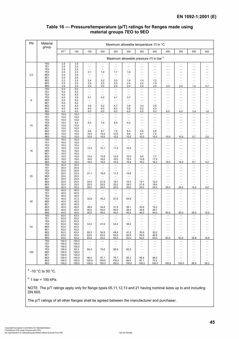
EN 1092-1:2001 (E)
45
Table 16 — Pressure/temperature (p/T) ratings for flanges made usingmaterial groups 7EO to 9EO
Maximum allowable temperature TS in °C
RT a 100 150 200 250 300 350 400 450 500 550 600
PN Materialgroup
Maximum allowable pressure PS in bar b
7E0 2,5 2,5 — — — — — — — — — —7E1 2,5 2,5 — — — — — — — — — —7E2 2,5 2,5 — — — — — — — — — —7E3 2,5 2,3 2,1 1,9 1,7 1,6 — — — — — —
2,5 8E0 2,5 2,5 — — — — — — — — — —8E1 2,5 2,5 — — — — — — — — — —8E2 2,5 2,5 2,4 2,2 2,0 1,6 1,4 1,2 — — — —8E3 2,5 2,5 2,5 2,5 2,5 2,4 2,2 1,9 — — — —9E0 2,5 2,5 2,5 2,5 2,5 2,5 2,5 2,5 2,5 2,5 1,4 0,77E0 6,0 6,0 — — — — — — — — — —7E1 6,0 6,0 — — — — — — — — — —7E2 6,0 6,0 — — — — — — — — — —7E3 6,0 5,6 5,1 4,5 4,1 3,7 — — — — — —
6 8E0 6,0 6,0 — — — — — — — — — —8E1 6,0 6,0 — — — — — — — — — —8E2 6,0 6,0 5,8 5,2 4,7 3,9 3,4 2,9 — — — —8E3 6,0 6,0 6,0 6,0 6,0 5,8 5,2 4,5 — — — —9E0 6,0 6,0 6,0 6,0 6,0 6,0 6,0 6,0 6,0 6,0 3,4 1,67E0 10,0 10,0 — — — — — — — — — —7E1 10,0 10,0 — — — — — — — — — —7E2 10,0 10,0 — — — — — — — — — —7E3 10,0 9,3 8,4 7,6 6,9 6,2 — — — — — —
10 8E0 10,0 10,0 — — — — — — — — — —8E1 10,0 10,0 — — — — — — — — — —8E2 10,0 10,0 9,6 8,7 7,9 6,5 5,6 4,8 — — — —8E3 10,0 10,0 10,0 10,0 10,0 9,6 8,7 7,4 — — — —9E0 10,0 10,0 10,0 10,0 10,0 10,0 10,0 10,0 10,0 10,0 5,7 2,67E0 16,0 16,0 — — — — — — — — — —7E1 16,0 16,0 — — — — — — — — — —7E2 16,0 16,0 — — — — — — — — — —7E3 16,0 14,9 13,5 12,1 11,0 10,0 — — — — — —
16 8E0 16,0 16,0 — — — — — — — — — —8E1 16,0 16,0 — — — — — — — — — —8E2 16,0 16,0 15,4 13,9 12,6 10,5 9,0 7,7 — — — —8E3 16,0 16,0 16,0 16,0 16,0 15,4 13,9 11,9 — — — —9E0 16,0 16,0 16,0 16,0 16,0 16,0 16,0 16,0 16,0 16,0 9,1 4,27E0 25,0 25,0 — — — — — — — — — —7E1 25,0 25,0 — — — — — — — — — —7E2 25,0 25,0 — — — — — — — — — —7E3 25,0 23,3 21,1 18,9 17,2 15,6 — — — — — —
25 8E0 25,0 25,0 — — — — — — — — — —8E1 25,0 25,0 — — — — — — — — — —8E2 25,0 25,0 24,0 21,8 19,7 16,3 14,1 12,0 — — — —8E3 25,0 25,0 25,0 25,0 25,0 24,0 21,8 18,6 — — — —9E0 25,0 25,0 25,0 25,0 25,0 25,0 25,0 25,0 25,0 25,0 14,2 6,67E0 40,0 40,0 — — — — — — — — — —7E1 40,0 40,0 — — — — — — — — — —7E2 40,0 40,0 — — — — — — — — — —7E3 40,0 37,3 33,8 30,2 27,6 24,9 — — — — — —
40 8E0 40,0 40,0 — — — — — — — — — —8E1 40,0 40,0 — — — — — — — — — —8E2 40,0 40,0 38,4 34,8 31,5 26,1 22,6 19,2 — — — —8E3 40,0 40,0 40,0 40,0 40,0 38,4 34,8 29,7 — — — —9E0 40.0 40,0 40,0 40,0 40,0 40,0 40,0 40,0 40,0 40,0 28,2 10,57E0 63,0 63,0 — — — — — — — — — —7E1 63,0 63,0 — — — — — — — — — —7E2 63,0 63,0 — — — — — — — — — —7E3 63,0 58,8 53,2 47,6 43,4 39,2 — — — — — —
63 8E0 63,0 63,0 — — — — — — — — — —8E1 63,0 63,0 — — — — — — — — — —8E2 63,0 63,0 60,5 54,9 49,6 41,2 35,6 30,2 — — — —8E3 63,0 63,0 63,0 63,0 63,0 60,5 54,9 46,8 — — — —9E0 63,0 63,0 63,0 63,0 63,0 63,0 63,0 63,0 63,0 63,0 35,8 16,57E0 100,0 100,0 — — — — — — — — — —7E1 100,0 100,0 — — — — — — — — — —7E2 100,0 100,0 — — — — — — — — — —7E3 100,0 93,3 84,4 75,6 68,9 62,2 — — — — — —
100 8E0 100,0 100,0 — — — — — — — — — —8E1 100,0 100,0 — — — — — — — — — —8E2 100,0 100,0 96,0 87,1 78,7 65,3 56,4 48,0 — — — —8E3 100,0 100,0 100,0 100,0 100,0 96,0 87,1 74,2 — — — —9E0 100,0 100,0 100,0 100,0 100,0 100,0 100,0 100,0 100,0 100,0 56,9 26,2
a -10 °C to 50 °C.
b 1 bar = 100 kPa.
NOTE The p/T ratings apply only for flange types 05,11,12,13 and 21 having nominal sizes up to and includingDN 600.
The p/T ratings of all other flanges shall be agreed between the manufacturer and purchaser.
Copyright European Committee for Standardization Provided by IHS under license with CEN
Not for ResaleNo reproduction or networking permitted without license from IHS
--```,-`-`,,`,,`,`,,`---
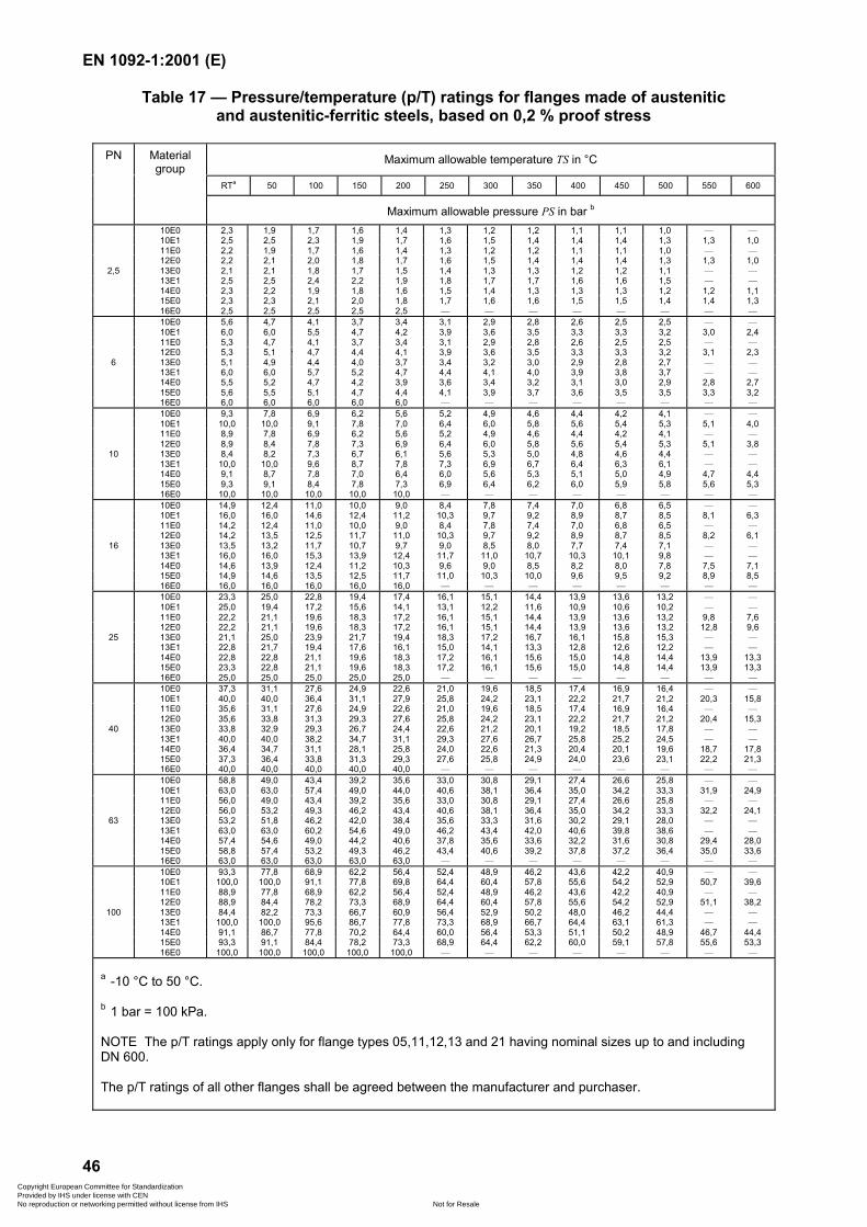
EN 1092-1:2001 (E)
46
Table 17 — Pressure/temperature (p/T) ratings for flanges made of austeniticand austenitic-ferritic steels, based on 0,2 % proof stress
Maximum allowable temperature TS in °C
RTa 50 100 150 200 250 300 350 400 450 500 550 600
PN Materialgroup
Maximum allowable pressure PS in bar b
10E0 2,3 1,9 1,7 1,6 1,4 1,3 1,2 1,2 1,1 1,1 1,0 — —10E1 2,5 2,5 2,3 1,9 1,7 1,6 1,5 1,4 1,4 1,4 1,3 1,3 1,011E0 2,2 1,9 1,7 1,6 1,4 1,3 1,2 1,2 1,1 1,1 1,0 — —12E0 2,2 2,1 2,0 1,8 1,7 1,6 1,5 1,4 1,4 1,4 1,3 1,3 1,0
2,5 13E0 2,1 2,1 1,8 1,7 1,5 1,4 1,3 1,3 1,2 1,2 1,1 — —13E1 2,5 2,5 2,4 2,2 1,9 1,8 1,7 1,7 1,6 1,6 1,5 — —14E0 2,3 2,2 1,9 1,8 1,6 1,5 1,4 1,3 1,3 1,3 1,2 1,2 1,115E0 2,3 2,3 2,1 2,0 1,8 1,7 1,6 1,6 1,5 1,5 1,4 1,4 1,316E0 2,5 2,5 2,5 2,5 2,5 — — — — — — — —10E0 5,6 4,7 4,1 3,7 3,4 3,1 2,9 2,8 2,6 2,5 2,5 — —10E1 6,0 6,0 5,5 4,7 4,2 3,9 3,6 3,5 3,3 3,3 3,2 3,0 2,411E0 5,3 4,7 4,1 3,7 3,4 3,1 2,9 2,8 2,6 2,5 2,5 — —12E0 5,3 5,1 4,7 4,4 4,1 3,9 3,6 3,5 3,3 3,3 3,2 3,1 2,3
6 13E0 5,1 4,9 4,4 4,0 3,7 3,4 3,2 3,0 2,9 2,8 2,7 — —13E1 6,0 6,0 5,7 5,2 4,7 4,4 4,1 4,0 3,9 3,8 3,7 — —14E0 5,5 5,2 4,7 4,2 3,9 3,6 3,4 3,2 3,1 3,0 2,9 2,8 2,715E0 5,6 5,5 5,1 4,7 4,4 4,1 3,9 3,7 3,6 3,5 3,5 3,3 3,216E0 6,0 6,0 6,0 6,0 6,0 — — — — — — — —10E0 9,3 7,8 6,9 6,2 5,6 5,2 4,9 4,6 4,4 4,2 4,1 — —10E1 10,0 10,0 9,1 7,8 7,0 6,4 6,0 5,8 5,6 5,4 5,3 5,1 4,011E0 8,9 7,8 6,9 6,2 5,6 5,2 4,9 4,6 4,4 4,2 4,1 — —12E0 8,9 8,4 7,8 7,3 6,9 6,4 6,0 5,8 5,6 5,4 5,3 5,1 3,8
10 13E0 8,4 8,2 7,3 6,7 6,1 5,6 5,3 5,0 4,8 4,6 4,4 — —13E1 10,0 10,0 9,6 8,7 7,8 7,3 6,9 6,7 6,4 6,3 6,1 — —14E0 9,1 8,7 7,8 7,0 6,4 6,0 5,6 5,3 5,1 5,0 4,9 4,7 4,415E0 9,3 9,1 8,4 7,8 7,3 6,9 6,4 6,2 6,0 5,9 5,8 5,6 5,316E0 10,0 10,0 10,0 10,0 10,0 — — — — — — — —10E0 14,9 12,4 11,0 10,0 9,0 8,4 7,8 7,4 7,0 6,8 6,5 — —10E1 16,0 16,0 14,6 12,4 11,2 10,3 9,7 9,2 8,9 8,7 8,5 8,1 6,311E0 14,2 12,4 11,0 10,0 9,0 8,4 7,8 7,4 7,0 6,8 6,5 — —12E0 14,2 13,5 12,5 11,7 11,0 10,3 9,7 9,2 8,9 8,7 8,5 8,2 6,1
16 13E0 13,5 13,2 11,7 10,7 9,7 9,0 8,5 8,0 7,7 7,4 7,1 — —13E1 16,0 16,0 15,3 13,9 12,4 11,7 11,0 10,7 10,3 10,1 9,8 — —14E0 14,6 13,9 12,4 11,2 10,3 9,6 9,0 8,5 8,2 8,0 7,8 7,5 7,115E0 14,9 14,6 13,5 12,5 11,7 11,0 10,3 10,0 9,6 9,5 9,2 8,9 8,516E0 16,0 16,0 16,0 16,0 16,0 — — — — — — — —10E0 23,3 25,0 22,8 19,4 17,4 16,1 15,1 14,4 13,9 13,6 13,2 — —10E1 25,0 19,4 17,2 15,6 14,1 13,1 12,2 11,6 10,9 10,6 10,2 — —11E0 22,2 21,1 19,6 18,3 17,2 16,1 15,1 14,4 13,9 13,6 13,2 9,8 7,612E0 22,2 21,1 19,6 18,3 17,2 16,1 15,1 14,4 13,9 13,6 13,2 12,8 9,6
25 13E0 21,1 25,0 23,9 21,7 19,4 18,3 17,2 16,7 16,1 15,8 15,3 — —13E1 22,8 21,7 19,4 17,6 16,1 15,0 14,1 13,3 12,8 12,6 12,2 — —14E0 22,8 22,8 21,1 19,6 18,3 17,2 16,1 15,6 15,0 14,8 14,4 13,9 13,315E0 23,3 22,8 21,1 19,6 18,3 17,2 16,1 15,6 15,0 14,8 14,4 13,9 13,316E0 25,0 25,0 25,0 25,0 25,0 — — — — — — — —10E0 37,3 31,1 27,6 24,9 22,6 21,0 19,6 18,5 17,4 16,9 16,4 — —10E1 40,0 40,0 36,4 31,1 27,9 25,8 24,2 23,1 22,2 21,7 21,2 20,3 15,811E0 35,6 31,1 27,6 24,9 22,6 21,0 19,6 18,5 17,4 16,9 16,4 — —12E0 35,6 33,8 31,3 29,3 27,6 25,8 24,2 23,1 22,2 21,7 21,2 20,4 15,3
40 13E0 33,8 32,9 29,3 26,7 24,4 22,6 21,2 20,1 19,2 18,5 17,8 — —13E1 40,0 40,0 38,2 34,7 31,1 29,3 27,6 26,7 25,8 25,2 24,5 — —14E0 36,4 34,7 31,1 28,1 25,8 24,0 22,6 21,3 20,4 20,1 19,6 18,7 17,815E0 37,3 36,4 33,8 31,3 29,3 27,6 25,8 24,9 24,0 23,6 23,1 22,2 21,316E0 40,0 40,0 40,0 40,0 40,0 — — — — — — — —10E0 58,8 49,0 43,4 39,2 35,6 33,0 30,8 29,1 27,4 26,6 25,8 — —10E1 63,0 63,0 57,4 49,0 44,0 40,6 38,1 36,4 35,0 34,2 33,3 31,9 24,911E0 56,0 49,0 43,4 39,2 35,6 33,0 30,8 29,1 27,4 26,6 25,8 — —12E0 56,0 53,2 49,3 46,2 43,4 40,6 38,1 36,4 35,0 34,2 33,3 32,2 24,1
63 13E0 53,2 51,8 46,2 42,0 38,4 35,6 33,3 31,6 30,2 29,1 28,0 — —13E1 63,0 63,0 60,2 54,6 49,0 46,2 43,4 42,0 40,6 39,8 38,6 — —14E0 57,4 54,6 49,0 44,2 40,6 37,8 35,6 33,6 32,2 31,6 30,8 29,4 28,015E0 58,8 57,4 53,2 49,3 46,2 43,4 40,6 39,2 37,8 37,2 36,4 35,0 33,616E0 63,0 63,0 63,0 63,0 63,0 — — — — — — — —10E0 93,3 77,8 68,9 62,2 56,4 52,4 48,9 46,2 43,6 42,2 40,9 — —10E1 100,0 100,0 91,1 77,8 69,8 64,4 60,4 57,8 55,6 54,2 52,9 50,7 39,611E0 88,9 77,8 68,9 62,2 56,4 52,4 48,9 46,2 43,6 42,2 40,9 — —12E0 88,9 84,4 78,2 73,3 68,9 64,4 60,4 57,8 55,6 54,2 52,9 51,1 38,2
100 13E0 84,4 82,2 73,3 66,7 60,9 56,4 52,9 50,2 48,0 46,2 44,4 — —13E1 100,0 100,0 95,6 86,7 77,8 73,3 68,9 66,7 64,4 63,1 61,3 — —14E0 91,1 86,7 77,8 70,2 64,4 60,0 56,4 53,3 51,1 50,2 48,9 46,7 44,415E0 93,3 91,1 84,4 78,2 73,3 68,9 64,4 62,2 60,0 59,1 57,8 55,6 53,316E0 100,0 100,0 100,0 100,0 100,0 — — — — — — — —
a -10 °C to 50 °C.
b 1 bar = 100 kPa.
NOTE The p/T ratings apply only for flange types 05,11,12,13 and 21 having nominal sizes up to and includingDN 600.
The p/T ratings of all other flanges shall be agreed between the manufacturer and purchaser.
Copyright European Committee for Standardization Provided by IHS under license with CEN
Not for ResaleNo reproduction or networking permitted without license from IHS
--```,-`-`,,`,,`,`,,`---
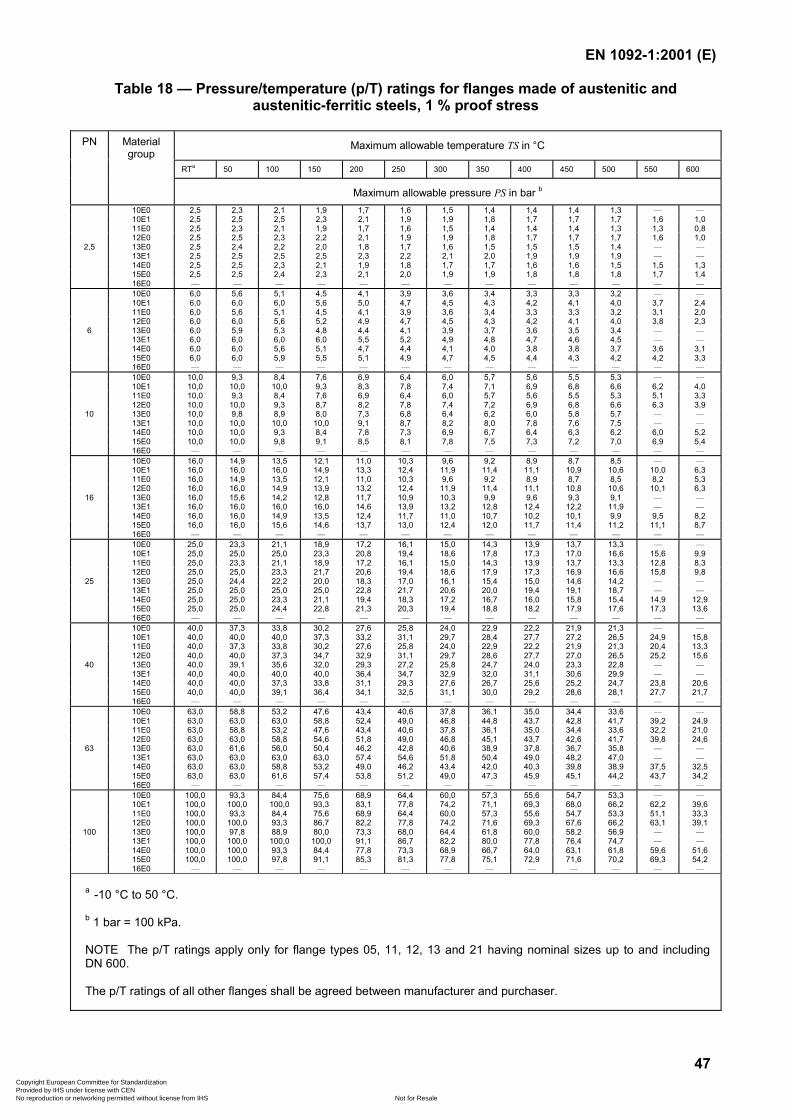
EN 1092-1:2001 (E)
47
Table 18 — Pressure/temperature (p/T) ratings for flanges made of austenitic andaustenitic-ferritic steels, 1 % proof stress
Maximum allowable temperature TS in °C
RTa 50 100 150 200 250 300 350 400 450 500 550 600
PN Materialgroup
Maximum allowable pressure PS in bar b
10E0 2,5 2,3 2,1 1,9 1,7 1,6 1,5 1,4 1,4 1,4 1,3 — —10E1 2,5 2,5 2,5 2,3 2,1 1,9 1,9 1,8 1,7 1,7 1,7 1,6 1,011E0 2,5 2,3 2,1 1,9 1,7 1,6 1,5 1,4 1,4 1,4 1,3 1,3 0,812E0 2,5 2,5 2,3 2,2 2,1 1,9 1,9 1,8 1,7 1,7 1,7 1,6 1,0
2,5 13E0 2,5 2,4 2,2 2,0 1,8 1,7 1,6 1,5 1,5 1,5 1,4 — —13E1 2,5 2,5 2,5 2,5 2,3 2,2 2,1 2,0 1,9 1,9 1,9 — —14E0 2,5 2,5 2,3 2,1 1,9 1,8 1,7 1,7 1,6 1,6 1,5 1,5 1,315E0 2,5 2,5 2,4 2,3 2,1 2,0 1,9 1,9 1,8 1,8 1,8 1,7 1,416E0 — — — — — — — — — — — — —10E0 6,0 5,6 5,1 4,5 4,1 3,9 3,6 3,4 3,3 3,3 3,2 — —10E1 6,0 6,0 6,0 5,6 5,0 4,7 4,5 4,3 4,2 4,1 4,0 3,7 2,411E0 6,0 5,6 5,1 4,5 4,1 3,9 3,6 3,4 3,3 3,3 3,2 3,1 2,012E0 6,0 6,0 5,6 5,2 4,9 4,7 4,5 4,3 4,2 4,1 4,0 3,8 2,3
6 13E0 6,0 5,9 5,3 4,8 4,4 4,1 3,9 3,7 3,6 3,5 3,4 — —13E1 6,0 6,0 6,0 6,0 5,5 5,2 4,9 4,8 4,7 4,6 4,5 — —14E0 6,0 6,0 5,6 5,1 4,7 4,4 4,1 4,0 3,8 3,8 3,7 3,6 3,115E0 6,0 6,0 5,9 5,5 5,1 4,9 4,7 4,5 4,4 4,3 4,2 4,2 3,316E0 — — — — — — — — — — — — —10E0 10,0 9,3 8,4 7,6 6,9 6,4 6,0 5,7 5,6 5,5 5,3 — —10E1 10,0 10,0 10,0 9,3 8,3 7,8 7,4 7,1 6,9 6,8 6,6 6,2 4,011E0 10,0 9,3 8,4 7,6 6,9 6,4 6,0 5,7 5,6 5,5 5,3 5,1 3,312E0 10,0 10,0 9,3 8,7 8,2 7,8 7,4 7,2 6,9 6,8 6,6 6,3 3,9
10 13E0 10,0 9,8 8,9 8,0 7,3 6,8 6,4 6,2 6,0 5,8 5,7 — —13E1 10,0 10,0 10,0 10,0 9,1 8,7 8,2 8,0 7,8 7,6 7,5 — —14E0 10,0 10,0 9,3 8,4 7,8 7,3 6,9 6,7 6,4 6,3 6,2 6,0 5,215E0 10,0 10,0 9,8 9,1 8,5 8,1 7,8 7,5 7,3 7,2 7,0 6,9 5,416E0 — — — — — — — — — — — — —10E0 16,0 14,9 13,5 12,1 11,0 10,3 9,6 9,2 8,9 8,7 8,5 — —10E1 16,0 16,0 16,0 14,9 13,3 12,4 11,9 11,4 11,1 10,9 10,6 10,0 6,311E0 16,0 14,9 13,5 12,1 11,0 10,3 9,6 9,2 8,9 8,7 8,5 8,2 5,312E0 16,0 16,0 14,9 13,9 13,2 12,4 11,9 11,4 11,1 10,8 10,6 10,1 6,3
16 13E0 16,0 15,6 14,2 12,8 11,7 10,9 10,3 9,9 9,6 9,3 9,1 — —13E1 16,0 16,0 16,0 16,0 14,6 13,9 13,2 12,8 12,4 12,2 11,9 — —14E0 16,0 16,0 14,9 13,5 12,4 11,7 11,0 10,7 10,2 10,1 9,9 9,5 8,215E0 16,0 16,0 15,6 14,6 13,7 13,0 12,4 12,0 11,7 11,4 11,2 11,1 8,716E0 — — — — — — — — — — — — —10E0 25,0 23,3 21,1 18,9 17,2 16,1 15,0 14,3 13,9 13,7 13,3 — —10E1 25,0 25,0 25,0 23,3 20,8 19,4 18,6 17,8 17,3 17,0 16,6 15,6 9,911E0 25,0 23,3 21,1 18,9 17,2 16,1 15,0 14,3 13,9 13,7 13,3 12,8 8,312E0 25,0 25,0 23,3 21,7 20,6 19,4 18,6 17,9 17,3 16,9 16,6 15,8 9,8
25 13E0 25,0 24,4 22,2 20,0 18,3 17,0 16,1 15,4 15,0 14,6 14,2 — —13E1 25,0 25,0 25,0 25,0 22,8 21,7 20,6 20,0 19,4 19,1 18,7 — —14E0 25,0 25,0 23,3 21,1 19,4 18,3 17,2 16,7 16,0 15,8 15,4 14,9 12,915E0 25,0 25,0 24,4 22,8 21,3 20,3 19,4 18,8 18,2 17,9 17,6 17,3 13,616E0 — — — — — — — — — — — — —10E0 40,0 37,3 33,8 30,2 27,6 25,8 24,0 22,9 22,2 21,9 21,3 — —10E1 40,0 40,0 40,0 37,3 33,2 31,1 29,7 28,4 27,7 27,2 26,5 24,9 15,811E0 40,0 37,3 33,8 30,2 27,6 25,8 24,0 22,9 22,2 21,9 21,3 20,4 13,312E0 40,0 40,0 37,3 34,7 32,9 31,1 29,7 28,6 27,7 27,0 26,5 25,2 15,6
40 13E0 40,0 39,1 35,6 32,0 29,3 27,2 25,8 24,7 24,0 23,3 22,8 — —13E1 40,0 40,0 40,0 40,0 36,4 34,7 32,9 32,0 31,1 30,6 29,9 — —14E0 40,0 40,0 37,3 33,8 31,1 29,3 27,6 26,7 25,6 25,2 24,7 23,8 20,615E0 40,0 40,0 39,1 36,4 34,1 32,5 31,1 30,0 29,2 28,6 28,1 27,7 21,716E0 — — — — — — — — — — — — —10E0 63,0 58,8 53,2 47,6 43,4 40,6 37,8 36,1 35,0 34,4 33,6 — —10E1 63,0 63,0 63,0 58,8 52,4 49,0 46,8 44,8 43,7 42,8 41,7 39,2 24,911E0 63,0 58,8 53,2 47,6 43,4 40,6 37,8 36,1 35,0 34,4 33,6 32,2 21,012E0 63,0 63,0 58,8 54,6 51,8 49,0 46,8 45,1 43,7 42,6 41,7 39,8 24,6
63 13E0 63,0 61,6 56,0 50,4 46,2 42,8 40,6 38,9 37,8 36,7 35,8 — —13E1 63,0 63,0 63,0 63,0 57,4 54,6 51,8 50,4 49,0 48,2 47,0 — —14E0 63,0 63,0 58,8 53,2 49,0 46,2 43,4 42,0 40,3 39,8 38,9 37,5 32,515E0 63,0 63,0 61,6 57,4 53,8 51,2 49,0 47,3 45,9 45,1 44,2 43,7 34,216E0 — — — — — — — — — — — — —10E0 100,0 93,3 84,4 75,6 68,9 64,4 60,0 57,3 55,6 54,7 53,3 — —10E1 100,0 100,0 100,0 93,3 83,1 77,8 74,2 71,1 69,3 68,0 66,2 62,2 39,611E0 100,0 93,3 84,4 75,6 68,9 64,4 60,0 57,3 55,6 54,7 53,3 51,1 33,312E0 100,0 100,0 93,3 86,7 82,2 77,8 74,2 71,6 69,3 67,6 66,2 63,1 39,1
100 13E0 100,0 97,8 88,9 80,0 73,3 68,0 64,4 61,8 60,0 58,2 56,9 — —13E1 100,0 100,0 100,0 100,0 91,1 86,7 82,2 80,0 77,8 76,4 74,7 — —14E0 100,0 100,0 93,3 84,4 77,8 73,3 68,9 66,7 64,0 63,1 61,8 59,6 51,615E0 100,0 100,0 97,8 91,1 85,3 81,3 77,8 75,1 72,9 71,6 70,2 69,3 54,216E0 — — — — — — — — — — — — —
a -10 °C to 50 °C.
b 1 bar = 100 kPa.
NOTE The p/T ratings apply only for flange types 05, 11, 12, 13 and 21 having nominal sizes up to and includingDN 600.
The p/T ratings of all other flanges shall be agreed between manufacturer and purchaser.
Copyright European Committee for Standardization Provided by IHS under license with CEN
Not for ResaleNo reproduction or networking permitted without license from IHS
--```,-`-`,,`,,`,`,,`---
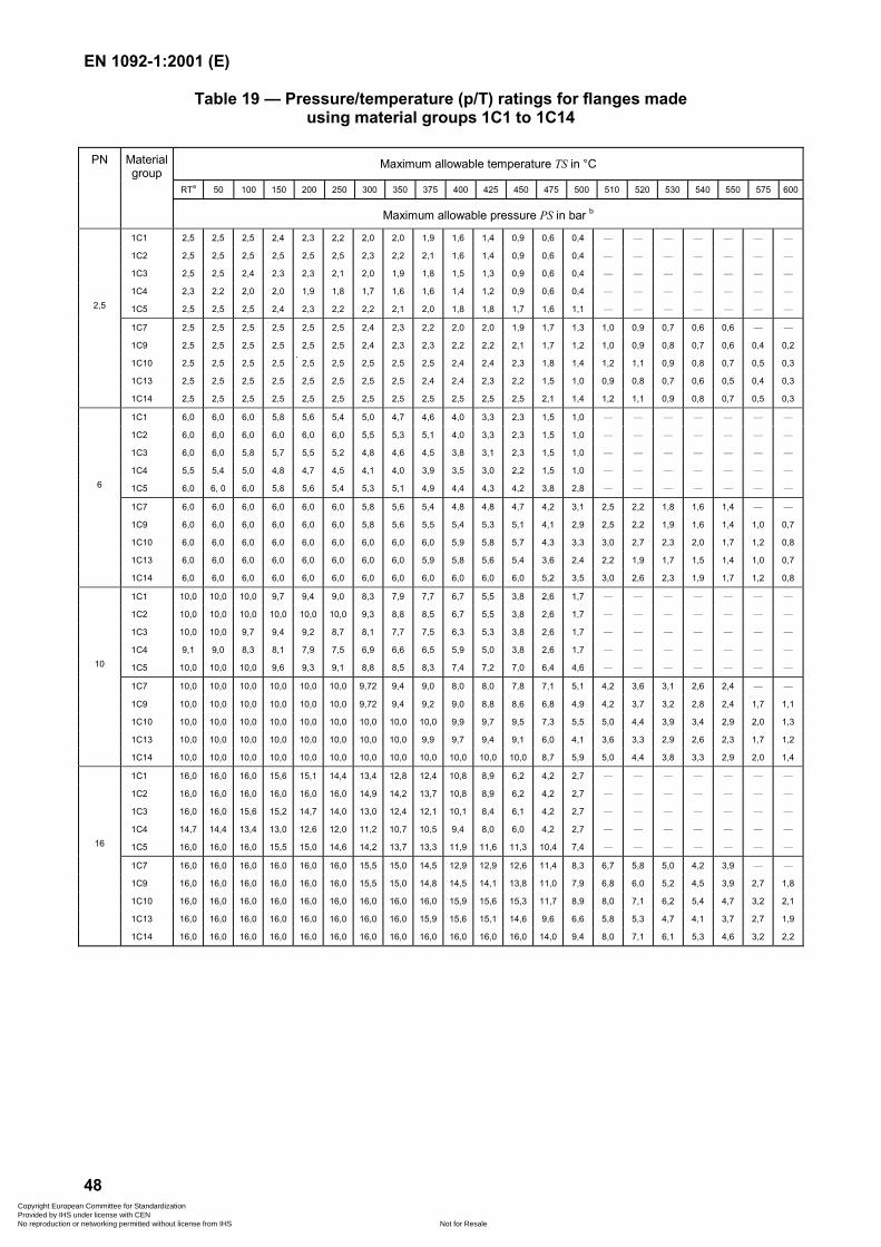
EN 1092-1:2001 (E)
48
Table 19 — Pressure/temperature (p/T) ratings for flanges madeusing material groups 1C1 to 1C14
Maximum allowable temperature TS in °C
RTa 50 100 150 200 250 300 350 375 400 425 450 475 500 510 520 530 540 550 575 600
PN Materialgroup
Maximum allowable pressure PS in bar b
1C1 2,5 2,5 2,5 2,4 2,3 2,2 2,0 2,0 1,9 1,6 1,4 0,9 0,6 0,4 — — — — — — —
1C2 2,5 2,5 2,5 2,5 2,5 2,5 2,3 2,2 2,1 1,6 1,4 0,9 0,6 0,4 — — — — — — —
1C3 2,5 2,5 2,4 2,3 2,3 2,1 2,0 1,9 1,8 1,5 1,3 0,9 0,6 0,4 — — — — — — —
1C4 2,3 2,2 2,0 2,0 1,9 1,8 1,7 1,6 1,6 1,4 1,2 0,9 0,6 0,4 — — — — — — —
1C5 2,5 2,5 2,5 2,4 2,3 2,2 2,2 2,1 2,0 1,8 1,8 1,7 1,6 1,1 — — — — — — —2,5
1C7 2,5 2,5 2,5 2,5 2,5 2,5 2,4 2,3 2,2 2,0 2,0 1,9 1,7 1,3 1,0 0,9 0,7 0,6 0,6 — —
1C9 2,5 2,5 2,5 2,5 2,5 2,5 2,4 2,3 2,3 2,2 2,2 2,1 1,7 1,2 1,0 0,9 0,8 0,7 0,6 0,4 0,2
1C10 2,5 2,5 2,5 2,5 2,5 2,5 2,5 2,5 2,5 2,4 2,4 2,3 1,8 1,4 1,2 1,1 0,9 0,8 0,7 0,5 0,3
1C13 2,5 2,5 2,5 2,5 2,5 2,5 2,5 2,5 2,4 2,4 2,3 2,2 1,5 1,0 0,9 0,8 0,7 0,6 0,5 0,4 0,3
1C14 2,5 2,5 2,5 2,5 2,5 2,5 2,5 2,5 2,5 2,5 2,5 2,5 2,1 1,4 1,2 1,1 0,9 0,8 0,7 0,5 0,3
1C1 6,0 6,0 6,0 5,8 5,6 5,4 5,0 4,7 4,6 4,0 3,3 2,3 1,5 1,0 — — — — — — —
1C2 6,0 6,0 6,0 6,0 6,0 6,0 5,5 5,3 5,1 4,0 3,3 2,3 1,5 1,0 — — — — — — —
1C3 6,0 6,0 5,8 5,7 5,5 5,2 4,8 4,6 4,5 3,8 3,1 2,3 1,5 1,0 — — — — — — —
1C4 5,5 5,4 5,0 4,8 4,7 4,5 4,1 4,0 3,9 3,5 3,0 2,2 1,5 1,0 — — — — — — —
1C5 6,0 6, 0 6,0 5,8 5,6 5,4 5,3 5,1 4,9 4,4 4,3 4,2 3,8 2,8 — — — — — — —6
1C7 6,0 6,0 6,0 6,0 6,0 6,0 5,8 5,6 5,4 4,8 4,8 4,7 4,2 3,1 2,5 2,2 1,8 1,6 1,4 — —
1C9 6,0 6,0 6,0 6,0 6,0 6,0 5,8 5,6 5,5 5,4 5,3 5,1 4,1 2,9 2,5 2,2 1,9 1,6 1,4 1,0 0,7
1C10 6,0 6,0 6,0 6,0 6,0 6,0 6,0 6,0 6,0 5,9 5,8 5,7 4,3 3,3 3,0 2,7 2,3 2,0 1,7 1,2 0,8
1C13 6,0 6,0 6,0 6,0 6,0 6,0 6,0 6,0 5,9 5,8 5,6 5,4 3,6 2,4 2,2 1,9 1,7 1,5 1,4 1,0 0,7
1C14 6,0 6,0 6,0 6,0 6,0 6,0 6,0 6,0 6,0 6,0 6,0 6,0 5,2 3,5 3,0 2,6 2,3 1,9 1,7 1,2 0,8
1C1 10,0 10,0 10,0 9,7 9,4 9,0 8,3 7,9 7,7 6,7 5,5 3,8 2,6 1,7 — — — — — — —
1C2 10,0 10,0 10,0 10,0 10,0 10,0 9,3 8,8 8,5 6,7 5,5 3,8 2,6 1,7 — — — — — — —
1C3 10,0 10,0 9,7 9,4 9,2 8,7 8,1 7,7 7,5 6,3 5,3 3,8 2,6 1,7 — — — — — — —
1C4 9,1 9,0 8,3 8,1 7,9 7,5 6,9 6,6 6,5 5,9 5,0 3,8 2,6 1,7 — — — — — — —
1C5 10,0 10,0 10,0 9,6 9,3 9,1 8,8 8,5 8,3 7,4 7,2 7,0 6,4 4,6 — — — — — — —10
1C7 10,0 10,0 10,0 10,0 10,0 10,0 9,72 9,4 9,0 8,0 8,0 7,8 7,1 5,1 4,2 3,6 3,1 2,6 2,4 — —
1C9 10,0 10,0 10,0 10,0 10,0 10,0 9,72 9,4 9,2 9,0 8,8 8,6 6,8 4,9 4,2 3,7 3,2 2,8 2,4 1,7 1,1
1C10 10,0 10,0 10,0 10,0 10,0 10,0 10,0 10,0 10,0 9,9 9,7 9,5 7,3 5,5 5,0 4,4 3,9 3,4 2,9 2,0 1,3
1C13 10,0 10,0 10,0 10,0 10,0 10,0 10,0 10,0 9,9 9,7 9,4 9,1 6,0 4,1 3,6 3,3 2,9 2,6 2,3 1,7 1,2
1C14 10,0 10,0 10,0 10,0 10,0 10,0 10,0 10,0 10,0 10,0 10,0 10,0 8,7 5,9 5,0 4,4 3,8 3,3 2,9 2,0 1,4
1C1 16,0 16,0 16,0 15,6 15,1 14,4 13,4 12,8 12,4 10,8 8,9 6,2 4,2 2,7 — — — — — — —
1C2 16,0 16,0 16,0 16,0 16,0 16,0 14,9 14,2 13,7 10,8 8,9 6,2 4,2 2,7 — — — — — — —
1C3 16,0 16,0 15,6 15,2 14,7 14,0 13,0 12,4 12,1 10,1 8,4 6,1 4,2 2,7 — — — — — — —
1C4 14,7 14,4 13,4 13,0 12,6 12,0 11,2 10,7 10,5 9,4 8,0 6,0 4,2 2,7 — — — — — — —
1C5 16,0 16,0 16,0 15,5 15,0 14,6 14,2 13,7 13,3 11,9 11,6 11,3 10,4 7,4 — — — — — — —16
1C7 16,0 16,0 16,0 16,0 16,0 16,0 15,5 15,0 14,5 12,9 12,9 12,6 11,4 8,3 6,7 5,8 5,0 4,2 3,9 — —
1C9 16,0 16,0 16,0 16,0 16,0 16,0 15,5 15,0 14,8 14,5 14,1 13,8 11,0 7,9 6,8 6,0 5,2 4,5 3,9 2,7 1,8
1C10 16,0 16,0 16,0 16,0 16,0 16,0 16,0 16,0 16,0 15,9 15,6 15,3 11,7 8,9 8,0 7,1 6,2 5,4 4,7 3,2 2,1
1C13 16,0 16,0 16,0 16,0 16,0 16,0 16,0 16,0 15,9 15,6 15,1 14,6 9,6 6,6 5,8 5,3 4,7 4,1 3,7 2,7 1,9
1C14 16,0 16,0 16,0 16,0 16,0 16,0 16,0 16,0 16,0 16,0 16,0 16,0 14,0 9,4 8,0 7,1 6,1 5,3 4,6 3,2 2,2
Copyright European Committee for Standardization Provided by IHS under license with CEN
Not for ResaleNo reproduction or networking permitted without license from IHS
--```,-`-`,,`,,`,`,,`---
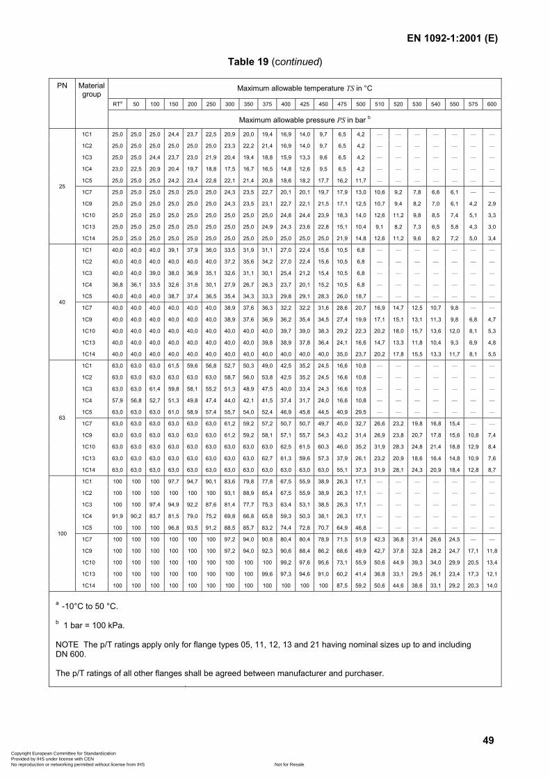
EN 1092-1:2001 (E)
49
Table 19 (continued)
Maximum allowable temperature TS in °C
RTa 50 100 150 200 250 300 350 375 400 425 450 475 500 510 520 530 540 550 575 600
PN Materialgroup
Maximum allowable pressure PS in bar b
1C1 25,0 25,0 25,0 24,4 23,7 22,5 20,9 20,0 19,4 16,9 14,0 9,7 6,5 4,2 — — — — — — —
1C2 25,0 25,0 25,0 25,0 25,0 25,0 23,3 22,2 21,4 16,9 14,0 9,7 6,5 4,2 — — — — — — —
1C3 25,0 25,0 24,4 23,7 23,0 21,9 20,4 19,4 18,8 15,9 13,3 9,6 6,5 4,2 — — — — — — —
1C4 23,0 22,5 20,9 20,4 19,7 18,8 17,5 16,7 16,5 14,8 12,6 9,5 6,5 4,2 — — — — — — —
1C5 25,0 25,0 25,0 24,2 23,4 22,8 22,1 21,4 20,8 18,6 18,2 17,7 16,2 11,7 — — — — — — —
1C7 25,0 25,0 25,0 25,0 25,0 25,0 24,3 23,5 22,7 20,1 20,1 19,7 17,9 13,0 10,6 9,2 7,8 6,6 6,1 — —
1C9 25,0 25,0 25,0 25,0 25,0 25,0 24,3 23,5 23,1 22,7 22,1 21,5 17,1 12,5 10,7 9,4 8,2 7,0 6,1 4,2 2,9
1C10 25,0 25,0 25,0 25,0 25,0 25,0 25,0 25,0 25,0 24,8 24,4 23,9 18,3 14,0 12,6 11,2 9,8 8,5 7,4 5,1 3,3
1C13 25,0 25,0 25,0 25,0 25,0 25,0 25,0 25,0 24,9 24,3 23,6 22,8 15,1 10,4 9,1 8,2 7,3 6,5 5,8 4,3 3,0
25
1C14 25,0 25,0 25,0 25,0 25,0 25,0 25,0 25,0 25,0 25,0 25,0 25,0 21,9 14,8 12,6 11,2 9,6 8,2 7,2 5,0 3,4
1C1 40,0 40,0 40,0 39,1 37,9 36,0 33,5 31,9 31,1 27,0 22,4 15,6 10,5 6,8 — — — — — — —
1C2 40,0 40,0 40,0 40,0 40,0 40,0 37,2 35,6 34,2 27,0 22,4 15,6 10,5 6,8 — — — — — — —
1C3 40,0 40,0 39,0 38,0 36,9 35,1 32,6 31,1 30,1 25,4 21,2 15,4 10,5 6,8 — — — — — — —
1C4 36,8 36,1 33,5 32,6 31,6 30,1 27,9 26,7 26,3 23,7 20,1 15,2 10,5 6,8 — — — — — — —
1C5 40,0 40,0 40,0 38,7 37,4 36,5 35,4 34,3 33,3 29,8 29,1 28,3 26,0 18,7 — — — — — — —
1C7 40,0 40,0 40,0 40,0 40,0 40,0 38,9 37,6 36,3 32,2 32,2 31,6 28,6 20,7 16,9 14,7 12,5 10,7 9,8 — —
1C9 40,0 40,0 40,0 40,0 40,0 40,0 38,9 37,6 36,9 36,2 35,4 34,5 27,4 19,9 17,1 15,1 13,1 11,3 9,8 6,8 4,7
1C10 40,0 40,0 40,0 40,0 40,0 40,0 40,0 40,0 40,0 39,7 39,0 38,3 29,2 22,3 20,2 18,0 15,7 13,6 12,0 8,1 5,3
1C13 40,0 40,0 40,0 40,0 40,0 40,0 40,0 40,0 39,8 38,9 37,8 36,4 24,1 16,6 14,7 13,3 11,8 10,4 9,3 6,9 4,8
40
1C14 40,0 40,0 40,0 40,0 40,0 40,0 40,0 40,0 40,0 40,0 40,0 40,0 35,0 23,7 20,2 17,8 15,5 13,3 11,7 8,1 5,5
1C1 63,0 63,0 63,0 61,5 59,6 56,8 52,7 50,3 49,0 42,5 35,2 24,5 16,6 10,8 — — — — — — —
1C2 63,0 63,0 63,0 63,0 63,0 63,0 58,7 56,0 53,8 42,5 35,2 24,5 16,6 10,8 — — — — — — —
1C3 63,0 63,0 61,4 59,8 58,1 55,2 51,3 48,9 47,5 40,0 33,4 24,3 16,6 10,8 — — — — — — —
1C4 57,9 56,8 52,7 51,3 49,8 47,4 44,0 42,1 41,5 37,4 31,7 24,0 16,6 10,8 — — — — — — —
1C5 63,0 63,0 63,0 61,0 58,9 57,4 55,7 54,0 52,4 46,9 45,8 44,5 40,9 29,5 — — — — — — —
1C7 63,0 63,0 63,0 63,0 63,0 63,0 61,2 59,2 57,2 50,7 50,7 49,7 45,0 32,7 26,6 23,2 19,8 16,8 15,4 — —
1C9 63,0 63,0 63,0 63,0 63,0 63,0 61,2 59,2 58,1 57,1 55,7 54,3 43,2 31,4 26,9 23,8 20,7 17,8 15,6 10,8 7,4
1C10 63,0 63,0 63,0 63,0 63,0 63,0 63,0 63,0 63,0 62,5 61,5 60,3 46,0 35,2 31,9 28,3 24,8 21,4 18,8 12,9 8,4
1C13 63,0 63,0 63,0 63,0 63,0 63,0 63,0 63,0 62,7 61,3 59,6 57,3 37,9 26,1 23,2 20,9 18,6 16,4 14,8 10,9 7,6
63
1C14 63,0 63,0 63,0 63,0 63,0 63,0 63,0 63,0 63,0 63,0 63,0 63,0 55,1 37,3 31,9 28,1 24,3 20,9 18,4 12,8 8,7
1C1 100 100 100 97,7 94,7 90,1 83,6 79,8 77,8 67,5 55,9 38,9 26,3 17,1 — — — — — — —
1C2 100 100 100 100 100 100 93,1 88,9 85,4 67,5 55,9 38,9 26,3 17,1 — — — — — — —
1C3 100 100 97,4 94,9 92,2 87,6 81,4 77,7 75,3 63,4 53,1 38,5 26,3 17,1 — — — — — — —
1C4 91,9 90,2 83,7 81,5 79,0 75,2 69,8 66,8 65,8 59,3 50,3 38,1 26,3 17,1 — — — — — — —
1C5 100 100 100 96,8 93,5 91,2 88,5 85,7 83,2 74,4 72,8 70,7 64,9 46,8 — — — — — — —
1C7 100 100 100 100 100 100 97,2 94,0 90,8 80,4 80,4 78,9 71,5 51,9 42,3 36,8 31,4 26,6 24,5 — —
1C9 100 100 100 100 100 100 97,2 94,0 92,3 90,6 88,4 86,2 68,6 49,9 42,7 37,8 32,8 28,2 24,7 17,1 11,8
1C10 100 100 100 100 100 100 100 100 100 99,2 97,6 95,6 73,1 55,9 50,6 44,9 39,3 34,0 29,9 20,5 13,4
1C13 100 100 100 100 100 100 100 100 99,6 97,3 94,6 91,0 60,2 41,4 36,8 33,1 29,5 26,1 23,4 17,3 12,1
100
1C14 100 100 100 100 100 100 100 100 100 100 100 100 87,5 59,2 50,6 44,6 38,6 33,1 29,2 20,3 14,0
a -10°C to 50 °C.
b 1 bar = 100 kPa.
NOTE The p/T ratings apply only for flange types 05, 11, 12, 13 and 21 having nominal sizes up to and includingDN 600.
The p/T ratings of all other flanges shall be agreed between manufacturer and purchaser.
Copyright European Committee for Standardization Provided by IHS under license with CEN
Not for ResaleNo reproduction or networking permitted without license from IHS
--```,-`-`,,`,,`,`,,`---
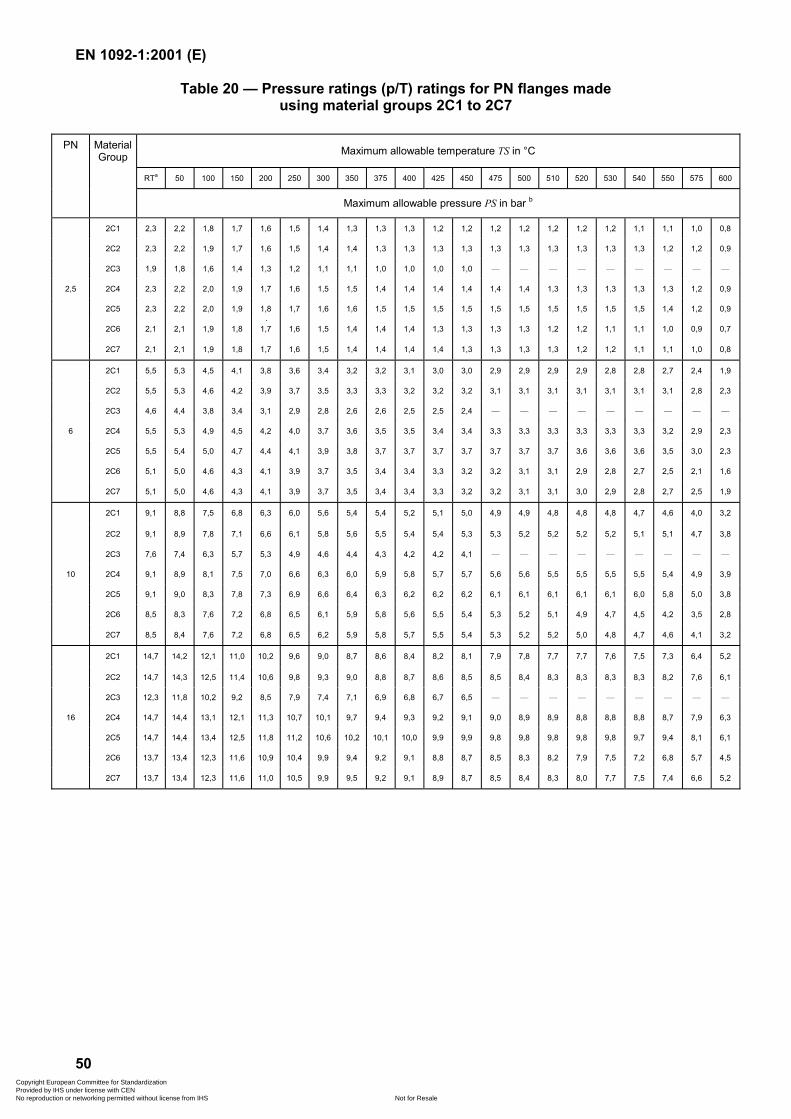
EN 1092-1:2001 (E)
50
Table 20 — Pressure ratings (p/T) ratings for PN flanges madeusing material groups 2C1 to 2C7
Maximum allowable temperature TS in °C
RTa 50 100 150 200 250 300 350 375 400 425 450 475 500 510 520 530 540 550 575 600
PN MaterialGroup
Maximum allowable pressure PS in bar b
2C1 2,3 2,2 1,8 1,7 1,6 1,5 1,4 1,3 1,3 1,3 1,2 1,2 1,2 1,2 1,2 1,2 1,2 1,1 1,1 1,0 0,8
2C2 2,3 2,2 1,9 1,7 1,6 1,5 1,4 1,4 1,3 1,3 1,3 1,3 1,3 1,3 1,3 1,3 1,3 1,3 1,2 1,2 0,9
2C3 1,9 1,8 1,6 1,4 1,3 1,2 1,1 1,1 1,0 1,0 1,0 1,0 — — — — — — — — —
2,5 2C4 2,3 2,2 2,0 1,9 1,7 1,6 1,5 1,5 1,4 1,4 1,4 1,4 1,4 1,4 1,3 1,3 1,3 1,3 1,3 1,2 0,9
2C5 2,3 2,2 2,0 1,9 1,8 1,7 1,6 1,6 1,5 1,5 1,5 1,5 1,5 1,5 1,5 1,5 1,5 1,5 1,4 1,2 0,9
2C6 2,1 2,1 1,9 1,8 1,7 1,6 1,5 1,4 1,4 1,4 1,3 1,3 1,3 1,3 1,2 1,2 1,1 1,1 1,0 0,9 0,7
2C7 2,1 2,1 1,9 1,8 1,7 1,6 1,5 1,4 1,4 1,4 1,4 1,3 1,3 1,3 1,3 1,2 1,2 1,1 1,1 1,0 0,8
2C1 5,5 5,3 4,5 4,1 3,8 3,6 3,4 3,2 3,2 3,1 3,0 3,0 2,9 2,9 2,9 2,9 2,8 2,8 2,7 2,4 1,9
2C2 5,5 5,3 4,6 4,2 3,9 3,7 3,5 3,3 3,3 3,2 3,2 3,2 3,1 3,1 3,1 3,1 3,1 3,1 3,1 2,8 2,3
2C3 4,6 4,4 3,8 3,4 3,1 2,9 2,8 2,6 2,6 2,5 2,5 2,4 — — — — — — — — —
6 2C4 5,5 5,3 4,9 4,5 4,2 4,0 3,7 3,6 3,5 3,5 3,4 3,4 3,3 3,3 3,3 3,3 3,3 3,3 3,2 2,9 2,3
2C5 5,5 5,4 5,0 4,7 4,4 4,1 3,9 3,8 3,7 3,7 3,7 3,7 3,7 3,7 3,7 3,6 3,6 3,6 3,5 3,0 2,3
2C6 5,1 5,0 4,6 4,3 4,1 3,9 3,7 3,5 3,4 3,4 3,3 3,2 3,2 3,1 3,1 2,9 2,8 2,7 2,5 2,1 1,6
2C7 5,1 5,0 4,6 4,3 4,1 3,9 3,7 3,5 3,4 3,4 3,3 3,2 3,2 3,1 3,1 3,0 2,9 2,8 2,7 2,5 1,9
2C1 9,1 8,8 7,5 6,8 6,3 6,0 5,6 5,4 5,4 5,2 5,1 5,0 4,9 4,9 4,8 4,8 4,8 4,7 4,6 4,0 3,2
2C2 9,1 8,9 7,8 7,1 6,6 6,1 5,8 5,6 5,5 5,4 5,4 5,3 5,3 5,2 5,2 5,2 5,2 5,1 5,1 4,7 3,8
2C3 7,6 7,4 6,3 5,7 5,3 4,9 4,6 4,4 4,3 4,2 4,2 4,1 — — — — — — — — —
10 2C4 9,1 8,9 8,1 7,5 7,0 6,6 6,3 6,0 5,9 5,8 5,7 5,7 5,6 5,6 5,5 5,5 5,5 5,5 5,4 4,9 3,9
2C5 9,1 9,0 8,3 7,8 7,3 6,9 6,6 6,4 6,3 6,2 6,2 6,2 6,1 6,1 6,1 6,1 6,1 6,0 5,8 5,0 3,8
2C6 8,5 8,3 7,6 7,2 6,8 6,5 6,1 5,9 5,8 5,6 5,5 5,4 5,3 5,2 5,1 4,9 4,7 4,5 4,2 3,5 2,8
2C7 8,5 8,4 7,6 7,2 6,8 6,5 6,2 5,9 5,8 5,7 5,5 5,4 5,3 5,2 5,2 5,0 4,8 4,7 4,6 4,1 3,2
2C1 14,7 14,2 12,1 11,0 10,2 9,6 9,0 8,7 8,6 8,4 8,2 8,1 7,9 7,8 7,7 7,7 7,6 7,5 7,3 6,4 5,2
2C2 14,7 14,3 12,5 11,4 10,6 9,8 9,3 9,0 8,8 8,7 8,6 8,5 8,5 8,4 8,3 8,3 8,3 8,3 8,2 7,6 6,1
2C3 12,3 11,8 10,2 9,2 8,5 7,9 7,4 7,1 6,9 6,8 6,7 6,5 — — — — — — — — —
16 2C4 14,7 14,4 13,1 12,1 11,3 10,7 10,1 9,7 9,4 9,3 9,2 9,1 9,0 8,9 8,9 8,8 8,8 8,8 8,7 7,9 6,3
2C5 14,7 14,4 13,4 12,5 11,8 11,2 10,6 10,2 10,1 10,0 9,9 9,9 9,8 9,8 9,8 9,8 9,8 9,7 9,4 8,1 6,1
2C6 13,7 13,4 12,3 11,6 10,9 10,4 9,9 9,4 9,2 9,1 8,8 8,7 8,5 8,3 8,2 7,9 7,5 7,2 6,8 5,7 4,5
2C7 13,7 13,4 12,3 11,6 11,0 10,5 9,9 9,5 9,2 9,1 8,9 8,7 8,5 8,4 8,3 8,0 7,7 7,5 7,4 6,6 5,2
Copyright European Committee for Standardization Provided by IHS under license with CEN
Not for ResaleNo reproduction or networking permitted without license from IHS
--```,-`-`,,`,,`,`,,`---
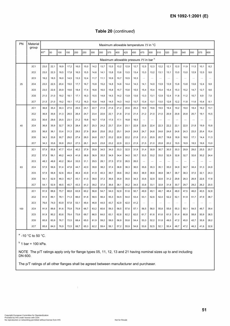
EN 1092-1:2001 (E)
51
Table 20 (continued)
Maximum allowable temperature TS in °C
RTa 50 100 150 200 250 300 350 375 400 425 450 475 500 510 520 530 540 550 575 600
PN Materialgroup
Maximum allowable pressure PS in bar b
2C1 23,0 22,1 18,9 17,2 16,0 15,0 14,2 13,7 13,5 13,2 12,9 12,7 12,5 12,3 12,2 12,1 12,0 11,9 11,5 10,1 8,2
2C2 23,0 22,3 19,5 17,8 16,5 15,5 14,6 14,1 13,8 13,6 13,5 13,4 13,3 13,2 13,1 13,1 13,0 13,0 12,9 12,0 9,6
2C3 19,2 18,5 16,0 14,5 13,3 12,4 11,7 11,1 10,9 10,7 10,5 10,3 — — — — — — — — —
2C4 23,0 22,5 20,4 19,0 17,7 16,7 15,8 15,2 14,8 14,6 14,4 14,3 14,1 14,0 13,9 13,9 13,8 13,8 13,6 12,4 9,8
2C5 23,0 22,6 20,9 19,6 18,4 17,4 16,6 16,0 15,8 15,7 15,6 15,5 15,4 15,4 15,4 15,4 15,3 15,2 14,7 12,7 9,6
2C6 21,5 21,0 19,2 18,1 17,1 16,3 15,5 14,8 14,5 14,2 13,9 13,6 13,3 13,1 12,9 12,4 11,8 11,2 10,7 8,9 7,0
25
2C7 21,5 21,0 19,2 18,1 17,2 16,3 15,6 14,8 14,5 14,3 14,0 13,7 13,4 13,1 13,0 12,6 12,2 11,8 11,6 10,4 8,1
2C1 36,8 35,4 30,3 27,5 25,5 24,1 22,7 21,9 21,6 21,2 20,6 20,3 19,9 19,6 19,5 19,4 19,2 19,0 18,4 16,2 13,1
2C2 36,8 35,6 31,3 28,5 26,4 24,7 23,4 22,6 22,1 21,8 21,6 21,4 21,2 21,0 21,0 20,9 20,8 20,8 20,7 19,1 15,5
2C3 30,6 29,6 25,5 23,1 21,2 19,8 18,7 17,8 17,5 17,1 16,8 16,5 — — — — — — — — —
2C4 36,8 35,9 32,7 30,3 28,4 26,7 25,3 24,2 23,7 23,4 23,1 22,8 22,6 22,4 22,3 22,2 22,1 22,0 21,8 19,9 15,8
2C5 36,8 36,1 33,4 31,3 29,5 27,9 26,6 25,6 25,2 25,1 24,9 24,8 24,7 24,6 24,6 24,6 24,6 24,3 23,5 20,4 15,4
2C6 34,3 33,6 30,7 29,0 27,4 26,0 24,8 23,7 23,2 22,8 22,2 21,8 21,3 20,9 20,7 19,8 18,9 18,0 17,1 14,4 11,3
40
2C7 34,3 33,6 30,8 29,0 27,5 26,1 24,9 23,8 23,2 22,9 22,3 21,9 21,5 21,0 20,8 20,2 19,5 18,9 18,5 16,6 13,0
2C1 57,9 55,8 47,7 43,4 40,2 37,9 35,8 34,5 34,0 33,3 32,5 31,9 31,4 30,9 30,7 30,5 30,3 29,9 29,0 25,5 20,7
2C2 57,9 56,1 49,2 44,9 41,6 38,9 36,9 35,5 34,9 34,4 34,0 33,7 33,5 33,2 33,0 32,9 32,8 32,7 32,6 30,2 24,4
2C3 48,3 46,6 40,2 36,4 33,5 31,1 29,5 28,1 27,5 27,0 26,5 26,0 — — — — — — — — —
2C4 57,9 56,6 51,4 47,8 44,7 42,0 39,8 38,2 37,4 36,8 36,3 36,0 35,6 35,3 35,1 35,0 34,9 34,7 34,4 31,3 24,8
2C5 57,9 56,8 52,6 49,4 46,4 43,9 41,9 40,3 39,7 39,6 39,2 39,0 38,9 38,8 38,8 38,7 38,7 38,3 37,0 32,1 24,3
2C6 54,1 52,9 48,3 45,7 43,1 41,0 39,0 37,3 36,6 35,9 35,0 34,3 33,6 32,9 32,6 31,2 29,8 28,3 26,9 22,6 17,8
63
2C7 54,1 52,9 48,5 45,7 43,3 41,2 39,2 37,4 36,6 36,1 35,2 34,5 33,8 33,1 32,8 31,8 30,7 29,7 29,2 26,2 20,5
2C1 91,9 88,6 75,7 68,8 63,9 60,2 56,8 54,7 54,0 52,9 51,6 50,7 49,9 49,1 48,7 48,4 48,0 47,5 46,0 40,5 32,8
2C2 91,9 89,1 78,1 71,3 66,0 61,8 58,5 56,4 55,3 54,5 54,0 53,4 53,1 52,6 52,4 52,2 52,1 51,9 51,7 47,9 38,7
2C3 76,6 74,0 63,9 57,8 53,1 49,4 46,8 44,5 43,7 42,9 42,0 41,2 — — — — — — — — —
2C4 91,9 89,8 81,6 75,9 70,9 66,7 63,2 60,6 59,3 58,5 57,6 57,1 56,5 56,0 55,8 55,6 55,3 55,1 54,5 49,7 39,4
2C5 91,9 90,2 83,6 78,4 73,6 69,7 66,5 64,0 63,1 62,8 62,2 62,0 61,7 61,6 61,6 61,5 61,4 60,8 58,8 50,9 38,5
2C6 85,8 83,9 76,7 72,5 68,4 65,0 61,9 59,2 58,0 56,9 55,6 54,4 53,3 52,2 51,8 49,5 47,2 45,0 42,7 35,9 28,2
100
2C7 85,8 84,0 76,9 72,5 68,7 65,3 62,2 59,4 58,1 57,2 55,9 54,8 53,6 52,5 52,1 50,4 48,7 47,2 46,3 41,6 32,6
a -10 °C to 50 °C.
b 1 bar = 100 kPa.
NOTE The p/T ratings apply only for flange types 05, 11, 12, 13 and 21 having nominal sizes up to and includingDN 600.
The p/T ratings of all other flanges shall be agreed between manufacturer and purchaser.
Copyright European Committee for Standardization Provided by IHS under license with CEN
Not for ResaleNo reproduction or networking permitted without license from IHS
--```,-`-`,,`,,`,`,,`---
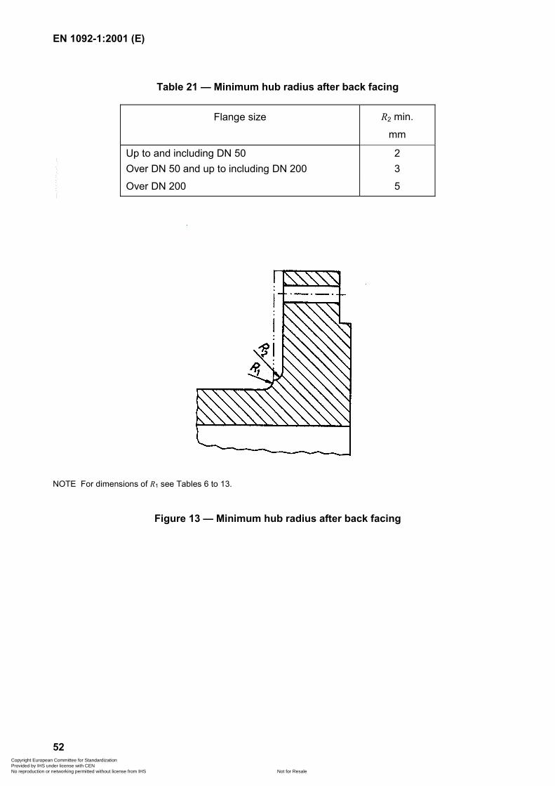
EN 1092-1:2001 (E)
52
Table 21 — Minimum hub radius after back facing
Flange size R2 min.
mm
Up to and including DN 50 2Over DN 50 and up to including DN 200 3Over DN 200 5
NOTE For dimensions of R1 see Tables 6 to 13.
Figure 13 — Minimum hub radius after back facing
Copyright European Committee for Standardization Provided by IHS under license with CEN
Not for ResaleNo reproduction or networking permitted without license from IHS
--```,-`-`,,`,,`,`,,`---
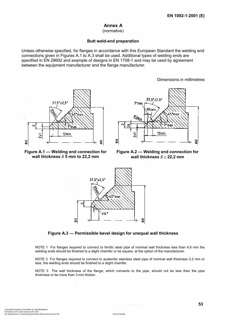
EN 1092-1:2001 (E)
53
Annex A(normative)
Butt weld-end preparation
Unless otherwise specified, for flanges in accordance with this European Standard the welding endconnections given in Figures A.1 to A.3 shall be used. Additional types of welding ends arespecified in EN 29692 and example of designs in EN 1708-1 and may be used by agreementbetween the equipment manufacturer and the flange manufacturer.
Dimensions in millimetres
Figure A.1 — Welding end connection forwall thickness S 5 mm to 22,2 mm
Figure A.2 — Welding end connection forwall thickness S � 22,2 mm
Figure A.3 — Permissible bevel design for unequal wall thickness
NOTE 1 For flanges required to connect to ferritic steel pipe of nominal wall thickness less than 4,8 mm thewelding ends should be finished to a slight chamfer or be square, at the option of the manufacturer.
NOTE 2 For flanges required to connect to austenitic stainless steel pipe of nominal wall thickness 3,2 mm orless, the welding ends should be finished to a slight chamfer.
NOTE 3 The wall thickness of the flange, which connects to the pipe, should not be less than the pipethickness or be more than 3 mm thicker.
Copyright European Committee for Standardization Provided by IHS under license with CEN
Not for ResaleNo reproduction or networking permitted without license from IHS
--```,-`-`,,`,,`,`,,`---
EN 1092-1:2001 (E)
54
Annex B(informative)
Material groups
The material groups contain materials of similar chemical/mechanical properties and corrosionresistance in order to facilitate an equivalent application of materials in a group depending onpressure, temperature and fluid.
The material groups 1E0 to 6E1 were part of several European national standards and can bedescribed as follows:
1E0 unalloyed structural steels without guaranteed thermal-temperature strength,application range �10 °C to + 100 °C;
1E1 unalloyed structural steels with thermal-temperature strength according toAD-Merkblatt W1, July 1995, table 4, application range �10 °C to 300 °C;
2E0 unalloyed steels without guaranteed thermal-temperature strength, application range350 °C up to 400 °C;
3E0 unalloyed steels with guaranteed thermal-temperature strength, application range upto 400 °C;
4E0 low alloyed steels with 0,3 % molybdenum;
5E0 low alloyed steels with 1 % chromium and 0,5 % molybdenum;
6E0 low alloyed steels with 2 % chromium and 1 % molybdenum;
6E1 alloy steel with 5 % chromium and 0,5 % molybdenum.
The following groups of materials contain steels with low temperature toughness:
7E0 low-temperature-tough fine-grain steel with a minimum yield strength of 315 N/mm2
at room temperature;
7E1 low-temperature-tough fine-grain steel with a minimum yield strength of 380 N/mm2
at room temperature;
7E2 low-temperature high alloy nickel steel;
7E3 low temperature steels with strength values for elevated temperatures according toAD-Merkblatt W10, November 1987, table 3a, application range up to 300 °C.
Copyright European Committee for Standardization Provided by IHS under license with CEN
Not for ResaleNo reproduction or networking permitted without license from IHS
--```,-`-`,,`,,`,`,,`---
EN 1092-1:2001 (E)
55
The following groups of materials contain creep-resistant fine-grain steels, differentiating only instrength:
8E0 yield strength 225 N/mm2 min. at room temperature;
8E1 yield strength 285 N/mm2 min. at room temperature;
8E2 yield strength 315 N/mm2 min. at room temperature;
8E3 yield strength 355 N/mm2 min. at room temperature;
9E0 high-temperature-tough ferritic steel with 12 % chromium, 1 % molybdenum and0,5 % vanadium.
The following groups contain austenitic stainless steels, with differences in corrosion resistance,weldability and strength, Groups 10E0 up to 12E0 are free of molybdenum, groups 13E0 to 15E0are alloyed with molybdenum:
10E0 extra low carbon steel (ELC-steel);
10E1 ELC-steel, nitrogen-alloyed;
11E0 standard carbon-content;
12E0 alloyed with elements which form extra stable carbides;
13E0 extra low carbon steel with molybdenum;
13E1 extra low carbon steel with molybdenum and nitrogen alloyed;
14E0 standard carbon-content alloyed with molybdenum;
15E0 alloyed with molybdenum and elements which form extra stable carbides;
16E0 austenitic-ferritic steels.
Copyright European Committee for Standardization Provided by IHS under license with CEN
Not for ResaleNo reproduction or networking permitted without license from IHS
--```,-`-`,,`,,`,`,,`---
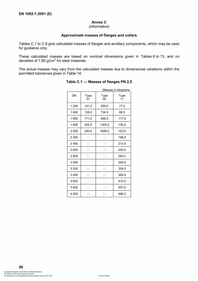
EN 1092-1:2001 (E)
56
Annex C(informative)
Approximate masses of flanges and collars
Tables C.1 to C.8 give calculated masses of flanges and ancillary components, which may be usedfor guidance only.
These calculated masses are based on nominal dimensions given in Tables 6 to 13, and ondensities of 7,80 g/cm3 for steel materials.
The actual masses may vary from the calculated masses due to dimensional variations within thepermitted tolerances given in Table 14.
Table C.1 — Masses of flanges PN 2,5
Masses in kilograms
DN Type01
Type05
Type11
1 200 101,5 505,0 77,5
1 400 128,0 724,5 89,5
1 600 171,0 996,0 117,5
1 800 202,5 1305,5 135,0
2 000 240,5 1699,5 153,0
2 200 — — 196,0
2 400 — — 213,0
2 600 — — 230,5
2 800 — — 283,5
3 000 — — 304,5
3 200 — — 324,5
3 400 — — 365,5
3 600 — — 410,5
3 800 — — 457,0
4 000 — — 480,5
Copyright European Committee for Standardization Provided by IHS under license with CEN
Not for ResaleNo reproduction or networking permitted without license from IHS
--```,-`-`,,`,,`,`,,`---
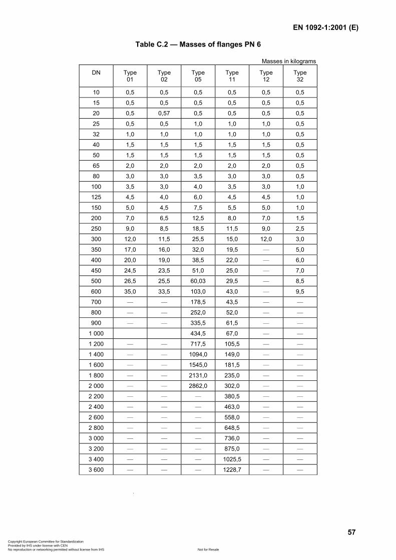
EN 1092-1:2001 (E)
57
Table C.2 — Masses of flanges PN 6
Masses in kilograms
DN Type01
Type02
Type05
Type11
Type12
Type32
10 0,5 0,5 0,5 0,5 0,5 0,5
15 0,5 0,5 0,5 0,5 0,5 0,5
20 0,5 0,57 0,5 0,5 0,5 0,5
25 0,5 0,5 1,0 1,0 1,0 0,5
32 1,0 1,0 1,0 1,0 1,0 0,5
40 1,5 1,5 1,5 1,5 1,5 0,5
50 1,5 1,5 1,5 1,5 1,5 0,5
65 2,0 2,0 2,0 2,0 2,0 0,5
80 3,0 3,0 3,5 3,0 3,0 0,5
100 3,5 3,0 4,0 3,5 3,0 1,0
125 4,5 4,0 6,0 4,5 4,5 1,0
150 5,0 4,5 7,5 5,5 5,0 1,0
200 7,0 6,5 12,5 8,0 7,0 1,5
250 9,0 8,5 18,5 11,5 9,0 2,5
300 12,0 11,5 25,5 15,0 12,0 3,0
350 17,0 16,0 32,0 19,5 — 5,0
400 20,0 19,0 38,5 22,0 — 6,0
450 24,5 23,5 51,0 25,0 — 7,0
500 26,5 25,5 60,03 29,5 — 8,5
600 35,0 33,5 103,0 43,0 — 9,5
700 — — 178,5 43,5 — —
800 — — 252,0 52,0 — —
900 — — 335,5 61,5 — —
1 000 434,5 67,0 — —
1 200 — — 717,5 105,5 — —
1 400 — — 1094,0 149,0 — —
1 600 — — 1545,0 181,5 — —
1 800 — — 2131,0 235,0 — —
2 000 — — 2862,0 302,0 — —
2 200 — — — 380,5 — —
2 400 — — — 463,0 — —
2 600 — — — 558,0 — —
2 800 — — — 648,5 — —
3 000 — — — 736,0 — —
3 200 — — — 875,0 — —
3 400 — — — 1025,5 — —
3 600 — — — 1228,7 — —
Copyright European Committee for Standardization Provided by IHS under license with CEN
Not for ResaleNo reproduction or networking permitted without license from IHS
--```,-`-`,,`,,`,`,,`---
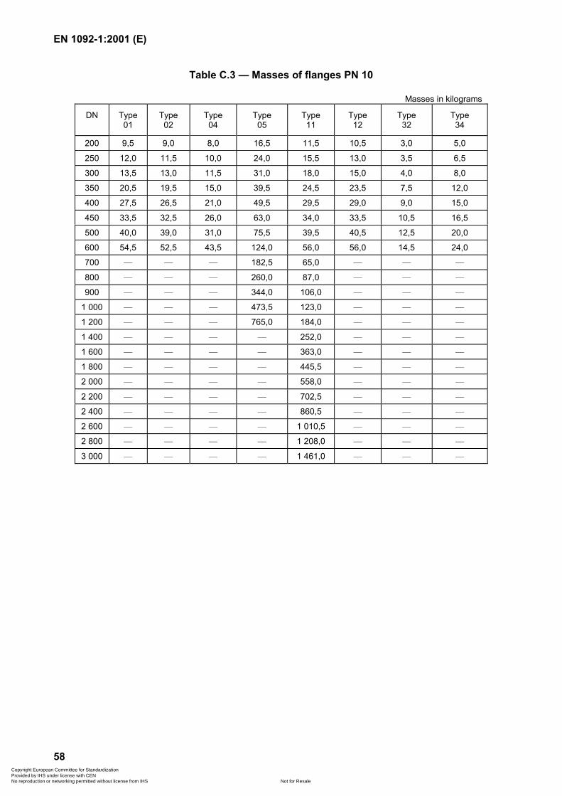
EN 1092-1:2001 (E)
58
Table C.3 — Masses of flanges PN 10
Masses in kilograms
DN Type01
Type02
Type04
Type05
Type11
Type12
Type32
Type34
200 9,5 9,0 8,0 16,5 11,5 10,5 3,0 5,0
250 12,0 11,5 10,0 24,0 15,5 13,0 3,5 6,5
300 13,5 13,0 11,5 31,0 18,0 15,0 4,0 8,0
350 20,5 19,5 15,0 39,5 24,5 23,5 7,5 12,0
400 27,5 26,5 21,0 49,5 29,5 29,0 9,0 15,0
450 33,5 32,5 26,0 63,0 34,0 33,5 10,5 16,5
500 40,0 39,0 31,0 75,5 39,5 40,5 12,5 20,0
600 54,5 52,5 43,5 124,0 56,0 56,0 14,5 24,0
700 — — — 182,5 65,0 — — —
800 — — — 260,0 87,0 — — —
900 — — — 344,0 106,0 — — —
1 000 — — — 473,5 123,0 — — —
1 200 — — — 765,0 184,0 — — —
1 400 — — — — 252,0 — — —
1 600 — — — — 363,0 — — —
1 800 — — — — 445,5 — — —
2 000 — — — — 558,0 — — —
2 200 — — — — 702,5 — — —
2 400 — — — — 860,5 — — —
2 600 — — — — 1 010,5 — — —
2 800 — — — — 1 208,0 — — —
3 000 — — — — 1 461,0 — — —
Copyright European Committee for Standardization Provided by IHS under license with CEN
Not for ResaleNo reproduction or networking permitted without license from IHS
--```,-`-`,,`,,`,`,,`---
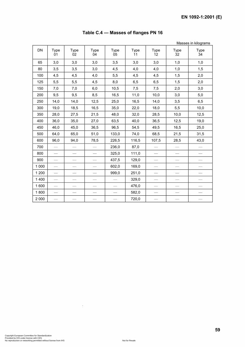
EN 1092-1:2001 (E)
59
Table C.4 — Masses of flanges PN 16
Masses in kilograms
DN Type01
Type02
Type04
Type05
Type11
Type12
Type32
Type34
65 3,0 3,0 3,0 3,5 3,0 3,0 1,0 1,0
80 3,5 3,5 3,0 4,5 4,0 4,0 1,0 1,5
100 4,5 4,5 4,0 5,5 4,5 4,5 1,5 2,0
125 5,5 5,5 4,5 8,0 6,5 6,5 1,5 2,0
150 7,0 7,0 6,0 10,5 7,5 7,5 2,0 3,0
200 9,5 9,5 8,5 16,5 11,0 10,0 3,0 5,0
250 14,0 14,0 12,5 25,0 16,5 14,0 3,5 6,5
300 19,0 18,5 16,5 35,0 22,0 18,0 5,5 10,0
350 28,0 27,5 21,5 48,0 32,0 28,5 10,0 12,5
400 36,0 35,0 27,0 63,5 40,0 36,5 12,5 19,0
450 46,0 45,0 36,5 96,5 54,5 49,5 16,5 25,0
500 64,0 65,0 51,0 133,0 74,0 68,5 21,5 31,5
600 96,0 94,0 78,5 226,5 116,5 107,5 28,5 43,0
700 — — — 236,0 87,0 — — —
800 — — — 325,0 111,0 — — —
900 — — — 437,5 129,0 — — —
1 000 — — — 602,0 169,0 — — —
1 200 — — — 999,0 251,0 — — —
1 400 — — — — 329,0 — — —
1 600 — — — — 476,0 — — —
1 800 — — — — 582,0 — — —
2 000 — — — — 720,0 — — —
Copyright European Committee for Standardization Provided by IHS under license with CEN
Not for ResaleNo reproduction or networking permitted without license from IHS
--```,-`-`,,`,,`,`,,`---
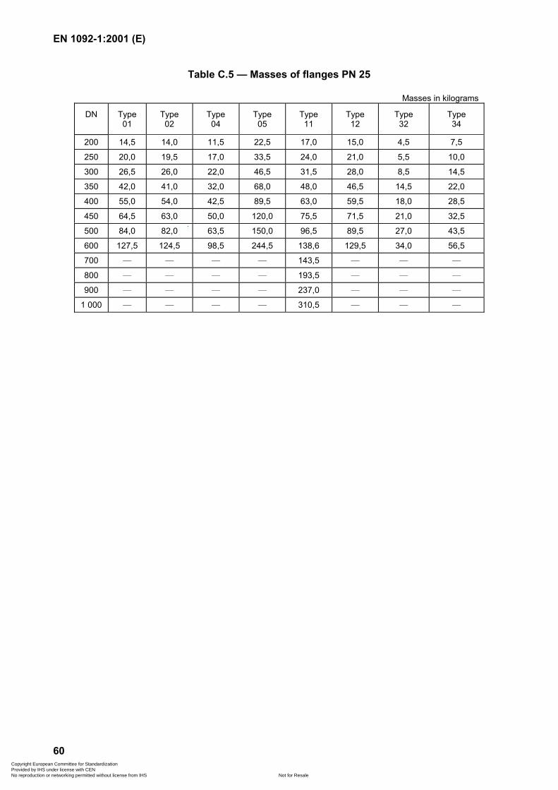
EN 1092-1:2001 (E)
60
Table C.5 — Masses of flanges PN 25
Masses in kilograms
DN Type01
Type02
Type04
Type05
Type11
Type12
Type32
Type34
200 14,5 14,0 11,5 22,5 17,0 15,0 4,5 7,5
250 20,0 19,5 17,0 33,5 24,0 21,0 5,5 10,0
300 26,5 26,0 22,0 46,5 31,5 28,0 8,5 14,5
350 42,0 41,0 32,0 68,0 48,0 46,5 14,5 22,0
400 55,0 54,0 42,5 89,5 63,0 59,5 18,0 28,5
450 64,5 63,0 50,0 120,0 75,5 71,5 21,0 32,5
500 84,0 82,0 63,5 150,0 96,5 89,5 27,0 43,5
600 127,5 124,5 98,5 244,5 138,6 129,5 34,0 56,5
700 — — — — 143,5 — — —
800 — — — — 193,5 — — —
900 — — — — 237,0 — — —
1 000 — — — — 310,5 — — —
Copyright European Committee for Standardization Provided by IHS under license with CEN
Not for ResaleNo reproduction or networking permitted without license from IHS
--```,-`-`,,`,,`,`,,`---
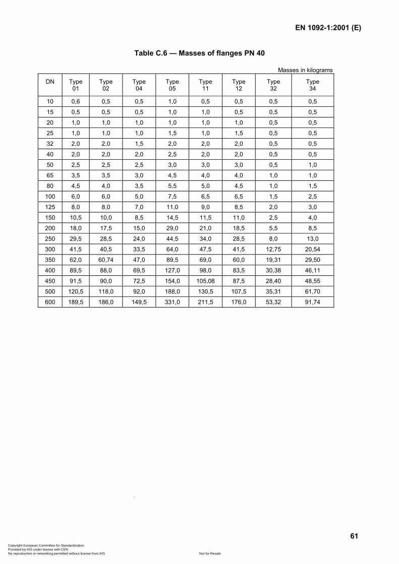
EN 1092-1:2001 (E)
61
Table C.6 — Masses of flanges PN 40
Masses in kilograms
DN Type01
Type02
Type04
Type05
Type11
Type12
Type32
Type34
10 0,6 0,5 0,5 1,0 0,5 0,5 0,5 0,5
15 0,5 0,5 0,5 1,0 1,0 0,5 0,5 0,5
20 1,0 1,0 1,0 1,0 1,0 1,0 0,5 0,5
25 1,0 1,0 1,0 1,5 1,0 1,5 0,5 0,5
32 2,0 2,0 1,5 2,0 2,0 2,0 0,5 0,5
40 2,0 2,0 2,0 2,5 2,0 2,0 0,5 0,5
50 2,5 2,5 2,5 3,0 3,0 3,0 0,5 1,0
65 3,5 3,5 3,0 4,5 4,0 4,0 1,0 1,0
80 4,5 4,0 3,5 5,5 5,0 4,5 1,0 1,5
100 6,0 6,0 5,0 7,5 6,5 6,5 1,5 2,5
125 8,0 8,0 7,0 11,0 9,0 8,5 2,0 3,0
150 10,5 10,0 8,5 14,5 11,5 11,0 2,5 4,0
200 18,0 17,5 15,0 29,0 21,0 18,5 5,5 8,5
250 29,5 28,5 24,0 44,5 34,0 28,5 8,0 13,0
300 41,5 40,5 33,5 64,0 47,5 41,5 12,75 20,54
350 62,0 60,74 47,0 89,5 69,0 60,0 19,31 29,50
400 89,5 88,0 69,5 127,0 98,0 83,5 30,38 46,11
450 91,5 90,0 72,5 154,0 105,08 87,5 28,40 48,55
500 120,5 118,0 92,0 188,0 130,5 107,5 35,31 61,70
600 189,5 186,0 149,5 331,0 211,5 176,0 53,32 91,74
Copyright European Committee for Standardization Provided by IHS under license with CEN
Not for ResaleNo reproduction or networking permitted without license from IHS
--```,-`-`,,`,,`,`,,`---
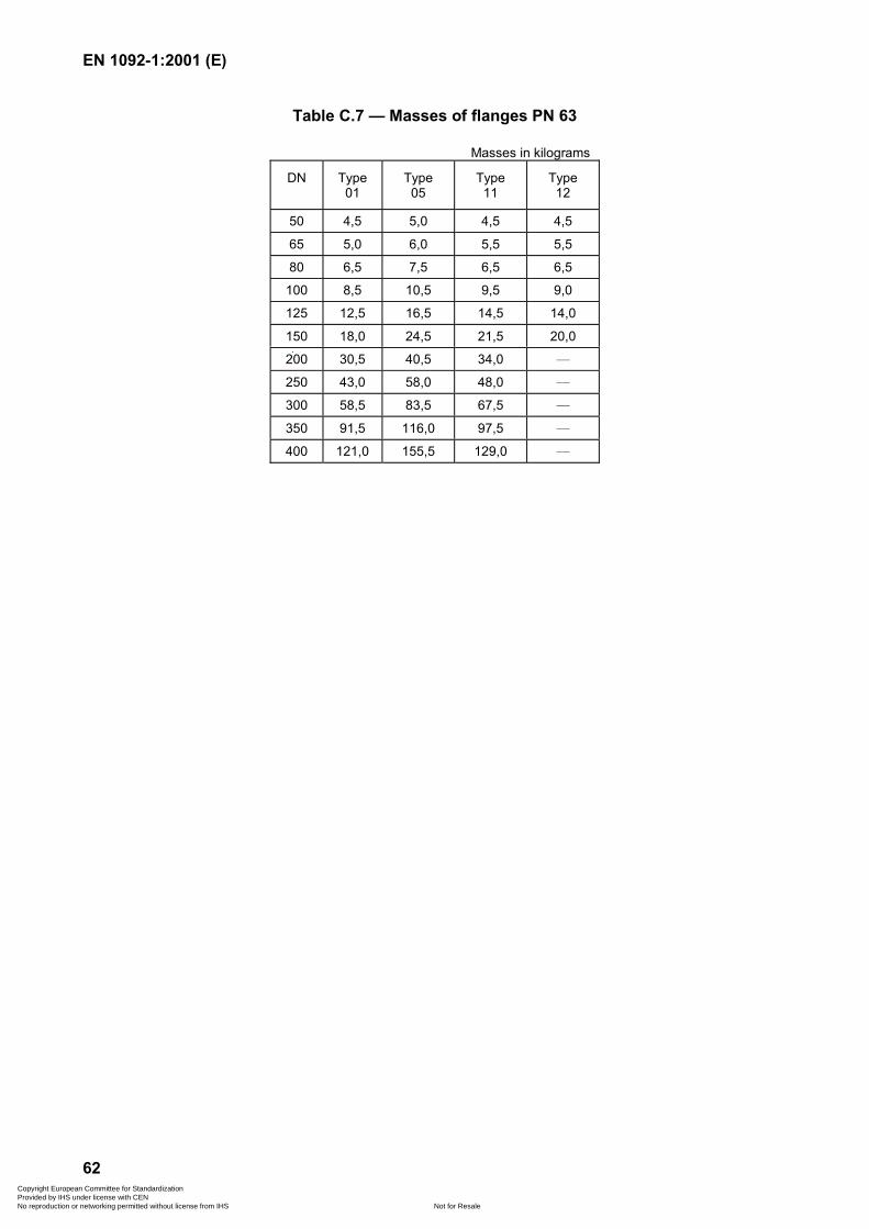
EN 1092-1:2001 (E)
62
Table C.7 — Masses of flanges PN 63
Masses in kilograms
DN Type01
Type05
Type11
Type12
50 4,5 5,0 4,5 4,5
65 5,0 6,0 5,5 5,5
80 6,5 7,5 6,5 6,5
100 8,5 10,5 9,5 9,0
125 12,5 16,5 14,5 14,0
150 18,0 24,5 21,5 20,0
200 30,5 40,5 34,0 —
250 43,0 58,0 48,0 —
300 58,5 83,5 67,5 —
350 91,5 116,0 97,5 —
400 121,0 155,5 129,0 —
Copyright European Committee for Standardization Provided by IHS under license with CEN
Not for ResaleNo reproduction or networking permitted without license from IHS
--```,-`-`,,`,,`,`,,`---
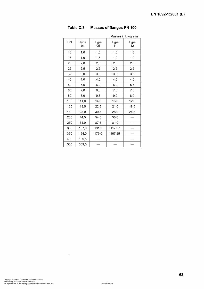
EN 1092-1:2001 (E)
63
Table C.8 — Masses of flanges PN 100
Masses in kilograms
DN Type01
Type05
Type11
Type12
10 1,0 1,0 1,0 1,0
15 1,0 1,5 1,0 1,0
20 2,0 2,0 2,0 2,0
25 2,5 2,5 2,5 2,5
32 3,0 3,5 3,0 3,0
40 4,0 4,5 4,0 4,0
50 5,5 6,0 6,0 5,5
65 7,0 8,0 7,5 7,0
80 8,0 9,5 9,0 8,0
100 11,0 14,0 13,0 12,0
125 18,5 22,5 21,0 18,5
150 25,0 30,5 28,0 24,5
200 44,5 54,5 50,0 —
250 71,0 87,5 81,0 —
300 107,0 131,5 117,97 —
350 154,0 179,0 167,25 —
400 199,5 — — —
500 339,5 — — —
Copyright European Committee for Standardization Provided by IHS under license with CEN
Not for ResaleNo reproduction or networking permitted without license from IHS
--```,-`-`,,`,,`,`,,`---
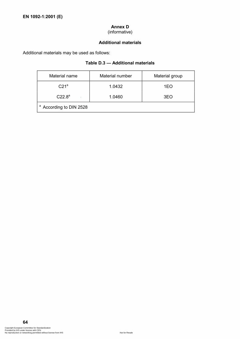
EN 1092-1:2001 (E)
64
Annex D(informative)
Additional materials
Additional materials may be used as follows:
Table D.3 — Additional materials
Material name Material number Material group
C21a 1.0432 1EO
C22.8a 1.0460 3EO
a According to DIN 2528
Copyright European Committee for Standardization Provided by IHS under license with CEN
Not for ResaleNo reproduction or networking permitted without license from IHS
--```,-`-`,,`,,`,`,,`---
EN 1092-1:2001 (E)
65
Annex E(informative)
Determination of p/T ratings for flanges using EN materials
The p/T ratings in Tables 15 to 18 were calculated in accordance with the following rules:
a) the ratings are calculated on the basis of strength values specified in European materialstandards;
b) the pressure is calculated from ���
����
�
225 PN eR=PS ;
it is limited to PS � PN;
c) for the value Re the value ReH or Rp0,2 and the rupture stress �r/100 000 is used for allmaterials. For austenitic materials, the value Rp1,0 (1 % proof stress) is used for theadditional p/T rating tables;
d) to take a product thickness of 40 mm as basis for the calculation (medium flange facethickness);
e) if strength values are not specified for specific temperatures, the p/T ratings shall alsonot be calculated;
f) if a material group comprises various materials, the material with the lowest strengthshall be chosen for calculation. If this is a casting and if its strength values are onlyslightly below the strength values of a forging or flat product, the strength values of theforging or flat product have been chosen.
NOTE The rules in this annex are given for information only.
Copyright European Committee for Standardization Provided by IHS under license with CEN
Not for ResaleNo reproduction or networking permitted without license from IHS
--```,-`-`,,`,,`,`,,`---
EN 1092-1:2001 (E)
66
Annex F(informative)
Determination of p/T ratings for flanges using ASTM materials
The p/T ratings in Tables 19 and 20 were calculated in accordance with the following rules:
a) the ratings are calculated based on strength values specified in the ASME Boiler andPressure Vessel Code — Section ll: Materials — Part D – Properties, 1995 edition July,1995 – 1996 addenda issued 31st December 1996;
b) the pressure is calculated from: ��
���
��
25strength designPNPS ;
c) design strengths are determined from:
— yield strengths at temperatures below the creep range;
— 1,5 � maximum allowable stress at temperature for temperatures in the creep range;
— a maximum of 225 N/mm2.
NOTE Temperatures in the creep range are defined as:
above 371 oC (700 oF) for material groups 1C1 to 1C7;
above 454 oC (850 oF) for material groups 1C9 to 1C14;
above 510 oC (950 oF) for material groups 2C1 to 2C7.
Table F.1 gives the design strengths used to calculate PS.
Copyright European Committee for Standardization Provided by IHS under license with CEN
Not for ResaleNo reproduction or networking permitted without license from IHS
--```,-`-`,,`,,`,`,,`---
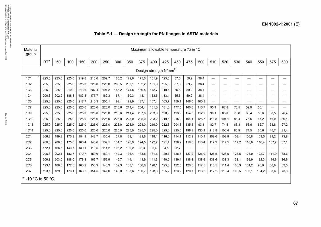
EN 1092-1:2001 (E)
67
,Table F.1 — Design strength for PN flanges in ASTM materials
Maximum allowable temperature TS in °CMaterialgroup
RTa 50 100 150 200 250 300 350 375 400 425 450 475 500 510 520 530 540 550 575 600
Design strength N/mm2
1C1 225,0 225,0 225,0 219,8 213,0 202,7 188,2 179,6 175,0 151,9 125,8 87,6 59,2 38,4 — — — — — — —
1C2 225,0 225,0 225,0 225,0 225,0 225,0 209,5 200,1 192,2 151,9 125,8 87,6 59,2 38,4 — — — — — — —
1C3 225,0 225,0 219,2 213,6 207,4 197,2 183,2 174,8 169,5 142,7 119,4 86,6 59,2 38,4 — — — — — — —
1C4 206,8 202,9 188,3 183,3 177,7 169,3 157,1 150,3 148,1 133,5 113,1 85,6 59,2 38,4 — — — — — — —
1C5 225,0 225,0 225,0 217,7 210,3 205,1 199,1 192,9 187,1 167,4 163,7 159,1 146,0 105,3 — — — — — — —
1C7 225,0 225,0 225,0 225,0 225,0 225,0 218,6 211,4 204,4 181,0 181,0 177,5 160,8 116,7 95,1 82,8 70,5 59,9 55,1 — —
1C9 225,0 225,0 225,0 225,0 225,0 225,0 218,6 211,4 207,6 203,9 198,9 193,9 154,3 112,2 96,1 85,0 73,8 63,4 55,6 38,5 26,4
1C10 225,0 225,0 225,0 225,0 225,0 225,0 225,0 225,0 225,0 223,2 219,5 215,2 164,4 125,7 113,8 101,1 88,4 76,5 67,2 46,0 30,1
1C13 225,0 225,0 225,0 225,0 225,0 225,0 225,0 225,0 224,0 219,0 212,8 204,8 135,5 93,1 82,7 74,5 66,3 58,6 52,7 38,8 27,2
1C14 225,0 225,0 225,0 225,0 225,0 225,0 225,0 225,0 225,0 225,0 225,0 225,0 196,8 133,1 113,8 100,4 86,9 74,5 65,6 45,7 31,4
2C1 206,8 199,3 170,3 154,9 143,7 135,4 127,8 123,1 121,6 119,1 116,0 114,1 112,2 110,4 109,6 108,9 108,1 106,8 103,5 91,2 73,8
2C2 206,8 200,5 175,8 160,4 148,6 139,1 131,7 126,9 124,5 122,7 121,4 120,2 119,5 118,4 117,9 117,5 117,2 116,8 116,4 107,7 87,1
2C3 172,4 166,5 143,7 130,1 119,5 111,2 105,2 100,2 98,3 96,4 94,5 92,7 — — — — — — — — —
2C4 206,8 202,1 183,7 170,7 159,6 150,1 142,3 136,4 133,5 131,6 129,7 128,5 127,2 126,0 125,5 125,0 124,5 123,9 122,7 111,9 88,6
2C5 206,8 203,0 188,0 176,3 165,7 156,9 149,7 144,1 141,9 141,3 140,0 139,4 138,8 138,6 138,6 138,3 138,1 136,9 132,3 114,6 86,6
2C6 193,1 188,8 172,5 163,2 153,9 146,3 139,3 133,1 130,6 128,1 125,0 122,5 120,0 117,5 116,5 111,4 106,3 101,2 96,0 80,8 63,5
2C7 193,1 189,0 173,1 163,2 154,5 147,0 140,0 133,6 130,7 128,8 125,7 123,2 120,7 118,2 117,2 113,4 109,5 106,1 104,2 93,6 73,3
a -10 °C to 50 °C.
Copyright E
uropean Com
mittee for S
tandardization P
rovided by IHS
under license with C
EN
Not for R
esaleN
o reproduction or networking perm
itted without license from
IHS
--```,-`-`,,`,,`,`,,`---

EN 1092-1:2001 (E)
68
Annex ZA(informative)
Essential safety requirements
Clauses of this European Standard addressing essential requirements orother provisions of EU Directives
This European Standard has been prepared under a mandate given to CEN by the EuropeanCommission and the European Free Trade Association (EFTA) and supports essentialrequirements of EU Directive 97/23/EC (Pressure Equipment Directive, PED).
WARNING Other requirements and other EU Directives may be applicable to theproducts falling within the scope of this standard.
The following clauses of this standard are likely to support requirements of Directive 97/23/EC.
Compliance with the clauses of this standard provides one means of conforming with the specificessential requirements of the Directive concerned and associated EFTA regulations.
Table ZA.1 — Correspondence between this European Standard and Directive 97/23/EC
Clause/subclause
of thisEuropeanStandard
Essential requirements (ERs)of Directive 97/23/EC
Qualifyingremarks/
notes
Annex 1,Clause 4
Materials:Materials for pressure equipment to be suitable duringlifetime — unless replacement is foreseen.
— 5.1
Annex 1,Clause 4.1a)
Materials for pressurized parts to have appropriateproperties for all operating and test conditions:
— to be sufficiently ductile and tough;
— characteristics of material to comply with ERs at 7.5
— to be selected in order to prevent brittle-type fracture,or appropriate measures to be taken.
—
Copyright European Committee for Standardization Provided by IHS under license with CEN
Not for ResaleNo reproduction or networking permitted without license from IHS
--```,-`-`,,`,,`,`,,`---

EN 1092-1:2001 (E)
69
Table ZA.1 (continued)
Clause/subclause
of thisEuropeanStandard
Essential requirements (ERs)of Directive 97/23/EC
Qualifyingremarks/
notes
Annex 1,Clause 2
Design —
Annex 1,Clause 2.1
To be designed to ensure safety throughout intendedlife — to incorporate approptiate safety coefficients.
—
Annex 1,Clause 2.2
To be designed for adequate strength. —
Annex 1,Clause 2.2.1
To be designed for loadings appropriate to its intendeduse.
Annex 1,Clause 2.2.2
To be designed for appropriate strength based on acalculation method.
—
Annex 1,Clause 2.2.3a)
Requirements to be met by applying one of the followingmethods — design by formula.
—
Annex 1,Clause 2.2.3b)
Design calculations to establish the resistance ofequipment, in particular:
— account to be taken of combinations of temperatureand pressure;
— maximum stresses and peak stresses to be withinsafe limits.
—
Annex 1,Clause 7
Specific quantitative requirements for certain pressureequipment.
—
5.5
Annex 1,Clause 7.1.2
Permissible general membrane stresses, forpredominantly static loads and for temperatures outsidethe creep range not exceeding the smaller of thefollowing values, according to the material used.
Ferritic steels excluding fine grain steel and speciallyheat treated steel:
— 2/3 Re/t and 5/12 Rm/20.
Austenitic steels:
— if elongation after rupture exceeds 30 %: 2/3 Re/t;
— if elongation after rupture exceeds 35 %: 5/6 Re/t and1/3 Rm/t.
—
5.10 Annex 1,Clause 3.1.5
Traceability:
Materials making up component parts to be identified bysuitable means from receipt, through production, up tofinal test.
—
Copyright European Committee for Standardization Provided by IHS under license with CEN
Not for ResaleNo reproduction or networking permitted without license from IHS
--```,-`-`,,`,,`,`,,`---

EN 1092-1:2001 (E)
70
Bibliography
EN 287-1, Approval testing of welders for fusion welding — Part 1: Steels.
EN 288-1, Specification and qualification of welding procedures for metallic materials —Part 1: General rules for fusion welding.
EN 1514-1, Flanges and their joints — Dimensions of gaskets for PN-designated flanges —Part 1: Non-metallic flat gaskets with or without inserts.
EN 1514-2, Flanges and their joints — Dimensions of gaskets for PN-designated flanges —Part 2: Spiral wound gaskets for use with steel flanges.
EN 1514-3, Flanges and their joints — Dimensions of gaskets for PN-designated flanges —Part 3: Non-metallic PTFE envelope gaskets.
EN 1514-4, Flanges and their joints — Dimensions of gaskets for PN-designated flanges —Part 4: Corrugated, flat or grooved metallic and filled metallic gaskets for use with steel flanges.
EN 1515-1, Flanges and their joints — Bolting — Part 1: Selection of bolting.
EN 1515-2:1994, Flanges and their joints — Bolting — Part 2: Combination of flange materials andbolting materials for steel flanges — PN designated.
EN 10204, Metallic products — Type of inspection documents (includes Amendment A1:1995).
EN ISO 4287, Geometrical product specification (GPS) — Surface texture: Profile method —Terms, definitions and surface texture parameters (ISO 4287:1997).
ISO 4200, Plain end steel tubes, welded and seamless; General tables dimensions and massesper unit length.
DIN 2528, Flanges — Steel flanges ready for use — Materials.
AD Merkblatt W10: 1987, Materials for low temperature application — Ferritic materials.
AD Merkblatt W1: 1995, Hot rolled products in unalloyed and alloyed steels.
ASME, Boiler and Pressure Vessel Code – Section ll: Materials — Part D — Properties 1995edition July, 1995 - 1996 addenda issued 31 December 1996.
Copyright European Committee for Standardization Provided by IHS under license with CEN
Not for ResaleNo reproduction or networking permitted without license from IHS
--```,-`-`,,`,,`,`,,`---

blankCopyright European Committee for Standardization Provided by IHS under license with CEN
Not for ResaleNo reproduction or networking permitted without license from IHS
--```,-`-`,,`,,`,`,,`---
BS EN 1092-1:2002
BSI
389 Chiswick High Road
London
W4 4AL
BSI — British Standards InstitutionBSI is the independent national body responsible for preparing British Standards. It presents the UK view on standards in Europe and at the international level. It is incorporated by Royal Charter.
Revisions
British Standards are updated by amendment or revision. Users of British Standards should make sure that they possess the latest amendments or editions.
It is the constant aim of BSI to improve the quality of our products and services. We would be grateful if anyone finding an inaccuracy or ambiguity while using this British Standard would inform the Secretary of the technical committee responsible, the identity of which can be found on the inside front cover. Tel: +44 (0)20 8996 9000. Fax: +44 (0)20 8996 7400.
BSI offers members an individual updating service called PLUS which ensures that subscribers automatically receive the latest editions of standards.
Buying standards
Orders for all BSI, international and foreign standards publications should be addressed to Customer Services. Tel: +44 (0)20 8996 9001. Fax: +44 (0)20 8996 7001. Email: [email protected]. Standards are also available from the BSI website at http://www.bsi-global.com.
In response to orders for international standards, it is BSI policy to supply the BSI implementation of those that have been published as British Standards, unless otherwise requested.
Information on standards
BSI provides a wide range of information on national, European and international standards through its Library and its Technical Help to Exporters Service. Various BSI electronic information services are also available which give details on all its products and services. Contact the Information Centre. Tel: +44 (0)20 8996 7111. Fax: +44 (0)20 8996 7048. Email: [email protected].
Subscribing members of BSI are kept up to date with standards developments and receive substantial discounts on the purchase price of standards. For details of these and other benefits contact Membership Administration. Tel: +44 (0)20 8996 7002. Fax: +44 (0)20 8996 7001. Email: [email protected].
Information regarding online access to British Standards via British Standards Online can be found at http://www.bsi-global.com/bsonline.
Further information about BSI is available on the BSI website at http://www.bsi-global.com.
Copyright
Copyright subsists in all BSI publications. BSI also holds the copyright, in the UK, of the publications of the international standardization bodies. Except as permitted under the Copyright, Designs and Patents Act 1988 no extract may be reproduced, stored in a retrieval system or transmitted in any form or by any means – electronic, photocopying, recording or otherwise – without prior written permission from BSI.
This does not preclude the free use, in the course of implementing the standard, of necessary details such as symbols, and size, type or grade designations. If these details are to be used for any other purpose than implementation then the prior written permission of BSI must be obtained.
Details and advice can be obtained from the Copyright & Licensing Manager. Tel: +44 (0)20 8996 7070. Fax: +44 (0)20 8996 7553. Email: [email protected].
Copyright European Committee for Standardization Provided by IHS under license with CEN
Not for ResaleNo reproduction or networking permitted without license from IHS
--```,-`-`,,`,,`,`,,`---
Related Documents