Proceedings of the Annual Stability Conference Structural Stability Research Council Pittsburgh, Pennsylvania, May 10-14, 2011 Flange Bracing Requirements for Stability of Metal Building Systems Cliff D. Bishop 1 , Donald W. White 2 , Akhil Sharma 3 , Y.D. Kim 4 Abstract Stability bracing requirements for metal building frames generally fall outside the scope of AISC’s Appendix 6 equations. This leads to various interpretations of how one should design bracing for these highly economized and complex framing systems. This paper offers an overview of current codified equations, discusses why several common building types do not adhere to the assumptions underlying these equations, and comments on potential design solutions for bracing design based on assessment of the brace strength requirements plus limiting the brace point movement under the expected strength loads. Results from virtual simulation of representative beam cases are discussed. Finally, a list of key observations is compiled offering insight into how increased economy and more uniform safety may be achieved. 1. Introduction The most recent codified requirements for stability bracing of columns, beams, and beam- columns can be found in Appendix 6 of the 2010 AISC Specification (AISC 2010). These provisions provide simplified design equations for several important but basic bracing situations, namely “relative” and “nodal” lateral bracing of columns and beams, and “nodal” and “continuous” torsional bracing of beams. Unfortunately, the stability bracing systems in metal building construction as well as other general construction, often do not match well with these basic cases. Therefore, practical stability bracing design typically involves significant interpretation and extrapolation of the basic rules. These rules often result in conservative designs; however, the true conservatism or lack of conservatism of the various ad hoc extrapolations is largely unknown. There are various attributes of metal building systems that place their stability bracing design outside the scope of AISC’s Appendix 6. A few of these that are addressed in this paper are: 1. Metal building frames make extensive use of web tapered members. AISC’s Appendix 6 only encompasses prismatic members. 2. The stiffness provided is assumed to be equal at each brace per Appendix 6. This is often not achieved due to variations in girt or purlin size, and in bracing diagonal lengths and angles of inclination. In addition, Appendix 6 assumes uniform spacing of braces. 1 E.I.T., Graduate Research Assistant, Georgia Institute of Technology, <[email protected]> 2 Ph.D., Professor, Georgia Institute of Technology, <[email protected]> 3 Structural Engineering Assistant, Skidmore Owings and Merrill, Chicago, IL, <[email protected]> 4 Ph.D., Postdoctoral Fellow, Georgia Institute of Technology, <[email protected]>

Welcome message from author
This document is posted to help you gain knowledge. Please leave a comment to let me know what you think about it! Share it to your friends and learn new things together.
Transcript

Proceedings of the
Annual Stability Conference
Structural Stability Research Council
Pittsburgh, Pennsylvania, May 10-14, 2011
Flange Bracing Requirements for Stability of Metal Building Systems
Cliff D. Bishop1, Donald W. White
2, Akhil Sharma
3, Y.D. Kim
4
Abstract
Stability bracing requirements for metal building frames generally fall outside the scope of
AISC’s Appendix 6 equations. This leads to various interpretations of how one should design
bracing for these highly economized and complex framing systems. This paper offers an
overview of current codified equations, discusses why several common building types do not
adhere to the assumptions underlying these equations, and comments on potential design
solutions for bracing design based on assessment of the brace strength requirements plus limiting
the brace point movement under the expected strength loads. Results from virtual simulation of
representative beam cases are discussed. Finally, a list of key observations is compiled offering
insight into how increased economy and more uniform safety may be achieved.
1. Introduction
The most recent codified requirements for stability bracing of columns, beams, and beam-
columns can be found in Appendix 6 of the 2010 AISC Specification (AISC 2010). These
provisions provide simplified design equations for several important but basic bracing situations,
namely “relative” and “nodal” lateral bracing of columns and beams, and “nodal” and
“continuous” torsional bracing of beams. Unfortunately, the stability bracing systems in metal
building construction as well as other general construction, often do not match well with these
basic cases. Therefore, practical stability bracing design typically involves significant
interpretation and extrapolation of the basic rules. These rules often result in conservative
designs; however, the true conservatism or lack of conservatism of the various ad hoc
extrapolations is largely unknown.
There are various attributes of metal building systems that place their stability bracing design
outside the scope of AISC’s Appendix 6. A few of these that are addressed in this paper are:
1. Metal building frames make extensive use of web tapered members. AISC’s Appendix 6
only encompasses prismatic members.
2. The stiffness provided is assumed to be equal at each brace per Appendix 6. This is often
not achieved due to variations in girt or purlin size, and in bracing diagonal lengths and
angles of inclination. In addition, Appendix 6 assumes uniform spacing of braces.
1 E.I.T., Graduate Research Assistant, Georgia Institute of Technology, <[email protected]>
2 Ph.D., Professor, Georgia Institute of Technology, <[email protected]>
3 Structural Engineering Assistant, Skidmore Owings and Merrill, Chicago, IL, <[email protected]>
4 Ph.D., Postdoctoral Fellow, Georgia Institute of Technology, <[email protected]>

3. Knee joints may not provide rigid twisting and lateral restraint to rafter ends; the AISC
equations are based on the assumption of rigid bracing at the member ends.
4. Warping restraint from joints and continuity with other more lightly-loaded member
segments, and the combined action of diaphragms and discrete braces may contribute
significantly to the stability of critical segments. These effects are not accounted for using
Appendix 6.
5. AISC’s Appendix 6 targets the design of the braces for a single upper-bound estimate of
the stiffness and strength requirements. However, some economy may be gained by
recognizing that the bracing stiffness and strength demands often reduce very sharply as
one moves away from a critical bracing location.
6. The AISC equations do not count on any interactions between lateral, relative, and
torsional bracing, yet metal building frames often are inherently designed with
permutations of all bracing types.
This paper provides a broad overview of the requirements for strength and stiffness of flexural
members. Beam bracing, in general, is more complicated than its column counterpart as bracing
for beams must account for both flexural and torsional influences on the member (Yura et al.,
1992; Yura and Helwig, 2009). The following specific AISC requirements and suggested
simplified equations for bracing of beams via lateral and torsional bracing are discussed in this
paper.
2. Current Specification Provisions for Stability Bracing
Nodal Lateral Bracing, Strength Requirement:
The AISC nodal lateral bracing strength requirement is
(1, AISC C-A-6-4b)
where Mr is the required flexural strength in the beam from LRFD or ASD load combinations;
Mr/ho is the required equivalent flange force from the LRFD or ASD load combinations, taken as
the largest value within the member length; CtN is the flange load height factor; Cd is the double
curvature factor; ho is the distance between flange centroids; and Pbr is the required axial strength
of the brace. The reader is referred to AISC (2010) for specific definitions of the terms.
Nodal Lateral Bracing, Stiffness Requirement:
A refined estimate of the lateral bracing stiffness from the AISC Commentary (2010) is
[
] (2, AISC C-A-6-3)
where ψ = 1/φ = 1/0.75 = 1.33 for LRFD and ψ = Ω = 2.0 for ASD; n is the number of
intermediate brace points within the beam length between the “end” rigid bracing locations; and
Lq is the unbraced length obtained by setting the resistance with K = 1.0 to the required moment.
Nodal Torsional Bracing, Stiffness Requirement:
The refined torsional bracing stiffness given by the AISC Commentary (2010) may be written as

[
⁄
] [
⁄
]
(3, AISC A-6-11)
where ψ = 1/φ = 1/0.75 = 1.33 for LRFD and ψ = Ω = 3.0 for ASD (Ω is usually taken equal to
1.5/φ, but it is taken as 1.52/0.75 in this case since the moment term appears twice in the
equation); Lb is the spacing between the torsional brace points, assumed constant in the
development of the equation; Mr/Cb is the equivalent uniform moment for a given unbraced
length within the member span; Cb is the equivalent uniform bending factor for a given unbraced
length, based on flange stresses for non-prismatic members; CtT is the torsional bracing factor
accounting for effects of the height of the transverse load, and nT is the number of intermediate
nodal torsional brace points within the member length between the rigid “end” brace locations,
where both twisting and lateral movement of the beam are prevented. Yura et al. (1992)
recommend that for nT = 1, the term (nT + 1)/nT may be multiplied by 0.75; Pe.eff is the effective
flange buckling load, equal to π2EIeff / Lb
2; E is the modulus of elasticity of steel = 29,000 ksi; Ieff
= Iy for doubly symmetric sections and
for singly symmetric sections; c is the distance
between cross section centroid and the centroid of the compression flange; t is the distance
between the cross-section centroid and the centroid of tension flange; Iyc is the lateral moment of
inertia of the compression flange; and Iyt is lateral moment of inertia of the tension flange.
Nodal Torsional Bracing, Strength Requirement:
Given the stiffness from Eq. 3 above and assuming an initial layover of the web of θ = θo =
0.002Lb/ho, the strength requirement may be estimated as:
(4, AISC C-A-6-8)
Sharma (2010) studied the application of the above equations to metal building frame members
and compared the results to full nonlinear shell FEA virtual simulation using Abaqus (Simulia
2010) for several large-scale metal building frames. One of his examples and its conclusions is
presented below to provide a motivation for the topics discussed in the remainder of the paper.
The reader is referred to Sharma (2010) for a detailed discussion of the results.
3. Motivating Example: 90 Foot Clear-Span Frame
Numerous insights can be gained from the study of a ninety foot clear span frame example from
Kim (2010) and White and Kim (2006). The original design of the frame was performed by Mr.
Duane Becker of Chief Industries. The design check calculations for this frame can be found in
Kim (2010). An elevation view of one-half of the frame is shown below in Figure 1.
An ASD gravity load combination including a uniform snow load is considered to act on the
frame, since this produces the largest moments. The following observations are noted:
1. The AISC equations give very conservative estimates of the stiffness demands; however,
the brace strength equations tend to underestimate the maximum bracing strength
demands at the limit load of the most critical brace.
2. If the frame is redesigned with wider flanges, the brace strength and stiffness demands
decrease substantially.

3. The torsional brace stiffness provided by representative minimal purlin sizes lies on the
knuckle of the knuckle curves for system strength versus brace stiffness for this frame.
Thus, a small decrease in the brace stiffness produces a relatively large decrease in the
system strength, while a significant increase in the brace stiffness has a relatively small
effect on the response.
19.00'
15.10'
D= 10"
D= 40.75"
45.00'
21.11'10.00' 10.00'
D=
40.7
5"
D=
24.7
5"
D=
23"
D=
31.8
8"
c1
c2
c3
c4
r1
r2r3
r4r5 r6
r7
r8 r9
r10
C
121/2
A
B CD
E
Figure 1: Elevation view of ninety foot clear-span
frame, from Kim (2010)
The remainder of the paper is focused on a number of basic beam models aimed at shedding light
on potential improvements for bracing of metal building structures, accounting for the above
metal building system attributes, as well as other attributes mentioned in the introduction, and the
corresponding behavior
4. Simplified Equations for Stability Bracing
The performance of torsional bracing is calculated via virtual test simulation in the following
sections. However, prior to virtual simulations, it is useful to consider other potential simplified
equations concerning the bracing demands. Based on research conducted by Tran (2009) and
Sharma (2010), significant economy may be achieved in some cases through very basic estimates
of the bracing strength and stiffness. Conceptually, by selecting an appropriate maximum brace
force and an allowable rotation or deflection at this strength limit, a stiffness requirement can be
extracted by dividing the brace force by a selected brace deflection limit. The following
equations (from Sharma 2010) present one example of such a set of equations. These equations
are referred to as the “simplified” equations in the subsequent discussions.
Nodal Lateral Bracing, Strength Requirement:
(5)
The corresponding displacement limit is suggested as
(6)
Nodal Lateral Bracing, Stiffness Requirement:

If one divides the bracing strength requirement by the corresponding displacement limit, the
following nodal bracing stiffness requirements are obtained:
(7)
where α = 1.0 for LRFD and 1.6 for ASD.
Nodal Torsional Bracing, Strength Requirement:
(8)
The corresponding displacement limit is suggested as
(9)
Nodal Torsional Bracing, Stiffness Requirement:
Similar to the lateral requirement, if one simply divides the brace strength by the allowable
rotation to calculate an effective stiffness, one obtains
(10)
5. Virtual Simulation Model Definition
General Layout:
To better understand the specific behavior, a series of individual beam cases were selected
representing a variety of bracing, loading, and end condition scenarios. The base member
selected was a W16x26. However, for most of the cases investigated, the distance between
flange centroids (ho) was doubled to 30.71 in. This modification was chosen as it created
characteristic dimensions more representative of the proportions typically used in metal building
frames. A summary of the beam cases is given below in Table 1.
Table 1: Beam Cases
Model L (ft) Lb (ft) N Loading1
L10-n1-U 20 10 1 Uniform
L10-n3-U 40 10 3 Uniform
L10-n5-FR 60 10 5 Full Reversal
L5-n10-FR 55 5 10 Full Reversal & Linear
L4-n10-FR 44 4 10 Full Reversal
L3-n10-FR 33 3 10 Full Reversal
Tapered 30 5 5 Linear
1. Uniform moment, full reverse-curvature bending, or linear variation in
moment from a maximum to zero along the full length of the member.
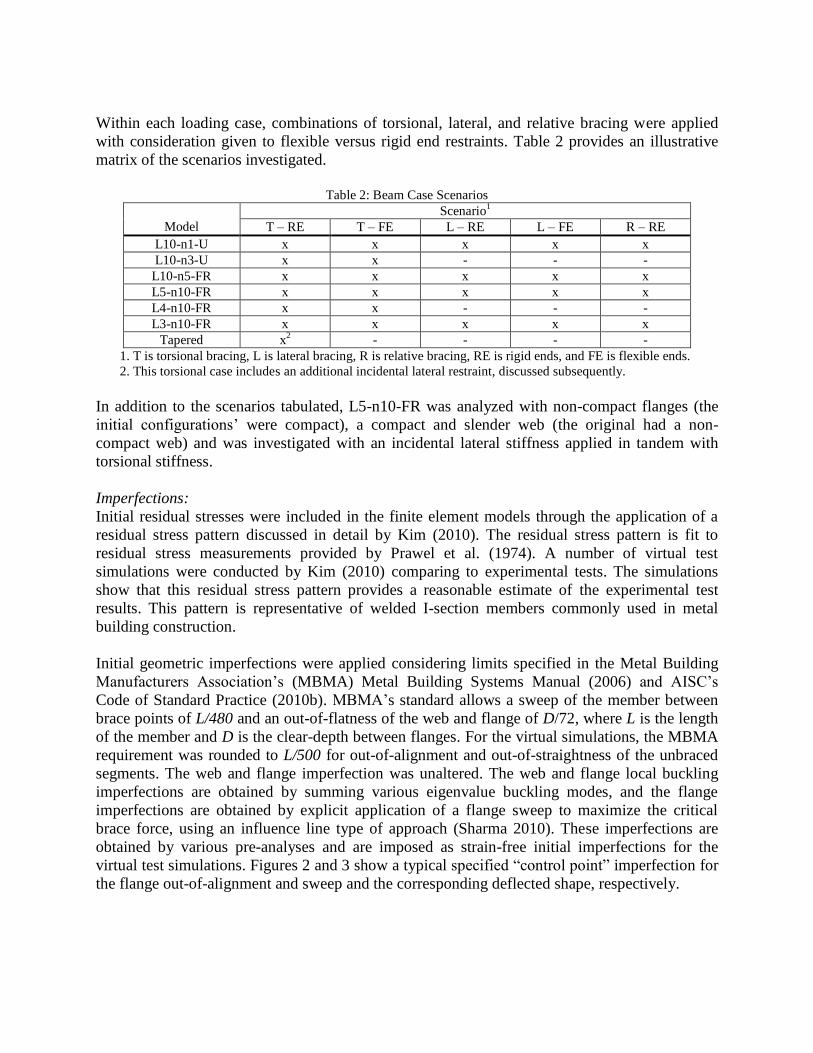
Within each loading case, combinations of torsional, lateral, and relative bracing were applied
with consideration given to flexible versus rigid end restraints. Table 2 provides an illustrative
matrix of the scenarios investigated.
Table 2: Beam Case Scenarios
M
Model
Scenario1
T – RE T – FE L – RE L – FE R – RE
L10-n1-U x x x x x
L10-n3-U x x - - -
L10-n5-FR x x x x x
L5-n10-FR x x x x x
L4-n10-FR x x - - -
L3-n10-FR x x x x x
Tapered x2
- - - -
1. T is torsional bracing, L is lateral bracing, R is relative bracing, RE is rigid ends, and FE is flexible ends.
2. This torsional case includes an additional incidental lateral restraint, discussed subsequently.
In addition to the scenarios tabulated, L5-n10-FR was analyzed with non-compact flanges (the
initial configurations’ were compact), a compact and slender web (the original had a non-
compact web) and was investigated with an incidental lateral stiffness applied in tandem with
torsional stiffness.
Imperfections:
Initial residual stresses were included in the finite element models through the application of a
residual stress pattern discussed in detail by Kim (2010). The residual stress pattern is fit to
residual stress measurements provided by Prawel et al. (1974). A number of virtual test
simulations were conducted by Kim (2010) comparing to experimental tests. The simulations
show that this residual stress pattern provides a reasonable estimate of the experimental test
results. This pattern is representative of welded I-section members commonly used in metal
building construction.
Initial geometric imperfections were applied considering limits specified in the Metal Building
Manufacturers Association’s (MBMA) Metal Building Systems Manual (2006) and AISC’s
Code of Standard Practice (2010b). MBMA’s standard allows a sweep of the member between
brace points of L/480 and an out-of-flatness of the web and flange of D/72, where L is the length
of the member and D is the clear-depth between flanges. For the virtual simulations, the MBMA
requirement was rounded to L/500 for out-of-alignment and out-of-straightness of the unbraced
segments. The web and flange imperfection was unaltered. The web and flange local buckling
imperfections are obtained by summing various eigenvalue buckling modes, and the flange
imperfections are obtained by explicit application of a flange sweep to maximize the critical
brace force, using an influence line type of approach (Sharma 2010). These imperfections are
obtained by various pre-analyses and are imposed as strain-free initial imperfections for the
virtual test simulations. Figures 2 and 3 show a typical specified “control point” imperfection for
the flange out-of-alignment and sweep and the corresponding deflected shape, respectively.

Lb/500
Lb/500
Elevation 1: Top Flange Imperfection
Lb/1000
Lb/1000
Brace Point (Typ.)
Elevation 2: Bottom Flange Imperfection Figure 2: Applied imperfections to top and bottom flanges
Maximum Top Flange
Imperfection
Maximum Bottom
Flange Imperfection Figure 3: Exaggerated deflected shape from Abaqus
(view looking down on the top flange from above)
6. Virtual Simulation Results
In all of the scenarios, the simplified equations were used to calculate a target stiffness for the
bracing scheme. Next, the beam was analyzed several times with fractions or multiples of the
target stiffness. Finally, knuckle curves were created, plotting normalized member strength
versus brace stiffness. These curves were then compared to the AISC and simplified
requirements. In all cases, a stiffness and brace strength requirement was extracted from the
knuckle curves at a value of stiffness required to reach 90% of the normalized capacity of the
rigidly-braced member. The stiffness and strength required to get to 90% of the rigidly-braced
beam capacity is discussed throughout this section. This limit has been suggested by a number of
authors, e.g., Stanway et al. (1992a & b), as a reasonable criterion for brace design.
End Twisting and Lateral Restraint Effects:
The knee region is often the most critical region of a metal building frame due to the high
moments at the rafter-column juncture. By considering the rafter as rigidly braced at its ends, one
assumes that the column is providing full lateral and twisting restraint to the rafter ends.
Obviously, this assumption is rarely met in practice. Thus, the effect of having a flexible end
should be considered in the overall bracing design. This was simulated in all the flexible end
cases by applying a torsional brace at each end with a stiffness equal to that of interior braces.
By comparing the torsional rigid end and flexible end cases (see Table 2), every flexible end case
saw an increase in brace stiffness required to reach 90% of the system strength when compared
with the rigid end cases. These increases ranged from 40% for cases involving uniform moment
to 270% for cases with full reverse-curvature bending. Similarly, the brace strength requirements
increased by 3% to 40%; however some brace force demands decreased.
In all cases, the AISC requirements were accurate to conservative for rigid end bracing, yet were
often lacking capacity for flexible end braces. Contrary to AISC, the simplified equations ranged
from unconservative for rigid ends and uniform bending to extremely conservative for rigid ends

and reverse-curvature bending. However, the simplified equations provided reasonable
conservative estimates of the required stiffness for full reverse-curvature bending when the ends
were flexible.
For the lateral bracing cases, the simplified method was able to shave from 7 to 100% off of the
stiffness requirements for rigid end bracing versus the AISC requirements while still providing
an adequate design. Furthermore, the increase in brace stiffness demand in the cases with flexible
ends was captured by the simplified equations in most cases.
Rapid Drop in Brace Demand Away from Critical Regions:
From initial analyses performed by Sharma (2010), sections of the rafter away from the critical
knee or ridge regions often see significantly smaller stiffness and strength demands. Thus, rafters
with a large number of brace locations have the potential to be designed with bracing stiffnesses
much less than required at the critical regions. Of course, the critical loading for each brace
would need to be considered via force envelopes from the global frame analysis.
In general, plots of normalized brace force for full reversal of moments showed a rapid
attenuation of forces from the critical end segment. Figure 4 shows one such plot for the
torsional braces in L5-n10-FR. One can see that the critical intermediate braces (1 and 10 in this
case) and the rigid ends are the only braces with significant force in this beam. In addition,
typically the interior brace locations often are subjected to smaller force from the moment
envelopes relative to the local beam capacity, even in tapered members. Thus, one might suspect
that trimming the interior brace stiffnesses might be a feasible (and safe) reduction in steel.
Mr/Mn
Mbr/Mn
0.02
0.01
10.9
Case 2
Case 3
Figure 4: Normalized brace force at stiffness Figure 5: Normalized brace force versus
level to reach 90% of the system strength normalized frame demand
Three additional cases were considered and run subsequent to the above findings:
Case 1: Each brace was allowed to have a different stiffness; calculated using Eq. 8 with Mr
taken as the largest moment within each brace’s adjacent unbraced lengths.
Case 2: Using the stiffness from Case 1 plus an additional reduction in brace stiffness based
on adjusting the 0.02 factor used in Eq. 8 via the piecewise continuous “Case 2”
curve from Fig. 5 above (dependent on the ratio Mr/Mn).
-2.5%
-2.0%
-1.5%
-1.0%
-0.5%
0.0%
0.5%
Star
t 1 2 3 4 5 6 7 8 9
10
En
d
Mb
rma
x/
Mm
ax
Rig
id
Brace No.

Case 3: Using the stiffness from Case 1 plus an additional reduction in brace stiffness based
on adjusting the 0.02 factor used in Eq. 8 via the linear “Case 3” curve from Fig.5
above (dependent on the ratio Mr/Mn).
In these cases, the brace designs were based on the largest moment in the adjacent unbraced
lengths for each brace while keeping the ends rigid. These cases produced maximum beam
strengths of 99.9%, 99.6%, and 95.7%, respectively, of the capacity reached by assigning all
braces the same stiffness (as shown in Fig. 4 above). Thus, a reduction of the brace stiffness
away from the critical regions used in Cases 1, 2, and 3 appears to afford an economic
advantage. It should be noted that all of these cases were analyzed under the specific loading
diagrams mentioned in Table 1. The reductions may be more minor in practical frames where the
design moment envelope must be considered and the member is tapered. Further analyses must
be completed before specific recommendations can be offered. Larger attenuation of the brace
forces along the member length is possible in situations where the LTB failure is within the
elastic buckling range, and if the braces are designed considering significant partial bracing
response.
Incidental Lateral Restraint Effects:
An argument can be made that frequently, multiple types of bracing act on a structure
simultaneously. For instance, one might include the shear panel stiffness provided by a roof or
wall diaphragm along with the flange bracing diagonals (torsional bracing) applied at the rafters.
The current AISC Appendix 6 provisions do not count on any “coupling” of bracing systems.
For these scenarios, a nodal lateral stiffness equal to 10% of the AISC requirement (Eq. 2) was
applied in addition the torsional stiffness (determined from previous analyses as the torsional
stiffness required for the beam to reach 90% of its rigid-braced strength); giving each brace equal
lateral and torsional stiffness. Then, the strength of the beam under this combined bracing
scheme was compared to how much more than 90% of the rigid-strength it could now reach. For
the case of L5-n10-FR, the system strength increased from 90% of the rigid-braced capacity to
94% of the rigid-braced capacity. The maximum normalized torsional brace force decreased
from 2% with only torsional bracing to 0.5% with combined torsional and lateral bracing; a four-
fold decrease! A minor decrease in the stiffness requirement was also observed when lateral
stiffness was added to the torsional stiffness. Thus, the addition of lateral bracing as a
supplement to torsional bracing not only increased the overall beam strength but also
substantially decreased the strength design requirement for the torsional braces.
Small Brace Force up to the Limit Load:
From the virtual simulations, the brace force remains relatively low in the targeted case studies
until just before the limit load is reached. Figure 6 below shows the normalized capacity versus
normalized brace force for a range of stiffness for L5-n10-FR. One immediately notices the
plateaus in strength corresponding to a sharp increase in brace force as the system limit load is
approached. The stiffness associated with 0.5βTS, 1.0βTS, and 2.0βTS all have a 90% up-crossing
around 0.6% brace force, yet do not peak until around 2.5% for only a marginal strength gain. If
it is considered sufficient for a brace to fail at a load level close to the otherwise maximum
strength of the structure, maximum brace force requirements of approximately 2 % of the
member moment appear to be sufficient from this study, and from a broader range of studies

considered by Sharma (2010). If this is not considered sufficient, the braces need to be designed
in general for up to approximately 4 % of the local member internal force. It should be noted that
both of these requirements are often larger than the requirements specified by AISC (2010)
Appendix 6. These limits appear to be reasonable for both inelastic and elastic LTB cases.
Figure 6: Beam strength v. brace force demand Figure 7: Flange slenderness comparison at
for L5-n10-FR stiffness to reach 90% of the system strength
Local-Buckling Protects Brace:
The original beam cases have a non-compact web and compact flanges. Permutations were
created to look at the effects of the brace force and stiffness when the flanges are non-compact as
well as where webs are slender versus compact. Figure 7 above shows the result of increasing the
slenderness of the flanges from a classification of compact to non-compact for L5-n10-FR. It is
apparent that there is a significant drop in the critical brace force in brace number 10. Also, the
stiffness required to reach 90% of the capacity of the beam dropped over two-fold.
Unfortunately, a similar drop was not seen by increasing the web slenderness. Figure 8 below
shows the effect of increasing the web slenderness. It should be noted that the critical
imperfection was the same for all levels of slenderness. Thus, if one had selected an imperfection
that emphasized the out-of-plane deformation of the web instead of the compression flange, a
bigger drop may have been realized.
LTB K-Factor Consideration:
Typical design for bracing per AISC’s Appendix 6 uses a K-factor of 1 for the critical unbraced
lengths. The equations do not permit any benefit from warping restraint provided by unbraced
segments adjacent to the critical segment. By completely restraining warping and lateral bending
at the ends, the approximate K-factor is reduced to 0.5 and a substantial benefit is realized in
bracing demand (see Figure 9 below) for L5-n10-FR (at the member design load level
corresponding to K = 1, and at the limit load level in the virtual test simulation). For real
systems, the actual K-factor will be bounded essentially by the 0.5 limit and would likely
produce brace forces between the values in Fig. 9. Improved estimates of the torsional bracing
stiffness requirements are obtained by Sharma (2010) for a number of example cases by using a
K < 1 in the calculation of Pe.eff of Eq. (3).
0
0.1
0.2
0.3
0.4
0.5
0.6
0.7
0.8
0.9
1
0.0% 1.0% 2.0% 3.0% 4.0%
M/
Mm
ax
Rig
id
Mbr/MmaxRigid
0.125βTS
0.5βTS
1.0βTS
2.0βTS
-2.5%
-2.0%
-1.5%
-1.0%
-0.5%
0.0%
0.5%
Star
t 1 2 3 4 5 6 7 8 9
10
En
d
Mb
rma
x/
Mm
ax
Rig
id
Brace No.
Compact
Non-Compact

Figure 8: Web slenderness comparison at Figure 9: Warping restraint effects at
stiffness to reach 90% of system strength stiffness to reach 90% of system strength
7. Summary of Key Observations
After compiling the results presented above with those by Sharma (2010), some key observations
can be gleaned. Further analysis and simulation are warranted to corroborate these observations
before any corresponding design recommendations can be proposed.
1. The AISC equations appear to work consistently well for rigid end, torsionally braced
beams, despite their slight conservatism and are able to develop 90 % of the rigidly
braced strength; a common criterion for brace design
2. Neither the AISC nor the example simplified equations seem to capture the effects of
flexible end restraints for the torsionally braced beam all that well.
3. The lateral stiffness requirements are met most accurately by the simplified equations for
both rigid and flexible ends in all cases except L10-n5-FR. A simplified form for the
determination of lateral stiffness, i.e., Eq. 7, potentially can be used for more accurate
estimates of the corresponding bracing demands.
4. Beams subjected to moment gradient can see substantially reduced stiffness demands in
non-critical regions, but experience an increase in critical brace strength demands.
5. Very marginal or incidental lateral bracing restraint can be counted upon to supplement
torsional bracing for a more economical bracing scheme. The addition of lateral bracing
increases the beam strength slightly while significantly decreasing the strength
requirements for the torsional bracing.
6. Brace forces typically remain relatively low until the limit load of the member is reached.
Thus, frames that do not need full rigid-braced capacity or are not subject to reversals in
inelastic deformation (such as may be present during seismic loading) may be able to be
designed for less stringent brace force requirements.
7. Local buckling of the member appears to protect the braces (up to the system strength
limit) by causing deformations inconsistent with the motion necessary to engage the
brace. Local web or flange buckles do not contribute to the relative movement of the
beam’s brace points and thus, do not affect the strength or stiffness requirements. This
seems especially true for sections controlled by flange local buckling. Upon reaching the
system strength limit, the brace force demands generally increase rapidly in all cases.
8. The inclusion of inherent warping restraint by adjacent non-critical segments reduces the
demands on the brace strength requirements as well as the required design stiffness.
-2.5%
-2.0%
-1.5%
-1.0%
-0.5%
0.0%
0.5%
1 2 3 4 5 6 7 8 9 10
Mb
rma
x/
Mm
ax
Rig
id
Brace No.
Compact Web
Non-Compact Web
Slender Web-2.5%
-2.0%
-1.5%
-1.0%
-0.5%
0.0%
0.5%
1.0%
Star
t 1 2 3 4 5 6 7 8 9
10
En
d
Mb
rma
x/
Mm
ax
Rig
id
Brace No.
NoWarping
Warping

9. The importance of the knuckle value as a lower bound stiffness requirement must be
emphasized. Designers should choose bracing stiffness values that are sufficiently above
the knuckle value so as to preclude slight variations in bracing stiffness causing drastic
reductions in system capacity while maintaining an acceptable level of system economy.
Since “rigid” bracing is unobtainable in practice, consideration must also be given to
what percentage of rigid system strength is needed (90% was used extensively in this
paper, see, e.g., Stanway et.al. 1992a & b).
10. When considering AISC’s Appendix 6 equations for rigid ends, the stiffness requirements
consistently place the capacity of the section above the knuckle value. However, for
flexible ends, the stiffness knuckle value is often larger than the Appendix 6 estimate.
Thus, more work is needed to determine accurate (and safe) bracing requirement for
beams with flexible ends.
8. Acknowledgements
The authors would like to thank MBMA for sponsoring this research and especially, the Steering
Committee which has been instrumental in the development of this research project. However,
the views expressed are solely those of the authors and may not represent the positions of the
aforementioned organizations or individuals.
9. References AISC (2010). “Specification for Structural Steel Buildings”, American Institute of Steel Construction, Inc. Chicago,
IL. ANSI/AISC 360-10.
AISC (2010b). “Code of Standard Practice for Steel Buildings and Bridges”, American Institute of Steel
Construction, Inc. Chicago, IL. AISC 303-10.
AISC (2002). “Example Problems Illustrating the Use of the New Bracing Provisions – Section C3, Spec and
Commentary”, Ad hoc Committee on Stability Bracing, November (revised from original version of August
1998).
Kim, Y. D. (2010). “Behavior and Design of Metal Building Frames Using General Prismatic and Web-Tapered
Steel I-Section Members”, Doctoral Dissertation, Georgia Institute of Technology, Atlanta, GA.
MBMA (2006). Metal Building Systems Manual, Metal Building Manufacturers Association, Cleveland, OH.
Prawel, S.P., Morrell, M.L. and Lee, G.C. (1974). “Bending and Buckling Strength of Tapered Structural Members,”
Welding Research Supplement, Vol. 53, February, 75-84.
Sharma, Akhil (2010). “Flange Stability Bracing Behavior in Metal Building Frame Systems”, In Partial Fulfillment
of the Requirements for the Degree, Master of Science in the School of Civil and Environmental Engineering,
Georgia Institute of Technology, Atlanta, GA.
Simulia (2010). Abaqus, Software and Analysis User’s Manual, Version 6.10.
Stanway, G.S., Chapman J.C., and Dowling, P.J. (1992a). “A Simply Supported Imperfect Column with a Trans-
verse Elastic Restraint at any Position. Part 1: Behaviour”. Proc. Instn. Civ. Engrs Structs & Bldgs, 94, May,
205-216.
Stanway, G.S., Chapman J.C., and Dowling, P.J. (1992b). “A Simply Supported Imperfect Column with a
Transverse Elastic Restraint at any Position. Part 2: Design Models”. Proc. Instn. Civ. Engrs Structs & Bldgs,
94, May, 217-228.
Tran, D. Q. (2009). “Towards Improved Flange Bracing Requirements for Metal Building Frame Systems”, In
Partial Fulfillment of the Requirements for the Degree, Master of Science in the School of Civil and
Environmental Engineering, Georgia Institute of Technology, Atlanta, GA.
White, D.W., and Kim, Y.D. (2006). “A Prototype Application of the AISC (2005) Stability Analysis and Design
Provisions to Metal Building Structural Systems”, Report Prepared for Metal Building Manufacturers
Association, January.
Yura, J. A. and Helwig, T. A. (2009). “Bracing for Stability,” Short course sponsored by the Structural Stability
Research Council, North American Steel Construction Conference, Phoenix, AZ, April.
Yura, J.A., Phillips, B., Raju, S., and Webb, S. (1992). “Bracing of Steel Beams in Bridges”, Report No. 1239-4F,
Center for Transportation Research, University of Texas at Austin. October, 80.
Related Documents